Page 1
1
Self-propelled Bouncing Spherical Robot
Undergraduate Honors Thesis
Presented in Partial Fulfillment of the Requirements for Graduation with Honors Research
Distinction in the Department of Mechanical and Aerospace Engineering at The Ohio State
University
By Xiaolin Wang
Thesis Committee Professor Manoj Srinivasan (Advisor)
Professor Sandra Metzler
2
Abstract
Most robots that can travel on the ground are either traditional wheeled robots or legged robots
Exploring non-traditional novel robots may provide new solutions for locomotion not previously
examined Currently self-rolling spherical robots have been designed and manufactured for
hobbies entertainment or military uses Similarly various researchers have built legged robots
that walk and run Our objective in this research project was to design build and control a self-
propelled bouncing and rolling spherical robot While some self-bouncing wheeled robots have
been built as toys the self-bouncing spherical robot (one that looks like a ball) remains largely not
explored No one has produced a robot that can bounce continuously and can be steered without
any external device to assist its movement To achieve this goal we plan to prototype up to three
different mechanisms for bouncing Each prototype would go through brainstorming computer-
aided design and simulation (of the bouncing) initial build redesign second build and final
analysis We follow the classic design cycle observe ideation prototype and testing We will
also perform dynamic analyses of the robot to improve the design This thesis reports on current
progress towards these goals we have designed and fabricated (and iterated) on a simple prototype
bouncing ball based on a spinning internal mass we have performed some 2D and 3D simulations
of the spinning mechanism that shows promise for the mechanism to produce persistent bouncing
Future work will consist of improving the current prototype matching the computer simulations
quantitatively to the prototype performing design optimization and trajectory optimizations for
optimal control exploring other designs closer to hopping robots and finally building the ability
to control and steer the robot
3
Acknowledgments
I would like to first thank my research advisor Professor Manoj Srinivasan for his belief in me
and tremendous support in this research project I really appreciate all of his guidance for both
programming and prototyping on this project It is because of his passion and enthusiasm that I
can achieve so much in this project and win the finalist in the Denman Research Forum of the Ohio
State University Secondly I would like to thank Kevin Wolf for his passionate assistance in
manufacturing and his valuable knowledge of 3D printing and machining I would also like to
thank Chris Adam for his consultation with electronics and teaching for soldering skills and
strategies Thank you to Aaron Orsborn and all the student workers for assistance in Machine
Shop Thank you to Professor Ryan Harne for his suggestion for various learning resources Thank
you to Myungjin Jung and Kai for this assistant for debugging BLDC motors Thank you to Zhiyi
Jiang for his help with Simulink Thank you to Zhihao Zhang for this consultant with the Lipo
battery Last but not least I would like to thank the College of Engineering and Second Year
Transformational Experience program for providing a substantial amount of fellowship for my
research projects
4
Table of contents
Abstracthelliphelliphelliphelliphelliphelliphelliphelliphelliphelliphelliphelliphelliphelliphelliphelliphelliphelliphelliphelliphelliphelliphelliphelliphelliphelliphelliphelliphelliphelliphelliphelliphelliphellip2
Acknowledgementshelliphelliphelliphelliphelliphelliphelliphelliphelliphelliphelliphelliphelliphelliphelliphelliphelliphelliphelliphelliphelliphelliphelliphelliphelliphelliphelliphelliphelliphellip3
List of Figureshelliphelliphelliphelliphelliphelliphelliphelliphelliphelliphelliphelliphelliphelliphelliphelliphelliphelliphelliphelliphelliphelliphelliphelliphelliphelliphelliphelliphelliphelliphelliphellip5
Chapter 1 Introductionhelliphelliphelliphelliphelliphelliphelliphelliphelliphelliphelliphelliphelliphelliphelliphelliphelliphelliphelliphelliphelliphelliphelliphelliphelliphelliphelliphellip11
Chapter 2 Other related robots and inspirationshelliphelliphelliphelliphelliphelliphelliphelliphelliphelliphelliphelliphelliphelliphelliphelliphelliphellip15
Chapter 3 Three basic designs Brainstorming and Designhelliphelliphelliphelliphelliphelliphelliphelliphelliphelliphelliphelliphelliphellip22
Chapter 4 Fabrication and design iterationshelliphelliphelliphelliphelliphelliphelliphelliphelliphelliphelliphelliphelliphelliphelliphelliphelliphelliphellip24
Chapter 5 3D Virtual Simulation and Controller Designhelliphelliphelliphelliphelliphelliphelliphelliphelliphelliphelliphelliphelliphellip62
Chapter 6 Conclusion and Future Workhelliphelliphelliphelliphelliphelliphelliphelliphelliphelliphelliphelliphelliphelliphelliphelliphelliphelliphelliphellip78
Referenceshelliphelliphelliphelliphelliphelliphelliphelliphelliphelliphelliphelliphelliphelliphelliphelliphelliphelliphelliphelliphelliphelliphelliphelliphelliphelliphelliphelliphelliphelliphelliphelliphellip80
Appendix Ahelliphelliphelliphelliphelliphelliphelliphelliphelliphelliphelliphelliphelliphelliphelliphelliphelliphelliphelliphelliphelliphelliphelliphelliphelliphelliphelliphelliphelliphelliphelliphellip83
Appendix Bhelliphelliphelliphelliphelliphelliphelliphelliphelliphelliphelliphelliphelliphelliphelliphelliphelliphelliphelliphelliphelliphelliphelliphelliphelliphelliphelliphelliphelliphelliphelliphellip108
5
List of Figures
Figure 101 Fictional bouncing robots and real rolling robotshelliphelliphelliphelliphelliphelliphelliphelliphelliphelliphelliphellip10
Figure 102 Classic design iteration cycle helliphelliphelliphelliphelliphelliphelliphelliphelliphelliphelliphelliphelliphelliphelliphelliphelliphelliphellip12
Figure 201 Sphero robothelliphelliphelliphelliphelliphelliphelliphelliphelliphelliphelliphelliphelliphelliphelliphelliphelliphelliphelliphelliphelliphelliphelliphelliphellip14
Figure 202 Previous jumping robots from other research labshelliphelliphelliphelliphelliphelliphelliphelliphelliphelliphellip15
Figure 203 Previous projects or products on market or by studenthelliphelliphelliphelliphelliphelliphelliphelliphelliphellip16
Figure 204 Jumping Sumo robothelliphelliphelliphelliphelliphelliphelliphelliphelliphelliphelliphelliphelliphelliphelliphelliphelliphelliphelliphelliphelliphelliphellip17
Figure 205 The mechanism in the soil compactorhelliphelliphelliphelliphelliphelliphelliphelliphelliphelliphelliphelliphelliphelliphelliphelliphellip17
Figure 206 Jumping toyhelliphelliphelliphelliphelliphelliphelliphelliphelliphelliphelliphelliphelliphelliphelliphelliphelliphelliphelliphelliphelliphelliphelliphelliphelliphelliphellip18
Figure 207 Anti Gravity wheelhelliphelliphelliphelliphelliphelliphelliphelliphelliphelliphelliphelliphelliphelliphelliphelliphelliphelliphelliphelliphelliphelliphelliphellip19
Figure 208 Cam mechanism with different cam shapehelliphelliphelliphelliphelliphelliphelliphelliphelliphelliphelliphelliphelliphelliphellip19
Figure 209 Effect of jumping height due to the swing of armshelliphelliphelliphelliphelliphelliphelliphelliphelliphelliphelliphellip20
Figure 301 Prototype designshelliphelliphelliphelliphelliphelliphelliphelliphelliphelliphelliphelliphelliphelliphelliphelliphelliphelliphelliphelliphelliphelliphelliphelliphellip22
Figure 401 Bouncing ball robothelliphelliphelliphelliphelliphelliphelliphelliphelliphelliphelliphelliphelliphelliphelliphelliphelliphelliphelliphelliphelliphelliphelliphellip23
Figure 402Transparent plastic domehelliphelliphelliphelliphelliphelliphelliphelliphelliphelliphelliphelliphelliphelliphelliphelliphelliphelliphelliphelliphelliphellip24
Figure 403 Rough initial build of prototype 1helliphelliphelliphelliphelliphelliphelliphelliphelliphelliphelliphelliphelliphelliphelliphelliphelliphelliphellip25
Figure 404 Idea to hold up the motorshelliphelliphelliphelliphelliphelliphelliphelliphelliphelliphelliphelliphelliphelliphelliphelliphelliphelliphelliphelliphellip26
6
Figure 405 Design to lower the center of gravityhelliphelliphelliphelliphelliphelliphelliphelliphelliphelliphelliphelliphelliphelliphelliphelliphellip27
Figure 406 Rough concept design with the transmission mechanismhelliphelliphelliphelliphelliphelliphelliphelliphellip28
Figure 407 Detailed model with measured dimensionshelliphelliphelliphelliphelliphelliphelliphelliphelliphelliphelliphelliphelliphelliphellip29
Figure 408 Anycubic photon printer and resin used in this projecthelliphelliphelliphelliphelliphellip helliphelliphelliphellip30
Figure 409 Initial print of the driving wheel with horizontal placementhelliphelliphelliphelliphelliphelliphelliphellip31
Figure 410 Shrink on large parts when placed horizontally on the printing bedhelliphelliphelliphelliphelliphellip32
Figure 411 Preview of PreForm interfacehelliphelliphelliphelliphelliphelliphelliphelliphelliphelliphelliphelliphelliphelliphelliphelliphelliphelliphelliphellip33
Figure 412 Close up photo of a large piece of print just after the printing processhelliphelliphelliphelliphellip34
Figure 413 One of a few successful parts with very small detailshelliphelliphelliphelliphelliphelliphelliphelliphelliphelliphellip34
Figure 414 Testing the core mechanismhelliphelliphelliphelliphelliphelliphelliphelliphelliphelliphelliphelliphelliphelliphelliphelliphelliphelliphelliphelliphellip35
Figure 415 Flat support for the transmission mechanismhelliphelliphelliphelliphelliphelliphelliphelliphelliphelliphelliphelliphelliphellip36
Figure 416 Round support to simulate spherical contact without the outer ballhelliphelliphelliphelliphelliphellip37
Figure 417 Metal wire cagehelliphelliphelliphelliphelliphelliphelliphelliphelliphelliphelliphelliphelliphelliphelliphelliphelliphelliphelliphelliphelliphelliphelliphelliphellip38
Figure 418 Wiffle Ballhelliphelliphelliphelliphelliphelliphelliphelliphelliphelliphelliphelliphelliphelliphelliphelliphelliphelliphelliphelliphelliphelliphelliphelliphelliphelliphellip39
Figure 419 Acrylic domehelliphelliphelliphelliphelliphelliphelliphelliphelliphelliphelliphelliphelliphelliphelliphelliphelliphelliphelliphelliphelliphelliphelliphelliphelliphellip39
Figure 420 Prototype ver 30helliphelliphelliphelliphelliphelliphelliphelliphelliphelliphelliphelliphelliphelliphelliphelliphelliphelliphelliphelliphelliphelliphelliphelliphellip40
Figure 421 Scorpion S-1804-1650KV Brushless DC motorhelliphelliphelliphelliphelliphelliphelliphelliphelliphelliphelliphelliphellip41
7
Figure 422 Circuit setup for BLDC motor and Arduinohelliphelliphelliphelliphelliphelliphelliphelliphelliphelliphelliphelliphelliphellip42
Figure 423 Close up view of different kinds of BLDC motors I experimented with helliphelliphellip43
Figure 424 Remains of prototype 40helliphelliphelliphelliphelliphelliphelliphelliphelliphelliphelliphelliphelliphelliphelliphelliphelliphelliphelliphelliphelliphellip43
Figure 425 Prototype 50helliphelliphelliphelliphelliphelliphelliphelliphelliphelliphelliphelliphelliphelliphelliphelliphelliphelliphelliphelliphelliphelliphelliphelliphelliphellip44
Figure 426 Idea for putting a bouncy material on the bottom may increase performancehelliphellip45
Figure 427 Some of the rubber spray I purchasedhelliphelliphelliphelliphelliphelliphelliphelliphelliphelliphelliphelliphelliphelliphelliphelliphellip46
Figure 428 One of the balls with rubber spray appliedhelliphelliphelliphelliphelliphelliphelliphelliphelliphelliphelliphelliphelliphelliphellip47
Figure 429 Close-up picture of the lightened bridgehelliphelliphelliphelliphelliphelliphelliphellip helliphelliphelliphelliphelliphelliphellip48
Figure 430 Close-up photo of the redesigned pendulum armhelliphelliphelliphelliphelliphelliphelliphelliphelliphelliphelliphelliphellip48
Figure 431 Close up after pendulum and bridge modificationhelliphelliphelliphelliphelliphelliphelliphelliphelliphelliphelliphellip49
Figure 432 Customized counterbalance masshelliphelliphelliphelliphelliphelliphelliphelliphelliphelliphelliphelliphelliphelliphelliphelliphelliphelliphellip50
Figure 433 Close-up photo of the CNC machined carbon steel masshelliphelliphelliphelliphelliphelliphelliphelliphelliphellip50
Figure 434 Roly-poly toyhelliphelliphelliphelliphelliphelliphelliphelliphelliphelliphelliphelliphelliphelliphelliphelliphelliphelliphelliphelliphelliphelliphelliphelliphelliphellip51
Figure 435 Different perspectives of the initial test setuphelliphelliphelliphelliphelliphelliphelliphelliphelliphelliphelliphelliphellip52
Figure 436One frame from the robot bouncing videohelliphelliphelliphelliphelliphelliphelliphelliphelliphelliphelliphelliphelliphelliphellip53
Figure 437 New machined mass and bottom weight addedhelliphelliphelliphelliphelliphelliphelliphelliphelliphelliphelliphelliphellip54
Figure 438 Improvised testing assemblyhelliphelliphelliphelliphelliphelliphelliphelliphelliphelliphelliphelliphelliphelliphelliphelliphelliphelliphelliphelliphellip56
8
Figure 439 Using a tachometer to measure the speed of the pendulumhelliphelliphelliphelliphelliphelliphelliphellip57
Figure 440 Broken arm parts copies and a modified arm parthelliphelliphelliphelliphelliphelliphelliphelliphelliphelliphelliphelliphellip58
Figure 501 Snapshot of Algodoo simulationhelliphelliphelliphelliphelliphelliphelliphelliphelliphelliphelliphelliphelliphelliphelliphelliphelliphelliphellip61
Figure 502 Animation of the simulationhelliphelliphelliphelliphelliphelliphelliphelliphelliphelliphelliphelliphelliphelliphelliphelliphelliphelliphelliphelliphellip63
Figure 503 Animation of bouncing simulation using MATLABhelliphelliphelliphelliphelliphelliphelliphelliphelliphelliphellip64
Figure 504 Imported CAD model of prototype ver 20 into SimScape multibodyhelliphelliphelliphellip66
Figure 505 SimScape multibody block diagram by imported CAD modelhelliphelliphelliphelliphelliphelliphellip66
Figure 506Imported CAD model of prototype ver 30 Into SimScape multibodyhelliphelliphelliphelliphellip67
Figure 507 Zoom-in of the tree structure of Simulink Diagramhelliphelliphelliphelliphelliphelliphelliphelliphelliphelliphelliphellip69
Figure 508 Simplified model with spinning mass for balancinghelliphelliphelliphelliphelliphelliphelliphelliphelliphelliphelliphellip70
Figure 509 Simplified model of spinning mass with bottom mass for balancinghelliphelliphelliphelliphellip70
Figure 510 Simplified model of spinning mass with bottom mass for balancinghelliphelliphelliphelliphellip71
Figure 511 Overall block diagram with manually tuned ideal spinning patternhelliphelliphelliphelliphelliphellip73
Figure 512 Complete SimScape block diagram without feedback controllerhelliphelliphelliphelliphelliphelliphellip73
Figure 513 Complete SimScape block diagram with feedback controllerhelliphelliphelliphelliphelliphelliphelliphellip74
Figure 514 A prismatic version of the actuationhelliphelliphelliphelliphelliphelliphelliphelliphelliphelliphelliphelliphelliphelliphelliphelliphellip74
Figure 515 Prismatic actuationhelliphelliphelliphelliphelliphelliphelliphelliphelliphelliphelliphelliphelliphelliphelliphelliphelliphelliphelliphelliphelliphelliphelliphellip75
9
Figure 516 Validation of the prismatic approach with realistic physical parametershelliphelliphelliphellip75
Figure 517 Overview of the whole lastest Simulink diagramhelliphelliphelliphelliphelliphelliphelliphelliphelliphelliphelliphelliphellip76
10
Chapter 1 Introduction
11 Background Information
Animals of different kinds have different morphology to take advantage of different ecological
niches in nature Similarly exploring new robot morphologies may help identify new robot
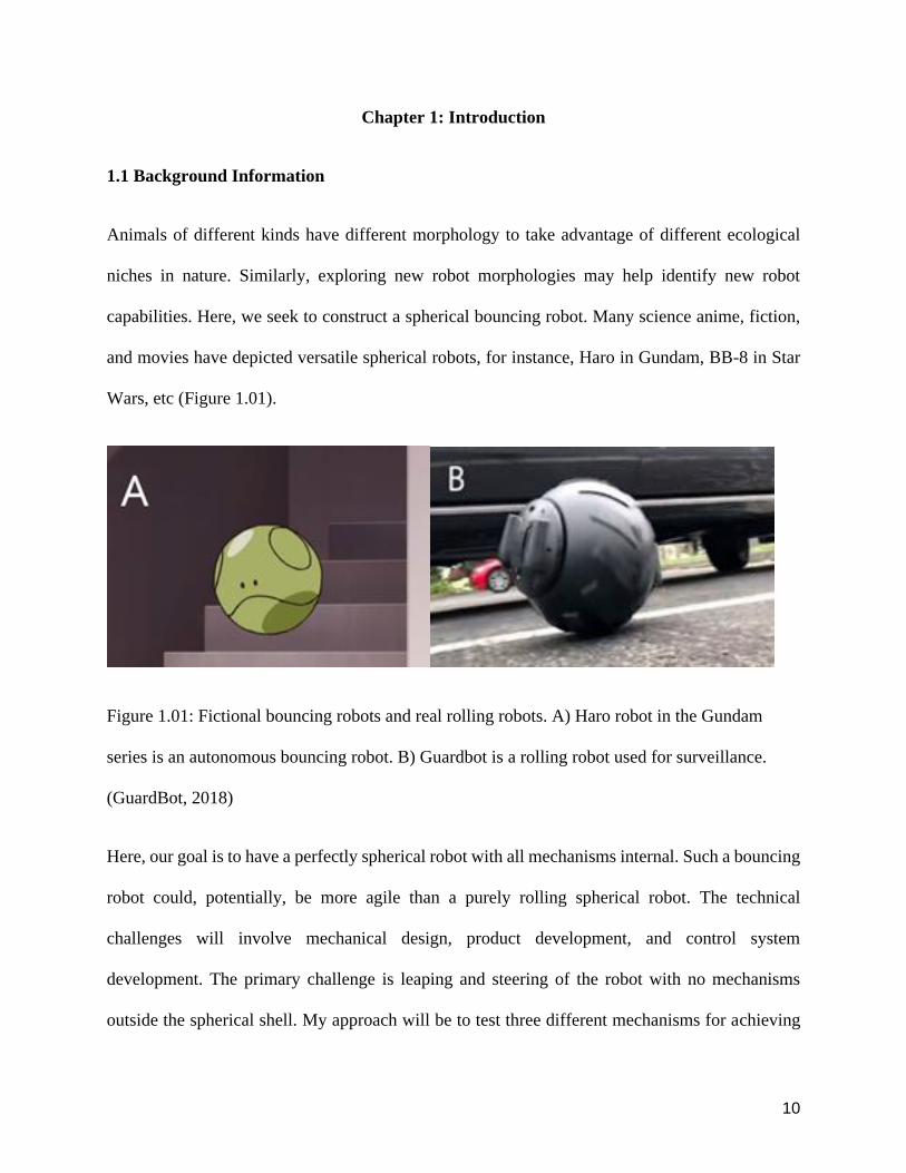
capabilities Here we seek to construct a spherical bouncing robot Many science anime fiction
and movies have depicted versatile spherical robots for instance Haro in Gundam BB-8 in Star
Wars etc (Figure 101)
Figure 101 Fictional bouncing robots and real rolling robots A) Haro robot in the Gundam
series is an autonomous bouncing robot B) Guardbot is a rolling robot used for surveillance
(GuardBot 2018)
Here our goal is to have a perfectly spherical robot with all mechanisms internal Such a bouncing
robot could potentially be more agile than a purely rolling spherical robot The technical
challenges will involve mechanical design product development and control system
development The primary challenge is leaping and steering of the robot with no mechanisms
outside the spherical shell My approach will be to test three different mechanisms for achieving
11
bouncing spinning masses slider-crank mechanism and a spring or a voice coil actuator A
spherical bouncing robot could be used in child daycare (as a toy) entertainment surveillance
low gravity space exploration etc For instance imagine a childrenrsquos toy that just looks like an
ordinary ball but can be remote-controlled to start bouncing in place and then steering around
while bouncing
12 Purpose of the Study
121 Original Research Goals
We first describe ideal research goals we would pursue if we had sufficient time and resources
We envision a robot that has a relatively small size for easy storage and utility We outline three
different approaches to achieve self-propelled bouncing For each approach we will build
computer models and perform optimizations of the controller to test feasibility We will build
prototypes of one approach one for each approach We will compare these prototypes along
various factors to determine the best solution Possible factors such as cost reliability easiness to
maneuver fabrication and bouncing performance will be taken into consideration Each prototype
might be the best solution in a different situation and depend on the material and fabrication My
objective is new solutions for locomotion not previously examined
122 Revised Research Goals
Due to limited time and resources we now describe our revised research goals that take these
constraints into account Specifically only one of the prototype ideas will be pursued by the author
through multiple fabrication iterations While the initial plan was to perform detailed trajectory
optimization using 2D and 3D bouncing robot simulation here we present progress toward such
12
simulation but do not present progress on model-based optimization of the design An improvised
testing frame will be built to conduct testing and early results will be presented
13 Design methodology
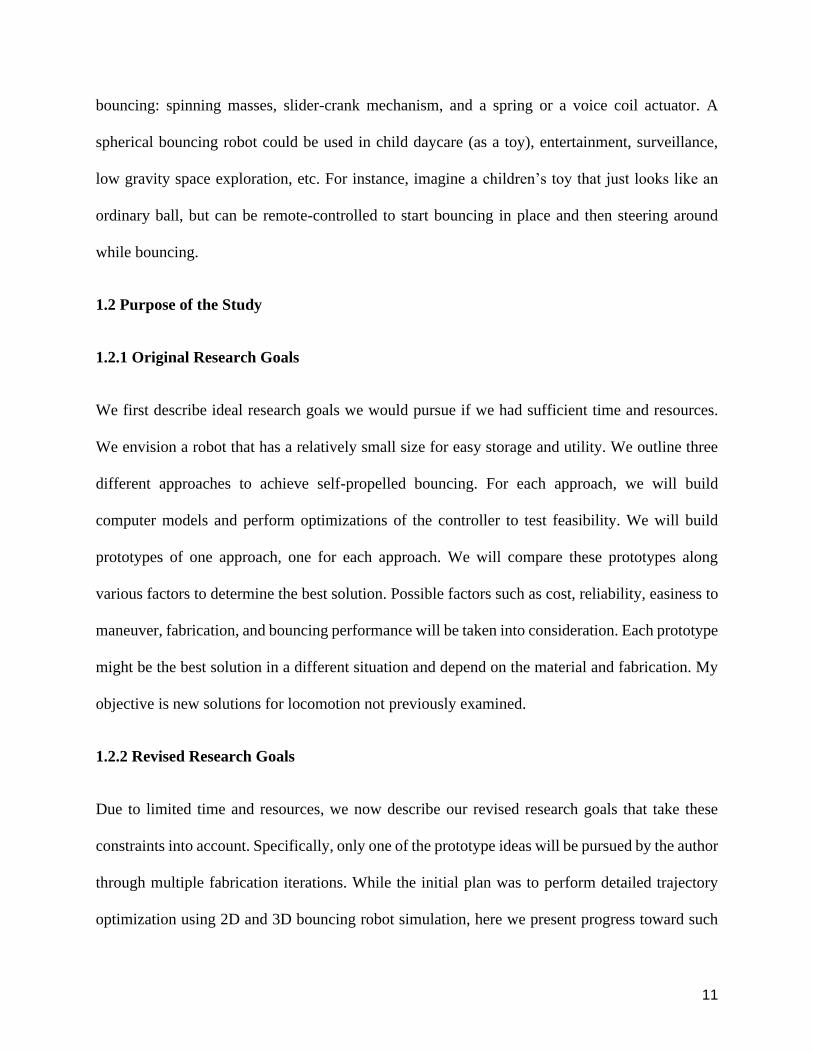
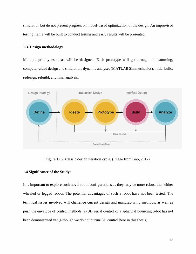
Multiple prototypes ideas will be designed Each prototype will go through brainstorming
computer-aided design and simulation dynamic analyses (MATLAB Simmechanics) initial build
redesign rebuild and final analysis
Figure 102 Classic design iteration cycle (Image from Gao 2017)
14 Significance of the Study
It is important to explore such novel robot configurations as they may be more robust than either
wheeled or legged robots The potential advantages of such a robot have not been tested The
technical issues involved will challenge current design and manufacturing methods as well as
push the envelope of control methods as 3D aerial control of a spherical bouncing robot has not
been demonstrated yet (although we do not pursue 3D control here in this thesis)
13
15 Overview of the Thesis
Chapter 1 discusses the goal methodology and significance of the project including a brief
literature survey Chapter 2 discusses other related robots and inspirations from existing devices
Chapter 3 discusses the prototype ideas to achieve the goals Chapter 4 discusses our attempts at
fabricating a simple robot and our design iterations Chapter 5 shows our road of building
simulation models and designing optimization controllers Chapter 6 concludes the thesis and
outlines future plans
14
Chapter 2 Other related robots and inspirations
In Chapter 1 I listed some robots that rolled or hopped Here I list a few other toys robots
machines or natural phenomena that provide further inspiration for our proposed device
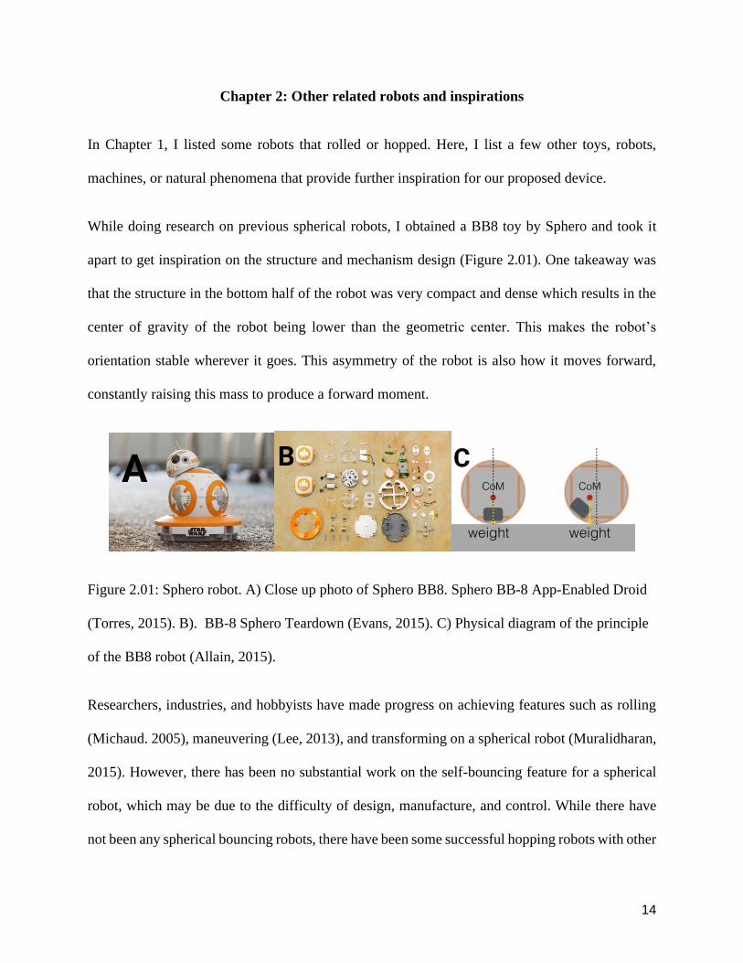
While doing research on previous spherical robots I obtained a BB8 toy by Sphero and took it
apart to get inspiration on the structure and mechanism design (Figure 201) One takeaway was
that the structure in the bottom half of the robot was very compact and dense which results in the
center of gravity of the robot being lower than the geometric center This makes the robotrsquos
orientation stable wherever it goes This asymmetry of the robot is also how it moves forward
constantly raising this mass to produce a forward moment
Figure 201 Sphero robot A) Close up photo of Sphero BB8 Sphero BB-8 App-Enabled Droid
(Torres 2015) B) BB-8 Sphero Teardown (Evans 2015) C) Physical diagram of the principle
of the BB8 robot (Allain 2015)
Researchers industries and hobbyists have made progress on achieving features such as rolling
(Michaud 2005) maneuvering (Lee 2013) and transforming on a spherical robot (Muralidharan
2015) However there has been no substantial work on the self-bouncing feature for a spherical
robot which may be due to the difficulty of design manufacture and control While there have
not been any spherical bouncing robots there have been some successful hopping robots with other
15
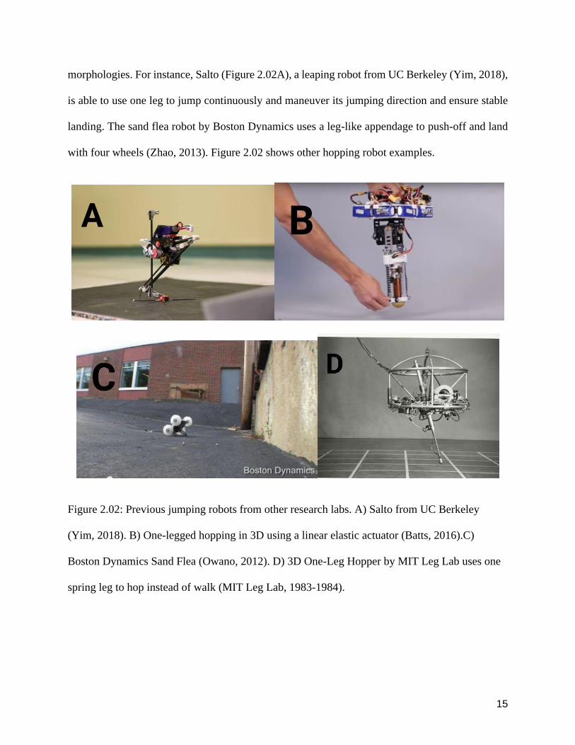
morphologies For instance Salto (Figure 202A) a leaping robot from UC Berkeley (Yim 2018)
is able to use one leg to jump continuously and maneuver its jumping direction and ensure stable
landing The sand flea robot by Boston Dynamics uses a leg-like appendage to push-off and land
with four wheels (Zhao 2013) Figure 202 shows other hopping robot examples
Figure 202 Previous jumping robots from other research labs A) Salto from UC Berkeley
(Yim 2018) B) One-legged hopping in 3D using a linear elastic actuator (Batts 2016)C)
Boston Dynamics Sand Flea (Owano 2012) D) 3D One-Leg Hopper by MIT Leg Lab uses one
spring leg to hop instead of walk (MIT Leg Lab 1983-1984)
16
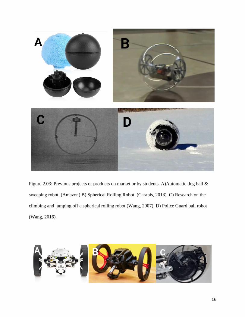
Figure 203 Previous projects or products on market or by students A)Automatic dog ball amp
sweeping robot (Amazon) B) Spherical Rolling Robot (Carabis 2013) C) Research on the
climbing and jumping off a spherical rolling robot (Wang 2007) D) Police Guard ball robot
(Wang 2016)
17
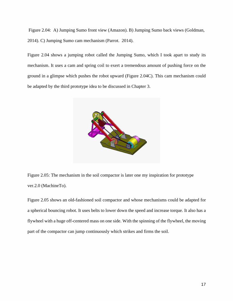
Figure 204 A) Jumping Sumo front view (Amazon) B) Jumping Sumo back views (Goldman
2014) C) Jumping Sumo cam mechanism (Parrot 2014)
Figure 204 shows a jumping robot called the Jumping Sumo which I took apart to study its
mechanism It uses a cam and spring coil to exert a tremendous amount of pushing force on the
ground in a glimpse which pushes the robot upward (Figure 204C) This cam mechanism could
be adapted by the third prototype idea to be discussed in Chapter 3
Figure 205 The mechanism in the soil compactor is later one my inspiration for prototype
ver20 (MachineTo)
Figure 205 shows an old-fashioned soil compactor and whose mechanisms could be adapted for
a spherical bouncing robot It uses belts to lower down the speed and increase torque It also has a
flywheel with a huge off-centered mass on one side With the spinning of the flywheel the moving
part of the compactor can jump continuously which strikes and firms the soil
18
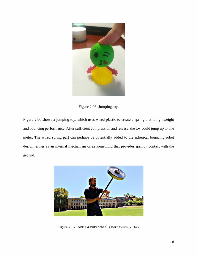
Figure 206 Jumping toy
Figure 206 shows a jumping toy which uses wired plastic to create a spring that is lightweight
and bouncing performance After sufficient compression and release the toy could jump up to one
meter The wired spring part can perhaps be potentially added to the spherical bouncing robot
design either as an internal mechanism or as something that provides springy contact with the
ground
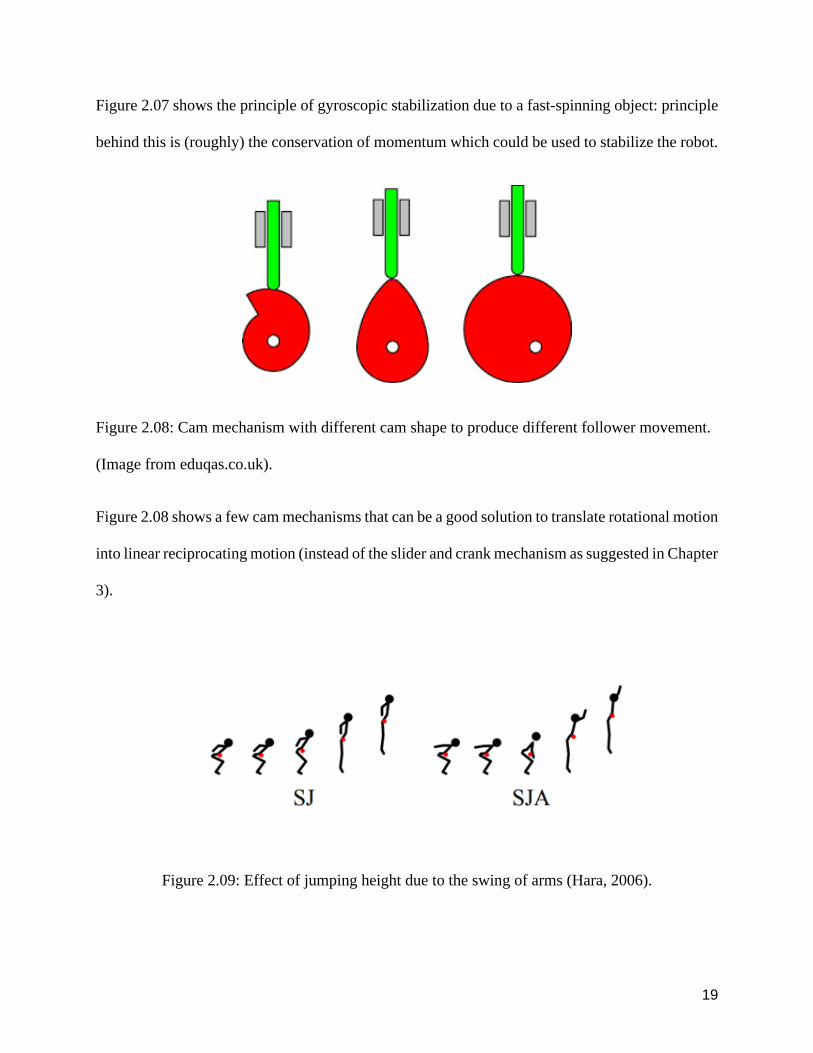
Figure 207 Anti Gravity wheel (Veritasium 2014)
19
Figure 207 shows the principle of gyroscopic stabilization due to a fast-spinning object principle
behind this is (roughly) the conservation of momentum which could be used to stabilize the robot
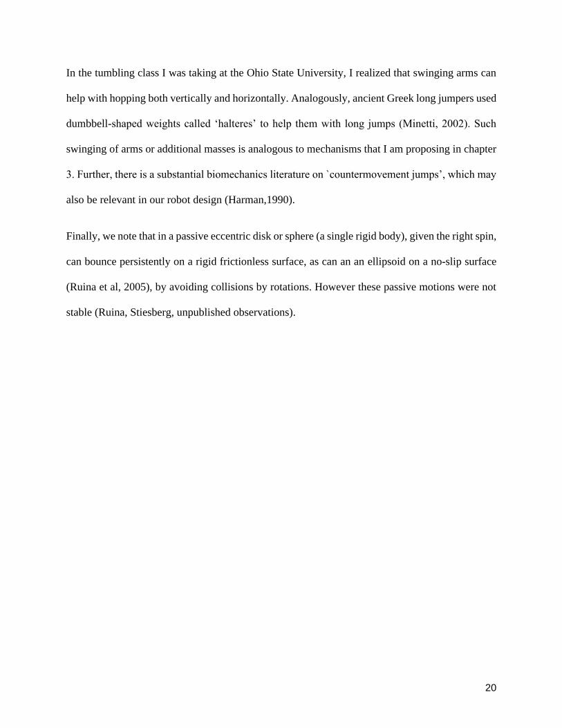
Figure 208 Cam mechanism with different cam shape to produce different follower movement
(Image from eduqascouk)
Figure 208 shows a few cam mechanisms that can be a good solution to translate rotational motion
into linear reciprocating motion (instead of the slider and crank mechanism as suggested in Chapter
3)
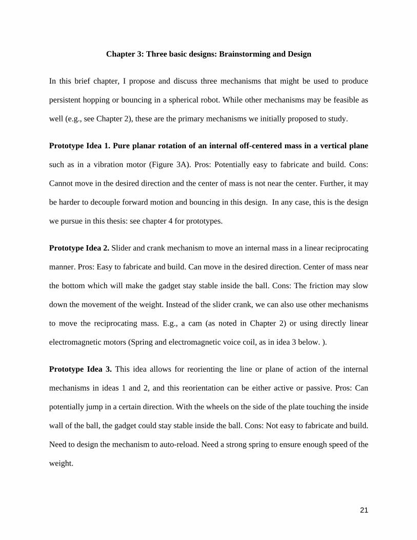
Figure 209 Effect of jumping height due to the swing of arms (Hara 2006)
20
In the tumbling class I was taking at the Ohio State University I realized that swinging arms can
help with hopping both vertically and horizontally Analogously ancient Greek long jumpers used
dumbbell-shaped weights called lsquohalteresrsquo to help them with long jumps (Minetti 2002) Such
swinging of arms or additional masses is analogous to mechanisms that I am proposing in chapter
3 Further there is a substantial biomechanics literature on `countermovement jumpsrsquo which may
also be relevant in our robot design (Harman1990)
Finally we note that in a passive eccentric disk or sphere (a single rigid body) given the right spin
can bounce persistently on a rigid frictionless surface as can an an ellipsoid on a no-slip surface
(Ruina et al 2005) by avoiding collisions by rotations However these passive motions were not
stable (Ruina Stiesberg unpublished observations)
21
Chapter 3 Three basic designs Brainstorming and Design
In this brief chapter I propose and discuss three mechanisms that might be used to produce
persistent hopping or bouncing in a spherical robot While other mechanisms may be feasible as
well (eg see Chapter 2) these are the primary mechanisms we initially proposed to study
Prototype Idea 1 Pure planar rotation of an internal off-centered mass in a vertical plane
such as in a vibration motor (Figure 3A) Pros Potentially easy to fabricate and build Cons
Cannot move in the desired direction and the center of mass is not near the center Further it may
be harder to decouple forward motion and bouncing in this design In any case this is the design
we pursue in this thesis see chapter 4 for prototypes
Prototype Idea 2 Slider and crank mechanism to move an internal mass in a linear reciprocating
manner Pros Easy to fabricate and build Can move in the desired direction Center of mass near
the bottom which will make the gadget stay stable inside the ball Cons The friction may slow
down the movement of the weight Instead of the slider crank we can also use other mechanisms
to move the reciprocating mass Eg a cam (as noted in Chapter 2) or using directly linear
electromagnetic motors (Spring and electromagnetic voice coil as in idea 3 below )
Prototype Idea 3 This idea allows for reorienting the line or plane of action of the internal
mechanisms in ideas 1 and 2 and this reorientation can be either active or passive Pros Can
potentially jump in a certain direction With the wheels on the side of the plate touching the inside
wall of the ball the gadget could stay stable inside the ball Cons Not easy to fabricate and build
Need to design the mechanism to auto-reload Need a strong spring to ensure enough speed of the
weight
22
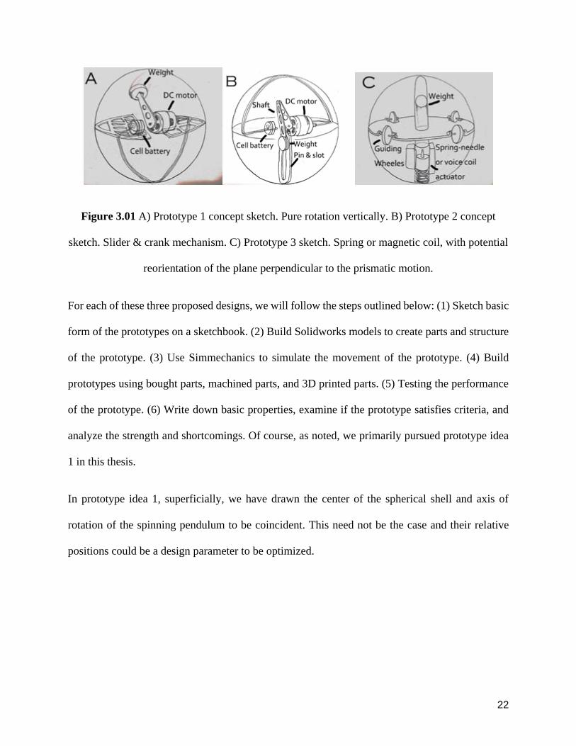
Figure 301 A) Prototype 1 concept sketch Pure rotation vertically B) Prototype 2 concept
sketch Slider amp crank mechanism C) Prototype 3 sketch Spring or magnetic coil with potential
reorientation of the plane perpendicular to the prismatic motion
For each of these three proposed designs we will follow the steps outlined below (1) Sketch basic
form of the prototypes on a sketchbook (2) Build Solidworks models to create parts and structure
of the prototype (3) Use Simmechanics to simulate the movement of the prototype (4) Build
prototypes using bought parts machined parts and 3D printed parts (5) Testing the performance
of the prototype (6) Write down basic properties examine if the prototype satisfies criteria and
analyze the strength and shortcomings Of course as noted we primarily pursued prototype idea
1 in this thesis
In prototype idea 1 superficially we have drawn the center of the spherical shell and axis of
rotation of the spinning pendulum to be coincident This need not be the case and their relative
positions could be a design parameter to be optimized
23
Chapter 4 Fabrication and design iterations
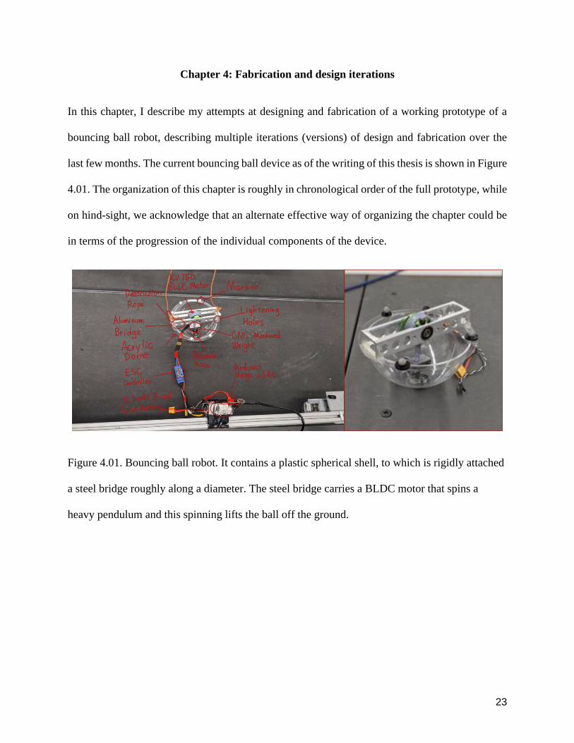
In this chapter I describe my attempts at designing and fabrication of a working prototype of a
bouncing ball robot describing multiple iterations (versions) of design and fabrication over the
last few months The current bouncing ball device as of the writing of this thesis is shown in Figure
401 The organization of this chapter is roughly in chronological order of the full prototype while
on hind-sight we acknowledge that an alternate effective way of organizing the chapter could be
in terms of the progression of the individual components of the device
Figure 401 Bouncing ball robot It contains a plastic spherical shell to which is rigidly attached
a steel bridge roughly along a diameter The steel bridge carries a BLDC motor that spins a
heavy pendulum and this spinning lifts the ball off the ground
24
41 Prototype version 10
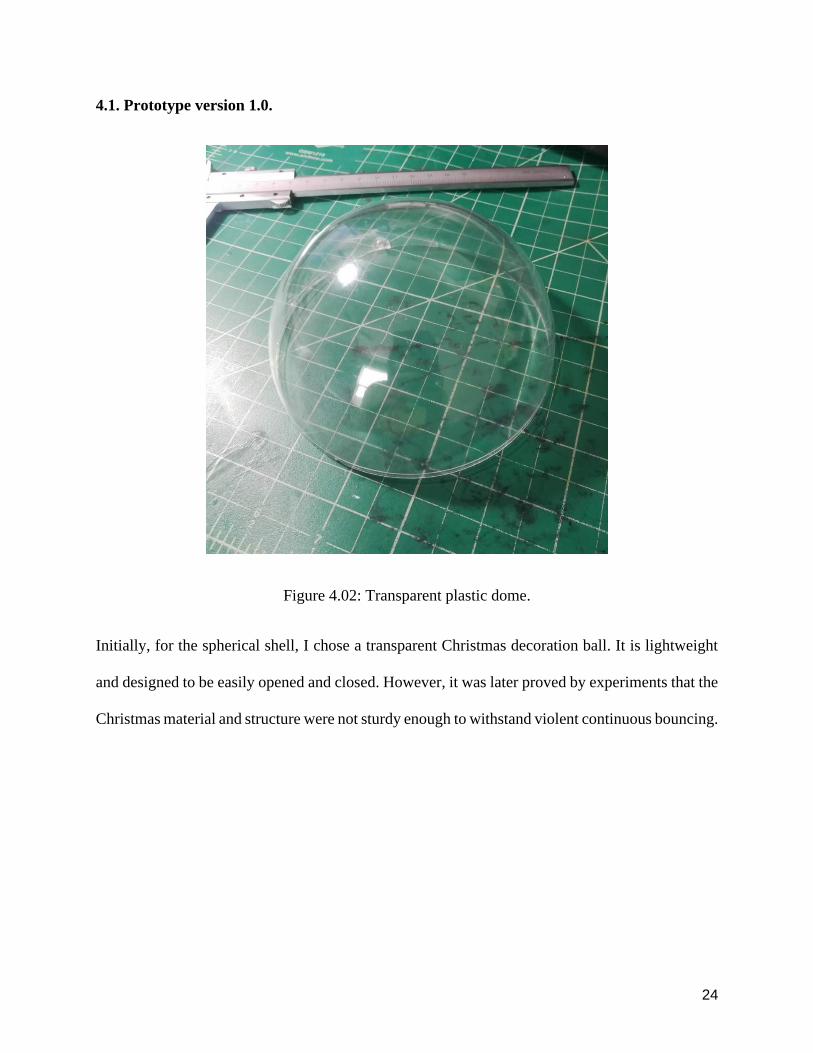
Figure 402 Transparent plastic dome
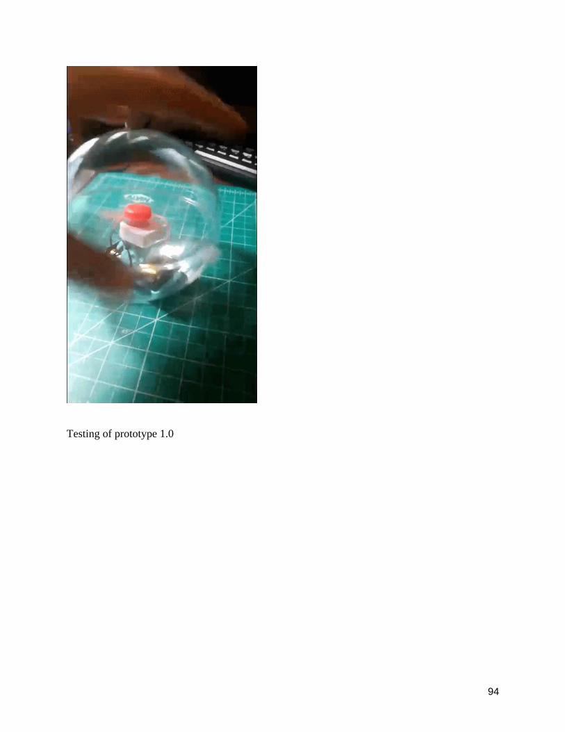
Initially for the spherical shell I chose a transparent Christmas decoration ball It is lightweight
and designed to be easily opened and closed However it was later proved by experiments that the
Christmas material and structure were not sturdy enough to withstand violent continuous bouncing
25
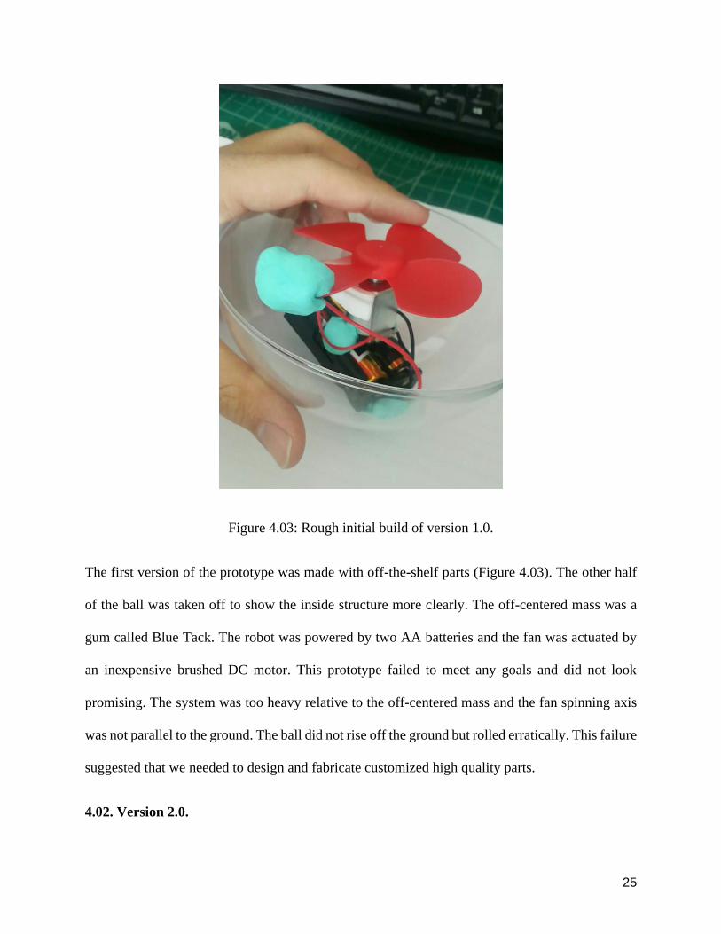
Figure 403 Rough initial build of version 10
The first version of the prototype was made with off-the-shelf parts (Figure 403) The other half
of the ball was taken off to show the inside structure more clearly The off-centered mass was a
gum called Blue Tack The robot was powered by two AA batteries and the fan was actuated by
an inexpensive brushed DC motor This prototype failed to meet any goals and did not look
promising The system was too heavy relative to the off-centered mass and the fan spinning axis
was not parallel to the ground The ball did not rise off the ground but rolled erratically This failure
suggested that we needed to design and fabricate customized high quality parts
402 Version 20
26
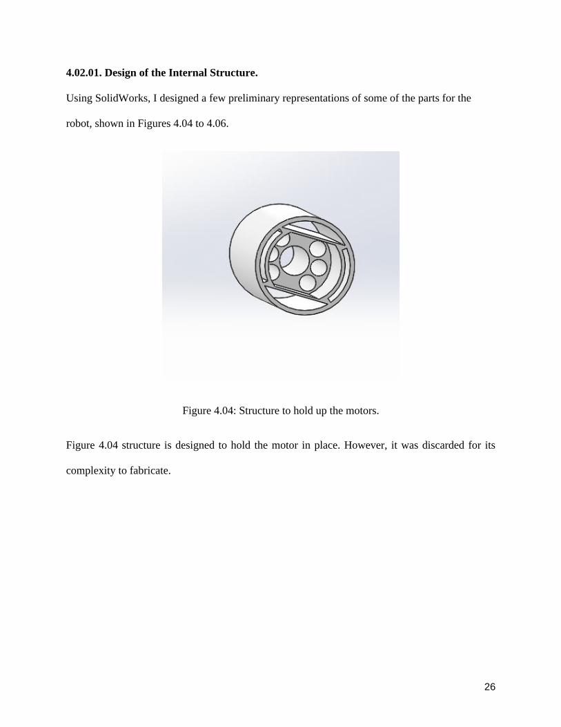
40201 Design of the Internal Structure
Using SolidWorks I designed a few preliminary representations of some of the parts for the
robot shown in Figures 404 to 406
Figure 404 Structure to hold up the motors
Figure 404 structure is designed to hold the motor in place However it was discarded for its
complexity to fabricate
27
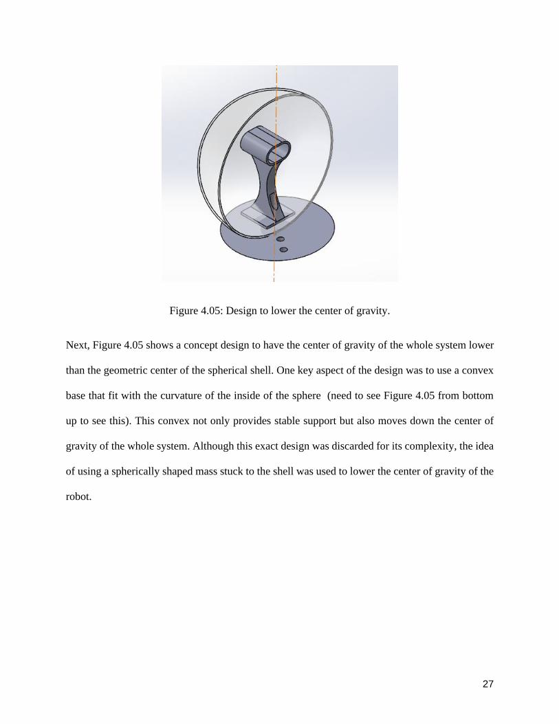
Figure 405 Design to lower the center of gravity
Next Figure 405 shows a concept design to have the center of gravity of the whole system lower
than the geometric center of the spherical shell One key aspect of the design was to use a convex
base that fit with the curvature of the inside of the sphere (need to see Figure 405 from bottom
up to see this) This convex not only provides stable support but also moves down the center of
gravity of the whole system Although this exact design was discarded for its complexity the idea
of using a spherically shaped mass stuck to the shell was used to lower the center of gravity of the
robot
28
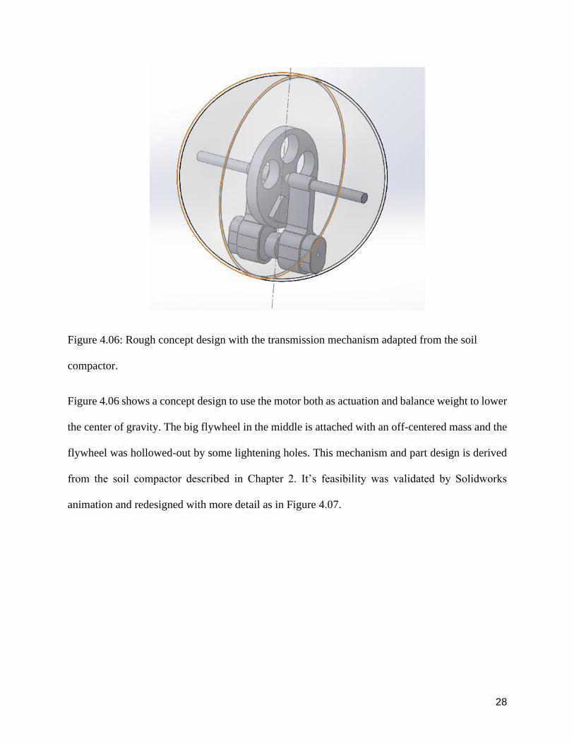
Figure 406 Rough concept design with the transmission mechanism adapted from the soil
compactor
Figure 406 shows a concept design to use the motor both as actuation and balance weight to lower
the center of gravity The big flywheel in the middle is attached with an off-centered mass and the
flywheel was hollowed-out by some lightening holes This mechanism and part design is derived
from the soil compactor described in Chapter 2 Itrsquos feasibility was validated by Solidworks
animation and redesigned with more detail as in Figure 407
29
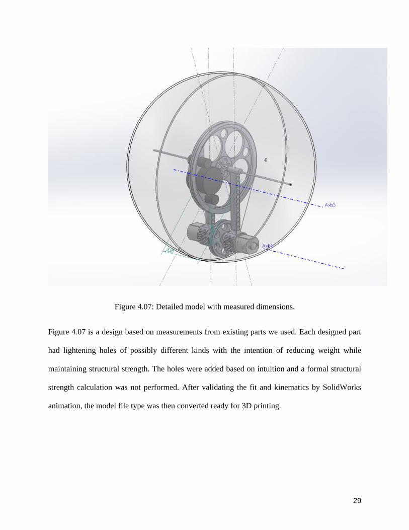
Figure 407 Detailed model with measured dimensions
Figure 407 is a design based on measurements from existing parts we used Each designed part
had lightening holes of possibly different kinds with the intention of reducing weight while
maintaining structural strength The holes were added based on intuition and a formal structural
strength calculation was not performed After validating the fit and kinematics by SolidWorks
animation the model file type was then converted ready for 3D printing
30
40202 3D Printing the Internal Structure
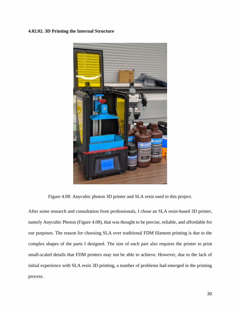
Figure 408 Anycubic photon 3D printer and SLA resin used in this project
After some research and consultation from professionals I chose an SLA resin-based 3D printer
namely Anycubic Photon (Figure 408) that was thought to be precise reliable and affordable for
our purposes The reason for choosing SLA over traditional FDM filament printing is due to the
complex shapes of the parts I designed The size of each part also requires the printer to print
small-scaled details that FDM printers may not be able to achieve However due to the lack of
initial experience with SLA resin 3D printing a number of problems had emerged in the printing
process
31
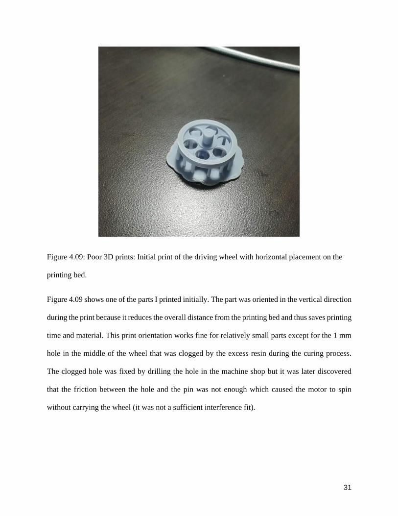
Figure 409 Poor 3D prints Initial print of the driving wheel with horizontal placement on the
printing bed
Figure 409 shows one of the parts I printed initially The part was oriented in the vertical direction
during the print because it reduces the overall distance from the printing bed and thus saves printing
time and material This print orientation works fine for relatively small parts except for the 1 mm
hole in the middle of the wheel that was clogged by the excess resin during the curing process
The clogged hole was fixed by drilling the hole in the machine shop but it was later discovered
that the friction between the hole and the pin was not enough which caused the motor to spin
without carrying the wheel (it was not a sufficient interference fit)
32
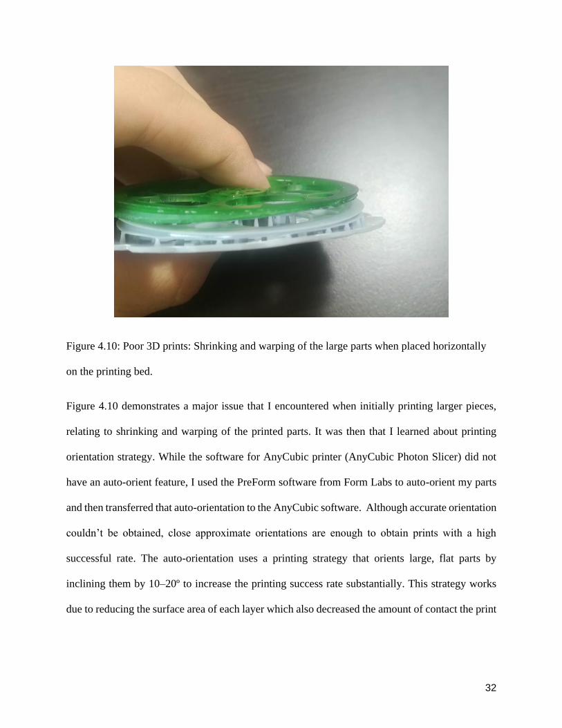
Figure 410 Poor 3D prints Shrinking and warping of the large parts when placed horizontally
on the printing bed
Figure 410 demonstrates a major issue that I encountered when initially printing larger pieces
relating to shrinking and warping of the printed parts It was then that I learned about printing
orientation strategy While the software for AnyCubic printer (AnyCubic Photon Slicer) did not
have an auto-orient feature I used the PreForm software from Form Labs to auto-orient my parts
and then transferred that auto-orientation to the AnyCubic software Although accurate orientation
couldnrsquot be obtained close approximate orientations are enough to obtain prints with a high
successful rate The auto-orientation uses a printing strategy that orients large flat parts by
inclining them by 10ndash20ordm to increase the printing success rate substantially This strategy works
due to reducing the surface area of each layer which also decreased the amount of contact the print
33
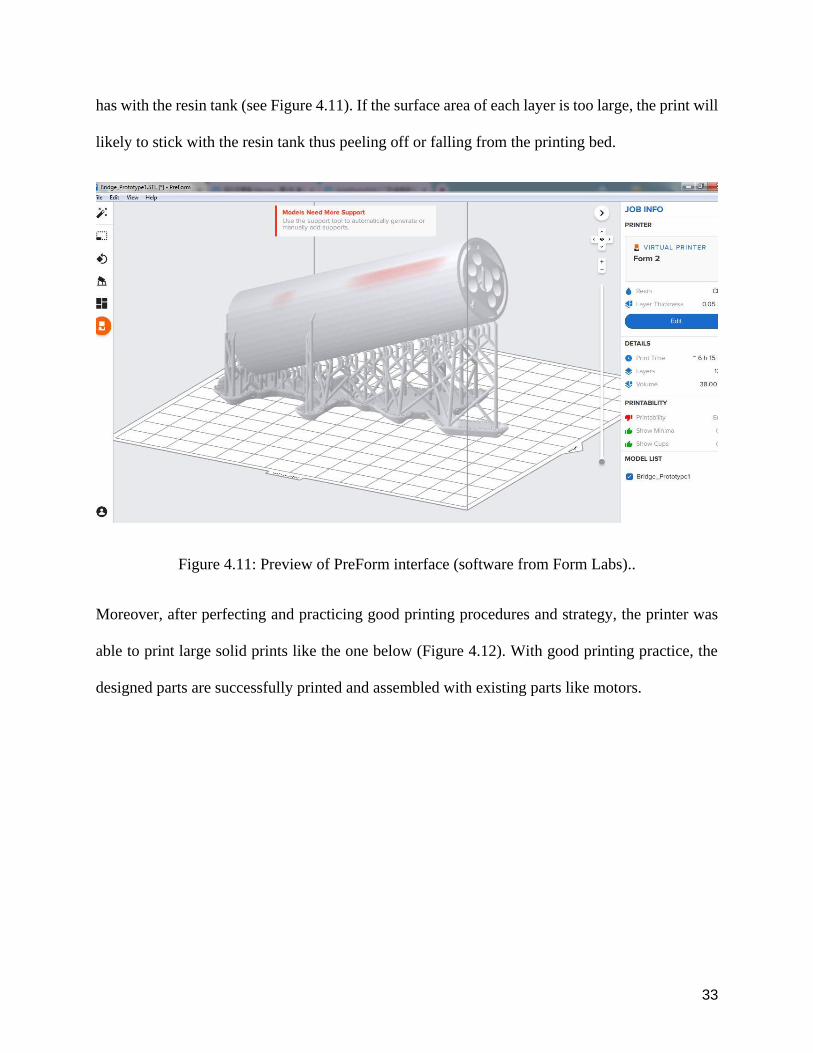
has with the resin tank (see Figure 411) If the surface area of each layer is too large the print will
likely to stick with the resin tank thus peeling off or falling from the printing bed
Figure 411 Preview of PreForm interface (software from Form Labs)
Moreover after perfecting and practicing good printing procedures and strategy the printer was
able to print large solid prints like the one below (Figure 412) With good printing practice the
designed parts are successfully printed and assembled with existing parts like motors
34
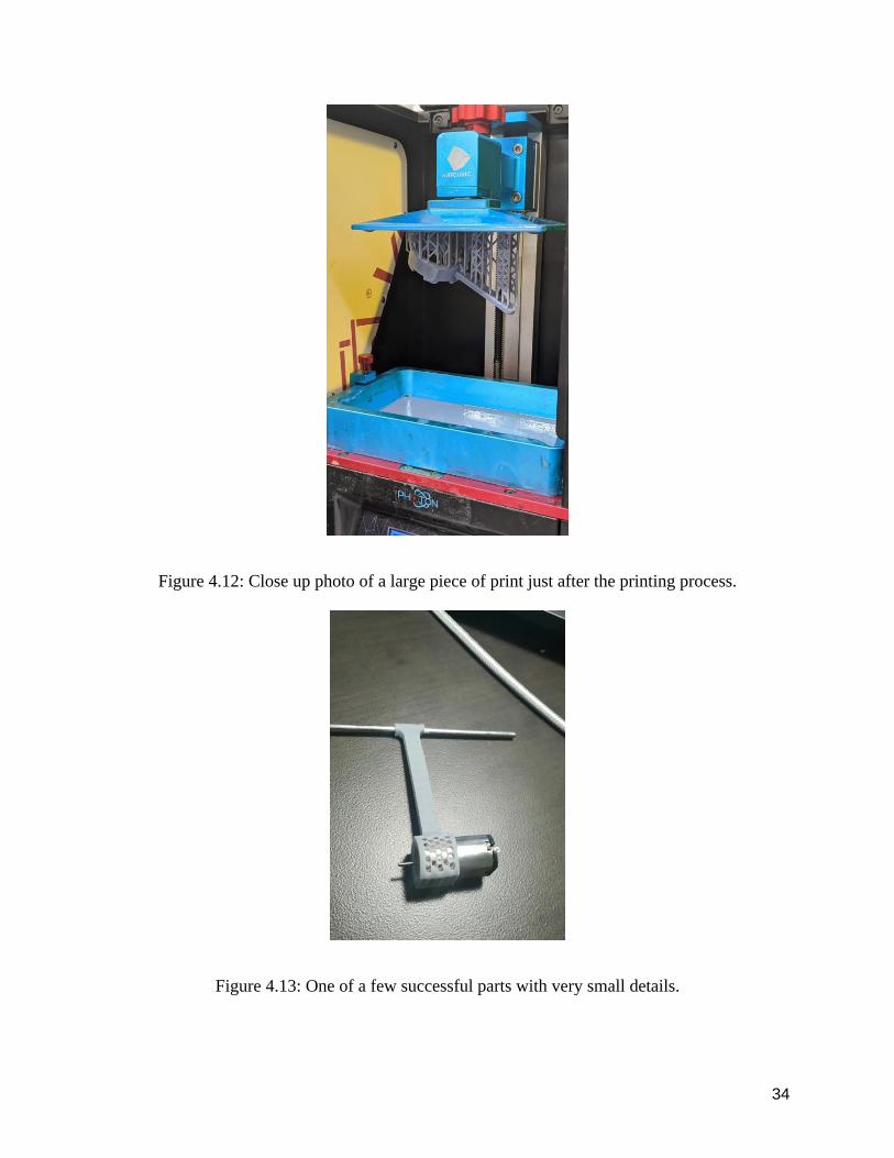
Figure 412 Close up photo of a large piece of print just after the printing process
Figure 413 One of a few successful parts with very small details
35
The motor I bought was an N20 DC motor This DC motor has a larger power vs weight ratio than
a regular DC motor Figure 413 shows the motor along with the pendulum part it is attached to
The grid size on the printed part (Figure 413) was in millimeter-scale but the printer was still able
to print and maintain its integrity
Figure 414 Testing the core mechanism
Due to the resin curing process by ultraviolet light the print will shrink in some areas afterward
Therefore I experimented with the tolerance of the sizes of holes in order to let it fit with existing
36
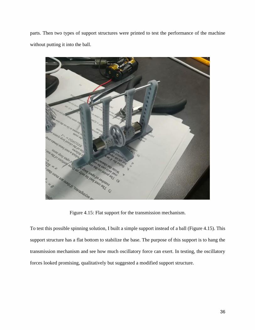
parts Then two types of support structures were printed to test the performance of the machine
without putting it into the ball
Figure 415 Flat support for the transmission mechanism
To test this possible spinning solution I built a simple support instead of a ball (Figure 415) This
support structure has a flat bottom to stabilize the base The purpose of this support is to hang the
transmission mechanism and see how much oscillatory force can exert In testing the oscillatory
forces looked promising qualitatively but suggested a modified support structure
37
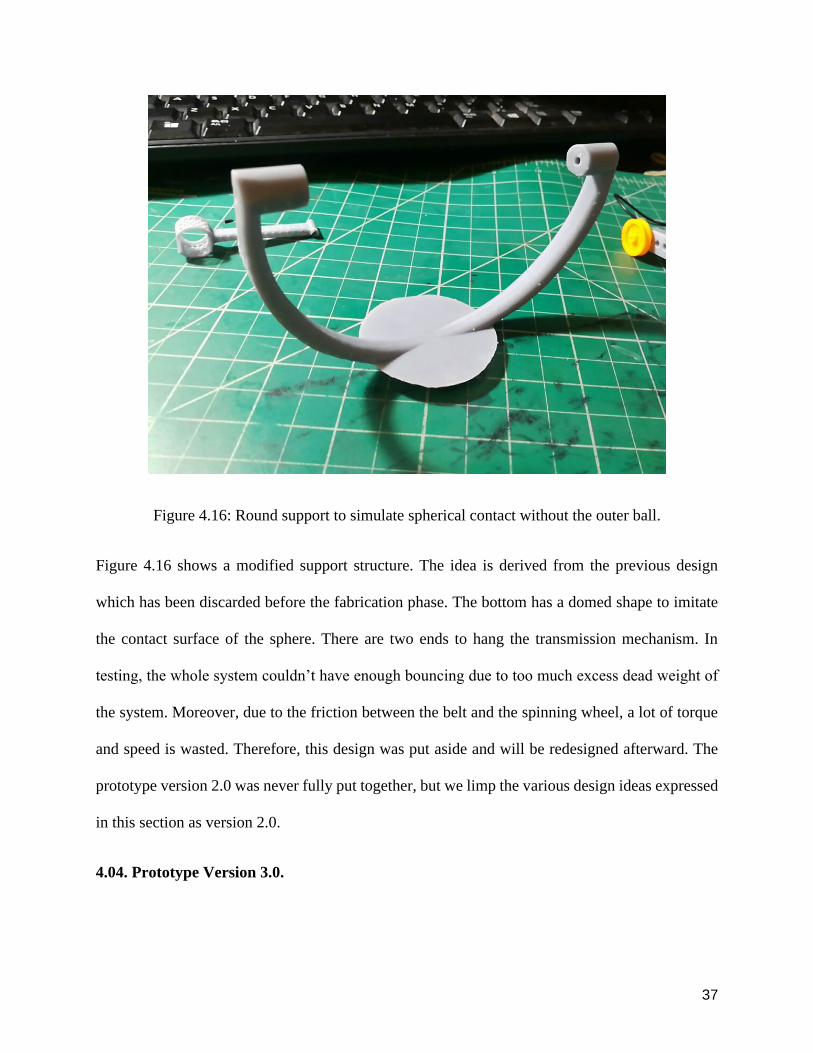
Figure 416 Round support to simulate spherical contact without the outer ball
Figure 416 shows a modified support structure The idea is derived from the previous design
which has been discarded before the fabrication phase The bottom has a domed shape to imitate
the contact surface of the sphere There are two ends to hang the transmission mechanism In
testing the whole system couldnrsquot have enough bouncing due to too much excess dead weight of
the system Moreover due to the friction between the belt and the spinning wheel a lot of torque
and speed is wasted Therefore this design was put aside and will be redesigned afterward The
prototype version 20 was never fully put together but we limp the various design ideas expressed
in this section as version 20
404 Prototype Version 30
38
Due partly to the complexity and poor robustness of the designs in version 20 after discussions
with my advisor Professor Manoj Srinivasan I switched back to the initial idea of a simple
spinning mass for prototype version 30
40401 Further Candidates for the Outer Shell
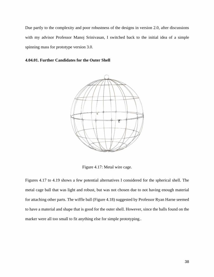
Figure 417 Metal wire cage
Figures 417 to 419 shows a few potential alternatives I considered for the spherical shell The
metal cage ball that was light and robust but was not chosen due to not having enough material
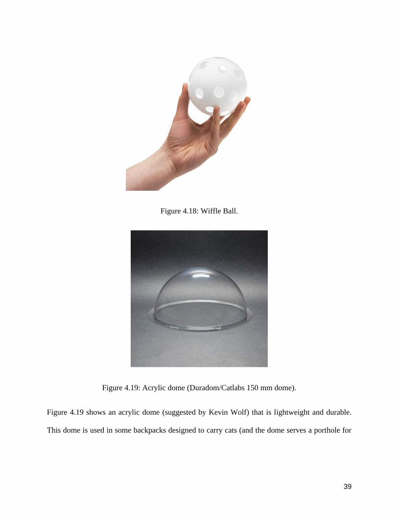
for attaching other parts The wiffle ball (Figure 418) suggested by Professor Ryan Harne seemed
to have a material and shape that is good for the outer shell However since the balls found on the
marker were all too small to fit anything else for simple prototyping
39
Figure 418 Wiffle Ball
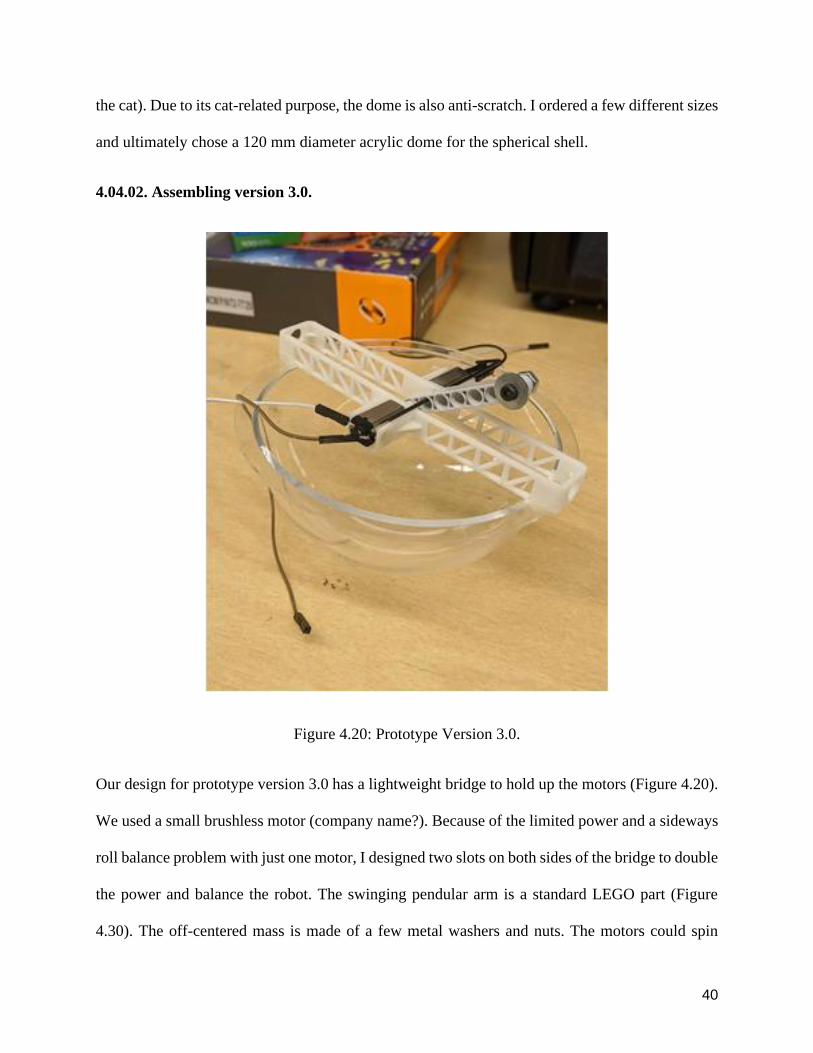
Figure 419 Acrylic dome (DuradomCatlabs 150 mm dome)
Figure 419 shows an acrylic dome (suggested by Kevin Wolf) that is lightweight and durable
This dome is used in some backpacks designed to carry cats (and the dome serves a porthole for
40
the cat) Due to its cat-related purpose the dome is also anti-scratch I ordered a few different sizes
and ultimately chose a 120 mm diameter acrylic dome for the spherical shell
40402 Assembling version 30
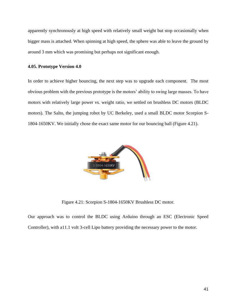
Figure 420 Prototype Version 30
Our design for prototype version 30 has a lightweight bridge to hold up the motors (Figure 420)
We used a small brushless motor (company name) Because of the limited power and a sideways
roll balance problem with just one motor I designed two slots on both sides of the bridge to double
the power and balance the robot The swinging pendular arm is a standard LEGO part (Figure
430) The off-centered mass is made of a few metal washers and nuts The motors could spin
41
apparently synchronously at high speed with relatively small weight but stop occasionally when
bigger mass is attached When spinning at high speed the sphere was able to leave the ground by
around 3 mm which was promising but perhaps not significant enough
405 Prototype Version 40
In order to achieve higher bouncing the next step was to upgrade each component The most
obvious problem with the previous prototype is the motorsrsquo ability to swing large masses To have
motors with relatively large power vs weight ratio we settled on brushless DC motors (BLDC
motors) The Salto the jumping robot by UC Berkeley used a small BLDC motor Scorpion S-
1804-1650KV We initially chose the exact same motor for our bouncing ball (Figure 421)
Figure 421 Scorpion S-1804-1650KV Brushless DC motor
Our approach was to control the BLDC using Arduino through an ESC (Electronic Speed
Controller) with a111 volt 3-cell Lipo battery providing the necessary power to the motor
42
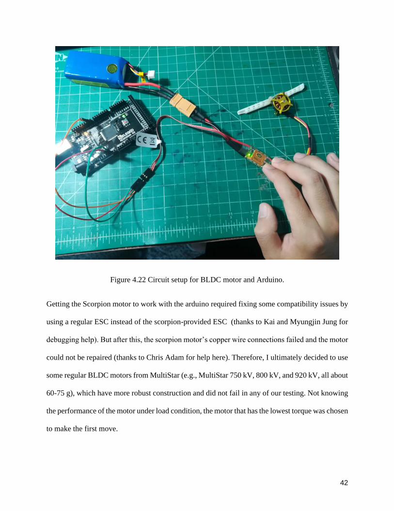
Figure 422 Circuit setup for BLDC motor and Arduino
Getting the Scorpion motor to work with the arduino required fixing some compatibility issues by
using a regular ESC instead of the scorpion-provided ESC (thanks to Kai and Myungjin Jung for
debugging help) But after this the scorpion motorrsquos copper wire connections failed and the motor
could not be repaired (thanks to Chris Adam for help here) Therefore I ultimately decided to use
some regular BLDC motors from MultiStar (eg MultiStar 750 kV 800 kV and 920 kV all about
60-75 g) which have more robust construction and did not fail in any of our testing Not knowing
the performance of the motor under load condition the motor that has the lowest torque was chosen
to make the first move
43
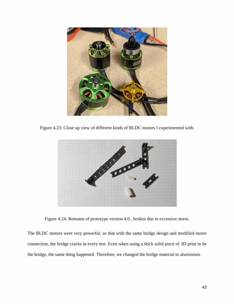
Figure 423 Close up view of different kinds of BLDC motors I experimented with
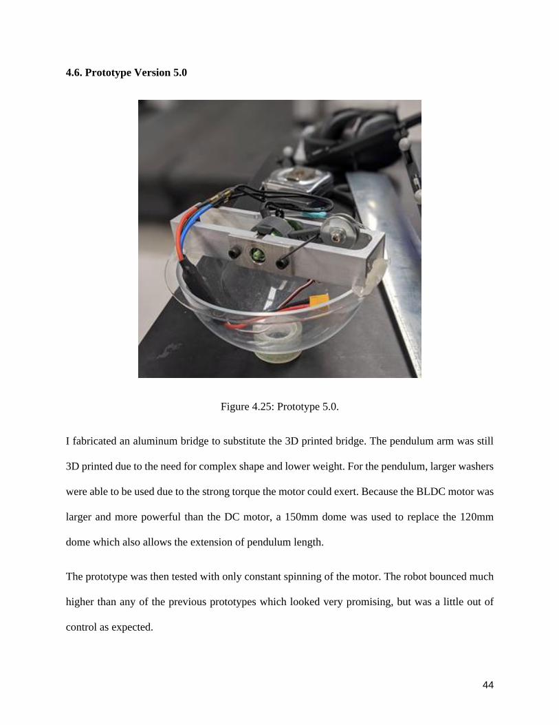
Figure 424 Remains of prototype version 40 broken due to excessive stress
The BLDC motors were very powerful so that with the same bridge design and modified motor
connection the bridge cracks in every test Even when using a thick solid piece of 3D print to be
the bridge the same thing happened Therefore we changed the bridge material to aluminium
44
46 Prototype Version 50
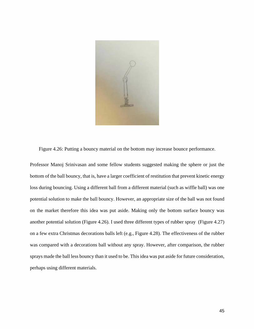
Figure 425 Prototype 50
I fabricated an aluminum bridge to substitute the 3D printed bridge The pendulum arm was still
3D printed due to the need for complex shape and lower weight For the pendulum larger washers
were able to be used due to the strong torque the motor could exert Because the BLDC motor was
larger and more powerful than the DC motor a 150mm dome was used to replace the 120mm
dome which also allows the extension of pendulum length
The prototype was then tested with only constant spinning of the motor The robot bounced much
higher than any of the previous prototypes which looked very promising but was a little out of
control as expected
45
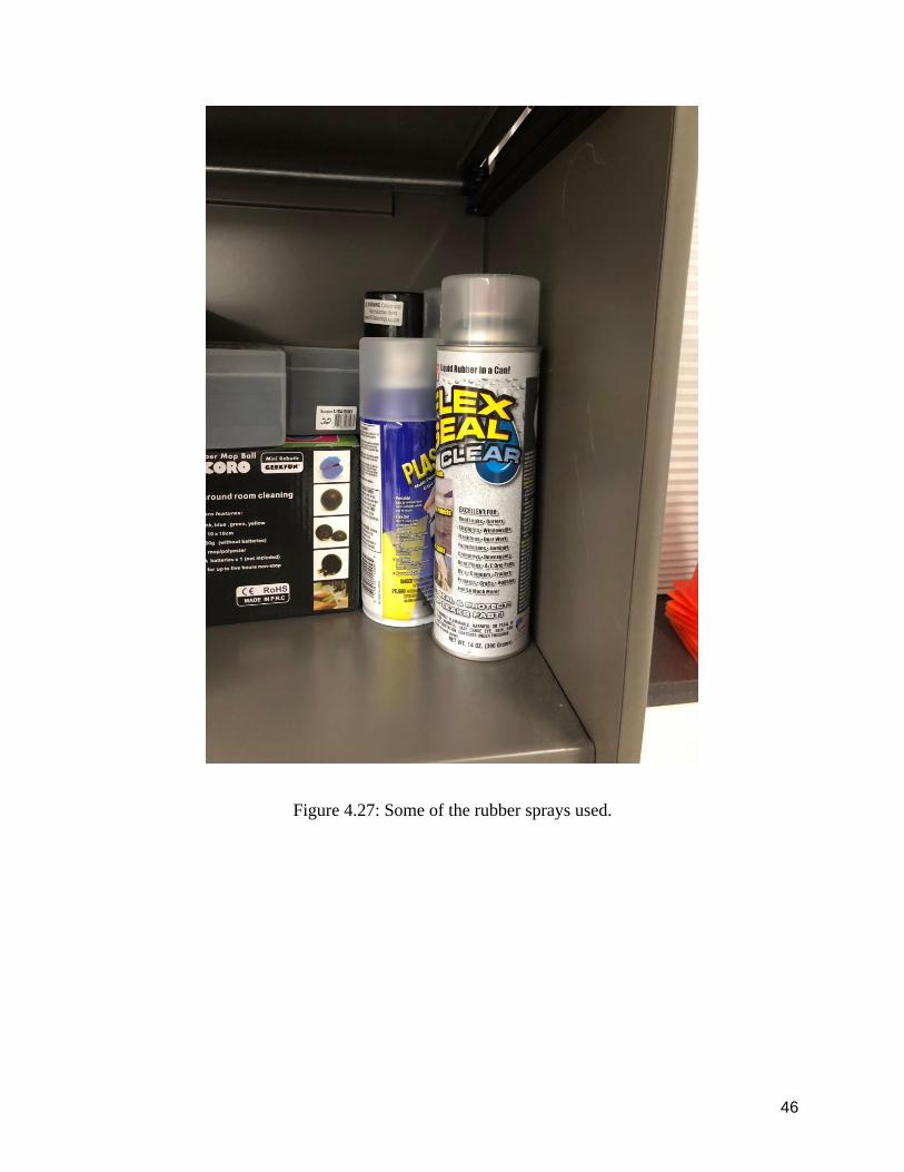
Figure 426 Putting a bouncy material on the bottom may increase bounce performance
Professor Manoj Srinivasan and some fellow students suggested making the sphere or just the
bottom of the ball bouncy that is have a larger coefficient of restitution that prevent kinetic energy
loss during bouncing Using a different ball from a different material (such as wiffle ball) was one
potential solution to make the ball bouncy However an appropriate size of the ball was not found
on the market therefore this idea was put aside Making only the bottom surface bouncy was
another potential solution (Figure 426) I used three different types of rubber spray (Figure 427)
on a few extra Christmas decorations balls left (eg Figure 428) The effectiveness of the rubber
was compared with a decorations ball without any spray However after comparison the rubber
sprays made the ball less bouncy than it used to be This idea was put aside for future consideration
perhaps using different materials
46
Figure 427 Some of the rubber sprays used
47
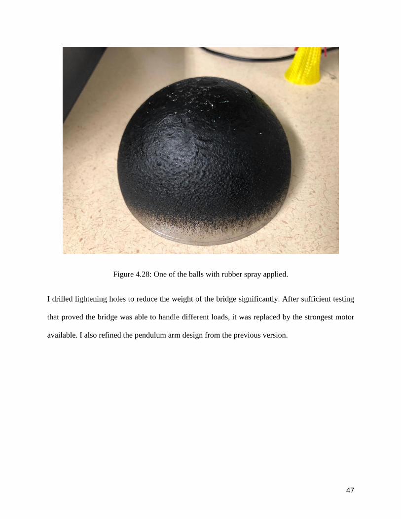
Figure 428 One of the balls with rubber spray applied
I drilled lightening holes to reduce the weight of the bridge significantly After sufficient testing
that proved the bridge was able to handle different loads it was replaced by the strongest motor
available I also refined the pendulum arm design from the previous version
48
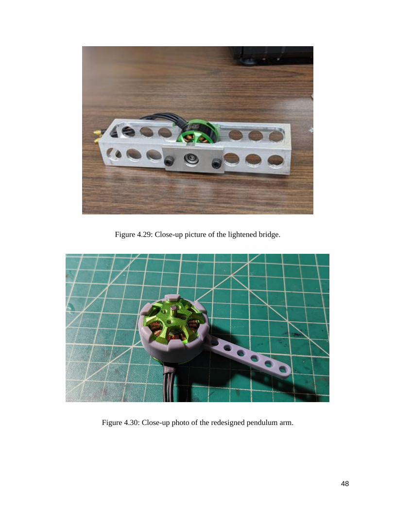
Figure 429 Close-up picture of the lightened bridge
Figure 430 Close-up photo of the redesigned pendulum arm
49
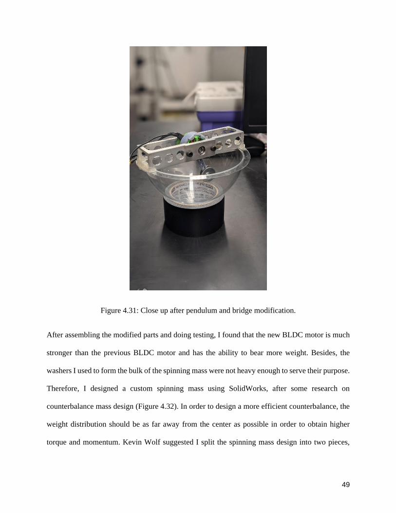
Figure 431 Close up after pendulum and bridge modification
After assembling the modified parts and doing testing I found that the new BLDC motor is much
stronger than the previous BLDC motor and has the ability to bear more weight Besides the
washers I used to form the bulk of the spinning mass were not heavy enough to serve their purpose
Therefore I designed a custom spinning mass using SolidWorks after some research on
counterbalance mass design (Figure 432) In order to design a more efficient counterbalance the
weight distribution should be as far away from the center as possible in order to obtain higher
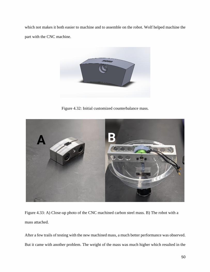
torque and momentum Kevin Wolf suggested I split the spinning mass design into two pieces
50
which not makes it both easier to machine and to assemble on the robot Wolf helped machine the
part with the CNC machine
Figure 432 Initial customized counterbalance mass
Figure 433 A) Close-up photo of the CNC machined carbon steel mass B) The robot with a
mass attached
After a few trails of testing with the new machined mass a much better performance was observed
But it came with another problem The weight of the mass was much higher which resulted in the
51
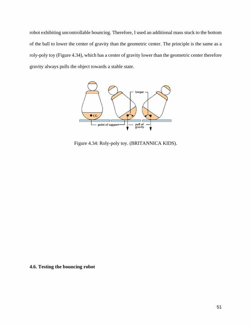
robot exhibiting uncontrollable bouncing Therefore I used an additional mass stuck to the bottom
of the ball to lower the center of gravity than the geometric center The principle is the same as a
roly-poly toy (Figure 434) which has a center of gravity lower than the geometric center therefore
gravity always pulls the object towards a stable state
Figure 434 Roly-poly toy (BRITANNICA KIDS)
46 Testing the bouncing robot
52
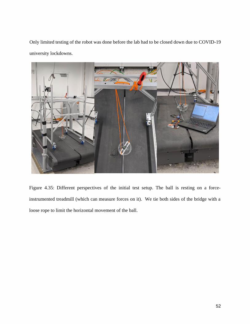
Only limited testing of the robot was done before the lab had to be closed down due to COVID-19
university lockdowns
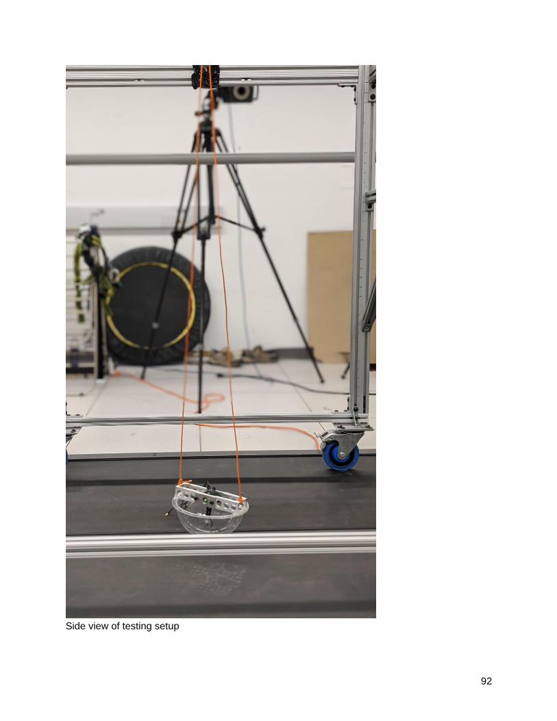
Figure 435 Different perspectives of the initial test setup The ball is resting on a force-
instrumented treadmill (which can measure forces on it) We tie both sides of the bridge with a
loose rope to limit the horizontal movement of the ball
53
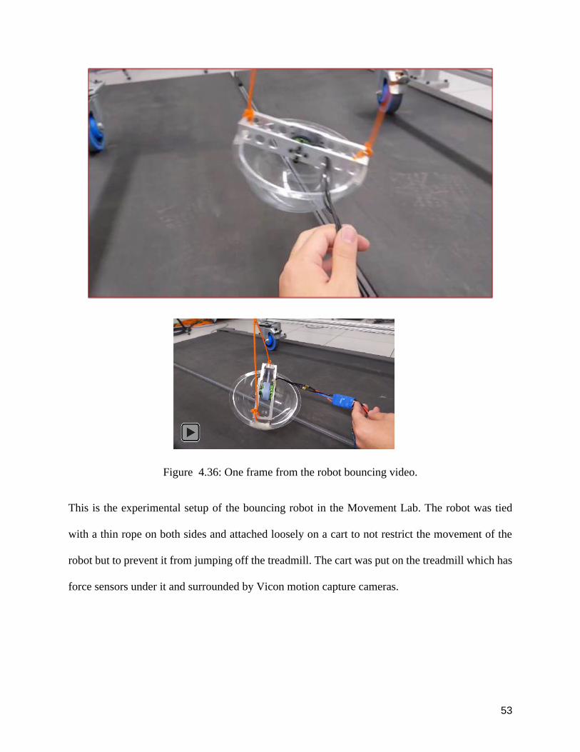
Figure 436 One frame from the robot bouncing video
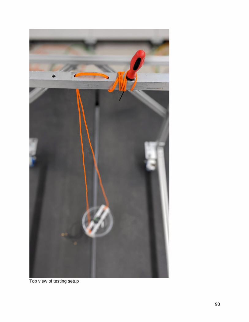
This is the experimental setup of the bouncing robot in the Movement Lab The robot was tied
with a thin rope on both sides and attached loosely on a cart to not restrict the movement of the
robot but to prevent it from jumping off the treadmill The cart was put on the treadmill which has
force sensors under it and surrounded by Vicon motion capture cameras
54
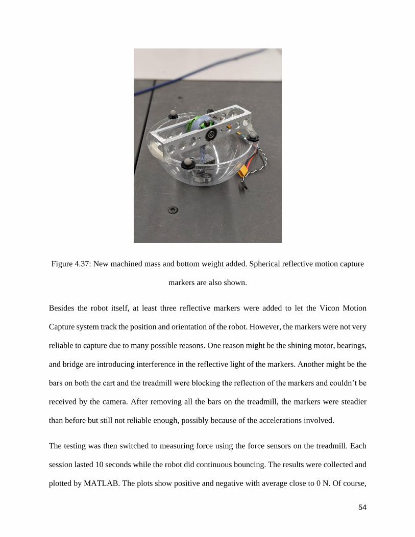
Figure 437 New machined mass and bottom weight added Spherical reflective motion capture
markers are also shown
Besides the robot itself at least three reflective markers were added to let the Vicon Motion
Capture system track the position and orientation of the robot However the markers were not very
reliable to capture due to many possible reasons One reason might be the shining motor bearings
and bridge are introducing interference in the reflective light of the markers Another might be the
bars on both the cart and the treadmill were blocking the reflection of the markers and couldnrsquot be
received by the camera After removing all the bars on the treadmill the markers were steadier
than before but still not reliable enough possibly because of the accelerations involved
The testing was then switched to measuring force using the force sensors on the treadmill Each
session lasted 10 seconds while the robot did continuous bouncing The results were collected and
plotted by MATLAB The plots show positive and negative with average close to 0 N Of course
55
negative normal reaction forces (downward forces) from the treadmill are not possible No such
negative forces are seen during the treadmillrsquos normal function for biomechanics experiments
such as walking It is likely that this phenomenon of qualitatively incorrect forces reported by the
treadmill is due to the fast time-scale of the impact forces on the treadmill (say happening over a
small duration ΔT) and the treadmill may have a lowest natural frequency that is smaller than
1(ΔT) that is the treadmill vibration dynamics specifically the treadmill ldquobouncing backrdquo or
ldquoringingrdquo may create these negative forces In order to validate that hypothesis I used a tripod and
stab the treadmill to achieve a sharp force stroke The result shows a similar pattern to the bouncing
data Although this experiment was put aside for further consideration it was discovered that the
treadmill originally used to measure the force of peoplersquos feet walking was not able to capture
fast time-scale impact forces accurately It may be possible to fix this issue by performing a
`system identificationrsquo of the treadmill (that is model it as a mass-spring-damper system) and then
infer the actual forces that are consistent with the reported forces or vibration The data and plots
could not be displayed in this thesis due to lab closure
56
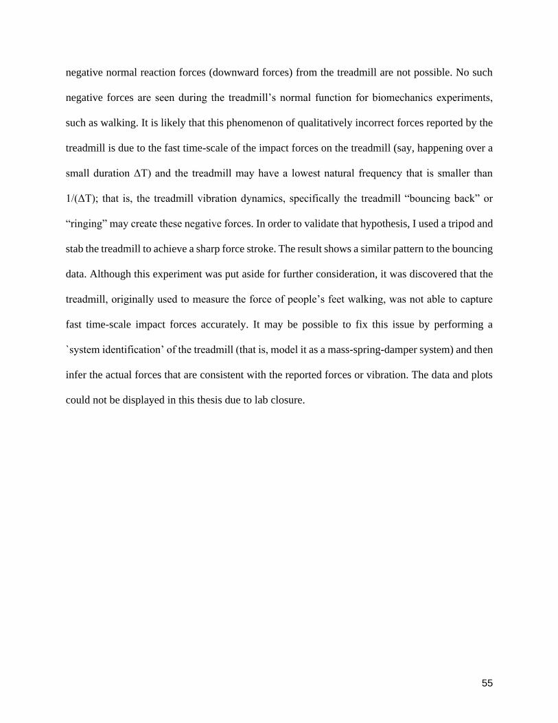
Figure 438 Improvised testing assembly
Due to time and budget constraints the power and control circuit was improvised with a battery
and an Arduino board wrapped on the beam of the cart by duct tape rather than incorporating them
within the ball or have a more polished finish The connection between each port was also
reinforced by duct tape to prevent tears
57
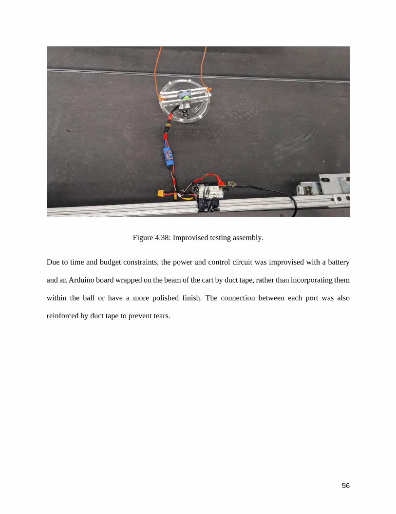
Figure 439 Using a tachometer to measure the speed of the pendulum under different power
outputs
58
Due to the mass attached to the motor the motor had a much lower loaded speed compared to the
speed setting with the mass attached Using the borrowed tachometer from the measurement lab
along with a tripod (Figure 439) the actual revolution speed was measured for multiple speed
settings The arduino ESC servo library allowed speed values from 55 to 57 where 55 was the
lowest speed value At the lowest speed setting of 55 we measured a corresponding speed of 130-
140 rotations per minute and a speed setting of 57 corresponded to 150-160 RPM This test was to
have a benchmark to have a rough estimate of the speed under load At these lowest spinning
speeds the ball bouncing was already a few centimeters and seemed uncontrollable so we did not
test higher spinning speeds
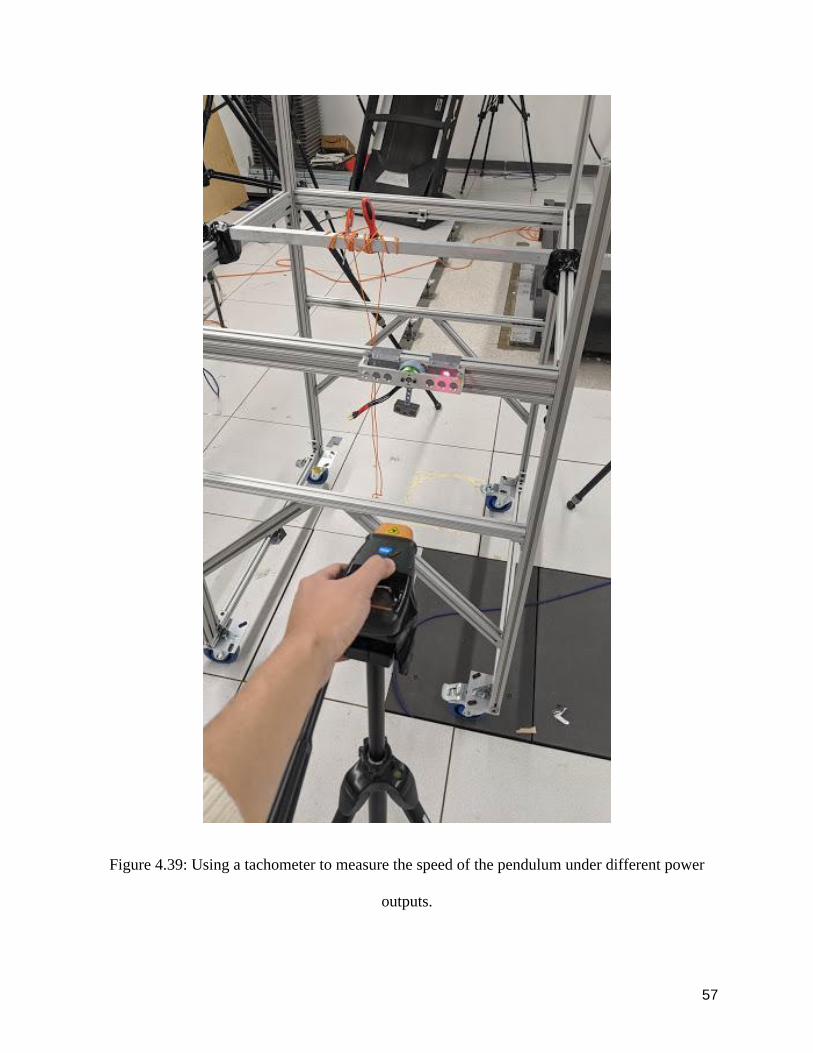
Figure 440 Broken arm parts copies and a modified arm part thicker and without lightening
holes to avoid failure in future runs
During testing the arm part of the pendulum broke three times (Figure 440) The two broken parts
both broke in the rim and the intersection of the rim and arm The breaking of the arm was a critical
failure of the part The failing point was always near a cross-section with a lightning hole where
the cross-sectional area was the least The failures were also close to the base of the pendular arm
59
where the ldquocentrifugal forcesrdquo of spinning the mass would be largest and perhaps also enhanced
due to stress concentration To prevent such failure I decided to eliminate the holes The weight
is a primary concern for this part compared to the overall weight of the robot and it is more
important to prevent mechanical failure In some cases the circular part holding the motor also
cracked likely due to insufficient clearance with the motor and this issue was solved by increasing
the diameter of the rim
In addition to spinning the motor at a constant speed I also tried to modify the Arduino code to
achieve a better spinning pattern my goal was to alternatingly spin the motor and then stop the
motor for a very short amount of time and restart soon after Due to the nature of the BLDC motor
the motor could not be brought to a complete stop immediately during the spinning process thus
a longer ldquostoprdquo time was needed Eventually the following simple code was used to vary the speed
of the motor within a cycle alternating between powering the motor (ESCwrite(55)) and letting
the motor coast (ESCwrite(0))
void loop()
ESCwrite(55)
delay(100)
ESCwrite(0) or ESCwrite(50)
delay(500)
60
Unfortunately due to lab closures we did not experiment further with this strategy of altering the
speed of the pendulum within a cycle to achieve better bounce performance and better control of
the bouncing ball
61
Chapter 5 3D Computer Simulation and Controller Testing
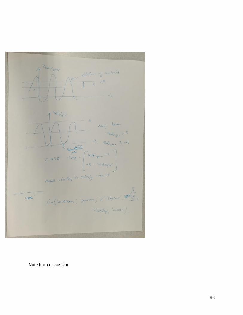
Before formally doing computer simulations of the bouncing ball I outlined a way by which the
ball would bounce continuously hypothesized a spinning and bouncing spinning and bouncing
synchronization pattern See Appendix A for some early conceptual drawings and some simple
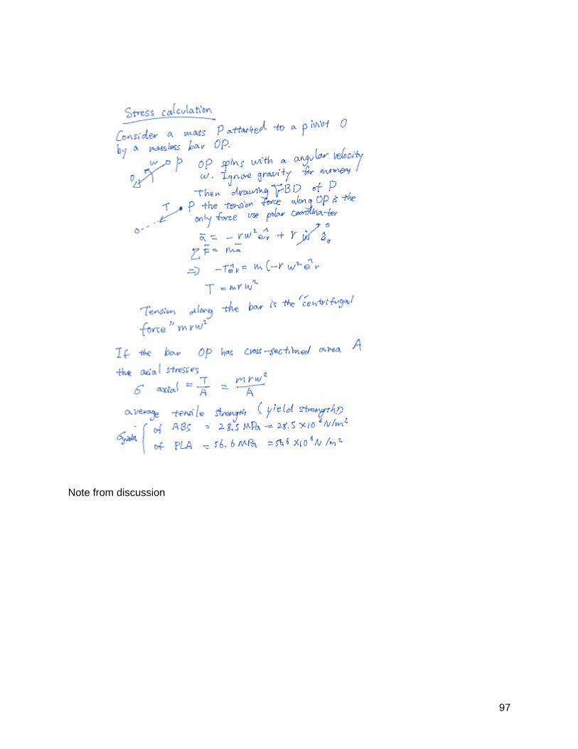
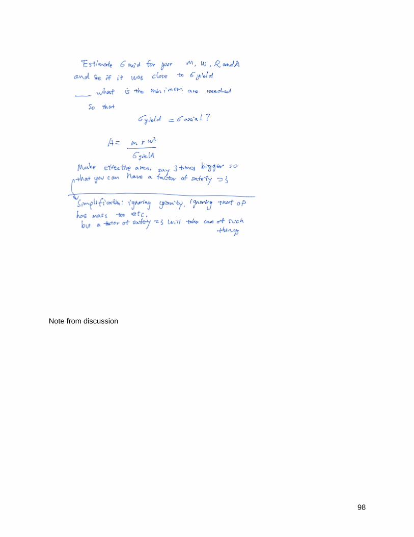
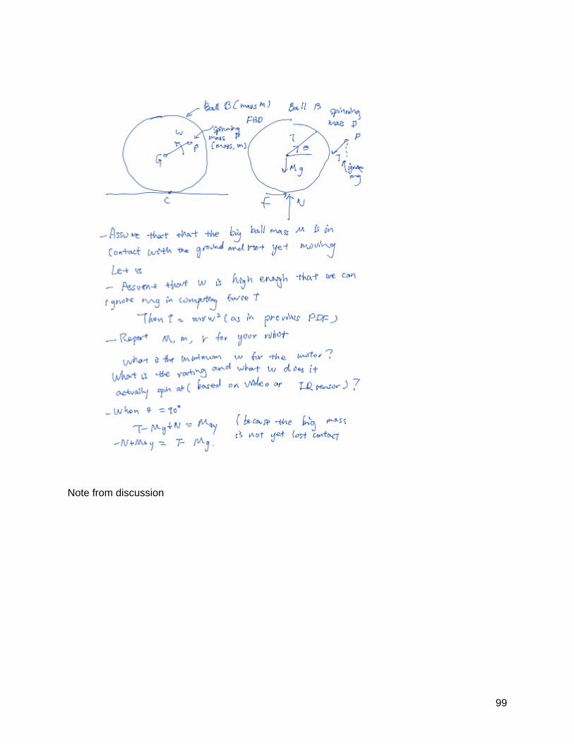
calculations for the minimal conditions on the spin angular velocity for sphere take-off The basic
idea of the bouncing ball is that a spinning mass requires a centripetal force when this centripetal
force is downward on the spinning mass the equal and opposite reaction on the spherical shell is
upward and it can produce an upward force to lift the shell off the ground
A variety of software is used in academia and industry for simulating 3D multibody dynamics for
instance Co-sim Adams Design Simulation Technologies MATLABrsquos Simscape etc Of course
one can also directly write the equations of motion and solve the differential equations for
instance using ode45 in MATLAB Here we used the Algodoo MATLAB and Simscape
Multibody to make progress on building a computer simulation of the bouncing ball robot
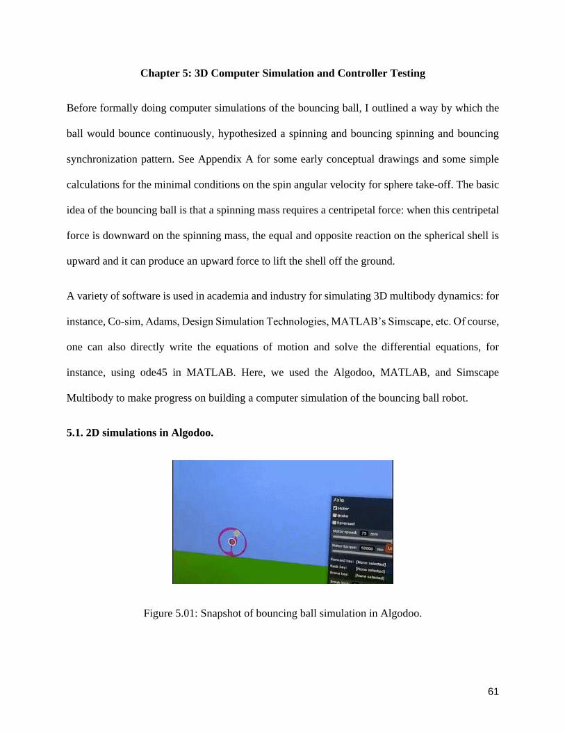
51 2D simulations in Algodoo
Figure 501 Snapshot of bouncing ball simulation in Algodoo
62
Algodoo is a simple easy-to-use software that can do various 2D physics-based dynamic
simulations with rough sketches it also has simple ways of actuating parts (eg motors and gears)
and can simulate contact bouncing and even simple fluid mechanics The program used to create
simple games is simple enough that one can set up a multibody simulation in less than two
minutes
I created a circular disk (representing the ball) hollowed the interior and left a beam across a
diameter To this beam I attached an axle with a motor in the center of the beam and attached a
thin rod on the motor with a relatively large ball with high-density specifications The direction
and speed of the motor could be controlled by the panel on the right as seen in the figure (Figure
501) With reasonably high speed and torque on the motor the system could do very high
bouncing One problem with the model is the robot was not controllable and the spinning pattern
did not synchronize with the bouncing pattern (Figure 502)
63
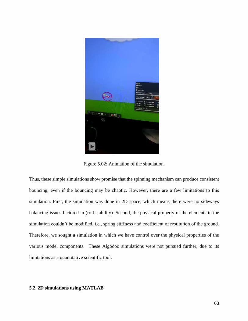
Figure 502 Animation of the simulation
Thus these simple simulations show promise that the spinning mechanism can produce consistent
bouncing even if the bouncing may be chaotic However there are a few limitations to this
simulation First the simulation was done in 2D space which means there were no sideways
balancing issues factored in (roll stability) Second the physical property of the elements in the
simulation couldnrsquot be modified ie spring stiffness and coefficient of restitution of the ground
Therefore we sought a simulation in which we have control over the physical properties of the
various model components These Algodoo simulations were not pursued further due to its
limitations as a quantitative scientific tool
52 2D simulations using MATLAB
64
Figure 503 A snapshot of 2D bouncing simulation using MATLAB
I explored directly writing the equations of motion for a 2D version of the system and solving the
resulting differential equations in MATLAB using ode45 The equations of motion were obtained
by drawing free body diagrams for each rigid body and writing Newton-Euler equations for each
free body diagram The contact with the ground surface was modeled by a spring and damper
which gets activated only when the circular shell touches the ground This is a work in progress
while the simulation often produces bouncing animation (Figure 503) there were some un-
physical features of the bouncing suggesting that the simulations need to be improved
52 3D simulations using Simscape Multibody
521 What is Simscape multibody
65
Simscape Multibody is a product under MATLAB-Simulink formerly called SimMechanics is a
software that can provide multibody 3D mechanical system simulation environment for simulating
objects such as robots automotive vehicles and aircrafts The parts can be models with either
simscape blocks or importing CAD model files The multibody system can be described by
defining the properties of the rigid bodies joints constraints force elements and sensors Simscape
Multibody automatically solves equations of motion for the system Other parameters like masses
densities inertias joints constraints and controllers can be manipulated and modified Simscape
Multibody can be called programmatically from within MATLAB Features such as functions
variables and expressions can be programmed in MATLAB and used by SimScape
522 Model details
Diameter of the sphere 150 mm
Weight of the spinning mass 27 g
Dead mass (spherical shell + motor + bridge) 311 g
523 Results so far for spinning actuation
66
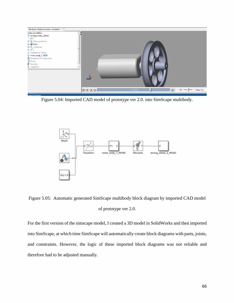
Figure 504 Imported CAD model of prototype ver 20 into SimScape multibody
Figure 505 Automatic generated SimScape multibody block diagram by imported CAD model
of prototype ver 20
For the first version of the simscape model I created a 3D model in SolidWorks and then imported
into SimScape at which time SimScape will automatically create block diagrams with parts joints
and constraints However the logic of these imported block diagrams was not reliable and
therefore had to be adjusted manually
67
Figure 506 Imported CAD model of prototype ver 30 Into SimScape multibody
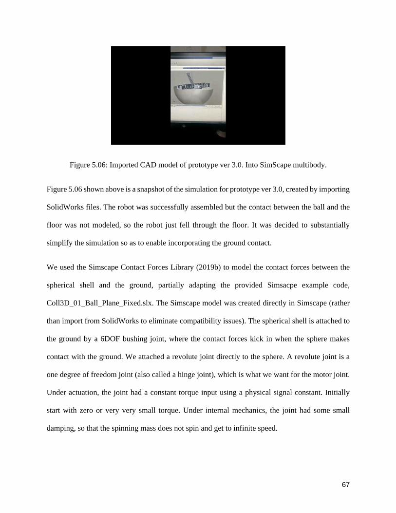
Figure 506 shown above is a snapshot of the simulation for prototype ver 30 created by importing
SolidWorks files The robot was successfully assembled but the contact between the ball and the
floor was not modeled so the robot just fell through the floor It was decided to substantially
simplify the simulation so as to enable incorporating the ground contact
We used the Simscape Contact Forces Library (2019b) to model the contact forces between the
spherical shell and the ground partially adapting the provided Simsacpe example code
Coll3D_01_Ball_Plane_Fixedslx The Simscape model was created directly in Simscape (rather
than import from SolidWorks to eliminate compatibility issues) The spherical shell is attached to
the ground by a 6DOF bushing joint where the contact forces kick in when the sphere makes
contact with the ground We attached a revolute joint directly to the sphere A revolute joint is a
one degree of freedom joint (also called a hinge joint) which is what we want for the motor joint
Under actuation the joint had a constant torque input using a physical signal constant Initially
start with zero or very very small torque Under internal mechanics the joint had some small
damping so that the spinning mass does not spin and get to infinite speed
68
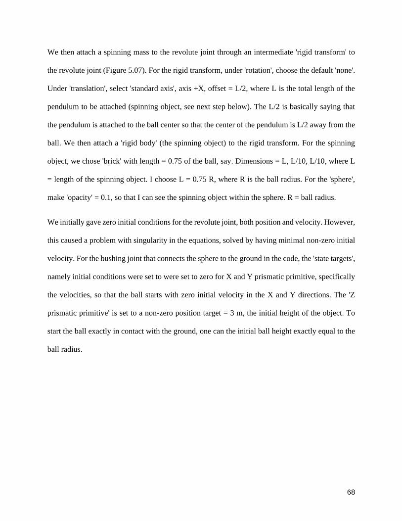
We then attach a spinning mass to the revolute joint through an intermediate rigid transform to
the revolute joint (Figure 507) For the rigid transform under rotation choose the default none
Under translation select standard axis axis +X offset = L2 where L is the total length of the
pendulum to be attached (spinning object see next step below) The L2 is basically saying that
the pendulum is attached to the ball center so that the center of the pendulum is L2 away from the
ball We then attach a rigid body (the spinning object) to the rigid transform For the spinning
object we chose brick with length = 075 of the ball say Dimensions = L L10 L10 where L
= length of the spinning object I choose L = 075 R where R is the ball radius For the sphere
make opacity = 01 so that I can see the spinning object within the sphere R = ball radius
We initially gave zero initial conditions for the revolute joint both position and velocity However
this caused a problem with singularity in the equations solved by having minimal non-zero initial
velocity For the bushing joint that connects the sphere to the ground in the code the state targets
namely initial conditions were set to were set to zero for X and Y prismatic primitive specifically
the velocities so that the ball starts with zero initial velocity in the X and Y directions The Z
prismatic primitive is set to a non-zero position target = 3 m the initial height of the object To
start the ball exactly in contact with the ground one can the initial ball height exactly equal to the
ball radius
69
Figure 507 Zoom-in of the tree structure of Simulink Diagram
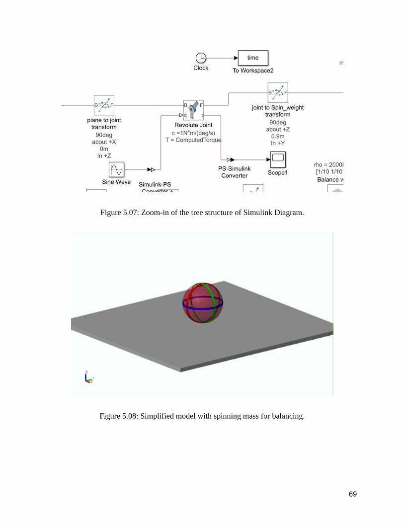
Figure 508 Simplified model with spinning mass for balancing
70
This is the animation of the first successful simulation build on the contact simulation example
There is one off-centered mass in the ball spinning with respect to an axis The response of the ball
was not predictable
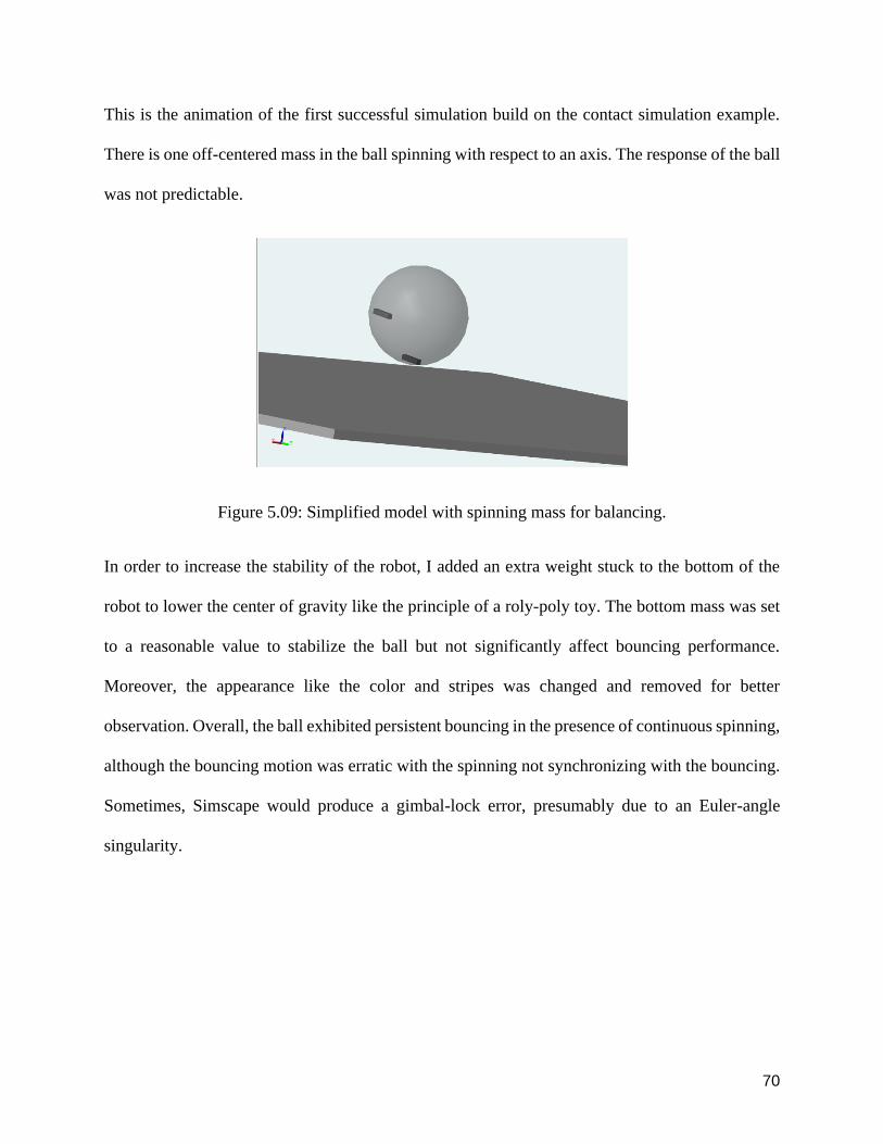
Figure 509 Simplified model with spinning mass for balancing
In order to increase the stability of the robot I added an extra weight stuck to the bottom of the
robot to lower the center of gravity like the principle of a roly-poly toy The bottom mass was set
to a reasonable value to stabilize the ball but not significantly affect bouncing performance
Moreover the appearance like the color and stripes was changed and removed for better
observation Overall the ball exhibited persistent bouncing in the presence of continuous spinning
although the bouncing motion was erratic with the spinning not synchronizing with the bouncing
Sometimes Simscape would produce a gimbal-lock error presumably due to an Euler-angle
singularity
71
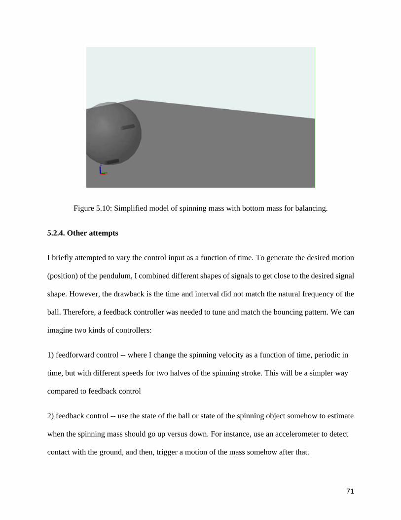
Figure 510 Simplified model of spinning mass with bottom mass for balancing
524 Other attempts
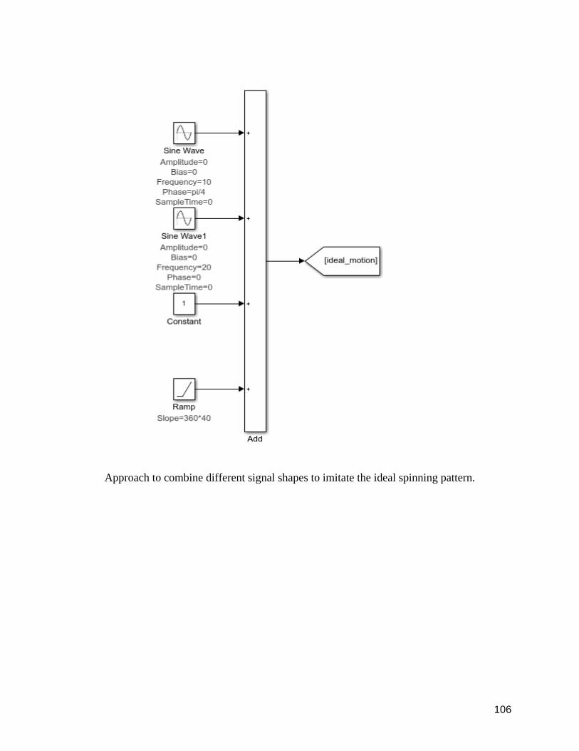
I briefly attempted to vary the control input as a function of time To generate the desired motion
(position) of the pendulum I combined different shapes of signals to get close to the desired signal
shape However the drawback is the time and interval did not match the natural frequency of the
ball Therefore a feedback controller was needed to tune and match the bouncing pattern We can
imagine two kinds of controllers
1) feedforward control -- where I change the spinning velocity as a function of time periodic in
time but with different speeds for two halves of the spinning stroke This will be a simpler way
compared to feedback control
2) feedback control -- use the state of the ball or state of the spinning object somehow to estimate
when the spinning mass should go up versus down For instance use an accelerometer to detect
contact with the ground and then trigger a motion of the mass somehow after that
72
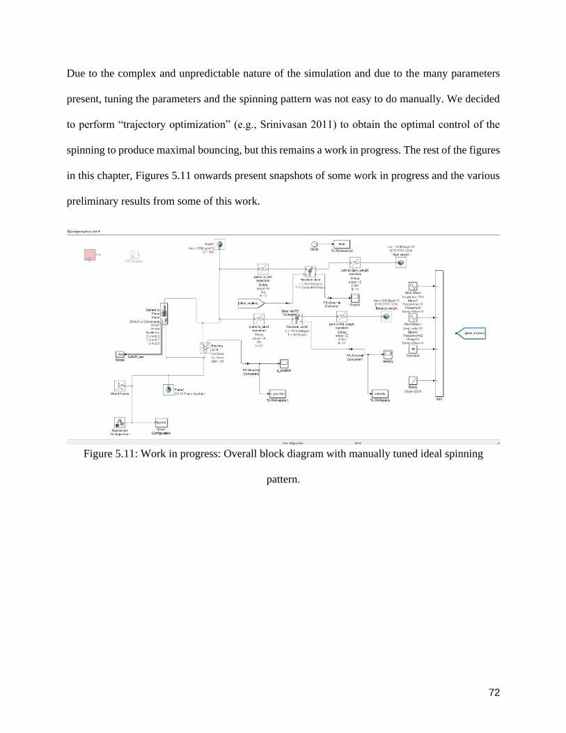
Due to the complex and unpredictable nature of the simulation and due to the many parameters
present tuning the parameters and the spinning pattern was not easy to do manually We decided
to perform ldquotrajectory optimizationrdquo (eg Srinivasan 2011) to obtain the optimal control of the
spinning to produce maximal bouncing but this remains a work in progress The rest of the figures
in this chapter Figures 511 onwards present snapshots of some work in progress and the various
preliminary results from some of this work
Figure 511 Work in progress Overall block diagram with manually tuned ideal spinning
pattern
73
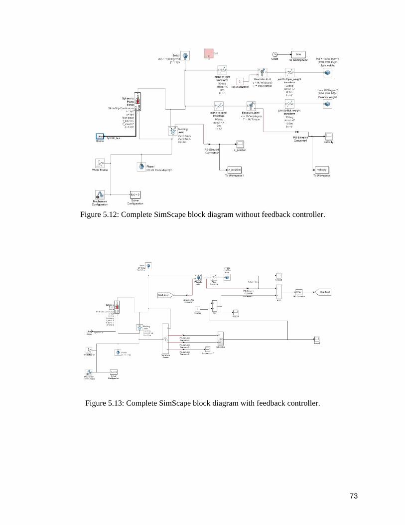
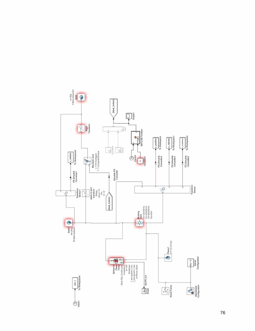
Figure 512 Complete SimScape block diagram without feedback controller
Figure 513 Complete SimScape block diagram with feedback controller
74
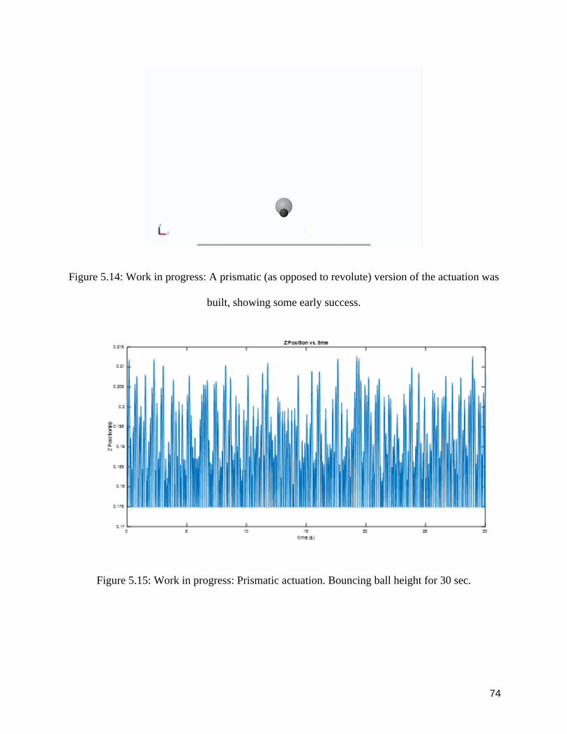
Figure 514 Work in progress A prismatic (as opposed to revolute) version of the actuation was
built showing some early success
Figure 515 Work in progress Prismatic actuation Bouncing ball height for 30 sec
75
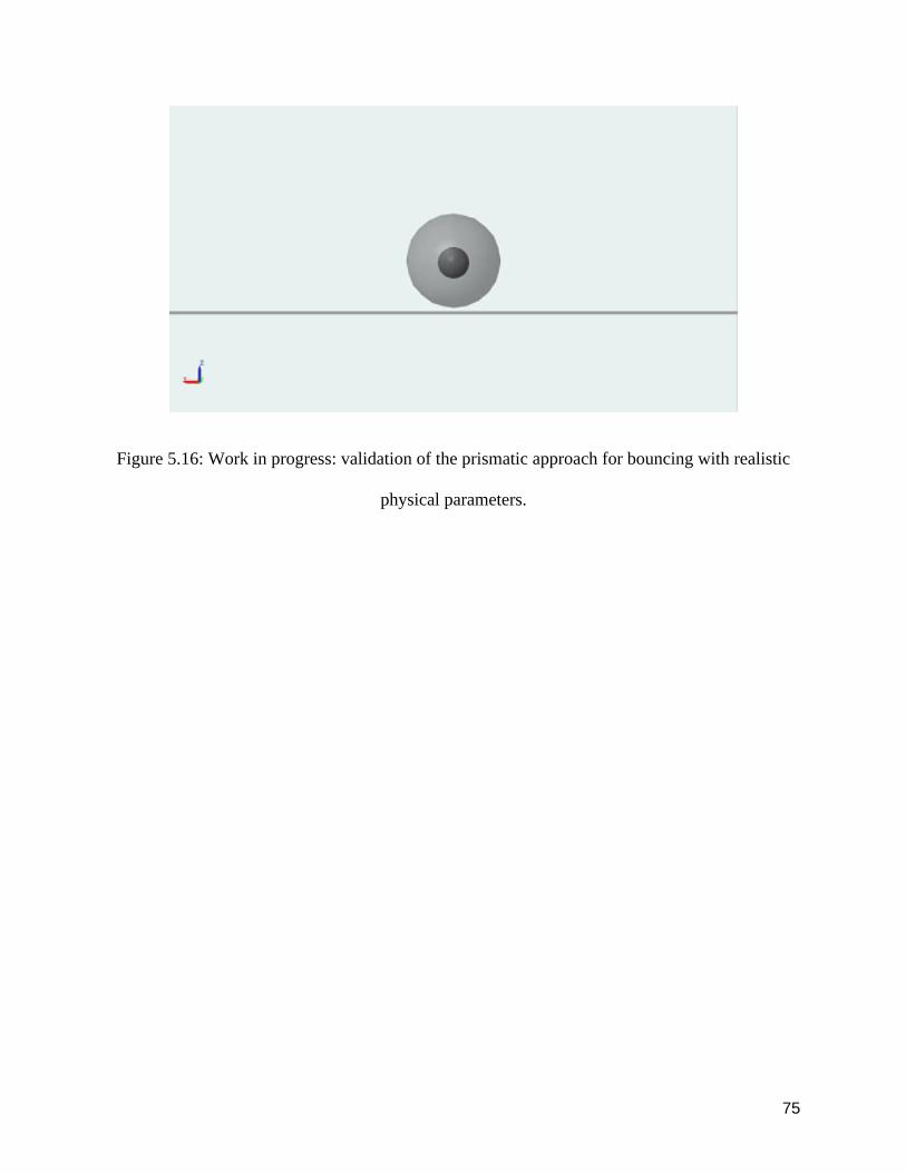
Figure 516 Work in progress validation of the prismatic approach for bouncing with realistic
physical parameters
76
77
Figure 517 Work in progress Overview of the whole lastest Simulink diagram
Chapter 6 Conclusion and Future Work
This chapter describes the contributions additional applications future work and summary of the
work done in this research
61 Contributions
This ambitious project had numerous aspects namely design fabrication computer simulation
through multiple modeling paradigms optimal control etc Due to the numerous aspects of this
ambitious project the author could not complete the original research goals These numerous
which can be taken over by other researchers to improve upgrade and perfect the project
We fabricated a simple and robust bouncing ball device after about six prototype iterations and
this device exhibited persistent bouncing More work needs to be done to go from this prototype
to make the bouncing periodic and synchronous make the bounce height higher and make the
bounce controllable
Similarly we showed feasibility of a persistent bouncing robot first through an algodoo simulation
and then using MATLAB 2D simulations and Simscape 3D simulations However the latter two
simulations should be considered works in progress with some debugging and fine-tuning required
for reliability Once these reliability issues are resolved we should do parameter sweeps to
examine the effect of parameters We also need to complete testing frameworks in which the
actuation is time-varying or feedback controlled to more clearly see the effect of these different
control approaches
78
62 Significance of the robot and additional applications
We have explored the feasibility of a novel robot configuration It is important to consider novel
robot configurations as they may potentially have advantages over traditional configurations (such
as legged or wheeled robots) This novel robot when complete has the potential advantage that
all the mechanisms could be internal but the potential advantages of such a robot have not been
tested One possible advantage is having an air-tight body Unlike traditional wheeled or legged
robots this robot could be less prone to get dust and liquid into its electronic and mechanical
components
Second due to the nature of its movement the robot may have some potential advantages for
certain terrain For instance high bumps on the road may be traversed better by a bouncing robot
than a rolling robot
The rolling and bouncing may be most useful as an entertainment toy for children and perhaps
pets indeed for such purposes a periodic and perfectly controllable motion may not be essential
However for such situations it is important to have a safety-first approach and make sure that the
robot cannot injure the person being capable of avoiding a human or an animal Perhaps the
bouncing motion will be useful in low gravity space For use as a surveillance robot however the
robot needs to be very quiet so that bouncing aspect may make it less useful in that context
Finally this novel robot raises technical issues that will challenge current design and
manufacturing methods as well as push the envelope of control methods as 3D aerial control of
a spherical bouncing robot has not been demonstrated yet
63 Future Work
79
As noted the author here explored numerous aspects of the problem of building a spherical robot
For future researchers who continue this project the recommendation will be to tackle only one
aspect of this project This can be divided into designing new locomotion ideas building
generations of prototypes based on existing designs that previous researchers could not complete
perfecting existing prototypes by upgrading components building test contraptions and
conducting tests completing working simulation models and optimization of controllers design
of nonlinear controllers performing stability analysis of the 3D bouncing in place or with forward
movement etc Future researchers could also complete building prototypes of cam slider and
crank and coil mechanisms that the author envisioned but failed to complete due to the time
constraints New alternative materials could also be pursued to reduce the weight and meet
strength including exploring other off-the-shelf parts The shape design of the supporting parts
could be optimized in order to reduce the weight of the part while maintaining structural property
Due to time material and budget the author could not build a complete testing framework
However a complete and strong testing framework is essential for testing to eventually produce
reliable results Furthermore different optimization strategies should be tested to produce the best
results for the bouncing
80
References
Note that the image citations are in a separate reference list in Appendix B
Chatzinikolaidis I Stouraitis T Vijayakumar S amp Li Z (2018 November) Nonlinear
Optimization using Discrete Variational Mechanics for Dynamic Maneuvers of a 3D One-Leg
Hopper In 2018 IEEE-RAS 18th International Conference on Humanoid Robots (Humanoids)
(pp 1-9) IEEE
Batts Zachary Joohyung Kim and Katsu Yamane Untethered one-legged hopping in 3d using
linear elastic actuator in parallel (leap) International Symposium on Experimental Robotics
Springer Cham 2016
Hara M Shibayama A Takeshita D amp Fukashiro S (2006) The effect of arm swing on lower
extremities in vertical jumping Journal of biomechanics 39(13) 2503-2511
Harman Everett A et al The effects of arms and countermovement on vertical jumping Med
Sci Sports Exerc 226 (1990) 825-833
Lee Jaeyeon and Wooram Park Design and path planning for a spherical rolling robot ASME
2013 International Mechanical Engineering Congress and Exposition American Society of
Mechanical Engineers 2013
Michaud Franccedilois and Serge Caron Roball the rolling robot Autonomous robots 122 (2002)
211-222
Michaud Franccedilois et al Autonomous spherical mobile robot for child-development studies
IEEE Transactions on Systems Man and Cybernetics-Part A Systems and Humans 354 (2005)
471-480
81
Minetti A E amp Ardigo L P (2002) Halteres used in ancient Olympic long jump Nature
420(6912) 141-142
Muralidharan Vijay and Arun D Mahindrakar Geometric controllability and stabilization of
spherical robot dynamics IEEE Transactions on Automatic Control 6010 (2015) 2762-2767
Ruina Andy John EA Bertram and Manoj Srinivasan A collisional model of the energetic cost
of support work qualitatively explains leg sequencing in walking and galloping pseudo-elastic leg
behavior in running and the walk-to-run transition Journal of theoretical biology 2372 (2005)
170-192
Srinivasan Fifteen observations on the structure of energy optimal gaits in many simple biped
models Journal of Royal Society Interface 2011
Sastra Jimmy Sachin Chitta and Mark Yim Dynamic rolling for a modular loop robot The
International Journal of Robotics Research 286 (2009) 758-773
Wang L Q Sun H X amp Jia Q X (2007) Research on the climbing and jumping of a spherical
rolling robot Beijing Youdian Daxue Xuebao Journal of Beijing University of Posts and
Telecommunication 30(2) 11-14
Yim Justin K and Ronald S Fearing Precision Jumping Limits from Flight-phase Control in
Salto-1P 2018 IEEERSJ International Conference on Intelligent Robots and Systems (IROS)
IEEE 2018
Zhao Jianguo et al Controlling aerial maneuvering of a miniature jumping robot using its tail
Intelligent Robots and Systems (IROS) 2013 IEEERSJ International Conference on IEEE 2013
82
83
Appendix A
This appendix has miscellaneous figures snapshots notes etc that did not belong in the main
manuscript Some of these may be removed in the next version of this thesis
Example of Haro in anime
84
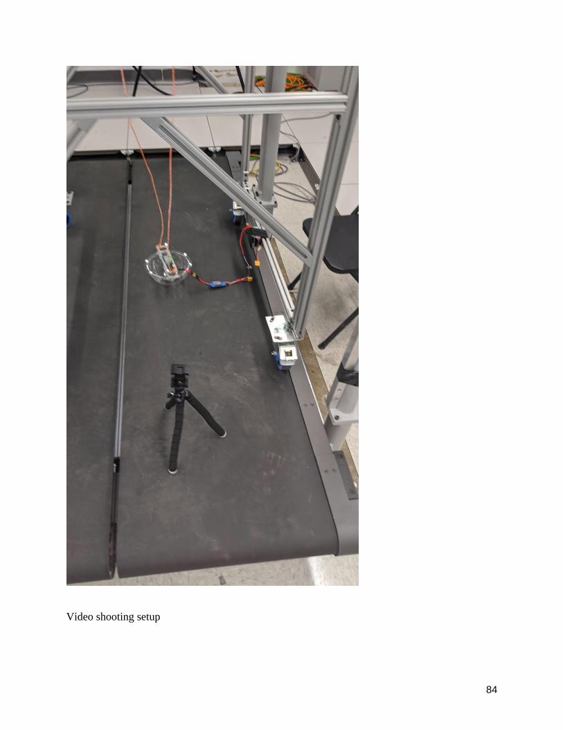
Video shooting setup
85
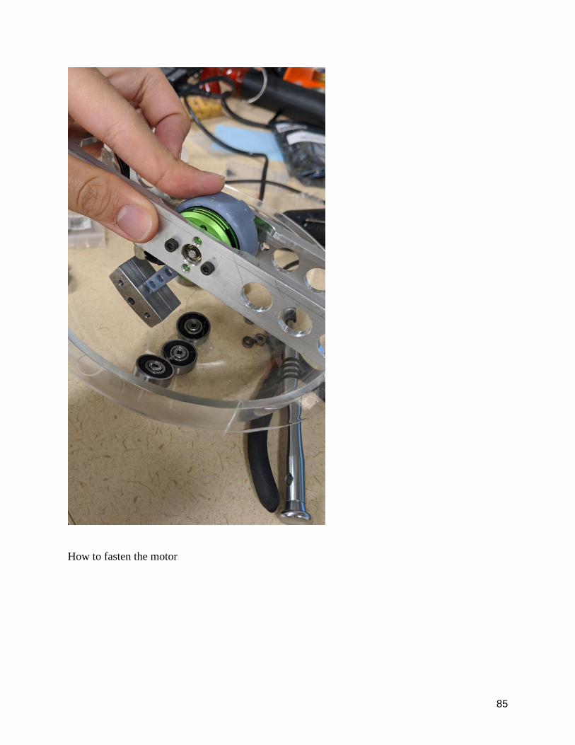
How to fasten the motor
86
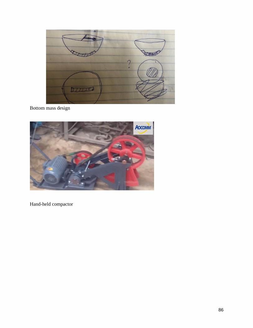
Bottom mass design
Hand-held compactor
87
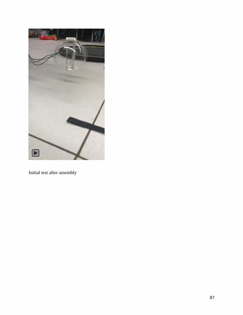
Initial test after assembly
88
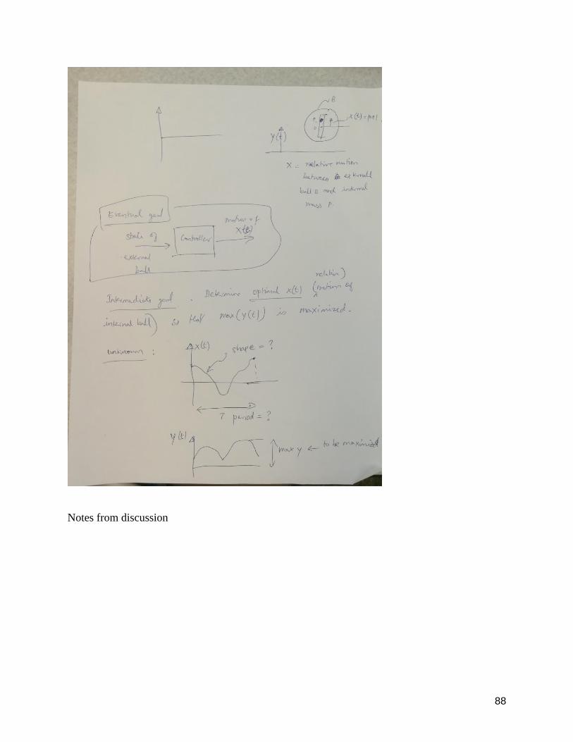
Notes from discussion
89
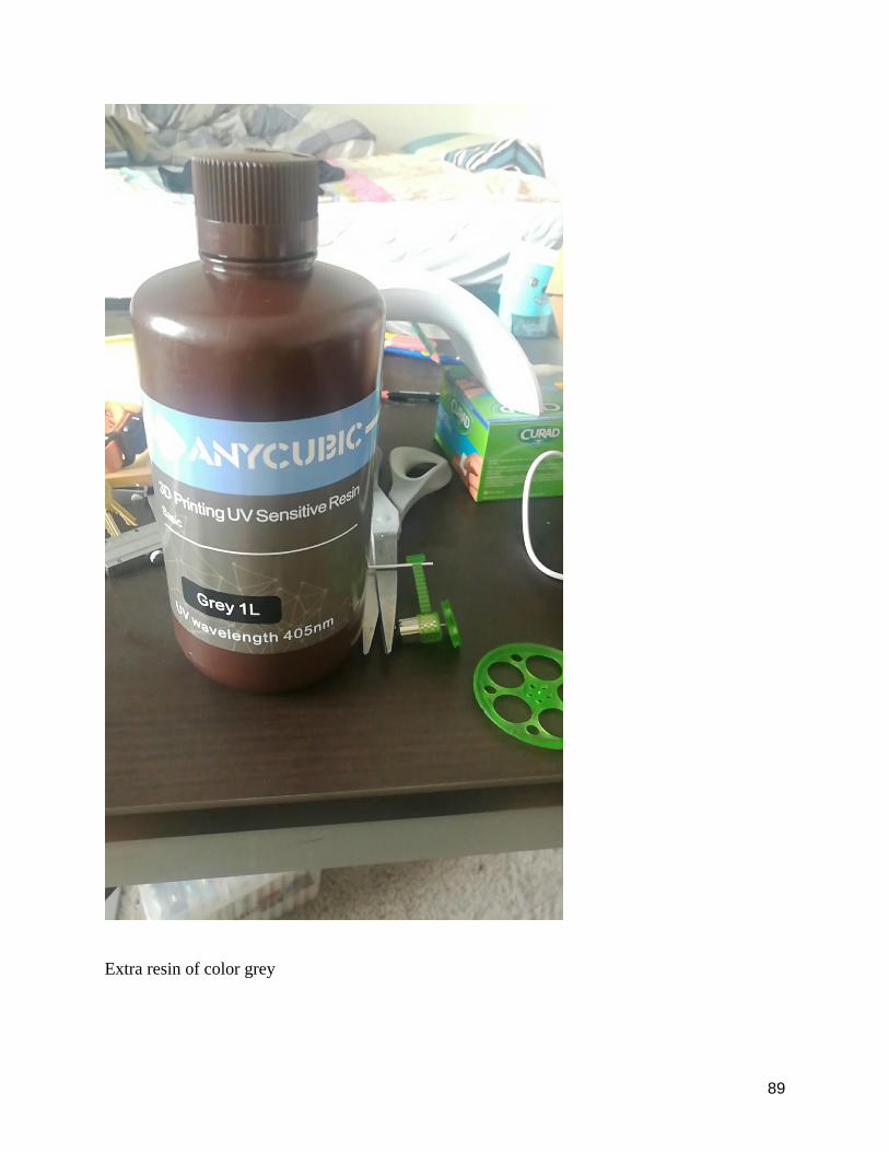
Extra resin of color grey
90
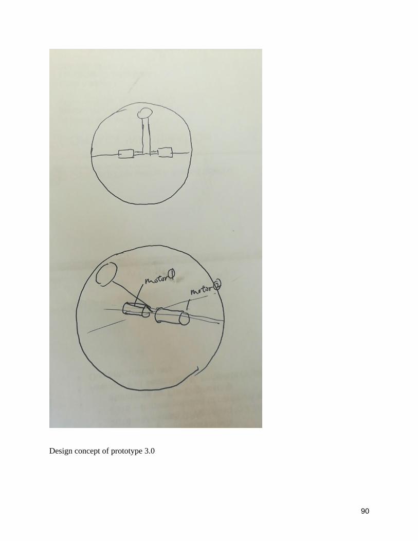
Design concept of prototype 30
91
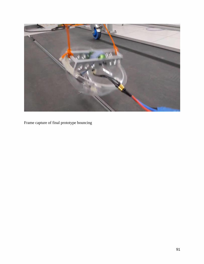
Frame capture of final prototype bouncing
92
Side view of testing setup
93
Top view of testing setup
94
Testing of prototype 10
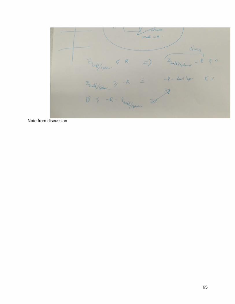
95
Note from discussion
96
Note from discussion
97
Note from discussion
98
Note from discussion
99
Note from discussion
100
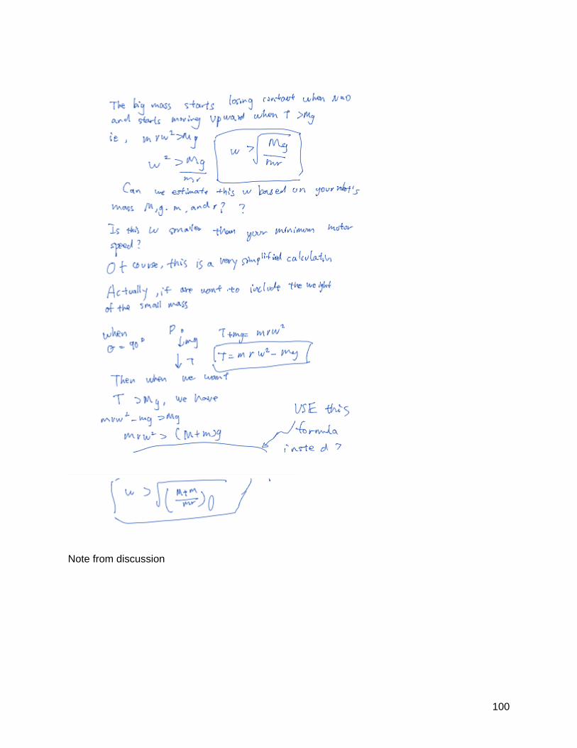
Note from discussion
101
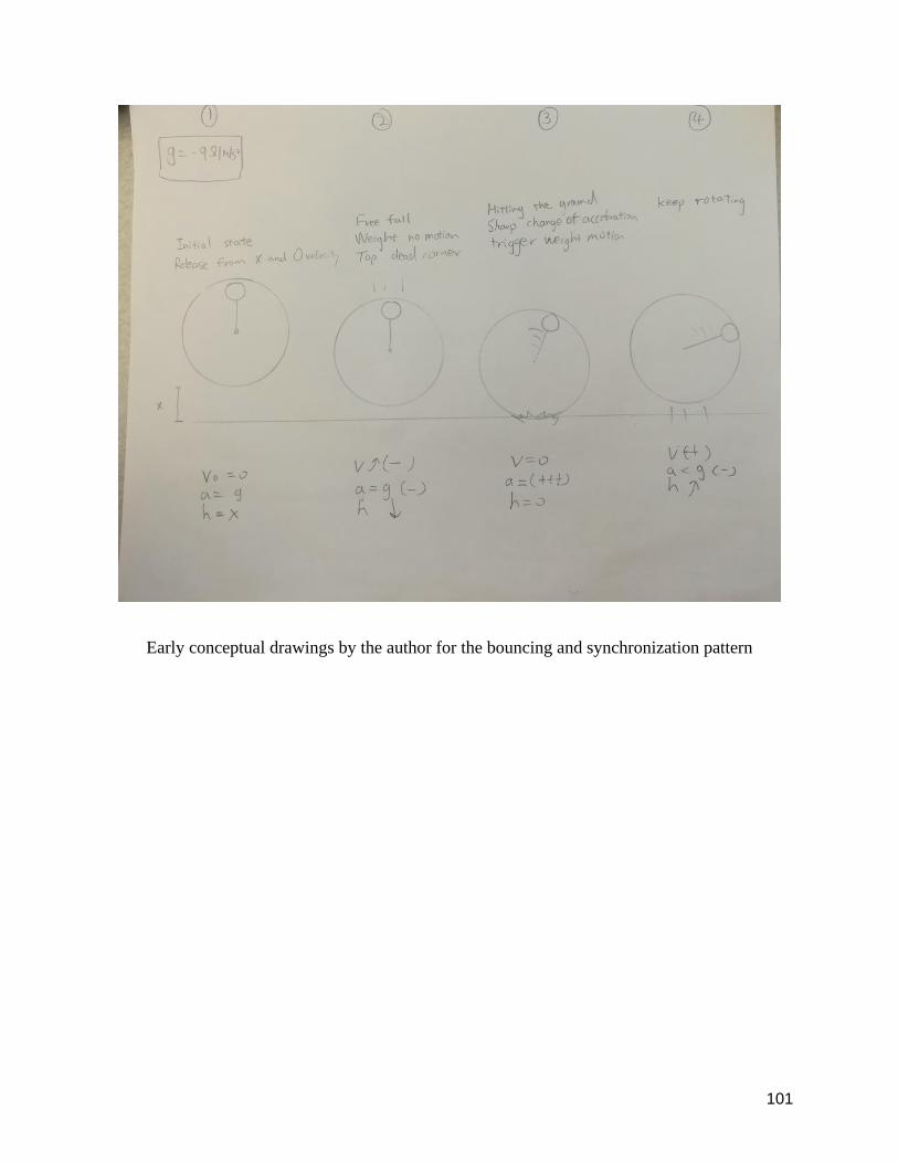
Early conceptual drawings by the author for the bouncing and synchronization pattern
102
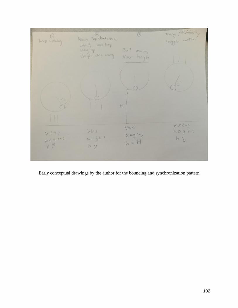
Early conceptual drawings by the author for the bouncing and synchronization pattern
103
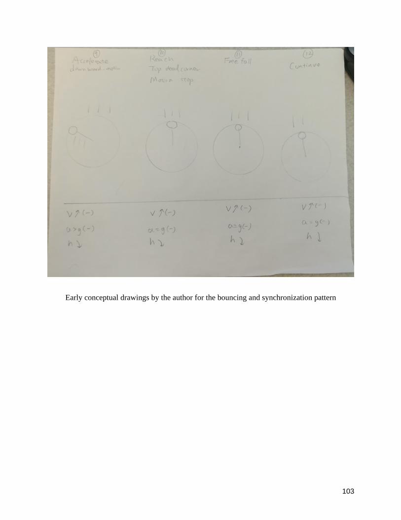
Early conceptual drawings by the author for the bouncing and synchronization pattern
104
Velocity and acceleration of deal bouncing pattern
As shown in the diagrams above ideally if the spinning pattern and bouncing pattern
synchronized the robot would get maximum bouncing height possible In an ideal scenario say
when the weight almost reaches the top end (the compression force is too weak to hold the
spring) the spring stores enough energy and rebounds the sphere subsequently the weight
passes the top end and swings down which further highers the ball When it reaches the bottom
end the motor breaks and right before the ball hits the ground the arm swings upward to
compress the spring
105
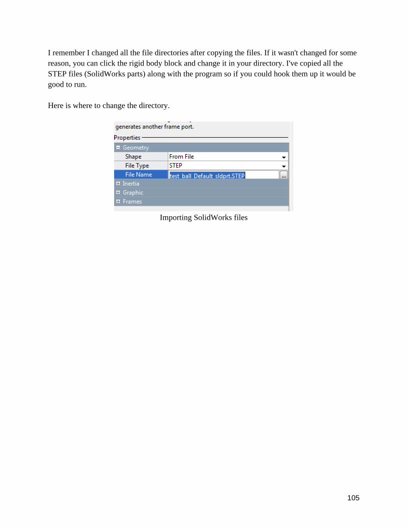
I remember I changed all the file directories after copying the files If it wasnt changed for some
reason you can click the rigid body block and change it in your directory Ive copied all the
STEP files (SolidWorks parts) along with the program so if you could hook them up it would be
good to run
Here is where to change the directory
Importing SolidWorks files
106
Approach to combine different signal shapes to imitate the ideal spinning pattern
107
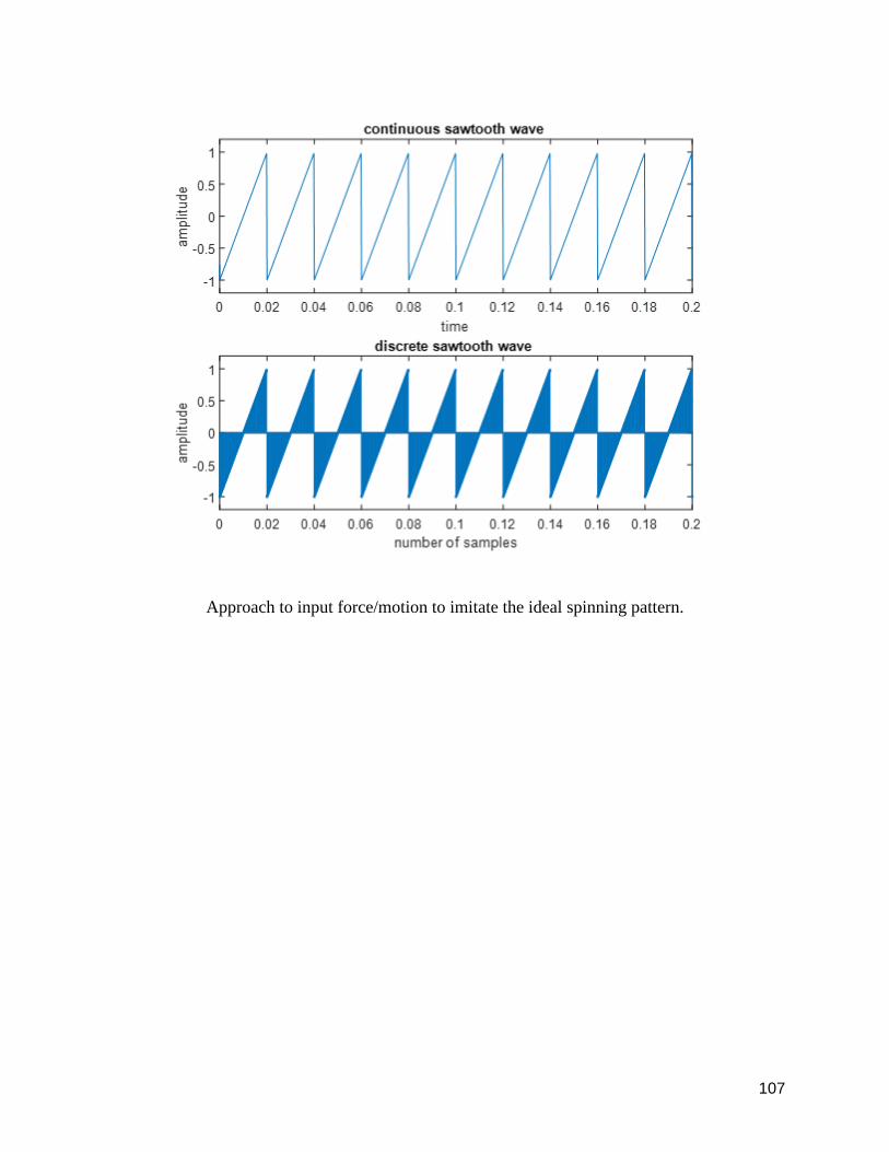
Approach to input forcemotion to imitate the ideal spinning pattern
108
Appendix B
This appendix lists the list of webpages from which illustrative photographs in the thesis have
been drawn from (assuming fair use for educational purposes)
Figure 101 GuardBots HARV 95 ROBOT ROLLING UNDER CAR GuardBot 2018
httpswwwyoutubecomwatchv=sMpPw9x4mvs
Figure 102(From student to professional Vicky Gao 2017httpsmediummuzlifrom-student-
to-professional-2bccb86f77a2)
Figure 201 Sphero robot A) Sphero BB-8 App-Enabled Droid ReviewTimothy Torres
2015httpswwwpcmagcomreviewssphero-bb-8-app-enabled-droidB) BB-8 Sphero
Teardown Dave Evans2015 httpswwwfictivcomblogpostsbb-8-sphero-teardown C) The
Physics of How That Star Wars BB-8 Toy Works Rhett Allain 2015
httpswwwwiredcom201509physics-star-wars-bb-8-toy-works
Figure 202 C)Sand Flea robot is set to leap into reconnaissance (w video) Nancy Owano
2012 httpsphysorgnews2012-03-sand-flea-robot-reconnaissance-videohtml
D) 3D One-Leg Hopper MIT Leg Lab 1983-1984
httpwwwaimiteduprojectsleglabrobots3D_hopper3D_hopperhtml
109
Figure 204 A)Parrot Jumping Night MiniDrone - Buzz (White) Amazon
httpswwwamazoncomParrot-Jumping-Night-MiniDrone-WhitedpB0111O8VNQ B) Parrot
MiniDrone Jumping Sumo review Joshua Goldman 2014httpswwwcnetcomreviewsparrot-
minidrone-jumping-sumo-reviewC)How to replace Jump Mechanism on Parrot Jumping Sumo
Parrot 2014 httpswwwyoutubecomwatchv=1nePU5mz8Z4
Figure 203 A)Magic Roller Ball ToyCute Rolling Vacuum Floor Sweeping Robot Cleaner with
4pcs Colorful Covers Set (Amazon)
httpswwwamazoncomgpproductB07D7RX8QTref=ppx_yo_dt_b_search_asin_titleie=UT
F8amppsc=1 B) Spherical Rolling Robot David Carabis 2013
httpswwwyoutubecomwatchv=LmvUkbdXNbM D) Real life robotic ball drone has been
tested by US marines and is like devices in Jurassic World and the BBC The Prisoner Brian
Wang 2016 httpswwwnextbigfuturecom201611real-life-robotic-bll-drone-has-beenhtml
Figure 205 Gravel Soil Compacted High Technology Frog Compactor MachineTo
httpwwwmachinetocomgravel-soil-compacted-high-technology-frog-compactor-10106361
Figure 207 Anti Gravity wheel Veritasium 2014
httpswwwyoutubecomwatchv=GeyDf4ooPdo
Figure 208 Cams eduqas httpresourcedownloadwjeccouks3amazonawscomvtc2016-
1716-17_1-
110
4websitecategory4functions_of_mechanical_devicesfunction_of_mechanical_productsmedia
documentscamspdf
Figure 209 The effect of arm swing on lower extremities in vertical jumping Mikiko Hara
Akira Shibayama Daisuke Takeshita Senshi Fukashiro 2006
httpswwwsciencedirectcomsciencearticleabspiiS0021929005003647
Figure 429 Roly-poly toy BRITANNICA KIDS
httpskidsbritannicacomstudentsassemblyview53661
Page 2
2
Abstract
Most robots that can travel on the ground are either traditional wheeled robots or legged robots
Exploring non-traditional novel robots may provide new solutions for locomotion not previously
examined Currently self-rolling spherical robots have been designed and manufactured for
hobbies entertainment or military uses Similarly various researchers have built legged robots
that walk and run Our objective in this research project was to design build and control a self-
propelled bouncing and rolling spherical robot While some self-bouncing wheeled robots have
been built as toys the self-bouncing spherical robot (one that looks like a ball) remains largely not
explored No one has produced a robot that can bounce continuously and can be steered without
any external device to assist its movement To achieve this goal we plan to prototype up to three
different mechanisms for bouncing Each prototype would go through brainstorming computer-
aided design and simulation (of the bouncing) initial build redesign second build and final
analysis We follow the classic design cycle observe ideation prototype and testing We will
also perform dynamic analyses of the robot to improve the design This thesis reports on current
progress towards these goals we have designed and fabricated (and iterated) on a simple prototype
bouncing ball based on a spinning internal mass we have performed some 2D and 3D simulations
of the spinning mechanism that shows promise for the mechanism to produce persistent bouncing
Future work will consist of improving the current prototype matching the computer simulations
quantitatively to the prototype performing design optimization and trajectory optimizations for
optimal control exploring other designs closer to hopping robots and finally building the ability
to control and steer the robot
3
Acknowledgments
I would like to first thank my research advisor Professor Manoj Srinivasan for his belief in me
and tremendous support in this research project I really appreciate all of his guidance for both
programming and prototyping on this project It is because of his passion and enthusiasm that I
can achieve so much in this project and win the finalist in the Denman Research Forum of the Ohio
State University Secondly I would like to thank Kevin Wolf for his passionate assistance in
manufacturing and his valuable knowledge of 3D printing and machining I would also like to
thank Chris Adam for his consultation with electronics and teaching for soldering skills and
strategies Thank you to Aaron Orsborn and all the student workers for assistance in Machine
Shop Thank you to Professor Ryan Harne for his suggestion for various learning resources Thank
you to Myungjin Jung and Kai for this assistant for debugging BLDC motors Thank you to Zhiyi
Jiang for his help with Simulink Thank you to Zhihao Zhang for this consultant with the Lipo
battery Last but not least I would like to thank the College of Engineering and Second Year
Transformational Experience program for providing a substantial amount of fellowship for my
research projects
4
Table of contents
Abstracthelliphelliphelliphelliphelliphelliphelliphelliphelliphelliphelliphelliphelliphelliphelliphelliphelliphelliphelliphelliphelliphelliphelliphelliphelliphelliphelliphelliphelliphelliphelliphelliphelliphellip2
Acknowledgementshelliphelliphelliphelliphelliphelliphelliphelliphelliphelliphelliphelliphelliphelliphelliphelliphelliphelliphelliphelliphelliphelliphelliphelliphelliphelliphelliphelliphelliphellip3
List of Figureshelliphelliphelliphelliphelliphelliphelliphelliphelliphelliphelliphelliphelliphelliphelliphelliphelliphelliphelliphelliphelliphelliphelliphelliphelliphelliphelliphelliphelliphelliphelliphellip5
Chapter 1 Introductionhelliphelliphelliphelliphelliphelliphelliphelliphelliphelliphelliphelliphelliphelliphelliphelliphelliphelliphelliphelliphelliphelliphelliphelliphelliphelliphelliphellip11
Chapter 2 Other related robots and inspirationshelliphelliphelliphelliphelliphelliphelliphelliphelliphelliphelliphelliphelliphelliphelliphelliphelliphellip15
Chapter 3 Three basic designs Brainstorming and Designhelliphelliphelliphelliphelliphelliphelliphelliphelliphelliphelliphelliphelliphellip22
Chapter 4 Fabrication and design iterationshelliphelliphelliphelliphelliphelliphelliphelliphelliphelliphelliphelliphelliphelliphelliphelliphelliphelliphellip24
Chapter 5 3D Virtual Simulation and Controller Designhelliphelliphelliphelliphelliphelliphelliphelliphelliphelliphelliphelliphelliphellip62
Chapter 6 Conclusion and Future Workhelliphelliphelliphelliphelliphelliphelliphelliphelliphelliphelliphelliphelliphelliphelliphelliphelliphelliphelliphellip78
Referenceshelliphelliphelliphelliphelliphelliphelliphelliphelliphelliphelliphelliphelliphelliphelliphelliphelliphelliphelliphelliphelliphelliphelliphelliphelliphelliphelliphelliphelliphelliphelliphelliphellip80
Appendix Ahelliphelliphelliphelliphelliphelliphelliphelliphelliphelliphelliphelliphelliphelliphelliphelliphelliphelliphelliphelliphelliphelliphelliphelliphelliphelliphelliphelliphelliphelliphelliphellip83
Appendix Bhelliphelliphelliphelliphelliphelliphelliphelliphelliphelliphelliphelliphelliphelliphelliphelliphelliphelliphelliphelliphelliphelliphelliphelliphelliphelliphelliphelliphelliphelliphelliphellip108
5
List of Figures
Figure 101 Fictional bouncing robots and real rolling robotshelliphelliphelliphelliphelliphelliphelliphelliphelliphelliphelliphellip10
Figure 102 Classic design iteration cycle helliphelliphelliphelliphelliphelliphelliphelliphelliphelliphelliphelliphelliphelliphelliphelliphelliphelliphellip12
Figure 201 Sphero robothelliphelliphelliphelliphelliphelliphelliphelliphelliphelliphelliphelliphelliphelliphelliphelliphelliphelliphelliphelliphelliphelliphelliphelliphellip14
Figure 202 Previous jumping robots from other research labshelliphelliphelliphelliphelliphelliphelliphelliphelliphelliphellip15
Figure 203 Previous projects or products on market or by studenthelliphelliphelliphelliphelliphelliphelliphelliphelliphellip16
Figure 204 Jumping Sumo robothelliphelliphelliphelliphelliphelliphelliphelliphelliphelliphelliphelliphelliphelliphelliphelliphelliphelliphelliphelliphelliphelliphellip17
Figure 205 The mechanism in the soil compactorhelliphelliphelliphelliphelliphelliphelliphelliphelliphelliphelliphelliphelliphelliphelliphelliphellip17
Figure 206 Jumping toyhelliphelliphelliphelliphelliphelliphelliphelliphelliphelliphelliphelliphelliphelliphelliphelliphelliphelliphelliphelliphelliphelliphelliphelliphelliphelliphellip18
Figure 207 Anti Gravity wheelhelliphelliphelliphelliphelliphelliphelliphelliphelliphelliphelliphelliphelliphelliphelliphelliphelliphelliphelliphelliphelliphelliphelliphellip19
Figure 208 Cam mechanism with different cam shapehelliphelliphelliphelliphelliphelliphelliphelliphelliphelliphelliphelliphelliphelliphellip19
Figure 209 Effect of jumping height due to the swing of armshelliphelliphelliphelliphelliphelliphelliphelliphelliphelliphelliphellip20
Figure 301 Prototype designshelliphelliphelliphelliphelliphelliphelliphelliphelliphelliphelliphelliphelliphelliphelliphelliphelliphelliphelliphelliphelliphelliphelliphelliphellip22
Figure 401 Bouncing ball robothelliphelliphelliphelliphelliphelliphelliphelliphelliphelliphelliphelliphelliphelliphelliphelliphelliphelliphelliphelliphelliphelliphelliphellip23
Figure 402Transparent plastic domehelliphelliphelliphelliphelliphelliphelliphelliphelliphelliphelliphelliphelliphelliphelliphelliphelliphelliphelliphelliphelliphellip24
Figure 403 Rough initial build of prototype 1helliphelliphelliphelliphelliphelliphelliphelliphelliphelliphelliphelliphelliphelliphelliphelliphelliphelliphellip25
Figure 404 Idea to hold up the motorshelliphelliphelliphelliphelliphelliphelliphelliphelliphelliphelliphelliphelliphelliphelliphelliphelliphelliphelliphelliphellip26
6
Figure 405 Design to lower the center of gravityhelliphelliphelliphelliphelliphelliphelliphelliphelliphelliphelliphelliphelliphelliphelliphelliphellip27
Figure 406 Rough concept design with the transmission mechanismhelliphelliphelliphelliphelliphelliphelliphelliphellip28
Figure 407 Detailed model with measured dimensionshelliphelliphelliphelliphelliphelliphelliphelliphelliphelliphelliphelliphelliphelliphellip29
Figure 408 Anycubic photon printer and resin used in this projecthelliphelliphelliphelliphelliphellip helliphelliphelliphellip30
Figure 409 Initial print of the driving wheel with horizontal placementhelliphelliphelliphelliphelliphelliphelliphellip31
Figure 410 Shrink on large parts when placed horizontally on the printing bedhelliphelliphelliphelliphelliphellip32
Figure 411 Preview of PreForm interfacehelliphelliphelliphelliphelliphelliphelliphelliphelliphelliphelliphelliphelliphelliphelliphelliphelliphelliphelliphellip33
Figure 412 Close up photo of a large piece of print just after the printing processhelliphelliphelliphelliphellip34
Figure 413 One of a few successful parts with very small detailshelliphelliphelliphelliphelliphelliphelliphelliphelliphelliphellip34
Figure 414 Testing the core mechanismhelliphelliphelliphelliphelliphelliphelliphelliphelliphelliphelliphelliphelliphelliphelliphelliphelliphelliphelliphelliphellip35
Figure 415 Flat support for the transmission mechanismhelliphelliphelliphelliphelliphelliphelliphelliphelliphelliphelliphelliphelliphellip36
Figure 416 Round support to simulate spherical contact without the outer ballhelliphelliphelliphelliphelliphellip37
Figure 417 Metal wire cagehelliphelliphelliphelliphelliphelliphelliphelliphelliphelliphelliphelliphelliphelliphelliphelliphelliphelliphelliphelliphelliphelliphelliphelliphellip38
Figure 418 Wiffle Ballhelliphelliphelliphelliphelliphelliphelliphelliphelliphelliphelliphelliphelliphelliphelliphelliphelliphelliphelliphelliphelliphelliphelliphelliphelliphelliphellip39
Figure 419 Acrylic domehelliphelliphelliphelliphelliphelliphelliphelliphelliphelliphelliphelliphelliphelliphelliphelliphelliphelliphelliphelliphelliphelliphelliphelliphelliphellip39
Figure 420 Prototype ver 30helliphelliphelliphelliphelliphelliphelliphelliphelliphelliphelliphelliphelliphelliphelliphelliphelliphelliphelliphelliphelliphelliphelliphelliphellip40
Figure 421 Scorpion S-1804-1650KV Brushless DC motorhelliphelliphelliphelliphelliphelliphelliphelliphelliphelliphelliphelliphellip41
7
Figure 422 Circuit setup for BLDC motor and Arduinohelliphelliphelliphelliphelliphelliphelliphelliphelliphelliphelliphelliphelliphellip42
Figure 423 Close up view of different kinds of BLDC motors I experimented with helliphelliphellip43
Figure 424 Remains of prototype 40helliphelliphelliphelliphelliphelliphelliphelliphelliphelliphelliphelliphelliphelliphelliphelliphelliphelliphelliphelliphelliphellip43
Figure 425 Prototype 50helliphelliphelliphelliphelliphelliphelliphelliphelliphelliphelliphelliphelliphelliphelliphelliphelliphelliphelliphelliphelliphelliphelliphelliphelliphellip44
Figure 426 Idea for putting a bouncy material on the bottom may increase performancehelliphellip45
Figure 427 Some of the rubber spray I purchasedhelliphelliphelliphelliphelliphelliphelliphelliphelliphelliphelliphelliphelliphelliphelliphelliphellip46
Figure 428 One of the balls with rubber spray appliedhelliphelliphelliphelliphelliphelliphelliphelliphelliphelliphelliphelliphelliphelliphellip47
Figure 429 Close-up picture of the lightened bridgehelliphelliphelliphelliphelliphelliphelliphellip helliphelliphelliphelliphelliphelliphellip48
Figure 430 Close-up photo of the redesigned pendulum armhelliphelliphelliphelliphelliphelliphelliphelliphelliphelliphelliphelliphellip48
Figure 431 Close up after pendulum and bridge modificationhelliphelliphelliphelliphelliphelliphelliphelliphelliphelliphelliphellip49
Figure 432 Customized counterbalance masshelliphelliphelliphelliphelliphelliphelliphelliphelliphelliphelliphelliphelliphelliphelliphelliphelliphelliphellip50
Figure 433 Close-up photo of the CNC machined carbon steel masshelliphelliphelliphelliphelliphelliphelliphelliphelliphellip50
Figure 434 Roly-poly toyhelliphelliphelliphelliphelliphelliphelliphelliphelliphelliphelliphelliphelliphelliphelliphelliphelliphelliphelliphelliphelliphelliphelliphelliphelliphellip51
Figure 435 Different perspectives of the initial test setuphelliphelliphelliphelliphelliphelliphelliphelliphelliphelliphelliphelliphellip52
Figure 436One frame from the robot bouncing videohelliphelliphelliphelliphelliphelliphelliphelliphelliphelliphelliphelliphelliphelliphellip53
Figure 437 New machined mass and bottom weight addedhelliphelliphelliphelliphelliphelliphelliphelliphelliphelliphelliphelliphellip54
Figure 438 Improvised testing assemblyhelliphelliphelliphelliphelliphelliphelliphelliphelliphelliphelliphelliphelliphelliphelliphelliphelliphelliphelliphelliphellip56
8
Figure 439 Using a tachometer to measure the speed of the pendulumhelliphelliphelliphelliphelliphelliphelliphellip57
Figure 440 Broken arm parts copies and a modified arm parthelliphelliphelliphelliphelliphelliphelliphelliphelliphelliphelliphelliphellip58
Figure 501 Snapshot of Algodoo simulationhelliphelliphelliphelliphelliphelliphelliphelliphelliphelliphelliphelliphelliphelliphelliphelliphelliphelliphellip61
Figure 502 Animation of the simulationhelliphelliphelliphelliphelliphelliphelliphelliphelliphelliphelliphelliphelliphelliphelliphelliphelliphelliphelliphelliphellip63
Figure 503 Animation of bouncing simulation using MATLABhelliphelliphelliphelliphelliphelliphelliphelliphelliphelliphellip64
Figure 504 Imported CAD model of prototype ver 20 into SimScape multibodyhelliphelliphelliphellip66
Figure 505 SimScape multibody block diagram by imported CAD modelhelliphelliphelliphelliphelliphelliphellip66
Figure 506Imported CAD model of prototype ver 30 Into SimScape multibodyhelliphelliphelliphelliphellip67
Figure 507 Zoom-in of the tree structure of Simulink Diagramhelliphelliphelliphelliphelliphelliphelliphelliphelliphelliphelliphellip69
Figure 508 Simplified model with spinning mass for balancinghelliphelliphelliphelliphelliphelliphelliphelliphelliphelliphelliphellip70
Figure 509 Simplified model of spinning mass with bottom mass for balancinghelliphelliphelliphelliphellip70
Figure 510 Simplified model of spinning mass with bottom mass for balancinghelliphelliphelliphelliphellip71
Figure 511 Overall block diagram with manually tuned ideal spinning patternhelliphelliphelliphelliphelliphellip73
Figure 512 Complete SimScape block diagram without feedback controllerhelliphelliphelliphelliphelliphelliphellip73
Figure 513 Complete SimScape block diagram with feedback controllerhelliphelliphelliphelliphelliphelliphelliphellip74
Figure 514 A prismatic version of the actuationhelliphelliphelliphelliphelliphelliphelliphelliphelliphelliphelliphelliphelliphelliphelliphelliphellip74
Figure 515 Prismatic actuationhelliphelliphelliphelliphelliphelliphelliphelliphelliphelliphelliphelliphelliphelliphelliphelliphelliphelliphelliphelliphelliphelliphelliphellip75
9
Figure 516 Validation of the prismatic approach with realistic physical parametershelliphelliphelliphellip75
Figure 517 Overview of the whole lastest Simulink diagramhelliphelliphelliphelliphelliphelliphelliphelliphelliphelliphelliphelliphellip76
10
Chapter 1 Introduction
11 Background Information
Animals of different kinds have different morphology to take advantage of different ecological
niches in nature Similarly exploring new robot morphologies may help identify new robot
capabilities Here we seek to construct a spherical bouncing robot Many science anime fiction
and movies have depicted versatile spherical robots for instance Haro in Gundam BB-8 in Star
Wars etc (Figure 101)
Figure 101 Fictional bouncing robots and real rolling robots A) Haro robot in the Gundam
series is an autonomous bouncing robot B) Guardbot is a rolling robot used for surveillance
(GuardBot 2018)
Here our goal is to have a perfectly spherical robot with all mechanisms internal Such a bouncing
robot could potentially be more agile than a purely rolling spherical robot The technical
challenges will involve mechanical design product development and control system
development The primary challenge is leaping and steering of the robot with no mechanisms
outside the spherical shell My approach will be to test three different mechanisms for achieving
11
bouncing spinning masses slider-crank mechanism and a spring or a voice coil actuator A
spherical bouncing robot could be used in child daycare (as a toy) entertainment surveillance
low gravity space exploration etc For instance imagine a childrenrsquos toy that just looks like an
ordinary ball but can be remote-controlled to start bouncing in place and then steering around
while bouncing
12 Purpose of the Study
121 Original Research Goals
We first describe ideal research goals we would pursue if we had sufficient time and resources
We envision a robot that has a relatively small size for easy storage and utility We outline three
different approaches to achieve self-propelled bouncing For each approach we will build
computer models and perform optimizations of the controller to test feasibility We will build
prototypes of one approach one for each approach We will compare these prototypes along
various factors to determine the best solution Possible factors such as cost reliability easiness to
maneuver fabrication and bouncing performance will be taken into consideration Each prototype
might be the best solution in a different situation and depend on the material and fabrication My
objective is new solutions for locomotion not previously examined
122 Revised Research Goals
Due to limited time and resources we now describe our revised research goals that take these
constraints into account Specifically only one of the prototype ideas will be pursued by the author
through multiple fabrication iterations While the initial plan was to perform detailed trajectory
optimization using 2D and 3D bouncing robot simulation here we present progress toward such
12
simulation but do not present progress on model-based optimization of the design An improvised
testing frame will be built to conduct testing and early results will be presented
13 Design methodology
Multiple prototypes ideas will be designed Each prototype will go through brainstorming
computer-aided design and simulation dynamic analyses (MATLAB Simmechanics) initial build
redesign rebuild and final analysis
Figure 102 Classic design iteration cycle (Image from Gao 2017)
14 Significance of the Study
It is important to explore such novel robot configurations as they may be more robust than either
wheeled or legged robots The potential advantages of such a robot have not been tested The
technical issues involved will challenge current design and manufacturing methods as well as
push the envelope of control methods as 3D aerial control of a spherical bouncing robot has not
been demonstrated yet (although we do not pursue 3D control here in this thesis)
13
15 Overview of the Thesis
Chapter 1 discusses the goal methodology and significance of the project including a brief
literature survey Chapter 2 discusses other related robots and inspirations from existing devices
Chapter 3 discusses the prototype ideas to achieve the goals Chapter 4 discusses our attempts at
fabricating a simple robot and our design iterations Chapter 5 shows our road of building
simulation models and designing optimization controllers Chapter 6 concludes the thesis and
outlines future plans
14
Chapter 2 Other related robots and inspirations
In Chapter 1 I listed some robots that rolled or hopped Here I list a few other toys robots
machines or natural phenomena that provide further inspiration for our proposed device
While doing research on previous spherical robots I obtained a BB8 toy by Sphero and took it
apart to get inspiration on the structure and mechanism design (Figure 201) One takeaway was
that the structure in the bottom half of the robot was very compact and dense which results in the
center of gravity of the robot being lower than the geometric center This makes the robotrsquos
orientation stable wherever it goes This asymmetry of the robot is also how it moves forward
constantly raising this mass to produce a forward moment
Figure 201 Sphero robot A) Close up photo of Sphero BB8 Sphero BB-8 App-Enabled Droid
(Torres 2015) B) BB-8 Sphero Teardown (Evans 2015) C) Physical diagram of the principle
of the BB8 robot (Allain 2015)
Researchers industries and hobbyists have made progress on achieving features such as rolling
(Michaud 2005) maneuvering (Lee 2013) and transforming on a spherical robot (Muralidharan
2015) However there has been no substantial work on the self-bouncing feature for a spherical
robot which may be due to the difficulty of design manufacture and control While there have
not been any spherical bouncing robots there have been some successful hopping robots with other
15
morphologies For instance Salto (Figure 202A) a leaping robot from UC Berkeley (Yim 2018)
is able to use one leg to jump continuously and maneuver its jumping direction and ensure stable
landing The sand flea robot by Boston Dynamics uses a leg-like appendage to push-off and land
with four wheels (Zhao 2013) Figure 202 shows other hopping robot examples
Figure 202 Previous jumping robots from other research labs A) Salto from UC Berkeley
(Yim 2018) B) One-legged hopping in 3D using a linear elastic actuator (Batts 2016)C)
Boston Dynamics Sand Flea (Owano 2012) D) 3D One-Leg Hopper by MIT Leg Lab uses one
spring leg to hop instead of walk (MIT Leg Lab 1983-1984)
16
Figure 203 Previous projects or products on market or by students A)Automatic dog ball amp
sweeping robot (Amazon) B) Spherical Rolling Robot (Carabis 2013) C) Research on the
climbing and jumping off a spherical rolling robot (Wang 2007) D) Police Guard ball robot
(Wang 2016)
17
Figure 204 A) Jumping Sumo front view (Amazon) B) Jumping Sumo back views (Goldman
2014) C) Jumping Sumo cam mechanism (Parrot 2014)
Figure 204 shows a jumping robot called the Jumping Sumo which I took apart to study its
mechanism It uses a cam and spring coil to exert a tremendous amount of pushing force on the
ground in a glimpse which pushes the robot upward (Figure 204C) This cam mechanism could
be adapted by the third prototype idea to be discussed in Chapter 3
Figure 205 The mechanism in the soil compactor is later one my inspiration for prototype
ver20 (MachineTo)
Figure 205 shows an old-fashioned soil compactor and whose mechanisms could be adapted for
a spherical bouncing robot It uses belts to lower down the speed and increase torque It also has a
flywheel with a huge off-centered mass on one side With the spinning of the flywheel the moving
part of the compactor can jump continuously which strikes and firms the soil
18
Figure 206 Jumping toy
Figure 206 shows a jumping toy which uses wired plastic to create a spring that is lightweight
and bouncing performance After sufficient compression and release the toy could jump up to one
meter The wired spring part can perhaps be potentially added to the spherical bouncing robot
design either as an internal mechanism or as something that provides springy contact with the
ground
Figure 207 Anti Gravity wheel (Veritasium 2014)
19
Figure 207 shows the principle of gyroscopic stabilization due to a fast-spinning object principle
behind this is (roughly) the conservation of momentum which could be used to stabilize the robot
Figure 208 Cam mechanism with different cam shape to produce different follower movement
(Image from eduqascouk)
Figure 208 shows a few cam mechanisms that can be a good solution to translate rotational motion
into linear reciprocating motion (instead of the slider and crank mechanism as suggested in Chapter
3)
Figure 209 Effect of jumping height due to the swing of arms (Hara 2006)
20
In the tumbling class I was taking at the Ohio State University I realized that swinging arms can
help with hopping both vertically and horizontally Analogously ancient Greek long jumpers used
dumbbell-shaped weights called lsquohalteresrsquo to help them with long jumps (Minetti 2002) Such
swinging of arms or additional masses is analogous to mechanisms that I am proposing in chapter
3 Further there is a substantial biomechanics literature on `countermovement jumpsrsquo which may
also be relevant in our robot design (Harman1990)
Finally we note that in a passive eccentric disk or sphere (a single rigid body) given the right spin
can bounce persistently on a rigid frictionless surface as can an an ellipsoid on a no-slip surface
(Ruina et al 2005) by avoiding collisions by rotations However these passive motions were not
stable (Ruina Stiesberg unpublished observations)
21
Chapter 3 Three basic designs Brainstorming and Design
In this brief chapter I propose and discuss three mechanisms that might be used to produce
persistent hopping or bouncing in a spherical robot While other mechanisms may be feasible as
well (eg see Chapter 2) these are the primary mechanisms we initially proposed to study
Prototype Idea 1 Pure planar rotation of an internal off-centered mass in a vertical plane
such as in a vibration motor (Figure 3A) Pros Potentially easy to fabricate and build Cons
Cannot move in the desired direction and the center of mass is not near the center Further it may
be harder to decouple forward motion and bouncing in this design In any case this is the design
we pursue in this thesis see chapter 4 for prototypes
Prototype Idea 2 Slider and crank mechanism to move an internal mass in a linear reciprocating
manner Pros Easy to fabricate and build Can move in the desired direction Center of mass near
the bottom which will make the gadget stay stable inside the ball Cons The friction may slow
down the movement of the weight Instead of the slider crank we can also use other mechanisms
to move the reciprocating mass Eg a cam (as noted in Chapter 2) or using directly linear
electromagnetic motors (Spring and electromagnetic voice coil as in idea 3 below )
Prototype Idea 3 This idea allows for reorienting the line or plane of action of the internal
mechanisms in ideas 1 and 2 and this reorientation can be either active or passive Pros Can
potentially jump in a certain direction With the wheels on the side of the plate touching the inside
wall of the ball the gadget could stay stable inside the ball Cons Not easy to fabricate and build
Need to design the mechanism to auto-reload Need a strong spring to ensure enough speed of the
weight
22
Figure 301 A) Prototype 1 concept sketch Pure rotation vertically B) Prototype 2 concept
sketch Slider amp crank mechanism C) Prototype 3 sketch Spring or magnetic coil with potential
reorientation of the plane perpendicular to the prismatic motion
For each of these three proposed designs we will follow the steps outlined below (1) Sketch basic
form of the prototypes on a sketchbook (2) Build Solidworks models to create parts and structure
of the prototype (3) Use Simmechanics to simulate the movement of the prototype (4) Build
prototypes using bought parts machined parts and 3D printed parts (5) Testing the performance
of the prototype (6) Write down basic properties examine if the prototype satisfies criteria and
analyze the strength and shortcomings Of course as noted we primarily pursued prototype idea
1 in this thesis
In prototype idea 1 superficially we have drawn the center of the spherical shell and axis of
rotation of the spinning pendulum to be coincident This need not be the case and their relative
positions could be a design parameter to be optimized
23
Chapter 4 Fabrication and design iterations
In this chapter I describe my attempts at designing and fabrication of a working prototype of a
bouncing ball robot describing multiple iterations (versions) of design and fabrication over the
last few months The current bouncing ball device as of the writing of this thesis is shown in Figure
401 The organization of this chapter is roughly in chronological order of the full prototype while
on hind-sight we acknowledge that an alternate effective way of organizing the chapter could be
in terms of the progression of the individual components of the device
Figure 401 Bouncing ball robot It contains a plastic spherical shell to which is rigidly attached
a steel bridge roughly along a diameter The steel bridge carries a BLDC motor that spins a
heavy pendulum and this spinning lifts the ball off the ground
24
41 Prototype version 10
Figure 402 Transparent plastic dome
Initially for the spherical shell I chose a transparent Christmas decoration ball It is lightweight
and designed to be easily opened and closed However it was later proved by experiments that the
Christmas material and structure were not sturdy enough to withstand violent continuous bouncing
25
Figure 403 Rough initial build of version 10
The first version of the prototype was made with off-the-shelf parts (Figure 403) The other half
of the ball was taken off to show the inside structure more clearly The off-centered mass was a
gum called Blue Tack The robot was powered by two AA batteries and the fan was actuated by
an inexpensive brushed DC motor This prototype failed to meet any goals and did not look
promising The system was too heavy relative to the off-centered mass and the fan spinning axis
was not parallel to the ground The ball did not rise off the ground but rolled erratically This failure
suggested that we needed to design and fabricate customized high quality parts
402 Version 20
26
40201 Design of the Internal Structure
Using SolidWorks I designed a few preliminary representations of some of the parts for the
robot shown in Figures 404 to 406
Figure 404 Structure to hold up the motors
Figure 404 structure is designed to hold the motor in place However it was discarded for its
complexity to fabricate
27
Figure 405 Design to lower the center of gravity
Next Figure 405 shows a concept design to have the center of gravity of the whole system lower
than the geometric center of the spherical shell One key aspect of the design was to use a convex
base that fit with the curvature of the inside of the sphere (need to see Figure 405 from bottom
up to see this) This convex not only provides stable support but also moves down the center of
gravity of the whole system Although this exact design was discarded for its complexity the idea
of using a spherically shaped mass stuck to the shell was used to lower the center of gravity of the
robot
28
Figure 406 Rough concept design with the transmission mechanism adapted from the soil
compactor
Figure 406 shows a concept design to use the motor both as actuation and balance weight to lower
the center of gravity The big flywheel in the middle is attached with an off-centered mass and the
flywheel was hollowed-out by some lightening holes This mechanism and part design is derived
from the soil compactor described in Chapter 2 Itrsquos feasibility was validated by Solidworks
animation and redesigned with more detail as in Figure 407
29
Figure 407 Detailed model with measured dimensions
Figure 407 is a design based on measurements from existing parts we used Each designed part
had lightening holes of possibly different kinds with the intention of reducing weight while
maintaining structural strength The holes were added based on intuition and a formal structural
strength calculation was not performed After validating the fit and kinematics by SolidWorks
animation the model file type was then converted ready for 3D printing
30
40202 3D Printing the Internal Structure
Figure 408 Anycubic photon 3D printer and SLA resin used in this project
After some research and consultation from professionals I chose an SLA resin-based 3D printer
namely Anycubic Photon (Figure 408) that was thought to be precise reliable and affordable for
our purposes The reason for choosing SLA over traditional FDM filament printing is due to the
complex shapes of the parts I designed The size of each part also requires the printer to print
small-scaled details that FDM printers may not be able to achieve However due to the lack of
initial experience with SLA resin 3D printing a number of problems had emerged in the printing
process
31
Figure 409 Poor 3D prints Initial print of the driving wheel with horizontal placement on the
printing bed
Figure 409 shows one of the parts I printed initially The part was oriented in the vertical direction
during the print because it reduces the overall distance from the printing bed and thus saves printing
time and material This print orientation works fine for relatively small parts except for the 1 mm
hole in the middle of the wheel that was clogged by the excess resin during the curing process
The clogged hole was fixed by drilling the hole in the machine shop but it was later discovered
that the friction between the hole and the pin was not enough which caused the motor to spin
without carrying the wheel (it was not a sufficient interference fit)
32
Figure 410 Poor 3D prints Shrinking and warping of the large parts when placed horizontally
on the printing bed
Figure 410 demonstrates a major issue that I encountered when initially printing larger pieces
relating to shrinking and warping of the printed parts It was then that I learned about printing
orientation strategy While the software for AnyCubic printer (AnyCubic Photon Slicer) did not
have an auto-orient feature I used the PreForm software from Form Labs to auto-orient my parts
and then transferred that auto-orientation to the AnyCubic software Although accurate orientation
couldnrsquot be obtained close approximate orientations are enough to obtain prints with a high
successful rate The auto-orientation uses a printing strategy that orients large flat parts by
inclining them by 10ndash20ordm to increase the printing success rate substantially This strategy works
due to reducing the surface area of each layer which also decreased the amount of contact the print
33
has with the resin tank (see Figure 411) If the surface area of each layer is too large the print will
likely to stick with the resin tank thus peeling off or falling from the printing bed
Figure 411 Preview of PreForm interface (software from Form Labs)
Moreover after perfecting and practicing good printing procedures and strategy the printer was
able to print large solid prints like the one below (Figure 412) With good printing practice the
designed parts are successfully printed and assembled with existing parts like motors
34
Figure 412 Close up photo of a large piece of print just after the printing process
Figure 413 One of a few successful parts with very small details
35
The motor I bought was an N20 DC motor This DC motor has a larger power vs weight ratio than
a regular DC motor Figure 413 shows the motor along with the pendulum part it is attached to
The grid size on the printed part (Figure 413) was in millimeter-scale but the printer was still able
to print and maintain its integrity
Figure 414 Testing the core mechanism
Due to the resin curing process by ultraviolet light the print will shrink in some areas afterward
Therefore I experimented with the tolerance of the sizes of holes in order to let it fit with existing
36
parts Then two types of support structures were printed to test the performance of the machine
without putting it into the ball
Figure 415 Flat support for the transmission mechanism
To test this possible spinning solution I built a simple support instead of a ball (Figure 415) This
support structure has a flat bottom to stabilize the base The purpose of this support is to hang the
transmission mechanism and see how much oscillatory force can exert In testing the oscillatory
forces looked promising qualitatively but suggested a modified support structure
37
Figure 416 Round support to simulate spherical contact without the outer ball
Figure 416 shows a modified support structure The idea is derived from the previous design
which has been discarded before the fabrication phase The bottom has a domed shape to imitate
the contact surface of the sphere There are two ends to hang the transmission mechanism In
testing the whole system couldnrsquot have enough bouncing due to too much excess dead weight of
the system Moreover due to the friction between the belt and the spinning wheel a lot of torque
and speed is wasted Therefore this design was put aside and will be redesigned afterward The
prototype version 20 was never fully put together but we limp the various design ideas expressed
in this section as version 20
404 Prototype Version 30
38
Due partly to the complexity and poor robustness of the designs in version 20 after discussions
with my advisor Professor Manoj Srinivasan I switched back to the initial idea of a simple
spinning mass for prototype version 30
40401 Further Candidates for the Outer Shell
Figure 417 Metal wire cage
Figures 417 to 419 shows a few potential alternatives I considered for the spherical shell The
metal cage ball that was light and robust but was not chosen due to not having enough material
for attaching other parts The wiffle ball (Figure 418) suggested by Professor Ryan Harne seemed
to have a material and shape that is good for the outer shell However since the balls found on the
marker were all too small to fit anything else for simple prototyping
39
Figure 418 Wiffle Ball
Figure 419 Acrylic dome (DuradomCatlabs 150 mm dome)
Figure 419 shows an acrylic dome (suggested by Kevin Wolf) that is lightweight and durable
This dome is used in some backpacks designed to carry cats (and the dome serves a porthole for
40
the cat) Due to its cat-related purpose the dome is also anti-scratch I ordered a few different sizes
and ultimately chose a 120 mm diameter acrylic dome for the spherical shell
40402 Assembling version 30
Figure 420 Prototype Version 30
Our design for prototype version 30 has a lightweight bridge to hold up the motors (Figure 420)
We used a small brushless motor (company name) Because of the limited power and a sideways
roll balance problem with just one motor I designed two slots on both sides of the bridge to double
the power and balance the robot The swinging pendular arm is a standard LEGO part (Figure
430) The off-centered mass is made of a few metal washers and nuts The motors could spin
41
apparently synchronously at high speed with relatively small weight but stop occasionally when
bigger mass is attached When spinning at high speed the sphere was able to leave the ground by
around 3 mm which was promising but perhaps not significant enough
405 Prototype Version 40
In order to achieve higher bouncing the next step was to upgrade each component The most
obvious problem with the previous prototype is the motorsrsquo ability to swing large masses To have
motors with relatively large power vs weight ratio we settled on brushless DC motors (BLDC
motors) The Salto the jumping robot by UC Berkeley used a small BLDC motor Scorpion S-
1804-1650KV We initially chose the exact same motor for our bouncing ball (Figure 421)
Figure 421 Scorpion S-1804-1650KV Brushless DC motor
Our approach was to control the BLDC using Arduino through an ESC (Electronic Speed
Controller) with a111 volt 3-cell Lipo battery providing the necessary power to the motor
42
Figure 422 Circuit setup for BLDC motor and Arduino
Getting the Scorpion motor to work with the arduino required fixing some compatibility issues by
using a regular ESC instead of the scorpion-provided ESC (thanks to Kai and Myungjin Jung for
debugging help) But after this the scorpion motorrsquos copper wire connections failed and the motor
could not be repaired (thanks to Chris Adam for help here) Therefore I ultimately decided to use
some regular BLDC motors from MultiStar (eg MultiStar 750 kV 800 kV and 920 kV all about
60-75 g) which have more robust construction and did not fail in any of our testing Not knowing
the performance of the motor under load condition the motor that has the lowest torque was chosen
to make the first move
43
Figure 423 Close up view of different kinds of BLDC motors I experimented with
Figure 424 Remains of prototype version 40 broken due to excessive stress
The BLDC motors were very powerful so that with the same bridge design and modified motor
connection the bridge cracks in every test Even when using a thick solid piece of 3D print to be
the bridge the same thing happened Therefore we changed the bridge material to aluminium
44
46 Prototype Version 50
Figure 425 Prototype 50
I fabricated an aluminum bridge to substitute the 3D printed bridge The pendulum arm was still
3D printed due to the need for complex shape and lower weight For the pendulum larger washers
were able to be used due to the strong torque the motor could exert Because the BLDC motor was
larger and more powerful than the DC motor a 150mm dome was used to replace the 120mm
dome which also allows the extension of pendulum length
The prototype was then tested with only constant spinning of the motor The robot bounced much
higher than any of the previous prototypes which looked very promising but was a little out of
control as expected
45
Figure 426 Putting a bouncy material on the bottom may increase bounce performance
Professor Manoj Srinivasan and some fellow students suggested making the sphere or just the
bottom of the ball bouncy that is have a larger coefficient of restitution that prevent kinetic energy
loss during bouncing Using a different ball from a different material (such as wiffle ball) was one
potential solution to make the ball bouncy However an appropriate size of the ball was not found
on the market therefore this idea was put aside Making only the bottom surface bouncy was
another potential solution (Figure 426) I used three different types of rubber spray (Figure 427)
on a few extra Christmas decorations balls left (eg Figure 428) The effectiveness of the rubber
was compared with a decorations ball without any spray However after comparison the rubber
sprays made the ball less bouncy than it used to be This idea was put aside for future consideration
perhaps using different materials
46
Figure 427 Some of the rubber sprays used
47
Figure 428 One of the balls with rubber spray applied
I drilled lightening holes to reduce the weight of the bridge significantly After sufficient testing
that proved the bridge was able to handle different loads it was replaced by the strongest motor
available I also refined the pendulum arm design from the previous version
48
Figure 429 Close-up picture of the lightened bridge
Figure 430 Close-up photo of the redesigned pendulum arm
49
Figure 431 Close up after pendulum and bridge modification
After assembling the modified parts and doing testing I found that the new BLDC motor is much
stronger than the previous BLDC motor and has the ability to bear more weight Besides the
washers I used to form the bulk of the spinning mass were not heavy enough to serve their purpose
Therefore I designed a custom spinning mass using SolidWorks after some research on
counterbalance mass design (Figure 432) In order to design a more efficient counterbalance the
weight distribution should be as far away from the center as possible in order to obtain higher
torque and momentum Kevin Wolf suggested I split the spinning mass design into two pieces
50
which not makes it both easier to machine and to assemble on the robot Wolf helped machine the
part with the CNC machine
Figure 432 Initial customized counterbalance mass
Figure 433 A) Close-up photo of the CNC machined carbon steel mass B) The robot with a
mass attached
After a few trails of testing with the new machined mass a much better performance was observed
But it came with another problem The weight of the mass was much higher which resulted in the
51
robot exhibiting uncontrollable bouncing Therefore I used an additional mass stuck to the bottom
of the ball to lower the center of gravity than the geometric center The principle is the same as a
roly-poly toy (Figure 434) which has a center of gravity lower than the geometric center therefore
gravity always pulls the object towards a stable state
Figure 434 Roly-poly toy (BRITANNICA KIDS)
46 Testing the bouncing robot
52
Only limited testing of the robot was done before the lab had to be closed down due to COVID-19
university lockdowns
Figure 435 Different perspectives of the initial test setup The ball is resting on a force-
instrumented treadmill (which can measure forces on it) We tie both sides of the bridge with a
loose rope to limit the horizontal movement of the ball
53
Figure 436 One frame from the robot bouncing video
This is the experimental setup of the bouncing robot in the Movement Lab The robot was tied
with a thin rope on both sides and attached loosely on a cart to not restrict the movement of the
robot but to prevent it from jumping off the treadmill The cart was put on the treadmill which has
force sensors under it and surrounded by Vicon motion capture cameras
54
Figure 437 New machined mass and bottom weight added Spherical reflective motion capture
markers are also shown
Besides the robot itself at least three reflective markers were added to let the Vicon Motion
Capture system track the position and orientation of the robot However the markers were not very
reliable to capture due to many possible reasons One reason might be the shining motor bearings
and bridge are introducing interference in the reflective light of the markers Another might be the
bars on both the cart and the treadmill were blocking the reflection of the markers and couldnrsquot be
received by the camera After removing all the bars on the treadmill the markers were steadier
than before but still not reliable enough possibly because of the accelerations involved
The testing was then switched to measuring force using the force sensors on the treadmill Each
session lasted 10 seconds while the robot did continuous bouncing The results were collected and
plotted by MATLAB The plots show positive and negative with average close to 0 N Of course
55
negative normal reaction forces (downward forces) from the treadmill are not possible No such
negative forces are seen during the treadmillrsquos normal function for biomechanics experiments
such as walking It is likely that this phenomenon of qualitatively incorrect forces reported by the
treadmill is due to the fast time-scale of the impact forces on the treadmill (say happening over a
small duration ΔT) and the treadmill may have a lowest natural frequency that is smaller than
1(ΔT) that is the treadmill vibration dynamics specifically the treadmill ldquobouncing backrdquo or
ldquoringingrdquo may create these negative forces In order to validate that hypothesis I used a tripod and
stab the treadmill to achieve a sharp force stroke The result shows a similar pattern to the bouncing
data Although this experiment was put aside for further consideration it was discovered that the
treadmill originally used to measure the force of peoplersquos feet walking was not able to capture
fast time-scale impact forces accurately It may be possible to fix this issue by performing a
`system identificationrsquo of the treadmill (that is model it as a mass-spring-damper system) and then
infer the actual forces that are consistent with the reported forces or vibration The data and plots
could not be displayed in this thesis due to lab closure
56
Figure 438 Improvised testing assembly
Due to time and budget constraints the power and control circuit was improvised with a battery
and an Arduino board wrapped on the beam of the cart by duct tape rather than incorporating them
within the ball or have a more polished finish The connection between each port was also
reinforced by duct tape to prevent tears
57
Figure 439 Using a tachometer to measure the speed of the pendulum under different power
outputs
58
Due to the mass attached to the motor the motor had a much lower loaded speed compared to the
speed setting with the mass attached Using the borrowed tachometer from the measurement lab
along with a tripod (Figure 439) the actual revolution speed was measured for multiple speed
settings The arduino ESC servo library allowed speed values from 55 to 57 where 55 was the
lowest speed value At the lowest speed setting of 55 we measured a corresponding speed of 130-
140 rotations per minute and a speed setting of 57 corresponded to 150-160 RPM This test was to
have a benchmark to have a rough estimate of the speed under load At these lowest spinning
speeds the ball bouncing was already a few centimeters and seemed uncontrollable so we did not
test higher spinning speeds
Figure 440 Broken arm parts copies and a modified arm part thicker and without lightening
holes to avoid failure in future runs
During testing the arm part of the pendulum broke three times (Figure 440) The two broken parts
both broke in the rim and the intersection of the rim and arm The breaking of the arm was a critical
failure of the part The failing point was always near a cross-section with a lightning hole where
the cross-sectional area was the least The failures were also close to the base of the pendular arm
59
where the ldquocentrifugal forcesrdquo of spinning the mass would be largest and perhaps also enhanced
due to stress concentration To prevent such failure I decided to eliminate the holes The weight
is a primary concern for this part compared to the overall weight of the robot and it is more
important to prevent mechanical failure In some cases the circular part holding the motor also
cracked likely due to insufficient clearance with the motor and this issue was solved by increasing
the diameter of the rim
In addition to spinning the motor at a constant speed I also tried to modify the Arduino code to
achieve a better spinning pattern my goal was to alternatingly spin the motor and then stop the
motor for a very short amount of time and restart soon after Due to the nature of the BLDC motor
the motor could not be brought to a complete stop immediately during the spinning process thus
a longer ldquostoprdquo time was needed Eventually the following simple code was used to vary the speed
of the motor within a cycle alternating between powering the motor (ESCwrite(55)) and letting
the motor coast (ESCwrite(0))
void loop()
ESCwrite(55)
delay(100)
ESCwrite(0) or ESCwrite(50)
delay(500)
60
Unfortunately due to lab closures we did not experiment further with this strategy of altering the
speed of the pendulum within a cycle to achieve better bounce performance and better control of
the bouncing ball
61
Chapter 5 3D Computer Simulation and Controller Testing
Before formally doing computer simulations of the bouncing ball I outlined a way by which the
ball would bounce continuously hypothesized a spinning and bouncing spinning and bouncing
synchronization pattern See Appendix A for some early conceptual drawings and some simple
calculations for the minimal conditions on the spin angular velocity for sphere take-off The basic
idea of the bouncing ball is that a spinning mass requires a centripetal force when this centripetal
force is downward on the spinning mass the equal and opposite reaction on the spherical shell is
upward and it can produce an upward force to lift the shell off the ground
A variety of software is used in academia and industry for simulating 3D multibody dynamics for
instance Co-sim Adams Design Simulation Technologies MATLABrsquos Simscape etc Of course
one can also directly write the equations of motion and solve the differential equations for
instance using ode45 in MATLAB Here we used the Algodoo MATLAB and Simscape
Multibody to make progress on building a computer simulation of the bouncing ball robot
51 2D simulations in Algodoo
Figure 501 Snapshot of bouncing ball simulation in Algodoo
62
Algodoo is a simple easy-to-use software that can do various 2D physics-based dynamic
simulations with rough sketches it also has simple ways of actuating parts (eg motors and gears)
and can simulate contact bouncing and even simple fluid mechanics The program used to create
simple games is simple enough that one can set up a multibody simulation in less than two
minutes
I created a circular disk (representing the ball) hollowed the interior and left a beam across a
diameter To this beam I attached an axle with a motor in the center of the beam and attached a
thin rod on the motor with a relatively large ball with high-density specifications The direction
and speed of the motor could be controlled by the panel on the right as seen in the figure (Figure
501) With reasonably high speed and torque on the motor the system could do very high
bouncing One problem with the model is the robot was not controllable and the spinning pattern
did not synchronize with the bouncing pattern (Figure 502)
63
Figure 502 Animation of the simulation
Thus these simple simulations show promise that the spinning mechanism can produce consistent
bouncing even if the bouncing may be chaotic However there are a few limitations to this
simulation First the simulation was done in 2D space which means there were no sideways
balancing issues factored in (roll stability) Second the physical property of the elements in the
simulation couldnrsquot be modified ie spring stiffness and coefficient of restitution of the ground
Therefore we sought a simulation in which we have control over the physical properties of the
various model components These Algodoo simulations were not pursued further due to its
limitations as a quantitative scientific tool
52 2D simulations using MATLAB
64
Figure 503 A snapshot of 2D bouncing simulation using MATLAB
I explored directly writing the equations of motion for a 2D version of the system and solving the
resulting differential equations in MATLAB using ode45 The equations of motion were obtained
by drawing free body diagrams for each rigid body and writing Newton-Euler equations for each
free body diagram The contact with the ground surface was modeled by a spring and damper
which gets activated only when the circular shell touches the ground This is a work in progress
while the simulation often produces bouncing animation (Figure 503) there were some un-
physical features of the bouncing suggesting that the simulations need to be improved
52 3D simulations using Simscape Multibody
521 What is Simscape multibody
65
Simscape Multibody is a product under MATLAB-Simulink formerly called SimMechanics is a
software that can provide multibody 3D mechanical system simulation environment for simulating
objects such as robots automotive vehicles and aircrafts The parts can be models with either
simscape blocks or importing CAD model files The multibody system can be described by
defining the properties of the rigid bodies joints constraints force elements and sensors Simscape
Multibody automatically solves equations of motion for the system Other parameters like masses
densities inertias joints constraints and controllers can be manipulated and modified Simscape
Multibody can be called programmatically from within MATLAB Features such as functions
variables and expressions can be programmed in MATLAB and used by SimScape
522 Model details
Diameter of the sphere 150 mm
Weight of the spinning mass 27 g
Dead mass (spherical shell + motor + bridge) 311 g
523 Results so far for spinning actuation
66
Figure 504 Imported CAD model of prototype ver 20 into SimScape multibody
Figure 505 Automatic generated SimScape multibody block diagram by imported CAD model
of prototype ver 20
For the first version of the simscape model I created a 3D model in SolidWorks and then imported
into SimScape at which time SimScape will automatically create block diagrams with parts joints
and constraints However the logic of these imported block diagrams was not reliable and
therefore had to be adjusted manually
67
Figure 506 Imported CAD model of prototype ver 30 Into SimScape multibody
Figure 506 shown above is a snapshot of the simulation for prototype ver 30 created by importing
SolidWorks files The robot was successfully assembled but the contact between the ball and the
floor was not modeled so the robot just fell through the floor It was decided to substantially
simplify the simulation so as to enable incorporating the ground contact
We used the Simscape Contact Forces Library (2019b) to model the contact forces between the
spherical shell and the ground partially adapting the provided Simsacpe example code
Coll3D_01_Ball_Plane_Fixedslx The Simscape model was created directly in Simscape (rather
than import from SolidWorks to eliminate compatibility issues) The spherical shell is attached to
the ground by a 6DOF bushing joint where the contact forces kick in when the sphere makes
contact with the ground We attached a revolute joint directly to the sphere A revolute joint is a
one degree of freedom joint (also called a hinge joint) which is what we want for the motor joint
Under actuation the joint had a constant torque input using a physical signal constant Initially
start with zero or very very small torque Under internal mechanics the joint had some small
damping so that the spinning mass does not spin and get to infinite speed
68
We then attach a spinning mass to the revolute joint through an intermediate rigid transform to
the revolute joint (Figure 507) For the rigid transform under rotation choose the default none
Under translation select standard axis axis +X offset = L2 where L is the total length of the
pendulum to be attached (spinning object see next step below) The L2 is basically saying that
the pendulum is attached to the ball center so that the center of the pendulum is L2 away from the
ball We then attach a rigid body (the spinning object) to the rigid transform For the spinning
object we chose brick with length = 075 of the ball say Dimensions = L L10 L10 where L
= length of the spinning object I choose L = 075 R where R is the ball radius For the sphere
make opacity = 01 so that I can see the spinning object within the sphere R = ball radius
We initially gave zero initial conditions for the revolute joint both position and velocity However
this caused a problem with singularity in the equations solved by having minimal non-zero initial
velocity For the bushing joint that connects the sphere to the ground in the code the state targets
namely initial conditions were set to were set to zero for X and Y prismatic primitive specifically
the velocities so that the ball starts with zero initial velocity in the X and Y directions The Z
prismatic primitive is set to a non-zero position target = 3 m the initial height of the object To
start the ball exactly in contact with the ground one can the initial ball height exactly equal to the
ball radius
69
Figure 507 Zoom-in of the tree structure of Simulink Diagram
Figure 508 Simplified model with spinning mass for balancing
70
This is the animation of the first successful simulation build on the contact simulation example
There is one off-centered mass in the ball spinning with respect to an axis The response of the ball
was not predictable
Figure 509 Simplified model with spinning mass for balancing
In order to increase the stability of the robot I added an extra weight stuck to the bottom of the
robot to lower the center of gravity like the principle of a roly-poly toy The bottom mass was set
to a reasonable value to stabilize the ball but not significantly affect bouncing performance
Moreover the appearance like the color and stripes was changed and removed for better
observation Overall the ball exhibited persistent bouncing in the presence of continuous spinning
although the bouncing motion was erratic with the spinning not synchronizing with the bouncing
Sometimes Simscape would produce a gimbal-lock error presumably due to an Euler-angle
singularity
71
Figure 510 Simplified model of spinning mass with bottom mass for balancing
524 Other attempts
I briefly attempted to vary the control input as a function of time To generate the desired motion
(position) of the pendulum I combined different shapes of signals to get close to the desired signal
shape However the drawback is the time and interval did not match the natural frequency of the
ball Therefore a feedback controller was needed to tune and match the bouncing pattern We can
imagine two kinds of controllers
1) feedforward control -- where I change the spinning velocity as a function of time periodic in
time but with different speeds for two halves of the spinning stroke This will be a simpler way
compared to feedback control
2) feedback control -- use the state of the ball or state of the spinning object somehow to estimate
when the spinning mass should go up versus down For instance use an accelerometer to detect
contact with the ground and then trigger a motion of the mass somehow after that
72
Due to the complex and unpredictable nature of the simulation and due to the many parameters
present tuning the parameters and the spinning pattern was not easy to do manually We decided
to perform ldquotrajectory optimizationrdquo (eg Srinivasan 2011) to obtain the optimal control of the
spinning to produce maximal bouncing but this remains a work in progress The rest of the figures
in this chapter Figures 511 onwards present snapshots of some work in progress and the various
preliminary results from some of this work
Figure 511 Work in progress Overall block diagram with manually tuned ideal spinning
pattern
73
Figure 512 Complete SimScape block diagram without feedback controller
Figure 513 Complete SimScape block diagram with feedback controller
74
Figure 514 Work in progress A prismatic (as opposed to revolute) version of the actuation was
built showing some early success
Figure 515 Work in progress Prismatic actuation Bouncing ball height for 30 sec
75
Figure 516 Work in progress validation of the prismatic approach for bouncing with realistic
physical parameters
76
77
Figure 517 Work in progress Overview of the whole lastest Simulink diagram
Chapter 6 Conclusion and Future Work
This chapter describes the contributions additional applications future work and summary of the
work done in this research
61 Contributions
This ambitious project had numerous aspects namely design fabrication computer simulation
through multiple modeling paradigms optimal control etc Due to the numerous aspects of this
ambitious project the author could not complete the original research goals These numerous
which can be taken over by other researchers to improve upgrade and perfect the project
We fabricated a simple and robust bouncing ball device after about six prototype iterations and
this device exhibited persistent bouncing More work needs to be done to go from this prototype
to make the bouncing periodic and synchronous make the bounce height higher and make the
bounce controllable
Similarly we showed feasibility of a persistent bouncing robot first through an algodoo simulation
and then using MATLAB 2D simulations and Simscape 3D simulations However the latter two
simulations should be considered works in progress with some debugging and fine-tuning required
for reliability Once these reliability issues are resolved we should do parameter sweeps to
examine the effect of parameters We also need to complete testing frameworks in which the
actuation is time-varying or feedback controlled to more clearly see the effect of these different
control approaches
78
62 Significance of the robot and additional applications
We have explored the feasibility of a novel robot configuration It is important to consider novel
robot configurations as they may potentially have advantages over traditional configurations (such
as legged or wheeled robots) This novel robot when complete has the potential advantage that
all the mechanisms could be internal but the potential advantages of such a robot have not been
tested One possible advantage is having an air-tight body Unlike traditional wheeled or legged
robots this robot could be less prone to get dust and liquid into its electronic and mechanical
components
Second due to the nature of its movement the robot may have some potential advantages for
certain terrain For instance high bumps on the road may be traversed better by a bouncing robot
than a rolling robot
The rolling and bouncing may be most useful as an entertainment toy for children and perhaps
pets indeed for such purposes a periodic and perfectly controllable motion may not be essential
However for such situations it is important to have a safety-first approach and make sure that the
robot cannot injure the person being capable of avoiding a human or an animal Perhaps the
bouncing motion will be useful in low gravity space For use as a surveillance robot however the
robot needs to be very quiet so that bouncing aspect may make it less useful in that context
Finally this novel robot raises technical issues that will challenge current design and
manufacturing methods as well as push the envelope of control methods as 3D aerial control of
a spherical bouncing robot has not been demonstrated yet
63 Future Work
79
As noted the author here explored numerous aspects of the problem of building a spherical robot
For future researchers who continue this project the recommendation will be to tackle only one
aspect of this project This can be divided into designing new locomotion ideas building
generations of prototypes based on existing designs that previous researchers could not complete
perfecting existing prototypes by upgrading components building test contraptions and
conducting tests completing working simulation models and optimization of controllers design
of nonlinear controllers performing stability analysis of the 3D bouncing in place or with forward
movement etc Future researchers could also complete building prototypes of cam slider and
crank and coil mechanisms that the author envisioned but failed to complete due to the time
constraints New alternative materials could also be pursued to reduce the weight and meet
strength including exploring other off-the-shelf parts The shape design of the supporting parts
could be optimized in order to reduce the weight of the part while maintaining structural property
Due to time material and budget the author could not build a complete testing framework
However a complete and strong testing framework is essential for testing to eventually produce
reliable results Furthermore different optimization strategies should be tested to produce the best
results for the bouncing
80
References
Note that the image citations are in a separate reference list in Appendix B
Chatzinikolaidis I Stouraitis T Vijayakumar S amp Li Z (2018 November) Nonlinear
Optimization using Discrete Variational Mechanics for Dynamic Maneuvers of a 3D One-Leg
Hopper In 2018 IEEE-RAS 18th International Conference on Humanoid Robots (Humanoids)
(pp 1-9) IEEE
Batts Zachary Joohyung Kim and Katsu Yamane Untethered one-legged hopping in 3d using
linear elastic actuator in parallel (leap) International Symposium on Experimental Robotics
Springer Cham 2016
Hara M Shibayama A Takeshita D amp Fukashiro S (2006) The effect of arm swing on lower
extremities in vertical jumping Journal of biomechanics 39(13) 2503-2511
Harman Everett A et al The effects of arms and countermovement on vertical jumping Med
Sci Sports Exerc 226 (1990) 825-833
Lee Jaeyeon and Wooram Park Design and path planning for a spherical rolling robot ASME
2013 International Mechanical Engineering Congress and Exposition American Society of
Mechanical Engineers 2013
Michaud Franccedilois and Serge Caron Roball the rolling robot Autonomous robots 122 (2002)
211-222
Michaud Franccedilois et al Autonomous spherical mobile robot for child-development studies
IEEE Transactions on Systems Man and Cybernetics-Part A Systems and Humans 354 (2005)
471-480
81
Minetti A E amp Ardigo L P (2002) Halteres used in ancient Olympic long jump Nature
420(6912) 141-142
Muralidharan Vijay and Arun D Mahindrakar Geometric controllability and stabilization of
spherical robot dynamics IEEE Transactions on Automatic Control 6010 (2015) 2762-2767
Ruina Andy John EA Bertram and Manoj Srinivasan A collisional model of the energetic cost
of support work qualitatively explains leg sequencing in walking and galloping pseudo-elastic leg
behavior in running and the walk-to-run transition Journal of theoretical biology 2372 (2005)
170-192
Srinivasan Fifteen observations on the structure of energy optimal gaits in many simple biped
models Journal of Royal Society Interface 2011
Sastra Jimmy Sachin Chitta and Mark Yim Dynamic rolling for a modular loop robot The
International Journal of Robotics Research 286 (2009) 758-773
Wang L Q Sun H X amp Jia Q X (2007) Research on the climbing and jumping of a spherical
rolling robot Beijing Youdian Daxue Xuebao Journal of Beijing University of Posts and
Telecommunication 30(2) 11-14
Yim Justin K and Ronald S Fearing Precision Jumping Limits from Flight-phase Control in
Salto-1P 2018 IEEERSJ International Conference on Intelligent Robots and Systems (IROS)
IEEE 2018
Zhao Jianguo et al Controlling aerial maneuvering of a miniature jumping robot using its tail
Intelligent Robots and Systems (IROS) 2013 IEEERSJ International Conference on IEEE 2013
82
83
Appendix A
This appendix has miscellaneous figures snapshots notes etc that did not belong in the main
manuscript Some of these may be removed in the next version of this thesis
Example of Haro in anime
84
Video shooting setup
85
How to fasten the motor
86
Bottom mass design
Hand-held compactor
87
Initial test after assembly
88
Notes from discussion
89
Extra resin of color grey
90
Design concept of prototype 30
91
Frame capture of final prototype bouncing
92
Side view of testing setup
93
Top view of testing setup
94
Testing of prototype 10
95
Note from discussion
96
Note from discussion
97
Note from discussion
98
Note from discussion
99
Note from discussion
100
Note from discussion
101
Early conceptual drawings by the author for the bouncing and synchronization pattern
102
Early conceptual drawings by the author for the bouncing and synchronization pattern
103
Early conceptual drawings by the author for the bouncing and synchronization pattern
104
Velocity and acceleration of deal bouncing pattern
As shown in the diagrams above ideally if the spinning pattern and bouncing pattern
synchronized the robot would get maximum bouncing height possible In an ideal scenario say
when the weight almost reaches the top end (the compression force is too weak to hold the
spring) the spring stores enough energy and rebounds the sphere subsequently the weight
passes the top end and swings down which further highers the ball When it reaches the bottom
end the motor breaks and right before the ball hits the ground the arm swings upward to
compress the spring
105
I remember I changed all the file directories after copying the files If it wasnt changed for some
reason you can click the rigid body block and change it in your directory Ive copied all the
STEP files (SolidWorks parts) along with the program so if you could hook them up it would be
good to run
Here is where to change the directory
Importing SolidWorks files
106
Approach to combine different signal shapes to imitate the ideal spinning pattern
107
Approach to input forcemotion to imitate the ideal spinning pattern
108
Appendix B
This appendix lists the list of webpages from which illustrative photographs in the thesis have
been drawn from (assuming fair use for educational purposes)
Figure 101 GuardBots HARV 95 ROBOT ROLLING UNDER CAR GuardBot 2018
httpswwwyoutubecomwatchv=sMpPw9x4mvs
Figure 102(From student to professional Vicky Gao 2017httpsmediummuzlifrom-student-
to-professional-2bccb86f77a2)
Figure 201 Sphero robot A) Sphero BB-8 App-Enabled Droid ReviewTimothy Torres
2015httpswwwpcmagcomreviewssphero-bb-8-app-enabled-droidB) BB-8 Sphero
Teardown Dave Evans2015 httpswwwfictivcomblogpostsbb-8-sphero-teardown C) The
Physics of How That Star Wars BB-8 Toy Works Rhett Allain 2015
httpswwwwiredcom201509physics-star-wars-bb-8-toy-works
Figure 202 C)Sand Flea robot is set to leap into reconnaissance (w video) Nancy Owano
2012 httpsphysorgnews2012-03-sand-flea-robot-reconnaissance-videohtml
D) 3D One-Leg Hopper MIT Leg Lab 1983-1984
httpwwwaimiteduprojectsleglabrobots3D_hopper3D_hopperhtml
109
Figure 204 A)Parrot Jumping Night MiniDrone - Buzz (White) Amazon
httpswwwamazoncomParrot-Jumping-Night-MiniDrone-WhitedpB0111O8VNQ B) Parrot
MiniDrone Jumping Sumo review Joshua Goldman 2014httpswwwcnetcomreviewsparrot-
minidrone-jumping-sumo-reviewC)How to replace Jump Mechanism on Parrot Jumping Sumo
Parrot 2014 httpswwwyoutubecomwatchv=1nePU5mz8Z4
Figure 203 A)Magic Roller Ball ToyCute Rolling Vacuum Floor Sweeping Robot Cleaner with
4pcs Colorful Covers Set (Amazon)
httpswwwamazoncomgpproductB07D7RX8QTref=ppx_yo_dt_b_search_asin_titleie=UT
F8amppsc=1 B) Spherical Rolling Robot David Carabis 2013
httpswwwyoutubecomwatchv=LmvUkbdXNbM D) Real life robotic ball drone has been
tested by US marines and is like devices in Jurassic World and the BBC The Prisoner Brian
Wang 2016 httpswwwnextbigfuturecom201611real-life-robotic-bll-drone-has-beenhtml
Figure 205 Gravel Soil Compacted High Technology Frog Compactor MachineTo
httpwwwmachinetocomgravel-soil-compacted-high-technology-frog-compactor-10106361
Figure 207 Anti Gravity wheel Veritasium 2014
httpswwwyoutubecomwatchv=GeyDf4ooPdo
Figure 208 Cams eduqas httpresourcedownloadwjeccouks3amazonawscomvtc2016-
1716-17_1-
110
4websitecategory4functions_of_mechanical_devicesfunction_of_mechanical_productsmedia
documentscamspdf
Figure 209 The effect of arm swing on lower extremities in vertical jumping Mikiko Hara
Akira Shibayama Daisuke Takeshita Senshi Fukashiro 2006
httpswwwsciencedirectcomsciencearticleabspiiS0021929005003647
Figure 429 Roly-poly toy BRITANNICA KIDS
httpskidsbritannicacomstudentsassemblyview53661
Page 3
3
Acknowledgments
I would like to first thank my research advisor Professor Manoj Srinivasan for his belief in me
and tremendous support in this research project I really appreciate all of his guidance for both
programming and prototyping on this project It is because of his passion and enthusiasm that I
can achieve so much in this project and win the finalist in the Denman Research Forum of the Ohio
State University Secondly I would like to thank Kevin Wolf for his passionate assistance in
manufacturing and his valuable knowledge of 3D printing and machining I would also like to
thank Chris Adam for his consultation with electronics and teaching for soldering skills and
strategies Thank you to Aaron Orsborn and all the student workers for assistance in Machine
Shop Thank you to Professor Ryan Harne for his suggestion for various learning resources Thank
you to Myungjin Jung and Kai for this assistant for debugging BLDC motors Thank you to Zhiyi
Jiang for his help with Simulink Thank you to Zhihao Zhang for this consultant with the Lipo
battery Last but not least I would like to thank the College of Engineering and Second Year
Transformational Experience program for providing a substantial amount of fellowship for my
research projects
4
Table of contents
Abstracthelliphelliphelliphelliphelliphelliphelliphelliphelliphelliphelliphelliphelliphelliphelliphelliphelliphelliphelliphelliphelliphelliphelliphelliphelliphelliphelliphelliphelliphelliphelliphelliphelliphellip2
Acknowledgementshelliphelliphelliphelliphelliphelliphelliphelliphelliphelliphelliphelliphelliphelliphelliphelliphelliphelliphelliphelliphelliphelliphelliphelliphelliphelliphelliphelliphelliphellip3
List of Figureshelliphelliphelliphelliphelliphelliphelliphelliphelliphelliphelliphelliphelliphelliphelliphelliphelliphelliphelliphelliphelliphelliphelliphelliphelliphelliphelliphelliphelliphelliphelliphellip5
Chapter 1 Introductionhelliphelliphelliphelliphelliphelliphelliphelliphelliphelliphelliphelliphelliphelliphelliphelliphelliphelliphelliphelliphelliphelliphelliphelliphelliphelliphelliphellip11
Chapter 2 Other related robots and inspirationshelliphelliphelliphelliphelliphelliphelliphelliphelliphelliphelliphelliphelliphelliphelliphelliphelliphellip15
Chapter 3 Three basic designs Brainstorming and Designhelliphelliphelliphelliphelliphelliphelliphelliphelliphelliphelliphelliphelliphellip22
Chapter 4 Fabrication and design iterationshelliphelliphelliphelliphelliphelliphelliphelliphelliphelliphelliphelliphelliphelliphelliphelliphelliphelliphellip24
Chapter 5 3D Virtual Simulation and Controller Designhelliphelliphelliphelliphelliphelliphelliphelliphelliphelliphelliphelliphelliphellip62
Chapter 6 Conclusion and Future Workhelliphelliphelliphelliphelliphelliphelliphelliphelliphelliphelliphelliphelliphelliphelliphelliphelliphelliphelliphellip78
Referenceshelliphelliphelliphelliphelliphelliphelliphelliphelliphelliphelliphelliphelliphelliphelliphelliphelliphelliphelliphelliphelliphelliphelliphelliphelliphelliphelliphelliphelliphelliphelliphelliphellip80
Appendix Ahelliphelliphelliphelliphelliphelliphelliphelliphelliphelliphelliphelliphelliphelliphelliphelliphelliphelliphelliphelliphelliphelliphelliphelliphelliphelliphelliphelliphelliphelliphelliphellip83
Appendix Bhelliphelliphelliphelliphelliphelliphelliphelliphelliphelliphelliphelliphelliphelliphelliphelliphelliphelliphelliphelliphelliphelliphelliphelliphelliphelliphelliphelliphelliphelliphelliphellip108
5
List of Figures
Figure 101 Fictional bouncing robots and real rolling robotshelliphelliphelliphelliphelliphelliphelliphelliphelliphelliphelliphellip10
Figure 102 Classic design iteration cycle helliphelliphelliphelliphelliphelliphelliphelliphelliphelliphelliphelliphelliphelliphelliphelliphelliphelliphellip12
Figure 201 Sphero robothelliphelliphelliphelliphelliphelliphelliphelliphelliphelliphelliphelliphelliphelliphelliphelliphelliphelliphelliphelliphelliphelliphelliphelliphellip14
Figure 202 Previous jumping robots from other research labshelliphelliphelliphelliphelliphelliphelliphelliphelliphelliphellip15
Figure 203 Previous projects or products on market or by studenthelliphelliphelliphelliphelliphelliphelliphelliphelliphellip16
Figure 204 Jumping Sumo robothelliphelliphelliphelliphelliphelliphelliphelliphelliphelliphelliphelliphelliphelliphelliphelliphelliphelliphelliphelliphelliphelliphellip17
Figure 205 The mechanism in the soil compactorhelliphelliphelliphelliphelliphelliphelliphelliphelliphelliphelliphelliphelliphelliphelliphelliphellip17
Figure 206 Jumping toyhelliphelliphelliphelliphelliphelliphelliphelliphelliphelliphelliphelliphelliphelliphelliphelliphelliphelliphelliphelliphelliphelliphelliphelliphelliphelliphellip18
Figure 207 Anti Gravity wheelhelliphelliphelliphelliphelliphelliphelliphelliphelliphelliphelliphelliphelliphelliphelliphelliphelliphelliphelliphelliphelliphelliphelliphellip19
Figure 208 Cam mechanism with different cam shapehelliphelliphelliphelliphelliphelliphelliphelliphelliphelliphelliphelliphelliphelliphellip19
Figure 209 Effect of jumping height due to the swing of armshelliphelliphelliphelliphelliphelliphelliphelliphelliphelliphelliphellip20
Figure 301 Prototype designshelliphelliphelliphelliphelliphelliphelliphelliphelliphelliphelliphelliphelliphelliphelliphelliphelliphelliphelliphelliphelliphelliphelliphelliphellip22
Figure 401 Bouncing ball robothelliphelliphelliphelliphelliphelliphelliphelliphelliphelliphelliphelliphelliphelliphelliphelliphelliphelliphelliphelliphelliphelliphelliphellip23
Figure 402Transparent plastic domehelliphelliphelliphelliphelliphelliphelliphelliphelliphelliphelliphelliphelliphelliphelliphelliphelliphelliphelliphelliphelliphellip24
Figure 403 Rough initial build of prototype 1helliphelliphelliphelliphelliphelliphelliphelliphelliphelliphelliphelliphelliphelliphelliphelliphelliphelliphellip25
Figure 404 Idea to hold up the motorshelliphelliphelliphelliphelliphelliphelliphelliphelliphelliphelliphelliphelliphelliphelliphelliphelliphelliphelliphelliphellip26
6
Figure 405 Design to lower the center of gravityhelliphelliphelliphelliphelliphelliphelliphelliphelliphelliphelliphelliphelliphelliphelliphelliphellip27
Figure 406 Rough concept design with the transmission mechanismhelliphelliphelliphelliphelliphelliphelliphelliphellip28
Figure 407 Detailed model with measured dimensionshelliphelliphelliphelliphelliphelliphelliphelliphelliphelliphelliphelliphelliphelliphellip29
Figure 408 Anycubic photon printer and resin used in this projecthelliphelliphelliphelliphelliphellip helliphelliphelliphellip30
Figure 409 Initial print of the driving wheel with horizontal placementhelliphelliphelliphelliphelliphelliphelliphellip31
Figure 410 Shrink on large parts when placed horizontally on the printing bedhelliphelliphelliphelliphelliphellip32
Figure 411 Preview of PreForm interfacehelliphelliphelliphelliphelliphelliphelliphelliphelliphelliphelliphelliphelliphelliphelliphelliphelliphelliphelliphellip33
Figure 412 Close up photo of a large piece of print just after the printing processhelliphelliphelliphelliphellip34
Figure 413 One of a few successful parts with very small detailshelliphelliphelliphelliphelliphelliphelliphelliphelliphelliphellip34
Figure 414 Testing the core mechanismhelliphelliphelliphelliphelliphelliphelliphelliphelliphelliphelliphelliphelliphelliphelliphelliphelliphelliphelliphelliphellip35
Figure 415 Flat support for the transmission mechanismhelliphelliphelliphelliphelliphelliphelliphelliphelliphelliphelliphelliphelliphellip36
Figure 416 Round support to simulate spherical contact without the outer ballhelliphelliphelliphelliphelliphellip37
Figure 417 Metal wire cagehelliphelliphelliphelliphelliphelliphelliphelliphelliphelliphelliphelliphelliphelliphelliphelliphelliphelliphelliphelliphelliphelliphelliphelliphellip38
Figure 418 Wiffle Ballhelliphelliphelliphelliphelliphelliphelliphelliphelliphelliphelliphelliphelliphelliphelliphelliphelliphelliphelliphelliphelliphelliphelliphelliphelliphelliphellip39
Figure 419 Acrylic domehelliphelliphelliphelliphelliphelliphelliphelliphelliphelliphelliphelliphelliphelliphelliphelliphelliphelliphelliphelliphelliphelliphelliphelliphelliphellip39
Figure 420 Prototype ver 30helliphelliphelliphelliphelliphelliphelliphelliphelliphelliphelliphelliphelliphelliphelliphelliphelliphelliphelliphelliphelliphelliphelliphelliphellip40
Figure 421 Scorpion S-1804-1650KV Brushless DC motorhelliphelliphelliphelliphelliphelliphelliphelliphelliphelliphelliphelliphellip41
7
Figure 422 Circuit setup for BLDC motor and Arduinohelliphelliphelliphelliphelliphelliphelliphelliphelliphelliphelliphelliphelliphellip42
Figure 423 Close up view of different kinds of BLDC motors I experimented with helliphelliphellip43
Figure 424 Remains of prototype 40helliphelliphelliphelliphelliphelliphelliphelliphelliphelliphelliphelliphelliphelliphelliphelliphelliphelliphelliphelliphelliphellip43
Figure 425 Prototype 50helliphelliphelliphelliphelliphelliphelliphelliphelliphelliphelliphelliphelliphelliphelliphelliphelliphelliphelliphelliphelliphelliphelliphelliphelliphellip44
Figure 426 Idea for putting a bouncy material on the bottom may increase performancehelliphellip45
Figure 427 Some of the rubber spray I purchasedhelliphelliphelliphelliphelliphelliphelliphelliphelliphelliphelliphelliphelliphelliphelliphelliphellip46
Figure 428 One of the balls with rubber spray appliedhelliphelliphelliphelliphelliphelliphelliphelliphelliphelliphelliphelliphelliphelliphellip47
Figure 429 Close-up picture of the lightened bridgehelliphelliphelliphelliphelliphelliphelliphellip helliphelliphelliphelliphelliphelliphellip48
Figure 430 Close-up photo of the redesigned pendulum armhelliphelliphelliphelliphelliphelliphelliphelliphelliphelliphelliphelliphellip48
Figure 431 Close up after pendulum and bridge modificationhelliphelliphelliphelliphelliphelliphelliphelliphelliphelliphelliphellip49
Figure 432 Customized counterbalance masshelliphelliphelliphelliphelliphelliphelliphelliphelliphelliphelliphelliphelliphelliphelliphelliphelliphelliphellip50
Figure 433 Close-up photo of the CNC machined carbon steel masshelliphelliphelliphelliphelliphelliphelliphelliphelliphellip50
Figure 434 Roly-poly toyhelliphelliphelliphelliphelliphelliphelliphelliphelliphelliphelliphelliphelliphelliphelliphelliphelliphelliphelliphelliphelliphelliphelliphelliphelliphellip51
Figure 435 Different perspectives of the initial test setuphelliphelliphelliphelliphelliphelliphelliphelliphelliphelliphelliphelliphellip52
Figure 436One frame from the robot bouncing videohelliphelliphelliphelliphelliphelliphelliphelliphelliphelliphelliphelliphelliphelliphellip53
Figure 437 New machined mass and bottom weight addedhelliphelliphelliphelliphelliphelliphelliphelliphelliphelliphelliphelliphellip54
Figure 438 Improvised testing assemblyhelliphelliphelliphelliphelliphelliphelliphelliphelliphelliphelliphelliphelliphelliphelliphelliphelliphelliphelliphelliphellip56
8
Figure 439 Using a tachometer to measure the speed of the pendulumhelliphelliphelliphelliphelliphelliphelliphellip57
Figure 440 Broken arm parts copies and a modified arm parthelliphelliphelliphelliphelliphelliphelliphelliphelliphelliphelliphelliphellip58
Figure 501 Snapshot of Algodoo simulationhelliphelliphelliphelliphelliphelliphelliphelliphelliphelliphelliphelliphelliphelliphelliphelliphelliphelliphellip61
Figure 502 Animation of the simulationhelliphelliphelliphelliphelliphelliphelliphelliphelliphelliphelliphelliphelliphelliphelliphelliphelliphelliphelliphelliphellip63
Figure 503 Animation of bouncing simulation using MATLABhelliphelliphelliphelliphelliphelliphelliphelliphelliphelliphellip64
Figure 504 Imported CAD model of prototype ver 20 into SimScape multibodyhelliphelliphelliphellip66
Figure 505 SimScape multibody block diagram by imported CAD modelhelliphelliphelliphelliphelliphelliphellip66
Figure 506Imported CAD model of prototype ver 30 Into SimScape multibodyhelliphelliphelliphelliphellip67
Figure 507 Zoom-in of the tree structure of Simulink Diagramhelliphelliphelliphelliphelliphelliphelliphelliphelliphelliphelliphellip69
Figure 508 Simplified model with spinning mass for balancinghelliphelliphelliphelliphelliphelliphelliphelliphelliphelliphelliphellip70
Figure 509 Simplified model of spinning mass with bottom mass for balancinghelliphelliphelliphelliphellip70
Figure 510 Simplified model of spinning mass with bottom mass for balancinghelliphelliphelliphelliphellip71
Figure 511 Overall block diagram with manually tuned ideal spinning patternhelliphelliphelliphelliphelliphellip73
Figure 512 Complete SimScape block diagram without feedback controllerhelliphelliphelliphelliphelliphelliphellip73
Figure 513 Complete SimScape block diagram with feedback controllerhelliphelliphelliphelliphelliphelliphelliphellip74
Figure 514 A prismatic version of the actuationhelliphelliphelliphelliphelliphelliphelliphelliphelliphelliphelliphelliphelliphelliphelliphelliphellip74
Figure 515 Prismatic actuationhelliphelliphelliphelliphelliphelliphelliphelliphelliphelliphelliphelliphelliphelliphelliphelliphelliphelliphelliphelliphelliphelliphelliphellip75
9
Figure 516 Validation of the prismatic approach with realistic physical parametershelliphelliphelliphellip75
Figure 517 Overview of the whole lastest Simulink diagramhelliphelliphelliphelliphelliphelliphelliphelliphelliphelliphelliphelliphellip76
10
Chapter 1 Introduction
11 Background Information
Animals of different kinds have different morphology to take advantage of different ecological
niches in nature Similarly exploring new robot morphologies may help identify new robot
capabilities Here we seek to construct a spherical bouncing robot Many science anime fiction
and movies have depicted versatile spherical robots for instance Haro in Gundam BB-8 in Star
Wars etc (Figure 101)
Figure 101 Fictional bouncing robots and real rolling robots A) Haro robot in the Gundam
series is an autonomous bouncing robot B) Guardbot is a rolling robot used for surveillance
(GuardBot 2018)
Here our goal is to have a perfectly spherical robot with all mechanisms internal Such a bouncing
robot could potentially be more agile than a purely rolling spherical robot The technical
challenges will involve mechanical design product development and control system
development The primary challenge is leaping and steering of the robot with no mechanisms
outside the spherical shell My approach will be to test three different mechanisms for achieving
11
bouncing spinning masses slider-crank mechanism and a spring or a voice coil actuator A
spherical bouncing robot could be used in child daycare (as a toy) entertainment surveillance
low gravity space exploration etc For instance imagine a childrenrsquos toy that just looks like an
ordinary ball but can be remote-controlled to start bouncing in place and then steering around
while bouncing
12 Purpose of the Study
121 Original Research Goals
We first describe ideal research goals we would pursue if we had sufficient time and resources
We envision a robot that has a relatively small size for easy storage and utility We outline three
different approaches to achieve self-propelled bouncing For each approach we will build
computer models and perform optimizations of the controller to test feasibility We will build
prototypes of one approach one for each approach We will compare these prototypes along
various factors to determine the best solution Possible factors such as cost reliability easiness to
maneuver fabrication and bouncing performance will be taken into consideration Each prototype
might be the best solution in a different situation and depend on the material and fabrication My
objective is new solutions for locomotion not previously examined
122 Revised Research Goals
Due to limited time and resources we now describe our revised research goals that take these
constraints into account Specifically only one of the prototype ideas will be pursued by the author
through multiple fabrication iterations While the initial plan was to perform detailed trajectory
optimization using 2D and 3D bouncing robot simulation here we present progress toward such
12
simulation but do not present progress on model-based optimization of the design An improvised
testing frame will be built to conduct testing and early results will be presented
13 Design methodology
Multiple prototypes ideas will be designed Each prototype will go through brainstorming
computer-aided design and simulation dynamic analyses (MATLAB Simmechanics) initial build
redesign rebuild and final analysis
Figure 102 Classic design iteration cycle (Image from Gao 2017)
14 Significance of the Study
It is important to explore such novel robot configurations as they may be more robust than either
wheeled or legged robots The potential advantages of such a robot have not been tested The
technical issues involved will challenge current design and manufacturing methods as well as
push the envelope of control methods as 3D aerial control of a spherical bouncing robot has not
been demonstrated yet (although we do not pursue 3D control here in this thesis)
13
15 Overview of the Thesis
Chapter 1 discusses the goal methodology and significance of the project including a brief
literature survey Chapter 2 discusses other related robots and inspirations from existing devices
Chapter 3 discusses the prototype ideas to achieve the goals Chapter 4 discusses our attempts at
fabricating a simple robot and our design iterations Chapter 5 shows our road of building
simulation models and designing optimization controllers Chapter 6 concludes the thesis and
outlines future plans
14
Chapter 2 Other related robots and inspirations
In Chapter 1 I listed some robots that rolled or hopped Here I list a few other toys robots
machines or natural phenomena that provide further inspiration for our proposed device
While doing research on previous spherical robots I obtained a BB8 toy by Sphero and took it
apart to get inspiration on the structure and mechanism design (Figure 201) One takeaway was
that the structure in the bottom half of the robot was very compact and dense which results in the
center of gravity of the robot being lower than the geometric center This makes the robotrsquos
orientation stable wherever it goes This asymmetry of the robot is also how it moves forward
constantly raising this mass to produce a forward moment
Figure 201 Sphero robot A) Close up photo of Sphero BB8 Sphero BB-8 App-Enabled Droid
(Torres 2015) B) BB-8 Sphero Teardown (Evans 2015) C) Physical diagram of the principle
of the BB8 robot (Allain 2015)
Researchers industries and hobbyists have made progress on achieving features such as rolling
(Michaud 2005) maneuvering (Lee 2013) and transforming on a spherical robot (Muralidharan
2015) However there has been no substantial work on the self-bouncing feature for a spherical
robot which may be due to the difficulty of design manufacture and control While there have
not been any spherical bouncing robots there have been some successful hopping robots with other
15
morphologies For instance Salto (Figure 202A) a leaping robot from UC Berkeley (Yim 2018)
is able to use one leg to jump continuously and maneuver its jumping direction and ensure stable
landing The sand flea robot by Boston Dynamics uses a leg-like appendage to push-off and land
with four wheels (Zhao 2013) Figure 202 shows other hopping robot examples
Figure 202 Previous jumping robots from other research labs A) Salto from UC Berkeley
(Yim 2018) B) One-legged hopping in 3D using a linear elastic actuator (Batts 2016)C)
Boston Dynamics Sand Flea (Owano 2012) D) 3D One-Leg Hopper by MIT Leg Lab uses one
spring leg to hop instead of walk (MIT Leg Lab 1983-1984)
16
Figure 203 Previous projects or products on market or by students A)Automatic dog ball amp
sweeping robot (Amazon) B) Spherical Rolling Robot (Carabis 2013) C) Research on the
climbing and jumping off a spherical rolling robot (Wang 2007) D) Police Guard ball robot
(Wang 2016)
17
Figure 204 A) Jumping Sumo front view (Amazon) B) Jumping Sumo back views (Goldman
2014) C) Jumping Sumo cam mechanism (Parrot 2014)
Figure 204 shows a jumping robot called the Jumping Sumo which I took apart to study its
mechanism It uses a cam and spring coil to exert a tremendous amount of pushing force on the
ground in a glimpse which pushes the robot upward (Figure 204C) This cam mechanism could
be adapted by the third prototype idea to be discussed in Chapter 3
Figure 205 The mechanism in the soil compactor is later one my inspiration for prototype
ver20 (MachineTo)
Figure 205 shows an old-fashioned soil compactor and whose mechanisms could be adapted for
a spherical bouncing robot It uses belts to lower down the speed and increase torque It also has a
flywheel with a huge off-centered mass on one side With the spinning of the flywheel the moving
part of the compactor can jump continuously which strikes and firms the soil
18
Figure 206 Jumping toy
Figure 206 shows a jumping toy which uses wired plastic to create a spring that is lightweight
and bouncing performance After sufficient compression and release the toy could jump up to one
meter The wired spring part can perhaps be potentially added to the spherical bouncing robot
design either as an internal mechanism or as something that provides springy contact with the
ground
Figure 207 Anti Gravity wheel (Veritasium 2014)
19
Figure 207 shows the principle of gyroscopic stabilization due to a fast-spinning object principle
behind this is (roughly) the conservation of momentum which could be used to stabilize the robot
Figure 208 Cam mechanism with different cam shape to produce different follower movement
(Image from eduqascouk)
Figure 208 shows a few cam mechanisms that can be a good solution to translate rotational motion
into linear reciprocating motion (instead of the slider and crank mechanism as suggested in Chapter
3)
Figure 209 Effect of jumping height due to the swing of arms (Hara 2006)
20
In the tumbling class I was taking at the Ohio State University I realized that swinging arms can
help with hopping both vertically and horizontally Analogously ancient Greek long jumpers used
dumbbell-shaped weights called lsquohalteresrsquo to help them with long jumps (Minetti 2002) Such
swinging of arms or additional masses is analogous to mechanisms that I am proposing in chapter
3 Further there is a substantial biomechanics literature on `countermovement jumpsrsquo which may
also be relevant in our robot design (Harman1990)
Finally we note that in a passive eccentric disk or sphere (a single rigid body) given the right spin
can bounce persistently on a rigid frictionless surface as can an an ellipsoid on a no-slip surface
(Ruina et al 2005) by avoiding collisions by rotations However these passive motions were not
stable (Ruina Stiesberg unpublished observations)
21
Chapter 3 Three basic designs Brainstorming and Design
In this brief chapter I propose and discuss three mechanisms that might be used to produce
persistent hopping or bouncing in a spherical robot While other mechanisms may be feasible as
well (eg see Chapter 2) these are the primary mechanisms we initially proposed to study
Prototype Idea 1 Pure planar rotation of an internal off-centered mass in a vertical plane
such as in a vibration motor (Figure 3A) Pros Potentially easy to fabricate and build Cons
Cannot move in the desired direction and the center of mass is not near the center Further it may
be harder to decouple forward motion and bouncing in this design In any case this is the design
we pursue in this thesis see chapter 4 for prototypes
Prototype Idea 2 Slider and crank mechanism to move an internal mass in a linear reciprocating
manner Pros Easy to fabricate and build Can move in the desired direction Center of mass near
the bottom which will make the gadget stay stable inside the ball Cons The friction may slow
down the movement of the weight Instead of the slider crank we can also use other mechanisms
to move the reciprocating mass Eg a cam (as noted in Chapter 2) or using directly linear
electromagnetic motors (Spring and electromagnetic voice coil as in idea 3 below )
Prototype Idea 3 This idea allows for reorienting the line or plane of action of the internal
mechanisms in ideas 1 and 2 and this reorientation can be either active or passive Pros Can
potentially jump in a certain direction With the wheels on the side of the plate touching the inside
wall of the ball the gadget could stay stable inside the ball Cons Not easy to fabricate and build
Need to design the mechanism to auto-reload Need a strong spring to ensure enough speed of the
weight
22
Figure 301 A) Prototype 1 concept sketch Pure rotation vertically B) Prototype 2 concept
sketch Slider amp crank mechanism C) Prototype 3 sketch Spring or magnetic coil with potential
reorientation of the plane perpendicular to the prismatic motion
For each of these three proposed designs we will follow the steps outlined below (1) Sketch basic
form of the prototypes on a sketchbook (2) Build Solidworks models to create parts and structure
of the prototype (3) Use Simmechanics to simulate the movement of the prototype (4) Build
prototypes using bought parts machined parts and 3D printed parts (5) Testing the performance
of the prototype (6) Write down basic properties examine if the prototype satisfies criteria and
analyze the strength and shortcomings Of course as noted we primarily pursued prototype idea
1 in this thesis
In prototype idea 1 superficially we have drawn the center of the spherical shell and axis of
rotation of the spinning pendulum to be coincident This need not be the case and their relative
positions could be a design parameter to be optimized
23
Chapter 4 Fabrication and design iterations
In this chapter I describe my attempts at designing and fabrication of a working prototype of a
bouncing ball robot describing multiple iterations (versions) of design and fabrication over the
last few months The current bouncing ball device as of the writing of this thesis is shown in Figure
401 The organization of this chapter is roughly in chronological order of the full prototype while
on hind-sight we acknowledge that an alternate effective way of organizing the chapter could be
in terms of the progression of the individual components of the device
Figure 401 Bouncing ball robot It contains a plastic spherical shell to which is rigidly attached
a steel bridge roughly along a diameter The steel bridge carries a BLDC motor that spins a
heavy pendulum and this spinning lifts the ball off the ground
24
41 Prototype version 10
Figure 402 Transparent plastic dome
Initially for the spherical shell I chose a transparent Christmas decoration ball It is lightweight
and designed to be easily opened and closed However it was later proved by experiments that the
Christmas material and structure were not sturdy enough to withstand violent continuous bouncing
25
Figure 403 Rough initial build of version 10
The first version of the prototype was made with off-the-shelf parts (Figure 403) The other half
of the ball was taken off to show the inside structure more clearly The off-centered mass was a
gum called Blue Tack The robot was powered by two AA batteries and the fan was actuated by
an inexpensive brushed DC motor This prototype failed to meet any goals and did not look
promising The system was too heavy relative to the off-centered mass and the fan spinning axis
was not parallel to the ground The ball did not rise off the ground but rolled erratically This failure
suggested that we needed to design and fabricate customized high quality parts
402 Version 20
26
40201 Design of the Internal Structure
Using SolidWorks I designed a few preliminary representations of some of the parts for the
robot shown in Figures 404 to 406
Figure 404 Structure to hold up the motors
Figure 404 structure is designed to hold the motor in place However it was discarded for its
complexity to fabricate
27
Figure 405 Design to lower the center of gravity
Next Figure 405 shows a concept design to have the center of gravity of the whole system lower
than the geometric center of the spherical shell One key aspect of the design was to use a convex
base that fit with the curvature of the inside of the sphere (need to see Figure 405 from bottom
up to see this) This convex not only provides stable support but also moves down the center of
gravity of the whole system Although this exact design was discarded for its complexity the idea
of using a spherically shaped mass stuck to the shell was used to lower the center of gravity of the
robot
28
Figure 406 Rough concept design with the transmission mechanism adapted from the soil
compactor
Figure 406 shows a concept design to use the motor both as actuation and balance weight to lower
the center of gravity The big flywheel in the middle is attached with an off-centered mass and the
flywheel was hollowed-out by some lightening holes This mechanism and part design is derived
from the soil compactor described in Chapter 2 Itrsquos feasibility was validated by Solidworks
animation and redesigned with more detail as in Figure 407
29
Figure 407 Detailed model with measured dimensions
Figure 407 is a design based on measurements from existing parts we used Each designed part
had lightening holes of possibly different kinds with the intention of reducing weight while
maintaining structural strength The holes were added based on intuition and a formal structural
strength calculation was not performed After validating the fit and kinematics by SolidWorks
animation the model file type was then converted ready for 3D printing
30
40202 3D Printing the Internal Structure
Figure 408 Anycubic photon 3D printer and SLA resin used in this project
After some research and consultation from professionals I chose an SLA resin-based 3D printer
namely Anycubic Photon (Figure 408) that was thought to be precise reliable and affordable for
our purposes The reason for choosing SLA over traditional FDM filament printing is due to the
complex shapes of the parts I designed The size of each part also requires the printer to print
small-scaled details that FDM printers may not be able to achieve However due to the lack of
initial experience with SLA resin 3D printing a number of problems had emerged in the printing
process
31
Figure 409 Poor 3D prints Initial print of the driving wheel with horizontal placement on the
printing bed
Figure 409 shows one of the parts I printed initially The part was oriented in the vertical direction
during the print because it reduces the overall distance from the printing bed and thus saves printing
time and material This print orientation works fine for relatively small parts except for the 1 mm
hole in the middle of the wheel that was clogged by the excess resin during the curing process
The clogged hole was fixed by drilling the hole in the machine shop but it was later discovered
that the friction between the hole and the pin was not enough which caused the motor to spin
without carrying the wheel (it was not a sufficient interference fit)
32
Figure 410 Poor 3D prints Shrinking and warping of the large parts when placed horizontally
on the printing bed
Figure 410 demonstrates a major issue that I encountered when initially printing larger pieces
relating to shrinking and warping of the printed parts It was then that I learned about printing
orientation strategy While the software for AnyCubic printer (AnyCubic Photon Slicer) did not
have an auto-orient feature I used the PreForm software from Form Labs to auto-orient my parts
and then transferred that auto-orientation to the AnyCubic software Although accurate orientation
couldnrsquot be obtained close approximate orientations are enough to obtain prints with a high
successful rate The auto-orientation uses a printing strategy that orients large flat parts by
inclining them by 10ndash20ordm to increase the printing success rate substantially This strategy works
due to reducing the surface area of each layer which also decreased the amount of contact the print
33
has with the resin tank (see Figure 411) If the surface area of each layer is too large the print will
likely to stick with the resin tank thus peeling off or falling from the printing bed
Figure 411 Preview of PreForm interface (software from Form Labs)
Moreover after perfecting and practicing good printing procedures and strategy the printer was
able to print large solid prints like the one below (Figure 412) With good printing practice the
designed parts are successfully printed and assembled with existing parts like motors
34
Figure 412 Close up photo of a large piece of print just after the printing process
Figure 413 One of a few successful parts with very small details
35
The motor I bought was an N20 DC motor This DC motor has a larger power vs weight ratio than
a regular DC motor Figure 413 shows the motor along with the pendulum part it is attached to
The grid size on the printed part (Figure 413) was in millimeter-scale but the printer was still able
to print and maintain its integrity
Figure 414 Testing the core mechanism
Due to the resin curing process by ultraviolet light the print will shrink in some areas afterward
Therefore I experimented with the tolerance of the sizes of holes in order to let it fit with existing
36
parts Then two types of support structures were printed to test the performance of the machine
without putting it into the ball
Figure 415 Flat support for the transmission mechanism
To test this possible spinning solution I built a simple support instead of a ball (Figure 415) This
support structure has a flat bottom to stabilize the base The purpose of this support is to hang the
transmission mechanism and see how much oscillatory force can exert In testing the oscillatory
forces looked promising qualitatively but suggested a modified support structure
37
Figure 416 Round support to simulate spherical contact without the outer ball
Figure 416 shows a modified support structure The idea is derived from the previous design
which has been discarded before the fabrication phase The bottom has a domed shape to imitate
the contact surface of the sphere There are two ends to hang the transmission mechanism In
testing the whole system couldnrsquot have enough bouncing due to too much excess dead weight of
the system Moreover due to the friction between the belt and the spinning wheel a lot of torque
and speed is wasted Therefore this design was put aside and will be redesigned afterward The
prototype version 20 was never fully put together but we limp the various design ideas expressed
in this section as version 20
404 Prototype Version 30
38
Due partly to the complexity and poor robustness of the designs in version 20 after discussions
with my advisor Professor Manoj Srinivasan I switched back to the initial idea of a simple
spinning mass for prototype version 30
40401 Further Candidates for the Outer Shell
Figure 417 Metal wire cage
Figures 417 to 419 shows a few potential alternatives I considered for the spherical shell The
metal cage ball that was light and robust but was not chosen due to not having enough material
for attaching other parts The wiffle ball (Figure 418) suggested by Professor Ryan Harne seemed
to have a material and shape that is good for the outer shell However since the balls found on the
marker were all too small to fit anything else for simple prototyping
39
Figure 418 Wiffle Ball
Figure 419 Acrylic dome (DuradomCatlabs 150 mm dome)
Figure 419 shows an acrylic dome (suggested by Kevin Wolf) that is lightweight and durable
This dome is used in some backpacks designed to carry cats (and the dome serves a porthole for
40
the cat) Due to its cat-related purpose the dome is also anti-scratch I ordered a few different sizes
and ultimately chose a 120 mm diameter acrylic dome for the spherical shell
40402 Assembling version 30
Figure 420 Prototype Version 30
Our design for prototype version 30 has a lightweight bridge to hold up the motors (Figure 420)
We used a small brushless motor (company name) Because of the limited power and a sideways
roll balance problem with just one motor I designed two slots on both sides of the bridge to double
the power and balance the robot The swinging pendular arm is a standard LEGO part (Figure
430) The off-centered mass is made of a few metal washers and nuts The motors could spin
41
apparently synchronously at high speed with relatively small weight but stop occasionally when
bigger mass is attached When spinning at high speed the sphere was able to leave the ground by
around 3 mm which was promising but perhaps not significant enough
405 Prototype Version 40
In order to achieve higher bouncing the next step was to upgrade each component The most
obvious problem with the previous prototype is the motorsrsquo ability to swing large masses To have
motors with relatively large power vs weight ratio we settled on brushless DC motors (BLDC
motors) The Salto the jumping robot by UC Berkeley used a small BLDC motor Scorpion S-
1804-1650KV We initially chose the exact same motor for our bouncing ball (Figure 421)
Figure 421 Scorpion S-1804-1650KV Brushless DC motor
Our approach was to control the BLDC using Arduino through an ESC (Electronic Speed
Controller) with a111 volt 3-cell Lipo battery providing the necessary power to the motor
42
Figure 422 Circuit setup for BLDC motor and Arduino
Getting the Scorpion motor to work with the arduino required fixing some compatibility issues by
using a regular ESC instead of the scorpion-provided ESC (thanks to Kai and Myungjin Jung for
debugging help) But after this the scorpion motorrsquos copper wire connections failed and the motor
could not be repaired (thanks to Chris Adam for help here) Therefore I ultimately decided to use
some regular BLDC motors from MultiStar (eg MultiStar 750 kV 800 kV and 920 kV all about
60-75 g) which have more robust construction and did not fail in any of our testing Not knowing
the performance of the motor under load condition the motor that has the lowest torque was chosen
to make the first move
43
Figure 423 Close up view of different kinds of BLDC motors I experimented with
Figure 424 Remains of prototype version 40 broken due to excessive stress
The BLDC motors were very powerful so that with the same bridge design and modified motor
connection the bridge cracks in every test Even when using a thick solid piece of 3D print to be
the bridge the same thing happened Therefore we changed the bridge material to aluminium
44
46 Prototype Version 50
Figure 425 Prototype 50
I fabricated an aluminum bridge to substitute the 3D printed bridge The pendulum arm was still
3D printed due to the need for complex shape and lower weight For the pendulum larger washers
were able to be used due to the strong torque the motor could exert Because the BLDC motor was
larger and more powerful than the DC motor a 150mm dome was used to replace the 120mm
dome which also allows the extension of pendulum length
The prototype was then tested with only constant spinning of the motor The robot bounced much
higher than any of the previous prototypes which looked very promising but was a little out of
control as expected
45
Figure 426 Putting a bouncy material on the bottom may increase bounce performance
Professor Manoj Srinivasan and some fellow students suggested making the sphere or just the
bottom of the ball bouncy that is have a larger coefficient of restitution that prevent kinetic energy
loss during bouncing Using a different ball from a different material (such as wiffle ball) was one
potential solution to make the ball bouncy However an appropriate size of the ball was not found
on the market therefore this idea was put aside Making only the bottom surface bouncy was
another potential solution (Figure 426) I used three different types of rubber spray (Figure 427)
on a few extra Christmas decorations balls left (eg Figure 428) The effectiveness of the rubber
was compared with a decorations ball without any spray However after comparison the rubber
sprays made the ball less bouncy than it used to be This idea was put aside for future consideration
perhaps using different materials
46
Figure 427 Some of the rubber sprays used
47
Figure 428 One of the balls with rubber spray applied
I drilled lightening holes to reduce the weight of the bridge significantly After sufficient testing
that proved the bridge was able to handle different loads it was replaced by the strongest motor
available I also refined the pendulum arm design from the previous version
48
Figure 429 Close-up picture of the lightened bridge
Figure 430 Close-up photo of the redesigned pendulum arm
49
Figure 431 Close up after pendulum and bridge modification
After assembling the modified parts and doing testing I found that the new BLDC motor is much
stronger than the previous BLDC motor and has the ability to bear more weight Besides the
washers I used to form the bulk of the spinning mass were not heavy enough to serve their purpose
Therefore I designed a custom spinning mass using SolidWorks after some research on
counterbalance mass design (Figure 432) In order to design a more efficient counterbalance the
weight distribution should be as far away from the center as possible in order to obtain higher
torque and momentum Kevin Wolf suggested I split the spinning mass design into two pieces
50
which not makes it both easier to machine and to assemble on the robot Wolf helped machine the
part with the CNC machine
Figure 432 Initial customized counterbalance mass
Figure 433 A) Close-up photo of the CNC machined carbon steel mass B) The robot with a
mass attached
After a few trails of testing with the new machined mass a much better performance was observed
But it came with another problem The weight of the mass was much higher which resulted in the
51
robot exhibiting uncontrollable bouncing Therefore I used an additional mass stuck to the bottom
of the ball to lower the center of gravity than the geometric center The principle is the same as a
roly-poly toy (Figure 434) which has a center of gravity lower than the geometric center therefore
gravity always pulls the object towards a stable state
Figure 434 Roly-poly toy (BRITANNICA KIDS)
46 Testing the bouncing robot
52
Only limited testing of the robot was done before the lab had to be closed down due to COVID-19
university lockdowns
Figure 435 Different perspectives of the initial test setup The ball is resting on a force-
instrumented treadmill (which can measure forces on it) We tie both sides of the bridge with a
loose rope to limit the horizontal movement of the ball
53
Figure 436 One frame from the robot bouncing video
This is the experimental setup of the bouncing robot in the Movement Lab The robot was tied
with a thin rope on both sides and attached loosely on a cart to not restrict the movement of the
robot but to prevent it from jumping off the treadmill The cart was put on the treadmill which has
force sensors under it and surrounded by Vicon motion capture cameras
54
Figure 437 New machined mass and bottom weight added Spherical reflective motion capture
markers are also shown
Besides the robot itself at least three reflective markers were added to let the Vicon Motion
Capture system track the position and orientation of the robot However the markers were not very
reliable to capture due to many possible reasons One reason might be the shining motor bearings
and bridge are introducing interference in the reflective light of the markers Another might be the
bars on both the cart and the treadmill were blocking the reflection of the markers and couldnrsquot be
received by the camera After removing all the bars on the treadmill the markers were steadier
than before but still not reliable enough possibly because of the accelerations involved
The testing was then switched to measuring force using the force sensors on the treadmill Each
session lasted 10 seconds while the robot did continuous bouncing The results were collected and
plotted by MATLAB The plots show positive and negative with average close to 0 N Of course
55
negative normal reaction forces (downward forces) from the treadmill are not possible No such
negative forces are seen during the treadmillrsquos normal function for biomechanics experiments
such as walking It is likely that this phenomenon of qualitatively incorrect forces reported by the
treadmill is due to the fast time-scale of the impact forces on the treadmill (say happening over a
small duration ΔT) and the treadmill may have a lowest natural frequency that is smaller than
1(ΔT) that is the treadmill vibration dynamics specifically the treadmill ldquobouncing backrdquo or
ldquoringingrdquo may create these negative forces In order to validate that hypothesis I used a tripod and
stab the treadmill to achieve a sharp force stroke The result shows a similar pattern to the bouncing
data Although this experiment was put aside for further consideration it was discovered that the
treadmill originally used to measure the force of peoplersquos feet walking was not able to capture
fast time-scale impact forces accurately It may be possible to fix this issue by performing a
`system identificationrsquo of the treadmill (that is model it as a mass-spring-damper system) and then
infer the actual forces that are consistent with the reported forces or vibration The data and plots
could not be displayed in this thesis due to lab closure
56
Figure 438 Improvised testing assembly
Due to time and budget constraints the power and control circuit was improvised with a battery
and an Arduino board wrapped on the beam of the cart by duct tape rather than incorporating them
within the ball or have a more polished finish The connection between each port was also
reinforced by duct tape to prevent tears
57
Figure 439 Using a tachometer to measure the speed of the pendulum under different power
outputs
58
Due to the mass attached to the motor the motor had a much lower loaded speed compared to the
speed setting with the mass attached Using the borrowed tachometer from the measurement lab
along with a tripod (Figure 439) the actual revolution speed was measured for multiple speed
settings The arduino ESC servo library allowed speed values from 55 to 57 where 55 was the
lowest speed value At the lowest speed setting of 55 we measured a corresponding speed of 130-
140 rotations per minute and a speed setting of 57 corresponded to 150-160 RPM This test was to
have a benchmark to have a rough estimate of the speed under load At these lowest spinning
speeds the ball bouncing was already a few centimeters and seemed uncontrollable so we did not
test higher spinning speeds
Figure 440 Broken arm parts copies and a modified arm part thicker and without lightening
holes to avoid failure in future runs
During testing the arm part of the pendulum broke three times (Figure 440) The two broken parts
both broke in the rim and the intersection of the rim and arm The breaking of the arm was a critical
failure of the part The failing point was always near a cross-section with a lightning hole where
the cross-sectional area was the least The failures were also close to the base of the pendular arm
59
where the ldquocentrifugal forcesrdquo of spinning the mass would be largest and perhaps also enhanced
due to stress concentration To prevent such failure I decided to eliminate the holes The weight
is a primary concern for this part compared to the overall weight of the robot and it is more
important to prevent mechanical failure In some cases the circular part holding the motor also
cracked likely due to insufficient clearance with the motor and this issue was solved by increasing
the diameter of the rim
In addition to spinning the motor at a constant speed I also tried to modify the Arduino code to
achieve a better spinning pattern my goal was to alternatingly spin the motor and then stop the
motor for a very short amount of time and restart soon after Due to the nature of the BLDC motor
the motor could not be brought to a complete stop immediately during the spinning process thus
a longer ldquostoprdquo time was needed Eventually the following simple code was used to vary the speed
of the motor within a cycle alternating between powering the motor (ESCwrite(55)) and letting
the motor coast (ESCwrite(0))
void loop()
ESCwrite(55)
delay(100)
ESCwrite(0) or ESCwrite(50)
delay(500)
60
Unfortunately due to lab closures we did not experiment further with this strategy of altering the
speed of the pendulum within a cycle to achieve better bounce performance and better control of
the bouncing ball
61
Chapter 5 3D Computer Simulation and Controller Testing
Before formally doing computer simulations of the bouncing ball I outlined a way by which the
ball would bounce continuously hypothesized a spinning and bouncing spinning and bouncing
synchronization pattern See Appendix A for some early conceptual drawings and some simple
calculations for the minimal conditions on the spin angular velocity for sphere take-off The basic
idea of the bouncing ball is that a spinning mass requires a centripetal force when this centripetal
force is downward on the spinning mass the equal and opposite reaction on the spherical shell is
upward and it can produce an upward force to lift the shell off the ground
A variety of software is used in academia and industry for simulating 3D multibody dynamics for
instance Co-sim Adams Design Simulation Technologies MATLABrsquos Simscape etc Of course
one can also directly write the equations of motion and solve the differential equations for
instance using ode45 in MATLAB Here we used the Algodoo MATLAB and Simscape
Multibody to make progress on building a computer simulation of the bouncing ball robot
51 2D simulations in Algodoo
Figure 501 Snapshot of bouncing ball simulation in Algodoo
62
Algodoo is a simple easy-to-use software that can do various 2D physics-based dynamic
simulations with rough sketches it also has simple ways of actuating parts (eg motors and gears)
and can simulate contact bouncing and even simple fluid mechanics The program used to create
simple games is simple enough that one can set up a multibody simulation in less than two
minutes
I created a circular disk (representing the ball) hollowed the interior and left a beam across a
diameter To this beam I attached an axle with a motor in the center of the beam and attached a
thin rod on the motor with a relatively large ball with high-density specifications The direction
and speed of the motor could be controlled by the panel on the right as seen in the figure (Figure
501) With reasonably high speed and torque on the motor the system could do very high
bouncing One problem with the model is the robot was not controllable and the spinning pattern
did not synchronize with the bouncing pattern (Figure 502)
63
Figure 502 Animation of the simulation
Thus these simple simulations show promise that the spinning mechanism can produce consistent
bouncing even if the bouncing may be chaotic However there are a few limitations to this
simulation First the simulation was done in 2D space which means there were no sideways
balancing issues factored in (roll stability) Second the physical property of the elements in the
simulation couldnrsquot be modified ie spring stiffness and coefficient of restitution of the ground
Therefore we sought a simulation in which we have control over the physical properties of the
various model components These Algodoo simulations were not pursued further due to its
limitations as a quantitative scientific tool
52 2D simulations using MATLAB
64
Figure 503 A snapshot of 2D bouncing simulation using MATLAB
I explored directly writing the equations of motion for a 2D version of the system and solving the
resulting differential equations in MATLAB using ode45 The equations of motion were obtained
by drawing free body diagrams for each rigid body and writing Newton-Euler equations for each
free body diagram The contact with the ground surface was modeled by a spring and damper
which gets activated only when the circular shell touches the ground This is a work in progress
while the simulation often produces bouncing animation (Figure 503) there were some un-
physical features of the bouncing suggesting that the simulations need to be improved
52 3D simulations using Simscape Multibody
521 What is Simscape multibody
65
Simscape Multibody is a product under MATLAB-Simulink formerly called SimMechanics is a
software that can provide multibody 3D mechanical system simulation environment for simulating
objects such as robots automotive vehicles and aircrafts The parts can be models with either
simscape blocks or importing CAD model files The multibody system can be described by
defining the properties of the rigid bodies joints constraints force elements and sensors Simscape
Multibody automatically solves equations of motion for the system Other parameters like masses
densities inertias joints constraints and controllers can be manipulated and modified Simscape
Multibody can be called programmatically from within MATLAB Features such as functions
variables and expressions can be programmed in MATLAB and used by SimScape
522 Model details
Diameter of the sphere 150 mm
Weight of the spinning mass 27 g
Dead mass (spherical shell + motor + bridge) 311 g
523 Results so far for spinning actuation
66
Figure 504 Imported CAD model of prototype ver 20 into SimScape multibody
Figure 505 Automatic generated SimScape multibody block diagram by imported CAD model
of prototype ver 20
For the first version of the simscape model I created a 3D model in SolidWorks and then imported
into SimScape at which time SimScape will automatically create block diagrams with parts joints
and constraints However the logic of these imported block diagrams was not reliable and
therefore had to be adjusted manually
67
Figure 506 Imported CAD model of prototype ver 30 Into SimScape multibody
Figure 506 shown above is a snapshot of the simulation for prototype ver 30 created by importing
SolidWorks files The robot was successfully assembled but the contact between the ball and the
floor was not modeled so the robot just fell through the floor It was decided to substantially
simplify the simulation so as to enable incorporating the ground contact
We used the Simscape Contact Forces Library (2019b) to model the contact forces between the
spherical shell and the ground partially adapting the provided Simsacpe example code
Coll3D_01_Ball_Plane_Fixedslx The Simscape model was created directly in Simscape (rather
than import from SolidWorks to eliminate compatibility issues) The spherical shell is attached to
the ground by a 6DOF bushing joint where the contact forces kick in when the sphere makes
contact with the ground We attached a revolute joint directly to the sphere A revolute joint is a
one degree of freedom joint (also called a hinge joint) which is what we want for the motor joint
Under actuation the joint had a constant torque input using a physical signal constant Initially
start with zero or very very small torque Under internal mechanics the joint had some small
damping so that the spinning mass does not spin and get to infinite speed
68
We then attach a spinning mass to the revolute joint through an intermediate rigid transform to
the revolute joint (Figure 507) For the rigid transform under rotation choose the default none
Under translation select standard axis axis +X offset = L2 where L is the total length of the
pendulum to be attached (spinning object see next step below) The L2 is basically saying that
the pendulum is attached to the ball center so that the center of the pendulum is L2 away from the
ball We then attach a rigid body (the spinning object) to the rigid transform For the spinning
object we chose brick with length = 075 of the ball say Dimensions = L L10 L10 where L
= length of the spinning object I choose L = 075 R where R is the ball radius For the sphere
make opacity = 01 so that I can see the spinning object within the sphere R = ball radius
We initially gave zero initial conditions for the revolute joint both position and velocity However
this caused a problem with singularity in the equations solved by having minimal non-zero initial
velocity For the bushing joint that connects the sphere to the ground in the code the state targets
namely initial conditions were set to were set to zero for X and Y prismatic primitive specifically
the velocities so that the ball starts with zero initial velocity in the X and Y directions The Z
prismatic primitive is set to a non-zero position target = 3 m the initial height of the object To
start the ball exactly in contact with the ground one can the initial ball height exactly equal to the
ball radius
69
Figure 507 Zoom-in of the tree structure of Simulink Diagram
Figure 508 Simplified model with spinning mass for balancing
70
This is the animation of the first successful simulation build on the contact simulation example
There is one off-centered mass in the ball spinning with respect to an axis The response of the ball
was not predictable
Figure 509 Simplified model with spinning mass for balancing
In order to increase the stability of the robot I added an extra weight stuck to the bottom of the
robot to lower the center of gravity like the principle of a roly-poly toy The bottom mass was set
to a reasonable value to stabilize the ball but not significantly affect bouncing performance
Moreover the appearance like the color and stripes was changed and removed for better
observation Overall the ball exhibited persistent bouncing in the presence of continuous spinning
although the bouncing motion was erratic with the spinning not synchronizing with the bouncing
Sometimes Simscape would produce a gimbal-lock error presumably due to an Euler-angle
singularity
71
Figure 510 Simplified model of spinning mass with bottom mass for balancing
524 Other attempts
I briefly attempted to vary the control input as a function of time To generate the desired motion
(position) of the pendulum I combined different shapes of signals to get close to the desired signal
shape However the drawback is the time and interval did not match the natural frequency of the
ball Therefore a feedback controller was needed to tune and match the bouncing pattern We can
imagine two kinds of controllers
1) feedforward control -- where I change the spinning velocity as a function of time periodic in
time but with different speeds for two halves of the spinning stroke This will be a simpler way
compared to feedback control
2) feedback control -- use the state of the ball or state of the spinning object somehow to estimate
when the spinning mass should go up versus down For instance use an accelerometer to detect
contact with the ground and then trigger a motion of the mass somehow after that
72
Due to the complex and unpredictable nature of the simulation and due to the many parameters
present tuning the parameters and the spinning pattern was not easy to do manually We decided
to perform ldquotrajectory optimizationrdquo (eg Srinivasan 2011) to obtain the optimal control of the
spinning to produce maximal bouncing but this remains a work in progress The rest of the figures
in this chapter Figures 511 onwards present snapshots of some work in progress and the various
preliminary results from some of this work
Figure 511 Work in progress Overall block diagram with manually tuned ideal spinning
pattern
73
Figure 512 Complete SimScape block diagram without feedback controller
Figure 513 Complete SimScape block diagram with feedback controller
74
Figure 514 Work in progress A prismatic (as opposed to revolute) version of the actuation was
built showing some early success
Figure 515 Work in progress Prismatic actuation Bouncing ball height for 30 sec
75
Figure 516 Work in progress validation of the prismatic approach for bouncing with realistic
physical parameters
76
77
Figure 517 Work in progress Overview of the whole lastest Simulink diagram
Chapter 6 Conclusion and Future Work
This chapter describes the contributions additional applications future work and summary of the
work done in this research
61 Contributions
This ambitious project had numerous aspects namely design fabrication computer simulation
through multiple modeling paradigms optimal control etc Due to the numerous aspects of this
ambitious project the author could not complete the original research goals These numerous
which can be taken over by other researchers to improve upgrade and perfect the project
We fabricated a simple and robust bouncing ball device after about six prototype iterations and
this device exhibited persistent bouncing More work needs to be done to go from this prototype
to make the bouncing periodic and synchronous make the bounce height higher and make the
bounce controllable
Similarly we showed feasibility of a persistent bouncing robot first through an algodoo simulation
and then using MATLAB 2D simulations and Simscape 3D simulations However the latter two
simulations should be considered works in progress with some debugging and fine-tuning required
for reliability Once these reliability issues are resolved we should do parameter sweeps to
examine the effect of parameters We also need to complete testing frameworks in which the
actuation is time-varying or feedback controlled to more clearly see the effect of these different
control approaches
78
62 Significance of the robot and additional applications
We have explored the feasibility of a novel robot configuration It is important to consider novel
robot configurations as they may potentially have advantages over traditional configurations (such
as legged or wheeled robots) This novel robot when complete has the potential advantage that
all the mechanisms could be internal but the potential advantages of such a robot have not been
tested One possible advantage is having an air-tight body Unlike traditional wheeled or legged
robots this robot could be less prone to get dust and liquid into its electronic and mechanical
components
Second due to the nature of its movement the robot may have some potential advantages for
certain terrain For instance high bumps on the road may be traversed better by a bouncing robot
than a rolling robot
The rolling and bouncing may be most useful as an entertainment toy for children and perhaps
pets indeed for such purposes a periodic and perfectly controllable motion may not be essential
However for such situations it is important to have a safety-first approach and make sure that the
robot cannot injure the person being capable of avoiding a human or an animal Perhaps the
bouncing motion will be useful in low gravity space For use as a surveillance robot however the
robot needs to be very quiet so that bouncing aspect may make it less useful in that context
Finally this novel robot raises technical issues that will challenge current design and
manufacturing methods as well as push the envelope of control methods as 3D aerial control of
a spherical bouncing robot has not been demonstrated yet
63 Future Work
79
As noted the author here explored numerous aspects of the problem of building a spherical robot
For future researchers who continue this project the recommendation will be to tackle only one
aspect of this project This can be divided into designing new locomotion ideas building
generations of prototypes based on existing designs that previous researchers could not complete
perfecting existing prototypes by upgrading components building test contraptions and
conducting tests completing working simulation models and optimization of controllers design
of nonlinear controllers performing stability analysis of the 3D bouncing in place or with forward
movement etc Future researchers could also complete building prototypes of cam slider and
crank and coil mechanisms that the author envisioned but failed to complete due to the time
constraints New alternative materials could also be pursued to reduce the weight and meet
strength including exploring other off-the-shelf parts The shape design of the supporting parts
could be optimized in order to reduce the weight of the part while maintaining structural property
Due to time material and budget the author could not build a complete testing framework
However a complete and strong testing framework is essential for testing to eventually produce
reliable results Furthermore different optimization strategies should be tested to produce the best
results for the bouncing
80
References
Note that the image citations are in a separate reference list in Appendix B
Chatzinikolaidis I Stouraitis T Vijayakumar S amp Li Z (2018 November) Nonlinear
Optimization using Discrete Variational Mechanics for Dynamic Maneuvers of a 3D One-Leg
Hopper In 2018 IEEE-RAS 18th International Conference on Humanoid Robots (Humanoids)
(pp 1-9) IEEE
Batts Zachary Joohyung Kim and Katsu Yamane Untethered one-legged hopping in 3d using
linear elastic actuator in parallel (leap) International Symposium on Experimental Robotics
Springer Cham 2016
Hara M Shibayama A Takeshita D amp Fukashiro S (2006) The effect of arm swing on lower
extremities in vertical jumping Journal of biomechanics 39(13) 2503-2511
Harman Everett A et al The effects of arms and countermovement on vertical jumping Med
Sci Sports Exerc 226 (1990) 825-833
Lee Jaeyeon and Wooram Park Design and path planning for a spherical rolling robot ASME
2013 International Mechanical Engineering Congress and Exposition American Society of
Mechanical Engineers 2013
Michaud Franccedilois and Serge Caron Roball the rolling robot Autonomous robots 122 (2002)
211-222
Michaud Franccedilois et al Autonomous spherical mobile robot for child-development studies
IEEE Transactions on Systems Man and Cybernetics-Part A Systems and Humans 354 (2005)
471-480
81
Minetti A E amp Ardigo L P (2002) Halteres used in ancient Olympic long jump Nature
420(6912) 141-142
Muralidharan Vijay and Arun D Mahindrakar Geometric controllability and stabilization of
spherical robot dynamics IEEE Transactions on Automatic Control 6010 (2015) 2762-2767
Ruina Andy John EA Bertram and Manoj Srinivasan A collisional model of the energetic cost
of support work qualitatively explains leg sequencing in walking and galloping pseudo-elastic leg
behavior in running and the walk-to-run transition Journal of theoretical biology 2372 (2005)
170-192
Srinivasan Fifteen observations on the structure of energy optimal gaits in many simple biped
models Journal of Royal Society Interface 2011
Sastra Jimmy Sachin Chitta and Mark Yim Dynamic rolling for a modular loop robot The
International Journal of Robotics Research 286 (2009) 758-773
Wang L Q Sun H X amp Jia Q X (2007) Research on the climbing and jumping of a spherical
rolling robot Beijing Youdian Daxue Xuebao Journal of Beijing University of Posts and
Telecommunication 30(2) 11-14
Yim Justin K and Ronald S Fearing Precision Jumping Limits from Flight-phase Control in
Salto-1P 2018 IEEERSJ International Conference on Intelligent Robots and Systems (IROS)
IEEE 2018
Zhao Jianguo et al Controlling aerial maneuvering of a miniature jumping robot using its tail
Intelligent Robots and Systems (IROS) 2013 IEEERSJ International Conference on IEEE 2013
82
83
Appendix A
This appendix has miscellaneous figures snapshots notes etc that did not belong in the main
manuscript Some of these may be removed in the next version of this thesis
Example of Haro in anime
84
Video shooting setup
85
How to fasten the motor
86
Bottom mass design
Hand-held compactor
87
Initial test after assembly
88
Notes from discussion
89
Extra resin of color grey
90
Design concept of prototype 30
91
Frame capture of final prototype bouncing
92
Side view of testing setup
93
Top view of testing setup
94
Testing of prototype 10
95
Note from discussion
96
Note from discussion
97
Note from discussion
98
Note from discussion
99
Note from discussion
100
Note from discussion
101
Early conceptual drawings by the author for the bouncing and synchronization pattern
102
Early conceptual drawings by the author for the bouncing and synchronization pattern
103
Early conceptual drawings by the author for the bouncing and synchronization pattern
104
Velocity and acceleration of deal bouncing pattern
As shown in the diagrams above ideally if the spinning pattern and bouncing pattern
synchronized the robot would get maximum bouncing height possible In an ideal scenario say
when the weight almost reaches the top end (the compression force is too weak to hold the
spring) the spring stores enough energy and rebounds the sphere subsequently the weight
passes the top end and swings down which further highers the ball When it reaches the bottom
end the motor breaks and right before the ball hits the ground the arm swings upward to
compress the spring
105
I remember I changed all the file directories after copying the files If it wasnt changed for some
reason you can click the rigid body block and change it in your directory Ive copied all the
STEP files (SolidWorks parts) along with the program so if you could hook them up it would be
good to run
Here is where to change the directory
Importing SolidWorks files
106
Approach to combine different signal shapes to imitate the ideal spinning pattern
107
Approach to input forcemotion to imitate the ideal spinning pattern
108
Appendix B
This appendix lists the list of webpages from which illustrative photographs in the thesis have
been drawn from (assuming fair use for educational purposes)
Figure 101 GuardBots HARV 95 ROBOT ROLLING UNDER CAR GuardBot 2018
httpswwwyoutubecomwatchv=sMpPw9x4mvs
Figure 102(From student to professional Vicky Gao 2017httpsmediummuzlifrom-student-
to-professional-2bccb86f77a2)
Figure 201 Sphero robot A) Sphero BB-8 App-Enabled Droid ReviewTimothy Torres
2015httpswwwpcmagcomreviewssphero-bb-8-app-enabled-droidB) BB-8 Sphero
Teardown Dave Evans2015 httpswwwfictivcomblogpostsbb-8-sphero-teardown C) The
Physics of How That Star Wars BB-8 Toy Works Rhett Allain 2015
httpswwwwiredcom201509physics-star-wars-bb-8-toy-works
Figure 202 C)Sand Flea robot is set to leap into reconnaissance (w video) Nancy Owano
2012 httpsphysorgnews2012-03-sand-flea-robot-reconnaissance-videohtml
D) 3D One-Leg Hopper MIT Leg Lab 1983-1984
httpwwwaimiteduprojectsleglabrobots3D_hopper3D_hopperhtml
109
Figure 204 A)Parrot Jumping Night MiniDrone - Buzz (White) Amazon
httpswwwamazoncomParrot-Jumping-Night-MiniDrone-WhitedpB0111O8VNQ B) Parrot
MiniDrone Jumping Sumo review Joshua Goldman 2014httpswwwcnetcomreviewsparrot-
minidrone-jumping-sumo-reviewC)How to replace Jump Mechanism on Parrot Jumping Sumo
Parrot 2014 httpswwwyoutubecomwatchv=1nePU5mz8Z4
Figure 203 A)Magic Roller Ball ToyCute Rolling Vacuum Floor Sweeping Robot Cleaner with
4pcs Colorful Covers Set (Amazon)
httpswwwamazoncomgpproductB07D7RX8QTref=ppx_yo_dt_b_search_asin_titleie=UT
F8amppsc=1 B) Spherical Rolling Robot David Carabis 2013
httpswwwyoutubecomwatchv=LmvUkbdXNbM D) Real life robotic ball drone has been
tested by US marines and is like devices in Jurassic World and the BBC The Prisoner Brian
Wang 2016 httpswwwnextbigfuturecom201611real-life-robotic-bll-drone-has-beenhtml
Figure 205 Gravel Soil Compacted High Technology Frog Compactor MachineTo
httpwwwmachinetocomgravel-soil-compacted-high-technology-frog-compactor-10106361
Figure 207 Anti Gravity wheel Veritasium 2014
httpswwwyoutubecomwatchv=GeyDf4ooPdo
Figure 208 Cams eduqas httpresourcedownloadwjeccouks3amazonawscomvtc2016-
1716-17_1-
110
4websitecategory4functions_of_mechanical_devicesfunction_of_mechanical_productsmedia
documentscamspdf
Figure 209 The effect of arm swing on lower extremities in vertical jumping Mikiko Hara
Akira Shibayama Daisuke Takeshita Senshi Fukashiro 2006
httpswwwsciencedirectcomsciencearticleabspiiS0021929005003647
Figure 429 Roly-poly toy BRITANNICA KIDS
httpskidsbritannicacomstudentsassemblyview53661
Page 4
4
Table of contents
Abstracthelliphelliphelliphelliphelliphelliphelliphelliphelliphelliphelliphelliphelliphelliphelliphelliphelliphelliphelliphelliphelliphelliphelliphelliphelliphelliphelliphelliphelliphelliphelliphelliphelliphellip2
Acknowledgementshelliphelliphelliphelliphelliphelliphelliphelliphelliphelliphelliphelliphelliphelliphelliphelliphelliphelliphelliphelliphelliphelliphelliphelliphelliphelliphelliphelliphelliphellip3
List of Figureshelliphelliphelliphelliphelliphelliphelliphelliphelliphelliphelliphelliphelliphelliphelliphelliphelliphelliphelliphelliphelliphelliphelliphelliphelliphelliphelliphelliphelliphelliphelliphellip5
Chapter 1 Introductionhelliphelliphelliphelliphelliphelliphelliphelliphelliphelliphelliphelliphelliphelliphelliphelliphelliphelliphelliphelliphelliphelliphelliphelliphelliphelliphelliphellip11
Chapter 2 Other related robots and inspirationshelliphelliphelliphelliphelliphelliphelliphelliphelliphelliphelliphelliphelliphelliphelliphelliphelliphellip15
Chapter 3 Three basic designs Brainstorming and Designhelliphelliphelliphelliphelliphelliphelliphelliphelliphelliphelliphelliphelliphellip22
Chapter 4 Fabrication and design iterationshelliphelliphelliphelliphelliphelliphelliphelliphelliphelliphelliphelliphelliphelliphelliphelliphelliphelliphellip24
Chapter 5 3D Virtual Simulation and Controller Designhelliphelliphelliphelliphelliphelliphelliphelliphelliphelliphelliphelliphelliphellip62
Chapter 6 Conclusion and Future Workhelliphelliphelliphelliphelliphelliphelliphelliphelliphelliphelliphelliphelliphelliphelliphelliphelliphelliphelliphellip78
Referenceshelliphelliphelliphelliphelliphelliphelliphelliphelliphelliphelliphelliphelliphelliphelliphelliphelliphelliphelliphelliphelliphelliphelliphelliphelliphelliphelliphelliphelliphelliphelliphelliphellip80
Appendix Ahelliphelliphelliphelliphelliphelliphelliphelliphelliphelliphelliphelliphelliphelliphelliphelliphelliphelliphelliphelliphelliphelliphelliphelliphelliphelliphelliphelliphelliphelliphelliphellip83
Appendix Bhelliphelliphelliphelliphelliphelliphelliphelliphelliphelliphelliphelliphelliphelliphelliphelliphelliphelliphelliphelliphelliphelliphelliphelliphelliphelliphelliphelliphelliphelliphelliphellip108
5
List of Figures
Figure 101 Fictional bouncing robots and real rolling robotshelliphelliphelliphelliphelliphelliphelliphelliphelliphelliphelliphellip10
Figure 102 Classic design iteration cycle helliphelliphelliphelliphelliphelliphelliphelliphelliphelliphelliphelliphelliphelliphelliphelliphelliphelliphellip12
Figure 201 Sphero robothelliphelliphelliphelliphelliphelliphelliphelliphelliphelliphelliphelliphelliphelliphelliphelliphelliphelliphelliphelliphelliphelliphelliphelliphellip14
Figure 202 Previous jumping robots from other research labshelliphelliphelliphelliphelliphelliphelliphelliphelliphelliphellip15
Figure 203 Previous projects or products on market or by studenthelliphelliphelliphelliphelliphelliphelliphelliphelliphellip16
Figure 204 Jumping Sumo robothelliphelliphelliphelliphelliphelliphelliphelliphelliphelliphelliphelliphelliphelliphelliphelliphelliphelliphelliphelliphelliphelliphellip17
Figure 205 The mechanism in the soil compactorhelliphelliphelliphelliphelliphelliphelliphelliphelliphelliphelliphelliphelliphelliphelliphelliphellip17
Figure 206 Jumping toyhelliphelliphelliphelliphelliphelliphelliphelliphelliphelliphelliphelliphelliphelliphelliphelliphelliphelliphelliphelliphelliphelliphelliphelliphelliphelliphellip18
Figure 207 Anti Gravity wheelhelliphelliphelliphelliphelliphelliphelliphelliphelliphelliphelliphelliphelliphelliphelliphelliphelliphelliphelliphelliphelliphelliphelliphellip19
Figure 208 Cam mechanism with different cam shapehelliphelliphelliphelliphelliphelliphelliphelliphelliphelliphelliphelliphelliphelliphellip19
Figure 209 Effect of jumping height due to the swing of armshelliphelliphelliphelliphelliphelliphelliphelliphelliphelliphelliphellip20
Figure 301 Prototype designshelliphelliphelliphelliphelliphelliphelliphelliphelliphelliphelliphelliphelliphelliphelliphelliphelliphelliphelliphelliphelliphelliphelliphelliphellip22
Figure 401 Bouncing ball robothelliphelliphelliphelliphelliphelliphelliphelliphelliphelliphelliphelliphelliphelliphelliphelliphelliphelliphelliphelliphelliphelliphelliphellip23
Figure 402Transparent plastic domehelliphelliphelliphelliphelliphelliphelliphelliphelliphelliphelliphelliphelliphelliphelliphelliphelliphelliphelliphelliphelliphellip24
Figure 403 Rough initial build of prototype 1helliphelliphelliphelliphelliphelliphelliphelliphelliphelliphelliphelliphelliphelliphelliphelliphelliphelliphellip25
Figure 404 Idea to hold up the motorshelliphelliphelliphelliphelliphelliphelliphelliphelliphelliphelliphelliphelliphelliphelliphelliphelliphelliphelliphelliphellip26
6
Figure 405 Design to lower the center of gravityhelliphelliphelliphelliphelliphelliphelliphelliphelliphelliphelliphelliphelliphelliphelliphelliphellip27
Figure 406 Rough concept design with the transmission mechanismhelliphelliphelliphelliphelliphelliphelliphelliphellip28
Figure 407 Detailed model with measured dimensionshelliphelliphelliphelliphelliphelliphelliphelliphelliphelliphelliphelliphelliphelliphellip29
Figure 408 Anycubic photon printer and resin used in this projecthelliphelliphelliphelliphelliphellip helliphelliphelliphellip30
Figure 409 Initial print of the driving wheel with horizontal placementhelliphelliphelliphelliphelliphelliphelliphellip31
Figure 410 Shrink on large parts when placed horizontally on the printing bedhelliphelliphelliphelliphelliphellip32
Figure 411 Preview of PreForm interfacehelliphelliphelliphelliphelliphelliphelliphelliphelliphelliphelliphelliphelliphelliphelliphelliphelliphelliphelliphellip33
Figure 412 Close up photo of a large piece of print just after the printing processhelliphelliphelliphelliphellip34
Figure 413 One of a few successful parts with very small detailshelliphelliphelliphelliphelliphelliphelliphelliphelliphelliphellip34
Figure 414 Testing the core mechanismhelliphelliphelliphelliphelliphelliphelliphelliphelliphelliphelliphelliphelliphelliphelliphelliphelliphelliphelliphelliphellip35
Figure 415 Flat support for the transmission mechanismhelliphelliphelliphelliphelliphelliphelliphelliphelliphelliphelliphelliphelliphellip36
Figure 416 Round support to simulate spherical contact without the outer ballhelliphelliphelliphelliphelliphellip37
Figure 417 Metal wire cagehelliphelliphelliphelliphelliphelliphelliphelliphelliphelliphelliphelliphelliphelliphelliphelliphelliphelliphelliphelliphelliphelliphelliphelliphellip38
Figure 418 Wiffle Ballhelliphelliphelliphelliphelliphelliphelliphelliphelliphelliphelliphelliphelliphelliphelliphelliphelliphelliphelliphelliphelliphelliphelliphelliphelliphelliphellip39
Figure 419 Acrylic domehelliphelliphelliphelliphelliphelliphelliphelliphelliphelliphelliphelliphelliphelliphelliphelliphelliphelliphelliphelliphelliphelliphelliphelliphelliphellip39
Figure 420 Prototype ver 30helliphelliphelliphelliphelliphelliphelliphelliphelliphelliphelliphelliphelliphelliphelliphelliphelliphelliphelliphelliphelliphelliphelliphelliphellip40
Figure 421 Scorpion S-1804-1650KV Brushless DC motorhelliphelliphelliphelliphelliphelliphelliphelliphelliphelliphelliphelliphellip41
7
Figure 422 Circuit setup for BLDC motor and Arduinohelliphelliphelliphelliphelliphelliphelliphelliphelliphelliphelliphelliphelliphellip42
Figure 423 Close up view of different kinds of BLDC motors I experimented with helliphelliphellip43
Figure 424 Remains of prototype 40helliphelliphelliphelliphelliphelliphelliphelliphelliphelliphelliphelliphelliphelliphelliphelliphelliphelliphelliphelliphelliphellip43
Figure 425 Prototype 50helliphelliphelliphelliphelliphelliphelliphelliphelliphelliphelliphelliphelliphelliphelliphelliphelliphelliphelliphelliphelliphelliphelliphelliphelliphellip44
Figure 426 Idea for putting a bouncy material on the bottom may increase performancehelliphellip45
Figure 427 Some of the rubber spray I purchasedhelliphelliphelliphelliphelliphelliphelliphelliphelliphelliphelliphelliphelliphelliphelliphelliphellip46
Figure 428 One of the balls with rubber spray appliedhelliphelliphelliphelliphelliphelliphelliphelliphelliphelliphelliphelliphelliphelliphellip47
Figure 429 Close-up picture of the lightened bridgehelliphelliphelliphelliphelliphelliphelliphellip helliphelliphelliphelliphelliphelliphellip48
Figure 430 Close-up photo of the redesigned pendulum armhelliphelliphelliphelliphelliphelliphelliphelliphelliphelliphelliphelliphellip48
Figure 431 Close up after pendulum and bridge modificationhelliphelliphelliphelliphelliphelliphelliphelliphelliphelliphelliphellip49
Figure 432 Customized counterbalance masshelliphelliphelliphelliphelliphelliphelliphelliphelliphelliphelliphelliphelliphelliphelliphelliphelliphelliphellip50
Figure 433 Close-up photo of the CNC machined carbon steel masshelliphelliphelliphelliphelliphelliphelliphelliphelliphellip50
Figure 434 Roly-poly toyhelliphelliphelliphelliphelliphelliphelliphelliphelliphelliphelliphelliphelliphelliphelliphelliphelliphelliphelliphelliphelliphelliphelliphelliphelliphellip51
Figure 435 Different perspectives of the initial test setuphelliphelliphelliphelliphelliphelliphelliphelliphelliphelliphelliphelliphellip52
Figure 436One frame from the robot bouncing videohelliphelliphelliphelliphelliphelliphelliphelliphelliphelliphelliphelliphelliphelliphellip53
Figure 437 New machined mass and bottom weight addedhelliphelliphelliphelliphelliphelliphelliphelliphelliphelliphelliphelliphellip54
Figure 438 Improvised testing assemblyhelliphelliphelliphelliphelliphelliphelliphelliphelliphelliphelliphelliphelliphelliphelliphelliphelliphelliphelliphelliphellip56
8
Figure 439 Using a tachometer to measure the speed of the pendulumhelliphelliphelliphelliphelliphelliphelliphellip57
Figure 440 Broken arm parts copies and a modified arm parthelliphelliphelliphelliphelliphelliphelliphelliphelliphelliphelliphelliphellip58
Figure 501 Snapshot of Algodoo simulationhelliphelliphelliphelliphelliphelliphelliphelliphelliphelliphelliphelliphelliphelliphelliphelliphelliphelliphellip61
Figure 502 Animation of the simulationhelliphelliphelliphelliphelliphelliphelliphelliphelliphelliphelliphelliphelliphelliphelliphelliphelliphelliphelliphelliphellip63
Figure 503 Animation of bouncing simulation using MATLABhelliphelliphelliphelliphelliphelliphelliphelliphelliphelliphellip64
Figure 504 Imported CAD model of prototype ver 20 into SimScape multibodyhelliphelliphelliphellip66
Figure 505 SimScape multibody block diagram by imported CAD modelhelliphelliphelliphelliphelliphelliphellip66
Figure 506Imported CAD model of prototype ver 30 Into SimScape multibodyhelliphelliphelliphelliphellip67
Figure 507 Zoom-in of the tree structure of Simulink Diagramhelliphelliphelliphelliphelliphelliphelliphelliphelliphelliphelliphellip69
Figure 508 Simplified model with spinning mass for balancinghelliphelliphelliphelliphelliphelliphelliphelliphelliphelliphelliphellip70
Figure 509 Simplified model of spinning mass with bottom mass for balancinghelliphelliphelliphelliphellip70
Figure 510 Simplified model of spinning mass with bottom mass for balancinghelliphelliphelliphelliphellip71
Figure 511 Overall block diagram with manually tuned ideal spinning patternhelliphelliphelliphelliphelliphellip73
Figure 512 Complete SimScape block diagram without feedback controllerhelliphelliphelliphelliphelliphelliphellip73
Figure 513 Complete SimScape block diagram with feedback controllerhelliphelliphelliphelliphelliphelliphelliphellip74
Figure 514 A prismatic version of the actuationhelliphelliphelliphelliphelliphelliphelliphelliphelliphelliphelliphelliphelliphelliphelliphelliphellip74
Figure 515 Prismatic actuationhelliphelliphelliphelliphelliphelliphelliphelliphelliphelliphelliphelliphelliphelliphelliphelliphelliphelliphelliphelliphelliphelliphelliphellip75
9
Figure 516 Validation of the prismatic approach with realistic physical parametershelliphelliphelliphellip75
Figure 517 Overview of the whole lastest Simulink diagramhelliphelliphelliphelliphelliphelliphelliphelliphelliphelliphelliphelliphellip76
10
Chapter 1 Introduction
11 Background Information
Animals of different kinds have different morphology to take advantage of different ecological
niches in nature Similarly exploring new robot morphologies may help identify new robot
capabilities Here we seek to construct a spherical bouncing robot Many science anime fiction
and movies have depicted versatile spherical robots for instance Haro in Gundam BB-8 in Star
Wars etc (Figure 101)
Figure 101 Fictional bouncing robots and real rolling robots A) Haro robot in the Gundam
series is an autonomous bouncing robot B) Guardbot is a rolling robot used for surveillance
(GuardBot 2018)
Here our goal is to have a perfectly spherical robot with all mechanisms internal Such a bouncing
robot could potentially be more agile than a purely rolling spherical robot The technical
challenges will involve mechanical design product development and control system
development The primary challenge is leaping and steering of the robot with no mechanisms
outside the spherical shell My approach will be to test three different mechanisms for achieving
11
bouncing spinning masses slider-crank mechanism and a spring or a voice coil actuator A
spherical bouncing robot could be used in child daycare (as a toy) entertainment surveillance
low gravity space exploration etc For instance imagine a childrenrsquos toy that just looks like an
ordinary ball but can be remote-controlled to start bouncing in place and then steering around
while bouncing
12 Purpose of the Study
121 Original Research Goals
We first describe ideal research goals we would pursue if we had sufficient time and resources
We envision a robot that has a relatively small size for easy storage and utility We outline three
different approaches to achieve self-propelled bouncing For each approach we will build
computer models and perform optimizations of the controller to test feasibility We will build
prototypes of one approach one for each approach We will compare these prototypes along
various factors to determine the best solution Possible factors such as cost reliability easiness to
maneuver fabrication and bouncing performance will be taken into consideration Each prototype
might be the best solution in a different situation and depend on the material and fabrication My
objective is new solutions for locomotion not previously examined
122 Revised Research Goals
Due to limited time and resources we now describe our revised research goals that take these
constraints into account Specifically only one of the prototype ideas will be pursued by the author
through multiple fabrication iterations While the initial plan was to perform detailed trajectory
optimization using 2D and 3D bouncing robot simulation here we present progress toward such
12
simulation but do not present progress on model-based optimization of the design An improvised
testing frame will be built to conduct testing and early results will be presented
13 Design methodology
Multiple prototypes ideas will be designed Each prototype will go through brainstorming
computer-aided design and simulation dynamic analyses (MATLAB Simmechanics) initial build
redesign rebuild and final analysis
Figure 102 Classic design iteration cycle (Image from Gao 2017)
14 Significance of the Study
It is important to explore such novel robot configurations as they may be more robust than either
wheeled or legged robots The potential advantages of such a robot have not been tested The
technical issues involved will challenge current design and manufacturing methods as well as
push the envelope of control methods as 3D aerial control of a spherical bouncing robot has not
been demonstrated yet (although we do not pursue 3D control here in this thesis)
13
15 Overview of the Thesis
Chapter 1 discusses the goal methodology and significance of the project including a brief
literature survey Chapter 2 discusses other related robots and inspirations from existing devices
Chapter 3 discusses the prototype ideas to achieve the goals Chapter 4 discusses our attempts at
fabricating a simple robot and our design iterations Chapter 5 shows our road of building
simulation models and designing optimization controllers Chapter 6 concludes the thesis and
outlines future plans
14
Chapter 2 Other related robots and inspirations
In Chapter 1 I listed some robots that rolled or hopped Here I list a few other toys robots
machines or natural phenomena that provide further inspiration for our proposed device
While doing research on previous spherical robots I obtained a BB8 toy by Sphero and took it
apart to get inspiration on the structure and mechanism design (Figure 201) One takeaway was
that the structure in the bottom half of the robot was very compact and dense which results in the
center of gravity of the robot being lower than the geometric center This makes the robotrsquos
orientation stable wherever it goes This asymmetry of the robot is also how it moves forward
constantly raising this mass to produce a forward moment
Figure 201 Sphero robot A) Close up photo of Sphero BB8 Sphero BB-8 App-Enabled Droid
(Torres 2015) B) BB-8 Sphero Teardown (Evans 2015) C) Physical diagram of the principle
of the BB8 robot (Allain 2015)
Researchers industries and hobbyists have made progress on achieving features such as rolling
(Michaud 2005) maneuvering (Lee 2013) and transforming on a spherical robot (Muralidharan
2015) However there has been no substantial work on the self-bouncing feature for a spherical
robot which may be due to the difficulty of design manufacture and control While there have
not been any spherical bouncing robots there have been some successful hopping robots with other
15
morphologies For instance Salto (Figure 202A) a leaping robot from UC Berkeley (Yim 2018)
is able to use one leg to jump continuously and maneuver its jumping direction and ensure stable
landing The sand flea robot by Boston Dynamics uses a leg-like appendage to push-off and land
with four wheels (Zhao 2013) Figure 202 shows other hopping robot examples
Figure 202 Previous jumping robots from other research labs A) Salto from UC Berkeley
(Yim 2018) B) One-legged hopping in 3D using a linear elastic actuator (Batts 2016)C)
Boston Dynamics Sand Flea (Owano 2012) D) 3D One-Leg Hopper by MIT Leg Lab uses one
spring leg to hop instead of walk (MIT Leg Lab 1983-1984)
16
Figure 203 Previous projects or products on market or by students A)Automatic dog ball amp
sweeping robot (Amazon) B) Spherical Rolling Robot (Carabis 2013) C) Research on the
climbing and jumping off a spherical rolling robot (Wang 2007) D) Police Guard ball robot
(Wang 2016)
17
Figure 204 A) Jumping Sumo front view (Amazon) B) Jumping Sumo back views (Goldman
2014) C) Jumping Sumo cam mechanism (Parrot 2014)
Figure 204 shows a jumping robot called the Jumping Sumo which I took apart to study its
mechanism It uses a cam and spring coil to exert a tremendous amount of pushing force on the
ground in a glimpse which pushes the robot upward (Figure 204C) This cam mechanism could
be adapted by the third prototype idea to be discussed in Chapter 3
Figure 205 The mechanism in the soil compactor is later one my inspiration for prototype
ver20 (MachineTo)
Figure 205 shows an old-fashioned soil compactor and whose mechanisms could be adapted for
a spherical bouncing robot It uses belts to lower down the speed and increase torque It also has a
flywheel with a huge off-centered mass on one side With the spinning of the flywheel the moving
part of the compactor can jump continuously which strikes and firms the soil
18
Figure 206 Jumping toy
Figure 206 shows a jumping toy which uses wired plastic to create a spring that is lightweight
and bouncing performance After sufficient compression and release the toy could jump up to one
meter The wired spring part can perhaps be potentially added to the spherical bouncing robot
design either as an internal mechanism or as something that provides springy contact with the
ground
Figure 207 Anti Gravity wheel (Veritasium 2014)
19
Figure 207 shows the principle of gyroscopic stabilization due to a fast-spinning object principle
behind this is (roughly) the conservation of momentum which could be used to stabilize the robot
Figure 208 Cam mechanism with different cam shape to produce different follower movement
(Image from eduqascouk)
Figure 208 shows a few cam mechanisms that can be a good solution to translate rotational motion
into linear reciprocating motion (instead of the slider and crank mechanism as suggested in Chapter
3)
Figure 209 Effect of jumping height due to the swing of arms (Hara 2006)
20
In the tumbling class I was taking at the Ohio State University I realized that swinging arms can
help with hopping both vertically and horizontally Analogously ancient Greek long jumpers used
dumbbell-shaped weights called lsquohalteresrsquo to help them with long jumps (Minetti 2002) Such
swinging of arms or additional masses is analogous to mechanisms that I am proposing in chapter
3 Further there is a substantial biomechanics literature on `countermovement jumpsrsquo which may
also be relevant in our robot design (Harman1990)
Finally we note that in a passive eccentric disk or sphere (a single rigid body) given the right spin
can bounce persistently on a rigid frictionless surface as can an an ellipsoid on a no-slip surface
(Ruina et al 2005) by avoiding collisions by rotations However these passive motions were not
stable (Ruina Stiesberg unpublished observations)
21
Chapter 3 Three basic designs Brainstorming and Design
In this brief chapter I propose and discuss three mechanisms that might be used to produce
persistent hopping or bouncing in a spherical robot While other mechanisms may be feasible as
well (eg see Chapter 2) these are the primary mechanisms we initially proposed to study
Prototype Idea 1 Pure planar rotation of an internal off-centered mass in a vertical plane
such as in a vibration motor (Figure 3A) Pros Potentially easy to fabricate and build Cons
Cannot move in the desired direction and the center of mass is not near the center Further it may
be harder to decouple forward motion and bouncing in this design In any case this is the design
we pursue in this thesis see chapter 4 for prototypes
Prototype Idea 2 Slider and crank mechanism to move an internal mass in a linear reciprocating
manner Pros Easy to fabricate and build Can move in the desired direction Center of mass near
the bottom which will make the gadget stay stable inside the ball Cons The friction may slow
down the movement of the weight Instead of the slider crank we can also use other mechanisms
to move the reciprocating mass Eg a cam (as noted in Chapter 2) or using directly linear
electromagnetic motors (Spring and electromagnetic voice coil as in idea 3 below )
Prototype Idea 3 This idea allows for reorienting the line or plane of action of the internal
mechanisms in ideas 1 and 2 and this reorientation can be either active or passive Pros Can
potentially jump in a certain direction With the wheels on the side of the plate touching the inside
wall of the ball the gadget could stay stable inside the ball Cons Not easy to fabricate and build
Need to design the mechanism to auto-reload Need a strong spring to ensure enough speed of the
weight
22
Figure 301 A) Prototype 1 concept sketch Pure rotation vertically B) Prototype 2 concept
sketch Slider amp crank mechanism C) Prototype 3 sketch Spring or magnetic coil with potential
reorientation of the plane perpendicular to the prismatic motion
For each of these three proposed designs we will follow the steps outlined below (1) Sketch basic
form of the prototypes on a sketchbook (2) Build Solidworks models to create parts and structure
of the prototype (3) Use Simmechanics to simulate the movement of the prototype (4) Build
prototypes using bought parts machined parts and 3D printed parts (5) Testing the performance
of the prototype (6) Write down basic properties examine if the prototype satisfies criteria and
analyze the strength and shortcomings Of course as noted we primarily pursued prototype idea
1 in this thesis
In prototype idea 1 superficially we have drawn the center of the spherical shell and axis of
rotation of the spinning pendulum to be coincident This need not be the case and their relative
positions could be a design parameter to be optimized
23
Chapter 4 Fabrication and design iterations
In this chapter I describe my attempts at designing and fabrication of a working prototype of a
bouncing ball robot describing multiple iterations (versions) of design and fabrication over the
last few months The current bouncing ball device as of the writing of this thesis is shown in Figure
401 The organization of this chapter is roughly in chronological order of the full prototype while
on hind-sight we acknowledge that an alternate effective way of organizing the chapter could be
in terms of the progression of the individual components of the device
Figure 401 Bouncing ball robot It contains a plastic spherical shell to which is rigidly attached
a steel bridge roughly along a diameter The steel bridge carries a BLDC motor that spins a
heavy pendulum and this spinning lifts the ball off the ground
24
41 Prototype version 10
Figure 402 Transparent plastic dome
Initially for the spherical shell I chose a transparent Christmas decoration ball It is lightweight
and designed to be easily opened and closed However it was later proved by experiments that the
Christmas material and structure were not sturdy enough to withstand violent continuous bouncing
25
Figure 403 Rough initial build of version 10
The first version of the prototype was made with off-the-shelf parts (Figure 403) The other half
of the ball was taken off to show the inside structure more clearly The off-centered mass was a
gum called Blue Tack The robot was powered by two AA batteries and the fan was actuated by
an inexpensive brushed DC motor This prototype failed to meet any goals and did not look
promising The system was too heavy relative to the off-centered mass and the fan spinning axis
was not parallel to the ground The ball did not rise off the ground but rolled erratically This failure
suggested that we needed to design and fabricate customized high quality parts
402 Version 20
26
40201 Design of the Internal Structure
Using SolidWorks I designed a few preliminary representations of some of the parts for the
robot shown in Figures 404 to 406
Figure 404 Structure to hold up the motors
Figure 404 structure is designed to hold the motor in place However it was discarded for its
complexity to fabricate
27
Figure 405 Design to lower the center of gravity
Next Figure 405 shows a concept design to have the center of gravity of the whole system lower
than the geometric center of the spherical shell One key aspect of the design was to use a convex
base that fit with the curvature of the inside of the sphere (need to see Figure 405 from bottom
up to see this) This convex not only provides stable support but also moves down the center of
gravity of the whole system Although this exact design was discarded for its complexity the idea
of using a spherically shaped mass stuck to the shell was used to lower the center of gravity of the
robot
28
Figure 406 Rough concept design with the transmission mechanism adapted from the soil
compactor
Figure 406 shows a concept design to use the motor both as actuation and balance weight to lower
the center of gravity The big flywheel in the middle is attached with an off-centered mass and the
flywheel was hollowed-out by some lightening holes This mechanism and part design is derived
from the soil compactor described in Chapter 2 Itrsquos feasibility was validated by Solidworks
animation and redesigned with more detail as in Figure 407
29
Figure 407 Detailed model with measured dimensions
Figure 407 is a design based on measurements from existing parts we used Each designed part
had lightening holes of possibly different kinds with the intention of reducing weight while
maintaining structural strength The holes were added based on intuition and a formal structural
strength calculation was not performed After validating the fit and kinematics by SolidWorks
animation the model file type was then converted ready for 3D printing
30
40202 3D Printing the Internal Structure
Figure 408 Anycubic photon 3D printer and SLA resin used in this project
After some research and consultation from professionals I chose an SLA resin-based 3D printer
namely Anycubic Photon (Figure 408) that was thought to be precise reliable and affordable for
our purposes The reason for choosing SLA over traditional FDM filament printing is due to the
complex shapes of the parts I designed The size of each part also requires the printer to print
small-scaled details that FDM printers may not be able to achieve However due to the lack of
initial experience with SLA resin 3D printing a number of problems had emerged in the printing
process
31
Figure 409 Poor 3D prints Initial print of the driving wheel with horizontal placement on the
printing bed
Figure 409 shows one of the parts I printed initially The part was oriented in the vertical direction
during the print because it reduces the overall distance from the printing bed and thus saves printing
time and material This print orientation works fine for relatively small parts except for the 1 mm
hole in the middle of the wheel that was clogged by the excess resin during the curing process
The clogged hole was fixed by drilling the hole in the machine shop but it was later discovered
that the friction between the hole and the pin was not enough which caused the motor to spin
without carrying the wheel (it was not a sufficient interference fit)
32
Figure 410 Poor 3D prints Shrinking and warping of the large parts when placed horizontally
on the printing bed
Figure 410 demonstrates a major issue that I encountered when initially printing larger pieces
relating to shrinking and warping of the printed parts It was then that I learned about printing
orientation strategy While the software for AnyCubic printer (AnyCubic Photon Slicer) did not
have an auto-orient feature I used the PreForm software from Form Labs to auto-orient my parts
and then transferred that auto-orientation to the AnyCubic software Although accurate orientation
couldnrsquot be obtained close approximate orientations are enough to obtain prints with a high
successful rate The auto-orientation uses a printing strategy that orients large flat parts by
inclining them by 10ndash20ordm to increase the printing success rate substantially This strategy works
due to reducing the surface area of each layer which also decreased the amount of contact the print
33
has with the resin tank (see Figure 411) If the surface area of each layer is too large the print will
likely to stick with the resin tank thus peeling off or falling from the printing bed
Figure 411 Preview of PreForm interface (software from Form Labs)
Moreover after perfecting and practicing good printing procedures and strategy the printer was
able to print large solid prints like the one below (Figure 412) With good printing practice the
designed parts are successfully printed and assembled with existing parts like motors
34
Figure 412 Close up photo of a large piece of print just after the printing process
Figure 413 One of a few successful parts with very small details
35
The motor I bought was an N20 DC motor This DC motor has a larger power vs weight ratio than
a regular DC motor Figure 413 shows the motor along with the pendulum part it is attached to
The grid size on the printed part (Figure 413) was in millimeter-scale but the printer was still able
to print and maintain its integrity
Figure 414 Testing the core mechanism
Due to the resin curing process by ultraviolet light the print will shrink in some areas afterward
Therefore I experimented with the tolerance of the sizes of holes in order to let it fit with existing
36
parts Then two types of support structures were printed to test the performance of the machine
without putting it into the ball
Figure 415 Flat support for the transmission mechanism
To test this possible spinning solution I built a simple support instead of a ball (Figure 415) This
support structure has a flat bottom to stabilize the base The purpose of this support is to hang the
transmission mechanism and see how much oscillatory force can exert In testing the oscillatory
forces looked promising qualitatively but suggested a modified support structure
37
Figure 416 Round support to simulate spherical contact without the outer ball
Figure 416 shows a modified support structure The idea is derived from the previous design
which has been discarded before the fabrication phase The bottom has a domed shape to imitate
the contact surface of the sphere There are two ends to hang the transmission mechanism In
testing the whole system couldnrsquot have enough bouncing due to too much excess dead weight of
the system Moreover due to the friction between the belt and the spinning wheel a lot of torque
and speed is wasted Therefore this design was put aside and will be redesigned afterward The
prototype version 20 was never fully put together but we limp the various design ideas expressed
in this section as version 20
404 Prototype Version 30
38
Due partly to the complexity and poor robustness of the designs in version 20 after discussions
with my advisor Professor Manoj Srinivasan I switched back to the initial idea of a simple
spinning mass for prototype version 30
40401 Further Candidates for the Outer Shell
Figure 417 Metal wire cage
Figures 417 to 419 shows a few potential alternatives I considered for the spherical shell The
metal cage ball that was light and robust but was not chosen due to not having enough material
for attaching other parts The wiffle ball (Figure 418) suggested by Professor Ryan Harne seemed
to have a material and shape that is good for the outer shell However since the balls found on the
marker were all too small to fit anything else for simple prototyping
39
Figure 418 Wiffle Ball
Figure 419 Acrylic dome (DuradomCatlabs 150 mm dome)
Figure 419 shows an acrylic dome (suggested by Kevin Wolf) that is lightweight and durable
This dome is used in some backpacks designed to carry cats (and the dome serves a porthole for
40
the cat) Due to its cat-related purpose the dome is also anti-scratch I ordered a few different sizes
and ultimately chose a 120 mm diameter acrylic dome for the spherical shell
40402 Assembling version 30
Figure 420 Prototype Version 30
Our design for prototype version 30 has a lightweight bridge to hold up the motors (Figure 420)
We used a small brushless motor (company name) Because of the limited power and a sideways
roll balance problem with just one motor I designed two slots on both sides of the bridge to double
the power and balance the robot The swinging pendular arm is a standard LEGO part (Figure
430) The off-centered mass is made of a few metal washers and nuts The motors could spin
41
apparently synchronously at high speed with relatively small weight but stop occasionally when
bigger mass is attached When spinning at high speed the sphere was able to leave the ground by
around 3 mm which was promising but perhaps not significant enough
405 Prototype Version 40
In order to achieve higher bouncing the next step was to upgrade each component The most
obvious problem with the previous prototype is the motorsrsquo ability to swing large masses To have
motors with relatively large power vs weight ratio we settled on brushless DC motors (BLDC
motors) The Salto the jumping robot by UC Berkeley used a small BLDC motor Scorpion S-
1804-1650KV We initially chose the exact same motor for our bouncing ball (Figure 421)
Figure 421 Scorpion S-1804-1650KV Brushless DC motor
Our approach was to control the BLDC using Arduino through an ESC (Electronic Speed
Controller) with a111 volt 3-cell Lipo battery providing the necessary power to the motor
42
Figure 422 Circuit setup for BLDC motor and Arduino
Getting the Scorpion motor to work with the arduino required fixing some compatibility issues by
using a regular ESC instead of the scorpion-provided ESC (thanks to Kai and Myungjin Jung for
debugging help) But after this the scorpion motorrsquos copper wire connections failed and the motor
could not be repaired (thanks to Chris Adam for help here) Therefore I ultimately decided to use
some regular BLDC motors from MultiStar (eg MultiStar 750 kV 800 kV and 920 kV all about
60-75 g) which have more robust construction and did not fail in any of our testing Not knowing
the performance of the motor under load condition the motor that has the lowest torque was chosen
to make the first move
43
Figure 423 Close up view of different kinds of BLDC motors I experimented with
Figure 424 Remains of prototype version 40 broken due to excessive stress
The BLDC motors were very powerful so that with the same bridge design and modified motor
connection the bridge cracks in every test Even when using a thick solid piece of 3D print to be
the bridge the same thing happened Therefore we changed the bridge material to aluminium
44
46 Prototype Version 50
Figure 425 Prototype 50
I fabricated an aluminum bridge to substitute the 3D printed bridge The pendulum arm was still
3D printed due to the need for complex shape and lower weight For the pendulum larger washers
were able to be used due to the strong torque the motor could exert Because the BLDC motor was
larger and more powerful than the DC motor a 150mm dome was used to replace the 120mm
dome which also allows the extension of pendulum length
The prototype was then tested with only constant spinning of the motor The robot bounced much
higher than any of the previous prototypes which looked very promising but was a little out of
control as expected
45
Figure 426 Putting a bouncy material on the bottom may increase bounce performance
Professor Manoj Srinivasan and some fellow students suggested making the sphere or just the
bottom of the ball bouncy that is have a larger coefficient of restitution that prevent kinetic energy
loss during bouncing Using a different ball from a different material (such as wiffle ball) was one
potential solution to make the ball bouncy However an appropriate size of the ball was not found
on the market therefore this idea was put aside Making only the bottom surface bouncy was
another potential solution (Figure 426) I used three different types of rubber spray (Figure 427)
on a few extra Christmas decorations balls left (eg Figure 428) The effectiveness of the rubber
was compared with a decorations ball without any spray However after comparison the rubber
sprays made the ball less bouncy than it used to be This idea was put aside for future consideration
perhaps using different materials
46
Figure 427 Some of the rubber sprays used
47
Figure 428 One of the balls with rubber spray applied
I drilled lightening holes to reduce the weight of the bridge significantly After sufficient testing
that proved the bridge was able to handle different loads it was replaced by the strongest motor
available I also refined the pendulum arm design from the previous version
48
Figure 429 Close-up picture of the lightened bridge
Figure 430 Close-up photo of the redesigned pendulum arm
49
Figure 431 Close up after pendulum and bridge modification
After assembling the modified parts and doing testing I found that the new BLDC motor is much
stronger than the previous BLDC motor and has the ability to bear more weight Besides the
washers I used to form the bulk of the spinning mass were not heavy enough to serve their purpose
Therefore I designed a custom spinning mass using SolidWorks after some research on
counterbalance mass design (Figure 432) In order to design a more efficient counterbalance the
weight distribution should be as far away from the center as possible in order to obtain higher
torque and momentum Kevin Wolf suggested I split the spinning mass design into two pieces
50
which not makes it both easier to machine and to assemble on the robot Wolf helped machine the
part with the CNC machine
Figure 432 Initial customized counterbalance mass
Figure 433 A) Close-up photo of the CNC machined carbon steel mass B) The robot with a
mass attached
After a few trails of testing with the new machined mass a much better performance was observed
But it came with another problem The weight of the mass was much higher which resulted in the
51
robot exhibiting uncontrollable bouncing Therefore I used an additional mass stuck to the bottom
of the ball to lower the center of gravity than the geometric center The principle is the same as a
roly-poly toy (Figure 434) which has a center of gravity lower than the geometric center therefore
gravity always pulls the object towards a stable state
Figure 434 Roly-poly toy (BRITANNICA KIDS)
46 Testing the bouncing robot
52
Only limited testing of the robot was done before the lab had to be closed down due to COVID-19
university lockdowns
Figure 435 Different perspectives of the initial test setup The ball is resting on a force-
instrumented treadmill (which can measure forces on it) We tie both sides of the bridge with a
loose rope to limit the horizontal movement of the ball
53
Figure 436 One frame from the robot bouncing video
This is the experimental setup of the bouncing robot in the Movement Lab The robot was tied
with a thin rope on both sides and attached loosely on a cart to not restrict the movement of the
robot but to prevent it from jumping off the treadmill The cart was put on the treadmill which has
force sensors under it and surrounded by Vicon motion capture cameras
54
Figure 437 New machined mass and bottom weight added Spherical reflective motion capture
markers are also shown
Besides the robot itself at least three reflective markers were added to let the Vicon Motion
Capture system track the position and orientation of the robot However the markers were not very
reliable to capture due to many possible reasons One reason might be the shining motor bearings
and bridge are introducing interference in the reflective light of the markers Another might be the
bars on both the cart and the treadmill were blocking the reflection of the markers and couldnrsquot be
received by the camera After removing all the bars on the treadmill the markers were steadier
than before but still not reliable enough possibly because of the accelerations involved
The testing was then switched to measuring force using the force sensors on the treadmill Each
session lasted 10 seconds while the robot did continuous bouncing The results were collected and
plotted by MATLAB The plots show positive and negative with average close to 0 N Of course
55
negative normal reaction forces (downward forces) from the treadmill are not possible No such
negative forces are seen during the treadmillrsquos normal function for biomechanics experiments
such as walking It is likely that this phenomenon of qualitatively incorrect forces reported by the
treadmill is due to the fast time-scale of the impact forces on the treadmill (say happening over a
small duration ΔT) and the treadmill may have a lowest natural frequency that is smaller than
1(ΔT) that is the treadmill vibration dynamics specifically the treadmill ldquobouncing backrdquo or
ldquoringingrdquo may create these negative forces In order to validate that hypothesis I used a tripod and
stab the treadmill to achieve a sharp force stroke The result shows a similar pattern to the bouncing
data Although this experiment was put aside for further consideration it was discovered that the
treadmill originally used to measure the force of peoplersquos feet walking was not able to capture
fast time-scale impact forces accurately It may be possible to fix this issue by performing a
`system identificationrsquo of the treadmill (that is model it as a mass-spring-damper system) and then
infer the actual forces that are consistent with the reported forces or vibration The data and plots
could not be displayed in this thesis due to lab closure
56
Figure 438 Improvised testing assembly
Due to time and budget constraints the power and control circuit was improvised with a battery
and an Arduino board wrapped on the beam of the cart by duct tape rather than incorporating them
within the ball or have a more polished finish The connection between each port was also
reinforced by duct tape to prevent tears
57
Figure 439 Using a tachometer to measure the speed of the pendulum under different power
outputs
58
Due to the mass attached to the motor the motor had a much lower loaded speed compared to the
speed setting with the mass attached Using the borrowed tachometer from the measurement lab
along with a tripod (Figure 439) the actual revolution speed was measured for multiple speed
settings The arduino ESC servo library allowed speed values from 55 to 57 where 55 was the
lowest speed value At the lowest speed setting of 55 we measured a corresponding speed of 130-
140 rotations per minute and a speed setting of 57 corresponded to 150-160 RPM This test was to
have a benchmark to have a rough estimate of the speed under load At these lowest spinning
speeds the ball bouncing was already a few centimeters and seemed uncontrollable so we did not
test higher spinning speeds
Figure 440 Broken arm parts copies and a modified arm part thicker and without lightening
holes to avoid failure in future runs
During testing the arm part of the pendulum broke three times (Figure 440) The two broken parts
both broke in the rim and the intersection of the rim and arm The breaking of the arm was a critical
failure of the part The failing point was always near a cross-section with a lightning hole where
the cross-sectional area was the least The failures were also close to the base of the pendular arm
59
where the ldquocentrifugal forcesrdquo of spinning the mass would be largest and perhaps also enhanced
due to stress concentration To prevent such failure I decided to eliminate the holes The weight
is a primary concern for this part compared to the overall weight of the robot and it is more
important to prevent mechanical failure In some cases the circular part holding the motor also
cracked likely due to insufficient clearance with the motor and this issue was solved by increasing
the diameter of the rim
In addition to spinning the motor at a constant speed I also tried to modify the Arduino code to
achieve a better spinning pattern my goal was to alternatingly spin the motor and then stop the
motor for a very short amount of time and restart soon after Due to the nature of the BLDC motor
the motor could not be brought to a complete stop immediately during the spinning process thus
a longer ldquostoprdquo time was needed Eventually the following simple code was used to vary the speed
of the motor within a cycle alternating between powering the motor (ESCwrite(55)) and letting
the motor coast (ESCwrite(0))
void loop()
ESCwrite(55)
delay(100)
ESCwrite(0) or ESCwrite(50)
delay(500)
60
Unfortunately due to lab closures we did not experiment further with this strategy of altering the
speed of the pendulum within a cycle to achieve better bounce performance and better control of
the bouncing ball
61
Chapter 5 3D Computer Simulation and Controller Testing
Before formally doing computer simulations of the bouncing ball I outlined a way by which the
ball would bounce continuously hypothesized a spinning and bouncing spinning and bouncing
synchronization pattern See Appendix A for some early conceptual drawings and some simple
calculations for the minimal conditions on the spin angular velocity for sphere take-off The basic
idea of the bouncing ball is that a spinning mass requires a centripetal force when this centripetal
force is downward on the spinning mass the equal and opposite reaction on the spherical shell is
upward and it can produce an upward force to lift the shell off the ground
A variety of software is used in academia and industry for simulating 3D multibody dynamics for
instance Co-sim Adams Design Simulation Technologies MATLABrsquos Simscape etc Of course
one can also directly write the equations of motion and solve the differential equations for
instance using ode45 in MATLAB Here we used the Algodoo MATLAB and Simscape
Multibody to make progress on building a computer simulation of the bouncing ball robot
51 2D simulations in Algodoo
Figure 501 Snapshot of bouncing ball simulation in Algodoo
62
Algodoo is a simple easy-to-use software that can do various 2D physics-based dynamic
simulations with rough sketches it also has simple ways of actuating parts (eg motors and gears)
and can simulate contact bouncing and even simple fluid mechanics The program used to create
simple games is simple enough that one can set up a multibody simulation in less than two
minutes
I created a circular disk (representing the ball) hollowed the interior and left a beam across a
diameter To this beam I attached an axle with a motor in the center of the beam and attached a
thin rod on the motor with a relatively large ball with high-density specifications The direction
and speed of the motor could be controlled by the panel on the right as seen in the figure (Figure
501) With reasonably high speed and torque on the motor the system could do very high
bouncing One problem with the model is the robot was not controllable and the spinning pattern
did not synchronize with the bouncing pattern (Figure 502)
63
Figure 502 Animation of the simulation
Thus these simple simulations show promise that the spinning mechanism can produce consistent
bouncing even if the bouncing may be chaotic However there are a few limitations to this
simulation First the simulation was done in 2D space which means there were no sideways
balancing issues factored in (roll stability) Second the physical property of the elements in the
simulation couldnrsquot be modified ie spring stiffness and coefficient of restitution of the ground
Therefore we sought a simulation in which we have control over the physical properties of the
various model components These Algodoo simulations were not pursued further due to its
limitations as a quantitative scientific tool
52 2D simulations using MATLAB
64
Figure 503 A snapshot of 2D bouncing simulation using MATLAB
I explored directly writing the equations of motion for a 2D version of the system and solving the
resulting differential equations in MATLAB using ode45 The equations of motion were obtained
by drawing free body diagrams for each rigid body and writing Newton-Euler equations for each
free body diagram The contact with the ground surface was modeled by a spring and damper
which gets activated only when the circular shell touches the ground This is a work in progress
while the simulation often produces bouncing animation (Figure 503) there were some un-
physical features of the bouncing suggesting that the simulations need to be improved
52 3D simulations using Simscape Multibody
521 What is Simscape multibody
65
Simscape Multibody is a product under MATLAB-Simulink formerly called SimMechanics is a
software that can provide multibody 3D mechanical system simulation environment for simulating
objects such as robots automotive vehicles and aircrafts The parts can be models with either
simscape blocks or importing CAD model files The multibody system can be described by
defining the properties of the rigid bodies joints constraints force elements and sensors Simscape
Multibody automatically solves equations of motion for the system Other parameters like masses
densities inertias joints constraints and controllers can be manipulated and modified Simscape
Multibody can be called programmatically from within MATLAB Features such as functions
variables and expressions can be programmed in MATLAB and used by SimScape
522 Model details
Diameter of the sphere 150 mm
Weight of the spinning mass 27 g
Dead mass (spherical shell + motor + bridge) 311 g
523 Results so far for spinning actuation
66
Figure 504 Imported CAD model of prototype ver 20 into SimScape multibody
Figure 505 Automatic generated SimScape multibody block diagram by imported CAD model
of prototype ver 20
For the first version of the simscape model I created a 3D model in SolidWorks and then imported
into SimScape at which time SimScape will automatically create block diagrams with parts joints
and constraints However the logic of these imported block diagrams was not reliable and
therefore had to be adjusted manually
67
Figure 506 Imported CAD model of prototype ver 30 Into SimScape multibody
Figure 506 shown above is a snapshot of the simulation for prototype ver 30 created by importing
SolidWorks files The robot was successfully assembled but the contact between the ball and the
floor was not modeled so the robot just fell through the floor It was decided to substantially
simplify the simulation so as to enable incorporating the ground contact
We used the Simscape Contact Forces Library (2019b) to model the contact forces between the
spherical shell and the ground partially adapting the provided Simsacpe example code
Coll3D_01_Ball_Plane_Fixedslx The Simscape model was created directly in Simscape (rather
than import from SolidWorks to eliminate compatibility issues) The spherical shell is attached to
the ground by a 6DOF bushing joint where the contact forces kick in when the sphere makes
contact with the ground We attached a revolute joint directly to the sphere A revolute joint is a
one degree of freedom joint (also called a hinge joint) which is what we want for the motor joint
Under actuation the joint had a constant torque input using a physical signal constant Initially
start with zero or very very small torque Under internal mechanics the joint had some small
damping so that the spinning mass does not spin and get to infinite speed
68
We then attach a spinning mass to the revolute joint through an intermediate rigid transform to
the revolute joint (Figure 507) For the rigid transform under rotation choose the default none
Under translation select standard axis axis +X offset = L2 where L is the total length of the
pendulum to be attached (spinning object see next step below) The L2 is basically saying that
the pendulum is attached to the ball center so that the center of the pendulum is L2 away from the
ball We then attach a rigid body (the spinning object) to the rigid transform For the spinning
object we chose brick with length = 075 of the ball say Dimensions = L L10 L10 where L
= length of the spinning object I choose L = 075 R where R is the ball radius For the sphere
make opacity = 01 so that I can see the spinning object within the sphere R = ball radius
We initially gave zero initial conditions for the revolute joint both position and velocity However
this caused a problem with singularity in the equations solved by having minimal non-zero initial
velocity For the bushing joint that connects the sphere to the ground in the code the state targets
namely initial conditions were set to were set to zero for X and Y prismatic primitive specifically
the velocities so that the ball starts with zero initial velocity in the X and Y directions The Z
prismatic primitive is set to a non-zero position target = 3 m the initial height of the object To
start the ball exactly in contact with the ground one can the initial ball height exactly equal to the
ball radius
69
Figure 507 Zoom-in of the tree structure of Simulink Diagram
Figure 508 Simplified model with spinning mass for balancing
70
This is the animation of the first successful simulation build on the contact simulation example
There is one off-centered mass in the ball spinning with respect to an axis The response of the ball
was not predictable
Figure 509 Simplified model with spinning mass for balancing
In order to increase the stability of the robot I added an extra weight stuck to the bottom of the
robot to lower the center of gravity like the principle of a roly-poly toy The bottom mass was set
to a reasonable value to stabilize the ball but not significantly affect bouncing performance
Moreover the appearance like the color and stripes was changed and removed for better
observation Overall the ball exhibited persistent bouncing in the presence of continuous spinning
although the bouncing motion was erratic with the spinning not synchronizing with the bouncing
Sometimes Simscape would produce a gimbal-lock error presumably due to an Euler-angle
singularity
71
Figure 510 Simplified model of spinning mass with bottom mass for balancing
524 Other attempts
I briefly attempted to vary the control input as a function of time To generate the desired motion
(position) of the pendulum I combined different shapes of signals to get close to the desired signal
shape However the drawback is the time and interval did not match the natural frequency of the
ball Therefore a feedback controller was needed to tune and match the bouncing pattern We can
imagine two kinds of controllers
1) feedforward control -- where I change the spinning velocity as a function of time periodic in
time but with different speeds for two halves of the spinning stroke This will be a simpler way
compared to feedback control
2) feedback control -- use the state of the ball or state of the spinning object somehow to estimate
when the spinning mass should go up versus down For instance use an accelerometer to detect
contact with the ground and then trigger a motion of the mass somehow after that
72
Due to the complex and unpredictable nature of the simulation and due to the many parameters
present tuning the parameters and the spinning pattern was not easy to do manually We decided
to perform ldquotrajectory optimizationrdquo (eg Srinivasan 2011) to obtain the optimal control of the
spinning to produce maximal bouncing but this remains a work in progress The rest of the figures
in this chapter Figures 511 onwards present snapshots of some work in progress and the various
preliminary results from some of this work
Figure 511 Work in progress Overall block diagram with manually tuned ideal spinning
pattern
73
Figure 512 Complete SimScape block diagram without feedback controller
Figure 513 Complete SimScape block diagram with feedback controller
74
Figure 514 Work in progress A prismatic (as opposed to revolute) version of the actuation was
built showing some early success
Figure 515 Work in progress Prismatic actuation Bouncing ball height for 30 sec
75
Figure 516 Work in progress validation of the prismatic approach for bouncing with realistic
physical parameters
76
77
Figure 517 Work in progress Overview of the whole lastest Simulink diagram
Chapter 6 Conclusion and Future Work
This chapter describes the contributions additional applications future work and summary of the
work done in this research
61 Contributions
This ambitious project had numerous aspects namely design fabrication computer simulation
through multiple modeling paradigms optimal control etc Due to the numerous aspects of this
ambitious project the author could not complete the original research goals These numerous
which can be taken over by other researchers to improve upgrade and perfect the project
We fabricated a simple and robust bouncing ball device after about six prototype iterations and
this device exhibited persistent bouncing More work needs to be done to go from this prototype
to make the bouncing periodic and synchronous make the bounce height higher and make the
bounce controllable
Similarly we showed feasibility of a persistent bouncing robot first through an algodoo simulation
and then using MATLAB 2D simulations and Simscape 3D simulations However the latter two
simulations should be considered works in progress with some debugging and fine-tuning required
for reliability Once these reliability issues are resolved we should do parameter sweeps to
examine the effect of parameters We also need to complete testing frameworks in which the
actuation is time-varying or feedback controlled to more clearly see the effect of these different
control approaches
78
62 Significance of the robot and additional applications
We have explored the feasibility of a novel robot configuration It is important to consider novel
robot configurations as they may potentially have advantages over traditional configurations (such
as legged or wheeled robots) This novel robot when complete has the potential advantage that
all the mechanisms could be internal but the potential advantages of such a robot have not been
tested One possible advantage is having an air-tight body Unlike traditional wheeled or legged
robots this robot could be less prone to get dust and liquid into its electronic and mechanical
components
Second due to the nature of its movement the robot may have some potential advantages for
certain terrain For instance high bumps on the road may be traversed better by a bouncing robot
than a rolling robot
The rolling and bouncing may be most useful as an entertainment toy for children and perhaps
pets indeed for such purposes a periodic and perfectly controllable motion may not be essential
However for such situations it is important to have a safety-first approach and make sure that the
robot cannot injure the person being capable of avoiding a human or an animal Perhaps the
bouncing motion will be useful in low gravity space For use as a surveillance robot however the
robot needs to be very quiet so that bouncing aspect may make it less useful in that context
Finally this novel robot raises technical issues that will challenge current design and
manufacturing methods as well as push the envelope of control methods as 3D aerial control of
a spherical bouncing robot has not been demonstrated yet
63 Future Work
79
As noted the author here explored numerous aspects of the problem of building a spherical robot
For future researchers who continue this project the recommendation will be to tackle only one
aspect of this project This can be divided into designing new locomotion ideas building
generations of prototypes based on existing designs that previous researchers could not complete
perfecting existing prototypes by upgrading components building test contraptions and
conducting tests completing working simulation models and optimization of controllers design
of nonlinear controllers performing stability analysis of the 3D bouncing in place or with forward
movement etc Future researchers could also complete building prototypes of cam slider and
crank and coil mechanisms that the author envisioned but failed to complete due to the time
constraints New alternative materials could also be pursued to reduce the weight and meet
strength including exploring other off-the-shelf parts The shape design of the supporting parts
could be optimized in order to reduce the weight of the part while maintaining structural property
Due to time material and budget the author could not build a complete testing framework
However a complete and strong testing framework is essential for testing to eventually produce
reliable results Furthermore different optimization strategies should be tested to produce the best
results for the bouncing
80
References
Note that the image citations are in a separate reference list in Appendix B
Chatzinikolaidis I Stouraitis T Vijayakumar S amp Li Z (2018 November) Nonlinear
Optimization using Discrete Variational Mechanics for Dynamic Maneuvers of a 3D One-Leg
Hopper In 2018 IEEE-RAS 18th International Conference on Humanoid Robots (Humanoids)
(pp 1-9) IEEE
Batts Zachary Joohyung Kim and Katsu Yamane Untethered one-legged hopping in 3d using
linear elastic actuator in parallel (leap) International Symposium on Experimental Robotics
Springer Cham 2016
Hara M Shibayama A Takeshita D amp Fukashiro S (2006) The effect of arm swing on lower
extremities in vertical jumping Journal of biomechanics 39(13) 2503-2511
Harman Everett A et al The effects of arms and countermovement on vertical jumping Med
Sci Sports Exerc 226 (1990) 825-833
Lee Jaeyeon and Wooram Park Design and path planning for a spherical rolling robot ASME
2013 International Mechanical Engineering Congress and Exposition American Society of
Mechanical Engineers 2013
Michaud Franccedilois and Serge Caron Roball the rolling robot Autonomous robots 122 (2002)
211-222
Michaud Franccedilois et al Autonomous spherical mobile robot for child-development studies
IEEE Transactions on Systems Man and Cybernetics-Part A Systems and Humans 354 (2005)
471-480
81
Minetti A E amp Ardigo L P (2002) Halteres used in ancient Olympic long jump Nature
420(6912) 141-142
Muralidharan Vijay and Arun D Mahindrakar Geometric controllability and stabilization of
spherical robot dynamics IEEE Transactions on Automatic Control 6010 (2015) 2762-2767
Ruina Andy John EA Bertram and Manoj Srinivasan A collisional model of the energetic cost
of support work qualitatively explains leg sequencing in walking and galloping pseudo-elastic leg
behavior in running and the walk-to-run transition Journal of theoretical biology 2372 (2005)
170-192
Srinivasan Fifteen observations on the structure of energy optimal gaits in many simple biped
models Journal of Royal Society Interface 2011
Sastra Jimmy Sachin Chitta and Mark Yim Dynamic rolling for a modular loop robot The
International Journal of Robotics Research 286 (2009) 758-773
Wang L Q Sun H X amp Jia Q X (2007) Research on the climbing and jumping of a spherical
rolling robot Beijing Youdian Daxue Xuebao Journal of Beijing University of Posts and
Telecommunication 30(2) 11-14
Yim Justin K and Ronald S Fearing Precision Jumping Limits from Flight-phase Control in
Salto-1P 2018 IEEERSJ International Conference on Intelligent Robots and Systems (IROS)
IEEE 2018
Zhao Jianguo et al Controlling aerial maneuvering of a miniature jumping robot using its tail
Intelligent Robots and Systems (IROS) 2013 IEEERSJ International Conference on IEEE 2013
82
83
Appendix A
This appendix has miscellaneous figures snapshots notes etc that did not belong in the main
manuscript Some of these may be removed in the next version of this thesis
Example of Haro in anime
84
Video shooting setup
85
How to fasten the motor
86
Bottom mass design
Hand-held compactor
87
Initial test after assembly
88
Notes from discussion
89
Extra resin of color grey
90
Design concept of prototype 30
91
Frame capture of final prototype bouncing
92
Side view of testing setup
93
Top view of testing setup
94
Testing of prototype 10
95
Note from discussion
96
Note from discussion
97
Note from discussion
98
Note from discussion
99
Note from discussion
100
Note from discussion
101
Early conceptual drawings by the author for the bouncing and synchronization pattern
102
Early conceptual drawings by the author for the bouncing and synchronization pattern
103
Early conceptual drawings by the author for the bouncing and synchronization pattern
104
Velocity and acceleration of deal bouncing pattern
As shown in the diagrams above ideally if the spinning pattern and bouncing pattern
synchronized the robot would get maximum bouncing height possible In an ideal scenario say
when the weight almost reaches the top end (the compression force is too weak to hold the
spring) the spring stores enough energy and rebounds the sphere subsequently the weight
passes the top end and swings down which further highers the ball When it reaches the bottom
end the motor breaks and right before the ball hits the ground the arm swings upward to
compress the spring
105
I remember I changed all the file directories after copying the files If it wasnt changed for some
reason you can click the rigid body block and change it in your directory Ive copied all the
STEP files (SolidWorks parts) along with the program so if you could hook them up it would be
good to run
Here is where to change the directory
Importing SolidWorks files
106
Approach to combine different signal shapes to imitate the ideal spinning pattern
107
Approach to input forcemotion to imitate the ideal spinning pattern
108
Appendix B
This appendix lists the list of webpages from which illustrative photographs in the thesis have
been drawn from (assuming fair use for educational purposes)
Figure 101 GuardBots HARV 95 ROBOT ROLLING UNDER CAR GuardBot 2018
httpswwwyoutubecomwatchv=sMpPw9x4mvs
Figure 102(From student to professional Vicky Gao 2017httpsmediummuzlifrom-student-
to-professional-2bccb86f77a2)
Figure 201 Sphero robot A) Sphero BB-8 App-Enabled Droid ReviewTimothy Torres
2015httpswwwpcmagcomreviewssphero-bb-8-app-enabled-droidB) BB-8 Sphero
Teardown Dave Evans2015 httpswwwfictivcomblogpostsbb-8-sphero-teardown C) The
Physics of How That Star Wars BB-8 Toy Works Rhett Allain 2015
httpswwwwiredcom201509physics-star-wars-bb-8-toy-works
Figure 202 C)Sand Flea robot is set to leap into reconnaissance (w video) Nancy Owano
2012 httpsphysorgnews2012-03-sand-flea-robot-reconnaissance-videohtml
D) 3D One-Leg Hopper MIT Leg Lab 1983-1984
httpwwwaimiteduprojectsleglabrobots3D_hopper3D_hopperhtml
109
Figure 204 A)Parrot Jumping Night MiniDrone - Buzz (White) Amazon
httpswwwamazoncomParrot-Jumping-Night-MiniDrone-WhitedpB0111O8VNQ B) Parrot
MiniDrone Jumping Sumo review Joshua Goldman 2014httpswwwcnetcomreviewsparrot-
minidrone-jumping-sumo-reviewC)How to replace Jump Mechanism on Parrot Jumping Sumo
Parrot 2014 httpswwwyoutubecomwatchv=1nePU5mz8Z4
Figure 203 A)Magic Roller Ball ToyCute Rolling Vacuum Floor Sweeping Robot Cleaner with
4pcs Colorful Covers Set (Amazon)
httpswwwamazoncomgpproductB07D7RX8QTref=ppx_yo_dt_b_search_asin_titleie=UT
F8amppsc=1 B) Spherical Rolling Robot David Carabis 2013
httpswwwyoutubecomwatchv=LmvUkbdXNbM D) Real life robotic ball drone has been
tested by US marines and is like devices in Jurassic World and the BBC The Prisoner Brian
Wang 2016 httpswwwnextbigfuturecom201611real-life-robotic-bll-drone-has-beenhtml
Figure 205 Gravel Soil Compacted High Technology Frog Compactor MachineTo
httpwwwmachinetocomgravel-soil-compacted-high-technology-frog-compactor-10106361
Figure 207 Anti Gravity wheel Veritasium 2014
httpswwwyoutubecomwatchv=GeyDf4ooPdo
Figure 208 Cams eduqas httpresourcedownloadwjeccouks3amazonawscomvtc2016-
1716-17_1-
110
4websitecategory4functions_of_mechanical_devicesfunction_of_mechanical_productsmedia
documentscamspdf
Figure 209 The effect of arm swing on lower extremities in vertical jumping Mikiko Hara
Akira Shibayama Daisuke Takeshita Senshi Fukashiro 2006
httpswwwsciencedirectcomsciencearticleabspiiS0021929005003647
Figure 429 Roly-poly toy BRITANNICA KIDS
httpskidsbritannicacomstudentsassemblyview53661
Page 5
5
List of Figures
Figure 101 Fictional bouncing robots and real rolling robotshelliphelliphelliphelliphelliphelliphelliphelliphelliphelliphelliphellip10
Figure 102 Classic design iteration cycle helliphelliphelliphelliphelliphelliphelliphelliphelliphelliphelliphelliphelliphelliphelliphelliphelliphelliphellip12
Figure 201 Sphero robothelliphelliphelliphelliphelliphelliphelliphelliphelliphelliphelliphelliphelliphelliphelliphelliphelliphelliphelliphelliphelliphelliphelliphelliphellip14
Figure 202 Previous jumping robots from other research labshelliphelliphelliphelliphelliphelliphelliphelliphelliphelliphellip15
Figure 203 Previous projects or products on market or by studenthelliphelliphelliphelliphelliphelliphelliphelliphelliphellip16
Figure 204 Jumping Sumo robothelliphelliphelliphelliphelliphelliphelliphelliphelliphelliphelliphelliphelliphelliphelliphelliphelliphelliphelliphelliphelliphelliphellip17
Figure 205 The mechanism in the soil compactorhelliphelliphelliphelliphelliphelliphelliphelliphelliphelliphelliphelliphelliphelliphelliphelliphellip17
Figure 206 Jumping toyhelliphelliphelliphelliphelliphelliphelliphelliphelliphelliphelliphelliphelliphelliphelliphelliphelliphelliphelliphelliphelliphelliphelliphelliphelliphelliphellip18
Figure 207 Anti Gravity wheelhelliphelliphelliphelliphelliphelliphelliphelliphelliphelliphelliphelliphelliphelliphelliphelliphelliphelliphelliphelliphelliphelliphelliphellip19
Figure 208 Cam mechanism with different cam shapehelliphelliphelliphelliphelliphelliphelliphelliphelliphelliphelliphelliphelliphelliphellip19
Figure 209 Effect of jumping height due to the swing of armshelliphelliphelliphelliphelliphelliphelliphelliphelliphelliphelliphellip20
Figure 301 Prototype designshelliphelliphelliphelliphelliphelliphelliphelliphelliphelliphelliphelliphelliphelliphelliphelliphelliphelliphelliphelliphelliphelliphelliphelliphellip22
Figure 401 Bouncing ball robothelliphelliphelliphelliphelliphelliphelliphelliphelliphelliphelliphelliphelliphelliphelliphelliphelliphelliphelliphelliphelliphelliphelliphellip23
Figure 402Transparent plastic domehelliphelliphelliphelliphelliphelliphelliphelliphelliphelliphelliphelliphelliphelliphelliphelliphelliphelliphelliphelliphelliphellip24
Figure 403 Rough initial build of prototype 1helliphelliphelliphelliphelliphelliphelliphelliphelliphelliphelliphelliphelliphelliphelliphelliphelliphelliphellip25
Figure 404 Idea to hold up the motorshelliphelliphelliphelliphelliphelliphelliphelliphelliphelliphelliphelliphelliphelliphelliphelliphelliphelliphelliphelliphellip26
6
Figure 405 Design to lower the center of gravityhelliphelliphelliphelliphelliphelliphelliphelliphelliphelliphelliphelliphelliphelliphelliphelliphellip27
Figure 406 Rough concept design with the transmission mechanismhelliphelliphelliphelliphelliphelliphelliphelliphellip28
Figure 407 Detailed model with measured dimensionshelliphelliphelliphelliphelliphelliphelliphelliphelliphelliphelliphelliphelliphelliphellip29
Figure 408 Anycubic photon printer and resin used in this projecthelliphelliphelliphelliphelliphellip helliphelliphelliphellip30
Figure 409 Initial print of the driving wheel with horizontal placementhelliphelliphelliphelliphelliphelliphelliphellip31
Figure 410 Shrink on large parts when placed horizontally on the printing bedhelliphelliphelliphelliphelliphellip32
Figure 411 Preview of PreForm interfacehelliphelliphelliphelliphelliphelliphelliphelliphelliphelliphelliphelliphelliphelliphelliphelliphelliphelliphelliphellip33
Figure 412 Close up photo of a large piece of print just after the printing processhelliphelliphelliphelliphellip34
Figure 413 One of a few successful parts with very small detailshelliphelliphelliphelliphelliphelliphelliphelliphelliphelliphellip34
Figure 414 Testing the core mechanismhelliphelliphelliphelliphelliphelliphelliphelliphelliphelliphelliphelliphelliphelliphelliphelliphelliphelliphelliphelliphellip35
Figure 415 Flat support for the transmission mechanismhelliphelliphelliphelliphelliphelliphelliphelliphelliphelliphelliphelliphelliphellip36
Figure 416 Round support to simulate spherical contact without the outer ballhelliphelliphelliphelliphelliphellip37
Figure 417 Metal wire cagehelliphelliphelliphelliphelliphelliphelliphelliphelliphelliphelliphelliphelliphelliphelliphelliphelliphelliphelliphelliphelliphelliphelliphelliphellip38
Figure 418 Wiffle Ballhelliphelliphelliphelliphelliphelliphelliphelliphelliphelliphelliphelliphelliphelliphelliphelliphelliphelliphelliphelliphelliphelliphelliphelliphelliphelliphellip39
Figure 419 Acrylic domehelliphelliphelliphelliphelliphelliphelliphelliphelliphelliphelliphelliphelliphelliphelliphelliphelliphelliphelliphelliphelliphelliphelliphelliphelliphellip39
Figure 420 Prototype ver 30helliphelliphelliphelliphelliphelliphelliphelliphelliphelliphelliphelliphelliphelliphelliphelliphelliphelliphelliphelliphelliphelliphelliphelliphellip40
Figure 421 Scorpion S-1804-1650KV Brushless DC motorhelliphelliphelliphelliphelliphelliphelliphelliphelliphelliphelliphelliphellip41
7
Figure 422 Circuit setup for BLDC motor and Arduinohelliphelliphelliphelliphelliphelliphelliphelliphelliphelliphelliphelliphelliphellip42
Figure 423 Close up view of different kinds of BLDC motors I experimented with helliphelliphellip43
Figure 424 Remains of prototype 40helliphelliphelliphelliphelliphelliphelliphelliphelliphelliphelliphelliphelliphelliphelliphelliphelliphelliphelliphelliphelliphellip43
Figure 425 Prototype 50helliphelliphelliphelliphelliphelliphelliphelliphelliphelliphelliphelliphelliphelliphelliphelliphelliphelliphelliphelliphelliphelliphelliphelliphelliphellip44
Figure 426 Idea for putting a bouncy material on the bottom may increase performancehelliphellip45
Figure 427 Some of the rubber spray I purchasedhelliphelliphelliphelliphelliphelliphelliphelliphelliphelliphelliphelliphelliphelliphelliphelliphellip46
Figure 428 One of the balls with rubber spray appliedhelliphelliphelliphelliphelliphelliphelliphelliphelliphelliphelliphelliphelliphelliphellip47
Figure 429 Close-up picture of the lightened bridgehelliphelliphelliphelliphelliphelliphelliphellip helliphelliphelliphelliphelliphelliphellip48
Figure 430 Close-up photo of the redesigned pendulum armhelliphelliphelliphelliphelliphelliphelliphelliphelliphelliphelliphelliphellip48
Figure 431 Close up after pendulum and bridge modificationhelliphelliphelliphelliphelliphelliphelliphelliphelliphelliphelliphellip49
Figure 432 Customized counterbalance masshelliphelliphelliphelliphelliphelliphelliphelliphelliphelliphelliphelliphelliphelliphelliphelliphelliphelliphellip50
Figure 433 Close-up photo of the CNC machined carbon steel masshelliphelliphelliphelliphelliphelliphelliphelliphelliphellip50
Figure 434 Roly-poly toyhelliphelliphelliphelliphelliphelliphelliphelliphelliphelliphelliphelliphelliphelliphelliphelliphelliphelliphelliphelliphelliphelliphelliphelliphelliphellip51
Figure 435 Different perspectives of the initial test setuphelliphelliphelliphelliphelliphelliphelliphelliphelliphelliphelliphelliphellip52
Figure 436One frame from the robot bouncing videohelliphelliphelliphelliphelliphelliphelliphelliphelliphelliphelliphelliphelliphelliphellip53
Figure 437 New machined mass and bottom weight addedhelliphelliphelliphelliphelliphelliphelliphelliphelliphelliphelliphelliphellip54
Figure 438 Improvised testing assemblyhelliphelliphelliphelliphelliphelliphelliphelliphelliphelliphelliphelliphelliphelliphelliphelliphelliphelliphelliphelliphellip56
8
Figure 439 Using a tachometer to measure the speed of the pendulumhelliphelliphelliphelliphelliphelliphelliphellip57
Figure 440 Broken arm parts copies and a modified arm parthelliphelliphelliphelliphelliphelliphelliphelliphelliphelliphelliphelliphellip58
Figure 501 Snapshot of Algodoo simulationhelliphelliphelliphelliphelliphelliphelliphelliphelliphelliphelliphelliphelliphelliphelliphelliphelliphelliphellip61
Figure 502 Animation of the simulationhelliphelliphelliphelliphelliphelliphelliphelliphelliphelliphelliphelliphelliphelliphelliphelliphelliphelliphelliphelliphellip63
Figure 503 Animation of bouncing simulation using MATLABhelliphelliphelliphelliphelliphelliphelliphelliphelliphelliphellip64
Figure 504 Imported CAD model of prototype ver 20 into SimScape multibodyhelliphelliphelliphellip66
Figure 505 SimScape multibody block diagram by imported CAD modelhelliphelliphelliphelliphelliphelliphellip66
Figure 506Imported CAD model of prototype ver 30 Into SimScape multibodyhelliphelliphelliphelliphellip67
Figure 507 Zoom-in of the tree structure of Simulink Diagramhelliphelliphelliphelliphelliphelliphelliphelliphelliphelliphelliphellip69
Figure 508 Simplified model with spinning mass for balancinghelliphelliphelliphelliphelliphelliphelliphelliphelliphelliphelliphellip70
Figure 509 Simplified model of spinning mass with bottom mass for balancinghelliphelliphelliphelliphellip70
Figure 510 Simplified model of spinning mass with bottom mass for balancinghelliphelliphelliphelliphellip71
Figure 511 Overall block diagram with manually tuned ideal spinning patternhelliphelliphelliphelliphelliphellip73
Figure 512 Complete SimScape block diagram without feedback controllerhelliphelliphelliphelliphelliphelliphellip73
Figure 513 Complete SimScape block diagram with feedback controllerhelliphelliphelliphelliphelliphelliphelliphellip74
Figure 514 A prismatic version of the actuationhelliphelliphelliphelliphelliphelliphelliphelliphelliphelliphelliphelliphelliphelliphelliphelliphellip74
Figure 515 Prismatic actuationhelliphelliphelliphelliphelliphelliphelliphelliphelliphelliphelliphelliphelliphelliphelliphelliphelliphelliphelliphelliphelliphelliphelliphellip75
9
Figure 516 Validation of the prismatic approach with realistic physical parametershelliphelliphelliphellip75
Figure 517 Overview of the whole lastest Simulink diagramhelliphelliphelliphelliphelliphelliphelliphelliphelliphelliphelliphelliphellip76
10
Chapter 1 Introduction
11 Background Information
Animals of different kinds have different morphology to take advantage of different ecological
niches in nature Similarly exploring new robot morphologies may help identify new robot
capabilities Here we seek to construct a spherical bouncing robot Many science anime fiction
and movies have depicted versatile spherical robots for instance Haro in Gundam BB-8 in Star
Wars etc (Figure 101)
Figure 101 Fictional bouncing robots and real rolling robots A) Haro robot in the Gundam
series is an autonomous bouncing robot B) Guardbot is a rolling robot used for surveillance
(GuardBot 2018)
Here our goal is to have a perfectly spherical robot with all mechanisms internal Such a bouncing
robot could potentially be more agile than a purely rolling spherical robot The technical
challenges will involve mechanical design product development and control system
development The primary challenge is leaping and steering of the robot with no mechanisms
outside the spherical shell My approach will be to test three different mechanisms for achieving
11
bouncing spinning masses slider-crank mechanism and a spring or a voice coil actuator A
spherical bouncing robot could be used in child daycare (as a toy) entertainment surveillance
low gravity space exploration etc For instance imagine a childrenrsquos toy that just looks like an
ordinary ball but can be remote-controlled to start bouncing in place and then steering around
while bouncing
12 Purpose of the Study
121 Original Research Goals
We first describe ideal research goals we would pursue if we had sufficient time and resources
We envision a robot that has a relatively small size for easy storage and utility We outline three
different approaches to achieve self-propelled bouncing For each approach we will build
computer models and perform optimizations of the controller to test feasibility We will build
prototypes of one approach one for each approach We will compare these prototypes along
various factors to determine the best solution Possible factors such as cost reliability easiness to
maneuver fabrication and bouncing performance will be taken into consideration Each prototype
might be the best solution in a different situation and depend on the material and fabrication My
objective is new solutions for locomotion not previously examined
122 Revised Research Goals
Due to limited time and resources we now describe our revised research goals that take these
constraints into account Specifically only one of the prototype ideas will be pursued by the author
through multiple fabrication iterations While the initial plan was to perform detailed trajectory
optimization using 2D and 3D bouncing robot simulation here we present progress toward such
12
simulation but do not present progress on model-based optimization of the design An improvised
testing frame will be built to conduct testing and early results will be presented
13 Design methodology
Multiple prototypes ideas will be designed Each prototype will go through brainstorming
computer-aided design and simulation dynamic analyses (MATLAB Simmechanics) initial build
redesign rebuild and final analysis
Figure 102 Classic design iteration cycle (Image from Gao 2017)
14 Significance of the Study
It is important to explore such novel robot configurations as they may be more robust than either
wheeled or legged robots The potential advantages of such a robot have not been tested The
technical issues involved will challenge current design and manufacturing methods as well as
push the envelope of control methods as 3D aerial control of a spherical bouncing robot has not
been demonstrated yet (although we do not pursue 3D control here in this thesis)
13
15 Overview of the Thesis
Chapter 1 discusses the goal methodology and significance of the project including a brief
literature survey Chapter 2 discusses other related robots and inspirations from existing devices
Chapter 3 discusses the prototype ideas to achieve the goals Chapter 4 discusses our attempts at
fabricating a simple robot and our design iterations Chapter 5 shows our road of building
simulation models and designing optimization controllers Chapter 6 concludes the thesis and
outlines future plans
14
Chapter 2 Other related robots and inspirations
In Chapter 1 I listed some robots that rolled or hopped Here I list a few other toys robots
machines or natural phenomena that provide further inspiration for our proposed device
While doing research on previous spherical robots I obtained a BB8 toy by Sphero and took it
apart to get inspiration on the structure and mechanism design (Figure 201) One takeaway was
that the structure in the bottom half of the robot was very compact and dense which results in the
center of gravity of the robot being lower than the geometric center This makes the robotrsquos
orientation stable wherever it goes This asymmetry of the robot is also how it moves forward
constantly raising this mass to produce a forward moment
Figure 201 Sphero robot A) Close up photo of Sphero BB8 Sphero BB-8 App-Enabled Droid
(Torres 2015) B) BB-8 Sphero Teardown (Evans 2015) C) Physical diagram of the principle
of the BB8 robot (Allain 2015)
Researchers industries and hobbyists have made progress on achieving features such as rolling
(Michaud 2005) maneuvering (Lee 2013) and transforming on a spherical robot (Muralidharan
2015) However there has been no substantial work on the self-bouncing feature for a spherical
robot which may be due to the difficulty of design manufacture and control While there have
not been any spherical bouncing robots there have been some successful hopping robots with other
15
morphologies For instance Salto (Figure 202A) a leaping robot from UC Berkeley (Yim 2018)
is able to use one leg to jump continuously and maneuver its jumping direction and ensure stable
landing The sand flea robot by Boston Dynamics uses a leg-like appendage to push-off and land
with four wheels (Zhao 2013) Figure 202 shows other hopping robot examples
Figure 202 Previous jumping robots from other research labs A) Salto from UC Berkeley
(Yim 2018) B) One-legged hopping in 3D using a linear elastic actuator (Batts 2016)C)
Boston Dynamics Sand Flea (Owano 2012) D) 3D One-Leg Hopper by MIT Leg Lab uses one
spring leg to hop instead of walk (MIT Leg Lab 1983-1984)
16
Figure 203 Previous projects or products on market or by students A)Automatic dog ball amp
sweeping robot (Amazon) B) Spherical Rolling Robot (Carabis 2013) C) Research on the
climbing and jumping off a spherical rolling robot (Wang 2007) D) Police Guard ball robot
(Wang 2016)
17
Figure 204 A) Jumping Sumo front view (Amazon) B) Jumping Sumo back views (Goldman
2014) C) Jumping Sumo cam mechanism (Parrot 2014)
Figure 204 shows a jumping robot called the Jumping Sumo which I took apart to study its
mechanism It uses a cam and spring coil to exert a tremendous amount of pushing force on the
ground in a glimpse which pushes the robot upward (Figure 204C) This cam mechanism could
be adapted by the third prototype idea to be discussed in Chapter 3
Figure 205 The mechanism in the soil compactor is later one my inspiration for prototype
ver20 (MachineTo)
Figure 205 shows an old-fashioned soil compactor and whose mechanisms could be adapted for
a spherical bouncing robot It uses belts to lower down the speed and increase torque It also has a
flywheel with a huge off-centered mass on one side With the spinning of the flywheel the moving
part of the compactor can jump continuously which strikes and firms the soil
18
Figure 206 Jumping toy
Figure 206 shows a jumping toy which uses wired plastic to create a spring that is lightweight
and bouncing performance After sufficient compression and release the toy could jump up to one
meter The wired spring part can perhaps be potentially added to the spherical bouncing robot
design either as an internal mechanism or as something that provides springy contact with the
ground
Figure 207 Anti Gravity wheel (Veritasium 2014)
19
Figure 207 shows the principle of gyroscopic stabilization due to a fast-spinning object principle
behind this is (roughly) the conservation of momentum which could be used to stabilize the robot
Figure 208 Cam mechanism with different cam shape to produce different follower movement
(Image from eduqascouk)
Figure 208 shows a few cam mechanisms that can be a good solution to translate rotational motion
into linear reciprocating motion (instead of the slider and crank mechanism as suggested in Chapter
3)
Figure 209 Effect of jumping height due to the swing of arms (Hara 2006)
20
In the tumbling class I was taking at the Ohio State University I realized that swinging arms can
help with hopping both vertically and horizontally Analogously ancient Greek long jumpers used
dumbbell-shaped weights called lsquohalteresrsquo to help them with long jumps (Minetti 2002) Such
swinging of arms or additional masses is analogous to mechanisms that I am proposing in chapter
3 Further there is a substantial biomechanics literature on `countermovement jumpsrsquo which may
also be relevant in our robot design (Harman1990)
Finally we note that in a passive eccentric disk or sphere (a single rigid body) given the right spin
can bounce persistently on a rigid frictionless surface as can an an ellipsoid on a no-slip surface
(Ruina et al 2005) by avoiding collisions by rotations However these passive motions were not
stable (Ruina Stiesberg unpublished observations)
21
Chapter 3 Three basic designs Brainstorming and Design
In this brief chapter I propose and discuss three mechanisms that might be used to produce
persistent hopping or bouncing in a spherical robot While other mechanisms may be feasible as
well (eg see Chapter 2) these are the primary mechanisms we initially proposed to study
Prototype Idea 1 Pure planar rotation of an internal off-centered mass in a vertical plane
such as in a vibration motor (Figure 3A) Pros Potentially easy to fabricate and build Cons
Cannot move in the desired direction and the center of mass is not near the center Further it may
be harder to decouple forward motion and bouncing in this design In any case this is the design
we pursue in this thesis see chapter 4 for prototypes
Prototype Idea 2 Slider and crank mechanism to move an internal mass in a linear reciprocating
manner Pros Easy to fabricate and build Can move in the desired direction Center of mass near
the bottom which will make the gadget stay stable inside the ball Cons The friction may slow
down the movement of the weight Instead of the slider crank we can also use other mechanisms
to move the reciprocating mass Eg a cam (as noted in Chapter 2) or using directly linear
electromagnetic motors (Spring and electromagnetic voice coil as in idea 3 below )
Prototype Idea 3 This idea allows for reorienting the line or plane of action of the internal
mechanisms in ideas 1 and 2 and this reorientation can be either active or passive Pros Can
potentially jump in a certain direction With the wheels on the side of the plate touching the inside
wall of the ball the gadget could stay stable inside the ball Cons Not easy to fabricate and build
Need to design the mechanism to auto-reload Need a strong spring to ensure enough speed of the
weight
22
Figure 301 A) Prototype 1 concept sketch Pure rotation vertically B) Prototype 2 concept
sketch Slider amp crank mechanism C) Prototype 3 sketch Spring or magnetic coil with potential
reorientation of the plane perpendicular to the prismatic motion
For each of these three proposed designs we will follow the steps outlined below (1) Sketch basic
form of the prototypes on a sketchbook (2) Build Solidworks models to create parts and structure
of the prototype (3) Use Simmechanics to simulate the movement of the prototype (4) Build
prototypes using bought parts machined parts and 3D printed parts (5) Testing the performance
of the prototype (6) Write down basic properties examine if the prototype satisfies criteria and
analyze the strength and shortcomings Of course as noted we primarily pursued prototype idea
1 in this thesis
In prototype idea 1 superficially we have drawn the center of the spherical shell and axis of
rotation of the spinning pendulum to be coincident This need not be the case and their relative
positions could be a design parameter to be optimized
23
Chapter 4 Fabrication and design iterations
In this chapter I describe my attempts at designing and fabrication of a working prototype of a
bouncing ball robot describing multiple iterations (versions) of design and fabrication over the
last few months The current bouncing ball device as of the writing of this thesis is shown in Figure
401 The organization of this chapter is roughly in chronological order of the full prototype while
on hind-sight we acknowledge that an alternate effective way of organizing the chapter could be
in terms of the progression of the individual components of the device
Figure 401 Bouncing ball robot It contains a plastic spherical shell to which is rigidly attached
a steel bridge roughly along a diameter The steel bridge carries a BLDC motor that spins a
heavy pendulum and this spinning lifts the ball off the ground
24
41 Prototype version 10
Figure 402 Transparent plastic dome
Initially for the spherical shell I chose a transparent Christmas decoration ball It is lightweight
and designed to be easily opened and closed However it was later proved by experiments that the
Christmas material and structure were not sturdy enough to withstand violent continuous bouncing
25
Figure 403 Rough initial build of version 10
The first version of the prototype was made with off-the-shelf parts (Figure 403) The other half
of the ball was taken off to show the inside structure more clearly The off-centered mass was a
gum called Blue Tack The robot was powered by two AA batteries and the fan was actuated by
an inexpensive brushed DC motor This prototype failed to meet any goals and did not look
promising The system was too heavy relative to the off-centered mass and the fan spinning axis
was not parallel to the ground The ball did not rise off the ground but rolled erratically This failure
suggested that we needed to design and fabricate customized high quality parts
402 Version 20
26
40201 Design of the Internal Structure
Using SolidWorks I designed a few preliminary representations of some of the parts for the
robot shown in Figures 404 to 406
Figure 404 Structure to hold up the motors
Figure 404 structure is designed to hold the motor in place However it was discarded for its
complexity to fabricate
27
Figure 405 Design to lower the center of gravity
Next Figure 405 shows a concept design to have the center of gravity of the whole system lower
than the geometric center of the spherical shell One key aspect of the design was to use a convex
base that fit with the curvature of the inside of the sphere (need to see Figure 405 from bottom
up to see this) This convex not only provides stable support but also moves down the center of
gravity of the whole system Although this exact design was discarded for its complexity the idea
of using a spherically shaped mass stuck to the shell was used to lower the center of gravity of the
robot
28
Figure 406 Rough concept design with the transmission mechanism adapted from the soil
compactor
Figure 406 shows a concept design to use the motor both as actuation and balance weight to lower
the center of gravity The big flywheel in the middle is attached with an off-centered mass and the
flywheel was hollowed-out by some lightening holes This mechanism and part design is derived
from the soil compactor described in Chapter 2 Itrsquos feasibility was validated by Solidworks
animation and redesigned with more detail as in Figure 407
29
Figure 407 Detailed model with measured dimensions
Figure 407 is a design based on measurements from existing parts we used Each designed part
had lightening holes of possibly different kinds with the intention of reducing weight while
maintaining structural strength The holes were added based on intuition and a formal structural
strength calculation was not performed After validating the fit and kinematics by SolidWorks
animation the model file type was then converted ready for 3D printing
30
40202 3D Printing the Internal Structure
Figure 408 Anycubic photon 3D printer and SLA resin used in this project
After some research and consultation from professionals I chose an SLA resin-based 3D printer
namely Anycubic Photon (Figure 408) that was thought to be precise reliable and affordable for
our purposes The reason for choosing SLA over traditional FDM filament printing is due to the
complex shapes of the parts I designed The size of each part also requires the printer to print
small-scaled details that FDM printers may not be able to achieve However due to the lack of
initial experience with SLA resin 3D printing a number of problems had emerged in the printing
process
31
Figure 409 Poor 3D prints Initial print of the driving wheel with horizontal placement on the
printing bed
Figure 409 shows one of the parts I printed initially The part was oriented in the vertical direction
during the print because it reduces the overall distance from the printing bed and thus saves printing
time and material This print orientation works fine for relatively small parts except for the 1 mm
hole in the middle of the wheel that was clogged by the excess resin during the curing process
The clogged hole was fixed by drilling the hole in the machine shop but it was later discovered
that the friction between the hole and the pin was not enough which caused the motor to spin
without carrying the wheel (it was not a sufficient interference fit)
32
Figure 410 Poor 3D prints Shrinking and warping of the large parts when placed horizontally
on the printing bed
Figure 410 demonstrates a major issue that I encountered when initially printing larger pieces
relating to shrinking and warping of the printed parts It was then that I learned about printing
orientation strategy While the software for AnyCubic printer (AnyCubic Photon Slicer) did not
have an auto-orient feature I used the PreForm software from Form Labs to auto-orient my parts
and then transferred that auto-orientation to the AnyCubic software Although accurate orientation
couldnrsquot be obtained close approximate orientations are enough to obtain prints with a high
successful rate The auto-orientation uses a printing strategy that orients large flat parts by
inclining them by 10ndash20ordm to increase the printing success rate substantially This strategy works
due to reducing the surface area of each layer which also decreased the amount of contact the print
33
has with the resin tank (see Figure 411) If the surface area of each layer is too large the print will
likely to stick with the resin tank thus peeling off or falling from the printing bed
Figure 411 Preview of PreForm interface (software from Form Labs)
Moreover after perfecting and practicing good printing procedures and strategy the printer was
able to print large solid prints like the one below (Figure 412) With good printing practice the
designed parts are successfully printed and assembled with existing parts like motors
34
Figure 412 Close up photo of a large piece of print just after the printing process
Figure 413 One of a few successful parts with very small details
35
The motor I bought was an N20 DC motor This DC motor has a larger power vs weight ratio than
a regular DC motor Figure 413 shows the motor along with the pendulum part it is attached to
The grid size on the printed part (Figure 413) was in millimeter-scale but the printer was still able
to print and maintain its integrity
Figure 414 Testing the core mechanism
Due to the resin curing process by ultraviolet light the print will shrink in some areas afterward
Therefore I experimented with the tolerance of the sizes of holes in order to let it fit with existing
36
parts Then two types of support structures were printed to test the performance of the machine
without putting it into the ball
Figure 415 Flat support for the transmission mechanism
To test this possible spinning solution I built a simple support instead of a ball (Figure 415) This
support structure has a flat bottom to stabilize the base The purpose of this support is to hang the
transmission mechanism and see how much oscillatory force can exert In testing the oscillatory
forces looked promising qualitatively but suggested a modified support structure
37
Figure 416 Round support to simulate spherical contact without the outer ball
Figure 416 shows a modified support structure The idea is derived from the previous design
which has been discarded before the fabrication phase The bottom has a domed shape to imitate
the contact surface of the sphere There are two ends to hang the transmission mechanism In
testing the whole system couldnrsquot have enough bouncing due to too much excess dead weight of
the system Moreover due to the friction between the belt and the spinning wheel a lot of torque
and speed is wasted Therefore this design was put aside and will be redesigned afterward The
prototype version 20 was never fully put together but we limp the various design ideas expressed
in this section as version 20
404 Prototype Version 30
38
Due partly to the complexity and poor robustness of the designs in version 20 after discussions
with my advisor Professor Manoj Srinivasan I switched back to the initial idea of a simple
spinning mass for prototype version 30
40401 Further Candidates for the Outer Shell
Figure 417 Metal wire cage
Figures 417 to 419 shows a few potential alternatives I considered for the spherical shell The
metal cage ball that was light and robust but was not chosen due to not having enough material
for attaching other parts The wiffle ball (Figure 418) suggested by Professor Ryan Harne seemed
to have a material and shape that is good for the outer shell However since the balls found on the
marker were all too small to fit anything else for simple prototyping
39
Figure 418 Wiffle Ball
Figure 419 Acrylic dome (DuradomCatlabs 150 mm dome)
Figure 419 shows an acrylic dome (suggested by Kevin Wolf) that is lightweight and durable
This dome is used in some backpacks designed to carry cats (and the dome serves a porthole for
40
the cat) Due to its cat-related purpose the dome is also anti-scratch I ordered a few different sizes
and ultimately chose a 120 mm diameter acrylic dome for the spherical shell
40402 Assembling version 30
Figure 420 Prototype Version 30
Our design for prototype version 30 has a lightweight bridge to hold up the motors (Figure 420)
We used a small brushless motor (company name) Because of the limited power and a sideways
roll balance problem with just one motor I designed two slots on both sides of the bridge to double
the power and balance the robot The swinging pendular arm is a standard LEGO part (Figure
430) The off-centered mass is made of a few metal washers and nuts The motors could spin
41
apparently synchronously at high speed with relatively small weight but stop occasionally when
bigger mass is attached When spinning at high speed the sphere was able to leave the ground by
around 3 mm which was promising but perhaps not significant enough
405 Prototype Version 40
In order to achieve higher bouncing the next step was to upgrade each component The most
obvious problem with the previous prototype is the motorsrsquo ability to swing large masses To have
motors with relatively large power vs weight ratio we settled on brushless DC motors (BLDC
motors) The Salto the jumping robot by UC Berkeley used a small BLDC motor Scorpion S-
1804-1650KV We initially chose the exact same motor for our bouncing ball (Figure 421)
Figure 421 Scorpion S-1804-1650KV Brushless DC motor
Our approach was to control the BLDC using Arduino through an ESC (Electronic Speed
Controller) with a111 volt 3-cell Lipo battery providing the necessary power to the motor
42
Figure 422 Circuit setup for BLDC motor and Arduino
Getting the Scorpion motor to work with the arduino required fixing some compatibility issues by
using a regular ESC instead of the scorpion-provided ESC (thanks to Kai and Myungjin Jung for
debugging help) But after this the scorpion motorrsquos copper wire connections failed and the motor
could not be repaired (thanks to Chris Adam for help here) Therefore I ultimately decided to use
some regular BLDC motors from MultiStar (eg MultiStar 750 kV 800 kV and 920 kV all about
60-75 g) which have more robust construction and did not fail in any of our testing Not knowing
the performance of the motor under load condition the motor that has the lowest torque was chosen
to make the first move
43
Figure 423 Close up view of different kinds of BLDC motors I experimented with
Figure 424 Remains of prototype version 40 broken due to excessive stress
The BLDC motors were very powerful so that with the same bridge design and modified motor
connection the bridge cracks in every test Even when using a thick solid piece of 3D print to be
the bridge the same thing happened Therefore we changed the bridge material to aluminium
44
46 Prototype Version 50
Figure 425 Prototype 50
I fabricated an aluminum bridge to substitute the 3D printed bridge The pendulum arm was still
3D printed due to the need for complex shape and lower weight For the pendulum larger washers
were able to be used due to the strong torque the motor could exert Because the BLDC motor was
larger and more powerful than the DC motor a 150mm dome was used to replace the 120mm
dome which also allows the extension of pendulum length
The prototype was then tested with only constant spinning of the motor The robot bounced much
higher than any of the previous prototypes which looked very promising but was a little out of
control as expected
45
Figure 426 Putting a bouncy material on the bottom may increase bounce performance
Professor Manoj Srinivasan and some fellow students suggested making the sphere or just the
bottom of the ball bouncy that is have a larger coefficient of restitution that prevent kinetic energy
loss during bouncing Using a different ball from a different material (such as wiffle ball) was one
potential solution to make the ball bouncy However an appropriate size of the ball was not found
on the market therefore this idea was put aside Making only the bottom surface bouncy was
another potential solution (Figure 426) I used three different types of rubber spray (Figure 427)
on a few extra Christmas decorations balls left (eg Figure 428) The effectiveness of the rubber
was compared with a decorations ball without any spray However after comparison the rubber
sprays made the ball less bouncy than it used to be This idea was put aside for future consideration
perhaps using different materials
46
Figure 427 Some of the rubber sprays used
47
Figure 428 One of the balls with rubber spray applied
I drilled lightening holes to reduce the weight of the bridge significantly After sufficient testing
that proved the bridge was able to handle different loads it was replaced by the strongest motor
available I also refined the pendulum arm design from the previous version
48
Figure 429 Close-up picture of the lightened bridge
Figure 430 Close-up photo of the redesigned pendulum arm
49
Figure 431 Close up after pendulum and bridge modification
After assembling the modified parts and doing testing I found that the new BLDC motor is much
stronger than the previous BLDC motor and has the ability to bear more weight Besides the
washers I used to form the bulk of the spinning mass were not heavy enough to serve their purpose
Therefore I designed a custom spinning mass using SolidWorks after some research on
counterbalance mass design (Figure 432) In order to design a more efficient counterbalance the
weight distribution should be as far away from the center as possible in order to obtain higher
torque and momentum Kevin Wolf suggested I split the spinning mass design into two pieces
50
which not makes it both easier to machine and to assemble on the robot Wolf helped machine the
part with the CNC machine
Figure 432 Initial customized counterbalance mass
Figure 433 A) Close-up photo of the CNC machined carbon steel mass B) The robot with a
mass attached
After a few trails of testing with the new machined mass a much better performance was observed
But it came with another problem The weight of the mass was much higher which resulted in the
51
robot exhibiting uncontrollable bouncing Therefore I used an additional mass stuck to the bottom
of the ball to lower the center of gravity than the geometric center The principle is the same as a
roly-poly toy (Figure 434) which has a center of gravity lower than the geometric center therefore
gravity always pulls the object towards a stable state
Figure 434 Roly-poly toy (BRITANNICA KIDS)
46 Testing the bouncing robot
52
Only limited testing of the robot was done before the lab had to be closed down due to COVID-19
university lockdowns
Figure 435 Different perspectives of the initial test setup The ball is resting on a force-
instrumented treadmill (which can measure forces on it) We tie both sides of the bridge with a
loose rope to limit the horizontal movement of the ball
53
Figure 436 One frame from the robot bouncing video
This is the experimental setup of the bouncing robot in the Movement Lab The robot was tied
with a thin rope on both sides and attached loosely on a cart to not restrict the movement of the
robot but to prevent it from jumping off the treadmill The cart was put on the treadmill which has
force sensors under it and surrounded by Vicon motion capture cameras
54
Figure 437 New machined mass and bottom weight added Spherical reflective motion capture
markers are also shown
Besides the robot itself at least three reflective markers were added to let the Vicon Motion
Capture system track the position and orientation of the robot However the markers were not very
reliable to capture due to many possible reasons One reason might be the shining motor bearings
and bridge are introducing interference in the reflective light of the markers Another might be the
bars on both the cart and the treadmill were blocking the reflection of the markers and couldnrsquot be
received by the camera After removing all the bars on the treadmill the markers were steadier
than before but still not reliable enough possibly because of the accelerations involved
The testing was then switched to measuring force using the force sensors on the treadmill Each
session lasted 10 seconds while the robot did continuous bouncing The results were collected and
plotted by MATLAB The plots show positive and negative with average close to 0 N Of course
55
negative normal reaction forces (downward forces) from the treadmill are not possible No such
negative forces are seen during the treadmillrsquos normal function for biomechanics experiments
such as walking It is likely that this phenomenon of qualitatively incorrect forces reported by the
treadmill is due to the fast time-scale of the impact forces on the treadmill (say happening over a
small duration ΔT) and the treadmill may have a lowest natural frequency that is smaller than
1(ΔT) that is the treadmill vibration dynamics specifically the treadmill ldquobouncing backrdquo or
ldquoringingrdquo may create these negative forces In order to validate that hypothesis I used a tripod and
stab the treadmill to achieve a sharp force stroke The result shows a similar pattern to the bouncing
data Although this experiment was put aside for further consideration it was discovered that the
treadmill originally used to measure the force of peoplersquos feet walking was not able to capture
fast time-scale impact forces accurately It may be possible to fix this issue by performing a
`system identificationrsquo of the treadmill (that is model it as a mass-spring-damper system) and then
infer the actual forces that are consistent with the reported forces or vibration The data and plots
could not be displayed in this thesis due to lab closure
56
Figure 438 Improvised testing assembly
Due to time and budget constraints the power and control circuit was improvised with a battery
and an Arduino board wrapped on the beam of the cart by duct tape rather than incorporating them
within the ball or have a more polished finish The connection between each port was also
reinforced by duct tape to prevent tears
57
Figure 439 Using a tachometer to measure the speed of the pendulum under different power
outputs
58
Due to the mass attached to the motor the motor had a much lower loaded speed compared to the
speed setting with the mass attached Using the borrowed tachometer from the measurement lab
along with a tripod (Figure 439) the actual revolution speed was measured for multiple speed
settings The arduino ESC servo library allowed speed values from 55 to 57 where 55 was the
lowest speed value At the lowest speed setting of 55 we measured a corresponding speed of 130-
140 rotations per minute and a speed setting of 57 corresponded to 150-160 RPM This test was to
have a benchmark to have a rough estimate of the speed under load At these lowest spinning
speeds the ball bouncing was already a few centimeters and seemed uncontrollable so we did not
test higher spinning speeds
Figure 440 Broken arm parts copies and a modified arm part thicker and without lightening
holes to avoid failure in future runs
During testing the arm part of the pendulum broke three times (Figure 440) The two broken parts
both broke in the rim and the intersection of the rim and arm The breaking of the arm was a critical
failure of the part The failing point was always near a cross-section with a lightning hole where
the cross-sectional area was the least The failures were also close to the base of the pendular arm
59
where the ldquocentrifugal forcesrdquo of spinning the mass would be largest and perhaps also enhanced
due to stress concentration To prevent such failure I decided to eliminate the holes The weight
is a primary concern for this part compared to the overall weight of the robot and it is more
important to prevent mechanical failure In some cases the circular part holding the motor also
cracked likely due to insufficient clearance with the motor and this issue was solved by increasing
the diameter of the rim
In addition to spinning the motor at a constant speed I also tried to modify the Arduino code to
achieve a better spinning pattern my goal was to alternatingly spin the motor and then stop the
motor for a very short amount of time and restart soon after Due to the nature of the BLDC motor
the motor could not be brought to a complete stop immediately during the spinning process thus
a longer ldquostoprdquo time was needed Eventually the following simple code was used to vary the speed
of the motor within a cycle alternating between powering the motor (ESCwrite(55)) and letting
the motor coast (ESCwrite(0))
void loop()
ESCwrite(55)
delay(100)
ESCwrite(0) or ESCwrite(50)
delay(500)
60
Unfortunately due to lab closures we did not experiment further with this strategy of altering the
speed of the pendulum within a cycle to achieve better bounce performance and better control of
the bouncing ball
61
Chapter 5 3D Computer Simulation and Controller Testing
Before formally doing computer simulations of the bouncing ball I outlined a way by which the
ball would bounce continuously hypothesized a spinning and bouncing spinning and bouncing
synchronization pattern See Appendix A for some early conceptual drawings and some simple
calculations for the minimal conditions on the spin angular velocity for sphere take-off The basic
idea of the bouncing ball is that a spinning mass requires a centripetal force when this centripetal
force is downward on the spinning mass the equal and opposite reaction on the spherical shell is
upward and it can produce an upward force to lift the shell off the ground
A variety of software is used in academia and industry for simulating 3D multibody dynamics for
instance Co-sim Adams Design Simulation Technologies MATLABrsquos Simscape etc Of course
one can also directly write the equations of motion and solve the differential equations for
instance using ode45 in MATLAB Here we used the Algodoo MATLAB and Simscape
Multibody to make progress on building a computer simulation of the bouncing ball robot
51 2D simulations in Algodoo
Figure 501 Snapshot of bouncing ball simulation in Algodoo
62
Algodoo is a simple easy-to-use software that can do various 2D physics-based dynamic
simulations with rough sketches it also has simple ways of actuating parts (eg motors and gears)
and can simulate contact bouncing and even simple fluid mechanics The program used to create
simple games is simple enough that one can set up a multibody simulation in less than two
minutes
I created a circular disk (representing the ball) hollowed the interior and left a beam across a
diameter To this beam I attached an axle with a motor in the center of the beam and attached a
thin rod on the motor with a relatively large ball with high-density specifications The direction
and speed of the motor could be controlled by the panel on the right as seen in the figure (Figure
501) With reasonably high speed and torque on the motor the system could do very high
bouncing One problem with the model is the robot was not controllable and the spinning pattern
did not synchronize with the bouncing pattern (Figure 502)
63
Figure 502 Animation of the simulation
Thus these simple simulations show promise that the spinning mechanism can produce consistent
bouncing even if the bouncing may be chaotic However there are a few limitations to this
simulation First the simulation was done in 2D space which means there were no sideways
balancing issues factored in (roll stability) Second the physical property of the elements in the
simulation couldnrsquot be modified ie spring stiffness and coefficient of restitution of the ground
Therefore we sought a simulation in which we have control over the physical properties of the
various model components These Algodoo simulations were not pursued further due to its
limitations as a quantitative scientific tool
52 2D simulations using MATLAB
64
Figure 503 A snapshot of 2D bouncing simulation using MATLAB
I explored directly writing the equations of motion for a 2D version of the system and solving the
resulting differential equations in MATLAB using ode45 The equations of motion were obtained
by drawing free body diagrams for each rigid body and writing Newton-Euler equations for each
free body diagram The contact with the ground surface was modeled by a spring and damper
which gets activated only when the circular shell touches the ground This is a work in progress
while the simulation often produces bouncing animation (Figure 503) there were some un-
physical features of the bouncing suggesting that the simulations need to be improved
52 3D simulations using Simscape Multibody
521 What is Simscape multibody
65
Simscape Multibody is a product under MATLAB-Simulink formerly called SimMechanics is a
software that can provide multibody 3D mechanical system simulation environment for simulating
objects such as robots automotive vehicles and aircrafts The parts can be models with either
simscape blocks or importing CAD model files The multibody system can be described by
defining the properties of the rigid bodies joints constraints force elements and sensors Simscape
Multibody automatically solves equations of motion for the system Other parameters like masses
densities inertias joints constraints and controllers can be manipulated and modified Simscape
Multibody can be called programmatically from within MATLAB Features such as functions
variables and expressions can be programmed in MATLAB and used by SimScape
522 Model details
Diameter of the sphere 150 mm
Weight of the spinning mass 27 g
Dead mass (spherical shell + motor + bridge) 311 g
523 Results so far for spinning actuation
66
Figure 504 Imported CAD model of prototype ver 20 into SimScape multibody
Figure 505 Automatic generated SimScape multibody block diagram by imported CAD model
of prototype ver 20
For the first version of the simscape model I created a 3D model in SolidWorks and then imported
into SimScape at which time SimScape will automatically create block diagrams with parts joints
and constraints However the logic of these imported block diagrams was not reliable and
therefore had to be adjusted manually
67
Figure 506 Imported CAD model of prototype ver 30 Into SimScape multibody
Figure 506 shown above is a snapshot of the simulation for prototype ver 30 created by importing
SolidWorks files The robot was successfully assembled but the contact between the ball and the
floor was not modeled so the robot just fell through the floor It was decided to substantially
simplify the simulation so as to enable incorporating the ground contact
We used the Simscape Contact Forces Library (2019b) to model the contact forces between the
spherical shell and the ground partially adapting the provided Simsacpe example code
Coll3D_01_Ball_Plane_Fixedslx The Simscape model was created directly in Simscape (rather
than import from SolidWorks to eliminate compatibility issues) The spherical shell is attached to
the ground by a 6DOF bushing joint where the contact forces kick in when the sphere makes
contact with the ground We attached a revolute joint directly to the sphere A revolute joint is a
one degree of freedom joint (also called a hinge joint) which is what we want for the motor joint
Under actuation the joint had a constant torque input using a physical signal constant Initially
start with zero or very very small torque Under internal mechanics the joint had some small
damping so that the spinning mass does not spin and get to infinite speed
68
We then attach a spinning mass to the revolute joint through an intermediate rigid transform to
the revolute joint (Figure 507) For the rigid transform under rotation choose the default none
Under translation select standard axis axis +X offset = L2 where L is the total length of the
pendulum to be attached (spinning object see next step below) The L2 is basically saying that
the pendulum is attached to the ball center so that the center of the pendulum is L2 away from the
ball We then attach a rigid body (the spinning object) to the rigid transform For the spinning
object we chose brick with length = 075 of the ball say Dimensions = L L10 L10 where L
= length of the spinning object I choose L = 075 R where R is the ball radius For the sphere
make opacity = 01 so that I can see the spinning object within the sphere R = ball radius
We initially gave zero initial conditions for the revolute joint both position and velocity However
this caused a problem with singularity in the equations solved by having minimal non-zero initial
velocity For the bushing joint that connects the sphere to the ground in the code the state targets
namely initial conditions were set to were set to zero for X and Y prismatic primitive specifically
the velocities so that the ball starts with zero initial velocity in the X and Y directions The Z
prismatic primitive is set to a non-zero position target = 3 m the initial height of the object To
start the ball exactly in contact with the ground one can the initial ball height exactly equal to the
ball radius
69
Figure 507 Zoom-in of the tree structure of Simulink Diagram
Figure 508 Simplified model with spinning mass for balancing
70
This is the animation of the first successful simulation build on the contact simulation example
There is one off-centered mass in the ball spinning with respect to an axis The response of the ball
was not predictable
Figure 509 Simplified model with spinning mass for balancing
In order to increase the stability of the robot I added an extra weight stuck to the bottom of the
robot to lower the center of gravity like the principle of a roly-poly toy The bottom mass was set
to a reasonable value to stabilize the ball but not significantly affect bouncing performance
Moreover the appearance like the color and stripes was changed and removed for better
observation Overall the ball exhibited persistent bouncing in the presence of continuous spinning
although the bouncing motion was erratic with the spinning not synchronizing with the bouncing
Sometimes Simscape would produce a gimbal-lock error presumably due to an Euler-angle
singularity
71
Figure 510 Simplified model of spinning mass with bottom mass for balancing
524 Other attempts
I briefly attempted to vary the control input as a function of time To generate the desired motion
(position) of the pendulum I combined different shapes of signals to get close to the desired signal
shape However the drawback is the time and interval did not match the natural frequency of the
ball Therefore a feedback controller was needed to tune and match the bouncing pattern We can
imagine two kinds of controllers
1) feedforward control -- where I change the spinning velocity as a function of time periodic in
time but with different speeds for two halves of the spinning stroke This will be a simpler way
compared to feedback control
2) feedback control -- use the state of the ball or state of the spinning object somehow to estimate
when the spinning mass should go up versus down For instance use an accelerometer to detect
contact with the ground and then trigger a motion of the mass somehow after that
72
Due to the complex and unpredictable nature of the simulation and due to the many parameters
present tuning the parameters and the spinning pattern was not easy to do manually We decided
to perform ldquotrajectory optimizationrdquo (eg Srinivasan 2011) to obtain the optimal control of the
spinning to produce maximal bouncing but this remains a work in progress The rest of the figures
in this chapter Figures 511 onwards present snapshots of some work in progress and the various
preliminary results from some of this work
Figure 511 Work in progress Overall block diagram with manually tuned ideal spinning
pattern
73
Figure 512 Complete SimScape block diagram without feedback controller
Figure 513 Complete SimScape block diagram with feedback controller
74
Figure 514 Work in progress A prismatic (as opposed to revolute) version of the actuation was
built showing some early success
Figure 515 Work in progress Prismatic actuation Bouncing ball height for 30 sec
75
Figure 516 Work in progress validation of the prismatic approach for bouncing with realistic
physical parameters
76
77
Figure 517 Work in progress Overview of the whole lastest Simulink diagram
Chapter 6 Conclusion and Future Work
This chapter describes the contributions additional applications future work and summary of the
work done in this research
61 Contributions
This ambitious project had numerous aspects namely design fabrication computer simulation
through multiple modeling paradigms optimal control etc Due to the numerous aspects of this
ambitious project the author could not complete the original research goals These numerous
which can be taken over by other researchers to improve upgrade and perfect the project
We fabricated a simple and robust bouncing ball device after about six prototype iterations and
this device exhibited persistent bouncing More work needs to be done to go from this prototype
to make the bouncing periodic and synchronous make the bounce height higher and make the
bounce controllable
Similarly we showed feasibility of a persistent bouncing robot first through an algodoo simulation
and then using MATLAB 2D simulations and Simscape 3D simulations However the latter two
simulations should be considered works in progress with some debugging and fine-tuning required
for reliability Once these reliability issues are resolved we should do parameter sweeps to
examine the effect of parameters We also need to complete testing frameworks in which the
actuation is time-varying or feedback controlled to more clearly see the effect of these different
control approaches
78
62 Significance of the robot and additional applications
We have explored the feasibility of a novel robot configuration It is important to consider novel
robot configurations as they may potentially have advantages over traditional configurations (such
as legged or wheeled robots) This novel robot when complete has the potential advantage that
all the mechanisms could be internal but the potential advantages of such a robot have not been
tested One possible advantage is having an air-tight body Unlike traditional wheeled or legged
robots this robot could be less prone to get dust and liquid into its electronic and mechanical
components
Second due to the nature of its movement the robot may have some potential advantages for
certain terrain For instance high bumps on the road may be traversed better by a bouncing robot
than a rolling robot
The rolling and bouncing may be most useful as an entertainment toy for children and perhaps
pets indeed for such purposes a periodic and perfectly controllable motion may not be essential
However for such situations it is important to have a safety-first approach and make sure that the
robot cannot injure the person being capable of avoiding a human or an animal Perhaps the
bouncing motion will be useful in low gravity space For use as a surveillance robot however the
robot needs to be very quiet so that bouncing aspect may make it less useful in that context
Finally this novel robot raises technical issues that will challenge current design and
manufacturing methods as well as push the envelope of control methods as 3D aerial control of
a spherical bouncing robot has not been demonstrated yet
63 Future Work
79
As noted the author here explored numerous aspects of the problem of building a spherical robot
For future researchers who continue this project the recommendation will be to tackle only one
aspect of this project This can be divided into designing new locomotion ideas building
generations of prototypes based on existing designs that previous researchers could not complete
perfecting existing prototypes by upgrading components building test contraptions and
conducting tests completing working simulation models and optimization of controllers design
of nonlinear controllers performing stability analysis of the 3D bouncing in place or with forward
movement etc Future researchers could also complete building prototypes of cam slider and
crank and coil mechanisms that the author envisioned but failed to complete due to the time
constraints New alternative materials could also be pursued to reduce the weight and meet
strength including exploring other off-the-shelf parts The shape design of the supporting parts
could be optimized in order to reduce the weight of the part while maintaining structural property
Due to time material and budget the author could not build a complete testing framework
However a complete and strong testing framework is essential for testing to eventually produce
reliable results Furthermore different optimization strategies should be tested to produce the best
results for the bouncing
80
References
Note that the image citations are in a separate reference list in Appendix B
Chatzinikolaidis I Stouraitis T Vijayakumar S amp Li Z (2018 November) Nonlinear
Optimization using Discrete Variational Mechanics for Dynamic Maneuvers of a 3D One-Leg
Hopper In 2018 IEEE-RAS 18th International Conference on Humanoid Robots (Humanoids)
(pp 1-9) IEEE
Batts Zachary Joohyung Kim and Katsu Yamane Untethered one-legged hopping in 3d using
linear elastic actuator in parallel (leap) International Symposium on Experimental Robotics
Springer Cham 2016
Hara M Shibayama A Takeshita D amp Fukashiro S (2006) The effect of arm swing on lower
extremities in vertical jumping Journal of biomechanics 39(13) 2503-2511
Harman Everett A et al The effects of arms and countermovement on vertical jumping Med
Sci Sports Exerc 226 (1990) 825-833
Lee Jaeyeon and Wooram Park Design and path planning for a spherical rolling robot ASME
2013 International Mechanical Engineering Congress and Exposition American Society of
Mechanical Engineers 2013
Michaud Franccedilois and Serge Caron Roball the rolling robot Autonomous robots 122 (2002)
211-222
Michaud Franccedilois et al Autonomous spherical mobile robot for child-development studies
IEEE Transactions on Systems Man and Cybernetics-Part A Systems and Humans 354 (2005)
471-480
81
Minetti A E amp Ardigo L P (2002) Halteres used in ancient Olympic long jump Nature
420(6912) 141-142
Muralidharan Vijay and Arun D Mahindrakar Geometric controllability and stabilization of
spherical robot dynamics IEEE Transactions on Automatic Control 6010 (2015) 2762-2767
Ruina Andy John EA Bertram and Manoj Srinivasan A collisional model of the energetic cost
of support work qualitatively explains leg sequencing in walking and galloping pseudo-elastic leg
behavior in running and the walk-to-run transition Journal of theoretical biology 2372 (2005)
170-192
Srinivasan Fifteen observations on the structure of energy optimal gaits in many simple biped
models Journal of Royal Society Interface 2011
Sastra Jimmy Sachin Chitta and Mark Yim Dynamic rolling for a modular loop robot The
International Journal of Robotics Research 286 (2009) 758-773
Wang L Q Sun H X amp Jia Q X (2007) Research on the climbing and jumping of a spherical
rolling robot Beijing Youdian Daxue Xuebao Journal of Beijing University of Posts and
Telecommunication 30(2) 11-14
Yim Justin K and Ronald S Fearing Precision Jumping Limits from Flight-phase Control in
Salto-1P 2018 IEEERSJ International Conference on Intelligent Robots and Systems (IROS)
IEEE 2018
Zhao Jianguo et al Controlling aerial maneuvering of a miniature jumping robot using its tail
Intelligent Robots and Systems (IROS) 2013 IEEERSJ International Conference on IEEE 2013
82
83
Appendix A
This appendix has miscellaneous figures snapshots notes etc that did not belong in the main
manuscript Some of these may be removed in the next version of this thesis
Example of Haro in anime
84
Video shooting setup
85
How to fasten the motor
86
Bottom mass design
Hand-held compactor
87
Initial test after assembly
88
Notes from discussion
89
Extra resin of color grey
90
Design concept of prototype 30
91
Frame capture of final prototype bouncing
92
Side view of testing setup
93
Top view of testing setup
94
Testing of prototype 10
95
Note from discussion
96
Note from discussion
97
Note from discussion
98
Note from discussion
99
Note from discussion
100
Note from discussion
101
Early conceptual drawings by the author for the bouncing and synchronization pattern
102
Early conceptual drawings by the author for the bouncing and synchronization pattern
103
Early conceptual drawings by the author for the bouncing and synchronization pattern
104
Velocity and acceleration of deal bouncing pattern
As shown in the diagrams above ideally if the spinning pattern and bouncing pattern
synchronized the robot would get maximum bouncing height possible In an ideal scenario say
when the weight almost reaches the top end (the compression force is too weak to hold the
spring) the spring stores enough energy and rebounds the sphere subsequently the weight
passes the top end and swings down which further highers the ball When it reaches the bottom
end the motor breaks and right before the ball hits the ground the arm swings upward to
compress the spring
105
I remember I changed all the file directories after copying the files If it wasnt changed for some
reason you can click the rigid body block and change it in your directory Ive copied all the
STEP files (SolidWorks parts) along with the program so if you could hook them up it would be
good to run
Here is where to change the directory
Importing SolidWorks files
106
Approach to combine different signal shapes to imitate the ideal spinning pattern
107
Approach to input forcemotion to imitate the ideal spinning pattern
108
Appendix B
This appendix lists the list of webpages from which illustrative photographs in the thesis have
been drawn from (assuming fair use for educational purposes)
Figure 101 GuardBots HARV 95 ROBOT ROLLING UNDER CAR GuardBot 2018
httpswwwyoutubecomwatchv=sMpPw9x4mvs
Figure 102(From student to professional Vicky Gao 2017httpsmediummuzlifrom-student-
to-professional-2bccb86f77a2)
Figure 201 Sphero robot A) Sphero BB-8 App-Enabled Droid ReviewTimothy Torres
2015httpswwwpcmagcomreviewssphero-bb-8-app-enabled-droidB) BB-8 Sphero
Teardown Dave Evans2015 httpswwwfictivcomblogpostsbb-8-sphero-teardown C) The
Physics of How That Star Wars BB-8 Toy Works Rhett Allain 2015
httpswwwwiredcom201509physics-star-wars-bb-8-toy-works
Figure 202 C)Sand Flea robot is set to leap into reconnaissance (w video) Nancy Owano
2012 httpsphysorgnews2012-03-sand-flea-robot-reconnaissance-videohtml
D) 3D One-Leg Hopper MIT Leg Lab 1983-1984
httpwwwaimiteduprojectsleglabrobots3D_hopper3D_hopperhtml
109
Figure 204 A)Parrot Jumping Night MiniDrone - Buzz (White) Amazon
httpswwwamazoncomParrot-Jumping-Night-MiniDrone-WhitedpB0111O8VNQ B) Parrot
MiniDrone Jumping Sumo review Joshua Goldman 2014httpswwwcnetcomreviewsparrot-
minidrone-jumping-sumo-reviewC)How to replace Jump Mechanism on Parrot Jumping Sumo
Parrot 2014 httpswwwyoutubecomwatchv=1nePU5mz8Z4
Figure 203 A)Magic Roller Ball ToyCute Rolling Vacuum Floor Sweeping Robot Cleaner with
4pcs Colorful Covers Set (Amazon)
httpswwwamazoncomgpproductB07D7RX8QTref=ppx_yo_dt_b_search_asin_titleie=UT
F8amppsc=1 B) Spherical Rolling Robot David Carabis 2013
httpswwwyoutubecomwatchv=LmvUkbdXNbM D) Real life robotic ball drone has been
tested by US marines and is like devices in Jurassic World and the BBC The Prisoner Brian
Wang 2016 httpswwwnextbigfuturecom201611real-life-robotic-bll-drone-has-beenhtml
Figure 205 Gravel Soil Compacted High Technology Frog Compactor MachineTo
httpwwwmachinetocomgravel-soil-compacted-high-technology-frog-compactor-10106361
Figure 207 Anti Gravity wheel Veritasium 2014
httpswwwyoutubecomwatchv=GeyDf4ooPdo
Figure 208 Cams eduqas httpresourcedownloadwjeccouks3amazonawscomvtc2016-
1716-17_1-
110
4websitecategory4functions_of_mechanical_devicesfunction_of_mechanical_productsmedia
documentscamspdf
Figure 209 The effect of arm swing on lower extremities in vertical jumping Mikiko Hara
Akira Shibayama Daisuke Takeshita Senshi Fukashiro 2006
httpswwwsciencedirectcomsciencearticleabspiiS0021929005003647
Figure 429 Roly-poly toy BRITANNICA KIDS
httpskidsbritannicacomstudentsassemblyview53661
Page 6
6
Figure 405 Design to lower the center of gravityhelliphelliphelliphelliphelliphelliphelliphelliphelliphelliphelliphelliphelliphelliphelliphelliphellip27
Figure 406 Rough concept design with the transmission mechanismhelliphelliphelliphelliphelliphelliphelliphelliphellip28
Figure 407 Detailed model with measured dimensionshelliphelliphelliphelliphelliphelliphelliphelliphelliphelliphelliphelliphelliphelliphellip29
Figure 408 Anycubic photon printer and resin used in this projecthelliphelliphelliphelliphelliphellip helliphelliphelliphellip30
Figure 409 Initial print of the driving wheel with horizontal placementhelliphelliphelliphelliphelliphelliphelliphellip31
Figure 410 Shrink on large parts when placed horizontally on the printing bedhelliphelliphelliphelliphelliphellip32
Figure 411 Preview of PreForm interfacehelliphelliphelliphelliphelliphelliphelliphelliphelliphelliphelliphelliphelliphelliphelliphelliphelliphelliphelliphellip33
Figure 412 Close up photo of a large piece of print just after the printing processhelliphelliphelliphelliphellip34
Figure 413 One of a few successful parts with very small detailshelliphelliphelliphelliphelliphelliphelliphelliphelliphelliphellip34
Figure 414 Testing the core mechanismhelliphelliphelliphelliphelliphelliphelliphelliphelliphelliphelliphelliphelliphelliphelliphelliphelliphelliphelliphelliphellip35
Figure 415 Flat support for the transmission mechanismhelliphelliphelliphelliphelliphelliphelliphelliphelliphelliphelliphelliphelliphellip36
Figure 416 Round support to simulate spherical contact without the outer ballhelliphelliphelliphelliphelliphellip37
Figure 417 Metal wire cagehelliphelliphelliphelliphelliphelliphelliphelliphelliphelliphelliphelliphelliphelliphelliphelliphelliphelliphelliphelliphelliphelliphelliphelliphellip38
Figure 418 Wiffle Ballhelliphelliphelliphelliphelliphelliphelliphelliphelliphelliphelliphelliphelliphelliphelliphelliphelliphelliphelliphelliphelliphelliphelliphelliphelliphelliphellip39
Figure 419 Acrylic domehelliphelliphelliphelliphelliphelliphelliphelliphelliphelliphelliphelliphelliphelliphelliphelliphelliphelliphelliphelliphelliphelliphelliphelliphelliphellip39
Figure 420 Prototype ver 30helliphelliphelliphelliphelliphelliphelliphelliphelliphelliphelliphelliphelliphelliphelliphelliphelliphelliphelliphelliphelliphelliphelliphelliphellip40
Figure 421 Scorpion S-1804-1650KV Brushless DC motorhelliphelliphelliphelliphelliphelliphelliphelliphelliphelliphelliphelliphellip41
7
Figure 422 Circuit setup for BLDC motor and Arduinohelliphelliphelliphelliphelliphelliphelliphelliphelliphelliphelliphelliphelliphellip42
Figure 423 Close up view of different kinds of BLDC motors I experimented with helliphelliphellip43
Figure 424 Remains of prototype 40helliphelliphelliphelliphelliphelliphelliphelliphelliphelliphelliphelliphelliphelliphelliphelliphelliphelliphelliphelliphelliphellip43
Figure 425 Prototype 50helliphelliphelliphelliphelliphelliphelliphelliphelliphelliphelliphelliphelliphelliphelliphelliphelliphelliphelliphelliphelliphelliphelliphelliphelliphellip44
Figure 426 Idea for putting a bouncy material on the bottom may increase performancehelliphellip45
Figure 427 Some of the rubber spray I purchasedhelliphelliphelliphelliphelliphelliphelliphelliphelliphelliphelliphelliphelliphelliphelliphelliphellip46
Figure 428 One of the balls with rubber spray appliedhelliphelliphelliphelliphelliphelliphelliphelliphelliphelliphelliphelliphelliphelliphellip47
Figure 429 Close-up picture of the lightened bridgehelliphelliphelliphelliphelliphelliphelliphellip helliphelliphelliphelliphelliphelliphellip48
Figure 430 Close-up photo of the redesigned pendulum armhelliphelliphelliphelliphelliphelliphelliphelliphelliphelliphelliphelliphellip48
Figure 431 Close up after pendulum and bridge modificationhelliphelliphelliphelliphelliphelliphelliphelliphelliphelliphelliphellip49
Figure 432 Customized counterbalance masshelliphelliphelliphelliphelliphelliphelliphelliphelliphelliphelliphelliphelliphelliphelliphelliphelliphelliphellip50
Figure 433 Close-up photo of the CNC machined carbon steel masshelliphelliphelliphelliphelliphelliphelliphelliphelliphellip50
Figure 434 Roly-poly toyhelliphelliphelliphelliphelliphelliphelliphelliphelliphelliphelliphelliphelliphelliphelliphelliphelliphelliphelliphelliphelliphelliphelliphelliphelliphellip51
Figure 435 Different perspectives of the initial test setuphelliphelliphelliphelliphelliphelliphelliphelliphelliphelliphelliphelliphellip52
Figure 436One frame from the robot bouncing videohelliphelliphelliphelliphelliphelliphelliphelliphelliphelliphelliphelliphelliphelliphellip53
Figure 437 New machined mass and bottom weight addedhelliphelliphelliphelliphelliphelliphelliphelliphelliphelliphelliphelliphellip54
Figure 438 Improvised testing assemblyhelliphelliphelliphelliphelliphelliphelliphelliphelliphelliphelliphelliphelliphelliphelliphelliphelliphelliphelliphelliphellip56
8
Figure 439 Using a tachometer to measure the speed of the pendulumhelliphelliphelliphelliphelliphelliphelliphellip57
Figure 440 Broken arm parts copies and a modified arm parthelliphelliphelliphelliphelliphelliphelliphelliphelliphelliphelliphelliphellip58
Figure 501 Snapshot of Algodoo simulationhelliphelliphelliphelliphelliphelliphelliphelliphelliphelliphelliphelliphelliphelliphelliphelliphelliphelliphellip61
Figure 502 Animation of the simulationhelliphelliphelliphelliphelliphelliphelliphelliphelliphelliphelliphelliphelliphelliphelliphelliphelliphelliphelliphelliphellip63
Figure 503 Animation of bouncing simulation using MATLABhelliphelliphelliphelliphelliphelliphelliphelliphelliphelliphellip64
Figure 504 Imported CAD model of prototype ver 20 into SimScape multibodyhelliphelliphelliphellip66
Figure 505 SimScape multibody block diagram by imported CAD modelhelliphelliphelliphelliphelliphelliphellip66
Figure 506Imported CAD model of prototype ver 30 Into SimScape multibodyhelliphelliphelliphelliphellip67
Figure 507 Zoom-in of the tree structure of Simulink Diagramhelliphelliphelliphelliphelliphelliphelliphelliphelliphelliphelliphellip69
Figure 508 Simplified model with spinning mass for balancinghelliphelliphelliphelliphelliphelliphelliphelliphelliphelliphelliphellip70
Figure 509 Simplified model of spinning mass with bottom mass for balancinghelliphelliphelliphelliphellip70
Figure 510 Simplified model of spinning mass with bottom mass for balancinghelliphelliphelliphelliphellip71
Figure 511 Overall block diagram with manually tuned ideal spinning patternhelliphelliphelliphelliphelliphellip73
Figure 512 Complete SimScape block diagram without feedback controllerhelliphelliphelliphelliphelliphelliphellip73
Figure 513 Complete SimScape block diagram with feedback controllerhelliphelliphelliphelliphelliphelliphelliphellip74
Figure 514 A prismatic version of the actuationhelliphelliphelliphelliphelliphelliphelliphelliphelliphelliphelliphelliphelliphelliphelliphelliphellip74
Figure 515 Prismatic actuationhelliphelliphelliphelliphelliphelliphelliphelliphelliphelliphelliphelliphelliphelliphelliphelliphelliphelliphelliphelliphelliphelliphelliphellip75
9
Figure 516 Validation of the prismatic approach with realistic physical parametershelliphelliphelliphellip75
Figure 517 Overview of the whole lastest Simulink diagramhelliphelliphelliphelliphelliphelliphelliphelliphelliphelliphelliphelliphellip76
10
Chapter 1 Introduction
11 Background Information
Animals of different kinds have different morphology to take advantage of different ecological
niches in nature Similarly exploring new robot morphologies may help identify new robot
capabilities Here we seek to construct a spherical bouncing robot Many science anime fiction
and movies have depicted versatile spherical robots for instance Haro in Gundam BB-8 in Star
Wars etc (Figure 101)
Figure 101 Fictional bouncing robots and real rolling robots A) Haro robot in the Gundam
series is an autonomous bouncing robot B) Guardbot is a rolling robot used for surveillance
(GuardBot 2018)
Here our goal is to have a perfectly spherical robot with all mechanisms internal Such a bouncing
robot could potentially be more agile than a purely rolling spherical robot The technical
challenges will involve mechanical design product development and control system
development The primary challenge is leaping and steering of the robot with no mechanisms
outside the spherical shell My approach will be to test three different mechanisms for achieving
11
bouncing spinning masses slider-crank mechanism and a spring or a voice coil actuator A
spherical bouncing robot could be used in child daycare (as a toy) entertainment surveillance
low gravity space exploration etc For instance imagine a childrenrsquos toy that just looks like an
ordinary ball but can be remote-controlled to start bouncing in place and then steering around
while bouncing
12 Purpose of the Study
121 Original Research Goals
We first describe ideal research goals we would pursue if we had sufficient time and resources
We envision a robot that has a relatively small size for easy storage and utility We outline three
different approaches to achieve self-propelled bouncing For each approach we will build
computer models and perform optimizations of the controller to test feasibility We will build
prototypes of one approach one for each approach We will compare these prototypes along
various factors to determine the best solution Possible factors such as cost reliability easiness to
maneuver fabrication and bouncing performance will be taken into consideration Each prototype
might be the best solution in a different situation and depend on the material and fabrication My
objective is new solutions for locomotion not previously examined
122 Revised Research Goals
Due to limited time and resources we now describe our revised research goals that take these
constraints into account Specifically only one of the prototype ideas will be pursued by the author
through multiple fabrication iterations While the initial plan was to perform detailed trajectory
optimization using 2D and 3D bouncing robot simulation here we present progress toward such
12
simulation but do not present progress on model-based optimization of the design An improvised
testing frame will be built to conduct testing and early results will be presented
13 Design methodology
Multiple prototypes ideas will be designed Each prototype will go through brainstorming
computer-aided design and simulation dynamic analyses (MATLAB Simmechanics) initial build
redesign rebuild and final analysis
Figure 102 Classic design iteration cycle (Image from Gao 2017)
14 Significance of the Study
It is important to explore such novel robot configurations as they may be more robust than either
wheeled or legged robots The potential advantages of such a robot have not been tested The
technical issues involved will challenge current design and manufacturing methods as well as
push the envelope of control methods as 3D aerial control of a spherical bouncing robot has not
been demonstrated yet (although we do not pursue 3D control here in this thesis)
13
15 Overview of the Thesis
Chapter 1 discusses the goal methodology and significance of the project including a brief
literature survey Chapter 2 discusses other related robots and inspirations from existing devices
Chapter 3 discusses the prototype ideas to achieve the goals Chapter 4 discusses our attempts at
fabricating a simple robot and our design iterations Chapter 5 shows our road of building
simulation models and designing optimization controllers Chapter 6 concludes the thesis and
outlines future plans
14
Chapter 2 Other related robots and inspirations
In Chapter 1 I listed some robots that rolled or hopped Here I list a few other toys robots
machines or natural phenomena that provide further inspiration for our proposed device
While doing research on previous spherical robots I obtained a BB8 toy by Sphero and took it
apart to get inspiration on the structure and mechanism design (Figure 201) One takeaway was
that the structure in the bottom half of the robot was very compact and dense which results in the
center of gravity of the robot being lower than the geometric center This makes the robotrsquos
orientation stable wherever it goes This asymmetry of the robot is also how it moves forward
constantly raising this mass to produce a forward moment
Figure 201 Sphero robot A) Close up photo of Sphero BB8 Sphero BB-8 App-Enabled Droid
(Torres 2015) B) BB-8 Sphero Teardown (Evans 2015) C) Physical diagram of the principle
of the BB8 robot (Allain 2015)
Researchers industries and hobbyists have made progress on achieving features such as rolling
(Michaud 2005) maneuvering (Lee 2013) and transforming on a spherical robot (Muralidharan
2015) However there has been no substantial work on the self-bouncing feature for a spherical
robot which may be due to the difficulty of design manufacture and control While there have
not been any spherical bouncing robots there have been some successful hopping robots with other
15
morphologies For instance Salto (Figure 202A) a leaping robot from UC Berkeley (Yim 2018)
is able to use one leg to jump continuously and maneuver its jumping direction and ensure stable
landing The sand flea robot by Boston Dynamics uses a leg-like appendage to push-off and land
with four wheels (Zhao 2013) Figure 202 shows other hopping robot examples
Figure 202 Previous jumping robots from other research labs A) Salto from UC Berkeley
(Yim 2018) B) One-legged hopping in 3D using a linear elastic actuator (Batts 2016)C)
Boston Dynamics Sand Flea (Owano 2012) D) 3D One-Leg Hopper by MIT Leg Lab uses one
spring leg to hop instead of walk (MIT Leg Lab 1983-1984)
16
Figure 203 Previous projects or products on market or by students A)Automatic dog ball amp
sweeping robot (Amazon) B) Spherical Rolling Robot (Carabis 2013) C) Research on the
climbing and jumping off a spherical rolling robot (Wang 2007) D) Police Guard ball robot
(Wang 2016)
17
Figure 204 A) Jumping Sumo front view (Amazon) B) Jumping Sumo back views (Goldman
2014) C) Jumping Sumo cam mechanism (Parrot 2014)
Figure 204 shows a jumping robot called the Jumping Sumo which I took apart to study its
mechanism It uses a cam and spring coil to exert a tremendous amount of pushing force on the
ground in a glimpse which pushes the robot upward (Figure 204C) This cam mechanism could
be adapted by the third prototype idea to be discussed in Chapter 3
Figure 205 The mechanism in the soil compactor is later one my inspiration for prototype
ver20 (MachineTo)
Figure 205 shows an old-fashioned soil compactor and whose mechanisms could be adapted for
a spherical bouncing robot It uses belts to lower down the speed and increase torque It also has a
flywheel with a huge off-centered mass on one side With the spinning of the flywheel the moving
part of the compactor can jump continuously which strikes and firms the soil
18
Figure 206 Jumping toy
Figure 206 shows a jumping toy which uses wired plastic to create a spring that is lightweight
and bouncing performance After sufficient compression and release the toy could jump up to one
meter The wired spring part can perhaps be potentially added to the spherical bouncing robot
design either as an internal mechanism or as something that provides springy contact with the
ground
Figure 207 Anti Gravity wheel (Veritasium 2014)
19
Figure 207 shows the principle of gyroscopic stabilization due to a fast-spinning object principle
behind this is (roughly) the conservation of momentum which could be used to stabilize the robot
Figure 208 Cam mechanism with different cam shape to produce different follower movement
(Image from eduqascouk)
Figure 208 shows a few cam mechanisms that can be a good solution to translate rotational motion
into linear reciprocating motion (instead of the slider and crank mechanism as suggested in Chapter
3)
Figure 209 Effect of jumping height due to the swing of arms (Hara 2006)
20
In the tumbling class I was taking at the Ohio State University I realized that swinging arms can
help with hopping both vertically and horizontally Analogously ancient Greek long jumpers used
dumbbell-shaped weights called lsquohalteresrsquo to help them with long jumps (Minetti 2002) Such
swinging of arms or additional masses is analogous to mechanisms that I am proposing in chapter
3 Further there is a substantial biomechanics literature on `countermovement jumpsrsquo which may
also be relevant in our robot design (Harman1990)
Finally we note that in a passive eccentric disk or sphere (a single rigid body) given the right spin
can bounce persistently on a rigid frictionless surface as can an an ellipsoid on a no-slip surface
(Ruina et al 2005) by avoiding collisions by rotations However these passive motions were not
stable (Ruina Stiesberg unpublished observations)
21
Chapter 3 Three basic designs Brainstorming and Design
In this brief chapter I propose and discuss three mechanisms that might be used to produce
persistent hopping or bouncing in a spherical robot While other mechanisms may be feasible as
well (eg see Chapter 2) these are the primary mechanisms we initially proposed to study
Prototype Idea 1 Pure planar rotation of an internal off-centered mass in a vertical plane
such as in a vibration motor (Figure 3A) Pros Potentially easy to fabricate and build Cons
Cannot move in the desired direction and the center of mass is not near the center Further it may
be harder to decouple forward motion and bouncing in this design In any case this is the design
we pursue in this thesis see chapter 4 for prototypes
Prototype Idea 2 Slider and crank mechanism to move an internal mass in a linear reciprocating
manner Pros Easy to fabricate and build Can move in the desired direction Center of mass near
the bottom which will make the gadget stay stable inside the ball Cons The friction may slow
down the movement of the weight Instead of the slider crank we can also use other mechanisms
to move the reciprocating mass Eg a cam (as noted in Chapter 2) or using directly linear
electromagnetic motors (Spring and electromagnetic voice coil as in idea 3 below )
Prototype Idea 3 This idea allows for reorienting the line or plane of action of the internal
mechanisms in ideas 1 and 2 and this reorientation can be either active or passive Pros Can
potentially jump in a certain direction With the wheels on the side of the plate touching the inside
wall of the ball the gadget could stay stable inside the ball Cons Not easy to fabricate and build
Need to design the mechanism to auto-reload Need a strong spring to ensure enough speed of the
weight
22
Figure 301 A) Prototype 1 concept sketch Pure rotation vertically B) Prototype 2 concept
sketch Slider amp crank mechanism C) Prototype 3 sketch Spring or magnetic coil with potential
reorientation of the plane perpendicular to the prismatic motion
For each of these three proposed designs we will follow the steps outlined below (1) Sketch basic
form of the prototypes on a sketchbook (2) Build Solidworks models to create parts and structure
of the prototype (3) Use Simmechanics to simulate the movement of the prototype (4) Build
prototypes using bought parts machined parts and 3D printed parts (5) Testing the performance
of the prototype (6) Write down basic properties examine if the prototype satisfies criteria and
analyze the strength and shortcomings Of course as noted we primarily pursued prototype idea
1 in this thesis
In prototype idea 1 superficially we have drawn the center of the spherical shell and axis of
rotation of the spinning pendulum to be coincident This need not be the case and their relative
positions could be a design parameter to be optimized
23
Chapter 4 Fabrication and design iterations
In this chapter I describe my attempts at designing and fabrication of a working prototype of a
bouncing ball robot describing multiple iterations (versions) of design and fabrication over the
last few months The current bouncing ball device as of the writing of this thesis is shown in Figure
401 The organization of this chapter is roughly in chronological order of the full prototype while
on hind-sight we acknowledge that an alternate effective way of organizing the chapter could be
in terms of the progression of the individual components of the device
Figure 401 Bouncing ball robot It contains a plastic spherical shell to which is rigidly attached
a steel bridge roughly along a diameter The steel bridge carries a BLDC motor that spins a
heavy pendulum and this spinning lifts the ball off the ground
24
41 Prototype version 10
Figure 402 Transparent plastic dome
Initially for the spherical shell I chose a transparent Christmas decoration ball It is lightweight
and designed to be easily opened and closed However it was later proved by experiments that the
Christmas material and structure were not sturdy enough to withstand violent continuous bouncing
25
Figure 403 Rough initial build of version 10
The first version of the prototype was made with off-the-shelf parts (Figure 403) The other half
of the ball was taken off to show the inside structure more clearly The off-centered mass was a
gum called Blue Tack The robot was powered by two AA batteries and the fan was actuated by
an inexpensive brushed DC motor This prototype failed to meet any goals and did not look
promising The system was too heavy relative to the off-centered mass and the fan spinning axis
was not parallel to the ground The ball did not rise off the ground but rolled erratically This failure
suggested that we needed to design and fabricate customized high quality parts
402 Version 20
26
40201 Design of the Internal Structure
Using SolidWorks I designed a few preliminary representations of some of the parts for the
robot shown in Figures 404 to 406
Figure 404 Structure to hold up the motors
Figure 404 structure is designed to hold the motor in place However it was discarded for its
complexity to fabricate
27
Figure 405 Design to lower the center of gravity
Next Figure 405 shows a concept design to have the center of gravity of the whole system lower
than the geometric center of the spherical shell One key aspect of the design was to use a convex
base that fit with the curvature of the inside of the sphere (need to see Figure 405 from bottom
up to see this) This convex not only provides stable support but also moves down the center of
gravity of the whole system Although this exact design was discarded for its complexity the idea
of using a spherically shaped mass stuck to the shell was used to lower the center of gravity of the
robot
28
Figure 406 Rough concept design with the transmission mechanism adapted from the soil
compactor
Figure 406 shows a concept design to use the motor both as actuation and balance weight to lower
the center of gravity The big flywheel in the middle is attached with an off-centered mass and the
flywheel was hollowed-out by some lightening holes This mechanism and part design is derived
from the soil compactor described in Chapter 2 Itrsquos feasibility was validated by Solidworks
animation and redesigned with more detail as in Figure 407
29
Figure 407 Detailed model with measured dimensions
Figure 407 is a design based on measurements from existing parts we used Each designed part
had lightening holes of possibly different kinds with the intention of reducing weight while
maintaining structural strength The holes were added based on intuition and a formal structural
strength calculation was not performed After validating the fit and kinematics by SolidWorks
animation the model file type was then converted ready for 3D printing
30
40202 3D Printing the Internal Structure
Figure 408 Anycubic photon 3D printer and SLA resin used in this project
After some research and consultation from professionals I chose an SLA resin-based 3D printer
namely Anycubic Photon (Figure 408) that was thought to be precise reliable and affordable for
our purposes The reason for choosing SLA over traditional FDM filament printing is due to the
complex shapes of the parts I designed The size of each part also requires the printer to print
small-scaled details that FDM printers may not be able to achieve However due to the lack of
initial experience with SLA resin 3D printing a number of problems had emerged in the printing
process
31
Figure 409 Poor 3D prints Initial print of the driving wheel with horizontal placement on the
printing bed
Figure 409 shows one of the parts I printed initially The part was oriented in the vertical direction
during the print because it reduces the overall distance from the printing bed and thus saves printing
time and material This print orientation works fine for relatively small parts except for the 1 mm
hole in the middle of the wheel that was clogged by the excess resin during the curing process
The clogged hole was fixed by drilling the hole in the machine shop but it was later discovered
that the friction between the hole and the pin was not enough which caused the motor to spin
without carrying the wheel (it was not a sufficient interference fit)
32
Figure 410 Poor 3D prints Shrinking and warping of the large parts when placed horizontally
on the printing bed
Figure 410 demonstrates a major issue that I encountered when initially printing larger pieces
relating to shrinking and warping of the printed parts It was then that I learned about printing
orientation strategy While the software for AnyCubic printer (AnyCubic Photon Slicer) did not
have an auto-orient feature I used the PreForm software from Form Labs to auto-orient my parts
and then transferred that auto-orientation to the AnyCubic software Although accurate orientation
couldnrsquot be obtained close approximate orientations are enough to obtain prints with a high
successful rate The auto-orientation uses a printing strategy that orients large flat parts by
inclining them by 10ndash20ordm to increase the printing success rate substantially This strategy works
due to reducing the surface area of each layer which also decreased the amount of contact the print
33
has with the resin tank (see Figure 411) If the surface area of each layer is too large the print will
likely to stick with the resin tank thus peeling off or falling from the printing bed
Figure 411 Preview of PreForm interface (software from Form Labs)
Moreover after perfecting and practicing good printing procedures and strategy the printer was
able to print large solid prints like the one below (Figure 412) With good printing practice the
designed parts are successfully printed and assembled with existing parts like motors
34
Figure 412 Close up photo of a large piece of print just after the printing process
Figure 413 One of a few successful parts with very small details
35
The motor I bought was an N20 DC motor This DC motor has a larger power vs weight ratio than
a regular DC motor Figure 413 shows the motor along with the pendulum part it is attached to
The grid size on the printed part (Figure 413) was in millimeter-scale but the printer was still able
to print and maintain its integrity
Figure 414 Testing the core mechanism
Due to the resin curing process by ultraviolet light the print will shrink in some areas afterward
Therefore I experimented with the tolerance of the sizes of holes in order to let it fit with existing
36
parts Then two types of support structures were printed to test the performance of the machine
without putting it into the ball
Figure 415 Flat support for the transmission mechanism
To test this possible spinning solution I built a simple support instead of a ball (Figure 415) This
support structure has a flat bottom to stabilize the base The purpose of this support is to hang the
transmission mechanism and see how much oscillatory force can exert In testing the oscillatory
forces looked promising qualitatively but suggested a modified support structure
37
Figure 416 Round support to simulate spherical contact without the outer ball
Figure 416 shows a modified support structure The idea is derived from the previous design
which has been discarded before the fabrication phase The bottom has a domed shape to imitate
the contact surface of the sphere There are two ends to hang the transmission mechanism In
testing the whole system couldnrsquot have enough bouncing due to too much excess dead weight of
the system Moreover due to the friction between the belt and the spinning wheel a lot of torque
and speed is wasted Therefore this design was put aside and will be redesigned afterward The
prototype version 20 was never fully put together but we limp the various design ideas expressed
in this section as version 20
404 Prototype Version 30
38
Due partly to the complexity and poor robustness of the designs in version 20 after discussions
with my advisor Professor Manoj Srinivasan I switched back to the initial idea of a simple
spinning mass for prototype version 30
40401 Further Candidates for the Outer Shell
Figure 417 Metal wire cage
Figures 417 to 419 shows a few potential alternatives I considered for the spherical shell The
metal cage ball that was light and robust but was not chosen due to not having enough material
for attaching other parts The wiffle ball (Figure 418) suggested by Professor Ryan Harne seemed
to have a material and shape that is good for the outer shell However since the balls found on the
marker were all too small to fit anything else for simple prototyping
39
Figure 418 Wiffle Ball
Figure 419 Acrylic dome (DuradomCatlabs 150 mm dome)
Figure 419 shows an acrylic dome (suggested by Kevin Wolf) that is lightweight and durable
This dome is used in some backpacks designed to carry cats (and the dome serves a porthole for
40
the cat) Due to its cat-related purpose the dome is also anti-scratch I ordered a few different sizes
and ultimately chose a 120 mm diameter acrylic dome for the spherical shell
40402 Assembling version 30
Figure 420 Prototype Version 30
Our design for prototype version 30 has a lightweight bridge to hold up the motors (Figure 420)
We used a small brushless motor (company name) Because of the limited power and a sideways
roll balance problem with just one motor I designed two slots on both sides of the bridge to double
the power and balance the robot The swinging pendular arm is a standard LEGO part (Figure
430) The off-centered mass is made of a few metal washers and nuts The motors could spin
41
apparently synchronously at high speed with relatively small weight but stop occasionally when
bigger mass is attached When spinning at high speed the sphere was able to leave the ground by
around 3 mm which was promising but perhaps not significant enough
405 Prototype Version 40
In order to achieve higher bouncing the next step was to upgrade each component The most
obvious problem with the previous prototype is the motorsrsquo ability to swing large masses To have
motors with relatively large power vs weight ratio we settled on brushless DC motors (BLDC
motors) The Salto the jumping robot by UC Berkeley used a small BLDC motor Scorpion S-
1804-1650KV We initially chose the exact same motor for our bouncing ball (Figure 421)
Figure 421 Scorpion S-1804-1650KV Brushless DC motor
Our approach was to control the BLDC using Arduino through an ESC (Electronic Speed
Controller) with a111 volt 3-cell Lipo battery providing the necessary power to the motor
42
Figure 422 Circuit setup for BLDC motor and Arduino
Getting the Scorpion motor to work with the arduino required fixing some compatibility issues by
using a regular ESC instead of the scorpion-provided ESC (thanks to Kai and Myungjin Jung for
debugging help) But after this the scorpion motorrsquos copper wire connections failed and the motor
could not be repaired (thanks to Chris Adam for help here) Therefore I ultimately decided to use
some regular BLDC motors from MultiStar (eg MultiStar 750 kV 800 kV and 920 kV all about
60-75 g) which have more robust construction and did not fail in any of our testing Not knowing
the performance of the motor under load condition the motor that has the lowest torque was chosen
to make the first move
43
Figure 423 Close up view of different kinds of BLDC motors I experimented with
Figure 424 Remains of prototype version 40 broken due to excessive stress
The BLDC motors were very powerful so that with the same bridge design and modified motor
connection the bridge cracks in every test Even when using a thick solid piece of 3D print to be
the bridge the same thing happened Therefore we changed the bridge material to aluminium
44
46 Prototype Version 50
Figure 425 Prototype 50
I fabricated an aluminum bridge to substitute the 3D printed bridge The pendulum arm was still
3D printed due to the need for complex shape and lower weight For the pendulum larger washers
were able to be used due to the strong torque the motor could exert Because the BLDC motor was
larger and more powerful than the DC motor a 150mm dome was used to replace the 120mm
dome which also allows the extension of pendulum length
The prototype was then tested with only constant spinning of the motor The robot bounced much
higher than any of the previous prototypes which looked very promising but was a little out of
control as expected
45
Figure 426 Putting a bouncy material on the bottom may increase bounce performance
Professor Manoj Srinivasan and some fellow students suggested making the sphere or just the
bottom of the ball bouncy that is have a larger coefficient of restitution that prevent kinetic energy
loss during bouncing Using a different ball from a different material (such as wiffle ball) was one
potential solution to make the ball bouncy However an appropriate size of the ball was not found
on the market therefore this idea was put aside Making only the bottom surface bouncy was
another potential solution (Figure 426) I used three different types of rubber spray (Figure 427)
on a few extra Christmas decorations balls left (eg Figure 428) The effectiveness of the rubber
was compared with a decorations ball without any spray However after comparison the rubber
sprays made the ball less bouncy than it used to be This idea was put aside for future consideration
perhaps using different materials
46
Figure 427 Some of the rubber sprays used
47
Figure 428 One of the balls with rubber spray applied
I drilled lightening holes to reduce the weight of the bridge significantly After sufficient testing
that proved the bridge was able to handle different loads it was replaced by the strongest motor
available I also refined the pendulum arm design from the previous version
48
Figure 429 Close-up picture of the lightened bridge
Figure 430 Close-up photo of the redesigned pendulum arm
49
Figure 431 Close up after pendulum and bridge modification
After assembling the modified parts and doing testing I found that the new BLDC motor is much
stronger than the previous BLDC motor and has the ability to bear more weight Besides the
washers I used to form the bulk of the spinning mass were not heavy enough to serve their purpose
Therefore I designed a custom spinning mass using SolidWorks after some research on
counterbalance mass design (Figure 432) In order to design a more efficient counterbalance the
weight distribution should be as far away from the center as possible in order to obtain higher
torque and momentum Kevin Wolf suggested I split the spinning mass design into two pieces
50
which not makes it both easier to machine and to assemble on the robot Wolf helped machine the
part with the CNC machine
Figure 432 Initial customized counterbalance mass
Figure 433 A) Close-up photo of the CNC machined carbon steel mass B) The robot with a
mass attached
After a few trails of testing with the new machined mass a much better performance was observed
But it came with another problem The weight of the mass was much higher which resulted in the
51
robot exhibiting uncontrollable bouncing Therefore I used an additional mass stuck to the bottom
of the ball to lower the center of gravity than the geometric center The principle is the same as a
roly-poly toy (Figure 434) which has a center of gravity lower than the geometric center therefore
gravity always pulls the object towards a stable state
Figure 434 Roly-poly toy (BRITANNICA KIDS)
46 Testing the bouncing robot
52
Only limited testing of the robot was done before the lab had to be closed down due to COVID-19
university lockdowns
Figure 435 Different perspectives of the initial test setup The ball is resting on a force-
instrumented treadmill (which can measure forces on it) We tie both sides of the bridge with a
loose rope to limit the horizontal movement of the ball
53
Figure 436 One frame from the robot bouncing video
This is the experimental setup of the bouncing robot in the Movement Lab The robot was tied
with a thin rope on both sides and attached loosely on a cart to not restrict the movement of the
robot but to prevent it from jumping off the treadmill The cart was put on the treadmill which has
force sensors under it and surrounded by Vicon motion capture cameras
54
Figure 437 New machined mass and bottom weight added Spherical reflective motion capture
markers are also shown
Besides the robot itself at least three reflective markers were added to let the Vicon Motion
Capture system track the position and orientation of the robot However the markers were not very
reliable to capture due to many possible reasons One reason might be the shining motor bearings
and bridge are introducing interference in the reflective light of the markers Another might be the
bars on both the cart and the treadmill were blocking the reflection of the markers and couldnrsquot be
received by the camera After removing all the bars on the treadmill the markers were steadier
than before but still not reliable enough possibly because of the accelerations involved
The testing was then switched to measuring force using the force sensors on the treadmill Each
session lasted 10 seconds while the robot did continuous bouncing The results were collected and
plotted by MATLAB The plots show positive and negative with average close to 0 N Of course
55
negative normal reaction forces (downward forces) from the treadmill are not possible No such
negative forces are seen during the treadmillrsquos normal function for biomechanics experiments
such as walking It is likely that this phenomenon of qualitatively incorrect forces reported by the
treadmill is due to the fast time-scale of the impact forces on the treadmill (say happening over a
small duration ΔT) and the treadmill may have a lowest natural frequency that is smaller than
1(ΔT) that is the treadmill vibration dynamics specifically the treadmill ldquobouncing backrdquo or
ldquoringingrdquo may create these negative forces In order to validate that hypothesis I used a tripod and
stab the treadmill to achieve a sharp force stroke The result shows a similar pattern to the bouncing
data Although this experiment was put aside for further consideration it was discovered that the
treadmill originally used to measure the force of peoplersquos feet walking was not able to capture
fast time-scale impact forces accurately It may be possible to fix this issue by performing a
`system identificationrsquo of the treadmill (that is model it as a mass-spring-damper system) and then
infer the actual forces that are consistent with the reported forces or vibration The data and plots
could not be displayed in this thesis due to lab closure
56
Figure 438 Improvised testing assembly
Due to time and budget constraints the power and control circuit was improvised with a battery
and an Arduino board wrapped on the beam of the cart by duct tape rather than incorporating them
within the ball or have a more polished finish The connection between each port was also
reinforced by duct tape to prevent tears
57
Figure 439 Using a tachometer to measure the speed of the pendulum under different power
outputs
58
Due to the mass attached to the motor the motor had a much lower loaded speed compared to the
speed setting with the mass attached Using the borrowed tachometer from the measurement lab
along with a tripod (Figure 439) the actual revolution speed was measured for multiple speed
settings The arduino ESC servo library allowed speed values from 55 to 57 where 55 was the
lowest speed value At the lowest speed setting of 55 we measured a corresponding speed of 130-
140 rotations per minute and a speed setting of 57 corresponded to 150-160 RPM This test was to
have a benchmark to have a rough estimate of the speed under load At these lowest spinning
speeds the ball bouncing was already a few centimeters and seemed uncontrollable so we did not
test higher spinning speeds
Figure 440 Broken arm parts copies and a modified arm part thicker and without lightening
holes to avoid failure in future runs
During testing the arm part of the pendulum broke three times (Figure 440) The two broken parts
both broke in the rim and the intersection of the rim and arm The breaking of the arm was a critical
failure of the part The failing point was always near a cross-section with a lightning hole where
the cross-sectional area was the least The failures were also close to the base of the pendular arm
59
where the ldquocentrifugal forcesrdquo of spinning the mass would be largest and perhaps also enhanced
due to stress concentration To prevent such failure I decided to eliminate the holes The weight
is a primary concern for this part compared to the overall weight of the robot and it is more
important to prevent mechanical failure In some cases the circular part holding the motor also
cracked likely due to insufficient clearance with the motor and this issue was solved by increasing
the diameter of the rim
In addition to spinning the motor at a constant speed I also tried to modify the Arduino code to
achieve a better spinning pattern my goal was to alternatingly spin the motor and then stop the
motor for a very short amount of time and restart soon after Due to the nature of the BLDC motor
the motor could not be brought to a complete stop immediately during the spinning process thus
a longer ldquostoprdquo time was needed Eventually the following simple code was used to vary the speed
of the motor within a cycle alternating between powering the motor (ESCwrite(55)) and letting
the motor coast (ESCwrite(0))
void loop()
ESCwrite(55)
delay(100)
ESCwrite(0) or ESCwrite(50)
delay(500)
60
Unfortunately due to lab closures we did not experiment further with this strategy of altering the
speed of the pendulum within a cycle to achieve better bounce performance and better control of
the bouncing ball
61
Chapter 5 3D Computer Simulation and Controller Testing
Before formally doing computer simulations of the bouncing ball I outlined a way by which the
ball would bounce continuously hypothesized a spinning and bouncing spinning and bouncing
synchronization pattern See Appendix A for some early conceptual drawings and some simple
calculations for the minimal conditions on the spin angular velocity for sphere take-off The basic
idea of the bouncing ball is that a spinning mass requires a centripetal force when this centripetal
force is downward on the spinning mass the equal and opposite reaction on the spherical shell is
upward and it can produce an upward force to lift the shell off the ground
A variety of software is used in academia and industry for simulating 3D multibody dynamics for
instance Co-sim Adams Design Simulation Technologies MATLABrsquos Simscape etc Of course
one can also directly write the equations of motion and solve the differential equations for
instance using ode45 in MATLAB Here we used the Algodoo MATLAB and Simscape
Multibody to make progress on building a computer simulation of the bouncing ball robot
51 2D simulations in Algodoo
Figure 501 Snapshot of bouncing ball simulation in Algodoo
62
Algodoo is a simple easy-to-use software that can do various 2D physics-based dynamic
simulations with rough sketches it also has simple ways of actuating parts (eg motors and gears)
and can simulate contact bouncing and even simple fluid mechanics The program used to create
simple games is simple enough that one can set up a multibody simulation in less than two
minutes
I created a circular disk (representing the ball) hollowed the interior and left a beam across a
diameter To this beam I attached an axle with a motor in the center of the beam and attached a
thin rod on the motor with a relatively large ball with high-density specifications The direction
and speed of the motor could be controlled by the panel on the right as seen in the figure (Figure
501) With reasonably high speed and torque on the motor the system could do very high
bouncing One problem with the model is the robot was not controllable and the spinning pattern
did not synchronize with the bouncing pattern (Figure 502)
63
Figure 502 Animation of the simulation
Thus these simple simulations show promise that the spinning mechanism can produce consistent
bouncing even if the bouncing may be chaotic However there are a few limitations to this
simulation First the simulation was done in 2D space which means there were no sideways
balancing issues factored in (roll stability) Second the physical property of the elements in the
simulation couldnrsquot be modified ie spring stiffness and coefficient of restitution of the ground
Therefore we sought a simulation in which we have control over the physical properties of the
various model components These Algodoo simulations were not pursued further due to its
limitations as a quantitative scientific tool
52 2D simulations using MATLAB
64
Figure 503 A snapshot of 2D bouncing simulation using MATLAB
I explored directly writing the equations of motion for a 2D version of the system and solving the
resulting differential equations in MATLAB using ode45 The equations of motion were obtained
by drawing free body diagrams for each rigid body and writing Newton-Euler equations for each
free body diagram The contact with the ground surface was modeled by a spring and damper
which gets activated only when the circular shell touches the ground This is a work in progress
while the simulation often produces bouncing animation (Figure 503) there were some un-
physical features of the bouncing suggesting that the simulations need to be improved
52 3D simulations using Simscape Multibody
521 What is Simscape multibody
65
Simscape Multibody is a product under MATLAB-Simulink formerly called SimMechanics is a
software that can provide multibody 3D mechanical system simulation environment for simulating
objects such as robots automotive vehicles and aircrafts The parts can be models with either
simscape blocks or importing CAD model files The multibody system can be described by
defining the properties of the rigid bodies joints constraints force elements and sensors Simscape
Multibody automatically solves equations of motion for the system Other parameters like masses
densities inertias joints constraints and controllers can be manipulated and modified Simscape
Multibody can be called programmatically from within MATLAB Features such as functions
variables and expressions can be programmed in MATLAB and used by SimScape
522 Model details
Diameter of the sphere 150 mm
Weight of the spinning mass 27 g
Dead mass (spherical shell + motor + bridge) 311 g
523 Results so far for spinning actuation
66
Figure 504 Imported CAD model of prototype ver 20 into SimScape multibody
Figure 505 Automatic generated SimScape multibody block diagram by imported CAD model
of prototype ver 20
For the first version of the simscape model I created a 3D model in SolidWorks and then imported
into SimScape at which time SimScape will automatically create block diagrams with parts joints
and constraints However the logic of these imported block diagrams was not reliable and
therefore had to be adjusted manually
67
Figure 506 Imported CAD model of prototype ver 30 Into SimScape multibody
Figure 506 shown above is a snapshot of the simulation for prototype ver 30 created by importing
SolidWorks files The robot was successfully assembled but the contact between the ball and the
floor was not modeled so the robot just fell through the floor It was decided to substantially
simplify the simulation so as to enable incorporating the ground contact
We used the Simscape Contact Forces Library (2019b) to model the contact forces between the
spherical shell and the ground partially adapting the provided Simsacpe example code
Coll3D_01_Ball_Plane_Fixedslx The Simscape model was created directly in Simscape (rather
than import from SolidWorks to eliminate compatibility issues) The spherical shell is attached to
the ground by a 6DOF bushing joint where the contact forces kick in when the sphere makes
contact with the ground We attached a revolute joint directly to the sphere A revolute joint is a
one degree of freedom joint (also called a hinge joint) which is what we want for the motor joint
Under actuation the joint had a constant torque input using a physical signal constant Initially
start with zero or very very small torque Under internal mechanics the joint had some small
damping so that the spinning mass does not spin and get to infinite speed
68
We then attach a spinning mass to the revolute joint through an intermediate rigid transform to
the revolute joint (Figure 507) For the rigid transform under rotation choose the default none
Under translation select standard axis axis +X offset = L2 where L is the total length of the
pendulum to be attached (spinning object see next step below) The L2 is basically saying that
the pendulum is attached to the ball center so that the center of the pendulum is L2 away from the
ball We then attach a rigid body (the spinning object) to the rigid transform For the spinning
object we chose brick with length = 075 of the ball say Dimensions = L L10 L10 where L
= length of the spinning object I choose L = 075 R where R is the ball radius For the sphere
make opacity = 01 so that I can see the spinning object within the sphere R = ball radius
We initially gave zero initial conditions for the revolute joint both position and velocity However
this caused a problem with singularity in the equations solved by having minimal non-zero initial
velocity For the bushing joint that connects the sphere to the ground in the code the state targets
namely initial conditions were set to were set to zero for X and Y prismatic primitive specifically
the velocities so that the ball starts with zero initial velocity in the X and Y directions The Z
prismatic primitive is set to a non-zero position target = 3 m the initial height of the object To
start the ball exactly in contact with the ground one can the initial ball height exactly equal to the
ball radius
69
Figure 507 Zoom-in of the tree structure of Simulink Diagram
Figure 508 Simplified model with spinning mass for balancing
70
This is the animation of the first successful simulation build on the contact simulation example
There is one off-centered mass in the ball spinning with respect to an axis The response of the ball
was not predictable
Figure 509 Simplified model with spinning mass for balancing
In order to increase the stability of the robot I added an extra weight stuck to the bottom of the
robot to lower the center of gravity like the principle of a roly-poly toy The bottom mass was set
to a reasonable value to stabilize the ball but not significantly affect bouncing performance
Moreover the appearance like the color and stripes was changed and removed for better
observation Overall the ball exhibited persistent bouncing in the presence of continuous spinning
although the bouncing motion was erratic with the spinning not synchronizing with the bouncing
Sometimes Simscape would produce a gimbal-lock error presumably due to an Euler-angle
singularity
71
Figure 510 Simplified model of spinning mass with bottom mass for balancing
524 Other attempts
I briefly attempted to vary the control input as a function of time To generate the desired motion
(position) of the pendulum I combined different shapes of signals to get close to the desired signal
shape However the drawback is the time and interval did not match the natural frequency of the
ball Therefore a feedback controller was needed to tune and match the bouncing pattern We can
imagine two kinds of controllers
1) feedforward control -- where I change the spinning velocity as a function of time periodic in
time but with different speeds for two halves of the spinning stroke This will be a simpler way
compared to feedback control
2) feedback control -- use the state of the ball or state of the spinning object somehow to estimate
when the spinning mass should go up versus down For instance use an accelerometer to detect
contact with the ground and then trigger a motion of the mass somehow after that
72
Due to the complex and unpredictable nature of the simulation and due to the many parameters
present tuning the parameters and the spinning pattern was not easy to do manually We decided
to perform ldquotrajectory optimizationrdquo (eg Srinivasan 2011) to obtain the optimal control of the
spinning to produce maximal bouncing but this remains a work in progress The rest of the figures
in this chapter Figures 511 onwards present snapshots of some work in progress and the various
preliminary results from some of this work
Figure 511 Work in progress Overall block diagram with manually tuned ideal spinning
pattern
73
Figure 512 Complete SimScape block diagram without feedback controller
Figure 513 Complete SimScape block diagram with feedback controller
74
Figure 514 Work in progress A prismatic (as opposed to revolute) version of the actuation was
built showing some early success
Figure 515 Work in progress Prismatic actuation Bouncing ball height for 30 sec
75
Figure 516 Work in progress validation of the prismatic approach for bouncing with realistic
physical parameters
76
77
Figure 517 Work in progress Overview of the whole lastest Simulink diagram
Chapter 6 Conclusion and Future Work
This chapter describes the contributions additional applications future work and summary of the
work done in this research
61 Contributions
This ambitious project had numerous aspects namely design fabrication computer simulation
through multiple modeling paradigms optimal control etc Due to the numerous aspects of this
ambitious project the author could not complete the original research goals These numerous
which can be taken over by other researchers to improve upgrade and perfect the project
We fabricated a simple and robust bouncing ball device after about six prototype iterations and
this device exhibited persistent bouncing More work needs to be done to go from this prototype
to make the bouncing periodic and synchronous make the bounce height higher and make the
bounce controllable
Similarly we showed feasibility of a persistent bouncing robot first through an algodoo simulation
and then using MATLAB 2D simulations and Simscape 3D simulations However the latter two
simulations should be considered works in progress with some debugging and fine-tuning required
for reliability Once these reliability issues are resolved we should do parameter sweeps to
examine the effect of parameters We also need to complete testing frameworks in which the
actuation is time-varying or feedback controlled to more clearly see the effect of these different
control approaches
78
62 Significance of the robot and additional applications
We have explored the feasibility of a novel robot configuration It is important to consider novel
robot configurations as they may potentially have advantages over traditional configurations (such
as legged or wheeled robots) This novel robot when complete has the potential advantage that
all the mechanisms could be internal but the potential advantages of such a robot have not been
tested One possible advantage is having an air-tight body Unlike traditional wheeled or legged
robots this robot could be less prone to get dust and liquid into its electronic and mechanical
components
Second due to the nature of its movement the robot may have some potential advantages for
certain terrain For instance high bumps on the road may be traversed better by a bouncing robot
than a rolling robot
The rolling and bouncing may be most useful as an entertainment toy for children and perhaps
pets indeed for such purposes a periodic and perfectly controllable motion may not be essential
However for such situations it is important to have a safety-first approach and make sure that the
robot cannot injure the person being capable of avoiding a human or an animal Perhaps the
bouncing motion will be useful in low gravity space For use as a surveillance robot however the
robot needs to be very quiet so that bouncing aspect may make it less useful in that context
Finally this novel robot raises technical issues that will challenge current design and
manufacturing methods as well as push the envelope of control methods as 3D aerial control of
a spherical bouncing robot has not been demonstrated yet
63 Future Work
79
As noted the author here explored numerous aspects of the problem of building a spherical robot
For future researchers who continue this project the recommendation will be to tackle only one
aspect of this project This can be divided into designing new locomotion ideas building
generations of prototypes based on existing designs that previous researchers could not complete
perfecting existing prototypes by upgrading components building test contraptions and
conducting tests completing working simulation models and optimization of controllers design
of nonlinear controllers performing stability analysis of the 3D bouncing in place or with forward
movement etc Future researchers could also complete building prototypes of cam slider and
crank and coil mechanisms that the author envisioned but failed to complete due to the time
constraints New alternative materials could also be pursued to reduce the weight and meet
strength including exploring other off-the-shelf parts The shape design of the supporting parts
could be optimized in order to reduce the weight of the part while maintaining structural property
Due to time material and budget the author could not build a complete testing framework
However a complete and strong testing framework is essential for testing to eventually produce
reliable results Furthermore different optimization strategies should be tested to produce the best
results for the bouncing
80
References
Note that the image citations are in a separate reference list in Appendix B
Chatzinikolaidis I Stouraitis T Vijayakumar S amp Li Z (2018 November) Nonlinear
Optimization using Discrete Variational Mechanics for Dynamic Maneuvers of a 3D One-Leg
Hopper In 2018 IEEE-RAS 18th International Conference on Humanoid Robots (Humanoids)
(pp 1-9) IEEE
Batts Zachary Joohyung Kim and Katsu Yamane Untethered one-legged hopping in 3d using
linear elastic actuator in parallel (leap) International Symposium on Experimental Robotics
Springer Cham 2016
Hara M Shibayama A Takeshita D amp Fukashiro S (2006) The effect of arm swing on lower
extremities in vertical jumping Journal of biomechanics 39(13) 2503-2511
Harman Everett A et al The effects of arms and countermovement on vertical jumping Med
Sci Sports Exerc 226 (1990) 825-833
Lee Jaeyeon and Wooram Park Design and path planning for a spherical rolling robot ASME
2013 International Mechanical Engineering Congress and Exposition American Society of
Mechanical Engineers 2013
Michaud Franccedilois and Serge Caron Roball the rolling robot Autonomous robots 122 (2002)
211-222
Michaud Franccedilois et al Autonomous spherical mobile robot for child-development studies
IEEE Transactions on Systems Man and Cybernetics-Part A Systems and Humans 354 (2005)
471-480
81
Minetti A E amp Ardigo L P (2002) Halteres used in ancient Olympic long jump Nature
420(6912) 141-142
Muralidharan Vijay and Arun D Mahindrakar Geometric controllability and stabilization of
spherical robot dynamics IEEE Transactions on Automatic Control 6010 (2015) 2762-2767
Ruina Andy John EA Bertram and Manoj Srinivasan A collisional model of the energetic cost
of support work qualitatively explains leg sequencing in walking and galloping pseudo-elastic leg
behavior in running and the walk-to-run transition Journal of theoretical biology 2372 (2005)
170-192
Srinivasan Fifteen observations on the structure of energy optimal gaits in many simple biped
models Journal of Royal Society Interface 2011
Sastra Jimmy Sachin Chitta and Mark Yim Dynamic rolling for a modular loop robot The
International Journal of Robotics Research 286 (2009) 758-773
Wang L Q Sun H X amp Jia Q X (2007) Research on the climbing and jumping of a spherical
rolling robot Beijing Youdian Daxue Xuebao Journal of Beijing University of Posts and
Telecommunication 30(2) 11-14
Yim Justin K and Ronald S Fearing Precision Jumping Limits from Flight-phase Control in
Salto-1P 2018 IEEERSJ International Conference on Intelligent Robots and Systems (IROS)
IEEE 2018
Zhao Jianguo et al Controlling aerial maneuvering of a miniature jumping robot using its tail
Intelligent Robots and Systems (IROS) 2013 IEEERSJ International Conference on IEEE 2013
82
83
Appendix A
This appendix has miscellaneous figures snapshots notes etc that did not belong in the main
manuscript Some of these may be removed in the next version of this thesis
Example of Haro in anime
84
Video shooting setup
85
How to fasten the motor
86
Bottom mass design
Hand-held compactor
87
Initial test after assembly
88
Notes from discussion
89
Extra resin of color grey
90
Design concept of prototype 30
91
Frame capture of final prototype bouncing
92
Side view of testing setup
93
Top view of testing setup
94
Testing of prototype 10
95
Note from discussion
96
Note from discussion
97
Note from discussion
98
Note from discussion
99
Note from discussion
100
Note from discussion
101
Early conceptual drawings by the author for the bouncing and synchronization pattern
102
Early conceptual drawings by the author for the bouncing and synchronization pattern
103
Early conceptual drawings by the author for the bouncing and synchronization pattern
104
Velocity and acceleration of deal bouncing pattern
As shown in the diagrams above ideally if the spinning pattern and bouncing pattern
synchronized the robot would get maximum bouncing height possible In an ideal scenario say
when the weight almost reaches the top end (the compression force is too weak to hold the
spring) the spring stores enough energy and rebounds the sphere subsequently the weight
passes the top end and swings down which further highers the ball When it reaches the bottom
end the motor breaks and right before the ball hits the ground the arm swings upward to
compress the spring
105
I remember I changed all the file directories after copying the files If it wasnt changed for some
reason you can click the rigid body block and change it in your directory Ive copied all the
STEP files (SolidWorks parts) along with the program so if you could hook them up it would be
good to run
Here is where to change the directory
Importing SolidWorks files
106
Approach to combine different signal shapes to imitate the ideal spinning pattern
107
Approach to input forcemotion to imitate the ideal spinning pattern
108
Appendix B
This appendix lists the list of webpages from which illustrative photographs in the thesis have
been drawn from (assuming fair use for educational purposes)
Figure 101 GuardBots HARV 95 ROBOT ROLLING UNDER CAR GuardBot 2018
httpswwwyoutubecomwatchv=sMpPw9x4mvs
Figure 102(From student to professional Vicky Gao 2017httpsmediummuzlifrom-student-
to-professional-2bccb86f77a2)
Figure 201 Sphero robot A) Sphero BB-8 App-Enabled Droid ReviewTimothy Torres
2015httpswwwpcmagcomreviewssphero-bb-8-app-enabled-droidB) BB-8 Sphero
Teardown Dave Evans2015 httpswwwfictivcomblogpostsbb-8-sphero-teardown C) The
Physics of How That Star Wars BB-8 Toy Works Rhett Allain 2015
httpswwwwiredcom201509physics-star-wars-bb-8-toy-works
Figure 202 C)Sand Flea robot is set to leap into reconnaissance (w video) Nancy Owano
2012 httpsphysorgnews2012-03-sand-flea-robot-reconnaissance-videohtml
D) 3D One-Leg Hopper MIT Leg Lab 1983-1984
httpwwwaimiteduprojectsleglabrobots3D_hopper3D_hopperhtml
109
Figure 204 A)Parrot Jumping Night MiniDrone - Buzz (White) Amazon
httpswwwamazoncomParrot-Jumping-Night-MiniDrone-WhitedpB0111O8VNQ B) Parrot
MiniDrone Jumping Sumo review Joshua Goldman 2014httpswwwcnetcomreviewsparrot-
minidrone-jumping-sumo-reviewC)How to replace Jump Mechanism on Parrot Jumping Sumo
Parrot 2014 httpswwwyoutubecomwatchv=1nePU5mz8Z4
Figure 203 A)Magic Roller Ball ToyCute Rolling Vacuum Floor Sweeping Robot Cleaner with
4pcs Colorful Covers Set (Amazon)
httpswwwamazoncomgpproductB07D7RX8QTref=ppx_yo_dt_b_search_asin_titleie=UT
F8amppsc=1 B) Spherical Rolling Robot David Carabis 2013
httpswwwyoutubecomwatchv=LmvUkbdXNbM D) Real life robotic ball drone has been
tested by US marines and is like devices in Jurassic World and the BBC The Prisoner Brian
Wang 2016 httpswwwnextbigfuturecom201611real-life-robotic-bll-drone-has-beenhtml
Figure 205 Gravel Soil Compacted High Technology Frog Compactor MachineTo
httpwwwmachinetocomgravel-soil-compacted-high-technology-frog-compactor-10106361
Figure 207 Anti Gravity wheel Veritasium 2014
httpswwwyoutubecomwatchv=GeyDf4ooPdo
Figure 208 Cams eduqas httpresourcedownloadwjeccouks3amazonawscomvtc2016-
1716-17_1-
110
4websitecategory4functions_of_mechanical_devicesfunction_of_mechanical_productsmedia
documentscamspdf
Figure 209 The effect of arm swing on lower extremities in vertical jumping Mikiko Hara
Akira Shibayama Daisuke Takeshita Senshi Fukashiro 2006
httpswwwsciencedirectcomsciencearticleabspiiS0021929005003647
Figure 429 Roly-poly toy BRITANNICA KIDS
httpskidsbritannicacomstudentsassemblyview53661
Page 7
7
Figure 422 Circuit setup for BLDC motor and Arduinohelliphelliphelliphelliphelliphelliphelliphelliphelliphelliphelliphelliphelliphellip42
Figure 423 Close up view of different kinds of BLDC motors I experimented with helliphelliphellip43
Figure 424 Remains of prototype 40helliphelliphelliphelliphelliphelliphelliphelliphelliphelliphelliphelliphelliphelliphelliphelliphelliphelliphelliphelliphelliphellip43
Figure 425 Prototype 50helliphelliphelliphelliphelliphelliphelliphelliphelliphelliphelliphelliphelliphelliphelliphelliphelliphelliphelliphelliphelliphelliphelliphelliphelliphellip44
Figure 426 Idea for putting a bouncy material on the bottom may increase performancehelliphellip45
Figure 427 Some of the rubber spray I purchasedhelliphelliphelliphelliphelliphelliphelliphelliphelliphelliphelliphelliphelliphelliphelliphelliphellip46
Figure 428 One of the balls with rubber spray appliedhelliphelliphelliphelliphelliphelliphelliphelliphelliphelliphelliphelliphelliphelliphellip47
Figure 429 Close-up picture of the lightened bridgehelliphelliphelliphelliphelliphelliphelliphellip helliphelliphelliphelliphelliphelliphellip48
Figure 430 Close-up photo of the redesigned pendulum armhelliphelliphelliphelliphelliphelliphelliphelliphelliphelliphelliphelliphellip48
Figure 431 Close up after pendulum and bridge modificationhelliphelliphelliphelliphelliphelliphelliphelliphelliphelliphelliphellip49
Figure 432 Customized counterbalance masshelliphelliphelliphelliphelliphelliphelliphelliphelliphelliphelliphelliphelliphelliphelliphelliphelliphelliphellip50
Figure 433 Close-up photo of the CNC machined carbon steel masshelliphelliphelliphelliphelliphelliphelliphelliphelliphellip50
Figure 434 Roly-poly toyhelliphelliphelliphelliphelliphelliphelliphelliphelliphelliphelliphelliphelliphelliphelliphelliphelliphelliphelliphelliphelliphelliphelliphelliphelliphellip51
Figure 435 Different perspectives of the initial test setuphelliphelliphelliphelliphelliphelliphelliphelliphelliphelliphelliphelliphellip52
Figure 436One frame from the robot bouncing videohelliphelliphelliphelliphelliphelliphelliphelliphelliphelliphelliphelliphelliphelliphellip53
Figure 437 New machined mass and bottom weight addedhelliphelliphelliphelliphelliphelliphelliphelliphelliphelliphelliphelliphellip54
Figure 438 Improvised testing assemblyhelliphelliphelliphelliphelliphelliphelliphelliphelliphelliphelliphelliphelliphelliphelliphelliphelliphelliphelliphelliphellip56
8
Figure 439 Using a tachometer to measure the speed of the pendulumhelliphelliphelliphelliphelliphelliphelliphellip57
Figure 440 Broken arm parts copies and a modified arm parthelliphelliphelliphelliphelliphelliphelliphelliphelliphelliphelliphelliphellip58
Figure 501 Snapshot of Algodoo simulationhelliphelliphelliphelliphelliphelliphelliphelliphelliphelliphelliphelliphelliphelliphelliphelliphelliphelliphellip61
Figure 502 Animation of the simulationhelliphelliphelliphelliphelliphelliphelliphelliphelliphelliphelliphelliphelliphelliphelliphelliphelliphelliphelliphelliphellip63
Figure 503 Animation of bouncing simulation using MATLABhelliphelliphelliphelliphelliphelliphelliphelliphelliphelliphellip64
Figure 504 Imported CAD model of prototype ver 20 into SimScape multibodyhelliphelliphelliphellip66
Figure 505 SimScape multibody block diagram by imported CAD modelhelliphelliphelliphelliphelliphelliphellip66
Figure 506Imported CAD model of prototype ver 30 Into SimScape multibodyhelliphelliphelliphelliphellip67
Figure 507 Zoom-in of the tree structure of Simulink Diagramhelliphelliphelliphelliphelliphelliphelliphelliphelliphelliphelliphellip69
Figure 508 Simplified model with spinning mass for balancinghelliphelliphelliphelliphelliphelliphelliphelliphelliphelliphelliphellip70
Figure 509 Simplified model of spinning mass with bottom mass for balancinghelliphelliphelliphelliphellip70
Figure 510 Simplified model of spinning mass with bottom mass for balancinghelliphelliphelliphelliphellip71
Figure 511 Overall block diagram with manually tuned ideal spinning patternhelliphelliphelliphelliphelliphellip73
Figure 512 Complete SimScape block diagram without feedback controllerhelliphelliphelliphelliphelliphelliphellip73
Figure 513 Complete SimScape block diagram with feedback controllerhelliphelliphelliphelliphelliphelliphelliphellip74
Figure 514 A prismatic version of the actuationhelliphelliphelliphelliphelliphelliphelliphelliphelliphelliphelliphelliphelliphelliphelliphelliphellip74
Figure 515 Prismatic actuationhelliphelliphelliphelliphelliphelliphelliphelliphelliphelliphelliphelliphelliphelliphelliphelliphelliphelliphelliphelliphelliphelliphelliphellip75
9
Figure 516 Validation of the prismatic approach with realistic physical parametershelliphelliphelliphellip75
Figure 517 Overview of the whole lastest Simulink diagramhelliphelliphelliphelliphelliphelliphelliphelliphelliphelliphelliphelliphellip76
10
Chapter 1 Introduction
11 Background Information
Animals of different kinds have different morphology to take advantage of different ecological
niches in nature Similarly exploring new robot morphologies may help identify new robot
capabilities Here we seek to construct a spherical bouncing robot Many science anime fiction
and movies have depicted versatile spherical robots for instance Haro in Gundam BB-8 in Star
Wars etc (Figure 101)
Figure 101 Fictional bouncing robots and real rolling robots A) Haro robot in the Gundam
series is an autonomous bouncing robot B) Guardbot is a rolling robot used for surveillance
(GuardBot 2018)
Here our goal is to have a perfectly spherical robot with all mechanisms internal Such a bouncing
robot could potentially be more agile than a purely rolling spherical robot The technical
challenges will involve mechanical design product development and control system
development The primary challenge is leaping and steering of the robot with no mechanisms
outside the spherical shell My approach will be to test three different mechanisms for achieving
11
bouncing spinning masses slider-crank mechanism and a spring or a voice coil actuator A
spherical bouncing robot could be used in child daycare (as a toy) entertainment surveillance
low gravity space exploration etc For instance imagine a childrenrsquos toy that just looks like an
ordinary ball but can be remote-controlled to start bouncing in place and then steering around
while bouncing
12 Purpose of the Study
121 Original Research Goals
We first describe ideal research goals we would pursue if we had sufficient time and resources
We envision a robot that has a relatively small size for easy storage and utility We outline three
different approaches to achieve self-propelled bouncing For each approach we will build
computer models and perform optimizations of the controller to test feasibility We will build
prototypes of one approach one for each approach We will compare these prototypes along
various factors to determine the best solution Possible factors such as cost reliability easiness to
maneuver fabrication and bouncing performance will be taken into consideration Each prototype
might be the best solution in a different situation and depend on the material and fabrication My
objective is new solutions for locomotion not previously examined
122 Revised Research Goals
Due to limited time and resources we now describe our revised research goals that take these
constraints into account Specifically only one of the prototype ideas will be pursued by the author
through multiple fabrication iterations While the initial plan was to perform detailed trajectory
optimization using 2D and 3D bouncing robot simulation here we present progress toward such
12
simulation but do not present progress on model-based optimization of the design An improvised
testing frame will be built to conduct testing and early results will be presented
13 Design methodology
Multiple prototypes ideas will be designed Each prototype will go through brainstorming
computer-aided design and simulation dynamic analyses (MATLAB Simmechanics) initial build
redesign rebuild and final analysis
Figure 102 Classic design iteration cycle (Image from Gao 2017)
14 Significance of the Study
It is important to explore such novel robot configurations as they may be more robust than either
wheeled or legged robots The potential advantages of such a robot have not been tested The
technical issues involved will challenge current design and manufacturing methods as well as
push the envelope of control methods as 3D aerial control of a spherical bouncing robot has not
been demonstrated yet (although we do not pursue 3D control here in this thesis)
13
15 Overview of the Thesis
Chapter 1 discusses the goal methodology and significance of the project including a brief
literature survey Chapter 2 discusses other related robots and inspirations from existing devices
Chapter 3 discusses the prototype ideas to achieve the goals Chapter 4 discusses our attempts at
fabricating a simple robot and our design iterations Chapter 5 shows our road of building
simulation models and designing optimization controllers Chapter 6 concludes the thesis and
outlines future plans
14
Chapter 2 Other related robots and inspirations
In Chapter 1 I listed some robots that rolled or hopped Here I list a few other toys robots
machines or natural phenomena that provide further inspiration for our proposed device
While doing research on previous spherical robots I obtained a BB8 toy by Sphero and took it
apart to get inspiration on the structure and mechanism design (Figure 201) One takeaway was
that the structure in the bottom half of the robot was very compact and dense which results in the
center of gravity of the robot being lower than the geometric center This makes the robotrsquos
orientation stable wherever it goes This asymmetry of the robot is also how it moves forward
constantly raising this mass to produce a forward moment
Figure 201 Sphero robot A) Close up photo of Sphero BB8 Sphero BB-8 App-Enabled Droid
(Torres 2015) B) BB-8 Sphero Teardown (Evans 2015) C) Physical diagram of the principle
of the BB8 robot (Allain 2015)
Researchers industries and hobbyists have made progress on achieving features such as rolling
(Michaud 2005) maneuvering (Lee 2013) and transforming on a spherical robot (Muralidharan
2015) However there has been no substantial work on the self-bouncing feature for a spherical
robot which may be due to the difficulty of design manufacture and control While there have
not been any spherical bouncing robots there have been some successful hopping robots with other
15
morphologies For instance Salto (Figure 202A) a leaping robot from UC Berkeley (Yim 2018)
is able to use one leg to jump continuously and maneuver its jumping direction and ensure stable
landing The sand flea robot by Boston Dynamics uses a leg-like appendage to push-off and land
with four wheels (Zhao 2013) Figure 202 shows other hopping robot examples
Figure 202 Previous jumping robots from other research labs A) Salto from UC Berkeley
(Yim 2018) B) One-legged hopping in 3D using a linear elastic actuator (Batts 2016)C)
Boston Dynamics Sand Flea (Owano 2012) D) 3D One-Leg Hopper by MIT Leg Lab uses one
spring leg to hop instead of walk (MIT Leg Lab 1983-1984)
16
Figure 203 Previous projects or products on market or by students A)Automatic dog ball amp
sweeping robot (Amazon) B) Spherical Rolling Robot (Carabis 2013) C) Research on the
climbing and jumping off a spherical rolling robot (Wang 2007) D) Police Guard ball robot
(Wang 2016)
17
Figure 204 A) Jumping Sumo front view (Amazon) B) Jumping Sumo back views (Goldman
2014) C) Jumping Sumo cam mechanism (Parrot 2014)
Figure 204 shows a jumping robot called the Jumping Sumo which I took apart to study its
mechanism It uses a cam and spring coil to exert a tremendous amount of pushing force on the
ground in a glimpse which pushes the robot upward (Figure 204C) This cam mechanism could
be adapted by the third prototype idea to be discussed in Chapter 3
Figure 205 The mechanism in the soil compactor is later one my inspiration for prototype
ver20 (MachineTo)
Figure 205 shows an old-fashioned soil compactor and whose mechanisms could be adapted for
a spherical bouncing robot It uses belts to lower down the speed and increase torque It also has a
flywheel with a huge off-centered mass on one side With the spinning of the flywheel the moving
part of the compactor can jump continuously which strikes and firms the soil
18
Figure 206 Jumping toy
Figure 206 shows a jumping toy which uses wired plastic to create a spring that is lightweight
and bouncing performance After sufficient compression and release the toy could jump up to one
meter The wired spring part can perhaps be potentially added to the spherical bouncing robot
design either as an internal mechanism or as something that provides springy contact with the
ground
Figure 207 Anti Gravity wheel (Veritasium 2014)
19
Figure 207 shows the principle of gyroscopic stabilization due to a fast-spinning object principle
behind this is (roughly) the conservation of momentum which could be used to stabilize the robot
Figure 208 Cam mechanism with different cam shape to produce different follower movement
(Image from eduqascouk)
Figure 208 shows a few cam mechanisms that can be a good solution to translate rotational motion
into linear reciprocating motion (instead of the slider and crank mechanism as suggested in Chapter
3)
Figure 209 Effect of jumping height due to the swing of arms (Hara 2006)
20
In the tumbling class I was taking at the Ohio State University I realized that swinging arms can
help with hopping both vertically and horizontally Analogously ancient Greek long jumpers used
dumbbell-shaped weights called lsquohalteresrsquo to help them with long jumps (Minetti 2002) Such
swinging of arms or additional masses is analogous to mechanisms that I am proposing in chapter
3 Further there is a substantial biomechanics literature on `countermovement jumpsrsquo which may
also be relevant in our robot design (Harman1990)
Finally we note that in a passive eccentric disk or sphere (a single rigid body) given the right spin
can bounce persistently on a rigid frictionless surface as can an an ellipsoid on a no-slip surface
(Ruina et al 2005) by avoiding collisions by rotations However these passive motions were not
stable (Ruina Stiesberg unpublished observations)
21
Chapter 3 Three basic designs Brainstorming and Design
In this brief chapter I propose and discuss three mechanisms that might be used to produce
persistent hopping or bouncing in a spherical robot While other mechanisms may be feasible as
well (eg see Chapter 2) these are the primary mechanisms we initially proposed to study
Prototype Idea 1 Pure planar rotation of an internal off-centered mass in a vertical plane
such as in a vibration motor (Figure 3A) Pros Potentially easy to fabricate and build Cons
Cannot move in the desired direction and the center of mass is not near the center Further it may
be harder to decouple forward motion and bouncing in this design In any case this is the design
we pursue in this thesis see chapter 4 for prototypes
Prototype Idea 2 Slider and crank mechanism to move an internal mass in a linear reciprocating
manner Pros Easy to fabricate and build Can move in the desired direction Center of mass near
the bottom which will make the gadget stay stable inside the ball Cons The friction may slow
down the movement of the weight Instead of the slider crank we can also use other mechanisms
to move the reciprocating mass Eg a cam (as noted in Chapter 2) or using directly linear
electromagnetic motors (Spring and electromagnetic voice coil as in idea 3 below )
Prototype Idea 3 This idea allows for reorienting the line or plane of action of the internal
mechanisms in ideas 1 and 2 and this reorientation can be either active or passive Pros Can
potentially jump in a certain direction With the wheels on the side of the plate touching the inside
wall of the ball the gadget could stay stable inside the ball Cons Not easy to fabricate and build
Need to design the mechanism to auto-reload Need a strong spring to ensure enough speed of the
weight
22
Figure 301 A) Prototype 1 concept sketch Pure rotation vertically B) Prototype 2 concept
sketch Slider amp crank mechanism C) Prototype 3 sketch Spring or magnetic coil with potential
reorientation of the plane perpendicular to the prismatic motion
For each of these three proposed designs we will follow the steps outlined below (1) Sketch basic
form of the prototypes on a sketchbook (2) Build Solidworks models to create parts and structure
of the prototype (3) Use Simmechanics to simulate the movement of the prototype (4) Build
prototypes using bought parts machined parts and 3D printed parts (5) Testing the performance
of the prototype (6) Write down basic properties examine if the prototype satisfies criteria and
analyze the strength and shortcomings Of course as noted we primarily pursued prototype idea
1 in this thesis
In prototype idea 1 superficially we have drawn the center of the spherical shell and axis of
rotation of the spinning pendulum to be coincident This need not be the case and their relative
positions could be a design parameter to be optimized
23
Chapter 4 Fabrication and design iterations
In this chapter I describe my attempts at designing and fabrication of a working prototype of a
bouncing ball robot describing multiple iterations (versions) of design and fabrication over the
last few months The current bouncing ball device as of the writing of this thesis is shown in Figure
401 The organization of this chapter is roughly in chronological order of the full prototype while
on hind-sight we acknowledge that an alternate effective way of organizing the chapter could be
in terms of the progression of the individual components of the device
Figure 401 Bouncing ball robot It contains a plastic spherical shell to which is rigidly attached
a steel bridge roughly along a diameter The steel bridge carries a BLDC motor that spins a
heavy pendulum and this spinning lifts the ball off the ground
24
41 Prototype version 10
Figure 402 Transparent plastic dome
Initially for the spherical shell I chose a transparent Christmas decoration ball It is lightweight
and designed to be easily opened and closed However it was later proved by experiments that the
Christmas material and structure were not sturdy enough to withstand violent continuous bouncing
25
Figure 403 Rough initial build of version 10
The first version of the prototype was made with off-the-shelf parts (Figure 403) The other half
of the ball was taken off to show the inside structure more clearly The off-centered mass was a
gum called Blue Tack The robot was powered by two AA batteries and the fan was actuated by
an inexpensive brushed DC motor This prototype failed to meet any goals and did not look
promising The system was too heavy relative to the off-centered mass and the fan spinning axis
was not parallel to the ground The ball did not rise off the ground but rolled erratically This failure
suggested that we needed to design and fabricate customized high quality parts
402 Version 20
26
40201 Design of the Internal Structure
Using SolidWorks I designed a few preliminary representations of some of the parts for the
robot shown in Figures 404 to 406
Figure 404 Structure to hold up the motors
Figure 404 structure is designed to hold the motor in place However it was discarded for its
complexity to fabricate
27
Figure 405 Design to lower the center of gravity
Next Figure 405 shows a concept design to have the center of gravity of the whole system lower
than the geometric center of the spherical shell One key aspect of the design was to use a convex
base that fit with the curvature of the inside of the sphere (need to see Figure 405 from bottom
up to see this) This convex not only provides stable support but also moves down the center of
gravity of the whole system Although this exact design was discarded for its complexity the idea
of using a spherically shaped mass stuck to the shell was used to lower the center of gravity of the
robot
28
Figure 406 Rough concept design with the transmission mechanism adapted from the soil
compactor
Figure 406 shows a concept design to use the motor both as actuation and balance weight to lower
the center of gravity The big flywheel in the middle is attached with an off-centered mass and the
flywheel was hollowed-out by some lightening holes This mechanism and part design is derived
from the soil compactor described in Chapter 2 Itrsquos feasibility was validated by Solidworks
animation and redesigned with more detail as in Figure 407
29
Figure 407 Detailed model with measured dimensions
Figure 407 is a design based on measurements from existing parts we used Each designed part
had lightening holes of possibly different kinds with the intention of reducing weight while
maintaining structural strength The holes were added based on intuition and a formal structural
strength calculation was not performed After validating the fit and kinematics by SolidWorks
animation the model file type was then converted ready for 3D printing
30
40202 3D Printing the Internal Structure
Figure 408 Anycubic photon 3D printer and SLA resin used in this project
After some research and consultation from professionals I chose an SLA resin-based 3D printer
namely Anycubic Photon (Figure 408) that was thought to be precise reliable and affordable for
our purposes The reason for choosing SLA over traditional FDM filament printing is due to the
complex shapes of the parts I designed The size of each part also requires the printer to print
small-scaled details that FDM printers may not be able to achieve However due to the lack of
initial experience with SLA resin 3D printing a number of problems had emerged in the printing
process
31
Figure 409 Poor 3D prints Initial print of the driving wheel with horizontal placement on the
printing bed
Figure 409 shows one of the parts I printed initially The part was oriented in the vertical direction
during the print because it reduces the overall distance from the printing bed and thus saves printing
time and material This print orientation works fine for relatively small parts except for the 1 mm
hole in the middle of the wheel that was clogged by the excess resin during the curing process
The clogged hole was fixed by drilling the hole in the machine shop but it was later discovered
that the friction between the hole and the pin was not enough which caused the motor to spin
without carrying the wheel (it was not a sufficient interference fit)
32
Figure 410 Poor 3D prints Shrinking and warping of the large parts when placed horizontally
on the printing bed
Figure 410 demonstrates a major issue that I encountered when initially printing larger pieces
relating to shrinking and warping of the printed parts It was then that I learned about printing
orientation strategy While the software for AnyCubic printer (AnyCubic Photon Slicer) did not
have an auto-orient feature I used the PreForm software from Form Labs to auto-orient my parts
and then transferred that auto-orientation to the AnyCubic software Although accurate orientation
couldnrsquot be obtained close approximate orientations are enough to obtain prints with a high
successful rate The auto-orientation uses a printing strategy that orients large flat parts by
inclining them by 10ndash20ordm to increase the printing success rate substantially This strategy works
due to reducing the surface area of each layer which also decreased the amount of contact the print
33
has with the resin tank (see Figure 411) If the surface area of each layer is too large the print will
likely to stick with the resin tank thus peeling off or falling from the printing bed
Figure 411 Preview of PreForm interface (software from Form Labs)
Moreover after perfecting and practicing good printing procedures and strategy the printer was
able to print large solid prints like the one below (Figure 412) With good printing practice the
designed parts are successfully printed and assembled with existing parts like motors
34
Figure 412 Close up photo of a large piece of print just after the printing process
Figure 413 One of a few successful parts with very small details
35
The motor I bought was an N20 DC motor This DC motor has a larger power vs weight ratio than
a regular DC motor Figure 413 shows the motor along with the pendulum part it is attached to
The grid size on the printed part (Figure 413) was in millimeter-scale but the printer was still able
to print and maintain its integrity
Figure 414 Testing the core mechanism
Due to the resin curing process by ultraviolet light the print will shrink in some areas afterward
Therefore I experimented with the tolerance of the sizes of holes in order to let it fit with existing
36
parts Then two types of support structures were printed to test the performance of the machine
without putting it into the ball
Figure 415 Flat support for the transmission mechanism
To test this possible spinning solution I built a simple support instead of a ball (Figure 415) This
support structure has a flat bottom to stabilize the base The purpose of this support is to hang the
transmission mechanism and see how much oscillatory force can exert In testing the oscillatory
forces looked promising qualitatively but suggested a modified support structure
37
Figure 416 Round support to simulate spherical contact without the outer ball
Figure 416 shows a modified support structure The idea is derived from the previous design
which has been discarded before the fabrication phase The bottom has a domed shape to imitate
the contact surface of the sphere There are two ends to hang the transmission mechanism In
testing the whole system couldnrsquot have enough bouncing due to too much excess dead weight of
the system Moreover due to the friction between the belt and the spinning wheel a lot of torque
and speed is wasted Therefore this design was put aside and will be redesigned afterward The
prototype version 20 was never fully put together but we limp the various design ideas expressed
in this section as version 20
404 Prototype Version 30
38
Due partly to the complexity and poor robustness of the designs in version 20 after discussions
with my advisor Professor Manoj Srinivasan I switched back to the initial idea of a simple
spinning mass for prototype version 30
40401 Further Candidates for the Outer Shell
Figure 417 Metal wire cage
Figures 417 to 419 shows a few potential alternatives I considered for the spherical shell The
metal cage ball that was light and robust but was not chosen due to not having enough material
for attaching other parts The wiffle ball (Figure 418) suggested by Professor Ryan Harne seemed
to have a material and shape that is good for the outer shell However since the balls found on the
marker were all too small to fit anything else for simple prototyping
39
Figure 418 Wiffle Ball
Figure 419 Acrylic dome (DuradomCatlabs 150 mm dome)
Figure 419 shows an acrylic dome (suggested by Kevin Wolf) that is lightweight and durable
This dome is used in some backpacks designed to carry cats (and the dome serves a porthole for
40
the cat) Due to its cat-related purpose the dome is also anti-scratch I ordered a few different sizes
and ultimately chose a 120 mm diameter acrylic dome for the spherical shell
40402 Assembling version 30
Figure 420 Prototype Version 30
Our design for prototype version 30 has a lightweight bridge to hold up the motors (Figure 420)
We used a small brushless motor (company name) Because of the limited power and a sideways
roll balance problem with just one motor I designed two slots on both sides of the bridge to double
the power and balance the robot The swinging pendular arm is a standard LEGO part (Figure
430) The off-centered mass is made of a few metal washers and nuts The motors could spin
41
apparently synchronously at high speed with relatively small weight but stop occasionally when
bigger mass is attached When spinning at high speed the sphere was able to leave the ground by
around 3 mm which was promising but perhaps not significant enough
405 Prototype Version 40
In order to achieve higher bouncing the next step was to upgrade each component The most
obvious problem with the previous prototype is the motorsrsquo ability to swing large masses To have
motors with relatively large power vs weight ratio we settled on brushless DC motors (BLDC
motors) The Salto the jumping robot by UC Berkeley used a small BLDC motor Scorpion S-
1804-1650KV We initially chose the exact same motor for our bouncing ball (Figure 421)
Figure 421 Scorpion S-1804-1650KV Brushless DC motor
Our approach was to control the BLDC using Arduino through an ESC (Electronic Speed
Controller) with a111 volt 3-cell Lipo battery providing the necessary power to the motor
42
Figure 422 Circuit setup for BLDC motor and Arduino
Getting the Scorpion motor to work with the arduino required fixing some compatibility issues by
using a regular ESC instead of the scorpion-provided ESC (thanks to Kai and Myungjin Jung for
debugging help) But after this the scorpion motorrsquos copper wire connections failed and the motor
could not be repaired (thanks to Chris Adam for help here) Therefore I ultimately decided to use
some regular BLDC motors from MultiStar (eg MultiStar 750 kV 800 kV and 920 kV all about
60-75 g) which have more robust construction and did not fail in any of our testing Not knowing
the performance of the motor under load condition the motor that has the lowest torque was chosen
to make the first move
43
Figure 423 Close up view of different kinds of BLDC motors I experimented with
Figure 424 Remains of prototype version 40 broken due to excessive stress
The BLDC motors were very powerful so that with the same bridge design and modified motor
connection the bridge cracks in every test Even when using a thick solid piece of 3D print to be
the bridge the same thing happened Therefore we changed the bridge material to aluminium
44
46 Prototype Version 50
Figure 425 Prototype 50
I fabricated an aluminum bridge to substitute the 3D printed bridge The pendulum arm was still
3D printed due to the need for complex shape and lower weight For the pendulum larger washers
were able to be used due to the strong torque the motor could exert Because the BLDC motor was
larger and more powerful than the DC motor a 150mm dome was used to replace the 120mm
dome which also allows the extension of pendulum length
The prototype was then tested with only constant spinning of the motor The robot bounced much
higher than any of the previous prototypes which looked very promising but was a little out of
control as expected
45
Figure 426 Putting a bouncy material on the bottom may increase bounce performance
Professor Manoj Srinivasan and some fellow students suggested making the sphere or just the
bottom of the ball bouncy that is have a larger coefficient of restitution that prevent kinetic energy
loss during bouncing Using a different ball from a different material (such as wiffle ball) was one
potential solution to make the ball bouncy However an appropriate size of the ball was not found
on the market therefore this idea was put aside Making only the bottom surface bouncy was
another potential solution (Figure 426) I used three different types of rubber spray (Figure 427)
on a few extra Christmas decorations balls left (eg Figure 428) The effectiveness of the rubber
was compared with a decorations ball without any spray However after comparison the rubber
sprays made the ball less bouncy than it used to be This idea was put aside for future consideration
perhaps using different materials
46
Figure 427 Some of the rubber sprays used
47
Figure 428 One of the balls with rubber spray applied
I drilled lightening holes to reduce the weight of the bridge significantly After sufficient testing
that proved the bridge was able to handle different loads it was replaced by the strongest motor
available I also refined the pendulum arm design from the previous version
48
Figure 429 Close-up picture of the lightened bridge
Figure 430 Close-up photo of the redesigned pendulum arm
49
Figure 431 Close up after pendulum and bridge modification
After assembling the modified parts and doing testing I found that the new BLDC motor is much
stronger than the previous BLDC motor and has the ability to bear more weight Besides the
washers I used to form the bulk of the spinning mass were not heavy enough to serve their purpose
Therefore I designed a custom spinning mass using SolidWorks after some research on
counterbalance mass design (Figure 432) In order to design a more efficient counterbalance the
weight distribution should be as far away from the center as possible in order to obtain higher
torque and momentum Kevin Wolf suggested I split the spinning mass design into two pieces
50
which not makes it both easier to machine and to assemble on the robot Wolf helped machine the
part with the CNC machine
Figure 432 Initial customized counterbalance mass
Figure 433 A) Close-up photo of the CNC machined carbon steel mass B) The robot with a
mass attached
After a few trails of testing with the new machined mass a much better performance was observed
But it came with another problem The weight of the mass was much higher which resulted in the
51
robot exhibiting uncontrollable bouncing Therefore I used an additional mass stuck to the bottom
of the ball to lower the center of gravity than the geometric center The principle is the same as a
roly-poly toy (Figure 434) which has a center of gravity lower than the geometric center therefore
gravity always pulls the object towards a stable state
Figure 434 Roly-poly toy (BRITANNICA KIDS)
46 Testing the bouncing robot
52
Only limited testing of the robot was done before the lab had to be closed down due to COVID-19
university lockdowns
Figure 435 Different perspectives of the initial test setup The ball is resting on a force-
instrumented treadmill (which can measure forces on it) We tie both sides of the bridge with a
loose rope to limit the horizontal movement of the ball
53
Figure 436 One frame from the robot bouncing video
This is the experimental setup of the bouncing robot in the Movement Lab The robot was tied
with a thin rope on both sides and attached loosely on a cart to not restrict the movement of the
robot but to prevent it from jumping off the treadmill The cart was put on the treadmill which has
force sensors under it and surrounded by Vicon motion capture cameras
54
Figure 437 New machined mass and bottom weight added Spherical reflective motion capture
markers are also shown
Besides the robot itself at least three reflective markers were added to let the Vicon Motion
Capture system track the position and orientation of the robot However the markers were not very
reliable to capture due to many possible reasons One reason might be the shining motor bearings
and bridge are introducing interference in the reflective light of the markers Another might be the
bars on both the cart and the treadmill were blocking the reflection of the markers and couldnrsquot be
received by the camera After removing all the bars on the treadmill the markers were steadier
than before but still not reliable enough possibly because of the accelerations involved
The testing was then switched to measuring force using the force sensors on the treadmill Each
session lasted 10 seconds while the robot did continuous bouncing The results were collected and
plotted by MATLAB The plots show positive and negative with average close to 0 N Of course
55
negative normal reaction forces (downward forces) from the treadmill are not possible No such
negative forces are seen during the treadmillrsquos normal function for biomechanics experiments
such as walking It is likely that this phenomenon of qualitatively incorrect forces reported by the
treadmill is due to the fast time-scale of the impact forces on the treadmill (say happening over a
small duration ΔT) and the treadmill may have a lowest natural frequency that is smaller than
1(ΔT) that is the treadmill vibration dynamics specifically the treadmill ldquobouncing backrdquo or
ldquoringingrdquo may create these negative forces In order to validate that hypothesis I used a tripod and
stab the treadmill to achieve a sharp force stroke The result shows a similar pattern to the bouncing
data Although this experiment was put aside for further consideration it was discovered that the
treadmill originally used to measure the force of peoplersquos feet walking was not able to capture
fast time-scale impact forces accurately It may be possible to fix this issue by performing a
`system identificationrsquo of the treadmill (that is model it as a mass-spring-damper system) and then
infer the actual forces that are consistent with the reported forces or vibration The data and plots
could not be displayed in this thesis due to lab closure
56
Figure 438 Improvised testing assembly
Due to time and budget constraints the power and control circuit was improvised with a battery
and an Arduino board wrapped on the beam of the cart by duct tape rather than incorporating them
within the ball or have a more polished finish The connection between each port was also
reinforced by duct tape to prevent tears
57
Figure 439 Using a tachometer to measure the speed of the pendulum under different power
outputs
58
Due to the mass attached to the motor the motor had a much lower loaded speed compared to the
speed setting with the mass attached Using the borrowed tachometer from the measurement lab
along with a tripod (Figure 439) the actual revolution speed was measured for multiple speed
settings The arduino ESC servo library allowed speed values from 55 to 57 where 55 was the
lowest speed value At the lowest speed setting of 55 we measured a corresponding speed of 130-
140 rotations per minute and a speed setting of 57 corresponded to 150-160 RPM This test was to
have a benchmark to have a rough estimate of the speed under load At these lowest spinning
speeds the ball bouncing was already a few centimeters and seemed uncontrollable so we did not
test higher spinning speeds
Figure 440 Broken arm parts copies and a modified arm part thicker and without lightening
holes to avoid failure in future runs
During testing the arm part of the pendulum broke three times (Figure 440) The two broken parts
both broke in the rim and the intersection of the rim and arm The breaking of the arm was a critical
failure of the part The failing point was always near a cross-section with a lightning hole where
the cross-sectional area was the least The failures were also close to the base of the pendular arm
59
where the ldquocentrifugal forcesrdquo of spinning the mass would be largest and perhaps also enhanced
due to stress concentration To prevent such failure I decided to eliminate the holes The weight
is a primary concern for this part compared to the overall weight of the robot and it is more
important to prevent mechanical failure In some cases the circular part holding the motor also
cracked likely due to insufficient clearance with the motor and this issue was solved by increasing
the diameter of the rim
In addition to spinning the motor at a constant speed I also tried to modify the Arduino code to
achieve a better spinning pattern my goal was to alternatingly spin the motor and then stop the
motor for a very short amount of time and restart soon after Due to the nature of the BLDC motor
the motor could not be brought to a complete stop immediately during the spinning process thus
a longer ldquostoprdquo time was needed Eventually the following simple code was used to vary the speed
of the motor within a cycle alternating between powering the motor (ESCwrite(55)) and letting
the motor coast (ESCwrite(0))
void loop()
ESCwrite(55)
delay(100)
ESCwrite(0) or ESCwrite(50)
delay(500)
60
Unfortunately due to lab closures we did not experiment further with this strategy of altering the
speed of the pendulum within a cycle to achieve better bounce performance and better control of
the bouncing ball
61
Chapter 5 3D Computer Simulation and Controller Testing
Before formally doing computer simulations of the bouncing ball I outlined a way by which the
ball would bounce continuously hypothesized a spinning and bouncing spinning and bouncing
synchronization pattern See Appendix A for some early conceptual drawings and some simple
calculations for the minimal conditions on the spin angular velocity for sphere take-off The basic
idea of the bouncing ball is that a spinning mass requires a centripetal force when this centripetal
force is downward on the spinning mass the equal and opposite reaction on the spherical shell is
upward and it can produce an upward force to lift the shell off the ground
A variety of software is used in academia and industry for simulating 3D multibody dynamics for
instance Co-sim Adams Design Simulation Technologies MATLABrsquos Simscape etc Of course
one can also directly write the equations of motion and solve the differential equations for
instance using ode45 in MATLAB Here we used the Algodoo MATLAB and Simscape
Multibody to make progress on building a computer simulation of the bouncing ball robot
51 2D simulations in Algodoo
Figure 501 Snapshot of bouncing ball simulation in Algodoo
62
Algodoo is a simple easy-to-use software that can do various 2D physics-based dynamic
simulations with rough sketches it also has simple ways of actuating parts (eg motors and gears)
and can simulate contact bouncing and even simple fluid mechanics The program used to create
simple games is simple enough that one can set up a multibody simulation in less than two
minutes
I created a circular disk (representing the ball) hollowed the interior and left a beam across a
diameter To this beam I attached an axle with a motor in the center of the beam and attached a
thin rod on the motor with a relatively large ball with high-density specifications The direction
and speed of the motor could be controlled by the panel on the right as seen in the figure (Figure
501) With reasonably high speed and torque on the motor the system could do very high
bouncing One problem with the model is the robot was not controllable and the spinning pattern
did not synchronize with the bouncing pattern (Figure 502)
63
Figure 502 Animation of the simulation
Thus these simple simulations show promise that the spinning mechanism can produce consistent
bouncing even if the bouncing may be chaotic However there are a few limitations to this
simulation First the simulation was done in 2D space which means there were no sideways
balancing issues factored in (roll stability) Second the physical property of the elements in the
simulation couldnrsquot be modified ie spring stiffness and coefficient of restitution of the ground
Therefore we sought a simulation in which we have control over the physical properties of the
various model components These Algodoo simulations were not pursued further due to its
limitations as a quantitative scientific tool
52 2D simulations using MATLAB
64
Figure 503 A snapshot of 2D bouncing simulation using MATLAB
I explored directly writing the equations of motion for a 2D version of the system and solving the
resulting differential equations in MATLAB using ode45 The equations of motion were obtained
by drawing free body diagrams for each rigid body and writing Newton-Euler equations for each
free body diagram The contact with the ground surface was modeled by a spring and damper
which gets activated only when the circular shell touches the ground This is a work in progress
while the simulation often produces bouncing animation (Figure 503) there were some un-
physical features of the bouncing suggesting that the simulations need to be improved
52 3D simulations using Simscape Multibody
521 What is Simscape multibody
65
Simscape Multibody is a product under MATLAB-Simulink formerly called SimMechanics is a
software that can provide multibody 3D mechanical system simulation environment for simulating
objects such as robots automotive vehicles and aircrafts The parts can be models with either
simscape blocks or importing CAD model files The multibody system can be described by
defining the properties of the rigid bodies joints constraints force elements and sensors Simscape
Multibody automatically solves equations of motion for the system Other parameters like masses
densities inertias joints constraints and controllers can be manipulated and modified Simscape
Multibody can be called programmatically from within MATLAB Features such as functions
variables and expressions can be programmed in MATLAB and used by SimScape
522 Model details
Diameter of the sphere 150 mm
Weight of the spinning mass 27 g
Dead mass (spherical shell + motor + bridge) 311 g
523 Results so far for spinning actuation
66
Figure 504 Imported CAD model of prototype ver 20 into SimScape multibody
Figure 505 Automatic generated SimScape multibody block diagram by imported CAD model
of prototype ver 20
For the first version of the simscape model I created a 3D model in SolidWorks and then imported
into SimScape at which time SimScape will automatically create block diagrams with parts joints
and constraints However the logic of these imported block diagrams was not reliable and
therefore had to be adjusted manually
67
Figure 506 Imported CAD model of prototype ver 30 Into SimScape multibody
Figure 506 shown above is a snapshot of the simulation for prototype ver 30 created by importing
SolidWorks files The robot was successfully assembled but the contact between the ball and the
floor was not modeled so the robot just fell through the floor It was decided to substantially
simplify the simulation so as to enable incorporating the ground contact
We used the Simscape Contact Forces Library (2019b) to model the contact forces between the
spherical shell and the ground partially adapting the provided Simsacpe example code
Coll3D_01_Ball_Plane_Fixedslx The Simscape model was created directly in Simscape (rather
than import from SolidWorks to eliminate compatibility issues) The spherical shell is attached to
the ground by a 6DOF bushing joint where the contact forces kick in when the sphere makes
contact with the ground We attached a revolute joint directly to the sphere A revolute joint is a
one degree of freedom joint (also called a hinge joint) which is what we want for the motor joint
Under actuation the joint had a constant torque input using a physical signal constant Initially
start with zero or very very small torque Under internal mechanics the joint had some small
damping so that the spinning mass does not spin and get to infinite speed
68
We then attach a spinning mass to the revolute joint through an intermediate rigid transform to
the revolute joint (Figure 507) For the rigid transform under rotation choose the default none
Under translation select standard axis axis +X offset = L2 where L is the total length of the
pendulum to be attached (spinning object see next step below) The L2 is basically saying that
the pendulum is attached to the ball center so that the center of the pendulum is L2 away from the
ball We then attach a rigid body (the spinning object) to the rigid transform For the spinning
object we chose brick with length = 075 of the ball say Dimensions = L L10 L10 where L
= length of the spinning object I choose L = 075 R where R is the ball radius For the sphere
make opacity = 01 so that I can see the spinning object within the sphere R = ball radius
We initially gave zero initial conditions for the revolute joint both position and velocity However
this caused a problem with singularity in the equations solved by having minimal non-zero initial
velocity For the bushing joint that connects the sphere to the ground in the code the state targets
namely initial conditions were set to were set to zero for X and Y prismatic primitive specifically
the velocities so that the ball starts with zero initial velocity in the X and Y directions The Z
prismatic primitive is set to a non-zero position target = 3 m the initial height of the object To
start the ball exactly in contact with the ground one can the initial ball height exactly equal to the
ball radius
69
Figure 507 Zoom-in of the tree structure of Simulink Diagram
Figure 508 Simplified model with spinning mass for balancing
70
This is the animation of the first successful simulation build on the contact simulation example
There is one off-centered mass in the ball spinning with respect to an axis The response of the ball
was not predictable
Figure 509 Simplified model with spinning mass for balancing
In order to increase the stability of the robot I added an extra weight stuck to the bottom of the
robot to lower the center of gravity like the principle of a roly-poly toy The bottom mass was set
to a reasonable value to stabilize the ball but not significantly affect bouncing performance
Moreover the appearance like the color and stripes was changed and removed for better
observation Overall the ball exhibited persistent bouncing in the presence of continuous spinning
although the bouncing motion was erratic with the spinning not synchronizing with the bouncing
Sometimes Simscape would produce a gimbal-lock error presumably due to an Euler-angle
singularity
71
Figure 510 Simplified model of spinning mass with bottom mass for balancing
524 Other attempts
I briefly attempted to vary the control input as a function of time To generate the desired motion
(position) of the pendulum I combined different shapes of signals to get close to the desired signal
shape However the drawback is the time and interval did not match the natural frequency of the
ball Therefore a feedback controller was needed to tune and match the bouncing pattern We can
imagine two kinds of controllers
1) feedforward control -- where I change the spinning velocity as a function of time periodic in
time but with different speeds for two halves of the spinning stroke This will be a simpler way
compared to feedback control
2) feedback control -- use the state of the ball or state of the spinning object somehow to estimate
when the spinning mass should go up versus down For instance use an accelerometer to detect
contact with the ground and then trigger a motion of the mass somehow after that
72
Due to the complex and unpredictable nature of the simulation and due to the many parameters
present tuning the parameters and the spinning pattern was not easy to do manually We decided
to perform ldquotrajectory optimizationrdquo (eg Srinivasan 2011) to obtain the optimal control of the
spinning to produce maximal bouncing but this remains a work in progress The rest of the figures
in this chapter Figures 511 onwards present snapshots of some work in progress and the various
preliminary results from some of this work
Figure 511 Work in progress Overall block diagram with manually tuned ideal spinning
pattern
73
Figure 512 Complete SimScape block diagram without feedback controller
Figure 513 Complete SimScape block diagram with feedback controller
74
Figure 514 Work in progress A prismatic (as opposed to revolute) version of the actuation was
built showing some early success
Figure 515 Work in progress Prismatic actuation Bouncing ball height for 30 sec
75
Figure 516 Work in progress validation of the prismatic approach for bouncing with realistic
physical parameters
76
77
Figure 517 Work in progress Overview of the whole lastest Simulink diagram
Chapter 6 Conclusion and Future Work
This chapter describes the contributions additional applications future work and summary of the
work done in this research
61 Contributions
This ambitious project had numerous aspects namely design fabrication computer simulation
through multiple modeling paradigms optimal control etc Due to the numerous aspects of this
ambitious project the author could not complete the original research goals These numerous
which can be taken over by other researchers to improve upgrade and perfect the project
We fabricated a simple and robust bouncing ball device after about six prototype iterations and
this device exhibited persistent bouncing More work needs to be done to go from this prototype
to make the bouncing periodic and synchronous make the bounce height higher and make the
bounce controllable
Similarly we showed feasibility of a persistent bouncing robot first through an algodoo simulation
and then using MATLAB 2D simulations and Simscape 3D simulations However the latter two
simulations should be considered works in progress with some debugging and fine-tuning required
for reliability Once these reliability issues are resolved we should do parameter sweeps to
examine the effect of parameters We also need to complete testing frameworks in which the
actuation is time-varying or feedback controlled to more clearly see the effect of these different
control approaches
78
62 Significance of the robot and additional applications
We have explored the feasibility of a novel robot configuration It is important to consider novel
robot configurations as they may potentially have advantages over traditional configurations (such
as legged or wheeled robots) This novel robot when complete has the potential advantage that
all the mechanisms could be internal but the potential advantages of such a robot have not been
tested One possible advantage is having an air-tight body Unlike traditional wheeled or legged
robots this robot could be less prone to get dust and liquid into its electronic and mechanical
components
Second due to the nature of its movement the robot may have some potential advantages for
certain terrain For instance high bumps on the road may be traversed better by a bouncing robot
than a rolling robot
The rolling and bouncing may be most useful as an entertainment toy for children and perhaps
pets indeed for such purposes a periodic and perfectly controllable motion may not be essential
However for such situations it is important to have a safety-first approach and make sure that the
robot cannot injure the person being capable of avoiding a human or an animal Perhaps the
bouncing motion will be useful in low gravity space For use as a surveillance robot however the
robot needs to be very quiet so that bouncing aspect may make it less useful in that context
Finally this novel robot raises technical issues that will challenge current design and
manufacturing methods as well as push the envelope of control methods as 3D aerial control of
a spherical bouncing robot has not been demonstrated yet
63 Future Work
79
As noted the author here explored numerous aspects of the problem of building a spherical robot
For future researchers who continue this project the recommendation will be to tackle only one
aspect of this project This can be divided into designing new locomotion ideas building
generations of prototypes based on existing designs that previous researchers could not complete
perfecting existing prototypes by upgrading components building test contraptions and
conducting tests completing working simulation models and optimization of controllers design
of nonlinear controllers performing stability analysis of the 3D bouncing in place or with forward
movement etc Future researchers could also complete building prototypes of cam slider and
crank and coil mechanisms that the author envisioned but failed to complete due to the time
constraints New alternative materials could also be pursued to reduce the weight and meet
strength including exploring other off-the-shelf parts The shape design of the supporting parts
could be optimized in order to reduce the weight of the part while maintaining structural property
Due to time material and budget the author could not build a complete testing framework
However a complete and strong testing framework is essential for testing to eventually produce
reliable results Furthermore different optimization strategies should be tested to produce the best
results for the bouncing
80
References
Note that the image citations are in a separate reference list in Appendix B
Chatzinikolaidis I Stouraitis T Vijayakumar S amp Li Z (2018 November) Nonlinear
Optimization using Discrete Variational Mechanics for Dynamic Maneuvers of a 3D One-Leg
Hopper In 2018 IEEE-RAS 18th International Conference on Humanoid Robots (Humanoids)
(pp 1-9) IEEE
Batts Zachary Joohyung Kim and Katsu Yamane Untethered one-legged hopping in 3d using
linear elastic actuator in parallel (leap) International Symposium on Experimental Robotics
Springer Cham 2016
Hara M Shibayama A Takeshita D amp Fukashiro S (2006) The effect of arm swing on lower
extremities in vertical jumping Journal of biomechanics 39(13) 2503-2511
Harman Everett A et al The effects of arms and countermovement on vertical jumping Med
Sci Sports Exerc 226 (1990) 825-833
Lee Jaeyeon and Wooram Park Design and path planning for a spherical rolling robot ASME
2013 International Mechanical Engineering Congress and Exposition American Society of
Mechanical Engineers 2013
Michaud Franccedilois and Serge Caron Roball the rolling robot Autonomous robots 122 (2002)
211-222
Michaud Franccedilois et al Autonomous spherical mobile robot for child-development studies
IEEE Transactions on Systems Man and Cybernetics-Part A Systems and Humans 354 (2005)
471-480
81
Minetti A E amp Ardigo L P (2002) Halteres used in ancient Olympic long jump Nature
420(6912) 141-142
Muralidharan Vijay and Arun D Mahindrakar Geometric controllability and stabilization of
spherical robot dynamics IEEE Transactions on Automatic Control 6010 (2015) 2762-2767
Ruina Andy John EA Bertram and Manoj Srinivasan A collisional model of the energetic cost
of support work qualitatively explains leg sequencing in walking and galloping pseudo-elastic leg
behavior in running and the walk-to-run transition Journal of theoretical biology 2372 (2005)
170-192
Srinivasan Fifteen observations on the structure of energy optimal gaits in many simple biped
models Journal of Royal Society Interface 2011
Sastra Jimmy Sachin Chitta and Mark Yim Dynamic rolling for a modular loop robot The
International Journal of Robotics Research 286 (2009) 758-773
Wang L Q Sun H X amp Jia Q X (2007) Research on the climbing and jumping of a spherical
rolling robot Beijing Youdian Daxue Xuebao Journal of Beijing University of Posts and
Telecommunication 30(2) 11-14
Yim Justin K and Ronald S Fearing Precision Jumping Limits from Flight-phase Control in
Salto-1P 2018 IEEERSJ International Conference on Intelligent Robots and Systems (IROS)
IEEE 2018
Zhao Jianguo et al Controlling aerial maneuvering of a miniature jumping robot using its tail
Intelligent Robots and Systems (IROS) 2013 IEEERSJ International Conference on IEEE 2013
82
83
Appendix A
This appendix has miscellaneous figures snapshots notes etc that did not belong in the main
manuscript Some of these may be removed in the next version of this thesis
Example of Haro in anime
84
Video shooting setup
85
How to fasten the motor
86
Bottom mass design
Hand-held compactor
87
Initial test after assembly
88
Notes from discussion
89
Extra resin of color grey
90
Design concept of prototype 30
91
Frame capture of final prototype bouncing
92
Side view of testing setup
93
Top view of testing setup
94
Testing of prototype 10
95
Note from discussion
96
Note from discussion
97
Note from discussion
98
Note from discussion
99
Note from discussion
100
Note from discussion
101
Early conceptual drawings by the author for the bouncing and synchronization pattern
102
Early conceptual drawings by the author for the bouncing and synchronization pattern
103
Early conceptual drawings by the author for the bouncing and synchronization pattern
104
Velocity and acceleration of deal bouncing pattern
As shown in the diagrams above ideally if the spinning pattern and bouncing pattern
synchronized the robot would get maximum bouncing height possible In an ideal scenario say
when the weight almost reaches the top end (the compression force is too weak to hold the
spring) the spring stores enough energy and rebounds the sphere subsequently the weight
passes the top end and swings down which further highers the ball When it reaches the bottom
end the motor breaks and right before the ball hits the ground the arm swings upward to
compress the spring
105
I remember I changed all the file directories after copying the files If it wasnt changed for some
reason you can click the rigid body block and change it in your directory Ive copied all the
STEP files (SolidWorks parts) along with the program so if you could hook them up it would be
good to run
Here is where to change the directory
Importing SolidWorks files
106
Approach to combine different signal shapes to imitate the ideal spinning pattern
107
Approach to input forcemotion to imitate the ideal spinning pattern
108
Appendix B
This appendix lists the list of webpages from which illustrative photographs in the thesis have
been drawn from (assuming fair use for educational purposes)
Figure 101 GuardBots HARV 95 ROBOT ROLLING UNDER CAR GuardBot 2018
httpswwwyoutubecomwatchv=sMpPw9x4mvs
Figure 102(From student to professional Vicky Gao 2017httpsmediummuzlifrom-student-
to-professional-2bccb86f77a2)
Figure 201 Sphero robot A) Sphero BB-8 App-Enabled Droid ReviewTimothy Torres
2015httpswwwpcmagcomreviewssphero-bb-8-app-enabled-droidB) BB-8 Sphero
Teardown Dave Evans2015 httpswwwfictivcomblogpostsbb-8-sphero-teardown C) The
Physics of How That Star Wars BB-8 Toy Works Rhett Allain 2015
httpswwwwiredcom201509physics-star-wars-bb-8-toy-works
Figure 202 C)Sand Flea robot is set to leap into reconnaissance (w video) Nancy Owano
2012 httpsphysorgnews2012-03-sand-flea-robot-reconnaissance-videohtml
D) 3D One-Leg Hopper MIT Leg Lab 1983-1984
httpwwwaimiteduprojectsleglabrobots3D_hopper3D_hopperhtml
109
Figure 204 A)Parrot Jumping Night MiniDrone - Buzz (White) Amazon
httpswwwamazoncomParrot-Jumping-Night-MiniDrone-WhitedpB0111O8VNQ B) Parrot
MiniDrone Jumping Sumo review Joshua Goldman 2014httpswwwcnetcomreviewsparrot-
minidrone-jumping-sumo-reviewC)How to replace Jump Mechanism on Parrot Jumping Sumo
Parrot 2014 httpswwwyoutubecomwatchv=1nePU5mz8Z4
Figure 203 A)Magic Roller Ball ToyCute Rolling Vacuum Floor Sweeping Robot Cleaner with
4pcs Colorful Covers Set (Amazon)
httpswwwamazoncomgpproductB07D7RX8QTref=ppx_yo_dt_b_search_asin_titleie=UT
F8amppsc=1 B) Spherical Rolling Robot David Carabis 2013
httpswwwyoutubecomwatchv=LmvUkbdXNbM D) Real life robotic ball drone has been
tested by US marines and is like devices in Jurassic World and the BBC The Prisoner Brian
Wang 2016 httpswwwnextbigfuturecom201611real-life-robotic-bll-drone-has-beenhtml
Figure 205 Gravel Soil Compacted High Technology Frog Compactor MachineTo
httpwwwmachinetocomgravel-soil-compacted-high-technology-frog-compactor-10106361
Figure 207 Anti Gravity wheel Veritasium 2014
httpswwwyoutubecomwatchv=GeyDf4ooPdo
Figure 208 Cams eduqas httpresourcedownloadwjeccouks3amazonawscomvtc2016-
1716-17_1-
110
4websitecategory4functions_of_mechanical_devicesfunction_of_mechanical_productsmedia
documentscamspdf
Figure 209 The effect of arm swing on lower extremities in vertical jumping Mikiko Hara
Akira Shibayama Daisuke Takeshita Senshi Fukashiro 2006
httpswwwsciencedirectcomsciencearticleabspiiS0021929005003647
Figure 429 Roly-poly toy BRITANNICA KIDS
httpskidsbritannicacomstudentsassemblyview53661
Page 8
8
Figure 439 Using a tachometer to measure the speed of the pendulumhelliphelliphelliphelliphelliphelliphelliphellip57
Figure 440 Broken arm parts copies and a modified arm parthelliphelliphelliphelliphelliphelliphelliphelliphelliphelliphelliphelliphellip58
Figure 501 Snapshot of Algodoo simulationhelliphelliphelliphelliphelliphelliphelliphelliphelliphelliphelliphelliphelliphelliphelliphelliphelliphelliphellip61
Figure 502 Animation of the simulationhelliphelliphelliphelliphelliphelliphelliphelliphelliphelliphelliphelliphelliphelliphelliphelliphelliphelliphelliphelliphellip63
Figure 503 Animation of bouncing simulation using MATLABhelliphelliphelliphelliphelliphelliphelliphelliphelliphelliphellip64
Figure 504 Imported CAD model of prototype ver 20 into SimScape multibodyhelliphelliphelliphellip66
Figure 505 SimScape multibody block diagram by imported CAD modelhelliphelliphelliphelliphelliphelliphellip66
Figure 506Imported CAD model of prototype ver 30 Into SimScape multibodyhelliphelliphelliphelliphellip67
Figure 507 Zoom-in of the tree structure of Simulink Diagramhelliphelliphelliphelliphelliphelliphelliphelliphelliphelliphelliphellip69
Figure 508 Simplified model with spinning mass for balancinghelliphelliphelliphelliphelliphelliphelliphelliphelliphelliphelliphellip70
Figure 509 Simplified model of spinning mass with bottom mass for balancinghelliphelliphelliphelliphellip70
Figure 510 Simplified model of spinning mass with bottom mass for balancinghelliphelliphelliphelliphellip71
Figure 511 Overall block diagram with manually tuned ideal spinning patternhelliphelliphelliphelliphelliphellip73
Figure 512 Complete SimScape block diagram without feedback controllerhelliphelliphelliphelliphelliphelliphellip73
Figure 513 Complete SimScape block diagram with feedback controllerhelliphelliphelliphelliphelliphelliphelliphellip74
Figure 514 A prismatic version of the actuationhelliphelliphelliphelliphelliphelliphelliphelliphelliphelliphelliphelliphelliphelliphelliphelliphellip74
Figure 515 Prismatic actuationhelliphelliphelliphelliphelliphelliphelliphelliphelliphelliphelliphelliphelliphelliphelliphelliphelliphelliphelliphelliphelliphelliphelliphellip75
9
Figure 516 Validation of the prismatic approach with realistic physical parametershelliphelliphelliphellip75
Figure 517 Overview of the whole lastest Simulink diagramhelliphelliphelliphelliphelliphelliphelliphelliphelliphelliphelliphelliphellip76
10
Chapter 1 Introduction
11 Background Information
Animals of different kinds have different morphology to take advantage of different ecological
niches in nature Similarly exploring new robot morphologies may help identify new robot
capabilities Here we seek to construct a spherical bouncing robot Many science anime fiction
and movies have depicted versatile spherical robots for instance Haro in Gundam BB-8 in Star
Wars etc (Figure 101)
Figure 101 Fictional bouncing robots and real rolling robots A) Haro robot in the Gundam
series is an autonomous bouncing robot B) Guardbot is a rolling robot used for surveillance
(GuardBot 2018)
Here our goal is to have a perfectly spherical robot with all mechanisms internal Such a bouncing
robot could potentially be more agile than a purely rolling spherical robot The technical
challenges will involve mechanical design product development and control system
development The primary challenge is leaping and steering of the robot with no mechanisms
outside the spherical shell My approach will be to test three different mechanisms for achieving
11
bouncing spinning masses slider-crank mechanism and a spring or a voice coil actuator A
spherical bouncing robot could be used in child daycare (as a toy) entertainment surveillance
low gravity space exploration etc For instance imagine a childrenrsquos toy that just looks like an
ordinary ball but can be remote-controlled to start bouncing in place and then steering around
while bouncing
12 Purpose of the Study
121 Original Research Goals
We first describe ideal research goals we would pursue if we had sufficient time and resources
We envision a robot that has a relatively small size for easy storage and utility We outline three
different approaches to achieve self-propelled bouncing For each approach we will build
computer models and perform optimizations of the controller to test feasibility We will build
prototypes of one approach one for each approach We will compare these prototypes along
various factors to determine the best solution Possible factors such as cost reliability easiness to
maneuver fabrication and bouncing performance will be taken into consideration Each prototype
might be the best solution in a different situation and depend on the material and fabrication My
objective is new solutions for locomotion not previously examined
122 Revised Research Goals
Due to limited time and resources we now describe our revised research goals that take these
constraints into account Specifically only one of the prototype ideas will be pursued by the author
through multiple fabrication iterations While the initial plan was to perform detailed trajectory
optimization using 2D and 3D bouncing robot simulation here we present progress toward such
12
simulation but do not present progress on model-based optimization of the design An improvised
testing frame will be built to conduct testing and early results will be presented
13 Design methodology
Multiple prototypes ideas will be designed Each prototype will go through brainstorming
computer-aided design and simulation dynamic analyses (MATLAB Simmechanics) initial build
redesign rebuild and final analysis
Figure 102 Classic design iteration cycle (Image from Gao 2017)
14 Significance of the Study
It is important to explore such novel robot configurations as they may be more robust than either
wheeled or legged robots The potential advantages of such a robot have not been tested The
technical issues involved will challenge current design and manufacturing methods as well as
push the envelope of control methods as 3D aerial control of a spherical bouncing robot has not
been demonstrated yet (although we do not pursue 3D control here in this thesis)
13
15 Overview of the Thesis
Chapter 1 discusses the goal methodology and significance of the project including a brief
literature survey Chapter 2 discusses other related robots and inspirations from existing devices
Chapter 3 discusses the prototype ideas to achieve the goals Chapter 4 discusses our attempts at
fabricating a simple robot and our design iterations Chapter 5 shows our road of building
simulation models and designing optimization controllers Chapter 6 concludes the thesis and
outlines future plans
14
Chapter 2 Other related robots and inspirations
In Chapter 1 I listed some robots that rolled or hopped Here I list a few other toys robots
machines or natural phenomena that provide further inspiration for our proposed device
While doing research on previous spherical robots I obtained a BB8 toy by Sphero and took it
apart to get inspiration on the structure and mechanism design (Figure 201) One takeaway was
that the structure in the bottom half of the robot was very compact and dense which results in the
center of gravity of the robot being lower than the geometric center This makes the robotrsquos
orientation stable wherever it goes This asymmetry of the robot is also how it moves forward
constantly raising this mass to produce a forward moment
Figure 201 Sphero robot A) Close up photo of Sphero BB8 Sphero BB-8 App-Enabled Droid
(Torres 2015) B) BB-8 Sphero Teardown (Evans 2015) C) Physical diagram of the principle
of the BB8 robot (Allain 2015)
Researchers industries and hobbyists have made progress on achieving features such as rolling
(Michaud 2005) maneuvering (Lee 2013) and transforming on a spherical robot (Muralidharan
2015) However there has been no substantial work on the self-bouncing feature for a spherical
robot which may be due to the difficulty of design manufacture and control While there have
not been any spherical bouncing robots there have been some successful hopping robots with other
15
morphologies For instance Salto (Figure 202A) a leaping robot from UC Berkeley (Yim 2018)
is able to use one leg to jump continuously and maneuver its jumping direction and ensure stable
landing The sand flea robot by Boston Dynamics uses a leg-like appendage to push-off and land
with four wheels (Zhao 2013) Figure 202 shows other hopping robot examples
Figure 202 Previous jumping robots from other research labs A) Salto from UC Berkeley
(Yim 2018) B) One-legged hopping in 3D using a linear elastic actuator (Batts 2016)C)
Boston Dynamics Sand Flea (Owano 2012) D) 3D One-Leg Hopper by MIT Leg Lab uses one
spring leg to hop instead of walk (MIT Leg Lab 1983-1984)
16
Figure 203 Previous projects or products on market or by students A)Automatic dog ball amp
sweeping robot (Amazon) B) Spherical Rolling Robot (Carabis 2013) C) Research on the
climbing and jumping off a spherical rolling robot (Wang 2007) D) Police Guard ball robot
(Wang 2016)
17
Figure 204 A) Jumping Sumo front view (Amazon) B) Jumping Sumo back views (Goldman
2014) C) Jumping Sumo cam mechanism (Parrot 2014)
Figure 204 shows a jumping robot called the Jumping Sumo which I took apart to study its
mechanism It uses a cam and spring coil to exert a tremendous amount of pushing force on the
ground in a glimpse which pushes the robot upward (Figure 204C) This cam mechanism could
be adapted by the third prototype idea to be discussed in Chapter 3
Figure 205 The mechanism in the soil compactor is later one my inspiration for prototype
ver20 (MachineTo)
Figure 205 shows an old-fashioned soil compactor and whose mechanisms could be adapted for
a spherical bouncing robot It uses belts to lower down the speed and increase torque It also has a
flywheel with a huge off-centered mass on one side With the spinning of the flywheel the moving
part of the compactor can jump continuously which strikes and firms the soil
18
Figure 206 Jumping toy
Figure 206 shows a jumping toy which uses wired plastic to create a spring that is lightweight
and bouncing performance After sufficient compression and release the toy could jump up to one
meter The wired spring part can perhaps be potentially added to the spherical bouncing robot
design either as an internal mechanism or as something that provides springy contact with the
ground
Figure 207 Anti Gravity wheel (Veritasium 2014)
19
Figure 207 shows the principle of gyroscopic stabilization due to a fast-spinning object principle
behind this is (roughly) the conservation of momentum which could be used to stabilize the robot
Figure 208 Cam mechanism with different cam shape to produce different follower movement
(Image from eduqascouk)
Figure 208 shows a few cam mechanisms that can be a good solution to translate rotational motion
into linear reciprocating motion (instead of the slider and crank mechanism as suggested in Chapter
3)
Figure 209 Effect of jumping height due to the swing of arms (Hara 2006)
20
In the tumbling class I was taking at the Ohio State University I realized that swinging arms can
help with hopping both vertically and horizontally Analogously ancient Greek long jumpers used
dumbbell-shaped weights called lsquohalteresrsquo to help them with long jumps (Minetti 2002) Such
swinging of arms or additional masses is analogous to mechanisms that I am proposing in chapter
3 Further there is a substantial biomechanics literature on `countermovement jumpsrsquo which may
also be relevant in our robot design (Harman1990)
Finally we note that in a passive eccentric disk or sphere (a single rigid body) given the right spin
can bounce persistently on a rigid frictionless surface as can an an ellipsoid on a no-slip surface
(Ruina et al 2005) by avoiding collisions by rotations However these passive motions were not
stable (Ruina Stiesberg unpublished observations)
21
Chapter 3 Three basic designs Brainstorming and Design
In this brief chapter I propose and discuss three mechanisms that might be used to produce
persistent hopping or bouncing in a spherical robot While other mechanisms may be feasible as
well (eg see Chapter 2) these are the primary mechanisms we initially proposed to study
Prototype Idea 1 Pure planar rotation of an internal off-centered mass in a vertical plane
such as in a vibration motor (Figure 3A) Pros Potentially easy to fabricate and build Cons
Cannot move in the desired direction and the center of mass is not near the center Further it may
be harder to decouple forward motion and bouncing in this design In any case this is the design
we pursue in this thesis see chapter 4 for prototypes
Prototype Idea 2 Slider and crank mechanism to move an internal mass in a linear reciprocating
manner Pros Easy to fabricate and build Can move in the desired direction Center of mass near
the bottom which will make the gadget stay stable inside the ball Cons The friction may slow
down the movement of the weight Instead of the slider crank we can also use other mechanisms
to move the reciprocating mass Eg a cam (as noted in Chapter 2) or using directly linear
electromagnetic motors (Spring and electromagnetic voice coil as in idea 3 below )
Prototype Idea 3 This idea allows for reorienting the line or plane of action of the internal
mechanisms in ideas 1 and 2 and this reorientation can be either active or passive Pros Can
potentially jump in a certain direction With the wheels on the side of the plate touching the inside
wall of the ball the gadget could stay stable inside the ball Cons Not easy to fabricate and build
Need to design the mechanism to auto-reload Need a strong spring to ensure enough speed of the
weight
22
Figure 301 A) Prototype 1 concept sketch Pure rotation vertically B) Prototype 2 concept
sketch Slider amp crank mechanism C) Prototype 3 sketch Spring or magnetic coil with potential
reorientation of the plane perpendicular to the prismatic motion
For each of these three proposed designs we will follow the steps outlined below (1) Sketch basic
form of the prototypes on a sketchbook (2) Build Solidworks models to create parts and structure
of the prototype (3) Use Simmechanics to simulate the movement of the prototype (4) Build
prototypes using bought parts machined parts and 3D printed parts (5) Testing the performance
of the prototype (6) Write down basic properties examine if the prototype satisfies criteria and
analyze the strength and shortcomings Of course as noted we primarily pursued prototype idea
1 in this thesis
In prototype idea 1 superficially we have drawn the center of the spherical shell and axis of
rotation of the spinning pendulum to be coincident This need not be the case and their relative
positions could be a design parameter to be optimized
23
Chapter 4 Fabrication and design iterations
In this chapter I describe my attempts at designing and fabrication of a working prototype of a
bouncing ball robot describing multiple iterations (versions) of design and fabrication over the
last few months The current bouncing ball device as of the writing of this thesis is shown in Figure
401 The organization of this chapter is roughly in chronological order of the full prototype while
on hind-sight we acknowledge that an alternate effective way of organizing the chapter could be
in terms of the progression of the individual components of the device
Figure 401 Bouncing ball robot It contains a plastic spherical shell to which is rigidly attached
a steel bridge roughly along a diameter The steel bridge carries a BLDC motor that spins a
heavy pendulum and this spinning lifts the ball off the ground
24
41 Prototype version 10
Figure 402 Transparent plastic dome
Initially for the spherical shell I chose a transparent Christmas decoration ball It is lightweight
and designed to be easily opened and closed However it was later proved by experiments that the
Christmas material and structure were not sturdy enough to withstand violent continuous bouncing
25
Figure 403 Rough initial build of version 10
The first version of the prototype was made with off-the-shelf parts (Figure 403) The other half
of the ball was taken off to show the inside structure more clearly The off-centered mass was a
gum called Blue Tack The robot was powered by two AA batteries and the fan was actuated by
an inexpensive brushed DC motor This prototype failed to meet any goals and did not look
promising The system was too heavy relative to the off-centered mass and the fan spinning axis
was not parallel to the ground The ball did not rise off the ground but rolled erratically This failure
suggested that we needed to design and fabricate customized high quality parts
402 Version 20
26
40201 Design of the Internal Structure
Using SolidWorks I designed a few preliminary representations of some of the parts for the
robot shown in Figures 404 to 406
Figure 404 Structure to hold up the motors
Figure 404 structure is designed to hold the motor in place However it was discarded for its
complexity to fabricate
27
Figure 405 Design to lower the center of gravity
Next Figure 405 shows a concept design to have the center of gravity of the whole system lower
than the geometric center of the spherical shell One key aspect of the design was to use a convex
base that fit with the curvature of the inside of the sphere (need to see Figure 405 from bottom
up to see this) This convex not only provides stable support but also moves down the center of
gravity of the whole system Although this exact design was discarded for its complexity the idea
of using a spherically shaped mass stuck to the shell was used to lower the center of gravity of the
robot
28
Figure 406 Rough concept design with the transmission mechanism adapted from the soil
compactor
Figure 406 shows a concept design to use the motor both as actuation and balance weight to lower
the center of gravity The big flywheel in the middle is attached with an off-centered mass and the
flywheel was hollowed-out by some lightening holes This mechanism and part design is derived
from the soil compactor described in Chapter 2 Itrsquos feasibility was validated by Solidworks
animation and redesigned with more detail as in Figure 407
29
Figure 407 Detailed model with measured dimensions
Figure 407 is a design based on measurements from existing parts we used Each designed part
had lightening holes of possibly different kinds with the intention of reducing weight while
maintaining structural strength The holes were added based on intuition and a formal structural
strength calculation was not performed After validating the fit and kinematics by SolidWorks
animation the model file type was then converted ready for 3D printing
30
40202 3D Printing the Internal Structure
Figure 408 Anycubic photon 3D printer and SLA resin used in this project
After some research and consultation from professionals I chose an SLA resin-based 3D printer
namely Anycubic Photon (Figure 408) that was thought to be precise reliable and affordable for
our purposes The reason for choosing SLA over traditional FDM filament printing is due to the
complex shapes of the parts I designed The size of each part also requires the printer to print
small-scaled details that FDM printers may not be able to achieve However due to the lack of
initial experience with SLA resin 3D printing a number of problems had emerged in the printing
process
31
Figure 409 Poor 3D prints Initial print of the driving wheel with horizontal placement on the
printing bed
Figure 409 shows one of the parts I printed initially The part was oriented in the vertical direction
during the print because it reduces the overall distance from the printing bed and thus saves printing
time and material This print orientation works fine for relatively small parts except for the 1 mm
hole in the middle of the wheel that was clogged by the excess resin during the curing process
The clogged hole was fixed by drilling the hole in the machine shop but it was later discovered
that the friction between the hole and the pin was not enough which caused the motor to spin
without carrying the wheel (it was not a sufficient interference fit)
32
Figure 410 Poor 3D prints Shrinking and warping of the large parts when placed horizontally
on the printing bed
Figure 410 demonstrates a major issue that I encountered when initially printing larger pieces
relating to shrinking and warping of the printed parts It was then that I learned about printing
orientation strategy While the software for AnyCubic printer (AnyCubic Photon Slicer) did not
have an auto-orient feature I used the PreForm software from Form Labs to auto-orient my parts
and then transferred that auto-orientation to the AnyCubic software Although accurate orientation
couldnrsquot be obtained close approximate orientations are enough to obtain prints with a high
successful rate The auto-orientation uses a printing strategy that orients large flat parts by
inclining them by 10ndash20ordm to increase the printing success rate substantially This strategy works
due to reducing the surface area of each layer which also decreased the amount of contact the print
33
has with the resin tank (see Figure 411) If the surface area of each layer is too large the print will
likely to stick with the resin tank thus peeling off or falling from the printing bed
Figure 411 Preview of PreForm interface (software from Form Labs)
Moreover after perfecting and practicing good printing procedures and strategy the printer was
able to print large solid prints like the one below (Figure 412) With good printing practice the
designed parts are successfully printed and assembled with existing parts like motors
34
Figure 412 Close up photo of a large piece of print just after the printing process
Figure 413 One of a few successful parts with very small details
35
The motor I bought was an N20 DC motor This DC motor has a larger power vs weight ratio than
a regular DC motor Figure 413 shows the motor along with the pendulum part it is attached to
The grid size on the printed part (Figure 413) was in millimeter-scale but the printer was still able
to print and maintain its integrity
Figure 414 Testing the core mechanism
Due to the resin curing process by ultraviolet light the print will shrink in some areas afterward
Therefore I experimented with the tolerance of the sizes of holes in order to let it fit with existing
36
parts Then two types of support structures were printed to test the performance of the machine
without putting it into the ball
Figure 415 Flat support for the transmission mechanism
To test this possible spinning solution I built a simple support instead of a ball (Figure 415) This
support structure has a flat bottom to stabilize the base The purpose of this support is to hang the
transmission mechanism and see how much oscillatory force can exert In testing the oscillatory
forces looked promising qualitatively but suggested a modified support structure
37
Figure 416 Round support to simulate spherical contact without the outer ball
Figure 416 shows a modified support structure The idea is derived from the previous design
which has been discarded before the fabrication phase The bottom has a domed shape to imitate
the contact surface of the sphere There are two ends to hang the transmission mechanism In
testing the whole system couldnrsquot have enough bouncing due to too much excess dead weight of
the system Moreover due to the friction between the belt and the spinning wheel a lot of torque
and speed is wasted Therefore this design was put aside and will be redesigned afterward The
prototype version 20 was never fully put together but we limp the various design ideas expressed
in this section as version 20
404 Prototype Version 30
38
Due partly to the complexity and poor robustness of the designs in version 20 after discussions
with my advisor Professor Manoj Srinivasan I switched back to the initial idea of a simple
spinning mass for prototype version 30
40401 Further Candidates for the Outer Shell
Figure 417 Metal wire cage
Figures 417 to 419 shows a few potential alternatives I considered for the spherical shell The
metal cage ball that was light and robust but was not chosen due to not having enough material
for attaching other parts The wiffle ball (Figure 418) suggested by Professor Ryan Harne seemed
to have a material and shape that is good for the outer shell However since the balls found on the
marker were all too small to fit anything else for simple prototyping
39
Figure 418 Wiffle Ball
Figure 419 Acrylic dome (DuradomCatlabs 150 mm dome)
Figure 419 shows an acrylic dome (suggested by Kevin Wolf) that is lightweight and durable
This dome is used in some backpacks designed to carry cats (and the dome serves a porthole for
40
the cat) Due to its cat-related purpose the dome is also anti-scratch I ordered a few different sizes
and ultimately chose a 120 mm diameter acrylic dome for the spherical shell
40402 Assembling version 30
Figure 420 Prototype Version 30
Our design for prototype version 30 has a lightweight bridge to hold up the motors (Figure 420)
We used a small brushless motor (company name) Because of the limited power and a sideways
roll balance problem with just one motor I designed two slots on both sides of the bridge to double
the power and balance the robot The swinging pendular arm is a standard LEGO part (Figure
430) The off-centered mass is made of a few metal washers and nuts The motors could spin
41
apparently synchronously at high speed with relatively small weight but stop occasionally when
bigger mass is attached When spinning at high speed the sphere was able to leave the ground by
around 3 mm which was promising but perhaps not significant enough
405 Prototype Version 40
In order to achieve higher bouncing the next step was to upgrade each component The most
obvious problem with the previous prototype is the motorsrsquo ability to swing large masses To have
motors with relatively large power vs weight ratio we settled on brushless DC motors (BLDC
motors) The Salto the jumping robot by UC Berkeley used a small BLDC motor Scorpion S-
1804-1650KV We initially chose the exact same motor for our bouncing ball (Figure 421)
Figure 421 Scorpion S-1804-1650KV Brushless DC motor
Our approach was to control the BLDC using Arduino through an ESC (Electronic Speed
Controller) with a111 volt 3-cell Lipo battery providing the necessary power to the motor
42
Figure 422 Circuit setup for BLDC motor and Arduino
Getting the Scorpion motor to work with the arduino required fixing some compatibility issues by
using a regular ESC instead of the scorpion-provided ESC (thanks to Kai and Myungjin Jung for
debugging help) But after this the scorpion motorrsquos copper wire connections failed and the motor
could not be repaired (thanks to Chris Adam for help here) Therefore I ultimately decided to use
some regular BLDC motors from MultiStar (eg MultiStar 750 kV 800 kV and 920 kV all about
60-75 g) which have more robust construction and did not fail in any of our testing Not knowing
the performance of the motor under load condition the motor that has the lowest torque was chosen
to make the first move
43
Figure 423 Close up view of different kinds of BLDC motors I experimented with
Figure 424 Remains of prototype version 40 broken due to excessive stress
The BLDC motors were very powerful so that with the same bridge design and modified motor
connection the bridge cracks in every test Even when using a thick solid piece of 3D print to be
the bridge the same thing happened Therefore we changed the bridge material to aluminium
44
46 Prototype Version 50
Figure 425 Prototype 50
I fabricated an aluminum bridge to substitute the 3D printed bridge The pendulum arm was still
3D printed due to the need for complex shape and lower weight For the pendulum larger washers
were able to be used due to the strong torque the motor could exert Because the BLDC motor was
larger and more powerful than the DC motor a 150mm dome was used to replace the 120mm
dome which also allows the extension of pendulum length
The prototype was then tested with only constant spinning of the motor The robot bounced much
higher than any of the previous prototypes which looked very promising but was a little out of
control as expected
45
Figure 426 Putting a bouncy material on the bottom may increase bounce performance
Professor Manoj Srinivasan and some fellow students suggested making the sphere or just the
bottom of the ball bouncy that is have a larger coefficient of restitution that prevent kinetic energy
loss during bouncing Using a different ball from a different material (such as wiffle ball) was one
potential solution to make the ball bouncy However an appropriate size of the ball was not found
on the market therefore this idea was put aside Making only the bottom surface bouncy was
another potential solution (Figure 426) I used three different types of rubber spray (Figure 427)
on a few extra Christmas decorations balls left (eg Figure 428) The effectiveness of the rubber
was compared with a decorations ball without any spray However after comparison the rubber
sprays made the ball less bouncy than it used to be This idea was put aside for future consideration
perhaps using different materials
46
Figure 427 Some of the rubber sprays used
47
Figure 428 One of the balls with rubber spray applied
I drilled lightening holes to reduce the weight of the bridge significantly After sufficient testing
that proved the bridge was able to handle different loads it was replaced by the strongest motor
available I also refined the pendulum arm design from the previous version
48
Figure 429 Close-up picture of the lightened bridge
Figure 430 Close-up photo of the redesigned pendulum arm
49
Figure 431 Close up after pendulum and bridge modification
After assembling the modified parts and doing testing I found that the new BLDC motor is much
stronger than the previous BLDC motor and has the ability to bear more weight Besides the
washers I used to form the bulk of the spinning mass were not heavy enough to serve their purpose
Therefore I designed a custom spinning mass using SolidWorks after some research on
counterbalance mass design (Figure 432) In order to design a more efficient counterbalance the
weight distribution should be as far away from the center as possible in order to obtain higher
torque and momentum Kevin Wolf suggested I split the spinning mass design into two pieces
50
which not makes it both easier to machine and to assemble on the robot Wolf helped machine the
part with the CNC machine
Figure 432 Initial customized counterbalance mass
Figure 433 A) Close-up photo of the CNC machined carbon steel mass B) The robot with a
mass attached
After a few trails of testing with the new machined mass a much better performance was observed
But it came with another problem The weight of the mass was much higher which resulted in the
51
robot exhibiting uncontrollable bouncing Therefore I used an additional mass stuck to the bottom
of the ball to lower the center of gravity than the geometric center The principle is the same as a
roly-poly toy (Figure 434) which has a center of gravity lower than the geometric center therefore
gravity always pulls the object towards a stable state
Figure 434 Roly-poly toy (BRITANNICA KIDS)
46 Testing the bouncing robot
52
Only limited testing of the robot was done before the lab had to be closed down due to COVID-19
university lockdowns
Figure 435 Different perspectives of the initial test setup The ball is resting on a force-
instrumented treadmill (which can measure forces on it) We tie both sides of the bridge with a
loose rope to limit the horizontal movement of the ball
53
Figure 436 One frame from the robot bouncing video
This is the experimental setup of the bouncing robot in the Movement Lab The robot was tied
with a thin rope on both sides and attached loosely on a cart to not restrict the movement of the
robot but to prevent it from jumping off the treadmill The cart was put on the treadmill which has
force sensors under it and surrounded by Vicon motion capture cameras
54
Figure 437 New machined mass and bottom weight added Spherical reflective motion capture
markers are also shown
Besides the robot itself at least three reflective markers were added to let the Vicon Motion
Capture system track the position and orientation of the robot However the markers were not very
reliable to capture due to many possible reasons One reason might be the shining motor bearings
and bridge are introducing interference in the reflective light of the markers Another might be the
bars on both the cart and the treadmill were blocking the reflection of the markers and couldnrsquot be
received by the camera After removing all the bars on the treadmill the markers were steadier
than before but still not reliable enough possibly because of the accelerations involved
The testing was then switched to measuring force using the force sensors on the treadmill Each
session lasted 10 seconds while the robot did continuous bouncing The results were collected and
plotted by MATLAB The plots show positive and negative with average close to 0 N Of course
55
negative normal reaction forces (downward forces) from the treadmill are not possible No such
negative forces are seen during the treadmillrsquos normal function for biomechanics experiments
such as walking It is likely that this phenomenon of qualitatively incorrect forces reported by the
treadmill is due to the fast time-scale of the impact forces on the treadmill (say happening over a
small duration ΔT) and the treadmill may have a lowest natural frequency that is smaller than
1(ΔT) that is the treadmill vibration dynamics specifically the treadmill ldquobouncing backrdquo or
ldquoringingrdquo may create these negative forces In order to validate that hypothesis I used a tripod and
stab the treadmill to achieve a sharp force stroke The result shows a similar pattern to the bouncing
data Although this experiment was put aside for further consideration it was discovered that the
treadmill originally used to measure the force of peoplersquos feet walking was not able to capture
fast time-scale impact forces accurately It may be possible to fix this issue by performing a
`system identificationrsquo of the treadmill (that is model it as a mass-spring-damper system) and then
infer the actual forces that are consistent with the reported forces or vibration The data and plots
could not be displayed in this thesis due to lab closure
56
Figure 438 Improvised testing assembly
Due to time and budget constraints the power and control circuit was improvised with a battery
and an Arduino board wrapped on the beam of the cart by duct tape rather than incorporating them
within the ball or have a more polished finish The connection between each port was also
reinforced by duct tape to prevent tears
57
Figure 439 Using a tachometer to measure the speed of the pendulum under different power
outputs
58
Due to the mass attached to the motor the motor had a much lower loaded speed compared to the
speed setting with the mass attached Using the borrowed tachometer from the measurement lab
along with a tripod (Figure 439) the actual revolution speed was measured for multiple speed
settings The arduino ESC servo library allowed speed values from 55 to 57 where 55 was the
lowest speed value At the lowest speed setting of 55 we measured a corresponding speed of 130-
140 rotations per minute and a speed setting of 57 corresponded to 150-160 RPM This test was to
have a benchmark to have a rough estimate of the speed under load At these lowest spinning
speeds the ball bouncing was already a few centimeters and seemed uncontrollable so we did not
test higher spinning speeds
Figure 440 Broken arm parts copies and a modified arm part thicker and without lightening
holes to avoid failure in future runs
During testing the arm part of the pendulum broke three times (Figure 440) The two broken parts
both broke in the rim and the intersection of the rim and arm The breaking of the arm was a critical
failure of the part The failing point was always near a cross-section with a lightning hole where
the cross-sectional area was the least The failures were also close to the base of the pendular arm
59
where the ldquocentrifugal forcesrdquo of spinning the mass would be largest and perhaps also enhanced
due to stress concentration To prevent such failure I decided to eliminate the holes The weight
is a primary concern for this part compared to the overall weight of the robot and it is more
important to prevent mechanical failure In some cases the circular part holding the motor also
cracked likely due to insufficient clearance with the motor and this issue was solved by increasing
the diameter of the rim
In addition to spinning the motor at a constant speed I also tried to modify the Arduino code to
achieve a better spinning pattern my goal was to alternatingly spin the motor and then stop the
motor for a very short amount of time and restart soon after Due to the nature of the BLDC motor
the motor could not be brought to a complete stop immediately during the spinning process thus
a longer ldquostoprdquo time was needed Eventually the following simple code was used to vary the speed
of the motor within a cycle alternating between powering the motor (ESCwrite(55)) and letting
the motor coast (ESCwrite(0))
void loop()
ESCwrite(55)
delay(100)
ESCwrite(0) or ESCwrite(50)
delay(500)
60
Unfortunately due to lab closures we did not experiment further with this strategy of altering the
speed of the pendulum within a cycle to achieve better bounce performance and better control of
the bouncing ball
61
Chapter 5 3D Computer Simulation and Controller Testing
Before formally doing computer simulations of the bouncing ball I outlined a way by which the
ball would bounce continuously hypothesized a spinning and bouncing spinning and bouncing
synchronization pattern See Appendix A for some early conceptual drawings and some simple
calculations for the minimal conditions on the spin angular velocity for sphere take-off The basic
idea of the bouncing ball is that a spinning mass requires a centripetal force when this centripetal
force is downward on the spinning mass the equal and opposite reaction on the spherical shell is
upward and it can produce an upward force to lift the shell off the ground
A variety of software is used in academia and industry for simulating 3D multibody dynamics for
instance Co-sim Adams Design Simulation Technologies MATLABrsquos Simscape etc Of course
one can also directly write the equations of motion and solve the differential equations for
instance using ode45 in MATLAB Here we used the Algodoo MATLAB and Simscape
Multibody to make progress on building a computer simulation of the bouncing ball robot
51 2D simulations in Algodoo
Figure 501 Snapshot of bouncing ball simulation in Algodoo
62
Algodoo is a simple easy-to-use software that can do various 2D physics-based dynamic
simulations with rough sketches it also has simple ways of actuating parts (eg motors and gears)
and can simulate contact bouncing and even simple fluid mechanics The program used to create
simple games is simple enough that one can set up a multibody simulation in less than two
minutes
I created a circular disk (representing the ball) hollowed the interior and left a beam across a
diameter To this beam I attached an axle with a motor in the center of the beam and attached a
thin rod on the motor with a relatively large ball with high-density specifications The direction
and speed of the motor could be controlled by the panel on the right as seen in the figure (Figure
501) With reasonably high speed and torque on the motor the system could do very high
bouncing One problem with the model is the robot was not controllable and the spinning pattern
did not synchronize with the bouncing pattern (Figure 502)
63
Figure 502 Animation of the simulation
Thus these simple simulations show promise that the spinning mechanism can produce consistent
bouncing even if the bouncing may be chaotic However there are a few limitations to this
simulation First the simulation was done in 2D space which means there were no sideways
balancing issues factored in (roll stability) Second the physical property of the elements in the
simulation couldnrsquot be modified ie spring stiffness and coefficient of restitution of the ground
Therefore we sought a simulation in which we have control over the physical properties of the
various model components These Algodoo simulations were not pursued further due to its
limitations as a quantitative scientific tool
52 2D simulations using MATLAB
64
Figure 503 A snapshot of 2D bouncing simulation using MATLAB
I explored directly writing the equations of motion for a 2D version of the system and solving the
resulting differential equations in MATLAB using ode45 The equations of motion were obtained
by drawing free body diagrams for each rigid body and writing Newton-Euler equations for each
free body diagram The contact with the ground surface was modeled by a spring and damper
which gets activated only when the circular shell touches the ground This is a work in progress
while the simulation often produces bouncing animation (Figure 503) there were some un-
physical features of the bouncing suggesting that the simulations need to be improved
52 3D simulations using Simscape Multibody
521 What is Simscape multibody
65
Simscape Multibody is a product under MATLAB-Simulink formerly called SimMechanics is a
software that can provide multibody 3D mechanical system simulation environment for simulating
objects such as robots automotive vehicles and aircrafts The parts can be models with either
simscape blocks or importing CAD model files The multibody system can be described by
defining the properties of the rigid bodies joints constraints force elements and sensors Simscape
Multibody automatically solves equations of motion for the system Other parameters like masses
densities inertias joints constraints and controllers can be manipulated and modified Simscape
Multibody can be called programmatically from within MATLAB Features such as functions
variables and expressions can be programmed in MATLAB and used by SimScape
522 Model details
Diameter of the sphere 150 mm
Weight of the spinning mass 27 g
Dead mass (spherical shell + motor + bridge) 311 g
523 Results so far for spinning actuation
66
Figure 504 Imported CAD model of prototype ver 20 into SimScape multibody
Figure 505 Automatic generated SimScape multibody block diagram by imported CAD model
of prototype ver 20
For the first version of the simscape model I created a 3D model in SolidWorks and then imported
into SimScape at which time SimScape will automatically create block diagrams with parts joints
and constraints However the logic of these imported block diagrams was not reliable and
therefore had to be adjusted manually
67
Figure 506 Imported CAD model of prototype ver 30 Into SimScape multibody
Figure 506 shown above is a snapshot of the simulation for prototype ver 30 created by importing
SolidWorks files The robot was successfully assembled but the contact between the ball and the
floor was not modeled so the robot just fell through the floor It was decided to substantially
simplify the simulation so as to enable incorporating the ground contact
We used the Simscape Contact Forces Library (2019b) to model the contact forces between the
spherical shell and the ground partially adapting the provided Simsacpe example code
Coll3D_01_Ball_Plane_Fixedslx The Simscape model was created directly in Simscape (rather
than import from SolidWorks to eliminate compatibility issues) The spherical shell is attached to
the ground by a 6DOF bushing joint where the contact forces kick in when the sphere makes
contact with the ground We attached a revolute joint directly to the sphere A revolute joint is a
one degree of freedom joint (also called a hinge joint) which is what we want for the motor joint
Under actuation the joint had a constant torque input using a physical signal constant Initially
start with zero or very very small torque Under internal mechanics the joint had some small
damping so that the spinning mass does not spin and get to infinite speed
68
We then attach a spinning mass to the revolute joint through an intermediate rigid transform to
the revolute joint (Figure 507) For the rigid transform under rotation choose the default none
Under translation select standard axis axis +X offset = L2 where L is the total length of the
pendulum to be attached (spinning object see next step below) The L2 is basically saying that
the pendulum is attached to the ball center so that the center of the pendulum is L2 away from the
ball We then attach a rigid body (the spinning object) to the rigid transform For the spinning
object we chose brick with length = 075 of the ball say Dimensions = L L10 L10 where L
= length of the spinning object I choose L = 075 R where R is the ball radius For the sphere
make opacity = 01 so that I can see the spinning object within the sphere R = ball radius
We initially gave zero initial conditions for the revolute joint both position and velocity However
this caused a problem with singularity in the equations solved by having minimal non-zero initial
velocity For the bushing joint that connects the sphere to the ground in the code the state targets
namely initial conditions were set to were set to zero for X and Y prismatic primitive specifically
the velocities so that the ball starts with zero initial velocity in the X and Y directions The Z
prismatic primitive is set to a non-zero position target = 3 m the initial height of the object To
start the ball exactly in contact with the ground one can the initial ball height exactly equal to the
ball radius
69
Figure 507 Zoom-in of the tree structure of Simulink Diagram
Figure 508 Simplified model with spinning mass for balancing
70
This is the animation of the first successful simulation build on the contact simulation example
There is one off-centered mass in the ball spinning with respect to an axis The response of the ball
was not predictable
Figure 509 Simplified model with spinning mass for balancing
In order to increase the stability of the robot I added an extra weight stuck to the bottom of the
robot to lower the center of gravity like the principle of a roly-poly toy The bottom mass was set
to a reasonable value to stabilize the ball but not significantly affect bouncing performance
Moreover the appearance like the color and stripes was changed and removed for better
observation Overall the ball exhibited persistent bouncing in the presence of continuous spinning
although the bouncing motion was erratic with the spinning not synchronizing with the bouncing
Sometimes Simscape would produce a gimbal-lock error presumably due to an Euler-angle
singularity
71
Figure 510 Simplified model of spinning mass with bottom mass for balancing
524 Other attempts
I briefly attempted to vary the control input as a function of time To generate the desired motion
(position) of the pendulum I combined different shapes of signals to get close to the desired signal
shape However the drawback is the time and interval did not match the natural frequency of the
ball Therefore a feedback controller was needed to tune and match the bouncing pattern We can
imagine two kinds of controllers
1) feedforward control -- where I change the spinning velocity as a function of time periodic in
time but with different speeds for two halves of the spinning stroke This will be a simpler way
compared to feedback control
2) feedback control -- use the state of the ball or state of the spinning object somehow to estimate
when the spinning mass should go up versus down For instance use an accelerometer to detect
contact with the ground and then trigger a motion of the mass somehow after that
72
Due to the complex and unpredictable nature of the simulation and due to the many parameters
present tuning the parameters and the spinning pattern was not easy to do manually We decided
to perform ldquotrajectory optimizationrdquo (eg Srinivasan 2011) to obtain the optimal control of the
spinning to produce maximal bouncing but this remains a work in progress The rest of the figures
in this chapter Figures 511 onwards present snapshots of some work in progress and the various
preliminary results from some of this work
Figure 511 Work in progress Overall block diagram with manually tuned ideal spinning
pattern
73
Figure 512 Complete SimScape block diagram without feedback controller
Figure 513 Complete SimScape block diagram with feedback controller
74
Figure 514 Work in progress A prismatic (as opposed to revolute) version of the actuation was
built showing some early success
Figure 515 Work in progress Prismatic actuation Bouncing ball height for 30 sec
75
Figure 516 Work in progress validation of the prismatic approach for bouncing with realistic
physical parameters
76
77
Figure 517 Work in progress Overview of the whole lastest Simulink diagram
Chapter 6 Conclusion and Future Work
This chapter describes the contributions additional applications future work and summary of the
work done in this research
61 Contributions
This ambitious project had numerous aspects namely design fabrication computer simulation
through multiple modeling paradigms optimal control etc Due to the numerous aspects of this
ambitious project the author could not complete the original research goals These numerous
which can be taken over by other researchers to improve upgrade and perfect the project
We fabricated a simple and robust bouncing ball device after about six prototype iterations and
this device exhibited persistent bouncing More work needs to be done to go from this prototype
to make the bouncing periodic and synchronous make the bounce height higher and make the
bounce controllable
Similarly we showed feasibility of a persistent bouncing robot first through an algodoo simulation
and then using MATLAB 2D simulations and Simscape 3D simulations However the latter two
simulations should be considered works in progress with some debugging and fine-tuning required
for reliability Once these reliability issues are resolved we should do parameter sweeps to
examine the effect of parameters We also need to complete testing frameworks in which the
actuation is time-varying or feedback controlled to more clearly see the effect of these different
control approaches
78
62 Significance of the robot and additional applications
We have explored the feasibility of a novel robot configuration It is important to consider novel
robot configurations as they may potentially have advantages over traditional configurations (such
as legged or wheeled robots) This novel robot when complete has the potential advantage that
all the mechanisms could be internal but the potential advantages of such a robot have not been
tested One possible advantage is having an air-tight body Unlike traditional wheeled or legged
robots this robot could be less prone to get dust and liquid into its electronic and mechanical
components
Second due to the nature of its movement the robot may have some potential advantages for
certain terrain For instance high bumps on the road may be traversed better by a bouncing robot
than a rolling robot
The rolling and bouncing may be most useful as an entertainment toy for children and perhaps
pets indeed for such purposes a periodic and perfectly controllable motion may not be essential
However for such situations it is important to have a safety-first approach and make sure that the
robot cannot injure the person being capable of avoiding a human or an animal Perhaps the
bouncing motion will be useful in low gravity space For use as a surveillance robot however the
robot needs to be very quiet so that bouncing aspect may make it less useful in that context
Finally this novel robot raises technical issues that will challenge current design and
manufacturing methods as well as push the envelope of control methods as 3D aerial control of
a spherical bouncing robot has not been demonstrated yet
63 Future Work
79
As noted the author here explored numerous aspects of the problem of building a spherical robot
For future researchers who continue this project the recommendation will be to tackle only one
aspect of this project This can be divided into designing new locomotion ideas building
generations of prototypes based on existing designs that previous researchers could not complete
perfecting existing prototypes by upgrading components building test contraptions and
conducting tests completing working simulation models and optimization of controllers design
of nonlinear controllers performing stability analysis of the 3D bouncing in place or with forward
movement etc Future researchers could also complete building prototypes of cam slider and
crank and coil mechanisms that the author envisioned but failed to complete due to the time
constraints New alternative materials could also be pursued to reduce the weight and meet
strength including exploring other off-the-shelf parts The shape design of the supporting parts
could be optimized in order to reduce the weight of the part while maintaining structural property
Due to time material and budget the author could not build a complete testing framework
However a complete and strong testing framework is essential for testing to eventually produce
reliable results Furthermore different optimization strategies should be tested to produce the best
results for the bouncing
80
References
Note that the image citations are in a separate reference list in Appendix B
Chatzinikolaidis I Stouraitis T Vijayakumar S amp Li Z (2018 November) Nonlinear
Optimization using Discrete Variational Mechanics for Dynamic Maneuvers of a 3D One-Leg
Hopper In 2018 IEEE-RAS 18th International Conference on Humanoid Robots (Humanoids)
(pp 1-9) IEEE
Batts Zachary Joohyung Kim and Katsu Yamane Untethered one-legged hopping in 3d using
linear elastic actuator in parallel (leap) International Symposium on Experimental Robotics
Springer Cham 2016
Hara M Shibayama A Takeshita D amp Fukashiro S (2006) The effect of arm swing on lower
extremities in vertical jumping Journal of biomechanics 39(13) 2503-2511
Harman Everett A et al The effects of arms and countermovement on vertical jumping Med
Sci Sports Exerc 226 (1990) 825-833
Lee Jaeyeon and Wooram Park Design and path planning for a spherical rolling robot ASME
2013 International Mechanical Engineering Congress and Exposition American Society of
Mechanical Engineers 2013
Michaud Franccedilois and Serge Caron Roball the rolling robot Autonomous robots 122 (2002)
211-222
Michaud Franccedilois et al Autonomous spherical mobile robot for child-development studies
IEEE Transactions on Systems Man and Cybernetics-Part A Systems and Humans 354 (2005)
471-480
81
Minetti A E amp Ardigo L P (2002) Halteres used in ancient Olympic long jump Nature
420(6912) 141-142
Muralidharan Vijay and Arun D Mahindrakar Geometric controllability and stabilization of
spherical robot dynamics IEEE Transactions on Automatic Control 6010 (2015) 2762-2767
Ruina Andy John EA Bertram and Manoj Srinivasan A collisional model of the energetic cost
of support work qualitatively explains leg sequencing in walking and galloping pseudo-elastic leg
behavior in running and the walk-to-run transition Journal of theoretical biology 2372 (2005)
170-192
Srinivasan Fifteen observations on the structure of energy optimal gaits in many simple biped
models Journal of Royal Society Interface 2011
Sastra Jimmy Sachin Chitta and Mark Yim Dynamic rolling for a modular loop robot The
International Journal of Robotics Research 286 (2009) 758-773
Wang L Q Sun H X amp Jia Q X (2007) Research on the climbing and jumping of a spherical
rolling robot Beijing Youdian Daxue Xuebao Journal of Beijing University of Posts and
Telecommunication 30(2) 11-14
Yim Justin K and Ronald S Fearing Precision Jumping Limits from Flight-phase Control in
Salto-1P 2018 IEEERSJ International Conference on Intelligent Robots and Systems (IROS)
IEEE 2018
Zhao Jianguo et al Controlling aerial maneuvering of a miniature jumping robot using its tail
Intelligent Robots and Systems (IROS) 2013 IEEERSJ International Conference on IEEE 2013
82
83
Appendix A
This appendix has miscellaneous figures snapshots notes etc that did not belong in the main
manuscript Some of these may be removed in the next version of this thesis
Example of Haro in anime
84
Video shooting setup
85
How to fasten the motor
86
Bottom mass design
Hand-held compactor
87
Initial test after assembly
88
Notes from discussion
89
Extra resin of color grey
90
Design concept of prototype 30
91
Frame capture of final prototype bouncing
92
Side view of testing setup
93
Top view of testing setup
94
Testing of prototype 10
95
Note from discussion
96
Note from discussion
97
Note from discussion
98
Note from discussion
99
Note from discussion
100
Note from discussion
101
Early conceptual drawings by the author for the bouncing and synchronization pattern
102
Early conceptual drawings by the author for the bouncing and synchronization pattern
103
Early conceptual drawings by the author for the bouncing and synchronization pattern
104
Velocity and acceleration of deal bouncing pattern
As shown in the diagrams above ideally if the spinning pattern and bouncing pattern
synchronized the robot would get maximum bouncing height possible In an ideal scenario say
when the weight almost reaches the top end (the compression force is too weak to hold the
spring) the spring stores enough energy and rebounds the sphere subsequently the weight
passes the top end and swings down which further highers the ball When it reaches the bottom
end the motor breaks and right before the ball hits the ground the arm swings upward to
compress the spring
105
I remember I changed all the file directories after copying the files If it wasnt changed for some
reason you can click the rigid body block and change it in your directory Ive copied all the
STEP files (SolidWorks parts) along with the program so if you could hook them up it would be
good to run
Here is where to change the directory
Importing SolidWorks files
106
Approach to combine different signal shapes to imitate the ideal spinning pattern
107
Approach to input forcemotion to imitate the ideal spinning pattern
108
Appendix B
This appendix lists the list of webpages from which illustrative photographs in the thesis have
been drawn from (assuming fair use for educational purposes)
Figure 101 GuardBots HARV 95 ROBOT ROLLING UNDER CAR GuardBot 2018
httpswwwyoutubecomwatchv=sMpPw9x4mvs
Figure 102(From student to professional Vicky Gao 2017httpsmediummuzlifrom-student-
to-professional-2bccb86f77a2)
Figure 201 Sphero robot A) Sphero BB-8 App-Enabled Droid ReviewTimothy Torres
2015httpswwwpcmagcomreviewssphero-bb-8-app-enabled-droidB) BB-8 Sphero
Teardown Dave Evans2015 httpswwwfictivcomblogpostsbb-8-sphero-teardown C) The
Physics of How That Star Wars BB-8 Toy Works Rhett Allain 2015
httpswwwwiredcom201509physics-star-wars-bb-8-toy-works
Figure 202 C)Sand Flea robot is set to leap into reconnaissance (w video) Nancy Owano
2012 httpsphysorgnews2012-03-sand-flea-robot-reconnaissance-videohtml
D) 3D One-Leg Hopper MIT Leg Lab 1983-1984
httpwwwaimiteduprojectsleglabrobots3D_hopper3D_hopperhtml
109
Figure 204 A)Parrot Jumping Night MiniDrone - Buzz (White) Amazon
httpswwwamazoncomParrot-Jumping-Night-MiniDrone-WhitedpB0111O8VNQ B) Parrot
MiniDrone Jumping Sumo review Joshua Goldman 2014httpswwwcnetcomreviewsparrot-
minidrone-jumping-sumo-reviewC)How to replace Jump Mechanism on Parrot Jumping Sumo
Parrot 2014 httpswwwyoutubecomwatchv=1nePU5mz8Z4
Figure 203 A)Magic Roller Ball ToyCute Rolling Vacuum Floor Sweeping Robot Cleaner with
4pcs Colorful Covers Set (Amazon)
httpswwwamazoncomgpproductB07D7RX8QTref=ppx_yo_dt_b_search_asin_titleie=UT
F8amppsc=1 B) Spherical Rolling Robot David Carabis 2013
httpswwwyoutubecomwatchv=LmvUkbdXNbM D) Real life robotic ball drone has been
tested by US marines and is like devices in Jurassic World and the BBC The Prisoner Brian
Wang 2016 httpswwwnextbigfuturecom201611real-life-robotic-bll-drone-has-beenhtml
Figure 205 Gravel Soil Compacted High Technology Frog Compactor MachineTo
httpwwwmachinetocomgravel-soil-compacted-high-technology-frog-compactor-10106361
Figure 207 Anti Gravity wheel Veritasium 2014
httpswwwyoutubecomwatchv=GeyDf4ooPdo
Figure 208 Cams eduqas httpresourcedownloadwjeccouks3amazonawscomvtc2016-
1716-17_1-
110
4websitecategory4functions_of_mechanical_devicesfunction_of_mechanical_productsmedia
documentscamspdf
Figure 209 The effect of arm swing on lower extremities in vertical jumping Mikiko Hara
Akira Shibayama Daisuke Takeshita Senshi Fukashiro 2006
httpswwwsciencedirectcomsciencearticleabspiiS0021929005003647
Figure 429 Roly-poly toy BRITANNICA KIDS
httpskidsbritannicacomstudentsassemblyview53661
Page 9
9
Figure 516 Validation of the prismatic approach with realistic physical parametershelliphelliphelliphellip75
Figure 517 Overview of the whole lastest Simulink diagramhelliphelliphelliphelliphelliphelliphelliphelliphelliphelliphelliphelliphellip76
10
Chapter 1 Introduction
11 Background Information
Animals of different kinds have different morphology to take advantage of different ecological
niches in nature Similarly exploring new robot morphologies may help identify new robot
capabilities Here we seek to construct a spherical bouncing robot Many science anime fiction
and movies have depicted versatile spherical robots for instance Haro in Gundam BB-8 in Star
Wars etc (Figure 101)
Figure 101 Fictional bouncing robots and real rolling robots A) Haro robot in the Gundam
series is an autonomous bouncing robot B) Guardbot is a rolling robot used for surveillance
(GuardBot 2018)
Here our goal is to have a perfectly spherical robot with all mechanisms internal Such a bouncing
robot could potentially be more agile than a purely rolling spherical robot The technical
challenges will involve mechanical design product development and control system
development The primary challenge is leaping and steering of the robot with no mechanisms
outside the spherical shell My approach will be to test three different mechanisms for achieving
11
bouncing spinning masses slider-crank mechanism and a spring or a voice coil actuator A
spherical bouncing robot could be used in child daycare (as a toy) entertainment surveillance
low gravity space exploration etc For instance imagine a childrenrsquos toy that just looks like an
ordinary ball but can be remote-controlled to start bouncing in place and then steering around
while bouncing
12 Purpose of the Study
121 Original Research Goals
We first describe ideal research goals we would pursue if we had sufficient time and resources
We envision a robot that has a relatively small size for easy storage and utility We outline three
different approaches to achieve self-propelled bouncing For each approach we will build
computer models and perform optimizations of the controller to test feasibility We will build
prototypes of one approach one for each approach We will compare these prototypes along
various factors to determine the best solution Possible factors such as cost reliability easiness to
maneuver fabrication and bouncing performance will be taken into consideration Each prototype
might be the best solution in a different situation and depend on the material and fabrication My
objective is new solutions for locomotion not previously examined
122 Revised Research Goals
Due to limited time and resources we now describe our revised research goals that take these
constraints into account Specifically only one of the prototype ideas will be pursued by the author
through multiple fabrication iterations While the initial plan was to perform detailed trajectory
optimization using 2D and 3D bouncing robot simulation here we present progress toward such
12
simulation but do not present progress on model-based optimization of the design An improvised
testing frame will be built to conduct testing and early results will be presented
13 Design methodology
Multiple prototypes ideas will be designed Each prototype will go through brainstorming
computer-aided design and simulation dynamic analyses (MATLAB Simmechanics) initial build
redesign rebuild and final analysis
Figure 102 Classic design iteration cycle (Image from Gao 2017)
14 Significance of the Study
It is important to explore such novel robot configurations as they may be more robust than either
wheeled or legged robots The potential advantages of such a robot have not been tested The
technical issues involved will challenge current design and manufacturing methods as well as
push the envelope of control methods as 3D aerial control of a spherical bouncing robot has not
been demonstrated yet (although we do not pursue 3D control here in this thesis)
13
15 Overview of the Thesis
Chapter 1 discusses the goal methodology and significance of the project including a brief
literature survey Chapter 2 discusses other related robots and inspirations from existing devices
Chapter 3 discusses the prototype ideas to achieve the goals Chapter 4 discusses our attempts at
fabricating a simple robot and our design iterations Chapter 5 shows our road of building
simulation models and designing optimization controllers Chapter 6 concludes the thesis and
outlines future plans
14
Chapter 2 Other related robots and inspirations
In Chapter 1 I listed some robots that rolled or hopped Here I list a few other toys robots
machines or natural phenomena that provide further inspiration for our proposed device
While doing research on previous spherical robots I obtained a BB8 toy by Sphero and took it
apart to get inspiration on the structure and mechanism design (Figure 201) One takeaway was
that the structure in the bottom half of the robot was very compact and dense which results in the
center of gravity of the robot being lower than the geometric center This makes the robotrsquos
orientation stable wherever it goes This asymmetry of the robot is also how it moves forward
constantly raising this mass to produce a forward moment
Figure 201 Sphero robot A) Close up photo of Sphero BB8 Sphero BB-8 App-Enabled Droid
(Torres 2015) B) BB-8 Sphero Teardown (Evans 2015) C) Physical diagram of the principle
of the BB8 robot (Allain 2015)
Researchers industries and hobbyists have made progress on achieving features such as rolling
(Michaud 2005) maneuvering (Lee 2013) and transforming on a spherical robot (Muralidharan
2015) However there has been no substantial work on the self-bouncing feature for a spherical
robot which may be due to the difficulty of design manufacture and control While there have
not been any spherical bouncing robots there have been some successful hopping robots with other
15
morphologies For instance Salto (Figure 202A) a leaping robot from UC Berkeley (Yim 2018)
is able to use one leg to jump continuously and maneuver its jumping direction and ensure stable
landing The sand flea robot by Boston Dynamics uses a leg-like appendage to push-off and land
with four wheels (Zhao 2013) Figure 202 shows other hopping robot examples
Figure 202 Previous jumping robots from other research labs A) Salto from UC Berkeley
(Yim 2018) B) One-legged hopping in 3D using a linear elastic actuator (Batts 2016)C)
Boston Dynamics Sand Flea (Owano 2012) D) 3D One-Leg Hopper by MIT Leg Lab uses one
spring leg to hop instead of walk (MIT Leg Lab 1983-1984)
16
Figure 203 Previous projects or products on market or by students A)Automatic dog ball amp
sweeping robot (Amazon) B) Spherical Rolling Robot (Carabis 2013) C) Research on the
climbing and jumping off a spherical rolling robot (Wang 2007) D) Police Guard ball robot
(Wang 2016)
17
Figure 204 A) Jumping Sumo front view (Amazon) B) Jumping Sumo back views (Goldman
2014) C) Jumping Sumo cam mechanism (Parrot 2014)
Figure 204 shows a jumping robot called the Jumping Sumo which I took apart to study its
mechanism It uses a cam and spring coil to exert a tremendous amount of pushing force on the
ground in a glimpse which pushes the robot upward (Figure 204C) This cam mechanism could
be adapted by the third prototype idea to be discussed in Chapter 3
Figure 205 The mechanism in the soil compactor is later one my inspiration for prototype
ver20 (MachineTo)
Figure 205 shows an old-fashioned soil compactor and whose mechanisms could be adapted for
a spherical bouncing robot It uses belts to lower down the speed and increase torque It also has a
flywheel with a huge off-centered mass on one side With the spinning of the flywheel the moving
part of the compactor can jump continuously which strikes and firms the soil
18
Figure 206 Jumping toy
Figure 206 shows a jumping toy which uses wired plastic to create a spring that is lightweight
and bouncing performance After sufficient compression and release the toy could jump up to one
meter The wired spring part can perhaps be potentially added to the spherical bouncing robot
design either as an internal mechanism or as something that provides springy contact with the
ground
Figure 207 Anti Gravity wheel (Veritasium 2014)
19
Figure 207 shows the principle of gyroscopic stabilization due to a fast-spinning object principle
behind this is (roughly) the conservation of momentum which could be used to stabilize the robot
Figure 208 Cam mechanism with different cam shape to produce different follower movement
(Image from eduqascouk)
Figure 208 shows a few cam mechanisms that can be a good solution to translate rotational motion
into linear reciprocating motion (instead of the slider and crank mechanism as suggested in Chapter
3)
Figure 209 Effect of jumping height due to the swing of arms (Hara 2006)
20
In the tumbling class I was taking at the Ohio State University I realized that swinging arms can
help with hopping both vertically and horizontally Analogously ancient Greek long jumpers used
dumbbell-shaped weights called lsquohalteresrsquo to help them with long jumps (Minetti 2002) Such
swinging of arms or additional masses is analogous to mechanisms that I am proposing in chapter
3 Further there is a substantial biomechanics literature on `countermovement jumpsrsquo which may
also be relevant in our robot design (Harman1990)
Finally we note that in a passive eccentric disk or sphere (a single rigid body) given the right spin
can bounce persistently on a rigid frictionless surface as can an an ellipsoid on a no-slip surface
(Ruina et al 2005) by avoiding collisions by rotations However these passive motions were not
stable (Ruina Stiesberg unpublished observations)
21
Chapter 3 Three basic designs Brainstorming and Design
In this brief chapter I propose and discuss three mechanisms that might be used to produce
persistent hopping or bouncing in a spherical robot While other mechanisms may be feasible as
well (eg see Chapter 2) these are the primary mechanisms we initially proposed to study
Prototype Idea 1 Pure planar rotation of an internal off-centered mass in a vertical plane
such as in a vibration motor (Figure 3A) Pros Potentially easy to fabricate and build Cons
Cannot move in the desired direction and the center of mass is not near the center Further it may
be harder to decouple forward motion and bouncing in this design In any case this is the design
we pursue in this thesis see chapter 4 for prototypes
Prototype Idea 2 Slider and crank mechanism to move an internal mass in a linear reciprocating
manner Pros Easy to fabricate and build Can move in the desired direction Center of mass near
the bottom which will make the gadget stay stable inside the ball Cons The friction may slow
down the movement of the weight Instead of the slider crank we can also use other mechanisms
to move the reciprocating mass Eg a cam (as noted in Chapter 2) or using directly linear
electromagnetic motors (Spring and electromagnetic voice coil as in idea 3 below )
Prototype Idea 3 This idea allows for reorienting the line or plane of action of the internal
mechanisms in ideas 1 and 2 and this reorientation can be either active or passive Pros Can
potentially jump in a certain direction With the wheels on the side of the plate touching the inside
wall of the ball the gadget could stay stable inside the ball Cons Not easy to fabricate and build
Need to design the mechanism to auto-reload Need a strong spring to ensure enough speed of the
weight
22
Figure 301 A) Prototype 1 concept sketch Pure rotation vertically B) Prototype 2 concept
sketch Slider amp crank mechanism C) Prototype 3 sketch Spring or magnetic coil with potential
reorientation of the plane perpendicular to the prismatic motion
For each of these three proposed designs we will follow the steps outlined below (1) Sketch basic
form of the prototypes on a sketchbook (2) Build Solidworks models to create parts and structure
of the prototype (3) Use Simmechanics to simulate the movement of the prototype (4) Build
prototypes using bought parts machined parts and 3D printed parts (5) Testing the performance
of the prototype (6) Write down basic properties examine if the prototype satisfies criteria and
analyze the strength and shortcomings Of course as noted we primarily pursued prototype idea
1 in this thesis
In prototype idea 1 superficially we have drawn the center of the spherical shell and axis of
rotation of the spinning pendulum to be coincident This need not be the case and their relative
positions could be a design parameter to be optimized
23
Chapter 4 Fabrication and design iterations
In this chapter I describe my attempts at designing and fabrication of a working prototype of a
bouncing ball robot describing multiple iterations (versions) of design and fabrication over the
last few months The current bouncing ball device as of the writing of this thesis is shown in Figure
401 The organization of this chapter is roughly in chronological order of the full prototype while
on hind-sight we acknowledge that an alternate effective way of organizing the chapter could be
in terms of the progression of the individual components of the device
Figure 401 Bouncing ball robot It contains a plastic spherical shell to which is rigidly attached
a steel bridge roughly along a diameter The steel bridge carries a BLDC motor that spins a
heavy pendulum and this spinning lifts the ball off the ground
24
41 Prototype version 10
Figure 402 Transparent plastic dome
Initially for the spherical shell I chose a transparent Christmas decoration ball It is lightweight
and designed to be easily opened and closed However it was later proved by experiments that the
Christmas material and structure were not sturdy enough to withstand violent continuous bouncing
25
Figure 403 Rough initial build of version 10
The first version of the prototype was made with off-the-shelf parts (Figure 403) The other half
of the ball was taken off to show the inside structure more clearly The off-centered mass was a
gum called Blue Tack The robot was powered by two AA batteries and the fan was actuated by
an inexpensive brushed DC motor This prototype failed to meet any goals and did not look
promising The system was too heavy relative to the off-centered mass and the fan spinning axis
was not parallel to the ground The ball did not rise off the ground but rolled erratically This failure
suggested that we needed to design and fabricate customized high quality parts
402 Version 20
26
40201 Design of the Internal Structure
Using SolidWorks I designed a few preliminary representations of some of the parts for the
robot shown in Figures 404 to 406
Figure 404 Structure to hold up the motors
Figure 404 structure is designed to hold the motor in place However it was discarded for its
complexity to fabricate
27
Figure 405 Design to lower the center of gravity
Next Figure 405 shows a concept design to have the center of gravity of the whole system lower
than the geometric center of the spherical shell One key aspect of the design was to use a convex
base that fit with the curvature of the inside of the sphere (need to see Figure 405 from bottom
up to see this) This convex not only provides stable support but also moves down the center of
gravity of the whole system Although this exact design was discarded for its complexity the idea
of using a spherically shaped mass stuck to the shell was used to lower the center of gravity of the
robot
28
Figure 406 Rough concept design with the transmission mechanism adapted from the soil
compactor
Figure 406 shows a concept design to use the motor both as actuation and balance weight to lower
the center of gravity The big flywheel in the middle is attached with an off-centered mass and the
flywheel was hollowed-out by some lightening holes This mechanism and part design is derived
from the soil compactor described in Chapter 2 Itrsquos feasibility was validated by Solidworks
animation and redesigned with more detail as in Figure 407
29
Figure 407 Detailed model with measured dimensions
Figure 407 is a design based on measurements from existing parts we used Each designed part
had lightening holes of possibly different kinds with the intention of reducing weight while
maintaining structural strength The holes were added based on intuition and a formal structural
strength calculation was not performed After validating the fit and kinematics by SolidWorks
animation the model file type was then converted ready for 3D printing
30
40202 3D Printing the Internal Structure
Figure 408 Anycubic photon 3D printer and SLA resin used in this project
After some research and consultation from professionals I chose an SLA resin-based 3D printer
namely Anycubic Photon (Figure 408) that was thought to be precise reliable and affordable for
our purposes The reason for choosing SLA over traditional FDM filament printing is due to the
complex shapes of the parts I designed The size of each part also requires the printer to print
small-scaled details that FDM printers may not be able to achieve However due to the lack of
initial experience with SLA resin 3D printing a number of problems had emerged in the printing
process
31
Figure 409 Poor 3D prints Initial print of the driving wheel with horizontal placement on the
printing bed
Figure 409 shows one of the parts I printed initially The part was oriented in the vertical direction
during the print because it reduces the overall distance from the printing bed and thus saves printing
time and material This print orientation works fine for relatively small parts except for the 1 mm
hole in the middle of the wheel that was clogged by the excess resin during the curing process
The clogged hole was fixed by drilling the hole in the machine shop but it was later discovered
that the friction between the hole and the pin was not enough which caused the motor to spin
without carrying the wheel (it was not a sufficient interference fit)
32
Figure 410 Poor 3D prints Shrinking and warping of the large parts when placed horizontally
on the printing bed
Figure 410 demonstrates a major issue that I encountered when initially printing larger pieces
relating to shrinking and warping of the printed parts It was then that I learned about printing
orientation strategy While the software for AnyCubic printer (AnyCubic Photon Slicer) did not
have an auto-orient feature I used the PreForm software from Form Labs to auto-orient my parts
and then transferred that auto-orientation to the AnyCubic software Although accurate orientation
couldnrsquot be obtained close approximate orientations are enough to obtain prints with a high
successful rate The auto-orientation uses a printing strategy that orients large flat parts by
inclining them by 10ndash20ordm to increase the printing success rate substantially This strategy works
due to reducing the surface area of each layer which also decreased the amount of contact the print
33
has with the resin tank (see Figure 411) If the surface area of each layer is too large the print will
likely to stick with the resin tank thus peeling off or falling from the printing bed
Figure 411 Preview of PreForm interface (software from Form Labs)
Moreover after perfecting and practicing good printing procedures and strategy the printer was
able to print large solid prints like the one below (Figure 412) With good printing practice the
designed parts are successfully printed and assembled with existing parts like motors
34
Figure 412 Close up photo of a large piece of print just after the printing process
Figure 413 One of a few successful parts with very small details
35
The motor I bought was an N20 DC motor This DC motor has a larger power vs weight ratio than
a regular DC motor Figure 413 shows the motor along with the pendulum part it is attached to
The grid size on the printed part (Figure 413) was in millimeter-scale but the printer was still able
to print and maintain its integrity
Figure 414 Testing the core mechanism
Due to the resin curing process by ultraviolet light the print will shrink in some areas afterward
Therefore I experimented with the tolerance of the sizes of holes in order to let it fit with existing
36
parts Then two types of support structures were printed to test the performance of the machine
without putting it into the ball
Figure 415 Flat support for the transmission mechanism
To test this possible spinning solution I built a simple support instead of a ball (Figure 415) This
support structure has a flat bottom to stabilize the base The purpose of this support is to hang the
transmission mechanism and see how much oscillatory force can exert In testing the oscillatory
forces looked promising qualitatively but suggested a modified support structure
37
Figure 416 Round support to simulate spherical contact without the outer ball
Figure 416 shows a modified support structure The idea is derived from the previous design
which has been discarded before the fabrication phase The bottom has a domed shape to imitate
the contact surface of the sphere There are two ends to hang the transmission mechanism In
testing the whole system couldnrsquot have enough bouncing due to too much excess dead weight of
the system Moreover due to the friction between the belt and the spinning wheel a lot of torque
and speed is wasted Therefore this design was put aside and will be redesigned afterward The
prototype version 20 was never fully put together but we limp the various design ideas expressed
in this section as version 20
404 Prototype Version 30
38
Due partly to the complexity and poor robustness of the designs in version 20 after discussions
with my advisor Professor Manoj Srinivasan I switched back to the initial idea of a simple
spinning mass for prototype version 30
40401 Further Candidates for the Outer Shell
Figure 417 Metal wire cage
Figures 417 to 419 shows a few potential alternatives I considered for the spherical shell The
metal cage ball that was light and robust but was not chosen due to not having enough material
for attaching other parts The wiffle ball (Figure 418) suggested by Professor Ryan Harne seemed
to have a material and shape that is good for the outer shell However since the balls found on the
marker were all too small to fit anything else for simple prototyping
39
Figure 418 Wiffle Ball
Figure 419 Acrylic dome (DuradomCatlabs 150 mm dome)
Figure 419 shows an acrylic dome (suggested by Kevin Wolf) that is lightweight and durable
This dome is used in some backpacks designed to carry cats (and the dome serves a porthole for
40
the cat) Due to its cat-related purpose the dome is also anti-scratch I ordered a few different sizes
and ultimately chose a 120 mm diameter acrylic dome for the spherical shell
40402 Assembling version 30
Figure 420 Prototype Version 30
Our design for prototype version 30 has a lightweight bridge to hold up the motors (Figure 420)
We used a small brushless motor (company name) Because of the limited power and a sideways
roll balance problem with just one motor I designed two slots on both sides of the bridge to double
the power and balance the robot The swinging pendular arm is a standard LEGO part (Figure
430) The off-centered mass is made of a few metal washers and nuts The motors could spin
41
apparently synchronously at high speed with relatively small weight but stop occasionally when
bigger mass is attached When spinning at high speed the sphere was able to leave the ground by
around 3 mm which was promising but perhaps not significant enough
405 Prototype Version 40
In order to achieve higher bouncing the next step was to upgrade each component The most
obvious problem with the previous prototype is the motorsrsquo ability to swing large masses To have
motors with relatively large power vs weight ratio we settled on brushless DC motors (BLDC
motors) The Salto the jumping robot by UC Berkeley used a small BLDC motor Scorpion S-
1804-1650KV We initially chose the exact same motor for our bouncing ball (Figure 421)
Figure 421 Scorpion S-1804-1650KV Brushless DC motor
Our approach was to control the BLDC using Arduino through an ESC (Electronic Speed
Controller) with a111 volt 3-cell Lipo battery providing the necessary power to the motor
42
Figure 422 Circuit setup for BLDC motor and Arduino
Getting the Scorpion motor to work with the arduino required fixing some compatibility issues by
using a regular ESC instead of the scorpion-provided ESC (thanks to Kai and Myungjin Jung for
debugging help) But after this the scorpion motorrsquos copper wire connections failed and the motor
could not be repaired (thanks to Chris Adam for help here) Therefore I ultimately decided to use
some regular BLDC motors from MultiStar (eg MultiStar 750 kV 800 kV and 920 kV all about
60-75 g) which have more robust construction and did not fail in any of our testing Not knowing
the performance of the motor under load condition the motor that has the lowest torque was chosen
to make the first move
43
Figure 423 Close up view of different kinds of BLDC motors I experimented with
Figure 424 Remains of prototype version 40 broken due to excessive stress
The BLDC motors were very powerful so that with the same bridge design and modified motor
connection the bridge cracks in every test Even when using a thick solid piece of 3D print to be
the bridge the same thing happened Therefore we changed the bridge material to aluminium
44
46 Prototype Version 50
Figure 425 Prototype 50
I fabricated an aluminum bridge to substitute the 3D printed bridge The pendulum arm was still
3D printed due to the need for complex shape and lower weight For the pendulum larger washers
were able to be used due to the strong torque the motor could exert Because the BLDC motor was
larger and more powerful than the DC motor a 150mm dome was used to replace the 120mm
dome which also allows the extension of pendulum length
The prototype was then tested with only constant spinning of the motor The robot bounced much
higher than any of the previous prototypes which looked very promising but was a little out of
control as expected
45
Figure 426 Putting a bouncy material on the bottom may increase bounce performance
Professor Manoj Srinivasan and some fellow students suggested making the sphere or just the
bottom of the ball bouncy that is have a larger coefficient of restitution that prevent kinetic energy
loss during bouncing Using a different ball from a different material (such as wiffle ball) was one
potential solution to make the ball bouncy However an appropriate size of the ball was not found
on the market therefore this idea was put aside Making only the bottom surface bouncy was
another potential solution (Figure 426) I used three different types of rubber spray (Figure 427)
on a few extra Christmas decorations balls left (eg Figure 428) The effectiveness of the rubber
was compared with a decorations ball without any spray However after comparison the rubber
sprays made the ball less bouncy than it used to be This idea was put aside for future consideration
perhaps using different materials
46
Figure 427 Some of the rubber sprays used
47
Figure 428 One of the balls with rubber spray applied
I drilled lightening holes to reduce the weight of the bridge significantly After sufficient testing
that proved the bridge was able to handle different loads it was replaced by the strongest motor
available I also refined the pendulum arm design from the previous version
48
Figure 429 Close-up picture of the lightened bridge
Figure 430 Close-up photo of the redesigned pendulum arm
49
Figure 431 Close up after pendulum and bridge modification
After assembling the modified parts and doing testing I found that the new BLDC motor is much
stronger than the previous BLDC motor and has the ability to bear more weight Besides the
washers I used to form the bulk of the spinning mass were not heavy enough to serve their purpose
Therefore I designed a custom spinning mass using SolidWorks after some research on
counterbalance mass design (Figure 432) In order to design a more efficient counterbalance the
weight distribution should be as far away from the center as possible in order to obtain higher
torque and momentum Kevin Wolf suggested I split the spinning mass design into two pieces
50
which not makes it both easier to machine and to assemble on the robot Wolf helped machine the
part with the CNC machine
Figure 432 Initial customized counterbalance mass
Figure 433 A) Close-up photo of the CNC machined carbon steel mass B) The robot with a
mass attached
After a few trails of testing with the new machined mass a much better performance was observed
But it came with another problem The weight of the mass was much higher which resulted in the
51
robot exhibiting uncontrollable bouncing Therefore I used an additional mass stuck to the bottom
of the ball to lower the center of gravity than the geometric center The principle is the same as a
roly-poly toy (Figure 434) which has a center of gravity lower than the geometric center therefore
gravity always pulls the object towards a stable state
Figure 434 Roly-poly toy (BRITANNICA KIDS)
46 Testing the bouncing robot
52
Only limited testing of the robot was done before the lab had to be closed down due to COVID-19
university lockdowns
Figure 435 Different perspectives of the initial test setup The ball is resting on a force-
instrumented treadmill (which can measure forces on it) We tie both sides of the bridge with a
loose rope to limit the horizontal movement of the ball
53
Figure 436 One frame from the robot bouncing video
This is the experimental setup of the bouncing robot in the Movement Lab The robot was tied
with a thin rope on both sides and attached loosely on a cart to not restrict the movement of the
robot but to prevent it from jumping off the treadmill The cart was put on the treadmill which has
force sensors under it and surrounded by Vicon motion capture cameras
54
Figure 437 New machined mass and bottom weight added Spherical reflective motion capture
markers are also shown
Besides the robot itself at least three reflective markers were added to let the Vicon Motion
Capture system track the position and orientation of the robot However the markers were not very
reliable to capture due to many possible reasons One reason might be the shining motor bearings
and bridge are introducing interference in the reflective light of the markers Another might be the
bars on both the cart and the treadmill were blocking the reflection of the markers and couldnrsquot be
received by the camera After removing all the bars on the treadmill the markers were steadier
than before but still not reliable enough possibly because of the accelerations involved
The testing was then switched to measuring force using the force sensors on the treadmill Each
session lasted 10 seconds while the robot did continuous bouncing The results were collected and
plotted by MATLAB The plots show positive and negative with average close to 0 N Of course
55
negative normal reaction forces (downward forces) from the treadmill are not possible No such
negative forces are seen during the treadmillrsquos normal function for biomechanics experiments
such as walking It is likely that this phenomenon of qualitatively incorrect forces reported by the
treadmill is due to the fast time-scale of the impact forces on the treadmill (say happening over a
small duration ΔT) and the treadmill may have a lowest natural frequency that is smaller than
1(ΔT) that is the treadmill vibration dynamics specifically the treadmill ldquobouncing backrdquo or
ldquoringingrdquo may create these negative forces In order to validate that hypothesis I used a tripod and
stab the treadmill to achieve a sharp force stroke The result shows a similar pattern to the bouncing
data Although this experiment was put aside for further consideration it was discovered that the
treadmill originally used to measure the force of peoplersquos feet walking was not able to capture
fast time-scale impact forces accurately It may be possible to fix this issue by performing a
`system identificationrsquo of the treadmill (that is model it as a mass-spring-damper system) and then
infer the actual forces that are consistent with the reported forces or vibration The data and plots
could not be displayed in this thesis due to lab closure
56
Figure 438 Improvised testing assembly
Due to time and budget constraints the power and control circuit was improvised with a battery
and an Arduino board wrapped on the beam of the cart by duct tape rather than incorporating them
within the ball or have a more polished finish The connection between each port was also
reinforced by duct tape to prevent tears
57
Figure 439 Using a tachometer to measure the speed of the pendulum under different power
outputs
58
Due to the mass attached to the motor the motor had a much lower loaded speed compared to the
speed setting with the mass attached Using the borrowed tachometer from the measurement lab
along with a tripod (Figure 439) the actual revolution speed was measured for multiple speed
settings The arduino ESC servo library allowed speed values from 55 to 57 where 55 was the
lowest speed value At the lowest speed setting of 55 we measured a corresponding speed of 130-
140 rotations per minute and a speed setting of 57 corresponded to 150-160 RPM This test was to
have a benchmark to have a rough estimate of the speed under load At these lowest spinning
speeds the ball bouncing was already a few centimeters and seemed uncontrollable so we did not
test higher spinning speeds
Figure 440 Broken arm parts copies and a modified arm part thicker and without lightening
holes to avoid failure in future runs
During testing the arm part of the pendulum broke three times (Figure 440) The two broken parts
both broke in the rim and the intersection of the rim and arm The breaking of the arm was a critical
failure of the part The failing point was always near a cross-section with a lightning hole where
the cross-sectional area was the least The failures were also close to the base of the pendular arm
59
where the ldquocentrifugal forcesrdquo of spinning the mass would be largest and perhaps also enhanced
due to stress concentration To prevent such failure I decided to eliminate the holes The weight
is a primary concern for this part compared to the overall weight of the robot and it is more
important to prevent mechanical failure In some cases the circular part holding the motor also
cracked likely due to insufficient clearance with the motor and this issue was solved by increasing
the diameter of the rim
In addition to spinning the motor at a constant speed I also tried to modify the Arduino code to
achieve a better spinning pattern my goal was to alternatingly spin the motor and then stop the
motor for a very short amount of time and restart soon after Due to the nature of the BLDC motor
the motor could not be brought to a complete stop immediately during the spinning process thus
a longer ldquostoprdquo time was needed Eventually the following simple code was used to vary the speed
of the motor within a cycle alternating between powering the motor (ESCwrite(55)) and letting
the motor coast (ESCwrite(0))
void loop()
ESCwrite(55)
delay(100)
ESCwrite(0) or ESCwrite(50)
delay(500)
60
Unfortunately due to lab closures we did not experiment further with this strategy of altering the
speed of the pendulum within a cycle to achieve better bounce performance and better control of
the bouncing ball
61
Chapter 5 3D Computer Simulation and Controller Testing
Before formally doing computer simulations of the bouncing ball I outlined a way by which the
ball would bounce continuously hypothesized a spinning and bouncing spinning and bouncing
synchronization pattern See Appendix A for some early conceptual drawings and some simple
calculations for the minimal conditions on the spin angular velocity for sphere take-off The basic
idea of the bouncing ball is that a spinning mass requires a centripetal force when this centripetal
force is downward on the spinning mass the equal and opposite reaction on the spherical shell is
upward and it can produce an upward force to lift the shell off the ground
A variety of software is used in academia and industry for simulating 3D multibody dynamics for
instance Co-sim Adams Design Simulation Technologies MATLABrsquos Simscape etc Of course
one can also directly write the equations of motion and solve the differential equations for
instance using ode45 in MATLAB Here we used the Algodoo MATLAB and Simscape
Multibody to make progress on building a computer simulation of the bouncing ball robot
51 2D simulations in Algodoo
Figure 501 Snapshot of bouncing ball simulation in Algodoo
62
Algodoo is a simple easy-to-use software that can do various 2D physics-based dynamic
simulations with rough sketches it also has simple ways of actuating parts (eg motors and gears)
and can simulate contact bouncing and even simple fluid mechanics The program used to create
simple games is simple enough that one can set up a multibody simulation in less than two
minutes
I created a circular disk (representing the ball) hollowed the interior and left a beam across a
diameter To this beam I attached an axle with a motor in the center of the beam and attached a
thin rod on the motor with a relatively large ball with high-density specifications The direction
and speed of the motor could be controlled by the panel on the right as seen in the figure (Figure
501) With reasonably high speed and torque on the motor the system could do very high
bouncing One problem with the model is the robot was not controllable and the spinning pattern
did not synchronize with the bouncing pattern (Figure 502)
63
Figure 502 Animation of the simulation
Thus these simple simulations show promise that the spinning mechanism can produce consistent
bouncing even if the bouncing may be chaotic However there are a few limitations to this
simulation First the simulation was done in 2D space which means there were no sideways
balancing issues factored in (roll stability) Second the physical property of the elements in the
simulation couldnrsquot be modified ie spring stiffness and coefficient of restitution of the ground
Therefore we sought a simulation in which we have control over the physical properties of the
various model components These Algodoo simulations were not pursued further due to its
limitations as a quantitative scientific tool
52 2D simulations using MATLAB
64
Figure 503 A snapshot of 2D bouncing simulation using MATLAB
I explored directly writing the equations of motion for a 2D version of the system and solving the
resulting differential equations in MATLAB using ode45 The equations of motion were obtained
by drawing free body diagrams for each rigid body and writing Newton-Euler equations for each
free body diagram The contact with the ground surface was modeled by a spring and damper
which gets activated only when the circular shell touches the ground This is a work in progress
while the simulation often produces bouncing animation (Figure 503) there were some un-
physical features of the bouncing suggesting that the simulations need to be improved
52 3D simulations using Simscape Multibody
521 What is Simscape multibody
65
Simscape Multibody is a product under MATLAB-Simulink formerly called SimMechanics is a
software that can provide multibody 3D mechanical system simulation environment for simulating
objects such as robots automotive vehicles and aircrafts The parts can be models with either
simscape blocks or importing CAD model files The multibody system can be described by
defining the properties of the rigid bodies joints constraints force elements and sensors Simscape
Multibody automatically solves equations of motion for the system Other parameters like masses
densities inertias joints constraints and controllers can be manipulated and modified Simscape
Multibody can be called programmatically from within MATLAB Features such as functions
variables and expressions can be programmed in MATLAB and used by SimScape
522 Model details
Diameter of the sphere 150 mm
Weight of the spinning mass 27 g
Dead mass (spherical shell + motor + bridge) 311 g
523 Results so far for spinning actuation
66
Figure 504 Imported CAD model of prototype ver 20 into SimScape multibody
Figure 505 Automatic generated SimScape multibody block diagram by imported CAD model
of prototype ver 20
For the first version of the simscape model I created a 3D model in SolidWorks and then imported
into SimScape at which time SimScape will automatically create block diagrams with parts joints
and constraints However the logic of these imported block diagrams was not reliable and
therefore had to be adjusted manually
67
Figure 506 Imported CAD model of prototype ver 30 Into SimScape multibody
Figure 506 shown above is a snapshot of the simulation for prototype ver 30 created by importing
SolidWorks files The robot was successfully assembled but the contact between the ball and the
floor was not modeled so the robot just fell through the floor It was decided to substantially
simplify the simulation so as to enable incorporating the ground contact
We used the Simscape Contact Forces Library (2019b) to model the contact forces between the
spherical shell and the ground partially adapting the provided Simsacpe example code
Coll3D_01_Ball_Plane_Fixedslx The Simscape model was created directly in Simscape (rather
than import from SolidWorks to eliminate compatibility issues) The spherical shell is attached to
the ground by a 6DOF bushing joint where the contact forces kick in when the sphere makes
contact with the ground We attached a revolute joint directly to the sphere A revolute joint is a
one degree of freedom joint (also called a hinge joint) which is what we want for the motor joint
Under actuation the joint had a constant torque input using a physical signal constant Initially
start with zero or very very small torque Under internal mechanics the joint had some small
damping so that the spinning mass does not spin and get to infinite speed
68
We then attach a spinning mass to the revolute joint through an intermediate rigid transform to
the revolute joint (Figure 507) For the rigid transform under rotation choose the default none
Under translation select standard axis axis +X offset = L2 where L is the total length of the
pendulum to be attached (spinning object see next step below) The L2 is basically saying that
the pendulum is attached to the ball center so that the center of the pendulum is L2 away from the
ball We then attach a rigid body (the spinning object) to the rigid transform For the spinning
object we chose brick with length = 075 of the ball say Dimensions = L L10 L10 where L
= length of the spinning object I choose L = 075 R where R is the ball radius For the sphere
make opacity = 01 so that I can see the spinning object within the sphere R = ball radius
We initially gave zero initial conditions for the revolute joint both position and velocity However
this caused a problem with singularity in the equations solved by having minimal non-zero initial
velocity For the bushing joint that connects the sphere to the ground in the code the state targets
namely initial conditions were set to were set to zero for X and Y prismatic primitive specifically
the velocities so that the ball starts with zero initial velocity in the X and Y directions The Z
prismatic primitive is set to a non-zero position target = 3 m the initial height of the object To
start the ball exactly in contact with the ground one can the initial ball height exactly equal to the
ball radius
69
Figure 507 Zoom-in of the tree structure of Simulink Diagram
Figure 508 Simplified model with spinning mass for balancing
70
This is the animation of the first successful simulation build on the contact simulation example
There is one off-centered mass in the ball spinning with respect to an axis The response of the ball
was not predictable
Figure 509 Simplified model with spinning mass for balancing
In order to increase the stability of the robot I added an extra weight stuck to the bottom of the
robot to lower the center of gravity like the principle of a roly-poly toy The bottom mass was set
to a reasonable value to stabilize the ball but not significantly affect bouncing performance
Moreover the appearance like the color and stripes was changed and removed for better
observation Overall the ball exhibited persistent bouncing in the presence of continuous spinning
although the bouncing motion was erratic with the spinning not synchronizing with the bouncing
Sometimes Simscape would produce a gimbal-lock error presumably due to an Euler-angle
singularity
71
Figure 510 Simplified model of spinning mass with bottom mass for balancing
524 Other attempts
I briefly attempted to vary the control input as a function of time To generate the desired motion
(position) of the pendulum I combined different shapes of signals to get close to the desired signal
shape However the drawback is the time and interval did not match the natural frequency of the
ball Therefore a feedback controller was needed to tune and match the bouncing pattern We can
imagine two kinds of controllers
1) feedforward control -- where I change the spinning velocity as a function of time periodic in
time but with different speeds for two halves of the spinning stroke This will be a simpler way
compared to feedback control
2) feedback control -- use the state of the ball or state of the spinning object somehow to estimate
when the spinning mass should go up versus down For instance use an accelerometer to detect
contact with the ground and then trigger a motion of the mass somehow after that
72
Due to the complex and unpredictable nature of the simulation and due to the many parameters
present tuning the parameters and the spinning pattern was not easy to do manually We decided
to perform ldquotrajectory optimizationrdquo (eg Srinivasan 2011) to obtain the optimal control of the
spinning to produce maximal bouncing but this remains a work in progress The rest of the figures
in this chapter Figures 511 onwards present snapshots of some work in progress and the various
preliminary results from some of this work
Figure 511 Work in progress Overall block diagram with manually tuned ideal spinning
pattern
73
Figure 512 Complete SimScape block diagram without feedback controller
Figure 513 Complete SimScape block diagram with feedback controller
74
Figure 514 Work in progress A prismatic (as opposed to revolute) version of the actuation was
built showing some early success
Figure 515 Work in progress Prismatic actuation Bouncing ball height for 30 sec
75
Figure 516 Work in progress validation of the prismatic approach for bouncing with realistic
physical parameters
76
77
Figure 517 Work in progress Overview of the whole lastest Simulink diagram
Chapter 6 Conclusion and Future Work
This chapter describes the contributions additional applications future work and summary of the
work done in this research
61 Contributions
This ambitious project had numerous aspects namely design fabrication computer simulation
through multiple modeling paradigms optimal control etc Due to the numerous aspects of this
ambitious project the author could not complete the original research goals These numerous
which can be taken over by other researchers to improve upgrade and perfect the project
We fabricated a simple and robust bouncing ball device after about six prototype iterations and
this device exhibited persistent bouncing More work needs to be done to go from this prototype
to make the bouncing periodic and synchronous make the bounce height higher and make the
bounce controllable
Similarly we showed feasibility of a persistent bouncing robot first through an algodoo simulation
and then using MATLAB 2D simulations and Simscape 3D simulations However the latter two
simulations should be considered works in progress with some debugging and fine-tuning required
for reliability Once these reliability issues are resolved we should do parameter sweeps to
examine the effect of parameters We also need to complete testing frameworks in which the
actuation is time-varying or feedback controlled to more clearly see the effect of these different
control approaches
78
62 Significance of the robot and additional applications
We have explored the feasibility of a novel robot configuration It is important to consider novel
robot configurations as they may potentially have advantages over traditional configurations (such
as legged or wheeled robots) This novel robot when complete has the potential advantage that
all the mechanisms could be internal but the potential advantages of such a robot have not been
tested One possible advantage is having an air-tight body Unlike traditional wheeled or legged
robots this robot could be less prone to get dust and liquid into its electronic and mechanical
components
Second due to the nature of its movement the robot may have some potential advantages for
certain terrain For instance high bumps on the road may be traversed better by a bouncing robot
than a rolling robot
The rolling and bouncing may be most useful as an entertainment toy for children and perhaps
pets indeed for such purposes a periodic and perfectly controllable motion may not be essential
However for such situations it is important to have a safety-first approach and make sure that the
robot cannot injure the person being capable of avoiding a human or an animal Perhaps the
bouncing motion will be useful in low gravity space For use as a surveillance robot however the
robot needs to be very quiet so that bouncing aspect may make it less useful in that context
Finally this novel robot raises technical issues that will challenge current design and
manufacturing methods as well as push the envelope of control methods as 3D aerial control of
a spherical bouncing robot has not been demonstrated yet
63 Future Work
79
As noted the author here explored numerous aspects of the problem of building a spherical robot
For future researchers who continue this project the recommendation will be to tackle only one
aspect of this project This can be divided into designing new locomotion ideas building
generations of prototypes based on existing designs that previous researchers could not complete
perfecting existing prototypes by upgrading components building test contraptions and
conducting tests completing working simulation models and optimization of controllers design
of nonlinear controllers performing stability analysis of the 3D bouncing in place or with forward
movement etc Future researchers could also complete building prototypes of cam slider and
crank and coil mechanisms that the author envisioned but failed to complete due to the time
constraints New alternative materials could also be pursued to reduce the weight and meet
strength including exploring other off-the-shelf parts The shape design of the supporting parts
could be optimized in order to reduce the weight of the part while maintaining structural property
Due to time material and budget the author could not build a complete testing framework
However a complete and strong testing framework is essential for testing to eventually produce
reliable results Furthermore different optimization strategies should be tested to produce the best
results for the bouncing
80
References
Note that the image citations are in a separate reference list in Appendix B
Chatzinikolaidis I Stouraitis T Vijayakumar S amp Li Z (2018 November) Nonlinear
Optimization using Discrete Variational Mechanics for Dynamic Maneuvers of a 3D One-Leg
Hopper In 2018 IEEE-RAS 18th International Conference on Humanoid Robots (Humanoids)
(pp 1-9) IEEE
Batts Zachary Joohyung Kim and Katsu Yamane Untethered one-legged hopping in 3d using
linear elastic actuator in parallel (leap) International Symposium on Experimental Robotics
Springer Cham 2016
Hara M Shibayama A Takeshita D amp Fukashiro S (2006) The effect of arm swing on lower
extremities in vertical jumping Journal of biomechanics 39(13) 2503-2511
Harman Everett A et al The effects of arms and countermovement on vertical jumping Med
Sci Sports Exerc 226 (1990) 825-833
Lee Jaeyeon and Wooram Park Design and path planning for a spherical rolling robot ASME
2013 International Mechanical Engineering Congress and Exposition American Society of
Mechanical Engineers 2013
Michaud Franccedilois and Serge Caron Roball the rolling robot Autonomous robots 122 (2002)
211-222
Michaud Franccedilois et al Autonomous spherical mobile robot for child-development studies
IEEE Transactions on Systems Man and Cybernetics-Part A Systems and Humans 354 (2005)
471-480
81
Minetti A E amp Ardigo L P (2002) Halteres used in ancient Olympic long jump Nature
420(6912) 141-142
Muralidharan Vijay and Arun D Mahindrakar Geometric controllability and stabilization of
spherical robot dynamics IEEE Transactions on Automatic Control 6010 (2015) 2762-2767
Ruina Andy John EA Bertram and Manoj Srinivasan A collisional model of the energetic cost
of support work qualitatively explains leg sequencing in walking and galloping pseudo-elastic leg
behavior in running and the walk-to-run transition Journal of theoretical biology 2372 (2005)
170-192
Srinivasan Fifteen observations on the structure of energy optimal gaits in many simple biped
models Journal of Royal Society Interface 2011
Sastra Jimmy Sachin Chitta and Mark Yim Dynamic rolling for a modular loop robot The
International Journal of Robotics Research 286 (2009) 758-773
Wang L Q Sun H X amp Jia Q X (2007) Research on the climbing and jumping of a spherical
rolling robot Beijing Youdian Daxue Xuebao Journal of Beijing University of Posts and
Telecommunication 30(2) 11-14
Yim Justin K and Ronald S Fearing Precision Jumping Limits from Flight-phase Control in
Salto-1P 2018 IEEERSJ International Conference on Intelligent Robots and Systems (IROS)
IEEE 2018
Zhao Jianguo et al Controlling aerial maneuvering of a miniature jumping robot using its tail
Intelligent Robots and Systems (IROS) 2013 IEEERSJ International Conference on IEEE 2013
82
83
Appendix A
This appendix has miscellaneous figures snapshots notes etc that did not belong in the main
manuscript Some of these may be removed in the next version of this thesis
Example of Haro in anime
84
Video shooting setup
85
How to fasten the motor
86
Bottom mass design
Hand-held compactor
87
Initial test after assembly
88
Notes from discussion
89
Extra resin of color grey
90
Design concept of prototype 30
91
Frame capture of final prototype bouncing
92
Side view of testing setup
93
Top view of testing setup
94
Testing of prototype 10
95
Note from discussion
96
Note from discussion
97
Note from discussion
98
Note from discussion
99
Note from discussion
100
Note from discussion
101
Early conceptual drawings by the author for the bouncing and synchronization pattern
102
Early conceptual drawings by the author for the bouncing and synchronization pattern
103
Early conceptual drawings by the author for the bouncing and synchronization pattern
104
Velocity and acceleration of deal bouncing pattern
As shown in the diagrams above ideally if the spinning pattern and bouncing pattern
synchronized the robot would get maximum bouncing height possible In an ideal scenario say
when the weight almost reaches the top end (the compression force is too weak to hold the
spring) the spring stores enough energy and rebounds the sphere subsequently the weight
passes the top end and swings down which further highers the ball When it reaches the bottom
end the motor breaks and right before the ball hits the ground the arm swings upward to
compress the spring
105
I remember I changed all the file directories after copying the files If it wasnt changed for some
reason you can click the rigid body block and change it in your directory Ive copied all the
STEP files (SolidWorks parts) along with the program so if you could hook them up it would be
good to run
Here is where to change the directory
Importing SolidWorks files
106
Approach to combine different signal shapes to imitate the ideal spinning pattern
107
Approach to input forcemotion to imitate the ideal spinning pattern
108
Appendix B
This appendix lists the list of webpages from which illustrative photographs in the thesis have
been drawn from (assuming fair use for educational purposes)
Figure 101 GuardBots HARV 95 ROBOT ROLLING UNDER CAR GuardBot 2018
httpswwwyoutubecomwatchv=sMpPw9x4mvs
Figure 102(From student to professional Vicky Gao 2017httpsmediummuzlifrom-student-
to-professional-2bccb86f77a2)
Figure 201 Sphero robot A) Sphero BB-8 App-Enabled Droid ReviewTimothy Torres
2015httpswwwpcmagcomreviewssphero-bb-8-app-enabled-droidB) BB-8 Sphero
Teardown Dave Evans2015 httpswwwfictivcomblogpostsbb-8-sphero-teardown C) The
Physics of How That Star Wars BB-8 Toy Works Rhett Allain 2015
httpswwwwiredcom201509physics-star-wars-bb-8-toy-works
Figure 202 C)Sand Flea robot is set to leap into reconnaissance (w video) Nancy Owano
2012 httpsphysorgnews2012-03-sand-flea-robot-reconnaissance-videohtml
D) 3D One-Leg Hopper MIT Leg Lab 1983-1984
httpwwwaimiteduprojectsleglabrobots3D_hopper3D_hopperhtml
109
Figure 204 A)Parrot Jumping Night MiniDrone - Buzz (White) Amazon
httpswwwamazoncomParrot-Jumping-Night-MiniDrone-WhitedpB0111O8VNQ B) Parrot
MiniDrone Jumping Sumo review Joshua Goldman 2014httpswwwcnetcomreviewsparrot-
minidrone-jumping-sumo-reviewC)How to replace Jump Mechanism on Parrot Jumping Sumo
Parrot 2014 httpswwwyoutubecomwatchv=1nePU5mz8Z4
Figure 203 A)Magic Roller Ball ToyCute Rolling Vacuum Floor Sweeping Robot Cleaner with
4pcs Colorful Covers Set (Amazon)
httpswwwamazoncomgpproductB07D7RX8QTref=ppx_yo_dt_b_search_asin_titleie=UT
F8amppsc=1 B) Spherical Rolling Robot David Carabis 2013
httpswwwyoutubecomwatchv=LmvUkbdXNbM D) Real life robotic ball drone has been
tested by US marines and is like devices in Jurassic World and the BBC The Prisoner Brian
Wang 2016 httpswwwnextbigfuturecom201611real-life-robotic-bll-drone-has-beenhtml
Figure 205 Gravel Soil Compacted High Technology Frog Compactor MachineTo
httpwwwmachinetocomgravel-soil-compacted-high-technology-frog-compactor-10106361
Figure 207 Anti Gravity wheel Veritasium 2014
httpswwwyoutubecomwatchv=GeyDf4ooPdo
Figure 208 Cams eduqas httpresourcedownloadwjeccouks3amazonawscomvtc2016-
1716-17_1-
110
4websitecategory4functions_of_mechanical_devicesfunction_of_mechanical_productsmedia
documentscamspdf
Figure 209 The effect of arm swing on lower extremities in vertical jumping Mikiko Hara
Akira Shibayama Daisuke Takeshita Senshi Fukashiro 2006
httpswwwsciencedirectcomsciencearticleabspiiS0021929005003647
Figure 429 Roly-poly toy BRITANNICA KIDS
httpskidsbritannicacomstudentsassemblyview53661
Page 10
10
Chapter 1 Introduction
11 Background Information
Animals of different kinds have different morphology to take advantage of different ecological
niches in nature Similarly exploring new robot morphologies may help identify new robot
capabilities Here we seek to construct a spherical bouncing robot Many science anime fiction
and movies have depicted versatile spherical robots for instance Haro in Gundam BB-8 in Star
Wars etc (Figure 101)
Figure 101 Fictional bouncing robots and real rolling robots A) Haro robot in the Gundam
series is an autonomous bouncing robot B) Guardbot is a rolling robot used for surveillance
(GuardBot 2018)
Here our goal is to have a perfectly spherical robot with all mechanisms internal Such a bouncing
robot could potentially be more agile than a purely rolling spherical robot The technical
challenges will involve mechanical design product development and control system
development The primary challenge is leaping and steering of the robot with no mechanisms
outside the spherical shell My approach will be to test three different mechanisms for achieving
11
bouncing spinning masses slider-crank mechanism and a spring or a voice coil actuator A
spherical bouncing robot could be used in child daycare (as a toy) entertainment surveillance
low gravity space exploration etc For instance imagine a childrenrsquos toy that just looks like an
ordinary ball but can be remote-controlled to start bouncing in place and then steering around
while bouncing
12 Purpose of the Study
121 Original Research Goals
We first describe ideal research goals we would pursue if we had sufficient time and resources
We envision a robot that has a relatively small size for easy storage and utility We outline three
different approaches to achieve self-propelled bouncing For each approach we will build
computer models and perform optimizations of the controller to test feasibility We will build
prototypes of one approach one for each approach We will compare these prototypes along
various factors to determine the best solution Possible factors such as cost reliability easiness to
maneuver fabrication and bouncing performance will be taken into consideration Each prototype
might be the best solution in a different situation and depend on the material and fabrication My
objective is new solutions for locomotion not previously examined
122 Revised Research Goals
Due to limited time and resources we now describe our revised research goals that take these
constraints into account Specifically only one of the prototype ideas will be pursued by the author
through multiple fabrication iterations While the initial plan was to perform detailed trajectory
optimization using 2D and 3D bouncing robot simulation here we present progress toward such
12
simulation but do not present progress on model-based optimization of the design An improvised
testing frame will be built to conduct testing and early results will be presented
13 Design methodology
Multiple prototypes ideas will be designed Each prototype will go through brainstorming
computer-aided design and simulation dynamic analyses (MATLAB Simmechanics) initial build
redesign rebuild and final analysis
Figure 102 Classic design iteration cycle (Image from Gao 2017)
14 Significance of the Study
It is important to explore such novel robot configurations as they may be more robust than either
wheeled or legged robots The potential advantages of such a robot have not been tested The
technical issues involved will challenge current design and manufacturing methods as well as
push the envelope of control methods as 3D aerial control of a spherical bouncing robot has not
been demonstrated yet (although we do not pursue 3D control here in this thesis)
13
15 Overview of the Thesis
Chapter 1 discusses the goal methodology and significance of the project including a brief
literature survey Chapter 2 discusses other related robots and inspirations from existing devices
Chapter 3 discusses the prototype ideas to achieve the goals Chapter 4 discusses our attempts at
fabricating a simple robot and our design iterations Chapter 5 shows our road of building
simulation models and designing optimization controllers Chapter 6 concludes the thesis and
outlines future plans
14
Chapter 2 Other related robots and inspirations
In Chapter 1 I listed some robots that rolled or hopped Here I list a few other toys robots
machines or natural phenomena that provide further inspiration for our proposed device
While doing research on previous spherical robots I obtained a BB8 toy by Sphero and took it
apart to get inspiration on the structure and mechanism design (Figure 201) One takeaway was
that the structure in the bottom half of the robot was very compact and dense which results in the
center of gravity of the robot being lower than the geometric center This makes the robotrsquos
orientation stable wherever it goes This asymmetry of the robot is also how it moves forward
constantly raising this mass to produce a forward moment
Figure 201 Sphero robot A) Close up photo of Sphero BB8 Sphero BB-8 App-Enabled Droid
(Torres 2015) B) BB-8 Sphero Teardown (Evans 2015) C) Physical diagram of the principle
of the BB8 robot (Allain 2015)
Researchers industries and hobbyists have made progress on achieving features such as rolling
(Michaud 2005) maneuvering (Lee 2013) and transforming on a spherical robot (Muralidharan
2015) However there has been no substantial work on the self-bouncing feature for a spherical
robot which may be due to the difficulty of design manufacture and control While there have
not been any spherical bouncing robots there have been some successful hopping robots with other
15
morphologies For instance Salto (Figure 202A) a leaping robot from UC Berkeley (Yim 2018)
is able to use one leg to jump continuously and maneuver its jumping direction and ensure stable
landing The sand flea robot by Boston Dynamics uses a leg-like appendage to push-off and land
with four wheels (Zhao 2013) Figure 202 shows other hopping robot examples
Figure 202 Previous jumping robots from other research labs A) Salto from UC Berkeley
(Yim 2018) B) One-legged hopping in 3D using a linear elastic actuator (Batts 2016)C)
Boston Dynamics Sand Flea (Owano 2012) D) 3D One-Leg Hopper by MIT Leg Lab uses one
spring leg to hop instead of walk (MIT Leg Lab 1983-1984)
16
Figure 203 Previous projects or products on market or by students A)Automatic dog ball amp
sweeping robot (Amazon) B) Spherical Rolling Robot (Carabis 2013) C) Research on the
climbing and jumping off a spherical rolling robot (Wang 2007) D) Police Guard ball robot
(Wang 2016)
17
Figure 204 A) Jumping Sumo front view (Amazon) B) Jumping Sumo back views (Goldman
2014) C) Jumping Sumo cam mechanism (Parrot 2014)
Figure 204 shows a jumping robot called the Jumping Sumo which I took apart to study its
mechanism It uses a cam and spring coil to exert a tremendous amount of pushing force on the
ground in a glimpse which pushes the robot upward (Figure 204C) This cam mechanism could
be adapted by the third prototype idea to be discussed in Chapter 3
Figure 205 The mechanism in the soil compactor is later one my inspiration for prototype
ver20 (MachineTo)
Figure 205 shows an old-fashioned soil compactor and whose mechanisms could be adapted for
a spherical bouncing robot It uses belts to lower down the speed and increase torque It also has a
flywheel with a huge off-centered mass on one side With the spinning of the flywheel the moving
part of the compactor can jump continuously which strikes and firms the soil
18
Figure 206 Jumping toy
Figure 206 shows a jumping toy which uses wired plastic to create a spring that is lightweight
and bouncing performance After sufficient compression and release the toy could jump up to one
meter The wired spring part can perhaps be potentially added to the spherical bouncing robot
design either as an internal mechanism or as something that provides springy contact with the
ground
Figure 207 Anti Gravity wheel (Veritasium 2014)
19
Figure 207 shows the principle of gyroscopic stabilization due to a fast-spinning object principle
behind this is (roughly) the conservation of momentum which could be used to stabilize the robot
Figure 208 Cam mechanism with different cam shape to produce different follower movement
(Image from eduqascouk)
Figure 208 shows a few cam mechanisms that can be a good solution to translate rotational motion
into linear reciprocating motion (instead of the slider and crank mechanism as suggested in Chapter
3)
Figure 209 Effect of jumping height due to the swing of arms (Hara 2006)
20
In the tumbling class I was taking at the Ohio State University I realized that swinging arms can
help with hopping both vertically and horizontally Analogously ancient Greek long jumpers used
dumbbell-shaped weights called lsquohalteresrsquo to help them with long jumps (Minetti 2002) Such
swinging of arms or additional masses is analogous to mechanisms that I am proposing in chapter
3 Further there is a substantial biomechanics literature on `countermovement jumpsrsquo which may
also be relevant in our robot design (Harman1990)
Finally we note that in a passive eccentric disk or sphere (a single rigid body) given the right spin
can bounce persistently on a rigid frictionless surface as can an an ellipsoid on a no-slip surface
(Ruina et al 2005) by avoiding collisions by rotations However these passive motions were not
stable (Ruina Stiesberg unpublished observations)
21
Chapter 3 Three basic designs Brainstorming and Design
In this brief chapter I propose and discuss three mechanisms that might be used to produce
persistent hopping or bouncing in a spherical robot While other mechanisms may be feasible as
well (eg see Chapter 2) these are the primary mechanisms we initially proposed to study
Prototype Idea 1 Pure planar rotation of an internal off-centered mass in a vertical plane
such as in a vibration motor (Figure 3A) Pros Potentially easy to fabricate and build Cons
Cannot move in the desired direction and the center of mass is not near the center Further it may
be harder to decouple forward motion and bouncing in this design In any case this is the design
we pursue in this thesis see chapter 4 for prototypes
Prototype Idea 2 Slider and crank mechanism to move an internal mass in a linear reciprocating
manner Pros Easy to fabricate and build Can move in the desired direction Center of mass near
the bottom which will make the gadget stay stable inside the ball Cons The friction may slow
down the movement of the weight Instead of the slider crank we can also use other mechanisms
to move the reciprocating mass Eg a cam (as noted in Chapter 2) or using directly linear
electromagnetic motors (Spring and electromagnetic voice coil as in idea 3 below )
Prototype Idea 3 This idea allows for reorienting the line or plane of action of the internal
mechanisms in ideas 1 and 2 and this reorientation can be either active or passive Pros Can
potentially jump in a certain direction With the wheels on the side of the plate touching the inside
wall of the ball the gadget could stay stable inside the ball Cons Not easy to fabricate and build
Need to design the mechanism to auto-reload Need a strong spring to ensure enough speed of the
weight
22
Figure 301 A) Prototype 1 concept sketch Pure rotation vertically B) Prototype 2 concept
sketch Slider amp crank mechanism C) Prototype 3 sketch Spring or magnetic coil with potential
reorientation of the plane perpendicular to the prismatic motion
For each of these three proposed designs we will follow the steps outlined below (1) Sketch basic
form of the prototypes on a sketchbook (2) Build Solidworks models to create parts and structure
of the prototype (3) Use Simmechanics to simulate the movement of the prototype (4) Build
prototypes using bought parts machined parts and 3D printed parts (5) Testing the performance
of the prototype (6) Write down basic properties examine if the prototype satisfies criteria and
analyze the strength and shortcomings Of course as noted we primarily pursued prototype idea
1 in this thesis
In prototype idea 1 superficially we have drawn the center of the spherical shell and axis of
rotation of the spinning pendulum to be coincident This need not be the case and their relative
positions could be a design parameter to be optimized
23
Chapter 4 Fabrication and design iterations
In this chapter I describe my attempts at designing and fabrication of a working prototype of a
bouncing ball robot describing multiple iterations (versions) of design and fabrication over the
last few months The current bouncing ball device as of the writing of this thesis is shown in Figure
401 The organization of this chapter is roughly in chronological order of the full prototype while
on hind-sight we acknowledge that an alternate effective way of organizing the chapter could be
in terms of the progression of the individual components of the device
Figure 401 Bouncing ball robot It contains a plastic spherical shell to which is rigidly attached
a steel bridge roughly along a diameter The steel bridge carries a BLDC motor that spins a
heavy pendulum and this spinning lifts the ball off the ground
24
41 Prototype version 10
Figure 402 Transparent plastic dome
Initially for the spherical shell I chose a transparent Christmas decoration ball It is lightweight
and designed to be easily opened and closed However it was later proved by experiments that the
Christmas material and structure were not sturdy enough to withstand violent continuous bouncing
25
Figure 403 Rough initial build of version 10
The first version of the prototype was made with off-the-shelf parts (Figure 403) The other half
of the ball was taken off to show the inside structure more clearly The off-centered mass was a
gum called Blue Tack The robot was powered by two AA batteries and the fan was actuated by
an inexpensive brushed DC motor This prototype failed to meet any goals and did not look
promising The system was too heavy relative to the off-centered mass and the fan spinning axis
was not parallel to the ground The ball did not rise off the ground but rolled erratically This failure
suggested that we needed to design and fabricate customized high quality parts
402 Version 20
26
40201 Design of the Internal Structure
Using SolidWorks I designed a few preliminary representations of some of the parts for the
robot shown in Figures 404 to 406
Figure 404 Structure to hold up the motors
Figure 404 structure is designed to hold the motor in place However it was discarded for its
complexity to fabricate
27
Figure 405 Design to lower the center of gravity
Next Figure 405 shows a concept design to have the center of gravity of the whole system lower
than the geometric center of the spherical shell One key aspect of the design was to use a convex
base that fit with the curvature of the inside of the sphere (need to see Figure 405 from bottom
up to see this) This convex not only provides stable support but also moves down the center of
gravity of the whole system Although this exact design was discarded for its complexity the idea
of using a spherically shaped mass stuck to the shell was used to lower the center of gravity of the
robot
28
Figure 406 Rough concept design with the transmission mechanism adapted from the soil
compactor
Figure 406 shows a concept design to use the motor both as actuation and balance weight to lower
the center of gravity The big flywheel in the middle is attached with an off-centered mass and the
flywheel was hollowed-out by some lightening holes This mechanism and part design is derived
from the soil compactor described in Chapter 2 Itrsquos feasibility was validated by Solidworks
animation and redesigned with more detail as in Figure 407
29
Figure 407 Detailed model with measured dimensions
Figure 407 is a design based on measurements from existing parts we used Each designed part
had lightening holes of possibly different kinds with the intention of reducing weight while
maintaining structural strength The holes were added based on intuition and a formal structural
strength calculation was not performed After validating the fit and kinematics by SolidWorks
animation the model file type was then converted ready for 3D printing
30
40202 3D Printing the Internal Structure
Figure 408 Anycubic photon 3D printer and SLA resin used in this project
After some research and consultation from professionals I chose an SLA resin-based 3D printer
namely Anycubic Photon (Figure 408) that was thought to be precise reliable and affordable for
our purposes The reason for choosing SLA over traditional FDM filament printing is due to the
complex shapes of the parts I designed The size of each part also requires the printer to print
small-scaled details that FDM printers may not be able to achieve However due to the lack of
initial experience with SLA resin 3D printing a number of problems had emerged in the printing
process
31
Figure 409 Poor 3D prints Initial print of the driving wheel with horizontal placement on the
printing bed
Figure 409 shows one of the parts I printed initially The part was oriented in the vertical direction
during the print because it reduces the overall distance from the printing bed and thus saves printing
time and material This print orientation works fine for relatively small parts except for the 1 mm
hole in the middle of the wheel that was clogged by the excess resin during the curing process
The clogged hole was fixed by drilling the hole in the machine shop but it was later discovered
that the friction between the hole and the pin was not enough which caused the motor to spin
without carrying the wheel (it was not a sufficient interference fit)
32
Figure 410 Poor 3D prints Shrinking and warping of the large parts when placed horizontally
on the printing bed
Figure 410 demonstrates a major issue that I encountered when initially printing larger pieces
relating to shrinking and warping of the printed parts It was then that I learned about printing
orientation strategy While the software for AnyCubic printer (AnyCubic Photon Slicer) did not
have an auto-orient feature I used the PreForm software from Form Labs to auto-orient my parts
and then transferred that auto-orientation to the AnyCubic software Although accurate orientation
couldnrsquot be obtained close approximate orientations are enough to obtain prints with a high
successful rate The auto-orientation uses a printing strategy that orients large flat parts by
inclining them by 10ndash20ordm to increase the printing success rate substantially This strategy works
due to reducing the surface area of each layer which also decreased the amount of contact the print
33
has with the resin tank (see Figure 411) If the surface area of each layer is too large the print will
likely to stick with the resin tank thus peeling off or falling from the printing bed
Figure 411 Preview of PreForm interface (software from Form Labs)
Moreover after perfecting and practicing good printing procedures and strategy the printer was
able to print large solid prints like the one below (Figure 412) With good printing practice the
designed parts are successfully printed and assembled with existing parts like motors
34
Figure 412 Close up photo of a large piece of print just after the printing process
Figure 413 One of a few successful parts with very small details
35
The motor I bought was an N20 DC motor This DC motor has a larger power vs weight ratio than
a regular DC motor Figure 413 shows the motor along with the pendulum part it is attached to
The grid size on the printed part (Figure 413) was in millimeter-scale but the printer was still able
to print and maintain its integrity
Figure 414 Testing the core mechanism
Due to the resin curing process by ultraviolet light the print will shrink in some areas afterward
Therefore I experimented with the tolerance of the sizes of holes in order to let it fit with existing
36
parts Then two types of support structures were printed to test the performance of the machine
without putting it into the ball
Figure 415 Flat support for the transmission mechanism
To test this possible spinning solution I built a simple support instead of a ball (Figure 415) This
support structure has a flat bottom to stabilize the base The purpose of this support is to hang the
transmission mechanism and see how much oscillatory force can exert In testing the oscillatory
forces looked promising qualitatively but suggested a modified support structure
37
Figure 416 Round support to simulate spherical contact without the outer ball
Figure 416 shows a modified support structure The idea is derived from the previous design
which has been discarded before the fabrication phase The bottom has a domed shape to imitate
the contact surface of the sphere There are two ends to hang the transmission mechanism In
testing the whole system couldnrsquot have enough bouncing due to too much excess dead weight of
the system Moreover due to the friction between the belt and the spinning wheel a lot of torque
and speed is wasted Therefore this design was put aside and will be redesigned afterward The
prototype version 20 was never fully put together but we limp the various design ideas expressed
in this section as version 20
404 Prototype Version 30
38
Due partly to the complexity and poor robustness of the designs in version 20 after discussions
with my advisor Professor Manoj Srinivasan I switched back to the initial idea of a simple
spinning mass for prototype version 30
40401 Further Candidates for the Outer Shell
Figure 417 Metal wire cage
Figures 417 to 419 shows a few potential alternatives I considered for the spherical shell The
metal cage ball that was light and robust but was not chosen due to not having enough material
for attaching other parts The wiffle ball (Figure 418) suggested by Professor Ryan Harne seemed
to have a material and shape that is good for the outer shell However since the balls found on the
marker were all too small to fit anything else for simple prototyping
39
Figure 418 Wiffle Ball
Figure 419 Acrylic dome (DuradomCatlabs 150 mm dome)
Figure 419 shows an acrylic dome (suggested by Kevin Wolf) that is lightweight and durable
This dome is used in some backpacks designed to carry cats (and the dome serves a porthole for
40
the cat) Due to its cat-related purpose the dome is also anti-scratch I ordered a few different sizes
and ultimately chose a 120 mm diameter acrylic dome for the spherical shell
40402 Assembling version 30
Figure 420 Prototype Version 30
Our design for prototype version 30 has a lightweight bridge to hold up the motors (Figure 420)
We used a small brushless motor (company name) Because of the limited power and a sideways
roll balance problem with just one motor I designed two slots on both sides of the bridge to double
the power and balance the robot The swinging pendular arm is a standard LEGO part (Figure
430) The off-centered mass is made of a few metal washers and nuts The motors could spin
41
apparently synchronously at high speed with relatively small weight but stop occasionally when
bigger mass is attached When spinning at high speed the sphere was able to leave the ground by
around 3 mm which was promising but perhaps not significant enough
405 Prototype Version 40
In order to achieve higher bouncing the next step was to upgrade each component The most
obvious problem with the previous prototype is the motorsrsquo ability to swing large masses To have
motors with relatively large power vs weight ratio we settled on brushless DC motors (BLDC
motors) The Salto the jumping robot by UC Berkeley used a small BLDC motor Scorpion S-
1804-1650KV We initially chose the exact same motor for our bouncing ball (Figure 421)
Figure 421 Scorpion S-1804-1650KV Brushless DC motor
Our approach was to control the BLDC using Arduino through an ESC (Electronic Speed
Controller) with a111 volt 3-cell Lipo battery providing the necessary power to the motor
42
Figure 422 Circuit setup for BLDC motor and Arduino
Getting the Scorpion motor to work with the arduino required fixing some compatibility issues by
using a regular ESC instead of the scorpion-provided ESC (thanks to Kai and Myungjin Jung for
debugging help) But after this the scorpion motorrsquos copper wire connections failed and the motor
could not be repaired (thanks to Chris Adam for help here) Therefore I ultimately decided to use
some regular BLDC motors from MultiStar (eg MultiStar 750 kV 800 kV and 920 kV all about
60-75 g) which have more robust construction and did not fail in any of our testing Not knowing
the performance of the motor under load condition the motor that has the lowest torque was chosen
to make the first move
43
Figure 423 Close up view of different kinds of BLDC motors I experimented with
Figure 424 Remains of prototype version 40 broken due to excessive stress
The BLDC motors were very powerful so that with the same bridge design and modified motor
connection the bridge cracks in every test Even when using a thick solid piece of 3D print to be
the bridge the same thing happened Therefore we changed the bridge material to aluminium
44
46 Prototype Version 50
Figure 425 Prototype 50
I fabricated an aluminum bridge to substitute the 3D printed bridge The pendulum arm was still
3D printed due to the need for complex shape and lower weight For the pendulum larger washers
were able to be used due to the strong torque the motor could exert Because the BLDC motor was
larger and more powerful than the DC motor a 150mm dome was used to replace the 120mm
dome which also allows the extension of pendulum length
The prototype was then tested with only constant spinning of the motor The robot bounced much
higher than any of the previous prototypes which looked very promising but was a little out of
control as expected
45
Figure 426 Putting a bouncy material on the bottom may increase bounce performance
Professor Manoj Srinivasan and some fellow students suggested making the sphere or just the
bottom of the ball bouncy that is have a larger coefficient of restitution that prevent kinetic energy
loss during bouncing Using a different ball from a different material (such as wiffle ball) was one
potential solution to make the ball bouncy However an appropriate size of the ball was not found
on the market therefore this idea was put aside Making only the bottom surface bouncy was
another potential solution (Figure 426) I used three different types of rubber spray (Figure 427)
on a few extra Christmas decorations balls left (eg Figure 428) The effectiveness of the rubber
was compared with a decorations ball without any spray However after comparison the rubber
sprays made the ball less bouncy than it used to be This idea was put aside for future consideration
perhaps using different materials
46
Figure 427 Some of the rubber sprays used
47
Figure 428 One of the balls with rubber spray applied
I drilled lightening holes to reduce the weight of the bridge significantly After sufficient testing
that proved the bridge was able to handle different loads it was replaced by the strongest motor
available I also refined the pendulum arm design from the previous version
48
Figure 429 Close-up picture of the lightened bridge
Figure 430 Close-up photo of the redesigned pendulum arm
49
Figure 431 Close up after pendulum and bridge modification
After assembling the modified parts and doing testing I found that the new BLDC motor is much
stronger than the previous BLDC motor and has the ability to bear more weight Besides the
washers I used to form the bulk of the spinning mass were not heavy enough to serve their purpose
Therefore I designed a custom spinning mass using SolidWorks after some research on
counterbalance mass design (Figure 432) In order to design a more efficient counterbalance the
weight distribution should be as far away from the center as possible in order to obtain higher
torque and momentum Kevin Wolf suggested I split the spinning mass design into two pieces
50
which not makes it both easier to machine and to assemble on the robot Wolf helped machine the
part with the CNC machine
Figure 432 Initial customized counterbalance mass
Figure 433 A) Close-up photo of the CNC machined carbon steel mass B) The robot with a
mass attached
After a few trails of testing with the new machined mass a much better performance was observed
But it came with another problem The weight of the mass was much higher which resulted in the
51
robot exhibiting uncontrollable bouncing Therefore I used an additional mass stuck to the bottom
of the ball to lower the center of gravity than the geometric center The principle is the same as a
roly-poly toy (Figure 434) which has a center of gravity lower than the geometric center therefore
gravity always pulls the object towards a stable state
Figure 434 Roly-poly toy (BRITANNICA KIDS)
46 Testing the bouncing robot
52
Only limited testing of the robot was done before the lab had to be closed down due to COVID-19
university lockdowns
Figure 435 Different perspectives of the initial test setup The ball is resting on a force-
instrumented treadmill (which can measure forces on it) We tie both sides of the bridge with a
loose rope to limit the horizontal movement of the ball
53
Figure 436 One frame from the robot bouncing video
This is the experimental setup of the bouncing robot in the Movement Lab The robot was tied
with a thin rope on both sides and attached loosely on a cart to not restrict the movement of the
robot but to prevent it from jumping off the treadmill The cart was put on the treadmill which has
force sensors under it and surrounded by Vicon motion capture cameras
54
Figure 437 New machined mass and bottom weight added Spherical reflective motion capture
markers are also shown
Besides the robot itself at least three reflective markers were added to let the Vicon Motion
Capture system track the position and orientation of the robot However the markers were not very
reliable to capture due to many possible reasons One reason might be the shining motor bearings
and bridge are introducing interference in the reflective light of the markers Another might be the
bars on both the cart and the treadmill were blocking the reflection of the markers and couldnrsquot be
received by the camera After removing all the bars on the treadmill the markers were steadier
than before but still not reliable enough possibly because of the accelerations involved
The testing was then switched to measuring force using the force sensors on the treadmill Each
session lasted 10 seconds while the robot did continuous bouncing The results were collected and
plotted by MATLAB The plots show positive and negative with average close to 0 N Of course
55
negative normal reaction forces (downward forces) from the treadmill are not possible No such
negative forces are seen during the treadmillrsquos normal function for biomechanics experiments
such as walking It is likely that this phenomenon of qualitatively incorrect forces reported by the
treadmill is due to the fast time-scale of the impact forces on the treadmill (say happening over a
small duration ΔT) and the treadmill may have a lowest natural frequency that is smaller than
1(ΔT) that is the treadmill vibration dynamics specifically the treadmill ldquobouncing backrdquo or
ldquoringingrdquo may create these negative forces In order to validate that hypothesis I used a tripod and
stab the treadmill to achieve a sharp force stroke The result shows a similar pattern to the bouncing
data Although this experiment was put aside for further consideration it was discovered that the
treadmill originally used to measure the force of peoplersquos feet walking was not able to capture
fast time-scale impact forces accurately It may be possible to fix this issue by performing a
`system identificationrsquo of the treadmill (that is model it as a mass-spring-damper system) and then
infer the actual forces that are consistent with the reported forces or vibration The data and plots
could not be displayed in this thesis due to lab closure
56
Figure 438 Improvised testing assembly
Due to time and budget constraints the power and control circuit was improvised with a battery
and an Arduino board wrapped on the beam of the cart by duct tape rather than incorporating them
within the ball or have a more polished finish The connection between each port was also
reinforced by duct tape to prevent tears
57
Figure 439 Using a tachometer to measure the speed of the pendulum under different power
outputs
58
Due to the mass attached to the motor the motor had a much lower loaded speed compared to the
speed setting with the mass attached Using the borrowed tachometer from the measurement lab
along with a tripod (Figure 439) the actual revolution speed was measured for multiple speed
settings The arduino ESC servo library allowed speed values from 55 to 57 where 55 was the
lowest speed value At the lowest speed setting of 55 we measured a corresponding speed of 130-
140 rotations per minute and a speed setting of 57 corresponded to 150-160 RPM This test was to
have a benchmark to have a rough estimate of the speed under load At these lowest spinning
speeds the ball bouncing was already a few centimeters and seemed uncontrollable so we did not
test higher spinning speeds
Figure 440 Broken arm parts copies and a modified arm part thicker and without lightening
holes to avoid failure in future runs
During testing the arm part of the pendulum broke three times (Figure 440) The two broken parts
both broke in the rim and the intersection of the rim and arm The breaking of the arm was a critical
failure of the part The failing point was always near a cross-section with a lightning hole where
the cross-sectional area was the least The failures were also close to the base of the pendular arm
59
where the ldquocentrifugal forcesrdquo of spinning the mass would be largest and perhaps also enhanced
due to stress concentration To prevent such failure I decided to eliminate the holes The weight
is a primary concern for this part compared to the overall weight of the robot and it is more
important to prevent mechanical failure In some cases the circular part holding the motor also
cracked likely due to insufficient clearance with the motor and this issue was solved by increasing
the diameter of the rim
In addition to spinning the motor at a constant speed I also tried to modify the Arduino code to
achieve a better spinning pattern my goal was to alternatingly spin the motor and then stop the
motor for a very short amount of time and restart soon after Due to the nature of the BLDC motor
the motor could not be brought to a complete stop immediately during the spinning process thus
a longer ldquostoprdquo time was needed Eventually the following simple code was used to vary the speed
of the motor within a cycle alternating between powering the motor (ESCwrite(55)) and letting
the motor coast (ESCwrite(0))
void loop()
ESCwrite(55)
delay(100)
ESCwrite(0) or ESCwrite(50)
delay(500)
60
Unfortunately due to lab closures we did not experiment further with this strategy of altering the
speed of the pendulum within a cycle to achieve better bounce performance and better control of
the bouncing ball
61
Chapter 5 3D Computer Simulation and Controller Testing
Before formally doing computer simulations of the bouncing ball I outlined a way by which the
ball would bounce continuously hypothesized a spinning and bouncing spinning and bouncing
synchronization pattern See Appendix A for some early conceptual drawings and some simple
calculations for the minimal conditions on the spin angular velocity for sphere take-off The basic
idea of the bouncing ball is that a spinning mass requires a centripetal force when this centripetal
force is downward on the spinning mass the equal and opposite reaction on the spherical shell is
upward and it can produce an upward force to lift the shell off the ground
A variety of software is used in academia and industry for simulating 3D multibody dynamics for
instance Co-sim Adams Design Simulation Technologies MATLABrsquos Simscape etc Of course
one can also directly write the equations of motion and solve the differential equations for
instance using ode45 in MATLAB Here we used the Algodoo MATLAB and Simscape
Multibody to make progress on building a computer simulation of the bouncing ball robot
51 2D simulations in Algodoo
Figure 501 Snapshot of bouncing ball simulation in Algodoo
62
Algodoo is a simple easy-to-use software that can do various 2D physics-based dynamic
simulations with rough sketches it also has simple ways of actuating parts (eg motors and gears)
and can simulate contact bouncing and even simple fluid mechanics The program used to create
simple games is simple enough that one can set up a multibody simulation in less than two
minutes
I created a circular disk (representing the ball) hollowed the interior and left a beam across a
diameter To this beam I attached an axle with a motor in the center of the beam and attached a
thin rod on the motor with a relatively large ball with high-density specifications The direction
and speed of the motor could be controlled by the panel on the right as seen in the figure (Figure
501) With reasonably high speed and torque on the motor the system could do very high
bouncing One problem with the model is the robot was not controllable and the spinning pattern
did not synchronize with the bouncing pattern (Figure 502)
63
Figure 502 Animation of the simulation
Thus these simple simulations show promise that the spinning mechanism can produce consistent
bouncing even if the bouncing may be chaotic However there are a few limitations to this
simulation First the simulation was done in 2D space which means there were no sideways
balancing issues factored in (roll stability) Second the physical property of the elements in the
simulation couldnrsquot be modified ie spring stiffness and coefficient of restitution of the ground
Therefore we sought a simulation in which we have control over the physical properties of the
various model components These Algodoo simulations were not pursued further due to its
limitations as a quantitative scientific tool
52 2D simulations using MATLAB
64
Figure 503 A snapshot of 2D bouncing simulation using MATLAB
I explored directly writing the equations of motion for a 2D version of the system and solving the
resulting differential equations in MATLAB using ode45 The equations of motion were obtained
by drawing free body diagrams for each rigid body and writing Newton-Euler equations for each
free body diagram The contact with the ground surface was modeled by a spring and damper
which gets activated only when the circular shell touches the ground This is a work in progress
while the simulation often produces bouncing animation (Figure 503) there were some un-
physical features of the bouncing suggesting that the simulations need to be improved
52 3D simulations using Simscape Multibody
521 What is Simscape multibody
65
Simscape Multibody is a product under MATLAB-Simulink formerly called SimMechanics is a
software that can provide multibody 3D mechanical system simulation environment for simulating
objects such as robots automotive vehicles and aircrafts The parts can be models with either
simscape blocks or importing CAD model files The multibody system can be described by
defining the properties of the rigid bodies joints constraints force elements and sensors Simscape
Multibody automatically solves equations of motion for the system Other parameters like masses
densities inertias joints constraints and controllers can be manipulated and modified Simscape
Multibody can be called programmatically from within MATLAB Features such as functions
variables and expressions can be programmed in MATLAB and used by SimScape
522 Model details
Diameter of the sphere 150 mm
Weight of the spinning mass 27 g
Dead mass (spherical shell + motor + bridge) 311 g
523 Results so far for spinning actuation
66
Figure 504 Imported CAD model of prototype ver 20 into SimScape multibody
Figure 505 Automatic generated SimScape multibody block diagram by imported CAD model
of prototype ver 20
For the first version of the simscape model I created a 3D model in SolidWorks and then imported
into SimScape at which time SimScape will automatically create block diagrams with parts joints
and constraints However the logic of these imported block diagrams was not reliable and
therefore had to be adjusted manually
67
Figure 506 Imported CAD model of prototype ver 30 Into SimScape multibody
Figure 506 shown above is a snapshot of the simulation for prototype ver 30 created by importing
SolidWorks files The robot was successfully assembled but the contact between the ball and the
floor was not modeled so the robot just fell through the floor It was decided to substantially
simplify the simulation so as to enable incorporating the ground contact
We used the Simscape Contact Forces Library (2019b) to model the contact forces between the
spherical shell and the ground partially adapting the provided Simsacpe example code
Coll3D_01_Ball_Plane_Fixedslx The Simscape model was created directly in Simscape (rather
than import from SolidWorks to eliminate compatibility issues) The spherical shell is attached to
the ground by a 6DOF bushing joint where the contact forces kick in when the sphere makes
contact with the ground We attached a revolute joint directly to the sphere A revolute joint is a
one degree of freedom joint (also called a hinge joint) which is what we want for the motor joint
Under actuation the joint had a constant torque input using a physical signal constant Initially
start with zero or very very small torque Under internal mechanics the joint had some small
damping so that the spinning mass does not spin and get to infinite speed
68
We then attach a spinning mass to the revolute joint through an intermediate rigid transform to
the revolute joint (Figure 507) For the rigid transform under rotation choose the default none
Under translation select standard axis axis +X offset = L2 where L is the total length of the
pendulum to be attached (spinning object see next step below) The L2 is basically saying that
the pendulum is attached to the ball center so that the center of the pendulum is L2 away from the
ball We then attach a rigid body (the spinning object) to the rigid transform For the spinning
object we chose brick with length = 075 of the ball say Dimensions = L L10 L10 where L
= length of the spinning object I choose L = 075 R where R is the ball radius For the sphere
make opacity = 01 so that I can see the spinning object within the sphere R = ball radius
We initially gave zero initial conditions for the revolute joint both position and velocity However
this caused a problem with singularity in the equations solved by having minimal non-zero initial
velocity For the bushing joint that connects the sphere to the ground in the code the state targets
namely initial conditions were set to were set to zero for X and Y prismatic primitive specifically
the velocities so that the ball starts with zero initial velocity in the X and Y directions The Z
prismatic primitive is set to a non-zero position target = 3 m the initial height of the object To
start the ball exactly in contact with the ground one can the initial ball height exactly equal to the
ball radius
69
Figure 507 Zoom-in of the tree structure of Simulink Diagram
Figure 508 Simplified model with spinning mass for balancing
70
This is the animation of the first successful simulation build on the contact simulation example
There is one off-centered mass in the ball spinning with respect to an axis The response of the ball
was not predictable
Figure 509 Simplified model with spinning mass for balancing
In order to increase the stability of the robot I added an extra weight stuck to the bottom of the
robot to lower the center of gravity like the principle of a roly-poly toy The bottom mass was set
to a reasonable value to stabilize the ball but not significantly affect bouncing performance
Moreover the appearance like the color and stripes was changed and removed for better
observation Overall the ball exhibited persistent bouncing in the presence of continuous spinning
although the bouncing motion was erratic with the spinning not synchronizing with the bouncing
Sometimes Simscape would produce a gimbal-lock error presumably due to an Euler-angle
singularity
71
Figure 510 Simplified model of spinning mass with bottom mass for balancing
524 Other attempts
I briefly attempted to vary the control input as a function of time To generate the desired motion
(position) of the pendulum I combined different shapes of signals to get close to the desired signal
shape However the drawback is the time and interval did not match the natural frequency of the
ball Therefore a feedback controller was needed to tune and match the bouncing pattern We can
imagine two kinds of controllers
1) feedforward control -- where I change the spinning velocity as a function of time periodic in
time but with different speeds for two halves of the spinning stroke This will be a simpler way
compared to feedback control
2) feedback control -- use the state of the ball or state of the spinning object somehow to estimate
when the spinning mass should go up versus down For instance use an accelerometer to detect
contact with the ground and then trigger a motion of the mass somehow after that
72
Due to the complex and unpredictable nature of the simulation and due to the many parameters
present tuning the parameters and the spinning pattern was not easy to do manually We decided
to perform ldquotrajectory optimizationrdquo (eg Srinivasan 2011) to obtain the optimal control of the
spinning to produce maximal bouncing but this remains a work in progress The rest of the figures
in this chapter Figures 511 onwards present snapshots of some work in progress and the various
preliminary results from some of this work
Figure 511 Work in progress Overall block diagram with manually tuned ideal spinning
pattern
73
Figure 512 Complete SimScape block diagram without feedback controller
Figure 513 Complete SimScape block diagram with feedback controller
74
Figure 514 Work in progress A prismatic (as opposed to revolute) version of the actuation was
built showing some early success
Figure 515 Work in progress Prismatic actuation Bouncing ball height for 30 sec
75
Figure 516 Work in progress validation of the prismatic approach for bouncing with realistic
physical parameters
76
77
Figure 517 Work in progress Overview of the whole lastest Simulink diagram
Chapter 6 Conclusion and Future Work
This chapter describes the contributions additional applications future work and summary of the
work done in this research
61 Contributions
This ambitious project had numerous aspects namely design fabrication computer simulation
through multiple modeling paradigms optimal control etc Due to the numerous aspects of this
ambitious project the author could not complete the original research goals These numerous
which can be taken over by other researchers to improve upgrade and perfect the project
We fabricated a simple and robust bouncing ball device after about six prototype iterations and
this device exhibited persistent bouncing More work needs to be done to go from this prototype
to make the bouncing periodic and synchronous make the bounce height higher and make the
bounce controllable
Similarly we showed feasibility of a persistent bouncing robot first through an algodoo simulation
and then using MATLAB 2D simulations and Simscape 3D simulations However the latter two
simulations should be considered works in progress with some debugging and fine-tuning required
for reliability Once these reliability issues are resolved we should do parameter sweeps to
examine the effect of parameters We also need to complete testing frameworks in which the
actuation is time-varying or feedback controlled to more clearly see the effect of these different
control approaches
78
62 Significance of the robot and additional applications
We have explored the feasibility of a novel robot configuration It is important to consider novel
robot configurations as they may potentially have advantages over traditional configurations (such
as legged or wheeled robots) This novel robot when complete has the potential advantage that
all the mechanisms could be internal but the potential advantages of such a robot have not been
tested One possible advantage is having an air-tight body Unlike traditional wheeled or legged
robots this robot could be less prone to get dust and liquid into its electronic and mechanical
components
Second due to the nature of its movement the robot may have some potential advantages for
certain terrain For instance high bumps on the road may be traversed better by a bouncing robot
than a rolling robot
The rolling and bouncing may be most useful as an entertainment toy for children and perhaps
pets indeed for such purposes a periodic and perfectly controllable motion may not be essential
However for such situations it is important to have a safety-first approach and make sure that the
robot cannot injure the person being capable of avoiding a human or an animal Perhaps the
bouncing motion will be useful in low gravity space For use as a surveillance robot however the
robot needs to be very quiet so that bouncing aspect may make it less useful in that context
Finally this novel robot raises technical issues that will challenge current design and
manufacturing methods as well as push the envelope of control methods as 3D aerial control of
a spherical bouncing robot has not been demonstrated yet
63 Future Work
79
As noted the author here explored numerous aspects of the problem of building a spherical robot
For future researchers who continue this project the recommendation will be to tackle only one
aspect of this project This can be divided into designing new locomotion ideas building
generations of prototypes based on existing designs that previous researchers could not complete
perfecting existing prototypes by upgrading components building test contraptions and
conducting tests completing working simulation models and optimization of controllers design
of nonlinear controllers performing stability analysis of the 3D bouncing in place or with forward
movement etc Future researchers could also complete building prototypes of cam slider and
crank and coil mechanisms that the author envisioned but failed to complete due to the time
constraints New alternative materials could also be pursued to reduce the weight and meet
strength including exploring other off-the-shelf parts The shape design of the supporting parts
could be optimized in order to reduce the weight of the part while maintaining structural property
Due to time material and budget the author could not build a complete testing framework
However a complete and strong testing framework is essential for testing to eventually produce
reliable results Furthermore different optimization strategies should be tested to produce the best
results for the bouncing
80
References
Note that the image citations are in a separate reference list in Appendix B
Chatzinikolaidis I Stouraitis T Vijayakumar S amp Li Z (2018 November) Nonlinear
Optimization using Discrete Variational Mechanics for Dynamic Maneuvers of a 3D One-Leg
Hopper In 2018 IEEE-RAS 18th International Conference on Humanoid Robots (Humanoids)
(pp 1-9) IEEE
Batts Zachary Joohyung Kim and Katsu Yamane Untethered one-legged hopping in 3d using
linear elastic actuator in parallel (leap) International Symposium on Experimental Robotics
Springer Cham 2016
Hara M Shibayama A Takeshita D amp Fukashiro S (2006) The effect of arm swing on lower
extremities in vertical jumping Journal of biomechanics 39(13) 2503-2511
Harman Everett A et al The effects of arms and countermovement on vertical jumping Med
Sci Sports Exerc 226 (1990) 825-833
Lee Jaeyeon and Wooram Park Design and path planning for a spherical rolling robot ASME
2013 International Mechanical Engineering Congress and Exposition American Society of
Mechanical Engineers 2013
Michaud Franccedilois and Serge Caron Roball the rolling robot Autonomous robots 122 (2002)
211-222
Michaud Franccedilois et al Autonomous spherical mobile robot for child-development studies
IEEE Transactions on Systems Man and Cybernetics-Part A Systems and Humans 354 (2005)
471-480
81
Minetti A E amp Ardigo L P (2002) Halteres used in ancient Olympic long jump Nature
420(6912) 141-142
Muralidharan Vijay and Arun D Mahindrakar Geometric controllability and stabilization of
spherical robot dynamics IEEE Transactions on Automatic Control 6010 (2015) 2762-2767
Ruina Andy John EA Bertram and Manoj Srinivasan A collisional model of the energetic cost
of support work qualitatively explains leg sequencing in walking and galloping pseudo-elastic leg
behavior in running and the walk-to-run transition Journal of theoretical biology 2372 (2005)
170-192
Srinivasan Fifteen observations on the structure of energy optimal gaits in many simple biped
models Journal of Royal Society Interface 2011
Sastra Jimmy Sachin Chitta and Mark Yim Dynamic rolling for a modular loop robot The
International Journal of Robotics Research 286 (2009) 758-773
Wang L Q Sun H X amp Jia Q X (2007) Research on the climbing and jumping of a spherical
rolling robot Beijing Youdian Daxue Xuebao Journal of Beijing University of Posts and
Telecommunication 30(2) 11-14
Yim Justin K and Ronald S Fearing Precision Jumping Limits from Flight-phase Control in
Salto-1P 2018 IEEERSJ International Conference on Intelligent Robots and Systems (IROS)
IEEE 2018
Zhao Jianguo et al Controlling aerial maneuvering of a miniature jumping robot using its tail
Intelligent Robots and Systems (IROS) 2013 IEEERSJ International Conference on IEEE 2013
82
83
Appendix A
This appendix has miscellaneous figures snapshots notes etc that did not belong in the main
manuscript Some of these may be removed in the next version of this thesis
Example of Haro in anime
84
Video shooting setup
85
How to fasten the motor
86
Bottom mass design
Hand-held compactor
87
Initial test after assembly
88
Notes from discussion
89
Extra resin of color grey
90
Design concept of prototype 30
91
Frame capture of final prototype bouncing
92
Side view of testing setup
93
Top view of testing setup
94
Testing of prototype 10
95
Note from discussion
96
Note from discussion
97
Note from discussion
98
Note from discussion
99
Note from discussion
100
Note from discussion
101
Early conceptual drawings by the author for the bouncing and synchronization pattern
102
Early conceptual drawings by the author for the bouncing and synchronization pattern
103
Early conceptual drawings by the author for the bouncing and synchronization pattern
104
Velocity and acceleration of deal bouncing pattern
As shown in the diagrams above ideally if the spinning pattern and bouncing pattern
synchronized the robot would get maximum bouncing height possible In an ideal scenario say
when the weight almost reaches the top end (the compression force is too weak to hold the
spring) the spring stores enough energy and rebounds the sphere subsequently the weight
passes the top end and swings down which further highers the ball When it reaches the bottom
end the motor breaks and right before the ball hits the ground the arm swings upward to
compress the spring
105
I remember I changed all the file directories after copying the files If it wasnt changed for some
reason you can click the rigid body block and change it in your directory Ive copied all the
STEP files (SolidWorks parts) along with the program so if you could hook them up it would be
good to run
Here is where to change the directory
Importing SolidWorks files
106
Approach to combine different signal shapes to imitate the ideal spinning pattern
107
Approach to input forcemotion to imitate the ideal spinning pattern
108
Appendix B
This appendix lists the list of webpages from which illustrative photographs in the thesis have
been drawn from (assuming fair use for educational purposes)
Figure 101 GuardBots HARV 95 ROBOT ROLLING UNDER CAR GuardBot 2018
httpswwwyoutubecomwatchv=sMpPw9x4mvs
Figure 102(From student to professional Vicky Gao 2017httpsmediummuzlifrom-student-
to-professional-2bccb86f77a2)
Figure 201 Sphero robot A) Sphero BB-8 App-Enabled Droid ReviewTimothy Torres
2015httpswwwpcmagcomreviewssphero-bb-8-app-enabled-droidB) BB-8 Sphero
Teardown Dave Evans2015 httpswwwfictivcomblogpostsbb-8-sphero-teardown C) The
Physics of How That Star Wars BB-8 Toy Works Rhett Allain 2015
httpswwwwiredcom201509physics-star-wars-bb-8-toy-works
Figure 202 C)Sand Flea robot is set to leap into reconnaissance (w video) Nancy Owano
2012 httpsphysorgnews2012-03-sand-flea-robot-reconnaissance-videohtml
D) 3D One-Leg Hopper MIT Leg Lab 1983-1984
httpwwwaimiteduprojectsleglabrobots3D_hopper3D_hopperhtml
109
Figure 204 A)Parrot Jumping Night MiniDrone - Buzz (White) Amazon
httpswwwamazoncomParrot-Jumping-Night-MiniDrone-WhitedpB0111O8VNQ B) Parrot
MiniDrone Jumping Sumo review Joshua Goldman 2014httpswwwcnetcomreviewsparrot-
minidrone-jumping-sumo-reviewC)How to replace Jump Mechanism on Parrot Jumping Sumo
Parrot 2014 httpswwwyoutubecomwatchv=1nePU5mz8Z4
Figure 203 A)Magic Roller Ball ToyCute Rolling Vacuum Floor Sweeping Robot Cleaner with
4pcs Colorful Covers Set (Amazon)
httpswwwamazoncomgpproductB07D7RX8QTref=ppx_yo_dt_b_search_asin_titleie=UT
F8amppsc=1 B) Spherical Rolling Robot David Carabis 2013
httpswwwyoutubecomwatchv=LmvUkbdXNbM D) Real life robotic ball drone has been
tested by US marines and is like devices in Jurassic World and the BBC The Prisoner Brian
Wang 2016 httpswwwnextbigfuturecom201611real-life-robotic-bll-drone-has-beenhtml
Figure 205 Gravel Soil Compacted High Technology Frog Compactor MachineTo
httpwwwmachinetocomgravel-soil-compacted-high-technology-frog-compactor-10106361
Figure 207 Anti Gravity wheel Veritasium 2014
httpswwwyoutubecomwatchv=GeyDf4ooPdo
Figure 208 Cams eduqas httpresourcedownloadwjeccouks3amazonawscomvtc2016-
1716-17_1-
110
4websitecategory4functions_of_mechanical_devicesfunction_of_mechanical_productsmedia
documentscamspdf
Figure 209 The effect of arm swing on lower extremities in vertical jumping Mikiko Hara
Akira Shibayama Daisuke Takeshita Senshi Fukashiro 2006
httpswwwsciencedirectcomsciencearticleabspiiS0021929005003647
Figure 429 Roly-poly toy BRITANNICA KIDS
httpskidsbritannicacomstudentsassemblyview53661
Page 11
11
bouncing spinning masses slider-crank mechanism and a spring or a voice coil actuator A
spherical bouncing robot could be used in child daycare (as a toy) entertainment surveillance
low gravity space exploration etc For instance imagine a childrenrsquos toy that just looks like an
ordinary ball but can be remote-controlled to start bouncing in place and then steering around
while bouncing
12 Purpose of the Study
121 Original Research Goals
We first describe ideal research goals we would pursue if we had sufficient time and resources
We envision a robot that has a relatively small size for easy storage and utility We outline three
different approaches to achieve self-propelled bouncing For each approach we will build
computer models and perform optimizations of the controller to test feasibility We will build
prototypes of one approach one for each approach We will compare these prototypes along
various factors to determine the best solution Possible factors such as cost reliability easiness to
maneuver fabrication and bouncing performance will be taken into consideration Each prototype
might be the best solution in a different situation and depend on the material and fabrication My
objective is new solutions for locomotion not previously examined
122 Revised Research Goals
Due to limited time and resources we now describe our revised research goals that take these
constraints into account Specifically only one of the prototype ideas will be pursued by the author
through multiple fabrication iterations While the initial plan was to perform detailed trajectory
optimization using 2D and 3D bouncing robot simulation here we present progress toward such
12
simulation but do not present progress on model-based optimization of the design An improvised
testing frame will be built to conduct testing and early results will be presented
13 Design methodology
Multiple prototypes ideas will be designed Each prototype will go through brainstorming
computer-aided design and simulation dynamic analyses (MATLAB Simmechanics) initial build
redesign rebuild and final analysis
Figure 102 Classic design iteration cycle (Image from Gao 2017)
14 Significance of the Study
It is important to explore such novel robot configurations as they may be more robust than either
wheeled or legged robots The potential advantages of such a robot have not been tested The
technical issues involved will challenge current design and manufacturing methods as well as
push the envelope of control methods as 3D aerial control of a spherical bouncing robot has not
been demonstrated yet (although we do not pursue 3D control here in this thesis)
13
15 Overview of the Thesis
Chapter 1 discusses the goal methodology and significance of the project including a brief
literature survey Chapter 2 discusses other related robots and inspirations from existing devices
Chapter 3 discusses the prototype ideas to achieve the goals Chapter 4 discusses our attempts at
fabricating a simple robot and our design iterations Chapter 5 shows our road of building
simulation models and designing optimization controllers Chapter 6 concludes the thesis and
outlines future plans
14
Chapter 2 Other related robots and inspirations
In Chapter 1 I listed some robots that rolled or hopped Here I list a few other toys robots
machines or natural phenomena that provide further inspiration for our proposed device
While doing research on previous spherical robots I obtained a BB8 toy by Sphero and took it
apart to get inspiration on the structure and mechanism design (Figure 201) One takeaway was
that the structure in the bottom half of the robot was very compact and dense which results in the
center of gravity of the robot being lower than the geometric center This makes the robotrsquos
orientation stable wherever it goes This asymmetry of the robot is also how it moves forward
constantly raising this mass to produce a forward moment
Figure 201 Sphero robot A) Close up photo of Sphero BB8 Sphero BB-8 App-Enabled Droid
(Torres 2015) B) BB-8 Sphero Teardown (Evans 2015) C) Physical diagram of the principle
of the BB8 robot (Allain 2015)
Researchers industries and hobbyists have made progress on achieving features such as rolling
(Michaud 2005) maneuvering (Lee 2013) and transforming on a spherical robot (Muralidharan
2015) However there has been no substantial work on the self-bouncing feature for a spherical
robot which may be due to the difficulty of design manufacture and control While there have
not been any spherical bouncing robots there have been some successful hopping robots with other
15
morphologies For instance Salto (Figure 202A) a leaping robot from UC Berkeley (Yim 2018)
is able to use one leg to jump continuously and maneuver its jumping direction and ensure stable
landing The sand flea robot by Boston Dynamics uses a leg-like appendage to push-off and land
with four wheels (Zhao 2013) Figure 202 shows other hopping robot examples
Figure 202 Previous jumping robots from other research labs A) Salto from UC Berkeley
(Yim 2018) B) One-legged hopping in 3D using a linear elastic actuator (Batts 2016)C)
Boston Dynamics Sand Flea (Owano 2012) D) 3D One-Leg Hopper by MIT Leg Lab uses one
spring leg to hop instead of walk (MIT Leg Lab 1983-1984)
16
Figure 203 Previous projects or products on market or by students A)Automatic dog ball amp
sweeping robot (Amazon) B) Spherical Rolling Robot (Carabis 2013) C) Research on the
climbing and jumping off a spherical rolling robot (Wang 2007) D) Police Guard ball robot
(Wang 2016)
17
Figure 204 A) Jumping Sumo front view (Amazon) B) Jumping Sumo back views (Goldman
2014) C) Jumping Sumo cam mechanism (Parrot 2014)
Figure 204 shows a jumping robot called the Jumping Sumo which I took apart to study its
mechanism It uses a cam and spring coil to exert a tremendous amount of pushing force on the
ground in a glimpse which pushes the robot upward (Figure 204C) This cam mechanism could
be adapted by the third prototype idea to be discussed in Chapter 3
Figure 205 The mechanism in the soil compactor is later one my inspiration for prototype
ver20 (MachineTo)
Figure 205 shows an old-fashioned soil compactor and whose mechanisms could be adapted for
a spherical bouncing robot It uses belts to lower down the speed and increase torque It also has a
flywheel with a huge off-centered mass on one side With the spinning of the flywheel the moving
part of the compactor can jump continuously which strikes and firms the soil
18
Figure 206 Jumping toy
Figure 206 shows a jumping toy which uses wired plastic to create a spring that is lightweight
and bouncing performance After sufficient compression and release the toy could jump up to one
meter The wired spring part can perhaps be potentially added to the spherical bouncing robot
design either as an internal mechanism or as something that provides springy contact with the
ground
Figure 207 Anti Gravity wheel (Veritasium 2014)
19
Figure 207 shows the principle of gyroscopic stabilization due to a fast-spinning object principle
behind this is (roughly) the conservation of momentum which could be used to stabilize the robot
Figure 208 Cam mechanism with different cam shape to produce different follower movement
(Image from eduqascouk)
Figure 208 shows a few cam mechanisms that can be a good solution to translate rotational motion
into linear reciprocating motion (instead of the slider and crank mechanism as suggested in Chapter
3)
Figure 209 Effect of jumping height due to the swing of arms (Hara 2006)
20
In the tumbling class I was taking at the Ohio State University I realized that swinging arms can
help with hopping both vertically and horizontally Analogously ancient Greek long jumpers used
dumbbell-shaped weights called lsquohalteresrsquo to help them with long jumps (Minetti 2002) Such
swinging of arms or additional masses is analogous to mechanisms that I am proposing in chapter
3 Further there is a substantial biomechanics literature on `countermovement jumpsrsquo which may
also be relevant in our robot design (Harman1990)
Finally we note that in a passive eccentric disk or sphere (a single rigid body) given the right spin
can bounce persistently on a rigid frictionless surface as can an an ellipsoid on a no-slip surface
(Ruina et al 2005) by avoiding collisions by rotations However these passive motions were not
stable (Ruina Stiesberg unpublished observations)
21
Chapter 3 Three basic designs Brainstorming and Design
In this brief chapter I propose and discuss three mechanisms that might be used to produce
persistent hopping or bouncing in a spherical robot While other mechanisms may be feasible as
well (eg see Chapter 2) these are the primary mechanisms we initially proposed to study
Prototype Idea 1 Pure planar rotation of an internal off-centered mass in a vertical plane
such as in a vibration motor (Figure 3A) Pros Potentially easy to fabricate and build Cons
Cannot move in the desired direction and the center of mass is not near the center Further it may
be harder to decouple forward motion and bouncing in this design In any case this is the design
we pursue in this thesis see chapter 4 for prototypes
Prototype Idea 2 Slider and crank mechanism to move an internal mass in a linear reciprocating
manner Pros Easy to fabricate and build Can move in the desired direction Center of mass near
the bottom which will make the gadget stay stable inside the ball Cons The friction may slow
down the movement of the weight Instead of the slider crank we can also use other mechanisms
to move the reciprocating mass Eg a cam (as noted in Chapter 2) or using directly linear
electromagnetic motors (Spring and electromagnetic voice coil as in idea 3 below )
Prototype Idea 3 This idea allows for reorienting the line or plane of action of the internal
mechanisms in ideas 1 and 2 and this reorientation can be either active or passive Pros Can
potentially jump in a certain direction With the wheels on the side of the plate touching the inside
wall of the ball the gadget could stay stable inside the ball Cons Not easy to fabricate and build
Need to design the mechanism to auto-reload Need a strong spring to ensure enough speed of the
weight
22
Figure 301 A) Prototype 1 concept sketch Pure rotation vertically B) Prototype 2 concept
sketch Slider amp crank mechanism C) Prototype 3 sketch Spring or magnetic coil with potential
reorientation of the plane perpendicular to the prismatic motion
For each of these three proposed designs we will follow the steps outlined below (1) Sketch basic
form of the prototypes on a sketchbook (2) Build Solidworks models to create parts and structure
of the prototype (3) Use Simmechanics to simulate the movement of the prototype (4) Build
prototypes using bought parts machined parts and 3D printed parts (5) Testing the performance
of the prototype (6) Write down basic properties examine if the prototype satisfies criteria and
analyze the strength and shortcomings Of course as noted we primarily pursued prototype idea
1 in this thesis
In prototype idea 1 superficially we have drawn the center of the spherical shell and axis of
rotation of the spinning pendulum to be coincident This need not be the case and their relative
positions could be a design parameter to be optimized
23
Chapter 4 Fabrication and design iterations
In this chapter I describe my attempts at designing and fabrication of a working prototype of a
bouncing ball robot describing multiple iterations (versions) of design and fabrication over the
last few months The current bouncing ball device as of the writing of this thesis is shown in Figure
401 The organization of this chapter is roughly in chronological order of the full prototype while
on hind-sight we acknowledge that an alternate effective way of organizing the chapter could be
in terms of the progression of the individual components of the device
Figure 401 Bouncing ball robot It contains a plastic spherical shell to which is rigidly attached
a steel bridge roughly along a diameter The steel bridge carries a BLDC motor that spins a
heavy pendulum and this spinning lifts the ball off the ground
24
41 Prototype version 10
Figure 402 Transparent plastic dome
Initially for the spherical shell I chose a transparent Christmas decoration ball It is lightweight
and designed to be easily opened and closed However it was later proved by experiments that the
Christmas material and structure were not sturdy enough to withstand violent continuous bouncing
25
Figure 403 Rough initial build of version 10
The first version of the prototype was made with off-the-shelf parts (Figure 403) The other half
of the ball was taken off to show the inside structure more clearly The off-centered mass was a
gum called Blue Tack The robot was powered by two AA batteries and the fan was actuated by
an inexpensive brushed DC motor This prototype failed to meet any goals and did not look
promising The system was too heavy relative to the off-centered mass and the fan spinning axis
was not parallel to the ground The ball did not rise off the ground but rolled erratically This failure
suggested that we needed to design and fabricate customized high quality parts
402 Version 20
26
40201 Design of the Internal Structure
Using SolidWorks I designed a few preliminary representations of some of the parts for the
robot shown in Figures 404 to 406
Figure 404 Structure to hold up the motors
Figure 404 structure is designed to hold the motor in place However it was discarded for its
complexity to fabricate
27
Figure 405 Design to lower the center of gravity
Next Figure 405 shows a concept design to have the center of gravity of the whole system lower
than the geometric center of the spherical shell One key aspect of the design was to use a convex
base that fit with the curvature of the inside of the sphere (need to see Figure 405 from bottom
up to see this) This convex not only provides stable support but also moves down the center of
gravity of the whole system Although this exact design was discarded for its complexity the idea
of using a spherically shaped mass stuck to the shell was used to lower the center of gravity of the
robot
28
Figure 406 Rough concept design with the transmission mechanism adapted from the soil
compactor
Figure 406 shows a concept design to use the motor both as actuation and balance weight to lower
the center of gravity The big flywheel in the middle is attached with an off-centered mass and the
flywheel was hollowed-out by some lightening holes This mechanism and part design is derived
from the soil compactor described in Chapter 2 Itrsquos feasibility was validated by Solidworks
animation and redesigned with more detail as in Figure 407
29
Figure 407 Detailed model with measured dimensions
Figure 407 is a design based on measurements from existing parts we used Each designed part
had lightening holes of possibly different kinds with the intention of reducing weight while
maintaining structural strength The holes were added based on intuition and a formal structural
strength calculation was not performed After validating the fit and kinematics by SolidWorks
animation the model file type was then converted ready for 3D printing
30
40202 3D Printing the Internal Structure
Figure 408 Anycubic photon 3D printer and SLA resin used in this project
After some research and consultation from professionals I chose an SLA resin-based 3D printer
namely Anycubic Photon (Figure 408) that was thought to be precise reliable and affordable for
our purposes The reason for choosing SLA over traditional FDM filament printing is due to the
complex shapes of the parts I designed The size of each part also requires the printer to print
small-scaled details that FDM printers may not be able to achieve However due to the lack of
initial experience with SLA resin 3D printing a number of problems had emerged in the printing
process
31
Figure 409 Poor 3D prints Initial print of the driving wheel with horizontal placement on the
printing bed
Figure 409 shows one of the parts I printed initially The part was oriented in the vertical direction
during the print because it reduces the overall distance from the printing bed and thus saves printing
time and material This print orientation works fine for relatively small parts except for the 1 mm
hole in the middle of the wheel that was clogged by the excess resin during the curing process
The clogged hole was fixed by drilling the hole in the machine shop but it was later discovered
that the friction between the hole and the pin was not enough which caused the motor to spin
without carrying the wheel (it was not a sufficient interference fit)
32
Figure 410 Poor 3D prints Shrinking and warping of the large parts when placed horizontally
on the printing bed
Figure 410 demonstrates a major issue that I encountered when initially printing larger pieces
relating to shrinking and warping of the printed parts It was then that I learned about printing
orientation strategy While the software for AnyCubic printer (AnyCubic Photon Slicer) did not
have an auto-orient feature I used the PreForm software from Form Labs to auto-orient my parts
and then transferred that auto-orientation to the AnyCubic software Although accurate orientation
couldnrsquot be obtained close approximate orientations are enough to obtain prints with a high
successful rate The auto-orientation uses a printing strategy that orients large flat parts by
inclining them by 10ndash20ordm to increase the printing success rate substantially This strategy works
due to reducing the surface area of each layer which also decreased the amount of contact the print
33
has with the resin tank (see Figure 411) If the surface area of each layer is too large the print will
likely to stick with the resin tank thus peeling off or falling from the printing bed
Figure 411 Preview of PreForm interface (software from Form Labs)
Moreover after perfecting and practicing good printing procedures and strategy the printer was
able to print large solid prints like the one below (Figure 412) With good printing practice the
designed parts are successfully printed and assembled with existing parts like motors
34
Figure 412 Close up photo of a large piece of print just after the printing process
Figure 413 One of a few successful parts with very small details
35
The motor I bought was an N20 DC motor This DC motor has a larger power vs weight ratio than
a regular DC motor Figure 413 shows the motor along with the pendulum part it is attached to
The grid size on the printed part (Figure 413) was in millimeter-scale but the printer was still able
to print and maintain its integrity
Figure 414 Testing the core mechanism
Due to the resin curing process by ultraviolet light the print will shrink in some areas afterward
Therefore I experimented with the tolerance of the sizes of holes in order to let it fit with existing
36
parts Then two types of support structures were printed to test the performance of the machine
without putting it into the ball
Figure 415 Flat support for the transmission mechanism
To test this possible spinning solution I built a simple support instead of a ball (Figure 415) This
support structure has a flat bottom to stabilize the base The purpose of this support is to hang the
transmission mechanism and see how much oscillatory force can exert In testing the oscillatory
forces looked promising qualitatively but suggested a modified support structure
37
Figure 416 Round support to simulate spherical contact without the outer ball
Figure 416 shows a modified support structure The idea is derived from the previous design
which has been discarded before the fabrication phase The bottom has a domed shape to imitate
the contact surface of the sphere There are two ends to hang the transmission mechanism In
testing the whole system couldnrsquot have enough bouncing due to too much excess dead weight of
the system Moreover due to the friction between the belt and the spinning wheel a lot of torque
and speed is wasted Therefore this design was put aside and will be redesigned afterward The
prototype version 20 was never fully put together but we limp the various design ideas expressed
in this section as version 20
404 Prototype Version 30
38
Due partly to the complexity and poor robustness of the designs in version 20 after discussions
with my advisor Professor Manoj Srinivasan I switched back to the initial idea of a simple
spinning mass for prototype version 30
40401 Further Candidates for the Outer Shell
Figure 417 Metal wire cage
Figures 417 to 419 shows a few potential alternatives I considered for the spherical shell The
metal cage ball that was light and robust but was not chosen due to not having enough material
for attaching other parts The wiffle ball (Figure 418) suggested by Professor Ryan Harne seemed
to have a material and shape that is good for the outer shell However since the balls found on the
marker were all too small to fit anything else for simple prototyping
39
Figure 418 Wiffle Ball
Figure 419 Acrylic dome (DuradomCatlabs 150 mm dome)
Figure 419 shows an acrylic dome (suggested by Kevin Wolf) that is lightweight and durable
This dome is used in some backpacks designed to carry cats (and the dome serves a porthole for
40
the cat) Due to its cat-related purpose the dome is also anti-scratch I ordered a few different sizes
and ultimately chose a 120 mm diameter acrylic dome for the spherical shell
40402 Assembling version 30
Figure 420 Prototype Version 30
Our design for prototype version 30 has a lightweight bridge to hold up the motors (Figure 420)
We used a small brushless motor (company name) Because of the limited power and a sideways
roll balance problem with just one motor I designed two slots on both sides of the bridge to double
the power and balance the robot The swinging pendular arm is a standard LEGO part (Figure
430) The off-centered mass is made of a few metal washers and nuts The motors could spin
41
apparently synchronously at high speed with relatively small weight but stop occasionally when
bigger mass is attached When spinning at high speed the sphere was able to leave the ground by
around 3 mm which was promising but perhaps not significant enough
405 Prototype Version 40
In order to achieve higher bouncing the next step was to upgrade each component The most
obvious problem with the previous prototype is the motorsrsquo ability to swing large masses To have
motors with relatively large power vs weight ratio we settled on brushless DC motors (BLDC
motors) The Salto the jumping robot by UC Berkeley used a small BLDC motor Scorpion S-
1804-1650KV We initially chose the exact same motor for our bouncing ball (Figure 421)
Figure 421 Scorpion S-1804-1650KV Brushless DC motor
Our approach was to control the BLDC using Arduino through an ESC (Electronic Speed
Controller) with a111 volt 3-cell Lipo battery providing the necessary power to the motor
42
Figure 422 Circuit setup for BLDC motor and Arduino
Getting the Scorpion motor to work with the arduino required fixing some compatibility issues by
using a regular ESC instead of the scorpion-provided ESC (thanks to Kai and Myungjin Jung for
debugging help) But after this the scorpion motorrsquos copper wire connections failed and the motor
could not be repaired (thanks to Chris Adam for help here) Therefore I ultimately decided to use
some regular BLDC motors from MultiStar (eg MultiStar 750 kV 800 kV and 920 kV all about
60-75 g) which have more robust construction and did not fail in any of our testing Not knowing
the performance of the motor under load condition the motor that has the lowest torque was chosen
to make the first move
43
Figure 423 Close up view of different kinds of BLDC motors I experimented with
Figure 424 Remains of prototype version 40 broken due to excessive stress
The BLDC motors were very powerful so that with the same bridge design and modified motor
connection the bridge cracks in every test Even when using a thick solid piece of 3D print to be
the bridge the same thing happened Therefore we changed the bridge material to aluminium
44
46 Prototype Version 50
Figure 425 Prototype 50
I fabricated an aluminum bridge to substitute the 3D printed bridge The pendulum arm was still
3D printed due to the need for complex shape and lower weight For the pendulum larger washers
were able to be used due to the strong torque the motor could exert Because the BLDC motor was
larger and more powerful than the DC motor a 150mm dome was used to replace the 120mm
dome which also allows the extension of pendulum length
The prototype was then tested with only constant spinning of the motor The robot bounced much
higher than any of the previous prototypes which looked very promising but was a little out of
control as expected
45
Figure 426 Putting a bouncy material on the bottom may increase bounce performance
Professor Manoj Srinivasan and some fellow students suggested making the sphere or just the
bottom of the ball bouncy that is have a larger coefficient of restitution that prevent kinetic energy
loss during bouncing Using a different ball from a different material (such as wiffle ball) was one
potential solution to make the ball bouncy However an appropriate size of the ball was not found
on the market therefore this idea was put aside Making only the bottom surface bouncy was
another potential solution (Figure 426) I used three different types of rubber spray (Figure 427)
on a few extra Christmas decorations balls left (eg Figure 428) The effectiveness of the rubber
was compared with a decorations ball without any spray However after comparison the rubber
sprays made the ball less bouncy than it used to be This idea was put aside for future consideration
perhaps using different materials
46
Figure 427 Some of the rubber sprays used
47
Figure 428 One of the balls with rubber spray applied
I drilled lightening holes to reduce the weight of the bridge significantly After sufficient testing
that proved the bridge was able to handle different loads it was replaced by the strongest motor
available I also refined the pendulum arm design from the previous version
48
Figure 429 Close-up picture of the lightened bridge
Figure 430 Close-up photo of the redesigned pendulum arm
49
Figure 431 Close up after pendulum and bridge modification
After assembling the modified parts and doing testing I found that the new BLDC motor is much
stronger than the previous BLDC motor and has the ability to bear more weight Besides the
washers I used to form the bulk of the spinning mass were not heavy enough to serve their purpose
Therefore I designed a custom spinning mass using SolidWorks after some research on
counterbalance mass design (Figure 432) In order to design a more efficient counterbalance the
weight distribution should be as far away from the center as possible in order to obtain higher
torque and momentum Kevin Wolf suggested I split the spinning mass design into two pieces
50
which not makes it both easier to machine and to assemble on the robot Wolf helped machine the
part with the CNC machine
Figure 432 Initial customized counterbalance mass
Figure 433 A) Close-up photo of the CNC machined carbon steel mass B) The robot with a
mass attached
After a few trails of testing with the new machined mass a much better performance was observed
But it came with another problem The weight of the mass was much higher which resulted in the
51
robot exhibiting uncontrollable bouncing Therefore I used an additional mass stuck to the bottom
of the ball to lower the center of gravity than the geometric center The principle is the same as a
roly-poly toy (Figure 434) which has a center of gravity lower than the geometric center therefore
gravity always pulls the object towards a stable state
Figure 434 Roly-poly toy (BRITANNICA KIDS)
46 Testing the bouncing robot
52
Only limited testing of the robot was done before the lab had to be closed down due to COVID-19
university lockdowns
Figure 435 Different perspectives of the initial test setup The ball is resting on a force-
instrumented treadmill (which can measure forces on it) We tie both sides of the bridge with a
loose rope to limit the horizontal movement of the ball
53
Figure 436 One frame from the robot bouncing video
This is the experimental setup of the bouncing robot in the Movement Lab The robot was tied
with a thin rope on both sides and attached loosely on a cart to not restrict the movement of the
robot but to prevent it from jumping off the treadmill The cart was put on the treadmill which has
force sensors under it and surrounded by Vicon motion capture cameras
54
Figure 437 New machined mass and bottom weight added Spherical reflective motion capture
markers are also shown
Besides the robot itself at least three reflective markers were added to let the Vicon Motion
Capture system track the position and orientation of the robot However the markers were not very
reliable to capture due to many possible reasons One reason might be the shining motor bearings
and bridge are introducing interference in the reflective light of the markers Another might be the
bars on both the cart and the treadmill were blocking the reflection of the markers and couldnrsquot be
received by the camera After removing all the bars on the treadmill the markers were steadier
than before but still not reliable enough possibly because of the accelerations involved
The testing was then switched to measuring force using the force sensors on the treadmill Each
session lasted 10 seconds while the robot did continuous bouncing The results were collected and
plotted by MATLAB The plots show positive and negative with average close to 0 N Of course
55
negative normal reaction forces (downward forces) from the treadmill are not possible No such
negative forces are seen during the treadmillrsquos normal function for biomechanics experiments
such as walking It is likely that this phenomenon of qualitatively incorrect forces reported by the
treadmill is due to the fast time-scale of the impact forces on the treadmill (say happening over a
small duration ΔT) and the treadmill may have a lowest natural frequency that is smaller than
1(ΔT) that is the treadmill vibration dynamics specifically the treadmill ldquobouncing backrdquo or
ldquoringingrdquo may create these negative forces In order to validate that hypothesis I used a tripod and
stab the treadmill to achieve a sharp force stroke The result shows a similar pattern to the bouncing
data Although this experiment was put aside for further consideration it was discovered that the
treadmill originally used to measure the force of peoplersquos feet walking was not able to capture
fast time-scale impact forces accurately It may be possible to fix this issue by performing a
`system identificationrsquo of the treadmill (that is model it as a mass-spring-damper system) and then
infer the actual forces that are consistent with the reported forces or vibration The data and plots
could not be displayed in this thesis due to lab closure
56
Figure 438 Improvised testing assembly
Due to time and budget constraints the power and control circuit was improvised with a battery
and an Arduino board wrapped on the beam of the cart by duct tape rather than incorporating them
within the ball or have a more polished finish The connection between each port was also
reinforced by duct tape to prevent tears
57
Figure 439 Using a tachometer to measure the speed of the pendulum under different power
outputs
58
Due to the mass attached to the motor the motor had a much lower loaded speed compared to the
speed setting with the mass attached Using the borrowed tachometer from the measurement lab
along with a tripod (Figure 439) the actual revolution speed was measured for multiple speed
settings The arduino ESC servo library allowed speed values from 55 to 57 where 55 was the
lowest speed value At the lowest speed setting of 55 we measured a corresponding speed of 130-
140 rotations per minute and a speed setting of 57 corresponded to 150-160 RPM This test was to
have a benchmark to have a rough estimate of the speed under load At these lowest spinning
speeds the ball bouncing was already a few centimeters and seemed uncontrollable so we did not
test higher spinning speeds
Figure 440 Broken arm parts copies and a modified arm part thicker and without lightening
holes to avoid failure in future runs
During testing the arm part of the pendulum broke three times (Figure 440) The two broken parts
both broke in the rim and the intersection of the rim and arm The breaking of the arm was a critical
failure of the part The failing point was always near a cross-section with a lightning hole where
the cross-sectional area was the least The failures were also close to the base of the pendular arm
59
where the ldquocentrifugal forcesrdquo of spinning the mass would be largest and perhaps also enhanced
due to stress concentration To prevent such failure I decided to eliminate the holes The weight
is a primary concern for this part compared to the overall weight of the robot and it is more
important to prevent mechanical failure In some cases the circular part holding the motor also
cracked likely due to insufficient clearance with the motor and this issue was solved by increasing
the diameter of the rim
In addition to spinning the motor at a constant speed I also tried to modify the Arduino code to
achieve a better spinning pattern my goal was to alternatingly spin the motor and then stop the
motor for a very short amount of time and restart soon after Due to the nature of the BLDC motor
the motor could not be brought to a complete stop immediately during the spinning process thus
a longer ldquostoprdquo time was needed Eventually the following simple code was used to vary the speed
of the motor within a cycle alternating between powering the motor (ESCwrite(55)) and letting
the motor coast (ESCwrite(0))
void loop()
ESCwrite(55)
delay(100)
ESCwrite(0) or ESCwrite(50)
delay(500)
60
Unfortunately due to lab closures we did not experiment further with this strategy of altering the
speed of the pendulum within a cycle to achieve better bounce performance and better control of
the bouncing ball
61
Chapter 5 3D Computer Simulation and Controller Testing
Before formally doing computer simulations of the bouncing ball I outlined a way by which the
ball would bounce continuously hypothesized a spinning and bouncing spinning and bouncing
synchronization pattern See Appendix A for some early conceptual drawings and some simple
calculations for the minimal conditions on the spin angular velocity for sphere take-off The basic
idea of the bouncing ball is that a spinning mass requires a centripetal force when this centripetal
force is downward on the spinning mass the equal and opposite reaction on the spherical shell is
upward and it can produce an upward force to lift the shell off the ground
A variety of software is used in academia and industry for simulating 3D multibody dynamics for
instance Co-sim Adams Design Simulation Technologies MATLABrsquos Simscape etc Of course
one can also directly write the equations of motion and solve the differential equations for
instance using ode45 in MATLAB Here we used the Algodoo MATLAB and Simscape
Multibody to make progress on building a computer simulation of the bouncing ball robot
51 2D simulations in Algodoo
Figure 501 Snapshot of bouncing ball simulation in Algodoo
62
Algodoo is a simple easy-to-use software that can do various 2D physics-based dynamic
simulations with rough sketches it also has simple ways of actuating parts (eg motors and gears)
and can simulate contact bouncing and even simple fluid mechanics The program used to create
simple games is simple enough that one can set up a multibody simulation in less than two
minutes
I created a circular disk (representing the ball) hollowed the interior and left a beam across a
diameter To this beam I attached an axle with a motor in the center of the beam and attached a
thin rod on the motor with a relatively large ball with high-density specifications The direction
and speed of the motor could be controlled by the panel on the right as seen in the figure (Figure
501) With reasonably high speed and torque on the motor the system could do very high
bouncing One problem with the model is the robot was not controllable and the spinning pattern
did not synchronize with the bouncing pattern (Figure 502)
63
Figure 502 Animation of the simulation
Thus these simple simulations show promise that the spinning mechanism can produce consistent
bouncing even if the bouncing may be chaotic However there are a few limitations to this
simulation First the simulation was done in 2D space which means there were no sideways
balancing issues factored in (roll stability) Second the physical property of the elements in the
simulation couldnrsquot be modified ie spring stiffness and coefficient of restitution of the ground
Therefore we sought a simulation in which we have control over the physical properties of the
various model components These Algodoo simulations were not pursued further due to its
limitations as a quantitative scientific tool
52 2D simulations using MATLAB
64
Figure 503 A snapshot of 2D bouncing simulation using MATLAB
I explored directly writing the equations of motion for a 2D version of the system and solving the
resulting differential equations in MATLAB using ode45 The equations of motion were obtained
by drawing free body diagrams for each rigid body and writing Newton-Euler equations for each
free body diagram The contact with the ground surface was modeled by a spring and damper
which gets activated only when the circular shell touches the ground This is a work in progress
while the simulation often produces bouncing animation (Figure 503) there were some un-
physical features of the bouncing suggesting that the simulations need to be improved
52 3D simulations using Simscape Multibody
521 What is Simscape multibody
65
Simscape Multibody is a product under MATLAB-Simulink formerly called SimMechanics is a
software that can provide multibody 3D mechanical system simulation environment for simulating
objects such as robots automotive vehicles and aircrafts The parts can be models with either
simscape blocks or importing CAD model files The multibody system can be described by
defining the properties of the rigid bodies joints constraints force elements and sensors Simscape
Multibody automatically solves equations of motion for the system Other parameters like masses
densities inertias joints constraints and controllers can be manipulated and modified Simscape
Multibody can be called programmatically from within MATLAB Features such as functions
variables and expressions can be programmed in MATLAB and used by SimScape
522 Model details
Diameter of the sphere 150 mm
Weight of the spinning mass 27 g
Dead mass (spherical shell + motor + bridge) 311 g
523 Results so far for spinning actuation
66
Figure 504 Imported CAD model of prototype ver 20 into SimScape multibody
Figure 505 Automatic generated SimScape multibody block diagram by imported CAD model
of prototype ver 20
For the first version of the simscape model I created a 3D model in SolidWorks and then imported
into SimScape at which time SimScape will automatically create block diagrams with parts joints
and constraints However the logic of these imported block diagrams was not reliable and
therefore had to be adjusted manually
67
Figure 506 Imported CAD model of prototype ver 30 Into SimScape multibody
Figure 506 shown above is a snapshot of the simulation for prototype ver 30 created by importing
SolidWorks files The robot was successfully assembled but the contact between the ball and the
floor was not modeled so the robot just fell through the floor It was decided to substantially
simplify the simulation so as to enable incorporating the ground contact
We used the Simscape Contact Forces Library (2019b) to model the contact forces between the
spherical shell and the ground partially adapting the provided Simsacpe example code
Coll3D_01_Ball_Plane_Fixedslx The Simscape model was created directly in Simscape (rather
than import from SolidWorks to eliminate compatibility issues) The spherical shell is attached to
the ground by a 6DOF bushing joint where the contact forces kick in when the sphere makes
contact with the ground We attached a revolute joint directly to the sphere A revolute joint is a
one degree of freedom joint (also called a hinge joint) which is what we want for the motor joint
Under actuation the joint had a constant torque input using a physical signal constant Initially
start with zero or very very small torque Under internal mechanics the joint had some small
damping so that the spinning mass does not spin and get to infinite speed
68
We then attach a spinning mass to the revolute joint through an intermediate rigid transform to
the revolute joint (Figure 507) For the rigid transform under rotation choose the default none
Under translation select standard axis axis +X offset = L2 where L is the total length of the
pendulum to be attached (spinning object see next step below) The L2 is basically saying that
the pendulum is attached to the ball center so that the center of the pendulum is L2 away from the
ball We then attach a rigid body (the spinning object) to the rigid transform For the spinning
object we chose brick with length = 075 of the ball say Dimensions = L L10 L10 where L
= length of the spinning object I choose L = 075 R where R is the ball radius For the sphere
make opacity = 01 so that I can see the spinning object within the sphere R = ball radius
We initially gave zero initial conditions for the revolute joint both position and velocity However
this caused a problem with singularity in the equations solved by having minimal non-zero initial
velocity For the bushing joint that connects the sphere to the ground in the code the state targets
namely initial conditions were set to were set to zero for X and Y prismatic primitive specifically
the velocities so that the ball starts with zero initial velocity in the X and Y directions The Z
prismatic primitive is set to a non-zero position target = 3 m the initial height of the object To
start the ball exactly in contact with the ground one can the initial ball height exactly equal to the
ball radius
69
Figure 507 Zoom-in of the tree structure of Simulink Diagram
Figure 508 Simplified model with spinning mass for balancing
70
This is the animation of the first successful simulation build on the contact simulation example
There is one off-centered mass in the ball spinning with respect to an axis The response of the ball
was not predictable
Figure 509 Simplified model with spinning mass for balancing
In order to increase the stability of the robot I added an extra weight stuck to the bottom of the
robot to lower the center of gravity like the principle of a roly-poly toy The bottom mass was set
to a reasonable value to stabilize the ball but not significantly affect bouncing performance
Moreover the appearance like the color and stripes was changed and removed for better
observation Overall the ball exhibited persistent bouncing in the presence of continuous spinning
although the bouncing motion was erratic with the spinning not synchronizing with the bouncing
Sometimes Simscape would produce a gimbal-lock error presumably due to an Euler-angle
singularity
71
Figure 510 Simplified model of spinning mass with bottom mass for balancing
524 Other attempts
I briefly attempted to vary the control input as a function of time To generate the desired motion
(position) of the pendulum I combined different shapes of signals to get close to the desired signal
shape However the drawback is the time and interval did not match the natural frequency of the
ball Therefore a feedback controller was needed to tune and match the bouncing pattern We can
imagine two kinds of controllers
1) feedforward control -- where I change the spinning velocity as a function of time periodic in
time but with different speeds for two halves of the spinning stroke This will be a simpler way
compared to feedback control
2) feedback control -- use the state of the ball or state of the spinning object somehow to estimate
when the spinning mass should go up versus down For instance use an accelerometer to detect
contact with the ground and then trigger a motion of the mass somehow after that
72
Due to the complex and unpredictable nature of the simulation and due to the many parameters
present tuning the parameters and the spinning pattern was not easy to do manually We decided
to perform ldquotrajectory optimizationrdquo (eg Srinivasan 2011) to obtain the optimal control of the
spinning to produce maximal bouncing but this remains a work in progress The rest of the figures
in this chapter Figures 511 onwards present snapshots of some work in progress and the various
preliminary results from some of this work
Figure 511 Work in progress Overall block diagram with manually tuned ideal spinning
pattern
73
Figure 512 Complete SimScape block diagram without feedback controller
Figure 513 Complete SimScape block diagram with feedback controller
74
Figure 514 Work in progress A prismatic (as opposed to revolute) version of the actuation was
built showing some early success
Figure 515 Work in progress Prismatic actuation Bouncing ball height for 30 sec
75
Figure 516 Work in progress validation of the prismatic approach for bouncing with realistic
physical parameters
76
77
Figure 517 Work in progress Overview of the whole lastest Simulink diagram
Chapter 6 Conclusion and Future Work
This chapter describes the contributions additional applications future work and summary of the
work done in this research
61 Contributions
This ambitious project had numerous aspects namely design fabrication computer simulation
through multiple modeling paradigms optimal control etc Due to the numerous aspects of this
ambitious project the author could not complete the original research goals These numerous
which can be taken over by other researchers to improve upgrade and perfect the project
We fabricated a simple and robust bouncing ball device after about six prototype iterations and
this device exhibited persistent bouncing More work needs to be done to go from this prototype
to make the bouncing periodic and synchronous make the bounce height higher and make the
bounce controllable
Similarly we showed feasibility of a persistent bouncing robot first through an algodoo simulation
and then using MATLAB 2D simulations and Simscape 3D simulations However the latter two
simulations should be considered works in progress with some debugging and fine-tuning required
for reliability Once these reliability issues are resolved we should do parameter sweeps to
examine the effect of parameters We also need to complete testing frameworks in which the
actuation is time-varying or feedback controlled to more clearly see the effect of these different
control approaches
78
62 Significance of the robot and additional applications
We have explored the feasibility of a novel robot configuration It is important to consider novel
robot configurations as they may potentially have advantages over traditional configurations (such
as legged or wheeled robots) This novel robot when complete has the potential advantage that
all the mechanisms could be internal but the potential advantages of such a robot have not been
tested One possible advantage is having an air-tight body Unlike traditional wheeled or legged
robots this robot could be less prone to get dust and liquid into its electronic and mechanical
components
Second due to the nature of its movement the robot may have some potential advantages for
certain terrain For instance high bumps on the road may be traversed better by a bouncing robot
than a rolling robot
The rolling and bouncing may be most useful as an entertainment toy for children and perhaps
pets indeed for such purposes a periodic and perfectly controllable motion may not be essential
However for such situations it is important to have a safety-first approach and make sure that the
robot cannot injure the person being capable of avoiding a human or an animal Perhaps the
bouncing motion will be useful in low gravity space For use as a surveillance robot however the
robot needs to be very quiet so that bouncing aspect may make it less useful in that context
Finally this novel robot raises technical issues that will challenge current design and
manufacturing methods as well as push the envelope of control methods as 3D aerial control of
a spherical bouncing robot has not been demonstrated yet
63 Future Work
79
As noted the author here explored numerous aspects of the problem of building a spherical robot
For future researchers who continue this project the recommendation will be to tackle only one
aspect of this project This can be divided into designing new locomotion ideas building
generations of prototypes based on existing designs that previous researchers could not complete
perfecting existing prototypes by upgrading components building test contraptions and
conducting tests completing working simulation models and optimization of controllers design
of nonlinear controllers performing stability analysis of the 3D bouncing in place or with forward
movement etc Future researchers could also complete building prototypes of cam slider and
crank and coil mechanisms that the author envisioned but failed to complete due to the time
constraints New alternative materials could also be pursued to reduce the weight and meet
strength including exploring other off-the-shelf parts The shape design of the supporting parts
could be optimized in order to reduce the weight of the part while maintaining structural property
Due to time material and budget the author could not build a complete testing framework
However a complete and strong testing framework is essential for testing to eventually produce
reliable results Furthermore different optimization strategies should be tested to produce the best
results for the bouncing
80
References
Note that the image citations are in a separate reference list in Appendix B
Chatzinikolaidis I Stouraitis T Vijayakumar S amp Li Z (2018 November) Nonlinear
Optimization using Discrete Variational Mechanics for Dynamic Maneuvers of a 3D One-Leg
Hopper In 2018 IEEE-RAS 18th International Conference on Humanoid Robots (Humanoids)
(pp 1-9) IEEE
Batts Zachary Joohyung Kim and Katsu Yamane Untethered one-legged hopping in 3d using
linear elastic actuator in parallel (leap) International Symposium on Experimental Robotics
Springer Cham 2016
Hara M Shibayama A Takeshita D amp Fukashiro S (2006) The effect of arm swing on lower
extremities in vertical jumping Journal of biomechanics 39(13) 2503-2511
Harman Everett A et al The effects of arms and countermovement on vertical jumping Med
Sci Sports Exerc 226 (1990) 825-833
Lee Jaeyeon and Wooram Park Design and path planning for a spherical rolling robot ASME
2013 International Mechanical Engineering Congress and Exposition American Society of
Mechanical Engineers 2013
Michaud Franccedilois and Serge Caron Roball the rolling robot Autonomous robots 122 (2002)
211-222
Michaud Franccedilois et al Autonomous spherical mobile robot for child-development studies
IEEE Transactions on Systems Man and Cybernetics-Part A Systems and Humans 354 (2005)
471-480
81
Minetti A E amp Ardigo L P (2002) Halteres used in ancient Olympic long jump Nature
420(6912) 141-142
Muralidharan Vijay and Arun D Mahindrakar Geometric controllability and stabilization of
spherical robot dynamics IEEE Transactions on Automatic Control 6010 (2015) 2762-2767
Ruina Andy John EA Bertram and Manoj Srinivasan A collisional model of the energetic cost
of support work qualitatively explains leg sequencing in walking and galloping pseudo-elastic leg
behavior in running and the walk-to-run transition Journal of theoretical biology 2372 (2005)
170-192
Srinivasan Fifteen observations on the structure of energy optimal gaits in many simple biped
models Journal of Royal Society Interface 2011
Sastra Jimmy Sachin Chitta and Mark Yim Dynamic rolling for a modular loop robot The
International Journal of Robotics Research 286 (2009) 758-773
Wang L Q Sun H X amp Jia Q X (2007) Research on the climbing and jumping of a spherical
rolling robot Beijing Youdian Daxue Xuebao Journal of Beijing University of Posts and
Telecommunication 30(2) 11-14
Yim Justin K and Ronald S Fearing Precision Jumping Limits from Flight-phase Control in
Salto-1P 2018 IEEERSJ International Conference on Intelligent Robots and Systems (IROS)
IEEE 2018
Zhao Jianguo et al Controlling aerial maneuvering of a miniature jumping robot using its tail
Intelligent Robots and Systems (IROS) 2013 IEEERSJ International Conference on IEEE 2013
82
83
Appendix A
This appendix has miscellaneous figures snapshots notes etc that did not belong in the main
manuscript Some of these may be removed in the next version of this thesis
Example of Haro in anime
84
Video shooting setup
85
How to fasten the motor
86
Bottom mass design
Hand-held compactor
87
Initial test after assembly
88
Notes from discussion
89
Extra resin of color grey
90
Design concept of prototype 30
91
Frame capture of final prototype bouncing
92
Side view of testing setup
93
Top view of testing setup
94
Testing of prototype 10
95
Note from discussion
96
Note from discussion
97
Note from discussion
98
Note from discussion
99
Note from discussion
100
Note from discussion
101
Early conceptual drawings by the author for the bouncing and synchronization pattern
102
Early conceptual drawings by the author for the bouncing and synchronization pattern
103
Early conceptual drawings by the author for the bouncing and synchronization pattern
104
Velocity and acceleration of deal bouncing pattern
As shown in the diagrams above ideally if the spinning pattern and bouncing pattern
synchronized the robot would get maximum bouncing height possible In an ideal scenario say
when the weight almost reaches the top end (the compression force is too weak to hold the
spring) the spring stores enough energy and rebounds the sphere subsequently the weight
passes the top end and swings down which further highers the ball When it reaches the bottom
end the motor breaks and right before the ball hits the ground the arm swings upward to
compress the spring
105
I remember I changed all the file directories after copying the files If it wasnt changed for some
reason you can click the rigid body block and change it in your directory Ive copied all the
STEP files (SolidWorks parts) along with the program so if you could hook them up it would be
good to run
Here is where to change the directory
Importing SolidWorks files
106
Approach to combine different signal shapes to imitate the ideal spinning pattern
107
Approach to input forcemotion to imitate the ideal spinning pattern
108
Appendix B
This appendix lists the list of webpages from which illustrative photographs in the thesis have
been drawn from (assuming fair use for educational purposes)
Figure 101 GuardBots HARV 95 ROBOT ROLLING UNDER CAR GuardBot 2018
httpswwwyoutubecomwatchv=sMpPw9x4mvs
Figure 102(From student to professional Vicky Gao 2017httpsmediummuzlifrom-student-
to-professional-2bccb86f77a2)
Figure 201 Sphero robot A) Sphero BB-8 App-Enabled Droid ReviewTimothy Torres
2015httpswwwpcmagcomreviewssphero-bb-8-app-enabled-droidB) BB-8 Sphero
Teardown Dave Evans2015 httpswwwfictivcomblogpostsbb-8-sphero-teardown C) The
Physics of How That Star Wars BB-8 Toy Works Rhett Allain 2015
httpswwwwiredcom201509physics-star-wars-bb-8-toy-works
Figure 202 C)Sand Flea robot is set to leap into reconnaissance (w video) Nancy Owano
2012 httpsphysorgnews2012-03-sand-flea-robot-reconnaissance-videohtml
D) 3D One-Leg Hopper MIT Leg Lab 1983-1984
httpwwwaimiteduprojectsleglabrobots3D_hopper3D_hopperhtml
109
Figure 204 A)Parrot Jumping Night MiniDrone - Buzz (White) Amazon
httpswwwamazoncomParrot-Jumping-Night-MiniDrone-WhitedpB0111O8VNQ B) Parrot
MiniDrone Jumping Sumo review Joshua Goldman 2014httpswwwcnetcomreviewsparrot-
minidrone-jumping-sumo-reviewC)How to replace Jump Mechanism on Parrot Jumping Sumo
Parrot 2014 httpswwwyoutubecomwatchv=1nePU5mz8Z4
Figure 203 A)Magic Roller Ball ToyCute Rolling Vacuum Floor Sweeping Robot Cleaner with
4pcs Colorful Covers Set (Amazon)
httpswwwamazoncomgpproductB07D7RX8QTref=ppx_yo_dt_b_search_asin_titleie=UT
F8amppsc=1 B) Spherical Rolling Robot David Carabis 2013
httpswwwyoutubecomwatchv=LmvUkbdXNbM D) Real life robotic ball drone has been
tested by US marines and is like devices in Jurassic World and the BBC The Prisoner Brian
Wang 2016 httpswwwnextbigfuturecom201611real-life-robotic-bll-drone-has-beenhtml
Figure 205 Gravel Soil Compacted High Technology Frog Compactor MachineTo
httpwwwmachinetocomgravel-soil-compacted-high-technology-frog-compactor-10106361
Figure 207 Anti Gravity wheel Veritasium 2014
httpswwwyoutubecomwatchv=GeyDf4ooPdo
Figure 208 Cams eduqas httpresourcedownloadwjeccouks3amazonawscomvtc2016-
1716-17_1-
110
4websitecategory4functions_of_mechanical_devicesfunction_of_mechanical_productsmedia
documentscamspdf
Figure 209 The effect of arm swing on lower extremities in vertical jumping Mikiko Hara
Akira Shibayama Daisuke Takeshita Senshi Fukashiro 2006
httpswwwsciencedirectcomsciencearticleabspiiS0021929005003647
Figure 429 Roly-poly toy BRITANNICA KIDS
httpskidsbritannicacomstudentsassemblyview53661
Page 12
12
simulation but do not present progress on model-based optimization of the design An improvised
testing frame will be built to conduct testing and early results will be presented
13 Design methodology
Multiple prototypes ideas will be designed Each prototype will go through brainstorming
computer-aided design and simulation dynamic analyses (MATLAB Simmechanics) initial build
redesign rebuild and final analysis
Figure 102 Classic design iteration cycle (Image from Gao 2017)
14 Significance of the Study
It is important to explore such novel robot configurations as they may be more robust than either
wheeled or legged robots The potential advantages of such a robot have not been tested The
technical issues involved will challenge current design and manufacturing methods as well as
push the envelope of control methods as 3D aerial control of a spherical bouncing robot has not
been demonstrated yet (although we do not pursue 3D control here in this thesis)
13
15 Overview of the Thesis
Chapter 1 discusses the goal methodology and significance of the project including a brief
literature survey Chapter 2 discusses other related robots and inspirations from existing devices
Chapter 3 discusses the prototype ideas to achieve the goals Chapter 4 discusses our attempts at
fabricating a simple robot and our design iterations Chapter 5 shows our road of building
simulation models and designing optimization controllers Chapter 6 concludes the thesis and
outlines future plans
14
Chapter 2 Other related robots and inspirations
In Chapter 1 I listed some robots that rolled or hopped Here I list a few other toys robots
machines or natural phenomena that provide further inspiration for our proposed device
While doing research on previous spherical robots I obtained a BB8 toy by Sphero and took it
apart to get inspiration on the structure and mechanism design (Figure 201) One takeaway was
that the structure in the bottom half of the robot was very compact and dense which results in the
center of gravity of the robot being lower than the geometric center This makes the robotrsquos
orientation stable wherever it goes This asymmetry of the robot is also how it moves forward
constantly raising this mass to produce a forward moment
Figure 201 Sphero robot A) Close up photo of Sphero BB8 Sphero BB-8 App-Enabled Droid
(Torres 2015) B) BB-8 Sphero Teardown (Evans 2015) C) Physical diagram of the principle
of the BB8 robot (Allain 2015)
Researchers industries and hobbyists have made progress on achieving features such as rolling
(Michaud 2005) maneuvering (Lee 2013) and transforming on a spherical robot (Muralidharan
2015) However there has been no substantial work on the self-bouncing feature for a spherical
robot which may be due to the difficulty of design manufacture and control While there have
not been any spherical bouncing robots there have been some successful hopping robots with other
15
morphologies For instance Salto (Figure 202A) a leaping robot from UC Berkeley (Yim 2018)
is able to use one leg to jump continuously and maneuver its jumping direction and ensure stable
landing The sand flea robot by Boston Dynamics uses a leg-like appendage to push-off and land
with four wheels (Zhao 2013) Figure 202 shows other hopping robot examples
Figure 202 Previous jumping robots from other research labs A) Salto from UC Berkeley
(Yim 2018) B) One-legged hopping in 3D using a linear elastic actuator (Batts 2016)C)
Boston Dynamics Sand Flea (Owano 2012) D) 3D One-Leg Hopper by MIT Leg Lab uses one
spring leg to hop instead of walk (MIT Leg Lab 1983-1984)
16
Figure 203 Previous projects or products on market or by students A)Automatic dog ball amp
sweeping robot (Amazon) B) Spherical Rolling Robot (Carabis 2013) C) Research on the
climbing and jumping off a spherical rolling robot (Wang 2007) D) Police Guard ball robot
(Wang 2016)
17
Figure 204 A) Jumping Sumo front view (Amazon) B) Jumping Sumo back views (Goldman
2014) C) Jumping Sumo cam mechanism (Parrot 2014)
Figure 204 shows a jumping robot called the Jumping Sumo which I took apart to study its
mechanism It uses a cam and spring coil to exert a tremendous amount of pushing force on the
ground in a glimpse which pushes the robot upward (Figure 204C) This cam mechanism could
be adapted by the third prototype idea to be discussed in Chapter 3
Figure 205 The mechanism in the soil compactor is later one my inspiration for prototype
ver20 (MachineTo)
Figure 205 shows an old-fashioned soil compactor and whose mechanisms could be adapted for
a spherical bouncing robot It uses belts to lower down the speed and increase torque It also has a
flywheel with a huge off-centered mass on one side With the spinning of the flywheel the moving
part of the compactor can jump continuously which strikes and firms the soil
18
Figure 206 Jumping toy
Figure 206 shows a jumping toy which uses wired plastic to create a spring that is lightweight
and bouncing performance After sufficient compression and release the toy could jump up to one
meter The wired spring part can perhaps be potentially added to the spherical bouncing robot
design either as an internal mechanism or as something that provides springy contact with the
ground
Figure 207 Anti Gravity wheel (Veritasium 2014)
19
Figure 207 shows the principle of gyroscopic stabilization due to a fast-spinning object principle
behind this is (roughly) the conservation of momentum which could be used to stabilize the robot
Figure 208 Cam mechanism with different cam shape to produce different follower movement
(Image from eduqascouk)
Figure 208 shows a few cam mechanisms that can be a good solution to translate rotational motion
into linear reciprocating motion (instead of the slider and crank mechanism as suggested in Chapter
3)
Figure 209 Effect of jumping height due to the swing of arms (Hara 2006)
20
In the tumbling class I was taking at the Ohio State University I realized that swinging arms can
help with hopping both vertically and horizontally Analogously ancient Greek long jumpers used
dumbbell-shaped weights called lsquohalteresrsquo to help them with long jumps (Minetti 2002) Such
swinging of arms or additional masses is analogous to mechanisms that I am proposing in chapter
3 Further there is a substantial biomechanics literature on `countermovement jumpsrsquo which may
also be relevant in our robot design (Harman1990)
Finally we note that in a passive eccentric disk or sphere (a single rigid body) given the right spin
can bounce persistently on a rigid frictionless surface as can an an ellipsoid on a no-slip surface
(Ruina et al 2005) by avoiding collisions by rotations However these passive motions were not
stable (Ruina Stiesberg unpublished observations)
21
Chapter 3 Three basic designs Brainstorming and Design
In this brief chapter I propose and discuss three mechanisms that might be used to produce
persistent hopping or bouncing in a spherical robot While other mechanisms may be feasible as
well (eg see Chapter 2) these are the primary mechanisms we initially proposed to study
Prototype Idea 1 Pure planar rotation of an internal off-centered mass in a vertical plane
such as in a vibration motor (Figure 3A) Pros Potentially easy to fabricate and build Cons
Cannot move in the desired direction and the center of mass is not near the center Further it may
be harder to decouple forward motion and bouncing in this design In any case this is the design
we pursue in this thesis see chapter 4 for prototypes
Prototype Idea 2 Slider and crank mechanism to move an internal mass in a linear reciprocating
manner Pros Easy to fabricate and build Can move in the desired direction Center of mass near
the bottom which will make the gadget stay stable inside the ball Cons The friction may slow
down the movement of the weight Instead of the slider crank we can also use other mechanisms
to move the reciprocating mass Eg a cam (as noted in Chapter 2) or using directly linear
electromagnetic motors (Spring and electromagnetic voice coil as in idea 3 below )
Prototype Idea 3 This idea allows for reorienting the line or plane of action of the internal
mechanisms in ideas 1 and 2 and this reorientation can be either active or passive Pros Can
potentially jump in a certain direction With the wheels on the side of the plate touching the inside
wall of the ball the gadget could stay stable inside the ball Cons Not easy to fabricate and build
Need to design the mechanism to auto-reload Need a strong spring to ensure enough speed of the
weight
22
Figure 301 A) Prototype 1 concept sketch Pure rotation vertically B) Prototype 2 concept
sketch Slider amp crank mechanism C) Prototype 3 sketch Spring or magnetic coil with potential
reorientation of the plane perpendicular to the prismatic motion
For each of these three proposed designs we will follow the steps outlined below (1) Sketch basic
form of the prototypes on a sketchbook (2) Build Solidworks models to create parts and structure
of the prototype (3) Use Simmechanics to simulate the movement of the prototype (4) Build
prototypes using bought parts machined parts and 3D printed parts (5) Testing the performance
of the prototype (6) Write down basic properties examine if the prototype satisfies criteria and
analyze the strength and shortcomings Of course as noted we primarily pursued prototype idea
1 in this thesis
In prototype idea 1 superficially we have drawn the center of the spherical shell and axis of
rotation of the spinning pendulum to be coincident This need not be the case and their relative
positions could be a design parameter to be optimized
23
Chapter 4 Fabrication and design iterations
In this chapter I describe my attempts at designing and fabrication of a working prototype of a
bouncing ball robot describing multiple iterations (versions) of design and fabrication over the
last few months The current bouncing ball device as of the writing of this thesis is shown in Figure
401 The organization of this chapter is roughly in chronological order of the full prototype while
on hind-sight we acknowledge that an alternate effective way of organizing the chapter could be
in terms of the progression of the individual components of the device
Figure 401 Bouncing ball robot It contains a plastic spherical shell to which is rigidly attached
a steel bridge roughly along a diameter The steel bridge carries a BLDC motor that spins a
heavy pendulum and this spinning lifts the ball off the ground
24
41 Prototype version 10
Figure 402 Transparent plastic dome
Initially for the spherical shell I chose a transparent Christmas decoration ball It is lightweight
and designed to be easily opened and closed However it was later proved by experiments that the
Christmas material and structure were not sturdy enough to withstand violent continuous bouncing
25
Figure 403 Rough initial build of version 10
The first version of the prototype was made with off-the-shelf parts (Figure 403) The other half
of the ball was taken off to show the inside structure more clearly The off-centered mass was a
gum called Blue Tack The robot was powered by two AA batteries and the fan was actuated by
an inexpensive brushed DC motor This prototype failed to meet any goals and did not look
promising The system was too heavy relative to the off-centered mass and the fan spinning axis
was not parallel to the ground The ball did not rise off the ground but rolled erratically This failure
suggested that we needed to design and fabricate customized high quality parts
402 Version 20
26
40201 Design of the Internal Structure
Using SolidWorks I designed a few preliminary representations of some of the parts for the
robot shown in Figures 404 to 406
Figure 404 Structure to hold up the motors
Figure 404 structure is designed to hold the motor in place However it was discarded for its
complexity to fabricate
27
Figure 405 Design to lower the center of gravity
Next Figure 405 shows a concept design to have the center of gravity of the whole system lower
than the geometric center of the spherical shell One key aspect of the design was to use a convex
base that fit with the curvature of the inside of the sphere (need to see Figure 405 from bottom
up to see this) This convex not only provides stable support but also moves down the center of
gravity of the whole system Although this exact design was discarded for its complexity the idea
of using a spherically shaped mass stuck to the shell was used to lower the center of gravity of the
robot
28
Figure 406 Rough concept design with the transmission mechanism adapted from the soil
compactor
Figure 406 shows a concept design to use the motor both as actuation and balance weight to lower
the center of gravity The big flywheel in the middle is attached with an off-centered mass and the
flywheel was hollowed-out by some lightening holes This mechanism and part design is derived
from the soil compactor described in Chapter 2 Itrsquos feasibility was validated by Solidworks
animation and redesigned with more detail as in Figure 407
29
Figure 407 Detailed model with measured dimensions
Figure 407 is a design based on measurements from existing parts we used Each designed part
had lightening holes of possibly different kinds with the intention of reducing weight while
maintaining structural strength The holes were added based on intuition and a formal structural
strength calculation was not performed After validating the fit and kinematics by SolidWorks
animation the model file type was then converted ready for 3D printing
30
40202 3D Printing the Internal Structure
Figure 408 Anycubic photon 3D printer and SLA resin used in this project
After some research and consultation from professionals I chose an SLA resin-based 3D printer
namely Anycubic Photon (Figure 408) that was thought to be precise reliable and affordable for
our purposes The reason for choosing SLA over traditional FDM filament printing is due to the
complex shapes of the parts I designed The size of each part also requires the printer to print
small-scaled details that FDM printers may not be able to achieve However due to the lack of
initial experience with SLA resin 3D printing a number of problems had emerged in the printing
process
31
Figure 409 Poor 3D prints Initial print of the driving wheel with horizontal placement on the
printing bed
Figure 409 shows one of the parts I printed initially The part was oriented in the vertical direction
during the print because it reduces the overall distance from the printing bed and thus saves printing
time and material This print orientation works fine for relatively small parts except for the 1 mm
hole in the middle of the wheel that was clogged by the excess resin during the curing process
The clogged hole was fixed by drilling the hole in the machine shop but it was later discovered
that the friction between the hole and the pin was not enough which caused the motor to spin
without carrying the wheel (it was not a sufficient interference fit)
32
Figure 410 Poor 3D prints Shrinking and warping of the large parts when placed horizontally
on the printing bed
Figure 410 demonstrates a major issue that I encountered when initially printing larger pieces
relating to shrinking and warping of the printed parts It was then that I learned about printing
orientation strategy While the software for AnyCubic printer (AnyCubic Photon Slicer) did not
have an auto-orient feature I used the PreForm software from Form Labs to auto-orient my parts
and then transferred that auto-orientation to the AnyCubic software Although accurate orientation
couldnrsquot be obtained close approximate orientations are enough to obtain prints with a high
successful rate The auto-orientation uses a printing strategy that orients large flat parts by
inclining them by 10ndash20ordm to increase the printing success rate substantially This strategy works
due to reducing the surface area of each layer which also decreased the amount of contact the print
33
has with the resin tank (see Figure 411) If the surface area of each layer is too large the print will
likely to stick with the resin tank thus peeling off or falling from the printing bed
Figure 411 Preview of PreForm interface (software from Form Labs)
Moreover after perfecting and practicing good printing procedures and strategy the printer was
able to print large solid prints like the one below (Figure 412) With good printing practice the
designed parts are successfully printed and assembled with existing parts like motors
34
Figure 412 Close up photo of a large piece of print just after the printing process
Figure 413 One of a few successful parts with very small details
35
The motor I bought was an N20 DC motor This DC motor has a larger power vs weight ratio than
a regular DC motor Figure 413 shows the motor along with the pendulum part it is attached to
The grid size on the printed part (Figure 413) was in millimeter-scale but the printer was still able
to print and maintain its integrity
Figure 414 Testing the core mechanism
Due to the resin curing process by ultraviolet light the print will shrink in some areas afterward
Therefore I experimented with the tolerance of the sizes of holes in order to let it fit with existing
36
parts Then two types of support structures were printed to test the performance of the machine
without putting it into the ball
Figure 415 Flat support for the transmission mechanism
To test this possible spinning solution I built a simple support instead of a ball (Figure 415) This
support structure has a flat bottom to stabilize the base The purpose of this support is to hang the
transmission mechanism and see how much oscillatory force can exert In testing the oscillatory
forces looked promising qualitatively but suggested a modified support structure
37
Figure 416 Round support to simulate spherical contact without the outer ball
Figure 416 shows a modified support structure The idea is derived from the previous design
which has been discarded before the fabrication phase The bottom has a domed shape to imitate
the contact surface of the sphere There are two ends to hang the transmission mechanism In
testing the whole system couldnrsquot have enough bouncing due to too much excess dead weight of
the system Moreover due to the friction between the belt and the spinning wheel a lot of torque
and speed is wasted Therefore this design was put aside and will be redesigned afterward The
prototype version 20 was never fully put together but we limp the various design ideas expressed
in this section as version 20
404 Prototype Version 30
38
Due partly to the complexity and poor robustness of the designs in version 20 after discussions
with my advisor Professor Manoj Srinivasan I switched back to the initial idea of a simple
spinning mass for prototype version 30
40401 Further Candidates for the Outer Shell
Figure 417 Metal wire cage
Figures 417 to 419 shows a few potential alternatives I considered for the spherical shell The
metal cage ball that was light and robust but was not chosen due to not having enough material
for attaching other parts The wiffle ball (Figure 418) suggested by Professor Ryan Harne seemed
to have a material and shape that is good for the outer shell However since the balls found on the
marker were all too small to fit anything else for simple prototyping
39
Figure 418 Wiffle Ball
Figure 419 Acrylic dome (DuradomCatlabs 150 mm dome)
Figure 419 shows an acrylic dome (suggested by Kevin Wolf) that is lightweight and durable
This dome is used in some backpacks designed to carry cats (and the dome serves a porthole for
40
the cat) Due to its cat-related purpose the dome is also anti-scratch I ordered a few different sizes
and ultimately chose a 120 mm diameter acrylic dome for the spherical shell
40402 Assembling version 30
Figure 420 Prototype Version 30
Our design for prototype version 30 has a lightweight bridge to hold up the motors (Figure 420)
We used a small brushless motor (company name) Because of the limited power and a sideways
roll balance problem with just one motor I designed two slots on both sides of the bridge to double
the power and balance the robot The swinging pendular arm is a standard LEGO part (Figure
430) The off-centered mass is made of a few metal washers and nuts The motors could spin
41
apparently synchronously at high speed with relatively small weight but stop occasionally when
bigger mass is attached When spinning at high speed the sphere was able to leave the ground by
around 3 mm which was promising but perhaps not significant enough
405 Prototype Version 40
In order to achieve higher bouncing the next step was to upgrade each component The most
obvious problem with the previous prototype is the motorsrsquo ability to swing large masses To have
motors with relatively large power vs weight ratio we settled on brushless DC motors (BLDC
motors) The Salto the jumping robot by UC Berkeley used a small BLDC motor Scorpion S-
1804-1650KV We initially chose the exact same motor for our bouncing ball (Figure 421)
Figure 421 Scorpion S-1804-1650KV Brushless DC motor
Our approach was to control the BLDC using Arduino through an ESC (Electronic Speed
Controller) with a111 volt 3-cell Lipo battery providing the necessary power to the motor
42
Figure 422 Circuit setup for BLDC motor and Arduino
Getting the Scorpion motor to work with the arduino required fixing some compatibility issues by
using a regular ESC instead of the scorpion-provided ESC (thanks to Kai and Myungjin Jung for
debugging help) But after this the scorpion motorrsquos copper wire connections failed and the motor
could not be repaired (thanks to Chris Adam for help here) Therefore I ultimately decided to use
some regular BLDC motors from MultiStar (eg MultiStar 750 kV 800 kV and 920 kV all about
60-75 g) which have more robust construction and did not fail in any of our testing Not knowing
the performance of the motor under load condition the motor that has the lowest torque was chosen
to make the first move
43
Figure 423 Close up view of different kinds of BLDC motors I experimented with
Figure 424 Remains of prototype version 40 broken due to excessive stress
The BLDC motors were very powerful so that with the same bridge design and modified motor
connection the bridge cracks in every test Even when using a thick solid piece of 3D print to be
the bridge the same thing happened Therefore we changed the bridge material to aluminium
44
46 Prototype Version 50
Figure 425 Prototype 50
I fabricated an aluminum bridge to substitute the 3D printed bridge The pendulum arm was still
3D printed due to the need for complex shape and lower weight For the pendulum larger washers
were able to be used due to the strong torque the motor could exert Because the BLDC motor was
larger and more powerful than the DC motor a 150mm dome was used to replace the 120mm
dome which also allows the extension of pendulum length
The prototype was then tested with only constant spinning of the motor The robot bounced much
higher than any of the previous prototypes which looked very promising but was a little out of
control as expected
45
Figure 426 Putting a bouncy material on the bottom may increase bounce performance
Professor Manoj Srinivasan and some fellow students suggested making the sphere or just the
bottom of the ball bouncy that is have a larger coefficient of restitution that prevent kinetic energy
loss during bouncing Using a different ball from a different material (such as wiffle ball) was one
potential solution to make the ball bouncy However an appropriate size of the ball was not found
on the market therefore this idea was put aside Making only the bottom surface bouncy was
another potential solution (Figure 426) I used three different types of rubber spray (Figure 427)
on a few extra Christmas decorations balls left (eg Figure 428) The effectiveness of the rubber
was compared with a decorations ball without any spray However after comparison the rubber
sprays made the ball less bouncy than it used to be This idea was put aside for future consideration
perhaps using different materials
46
Figure 427 Some of the rubber sprays used
47
Figure 428 One of the balls with rubber spray applied
I drilled lightening holes to reduce the weight of the bridge significantly After sufficient testing
that proved the bridge was able to handle different loads it was replaced by the strongest motor
available I also refined the pendulum arm design from the previous version
48
Figure 429 Close-up picture of the lightened bridge
Figure 430 Close-up photo of the redesigned pendulum arm
49
Figure 431 Close up after pendulum and bridge modification
After assembling the modified parts and doing testing I found that the new BLDC motor is much
stronger than the previous BLDC motor and has the ability to bear more weight Besides the
washers I used to form the bulk of the spinning mass were not heavy enough to serve their purpose
Therefore I designed a custom spinning mass using SolidWorks after some research on
counterbalance mass design (Figure 432) In order to design a more efficient counterbalance the
weight distribution should be as far away from the center as possible in order to obtain higher
torque and momentum Kevin Wolf suggested I split the spinning mass design into two pieces
50
which not makes it both easier to machine and to assemble on the robot Wolf helped machine the
part with the CNC machine
Figure 432 Initial customized counterbalance mass
Figure 433 A) Close-up photo of the CNC machined carbon steel mass B) The robot with a
mass attached
After a few trails of testing with the new machined mass a much better performance was observed
But it came with another problem The weight of the mass was much higher which resulted in the
51
robot exhibiting uncontrollable bouncing Therefore I used an additional mass stuck to the bottom
of the ball to lower the center of gravity than the geometric center The principle is the same as a
roly-poly toy (Figure 434) which has a center of gravity lower than the geometric center therefore
gravity always pulls the object towards a stable state
Figure 434 Roly-poly toy (BRITANNICA KIDS)
46 Testing the bouncing robot
52
Only limited testing of the robot was done before the lab had to be closed down due to COVID-19
university lockdowns
Figure 435 Different perspectives of the initial test setup The ball is resting on a force-
instrumented treadmill (which can measure forces on it) We tie both sides of the bridge with a
loose rope to limit the horizontal movement of the ball
53
Figure 436 One frame from the robot bouncing video
This is the experimental setup of the bouncing robot in the Movement Lab The robot was tied
with a thin rope on both sides and attached loosely on a cart to not restrict the movement of the
robot but to prevent it from jumping off the treadmill The cart was put on the treadmill which has
force sensors under it and surrounded by Vicon motion capture cameras
54
Figure 437 New machined mass and bottom weight added Spherical reflective motion capture
markers are also shown
Besides the robot itself at least three reflective markers were added to let the Vicon Motion
Capture system track the position and orientation of the robot However the markers were not very
reliable to capture due to many possible reasons One reason might be the shining motor bearings
and bridge are introducing interference in the reflective light of the markers Another might be the
bars on both the cart and the treadmill were blocking the reflection of the markers and couldnrsquot be
received by the camera After removing all the bars on the treadmill the markers were steadier
than before but still not reliable enough possibly because of the accelerations involved
The testing was then switched to measuring force using the force sensors on the treadmill Each
session lasted 10 seconds while the robot did continuous bouncing The results were collected and
plotted by MATLAB The plots show positive and negative with average close to 0 N Of course
55
negative normal reaction forces (downward forces) from the treadmill are not possible No such
negative forces are seen during the treadmillrsquos normal function for biomechanics experiments
such as walking It is likely that this phenomenon of qualitatively incorrect forces reported by the
treadmill is due to the fast time-scale of the impact forces on the treadmill (say happening over a
small duration ΔT) and the treadmill may have a lowest natural frequency that is smaller than
1(ΔT) that is the treadmill vibration dynamics specifically the treadmill ldquobouncing backrdquo or
ldquoringingrdquo may create these negative forces In order to validate that hypothesis I used a tripod and
stab the treadmill to achieve a sharp force stroke The result shows a similar pattern to the bouncing
data Although this experiment was put aside for further consideration it was discovered that the
treadmill originally used to measure the force of peoplersquos feet walking was not able to capture
fast time-scale impact forces accurately It may be possible to fix this issue by performing a
`system identificationrsquo of the treadmill (that is model it as a mass-spring-damper system) and then
infer the actual forces that are consistent with the reported forces or vibration The data and plots
could not be displayed in this thesis due to lab closure
56
Figure 438 Improvised testing assembly
Due to time and budget constraints the power and control circuit was improvised with a battery
and an Arduino board wrapped on the beam of the cart by duct tape rather than incorporating them
within the ball or have a more polished finish The connection between each port was also
reinforced by duct tape to prevent tears
57
Figure 439 Using a tachometer to measure the speed of the pendulum under different power
outputs
58
Due to the mass attached to the motor the motor had a much lower loaded speed compared to the
speed setting with the mass attached Using the borrowed tachometer from the measurement lab
along with a tripod (Figure 439) the actual revolution speed was measured for multiple speed
settings The arduino ESC servo library allowed speed values from 55 to 57 where 55 was the
lowest speed value At the lowest speed setting of 55 we measured a corresponding speed of 130-
140 rotations per minute and a speed setting of 57 corresponded to 150-160 RPM This test was to
have a benchmark to have a rough estimate of the speed under load At these lowest spinning
speeds the ball bouncing was already a few centimeters and seemed uncontrollable so we did not
test higher spinning speeds
Figure 440 Broken arm parts copies and a modified arm part thicker and without lightening
holes to avoid failure in future runs
During testing the arm part of the pendulum broke three times (Figure 440) The two broken parts
both broke in the rim and the intersection of the rim and arm The breaking of the arm was a critical
failure of the part The failing point was always near a cross-section with a lightning hole where
the cross-sectional area was the least The failures were also close to the base of the pendular arm
59
where the ldquocentrifugal forcesrdquo of spinning the mass would be largest and perhaps also enhanced
due to stress concentration To prevent such failure I decided to eliminate the holes The weight
is a primary concern for this part compared to the overall weight of the robot and it is more
important to prevent mechanical failure In some cases the circular part holding the motor also
cracked likely due to insufficient clearance with the motor and this issue was solved by increasing
the diameter of the rim
In addition to spinning the motor at a constant speed I also tried to modify the Arduino code to
achieve a better spinning pattern my goal was to alternatingly spin the motor and then stop the
motor for a very short amount of time and restart soon after Due to the nature of the BLDC motor
the motor could not be brought to a complete stop immediately during the spinning process thus
a longer ldquostoprdquo time was needed Eventually the following simple code was used to vary the speed
of the motor within a cycle alternating between powering the motor (ESCwrite(55)) and letting
the motor coast (ESCwrite(0))
void loop()
ESCwrite(55)
delay(100)
ESCwrite(0) or ESCwrite(50)
delay(500)
60
Unfortunately due to lab closures we did not experiment further with this strategy of altering the
speed of the pendulum within a cycle to achieve better bounce performance and better control of
the bouncing ball
61
Chapter 5 3D Computer Simulation and Controller Testing
Before formally doing computer simulations of the bouncing ball I outlined a way by which the
ball would bounce continuously hypothesized a spinning and bouncing spinning and bouncing
synchronization pattern See Appendix A for some early conceptual drawings and some simple
calculations for the minimal conditions on the spin angular velocity for sphere take-off The basic
idea of the bouncing ball is that a spinning mass requires a centripetal force when this centripetal
force is downward on the spinning mass the equal and opposite reaction on the spherical shell is
upward and it can produce an upward force to lift the shell off the ground
A variety of software is used in academia and industry for simulating 3D multibody dynamics for
instance Co-sim Adams Design Simulation Technologies MATLABrsquos Simscape etc Of course
one can also directly write the equations of motion and solve the differential equations for
instance using ode45 in MATLAB Here we used the Algodoo MATLAB and Simscape
Multibody to make progress on building a computer simulation of the bouncing ball robot
51 2D simulations in Algodoo
Figure 501 Snapshot of bouncing ball simulation in Algodoo
62
Algodoo is a simple easy-to-use software that can do various 2D physics-based dynamic
simulations with rough sketches it also has simple ways of actuating parts (eg motors and gears)
and can simulate contact bouncing and even simple fluid mechanics The program used to create
simple games is simple enough that one can set up a multibody simulation in less than two
minutes
I created a circular disk (representing the ball) hollowed the interior and left a beam across a
diameter To this beam I attached an axle with a motor in the center of the beam and attached a
thin rod on the motor with a relatively large ball with high-density specifications The direction
and speed of the motor could be controlled by the panel on the right as seen in the figure (Figure
501) With reasonably high speed and torque on the motor the system could do very high
bouncing One problem with the model is the robot was not controllable and the spinning pattern
did not synchronize with the bouncing pattern (Figure 502)
63
Figure 502 Animation of the simulation
Thus these simple simulations show promise that the spinning mechanism can produce consistent
bouncing even if the bouncing may be chaotic However there are a few limitations to this
simulation First the simulation was done in 2D space which means there were no sideways
balancing issues factored in (roll stability) Second the physical property of the elements in the
simulation couldnrsquot be modified ie spring stiffness and coefficient of restitution of the ground
Therefore we sought a simulation in which we have control over the physical properties of the
various model components These Algodoo simulations were not pursued further due to its
limitations as a quantitative scientific tool
52 2D simulations using MATLAB
64
Figure 503 A snapshot of 2D bouncing simulation using MATLAB
I explored directly writing the equations of motion for a 2D version of the system and solving the
resulting differential equations in MATLAB using ode45 The equations of motion were obtained
by drawing free body diagrams for each rigid body and writing Newton-Euler equations for each
free body diagram The contact with the ground surface was modeled by a spring and damper
which gets activated only when the circular shell touches the ground This is a work in progress
while the simulation often produces bouncing animation (Figure 503) there were some un-
physical features of the bouncing suggesting that the simulations need to be improved
52 3D simulations using Simscape Multibody
521 What is Simscape multibody
65
Simscape Multibody is a product under MATLAB-Simulink formerly called SimMechanics is a
software that can provide multibody 3D mechanical system simulation environment for simulating
objects such as robots automotive vehicles and aircrafts The parts can be models with either
simscape blocks or importing CAD model files The multibody system can be described by
defining the properties of the rigid bodies joints constraints force elements and sensors Simscape
Multibody automatically solves equations of motion for the system Other parameters like masses
densities inertias joints constraints and controllers can be manipulated and modified Simscape
Multibody can be called programmatically from within MATLAB Features such as functions
variables and expressions can be programmed in MATLAB and used by SimScape
522 Model details
Diameter of the sphere 150 mm
Weight of the spinning mass 27 g
Dead mass (spherical shell + motor + bridge) 311 g
523 Results so far for spinning actuation
66
Figure 504 Imported CAD model of prototype ver 20 into SimScape multibody
Figure 505 Automatic generated SimScape multibody block diagram by imported CAD model
of prototype ver 20
For the first version of the simscape model I created a 3D model in SolidWorks and then imported
into SimScape at which time SimScape will automatically create block diagrams with parts joints
and constraints However the logic of these imported block diagrams was not reliable and
therefore had to be adjusted manually
67
Figure 506 Imported CAD model of prototype ver 30 Into SimScape multibody
Figure 506 shown above is a snapshot of the simulation for prototype ver 30 created by importing
SolidWorks files The robot was successfully assembled but the contact between the ball and the
floor was not modeled so the robot just fell through the floor It was decided to substantially
simplify the simulation so as to enable incorporating the ground contact
We used the Simscape Contact Forces Library (2019b) to model the contact forces between the
spherical shell and the ground partially adapting the provided Simsacpe example code
Coll3D_01_Ball_Plane_Fixedslx The Simscape model was created directly in Simscape (rather
than import from SolidWorks to eliminate compatibility issues) The spherical shell is attached to
the ground by a 6DOF bushing joint where the contact forces kick in when the sphere makes
contact with the ground We attached a revolute joint directly to the sphere A revolute joint is a
one degree of freedom joint (also called a hinge joint) which is what we want for the motor joint
Under actuation the joint had a constant torque input using a physical signal constant Initially
start with zero or very very small torque Under internal mechanics the joint had some small
damping so that the spinning mass does not spin and get to infinite speed
68
We then attach a spinning mass to the revolute joint through an intermediate rigid transform to
the revolute joint (Figure 507) For the rigid transform under rotation choose the default none
Under translation select standard axis axis +X offset = L2 where L is the total length of the
pendulum to be attached (spinning object see next step below) The L2 is basically saying that
the pendulum is attached to the ball center so that the center of the pendulum is L2 away from the
ball We then attach a rigid body (the spinning object) to the rigid transform For the spinning
object we chose brick with length = 075 of the ball say Dimensions = L L10 L10 where L
= length of the spinning object I choose L = 075 R where R is the ball radius For the sphere
make opacity = 01 so that I can see the spinning object within the sphere R = ball radius
We initially gave zero initial conditions for the revolute joint both position and velocity However
this caused a problem with singularity in the equations solved by having minimal non-zero initial
velocity For the bushing joint that connects the sphere to the ground in the code the state targets
namely initial conditions were set to were set to zero for X and Y prismatic primitive specifically
the velocities so that the ball starts with zero initial velocity in the X and Y directions The Z
prismatic primitive is set to a non-zero position target = 3 m the initial height of the object To
start the ball exactly in contact with the ground one can the initial ball height exactly equal to the
ball radius
69
Figure 507 Zoom-in of the tree structure of Simulink Diagram
Figure 508 Simplified model with spinning mass for balancing
70
This is the animation of the first successful simulation build on the contact simulation example
There is one off-centered mass in the ball spinning with respect to an axis The response of the ball
was not predictable
Figure 509 Simplified model with spinning mass for balancing
In order to increase the stability of the robot I added an extra weight stuck to the bottom of the
robot to lower the center of gravity like the principle of a roly-poly toy The bottom mass was set
to a reasonable value to stabilize the ball but not significantly affect bouncing performance
Moreover the appearance like the color and stripes was changed and removed for better
observation Overall the ball exhibited persistent bouncing in the presence of continuous spinning
although the bouncing motion was erratic with the spinning not synchronizing with the bouncing
Sometimes Simscape would produce a gimbal-lock error presumably due to an Euler-angle
singularity
71
Figure 510 Simplified model of spinning mass with bottom mass for balancing
524 Other attempts
I briefly attempted to vary the control input as a function of time To generate the desired motion
(position) of the pendulum I combined different shapes of signals to get close to the desired signal
shape However the drawback is the time and interval did not match the natural frequency of the
ball Therefore a feedback controller was needed to tune and match the bouncing pattern We can
imagine two kinds of controllers
1) feedforward control -- where I change the spinning velocity as a function of time periodic in
time but with different speeds for two halves of the spinning stroke This will be a simpler way
compared to feedback control
2) feedback control -- use the state of the ball or state of the spinning object somehow to estimate
when the spinning mass should go up versus down For instance use an accelerometer to detect
contact with the ground and then trigger a motion of the mass somehow after that
72
Due to the complex and unpredictable nature of the simulation and due to the many parameters
present tuning the parameters and the spinning pattern was not easy to do manually We decided
to perform ldquotrajectory optimizationrdquo (eg Srinivasan 2011) to obtain the optimal control of the
spinning to produce maximal bouncing but this remains a work in progress The rest of the figures
in this chapter Figures 511 onwards present snapshots of some work in progress and the various
preliminary results from some of this work
Figure 511 Work in progress Overall block diagram with manually tuned ideal spinning
pattern
73
Figure 512 Complete SimScape block diagram without feedback controller
Figure 513 Complete SimScape block diagram with feedback controller
74
Figure 514 Work in progress A prismatic (as opposed to revolute) version of the actuation was
built showing some early success
Figure 515 Work in progress Prismatic actuation Bouncing ball height for 30 sec
75
Figure 516 Work in progress validation of the prismatic approach for bouncing with realistic
physical parameters
76
77
Figure 517 Work in progress Overview of the whole lastest Simulink diagram
Chapter 6 Conclusion and Future Work
This chapter describes the contributions additional applications future work and summary of the
work done in this research
61 Contributions
This ambitious project had numerous aspects namely design fabrication computer simulation
through multiple modeling paradigms optimal control etc Due to the numerous aspects of this
ambitious project the author could not complete the original research goals These numerous
which can be taken over by other researchers to improve upgrade and perfect the project
We fabricated a simple and robust bouncing ball device after about six prototype iterations and
this device exhibited persistent bouncing More work needs to be done to go from this prototype
to make the bouncing periodic and synchronous make the bounce height higher and make the
bounce controllable
Similarly we showed feasibility of a persistent bouncing robot first through an algodoo simulation
and then using MATLAB 2D simulations and Simscape 3D simulations However the latter two
simulations should be considered works in progress with some debugging and fine-tuning required
for reliability Once these reliability issues are resolved we should do parameter sweeps to
examine the effect of parameters We also need to complete testing frameworks in which the
actuation is time-varying or feedback controlled to more clearly see the effect of these different
control approaches
78
62 Significance of the robot and additional applications
We have explored the feasibility of a novel robot configuration It is important to consider novel
robot configurations as they may potentially have advantages over traditional configurations (such
as legged or wheeled robots) This novel robot when complete has the potential advantage that
all the mechanisms could be internal but the potential advantages of such a robot have not been
tested One possible advantage is having an air-tight body Unlike traditional wheeled or legged
robots this robot could be less prone to get dust and liquid into its electronic and mechanical
components
Second due to the nature of its movement the robot may have some potential advantages for
certain terrain For instance high bumps on the road may be traversed better by a bouncing robot
than a rolling robot
The rolling and bouncing may be most useful as an entertainment toy for children and perhaps
pets indeed for such purposes a periodic and perfectly controllable motion may not be essential
However for such situations it is important to have a safety-first approach and make sure that the
robot cannot injure the person being capable of avoiding a human or an animal Perhaps the
bouncing motion will be useful in low gravity space For use as a surveillance robot however the
robot needs to be very quiet so that bouncing aspect may make it less useful in that context
Finally this novel robot raises technical issues that will challenge current design and
manufacturing methods as well as push the envelope of control methods as 3D aerial control of
a spherical bouncing robot has not been demonstrated yet
63 Future Work
79
As noted the author here explored numerous aspects of the problem of building a spherical robot
For future researchers who continue this project the recommendation will be to tackle only one
aspect of this project This can be divided into designing new locomotion ideas building
generations of prototypes based on existing designs that previous researchers could not complete
perfecting existing prototypes by upgrading components building test contraptions and
conducting tests completing working simulation models and optimization of controllers design
of nonlinear controllers performing stability analysis of the 3D bouncing in place or with forward
movement etc Future researchers could also complete building prototypes of cam slider and
crank and coil mechanisms that the author envisioned but failed to complete due to the time
constraints New alternative materials could also be pursued to reduce the weight and meet
strength including exploring other off-the-shelf parts The shape design of the supporting parts
could be optimized in order to reduce the weight of the part while maintaining structural property
Due to time material and budget the author could not build a complete testing framework
However a complete and strong testing framework is essential for testing to eventually produce
reliable results Furthermore different optimization strategies should be tested to produce the best
results for the bouncing
80
References
Note that the image citations are in a separate reference list in Appendix B
Chatzinikolaidis I Stouraitis T Vijayakumar S amp Li Z (2018 November) Nonlinear
Optimization using Discrete Variational Mechanics for Dynamic Maneuvers of a 3D One-Leg
Hopper In 2018 IEEE-RAS 18th International Conference on Humanoid Robots (Humanoids)
(pp 1-9) IEEE
Batts Zachary Joohyung Kim and Katsu Yamane Untethered one-legged hopping in 3d using
linear elastic actuator in parallel (leap) International Symposium on Experimental Robotics
Springer Cham 2016
Hara M Shibayama A Takeshita D amp Fukashiro S (2006) The effect of arm swing on lower
extremities in vertical jumping Journal of biomechanics 39(13) 2503-2511
Harman Everett A et al The effects of arms and countermovement on vertical jumping Med
Sci Sports Exerc 226 (1990) 825-833
Lee Jaeyeon and Wooram Park Design and path planning for a spherical rolling robot ASME
2013 International Mechanical Engineering Congress and Exposition American Society of
Mechanical Engineers 2013
Michaud Franccedilois and Serge Caron Roball the rolling robot Autonomous robots 122 (2002)
211-222
Michaud Franccedilois et al Autonomous spherical mobile robot for child-development studies
IEEE Transactions on Systems Man and Cybernetics-Part A Systems and Humans 354 (2005)
471-480
81
Minetti A E amp Ardigo L P (2002) Halteres used in ancient Olympic long jump Nature
420(6912) 141-142
Muralidharan Vijay and Arun D Mahindrakar Geometric controllability and stabilization of
spherical robot dynamics IEEE Transactions on Automatic Control 6010 (2015) 2762-2767
Ruina Andy John EA Bertram and Manoj Srinivasan A collisional model of the energetic cost
of support work qualitatively explains leg sequencing in walking and galloping pseudo-elastic leg
behavior in running and the walk-to-run transition Journal of theoretical biology 2372 (2005)
170-192
Srinivasan Fifteen observations on the structure of energy optimal gaits in many simple biped
models Journal of Royal Society Interface 2011
Sastra Jimmy Sachin Chitta and Mark Yim Dynamic rolling for a modular loop robot The
International Journal of Robotics Research 286 (2009) 758-773
Wang L Q Sun H X amp Jia Q X (2007) Research on the climbing and jumping of a spherical
rolling robot Beijing Youdian Daxue Xuebao Journal of Beijing University of Posts and
Telecommunication 30(2) 11-14
Yim Justin K and Ronald S Fearing Precision Jumping Limits from Flight-phase Control in
Salto-1P 2018 IEEERSJ International Conference on Intelligent Robots and Systems (IROS)
IEEE 2018
Zhao Jianguo et al Controlling aerial maneuvering of a miniature jumping robot using its tail
Intelligent Robots and Systems (IROS) 2013 IEEERSJ International Conference on IEEE 2013
82
83
Appendix A
This appendix has miscellaneous figures snapshots notes etc that did not belong in the main
manuscript Some of these may be removed in the next version of this thesis
Example of Haro in anime
84
Video shooting setup
85
How to fasten the motor
86
Bottom mass design
Hand-held compactor
87
Initial test after assembly
88
Notes from discussion
89
Extra resin of color grey
90
Design concept of prototype 30
91
Frame capture of final prototype bouncing
92
Side view of testing setup
93
Top view of testing setup
94
Testing of prototype 10
95
Note from discussion
96
Note from discussion
97
Note from discussion
98
Note from discussion
99
Note from discussion
100
Note from discussion
101
Early conceptual drawings by the author for the bouncing and synchronization pattern
102
Early conceptual drawings by the author for the bouncing and synchronization pattern
103
Early conceptual drawings by the author for the bouncing and synchronization pattern
104
Velocity and acceleration of deal bouncing pattern
As shown in the diagrams above ideally if the spinning pattern and bouncing pattern
synchronized the robot would get maximum bouncing height possible In an ideal scenario say
when the weight almost reaches the top end (the compression force is too weak to hold the
spring) the spring stores enough energy and rebounds the sphere subsequently the weight
passes the top end and swings down which further highers the ball When it reaches the bottom
end the motor breaks and right before the ball hits the ground the arm swings upward to
compress the spring
105
I remember I changed all the file directories after copying the files If it wasnt changed for some
reason you can click the rigid body block and change it in your directory Ive copied all the
STEP files (SolidWorks parts) along with the program so if you could hook them up it would be
good to run
Here is where to change the directory
Importing SolidWorks files
106
Approach to combine different signal shapes to imitate the ideal spinning pattern
107
Approach to input forcemotion to imitate the ideal spinning pattern
108
Appendix B
This appendix lists the list of webpages from which illustrative photographs in the thesis have
been drawn from (assuming fair use for educational purposes)
Figure 101 GuardBots HARV 95 ROBOT ROLLING UNDER CAR GuardBot 2018
httpswwwyoutubecomwatchv=sMpPw9x4mvs
Figure 102(From student to professional Vicky Gao 2017httpsmediummuzlifrom-student-
to-professional-2bccb86f77a2)
Figure 201 Sphero robot A) Sphero BB-8 App-Enabled Droid ReviewTimothy Torres
2015httpswwwpcmagcomreviewssphero-bb-8-app-enabled-droidB) BB-8 Sphero
Teardown Dave Evans2015 httpswwwfictivcomblogpostsbb-8-sphero-teardown C) The
Physics of How That Star Wars BB-8 Toy Works Rhett Allain 2015
httpswwwwiredcom201509physics-star-wars-bb-8-toy-works
Figure 202 C)Sand Flea robot is set to leap into reconnaissance (w video) Nancy Owano
2012 httpsphysorgnews2012-03-sand-flea-robot-reconnaissance-videohtml
D) 3D One-Leg Hopper MIT Leg Lab 1983-1984
httpwwwaimiteduprojectsleglabrobots3D_hopper3D_hopperhtml
109
Figure 204 A)Parrot Jumping Night MiniDrone - Buzz (White) Amazon
httpswwwamazoncomParrot-Jumping-Night-MiniDrone-WhitedpB0111O8VNQ B) Parrot
MiniDrone Jumping Sumo review Joshua Goldman 2014httpswwwcnetcomreviewsparrot-
minidrone-jumping-sumo-reviewC)How to replace Jump Mechanism on Parrot Jumping Sumo
Parrot 2014 httpswwwyoutubecomwatchv=1nePU5mz8Z4
Figure 203 A)Magic Roller Ball ToyCute Rolling Vacuum Floor Sweeping Robot Cleaner with
4pcs Colorful Covers Set (Amazon)
httpswwwamazoncomgpproductB07D7RX8QTref=ppx_yo_dt_b_search_asin_titleie=UT
F8amppsc=1 B) Spherical Rolling Robot David Carabis 2013
httpswwwyoutubecomwatchv=LmvUkbdXNbM D) Real life robotic ball drone has been
tested by US marines and is like devices in Jurassic World and the BBC The Prisoner Brian
Wang 2016 httpswwwnextbigfuturecom201611real-life-robotic-bll-drone-has-beenhtml
Figure 205 Gravel Soil Compacted High Technology Frog Compactor MachineTo
httpwwwmachinetocomgravel-soil-compacted-high-technology-frog-compactor-10106361
Figure 207 Anti Gravity wheel Veritasium 2014
httpswwwyoutubecomwatchv=GeyDf4ooPdo
Figure 208 Cams eduqas httpresourcedownloadwjeccouks3amazonawscomvtc2016-
1716-17_1-
110
4websitecategory4functions_of_mechanical_devicesfunction_of_mechanical_productsmedia
documentscamspdf
Figure 209 The effect of arm swing on lower extremities in vertical jumping Mikiko Hara
Akira Shibayama Daisuke Takeshita Senshi Fukashiro 2006
httpswwwsciencedirectcomsciencearticleabspiiS0021929005003647
Figure 429 Roly-poly toy BRITANNICA KIDS
httpskidsbritannicacomstudentsassemblyview53661
Page 13
13
15 Overview of the Thesis
Chapter 1 discusses the goal methodology and significance of the project including a brief
literature survey Chapter 2 discusses other related robots and inspirations from existing devices
Chapter 3 discusses the prototype ideas to achieve the goals Chapter 4 discusses our attempts at
fabricating a simple robot and our design iterations Chapter 5 shows our road of building
simulation models and designing optimization controllers Chapter 6 concludes the thesis and
outlines future plans
14
Chapter 2 Other related robots and inspirations
In Chapter 1 I listed some robots that rolled or hopped Here I list a few other toys robots
machines or natural phenomena that provide further inspiration for our proposed device
While doing research on previous spherical robots I obtained a BB8 toy by Sphero and took it
apart to get inspiration on the structure and mechanism design (Figure 201) One takeaway was
that the structure in the bottom half of the robot was very compact and dense which results in the
center of gravity of the robot being lower than the geometric center This makes the robotrsquos
orientation stable wherever it goes This asymmetry of the robot is also how it moves forward
constantly raising this mass to produce a forward moment
Figure 201 Sphero robot A) Close up photo of Sphero BB8 Sphero BB-8 App-Enabled Droid
(Torres 2015) B) BB-8 Sphero Teardown (Evans 2015) C) Physical diagram of the principle
of the BB8 robot (Allain 2015)
Researchers industries and hobbyists have made progress on achieving features such as rolling
(Michaud 2005) maneuvering (Lee 2013) and transforming on a spherical robot (Muralidharan
2015) However there has been no substantial work on the self-bouncing feature for a spherical
robot which may be due to the difficulty of design manufacture and control While there have
not been any spherical bouncing robots there have been some successful hopping robots with other
15
morphologies For instance Salto (Figure 202A) a leaping robot from UC Berkeley (Yim 2018)
is able to use one leg to jump continuously and maneuver its jumping direction and ensure stable
landing The sand flea robot by Boston Dynamics uses a leg-like appendage to push-off and land
with four wheels (Zhao 2013) Figure 202 shows other hopping robot examples
Figure 202 Previous jumping robots from other research labs A) Salto from UC Berkeley
(Yim 2018) B) One-legged hopping in 3D using a linear elastic actuator (Batts 2016)C)
Boston Dynamics Sand Flea (Owano 2012) D) 3D One-Leg Hopper by MIT Leg Lab uses one
spring leg to hop instead of walk (MIT Leg Lab 1983-1984)
16
Figure 203 Previous projects or products on market or by students A)Automatic dog ball amp
sweeping robot (Amazon) B) Spherical Rolling Robot (Carabis 2013) C) Research on the
climbing and jumping off a spherical rolling robot (Wang 2007) D) Police Guard ball robot
(Wang 2016)
17
Figure 204 A) Jumping Sumo front view (Amazon) B) Jumping Sumo back views (Goldman
2014) C) Jumping Sumo cam mechanism (Parrot 2014)
Figure 204 shows a jumping robot called the Jumping Sumo which I took apart to study its
mechanism It uses a cam and spring coil to exert a tremendous amount of pushing force on the
ground in a glimpse which pushes the robot upward (Figure 204C) This cam mechanism could
be adapted by the third prototype idea to be discussed in Chapter 3
Figure 205 The mechanism in the soil compactor is later one my inspiration for prototype
ver20 (MachineTo)
Figure 205 shows an old-fashioned soil compactor and whose mechanisms could be adapted for
a spherical bouncing robot It uses belts to lower down the speed and increase torque It also has a
flywheel with a huge off-centered mass on one side With the spinning of the flywheel the moving
part of the compactor can jump continuously which strikes and firms the soil
18
Figure 206 Jumping toy
Figure 206 shows a jumping toy which uses wired plastic to create a spring that is lightweight
and bouncing performance After sufficient compression and release the toy could jump up to one
meter The wired spring part can perhaps be potentially added to the spherical bouncing robot
design either as an internal mechanism or as something that provides springy contact with the
ground
Figure 207 Anti Gravity wheel (Veritasium 2014)
19
Figure 207 shows the principle of gyroscopic stabilization due to a fast-spinning object principle
behind this is (roughly) the conservation of momentum which could be used to stabilize the robot
Figure 208 Cam mechanism with different cam shape to produce different follower movement
(Image from eduqascouk)
Figure 208 shows a few cam mechanisms that can be a good solution to translate rotational motion
into linear reciprocating motion (instead of the slider and crank mechanism as suggested in Chapter
3)
Figure 209 Effect of jumping height due to the swing of arms (Hara 2006)
20
In the tumbling class I was taking at the Ohio State University I realized that swinging arms can
help with hopping both vertically and horizontally Analogously ancient Greek long jumpers used
dumbbell-shaped weights called lsquohalteresrsquo to help them with long jumps (Minetti 2002) Such
swinging of arms or additional masses is analogous to mechanisms that I am proposing in chapter
3 Further there is a substantial biomechanics literature on `countermovement jumpsrsquo which may
also be relevant in our robot design (Harman1990)
Finally we note that in a passive eccentric disk or sphere (a single rigid body) given the right spin
can bounce persistently on a rigid frictionless surface as can an an ellipsoid on a no-slip surface
(Ruina et al 2005) by avoiding collisions by rotations However these passive motions were not
stable (Ruina Stiesberg unpublished observations)
21
Chapter 3 Three basic designs Brainstorming and Design
In this brief chapter I propose and discuss three mechanisms that might be used to produce
persistent hopping or bouncing in a spherical robot While other mechanisms may be feasible as
well (eg see Chapter 2) these are the primary mechanisms we initially proposed to study
Prototype Idea 1 Pure planar rotation of an internal off-centered mass in a vertical plane
such as in a vibration motor (Figure 3A) Pros Potentially easy to fabricate and build Cons
Cannot move in the desired direction and the center of mass is not near the center Further it may
be harder to decouple forward motion and bouncing in this design In any case this is the design
we pursue in this thesis see chapter 4 for prototypes
Prototype Idea 2 Slider and crank mechanism to move an internal mass in a linear reciprocating
manner Pros Easy to fabricate and build Can move in the desired direction Center of mass near
the bottom which will make the gadget stay stable inside the ball Cons The friction may slow
down the movement of the weight Instead of the slider crank we can also use other mechanisms
to move the reciprocating mass Eg a cam (as noted in Chapter 2) or using directly linear
electromagnetic motors (Spring and electromagnetic voice coil as in idea 3 below )
Prototype Idea 3 This idea allows for reorienting the line or plane of action of the internal
mechanisms in ideas 1 and 2 and this reorientation can be either active or passive Pros Can
potentially jump in a certain direction With the wheels on the side of the plate touching the inside
wall of the ball the gadget could stay stable inside the ball Cons Not easy to fabricate and build
Need to design the mechanism to auto-reload Need a strong spring to ensure enough speed of the
weight
22
Figure 301 A) Prototype 1 concept sketch Pure rotation vertically B) Prototype 2 concept
sketch Slider amp crank mechanism C) Prototype 3 sketch Spring or magnetic coil with potential
reorientation of the plane perpendicular to the prismatic motion
For each of these three proposed designs we will follow the steps outlined below (1) Sketch basic
form of the prototypes on a sketchbook (2) Build Solidworks models to create parts and structure
of the prototype (3) Use Simmechanics to simulate the movement of the prototype (4) Build
prototypes using bought parts machined parts and 3D printed parts (5) Testing the performance
of the prototype (6) Write down basic properties examine if the prototype satisfies criteria and
analyze the strength and shortcomings Of course as noted we primarily pursued prototype idea
1 in this thesis
In prototype idea 1 superficially we have drawn the center of the spherical shell and axis of
rotation of the spinning pendulum to be coincident This need not be the case and their relative
positions could be a design parameter to be optimized
23
Chapter 4 Fabrication and design iterations
In this chapter I describe my attempts at designing and fabrication of a working prototype of a
bouncing ball robot describing multiple iterations (versions) of design and fabrication over the
last few months The current bouncing ball device as of the writing of this thesis is shown in Figure
401 The organization of this chapter is roughly in chronological order of the full prototype while
on hind-sight we acknowledge that an alternate effective way of organizing the chapter could be
in terms of the progression of the individual components of the device
Figure 401 Bouncing ball robot It contains a plastic spherical shell to which is rigidly attached
a steel bridge roughly along a diameter The steel bridge carries a BLDC motor that spins a
heavy pendulum and this spinning lifts the ball off the ground
24
41 Prototype version 10
Figure 402 Transparent plastic dome
Initially for the spherical shell I chose a transparent Christmas decoration ball It is lightweight
and designed to be easily opened and closed However it was later proved by experiments that the
Christmas material and structure were not sturdy enough to withstand violent continuous bouncing
25
Figure 403 Rough initial build of version 10
The first version of the prototype was made with off-the-shelf parts (Figure 403) The other half
of the ball was taken off to show the inside structure more clearly The off-centered mass was a
gum called Blue Tack The robot was powered by two AA batteries and the fan was actuated by
an inexpensive brushed DC motor This prototype failed to meet any goals and did not look
promising The system was too heavy relative to the off-centered mass and the fan spinning axis
was not parallel to the ground The ball did not rise off the ground but rolled erratically This failure
suggested that we needed to design and fabricate customized high quality parts
402 Version 20
26
40201 Design of the Internal Structure
Using SolidWorks I designed a few preliminary representations of some of the parts for the
robot shown in Figures 404 to 406
Figure 404 Structure to hold up the motors
Figure 404 structure is designed to hold the motor in place However it was discarded for its
complexity to fabricate
27
Figure 405 Design to lower the center of gravity
Next Figure 405 shows a concept design to have the center of gravity of the whole system lower
than the geometric center of the spherical shell One key aspect of the design was to use a convex
base that fit with the curvature of the inside of the sphere (need to see Figure 405 from bottom
up to see this) This convex not only provides stable support but also moves down the center of
gravity of the whole system Although this exact design was discarded for its complexity the idea
of using a spherically shaped mass stuck to the shell was used to lower the center of gravity of the
robot
28
Figure 406 Rough concept design with the transmission mechanism adapted from the soil
compactor
Figure 406 shows a concept design to use the motor both as actuation and balance weight to lower
the center of gravity The big flywheel in the middle is attached with an off-centered mass and the
flywheel was hollowed-out by some lightening holes This mechanism and part design is derived
from the soil compactor described in Chapter 2 Itrsquos feasibility was validated by Solidworks
animation and redesigned with more detail as in Figure 407
29
Figure 407 Detailed model with measured dimensions
Figure 407 is a design based on measurements from existing parts we used Each designed part
had lightening holes of possibly different kinds with the intention of reducing weight while
maintaining structural strength The holes were added based on intuition and a formal structural
strength calculation was not performed After validating the fit and kinematics by SolidWorks
animation the model file type was then converted ready for 3D printing
30
40202 3D Printing the Internal Structure
Figure 408 Anycubic photon 3D printer and SLA resin used in this project
After some research and consultation from professionals I chose an SLA resin-based 3D printer
namely Anycubic Photon (Figure 408) that was thought to be precise reliable and affordable for
our purposes The reason for choosing SLA over traditional FDM filament printing is due to the
complex shapes of the parts I designed The size of each part also requires the printer to print
small-scaled details that FDM printers may not be able to achieve However due to the lack of
initial experience with SLA resin 3D printing a number of problems had emerged in the printing
process
31
Figure 409 Poor 3D prints Initial print of the driving wheel with horizontal placement on the
printing bed
Figure 409 shows one of the parts I printed initially The part was oriented in the vertical direction
during the print because it reduces the overall distance from the printing bed and thus saves printing
time and material This print orientation works fine for relatively small parts except for the 1 mm
hole in the middle of the wheel that was clogged by the excess resin during the curing process
The clogged hole was fixed by drilling the hole in the machine shop but it was later discovered
that the friction between the hole and the pin was not enough which caused the motor to spin
without carrying the wheel (it was not a sufficient interference fit)
32
Figure 410 Poor 3D prints Shrinking and warping of the large parts when placed horizontally
on the printing bed
Figure 410 demonstrates a major issue that I encountered when initially printing larger pieces
relating to shrinking and warping of the printed parts It was then that I learned about printing
orientation strategy While the software for AnyCubic printer (AnyCubic Photon Slicer) did not
have an auto-orient feature I used the PreForm software from Form Labs to auto-orient my parts
and then transferred that auto-orientation to the AnyCubic software Although accurate orientation
couldnrsquot be obtained close approximate orientations are enough to obtain prints with a high
successful rate The auto-orientation uses a printing strategy that orients large flat parts by
inclining them by 10ndash20ordm to increase the printing success rate substantially This strategy works
due to reducing the surface area of each layer which also decreased the amount of contact the print
33
has with the resin tank (see Figure 411) If the surface area of each layer is too large the print will
likely to stick with the resin tank thus peeling off or falling from the printing bed
Figure 411 Preview of PreForm interface (software from Form Labs)
Moreover after perfecting and practicing good printing procedures and strategy the printer was
able to print large solid prints like the one below (Figure 412) With good printing practice the
designed parts are successfully printed and assembled with existing parts like motors
34
Figure 412 Close up photo of a large piece of print just after the printing process
Figure 413 One of a few successful parts with very small details
35
The motor I bought was an N20 DC motor This DC motor has a larger power vs weight ratio than
a regular DC motor Figure 413 shows the motor along with the pendulum part it is attached to
The grid size on the printed part (Figure 413) was in millimeter-scale but the printer was still able
to print and maintain its integrity
Figure 414 Testing the core mechanism
Due to the resin curing process by ultraviolet light the print will shrink in some areas afterward
Therefore I experimented with the tolerance of the sizes of holes in order to let it fit with existing
36
parts Then two types of support structures were printed to test the performance of the machine
without putting it into the ball
Figure 415 Flat support for the transmission mechanism
To test this possible spinning solution I built a simple support instead of a ball (Figure 415) This
support structure has a flat bottom to stabilize the base The purpose of this support is to hang the
transmission mechanism and see how much oscillatory force can exert In testing the oscillatory
forces looked promising qualitatively but suggested a modified support structure
37
Figure 416 Round support to simulate spherical contact without the outer ball
Figure 416 shows a modified support structure The idea is derived from the previous design
which has been discarded before the fabrication phase The bottom has a domed shape to imitate
the contact surface of the sphere There are two ends to hang the transmission mechanism In
testing the whole system couldnrsquot have enough bouncing due to too much excess dead weight of
the system Moreover due to the friction between the belt and the spinning wheel a lot of torque
and speed is wasted Therefore this design was put aside and will be redesigned afterward The
prototype version 20 was never fully put together but we limp the various design ideas expressed
in this section as version 20
404 Prototype Version 30
38
Due partly to the complexity and poor robustness of the designs in version 20 after discussions
with my advisor Professor Manoj Srinivasan I switched back to the initial idea of a simple
spinning mass for prototype version 30
40401 Further Candidates for the Outer Shell
Figure 417 Metal wire cage
Figures 417 to 419 shows a few potential alternatives I considered for the spherical shell The
metal cage ball that was light and robust but was not chosen due to not having enough material
for attaching other parts The wiffle ball (Figure 418) suggested by Professor Ryan Harne seemed
to have a material and shape that is good for the outer shell However since the balls found on the
marker were all too small to fit anything else for simple prototyping
39
Figure 418 Wiffle Ball
Figure 419 Acrylic dome (DuradomCatlabs 150 mm dome)
Figure 419 shows an acrylic dome (suggested by Kevin Wolf) that is lightweight and durable
This dome is used in some backpacks designed to carry cats (and the dome serves a porthole for
40
the cat) Due to its cat-related purpose the dome is also anti-scratch I ordered a few different sizes
and ultimately chose a 120 mm diameter acrylic dome for the spherical shell
40402 Assembling version 30
Figure 420 Prototype Version 30
Our design for prototype version 30 has a lightweight bridge to hold up the motors (Figure 420)
We used a small brushless motor (company name) Because of the limited power and a sideways
roll balance problem with just one motor I designed two slots on both sides of the bridge to double
the power and balance the robot The swinging pendular arm is a standard LEGO part (Figure
430) The off-centered mass is made of a few metal washers and nuts The motors could spin
41
apparently synchronously at high speed with relatively small weight but stop occasionally when
bigger mass is attached When spinning at high speed the sphere was able to leave the ground by
around 3 mm which was promising but perhaps not significant enough
405 Prototype Version 40
In order to achieve higher bouncing the next step was to upgrade each component The most
obvious problem with the previous prototype is the motorsrsquo ability to swing large masses To have
motors with relatively large power vs weight ratio we settled on brushless DC motors (BLDC
motors) The Salto the jumping robot by UC Berkeley used a small BLDC motor Scorpion S-
1804-1650KV We initially chose the exact same motor for our bouncing ball (Figure 421)
Figure 421 Scorpion S-1804-1650KV Brushless DC motor
Our approach was to control the BLDC using Arduino through an ESC (Electronic Speed
Controller) with a111 volt 3-cell Lipo battery providing the necessary power to the motor
42
Figure 422 Circuit setup for BLDC motor and Arduino
Getting the Scorpion motor to work with the arduino required fixing some compatibility issues by
using a regular ESC instead of the scorpion-provided ESC (thanks to Kai and Myungjin Jung for
debugging help) But after this the scorpion motorrsquos copper wire connections failed and the motor
could not be repaired (thanks to Chris Adam for help here) Therefore I ultimately decided to use
some regular BLDC motors from MultiStar (eg MultiStar 750 kV 800 kV and 920 kV all about
60-75 g) which have more robust construction and did not fail in any of our testing Not knowing
the performance of the motor under load condition the motor that has the lowest torque was chosen
to make the first move
43
Figure 423 Close up view of different kinds of BLDC motors I experimented with
Figure 424 Remains of prototype version 40 broken due to excessive stress
The BLDC motors were very powerful so that with the same bridge design and modified motor
connection the bridge cracks in every test Even when using a thick solid piece of 3D print to be
the bridge the same thing happened Therefore we changed the bridge material to aluminium
44
46 Prototype Version 50
Figure 425 Prototype 50
I fabricated an aluminum bridge to substitute the 3D printed bridge The pendulum arm was still
3D printed due to the need for complex shape and lower weight For the pendulum larger washers
were able to be used due to the strong torque the motor could exert Because the BLDC motor was
larger and more powerful than the DC motor a 150mm dome was used to replace the 120mm
dome which also allows the extension of pendulum length
The prototype was then tested with only constant spinning of the motor The robot bounced much
higher than any of the previous prototypes which looked very promising but was a little out of
control as expected
45
Figure 426 Putting a bouncy material on the bottom may increase bounce performance
Professor Manoj Srinivasan and some fellow students suggested making the sphere or just the
bottom of the ball bouncy that is have a larger coefficient of restitution that prevent kinetic energy
loss during bouncing Using a different ball from a different material (such as wiffle ball) was one
potential solution to make the ball bouncy However an appropriate size of the ball was not found
on the market therefore this idea was put aside Making only the bottom surface bouncy was
another potential solution (Figure 426) I used three different types of rubber spray (Figure 427)
on a few extra Christmas decorations balls left (eg Figure 428) The effectiveness of the rubber
was compared with a decorations ball without any spray However after comparison the rubber
sprays made the ball less bouncy than it used to be This idea was put aside for future consideration
perhaps using different materials
46
Figure 427 Some of the rubber sprays used
47
Figure 428 One of the balls with rubber spray applied
I drilled lightening holes to reduce the weight of the bridge significantly After sufficient testing
that proved the bridge was able to handle different loads it was replaced by the strongest motor
available I also refined the pendulum arm design from the previous version
48
Figure 429 Close-up picture of the lightened bridge
Figure 430 Close-up photo of the redesigned pendulum arm
49
Figure 431 Close up after pendulum and bridge modification
After assembling the modified parts and doing testing I found that the new BLDC motor is much
stronger than the previous BLDC motor and has the ability to bear more weight Besides the
washers I used to form the bulk of the spinning mass were not heavy enough to serve their purpose
Therefore I designed a custom spinning mass using SolidWorks after some research on
counterbalance mass design (Figure 432) In order to design a more efficient counterbalance the
weight distribution should be as far away from the center as possible in order to obtain higher
torque and momentum Kevin Wolf suggested I split the spinning mass design into two pieces
50
which not makes it both easier to machine and to assemble on the robot Wolf helped machine the
part with the CNC machine
Figure 432 Initial customized counterbalance mass
Figure 433 A) Close-up photo of the CNC machined carbon steel mass B) The robot with a
mass attached
After a few trails of testing with the new machined mass a much better performance was observed
But it came with another problem The weight of the mass was much higher which resulted in the
51
robot exhibiting uncontrollable bouncing Therefore I used an additional mass stuck to the bottom
of the ball to lower the center of gravity than the geometric center The principle is the same as a
roly-poly toy (Figure 434) which has a center of gravity lower than the geometric center therefore
gravity always pulls the object towards a stable state
Figure 434 Roly-poly toy (BRITANNICA KIDS)
46 Testing the bouncing robot
52
Only limited testing of the robot was done before the lab had to be closed down due to COVID-19
university lockdowns
Figure 435 Different perspectives of the initial test setup The ball is resting on a force-
instrumented treadmill (which can measure forces on it) We tie both sides of the bridge with a
loose rope to limit the horizontal movement of the ball
53
Figure 436 One frame from the robot bouncing video
This is the experimental setup of the bouncing robot in the Movement Lab The robot was tied
with a thin rope on both sides and attached loosely on a cart to not restrict the movement of the
robot but to prevent it from jumping off the treadmill The cart was put on the treadmill which has
force sensors under it and surrounded by Vicon motion capture cameras
54
Figure 437 New machined mass and bottom weight added Spherical reflective motion capture
markers are also shown
Besides the robot itself at least three reflective markers were added to let the Vicon Motion
Capture system track the position and orientation of the robot However the markers were not very
reliable to capture due to many possible reasons One reason might be the shining motor bearings
and bridge are introducing interference in the reflective light of the markers Another might be the
bars on both the cart and the treadmill were blocking the reflection of the markers and couldnrsquot be
received by the camera After removing all the bars on the treadmill the markers were steadier
than before but still not reliable enough possibly because of the accelerations involved
The testing was then switched to measuring force using the force sensors on the treadmill Each
session lasted 10 seconds while the robot did continuous bouncing The results were collected and
plotted by MATLAB The plots show positive and negative with average close to 0 N Of course
55
negative normal reaction forces (downward forces) from the treadmill are not possible No such
negative forces are seen during the treadmillrsquos normal function for biomechanics experiments
such as walking It is likely that this phenomenon of qualitatively incorrect forces reported by the
treadmill is due to the fast time-scale of the impact forces on the treadmill (say happening over a
small duration ΔT) and the treadmill may have a lowest natural frequency that is smaller than
1(ΔT) that is the treadmill vibration dynamics specifically the treadmill ldquobouncing backrdquo or
ldquoringingrdquo may create these negative forces In order to validate that hypothesis I used a tripod and
stab the treadmill to achieve a sharp force stroke The result shows a similar pattern to the bouncing
data Although this experiment was put aside for further consideration it was discovered that the
treadmill originally used to measure the force of peoplersquos feet walking was not able to capture
fast time-scale impact forces accurately It may be possible to fix this issue by performing a
`system identificationrsquo of the treadmill (that is model it as a mass-spring-damper system) and then
infer the actual forces that are consistent with the reported forces or vibration The data and plots
could not be displayed in this thesis due to lab closure
56
Figure 438 Improvised testing assembly
Due to time and budget constraints the power and control circuit was improvised with a battery
and an Arduino board wrapped on the beam of the cart by duct tape rather than incorporating them
within the ball or have a more polished finish The connection between each port was also
reinforced by duct tape to prevent tears
57
Figure 439 Using a tachometer to measure the speed of the pendulum under different power
outputs
58
Due to the mass attached to the motor the motor had a much lower loaded speed compared to the
speed setting with the mass attached Using the borrowed tachometer from the measurement lab
along with a tripod (Figure 439) the actual revolution speed was measured for multiple speed
settings The arduino ESC servo library allowed speed values from 55 to 57 where 55 was the
lowest speed value At the lowest speed setting of 55 we measured a corresponding speed of 130-
140 rotations per minute and a speed setting of 57 corresponded to 150-160 RPM This test was to
have a benchmark to have a rough estimate of the speed under load At these lowest spinning
speeds the ball bouncing was already a few centimeters and seemed uncontrollable so we did not
test higher spinning speeds
Figure 440 Broken arm parts copies and a modified arm part thicker and without lightening
holes to avoid failure in future runs
During testing the arm part of the pendulum broke three times (Figure 440) The two broken parts
both broke in the rim and the intersection of the rim and arm The breaking of the arm was a critical
failure of the part The failing point was always near a cross-section with a lightning hole where
the cross-sectional area was the least The failures were also close to the base of the pendular arm
59
where the ldquocentrifugal forcesrdquo of spinning the mass would be largest and perhaps also enhanced
due to stress concentration To prevent such failure I decided to eliminate the holes The weight
is a primary concern for this part compared to the overall weight of the robot and it is more
important to prevent mechanical failure In some cases the circular part holding the motor also
cracked likely due to insufficient clearance with the motor and this issue was solved by increasing
the diameter of the rim
In addition to spinning the motor at a constant speed I also tried to modify the Arduino code to
achieve a better spinning pattern my goal was to alternatingly spin the motor and then stop the
motor for a very short amount of time and restart soon after Due to the nature of the BLDC motor
the motor could not be brought to a complete stop immediately during the spinning process thus
a longer ldquostoprdquo time was needed Eventually the following simple code was used to vary the speed
of the motor within a cycle alternating between powering the motor (ESCwrite(55)) and letting
the motor coast (ESCwrite(0))
void loop()
ESCwrite(55)
delay(100)
ESCwrite(0) or ESCwrite(50)
delay(500)
60
Unfortunately due to lab closures we did not experiment further with this strategy of altering the
speed of the pendulum within a cycle to achieve better bounce performance and better control of
the bouncing ball
61
Chapter 5 3D Computer Simulation and Controller Testing
Before formally doing computer simulations of the bouncing ball I outlined a way by which the
ball would bounce continuously hypothesized a spinning and bouncing spinning and bouncing
synchronization pattern See Appendix A for some early conceptual drawings and some simple
calculations for the minimal conditions on the spin angular velocity for sphere take-off The basic
idea of the bouncing ball is that a spinning mass requires a centripetal force when this centripetal
force is downward on the spinning mass the equal and opposite reaction on the spherical shell is
upward and it can produce an upward force to lift the shell off the ground
A variety of software is used in academia and industry for simulating 3D multibody dynamics for
instance Co-sim Adams Design Simulation Technologies MATLABrsquos Simscape etc Of course
one can also directly write the equations of motion and solve the differential equations for
instance using ode45 in MATLAB Here we used the Algodoo MATLAB and Simscape
Multibody to make progress on building a computer simulation of the bouncing ball robot
51 2D simulations in Algodoo
Figure 501 Snapshot of bouncing ball simulation in Algodoo
62
Algodoo is a simple easy-to-use software that can do various 2D physics-based dynamic
simulations with rough sketches it also has simple ways of actuating parts (eg motors and gears)
and can simulate contact bouncing and even simple fluid mechanics The program used to create
simple games is simple enough that one can set up a multibody simulation in less than two
minutes
I created a circular disk (representing the ball) hollowed the interior and left a beam across a
diameter To this beam I attached an axle with a motor in the center of the beam and attached a
thin rod on the motor with a relatively large ball with high-density specifications The direction
and speed of the motor could be controlled by the panel on the right as seen in the figure (Figure
501) With reasonably high speed and torque on the motor the system could do very high
bouncing One problem with the model is the robot was not controllable and the spinning pattern
did not synchronize with the bouncing pattern (Figure 502)
63
Figure 502 Animation of the simulation
Thus these simple simulations show promise that the spinning mechanism can produce consistent
bouncing even if the bouncing may be chaotic However there are a few limitations to this
simulation First the simulation was done in 2D space which means there were no sideways
balancing issues factored in (roll stability) Second the physical property of the elements in the
simulation couldnrsquot be modified ie spring stiffness and coefficient of restitution of the ground
Therefore we sought a simulation in which we have control over the physical properties of the
various model components These Algodoo simulations were not pursued further due to its
limitations as a quantitative scientific tool
52 2D simulations using MATLAB
64
Figure 503 A snapshot of 2D bouncing simulation using MATLAB
I explored directly writing the equations of motion for a 2D version of the system and solving the
resulting differential equations in MATLAB using ode45 The equations of motion were obtained
by drawing free body diagrams for each rigid body and writing Newton-Euler equations for each
free body diagram The contact with the ground surface was modeled by a spring and damper
which gets activated only when the circular shell touches the ground This is a work in progress
while the simulation often produces bouncing animation (Figure 503) there were some un-
physical features of the bouncing suggesting that the simulations need to be improved
52 3D simulations using Simscape Multibody
521 What is Simscape multibody
65
Simscape Multibody is a product under MATLAB-Simulink formerly called SimMechanics is a
software that can provide multibody 3D mechanical system simulation environment for simulating
objects such as robots automotive vehicles and aircrafts The parts can be models with either
simscape blocks or importing CAD model files The multibody system can be described by
defining the properties of the rigid bodies joints constraints force elements and sensors Simscape
Multibody automatically solves equations of motion for the system Other parameters like masses
densities inertias joints constraints and controllers can be manipulated and modified Simscape
Multibody can be called programmatically from within MATLAB Features such as functions
variables and expressions can be programmed in MATLAB and used by SimScape
522 Model details
Diameter of the sphere 150 mm
Weight of the spinning mass 27 g
Dead mass (spherical shell + motor + bridge) 311 g
523 Results so far for spinning actuation
66
Figure 504 Imported CAD model of prototype ver 20 into SimScape multibody
Figure 505 Automatic generated SimScape multibody block diagram by imported CAD model
of prototype ver 20
For the first version of the simscape model I created a 3D model in SolidWorks and then imported
into SimScape at which time SimScape will automatically create block diagrams with parts joints
and constraints However the logic of these imported block diagrams was not reliable and
therefore had to be adjusted manually
67
Figure 506 Imported CAD model of prototype ver 30 Into SimScape multibody
Figure 506 shown above is a snapshot of the simulation for prototype ver 30 created by importing
SolidWorks files The robot was successfully assembled but the contact between the ball and the
floor was not modeled so the robot just fell through the floor It was decided to substantially
simplify the simulation so as to enable incorporating the ground contact
We used the Simscape Contact Forces Library (2019b) to model the contact forces between the
spherical shell and the ground partially adapting the provided Simsacpe example code
Coll3D_01_Ball_Plane_Fixedslx The Simscape model was created directly in Simscape (rather
than import from SolidWorks to eliminate compatibility issues) The spherical shell is attached to
the ground by a 6DOF bushing joint where the contact forces kick in when the sphere makes
contact with the ground We attached a revolute joint directly to the sphere A revolute joint is a
one degree of freedom joint (also called a hinge joint) which is what we want for the motor joint
Under actuation the joint had a constant torque input using a physical signal constant Initially
start with zero or very very small torque Under internal mechanics the joint had some small
damping so that the spinning mass does not spin and get to infinite speed
68
We then attach a spinning mass to the revolute joint through an intermediate rigid transform to
the revolute joint (Figure 507) For the rigid transform under rotation choose the default none
Under translation select standard axis axis +X offset = L2 where L is the total length of the
pendulum to be attached (spinning object see next step below) The L2 is basically saying that
the pendulum is attached to the ball center so that the center of the pendulum is L2 away from the
ball We then attach a rigid body (the spinning object) to the rigid transform For the spinning
object we chose brick with length = 075 of the ball say Dimensions = L L10 L10 where L
= length of the spinning object I choose L = 075 R where R is the ball radius For the sphere
make opacity = 01 so that I can see the spinning object within the sphere R = ball radius
We initially gave zero initial conditions for the revolute joint both position and velocity However
this caused a problem with singularity in the equations solved by having minimal non-zero initial
velocity For the bushing joint that connects the sphere to the ground in the code the state targets
namely initial conditions were set to were set to zero for X and Y prismatic primitive specifically
the velocities so that the ball starts with zero initial velocity in the X and Y directions The Z
prismatic primitive is set to a non-zero position target = 3 m the initial height of the object To
start the ball exactly in contact with the ground one can the initial ball height exactly equal to the
ball radius
69
Figure 507 Zoom-in of the tree structure of Simulink Diagram
Figure 508 Simplified model with spinning mass for balancing
70
This is the animation of the first successful simulation build on the contact simulation example
There is one off-centered mass in the ball spinning with respect to an axis The response of the ball
was not predictable
Figure 509 Simplified model with spinning mass for balancing
In order to increase the stability of the robot I added an extra weight stuck to the bottom of the
robot to lower the center of gravity like the principle of a roly-poly toy The bottom mass was set
to a reasonable value to stabilize the ball but not significantly affect bouncing performance
Moreover the appearance like the color and stripes was changed and removed for better
observation Overall the ball exhibited persistent bouncing in the presence of continuous spinning
although the bouncing motion was erratic with the spinning not synchronizing with the bouncing
Sometimes Simscape would produce a gimbal-lock error presumably due to an Euler-angle
singularity
71
Figure 510 Simplified model of spinning mass with bottom mass for balancing
524 Other attempts
I briefly attempted to vary the control input as a function of time To generate the desired motion
(position) of the pendulum I combined different shapes of signals to get close to the desired signal
shape However the drawback is the time and interval did not match the natural frequency of the
ball Therefore a feedback controller was needed to tune and match the bouncing pattern We can
imagine two kinds of controllers
1) feedforward control -- where I change the spinning velocity as a function of time periodic in
time but with different speeds for two halves of the spinning stroke This will be a simpler way
compared to feedback control
2) feedback control -- use the state of the ball or state of the spinning object somehow to estimate
when the spinning mass should go up versus down For instance use an accelerometer to detect
contact with the ground and then trigger a motion of the mass somehow after that
72
Due to the complex and unpredictable nature of the simulation and due to the many parameters
present tuning the parameters and the spinning pattern was not easy to do manually We decided
to perform ldquotrajectory optimizationrdquo (eg Srinivasan 2011) to obtain the optimal control of the
spinning to produce maximal bouncing but this remains a work in progress The rest of the figures
in this chapter Figures 511 onwards present snapshots of some work in progress and the various
preliminary results from some of this work
Figure 511 Work in progress Overall block diagram with manually tuned ideal spinning
pattern
73
Figure 512 Complete SimScape block diagram without feedback controller
Figure 513 Complete SimScape block diagram with feedback controller
74
Figure 514 Work in progress A prismatic (as opposed to revolute) version of the actuation was
built showing some early success
Figure 515 Work in progress Prismatic actuation Bouncing ball height for 30 sec
75
Figure 516 Work in progress validation of the prismatic approach for bouncing with realistic
physical parameters
76
77
Figure 517 Work in progress Overview of the whole lastest Simulink diagram
Chapter 6 Conclusion and Future Work
This chapter describes the contributions additional applications future work and summary of the
work done in this research
61 Contributions
This ambitious project had numerous aspects namely design fabrication computer simulation
through multiple modeling paradigms optimal control etc Due to the numerous aspects of this
ambitious project the author could not complete the original research goals These numerous
which can be taken over by other researchers to improve upgrade and perfect the project
We fabricated a simple and robust bouncing ball device after about six prototype iterations and
this device exhibited persistent bouncing More work needs to be done to go from this prototype
to make the bouncing periodic and synchronous make the bounce height higher and make the
bounce controllable
Similarly we showed feasibility of a persistent bouncing robot first through an algodoo simulation
and then using MATLAB 2D simulations and Simscape 3D simulations However the latter two
simulations should be considered works in progress with some debugging and fine-tuning required
for reliability Once these reliability issues are resolved we should do parameter sweeps to
examine the effect of parameters We also need to complete testing frameworks in which the
actuation is time-varying or feedback controlled to more clearly see the effect of these different
control approaches
78
62 Significance of the robot and additional applications
We have explored the feasibility of a novel robot configuration It is important to consider novel
robot configurations as they may potentially have advantages over traditional configurations (such
as legged or wheeled robots) This novel robot when complete has the potential advantage that
all the mechanisms could be internal but the potential advantages of such a robot have not been
tested One possible advantage is having an air-tight body Unlike traditional wheeled or legged
robots this robot could be less prone to get dust and liquid into its electronic and mechanical
components
Second due to the nature of its movement the robot may have some potential advantages for
certain terrain For instance high bumps on the road may be traversed better by a bouncing robot
than a rolling robot
The rolling and bouncing may be most useful as an entertainment toy for children and perhaps
pets indeed for such purposes a periodic and perfectly controllable motion may not be essential
However for such situations it is important to have a safety-first approach and make sure that the
robot cannot injure the person being capable of avoiding a human or an animal Perhaps the
bouncing motion will be useful in low gravity space For use as a surveillance robot however the
robot needs to be very quiet so that bouncing aspect may make it less useful in that context
Finally this novel robot raises technical issues that will challenge current design and
manufacturing methods as well as push the envelope of control methods as 3D aerial control of
a spherical bouncing robot has not been demonstrated yet
63 Future Work
79
As noted the author here explored numerous aspects of the problem of building a spherical robot
For future researchers who continue this project the recommendation will be to tackle only one
aspect of this project This can be divided into designing new locomotion ideas building
generations of prototypes based on existing designs that previous researchers could not complete
perfecting existing prototypes by upgrading components building test contraptions and
conducting tests completing working simulation models and optimization of controllers design
of nonlinear controllers performing stability analysis of the 3D bouncing in place or with forward
movement etc Future researchers could also complete building prototypes of cam slider and
crank and coil mechanisms that the author envisioned but failed to complete due to the time
constraints New alternative materials could also be pursued to reduce the weight and meet
strength including exploring other off-the-shelf parts The shape design of the supporting parts
could be optimized in order to reduce the weight of the part while maintaining structural property
Due to time material and budget the author could not build a complete testing framework
However a complete and strong testing framework is essential for testing to eventually produce
reliable results Furthermore different optimization strategies should be tested to produce the best
results for the bouncing
80
References
Note that the image citations are in a separate reference list in Appendix B
Chatzinikolaidis I Stouraitis T Vijayakumar S amp Li Z (2018 November) Nonlinear
Optimization using Discrete Variational Mechanics for Dynamic Maneuvers of a 3D One-Leg
Hopper In 2018 IEEE-RAS 18th International Conference on Humanoid Robots (Humanoids)
(pp 1-9) IEEE
Batts Zachary Joohyung Kim and Katsu Yamane Untethered one-legged hopping in 3d using
linear elastic actuator in parallel (leap) International Symposium on Experimental Robotics
Springer Cham 2016
Hara M Shibayama A Takeshita D amp Fukashiro S (2006) The effect of arm swing on lower
extremities in vertical jumping Journal of biomechanics 39(13) 2503-2511
Harman Everett A et al The effects of arms and countermovement on vertical jumping Med
Sci Sports Exerc 226 (1990) 825-833
Lee Jaeyeon and Wooram Park Design and path planning for a spherical rolling robot ASME
2013 International Mechanical Engineering Congress and Exposition American Society of
Mechanical Engineers 2013
Michaud Franccedilois and Serge Caron Roball the rolling robot Autonomous robots 122 (2002)
211-222
Michaud Franccedilois et al Autonomous spherical mobile robot for child-development studies
IEEE Transactions on Systems Man and Cybernetics-Part A Systems and Humans 354 (2005)
471-480
81
Minetti A E amp Ardigo L P (2002) Halteres used in ancient Olympic long jump Nature
420(6912) 141-142
Muralidharan Vijay and Arun D Mahindrakar Geometric controllability and stabilization of
spherical robot dynamics IEEE Transactions on Automatic Control 6010 (2015) 2762-2767
Ruina Andy John EA Bertram and Manoj Srinivasan A collisional model of the energetic cost
of support work qualitatively explains leg sequencing in walking and galloping pseudo-elastic leg
behavior in running and the walk-to-run transition Journal of theoretical biology 2372 (2005)
170-192
Srinivasan Fifteen observations on the structure of energy optimal gaits in many simple biped
models Journal of Royal Society Interface 2011
Sastra Jimmy Sachin Chitta and Mark Yim Dynamic rolling for a modular loop robot The
International Journal of Robotics Research 286 (2009) 758-773
Wang L Q Sun H X amp Jia Q X (2007) Research on the climbing and jumping of a spherical
rolling robot Beijing Youdian Daxue Xuebao Journal of Beijing University of Posts and
Telecommunication 30(2) 11-14
Yim Justin K and Ronald S Fearing Precision Jumping Limits from Flight-phase Control in
Salto-1P 2018 IEEERSJ International Conference on Intelligent Robots and Systems (IROS)
IEEE 2018
Zhao Jianguo et al Controlling aerial maneuvering of a miniature jumping robot using its tail
Intelligent Robots and Systems (IROS) 2013 IEEERSJ International Conference on IEEE 2013
82
83
Appendix A
This appendix has miscellaneous figures snapshots notes etc that did not belong in the main
manuscript Some of these may be removed in the next version of this thesis
Example of Haro in anime
84
Video shooting setup
85
How to fasten the motor
86
Bottom mass design
Hand-held compactor
87
Initial test after assembly
88
Notes from discussion
89
Extra resin of color grey
90
Design concept of prototype 30
91
Frame capture of final prototype bouncing
92
Side view of testing setup
93
Top view of testing setup
94
Testing of prototype 10
95
Note from discussion
96
Note from discussion
97
Note from discussion
98
Note from discussion
99
Note from discussion
100
Note from discussion
101
Early conceptual drawings by the author for the bouncing and synchronization pattern
102
Early conceptual drawings by the author for the bouncing and synchronization pattern
103
Early conceptual drawings by the author for the bouncing and synchronization pattern
104
Velocity and acceleration of deal bouncing pattern
As shown in the diagrams above ideally if the spinning pattern and bouncing pattern
synchronized the robot would get maximum bouncing height possible In an ideal scenario say
when the weight almost reaches the top end (the compression force is too weak to hold the
spring) the spring stores enough energy and rebounds the sphere subsequently the weight
passes the top end and swings down which further highers the ball When it reaches the bottom
end the motor breaks and right before the ball hits the ground the arm swings upward to
compress the spring
105
I remember I changed all the file directories after copying the files If it wasnt changed for some
reason you can click the rigid body block and change it in your directory Ive copied all the
STEP files (SolidWorks parts) along with the program so if you could hook them up it would be
good to run
Here is where to change the directory
Importing SolidWorks files
106
Approach to combine different signal shapes to imitate the ideal spinning pattern
107
Approach to input forcemotion to imitate the ideal spinning pattern
108
Appendix B
This appendix lists the list of webpages from which illustrative photographs in the thesis have
been drawn from (assuming fair use for educational purposes)
Figure 101 GuardBots HARV 95 ROBOT ROLLING UNDER CAR GuardBot 2018
httpswwwyoutubecomwatchv=sMpPw9x4mvs
Figure 102(From student to professional Vicky Gao 2017httpsmediummuzlifrom-student-
to-professional-2bccb86f77a2)
Figure 201 Sphero robot A) Sphero BB-8 App-Enabled Droid ReviewTimothy Torres
2015httpswwwpcmagcomreviewssphero-bb-8-app-enabled-droidB) BB-8 Sphero
Teardown Dave Evans2015 httpswwwfictivcomblogpostsbb-8-sphero-teardown C) The
Physics of How That Star Wars BB-8 Toy Works Rhett Allain 2015
httpswwwwiredcom201509physics-star-wars-bb-8-toy-works
Figure 202 C)Sand Flea robot is set to leap into reconnaissance (w video) Nancy Owano
2012 httpsphysorgnews2012-03-sand-flea-robot-reconnaissance-videohtml
D) 3D One-Leg Hopper MIT Leg Lab 1983-1984
httpwwwaimiteduprojectsleglabrobots3D_hopper3D_hopperhtml
109
Figure 204 A)Parrot Jumping Night MiniDrone - Buzz (White) Amazon
httpswwwamazoncomParrot-Jumping-Night-MiniDrone-WhitedpB0111O8VNQ B) Parrot
MiniDrone Jumping Sumo review Joshua Goldman 2014httpswwwcnetcomreviewsparrot-
minidrone-jumping-sumo-reviewC)How to replace Jump Mechanism on Parrot Jumping Sumo
Parrot 2014 httpswwwyoutubecomwatchv=1nePU5mz8Z4
Figure 203 A)Magic Roller Ball ToyCute Rolling Vacuum Floor Sweeping Robot Cleaner with
4pcs Colorful Covers Set (Amazon)
httpswwwamazoncomgpproductB07D7RX8QTref=ppx_yo_dt_b_search_asin_titleie=UT
F8amppsc=1 B) Spherical Rolling Robot David Carabis 2013
httpswwwyoutubecomwatchv=LmvUkbdXNbM D) Real life robotic ball drone has been
tested by US marines and is like devices in Jurassic World and the BBC The Prisoner Brian
Wang 2016 httpswwwnextbigfuturecom201611real-life-robotic-bll-drone-has-beenhtml
Figure 205 Gravel Soil Compacted High Technology Frog Compactor MachineTo
httpwwwmachinetocomgravel-soil-compacted-high-technology-frog-compactor-10106361
Figure 207 Anti Gravity wheel Veritasium 2014
httpswwwyoutubecomwatchv=GeyDf4ooPdo
Figure 208 Cams eduqas httpresourcedownloadwjeccouks3amazonawscomvtc2016-
1716-17_1-
110
4websitecategory4functions_of_mechanical_devicesfunction_of_mechanical_productsmedia
documentscamspdf
Figure 209 The effect of arm swing on lower extremities in vertical jumping Mikiko Hara
Akira Shibayama Daisuke Takeshita Senshi Fukashiro 2006
httpswwwsciencedirectcomsciencearticleabspiiS0021929005003647
Figure 429 Roly-poly toy BRITANNICA KIDS
httpskidsbritannicacomstudentsassemblyview53661
Page 14
14
Chapter 2 Other related robots and inspirations
In Chapter 1 I listed some robots that rolled or hopped Here I list a few other toys robots
machines or natural phenomena that provide further inspiration for our proposed device
While doing research on previous spherical robots I obtained a BB8 toy by Sphero and took it
apart to get inspiration on the structure and mechanism design (Figure 201) One takeaway was
that the structure in the bottom half of the robot was very compact and dense which results in the
center of gravity of the robot being lower than the geometric center This makes the robotrsquos
orientation stable wherever it goes This asymmetry of the robot is also how it moves forward
constantly raising this mass to produce a forward moment
Figure 201 Sphero robot A) Close up photo of Sphero BB8 Sphero BB-8 App-Enabled Droid
(Torres 2015) B) BB-8 Sphero Teardown (Evans 2015) C) Physical diagram of the principle
of the BB8 robot (Allain 2015)
Researchers industries and hobbyists have made progress on achieving features such as rolling
(Michaud 2005) maneuvering (Lee 2013) and transforming on a spherical robot (Muralidharan
2015) However there has been no substantial work on the self-bouncing feature for a spherical
robot which may be due to the difficulty of design manufacture and control While there have
not been any spherical bouncing robots there have been some successful hopping robots with other
15
morphologies For instance Salto (Figure 202A) a leaping robot from UC Berkeley (Yim 2018)
is able to use one leg to jump continuously and maneuver its jumping direction and ensure stable
landing The sand flea robot by Boston Dynamics uses a leg-like appendage to push-off and land
with four wheels (Zhao 2013) Figure 202 shows other hopping robot examples
Figure 202 Previous jumping robots from other research labs A) Salto from UC Berkeley
(Yim 2018) B) One-legged hopping in 3D using a linear elastic actuator (Batts 2016)C)
Boston Dynamics Sand Flea (Owano 2012) D) 3D One-Leg Hopper by MIT Leg Lab uses one
spring leg to hop instead of walk (MIT Leg Lab 1983-1984)
16
Figure 203 Previous projects or products on market or by students A)Automatic dog ball amp
sweeping robot (Amazon) B) Spherical Rolling Robot (Carabis 2013) C) Research on the
climbing and jumping off a spherical rolling robot (Wang 2007) D) Police Guard ball robot
(Wang 2016)
17
Figure 204 A) Jumping Sumo front view (Amazon) B) Jumping Sumo back views (Goldman
2014) C) Jumping Sumo cam mechanism (Parrot 2014)
Figure 204 shows a jumping robot called the Jumping Sumo which I took apart to study its
mechanism It uses a cam and spring coil to exert a tremendous amount of pushing force on the
ground in a glimpse which pushes the robot upward (Figure 204C) This cam mechanism could
be adapted by the third prototype idea to be discussed in Chapter 3
Figure 205 The mechanism in the soil compactor is later one my inspiration for prototype
ver20 (MachineTo)
Figure 205 shows an old-fashioned soil compactor and whose mechanisms could be adapted for
a spherical bouncing robot It uses belts to lower down the speed and increase torque It also has a
flywheel with a huge off-centered mass on one side With the spinning of the flywheel the moving
part of the compactor can jump continuously which strikes and firms the soil
18
Figure 206 Jumping toy
Figure 206 shows a jumping toy which uses wired plastic to create a spring that is lightweight
and bouncing performance After sufficient compression and release the toy could jump up to one
meter The wired spring part can perhaps be potentially added to the spherical bouncing robot
design either as an internal mechanism or as something that provides springy contact with the
ground
Figure 207 Anti Gravity wheel (Veritasium 2014)
19
Figure 207 shows the principle of gyroscopic stabilization due to a fast-spinning object principle
behind this is (roughly) the conservation of momentum which could be used to stabilize the robot
Figure 208 Cam mechanism with different cam shape to produce different follower movement
(Image from eduqascouk)
Figure 208 shows a few cam mechanisms that can be a good solution to translate rotational motion
into linear reciprocating motion (instead of the slider and crank mechanism as suggested in Chapter
3)
Figure 209 Effect of jumping height due to the swing of arms (Hara 2006)
20
In the tumbling class I was taking at the Ohio State University I realized that swinging arms can
help with hopping both vertically and horizontally Analogously ancient Greek long jumpers used
dumbbell-shaped weights called lsquohalteresrsquo to help them with long jumps (Minetti 2002) Such
swinging of arms or additional masses is analogous to mechanisms that I am proposing in chapter
3 Further there is a substantial biomechanics literature on `countermovement jumpsrsquo which may
also be relevant in our robot design (Harman1990)
Finally we note that in a passive eccentric disk or sphere (a single rigid body) given the right spin
can bounce persistently on a rigid frictionless surface as can an an ellipsoid on a no-slip surface
(Ruina et al 2005) by avoiding collisions by rotations However these passive motions were not
stable (Ruina Stiesberg unpublished observations)
21
Chapter 3 Three basic designs Brainstorming and Design
In this brief chapter I propose and discuss three mechanisms that might be used to produce
persistent hopping or bouncing in a spherical robot While other mechanisms may be feasible as
well (eg see Chapter 2) these are the primary mechanisms we initially proposed to study
Prototype Idea 1 Pure planar rotation of an internal off-centered mass in a vertical plane
such as in a vibration motor (Figure 3A) Pros Potentially easy to fabricate and build Cons
Cannot move in the desired direction and the center of mass is not near the center Further it may
be harder to decouple forward motion and bouncing in this design In any case this is the design
we pursue in this thesis see chapter 4 for prototypes
Prototype Idea 2 Slider and crank mechanism to move an internal mass in a linear reciprocating
manner Pros Easy to fabricate and build Can move in the desired direction Center of mass near
the bottom which will make the gadget stay stable inside the ball Cons The friction may slow
down the movement of the weight Instead of the slider crank we can also use other mechanisms
to move the reciprocating mass Eg a cam (as noted in Chapter 2) or using directly linear
electromagnetic motors (Spring and electromagnetic voice coil as in idea 3 below )
Prototype Idea 3 This idea allows for reorienting the line or plane of action of the internal
mechanisms in ideas 1 and 2 and this reorientation can be either active or passive Pros Can
potentially jump in a certain direction With the wheels on the side of the plate touching the inside
wall of the ball the gadget could stay stable inside the ball Cons Not easy to fabricate and build
Need to design the mechanism to auto-reload Need a strong spring to ensure enough speed of the
weight
22
Figure 301 A) Prototype 1 concept sketch Pure rotation vertically B) Prototype 2 concept
sketch Slider amp crank mechanism C) Prototype 3 sketch Spring or magnetic coil with potential
reorientation of the plane perpendicular to the prismatic motion
For each of these three proposed designs we will follow the steps outlined below (1) Sketch basic
form of the prototypes on a sketchbook (2) Build Solidworks models to create parts and structure
of the prototype (3) Use Simmechanics to simulate the movement of the prototype (4) Build
prototypes using bought parts machined parts and 3D printed parts (5) Testing the performance
of the prototype (6) Write down basic properties examine if the prototype satisfies criteria and
analyze the strength and shortcomings Of course as noted we primarily pursued prototype idea
1 in this thesis
In prototype idea 1 superficially we have drawn the center of the spherical shell and axis of
rotation of the spinning pendulum to be coincident This need not be the case and their relative
positions could be a design parameter to be optimized
23
Chapter 4 Fabrication and design iterations
In this chapter I describe my attempts at designing and fabrication of a working prototype of a
bouncing ball robot describing multiple iterations (versions) of design and fabrication over the
last few months The current bouncing ball device as of the writing of this thesis is shown in Figure
401 The organization of this chapter is roughly in chronological order of the full prototype while
on hind-sight we acknowledge that an alternate effective way of organizing the chapter could be
in terms of the progression of the individual components of the device
Figure 401 Bouncing ball robot It contains a plastic spherical shell to which is rigidly attached
a steel bridge roughly along a diameter The steel bridge carries a BLDC motor that spins a
heavy pendulum and this spinning lifts the ball off the ground
24
41 Prototype version 10
Figure 402 Transparent plastic dome
Initially for the spherical shell I chose a transparent Christmas decoration ball It is lightweight
and designed to be easily opened and closed However it was later proved by experiments that the
Christmas material and structure were not sturdy enough to withstand violent continuous bouncing
25
Figure 403 Rough initial build of version 10
The first version of the prototype was made with off-the-shelf parts (Figure 403) The other half
of the ball was taken off to show the inside structure more clearly The off-centered mass was a
gum called Blue Tack The robot was powered by two AA batteries and the fan was actuated by
an inexpensive brushed DC motor This prototype failed to meet any goals and did not look
promising The system was too heavy relative to the off-centered mass and the fan spinning axis
was not parallel to the ground The ball did not rise off the ground but rolled erratically This failure
suggested that we needed to design and fabricate customized high quality parts
402 Version 20
26
40201 Design of the Internal Structure
Using SolidWorks I designed a few preliminary representations of some of the parts for the
robot shown in Figures 404 to 406
Figure 404 Structure to hold up the motors
Figure 404 structure is designed to hold the motor in place However it was discarded for its
complexity to fabricate
27
Figure 405 Design to lower the center of gravity
Next Figure 405 shows a concept design to have the center of gravity of the whole system lower
than the geometric center of the spherical shell One key aspect of the design was to use a convex
base that fit with the curvature of the inside of the sphere (need to see Figure 405 from bottom
up to see this) This convex not only provides stable support but also moves down the center of
gravity of the whole system Although this exact design was discarded for its complexity the idea
of using a spherically shaped mass stuck to the shell was used to lower the center of gravity of the
robot
28
Figure 406 Rough concept design with the transmission mechanism adapted from the soil
compactor
Figure 406 shows a concept design to use the motor both as actuation and balance weight to lower
the center of gravity The big flywheel in the middle is attached with an off-centered mass and the
flywheel was hollowed-out by some lightening holes This mechanism and part design is derived
from the soil compactor described in Chapter 2 Itrsquos feasibility was validated by Solidworks
animation and redesigned with more detail as in Figure 407
29
Figure 407 Detailed model with measured dimensions
Figure 407 is a design based on measurements from existing parts we used Each designed part
had lightening holes of possibly different kinds with the intention of reducing weight while
maintaining structural strength The holes were added based on intuition and a formal structural
strength calculation was not performed After validating the fit and kinematics by SolidWorks
animation the model file type was then converted ready for 3D printing
30
40202 3D Printing the Internal Structure
Figure 408 Anycubic photon 3D printer and SLA resin used in this project
After some research and consultation from professionals I chose an SLA resin-based 3D printer
namely Anycubic Photon (Figure 408) that was thought to be precise reliable and affordable for
our purposes The reason for choosing SLA over traditional FDM filament printing is due to the
complex shapes of the parts I designed The size of each part also requires the printer to print
small-scaled details that FDM printers may not be able to achieve However due to the lack of
initial experience with SLA resin 3D printing a number of problems had emerged in the printing
process
31
Figure 409 Poor 3D prints Initial print of the driving wheel with horizontal placement on the
printing bed
Figure 409 shows one of the parts I printed initially The part was oriented in the vertical direction
during the print because it reduces the overall distance from the printing bed and thus saves printing
time and material This print orientation works fine for relatively small parts except for the 1 mm
hole in the middle of the wheel that was clogged by the excess resin during the curing process
The clogged hole was fixed by drilling the hole in the machine shop but it was later discovered
that the friction between the hole and the pin was not enough which caused the motor to spin
without carrying the wheel (it was not a sufficient interference fit)
32
Figure 410 Poor 3D prints Shrinking and warping of the large parts when placed horizontally
on the printing bed
Figure 410 demonstrates a major issue that I encountered when initially printing larger pieces
relating to shrinking and warping of the printed parts It was then that I learned about printing
orientation strategy While the software for AnyCubic printer (AnyCubic Photon Slicer) did not
have an auto-orient feature I used the PreForm software from Form Labs to auto-orient my parts
and then transferred that auto-orientation to the AnyCubic software Although accurate orientation
couldnrsquot be obtained close approximate orientations are enough to obtain prints with a high
successful rate The auto-orientation uses a printing strategy that orients large flat parts by
inclining them by 10ndash20ordm to increase the printing success rate substantially This strategy works
due to reducing the surface area of each layer which also decreased the amount of contact the print
33
has with the resin tank (see Figure 411) If the surface area of each layer is too large the print will
likely to stick with the resin tank thus peeling off or falling from the printing bed
Figure 411 Preview of PreForm interface (software from Form Labs)
Moreover after perfecting and practicing good printing procedures and strategy the printer was
able to print large solid prints like the one below (Figure 412) With good printing practice the
designed parts are successfully printed and assembled with existing parts like motors
34
Figure 412 Close up photo of a large piece of print just after the printing process
Figure 413 One of a few successful parts with very small details
35
The motor I bought was an N20 DC motor This DC motor has a larger power vs weight ratio than
a regular DC motor Figure 413 shows the motor along with the pendulum part it is attached to
The grid size on the printed part (Figure 413) was in millimeter-scale but the printer was still able
to print and maintain its integrity
Figure 414 Testing the core mechanism
Due to the resin curing process by ultraviolet light the print will shrink in some areas afterward
Therefore I experimented with the tolerance of the sizes of holes in order to let it fit with existing
36
parts Then two types of support structures were printed to test the performance of the machine
without putting it into the ball
Figure 415 Flat support for the transmission mechanism
To test this possible spinning solution I built a simple support instead of a ball (Figure 415) This
support structure has a flat bottom to stabilize the base The purpose of this support is to hang the
transmission mechanism and see how much oscillatory force can exert In testing the oscillatory
forces looked promising qualitatively but suggested a modified support structure
37
Figure 416 Round support to simulate spherical contact without the outer ball
Figure 416 shows a modified support structure The idea is derived from the previous design
which has been discarded before the fabrication phase The bottom has a domed shape to imitate
the contact surface of the sphere There are two ends to hang the transmission mechanism In
testing the whole system couldnrsquot have enough bouncing due to too much excess dead weight of
the system Moreover due to the friction between the belt and the spinning wheel a lot of torque
and speed is wasted Therefore this design was put aside and will be redesigned afterward The
prototype version 20 was never fully put together but we limp the various design ideas expressed
in this section as version 20
404 Prototype Version 30
38
Due partly to the complexity and poor robustness of the designs in version 20 after discussions
with my advisor Professor Manoj Srinivasan I switched back to the initial idea of a simple
spinning mass for prototype version 30
40401 Further Candidates for the Outer Shell
Figure 417 Metal wire cage
Figures 417 to 419 shows a few potential alternatives I considered for the spherical shell The
metal cage ball that was light and robust but was not chosen due to not having enough material
for attaching other parts The wiffle ball (Figure 418) suggested by Professor Ryan Harne seemed
to have a material and shape that is good for the outer shell However since the balls found on the
marker were all too small to fit anything else for simple prototyping
39
Figure 418 Wiffle Ball
Figure 419 Acrylic dome (DuradomCatlabs 150 mm dome)
Figure 419 shows an acrylic dome (suggested by Kevin Wolf) that is lightweight and durable
This dome is used in some backpacks designed to carry cats (and the dome serves a porthole for
40
the cat) Due to its cat-related purpose the dome is also anti-scratch I ordered a few different sizes
and ultimately chose a 120 mm diameter acrylic dome for the spherical shell
40402 Assembling version 30
Figure 420 Prototype Version 30
Our design for prototype version 30 has a lightweight bridge to hold up the motors (Figure 420)
We used a small brushless motor (company name) Because of the limited power and a sideways
roll balance problem with just one motor I designed two slots on both sides of the bridge to double
the power and balance the robot The swinging pendular arm is a standard LEGO part (Figure
430) The off-centered mass is made of a few metal washers and nuts The motors could spin
41
apparently synchronously at high speed with relatively small weight but stop occasionally when
bigger mass is attached When spinning at high speed the sphere was able to leave the ground by
around 3 mm which was promising but perhaps not significant enough
405 Prototype Version 40
In order to achieve higher bouncing the next step was to upgrade each component The most
obvious problem with the previous prototype is the motorsrsquo ability to swing large masses To have
motors with relatively large power vs weight ratio we settled on brushless DC motors (BLDC
motors) The Salto the jumping robot by UC Berkeley used a small BLDC motor Scorpion S-
1804-1650KV We initially chose the exact same motor for our bouncing ball (Figure 421)
Figure 421 Scorpion S-1804-1650KV Brushless DC motor
Our approach was to control the BLDC using Arduino through an ESC (Electronic Speed
Controller) with a111 volt 3-cell Lipo battery providing the necessary power to the motor
42
Figure 422 Circuit setup for BLDC motor and Arduino
Getting the Scorpion motor to work with the arduino required fixing some compatibility issues by
using a regular ESC instead of the scorpion-provided ESC (thanks to Kai and Myungjin Jung for
debugging help) But after this the scorpion motorrsquos copper wire connections failed and the motor
could not be repaired (thanks to Chris Adam for help here) Therefore I ultimately decided to use
some regular BLDC motors from MultiStar (eg MultiStar 750 kV 800 kV and 920 kV all about
60-75 g) which have more robust construction and did not fail in any of our testing Not knowing
the performance of the motor under load condition the motor that has the lowest torque was chosen
to make the first move
43
Figure 423 Close up view of different kinds of BLDC motors I experimented with
Figure 424 Remains of prototype version 40 broken due to excessive stress
The BLDC motors were very powerful so that with the same bridge design and modified motor
connection the bridge cracks in every test Even when using a thick solid piece of 3D print to be
the bridge the same thing happened Therefore we changed the bridge material to aluminium
44
46 Prototype Version 50
Figure 425 Prototype 50
I fabricated an aluminum bridge to substitute the 3D printed bridge The pendulum arm was still
3D printed due to the need for complex shape and lower weight For the pendulum larger washers
were able to be used due to the strong torque the motor could exert Because the BLDC motor was
larger and more powerful than the DC motor a 150mm dome was used to replace the 120mm
dome which also allows the extension of pendulum length
The prototype was then tested with only constant spinning of the motor The robot bounced much
higher than any of the previous prototypes which looked very promising but was a little out of
control as expected
45
Figure 426 Putting a bouncy material on the bottom may increase bounce performance
Professor Manoj Srinivasan and some fellow students suggested making the sphere or just the
bottom of the ball bouncy that is have a larger coefficient of restitution that prevent kinetic energy
loss during bouncing Using a different ball from a different material (such as wiffle ball) was one
potential solution to make the ball bouncy However an appropriate size of the ball was not found
on the market therefore this idea was put aside Making only the bottom surface bouncy was
another potential solution (Figure 426) I used three different types of rubber spray (Figure 427)
on a few extra Christmas decorations balls left (eg Figure 428) The effectiveness of the rubber
was compared with a decorations ball without any spray However after comparison the rubber
sprays made the ball less bouncy than it used to be This idea was put aside for future consideration
perhaps using different materials
46
Figure 427 Some of the rubber sprays used
47
Figure 428 One of the balls with rubber spray applied
I drilled lightening holes to reduce the weight of the bridge significantly After sufficient testing
that proved the bridge was able to handle different loads it was replaced by the strongest motor
available I also refined the pendulum arm design from the previous version
48
Figure 429 Close-up picture of the lightened bridge
Figure 430 Close-up photo of the redesigned pendulum arm
49
Figure 431 Close up after pendulum and bridge modification
After assembling the modified parts and doing testing I found that the new BLDC motor is much
stronger than the previous BLDC motor and has the ability to bear more weight Besides the
washers I used to form the bulk of the spinning mass were not heavy enough to serve their purpose
Therefore I designed a custom spinning mass using SolidWorks after some research on
counterbalance mass design (Figure 432) In order to design a more efficient counterbalance the
weight distribution should be as far away from the center as possible in order to obtain higher
torque and momentum Kevin Wolf suggested I split the spinning mass design into two pieces
50
which not makes it both easier to machine and to assemble on the robot Wolf helped machine the
part with the CNC machine
Figure 432 Initial customized counterbalance mass
Figure 433 A) Close-up photo of the CNC machined carbon steel mass B) The robot with a
mass attached
After a few trails of testing with the new machined mass a much better performance was observed
But it came with another problem The weight of the mass was much higher which resulted in the
51
robot exhibiting uncontrollable bouncing Therefore I used an additional mass stuck to the bottom
of the ball to lower the center of gravity than the geometric center The principle is the same as a
roly-poly toy (Figure 434) which has a center of gravity lower than the geometric center therefore
gravity always pulls the object towards a stable state
Figure 434 Roly-poly toy (BRITANNICA KIDS)
46 Testing the bouncing robot
52
Only limited testing of the robot was done before the lab had to be closed down due to COVID-19
university lockdowns
Figure 435 Different perspectives of the initial test setup The ball is resting on a force-
instrumented treadmill (which can measure forces on it) We tie both sides of the bridge with a
loose rope to limit the horizontal movement of the ball
53
Figure 436 One frame from the robot bouncing video
This is the experimental setup of the bouncing robot in the Movement Lab The robot was tied
with a thin rope on both sides and attached loosely on a cart to not restrict the movement of the
robot but to prevent it from jumping off the treadmill The cart was put on the treadmill which has
force sensors under it and surrounded by Vicon motion capture cameras
54
Figure 437 New machined mass and bottom weight added Spherical reflective motion capture
markers are also shown
Besides the robot itself at least three reflective markers were added to let the Vicon Motion
Capture system track the position and orientation of the robot However the markers were not very
reliable to capture due to many possible reasons One reason might be the shining motor bearings
and bridge are introducing interference in the reflective light of the markers Another might be the
bars on both the cart and the treadmill were blocking the reflection of the markers and couldnrsquot be
received by the camera After removing all the bars on the treadmill the markers were steadier
than before but still not reliable enough possibly because of the accelerations involved
The testing was then switched to measuring force using the force sensors on the treadmill Each
session lasted 10 seconds while the robot did continuous bouncing The results were collected and
plotted by MATLAB The plots show positive and negative with average close to 0 N Of course
55
negative normal reaction forces (downward forces) from the treadmill are not possible No such
negative forces are seen during the treadmillrsquos normal function for biomechanics experiments
such as walking It is likely that this phenomenon of qualitatively incorrect forces reported by the
treadmill is due to the fast time-scale of the impact forces on the treadmill (say happening over a
small duration ΔT) and the treadmill may have a lowest natural frequency that is smaller than
1(ΔT) that is the treadmill vibration dynamics specifically the treadmill ldquobouncing backrdquo or
ldquoringingrdquo may create these negative forces In order to validate that hypothesis I used a tripod and
stab the treadmill to achieve a sharp force stroke The result shows a similar pattern to the bouncing
data Although this experiment was put aside for further consideration it was discovered that the
treadmill originally used to measure the force of peoplersquos feet walking was not able to capture
fast time-scale impact forces accurately It may be possible to fix this issue by performing a
`system identificationrsquo of the treadmill (that is model it as a mass-spring-damper system) and then
infer the actual forces that are consistent with the reported forces or vibration The data and plots
could not be displayed in this thesis due to lab closure
56
Figure 438 Improvised testing assembly
Due to time and budget constraints the power and control circuit was improvised with a battery
and an Arduino board wrapped on the beam of the cart by duct tape rather than incorporating them
within the ball or have a more polished finish The connection between each port was also
reinforced by duct tape to prevent tears
57
Figure 439 Using a tachometer to measure the speed of the pendulum under different power
outputs
58
Due to the mass attached to the motor the motor had a much lower loaded speed compared to the
speed setting with the mass attached Using the borrowed tachometer from the measurement lab
along with a tripod (Figure 439) the actual revolution speed was measured for multiple speed
settings The arduino ESC servo library allowed speed values from 55 to 57 where 55 was the
lowest speed value At the lowest speed setting of 55 we measured a corresponding speed of 130-
140 rotations per minute and a speed setting of 57 corresponded to 150-160 RPM This test was to
have a benchmark to have a rough estimate of the speed under load At these lowest spinning
speeds the ball bouncing was already a few centimeters and seemed uncontrollable so we did not
test higher spinning speeds
Figure 440 Broken arm parts copies and a modified arm part thicker and without lightening
holes to avoid failure in future runs
During testing the arm part of the pendulum broke three times (Figure 440) The two broken parts
both broke in the rim and the intersection of the rim and arm The breaking of the arm was a critical
failure of the part The failing point was always near a cross-section with a lightning hole where
the cross-sectional area was the least The failures were also close to the base of the pendular arm
59
where the ldquocentrifugal forcesrdquo of spinning the mass would be largest and perhaps also enhanced
due to stress concentration To prevent such failure I decided to eliminate the holes The weight
is a primary concern for this part compared to the overall weight of the robot and it is more
important to prevent mechanical failure In some cases the circular part holding the motor also
cracked likely due to insufficient clearance with the motor and this issue was solved by increasing
the diameter of the rim
In addition to spinning the motor at a constant speed I also tried to modify the Arduino code to
achieve a better spinning pattern my goal was to alternatingly spin the motor and then stop the
motor for a very short amount of time and restart soon after Due to the nature of the BLDC motor
the motor could not be brought to a complete stop immediately during the spinning process thus
a longer ldquostoprdquo time was needed Eventually the following simple code was used to vary the speed
of the motor within a cycle alternating between powering the motor (ESCwrite(55)) and letting
the motor coast (ESCwrite(0))
void loop()
ESCwrite(55)
delay(100)
ESCwrite(0) or ESCwrite(50)
delay(500)
60
Unfortunately due to lab closures we did not experiment further with this strategy of altering the
speed of the pendulum within a cycle to achieve better bounce performance and better control of
the bouncing ball
61
Chapter 5 3D Computer Simulation and Controller Testing
Before formally doing computer simulations of the bouncing ball I outlined a way by which the
ball would bounce continuously hypothesized a spinning and bouncing spinning and bouncing
synchronization pattern See Appendix A for some early conceptual drawings and some simple
calculations for the minimal conditions on the spin angular velocity for sphere take-off The basic
idea of the bouncing ball is that a spinning mass requires a centripetal force when this centripetal
force is downward on the spinning mass the equal and opposite reaction on the spherical shell is
upward and it can produce an upward force to lift the shell off the ground
A variety of software is used in academia and industry for simulating 3D multibody dynamics for
instance Co-sim Adams Design Simulation Technologies MATLABrsquos Simscape etc Of course
one can also directly write the equations of motion and solve the differential equations for
instance using ode45 in MATLAB Here we used the Algodoo MATLAB and Simscape
Multibody to make progress on building a computer simulation of the bouncing ball robot
51 2D simulations in Algodoo
Figure 501 Snapshot of bouncing ball simulation in Algodoo
62
Algodoo is a simple easy-to-use software that can do various 2D physics-based dynamic
simulations with rough sketches it also has simple ways of actuating parts (eg motors and gears)
and can simulate contact bouncing and even simple fluid mechanics The program used to create
simple games is simple enough that one can set up a multibody simulation in less than two
minutes
I created a circular disk (representing the ball) hollowed the interior and left a beam across a
diameter To this beam I attached an axle with a motor in the center of the beam and attached a
thin rod on the motor with a relatively large ball with high-density specifications The direction
and speed of the motor could be controlled by the panel on the right as seen in the figure (Figure
501) With reasonably high speed and torque on the motor the system could do very high
bouncing One problem with the model is the robot was not controllable and the spinning pattern
did not synchronize with the bouncing pattern (Figure 502)
63
Figure 502 Animation of the simulation
Thus these simple simulations show promise that the spinning mechanism can produce consistent
bouncing even if the bouncing may be chaotic However there are a few limitations to this
simulation First the simulation was done in 2D space which means there were no sideways
balancing issues factored in (roll stability) Second the physical property of the elements in the
simulation couldnrsquot be modified ie spring stiffness and coefficient of restitution of the ground
Therefore we sought a simulation in which we have control over the physical properties of the
various model components These Algodoo simulations were not pursued further due to its
limitations as a quantitative scientific tool
52 2D simulations using MATLAB
64
Figure 503 A snapshot of 2D bouncing simulation using MATLAB
I explored directly writing the equations of motion for a 2D version of the system and solving the
resulting differential equations in MATLAB using ode45 The equations of motion were obtained
by drawing free body diagrams for each rigid body and writing Newton-Euler equations for each
free body diagram The contact with the ground surface was modeled by a spring and damper
which gets activated only when the circular shell touches the ground This is a work in progress
while the simulation often produces bouncing animation (Figure 503) there were some un-
physical features of the bouncing suggesting that the simulations need to be improved
52 3D simulations using Simscape Multibody
521 What is Simscape multibody
65
Simscape Multibody is a product under MATLAB-Simulink formerly called SimMechanics is a
software that can provide multibody 3D mechanical system simulation environment for simulating
objects such as robots automotive vehicles and aircrafts The parts can be models with either
simscape blocks or importing CAD model files The multibody system can be described by
defining the properties of the rigid bodies joints constraints force elements and sensors Simscape
Multibody automatically solves equations of motion for the system Other parameters like masses
densities inertias joints constraints and controllers can be manipulated and modified Simscape
Multibody can be called programmatically from within MATLAB Features such as functions
variables and expressions can be programmed in MATLAB and used by SimScape
522 Model details
Diameter of the sphere 150 mm
Weight of the spinning mass 27 g
Dead mass (spherical shell + motor + bridge) 311 g
523 Results so far for spinning actuation
66
Figure 504 Imported CAD model of prototype ver 20 into SimScape multibody
Figure 505 Automatic generated SimScape multibody block diagram by imported CAD model
of prototype ver 20
For the first version of the simscape model I created a 3D model in SolidWorks and then imported
into SimScape at which time SimScape will automatically create block diagrams with parts joints
and constraints However the logic of these imported block diagrams was not reliable and
therefore had to be adjusted manually
67
Figure 506 Imported CAD model of prototype ver 30 Into SimScape multibody
Figure 506 shown above is a snapshot of the simulation for prototype ver 30 created by importing
SolidWorks files The robot was successfully assembled but the contact between the ball and the
floor was not modeled so the robot just fell through the floor It was decided to substantially
simplify the simulation so as to enable incorporating the ground contact
We used the Simscape Contact Forces Library (2019b) to model the contact forces between the
spherical shell and the ground partially adapting the provided Simsacpe example code
Coll3D_01_Ball_Plane_Fixedslx The Simscape model was created directly in Simscape (rather
than import from SolidWorks to eliminate compatibility issues) The spherical shell is attached to
the ground by a 6DOF bushing joint where the contact forces kick in when the sphere makes
contact with the ground We attached a revolute joint directly to the sphere A revolute joint is a
one degree of freedom joint (also called a hinge joint) which is what we want for the motor joint
Under actuation the joint had a constant torque input using a physical signal constant Initially
start with zero or very very small torque Under internal mechanics the joint had some small
damping so that the spinning mass does not spin and get to infinite speed
68
We then attach a spinning mass to the revolute joint through an intermediate rigid transform to
the revolute joint (Figure 507) For the rigid transform under rotation choose the default none
Under translation select standard axis axis +X offset = L2 where L is the total length of the
pendulum to be attached (spinning object see next step below) The L2 is basically saying that
the pendulum is attached to the ball center so that the center of the pendulum is L2 away from the
ball We then attach a rigid body (the spinning object) to the rigid transform For the spinning
object we chose brick with length = 075 of the ball say Dimensions = L L10 L10 where L
= length of the spinning object I choose L = 075 R where R is the ball radius For the sphere
make opacity = 01 so that I can see the spinning object within the sphere R = ball radius
We initially gave zero initial conditions for the revolute joint both position and velocity However
this caused a problem with singularity in the equations solved by having minimal non-zero initial
velocity For the bushing joint that connects the sphere to the ground in the code the state targets
namely initial conditions were set to were set to zero for X and Y prismatic primitive specifically
the velocities so that the ball starts with zero initial velocity in the X and Y directions The Z
prismatic primitive is set to a non-zero position target = 3 m the initial height of the object To
start the ball exactly in contact with the ground one can the initial ball height exactly equal to the
ball radius
69
Figure 507 Zoom-in of the tree structure of Simulink Diagram
Figure 508 Simplified model with spinning mass for balancing
70
This is the animation of the first successful simulation build on the contact simulation example
There is one off-centered mass in the ball spinning with respect to an axis The response of the ball
was not predictable
Figure 509 Simplified model with spinning mass for balancing
In order to increase the stability of the robot I added an extra weight stuck to the bottom of the
robot to lower the center of gravity like the principle of a roly-poly toy The bottom mass was set
to a reasonable value to stabilize the ball but not significantly affect bouncing performance
Moreover the appearance like the color and stripes was changed and removed for better
observation Overall the ball exhibited persistent bouncing in the presence of continuous spinning
although the bouncing motion was erratic with the spinning not synchronizing with the bouncing
Sometimes Simscape would produce a gimbal-lock error presumably due to an Euler-angle
singularity
71
Figure 510 Simplified model of spinning mass with bottom mass for balancing
524 Other attempts
I briefly attempted to vary the control input as a function of time To generate the desired motion
(position) of the pendulum I combined different shapes of signals to get close to the desired signal
shape However the drawback is the time and interval did not match the natural frequency of the
ball Therefore a feedback controller was needed to tune and match the bouncing pattern We can
imagine two kinds of controllers
1) feedforward control -- where I change the spinning velocity as a function of time periodic in
time but with different speeds for two halves of the spinning stroke This will be a simpler way
compared to feedback control
2) feedback control -- use the state of the ball or state of the spinning object somehow to estimate
when the spinning mass should go up versus down For instance use an accelerometer to detect
contact with the ground and then trigger a motion of the mass somehow after that
72
Due to the complex and unpredictable nature of the simulation and due to the many parameters
present tuning the parameters and the spinning pattern was not easy to do manually We decided
to perform ldquotrajectory optimizationrdquo (eg Srinivasan 2011) to obtain the optimal control of the
spinning to produce maximal bouncing but this remains a work in progress The rest of the figures
in this chapter Figures 511 onwards present snapshots of some work in progress and the various
preliminary results from some of this work
Figure 511 Work in progress Overall block diagram with manually tuned ideal spinning
pattern
73
Figure 512 Complete SimScape block diagram without feedback controller
Figure 513 Complete SimScape block diagram with feedback controller
74
Figure 514 Work in progress A prismatic (as opposed to revolute) version of the actuation was
built showing some early success
Figure 515 Work in progress Prismatic actuation Bouncing ball height for 30 sec
75
Figure 516 Work in progress validation of the prismatic approach for bouncing with realistic
physical parameters
76
77
Figure 517 Work in progress Overview of the whole lastest Simulink diagram
Chapter 6 Conclusion and Future Work
This chapter describes the contributions additional applications future work and summary of the
work done in this research
61 Contributions
This ambitious project had numerous aspects namely design fabrication computer simulation
through multiple modeling paradigms optimal control etc Due to the numerous aspects of this
ambitious project the author could not complete the original research goals These numerous
which can be taken over by other researchers to improve upgrade and perfect the project
We fabricated a simple and robust bouncing ball device after about six prototype iterations and
this device exhibited persistent bouncing More work needs to be done to go from this prototype
to make the bouncing periodic and synchronous make the bounce height higher and make the
bounce controllable
Similarly we showed feasibility of a persistent bouncing robot first through an algodoo simulation
and then using MATLAB 2D simulations and Simscape 3D simulations However the latter two
simulations should be considered works in progress with some debugging and fine-tuning required
for reliability Once these reliability issues are resolved we should do parameter sweeps to
examine the effect of parameters We also need to complete testing frameworks in which the
actuation is time-varying or feedback controlled to more clearly see the effect of these different
control approaches
78
62 Significance of the robot and additional applications
We have explored the feasibility of a novel robot configuration It is important to consider novel
robot configurations as they may potentially have advantages over traditional configurations (such
as legged or wheeled robots) This novel robot when complete has the potential advantage that
all the mechanisms could be internal but the potential advantages of such a robot have not been
tested One possible advantage is having an air-tight body Unlike traditional wheeled or legged
robots this robot could be less prone to get dust and liquid into its electronic and mechanical
components
Second due to the nature of its movement the robot may have some potential advantages for
certain terrain For instance high bumps on the road may be traversed better by a bouncing robot
than a rolling robot
The rolling and bouncing may be most useful as an entertainment toy for children and perhaps
pets indeed for such purposes a periodic and perfectly controllable motion may not be essential
However for such situations it is important to have a safety-first approach and make sure that the
robot cannot injure the person being capable of avoiding a human or an animal Perhaps the
bouncing motion will be useful in low gravity space For use as a surveillance robot however the
robot needs to be very quiet so that bouncing aspect may make it less useful in that context
Finally this novel robot raises technical issues that will challenge current design and
manufacturing methods as well as push the envelope of control methods as 3D aerial control of
a spherical bouncing robot has not been demonstrated yet
63 Future Work
79
As noted the author here explored numerous aspects of the problem of building a spherical robot
For future researchers who continue this project the recommendation will be to tackle only one
aspect of this project This can be divided into designing new locomotion ideas building
generations of prototypes based on existing designs that previous researchers could not complete
perfecting existing prototypes by upgrading components building test contraptions and
conducting tests completing working simulation models and optimization of controllers design
of nonlinear controllers performing stability analysis of the 3D bouncing in place or with forward
movement etc Future researchers could also complete building prototypes of cam slider and
crank and coil mechanisms that the author envisioned but failed to complete due to the time
constraints New alternative materials could also be pursued to reduce the weight and meet
strength including exploring other off-the-shelf parts The shape design of the supporting parts
could be optimized in order to reduce the weight of the part while maintaining structural property
Due to time material and budget the author could not build a complete testing framework
However a complete and strong testing framework is essential for testing to eventually produce
reliable results Furthermore different optimization strategies should be tested to produce the best
results for the bouncing
80
References
Note that the image citations are in a separate reference list in Appendix B
Chatzinikolaidis I Stouraitis T Vijayakumar S amp Li Z (2018 November) Nonlinear
Optimization using Discrete Variational Mechanics for Dynamic Maneuvers of a 3D One-Leg
Hopper In 2018 IEEE-RAS 18th International Conference on Humanoid Robots (Humanoids)
(pp 1-9) IEEE
Batts Zachary Joohyung Kim and Katsu Yamane Untethered one-legged hopping in 3d using
linear elastic actuator in parallel (leap) International Symposium on Experimental Robotics
Springer Cham 2016
Hara M Shibayama A Takeshita D amp Fukashiro S (2006) The effect of arm swing on lower
extremities in vertical jumping Journal of biomechanics 39(13) 2503-2511
Harman Everett A et al The effects of arms and countermovement on vertical jumping Med
Sci Sports Exerc 226 (1990) 825-833
Lee Jaeyeon and Wooram Park Design and path planning for a spherical rolling robot ASME
2013 International Mechanical Engineering Congress and Exposition American Society of
Mechanical Engineers 2013
Michaud Franccedilois and Serge Caron Roball the rolling robot Autonomous robots 122 (2002)
211-222
Michaud Franccedilois et al Autonomous spherical mobile robot for child-development studies
IEEE Transactions on Systems Man and Cybernetics-Part A Systems and Humans 354 (2005)
471-480
81
Minetti A E amp Ardigo L P (2002) Halteres used in ancient Olympic long jump Nature
420(6912) 141-142
Muralidharan Vijay and Arun D Mahindrakar Geometric controllability and stabilization of
spherical robot dynamics IEEE Transactions on Automatic Control 6010 (2015) 2762-2767
Ruina Andy John EA Bertram and Manoj Srinivasan A collisional model of the energetic cost
of support work qualitatively explains leg sequencing in walking and galloping pseudo-elastic leg
behavior in running and the walk-to-run transition Journal of theoretical biology 2372 (2005)
170-192
Srinivasan Fifteen observations on the structure of energy optimal gaits in many simple biped
models Journal of Royal Society Interface 2011
Sastra Jimmy Sachin Chitta and Mark Yim Dynamic rolling for a modular loop robot The
International Journal of Robotics Research 286 (2009) 758-773
Wang L Q Sun H X amp Jia Q X (2007) Research on the climbing and jumping of a spherical
rolling robot Beijing Youdian Daxue Xuebao Journal of Beijing University of Posts and
Telecommunication 30(2) 11-14
Yim Justin K and Ronald S Fearing Precision Jumping Limits from Flight-phase Control in
Salto-1P 2018 IEEERSJ International Conference on Intelligent Robots and Systems (IROS)
IEEE 2018
Zhao Jianguo et al Controlling aerial maneuvering of a miniature jumping robot using its tail
Intelligent Robots and Systems (IROS) 2013 IEEERSJ International Conference on IEEE 2013
82
83
Appendix A
This appendix has miscellaneous figures snapshots notes etc that did not belong in the main
manuscript Some of these may be removed in the next version of this thesis
Example of Haro in anime
84
Video shooting setup
85
How to fasten the motor
86
Bottom mass design
Hand-held compactor
87
Initial test after assembly
88
Notes from discussion
89
Extra resin of color grey
90
Design concept of prototype 30
91
Frame capture of final prototype bouncing
92
Side view of testing setup
93
Top view of testing setup
94
Testing of prototype 10
95
Note from discussion
96
Note from discussion
97
Note from discussion
98
Note from discussion
99
Note from discussion
100
Note from discussion
101
Early conceptual drawings by the author for the bouncing and synchronization pattern
102
Early conceptual drawings by the author for the bouncing and synchronization pattern
103
Early conceptual drawings by the author for the bouncing and synchronization pattern
104
Velocity and acceleration of deal bouncing pattern
As shown in the diagrams above ideally if the spinning pattern and bouncing pattern
synchronized the robot would get maximum bouncing height possible In an ideal scenario say
when the weight almost reaches the top end (the compression force is too weak to hold the
spring) the spring stores enough energy and rebounds the sphere subsequently the weight
passes the top end and swings down which further highers the ball When it reaches the bottom
end the motor breaks and right before the ball hits the ground the arm swings upward to
compress the spring
105
I remember I changed all the file directories after copying the files If it wasnt changed for some
reason you can click the rigid body block and change it in your directory Ive copied all the
STEP files (SolidWorks parts) along with the program so if you could hook them up it would be
good to run
Here is where to change the directory
Importing SolidWorks files
106
Approach to combine different signal shapes to imitate the ideal spinning pattern
107
Approach to input forcemotion to imitate the ideal spinning pattern
108
Appendix B
This appendix lists the list of webpages from which illustrative photographs in the thesis have
been drawn from (assuming fair use for educational purposes)
Figure 101 GuardBots HARV 95 ROBOT ROLLING UNDER CAR GuardBot 2018
httpswwwyoutubecomwatchv=sMpPw9x4mvs
Figure 102(From student to professional Vicky Gao 2017httpsmediummuzlifrom-student-
to-professional-2bccb86f77a2)
Figure 201 Sphero robot A) Sphero BB-8 App-Enabled Droid ReviewTimothy Torres
2015httpswwwpcmagcomreviewssphero-bb-8-app-enabled-droidB) BB-8 Sphero
Teardown Dave Evans2015 httpswwwfictivcomblogpostsbb-8-sphero-teardown C) The
Physics of How That Star Wars BB-8 Toy Works Rhett Allain 2015
httpswwwwiredcom201509physics-star-wars-bb-8-toy-works
Figure 202 C)Sand Flea robot is set to leap into reconnaissance (w video) Nancy Owano
2012 httpsphysorgnews2012-03-sand-flea-robot-reconnaissance-videohtml
D) 3D One-Leg Hopper MIT Leg Lab 1983-1984
httpwwwaimiteduprojectsleglabrobots3D_hopper3D_hopperhtml
109
Figure 204 A)Parrot Jumping Night MiniDrone - Buzz (White) Amazon
httpswwwamazoncomParrot-Jumping-Night-MiniDrone-WhitedpB0111O8VNQ B) Parrot
MiniDrone Jumping Sumo review Joshua Goldman 2014httpswwwcnetcomreviewsparrot-
minidrone-jumping-sumo-reviewC)How to replace Jump Mechanism on Parrot Jumping Sumo
Parrot 2014 httpswwwyoutubecomwatchv=1nePU5mz8Z4
Figure 203 A)Magic Roller Ball ToyCute Rolling Vacuum Floor Sweeping Robot Cleaner with
4pcs Colorful Covers Set (Amazon)
httpswwwamazoncomgpproductB07D7RX8QTref=ppx_yo_dt_b_search_asin_titleie=UT
F8amppsc=1 B) Spherical Rolling Robot David Carabis 2013
httpswwwyoutubecomwatchv=LmvUkbdXNbM D) Real life robotic ball drone has been
tested by US marines and is like devices in Jurassic World and the BBC The Prisoner Brian
Wang 2016 httpswwwnextbigfuturecom201611real-life-robotic-bll-drone-has-beenhtml
Figure 205 Gravel Soil Compacted High Technology Frog Compactor MachineTo
httpwwwmachinetocomgravel-soil-compacted-high-technology-frog-compactor-10106361
Figure 207 Anti Gravity wheel Veritasium 2014
httpswwwyoutubecomwatchv=GeyDf4ooPdo
Figure 208 Cams eduqas httpresourcedownloadwjeccouks3amazonawscomvtc2016-
1716-17_1-
110
4websitecategory4functions_of_mechanical_devicesfunction_of_mechanical_productsmedia
documentscamspdf
Figure 209 The effect of arm swing on lower extremities in vertical jumping Mikiko Hara
Akira Shibayama Daisuke Takeshita Senshi Fukashiro 2006
httpswwwsciencedirectcomsciencearticleabspiiS0021929005003647
Figure 429 Roly-poly toy BRITANNICA KIDS
httpskidsbritannicacomstudentsassemblyview53661
Page 15
15
morphologies For instance Salto (Figure 202A) a leaping robot from UC Berkeley (Yim 2018)
is able to use one leg to jump continuously and maneuver its jumping direction and ensure stable
landing The sand flea robot by Boston Dynamics uses a leg-like appendage to push-off and land
with four wheels (Zhao 2013) Figure 202 shows other hopping robot examples
Figure 202 Previous jumping robots from other research labs A) Salto from UC Berkeley
(Yim 2018) B) One-legged hopping in 3D using a linear elastic actuator (Batts 2016)C)
Boston Dynamics Sand Flea (Owano 2012) D) 3D One-Leg Hopper by MIT Leg Lab uses one
spring leg to hop instead of walk (MIT Leg Lab 1983-1984)
16
Figure 203 Previous projects or products on market or by students A)Automatic dog ball amp
sweeping robot (Amazon) B) Spherical Rolling Robot (Carabis 2013) C) Research on the
climbing and jumping off a spherical rolling robot (Wang 2007) D) Police Guard ball robot
(Wang 2016)
17
Figure 204 A) Jumping Sumo front view (Amazon) B) Jumping Sumo back views (Goldman
2014) C) Jumping Sumo cam mechanism (Parrot 2014)
Figure 204 shows a jumping robot called the Jumping Sumo which I took apart to study its
mechanism It uses a cam and spring coil to exert a tremendous amount of pushing force on the
ground in a glimpse which pushes the robot upward (Figure 204C) This cam mechanism could
be adapted by the third prototype idea to be discussed in Chapter 3
Figure 205 The mechanism in the soil compactor is later one my inspiration for prototype
ver20 (MachineTo)
Figure 205 shows an old-fashioned soil compactor and whose mechanisms could be adapted for
a spherical bouncing robot It uses belts to lower down the speed and increase torque It also has a
flywheel with a huge off-centered mass on one side With the spinning of the flywheel the moving
part of the compactor can jump continuously which strikes and firms the soil
18
Figure 206 Jumping toy
Figure 206 shows a jumping toy which uses wired plastic to create a spring that is lightweight
and bouncing performance After sufficient compression and release the toy could jump up to one
meter The wired spring part can perhaps be potentially added to the spherical bouncing robot
design either as an internal mechanism or as something that provides springy contact with the
ground
Figure 207 Anti Gravity wheel (Veritasium 2014)
19
Figure 207 shows the principle of gyroscopic stabilization due to a fast-spinning object principle
behind this is (roughly) the conservation of momentum which could be used to stabilize the robot
Figure 208 Cam mechanism with different cam shape to produce different follower movement
(Image from eduqascouk)
Figure 208 shows a few cam mechanisms that can be a good solution to translate rotational motion
into linear reciprocating motion (instead of the slider and crank mechanism as suggested in Chapter
3)
Figure 209 Effect of jumping height due to the swing of arms (Hara 2006)
20
In the tumbling class I was taking at the Ohio State University I realized that swinging arms can
help with hopping both vertically and horizontally Analogously ancient Greek long jumpers used
dumbbell-shaped weights called lsquohalteresrsquo to help them with long jumps (Minetti 2002) Such
swinging of arms or additional masses is analogous to mechanisms that I am proposing in chapter
3 Further there is a substantial biomechanics literature on `countermovement jumpsrsquo which may
also be relevant in our robot design (Harman1990)
Finally we note that in a passive eccentric disk or sphere (a single rigid body) given the right spin
can bounce persistently on a rigid frictionless surface as can an an ellipsoid on a no-slip surface
(Ruina et al 2005) by avoiding collisions by rotations However these passive motions were not
stable (Ruina Stiesberg unpublished observations)
21
Chapter 3 Three basic designs Brainstorming and Design
In this brief chapter I propose and discuss three mechanisms that might be used to produce
persistent hopping or bouncing in a spherical robot While other mechanisms may be feasible as
well (eg see Chapter 2) these are the primary mechanisms we initially proposed to study
Prototype Idea 1 Pure planar rotation of an internal off-centered mass in a vertical plane
such as in a vibration motor (Figure 3A) Pros Potentially easy to fabricate and build Cons
Cannot move in the desired direction and the center of mass is not near the center Further it may
be harder to decouple forward motion and bouncing in this design In any case this is the design
we pursue in this thesis see chapter 4 for prototypes
Prototype Idea 2 Slider and crank mechanism to move an internal mass in a linear reciprocating
manner Pros Easy to fabricate and build Can move in the desired direction Center of mass near
the bottom which will make the gadget stay stable inside the ball Cons The friction may slow
down the movement of the weight Instead of the slider crank we can also use other mechanisms
to move the reciprocating mass Eg a cam (as noted in Chapter 2) or using directly linear
electromagnetic motors (Spring and electromagnetic voice coil as in idea 3 below )
Prototype Idea 3 This idea allows for reorienting the line or plane of action of the internal
mechanisms in ideas 1 and 2 and this reorientation can be either active or passive Pros Can
potentially jump in a certain direction With the wheels on the side of the plate touching the inside
wall of the ball the gadget could stay stable inside the ball Cons Not easy to fabricate and build
Need to design the mechanism to auto-reload Need a strong spring to ensure enough speed of the
weight
22
Figure 301 A) Prototype 1 concept sketch Pure rotation vertically B) Prototype 2 concept
sketch Slider amp crank mechanism C) Prototype 3 sketch Spring or magnetic coil with potential
reorientation of the plane perpendicular to the prismatic motion
For each of these three proposed designs we will follow the steps outlined below (1) Sketch basic
form of the prototypes on a sketchbook (2) Build Solidworks models to create parts and structure
of the prototype (3) Use Simmechanics to simulate the movement of the prototype (4) Build
prototypes using bought parts machined parts and 3D printed parts (5) Testing the performance
of the prototype (6) Write down basic properties examine if the prototype satisfies criteria and
analyze the strength and shortcomings Of course as noted we primarily pursued prototype idea
1 in this thesis
In prototype idea 1 superficially we have drawn the center of the spherical shell and axis of
rotation of the spinning pendulum to be coincident This need not be the case and their relative
positions could be a design parameter to be optimized
23
Chapter 4 Fabrication and design iterations
In this chapter I describe my attempts at designing and fabrication of a working prototype of a
bouncing ball robot describing multiple iterations (versions) of design and fabrication over the
last few months The current bouncing ball device as of the writing of this thesis is shown in Figure
401 The organization of this chapter is roughly in chronological order of the full prototype while
on hind-sight we acknowledge that an alternate effective way of organizing the chapter could be
in terms of the progression of the individual components of the device
Figure 401 Bouncing ball robot It contains a plastic spherical shell to which is rigidly attached
a steel bridge roughly along a diameter The steel bridge carries a BLDC motor that spins a
heavy pendulum and this spinning lifts the ball off the ground
24
41 Prototype version 10
Figure 402 Transparent plastic dome
Initially for the spherical shell I chose a transparent Christmas decoration ball It is lightweight
and designed to be easily opened and closed However it was later proved by experiments that the
Christmas material and structure were not sturdy enough to withstand violent continuous bouncing
25
Figure 403 Rough initial build of version 10
The first version of the prototype was made with off-the-shelf parts (Figure 403) The other half
of the ball was taken off to show the inside structure more clearly The off-centered mass was a
gum called Blue Tack The robot was powered by two AA batteries and the fan was actuated by
an inexpensive brushed DC motor This prototype failed to meet any goals and did not look
promising The system was too heavy relative to the off-centered mass and the fan spinning axis
was not parallel to the ground The ball did not rise off the ground but rolled erratically This failure
suggested that we needed to design and fabricate customized high quality parts
402 Version 20
26
40201 Design of the Internal Structure
Using SolidWorks I designed a few preliminary representations of some of the parts for the
robot shown in Figures 404 to 406
Figure 404 Structure to hold up the motors
Figure 404 structure is designed to hold the motor in place However it was discarded for its
complexity to fabricate
27
Figure 405 Design to lower the center of gravity
Next Figure 405 shows a concept design to have the center of gravity of the whole system lower
than the geometric center of the spherical shell One key aspect of the design was to use a convex
base that fit with the curvature of the inside of the sphere (need to see Figure 405 from bottom
up to see this) This convex not only provides stable support but also moves down the center of
gravity of the whole system Although this exact design was discarded for its complexity the idea
of using a spherically shaped mass stuck to the shell was used to lower the center of gravity of the
robot
28
Figure 406 Rough concept design with the transmission mechanism adapted from the soil
compactor
Figure 406 shows a concept design to use the motor both as actuation and balance weight to lower
the center of gravity The big flywheel in the middle is attached with an off-centered mass and the
flywheel was hollowed-out by some lightening holes This mechanism and part design is derived
from the soil compactor described in Chapter 2 Itrsquos feasibility was validated by Solidworks
animation and redesigned with more detail as in Figure 407
29
Figure 407 Detailed model with measured dimensions
Figure 407 is a design based on measurements from existing parts we used Each designed part
had lightening holes of possibly different kinds with the intention of reducing weight while
maintaining structural strength The holes were added based on intuition and a formal structural
strength calculation was not performed After validating the fit and kinematics by SolidWorks
animation the model file type was then converted ready for 3D printing
30
40202 3D Printing the Internal Structure
Figure 408 Anycubic photon 3D printer and SLA resin used in this project
After some research and consultation from professionals I chose an SLA resin-based 3D printer
namely Anycubic Photon (Figure 408) that was thought to be precise reliable and affordable for
our purposes The reason for choosing SLA over traditional FDM filament printing is due to the
complex shapes of the parts I designed The size of each part also requires the printer to print
small-scaled details that FDM printers may not be able to achieve However due to the lack of
initial experience with SLA resin 3D printing a number of problems had emerged in the printing
process
31
Figure 409 Poor 3D prints Initial print of the driving wheel with horizontal placement on the
printing bed
Figure 409 shows one of the parts I printed initially The part was oriented in the vertical direction
during the print because it reduces the overall distance from the printing bed and thus saves printing
time and material This print orientation works fine for relatively small parts except for the 1 mm
hole in the middle of the wheel that was clogged by the excess resin during the curing process
The clogged hole was fixed by drilling the hole in the machine shop but it was later discovered
that the friction between the hole and the pin was not enough which caused the motor to spin
without carrying the wheel (it was not a sufficient interference fit)
32
Figure 410 Poor 3D prints Shrinking and warping of the large parts when placed horizontally
on the printing bed
Figure 410 demonstrates a major issue that I encountered when initially printing larger pieces
relating to shrinking and warping of the printed parts It was then that I learned about printing
orientation strategy While the software for AnyCubic printer (AnyCubic Photon Slicer) did not
have an auto-orient feature I used the PreForm software from Form Labs to auto-orient my parts
and then transferred that auto-orientation to the AnyCubic software Although accurate orientation
couldnrsquot be obtained close approximate orientations are enough to obtain prints with a high
successful rate The auto-orientation uses a printing strategy that orients large flat parts by
inclining them by 10ndash20ordm to increase the printing success rate substantially This strategy works
due to reducing the surface area of each layer which also decreased the amount of contact the print
33
has with the resin tank (see Figure 411) If the surface area of each layer is too large the print will
likely to stick with the resin tank thus peeling off or falling from the printing bed
Figure 411 Preview of PreForm interface (software from Form Labs)
Moreover after perfecting and practicing good printing procedures and strategy the printer was
able to print large solid prints like the one below (Figure 412) With good printing practice the
designed parts are successfully printed and assembled with existing parts like motors
34
Figure 412 Close up photo of a large piece of print just after the printing process
Figure 413 One of a few successful parts with very small details
35
The motor I bought was an N20 DC motor This DC motor has a larger power vs weight ratio than
a regular DC motor Figure 413 shows the motor along with the pendulum part it is attached to
The grid size on the printed part (Figure 413) was in millimeter-scale but the printer was still able
to print and maintain its integrity
Figure 414 Testing the core mechanism
Due to the resin curing process by ultraviolet light the print will shrink in some areas afterward
Therefore I experimented with the tolerance of the sizes of holes in order to let it fit with existing
36
parts Then two types of support structures were printed to test the performance of the machine
without putting it into the ball
Figure 415 Flat support for the transmission mechanism
To test this possible spinning solution I built a simple support instead of a ball (Figure 415) This
support structure has a flat bottom to stabilize the base The purpose of this support is to hang the
transmission mechanism and see how much oscillatory force can exert In testing the oscillatory
forces looked promising qualitatively but suggested a modified support structure
37
Figure 416 Round support to simulate spherical contact without the outer ball
Figure 416 shows a modified support structure The idea is derived from the previous design
which has been discarded before the fabrication phase The bottom has a domed shape to imitate
the contact surface of the sphere There are two ends to hang the transmission mechanism In
testing the whole system couldnrsquot have enough bouncing due to too much excess dead weight of
the system Moreover due to the friction between the belt and the spinning wheel a lot of torque
and speed is wasted Therefore this design was put aside and will be redesigned afterward The
prototype version 20 was never fully put together but we limp the various design ideas expressed
in this section as version 20
404 Prototype Version 30
38
Due partly to the complexity and poor robustness of the designs in version 20 after discussions
with my advisor Professor Manoj Srinivasan I switched back to the initial idea of a simple
spinning mass for prototype version 30
40401 Further Candidates for the Outer Shell
Figure 417 Metal wire cage
Figures 417 to 419 shows a few potential alternatives I considered for the spherical shell The
metal cage ball that was light and robust but was not chosen due to not having enough material
for attaching other parts The wiffle ball (Figure 418) suggested by Professor Ryan Harne seemed
to have a material and shape that is good for the outer shell However since the balls found on the
marker were all too small to fit anything else for simple prototyping
39
Figure 418 Wiffle Ball
Figure 419 Acrylic dome (DuradomCatlabs 150 mm dome)
Figure 419 shows an acrylic dome (suggested by Kevin Wolf) that is lightweight and durable
This dome is used in some backpacks designed to carry cats (and the dome serves a porthole for
40
the cat) Due to its cat-related purpose the dome is also anti-scratch I ordered a few different sizes
and ultimately chose a 120 mm diameter acrylic dome for the spherical shell
40402 Assembling version 30
Figure 420 Prototype Version 30
Our design for prototype version 30 has a lightweight bridge to hold up the motors (Figure 420)
We used a small brushless motor (company name) Because of the limited power and a sideways
roll balance problem with just one motor I designed two slots on both sides of the bridge to double
the power and balance the robot The swinging pendular arm is a standard LEGO part (Figure
430) The off-centered mass is made of a few metal washers and nuts The motors could spin
41
apparently synchronously at high speed with relatively small weight but stop occasionally when
bigger mass is attached When spinning at high speed the sphere was able to leave the ground by
around 3 mm which was promising but perhaps not significant enough
405 Prototype Version 40
In order to achieve higher bouncing the next step was to upgrade each component The most
obvious problem with the previous prototype is the motorsrsquo ability to swing large masses To have
motors with relatively large power vs weight ratio we settled on brushless DC motors (BLDC
motors) The Salto the jumping robot by UC Berkeley used a small BLDC motor Scorpion S-
1804-1650KV We initially chose the exact same motor for our bouncing ball (Figure 421)
Figure 421 Scorpion S-1804-1650KV Brushless DC motor
Our approach was to control the BLDC using Arduino through an ESC (Electronic Speed
Controller) with a111 volt 3-cell Lipo battery providing the necessary power to the motor
42
Figure 422 Circuit setup for BLDC motor and Arduino
Getting the Scorpion motor to work with the arduino required fixing some compatibility issues by
using a regular ESC instead of the scorpion-provided ESC (thanks to Kai and Myungjin Jung for
debugging help) But after this the scorpion motorrsquos copper wire connections failed and the motor
could not be repaired (thanks to Chris Adam for help here) Therefore I ultimately decided to use
some regular BLDC motors from MultiStar (eg MultiStar 750 kV 800 kV and 920 kV all about
60-75 g) which have more robust construction and did not fail in any of our testing Not knowing
the performance of the motor under load condition the motor that has the lowest torque was chosen
to make the first move
43
Figure 423 Close up view of different kinds of BLDC motors I experimented with
Figure 424 Remains of prototype version 40 broken due to excessive stress
The BLDC motors were very powerful so that with the same bridge design and modified motor
connection the bridge cracks in every test Even when using a thick solid piece of 3D print to be
the bridge the same thing happened Therefore we changed the bridge material to aluminium
44
46 Prototype Version 50
Figure 425 Prototype 50
I fabricated an aluminum bridge to substitute the 3D printed bridge The pendulum arm was still
3D printed due to the need for complex shape and lower weight For the pendulum larger washers
were able to be used due to the strong torque the motor could exert Because the BLDC motor was
larger and more powerful than the DC motor a 150mm dome was used to replace the 120mm
dome which also allows the extension of pendulum length
The prototype was then tested with only constant spinning of the motor The robot bounced much
higher than any of the previous prototypes which looked very promising but was a little out of
control as expected
45
Figure 426 Putting a bouncy material on the bottom may increase bounce performance
Professor Manoj Srinivasan and some fellow students suggested making the sphere or just the
bottom of the ball bouncy that is have a larger coefficient of restitution that prevent kinetic energy
loss during bouncing Using a different ball from a different material (such as wiffle ball) was one
potential solution to make the ball bouncy However an appropriate size of the ball was not found
on the market therefore this idea was put aside Making only the bottom surface bouncy was
another potential solution (Figure 426) I used three different types of rubber spray (Figure 427)
on a few extra Christmas decorations balls left (eg Figure 428) The effectiveness of the rubber
was compared with a decorations ball without any spray However after comparison the rubber
sprays made the ball less bouncy than it used to be This idea was put aside for future consideration
perhaps using different materials
46
Figure 427 Some of the rubber sprays used
47
Figure 428 One of the balls with rubber spray applied
I drilled lightening holes to reduce the weight of the bridge significantly After sufficient testing
that proved the bridge was able to handle different loads it was replaced by the strongest motor
available I also refined the pendulum arm design from the previous version
48
Figure 429 Close-up picture of the lightened bridge
Figure 430 Close-up photo of the redesigned pendulum arm
49
Figure 431 Close up after pendulum and bridge modification
After assembling the modified parts and doing testing I found that the new BLDC motor is much
stronger than the previous BLDC motor and has the ability to bear more weight Besides the
washers I used to form the bulk of the spinning mass were not heavy enough to serve their purpose
Therefore I designed a custom spinning mass using SolidWorks after some research on
counterbalance mass design (Figure 432) In order to design a more efficient counterbalance the
weight distribution should be as far away from the center as possible in order to obtain higher
torque and momentum Kevin Wolf suggested I split the spinning mass design into two pieces
50
which not makes it both easier to machine and to assemble on the robot Wolf helped machine the
part with the CNC machine
Figure 432 Initial customized counterbalance mass
Figure 433 A) Close-up photo of the CNC machined carbon steel mass B) The robot with a
mass attached
After a few trails of testing with the new machined mass a much better performance was observed
But it came with another problem The weight of the mass was much higher which resulted in the
51
robot exhibiting uncontrollable bouncing Therefore I used an additional mass stuck to the bottom
of the ball to lower the center of gravity than the geometric center The principle is the same as a
roly-poly toy (Figure 434) which has a center of gravity lower than the geometric center therefore
gravity always pulls the object towards a stable state
Figure 434 Roly-poly toy (BRITANNICA KIDS)
46 Testing the bouncing robot
52
Only limited testing of the robot was done before the lab had to be closed down due to COVID-19
university lockdowns
Figure 435 Different perspectives of the initial test setup The ball is resting on a force-
instrumented treadmill (which can measure forces on it) We tie both sides of the bridge with a
loose rope to limit the horizontal movement of the ball
53
Figure 436 One frame from the robot bouncing video
This is the experimental setup of the bouncing robot in the Movement Lab The robot was tied
with a thin rope on both sides and attached loosely on a cart to not restrict the movement of the
robot but to prevent it from jumping off the treadmill The cart was put on the treadmill which has
force sensors under it and surrounded by Vicon motion capture cameras
54
Figure 437 New machined mass and bottom weight added Spherical reflective motion capture
markers are also shown
Besides the robot itself at least three reflective markers were added to let the Vicon Motion
Capture system track the position and orientation of the robot However the markers were not very
reliable to capture due to many possible reasons One reason might be the shining motor bearings
and bridge are introducing interference in the reflective light of the markers Another might be the
bars on both the cart and the treadmill were blocking the reflection of the markers and couldnrsquot be
received by the camera After removing all the bars on the treadmill the markers were steadier
than before but still not reliable enough possibly because of the accelerations involved
The testing was then switched to measuring force using the force sensors on the treadmill Each
session lasted 10 seconds while the robot did continuous bouncing The results were collected and
plotted by MATLAB The plots show positive and negative with average close to 0 N Of course
55
negative normal reaction forces (downward forces) from the treadmill are not possible No such
negative forces are seen during the treadmillrsquos normal function for biomechanics experiments
such as walking It is likely that this phenomenon of qualitatively incorrect forces reported by the
treadmill is due to the fast time-scale of the impact forces on the treadmill (say happening over a
small duration ΔT) and the treadmill may have a lowest natural frequency that is smaller than
1(ΔT) that is the treadmill vibration dynamics specifically the treadmill ldquobouncing backrdquo or
ldquoringingrdquo may create these negative forces In order to validate that hypothesis I used a tripod and
stab the treadmill to achieve a sharp force stroke The result shows a similar pattern to the bouncing
data Although this experiment was put aside for further consideration it was discovered that the
treadmill originally used to measure the force of peoplersquos feet walking was not able to capture
fast time-scale impact forces accurately It may be possible to fix this issue by performing a
`system identificationrsquo of the treadmill (that is model it as a mass-spring-damper system) and then
infer the actual forces that are consistent with the reported forces or vibration The data and plots
could not be displayed in this thesis due to lab closure
56
Figure 438 Improvised testing assembly
Due to time and budget constraints the power and control circuit was improvised with a battery
and an Arduino board wrapped on the beam of the cart by duct tape rather than incorporating them
within the ball or have a more polished finish The connection between each port was also
reinforced by duct tape to prevent tears
57
Figure 439 Using a tachometer to measure the speed of the pendulum under different power
outputs
58
Due to the mass attached to the motor the motor had a much lower loaded speed compared to the
speed setting with the mass attached Using the borrowed tachometer from the measurement lab
along with a tripod (Figure 439) the actual revolution speed was measured for multiple speed
settings The arduino ESC servo library allowed speed values from 55 to 57 where 55 was the
lowest speed value At the lowest speed setting of 55 we measured a corresponding speed of 130-
140 rotations per minute and a speed setting of 57 corresponded to 150-160 RPM This test was to
have a benchmark to have a rough estimate of the speed under load At these lowest spinning
speeds the ball bouncing was already a few centimeters and seemed uncontrollable so we did not
test higher spinning speeds
Figure 440 Broken arm parts copies and a modified arm part thicker and without lightening
holes to avoid failure in future runs
During testing the arm part of the pendulum broke three times (Figure 440) The two broken parts
both broke in the rim and the intersection of the rim and arm The breaking of the arm was a critical
failure of the part The failing point was always near a cross-section with a lightning hole where
the cross-sectional area was the least The failures were also close to the base of the pendular arm
59
where the ldquocentrifugal forcesrdquo of spinning the mass would be largest and perhaps also enhanced
due to stress concentration To prevent such failure I decided to eliminate the holes The weight
is a primary concern for this part compared to the overall weight of the robot and it is more
important to prevent mechanical failure In some cases the circular part holding the motor also
cracked likely due to insufficient clearance with the motor and this issue was solved by increasing
the diameter of the rim
In addition to spinning the motor at a constant speed I also tried to modify the Arduino code to
achieve a better spinning pattern my goal was to alternatingly spin the motor and then stop the
motor for a very short amount of time and restart soon after Due to the nature of the BLDC motor
the motor could not be brought to a complete stop immediately during the spinning process thus
a longer ldquostoprdquo time was needed Eventually the following simple code was used to vary the speed
of the motor within a cycle alternating between powering the motor (ESCwrite(55)) and letting
the motor coast (ESCwrite(0))
void loop()
ESCwrite(55)
delay(100)
ESCwrite(0) or ESCwrite(50)
delay(500)
60
Unfortunately due to lab closures we did not experiment further with this strategy of altering the
speed of the pendulum within a cycle to achieve better bounce performance and better control of
the bouncing ball
61
Chapter 5 3D Computer Simulation and Controller Testing
Before formally doing computer simulations of the bouncing ball I outlined a way by which the
ball would bounce continuously hypothesized a spinning and bouncing spinning and bouncing
synchronization pattern See Appendix A for some early conceptual drawings and some simple
calculations for the minimal conditions on the spin angular velocity for sphere take-off The basic
idea of the bouncing ball is that a spinning mass requires a centripetal force when this centripetal
force is downward on the spinning mass the equal and opposite reaction on the spherical shell is
upward and it can produce an upward force to lift the shell off the ground
A variety of software is used in academia and industry for simulating 3D multibody dynamics for
instance Co-sim Adams Design Simulation Technologies MATLABrsquos Simscape etc Of course
one can also directly write the equations of motion and solve the differential equations for
instance using ode45 in MATLAB Here we used the Algodoo MATLAB and Simscape
Multibody to make progress on building a computer simulation of the bouncing ball robot
51 2D simulations in Algodoo
Figure 501 Snapshot of bouncing ball simulation in Algodoo
62
Algodoo is a simple easy-to-use software that can do various 2D physics-based dynamic
simulations with rough sketches it also has simple ways of actuating parts (eg motors and gears)
and can simulate contact bouncing and even simple fluid mechanics The program used to create
simple games is simple enough that one can set up a multibody simulation in less than two
minutes
I created a circular disk (representing the ball) hollowed the interior and left a beam across a
diameter To this beam I attached an axle with a motor in the center of the beam and attached a
thin rod on the motor with a relatively large ball with high-density specifications The direction
and speed of the motor could be controlled by the panel on the right as seen in the figure (Figure
501) With reasonably high speed and torque on the motor the system could do very high
bouncing One problem with the model is the robot was not controllable and the spinning pattern
did not synchronize with the bouncing pattern (Figure 502)
63
Figure 502 Animation of the simulation
Thus these simple simulations show promise that the spinning mechanism can produce consistent
bouncing even if the bouncing may be chaotic However there are a few limitations to this
simulation First the simulation was done in 2D space which means there were no sideways
balancing issues factored in (roll stability) Second the physical property of the elements in the
simulation couldnrsquot be modified ie spring stiffness and coefficient of restitution of the ground
Therefore we sought a simulation in which we have control over the physical properties of the
various model components These Algodoo simulations were not pursued further due to its
limitations as a quantitative scientific tool
52 2D simulations using MATLAB
64
Figure 503 A snapshot of 2D bouncing simulation using MATLAB
I explored directly writing the equations of motion for a 2D version of the system and solving the
resulting differential equations in MATLAB using ode45 The equations of motion were obtained
by drawing free body diagrams for each rigid body and writing Newton-Euler equations for each
free body diagram The contact with the ground surface was modeled by a spring and damper
which gets activated only when the circular shell touches the ground This is a work in progress
while the simulation often produces bouncing animation (Figure 503) there were some un-
physical features of the bouncing suggesting that the simulations need to be improved
52 3D simulations using Simscape Multibody
521 What is Simscape multibody
65
Simscape Multibody is a product under MATLAB-Simulink formerly called SimMechanics is a
software that can provide multibody 3D mechanical system simulation environment for simulating
objects such as robots automotive vehicles and aircrafts The parts can be models with either
simscape blocks or importing CAD model files The multibody system can be described by
defining the properties of the rigid bodies joints constraints force elements and sensors Simscape
Multibody automatically solves equations of motion for the system Other parameters like masses
densities inertias joints constraints and controllers can be manipulated and modified Simscape
Multibody can be called programmatically from within MATLAB Features such as functions
variables and expressions can be programmed in MATLAB and used by SimScape
522 Model details
Diameter of the sphere 150 mm
Weight of the spinning mass 27 g
Dead mass (spherical shell + motor + bridge) 311 g
523 Results so far for spinning actuation
66
Figure 504 Imported CAD model of prototype ver 20 into SimScape multibody
Figure 505 Automatic generated SimScape multibody block diagram by imported CAD model
of prototype ver 20
For the first version of the simscape model I created a 3D model in SolidWorks and then imported
into SimScape at which time SimScape will automatically create block diagrams with parts joints
and constraints However the logic of these imported block diagrams was not reliable and
therefore had to be adjusted manually
67
Figure 506 Imported CAD model of prototype ver 30 Into SimScape multibody
Figure 506 shown above is a snapshot of the simulation for prototype ver 30 created by importing
SolidWorks files The robot was successfully assembled but the contact between the ball and the
floor was not modeled so the robot just fell through the floor It was decided to substantially
simplify the simulation so as to enable incorporating the ground contact
We used the Simscape Contact Forces Library (2019b) to model the contact forces between the
spherical shell and the ground partially adapting the provided Simsacpe example code
Coll3D_01_Ball_Plane_Fixedslx The Simscape model was created directly in Simscape (rather
than import from SolidWorks to eliminate compatibility issues) The spherical shell is attached to
the ground by a 6DOF bushing joint where the contact forces kick in when the sphere makes
contact with the ground We attached a revolute joint directly to the sphere A revolute joint is a
one degree of freedom joint (also called a hinge joint) which is what we want for the motor joint
Under actuation the joint had a constant torque input using a physical signal constant Initially
start with zero or very very small torque Under internal mechanics the joint had some small
damping so that the spinning mass does not spin and get to infinite speed
68
We then attach a spinning mass to the revolute joint through an intermediate rigid transform to
the revolute joint (Figure 507) For the rigid transform under rotation choose the default none
Under translation select standard axis axis +X offset = L2 where L is the total length of the
pendulum to be attached (spinning object see next step below) The L2 is basically saying that
the pendulum is attached to the ball center so that the center of the pendulum is L2 away from the
ball We then attach a rigid body (the spinning object) to the rigid transform For the spinning
object we chose brick with length = 075 of the ball say Dimensions = L L10 L10 where L
= length of the spinning object I choose L = 075 R where R is the ball radius For the sphere
make opacity = 01 so that I can see the spinning object within the sphere R = ball radius
We initially gave zero initial conditions for the revolute joint both position and velocity However
this caused a problem with singularity in the equations solved by having minimal non-zero initial
velocity For the bushing joint that connects the sphere to the ground in the code the state targets
namely initial conditions were set to were set to zero for X and Y prismatic primitive specifically
the velocities so that the ball starts with zero initial velocity in the X and Y directions The Z
prismatic primitive is set to a non-zero position target = 3 m the initial height of the object To
start the ball exactly in contact with the ground one can the initial ball height exactly equal to the
ball radius
69
Figure 507 Zoom-in of the tree structure of Simulink Diagram
Figure 508 Simplified model with spinning mass for balancing
70
This is the animation of the first successful simulation build on the contact simulation example
There is one off-centered mass in the ball spinning with respect to an axis The response of the ball
was not predictable
Figure 509 Simplified model with spinning mass for balancing
In order to increase the stability of the robot I added an extra weight stuck to the bottom of the
robot to lower the center of gravity like the principle of a roly-poly toy The bottom mass was set
to a reasonable value to stabilize the ball but not significantly affect bouncing performance
Moreover the appearance like the color and stripes was changed and removed for better
observation Overall the ball exhibited persistent bouncing in the presence of continuous spinning
although the bouncing motion was erratic with the spinning not synchronizing with the bouncing
Sometimes Simscape would produce a gimbal-lock error presumably due to an Euler-angle
singularity
71
Figure 510 Simplified model of spinning mass with bottom mass for balancing
524 Other attempts
I briefly attempted to vary the control input as a function of time To generate the desired motion
(position) of the pendulum I combined different shapes of signals to get close to the desired signal
shape However the drawback is the time and interval did not match the natural frequency of the
ball Therefore a feedback controller was needed to tune and match the bouncing pattern We can
imagine two kinds of controllers
1) feedforward control -- where I change the spinning velocity as a function of time periodic in
time but with different speeds for two halves of the spinning stroke This will be a simpler way
compared to feedback control
2) feedback control -- use the state of the ball or state of the spinning object somehow to estimate
when the spinning mass should go up versus down For instance use an accelerometer to detect
contact with the ground and then trigger a motion of the mass somehow after that
72
Due to the complex and unpredictable nature of the simulation and due to the many parameters
present tuning the parameters and the spinning pattern was not easy to do manually We decided
to perform ldquotrajectory optimizationrdquo (eg Srinivasan 2011) to obtain the optimal control of the
spinning to produce maximal bouncing but this remains a work in progress The rest of the figures
in this chapter Figures 511 onwards present snapshots of some work in progress and the various
preliminary results from some of this work
Figure 511 Work in progress Overall block diagram with manually tuned ideal spinning
pattern
73
Figure 512 Complete SimScape block diagram without feedback controller
Figure 513 Complete SimScape block diagram with feedback controller
74
Figure 514 Work in progress A prismatic (as opposed to revolute) version of the actuation was
built showing some early success
Figure 515 Work in progress Prismatic actuation Bouncing ball height for 30 sec
75
Figure 516 Work in progress validation of the prismatic approach for bouncing with realistic
physical parameters
76
77
Figure 517 Work in progress Overview of the whole lastest Simulink diagram
Chapter 6 Conclusion and Future Work
This chapter describes the contributions additional applications future work and summary of the
work done in this research
61 Contributions
This ambitious project had numerous aspects namely design fabrication computer simulation
through multiple modeling paradigms optimal control etc Due to the numerous aspects of this
ambitious project the author could not complete the original research goals These numerous
which can be taken over by other researchers to improve upgrade and perfect the project
We fabricated a simple and robust bouncing ball device after about six prototype iterations and
this device exhibited persistent bouncing More work needs to be done to go from this prototype
to make the bouncing periodic and synchronous make the bounce height higher and make the
bounce controllable
Similarly we showed feasibility of a persistent bouncing robot first through an algodoo simulation
and then using MATLAB 2D simulations and Simscape 3D simulations However the latter two
simulations should be considered works in progress with some debugging and fine-tuning required
for reliability Once these reliability issues are resolved we should do parameter sweeps to
examine the effect of parameters We also need to complete testing frameworks in which the
actuation is time-varying or feedback controlled to more clearly see the effect of these different
control approaches
78
62 Significance of the robot and additional applications
We have explored the feasibility of a novel robot configuration It is important to consider novel
robot configurations as they may potentially have advantages over traditional configurations (such
as legged or wheeled robots) This novel robot when complete has the potential advantage that
all the mechanisms could be internal but the potential advantages of such a robot have not been
tested One possible advantage is having an air-tight body Unlike traditional wheeled or legged
robots this robot could be less prone to get dust and liquid into its electronic and mechanical
components
Second due to the nature of its movement the robot may have some potential advantages for
certain terrain For instance high bumps on the road may be traversed better by a bouncing robot
than a rolling robot
The rolling and bouncing may be most useful as an entertainment toy for children and perhaps
pets indeed for such purposes a periodic and perfectly controllable motion may not be essential
However for such situations it is important to have a safety-first approach and make sure that the
robot cannot injure the person being capable of avoiding a human or an animal Perhaps the
bouncing motion will be useful in low gravity space For use as a surveillance robot however the
robot needs to be very quiet so that bouncing aspect may make it less useful in that context
Finally this novel robot raises technical issues that will challenge current design and
manufacturing methods as well as push the envelope of control methods as 3D aerial control of
a spherical bouncing robot has not been demonstrated yet
63 Future Work
79
As noted the author here explored numerous aspects of the problem of building a spherical robot
For future researchers who continue this project the recommendation will be to tackle only one
aspect of this project This can be divided into designing new locomotion ideas building
generations of prototypes based on existing designs that previous researchers could not complete
perfecting existing prototypes by upgrading components building test contraptions and
conducting tests completing working simulation models and optimization of controllers design
of nonlinear controllers performing stability analysis of the 3D bouncing in place or with forward
movement etc Future researchers could also complete building prototypes of cam slider and
crank and coil mechanisms that the author envisioned but failed to complete due to the time
constraints New alternative materials could also be pursued to reduce the weight and meet
strength including exploring other off-the-shelf parts The shape design of the supporting parts
could be optimized in order to reduce the weight of the part while maintaining structural property
Due to time material and budget the author could not build a complete testing framework
However a complete and strong testing framework is essential for testing to eventually produce
reliable results Furthermore different optimization strategies should be tested to produce the best
results for the bouncing
80
References
Note that the image citations are in a separate reference list in Appendix B
Chatzinikolaidis I Stouraitis T Vijayakumar S amp Li Z (2018 November) Nonlinear
Optimization using Discrete Variational Mechanics for Dynamic Maneuvers of a 3D One-Leg
Hopper In 2018 IEEE-RAS 18th International Conference on Humanoid Robots (Humanoids)
(pp 1-9) IEEE
Batts Zachary Joohyung Kim and Katsu Yamane Untethered one-legged hopping in 3d using
linear elastic actuator in parallel (leap) International Symposium on Experimental Robotics
Springer Cham 2016
Hara M Shibayama A Takeshita D amp Fukashiro S (2006) The effect of arm swing on lower
extremities in vertical jumping Journal of biomechanics 39(13) 2503-2511
Harman Everett A et al The effects of arms and countermovement on vertical jumping Med
Sci Sports Exerc 226 (1990) 825-833
Lee Jaeyeon and Wooram Park Design and path planning for a spherical rolling robot ASME
2013 International Mechanical Engineering Congress and Exposition American Society of
Mechanical Engineers 2013
Michaud Franccedilois and Serge Caron Roball the rolling robot Autonomous robots 122 (2002)
211-222
Michaud Franccedilois et al Autonomous spherical mobile robot for child-development studies
IEEE Transactions on Systems Man and Cybernetics-Part A Systems and Humans 354 (2005)
471-480
81
Minetti A E amp Ardigo L P (2002) Halteres used in ancient Olympic long jump Nature
420(6912) 141-142
Muralidharan Vijay and Arun D Mahindrakar Geometric controllability and stabilization of
spherical robot dynamics IEEE Transactions on Automatic Control 6010 (2015) 2762-2767
Ruina Andy John EA Bertram and Manoj Srinivasan A collisional model of the energetic cost
of support work qualitatively explains leg sequencing in walking and galloping pseudo-elastic leg
behavior in running and the walk-to-run transition Journal of theoretical biology 2372 (2005)
170-192
Srinivasan Fifteen observations on the structure of energy optimal gaits in many simple biped
models Journal of Royal Society Interface 2011
Sastra Jimmy Sachin Chitta and Mark Yim Dynamic rolling for a modular loop robot The
International Journal of Robotics Research 286 (2009) 758-773
Wang L Q Sun H X amp Jia Q X (2007) Research on the climbing and jumping of a spherical
rolling robot Beijing Youdian Daxue Xuebao Journal of Beijing University of Posts and
Telecommunication 30(2) 11-14
Yim Justin K and Ronald S Fearing Precision Jumping Limits from Flight-phase Control in
Salto-1P 2018 IEEERSJ International Conference on Intelligent Robots and Systems (IROS)
IEEE 2018
Zhao Jianguo et al Controlling aerial maneuvering of a miniature jumping robot using its tail
Intelligent Robots and Systems (IROS) 2013 IEEERSJ International Conference on IEEE 2013
82
83
Appendix A
This appendix has miscellaneous figures snapshots notes etc that did not belong in the main
manuscript Some of these may be removed in the next version of this thesis
Example of Haro in anime
84
Video shooting setup
85
How to fasten the motor
86
Bottom mass design
Hand-held compactor
87
Initial test after assembly
88
Notes from discussion
89
Extra resin of color grey
90
Design concept of prototype 30
91
Frame capture of final prototype bouncing
92
Side view of testing setup
93
Top view of testing setup
94
Testing of prototype 10
95
Note from discussion
96
Note from discussion
97
Note from discussion
98
Note from discussion
99
Note from discussion
100
Note from discussion
101
Early conceptual drawings by the author for the bouncing and synchronization pattern
102
Early conceptual drawings by the author for the bouncing and synchronization pattern
103
Early conceptual drawings by the author for the bouncing and synchronization pattern
104
Velocity and acceleration of deal bouncing pattern
As shown in the diagrams above ideally if the spinning pattern and bouncing pattern
synchronized the robot would get maximum bouncing height possible In an ideal scenario say
when the weight almost reaches the top end (the compression force is too weak to hold the
spring) the spring stores enough energy and rebounds the sphere subsequently the weight
passes the top end and swings down which further highers the ball When it reaches the bottom
end the motor breaks and right before the ball hits the ground the arm swings upward to
compress the spring
105
I remember I changed all the file directories after copying the files If it wasnt changed for some
reason you can click the rigid body block and change it in your directory Ive copied all the
STEP files (SolidWorks parts) along with the program so if you could hook them up it would be
good to run
Here is where to change the directory
Importing SolidWorks files
106
Approach to combine different signal shapes to imitate the ideal spinning pattern
107
Approach to input forcemotion to imitate the ideal spinning pattern
108
Appendix B
This appendix lists the list of webpages from which illustrative photographs in the thesis have
been drawn from (assuming fair use for educational purposes)
Figure 101 GuardBots HARV 95 ROBOT ROLLING UNDER CAR GuardBot 2018
httpswwwyoutubecomwatchv=sMpPw9x4mvs
Figure 102(From student to professional Vicky Gao 2017httpsmediummuzlifrom-student-
to-professional-2bccb86f77a2)
Figure 201 Sphero robot A) Sphero BB-8 App-Enabled Droid ReviewTimothy Torres
2015httpswwwpcmagcomreviewssphero-bb-8-app-enabled-droidB) BB-8 Sphero
Teardown Dave Evans2015 httpswwwfictivcomblogpostsbb-8-sphero-teardown C) The
Physics of How That Star Wars BB-8 Toy Works Rhett Allain 2015
httpswwwwiredcom201509physics-star-wars-bb-8-toy-works
Figure 202 C)Sand Flea robot is set to leap into reconnaissance (w video) Nancy Owano
2012 httpsphysorgnews2012-03-sand-flea-robot-reconnaissance-videohtml
D) 3D One-Leg Hopper MIT Leg Lab 1983-1984
httpwwwaimiteduprojectsleglabrobots3D_hopper3D_hopperhtml
109
Figure 204 A)Parrot Jumping Night MiniDrone - Buzz (White) Amazon
httpswwwamazoncomParrot-Jumping-Night-MiniDrone-WhitedpB0111O8VNQ B) Parrot
MiniDrone Jumping Sumo review Joshua Goldman 2014httpswwwcnetcomreviewsparrot-
minidrone-jumping-sumo-reviewC)How to replace Jump Mechanism on Parrot Jumping Sumo
Parrot 2014 httpswwwyoutubecomwatchv=1nePU5mz8Z4
Figure 203 A)Magic Roller Ball ToyCute Rolling Vacuum Floor Sweeping Robot Cleaner with
4pcs Colorful Covers Set (Amazon)
httpswwwamazoncomgpproductB07D7RX8QTref=ppx_yo_dt_b_search_asin_titleie=UT
F8amppsc=1 B) Spherical Rolling Robot David Carabis 2013
httpswwwyoutubecomwatchv=LmvUkbdXNbM D) Real life robotic ball drone has been
tested by US marines and is like devices in Jurassic World and the BBC The Prisoner Brian
Wang 2016 httpswwwnextbigfuturecom201611real-life-robotic-bll-drone-has-beenhtml
Figure 205 Gravel Soil Compacted High Technology Frog Compactor MachineTo
httpwwwmachinetocomgravel-soil-compacted-high-technology-frog-compactor-10106361
Figure 207 Anti Gravity wheel Veritasium 2014
httpswwwyoutubecomwatchv=GeyDf4ooPdo
Figure 208 Cams eduqas httpresourcedownloadwjeccouks3amazonawscomvtc2016-
1716-17_1-
110
4websitecategory4functions_of_mechanical_devicesfunction_of_mechanical_productsmedia
documentscamspdf
Figure 209 The effect of arm swing on lower extremities in vertical jumping Mikiko Hara
Akira Shibayama Daisuke Takeshita Senshi Fukashiro 2006
httpswwwsciencedirectcomsciencearticleabspiiS0021929005003647
Figure 429 Roly-poly toy BRITANNICA KIDS
httpskidsbritannicacomstudentsassemblyview53661
Page 16
16
Figure 203 Previous projects or products on market or by students A)Automatic dog ball amp
sweeping robot (Amazon) B) Spherical Rolling Robot (Carabis 2013) C) Research on the
climbing and jumping off a spherical rolling robot (Wang 2007) D) Police Guard ball robot
(Wang 2016)
17
Figure 204 A) Jumping Sumo front view (Amazon) B) Jumping Sumo back views (Goldman
2014) C) Jumping Sumo cam mechanism (Parrot 2014)
Figure 204 shows a jumping robot called the Jumping Sumo which I took apart to study its
mechanism It uses a cam and spring coil to exert a tremendous amount of pushing force on the
ground in a glimpse which pushes the robot upward (Figure 204C) This cam mechanism could
be adapted by the third prototype idea to be discussed in Chapter 3
Figure 205 The mechanism in the soil compactor is later one my inspiration for prototype
ver20 (MachineTo)
Figure 205 shows an old-fashioned soil compactor and whose mechanisms could be adapted for
a spherical bouncing robot It uses belts to lower down the speed and increase torque It also has a
flywheel with a huge off-centered mass on one side With the spinning of the flywheel the moving
part of the compactor can jump continuously which strikes and firms the soil
18
Figure 206 Jumping toy
Figure 206 shows a jumping toy which uses wired plastic to create a spring that is lightweight
and bouncing performance After sufficient compression and release the toy could jump up to one
meter The wired spring part can perhaps be potentially added to the spherical bouncing robot
design either as an internal mechanism or as something that provides springy contact with the
ground
Figure 207 Anti Gravity wheel (Veritasium 2014)
19
Figure 207 shows the principle of gyroscopic stabilization due to a fast-spinning object principle
behind this is (roughly) the conservation of momentum which could be used to stabilize the robot
Figure 208 Cam mechanism with different cam shape to produce different follower movement
(Image from eduqascouk)
Figure 208 shows a few cam mechanisms that can be a good solution to translate rotational motion
into linear reciprocating motion (instead of the slider and crank mechanism as suggested in Chapter
3)
Figure 209 Effect of jumping height due to the swing of arms (Hara 2006)
20
In the tumbling class I was taking at the Ohio State University I realized that swinging arms can
help with hopping both vertically and horizontally Analogously ancient Greek long jumpers used
dumbbell-shaped weights called lsquohalteresrsquo to help them with long jumps (Minetti 2002) Such
swinging of arms or additional masses is analogous to mechanisms that I am proposing in chapter
3 Further there is a substantial biomechanics literature on `countermovement jumpsrsquo which may
also be relevant in our robot design (Harman1990)
Finally we note that in a passive eccentric disk or sphere (a single rigid body) given the right spin
can bounce persistently on a rigid frictionless surface as can an an ellipsoid on a no-slip surface
(Ruina et al 2005) by avoiding collisions by rotations However these passive motions were not
stable (Ruina Stiesberg unpublished observations)
21
Chapter 3 Three basic designs Brainstorming and Design
In this brief chapter I propose and discuss three mechanisms that might be used to produce
persistent hopping or bouncing in a spherical robot While other mechanisms may be feasible as
well (eg see Chapter 2) these are the primary mechanisms we initially proposed to study
Prototype Idea 1 Pure planar rotation of an internal off-centered mass in a vertical plane
such as in a vibration motor (Figure 3A) Pros Potentially easy to fabricate and build Cons
Cannot move in the desired direction and the center of mass is not near the center Further it may
be harder to decouple forward motion and bouncing in this design In any case this is the design
we pursue in this thesis see chapter 4 for prototypes
Prototype Idea 2 Slider and crank mechanism to move an internal mass in a linear reciprocating
manner Pros Easy to fabricate and build Can move in the desired direction Center of mass near
the bottom which will make the gadget stay stable inside the ball Cons The friction may slow
down the movement of the weight Instead of the slider crank we can also use other mechanisms
to move the reciprocating mass Eg a cam (as noted in Chapter 2) or using directly linear
electromagnetic motors (Spring and electromagnetic voice coil as in idea 3 below )
Prototype Idea 3 This idea allows for reorienting the line or plane of action of the internal
mechanisms in ideas 1 and 2 and this reorientation can be either active or passive Pros Can
potentially jump in a certain direction With the wheels on the side of the plate touching the inside
wall of the ball the gadget could stay stable inside the ball Cons Not easy to fabricate and build
Need to design the mechanism to auto-reload Need a strong spring to ensure enough speed of the
weight
22
Figure 301 A) Prototype 1 concept sketch Pure rotation vertically B) Prototype 2 concept
sketch Slider amp crank mechanism C) Prototype 3 sketch Spring or magnetic coil with potential
reorientation of the plane perpendicular to the prismatic motion
For each of these three proposed designs we will follow the steps outlined below (1) Sketch basic
form of the prototypes on a sketchbook (2) Build Solidworks models to create parts and structure
of the prototype (3) Use Simmechanics to simulate the movement of the prototype (4) Build
prototypes using bought parts machined parts and 3D printed parts (5) Testing the performance
of the prototype (6) Write down basic properties examine if the prototype satisfies criteria and
analyze the strength and shortcomings Of course as noted we primarily pursued prototype idea
1 in this thesis
In prototype idea 1 superficially we have drawn the center of the spherical shell and axis of
rotation of the spinning pendulum to be coincident This need not be the case and their relative
positions could be a design parameter to be optimized
23
Chapter 4 Fabrication and design iterations
In this chapter I describe my attempts at designing and fabrication of a working prototype of a
bouncing ball robot describing multiple iterations (versions) of design and fabrication over the
last few months The current bouncing ball device as of the writing of this thesis is shown in Figure
401 The organization of this chapter is roughly in chronological order of the full prototype while
on hind-sight we acknowledge that an alternate effective way of organizing the chapter could be
in terms of the progression of the individual components of the device
Figure 401 Bouncing ball robot It contains a plastic spherical shell to which is rigidly attached
a steel bridge roughly along a diameter The steel bridge carries a BLDC motor that spins a
heavy pendulum and this spinning lifts the ball off the ground
24
41 Prototype version 10
Figure 402 Transparent plastic dome
Initially for the spherical shell I chose a transparent Christmas decoration ball It is lightweight
and designed to be easily opened and closed However it was later proved by experiments that the
Christmas material and structure were not sturdy enough to withstand violent continuous bouncing
25
Figure 403 Rough initial build of version 10
The first version of the prototype was made with off-the-shelf parts (Figure 403) The other half
of the ball was taken off to show the inside structure more clearly The off-centered mass was a
gum called Blue Tack The robot was powered by two AA batteries and the fan was actuated by
an inexpensive brushed DC motor This prototype failed to meet any goals and did not look
promising The system was too heavy relative to the off-centered mass and the fan spinning axis
was not parallel to the ground The ball did not rise off the ground but rolled erratically This failure
suggested that we needed to design and fabricate customized high quality parts
402 Version 20
26
40201 Design of the Internal Structure
Using SolidWorks I designed a few preliminary representations of some of the parts for the
robot shown in Figures 404 to 406
Figure 404 Structure to hold up the motors
Figure 404 structure is designed to hold the motor in place However it was discarded for its
complexity to fabricate
27
Figure 405 Design to lower the center of gravity
Next Figure 405 shows a concept design to have the center of gravity of the whole system lower
than the geometric center of the spherical shell One key aspect of the design was to use a convex
base that fit with the curvature of the inside of the sphere (need to see Figure 405 from bottom
up to see this) This convex not only provides stable support but also moves down the center of
gravity of the whole system Although this exact design was discarded for its complexity the idea
of using a spherically shaped mass stuck to the shell was used to lower the center of gravity of the
robot
28
Figure 406 Rough concept design with the transmission mechanism adapted from the soil
compactor
Figure 406 shows a concept design to use the motor both as actuation and balance weight to lower
the center of gravity The big flywheel in the middle is attached with an off-centered mass and the
flywheel was hollowed-out by some lightening holes This mechanism and part design is derived
from the soil compactor described in Chapter 2 Itrsquos feasibility was validated by Solidworks
animation and redesigned with more detail as in Figure 407
29
Figure 407 Detailed model with measured dimensions
Figure 407 is a design based on measurements from existing parts we used Each designed part
had lightening holes of possibly different kinds with the intention of reducing weight while
maintaining structural strength The holes were added based on intuition and a formal structural
strength calculation was not performed After validating the fit and kinematics by SolidWorks
animation the model file type was then converted ready for 3D printing
30
40202 3D Printing the Internal Structure
Figure 408 Anycubic photon 3D printer and SLA resin used in this project
After some research and consultation from professionals I chose an SLA resin-based 3D printer
namely Anycubic Photon (Figure 408) that was thought to be precise reliable and affordable for
our purposes The reason for choosing SLA over traditional FDM filament printing is due to the
complex shapes of the parts I designed The size of each part also requires the printer to print
small-scaled details that FDM printers may not be able to achieve However due to the lack of
initial experience with SLA resin 3D printing a number of problems had emerged in the printing
process
31
Figure 409 Poor 3D prints Initial print of the driving wheel with horizontal placement on the
printing bed
Figure 409 shows one of the parts I printed initially The part was oriented in the vertical direction
during the print because it reduces the overall distance from the printing bed and thus saves printing
time and material This print orientation works fine for relatively small parts except for the 1 mm
hole in the middle of the wheel that was clogged by the excess resin during the curing process
The clogged hole was fixed by drilling the hole in the machine shop but it was later discovered
that the friction between the hole and the pin was not enough which caused the motor to spin
without carrying the wheel (it was not a sufficient interference fit)
32
Figure 410 Poor 3D prints Shrinking and warping of the large parts when placed horizontally
on the printing bed
Figure 410 demonstrates a major issue that I encountered when initially printing larger pieces
relating to shrinking and warping of the printed parts It was then that I learned about printing
orientation strategy While the software for AnyCubic printer (AnyCubic Photon Slicer) did not
have an auto-orient feature I used the PreForm software from Form Labs to auto-orient my parts
and then transferred that auto-orientation to the AnyCubic software Although accurate orientation
couldnrsquot be obtained close approximate orientations are enough to obtain prints with a high
successful rate The auto-orientation uses a printing strategy that orients large flat parts by
inclining them by 10ndash20ordm to increase the printing success rate substantially This strategy works
due to reducing the surface area of each layer which also decreased the amount of contact the print
33
has with the resin tank (see Figure 411) If the surface area of each layer is too large the print will
likely to stick with the resin tank thus peeling off or falling from the printing bed
Figure 411 Preview of PreForm interface (software from Form Labs)
Moreover after perfecting and practicing good printing procedures and strategy the printer was
able to print large solid prints like the one below (Figure 412) With good printing practice the
designed parts are successfully printed and assembled with existing parts like motors
34
Figure 412 Close up photo of a large piece of print just after the printing process
Figure 413 One of a few successful parts with very small details
35
The motor I bought was an N20 DC motor This DC motor has a larger power vs weight ratio than
a regular DC motor Figure 413 shows the motor along with the pendulum part it is attached to
The grid size on the printed part (Figure 413) was in millimeter-scale but the printer was still able
to print and maintain its integrity
Figure 414 Testing the core mechanism
Due to the resin curing process by ultraviolet light the print will shrink in some areas afterward
Therefore I experimented with the tolerance of the sizes of holes in order to let it fit with existing
36
parts Then two types of support structures were printed to test the performance of the machine
without putting it into the ball
Figure 415 Flat support for the transmission mechanism
To test this possible spinning solution I built a simple support instead of a ball (Figure 415) This
support structure has a flat bottom to stabilize the base The purpose of this support is to hang the
transmission mechanism and see how much oscillatory force can exert In testing the oscillatory
forces looked promising qualitatively but suggested a modified support structure
37
Figure 416 Round support to simulate spherical contact without the outer ball
Figure 416 shows a modified support structure The idea is derived from the previous design
which has been discarded before the fabrication phase The bottom has a domed shape to imitate
the contact surface of the sphere There are two ends to hang the transmission mechanism In
testing the whole system couldnrsquot have enough bouncing due to too much excess dead weight of
the system Moreover due to the friction between the belt and the spinning wheel a lot of torque
and speed is wasted Therefore this design was put aside and will be redesigned afterward The
prototype version 20 was never fully put together but we limp the various design ideas expressed
in this section as version 20
404 Prototype Version 30
38
Due partly to the complexity and poor robustness of the designs in version 20 after discussions
with my advisor Professor Manoj Srinivasan I switched back to the initial idea of a simple
spinning mass for prototype version 30
40401 Further Candidates for the Outer Shell
Figure 417 Metal wire cage
Figures 417 to 419 shows a few potential alternatives I considered for the spherical shell The
metal cage ball that was light and robust but was not chosen due to not having enough material
for attaching other parts The wiffle ball (Figure 418) suggested by Professor Ryan Harne seemed
to have a material and shape that is good for the outer shell However since the balls found on the
marker were all too small to fit anything else for simple prototyping
39
Figure 418 Wiffle Ball
Figure 419 Acrylic dome (DuradomCatlabs 150 mm dome)
Figure 419 shows an acrylic dome (suggested by Kevin Wolf) that is lightweight and durable
This dome is used in some backpacks designed to carry cats (and the dome serves a porthole for
40
the cat) Due to its cat-related purpose the dome is also anti-scratch I ordered a few different sizes
and ultimately chose a 120 mm diameter acrylic dome for the spherical shell
40402 Assembling version 30
Figure 420 Prototype Version 30
Our design for prototype version 30 has a lightweight bridge to hold up the motors (Figure 420)
We used a small brushless motor (company name) Because of the limited power and a sideways
roll balance problem with just one motor I designed two slots on both sides of the bridge to double
the power and balance the robot The swinging pendular arm is a standard LEGO part (Figure
430) The off-centered mass is made of a few metal washers and nuts The motors could spin
41
apparently synchronously at high speed with relatively small weight but stop occasionally when
bigger mass is attached When spinning at high speed the sphere was able to leave the ground by
around 3 mm which was promising but perhaps not significant enough
405 Prototype Version 40
In order to achieve higher bouncing the next step was to upgrade each component The most
obvious problem with the previous prototype is the motorsrsquo ability to swing large masses To have
motors with relatively large power vs weight ratio we settled on brushless DC motors (BLDC
motors) The Salto the jumping robot by UC Berkeley used a small BLDC motor Scorpion S-
1804-1650KV We initially chose the exact same motor for our bouncing ball (Figure 421)
Figure 421 Scorpion S-1804-1650KV Brushless DC motor
Our approach was to control the BLDC using Arduino through an ESC (Electronic Speed
Controller) with a111 volt 3-cell Lipo battery providing the necessary power to the motor
42
Figure 422 Circuit setup for BLDC motor and Arduino
Getting the Scorpion motor to work with the arduino required fixing some compatibility issues by
using a regular ESC instead of the scorpion-provided ESC (thanks to Kai and Myungjin Jung for
debugging help) But after this the scorpion motorrsquos copper wire connections failed and the motor
could not be repaired (thanks to Chris Adam for help here) Therefore I ultimately decided to use
some regular BLDC motors from MultiStar (eg MultiStar 750 kV 800 kV and 920 kV all about
60-75 g) which have more robust construction and did not fail in any of our testing Not knowing
the performance of the motor under load condition the motor that has the lowest torque was chosen
to make the first move
43
Figure 423 Close up view of different kinds of BLDC motors I experimented with
Figure 424 Remains of prototype version 40 broken due to excessive stress
The BLDC motors were very powerful so that with the same bridge design and modified motor
connection the bridge cracks in every test Even when using a thick solid piece of 3D print to be
the bridge the same thing happened Therefore we changed the bridge material to aluminium
44
46 Prototype Version 50
Figure 425 Prototype 50
I fabricated an aluminum bridge to substitute the 3D printed bridge The pendulum arm was still
3D printed due to the need for complex shape and lower weight For the pendulum larger washers
were able to be used due to the strong torque the motor could exert Because the BLDC motor was
larger and more powerful than the DC motor a 150mm dome was used to replace the 120mm
dome which also allows the extension of pendulum length
The prototype was then tested with only constant spinning of the motor The robot bounced much
higher than any of the previous prototypes which looked very promising but was a little out of
control as expected
45
Figure 426 Putting a bouncy material on the bottom may increase bounce performance
Professor Manoj Srinivasan and some fellow students suggested making the sphere or just the
bottom of the ball bouncy that is have a larger coefficient of restitution that prevent kinetic energy
loss during bouncing Using a different ball from a different material (such as wiffle ball) was one
potential solution to make the ball bouncy However an appropriate size of the ball was not found
on the market therefore this idea was put aside Making only the bottom surface bouncy was
another potential solution (Figure 426) I used three different types of rubber spray (Figure 427)
on a few extra Christmas decorations balls left (eg Figure 428) The effectiveness of the rubber
was compared with a decorations ball without any spray However after comparison the rubber
sprays made the ball less bouncy than it used to be This idea was put aside for future consideration
perhaps using different materials
46
Figure 427 Some of the rubber sprays used
47
Figure 428 One of the balls with rubber spray applied
I drilled lightening holes to reduce the weight of the bridge significantly After sufficient testing
that proved the bridge was able to handle different loads it was replaced by the strongest motor
available I also refined the pendulum arm design from the previous version
48
Figure 429 Close-up picture of the lightened bridge
Figure 430 Close-up photo of the redesigned pendulum arm
49
Figure 431 Close up after pendulum and bridge modification
After assembling the modified parts and doing testing I found that the new BLDC motor is much
stronger than the previous BLDC motor and has the ability to bear more weight Besides the
washers I used to form the bulk of the spinning mass were not heavy enough to serve their purpose
Therefore I designed a custom spinning mass using SolidWorks after some research on
counterbalance mass design (Figure 432) In order to design a more efficient counterbalance the
weight distribution should be as far away from the center as possible in order to obtain higher
torque and momentum Kevin Wolf suggested I split the spinning mass design into two pieces
50
which not makes it both easier to machine and to assemble on the robot Wolf helped machine the
part with the CNC machine
Figure 432 Initial customized counterbalance mass
Figure 433 A) Close-up photo of the CNC machined carbon steel mass B) The robot with a
mass attached
After a few trails of testing with the new machined mass a much better performance was observed
But it came with another problem The weight of the mass was much higher which resulted in the
51
robot exhibiting uncontrollable bouncing Therefore I used an additional mass stuck to the bottom
of the ball to lower the center of gravity than the geometric center The principle is the same as a
roly-poly toy (Figure 434) which has a center of gravity lower than the geometric center therefore
gravity always pulls the object towards a stable state
Figure 434 Roly-poly toy (BRITANNICA KIDS)
46 Testing the bouncing robot
52
Only limited testing of the robot was done before the lab had to be closed down due to COVID-19
university lockdowns
Figure 435 Different perspectives of the initial test setup The ball is resting on a force-
instrumented treadmill (which can measure forces on it) We tie both sides of the bridge with a
loose rope to limit the horizontal movement of the ball
53
Figure 436 One frame from the robot bouncing video
This is the experimental setup of the bouncing robot in the Movement Lab The robot was tied
with a thin rope on both sides and attached loosely on a cart to not restrict the movement of the
robot but to prevent it from jumping off the treadmill The cart was put on the treadmill which has
force sensors under it and surrounded by Vicon motion capture cameras
54
Figure 437 New machined mass and bottom weight added Spherical reflective motion capture
markers are also shown
Besides the robot itself at least three reflective markers were added to let the Vicon Motion
Capture system track the position and orientation of the robot However the markers were not very
reliable to capture due to many possible reasons One reason might be the shining motor bearings
and bridge are introducing interference in the reflective light of the markers Another might be the
bars on both the cart and the treadmill were blocking the reflection of the markers and couldnrsquot be
received by the camera After removing all the bars on the treadmill the markers were steadier
than before but still not reliable enough possibly because of the accelerations involved
The testing was then switched to measuring force using the force sensors on the treadmill Each
session lasted 10 seconds while the robot did continuous bouncing The results were collected and
plotted by MATLAB The plots show positive and negative with average close to 0 N Of course
55
negative normal reaction forces (downward forces) from the treadmill are not possible No such
negative forces are seen during the treadmillrsquos normal function for biomechanics experiments
such as walking It is likely that this phenomenon of qualitatively incorrect forces reported by the
treadmill is due to the fast time-scale of the impact forces on the treadmill (say happening over a
small duration ΔT) and the treadmill may have a lowest natural frequency that is smaller than
1(ΔT) that is the treadmill vibration dynamics specifically the treadmill ldquobouncing backrdquo or
ldquoringingrdquo may create these negative forces In order to validate that hypothesis I used a tripod and
stab the treadmill to achieve a sharp force stroke The result shows a similar pattern to the bouncing
data Although this experiment was put aside for further consideration it was discovered that the
treadmill originally used to measure the force of peoplersquos feet walking was not able to capture
fast time-scale impact forces accurately It may be possible to fix this issue by performing a
`system identificationrsquo of the treadmill (that is model it as a mass-spring-damper system) and then
infer the actual forces that are consistent with the reported forces or vibration The data and plots
could not be displayed in this thesis due to lab closure
56
Figure 438 Improvised testing assembly
Due to time and budget constraints the power and control circuit was improvised with a battery
and an Arduino board wrapped on the beam of the cart by duct tape rather than incorporating them
within the ball or have a more polished finish The connection between each port was also
reinforced by duct tape to prevent tears
57
Figure 439 Using a tachometer to measure the speed of the pendulum under different power
outputs
58
Due to the mass attached to the motor the motor had a much lower loaded speed compared to the
speed setting with the mass attached Using the borrowed tachometer from the measurement lab
along with a tripod (Figure 439) the actual revolution speed was measured for multiple speed
settings The arduino ESC servo library allowed speed values from 55 to 57 where 55 was the
lowest speed value At the lowest speed setting of 55 we measured a corresponding speed of 130-
140 rotations per minute and a speed setting of 57 corresponded to 150-160 RPM This test was to
have a benchmark to have a rough estimate of the speed under load At these lowest spinning
speeds the ball bouncing was already a few centimeters and seemed uncontrollable so we did not
test higher spinning speeds
Figure 440 Broken arm parts copies and a modified arm part thicker and without lightening
holes to avoid failure in future runs
During testing the arm part of the pendulum broke three times (Figure 440) The two broken parts
both broke in the rim and the intersection of the rim and arm The breaking of the arm was a critical
failure of the part The failing point was always near a cross-section with a lightning hole where
the cross-sectional area was the least The failures were also close to the base of the pendular arm
59
where the ldquocentrifugal forcesrdquo of spinning the mass would be largest and perhaps also enhanced
due to stress concentration To prevent such failure I decided to eliminate the holes The weight
is a primary concern for this part compared to the overall weight of the robot and it is more
important to prevent mechanical failure In some cases the circular part holding the motor also
cracked likely due to insufficient clearance with the motor and this issue was solved by increasing
the diameter of the rim
In addition to spinning the motor at a constant speed I also tried to modify the Arduino code to
achieve a better spinning pattern my goal was to alternatingly spin the motor and then stop the
motor for a very short amount of time and restart soon after Due to the nature of the BLDC motor
the motor could not be brought to a complete stop immediately during the spinning process thus
a longer ldquostoprdquo time was needed Eventually the following simple code was used to vary the speed
of the motor within a cycle alternating between powering the motor (ESCwrite(55)) and letting
the motor coast (ESCwrite(0))
void loop()
ESCwrite(55)
delay(100)
ESCwrite(0) or ESCwrite(50)
delay(500)
60
Unfortunately due to lab closures we did not experiment further with this strategy of altering the
speed of the pendulum within a cycle to achieve better bounce performance and better control of
the bouncing ball
61
Chapter 5 3D Computer Simulation and Controller Testing
Before formally doing computer simulations of the bouncing ball I outlined a way by which the
ball would bounce continuously hypothesized a spinning and bouncing spinning and bouncing
synchronization pattern See Appendix A for some early conceptual drawings and some simple
calculations for the minimal conditions on the spin angular velocity for sphere take-off The basic
idea of the bouncing ball is that a spinning mass requires a centripetal force when this centripetal
force is downward on the spinning mass the equal and opposite reaction on the spherical shell is
upward and it can produce an upward force to lift the shell off the ground
A variety of software is used in academia and industry for simulating 3D multibody dynamics for
instance Co-sim Adams Design Simulation Technologies MATLABrsquos Simscape etc Of course
one can also directly write the equations of motion and solve the differential equations for
instance using ode45 in MATLAB Here we used the Algodoo MATLAB and Simscape
Multibody to make progress on building a computer simulation of the bouncing ball robot
51 2D simulations in Algodoo
Figure 501 Snapshot of bouncing ball simulation in Algodoo
62
Algodoo is a simple easy-to-use software that can do various 2D physics-based dynamic
simulations with rough sketches it also has simple ways of actuating parts (eg motors and gears)
and can simulate contact bouncing and even simple fluid mechanics The program used to create
simple games is simple enough that one can set up a multibody simulation in less than two
minutes
I created a circular disk (representing the ball) hollowed the interior and left a beam across a
diameter To this beam I attached an axle with a motor in the center of the beam and attached a
thin rod on the motor with a relatively large ball with high-density specifications The direction
and speed of the motor could be controlled by the panel on the right as seen in the figure (Figure
501) With reasonably high speed and torque on the motor the system could do very high
bouncing One problem with the model is the robot was not controllable and the spinning pattern
did not synchronize with the bouncing pattern (Figure 502)
63
Figure 502 Animation of the simulation
Thus these simple simulations show promise that the spinning mechanism can produce consistent
bouncing even if the bouncing may be chaotic However there are a few limitations to this
simulation First the simulation was done in 2D space which means there were no sideways
balancing issues factored in (roll stability) Second the physical property of the elements in the
simulation couldnrsquot be modified ie spring stiffness and coefficient of restitution of the ground
Therefore we sought a simulation in which we have control over the physical properties of the
various model components These Algodoo simulations were not pursued further due to its
limitations as a quantitative scientific tool
52 2D simulations using MATLAB
64
Figure 503 A snapshot of 2D bouncing simulation using MATLAB
I explored directly writing the equations of motion for a 2D version of the system and solving the
resulting differential equations in MATLAB using ode45 The equations of motion were obtained
by drawing free body diagrams for each rigid body and writing Newton-Euler equations for each
free body diagram The contact with the ground surface was modeled by a spring and damper
which gets activated only when the circular shell touches the ground This is a work in progress
while the simulation often produces bouncing animation (Figure 503) there were some un-
physical features of the bouncing suggesting that the simulations need to be improved
52 3D simulations using Simscape Multibody
521 What is Simscape multibody
65
Simscape Multibody is a product under MATLAB-Simulink formerly called SimMechanics is a
software that can provide multibody 3D mechanical system simulation environment for simulating
objects such as robots automotive vehicles and aircrafts The parts can be models with either
simscape blocks or importing CAD model files The multibody system can be described by
defining the properties of the rigid bodies joints constraints force elements and sensors Simscape
Multibody automatically solves equations of motion for the system Other parameters like masses
densities inertias joints constraints and controllers can be manipulated and modified Simscape
Multibody can be called programmatically from within MATLAB Features such as functions
variables and expressions can be programmed in MATLAB and used by SimScape
522 Model details
Diameter of the sphere 150 mm
Weight of the spinning mass 27 g
Dead mass (spherical shell + motor + bridge) 311 g
523 Results so far for spinning actuation
66
Figure 504 Imported CAD model of prototype ver 20 into SimScape multibody
Figure 505 Automatic generated SimScape multibody block diagram by imported CAD model
of prototype ver 20
For the first version of the simscape model I created a 3D model in SolidWorks and then imported
into SimScape at which time SimScape will automatically create block diagrams with parts joints
and constraints However the logic of these imported block diagrams was not reliable and
therefore had to be adjusted manually
67
Figure 506 Imported CAD model of prototype ver 30 Into SimScape multibody
Figure 506 shown above is a snapshot of the simulation for prototype ver 30 created by importing
SolidWorks files The robot was successfully assembled but the contact between the ball and the
floor was not modeled so the robot just fell through the floor It was decided to substantially
simplify the simulation so as to enable incorporating the ground contact
We used the Simscape Contact Forces Library (2019b) to model the contact forces between the
spherical shell and the ground partially adapting the provided Simsacpe example code
Coll3D_01_Ball_Plane_Fixedslx The Simscape model was created directly in Simscape (rather
than import from SolidWorks to eliminate compatibility issues) The spherical shell is attached to
the ground by a 6DOF bushing joint where the contact forces kick in when the sphere makes
contact with the ground We attached a revolute joint directly to the sphere A revolute joint is a
one degree of freedom joint (also called a hinge joint) which is what we want for the motor joint
Under actuation the joint had a constant torque input using a physical signal constant Initially
start with zero or very very small torque Under internal mechanics the joint had some small
damping so that the spinning mass does not spin and get to infinite speed
68
We then attach a spinning mass to the revolute joint through an intermediate rigid transform to
the revolute joint (Figure 507) For the rigid transform under rotation choose the default none
Under translation select standard axis axis +X offset = L2 where L is the total length of the
pendulum to be attached (spinning object see next step below) The L2 is basically saying that
the pendulum is attached to the ball center so that the center of the pendulum is L2 away from the
ball We then attach a rigid body (the spinning object) to the rigid transform For the spinning
object we chose brick with length = 075 of the ball say Dimensions = L L10 L10 where L
= length of the spinning object I choose L = 075 R where R is the ball radius For the sphere
make opacity = 01 so that I can see the spinning object within the sphere R = ball radius
We initially gave zero initial conditions for the revolute joint both position and velocity However
this caused a problem with singularity in the equations solved by having minimal non-zero initial
velocity For the bushing joint that connects the sphere to the ground in the code the state targets
namely initial conditions were set to were set to zero for X and Y prismatic primitive specifically
the velocities so that the ball starts with zero initial velocity in the X and Y directions The Z
prismatic primitive is set to a non-zero position target = 3 m the initial height of the object To
start the ball exactly in contact with the ground one can the initial ball height exactly equal to the
ball radius
69
Figure 507 Zoom-in of the tree structure of Simulink Diagram
Figure 508 Simplified model with spinning mass for balancing
70
This is the animation of the first successful simulation build on the contact simulation example
There is one off-centered mass in the ball spinning with respect to an axis The response of the ball
was not predictable
Figure 509 Simplified model with spinning mass for balancing
In order to increase the stability of the robot I added an extra weight stuck to the bottom of the
robot to lower the center of gravity like the principle of a roly-poly toy The bottom mass was set
to a reasonable value to stabilize the ball but not significantly affect bouncing performance
Moreover the appearance like the color and stripes was changed and removed for better
observation Overall the ball exhibited persistent bouncing in the presence of continuous spinning
although the bouncing motion was erratic with the spinning not synchronizing with the bouncing
Sometimes Simscape would produce a gimbal-lock error presumably due to an Euler-angle
singularity
71
Figure 510 Simplified model of spinning mass with bottom mass for balancing
524 Other attempts
I briefly attempted to vary the control input as a function of time To generate the desired motion
(position) of the pendulum I combined different shapes of signals to get close to the desired signal
shape However the drawback is the time and interval did not match the natural frequency of the
ball Therefore a feedback controller was needed to tune and match the bouncing pattern We can
imagine two kinds of controllers
1) feedforward control -- where I change the spinning velocity as a function of time periodic in
time but with different speeds for two halves of the spinning stroke This will be a simpler way
compared to feedback control
2) feedback control -- use the state of the ball or state of the spinning object somehow to estimate
when the spinning mass should go up versus down For instance use an accelerometer to detect
contact with the ground and then trigger a motion of the mass somehow after that
72
Due to the complex and unpredictable nature of the simulation and due to the many parameters
present tuning the parameters and the spinning pattern was not easy to do manually We decided
to perform ldquotrajectory optimizationrdquo (eg Srinivasan 2011) to obtain the optimal control of the
spinning to produce maximal bouncing but this remains a work in progress The rest of the figures
in this chapter Figures 511 onwards present snapshots of some work in progress and the various
preliminary results from some of this work
Figure 511 Work in progress Overall block diagram with manually tuned ideal spinning
pattern
73
Figure 512 Complete SimScape block diagram without feedback controller
Figure 513 Complete SimScape block diagram with feedback controller
74
Figure 514 Work in progress A prismatic (as opposed to revolute) version of the actuation was
built showing some early success
Figure 515 Work in progress Prismatic actuation Bouncing ball height for 30 sec
75
Figure 516 Work in progress validation of the prismatic approach for bouncing with realistic
physical parameters
76
77
Figure 517 Work in progress Overview of the whole lastest Simulink diagram
Chapter 6 Conclusion and Future Work
This chapter describes the contributions additional applications future work and summary of the
work done in this research
61 Contributions
This ambitious project had numerous aspects namely design fabrication computer simulation
through multiple modeling paradigms optimal control etc Due to the numerous aspects of this
ambitious project the author could not complete the original research goals These numerous
which can be taken over by other researchers to improve upgrade and perfect the project
We fabricated a simple and robust bouncing ball device after about six prototype iterations and
this device exhibited persistent bouncing More work needs to be done to go from this prototype
to make the bouncing periodic and synchronous make the bounce height higher and make the
bounce controllable
Similarly we showed feasibility of a persistent bouncing robot first through an algodoo simulation
and then using MATLAB 2D simulations and Simscape 3D simulations However the latter two
simulations should be considered works in progress with some debugging and fine-tuning required
for reliability Once these reliability issues are resolved we should do parameter sweeps to
examine the effect of parameters We also need to complete testing frameworks in which the
actuation is time-varying or feedback controlled to more clearly see the effect of these different
control approaches
78
62 Significance of the robot and additional applications
We have explored the feasibility of a novel robot configuration It is important to consider novel
robot configurations as they may potentially have advantages over traditional configurations (such
as legged or wheeled robots) This novel robot when complete has the potential advantage that
all the mechanisms could be internal but the potential advantages of such a robot have not been
tested One possible advantage is having an air-tight body Unlike traditional wheeled or legged
robots this robot could be less prone to get dust and liquid into its electronic and mechanical
components
Second due to the nature of its movement the robot may have some potential advantages for
certain terrain For instance high bumps on the road may be traversed better by a bouncing robot
than a rolling robot
The rolling and bouncing may be most useful as an entertainment toy for children and perhaps
pets indeed for such purposes a periodic and perfectly controllable motion may not be essential
However for such situations it is important to have a safety-first approach and make sure that the
robot cannot injure the person being capable of avoiding a human or an animal Perhaps the
bouncing motion will be useful in low gravity space For use as a surveillance robot however the
robot needs to be very quiet so that bouncing aspect may make it less useful in that context
Finally this novel robot raises technical issues that will challenge current design and
manufacturing methods as well as push the envelope of control methods as 3D aerial control of
a spherical bouncing robot has not been demonstrated yet
63 Future Work
79
As noted the author here explored numerous aspects of the problem of building a spherical robot
For future researchers who continue this project the recommendation will be to tackle only one
aspect of this project This can be divided into designing new locomotion ideas building
generations of prototypes based on existing designs that previous researchers could not complete
perfecting existing prototypes by upgrading components building test contraptions and
conducting tests completing working simulation models and optimization of controllers design
of nonlinear controllers performing stability analysis of the 3D bouncing in place or with forward
movement etc Future researchers could also complete building prototypes of cam slider and
crank and coil mechanisms that the author envisioned but failed to complete due to the time
constraints New alternative materials could also be pursued to reduce the weight and meet
strength including exploring other off-the-shelf parts The shape design of the supporting parts
could be optimized in order to reduce the weight of the part while maintaining structural property
Due to time material and budget the author could not build a complete testing framework
However a complete and strong testing framework is essential for testing to eventually produce
reliable results Furthermore different optimization strategies should be tested to produce the best
results for the bouncing
80
References
Note that the image citations are in a separate reference list in Appendix B
Chatzinikolaidis I Stouraitis T Vijayakumar S amp Li Z (2018 November) Nonlinear
Optimization using Discrete Variational Mechanics for Dynamic Maneuvers of a 3D One-Leg
Hopper In 2018 IEEE-RAS 18th International Conference on Humanoid Robots (Humanoids)
(pp 1-9) IEEE
Batts Zachary Joohyung Kim and Katsu Yamane Untethered one-legged hopping in 3d using
linear elastic actuator in parallel (leap) International Symposium on Experimental Robotics
Springer Cham 2016
Hara M Shibayama A Takeshita D amp Fukashiro S (2006) The effect of arm swing on lower
extremities in vertical jumping Journal of biomechanics 39(13) 2503-2511
Harman Everett A et al The effects of arms and countermovement on vertical jumping Med
Sci Sports Exerc 226 (1990) 825-833
Lee Jaeyeon and Wooram Park Design and path planning for a spherical rolling robot ASME
2013 International Mechanical Engineering Congress and Exposition American Society of
Mechanical Engineers 2013
Michaud Franccedilois and Serge Caron Roball the rolling robot Autonomous robots 122 (2002)
211-222
Michaud Franccedilois et al Autonomous spherical mobile robot for child-development studies
IEEE Transactions on Systems Man and Cybernetics-Part A Systems and Humans 354 (2005)
471-480
81
Minetti A E amp Ardigo L P (2002) Halteres used in ancient Olympic long jump Nature
420(6912) 141-142
Muralidharan Vijay and Arun D Mahindrakar Geometric controllability and stabilization of
spherical robot dynamics IEEE Transactions on Automatic Control 6010 (2015) 2762-2767
Ruina Andy John EA Bertram and Manoj Srinivasan A collisional model of the energetic cost
of support work qualitatively explains leg sequencing in walking and galloping pseudo-elastic leg
behavior in running and the walk-to-run transition Journal of theoretical biology 2372 (2005)
170-192
Srinivasan Fifteen observations on the structure of energy optimal gaits in many simple biped
models Journal of Royal Society Interface 2011
Sastra Jimmy Sachin Chitta and Mark Yim Dynamic rolling for a modular loop robot The
International Journal of Robotics Research 286 (2009) 758-773
Wang L Q Sun H X amp Jia Q X (2007) Research on the climbing and jumping of a spherical
rolling robot Beijing Youdian Daxue Xuebao Journal of Beijing University of Posts and
Telecommunication 30(2) 11-14
Yim Justin K and Ronald S Fearing Precision Jumping Limits from Flight-phase Control in
Salto-1P 2018 IEEERSJ International Conference on Intelligent Robots and Systems (IROS)
IEEE 2018
Zhao Jianguo et al Controlling aerial maneuvering of a miniature jumping robot using its tail
Intelligent Robots and Systems (IROS) 2013 IEEERSJ International Conference on IEEE 2013
82
83
Appendix A
This appendix has miscellaneous figures snapshots notes etc that did not belong in the main
manuscript Some of these may be removed in the next version of this thesis
Example of Haro in anime
84
Video shooting setup
85
How to fasten the motor
86
Bottom mass design
Hand-held compactor
87
Initial test after assembly
88
Notes from discussion
89
Extra resin of color grey
90
Design concept of prototype 30
91
Frame capture of final prototype bouncing
92
Side view of testing setup
93
Top view of testing setup
94
Testing of prototype 10
95
Note from discussion
96
Note from discussion
97
Note from discussion
98
Note from discussion
99
Note from discussion
100
Note from discussion
101
Early conceptual drawings by the author for the bouncing and synchronization pattern
102
Early conceptual drawings by the author for the bouncing and synchronization pattern
103
Early conceptual drawings by the author for the bouncing and synchronization pattern
104
Velocity and acceleration of deal bouncing pattern
As shown in the diagrams above ideally if the spinning pattern and bouncing pattern
synchronized the robot would get maximum bouncing height possible In an ideal scenario say
when the weight almost reaches the top end (the compression force is too weak to hold the
spring) the spring stores enough energy and rebounds the sphere subsequently the weight
passes the top end and swings down which further highers the ball When it reaches the bottom
end the motor breaks and right before the ball hits the ground the arm swings upward to
compress the spring
105
I remember I changed all the file directories after copying the files If it wasnt changed for some
reason you can click the rigid body block and change it in your directory Ive copied all the
STEP files (SolidWorks parts) along with the program so if you could hook them up it would be
good to run
Here is where to change the directory
Importing SolidWorks files
106
Approach to combine different signal shapes to imitate the ideal spinning pattern
107
Approach to input forcemotion to imitate the ideal spinning pattern
108
Appendix B
This appendix lists the list of webpages from which illustrative photographs in the thesis have
been drawn from (assuming fair use for educational purposes)
Figure 101 GuardBots HARV 95 ROBOT ROLLING UNDER CAR GuardBot 2018
httpswwwyoutubecomwatchv=sMpPw9x4mvs
Figure 102(From student to professional Vicky Gao 2017httpsmediummuzlifrom-student-
to-professional-2bccb86f77a2)
Figure 201 Sphero robot A) Sphero BB-8 App-Enabled Droid ReviewTimothy Torres
2015httpswwwpcmagcomreviewssphero-bb-8-app-enabled-droidB) BB-8 Sphero
Teardown Dave Evans2015 httpswwwfictivcomblogpostsbb-8-sphero-teardown C) The
Physics of How That Star Wars BB-8 Toy Works Rhett Allain 2015
httpswwwwiredcom201509physics-star-wars-bb-8-toy-works
Figure 202 C)Sand Flea robot is set to leap into reconnaissance (w video) Nancy Owano
2012 httpsphysorgnews2012-03-sand-flea-robot-reconnaissance-videohtml
D) 3D One-Leg Hopper MIT Leg Lab 1983-1984
httpwwwaimiteduprojectsleglabrobots3D_hopper3D_hopperhtml
109
Figure 204 A)Parrot Jumping Night MiniDrone - Buzz (White) Amazon
httpswwwamazoncomParrot-Jumping-Night-MiniDrone-WhitedpB0111O8VNQ B) Parrot
MiniDrone Jumping Sumo review Joshua Goldman 2014httpswwwcnetcomreviewsparrot-
minidrone-jumping-sumo-reviewC)How to replace Jump Mechanism on Parrot Jumping Sumo
Parrot 2014 httpswwwyoutubecomwatchv=1nePU5mz8Z4
Figure 203 A)Magic Roller Ball ToyCute Rolling Vacuum Floor Sweeping Robot Cleaner with
4pcs Colorful Covers Set (Amazon)
httpswwwamazoncomgpproductB07D7RX8QTref=ppx_yo_dt_b_search_asin_titleie=UT
F8amppsc=1 B) Spherical Rolling Robot David Carabis 2013
httpswwwyoutubecomwatchv=LmvUkbdXNbM D) Real life robotic ball drone has been
tested by US marines and is like devices in Jurassic World and the BBC The Prisoner Brian
Wang 2016 httpswwwnextbigfuturecom201611real-life-robotic-bll-drone-has-beenhtml
Figure 205 Gravel Soil Compacted High Technology Frog Compactor MachineTo
httpwwwmachinetocomgravel-soil-compacted-high-technology-frog-compactor-10106361
Figure 207 Anti Gravity wheel Veritasium 2014
httpswwwyoutubecomwatchv=GeyDf4ooPdo
Figure 208 Cams eduqas httpresourcedownloadwjeccouks3amazonawscomvtc2016-
1716-17_1-
110
4websitecategory4functions_of_mechanical_devicesfunction_of_mechanical_productsmedia
documentscamspdf
Figure 209 The effect of arm swing on lower extremities in vertical jumping Mikiko Hara
Akira Shibayama Daisuke Takeshita Senshi Fukashiro 2006
httpswwwsciencedirectcomsciencearticleabspiiS0021929005003647
Figure 429 Roly-poly toy BRITANNICA KIDS
httpskidsbritannicacomstudentsassemblyview53661
Page 17
17
Figure 204 A) Jumping Sumo front view (Amazon) B) Jumping Sumo back views (Goldman
2014) C) Jumping Sumo cam mechanism (Parrot 2014)
Figure 204 shows a jumping robot called the Jumping Sumo which I took apart to study its
mechanism It uses a cam and spring coil to exert a tremendous amount of pushing force on the
ground in a glimpse which pushes the robot upward (Figure 204C) This cam mechanism could
be adapted by the third prototype idea to be discussed in Chapter 3
Figure 205 The mechanism in the soil compactor is later one my inspiration for prototype
ver20 (MachineTo)
Figure 205 shows an old-fashioned soil compactor and whose mechanisms could be adapted for
a spherical bouncing robot It uses belts to lower down the speed and increase torque It also has a
flywheel with a huge off-centered mass on one side With the spinning of the flywheel the moving
part of the compactor can jump continuously which strikes and firms the soil
18
Figure 206 Jumping toy
Figure 206 shows a jumping toy which uses wired plastic to create a spring that is lightweight
and bouncing performance After sufficient compression and release the toy could jump up to one
meter The wired spring part can perhaps be potentially added to the spherical bouncing robot
design either as an internal mechanism or as something that provides springy contact with the
ground
Figure 207 Anti Gravity wheel (Veritasium 2014)
19
Figure 207 shows the principle of gyroscopic stabilization due to a fast-spinning object principle
behind this is (roughly) the conservation of momentum which could be used to stabilize the robot
Figure 208 Cam mechanism with different cam shape to produce different follower movement
(Image from eduqascouk)
Figure 208 shows a few cam mechanisms that can be a good solution to translate rotational motion
into linear reciprocating motion (instead of the slider and crank mechanism as suggested in Chapter
3)
Figure 209 Effect of jumping height due to the swing of arms (Hara 2006)
20
In the tumbling class I was taking at the Ohio State University I realized that swinging arms can
help with hopping both vertically and horizontally Analogously ancient Greek long jumpers used
dumbbell-shaped weights called lsquohalteresrsquo to help them with long jumps (Minetti 2002) Such
swinging of arms or additional masses is analogous to mechanisms that I am proposing in chapter
3 Further there is a substantial biomechanics literature on `countermovement jumpsrsquo which may
also be relevant in our robot design (Harman1990)
Finally we note that in a passive eccentric disk or sphere (a single rigid body) given the right spin
can bounce persistently on a rigid frictionless surface as can an an ellipsoid on a no-slip surface
(Ruina et al 2005) by avoiding collisions by rotations However these passive motions were not
stable (Ruina Stiesberg unpublished observations)
21
Chapter 3 Three basic designs Brainstorming and Design
In this brief chapter I propose and discuss three mechanisms that might be used to produce
persistent hopping or bouncing in a spherical robot While other mechanisms may be feasible as
well (eg see Chapter 2) these are the primary mechanisms we initially proposed to study
Prototype Idea 1 Pure planar rotation of an internal off-centered mass in a vertical plane
such as in a vibration motor (Figure 3A) Pros Potentially easy to fabricate and build Cons
Cannot move in the desired direction and the center of mass is not near the center Further it may
be harder to decouple forward motion and bouncing in this design In any case this is the design
we pursue in this thesis see chapter 4 for prototypes
Prototype Idea 2 Slider and crank mechanism to move an internal mass in a linear reciprocating
manner Pros Easy to fabricate and build Can move in the desired direction Center of mass near
the bottom which will make the gadget stay stable inside the ball Cons The friction may slow
down the movement of the weight Instead of the slider crank we can also use other mechanisms
to move the reciprocating mass Eg a cam (as noted in Chapter 2) or using directly linear
electromagnetic motors (Spring and electromagnetic voice coil as in idea 3 below )
Prototype Idea 3 This idea allows for reorienting the line or plane of action of the internal
mechanisms in ideas 1 and 2 and this reorientation can be either active or passive Pros Can
potentially jump in a certain direction With the wheels on the side of the plate touching the inside
wall of the ball the gadget could stay stable inside the ball Cons Not easy to fabricate and build
Need to design the mechanism to auto-reload Need a strong spring to ensure enough speed of the
weight
22
Figure 301 A) Prototype 1 concept sketch Pure rotation vertically B) Prototype 2 concept
sketch Slider amp crank mechanism C) Prototype 3 sketch Spring or magnetic coil with potential
reorientation of the plane perpendicular to the prismatic motion
For each of these three proposed designs we will follow the steps outlined below (1) Sketch basic
form of the prototypes on a sketchbook (2) Build Solidworks models to create parts and structure
of the prototype (3) Use Simmechanics to simulate the movement of the prototype (4) Build
prototypes using bought parts machined parts and 3D printed parts (5) Testing the performance
of the prototype (6) Write down basic properties examine if the prototype satisfies criteria and
analyze the strength and shortcomings Of course as noted we primarily pursued prototype idea
1 in this thesis
In prototype idea 1 superficially we have drawn the center of the spherical shell and axis of
rotation of the spinning pendulum to be coincident This need not be the case and their relative
positions could be a design parameter to be optimized
23
Chapter 4 Fabrication and design iterations
In this chapter I describe my attempts at designing and fabrication of a working prototype of a
bouncing ball robot describing multiple iterations (versions) of design and fabrication over the
last few months The current bouncing ball device as of the writing of this thesis is shown in Figure
401 The organization of this chapter is roughly in chronological order of the full prototype while
on hind-sight we acknowledge that an alternate effective way of organizing the chapter could be
in terms of the progression of the individual components of the device
Figure 401 Bouncing ball robot It contains a plastic spherical shell to which is rigidly attached
a steel bridge roughly along a diameter The steel bridge carries a BLDC motor that spins a
heavy pendulum and this spinning lifts the ball off the ground
24
41 Prototype version 10
Figure 402 Transparent plastic dome
Initially for the spherical shell I chose a transparent Christmas decoration ball It is lightweight
and designed to be easily opened and closed However it was later proved by experiments that the
Christmas material and structure were not sturdy enough to withstand violent continuous bouncing
25
Figure 403 Rough initial build of version 10
The first version of the prototype was made with off-the-shelf parts (Figure 403) The other half
of the ball was taken off to show the inside structure more clearly The off-centered mass was a
gum called Blue Tack The robot was powered by two AA batteries and the fan was actuated by
an inexpensive brushed DC motor This prototype failed to meet any goals and did not look
promising The system was too heavy relative to the off-centered mass and the fan spinning axis
was not parallel to the ground The ball did not rise off the ground but rolled erratically This failure
suggested that we needed to design and fabricate customized high quality parts
402 Version 20
26
40201 Design of the Internal Structure
Using SolidWorks I designed a few preliminary representations of some of the parts for the
robot shown in Figures 404 to 406
Figure 404 Structure to hold up the motors
Figure 404 structure is designed to hold the motor in place However it was discarded for its
complexity to fabricate
27
Figure 405 Design to lower the center of gravity
Next Figure 405 shows a concept design to have the center of gravity of the whole system lower
than the geometric center of the spherical shell One key aspect of the design was to use a convex
base that fit with the curvature of the inside of the sphere (need to see Figure 405 from bottom
up to see this) This convex not only provides stable support but also moves down the center of
gravity of the whole system Although this exact design was discarded for its complexity the idea
of using a spherically shaped mass stuck to the shell was used to lower the center of gravity of the
robot
28
Figure 406 Rough concept design with the transmission mechanism adapted from the soil
compactor
Figure 406 shows a concept design to use the motor both as actuation and balance weight to lower
the center of gravity The big flywheel in the middle is attached with an off-centered mass and the
flywheel was hollowed-out by some lightening holes This mechanism and part design is derived
from the soil compactor described in Chapter 2 Itrsquos feasibility was validated by Solidworks
animation and redesigned with more detail as in Figure 407
29
Figure 407 Detailed model with measured dimensions
Figure 407 is a design based on measurements from existing parts we used Each designed part
had lightening holes of possibly different kinds with the intention of reducing weight while
maintaining structural strength The holes were added based on intuition and a formal structural
strength calculation was not performed After validating the fit and kinematics by SolidWorks
animation the model file type was then converted ready for 3D printing
30
40202 3D Printing the Internal Structure
Figure 408 Anycubic photon 3D printer and SLA resin used in this project
After some research and consultation from professionals I chose an SLA resin-based 3D printer
namely Anycubic Photon (Figure 408) that was thought to be precise reliable and affordable for
our purposes The reason for choosing SLA over traditional FDM filament printing is due to the
complex shapes of the parts I designed The size of each part also requires the printer to print
small-scaled details that FDM printers may not be able to achieve However due to the lack of
initial experience with SLA resin 3D printing a number of problems had emerged in the printing
process
31
Figure 409 Poor 3D prints Initial print of the driving wheel with horizontal placement on the
printing bed
Figure 409 shows one of the parts I printed initially The part was oriented in the vertical direction
during the print because it reduces the overall distance from the printing bed and thus saves printing
time and material This print orientation works fine for relatively small parts except for the 1 mm
hole in the middle of the wheel that was clogged by the excess resin during the curing process
The clogged hole was fixed by drilling the hole in the machine shop but it was later discovered
that the friction between the hole and the pin was not enough which caused the motor to spin
without carrying the wheel (it was not a sufficient interference fit)
32
Figure 410 Poor 3D prints Shrinking and warping of the large parts when placed horizontally
on the printing bed
Figure 410 demonstrates a major issue that I encountered when initially printing larger pieces
relating to shrinking and warping of the printed parts It was then that I learned about printing
orientation strategy While the software for AnyCubic printer (AnyCubic Photon Slicer) did not
have an auto-orient feature I used the PreForm software from Form Labs to auto-orient my parts
and then transferred that auto-orientation to the AnyCubic software Although accurate orientation
couldnrsquot be obtained close approximate orientations are enough to obtain prints with a high
successful rate The auto-orientation uses a printing strategy that orients large flat parts by
inclining them by 10ndash20ordm to increase the printing success rate substantially This strategy works
due to reducing the surface area of each layer which also decreased the amount of contact the print
33
has with the resin tank (see Figure 411) If the surface area of each layer is too large the print will
likely to stick with the resin tank thus peeling off or falling from the printing bed
Figure 411 Preview of PreForm interface (software from Form Labs)
Moreover after perfecting and practicing good printing procedures and strategy the printer was
able to print large solid prints like the one below (Figure 412) With good printing practice the
designed parts are successfully printed and assembled with existing parts like motors
34
Figure 412 Close up photo of a large piece of print just after the printing process
Figure 413 One of a few successful parts with very small details
35
The motor I bought was an N20 DC motor This DC motor has a larger power vs weight ratio than
a regular DC motor Figure 413 shows the motor along with the pendulum part it is attached to
The grid size on the printed part (Figure 413) was in millimeter-scale but the printer was still able
to print and maintain its integrity
Figure 414 Testing the core mechanism
Due to the resin curing process by ultraviolet light the print will shrink in some areas afterward
Therefore I experimented with the tolerance of the sizes of holes in order to let it fit with existing
36
parts Then two types of support structures were printed to test the performance of the machine
without putting it into the ball
Figure 415 Flat support for the transmission mechanism
To test this possible spinning solution I built a simple support instead of a ball (Figure 415) This
support structure has a flat bottom to stabilize the base The purpose of this support is to hang the
transmission mechanism and see how much oscillatory force can exert In testing the oscillatory
forces looked promising qualitatively but suggested a modified support structure
37
Figure 416 Round support to simulate spherical contact without the outer ball
Figure 416 shows a modified support structure The idea is derived from the previous design
which has been discarded before the fabrication phase The bottom has a domed shape to imitate
the contact surface of the sphere There are two ends to hang the transmission mechanism In
testing the whole system couldnrsquot have enough bouncing due to too much excess dead weight of
the system Moreover due to the friction between the belt and the spinning wheel a lot of torque
and speed is wasted Therefore this design was put aside and will be redesigned afterward The
prototype version 20 was never fully put together but we limp the various design ideas expressed
in this section as version 20
404 Prototype Version 30
38
Due partly to the complexity and poor robustness of the designs in version 20 after discussions
with my advisor Professor Manoj Srinivasan I switched back to the initial idea of a simple
spinning mass for prototype version 30
40401 Further Candidates for the Outer Shell
Figure 417 Metal wire cage
Figures 417 to 419 shows a few potential alternatives I considered for the spherical shell The
metal cage ball that was light and robust but was not chosen due to not having enough material
for attaching other parts The wiffle ball (Figure 418) suggested by Professor Ryan Harne seemed
to have a material and shape that is good for the outer shell However since the balls found on the
marker were all too small to fit anything else for simple prototyping
39
Figure 418 Wiffle Ball
Figure 419 Acrylic dome (DuradomCatlabs 150 mm dome)
Figure 419 shows an acrylic dome (suggested by Kevin Wolf) that is lightweight and durable
This dome is used in some backpacks designed to carry cats (and the dome serves a porthole for
40
the cat) Due to its cat-related purpose the dome is also anti-scratch I ordered a few different sizes
and ultimately chose a 120 mm diameter acrylic dome for the spherical shell
40402 Assembling version 30
Figure 420 Prototype Version 30
Our design for prototype version 30 has a lightweight bridge to hold up the motors (Figure 420)
We used a small brushless motor (company name) Because of the limited power and a sideways
roll balance problem with just one motor I designed two slots on both sides of the bridge to double
the power and balance the robot The swinging pendular arm is a standard LEGO part (Figure
430) The off-centered mass is made of a few metal washers and nuts The motors could spin
41
apparently synchronously at high speed with relatively small weight but stop occasionally when
bigger mass is attached When spinning at high speed the sphere was able to leave the ground by
around 3 mm which was promising but perhaps not significant enough
405 Prototype Version 40
In order to achieve higher bouncing the next step was to upgrade each component The most
obvious problem with the previous prototype is the motorsrsquo ability to swing large masses To have
motors with relatively large power vs weight ratio we settled on brushless DC motors (BLDC
motors) The Salto the jumping robot by UC Berkeley used a small BLDC motor Scorpion S-
1804-1650KV We initially chose the exact same motor for our bouncing ball (Figure 421)
Figure 421 Scorpion S-1804-1650KV Brushless DC motor
Our approach was to control the BLDC using Arduino through an ESC (Electronic Speed
Controller) with a111 volt 3-cell Lipo battery providing the necessary power to the motor
42
Figure 422 Circuit setup for BLDC motor and Arduino
Getting the Scorpion motor to work with the arduino required fixing some compatibility issues by
using a regular ESC instead of the scorpion-provided ESC (thanks to Kai and Myungjin Jung for
debugging help) But after this the scorpion motorrsquos copper wire connections failed and the motor
could not be repaired (thanks to Chris Adam for help here) Therefore I ultimately decided to use
some regular BLDC motors from MultiStar (eg MultiStar 750 kV 800 kV and 920 kV all about
60-75 g) which have more robust construction and did not fail in any of our testing Not knowing
the performance of the motor under load condition the motor that has the lowest torque was chosen
to make the first move
43
Figure 423 Close up view of different kinds of BLDC motors I experimented with
Figure 424 Remains of prototype version 40 broken due to excessive stress
The BLDC motors were very powerful so that with the same bridge design and modified motor
connection the bridge cracks in every test Even when using a thick solid piece of 3D print to be
the bridge the same thing happened Therefore we changed the bridge material to aluminium
44
46 Prototype Version 50
Figure 425 Prototype 50
I fabricated an aluminum bridge to substitute the 3D printed bridge The pendulum arm was still
3D printed due to the need for complex shape and lower weight For the pendulum larger washers
were able to be used due to the strong torque the motor could exert Because the BLDC motor was
larger and more powerful than the DC motor a 150mm dome was used to replace the 120mm
dome which also allows the extension of pendulum length
The prototype was then tested with only constant spinning of the motor The robot bounced much
higher than any of the previous prototypes which looked very promising but was a little out of
control as expected
45
Figure 426 Putting a bouncy material on the bottom may increase bounce performance
Professor Manoj Srinivasan and some fellow students suggested making the sphere or just the
bottom of the ball bouncy that is have a larger coefficient of restitution that prevent kinetic energy
loss during bouncing Using a different ball from a different material (such as wiffle ball) was one
potential solution to make the ball bouncy However an appropriate size of the ball was not found
on the market therefore this idea was put aside Making only the bottom surface bouncy was
another potential solution (Figure 426) I used three different types of rubber spray (Figure 427)
on a few extra Christmas decorations balls left (eg Figure 428) The effectiveness of the rubber
was compared with a decorations ball without any spray However after comparison the rubber
sprays made the ball less bouncy than it used to be This idea was put aside for future consideration
perhaps using different materials
46
Figure 427 Some of the rubber sprays used
47
Figure 428 One of the balls with rubber spray applied
I drilled lightening holes to reduce the weight of the bridge significantly After sufficient testing
that proved the bridge was able to handle different loads it was replaced by the strongest motor
available I also refined the pendulum arm design from the previous version
48
Figure 429 Close-up picture of the lightened bridge
Figure 430 Close-up photo of the redesigned pendulum arm
49
Figure 431 Close up after pendulum and bridge modification
After assembling the modified parts and doing testing I found that the new BLDC motor is much
stronger than the previous BLDC motor and has the ability to bear more weight Besides the
washers I used to form the bulk of the spinning mass were not heavy enough to serve their purpose
Therefore I designed a custom spinning mass using SolidWorks after some research on
counterbalance mass design (Figure 432) In order to design a more efficient counterbalance the
weight distribution should be as far away from the center as possible in order to obtain higher
torque and momentum Kevin Wolf suggested I split the spinning mass design into two pieces
50
which not makes it both easier to machine and to assemble on the robot Wolf helped machine the
part with the CNC machine
Figure 432 Initial customized counterbalance mass
Figure 433 A) Close-up photo of the CNC machined carbon steel mass B) The robot with a
mass attached
After a few trails of testing with the new machined mass a much better performance was observed
But it came with another problem The weight of the mass was much higher which resulted in the
51
robot exhibiting uncontrollable bouncing Therefore I used an additional mass stuck to the bottom
of the ball to lower the center of gravity than the geometric center The principle is the same as a
roly-poly toy (Figure 434) which has a center of gravity lower than the geometric center therefore
gravity always pulls the object towards a stable state
Figure 434 Roly-poly toy (BRITANNICA KIDS)
46 Testing the bouncing robot
52
Only limited testing of the robot was done before the lab had to be closed down due to COVID-19
university lockdowns
Figure 435 Different perspectives of the initial test setup The ball is resting on a force-
instrumented treadmill (which can measure forces on it) We tie both sides of the bridge with a
loose rope to limit the horizontal movement of the ball
53
Figure 436 One frame from the robot bouncing video
This is the experimental setup of the bouncing robot in the Movement Lab The robot was tied
with a thin rope on both sides and attached loosely on a cart to not restrict the movement of the
robot but to prevent it from jumping off the treadmill The cart was put on the treadmill which has
force sensors under it and surrounded by Vicon motion capture cameras
54
Figure 437 New machined mass and bottom weight added Spherical reflective motion capture
markers are also shown
Besides the robot itself at least three reflective markers were added to let the Vicon Motion
Capture system track the position and orientation of the robot However the markers were not very
reliable to capture due to many possible reasons One reason might be the shining motor bearings
and bridge are introducing interference in the reflective light of the markers Another might be the
bars on both the cart and the treadmill were blocking the reflection of the markers and couldnrsquot be
received by the camera After removing all the bars on the treadmill the markers were steadier
than before but still not reliable enough possibly because of the accelerations involved
The testing was then switched to measuring force using the force sensors on the treadmill Each
session lasted 10 seconds while the robot did continuous bouncing The results were collected and
plotted by MATLAB The plots show positive and negative with average close to 0 N Of course
55
negative normal reaction forces (downward forces) from the treadmill are not possible No such
negative forces are seen during the treadmillrsquos normal function for biomechanics experiments
such as walking It is likely that this phenomenon of qualitatively incorrect forces reported by the
treadmill is due to the fast time-scale of the impact forces on the treadmill (say happening over a
small duration ΔT) and the treadmill may have a lowest natural frequency that is smaller than
1(ΔT) that is the treadmill vibration dynamics specifically the treadmill ldquobouncing backrdquo or
ldquoringingrdquo may create these negative forces In order to validate that hypothesis I used a tripod and
stab the treadmill to achieve a sharp force stroke The result shows a similar pattern to the bouncing
data Although this experiment was put aside for further consideration it was discovered that the
treadmill originally used to measure the force of peoplersquos feet walking was not able to capture
fast time-scale impact forces accurately It may be possible to fix this issue by performing a
`system identificationrsquo of the treadmill (that is model it as a mass-spring-damper system) and then
infer the actual forces that are consistent with the reported forces or vibration The data and plots
could not be displayed in this thesis due to lab closure
56
Figure 438 Improvised testing assembly
Due to time and budget constraints the power and control circuit was improvised with a battery
and an Arduino board wrapped on the beam of the cart by duct tape rather than incorporating them
within the ball or have a more polished finish The connection between each port was also
reinforced by duct tape to prevent tears
57
Figure 439 Using a tachometer to measure the speed of the pendulum under different power
outputs
58
Due to the mass attached to the motor the motor had a much lower loaded speed compared to the
speed setting with the mass attached Using the borrowed tachometer from the measurement lab
along with a tripod (Figure 439) the actual revolution speed was measured for multiple speed
settings The arduino ESC servo library allowed speed values from 55 to 57 where 55 was the
lowest speed value At the lowest speed setting of 55 we measured a corresponding speed of 130-
140 rotations per minute and a speed setting of 57 corresponded to 150-160 RPM This test was to
have a benchmark to have a rough estimate of the speed under load At these lowest spinning
speeds the ball bouncing was already a few centimeters and seemed uncontrollable so we did not
test higher spinning speeds
Figure 440 Broken arm parts copies and a modified arm part thicker and without lightening
holes to avoid failure in future runs
During testing the arm part of the pendulum broke three times (Figure 440) The two broken parts
both broke in the rim and the intersection of the rim and arm The breaking of the arm was a critical
failure of the part The failing point was always near a cross-section with a lightning hole where
the cross-sectional area was the least The failures were also close to the base of the pendular arm
59
where the ldquocentrifugal forcesrdquo of spinning the mass would be largest and perhaps also enhanced
due to stress concentration To prevent such failure I decided to eliminate the holes The weight
is a primary concern for this part compared to the overall weight of the robot and it is more
important to prevent mechanical failure In some cases the circular part holding the motor also
cracked likely due to insufficient clearance with the motor and this issue was solved by increasing
the diameter of the rim
In addition to spinning the motor at a constant speed I also tried to modify the Arduino code to
achieve a better spinning pattern my goal was to alternatingly spin the motor and then stop the
motor for a very short amount of time and restart soon after Due to the nature of the BLDC motor
the motor could not be brought to a complete stop immediately during the spinning process thus
a longer ldquostoprdquo time was needed Eventually the following simple code was used to vary the speed
of the motor within a cycle alternating between powering the motor (ESCwrite(55)) and letting
the motor coast (ESCwrite(0))
void loop()
ESCwrite(55)
delay(100)
ESCwrite(0) or ESCwrite(50)
delay(500)
60
Unfortunately due to lab closures we did not experiment further with this strategy of altering the
speed of the pendulum within a cycle to achieve better bounce performance and better control of
the bouncing ball
61
Chapter 5 3D Computer Simulation and Controller Testing
Before formally doing computer simulations of the bouncing ball I outlined a way by which the
ball would bounce continuously hypothesized a spinning and bouncing spinning and bouncing
synchronization pattern See Appendix A for some early conceptual drawings and some simple
calculations for the minimal conditions on the spin angular velocity for sphere take-off The basic
idea of the bouncing ball is that a spinning mass requires a centripetal force when this centripetal
force is downward on the spinning mass the equal and opposite reaction on the spherical shell is
upward and it can produce an upward force to lift the shell off the ground
A variety of software is used in academia and industry for simulating 3D multibody dynamics for
instance Co-sim Adams Design Simulation Technologies MATLABrsquos Simscape etc Of course
one can also directly write the equations of motion and solve the differential equations for
instance using ode45 in MATLAB Here we used the Algodoo MATLAB and Simscape
Multibody to make progress on building a computer simulation of the bouncing ball robot
51 2D simulations in Algodoo
Figure 501 Snapshot of bouncing ball simulation in Algodoo
62
Algodoo is a simple easy-to-use software that can do various 2D physics-based dynamic
simulations with rough sketches it also has simple ways of actuating parts (eg motors and gears)
and can simulate contact bouncing and even simple fluid mechanics The program used to create
simple games is simple enough that one can set up a multibody simulation in less than two
minutes
I created a circular disk (representing the ball) hollowed the interior and left a beam across a
diameter To this beam I attached an axle with a motor in the center of the beam and attached a
thin rod on the motor with a relatively large ball with high-density specifications The direction
and speed of the motor could be controlled by the panel on the right as seen in the figure (Figure
501) With reasonably high speed and torque on the motor the system could do very high
bouncing One problem with the model is the robot was not controllable and the spinning pattern
did not synchronize with the bouncing pattern (Figure 502)
63
Figure 502 Animation of the simulation
Thus these simple simulations show promise that the spinning mechanism can produce consistent
bouncing even if the bouncing may be chaotic However there are a few limitations to this
simulation First the simulation was done in 2D space which means there were no sideways
balancing issues factored in (roll stability) Second the physical property of the elements in the
simulation couldnrsquot be modified ie spring stiffness and coefficient of restitution of the ground
Therefore we sought a simulation in which we have control over the physical properties of the
various model components These Algodoo simulations were not pursued further due to its
limitations as a quantitative scientific tool
52 2D simulations using MATLAB
64
Figure 503 A snapshot of 2D bouncing simulation using MATLAB
I explored directly writing the equations of motion for a 2D version of the system and solving the
resulting differential equations in MATLAB using ode45 The equations of motion were obtained
by drawing free body diagrams for each rigid body and writing Newton-Euler equations for each
free body diagram The contact with the ground surface was modeled by a spring and damper
which gets activated only when the circular shell touches the ground This is a work in progress
while the simulation often produces bouncing animation (Figure 503) there were some un-
physical features of the bouncing suggesting that the simulations need to be improved
52 3D simulations using Simscape Multibody
521 What is Simscape multibody
65
Simscape Multibody is a product under MATLAB-Simulink formerly called SimMechanics is a
software that can provide multibody 3D mechanical system simulation environment for simulating
objects such as robots automotive vehicles and aircrafts The parts can be models with either
simscape blocks or importing CAD model files The multibody system can be described by
defining the properties of the rigid bodies joints constraints force elements and sensors Simscape
Multibody automatically solves equations of motion for the system Other parameters like masses
densities inertias joints constraints and controllers can be manipulated and modified Simscape
Multibody can be called programmatically from within MATLAB Features such as functions
variables and expressions can be programmed in MATLAB and used by SimScape
522 Model details
Diameter of the sphere 150 mm
Weight of the spinning mass 27 g
Dead mass (spherical shell + motor + bridge) 311 g
523 Results so far for spinning actuation
66
Figure 504 Imported CAD model of prototype ver 20 into SimScape multibody
Figure 505 Automatic generated SimScape multibody block diagram by imported CAD model
of prototype ver 20
For the first version of the simscape model I created a 3D model in SolidWorks and then imported
into SimScape at which time SimScape will automatically create block diagrams with parts joints
and constraints However the logic of these imported block diagrams was not reliable and
therefore had to be adjusted manually
67
Figure 506 Imported CAD model of prototype ver 30 Into SimScape multibody
Figure 506 shown above is a snapshot of the simulation for prototype ver 30 created by importing
SolidWorks files The robot was successfully assembled but the contact between the ball and the
floor was not modeled so the robot just fell through the floor It was decided to substantially
simplify the simulation so as to enable incorporating the ground contact
We used the Simscape Contact Forces Library (2019b) to model the contact forces between the
spherical shell and the ground partially adapting the provided Simsacpe example code
Coll3D_01_Ball_Plane_Fixedslx The Simscape model was created directly in Simscape (rather
than import from SolidWorks to eliminate compatibility issues) The spherical shell is attached to
the ground by a 6DOF bushing joint where the contact forces kick in when the sphere makes
contact with the ground We attached a revolute joint directly to the sphere A revolute joint is a
one degree of freedom joint (also called a hinge joint) which is what we want for the motor joint
Under actuation the joint had a constant torque input using a physical signal constant Initially
start with zero or very very small torque Under internal mechanics the joint had some small
damping so that the spinning mass does not spin and get to infinite speed
68
We then attach a spinning mass to the revolute joint through an intermediate rigid transform to
the revolute joint (Figure 507) For the rigid transform under rotation choose the default none
Under translation select standard axis axis +X offset = L2 where L is the total length of the
pendulum to be attached (spinning object see next step below) The L2 is basically saying that
the pendulum is attached to the ball center so that the center of the pendulum is L2 away from the
ball We then attach a rigid body (the spinning object) to the rigid transform For the spinning
object we chose brick with length = 075 of the ball say Dimensions = L L10 L10 where L
= length of the spinning object I choose L = 075 R where R is the ball radius For the sphere
make opacity = 01 so that I can see the spinning object within the sphere R = ball radius
We initially gave zero initial conditions for the revolute joint both position and velocity However
this caused a problem with singularity in the equations solved by having minimal non-zero initial
velocity For the bushing joint that connects the sphere to the ground in the code the state targets
namely initial conditions were set to were set to zero for X and Y prismatic primitive specifically
the velocities so that the ball starts with zero initial velocity in the X and Y directions The Z
prismatic primitive is set to a non-zero position target = 3 m the initial height of the object To
start the ball exactly in contact with the ground one can the initial ball height exactly equal to the
ball radius
69
Figure 507 Zoom-in of the tree structure of Simulink Diagram
Figure 508 Simplified model with spinning mass for balancing
70
This is the animation of the first successful simulation build on the contact simulation example
There is one off-centered mass in the ball spinning with respect to an axis The response of the ball
was not predictable
Figure 509 Simplified model with spinning mass for balancing
In order to increase the stability of the robot I added an extra weight stuck to the bottom of the
robot to lower the center of gravity like the principle of a roly-poly toy The bottom mass was set
to a reasonable value to stabilize the ball but not significantly affect bouncing performance
Moreover the appearance like the color and stripes was changed and removed for better
observation Overall the ball exhibited persistent bouncing in the presence of continuous spinning
although the bouncing motion was erratic with the spinning not synchronizing with the bouncing
Sometimes Simscape would produce a gimbal-lock error presumably due to an Euler-angle
singularity
71
Figure 510 Simplified model of spinning mass with bottom mass for balancing
524 Other attempts
I briefly attempted to vary the control input as a function of time To generate the desired motion
(position) of the pendulum I combined different shapes of signals to get close to the desired signal
shape However the drawback is the time and interval did not match the natural frequency of the
ball Therefore a feedback controller was needed to tune and match the bouncing pattern We can
imagine two kinds of controllers
1) feedforward control -- where I change the spinning velocity as a function of time periodic in
time but with different speeds for two halves of the spinning stroke This will be a simpler way
compared to feedback control
2) feedback control -- use the state of the ball or state of the spinning object somehow to estimate
when the spinning mass should go up versus down For instance use an accelerometer to detect
contact with the ground and then trigger a motion of the mass somehow after that
72
Due to the complex and unpredictable nature of the simulation and due to the many parameters
present tuning the parameters and the spinning pattern was not easy to do manually We decided
to perform ldquotrajectory optimizationrdquo (eg Srinivasan 2011) to obtain the optimal control of the
spinning to produce maximal bouncing but this remains a work in progress The rest of the figures
in this chapter Figures 511 onwards present snapshots of some work in progress and the various
preliminary results from some of this work
Figure 511 Work in progress Overall block diagram with manually tuned ideal spinning
pattern
73
Figure 512 Complete SimScape block diagram without feedback controller
Figure 513 Complete SimScape block diagram with feedback controller
74
Figure 514 Work in progress A prismatic (as opposed to revolute) version of the actuation was
built showing some early success
Figure 515 Work in progress Prismatic actuation Bouncing ball height for 30 sec
75
Figure 516 Work in progress validation of the prismatic approach for bouncing with realistic
physical parameters
76
77
Figure 517 Work in progress Overview of the whole lastest Simulink diagram
Chapter 6 Conclusion and Future Work
This chapter describes the contributions additional applications future work and summary of the
work done in this research
61 Contributions
This ambitious project had numerous aspects namely design fabrication computer simulation
through multiple modeling paradigms optimal control etc Due to the numerous aspects of this
ambitious project the author could not complete the original research goals These numerous
which can be taken over by other researchers to improve upgrade and perfect the project
We fabricated a simple and robust bouncing ball device after about six prototype iterations and
this device exhibited persistent bouncing More work needs to be done to go from this prototype
to make the bouncing periodic and synchronous make the bounce height higher and make the
bounce controllable
Similarly we showed feasibility of a persistent bouncing robot first through an algodoo simulation
and then using MATLAB 2D simulations and Simscape 3D simulations However the latter two
simulations should be considered works in progress with some debugging and fine-tuning required
for reliability Once these reliability issues are resolved we should do parameter sweeps to
examine the effect of parameters We also need to complete testing frameworks in which the
actuation is time-varying or feedback controlled to more clearly see the effect of these different
control approaches
78
62 Significance of the robot and additional applications
We have explored the feasibility of a novel robot configuration It is important to consider novel
robot configurations as they may potentially have advantages over traditional configurations (such
as legged or wheeled robots) This novel robot when complete has the potential advantage that
all the mechanisms could be internal but the potential advantages of such a robot have not been
tested One possible advantage is having an air-tight body Unlike traditional wheeled or legged
robots this robot could be less prone to get dust and liquid into its electronic and mechanical
components
Second due to the nature of its movement the robot may have some potential advantages for
certain terrain For instance high bumps on the road may be traversed better by a bouncing robot
than a rolling robot
The rolling and bouncing may be most useful as an entertainment toy for children and perhaps
pets indeed for such purposes a periodic and perfectly controllable motion may not be essential
However for such situations it is important to have a safety-first approach and make sure that the
robot cannot injure the person being capable of avoiding a human or an animal Perhaps the
bouncing motion will be useful in low gravity space For use as a surveillance robot however the
robot needs to be very quiet so that bouncing aspect may make it less useful in that context
Finally this novel robot raises technical issues that will challenge current design and
manufacturing methods as well as push the envelope of control methods as 3D aerial control of
a spherical bouncing robot has not been demonstrated yet
63 Future Work
79
As noted the author here explored numerous aspects of the problem of building a spherical robot
For future researchers who continue this project the recommendation will be to tackle only one
aspect of this project This can be divided into designing new locomotion ideas building
generations of prototypes based on existing designs that previous researchers could not complete
perfecting existing prototypes by upgrading components building test contraptions and
conducting tests completing working simulation models and optimization of controllers design
of nonlinear controllers performing stability analysis of the 3D bouncing in place or with forward
movement etc Future researchers could also complete building prototypes of cam slider and
crank and coil mechanisms that the author envisioned but failed to complete due to the time
constraints New alternative materials could also be pursued to reduce the weight and meet
strength including exploring other off-the-shelf parts The shape design of the supporting parts
could be optimized in order to reduce the weight of the part while maintaining structural property
Due to time material and budget the author could not build a complete testing framework
However a complete and strong testing framework is essential for testing to eventually produce
reliable results Furthermore different optimization strategies should be tested to produce the best
results for the bouncing
80
References
Note that the image citations are in a separate reference list in Appendix B
Chatzinikolaidis I Stouraitis T Vijayakumar S amp Li Z (2018 November) Nonlinear
Optimization using Discrete Variational Mechanics for Dynamic Maneuvers of a 3D One-Leg
Hopper In 2018 IEEE-RAS 18th International Conference on Humanoid Robots (Humanoids)
(pp 1-9) IEEE
Batts Zachary Joohyung Kim and Katsu Yamane Untethered one-legged hopping in 3d using
linear elastic actuator in parallel (leap) International Symposium on Experimental Robotics
Springer Cham 2016
Hara M Shibayama A Takeshita D amp Fukashiro S (2006) The effect of arm swing on lower
extremities in vertical jumping Journal of biomechanics 39(13) 2503-2511
Harman Everett A et al The effects of arms and countermovement on vertical jumping Med
Sci Sports Exerc 226 (1990) 825-833
Lee Jaeyeon and Wooram Park Design and path planning for a spherical rolling robot ASME
2013 International Mechanical Engineering Congress and Exposition American Society of
Mechanical Engineers 2013
Michaud Franccedilois and Serge Caron Roball the rolling robot Autonomous robots 122 (2002)
211-222
Michaud Franccedilois et al Autonomous spherical mobile robot for child-development studies
IEEE Transactions on Systems Man and Cybernetics-Part A Systems and Humans 354 (2005)
471-480
81
Minetti A E amp Ardigo L P (2002) Halteres used in ancient Olympic long jump Nature
420(6912) 141-142
Muralidharan Vijay and Arun D Mahindrakar Geometric controllability and stabilization of
spherical robot dynamics IEEE Transactions on Automatic Control 6010 (2015) 2762-2767
Ruina Andy John EA Bertram and Manoj Srinivasan A collisional model of the energetic cost
of support work qualitatively explains leg sequencing in walking and galloping pseudo-elastic leg
behavior in running and the walk-to-run transition Journal of theoretical biology 2372 (2005)
170-192
Srinivasan Fifteen observations on the structure of energy optimal gaits in many simple biped
models Journal of Royal Society Interface 2011
Sastra Jimmy Sachin Chitta and Mark Yim Dynamic rolling for a modular loop robot The
International Journal of Robotics Research 286 (2009) 758-773
Wang L Q Sun H X amp Jia Q X (2007) Research on the climbing and jumping of a spherical
rolling robot Beijing Youdian Daxue Xuebao Journal of Beijing University of Posts and
Telecommunication 30(2) 11-14
Yim Justin K and Ronald S Fearing Precision Jumping Limits from Flight-phase Control in
Salto-1P 2018 IEEERSJ International Conference on Intelligent Robots and Systems (IROS)
IEEE 2018
Zhao Jianguo et al Controlling aerial maneuvering of a miniature jumping robot using its tail
Intelligent Robots and Systems (IROS) 2013 IEEERSJ International Conference on IEEE 2013
82
83
Appendix A
This appendix has miscellaneous figures snapshots notes etc that did not belong in the main
manuscript Some of these may be removed in the next version of this thesis
Example of Haro in anime
84
Video shooting setup
85
How to fasten the motor
86
Bottom mass design
Hand-held compactor
87
Initial test after assembly
88
Notes from discussion
89
Extra resin of color grey
90
Design concept of prototype 30
91
Frame capture of final prototype bouncing
92
Side view of testing setup
93
Top view of testing setup
94
Testing of prototype 10
95
Note from discussion
96
Note from discussion
97
Note from discussion
98
Note from discussion
99
Note from discussion
100
Note from discussion
101
Early conceptual drawings by the author for the bouncing and synchronization pattern
102
Early conceptual drawings by the author for the bouncing and synchronization pattern
103
Early conceptual drawings by the author for the bouncing and synchronization pattern
104
Velocity and acceleration of deal bouncing pattern
As shown in the diagrams above ideally if the spinning pattern and bouncing pattern
synchronized the robot would get maximum bouncing height possible In an ideal scenario say
when the weight almost reaches the top end (the compression force is too weak to hold the
spring) the spring stores enough energy and rebounds the sphere subsequently the weight
passes the top end and swings down which further highers the ball When it reaches the bottom
end the motor breaks and right before the ball hits the ground the arm swings upward to
compress the spring
105
I remember I changed all the file directories after copying the files If it wasnt changed for some
reason you can click the rigid body block and change it in your directory Ive copied all the
STEP files (SolidWorks parts) along with the program so if you could hook them up it would be
good to run
Here is where to change the directory
Importing SolidWorks files
106
Approach to combine different signal shapes to imitate the ideal spinning pattern
107
Approach to input forcemotion to imitate the ideal spinning pattern
108
Appendix B
This appendix lists the list of webpages from which illustrative photographs in the thesis have
been drawn from (assuming fair use for educational purposes)
Figure 101 GuardBots HARV 95 ROBOT ROLLING UNDER CAR GuardBot 2018
httpswwwyoutubecomwatchv=sMpPw9x4mvs
Figure 102(From student to professional Vicky Gao 2017httpsmediummuzlifrom-student-
to-professional-2bccb86f77a2)
Figure 201 Sphero robot A) Sphero BB-8 App-Enabled Droid ReviewTimothy Torres
2015httpswwwpcmagcomreviewssphero-bb-8-app-enabled-droidB) BB-8 Sphero
Teardown Dave Evans2015 httpswwwfictivcomblogpostsbb-8-sphero-teardown C) The
Physics of How That Star Wars BB-8 Toy Works Rhett Allain 2015
httpswwwwiredcom201509physics-star-wars-bb-8-toy-works
Figure 202 C)Sand Flea robot is set to leap into reconnaissance (w video) Nancy Owano
2012 httpsphysorgnews2012-03-sand-flea-robot-reconnaissance-videohtml
D) 3D One-Leg Hopper MIT Leg Lab 1983-1984
httpwwwaimiteduprojectsleglabrobots3D_hopper3D_hopperhtml
109
Figure 204 A)Parrot Jumping Night MiniDrone - Buzz (White) Amazon
httpswwwamazoncomParrot-Jumping-Night-MiniDrone-WhitedpB0111O8VNQ B) Parrot
MiniDrone Jumping Sumo review Joshua Goldman 2014httpswwwcnetcomreviewsparrot-
minidrone-jumping-sumo-reviewC)How to replace Jump Mechanism on Parrot Jumping Sumo
Parrot 2014 httpswwwyoutubecomwatchv=1nePU5mz8Z4
Figure 203 A)Magic Roller Ball ToyCute Rolling Vacuum Floor Sweeping Robot Cleaner with
4pcs Colorful Covers Set (Amazon)
httpswwwamazoncomgpproductB07D7RX8QTref=ppx_yo_dt_b_search_asin_titleie=UT
F8amppsc=1 B) Spherical Rolling Robot David Carabis 2013
httpswwwyoutubecomwatchv=LmvUkbdXNbM D) Real life robotic ball drone has been
tested by US marines and is like devices in Jurassic World and the BBC The Prisoner Brian
Wang 2016 httpswwwnextbigfuturecom201611real-life-robotic-bll-drone-has-beenhtml
Figure 205 Gravel Soil Compacted High Technology Frog Compactor MachineTo
httpwwwmachinetocomgravel-soil-compacted-high-technology-frog-compactor-10106361
Figure 207 Anti Gravity wheel Veritasium 2014
httpswwwyoutubecomwatchv=GeyDf4ooPdo
Figure 208 Cams eduqas httpresourcedownloadwjeccouks3amazonawscomvtc2016-
1716-17_1-
110
4websitecategory4functions_of_mechanical_devicesfunction_of_mechanical_productsmedia
documentscamspdf
Figure 209 The effect of arm swing on lower extremities in vertical jumping Mikiko Hara
Akira Shibayama Daisuke Takeshita Senshi Fukashiro 2006
httpswwwsciencedirectcomsciencearticleabspiiS0021929005003647
Figure 429 Roly-poly toy BRITANNICA KIDS
httpskidsbritannicacomstudentsassemblyview53661
Page 18
18
Figure 206 Jumping toy
Figure 206 shows a jumping toy which uses wired plastic to create a spring that is lightweight
and bouncing performance After sufficient compression and release the toy could jump up to one
meter The wired spring part can perhaps be potentially added to the spherical bouncing robot
design either as an internal mechanism or as something that provides springy contact with the
ground
Figure 207 Anti Gravity wheel (Veritasium 2014)
19
Figure 207 shows the principle of gyroscopic stabilization due to a fast-spinning object principle
behind this is (roughly) the conservation of momentum which could be used to stabilize the robot
Figure 208 Cam mechanism with different cam shape to produce different follower movement
(Image from eduqascouk)
Figure 208 shows a few cam mechanisms that can be a good solution to translate rotational motion
into linear reciprocating motion (instead of the slider and crank mechanism as suggested in Chapter
3)
Figure 209 Effect of jumping height due to the swing of arms (Hara 2006)
20
In the tumbling class I was taking at the Ohio State University I realized that swinging arms can
help with hopping both vertically and horizontally Analogously ancient Greek long jumpers used
dumbbell-shaped weights called lsquohalteresrsquo to help them with long jumps (Minetti 2002) Such
swinging of arms or additional masses is analogous to mechanisms that I am proposing in chapter
3 Further there is a substantial biomechanics literature on `countermovement jumpsrsquo which may
also be relevant in our robot design (Harman1990)
Finally we note that in a passive eccentric disk or sphere (a single rigid body) given the right spin
can bounce persistently on a rigid frictionless surface as can an an ellipsoid on a no-slip surface
(Ruina et al 2005) by avoiding collisions by rotations However these passive motions were not
stable (Ruina Stiesberg unpublished observations)
21
Chapter 3 Three basic designs Brainstorming and Design
In this brief chapter I propose and discuss three mechanisms that might be used to produce
persistent hopping or bouncing in a spherical robot While other mechanisms may be feasible as
well (eg see Chapter 2) these are the primary mechanisms we initially proposed to study
Prototype Idea 1 Pure planar rotation of an internal off-centered mass in a vertical plane
such as in a vibration motor (Figure 3A) Pros Potentially easy to fabricate and build Cons
Cannot move in the desired direction and the center of mass is not near the center Further it may
be harder to decouple forward motion and bouncing in this design In any case this is the design
we pursue in this thesis see chapter 4 for prototypes
Prototype Idea 2 Slider and crank mechanism to move an internal mass in a linear reciprocating
manner Pros Easy to fabricate and build Can move in the desired direction Center of mass near
the bottom which will make the gadget stay stable inside the ball Cons The friction may slow
down the movement of the weight Instead of the slider crank we can also use other mechanisms
to move the reciprocating mass Eg a cam (as noted in Chapter 2) or using directly linear
electromagnetic motors (Spring and electromagnetic voice coil as in idea 3 below )
Prototype Idea 3 This idea allows for reorienting the line or plane of action of the internal
mechanisms in ideas 1 and 2 and this reorientation can be either active or passive Pros Can
potentially jump in a certain direction With the wheels on the side of the plate touching the inside
wall of the ball the gadget could stay stable inside the ball Cons Not easy to fabricate and build
Need to design the mechanism to auto-reload Need a strong spring to ensure enough speed of the
weight
22
Figure 301 A) Prototype 1 concept sketch Pure rotation vertically B) Prototype 2 concept
sketch Slider amp crank mechanism C) Prototype 3 sketch Spring or magnetic coil with potential
reorientation of the plane perpendicular to the prismatic motion
For each of these three proposed designs we will follow the steps outlined below (1) Sketch basic
form of the prototypes on a sketchbook (2) Build Solidworks models to create parts and structure
of the prototype (3) Use Simmechanics to simulate the movement of the prototype (4) Build
prototypes using bought parts machined parts and 3D printed parts (5) Testing the performance
of the prototype (6) Write down basic properties examine if the prototype satisfies criteria and
analyze the strength and shortcomings Of course as noted we primarily pursued prototype idea
1 in this thesis
In prototype idea 1 superficially we have drawn the center of the spherical shell and axis of
rotation of the spinning pendulum to be coincident This need not be the case and their relative
positions could be a design parameter to be optimized
23
Chapter 4 Fabrication and design iterations
In this chapter I describe my attempts at designing and fabrication of a working prototype of a
bouncing ball robot describing multiple iterations (versions) of design and fabrication over the
last few months The current bouncing ball device as of the writing of this thesis is shown in Figure
401 The organization of this chapter is roughly in chronological order of the full prototype while
on hind-sight we acknowledge that an alternate effective way of organizing the chapter could be
in terms of the progression of the individual components of the device
Figure 401 Bouncing ball robot It contains a plastic spherical shell to which is rigidly attached
a steel bridge roughly along a diameter The steel bridge carries a BLDC motor that spins a
heavy pendulum and this spinning lifts the ball off the ground
24
41 Prototype version 10
Figure 402 Transparent plastic dome
Initially for the spherical shell I chose a transparent Christmas decoration ball It is lightweight
and designed to be easily opened and closed However it was later proved by experiments that the
Christmas material and structure were not sturdy enough to withstand violent continuous bouncing
25
Figure 403 Rough initial build of version 10
The first version of the prototype was made with off-the-shelf parts (Figure 403) The other half
of the ball was taken off to show the inside structure more clearly The off-centered mass was a
gum called Blue Tack The robot was powered by two AA batteries and the fan was actuated by
an inexpensive brushed DC motor This prototype failed to meet any goals and did not look
promising The system was too heavy relative to the off-centered mass and the fan spinning axis
was not parallel to the ground The ball did not rise off the ground but rolled erratically This failure
suggested that we needed to design and fabricate customized high quality parts
402 Version 20
26
40201 Design of the Internal Structure
Using SolidWorks I designed a few preliminary representations of some of the parts for the
robot shown in Figures 404 to 406
Figure 404 Structure to hold up the motors
Figure 404 structure is designed to hold the motor in place However it was discarded for its
complexity to fabricate
27
Figure 405 Design to lower the center of gravity
Next Figure 405 shows a concept design to have the center of gravity of the whole system lower
than the geometric center of the spherical shell One key aspect of the design was to use a convex
base that fit with the curvature of the inside of the sphere (need to see Figure 405 from bottom
up to see this) This convex not only provides stable support but also moves down the center of
gravity of the whole system Although this exact design was discarded for its complexity the idea
of using a spherically shaped mass stuck to the shell was used to lower the center of gravity of the
robot
28
Figure 406 Rough concept design with the transmission mechanism adapted from the soil
compactor
Figure 406 shows a concept design to use the motor both as actuation and balance weight to lower
the center of gravity The big flywheel in the middle is attached with an off-centered mass and the
flywheel was hollowed-out by some lightening holes This mechanism and part design is derived
from the soil compactor described in Chapter 2 Itrsquos feasibility was validated by Solidworks
animation and redesigned with more detail as in Figure 407
29
Figure 407 Detailed model with measured dimensions
Figure 407 is a design based on measurements from existing parts we used Each designed part
had lightening holes of possibly different kinds with the intention of reducing weight while
maintaining structural strength The holes were added based on intuition and a formal structural
strength calculation was not performed After validating the fit and kinematics by SolidWorks
animation the model file type was then converted ready for 3D printing
30
40202 3D Printing the Internal Structure
Figure 408 Anycubic photon 3D printer and SLA resin used in this project
After some research and consultation from professionals I chose an SLA resin-based 3D printer
namely Anycubic Photon (Figure 408) that was thought to be precise reliable and affordable for
our purposes The reason for choosing SLA over traditional FDM filament printing is due to the
complex shapes of the parts I designed The size of each part also requires the printer to print
small-scaled details that FDM printers may not be able to achieve However due to the lack of
initial experience with SLA resin 3D printing a number of problems had emerged in the printing
process
31
Figure 409 Poor 3D prints Initial print of the driving wheel with horizontal placement on the
printing bed
Figure 409 shows one of the parts I printed initially The part was oriented in the vertical direction
during the print because it reduces the overall distance from the printing bed and thus saves printing
time and material This print orientation works fine for relatively small parts except for the 1 mm
hole in the middle of the wheel that was clogged by the excess resin during the curing process
The clogged hole was fixed by drilling the hole in the machine shop but it was later discovered
that the friction between the hole and the pin was not enough which caused the motor to spin
without carrying the wheel (it was not a sufficient interference fit)
32
Figure 410 Poor 3D prints Shrinking and warping of the large parts when placed horizontally
on the printing bed
Figure 410 demonstrates a major issue that I encountered when initially printing larger pieces
relating to shrinking and warping of the printed parts It was then that I learned about printing
orientation strategy While the software for AnyCubic printer (AnyCubic Photon Slicer) did not
have an auto-orient feature I used the PreForm software from Form Labs to auto-orient my parts
and then transferred that auto-orientation to the AnyCubic software Although accurate orientation
couldnrsquot be obtained close approximate orientations are enough to obtain prints with a high
successful rate The auto-orientation uses a printing strategy that orients large flat parts by
inclining them by 10ndash20ordm to increase the printing success rate substantially This strategy works
due to reducing the surface area of each layer which also decreased the amount of contact the print
33
has with the resin tank (see Figure 411) If the surface area of each layer is too large the print will
likely to stick with the resin tank thus peeling off or falling from the printing bed
Figure 411 Preview of PreForm interface (software from Form Labs)
Moreover after perfecting and practicing good printing procedures and strategy the printer was
able to print large solid prints like the one below (Figure 412) With good printing practice the
designed parts are successfully printed and assembled with existing parts like motors
34
Figure 412 Close up photo of a large piece of print just after the printing process
Figure 413 One of a few successful parts with very small details
35
The motor I bought was an N20 DC motor This DC motor has a larger power vs weight ratio than
a regular DC motor Figure 413 shows the motor along with the pendulum part it is attached to
The grid size on the printed part (Figure 413) was in millimeter-scale but the printer was still able
to print and maintain its integrity
Figure 414 Testing the core mechanism
Due to the resin curing process by ultraviolet light the print will shrink in some areas afterward
Therefore I experimented with the tolerance of the sizes of holes in order to let it fit with existing
36
parts Then two types of support structures were printed to test the performance of the machine
without putting it into the ball
Figure 415 Flat support for the transmission mechanism
To test this possible spinning solution I built a simple support instead of a ball (Figure 415) This
support structure has a flat bottom to stabilize the base The purpose of this support is to hang the
transmission mechanism and see how much oscillatory force can exert In testing the oscillatory
forces looked promising qualitatively but suggested a modified support structure
37
Figure 416 Round support to simulate spherical contact without the outer ball
Figure 416 shows a modified support structure The idea is derived from the previous design
which has been discarded before the fabrication phase The bottom has a domed shape to imitate
the contact surface of the sphere There are two ends to hang the transmission mechanism In
testing the whole system couldnrsquot have enough bouncing due to too much excess dead weight of
the system Moreover due to the friction between the belt and the spinning wheel a lot of torque
and speed is wasted Therefore this design was put aside and will be redesigned afterward The
prototype version 20 was never fully put together but we limp the various design ideas expressed
in this section as version 20
404 Prototype Version 30
38
Due partly to the complexity and poor robustness of the designs in version 20 after discussions
with my advisor Professor Manoj Srinivasan I switched back to the initial idea of a simple
spinning mass for prototype version 30
40401 Further Candidates for the Outer Shell
Figure 417 Metal wire cage
Figures 417 to 419 shows a few potential alternatives I considered for the spherical shell The
metal cage ball that was light and robust but was not chosen due to not having enough material
for attaching other parts The wiffle ball (Figure 418) suggested by Professor Ryan Harne seemed
to have a material and shape that is good for the outer shell However since the balls found on the
marker were all too small to fit anything else for simple prototyping
39
Figure 418 Wiffle Ball
Figure 419 Acrylic dome (DuradomCatlabs 150 mm dome)
Figure 419 shows an acrylic dome (suggested by Kevin Wolf) that is lightweight and durable
This dome is used in some backpacks designed to carry cats (and the dome serves a porthole for
40
the cat) Due to its cat-related purpose the dome is also anti-scratch I ordered a few different sizes
and ultimately chose a 120 mm diameter acrylic dome for the spherical shell
40402 Assembling version 30
Figure 420 Prototype Version 30
Our design for prototype version 30 has a lightweight bridge to hold up the motors (Figure 420)
We used a small brushless motor (company name) Because of the limited power and a sideways
roll balance problem with just one motor I designed two slots on both sides of the bridge to double
the power and balance the robot The swinging pendular arm is a standard LEGO part (Figure
430) The off-centered mass is made of a few metal washers and nuts The motors could spin
41
apparently synchronously at high speed with relatively small weight but stop occasionally when
bigger mass is attached When spinning at high speed the sphere was able to leave the ground by
around 3 mm which was promising but perhaps not significant enough
405 Prototype Version 40
In order to achieve higher bouncing the next step was to upgrade each component The most
obvious problem with the previous prototype is the motorsrsquo ability to swing large masses To have
motors with relatively large power vs weight ratio we settled on brushless DC motors (BLDC
motors) The Salto the jumping robot by UC Berkeley used a small BLDC motor Scorpion S-
1804-1650KV We initially chose the exact same motor for our bouncing ball (Figure 421)
Figure 421 Scorpion S-1804-1650KV Brushless DC motor
Our approach was to control the BLDC using Arduino through an ESC (Electronic Speed
Controller) with a111 volt 3-cell Lipo battery providing the necessary power to the motor
42
Figure 422 Circuit setup for BLDC motor and Arduino
Getting the Scorpion motor to work with the arduino required fixing some compatibility issues by
using a regular ESC instead of the scorpion-provided ESC (thanks to Kai and Myungjin Jung for
debugging help) But after this the scorpion motorrsquos copper wire connections failed and the motor
could not be repaired (thanks to Chris Adam for help here) Therefore I ultimately decided to use
some regular BLDC motors from MultiStar (eg MultiStar 750 kV 800 kV and 920 kV all about
60-75 g) which have more robust construction and did not fail in any of our testing Not knowing
the performance of the motor under load condition the motor that has the lowest torque was chosen
to make the first move
43
Figure 423 Close up view of different kinds of BLDC motors I experimented with
Figure 424 Remains of prototype version 40 broken due to excessive stress
The BLDC motors were very powerful so that with the same bridge design and modified motor
connection the bridge cracks in every test Even when using a thick solid piece of 3D print to be
the bridge the same thing happened Therefore we changed the bridge material to aluminium
44
46 Prototype Version 50
Figure 425 Prototype 50
I fabricated an aluminum bridge to substitute the 3D printed bridge The pendulum arm was still
3D printed due to the need for complex shape and lower weight For the pendulum larger washers
were able to be used due to the strong torque the motor could exert Because the BLDC motor was
larger and more powerful than the DC motor a 150mm dome was used to replace the 120mm
dome which also allows the extension of pendulum length
The prototype was then tested with only constant spinning of the motor The robot bounced much
higher than any of the previous prototypes which looked very promising but was a little out of
control as expected
45
Figure 426 Putting a bouncy material on the bottom may increase bounce performance
Professor Manoj Srinivasan and some fellow students suggested making the sphere or just the
bottom of the ball bouncy that is have a larger coefficient of restitution that prevent kinetic energy
loss during bouncing Using a different ball from a different material (such as wiffle ball) was one
potential solution to make the ball bouncy However an appropriate size of the ball was not found
on the market therefore this idea was put aside Making only the bottom surface bouncy was
another potential solution (Figure 426) I used three different types of rubber spray (Figure 427)
on a few extra Christmas decorations balls left (eg Figure 428) The effectiveness of the rubber
was compared with a decorations ball without any spray However after comparison the rubber
sprays made the ball less bouncy than it used to be This idea was put aside for future consideration
perhaps using different materials
46
Figure 427 Some of the rubber sprays used
47
Figure 428 One of the balls with rubber spray applied
I drilled lightening holes to reduce the weight of the bridge significantly After sufficient testing
that proved the bridge was able to handle different loads it was replaced by the strongest motor
available I also refined the pendulum arm design from the previous version
48
Figure 429 Close-up picture of the lightened bridge
Figure 430 Close-up photo of the redesigned pendulum arm
49
Figure 431 Close up after pendulum and bridge modification
After assembling the modified parts and doing testing I found that the new BLDC motor is much
stronger than the previous BLDC motor and has the ability to bear more weight Besides the
washers I used to form the bulk of the spinning mass were not heavy enough to serve their purpose
Therefore I designed a custom spinning mass using SolidWorks after some research on
counterbalance mass design (Figure 432) In order to design a more efficient counterbalance the
weight distribution should be as far away from the center as possible in order to obtain higher
torque and momentum Kevin Wolf suggested I split the spinning mass design into two pieces
50
which not makes it both easier to machine and to assemble on the robot Wolf helped machine the
part with the CNC machine
Figure 432 Initial customized counterbalance mass
Figure 433 A) Close-up photo of the CNC machined carbon steel mass B) The robot with a
mass attached
After a few trails of testing with the new machined mass a much better performance was observed
But it came with another problem The weight of the mass was much higher which resulted in the
51
robot exhibiting uncontrollable bouncing Therefore I used an additional mass stuck to the bottom
of the ball to lower the center of gravity than the geometric center The principle is the same as a
roly-poly toy (Figure 434) which has a center of gravity lower than the geometric center therefore
gravity always pulls the object towards a stable state
Figure 434 Roly-poly toy (BRITANNICA KIDS)
46 Testing the bouncing robot
52
Only limited testing of the robot was done before the lab had to be closed down due to COVID-19
university lockdowns
Figure 435 Different perspectives of the initial test setup The ball is resting on a force-
instrumented treadmill (which can measure forces on it) We tie both sides of the bridge with a
loose rope to limit the horizontal movement of the ball
53
Figure 436 One frame from the robot bouncing video
This is the experimental setup of the bouncing robot in the Movement Lab The robot was tied
with a thin rope on both sides and attached loosely on a cart to not restrict the movement of the
robot but to prevent it from jumping off the treadmill The cart was put on the treadmill which has
force sensors under it and surrounded by Vicon motion capture cameras
54
Figure 437 New machined mass and bottom weight added Spherical reflective motion capture
markers are also shown
Besides the robot itself at least three reflective markers were added to let the Vicon Motion
Capture system track the position and orientation of the robot However the markers were not very
reliable to capture due to many possible reasons One reason might be the shining motor bearings
and bridge are introducing interference in the reflective light of the markers Another might be the
bars on both the cart and the treadmill were blocking the reflection of the markers and couldnrsquot be
received by the camera After removing all the bars on the treadmill the markers were steadier
than before but still not reliable enough possibly because of the accelerations involved
The testing was then switched to measuring force using the force sensors on the treadmill Each
session lasted 10 seconds while the robot did continuous bouncing The results were collected and
plotted by MATLAB The plots show positive and negative with average close to 0 N Of course
55
negative normal reaction forces (downward forces) from the treadmill are not possible No such
negative forces are seen during the treadmillrsquos normal function for biomechanics experiments
such as walking It is likely that this phenomenon of qualitatively incorrect forces reported by the
treadmill is due to the fast time-scale of the impact forces on the treadmill (say happening over a
small duration ΔT) and the treadmill may have a lowest natural frequency that is smaller than
1(ΔT) that is the treadmill vibration dynamics specifically the treadmill ldquobouncing backrdquo or
ldquoringingrdquo may create these negative forces In order to validate that hypothesis I used a tripod and
stab the treadmill to achieve a sharp force stroke The result shows a similar pattern to the bouncing
data Although this experiment was put aside for further consideration it was discovered that the
treadmill originally used to measure the force of peoplersquos feet walking was not able to capture
fast time-scale impact forces accurately It may be possible to fix this issue by performing a
`system identificationrsquo of the treadmill (that is model it as a mass-spring-damper system) and then
infer the actual forces that are consistent with the reported forces or vibration The data and plots
could not be displayed in this thesis due to lab closure
56
Figure 438 Improvised testing assembly
Due to time and budget constraints the power and control circuit was improvised with a battery
and an Arduino board wrapped on the beam of the cart by duct tape rather than incorporating them
within the ball or have a more polished finish The connection between each port was also
reinforced by duct tape to prevent tears
57
Figure 439 Using a tachometer to measure the speed of the pendulum under different power
outputs
58
Due to the mass attached to the motor the motor had a much lower loaded speed compared to the
speed setting with the mass attached Using the borrowed tachometer from the measurement lab
along with a tripod (Figure 439) the actual revolution speed was measured for multiple speed
settings The arduino ESC servo library allowed speed values from 55 to 57 where 55 was the
lowest speed value At the lowest speed setting of 55 we measured a corresponding speed of 130-
140 rotations per minute and a speed setting of 57 corresponded to 150-160 RPM This test was to
have a benchmark to have a rough estimate of the speed under load At these lowest spinning
speeds the ball bouncing was already a few centimeters and seemed uncontrollable so we did not
test higher spinning speeds
Figure 440 Broken arm parts copies and a modified arm part thicker and without lightening
holes to avoid failure in future runs
During testing the arm part of the pendulum broke three times (Figure 440) The two broken parts
both broke in the rim and the intersection of the rim and arm The breaking of the arm was a critical
failure of the part The failing point was always near a cross-section with a lightning hole where
the cross-sectional area was the least The failures were also close to the base of the pendular arm
59
where the ldquocentrifugal forcesrdquo of spinning the mass would be largest and perhaps also enhanced
due to stress concentration To prevent such failure I decided to eliminate the holes The weight
is a primary concern for this part compared to the overall weight of the robot and it is more
important to prevent mechanical failure In some cases the circular part holding the motor also
cracked likely due to insufficient clearance with the motor and this issue was solved by increasing
the diameter of the rim
In addition to spinning the motor at a constant speed I also tried to modify the Arduino code to
achieve a better spinning pattern my goal was to alternatingly spin the motor and then stop the
motor for a very short amount of time and restart soon after Due to the nature of the BLDC motor
the motor could not be brought to a complete stop immediately during the spinning process thus
a longer ldquostoprdquo time was needed Eventually the following simple code was used to vary the speed
of the motor within a cycle alternating between powering the motor (ESCwrite(55)) and letting
the motor coast (ESCwrite(0))
void loop()
ESCwrite(55)
delay(100)
ESCwrite(0) or ESCwrite(50)
delay(500)
60
Unfortunately due to lab closures we did not experiment further with this strategy of altering the
speed of the pendulum within a cycle to achieve better bounce performance and better control of
the bouncing ball
61
Chapter 5 3D Computer Simulation and Controller Testing
Before formally doing computer simulations of the bouncing ball I outlined a way by which the
ball would bounce continuously hypothesized a spinning and bouncing spinning and bouncing
synchronization pattern See Appendix A for some early conceptual drawings and some simple
calculations for the minimal conditions on the spin angular velocity for sphere take-off The basic
idea of the bouncing ball is that a spinning mass requires a centripetal force when this centripetal
force is downward on the spinning mass the equal and opposite reaction on the spherical shell is
upward and it can produce an upward force to lift the shell off the ground
A variety of software is used in academia and industry for simulating 3D multibody dynamics for
instance Co-sim Adams Design Simulation Technologies MATLABrsquos Simscape etc Of course
one can also directly write the equations of motion and solve the differential equations for
instance using ode45 in MATLAB Here we used the Algodoo MATLAB and Simscape
Multibody to make progress on building a computer simulation of the bouncing ball robot
51 2D simulations in Algodoo
Figure 501 Snapshot of bouncing ball simulation in Algodoo
62
Algodoo is a simple easy-to-use software that can do various 2D physics-based dynamic
simulations with rough sketches it also has simple ways of actuating parts (eg motors and gears)
and can simulate contact bouncing and even simple fluid mechanics The program used to create
simple games is simple enough that one can set up a multibody simulation in less than two
minutes
I created a circular disk (representing the ball) hollowed the interior and left a beam across a
diameter To this beam I attached an axle with a motor in the center of the beam and attached a
thin rod on the motor with a relatively large ball with high-density specifications The direction
and speed of the motor could be controlled by the panel on the right as seen in the figure (Figure
501) With reasonably high speed and torque on the motor the system could do very high
bouncing One problem with the model is the robot was not controllable and the spinning pattern
did not synchronize with the bouncing pattern (Figure 502)
63
Figure 502 Animation of the simulation
Thus these simple simulations show promise that the spinning mechanism can produce consistent
bouncing even if the bouncing may be chaotic However there are a few limitations to this
simulation First the simulation was done in 2D space which means there were no sideways
balancing issues factored in (roll stability) Second the physical property of the elements in the
simulation couldnrsquot be modified ie spring stiffness and coefficient of restitution of the ground
Therefore we sought a simulation in which we have control over the physical properties of the
various model components These Algodoo simulations were not pursued further due to its
limitations as a quantitative scientific tool
52 2D simulations using MATLAB
64
Figure 503 A snapshot of 2D bouncing simulation using MATLAB
I explored directly writing the equations of motion for a 2D version of the system and solving the
resulting differential equations in MATLAB using ode45 The equations of motion were obtained
by drawing free body diagrams for each rigid body and writing Newton-Euler equations for each
free body diagram The contact with the ground surface was modeled by a spring and damper
which gets activated only when the circular shell touches the ground This is a work in progress
while the simulation often produces bouncing animation (Figure 503) there were some un-
physical features of the bouncing suggesting that the simulations need to be improved
52 3D simulations using Simscape Multibody
521 What is Simscape multibody
65
Simscape Multibody is a product under MATLAB-Simulink formerly called SimMechanics is a
software that can provide multibody 3D mechanical system simulation environment for simulating
objects such as robots automotive vehicles and aircrafts The parts can be models with either
simscape blocks or importing CAD model files The multibody system can be described by
defining the properties of the rigid bodies joints constraints force elements and sensors Simscape
Multibody automatically solves equations of motion for the system Other parameters like masses
densities inertias joints constraints and controllers can be manipulated and modified Simscape
Multibody can be called programmatically from within MATLAB Features such as functions
variables and expressions can be programmed in MATLAB and used by SimScape
522 Model details
Diameter of the sphere 150 mm
Weight of the spinning mass 27 g
Dead mass (spherical shell + motor + bridge) 311 g
523 Results so far for spinning actuation
66
Figure 504 Imported CAD model of prototype ver 20 into SimScape multibody
Figure 505 Automatic generated SimScape multibody block diagram by imported CAD model
of prototype ver 20
For the first version of the simscape model I created a 3D model in SolidWorks and then imported
into SimScape at which time SimScape will automatically create block diagrams with parts joints
and constraints However the logic of these imported block diagrams was not reliable and
therefore had to be adjusted manually
67
Figure 506 Imported CAD model of prototype ver 30 Into SimScape multibody
Figure 506 shown above is a snapshot of the simulation for prototype ver 30 created by importing
SolidWorks files The robot was successfully assembled but the contact between the ball and the
floor was not modeled so the robot just fell through the floor It was decided to substantially
simplify the simulation so as to enable incorporating the ground contact
We used the Simscape Contact Forces Library (2019b) to model the contact forces between the
spherical shell and the ground partially adapting the provided Simsacpe example code
Coll3D_01_Ball_Plane_Fixedslx The Simscape model was created directly in Simscape (rather
than import from SolidWorks to eliminate compatibility issues) The spherical shell is attached to
the ground by a 6DOF bushing joint where the contact forces kick in when the sphere makes
contact with the ground We attached a revolute joint directly to the sphere A revolute joint is a
one degree of freedom joint (also called a hinge joint) which is what we want for the motor joint
Under actuation the joint had a constant torque input using a physical signal constant Initially
start with zero or very very small torque Under internal mechanics the joint had some small
damping so that the spinning mass does not spin and get to infinite speed
68
We then attach a spinning mass to the revolute joint through an intermediate rigid transform to
the revolute joint (Figure 507) For the rigid transform under rotation choose the default none
Under translation select standard axis axis +X offset = L2 where L is the total length of the
pendulum to be attached (spinning object see next step below) The L2 is basically saying that
the pendulum is attached to the ball center so that the center of the pendulum is L2 away from the
ball We then attach a rigid body (the spinning object) to the rigid transform For the spinning
object we chose brick with length = 075 of the ball say Dimensions = L L10 L10 where L
= length of the spinning object I choose L = 075 R where R is the ball radius For the sphere
make opacity = 01 so that I can see the spinning object within the sphere R = ball radius
We initially gave zero initial conditions for the revolute joint both position and velocity However
this caused a problem with singularity in the equations solved by having minimal non-zero initial
velocity For the bushing joint that connects the sphere to the ground in the code the state targets
namely initial conditions were set to were set to zero for X and Y prismatic primitive specifically
the velocities so that the ball starts with zero initial velocity in the X and Y directions The Z
prismatic primitive is set to a non-zero position target = 3 m the initial height of the object To
start the ball exactly in contact with the ground one can the initial ball height exactly equal to the
ball radius
69
Figure 507 Zoom-in of the tree structure of Simulink Diagram
Figure 508 Simplified model with spinning mass for balancing
70
This is the animation of the first successful simulation build on the contact simulation example
There is one off-centered mass in the ball spinning with respect to an axis The response of the ball
was not predictable
Figure 509 Simplified model with spinning mass for balancing
In order to increase the stability of the robot I added an extra weight stuck to the bottom of the
robot to lower the center of gravity like the principle of a roly-poly toy The bottom mass was set
to a reasonable value to stabilize the ball but not significantly affect bouncing performance
Moreover the appearance like the color and stripes was changed and removed for better
observation Overall the ball exhibited persistent bouncing in the presence of continuous spinning
although the bouncing motion was erratic with the spinning not synchronizing with the bouncing
Sometimes Simscape would produce a gimbal-lock error presumably due to an Euler-angle
singularity
71
Figure 510 Simplified model of spinning mass with bottom mass for balancing
524 Other attempts
I briefly attempted to vary the control input as a function of time To generate the desired motion
(position) of the pendulum I combined different shapes of signals to get close to the desired signal
shape However the drawback is the time and interval did not match the natural frequency of the
ball Therefore a feedback controller was needed to tune and match the bouncing pattern We can
imagine two kinds of controllers
1) feedforward control -- where I change the spinning velocity as a function of time periodic in
time but with different speeds for two halves of the spinning stroke This will be a simpler way
compared to feedback control
2) feedback control -- use the state of the ball or state of the spinning object somehow to estimate
when the spinning mass should go up versus down For instance use an accelerometer to detect
contact with the ground and then trigger a motion of the mass somehow after that
72
Due to the complex and unpredictable nature of the simulation and due to the many parameters
present tuning the parameters and the spinning pattern was not easy to do manually We decided
to perform ldquotrajectory optimizationrdquo (eg Srinivasan 2011) to obtain the optimal control of the
spinning to produce maximal bouncing but this remains a work in progress The rest of the figures
in this chapter Figures 511 onwards present snapshots of some work in progress and the various
preliminary results from some of this work
Figure 511 Work in progress Overall block diagram with manually tuned ideal spinning
pattern
73
Figure 512 Complete SimScape block diagram without feedback controller
Figure 513 Complete SimScape block diagram with feedback controller
74
Figure 514 Work in progress A prismatic (as opposed to revolute) version of the actuation was
built showing some early success
Figure 515 Work in progress Prismatic actuation Bouncing ball height for 30 sec
75
Figure 516 Work in progress validation of the prismatic approach for bouncing with realistic
physical parameters
76
77
Figure 517 Work in progress Overview of the whole lastest Simulink diagram
Chapter 6 Conclusion and Future Work
This chapter describes the contributions additional applications future work and summary of the
work done in this research
61 Contributions
This ambitious project had numerous aspects namely design fabrication computer simulation
through multiple modeling paradigms optimal control etc Due to the numerous aspects of this
ambitious project the author could not complete the original research goals These numerous
which can be taken over by other researchers to improve upgrade and perfect the project
We fabricated a simple and robust bouncing ball device after about six prototype iterations and
this device exhibited persistent bouncing More work needs to be done to go from this prototype
to make the bouncing periodic and synchronous make the bounce height higher and make the
bounce controllable
Similarly we showed feasibility of a persistent bouncing robot first through an algodoo simulation
and then using MATLAB 2D simulations and Simscape 3D simulations However the latter two
simulations should be considered works in progress with some debugging and fine-tuning required
for reliability Once these reliability issues are resolved we should do parameter sweeps to
examine the effect of parameters We also need to complete testing frameworks in which the
actuation is time-varying or feedback controlled to more clearly see the effect of these different
control approaches
78
62 Significance of the robot and additional applications
We have explored the feasibility of a novel robot configuration It is important to consider novel
robot configurations as they may potentially have advantages over traditional configurations (such
as legged or wheeled robots) This novel robot when complete has the potential advantage that
all the mechanisms could be internal but the potential advantages of such a robot have not been
tested One possible advantage is having an air-tight body Unlike traditional wheeled or legged
robots this robot could be less prone to get dust and liquid into its electronic and mechanical
components
Second due to the nature of its movement the robot may have some potential advantages for
certain terrain For instance high bumps on the road may be traversed better by a bouncing robot
than a rolling robot
The rolling and bouncing may be most useful as an entertainment toy for children and perhaps
pets indeed for such purposes a periodic and perfectly controllable motion may not be essential
However for such situations it is important to have a safety-first approach and make sure that the
robot cannot injure the person being capable of avoiding a human or an animal Perhaps the
bouncing motion will be useful in low gravity space For use as a surveillance robot however the
robot needs to be very quiet so that bouncing aspect may make it less useful in that context
Finally this novel robot raises technical issues that will challenge current design and
manufacturing methods as well as push the envelope of control methods as 3D aerial control of
a spherical bouncing robot has not been demonstrated yet
63 Future Work
79
As noted the author here explored numerous aspects of the problem of building a spherical robot
For future researchers who continue this project the recommendation will be to tackle only one
aspect of this project This can be divided into designing new locomotion ideas building
generations of prototypes based on existing designs that previous researchers could not complete
perfecting existing prototypes by upgrading components building test contraptions and
conducting tests completing working simulation models and optimization of controllers design
of nonlinear controllers performing stability analysis of the 3D bouncing in place or with forward
movement etc Future researchers could also complete building prototypes of cam slider and
crank and coil mechanisms that the author envisioned but failed to complete due to the time
constraints New alternative materials could also be pursued to reduce the weight and meet
strength including exploring other off-the-shelf parts The shape design of the supporting parts
could be optimized in order to reduce the weight of the part while maintaining structural property
Due to time material and budget the author could not build a complete testing framework
However a complete and strong testing framework is essential for testing to eventually produce
reliable results Furthermore different optimization strategies should be tested to produce the best
results for the bouncing
80
References
Note that the image citations are in a separate reference list in Appendix B
Chatzinikolaidis I Stouraitis T Vijayakumar S amp Li Z (2018 November) Nonlinear
Optimization using Discrete Variational Mechanics for Dynamic Maneuvers of a 3D One-Leg
Hopper In 2018 IEEE-RAS 18th International Conference on Humanoid Robots (Humanoids)
(pp 1-9) IEEE
Batts Zachary Joohyung Kim and Katsu Yamane Untethered one-legged hopping in 3d using
linear elastic actuator in parallel (leap) International Symposium on Experimental Robotics
Springer Cham 2016
Hara M Shibayama A Takeshita D amp Fukashiro S (2006) The effect of arm swing on lower
extremities in vertical jumping Journal of biomechanics 39(13) 2503-2511
Harman Everett A et al The effects of arms and countermovement on vertical jumping Med
Sci Sports Exerc 226 (1990) 825-833
Lee Jaeyeon and Wooram Park Design and path planning for a spherical rolling robot ASME
2013 International Mechanical Engineering Congress and Exposition American Society of
Mechanical Engineers 2013
Michaud Franccedilois and Serge Caron Roball the rolling robot Autonomous robots 122 (2002)
211-222
Michaud Franccedilois et al Autonomous spherical mobile robot for child-development studies
IEEE Transactions on Systems Man and Cybernetics-Part A Systems and Humans 354 (2005)
471-480
81
Minetti A E amp Ardigo L P (2002) Halteres used in ancient Olympic long jump Nature
420(6912) 141-142
Muralidharan Vijay and Arun D Mahindrakar Geometric controllability and stabilization of
spherical robot dynamics IEEE Transactions on Automatic Control 6010 (2015) 2762-2767
Ruina Andy John EA Bertram and Manoj Srinivasan A collisional model of the energetic cost
of support work qualitatively explains leg sequencing in walking and galloping pseudo-elastic leg
behavior in running and the walk-to-run transition Journal of theoretical biology 2372 (2005)
170-192
Srinivasan Fifteen observations on the structure of energy optimal gaits in many simple biped
models Journal of Royal Society Interface 2011
Sastra Jimmy Sachin Chitta and Mark Yim Dynamic rolling for a modular loop robot The
International Journal of Robotics Research 286 (2009) 758-773
Wang L Q Sun H X amp Jia Q X (2007) Research on the climbing and jumping of a spherical
rolling robot Beijing Youdian Daxue Xuebao Journal of Beijing University of Posts and
Telecommunication 30(2) 11-14
Yim Justin K and Ronald S Fearing Precision Jumping Limits from Flight-phase Control in
Salto-1P 2018 IEEERSJ International Conference on Intelligent Robots and Systems (IROS)
IEEE 2018
Zhao Jianguo et al Controlling aerial maneuvering of a miniature jumping robot using its tail
Intelligent Robots and Systems (IROS) 2013 IEEERSJ International Conference on IEEE 2013
82
83
Appendix A
This appendix has miscellaneous figures snapshots notes etc that did not belong in the main
manuscript Some of these may be removed in the next version of this thesis
Example of Haro in anime
84
Video shooting setup
85
How to fasten the motor
86
Bottom mass design
Hand-held compactor
87
Initial test after assembly
88
Notes from discussion
89
Extra resin of color grey
90
Design concept of prototype 30
91
Frame capture of final prototype bouncing
92
Side view of testing setup
93
Top view of testing setup
94
Testing of prototype 10
95
Note from discussion
96
Note from discussion
97
Note from discussion
98
Note from discussion
99
Note from discussion
100
Note from discussion
101
Early conceptual drawings by the author for the bouncing and synchronization pattern
102
Early conceptual drawings by the author for the bouncing and synchronization pattern
103
Early conceptual drawings by the author for the bouncing and synchronization pattern
104
Velocity and acceleration of deal bouncing pattern
As shown in the diagrams above ideally if the spinning pattern and bouncing pattern
synchronized the robot would get maximum bouncing height possible In an ideal scenario say
when the weight almost reaches the top end (the compression force is too weak to hold the
spring) the spring stores enough energy and rebounds the sphere subsequently the weight
passes the top end and swings down which further highers the ball When it reaches the bottom
end the motor breaks and right before the ball hits the ground the arm swings upward to
compress the spring
105
I remember I changed all the file directories after copying the files If it wasnt changed for some
reason you can click the rigid body block and change it in your directory Ive copied all the
STEP files (SolidWorks parts) along with the program so if you could hook them up it would be
good to run
Here is where to change the directory
Importing SolidWorks files
106
Approach to combine different signal shapes to imitate the ideal spinning pattern
107
Approach to input forcemotion to imitate the ideal spinning pattern
108
Appendix B
This appendix lists the list of webpages from which illustrative photographs in the thesis have
been drawn from (assuming fair use for educational purposes)
Figure 101 GuardBots HARV 95 ROBOT ROLLING UNDER CAR GuardBot 2018
httpswwwyoutubecomwatchv=sMpPw9x4mvs
Figure 102(From student to professional Vicky Gao 2017httpsmediummuzlifrom-student-
to-professional-2bccb86f77a2)
Figure 201 Sphero robot A) Sphero BB-8 App-Enabled Droid ReviewTimothy Torres
2015httpswwwpcmagcomreviewssphero-bb-8-app-enabled-droidB) BB-8 Sphero
Teardown Dave Evans2015 httpswwwfictivcomblogpostsbb-8-sphero-teardown C) The
Physics of How That Star Wars BB-8 Toy Works Rhett Allain 2015
httpswwwwiredcom201509physics-star-wars-bb-8-toy-works
Figure 202 C)Sand Flea robot is set to leap into reconnaissance (w video) Nancy Owano
2012 httpsphysorgnews2012-03-sand-flea-robot-reconnaissance-videohtml
D) 3D One-Leg Hopper MIT Leg Lab 1983-1984
httpwwwaimiteduprojectsleglabrobots3D_hopper3D_hopperhtml
109
Figure 204 A)Parrot Jumping Night MiniDrone - Buzz (White) Amazon
httpswwwamazoncomParrot-Jumping-Night-MiniDrone-WhitedpB0111O8VNQ B) Parrot
MiniDrone Jumping Sumo review Joshua Goldman 2014httpswwwcnetcomreviewsparrot-
minidrone-jumping-sumo-reviewC)How to replace Jump Mechanism on Parrot Jumping Sumo
Parrot 2014 httpswwwyoutubecomwatchv=1nePU5mz8Z4
Figure 203 A)Magic Roller Ball ToyCute Rolling Vacuum Floor Sweeping Robot Cleaner with
4pcs Colorful Covers Set (Amazon)
httpswwwamazoncomgpproductB07D7RX8QTref=ppx_yo_dt_b_search_asin_titleie=UT
F8amppsc=1 B) Spherical Rolling Robot David Carabis 2013
httpswwwyoutubecomwatchv=LmvUkbdXNbM D) Real life robotic ball drone has been
tested by US marines and is like devices in Jurassic World and the BBC The Prisoner Brian
Wang 2016 httpswwwnextbigfuturecom201611real-life-robotic-bll-drone-has-beenhtml
Figure 205 Gravel Soil Compacted High Technology Frog Compactor MachineTo
httpwwwmachinetocomgravel-soil-compacted-high-technology-frog-compactor-10106361
Figure 207 Anti Gravity wheel Veritasium 2014
httpswwwyoutubecomwatchv=GeyDf4ooPdo
Figure 208 Cams eduqas httpresourcedownloadwjeccouks3amazonawscomvtc2016-
1716-17_1-
110
4websitecategory4functions_of_mechanical_devicesfunction_of_mechanical_productsmedia
documentscamspdf
Figure 209 The effect of arm swing on lower extremities in vertical jumping Mikiko Hara
Akira Shibayama Daisuke Takeshita Senshi Fukashiro 2006
httpswwwsciencedirectcomsciencearticleabspiiS0021929005003647
Figure 429 Roly-poly toy BRITANNICA KIDS
httpskidsbritannicacomstudentsassemblyview53661
Page 19
19
Figure 207 shows the principle of gyroscopic stabilization due to a fast-spinning object principle
behind this is (roughly) the conservation of momentum which could be used to stabilize the robot
Figure 208 Cam mechanism with different cam shape to produce different follower movement
(Image from eduqascouk)
Figure 208 shows a few cam mechanisms that can be a good solution to translate rotational motion
into linear reciprocating motion (instead of the slider and crank mechanism as suggested in Chapter
3)
Figure 209 Effect of jumping height due to the swing of arms (Hara 2006)
20
In the tumbling class I was taking at the Ohio State University I realized that swinging arms can
help with hopping both vertically and horizontally Analogously ancient Greek long jumpers used
dumbbell-shaped weights called lsquohalteresrsquo to help them with long jumps (Minetti 2002) Such
swinging of arms or additional masses is analogous to mechanisms that I am proposing in chapter
3 Further there is a substantial biomechanics literature on `countermovement jumpsrsquo which may
also be relevant in our robot design (Harman1990)
Finally we note that in a passive eccentric disk or sphere (a single rigid body) given the right spin
can bounce persistently on a rigid frictionless surface as can an an ellipsoid on a no-slip surface
(Ruina et al 2005) by avoiding collisions by rotations However these passive motions were not
stable (Ruina Stiesberg unpublished observations)
21
Chapter 3 Three basic designs Brainstorming and Design
In this brief chapter I propose and discuss three mechanisms that might be used to produce
persistent hopping or bouncing in a spherical robot While other mechanisms may be feasible as
well (eg see Chapter 2) these are the primary mechanisms we initially proposed to study
Prototype Idea 1 Pure planar rotation of an internal off-centered mass in a vertical plane
such as in a vibration motor (Figure 3A) Pros Potentially easy to fabricate and build Cons
Cannot move in the desired direction and the center of mass is not near the center Further it may
be harder to decouple forward motion and bouncing in this design In any case this is the design
we pursue in this thesis see chapter 4 for prototypes
Prototype Idea 2 Slider and crank mechanism to move an internal mass in a linear reciprocating
manner Pros Easy to fabricate and build Can move in the desired direction Center of mass near
the bottom which will make the gadget stay stable inside the ball Cons The friction may slow
down the movement of the weight Instead of the slider crank we can also use other mechanisms
to move the reciprocating mass Eg a cam (as noted in Chapter 2) or using directly linear
electromagnetic motors (Spring and electromagnetic voice coil as in idea 3 below )
Prototype Idea 3 This idea allows for reorienting the line or plane of action of the internal
mechanisms in ideas 1 and 2 and this reorientation can be either active or passive Pros Can
potentially jump in a certain direction With the wheels on the side of the plate touching the inside
wall of the ball the gadget could stay stable inside the ball Cons Not easy to fabricate and build
Need to design the mechanism to auto-reload Need a strong spring to ensure enough speed of the
weight
22
Figure 301 A) Prototype 1 concept sketch Pure rotation vertically B) Prototype 2 concept
sketch Slider amp crank mechanism C) Prototype 3 sketch Spring or magnetic coil with potential
reorientation of the plane perpendicular to the prismatic motion
For each of these three proposed designs we will follow the steps outlined below (1) Sketch basic
form of the prototypes on a sketchbook (2) Build Solidworks models to create parts and structure
of the prototype (3) Use Simmechanics to simulate the movement of the prototype (4) Build
prototypes using bought parts machined parts and 3D printed parts (5) Testing the performance
of the prototype (6) Write down basic properties examine if the prototype satisfies criteria and
analyze the strength and shortcomings Of course as noted we primarily pursued prototype idea
1 in this thesis
In prototype idea 1 superficially we have drawn the center of the spherical shell and axis of
rotation of the spinning pendulum to be coincident This need not be the case and their relative
positions could be a design parameter to be optimized
23
Chapter 4 Fabrication and design iterations
In this chapter I describe my attempts at designing and fabrication of a working prototype of a
bouncing ball robot describing multiple iterations (versions) of design and fabrication over the
last few months The current bouncing ball device as of the writing of this thesis is shown in Figure
401 The organization of this chapter is roughly in chronological order of the full prototype while
on hind-sight we acknowledge that an alternate effective way of organizing the chapter could be
in terms of the progression of the individual components of the device
Figure 401 Bouncing ball robot It contains a plastic spherical shell to which is rigidly attached
a steel bridge roughly along a diameter The steel bridge carries a BLDC motor that spins a
heavy pendulum and this spinning lifts the ball off the ground
24
41 Prototype version 10
Figure 402 Transparent plastic dome
Initially for the spherical shell I chose a transparent Christmas decoration ball It is lightweight
and designed to be easily opened and closed However it was later proved by experiments that the
Christmas material and structure were not sturdy enough to withstand violent continuous bouncing
25
Figure 403 Rough initial build of version 10
The first version of the prototype was made with off-the-shelf parts (Figure 403) The other half
of the ball was taken off to show the inside structure more clearly The off-centered mass was a
gum called Blue Tack The robot was powered by two AA batteries and the fan was actuated by
an inexpensive brushed DC motor This prototype failed to meet any goals and did not look
promising The system was too heavy relative to the off-centered mass and the fan spinning axis
was not parallel to the ground The ball did not rise off the ground but rolled erratically This failure
suggested that we needed to design and fabricate customized high quality parts
402 Version 20
26
40201 Design of the Internal Structure
Using SolidWorks I designed a few preliminary representations of some of the parts for the
robot shown in Figures 404 to 406
Figure 404 Structure to hold up the motors
Figure 404 structure is designed to hold the motor in place However it was discarded for its
complexity to fabricate
27
Figure 405 Design to lower the center of gravity
Next Figure 405 shows a concept design to have the center of gravity of the whole system lower
than the geometric center of the spherical shell One key aspect of the design was to use a convex
base that fit with the curvature of the inside of the sphere (need to see Figure 405 from bottom
up to see this) This convex not only provides stable support but also moves down the center of
gravity of the whole system Although this exact design was discarded for its complexity the idea
of using a spherically shaped mass stuck to the shell was used to lower the center of gravity of the
robot
28
Figure 406 Rough concept design with the transmission mechanism adapted from the soil
compactor
Figure 406 shows a concept design to use the motor both as actuation and balance weight to lower
the center of gravity The big flywheel in the middle is attached with an off-centered mass and the
flywheel was hollowed-out by some lightening holes This mechanism and part design is derived
from the soil compactor described in Chapter 2 Itrsquos feasibility was validated by Solidworks
animation and redesigned with more detail as in Figure 407
29
Figure 407 Detailed model with measured dimensions
Figure 407 is a design based on measurements from existing parts we used Each designed part
had lightening holes of possibly different kinds with the intention of reducing weight while
maintaining structural strength The holes were added based on intuition and a formal structural
strength calculation was not performed After validating the fit and kinematics by SolidWorks
animation the model file type was then converted ready for 3D printing
30
40202 3D Printing the Internal Structure
Figure 408 Anycubic photon 3D printer and SLA resin used in this project
After some research and consultation from professionals I chose an SLA resin-based 3D printer
namely Anycubic Photon (Figure 408) that was thought to be precise reliable and affordable for
our purposes The reason for choosing SLA over traditional FDM filament printing is due to the
complex shapes of the parts I designed The size of each part also requires the printer to print
small-scaled details that FDM printers may not be able to achieve However due to the lack of
initial experience with SLA resin 3D printing a number of problems had emerged in the printing
process
31
Figure 409 Poor 3D prints Initial print of the driving wheel with horizontal placement on the
printing bed
Figure 409 shows one of the parts I printed initially The part was oriented in the vertical direction
during the print because it reduces the overall distance from the printing bed and thus saves printing
time and material This print orientation works fine for relatively small parts except for the 1 mm
hole in the middle of the wheel that was clogged by the excess resin during the curing process
The clogged hole was fixed by drilling the hole in the machine shop but it was later discovered
that the friction between the hole and the pin was not enough which caused the motor to spin
without carrying the wheel (it was not a sufficient interference fit)
32
Figure 410 Poor 3D prints Shrinking and warping of the large parts when placed horizontally
on the printing bed
Figure 410 demonstrates a major issue that I encountered when initially printing larger pieces
relating to shrinking and warping of the printed parts It was then that I learned about printing
orientation strategy While the software for AnyCubic printer (AnyCubic Photon Slicer) did not
have an auto-orient feature I used the PreForm software from Form Labs to auto-orient my parts
and then transferred that auto-orientation to the AnyCubic software Although accurate orientation
couldnrsquot be obtained close approximate orientations are enough to obtain prints with a high
successful rate The auto-orientation uses a printing strategy that orients large flat parts by
inclining them by 10ndash20ordm to increase the printing success rate substantially This strategy works
due to reducing the surface area of each layer which also decreased the amount of contact the print
33
has with the resin tank (see Figure 411) If the surface area of each layer is too large the print will
likely to stick with the resin tank thus peeling off or falling from the printing bed
Figure 411 Preview of PreForm interface (software from Form Labs)
Moreover after perfecting and practicing good printing procedures and strategy the printer was
able to print large solid prints like the one below (Figure 412) With good printing practice the
designed parts are successfully printed and assembled with existing parts like motors
34
Figure 412 Close up photo of a large piece of print just after the printing process
Figure 413 One of a few successful parts with very small details
35
The motor I bought was an N20 DC motor This DC motor has a larger power vs weight ratio than
a regular DC motor Figure 413 shows the motor along with the pendulum part it is attached to
The grid size on the printed part (Figure 413) was in millimeter-scale but the printer was still able
to print and maintain its integrity
Figure 414 Testing the core mechanism
Due to the resin curing process by ultraviolet light the print will shrink in some areas afterward
Therefore I experimented with the tolerance of the sizes of holes in order to let it fit with existing
36
parts Then two types of support structures were printed to test the performance of the machine
without putting it into the ball
Figure 415 Flat support for the transmission mechanism
To test this possible spinning solution I built a simple support instead of a ball (Figure 415) This
support structure has a flat bottom to stabilize the base The purpose of this support is to hang the
transmission mechanism and see how much oscillatory force can exert In testing the oscillatory
forces looked promising qualitatively but suggested a modified support structure
37
Figure 416 Round support to simulate spherical contact without the outer ball
Figure 416 shows a modified support structure The idea is derived from the previous design
which has been discarded before the fabrication phase The bottom has a domed shape to imitate
the contact surface of the sphere There are two ends to hang the transmission mechanism In
testing the whole system couldnrsquot have enough bouncing due to too much excess dead weight of
the system Moreover due to the friction between the belt and the spinning wheel a lot of torque
and speed is wasted Therefore this design was put aside and will be redesigned afterward The
prototype version 20 was never fully put together but we limp the various design ideas expressed
in this section as version 20
404 Prototype Version 30
38
Due partly to the complexity and poor robustness of the designs in version 20 after discussions
with my advisor Professor Manoj Srinivasan I switched back to the initial idea of a simple
spinning mass for prototype version 30
40401 Further Candidates for the Outer Shell
Figure 417 Metal wire cage
Figures 417 to 419 shows a few potential alternatives I considered for the spherical shell The
metal cage ball that was light and robust but was not chosen due to not having enough material
for attaching other parts The wiffle ball (Figure 418) suggested by Professor Ryan Harne seemed
to have a material and shape that is good for the outer shell However since the balls found on the
marker were all too small to fit anything else for simple prototyping
39
Figure 418 Wiffle Ball
Figure 419 Acrylic dome (DuradomCatlabs 150 mm dome)
Figure 419 shows an acrylic dome (suggested by Kevin Wolf) that is lightweight and durable
This dome is used in some backpacks designed to carry cats (and the dome serves a porthole for
40
the cat) Due to its cat-related purpose the dome is also anti-scratch I ordered a few different sizes
and ultimately chose a 120 mm diameter acrylic dome for the spherical shell
40402 Assembling version 30
Figure 420 Prototype Version 30
Our design for prototype version 30 has a lightweight bridge to hold up the motors (Figure 420)
We used a small brushless motor (company name) Because of the limited power and a sideways
roll balance problem with just one motor I designed two slots on both sides of the bridge to double
the power and balance the robot The swinging pendular arm is a standard LEGO part (Figure
430) The off-centered mass is made of a few metal washers and nuts The motors could spin
41
apparently synchronously at high speed with relatively small weight but stop occasionally when
bigger mass is attached When spinning at high speed the sphere was able to leave the ground by
around 3 mm which was promising but perhaps not significant enough
405 Prototype Version 40
In order to achieve higher bouncing the next step was to upgrade each component The most
obvious problem with the previous prototype is the motorsrsquo ability to swing large masses To have
motors with relatively large power vs weight ratio we settled on brushless DC motors (BLDC
motors) The Salto the jumping robot by UC Berkeley used a small BLDC motor Scorpion S-
1804-1650KV We initially chose the exact same motor for our bouncing ball (Figure 421)
Figure 421 Scorpion S-1804-1650KV Brushless DC motor
Our approach was to control the BLDC using Arduino through an ESC (Electronic Speed
Controller) with a111 volt 3-cell Lipo battery providing the necessary power to the motor
42
Figure 422 Circuit setup for BLDC motor and Arduino
Getting the Scorpion motor to work with the arduino required fixing some compatibility issues by
using a regular ESC instead of the scorpion-provided ESC (thanks to Kai and Myungjin Jung for
debugging help) But after this the scorpion motorrsquos copper wire connections failed and the motor
could not be repaired (thanks to Chris Adam for help here) Therefore I ultimately decided to use
some regular BLDC motors from MultiStar (eg MultiStar 750 kV 800 kV and 920 kV all about
60-75 g) which have more robust construction and did not fail in any of our testing Not knowing
the performance of the motor under load condition the motor that has the lowest torque was chosen
to make the first move
43
Figure 423 Close up view of different kinds of BLDC motors I experimented with
Figure 424 Remains of prototype version 40 broken due to excessive stress
The BLDC motors were very powerful so that with the same bridge design and modified motor
connection the bridge cracks in every test Even when using a thick solid piece of 3D print to be
the bridge the same thing happened Therefore we changed the bridge material to aluminium
44
46 Prototype Version 50
Figure 425 Prototype 50
I fabricated an aluminum bridge to substitute the 3D printed bridge The pendulum arm was still
3D printed due to the need for complex shape and lower weight For the pendulum larger washers
were able to be used due to the strong torque the motor could exert Because the BLDC motor was
larger and more powerful than the DC motor a 150mm dome was used to replace the 120mm
dome which also allows the extension of pendulum length
The prototype was then tested with only constant spinning of the motor The robot bounced much
higher than any of the previous prototypes which looked very promising but was a little out of
control as expected
45
Figure 426 Putting a bouncy material on the bottom may increase bounce performance
Professor Manoj Srinivasan and some fellow students suggested making the sphere or just the
bottom of the ball bouncy that is have a larger coefficient of restitution that prevent kinetic energy
loss during bouncing Using a different ball from a different material (such as wiffle ball) was one
potential solution to make the ball bouncy However an appropriate size of the ball was not found
on the market therefore this idea was put aside Making only the bottom surface bouncy was
another potential solution (Figure 426) I used three different types of rubber spray (Figure 427)
on a few extra Christmas decorations balls left (eg Figure 428) The effectiveness of the rubber
was compared with a decorations ball without any spray However after comparison the rubber
sprays made the ball less bouncy than it used to be This idea was put aside for future consideration
perhaps using different materials
46
Figure 427 Some of the rubber sprays used
47
Figure 428 One of the balls with rubber spray applied
I drilled lightening holes to reduce the weight of the bridge significantly After sufficient testing
that proved the bridge was able to handle different loads it was replaced by the strongest motor
available I also refined the pendulum arm design from the previous version
48
Figure 429 Close-up picture of the lightened bridge
Figure 430 Close-up photo of the redesigned pendulum arm
49
Figure 431 Close up after pendulum and bridge modification
After assembling the modified parts and doing testing I found that the new BLDC motor is much
stronger than the previous BLDC motor and has the ability to bear more weight Besides the
washers I used to form the bulk of the spinning mass were not heavy enough to serve their purpose
Therefore I designed a custom spinning mass using SolidWorks after some research on
counterbalance mass design (Figure 432) In order to design a more efficient counterbalance the
weight distribution should be as far away from the center as possible in order to obtain higher
torque and momentum Kevin Wolf suggested I split the spinning mass design into two pieces
50
which not makes it both easier to machine and to assemble on the robot Wolf helped machine the
part with the CNC machine
Figure 432 Initial customized counterbalance mass
Figure 433 A) Close-up photo of the CNC machined carbon steel mass B) The robot with a
mass attached
After a few trails of testing with the new machined mass a much better performance was observed
But it came with another problem The weight of the mass was much higher which resulted in the
51
robot exhibiting uncontrollable bouncing Therefore I used an additional mass stuck to the bottom
of the ball to lower the center of gravity than the geometric center The principle is the same as a
roly-poly toy (Figure 434) which has a center of gravity lower than the geometric center therefore
gravity always pulls the object towards a stable state
Figure 434 Roly-poly toy (BRITANNICA KIDS)
46 Testing the bouncing robot
52
Only limited testing of the robot was done before the lab had to be closed down due to COVID-19
university lockdowns
Figure 435 Different perspectives of the initial test setup The ball is resting on a force-
instrumented treadmill (which can measure forces on it) We tie both sides of the bridge with a
loose rope to limit the horizontal movement of the ball
53
Figure 436 One frame from the robot bouncing video
This is the experimental setup of the bouncing robot in the Movement Lab The robot was tied
with a thin rope on both sides and attached loosely on a cart to not restrict the movement of the
robot but to prevent it from jumping off the treadmill The cart was put on the treadmill which has
force sensors under it and surrounded by Vicon motion capture cameras
54
Figure 437 New machined mass and bottom weight added Spherical reflective motion capture
markers are also shown
Besides the robot itself at least three reflective markers were added to let the Vicon Motion
Capture system track the position and orientation of the robot However the markers were not very
reliable to capture due to many possible reasons One reason might be the shining motor bearings
and bridge are introducing interference in the reflective light of the markers Another might be the
bars on both the cart and the treadmill were blocking the reflection of the markers and couldnrsquot be
received by the camera After removing all the bars on the treadmill the markers were steadier
than before but still not reliable enough possibly because of the accelerations involved
The testing was then switched to measuring force using the force sensors on the treadmill Each
session lasted 10 seconds while the robot did continuous bouncing The results were collected and
plotted by MATLAB The plots show positive and negative with average close to 0 N Of course
55
negative normal reaction forces (downward forces) from the treadmill are not possible No such
negative forces are seen during the treadmillrsquos normal function for biomechanics experiments
such as walking It is likely that this phenomenon of qualitatively incorrect forces reported by the
treadmill is due to the fast time-scale of the impact forces on the treadmill (say happening over a
small duration ΔT) and the treadmill may have a lowest natural frequency that is smaller than
1(ΔT) that is the treadmill vibration dynamics specifically the treadmill ldquobouncing backrdquo or
ldquoringingrdquo may create these negative forces In order to validate that hypothesis I used a tripod and
stab the treadmill to achieve a sharp force stroke The result shows a similar pattern to the bouncing
data Although this experiment was put aside for further consideration it was discovered that the
treadmill originally used to measure the force of peoplersquos feet walking was not able to capture
fast time-scale impact forces accurately It may be possible to fix this issue by performing a
`system identificationrsquo of the treadmill (that is model it as a mass-spring-damper system) and then
infer the actual forces that are consistent with the reported forces or vibration The data and plots
could not be displayed in this thesis due to lab closure
56
Figure 438 Improvised testing assembly
Due to time and budget constraints the power and control circuit was improvised with a battery
and an Arduino board wrapped on the beam of the cart by duct tape rather than incorporating them
within the ball or have a more polished finish The connection between each port was also
reinforced by duct tape to prevent tears
57
Figure 439 Using a tachometer to measure the speed of the pendulum under different power
outputs
58
Due to the mass attached to the motor the motor had a much lower loaded speed compared to the
speed setting with the mass attached Using the borrowed tachometer from the measurement lab
along with a tripod (Figure 439) the actual revolution speed was measured for multiple speed
settings The arduino ESC servo library allowed speed values from 55 to 57 where 55 was the
lowest speed value At the lowest speed setting of 55 we measured a corresponding speed of 130-
140 rotations per minute and a speed setting of 57 corresponded to 150-160 RPM This test was to
have a benchmark to have a rough estimate of the speed under load At these lowest spinning
speeds the ball bouncing was already a few centimeters and seemed uncontrollable so we did not
test higher spinning speeds
Figure 440 Broken arm parts copies and a modified arm part thicker and without lightening
holes to avoid failure in future runs
During testing the arm part of the pendulum broke three times (Figure 440) The two broken parts
both broke in the rim and the intersection of the rim and arm The breaking of the arm was a critical
failure of the part The failing point was always near a cross-section with a lightning hole where
the cross-sectional area was the least The failures were also close to the base of the pendular arm
59
where the ldquocentrifugal forcesrdquo of spinning the mass would be largest and perhaps also enhanced
due to stress concentration To prevent such failure I decided to eliminate the holes The weight
is a primary concern for this part compared to the overall weight of the robot and it is more
important to prevent mechanical failure In some cases the circular part holding the motor also
cracked likely due to insufficient clearance with the motor and this issue was solved by increasing
the diameter of the rim
In addition to spinning the motor at a constant speed I also tried to modify the Arduino code to
achieve a better spinning pattern my goal was to alternatingly spin the motor and then stop the
motor for a very short amount of time and restart soon after Due to the nature of the BLDC motor
the motor could not be brought to a complete stop immediately during the spinning process thus
a longer ldquostoprdquo time was needed Eventually the following simple code was used to vary the speed
of the motor within a cycle alternating between powering the motor (ESCwrite(55)) and letting
the motor coast (ESCwrite(0))
void loop()
ESCwrite(55)
delay(100)
ESCwrite(0) or ESCwrite(50)
delay(500)
60
Unfortunately due to lab closures we did not experiment further with this strategy of altering the
speed of the pendulum within a cycle to achieve better bounce performance and better control of
the bouncing ball
61
Chapter 5 3D Computer Simulation and Controller Testing
Before formally doing computer simulations of the bouncing ball I outlined a way by which the
ball would bounce continuously hypothesized a spinning and bouncing spinning and bouncing
synchronization pattern See Appendix A for some early conceptual drawings and some simple
calculations for the minimal conditions on the spin angular velocity for sphere take-off The basic
idea of the bouncing ball is that a spinning mass requires a centripetal force when this centripetal
force is downward on the spinning mass the equal and opposite reaction on the spherical shell is
upward and it can produce an upward force to lift the shell off the ground
A variety of software is used in academia and industry for simulating 3D multibody dynamics for
instance Co-sim Adams Design Simulation Technologies MATLABrsquos Simscape etc Of course
one can also directly write the equations of motion and solve the differential equations for
instance using ode45 in MATLAB Here we used the Algodoo MATLAB and Simscape
Multibody to make progress on building a computer simulation of the bouncing ball robot
51 2D simulations in Algodoo
Figure 501 Snapshot of bouncing ball simulation in Algodoo
62
Algodoo is a simple easy-to-use software that can do various 2D physics-based dynamic
simulations with rough sketches it also has simple ways of actuating parts (eg motors and gears)
and can simulate contact bouncing and even simple fluid mechanics The program used to create
simple games is simple enough that one can set up a multibody simulation in less than two
minutes
I created a circular disk (representing the ball) hollowed the interior and left a beam across a
diameter To this beam I attached an axle with a motor in the center of the beam and attached a
thin rod on the motor with a relatively large ball with high-density specifications The direction
and speed of the motor could be controlled by the panel on the right as seen in the figure (Figure
501) With reasonably high speed and torque on the motor the system could do very high
bouncing One problem with the model is the robot was not controllable and the spinning pattern
did not synchronize with the bouncing pattern (Figure 502)
63
Figure 502 Animation of the simulation
Thus these simple simulations show promise that the spinning mechanism can produce consistent
bouncing even if the bouncing may be chaotic However there are a few limitations to this
simulation First the simulation was done in 2D space which means there were no sideways
balancing issues factored in (roll stability) Second the physical property of the elements in the
simulation couldnrsquot be modified ie spring stiffness and coefficient of restitution of the ground
Therefore we sought a simulation in which we have control over the physical properties of the
various model components These Algodoo simulations were not pursued further due to its
limitations as a quantitative scientific tool
52 2D simulations using MATLAB
64
Figure 503 A snapshot of 2D bouncing simulation using MATLAB
I explored directly writing the equations of motion for a 2D version of the system and solving the
resulting differential equations in MATLAB using ode45 The equations of motion were obtained
by drawing free body diagrams for each rigid body and writing Newton-Euler equations for each
free body diagram The contact with the ground surface was modeled by a spring and damper
which gets activated only when the circular shell touches the ground This is a work in progress
while the simulation often produces bouncing animation (Figure 503) there were some un-
physical features of the bouncing suggesting that the simulations need to be improved
52 3D simulations using Simscape Multibody
521 What is Simscape multibody
65
Simscape Multibody is a product under MATLAB-Simulink formerly called SimMechanics is a
software that can provide multibody 3D mechanical system simulation environment for simulating
objects such as robots automotive vehicles and aircrafts The parts can be models with either
simscape blocks or importing CAD model files The multibody system can be described by
defining the properties of the rigid bodies joints constraints force elements and sensors Simscape
Multibody automatically solves equations of motion for the system Other parameters like masses
densities inertias joints constraints and controllers can be manipulated and modified Simscape
Multibody can be called programmatically from within MATLAB Features such as functions
variables and expressions can be programmed in MATLAB and used by SimScape
522 Model details
Diameter of the sphere 150 mm
Weight of the spinning mass 27 g
Dead mass (spherical shell + motor + bridge) 311 g
523 Results so far for spinning actuation
66
Figure 504 Imported CAD model of prototype ver 20 into SimScape multibody
Figure 505 Automatic generated SimScape multibody block diagram by imported CAD model
of prototype ver 20
For the first version of the simscape model I created a 3D model in SolidWorks and then imported
into SimScape at which time SimScape will automatically create block diagrams with parts joints
and constraints However the logic of these imported block diagrams was not reliable and
therefore had to be adjusted manually
67
Figure 506 Imported CAD model of prototype ver 30 Into SimScape multibody
Figure 506 shown above is a snapshot of the simulation for prototype ver 30 created by importing
SolidWorks files The robot was successfully assembled but the contact between the ball and the
floor was not modeled so the robot just fell through the floor It was decided to substantially
simplify the simulation so as to enable incorporating the ground contact
We used the Simscape Contact Forces Library (2019b) to model the contact forces between the
spherical shell and the ground partially adapting the provided Simsacpe example code
Coll3D_01_Ball_Plane_Fixedslx The Simscape model was created directly in Simscape (rather
than import from SolidWorks to eliminate compatibility issues) The spherical shell is attached to
the ground by a 6DOF bushing joint where the contact forces kick in when the sphere makes
contact with the ground We attached a revolute joint directly to the sphere A revolute joint is a
one degree of freedom joint (also called a hinge joint) which is what we want for the motor joint
Under actuation the joint had a constant torque input using a physical signal constant Initially
start with zero or very very small torque Under internal mechanics the joint had some small
damping so that the spinning mass does not spin and get to infinite speed
68
We then attach a spinning mass to the revolute joint through an intermediate rigid transform to
the revolute joint (Figure 507) For the rigid transform under rotation choose the default none
Under translation select standard axis axis +X offset = L2 where L is the total length of the
pendulum to be attached (spinning object see next step below) The L2 is basically saying that
the pendulum is attached to the ball center so that the center of the pendulum is L2 away from the
ball We then attach a rigid body (the spinning object) to the rigid transform For the spinning
object we chose brick with length = 075 of the ball say Dimensions = L L10 L10 where L
= length of the spinning object I choose L = 075 R where R is the ball radius For the sphere
make opacity = 01 so that I can see the spinning object within the sphere R = ball radius
We initially gave zero initial conditions for the revolute joint both position and velocity However
this caused a problem with singularity in the equations solved by having minimal non-zero initial
velocity For the bushing joint that connects the sphere to the ground in the code the state targets
namely initial conditions were set to were set to zero for X and Y prismatic primitive specifically
the velocities so that the ball starts with zero initial velocity in the X and Y directions The Z
prismatic primitive is set to a non-zero position target = 3 m the initial height of the object To
start the ball exactly in contact with the ground one can the initial ball height exactly equal to the
ball radius
69
Figure 507 Zoom-in of the tree structure of Simulink Diagram
Figure 508 Simplified model with spinning mass for balancing
70
This is the animation of the first successful simulation build on the contact simulation example
There is one off-centered mass in the ball spinning with respect to an axis The response of the ball
was not predictable
Figure 509 Simplified model with spinning mass for balancing
In order to increase the stability of the robot I added an extra weight stuck to the bottom of the
robot to lower the center of gravity like the principle of a roly-poly toy The bottom mass was set
to a reasonable value to stabilize the ball but not significantly affect bouncing performance
Moreover the appearance like the color and stripes was changed and removed for better
observation Overall the ball exhibited persistent bouncing in the presence of continuous spinning
although the bouncing motion was erratic with the spinning not synchronizing with the bouncing
Sometimes Simscape would produce a gimbal-lock error presumably due to an Euler-angle
singularity
71
Figure 510 Simplified model of spinning mass with bottom mass for balancing
524 Other attempts
I briefly attempted to vary the control input as a function of time To generate the desired motion
(position) of the pendulum I combined different shapes of signals to get close to the desired signal
shape However the drawback is the time and interval did not match the natural frequency of the
ball Therefore a feedback controller was needed to tune and match the bouncing pattern We can
imagine two kinds of controllers
1) feedforward control -- where I change the spinning velocity as a function of time periodic in
time but with different speeds for two halves of the spinning stroke This will be a simpler way
compared to feedback control
2) feedback control -- use the state of the ball or state of the spinning object somehow to estimate
when the spinning mass should go up versus down For instance use an accelerometer to detect
contact with the ground and then trigger a motion of the mass somehow after that
72
Due to the complex and unpredictable nature of the simulation and due to the many parameters
present tuning the parameters and the spinning pattern was not easy to do manually We decided
to perform ldquotrajectory optimizationrdquo (eg Srinivasan 2011) to obtain the optimal control of the
spinning to produce maximal bouncing but this remains a work in progress The rest of the figures
in this chapter Figures 511 onwards present snapshots of some work in progress and the various
preliminary results from some of this work
Figure 511 Work in progress Overall block diagram with manually tuned ideal spinning
pattern
73
Figure 512 Complete SimScape block diagram without feedback controller
Figure 513 Complete SimScape block diagram with feedback controller
74
Figure 514 Work in progress A prismatic (as opposed to revolute) version of the actuation was
built showing some early success
Figure 515 Work in progress Prismatic actuation Bouncing ball height for 30 sec
75
Figure 516 Work in progress validation of the prismatic approach for bouncing with realistic
physical parameters
76
77
Figure 517 Work in progress Overview of the whole lastest Simulink diagram
Chapter 6 Conclusion and Future Work
This chapter describes the contributions additional applications future work and summary of the
work done in this research
61 Contributions
This ambitious project had numerous aspects namely design fabrication computer simulation
through multiple modeling paradigms optimal control etc Due to the numerous aspects of this
ambitious project the author could not complete the original research goals These numerous
which can be taken over by other researchers to improve upgrade and perfect the project
We fabricated a simple and robust bouncing ball device after about six prototype iterations and
this device exhibited persistent bouncing More work needs to be done to go from this prototype
to make the bouncing periodic and synchronous make the bounce height higher and make the
bounce controllable
Similarly we showed feasibility of a persistent bouncing robot first through an algodoo simulation
and then using MATLAB 2D simulations and Simscape 3D simulations However the latter two
simulations should be considered works in progress with some debugging and fine-tuning required
for reliability Once these reliability issues are resolved we should do parameter sweeps to
examine the effect of parameters We also need to complete testing frameworks in which the
actuation is time-varying or feedback controlled to more clearly see the effect of these different
control approaches
78
62 Significance of the robot and additional applications
We have explored the feasibility of a novel robot configuration It is important to consider novel
robot configurations as they may potentially have advantages over traditional configurations (such
as legged or wheeled robots) This novel robot when complete has the potential advantage that
all the mechanisms could be internal but the potential advantages of such a robot have not been
tested One possible advantage is having an air-tight body Unlike traditional wheeled or legged
robots this robot could be less prone to get dust and liquid into its electronic and mechanical
components
Second due to the nature of its movement the robot may have some potential advantages for
certain terrain For instance high bumps on the road may be traversed better by a bouncing robot
than a rolling robot
The rolling and bouncing may be most useful as an entertainment toy for children and perhaps
pets indeed for such purposes a periodic and perfectly controllable motion may not be essential
However for such situations it is important to have a safety-first approach and make sure that the
robot cannot injure the person being capable of avoiding a human or an animal Perhaps the
bouncing motion will be useful in low gravity space For use as a surveillance robot however the
robot needs to be very quiet so that bouncing aspect may make it less useful in that context
Finally this novel robot raises technical issues that will challenge current design and
manufacturing methods as well as push the envelope of control methods as 3D aerial control of
a spherical bouncing robot has not been demonstrated yet
63 Future Work
79
As noted the author here explored numerous aspects of the problem of building a spherical robot
For future researchers who continue this project the recommendation will be to tackle only one
aspect of this project This can be divided into designing new locomotion ideas building
generations of prototypes based on existing designs that previous researchers could not complete
perfecting existing prototypes by upgrading components building test contraptions and
conducting tests completing working simulation models and optimization of controllers design
of nonlinear controllers performing stability analysis of the 3D bouncing in place or with forward
movement etc Future researchers could also complete building prototypes of cam slider and
crank and coil mechanisms that the author envisioned but failed to complete due to the time
constraints New alternative materials could also be pursued to reduce the weight and meet
strength including exploring other off-the-shelf parts The shape design of the supporting parts
could be optimized in order to reduce the weight of the part while maintaining structural property
Due to time material and budget the author could not build a complete testing framework
However a complete and strong testing framework is essential for testing to eventually produce
reliable results Furthermore different optimization strategies should be tested to produce the best
results for the bouncing
80
References
Note that the image citations are in a separate reference list in Appendix B
Chatzinikolaidis I Stouraitis T Vijayakumar S amp Li Z (2018 November) Nonlinear
Optimization using Discrete Variational Mechanics for Dynamic Maneuvers of a 3D One-Leg
Hopper In 2018 IEEE-RAS 18th International Conference on Humanoid Robots (Humanoids)
(pp 1-9) IEEE
Batts Zachary Joohyung Kim and Katsu Yamane Untethered one-legged hopping in 3d using
linear elastic actuator in parallel (leap) International Symposium on Experimental Robotics
Springer Cham 2016
Hara M Shibayama A Takeshita D amp Fukashiro S (2006) The effect of arm swing on lower
extremities in vertical jumping Journal of biomechanics 39(13) 2503-2511
Harman Everett A et al The effects of arms and countermovement on vertical jumping Med
Sci Sports Exerc 226 (1990) 825-833
Lee Jaeyeon and Wooram Park Design and path planning for a spherical rolling robot ASME
2013 International Mechanical Engineering Congress and Exposition American Society of
Mechanical Engineers 2013
Michaud Franccedilois and Serge Caron Roball the rolling robot Autonomous robots 122 (2002)
211-222
Michaud Franccedilois et al Autonomous spherical mobile robot for child-development studies
IEEE Transactions on Systems Man and Cybernetics-Part A Systems and Humans 354 (2005)
471-480
81
Minetti A E amp Ardigo L P (2002) Halteres used in ancient Olympic long jump Nature
420(6912) 141-142
Muralidharan Vijay and Arun D Mahindrakar Geometric controllability and stabilization of
spherical robot dynamics IEEE Transactions on Automatic Control 6010 (2015) 2762-2767
Ruina Andy John EA Bertram and Manoj Srinivasan A collisional model of the energetic cost
of support work qualitatively explains leg sequencing in walking and galloping pseudo-elastic leg
behavior in running and the walk-to-run transition Journal of theoretical biology 2372 (2005)
170-192
Srinivasan Fifteen observations on the structure of energy optimal gaits in many simple biped
models Journal of Royal Society Interface 2011
Sastra Jimmy Sachin Chitta and Mark Yim Dynamic rolling for a modular loop robot The
International Journal of Robotics Research 286 (2009) 758-773
Wang L Q Sun H X amp Jia Q X (2007) Research on the climbing and jumping of a spherical
rolling robot Beijing Youdian Daxue Xuebao Journal of Beijing University of Posts and
Telecommunication 30(2) 11-14
Yim Justin K and Ronald S Fearing Precision Jumping Limits from Flight-phase Control in
Salto-1P 2018 IEEERSJ International Conference on Intelligent Robots and Systems (IROS)
IEEE 2018
Zhao Jianguo et al Controlling aerial maneuvering of a miniature jumping robot using its tail
Intelligent Robots and Systems (IROS) 2013 IEEERSJ International Conference on IEEE 2013
82
83
Appendix A
This appendix has miscellaneous figures snapshots notes etc that did not belong in the main
manuscript Some of these may be removed in the next version of this thesis
Example of Haro in anime
84
Video shooting setup
85
How to fasten the motor
86
Bottom mass design
Hand-held compactor
87
Initial test after assembly
88
Notes from discussion
89
Extra resin of color grey
90
Design concept of prototype 30
91
Frame capture of final prototype bouncing
92
Side view of testing setup
93
Top view of testing setup
94
Testing of prototype 10
95
Note from discussion
96
Note from discussion
97
Note from discussion
98
Note from discussion
99
Note from discussion
100
Note from discussion
101
Early conceptual drawings by the author for the bouncing and synchronization pattern
102
Early conceptual drawings by the author for the bouncing and synchronization pattern
103
Early conceptual drawings by the author for the bouncing and synchronization pattern
104
Velocity and acceleration of deal bouncing pattern
As shown in the diagrams above ideally if the spinning pattern and bouncing pattern
synchronized the robot would get maximum bouncing height possible In an ideal scenario say
when the weight almost reaches the top end (the compression force is too weak to hold the
spring) the spring stores enough energy and rebounds the sphere subsequently the weight
passes the top end and swings down which further highers the ball When it reaches the bottom
end the motor breaks and right before the ball hits the ground the arm swings upward to
compress the spring
105
I remember I changed all the file directories after copying the files If it wasnt changed for some
reason you can click the rigid body block and change it in your directory Ive copied all the
STEP files (SolidWorks parts) along with the program so if you could hook them up it would be
good to run
Here is where to change the directory
Importing SolidWorks files
106
Approach to combine different signal shapes to imitate the ideal spinning pattern
107
Approach to input forcemotion to imitate the ideal spinning pattern
108
Appendix B
This appendix lists the list of webpages from which illustrative photographs in the thesis have
been drawn from (assuming fair use for educational purposes)
Figure 101 GuardBots HARV 95 ROBOT ROLLING UNDER CAR GuardBot 2018
httpswwwyoutubecomwatchv=sMpPw9x4mvs
Figure 102(From student to professional Vicky Gao 2017httpsmediummuzlifrom-student-
to-professional-2bccb86f77a2)
Figure 201 Sphero robot A) Sphero BB-8 App-Enabled Droid ReviewTimothy Torres
2015httpswwwpcmagcomreviewssphero-bb-8-app-enabled-droidB) BB-8 Sphero
Teardown Dave Evans2015 httpswwwfictivcomblogpostsbb-8-sphero-teardown C) The
Physics of How That Star Wars BB-8 Toy Works Rhett Allain 2015
httpswwwwiredcom201509physics-star-wars-bb-8-toy-works
Figure 202 C)Sand Flea robot is set to leap into reconnaissance (w video) Nancy Owano
2012 httpsphysorgnews2012-03-sand-flea-robot-reconnaissance-videohtml
D) 3D One-Leg Hopper MIT Leg Lab 1983-1984
httpwwwaimiteduprojectsleglabrobots3D_hopper3D_hopperhtml
109
Figure 204 A)Parrot Jumping Night MiniDrone - Buzz (White) Amazon
httpswwwamazoncomParrot-Jumping-Night-MiniDrone-WhitedpB0111O8VNQ B) Parrot
MiniDrone Jumping Sumo review Joshua Goldman 2014httpswwwcnetcomreviewsparrot-
minidrone-jumping-sumo-reviewC)How to replace Jump Mechanism on Parrot Jumping Sumo
Parrot 2014 httpswwwyoutubecomwatchv=1nePU5mz8Z4
Figure 203 A)Magic Roller Ball ToyCute Rolling Vacuum Floor Sweeping Robot Cleaner with
4pcs Colorful Covers Set (Amazon)
httpswwwamazoncomgpproductB07D7RX8QTref=ppx_yo_dt_b_search_asin_titleie=UT
F8amppsc=1 B) Spherical Rolling Robot David Carabis 2013
httpswwwyoutubecomwatchv=LmvUkbdXNbM D) Real life robotic ball drone has been
tested by US marines and is like devices in Jurassic World and the BBC The Prisoner Brian
Wang 2016 httpswwwnextbigfuturecom201611real-life-robotic-bll-drone-has-beenhtml
Figure 205 Gravel Soil Compacted High Technology Frog Compactor MachineTo
httpwwwmachinetocomgravel-soil-compacted-high-technology-frog-compactor-10106361
Figure 207 Anti Gravity wheel Veritasium 2014
httpswwwyoutubecomwatchv=GeyDf4ooPdo
Figure 208 Cams eduqas httpresourcedownloadwjeccouks3amazonawscomvtc2016-
1716-17_1-
110
4websitecategory4functions_of_mechanical_devicesfunction_of_mechanical_productsmedia
documentscamspdf
Figure 209 The effect of arm swing on lower extremities in vertical jumping Mikiko Hara
Akira Shibayama Daisuke Takeshita Senshi Fukashiro 2006
httpswwwsciencedirectcomsciencearticleabspiiS0021929005003647
Figure 429 Roly-poly toy BRITANNICA KIDS
httpskidsbritannicacomstudentsassemblyview53661
Page 20
20
In the tumbling class I was taking at the Ohio State University I realized that swinging arms can
help with hopping both vertically and horizontally Analogously ancient Greek long jumpers used
dumbbell-shaped weights called lsquohalteresrsquo to help them with long jumps (Minetti 2002) Such
swinging of arms or additional masses is analogous to mechanisms that I am proposing in chapter
3 Further there is a substantial biomechanics literature on `countermovement jumpsrsquo which may
also be relevant in our robot design (Harman1990)
Finally we note that in a passive eccentric disk or sphere (a single rigid body) given the right spin
can bounce persistently on a rigid frictionless surface as can an an ellipsoid on a no-slip surface
(Ruina et al 2005) by avoiding collisions by rotations However these passive motions were not
stable (Ruina Stiesberg unpublished observations)
21
Chapter 3 Three basic designs Brainstorming and Design
In this brief chapter I propose and discuss three mechanisms that might be used to produce
persistent hopping or bouncing in a spherical robot While other mechanisms may be feasible as
well (eg see Chapter 2) these are the primary mechanisms we initially proposed to study
Prototype Idea 1 Pure planar rotation of an internal off-centered mass in a vertical plane
such as in a vibration motor (Figure 3A) Pros Potentially easy to fabricate and build Cons
Cannot move in the desired direction and the center of mass is not near the center Further it may
be harder to decouple forward motion and bouncing in this design In any case this is the design
we pursue in this thesis see chapter 4 for prototypes
Prototype Idea 2 Slider and crank mechanism to move an internal mass in a linear reciprocating
manner Pros Easy to fabricate and build Can move in the desired direction Center of mass near
the bottom which will make the gadget stay stable inside the ball Cons The friction may slow
down the movement of the weight Instead of the slider crank we can also use other mechanisms
to move the reciprocating mass Eg a cam (as noted in Chapter 2) or using directly linear
electromagnetic motors (Spring and electromagnetic voice coil as in idea 3 below )
Prototype Idea 3 This idea allows for reorienting the line or plane of action of the internal
mechanisms in ideas 1 and 2 and this reorientation can be either active or passive Pros Can
potentially jump in a certain direction With the wheels on the side of the plate touching the inside
wall of the ball the gadget could stay stable inside the ball Cons Not easy to fabricate and build
Need to design the mechanism to auto-reload Need a strong spring to ensure enough speed of the
weight
22
Figure 301 A) Prototype 1 concept sketch Pure rotation vertically B) Prototype 2 concept
sketch Slider amp crank mechanism C) Prototype 3 sketch Spring or magnetic coil with potential
reorientation of the plane perpendicular to the prismatic motion
For each of these three proposed designs we will follow the steps outlined below (1) Sketch basic
form of the prototypes on a sketchbook (2) Build Solidworks models to create parts and structure
of the prototype (3) Use Simmechanics to simulate the movement of the prototype (4) Build
prototypes using bought parts machined parts and 3D printed parts (5) Testing the performance
of the prototype (6) Write down basic properties examine if the prototype satisfies criteria and
analyze the strength and shortcomings Of course as noted we primarily pursued prototype idea
1 in this thesis
In prototype idea 1 superficially we have drawn the center of the spherical shell and axis of
rotation of the spinning pendulum to be coincident This need not be the case and their relative
positions could be a design parameter to be optimized
23
Chapter 4 Fabrication and design iterations
In this chapter I describe my attempts at designing and fabrication of a working prototype of a
bouncing ball robot describing multiple iterations (versions) of design and fabrication over the
last few months The current bouncing ball device as of the writing of this thesis is shown in Figure
401 The organization of this chapter is roughly in chronological order of the full prototype while
on hind-sight we acknowledge that an alternate effective way of organizing the chapter could be
in terms of the progression of the individual components of the device
Figure 401 Bouncing ball robot It contains a plastic spherical shell to which is rigidly attached
a steel bridge roughly along a diameter The steel bridge carries a BLDC motor that spins a
heavy pendulum and this spinning lifts the ball off the ground
24
41 Prototype version 10
Figure 402 Transparent plastic dome
Initially for the spherical shell I chose a transparent Christmas decoration ball It is lightweight
and designed to be easily opened and closed However it was later proved by experiments that the
Christmas material and structure were not sturdy enough to withstand violent continuous bouncing
25
Figure 403 Rough initial build of version 10
The first version of the prototype was made with off-the-shelf parts (Figure 403) The other half
of the ball was taken off to show the inside structure more clearly The off-centered mass was a
gum called Blue Tack The robot was powered by two AA batteries and the fan was actuated by
an inexpensive brushed DC motor This prototype failed to meet any goals and did not look
promising The system was too heavy relative to the off-centered mass and the fan spinning axis
was not parallel to the ground The ball did not rise off the ground but rolled erratically This failure
suggested that we needed to design and fabricate customized high quality parts
402 Version 20
26
40201 Design of the Internal Structure
Using SolidWorks I designed a few preliminary representations of some of the parts for the
robot shown in Figures 404 to 406
Figure 404 Structure to hold up the motors
Figure 404 structure is designed to hold the motor in place However it was discarded for its
complexity to fabricate
27
Figure 405 Design to lower the center of gravity
Next Figure 405 shows a concept design to have the center of gravity of the whole system lower
than the geometric center of the spherical shell One key aspect of the design was to use a convex
base that fit with the curvature of the inside of the sphere (need to see Figure 405 from bottom
up to see this) This convex not only provides stable support but also moves down the center of
gravity of the whole system Although this exact design was discarded for its complexity the idea
of using a spherically shaped mass stuck to the shell was used to lower the center of gravity of the
robot
28
Figure 406 Rough concept design with the transmission mechanism adapted from the soil
compactor
Figure 406 shows a concept design to use the motor both as actuation and balance weight to lower
the center of gravity The big flywheel in the middle is attached with an off-centered mass and the
flywheel was hollowed-out by some lightening holes This mechanism and part design is derived
from the soil compactor described in Chapter 2 Itrsquos feasibility was validated by Solidworks
animation and redesigned with more detail as in Figure 407
29
Figure 407 Detailed model with measured dimensions
Figure 407 is a design based on measurements from existing parts we used Each designed part
had lightening holes of possibly different kinds with the intention of reducing weight while
maintaining structural strength The holes were added based on intuition and a formal structural
strength calculation was not performed After validating the fit and kinematics by SolidWorks
animation the model file type was then converted ready for 3D printing
30
40202 3D Printing the Internal Structure
Figure 408 Anycubic photon 3D printer and SLA resin used in this project
After some research and consultation from professionals I chose an SLA resin-based 3D printer
namely Anycubic Photon (Figure 408) that was thought to be precise reliable and affordable for
our purposes The reason for choosing SLA over traditional FDM filament printing is due to the
complex shapes of the parts I designed The size of each part also requires the printer to print
small-scaled details that FDM printers may not be able to achieve However due to the lack of
initial experience with SLA resin 3D printing a number of problems had emerged in the printing
process
31
Figure 409 Poor 3D prints Initial print of the driving wheel with horizontal placement on the
printing bed
Figure 409 shows one of the parts I printed initially The part was oriented in the vertical direction
during the print because it reduces the overall distance from the printing bed and thus saves printing
time and material This print orientation works fine for relatively small parts except for the 1 mm
hole in the middle of the wheel that was clogged by the excess resin during the curing process
The clogged hole was fixed by drilling the hole in the machine shop but it was later discovered
that the friction between the hole and the pin was not enough which caused the motor to spin
without carrying the wheel (it was not a sufficient interference fit)
32
Figure 410 Poor 3D prints Shrinking and warping of the large parts when placed horizontally
on the printing bed
Figure 410 demonstrates a major issue that I encountered when initially printing larger pieces
relating to shrinking and warping of the printed parts It was then that I learned about printing
orientation strategy While the software for AnyCubic printer (AnyCubic Photon Slicer) did not
have an auto-orient feature I used the PreForm software from Form Labs to auto-orient my parts
and then transferred that auto-orientation to the AnyCubic software Although accurate orientation
couldnrsquot be obtained close approximate orientations are enough to obtain prints with a high
successful rate The auto-orientation uses a printing strategy that orients large flat parts by
inclining them by 10ndash20ordm to increase the printing success rate substantially This strategy works
due to reducing the surface area of each layer which also decreased the amount of contact the print
33
has with the resin tank (see Figure 411) If the surface area of each layer is too large the print will
likely to stick with the resin tank thus peeling off or falling from the printing bed
Figure 411 Preview of PreForm interface (software from Form Labs)
Moreover after perfecting and practicing good printing procedures and strategy the printer was
able to print large solid prints like the one below (Figure 412) With good printing practice the
designed parts are successfully printed and assembled with existing parts like motors
34
Figure 412 Close up photo of a large piece of print just after the printing process
Figure 413 One of a few successful parts with very small details
35
The motor I bought was an N20 DC motor This DC motor has a larger power vs weight ratio than
a regular DC motor Figure 413 shows the motor along with the pendulum part it is attached to
The grid size on the printed part (Figure 413) was in millimeter-scale but the printer was still able
to print and maintain its integrity
Figure 414 Testing the core mechanism
Due to the resin curing process by ultraviolet light the print will shrink in some areas afterward
Therefore I experimented with the tolerance of the sizes of holes in order to let it fit with existing
36
parts Then two types of support structures were printed to test the performance of the machine
without putting it into the ball
Figure 415 Flat support for the transmission mechanism
To test this possible spinning solution I built a simple support instead of a ball (Figure 415) This
support structure has a flat bottom to stabilize the base The purpose of this support is to hang the
transmission mechanism and see how much oscillatory force can exert In testing the oscillatory
forces looked promising qualitatively but suggested a modified support structure
37
Figure 416 Round support to simulate spherical contact without the outer ball
Figure 416 shows a modified support structure The idea is derived from the previous design
which has been discarded before the fabrication phase The bottom has a domed shape to imitate
the contact surface of the sphere There are two ends to hang the transmission mechanism In
testing the whole system couldnrsquot have enough bouncing due to too much excess dead weight of
the system Moreover due to the friction between the belt and the spinning wheel a lot of torque
and speed is wasted Therefore this design was put aside and will be redesigned afterward The
prototype version 20 was never fully put together but we limp the various design ideas expressed
in this section as version 20
404 Prototype Version 30
38
Due partly to the complexity and poor robustness of the designs in version 20 after discussions
with my advisor Professor Manoj Srinivasan I switched back to the initial idea of a simple
spinning mass for prototype version 30
40401 Further Candidates for the Outer Shell
Figure 417 Metal wire cage
Figures 417 to 419 shows a few potential alternatives I considered for the spherical shell The
metal cage ball that was light and robust but was not chosen due to not having enough material
for attaching other parts The wiffle ball (Figure 418) suggested by Professor Ryan Harne seemed
to have a material and shape that is good for the outer shell However since the balls found on the
marker were all too small to fit anything else for simple prototyping
39
Figure 418 Wiffle Ball
Figure 419 Acrylic dome (DuradomCatlabs 150 mm dome)
Figure 419 shows an acrylic dome (suggested by Kevin Wolf) that is lightweight and durable
This dome is used in some backpacks designed to carry cats (and the dome serves a porthole for
40
the cat) Due to its cat-related purpose the dome is also anti-scratch I ordered a few different sizes
and ultimately chose a 120 mm diameter acrylic dome for the spherical shell
40402 Assembling version 30
Figure 420 Prototype Version 30
Our design for prototype version 30 has a lightweight bridge to hold up the motors (Figure 420)
We used a small brushless motor (company name) Because of the limited power and a sideways
roll balance problem with just one motor I designed two slots on both sides of the bridge to double
the power and balance the robot The swinging pendular arm is a standard LEGO part (Figure
430) The off-centered mass is made of a few metal washers and nuts The motors could spin
41
apparently synchronously at high speed with relatively small weight but stop occasionally when
bigger mass is attached When spinning at high speed the sphere was able to leave the ground by
around 3 mm which was promising but perhaps not significant enough
405 Prototype Version 40
In order to achieve higher bouncing the next step was to upgrade each component The most
obvious problem with the previous prototype is the motorsrsquo ability to swing large masses To have
motors with relatively large power vs weight ratio we settled on brushless DC motors (BLDC
motors) The Salto the jumping robot by UC Berkeley used a small BLDC motor Scorpion S-
1804-1650KV We initially chose the exact same motor for our bouncing ball (Figure 421)
Figure 421 Scorpion S-1804-1650KV Brushless DC motor
Our approach was to control the BLDC using Arduino through an ESC (Electronic Speed
Controller) with a111 volt 3-cell Lipo battery providing the necessary power to the motor
42
Figure 422 Circuit setup for BLDC motor and Arduino
Getting the Scorpion motor to work with the arduino required fixing some compatibility issues by
using a regular ESC instead of the scorpion-provided ESC (thanks to Kai and Myungjin Jung for
debugging help) But after this the scorpion motorrsquos copper wire connections failed and the motor
could not be repaired (thanks to Chris Adam for help here) Therefore I ultimately decided to use
some regular BLDC motors from MultiStar (eg MultiStar 750 kV 800 kV and 920 kV all about
60-75 g) which have more robust construction and did not fail in any of our testing Not knowing
the performance of the motor under load condition the motor that has the lowest torque was chosen
to make the first move
43
Figure 423 Close up view of different kinds of BLDC motors I experimented with
Figure 424 Remains of prototype version 40 broken due to excessive stress
The BLDC motors were very powerful so that with the same bridge design and modified motor
connection the bridge cracks in every test Even when using a thick solid piece of 3D print to be
the bridge the same thing happened Therefore we changed the bridge material to aluminium
44
46 Prototype Version 50
Figure 425 Prototype 50
I fabricated an aluminum bridge to substitute the 3D printed bridge The pendulum arm was still
3D printed due to the need for complex shape and lower weight For the pendulum larger washers
were able to be used due to the strong torque the motor could exert Because the BLDC motor was
larger and more powerful than the DC motor a 150mm dome was used to replace the 120mm
dome which also allows the extension of pendulum length
The prototype was then tested with only constant spinning of the motor The robot bounced much
higher than any of the previous prototypes which looked very promising but was a little out of
control as expected
45
Figure 426 Putting a bouncy material on the bottom may increase bounce performance
Professor Manoj Srinivasan and some fellow students suggested making the sphere or just the
bottom of the ball bouncy that is have a larger coefficient of restitution that prevent kinetic energy
loss during bouncing Using a different ball from a different material (such as wiffle ball) was one
potential solution to make the ball bouncy However an appropriate size of the ball was not found
on the market therefore this idea was put aside Making only the bottom surface bouncy was
another potential solution (Figure 426) I used three different types of rubber spray (Figure 427)
on a few extra Christmas decorations balls left (eg Figure 428) The effectiveness of the rubber
was compared with a decorations ball without any spray However after comparison the rubber
sprays made the ball less bouncy than it used to be This idea was put aside for future consideration
perhaps using different materials
46
Figure 427 Some of the rubber sprays used
47
Figure 428 One of the balls with rubber spray applied
I drilled lightening holes to reduce the weight of the bridge significantly After sufficient testing
that proved the bridge was able to handle different loads it was replaced by the strongest motor
available I also refined the pendulum arm design from the previous version
48
Figure 429 Close-up picture of the lightened bridge
Figure 430 Close-up photo of the redesigned pendulum arm
49
Figure 431 Close up after pendulum and bridge modification
After assembling the modified parts and doing testing I found that the new BLDC motor is much
stronger than the previous BLDC motor and has the ability to bear more weight Besides the
washers I used to form the bulk of the spinning mass were not heavy enough to serve their purpose
Therefore I designed a custom spinning mass using SolidWorks after some research on
counterbalance mass design (Figure 432) In order to design a more efficient counterbalance the
weight distribution should be as far away from the center as possible in order to obtain higher
torque and momentum Kevin Wolf suggested I split the spinning mass design into two pieces
50
which not makes it both easier to machine and to assemble on the robot Wolf helped machine the
part with the CNC machine
Figure 432 Initial customized counterbalance mass
Figure 433 A) Close-up photo of the CNC machined carbon steel mass B) The robot with a
mass attached
After a few trails of testing with the new machined mass a much better performance was observed
But it came with another problem The weight of the mass was much higher which resulted in the
51
robot exhibiting uncontrollable bouncing Therefore I used an additional mass stuck to the bottom
of the ball to lower the center of gravity than the geometric center The principle is the same as a
roly-poly toy (Figure 434) which has a center of gravity lower than the geometric center therefore
gravity always pulls the object towards a stable state
Figure 434 Roly-poly toy (BRITANNICA KIDS)
46 Testing the bouncing robot
52
Only limited testing of the robot was done before the lab had to be closed down due to COVID-19
university lockdowns
Figure 435 Different perspectives of the initial test setup The ball is resting on a force-
instrumented treadmill (which can measure forces on it) We tie both sides of the bridge with a
loose rope to limit the horizontal movement of the ball
53
Figure 436 One frame from the robot bouncing video
This is the experimental setup of the bouncing robot in the Movement Lab The robot was tied
with a thin rope on both sides and attached loosely on a cart to not restrict the movement of the
robot but to prevent it from jumping off the treadmill The cart was put on the treadmill which has
force sensors under it and surrounded by Vicon motion capture cameras
54
Figure 437 New machined mass and bottom weight added Spherical reflective motion capture
markers are also shown
Besides the robot itself at least three reflective markers were added to let the Vicon Motion
Capture system track the position and orientation of the robot However the markers were not very
reliable to capture due to many possible reasons One reason might be the shining motor bearings
and bridge are introducing interference in the reflective light of the markers Another might be the
bars on both the cart and the treadmill were blocking the reflection of the markers and couldnrsquot be
received by the camera After removing all the bars on the treadmill the markers were steadier
than before but still not reliable enough possibly because of the accelerations involved
The testing was then switched to measuring force using the force sensors on the treadmill Each
session lasted 10 seconds while the robot did continuous bouncing The results were collected and
plotted by MATLAB The plots show positive and negative with average close to 0 N Of course
55
negative normal reaction forces (downward forces) from the treadmill are not possible No such
negative forces are seen during the treadmillrsquos normal function for biomechanics experiments
such as walking It is likely that this phenomenon of qualitatively incorrect forces reported by the
treadmill is due to the fast time-scale of the impact forces on the treadmill (say happening over a
small duration ΔT) and the treadmill may have a lowest natural frequency that is smaller than
1(ΔT) that is the treadmill vibration dynamics specifically the treadmill ldquobouncing backrdquo or
ldquoringingrdquo may create these negative forces In order to validate that hypothesis I used a tripod and
stab the treadmill to achieve a sharp force stroke The result shows a similar pattern to the bouncing
data Although this experiment was put aside for further consideration it was discovered that the
treadmill originally used to measure the force of peoplersquos feet walking was not able to capture
fast time-scale impact forces accurately It may be possible to fix this issue by performing a
`system identificationrsquo of the treadmill (that is model it as a mass-spring-damper system) and then
infer the actual forces that are consistent with the reported forces or vibration The data and plots
could not be displayed in this thesis due to lab closure
56
Figure 438 Improvised testing assembly
Due to time and budget constraints the power and control circuit was improvised with a battery
and an Arduino board wrapped on the beam of the cart by duct tape rather than incorporating them
within the ball or have a more polished finish The connection between each port was also
reinforced by duct tape to prevent tears
57
Figure 439 Using a tachometer to measure the speed of the pendulum under different power
outputs
58
Due to the mass attached to the motor the motor had a much lower loaded speed compared to the
speed setting with the mass attached Using the borrowed tachometer from the measurement lab
along with a tripod (Figure 439) the actual revolution speed was measured for multiple speed
settings The arduino ESC servo library allowed speed values from 55 to 57 where 55 was the
lowest speed value At the lowest speed setting of 55 we measured a corresponding speed of 130-
140 rotations per minute and a speed setting of 57 corresponded to 150-160 RPM This test was to
have a benchmark to have a rough estimate of the speed under load At these lowest spinning
speeds the ball bouncing was already a few centimeters and seemed uncontrollable so we did not
test higher spinning speeds
Figure 440 Broken arm parts copies and a modified arm part thicker and without lightening
holes to avoid failure in future runs
During testing the arm part of the pendulum broke three times (Figure 440) The two broken parts
both broke in the rim and the intersection of the rim and arm The breaking of the arm was a critical
failure of the part The failing point was always near a cross-section with a lightning hole where
the cross-sectional area was the least The failures were also close to the base of the pendular arm
59
where the ldquocentrifugal forcesrdquo of spinning the mass would be largest and perhaps also enhanced
due to stress concentration To prevent such failure I decided to eliminate the holes The weight
is a primary concern for this part compared to the overall weight of the robot and it is more
important to prevent mechanical failure In some cases the circular part holding the motor also
cracked likely due to insufficient clearance with the motor and this issue was solved by increasing
the diameter of the rim
In addition to spinning the motor at a constant speed I also tried to modify the Arduino code to
achieve a better spinning pattern my goal was to alternatingly spin the motor and then stop the
motor for a very short amount of time and restart soon after Due to the nature of the BLDC motor
the motor could not be brought to a complete stop immediately during the spinning process thus
a longer ldquostoprdquo time was needed Eventually the following simple code was used to vary the speed
of the motor within a cycle alternating between powering the motor (ESCwrite(55)) and letting
the motor coast (ESCwrite(0))
void loop()
ESCwrite(55)
delay(100)
ESCwrite(0) or ESCwrite(50)
delay(500)
60
Unfortunately due to lab closures we did not experiment further with this strategy of altering the
speed of the pendulum within a cycle to achieve better bounce performance and better control of
the bouncing ball
61
Chapter 5 3D Computer Simulation and Controller Testing
Before formally doing computer simulations of the bouncing ball I outlined a way by which the
ball would bounce continuously hypothesized a spinning and bouncing spinning and bouncing
synchronization pattern See Appendix A for some early conceptual drawings and some simple
calculations for the minimal conditions on the spin angular velocity for sphere take-off The basic
idea of the bouncing ball is that a spinning mass requires a centripetal force when this centripetal
force is downward on the spinning mass the equal and opposite reaction on the spherical shell is
upward and it can produce an upward force to lift the shell off the ground
A variety of software is used in academia and industry for simulating 3D multibody dynamics for
instance Co-sim Adams Design Simulation Technologies MATLABrsquos Simscape etc Of course
one can also directly write the equations of motion and solve the differential equations for
instance using ode45 in MATLAB Here we used the Algodoo MATLAB and Simscape
Multibody to make progress on building a computer simulation of the bouncing ball robot
51 2D simulations in Algodoo
Figure 501 Snapshot of bouncing ball simulation in Algodoo
62
Algodoo is a simple easy-to-use software that can do various 2D physics-based dynamic
simulations with rough sketches it also has simple ways of actuating parts (eg motors and gears)
and can simulate contact bouncing and even simple fluid mechanics The program used to create
simple games is simple enough that one can set up a multibody simulation in less than two
minutes
I created a circular disk (representing the ball) hollowed the interior and left a beam across a
diameter To this beam I attached an axle with a motor in the center of the beam and attached a
thin rod on the motor with a relatively large ball with high-density specifications The direction
and speed of the motor could be controlled by the panel on the right as seen in the figure (Figure
501) With reasonably high speed and torque on the motor the system could do very high
bouncing One problem with the model is the robot was not controllable and the spinning pattern
did not synchronize with the bouncing pattern (Figure 502)
63
Figure 502 Animation of the simulation
Thus these simple simulations show promise that the spinning mechanism can produce consistent
bouncing even if the bouncing may be chaotic However there are a few limitations to this
simulation First the simulation was done in 2D space which means there were no sideways
balancing issues factored in (roll stability) Second the physical property of the elements in the
simulation couldnrsquot be modified ie spring stiffness and coefficient of restitution of the ground
Therefore we sought a simulation in which we have control over the physical properties of the
various model components These Algodoo simulations were not pursued further due to its
limitations as a quantitative scientific tool
52 2D simulations using MATLAB
64
Figure 503 A snapshot of 2D bouncing simulation using MATLAB
I explored directly writing the equations of motion for a 2D version of the system and solving the
resulting differential equations in MATLAB using ode45 The equations of motion were obtained
by drawing free body diagrams for each rigid body and writing Newton-Euler equations for each
free body diagram The contact with the ground surface was modeled by a spring and damper
which gets activated only when the circular shell touches the ground This is a work in progress
while the simulation often produces bouncing animation (Figure 503) there were some un-
physical features of the bouncing suggesting that the simulations need to be improved
52 3D simulations using Simscape Multibody
521 What is Simscape multibody
65
Simscape Multibody is a product under MATLAB-Simulink formerly called SimMechanics is a
software that can provide multibody 3D mechanical system simulation environment for simulating
objects such as robots automotive vehicles and aircrafts The parts can be models with either
simscape blocks or importing CAD model files The multibody system can be described by
defining the properties of the rigid bodies joints constraints force elements and sensors Simscape
Multibody automatically solves equations of motion for the system Other parameters like masses
densities inertias joints constraints and controllers can be manipulated and modified Simscape
Multibody can be called programmatically from within MATLAB Features such as functions
variables and expressions can be programmed in MATLAB and used by SimScape
522 Model details
Diameter of the sphere 150 mm
Weight of the spinning mass 27 g
Dead mass (spherical shell + motor + bridge) 311 g
523 Results so far for spinning actuation
66
Figure 504 Imported CAD model of prototype ver 20 into SimScape multibody
Figure 505 Automatic generated SimScape multibody block diagram by imported CAD model
of prototype ver 20
For the first version of the simscape model I created a 3D model in SolidWorks and then imported
into SimScape at which time SimScape will automatically create block diagrams with parts joints
and constraints However the logic of these imported block diagrams was not reliable and
therefore had to be adjusted manually
67
Figure 506 Imported CAD model of prototype ver 30 Into SimScape multibody
Figure 506 shown above is a snapshot of the simulation for prototype ver 30 created by importing
SolidWorks files The robot was successfully assembled but the contact between the ball and the
floor was not modeled so the robot just fell through the floor It was decided to substantially
simplify the simulation so as to enable incorporating the ground contact
We used the Simscape Contact Forces Library (2019b) to model the contact forces between the
spherical shell and the ground partially adapting the provided Simsacpe example code
Coll3D_01_Ball_Plane_Fixedslx The Simscape model was created directly in Simscape (rather
than import from SolidWorks to eliminate compatibility issues) The spherical shell is attached to
the ground by a 6DOF bushing joint where the contact forces kick in when the sphere makes
contact with the ground We attached a revolute joint directly to the sphere A revolute joint is a
one degree of freedom joint (also called a hinge joint) which is what we want for the motor joint
Under actuation the joint had a constant torque input using a physical signal constant Initially
start with zero or very very small torque Under internal mechanics the joint had some small
damping so that the spinning mass does not spin and get to infinite speed
68
We then attach a spinning mass to the revolute joint through an intermediate rigid transform to
the revolute joint (Figure 507) For the rigid transform under rotation choose the default none
Under translation select standard axis axis +X offset = L2 where L is the total length of the
pendulum to be attached (spinning object see next step below) The L2 is basically saying that
the pendulum is attached to the ball center so that the center of the pendulum is L2 away from the
ball We then attach a rigid body (the spinning object) to the rigid transform For the spinning
object we chose brick with length = 075 of the ball say Dimensions = L L10 L10 where L
= length of the spinning object I choose L = 075 R where R is the ball radius For the sphere
make opacity = 01 so that I can see the spinning object within the sphere R = ball radius
We initially gave zero initial conditions for the revolute joint both position and velocity However
this caused a problem with singularity in the equations solved by having minimal non-zero initial
velocity For the bushing joint that connects the sphere to the ground in the code the state targets
namely initial conditions were set to were set to zero for X and Y prismatic primitive specifically
the velocities so that the ball starts with zero initial velocity in the X and Y directions The Z
prismatic primitive is set to a non-zero position target = 3 m the initial height of the object To
start the ball exactly in contact with the ground one can the initial ball height exactly equal to the
ball radius
69
Figure 507 Zoom-in of the tree structure of Simulink Diagram
Figure 508 Simplified model with spinning mass for balancing
70
This is the animation of the first successful simulation build on the contact simulation example
There is one off-centered mass in the ball spinning with respect to an axis The response of the ball
was not predictable
Figure 509 Simplified model with spinning mass for balancing
In order to increase the stability of the robot I added an extra weight stuck to the bottom of the
robot to lower the center of gravity like the principle of a roly-poly toy The bottom mass was set
to a reasonable value to stabilize the ball but not significantly affect bouncing performance
Moreover the appearance like the color and stripes was changed and removed for better
observation Overall the ball exhibited persistent bouncing in the presence of continuous spinning
although the bouncing motion was erratic with the spinning not synchronizing with the bouncing
Sometimes Simscape would produce a gimbal-lock error presumably due to an Euler-angle
singularity
71
Figure 510 Simplified model of spinning mass with bottom mass for balancing
524 Other attempts
I briefly attempted to vary the control input as a function of time To generate the desired motion
(position) of the pendulum I combined different shapes of signals to get close to the desired signal
shape However the drawback is the time and interval did not match the natural frequency of the
ball Therefore a feedback controller was needed to tune and match the bouncing pattern We can
imagine two kinds of controllers
1) feedforward control -- where I change the spinning velocity as a function of time periodic in
time but with different speeds for two halves of the spinning stroke This will be a simpler way
compared to feedback control
2) feedback control -- use the state of the ball or state of the spinning object somehow to estimate
when the spinning mass should go up versus down For instance use an accelerometer to detect
contact with the ground and then trigger a motion of the mass somehow after that
72
Due to the complex and unpredictable nature of the simulation and due to the many parameters
present tuning the parameters and the spinning pattern was not easy to do manually We decided
to perform ldquotrajectory optimizationrdquo (eg Srinivasan 2011) to obtain the optimal control of the
spinning to produce maximal bouncing but this remains a work in progress The rest of the figures
in this chapter Figures 511 onwards present snapshots of some work in progress and the various
preliminary results from some of this work
Figure 511 Work in progress Overall block diagram with manually tuned ideal spinning
pattern
73
Figure 512 Complete SimScape block diagram without feedback controller
Figure 513 Complete SimScape block diagram with feedback controller
74
Figure 514 Work in progress A prismatic (as opposed to revolute) version of the actuation was
built showing some early success
Figure 515 Work in progress Prismatic actuation Bouncing ball height for 30 sec
75
Figure 516 Work in progress validation of the prismatic approach for bouncing with realistic
physical parameters
76
77
Figure 517 Work in progress Overview of the whole lastest Simulink diagram
Chapter 6 Conclusion and Future Work
This chapter describes the contributions additional applications future work and summary of the
work done in this research
61 Contributions
This ambitious project had numerous aspects namely design fabrication computer simulation
through multiple modeling paradigms optimal control etc Due to the numerous aspects of this
ambitious project the author could not complete the original research goals These numerous
which can be taken over by other researchers to improve upgrade and perfect the project
We fabricated a simple and robust bouncing ball device after about six prototype iterations and
this device exhibited persistent bouncing More work needs to be done to go from this prototype
to make the bouncing periodic and synchronous make the bounce height higher and make the
bounce controllable
Similarly we showed feasibility of a persistent bouncing robot first through an algodoo simulation
and then using MATLAB 2D simulations and Simscape 3D simulations However the latter two
simulations should be considered works in progress with some debugging and fine-tuning required
for reliability Once these reliability issues are resolved we should do parameter sweeps to
examine the effect of parameters We also need to complete testing frameworks in which the
actuation is time-varying or feedback controlled to more clearly see the effect of these different
control approaches
78
62 Significance of the robot and additional applications
We have explored the feasibility of a novel robot configuration It is important to consider novel
robot configurations as they may potentially have advantages over traditional configurations (such
as legged or wheeled robots) This novel robot when complete has the potential advantage that
all the mechanisms could be internal but the potential advantages of such a robot have not been
tested One possible advantage is having an air-tight body Unlike traditional wheeled or legged
robots this robot could be less prone to get dust and liquid into its electronic and mechanical
components
Second due to the nature of its movement the robot may have some potential advantages for
certain terrain For instance high bumps on the road may be traversed better by a bouncing robot
than a rolling robot
The rolling and bouncing may be most useful as an entertainment toy for children and perhaps
pets indeed for such purposes a periodic and perfectly controllable motion may not be essential
However for such situations it is important to have a safety-first approach and make sure that the
robot cannot injure the person being capable of avoiding a human or an animal Perhaps the
bouncing motion will be useful in low gravity space For use as a surveillance robot however the
robot needs to be very quiet so that bouncing aspect may make it less useful in that context
Finally this novel robot raises technical issues that will challenge current design and
manufacturing methods as well as push the envelope of control methods as 3D aerial control of
a spherical bouncing robot has not been demonstrated yet
63 Future Work
79
As noted the author here explored numerous aspects of the problem of building a spherical robot
For future researchers who continue this project the recommendation will be to tackle only one
aspect of this project This can be divided into designing new locomotion ideas building
generations of prototypes based on existing designs that previous researchers could not complete
perfecting existing prototypes by upgrading components building test contraptions and
conducting tests completing working simulation models and optimization of controllers design
of nonlinear controllers performing stability analysis of the 3D bouncing in place or with forward
movement etc Future researchers could also complete building prototypes of cam slider and
crank and coil mechanisms that the author envisioned but failed to complete due to the time
constraints New alternative materials could also be pursued to reduce the weight and meet
strength including exploring other off-the-shelf parts The shape design of the supporting parts
could be optimized in order to reduce the weight of the part while maintaining structural property
Due to time material and budget the author could not build a complete testing framework
However a complete and strong testing framework is essential for testing to eventually produce
reliable results Furthermore different optimization strategies should be tested to produce the best
results for the bouncing
80
References
Note that the image citations are in a separate reference list in Appendix B
Chatzinikolaidis I Stouraitis T Vijayakumar S amp Li Z (2018 November) Nonlinear
Optimization using Discrete Variational Mechanics for Dynamic Maneuvers of a 3D One-Leg
Hopper In 2018 IEEE-RAS 18th International Conference on Humanoid Robots (Humanoids)
(pp 1-9) IEEE
Batts Zachary Joohyung Kim and Katsu Yamane Untethered one-legged hopping in 3d using
linear elastic actuator in parallel (leap) International Symposium on Experimental Robotics
Springer Cham 2016
Hara M Shibayama A Takeshita D amp Fukashiro S (2006) The effect of arm swing on lower
extremities in vertical jumping Journal of biomechanics 39(13) 2503-2511
Harman Everett A et al The effects of arms and countermovement on vertical jumping Med
Sci Sports Exerc 226 (1990) 825-833
Lee Jaeyeon and Wooram Park Design and path planning for a spherical rolling robot ASME
2013 International Mechanical Engineering Congress and Exposition American Society of
Mechanical Engineers 2013
Michaud Franccedilois and Serge Caron Roball the rolling robot Autonomous robots 122 (2002)
211-222
Michaud Franccedilois et al Autonomous spherical mobile robot for child-development studies
IEEE Transactions on Systems Man and Cybernetics-Part A Systems and Humans 354 (2005)
471-480
81
Minetti A E amp Ardigo L P (2002) Halteres used in ancient Olympic long jump Nature
420(6912) 141-142
Muralidharan Vijay and Arun D Mahindrakar Geometric controllability and stabilization of
spherical robot dynamics IEEE Transactions on Automatic Control 6010 (2015) 2762-2767
Ruina Andy John EA Bertram and Manoj Srinivasan A collisional model of the energetic cost
of support work qualitatively explains leg sequencing in walking and galloping pseudo-elastic leg
behavior in running and the walk-to-run transition Journal of theoretical biology 2372 (2005)
170-192
Srinivasan Fifteen observations on the structure of energy optimal gaits in many simple biped
models Journal of Royal Society Interface 2011
Sastra Jimmy Sachin Chitta and Mark Yim Dynamic rolling for a modular loop robot The
International Journal of Robotics Research 286 (2009) 758-773
Wang L Q Sun H X amp Jia Q X (2007) Research on the climbing and jumping of a spherical
rolling robot Beijing Youdian Daxue Xuebao Journal of Beijing University of Posts and
Telecommunication 30(2) 11-14
Yim Justin K and Ronald S Fearing Precision Jumping Limits from Flight-phase Control in
Salto-1P 2018 IEEERSJ International Conference on Intelligent Robots and Systems (IROS)
IEEE 2018
Zhao Jianguo et al Controlling aerial maneuvering of a miniature jumping robot using its tail
Intelligent Robots and Systems (IROS) 2013 IEEERSJ International Conference on IEEE 2013
82
83
Appendix A
This appendix has miscellaneous figures snapshots notes etc that did not belong in the main
manuscript Some of these may be removed in the next version of this thesis
Example of Haro in anime
84
Video shooting setup
85
How to fasten the motor
86
Bottom mass design
Hand-held compactor
87
Initial test after assembly
88
Notes from discussion
89
Extra resin of color grey
90
Design concept of prototype 30
91
Frame capture of final prototype bouncing
92
Side view of testing setup
93
Top view of testing setup
94
Testing of prototype 10
95
Note from discussion
96
Note from discussion
97
Note from discussion
98
Note from discussion
99
Note from discussion
100
Note from discussion
101
Early conceptual drawings by the author for the bouncing and synchronization pattern
102
Early conceptual drawings by the author for the bouncing and synchronization pattern
103
Early conceptual drawings by the author for the bouncing and synchronization pattern
104
Velocity and acceleration of deal bouncing pattern
As shown in the diagrams above ideally if the spinning pattern and bouncing pattern
synchronized the robot would get maximum bouncing height possible In an ideal scenario say
when the weight almost reaches the top end (the compression force is too weak to hold the
spring) the spring stores enough energy and rebounds the sphere subsequently the weight
passes the top end and swings down which further highers the ball When it reaches the bottom
end the motor breaks and right before the ball hits the ground the arm swings upward to
compress the spring
105
I remember I changed all the file directories after copying the files If it wasnt changed for some
reason you can click the rigid body block and change it in your directory Ive copied all the
STEP files (SolidWorks parts) along with the program so if you could hook them up it would be
good to run
Here is where to change the directory
Importing SolidWorks files
106
Approach to combine different signal shapes to imitate the ideal spinning pattern
107
Approach to input forcemotion to imitate the ideal spinning pattern
108
Appendix B
This appendix lists the list of webpages from which illustrative photographs in the thesis have
been drawn from (assuming fair use for educational purposes)
Figure 101 GuardBots HARV 95 ROBOT ROLLING UNDER CAR GuardBot 2018
httpswwwyoutubecomwatchv=sMpPw9x4mvs
Figure 102(From student to professional Vicky Gao 2017httpsmediummuzlifrom-student-
to-professional-2bccb86f77a2)
Figure 201 Sphero robot A) Sphero BB-8 App-Enabled Droid ReviewTimothy Torres
2015httpswwwpcmagcomreviewssphero-bb-8-app-enabled-droidB) BB-8 Sphero
Teardown Dave Evans2015 httpswwwfictivcomblogpostsbb-8-sphero-teardown C) The
Physics of How That Star Wars BB-8 Toy Works Rhett Allain 2015
httpswwwwiredcom201509physics-star-wars-bb-8-toy-works
Figure 202 C)Sand Flea robot is set to leap into reconnaissance (w video) Nancy Owano
2012 httpsphysorgnews2012-03-sand-flea-robot-reconnaissance-videohtml
D) 3D One-Leg Hopper MIT Leg Lab 1983-1984
httpwwwaimiteduprojectsleglabrobots3D_hopper3D_hopperhtml
109
Figure 204 A)Parrot Jumping Night MiniDrone - Buzz (White) Amazon
httpswwwamazoncomParrot-Jumping-Night-MiniDrone-WhitedpB0111O8VNQ B) Parrot
MiniDrone Jumping Sumo review Joshua Goldman 2014httpswwwcnetcomreviewsparrot-
minidrone-jumping-sumo-reviewC)How to replace Jump Mechanism on Parrot Jumping Sumo
Parrot 2014 httpswwwyoutubecomwatchv=1nePU5mz8Z4
Figure 203 A)Magic Roller Ball ToyCute Rolling Vacuum Floor Sweeping Robot Cleaner with
4pcs Colorful Covers Set (Amazon)
httpswwwamazoncomgpproductB07D7RX8QTref=ppx_yo_dt_b_search_asin_titleie=UT
F8amppsc=1 B) Spherical Rolling Robot David Carabis 2013
httpswwwyoutubecomwatchv=LmvUkbdXNbM D) Real life robotic ball drone has been
tested by US marines and is like devices in Jurassic World and the BBC The Prisoner Brian
Wang 2016 httpswwwnextbigfuturecom201611real-life-robotic-bll-drone-has-beenhtml
Figure 205 Gravel Soil Compacted High Technology Frog Compactor MachineTo
httpwwwmachinetocomgravel-soil-compacted-high-technology-frog-compactor-10106361
Figure 207 Anti Gravity wheel Veritasium 2014
httpswwwyoutubecomwatchv=GeyDf4ooPdo
Figure 208 Cams eduqas httpresourcedownloadwjeccouks3amazonawscomvtc2016-
1716-17_1-
110
4websitecategory4functions_of_mechanical_devicesfunction_of_mechanical_productsmedia
documentscamspdf
Figure 209 The effect of arm swing on lower extremities in vertical jumping Mikiko Hara
Akira Shibayama Daisuke Takeshita Senshi Fukashiro 2006
httpswwwsciencedirectcomsciencearticleabspiiS0021929005003647
Figure 429 Roly-poly toy BRITANNICA KIDS
httpskidsbritannicacomstudentsassemblyview53661
Page 21
21
Chapter 3 Three basic designs Brainstorming and Design
In this brief chapter I propose and discuss three mechanisms that might be used to produce
persistent hopping or bouncing in a spherical robot While other mechanisms may be feasible as
well (eg see Chapter 2) these are the primary mechanisms we initially proposed to study
Prototype Idea 1 Pure planar rotation of an internal off-centered mass in a vertical plane
such as in a vibration motor (Figure 3A) Pros Potentially easy to fabricate and build Cons
Cannot move in the desired direction and the center of mass is not near the center Further it may
be harder to decouple forward motion and bouncing in this design In any case this is the design
we pursue in this thesis see chapter 4 for prototypes
Prototype Idea 2 Slider and crank mechanism to move an internal mass in a linear reciprocating
manner Pros Easy to fabricate and build Can move in the desired direction Center of mass near
the bottom which will make the gadget stay stable inside the ball Cons The friction may slow
down the movement of the weight Instead of the slider crank we can also use other mechanisms
to move the reciprocating mass Eg a cam (as noted in Chapter 2) or using directly linear
electromagnetic motors (Spring and electromagnetic voice coil as in idea 3 below )
Prototype Idea 3 This idea allows for reorienting the line or plane of action of the internal
mechanisms in ideas 1 and 2 and this reorientation can be either active or passive Pros Can
potentially jump in a certain direction With the wheels on the side of the plate touching the inside
wall of the ball the gadget could stay stable inside the ball Cons Not easy to fabricate and build
Need to design the mechanism to auto-reload Need a strong spring to ensure enough speed of the
weight
22
Figure 301 A) Prototype 1 concept sketch Pure rotation vertically B) Prototype 2 concept
sketch Slider amp crank mechanism C) Prototype 3 sketch Spring or magnetic coil with potential
reorientation of the plane perpendicular to the prismatic motion
For each of these three proposed designs we will follow the steps outlined below (1) Sketch basic
form of the prototypes on a sketchbook (2) Build Solidworks models to create parts and structure
of the prototype (3) Use Simmechanics to simulate the movement of the prototype (4) Build
prototypes using bought parts machined parts and 3D printed parts (5) Testing the performance
of the prototype (6) Write down basic properties examine if the prototype satisfies criteria and
analyze the strength and shortcomings Of course as noted we primarily pursued prototype idea
1 in this thesis
In prototype idea 1 superficially we have drawn the center of the spherical shell and axis of
rotation of the spinning pendulum to be coincident This need not be the case and their relative
positions could be a design parameter to be optimized
23
Chapter 4 Fabrication and design iterations
In this chapter I describe my attempts at designing and fabrication of a working prototype of a
bouncing ball robot describing multiple iterations (versions) of design and fabrication over the
last few months The current bouncing ball device as of the writing of this thesis is shown in Figure
401 The organization of this chapter is roughly in chronological order of the full prototype while
on hind-sight we acknowledge that an alternate effective way of organizing the chapter could be
in terms of the progression of the individual components of the device
Figure 401 Bouncing ball robot It contains a plastic spherical shell to which is rigidly attached
a steel bridge roughly along a diameter The steel bridge carries a BLDC motor that spins a
heavy pendulum and this spinning lifts the ball off the ground
24
41 Prototype version 10
Figure 402 Transparent plastic dome
Initially for the spherical shell I chose a transparent Christmas decoration ball It is lightweight
and designed to be easily opened and closed However it was later proved by experiments that the
Christmas material and structure were not sturdy enough to withstand violent continuous bouncing
25
Figure 403 Rough initial build of version 10
The first version of the prototype was made with off-the-shelf parts (Figure 403) The other half
of the ball was taken off to show the inside structure more clearly The off-centered mass was a
gum called Blue Tack The robot was powered by two AA batteries and the fan was actuated by
an inexpensive brushed DC motor This prototype failed to meet any goals and did not look
promising The system was too heavy relative to the off-centered mass and the fan spinning axis
was not parallel to the ground The ball did not rise off the ground but rolled erratically This failure
suggested that we needed to design and fabricate customized high quality parts
402 Version 20
26
40201 Design of the Internal Structure
Using SolidWorks I designed a few preliminary representations of some of the parts for the
robot shown in Figures 404 to 406
Figure 404 Structure to hold up the motors
Figure 404 structure is designed to hold the motor in place However it was discarded for its
complexity to fabricate
27
Figure 405 Design to lower the center of gravity
Next Figure 405 shows a concept design to have the center of gravity of the whole system lower
than the geometric center of the spherical shell One key aspect of the design was to use a convex
base that fit with the curvature of the inside of the sphere (need to see Figure 405 from bottom
up to see this) This convex not only provides stable support but also moves down the center of
gravity of the whole system Although this exact design was discarded for its complexity the idea
of using a spherically shaped mass stuck to the shell was used to lower the center of gravity of the
robot
28
Figure 406 Rough concept design with the transmission mechanism adapted from the soil
compactor
Figure 406 shows a concept design to use the motor both as actuation and balance weight to lower
the center of gravity The big flywheel in the middle is attached with an off-centered mass and the
flywheel was hollowed-out by some lightening holes This mechanism and part design is derived
from the soil compactor described in Chapter 2 Itrsquos feasibility was validated by Solidworks
animation and redesigned with more detail as in Figure 407
29
Figure 407 Detailed model with measured dimensions
Figure 407 is a design based on measurements from existing parts we used Each designed part
had lightening holes of possibly different kinds with the intention of reducing weight while
maintaining structural strength The holes were added based on intuition and a formal structural
strength calculation was not performed After validating the fit and kinematics by SolidWorks
animation the model file type was then converted ready for 3D printing
30
40202 3D Printing the Internal Structure
Figure 408 Anycubic photon 3D printer and SLA resin used in this project
After some research and consultation from professionals I chose an SLA resin-based 3D printer
namely Anycubic Photon (Figure 408) that was thought to be precise reliable and affordable for
our purposes The reason for choosing SLA over traditional FDM filament printing is due to the
complex shapes of the parts I designed The size of each part also requires the printer to print
small-scaled details that FDM printers may not be able to achieve However due to the lack of
initial experience with SLA resin 3D printing a number of problems had emerged in the printing
process
31
Figure 409 Poor 3D prints Initial print of the driving wheel with horizontal placement on the
printing bed
Figure 409 shows one of the parts I printed initially The part was oriented in the vertical direction
during the print because it reduces the overall distance from the printing bed and thus saves printing
time and material This print orientation works fine for relatively small parts except for the 1 mm
hole in the middle of the wheel that was clogged by the excess resin during the curing process
The clogged hole was fixed by drilling the hole in the machine shop but it was later discovered
that the friction between the hole and the pin was not enough which caused the motor to spin
without carrying the wheel (it was not a sufficient interference fit)
32
Figure 410 Poor 3D prints Shrinking and warping of the large parts when placed horizontally
on the printing bed
Figure 410 demonstrates a major issue that I encountered when initially printing larger pieces
relating to shrinking and warping of the printed parts It was then that I learned about printing
orientation strategy While the software for AnyCubic printer (AnyCubic Photon Slicer) did not
have an auto-orient feature I used the PreForm software from Form Labs to auto-orient my parts
and then transferred that auto-orientation to the AnyCubic software Although accurate orientation
couldnrsquot be obtained close approximate orientations are enough to obtain prints with a high
successful rate The auto-orientation uses a printing strategy that orients large flat parts by
inclining them by 10ndash20ordm to increase the printing success rate substantially This strategy works
due to reducing the surface area of each layer which also decreased the amount of contact the print
33
has with the resin tank (see Figure 411) If the surface area of each layer is too large the print will
likely to stick with the resin tank thus peeling off or falling from the printing bed
Figure 411 Preview of PreForm interface (software from Form Labs)
Moreover after perfecting and practicing good printing procedures and strategy the printer was
able to print large solid prints like the one below (Figure 412) With good printing practice the
designed parts are successfully printed and assembled with existing parts like motors
34
Figure 412 Close up photo of a large piece of print just after the printing process
Figure 413 One of a few successful parts with very small details
35
The motor I bought was an N20 DC motor This DC motor has a larger power vs weight ratio than
a regular DC motor Figure 413 shows the motor along with the pendulum part it is attached to
The grid size on the printed part (Figure 413) was in millimeter-scale but the printer was still able
to print and maintain its integrity
Figure 414 Testing the core mechanism
Due to the resin curing process by ultraviolet light the print will shrink in some areas afterward
Therefore I experimented with the tolerance of the sizes of holes in order to let it fit with existing
36
parts Then two types of support structures were printed to test the performance of the machine
without putting it into the ball
Figure 415 Flat support for the transmission mechanism
To test this possible spinning solution I built a simple support instead of a ball (Figure 415) This
support structure has a flat bottom to stabilize the base The purpose of this support is to hang the
transmission mechanism and see how much oscillatory force can exert In testing the oscillatory
forces looked promising qualitatively but suggested a modified support structure
37
Figure 416 Round support to simulate spherical contact without the outer ball
Figure 416 shows a modified support structure The idea is derived from the previous design
which has been discarded before the fabrication phase The bottom has a domed shape to imitate
the contact surface of the sphere There are two ends to hang the transmission mechanism In
testing the whole system couldnrsquot have enough bouncing due to too much excess dead weight of
the system Moreover due to the friction between the belt and the spinning wheel a lot of torque
and speed is wasted Therefore this design was put aside and will be redesigned afterward The
prototype version 20 was never fully put together but we limp the various design ideas expressed
in this section as version 20
404 Prototype Version 30
38
Due partly to the complexity and poor robustness of the designs in version 20 after discussions
with my advisor Professor Manoj Srinivasan I switched back to the initial idea of a simple
spinning mass for prototype version 30
40401 Further Candidates for the Outer Shell
Figure 417 Metal wire cage
Figures 417 to 419 shows a few potential alternatives I considered for the spherical shell The
metal cage ball that was light and robust but was not chosen due to not having enough material
for attaching other parts The wiffle ball (Figure 418) suggested by Professor Ryan Harne seemed
to have a material and shape that is good for the outer shell However since the balls found on the
marker were all too small to fit anything else for simple prototyping
39
Figure 418 Wiffle Ball
Figure 419 Acrylic dome (DuradomCatlabs 150 mm dome)
Figure 419 shows an acrylic dome (suggested by Kevin Wolf) that is lightweight and durable
This dome is used in some backpacks designed to carry cats (and the dome serves a porthole for
40
the cat) Due to its cat-related purpose the dome is also anti-scratch I ordered a few different sizes
and ultimately chose a 120 mm diameter acrylic dome for the spherical shell
40402 Assembling version 30
Figure 420 Prototype Version 30
Our design for prototype version 30 has a lightweight bridge to hold up the motors (Figure 420)
We used a small brushless motor (company name) Because of the limited power and a sideways
roll balance problem with just one motor I designed two slots on both sides of the bridge to double
the power and balance the robot The swinging pendular arm is a standard LEGO part (Figure
430) The off-centered mass is made of a few metal washers and nuts The motors could spin
41
apparently synchronously at high speed with relatively small weight but stop occasionally when
bigger mass is attached When spinning at high speed the sphere was able to leave the ground by
around 3 mm which was promising but perhaps not significant enough
405 Prototype Version 40
In order to achieve higher bouncing the next step was to upgrade each component The most
obvious problem with the previous prototype is the motorsrsquo ability to swing large masses To have
motors with relatively large power vs weight ratio we settled on brushless DC motors (BLDC
motors) The Salto the jumping robot by UC Berkeley used a small BLDC motor Scorpion S-
1804-1650KV We initially chose the exact same motor for our bouncing ball (Figure 421)
Figure 421 Scorpion S-1804-1650KV Brushless DC motor
Our approach was to control the BLDC using Arduino through an ESC (Electronic Speed
Controller) with a111 volt 3-cell Lipo battery providing the necessary power to the motor
42
Figure 422 Circuit setup for BLDC motor and Arduino
Getting the Scorpion motor to work with the arduino required fixing some compatibility issues by
using a regular ESC instead of the scorpion-provided ESC (thanks to Kai and Myungjin Jung for
debugging help) But after this the scorpion motorrsquos copper wire connections failed and the motor
could not be repaired (thanks to Chris Adam for help here) Therefore I ultimately decided to use
some regular BLDC motors from MultiStar (eg MultiStar 750 kV 800 kV and 920 kV all about
60-75 g) which have more robust construction and did not fail in any of our testing Not knowing
the performance of the motor under load condition the motor that has the lowest torque was chosen
to make the first move
43
Figure 423 Close up view of different kinds of BLDC motors I experimented with
Figure 424 Remains of prototype version 40 broken due to excessive stress
The BLDC motors were very powerful so that with the same bridge design and modified motor
connection the bridge cracks in every test Even when using a thick solid piece of 3D print to be
the bridge the same thing happened Therefore we changed the bridge material to aluminium
44
46 Prototype Version 50
Figure 425 Prototype 50
I fabricated an aluminum bridge to substitute the 3D printed bridge The pendulum arm was still
3D printed due to the need for complex shape and lower weight For the pendulum larger washers
were able to be used due to the strong torque the motor could exert Because the BLDC motor was
larger and more powerful than the DC motor a 150mm dome was used to replace the 120mm
dome which also allows the extension of pendulum length
The prototype was then tested with only constant spinning of the motor The robot bounced much
higher than any of the previous prototypes which looked very promising but was a little out of
control as expected
45
Figure 426 Putting a bouncy material on the bottom may increase bounce performance
Professor Manoj Srinivasan and some fellow students suggested making the sphere or just the
bottom of the ball bouncy that is have a larger coefficient of restitution that prevent kinetic energy
loss during bouncing Using a different ball from a different material (such as wiffle ball) was one
potential solution to make the ball bouncy However an appropriate size of the ball was not found
on the market therefore this idea was put aside Making only the bottom surface bouncy was
another potential solution (Figure 426) I used three different types of rubber spray (Figure 427)
on a few extra Christmas decorations balls left (eg Figure 428) The effectiveness of the rubber
was compared with a decorations ball without any spray However after comparison the rubber
sprays made the ball less bouncy than it used to be This idea was put aside for future consideration
perhaps using different materials
46
Figure 427 Some of the rubber sprays used
47
Figure 428 One of the balls with rubber spray applied
I drilled lightening holes to reduce the weight of the bridge significantly After sufficient testing
that proved the bridge was able to handle different loads it was replaced by the strongest motor
available I also refined the pendulum arm design from the previous version
48
Figure 429 Close-up picture of the lightened bridge
Figure 430 Close-up photo of the redesigned pendulum arm
49
Figure 431 Close up after pendulum and bridge modification
After assembling the modified parts and doing testing I found that the new BLDC motor is much
stronger than the previous BLDC motor and has the ability to bear more weight Besides the
washers I used to form the bulk of the spinning mass were not heavy enough to serve their purpose
Therefore I designed a custom spinning mass using SolidWorks after some research on
counterbalance mass design (Figure 432) In order to design a more efficient counterbalance the
weight distribution should be as far away from the center as possible in order to obtain higher
torque and momentum Kevin Wolf suggested I split the spinning mass design into two pieces
50
which not makes it both easier to machine and to assemble on the robot Wolf helped machine the
part with the CNC machine
Figure 432 Initial customized counterbalance mass
Figure 433 A) Close-up photo of the CNC machined carbon steel mass B) The robot with a
mass attached
After a few trails of testing with the new machined mass a much better performance was observed
But it came with another problem The weight of the mass was much higher which resulted in the
51
robot exhibiting uncontrollable bouncing Therefore I used an additional mass stuck to the bottom
of the ball to lower the center of gravity than the geometric center The principle is the same as a
roly-poly toy (Figure 434) which has a center of gravity lower than the geometric center therefore
gravity always pulls the object towards a stable state
Figure 434 Roly-poly toy (BRITANNICA KIDS)
46 Testing the bouncing robot
52
Only limited testing of the robot was done before the lab had to be closed down due to COVID-19
university lockdowns
Figure 435 Different perspectives of the initial test setup The ball is resting on a force-
instrumented treadmill (which can measure forces on it) We tie both sides of the bridge with a
loose rope to limit the horizontal movement of the ball
53
Figure 436 One frame from the robot bouncing video
This is the experimental setup of the bouncing robot in the Movement Lab The robot was tied
with a thin rope on both sides and attached loosely on a cart to not restrict the movement of the
robot but to prevent it from jumping off the treadmill The cart was put on the treadmill which has
force sensors under it and surrounded by Vicon motion capture cameras
54
Figure 437 New machined mass and bottom weight added Spherical reflective motion capture
markers are also shown
Besides the robot itself at least three reflective markers were added to let the Vicon Motion
Capture system track the position and orientation of the robot However the markers were not very
reliable to capture due to many possible reasons One reason might be the shining motor bearings
and bridge are introducing interference in the reflective light of the markers Another might be the
bars on both the cart and the treadmill were blocking the reflection of the markers and couldnrsquot be
received by the camera After removing all the bars on the treadmill the markers were steadier
than before but still not reliable enough possibly because of the accelerations involved
The testing was then switched to measuring force using the force sensors on the treadmill Each
session lasted 10 seconds while the robot did continuous bouncing The results were collected and
plotted by MATLAB The plots show positive and negative with average close to 0 N Of course
55
negative normal reaction forces (downward forces) from the treadmill are not possible No such
negative forces are seen during the treadmillrsquos normal function for biomechanics experiments
such as walking It is likely that this phenomenon of qualitatively incorrect forces reported by the
treadmill is due to the fast time-scale of the impact forces on the treadmill (say happening over a
small duration ΔT) and the treadmill may have a lowest natural frequency that is smaller than
1(ΔT) that is the treadmill vibration dynamics specifically the treadmill ldquobouncing backrdquo or
ldquoringingrdquo may create these negative forces In order to validate that hypothesis I used a tripod and
stab the treadmill to achieve a sharp force stroke The result shows a similar pattern to the bouncing
data Although this experiment was put aside for further consideration it was discovered that the
treadmill originally used to measure the force of peoplersquos feet walking was not able to capture
fast time-scale impact forces accurately It may be possible to fix this issue by performing a
`system identificationrsquo of the treadmill (that is model it as a mass-spring-damper system) and then
infer the actual forces that are consistent with the reported forces or vibration The data and plots
could not be displayed in this thesis due to lab closure
56
Figure 438 Improvised testing assembly
Due to time and budget constraints the power and control circuit was improvised with a battery
and an Arduino board wrapped on the beam of the cart by duct tape rather than incorporating them
within the ball or have a more polished finish The connection between each port was also
reinforced by duct tape to prevent tears
57
Figure 439 Using a tachometer to measure the speed of the pendulum under different power
outputs
58
Due to the mass attached to the motor the motor had a much lower loaded speed compared to the
speed setting with the mass attached Using the borrowed tachometer from the measurement lab
along with a tripod (Figure 439) the actual revolution speed was measured for multiple speed
settings The arduino ESC servo library allowed speed values from 55 to 57 where 55 was the
lowest speed value At the lowest speed setting of 55 we measured a corresponding speed of 130-
140 rotations per minute and a speed setting of 57 corresponded to 150-160 RPM This test was to
have a benchmark to have a rough estimate of the speed under load At these lowest spinning
speeds the ball bouncing was already a few centimeters and seemed uncontrollable so we did not
test higher spinning speeds
Figure 440 Broken arm parts copies and a modified arm part thicker and without lightening
holes to avoid failure in future runs
During testing the arm part of the pendulum broke three times (Figure 440) The two broken parts
both broke in the rim and the intersection of the rim and arm The breaking of the arm was a critical
failure of the part The failing point was always near a cross-section with a lightning hole where
the cross-sectional area was the least The failures were also close to the base of the pendular arm
59
where the ldquocentrifugal forcesrdquo of spinning the mass would be largest and perhaps also enhanced
due to stress concentration To prevent such failure I decided to eliminate the holes The weight
is a primary concern for this part compared to the overall weight of the robot and it is more
important to prevent mechanical failure In some cases the circular part holding the motor also
cracked likely due to insufficient clearance with the motor and this issue was solved by increasing
the diameter of the rim
In addition to spinning the motor at a constant speed I also tried to modify the Arduino code to
achieve a better spinning pattern my goal was to alternatingly spin the motor and then stop the
motor for a very short amount of time and restart soon after Due to the nature of the BLDC motor
the motor could not be brought to a complete stop immediately during the spinning process thus
a longer ldquostoprdquo time was needed Eventually the following simple code was used to vary the speed
of the motor within a cycle alternating between powering the motor (ESCwrite(55)) and letting
the motor coast (ESCwrite(0))
void loop()
ESCwrite(55)
delay(100)
ESCwrite(0) or ESCwrite(50)
delay(500)
60
Unfortunately due to lab closures we did not experiment further with this strategy of altering the
speed of the pendulum within a cycle to achieve better bounce performance and better control of
the bouncing ball
61
Chapter 5 3D Computer Simulation and Controller Testing
Before formally doing computer simulations of the bouncing ball I outlined a way by which the
ball would bounce continuously hypothesized a spinning and bouncing spinning and bouncing
synchronization pattern See Appendix A for some early conceptual drawings and some simple
calculations for the minimal conditions on the spin angular velocity for sphere take-off The basic
idea of the bouncing ball is that a spinning mass requires a centripetal force when this centripetal
force is downward on the spinning mass the equal and opposite reaction on the spherical shell is
upward and it can produce an upward force to lift the shell off the ground
A variety of software is used in academia and industry for simulating 3D multibody dynamics for
instance Co-sim Adams Design Simulation Technologies MATLABrsquos Simscape etc Of course
one can also directly write the equations of motion and solve the differential equations for
instance using ode45 in MATLAB Here we used the Algodoo MATLAB and Simscape
Multibody to make progress on building a computer simulation of the bouncing ball robot
51 2D simulations in Algodoo
Figure 501 Snapshot of bouncing ball simulation in Algodoo
62
Algodoo is a simple easy-to-use software that can do various 2D physics-based dynamic
simulations with rough sketches it also has simple ways of actuating parts (eg motors and gears)
and can simulate contact bouncing and even simple fluid mechanics The program used to create
simple games is simple enough that one can set up a multibody simulation in less than two
minutes
I created a circular disk (representing the ball) hollowed the interior and left a beam across a
diameter To this beam I attached an axle with a motor in the center of the beam and attached a
thin rod on the motor with a relatively large ball with high-density specifications The direction
and speed of the motor could be controlled by the panel on the right as seen in the figure (Figure
501) With reasonably high speed and torque on the motor the system could do very high
bouncing One problem with the model is the robot was not controllable and the spinning pattern
did not synchronize with the bouncing pattern (Figure 502)
63
Figure 502 Animation of the simulation
Thus these simple simulations show promise that the spinning mechanism can produce consistent
bouncing even if the bouncing may be chaotic However there are a few limitations to this
simulation First the simulation was done in 2D space which means there were no sideways
balancing issues factored in (roll stability) Second the physical property of the elements in the
simulation couldnrsquot be modified ie spring stiffness and coefficient of restitution of the ground
Therefore we sought a simulation in which we have control over the physical properties of the
various model components These Algodoo simulations were not pursued further due to its
limitations as a quantitative scientific tool
52 2D simulations using MATLAB
64
Figure 503 A snapshot of 2D bouncing simulation using MATLAB
I explored directly writing the equations of motion for a 2D version of the system and solving the
resulting differential equations in MATLAB using ode45 The equations of motion were obtained
by drawing free body diagrams for each rigid body and writing Newton-Euler equations for each
free body diagram The contact with the ground surface was modeled by a spring and damper
which gets activated only when the circular shell touches the ground This is a work in progress
while the simulation often produces bouncing animation (Figure 503) there were some un-
physical features of the bouncing suggesting that the simulations need to be improved
52 3D simulations using Simscape Multibody
521 What is Simscape multibody
65
Simscape Multibody is a product under MATLAB-Simulink formerly called SimMechanics is a
software that can provide multibody 3D mechanical system simulation environment for simulating
objects such as robots automotive vehicles and aircrafts The parts can be models with either
simscape blocks or importing CAD model files The multibody system can be described by
defining the properties of the rigid bodies joints constraints force elements and sensors Simscape
Multibody automatically solves equations of motion for the system Other parameters like masses
densities inertias joints constraints and controllers can be manipulated and modified Simscape
Multibody can be called programmatically from within MATLAB Features such as functions
variables and expressions can be programmed in MATLAB and used by SimScape
522 Model details
Diameter of the sphere 150 mm
Weight of the spinning mass 27 g
Dead mass (spherical shell + motor + bridge) 311 g
523 Results so far for spinning actuation
66
Figure 504 Imported CAD model of prototype ver 20 into SimScape multibody
Figure 505 Automatic generated SimScape multibody block diagram by imported CAD model
of prototype ver 20
For the first version of the simscape model I created a 3D model in SolidWorks and then imported
into SimScape at which time SimScape will automatically create block diagrams with parts joints
and constraints However the logic of these imported block diagrams was not reliable and
therefore had to be adjusted manually
67
Figure 506 Imported CAD model of prototype ver 30 Into SimScape multibody
Figure 506 shown above is a snapshot of the simulation for prototype ver 30 created by importing
SolidWorks files The robot was successfully assembled but the contact between the ball and the
floor was not modeled so the robot just fell through the floor It was decided to substantially
simplify the simulation so as to enable incorporating the ground contact
We used the Simscape Contact Forces Library (2019b) to model the contact forces between the
spherical shell and the ground partially adapting the provided Simsacpe example code
Coll3D_01_Ball_Plane_Fixedslx The Simscape model was created directly in Simscape (rather
than import from SolidWorks to eliminate compatibility issues) The spherical shell is attached to
the ground by a 6DOF bushing joint where the contact forces kick in when the sphere makes
contact with the ground We attached a revolute joint directly to the sphere A revolute joint is a
one degree of freedom joint (also called a hinge joint) which is what we want for the motor joint
Under actuation the joint had a constant torque input using a physical signal constant Initially
start with zero or very very small torque Under internal mechanics the joint had some small
damping so that the spinning mass does not spin and get to infinite speed
68
We then attach a spinning mass to the revolute joint through an intermediate rigid transform to
the revolute joint (Figure 507) For the rigid transform under rotation choose the default none
Under translation select standard axis axis +X offset = L2 where L is the total length of the
pendulum to be attached (spinning object see next step below) The L2 is basically saying that
the pendulum is attached to the ball center so that the center of the pendulum is L2 away from the
ball We then attach a rigid body (the spinning object) to the rigid transform For the spinning
object we chose brick with length = 075 of the ball say Dimensions = L L10 L10 where L
= length of the spinning object I choose L = 075 R where R is the ball radius For the sphere
make opacity = 01 so that I can see the spinning object within the sphere R = ball radius
We initially gave zero initial conditions for the revolute joint both position and velocity However
this caused a problem with singularity in the equations solved by having minimal non-zero initial
velocity For the bushing joint that connects the sphere to the ground in the code the state targets
namely initial conditions were set to were set to zero for X and Y prismatic primitive specifically
the velocities so that the ball starts with zero initial velocity in the X and Y directions The Z
prismatic primitive is set to a non-zero position target = 3 m the initial height of the object To
start the ball exactly in contact with the ground one can the initial ball height exactly equal to the
ball radius
69
Figure 507 Zoom-in of the tree structure of Simulink Diagram
Figure 508 Simplified model with spinning mass for balancing
70
This is the animation of the first successful simulation build on the contact simulation example
There is one off-centered mass in the ball spinning with respect to an axis The response of the ball
was not predictable
Figure 509 Simplified model with spinning mass for balancing
In order to increase the stability of the robot I added an extra weight stuck to the bottom of the
robot to lower the center of gravity like the principle of a roly-poly toy The bottom mass was set
to a reasonable value to stabilize the ball but not significantly affect bouncing performance
Moreover the appearance like the color and stripes was changed and removed for better
observation Overall the ball exhibited persistent bouncing in the presence of continuous spinning
although the bouncing motion was erratic with the spinning not synchronizing with the bouncing
Sometimes Simscape would produce a gimbal-lock error presumably due to an Euler-angle
singularity
71
Figure 510 Simplified model of spinning mass with bottom mass for balancing
524 Other attempts
I briefly attempted to vary the control input as a function of time To generate the desired motion
(position) of the pendulum I combined different shapes of signals to get close to the desired signal
shape However the drawback is the time and interval did not match the natural frequency of the
ball Therefore a feedback controller was needed to tune and match the bouncing pattern We can
imagine two kinds of controllers
1) feedforward control -- where I change the spinning velocity as a function of time periodic in
time but with different speeds for two halves of the spinning stroke This will be a simpler way
compared to feedback control
2) feedback control -- use the state of the ball or state of the spinning object somehow to estimate
when the spinning mass should go up versus down For instance use an accelerometer to detect
contact with the ground and then trigger a motion of the mass somehow after that
72
Due to the complex and unpredictable nature of the simulation and due to the many parameters
present tuning the parameters and the spinning pattern was not easy to do manually We decided
to perform ldquotrajectory optimizationrdquo (eg Srinivasan 2011) to obtain the optimal control of the
spinning to produce maximal bouncing but this remains a work in progress The rest of the figures
in this chapter Figures 511 onwards present snapshots of some work in progress and the various
preliminary results from some of this work
Figure 511 Work in progress Overall block diagram with manually tuned ideal spinning
pattern
73
Figure 512 Complete SimScape block diagram without feedback controller
Figure 513 Complete SimScape block diagram with feedback controller
74
Figure 514 Work in progress A prismatic (as opposed to revolute) version of the actuation was
built showing some early success
Figure 515 Work in progress Prismatic actuation Bouncing ball height for 30 sec
75
Figure 516 Work in progress validation of the prismatic approach for bouncing with realistic
physical parameters
76
77
Figure 517 Work in progress Overview of the whole lastest Simulink diagram
Chapter 6 Conclusion and Future Work
This chapter describes the contributions additional applications future work and summary of the
work done in this research
61 Contributions
This ambitious project had numerous aspects namely design fabrication computer simulation
through multiple modeling paradigms optimal control etc Due to the numerous aspects of this
ambitious project the author could not complete the original research goals These numerous
which can be taken over by other researchers to improve upgrade and perfect the project
We fabricated a simple and robust bouncing ball device after about six prototype iterations and
this device exhibited persistent bouncing More work needs to be done to go from this prototype
to make the bouncing periodic and synchronous make the bounce height higher and make the
bounce controllable
Similarly we showed feasibility of a persistent bouncing robot first through an algodoo simulation
and then using MATLAB 2D simulations and Simscape 3D simulations However the latter two
simulations should be considered works in progress with some debugging and fine-tuning required
for reliability Once these reliability issues are resolved we should do parameter sweeps to
examine the effect of parameters We also need to complete testing frameworks in which the
actuation is time-varying or feedback controlled to more clearly see the effect of these different
control approaches
78
62 Significance of the robot and additional applications
We have explored the feasibility of a novel robot configuration It is important to consider novel
robot configurations as they may potentially have advantages over traditional configurations (such
as legged or wheeled robots) This novel robot when complete has the potential advantage that
all the mechanisms could be internal but the potential advantages of such a robot have not been
tested One possible advantage is having an air-tight body Unlike traditional wheeled or legged
robots this robot could be less prone to get dust and liquid into its electronic and mechanical
components
Second due to the nature of its movement the robot may have some potential advantages for
certain terrain For instance high bumps on the road may be traversed better by a bouncing robot
than a rolling robot
The rolling and bouncing may be most useful as an entertainment toy for children and perhaps
pets indeed for such purposes a periodic and perfectly controllable motion may not be essential
However for such situations it is important to have a safety-first approach and make sure that the
robot cannot injure the person being capable of avoiding a human or an animal Perhaps the
bouncing motion will be useful in low gravity space For use as a surveillance robot however the
robot needs to be very quiet so that bouncing aspect may make it less useful in that context
Finally this novel robot raises technical issues that will challenge current design and
manufacturing methods as well as push the envelope of control methods as 3D aerial control of
a spherical bouncing robot has not been demonstrated yet
63 Future Work
79
As noted the author here explored numerous aspects of the problem of building a spherical robot
For future researchers who continue this project the recommendation will be to tackle only one
aspect of this project This can be divided into designing new locomotion ideas building
generations of prototypes based on existing designs that previous researchers could not complete
perfecting existing prototypes by upgrading components building test contraptions and
conducting tests completing working simulation models and optimization of controllers design
of nonlinear controllers performing stability analysis of the 3D bouncing in place or with forward
movement etc Future researchers could also complete building prototypes of cam slider and
crank and coil mechanisms that the author envisioned but failed to complete due to the time
constraints New alternative materials could also be pursued to reduce the weight and meet
strength including exploring other off-the-shelf parts The shape design of the supporting parts
could be optimized in order to reduce the weight of the part while maintaining structural property
Due to time material and budget the author could not build a complete testing framework
However a complete and strong testing framework is essential for testing to eventually produce
reliable results Furthermore different optimization strategies should be tested to produce the best
results for the bouncing
80
References
Note that the image citations are in a separate reference list in Appendix B
Chatzinikolaidis I Stouraitis T Vijayakumar S amp Li Z (2018 November) Nonlinear
Optimization using Discrete Variational Mechanics for Dynamic Maneuvers of a 3D One-Leg
Hopper In 2018 IEEE-RAS 18th International Conference on Humanoid Robots (Humanoids)
(pp 1-9) IEEE
Batts Zachary Joohyung Kim and Katsu Yamane Untethered one-legged hopping in 3d using
linear elastic actuator in parallel (leap) International Symposium on Experimental Robotics
Springer Cham 2016
Hara M Shibayama A Takeshita D amp Fukashiro S (2006) The effect of arm swing on lower
extremities in vertical jumping Journal of biomechanics 39(13) 2503-2511
Harman Everett A et al The effects of arms and countermovement on vertical jumping Med
Sci Sports Exerc 226 (1990) 825-833
Lee Jaeyeon and Wooram Park Design and path planning for a spherical rolling robot ASME
2013 International Mechanical Engineering Congress and Exposition American Society of
Mechanical Engineers 2013
Michaud Franccedilois and Serge Caron Roball the rolling robot Autonomous robots 122 (2002)
211-222
Michaud Franccedilois et al Autonomous spherical mobile robot for child-development studies
IEEE Transactions on Systems Man and Cybernetics-Part A Systems and Humans 354 (2005)
471-480
81
Minetti A E amp Ardigo L P (2002) Halteres used in ancient Olympic long jump Nature
420(6912) 141-142
Muralidharan Vijay and Arun D Mahindrakar Geometric controllability and stabilization of
spherical robot dynamics IEEE Transactions on Automatic Control 6010 (2015) 2762-2767
Ruina Andy John EA Bertram and Manoj Srinivasan A collisional model of the energetic cost
of support work qualitatively explains leg sequencing in walking and galloping pseudo-elastic leg
behavior in running and the walk-to-run transition Journal of theoretical biology 2372 (2005)
170-192
Srinivasan Fifteen observations on the structure of energy optimal gaits in many simple biped
models Journal of Royal Society Interface 2011
Sastra Jimmy Sachin Chitta and Mark Yim Dynamic rolling for a modular loop robot The
International Journal of Robotics Research 286 (2009) 758-773
Wang L Q Sun H X amp Jia Q X (2007) Research on the climbing and jumping of a spherical
rolling robot Beijing Youdian Daxue Xuebao Journal of Beijing University of Posts and
Telecommunication 30(2) 11-14
Yim Justin K and Ronald S Fearing Precision Jumping Limits from Flight-phase Control in
Salto-1P 2018 IEEERSJ International Conference on Intelligent Robots and Systems (IROS)
IEEE 2018
Zhao Jianguo et al Controlling aerial maneuvering of a miniature jumping robot using its tail
Intelligent Robots and Systems (IROS) 2013 IEEERSJ International Conference on IEEE 2013
82
83
Appendix A
This appendix has miscellaneous figures snapshots notes etc that did not belong in the main
manuscript Some of these may be removed in the next version of this thesis
Example of Haro in anime
84
Video shooting setup
85
How to fasten the motor
86
Bottom mass design
Hand-held compactor
87
Initial test after assembly
88
Notes from discussion
89
Extra resin of color grey
90
Design concept of prototype 30
91
Frame capture of final prototype bouncing
92
Side view of testing setup
93
Top view of testing setup
94
Testing of prototype 10
95
Note from discussion
96
Note from discussion
97
Note from discussion
98
Note from discussion
99
Note from discussion
100
Note from discussion
101
Early conceptual drawings by the author for the bouncing and synchronization pattern
102
Early conceptual drawings by the author for the bouncing and synchronization pattern
103
Early conceptual drawings by the author for the bouncing and synchronization pattern
104
Velocity and acceleration of deal bouncing pattern
As shown in the diagrams above ideally if the spinning pattern and bouncing pattern
synchronized the robot would get maximum bouncing height possible In an ideal scenario say
when the weight almost reaches the top end (the compression force is too weak to hold the
spring) the spring stores enough energy and rebounds the sphere subsequently the weight
passes the top end and swings down which further highers the ball When it reaches the bottom
end the motor breaks and right before the ball hits the ground the arm swings upward to
compress the spring
105
I remember I changed all the file directories after copying the files If it wasnt changed for some
reason you can click the rigid body block and change it in your directory Ive copied all the
STEP files (SolidWorks parts) along with the program so if you could hook them up it would be
good to run
Here is where to change the directory
Importing SolidWorks files
106
Approach to combine different signal shapes to imitate the ideal spinning pattern
107
Approach to input forcemotion to imitate the ideal spinning pattern
108
Appendix B
This appendix lists the list of webpages from which illustrative photographs in the thesis have
been drawn from (assuming fair use for educational purposes)
Figure 101 GuardBots HARV 95 ROBOT ROLLING UNDER CAR GuardBot 2018
httpswwwyoutubecomwatchv=sMpPw9x4mvs
Figure 102(From student to professional Vicky Gao 2017httpsmediummuzlifrom-student-
to-professional-2bccb86f77a2)
Figure 201 Sphero robot A) Sphero BB-8 App-Enabled Droid ReviewTimothy Torres
2015httpswwwpcmagcomreviewssphero-bb-8-app-enabled-droidB) BB-8 Sphero
Teardown Dave Evans2015 httpswwwfictivcomblogpostsbb-8-sphero-teardown C) The
Physics of How That Star Wars BB-8 Toy Works Rhett Allain 2015
httpswwwwiredcom201509physics-star-wars-bb-8-toy-works
Figure 202 C)Sand Flea robot is set to leap into reconnaissance (w video) Nancy Owano
2012 httpsphysorgnews2012-03-sand-flea-robot-reconnaissance-videohtml
D) 3D One-Leg Hopper MIT Leg Lab 1983-1984
httpwwwaimiteduprojectsleglabrobots3D_hopper3D_hopperhtml
109
Figure 204 A)Parrot Jumping Night MiniDrone - Buzz (White) Amazon
httpswwwamazoncomParrot-Jumping-Night-MiniDrone-WhitedpB0111O8VNQ B) Parrot
MiniDrone Jumping Sumo review Joshua Goldman 2014httpswwwcnetcomreviewsparrot-
minidrone-jumping-sumo-reviewC)How to replace Jump Mechanism on Parrot Jumping Sumo
Parrot 2014 httpswwwyoutubecomwatchv=1nePU5mz8Z4
Figure 203 A)Magic Roller Ball ToyCute Rolling Vacuum Floor Sweeping Robot Cleaner with
4pcs Colorful Covers Set (Amazon)
httpswwwamazoncomgpproductB07D7RX8QTref=ppx_yo_dt_b_search_asin_titleie=UT
F8amppsc=1 B) Spherical Rolling Robot David Carabis 2013
httpswwwyoutubecomwatchv=LmvUkbdXNbM D) Real life robotic ball drone has been
tested by US marines and is like devices in Jurassic World and the BBC The Prisoner Brian
Wang 2016 httpswwwnextbigfuturecom201611real-life-robotic-bll-drone-has-beenhtml
Figure 205 Gravel Soil Compacted High Technology Frog Compactor MachineTo
httpwwwmachinetocomgravel-soil-compacted-high-technology-frog-compactor-10106361
Figure 207 Anti Gravity wheel Veritasium 2014
httpswwwyoutubecomwatchv=GeyDf4ooPdo
Figure 208 Cams eduqas httpresourcedownloadwjeccouks3amazonawscomvtc2016-
1716-17_1-
110
4websitecategory4functions_of_mechanical_devicesfunction_of_mechanical_productsmedia
documentscamspdf
Figure 209 The effect of arm swing on lower extremities in vertical jumping Mikiko Hara
Akira Shibayama Daisuke Takeshita Senshi Fukashiro 2006
httpswwwsciencedirectcomsciencearticleabspiiS0021929005003647
Figure 429 Roly-poly toy BRITANNICA KIDS
httpskidsbritannicacomstudentsassemblyview53661
Page 22
22
Figure 301 A) Prototype 1 concept sketch Pure rotation vertically B) Prototype 2 concept
sketch Slider amp crank mechanism C) Prototype 3 sketch Spring or magnetic coil with potential
reorientation of the plane perpendicular to the prismatic motion
For each of these three proposed designs we will follow the steps outlined below (1) Sketch basic
form of the prototypes on a sketchbook (2) Build Solidworks models to create parts and structure
of the prototype (3) Use Simmechanics to simulate the movement of the prototype (4) Build
prototypes using bought parts machined parts and 3D printed parts (5) Testing the performance
of the prototype (6) Write down basic properties examine if the prototype satisfies criteria and
analyze the strength and shortcomings Of course as noted we primarily pursued prototype idea
1 in this thesis
In prototype idea 1 superficially we have drawn the center of the spherical shell and axis of
rotation of the spinning pendulum to be coincident This need not be the case and their relative
positions could be a design parameter to be optimized
23
Chapter 4 Fabrication and design iterations
In this chapter I describe my attempts at designing and fabrication of a working prototype of a
bouncing ball robot describing multiple iterations (versions) of design and fabrication over the
last few months The current bouncing ball device as of the writing of this thesis is shown in Figure
401 The organization of this chapter is roughly in chronological order of the full prototype while
on hind-sight we acknowledge that an alternate effective way of organizing the chapter could be
in terms of the progression of the individual components of the device
Figure 401 Bouncing ball robot It contains a plastic spherical shell to which is rigidly attached
a steel bridge roughly along a diameter The steel bridge carries a BLDC motor that spins a
heavy pendulum and this spinning lifts the ball off the ground
24
41 Prototype version 10
Figure 402 Transparent plastic dome
Initially for the spherical shell I chose a transparent Christmas decoration ball It is lightweight
and designed to be easily opened and closed However it was later proved by experiments that the
Christmas material and structure were not sturdy enough to withstand violent continuous bouncing
25
Figure 403 Rough initial build of version 10
The first version of the prototype was made with off-the-shelf parts (Figure 403) The other half
of the ball was taken off to show the inside structure more clearly The off-centered mass was a
gum called Blue Tack The robot was powered by two AA batteries and the fan was actuated by
an inexpensive brushed DC motor This prototype failed to meet any goals and did not look
promising The system was too heavy relative to the off-centered mass and the fan spinning axis
was not parallel to the ground The ball did not rise off the ground but rolled erratically This failure
suggested that we needed to design and fabricate customized high quality parts
402 Version 20
26
40201 Design of the Internal Structure
Using SolidWorks I designed a few preliminary representations of some of the parts for the
robot shown in Figures 404 to 406
Figure 404 Structure to hold up the motors
Figure 404 structure is designed to hold the motor in place However it was discarded for its
complexity to fabricate
27
Figure 405 Design to lower the center of gravity
Next Figure 405 shows a concept design to have the center of gravity of the whole system lower
than the geometric center of the spherical shell One key aspect of the design was to use a convex
base that fit with the curvature of the inside of the sphere (need to see Figure 405 from bottom
up to see this) This convex not only provides stable support but also moves down the center of
gravity of the whole system Although this exact design was discarded for its complexity the idea
of using a spherically shaped mass stuck to the shell was used to lower the center of gravity of the
robot
28
Figure 406 Rough concept design with the transmission mechanism adapted from the soil
compactor
Figure 406 shows a concept design to use the motor both as actuation and balance weight to lower
the center of gravity The big flywheel in the middle is attached with an off-centered mass and the
flywheel was hollowed-out by some lightening holes This mechanism and part design is derived
from the soil compactor described in Chapter 2 Itrsquos feasibility was validated by Solidworks
animation and redesigned with more detail as in Figure 407
29
Figure 407 Detailed model with measured dimensions
Figure 407 is a design based on measurements from existing parts we used Each designed part
had lightening holes of possibly different kinds with the intention of reducing weight while
maintaining structural strength The holes were added based on intuition and a formal structural
strength calculation was not performed After validating the fit and kinematics by SolidWorks
animation the model file type was then converted ready for 3D printing
30
40202 3D Printing the Internal Structure
Figure 408 Anycubic photon 3D printer and SLA resin used in this project
After some research and consultation from professionals I chose an SLA resin-based 3D printer
namely Anycubic Photon (Figure 408) that was thought to be precise reliable and affordable for
our purposes The reason for choosing SLA over traditional FDM filament printing is due to the
complex shapes of the parts I designed The size of each part also requires the printer to print
small-scaled details that FDM printers may not be able to achieve However due to the lack of
initial experience with SLA resin 3D printing a number of problems had emerged in the printing
process
31
Figure 409 Poor 3D prints Initial print of the driving wheel with horizontal placement on the
printing bed
Figure 409 shows one of the parts I printed initially The part was oriented in the vertical direction
during the print because it reduces the overall distance from the printing bed and thus saves printing
time and material This print orientation works fine for relatively small parts except for the 1 mm
hole in the middle of the wheel that was clogged by the excess resin during the curing process
The clogged hole was fixed by drilling the hole in the machine shop but it was later discovered
that the friction between the hole and the pin was not enough which caused the motor to spin
without carrying the wheel (it was not a sufficient interference fit)
32
Figure 410 Poor 3D prints Shrinking and warping of the large parts when placed horizontally
on the printing bed
Figure 410 demonstrates a major issue that I encountered when initially printing larger pieces
relating to shrinking and warping of the printed parts It was then that I learned about printing
orientation strategy While the software for AnyCubic printer (AnyCubic Photon Slicer) did not
have an auto-orient feature I used the PreForm software from Form Labs to auto-orient my parts
and then transferred that auto-orientation to the AnyCubic software Although accurate orientation
couldnrsquot be obtained close approximate orientations are enough to obtain prints with a high
successful rate The auto-orientation uses a printing strategy that orients large flat parts by
inclining them by 10ndash20ordm to increase the printing success rate substantially This strategy works
due to reducing the surface area of each layer which also decreased the amount of contact the print
33
has with the resin tank (see Figure 411) If the surface area of each layer is too large the print will
likely to stick with the resin tank thus peeling off or falling from the printing bed
Figure 411 Preview of PreForm interface (software from Form Labs)
Moreover after perfecting and practicing good printing procedures and strategy the printer was
able to print large solid prints like the one below (Figure 412) With good printing practice the
designed parts are successfully printed and assembled with existing parts like motors
34
Figure 412 Close up photo of a large piece of print just after the printing process
Figure 413 One of a few successful parts with very small details
35
The motor I bought was an N20 DC motor This DC motor has a larger power vs weight ratio than
a regular DC motor Figure 413 shows the motor along with the pendulum part it is attached to
The grid size on the printed part (Figure 413) was in millimeter-scale but the printer was still able
to print and maintain its integrity
Figure 414 Testing the core mechanism
Due to the resin curing process by ultraviolet light the print will shrink in some areas afterward
Therefore I experimented with the tolerance of the sizes of holes in order to let it fit with existing
36
parts Then two types of support structures were printed to test the performance of the machine
without putting it into the ball
Figure 415 Flat support for the transmission mechanism
To test this possible spinning solution I built a simple support instead of a ball (Figure 415) This
support structure has a flat bottom to stabilize the base The purpose of this support is to hang the
transmission mechanism and see how much oscillatory force can exert In testing the oscillatory
forces looked promising qualitatively but suggested a modified support structure
37
Figure 416 Round support to simulate spherical contact without the outer ball
Figure 416 shows a modified support structure The idea is derived from the previous design
which has been discarded before the fabrication phase The bottom has a domed shape to imitate
the contact surface of the sphere There are two ends to hang the transmission mechanism In
testing the whole system couldnrsquot have enough bouncing due to too much excess dead weight of
the system Moreover due to the friction between the belt and the spinning wheel a lot of torque
and speed is wasted Therefore this design was put aside and will be redesigned afterward The
prototype version 20 was never fully put together but we limp the various design ideas expressed
in this section as version 20
404 Prototype Version 30
38
Due partly to the complexity and poor robustness of the designs in version 20 after discussions
with my advisor Professor Manoj Srinivasan I switched back to the initial idea of a simple
spinning mass for prototype version 30
40401 Further Candidates for the Outer Shell
Figure 417 Metal wire cage
Figures 417 to 419 shows a few potential alternatives I considered for the spherical shell The
metal cage ball that was light and robust but was not chosen due to not having enough material
for attaching other parts The wiffle ball (Figure 418) suggested by Professor Ryan Harne seemed
to have a material and shape that is good for the outer shell However since the balls found on the
marker were all too small to fit anything else for simple prototyping
39
Figure 418 Wiffle Ball
Figure 419 Acrylic dome (DuradomCatlabs 150 mm dome)
Figure 419 shows an acrylic dome (suggested by Kevin Wolf) that is lightweight and durable
This dome is used in some backpacks designed to carry cats (and the dome serves a porthole for
40
the cat) Due to its cat-related purpose the dome is also anti-scratch I ordered a few different sizes
and ultimately chose a 120 mm diameter acrylic dome for the spherical shell
40402 Assembling version 30
Figure 420 Prototype Version 30
Our design for prototype version 30 has a lightweight bridge to hold up the motors (Figure 420)
We used a small brushless motor (company name) Because of the limited power and a sideways
roll balance problem with just one motor I designed two slots on both sides of the bridge to double
the power and balance the robot The swinging pendular arm is a standard LEGO part (Figure
430) The off-centered mass is made of a few metal washers and nuts The motors could spin
41
apparently synchronously at high speed with relatively small weight but stop occasionally when
bigger mass is attached When spinning at high speed the sphere was able to leave the ground by
around 3 mm which was promising but perhaps not significant enough
405 Prototype Version 40
In order to achieve higher bouncing the next step was to upgrade each component The most
obvious problem with the previous prototype is the motorsrsquo ability to swing large masses To have
motors with relatively large power vs weight ratio we settled on brushless DC motors (BLDC
motors) The Salto the jumping robot by UC Berkeley used a small BLDC motor Scorpion S-
1804-1650KV We initially chose the exact same motor for our bouncing ball (Figure 421)
Figure 421 Scorpion S-1804-1650KV Brushless DC motor
Our approach was to control the BLDC using Arduino through an ESC (Electronic Speed
Controller) with a111 volt 3-cell Lipo battery providing the necessary power to the motor
42
Figure 422 Circuit setup for BLDC motor and Arduino
Getting the Scorpion motor to work with the arduino required fixing some compatibility issues by
using a regular ESC instead of the scorpion-provided ESC (thanks to Kai and Myungjin Jung for
debugging help) But after this the scorpion motorrsquos copper wire connections failed and the motor
could not be repaired (thanks to Chris Adam for help here) Therefore I ultimately decided to use
some regular BLDC motors from MultiStar (eg MultiStar 750 kV 800 kV and 920 kV all about
60-75 g) which have more robust construction and did not fail in any of our testing Not knowing
the performance of the motor under load condition the motor that has the lowest torque was chosen
to make the first move
43
Figure 423 Close up view of different kinds of BLDC motors I experimented with
Figure 424 Remains of prototype version 40 broken due to excessive stress
The BLDC motors were very powerful so that with the same bridge design and modified motor
connection the bridge cracks in every test Even when using a thick solid piece of 3D print to be
the bridge the same thing happened Therefore we changed the bridge material to aluminium
44
46 Prototype Version 50
Figure 425 Prototype 50
I fabricated an aluminum bridge to substitute the 3D printed bridge The pendulum arm was still
3D printed due to the need for complex shape and lower weight For the pendulum larger washers
were able to be used due to the strong torque the motor could exert Because the BLDC motor was
larger and more powerful than the DC motor a 150mm dome was used to replace the 120mm
dome which also allows the extension of pendulum length
The prototype was then tested with only constant spinning of the motor The robot bounced much
higher than any of the previous prototypes which looked very promising but was a little out of
control as expected
45
Figure 426 Putting a bouncy material on the bottom may increase bounce performance
Professor Manoj Srinivasan and some fellow students suggested making the sphere or just the
bottom of the ball bouncy that is have a larger coefficient of restitution that prevent kinetic energy
loss during bouncing Using a different ball from a different material (such as wiffle ball) was one
potential solution to make the ball bouncy However an appropriate size of the ball was not found
on the market therefore this idea was put aside Making only the bottom surface bouncy was
another potential solution (Figure 426) I used three different types of rubber spray (Figure 427)
on a few extra Christmas decorations balls left (eg Figure 428) The effectiveness of the rubber
was compared with a decorations ball without any spray However after comparison the rubber
sprays made the ball less bouncy than it used to be This idea was put aside for future consideration
perhaps using different materials
46
Figure 427 Some of the rubber sprays used
47
Figure 428 One of the balls with rubber spray applied
I drilled lightening holes to reduce the weight of the bridge significantly After sufficient testing
that proved the bridge was able to handle different loads it was replaced by the strongest motor
available I also refined the pendulum arm design from the previous version
48
Figure 429 Close-up picture of the lightened bridge
Figure 430 Close-up photo of the redesigned pendulum arm
49
Figure 431 Close up after pendulum and bridge modification
After assembling the modified parts and doing testing I found that the new BLDC motor is much
stronger than the previous BLDC motor and has the ability to bear more weight Besides the
washers I used to form the bulk of the spinning mass were not heavy enough to serve their purpose
Therefore I designed a custom spinning mass using SolidWorks after some research on
counterbalance mass design (Figure 432) In order to design a more efficient counterbalance the
weight distribution should be as far away from the center as possible in order to obtain higher
torque and momentum Kevin Wolf suggested I split the spinning mass design into two pieces
50
which not makes it both easier to machine and to assemble on the robot Wolf helped machine the
part with the CNC machine
Figure 432 Initial customized counterbalance mass
Figure 433 A) Close-up photo of the CNC machined carbon steel mass B) The robot with a
mass attached
After a few trails of testing with the new machined mass a much better performance was observed
But it came with another problem The weight of the mass was much higher which resulted in the
51
robot exhibiting uncontrollable bouncing Therefore I used an additional mass stuck to the bottom
of the ball to lower the center of gravity than the geometric center The principle is the same as a
roly-poly toy (Figure 434) which has a center of gravity lower than the geometric center therefore
gravity always pulls the object towards a stable state
Figure 434 Roly-poly toy (BRITANNICA KIDS)
46 Testing the bouncing robot
52
Only limited testing of the robot was done before the lab had to be closed down due to COVID-19
university lockdowns
Figure 435 Different perspectives of the initial test setup The ball is resting on a force-
instrumented treadmill (which can measure forces on it) We tie both sides of the bridge with a
loose rope to limit the horizontal movement of the ball
53
Figure 436 One frame from the robot bouncing video
This is the experimental setup of the bouncing robot in the Movement Lab The robot was tied
with a thin rope on both sides and attached loosely on a cart to not restrict the movement of the
robot but to prevent it from jumping off the treadmill The cart was put on the treadmill which has
force sensors under it and surrounded by Vicon motion capture cameras
54
Figure 437 New machined mass and bottom weight added Spherical reflective motion capture
markers are also shown
Besides the robot itself at least three reflective markers were added to let the Vicon Motion
Capture system track the position and orientation of the robot However the markers were not very
reliable to capture due to many possible reasons One reason might be the shining motor bearings
and bridge are introducing interference in the reflective light of the markers Another might be the
bars on both the cart and the treadmill were blocking the reflection of the markers and couldnrsquot be
received by the camera After removing all the bars on the treadmill the markers were steadier
than before but still not reliable enough possibly because of the accelerations involved
The testing was then switched to measuring force using the force sensors on the treadmill Each
session lasted 10 seconds while the robot did continuous bouncing The results were collected and
plotted by MATLAB The plots show positive and negative with average close to 0 N Of course
55
negative normal reaction forces (downward forces) from the treadmill are not possible No such
negative forces are seen during the treadmillrsquos normal function for biomechanics experiments
such as walking It is likely that this phenomenon of qualitatively incorrect forces reported by the
treadmill is due to the fast time-scale of the impact forces on the treadmill (say happening over a
small duration ΔT) and the treadmill may have a lowest natural frequency that is smaller than
1(ΔT) that is the treadmill vibration dynamics specifically the treadmill ldquobouncing backrdquo or
ldquoringingrdquo may create these negative forces In order to validate that hypothesis I used a tripod and
stab the treadmill to achieve a sharp force stroke The result shows a similar pattern to the bouncing
data Although this experiment was put aside for further consideration it was discovered that the
treadmill originally used to measure the force of peoplersquos feet walking was not able to capture
fast time-scale impact forces accurately It may be possible to fix this issue by performing a
`system identificationrsquo of the treadmill (that is model it as a mass-spring-damper system) and then
infer the actual forces that are consistent with the reported forces or vibration The data and plots
could not be displayed in this thesis due to lab closure
56
Figure 438 Improvised testing assembly
Due to time and budget constraints the power and control circuit was improvised with a battery
and an Arduino board wrapped on the beam of the cart by duct tape rather than incorporating them
within the ball or have a more polished finish The connection between each port was also
reinforced by duct tape to prevent tears
57
Figure 439 Using a tachometer to measure the speed of the pendulum under different power
outputs
58
Due to the mass attached to the motor the motor had a much lower loaded speed compared to the
speed setting with the mass attached Using the borrowed tachometer from the measurement lab
along with a tripod (Figure 439) the actual revolution speed was measured for multiple speed
settings The arduino ESC servo library allowed speed values from 55 to 57 where 55 was the
lowest speed value At the lowest speed setting of 55 we measured a corresponding speed of 130-
140 rotations per minute and a speed setting of 57 corresponded to 150-160 RPM This test was to
have a benchmark to have a rough estimate of the speed under load At these lowest spinning
speeds the ball bouncing was already a few centimeters and seemed uncontrollable so we did not
test higher spinning speeds
Figure 440 Broken arm parts copies and a modified arm part thicker and without lightening
holes to avoid failure in future runs
During testing the arm part of the pendulum broke three times (Figure 440) The two broken parts
both broke in the rim and the intersection of the rim and arm The breaking of the arm was a critical
failure of the part The failing point was always near a cross-section with a lightning hole where
the cross-sectional area was the least The failures were also close to the base of the pendular arm
59
where the ldquocentrifugal forcesrdquo of spinning the mass would be largest and perhaps also enhanced
due to stress concentration To prevent such failure I decided to eliminate the holes The weight
is a primary concern for this part compared to the overall weight of the robot and it is more
important to prevent mechanical failure In some cases the circular part holding the motor also
cracked likely due to insufficient clearance with the motor and this issue was solved by increasing
the diameter of the rim
In addition to spinning the motor at a constant speed I also tried to modify the Arduino code to
achieve a better spinning pattern my goal was to alternatingly spin the motor and then stop the
motor for a very short amount of time and restart soon after Due to the nature of the BLDC motor
the motor could not be brought to a complete stop immediately during the spinning process thus
a longer ldquostoprdquo time was needed Eventually the following simple code was used to vary the speed
of the motor within a cycle alternating between powering the motor (ESCwrite(55)) and letting
the motor coast (ESCwrite(0))
void loop()
ESCwrite(55)
delay(100)
ESCwrite(0) or ESCwrite(50)
delay(500)
60
Unfortunately due to lab closures we did not experiment further with this strategy of altering the
speed of the pendulum within a cycle to achieve better bounce performance and better control of
the bouncing ball
61
Chapter 5 3D Computer Simulation and Controller Testing
Before formally doing computer simulations of the bouncing ball I outlined a way by which the
ball would bounce continuously hypothesized a spinning and bouncing spinning and bouncing
synchronization pattern See Appendix A for some early conceptual drawings and some simple
calculations for the minimal conditions on the spin angular velocity for sphere take-off The basic
idea of the bouncing ball is that a spinning mass requires a centripetal force when this centripetal
force is downward on the spinning mass the equal and opposite reaction on the spherical shell is
upward and it can produce an upward force to lift the shell off the ground
A variety of software is used in academia and industry for simulating 3D multibody dynamics for
instance Co-sim Adams Design Simulation Technologies MATLABrsquos Simscape etc Of course
one can also directly write the equations of motion and solve the differential equations for
instance using ode45 in MATLAB Here we used the Algodoo MATLAB and Simscape
Multibody to make progress on building a computer simulation of the bouncing ball robot
51 2D simulations in Algodoo
Figure 501 Snapshot of bouncing ball simulation in Algodoo
62
Algodoo is a simple easy-to-use software that can do various 2D physics-based dynamic
simulations with rough sketches it also has simple ways of actuating parts (eg motors and gears)
and can simulate contact bouncing and even simple fluid mechanics The program used to create
simple games is simple enough that one can set up a multibody simulation in less than two
minutes
I created a circular disk (representing the ball) hollowed the interior and left a beam across a
diameter To this beam I attached an axle with a motor in the center of the beam and attached a
thin rod on the motor with a relatively large ball with high-density specifications The direction
and speed of the motor could be controlled by the panel on the right as seen in the figure (Figure
501) With reasonably high speed and torque on the motor the system could do very high
bouncing One problem with the model is the robot was not controllable and the spinning pattern
did not synchronize with the bouncing pattern (Figure 502)
63
Figure 502 Animation of the simulation
Thus these simple simulations show promise that the spinning mechanism can produce consistent
bouncing even if the bouncing may be chaotic However there are a few limitations to this
simulation First the simulation was done in 2D space which means there were no sideways
balancing issues factored in (roll stability) Second the physical property of the elements in the
simulation couldnrsquot be modified ie spring stiffness and coefficient of restitution of the ground
Therefore we sought a simulation in which we have control over the physical properties of the
various model components These Algodoo simulations were not pursued further due to its
limitations as a quantitative scientific tool
52 2D simulations using MATLAB
64
Figure 503 A snapshot of 2D bouncing simulation using MATLAB
I explored directly writing the equations of motion for a 2D version of the system and solving the
resulting differential equations in MATLAB using ode45 The equations of motion were obtained
by drawing free body diagrams for each rigid body and writing Newton-Euler equations for each
free body diagram The contact with the ground surface was modeled by a spring and damper
which gets activated only when the circular shell touches the ground This is a work in progress
while the simulation often produces bouncing animation (Figure 503) there were some un-
physical features of the bouncing suggesting that the simulations need to be improved
52 3D simulations using Simscape Multibody
521 What is Simscape multibody
65
Simscape Multibody is a product under MATLAB-Simulink formerly called SimMechanics is a
software that can provide multibody 3D mechanical system simulation environment for simulating
objects such as robots automotive vehicles and aircrafts The parts can be models with either
simscape blocks or importing CAD model files The multibody system can be described by
defining the properties of the rigid bodies joints constraints force elements and sensors Simscape
Multibody automatically solves equations of motion for the system Other parameters like masses
densities inertias joints constraints and controllers can be manipulated and modified Simscape
Multibody can be called programmatically from within MATLAB Features such as functions
variables and expressions can be programmed in MATLAB and used by SimScape
522 Model details
Diameter of the sphere 150 mm
Weight of the spinning mass 27 g
Dead mass (spherical shell + motor + bridge) 311 g
523 Results so far for spinning actuation
66
Figure 504 Imported CAD model of prototype ver 20 into SimScape multibody
Figure 505 Automatic generated SimScape multibody block diagram by imported CAD model
of prototype ver 20
For the first version of the simscape model I created a 3D model in SolidWorks and then imported
into SimScape at which time SimScape will automatically create block diagrams with parts joints
and constraints However the logic of these imported block diagrams was not reliable and
therefore had to be adjusted manually
67
Figure 506 Imported CAD model of prototype ver 30 Into SimScape multibody
Figure 506 shown above is a snapshot of the simulation for prototype ver 30 created by importing
SolidWorks files The robot was successfully assembled but the contact between the ball and the
floor was not modeled so the robot just fell through the floor It was decided to substantially
simplify the simulation so as to enable incorporating the ground contact
We used the Simscape Contact Forces Library (2019b) to model the contact forces between the
spherical shell and the ground partially adapting the provided Simsacpe example code
Coll3D_01_Ball_Plane_Fixedslx The Simscape model was created directly in Simscape (rather
than import from SolidWorks to eliminate compatibility issues) The spherical shell is attached to
the ground by a 6DOF bushing joint where the contact forces kick in when the sphere makes
contact with the ground We attached a revolute joint directly to the sphere A revolute joint is a
one degree of freedom joint (also called a hinge joint) which is what we want for the motor joint
Under actuation the joint had a constant torque input using a physical signal constant Initially
start with zero or very very small torque Under internal mechanics the joint had some small
damping so that the spinning mass does not spin and get to infinite speed
68
We then attach a spinning mass to the revolute joint through an intermediate rigid transform to
the revolute joint (Figure 507) For the rigid transform under rotation choose the default none
Under translation select standard axis axis +X offset = L2 where L is the total length of the
pendulum to be attached (spinning object see next step below) The L2 is basically saying that
the pendulum is attached to the ball center so that the center of the pendulum is L2 away from the
ball We then attach a rigid body (the spinning object) to the rigid transform For the spinning
object we chose brick with length = 075 of the ball say Dimensions = L L10 L10 where L
= length of the spinning object I choose L = 075 R where R is the ball radius For the sphere
make opacity = 01 so that I can see the spinning object within the sphere R = ball radius
We initially gave zero initial conditions for the revolute joint both position and velocity However
this caused a problem with singularity in the equations solved by having minimal non-zero initial
velocity For the bushing joint that connects the sphere to the ground in the code the state targets
namely initial conditions were set to were set to zero for X and Y prismatic primitive specifically
the velocities so that the ball starts with zero initial velocity in the X and Y directions The Z
prismatic primitive is set to a non-zero position target = 3 m the initial height of the object To
start the ball exactly in contact with the ground one can the initial ball height exactly equal to the
ball radius
69
Figure 507 Zoom-in of the tree structure of Simulink Diagram
Figure 508 Simplified model with spinning mass for balancing
70
This is the animation of the first successful simulation build on the contact simulation example
There is one off-centered mass in the ball spinning with respect to an axis The response of the ball
was not predictable
Figure 509 Simplified model with spinning mass for balancing
In order to increase the stability of the robot I added an extra weight stuck to the bottom of the
robot to lower the center of gravity like the principle of a roly-poly toy The bottom mass was set
to a reasonable value to stabilize the ball but not significantly affect bouncing performance
Moreover the appearance like the color and stripes was changed and removed for better
observation Overall the ball exhibited persistent bouncing in the presence of continuous spinning
although the bouncing motion was erratic with the spinning not synchronizing with the bouncing
Sometimes Simscape would produce a gimbal-lock error presumably due to an Euler-angle
singularity
71
Figure 510 Simplified model of spinning mass with bottom mass for balancing
524 Other attempts
I briefly attempted to vary the control input as a function of time To generate the desired motion
(position) of the pendulum I combined different shapes of signals to get close to the desired signal
shape However the drawback is the time and interval did not match the natural frequency of the
ball Therefore a feedback controller was needed to tune and match the bouncing pattern We can
imagine two kinds of controllers
1) feedforward control -- where I change the spinning velocity as a function of time periodic in
time but with different speeds for two halves of the spinning stroke This will be a simpler way
compared to feedback control
2) feedback control -- use the state of the ball or state of the spinning object somehow to estimate
when the spinning mass should go up versus down For instance use an accelerometer to detect
contact with the ground and then trigger a motion of the mass somehow after that
72
Due to the complex and unpredictable nature of the simulation and due to the many parameters
present tuning the parameters and the spinning pattern was not easy to do manually We decided
to perform ldquotrajectory optimizationrdquo (eg Srinivasan 2011) to obtain the optimal control of the
spinning to produce maximal bouncing but this remains a work in progress The rest of the figures
in this chapter Figures 511 onwards present snapshots of some work in progress and the various
preliminary results from some of this work
Figure 511 Work in progress Overall block diagram with manually tuned ideal spinning
pattern
73
Figure 512 Complete SimScape block diagram without feedback controller
Figure 513 Complete SimScape block diagram with feedback controller
74
Figure 514 Work in progress A prismatic (as opposed to revolute) version of the actuation was
built showing some early success
Figure 515 Work in progress Prismatic actuation Bouncing ball height for 30 sec
75
Figure 516 Work in progress validation of the prismatic approach for bouncing with realistic
physical parameters
76
77
Figure 517 Work in progress Overview of the whole lastest Simulink diagram
Chapter 6 Conclusion and Future Work
This chapter describes the contributions additional applications future work and summary of the
work done in this research
61 Contributions
This ambitious project had numerous aspects namely design fabrication computer simulation
through multiple modeling paradigms optimal control etc Due to the numerous aspects of this
ambitious project the author could not complete the original research goals These numerous
which can be taken over by other researchers to improve upgrade and perfect the project
We fabricated a simple and robust bouncing ball device after about six prototype iterations and
this device exhibited persistent bouncing More work needs to be done to go from this prototype
to make the bouncing periodic and synchronous make the bounce height higher and make the
bounce controllable
Similarly we showed feasibility of a persistent bouncing robot first through an algodoo simulation
and then using MATLAB 2D simulations and Simscape 3D simulations However the latter two
simulations should be considered works in progress with some debugging and fine-tuning required
for reliability Once these reliability issues are resolved we should do parameter sweeps to
examine the effect of parameters We also need to complete testing frameworks in which the
actuation is time-varying or feedback controlled to more clearly see the effect of these different
control approaches
78
62 Significance of the robot and additional applications
We have explored the feasibility of a novel robot configuration It is important to consider novel
robot configurations as they may potentially have advantages over traditional configurations (such
as legged or wheeled robots) This novel robot when complete has the potential advantage that
all the mechanisms could be internal but the potential advantages of such a robot have not been
tested One possible advantage is having an air-tight body Unlike traditional wheeled or legged
robots this robot could be less prone to get dust and liquid into its electronic and mechanical
components
Second due to the nature of its movement the robot may have some potential advantages for
certain terrain For instance high bumps on the road may be traversed better by a bouncing robot
than a rolling robot
The rolling and bouncing may be most useful as an entertainment toy for children and perhaps
pets indeed for such purposes a periodic and perfectly controllable motion may not be essential
However for such situations it is important to have a safety-first approach and make sure that the
robot cannot injure the person being capable of avoiding a human or an animal Perhaps the
bouncing motion will be useful in low gravity space For use as a surveillance robot however the
robot needs to be very quiet so that bouncing aspect may make it less useful in that context
Finally this novel robot raises technical issues that will challenge current design and
manufacturing methods as well as push the envelope of control methods as 3D aerial control of
a spherical bouncing robot has not been demonstrated yet
63 Future Work
79
As noted the author here explored numerous aspects of the problem of building a spherical robot
For future researchers who continue this project the recommendation will be to tackle only one
aspect of this project This can be divided into designing new locomotion ideas building
generations of prototypes based on existing designs that previous researchers could not complete
perfecting existing prototypes by upgrading components building test contraptions and
conducting tests completing working simulation models and optimization of controllers design
of nonlinear controllers performing stability analysis of the 3D bouncing in place or with forward
movement etc Future researchers could also complete building prototypes of cam slider and
crank and coil mechanisms that the author envisioned but failed to complete due to the time
constraints New alternative materials could also be pursued to reduce the weight and meet
strength including exploring other off-the-shelf parts The shape design of the supporting parts
could be optimized in order to reduce the weight of the part while maintaining structural property
Due to time material and budget the author could not build a complete testing framework
However a complete and strong testing framework is essential for testing to eventually produce
reliable results Furthermore different optimization strategies should be tested to produce the best
results for the bouncing
80
References
Note that the image citations are in a separate reference list in Appendix B
Chatzinikolaidis I Stouraitis T Vijayakumar S amp Li Z (2018 November) Nonlinear
Optimization using Discrete Variational Mechanics for Dynamic Maneuvers of a 3D One-Leg
Hopper In 2018 IEEE-RAS 18th International Conference on Humanoid Robots (Humanoids)
(pp 1-9) IEEE
Batts Zachary Joohyung Kim and Katsu Yamane Untethered one-legged hopping in 3d using
linear elastic actuator in parallel (leap) International Symposium on Experimental Robotics
Springer Cham 2016
Hara M Shibayama A Takeshita D amp Fukashiro S (2006) The effect of arm swing on lower
extremities in vertical jumping Journal of biomechanics 39(13) 2503-2511
Harman Everett A et al The effects of arms and countermovement on vertical jumping Med
Sci Sports Exerc 226 (1990) 825-833
Lee Jaeyeon and Wooram Park Design and path planning for a spherical rolling robot ASME
2013 International Mechanical Engineering Congress and Exposition American Society of
Mechanical Engineers 2013
Michaud Franccedilois and Serge Caron Roball the rolling robot Autonomous robots 122 (2002)
211-222
Michaud Franccedilois et al Autonomous spherical mobile robot for child-development studies
IEEE Transactions on Systems Man and Cybernetics-Part A Systems and Humans 354 (2005)
471-480
81
Minetti A E amp Ardigo L P (2002) Halteres used in ancient Olympic long jump Nature
420(6912) 141-142
Muralidharan Vijay and Arun D Mahindrakar Geometric controllability and stabilization of
spherical robot dynamics IEEE Transactions on Automatic Control 6010 (2015) 2762-2767
Ruina Andy John EA Bertram and Manoj Srinivasan A collisional model of the energetic cost
of support work qualitatively explains leg sequencing in walking and galloping pseudo-elastic leg
behavior in running and the walk-to-run transition Journal of theoretical biology 2372 (2005)
170-192
Srinivasan Fifteen observations on the structure of energy optimal gaits in many simple biped
models Journal of Royal Society Interface 2011
Sastra Jimmy Sachin Chitta and Mark Yim Dynamic rolling for a modular loop robot The
International Journal of Robotics Research 286 (2009) 758-773
Wang L Q Sun H X amp Jia Q X (2007) Research on the climbing and jumping of a spherical
rolling robot Beijing Youdian Daxue Xuebao Journal of Beijing University of Posts and
Telecommunication 30(2) 11-14
Yim Justin K and Ronald S Fearing Precision Jumping Limits from Flight-phase Control in
Salto-1P 2018 IEEERSJ International Conference on Intelligent Robots and Systems (IROS)
IEEE 2018
Zhao Jianguo et al Controlling aerial maneuvering of a miniature jumping robot using its tail
Intelligent Robots and Systems (IROS) 2013 IEEERSJ International Conference on IEEE 2013
82
83
Appendix A
This appendix has miscellaneous figures snapshots notes etc that did not belong in the main
manuscript Some of these may be removed in the next version of this thesis
Example of Haro in anime
84
Video shooting setup
85
How to fasten the motor
86
Bottom mass design
Hand-held compactor
87
Initial test after assembly
88
Notes from discussion
89
Extra resin of color grey
90
Design concept of prototype 30
91
Frame capture of final prototype bouncing
92
Side view of testing setup
93
Top view of testing setup
94
Testing of prototype 10
95
Note from discussion
96
Note from discussion
97
Note from discussion
98
Note from discussion
99
Note from discussion
100
Note from discussion
101
Early conceptual drawings by the author for the bouncing and synchronization pattern
102
Early conceptual drawings by the author for the bouncing and synchronization pattern
103
Early conceptual drawings by the author for the bouncing and synchronization pattern
104
Velocity and acceleration of deal bouncing pattern
As shown in the diagrams above ideally if the spinning pattern and bouncing pattern
synchronized the robot would get maximum bouncing height possible In an ideal scenario say
when the weight almost reaches the top end (the compression force is too weak to hold the
spring) the spring stores enough energy and rebounds the sphere subsequently the weight
passes the top end and swings down which further highers the ball When it reaches the bottom
end the motor breaks and right before the ball hits the ground the arm swings upward to
compress the spring
105
I remember I changed all the file directories after copying the files If it wasnt changed for some
reason you can click the rigid body block and change it in your directory Ive copied all the
STEP files (SolidWorks parts) along with the program so if you could hook them up it would be
good to run
Here is where to change the directory
Importing SolidWorks files
106
Approach to combine different signal shapes to imitate the ideal spinning pattern
107
Approach to input forcemotion to imitate the ideal spinning pattern
108
Appendix B
This appendix lists the list of webpages from which illustrative photographs in the thesis have
been drawn from (assuming fair use for educational purposes)
Figure 101 GuardBots HARV 95 ROBOT ROLLING UNDER CAR GuardBot 2018
httpswwwyoutubecomwatchv=sMpPw9x4mvs
Figure 102(From student to professional Vicky Gao 2017httpsmediummuzlifrom-student-
to-professional-2bccb86f77a2)
Figure 201 Sphero robot A) Sphero BB-8 App-Enabled Droid ReviewTimothy Torres
2015httpswwwpcmagcomreviewssphero-bb-8-app-enabled-droidB) BB-8 Sphero
Teardown Dave Evans2015 httpswwwfictivcomblogpostsbb-8-sphero-teardown C) The
Physics of How That Star Wars BB-8 Toy Works Rhett Allain 2015
httpswwwwiredcom201509physics-star-wars-bb-8-toy-works
Figure 202 C)Sand Flea robot is set to leap into reconnaissance (w video) Nancy Owano
2012 httpsphysorgnews2012-03-sand-flea-robot-reconnaissance-videohtml
D) 3D One-Leg Hopper MIT Leg Lab 1983-1984
httpwwwaimiteduprojectsleglabrobots3D_hopper3D_hopperhtml
109
Figure 204 A)Parrot Jumping Night MiniDrone - Buzz (White) Amazon
httpswwwamazoncomParrot-Jumping-Night-MiniDrone-WhitedpB0111O8VNQ B) Parrot
MiniDrone Jumping Sumo review Joshua Goldman 2014httpswwwcnetcomreviewsparrot-
minidrone-jumping-sumo-reviewC)How to replace Jump Mechanism on Parrot Jumping Sumo
Parrot 2014 httpswwwyoutubecomwatchv=1nePU5mz8Z4
Figure 203 A)Magic Roller Ball ToyCute Rolling Vacuum Floor Sweeping Robot Cleaner with
4pcs Colorful Covers Set (Amazon)
httpswwwamazoncomgpproductB07D7RX8QTref=ppx_yo_dt_b_search_asin_titleie=UT
F8amppsc=1 B) Spherical Rolling Robot David Carabis 2013
httpswwwyoutubecomwatchv=LmvUkbdXNbM D) Real life robotic ball drone has been
tested by US marines and is like devices in Jurassic World and the BBC The Prisoner Brian
Wang 2016 httpswwwnextbigfuturecom201611real-life-robotic-bll-drone-has-beenhtml
Figure 205 Gravel Soil Compacted High Technology Frog Compactor MachineTo
httpwwwmachinetocomgravel-soil-compacted-high-technology-frog-compactor-10106361
Figure 207 Anti Gravity wheel Veritasium 2014
httpswwwyoutubecomwatchv=GeyDf4ooPdo
Figure 208 Cams eduqas httpresourcedownloadwjeccouks3amazonawscomvtc2016-
1716-17_1-
110
4websitecategory4functions_of_mechanical_devicesfunction_of_mechanical_productsmedia
documentscamspdf
Figure 209 The effect of arm swing on lower extremities in vertical jumping Mikiko Hara
Akira Shibayama Daisuke Takeshita Senshi Fukashiro 2006
httpswwwsciencedirectcomsciencearticleabspiiS0021929005003647
Figure 429 Roly-poly toy BRITANNICA KIDS
httpskidsbritannicacomstudentsassemblyview53661
Page 23
23
Chapter 4 Fabrication and design iterations
In this chapter I describe my attempts at designing and fabrication of a working prototype of a
bouncing ball robot describing multiple iterations (versions) of design and fabrication over the
last few months The current bouncing ball device as of the writing of this thesis is shown in Figure
401 The organization of this chapter is roughly in chronological order of the full prototype while
on hind-sight we acknowledge that an alternate effective way of organizing the chapter could be
in terms of the progression of the individual components of the device
Figure 401 Bouncing ball robot It contains a plastic spherical shell to which is rigidly attached
a steel bridge roughly along a diameter The steel bridge carries a BLDC motor that spins a
heavy pendulum and this spinning lifts the ball off the ground
24
41 Prototype version 10
Figure 402 Transparent plastic dome
Initially for the spherical shell I chose a transparent Christmas decoration ball It is lightweight
and designed to be easily opened and closed However it was later proved by experiments that the
Christmas material and structure were not sturdy enough to withstand violent continuous bouncing
25
Figure 403 Rough initial build of version 10
The first version of the prototype was made with off-the-shelf parts (Figure 403) The other half
of the ball was taken off to show the inside structure more clearly The off-centered mass was a
gum called Blue Tack The robot was powered by two AA batteries and the fan was actuated by
an inexpensive brushed DC motor This prototype failed to meet any goals and did not look
promising The system was too heavy relative to the off-centered mass and the fan spinning axis
was not parallel to the ground The ball did not rise off the ground but rolled erratically This failure
suggested that we needed to design and fabricate customized high quality parts
402 Version 20
26
40201 Design of the Internal Structure
Using SolidWorks I designed a few preliminary representations of some of the parts for the
robot shown in Figures 404 to 406
Figure 404 Structure to hold up the motors
Figure 404 structure is designed to hold the motor in place However it was discarded for its
complexity to fabricate
27
Figure 405 Design to lower the center of gravity
Next Figure 405 shows a concept design to have the center of gravity of the whole system lower
than the geometric center of the spherical shell One key aspect of the design was to use a convex
base that fit with the curvature of the inside of the sphere (need to see Figure 405 from bottom
up to see this) This convex not only provides stable support but also moves down the center of
gravity of the whole system Although this exact design was discarded for its complexity the idea
of using a spherically shaped mass stuck to the shell was used to lower the center of gravity of the
robot
28
Figure 406 Rough concept design with the transmission mechanism adapted from the soil
compactor
Figure 406 shows a concept design to use the motor both as actuation and balance weight to lower
the center of gravity The big flywheel in the middle is attached with an off-centered mass and the
flywheel was hollowed-out by some lightening holes This mechanism and part design is derived
from the soil compactor described in Chapter 2 Itrsquos feasibility was validated by Solidworks
animation and redesigned with more detail as in Figure 407
29
Figure 407 Detailed model with measured dimensions
Figure 407 is a design based on measurements from existing parts we used Each designed part
had lightening holes of possibly different kinds with the intention of reducing weight while
maintaining structural strength The holes were added based on intuition and a formal structural
strength calculation was not performed After validating the fit and kinematics by SolidWorks
animation the model file type was then converted ready for 3D printing
30
40202 3D Printing the Internal Structure
Figure 408 Anycubic photon 3D printer and SLA resin used in this project
After some research and consultation from professionals I chose an SLA resin-based 3D printer
namely Anycubic Photon (Figure 408) that was thought to be precise reliable and affordable for
our purposes The reason for choosing SLA over traditional FDM filament printing is due to the
complex shapes of the parts I designed The size of each part also requires the printer to print
small-scaled details that FDM printers may not be able to achieve However due to the lack of
initial experience with SLA resin 3D printing a number of problems had emerged in the printing
process
31
Figure 409 Poor 3D prints Initial print of the driving wheel with horizontal placement on the
printing bed
Figure 409 shows one of the parts I printed initially The part was oriented in the vertical direction
during the print because it reduces the overall distance from the printing bed and thus saves printing
time and material This print orientation works fine for relatively small parts except for the 1 mm
hole in the middle of the wheel that was clogged by the excess resin during the curing process
The clogged hole was fixed by drilling the hole in the machine shop but it was later discovered
that the friction between the hole and the pin was not enough which caused the motor to spin
without carrying the wheel (it was not a sufficient interference fit)
32
Figure 410 Poor 3D prints Shrinking and warping of the large parts when placed horizontally
on the printing bed
Figure 410 demonstrates a major issue that I encountered when initially printing larger pieces
relating to shrinking and warping of the printed parts It was then that I learned about printing
orientation strategy While the software for AnyCubic printer (AnyCubic Photon Slicer) did not
have an auto-orient feature I used the PreForm software from Form Labs to auto-orient my parts
and then transferred that auto-orientation to the AnyCubic software Although accurate orientation
couldnrsquot be obtained close approximate orientations are enough to obtain prints with a high
successful rate The auto-orientation uses a printing strategy that orients large flat parts by
inclining them by 10ndash20ordm to increase the printing success rate substantially This strategy works
due to reducing the surface area of each layer which also decreased the amount of contact the print
33
has with the resin tank (see Figure 411) If the surface area of each layer is too large the print will
likely to stick with the resin tank thus peeling off or falling from the printing bed
Figure 411 Preview of PreForm interface (software from Form Labs)
Moreover after perfecting and practicing good printing procedures and strategy the printer was
able to print large solid prints like the one below (Figure 412) With good printing practice the
designed parts are successfully printed and assembled with existing parts like motors
34
Figure 412 Close up photo of a large piece of print just after the printing process
Figure 413 One of a few successful parts with very small details
35
The motor I bought was an N20 DC motor This DC motor has a larger power vs weight ratio than
a regular DC motor Figure 413 shows the motor along with the pendulum part it is attached to
The grid size on the printed part (Figure 413) was in millimeter-scale but the printer was still able
to print and maintain its integrity
Figure 414 Testing the core mechanism
Due to the resin curing process by ultraviolet light the print will shrink in some areas afterward
Therefore I experimented with the tolerance of the sizes of holes in order to let it fit with existing
36
parts Then two types of support structures were printed to test the performance of the machine
without putting it into the ball
Figure 415 Flat support for the transmission mechanism
To test this possible spinning solution I built a simple support instead of a ball (Figure 415) This
support structure has a flat bottom to stabilize the base The purpose of this support is to hang the
transmission mechanism and see how much oscillatory force can exert In testing the oscillatory
forces looked promising qualitatively but suggested a modified support structure
37
Figure 416 Round support to simulate spherical contact without the outer ball
Figure 416 shows a modified support structure The idea is derived from the previous design
which has been discarded before the fabrication phase The bottom has a domed shape to imitate
the contact surface of the sphere There are two ends to hang the transmission mechanism In
testing the whole system couldnrsquot have enough bouncing due to too much excess dead weight of
the system Moreover due to the friction between the belt and the spinning wheel a lot of torque
and speed is wasted Therefore this design was put aside and will be redesigned afterward The
prototype version 20 was never fully put together but we limp the various design ideas expressed
in this section as version 20
404 Prototype Version 30
38
Due partly to the complexity and poor robustness of the designs in version 20 after discussions
with my advisor Professor Manoj Srinivasan I switched back to the initial idea of a simple
spinning mass for prototype version 30
40401 Further Candidates for the Outer Shell
Figure 417 Metal wire cage
Figures 417 to 419 shows a few potential alternatives I considered for the spherical shell The
metal cage ball that was light and robust but was not chosen due to not having enough material
for attaching other parts The wiffle ball (Figure 418) suggested by Professor Ryan Harne seemed
to have a material and shape that is good for the outer shell However since the balls found on the
marker were all too small to fit anything else for simple prototyping
39
Figure 418 Wiffle Ball
Figure 419 Acrylic dome (DuradomCatlabs 150 mm dome)
Figure 419 shows an acrylic dome (suggested by Kevin Wolf) that is lightweight and durable
This dome is used in some backpacks designed to carry cats (and the dome serves a porthole for
40
the cat) Due to its cat-related purpose the dome is also anti-scratch I ordered a few different sizes
and ultimately chose a 120 mm diameter acrylic dome for the spherical shell
40402 Assembling version 30
Figure 420 Prototype Version 30
Our design for prototype version 30 has a lightweight bridge to hold up the motors (Figure 420)
We used a small brushless motor (company name) Because of the limited power and a sideways
roll balance problem with just one motor I designed two slots on both sides of the bridge to double
the power and balance the robot The swinging pendular arm is a standard LEGO part (Figure
430) The off-centered mass is made of a few metal washers and nuts The motors could spin
41
apparently synchronously at high speed with relatively small weight but stop occasionally when
bigger mass is attached When spinning at high speed the sphere was able to leave the ground by
around 3 mm which was promising but perhaps not significant enough
405 Prototype Version 40
In order to achieve higher bouncing the next step was to upgrade each component The most
obvious problem with the previous prototype is the motorsrsquo ability to swing large masses To have
motors with relatively large power vs weight ratio we settled on brushless DC motors (BLDC
motors) The Salto the jumping robot by UC Berkeley used a small BLDC motor Scorpion S-
1804-1650KV We initially chose the exact same motor for our bouncing ball (Figure 421)
Figure 421 Scorpion S-1804-1650KV Brushless DC motor
Our approach was to control the BLDC using Arduino through an ESC (Electronic Speed
Controller) with a111 volt 3-cell Lipo battery providing the necessary power to the motor
42
Figure 422 Circuit setup for BLDC motor and Arduino
Getting the Scorpion motor to work with the arduino required fixing some compatibility issues by
using a regular ESC instead of the scorpion-provided ESC (thanks to Kai and Myungjin Jung for
debugging help) But after this the scorpion motorrsquos copper wire connections failed and the motor
could not be repaired (thanks to Chris Adam for help here) Therefore I ultimately decided to use
some regular BLDC motors from MultiStar (eg MultiStar 750 kV 800 kV and 920 kV all about
60-75 g) which have more robust construction and did not fail in any of our testing Not knowing
the performance of the motor under load condition the motor that has the lowest torque was chosen
to make the first move
43
Figure 423 Close up view of different kinds of BLDC motors I experimented with
Figure 424 Remains of prototype version 40 broken due to excessive stress
The BLDC motors were very powerful so that with the same bridge design and modified motor
connection the bridge cracks in every test Even when using a thick solid piece of 3D print to be
the bridge the same thing happened Therefore we changed the bridge material to aluminium
44
46 Prototype Version 50
Figure 425 Prototype 50
I fabricated an aluminum bridge to substitute the 3D printed bridge The pendulum arm was still
3D printed due to the need for complex shape and lower weight For the pendulum larger washers
were able to be used due to the strong torque the motor could exert Because the BLDC motor was
larger and more powerful than the DC motor a 150mm dome was used to replace the 120mm
dome which also allows the extension of pendulum length
The prototype was then tested with only constant spinning of the motor The robot bounced much
higher than any of the previous prototypes which looked very promising but was a little out of
control as expected
45
Figure 426 Putting a bouncy material on the bottom may increase bounce performance
Professor Manoj Srinivasan and some fellow students suggested making the sphere or just the
bottom of the ball bouncy that is have a larger coefficient of restitution that prevent kinetic energy
loss during bouncing Using a different ball from a different material (such as wiffle ball) was one
potential solution to make the ball bouncy However an appropriate size of the ball was not found
on the market therefore this idea was put aside Making only the bottom surface bouncy was
another potential solution (Figure 426) I used three different types of rubber spray (Figure 427)
on a few extra Christmas decorations balls left (eg Figure 428) The effectiveness of the rubber
was compared with a decorations ball without any spray However after comparison the rubber
sprays made the ball less bouncy than it used to be This idea was put aside for future consideration
perhaps using different materials
46
Figure 427 Some of the rubber sprays used
47
Figure 428 One of the balls with rubber spray applied
I drilled lightening holes to reduce the weight of the bridge significantly After sufficient testing
that proved the bridge was able to handle different loads it was replaced by the strongest motor
available I also refined the pendulum arm design from the previous version
48
Figure 429 Close-up picture of the lightened bridge
Figure 430 Close-up photo of the redesigned pendulum arm
49
Figure 431 Close up after pendulum and bridge modification
After assembling the modified parts and doing testing I found that the new BLDC motor is much
stronger than the previous BLDC motor and has the ability to bear more weight Besides the
washers I used to form the bulk of the spinning mass were not heavy enough to serve their purpose
Therefore I designed a custom spinning mass using SolidWorks after some research on
counterbalance mass design (Figure 432) In order to design a more efficient counterbalance the
weight distribution should be as far away from the center as possible in order to obtain higher
torque and momentum Kevin Wolf suggested I split the spinning mass design into two pieces
50
which not makes it both easier to machine and to assemble on the robot Wolf helped machine the
part with the CNC machine
Figure 432 Initial customized counterbalance mass
Figure 433 A) Close-up photo of the CNC machined carbon steel mass B) The robot with a
mass attached
After a few trails of testing with the new machined mass a much better performance was observed
But it came with another problem The weight of the mass was much higher which resulted in the
51
robot exhibiting uncontrollable bouncing Therefore I used an additional mass stuck to the bottom
of the ball to lower the center of gravity than the geometric center The principle is the same as a
roly-poly toy (Figure 434) which has a center of gravity lower than the geometric center therefore
gravity always pulls the object towards a stable state
Figure 434 Roly-poly toy (BRITANNICA KIDS)
46 Testing the bouncing robot
52
Only limited testing of the robot was done before the lab had to be closed down due to COVID-19
university lockdowns
Figure 435 Different perspectives of the initial test setup The ball is resting on a force-
instrumented treadmill (which can measure forces on it) We tie both sides of the bridge with a
loose rope to limit the horizontal movement of the ball
53
Figure 436 One frame from the robot bouncing video
This is the experimental setup of the bouncing robot in the Movement Lab The robot was tied
with a thin rope on both sides and attached loosely on a cart to not restrict the movement of the
robot but to prevent it from jumping off the treadmill The cart was put on the treadmill which has
force sensors under it and surrounded by Vicon motion capture cameras
54
Figure 437 New machined mass and bottom weight added Spherical reflective motion capture
markers are also shown
Besides the robot itself at least three reflective markers were added to let the Vicon Motion
Capture system track the position and orientation of the robot However the markers were not very
reliable to capture due to many possible reasons One reason might be the shining motor bearings
and bridge are introducing interference in the reflective light of the markers Another might be the
bars on both the cart and the treadmill were blocking the reflection of the markers and couldnrsquot be
received by the camera After removing all the bars on the treadmill the markers were steadier
than before but still not reliable enough possibly because of the accelerations involved
The testing was then switched to measuring force using the force sensors on the treadmill Each
session lasted 10 seconds while the robot did continuous bouncing The results were collected and
plotted by MATLAB The plots show positive and negative with average close to 0 N Of course
55
negative normal reaction forces (downward forces) from the treadmill are not possible No such
negative forces are seen during the treadmillrsquos normal function for biomechanics experiments
such as walking It is likely that this phenomenon of qualitatively incorrect forces reported by the
treadmill is due to the fast time-scale of the impact forces on the treadmill (say happening over a
small duration ΔT) and the treadmill may have a lowest natural frequency that is smaller than
1(ΔT) that is the treadmill vibration dynamics specifically the treadmill ldquobouncing backrdquo or
ldquoringingrdquo may create these negative forces In order to validate that hypothesis I used a tripod and
stab the treadmill to achieve a sharp force stroke The result shows a similar pattern to the bouncing
data Although this experiment was put aside for further consideration it was discovered that the
treadmill originally used to measure the force of peoplersquos feet walking was not able to capture
fast time-scale impact forces accurately It may be possible to fix this issue by performing a
`system identificationrsquo of the treadmill (that is model it as a mass-spring-damper system) and then
infer the actual forces that are consistent with the reported forces or vibration The data and plots
could not be displayed in this thesis due to lab closure
56
Figure 438 Improvised testing assembly
Due to time and budget constraints the power and control circuit was improvised with a battery
and an Arduino board wrapped on the beam of the cart by duct tape rather than incorporating them
within the ball or have a more polished finish The connection between each port was also
reinforced by duct tape to prevent tears
57
Figure 439 Using a tachometer to measure the speed of the pendulum under different power
outputs
58
Due to the mass attached to the motor the motor had a much lower loaded speed compared to the
speed setting with the mass attached Using the borrowed tachometer from the measurement lab
along with a tripod (Figure 439) the actual revolution speed was measured for multiple speed
settings The arduino ESC servo library allowed speed values from 55 to 57 where 55 was the
lowest speed value At the lowest speed setting of 55 we measured a corresponding speed of 130-
140 rotations per minute and a speed setting of 57 corresponded to 150-160 RPM This test was to
have a benchmark to have a rough estimate of the speed under load At these lowest spinning
speeds the ball bouncing was already a few centimeters and seemed uncontrollable so we did not
test higher spinning speeds
Figure 440 Broken arm parts copies and a modified arm part thicker and without lightening
holes to avoid failure in future runs
During testing the arm part of the pendulum broke three times (Figure 440) The two broken parts
both broke in the rim and the intersection of the rim and arm The breaking of the arm was a critical
failure of the part The failing point was always near a cross-section with a lightning hole where
the cross-sectional area was the least The failures were also close to the base of the pendular arm
59
where the ldquocentrifugal forcesrdquo of spinning the mass would be largest and perhaps also enhanced
due to stress concentration To prevent such failure I decided to eliminate the holes The weight
is a primary concern for this part compared to the overall weight of the robot and it is more
important to prevent mechanical failure In some cases the circular part holding the motor also
cracked likely due to insufficient clearance with the motor and this issue was solved by increasing
the diameter of the rim
In addition to spinning the motor at a constant speed I also tried to modify the Arduino code to
achieve a better spinning pattern my goal was to alternatingly spin the motor and then stop the
motor for a very short amount of time and restart soon after Due to the nature of the BLDC motor
the motor could not be brought to a complete stop immediately during the spinning process thus
a longer ldquostoprdquo time was needed Eventually the following simple code was used to vary the speed
of the motor within a cycle alternating between powering the motor (ESCwrite(55)) and letting
the motor coast (ESCwrite(0))
void loop()
ESCwrite(55)
delay(100)
ESCwrite(0) or ESCwrite(50)
delay(500)
60
Unfortunately due to lab closures we did not experiment further with this strategy of altering the
speed of the pendulum within a cycle to achieve better bounce performance and better control of
the bouncing ball
61
Chapter 5 3D Computer Simulation and Controller Testing
Before formally doing computer simulations of the bouncing ball I outlined a way by which the
ball would bounce continuously hypothesized a spinning and bouncing spinning and bouncing
synchronization pattern See Appendix A for some early conceptual drawings and some simple
calculations for the minimal conditions on the spin angular velocity for sphere take-off The basic
idea of the bouncing ball is that a spinning mass requires a centripetal force when this centripetal
force is downward on the spinning mass the equal and opposite reaction on the spherical shell is
upward and it can produce an upward force to lift the shell off the ground
A variety of software is used in academia and industry for simulating 3D multibody dynamics for
instance Co-sim Adams Design Simulation Technologies MATLABrsquos Simscape etc Of course
one can also directly write the equations of motion and solve the differential equations for
instance using ode45 in MATLAB Here we used the Algodoo MATLAB and Simscape
Multibody to make progress on building a computer simulation of the bouncing ball robot
51 2D simulations in Algodoo
Figure 501 Snapshot of bouncing ball simulation in Algodoo
62
Algodoo is a simple easy-to-use software that can do various 2D physics-based dynamic
simulations with rough sketches it also has simple ways of actuating parts (eg motors and gears)
and can simulate contact bouncing and even simple fluid mechanics The program used to create
simple games is simple enough that one can set up a multibody simulation in less than two
minutes
I created a circular disk (representing the ball) hollowed the interior and left a beam across a
diameter To this beam I attached an axle with a motor in the center of the beam and attached a
thin rod on the motor with a relatively large ball with high-density specifications The direction
and speed of the motor could be controlled by the panel on the right as seen in the figure (Figure
501) With reasonably high speed and torque on the motor the system could do very high
bouncing One problem with the model is the robot was not controllable and the spinning pattern
did not synchronize with the bouncing pattern (Figure 502)
63
Figure 502 Animation of the simulation
Thus these simple simulations show promise that the spinning mechanism can produce consistent
bouncing even if the bouncing may be chaotic However there are a few limitations to this
simulation First the simulation was done in 2D space which means there were no sideways
balancing issues factored in (roll stability) Second the physical property of the elements in the
simulation couldnrsquot be modified ie spring stiffness and coefficient of restitution of the ground
Therefore we sought a simulation in which we have control over the physical properties of the
various model components These Algodoo simulations were not pursued further due to its
limitations as a quantitative scientific tool
52 2D simulations using MATLAB
64
Figure 503 A snapshot of 2D bouncing simulation using MATLAB
I explored directly writing the equations of motion for a 2D version of the system and solving the
resulting differential equations in MATLAB using ode45 The equations of motion were obtained
by drawing free body diagrams for each rigid body and writing Newton-Euler equations for each
free body diagram The contact with the ground surface was modeled by a spring and damper
which gets activated only when the circular shell touches the ground This is a work in progress
while the simulation often produces bouncing animation (Figure 503) there were some un-
physical features of the bouncing suggesting that the simulations need to be improved
52 3D simulations using Simscape Multibody
521 What is Simscape multibody
65
Simscape Multibody is a product under MATLAB-Simulink formerly called SimMechanics is a
software that can provide multibody 3D mechanical system simulation environment for simulating
objects such as robots automotive vehicles and aircrafts The parts can be models with either
simscape blocks or importing CAD model files The multibody system can be described by
defining the properties of the rigid bodies joints constraints force elements and sensors Simscape
Multibody automatically solves equations of motion for the system Other parameters like masses
densities inertias joints constraints and controllers can be manipulated and modified Simscape
Multibody can be called programmatically from within MATLAB Features such as functions
variables and expressions can be programmed in MATLAB and used by SimScape
522 Model details
Diameter of the sphere 150 mm
Weight of the spinning mass 27 g
Dead mass (spherical shell + motor + bridge) 311 g
523 Results so far for spinning actuation
66
Figure 504 Imported CAD model of prototype ver 20 into SimScape multibody
Figure 505 Automatic generated SimScape multibody block diagram by imported CAD model
of prototype ver 20
For the first version of the simscape model I created a 3D model in SolidWorks and then imported
into SimScape at which time SimScape will automatically create block diagrams with parts joints
and constraints However the logic of these imported block diagrams was not reliable and
therefore had to be adjusted manually
67
Figure 506 Imported CAD model of prototype ver 30 Into SimScape multibody
Figure 506 shown above is a snapshot of the simulation for prototype ver 30 created by importing
SolidWorks files The robot was successfully assembled but the contact between the ball and the
floor was not modeled so the robot just fell through the floor It was decided to substantially
simplify the simulation so as to enable incorporating the ground contact
We used the Simscape Contact Forces Library (2019b) to model the contact forces between the
spherical shell and the ground partially adapting the provided Simsacpe example code
Coll3D_01_Ball_Plane_Fixedslx The Simscape model was created directly in Simscape (rather
than import from SolidWorks to eliminate compatibility issues) The spherical shell is attached to
the ground by a 6DOF bushing joint where the contact forces kick in when the sphere makes
contact with the ground We attached a revolute joint directly to the sphere A revolute joint is a
one degree of freedom joint (also called a hinge joint) which is what we want for the motor joint
Under actuation the joint had a constant torque input using a physical signal constant Initially
start with zero or very very small torque Under internal mechanics the joint had some small
damping so that the spinning mass does not spin and get to infinite speed
68
We then attach a spinning mass to the revolute joint through an intermediate rigid transform to
the revolute joint (Figure 507) For the rigid transform under rotation choose the default none
Under translation select standard axis axis +X offset = L2 where L is the total length of the
pendulum to be attached (spinning object see next step below) The L2 is basically saying that
the pendulum is attached to the ball center so that the center of the pendulum is L2 away from the
ball We then attach a rigid body (the spinning object) to the rigid transform For the spinning
object we chose brick with length = 075 of the ball say Dimensions = L L10 L10 where L
= length of the spinning object I choose L = 075 R where R is the ball radius For the sphere
make opacity = 01 so that I can see the spinning object within the sphere R = ball radius
We initially gave zero initial conditions for the revolute joint both position and velocity However
this caused a problem with singularity in the equations solved by having minimal non-zero initial
velocity For the bushing joint that connects the sphere to the ground in the code the state targets
namely initial conditions were set to were set to zero for X and Y prismatic primitive specifically
the velocities so that the ball starts with zero initial velocity in the X and Y directions The Z
prismatic primitive is set to a non-zero position target = 3 m the initial height of the object To
start the ball exactly in contact with the ground one can the initial ball height exactly equal to the
ball radius
69
Figure 507 Zoom-in of the tree structure of Simulink Diagram
Figure 508 Simplified model with spinning mass for balancing
70
This is the animation of the first successful simulation build on the contact simulation example
There is one off-centered mass in the ball spinning with respect to an axis The response of the ball
was not predictable
Figure 509 Simplified model with spinning mass for balancing
In order to increase the stability of the robot I added an extra weight stuck to the bottom of the
robot to lower the center of gravity like the principle of a roly-poly toy The bottom mass was set
to a reasonable value to stabilize the ball but not significantly affect bouncing performance
Moreover the appearance like the color and stripes was changed and removed for better
observation Overall the ball exhibited persistent bouncing in the presence of continuous spinning
although the bouncing motion was erratic with the spinning not synchronizing with the bouncing
Sometimes Simscape would produce a gimbal-lock error presumably due to an Euler-angle
singularity
71
Figure 510 Simplified model of spinning mass with bottom mass for balancing
524 Other attempts
I briefly attempted to vary the control input as a function of time To generate the desired motion
(position) of the pendulum I combined different shapes of signals to get close to the desired signal
shape However the drawback is the time and interval did not match the natural frequency of the
ball Therefore a feedback controller was needed to tune and match the bouncing pattern We can
imagine two kinds of controllers
1) feedforward control -- where I change the spinning velocity as a function of time periodic in
time but with different speeds for two halves of the spinning stroke This will be a simpler way
compared to feedback control
2) feedback control -- use the state of the ball or state of the spinning object somehow to estimate
when the spinning mass should go up versus down For instance use an accelerometer to detect
contact with the ground and then trigger a motion of the mass somehow after that
72
Due to the complex and unpredictable nature of the simulation and due to the many parameters
present tuning the parameters and the spinning pattern was not easy to do manually We decided
to perform ldquotrajectory optimizationrdquo (eg Srinivasan 2011) to obtain the optimal control of the
spinning to produce maximal bouncing but this remains a work in progress The rest of the figures
in this chapter Figures 511 onwards present snapshots of some work in progress and the various
preliminary results from some of this work
Figure 511 Work in progress Overall block diagram with manually tuned ideal spinning
pattern
73
Figure 512 Complete SimScape block diagram without feedback controller
Figure 513 Complete SimScape block diagram with feedback controller
74
Figure 514 Work in progress A prismatic (as opposed to revolute) version of the actuation was
built showing some early success
Figure 515 Work in progress Prismatic actuation Bouncing ball height for 30 sec
75
Figure 516 Work in progress validation of the prismatic approach for bouncing with realistic
physical parameters
76
77
Figure 517 Work in progress Overview of the whole lastest Simulink diagram
Chapter 6 Conclusion and Future Work
This chapter describes the contributions additional applications future work and summary of the
work done in this research
61 Contributions
This ambitious project had numerous aspects namely design fabrication computer simulation
through multiple modeling paradigms optimal control etc Due to the numerous aspects of this
ambitious project the author could not complete the original research goals These numerous
which can be taken over by other researchers to improve upgrade and perfect the project
We fabricated a simple and robust bouncing ball device after about six prototype iterations and
this device exhibited persistent bouncing More work needs to be done to go from this prototype
to make the bouncing periodic and synchronous make the bounce height higher and make the
bounce controllable
Similarly we showed feasibility of a persistent bouncing robot first through an algodoo simulation
and then using MATLAB 2D simulations and Simscape 3D simulations However the latter two
simulations should be considered works in progress with some debugging and fine-tuning required
for reliability Once these reliability issues are resolved we should do parameter sweeps to
examine the effect of parameters We also need to complete testing frameworks in which the
actuation is time-varying or feedback controlled to more clearly see the effect of these different
control approaches
78
62 Significance of the robot and additional applications
We have explored the feasibility of a novel robot configuration It is important to consider novel
robot configurations as they may potentially have advantages over traditional configurations (such
as legged or wheeled robots) This novel robot when complete has the potential advantage that
all the mechanisms could be internal but the potential advantages of such a robot have not been
tested One possible advantage is having an air-tight body Unlike traditional wheeled or legged
robots this robot could be less prone to get dust and liquid into its electronic and mechanical
components
Second due to the nature of its movement the robot may have some potential advantages for
certain terrain For instance high bumps on the road may be traversed better by a bouncing robot
than a rolling robot
The rolling and bouncing may be most useful as an entertainment toy for children and perhaps
pets indeed for such purposes a periodic and perfectly controllable motion may not be essential
However for such situations it is important to have a safety-first approach and make sure that the
robot cannot injure the person being capable of avoiding a human or an animal Perhaps the
bouncing motion will be useful in low gravity space For use as a surveillance robot however the
robot needs to be very quiet so that bouncing aspect may make it less useful in that context
Finally this novel robot raises technical issues that will challenge current design and
manufacturing methods as well as push the envelope of control methods as 3D aerial control of
a spherical bouncing robot has not been demonstrated yet
63 Future Work
79
As noted the author here explored numerous aspects of the problem of building a spherical robot
For future researchers who continue this project the recommendation will be to tackle only one
aspect of this project This can be divided into designing new locomotion ideas building
generations of prototypes based on existing designs that previous researchers could not complete
perfecting existing prototypes by upgrading components building test contraptions and
conducting tests completing working simulation models and optimization of controllers design
of nonlinear controllers performing stability analysis of the 3D bouncing in place or with forward
movement etc Future researchers could also complete building prototypes of cam slider and
crank and coil mechanisms that the author envisioned but failed to complete due to the time
constraints New alternative materials could also be pursued to reduce the weight and meet
strength including exploring other off-the-shelf parts The shape design of the supporting parts
could be optimized in order to reduce the weight of the part while maintaining structural property
Due to time material and budget the author could not build a complete testing framework
However a complete and strong testing framework is essential for testing to eventually produce
reliable results Furthermore different optimization strategies should be tested to produce the best
results for the bouncing
80
References
Note that the image citations are in a separate reference list in Appendix B
Chatzinikolaidis I Stouraitis T Vijayakumar S amp Li Z (2018 November) Nonlinear
Optimization using Discrete Variational Mechanics for Dynamic Maneuvers of a 3D One-Leg
Hopper In 2018 IEEE-RAS 18th International Conference on Humanoid Robots (Humanoids)
(pp 1-9) IEEE
Batts Zachary Joohyung Kim and Katsu Yamane Untethered one-legged hopping in 3d using
linear elastic actuator in parallel (leap) International Symposium on Experimental Robotics
Springer Cham 2016
Hara M Shibayama A Takeshita D amp Fukashiro S (2006) The effect of arm swing on lower
extremities in vertical jumping Journal of biomechanics 39(13) 2503-2511
Harman Everett A et al The effects of arms and countermovement on vertical jumping Med
Sci Sports Exerc 226 (1990) 825-833
Lee Jaeyeon and Wooram Park Design and path planning for a spherical rolling robot ASME
2013 International Mechanical Engineering Congress and Exposition American Society of
Mechanical Engineers 2013
Michaud Franccedilois and Serge Caron Roball the rolling robot Autonomous robots 122 (2002)
211-222
Michaud Franccedilois et al Autonomous spherical mobile robot for child-development studies
IEEE Transactions on Systems Man and Cybernetics-Part A Systems and Humans 354 (2005)
471-480
81
Minetti A E amp Ardigo L P (2002) Halteres used in ancient Olympic long jump Nature
420(6912) 141-142
Muralidharan Vijay and Arun D Mahindrakar Geometric controllability and stabilization of
spherical robot dynamics IEEE Transactions on Automatic Control 6010 (2015) 2762-2767
Ruina Andy John EA Bertram and Manoj Srinivasan A collisional model of the energetic cost
of support work qualitatively explains leg sequencing in walking and galloping pseudo-elastic leg
behavior in running and the walk-to-run transition Journal of theoretical biology 2372 (2005)
170-192
Srinivasan Fifteen observations on the structure of energy optimal gaits in many simple biped
models Journal of Royal Society Interface 2011
Sastra Jimmy Sachin Chitta and Mark Yim Dynamic rolling for a modular loop robot The
International Journal of Robotics Research 286 (2009) 758-773
Wang L Q Sun H X amp Jia Q X (2007) Research on the climbing and jumping of a spherical
rolling robot Beijing Youdian Daxue Xuebao Journal of Beijing University of Posts and
Telecommunication 30(2) 11-14
Yim Justin K and Ronald S Fearing Precision Jumping Limits from Flight-phase Control in
Salto-1P 2018 IEEERSJ International Conference on Intelligent Robots and Systems (IROS)
IEEE 2018
Zhao Jianguo et al Controlling aerial maneuvering of a miniature jumping robot using its tail
Intelligent Robots and Systems (IROS) 2013 IEEERSJ International Conference on IEEE 2013
82
83
Appendix A
This appendix has miscellaneous figures snapshots notes etc that did not belong in the main
manuscript Some of these may be removed in the next version of this thesis
Example of Haro in anime
84
Video shooting setup
85
How to fasten the motor
86
Bottom mass design
Hand-held compactor
87
Initial test after assembly
88
Notes from discussion
89
Extra resin of color grey
90
Design concept of prototype 30
91
Frame capture of final prototype bouncing
92
Side view of testing setup
93
Top view of testing setup
94
Testing of prototype 10
95
Note from discussion
96
Note from discussion
97
Note from discussion
98
Note from discussion
99
Note from discussion
100
Note from discussion
101
Early conceptual drawings by the author for the bouncing and synchronization pattern
102
Early conceptual drawings by the author for the bouncing and synchronization pattern
103
Early conceptual drawings by the author for the bouncing and synchronization pattern
104
Velocity and acceleration of deal bouncing pattern
As shown in the diagrams above ideally if the spinning pattern and bouncing pattern
synchronized the robot would get maximum bouncing height possible In an ideal scenario say
when the weight almost reaches the top end (the compression force is too weak to hold the
spring) the spring stores enough energy and rebounds the sphere subsequently the weight
passes the top end and swings down which further highers the ball When it reaches the bottom
end the motor breaks and right before the ball hits the ground the arm swings upward to
compress the spring
105
I remember I changed all the file directories after copying the files If it wasnt changed for some
reason you can click the rigid body block and change it in your directory Ive copied all the
STEP files (SolidWorks parts) along with the program so if you could hook them up it would be
good to run
Here is where to change the directory
Importing SolidWorks files
106
Approach to combine different signal shapes to imitate the ideal spinning pattern
107
Approach to input forcemotion to imitate the ideal spinning pattern
108
Appendix B
This appendix lists the list of webpages from which illustrative photographs in the thesis have
been drawn from (assuming fair use for educational purposes)
Figure 101 GuardBots HARV 95 ROBOT ROLLING UNDER CAR GuardBot 2018
httpswwwyoutubecomwatchv=sMpPw9x4mvs
Figure 102(From student to professional Vicky Gao 2017httpsmediummuzlifrom-student-
to-professional-2bccb86f77a2)
Figure 201 Sphero robot A) Sphero BB-8 App-Enabled Droid ReviewTimothy Torres
2015httpswwwpcmagcomreviewssphero-bb-8-app-enabled-droidB) BB-8 Sphero
Teardown Dave Evans2015 httpswwwfictivcomblogpostsbb-8-sphero-teardown C) The
Physics of How That Star Wars BB-8 Toy Works Rhett Allain 2015
httpswwwwiredcom201509physics-star-wars-bb-8-toy-works
Figure 202 C)Sand Flea robot is set to leap into reconnaissance (w video) Nancy Owano
2012 httpsphysorgnews2012-03-sand-flea-robot-reconnaissance-videohtml
D) 3D One-Leg Hopper MIT Leg Lab 1983-1984
httpwwwaimiteduprojectsleglabrobots3D_hopper3D_hopperhtml
109
Figure 204 A)Parrot Jumping Night MiniDrone - Buzz (White) Amazon
httpswwwamazoncomParrot-Jumping-Night-MiniDrone-WhitedpB0111O8VNQ B) Parrot
MiniDrone Jumping Sumo review Joshua Goldman 2014httpswwwcnetcomreviewsparrot-
minidrone-jumping-sumo-reviewC)How to replace Jump Mechanism on Parrot Jumping Sumo
Parrot 2014 httpswwwyoutubecomwatchv=1nePU5mz8Z4
Figure 203 A)Magic Roller Ball ToyCute Rolling Vacuum Floor Sweeping Robot Cleaner with
4pcs Colorful Covers Set (Amazon)
httpswwwamazoncomgpproductB07D7RX8QTref=ppx_yo_dt_b_search_asin_titleie=UT
F8amppsc=1 B) Spherical Rolling Robot David Carabis 2013
httpswwwyoutubecomwatchv=LmvUkbdXNbM D) Real life robotic ball drone has been
tested by US marines and is like devices in Jurassic World and the BBC The Prisoner Brian
Wang 2016 httpswwwnextbigfuturecom201611real-life-robotic-bll-drone-has-beenhtml
Figure 205 Gravel Soil Compacted High Technology Frog Compactor MachineTo
httpwwwmachinetocomgravel-soil-compacted-high-technology-frog-compactor-10106361
Figure 207 Anti Gravity wheel Veritasium 2014
httpswwwyoutubecomwatchv=GeyDf4ooPdo
Figure 208 Cams eduqas httpresourcedownloadwjeccouks3amazonawscomvtc2016-
1716-17_1-
110
4websitecategory4functions_of_mechanical_devicesfunction_of_mechanical_productsmedia
documentscamspdf
Figure 209 The effect of arm swing on lower extremities in vertical jumping Mikiko Hara
Akira Shibayama Daisuke Takeshita Senshi Fukashiro 2006
httpswwwsciencedirectcomsciencearticleabspiiS0021929005003647
Figure 429 Roly-poly toy BRITANNICA KIDS
httpskidsbritannicacomstudentsassemblyview53661
Page 24
24
41 Prototype version 10
Figure 402 Transparent plastic dome
Initially for the spherical shell I chose a transparent Christmas decoration ball It is lightweight
and designed to be easily opened and closed However it was later proved by experiments that the
Christmas material and structure were not sturdy enough to withstand violent continuous bouncing
25
Figure 403 Rough initial build of version 10
The first version of the prototype was made with off-the-shelf parts (Figure 403) The other half
of the ball was taken off to show the inside structure more clearly The off-centered mass was a
gum called Blue Tack The robot was powered by two AA batteries and the fan was actuated by
an inexpensive brushed DC motor This prototype failed to meet any goals and did not look
promising The system was too heavy relative to the off-centered mass and the fan spinning axis
was not parallel to the ground The ball did not rise off the ground but rolled erratically This failure
suggested that we needed to design and fabricate customized high quality parts
402 Version 20
26
40201 Design of the Internal Structure
Using SolidWorks I designed a few preliminary representations of some of the parts for the
robot shown in Figures 404 to 406
Figure 404 Structure to hold up the motors
Figure 404 structure is designed to hold the motor in place However it was discarded for its
complexity to fabricate
27
Figure 405 Design to lower the center of gravity
Next Figure 405 shows a concept design to have the center of gravity of the whole system lower
than the geometric center of the spherical shell One key aspect of the design was to use a convex
base that fit with the curvature of the inside of the sphere (need to see Figure 405 from bottom
up to see this) This convex not only provides stable support but also moves down the center of
gravity of the whole system Although this exact design was discarded for its complexity the idea
of using a spherically shaped mass stuck to the shell was used to lower the center of gravity of the
robot
28
Figure 406 Rough concept design with the transmission mechanism adapted from the soil
compactor
Figure 406 shows a concept design to use the motor both as actuation and balance weight to lower
the center of gravity The big flywheel in the middle is attached with an off-centered mass and the
flywheel was hollowed-out by some lightening holes This mechanism and part design is derived
from the soil compactor described in Chapter 2 Itrsquos feasibility was validated by Solidworks
animation and redesigned with more detail as in Figure 407
29
Figure 407 Detailed model with measured dimensions
Figure 407 is a design based on measurements from existing parts we used Each designed part
had lightening holes of possibly different kinds with the intention of reducing weight while
maintaining structural strength The holes were added based on intuition and a formal structural
strength calculation was not performed After validating the fit and kinematics by SolidWorks
animation the model file type was then converted ready for 3D printing
30
40202 3D Printing the Internal Structure
Figure 408 Anycubic photon 3D printer and SLA resin used in this project
After some research and consultation from professionals I chose an SLA resin-based 3D printer
namely Anycubic Photon (Figure 408) that was thought to be precise reliable and affordable for
our purposes The reason for choosing SLA over traditional FDM filament printing is due to the
complex shapes of the parts I designed The size of each part also requires the printer to print
small-scaled details that FDM printers may not be able to achieve However due to the lack of
initial experience with SLA resin 3D printing a number of problems had emerged in the printing
process
31
Figure 409 Poor 3D prints Initial print of the driving wheel with horizontal placement on the
printing bed
Figure 409 shows one of the parts I printed initially The part was oriented in the vertical direction
during the print because it reduces the overall distance from the printing bed and thus saves printing
time and material This print orientation works fine for relatively small parts except for the 1 mm
hole in the middle of the wheel that was clogged by the excess resin during the curing process
The clogged hole was fixed by drilling the hole in the machine shop but it was later discovered
that the friction between the hole and the pin was not enough which caused the motor to spin
without carrying the wheel (it was not a sufficient interference fit)
32
Figure 410 Poor 3D prints Shrinking and warping of the large parts when placed horizontally
on the printing bed
Figure 410 demonstrates a major issue that I encountered when initially printing larger pieces
relating to shrinking and warping of the printed parts It was then that I learned about printing
orientation strategy While the software for AnyCubic printer (AnyCubic Photon Slicer) did not
have an auto-orient feature I used the PreForm software from Form Labs to auto-orient my parts
and then transferred that auto-orientation to the AnyCubic software Although accurate orientation
couldnrsquot be obtained close approximate orientations are enough to obtain prints with a high
successful rate The auto-orientation uses a printing strategy that orients large flat parts by
inclining them by 10ndash20ordm to increase the printing success rate substantially This strategy works
due to reducing the surface area of each layer which also decreased the amount of contact the print
33
has with the resin tank (see Figure 411) If the surface area of each layer is too large the print will
likely to stick with the resin tank thus peeling off or falling from the printing bed
Figure 411 Preview of PreForm interface (software from Form Labs)
Moreover after perfecting and practicing good printing procedures and strategy the printer was
able to print large solid prints like the one below (Figure 412) With good printing practice the
designed parts are successfully printed and assembled with existing parts like motors
34
Figure 412 Close up photo of a large piece of print just after the printing process
Figure 413 One of a few successful parts with very small details
35
The motor I bought was an N20 DC motor This DC motor has a larger power vs weight ratio than
a regular DC motor Figure 413 shows the motor along with the pendulum part it is attached to
The grid size on the printed part (Figure 413) was in millimeter-scale but the printer was still able
to print and maintain its integrity
Figure 414 Testing the core mechanism
Due to the resin curing process by ultraviolet light the print will shrink in some areas afterward
Therefore I experimented with the tolerance of the sizes of holes in order to let it fit with existing
36
parts Then two types of support structures were printed to test the performance of the machine
without putting it into the ball
Figure 415 Flat support for the transmission mechanism
To test this possible spinning solution I built a simple support instead of a ball (Figure 415) This
support structure has a flat bottom to stabilize the base The purpose of this support is to hang the
transmission mechanism and see how much oscillatory force can exert In testing the oscillatory
forces looked promising qualitatively but suggested a modified support structure
37
Figure 416 Round support to simulate spherical contact without the outer ball
Figure 416 shows a modified support structure The idea is derived from the previous design
which has been discarded before the fabrication phase The bottom has a domed shape to imitate
the contact surface of the sphere There are two ends to hang the transmission mechanism In
testing the whole system couldnrsquot have enough bouncing due to too much excess dead weight of
the system Moreover due to the friction between the belt and the spinning wheel a lot of torque
and speed is wasted Therefore this design was put aside and will be redesigned afterward The
prototype version 20 was never fully put together but we limp the various design ideas expressed
in this section as version 20
404 Prototype Version 30
38
Due partly to the complexity and poor robustness of the designs in version 20 after discussions
with my advisor Professor Manoj Srinivasan I switched back to the initial idea of a simple
spinning mass for prototype version 30
40401 Further Candidates for the Outer Shell
Figure 417 Metal wire cage
Figures 417 to 419 shows a few potential alternatives I considered for the spherical shell The
metal cage ball that was light and robust but was not chosen due to not having enough material
for attaching other parts The wiffle ball (Figure 418) suggested by Professor Ryan Harne seemed
to have a material and shape that is good for the outer shell However since the balls found on the
marker were all too small to fit anything else for simple prototyping
39
Figure 418 Wiffle Ball
Figure 419 Acrylic dome (DuradomCatlabs 150 mm dome)
Figure 419 shows an acrylic dome (suggested by Kevin Wolf) that is lightweight and durable
This dome is used in some backpacks designed to carry cats (and the dome serves a porthole for
40
the cat) Due to its cat-related purpose the dome is also anti-scratch I ordered a few different sizes
and ultimately chose a 120 mm diameter acrylic dome for the spherical shell
40402 Assembling version 30
Figure 420 Prototype Version 30
Our design for prototype version 30 has a lightweight bridge to hold up the motors (Figure 420)
We used a small brushless motor (company name) Because of the limited power and a sideways
roll balance problem with just one motor I designed two slots on both sides of the bridge to double
the power and balance the robot The swinging pendular arm is a standard LEGO part (Figure
430) The off-centered mass is made of a few metal washers and nuts The motors could spin
41
apparently synchronously at high speed with relatively small weight but stop occasionally when
bigger mass is attached When spinning at high speed the sphere was able to leave the ground by
around 3 mm which was promising but perhaps not significant enough
405 Prototype Version 40
In order to achieve higher bouncing the next step was to upgrade each component The most
obvious problem with the previous prototype is the motorsrsquo ability to swing large masses To have
motors with relatively large power vs weight ratio we settled on brushless DC motors (BLDC
motors) The Salto the jumping robot by UC Berkeley used a small BLDC motor Scorpion S-
1804-1650KV We initially chose the exact same motor for our bouncing ball (Figure 421)
Figure 421 Scorpion S-1804-1650KV Brushless DC motor
Our approach was to control the BLDC using Arduino through an ESC (Electronic Speed
Controller) with a111 volt 3-cell Lipo battery providing the necessary power to the motor
42
Figure 422 Circuit setup for BLDC motor and Arduino
Getting the Scorpion motor to work with the arduino required fixing some compatibility issues by
using a regular ESC instead of the scorpion-provided ESC (thanks to Kai and Myungjin Jung for
debugging help) But after this the scorpion motorrsquos copper wire connections failed and the motor
could not be repaired (thanks to Chris Adam for help here) Therefore I ultimately decided to use
some regular BLDC motors from MultiStar (eg MultiStar 750 kV 800 kV and 920 kV all about
60-75 g) which have more robust construction and did not fail in any of our testing Not knowing
the performance of the motor under load condition the motor that has the lowest torque was chosen
to make the first move
43
Figure 423 Close up view of different kinds of BLDC motors I experimented with
Figure 424 Remains of prototype version 40 broken due to excessive stress
The BLDC motors were very powerful so that with the same bridge design and modified motor
connection the bridge cracks in every test Even when using a thick solid piece of 3D print to be
the bridge the same thing happened Therefore we changed the bridge material to aluminium
44
46 Prototype Version 50
Figure 425 Prototype 50
I fabricated an aluminum bridge to substitute the 3D printed bridge The pendulum arm was still
3D printed due to the need for complex shape and lower weight For the pendulum larger washers
were able to be used due to the strong torque the motor could exert Because the BLDC motor was
larger and more powerful than the DC motor a 150mm dome was used to replace the 120mm
dome which also allows the extension of pendulum length
The prototype was then tested with only constant spinning of the motor The robot bounced much
higher than any of the previous prototypes which looked very promising but was a little out of
control as expected
45
Figure 426 Putting a bouncy material on the bottom may increase bounce performance
Professor Manoj Srinivasan and some fellow students suggested making the sphere or just the
bottom of the ball bouncy that is have a larger coefficient of restitution that prevent kinetic energy
loss during bouncing Using a different ball from a different material (such as wiffle ball) was one
potential solution to make the ball bouncy However an appropriate size of the ball was not found
on the market therefore this idea was put aside Making only the bottom surface bouncy was
another potential solution (Figure 426) I used three different types of rubber spray (Figure 427)
on a few extra Christmas decorations balls left (eg Figure 428) The effectiveness of the rubber
was compared with a decorations ball without any spray However after comparison the rubber
sprays made the ball less bouncy than it used to be This idea was put aside for future consideration
perhaps using different materials
46
Figure 427 Some of the rubber sprays used
47
Figure 428 One of the balls with rubber spray applied
I drilled lightening holes to reduce the weight of the bridge significantly After sufficient testing
that proved the bridge was able to handle different loads it was replaced by the strongest motor
available I also refined the pendulum arm design from the previous version
48
Figure 429 Close-up picture of the lightened bridge
Figure 430 Close-up photo of the redesigned pendulum arm
49
Figure 431 Close up after pendulum and bridge modification
After assembling the modified parts and doing testing I found that the new BLDC motor is much
stronger than the previous BLDC motor and has the ability to bear more weight Besides the
washers I used to form the bulk of the spinning mass were not heavy enough to serve their purpose
Therefore I designed a custom spinning mass using SolidWorks after some research on
counterbalance mass design (Figure 432) In order to design a more efficient counterbalance the
weight distribution should be as far away from the center as possible in order to obtain higher
torque and momentum Kevin Wolf suggested I split the spinning mass design into two pieces
50
which not makes it both easier to machine and to assemble on the robot Wolf helped machine the
part with the CNC machine
Figure 432 Initial customized counterbalance mass
Figure 433 A) Close-up photo of the CNC machined carbon steel mass B) The robot with a
mass attached
After a few trails of testing with the new machined mass a much better performance was observed
But it came with another problem The weight of the mass was much higher which resulted in the
51
robot exhibiting uncontrollable bouncing Therefore I used an additional mass stuck to the bottom
of the ball to lower the center of gravity than the geometric center The principle is the same as a
roly-poly toy (Figure 434) which has a center of gravity lower than the geometric center therefore
gravity always pulls the object towards a stable state
Figure 434 Roly-poly toy (BRITANNICA KIDS)
46 Testing the bouncing robot
52
Only limited testing of the robot was done before the lab had to be closed down due to COVID-19
university lockdowns
Figure 435 Different perspectives of the initial test setup The ball is resting on a force-
instrumented treadmill (which can measure forces on it) We tie both sides of the bridge with a
loose rope to limit the horizontal movement of the ball
53
Figure 436 One frame from the robot bouncing video
This is the experimental setup of the bouncing robot in the Movement Lab The robot was tied
with a thin rope on both sides and attached loosely on a cart to not restrict the movement of the
robot but to prevent it from jumping off the treadmill The cart was put on the treadmill which has
force sensors under it and surrounded by Vicon motion capture cameras
54
Figure 437 New machined mass and bottom weight added Spherical reflective motion capture
markers are also shown
Besides the robot itself at least three reflective markers were added to let the Vicon Motion
Capture system track the position and orientation of the robot However the markers were not very
reliable to capture due to many possible reasons One reason might be the shining motor bearings
and bridge are introducing interference in the reflective light of the markers Another might be the
bars on both the cart and the treadmill were blocking the reflection of the markers and couldnrsquot be
received by the camera After removing all the bars on the treadmill the markers were steadier
than before but still not reliable enough possibly because of the accelerations involved
The testing was then switched to measuring force using the force sensors on the treadmill Each
session lasted 10 seconds while the robot did continuous bouncing The results were collected and
plotted by MATLAB The plots show positive and negative with average close to 0 N Of course
55
negative normal reaction forces (downward forces) from the treadmill are not possible No such
negative forces are seen during the treadmillrsquos normal function for biomechanics experiments
such as walking It is likely that this phenomenon of qualitatively incorrect forces reported by the
treadmill is due to the fast time-scale of the impact forces on the treadmill (say happening over a
small duration ΔT) and the treadmill may have a lowest natural frequency that is smaller than
1(ΔT) that is the treadmill vibration dynamics specifically the treadmill ldquobouncing backrdquo or
ldquoringingrdquo may create these negative forces In order to validate that hypothesis I used a tripod and
stab the treadmill to achieve a sharp force stroke The result shows a similar pattern to the bouncing
data Although this experiment was put aside for further consideration it was discovered that the
treadmill originally used to measure the force of peoplersquos feet walking was not able to capture
fast time-scale impact forces accurately It may be possible to fix this issue by performing a
`system identificationrsquo of the treadmill (that is model it as a mass-spring-damper system) and then
infer the actual forces that are consistent with the reported forces or vibration The data and plots
could not be displayed in this thesis due to lab closure
56
Figure 438 Improvised testing assembly
Due to time and budget constraints the power and control circuit was improvised with a battery
and an Arduino board wrapped on the beam of the cart by duct tape rather than incorporating them
within the ball or have a more polished finish The connection between each port was also
reinforced by duct tape to prevent tears
57
Figure 439 Using a tachometer to measure the speed of the pendulum under different power
outputs
58
Due to the mass attached to the motor the motor had a much lower loaded speed compared to the
speed setting with the mass attached Using the borrowed tachometer from the measurement lab
along with a tripod (Figure 439) the actual revolution speed was measured for multiple speed
settings The arduino ESC servo library allowed speed values from 55 to 57 where 55 was the
lowest speed value At the lowest speed setting of 55 we measured a corresponding speed of 130-
140 rotations per minute and a speed setting of 57 corresponded to 150-160 RPM This test was to
have a benchmark to have a rough estimate of the speed under load At these lowest spinning
speeds the ball bouncing was already a few centimeters and seemed uncontrollable so we did not
test higher spinning speeds
Figure 440 Broken arm parts copies and a modified arm part thicker and without lightening
holes to avoid failure in future runs
During testing the arm part of the pendulum broke three times (Figure 440) The two broken parts
both broke in the rim and the intersection of the rim and arm The breaking of the arm was a critical
failure of the part The failing point was always near a cross-section with a lightning hole where
the cross-sectional area was the least The failures were also close to the base of the pendular arm
59
where the ldquocentrifugal forcesrdquo of spinning the mass would be largest and perhaps also enhanced
due to stress concentration To prevent such failure I decided to eliminate the holes The weight
is a primary concern for this part compared to the overall weight of the robot and it is more
important to prevent mechanical failure In some cases the circular part holding the motor also
cracked likely due to insufficient clearance with the motor and this issue was solved by increasing
the diameter of the rim
In addition to spinning the motor at a constant speed I also tried to modify the Arduino code to
achieve a better spinning pattern my goal was to alternatingly spin the motor and then stop the
motor for a very short amount of time and restart soon after Due to the nature of the BLDC motor
the motor could not be brought to a complete stop immediately during the spinning process thus
a longer ldquostoprdquo time was needed Eventually the following simple code was used to vary the speed
of the motor within a cycle alternating between powering the motor (ESCwrite(55)) and letting
the motor coast (ESCwrite(0))
void loop()
ESCwrite(55)
delay(100)
ESCwrite(0) or ESCwrite(50)
delay(500)
60
Unfortunately due to lab closures we did not experiment further with this strategy of altering the
speed of the pendulum within a cycle to achieve better bounce performance and better control of
the bouncing ball
61
Chapter 5 3D Computer Simulation and Controller Testing
Before formally doing computer simulations of the bouncing ball I outlined a way by which the
ball would bounce continuously hypothesized a spinning and bouncing spinning and bouncing
synchronization pattern See Appendix A for some early conceptual drawings and some simple
calculations for the minimal conditions on the spin angular velocity for sphere take-off The basic
idea of the bouncing ball is that a spinning mass requires a centripetal force when this centripetal
force is downward on the spinning mass the equal and opposite reaction on the spherical shell is
upward and it can produce an upward force to lift the shell off the ground
A variety of software is used in academia and industry for simulating 3D multibody dynamics for
instance Co-sim Adams Design Simulation Technologies MATLABrsquos Simscape etc Of course
one can also directly write the equations of motion and solve the differential equations for
instance using ode45 in MATLAB Here we used the Algodoo MATLAB and Simscape
Multibody to make progress on building a computer simulation of the bouncing ball robot
51 2D simulations in Algodoo
Figure 501 Snapshot of bouncing ball simulation in Algodoo
62
Algodoo is a simple easy-to-use software that can do various 2D physics-based dynamic
simulations with rough sketches it also has simple ways of actuating parts (eg motors and gears)
and can simulate contact bouncing and even simple fluid mechanics The program used to create
simple games is simple enough that one can set up a multibody simulation in less than two
minutes
I created a circular disk (representing the ball) hollowed the interior and left a beam across a
diameter To this beam I attached an axle with a motor in the center of the beam and attached a
thin rod on the motor with a relatively large ball with high-density specifications The direction
and speed of the motor could be controlled by the panel on the right as seen in the figure (Figure
501) With reasonably high speed and torque on the motor the system could do very high
bouncing One problem with the model is the robot was not controllable and the spinning pattern
did not synchronize with the bouncing pattern (Figure 502)
63
Figure 502 Animation of the simulation
Thus these simple simulations show promise that the spinning mechanism can produce consistent
bouncing even if the bouncing may be chaotic However there are a few limitations to this
simulation First the simulation was done in 2D space which means there were no sideways
balancing issues factored in (roll stability) Second the physical property of the elements in the
simulation couldnrsquot be modified ie spring stiffness and coefficient of restitution of the ground
Therefore we sought a simulation in which we have control over the physical properties of the
various model components These Algodoo simulations were not pursued further due to its
limitations as a quantitative scientific tool
52 2D simulations using MATLAB
64
Figure 503 A snapshot of 2D bouncing simulation using MATLAB
I explored directly writing the equations of motion for a 2D version of the system and solving the
resulting differential equations in MATLAB using ode45 The equations of motion were obtained
by drawing free body diagrams for each rigid body and writing Newton-Euler equations for each
free body diagram The contact with the ground surface was modeled by a spring and damper
which gets activated only when the circular shell touches the ground This is a work in progress
while the simulation often produces bouncing animation (Figure 503) there were some un-
physical features of the bouncing suggesting that the simulations need to be improved
52 3D simulations using Simscape Multibody
521 What is Simscape multibody
65
Simscape Multibody is a product under MATLAB-Simulink formerly called SimMechanics is a
software that can provide multibody 3D mechanical system simulation environment for simulating
objects such as robots automotive vehicles and aircrafts The parts can be models with either
simscape blocks or importing CAD model files The multibody system can be described by
defining the properties of the rigid bodies joints constraints force elements and sensors Simscape
Multibody automatically solves equations of motion for the system Other parameters like masses
densities inertias joints constraints and controllers can be manipulated and modified Simscape
Multibody can be called programmatically from within MATLAB Features such as functions
variables and expressions can be programmed in MATLAB and used by SimScape
522 Model details
Diameter of the sphere 150 mm
Weight of the spinning mass 27 g
Dead mass (spherical shell + motor + bridge) 311 g
523 Results so far for spinning actuation
66
Figure 504 Imported CAD model of prototype ver 20 into SimScape multibody
Figure 505 Automatic generated SimScape multibody block diagram by imported CAD model
of prototype ver 20
For the first version of the simscape model I created a 3D model in SolidWorks and then imported
into SimScape at which time SimScape will automatically create block diagrams with parts joints
and constraints However the logic of these imported block diagrams was not reliable and
therefore had to be adjusted manually
67
Figure 506 Imported CAD model of prototype ver 30 Into SimScape multibody
Figure 506 shown above is a snapshot of the simulation for prototype ver 30 created by importing
SolidWorks files The robot was successfully assembled but the contact between the ball and the
floor was not modeled so the robot just fell through the floor It was decided to substantially
simplify the simulation so as to enable incorporating the ground contact
We used the Simscape Contact Forces Library (2019b) to model the contact forces between the
spherical shell and the ground partially adapting the provided Simsacpe example code
Coll3D_01_Ball_Plane_Fixedslx The Simscape model was created directly in Simscape (rather
than import from SolidWorks to eliminate compatibility issues) The spherical shell is attached to
the ground by a 6DOF bushing joint where the contact forces kick in when the sphere makes
contact with the ground We attached a revolute joint directly to the sphere A revolute joint is a
one degree of freedom joint (also called a hinge joint) which is what we want for the motor joint
Under actuation the joint had a constant torque input using a physical signal constant Initially
start with zero or very very small torque Under internal mechanics the joint had some small
damping so that the spinning mass does not spin and get to infinite speed
68
We then attach a spinning mass to the revolute joint through an intermediate rigid transform to
the revolute joint (Figure 507) For the rigid transform under rotation choose the default none
Under translation select standard axis axis +X offset = L2 where L is the total length of the
pendulum to be attached (spinning object see next step below) The L2 is basically saying that
the pendulum is attached to the ball center so that the center of the pendulum is L2 away from the
ball We then attach a rigid body (the spinning object) to the rigid transform For the spinning
object we chose brick with length = 075 of the ball say Dimensions = L L10 L10 where L
= length of the spinning object I choose L = 075 R where R is the ball radius For the sphere
make opacity = 01 so that I can see the spinning object within the sphere R = ball radius
We initially gave zero initial conditions for the revolute joint both position and velocity However
this caused a problem with singularity in the equations solved by having minimal non-zero initial
velocity For the bushing joint that connects the sphere to the ground in the code the state targets
namely initial conditions were set to were set to zero for X and Y prismatic primitive specifically
the velocities so that the ball starts with zero initial velocity in the X and Y directions The Z
prismatic primitive is set to a non-zero position target = 3 m the initial height of the object To
start the ball exactly in contact with the ground one can the initial ball height exactly equal to the
ball radius
69
Figure 507 Zoom-in of the tree structure of Simulink Diagram
Figure 508 Simplified model with spinning mass for balancing
70
This is the animation of the first successful simulation build on the contact simulation example
There is one off-centered mass in the ball spinning with respect to an axis The response of the ball
was not predictable
Figure 509 Simplified model with spinning mass for balancing
In order to increase the stability of the robot I added an extra weight stuck to the bottom of the
robot to lower the center of gravity like the principle of a roly-poly toy The bottom mass was set
to a reasonable value to stabilize the ball but not significantly affect bouncing performance
Moreover the appearance like the color and stripes was changed and removed for better
observation Overall the ball exhibited persistent bouncing in the presence of continuous spinning
although the bouncing motion was erratic with the spinning not synchronizing with the bouncing
Sometimes Simscape would produce a gimbal-lock error presumably due to an Euler-angle
singularity
71
Figure 510 Simplified model of spinning mass with bottom mass for balancing
524 Other attempts
I briefly attempted to vary the control input as a function of time To generate the desired motion
(position) of the pendulum I combined different shapes of signals to get close to the desired signal
shape However the drawback is the time and interval did not match the natural frequency of the
ball Therefore a feedback controller was needed to tune and match the bouncing pattern We can
imagine two kinds of controllers
1) feedforward control -- where I change the spinning velocity as a function of time periodic in
time but with different speeds for two halves of the spinning stroke This will be a simpler way
compared to feedback control
2) feedback control -- use the state of the ball or state of the spinning object somehow to estimate
when the spinning mass should go up versus down For instance use an accelerometer to detect
contact with the ground and then trigger a motion of the mass somehow after that
72
Due to the complex and unpredictable nature of the simulation and due to the many parameters
present tuning the parameters and the spinning pattern was not easy to do manually We decided
to perform ldquotrajectory optimizationrdquo (eg Srinivasan 2011) to obtain the optimal control of the
spinning to produce maximal bouncing but this remains a work in progress The rest of the figures
in this chapter Figures 511 onwards present snapshots of some work in progress and the various
preliminary results from some of this work
Figure 511 Work in progress Overall block diagram with manually tuned ideal spinning
pattern
73
Figure 512 Complete SimScape block diagram without feedback controller
Figure 513 Complete SimScape block diagram with feedback controller
74
Figure 514 Work in progress A prismatic (as opposed to revolute) version of the actuation was
built showing some early success
Figure 515 Work in progress Prismatic actuation Bouncing ball height for 30 sec
75
Figure 516 Work in progress validation of the prismatic approach for bouncing with realistic
physical parameters
76
77
Figure 517 Work in progress Overview of the whole lastest Simulink diagram
Chapter 6 Conclusion and Future Work
This chapter describes the contributions additional applications future work and summary of the
work done in this research
61 Contributions
This ambitious project had numerous aspects namely design fabrication computer simulation
through multiple modeling paradigms optimal control etc Due to the numerous aspects of this
ambitious project the author could not complete the original research goals These numerous
which can be taken over by other researchers to improve upgrade and perfect the project
We fabricated a simple and robust bouncing ball device after about six prototype iterations and
this device exhibited persistent bouncing More work needs to be done to go from this prototype
to make the bouncing periodic and synchronous make the bounce height higher and make the
bounce controllable
Similarly we showed feasibility of a persistent bouncing robot first through an algodoo simulation
and then using MATLAB 2D simulations and Simscape 3D simulations However the latter two
simulations should be considered works in progress with some debugging and fine-tuning required
for reliability Once these reliability issues are resolved we should do parameter sweeps to
examine the effect of parameters We also need to complete testing frameworks in which the
actuation is time-varying or feedback controlled to more clearly see the effect of these different
control approaches
78
62 Significance of the robot and additional applications
We have explored the feasibility of a novel robot configuration It is important to consider novel
robot configurations as they may potentially have advantages over traditional configurations (such
as legged or wheeled robots) This novel robot when complete has the potential advantage that
all the mechanisms could be internal but the potential advantages of such a robot have not been
tested One possible advantage is having an air-tight body Unlike traditional wheeled or legged
robots this robot could be less prone to get dust and liquid into its electronic and mechanical
components
Second due to the nature of its movement the robot may have some potential advantages for
certain terrain For instance high bumps on the road may be traversed better by a bouncing robot
than a rolling robot
The rolling and bouncing may be most useful as an entertainment toy for children and perhaps
pets indeed for such purposes a periodic and perfectly controllable motion may not be essential
However for such situations it is important to have a safety-first approach and make sure that the
robot cannot injure the person being capable of avoiding a human or an animal Perhaps the
bouncing motion will be useful in low gravity space For use as a surveillance robot however the
robot needs to be very quiet so that bouncing aspect may make it less useful in that context
Finally this novel robot raises technical issues that will challenge current design and
manufacturing methods as well as push the envelope of control methods as 3D aerial control of
a spherical bouncing robot has not been demonstrated yet
63 Future Work
79
As noted the author here explored numerous aspects of the problem of building a spherical robot
For future researchers who continue this project the recommendation will be to tackle only one
aspect of this project This can be divided into designing new locomotion ideas building
generations of prototypes based on existing designs that previous researchers could not complete
perfecting existing prototypes by upgrading components building test contraptions and
conducting tests completing working simulation models and optimization of controllers design
of nonlinear controllers performing stability analysis of the 3D bouncing in place or with forward
movement etc Future researchers could also complete building prototypes of cam slider and
crank and coil mechanisms that the author envisioned but failed to complete due to the time
constraints New alternative materials could also be pursued to reduce the weight and meet
strength including exploring other off-the-shelf parts The shape design of the supporting parts
could be optimized in order to reduce the weight of the part while maintaining structural property
Due to time material and budget the author could not build a complete testing framework
However a complete and strong testing framework is essential for testing to eventually produce
reliable results Furthermore different optimization strategies should be tested to produce the best
results for the bouncing
80
References
Note that the image citations are in a separate reference list in Appendix B
Chatzinikolaidis I Stouraitis T Vijayakumar S amp Li Z (2018 November) Nonlinear
Optimization using Discrete Variational Mechanics for Dynamic Maneuvers of a 3D One-Leg
Hopper In 2018 IEEE-RAS 18th International Conference on Humanoid Robots (Humanoids)
(pp 1-9) IEEE
Batts Zachary Joohyung Kim and Katsu Yamane Untethered one-legged hopping in 3d using
linear elastic actuator in parallel (leap) International Symposium on Experimental Robotics
Springer Cham 2016
Hara M Shibayama A Takeshita D amp Fukashiro S (2006) The effect of arm swing on lower
extremities in vertical jumping Journal of biomechanics 39(13) 2503-2511
Harman Everett A et al The effects of arms and countermovement on vertical jumping Med
Sci Sports Exerc 226 (1990) 825-833
Lee Jaeyeon and Wooram Park Design and path planning for a spherical rolling robot ASME
2013 International Mechanical Engineering Congress and Exposition American Society of
Mechanical Engineers 2013
Michaud Franccedilois and Serge Caron Roball the rolling robot Autonomous robots 122 (2002)
211-222
Michaud Franccedilois et al Autonomous spherical mobile robot for child-development studies
IEEE Transactions on Systems Man and Cybernetics-Part A Systems and Humans 354 (2005)
471-480
81
Minetti A E amp Ardigo L P (2002) Halteres used in ancient Olympic long jump Nature
420(6912) 141-142
Muralidharan Vijay and Arun D Mahindrakar Geometric controllability and stabilization of
spherical robot dynamics IEEE Transactions on Automatic Control 6010 (2015) 2762-2767
Ruina Andy John EA Bertram and Manoj Srinivasan A collisional model of the energetic cost
of support work qualitatively explains leg sequencing in walking and galloping pseudo-elastic leg
behavior in running and the walk-to-run transition Journal of theoretical biology 2372 (2005)
170-192
Srinivasan Fifteen observations on the structure of energy optimal gaits in many simple biped
models Journal of Royal Society Interface 2011
Sastra Jimmy Sachin Chitta and Mark Yim Dynamic rolling for a modular loop robot The
International Journal of Robotics Research 286 (2009) 758-773
Wang L Q Sun H X amp Jia Q X (2007) Research on the climbing and jumping of a spherical
rolling robot Beijing Youdian Daxue Xuebao Journal of Beijing University of Posts and
Telecommunication 30(2) 11-14
Yim Justin K and Ronald S Fearing Precision Jumping Limits from Flight-phase Control in
Salto-1P 2018 IEEERSJ International Conference on Intelligent Robots and Systems (IROS)
IEEE 2018
Zhao Jianguo et al Controlling aerial maneuvering of a miniature jumping robot using its tail
Intelligent Robots and Systems (IROS) 2013 IEEERSJ International Conference on IEEE 2013
82
83
Appendix A
This appendix has miscellaneous figures snapshots notes etc that did not belong in the main
manuscript Some of these may be removed in the next version of this thesis
Example of Haro in anime
84
Video shooting setup
85
How to fasten the motor
86
Bottom mass design
Hand-held compactor
87
Initial test after assembly
88
Notes from discussion
89
Extra resin of color grey
90
Design concept of prototype 30
91
Frame capture of final prototype bouncing
92
Side view of testing setup
93
Top view of testing setup
94
Testing of prototype 10
95
Note from discussion
96
Note from discussion
97
Note from discussion
98
Note from discussion
99
Note from discussion
100
Note from discussion
101
Early conceptual drawings by the author for the bouncing and synchronization pattern
102
Early conceptual drawings by the author for the bouncing and synchronization pattern
103
Early conceptual drawings by the author for the bouncing and synchronization pattern
104
Velocity and acceleration of deal bouncing pattern
As shown in the diagrams above ideally if the spinning pattern and bouncing pattern
synchronized the robot would get maximum bouncing height possible In an ideal scenario say
when the weight almost reaches the top end (the compression force is too weak to hold the
spring) the spring stores enough energy and rebounds the sphere subsequently the weight
passes the top end and swings down which further highers the ball When it reaches the bottom
end the motor breaks and right before the ball hits the ground the arm swings upward to
compress the spring
105
I remember I changed all the file directories after copying the files If it wasnt changed for some
reason you can click the rigid body block and change it in your directory Ive copied all the
STEP files (SolidWorks parts) along with the program so if you could hook them up it would be
good to run
Here is where to change the directory
Importing SolidWorks files
106
Approach to combine different signal shapes to imitate the ideal spinning pattern
107
Approach to input forcemotion to imitate the ideal spinning pattern
108
Appendix B
This appendix lists the list of webpages from which illustrative photographs in the thesis have
been drawn from (assuming fair use for educational purposes)
Figure 101 GuardBots HARV 95 ROBOT ROLLING UNDER CAR GuardBot 2018
httpswwwyoutubecomwatchv=sMpPw9x4mvs
Figure 102(From student to professional Vicky Gao 2017httpsmediummuzlifrom-student-
to-professional-2bccb86f77a2)
Figure 201 Sphero robot A) Sphero BB-8 App-Enabled Droid ReviewTimothy Torres
2015httpswwwpcmagcomreviewssphero-bb-8-app-enabled-droidB) BB-8 Sphero
Teardown Dave Evans2015 httpswwwfictivcomblogpostsbb-8-sphero-teardown C) The
Physics of How That Star Wars BB-8 Toy Works Rhett Allain 2015
httpswwwwiredcom201509physics-star-wars-bb-8-toy-works
Figure 202 C)Sand Flea robot is set to leap into reconnaissance (w video) Nancy Owano
2012 httpsphysorgnews2012-03-sand-flea-robot-reconnaissance-videohtml
D) 3D One-Leg Hopper MIT Leg Lab 1983-1984
httpwwwaimiteduprojectsleglabrobots3D_hopper3D_hopperhtml
109
Figure 204 A)Parrot Jumping Night MiniDrone - Buzz (White) Amazon
httpswwwamazoncomParrot-Jumping-Night-MiniDrone-WhitedpB0111O8VNQ B) Parrot
MiniDrone Jumping Sumo review Joshua Goldman 2014httpswwwcnetcomreviewsparrot-
minidrone-jumping-sumo-reviewC)How to replace Jump Mechanism on Parrot Jumping Sumo
Parrot 2014 httpswwwyoutubecomwatchv=1nePU5mz8Z4
Figure 203 A)Magic Roller Ball ToyCute Rolling Vacuum Floor Sweeping Robot Cleaner with
4pcs Colorful Covers Set (Amazon)
httpswwwamazoncomgpproductB07D7RX8QTref=ppx_yo_dt_b_search_asin_titleie=UT
F8amppsc=1 B) Spherical Rolling Robot David Carabis 2013
httpswwwyoutubecomwatchv=LmvUkbdXNbM D) Real life robotic ball drone has been
tested by US marines and is like devices in Jurassic World and the BBC The Prisoner Brian
Wang 2016 httpswwwnextbigfuturecom201611real-life-robotic-bll-drone-has-beenhtml
Figure 205 Gravel Soil Compacted High Technology Frog Compactor MachineTo
httpwwwmachinetocomgravel-soil-compacted-high-technology-frog-compactor-10106361
Figure 207 Anti Gravity wheel Veritasium 2014
httpswwwyoutubecomwatchv=GeyDf4ooPdo
Figure 208 Cams eduqas httpresourcedownloadwjeccouks3amazonawscomvtc2016-
1716-17_1-
110
4websitecategory4functions_of_mechanical_devicesfunction_of_mechanical_productsmedia
documentscamspdf
Figure 209 The effect of arm swing on lower extremities in vertical jumping Mikiko Hara
Akira Shibayama Daisuke Takeshita Senshi Fukashiro 2006
httpswwwsciencedirectcomsciencearticleabspiiS0021929005003647
Figure 429 Roly-poly toy BRITANNICA KIDS
httpskidsbritannicacomstudentsassemblyview53661
Page 25
25
Figure 403 Rough initial build of version 10
The first version of the prototype was made with off-the-shelf parts (Figure 403) The other half
of the ball was taken off to show the inside structure more clearly The off-centered mass was a
gum called Blue Tack The robot was powered by two AA batteries and the fan was actuated by
an inexpensive brushed DC motor This prototype failed to meet any goals and did not look
promising The system was too heavy relative to the off-centered mass and the fan spinning axis
was not parallel to the ground The ball did not rise off the ground but rolled erratically This failure
suggested that we needed to design and fabricate customized high quality parts
402 Version 20
26
40201 Design of the Internal Structure
Using SolidWorks I designed a few preliminary representations of some of the parts for the
robot shown in Figures 404 to 406
Figure 404 Structure to hold up the motors
Figure 404 structure is designed to hold the motor in place However it was discarded for its
complexity to fabricate
27
Figure 405 Design to lower the center of gravity
Next Figure 405 shows a concept design to have the center of gravity of the whole system lower
than the geometric center of the spherical shell One key aspect of the design was to use a convex
base that fit with the curvature of the inside of the sphere (need to see Figure 405 from bottom
up to see this) This convex not only provides stable support but also moves down the center of
gravity of the whole system Although this exact design was discarded for its complexity the idea
of using a spherically shaped mass stuck to the shell was used to lower the center of gravity of the
robot
28
Figure 406 Rough concept design with the transmission mechanism adapted from the soil
compactor
Figure 406 shows a concept design to use the motor both as actuation and balance weight to lower
the center of gravity The big flywheel in the middle is attached with an off-centered mass and the
flywheel was hollowed-out by some lightening holes This mechanism and part design is derived
from the soil compactor described in Chapter 2 Itrsquos feasibility was validated by Solidworks
animation and redesigned with more detail as in Figure 407
29
Figure 407 Detailed model with measured dimensions
Figure 407 is a design based on measurements from existing parts we used Each designed part
had lightening holes of possibly different kinds with the intention of reducing weight while
maintaining structural strength The holes were added based on intuition and a formal structural
strength calculation was not performed After validating the fit and kinematics by SolidWorks
animation the model file type was then converted ready for 3D printing
30
40202 3D Printing the Internal Structure
Figure 408 Anycubic photon 3D printer and SLA resin used in this project
After some research and consultation from professionals I chose an SLA resin-based 3D printer
namely Anycubic Photon (Figure 408) that was thought to be precise reliable and affordable for
our purposes The reason for choosing SLA over traditional FDM filament printing is due to the
complex shapes of the parts I designed The size of each part also requires the printer to print
small-scaled details that FDM printers may not be able to achieve However due to the lack of
initial experience with SLA resin 3D printing a number of problems had emerged in the printing
process
31
Figure 409 Poor 3D prints Initial print of the driving wheel with horizontal placement on the
printing bed
Figure 409 shows one of the parts I printed initially The part was oriented in the vertical direction
during the print because it reduces the overall distance from the printing bed and thus saves printing
time and material This print orientation works fine for relatively small parts except for the 1 mm
hole in the middle of the wheel that was clogged by the excess resin during the curing process
The clogged hole was fixed by drilling the hole in the machine shop but it was later discovered
that the friction between the hole and the pin was not enough which caused the motor to spin
without carrying the wheel (it was not a sufficient interference fit)
32
Figure 410 Poor 3D prints Shrinking and warping of the large parts when placed horizontally
on the printing bed
Figure 410 demonstrates a major issue that I encountered when initially printing larger pieces
relating to shrinking and warping of the printed parts It was then that I learned about printing
orientation strategy While the software for AnyCubic printer (AnyCubic Photon Slicer) did not
have an auto-orient feature I used the PreForm software from Form Labs to auto-orient my parts
and then transferred that auto-orientation to the AnyCubic software Although accurate orientation
couldnrsquot be obtained close approximate orientations are enough to obtain prints with a high
successful rate The auto-orientation uses a printing strategy that orients large flat parts by
inclining them by 10ndash20ordm to increase the printing success rate substantially This strategy works
due to reducing the surface area of each layer which also decreased the amount of contact the print
33
has with the resin tank (see Figure 411) If the surface area of each layer is too large the print will
likely to stick with the resin tank thus peeling off or falling from the printing bed
Figure 411 Preview of PreForm interface (software from Form Labs)
Moreover after perfecting and practicing good printing procedures and strategy the printer was
able to print large solid prints like the one below (Figure 412) With good printing practice the
designed parts are successfully printed and assembled with existing parts like motors
34
Figure 412 Close up photo of a large piece of print just after the printing process
Figure 413 One of a few successful parts with very small details
35
The motor I bought was an N20 DC motor This DC motor has a larger power vs weight ratio than
a regular DC motor Figure 413 shows the motor along with the pendulum part it is attached to
The grid size on the printed part (Figure 413) was in millimeter-scale but the printer was still able
to print and maintain its integrity
Figure 414 Testing the core mechanism
Due to the resin curing process by ultraviolet light the print will shrink in some areas afterward
Therefore I experimented with the tolerance of the sizes of holes in order to let it fit with existing
36
parts Then two types of support structures were printed to test the performance of the machine
without putting it into the ball
Figure 415 Flat support for the transmission mechanism
To test this possible spinning solution I built a simple support instead of a ball (Figure 415) This
support structure has a flat bottom to stabilize the base The purpose of this support is to hang the
transmission mechanism and see how much oscillatory force can exert In testing the oscillatory
forces looked promising qualitatively but suggested a modified support structure
37
Figure 416 Round support to simulate spherical contact without the outer ball
Figure 416 shows a modified support structure The idea is derived from the previous design
which has been discarded before the fabrication phase The bottom has a domed shape to imitate
the contact surface of the sphere There are two ends to hang the transmission mechanism In
testing the whole system couldnrsquot have enough bouncing due to too much excess dead weight of
the system Moreover due to the friction between the belt and the spinning wheel a lot of torque
and speed is wasted Therefore this design was put aside and will be redesigned afterward The
prototype version 20 was never fully put together but we limp the various design ideas expressed
in this section as version 20
404 Prototype Version 30
38
Due partly to the complexity and poor robustness of the designs in version 20 after discussions
with my advisor Professor Manoj Srinivasan I switched back to the initial idea of a simple
spinning mass for prototype version 30
40401 Further Candidates for the Outer Shell
Figure 417 Metal wire cage
Figures 417 to 419 shows a few potential alternatives I considered for the spherical shell The
metal cage ball that was light and robust but was not chosen due to not having enough material
for attaching other parts The wiffle ball (Figure 418) suggested by Professor Ryan Harne seemed
to have a material and shape that is good for the outer shell However since the balls found on the
marker were all too small to fit anything else for simple prototyping
39
Figure 418 Wiffle Ball
Figure 419 Acrylic dome (DuradomCatlabs 150 mm dome)
Figure 419 shows an acrylic dome (suggested by Kevin Wolf) that is lightweight and durable
This dome is used in some backpacks designed to carry cats (and the dome serves a porthole for
40
the cat) Due to its cat-related purpose the dome is also anti-scratch I ordered a few different sizes
and ultimately chose a 120 mm diameter acrylic dome for the spherical shell
40402 Assembling version 30
Figure 420 Prototype Version 30
Our design for prototype version 30 has a lightweight bridge to hold up the motors (Figure 420)
We used a small brushless motor (company name) Because of the limited power and a sideways
roll balance problem with just one motor I designed two slots on both sides of the bridge to double
the power and balance the robot The swinging pendular arm is a standard LEGO part (Figure
430) The off-centered mass is made of a few metal washers and nuts The motors could spin
41
apparently synchronously at high speed with relatively small weight but stop occasionally when
bigger mass is attached When spinning at high speed the sphere was able to leave the ground by
around 3 mm which was promising but perhaps not significant enough
405 Prototype Version 40
In order to achieve higher bouncing the next step was to upgrade each component The most
obvious problem with the previous prototype is the motorsrsquo ability to swing large masses To have
motors with relatively large power vs weight ratio we settled on brushless DC motors (BLDC
motors) The Salto the jumping robot by UC Berkeley used a small BLDC motor Scorpion S-
1804-1650KV We initially chose the exact same motor for our bouncing ball (Figure 421)
Figure 421 Scorpion S-1804-1650KV Brushless DC motor
Our approach was to control the BLDC using Arduino through an ESC (Electronic Speed
Controller) with a111 volt 3-cell Lipo battery providing the necessary power to the motor
42
Figure 422 Circuit setup for BLDC motor and Arduino
Getting the Scorpion motor to work with the arduino required fixing some compatibility issues by
using a regular ESC instead of the scorpion-provided ESC (thanks to Kai and Myungjin Jung for
debugging help) But after this the scorpion motorrsquos copper wire connections failed and the motor
could not be repaired (thanks to Chris Adam for help here) Therefore I ultimately decided to use
some regular BLDC motors from MultiStar (eg MultiStar 750 kV 800 kV and 920 kV all about
60-75 g) which have more robust construction and did not fail in any of our testing Not knowing
the performance of the motor under load condition the motor that has the lowest torque was chosen
to make the first move
43
Figure 423 Close up view of different kinds of BLDC motors I experimented with
Figure 424 Remains of prototype version 40 broken due to excessive stress
The BLDC motors were very powerful so that with the same bridge design and modified motor
connection the bridge cracks in every test Even when using a thick solid piece of 3D print to be
the bridge the same thing happened Therefore we changed the bridge material to aluminium
44
46 Prototype Version 50
Figure 425 Prototype 50
I fabricated an aluminum bridge to substitute the 3D printed bridge The pendulum arm was still
3D printed due to the need for complex shape and lower weight For the pendulum larger washers
were able to be used due to the strong torque the motor could exert Because the BLDC motor was
larger and more powerful than the DC motor a 150mm dome was used to replace the 120mm
dome which also allows the extension of pendulum length
The prototype was then tested with only constant spinning of the motor The robot bounced much
higher than any of the previous prototypes which looked very promising but was a little out of
control as expected
45
Figure 426 Putting a bouncy material on the bottom may increase bounce performance
Professor Manoj Srinivasan and some fellow students suggested making the sphere or just the
bottom of the ball bouncy that is have a larger coefficient of restitution that prevent kinetic energy
loss during bouncing Using a different ball from a different material (such as wiffle ball) was one
potential solution to make the ball bouncy However an appropriate size of the ball was not found
on the market therefore this idea was put aside Making only the bottom surface bouncy was
another potential solution (Figure 426) I used three different types of rubber spray (Figure 427)
on a few extra Christmas decorations balls left (eg Figure 428) The effectiveness of the rubber
was compared with a decorations ball without any spray However after comparison the rubber
sprays made the ball less bouncy than it used to be This idea was put aside for future consideration
perhaps using different materials
46
Figure 427 Some of the rubber sprays used
47
Figure 428 One of the balls with rubber spray applied
I drilled lightening holes to reduce the weight of the bridge significantly After sufficient testing
that proved the bridge was able to handle different loads it was replaced by the strongest motor
available I also refined the pendulum arm design from the previous version
48
Figure 429 Close-up picture of the lightened bridge
Figure 430 Close-up photo of the redesigned pendulum arm
49
Figure 431 Close up after pendulum and bridge modification
After assembling the modified parts and doing testing I found that the new BLDC motor is much
stronger than the previous BLDC motor and has the ability to bear more weight Besides the
washers I used to form the bulk of the spinning mass were not heavy enough to serve their purpose
Therefore I designed a custom spinning mass using SolidWorks after some research on
counterbalance mass design (Figure 432) In order to design a more efficient counterbalance the
weight distribution should be as far away from the center as possible in order to obtain higher
torque and momentum Kevin Wolf suggested I split the spinning mass design into two pieces
50
which not makes it both easier to machine and to assemble on the robot Wolf helped machine the
part with the CNC machine
Figure 432 Initial customized counterbalance mass
Figure 433 A) Close-up photo of the CNC machined carbon steel mass B) The robot with a
mass attached
After a few trails of testing with the new machined mass a much better performance was observed
But it came with another problem The weight of the mass was much higher which resulted in the
51
robot exhibiting uncontrollable bouncing Therefore I used an additional mass stuck to the bottom
of the ball to lower the center of gravity than the geometric center The principle is the same as a
roly-poly toy (Figure 434) which has a center of gravity lower than the geometric center therefore
gravity always pulls the object towards a stable state
Figure 434 Roly-poly toy (BRITANNICA KIDS)
46 Testing the bouncing robot
52
Only limited testing of the robot was done before the lab had to be closed down due to COVID-19
university lockdowns
Figure 435 Different perspectives of the initial test setup The ball is resting on a force-
instrumented treadmill (which can measure forces on it) We tie both sides of the bridge with a
loose rope to limit the horizontal movement of the ball
53
Figure 436 One frame from the robot bouncing video
This is the experimental setup of the bouncing robot in the Movement Lab The robot was tied
with a thin rope on both sides and attached loosely on a cart to not restrict the movement of the
robot but to prevent it from jumping off the treadmill The cart was put on the treadmill which has
force sensors under it and surrounded by Vicon motion capture cameras
54
Figure 437 New machined mass and bottom weight added Spherical reflective motion capture
markers are also shown
Besides the robot itself at least three reflective markers were added to let the Vicon Motion
Capture system track the position and orientation of the robot However the markers were not very
reliable to capture due to many possible reasons One reason might be the shining motor bearings
and bridge are introducing interference in the reflective light of the markers Another might be the
bars on both the cart and the treadmill were blocking the reflection of the markers and couldnrsquot be
received by the camera After removing all the bars on the treadmill the markers were steadier
than before but still not reliable enough possibly because of the accelerations involved
The testing was then switched to measuring force using the force sensors on the treadmill Each
session lasted 10 seconds while the robot did continuous bouncing The results were collected and
plotted by MATLAB The plots show positive and negative with average close to 0 N Of course
55
negative normal reaction forces (downward forces) from the treadmill are not possible No such
negative forces are seen during the treadmillrsquos normal function for biomechanics experiments
such as walking It is likely that this phenomenon of qualitatively incorrect forces reported by the
treadmill is due to the fast time-scale of the impact forces on the treadmill (say happening over a
small duration ΔT) and the treadmill may have a lowest natural frequency that is smaller than
1(ΔT) that is the treadmill vibration dynamics specifically the treadmill ldquobouncing backrdquo or
ldquoringingrdquo may create these negative forces In order to validate that hypothesis I used a tripod and
stab the treadmill to achieve a sharp force stroke The result shows a similar pattern to the bouncing
data Although this experiment was put aside for further consideration it was discovered that the
treadmill originally used to measure the force of peoplersquos feet walking was not able to capture
fast time-scale impact forces accurately It may be possible to fix this issue by performing a
`system identificationrsquo of the treadmill (that is model it as a mass-spring-damper system) and then
infer the actual forces that are consistent with the reported forces or vibration The data and plots
could not be displayed in this thesis due to lab closure
56
Figure 438 Improvised testing assembly
Due to time and budget constraints the power and control circuit was improvised with a battery
and an Arduino board wrapped on the beam of the cart by duct tape rather than incorporating them
within the ball or have a more polished finish The connection between each port was also
reinforced by duct tape to prevent tears
57
Figure 439 Using a tachometer to measure the speed of the pendulum under different power
outputs
58
Due to the mass attached to the motor the motor had a much lower loaded speed compared to the
speed setting with the mass attached Using the borrowed tachometer from the measurement lab
along with a tripod (Figure 439) the actual revolution speed was measured for multiple speed
settings The arduino ESC servo library allowed speed values from 55 to 57 where 55 was the
lowest speed value At the lowest speed setting of 55 we measured a corresponding speed of 130-
140 rotations per minute and a speed setting of 57 corresponded to 150-160 RPM This test was to
have a benchmark to have a rough estimate of the speed under load At these lowest spinning
speeds the ball bouncing was already a few centimeters and seemed uncontrollable so we did not
test higher spinning speeds
Figure 440 Broken arm parts copies and a modified arm part thicker and without lightening
holes to avoid failure in future runs
During testing the arm part of the pendulum broke three times (Figure 440) The two broken parts
both broke in the rim and the intersection of the rim and arm The breaking of the arm was a critical
failure of the part The failing point was always near a cross-section with a lightning hole where
the cross-sectional area was the least The failures were also close to the base of the pendular arm
59
where the ldquocentrifugal forcesrdquo of spinning the mass would be largest and perhaps also enhanced
due to stress concentration To prevent such failure I decided to eliminate the holes The weight
is a primary concern for this part compared to the overall weight of the robot and it is more
important to prevent mechanical failure In some cases the circular part holding the motor also
cracked likely due to insufficient clearance with the motor and this issue was solved by increasing
the diameter of the rim
In addition to spinning the motor at a constant speed I also tried to modify the Arduino code to
achieve a better spinning pattern my goal was to alternatingly spin the motor and then stop the
motor for a very short amount of time and restart soon after Due to the nature of the BLDC motor
the motor could not be brought to a complete stop immediately during the spinning process thus
a longer ldquostoprdquo time was needed Eventually the following simple code was used to vary the speed
of the motor within a cycle alternating between powering the motor (ESCwrite(55)) and letting
the motor coast (ESCwrite(0))
void loop()
ESCwrite(55)
delay(100)
ESCwrite(0) or ESCwrite(50)
delay(500)
60
Unfortunately due to lab closures we did not experiment further with this strategy of altering the
speed of the pendulum within a cycle to achieve better bounce performance and better control of
the bouncing ball
61
Chapter 5 3D Computer Simulation and Controller Testing
Before formally doing computer simulations of the bouncing ball I outlined a way by which the
ball would bounce continuously hypothesized a spinning and bouncing spinning and bouncing
synchronization pattern See Appendix A for some early conceptual drawings and some simple
calculations for the minimal conditions on the spin angular velocity for sphere take-off The basic
idea of the bouncing ball is that a spinning mass requires a centripetal force when this centripetal
force is downward on the spinning mass the equal and opposite reaction on the spherical shell is
upward and it can produce an upward force to lift the shell off the ground
A variety of software is used in academia and industry for simulating 3D multibody dynamics for
instance Co-sim Adams Design Simulation Technologies MATLABrsquos Simscape etc Of course
one can also directly write the equations of motion and solve the differential equations for
instance using ode45 in MATLAB Here we used the Algodoo MATLAB and Simscape
Multibody to make progress on building a computer simulation of the bouncing ball robot
51 2D simulations in Algodoo
Figure 501 Snapshot of bouncing ball simulation in Algodoo
62
Algodoo is a simple easy-to-use software that can do various 2D physics-based dynamic
simulations with rough sketches it also has simple ways of actuating parts (eg motors and gears)
and can simulate contact bouncing and even simple fluid mechanics The program used to create
simple games is simple enough that one can set up a multibody simulation in less than two
minutes
I created a circular disk (representing the ball) hollowed the interior and left a beam across a
diameter To this beam I attached an axle with a motor in the center of the beam and attached a
thin rod on the motor with a relatively large ball with high-density specifications The direction
and speed of the motor could be controlled by the panel on the right as seen in the figure (Figure
501) With reasonably high speed and torque on the motor the system could do very high
bouncing One problem with the model is the robot was not controllable and the spinning pattern
did not synchronize with the bouncing pattern (Figure 502)
63
Figure 502 Animation of the simulation
Thus these simple simulations show promise that the spinning mechanism can produce consistent
bouncing even if the bouncing may be chaotic However there are a few limitations to this
simulation First the simulation was done in 2D space which means there were no sideways
balancing issues factored in (roll stability) Second the physical property of the elements in the
simulation couldnrsquot be modified ie spring stiffness and coefficient of restitution of the ground
Therefore we sought a simulation in which we have control over the physical properties of the
various model components These Algodoo simulations were not pursued further due to its
limitations as a quantitative scientific tool
52 2D simulations using MATLAB
64
Figure 503 A snapshot of 2D bouncing simulation using MATLAB
I explored directly writing the equations of motion for a 2D version of the system and solving the
resulting differential equations in MATLAB using ode45 The equations of motion were obtained
by drawing free body diagrams for each rigid body and writing Newton-Euler equations for each
free body diagram The contact with the ground surface was modeled by a spring and damper
which gets activated only when the circular shell touches the ground This is a work in progress
while the simulation often produces bouncing animation (Figure 503) there were some un-
physical features of the bouncing suggesting that the simulations need to be improved
52 3D simulations using Simscape Multibody
521 What is Simscape multibody
65
Simscape Multibody is a product under MATLAB-Simulink formerly called SimMechanics is a
software that can provide multibody 3D mechanical system simulation environment for simulating
objects such as robots automotive vehicles and aircrafts The parts can be models with either
simscape blocks or importing CAD model files The multibody system can be described by
defining the properties of the rigid bodies joints constraints force elements and sensors Simscape
Multibody automatically solves equations of motion for the system Other parameters like masses
densities inertias joints constraints and controllers can be manipulated and modified Simscape
Multibody can be called programmatically from within MATLAB Features such as functions
variables and expressions can be programmed in MATLAB and used by SimScape
522 Model details
Diameter of the sphere 150 mm
Weight of the spinning mass 27 g
Dead mass (spherical shell + motor + bridge) 311 g
523 Results so far for spinning actuation
66
Figure 504 Imported CAD model of prototype ver 20 into SimScape multibody
Figure 505 Automatic generated SimScape multibody block diagram by imported CAD model
of prototype ver 20
For the first version of the simscape model I created a 3D model in SolidWorks and then imported
into SimScape at which time SimScape will automatically create block diagrams with parts joints
and constraints However the logic of these imported block diagrams was not reliable and
therefore had to be adjusted manually
67
Figure 506 Imported CAD model of prototype ver 30 Into SimScape multibody
Figure 506 shown above is a snapshot of the simulation for prototype ver 30 created by importing
SolidWorks files The robot was successfully assembled but the contact between the ball and the
floor was not modeled so the robot just fell through the floor It was decided to substantially
simplify the simulation so as to enable incorporating the ground contact
We used the Simscape Contact Forces Library (2019b) to model the contact forces between the
spherical shell and the ground partially adapting the provided Simsacpe example code
Coll3D_01_Ball_Plane_Fixedslx The Simscape model was created directly in Simscape (rather
than import from SolidWorks to eliminate compatibility issues) The spherical shell is attached to
the ground by a 6DOF bushing joint where the contact forces kick in when the sphere makes
contact with the ground We attached a revolute joint directly to the sphere A revolute joint is a
one degree of freedom joint (also called a hinge joint) which is what we want for the motor joint
Under actuation the joint had a constant torque input using a physical signal constant Initially
start with zero or very very small torque Under internal mechanics the joint had some small
damping so that the spinning mass does not spin and get to infinite speed
68
We then attach a spinning mass to the revolute joint through an intermediate rigid transform to
the revolute joint (Figure 507) For the rigid transform under rotation choose the default none
Under translation select standard axis axis +X offset = L2 where L is the total length of the
pendulum to be attached (spinning object see next step below) The L2 is basically saying that
the pendulum is attached to the ball center so that the center of the pendulum is L2 away from the
ball We then attach a rigid body (the spinning object) to the rigid transform For the spinning
object we chose brick with length = 075 of the ball say Dimensions = L L10 L10 where L
= length of the spinning object I choose L = 075 R where R is the ball radius For the sphere
make opacity = 01 so that I can see the spinning object within the sphere R = ball radius
We initially gave zero initial conditions for the revolute joint both position and velocity However
this caused a problem with singularity in the equations solved by having minimal non-zero initial
velocity For the bushing joint that connects the sphere to the ground in the code the state targets
namely initial conditions were set to were set to zero for X and Y prismatic primitive specifically
the velocities so that the ball starts with zero initial velocity in the X and Y directions The Z
prismatic primitive is set to a non-zero position target = 3 m the initial height of the object To
start the ball exactly in contact with the ground one can the initial ball height exactly equal to the
ball radius
69
Figure 507 Zoom-in of the tree structure of Simulink Diagram
Figure 508 Simplified model with spinning mass for balancing
70
This is the animation of the first successful simulation build on the contact simulation example
There is one off-centered mass in the ball spinning with respect to an axis The response of the ball
was not predictable
Figure 509 Simplified model with spinning mass for balancing
In order to increase the stability of the robot I added an extra weight stuck to the bottom of the
robot to lower the center of gravity like the principle of a roly-poly toy The bottom mass was set
to a reasonable value to stabilize the ball but not significantly affect bouncing performance
Moreover the appearance like the color and stripes was changed and removed for better
observation Overall the ball exhibited persistent bouncing in the presence of continuous spinning
although the bouncing motion was erratic with the spinning not synchronizing with the bouncing
Sometimes Simscape would produce a gimbal-lock error presumably due to an Euler-angle
singularity
71
Figure 510 Simplified model of spinning mass with bottom mass for balancing
524 Other attempts
I briefly attempted to vary the control input as a function of time To generate the desired motion
(position) of the pendulum I combined different shapes of signals to get close to the desired signal
shape However the drawback is the time and interval did not match the natural frequency of the
ball Therefore a feedback controller was needed to tune and match the bouncing pattern We can
imagine two kinds of controllers
1) feedforward control -- where I change the spinning velocity as a function of time periodic in
time but with different speeds for two halves of the spinning stroke This will be a simpler way
compared to feedback control
2) feedback control -- use the state of the ball or state of the spinning object somehow to estimate
when the spinning mass should go up versus down For instance use an accelerometer to detect
contact with the ground and then trigger a motion of the mass somehow after that
72
Due to the complex and unpredictable nature of the simulation and due to the many parameters
present tuning the parameters and the spinning pattern was not easy to do manually We decided
to perform ldquotrajectory optimizationrdquo (eg Srinivasan 2011) to obtain the optimal control of the
spinning to produce maximal bouncing but this remains a work in progress The rest of the figures
in this chapter Figures 511 onwards present snapshots of some work in progress and the various
preliminary results from some of this work
Figure 511 Work in progress Overall block diagram with manually tuned ideal spinning
pattern
73
Figure 512 Complete SimScape block diagram without feedback controller
Figure 513 Complete SimScape block diagram with feedback controller
74
Figure 514 Work in progress A prismatic (as opposed to revolute) version of the actuation was
built showing some early success
Figure 515 Work in progress Prismatic actuation Bouncing ball height for 30 sec
75
Figure 516 Work in progress validation of the prismatic approach for bouncing with realistic
physical parameters
76
77
Figure 517 Work in progress Overview of the whole lastest Simulink diagram
Chapter 6 Conclusion and Future Work
This chapter describes the contributions additional applications future work and summary of the
work done in this research
61 Contributions
This ambitious project had numerous aspects namely design fabrication computer simulation
through multiple modeling paradigms optimal control etc Due to the numerous aspects of this
ambitious project the author could not complete the original research goals These numerous
which can be taken over by other researchers to improve upgrade and perfect the project
We fabricated a simple and robust bouncing ball device after about six prototype iterations and
this device exhibited persistent bouncing More work needs to be done to go from this prototype
to make the bouncing periodic and synchronous make the bounce height higher and make the
bounce controllable
Similarly we showed feasibility of a persistent bouncing robot first through an algodoo simulation
and then using MATLAB 2D simulations and Simscape 3D simulations However the latter two
simulations should be considered works in progress with some debugging and fine-tuning required
for reliability Once these reliability issues are resolved we should do parameter sweeps to
examine the effect of parameters We also need to complete testing frameworks in which the
actuation is time-varying or feedback controlled to more clearly see the effect of these different
control approaches
78
62 Significance of the robot and additional applications
We have explored the feasibility of a novel robot configuration It is important to consider novel
robot configurations as they may potentially have advantages over traditional configurations (such
as legged or wheeled robots) This novel robot when complete has the potential advantage that
all the mechanisms could be internal but the potential advantages of such a robot have not been
tested One possible advantage is having an air-tight body Unlike traditional wheeled or legged
robots this robot could be less prone to get dust and liquid into its electronic and mechanical
components
Second due to the nature of its movement the robot may have some potential advantages for
certain terrain For instance high bumps on the road may be traversed better by a bouncing robot
than a rolling robot
The rolling and bouncing may be most useful as an entertainment toy for children and perhaps
pets indeed for such purposes a periodic and perfectly controllable motion may not be essential
However for such situations it is important to have a safety-first approach and make sure that the
robot cannot injure the person being capable of avoiding a human or an animal Perhaps the
bouncing motion will be useful in low gravity space For use as a surveillance robot however the
robot needs to be very quiet so that bouncing aspect may make it less useful in that context
Finally this novel robot raises technical issues that will challenge current design and
manufacturing methods as well as push the envelope of control methods as 3D aerial control of
a spherical bouncing robot has not been demonstrated yet
63 Future Work
79
As noted the author here explored numerous aspects of the problem of building a spherical robot
For future researchers who continue this project the recommendation will be to tackle only one
aspect of this project This can be divided into designing new locomotion ideas building
generations of prototypes based on existing designs that previous researchers could not complete
perfecting existing prototypes by upgrading components building test contraptions and
conducting tests completing working simulation models and optimization of controllers design
of nonlinear controllers performing stability analysis of the 3D bouncing in place or with forward
movement etc Future researchers could also complete building prototypes of cam slider and
crank and coil mechanisms that the author envisioned but failed to complete due to the time
constraints New alternative materials could also be pursued to reduce the weight and meet
strength including exploring other off-the-shelf parts The shape design of the supporting parts
could be optimized in order to reduce the weight of the part while maintaining structural property
Due to time material and budget the author could not build a complete testing framework
However a complete and strong testing framework is essential for testing to eventually produce
reliable results Furthermore different optimization strategies should be tested to produce the best
results for the bouncing
80
References
Note that the image citations are in a separate reference list in Appendix B
Chatzinikolaidis I Stouraitis T Vijayakumar S amp Li Z (2018 November) Nonlinear
Optimization using Discrete Variational Mechanics for Dynamic Maneuvers of a 3D One-Leg
Hopper In 2018 IEEE-RAS 18th International Conference on Humanoid Robots (Humanoids)
(pp 1-9) IEEE
Batts Zachary Joohyung Kim and Katsu Yamane Untethered one-legged hopping in 3d using
linear elastic actuator in parallel (leap) International Symposium on Experimental Robotics
Springer Cham 2016
Hara M Shibayama A Takeshita D amp Fukashiro S (2006) The effect of arm swing on lower
extremities in vertical jumping Journal of biomechanics 39(13) 2503-2511
Harman Everett A et al The effects of arms and countermovement on vertical jumping Med
Sci Sports Exerc 226 (1990) 825-833
Lee Jaeyeon and Wooram Park Design and path planning for a spherical rolling robot ASME
2013 International Mechanical Engineering Congress and Exposition American Society of
Mechanical Engineers 2013
Michaud Franccedilois and Serge Caron Roball the rolling robot Autonomous robots 122 (2002)
211-222
Michaud Franccedilois et al Autonomous spherical mobile robot for child-development studies
IEEE Transactions on Systems Man and Cybernetics-Part A Systems and Humans 354 (2005)
471-480
81
Minetti A E amp Ardigo L P (2002) Halteres used in ancient Olympic long jump Nature
420(6912) 141-142
Muralidharan Vijay and Arun D Mahindrakar Geometric controllability and stabilization of
spherical robot dynamics IEEE Transactions on Automatic Control 6010 (2015) 2762-2767
Ruina Andy John EA Bertram and Manoj Srinivasan A collisional model of the energetic cost
of support work qualitatively explains leg sequencing in walking and galloping pseudo-elastic leg
behavior in running and the walk-to-run transition Journal of theoretical biology 2372 (2005)
170-192
Srinivasan Fifteen observations on the structure of energy optimal gaits in many simple biped
models Journal of Royal Society Interface 2011
Sastra Jimmy Sachin Chitta and Mark Yim Dynamic rolling for a modular loop robot The
International Journal of Robotics Research 286 (2009) 758-773
Wang L Q Sun H X amp Jia Q X (2007) Research on the climbing and jumping of a spherical
rolling robot Beijing Youdian Daxue Xuebao Journal of Beijing University of Posts and
Telecommunication 30(2) 11-14
Yim Justin K and Ronald S Fearing Precision Jumping Limits from Flight-phase Control in
Salto-1P 2018 IEEERSJ International Conference on Intelligent Robots and Systems (IROS)
IEEE 2018
Zhao Jianguo et al Controlling aerial maneuvering of a miniature jumping robot using its tail
Intelligent Robots and Systems (IROS) 2013 IEEERSJ International Conference on IEEE 2013
82
83
Appendix A
This appendix has miscellaneous figures snapshots notes etc that did not belong in the main
manuscript Some of these may be removed in the next version of this thesis
Example of Haro in anime
84
Video shooting setup
85
How to fasten the motor
86
Bottom mass design
Hand-held compactor
87
Initial test after assembly
88
Notes from discussion
89
Extra resin of color grey
90
Design concept of prototype 30
91
Frame capture of final prototype bouncing
92
Side view of testing setup
93
Top view of testing setup
94
Testing of prototype 10
95
Note from discussion
96
Note from discussion
97
Note from discussion
98
Note from discussion
99
Note from discussion
100
Note from discussion
101
Early conceptual drawings by the author for the bouncing and synchronization pattern
102
Early conceptual drawings by the author for the bouncing and synchronization pattern
103
Early conceptual drawings by the author for the bouncing and synchronization pattern
104
Velocity and acceleration of deal bouncing pattern
As shown in the diagrams above ideally if the spinning pattern and bouncing pattern
synchronized the robot would get maximum bouncing height possible In an ideal scenario say
when the weight almost reaches the top end (the compression force is too weak to hold the
spring) the spring stores enough energy and rebounds the sphere subsequently the weight
passes the top end and swings down which further highers the ball When it reaches the bottom
end the motor breaks and right before the ball hits the ground the arm swings upward to
compress the spring
105
I remember I changed all the file directories after copying the files If it wasnt changed for some
reason you can click the rigid body block and change it in your directory Ive copied all the
STEP files (SolidWorks parts) along with the program so if you could hook them up it would be
good to run
Here is where to change the directory
Importing SolidWorks files
106
Approach to combine different signal shapes to imitate the ideal spinning pattern
107
Approach to input forcemotion to imitate the ideal spinning pattern
108
Appendix B
This appendix lists the list of webpages from which illustrative photographs in the thesis have
been drawn from (assuming fair use for educational purposes)
Figure 101 GuardBots HARV 95 ROBOT ROLLING UNDER CAR GuardBot 2018
httpswwwyoutubecomwatchv=sMpPw9x4mvs
Figure 102(From student to professional Vicky Gao 2017httpsmediummuzlifrom-student-
to-professional-2bccb86f77a2)
Figure 201 Sphero robot A) Sphero BB-8 App-Enabled Droid ReviewTimothy Torres
2015httpswwwpcmagcomreviewssphero-bb-8-app-enabled-droidB) BB-8 Sphero
Teardown Dave Evans2015 httpswwwfictivcomblogpostsbb-8-sphero-teardown C) The
Physics of How That Star Wars BB-8 Toy Works Rhett Allain 2015
httpswwwwiredcom201509physics-star-wars-bb-8-toy-works
Figure 202 C)Sand Flea robot is set to leap into reconnaissance (w video) Nancy Owano
2012 httpsphysorgnews2012-03-sand-flea-robot-reconnaissance-videohtml
D) 3D One-Leg Hopper MIT Leg Lab 1983-1984
httpwwwaimiteduprojectsleglabrobots3D_hopper3D_hopperhtml
109
Figure 204 A)Parrot Jumping Night MiniDrone - Buzz (White) Amazon
httpswwwamazoncomParrot-Jumping-Night-MiniDrone-WhitedpB0111O8VNQ B) Parrot
MiniDrone Jumping Sumo review Joshua Goldman 2014httpswwwcnetcomreviewsparrot-
minidrone-jumping-sumo-reviewC)How to replace Jump Mechanism on Parrot Jumping Sumo
Parrot 2014 httpswwwyoutubecomwatchv=1nePU5mz8Z4
Figure 203 A)Magic Roller Ball ToyCute Rolling Vacuum Floor Sweeping Robot Cleaner with
4pcs Colorful Covers Set (Amazon)
httpswwwamazoncomgpproductB07D7RX8QTref=ppx_yo_dt_b_search_asin_titleie=UT
F8amppsc=1 B) Spherical Rolling Robot David Carabis 2013
httpswwwyoutubecomwatchv=LmvUkbdXNbM D) Real life robotic ball drone has been
tested by US marines and is like devices in Jurassic World and the BBC The Prisoner Brian
Wang 2016 httpswwwnextbigfuturecom201611real-life-robotic-bll-drone-has-beenhtml
Figure 205 Gravel Soil Compacted High Technology Frog Compactor MachineTo
httpwwwmachinetocomgravel-soil-compacted-high-technology-frog-compactor-10106361
Figure 207 Anti Gravity wheel Veritasium 2014
httpswwwyoutubecomwatchv=GeyDf4ooPdo
Figure 208 Cams eduqas httpresourcedownloadwjeccouks3amazonawscomvtc2016-
1716-17_1-
110
4websitecategory4functions_of_mechanical_devicesfunction_of_mechanical_productsmedia
documentscamspdf
Figure 209 The effect of arm swing on lower extremities in vertical jumping Mikiko Hara
Akira Shibayama Daisuke Takeshita Senshi Fukashiro 2006
httpswwwsciencedirectcomsciencearticleabspiiS0021929005003647
Figure 429 Roly-poly toy BRITANNICA KIDS
httpskidsbritannicacomstudentsassemblyview53661
Page 26
26
40201 Design of the Internal Structure
Using SolidWorks I designed a few preliminary representations of some of the parts for the
robot shown in Figures 404 to 406
Figure 404 Structure to hold up the motors
Figure 404 structure is designed to hold the motor in place However it was discarded for its
complexity to fabricate
27
Figure 405 Design to lower the center of gravity
Next Figure 405 shows a concept design to have the center of gravity of the whole system lower
than the geometric center of the spherical shell One key aspect of the design was to use a convex
base that fit with the curvature of the inside of the sphere (need to see Figure 405 from bottom
up to see this) This convex not only provides stable support but also moves down the center of
gravity of the whole system Although this exact design was discarded for its complexity the idea
of using a spherically shaped mass stuck to the shell was used to lower the center of gravity of the
robot
28
Figure 406 Rough concept design with the transmission mechanism adapted from the soil
compactor
Figure 406 shows a concept design to use the motor both as actuation and balance weight to lower
the center of gravity The big flywheel in the middle is attached with an off-centered mass and the
flywheel was hollowed-out by some lightening holes This mechanism and part design is derived
from the soil compactor described in Chapter 2 Itrsquos feasibility was validated by Solidworks
animation and redesigned with more detail as in Figure 407
29
Figure 407 Detailed model with measured dimensions
Figure 407 is a design based on measurements from existing parts we used Each designed part
had lightening holes of possibly different kinds with the intention of reducing weight while
maintaining structural strength The holes were added based on intuition and a formal structural
strength calculation was not performed After validating the fit and kinematics by SolidWorks
animation the model file type was then converted ready for 3D printing
30
40202 3D Printing the Internal Structure
Figure 408 Anycubic photon 3D printer and SLA resin used in this project
After some research and consultation from professionals I chose an SLA resin-based 3D printer
namely Anycubic Photon (Figure 408) that was thought to be precise reliable and affordable for
our purposes The reason for choosing SLA over traditional FDM filament printing is due to the
complex shapes of the parts I designed The size of each part also requires the printer to print
small-scaled details that FDM printers may not be able to achieve However due to the lack of
initial experience with SLA resin 3D printing a number of problems had emerged in the printing
process
31
Figure 409 Poor 3D prints Initial print of the driving wheel with horizontal placement on the
printing bed
Figure 409 shows one of the parts I printed initially The part was oriented in the vertical direction
during the print because it reduces the overall distance from the printing bed and thus saves printing
time and material This print orientation works fine for relatively small parts except for the 1 mm
hole in the middle of the wheel that was clogged by the excess resin during the curing process
The clogged hole was fixed by drilling the hole in the machine shop but it was later discovered
that the friction between the hole and the pin was not enough which caused the motor to spin
without carrying the wheel (it was not a sufficient interference fit)
32
Figure 410 Poor 3D prints Shrinking and warping of the large parts when placed horizontally
on the printing bed
Figure 410 demonstrates a major issue that I encountered when initially printing larger pieces
relating to shrinking and warping of the printed parts It was then that I learned about printing
orientation strategy While the software for AnyCubic printer (AnyCubic Photon Slicer) did not
have an auto-orient feature I used the PreForm software from Form Labs to auto-orient my parts
and then transferred that auto-orientation to the AnyCubic software Although accurate orientation
couldnrsquot be obtained close approximate orientations are enough to obtain prints with a high
successful rate The auto-orientation uses a printing strategy that orients large flat parts by
inclining them by 10ndash20ordm to increase the printing success rate substantially This strategy works
due to reducing the surface area of each layer which also decreased the amount of contact the print
33
has with the resin tank (see Figure 411) If the surface area of each layer is too large the print will
likely to stick with the resin tank thus peeling off or falling from the printing bed
Figure 411 Preview of PreForm interface (software from Form Labs)
Moreover after perfecting and practicing good printing procedures and strategy the printer was
able to print large solid prints like the one below (Figure 412) With good printing practice the
designed parts are successfully printed and assembled with existing parts like motors
34
Figure 412 Close up photo of a large piece of print just after the printing process
Figure 413 One of a few successful parts with very small details
35
The motor I bought was an N20 DC motor This DC motor has a larger power vs weight ratio than
a regular DC motor Figure 413 shows the motor along with the pendulum part it is attached to
The grid size on the printed part (Figure 413) was in millimeter-scale but the printer was still able
to print and maintain its integrity
Figure 414 Testing the core mechanism
Due to the resin curing process by ultraviolet light the print will shrink in some areas afterward
Therefore I experimented with the tolerance of the sizes of holes in order to let it fit with existing
36
parts Then two types of support structures were printed to test the performance of the machine
without putting it into the ball
Figure 415 Flat support for the transmission mechanism
To test this possible spinning solution I built a simple support instead of a ball (Figure 415) This
support structure has a flat bottom to stabilize the base The purpose of this support is to hang the
transmission mechanism and see how much oscillatory force can exert In testing the oscillatory
forces looked promising qualitatively but suggested a modified support structure
37
Figure 416 Round support to simulate spherical contact without the outer ball
Figure 416 shows a modified support structure The idea is derived from the previous design
which has been discarded before the fabrication phase The bottom has a domed shape to imitate
the contact surface of the sphere There are two ends to hang the transmission mechanism In
testing the whole system couldnrsquot have enough bouncing due to too much excess dead weight of
the system Moreover due to the friction between the belt and the spinning wheel a lot of torque
and speed is wasted Therefore this design was put aside and will be redesigned afterward The
prototype version 20 was never fully put together but we limp the various design ideas expressed
in this section as version 20
404 Prototype Version 30
38
Due partly to the complexity and poor robustness of the designs in version 20 after discussions
with my advisor Professor Manoj Srinivasan I switched back to the initial idea of a simple
spinning mass for prototype version 30
40401 Further Candidates for the Outer Shell
Figure 417 Metal wire cage
Figures 417 to 419 shows a few potential alternatives I considered for the spherical shell The
metal cage ball that was light and robust but was not chosen due to not having enough material
for attaching other parts The wiffle ball (Figure 418) suggested by Professor Ryan Harne seemed
to have a material and shape that is good for the outer shell However since the balls found on the
marker were all too small to fit anything else for simple prototyping
39
Figure 418 Wiffle Ball
Figure 419 Acrylic dome (DuradomCatlabs 150 mm dome)
Figure 419 shows an acrylic dome (suggested by Kevin Wolf) that is lightweight and durable
This dome is used in some backpacks designed to carry cats (and the dome serves a porthole for
40
the cat) Due to its cat-related purpose the dome is also anti-scratch I ordered a few different sizes
and ultimately chose a 120 mm diameter acrylic dome for the spherical shell
40402 Assembling version 30
Figure 420 Prototype Version 30
Our design for prototype version 30 has a lightweight bridge to hold up the motors (Figure 420)
We used a small brushless motor (company name) Because of the limited power and a sideways
roll balance problem with just one motor I designed two slots on both sides of the bridge to double
the power and balance the robot The swinging pendular arm is a standard LEGO part (Figure
430) The off-centered mass is made of a few metal washers and nuts The motors could spin
41
apparently synchronously at high speed with relatively small weight but stop occasionally when
bigger mass is attached When spinning at high speed the sphere was able to leave the ground by
around 3 mm which was promising but perhaps not significant enough
405 Prototype Version 40
In order to achieve higher bouncing the next step was to upgrade each component The most
obvious problem with the previous prototype is the motorsrsquo ability to swing large masses To have
motors with relatively large power vs weight ratio we settled on brushless DC motors (BLDC
motors) The Salto the jumping robot by UC Berkeley used a small BLDC motor Scorpion S-
1804-1650KV We initially chose the exact same motor for our bouncing ball (Figure 421)
Figure 421 Scorpion S-1804-1650KV Brushless DC motor
Our approach was to control the BLDC using Arduino through an ESC (Electronic Speed
Controller) with a111 volt 3-cell Lipo battery providing the necessary power to the motor
42
Figure 422 Circuit setup for BLDC motor and Arduino
Getting the Scorpion motor to work with the arduino required fixing some compatibility issues by
using a regular ESC instead of the scorpion-provided ESC (thanks to Kai and Myungjin Jung for
debugging help) But after this the scorpion motorrsquos copper wire connections failed and the motor
could not be repaired (thanks to Chris Adam for help here) Therefore I ultimately decided to use
some regular BLDC motors from MultiStar (eg MultiStar 750 kV 800 kV and 920 kV all about
60-75 g) which have more robust construction and did not fail in any of our testing Not knowing
the performance of the motor under load condition the motor that has the lowest torque was chosen
to make the first move
43
Figure 423 Close up view of different kinds of BLDC motors I experimented with
Figure 424 Remains of prototype version 40 broken due to excessive stress
The BLDC motors were very powerful so that with the same bridge design and modified motor
connection the bridge cracks in every test Even when using a thick solid piece of 3D print to be
the bridge the same thing happened Therefore we changed the bridge material to aluminium
44
46 Prototype Version 50
Figure 425 Prototype 50
I fabricated an aluminum bridge to substitute the 3D printed bridge The pendulum arm was still
3D printed due to the need for complex shape and lower weight For the pendulum larger washers
were able to be used due to the strong torque the motor could exert Because the BLDC motor was
larger and more powerful than the DC motor a 150mm dome was used to replace the 120mm
dome which also allows the extension of pendulum length
The prototype was then tested with only constant spinning of the motor The robot bounced much
higher than any of the previous prototypes which looked very promising but was a little out of
control as expected
45
Figure 426 Putting a bouncy material on the bottom may increase bounce performance
Professor Manoj Srinivasan and some fellow students suggested making the sphere or just the
bottom of the ball bouncy that is have a larger coefficient of restitution that prevent kinetic energy
loss during bouncing Using a different ball from a different material (such as wiffle ball) was one
potential solution to make the ball bouncy However an appropriate size of the ball was not found
on the market therefore this idea was put aside Making only the bottom surface bouncy was
another potential solution (Figure 426) I used three different types of rubber spray (Figure 427)
on a few extra Christmas decorations balls left (eg Figure 428) The effectiveness of the rubber
was compared with a decorations ball without any spray However after comparison the rubber
sprays made the ball less bouncy than it used to be This idea was put aside for future consideration
perhaps using different materials
46
Figure 427 Some of the rubber sprays used
47
Figure 428 One of the balls with rubber spray applied
I drilled lightening holes to reduce the weight of the bridge significantly After sufficient testing
that proved the bridge was able to handle different loads it was replaced by the strongest motor
available I also refined the pendulum arm design from the previous version
48
Figure 429 Close-up picture of the lightened bridge
Figure 430 Close-up photo of the redesigned pendulum arm
49
Figure 431 Close up after pendulum and bridge modification
After assembling the modified parts and doing testing I found that the new BLDC motor is much
stronger than the previous BLDC motor and has the ability to bear more weight Besides the
washers I used to form the bulk of the spinning mass were not heavy enough to serve their purpose
Therefore I designed a custom spinning mass using SolidWorks after some research on
counterbalance mass design (Figure 432) In order to design a more efficient counterbalance the
weight distribution should be as far away from the center as possible in order to obtain higher
torque and momentum Kevin Wolf suggested I split the spinning mass design into two pieces
50
which not makes it both easier to machine and to assemble on the robot Wolf helped machine the
part with the CNC machine
Figure 432 Initial customized counterbalance mass
Figure 433 A) Close-up photo of the CNC machined carbon steel mass B) The robot with a
mass attached
After a few trails of testing with the new machined mass a much better performance was observed
But it came with another problem The weight of the mass was much higher which resulted in the
51
robot exhibiting uncontrollable bouncing Therefore I used an additional mass stuck to the bottom
of the ball to lower the center of gravity than the geometric center The principle is the same as a
roly-poly toy (Figure 434) which has a center of gravity lower than the geometric center therefore
gravity always pulls the object towards a stable state
Figure 434 Roly-poly toy (BRITANNICA KIDS)
46 Testing the bouncing robot
52
Only limited testing of the robot was done before the lab had to be closed down due to COVID-19
university lockdowns
Figure 435 Different perspectives of the initial test setup The ball is resting on a force-
instrumented treadmill (which can measure forces on it) We tie both sides of the bridge with a
loose rope to limit the horizontal movement of the ball
53
Figure 436 One frame from the robot bouncing video
This is the experimental setup of the bouncing robot in the Movement Lab The robot was tied
with a thin rope on both sides and attached loosely on a cart to not restrict the movement of the
robot but to prevent it from jumping off the treadmill The cart was put on the treadmill which has
force sensors under it and surrounded by Vicon motion capture cameras
54
Figure 437 New machined mass and bottom weight added Spherical reflective motion capture
markers are also shown
Besides the robot itself at least three reflective markers were added to let the Vicon Motion
Capture system track the position and orientation of the robot However the markers were not very
reliable to capture due to many possible reasons One reason might be the shining motor bearings
and bridge are introducing interference in the reflective light of the markers Another might be the
bars on both the cart and the treadmill were blocking the reflection of the markers and couldnrsquot be
received by the camera After removing all the bars on the treadmill the markers were steadier
than before but still not reliable enough possibly because of the accelerations involved
The testing was then switched to measuring force using the force sensors on the treadmill Each
session lasted 10 seconds while the robot did continuous bouncing The results were collected and
plotted by MATLAB The plots show positive and negative with average close to 0 N Of course
55
negative normal reaction forces (downward forces) from the treadmill are not possible No such
negative forces are seen during the treadmillrsquos normal function for biomechanics experiments
such as walking It is likely that this phenomenon of qualitatively incorrect forces reported by the
treadmill is due to the fast time-scale of the impact forces on the treadmill (say happening over a
small duration ΔT) and the treadmill may have a lowest natural frequency that is smaller than
1(ΔT) that is the treadmill vibration dynamics specifically the treadmill ldquobouncing backrdquo or
ldquoringingrdquo may create these negative forces In order to validate that hypothesis I used a tripod and
stab the treadmill to achieve a sharp force stroke The result shows a similar pattern to the bouncing
data Although this experiment was put aside for further consideration it was discovered that the
treadmill originally used to measure the force of peoplersquos feet walking was not able to capture
fast time-scale impact forces accurately It may be possible to fix this issue by performing a
`system identificationrsquo of the treadmill (that is model it as a mass-spring-damper system) and then
infer the actual forces that are consistent with the reported forces or vibration The data and plots
could not be displayed in this thesis due to lab closure
56
Figure 438 Improvised testing assembly
Due to time and budget constraints the power and control circuit was improvised with a battery
and an Arduino board wrapped on the beam of the cart by duct tape rather than incorporating them
within the ball or have a more polished finish The connection between each port was also
reinforced by duct tape to prevent tears
57
Figure 439 Using a tachometer to measure the speed of the pendulum under different power
outputs
58
Due to the mass attached to the motor the motor had a much lower loaded speed compared to the
speed setting with the mass attached Using the borrowed tachometer from the measurement lab
along with a tripod (Figure 439) the actual revolution speed was measured for multiple speed
settings The arduino ESC servo library allowed speed values from 55 to 57 where 55 was the
lowest speed value At the lowest speed setting of 55 we measured a corresponding speed of 130-
140 rotations per minute and a speed setting of 57 corresponded to 150-160 RPM This test was to
have a benchmark to have a rough estimate of the speed under load At these lowest spinning
speeds the ball bouncing was already a few centimeters and seemed uncontrollable so we did not
test higher spinning speeds
Figure 440 Broken arm parts copies and a modified arm part thicker and without lightening
holes to avoid failure in future runs
During testing the arm part of the pendulum broke three times (Figure 440) The two broken parts
both broke in the rim and the intersection of the rim and arm The breaking of the arm was a critical
failure of the part The failing point was always near a cross-section with a lightning hole where
the cross-sectional area was the least The failures were also close to the base of the pendular arm
59
where the ldquocentrifugal forcesrdquo of spinning the mass would be largest and perhaps also enhanced
due to stress concentration To prevent such failure I decided to eliminate the holes The weight
is a primary concern for this part compared to the overall weight of the robot and it is more
important to prevent mechanical failure In some cases the circular part holding the motor also
cracked likely due to insufficient clearance with the motor and this issue was solved by increasing
the diameter of the rim
In addition to spinning the motor at a constant speed I also tried to modify the Arduino code to
achieve a better spinning pattern my goal was to alternatingly spin the motor and then stop the
motor for a very short amount of time and restart soon after Due to the nature of the BLDC motor
the motor could not be brought to a complete stop immediately during the spinning process thus
a longer ldquostoprdquo time was needed Eventually the following simple code was used to vary the speed
of the motor within a cycle alternating between powering the motor (ESCwrite(55)) and letting
the motor coast (ESCwrite(0))
void loop()
ESCwrite(55)
delay(100)
ESCwrite(0) or ESCwrite(50)
delay(500)
60
Unfortunately due to lab closures we did not experiment further with this strategy of altering the
speed of the pendulum within a cycle to achieve better bounce performance and better control of
the bouncing ball
61
Chapter 5 3D Computer Simulation and Controller Testing
Before formally doing computer simulations of the bouncing ball I outlined a way by which the
ball would bounce continuously hypothesized a spinning and bouncing spinning and bouncing
synchronization pattern See Appendix A for some early conceptual drawings and some simple
calculations for the minimal conditions on the spin angular velocity for sphere take-off The basic
idea of the bouncing ball is that a spinning mass requires a centripetal force when this centripetal
force is downward on the spinning mass the equal and opposite reaction on the spherical shell is
upward and it can produce an upward force to lift the shell off the ground
A variety of software is used in academia and industry for simulating 3D multibody dynamics for
instance Co-sim Adams Design Simulation Technologies MATLABrsquos Simscape etc Of course
one can also directly write the equations of motion and solve the differential equations for
instance using ode45 in MATLAB Here we used the Algodoo MATLAB and Simscape
Multibody to make progress on building a computer simulation of the bouncing ball robot
51 2D simulations in Algodoo
Figure 501 Snapshot of bouncing ball simulation in Algodoo
62
Algodoo is a simple easy-to-use software that can do various 2D physics-based dynamic
simulations with rough sketches it also has simple ways of actuating parts (eg motors and gears)
and can simulate contact bouncing and even simple fluid mechanics The program used to create
simple games is simple enough that one can set up a multibody simulation in less than two
minutes
I created a circular disk (representing the ball) hollowed the interior and left a beam across a
diameter To this beam I attached an axle with a motor in the center of the beam and attached a
thin rod on the motor with a relatively large ball with high-density specifications The direction
and speed of the motor could be controlled by the panel on the right as seen in the figure (Figure
501) With reasonably high speed and torque on the motor the system could do very high
bouncing One problem with the model is the robot was not controllable and the spinning pattern
did not synchronize with the bouncing pattern (Figure 502)
63
Figure 502 Animation of the simulation
Thus these simple simulations show promise that the spinning mechanism can produce consistent
bouncing even if the bouncing may be chaotic However there are a few limitations to this
simulation First the simulation was done in 2D space which means there were no sideways
balancing issues factored in (roll stability) Second the physical property of the elements in the
simulation couldnrsquot be modified ie spring stiffness and coefficient of restitution of the ground
Therefore we sought a simulation in which we have control over the physical properties of the
various model components These Algodoo simulations were not pursued further due to its
limitations as a quantitative scientific tool
52 2D simulations using MATLAB
64
Figure 503 A snapshot of 2D bouncing simulation using MATLAB
I explored directly writing the equations of motion for a 2D version of the system and solving the
resulting differential equations in MATLAB using ode45 The equations of motion were obtained
by drawing free body diagrams for each rigid body and writing Newton-Euler equations for each
free body diagram The contact with the ground surface was modeled by a spring and damper
which gets activated only when the circular shell touches the ground This is a work in progress
while the simulation often produces bouncing animation (Figure 503) there were some un-
physical features of the bouncing suggesting that the simulations need to be improved
52 3D simulations using Simscape Multibody
521 What is Simscape multibody
65
Simscape Multibody is a product under MATLAB-Simulink formerly called SimMechanics is a
software that can provide multibody 3D mechanical system simulation environment for simulating
objects such as robots automotive vehicles and aircrafts The parts can be models with either
simscape blocks or importing CAD model files The multibody system can be described by
defining the properties of the rigid bodies joints constraints force elements and sensors Simscape
Multibody automatically solves equations of motion for the system Other parameters like masses
densities inertias joints constraints and controllers can be manipulated and modified Simscape
Multibody can be called programmatically from within MATLAB Features such as functions
variables and expressions can be programmed in MATLAB and used by SimScape
522 Model details
Diameter of the sphere 150 mm
Weight of the spinning mass 27 g
Dead mass (spherical shell + motor + bridge) 311 g
523 Results so far for spinning actuation
66
Figure 504 Imported CAD model of prototype ver 20 into SimScape multibody
Figure 505 Automatic generated SimScape multibody block diagram by imported CAD model
of prototype ver 20
For the first version of the simscape model I created a 3D model in SolidWorks and then imported
into SimScape at which time SimScape will automatically create block diagrams with parts joints
and constraints However the logic of these imported block diagrams was not reliable and
therefore had to be adjusted manually
67
Figure 506 Imported CAD model of prototype ver 30 Into SimScape multibody
Figure 506 shown above is a snapshot of the simulation for prototype ver 30 created by importing
SolidWorks files The robot was successfully assembled but the contact between the ball and the
floor was not modeled so the robot just fell through the floor It was decided to substantially
simplify the simulation so as to enable incorporating the ground contact
We used the Simscape Contact Forces Library (2019b) to model the contact forces between the
spherical shell and the ground partially adapting the provided Simsacpe example code
Coll3D_01_Ball_Plane_Fixedslx The Simscape model was created directly in Simscape (rather
than import from SolidWorks to eliminate compatibility issues) The spherical shell is attached to
the ground by a 6DOF bushing joint where the contact forces kick in when the sphere makes
contact with the ground We attached a revolute joint directly to the sphere A revolute joint is a
one degree of freedom joint (also called a hinge joint) which is what we want for the motor joint
Under actuation the joint had a constant torque input using a physical signal constant Initially
start with zero or very very small torque Under internal mechanics the joint had some small
damping so that the spinning mass does not spin and get to infinite speed
68
We then attach a spinning mass to the revolute joint through an intermediate rigid transform to
the revolute joint (Figure 507) For the rigid transform under rotation choose the default none
Under translation select standard axis axis +X offset = L2 where L is the total length of the
pendulum to be attached (spinning object see next step below) The L2 is basically saying that
the pendulum is attached to the ball center so that the center of the pendulum is L2 away from the
ball We then attach a rigid body (the spinning object) to the rigid transform For the spinning
object we chose brick with length = 075 of the ball say Dimensions = L L10 L10 where L
= length of the spinning object I choose L = 075 R where R is the ball radius For the sphere
make opacity = 01 so that I can see the spinning object within the sphere R = ball radius
We initially gave zero initial conditions for the revolute joint both position and velocity However
this caused a problem with singularity in the equations solved by having minimal non-zero initial
velocity For the bushing joint that connects the sphere to the ground in the code the state targets
namely initial conditions were set to were set to zero for X and Y prismatic primitive specifically
the velocities so that the ball starts with zero initial velocity in the X and Y directions The Z
prismatic primitive is set to a non-zero position target = 3 m the initial height of the object To
start the ball exactly in contact with the ground one can the initial ball height exactly equal to the
ball radius
69
Figure 507 Zoom-in of the tree structure of Simulink Diagram
Figure 508 Simplified model with spinning mass for balancing
70
This is the animation of the first successful simulation build on the contact simulation example
There is one off-centered mass in the ball spinning with respect to an axis The response of the ball
was not predictable
Figure 509 Simplified model with spinning mass for balancing
In order to increase the stability of the robot I added an extra weight stuck to the bottom of the
robot to lower the center of gravity like the principle of a roly-poly toy The bottom mass was set
to a reasonable value to stabilize the ball but not significantly affect bouncing performance
Moreover the appearance like the color and stripes was changed and removed for better
observation Overall the ball exhibited persistent bouncing in the presence of continuous spinning
although the bouncing motion was erratic with the spinning not synchronizing with the bouncing
Sometimes Simscape would produce a gimbal-lock error presumably due to an Euler-angle
singularity
71
Figure 510 Simplified model of spinning mass with bottom mass for balancing
524 Other attempts
I briefly attempted to vary the control input as a function of time To generate the desired motion
(position) of the pendulum I combined different shapes of signals to get close to the desired signal
shape However the drawback is the time and interval did not match the natural frequency of the
ball Therefore a feedback controller was needed to tune and match the bouncing pattern We can
imagine two kinds of controllers
1) feedforward control -- where I change the spinning velocity as a function of time periodic in
time but with different speeds for two halves of the spinning stroke This will be a simpler way
compared to feedback control
2) feedback control -- use the state of the ball or state of the spinning object somehow to estimate
when the spinning mass should go up versus down For instance use an accelerometer to detect
contact with the ground and then trigger a motion of the mass somehow after that
72
Due to the complex and unpredictable nature of the simulation and due to the many parameters
present tuning the parameters and the spinning pattern was not easy to do manually We decided
to perform ldquotrajectory optimizationrdquo (eg Srinivasan 2011) to obtain the optimal control of the
spinning to produce maximal bouncing but this remains a work in progress The rest of the figures
in this chapter Figures 511 onwards present snapshots of some work in progress and the various
preliminary results from some of this work
Figure 511 Work in progress Overall block diagram with manually tuned ideal spinning
pattern
73
Figure 512 Complete SimScape block diagram without feedback controller
Figure 513 Complete SimScape block diagram with feedback controller
74
Figure 514 Work in progress A prismatic (as opposed to revolute) version of the actuation was
built showing some early success
Figure 515 Work in progress Prismatic actuation Bouncing ball height for 30 sec
75
Figure 516 Work in progress validation of the prismatic approach for bouncing with realistic
physical parameters
76
77
Figure 517 Work in progress Overview of the whole lastest Simulink diagram
Chapter 6 Conclusion and Future Work
This chapter describes the contributions additional applications future work and summary of the
work done in this research
61 Contributions
This ambitious project had numerous aspects namely design fabrication computer simulation
through multiple modeling paradigms optimal control etc Due to the numerous aspects of this
ambitious project the author could not complete the original research goals These numerous
which can be taken over by other researchers to improve upgrade and perfect the project
We fabricated a simple and robust bouncing ball device after about six prototype iterations and
this device exhibited persistent bouncing More work needs to be done to go from this prototype
to make the bouncing periodic and synchronous make the bounce height higher and make the
bounce controllable
Similarly we showed feasibility of a persistent bouncing robot first through an algodoo simulation
and then using MATLAB 2D simulations and Simscape 3D simulations However the latter two
simulations should be considered works in progress with some debugging and fine-tuning required
for reliability Once these reliability issues are resolved we should do parameter sweeps to
examine the effect of parameters We also need to complete testing frameworks in which the
actuation is time-varying or feedback controlled to more clearly see the effect of these different
control approaches
78
62 Significance of the robot and additional applications
We have explored the feasibility of a novel robot configuration It is important to consider novel
robot configurations as they may potentially have advantages over traditional configurations (such
as legged or wheeled robots) This novel robot when complete has the potential advantage that
all the mechanisms could be internal but the potential advantages of such a robot have not been
tested One possible advantage is having an air-tight body Unlike traditional wheeled or legged
robots this robot could be less prone to get dust and liquid into its electronic and mechanical
components
Second due to the nature of its movement the robot may have some potential advantages for
certain terrain For instance high bumps on the road may be traversed better by a bouncing robot
than a rolling robot
The rolling and bouncing may be most useful as an entertainment toy for children and perhaps
pets indeed for such purposes a periodic and perfectly controllable motion may not be essential
However for such situations it is important to have a safety-first approach and make sure that the
robot cannot injure the person being capable of avoiding a human or an animal Perhaps the
bouncing motion will be useful in low gravity space For use as a surveillance robot however the
robot needs to be very quiet so that bouncing aspect may make it less useful in that context
Finally this novel robot raises technical issues that will challenge current design and
manufacturing methods as well as push the envelope of control methods as 3D aerial control of
a spherical bouncing robot has not been demonstrated yet
63 Future Work
79
As noted the author here explored numerous aspects of the problem of building a spherical robot
For future researchers who continue this project the recommendation will be to tackle only one
aspect of this project This can be divided into designing new locomotion ideas building
generations of prototypes based on existing designs that previous researchers could not complete
perfecting existing prototypes by upgrading components building test contraptions and
conducting tests completing working simulation models and optimization of controllers design
of nonlinear controllers performing stability analysis of the 3D bouncing in place or with forward
movement etc Future researchers could also complete building prototypes of cam slider and
crank and coil mechanisms that the author envisioned but failed to complete due to the time
constraints New alternative materials could also be pursued to reduce the weight and meet
strength including exploring other off-the-shelf parts The shape design of the supporting parts
could be optimized in order to reduce the weight of the part while maintaining structural property
Due to time material and budget the author could not build a complete testing framework
However a complete and strong testing framework is essential for testing to eventually produce
reliable results Furthermore different optimization strategies should be tested to produce the best
results for the bouncing
80
References
Note that the image citations are in a separate reference list in Appendix B
Chatzinikolaidis I Stouraitis T Vijayakumar S amp Li Z (2018 November) Nonlinear
Optimization using Discrete Variational Mechanics for Dynamic Maneuvers of a 3D One-Leg
Hopper In 2018 IEEE-RAS 18th International Conference on Humanoid Robots (Humanoids)
(pp 1-9) IEEE
Batts Zachary Joohyung Kim and Katsu Yamane Untethered one-legged hopping in 3d using
linear elastic actuator in parallel (leap) International Symposium on Experimental Robotics
Springer Cham 2016
Hara M Shibayama A Takeshita D amp Fukashiro S (2006) The effect of arm swing on lower
extremities in vertical jumping Journal of biomechanics 39(13) 2503-2511
Harman Everett A et al The effects of arms and countermovement on vertical jumping Med
Sci Sports Exerc 226 (1990) 825-833
Lee Jaeyeon and Wooram Park Design and path planning for a spherical rolling robot ASME
2013 International Mechanical Engineering Congress and Exposition American Society of
Mechanical Engineers 2013
Michaud Franccedilois and Serge Caron Roball the rolling robot Autonomous robots 122 (2002)
211-222
Michaud Franccedilois et al Autonomous spherical mobile robot for child-development studies
IEEE Transactions on Systems Man and Cybernetics-Part A Systems and Humans 354 (2005)
471-480
81
Minetti A E amp Ardigo L P (2002) Halteres used in ancient Olympic long jump Nature
420(6912) 141-142
Muralidharan Vijay and Arun D Mahindrakar Geometric controllability and stabilization of
spherical robot dynamics IEEE Transactions on Automatic Control 6010 (2015) 2762-2767
Ruina Andy John EA Bertram and Manoj Srinivasan A collisional model of the energetic cost
of support work qualitatively explains leg sequencing in walking and galloping pseudo-elastic leg
behavior in running and the walk-to-run transition Journal of theoretical biology 2372 (2005)
170-192
Srinivasan Fifteen observations on the structure of energy optimal gaits in many simple biped
models Journal of Royal Society Interface 2011
Sastra Jimmy Sachin Chitta and Mark Yim Dynamic rolling for a modular loop robot The
International Journal of Robotics Research 286 (2009) 758-773
Wang L Q Sun H X amp Jia Q X (2007) Research on the climbing and jumping of a spherical
rolling robot Beijing Youdian Daxue Xuebao Journal of Beijing University of Posts and
Telecommunication 30(2) 11-14
Yim Justin K and Ronald S Fearing Precision Jumping Limits from Flight-phase Control in
Salto-1P 2018 IEEERSJ International Conference on Intelligent Robots and Systems (IROS)
IEEE 2018
Zhao Jianguo et al Controlling aerial maneuvering of a miniature jumping robot using its tail
Intelligent Robots and Systems (IROS) 2013 IEEERSJ International Conference on IEEE 2013
82
83
Appendix A
This appendix has miscellaneous figures snapshots notes etc that did not belong in the main
manuscript Some of these may be removed in the next version of this thesis
Example of Haro in anime
84
Video shooting setup
85
How to fasten the motor
86
Bottom mass design
Hand-held compactor
87
Initial test after assembly
88
Notes from discussion
89
Extra resin of color grey
90
Design concept of prototype 30
91
Frame capture of final prototype bouncing
92
Side view of testing setup
93
Top view of testing setup
94
Testing of prototype 10
95
Note from discussion
96
Note from discussion
97
Note from discussion
98
Note from discussion
99
Note from discussion
100
Note from discussion
101
Early conceptual drawings by the author for the bouncing and synchronization pattern
102
Early conceptual drawings by the author for the bouncing and synchronization pattern
103
Early conceptual drawings by the author for the bouncing and synchronization pattern
104
Velocity and acceleration of deal bouncing pattern
As shown in the diagrams above ideally if the spinning pattern and bouncing pattern
synchronized the robot would get maximum bouncing height possible In an ideal scenario say
when the weight almost reaches the top end (the compression force is too weak to hold the
spring) the spring stores enough energy and rebounds the sphere subsequently the weight
passes the top end and swings down which further highers the ball When it reaches the bottom
end the motor breaks and right before the ball hits the ground the arm swings upward to
compress the spring
105
I remember I changed all the file directories after copying the files If it wasnt changed for some
reason you can click the rigid body block and change it in your directory Ive copied all the
STEP files (SolidWorks parts) along with the program so if you could hook them up it would be
good to run
Here is where to change the directory
Importing SolidWorks files
106
Approach to combine different signal shapes to imitate the ideal spinning pattern
107
Approach to input forcemotion to imitate the ideal spinning pattern
108
Appendix B
This appendix lists the list of webpages from which illustrative photographs in the thesis have
been drawn from (assuming fair use for educational purposes)
Figure 101 GuardBots HARV 95 ROBOT ROLLING UNDER CAR GuardBot 2018
httpswwwyoutubecomwatchv=sMpPw9x4mvs
Figure 102(From student to professional Vicky Gao 2017httpsmediummuzlifrom-student-
to-professional-2bccb86f77a2)
Figure 201 Sphero robot A) Sphero BB-8 App-Enabled Droid ReviewTimothy Torres
2015httpswwwpcmagcomreviewssphero-bb-8-app-enabled-droidB) BB-8 Sphero
Teardown Dave Evans2015 httpswwwfictivcomblogpostsbb-8-sphero-teardown C) The
Physics of How That Star Wars BB-8 Toy Works Rhett Allain 2015
httpswwwwiredcom201509physics-star-wars-bb-8-toy-works
Figure 202 C)Sand Flea robot is set to leap into reconnaissance (w video) Nancy Owano
2012 httpsphysorgnews2012-03-sand-flea-robot-reconnaissance-videohtml
D) 3D One-Leg Hopper MIT Leg Lab 1983-1984
httpwwwaimiteduprojectsleglabrobots3D_hopper3D_hopperhtml
109
Figure 204 A)Parrot Jumping Night MiniDrone - Buzz (White) Amazon
httpswwwamazoncomParrot-Jumping-Night-MiniDrone-WhitedpB0111O8VNQ B) Parrot
MiniDrone Jumping Sumo review Joshua Goldman 2014httpswwwcnetcomreviewsparrot-
minidrone-jumping-sumo-reviewC)How to replace Jump Mechanism on Parrot Jumping Sumo
Parrot 2014 httpswwwyoutubecomwatchv=1nePU5mz8Z4
Figure 203 A)Magic Roller Ball ToyCute Rolling Vacuum Floor Sweeping Robot Cleaner with
4pcs Colorful Covers Set (Amazon)
httpswwwamazoncomgpproductB07D7RX8QTref=ppx_yo_dt_b_search_asin_titleie=UT
F8amppsc=1 B) Spherical Rolling Robot David Carabis 2013
httpswwwyoutubecomwatchv=LmvUkbdXNbM D) Real life robotic ball drone has been
tested by US marines and is like devices in Jurassic World and the BBC The Prisoner Brian
Wang 2016 httpswwwnextbigfuturecom201611real-life-robotic-bll-drone-has-beenhtml
Figure 205 Gravel Soil Compacted High Technology Frog Compactor MachineTo
httpwwwmachinetocomgravel-soil-compacted-high-technology-frog-compactor-10106361
Figure 207 Anti Gravity wheel Veritasium 2014
httpswwwyoutubecomwatchv=GeyDf4ooPdo
Figure 208 Cams eduqas httpresourcedownloadwjeccouks3amazonawscomvtc2016-
1716-17_1-
110
4websitecategory4functions_of_mechanical_devicesfunction_of_mechanical_productsmedia
documentscamspdf
Figure 209 The effect of arm swing on lower extremities in vertical jumping Mikiko Hara
Akira Shibayama Daisuke Takeshita Senshi Fukashiro 2006
httpswwwsciencedirectcomsciencearticleabspiiS0021929005003647
Figure 429 Roly-poly toy BRITANNICA KIDS
httpskidsbritannicacomstudentsassemblyview53661
Page 27
27
Figure 405 Design to lower the center of gravity
Next Figure 405 shows a concept design to have the center of gravity of the whole system lower
than the geometric center of the spherical shell One key aspect of the design was to use a convex
base that fit with the curvature of the inside of the sphere (need to see Figure 405 from bottom
up to see this) This convex not only provides stable support but also moves down the center of
gravity of the whole system Although this exact design was discarded for its complexity the idea
of using a spherically shaped mass stuck to the shell was used to lower the center of gravity of the
robot
28
Figure 406 Rough concept design with the transmission mechanism adapted from the soil
compactor
Figure 406 shows a concept design to use the motor both as actuation and balance weight to lower
the center of gravity The big flywheel in the middle is attached with an off-centered mass and the
flywheel was hollowed-out by some lightening holes This mechanism and part design is derived
from the soil compactor described in Chapter 2 Itrsquos feasibility was validated by Solidworks
animation and redesigned with more detail as in Figure 407
29
Figure 407 Detailed model with measured dimensions
Figure 407 is a design based on measurements from existing parts we used Each designed part
had lightening holes of possibly different kinds with the intention of reducing weight while
maintaining structural strength The holes were added based on intuition and a formal structural
strength calculation was not performed After validating the fit and kinematics by SolidWorks
animation the model file type was then converted ready for 3D printing
30
40202 3D Printing the Internal Structure
Figure 408 Anycubic photon 3D printer and SLA resin used in this project
After some research and consultation from professionals I chose an SLA resin-based 3D printer
namely Anycubic Photon (Figure 408) that was thought to be precise reliable and affordable for
our purposes The reason for choosing SLA over traditional FDM filament printing is due to the
complex shapes of the parts I designed The size of each part also requires the printer to print
small-scaled details that FDM printers may not be able to achieve However due to the lack of
initial experience with SLA resin 3D printing a number of problems had emerged in the printing
process
31
Figure 409 Poor 3D prints Initial print of the driving wheel with horizontal placement on the
printing bed
Figure 409 shows one of the parts I printed initially The part was oriented in the vertical direction
during the print because it reduces the overall distance from the printing bed and thus saves printing
time and material This print orientation works fine for relatively small parts except for the 1 mm
hole in the middle of the wheel that was clogged by the excess resin during the curing process
The clogged hole was fixed by drilling the hole in the machine shop but it was later discovered
that the friction between the hole and the pin was not enough which caused the motor to spin
without carrying the wheel (it was not a sufficient interference fit)
32
Figure 410 Poor 3D prints Shrinking and warping of the large parts when placed horizontally
on the printing bed
Figure 410 demonstrates a major issue that I encountered when initially printing larger pieces
relating to shrinking and warping of the printed parts It was then that I learned about printing
orientation strategy While the software for AnyCubic printer (AnyCubic Photon Slicer) did not
have an auto-orient feature I used the PreForm software from Form Labs to auto-orient my parts
and then transferred that auto-orientation to the AnyCubic software Although accurate orientation
couldnrsquot be obtained close approximate orientations are enough to obtain prints with a high
successful rate The auto-orientation uses a printing strategy that orients large flat parts by
inclining them by 10ndash20ordm to increase the printing success rate substantially This strategy works
due to reducing the surface area of each layer which also decreased the amount of contact the print
33
has with the resin tank (see Figure 411) If the surface area of each layer is too large the print will
likely to stick with the resin tank thus peeling off or falling from the printing bed
Figure 411 Preview of PreForm interface (software from Form Labs)
Moreover after perfecting and practicing good printing procedures and strategy the printer was
able to print large solid prints like the one below (Figure 412) With good printing practice the
designed parts are successfully printed and assembled with existing parts like motors
34
Figure 412 Close up photo of a large piece of print just after the printing process
Figure 413 One of a few successful parts with very small details
35
The motor I bought was an N20 DC motor This DC motor has a larger power vs weight ratio than
a regular DC motor Figure 413 shows the motor along with the pendulum part it is attached to
The grid size on the printed part (Figure 413) was in millimeter-scale but the printer was still able
to print and maintain its integrity
Figure 414 Testing the core mechanism
Due to the resin curing process by ultraviolet light the print will shrink in some areas afterward
Therefore I experimented with the tolerance of the sizes of holes in order to let it fit with existing
36
parts Then two types of support structures were printed to test the performance of the machine
without putting it into the ball
Figure 415 Flat support for the transmission mechanism
To test this possible spinning solution I built a simple support instead of a ball (Figure 415) This
support structure has a flat bottom to stabilize the base The purpose of this support is to hang the
transmission mechanism and see how much oscillatory force can exert In testing the oscillatory
forces looked promising qualitatively but suggested a modified support structure
37
Figure 416 Round support to simulate spherical contact without the outer ball
Figure 416 shows a modified support structure The idea is derived from the previous design
which has been discarded before the fabrication phase The bottom has a domed shape to imitate
the contact surface of the sphere There are two ends to hang the transmission mechanism In
testing the whole system couldnrsquot have enough bouncing due to too much excess dead weight of
the system Moreover due to the friction between the belt and the spinning wheel a lot of torque
and speed is wasted Therefore this design was put aside and will be redesigned afterward The
prototype version 20 was never fully put together but we limp the various design ideas expressed
in this section as version 20
404 Prototype Version 30
38
Due partly to the complexity and poor robustness of the designs in version 20 after discussions
with my advisor Professor Manoj Srinivasan I switched back to the initial idea of a simple
spinning mass for prototype version 30
40401 Further Candidates for the Outer Shell
Figure 417 Metal wire cage
Figures 417 to 419 shows a few potential alternatives I considered for the spherical shell The
metal cage ball that was light and robust but was not chosen due to not having enough material
for attaching other parts The wiffle ball (Figure 418) suggested by Professor Ryan Harne seemed
to have a material and shape that is good for the outer shell However since the balls found on the
marker were all too small to fit anything else for simple prototyping
39
Figure 418 Wiffle Ball
Figure 419 Acrylic dome (DuradomCatlabs 150 mm dome)
Figure 419 shows an acrylic dome (suggested by Kevin Wolf) that is lightweight and durable
This dome is used in some backpacks designed to carry cats (and the dome serves a porthole for
40
the cat) Due to its cat-related purpose the dome is also anti-scratch I ordered a few different sizes
and ultimately chose a 120 mm diameter acrylic dome for the spherical shell
40402 Assembling version 30
Figure 420 Prototype Version 30
Our design for prototype version 30 has a lightweight bridge to hold up the motors (Figure 420)
We used a small brushless motor (company name) Because of the limited power and a sideways
roll balance problem with just one motor I designed two slots on both sides of the bridge to double
the power and balance the robot The swinging pendular arm is a standard LEGO part (Figure
430) The off-centered mass is made of a few metal washers and nuts The motors could spin
41
apparently synchronously at high speed with relatively small weight but stop occasionally when
bigger mass is attached When spinning at high speed the sphere was able to leave the ground by
around 3 mm which was promising but perhaps not significant enough
405 Prototype Version 40
In order to achieve higher bouncing the next step was to upgrade each component The most
obvious problem with the previous prototype is the motorsrsquo ability to swing large masses To have
motors with relatively large power vs weight ratio we settled on brushless DC motors (BLDC
motors) The Salto the jumping robot by UC Berkeley used a small BLDC motor Scorpion S-
1804-1650KV We initially chose the exact same motor for our bouncing ball (Figure 421)
Figure 421 Scorpion S-1804-1650KV Brushless DC motor
Our approach was to control the BLDC using Arduino through an ESC (Electronic Speed
Controller) with a111 volt 3-cell Lipo battery providing the necessary power to the motor
42
Figure 422 Circuit setup for BLDC motor and Arduino
Getting the Scorpion motor to work with the arduino required fixing some compatibility issues by
using a regular ESC instead of the scorpion-provided ESC (thanks to Kai and Myungjin Jung for
debugging help) But after this the scorpion motorrsquos copper wire connections failed and the motor
could not be repaired (thanks to Chris Adam for help here) Therefore I ultimately decided to use
some regular BLDC motors from MultiStar (eg MultiStar 750 kV 800 kV and 920 kV all about
60-75 g) which have more robust construction and did not fail in any of our testing Not knowing
the performance of the motor under load condition the motor that has the lowest torque was chosen
to make the first move
43
Figure 423 Close up view of different kinds of BLDC motors I experimented with
Figure 424 Remains of prototype version 40 broken due to excessive stress
The BLDC motors were very powerful so that with the same bridge design and modified motor
connection the bridge cracks in every test Even when using a thick solid piece of 3D print to be
the bridge the same thing happened Therefore we changed the bridge material to aluminium
44
46 Prototype Version 50
Figure 425 Prototype 50
I fabricated an aluminum bridge to substitute the 3D printed bridge The pendulum arm was still
3D printed due to the need for complex shape and lower weight For the pendulum larger washers
were able to be used due to the strong torque the motor could exert Because the BLDC motor was
larger and more powerful than the DC motor a 150mm dome was used to replace the 120mm
dome which also allows the extension of pendulum length
The prototype was then tested with only constant spinning of the motor The robot bounced much
higher than any of the previous prototypes which looked very promising but was a little out of
control as expected
45
Figure 426 Putting a bouncy material on the bottom may increase bounce performance
Professor Manoj Srinivasan and some fellow students suggested making the sphere or just the
bottom of the ball bouncy that is have a larger coefficient of restitution that prevent kinetic energy
loss during bouncing Using a different ball from a different material (such as wiffle ball) was one
potential solution to make the ball bouncy However an appropriate size of the ball was not found
on the market therefore this idea was put aside Making only the bottom surface bouncy was
another potential solution (Figure 426) I used three different types of rubber spray (Figure 427)
on a few extra Christmas decorations balls left (eg Figure 428) The effectiveness of the rubber
was compared with a decorations ball without any spray However after comparison the rubber
sprays made the ball less bouncy than it used to be This idea was put aside for future consideration
perhaps using different materials
46
Figure 427 Some of the rubber sprays used
47
Figure 428 One of the balls with rubber spray applied
I drilled lightening holes to reduce the weight of the bridge significantly After sufficient testing
that proved the bridge was able to handle different loads it was replaced by the strongest motor
available I also refined the pendulum arm design from the previous version
48
Figure 429 Close-up picture of the lightened bridge
Figure 430 Close-up photo of the redesigned pendulum arm
49
Figure 431 Close up after pendulum and bridge modification
After assembling the modified parts and doing testing I found that the new BLDC motor is much
stronger than the previous BLDC motor and has the ability to bear more weight Besides the
washers I used to form the bulk of the spinning mass were not heavy enough to serve their purpose
Therefore I designed a custom spinning mass using SolidWorks after some research on
counterbalance mass design (Figure 432) In order to design a more efficient counterbalance the
weight distribution should be as far away from the center as possible in order to obtain higher
torque and momentum Kevin Wolf suggested I split the spinning mass design into two pieces
50
which not makes it both easier to machine and to assemble on the robot Wolf helped machine the
part with the CNC machine
Figure 432 Initial customized counterbalance mass
Figure 433 A) Close-up photo of the CNC machined carbon steel mass B) The robot with a
mass attached
After a few trails of testing with the new machined mass a much better performance was observed
But it came with another problem The weight of the mass was much higher which resulted in the
51
robot exhibiting uncontrollable bouncing Therefore I used an additional mass stuck to the bottom
of the ball to lower the center of gravity than the geometric center The principle is the same as a
roly-poly toy (Figure 434) which has a center of gravity lower than the geometric center therefore
gravity always pulls the object towards a stable state
Figure 434 Roly-poly toy (BRITANNICA KIDS)
46 Testing the bouncing robot
52
Only limited testing of the robot was done before the lab had to be closed down due to COVID-19
university lockdowns
Figure 435 Different perspectives of the initial test setup The ball is resting on a force-
instrumented treadmill (which can measure forces on it) We tie both sides of the bridge with a
loose rope to limit the horizontal movement of the ball
53
Figure 436 One frame from the robot bouncing video
This is the experimental setup of the bouncing robot in the Movement Lab The robot was tied
with a thin rope on both sides and attached loosely on a cart to not restrict the movement of the
robot but to prevent it from jumping off the treadmill The cart was put on the treadmill which has
force sensors under it and surrounded by Vicon motion capture cameras
54
Figure 437 New machined mass and bottom weight added Spherical reflective motion capture
markers are also shown
Besides the robot itself at least three reflective markers were added to let the Vicon Motion
Capture system track the position and orientation of the robot However the markers were not very
reliable to capture due to many possible reasons One reason might be the shining motor bearings
and bridge are introducing interference in the reflective light of the markers Another might be the
bars on both the cart and the treadmill were blocking the reflection of the markers and couldnrsquot be
received by the camera After removing all the bars on the treadmill the markers were steadier
than before but still not reliable enough possibly because of the accelerations involved
The testing was then switched to measuring force using the force sensors on the treadmill Each
session lasted 10 seconds while the robot did continuous bouncing The results were collected and
plotted by MATLAB The plots show positive and negative with average close to 0 N Of course
55
negative normal reaction forces (downward forces) from the treadmill are not possible No such
negative forces are seen during the treadmillrsquos normal function for biomechanics experiments
such as walking It is likely that this phenomenon of qualitatively incorrect forces reported by the
treadmill is due to the fast time-scale of the impact forces on the treadmill (say happening over a
small duration ΔT) and the treadmill may have a lowest natural frequency that is smaller than
1(ΔT) that is the treadmill vibration dynamics specifically the treadmill ldquobouncing backrdquo or
ldquoringingrdquo may create these negative forces In order to validate that hypothesis I used a tripod and
stab the treadmill to achieve a sharp force stroke The result shows a similar pattern to the bouncing
data Although this experiment was put aside for further consideration it was discovered that the
treadmill originally used to measure the force of peoplersquos feet walking was not able to capture
fast time-scale impact forces accurately It may be possible to fix this issue by performing a
`system identificationrsquo of the treadmill (that is model it as a mass-spring-damper system) and then
infer the actual forces that are consistent with the reported forces or vibration The data and plots
could not be displayed in this thesis due to lab closure
56
Figure 438 Improvised testing assembly
Due to time and budget constraints the power and control circuit was improvised with a battery
and an Arduino board wrapped on the beam of the cart by duct tape rather than incorporating them
within the ball or have a more polished finish The connection between each port was also
reinforced by duct tape to prevent tears
57
Figure 439 Using a tachometer to measure the speed of the pendulum under different power
outputs
58
Due to the mass attached to the motor the motor had a much lower loaded speed compared to the
speed setting with the mass attached Using the borrowed tachometer from the measurement lab
along with a tripod (Figure 439) the actual revolution speed was measured for multiple speed
settings The arduino ESC servo library allowed speed values from 55 to 57 where 55 was the
lowest speed value At the lowest speed setting of 55 we measured a corresponding speed of 130-
140 rotations per minute and a speed setting of 57 corresponded to 150-160 RPM This test was to
have a benchmark to have a rough estimate of the speed under load At these lowest spinning
speeds the ball bouncing was already a few centimeters and seemed uncontrollable so we did not
test higher spinning speeds
Figure 440 Broken arm parts copies and a modified arm part thicker and without lightening
holes to avoid failure in future runs
During testing the arm part of the pendulum broke three times (Figure 440) The two broken parts
both broke in the rim and the intersection of the rim and arm The breaking of the arm was a critical
failure of the part The failing point was always near a cross-section with a lightning hole where
the cross-sectional area was the least The failures were also close to the base of the pendular arm
59
where the ldquocentrifugal forcesrdquo of spinning the mass would be largest and perhaps also enhanced
due to stress concentration To prevent such failure I decided to eliminate the holes The weight
is a primary concern for this part compared to the overall weight of the robot and it is more
important to prevent mechanical failure In some cases the circular part holding the motor also
cracked likely due to insufficient clearance with the motor and this issue was solved by increasing
the diameter of the rim
In addition to spinning the motor at a constant speed I also tried to modify the Arduino code to
achieve a better spinning pattern my goal was to alternatingly spin the motor and then stop the
motor for a very short amount of time and restart soon after Due to the nature of the BLDC motor
the motor could not be brought to a complete stop immediately during the spinning process thus
a longer ldquostoprdquo time was needed Eventually the following simple code was used to vary the speed
of the motor within a cycle alternating between powering the motor (ESCwrite(55)) and letting
the motor coast (ESCwrite(0))
void loop()
ESCwrite(55)
delay(100)
ESCwrite(0) or ESCwrite(50)
delay(500)
60
Unfortunately due to lab closures we did not experiment further with this strategy of altering the
speed of the pendulum within a cycle to achieve better bounce performance and better control of
the bouncing ball
61
Chapter 5 3D Computer Simulation and Controller Testing
Before formally doing computer simulations of the bouncing ball I outlined a way by which the
ball would bounce continuously hypothesized a spinning and bouncing spinning and bouncing
synchronization pattern See Appendix A for some early conceptual drawings and some simple
calculations for the minimal conditions on the spin angular velocity for sphere take-off The basic
idea of the bouncing ball is that a spinning mass requires a centripetal force when this centripetal
force is downward on the spinning mass the equal and opposite reaction on the spherical shell is
upward and it can produce an upward force to lift the shell off the ground
A variety of software is used in academia and industry for simulating 3D multibody dynamics for
instance Co-sim Adams Design Simulation Technologies MATLABrsquos Simscape etc Of course
one can also directly write the equations of motion and solve the differential equations for
instance using ode45 in MATLAB Here we used the Algodoo MATLAB and Simscape
Multibody to make progress on building a computer simulation of the bouncing ball robot
51 2D simulations in Algodoo
Figure 501 Snapshot of bouncing ball simulation in Algodoo
62
Algodoo is a simple easy-to-use software that can do various 2D physics-based dynamic
simulations with rough sketches it also has simple ways of actuating parts (eg motors and gears)
and can simulate contact bouncing and even simple fluid mechanics The program used to create
simple games is simple enough that one can set up a multibody simulation in less than two
minutes
I created a circular disk (representing the ball) hollowed the interior and left a beam across a
diameter To this beam I attached an axle with a motor in the center of the beam and attached a
thin rod on the motor with a relatively large ball with high-density specifications The direction
and speed of the motor could be controlled by the panel on the right as seen in the figure (Figure
501) With reasonably high speed and torque on the motor the system could do very high
bouncing One problem with the model is the robot was not controllable and the spinning pattern
did not synchronize with the bouncing pattern (Figure 502)
63
Figure 502 Animation of the simulation
Thus these simple simulations show promise that the spinning mechanism can produce consistent
bouncing even if the bouncing may be chaotic However there are a few limitations to this
simulation First the simulation was done in 2D space which means there were no sideways
balancing issues factored in (roll stability) Second the physical property of the elements in the
simulation couldnrsquot be modified ie spring stiffness and coefficient of restitution of the ground
Therefore we sought a simulation in which we have control over the physical properties of the
various model components These Algodoo simulations were not pursued further due to its
limitations as a quantitative scientific tool
52 2D simulations using MATLAB
64
Figure 503 A snapshot of 2D bouncing simulation using MATLAB
I explored directly writing the equations of motion for a 2D version of the system and solving the
resulting differential equations in MATLAB using ode45 The equations of motion were obtained
by drawing free body diagrams for each rigid body and writing Newton-Euler equations for each
free body diagram The contact with the ground surface was modeled by a spring and damper
which gets activated only when the circular shell touches the ground This is a work in progress
while the simulation often produces bouncing animation (Figure 503) there were some un-
physical features of the bouncing suggesting that the simulations need to be improved
52 3D simulations using Simscape Multibody
521 What is Simscape multibody
65
Simscape Multibody is a product under MATLAB-Simulink formerly called SimMechanics is a
software that can provide multibody 3D mechanical system simulation environment for simulating
objects such as robots automotive vehicles and aircrafts The parts can be models with either
simscape blocks or importing CAD model files The multibody system can be described by
defining the properties of the rigid bodies joints constraints force elements and sensors Simscape
Multibody automatically solves equations of motion for the system Other parameters like masses
densities inertias joints constraints and controllers can be manipulated and modified Simscape
Multibody can be called programmatically from within MATLAB Features such as functions
variables and expressions can be programmed in MATLAB and used by SimScape
522 Model details
Diameter of the sphere 150 mm
Weight of the spinning mass 27 g
Dead mass (spherical shell + motor + bridge) 311 g
523 Results so far for spinning actuation
66
Figure 504 Imported CAD model of prototype ver 20 into SimScape multibody
Figure 505 Automatic generated SimScape multibody block diagram by imported CAD model
of prototype ver 20
For the first version of the simscape model I created a 3D model in SolidWorks and then imported
into SimScape at which time SimScape will automatically create block diagrams with parts joints
and constraints However the logic of these imported block diagrams was not reliable and
therefore had to be adjusted manually
67
Figure 506 Imported CAD model of prototype ver 30 Into SimScape multibody
Figure 506 shown above is a snapshot of the simulation for prototype ver 30 created by importing
SolidWorks files The robot was successfully assembled but the contact between the ball and the
floor was not modeled so the robot just fell through the floor It was decided to substantially
simplify the simulation so as to enable incorporating the ground contact
We used the Simscape Contact Forces Library (2019b) to model the contact forces between the
spherical shell and the ground partially adapting the provided Simsacpe example code
Coll3D_01_Ball_Plane_Fixedslx The Simscape model was created directly in Simscape (rather
than import from SolidWorks to eliminate compatibility issues) The spherical shell is attached to
the ground by a 6DOF bushing joint where the contact forces kick in when the sphere makes
contact with the ground We attached a revolute joint directly to the sphere A revolute joint is a
one degree of freedom joint (also called a hinge joint) which is what we want for the motor joint
Under actuation the joint had a constant torque input using a physical signal constant Initially
start with zero or very very small torque Under internal mechanics the joint had some small
damping so that the spinning mass does not spin and get to infinite speed
68
We then attach a spinning mass to the revolute joint through an intermediate rigid transform to
the revolute joint (Figure 507) For the rigid transform under rotation choose the default none
Under translation select standard axis axis +X offset = L2 where L is the total length of the
pendulum to be attached (spinning object see next step below) The L2 is basically saying that
the pendulum is attached to the ball center so that the center of the pendulum is L2 away from the
ball We then attach a rigid body (the spinning object) to the rigid transform For the spinning
object we chose brick with length = 075 of the ball say Dimensions = L L10 L10 where L
= length of the spinning object I choose L = 075 R where R is the ball radius For the sphere
make opacity = 01 so that I can see the spinning object within the sphere R = ball radius
We initially gave zero initial conditions for the revolute joint both position and velocity However
this caused a problem with singularity in the equations solved by having minimal non-zero initial
velocity For the bushing joint that connects the sphere to the ground in the code the state targets
namely initial conditions were set to were set to zero for X and Y prismatic primitive specifically
the velocities so that the ball starts with zero initial velocity in the X and Y directions The Z
prismatic primitive is set to a non-zero position target = 3 m the initial height of the object To
start the ball exactly in contact with the ground one can the initial ball height exactly equal to the
ball radius
69
Figure 507 Zoom-in of the tree structure of Simulink Diagram
Figure 508 Simplified model with spinning mass for balancing
70
This is the animation of the first successful simulation build on the contact simulation example
There is one off-centered mass in the ball spinning with respect to an axis The response of the ball
was not predictable
Figure 509 Simplified model with spinning mass for balancing
In order to increase the stability of the robot I added an extra weight stuck to the bottom of the
robot to lower the center of gravity like the principle of a roly-poly toy The bottom mass was set
to a reasonable value to stabilize the ball but not significantly affect bouncing performance
Moreover the appearance like the color and stripes was changed and removed for better
observation Overall the ball exhibited persistent bouncing in the presence of continuous spinning
although the bouncing motion was erratic with the spinning not synchronizing with the bouncing
Sometimes Simscape would produce a gimbal-lock error presumably due to an Euler-angle
singularity
71
Figure 510 Simplified model of spinning mass with bottom mass for balancing
524 Other attempts
I briefly attempted to vary the control input as a function of time To generate the desired motion
(position) of the pendulum I combined different shapes of signals to get close to the desired signal
shape However the drawback is the time and interval did not match the natural frequency of the
ball Therefore a feedback controller was needed to tune and match the bouncing pattern We can
imagine two kinds of controllers
1) feedforward control -- where I change the spinning velocity as a function of time periodic in
time but with different speeds for two halves of the spinning stroke This will be a simpler way
compared to feedback control
2) feedback control -- use the state of the ball or state of the spinning object somehow to estimate
when the spinning mass should go up versus down For instance use an accelerometer to detect
contact with the ground and then trigger a motion of the mass somehow after that
72
Due to the complex and unpredictable nature of the simulation and due to the many parameters
present tuning the parameters and the spinning pattern was not easy to do manually We decided
to perform ldquotrajectory optimizationrdquo (eg Srinivasan 2011) to obtain the optimal control of the
spinning to produce maximal bouncing but this remains a work in progress The rest of the figures
in this chapter Figures 511 onwards present snapshots of some work in progress and the various
preliminary results from some of this work
Figure 511 Work in progress Overall block diagram with manually tuned ideal spinning
pattern
73
Figure 512 Complete SimScape block diagram without feedback controller
Figure 513 Complete SimScape block diagram with feedback controller
74
Figure 514 Work in progress A prismatic (as opposed to revolute) version of the actuation was
built showing some early success
Figure 515 Work in progress Prismatic actuation Bouncing ball height for 30 sec
75
Figure 516 Work in progress validation of the prismatic approach for bouncing with realistic
physical parameters
76
77
Figure 517 Work in progress Overview of the whole lastest Simulink diagram
Chapter 6 Conclusion and Future Work
This chapter describes the contributions additional applications future work and summary of the
work done in this research
61 Contributions
This ambitious project had numerous aspects namely design fabrication computer simulation
through multiple modeling paradigms optimal control etc Due to the numerous aspects of this
ambitious project the author could not complete the original research goals These numerous
which can be taken over by other researchers to improve upgrade and perfect the project
We fabricated a simple and robust bouncing ball device after about six prototype iterations and
this device exhibited persistent bouncing More work needs to be done to go from this prototype
to make the bouncing periodic and synchronous make the bounce height higher and make the
bounce controllable
Similarly we showed feasibility of a persistent bouncing robot first through an algodoo simulation
and then using MATLAB 2D simulations and Simscape 3D simulations However the latter two
simulations should be considered works in progress with some debugging and fine-tuning required
for reliability Once these reliability issues are resolved we should do parameter sweeps to
examine the effect of parameters We also need to complete testing frameworks in which the
actuation is time-varying or feedback controlled to more clearly see the effect of these different
control approaches
78
62 Significance of the robot and additional applications
We have explored the feasibility of a novel robot configuration It is important to consider novel
robot configurations as they may potentially have advantages over traditional configurations (such
as legged or wheeled robots) This novel robot when complete has the potential advantage that
all the mechanisms could be internal but the potential advantages of such a robot have not been
tested One possible advantage is having an air-tight body Unlike traditional wheeled or legged
robots this robot could be less prone to get dust and liquid into its electronic and mechanical
components
Second due to the nature of its movement the robot may have some potential advantages for
certain terrain For instance high bumps on the road may be traversed better by a bouncing robot
than a rolling robot
The rolling and bouncing may be most useful as an entertainment toy for children and perhaps
pets indeed for such purposes a periodic and perfectly controllable motion may not be essential
However for such situations it is important to have a safety-first approach and make sure that the
robot cannot injure the person being capable of avoiding a human or an animal Perhaps the
bouncing motion will be useful in low gravity space For use as a surveillance robot however the
robot needs to be very quiet so that bouncing aspect may make it less useful in that context
Finally this novel robot raises technical issues that will challenge current design and
manufacturing methods as well as push the envelope of control methods as 3D aerial control of
a spherical bouncing robot has not been demonstrated yet
63 Future Work
79
As noted the author here explored numerous aspects of the problem of building a spherical robot
For future researchers who continue this project the recommendation will be to tackle only one
aspect of this project This can be divided into designing new locomotion ideas building
generations of prototypes based on existing designs that previous researchers could not complete
perfecting existing prototypes by upgrading components building test contraptions and
conducting tests completing working simulation models and optimization of controllers design
of nonlinear controllers performing stability analysis of the 3D bouncing in place or with forward
movement etc Future researchers could also complete building prototypes of cam slider and
crank and coil mechanisms that the author envisioned but failed to complete due to the time
constraints New alternative materials could also be pursued to reduce the weight and meet
strength including exploring other off-the-shelf parts The shape design of the supporting parts
could be optimized in order to reduce the weight of the part while maintaining structural property
Due to time material and budget the author could not build a complete testing framework
However a complete and strong testing framework is essential for testing to eventually produce
reliable results Furthermore different optimization strategies should be tested to produce the best
results for the bouncing
80
References
Note that the image citations are in a separate reference list in Appendix B
Chatzinikolaidis I Stouraitis T Vijayakumar S amp Li Z (2018 November) Nonlinear
Optimization using Discrete Variational Mechanics for Dynamic Maneuvers of a 3D One-Leg
Hopper In 2018 IEEE-RAS 18th International Conference on Humanoid Robots (Humanoids)
(pp 1-9) IEEE
Batts Zachary Joohyung Kim and Katsu Yamane Untethered one-legged hopping in 3d using
linear elastic actuator in parallel (leap) International Symposium on Experimental Robotics
Springer Cham 2016
Hara M Shibayama A Takeshita D amp Fukashiro S (2006) The effect of arm swing on lower
extremities in vertical jumping Journal of biomechanics 39(13) 2503-2511
Harman Everett A et al The effects of arms and countermovement on vertical jumping Med
Sci Sports Exerc 226 (1990) 825-833
Lee Jaeyeon and Wooram Park Design and path planning for a spherical rolling robot ASME
2013 International Mechanical Engineering Congress and Exposition American Society of
Mechanical Engineers 2013
Michaud Franccedilois and Serge Caron Roball the rolling robot Autonomous robots 122 (2002)
211-222
Michaud Franccedilois et al Autonomous spherical mobile robot for child-development studies
IEEE Transactions on Systems Man and Cybernetics-Part A Systems and Humans 354 (2005)
471-480
81
Minetti A E amp Ardigo L P (2002) Halteres used in ancient Olympic long jump Nature
420(6912) 141-142
Muralidharan Vijay and Arun D Mahindrakar Geometric controllability and stabilization of
spherical robot dynamics IEEE Transactions on Automatic Control 6010 (2015) 2762-2767
Ruina Andy John EA Bertram and Manoj Srinivasan A collisional model of the energetic cost
of support work qualitatively explains leg sequencing in walking and galloping pseudo-elastic leg
behavior in running and the walk-to-run transition Journal of theoretical biology 2372 (2005)
170-192
Srinivasan Fifteen observations on the structure of energy optimal gaits in many simple biped
models Journal of Royal Society Interface 2011
Sastra Jimmy Sachin Chitta and Mark Yim Dynamic rolling for a modular loop robot The
International Journal of Robotics Research 286 (2009) 758-773
Wang L Q Sun H X amp Jia Q X (2007) Research on the climbing and jumping of a spherical
rolling robot Beijing Youdian Daxue Xuebao Journal of Beijing University of Posts and
Telecommunication 30(2) 11-14
Yim Justin K and Ronald S Fearing Precision Jumping Limits from Flight-phase Control in
Salto-1P 2018 IEEERSJ International Conference on Intelligent Robots and Systems (IROS)
IEEE 2018
Zhao Jianguo et al Controlling aerial maneuvering of a miniature jumping robot using its tail
Intelligent Robots and Systems (IROS) 2013 IEEERSJ International Conference on IEEE 2013
82
83
Appendix A
This appendix has miscellaneous figures snapshots notes etc that did not belong in the main
manuscript Some of these may be removed in the next version of this thesis
Example of Haro in anime
84
Video shooting setup
85
How to fasten the motor
86
Bottom mass design
Hand-held compactor
87
Initial test after assembly
88
Notes from discussion
89
Extra resin of color grey
90
Design concept of prototype 30
91
Frame capture of final prototype bouncing
92
Side view of testing setup
93
Top view of testing setup
94
Testing of prototype 10
95
Note from discussion
96
Note from discussion
97
Note from discussion
98
Note from discussion
99
Note from discussion
100
Note from discussion
101
Early conceptual drawings by the author for the bouncing and synchronization pattern
102
Early conceptual drawings by the author for the bouncing and synchronization pattern
103
Early conceptual drawings by the author for the bouncing and synchronization pattern
104
Velocity and acceleration of deal bouncing pattern
As shown in the diagrams above ideally if the spinning pattern and bouncing pattern
synchronized the robot would get maximum bouncing height possible In an ideal scenario say
when the weight almost reaches the top end (the compression force is too weak to hold the
spring) the spring stores enough energy and rebounds the sphere subsequently the weight
passes the top end and swings down which further highers the ball When it reaches the bottom
end the motor breaks and right before the ball hits the ground the arm swings upward to
compress the spring
105
I remember I changed all the file directories after copying the files If it wasnt changed for some
reason you can click the rigid body block and change it in your directory Ive copied all the
STEP files (SolidWorks parts) along with the program so if you could hook them up it would be
good to run
Here is where to change the directory
Importing SolidWorks files
106
Approach to combine different signal shapes to imitate the ideal spinning pattern
107
Approach to input forcemotion to imitate the ideal spinning pattern
108
Appendix B
This appendix lists the list of webpages from which illustrative photographs in the thesis have
been drawn from (assuming fair use for educational purposes)
Figure 101 GuardBots HARV 95 ROBOT ROLLING UNDER CAR GuardBot 2018
httpswwwyoutubecomwatchv=sMpPw9x4mvs
Figure 102(From student to professional Vicky Gao 2017httpsmediummuzlifrom-student-
to-professional-2bccb86f77a2)
Figure 201 Sphero robot A) Sphero BB-8 App-Enabled Droid ReviewTimothy Torres
2015httpswwwpcmagcomreviewssphero-bb-8-app-enabled-droidB) BB-8 Sphero
Teardown Dave Evans2015 httpswwwfictivcomblogpostsbb-8-sphero-teardown C) The
Physics of How That Star Wars BB-8 Toy Works Rhett Allain 2015
httpswwwwiredcom201509physics-star-wars-bb-8-toy-works
Figure 202 C)Sand Flea robot is set to leap into reconnaissance (w video) Nancy Owano
2012 httpsphysorgnews2012-03-sand-flea-robot-reconnaissance-videohtml
D) 3D One-Leg Hopper MIT Leg Lab 1983-1984
httpwwwaimiteduprojectsleglabrobots3D_hopper3D_hopperhtml
109
Figure 204 A)Parrot Jumping Night MiniDrone - Buzz (White) Amazon
httpswwwamazoncomParrot-Jumping-Night-MiniDrone-WhitedpB0111O8VNQ B) Parrot
MiniDrone Jumping Sumo review Joshua Goldman 2014httpswwwcnetcomreviewsparrot-
minidrone-jumping-sumo-reviewC)How to replace Jump Mechanism on Parrot Jumping Sumo
Parrot 2014 httpswwwyoutubecomwatchv=1nePU5mz8Z4
Figure 203 A)Magic Roller Ball ToyCute Rolling Vacuum Floor Sweeping Robot Cleaner with
4pcs Colorful Covers Set (Amazon)
httpswwwamazoncomgpproductB07D7RX8QTref=ppx_yo_dt_b_search_asin_titleie=UT
F8amppsc=1 B) Spherical Rolling Robot David Carabis 2013
httpswwwyoutubecomwatchv=LmvUkbdXNbM D) Real life robotic ball drone has been
tested by US marines and is like devices in Jurassic World and the BBC The Prisoner Brian
Wang 2016 httpswwwnextbigfuturecom201611real-life-robotic-bll-drone-has-beenhtml
Figure 205 Gravel Soil Compacted High Technology Frog Compactor MachineTo
httpwwwmachinetocomgravel-soil-compacted-high-technology-frog-compactor-10106361
Figure 207 Anti Gravity wheel Veritasium 2014
httpswwwyoutubecomwatchv=GeyDf4ooPdo
Figure 208 Cams eduqas httpresourcedownloadwjeccouks3amazonawscomvtc2016-
1716-17_1-
110
4websitecategory4functions_of_mechanical_devicesfunction_of_mechanical_productsmedia
documentscamspdf
Figure 209 The effect of arm swing on lower extremities in vertical jumping Mikiko Hara
Akira Shibayama Daisuke Takeshita Senshi Fukashiro 2006
httpswwwsciencedirectcomsciencearticleabspiiS0021929005003647
Figure 429 Roly-poly toy BRITANNICA KIDS
httpskidsbritannicacomstudentsassemblyview53661
Page 28
28
Figure 406 Rough concept design with the transmission mechanism adapted from the soil
compactor
Figure 406 shows a concept design to use the motor both as actuation and balance weight to lower
the center of gravity The big flywheel in the middle is attached with an off-centered mass and the
flywheel was hollowed-out by some lightening holes This mechanism and part design is derived
from the soil compactor described in Chapter 2 Itrsquos feasibility was validated by Solidworks
animation and redesigned with more detail as in Figure 407
29
Figure 407 Detailed model with measured dimensions
Figure 407 is a design based on measurements from existing parts we used Each designed part
had lightening holes of possibly different kinds with the intention of reducing weight while
maintaining structural strength The holes were added based on intuition and a formal structural
strength calculation was not performed After validating the fit and kinematics by SolidWorks
animation the model file type was then converted ready for 3D printing
30
40202 3D Printing the Internal Structure
Figure 408 Anycubic photon 3D printer and SLA resin used in this project
After some research and consultation from professionals I chose an SLA resin-based 3D printer
namely Anycubic Photon (Figure 408) that was thought to be precise reliable and affordable for
our purposes The reason for choosing SLA over traditional FDM filament printing is due to the
complex shapes of the parts I designed The size of each part also requires the printer to print
small-scaled details that FDM printers may not be able to achieve However due to the lack of
initial experience with SLA resin 3D printing a number of problems had emerged in the printing
process
31
Figure 409 Poor 3D prints Initial print of the driving wheel with horizontal placement on the
printing bed
Figure 409 shows one of the parts I printed initially The part was oriented in the vertical direction
during the print because it reduces the overall distance from the printing bed and thus saves printing
time and material This print orientation works fine for relatively small parts except for the 1 mm
hole in the middle of the wheel that was clogged by the excess resin during the curing process
The clogged hole was fixed by drilling the hole in the machine shop but it was later discovered
that the friction between the hole and the pin was not enough which caused the motor to spin
without carrying the wheel (it was not a sufficient interference fit)
32
Figure 410 Poor 3D prints Shrinking and warping of the large parts when placed horizontally
on the printing bed
Figure 410 demonstrates a major issue that I encountered when initially printing larger pieces
relating to shrinking and warping of the printed parts It was then that I learned about printing
orientation strategy While the software for AnyCubic printer (AnyCubic Photon Slicer) did not
have an auto-orient feature I used the PreForm software from Form Labs to auto-orient my parts
and then transferred that auto-orientation to the AnyCubic software Although accurate orientation
couldnrsquot be obtained close approximate orientations are enough to obtain prints with a high
successful rate The auto-orientation uses a printing strategy that orients large flat parts by
inclining them by 10ndash20ordm to increase the printing success rate substantially This strategy works
due to reducing the surface area of each layer which also decreased the amount of contact the print
33
has with the resin tank (see Figure 411) If the surface area of each layer is too large the print will
likely to stick with the resin tank thus peeling off or falling from the printing bed
Figure 411 Preview of PreForm interface (software from Form Labs)
Moreover after perfecting and practicing good printing procedures and strategy the printer was
able to print large solid prints like the one below (Figure 412) With good printing practice the
designed parts are successfully printed and assembled with existing parts like motors
34
Figure 412 Close up photo of a large piece of print just after the printing process
Figure 413 One of a few successful parts with very small details
35
The motor I bought was an N20 DC motor This DC motor has a larger power vs weight ratio than
a regular DC motor Figure 413 shows the motor along with the pendulum part it is attached to
The grid size on the printed part (Figure 413) was in millimeter-scale but the printer was still able
to print and maintain its integrity
Figure 414 Testing the core mechanism
Due to the resin curing process by ultraviolet light the print will shrink in some areas afterward
Therefore I experimented with the tolerance of the sizes of holes in order to let it fit with existing
36
parts Then two types of support structures were printed to test the performance of the machine
without putting it into the ball
Figure 415 Flat support for the transmission mechanism
To test this possible spinning solution I built a simple support instead of a ball (Figure 415) This
support structure has a flat bottom to stabilize the base The purpose of this support is to hang the
transmission mechanism and see how much oscillatory force can exert In testing the oscillatory
forces looked promising qualitatively but suggested a modified support structure
37
Figure 416 Round support to simulate spherical contact without the outer ball
Figure 416 shows a modified support structure The idea is derived from the previous design
which has been discarded before the fabrication phase The bottom has a domed shape to imitate
the contact surface of the sphere There are two ends to hang the transmission mechanism In
testing the whole system couldnrsquot have enough bouncing due to too much excess dead weight of
the system Moreover due to the friction between the belt and the spinning wheel a lot of torque
and speed is wasted Therefore this design was put aside and will be redesigned afterward The
prototype version 20 was never fully put together but we limp the various design ideas expressed
in this section as version 20
404 Prototype Version 30
38
Due partly to the complexity and poor robustness of the designs in version 20 after discussions
with my advisor Professor Manoj Srinivasan I switched back to the initial idea of a simple
spinning mass for prototype version 30
40401 Further Candidates for the Outer Shell
Figure 417 Metal wire cage
Figures 417 to 419 shows a few potential alternatives I considered for the spherical shell The
metal cage ball that was light and robust but was not chosen due to not having enough material
for attaching other parts The wiffle ball (Figure 418) suggested by Professor Ryan Harne seemed
to have a material and shape that is good for the outer shell However since the balls found on the
marker were all too small to fit anything else for simple prototyping
39
Figure 418 Wiffle Ball
Figure 419 Acrylic dome (DuradomCatlabs 150 mm dome)
Figure 419 shows an acrylic dome (suggested by Kevin Wolf) that is lightweight and durable
This dome is used in some backpacks designed to carry cats (and the dome serves a porthole for
40
the cat) Due to its cat-related purpose the dome is also anti-scratch I ordered a few different sizes
and ultimately chose a 120 mm diameter acrylic dome for the spherical shell
40402 Assembling version 30
Figure 420 Prototype Version 30
Our design for prototype version 30 has a lightweight bridge to hold up the motors (Figure 420)
We used a small brushless motor (company name) Because of the limited power and a sideways
roll balance problem with just one motor I designed two slots on both sides of the bridge to double
the power and balance the robot The swinging pendular arm is a standard LEGO part (Figure
430) The off-centered mass is made of a few metal washers and nuts The motors could spin
41
apparently synchronously at high speed with relatively small weight but stop occasionally when
bigger mass is attached When spinning at high speed the sphere was able to leave the ground by
around 3 mm which was promising but perhaps not significant enough
405 Prototype Version 40
In order to achieve higher bouncing the next step was to upgrade each component The most
obvious problem with the previous prototype is the motorsrsquo ability to swing large masses To have
motors with relatively large power vs weight ratio we settled on brushless DC motors (BLDC
motors) The Salto the jumping robot by UC Berkeley used a small BLDC motor Scorpion S-
1804-1650KV We initially chose the exact same motor for our bouncing ball (Figure 421)
Figure 421 Scorpion S-1804-1650KV Brushless DC motor
Our approach was to control the BLDC using Arduino through an ESC (Electronic Speed
Controller) with a111 volt 3-cell Lipo battery providing the necessary power to the motor
42
Figure 422 Circuit setup for BLDC motor and Arduino
Getting the Scorpion motor to work with the arduino required fixing some compatibility issues by
using a regular ESC instead of the scorpion-provided ESC (thanks to Kai and Myungjin Jung for
debugging help) But after this the scorpion motorrsquos copper wire connections failed and the motor
could not be repaired (thanks to Chris Adam for help here) Therefore I ultimately decided to use
some regular BLDC motors from MultiStar (eg MultiStar 750 kV 800 kV and 920 kV all about
60-75 g) which have more robust construction and did not fail in any of our testing Not knowing
the performance of the motor under load condition the motor that has the lowest torque was chosen
to make the first move
43
Figure 423 Close up view of different kinds of BLDC motors I experimented with
Figure 424 Remains of prototype version 40 broken due to excessive stress
The BLDC motors were very powerful so that with the same bridge design and modified motor
connection the bridge cracks in every test Even when using a thick solid piece of 3D print to be
the bridge the same thing happened Therefore we changed the bridge material to aluminium
44
46 Prototype Version 50
Figure 425 Prototype 50
I fabricated an aluminum bridge to substitute the 3D printed bridge The pendulum arm was still
3D printed due to the need for complex shape and lower weight For the pendulum larger washers
were able to be used due to the strong torque the motor could exert Because the BLDC motor was
larger and more powerful than the DC motor a 150mm dome was used to replace the 120mm
dome which also allows the extension of pendulum length
The prototype was then tested with only constant spinning of the motor The robot bounced much
higher than any of the previous prototypes which looked very promising but was a little out of
control as expected
45
Figure 426 Putting a bouncy material on the bottom may increase bounce performance
Professor Manoj Srinivasan and some fellow students suggested making the sphere or just the
bottom of the ball bouncy that is have a larger coefficient of restitution that prevent kinetic energy
loss during bouncing Using a different ball from a different material (such as wiffle ball) was one
potential solution to make the ball bouncy However an appropriate size of the ball was not found
on the market therefore this idea was put aside Making only the bottom surface bouncy was
another potential solution (Figure 426) I used three different types of rubber spray (Figure 427)
on a few extra Christmas decorations balls left (eg Figure 428) The effectiveness of the rubber
was compared with a decorations ball without any spray However after comparison the rubber
sprays made the ball less bouncy than it used to be This idea was put aside for future consideration
perhaps using different materials
46
Figure 427 Some of the rubber sprays used
47
Figure 428 One of the balls with rubber spray applied
I drilled lightening holes to reduce the weight of the bridge significantly After sufficient testing
that proved the bridge was able to handle different loads it was replaced by the strongest motor
available I also refined the pendulum arm design from the previous version
48
Figure 429 Close-up picture of the lightened bridge
Figure 430 Close-up photo of the redesigned pendulum arm
49
Figure 431 Close up after pendulum and bridge modification
After assembling the modified parts and doing testing I found that the new BLDC motor is much
stronger than the previous BLDC motor and has the ability to bear more weight Besides the
washers I used to form the bulk of the spinning mass were not heavy enough to serve their purpose
Therefore I designed a custom spinning mass using SolidWorks after some research on
counterbalance mass design (Figure 432) In order to design a more efficient counterbalance the
weight distribution should be as far away from the center as possible in order to obtain higher
torque and momentum Kevin Wolf suggested I split the spinning mass design into two pieces
50
which not makes it both easier to machine and to assemble on the robot Wolf helped machine the
part with the CNC machine
Figure 432 Initial customized counterbalance mass
Figure 433 A) Close-up photo of the CNC machined carbon steel mass B) The robot with a
mass attached
After a few trails of testing with the new machined mass a much better performance was observed
But it came with another problem The weight of the mass was much higher which resulted in the
51
robot exhibiting uncontrollable bouncing Therefore I used an additional mass stuck to the bottom
of the ball to lower the center of gravity than the geometric center The principle is the same as a
roly-poly toy (Figure 434) which has a center of gravity lower than the geometric center therefore
gravity always pulls the object towards a stable state
Figure 434 Roly-poly toy (BRITANNICA KIDS)
46 Testing the bouncing robot
52
Only limited testing of the robot was done before the lab had to be closed down due to COVID-19
university lockdowns
Figure 435 Different perspectives of the initial test setup The ball is resting on a force-
instrumented treadmill (which can measure forces on it) We tie both sides of the bridge with a
loose rope to limit the horizontal movement of the ball
53
Figure 436 One frame from the robot bouncing video
This is the experimental setup of the bouncing robot in the Movement Lab The robot was tied
with a thin rope on both sides and attached loosely on a cart to not restrict the movement of the
robot but to prevent it from jumping off the treadmill The cart was put on the treadmill which has
force sensors under it and surrounded by Vicon motion capture cameras
54
Figure 437 New machined mass and bottom weight added Spherical reflective motion capture
markers are also shown
Besides the robot itself at least three reflective markers were added to let the Vicon Motion
Capture system track the position and orientation of the robot However the markers were not very
reliable to capture due to many possible reasons One reason might be the shining motor bearings
and bridge are introducing interference in the reflective light of the markers Another might be the
bars on both the cart and the treadmill were blocking the reflection of the markers and couldnrsquot be
received by the camera After removing all the bars on the treadmill the markers were steadier
than before but still not reliable enough possibly because of the accelerations involved
The testing was then switched to measuring force using the force sensors on the treadmill Each
session lasted 10 seconds while the robot did continuous bouncing The results were collected and
plotted by MATLAB The plots show positive and negative with average close to 0 N Of course
55
negative normal reaction forces (downward forces) from the treadmill are not possible No such
negative forces are seen during the treadmillrsquos normal function for biomechanics experiments
such as walking It is likely that this phenomenon of qualitatively incorrect forces reported by the
treadmill is due to the fast time-scale of the impact forces on the treadmill (say happening over a
small duration ΔT) and the treadmill may have a lowest natural frequency that is smaller than
1(ΔT) that is the treadmill vibration dynamics specifically the treadmill ldquobouncing backrdquo or
ldquoringingrdquo may create these negative forces In order to validate that hypothesis I used a tripod and
stab the treadmill to achieve a sharp force stroke The result shows a similar pattern to the bouncing
data Although this experiment was put aside for further consideration it was discovered that the
treadmill originally used to measure the force of peoplersquos feet walking was not able to capture
fast time-scale impact forces accurately It may be possible to fix this issue by performing a
`system identificationrsquo of the treadmill (that is model it as a mass-spring-damper system) and then
infer the actual forces that are consistent with the reported forces or vibration The data and plots
could not be displayed in this thesis due to lab closure
56
Figure 438 Improvised testing assembly
Due to time and budget constraints the power and control circuit was improvised with a battery
and an Arduino board wrapped on the beam of the cart by duct tape rather than incorporating them
within the ball or have a more polished finish The connection between each port was also
reinforced by duct tape to prevent tears
57
Figure 439 Using a tachometer to measure the speed of the pendulum under different power
outputs
58
Due to the mass attached to the motor the motor had a much lower loaded speed compared to the
speed setting with the mass attached Using the borrowed tachometer from the measurement lab
along with a tripod (Figure 439) the actual revolution speed was measured for multiple speed
settings The arduino ESC servo library allowed speed values from 55 to 57 where 55 was the
lowest speed value At the lowest speed setting of 55 we measured a corresponding speed of 130-
140 rotations per minute and a speed setting of 57 corresponded to 150-160 RPM This test was to
have a benchmark to have a rough estimate of the speed under load At these lowest spinning
speeds the ball bouncing was already a few centimeters and seemed uncontrollable so we did not
test higher spinning speeds
Figure 440 Broken arm parts copies and a modified arm part thicker and without lightening
holes to avoid failure in future runs
During testing the arm part of the pendulum broke three times (Figure 440) The two broken parts
both broke in the rim and the intersection of the rim and arm The breaking of the arm was a critical
failure of the part The failing point was always near a cross-section with a lightning hole where
the cross-sectional area was the least The failures were also close to the base of the pendular arm
59
where the ldquocentrifugal forcesrdquo of spinning the mass would be largest and perhaps also enhanced
due to stress concentration To prevent such failure I decided to eliminate the holes The weight
is a primary concern for this part compared to the overall weight of the robot and it is more
important to prevent mechanical failure In some cases the circular part holding the motor also
cracked likely due to insufficient clearance with the motor and this issue was solved by increasing
the diameter of the rim
In addition to spinning the motor at a constant speed I also tried to modify the Arduino code to
achieve a better spinning pattern my goal was to alternatingly spin the motor and then stop the
motor for a very short amount of time and restart soon after Due to the nature of the BLDC motor
the motor could not be brought to a complete stop immediately during the spinning process thus
a longer ldquostoprdquo time was needed Eventually the following simple code was used to vary the speed
of the motor within a cycle alternating between powering the motor (ESCwrite(55)) and letting
the motor coast (ESCwrite(0))
void loop()
ESCwrite(55)
delay(100)
ESCwrite(0) or ESCwrite(50)
delay(500)
60
Unfortunately due to lab closures we did not experiment further with this strategy of altering the
speed of the pendulum within a cycle to achieve better bounce performance and better control of
the bouncing ball
61
Chapter 5 3D Computer Simulation and Controller Testing
Before formally doing computer simulations of the bouncing ball I outlined a way by which the
ball would bounce continuously hypothesized a spinning and bouncing spinning and bouncing
synchronization pattern See Appendix A for some early conceptual drawings and some simple
calculations for the minimal conditions on the spin angular velocity for sphere take-off The basic
idea of the bouncing ball is that a spinning mass requires a centripetal force when this centripetal
force is downward on the spinning mass the equal and opposite reaction on the spherical shell is
upward and it can produce an upward force to lift the shell off the ground
A variety of software is used in academia and industry for simulating 3D multibody dynamics for
instance Co-sim Adams Design Simulation Technologies MATLABrsquos Simscape etc Of course
one can also directly write the equations of motion and solve the differential equations for
instance using ode45 in MATLAB Here we used the Algodoo MATLAB and Simscape
Multibody to make progress on building a computer simulation of the bouncing ball robot
51 2D simulations in Algodoo
Figure 501 Snapshot of bouncing ball simulation in Algodoo
62
Algodoo is a simple easy-to-use software that can do various 2D physics-based dynamic
simulations with rough sketches it also has simple ways of actuating parts (eg motors and gears)
and can simulate contact bouncing and even simple fluid mechanics The program used to create
simple games is simple enough that one can set up a multibody simulation in less than two
minutes
I created a circular disk (representing the ball) hollowed the interior and left a beam across a
diameter To this beam I attached an axle with a motor in the center of the beam and attached a
thin rod on the motor with a relatively large ball with high-density specifications The direction
and speed of the motor could be controlled by the panel on the right as seen in the figure (Figure
501) With reasonably high speed and torque on the motor the system could do very high
bouncing One problem with the model is the robot was not controllable and the spinning pattern
did not synchronize with the bouncing pattern (Figure 502)
63
Figure 502 Animation of the simulation
Thus these simple simulations show promise that the spinning mechanism can produce consistent
bouncing even if the bouncing may be chaotic However there are a few limitations to this
simulation First the simulation was done in 2D space which means there were no sideways
balancing issues factored in (roll stability) Second the physical property of the elements in the
simulation couldnrsquot be modified ie spring stiffness and coefficient of restitution of the ground
Therefore we sought a simulation in which we have control over the physical properties of the
various model components These Algodoo simulations were not pursued further due to its
limitations as a quantitative scientific tool
52 2D simulations using MATLAB
64
Figure 503 A snapshot of 2D bouncing simulation using MATLAB
I explored directly writing the equations of motion for a 2D version of the system and solving the
resulting differential equations in MATLAB using ode45 The equations of motion were obtained
by drawing free body diagrams for each rigid body and writing Newton-Euler equations for each
free body diagram The contact with the ground surface was modeled by a spring and damper
which gets activated only when the circular shell touches the ground This is a work in progress
while the simulation often produces bouncing animation (Figure 503) there were some un-
physical features of the bouncing suggesting that the simulations need to be improved
52 3D simulations using Simscape Multibody
521 What is Simscape multibody
65
Simscape Multibody is a product under MATLAB-Simulink formerly called SimMechanics is a
software that can provide multibody 3D mechanical system simulation environment for simulating
objects such as robots automotive vehicles and aircrafts The parts can be models with either
simscape blocks or importing CAD model files The multibody system can be described by
defining the properties of the rigid bodies joints constraints force elements and sensors Simscape
Multibody automatically solves equations of motion for the system Other parameters like masses
densities inertias joints constraints and controllers can be manipulated and modified Simscape
Multibody can be called programmatically from within MATLAB Features such as functions
variables and expressions can be programmed in MATLAB and used by SimScape
522 Model details
Diameter of the sphere 150 mm
Weight of the spinning mass 27 g
Dead mass (spherical shell + motor + bridge) 311 g
523 Results so far for spinning actuation
66
Figure 504 Imported CAD model of prototype ver 20 into SimScape multibody
Figure 505 Automatic generated SimScape multibody block diagram by imported CAD model
of prototype ver 20
For the first version of the simscape model I created a 3D model in SolidWorks and then imported
into SimScape at which time SimScape will automatically create block diagrams with parts joints
and constraints However the logic of these imported block diagrams was not reliable and
therefore had to be adjusted manually
67
Figure 506 Imported CAD model of prototype ver 30 Into SimScape multibody
Figure 506 shown above is a snapshot of the simulation for prototype ver 30 created by importing
SolidWorks files The robot was successfully assembled but the contact between the ball and the
floor was not modeled so the robot just fell through the floor It was decided to substantially
simplify the simulation so as to enable incorporating the ground contact
We used the Simscape Contact Forces Library (2019b) to model the contact forces between the
spherical shell and the ground partially adapting the provided Simsacpe example code
Coll3D_01_Ball_Plane_Fixedslx The Simscape model was created directly in Simscape (rather
than import from SolidWorks to eliminate compatibility issues) The spherical shell is attached to
the ground by a 6DOF bushing joint where the contact forces kick in when the sphere makes
contact with the ground We attached a revolute joint directly to the sphere A revolute joint is a
one degree of freedom joint (also called a hinge joint) which is what we want for the motor joint
Under actuation the joint had a constant torque input using a physical signal constant Initially
start with zero or very very small torque Under internal mechanics the joint had some small
damping so that the spinning mass does not spin and get to infinite speed
68
We then attach a spinning mass to the revolute joint through an intermediate rigid transform to
the revolute joint (Figure 507) For the rigid transform under rotation choose the default none
Under translation select standard axis axis +X offset = L2 where L is the total length of the
pendulum to be attached (spinning object see next step below) The L2 is basically saying that
the pendulum is attached to the ball center so that the center of the pendulum is L2 away from the
ball We then attach a rigid body (the spinning object) to the rigid transform For the spinning
object we chose brick with length = 075 of the ball say Dimensions = L L10 L10 where L
= length of the spinning object I choose L = 075 R where R is the ball radius For the sphere
make opacity = 01 so that I can see the spinning object within the sphere R = ball radius
We initially gave zero initial conditions for the revolute joint both position and velocity However
this caused a problem with singularity in the equations solved by having minimal non-zero initial
velocity For the bushing joint that connects the sphere to the ground in the code the state targets
namely initial conditions were set to were set to zero for X and Y prismatic primitive specifically
the velocities so that the ball starts with zero initial velocity in the X and Y directions The Z
prismatic primitive is set to a non-zero position target = 3 m the initial height of the object To
start the ball exactly in contact with the ground one can the initial ball height exactly equal to the
ball radius
69
Figure 507 Zoom-in of the tree structure of Simulink Diagram
Figure 508 Simplified model with spinning mass for balancing
70
This is the animation of the first successful simulation build on the contact simulation example
There is one off-centered mass in the ball spinning with respect to an axis The response of the ball
was not predictable
Figure 509 Simplified model with spinning mass for balancing
In order to increase the stability of the robot I added an extra weight stuck to the bottom of the
robot to lower the center of gravity like the principle of a roly-poly toy The bottom mass was set
to a reasonable value to stabilize the ball but not significantly affect bouncing performance
Moreover the appearance like the color and stripes was changed and removed for better
observation Overall the ball exhibited persistent bouncing in the presence of continuous spinning
although the bouncing motion was erratic with the spinning not synchronizing with the bouncing
Sometimes Simscape would produce a gimbal-lock error presumably due to an Euler-angle
singularity
71
Figure 510 Simplified model of spinning mass with bottom mass for balancing
524 Other attempts
I briefly attempted to vary the control input as a function of time To generate the desired motion
(position) of the pendulum I combined different shapes of signals to get close to the desired signal
shape However the drawback is the time and interval did not match the natural frequency of the
ball Therefore a feedback controller was needed to tune and match the bouncing pattern We can
imagine two kinds of controllers
1) feedforward control -- where I change the spinning velocity as a function of time periodic in
time but with different speeds for two halves of the spinning stroke This will be a simpler way
compared to feedback control
2) feedback control -- use the state of the ball or state of the spinning object somehow to estimate
when the spinning mass should go up versus down For instance use an accelerometer to detect
contact with the ground and then trigger a motion of the mass somehow after that
72
Due to the complex and unpredictable nature of the simulation and due to the many parameters
present tuning the parameters and the spinning pattern was not easy to do manually We decided
to perform ldquotrajectory optimizationrdquo (eg Srinivasan 2011) to obtain the optimal control of the
spinning to produce maximal bouncing but this remains a work in progress The rest of the figures
in this chapter Figures 511 onwards present snapshots of some work in progress and the various
preliminary results from some of this work
Figure 511 Work in progress Overall block diagram with manually tuned ideal spinning
pattern
73
Figure 512 Complete SimScape block diagram without feedback controller
Figure 513 Complete SimScape block diagram with feedback controller
74
Figure 514 Work in progress A prismatic (as opposed to revolute) version of the actuation was
built showing some early success
Figure 515 Work in progress Prismatic actuation Bouncing ball height for 30 sec
75
Figure 516 Work in progress validation of the prismatic approach for bouncing with realistic
physical parameters
76
77
Figure 517 Work in progress Overview of the whole lastest Simulink diagram
Chapter 6 Conclusion and Future Work
This chapter describes the contributions additional applications future work and summary of the
work done in this research
61 Contributions
This ambitious project had numerous aspects namely design fabrication computer simulation
through multiple modeling paradigms optimal control etc Due to the numerous aspects of this
ambitious project the author could not complete the original research goals These numerous
which can be taken over by other researchers to improve upgrade and perfect the project
We fabricated a simple and robust bouncing ball device after about six prototype iterations and
this device exhibited persistent bouncing More work needs to be done to go from this prototype
to make the bouncing periodic and synchronous make the bounce height higher and make the
bounce controllable
Similarly we showed feasibility of a persistent bouncing robot first through an algodoo simulation
and then using MATLAB 2D simulations and Simscape 3D simulations However the latter two
simulations should be considered works in progress with some debugging and fine-tuning required
for reliability Once these reliability issues are resolved we should do parameter sweeps to
examine the effect of parameters We also need to complete testing frameworks in which the
actuation is time-varying or feedback controlled to more clearly see the effect of these different
control approaches
78
62 Significance of the robot and additional applications
We have explored the feasibility of a novel robot configuration It is important to consider novel
robot configurations as they may potentially have advantages over traditional configurations (such
as legged or wheeled robots) This novel robot when complete has the potential advantage that
all the mechanisms could be internal but the potential advantages of such a robot have not been
tested One possible advantage is having an air-tight body Unlike traditional wheeled or legged
robots this robot could be less prone to get dust and liquid into its electronic and mechanical
components
Second due to the nature of its movement the robot may have some potential advantages for
certain terrain For instance high bumps on the road may be traversed better by a bouncing robot
than a rolling robot
The rolling and bouncing may be most useful as an entertainment toy for children and perhaps
pets indeed for such purposes a periodic and perfectly controllable motion may not be essential
However for such situations it is important to have a safety-first approach and make sure that the
robot cannot injure the person being capable of avoiding a human or an animal Perhaps the
bouncing motion will be useful in low gravity space For use as a surveillance robot however the
robot needs to be very quiet so that bouncing aspect may make it less useful in that context
Finally this novel robot raises technical issues that will challenge current design and
manufacturing methods as well as push the envelope of control methods as 3D aerial control of
a spherical bouncing robot has not been demonstrated yet
63 Future Work
79
As noted the author here explored numerous aspects of the problem of building a spherical robot
For future researchers who continue this project the recommendation will be to tackle only one
aspect of this project This can be divided into designing new locomotion ideas building
generations of prototypes based on existing designs that previous researchers could not complete
perfecting existing prototypes by upgrading components building test contraptions and
conducting tests completing working simulation models and optimization of controllers design
of nonlinear controllers performing stability analysis of the 3D bouncing in place or with forward
movement etc Future researchers could also complete building prototypes of cam slider and
crank and coil mechanisms that the author envisioned but failed to complete due to the time
constraints New alternative materials could also be pursued to reduce the weight and meet
strength including exploring other off-the-shelf parts The shape design of the supporting parts
could be optimized in order to reduce the weight of the part while maintaining structural property
Due to time material and budget the author could not build a complete testing framework
However a complete and strong testing framework is essential for testing to eventually produce
reliable results Furthermore different optimization strategies should be tested to produce the best
results for the bouncing
80
References
Note that the image citations are in a separate reference list in Appendix B
Chatzinikolaidis I Stouraitis T Vijayakumar S amp Li Z (2018 November) Nonlinear
Optimization using Discrete Variational Mechanics for Dynamic Maneuvers of a 3D One-Leg
Hopper In 2018 IEEE-RAS 18th International Conference on Humanoid Robots (Humanoids)
(pp 1-9) IEEE
Batts Zachary Joohyung Kim and Katsu Yamane Untethered one-legged hopping in 3d using
linear elastic actuator in parallel (leap) International Symposium on Experimental Robotics
Springer Cham 2016
Hara M Shibayama A Takeshita D amp Fukashiro S (2006) The effect of arm swing on lower
extremities in vertical jumping Journal of biomechanics 39(13) 2503-2511
Harman Everett A et al The effects of arms and countermovement on vertical jumping Med
Sci Sports Exerc 226 (1990) 825-833
Lee Jaeyeon and Wooram Park Design and path planning for a spherical rolling robot ASME
2013 International Mechanical Engineering Congress and Exposition American Society of
Mechanical Engineers 2013
Michaud Franccedilois and Serge Caron Roball the rolling robot Autonomous robots 122 (2002)
211-222
Michaud Franccedilois et al Autonomous spherical mobile robot for child-development studies
IEEE Transactions on Systems Man and Cybernetics-Part A Systems and Humans 354 (2005)
471-480
81
Minetti A E amp Ardigo L P (2002) Halteres used in ancient Olympic long jump Nature
420(6912) 141-142
Muralidharan Vijay and Arun D Mahindrakar Geometric controllability and stabilization of
spherical robot dynamics IEEE Transactions on Automatic Control 6010 (2015) 2762-2767
Ruina Andy John EA Bertram and Manoj Srinivasan A collisional model of the energetic cost
of support work qualitatively explains leg sequencing in walking and galloping pseudo-elastic leg
behavior in running and the walk-to-run transition Journal of theoretical biology 2372 (2005)
170-192
Srinivasan Fifteen observations on the structure of energy optimal gaits in many simple biped
models Journal of Royal Society Interface 2011
Sastra Jimmy Sachin Chitta and Mark Yim Dynamic rolling for a modular loop robot The
International Journal of Robotics Research 286 (2009) 758-773
Wang L Q Sun H X amp Jia Q X (2007) Research on the climbing and jumping of a spherical
rolling robot Beijing Youdian Daxue Xuebao Journal of Beijing University of Posts and
Telecommunication 30(2) 11-14
Yim Justin K and Ronald S Fearing Precision Jumping Limits from Flight-phase Control in
Salto-1P 2018 IEEERSJ International Conference on Intelligent Robots and Systems (IROS)
IEEE 2018
Zhao Jianguo et al Controlling aerial maneuvering of a miniature jumping robot using its tail
Intelligent Robots and Systems (IROS) 2013 IEEERSJ International Conference on IEEE 2013
82
83
Appendix A
This appendix has miscellaneous figures snapshots notes etc that did not belong in the main
manuscript Some of these may be removed in the next version of this thesis
Example of Haro in anime
84
Video shooting setup
85
How to fasten the motor
86
Bottom mass design
Hand-held compactor
87
Initial test after assembly
88
Notes from discussion
89
Extra resin of color grey
90
Design concept of prototype 30
91
Frame capture of final prototype bouncing
92
Side view of testing setup
93
Top view of testing setup
94
Testing of prototype 10
95
Note from discussion
96
Note from discussion
97
Note from discussion
98
Note from discussion
99
Note from discussion
100
Note from discussion
101
Early conceptual drawings by the author for the bouncing and synchronization pattern
102
Early conceptual drawings by the author for the bouncing and synchronization pattern
103
Early conceptual drawings by the author for the bouncing and synchronization pattern
104
Velocity and acceleration of deal bouncing pattern
As shown in the diagrams above ideally if the spinning pattern and bouncing pattern
synchronized the robot would get maximum bouncing height possible In an ideal scenario say
when the weight almost reaches the top end (the compression force is too weak to hold the
spring) the spring stores enough energy and rebounds the sphere subsequently the weight
passes the top end and swings down which further highers the ball When it reaches the bottom
end the motor breaks and right before the ball hits the ground the arm swings upward to
compress the spring
105
I remember I changed all the file directories after copying the files If it wasnt changed for some
reason you can click the rigid body block and change it in your directory Ive copied all the
STEP files (SolidWorks parts) along with the program so if you could hook them up it would be
good to run
Here is where to change the directory
Importing SolidWorks files
106
Approach to combine different signal shapes to imitate the ideal spinning pattern
107
Approach to input forcemotion to imitate the ideal spinning pattern
108
Appendix B
This appendix lists the list of webpages from which illustrative photographs in the thesis have
been drawn from (assuming fair use for educational purposes)
Figure 101 GuardBots HARV 95 ROBOT ROLLING UNDER CAR GuardBot 2018
httpswwwyoutubecomwatchv=sMpPw9x4mvs
Figure 102(From student to professional Vicky Gao 2017httpsmediummuzlifrom-student-
to-professional-2bccb86f77a2)
Figure 201 Sphero robot A) Sphero BB-8 App-Enabled Droid ReviewTimothy Torres
2015httpswwwpcmagcomreviewssphero-bb-8-app-enabled-droidB) BB-8 Sphero
Teardown Dave Evans2015 httpswwwfictivcomblogpostsbb-8-sphero-teardown C) The
Physics of How That Star Wars BB-8 Toy Works Rhett Allain 2015
httpswwwwiredcom201509physics-star-wars-bb-8-toy-works
Figure 202 C)Sand Flea robot is set to leap into reconnaissance (w video) Nancy Owano
2012 httpsphysorgnews2012-03-sand-flea-robot-reconnaissance-videohtml
D) 3D One-Leg Hopper MIT Leg Lab 1983-1984
httpwwwaimiteduprojectsleglabrobots3D_hopper3D_hopperhtml
109
Figure 204 A)Parrot Jumping Night MiniDrone - Buzz (White) Amazon
httpswwwamazoncomParrot-Jumping-Night-MiniDrone-WhitedpB0111O8VNQ B) Parrot
MiniDrone Jumping Sumo review Joshua Goldman 2014httpswwwcnetcomreviewsparrot-
minidrone-jumping-sumo-reviewC)How to replace Jump Mechanism on Parrot Jumping Sumo
Parrot 2014 httpswwwyoutubecomwatchv=1nePU5mz8Z4
Figure 203 A)Magic Roller Ball ToyCute Rolling Vacuum Floor Sweeping Robot Cleaner with
4pcs Colorful Covers Set (Amazon)
httpswwwamazoncomgpproductB07D7RX8QTref=ppx_yo_dt_b_search_asin_titleie=UT
F8amppsc=1 B) Spherical Rolling Robot David Carabis 2013
httpswwwyoutubecomwatchv=LmvUkbdXNbM D) Real life robotic ball drone has been
tested by US marines and is like devices in Jurassic World and the BBC The Prisoner Brian
Wang 2016 httpswwwnextbigfuturecom201611real-life-robotic-bll-drone-has-beenhtml
Figure 205 Gravel Soil Compacted High Technology Frog Compactor MachineTo
httpwwwmachinetocomgravel-soil-compacted-high-technology-frog-compactor-10106361
Figure 207 Anti Gravity wheel Veritasium 2014
httpswwwyoutubecomwatchv=GeyDf4ooPdo
Figure 208 Cams eduqas httpresourcedownloadwjeccouks3amazonawscomvtc2016-
1716-17_1-
110
4websitecategory4functions_of_mechanical_devicesfunction_of_mechanical_productsmedia
documentscamspdf
Figure 209 The effect of arm swing on lower extremities in vertical jumping Mikiko Hara
Akira Shibayama Daisuke Takeshita Senshi Fukashiro 2006
httpswwwsciencedirectcomsciencearticleabspiiS0021929005003647
Figure 429 Roly-poly toy BRITANNICA KIDS
httpskidsbritannicacomstudentsassemblyview53661
Page 29
29
Figure 407 Detailed model with measured dimensions
Figure 407 is a design based on measurements from existing parts we used Each designed part
had lightening holes of possibly different kinds with the intention of reducing weight while
maintaining structural strength The holes were added based on intuition and a formal structural
strength calculation was not performed After validating the fit and kinematics by SolidWorks
animation the model file type was then converted ready for 3D printing
30
40202 3D Printing the Internal Structure
Figure 408 Anycubic photon 3D printer and SLA resin used in this project
After some research and consultation from professionals I chose an SLA resin-based 3D printer
namely Anycubic Photon (Figure 408) that was thought to be precise reliable and affordable for
our purposes The reason for choosing SLA over traditional FDM filament printing is due to the
complex shapes of the parts I designed The size of each part also requires the printer to print
small-scaled details that FDM printers may not be able to achieve However due to the lack of
initial experience with SLA resin 3D printing a number of problems had emerged in the printing
process
31
Figure 409 Poor 3D prints Initial print of the driving wheel with horizontal placement on the
printing bed
Figure 409 shows one of the parts I printed initially The part was oriented in the vertical direction
during the print because it reduces the overall distance from the printing bed and thus saves printing
time and material This print orientation works fine for relatively small parts except for the 1 mm
hole in the middle of the wheel that was clogged by the excess resin during the curing process
The clogged hole was fixed by drilling the hole in the machine shop but it was later discovered
that the friction between the hole and the pin was not enough which caused the motor to spin
without carrying the wheel (it was not a sufficient interference fit)
32
Figure 410 Poor 3D prints Shrinking and warping of the large parts when placed horizontally
on the printing bed
Figure 410 demonstrates a major issue that I encountered when initially printing larger pieces
relating to shrinking and warping of the printed parts It was then that I learned about printing
orientation strategy While the software for AnyCubic printer (AnyCubic Photon Slicer) did not
have an auto-orient feature I used the PreForm software from Form Labs to auto-orient my parts
and then transferred that auto-orientation to the AnyCubic software Although accurate orientation
couldnrsquot be obtained close approximate orientations are enough to obtain prints with a high
successful rate The auto-orientation uses a printing strategy that orients large flat parts by
inclining them by 10ndash20ordm to increase the printing success rate substantially This strategy works
due to reducing the surface area of each layer which also decreased the amount of contact the print
33
has with the resin tank (see Figure 411) If the surface area of each layer is too large the print will
likely to stick with the resin tank thus peeling off or falling from the printing bed
Figure 411 Preview of PreForm interface (software from Form Labs)
Moreover after perfecting and practicing good printing procedures and strategy the printer was
able to print large solid prints like the one below (Figure 412) With good printing practice the
designed parts are successfully printed and assembled with existing parts like motors
34
Figure 412 Close up photo of a large piece of print just after the printing process
Figure 413 One of a few successful parts with very small details
35
The motor I bought was an N20 DC motor This DC motor has a larger power vs weight ratio than
a regular DC motor Figure 413 shows the motor along with the pendulum part it is attached to
The grid size on the printed part (Figure 413) was in millimeter-scale but the printer was still able
to print and maintain its integrity
Figure 414 Testing the core mechanism
Due to the resin curing process by ultraviolet light the print will shrink in some areas afterward
Therefore I experimented with the tolerance of the sizes of holes in order to let it fit with existing
36
parts Then two types of support structures were printed to test the performance of the machine
without putting it into the ball
Figure 415 Flat support for the transmission mechanism
To test this possible spinning solution I built a simple support instead of a ball (Figure 415) This
support structure has a flat bottom to stabilize the base The purpose of this support is to hang the
transmission mechanism and see how much oscillatory force can exert In testing the oscillatory
forces looked promising qualitatively but suggested a modified support structure
37
Figure 416 Round support to simulate spherical contact without the outer ball
Figure 416 shows a modified support structure The idea is derived from the previous design
which has been discarded before the fabrication phase The bottom has a domed shape to imitate
the contact surface of the sphere There are two ends to hang the transmission mechanism In
testing the whole system couldnrsquot have enough bouncing due to too much excess dead weight of
the system Moreover due to the friction between the belt and the spinning wheel a lot of torque
and speed is wasted Therefore this design was put aside and will be redesigned afterward The
prototype version 20 was never fully put together but we limp the various design ideas expressed
in this section as version 20
404 Prototype Version 30
38
Due partly to the complexity and poor robustness of the designs in version 20 after discussions
with my advisor Professor Manoj Srinivasan I switched back to the initial idea of a simple
spinning mass for prototype version 30
40401 Further Candidates for the Outer Shell
Figure 417 Metal wire cage
Figures 417 to 419 shows a few potential alternatives I considered for the spherical shell The
metal cage ball that was light and robust but was not chosen due to not having enough material
for attaching other parts The wiffle ball (Figure 418) suggested by Professor Ryan Harne seemed
to have a material and shape that is good for the outer shell However since the balls found on the
marker were all too small to fit anything else for simple prototyping
39
Figure 418 Wiffle Ball
Figure 419 Acrylic dome (DuradomCatlabs 150 mm dome)
Figure 419 shows an acrylic dome (suggested by Kevin Wolf) that is lightweight and durable
This dome is used in some backpacks designed to carry cats (and the dome serves a porthole for
40
the cat) Due to its cat-related purpose the dome is also anti-scratch I ordered a few different sizes
and ultimately chose a 120 mm diameter acrylic dome for the spherical shell
40402 Assembling version 30
Figure 420 Prototype Version 30
Our design for prototype version 30 has a lightweight bridge to hold up the motors (Figure 420)
We used a small brushless motor (company name) Because of the limited power and a sideways
roll balance problem with just one motor I designed two slots on both sides of the bridge to double
the power and balance the robot The swinging pendular arm is a standard LEGO part (Figure
430) The off-centered mass is made of a few metal washers and nuts The motors could spin
41
apparently synchronously at high speed with relatively small weight but stop occasionally when
bigger mass is attached When spinning at high speed the sphere was able to leave the ground by
around 3 mm which was promising but perhaps not significant enough
405 Prototype Version 40
In order to achieve higher bouncing the next step was to upgrade each component The most
obvious problem with the previous prototype is the motorsrsquo ability to swing large masses To have
motors with relatively large power vs weight ratio we settled on brushless DC motors (BLDC
motors) The Salto the jumping robot by UC Berkeley used a small BLDC motor Scorpion S-
1804-1650KV We initially chose the exact same motor for our bouncing ball (Figure 421)
Figure 421 Scorpion S-1804-1650KV Brushless DC motor
Our approach was to control the BLDC using Arduino through an ESC (Electronic Speed
Controller) with a111 volt 3-cell Lipo battery providing the necessary power to the motor
42
Figure 422 Circuit setup for BLDC motor and Arduino
Getting the Scorpion motor to work with the arduino required fixing some compatibility issues by
using a regular ESC instead of the scorpion-provided ESC (thanks to Kai and Myungjin Jung for
debugging help) But after this the scorpion motorrsquos copper wire connections failed and the motor
could not be repaired (thanks to Chris Adam for help here) Therefore I ultimately decided to use
some regular BLDC motors from MultiStar (eg MultiStar 750 kV 800 kV and 920 kV all about
60-75 g) which have more robust construction and did not fail in any of our testing Not knowing
the performance of the motor under load condition the motor that has the lowest torque was chosen
to make the first move
43
Figure 423 Close up view of different kinds of BLDC motors I experimented with
Figure 424 Remains of prototype version 40 broken due to excessive stress
The BLDC motors were very powerful so that with the same bridge design and modified motor
connection the bridge cracks in every test Even when using a thick solid piece of 3D print to be
the bridge the same thing happened Therefore we changed the bridge material to aluminium
44
46 Prototype Version 50
Figure 425 Prototype 50
I fabricated an aluminum bridge to substitute the 3D printed bridge The pendulum arm was still
3D printed due to the need for complex shape and lower weight For the pendulum larger washers
were able to be used due to the strong torque the motor could exert Because the BLDC motor was
larger and more powerful than the DC motor a 150mm dome was used to replace the 120mm
dome which also allows the extension of pendulum length
The prototype was then tested with only constant spinning of the motor The robot bounced much
higher than any of the previous prototypes which looked very promising but was a little out of
control as expected
45
Figure 426 Putting a bouncy material on the bottom may increase bounce performance
Professor Manoj Srinivasan and some fellow students suggested making the sphere or just the
bottom of the ball bouncy that is have a larger coefficient of restitution that prevent kinetic energy
loss during bouncing Using a different ball from a different material (such as wiffle ball) was one
potential solution to make the ball bouncy However an appropriate size of the ball was not found
on the market therefore this idea was put aside Making only the bottom surface bouncy was
another potential solution (Figure 426) I used three different types of rubber spray (Figure 427)
on a few extra Christmas decorations balls left (eg Figure 428) The effectiveness of the rubber
was compared with a decorations ball without any spray However after comparison the rubber
sprays made the ball less bouncy than it used to be This idea was put aside for future consideration
perhaps using different materials
46
Figure 427 Some of the rubber sprays used
47
Figure 428 One of the balls with rubber spray applied
I drilled lightening holes to reduce the weight of the bridge significantly After sufficient testing
that proved the bridge was able to handle different loads it was replaced by the strongest motor
available I also refined the pendulum arm design from the previous version
48
Figure 429 Close-up picture of the lightened bridge
Figure 430 Close-up photo of the redesigned pendulum arm
49
Figure 431 Close up after pendulum and bridge modification
After assembling the modified parts and doing testing I found that the new BLDC motor is much
stronger than the previous BLDC motor and has the ability to bear more weight Besides the
washers I used to form the bulk of the spinning mass were not heavy enough to serve their purpose
Therefore I designed a custom spinning mass using SolidWorks after some research on
counterbalance mass design (Figure 432) In order to design a more efficient counterbalance the
weight distribution should be as far away from the center as possible in order to obtain higher
torque and momentum Kevin Wolf suggested I split the spinning mass design into two pieces
50
which not makes it both easier to machine and to assemble on the robot Wolf helped machine the
part with the CNC machine
Figure 432 Initial customized counterbalance mass
Figure 433 A) Close-up photo of the CNC machined carbon steel mass B) The robot with a
mass attached
After a few trails of testing with the new machined mass a much better performance was observed
But it came with another problem The weight of the mass was much higher which resulted in the
51
robot exhibiting uncontrollable bouncing Therefore I used an additional mass stuck to the bottom
of the ball to lower the center of gravity than the geometric center The principle is the same as a
roly-poly toy (Figure 434) which has a center of gravity lower than the geometric center therefore
gravity always pulls the object towards a stable state
Figure 434 Roly-poly toy (BRITANNICA KIDS)
46 Testing the bouncing robot
52
Only limited testing of the robot was done before the lab had to be closed down due to COVID-19
university lockdowns
Figure 435 Different perspectives of the initial test setup The ball is resting on a force-
instrumented treadmill (which can measure forces on it) We tie both sides of the bridge with a
loose rope to limit the horizontal movement of the ball
53
Figure 436 One frame from the robot bouncing video
This is the experimental setup of the bouncing robot in the Movement Lab The robot was tied
with a thin rope on both sides and attached loosely on a cart to not restrict the movement of the
robot but to prevent it from jumping off the treadmill The cart was put on the treadmill which has
force sensors under it and surrounded by Vicon motion capture cameras
54
Figure 437 New machined mass and bottom weight added Spherical reflective motion capture
markers are also shown
Besides the robot itself at least three reflective markers were added to let the Vicon Motion
Capture system track the position and orientation of the robot However the markers were not very
reliable to capture due to many possible reasons One reason might be the shining motor bearings
and bridge are introducing interference in the reflective light of the markers Another might be the
bars on both the cart and the treadmill were blocking the reflection of the markers and couldnrsquot be
received by the camera After removing all the bars on the treadmill the markers were steadier
than before but still not reliable enough possibly because of the accelerations involved
The testing was then switched to measuring force using the force sensors on the treadmill Each
session lasted 10 seconds while the robot did continuous bouncing The results were collected and
plotted by MATLAB The plots show positive and negative with average close to 0 N Of course
55
negative normal reaction forces (downward forces) from the treadmill are not possible No such
negative forces are seen during the treadmillrsquos normal function for biomechanics experiments
such as walking It is likely that this phenomenon of qualitatively incorrect forces reported by the
treadmill is due to the fast time-scale of the impact forces on the treadmill (say happening over a
small duration ΔT) and the treadmill may have a lowest natural frequency that is smaller than
1(ΔT) that is the treadmill vibration dynamics specifically the treadmill ldquobouncing backrdquo or
ldquoringingrdquo may create these negative forces In order to validate that hypothesis I used a tripod and
stab the treadmill to achieve a sharp force stroke The result shows a similar pattern to the bouncing
data Although this experiment was put aside for further consideration it was discovered that the
treadmill originally used to measure the force of peoplersquos feet walking was not able to capture
fast time-scale impact forces accurately It may be possible to fix this issue by performing a
`system identificationrsquo of the treadmill (that is model it as a mass-spring-damper system) and then
infer the actual forces that are consistent with the reported forces or vibration The data and plots
could not be displayed in this thesis due to lab closure
56
Figure 438 Improvised testing assembly
Due to time and budget constraints the power and control circuit was improvised with a battery
and an Arduino board wrapped on the beam of the cart by duct tape rather than incorporating them
within the ball or have a more polished finish The connection between each port was also
reinforced by duct tape to prevent tears
57
Figure 439 Using a tachometer to measure the speed of the pendulum under different power
outputs
58
Due to the mass attached to the motor the motor had a much lower loaded speed compared to the
speed setting with the mass attached Using the borrowed tachometer from the measurement lab
along with a tripod (Figure 439) the actual revolution speed was measured for multiple speed
settings The arduino ESC servo library allowed speed values from 55 to 57 where 55 was the
lowest speed value At the lowest speed setting of 55 we measured a corresponding speed of 130-
140 rotations per minute and a speed setting of 57 corresponded to 150-160 RPM This test was to
have a benchmark to have a rough estimate of the speed under load At these lowest spinning
speeds the ball bouncing was already a few centimeters and seemed uncontrollable so we did not
test higher spinning speeds
Figure 440 Broken arm parts copies and a modified arm part thicker and without lightening
holes to avoid failure in future runs
During testing the arm part of the pendulum broke three times (Figure 440) The two broken parts
both broke in the rim and the intersection of the rim and arm The breaking of the arm was a critical
failure of the part The failing point was always near a cross-section with a lightning hole where
the cross-sectional area was the least The failures were also close to the base of the pendular arm
59
where the ldquocentrifugal forcesrdquo of spinning the mass would be largest and perhaps also enhanced
due to stress concentration To prevent such failure I decided to eliminate the holes The weight
is a primary concern for this part compared to the overall weight of the robot and it is more
important to prevent mechanical failure In some cases the circular part holding the motor also
cracked likely due to insufficient clearance with the motor and this issue was solved by increasing
the diameter of the rim
In addition to spinning the motor at a constant speed I also tried to modify the Arduino code to
achieve a better spinning pattern my goal was to alternatingly spin the motor and then stop the
motor for a very short amount of time and restart soon after Due to the nature of the BLDC motor
the motor could not be brought to a complete stop immediately during the spinning process thus
a longer ldquostoprdquo time was needed Eventually the following simple code was used to vary the speed
of the motor within a cycle alternating between powering the motor (ESCwrite(55)) and letting
the motor coast (ESCwrite(0))
void loop()
ESCwrite(55)
delay(100)
ESCwrite(0) or ESCwrite(50)
delay(500)
60
Unfortunately due to lab closures we did not experiment further with this strategy of altering the
speed of the pendulum within a cycle to achieve better bounce performance and better control of
the bouncing ball
61
Chapter 5 3D Computer Simulation and Controller Testing
Before formally doing computer simulations of the bouncing ball I outlined a way by which the
ball would bounce continuously hypothesized a spinning and bouncing spinning and bouncing
synchronization pattern See Appendix A for some early conceptual drawings and some simple
calculations for the minimal conditions on the spin angular velocity for sphere take-off The basic
idea of the bouncing ball is that a spinning mass requires a centripetal force when this centripetal
force is downward on the spinning mass the equal and opposite reaction on the spherical shell is
upward and it can produce an upward force to lift the shell off the ground
A variety of software is used in academia and industry for simulating 3D multibody dynamics for
instance Co-sim Adams Design Simulation Technologies MATLABrsquos Simscape etc Of course
one can also directly write the equations of motion and solve the differential equations for
instance using ode45 in MATLAB Here we used the Algodoo MATLAB and Simscape
Multibody to make progress on building a computer simulation of the bouncing ball robot
51 2D simulations in Algodoo
Figure 501 Snapshot of bouncing ball simulation in Algodoo
62
Algodoo is a simple easy-to-use software that can do various 2D physics-based dynamic
simulations with rough sketches it also has simple ways of actuating parts (eg motors and gears)
and can simulate contact bouncing and even simple fluid mechanics The program used to create
simple games is simple enough that one can set up a multibody simulation in less than two
minutes
I created a circular disk (representing the ball) hollowed the interior and left a beam across a
diameter To this beam I attached an axle with a motor in the center of the beam and attached a
thin rod on the motor with a relatively large ball with high-density specifications The direction
and speed of the motor could be controlled by the panel on the right as seen in the figure (Figure
501) With reasonably high speed and torque on the motor the system could do very high
bouncing One problem with the model is the robot was not controllable and the spinning pattern
did not synchronize with the bouncing pattern (Figure 502)
63
Figure 502 Animation of the simulation
Thus these simple simulations show promise that the spinning mechanism can produce consistent
bouncing even if the bouncing may be chaotic However there are a few limitations to this
simulation First the simulation was done in 2D space which means there were no sideways
balancing issues factored in (roll stability) Second the physical property of the elements in the
simulation couldnrsquot be modified ie spring stiffness and coefficient of restitution of the ground
Therefore we sought a simulation in which we have control over the physical properties of the
various model components These Algodoo simulations were not pursued further due to its
limitations as a quantitative scientific tool
52 2D simulations using MATLAB
64
Figure 503 A snapshot of 2D bouncing simulation using MATLAB
I explored directly writing the equations of motion for a 2D version of the system and solving the
resulting differential equations in MATLAB using ode45 The equations of motion were obtained
by drawing free body diagrams for each rigid body and writing Newton-Euler equations for each
free body diagram The contact with the ground surface was modeled by a spring and damper
which gets activated only when the circular shell touches the ground This is a work in progress
while the simulation often produces bouncing animation (Figure 503) there were some un-
physical features of the bouncing suggesting that the simulations need to be improved
52 3D simulations using Simscape Multibody
521 What is Simscape multibody
65
Simscape Multibody is a product under MATLAB-Simulink formerly called SimMechanics is a
software that can provide multibody 3D mechanical system simulation environment for simulating
objects such as robots automotive vehicles and aircrafts The parts can be models with either
simscape blocks or importing CAD model files The multibody system can be described by
defining the properties of the rigid bodies joints constraints force elements and sensors Simscape
Multibody automatically solves equations of motion for the system Other parameters like masses
densities inertias joints constraints and controllers can be manipulated and modified Simscape
Multibody can be called programmatically from within MATLAB Features such as functions
variables and expressions can be programmed in MATLAB and used by SimScape
522 Model details
Diameter of the sphere 150 mm
Weight of the spinning mass 27 g
Dead mass (spherical shell + motor + bridge) 311 g
523 Results so far for spinning actuation
66
Figure 504 Imported CAD model of prototype ver 20 into SimScape multibody
Figure 505 Automatic generated SimScape multibody block diagram by imported CAD model
of prototype ver 20
For the first version of the simscape model I created a 3D model in SolidWorks and then imported
into SimScape at which time SimScape will automatically create block diagrams with parts joints
and constraints However the logic of these imported block diagrams was not reliable and
therefore had to be adjusted manually
67
Figure 506 Imported CAD model of prototype ver 30 Into SimScape multibody
Figure 506 shown above is a snapshot of the simulation for prototype ver 30 created by importing
SolidWorks files The robot was successfully assembled but the contact between the ball and the
floor was not modeled so the robot just fell through the floor It was decided to substantially
simplify the simulation so as to enable incorporating the ground contact
We used the Simscape Contact Forces Library (2019b) to model the contact forces between the
spherical shell and the ground partially adapting the provided Simsacpe example code
Coll3D_01_Ball_Plane_Fixedslx The Simscape model was created directly in Simscape (rather
than import from SolidWorks to eliminate compatibility issues) The spherical shell is attached to
the ground by a 6DOF bushing joint where the contact forces kick in when the sphere makes
contact with the ground We attached a revolute joint directly to the sphere A revolute joint is a
one degree of freedom joint (also called a hinge joint) which is what we want for the motor joint
Under actuation the joint had a constant torque input using a physical signal constant Initially
start with zero or very very small torque Under internal mechanics the joint had some small
damping so that the spinning mass does not spin and get to infinite speed
68
We then attach a spinning mass to the revolute joint through an intermediate rigid transform to
the revolute joint (Figure 507) For the rigid transform under rotation choose the default none
Under translation select standard axis axis +X offset = L2 where L is the total length of the
pendulum to be attached (spinning object see next step below) The L2 is basically saying that
the pendulum is attached to the ball center so that the center of the pendulum is L2 away from the
ball We then attach a rigid body (the spinning object) to the rigid transform For the spinning
object we chose brick with length = 075 of the ball say Dimensions = L L10 L10 where L
= length of the spinning object I choose L = 075 R where R is the ball radius For the sphere
make opacity = 01 so that I can see the spinning object within the sphere R = ball radius
We initially gave zero initial conditions for the revolute joint both position and velocity However
this caused a problem with singularity in the equations solved by having minimal non-zero initial
velocity For the bushing joint that connects the sphere to the ground in the code the state targets
namely initial conditions were set to were set to zero for X and Y prismatic primitive specifically
the velocities so that the ball starts with zero initial velocity in the X and Y directions The Z
prismatic primitive is set to a non-zero position target = 3 m the initial height of the object To
start the ball exactly in contact with the ground one can the initial ball height exactly equal to the
ball radius
69
Figure 507 Zoom-in of the tree structure of Simulink Diagram
Figure 508 Simplified model with spinning mass for balancing
70
This is the animation of the first successful simulation build on the contact simulation example
There is one off-centered mass in the ball spinning with respect to an axis The response of the ball
was not predictable
Figure 509 Simplified model with spinning mass for balancing
In order to increase the stability of the robot I added an extra weight stuck to the bottom of the
robot to lower the center of gravity like the principle of a roly-poly toy The bottom mass was set
to a reasonable value to stabilize the ball but not significantly affect bouncing performance
Moreover the appearance like the color and stripes was changed and removed for better
observation Overall the ball exhibited persistent bouncing in the presence of continuous spinning
although the bouncing motion was erratic with the spinning not synchronizing with the bouncing
Sometimes Simscape would produce a gimbal-lock error presumably due to an Euler-angle
singularity
71
Figure 510 Simplified model of spinning mass with bottom mass for balancing
524 Other attempts
I briefly attempted to vary the control input as a function of time To generate the desired motion
(position) of the pendulum I combined different shapes of signals to get close to the desired signal
shape However the drawback is the time and interval did not match the natural frequency of the
ball Therefore a feedback controller was needed to tune and match the bouncing pattern We can
imagine two kinds of controllers
1) feedforward control -- where I change the spinning velocity as a function of time periodic in
time but with different speeds for two halves of the spinning stroke This will be a simpler way
compared to feedback control
2) feedback control -- use the state of the ball or state of the spinning object somehow to estimate
when the spinning mass should go up versus down For instance use an accelerometer to detect
contact with the ground and then trigger a motion of the mass somehow after that
72
Due to the complex and unpredictable nature of the simulation and due to the many parameters
present tuning the parameters and the spinning pattern was not easy to do manually We decided
to perform ldquotrajectory optimizationrdquo (eg Srinivasan 2011) to obtain the optimal control of the
spinning to produce maximal bouncing but this remains a work in progress The rest of the figures
in this chapter Figures 511 onwards present snapshots of some work in progress and the various
preliminary results from some of this work
Figure 511 Work in progress Overall block diagram with manually tuned ideal spinning
pattern
73
Figure 512 Complete SimScape block diagram without feedback controller
Figure 513 Complete SimScape block diagram with feedback controller
74
Figure 514 Work in progress A prismatic (as opposed to revolute) version of the actuation was
built showing some early success
Figure 515 Work in progress Prismatic actuation Bouncing ball height for 30 sec
75
Figure 516 Work in progress validation of the prismatic approach for bouncing with realistic
physical parameters
76
77
Figure 517 Work in progress Overview of the whole lastest Simulink diagram
Chapter 6 Conclusion and Future Work
This chapter describes the contributions additional applications future work and summary of the
work done in this research
61 Contributions
This ambitious project had numerous aspects namely design fabrication computer simulation
through multiple modeling paradigms optimal control etc Due to the numerous aspects of this
ambitious project the author could not complete the original research goals These numerous
which can be taken over by other researchers to improve upgrade and perfect the project
We fabricated a simple and robust bouncing ball device after about six prototype iterations and
this device exhibited persistent bouncing More work needs to be done to go from this prototype
to make the bouncing periodic and synchronous make the bounce height higher and make the
bounce controllable
Similarly we showed feasibility of a persistent bouncing robot first through an algodoo simulation
and then using MATLAB 2D simulations and Simscape 3D simulations However the latter two
simulations should be considered works in progress with some debugging and fine-tuning required
for reliability Once these reliability issues are resolved we should do parameter sweeps to
examine the effect of parameters We also need to complete testing frameworks in which the
actuation is time-varying or feedback controlled to more clearly see the effect of these different
control approaches
78
62 Significance of the robot and additional applications
We have explored the feasibility of a novel robot configuration It is important to consider novel
robot configurations as they may potentially have advantages over traditional configurations (such
as legged or wheeled robots) This novel robot when complete has the potential advantage that
all the mechanisms could be internal but the potential advantages of such a robot have not been
tested One possible advantage is having an air-tight body Unlike traditional wheeled or legged
robots this robot could be less prone to get dust and liquid into its electronic and mechanical
components
Second due to the nature of its movement the robot may have some potential advantages for
certain terrain For instance high bumps on the road may be traversed better by a bouncing robot
than a rolling robot
The rolling and bouncing may be most useful as an entertainment toy for children and perhaps
pets indeed for such purposes a periodic and perfectly controllable motion may not be essential
However for such situations it is important to have a safety-first approach and make sure that the
robot cannot injure the person being capable of avoiding a human or an animal Perhaps the
bouncing motion will be useful in low gravity space For use as a surveillance robot however the
robot needs to be very quiet so that bouncing aspect may make it less useful in that context
Finally this novel robot raises technical issues that will challenge current design and
manufacturing methods as well as push the envelope of control methods as 3D aerial control of
a spherical bouncing robot has not been demonstrated yet
63 Future Work
79
As noted the author here explored numerous aspects of the problem of building a spherical robot
For future researchers who continue this project the recommendation will be to tackle only one
aspect of this project This can be divided into designing new locomotion ideas building
generations of prototypes based on existing designs that previous researchers could not complete
perfecting existing prototypes by upgrading components building test contraptions and
conducting tests completing working simulation models and optimization of controllers design
of nonlinear controllers performing stability analysis of the 3D bouncing in place or with forward
movement etc Future researchers could also complete building prototypes of cam slider and
crank and coil mechanisms that the author envisioned but failed to complete due to the time
constraints New alternative materials could also be pursued to reduce the weight and meet
strength including exploring other off-the-shelf parts The shape design of the supporting parts
could be optimized in order to reduce the weight of the part while maintaining structural property
Due to time material and budget the author could not build a complete testing framework
However a complete and strong testing framework is essential for testing to eventually produce
reliable results Furthermore different optimization strategies should be tested to produce the best
results for the bouncing
80
References
Note that the image citations are in a separate reference list in Appendix B
Chatzinikolaidis I Stouraitis T Vijayakumar S amp Li Z (2018 November) Nonlinear
Optimization using Discrete Variational Mechanics for Dynamic Maneuvers of a 3D One-Leg
Hopper In 2018 IEEE-RAS 18th International Conference on Humanoid Robots (Humanoids)
(pp 1-9) IEEE
Batts Zachary Joohyung Kim and Katsu Yamane Untethered one-legged hopping in 3d using
linear elastic actuator in parallel (leap) International Symposium on Experimental Robotics
Springer Cham 2016
Hara M Shibayama A Takeshita D amp Fukashiro S (2006) The effect of arm swing on lower
extremities in vertical jumping Journal of biomechanics 39(13) 2503-2511
Harman Everett A et al The effects of arms and countermovement on vertical jumping Med
Sci Sports Exerc 226 (1990) 825-833
Lee Jaeyeon and Wooram Park Design and path planning for a spherical rolling robot ASME
2013 International Mechanical Engineering Congress and Exposition American Society of
Mechanical Engineers 2013
Michaud Franccedilois and Serge Caron Roball the rolling robot Autonomous robots 122 (2002)
211-222
Michaud Franccedilois et al Autonomous spherical mobile robot for child-development studies
IEEE Transactions on Systems Man and Cybernetics-Part A Systems and Humans 354 (2005)
471-480
81
Minetti A E amp Ardigo L P (2002) Halteres used in ancient Olympic long jump Nature
420(6912) 141-142
Muralidharan Vijay and Arun D Mahindrakar Geometric controllability and stabilization of
spherical robot dynamics IEEE Transactions on Automatic Control 6010 (2015) 2762-2767
Ruina Andy John EA Bertram and Manoj Srinivasan A collisional model of the energetic cost
of support work qualitatively explains leg sequencing in walking and galloping pseudo-elastic leg
behavior in running and the walk-to-run transition Journal of theoretical biology 2372 (2005)
170-192
Srinivasan Fifteen observations on the structure of energy optimal gaits in many simple biped
models Journal of Royal Society Interface 2011
Sastra Jimmy Sachin Chitta and Mark Yim Dynamic rolling for a modular loop robot The
International Journal of Robotics Research 286 (2009) 758-773
Wang L Q Sun H X amp Jia Q X (2007) Research on the climbing and jumping of a spherical
rolling robot Beijing Youdian Daxue Xuebao Journal of Beijing University of Posts and
Telecommunication 30(2) 11-14
Yim Justin K and Ronald S Fearing Precision Jumping Limits from Flight-phase Control in
Salto-1P 2018 IEEERSJ International Conference on Intelligent Robots and Systems (IROS)
IEEE 2018
Zhao Jianguo et al Controlling aerial maneuvering of a miniature jumping robot using its tail
Intelligent Robots and Systems (IROS) 2013 IEEERSJ International Conference on IEEE 2013
82
83
Appendix A
This appendix has miscellaneous figures snapshots notes etc that did not belong in the main
manuscript Some of these may be removed in the next version of this thesis
Example of Haro in anime
84
Video shooting setup
85
How to fasten the motor
86
Bottom mass design
Hand-held compactor
87
Initial test after assembly
88
Notes from discussion
89
Extra resin of color grey
90
Design concept of prototype 30
91
Frame capture of final prototype bouncing
92
Side view of testing setup
93
Top view of testing setup
94
Testing of prototype 10
95
Note from discussion
96
Note from discussion
97
Note from discussion
98
Note from discussion
99
Note from discussion
100
Note from discussion
101
Early conceptual drawings by the author for the bouncing and synchronization pattern
102
Early conceptual drawings by the author for the bouncing and synchronization pattern
103
Early conceptual drawings by the author for the bouncing and synchronization pattern
104
Velocity and acceleration of deal bouncing pattern
As shown in the diagrams above ideally if the spinning pattern and bouncing pattern
synchronized the robot would get maximum bouncing height possible In an ideal scenario say
when the weight almost reaches the top end (the compression force is too weak to hold the
spring) the spring stores enough energy and rebounds the sphere subsequently the weight
passes the top end and swings down which further highers the ball When it reaches the bottom
end the motor breaks and right before the ball hits the ground the arm swings upward to
compress the spring
105
I remember I changed all the file directories after copying the files If it wasnt changed for some
reason you can click the rigid body block and change it in your directory Ive copied all the
STEP files (SolidWorks parts) along with the program so if you could hook them up it would be
good to run
Here is where to change the directory
Importing SolidWorks files
106
Approach to combine different signal shapes to imitate the ideal spinning pattern
107
Approach to input forcemotion to imitate the ideal spinning pattern
108
Appendix B
This appendix lists the list of webpages from which illustrative photographs in the thesis have
been drawn from (assuming fair use for educational purposes)
Figure 101 GuardBots HARV 95 ROBOT ROLLING UNDER CAR GuardBot 2018
httpswwwyoutubecomwatchv=sMpPw9x4mvs
Figure 102(From student to professional Vicky Gao 2017httpsmediummuzlifrom-student-
to-professional-2bccb86f77a2)
Figure 201 Sphero robot A) Sphero BB-8 App-Enabled Droid ReviewTimothy Torres
2015httpswwwpcmagcomreviewssphero-bb-8-app-enabled-droidB) BB-8 Sphero
Teardown Dave Evans2015 httpswwwfictivcomblogpostsbb-8-sphero-teardown C) The
Physics of How That Star Wars BB-8 Toy Works Rhett Allain 2015
httpswwwwiredcom201509physics-star-wars-bb-8-toy-works
Figure 202 C)Sand Flea robot is set to leap into reconnaissance (w video) Nancy Owano
2012 httpsphysorgnews2012-03-sand-flea-robot-reconnaissance-videohtml
D) 3D One-Leg Hopper MIT Leg Lab 1983-1984
httpwwwaimiteduprojectsleglabrobots3D_hopper3D_hopperhtml
109
Figure 204 A)Parrot Jumping Night MiniDrone - Buzz (White) Amazon
httpswwwamazoncomParrot-Jumping-Night-MiniDrone-WhitedpB0111O8VNQ B) Parrot
MiniDrone Jumping Sumo review Joshua Goldman 2014httpswwwcnetcomreviewsparrot-
minidrone-jumping-sumo-reviewC)How to replace Jump Mechanism on Parrot Jumping Sumo
Parrot 2014 httpswwwyoutubecomwatchv=1nePU5mz8Z4
Figure 203 A)Magic Roller Ball ToyCute Rolling Vacuum Floor Sweeping Robot Cleaner with
4pcs Colorful Covers Set (Amazon)
httpswwwamazoncomgpproductB07D7RX8QTref=ppx_yo_dt_b_search_asin_titleie=UT
F8amppsc=1 B) Spherical Rolling Robot David Carabis 2013
httpswwwyoutubecomwatchv=LmvUkbdXNbM D) Real life robotic ball drone has been
tested by US marines and is like devices in Jurassic World and the BBC The Prisoner Brian
Wang 2016 httpswwwnextbigfuturecom201611real-life-robotic-bll-drone-has-beenhtml
Figure 205 Gravel Soil Compacted High Technology Frog Compactor MachineTo
httpwwwmachinetocomgravel-soil-compacted-high-technology-frog-compactor-10106361
Figure 207 Anti Gravity wheel Veritasium 2014
httpswwwyoutubecomwatchv=GeyDf4ooPdo
Figure 208 Cams eduqas httpresourcedownloadwjeccouks3amazonawscomvtc2016-
1716-17_1-
110
4websitecategory4functions_of_mechanical_devicesfunction_of_mechanical_productsmedia
documentscamspdf
Figure 209 The effect of arm swing on lower extremities in vertical jumping Mikiko Hara
Akira Shibayama Daisuke Takeshita Senshi Fukashiro 2006
httpswwwsciencedirectcomsciencearticleabspiiS0021929005003647
Figure 429 Roly-poly toy BRITANNICA KIDS
httpskidsbritannicacomstudentsassemblyview53661
Page 30
30
40202 3D Printing the Internal Structure
Figure 408 Anycubic photon 3D printer and SLA resin used in this project
After some research and consultation from professionals I chose an SLA resin-based 3D printer
namely Anycubic Photon (Figure 408) that was thought to be precise reliable and affordable for
our purposes The reason for choosing SLA over traditional FDM filament printing is due to the
complex shapes of the parts I designed The size of each part also requires the printer to print
small-scaled details that FDM printers may not be able to achieve However due to the lack of
initial experience with SLA resin 3D printing a number of problems had emerged in the printing
process
31
Figure 409 Poor 3D prints Initial print of the driving wheel with horizontal placement on the
printing bed
Figure 409 shows one of the parts I printed initially The part was oriented in the vertical direction
during the print because it reduces the overall distance from the printing bed and thus saves printing
time and material This print orientation works fine for relatively small parts except for the 1 mm
hole in the middle of the wheel that was clogged by the excess resin during the curing process
The clogged hole was fixed by drilling the hole in the machine shop but it was later discovered
that the friction between the hole and the pin was not enough which caused the motor to spin
without carrying the wheel (it was not a sufficient interference fit)
32
Figure 410 Poor 3D prints Shrinking and warping of the large parts when placed horizontally
on the printing bed
Figure 410 demonstrates a major issue that I encountered when initially printing larger pieces
relating to shrinking and warping of the printed parts It was then that I learned about printing
orientation strategy While the software for AnyCubic printer (AnyCubic Photon Slicer) did not
have an auto-orient feature I used the PreForm software from Form Labs to auto-orient my parts
and then transferred that auto-orientation to the AnyCubic software Although accurate orientation
couldnrsquot be obtained close approximate orientations are enough to obtain prints with a high
successful rate The auto-orientation uses a printing strategy that orients large flat parts by
inclining them by 10ndash20ordm to increase the printing success rate substantially This strategy works
due to reducing the surface area of each layer which also decreased the amount of contact the print
33
has with the resin tank (see Figure 411) If the surface area of each layer is too large the print will
likely to stick with the resin tank thus peeling off or falling from the printing bed
Figure 411 Preview of PreForm interface (software from Form Labs)
Moreover after perfecting and practicing good printing procedures and strategy the printer was
able to print large solid prints like the one below (Figure 412) With good printing practice the
designed parts are successfully printed and assembled with existing parts like motors
34
Figure 412 Close up photo of a large piece of print just after the printing process
Figure 413 One of a few successful parts with very small details
35
The motor I bought was an N20 DC motor This DC motor has a larger power vs weight ratio than
a regular DC motor Figure 413 shows the motor along with the pendulum part it is attached to
The grid size on the printed part (Figure 413) was in millimeter-scale but the printer was still able
to print and maintain its integrity
Figure 414 Testing the core mechanism
Due to the resin curing process by ultraviolet light the print will shrink in some areas afterward
Therefore I experimented with the tolerance of the sizes of holes in order to let it fit with existing
36
parts Then two types of support structures were printed to test the performance of the machine
without putting it into the ball
Figure 415 Flat support for the transmission mechanism
To test this possible spinning solution I built a simple support instead of a ball (Figure 415) This
support structure has a flat bottom to stabilize the base The purpose of this support is to hang the
transmission mechanism and see how much oscillatory force can exert In testing the oscillatory
forces looked promising qualitatively but suggested a modified support structure
37
Figure 416 Round support to simulate spherical contact without the outer ball
Figure 416 shows a modified support structure The idea is derived from the previous design
which has been discarded before the fabrication phase The bottom has a domed shape to imitate
the contact surface of the sphere There are two ends to hang the transmission mechanism In
testing the whole system couldnrsquot have enough bouncing due to too much excess dead weight of
the system Moreover due to the friction between the belt and the spinning wheel a lot of torque
and speed is wasted Therefore this design was put aside and will be redesigned afterward The
prototype version 20 was never fully put together but we limp the various design ideas expressed
in this section as version 20
404 Prototype Version 30
38
Due partly to the complexity and poor robustness of the designs in version 20 after discussions
with my advisor Professor Manoj Srinivasan I switched back to the initial idea of a simple
spinning mass for prototype version 30
40401 Further Candidates for the Outer Shell
Figure 417 Metal wire cage
Figures 417 to 419 shows a few potential alternatives I considered for the spherical shell The
metal cage ball that was light and robust but was not chosen due to not having enough material
for attaching other parts The wiffle ball (Figure 418) suggested by Professor Ryan Harne seemed
to have a material and shape that is good for the outer shell However since the balls found on the
marker were all too small to fit anything else for simple prototyping
39
Figure 418 Wiffle Ball
Figure 419 Acrylic dome (DuradomCatlabs 150 mm dome)
Figure 419 shows an acrylic dome (suggested by Kevin Wolf) that is lightweight and durable
This dome is used in some backpacks designed to carry cats (and the dome serves a porthole for
40
the cat) Due to its cat-related purpose the dome is also anti-scratch I ordered a few different sizes
and ultimately chose a 120 mm diameter acrylic dome for the spherical shell
40402 Assembling version 30
Figure 420 Prototype Version 30
Our design for prototype version 30 has a lightweight bridge to hold up the motors (Figure 420)
We used a small brushless motor (company name) Because of the limited power and a sideways
roll balance problem with just one motor I designed two slots on both sides of the bridge to double
the power and balance the robot The swinging pendular arm is a standard LEGO part (Figure
430) The off-centered mass is made of a few metal washers and nuts The motors could spin
41
apparently synchronously at high speed with relatively small weight but stop occasionally when
bigger mass is attached When spinning at high speed the sphere was able to leave the ground by
around 3 mm which was promising but perhaps not significant enough
405 Prototype Version 40
In order to achieve higher bouncing the next step was to upgrade each component The most
obvious problem with the previous prototype is the motorsrsquo ability to swing large masses To have
motors with relatively large power vs weight ratio we settled on brushless DC motors (BLDC
motors) The Salto the jumping robot by UC Berkeley used a small BLDC motor Scorpion S-
1804-1650KV We initially chose the exact same motor for our bouncing ball (Figure 421)
Figure 421 Scorpion S-1804-1650KV Brushless DC motor
Our approach was to control the BLDC using Arduino through an ESC (Electronic Speed
Controller) with a111 volt 3-cell Lipo battery providing the necessary power to the motor
42
Figure 422 Circuit setup for BLDC motor and Arduino
Getting the Scorpion motor to work with the arduino required fixing some compatibility issues by
using a regular ESC instead of the scorpion-provided ESC (thanks to Kai and Myungjin Jung for
debugging help) But after this the scorpion motorrsquos copper wire connections failed and the motor
could not be repaired (thanks to Chris Adam for help here) Therefore I ultimately decided to use
some regular BLDC motors from MultiStar (eg MultiStar 750 kV 800 kV and 920 kV all about
60-75 g) which have more robust construction and did not fail in any of our testing Not knowing
the performance of the motor under load condition the motor that has the lowest torque was chosen
to make the first move
43
Figure 423 Close up view of different kinds of BLDC motors I experimented with
Figure 424 Remains of prototype version 40 broken due to excessive stress
The BLDC motors were very powerful so that with the same bridge design and modified motor
connection the bridge cracks in every test Even when using a thick solid piece of 3D print to be
the bridge the same thing happened Therefore we changed the bridge material to aluminium
44
46 Prototype Version 50
Figure 425 Prototype 50
I fabricated an aluminum bridge to substitute the 3D printed bridge The pendulum arm was still
3D printed due to the need for complex shape and lower weight For the pendulum larger washers
were able to be used due to the strong torque the motor could exert Because the BLDC motor was
larger and more powerful than the DC motor a 150mm dome was used to replace the 120mm
dome which also allows the extension of pendulum length
The prototype was then tested with only constant spinning of the motor The robot bounced much
higher than any of the previous prototypes which looked very promising but was a little out of
control as expected
45
Figure 426 Putting a bouncy material on the bottom may increase bounce performance
Professor Manoj Srinivasan and some fellow students suggested making the sphere or just the
bottom of the ball bouncy that is have a larger coefficient of restitution that prevent kinetic energy
loss during bouncing Using a different ball from a different material (such as wiffle ball) was one
potential solution to make the ball bouncy However an appropriate size of the ball was not found
on the market therefore this idea was put aside Making only the bottom surface bouncy was
another potential solution (Figure 426) I used three different types of rubber spray (Figure 427)
on a few extra Christmas decorations balls left (eg Figure 428) The effectiveness of the rubber
was compared with a decorations ball without any spray However after comparison the rubber
sprays made the ball less bouncy than it used to be This idea was put aside for future consideration
perhaps using different materials
46
Figure 427 Some of the rubber sprays used
47
Figure 428 One of the balls with rubber spray applied
I drilled lightening holes to reduce the weight of the bridge significantly After sufficient testing
that proved the bridge was able to handle different loads it was replaced by the strongest motor
available I also refined the pendulum arm design from the previous version
48
Figure 429 Close-up picture of the lightened bridge
Figure 430 Close-up photo of the redesigned pendulum arm
49
Figure 431 Close up after pendulum and bridge modification
After assembling the modified parts and doing testing I found that the new BLDC motor is much
stronger than the previous BLDC motor and has the ability to bear more weight Besides the
washers I used to form the bulk of the spinning mass were not heavy enough to serve their purpose
Therefore I designed a custom spinning mass using SolidWorks after some research on
counterbalance mass design (Figure 432) In order to design a more efficient counterbalance the
weight distribution should be as far away from the center as possible in order to obtain higher
torque and momentum Kevin Wolf suggested I split the spinning mass design into two pieces
50
which not makes it both easier to machine and to assemble on the robot Wolf helped machine the
part with the CNC machine
Figure 432 Initial customized counterbalance mass
Figure 433 A) Close-up photo of the CNC machined carbon steel mass B) The robot with a
mass attached
After a few trails of testing with the new machined mass a much better performance was observed
But it came with another problem The weight of the mass was much higher which resulted in the
51
robot exhibiting uncontrollable bouncing Therefore I used an additional mass stuck to the bottom
of the ball to lower the center of gravity than the geometric center The principle is the same as a
roly-poly toy (Figure 434) which has a center of gravity lower than the geometric center therefore
gravity always pulls the object towards a stable state
Figure 434 Roly-poly toy (BRITANNICA KIDS)
46 Testing the bouncing robot
52
Only limited testing of the robot was done before the lab had to be closed down due to COVID-19
university lockdowns
Figure 435 Different perspectives of the initial test setup The ball is resting on a force-
instrumented treadmill (which can measure forces on it) We tie both sides of the bridge with a
loose rope to limit the horizontal movement of the ball
53
Figure 436 One frame from the robot bouncing video
This is the experimental setup of the bouncing robot in the Movement Lab The robot was tied
with a thin rope on both sides and attached loosely on a cart to not restrict the movement of the
robot but to prevent it from jumping off the treadmill The cart was put on the treadmill which has
force sensors under it and surrounded by Vicon motion capture cameras
54
Figure 437 New machined mass and bottom weight added Spherical reflective motion capture
markers are also shown
Besides the robot itself at least three reflective markers were added to let the Vicon Motion
Capture system track the position and orientation of the robot However the markers were not very
reliable to capture due to many possible reasons One reason might be the shining motor bearings
and bridge are introducing interference in the reflective light of the markers Another might be the
bars on both the cart and the treadmill were blocking the reflection of the markers and couldnrsquot be
received by the camera After removing all the bars on the treadmill the markers were steadier
than before but still not reliable enough possibly because of the accelerations involved
The testing was then switched to measuring force using the force sensors on the treadmill Each
session lasted 10 seconds while the robot did continuous bouncing The results were collected and
plotted by MATLAB The plots show positive and negative with average close to 0 N Of course
55
negative normal reaction forces (downward forces) from the treadmill are not possible No such
negative forces are seen during the treadmillrsquos normal function for biomechanics experiments
such as walking It is likely that this phenomenon of qualitatively incorrect forces reported by the
treadmill is due to the fast time-scale of the impact forces on the treadmill (say happening over a
small duration ΔT) and the treadmill may have a lowest natural frequency that is smaller than
1(ΔT) that is the treadmill vibration dynamics specifically the treadmill ldquobouncing backrdquo or
ldquoringingrdquo may create these negative forces In order to validate that hypothesis I used a tripod and
stab the treadmill to achieve a sharp force stroke The result shows a similar pattern to the bouncing
data Although this experiment was put aside for further consideration it was discovered that the
treadmill originally used to measure the force of peoplersquos feet walking was not able to capture
fast time-scale impact forces accurately It may be possible to fix this issue by performing a
`system identificationrsquo of the treadmill (that is model it as a mass-spring-damper system) and then
infer the actual forces that are consistent with the reported forces or vibration The data and plots
could not be displayed in this thesis due to lab closure
56
Figure 438 Improvised testing assembly
Due to time and budget constraints the power and control circuit was improvised with a battery
and an Arduino board wrapped on the beam of the cart by duct tape rather than incorporating them
within the ball or have a more polished finish The connection between each port was also
reinforced by duct tape to prevent tears
57
Figure 439 Using a tachometer to measure the speed of the pendulum under different power
outputs
58
Due to the mass attached to the motor the motor had a much lower loaded speed compared to the
speed setting with the mass attached Using the borrowed tachometer from the measurement lab
along with a tripod (Figure 439) the actual revolution speed was measured for multiple speed
settings The arduino ESC servo library allowed speed values from 55 to 57 where 55 was the
lowest speed value At the lowest speed setting of 55 we measured a corresponding speed of 130-
140 rotations per minute and a speed setting of 57 corresponded to 150-160 RPM This test was to
have a benchmark to have a rough estimate of the speed under load At these lowest spinning
speeds the ball bouncing was already a few centimeters and seemed uncontrollable so we did not
test higher spinning speeds
Figure 440 Broken arm parts copies and a modified arm part thicker and without lightening
holes to avoid failure in future runs
During testing the arm part of the pendulum broke three times (Figure 440) The two broken parts
both broke in the rim and the intersection of the rim and arm The breaking of the arm was a critical
failure of the part The failing point was always near a cross-section with a lightning hole where
the cross-sectional area was the least The failures were also close to the base of the pendular arm
59
where the ldquocentrifugal forcesrdquo of spinning the mass would be largest and perhaps also enhanced
due to stress concentration To prevent such failure I decided to eliminate the holes The weight
is a primary concern for this part compared to the overall weight of the robot and it is more
important to prevent mechanical failure In some cases the circular part holding the motor also
cracked likely due to insufficient clearance with the motor and this issue was solved by increasing
the diameter of the rim
In addition to spinning the motor at a constant speed I also tried to modify the Arduino code to
achieve a better spinning pattern my goal was to alternatingly spin the motor and then stop the
motor for a very short amount of time and restart soon after Due to the nature of the BLDC motor
the motor could not be brought to a complete stop immediately during the spinning process thus
a longer ldquostoprdquo time was needed Eventually the following simple code was used to vary the speed
of the motor within a cycle alternating between powering the motor (ESCwrite(55)) and letting
the motor coast (ESCwrite(0))
void loop()
ESCwrite(55)
delay(100)
ESCwrite(0) or ESCwrite(50)
delay(500)
60
Unfortunately due to lab closures we did not experiment further with this strategy of altering the
speed of the pendulum within a cycle to achieve better bounce performance and better control of
the bouncing ball
61
Chapter 5 3D Computer Simulation and Controller Testing
Before formally doing computer simulations of the bouncing ball I outlined a way by which the
ball would bounce continuously hypothesized a spinning and bouncing spinning and bouncing
synchronization pattern See Appendix A for some early conceptual drawings and some simple
calculations for the minimal conditions on the spin angular velocity for sphere take-off The basic
idea of the bouncing ball is that a spinning mass requires a centripetal force when this centripetal
force is downward on the spinning mass the equal and opposite reaction on the spherical shell is
upward and it can produce an upward force to lift the shell off the ground
A variety of software is used in academia and industry for simulating 3D multibody dynamics for
instance Co-sim Adams Design Simulation Technologies MATLABrsquos Simscape etc Of course
one can also directly write the equations of motion and solve the differential equations for
instance using ode45 in MATLAB Here we used the Algodoo MATLAB and Simscape
Multibody to make progress on building a computer simulation of the bouncing ball robot
51 2D simulations in Algodoo
Figure 501 Snapshot of bouncing ball simulation in Algodoo
62
Algodoo is a simple easy-to-use software that can do various 2D physics-based dynamic
simulations with rough sketches it also has simple ways of actuating parts (eg motors and gears)
and can simulate contact bouncing and even simple fluid mechanics The program used to create
simple games is simple enough that one can set up a multibody simulation in less than two
minutes
I created a circular disk (representing the ball) hollowed the interior and left a beam across a
diameter To this beam I attached an axle with a motor in the center of the beam and attached a
thin rod on the motor with a relatively large ball with high-density specifications The direction
and speed of the motor could be controlled by the panel on the right as seen in the figure (Figure
501) With reasonably high speed and torque on the motor the system could do very high
bouncing One problem with the model is the robot was not controllable and the spinning pattern
did not synchronize with the bouncing pattern (Figure 502)
63
Figure 502 Animation of the simulation
Thus these simple simulations show promise that the spinning mechanism can produce consistent
bouncing even if the bouncing may be chaotic However there are a few limitations to this
simulation First the simulation was done in 2D space which means there were no sideways
balancing issues factored in (roll stability) Second the physical property of the elements in the
simulation couldnrsquot be modified ie spring stiffness and coefficient of restitution of the ground
Therefore we sought a simulation in which we have control over the physical properties of the
various model components These Algodoo simulations were not pursued further due to its
limitations as a quantitative scientific tool
52 2D simulations using MATLAB
64
Figure 503 A snapshot of 2D bouncing simulation using MATLAB
I explored directly writing the equations of motion for a 2D version of the system and solving the
resulting differential equations in MATLAB using ode45 The equations of motion were obtained
by drawing free body diagrams for each rigid body and writing Newton-Euler equations for each
free body diagram The contact with the ground surface was modeled by a spring and damper
which gets activated only when the circular shell touches the ground This is a work in progress
while the simulation often produces bouncing animation (Figure 503) there were some un-
physical features of the bouncing suggesting that the simulations need to be improved
52 3D simulations using Simscape Multibody
521 What is Simscape multibody
65
Simscape Multibody is a product under MATLAB-Simulink formerly called SimMechanics is a
software that can provide multibody 3D mechanical system simulation environment for simulating
objects such as robots automotive vehicles and aircrafts The parts can be models with either
simscape blocks or importing CAD model files The multibody system can be described by
defining the properties of the rigid bodies joints constraints force elements and sensors Simscape
Multibody automatically solves equations of motion for the system Other parameters like masses
densities inertias joints constraints and controllers can be manipulated and modified Simscape
Multibody can be called programmatically from within MATLAB Features such as functions
variables and expressions can be programmed in MATLAB and used by SimScape
522 Model details
Diameter of the sphere 150 mm
Weight of the spinning mass 27 g
Dead mass (spherical shell + motor + bridge) 311 g
523 Results so far for spinning actuation
66
Figure 504 Imported CAD model of prototype ver 20 into SimScape multibody
Figure 505 Automatic generated SimScape multibody block diagram by imported CAD model
of prototype ver 20
For the first version of the simscape model I created a 3D model in SolidWorks and then imported
into SimScape at which time SimScape will automatically create block diagrams with parts joints
and constraints However the logic of these imported block diagrams was not reliable and
therefore had to be adjusted manually
67
Figure 506 Imported CAD model of prototype ver 30 Into SimScape multibody
Figure 506 shown above is a snapshot of the simulation for prototype ver 30 created by importing
SolidWorks files The robot was successfully assembled but the contact between the ball and the
floor was not modeled so the robot just fell through the floor It was decided to substantially
simplify the simulation so as to enable incorporating the ground contact
We used the Simscape Contact Forces Library (2019b) to model the contact forces between the
spherical shell and the ground partially adapting the provided Simsacpe example code
Coll3D_01_Ball_Plane_Fixedslx The Simscape model was created directly in Simscape (rather
than import from SolidWorks to eliminate compatibility issues) The spherical shell is attached to
the ground by a 6DOF bushing joint where the contact forces kick in when the sphere makes
contact with the ground We attached a revolute joint directly to the sphere A revolute joint is a
one degree of freedom joint (also called a hinge joint) which is what we want for the motor joint
Under actuation the joint had a constant torque input using a physical signal constant Initially
start with zero or very very small torque Under internal mechanics the joint had some small
damping so that the spinning mass does not spin and get to infinite speed
68
We then attach a spinning mass to the revolute joint through an intermediate rigid transform to
the revolute joint (Figure 507) For the rigid transform under rotation choose the default none
Under translation select standard axis axis +X offset = L2 where L is the total length of the
pendulum to be attached (spinning object see next step below) The L2 is basically saying that
the pendulum is attached to the ball center so that the center of the pendulum is L2 away from the
ball We then attach a rigid body (the spinning object) to the rigid transform For the spinning
object we chose brick with length = 075 of the ball say Dimensions = L L10 L10 where L
= length of the spinning object I choose L = 075 R where R is the ball radius For the sphere
make opacity = 01 so that I can see the spinning object within the sphere R = ball radius
We initially gave zero initial conditions for the revolute joint both position and velocity However
this caused a problem with singularity in the equations solved by having minimal non-zero initial
velocity For the bushing joint that connects the sphere to the ground in the code the state targets
namely initial conditions were set to were set to zero for X and Y prismatic primitive specifically
the velocities so that the ball starts with zero initial velocity in the X and Y directions The Z
prismatic primitive is set to a non-zero position target = 3 m the initial height of the object To
start the ball exactly in contact with the ground one can the initial ball height exactly equal to the
ball radius
69
Figure 507 Zoom-in of the tree structure of Simulink Diagram
Figure 508 Simplified model with spinning mass for balancing
70
This is the animation of the first successful simulation build on the contact simulation example
There is one off-centered mass in the ball spinning with respect to an axis The response of the ball
was not predictable
Figure 509 Simplified model with spinning mass for balancing
In order to increase the stability of the robot I added an extra weight stuck to the bottom of the
robot to lower the center of gravity like the principle of a roly-poly toy The bottom mass was set
to a reasonable value to stabilize the ball but not significantly affect bouncing performance
Moreover the appearance like the color and stripes was changed and removed for better
observation Overall the ball exhibited persistent bouncing in the presence of continuous spinning
although the bouncing motion was erratic with the spinning not synchronizing with the bouncing
Sometimes Simscape would produce a gimbal-lock error presumably due to an Euler-angle
singularity
71
Figure 510 Simplified model of spinning mass with bottom mass for balancing
524 Other attempts
I briefly attempted to vary the control input as a function of time To generate the desired motion
(position) of the pendulum I combined different shapes of signals to get close to the desired signal
shape However the drawback is the time and interval did not match the natural frequency of the
ball Therefore a feedback controller was needed to tune and match the bouncing pattern We can
imagine two kinds of controllers
1) feedforward control -- where I change the spinning velocity as a function of time periodic in
time but with different speeds for two halves of the spinning stroke This will be a simpler way
compared to feedback control
2) feedback control -- use the state of the ball or state of the spinning object somehow to estimate
when the spinning mass should go up versus down For instance use an accelerometer to detect
contact with the ground and then trigger a motion of the mass somehow after that
72
Due to the complex and unpredictable nature of the simulation and due to the many parameters
present tuning the parameters and the spinning pattern was not easy to do manually We decided
to perform ldquotrajectory optimizationrdquo (eg Srinivasan 2011) to obtain the optimal control of the
spinning to produce maximal bouncing but this remains a work in progress The rest of the figures
in this chapter Figures 511 onwards present snapshots of some work in progress and the various
preliminary results from some of this work
Figure 511 Work in progress Overall block diagram with manually tuned ideal spinning
pattern
73
Figure 512 Complete SimScape block diagram without feedback controller
Figure 513 Complete SimScape block diagram with feedback controller
74
Figure 514 Work in progress A prismatic (as opposed to revolute) version of the actuation was
built showing some early success
Figure 515 Work in progress Prismatic actuation Bouncing ball height for 30 sec
75
Figure 516 Work in progress validation of the prismatic approach for bouncing with realistic
physical parameters
76
77
Figure 517 Work in progress Overview of the whole lastest Simulink diagram
Chapter 6 Conclusion and Future Work
This chapter describes the contributions additional applications future work and summary of the
work done in this research
61 Contributions
This ambitious project had numerous aspects namely design fabrication computer simulation
through multiple modeling paradigms optimal control etc Due to the numerous aspects of this
ambitious project the author could not complete the original research goals These numerous
which can be taken over by other researchers to improve upgrade and perfect the project
We fabricated a simple and robust bouncing ball device after about six prototype iterations and
this device exhibited persistent bouncing More work needs to be done to go from this prototype
to make the bouncing periodic and synchronous make the bounce height higher and make the
bounce controllable
Similarly we showed feasibility of a persistent bouncing robot first through an algodoo simulation
and then using MATLAB 2D simulations and Simscape 3D simulations However the latter two
simulations should be considered works in progress with some debugging and fine-tuning required
for reliability Once these reliability issues are resolved we should do parameter sweeps to
examine the effect of parameters We also need to complete testing frameworks in which the
actuation is time-varying or feedback controlled to more clearly see the effect of these different
control approaches
78
62 Significance of the robot and additional applications
We have explored the feasibility of a novel robot configuration It is important to consider novel
robot configurations as they may potentially have advantages over traditional configurations (such
as legged or wheeled robots) This novel robot when complete has the potential advantage that
all the mechanisms could be internal but the potential advantages of such a robot have not been
tested One possible advantage is having an air-tight body Unlike traditional wheeled or legged
robots this robot could be less prone to get dust and liquid into its electronic and mechanical
components
Second due to the nature of its movement the robot may have some potential advantages for
certain terrain For instance high bumps on the road may be traversed better by a bouncing robot
than a rolling robot
The rolling and bouncing may be most useful as an entertainment toy for children and perhaps
pets indeed for such purposes a periodic and perfectly controllable motion may not be essential
However for such situations it is important to have a safety-first approach and make sure that the
robot cannot injure the person being capable of avoiding a human or an animal Perhaps the
bouncing motion will be useful in low gravity space For use as a surveillance robot however the
robot needs to be very quiet so that bouncing aspect may make it less useful in that context
Finally this novel robot raises technical issues that will challenge current design and
manufacturing methods as well as push the envelope of control methods as 3D aerial control of
a spherical bouncing robot has not been demonstrated yet
63 Future Work
79
As noted the author here explored numerous aspects of the problem of building a spherical robot
For future researchers who continue this project the recommendation will be to tackle only one
aspect of this project This can be divided into designing new locomotion ideas building
generations of prototypes based on existing designs that previous researchers could not complete
perfecting existing prototypes by upgrading components building test contraptions and
conducting tests completing working simulation models and optimization of controllers design
of nonlinear controllers performing stability analysis of the 3D bouncing in place or with forward
movement etc Future researchers could also complete building prototypes of cam slider and
crank and coil mechanisms that the author envisioned but failed to complete due to the time
constraints New alternative materials could also be pursued to reduce the weight and meet
strength including exploring other off-the-shelf parts The shape design of the supporting parts
could be optimized in order to reduce the weight of the part while maintaining structural property
Due to time material and budget the author could not build a complete testing framework
However a complete and strong testing framework is essential for testing to eventually produce
reliable results Furthermore different optimization strategies should be tested to produce the best
results for the bouncing
80
References
Note that the image citations are in a separate reference list in Appendix B
Chatzinikolaidis I Stouraitis T Vijayakumar S amp Li Z (2018 November) Nonlinear
Optimization using Discrete Variational Mechanics for Dynamic Maneuvers of a 3D One-Leg
Hopper In 2018 IEEE-RAS 18th International Conference on Humanoid Robots (Humanoids)
(pp 1-9) IEEE
Batts Zachary Joohyung Kim and Katsu Yamane Untethered one-legged hopping in 3d using
linear elastic actuator in parallel (leap) International Symposium on Experimental Robotics
Springer Cham 2016
Hara M Shibayama A Takeshita D amp Fukashiro S (2006) The effect of arm swing on lower
extremities in vertical jumping Journal of biomechanics 39(13) 2503-2511
Harman Everett A et al The effects of arms and countermovement on vertical jumping Med
Sci Sports Exerc 226 (1990) 825-833
Lee Jaeyeon and Wooram Park Design and path planning for a spherical rolling robot ASME
2013 International Mechanical Engineering Congress and Exposition American Society of
Mechanical Engineers 2013
Michaud Franccedilois and Serge Caron Roball the rolling robot Autonomous robots 122 (2002)
211-222
Michaud Franccedilois et al Autonomous spherical mobile robot for child-development studies
IEEE Transactions on Systems Man and Cybernetics-Part A Systems and Humans 354 (2005)
471-480
81
Minetti A E amp Ardigo L P (2002) Halteres used in ancient Olympic long jump Nature
420(6912) 141-142
Muralidharan Vijay and Arun D Mahindrakar Geometric controllability and stabilization of
spherical robot dynamics IEEE Transactions on Automatic Control 6010 (2015) 2762-2767
Ruina Andy John EA Bertram and Manoj Srinivasan A collisional model of the energetic cost
of support work qualitatively explains leg sequencing in walking and galloping pseudo-elastic leg
behavior in running and the walk-to-run transition Journal of theoretical biology 2372 (2005)
170-192
Srinivasan Fifteen observations on the structure of energy optimal gaits in many simple biped
models Journal of Royal Society Interface 2011
Sastra Jimmy Sachin Chitta and Mark Yim Dynamic rolling for a modular loop robot The
International Journal of Robotics Research 286 (2009) 758-773
Wang L Q Sun H X amp Jia Q X (2007) Research on the climbing and jumping of a spherical
rolling robot Beijing Youdian Daxue Xuebao Journal of Beijing University of Posts and
Telecommunication 30(2) 11-14
Yim Justin K and Ronald S Fearing Precision Jumping Limits from Flight-phase Control in
Salto-1P 2018 IEEERSJ International Conference on Intelligent Robots and Systems (IROS)
IEEE 2018
Zhao Jianguo et al Controlling aerial maneuvering of a miniature jumping robot using its tail
Intelligent Robots and Systems (IROS) 2013 IEEERSJ International Conference on IEEE 2013
82
83
Appendix A
This appendix has miscellaneous figures snapshots notes etc that did not belong in the main
manuscript Some of these may be removed in the next version of this thesis
Example of Haro in anime
84
Video shooting setup
85
How to fasten the motor
86
Bottom mass design
Hand-held compactor
87
Initial test after assembly
88
Notes from discussion
89
Extra resin of color grey
90
Design concept of prototype 30
91
Frame capture of final prototype bouncing
92
Side view of testing setup
93
Top view of testing setup
94
Testing of prototype 10
95
Note from discussion
96
Note from discussion
97
Note from discussion
98
Note from discussion
99
Note from discussion
100
Note from discussion
101
Early conceptual drawings by the author for the bouncing and synchronization pattern
102
Early conceptual drawings by the author for the bouncing and synchronization pattern
103
Early conceptual drawings by the author for the bouncing and synchronization pattern
104
Velocity and acceleration of deal bouncing pattern
As shown in the diagrams above ideally if the spinning pattern and bouncing pattern
synchronized the robot would get maximum bouncing height possible In an ideal scenario say
when the weight almost reaches the top end (the compression force is too weak to hold the
spring) the spring stores enough energy and rebounds the sphere subsequently the weight
passes the top end and swings down which further highers the ball When it reaches the bottom
end the motor breaks and right before the ball hits the ground the arm swings upward to
compress the spring
105
I remember I changed all the file directories after copying the files If it wasnt changed for some
reason you can click the rigid body block and change it in your directory Ive copied all the
STEP files (SolidWorks parts) along with the program so if you could hook them up it would be
good to run
Here is where to change the directory
Importing SolidWorks files
106
Approach to combine different signal shapes to imitate the ideal spinning pattern
107
Approach to input forcemotion to imitate the ideal spinning pattern
108
Appendix B
This appendix lists the list of webpages from which illustrative photographs in the thesis have
been drawn from (assuming fair use for educational purposes)
Figure 101 GuardBots HARV 95 ROBOT ROLLING UNDER CAR GuardBot 2018
httpswwwyoutubecomwatchv=sMpPw9x4mvs
Figure 102(From student to professional Vicky Gao 2017httpsmediummuzlifrom-student-
to-professional-2bccb86f77a2)
Figure 201 Sphero robot A) Sphero BB-8 App-Enabled Droid ReviewTimothy Torres
2015httpswwwpcmagcomreviewssphero-bb-8-app-enabled-droidB) BB-8 Sphero
Teardown Dave Evans2015 httpswwwfictivcomblogpostsbb-8-sphero-teardown C) The
Physics of How That Star Wars BB-8 Toy Works Rhett Allain 2015
httpswwwwiredcom201509physics-star-wars-bb-8-toy-works
Figure 202 C)Sand Flea robot is set to leap into reconnaissance (w video) Nancy Owano
2012 httpsphysorgnews2012-03-sand-flea-robot-reconnaissance-videohtml
D) 3D One-Leg Hopper MIT Leg Lab 1983-1984
httpwwwaimiteduprojectsleglabrobots3D_hopper3D_hopperhtml
109
Figure 204 A)Parrot Jumping Night MiniDrone - Buzz (White) Amazon
httpswwwamazoncomParrot-Jumping-Night-MiniDrone-WhitedpB0111O8VNQ B) Parrot
MiniDrone Jumping Sumo review Joshua Goldman 2014httpswwwcnetcomreviewsparrot-
minidrone-jumping-sumo-reviewC)How to replace Jump Mechanism on Parrot Jumping Sumo
Parrot 2014 httpswwwyoutubecomwatchv=1nePU5mz8Z4
Figure 203 A)Magic Roller Ball ToyCute Rolling Vacuum Floor Sweeping Robot Cleaner with
4pcs Colorful Covers Set (Amazon)
httpswwwamazoncomgpproductB07D7RX8QTref=ppx_yo_dt_b_search_asin_titleie=UT
F8amppsc=1 B) Spherical Rolling Robot David Carabis 2013
httpswwwyoutubecomwatchv=LmvUkbdXNbM D) Real life robotic ball drone has been
tested by US marines and is like devices in Jurassic World and the BBC The Prisoner Brian
Wang 2016 httpswwwnextbigfuturecom201611real-life-robotic-bll-drone-has-beenhtml
Figure 205 Gravel Soil Compacted High Technology Frog Compactor MachineTo
httpwwwmachinetocomgravel-soil-compacted-high-technology-frog-compactor-10106361
Figure 207 Anti Gravity wheel Veritasium 2014
httpswwwyoutubecomwatchv=GeyDf4ooPdo
Figure 208 Cams eduqas httpresourcedownloadwjeccouks3amazonawscomvtc2016-
1716-17_1-
110
4websitecategory4functions_of_mechanical_devicesfunction_of_mechanical_productsmedia
documentscamspdf
Figure 209 The effect of arm swing on lower extremities in vertical jumping Mikiko Hara
Akira Shibayama Daisuke Takeshita Senshi Fukashiro 2006
httpswwwsciencedirectcomsciencearticleabspiiS0021929005003647
Figure 429 Roly-poly toy BRITANNICA KIDS
httpskidsbritannicacomstudentsassemblyview53661
Page 31
31
Figure 409 Poor 3D prints Initial print of the driving wheel with horizontal placement on the
printing bed
Figure 409 shows one of the parts I printed initially The part was oriented in the vertical direction
during the print because it reduces the overall distance from the printing bed and thus saves printing
time and material This print orientation works fine for relatively small parts except for the 1 mm
hole in the middle of the wheel that was clogged by the excess resin during the curing process
The clogged hole was fixed by drilling the hole in the machine shop but it was later discovered
that the friction between the hole and the pin was not enough which caused the motor to spin
without carrying the wheel (it was not a sufficient interference fit)
32
Figure 410 Poor 3D prints Shrinking and warping of the large parts when placed horizontally
on the printing bed
Figure 410 demonstrates a major issue that I encountered when initially printing larger pieces
relating to shrinking and warping of the printed parts It was then that I learned about printing
orientation strategy While the software for AnyCubic printer (AnyCubic Photon Slicer) did not
have an auto-orient feature I used the PreForm software from Form Labs to auto-orient my parts
and then transferred that auto-orientation to the AnyCubic software Although accurate orientation
couldnrsquot be obtained close approximate orientations are enough to obtain prints with a high
successful rate The auto-orientation uses a printing strategy that orients large flat parts by
inclining them by 10ndash20ordm to increase the printing success rate substantially This strategy works
due to reducing the surface area of each layer which also decreased the amount of contact the print
33
has with the resin tank (see Figure 411) If the surface area of each layer is too large the print will
likely to stick with the resin tank thus peeling off or falling from the printing bed
Figure 411 Preview of PreForm interface (software from Form Labs)
Moreover after perfecting and practicing good printing procedures and strategy the printer was
able to print large solid prints like the one below (Figure 412) With good printing practice the
designed parts are successfully printed and assembled with existing parts like motors
34
Figure 412 Close up photo of a large piece of print just after the printing process
Figure 413 One of a few successful parts with very small details
35
The motor I bought was an N20 DC motor This DC motor has a larger power vs weight ratio than
a regular DC motor Figure 413 shows the motor along with the pendulum part it is attached to
The grid size on the printed part (Figure 413) was in millimeter-scale but the printer was still able
to print and maintain its integrity
Figure 414 Testing the core mechanism
Due to the resin curing process by ultraviolet light the print will shrink in some areas afterward
Therefore I experimented with the tolerance of the sizes of holes in order to let it fit with existing
36
parts Then two types of support structures were printed to test the performance of the machine
without putting it into the ball
Figure 415 Flat support for the transmission mechanism
To test this possible spinning solution I built a simple support instead of a ball (Figure 415) This
support structure has a flat bottom to stabilize the base The purpose of this support is to hang the
transmission mechanism and see how much oscillatory force can exert In testing the oscillatory
forces looked promising qualitatively but suggested a modified support structure
37
Figure 416 Round support to simulate spherical contact without the outer ball
Figure 416 shows a modified support structure The idea is derived from the previous design
which has been discarded before the fabrication phase The bottom has a domed shape to imitate
the contact surface of the sphere There are two ends to hang the transmission mechanism In
testing the whole system couldnrsquot have enough bouncing due to too much excess dead weight of
the system Moreover due to the friction between the belt and the spinning wheel a lot of torque
and speed is wasted Therefore this design was put aside and will be redesigned afterward The
prototype version 20 was never fully put together but we limp the various design ideas expressed
in this section as version 20
404 Prototype Version 30
38
Due partly to the complexity and poor robustness of the designs in version 20 after discussions
with my advisor Professor Manoj Srinivasan I switched back to the initial idea of a simple
spinning mass for prototype version 30
40401 Further Candidates for the Outer Shell
Figure 417 Metal wire cage
Figures 417 to 419 shows a few potential alternatives I considered for the spherical shell The
metal cage ball that was light and robust but was not chosen due to not having enough material
for attaching other parts The wiffle ball (Figure 418) suggested by Professor Ryan Harne seemed
to have a material and shape that is good for the outer shell However since the balls found on the
marker were all too small to fit anything else for simple prototyping
39
Figure 418 Wiffle Ball
Figure 419 Acrylic dome (DuradomCatlabs 150 mm dome)
Figure 419 shows an acrylic dome (suggested by Kevin Wolf) that is lightweight and durable
This dome is used in some backpacks designed to carry cats (and the dome serves a porthole for
40
the cat) Due to its cat-related purpose the dome is also anti-scratch I ordered a few different sizes
and ultimately chose a 120 mm diameter acrylic dome for the spherical shell
40402 Assembling version 30
Figure 420 Prototype Version 30
Our design for prototype version 30 has a lightweight bridge to hold up the motors (Figure 420)
We used a small brushless motor (company name) Because of the limited power and a sideways
roll balance problem with just one motor I designed two slots on both sides of the bridge to double
the power and balance the robot The swinging pendular arm is a standard LEGO part (Figure
430) The off-centered mass is made of a few metal washers and nuts The motors could spin
41
apparently synchronously at high speed with relatively small weight but stop occasionally when
bigger mass is attached When spinning at high speed the sphere was able to leave the ground by
around 3 mm which was promising but perhaps not significant enough
405 Prototype Version 40
In order to achieve higher bouncing the next step was to upgrade each component The most
obvious problem with the previous prototype is the motorsrsquo ability to swing large masses To have
motors with relatively large power vs weight ratio we settled on brushless DC motors (BLDC
motors) The Salto the jumping robot by UC Berkeley used a small BLDC motor Scorpion S-
1804-1650KV We initially chose the exact same motor for our bouncing ball (Figure 421)
Figure 421 Scorpion S-1804-1650KV Brushless DC motor
Our approach was to control the BLDC using Arduino through an ESC (Electronic Speed
Controller) with a111 volt 3-cell Lipo battery providing the necessary power to the motor
42
Figure 422 Circuit setup for BLDC motor and Arduino
Getting the Scorpion motor to work with the arduino required fixing some compatibility issues by
using a regular ESC instead of the scorpion-provided ESC (thanks to Kai and Myungjin Jung for
debugging help) But after this the scorpion motorrsquos copper wire connections failed and the motor
could not be repaired (thanks to Chris Adam for help here) Therefore I ultimately decided to use
some regular BLDC motors from MultiStar (eg MultiStar 750 kV 800 kV and 920 kV all about
60-75 g) which have more robust construction and did not fail in any of our testing Not knowing
the performance of the motor under load condition the motor that has the lowest torque was chosen
to make the first move
43
Figure 423 Close up view of different kinds of BLDC motors I experimented with
Figure 424 Remains of prototype version 40 broken due to excessive stress
The BLDC motors were very powerful so that with the same bridge design and modified motor
connection the bridge cracks in every test Even when using a thick solid piece of 3D print to be
the bridge the same thing happened Therefore we changed the bridge material to aluminium
44
46 Prototype Version 50
Figure 425 Prototype 50
I fabricated an aluminum bridge to substitute the 3D printed bridge The pendulum arm was still
3D printed due to the need for complex shape and lower weight For the pendulum larger washers
were able to be used due to the strong torque the motor could exert Because the BLDC motor was
larger and more powerful than the DC motor a 150mm dome was used to replace the 120mm
dome which also allows the extension of pendulum length
The prototype was then tested with only constant spinning of the motor The robot bounced much
higher than any of the previous prototypes which looked very promising but was a little out of
control as expected
45
Figure 426 Putting a bouncy material on the bottom may increase bounce performance
Professor Manoj Srinivasan and some fellow students suggested making the sphere or just the
bottom of the ball bouncy that is have a larger coefficient of restitution that prevent kinetic energy
loss during bouncing Using a different ball from a different material (such as wiffle ball) was one
potential solution to make the ball bouncy However an appropriate size of the ball was not found
on the market therefore this idea was put aside Making only the bottom surface bouncy was
another potential solution (Figure 426) I used three different types of rubber spray (Figure 427)
on a few extra Christmas decorations balls left (eg Figure 428) The effectiveness of the rubber
was compared with a decorations ball without any spray However after comparison the rubber
sprays made the ball less bouncy than it used to be This idea was put aside for future consideration
perhaps using different materials
46
Figure 427 Some of the rubber sprays used
47
Figure 428 One of the balls with rubber spray applied
I drilled lightening holes to reduce the weight of the bridge significantly After sufficient testing
that proved the bridge was able to handle different loads it was replaced by the strongest motor
available I also refined the pendulum arm design from the previous version
48
Figure 429 Close-up picture of the lightened bridge
Figure 430 Close-up photo of the redesigned pendulum arm
49
Figure 431 Close up after pendulum and bridge modification
After assembling the modified parts and doing testing I found that the new BLDC motor is much
stronger than the previous BLDC motor and has the ability to bear more weight Besides the
washers I used to form the bulk of the spinning mass were not heavy enough to serve their purpose
Therefore I designed a custom spinning mass using SolidWorks after some research on
counterbalance mass design (Figure 432) In order to design a more efficient counterbalance the
weight distribution should be as far away from the center as possible in order to obtain higher
torque and momentum Kevin Wolf suggested I split the spinning mass design into two pieces
50
which not makes it both easier to machine and to assemble on the robot Wolf helped machine the
part with the CNC machine
Figure 432 Initial customized counterbalance mass
Figure 433 A) Close-up photo of the CNC machined carbon steel mass B) The robot with a
mass attached
After a few trails of testing with the new machined mass a much better performance was observed
But it came with another problem The weight of the mass was much higher which resulted in the
51
robot exhibiting uncontrollable bouncing Therefore I used an additional mass stuck to the bottom
of the ball to lower the center of gravity than the geometric center The principle is the same as a
roly-poly toy (Figure 434) which has a center of gravity lower than the geometric center therefore
gravity always pulls the object towards a stable state
Figure 434 Roly-poly toy (BRITANNICA KIDS)
46 Testing the bouncing robot
52
Only limited testing of the robot was done before the lab had to be closed down due to COVID-19
university lockdowns
Figure 435 Different perspectives of the initial test setup The ball is resting on a force-
instrumented treadmill (which can measure forces on it) We tie both sides of the bridge with a
loose rope to limit the horizontal movement of the ball
53
Figure 436 One frame from the robot bouncing video
This is the experimental setup of the bouncing robot in the Movement Lab The robot was tied
with a thin rope on both sides and attached loosely on a cart to not restrict the movement of the
robot but to prevent it from jumping off the treadmill The cart was put on the treadmill which has
force sensors under it and surrounded by Vicon motion capture cameras
54
Figure 437 New machined mass and bottom weight added Spherical reflective motion capture
markers are also shown
Besides the robot itself at least three reflective markers were added to let the Vicon Motion
Capture system track the position and orientation of the robot However the markers were not very
reliable to capture due to many possible reasons One reason might be the shining motor bearings
and bridge are introducing interference in the reflective light of the markers Another might be the
bars on both the cart and the treadmill were blocking the reflection of the markers and couldnrsquot be
received by the camera After removing all the bars on the treadmill the markers were steadier
than before but still not reliable enough possibly because of the accelerations involved
The testing was then switched to measuring force using the force sensors on the treadmill Each
session lasted 10 seconds while the robot did continuous bouncing The results were collected and
plotted by MATLAB The plots show positive and negative with average close to 0 N Of course
55
negative normal reaction forces (downward forces) from the treadmill are not possible No such
negative forces are seen during the treadmillrsquos normal function for biomechanics experiments
such as walking It is likely that this phenomenon of qualitatively incorrect forces reported by the
treadmill is due to the fast time-scale of the impact forces on the treadmill (say happening over a
small duration ΔT) and the treadmill may have a lowest natural frequency that is smaller than
1(ΔT) that is the treadmill vibration dynamics specifically the treadmill ldquobouncing backrdquo or
ldquoringingrdquo may create these negative forces In order to validate that hypothesis I used a tripod and
stab the treadmill to achieve a sharp force stroke The result shows a similar pattern to the bouncing
data Although this experiment was put aside for further consideration it was discovered that the
treadmill originally used to measure the force of peoplersquos feet walking was not able to capture
fast time-scale impact forces accurately It may be possible to fix this issue by performing a
`system identificationrsquo of the treadmill (that is model it as a mass-spring-damper system) and then
infer the actual forces that are consistent with the reported forces or vibration The data and plots
could not be displayed in this thesis due to lab closure
56
Figure 438 Improvised testing assembly
Due to time and budget constraints the power and control circuit was improvised with a battery
and an Arduino board wrapped on the beam of the cart by duct tape rather than incorporating them
within the ball or have a more polished finish The connection between each port was also
reinforced by duct tape to prevent tears
57
Figure 439 Using a tachometer to measure the speed of the pendulum under different power
outputs
58
Due to the mass attached to the motor the motor had a much lower loaded speed compared to the
speed setting with the mass attached Using the borrowed tachometer from the measurement lab
along with a tripod (Figure 439) the actual revolution speed was measured for multiple speed
settings The arduino ESC servo library allowed speed values from 55 to 57 where 55 was the
lowest speed value At the lowest speed setting of 55 we measured a corresponding speed of 130-
140 rotations per minute and a speed setting of 57 corresponded to 150-160 RPM This test was to
have a benchmark to have a rough estimate of the speed under load At these lowest spinning
speeds the ball bouncing was already a few centimeters and seemed uncontrollable so we did not
test higher spinning speeds
Figure 440 Broken arm parts copies and a modified arm part thicker and without lightening
holes to avoid failure in future runs
During testing the arm part of the pendulum broke three times (Figure 440) The two broken parts
both broke in the rim and the intersection of the rim and arm The breaking of the arm was a critical
failure of the part The failing point was always near a cross-section with a lightning hole where
the cross-sectional area was the least The failures were also close to the base of the pendular arm
59
where the ldquocentrifugal forcesrdquo of spinning the mass would be largest and perhaps also enhanced
due to stress concentration To prevent such failure I decided to eliminate the holes The weight
is a primary concern for this part compared to the overall weight of the robot and it is more
important to prevent mechanical failure In some cases the circular part holding the motor also
cracked likely due to insufficient clearance with the motor and this issue was solved by increasing
the diameter of the rim
In addition to spinning the motor at a constant speed I also tried to modify the Arduino code to
achieve a better spinning pattern my goal was to alternatingly spin the motor and then stop the
motor for a very short amount of time and restart soon after Due to the nature of the BLDC motor
the motor could not be brought to a complete stop immediately during the spinning process thus
a longer ldquostoprdquo time was needed Eventually the following simple code was used to vary the speed
of the motor within a cycle alternating between powering the motor (ESCwrite(55)) and letting
the motor coast (ESCwrite(0))
void loop()
ESCwrite(55)
delay(100)
ESCwrite(0) or ESCwrite(50)
delay(500)
60
Unfortunately due to lab closures we did not experiment further with this strategy of altering the
speed of the pendulum within a cycle to achieve better bounce performance and better control of
the bouncing ball
61
Chapter 5 3D Computer Simulation and Controller Testing
Before formally doing computer simulations of the bouncing ball I outlined a way by which the
ball would bounce continuously hypothesized a spinning and bouncing spinning and bouncing
synchronization pattern See Appendix A for some early conceptual drawings and some simple
calculations for the minimal conditions on the spin angular velocity for sphere take-off The basic
idea of the bouncing ball is that a spinning mass requires a centripetal force when this centripetal
force is downward on the spinning mass the equal and opposite reaction on the spherical shell is
upward and it can produce an upward force to lift the shell off the ground
A variety of software is used in academia and industry for simulating 3D multibody dynamics for
instance Co-sim Adams Design Simulation Technologies MATLABrsquos Simscape etc Of course
one can also directly write the equations of motion and solve the differential equations for
instance using ode45 in MATLAB Here we used the Algodoo MATLAB and Simscape
Multibody to make progress on building a computer simulation of the bouncing ball robot
51 2D simulations in Algodoo
Figure 501 Snapshot of bouncing ball simulation in Algodoo
62
Algodoo is a simple easy-to-use software that can do various 2D physics-based dynamic
simulations with rough sketches it also has simple ways of actuating parts (eg motors and gears)
and can simulate contact bouncing and even simple fluid mechanics The program used to create
simple games is simple enough that one can set up a multibody simulation in less than two
minutes
I created a circular disk (representing the ball) hollowed the interior and left a beam across a
diameter To this beam I attached an axle with a motor in the center of the beam and attached a
thin rod on the motor with a relatively large ball with high-density specifications The direction
and speed of the motor could be controlled by the panel on the right as seen in the figure (Figure
501) With reasonably high speed and torque on the motor the system could do very high
bouncing One problem with the model is the robot was not controllable and the spinning pattern
did not synchronize with the bouncing pattern (Figure 502)
63
Figure 502 Animation of the simulation
Thus these simple simulations show promise that the spinning mechanism can produce consistent
bouncing even if the bouncing may be chaotic However there are a few limitations to this
simulation First the simulation was done in 2D space which means there were no sideways
balancing issues factored in (roll stability) Second the physical property of the elements in the
simulation couldnrsquot be modified ie spring stiffness and coefficient of restitution of the ground
Therefore we sought a simulation in which we have control over the physical properties of the
various model components These Algodoo simulations were not pursued further due to its
limitations as a quantitative scientific tool
52 2D simulations using MATLAB
64
Figure 503 A snapshot of 2D bouncing simulation using MATLAB
I explored directly writing the equations of motion for a 2D version of the system and solving the
resulting differential equations in MATLAB using ode45 The equations of motion were obtained
by drawing free body diagrams for each rigid body and writing Newton-Euler equations for each
free body diagram The contact with the ground surface was modeled by a spring and damper
which gets activated only when the circular shell touches the ground This is a work in progress
while the simulation often produces bouncing animation (Figure 503) there were some un-
physical features of the bouncing suggesting that the simulations need to be improved
52 3D simulations using Simscape Multibody
521 What is Simscape multibody
65
Simscape Multibody is a product under MATLAB-Simulink formerly called SimMechanics is a
software that can provide multibody 3D mechanical system simulation environment for simulating
objects such as robots automotive vehicles and aircrafts The parts can be models with either
simscape blocks or importing CAD model files The multibody system can be described by
defining the properties of the rigid bodies joints constraints force elements and sensors Simscape
Multibody automatically solves equations of motion for the system Other parameters like masses
densities inertias joints constraints and controllers can be manipulated and modified Simscape
Multibody can be called programmatically from within MATLAB Features such as functions
variables and expressions can be programmed in MATLAB and used by SimScape
522 Model details
Diameter of the sphere 150 mm
Weight of the spinning mass 27 g
Dead mass (spherical shell + motor + bridge) 311 g
523 Results so far for spinning actuation
66
Figure 504 Imported CAD model of prototype ver 20 into SimScape multibody
Figure 505 Automatic generated SimScape multibody block diagram by imported CAD model
of prototype ver 20
For the first version of the simscape model I created a 3D model in SolidWorks and then imported
into SimScape at which time SimScape will automatically create block diagrams with parts joints
and constraints However the logic of these imported block diagrams was not reliable and
therefore had to be adjusted manually
67
Figure 506 Imported CAD model of prototype ver 30 Into SimScape multibody
Figure 506 shown above is a snapshot of the simulation for prototype ver 30 created by importing
SolidWorks files The robot was successfully assembled but the contact between the ball and the
floor was not modeled so the robot just fell through the floor It was decided to substantially
simplify the simulation so as to enable incorporating the ground contact
We used the Simscape Contact Forces Library (2019b) to model the contact forces between the
spherical shell and the ground partially adapting the provided Simsacpe example code
Coll3D_01_Ball_Plane_Fixedslx The Simscape model was created directly in Simscape (rather
than import from SolidWorks to eliminate compatibility issues) The spherical shell is attached to
the ground by a 6DOF bushing joint where the contact forces kick in when the sphere makes
contact with the ground We attached a revolute joint directly to the sphere A revolute joint is a
one degree of freedom joint (also called a hinge joint) which is what we want for the motor joint
Under actuation the joint had a constant torque input using a physical signal constant Initially
start with zero or very very small torque Under internal mechanics the joint had some small
damping so that the spinning mass does not spin and get to infinite speed
68
We then attach a spinning mass to the revolute joint through an intermediate rigid transform to
the revolute joint (Figure 507) For the rigid transform under rotation choose the default none
Under translation select standard axis axis +X offset = L2 where L is the total length of the
pendulum to be attached (spinning object see next step below) The L2 is basically saying that
the pendulum is attached to the ball center so that the center of the pendulum is L2 away from the
ball We then attach a rigid body (the spinning object) to the rigid transform For the spinning
object we chose brick with length = 075 of the ball say Dimensions = L L10 L10 where L
= length of the spinning object I choose L = 075 R where R is the ball radius For the sphere
make opacity = 01 so that I can see the spinning object within the sphere R = ball radius
We initially gave zero initial conditions for the revolute joint both position and velocity However
this caused a problem with singularity in the equations solved by having minimal non-zero initial
velocity For the bushing joint that connects the sphere to the ground in the code the state targets
namely initial conditions were set to were set to zero for X and Y prismatic primitive specifically
the velocities so that the ball starts with zero initial velocity in the X and Y directions The Z
prismatic primitive is set to a non-zero position target = 3 m the initial height of the object To
start the ball exactly in contact with the ground one can the initial ball height exactly equal to the
ball radius
69
Figure 507 Zoom-in of the tree structure of Simulink Diagram
Figure 508 Simplified model with spinning mass for balancing
70
This is the animation of the first successful simulation build on the contact simulation example
There is one off-centered mass in the ball spinning with respect to an axis The response of the ball
was not predictable
Figure 509 Simplified model with spinning mass for balancing
In order to increase the stability of the robot I added an extra weight stuck to the bottom of the
robot to lower the center of gravity like the principle of a roly-poly toy The bottom mass was set
to a reasonable value to stabilize the ball but not significantly affect bouncing performance
Moreover the appearance like the color and stripes was changed and removed for better
observation Overall the ball exhibited persistent bouncing in the presence of continuous spinning
although the bouncing motion was erratic with the spinning not synchronizing with the bouncing
Sometimes Simscape would produce a gimbal-lock error presumably due to an Euler-angle
singularity
71
Figure 510 Simplified model of spinning mass with bottom mass for balancing
524 Other attempts
I briefly attempted to vary the control input as a function of time To generate the desired motion
(position) of the pendulum I combined different shapes of signals to get close to the desired signal
shape However the drawback is the time and interval did not match the natural frequency of the
ball Therefore a feedback controller was needed to tune and match the bouncing pattern We can
imagine two kinds of controllers
1) feedforward control -- where I change the spinning velocity as a function of time periodic in
time but with different speeds for two halves of the spinning stroke This will be a simpler way
compared to feedback control
2) feedback control -- use the state of the ball or state of the spinning object somehow to estimate
when the spinning mass should go up versus down For instance use an accelerometer to detect
contact with the ground and then trigger a motion of the mass somehow after that
72
Due to the complex and unpredictable nature of the simulation and due to the many parameters
present tuning the parameters and the spinning pattern was not easy to do manually We decided
to perform ldquotrajectory optimizationrdquo (eg Srinivasan 2011) to obtain the optimal control of the
spinning to produce maximal bouncing but this remains a work in progress The rest of the figures
in this chapter Figures 511 onwards present snapshots of some work in progress and the various
preliminary results from some of this work
Figure 511 Work in progress Overall block diagram with manually tuned ideal spinning
pattern
73
Figure 512 Complete SimScape block diagram without feedback controller
Figure 513 Complete SimScape block diagram with feedback controller
74
Figure 514 Work in progress A prismatic (as opposed to revolute) version of the actuation was
built showing some early success
Figure 515 Work in progress Prismatic actuation Bouncing ball height for 30 sec
75
Figure 516 Work in progress validation of the prismatic approach for bouncing with realistic
physical parameters
76
77
Figure 517 Work in progress Overview of the whole lastest Simulink diagram
Chapter 6 Conclusion and Future Work
This chapter describes the contributions additional applications future work and summary of the
work done in this research
61 Contributions
This ambitious project had numerous aspects namely design fabrication computer simulation
through multiple modeling paradigms optimal control etc Due to the numerous aspects of this
ambitious project the author could not complete the original research goals These numerous
which can be taken over by other researchers to improve upgrade and perfect the project
We fabricated a simple and robust bouncing ball device after about six prototype iterations and
this device exhibited persistent bouncing More work needs to be done to go from this prototype
to make the bouncing periodic and synchronous make the bounce height higher and make the
bounce controllable
Similarly we showed feasibility of a persistent bouncing robot first through an algodoo simulation
and then using MATLAB 2D simulations and Simscape 3D simulations However the latter two
simulations should be considered works in progress with some debugging and fine-tuning required
for reliability Once these reliability issues are resolved we should do parameter sweeps to
examine the effect of parameters We also need to complete testing frameworks in which the
actuation is time-varying or feedback controlled to more clearly see the effect of these different
control approaches
78
62 Significance of the robot and additional applications
We have explored the feasibility of a novel robot configuration It is important to consider novel
robot configurations as they may potentially have advantages over traditional configurations (such
as legged or wheeled robots) This novel robot when complete has the potential advantage that
all the mechanisms could be internal but the potential advantages of such a robot have not been
tested One possible advantage is having an air-tight body Unlike traditional wheeled or legged
robots this robot could be less prone to get dust and liquid into its electronic and mechanical
components
Second due to the nature of its movement the robot may have some potential advantages for
certain terrain For instance high bumps on the road may be traversed better by a bouncing robot
than a rolling robot
The rolling and bouncing may be most useful as an entertainment toy for children and perhaps
pets indeed for such purposes a periodic and perfectly controllable motion may not be essential
However for such situations it is important to have a safety-first approach and make sure that the
robot cannot injure the person being capable of avoiding a human or an animal Perhaps the
bouncing motion will be useful in low gravity space For use as a surveillance robot however the
robot needs to be very quiet so that bouncing aspect may make it less useful in that context
Finally this novel robot raises technical issues that will challenge current design and
manufacturing methods as well as push the envelope of control methods as 3D aerial control of
a spherical bouncing robot has not been demonstrated yet
63 Future Work
79
As noted the author here explored numerous aspects of the problem of building a spherical robot
For future researchers who continue this project the recommendation will be to tackle only one
aspect of this project This can be divided into designing new locomotion ideas building
generations of prototypes based on existing designs that previous researchers could not complete
perfecting existing prototypes by upgrading components building test contraptions and
conducting tests completing working simulation models and optimization of controllers design
of nonlinear controllers performing stability analysis of the 3D bouncing in place or with forward
movement etc Future researchers could also complete building prototypes of cam slider and
crank and coil mechanisms that the author envisioned but failed to complete due to the time
constraints New alternative materials could also be pursued to reduce the weight and meet
strength including exploring other off-the-shelf parts The shape design of the supporting parts
could be optimized in order to reduce the weight of the part while maintaining structural property
Due to time material and budget the author could not build a complete testing framework
However a complete and strong testing framework is essential for testing to eventually produce
reliable results Furthermore different optimization strategies should be tested to produce the best
results for the bouncing
80
References
Note that the image citations are in a separate reference list in Appendix B
Chatzinikolaidis I Stouraitis T Vijayakumar S amp Li Z (2018 November) Nonlinear
Optimization using Discrete Variational Mechanics for Dynamic Maneuvers of a 3D One-Leg
Hopper In 2018 IEEE-RAS 18th International Conference on Humanoid Robots (Humanoids)
(pp 1-9) IEEE
Batts Zachary Joohyung Kim and Katsu Yamane Untethered one-legged hopping in 3d using
linear elastic actuator in parallel (leap) International Symposium on Experimental Robotics
Springer Cham 2016
Hara M Shibayama A Takeshita D amp Fukashiro S (2006) The effect of arm swing on lower
extremities in vertical jumping Journal of biomechanics 39(13) 2503-2511
Harman Everett A et al The effects of arms and countermovement on vertical jumping Med
Sci Sports Exerc 226 (1990) 825-833
Lee Jaeyeon and Wooram Park Design and path planning for a spherical rolling robot ASME
2013 International Mechanical Engineering Congress and Exposition American Society of
Mechanical Engineers 2013
Michaud Franccedilois and Serge Caron Roball the rolling robot Autonomous robots 122 (2002)
211-222
Michaud Franccedilois et al Autonomous spherical mobile robot for child-development studies
IEEE Transactions on Systems Man and Cybernetics-Part A Systems and Humans 354 (2005)
471-480
81
Minetti A E amp Ardigo L P (2002) Halteres used in ancient Olympic long jump Nature
420(6912) 141-142
Muralidharan Vijay and Arun D Mahindrakar Geometric controllability and stabilization of
spherical robot dynamics IEEE Transactions on Automatic Control 6010 (2015) 2762-2767
Ruina Andy John EA Bertram and Manoj Srinivasan A collisional model of the energetic cost
of support work qualitatively explains leg sequencing in walking and galloping pseudo-elastic leg
behavior in running and the walk-to-run transition Journal of theoretical biology 2372 (2005)
170-192
Srinivasan Fifteen observations on the structure of energy optimal gaits in many simple biped
models Journal of Royal Society Interface 2011
Sastra Jimmy Sachin Chitta and Mark Yim Dynamic rolling for a modular loop robot The
International Journal of Robotics Research 286 (2009) 758-773
Wang L Q Sun H X amp Jia Q X (2007) Research on the climbing and jumping of a spherical
rolling robot Beijing Youdian Daxue Xuebao Journal of Beijing University of Posts and
Telecommunication 30(2) 11-14
Yim Justin K and Ronald S Fearing Precision Jumping Limits from Flight-phase Control in
Salto-1P 2018 IEEERSJ International Conference on Intelligent Robots and Systems (IROS)
IEEE 2018
Zhao Jianguo et al Controlling aerial maneuvering of a miniature jumping robot using its tail
Intelligent Robots and Systems (IROS) 2013 IEEERSJ International Conference on IEEE 2013
82
83
Appendix A
This appendix has miscellaneous figures snapshots notes etc that did not belong in the main
manuscript Some of these may be removed in the next version of this thesis
Example of Haro in anime
84
Video shooting setup
85
How to fasten the motor
86
Bottom mass design
Hand-held compactor
87
Initial test after assembly
88
Notes from discussion
89
Extra resin of color grey
90
Design concept of prototype 30
91
Frame capture of final prototype bouncing
92
Side view of testing setup
93
Top view of testing setup
94
Testing of prototype 10
95
Note from discussion
96
Note from discussion
97
Note from discussion
98
Note from discussion
99
Note from discussion
100
Note from discussion
101
Early conceptual drawings by the author for the bouncing and synchronization pattern
102
Early conceptual drawings by the author for the bouncing and synchronization pattern
103
Early conceptual drawings by the author for the bouncing and synchronization pattern
104
Velocity and acceleration of deal bouncing pattern
As shown in the diagrams above ideally if the spinning pattern and bouncing pattern
synchronized the robot would get maximum bouncing height possible In an ideal scenario say
when the weight almost reaches the top end (the compression force is too weak to hold the
spring) the spring stores enough energy and rebounds the sphere subsequently the weight
passes the top end and swings down which further highers the ball When it reaches the bottom
end the motor breaks and right before the ball hits the ground the arm swings upward to
compress the spring
105
I remember I changed all the file directories after copying the files If it wasnt changed for some
reason you can click the rigid body block and change it in your directory Ive copied all the
STEP files (SolidWorks parts) along with the program so if you could hook them up it would be
good to run
Here is where to change the directory
Importing SolidWorks files
106
Approach to combine different signal shapes to imitate the ideal spinning pattern
107
Approach to input forcemotion to imitate the ideal spinning pattern
108
Appendix B
This appendix lists the list of webpages from which illustrative photographs in the thesis have
been drawn from (assuming fair use for educational purposes)
Figure 101 GuardBots HARV 95 ROBOT ROLLING UNDER CAR GuardBot 2018
httpswwwyoutubecomwatchv=sMpPw9x4mvs
Figure 102(From student to professional Vicky Gao 2017httpsmediummuzlifrom-student-
to-professional-2bccb86f77a2)
Figure 201 Sphero robot A) Sphero BB-8 App-Enabled Droid ReviewTimothy Torres
2015httpswwwpcmagcomreviewssphero-bb-8-app-enabled-droidB) BB-8 Sphero
Teardown Dave Evans2015 httpswwwfictivcomblogpostsbb-8-sphero-teardown C) The
Physics of How That Star Wars BB-8 Toy Works Rhett Allain 2015
httpswwwwiredcom201509physics-star-wars-bb-8-toy-works
Figure 202 C)Sand Flea robot is set to leap into reconnaissance (w video) Nancy Owano
2012 httpsphysorgnews2012-03-sand-flea-robot-reconnaissance-videohtml
D) 3D One-Leg Hopper MIT Leg Lab 1983-1984
httpwwwaimiteduprojectsleglabrobots3D_hopper3D_hopperhtml
109
Figure 204 A)Parrot Jumping Night MiniDrone - Buzz (White) Amazon
httpswwwamazoncomParrot-Jumping-Night-MiniDrone-WhitedpB0111O8VNQ B) Parrot
MiniDrone Jumping Sumo review Joshua Goldman 2014httpswwwcnetcomreviewsparrot-
minidrone-jumping-sumo-reviewC)How to replace Jump Mechanism on Parrot Jumping Sumo
Parrot 2014 httpswwwyoutubecomwatchv=1nePU5mz8Z4
Figure 203 A)Magic Roller Ball ToyCute Rolling Vacuum Floor Sweeping Robot Cleaner with
4pcs Colorful Covers Set (Amazon)
httpswwwamazoncomgpproductB07D7RX8QTref=ppx_yo_dt_b_search_asin_titleie=UT
F8amppsc=1 B) Spherical Rolling Robot David Carabis 2013
httpswwwyoutubecomwatchv=LmvUkbdXNbM D) Real life robotic ball drone has been
tested by US marines and is like devices in Jurassic World and the BBC The Prisoner Brian
Wang 2016 httpswwwnextbigfuturecom201611real-life-robotic-bll-drone-has-beenhtml
Figure 205 Gravel Soil Compacted High Technology Frog Compactor MachineTo
httpwwwmachinetocomgravel-soil-compacted-high-technology-frog-compactor-10106361
Figure 207 Anti Gravity wheel Veritasium 2014
httpswwwyoutubecomwatchv=GeyDf4ooPdo
Figure 208 Cams eduqas httpresourcedownloadwjeccouks3amazonawscomvtc2016-
1716-17_1-
110
4websitecategory4functions_of_mechanical_devicesfunction_of_mechanical_productsmedia
documentscamspdf
Figure 209 The effect of arm swing on lower extremities in vertical jumping Mikiko Hara
Akira Shibayama Daisuke Takeshita Senshi Fukashiro 2006
httpswwwsciencedirectcomsciencearticleabspiiS0021929005003647
Figure 429 Roly-poly toy BRITANNICA KIDS
httpskidsbritannicacomstudentsassemblyview53661
Page 32
32
Figure 410 Poor 3D prints Shrinking and warping of the large parts when placed horizontally
on the printing bed
Figure 410 demonstrates a major issue that I encountered when initially printing larger pieces
relating to shrinking and warping of the printed parts It was then that I learned about printing
orientation strategy While the software for AnyCubic printer (AnyCubic Photon Slicer) did not
have an auto-orient feature I used the PreForm software from Form Labs to auto-orient my parts
and then transferred that auto-orientation to the AnyCubic software Although accurate orientation
couldnrsquot be obtained close approximate orientations are enough to obtain prints with a high
successful rate The auto-orientation uses a printing strategy that orients large flat parts by
inclining them by 10ndash20ordm to increase the printing success rate substantially This strategy works
due to reducing the surface area of each layer which also decreased the amount of contact the print
33
has with the resin tank (see Figure 411) If the surface area of each layer is too large the print will
likely to stick with the resin tank thus peeling off or falling from the printing bed
Figure 411 Preview of PreForm interface (software from Form Labs)
Moreover after perfecting and practicing good printing procedures and strategy the printer was
able to print large solid prints like the one below (Figure 412) With good printing practice the
designed parts are successfully printed and assembled with existing parts like motors
34
Figure 412 Close up photo of a large piece of print just after the printing process
Figure 413 One of a few successful parts with very small details
35
The motor I bought was an N20 DC motor This DC motor has a larger power vs weight ratio than
a regular DC motor Figure 413 shows the motor along with the pendulum part it is attached to
The grid size on the printed part (Figure 413) was in millimeter-scale but the printer was still able
to print and maintain its integrity
Figure 414 Testing the core mechanism
Due to the resin curing process by ultraviolet light the print will shrink in some areas afterward
Therefore I experimented with the tolerance of the sizes of holes in order to let it fit with existing
36
parts Then two types of support structures were printed to test the performance of the machine
without putting it into the ball
Figure 415 Flat support for the transmission mechanism
To test this possible spinning solution I built a simple support instead of a ball (Figure 415) This
support structure has a flat bottom to stabilize the base The purpose of this support is to hang the
transmission mechanism and see how much oscillatory force can exert In testing the oscillatory
forces looked promising qualitatively but suggested a modified support structure
37
Figure 416 Round support to simulate spherical contact without the outer ball
Figure 416 shows a modified support structure The idea is derived from the previous design
which has been discarded before the fabrication phase The bottom has a domed shape to imitate
the contact surface of the sphere There are two ends to hang the transmission mechanism In
testing the whole system couldnrsquot have enough bouncing due to too much excess dead weight of
the system Moreover due to the friction between the belt and the spinning wheel a lot of torque
and speed is wasted Therefore this design was put aside and will be redesigned afterward The
prototype version 20 was never fully put together but we limp the various design ideas expressed
in this section as version 20
404 Prototype Version 30
38
Due partly to the complexity and poor robustness of the designs in version 20 after discussions
with my advisor Professor Manoj Srinivasan I switched back to the initial idea of a simple
spinning mass for prototype version 30
40401 Further Candidates for the Outer Shell
Figure 417 Metal wire cage
Figures 417 to 419 shows a few potential alternatives I considered for the spherical shell The
metal cage ball that was light and robust but was not chosen due to not having enough material
for attaching other parts The wiffle ball (Figure 418) suggested by Professor Ryan Harne seemed
to have a material and shape that is good for the outer shell However since the balls found on the
marker were all too small to fit anything else for simple prototyping
39
Figure 418 Wiffle Ball
Figure 419 Acrylic dome (DuradomCatlabs 150 mm dome)
Figure 419 shows an acrylic dome (suggested by Kevin Wolf) that is lightweight and durable
This dome is used in some backpacks designed to carry cats (and the dome serves a porthole for
40
the cat) Due to its cat-related purpose the dome is also anti-scratch I ordered a few different sizes
and ultimately chose a 120 mm diameter acrylic dome for the spherical shell
40402 Assembling version 30
Figure 420 Prototype Version 30
Our design for prototype version 30 has a lightweight bridge to hold up the motors (Figure 420)
We used a small brushless motor (company name) Because of the limited power and a sideways
roll balance problem with just one motor I designed two slots on both sides of the bridge to double
the power and balance the robot The swinging pendular arm is a standard LEGO part (Figure
430) The off-centered mass is made of a few metal washers and nuts The motors could spin
41
apparently synchronously at high speed with relatively small weight but stop occasionally when
bigger mass is attached When spinning at high speed the sphere was able to leave the ground by
around 3 mm which was promising but perhaps not significant enough
405 Prototype Version 40
In order to achieve higher bouncing the next step was to upgrade each component The most
obvious problem with the previous prototype is the motorsrsquo ability to swing large masses To have
motors with relatively large power vs weight ratio we settled on brushless DC motors (BLDC
motors) The Salto the jumping robot by UC Berkeley used a small BLDC motor Scorpion S-
1804-1650KV We initially chose the exact same motor for our bouncing ball (Figure 421)
Figure 421 Scorpion S-1804-1650KV Brushless DC motor
Our approach was to control the BLDC using Arduino through an ESC (Electronic Speed
Controller) with a111 volt 3-cell Lipo battery providing the necessary power to the motor
42
Figure 422 Circuit setup for BLDC motor and Arduino
Getting the Scorpion motor to work with the arduino required fixing some compatibility issues by
using a regular ESC instead of the scorpion-provided ESC (thanks to Kai and Myungjin Jung for
debugging help) But after this the scorpion motorrsquos copper wire connections failed and the motor
could not be repaired (thanks to Chris Adam for help here) Therefore I ultimately decided to use
some regular BLDC motors from MultiStar (eg MultiStar 750 kV 800 kV and 920 kV all about
60-75 g) which have more robust construction and did not fail in any of our testing Not knowing
the performance of the motor under load condition the motor that has the lowest torque was chosen
to make the first move
43
Figure 423 Close up view of different kinds of BLDC motors I experimented with
Figure 424 Remains of prototype version 40 broken due to excessive stress
The BLDC motors were very powerful so that with the same bridge design and modified motor
connection the bridge cracks in every test Even when using a thick solid piece of 3D print to be
the bridge the same thing happened Therefore we changed the bridge material to aluminium
44
46 Prototype Version 50
Figure 425 Prototype 50
I fabricated an aluminum bridge to substitute the 3D printed bridge The pendulum arm was still
3D printed due to the need for complex shape and lower weight For the pendulum larger washers
were able to be used due to the strong torque the motor could exert Because the BLDC motor was
larger and more powerful than the DC motor a 150mm dome was used to replace the 120mm
dome which also allows the extension of pendulum length
The prototype was then tested with only constant spinning of the motor The robot bounced much
higher than any of the previous prototypes which looked very promising but was a little out of
control as expected
45
Figure 426 Putting a bouncy material on the bottom may increase bounce performance
Professor Manoj Srinivasan and some fellow students suggested making the sphere or just the
bottom of the ball bouncy that is have a larger coefficient of restitution that prevent kinetic energy
loss during bouncing Using a different ball from a different material (such as wiffle ball) was one
potential solution to make the ball bouncy However an appropriate size of the ball was not found
on the market therefore this idea was put aside Making only the bottom surface bouncy was
another potential solution (Figure 426) I used three different types of rubber spray (Figure 427)
on a few extra Christmas decorations balls left (eg Figure 428) The effectiveness of the rubber
was compared with a decorations ball without any spray However after comparison the rubber
sprays made the ball less bouncy than it used to be This idea was put aside for future consideration
perhaps using different materials
46
Figure 427 Some of the rubber sprays used
47
Figure 428 One of the balls with rubber spray applied
I drilled lightening holes to reduce the weight of the bridge significantly After sufficient testing
that proved the bridge was able to handle different loads it was replaced by the strongest motor
available I also refined the pendulum arm design from the previous version
48
Figure 429 Close-up picture of the lightened bridge
Figure 430 Close-up photo of the redesigned pendulum arm
49
Figure 431 Close up after pendulum and bridge modification
After assembling the modified parts and doing testing I found that the new BLDC motor is much
stronger than the previous BLDC motor and has the ability to bear more weight Besides the
washers I used to form the bulk of the spinning mass were not heavy enough to serve their purpose
Therefore I designed a custom spinning mass using SolidWorks after some research on
counterbalance mass design (Figure 432) In order to design a more efficient counterbalance the
weight distribution should be as far away from the center as possible in order to obtain higher
torque and momentum Kevin Wolf suggested I split the spinning mass design into two pieces
50
which not makes it both easier to machine and to assemble on the robot Wolf helped machine the
part with the CNC machine
Figure 432 Initial customized counterbalance mass
Figure 433 A) Close-up photo of the CNC machined carbon steel mass B) The robot with a
mass attached
After a few trails of testing with the new machined mass a much better performance was observed
But it came with another problem The weight of the mass was much higher which resulted in the
51
robot exhibiting uncontrollable bouncing Therefore I used an additional mass stuck to the bottom
of the ball to lower the center of gravity than the geometric center The principle is the same as a
roly-poly toy (Figure 434) which has a center of gravity lower than the geometric center therefore
gravity always pulls the object towards a stable state
Figure 434 Roly-poly toy (BRITANNICA KIDS)
46 Testing the bouncing robot
52
Only limited testing of the robot was done before the lab had to be closed down due to COVID-19
university lockdowns
Figure 435 Different perspectives of the initial test setup The ball is resting on a force-
instrumented treadmill (which can measure forces on it) We tie both sides of the bridge with a
loose rope to limit the horizontal movement of the ball
53
Figure 436 One frame from the robot bouncing video
This is the experimental setup of the bouncing robot in the Movement Lab The robot was tied
with a thin rope on both sides and attached loosely on a cart to not restrict the movement of the
robot but to prevent it from jumping off the treadmill The cart was put on the treadmill which has
force sensors under it and surrounded by Vicon motion capture cameras
54
Figure 437 New machined mass and bottom weight added Spherical reflective motion capture
markers are also shown
Besides the robot itself at least three reflective markers were added to let the Vicon Motion
Capture system track the position and orientation of the robot However the markers were not very
reliable to capture due to many possible reasons One reason might be the shining motor bearings
and bridge are introducing interference in the reflective light of the markers Another might be the
bars on both the cart and the treadmill were blocking the reflection of the markers and couldnrsquot be
received by the camera After removing all the bars on the treadmill the markers were steadier
than before but still not reliable enough possibly because of the accelerations involved
The testing was then switched to measuring force using the force sensors on the treadmill Each
session lasted 10 seconds while the robot did continuous bouncing The results were collected and
plotted by MATLAB The plots show positive and negative with average close to 0 N Of course
55
negative normal reaction forces (downward forces) from the treadmill are not possible No such
negative forces are seen during the treadmillrsquos normal function for biomechanics experiments
such as walking It is likely that this phenomenon of qualitatively incorrect forces reported by the
treadmill is due to the fast time-scale of the impact forces on the treadmill (say happening over a
small duration ΔT) and the treadmill may have a lowest natural frequency that is smaller than
1(ΔT) that is the treadmill vibration dynamics specifically the treadmill ldquobouncing backrdquo or
ldquoringingrdquo may create these negative forces In order to validate that hypothesis I used a tripod and
stab the treadmill to achieve a sharp force stroke The result shows a similar pattern to the bouncing
data Although this experiment was put aside for further consideration it was discovered that the
treadmill originally used to measure the force of peoplersquos feet walking was not able to capture
fast time-scale impact forces accurately It may be possible to fix this issue by performing a
`system identificationrsquo of the treadmill (that is model it as a mass-spring-damper system) and then
infer the actual forces that are consistent with the reported forces or vibration The data and plots
could not be displayed in this thesis due to lab closure
56
Figure 438 Improvised testing assembly
Due to time and budget constraints the power and control circuit was improvised with a battery
and an Arduino board wrapped on the beam of the cart by duct tape rather than incorporating them
within the ball or have a more polished finish The connection between each port was also
reinforced by duct tape to prevent tears
57
Figure 439 Using a tachometer to measure the speed of the pendulum under different power
outputs
58
Due to the mass attached to the motor the motor had a much lower loaded speed compared to the
speed setting with the mass attached Using the borrowed tachometer from the measurement lab
along with a tripod (Figure 439) the actual revolution speed was measured for multiple speed
settings The arduino ESC servo library allowed speed values from 55 to 57 where 55 was the
lowest speed value At the lowest speed setting of 55 we measured a corresponding speed of 130-
140 rotations per minute and a speed setting of 57 corresponded to 150-160 RPM This test was to
have a benchmark to have a rough estimate of the speed under load At these lowest spinning
speeds the ball bouncing was already a few centimeters and seemed uncontrollable so we did not
test higher spinning speeds
Figure 440 Broken arm parts copies and a modified arm part thicker and without lightening
holes to avoid failure in future runs
During testing the arm part of the pendulum broke three times (Figure 440) The two broken parts
both broke in the rim and the intersection of the rim and arm The breaking of the arm was a critical
failure of the part The failing point was always near a cross-section with a lightning hole where
the cross-sectional area was the least The failures were also close to the base of the pendular arm
59
where the ldquocentrifugal forcesrdquo of spinning the mass would be largest and perhaps also enhanced
due to stress concentration To prevent such failure I decided to eliminate the holes The weight
is a primary concern for this part compared to the overall weight of the robot and it is more
important to prevent mechanical failure In some cases the circular part holding the motor also
cracked likely due to insufficient clearance with the motor and this issue was solved by increasing
the diameter of the rim
In addition to spinning the motor at a constant speed I also tried to modify the Arduino code to
achieve a better spinning pattern my goal was to alternatingly spin the motor and then stop the
motor for a very short amount of time and restart soon after Due to the nature of the BLDC motor
the motor could not be brought to a complete stop immediately during the spinning process thus
a longer ldquostoprdquo time was needed Eventually the following simple code was used to vary the speed
of the motor within a cycle alternating between powering the motor (ESCwrite(55)) and letting
the motor coast (ESCwrite(0))
void loop()
ESCwrite(55)
delay(100)
ESCwrite(0) or ESCwrite(50)
delay(500)
60
Unfortunately due to lab closures we did not experiment further with this strategy of altering the
speed of the pendulum within a cycle to achieve better bounce performance and better control of
the bouncing ball
61
Chapter 5 3D Computer Simulation and Controller Testing
Before formally doing computer simulations of the bouncing ball I outlined a way by which the
ball would bounce continuously hypothesized a spinning and bouncing spinning and bouncing
synchronization pattern See Appendix A for some early conceptual drawings and some simple
calculations for the minimal conditions on the spin angular velocity for sphere take-off The basic
idea of the bouncing ball is that a spinning mass requires a centripetal force when this centripetal
force is downward on the spinning mass the equal and opposite reaction on the spherical shell is
upward and it can produce an upward force to lift the shell off the ground
A variety of software is used in academia and industry for simulating 3D multibody dynamics for
instance Co-sim Adams Design Simulation Technologies MATLABrsquos Simscape etc Of course
one can also directly write the equations of motion and solve the differential equations for
instance using ode45 in MATLAB Here we used the Algodoo MATLAB and Simscape
Multibody to make progress on building a computer simulation of the bouncing ball robot
51 2D simulations in Algodoo
Figure 501 Snapshot of bouncing ball simulation in Algodoo
62
Algodoo is a simple easy-to-use software that can do various 2D physics-based dynamic
simulations with rough sketches it also has simple ways of actuating parts (eg motors and gears)
and can simulate contact bouncing and even simple fluid mechanics The program used to create
simple games is simple enough that one can set up a multibody simulation in less than two
minutes
I created a circular disk (representing the ball) hollowed the interior and left a beam across a
diameter To this beam I attached an axle with a motor in the center of the beam and attached a
thin rod on the motor with a relatively large ball with high-density specifications The direction
and speed of the motor could be controlled by the panel on the right as seen in the figure (Figure
501) With reasonably high speed and torque on the motor the system could do very high
bouncing One problem with the model is the robot was not controllable and the spinning pattern
did not synchronize with the bouncing pattern (Figure 502)
63
Figure 502 Animation of the simulation
Thus these simple simulations show promise that the spinning mechanism can produce consistent
bouncing even if the bouncing may be chaotic However there are a few limitations to this
simulation First the simulation was done in 2D space which means there were no sideways
balancing issues factored in (roll stability) Second the physical property of the elements in the
simulation couldnrsquot be modified ie spring stiffness and coefficient of restitution of the ground
Therefore we sought a simulation in which we have control over the physical properties of the
various model components These Algodoo simulations were not pursued further due to its
limitations as a quantitative scientific tool
52 2D simulations using MATLAB
64
Figure 503 A snapshot of 2D bouncing simulation using MATLAB
I explored directly writing the equations of motion for a 2D version of the system and solving the
resulting differential equations in MATLAB using ode45 The equations of motion were obtained
by drawing free body diagrams for each rigid body and writing Newton-Euler equations for each
free body diagram The contact with the ground surface was modeled by a spring and damper
which gets activated only when the circular shell touches the ground This is a work in progress
while the simulation often produces bouncing animation (Figure 503) there were some un-
physical features of the bouncing suggesting that the simulations need to be improved
52 3D simulations using Simscape Multibody
521 What is Simscape multibody
65
Simscape Multibody is a product under MATLAB-Simulink formerly called SimMechanics is a
software that can provide multibody 3D mechanical system simulation environment for simulating
objects such as robots automotive vehicles and aircrafts The parts can be models with either
simscape blocks or importing CAD model files The multibody system can be described by
defining the properties of the rigid bodies joints constraints force elements and sensors Simscape
Multibody automatically solves equations of motion for the system Other parameters like masses
densities inertias joints constraints and controllers can be manipulated and modified Simscape
Multibody can be called programmatically from within MATLAB Features such as functions
variables and expressions can be programmed in MATLAB and used by SimScape
522 Model details
Diameter of the sphere 150 mm
Weight of the spinning mass 27 g
Dead mass (spherical shell + motor + bridge) 311 g
523 Results so far for spinning actuation
66
Figure 504 Imported CAD model of prototype ver 20 into SimScape multibody
Figure 505 Automatic generated SimScape multibody block diagram by imported CAD model
of prototype ver 20
For the first version of the simscape model I created a 3D model in SolidWorks and then imported
into SimScape at which time SimScape will automatically create block diagrams with parts joints
and constraints However the logic of these imported block diagrams was not reliable and
therefore had to be adjusted manually
67
Figure 506 Imported CAD model of prototype ver 30 Into SimScape multibody
Figure 506 shown above is a snapshot of the simulation for prototype ver 30 created by importing
SolidWorks files The robot was successfully assembled but the contact between the ball and the
floor was not modeled so the robot just fell through the floor It was decided to substantially
simplify the simulation so as to enable incorporating the ground contact
We used the Simscape Contact Forces Library (2019b) to model the contact forces between the
spherical shell and the ground partially adapting the provided Simsacpe example code
Coll3D_01_Ball_Plane_Fixedslx The Simscape model was created directly in Simscape (rather
than import from SolidWorks to eliminate compatibility issues) The spherical shell is attached to
the ground by a 6DOF bushing joint where the contact forces kick in when the sphere makes
contact with the ground We attached a revolute joint directly to the sphere A revolute joint is a
one degree of freedom joint (also called a hinge joint) which is what we want for the motor joint
Under actuation the joint had a constant torque input using a physical signal constant Initially
start with zero or very very small torque Under internal mechanics the joint had some small
damping so that the spinning mass does not spin and get to infinite speed
68
We then attach a spinning mass to the revolute joint through an intermediate rigid transform to
the revolute joint (Figure 507) For the rigid transform under rotation choose the default none
Under translation select standard axis axis +X offset = L2 where L is the total length of the
pendulum to be attached (spinning object see next step below) The L2 is basically saying that
the pendulum is attached to the ball center so that the center of the pendulum is L2 away from the
ball We then attach a rigid body (the spinning object) to the rigid transform For the spinning
object we chose brick with length = 075 of the ball say Dimensions = L L10 L10 where L
= length of the spinning object I choose L = 075 R where R is the ball radius For the sphere
make opacity = 01 so that I can see the spinning object within the sphere R = ball radius
We initially gave zero initial conditions for the revolute joint both position and velocity However
this caused a problem with singularity in the equations solved by having minimal non-zero initial
velocity For the bushing joint that connects the sphere to the ground in the code the state targets
namely initial conditions were set to were set to zero for X and Y prismatic primitive specifically
the velocities so that the ball starts with zero initial velocity in the X and Y directions The Z
prismatic primitive is set to a non-zero position target = 3 m the initial height of the object To
start the ball exactly in contact with the ground one can the initial ball height exactly equal to the
ball radius
69
Figure 507 Zoom-in of the tree structure of Simulink Diagram
Figure 508 Simplified model with spinning mass for balancing
70
This is the animation of the first successful simulation build on the contact simulation example
There is one off-centered mass in the ball spinning with respect to an axis The response of the ball
was not predictable
Figure 509 Simplified model with spinning mass for balancing
In order to increase the stability of the robot I added an extra weight stuck to the bottom of the
robot to lower the center of gravity like the principle of a roly-poly toy The bottom mass was set
to a reasonable value to stabilize the ball but not significantly affect bouncing performance
Moreover the appearance like the color and stripes was changed and removed for better
observation Overall the ball exhibited persistent bouncing in the presence of continuous spinning
although the bouncing motion was erratic with the spinning not synchronizing with the bouncing
Sometimes Simscape would produce a gimbal-lock error presumably due to an Euler-angle
singularity
71
Figure 510 Simplified model of spinning mass with bottom mass for balancing
524 Other attempts
I briefly attempted to vary the control input as a function of time To generate the desired motion
(position) of the pendulum I combined different shapes of signals to get close to the desired signal
shape However the drawback is the time and interval did not match the natural frequency of the
ball Therefore a feedback controller was needed to tune and match the bouncing pattern We can
imagine two kinds of controllers
1) feedforward control -- where I change the spinning velocity as a function of time periodic in
time but with different speeds for two halves of the spinning stroke This will be a simpler way
compared to feedback control
2) feedback control -- use the state of the ball or state of the spinning object somehow to estimate
when the spinning mass should go up versus down For instance use an accelerometer to detect
contact with the ground and then trigger a motion of the mass somehow after that
72
Due to the complex and unpredictable nature of the simulation and due to the many parameters
present tuning the parameters and the spinning pattern was not easy to do manually We decided
to perform ldquotrajectory optimizationrdquo (eg Srinivasan 2011) to obtain the optimal control of the
spinning to produce maximal bouncing but this remains a work in progress The rest of the figures
in this chapter Figures 511 onwards present snapshots of some work in progress and the various
preliminary results from some of this work
Figure 511 Work in progress Overall block diagram with manually tuned ideal spinning
pattern
73
Figure 512 Complete SimScape block diagram without feedback controller
Figure 513 Complete SimScape block diagram with feedback controller
74
Figure 514 Work in progress A prismatic (as opposed to revolute) version of the actuation was
built showing some early success
Figure 515 Work in progress Prismatic actuation Bouncing ball height for 30 sec
75
Figure 516 Work in progress validation of the prismatic approach for bouncing with realistic
physical parameters
76
77
Figure 517 Work in progress Overview of the whole lastest Simulink diagram
Chapter 6 Conclusion and Future Work
This chapter describes the contributions additional applications future work and summary of the
work done in this research
61 Contributions
This ambitious project had numerous aspects namely design fabrication computer simulation
through multiple modeling paradigms optimal control etc Due to the numerous aspects of this
ambitious project the author could not complete the original research goals These numerous
which can be taken over by other researchers to improve upgrade and perfect the project
We fabricated a simple and robust bouncing ball device after about six prototype iterations and
this device exhibited persistent bouncing More work needs to be done to go from this prototype
to make the bouncing periodic and synchronous make the bounce height higher and make the
bounce controllable
Similarly we showed feasibility of a persistent bouncing robot first through an algodoo simulation
and then using MATLAB 2D simulations and Simscape 3D simulations However the latter two
simulations should be considered works in progress with some debugging and fine-tuning required
for reliability Once these reliability issues are resolved we should do parameter sweeps to
examine the effect of parameters We also need to complete testing frameworks in which the
actuation is time-varying or feedback controlled to more clearly see the effect of these different
control approaches
78
62 Significance of the robot and additional applications
We have explored the feasibility of a novel robot configuration It is important to consider novel
robot configurations as they may potentially have advantages over traditional configurations (such
as legged or wheeled robots) This novel robot when complete has the potential advantage that
all the mechanisms could be internal but the potential advantages of such a robot have not been
tested One possible advantage is having an air-tight body Unlike traditional wheeled or legged
robots this robot could be less prone to get dust and liquid into its electronic and mechanical
components
Second due to the nature of its movement the robot may have some potential advantages for
certain terrain For instance high bumps on the road may be traversed better by a bouncing robot
than a rolling robot
The rolling and bouncing may be most useful as an entertainment toy for children and perhaps
pets indeed for such purposes a periodic and perfectly controllable motion may not be essential
However for such situations it is important to have a safety-first approach and make sure that the
robot cannot injure the person being capable of avoiding a human or an animal Perhaps the
bouncing motion will be useful in low gravity space For use as a surveillance robot however the
robot needs to be very quiet so that bouncing aspect may make it less useful in that context
Finally this novel robot raises technical issues that will challenge current design and
manufacturing methods as well as push the envelope of control methods as 3D aerial control of
a spherical bouncing robot has not been demonstrated yet
63 Future Work
79
As noted the author here explored numerous aspects of the problem of building a spherical robot
For future researchers who continue this project the recommendation will be to tackle only one
aspect of this project This can be divided into designing new locomotion ideas building
generations of prototypes based on existing designs that previous researchers could not complete
perfecting existing prototypes by upgrading components building test contraptions and
conducting tests completing working simulation models and optimization of controllers design
of nonlinear controllers performing stability analysis of the 3D bouncing in place or with forward
movement etc Future researchers could also complete building prototypes of cam slider and
crank and coil mechanisms that the author envisioned but failed to complete due to the time
constraints New alternative materials could also be pursued to reduce the weight and meet
strength including exploring other off-the-shelf parts The shape design of the supporting parts
could be optimized in order to reduce the weight of the part while maintaining structural property
Due to time material and budget the author could not build a complete testing framework
However a complete and strong testing framework is essential for testing to eventually produce
reliable results Furthermore different optimization strategies should be tested to produce the best
results for the bouncing
80
References
Note that the image citations are in a separate reference list in Appendix B
Chatzinikolaidis I Stouraitis T Vijayakumar S amp Li Z (2018 November) Nonlinear
Optimization using Discrete Variational Mechanics for Dynamic Maneuvers of a 3D One-Leg
Hopper In 2018 IEEE-RAS 18th International Conference on Humanoid Robots (Humanoids)
(pp 1-9) IEEE
Batts Zachary Joohyung Kim and Katsu Yamane Untethered one-legged hopping in 3d using
linear elastic actuator in parallel (leap) International Symposium on Experimental Robotics
Springer Cham 2016
Hara M Shibayama A Takeshita D amp Fukashiro S (2006) The effect of arm swing on lower
extremities in vertical jumping Journal of biomechanics 39(13) 2503-2511
Harman Everett A et al The effects of arms and countermovement on vertical jumping Med
Sci Sports Exerc 226 (1990) 825-833
Lee Jaeyeon and Wooram Park Design and path planning for a spherical rolling robot ASME
2013 International Mechanical Engineering Congress and Exposition American Society of
Mechanical Engineers 2013
Michaud Franccedilois and Serge Caron Roball the rolling robot Autonomous robots 122 (2002)
211-222
Michaud Franccedilois et al Autonomous spherical mobile robot for child-development studies
IEEE Transactions on Systems Man and Cybernetics-Part A Systems and Humans 354 (2005)
471-480
81
Minetti A E amp Ardigo L P (2002) Halteres used in ancient Olympic long jump Nature
420(6912) 141-142
Muralidharan Vijay and Arun D Mahindrakar Geometric controllability and stabilization of
spherical robot dynamics IEEE Transactions on Automatic Control 6010 (2015) 2762-2767
Ruina Andy John EA Bertram and Manoj Srinivasan A collisional model of the energetic cost
of support work qualitatively explains leg sequencing in walking and galloping pseudo-elastic leg
behavior in running and the walk-to-run transition Journal of theoretical biology 2372 (2005)
170-192
Srinivasan Fifteen observations on the structure of energy optimal gaits in many simple biped
models Journal of Royal Society Interface 2011
Sastra Jimmy Sachin Chitta and Mark Yim Dynamic rolling for a modular loop robot The
International Journal of Robotics Research 286 (2009) 758-773
Wang L Q Sun H X amp Jia Q X (2007) Research on the climbing and jumping of a spherical
rolling robot Beijing Youdian Daxue Xuebao Journal of Beijing University of Posts and
Telecommunication 30(2) 11-14
Yim Justin K and Ronald S Fearing Precision Jumping Limits from Flight-phase Control in
Salto-1P 2018 IEEERSJ International Conference on Intelligent Robots and Systems (IROS)
IEEE 2018
Zhao Jianguo et al Controlling aerial maneuvering of a miniature jumping robot using its tail
Intelligent Robots and Systems (IROS) 2013 IEEERSJ International Conference on IEEE 2013
82
83
Appendix A
This appendix has miscellaneous figures snapshots notes etc that did not belong in the main
manuscript Some of these may be removed in the next version of this thesis
Example of Haro in anime
84
Video shooting setup
85
How to fasten the motor
86
Bottom mass design
Hand-held compactor
87
Initial test after assembly
88
Notes from discussion
89
Extra resin of color grey
90
Design concept of prototype 30
91
Frame capture of final prototype bouncing
92
Side view of testing setup
93
Top view of testing setup
94
Testing of prototype 10
95
Note from discussion
96
Note from discussion
97
Note from discussion
98
Note from discussion
99
Note from discussion
100
Note from discussion
101
Early conceptual drawings by the author for the bouncing and synchronization pattern
102
Early conceptual drawings by the author for the bouncing and synchronization pattern
103
Early conceptual drawings by the author for the bouncing and synchronization pattern
104
Velocity and acceleration of deal bouncing pattern
As shown in the diagrams above ideally if the spinning pattern and bouncing pattern
synchronized the robot would get maximum bouncing height possible In an ideal scenario say
when the weight almost reaches the top end (the compression force is too weak to hold the
spring) the spring stores enough energy and rebounds the sphere subsequently the weight
passes the top end and swings down which further highers the ball When it reaches the bottom
end the motor breaks and right before the ball hits the ground the arm swings upward to
compress the spring
105
I remember I changed all the file directories after copying the files If it wasnt changed for some
reason you can click the rigid body block and change it in your directory Ive copied all the
STEP files (SolidWorks parts) along with the program so if you could hook them up it would be
good to run
Here is where to change the directory
Importing SolidWorks files
106
Approach to combine different signal shapes to imitate the ideal spinning pattern
107
Approach to input forcemotion to imitate the ideal spinning pattern
108
Appendix B
This appendix lists the list of webpages from which illustrative photographs in the thesis have
been drawn from (assuming fair use for educational purposes)
Figure 101 GuardBots HARV 95 ROBOT ROLLING UNDER CAR GuardBot 2018
httpswwwyoutubecomwatchv=sMpPw9x4mvs
Figure 102(From student to professional Vicky Gao 2017httpsmediummuzlifrom-student-
to-professional-2bccb86f77a2)
Figure 201 Sphero robot A) Sphero BB-8 App-Enabled Droid ReviewTimothy Torres
2015httpswwwpcmagcomreviewssphero-bb-8-app-enabled-droidB) BB-8 Sphero
Teardown Dave Evans2015 httpswwwfictivcomblogpostsbb-8-sphero-teardown C) The
Physics of How That Star Wars BB-8 Toy Works Rhett Allain 2015
httpswwwwiredcom201509physics-star-wars-bb-8-toy-works
Figure 202 C)Sand Flea robot is set to leap into reconnaissance (w video) Nancy Owano
2012 httpsphysorgnews2012-03-sand-flea-robot-reconnaissance-videohtml
D) 3D One-Leg Hopper MIT Leg Lab 1983-1984
httpwwwaimiteduprojectsleglabrobots3D_hopper3D_hopperhtml
109
Figure 204 A)Parrot Jumping Night MiniDrone - Buzz (White) Amazon
httpswwwamazoncomParrot-Jumping-Night-MiniDrone-WhitedpB0111O8VNQ B) Parrot
MiniDrone Jumping Sumo review Joshua Goldman 2014httpswwwcnetcomreviewsparrot-
minidrone-jumping-sumo-reviewC)How to replace Jump Mechanism on Parrot Jumping Sumo
Parrot 2014 httpswwwyoutubecomwatchv=1nePU5mz8Z4
Figure 203 A)Magic Roller Ball ToyCute Rolling Vacuum Floor Sweeping Robot Cleaner with
4pcs Colorful Covers Set (Amazon)
httpswwwamazoncomgpproductB07D7RX8QTref=ppx_yo_dt_b_search_asin_titleie=UT
F8amppsc=1 B) Spherical Rolling Robot David Carabis 2013
httpswwwyoutubecomwatchv=LmvUkbdXNbM D) Real life robotic ball drone has been
tested by US marines and is like devices in Jurassic World and the BBC The Prisoner Brian
Wang 2016 httpswwwnextbigfuturecom201611real-life-robotic-bll-drone-has-beenhtml
Figure 205 Gravel Soil Compacted High Technology Frog Compactor MachineTo
httpwwwmachinetocomgravel-soil-compacted-high-technology-frog-compactor-10106361
Figure 207 Anti Gravity wheel Veritasium 2014
httpswwwyoutubecomwatchv=GeyDf4ooPdo
Figure 208 Cams eduqas httpresourcedownloadwjeccouks3amazonawscomvtc2016-
1716-17_1-
110
4websitecategory4functions_of_mechanical_devicesfunction_of_mechanical_productsmedia
documentscamspdf
Figure 209 The effect of arm swing on lower extremities in vertical jumping Mikiko Hara
Akira Shibayama Daisuke Takeshita Senshi Fukashiro 2006
httpswwwsciencedirectcomsciencearticleabspiiS0021929005003647
Figure 429 Roly-poly toy BRITANNICA KIDS
httpskidsbritannicacomstudentsassemblyview53661
Page 33
33
has with the resin tank (see Figure 411) If the surface area of each layer is too large the print will
likely to stick with the resin tank thus peeling off or falling from the printing bed
Figure 411 Preview of PreForm interface (software from Form Labs)
Moreover after perfecting and practicing good printing procedures and strategy the printer was
able to print large solid prints like the one below (Figure 412) With good printing practice the
designed parts are successfully printed and assembled with existing parts like motors
34
Figure 412 Close up photo of a large piece of print just after the printing process
Figure 413 One of a few successful parts with very small details
35
The motor I bought was an N20 DC motor This DC motor has a larger power vs weight ratio than
a regular DC motor Figure 413 shows the motor along with the pendulum part it is attached to
The grid size on the printed part (Figure 413) was in millimeter-scale but the printer was still able
to print and maintain its integrity
Figure 414 Testing the core mechanism
Due to the resin curing process by ultraviolet light the print will shrink in some areas afterward
Therefore I experimented with the tolerance of the sizes of holes in order to let it fit with existing
36
parts Then two types of support structures were printed to test the performance of the machine
without putting it into the ball
Figure 415 Flat support for the transmission mechanism
To test this possible spinning solution I built a simple support instead of a ball (Figure 415) This
support structure has a flat bottom to stabilize the base The purpose of this support is to hang the
transmission mechanism and see how much oscillatory force can exert In testing the oscillatory
forces looked promising qualitatively but suggested a modified support structure
37
Figure 416 Round support to simulate spherical contact without the outer ball
Figure 416 shows a modified support structure The idea is derived from the previous design
which has been discarded before the fabrication phase The bottom has a domed shape to imitate
the contact surface of the sphere There are two ends to hang the transmission mechanism In
testing the whole system couldnrsquot have enough bouncing due to too much excess dead weight of
the system Moreover due to the friction between the belt and the spinning wheel a lot of torque
and speed is wasted Therefore this design was put aside and will be redesigned afterward The
prototype version 20 was never fully put together but we limp the various design ideas expressed
in this section as version 20
404 Prototype Version 30
38
Due partly to the complexity and poor robustness of the designs in version 20 after discussions
with my advisor Professor Manoj Srinivasan I switched back to the initial idea of a simple
spinning mass for prototype version 30
40401 Further Candidates for the Outer Shell
Figure 417 Metal wire cage
Figures 417 to 419 shows a few potential alternatives I considered for the spherical shell The
metal cage ball that was light and robust but was not chosen due to not having enough material
for attaching other parts The wiffle ball (Figure 418) suggested by Professor Ryan Harne seemed
to have a material and shape that is good for the outer shell However since the balls found on the
marker were all too small to fit anything else for simple prototyping
39
Figure 418 Wiffle Ball
Figure 419 Acrylic dome (DuradomCatlabs 150 mm dome)
Figure 419 shows an acrylic dome (suggested by Kevin Wolf) that is lightweight and durable
This dome is used in some backpacks designed to carry cats (and the dome serves a porthole for
40
the cat) Due to its cat-related purpose the dome is also anti-scratch I ordered a few different sizes
and ultimately chose a 120 mm diameter acrylic dome for the spherical shell
40402 Assembling version 30
Figure 420 Prototype Version 30
Our design for prototype version 30 has a lightweight bridge to hold up the motors (Figure 420)
We used a small brushless motor (company name) Because of the limited power and a sideways
roll balance problem with just one motor I designed two slots on both sides of the bridge to double
the power and balance the robot The swinging pendular arm is a standard LEGO part (Figure
430) The off-centered mass is made of a few metal washers and nuts The motors could spin
41
apparently synchronously at high speed with relatively small weight but stop occasionally when
bigger mass is attached When spinning at high speed the sphere was able to leave the ground by
around 3 mm which was promising but perhaps not significant enough
405 Prototype Version 40
In order to achieve higher bouncing the next step was to upgrade each component The most
obvious problem with the previous prototype is the motorsrsquo ability to swing large masses To have
motors with relatively large power vs weight ratio we settled on brushless DC motors (BLDC
motors) The Salto the jumping robot by UC Berkeley used a small BLDC motor Scorpion S-
1804-1650KV We initially chose the exact same motor for our bouncing ball (Figure 421)
Figure 421 Scorpion S-1804-1650KV Brushless DC motor
Our approach was to control the BLDC using Arduino through an ESC (Electronic Speed
Controller) with a111 volt 3-cell Lipo battery providing the necessary power to the motor
42
Figure 422 Circuit setup for BLDC motor and Arduino
Getting the Scorpion motor to work with the arduino required fixing some compatibility issues by
using a regular ESC instead of the scorpion-provided ESC (thanks to Kai and Myungjin Jung for
debugging help) But after this the scorpion motorrsquos copper wire connections failed and the motor
could not be repaired (thanks to Chris Adam for help here) Therefore I ultimately decided to use
some regular BLDC motors from MultiStar (eg MultiStar 750 kV 800 kV and 920 kV all about
60-75 g) which have more robust construction and did not fail in any of our testing Not knowing
the performance of the motor under load condition the motor that has the lowest torque was chosen
to make the first move
43
Figure 423 Close up view of different kinds of BLDC motors I experimented with
Figure 424 Remains of prototype version 40 broken due to excessive stress
The BLDC motors were very powerful so that with the same bridge design and modified motor
connection the bridge cracks in every test Even when using a thick solid piece of 3D print to be
the bridge the same thing happened Therefore we changed the bridge material to aluminium
44
46 Prototype Version 50
Figure 425 Prototype 50
I fabricated an aluminum bridge to substitute the 3D printed bridge The pendulum arm was still
3D printed due to the need for complex shape and lower weight For the pendulum larger washers
were able to be used due to the strong torque the motor could exert Because the BLDC motor was
larger and more powerful than the DC motor a 150mm dome was used to replace the 120mm
dome which also allows the extension of pendulum length
The prototype was then tested with only constant spinning of the motor The robot bounced much
higher than any of the previous prototypes which looked very promising but was a little out of
control as expected
45
Figure 426 Putting a bouncy material on the bottom may increase bounce performance
Professor Manoj Srinivasan and some fellow students suggested making the sphere or just the
bottom of the ball bouncy that is have a larger coefficient of restitution that prevent kinetic energy
loss during bouncing Using a different ball from a different material (such as wiffle ball) was one
potential solution to make the ball bouncy However an appropriate size of the ball was not found
on the market therefore this idea was put aside Making only the bottom surface bouncy was
another potential solution (Figure 426) I used three different types of rubber spray (Figure 427)
on a few extra Christmas decorations balls left (eg Figure 428) The effectiveness of the rubber
was compared with a decorations ball without any spray However after comparison the rubber
sprays made the ball less bouncy than it used to be This idea was put aside for future consideration
perhaps using different materials
46
Figure 427 Some of the rubber sprays used
47
Figure 428 One of the balls with rubber spray applied
I drilled lightening holes to reduce the weight of the bridge significantly After sufficient testing
that proved the bridge was able to handle different loads it was replaced by the strongest motor
available I also refined the pendulum arm design from the previous version
48
Figure 429 Close-up picture of the lightened bridge
Figure 430 Close-up photo of the redesigned pendulum arm
49
Figure 431 Close up after pendulum and bridge modification
After assembling the modified parts and doing testing I found that the new BLDC motor is much
stronger than the previous BLDC motor and has the ability to bear more weight Besides the
washers I used to form the bulk of the spinning mass were not heavy enough to serve their purpose
Therefore I designed a custom spinning mass using SolidWorks after some research on
counterbalance mass design (Figure 432) In order to design a more efficient counterbalance the
weight distribution should be as far away from the center as possible in order to obtain higher
torque and momentum Kevin Wolf suggested I split the spinning mass design into two pieces
50
which not makes it both easier to machine and to assemble on the robot Wolf helped machine the
part with the CNC machine
Figure 432 Initial customized counterbalance mass
Figure 433 A) Close-up photo of the CNC machined carbon steel mass B) The robot with a
mass attached
After a few trails of testing with the new machined mass a much better performance was observed
But it came with another problem The weight of the mass was much higher which resulted in the
51
robot exhibiting uncontrollable bouncing Therefore I used an additional mass stuck to the bottom
of the ball to lower the center of gravity than the geometric center The principle is the same as a
roly-poly toy (Figure 434) which has a center of gravity lower than the geometric center therefore
gravity always pulls the object towards a stable state
Figure 434 Roly-poly toy (BRITANNICA KIDS)
46 Testing the bouncing robot
52
Only limited testing of the robot was done before the lab had to be closed down due to COVID-19
university lockdowns
Figure 435 Different perspectives of the initial test setup The ball is resting on a force-
instrumented treadmill (which can measure forces on it) We tie both sides of the bridge with a
loose rope to limit the horizontal movement of the ball
53
Figure 436 One frame from the robot bouncing video
This is the experimental setup of the bouncing robot in the Movement Lab The robot was tied
with a thin rope on both sides and attached loosely on a cart to not restrict the movement of the
robot but to prevent it from jumping off the treadmill The cart was put on the treadmill which has
force sensors under it and surrounded by Vicon motion capture cameras
54
Figure 437 New machined mass and bottom weight added Spherical reflective motion capture
markers are also shown
Besides the robot itself at least three reflective markers were added to let the Vicon Motion
Capture system track the position and orientation of the robot However the markers were not very
reliable to capture due to many possible reasons One reason might be the shining motor bearings
and bridge are introducing interference in the reflective light of the markers Another might be the
bars on both the cart and the treadmill were blocking the reflection of the markers and couldnrsquot be
received by the camera After removing all the bars on the treadmill the markers were steadier
than before but still not reliable enough possibly because of the accelerations involved
The testing was then switched to measuring force using the force sensors on the treadmill Each
session lasted 10 seconds while the robot did continuous bouncing The results were collected and
plotted by MATLAB The plots show positive and negative with average close to 0 N Of course
55
negative normal reaction forces (downward forces) from the treadmill are not possible No such
negative forces are seen during the treadmillrsquos normal function for biomechanics experiments
such as walking It is likely that this phenomenon of qualitatively incorrect forces reported by the
treadmill is due to the fast time-scale of the impact forces on the treadmill (say happening over a
small duration ΔT) and the treadmill may have a lowest natural frequency that is smaller than
1(ΔT) that is the treadmill vibration dynamics specifically the treadmill ldquobouncing backrdquo or
ldquoringingrdquo may create these negative forces In order to validate that hypothesis I used a tripod and
stab the treadmill to achieve a sharp force stroke The result shows a similar pattern to the bouncing
data Although this experiment was put aside for further consideration it was discovered that the
treadmill originally used to measure the force of peoplersquos feet walking was not able to capture
fast time-scale impact forces accurately It may be possible to fix this issue by performing a
`system identificationrsquo of the treadmill (that is model it as a mass-spring-damper system) and then
infer the actual forces that are consistent with the reported forces or vibration The data and plots
could not be displayed in this thesis due to lab closure
56
Figure 438 Improvised testing assembly
Due to time and budget constraints the power and control circuit was improvised with a battery
and an Arduino board wrapped on the beam of the cart by duct tape rather than incorporating them
within the ball or have a more polished finish The connection between each port was also
reinforced by duct tape to prevent tears
57
Figure 439 Using a tachometer to measure the speed of the pendulum under different power
outputs
58
Due to the mass attached to the motor the motor had a much lower loaded speed compared to the
speed setting with the mass attached Using the borrowed tachometer from the measurement lab
along with a tripod (Figure 439) the actual revolution speed was measured for multiple speed
settings The arduino ESC servo library allowed speed values from 55 to 57 where 55 was the
lowest speed value At the lowest speed setting of 55 we measured a corresponding speed of 130-
140 rotations per minute and a speed setting of 57 corresponded to 150-160 RPM This test was to
have a benchmark to have a rough estimate of the speed under load At these lowest spinning
speeds the ball bouncing was already a few centimeters and seemed uncontrollable so we did not
test higher spinning speeds
Figure 440 Broken arm parts copies and a modified arm part thicker and without lightening
holes to avoid failure in future runs
During testing the arm part of the pendulum broke three times (Figure 440) The two broken parts
both broke in the rim and the intersection of the rim and arm The breaking of the arm was a critical
failure of the part The failing point was always near a cross-section with a lightning hole where
the cross-sectional area was the least The failures were also close to the base of the pendular arm
59
where the ldquocentrifugal forcesrdquo of spinning the mass would be largest and perhaps also enhanced
due to stress concentration To prevent such failure I decided to eliminate the holes The weight
is a primary concern for this part compared to the overall weight of the robot and it is more
important to prevent mechanical failure In some cases the circular part holding the motor also
cracked likely due to insufficient clearance with the motor and this issue was solved by increasing
the diameter of the rim
In addition to spinning the motor at a constant speed I also tried to modify the Arduino code to
achieve a better spinning pattern my goal was to alternatingly spin the motor and then stop the
motor for a very short amount of time and restart soon after Due to the nature of the BLDC motor
the motor could not be brought to a complete stop immediately during the spinning process thus
a longer ldquostoprdquo time was needed Eventually the following simple code was used to vary the speed
of the motor within a cycle alternating between powering the motor (ESCwrite(55)) and letting
the motor coast (ESCwrite(0))
void loop()
ESCwrite(55)
delay(100)
ESCwrite(0) or ESCwrite(50)
delay(500)
60
Unfortunately due to lab closures we did not experiment further with this strategy of altering the
speed of the pendulum within a cycle to achieve better bounce performance and better control of
the bouncing ball
61
Chapter 5 3D Computer Simulation and Controller Testing
Before formally doing computer simulations of the bouncing ball I outlined a way by which the
ball would bounce continuously hypothesized a spinning and bouncing spinning and bouncing
synchronization pattern See Appendix A for some early conceptual drawings and some simple
calculations for the minimal conditions on the spin angular velocity for sphere take-off The basic
idea of the bouncing ball is that a spinning mass requires a centripetal force when this centripetal
force is downward on the spinning mass the equal and opposite reaction on the spherical shell is
upward and it can produce an upward force to lift the shell off the ground
A variety of software is used in academia and industry for simulating 3D multibody dynamics for
instance Co-sim Adams Design Simulation Technologies MATLABrsquos Simscape etc Of course
one can also directly write the equations of motion and solve the differential equations for
instance using ode45 in MATLAB Here we used the Algodoo MATLAB and Simscape
Multibody to make progress on building a computer simulation of the bouncing ball robot
51 2D simulations in Algodoo
Figure 501 Snapshot of bouncing ball simulation in Algodoo
62
Algodoo is a simple easy-to-use software that can do various 2D physics-based dynamic
simulations with rough sketches it also has simple ways of actuating parts (eg motors and gears)
and can simulate contact bouncing and even simple fluid mechanics The program used to create
simple games is simple enough that one can set up a multibody simulation in less than two
minutes
I created a circular disk (representing the ball) hollowed the interior and left a beam across a
diameter To this beam I attached an axle with a motor in the center of the beam and attached a
thin rod on the motor with a relatively large ball with high-density specifications The direction
and speed of the motor could be controlled by the panel on the right as seen in the figure (Figure
501) With reasonably high speed and torque on the motor the system could do very high
bouncing One problem with the model is the robot was not controllable and the spinning pattern
did not synchronize with the bouncing pattern (Figure 502)
63
Figure 502 Animation of the simulation
Thus these simple simulations show promise that the spinning mechanism can produce consistent
bouncing even if the bouncing may be chaotic However there are a few limitations to this
simulation First the simulation was done in 2D space which means there were no sideways
balancing issues factored in (roll stability) Second the physical property of the elements in the
simulation couldnrsquot be modified ie spring stiffness and coefficient of restitution of the ground
Therefore we sought a simulation in which we have control over the physical properties of the
various model components These Algodoo simulations were not pursued further due to its
limitations as a quantitative scientific tool
52 2D simulations using MATLAB
64
Figure 503 A snapshot of 2D bouncing simulation using MATLAB
I explored directly writing the equations of motion for a 2D version of the system and solving the
resulting differential equations in MATLAB using ode45 The equations of motion were obtained
by drawing free body diagrams for each rigid body and writing Newton-Euler equations for each
free body diagram The contact with the ground surface was modeled by a spring and damper
which gets activated only when the circular shell touches the ground This is a work in progress
while the simulation often produces bouncing animation (Figure 503) there were some un-
physical features of the bouncing suggesting that the simulations need to be improved
52 3D simulations using Simscape Multibody
521 What is Simscape multibody
65
Simscape Multibody is a product under MATLAB-Simulink formerly called SimMechanics is a
software that can provide multibody 3D mechanical system simulation environment for simulating
objects such as robots automotive vehicles and aircrafts The parts can be models with either
simscape blocks or importing CAD model files The multibody system can be described by
defining the properties of the rigid bodies joints constraints force elements and sensors Simscape
Multibody automatically solves equations of motion for the system Other parameters like masses
densities inertias joints constraints and controllers can be manipulated and modified Simscape
Multibody can be called programmatically from within MATLAB Features such as functions
variables and expressions can be programmed in MATLAB and used by SimScape
522 Model details
Diameter of the sphere 150 mm
Weight of the spinning mass 27 g
Dead mass (spherical shell + motor + bridge) 311 g
523 Results so far for spinning actuation
66
Figure 504 Imported CAD model of prototype ver 20 into SimScape multibody
Figure 505 Automatic generated SimScape multibody block diagram by imported CAD model
of prototype ver 20
For the first version of the simscape model I created a 3D model in SolidWorks and then imported
into SimScape at which time SimScape will automatically create block diagrams with parts joints
and constraints However the logic of these imported block diagrams was not reliable and
therefore had to be adjusted manually
67
Figure 506 Imported CAD model of prototype ver 30 Into SimScape multibody
Figure 506 shown above is a snapshot of the simulation for prototype ver 30 created by importing
SolidWorks files The robot was successfully assembled but the contact between the ball and the
floor was not modeled so the robot just fell through the floor It was decided to substantially
simplify the simulation so as to enable incorporating the ground contact
We used the Simscape Contact Forces Library (2019b) to model the contact forces between the
spherical shell and the ground partially adapting the provided Simsacpe example code
Coll3D_01_Ball_Plane_Fixedslx The Simscape model was created directly in Simscape (rather
than import from SolidWorks to eliminate compatibility issues) The spherical shell is attached to
the ground by a 6DOF bushing joint where the contact forces kick in when the sphere makes
contact with the ground We attached a revolute joint directly to the sphere A revolute joint is a
one degree of freedom joint (also called a hinge joint) which is what we want for the motor joint
Under actuation the joint had a constant torque input using a physical signal constant Initially
start with zero or very very small torque Under internal mechanics the joint had some small
damping so that the spinning mass does not spin and get to infinite speed
68
We then attach a spinning mass to the revolute joint through an intermediate rigid transform to
the revolute joint (Figure 507) For the rigid transform under rotation choose the default none
Under translation select standard axis axis +X offset = L2 where L is the total length of the
pendulum to be attached (spinning object see next step below) The L2 is basically saying that
the pendulum is attached to the ball center so that the center of the pendulum is L2 away from the
ball We then attach a rigid body (the spinning object) to the rigid transform For the spinning
object we chose brick with length = 075 of the ball say Dimensions = L L10 L10 where L
= length of the spinning object I choose L = 075 R where R is the ball radius For the sphere
make opacity = 01 so that I can see the spinning object within the sphere R = ball radius
We initially gave zero initial conditions for the revolute joint both position and velocity However
this caused a problem with singularity in the equations solved by having minimal non-zero initial
velocity For the bushing joint that connects the sphere to the ground in the code the state targets
namely initial conditions were set to were set to zero for X and Y prismatic primitive specifically
the velocities so that the ball starts with zero initial velocity in the X and Y directions The Z
prismatic primitive is set to a non-zero position target = 3 m the initial height of the object To
start the ball exactly in contact with the ground one can the initial ball height exactly equal to the
ball radius
69
Figure 507 Zoom-in of the tree structure of Simulink Diagram
Figure 508 Simplified model with spinning mass for balancing
70
This is the animation of the first successful simulation build on the contact simulation example
There is one off-centered mass in the ball spinning with respect to an axis The response of the ball
was not predictable
Figure 509 Simplified model with spinning mass for balancing
In order to increase the stability of the robot I added an extra weight stuck to the bottom of the
robot to lower the center of gravity like the principle of a roly-poly toy The bottom mass was set
to a reasonable value to stabilize the ball but not significantly affect bouncing performance
Moreover the appearance like the color and stripes was changed and removed for better
observation Overall the ball exhibited persistent bouncing in the presence of continuous spinning
although the bouncing motion was erratic with the spinning not synchronizing with the bouncing
Sometimes Simscape would produce a gimbal-lock error presumably due to an Euler-angle
singularity
71
Figure 510 Simplified model of spinning mass with bottom mass for balancing
524 Other attempts
I briefly attempted to vary the control input as a function of time To generate the desired motion
(position) of the pendulum I combined different shapes of signals to get close to the desired signal
shape However the drawback is the time and interval did not match the natural frequency of the
ball Therefore a feedback controller was needed to tune and match the bouncing pattern We can
imagine two kinds of controllers
1) feedforward control -- where I change the spinning velocity as a function of time periodic in
time but with different speeds for two halves of the spinning stroke This will be a simpler way
compared to feedback control
2) feedback control -- use the state of the ball or state of the spinning object somehow to estimate
when the spinning mass should go up versus down For instance use an accelerometer to detect
contact with the ground and then trigger a motion of the mass somehow after that
72
Due to the complex and unpredictable nature of the simulation and due to the many parameters
present tuning the parameters and the spinning pattern was not easy to do manually We decided
to perform ldquotrajectory optimizationrdquo (eg Srinivasan 2011) to obtain the optimal control of the
spinning to produce maximal bouncing but this remains a work in progress The rest of the figures
in this chapter Figures 511 onwards present snapshots of some work in progress and the various
preliminary results from some of this work
Figure 511 Work in progress Overall block diagram with manually tuned ideal spinning
pattern
73
Figure 512 Complete SimScape block diagram without feedback controller
Figure 513 Complete SimScape block diagram with feedback controller
74
Figure 514 Work in progress A prismatic (as opposed to revolute) version of the actuation was
built showing some early success
Figure 515 Work in progress Prismatic actuation Bouncing ball height for 30 sec
75
Figure 516 Work in progress validation of the prismatic approach for bouncing with realistic
physical parameters
76
77
Figure 517 Work in progress Overview of the whole lastest Simulink diagram
Chapter 6 Conclusion and Future Work
This chapter describes the contributions additional applications future work and summary of the
work done in this research
61 Contributions
This ambitious project had numerous aspects namely design fabrication computer simulation
through multiple modeling paradigms optimal control etc Due to the numerous aspects of this
ambitious project the author could not complete the original research goals These numerous
which can be taken over by other researchers to improve upgrade and perfect the project
We fabricated a simple and robust bouncing ball device after about six prototype iterations and
this device exhibited persistent bouncing More work needs to be done to go from this prototype
to make the bouncing periodic and synchronous make the bounce height higher and make the
bounce controllable
Similarly we showed feasibility of a persistent bouncing robot first through an algodoo simulation
and then using MATLAB 2D simulations and Simscape 3D simulations However the latter two
simulations should be considered works in progress with some debugging and fine-tuning required
for reliability Once these reliability issues are resolved we should do parameter sweeps to
examine the effect of parameters We also need to complete testing frameworks in which the
actuation is time-varying or feedback controlled to more clearly see the effect of these different
control approaches
78
62 Significance of the robot and additional applications
We have explored the feasibility of a novel robot configuration It is important to consider novel
robot configurations as they may potentially have advantages over traditional configurations (such
as legged or wheeled robots) This novel robot when complete has the potential advantage that
all the mechanisms could be internal but the potential advantages of such a robot have not been
tested One possible advantage is having an air-tight body Unlike traditional wheeled or legged
robots this robot could be less prone to get dust and liquid into its electronic and mechanical
components
Second due to the nature of its movement the robot may have some potential advantages for
certain terrain For instance high bumps on the road may be traversed better by a bouncing robot
than a rolling robot
The rolling and bouncing may be most useful as an entertainment toy for children and perhaps
pets indeed for such purposes a periodic and perfectly controllable motion may not be essential
However for such situations it is important to have a safety-first approach and make sure that the
robot cannot injure the person being capable of avoiding a human or an animal Perhaps the
bouncing motion will be useful in low gravity space For use as a surveillance robot however the
robot needs to be very quiet so that bouncing aspect may make it less useful in that context
Finally this novel robot raises technical issues that will challenge current design and
manufacturing methods as well as push the envelope of control methods as 3D aerial control of
a spherical bouncing robot has not been demonstrated yet
63 Future Work
79
As noted the author here explored numerous aspects of the problem of building a spherical robot
For future researchers who continue this project the recommendation will be to tackle only one
aspect of this project This can be divided into designing new locomotion ideas building
generations of prototypes based on existing designs that previous researchers could not complete
perfecting existing prototypes by upgrading components building test contraptions and
conducting tests completing working simulation models and optimization of controllers design
of nonlinear controllers performing stability analysis of the 3D bouncing in place or with forward
movement etc Future researchers could also complete building prototypes of cam slider and
crank and coil mechanisms that the author envisioned but failed to complete due to the time
constraints New alternative materials could also be pursued to reduce the weight and meet
strength including exploring other off-the-shelf parts The shape design of the supporting parts
could be optimized in order to reduce the weight of the part while maintaining structural property
Due to time material and budget the author could not build a complete testing framework
However a complete and strong testing framework is essential for testing to eventually produce
reliable results Furthermore different optimization strategies should be tested to produce the best
results for the bouncing
80
References
Note that the image citations are in a separate reference list in Appendix B
Chatzinikolaidis I Stouraitis T Vijayakumar S amp Li Z (2018 November) Nonlinear
Optimization using Discrete Variational Mechanics for Dynamic Maneuvers of a 3D One-Leg
Hopper In 2018 IEEE-RAS 18th International Conference on Humanoid Robots (Humanoids)
(pp 1-9) IEEE
Batts Zachary Joohyung Kim and Katsu Yamane Untethered one-legged hopping in 3d using
linear elastic actuator in parallel (leap) International Symposium on Experimental Robotics
Springer Cham 2016
Hara M Shibayama A Takeshita D amp Fukashiro S (2006) The effect of arm swing on lower
extremities in vertical jumping Journal of biomechanics 39(13) 2503-2511
Harman Everett A et al The effects of arms and countermovement on vertical jumping Med
Sci Sports Exerc 226 (1990) 825-833
Lee Jaeyeon and Wooram Park Design and path planning for a spherical rolling robot ASME
2013 International Mechanical Engineering Congress and Exposition American Society of
Mechanical Engineers 2013
Michaud Franccedilois and Serge Caron Roball the rolling robot Autonomous robots 122 (2002)
211-222
Michaud Franccedilois et al Autonomous spherical mobile robot for child-development studies
IEEE Transactions on Systems Man and Cybernetics-Part A Systems and Humans 354 (2005)
471-480
81
Minetti A E amp Ardigo L P (2002) Halteres used in ancient Olympic long jump Nature
420(6912) 141-142
Muralidharan Vijay and Arun D Mahindrakar Geometric controllability and stabilization of
spherical robot dynamics IEEE Transactions on Automatic Control 6010 (2015) 2762-2767
Ruina Andy John EA Bertram and Manoj Srinivasan A collisional model of the energetic cost
of support work qualitatively explains leg sequencing in walking and galloping pseudo-elastic leg
behavior in running and the walk-to-run transition Journal of theoretical biology 2372 (2005)
170-192
Srinivasan Fifteen observations on the structure of energy optimal gaits in many simple biped
models Journal of Royal Society Interface 2011
Sastra Jimmy Sachin Chitta and Mark Yim Dynamic rolling for a modular loop robot The
International Journal of Robotics Research 286 (2009) 758-773
Wang L Q Sun H X amp Jia Q X (2007) Research on the climbing and jumping of a spherical
rolling robot Beijing Youdian Daxue Xuebao Journal of Beijing University of Posts and
Telecommunication 30(2) 11-14
Yim Justin K and Ronald S Fearing Precision Jumping Limits from Flight-phase Control in
Salto-1P 2018 IEEERSJ International Conference on Intelligent Robots and Systems (IROS)
IEEE 2018
Zhao Jianguo et al Controlling aerial maneuvering of a miniature jumping robot using its tail
Intelligent Robots and Systems (IROS) 2013 IEEERSJ International Conference on IEEE 2013
82
83
Appendix A
This appendix has miscellaneous figures snapshots notes etc that did not belong in the main
manuscript Some of these may be removed in the next version of this thesis
Example of Haro in anime
84
Video shooting setup
85
How to fasten the motor
86
Bottom mass design
Hand-held compactor
87
Initial test after assembly
88
Notes from discussion
89
Extra resin of color grey
90
Design concept of prototype 30
91
Frame capture of final prototype bouncing
92
Side view of testing setup
93
Top view of testing setup
94
Testing of prototype 10
95
Note from discussion
96
Note from discussion
97
Note from discussion
98
Note from discussion
99
Note from discussion
100
Note from discussion
101
Early conceptual drawings by the author for the bouncing and synchronization pattern
102
Early conceptual drawings by the author for the bouncing and synchronization pattern
103
Early conceptual drawings by the author for the bouncing and synchronization pattern
104
Velocity and acceleration of deal bouncing pattern
As shown in the diagrams above ideally if the spinning pattern and bouncing pattern
synchronized the robot would get maximum bouncing height possible In an ideal scenario say
when the weight almost reaches the top end (the compression force is too weak to hold the
spring) the spring stores enough energy and rebounds the sphere subsequently the weight
passes the top end and swings down which further highers the ball When it reaches the bottom
end the motor breaks and right before the ball hits the ground the arm swings upward to
compress the spring
105
I remember I changed all the file directories after copying the files If it wasnt changed for some
reason you can click the rigid body block and change it in your directory Ive copied all the
STEP files (SolidWorks parts) along with the program so if you could hook them up it would be
good to run
Here is where to change the directory
Importing SolidWorks files
106
Approach to combine different signal shapes to imitate the ideal spinning pattern
107
Approach to input forcemotion to imitate the ideal spinning pattern
108
Appendix B
This appendix lists the list of webpages from which illustrative photographs in the thesis have
been drawn from (assuming fair use for educational purposes)
Figure 101 GuardBots HARV 95 ROBOT ROLLING UNDER CAR GuardBot 2018
httpswwwyoutubecomwatchv=sMpPw9x4mvs
Figure 102(From student to professional Vicky Gao 2017httpsmediummuzlifrom-student-
to-professional-2bccb86f77a2)
Figure 201 Sphero robot A) Sphero BB-8 App-Enabled Droid ReviewTimothy Torres
2015httpswwwpcmagcomreviewssphero-bb-8-app-enabled-droidB) BB-8 Sphero
Teardown Dave Evans2015 httpswwwfictivcomblogpostsbb-8-sphero-teardown C) The
Physics of How That Star Wars BB-8 Toy Works Rhett Allain 2015
httpswwwwiredcom201509physics-star-wars-bb-8-toy-works
Figure 202 C)Sand Flea robot is set to leap into reconnaissance (w video) Nancy Owano
2012 httpsphysorgnews2012-03-sand-flea-robot-reconnaissance-videohtml
D) 3D One-Leg Hopper MIT Leg Lab 1983-1984
httpwwwaimiteduprojectsleglabrobots3D_hopper3D_hopperhtml
109
Figure 204 A)Parrot Jumping Night MiniDrone - Buzz (White) Amazon
httpswwwamazoncomParrot-Jumping-Night-MiniDrone-WhitedpB0111O8VNQ B) Parrot
MiniDrone Jumping Sumo review Joshua Goldman 2014httpswwwcnetcomreviewsparrot-
minidrone-jumping-sumo-reviewC)How to replace Jump Mechanism on Parrot Jumping Sumo
Parrot 2014 httpswwwyoutubecomwatchv=1nePU5mz8Z4
Figure 203 A)Magic Roller Ball ToyCute Rolling Vacuum Floor Sweeping Robot Cleaner with
4pcs Colorful Covers Set (Amazon)
httpswwwamazoncomgpproductB07D7RX8QTref=ppx_yo_dt_b_search_asin_titleie=UT
F8amppsc=1 B) Spherical Rolling Robot David Carabis 2013
httpswwwyoutubecomwatchv=LmvUkbdXNbM D) Real life robotic ball drone has been
tested by US marines and is like devices in Jurassic World and the BBC The Prisoner Brian
Wang 2016 httpswwwnextbigfuturecom201611real-life-robotic-bll-drone-has-beenhtml
Figure 205 Gravel Soil Compacted High Technology Frog Compactor MachineTo
httpwwwmachinetocomgravel-soil-compacted-high-technology-frog-compactor-10106361
Figure 207 Anti Gravity wheel Veritasium 2014
httpswwwyoutubecomwatchv=GeyDf4ooPdo
Figure 208 Cams eduqas httpresourcedownloadwjeccouks3amazonawscomvtc2016-
1716-17_1-
110
4websitecategory4functions_of_mechanical_devicesfunction_of_mechanical_productsmedia
documentscamspdf
Figure 209 The effect of arm swing on lower extremities in vertical jumping Mikiko Hara
Akira Shibayama Daisuke Takeshita Senshi Fukashiro 2006
httpswwwsciencedirectcomsciencearticleabspiiS0021929005003647
Figure 429 Roly-poly toy BRITANNICA KIDS
httpskidsbritannicacomstudentsassemblyview53661
Page 34
34
Figure 412 Close up photo of a large piece of print just after the printing process
Figure 413 One of a few successful parts with very small details
35
The motor I bought was an N20 DC motor This DC motor has a larger power vs weight ratio than
a regular DC motor Figure 413 shows the motor along with the pendulum part it is attached to
The grid size on the printed part (Figure 413) was in millimeter-scale but the printer was still able
to print and maintain its integrity
Figure 414 Testing the core mechanism
Due to the resin curing process by ultraviolet light the print will shrink in some areas afterward
Therefore I experimented with the tolerance of the sizes of holes in order to let it fit with existing
36
parts Then two types of support structures were printed to test the performance of the machine
without putting it into the ball
Figure 415 Flat support for the transmission mechanism
To test this possible spinning solution I built a simple support instead of a ball (Figure 415) This
support structure has a flat bottom to stabilize the base The purpose of this support is to hang the
transmission mechanism and see how much oscillatory force can exert In testing the oscillatory
forces looked promising qualitatively but suggested a modified support structure
37
Figure 416 Round support to simulate spherical contact without the outer ball
Figure 416 shows a modified support structure The idea is derived from the previous design
which has been discarded before the fabrication phase The bottom has a domed shape to imitate
the contact surface of the sphere There are two ends to hang the transmission mechanism In
testing the whole system couldnrsquot have enough bouncing due to too much excess dead weight of
the system Moreover due to the friction between the belt and the spinning wheel a lot of torque
and speed is wasted Therefore this design was put aside and will be redesigned afterward The
prototype version 20 was never fully put together but we limp the various design ideas expressed
in this section as version 20
404 Prototype Version 30
38
Due partly to the complexity and poor robustness of the designs in version 20 after discussions
with my advisor Professor Manoj Srinivasan I switched back to the initial idea of a simple
spinning mass for prototype version 30
40401 Further Candidates for the Outer Shell
Figure 417 Metal wire cage
Figures 417 to 419 shows a few potential alternatives I considered for the spherical shell The
metal cage ball that was light and robust but was not chosen due to not having enough material
for attaching other parts The wiffle ball (Figure 418) suggested by Professor Ryan Harne seemed
to have a material and shape that is good for the outer shell However since the balls found on the
marker were all too small to fit anything else for simple prototyping
39
Figure 418 Wiffle Ball
Figure 419 Acrylic dome (DuradomCatlabs 150 mm dome)
Figure 419 shows an acrylic dome (suggested by Kevin Wolf) that is lightweight and durable
This dome is used in some backpacks designed to carry cats (and the dome serves a porthole for
40
the cat) Due to its cat-related purpose the dome is also anti-scratch I ordered a few different sizes
and ultimately chose a 120 mm diameter acrylic dome for the spherical shell
40402 Assembling version 30
Figure 420 Prototype Version 30
Our design for prototype version 30 has a lightweight bridge to hold up the motors (Figure 420)
We used a small brushless motor (company name) Because of the limited power and a sideways
roll balance problem with just one motor I designed two slots on both sides of the bridge to double
the power and balance the robot The swinging pendular arm is a standard LEGO part (Figure
430) The off-centered mass is made of a few metal washers and nuts The motors could spin
41
apparently synchronously at high speed with relatively small weight but stop occasionally when
bigger mass is attached When spinning at high speed the sphere was able to leave the ground by
around 3 mm which was promising but perhaps not significant enough
405 Prototype Version 40
In order to achieve higher bouncing the next step was to upgrade each component The most
obvious problem with the previous prototype is the motorsrsquo ability to swing large masses To have
motors with relatively large power vs weight ratio we settled on brushless DC motors (BLDC
motors) The Salto the jumping robot by UC Berkeley used a small BLDC motor Scorpion S-
1804-1650KV We initially chose the exact same motor for our bouncing ball (Figure 421)
Figure 421 Scorpion S-1804-1650KV Brushless DC motor
Our approach was to control the BLDC using Arduino through an ESC (Electronic Speed
Controller) with a111 volt 3-cell Lipo battery providing the necessary power to the motor
42
Figure 422 Circuit setup for BLDC motor and Arduino
Getting the Scorpion motor to work with the arduino required fixing some compatibility issues by
using a regular ESC instead of the scorpion-provided ESC (thanks to Kai and Myungjin Jung for
debugging help) But after this the scorpion motorrsquos copper wire connections failed and the motor
could not be repaired (thanks to Chris Adam for help here) Therefore I ultimately decided to use
some regular BLDC motors from MultiStar (eg MultiStar 750 kV 800 kV and 920 kV all about
60-75 g) which have more robust construction and did not fail in any of our testing Not knowing
the performance of the motor under load condition the motor that has the lowest torque was chosen
to make the first move
43
Figure 423 Close up view of different kinds of BLDC motors I experimented with
Figure 424 Remains of prototype version 40 broken due to excessive stress
The BLDC motors were very powerful so that with the same bridge design and modified motor
connection the bridge cracks in every test Even when using a thick solid piece of 3D print to be
the bridge the same thing happened Therefore we changed the bridge material to aluminium
44
46 Prototype Version 50
Figure 425 Prototype 50
I fabricated an aluminum bridge to substitute the 3D printed bridge The pendulum arm was still
3D printed due to the need for complex shape and lower weight For the pendulum larger washers
were able to be used due to the strong torque the motor could exert Because the BLDC motor was
larger and more powerful than the DC motor a 150mm dome was used to replace the 120mm
dome which also allows the extension of pendulum length
The prototype was then tested with only constant spinning of the motor The robot bounced much
higher than any of the previous prototypes which looked very promising but was a little out of
control as expected
45
Figure 426 Putting a bouncy material on the bottom may increase bounce performance
Professor Manoj Srinivasan and some fellow students suggested making the sphere or just the
bottom of the ball bouncy that is have a larger coefficient of restitution that prevent kinetic energy
loss during bouncing Using a different ball from a different material (such as wiffle ball) was one
potential solution to make the ball bouncy However an appropriate size of the ball was not found
on the market therefore this idea was put aside Making only the bottom surface bouncy was
another potential solution (Figure 426) I used three different types of rubber spray (Figure 427)
on a few extra Christmas decorations balls left (eg Figure 428) The effectiveness of the rubber
was compared with a decorations ball without any spray However after comparison the rubber
sprays made the ball less bouncy than it used to be This idea was put aside for future consideration
perhaps using different materials
46
Figure 427 Some of the rubber sprays used
47
Figure 428 One of the balls with rubber spray applied
I drilled lightening holes to reduce the weight of the bridge significantly After sufficient testing
that proved the bridge was able to handle different loads it was replaced by the strongest motor
available I also refined the pendulum arm design from the previous version
48
Figure 429 Close-up picture of the lightened bridge
Figure 430 Close-up photo of the redesigned pendulum arm
49
Figure 431 Close up after pendulum and bridge modification
After assembling the modified parts and doing testing I found that the new BLDC motor is much
stronger than the previous BLDC motor and has the ability to bear more weight Besides the
washers I used to form the bulk of the spinning mass were not heavy enough to serve their purpose
Therefore I designed a custom spinning mass using SolidWorks after some research on
counterbalance mass design (Figure 432) In order to design a more efficient counterbalance the
weight distribution should be as far away from the center as possible in order to obtain higher
torque and momentum Kevin Wolf suggested I split the spinning mass design into two pieces
50
which not makes it both easier to machine and to assemble on the robot Wolf helped machine the
part with the CNC machine
Figure 432 Initial customized counterbalance mass
Figure 433 A) Close-up photo of the CNC machined carbon steel mass B) The robot with a
mass attached
After a few trails of testing with the new machined mass a much better performance was observed
But it came with another problem The weight of the mass was much higher which resulted in the
51
robot exhibiting uncontrollable bouncing Therefore I used an additional mass stuck to the bottom
of the ball to lower the center of gravity than the geometric center The principle is the same as a
roly-poly toy (Figure 434) which has a center of gravity lower than the geometric center therefore
gravity always pulls the object towards a stable state
Figure 434 Roly-poly toy (BRITANNICA KIDS)
46 Testing the bouncing robot
52
Only limited testing of the robot was done before the lab had to be closed down due to COVID-19
university lockdowns
Figure 435 Different perspectives of the initial test setup The ball is resting on a force-
instrumented treadmill (which can measure forces on it) We tie both sides of the bridge with a
loose rope to limit the horizontal movement of the ball
53
Figure 436 One frame from the robot bouncing video
This is the experimental setup of the bouncing robot in the Movement Lab The robot was tied
with a thin rope on both sides and attached loosely on a cart to not restrict the movement of the
robot but to prevent it from jumping off the treadmill The cart was put on the treadmill which has
force sensors under it and surrounded by Vicon motion capture cameras
54
Figure 437 New machined mass and bottom weight added Spherical reflective motion capture
markers are also shown
Besides the robot itself at least three reflective markers were added to let the Vicon Motion
Capture system track the position and orientation of the robot However the markers were not very
reliable to capture due to many possible reasons One reason might be the shining motor bearings
and bridge are introducing interference in the reflective light of the markers Another might be the
bars on both the cart and the treadmill were blocking the reflection of the markers and couldnrsquot be
received by the camera After removing all the bars on the treadmill the markers were steadier
than before but still not reliable enough possibly because of the accelerations involved
The testing was then switched to measuring force using the force sensors on the treadmill Each
session lasted 10 seconds while the robot did continuous bouncing The results were collected and
plotted by MATLAB The plots show positive and negative with average close to 0 N Of course
55
negative normal reaction forces (downward forces) from the treadmill are not possible No such
negative forces are seen during the treadmillrsquos normal function for biomechanics experiments
such as walking It is likely that this phenomenon of qualitatively incorrect forces reported by the
treadmill is due to the fast time-scale of the impact forces on the treadmill (say happening over a
small duration ΔT) and the treadmill may have a lowest natural frequency that is smaller than
1(ΔT) that is the treadmill vibration dynamics specifically the treadmill ldquobouncing backrdquo or
ldquoringingrdquo may create these negative forces In order to validate that hypothesis I used a tripod and
stab the treadmill to achieve a sharp force stroke The result shows a similar pattern to the bouncing
data Although this experiment was put aside for further consideration it was discovered that the
treadmill originally used to measure the force of peoplersquos feet walking was not able to capture
fast time-scale impact forces accurately It may be possible to fix this issue by performing a
`system identificationrsquo of the treadmill (that is model it as a mass-spring-damper system) and then
infer the actual forces that are consistent with the reported forces or vibration The data and plots
could not be displayed in this thesis due to lab closure
56
Figure 438 Improvised testing assembly
Due to time and budget constraints the power and control circuit was improvised with a battery
and an Arduino board wrapped on the beam of the cart by duct tape rather than incorporating them
within the ball or have a more polished finish The connection between each port was also
reinforced by duct tape to prevent tears
57
Figure 439 Using a tachometer to measure the speed of the pendulum under different power
outputs
58
Due to the mass attached to the motor the motor had a much lower loaded speed compared to the
speed setting with the mass attached Using the borrowed tachometer from the measurement lab
along with a tripod (Figure 439) the actual revolution speed was measured for multiple speed
settings The arduino ESC servo library allowed speed values from 55 to 57 where 55 was the
lowest speed value At the lowest speed setting of 55 we measured a corresponding speed of 130-
140 rotations per minute and a speed setting of 57 corresponded to 150-160 RPM This test was to
have a benchmark to have a rough estimate of the speed under load At these lowest spinning
speeds the ball bouncing was already a few centimeters and seemed uncontrollable so we did not
test higher spinning speeds
Figure 440 Broken arm parts copies and a modified arm part thicker and without lightening
holes to avoid failure in future runs
During testing the arm part of the pendulum broke three times (Figure 440) The two broken parts
both broke in the rim and the intersection of the rim and arm The breaking of the arm was a critical
failure of the part The failing point was always near a cross-section with a lightning hole where
the cross-sectional area was the least The failures were also close to the base of the pendular arm
59
where the ldquocentrifugal forcesrdquo of spinning the mass would be largest and perhaps also enhanced
due to stress concentration To prevent such failure I decided to eliminate the holes The weight
is a primary concern for this part compared to the overall weight of the robot and it is more
important to prevent mechanical failure In some cases the circular part holding the motor also
cracked likely due to insufficient clearance with the motor and this issue was solved by increasing
the diameter of the rim
In addition to spinning the motor at a constant speed I also tried to modify the Arduino code to
achieve a better spinning pattern my goal was to alternatingly spin the motor and then stop the
motor for a very short amount of time and restart soon after Due to the nature of the BLDC motor
the motor could not be brought to a complete stop immediately during the spinning process thus
a longer ldquostoprdquo time was needed Eventually the following simple code was used to vary the speed
of the motor within a cycle alternating between powering the motor (ESCwrite(55)) and letting
the motor coast (ESCwrite(0))
void loop()
ESCwrite(55)
delay(100)
ESCwrite(0) or ESCwrite(50)
delay(500)
60
Unfortunately due to lab closures we did not experiment further with this strategy of altering the
speed of the pendulum within a cycle to achieve better bounce performance and better control of
the bouncing ball
61
Chapter 5 3D Computer Simulation and Controller Testing
Before formally doing computer simulations of the bouncing ball I outlined a way by which the
ball would bounce continuously hypothesized a spinning and bouncing spinning and bouncing
synchronization pattern See Appendix A for some early conceptual drawings and some simple
calculations for the minimal conditions on the spin angular velocity for sphere take-off The basic
idea of the bouncing ball is that a spinning mass requires a centripetal force when this centripetal
force is downward on the spinning mass the equal and opposite reaction on the spherical shell is
upward and it can produce an upward force to lift the shell off the ground
A variety of software is used in academia and industry for simulating 3D multibody dynamics for
instance Co-sim Adams Design Simulation Technologies MATLABrsquos Simscape etc Of course
one can also directly write the equations of motion and solve the differential equations for
instance using ode45 in MATLAB Here we used the Algodoo MATLAB and Simscape
Multibody to make progress on building a computer simulation of the bouncing ball robot
51 2D simulations in Algodoo
Figure 501 Snapshot of bouncing ball simulation in Algodoo
62
Algodoo is a simple easy-to-use software that can do various 2D physics-based dynamic
simulations with rough sketches it also has simple ways of actuating parts (eg motors and gears)
and can simulate contact bouncing and even simple fluid mechanics The program used to create
simple games is simple enough that one can set up a multibody simulation in less than two
minutes
I created a circular disk (representing the ball) hollowed the interior and left a beam across a
diameter To this beam I attached an axle with a motor in the center of the beam and attached a
thin rod on the motor with a relatively large ball with high-density specifications The direction
and speed of the motor could be controlled by the panel on the right as seen in the figure (Figure
501) With reasonably high speed and torque on the motor the system could do very high
bouncing One problem with the model is the robot was not controllable and the spinning pattern
did not synchronize with the bouncing pattern (Figure 502)
63
Figure 502 Animation of the simulation
Thus these simple simulations show promise that the spinning mechanism can produce consistent
bouncing even if the bouncing may be chaotic However there are a few limitations to this
simulation First the simulation was done in 2D space which means there were no sideways
balancing issues factored in (roll stability) Second the physical property of the elements in the
simulation couldnrsquot be modified ie spring stiffness and coefficient of restitution of the ground
Therefore we sought a simulation in which we have control over the physical properties of the
various model components These Algodoo simulations were not pursued further due to its
limitations as a quantitative scientific tool
52 2D simulations using MATLAB
64
Figure 503 A snapshot of 2D bouncing simulation using MATLAB
I explored directly writing the equations of motion for a 2D version of the system and solving the
resulting differential equations in MATLAB using ode45 The equations of motion were obtained
by drawing free body diagrams for each rigid body and writing Newton-Euler equations for each
free body diagram The contact with the ground surface was modeled by a spring and damper
which gets activated only when the circular shell touches the ground This is a work in progress
while the simulation often produces bouncing animation (Figure 503) there were some un-
physical features of the bouncing suggesting that the simulations need to be improved
52 3D simulations using Simscape Multibody
521 What is Simscape multibody
65
Simscape Multibody is a product under MATLAB-Simulink formerly called SimMechanics is a
software that can provide multibody 3D mechanical system simulation environment for simulating
objects such as robots automotive vehicles and aircrafts The parts can be models with either
simscape blocks or importing CAD model files The multibody system can be described by
defining the properties of the rigid bodies joints constraints force elements and sensors Simscape
Multibody automatically solves equations of motion for the system Other parameters like masses
densities inertias joints constraints and controllers can be manipulated and modified Simscape
Multibody can be called programmatically from within MATLAB Features such as functions
variables and expressions can be programmed in MATLAB and used by SimScape
522 Model details
Diameter of the sphere 150 mm
Weight of the spinning mass 27 g
Dead mass (spherical shell + motor + bridge) 311 g
523 Results so far for spinning actuation
66
Figure 504 Imported CAD model of prototype ver 20 into SimScape multibody
Figure 505 Automatic generated SimScape multibody block diagram by imported CAD model
of prototype ver 20
For the first version of the simscape model I created a 3D model in SolidWorks and then imported
into SimScape at which time SimScape will automatically create block diagrams with parts joints
and constraints However the logic of these imported block diagrams was not reliable and
therefore had to be adjusted manually
67
Figure 506 Imported CAD model of prototype ver 30 Into SimScape multibody
Figure 506 shown above is a snapshot of the simulation for prototype ver 30 created by importing
SolidWorks files The robot was successfully assembled but the contact between the ball and the
floor was not modeled so the robot just fell through the floor It was decided to substantially
simplify the simulation so as to enable incorporating the ground contact
We used the Simscape Contact Forces Library (2019b) to model the contact forces between the
spherical shell and the ground partially adapting the provided Simsacpe example code
Coll3D_01_Ball_Plane_Fixedslx The Simscape model was created directly in Simscape (rather
than import from SolidWorks to eliminate compatibility issues) The spherical shell is attached to
the ground by a 6DOF bushing joint where the contact forces kick in when the sphere makes
contact with the ground We attached a revolute joint directly to the sphere A revolute joint is a
one degree of freedom joint (also called a hinge joint) which is what we want for the motor joint
Under actuation the joint had a constant torque input using a physical signal constant Initially
start with zero or very very small torque Under internal mechanics the joint had some small
damping so that the spinning mass does not spin and get to infinite speed
68
We then attach a spinning mass to the revolute joint through an intermediate rigid transform to
the revolute joint (Figure 507) For the rigid transform under rotation choose the default none
Under translation select standard axis axis +X offset = L2 where L is the total length of the
pendulum to be attached (spinning object see next step below) The L2 is basically saying that
the pendulum is attached to the ball center so that the center of the pendulum is L2 away from the
ball We then attach a rigid body (the spinning object) to the rigid transform For the spinning
object we chose brick with length = 075 of the ball say Dimensions = L L10 L10 where L
= length of the spinning object I choose L = 075 R where R is the ball radius For the sphere
make opacity = 01 so that I can see the spinning object within the sphere R = ball radius
We initially gave zero initial conditions for the revolute joint both position and velocity However
this caused a problem with singularity in the equations solved by having minimal non-zero initial
velocity For the bushing joint that connects the sphere to the ground in the code the state targets
namely initial conditions were set to were set to zero for X and Y prismatic primitive specifically
the velocities so that the ball starts with zero initial velocity in the X and Y directions The Z
prismatic primitive is set to a non-zero position target = 3 m the initial height of the object To
start the ball exactly in contact with the ground one can the initial ball height exactly equal to the
ball radius
69
Figure 507 Zoom-in of the tree structure of Simulink Diagram
Figure 508 Simplified model with spinning mass for balancing
70
This is the animation of the first successful simulation build on the contact simulation example
There is one off-centered mass in the ball spinning with respect to an axis The response of the ball
was not predictable
Figure 509 Simplified model with spinning mass for balancing
In order to increase the stability of the robot I added an extra weight stuck to the bottom of the
robot to lower the center of gravity like the principle of a roly-poly toy The bottom mass was set
to a reasonable value to stabilize the ball but not significantly affect bouncing performance
Moreover the appearance like the color and stripes was changed and removed for better
observation Overall the ball exhibited persistent bouncing in the presence of continuous spinning
although the bouncing motion was erratic with the spinning not synchronizing with the bouncing
Sometimes Simscape would produce a gimbal-lock error presumably due to an Euler-angle
singularity
71
Figure 510 Simplified model of spinning mass with bottom mass for balancing
524 Other attempts
I briefly attempted to vary the control input as a function of time To generate the desired motion
(position) of the pendulum I combined different shapes of signals to get close to the desired signal
shape However the drawback is the time and interval did not match the natural frequency of the
ball Therefore a feedback controller was needed to tune and match the bouncing pattern We can
imagine two kinds of controllers
1) feedforward control -- where I change the spinning velocity as a function of time periodic in
time but with different speeds for two halves of the spinning stroke This will be a simpler way
compared to feedback control
2) feedback control -- use the state of the ball or state of the spinning object somehow to estimate
when the spinning mass should go up versus down For instance use an accelerometer to detect
contact with the ground and then trigger a motion of the mass somehow after that
72
Due to the complex and unpredictable nature of the simulation and due to the many parameters
present tuning the parameters and the spinning pattern was not easy to do manually We decided
to perform ldquotrajectory optimizationrdquo (eg Srinivasan 2011) to obtain the optimal control of the
spinning to produce maximal bouncing but this remains a work in progress The rest of the figures
in this chapter Figures 511 onwards present snapshots of some work in progress and the various
preliminary results from some of this work
Figure 511 Work in progress Overall block diagram with manually tuned ideal spinning
pattern
73
Figure 512 Complete SimScape block diagram without feedback controller
Figure 513 Complete SimScape block diagram with feedback controller
74
Figure 514 Work in progress A prismatic (as opposed to revolute) version of the actuation was
built showing some early success
Figure 515 Work in progress Prismatic actuation Bouncing ball height for 30 sec
75
Figure 516 Work in progress validation of the prismatic approach for bouncing with realistic
physical parameters
76
77
Figure 517 Work in progress Overview of the whole lastest Simulink diagram
Chapter 6 Conclusion and Future Work
This chapter describes the contributions additional applications future work and summary of the
work done in this research
61 Contributions
This ambitious project had numerous aspects namely design fabrication computer simulation
through multiple modeling paradigms optimal control etc Due to the numerous aspects of this
ambitious project the author could not complete the original research goals These numerous
which can be taken over by other researchers to improve upgrade and perfect the project
We fabricated a simple and robust bouncing ball device after about six prototype iterations and
this device exhibited persistent bouncing More work needs to be done to go from this prototype
to make the bouncing periodic and synchronous make the bounce height higher and make the
bounce controllable
Similarly we showed feasibility of a persistent bouncing robot first through an algodoo simulation
and then using MATLAB 2D simulations and Simscape 3D simulations However the latter two
simulations should be considered works in progress with some debugging and fine-tuning required
for reliability Once these reliability issues are resolved we should do parameter sweeps to
examine the effect of parameters We also need to complete testing frameworks in which the
actuation is time-varying or feedback controlled to more clearly see the effect of these different
control approaches
78
62 Significance of the robot and additional applications
We have explored the feasibility of a novel robot configuration It is important to consider novel
robot configurations as they may potentially have advantages over traditional configurations (such
as legged or wheeled robots) This novel robot when complete has the potential advantage that
all the mechanisms could be internal but the potential advantages of such a robot have not been
tested One possible advantage is having an air-tight body Unlike traditional wheeled or legged
robots this robot could be less prone to get dust and liquid into its electronic and mechanical
components
Second due to the nature of its movement the robot may have some potential advantages for
certain terrain For instance high bumps on the road may be traversed better by a bouncing robot
than a rolling robot
The rolling and bouncing may be most useful as an entertainment toy for children and perhaps
pets indeed for such purposes a periodic and perfectly controllable motion may not be essential
However for such situations it is important to have a safety-first approach and make sure that the
robot cannot injure the person being capable of avoiding a human or an animal Perhaps the
bouncing motion will be useful in low gravity space For use as a surveillance robot however the
robot needs to be very quiet so that bouncing aspect may make it less useful in that context
Finally this novel robot raises technical issues that will challenge current design and
manufacturing methods as well as push the envelope of control methods as 3D aerial control of
a spherical bouncing robot has not been demonstrated yet
63 Future Work
79
As noted the author here explored numerous aspects of the problem of building a spherical robot
For future researchers who continue this project the recommendation will be to tackle only one
aspect of this project This can be divided into designing new locomotion ideas building
generations of prototypes based on existing designs that previous researchers could not complete
perfecting existing prototypes by upgrading components building test contraptions and
conducting tests completing working simulation models and optimization of controllers design
of nonlinear controllers performing stability analysis of the 3D bouncing in place or with forward
movement etc Future researchers could also complete building prototypes of cam slider and
crank and coil mechanisms that the author envisioned but failed to complete due to the time
constraints New alternative materials could also be pursued to reduce the weight and meet
strength including exploring other off-the-shelf parts The shape design of the supporting parts
could be optimized in order to reduce the weight of the part while maintaining structural property
Due to time material and budget the author could not build a complete testing framework
However a complete and strong testing framework is essential for testing to eventually produce
reliable results Furthermore different optimization strategies should be tested to produce the best
results for the bouncing
80
References
Note that the image citations are in a separate reference list in Appendix B
Chatzinikolaidis I Stouraitis T Vijayakumar S amp Li Z (2018 November) Nonlinear
Optimization using Discrete Variational Mechanics for Dynamic Maneuvers of a 3D One-Leg
Hopper In 2018 IEEE-RAS 18th International Conference on Humanoid Robots (Humanoids)
(pp 1-9) IEEE
Batts Zachary Joohyung Kim and Katsu Yamane Untethered one-legged hopping in 3d using
linear elastic actuator in parallel (leap) International Symposium on Experimental Robotics
Springer Cham 2016
Hara M Shibayama A Takeshita D amp Fukashiro S (2006) The effect of arm swing on lower
extremities in vertical jumping Journal of biomechanics 39(13) 2503-2511
Harman Everett A et al The effects of arms and countermovement on vertical jumping Med
Sci Sports Exerc 226 (1990) 825-833
Lee Jaeyeon and Wooram Park Design and path planning for a spherical rolling robot ASME
2013 International Mechanical Engineering Congress and Exposition American Society of
Mechanical Engineers 2013
Michaud Franccedilois and Serge Caron Roball the rolling robot Autonomous robots 122 (2002)
211-222
Michaud Franccedilois et al Autonomous spherical mobile robot for child-development studies
IEEE Transactions on Systems Man and Cybernetics-Part A Systems and Humans 354 (2005)
471-480
81
Minetti A E amp Ardigo L P (2002) Halteres used in ancient Olympic long jump Nature
420(6912) 141-142
Muralidharan Vijay and Arun D Mahindrakar Geometric controllability and stabilization of
spherical robot dynamics IEEE Transactions on Automatic Control 6010 (2015) 2762-2767
Ruina Andy John EA Bertram and Manoj Srinivasan A collisional model of the energetic cost
of support work qualitatively explains leg sequencing in walking and galloping pseudo-elastic leg
behavior in running and the walk-to-run transition Journal of theoretical biology 2372 (2005)
170-192
Srinivasan Fifteen observations on the structure of energy optimal gaits in many simple biped
models Journal of Royal Society Interface 2011
Sastra Jimmy Sachin Chitta and Mark Yim Dynamic rolling for a modular loop robot The
International Journal of Robotics Research 286 (2009) 758-773
Wang L Q Sun H X amp Jia Q X (2007) Research on the climbing and jumping of a spherical
rolling robot Beijing Youdian Daxue Xuebao Journal of Beijing University of Posts and
Telecommunication 30(2) 11-14
Yim Justin K and Ronald S Fearing Precision Jumping Limits from Flight-phase Control in
Salto-1P 2018 IEEERSJ International Conference on Intelligent Robots and Systems (IROS)
IEEE 2018
Zhao Jianguo et al Controlling aerial maneuvering of a miniature jumping robot using its tail
Intelligent Robots and Systems (IROS) 2013 IEEERSJ International Conference on IEEE 2013
82
83
Appendix A
This appendix has miscellaneous figures snapshots notes etc that did not belong in the main
manuscript Some of these may be removed in the next version of this thesis
Example of Haro in anime
84
Video shooting setup
85
How to fasten the motor
86
Bottom mass design
Hand-held compactor
87
Initial test after assembly
88
Notes from discussion
89
Extra resin of color grey
90
Design concept of prototype 30
91
Frame capture of final prototype bouncing
92
Side view of testing setup
93
Top view of testing setup
94
Testing of prototype 10
95
Note from discussion
96
Note from discussion
97
Note from discussion
98
Note from discussion
99
Note from discussion
100
Note from discussion
101
Early conceptual drawings by the author for the bouncing and synchronization pattern
102
Early conceptual drawings by the author for the bouncing and synchronization pattern
103
Early conceptual drawings by the author for the bouncing and synchronization pattern
104
Velocity and acceleration of deal bouncing pattern
As shown in the diagrams above ideally if the spinning pattern and bouncing pattern
synchronized the robot would get maximum bouncing height possible In an ideal scenario say
when the weight almost reaches the top end (the compression force is too weak to hold the
spring) the spring stores enough energy and rebounds the sphere subsequently the weight
passes the top end and swings down which further highers the ball When it reaches the bottom
end the motor breaks and right before the ball hits the ground the arm swings upward to
compress the spring
105
I remember I changed all the file directories after copying the files If it wasnt changed for some
reason you can click the rigid body block and change it in your directory Ive copied all the
STEP files (SolidWorks parts) along with the program so if you could hook them up it would be
good to run
Here is where to change the directory
Importing SolidWorks files
106
Approach to combine different signal shapes to imitate the ideal spinning pattern
107
Approach to input forcemotion to imitate the ideal spinning pattern
108
Appendix B
This appendix lists the list of webpages from which illustrative photographs in the thesis have
been drawn from (assuming fair use for educational purposes)
Figure 101 GuardBots HARV 95 ROBOT ROLLING UNDER CAR GuardBot 2018
httpswwwyoutubecomwatchv=sMpPw9x4mvs
Figure 102(From student to professional Vicky Gao 2017httpsmediummuzlifrom-student-
to-professional-2bccb86f77a2)
Figure 201 Sphero robot A) Sphero BB-8 App-Enabled Droid ReviewTimothy Torres
2015httpswwwpcmagcomreviewssphero-bb-8-app-enabled-droidB) BB-8 Sphero
Teardown Dave Evans2015 httpswwwfictivcomblogpostsbb-8-sphero-teardown C) The
Physics of How That Star Wars BB-8 Toy Works Rhett Allain 2015
httpswwwwiredcom201509physics-star-wars-bb-8-toy-works
Figure 202 C)Sand Flea robot is set to leap into reconnaissance (w video) Nancy Owano
2012 httpsphysorgnews2012-03-sand-flea-robot-reconnaissance-videohtml
D) 3D One-Leg Hopper MIT Leg Lab 1983-1984
httpwwwaimiteduprojectsleglabrobots3D_hopper3D_hopperhtml
109
Figure 204 A)Parrot Jumping Night MiniDrone - Buzz (White) Amazon
httpswwwamazoncomParrot-Jumping-Night-MiniDrone-WhitedpB0111O8VNQ B) Parrot
MiniDrone Jumping Sumo review Joshua Goldman 2014httpswwwcnetcomreviewsparrot-
minidrone-jumping-sumo-reviewC)How to replace Jump Mechanism on Parrot Jumping Sumo
Parrot 2014 httpswwwyoutubecomwatchv=1nePU5mz8Z4
Figure 203 A)Magic Roller Ball ToyCute Rolling Vacuum Floor Sweeping Robot Cleaner with
4pcs Colorful Covers Set (Amazon)
httpswwwamazoncomgpproductB07D7RX8QTref=ppx_yo_dt_b_search_asin_titleie=UT
F8amppsc=1 B) Spherical Rolling Robot David Carabis 2013
httpswwwyoutubecomwatchv=LmvUkbdXNbM D) Real life robotic ball drone has been
tested by US marines and is like devices in Jurassic World and the BBC The Prisoner Brian
Wang 2016 httpswwwnextbigfuturecom201611real-life-robotic-bll-drone-has-beenhtml
Figure 205 Gravel Soil Compacted High Technology Frog Compactor MachineTo
httpwwwmachinetocomgravel-soil-compacted-high-technology-frog-compactor-10106361
Figure 207 Anti Gravity wheel Veritasium 2014
httpswwwyoutubecomwatchv=GeyDf4ooPdo
Figure 208 Cams eduqas httpresourcedownloadwjeccouks3amazonawscomvtc2016-
1716-17_1-
110
4websitecategory4functions_of_mechanical_devicesfunction_of_mechanical_productsmedia
documentscamspdf
Figure 209 The effect of arm swing on lower extremities in vertical jumping Mikiko Hara
Akira Shibayama Daisuke Takeshita Senshi Fukashiro 2006
httpswwwsciencedirectcomsciencearticleabspiiS0021929005003647
Figure 429 Roly-poly toy BRITANNICA KIDS
httpskidsbritannicacomstudentsassemblyview53661
Page 35
35
The motor I bought was an N20 DC motor This DC motor has a larger power vs weight ratio than
a regular DC motor Figure 413 shows the motor along with the pendulum part it is attached to
The grid size on the printed part (Figure 413) was in millimeter-scale but the printer was still able
to print and maintain its integrity
Figure 414 Testing the core mechanism
Due to the resin curing process by ultraviolet light the print will shrink in some areas afterward
Therefore I experimented with the tolerance of the sizes of holes in order to let it fit with existing
36
parts Then two types of support structures were printed to test the performance of the machine
without putting it into the ball
Figure 415 Flat support for the transmission mechanism
To test this possible spinning solution I built a simple support instead of a ball (Figure 415) This
support structure has a flat bottom to stabilize the base The purpose of this support is to hang the
transmission mechanism and see how much oscillatory force can exert In testing the oscillatory
forces looked promising qualitatively but suggested a modified support structure
37
Figure 416 Round support to simulate spherical contact without the outer ball
Figure 416 shows a modified support structure The idea is derived from the previous design
which has been discarded before the fabrication phase The bottom has a domed shape to imitate
the contact surface of the sphere There are two ends to hang the transmission mechanism In
testing the whole system couldnrsquot have enough bouncing due to too much excess dead weight of
the system Moreover due to the friction between the belt and the spinning wheel a lot of torque
and speed is wasted Therefore this design was put aside and will be redesigned afterward The
prototype version 20 was never fully put together but we limp the various design ideas expressed
in this section as version 20
404 Prototype Version 30
38
Due partly to the complexity and poor robustness of the designs in version 20 after discussions
with my advisor Professor Manoj Srinivasan I switched back to the initial idea of a simple
spinning mass for prototype version 30
40401 Further Candidates for the Outer Shell
Figure 417 Metal wire cage
Figures 417 to 419 shows a few potential alternatives I considered for the spherical shell The
metal cage ball that was light and robust but was not chosen due to not having enough material
for attaching other parts The wiffle ball (Figure 418) suggested by Professor Ryan Harne seemed
to have a material and shape that is good for the outer shell However since the balls found on the
marker were all too small to fit anything else for simple prototyping
39
Figure 418 Wiffle Ball
Figure 419 Acrylic dome (DuradomCatlabs 150 mm dome)
Figure 419 shows an acrylic dome (suggested by Kevin Wolf) that is lightweight and durable
This dome is used in some backpacks designed to carry cats (and the dome serves a porthole for
40
the cat) Due to its cat-related purpose the dome is also anti-scratch I ordered a few different sizes
and ultimately chose a 120 mm diameter acrylic dome for the spherical shell
40402 Assembling version 30
Figure 420 Prototype Version 30
Our design for prototype version 30 has a lightweight bridge to hold up the motors (Figure 420)
We used a small brushless motor (company name) Because of the limited power and a sideways
roll balance problem with just one motor I designed two slots on both sides of the bridge to double
the power and balance the robot The swinging pendular arm is a standard LEGO part (Figure
430) The off-centered mass is made of a few metal washers and nuts The motors could spin
41
apparently synchronously at high speed with relatively small weight but stop occasionally when
bigger mass is attached When spinning at high speed the sphere was able to leave the ground by
around 3 mm which was promising but perhaps not significant enough
405 Prototype Version 40
In order to achieve higher bouncing the next step was to upgrade each component The most
obvious problem with the previous prototype is the motorsrsquo ability to swing large masses To have
motors with relatively large power vs weight ratio we settled on brushless DC motors (BLDC
motors) The Salto the jumping robot by UC Berkeley used a small BLDC motor Scorpion S-
1804-1650KV We initially chose the exact same motor for our bouncing ball (Figure 421)
Figure 421 Scorpion S-1804-1650KV Brushless DC motor
Our approach was to control the BLDC using Arduino through an ESC (Electronic Speed
Controller) with a111 volt 3-cell Lipo battery providing the necessary power to the motor
42
Figure 422 Circuit setup for BLDC motor and Arduino
Getting the Scorpion motor to work with the arduino required fixing some compatibility issues by
using a regular ESC instead of the scorpion-provided ESC (thanks to Kai and Myungjin Jung for
debugging help) But after this the scorpion motorrsquos copper wire connections failed and the motor
could not be repaired (thanks to Chris Adam for help here) Therefore I ultimately decided to use
some regular BLDC motors from MultiStar (eg MultiStar 750 kV 800 kV and 920 kV all about
60-75 g) which have more robust construction and did not fail in any of our testing Not knowing
the performance of the motor under load condition the motor that has the lowest torque was chosen
to make the first move
43
Figure 423 Close up view of different kinds of BLDC motors I experimented with
Figure 424 Remains of prototype version 40 broken due to excessive stress
The BLDC motors were very powerful so that with the same bridge design and modified motor
connection the bridge cracks in every test Even when using a thick solid piece of 3D print to be
the bridge the same thing happened Therefore we changed the bridge material to aluminium
44
46 Prototype Version 50
Figure 425 Prototype 50
I fabricated an aluminum bridge to substitute the 3D printed bridge The pendulum arm was still
3D printed due to the need for complex shape and lower weight For the pendulum larger washers
were able to be used due to the strong torque the motor could exert Because the BLDC motor was
larger and more powerful than the DC motor a 150mm dome was used to replace the 120mm
dome which also allows the extension of pendulum length
The prototype was then tested with only constant spinning of the motor The robot bounced much
higher than any of the previous prototypes which looked very promising but was a little out of
control as expected
45
Figure 426 Putting a bouncy material on the bottom may increase bounce performance
Professor Manoj Srinivasan and some fellow students suggested making the sphere or just the
bottom of the ball bouncy that is have a larger coefficient of restitution that prevent kinetic energy
loss during bouncing Using a different ball from a different material (such as wiffle ball) was one
potential solution to make the ball bouncy However an appropriate size of the ball was not found
on the market therefore this idea was put aside Making only the bottom surface bouncy was
another potential solution (Figure 426) I used three different types of rubber spray (Figure 427)
on a few extra Christmas decorations balls left (eg Figure 428) The effectiveness of the rubber
was compared with a decorations ball without any spray However after comparison the rubber
sprays made the ball less bouncy than it used to be This idea was put aside for future consideration
perhaps using different materials
46
Figure 427 Some of the rubber sprays used
47
Figure 428 One of the balls with rubber spray applied
I drilled lightening holes to reduce the weight of the bridge significantly After sufficient testing
that proved the bridge was able to handle different loads it was replaced by the strongest motor
available I also refined the pendulum arm design from the previous version
48
Figure 429 Close-up picture of the lightened bridge
Figure 430 Close-up photo of the redesigned pendulum arm
49
Figure 431 Close up after pendulum and bridge modification
After assembling the modified parts and doing testing I found that the new BLDC motor is much
stronger than the previous BLDC motor and has the ability to bear more weight Besides the
washers I used to form the bulk of the spinning mass were not heavy enough to serve their purpose
Therefore I designed a custom spinning mass using SolidWorks after some research on
counterbalance mass design (Figure 432) In order to design a more efficient counterbalance the
weight distribution should be as far away from the center as possible in order to obtain higher
torque and momentum Kevin Wolf suggested I split the spinning mass design into two pieces
50
which not makes it both easier to machine and to assemble on the robot Wolf helped machine the
part with the CNC machine
Figure 432 Initial customized counterbalance mass
Figure 433 A) Close-up photo of the CNC machined carbon steel mass B) The robot with a
mass attached
After a few trails of testing with the new machined mass a much better performance was observed
But it came with another problem The weight of the mass was much higher which resulted in the
51
robot exhibiting uncontrollable bouncing Therefore I used an additional mass stuck to the bottom
of the ball to lower the center of gravity than the geometric center The principle is the same as a
roly-poly toy (Figure 434) which has a center of gravity lower than the geometric center therefore
gravity always pulls the object towards a stable state
Figure 434 Roly-poly toy (BRITANNICA KIDS)
46 Testing the bouncing robot
52
Only limited testing of the robot was done before the lab had to be closed down due to COVID-19
university lockdowns
Figure 435 Different perspectives of the initial test setup The ball is resting on a force-
instrumented treadmill (which can measure forces on it) We tie both sides of the bridge with a
loose rope to limit the horizontal movement of the ball
53
Figure 436 One frame from the robot bouncing video
This is the experimental setup of the bouncing robot in the Movement Lab The robot was tied
with a thin rope on both sides and attached loosely on a cart to not restrict the movement of the
robot but to prevent it from jumping off the treadmill The cart was put on the treadmill which has
force sensors under it and surrounded by Vicon motion capture cameras
54
Figure 437 New machined mass and bottom weight added Spherical reflective motion capture
markers are also shown
Besides the robot itself at least three reflective markers were added to let the Vicon Motion
Capture system track the position and orientation of the robot However the markers were not very
reliable to capture due to many possible reasons One reason might be the shining motor bearings
and bridge are introducing interference in the reflective light of the markers Another might be the
bars on both the cart and the treadmill were blocking the reflection of the markers and couldnrsquot be
received by the camera After removing all the bars on the treadmill the markers were steadier
than before but still not reliable enough possibly because of the accelerations involved
The testing was then switched to measuring force using the force sensors on the treadmill Each
session lasted 10 seconds while the robot did continuous bouncing The results were collected and
plotted by MATLAB The plots show positive and negative with average close to 0 N Of course
55
negative normal reaction forces (downward forces) from the treadmill are not possible No such
negative forces are seen during the treadmillrsquos normal function for biomechanics experiments
such as walking It is likely that this phenomenon of qualitatively incorrect forces reported by the
treadmill is due to the fast time-scale of the impact forces on the treadmill (say happening over a
small duration ΔT) and the treadmill may have a lowest natural frequency that is smaller than
1(ΔT) that is the treadmill vibration dynamics specifically the treadmill ldquobouncing backrdquo or
ldquoringingrdquo may create these negative forces In order to validate that hypothesis I used a tripod and
stab the treadmill to achieve a sharp force stroke The result shows a similar pattern to the bouncing
data Although this experiment was put aside for further consideration it was discovered that the
treadmill originally used to measure the force of peoplersquos feet walking was not able to capture
fast time-scale impact forces accurately It may be possible to fix this issue by performing a
`system identificationrsquo of the treadmill (that is model it as a mass-spring-damper system) and then
infer the actual forces that are consistent with the reported forces or vibration The data and plots
could not be displayed in this thesis due to lab closure
56
Figure 438 Improvised testing assembly
Due to time and budget constraints the power and control circuit was improvised with a battery
and an Arduino board wrapped on the beam of the cart by duct tape rather than incorporating them
within the ball or have a more polished finish The connection between each port was also
reinforced by duct tape to prevent tears
57
Figure 439 Using a tachometer to measure the speed of the pendulum under different power
outputs
58
Due to the mass attached to the motor the motor had a much lower loaded speed compared to the
speed setting with the mass attached Using the borrowed tachometer from the measurement lab
along with a tripod (Figure 439) the actual revolution speed was measured for multiple speed
settings The arduino ESC servo library allowed speed values from 55 to 57 where 55 was the
lowest speed value At the lowest speed setting of 55 we measured a corresponding speed of 130-
140 rotations per minute and a speed setting of 57 corresponded to 150-160 RPM This test was to
have a benchmark to have a rough estimate of the speed under load At these lowest spinning
speeds the ball bouncing was already a few centimeters and seemed uncontrollable so we did not
test higher spinning speeds
Figure 440 Broken arm parts copies and a modified arm part thicker and without lightening
holes to avoid failure in future runs
During testing the arm part of the pendulum broke three times (Figure 440) The two broken parts
both broke in the rim and the intersection of the rim and arm The breaking of the arm was a critical
failure of the part The failing point was always near a cross-section with a lightning hole where
the cross-sectional area was the least The failures were also close to the base of the pendular arm
59
where the ldquocentrifugal forcesrdquo of spinning the mass would be largest and perhaps also enhanced
due to stress concentration To prevent such failure I decided to eliminate the holes The weight
is a primary concern for this part compared to the overall weight of the robot and it is more
important to prevent mechanical failure In some cases the circular part holding the motor also
cracked likely due to insufficient clearance with the motor and this issue was solved by increasing
the diameter of the rim
In addition to spinning the motor at a constant speed I also tried to modify the Arduino code to
achieve a better spinning pattern my goal was to alternatingly spin the motor and then stop the
motor for a very short amount of time and restart soon after Due to the nature of the BLDC motor
the motor could not be brought to a complete stop immediately during the spinning process thus
a longer ldquostoprdquo time was needed Eventually the following simple code was used to vary the speed
of the motor within a cycle alternating between powering the motor (ESCwrite(55)) and letting
the motor coast (ESCwrite(0))
void loop()
ESCwrite(55)
delay(100)
ESCwrite(0) or ESCwrite(50)
delay(500)
60
Unfortunately due to lab closures we did not experiment further with this strategy of altering the
speed of the pendulum within a cycle to achieve better bounce performance and better control of
the bouncing ball
61
Chapter 5 3D Computer Simulation and Controller Testing
Before formally doing computer simulations of the bouncing ball I outlined a way by which the
ball would bounce continuously hypothesized a spinning and bouncing spinning and bouncing
synchronization pattern See Appendix A for some early conceptual drawings and some simple
calculations for the minimal conditions on the spin angular velocity for sphere take-off The basic
idea of the bouncing ball is that a spinning mass requires a centripetal force when this centripetal
force is downward on the spinning mass the equal and opposite reaction on the spherical shell is
upward and it can produce an upward force to lift the shell off the ground
A variety of software is used in academia and industry for simulating 3D multibody dynamics for
instance Co-sim Adams Design Simulation Technologies MATLABrsquos Simscape etc Of course
one can also directly write the equations of motion and solve the differential equations for
instance using ode45 in MATLAB Here we used the Algodoo MATLAB and Simscape
Multibody to make progress on building a computer simulation of the bouncing ball robot
51 2D simulations in Algodoo
Figure 501 Snapshot of bouncing ball simulation in Algodoo
62
Algodoo is a simple easy-to-use software that can do various 2D physics-based dynamic
simulations with rough sketches it also has simple ways of actuating parts (eg motors and gears)
and can simulate contact bouncing and even simple fluid mechanics The program used to create
simple games is simple enough that one can set up a multibody simulation in less than two
minutes
I created a circular disk (representing the ball) hollowed the interior and left a beam across a
diameter To this beam I attached an axle with a motor in the center of the beam and attached a
thin rod on the motor with a relatively large ball with high-density specifications The direction
and speed of the motor could be controlled by the panel on the right as seen in the figure (Figure
501) With reasonably high speed and torque on the motor the system could do very high
bouncing One problem with the model is the robot was not controllable and the spinning pattern
did not synchronize with the bouncing pattern (Figure 502)
63
Figure 502 Animation of the simulation
Thus these simple simulations show promise that the spinning mechanism can produce consistent
bouncing even if the bouncing may be chaotic However there are a few limitations to this
simulation First the simulation was done in 2D space which means there were no sideways
balancing issues factored in (roll stability) Second the physical property of the elements in the
simulation couldnrsquot be modified ie spring stiffness and coefficient of restitution of the ground
Therefore we sought a simulation in which we have control over the physical properties of the
various model components These Algodoo simulations were not pursued further due to its
limitations as a quantitative scientific tool
52 2D simulations using MATLAB
64
Figure 503 A snapshot of 2D bouncing simulation using MATLAB
I explored directly writing the equations of motion for a 2D version of the system and solving the
resulting differential equations in MATLAB using ode45 The equations of motion were obtained
by drawing free body diagrams for each rigid body and writing Newton-Euler equations for each
free body diagram The contact with the ground surface was modeled by a spring and damper
which gets activated only when the circular shell touches the ground This is a work in progress
while the simulation often produces bouncing animation (Figure 503) there were some un-
physical features of the bouncing suggesting that the simulations need to be improved
52 3D simulations using Simscape Multibody
521 What is Simscape multibody
65
Simscape Multibody is a product under MATLAB-Simulink formerly called SimMechanics is a
software that can provide multibody 3D mechanical system simulation environment for simulating
objects such as robots automotive vehicles and aircrafts The parts can be models with either
simscape blocks or importing CAD model files The multibody system can be described by
defining the properties of the rigid bodies joints constraints force elements and sensors Simscape
Multibody automatically solves equations of motion for the system Other parameters like masses
densities inertias joints constraints and controllers can be manipulated and modified Simscape
Multibody can be called programmatically from within MATLAB Features such as functions
variables and expressions can be programmed in MATLAB and used by SimScape
522 Model details
Diameter of the sphere 150 mm
Weight of the spinning mass 27 g
Dead mass (spherical shell + motor + bridge) 311 g
523 Results so far for spinning actuation
66
Figure 504 Imported CAD model of prototype ver 20 into SimScape multibody
Figure 505 Automatic generated SimScape multibody block diagram by imported CAD model
of prototype ver 20
For the first version of the simscape model I created a 3D model in SolidWorks and then imported
into SimScape at which time SimScape will automatically create block diagrams with parts joints
and constraints However the logic of these imported block diagrams was not reliable and
therefore had to be adjusted manually
67
Figure 506 Imported CAD model of prototype ver 30 Into SimScape multibody
Figure 506 shown above is a snapshot of the simulation for prototype ver 30 created by importing
SolidWorks files The robot was successfully assembled but the contact between the ball and the
floor was not modeled so the robot just fell through the floor It was decided to substantially
simplify the simulation so as to enable incorporating the ground contact
We used the Simscape Contact Forces Library (2019b) to model the contact forces between the
spherical shell and the ground partially adapting the provided Simsacpe example code
Coll3D_01_Ball_Plane_Fixedslx The Simscape model was created directly in Simscape (rather
than import from SolidWorks to eliminate compatibility issues) The spherical shell is attached to
the ground by a 6DOF bushing joint where the contact forces kick in when the sphere makes
contact with the ground We attached a revolute joint directly to the sphere A revolute joint is a
one degree of freedom joint (also called a hinge joint) which is what we want for the motor joint
Under actuation the joint had a constant torque input using a physical signal constant Initially
start with zero or very very small torque Under internal mechanics the joint had some small
damping so that the spinning mass does not spin and get to infinite speed
68
We then attach a spinning mass to the revolute joint through an intermediate rigid transform to
the revolute joint (Figure 507) For the rigid transform under rotation choose the default none
Under translation select standard axis axis +X offset = L2 where L is the total length of the
pendulum to be attached (spinning object see next step below) The L2 is basically saying that
the pendulum is attached to the ball center so that the center of the pendulum is L2 away from the
ball We then attach a rigid body (the spinning object) to the rigid transform For the spinning
object we chose brick with length = 075 of the ball say Dimensions = L L10 L10 where L
= length of the spinning object I choose L = 075 R where R is the ball radius For the sphere
make opacity = 01 so that I can see the spinning object within the sphere R = ball radius
We initially gave zero initial conditions for the revolute joint both position and velocity However
this caused a problem with singularity in the equations solved by having minimal non-zero initial
velocity For the bushing joint that connects the sphere to the ground in the code the state targets
namely initial conditions were set to were set to zero for X and Y prismatic primitive specifically
the velocities so that the ball starts with zero initial velocity in the X and Y directions The Z
prismatic primitive is set to a non-zero position target = 3 m the initial height of the object To
start the ball exactly in contact with the ground one can the initial ball height exactly equal to the
ball radius
69
Figure 507 Zoom-in of the tree structure of Simulink Diagram
Figure 508 Simplified model with spinning mass for balancing
70
This is the animation of the first successful simulation build on the contact simulation example
There is one off-centered mass in the ball spinning with respect to an axis The response of the ball
was not predictable
Figure 509 Simplified model with spinning mass for balancing
In order to increase the stability of the robot I added an extra weight stuck to the bottom of the
robot to lower the center of gravity like the principle of a roly-poly toy The bottom mass was set
to a reasonable value to stabilize the ball but not significantly affect bouncing performance
Moreover the appearance like the color and stripes was changed and removed for better
observation Overall the ball exhibited persistent bouncing in the presence of continuous spinning
although the bouncing motion was erratic with the spinning not synchronizing with the bouncing
Sometimes Simscape would produce a gimbal-lock error presumably due to an Euler-angle
singularity
71
Figure 510 Simplified model of spinning mass with bottom mass for balancing
524 Other attempts
I briefly attempted to vary the control input as a function of time To generate the desired motion
(position) of the pendulum I combined different shapes of signals to get close to the desired signal
shape However the drawback is the time and interval did not match the natural frequency of the
ball Therefore a feedback controller was needed to tune and match the bouncing pattern We can
imagine two kinds of controllers
1) feedforward control -- where I change the spinning velocity as a function of time periodic in
time but with different speeds for two halves of the spinning stroke This will be a simpler way
compared to feedback control
2) feedback control -- use the state of the ball or state of the spinning object somehow to estimate
when the spinning mass should go up versus down For instance use an accelerometer to detect
contact with the ground and then trigger a motion of the mass somehow after that
72
Due to the complex and unpredictable nature of the simulation and due to the many parameters
present tuning the parameters and the spinning pattern was not easy to do manually We decided
to perform ldquotrajectory optimizationrdquo (eg Srinivasan 2011) to obtain the optimal control of the
spinning to produce maximal bouncing but this remains a work in progress The rest of the figures
in this chapter Figures 511 onwards present snapshots of some work in progress and the various
preliminary results from some of this work
Figure 511 Work in progress Overall block diagram with manually tuned ideal spinning
pattern
73
Figure 512 Complete SimScape block diagram without feedback controller
Figure 513 Complete SimScape block diagram with feedback controller
74
Figure 514 Work in progress A prismatic (as opposed to revolute) version of the actuation was
built showing some early success
Figure 515 Work in progress Prismatic actuation Bouncing ball height for 30 sec
75
Figure 516 Work in progress validation of the prismatic approach for bouncing with realistic
physical parameters
76
77
Figure 517 Work in progress Overview of the whole lastest Simulink diagram
Chapter 6 Conclusion and Future Work
This chapter describes the contributions additional applications future work and summary of the
work done in this research
61 Contributions
This ambitious project had numerous aspects namely design fabrication computer simulation
through multiple modeling paradigms optimal control etc Due to the numerous aspects of this
ambitious project the author could not complete the original research goals These numerous
which can be taken over by other researchers to improve upgrade and perfect the project
We fabricated a simple and robust bouncing ball device after about six prototype iterations and
this device exhibited persistent bouncing More work needs to be done to go from this prototype
to make the bouncing periodic and synchronous make the bounce height higher and make the
bounce controllable
Similarly we showed feasibility of a persistent bouncing robot first through an algodoo simulation
and then using MATLAB 2D simulations and Simscape 3D simulations However the latter two
simulations should be considered works in progress with some debugging and fine-tuning required
for reliability Once these reliability issues are resolved we should do parameter sweeps to
examine the effect of parameters We also need to complete testing frameworks in which the
actuation is time-varying or feedback controlled to more clearly see the effect of these different
control approaches
78
62 Significance of the robot and additional applications
We have explored the feasibility of a novel robot configuration It is important to consider novel
robot configurations as they may potentially have advantages over traditional configurations (such
as legged or wheeled robots) This novel robot when complete has the potential advantage that
all the mechanisms could be internal but the potential advantages of such a robot have not been
tested One possible advantage is having an air-tight body Unlike traditional wheeled or legged
robots this robot could be less prone to get dust and liquid into its electronic and mechanical
components
Second due to the nature of its movement the robot may have some potential advantages for
certain terrain For instance high bumps on the road may be traversed better by a bouncing robot
than a rolling robot
The rolling and bouncing may be most useful as an entertainment toy for children and perhaps
pets indeed for such purposes a periodic and perfectly controllable motion may not be essential
However for such situations it is important to have a safety-first approach and make sure that the
robot cannot injure the person being capable of avoiding a human or an animal Perhaps the
bouncing motion will be useful in low gravity space For use as a surveillance robot however the
robot needs to be very quiet so that bouncing aspect may make it less useful in that context
Finally this novel robot raises technical issues that will challenge current design and
manufacturing methods as well as push the envelope of control methods as 3D aerial control of
a spherical bouncing robot has not been demonstrated yet
63 Future Work
79
As noted the author here explored numerous aspects of the problem of building a spherical robot
For future researchers who continue this project the recommendation will be to tackle only one
aspect of this project This can be divided into designing new locomotion ideas building
generations of prototypes based on existing designs that previous researchers could not complete
perfecting existing prototypes by upgrading components building test contraptions and
conducting tests completing working simulation models and optimization of controllers design
of nonlinear controllers performing stability analysis of the 3D bouncing in place or with forward
movement etc Future researchers could also complete building prototypes of cam slider and
crank and coil mechanisms that the author envisioned but failed to complete due to the time
constraints New alternative materials could also be pursued to reduce the weight and meet
strength including exploring other off-the-shelf parts The shape design of the supporting parts
could be optimized in order to reduce the weight of the part while maintaining structural property
Due to time material and budget the author could not build a complete testing framework
However a complete and strong testing framework is essential for testing to eventually produce
reliable results Furthermore different optimization strategies should be tested to produce the best
results for the bouncing
80
References
Note that the image citations are in a separate reference list in Appendix B
Chatzinikolaidis I Stouraitis T Vijayakumar S amp Li Z (2018 November) Nonlinear
Optimization using Discrete Variational Mechanics for Dynamic Maneuvers of a 3D One-Leg
Hopper In 2018 IEEE-RAS 18th International Conference on Humanoid Robots (Humanoids)
(pp 1-9) IEEE
Batts Zachary Joohyung Kim and Katsu Yamane Untethered one-legged hopping in 3d using
linear elastic actuator in parallel (leap) International Symposium on Experimental Robotics
Springer Cham 2016
Hara M Shibayama A Takeshita D amp Fukashiro S (2006) The effect of arm swing on lower
extremities in vertical jumping Journal of biomechanics 39(13) 2503-2511
Harman Everett A et al The effects of arms and countermovement on vertical jumping Med
Sci Sports Exerc 226 (1990) 825-833
Lee Jaeyeon and Wooram Park Design and path planning for a spherical rolling robot ASME
2013 International Mechanical Engineering Congress and Exposition American Society of
Mechanical Engineers 2013
Michaud Franccedilois and Serge Caron Roball the rolling robot Autonomous robots 122 (2002)
211-222
Michaud Franccedilois et al Autonomous spherical mobile robot for child-development studies
IEEE Transactions on Systems Man and Cybernetics-Part A Systems and Humans 354 (2005)
471-480
81
Minetti A E amp Ardigo L P (2002) Halteres used in ancient Olympic long jump Nature
420(6912) 141-142
Muralidharan Vijay and Arun D Mahindrakar Geometric controllability and stabilization of
spherical robot dynamics IEEE Transactions on Automatic Control 6010 (2015) 2762-2767
Ruina Andy John EA Bertram and Manoj Srinivasan A collisional model of the energetic cost
of support work qualitatively explains leg sequencing in walking and galloping pseudo-elastic leg
behavior in running and the walk-to-run transition Journal of theoretical biology 2372 (2005)
170-192
Srinivasan Fifteen observations on the structure of energy optimal gaits in many simple biped
models Journal of Royal Society Interface 2011
Sastra Jimmy Sachin Chitta and Mark Yim Dynamic rolling for a modular loop robot The
International Journal of Robotics Research 286 (2009) 758-773
Wang L Q Sun H X amp Jia Q X (2007) Research on the climbing and jumping of a spherical
rolling robot Beijing Youdian Daxue Xuebao Journal of Beijing University of Posts and
Telecommunication 30(2) 11-14
Yim Justin K and Ronald S Fearing Precision Jumping Limits from Flight-phase Control in
Salto-1P 2018 IEEERSJ International Conference on Intelligent Robots and Systems (IROS)
IEEE 2018
Zhao Jianguo et al Controlling aerial maneuvering of a miniature jumping robot using its tail
Intelligent Robots and Systems (IROS) 2013 IEEERSJ International Conference on IEEE 2013
82
83
Appendix A
This appendix has miscellaneous figures snapshots notes etc that did not belong in the main
manuscript Some of these may be removed in the next version of this thesis
Example of Haro in anime
84
Video shooting setup
85
How to fasten the motor
86
Bottom mass design
Hand-held compactor
87
Initial test after assembly
88
Notes from discussion
89
Extra resin of color grey
90
Design concept of prototype 30
91
Frame capture of final prototype bouncing
92
Side view of testing setup
93
Top view of testing setup
94
Testing of prototype 10
95
Note from discussion
96
Note from discussion
97
Note from discussion
98
Note from discussion
99
Note from discussion
100
Note from discussion
101
Early conceptual drawings by the author for the bouncing and synchronization pattern
102
Early conceptual drawings by the author for the bouncing and synchronization pattern
103
Early conceptual drawings by the author for the bouncing and synchronization pattern
104
Velocity and acceleration of deal bouncing pattern
As shown in the diagrams above ideally if the spinning pattern and bouncing pattern
synchronized the robot would get maximum bouncing height possible In an ideal scenario say
when the weight almost reaches the top end (the compression force is too weak to hold the
spring) the spring stores enough energy and rebounds the sphere subsequently the weight
passes the top end and swings down which further highers the ball When it reaches the bottom
end the motor breaks and right before the ball hits the ground the arm swings upward to
compress the spring
105
I remember I changed all the file directories after copying the files If it wasnt changed for some
reason you can click the rigid body block and change it in your directory Ive copied all the
STEP files (SolidWorks parts) along with the program so if you could hook them up it would be
good to run
Here is where to change the directory
Importing SolidWorks files
106
Approach to combine different signal shapes to imitate the ideal spinning pattern
107
Approach to input forcemotion to imitate the ideal spinning pattern
108
Appendix B
This appendix lists the list of webpages from which illustrative photographs in the thesis have
been drawn from (assuming fair use for educational purposes)
Figure 101 GuardBots HARV 95 ROBOT ROLLING UNDER CAR GuardBot 2018
httpswwwyoutubecomwatchv=sMpPw9x4mvs
Figure 102(From student to professional Vicky Gao 2017httpsmediummuzlifrom-student-
to-professional-2bccb86f77a2)
Figure 201 Sphero robot A) Sphero BB-8 App-Enabled Droid ReviewTimothy Torres
2015httpswwwpcmagcomreviewssphero-bb-8-app-enabled-droidB) BB-8 Sphero
Teardown Dave Evans2015 httpswwwfictivcomblogpostsbb-8-sphero-teardown C) The
Physics of How That Star Wars BB-8 Toy Works Rhett Allain 2015
httpswwwwiredcom201509physics-star-wars-bb-8-toy-works
Figure 202 C)Sand Flea robot is set to leap into reconnaissance (w video) Nancy Owano
2012 httpsphysorgnews2012-03-sand-flea-robot-reconnaissance-videohtml
D) 3D One-Leg Hopper MIT Leg Lab 1983-1984
httpwwwaimiteduprojectsleglabrobots3D_hopper3D_hopperhtml
109
Figure 204 A)Parrot Jumping Night MiniDrone - Buzz (White) Amazon
httpswwwamazoncomParrot-Jumping-Night-MiniDrone-WhitedpB0111O8VNQ B) Parrot
MiniDrone Jumping Sumo review Joshua Goldman 2014httpswwwcnetcomreviewsparrot-
minidrone-jumping-sumo-reviewC)How to replace Jump Mechanism on Parrot Jumping Sumo
Parrot 2014 httpswwwyoutubecomwatchv=1nePU5mz8Z4
Figure 203 A)Magic Roller Ball ToyCute Rolling Vacuum Floor Sweeping Robot Cleaner with
4pcs Colorful Covers Set (Amazon)
httpswwwamazoncomgpproductB07D7RX8QTref=ppx_yo_dt_b_search_asin_titleie=UT
F8amppsc=1 B) Spherical Rolling Robot David Carabis 2013
httpswwwyoutubecomwatchv=LmvUkbdXNbM D) Real life robotic ball drone has been
tested by US marines and is like devices in Jurassic World and the BBC The Prisoner Brian
Wang 2016 httpswwwnextbigfuturecom201611real-life-robotic-bll-drone-has-beenhtml
Figure 205 Gravel Soil Compacted High Technology Frog Compactor MachineTo
httpwwwmachinetocomgravel-soil-compacted-high-technology-frog-compactor-10106361
Figure 207 Anti Gravity wheel Veritasium 2014
httpswwwyoutubecomwatchv=GeyDf4ooPdo
Figure 208 Cams eduqas httpresourcedownloadwjeccouks3amazonawscomvtc2016-
1716-17_1-
110
4websitecategory4functions_of_mechanical_devicesfunction_of_mechanical_productsmedia
documentscamspdf
Figure 209 The effect of arm swing on lower extremities in vertical jumping Mikiko Hara
Akira Shibayama Daisuke Takeshita Senshi Fukashiro 2006
httpswwwsciencedirectcomsciencearticleabspiiS0021929005003647
Figure 429 Roly-poly toy BRITANNICA KIDS
httpskidsbritannicacomstudentsassemblyview53661
Page 36
36
parts Then two types of support structures were printed to test the performance of the machine
without putting it into the ball
Figure 415 Flat support for the transmission mechanism
To test this possible spinning solution I built a simple support instead of a ball (Figure 415) This
support structure has a flat bottom to stabilize the base The purpose of this support is to hang the
transmission mechanism and see how much oscillatory force can exert In testing the oscillatory
forces looked promising qualitatively but suggested a modified support structure
37
Figure 416 Round support to simulate spherical contact without the outer ball
Figure 416 shows a modified support structure The idea is derived from the previous design
which has been discarded before the fabrication phase The bottom has a domed shape to imitate
the contact surface of the sphere There are two ends to hang the transmission mechanism In
testing the whole system couldnrsquot have enough bouncing due to too much excess dead weight of
the system Moreover due to the friction between the belt and the spinning wheel a lot of torque
and speed is wasted Therefore this design was put aside and will be redesigned afterward The
prototype version 20 was never fully put together but we limp the various design ideas expressed
in this section as version 20
404 Prototype Version 30
38
Due partly to the complexity and poor robustness of the designs in version 20 after discussions
with my advisor Professor Manoj Srinivasan I switched back to the initial idea of a simple
spinning mass for prototype version 30
40401 Further Candidates for the Outer Shell
Figure 417 Metal wire cage
Figures 417 to 419 shows a few potential alternatives I considered for the spherical shell The
metal cage ball that was light and robust but was not chosen due to not having enough material
for attaching other parts The wiffle ball (Figure 418) suggested by Professor Ryan Harne seemed
to have a material and shape that is good for the outer shell However since the balls found on the
marker were all too small to fit anything else for simple prototyping
39
Figure 418 Wiffle Ball
Figure 419 Acrylic dome (DuradomCatlabs 150 mm dome)
Figure 419 shows an acrylic dome (suggested by Kevin Wolf) that is lightweight and durable
This dome is used in some backpacks designed to carry cats (and the dome serves a porthole for
40
the cat) Due to its cat-related purpose the dome is also anti-scratch I ordered a few different sizes
and ultimately chose a 120 mm diameter acrylic dome for the spherical shell
40402 Assembling version 30
Figure 420 Prototype Version 30
Our design for prototype version 30 has a lightweight bridge to hold up the motors (Figure 420)
We used a small brushless motor (company name) Because of the limited power and a sideways
roll balance problem with just one motor I designed two slots on both sides of the bridge to double
the power and balance the robot The swinging pendular arm is a standard LEGO part (Figure
430) The off-centered mass is made of a few metal washers and nuts The motors could spin
41
apparently synchronously at high speed with relatively small weight but stop occasionally when
bigger mass is attached When spinning at high speed the sphere was able to leave the ground by
around 3 mm which was promising but perhaps not significant enough
405 Prototype Version 40
In order to achieve higher bouncing the next step was to upgrade each component The most
obvious problem with the previous prototype is the motorsrsquo ability to swing large masses To have
motors with relatively large power vs weight ratio we settled on brushless DC motors (BLDC
motors) The Salto the jumping robot by UC Berkeley used a small BLDC motor Scorpion S-
1804-1650KV We initially chose the exact same motor for our bouncing ball (Figure 421)
Figure 421 Scorpion S-1804-1650KV Brushless DC motor
Our approach was to control the BLDC using Arduino through an ESC (Electronic Speed
Controller) with a111 volt 3-cell Lipo battery providing the necessary power to the motor
42
Figure 422 Circuit setup for BLDC motor and Arduino
Getting the Scorpion motor to work with the arduino required fixing some compatibility issues by
using a regular ESC instead of the scorpion-provided ESC (thanks to Kai and Myungjin Jung for
debugging help) But after this the scorpion motorrsquos copper wire connections failed and the motor
could not be repaired (thanks to Chris Adam for help here) Therefore I ultimately decided to use
some regular BLDC motors from MultiStar (eg MultiStar 750 kV 800 kV and 920 kV all about
60-75 g) which have more robust construction and did not fail in any of our testing Not knowing
the performance of the motor under load condition the motor that has the lowest torque was chosen
to make the first move
43
Figure 423 Close up view of different kinds of BLDC motors I experimented with
Figure 424 Remains of prototype version 40 broken due to excessive stress
The BLDC motors were very powerful so that with the same bridge design and modified motor
connection the bridge cracks in every test Even when using a thick solid piece of 3D print to be
the bridge the same thing happened Therefore we changed the bridge material to aluminium
44
46 Prototype Version 50
Figure 425 Prototype 50
I fabricated an aluminum bridge to substitute the 3D printed bridge The pendulum arm was still
3D printed due to the need for complex shape and lower weight For the pendulum larger washers
were able to be used due to the strong torque the motor could exert Because the BLDC motor was
larger and more powerful than the DC motor a 150mm dome was used to replace the 120mm
dome which also allows the extension of pendulum length
The prototype was then tested with only constant spinning of the motor The robot bounced much
higher than any of the previous prototypes which looked very promising but was a little out of
control as expected
45
Figure 426 Putting a bouncy material on the bottom may increase bounce performance
Professor Manoj Srinivasan and some fellow students suggested making the sphere or just the
bottom of the ball bouncy that is have a larger coefficient of restitution that prevent kinetic energy
loss during bouncing Using a different ball from a different material (such as wiffle ball) was one
potential solution to make the ball bouncy However an appropriate size of the ball was not found
on the market therefore this idea was put aside Making only the bottom surface bouncy was
another potential solution (Figure 426) I used three different types of rubber spray (Figure 427)
on a few extra Christmas decorations balls left (eg Figure 428) The effectiveness of the rubber
was compared with a decorations ball without any spray However after comparison the rubber
sprays made the ball less bouncy than it used to be This idea was put aside for future consideration
perhaps using different materials
46
Figure 427 Some of the rubber sprays used
47
Figure 428 One of the balls with rubber spray applied
I drilled lightening holes to reduce the weight of the bridge significantly After sufficient testing
that proved the bridge was able to handle different loads it was replaced by the strongest motor
available I also refined the pendulum arm design from the previous version
48
Figure 429 Close-up picture of the lightened bridge
Figure 430 Close-up photo of the redesigned pendulum arm
49
Figure 431 Close up after pendulum and bridge modification
After assembling the modified parts and doing testing I found that the new BLDC motor is much
stronger than the previous BLDC motor and has the ability to bear more weight Besides the
washers I used to form the bulk of the spinning mass were not heavy enough to serve their purpose
Therefore I designed a custom spinning mass using SolidWorks after some research on
counterbalance mass design (Figure 432) In order to design a more efficient counterbalance the
weight distribution should be as far away from the center as possible in order to obtain higher
torque and momentum Kevin Wolf suggested I split the spinning mass design into two pieces
50
which not makes it both easier to machine and to assemble on the robot Wolf helped machine the
part with the CNC machine
Figure 432 Initial customized counterbalance mass
Figure 433 A) Close-up photo of the CNC machined carbon steel mass B) The robot with a
mass attached
After a few trails of testing with the new machined mass a much better performance was observed
But it came with another problem The weight of the mass was much higher which resulted in the
51
robot exhibiting uncontrollable bouncing Therefore I used an additional mass stuck to the bottom
of the ball to lower the center of gravity than the geometric center The principle is the same as a
roly-poly toy (Figure 434) which has a center of gravity lower than the geometric center therefore
gravity always pulls the object towards a stable state
Figure 434 Roly-poly toy (BRITANNICA KIDS)
46 Testing the bouncing robot
52
Only limited testing of the robot was done before the lab had to be closed down due to COVID-19
university lockdowns
Figure 435 Different perspectives of the initial test setup The ball is resting on a force-
instrumented treadmill (which can measure forces on it) We tie both sides of the bridge with a
loose rope to limit the horizontal movement of the ball
53
Figure 436 One frame from the robot bouncing video
This is the experimental setup of the bouncing robot in the Movement Lab The robot was tied
with a thin rope on both sides and attached loosely on a cart to not restrict the movement of the
robot but to prevent it from jumping off the treadmill The cart was put on the treadmill which has
force sensors under it and surrounded by Vicon motion capture cameras
54
Figure 437 New machined mass and bottom weight added Spherical reflective motion capture
markers are also shown
Besides the robot itself at least three reflective markers were added to let the Vicon Motion
Capture system track the position and orientation of the robot However the markers were not very
reliable to capture due to many possible reasons One reason might be the shining motor bearings
and bridge are introducing interference in the reflective light of the markers Another might be the
bars on both the cart and the treadmill were blocking the reflection of the markers and couldnrsquot be
received by the camera After removing all the bars on the treadmill the markers were steadier
than before but still not reliable enough possibly because of the accelerations involved
The testing was then switched to measuring force using the force sensors on the treadmill Each
session lasted 10 seconds while the robot did continuous bouncing The results were collected and
plotted by MATLAB The plots show positive and negative with average close to 0 N Of course
55
negative normal reaction forces (downward forces) from the treadmill are not possible No such
negative forces are seen during the treadmillrsquos normal function for biomechanics experiments
such as walking It is likely that this phenomenon of qualitatively incorrect forces reported by the
treadmill is due to the fast time-scale of the impact forces on the treadmill (say happening over a
small duration ΔT) and the treadmill may have a lowest natural frequency that is smaller than
1(ΔT) that is the treadmill vibration dynamics specifically the treadmill ldquobouncing backrdquo or
ldquoringingrdquo may create these negative forces In order to validate that hypothesis I used a tripod and
stab the treadmill to achieve a sharp force stroke The result shows a similar pattern to the bouncing
data Although this experiment was put aside for further consideration it was discovered that the
treadmill originally used to measure the force of peoplersquos feet walking was not able to capture
fast time-scale impact forces accurately It may be possible to fix this issue by performing a
`system identificationrsquo of the treadmill (that is model it as a mass-spring-damper system) and then
infer the actual forces that are consistent with the reported forces or vibration The data and plots
could not be displayed in this thesis due to lab closure
56
Figure 438 Improvised testing assembly
Due to time and budget constraints the power and control circuit was improvised with a battery
and an Arduino board wrapped on the beam of the cart by duct tape rather than incorporating them
within the ball or have a more polished finish The connection between each port was also
reinforced by duct tape to prevent tears
57
Figure 439 Using a tachometer to measure the speed of the pendulum under different power
outputs
58
Due to the mass attached to the motor the motor had a much lower loaded speed compared to the
speed setting with the mass attached Using the borrowed tachometer from the measurement lab
along with a tripod (Figure 439) the actual revolution speed was measured for multiple speed
settings The arduino ESC servo library allowed speed values from 55 to 57 where 55 was the
lowest speed value At the lowest speed setting of 55 we measured a corresponding speed of 130-
140 rotations per minute and a speed setting of 57 corresponded to 150-160 RPM This test was to
have a benchmark to have a rough estimate of the speed under load At these lowest spinning
speeds the ball bouncing was already a few centimeters and seemed uncontrollable so we did not
test higher spinning speeds
Figure 440 Broken arm parts copies and a modified arm part thicker and without lightening
holes to avoid failure in future runs
During testing the arm part of the pendulum broke three times (Figure 440) The two broken parts
both broke in the rim and the intersection of the rim and arm The breaking of the arm was a critical
failure of the part The failing point was always near a cross-section with a lightning hole where
the cross-sectional area was the least The failures were also close to the base of the pendular arm
59
where the ldquocentrifugal forcesrdquo of spinning the mass would be largest and perhaps also enhanced
due to stress concentration To prevent such failure I decided to eliminate the holes The weight
is a primary concern for this part compared to the overall weight of the robot and it is more
important to prevent mechanical failure In some cases the circular part holding the motor also
cracked likely due to insufficient clearance with the motor and this issue was solved by increasing
the diameter of the rim
In addition to spinning the motor at a constant speed I also tried to modify the Arduino code to
achieve a better spinning pattern my goal was to alternatingly spin the motor and then stop the
motor for a very short amount of time and restart soon after Due to the nature of the BLDC motor
the motor could not be brought to a complete stop immediately during the spinning process thus
a longer ldquostoprdquo time was needed Eventually the following simple code was used to vary the speed
of the motor within a cycle alternating between powering the motor (ESCwrite(55)) and letting
the motor coast (ESCwrite(0))
void loop()
ESCwrite(55)
delay(100)
ESCwrite(0) or ESCwrite(50)
delay(500)
60
Unfortunately due to lab closures we did not experiment further with this strategy of altering the
speed of the pendulum within a cycle to achieve better bounce performance and better control of
the bouncing ball
61
Chapter 5 3D Computer Simulation and Controller Testing
Before formally doing computer simulations of the bouncing ball I outlined a way by which the
ball would bounce continuously hypothesized a spinning and bouncing spinning and bouncing
synchronization pattern See Appendix A for some early conceptual drawings and some simple
calculations for the minimal conditions on the spin angular velocity for sphere take-off The basic
idea of the bouncing ball is that a spinning mass requires a centripetal force when this centripetal
force is downward on the spinning mass the equal and opposite reaction on the spherical shell is
upward and it can produce an upward force to lift the shell off the ground
A variety of software is used in academia and industry for simulating 3D multibody dynamics for
instance Co-sim Adams Design Simulation Technologies MATLABrsquos Simscape etc Of course
one can also directly write the equations of motion and solve the differential equations for
instance using ode45 in MATLAB Here we used the Algodoo MATLAB and Simscape
Multibody to make progress on building a computer simulation of the bouncing ball robot
51 2D simulations in Algodoo
Figure 501 Snapshot of bouncing ball simulation in Algodoo
62
Algodoo is a simple easy-to-use software that can do various 2D physics-based dynamic
simulations with rough sketches it also has simple ways of actuating parts (eg motors and gears)
and can simulate contact bouncing and even simple fluid mechanics The program used to create
simple games is simple enough that one can set up a multibody simulation in less than two
minutes
I created a circular disk (representing the ball) hollowed the interior and left a beam across a
diameter To this beam I attached an axle with a motor in the center of the beam and attached a
thin rod on the motor with a relatively large ball with high-density specifications The direction
and speed of the motor could be controlled by the panel on the right as seen in the figure (Figure
501) With reasonably high speed and torque on the motor the system could do very high
bouncing One problem with the model is the robot was not controllable and the spinning pattern
did not synchronize with the bouncing pattern (Figure 502)
63
Figure 502 Animation of the simulation
Thus these simple simulations show promise that the spinning mechanism can produce consistent
bouncing even if the bouncing may be chaotic However there are a few limitations to this
simulation First the simulation was done in 2D space which means there were no sideways
balancing issues factored in (roll stability) Second the physical property of the elements in the
simulation couldnrsquot be modified ie spring stiffness and coefficient of restitution of the ground
Therefore we sought a simulation in which we have control over the physical properties of the
various model components These Algodoo simulations were not pursued further due to its
limitations as a quantitative scientific tool
52 2D simulations using MATLAB
64
Figure 503 A snapshot of 2D bouncing simulation using MATLAB
I explored directly writing the equations of motion for a 2D version of the system and solving the
resulting differential equations in MATLAB using ode45 The equations of motion were obtained
by drawing free body diagrams for each rigid body and writing Newton-Euler equations for each
free body diagram The contact with the ground surface was modeled by a spring and damper
which gets activated only when the circular shell touches the ground This is a work in progress
while the simulation often produces bouncing animation (Figure 503) there were some un-
physical features of the bouncing suggesting that the simulations need to be improved
52 3D simulations using Simscape Multibody
521 What is Simscape multibody
65
Simscape Multibody is a product under MATLAB-Simulink formerly called SimMechanics is a
software that can provide multibody 3D mechanical system simulation environment for simulating
objects such as robots automotive vehicles and aircrafts The parts can be models with either
simscape blocks or importing CAD model files The multibody system can be described by
defining the properties of the rigid bodies joints constraints force elements and sensors Simscape
Multibody automatically solves equations of motion for the system Other parameters like masses
densities inertias joints constraints and controllers can be manipulated and modified Simscape
Multibody can be called programmatically from within MATLAB Features such as functions
variables and expressions can be programmed in MATLAB and used by SimScape
522 Model details
Diameter of the sphere 150 mm
Weight of the spinning mass 27 g
Dead mass (spherical shell + motor + bridge) 311 g
523 Results so far for spinning actuation
66
Figure 504 Imported CAD model of prototype ver 20 into SimScape multibody
Figure 505 Automatic generated SimScape multibody block diagram by imported CAD model
of prototype ver 20
For the first version of the simscape model I created a 3D model in SolidWorks and then imported
into SimScape at which time SimScape will automatically create block diagrams with parts joints
and constraints However the logic of these imported block diagrams was not reliable and
therefore had to be adjusted manually
67
Figure 506 Imported CAD model of prototype ver 30 Into SimScape multibody
Figure 506 shown above is a snapshot of the simulation for prototype ver 30 created by importing
SolidWorks files The robot was successfully assembled but the contact between the ball and the
floor was not modeled so the robot just fell through the floor It was decided to substantially
simplify the simulation so as to enable incorporating the ground contact
We used the Simscape Contact Forces Library (2019b) to model the contact forces between the
spherical shell and the ground partially adapting the provided Simsacpe example code
Coll3D_01_Ball_Plane_Fixedslx The Simscape model was created directly in Simscape (rather
than import from SolidWorks to eliminate compatibility issues) The spherical shell is attached to
the ground by a 6DOF bushing joint where the contact forces kick in when the sphere makes
contact with the ground We attached a revolute joint directly to the sphere A revolute joint is a
one degree of freedom joint (also called a hinge joint) which is what we want for the motor joint
Under actuation the joint had a constant torque input using a physical signal constant Initially
start with zero or very very small torque Under internal mechanics the joint had some small
damping so that the spinning mass does not spin and get to infinite speed
68
We then attach a spinning mass to the revolute joint through an intermediate rigid transform to
the revolute joint (Figure 507) For the rigid transform under rotation choose the default none
Under translation select standard axis axis +X offset = L2 where L is the total length of the
pendulum to be attached (spinning object see next step below) The L2 is basically saying that
the pendulum is attached to the ball center so that the center of the pendulum is L2 away from the
ball We then attach a rigid body (the spinning object) to the rigid transform For the spinning
object we chose brick with length = 075 of the ball say Dimensions = L L10 L10 where L
= length of the spinning object I choose L = 075 R where R is the ball radius For the sphere
make opacity = 01 so that I can see the spinning object within the sphere R = ball radius
We initially gave zero initial conditions for the revolute joint both position and velocity However
this caused a problem with singularity in the equations solved by having minimal non-zero initial
velocity For the bushing joint that connects the sphere to the ground in the code the state targets
namely initial conditions were set to were set to zero for X and Y prismatic primitive specifically
the velocities so that the ball starts with zero initial velocity in the X and Y directions The Z
prismatic primitive is set to a non-zero position target = 3 m the initial height of the object To
start the ball exactly in contact with the ground one can the initial ball height exactly equal to the
ball radius
69
Figure 507 Zoom-in of the tree structure of Simulink Diagram
Figure 508 Simplified model with spinning mass for balancing
70
This is the animation of the first successful simulation build on the contact simulation example
There is one off-centered mass in the ball spinning with respect to an axis The response of the ball
was not predictable
Figure 509 Simplified model with spinning mass for balancing
In order to increase the stability of the robot I added an extra weight stuck to the bottom of the
robot to lower the center of gravity like the principle of a roly-poly toy The bottom mass was set
to a reasonable value to stabilize the ball but not significantly affect bouncing performance
Moreover the appearance like the color and stripes was changed and removed for better
observation Overall the ball exhibited persistent bouncing in the presence of continuous spinning
although the bouncing motion was erratic with the spinning not synchronizing with the bouncing
Sometimes Simscape would produce a gimbal-lock error presumably due to an Euler-angle
singularity
71
Figure 510 Simplified model of spinning mass with bottom mass for balancing
524 Other attempts
I briefly attempted to vary the control input as a function of time To generate the desired motion
(position) of the pendulum I combined different shapes of signals to get close to the desired signal
shape However the drawback is the time and interval did not match the natural frequency of the
ball Therefore a feedback controller was needed to tune and match the bouncing pattern We can
imagine two kinds of controllers
1) feedforward control -- where I change the spinning velocity as a function of time periodic in
time but with different speeds for two halves of the spinning stroke This will be a simpler way
compared to feedback control
2) feedback control -- use the state of the ball or state of the spinning object somehow to estimate
when the spinning mass should go up versus down For instance use an accelerometer to detect
contact with the ground and then trigger a motion of the mass somehow after that
72
Due to the complex and unpredictable nature of the simulation and due to the many parameters
present tuning the parameters and the spinning pattern was not easy to do manually We decided
to perform ldquotrajectory optimizationrdquo (eg Srinivasan 2011) to obtain the optimal control of the
spinning to produce maximal bouncing but this remains a work in progress The rest of the figures
in this chapter Figures 511 onwards present snapshots of some work in progress and the various
preliminary results from some of this work
Figure 511 Work in progress Overall block diagram with manually tuned ideal spinning
pattern
73
Figure 512 Complete SimScape block diagram without feedback controller
Figure 513 Complete SimScape block diagram with feedback controller
74
Figure 514 Work in progress A prismatic (as opposed to revolute) version of the actuation was
built showing some early success
Figure 515 Work in progress Prismatic actuation Bouncing ball height for 30 sec
75
Figure 516 Work in progress validation of the prismatic approach for bouncing with realistic
physical parameters
76
77
Figure 517 Work in progress Overview of the whole lastest Simulink diagram
Chapter 6 Conclusion and Future Work
This chapter describes the contributions additional applications future work and summary of the
work done in this research
61 Contributions
This ambitious project had numerous aspects namely design fabrication computer simulation
through multiple modeling paradigms optimal control etc Due to the numerous aspects of this
ambitious project the author could not complete the original research goals These numerous
which can be taken over by other researchers to improve upgrade and perfect the project
We fabricated a simple and robust bouncing ball device after about six prototype iterations and
this device exhibited persistent bouncing More work needs to be done to go from this prototype
to make the bouncing periodic and synchronous make the bounce height higher and make the
bounce controllable
Similarly we showed feasibility of a persistent bouncing robot first through an algodoo simulation
and then using MATLAB 2D simulations and Simscape 3D simulations However the latter two
simulations should be considered works in progress with some debugging and fine-tuning required
for reliability Once these reliability issues are resolved we should do parameter sweeps to
examine the effect of parameters We also need to complete testing frameworks in which the
actuation is time-varying or feedback controlled to more clearly see the effect of these different
control approaches
78
62 Significance of the robot and additional applications
We have explored the feasibility of a novel robot configuration It is important to consider novel
robot configurations as they may potentially have advantages over traditional configurations (such
as legged or wheeled robots) This novel robot when complete has the potential advantage that
all the mechanisms could be internal but the potential advantages of such a robot have not been
tested One possible advantage is having an air-tight body Unlike traditional wheeled or legged
robots this robot could be less prone to get dust and liquid into its electronic and mechanical
components
Second due to the nature of its movement the robot may have some potential advantages for
certain terrain For instance high bumps on the road may be traversed better by a bouncing robot
than a rolling robot
The rolling and bouncing may be most useful as an entertainment toy for children and perhaps
pets indeed for such purposes a periodic and perfectly controllable motion may not be essential
However for such situations it is important to have a safety-first approach and make sure that the
robot cannot injure the person being capable of avoiding a human or an animal Perhaps the
bouncing motion will be useful in low gravity space For use as a surveillance robot however the
robot needs to be very quiet so that bouncing aspect may make it less useful in that context
Finally this novel robot raises technical issues that will challenge current design and
manufacturing methods as well as push the envelope of control methods as 3D aerial control of
a spherical bouncing robot has not been demonstrated yet
63 Future Work
79
As noted the author here explored numerous aspects of the problem of building a spherical robot
For future researchers who continue this project the recommendation will be to tackle only one
aspect of this project This can be divided into designing new locomotion ideas building
generations of prototypes based on existing designs that previous researchers could not complete
perfecting existing prototypes by upgrading components building test contraptions and
conducting tests completing working simulation models and optimization of controllers design
of nonlinear controllers performing stability analysis of the 3D bouncing in place or with forward
movement etc Future researchers could also complete building prototypes of cam slider and
crank and coil mechanisms that the author envisioned but failed to complete due to the time
constraints New alternative materials could also be pursued to reduce the weight and meet
strength including exploring other off-the-shelf parts The shape design of the supporting parts
could be optimized in order to reduce the weight of the part while maintaining structural property
Due to time material and budget the author could not build a complete testing framework
However a complete and strong testing framework is essential for testing to eventually produce
reliable results Furthermore different optimization strategies should be tested to produce the best
results for the bouncing
80
References
Note that the image citations are in a separate reference list in Appendix B
Chatzinikolaidis I Stouraitis T Vijayakumar S amp Li Z (2018 November) Nonlinear
Optimization using Discrete Variational Mechanics for Dynamic Maneuvers of a 3D One-Leg
Hopper In 2018 IEEE-RAS 18th International Conference on Humanoid Robots (Humanoids)
(pp 1-9) IEEE
Batts Zachary Joohyung Kim and Katsu Yamane Untethered one-legged hopping in 3d using
linear elastic actuator in parallel (leap) International Symposium on Experimental Robotics
Springer Cham 2016
Hara M Shibayama A Takeshita D amp Fukashiro S (2006) The effect of arm swing on lower
extremities in vertical jumping Journal of biomechanics 39(13) 2503-2511
Harman Everett A et al The effects of arms and countermovement on vertical jumping Med
Sci Sports Exerc 226 (1990) 825-833
Lee Jaeyeon and Wooram Park Design and path planning for a spherical rolling robot ASME
2013 International Mechanical Engineering Congress and Exposition American Society of
Mechanical Engineers 2013
Michaud Franccedilois and Serge Caron Roball the rolling robot Autonomous robots 122 (2002)
211-222
Michaud Franccedilois et al Autonomous spherical mobile robot for child-development studies
IEEE Transactions on Systems Man and Cybernetics-Part A Systems and Humans 354 (2005)
471-480
81
Minetti A E amp Ardigo L P (2002) Halteres used in ancient Olympic long jump Nature
420(6912) 141-142
Muralidharan Vijay and Arun D Mahindrakar Geometric controllability and stabilization of
spherical robot dynamics IEEE Transactions on Automatic Control 6010 (2015) 2762-2767
Ruina Andy John EA Bertram and Manoj Srinivasan A collisional model of the energetic cost
of support work qualitatively explains leg sequencing in walking and galloping pseudo-elastic leg
behavior in running and the walk-to-run transition Journal of theoretical biology 2372 (2005)
170-192
Srinivasan Fifteen observations on the structure of energy optimal gaits in many simple biped
models Journal of Royal Society Interface 2011
Sastra Jimmy Sachin Chitta and Mark Yim Dynamic rolling for a modular loop robot The
International Journal of Robotics Research 286 (2009) 758-773
Wang L Q Sun H X amp Jia Q X (2007) Research on the climbing and jumping of a spherical
rolling robot Beijing Youdian Daxue Xuebao Journal of Beijing University of Posts and
Telecommunication 30(2) 11-14
Yim Justin K and Ronald S Fearing Precision Jumping Limits from Flight-phase Control in
Salto-1P 2018 IEEERSJ International Conference on Intelligent Robots and Systems (IROS)
IEEE 2018
Zhao Jianguo et al Controlling aerial maneuvering of a miniature jumping robot using its tail
Intelligent Robots and Systems (IROS) 2013 IEEERSJ International Conference on IEEE 2013
82
83
Appendix A
This appendix has miscellaneous figures snapshots notes etc that did not belong in the main
manuscript Some of these may be removed in the next version of this thesis
Example of Haro in anime
84
Video shooting setup
85
How to fasten the motor
86
Bottom mass design
Hand-held compactor
87
Initial test after assembly
88
Notes from discussion
89
Extra resin of color grey
90
Design concept of prototype 30
91
Frame capture of final prototype bouncing
92
Side view of testing setup
93
Top view of testing setup
94
Testing of prototype 10
95
Note from discussion
96
Note from discussion
97
Note from discussion
98
Note from discussion
99
Note from discussion
100
Note from discussion
101
Early conceptual drawings by the author for the bouncing and synchronization pattern
102
Early conceptual drawings by the author for the bouncing and synchronization pattern
103
Early conceptual drawings by the author for the bouncing and synchronization pattern
104
Velocity and acceleration of deal bouncing pattern
As shown in the diagrams above ideally if the spinning pattern and bouncing pattern
synchronized the robot would get maximum bouncing height possible In an ideal scenario say
when the weight almost reaches the top end (the compression force is too weak to hold the
spring) the spring stores enough energy and rebounds the sphere subsequently the weight
passes the top end and swings down which further highers the ball When it reaches the bottom
end the motor breaks and right before the ball hits the ground the arm swings upward to
compress the spring
105
I remember I changed all the file directories after copying the files If it wasnt changed for some
reason you can click the rigid body block and change it in your directory Ive copied all the
STEP files (SolidWorks parts) along with the program so if you could hook them up it would be
good to run
Here is where to change the directory
Importing SolidWorks files
106
Approach to combine different signal shapes to imitate the ideal spinning pattern
107
Approach to input forcemotion to imitate the ideal spinning pattern
108
Appendix B
This appendix lists the list of webpages from which illustrative photographs in the thesis have
been drawn from (assuming fair use for educational purposes)
Figure 101 GuardBots HARV 95 ROBOT ROLLING UNDER CAR GuardBot 2018
httpswwwyoutubecomwatchv=sMpPw9x4mvs
Figure 102(From student to professional Vicky Gao 2017httpsmediummuzlifrom-student-
to-professional-2bccb86f77a2)
Figure 201 Sphero robot A) Sphero BB-8 App-Enabled Droid ReviewTimothy Torres
2015httpswwwpcmagcomreviewssphero-bb-8-app-enabled-droidB) BB-8 Sphero
Teardown Dave Evans2015 httpswwwfictivcomblogpostsbb-8-sphero-teardown C) The
Physics of How That Star Wars BB-8 Toy Works Rhett Allain 2015
httpswwwwiredcom201509physics-star-wars-bb-8-toy-works
Figure 202 C)Sand Flea robot is set to leap into reconnaissance (w video) Nancy Owano
2012 httpsphysorgnews2012-03-sand-flea-robot-reconnaissance-videohtml
D) 3D One-Leg Hopper MIT Leg Lab 1983-1984
httpwwwaimiteduprojectsleglabrobots3D_hopper3D_hopperhtml
109
Figure 204 A)Parrot Jumping Night MiniDrone - Buzz (White) Amazon
httpswwwamazoncomParrot-Jumping-Night-MiniDrone-WhitedpB0111O8VNQ B) Parrot
MiniDrone Jumping Sumo review Joshua Goldman 2014httpswwwcnetcomreviewsparrot-
minidrone-jumping-sumo-reviewC)How to replace Jump Mechanism on Parrot Jumping Sumo
Parrot 2014 httpswwwyoutubecomwatchv=1nePU5mz8Z4
Figure 203 A)Magic Roller Ball ToyCute Rolling Vacuum Floor Sweeping Robot Cleaner with
4pcs Colorful Covers Set (Amazon)
httpswwwamazoncomgpproductB07D7RX8QTref=ppx_yo_dt_b_search_asin_titleie=UT
F8amppsc=1 B) Spherical Rolling Robot David Carabis 2013
httpswwwyoutubecomwatchv=LmvUkbdXNbM D) Real life robotic ball drone has been
tested by US marines and is like devices in Jurassic World and the BBC The Prisoner Brian
Wang 2016 httpswwwnextbigfuturecom201611real-life-robotic-bll-drone-has-beenhtml
Figure 205 Gravel Soil Compacted High Technology Frog Compactor MachineTo
httpwwwmachinetocomgravel-soil-compacted-high-technology-frog-compactor-10106361
Figure 207 Anti Gravity wheel Veritasium 2014
httpswwwyoutubecomwatchv=GeyDf4ooPdo
Figure 208 Cams eduqas httpresourcedownloadwjeccouks3amazonawscomvtc2016-
1716-17_1-
110
4websitecategory4functions_of_mechanical_devicesfunction_of_mechanical_productsmedia
documentscamspdf
Figure 209 The effect of arm swing on lower extremities in vertical jumping Mikiko Hara
Akira Shibayama Daisuke Takeshita Senshi Fukashiro 2006
httpswwwsciencedirectcomsciencearticleabspiiS0021929005003647
Figure 429 Roly-poly toy BRITANNICA KIDS
httpskidsbritannicacomstudentsassemblyview53661
Page 37
37
Figure 416 Round support to simulate spherical contact without the outer ball
Figure 416 shows a modified support structure The idea is derived from the previous design
which has been discarded before the fabrication phase The bottom has a domed shape to imitate
the contact surface of the sphere There are two ends to hang the transmission mechanism In
testing the whole system couldnrsquot have enough bouncing due to too much excess dead weight of
the system Moreover due to the friction between the belt and the spinning wheel a lot of torque
and speed is wasted Therefore this design was put aside and will be redesigned afterward The
prototype version 20 was never fully put together but we limp the various design ideas expressed
in this section as version 20
404 Prototype Version 30
38
Due partly to the complexity and poor robustness of the designs in version 20 after discussions
with my advisor Professor Manoj Srinivasan I switched back to the initial idea of a simple
spinning mass for prototype version 30
40401 Further Candidates for the Outer Shell
Figure 417 Metal wire cage
Figures 417 to 419 shows a few potential alternatives I considered for the spherical shell The
metal cage ball that was light and robust but was not chosen due to not having enough material
for attaching other parts The wiffle ball (Figure 418) suggested by Professor Ryan Harne seemed
to have a material and shape that is good for the outer shell However since the balls found on the
marker were all too small to fit anything else for simple prototyping
39
Figure 418 Wiffle Ball
Figure 419 Acrylic dome (DuradomCatlabs 150 mm dome)
Figure 419 shows an acrylic dome (suggested by Kevin Wolf) that is lightweight and durable
This dome is used in some backpacks designed to carry cats (and the dome serves a porthole for
40
the cat) Due to its cat-related purpose the dome is also anti-scratch I ordered a few different sizes
and ultimately chose a 120 mm diameter acrylic dome for the spherical shell
40402 Assembling version 30
Figure 420 Prototype Version 30
Our design for prototype version 30 has a lightweight bridge to hold up the motors (Figure 420)
We used a small brushless motor (company name) Because of the limited power and a sideways
roll balance problem with just one motor I designed two slots on both sides of the bridge to double
the power and balance the robot The swinging pendular arm is a standard LEGO part (Figure
430) The off-centered mass is made of a few metal washers and nuts The motors could spin
41
apparently synchronously at high speed with relatively small weight but stop occasionally when
bigger mass is attached When spinning at high speed the sphere was able to leave the ground by
around 3 mm which was promising but perhaps not significant enough
405 Prototype Version 40
In order to achieve higher bouncing the next step was to upgrade each component The most
obvious problem with the previous prototype is the motorsrsquo ability to swing large masses To have
motors with relatively large power vs weight ratio we settled on brushless DC motors (BLDC
motors) The Salto the jumping robot by UC Berkeley used a small BLDC motor Scorpion S-
1804-1650KV We initially chose the exact same motor for our bouncing ball (Figure 421)
Figure 421 Scorpion S-1804-1650KV Brushless DC motor
Our approach was to control the BLDC using Arduino through an ESC (Electronic Speed
Controller) with a111 volt 3-cell Lipo battery providing the necessary power to the motor
42
Figure 422 Circuit setup for BLDC motor and Arduino
Getting the Scorpion motor to work with the arduino required fixing some compatibility issues by
using a regular ESC instead of the scorpion-provided ESC (thanks to Kai and Myungjin Jung for
debugging help) But after this the scorpion motorrsquos copper wire connections failed and the motor
could not be repaired (thanks to Chris Adam for help here) Therefore I ultimately decided to use
some regular BLDC motors from MultiStar (eg MultiStar 750 kV 800 kV and 920 kV all about
60-75 g) which have more robust construction and did not fail in any of our testing Not knowing
the performance of the motor under load condition the motor that has the lowest torque was chosen
to make the first move
43
Figure 423 Close up view of different kinds of BLDC motors I experimented with
Figure 424 Remains of prototype version 40 broken due to excessive stress
The BLDC motors were very powerful so that with the same bridge design and modified motor
connection the bridge cracks in every test Even when using a thick solid piece of 3D print to be
the bridge the same thing happened Therefore we changed the bridge material to aluminium
44
46 Prototype Version 50
Figure 425 Prototype 50
I fabricated an aluminum bridge to substitute the 3D printed bridge The pendulum arm was still
3D printed due to the need for complex shape and lower weight For the pendulum larger washers
were able to be used due to the strong torque the motor could exert Because the BLDC motor was
larger and more powerful than the DC motor a 150mm dome was used to replace the 120mm
dome which also allows the extension of pendulum length
The prototype was then tested with only constant spinning of the motor The robot bounced much
higher than any of the previous prototypes which looked very promising but was a little out of
control as expected
45
Figure 426 Putting a bouncy material on the bottom may increase bounce performance
Professor Manoj Srinivasan and some fellow students suggested making the sphere or just the
bottom of the ball bouncy that is have a larger coefficient of restitution that prevent kinetic energy
loss during bouncing Using a different ball from a different material (such as wiffle ball) was one
potential solution to make the ball bouncy However an appropriate size of the ball was not found
on the market therefore this idea was put aside Making only the bottom surface bouncy was
another potential solution (Figure 426) I used three different types of rubber spray (Figure 427)
on a few extra Christmas decorations balls left (eg Figure 428) The effectiveness of the rubber
was compared with a decorations ball without any spray However after comparison the rubber
sprays made the ball less bouncy than it used to be This idea was put aside for future consideration
perhaps using different materials
46
Figure 427 Some of the rubber sprays used
47
Figure 428 One of the balls with rubber spray applied
I drilled lightening holes to reduce the weight of the bridge significantly After sufficient testing
that proved the bridge was able to handle different loads it was replaced by the strongest motor
available I also refined the pendulum arm design from the previous version
48
Figure 429 Close-up picture of the lightened bridge
Figure 430 Close-up photo of the redesigned pendulum arm
49
Figure 431 Close up after pendulum and bridge modification
After assembling the modified parts and doing testing I found that the new BLDC motor is much
stronger than the previous BLDC motor and has the ability to bear more weight Besides the
washers I used to form the bulk of the spinning mass were not heavy enough to serve their purpose
Therefore I designed a custom spinning mass using SolidWorks after some research on
counterbalance mass design (Figure 432) In order to design a more efficient counterbalance the
weight distribution should be as far away from the center as possible in order to obtain higher
torque and momentum Kevin Wolf suggested I split the spinning mass design into two pieces
50
which not makes it both easier to machine and to assemble on the robot Wolf helped machine the
part with the CNC machine
Figure 432 Initial customized counterbalance mass
Figure 433 A) Close-up photo of the CNC machined carbon steel mass B) The robot with a
mass attached
After a few trails of testing with the new machined mass a much better performance was observed
But it came with another problem The weight of the mass was much higher which resulted in the
51
robot exhibiting uncontrollable bouncing Therefore I used an additional mass stuck to the bottom
of the ball to lower the center of gravity than the geometric center The principle is the same as a
roly-poly toy (Figure 434) which has a center of gravity lower than the geometric center therefore
gravity always pulls the object towards a stable state
Figure 434 Roly-poly toy (BRITANNICA KIDS)
46 Testing the bouncing robot
52
Only limited testing of the robot was done before the lab had to be closed down due to COVID-19
university lockdowns
Figure 435 Different perspectives of the initial test setup The ball is resting on a force-
instrumented treadmill (which can measure forces on it) We tie both sides of the bridge with a
loose rope to limit the horizontal movement of the ball
53
Figure 436 One frame from the robot bouncing video
This is the experimental setup of the bouncing robot in the Movement Lab The robot was tied
with a thin rope on both sides and attached loosely on a cart to not restrict the movement of the
robot but to prevent it from jumping off the treadmill The cart was put on the treadmill which has
force sensors under it and surrounded by Vicon motion capture cameras
54
Figure 437 New machined mass and bottom weight added Spherical reflective motion capture
markers are also shown
Besides the robot itself at least three reflective markers were added to let the Vicon Motion
Capture system track the position and orientation of the robot However the markers were not very
reliable to capture due to many possible reasons One reason might be the shining motor bearings
and bridge are introducing interference in the reflective light of the markers Another might be the
bars on both the cart and the treadmill were blocking the reflection of the markers and couldnrsquot be
received by the camera After removing all the bars on the treadmill the markers were steadier
than before but still not reliable enough possibly because of the accelerations involved
The testing was then switched to measuring force using the force sensors on the treadmill Each
session lasted 10 seconds while the robot did continuous bouncing The results were collected and
plotted by MATLAB The plots show positive and negative with average close to 0 N Of course
55
negative normal reaction forces (downward forces) from the treadmill are not possible No such
negative forces are seen during the treadmillrsquos normal function for biomechanics experiments
such as walking It is likely that this phenomenon of qualitatively incorrect forces reported by the
treadmill is due to the fast time-scale of the impact forces on the treadmill (say happening over a
small duration ΔT) and the treadmill may have a lowest natural frequency that is smaller than
1(ΔT) that is the treadmill vibration dynamics specifically the treadmill ldquobouncing backrdquo or
ldquoringingrdquo may create these negative forces In order to validate that hypothesis I used a tripod and
stab the treadmill to achieve a sharp force stroke The result shows a similar pattern to the bouncing
data Although this experiment was put aside for further consideration it was discovered that the
treadmill originally used to measure the force of peoplersquos feet walking was not able to capture
fast time-scale impact forces accurately It may be possible to fix this issue by performing a
`system identificationrsquo of the treadmill (that is model it as a mass-spring-damper system) and then
infer the actual forces that are consistent with the reported forces or vibration The data and plots
could not be displayed in this thesis due to lab closure
56
Figure 438 Improvised testing assembly
Due to time and budget constraints the power and control circuit was improvised with a battery
and an Arduino board wrapped on the beam of the cart by duct tape rather than incorporating them
within the ball or have a more polished finish The connection between each port was also
reinforced by duct tape to prevent tears
57
Figure 439 Using a tachometer to measure the speed of the pendulum under different power
outputs
58
Due to the mass attached to the motor the motor had a much lower loaded speed compared to the
speed setting with the mass attached Using the borrowed tachometer from the measurement lab
along with a tripod (Figure 439) the actual revolution speed was measured for multiple speed
settings The arduino ESC servo library allowed speed values from 55 to 57 where 55 was the
lowest speed value At the lowest speed setting of 55 we measured a corresponding speed of 130-
140 rotations per minute and a speed setting of 57 corresponded to 150-160 RPM This test was to
have a benchmark to have a rough estimate of the speed under load At these lowest spinning
speeds the ball bouncing was already a few centimeters and seemed uncontrollable so we did not
test higher spinning speeds
Figure 440 Broken arm parts copies and a modified arm part thicker and without lightening
holes to avoid failure in future runs
During testing the arm part of the pendulum broke three times (Figure 440) The two broken parts
both broke in the rim and the intersection of the rim and arm The breaking of the arm was a critical
failure of the part The failing point was always near a cross-section with a lightning hole where
the cross-sectional area was the least The failures were also close to the base of the pendular arm
59
where the ldquocentrifugal forcesrdquo of spinning the mass would be largest and perhaps also enhanced
due to stress concentration To prevent such failure I decided to eliminate the holes The weight
is a primary concern for this part compared to the overall weight of the robot and it is more
important to prevent mechanical failure In some cases the circular part holding the motor also
cracked likely due to insufficient clearance with the motor and this issue was solved by increasing
the diameter of the rim
In addition to spinning the motor at a constant speed I also tried to modify the Arduino code to
achieve a better spinning pattern my goal was to alternatingly spin the motor and then stop the
motor for a very short amount of time and restart soon after Due to the nature of the BLDC motor
the motor could not be brought to a complete stop immediately during the spinning process thus
a longer ldquostoprdquo time was needed Eventually the following simple code was used to vary the speed
of the motor within a cycle alternating between powering the motor (ESCwrite(55)) and letting
the motor coast (ESCwrite(0))
void loop()
ESCwrite(55)
delay(100)
ESCwrite(0) or ESCwrite(50)
delay(500)
60
Unfortunately due to lab closures we did not experiment further with this strategy of altering the
speed of the pendulum within a cycle to achieve better bounce performance and better control of
the bouncing ball
61
Chapter 5 3D Computer Simulation and Controller Testing
Before formally doing computer simulations of the bouncing ball I outlined a way by which the
ball would bounce continuously hypothesized a spinning and bouncing spinning and bouncing
synchronization pattern See Appendix A for some early conceptual drawings and some simple
calculations for the minimal conditions on the spin angular velocity for sphere take-off The basic
idea of the bouncing ball is that a spinning mass requires a centripetal force when this centripetal
force is downward on the spinning mass the equal and opposite reaction on the spherical shell is
upward and it can produce an upward force to lift the shell off the ground
A variety of software is used in academia and industry for simulating 3D multibody dynamics for
instance Co-sim Adams Design Simulation Technologies MATLABrsquos Simscape etc Of course
one can also directly write the equations of motion and solve the differential equations for
instance using ode45 in MATLAB Here we used the Algodoo MATLAB and Simscape
Multibody to make progress on building a computer simulation of the bouncing ball robot
51 2D simulations in Algodoo
Figure 501 Snapshot of bouncing ball simulation in Algodoo
62
Algodoo is a simple easy-to-use software that can do various 2D physics-based dynamic
simulations with rough sketches it also has simple ways of actuating parts (eg motors and gears)
and can simulate contact bouncing and even simple fluid mechanics The program used to create
simple games is simple enough that one can set up a multibody simulation in less than two
minutes
I created a circular disk (representing the ball) hollowed the interior and left a beam across a
diameter To this beam I attached an axle with a motor in the center of the beam and attached a
thin rod on the motor with a relatively large ball with high-density specifications The direction
and speed of the motor could be controlled by the panel on the right as seen in the figure (Figure
501) With reasonably high speed and torque on the motor the system could do very high
bouncing One problem with the model is the robot was not controllable and the spinning pattern
did not synchronize with the bouncing pattern (Figure 502)
63
Figure 502 Animation of the simulation
Thus these simple simulations show promise that the spinning mechanism can produce consistent
bouncing even if the bouncing may be chaotic However there are a few limitations to this
simulation First the simulation was done in 2D space which means there were no sideways
balancing issues factored in (roll stability) Second the physical property of the elements in the
simulation couldnrsquot be modified ie spring stiffness and coefficient of restitution of the ground
Therefore we sought a simulation in which we have control over the physical properties of the
various model components These Algodoo simulations were not pursued further due to its
limitations as a quantitative scientific tool
52 2D simulations using MATLAB
64
Figure 503 A snapshot of 2D bouncing simulation using MATLAB
I explored directly writing the equations of motion for a 2D version of the system and solving the
resulting differential equations in MATLAB using ode45 The equations of motion were obtained
by drawing free body diagrams for each rigid body and writing Newton-Euler equations for each
free body diagram The contact with the ground surface was modeled by a spring and damper
which gets activated only when the circular shell touches the ground This is a work in progress
while the simulation often produces bouncing animation (Figure 503) there were some un-
physical features of the bouncing suggesting that the simulations need to be improved
52 3D simulations using Simscape Multibody
521 What is Simscape multibody
65
Simscape Multibody is a product under MATLAB-Simulink formerly called SimMechanics is a
software that can provide multibody 3D mechanical system simulation environment for simulating
objects such as robots automotive vehicles and aircrafts The parts can be models with either
simscape blocks or importing CAD model files The multibody system can be described by
defining the properties of the rigid bodies joints constraints force elements and sensors Simscape
Multibody automatically solves equations of motion for the system Other parameters like masses
densities inertias joints constraints and controllers can be manipulated and modified Simscape
Multibody can be called programmatically from within MATLAB Features such as functions
variables and expressions can be programmed in MATLAB and used by SimScape
522 Model details
Diameter of the sphere 150 mm
Weight of the spinning mass 27 g
Dead mass (spherical shell + motor + bridge) 311 g
523 Results so far for spinning actuation
66
Figure 504 Imported CAD model of prototype ver 20 into SimScape multibody
Figure 505 Automatic generated SimScape multibody block diagram by imported CAD model
of prototype ver 20
For the first version of the simscape model I created a 3D model in SolidWorks and then imported
into SimScape at which time SimScape will automatically create block diagrams with parts joints
and constraints However the logic of these imported block diagrams was not reliable and
therefore had to be adjusted manually
67
Figure 506 Imported CAD model of prototype ver 30 Into SimScape multibody
Figure 506 shown above is a snapshot of the simulation for prototype ver 30 created by importing
SolidWorks files The robot was successfully assembled but the contact between the ball and the
floor was not modeled so the robot just fell through the floor It was decided to substantially
simplify the simulation so as to enable incorporating the ground contact
We used the Simscape Contact Forces Library (2019b) to model the contact forces between the
spherical shell and the ground partially adapting the provided Simsacpe example code
Coll3D_01_Ball_Plane_Fixedslx The Simscape model was created directly in Simscape (rather
than import from SolidWorks to eliminate compatibility issues) The spherical shell is attached to
the ground by a 6DOF bushing joint where the contact forces kick in when the sphere makes
contact with the ground We attached a revolute joint directly to the sphere A revolute joint is a
one degree of freedom joint (also called a hinge joint) which is what we want for the motor joint
Under actuation the joint had a constant torque input using a physical signal constant Initially
start with zero or very very small torque Under internal mechanics the joint had some small
damping so that the spinning mass does not spin and get to infinite speed
68
We then attach a spinning mass to the revolute joint through an intermediate rigid transform to
the revolute joint (Figure 507) For the rigid transform under rotation choose the default none
Under translation select standard axis axis +X offset = L2 where L is the total length of the
pendulum to be attached (spinning object see next step below) The L2 is basically saying that
the pendulum is attached to the ball center so that the center of the pendulum is L2 away from the
ball We then attach a rigid body (the spinning object) to the rigid transform For the spinning
object we chose brick with length = 075 of the ball say Dimensions = L L10 L10 where L
= length of the spinning object I choose L = 075 R where R is the ball radius For the sphere
make opacity = 01 so that I can see the spinning object within the sphere R = ball radius
We initially gave zero initial conditions for the revolute joint both position and velocity However
this caused a problem with singularity in the equations solved by having minimal non-zero initial
velocity For the bushing joint that connects the sphere to the ground in the code the state targets
namely initial conditions were set to were set to zero for X and Y prismatic primitive specifically
the velocities so that the ball starts with zero initial velocity in the X and Y directions The Z
prismatic primitive is set to a non-zero position target = 3 m the initial height of the object To
start the ball exactly in contact with the ground one can the initial ball height exactly equal to the
ball radius
69
Figure 507 Zoom-in of the tree structure of Simulink Diagram
Figure 508 Simplified model with spinning mass for balancing
70
This is the animation of the first successful simulation build on the contact simulation example
There is one off-centered mass in the ball spinning with respect to an axis The response of the ball
was not predictable
Figure 509 Simplified model with spinning mass for balancing
In order to increase the stability of the robot I added an extra weight stuck to the bottom of the
robot to lower the center of gravity like the principle of a roly-poly toy The bottom mass was set
to a reasonable value to stabilize the ball but not significantly affect bouncing performance
Moreover the appearance like the color and stripes was changed and removed for better
observation Overall the ball exhibited persistent bouncing in the presence of continuous spinning
although the bouncing motion was erratic with the spinning not synchronizing with the bouncing
Sometimes Simscape would produce a gimbal-lock error presumably due to an Euler-angle
singularity
71
Figure 510 Simplified model of spinning mass with bottom mass for balancing
524 Other attempts
I briefly attempted to vary the control input as a function of time To generate the desired motion
(position) of the pendulum I combined different shapes of signals to get close to the desired signal
shape However the drawback is the time and interval did not match the natural frequency of the
ball Therefore a feedback controller was needed to tune and match the bouncing pattern We can
imagine two kinds of controllers
1) feedforward control -- where I change the spinning velocity as a function of time periodic in
time but with different speeds for two halves of the spinning stroke This will be a simpler way
compared to feedback control
2) feedback control -- use the state of the ball or state of the spinning object somehow to estimate
when the spinning mass should go up versus down For instance use an accelerometer to detect
contact with the ground and then trigger a motion of the mass somehow after that
72
Due to the complex and unpredictable nature of the simulation and due to the many parameters
present tuning the parameters and the spinning pattern was not easy to do manually We decided
to perform ldquotrajectory optimizationrdquo (eg Srinivasan 2011) to obtain the optimal control of the
spinning to produce maximal bouncing but this remains a work in progress The rest of the figures
in this chapter Figures 511 onwards present snapshots of some work in progress and the various
preliminary results from some of this work
Figure 511 Work in progress Overall block diagram with manually tuned ideal spinning
pattern
73
Figure 512 Complete SimScape block diagram without feedback controller
Figure 513 Complete SimScape block diagram with feedback controller
74
Figure 514 Work in progress A prismatic (as opposed to revolute) version of the actuation was
built showing some early success
Figure 515 Work in progress Prismatic actuation Bouncing ball height for 30 sec
75
Figure 516 Work in progress validation of the prismatic approach for bouncing with realistic
physical parameters
76
77
Figure 517 Work in progress Overview of the whole lastest Simulink diagram
Chapter 6 Conclusion and Future Work
This chapter describes the contributions additional applications future work and summary of the
work done in this research
61 Contributions
This ambitious project had numerous aspects namely design fabrication computer simulation
through multiple modeling paradigms optimal control etc Due to the numerous aspects of this
ambitious project the author could not complete the original research goals These numerous
which can be taken over by other researchers to improve upgrade and perfect the project
We fabricated a simple and robust bouncing ball device after about six prototype iterations and
this device exhibited persistent bouncing More work needs to be done to go from this prototype
to make the bouncing periodic and synchronous make the bounce height higher and make the
bounce controllable
Similarly we showed feasibility of a persistent bouncing robot first through an algodoo simulation
and then using MATLAB 2D simulations and Simscape 3D simulations However the latter two
simulations should be considered works in progress with some debugging and fine-tuning required
for reliability Once these reliability issues are resolved we should do parameter sweeps to
examine the effect of parameters We also need to complete testing frameworks in which the
actuation is time-varying or feedback controlled to more clearly see the effect of these different
control approaches
78
62 Significance of the robot and additional applications
We have explored the feasibility of a novel robot configuration It is important to consider novel
robot configurations as they may potentially have advantages over traditional configurations (such
as legged or wheeled robots) This novel robot when complete has the potential advantage that
all the mechanisms could be internal but the potential advantages of such a robot have not been
tested One possible advantage is having an air-tight body Unlike traditional wheeled or legged
robots this robot could be less prone to get dust and liquid into its electronic and mechanical
components
Second due to the nature of its movement the robot may have some potential advantages for
certain terrain For instance high bumps on the road may be traversed better by a bouncing robot
than a rolling robot
The rolling and bouncing may be most useful as an entertainment toy for children and perhaps
pets indeed for such purposes a periodic and perfectly controllable motion may not be essential
However for such situations it is important to have a safety-first approach and make sure that the
robot cannot injure the person being capable of avoiding a human or an animal Perhaps the
bouncing motion will be useful in low gravity space For use as a surveillance robot however the
robot needs to be very quiet so that bouncing aspect may make it less useful in that context
Finally this novel robot raises technical issues that will challenge current design and
manufacturing methods as well as push the envelope of control methods as 3D aerial control of
a spherical bouncing robot has not been demonstrated yet
63 Future Work
79
As noted the author here explored numerous aspects of the problem of building a spherical robot
For future researchers who continue this project the recommendation will be to tackle only one
aspect of this project This can be divided into designing new locomotion ideas building
generations of prototypes based on existing designs that previous researchers could not complete
perfecting existing prototypes by upgrading components building test contraptions and
conducting tests completing working simulation models and optimization of controllers design
of nonlinear controllers performing stability analysis of the 3D bouncing in place or with forward
movement etc Future researchers could also complete building prototypes of cam slider and
crank and coil mechanisms that the author envisioned but failed to complete due to the time
constraints New alternative materials could also be pursued to reduce the weight and meet
strength including exploring other off-the-shelf parts The shape design of the supporting parts
could be optimized in order to reduce the weight of the part while maintaining structural property
Due to time material and budget the author could not build a complete testing framework
However a complete and strong testing framework is essential for testing to eventually produce
reliable results Furthermore different optimization strategies should be tested to produce the best
results for the bouncing
80
References
Note that the image citations are in a separate reference list in Appendix B
Chatzinikolaidis I Stouraitis T Vijayakumar S amp Li Z (2018 November) Nonlinear
Optimization using Discrete Variational Mechanics for Dynamic Maneuvers of a 3D One-Leg
Hopper In 2018 IEEE-RAS 18th International Conference on Humanoid Robots (Humanoids)
(pp 1-9) IEEE
Batts Zachary Joohyung Kim and Katsu Yamane Untethered one-legged hopping in 3d using
linear elastic actuator in parallel (leap) International Symposium on Experimental Robotics
Springer Cham 2016
Hara M Shibayama A Takeshita D amp Fukashiro S (2006) The effect of arm swing on lower
extremities in vertical jumping Journal of biomechanics 39(13) 2503-2511
Harman Everett A et al The effects of arms and countermovement on vertical jumping Med
Sci Sports Exerc 226 (1990) 825-833
Lee Jaeyeon and Wooram Park Design and path planning for a spherical rolling robot ASME
2013 International Mechanical Engineering Congress and Exposition American Society of
Mechanical Engineers 2013
Michaud Franccedilois and Serge Caron Roball the rolling robot Autonomous robots 122 (2002)
211-222
Michaud Franccedilois et al Autonomous spherical mobile robot for child-development studies
IEEE Transactions on Systems Man and Cybernetics-Part A Systems and Humans 354 (2005)
471-480
81
Minetti A E amp Ardigo L P (2002) Halteres used in ancient Olympic long jump Nature
420(6912) 141-142
Muralidharan Vijay and Arun D Mahindrakar Geometric controllability and stabilization of
spherical robot dynamics IEEE Transactions on Automatic Control 6010 (2015) 2762-2767
Ruina Andy John EA Bertram and Manoj Srinivasan A collisional model of the energetic cost
of support work qualitatively explains leg sequencing in walking and galloping pseudo-elastic leg
behavior in running and the walk-to-run transition Journal of theoretical biology 2372 (2005)
170-192
Srinivasan Fifteen observations on the structure of energy optimal gaits in many simple biped
models Journal of Royal Society Interface 2011
Sastra Jimmy Sachin Chitta and Mark Yim Dynamic rolling for a modular loop robot The
International Journal of Robotics Research 286 (2009) 758-773
Wang L Q Sun H X amp Jia Q X (2007) Research on the climbing and jumping of a spherical
rolling robot Beijing Youdian Daxue Xuebao Journal of Beijing University of Posts and
Telecommunication 30(2) 11-14
Yim Justin K and Ronald S Fearing Precision Jumping Limits from Flight-phase Control in
Salto-1P 2018 IEEERSJ International Conference on Intelligent Robots and Systems (IROS)
IEEE 2018
Zhao Jianguo et al Controlling aerial maneuvering of a miniature jumping robot using its tail
Intelligent Robots and Systems (IROS) 2013 IEEERSJ International Conference on IEEE 2013
82
83
Appendix A
This appendix has miscellaneous figures snapshots notes etc that did not belong in the main
manuscript Some of these may be removed in the next version of this thesis
Example of Haro in anime
84
Video shooting setup
85
How to fasten the motor
86
Bottom mass design
Hand-held compactor
87
Initial test after assembly
88
Notes from discussion
89
Extra resin of color grey
90
Design concept of prototype 30
91
Frame capture of final prototype bouncing
92
Side view of testing setup
93
Top view of testing setup
94
Testing of prototype 10
95
Note from discussion
96
Note from discussion
97
Note from discussion
98
Note from discussion
99
Note from discussion
100
Note from discussion
101
Early conceptual drawings by the author for the bouncing and synchronization pattern
102
Early conceptual drawings by the author for the bouncing and synchronization pattern
103
Early conceptual drawings by the author for the bouncing and synchronization pattern
104
Velocity and acceleration of deal bouncing pattern
As shown in the diagrams above ideally if the spinning pattern and bouncing pattern
synchronized the robot would get maximum bouncing height possible In an ideal scenario say
when the weight almost reaches the top end (the compression force is too weak to hold the
spring) the spring stores enough energy and rebounds the sphere subsequently the weight
passes the top end and swings down which further highers the ball When it reaches the bottom
end the motor breaks and right before the ball hits the ground the arm swings upward to
compress the spring
105
I remember I changed all the file directories after copying the files If it wasnt changed for some
reason you can click the rigid body block and change it in your directory Ive copied all the
STEP files (SolidWorks parts) along with the program so if you could hook them up it would be
good to run
Here is where to change the directory
Importing SolidWorks files
106
Approach to combine different signal shapes to imitate the ideal spinning pattern
107
Approach to input forcemotion to imitate the ideal spinning pattern
108
Appendix B
This appendix lists the list of webpages from which illustrative photographs in the thesis have
been drawn from (assuming fair use for educational purposes)
Figure 101 GuardBots HARV 95 ROBOT ROLLING UNDER CAR GuardBot 2018
httpswwwyoutubecomwatchv=sMpPw9x4mvs
Figure 102(From student to professional Vicky Gao 2017httpsmediummuzlifrom-student-
to-professional-2bccb86f77a2)
Figure 201 Sphero robot A) Sphero BB-8 App-Enabled Droid ReviewTimothy Torres
2015httpswwwpcmagcomreviewssphero-bb-8-app-enabled-droidB) BB-8 Sphero
Teardown Dave Evans2015 httpswwwfictivcomblogpostsbb-8-sphero-teardown C) The
Physics of How That Star Wars BB-8 Toy Works Rhett Allain 2015
httpswwwwiredcom201509physics-star-wars-bb-8-toy-works
Figure 202 C)Sand Flea robot is set to leap into reconnaissance (w video) Nancy Owano
2012 httpsphysorgnews2012-03-sand-flea-robot-reconnaissance-videohtml
D) 3D One-Leg Hopper MIT Leg Lab 1983-1984
httpwwwaimiteduprojectsleglabrobots3D_hopper3D_hopperhtml
109
Figure 204 A)Parrot Jumping Night MiniDrone - Buzz (White) Amazon
httpswwwamazoncomParrot-Jumping-Night-MiniDrone-WhitedpB0111O8VNQ B) Parrot
MiniDrone Jumping Sumo review Joshua Goldman 2014httpswwwcnetcomreviewsparrot-
minidrone-jumping-sumo-reviewC)How to replace Jump Mechanism on Parrot Jumping Sumo
Parrot 2014 httpswwwyoutubecomwatchv=1nePU5mz8Z4
Figure 203 A)Magic Roller Ball ToyCute Rolling Vacuum Floor Sweeping Robot Cleaner with
4pcs Colorful Covers Set (Amazon)
httpswwwamazoncomgpproductB07D7RX8QTref=ppx_yo_dt_b_search_asin_titleie=UT
F8amppsc=1 B) Spherical Rolling Robot David Carabis 2013
httpswwwyoutubecomwatchv=LmvUkbdXNbM D) Real life robotic ball drone has been
tested by US marines and is like devices in Jurassic World and the BBC The Prisoner Brian
Wang 2016 httpswwwnextbigfuturecom201611real-life-robotic-bll-drone-has-beenhtml
Figure 205 Gravel Soil Compacted High Technology Frog Compactor MachineTo
httpwwwmachinetocomgravel-soil-compacted-high-technology-frog-compactor-10106361
Figure 207 Anti Gravity wheel Veritasium 2014
httpswwwyoutubecomwatchv=GeyDf4ooPdo
Figure 208 Cams eduqas httpresourcedownloadwjeccouks3amazonawscomvtc2016-
1716-17_1-
110
4websitecategory4functions_of_mechanical_devicesfunction_of_mechanical_productsmedia
documentscamspdf
Figure 209 The effect of arm swing on lower extremities in vertical jumping Mikiko Hara
Akira Shibayama Daisuke Takeshita Senshi Fukashiro 2006
httpswwwsciencedirectcomsciencearticleabspiiS0021929005003647
Figure 429 Roly-poly toy BRITANNICA KIDS
httpskidsbritannicacomstudentsassemblyview53661
Page 38
38
Due partly to the complexity and poor robustness of the designs in version 20 after discussions
with my advisor Professor Manoj Srinivasan I switched back to the initial idea of a simple
spinning mass for prototype version 30
40401 Further Candidates for the Outer Shell
Figure 417 Metal wire cage
Figures 417 to 419 shows a few potential alternatives I considered for the spherical shell The
metal cage ball that was light and robust but was not chosen due to not having enough material
for attaching other parts The wiffle ball (Figure 418) suggested by Professor Ryan Harne seemed
to have a material and shape that is good for the outer shell However since the balls found on the
marker were all too small to fit anything else for simple prototyping
39
Figure 418 Wiffle Ball
Figure 419 Acrylic dome (DuradomCatlabs 150 mm dome)
Figure 419 shows an acrylic dome (suggested by Kevin Wolf) that is lightweight and durable
This dome is used in some backpacks designed to carry cats (and the dome serves a porthole for
40
the cat) Due to its cat-related purpose the dome is also anti-scratch I ordered a few different sizes
and ultimately chose a 120 mm diameter acrylic dome for the spherical shell
40402 Assembling version 30
Figure 420 Prototype Version 30
Our design for prototype version 30 has a lightweight bridge to hold up the motors (Figure 420)
We used a small brushless motor (company name) Because of the limited power and a sideways
roll balance problem with just one motor I designed two slots on both sides of the bridge to double
the power and balance the robot The swinging pendular arm is a standard LEGO part (Figure
430) The off-centered mass is made of a few metal washers and nuts The motors could spin
41
apparently synchronously at high speed with relatively small weight but stop occasionally when
bigger mass is attached When spinning at high speed the sphere was able to leave the ground by
around 3 mm which was promising but perhaps not significant enough
405 Prototype Version 40
In order to achieve higher bouncing the next step was to upgrade each component The most
obvious problem with the previous prototype is the motorsrsquo ability to swing large masses To have
motors with relatively large power vs weight ratio we settled on brushless DC motors (BLDC
motors) The Salto the jumping robot by UC Berkeley used a small BLDC motor Scorpion S-
1804-1650KV We initially chose the exact same motor for our bouncing ball (Figure 421)
Figure 421 Scorpion S-1804-1650KV Brushless DC motor
Our approach was to control the BLDC using Arduino through an ESC (Electronic Speed
Controller) with a111 volt 3-cell Lipo battery providing the necessary power to the motor
42
Figure 422 Circuit setup for BLDC motor and Arduino
Getting the Scorpion motor to work with the arduino required fixing some compatibility issues by
using a regular ESC instead of the scorpion-provided ESC (thanks to Kai and Myungjin Jung for
debugging help) But after this the scorpion motorrsquos copper wire connections failed and the motor
could not be repaired (thanks to Chris Adam for help here) Therefore I ultimately decided to use
some regular BLDC motors from MultiStar (eg MultiStar 750 kV 800 kV and 920 kV all about
60-75 g) which have more robust construction and did not fail in any of our testing Not knowing
the performance of the motor under load condition the motor that has the lowest torque was chosen
to make the first move
43
Figure 423 Close up view of different kinds of BLDC motors I experimented with
Figure 424 Remains of prototype version 40 broken due to excessive stress
The BLDC motors were very powerful so that with the same bridge design and modified motor
connection the bridge cracks in every test Even when using a thick solid piece of 3D print to be
the bridge the same thing happened Therefore we changed the bridge material to aluminium
44
46 Prototype Version 50
Figure 425 Prototype 50
I fabricated an aluminum bridge to substitute the 3D printed bridge The pendulum arm was still
3D printed due to the need for complex shape and lower weight For the pendulum larger washers
were able to be used due to the strong torque the motor could exert Because the BLDC motor was
larger and more powerful than the DC motor a 150mm dome was used to replace the 120mm
dome which also allows the extension of pendulum length
The prototype was then tested with only constant spinning of the motor The robot bounced much
higher than any of the previous prototypes which looked very promising but was a little out of
control as expected
45
Figure 426 Putting a bouncy material on the bottom may increase bounce performance
Professor Manoj Srinivasan and some fellow students suggested making the sphere or just the
bottom of the ball bouncy that is have a larger coefficient of restitution that prevent kinetic energy
loss during bouncing Using a different ball from a different material (such as wiffle ball) was one
potential solution to make the ball bouncy However an appropriate size of the ball was not found
on the market therefore this idea was put aside Making only the bottom surface bouncy was
another potential solution (Figure 426) I used three different types of rubber spray (Figure 427)
on a few extra Christmas decorations balls left (eg Figure 428) The effectiveness of the rubber
was compared with a decorations ball without any spray However after comparison the rubber
sprays made the ball less bouncy than it used to be This idea was put aside for future consideration
perhaps using different materials
46
Figure 427 Some of the rubber sprays used
47
Figure 428 One of the balls with rubber spray applied
I drilled lightening holes to reduce the weight of the bridge significantly After sufficient testing
that proved the bridge was able to handle different loads it was replaced by the strongest motor
available I also refined the pendulum arm design from the previous version
48
Figure 429 Close-up picture of the lightened bridge
Figure 430 Close-up photo of the redesigned pendulum arm
49
Figure 431 Close up after pendulum and bridge modification
After assembling the modified parts and doing testing I found that the new BLDC motor is much
stronger than the previous BLDC motor and has the ability to bear more weight Besides the
washers I used to form the bulk of the spinning mass were not heavy enough to serve their purpose
Therefore I designed a custom spinning mass using SolidWorks after some research on
counterbalance mass design (Figure 432) In order to design a more efficient counterbalance the
weight distribution should be as far away from the center as possible in order to obtain higher
torque and momentum Kevin Wolf suggested I split the spinning mass design into two pieces
50
which not makes it both easier to machine and to assemble on the robot Wolf helped machine the
part with the CNC machine
Figure 432 Initial customized counterbalance mass
Figure 433 A) Close-up photo of the CNC machined carbon steel mass B) The robot with a
mass attached
After a few trails of testing with the new machined mass a much better performance was observed
But it came with another problem The weight of the mass was much higher which resulted in the
51
robot exhibiting uncontrollable bouncing Therefore I used an additional mass stuck to the bottom
of the ball to lower the center of gravity than the geometric center The principle is the same as a
roly-poly toy (Figure 434) which has a center of gravity lower than the geometric center therefore
gravity always pulls the object towards a stable state
Figure 434 Roly-poly toy (BRITANNICA KIDS)
46 Testing the bouncing robot
52
Only limited testing of the robot was done before the lab had to be closed down due to COVID-19
university lockdowns
Figure 435 Different perspectives of the initial test setup The ball is resting on a force-
instrumented treadmill (which can measure forces on it) We tie both sides of the bridge with a
loose rope to limit the horizontal movement of the ball
53
Figure 436 One frame from the robot bouncing video
This is the experimental setup of the bouncing robot in the Movement Lab The robot was tied
with a thin rope on both sides and attached loosely on a cart to not restrict the movement of the
robot but to prevent it from jumping off the treadmill The cart was put on the treadmill which has
force sensors under it and surrounded by Vicon motion capture cameras
54
Figure 437 New machined mass and bottom weight added Spherical reflective motion capture
markers are also shown
Besides the robot itself at least three reflective markers were added to let the Vicon Motion
Capture system track the position and orientation of the robot However the markers were not very
reliable to capture due to many possible reasons One reason might be the shining motor bearings
and bridge are introducing interference in the reflective light of the markers Another might be the
bars on both the cart and the treadmill were blocking the reflection of the markers and couldnrsquot be
received by the camera After removing all the bars on the treadmill the markers were steadier
than before but still not reliable enough possibly because of the accelerations involved
The testing was then switched to measuring force using the force sensors on the treadmill Each
session lasted 10 seconds while the robot did continuous bouncing The results were collected and
plotted by MATLAB The plots show positive and negative with average close to 0 N Of course
55
negative normal reaction forces (downward forces) from the treadmill are not possible No such
negative forces are seen during the treadmillrsquos normal function for biomechanics experiments
such as walking It is likely that this phenomenon of qualitatively incorrect forces reported by the
treadmill is due to the fast time-scale of the impact forces on the treadmill (say happening over a
small duration ΔT) and the treadmill may have a lowest natural frequency that is smaller than
1(ΔT) that is the treadmill vibration dynamics specifically the treadmill ldquobouncing backrdquo or
ldquoringingrdquo may create these negative forces In order to validate that hypothesis I used a tripod and
stab the treadmill to achieve a sharp force stroke The result shows a similar pattern to the bouncing
data Although this experiment was put aside for further consideration it was discovered that the
treadmill originally used to measure the force of peoplersquos feet walking was not able to capture
fast time-scale impact forces accurately It may be possible to fix this issue by performing a
`system identificationrsquo of the treadmill (that is model it as a mass-spring-damper system) and then
infer the actual forces that are consistent with the reported forces or vibration The data and plots
could not be displayed in this thesis due to lab closure
56
Figure 438 Improvised testing assembly
Due to time and budget constraints the power and control circuit was improvised with a battery
and an Arduino board wrapped on the beam of the cart by duct tape rather than incorporating them
within the ball or have a more polished finish The connection between each port was also
reinforced by duct tape to prevent tears
57
Figure 439 Using a tachometer to measure the speed of the pendulum under different power
outputs
58
Due to the mass attached to the motor the motor had a much lower loaded speed compared to the
speed setting with the mass attached Using the borrowed tachometer from the measurement lab
along with a tripod (Figure 439) the actual revolution speed was measured for multiple speed
settings The arduino ESC servo library allowed speed values from 55 to 57 where 55 was the
lowest speed value At the lowest speed setting of 55 we measured a corresponding speed of 130-
140 rotations per minute and a speed setting of 57 corresponded to 150-160 RPM This test was to
have a benchmark to have a rough estimate of the speed under load At these lowest spinning
speeds the ball bouncing was already a few centimeters and seemed uncontrollable so we did not
test higher spinning speeds
Figure 440 Broken arm parts copies and a modified arm part thicker and without lightening
holes to avoid failure in future runs
During testing the arm part of the pendulum broke three times (Figure 440) The two broken parts
both broke in the rim and the intersection of the rim and arm The breaking of the arm was a critical
failure of the part The failing point was always near a cross-section with a lightning hole where
the cross-sectional area was the least The failures were also close to the base of the pendular arm
59
where the ldquocentrifugal forcesrdquo of spinning the mass would be largest and perhaps also enhanced
due to stress concentration To prevent such failure I decided to eliminate the holes The weight
is a primary concern for this part compared to the overall weight of the robot and it is more
important to prevent mechanical failure In some cases the circular part holding the motor also
cracked likely due to insufficient clearance with the motor and this issue was solved by increasing
the diameter of the rim
In addition to spinning the motor at a constant speed I also tried to modify the Arduino code to
achieve a better spinning pattern my goal was to alternatingly spin the motor and then stop the
motor for a very short amount of time and restart soon after Due to the nature of the BLDC motor
the motor could not be brought to a complete stop immediately during the spinning process thus
a longer ldquostoprdquo time was needed Eventually the following simple code was used to vary the speed
of the motor within a cycle alternating between powering the motor (ESCwrite(55)) and letting
the motor coast (ESCwrite(0))
void loop()
ESCwrite(55)
delay(100)
ESCwrite(0) or ESCwrite(50)
delay(500)
60
Unfortunately due to lab closures we did not experiment further with this strategy of altering the
speed of the pendulum within a cycle to achieve better bounce performance and better control of
the bouncing ball
61
Chapter 5 3D Computer Simulation and Controller Testing
Before formally doing computer simulations of the bouncing ball I outlined a way by which the
ball would bounce continuously hypothesized a spinning and bouncing spinning and bouncing
synchronization pattern See Appendix A for some early conceptual drawings and some simple
calculations for the minimal conditions on the spin angular velocity for sphere take-off The basic
idea of the bouncing ball is that a spinning mass requires a centripetal force when this centripetal
force is downward on the spinning mass the equal and opposite reaction on the spherical shell is
upward and it can produce an upward force to lift the shell off the ground
A variety of software is used in academia and industry for simulating 3D multibody dynamics for
instance Co-sim Adams Design Simulation Technologies MATLABrsquos Simscape etc Of course
one can also directly write the equations of motion and solve the differential equations for
instance using ode45 in MATLAB Here we used the Algodoo MATLAB and Simscape
Multibody to make progress on building a computer simulation of the bouncing ball robot
51 2D simulations in Algodoo
Figure 501 Snapshot of bouncing ball simulation in Algodoo
62
Algodoo is a simple easy-to-use software that can do various 2D physics-based dynamic
simulations with rough sketches it also has simple ways of actuating parts (eg motors and gears)
and can simulate contact bouncing and even simple fluid mechanics The program used to create
simple games is simple enough that one can set up a multibody simulation in less than two
minutes
I created a circular disk (representing the ball) hollowed the interior and left a beam across a
diameter To this beam I attached an axle with a motor in the center of the beam and attached a
thin rod on the motor with a relatively large ball with high-density specifications The direction
and speed of the motor could be controlled by the panel on the right as seen in the figure (Figure
501) With reasonably high speed and torque on the motor the system could do very high
bouncing One problem with the model is the robot was not controllable and the spinning pattern
did not synchronize with the bouncing pattern (Figure 502)
63
Figure 502 Animation of the simulation
Thus these simple simulations show promise that the spinning mechanism can produce consistent
bouncing even if the bouncing may be chaotic However there are a few limitations to this
simulation First the simulation was done in 2D space which means there were no sideways
balancing issues factored in (roll stability) Second the physical property of the elements in the
simulation couldnrsquot be modified ie spring stiffness and coefficient of restitution of the ground
Therefore we sought a simulation in which we have control over the physical properties of the
various model components These Algodoo simulations were not pursued further due to its
limitations as a quantitative scientific tool
52 2D simulations using MATLAB
64
Figure 503 A snapshot of 2D bouncing simulation using MATLAB
I explored directly writing the equations of motion for a 2D version of the system and solving the
resulting differential equations in MATLAB using ode45 The equations of motion were obtained
by drawing free body diagrams for each rigid body and writing Newton-Euler equations for each
free body diagram The contact with the ground surface was modeled by a spring and damper
which gets activated only when the circular shell touches the ground This is a work in progress
while the simulation often produces bouncing animation (Figure 503) there were some un-
physical features of the bouncing suggesting that the simulations need to be improved
52 3D simulations using Simscape Multibody
521 What is Simscape multibody
65
Simscape Multibody is a product under MATLAB-Simulink formerly called SimMechanics is a
software that can provide multibody 3D mechanical system simulation environment for simulating
objects such as robots automotive vehicles and aircrafts The parts can be models with either
simscape blocks or importing CAD model files The multibody system can be described by
defining the properties of the rigid bodies joints constraints force elements and sensors Simscape
Multibody automatically solves equations of motion for the system Other parameters like masses
densities inertias joints constraints and controllers can be manipulated and modified Simscape
Multibody can be called programmatically from within MATLAB Features such as functions
variables and expressions can be programmed in MATLAB and used by SimScape
522 Model details
Diameter of the sphere 150 mm
Weight of the spinning mass 27 g
Dead mass (spherical shell + motor + bridge) 311 g
523 Results so far for spinning actuation
66
Figure 504 Imported CAD model of prototype ver 20 into SimScape multibody
Figure 505 Automatic generated SimScape multibody block diagram by imported CAD model
of prototype ver 20
For the first version of the simscape model I created a 3D model in SolidWorks and then imported
into SimScape at which time SimScape will automatically create block diagrams with parts joints
and constraints However the logic of these imported block diagrams was not reliable and
therefore had to be adjusted manually
67
Figure 506 Imported CAD model of prototype ver 30 Into SimScape multibody
Figure 506 shown above is a snapshot of the simulation for prototype ver 30 created by importing
SolidWorks files The robot was successfully assembled but the contact between the ball and the
floor was not modeled so the robot just fell through the floor It was decided to substantially
simplify the simulation so as to enable incorporating the ground contact
We used the Simscape Contact Forces Library (2019b) to model the contact forces between the
spherical shell and the ground partially adapting the provided Simsacpe example code
Coll3D_01_Ball_Plane_Fixedslx The Simscape model was created directly in Simscape (rather
than import from SolidWorks to eliminate compatibility issues) The spherical shell is attached to
the ground by a 6DOF bushing joint where the contact forces kick in when the sphere makes
contact with the ground We attached a revolute joint directly to the sphere A revolute joint is a
one degree of freedom joint (also called a hinge joint) which is what we want for the motor joint
Under actuation the joint had a constant torque input using a physical signal constant Initially
start with zero or very very small torque Under internal mechanics the joint had some small
damping so that the spinning mass does not spin and get to infinite speed
68
We then attach a spinning mass to the revolute joint through an intermediate rigid transform to
the revolute joint (Figure 507) For the rigid transform under rotation choose the default none
Under translation select standard axis axis +X offset = L2 where L is the total length of the
pendulum to be attached (spinning object see next step below) The L2 is basically saying that
the pendulum is attached to the ball center so that the center of the pendulum is L2 away from the
ball We then attach a rigid body (the spinning object) to the rigid transform For the spinning
object we chose brick with length = 075 of the ball say Dimensions = L L10 L10 where L
= length of the spinning object I choose L = 075 R where R is the ball radius For the sphere
make opacity = 01 so that I can see the spinning object within the sphere R = ball radius
We initially gave zero initial conditions for the revolute joint both position and velocity However
this caused a problem with singularity in the equations solved by having minimal non-zero initial
velocity For the bushing joint that connects the sphere to the ground in the code the state targets
namely initial conditions were set to were set to zero for X and Y prismatic primitive specifically
the velocities so that the ball starts with zero initial velocity in the X and Y directions The Z
prismatic primitive is set to a non-zero position target = 3 m the initial height of the object To
start the ball exactly in contact with the ground one can the initial ball height exactly equal to the
ball radius
69
Figure 507 Zoom-in of the tree structure of Simulink Diagram
Figure 508 Simplified model with spinning mass for balancing
70
This is the animation of the first successful simulation build on the contact simulation example
There is one off-centered mass in the ball spinning with respect to an axis The response of the ball
was not predictable
Figure 509 Simplified model with spinning mass for balancing
In order to increase the stability of the robot I added an extra weight stuck to the bottom of the
robot to lower the center of gravity like the principle of a roly-poly toy The bottom mass was set
to a reasonable value to stabilize the ball but not significantly affect bouncing performance
Moreover the appearance like the color and stripes was changed and removed for better
observation Overall the ball exhibited persistent bouncing in the presence of continuous spinning
although the bouncing motion was erratic with the spinning not synchronizing with the bouncing
Sometimes Simscape would produce a gimbal-lock error presumably due to an Euler-angle
singularity
71
Figure 510 Simplified model of spinning mass with bottom mass for balancing
524 Other attempts
I briefly attempted to vary the control input as a function of time To generate the desired motion
(position) of the pendulum I combined different shapes of signals to get close to the desired signal
shape However the drawback is the time and interval did not match the natural frequency of the
ball Therefore a feedback controller was needed to tune and match the bouncing pattern We can
imagine two kinds of controllers
1) feedforward control -- where I change the spinning velocity as a function of time periodic in
time but with different speeds for two halves of the spinning stroke This will be a simpler way
compared to feedback control
2) feedback control -- use the state of the ball or state of the spinning object somehow to estimate
when the spinning mass should go up versus down For instance use an accelerometer to detect
contact with the ground and then trigger a motion of the mass somehow after that
72
Due to the complex and unpredictable nature of the simulation and due to the many parameters
present tuning the parameters and the spinning pattern was not easy to do manually We decided
to perform ldquotrajectory optimizationrdquo (eg Srinivasan 2011) to obtain the optimal control of the
spinning to produce maximal bouncing but this remains a work in progress The rest of the figures
in this chapter Figures 511 onwards present snapshots of some work in progress and the various
preliminary results from some of this work
Figure 511 Work in progress Overall block diagram with manually tuned ideal spinning
pattern
73
Figure 512 Complete SimScape block diagram without feedback controller
Figure 513 Complete SimScape block diagram with feedback controller
74
Figure 514 Work in progress A prismatic (as opposed to revolute) version of the actuation was
built showing some early success
Figure 515 Work in progress Prismatic actuation Bouncing ball height for 30 sec
75
Figure 516 Work in progress validation of the prismatic approach for bouncing with realistic
physical parameters
76
77
Figure 517 Work in progress Overview of the whole lastest Simulink diagram
Chapter 6 Conclusion and Future Work
This chapter describes the contributions additional applications future work and summary of the
work done in this research
61 Contributions
This ambitious project had numerous aspects namely design fabrication computer simulation
through multiple modeling paradigms optimal control etc Due to the numerous aspects of this
ambitious project the author could not complete the original research goals These numerous
which can be taken over by other researchers to improve upgrade and perfect the project
We fabricated a simple and robust bouncing ball device after about six prototype iterations and
this device exhibited persistent bouncing More work needs to be done to go from this prototype
to make the bouncing periodic and synchronous make the bounce height higher and make the
bounce controllable
Similarly we showed feasibility of a persistent bouncing robot first through an algodoo simulation
and then using MATLAB 2D simulations and Simscape 3D simulations However the latter two
simulations should be considered works in progress with some debugging and fine-tuning required
for reliability Once these reliability issues are resolved we should do parameter sweeps to
examine the effect of parameters We also need to complete testing frameworks in which the
actuation is time-varying or feedback controlled to more clearly see the effect of these different
control approaches
78
62 Significance of the robot and additional applications
We have explored the feasibility of a novel robot configuration It is important to consider novel
robot configurations as they may potentially have advantages over traditional configurations (such
as legged or wheeled robots) This novel robot when complete has the potential advantage that
all the mechanisms could be internal but the potential advantages of such a robot have not been
tested One possible advantage is having an air-tight body Unlike traditional wheeled or legged
robots this robot could be less prone to get dust and liquid into its electronic and mechanical
components
Second due to the nature of its movement the robot may have some potential advantages for
certain terrain For instance high bumps on the road may be traversed better by a bouncing robot
than a rolling robot
The rolling and bouncing may be most useful as an entertainment toy for children and perhaps
pets indeed for such purposes a periodic and perfectly controllable motion may not be essential
However for such situations it is important to have a safety-first approach and make sure that the
robot cannot injure the person being capable of avoiding a human or an animal Perhaps the
bouncing motion will be useful in low gravity space For use as a surveillance robot however the
robot needs to be very quiet so that bouncing aspect may make it less useful in that context
Finally this novel robot raises technical issues that will challenge current design and
manufacturing methods as well as push the envelope of control methods as 3D aerial control of
a spherical bouncing robot has not been demonstrated yet
63 Future Work
79
As noted the author here explored numerous aspects of the problem of building a spherical robot
For future researchers who continue this project the recommendation will be to tackle only one
aspect of this project This can be divided into designing new locomotion ideas building
generations of prototypes based on existing designs that previous researchers could not complete
perfecting existing prototypes by upgrading components building test contraptions and
conducting tests completing working simulation models and optimization of controllers design
of nonlinear controllers performing stability analysis of the 3D bouncing in place or with forward
movement etc Future researchers could also complete building prototypes of cam slider and
crank and coil mechanisms that the author envisioned but failed to complete due to the time
constraints New alternative materials could also be pursued to reduce the weight and meet
strength including exploring other off-the-shelf parts The shape design of the supporting parts
could be optimized in order to reduce the weight of the part while maintaining structural property
Due to time material and budget the author could not build a complete testing framework
However a complete and strong testing framework is essential for testing to eventually produce
reliable results Furthermore different optimization strategies should be tested to produce the best
results for the bouncing
80
References
Note that the image citations are in a separate reference list in Appendix B
Chatzinikolaidis I Stouraitis T Vijayakumar S amp Li Z (2018 November) Nonlinear
Optimization using Discrete Variational Mechanics for Dynamic Maneuvers of a 3D One-Leg
Hopper In 2018 IEEE-RAS 18th International Conference on Humanoid Robots (Humanoids)
(pp 1-9) IEEE
Batts Zachary Joohyung Kim and Katsu Yamane Untethered one-legged hopping in 3d using
linear elastic actuator in parallel (leap) International Symposium on Experimental Robotics
Springer Cham 2016
Hara M Shibayama A Takeshita D amp Fukashiro S (2006) The effect of arm swing on lower
extremities in vertical jumping Journal of biomechanics 39(13) 2503-2511
Harman Everett A et al The effects of arms and countermovement on vertical jumping Med
Sci Sports Exerc 226 (1990) 825-833
Lee Jaeyeon and Wooram Park Design and path planning for a spherical rolling robot ASME
2013 International Mechanical Engineering Congress and Exposition American Society of
Mechanical Engineers 2013
Michaud Franccedilois and Serge Caron Roball the rolling robot Autonomous robots 122 (2002)
211-222
Michaud Franccedilois et al Autonomous spherical mobile robot for child-development studies
IEEE Transactions on Systems Man and Cybernetics-Part A Systems and Humans 354 (2005)
471-480
81
Minetti A E amp Ardigo L P (2002) Halteres used in ancient Olympic long jump Nature
420(6912) 141-142
Muralidharan Vijay and Arun D Mahindrakar Geometric controllability and stabilization of
spherical robot dynamics IEEE Transactions on Automatic Control 6010 (2015) 2762-2767
Ruina Andy John EA Bertram and Manoj Srinivasan A collisional model of the energetic cost
of support work qualitatively explains leg sequencing in walking and galloping pseudo-elastic leg
behavior in running and the walk-to-run transition Journal of theoretical biology 2372 (2005)
170-192
Srinivasan Fifteen observations on the structure of energy optimal gaits in many simple biped
models Journal of Royal Society Interface 2011
Sastra Jimmy Sachin Chitta and Mark Yim Dynamic rolling for a modular loop robot The
International Journal of Robotics Research 286 (2009) 758-773
Wang L Q Sun H X amp Jia Q X (2007) Research on the climbing and jumping of a spherical
rolling robot Beijing Youdian Daxue Xuebao Journal of Beijing University of Posts and
Telecommunication 30(2) 11-14
Yim Justin K and Ronald S Fearing Precision Jumping Limits from Flight-phase Control in
Salto-1P 2018 IEEERSJ International Conference on Intelligent Robots and Systems (IROS)
IEEE 2018
Zhao Jianguo et al Controlling aerial maneuvering of a miniature jumping robot using its tail
Intelligent Robots and Systems (IROS) 2013 IEEERSJ International Conference on IEEE 2013
82
83
Appendix A
This appendix has miscellaneous figures snapshots notes etc that did not belong in the main
manuscript Some of these may be removed in the next version of this thesis
Example of Haro in anime
84
Video shooting setup
85
How to fasten the motor
86
Bottom mass design
Hand-held compactor
87
Initial test after assembly
88
Notes from discussion
89
Extra resin of color grey
90
Design concept of prototype 30
91
Frame capture of final prototype bouncing
92
Side view of testing setup
93
Top view of testing setup
94
Testing of prototype 10
95
Note from discussion
96
Note from discussion
97
Note from discussion
98
Note from discussion
99
Note from discussion
100
Note from discussion
101
Early conceptual drawings by the author for the bouncing and synchronization pattern
102
Early conceptual drawings by the author for the bouncing and synchronization pattern
103
Early conceptual drawings by the author for the bouncing and synchronization pattern
104
Velocity and acceleration of deal bouncing pattern
As shown in the diagrams above ideally if the spinning pattern and bouncing pattern
synchronized the robot would get maximum bouncing height possible In an ideal scenario say
when the weight almost reaches the top end (the compression force is too weak to hold the
spring) the spring stores enough energy and rebounds the sphere subsequently the weight
passes the top end and swings down which further highers the ball When it reaches the bottom
end the motor breaks and right before the ball hits the ground the arm swings upward to
compress the spring
105
I remember I changed all the file directories after copying the files If it wasnt changed for some
reason you can click the rigid body block and change it in your directory Ive copied all the
STEP files (SolidWorks parts) along with the program so if you could hook them up it would be
good to run
Here is where to change the directory
Importing SolidWorks files
106
Approach to combine different signal shapes to imitate the ideal spinning pattern
107
Approach to input forcemotion to imitate the ideal spinning pattern
108
Appendix B
This appendix lists the list of webpages from which illustrative photographs in the thesis have
been drawn from (assuming fair use for educational purposes)
Figure 101 GuardBots HARV 95 ROBOT ROLLING UNDER CAR GuardBot 2018
httpswwwyoutubecomwatchv=sMpPw9x4mvs
Figure 102(From student to professional Vicky Gao 2017httpsmediummuzlifrom-student-
to-professional-2bccb86f77a2)
Figure 201 Sphero robot A) Sphero BB-8 App-Enabled Droid ReviewTimothy Torres
2015httpswwwpcmagcomreviewssphero-bb-8-app-enabled-droidB) BB-8 Sphero
Teardown Dave Evans2015 httpswwwfictivcomblogpostsbb-8-sphero-teardown C) The
Physics of How That Star Wars BB-8 Toy Works Rhett Allain 2015
httpswwwwiredcom201509physics-star-wars-bb-8-toy-works
Figure 202 C)Sand Flea robot is set to leap into reconnaissance (w video) Nancy Owano
2012 httpsphysorgnews2012-03-sand-flea-robot-reconnaissance-videohtml
D) 3D One-Leg Hopper MIT Leg Lab 1983-1984
httpwwwaimiteduprojectsleglabrobots3D_hopper3D_hopperhtml
109
Figure 204 A)Parrot Jumping Night MiniDrone - Buzz (White) Amazon
httpswwwamazoncomParrot-Jumping-Night-MiniDrone-WhitedpB0111O8VNQ B) Parrot
MiniDrone Jumping Sumo review Joshua Goldman 2014httpswwwcnetcomreviewsparrot-
minidrone-jumping-sumo-reviewC)How to replace Jump Mechanism on Parrot Jumping Sumo
Parrot 2014 httpswwwyoutubecomwatchv=1nePU5mz8Z4
Figure 203 A)Magic Roller Ball ToyCute Rolling Vacuum Floor Sweeping Robot Cleaner with
4pcs Colorful Covers Set (Amazon)
httpswwwamazoncomgpproductB07D7RX8QTref=ppx_yo_dt_b_search_asin_titleie=UT
F8amppsc=1 B) Spherical Rolling Robot David Carabis 2013
httpswwwyoutubecomwatchv=LmvUkbdXNbM D) Real life robotic ball drone has been
tested by US marines and is like devices in Jurassic World and the BBC The Prisoner Brian
Wang 2016 httpswwwnextbigfuturecom201611real-life-robotic-bll-drone-has-beenhtml
Figure 205 Gravel Soil Compacted High Technology Frog Compactor MachineTo
httpwwwmachinetocomgravel-soil-compacted-high-technology-frog-compactor-10106361
Figure 207 Anti Gravity wheel Veritasium 2014
httpswwwyoutubecomwatchv=GeyDf4ooPdo
Figure 208 Cams eduqas httpresourcedownloadwjeccouks3amazonawscomvtc2016-
1716-17_1-
110
4websitecategory4functions_of_mechanical_devicesfunction_of_mechanical_productsmedia
documentscamspdf
Figure 209 The effect of arm swing on lower extremities in vertical jumping Mikiko Hara
Akira Shibayama Daisuke Takeshita Senshi Fukashiro 2006
httpswwwsciencedirectcomsciencearticleabspiiS0021929005003647
Figure 429 Roly-poly toy BRITANNICA KIDS
httpskidsbritannicacomstudentsassemblyview53661
Page 39
39
Figure 418 Wiffle Ball
Figure 419 Acrylic dome (DuradomCatlabs 150 mm dome)
Figure 419 shows an acrylic dome (suggested by Kevin Wolf) that is lightweight and durable
This dome is used in some backpacks designed to carry cats (and the dome serves a porthole for
40
the cat) Due to its cat-related purpose the dome is also anti-scratch I ordered a few different sizes
and ultimately chose a 120 mm diameter acrylic dome for the spherical shell
40402 Assembling version 30
Figure 420 Prototype Version 30
Our design for prototype version 30 has a lightweight bridge to hold up the motors (Figure 420)
We used a small brushless motor (company name) Because of the limited power and a sideways
roll balance problem with just one motor I designed two slots on both sides of the bridge to double
the power and balance the robot The swinging pendular arm is a standard LEGO part (Figure
430) The off-centered mass is made of a few metal washers and nuts The motors could spin
41
apparently synchronously at high speed with relatively small weight but stop occasionally when
bigger mass is attached When spinning at high speed the sphere was able to leave the ground by
around 3 mm which was promising but perhaps not significant enough
405 Prototype Version 40
In order to achieve higher bouncing the next step was to upgrade each component The most
obvious problem with the previous prototype is the motorsrsquo ability to swing large masses To have
motors with relatively large power vs weight ratio we settled on brushless DC motors (BLDC
motors) The Salto the jumping robot by UC Berkeley used a small BLDC motor Scorpion S-
1804-1650KV We initially chose the exact same motor for our bouncing ball (Figure 421)
Figure 421 Scorpion S-1804-1650KV Brushless DC motor
Our approach was to control the BLDC using Arduino through an ESC (Electronic Speed
Controller) with a111 volt 3-cell Lipo battery providing the necessary power to the motor
42
Figure 422 Circuit setup for BLDC motor and Arduino
Getting the Scorpion motor to work with the arduino required fixing some compatibility issues by
using a regular ESC instead of the scorpion-provided ESC (thanks to Kai and Myungjin Jung for
debugging help) But after this the scorpion motorrsquos copper wire connections failed and the motor
could not be repaired (thanks to Chris Adam for help here) Therefore I ultimately decided to use
some regular BLDC motors from MultiStar (eg MultiStar 750 kV 800 kV and 920 kV all about
60-75 g) which have more robust construction and did not fail in any of our testing Not knowing
the performance of the motor under load condition the motor that has the lowest torque was chosen
to make the first move
43
Figure 423 Close up view of different kinds of BLDC motors I experimented with
Figure 424 Remains of prototype version 40 broken due to excessive stress
The BLDC motors were very powerful so that with the same bridge design and modified motor
connection the bridge cracks in every test Even when using a thick solid piece of 3D print to be
the bridge the same thing happened Therefore we changed the bridge material to aluminium
44
46 Prototype Version 50
Figure 425 Prototype 50
I fabricated an aluminum bridge to substitute the 3D printed bridge The pendulum arm was still
3D printed due to the need for complex shape and lower weight For the pendulum larger washers
were able to be used due to the strong torque the motor could exert Because the BLDC motor was
larger and more powerful than the DC motor a 150mm dome was used to replace the 120mm
dome which also allows the extension of pendulum length
The prototype was then tested with only constant spinning of the motor The robot bounced much
higher than any of the previous prototypes which looked very promising but was a little out of
control as expected
45
Figure 426 Putting a bouncy material on the bottom may increase bounce performance
Professor Manoj Srinivasan and some fellow students suggested making the sphere or just the
bottom of the ball bouncy that is have a larger coefficient of restitution that prevent kinetic energy
loss during bouncing Using a different ball from a different material (such as wiffle ball) was one
potential solution to make the ball bouncy However an appropriate size of the ball was not found
on the market therefore this idea was put aside Making only the bottom surface bouncy was
another potential solution (Figure 426) I used three different types of rubber spray (Figure 427)
on a few extra Christmas decorations balls left (eg Figure 428) The effectiveness of the rubber
was compared with a decorations ball without any spray However after comparison the rubber
sprays made the ball less bouncy than it used to be This idea was put aside for future consideration
perhaps using different materials
46
Figure 427 Some of the rubber sprays used
47
Figure 428 One of the balls with rubber spray applied
I drilled lightening holes to reduce the weight of the bridge significantly After sufficient testing
that proved the bridge was able to handle different loads it was replaced by the strongest motor
available I also refined the pendulum arm design from the previous version
48
Figure 429 Close-up picture of the lightened bridge
Figure 430 Close-up photo of the redesigned pendulum arm
49
Figure 431 Close up after pendulum and bridge modification
After assembling the modified parts and doing testing I found that the new BLDC motor is much
stronger than the previous BLDC motor and has the ability to bear more weight Besides the
washers I used to form the bulk of the spinning mass were not heavy enough to serve their purpose
Therefore I designed a custom spinning mass using SolidWorks after some research on
counterbalance mass design (Figure 432) In order to design a more efficient counterbalance the
weight distribution should be as far away from the center as possible in order to obtain higher
torque and momentum Kevin Wolf suggested I split the spinning mass design into two pieces
50
which not makes it both easier to machine and to assemble on the robot Wolf helped machine the
part with the CNC machine
Figure 432 Initial customized counterbalance mass
Figure 433 A) Close-up photo of the CNC machined carbon steel mass B) The robot with a
mass attached
After a few trails of testing with the new machined mass a much better performance was observed
But it came with another problem The weight of the mass was much higher which resulted in the
51
robot exhibiting uncontrollable bouncing Therefore I used an additional mass stuck to the bottom
of the ball to lower the center of gravity than the geometric center The principle is the same as a
roly-poly toy (Figure 434) which has a center of gravity lower than the geometric center therefore
gravity always pulls the object towards a stable state
Figure 434 Roly-poly toy (BRITANNICA KIDS)
46 Testing the bouncing robot
52
Only limited testing of the robot was done before the lab had to be closed down due to COVID-19
university lockdowns
Figure 435 Different perspectives of the initial test setup The ball is resting on a force-
instrumented treadmill (which can measure forces on it) We tie both sides of the bridge with a
loose rope to limit the horizontal movement of the ball
53
Figure 436 One frame from the robot bouncing video
This is the experimental setup of the bouncing robot in the Movement Lab The robot was tied
with a thin rope on both sides and attached loosely on a cart to not restrict the movement of the
robot but to prevent it from jumping off the treadmill The cart was put on the treadmill which has
force sensors under it and surrounded by Vicon motion capture cameras
54
Figure 437 New machined mass and bottom weight added Spherical reflective motion capture
markers are also shown
Besides the robot itself at least three reflective markers were added to let the Vicon Motion
Capture system track the position and orientation of the robot However the markers were not very
reliable to capture due to many possible reasons One reason might be the shining motor bearings
and bridge are introducing interference in the reflective light of the markers Another might be the
bars on both the cart and the treadmill were blocking the reflection of the markers and couldnrsquot be
received by the camera After removing all the bars on the treadmill the markers were steadier
than before but still not reliable enough possibly because of the accelerations involved
The testing was then switched to measuring force using the force sensors on the treadmill Each
session lasted 10 seconds while the robot did continuous bouncing The results were collected and
plotted by MATLAB The plots show positive and negative with average close to 0 N Of course
55
negative normal reaction forces (downward forces) from the treadmill are not possible No such
negative forces are seen during the treadmillrsquos normal function for biomechanics experiments
such as walking It is likely that this phenomenon of qualitatively incorrect forces reported by the
treadmill is due to the fast time-scale of the impact forces on the treadmill (say happening over a
small duration ΔT) and the treadmill may have a lowest natural frequency that is smaller than
1(ΔT) that is the treadmill vibration dynamics specifically the treadmill ldquobouncing backrdquo or
ldquoringingrdquo may create these negative forces In order to validate that hypothesis I used a tripod and
stab the treadmill to achieve a sharp force stroke The result shows a similar pattern to the bouncing
data Although this experiment was put aside for further consideration it was discovered that the
treadmill originally used to measure the force of peoplersquos feet walking was not able to capture
fast time-scale impact forces accurately It may be possible to fix this issue by performing a
`system identificationrsquo of the treadmill (that is model it as a mass-spring-damper system) and then
infer the actual forces that are consistent with the reported forces or vibration The data and plots
could not be displayed in this thesis due to lab closure
56
Figure 438 Improvised testing assembly
Due to time and budget constraints the power and control circuit was improvised with a battery
and an Arduino board wrapped on the beam of the cart by duct tape rather than incorporating them
within the ball or have a more polished finish The connection between each port was also
reinforced by duct tape to prevent tears
57
Figure 439 Using a tachometer to measure the speed of the pendulum under different power
outputs
58
Due to the mass attached to the motor the motor had a much lower loaded speed compared to the
speed setting with the mass attached Using the borrowed tachometer from the measurement lab
along with a tripod (Figure 439) the actual revolution speed was measured for multiple speed
settings The arduino ESC servo library allowed speed values from 55 to 57 where 55 was the
lowest speed value At the lowest speed setting of 55 we measured a corresponding speed of 130-
140 rotations per minute and a speed setting of 57 corresponded to 150-160 RPM This test was to
have a benchmark to have a rough estimate of the speed under load At these lowest spinning
speeds the ball bouncing was already a few centimeters and seemed uncontrollable so we did not
test higher spinning speeds
Figure 440 Broken arm parts copies and a modified arm part thicker and without lightening
holes to avoid failure in future runs
During testing the arm part of the pendulum broke three times (Figure 440) The two broken parts
both broke in the rim and the intersection of the rim and arm The breaking of the arm was a critical
failure of the part The failing point was always near a cross-section with a lightning hole where
the cross-sectional area was the least The failures were also close to the base of the pendular arm
59
where the ldquocentrifugal forcesrdquo of spinning the mass would be largest and perhaps also enhanced
due to stress concentration To prevent such failure I decided to eliminate the holes The weight
is a primary concern for this part compared to the overall weight of the robot and it is more
important to prevent mechanical failure In some cases the circular part holding the motor also
cracked likely due to insufficient clearance with the motor and this issue was solved by increasing
the diameter of the rim
In addition to spinning the motor at a constant speed I also tried to modify the Arduino code to
achieve a better spinning pattern my goal was to alternatingly spin the motor and then stop the
motor for a very short amount of time and restart soon after Due to the nature of the BLDC motor
the motor could not be brought to a complete stop immediately during the spinning process thus
a longer ldquostoprdquo time was needed Eventually the following simple code was used to vary the speed
of the motor within a cycle alternating between powering the motor (ESCwrite(55)) and letting
the motor coast (ESCwrite(0))
void loop()
ESCwrite(55)
delay(100)
ESCwrite(0) or ESCwrite(50)
delay(500)
60
Unfortunately due to lab closures we did not experiment further with this strategy of altering the
speed of the pendulum within a cycle to achieve better bounce performance and better control of
the bouncing ball
61
Chapter 5 3D Computer Simulation and Controller Testing
Before formally doing computer simulations of the bouncing ball I outlined a way by which the
ball would bounce continuously hypothesized a spinning and bouncing spinning and bouncing
synchronization pattern See Appendix A for some early conceptual drawings and some simple
calculations for the minimal conditions on the spin angular velocity for sphere take-off The basic
idea of the bouncing ball is that a spinning mass requires a centripetal force when this centripetal
force is downward on the spinning mass the equal and opposite reaction on the spherical shell is
upward and it can produce an upward force to lift the shell off the ground
A variety of software is used in academia and industry for simulating 3D multibody dynamics for
instance Co-sim Adams Design Simulation Technologies MATLABrsquos Simscape etc Of course
one can also directly write the equations of motion and solve the differential equations for
instance using ode45 in MATLAB Here we used the Algodoo MATLAB and Simscape
Multibody to make progress on building a computer simulation of the bouncing ball robot
51 2D simulations in Algodoo
Figure 501 Snapshot of bouncing ball simulation in Algodoo
62
Algodoo is a simple easy-to-use software that can do various 2D physics-based dynamic
simulations with rough sketches it also has simple ways of actuating parts (eg motors and gears)
and can simulate contact bouncing and even simple fluid mechanics The program used to create
simple games is simple enough that one can set up a multibody simulation in less than two
minutes
I created a circular disk (representing the ball) hollowed the interior and left a beam across a
diameter To this beam I attached an axle with a motor in the center of the beam and attached a
thin rod on the motor with a relatively large ball with high-density specifications The direction
and speed of the motor could be controlled by the panel on the right as seen in the figure (Figure
501) With reasonably high speed and torque on the motor the system could do very high
bouncing One problem with the model is the robot was not controllable and the spinning pattern
did not synchronize with the bouncing pattern (Figure 502)
63
Figure 502 Animation of the simulation
Thus these simple simulations show promise that the spinning mechanism can produce consistent
bouncing even if the bouncing may be chaotic However there are a few limitations to this
simulation First the simulation was done in 2D space which means there were no sideways
balancing issues factored in (roll stability) Second the physical property of the elements in the
simulation couldnrsquot be modified ie spring stiffness and coefficient of restitution of the ground
Therefore we sought a simulation in which we have control over the physical properties of the
various model components These Algodoo simulations were not pursued further due to its
limitations as a quantitative scientific tool
52 2D simulations using MATLAB
64
Figure 503 A snapshot of 2D bouncing simulation using MATLAB
I explored directly writing the equations of motion for a 2D version of the system and solving the
resulting differential equations in MATLAB using ode45 The equations of motion were obtained
by drawing free body diagrams for each rigid body and writing Newton-Euler equations for each
free body diagram The contact with the ground surface was modeled by a spring and damper
which gets activated only when the circular shell touches the ground This is a work in progress
while the simulation often produces bouncing animation (Figure 503) there were some un-
physical features of the bouncing suggesting that the simulations need to be improved
52 3D simulations using Simscape Multibody
521 What is Simscape multibody
65
Simscape Multibody is a product under MATLAB-Simulink formerly called SimMechanics is a
software that can provide multibody 3D mechanical system simulation environment for simulating
objects such as robots automotive vehicles and aircrafts The parts can be models with either
simscape blocks or importing CAD model files The multibody system can be described by
defining the properties of the rigid bodies joints constraints force elements and sensors Simscape
Multibody automatically solves equations of motion for the system Other parameters like masses
densities inertias joints constraints and controllers can be manipulated and modified Simscape
Multibody can be called programmatically from within MATLAB Features such as functions
variables and expressions can be programmed in MATLAB and used by SimScape
522 Model details
Diameter of the sphere 150 mm
Weight of the spinning mass 27 g
Dead mass (spherical shell + motor + bridge) 311 g
523 Results so far for spinning actuation
66
Figure 504 Imported CAD model of prototype ver 20 into SimScape multibody
Figure 505 Automatic generated SimScape multibody block diagram by imported CAD model
of prototype ver 20
For the first version of the simscape model I created a 3D model in SolidWorks and then imported
into SimScape at which time SimScape will automatically create block diagrams with parts joints
and constraints However the logic of these imported block diagrams was not reliable and
therefore had to be adjusted manually
67
Figure 506 Imported CAD model of prototype ver 30 Into SimScape multibody
Figure 506 shown above is a snapshot of the simulation for prototype ver 30 created by importing
SolidWorks files The robot was successfully assembled but the contact between the ball and the
floor was not modeled so the robot just fell through the floor It was decided to substantially
simplify the simulation so as to enable incorporating the ground contact
We used the Simscape Contact Forces Library (2019b) to model the contact forces between the
spherical shell and the ground partially adapting the provided Simsacpe example code
Coll3D_01_Ball_Plane_Fixedslx The Simscape model was created directly in Simscape (rather
than import from SolidWorks to eliminate compatibility issues) The spherical shell is attached to
the ground by a 6DOF bushing joint where the contact forces kick in when the sphere makes
contact with the ground We attached a revolute joint directly to the sphere A revolute joint is a
one degree of freedom joint (also called a hinge joint) which is what we want for the motor joint
Under actuation the joint had a constant torque input using a physical signal constant Initially
start with zero or very very small torque Under internal mechanics the joint had some small
damping so that the spinning mass does not spin and get to infinite speed
68
We then attach a spinning mass to the revolute joint through an intermediate rigid transform to
the revolute joint (Figure 507) For the rigid transform under rotation choose the default none
Under translation select standard axis axis +X offset = L2 where L is the total length of the
pendulum to be attached (spinning object see next step below) The L2 is basically saying that
the pendulum is attached to the ball center so that the center of the pendulum is L2 away from the
ball We then attach a rigid body (the spinning object) to the rigid transform For the spinning
object we chose brick with length = 075 of the ball say Dimensions = L L10 L10 where L
= length of the spinning object I choose L = 075 R where R is the ball radius For the sphere
make opacity = 01 so that I can see the spinning object within the sphere R = ball radius
We initially gave zero initial conditions for the revolute joint both position and velocity However
this caused a problem with singularity in the equations solved by having minimal non-zero initial
velocity For the bushing joint that connects the sphere to the ground in the code the state targets
namely initial conditions were set to were set to zero for X and Y prismatic primitive specifically
the velocities so that the ball starts with zero initial velocity in the X and Y directions The Z
prismatic primitive is set to a non-zero position target = 3 m the initial height of the object To
start the ball exactly in contact with the ground one can the initial ball height exactly equal to the
ball radius
69
Figure 507 Zoom-in of the tree structure of Simulink Diagram
Figure 508 Simplified model with spinning mass for balancing
70
This is the animation of the first successful simulation build on the contact simulation example
There is one off-centered mass in the ball spinning with respect to an axis The response of the ball
was not predictable
Figure 509 Simplified model with spinning mass for balancing
In order to increase the stability of the robot I added an extra weight stuck to the bottom of the
robot to lower the center of gravity like the principle of a roly-poly toy The bottom mass was set
to a reasonable value to stabilize the ball but not significantly affect bouncing performance
Moreover the appearance like the color and stripes was changed and removed for better
observation Overall the ball exhibited persistent bouncing in the presence of continuous spinning
although the bouncing motion was erratic with the spinning not synchronizing with the bouncing
Sometimes Simscape would produce a gimbal-lock error presumably due to an Euler-angle
singularity
71
Figure 510 Simplified model of spinning mass with bottom mass for balancing
524 Other attempts
I briefly attempted to vary the control input as a function of time To generate the desired motion
(position) of the pendulum I combined different shapes of signals to get close to the desired signal
shape However the drawback is the time and interval did not match the natural frequency of the
ball Therefore a feedback controller was needed to tune and match the bouncing pattern We can
imagine two kinds of controllers
1) feedforward control -- where I change the spinning velocity as a function of time periodic in
time but with different speeds for two halves of the spinning stroke This will be a simpler way
compared to feedback control
2) feedback control -- use the state of the ball or state of the spinning object somehow to estimate
when the spinning mass should go up versus down For instance use an accelerometer to detect
contact with the ground and then trigger a motion of the mass somehow after that
72
Due to the complex and unpredictable nature of the simulation and due to the many parameters
present tuning the parameters and the spinning pattern was not easy to do manually We decided
to perform ldquotrajectory optimizationrdquo (eg Srinivasan 2011) to obtain the optimal control of the
spinning to produce maximal bouncing but this remains a work in progress The rest of the figures
in this chapter Figures 511 onwards present snapshots of some work in progress and the various
preliminary results from some of this work
Figure 511 Work in progress Overall block diagram with manually tuned ideal spinning
pattern
73
Figure 512 Complete SimScape block diagram without feedback controller
Figure 513 Complete SimScape block diagram with feedback controller
74
Figure 514 Work in progress A prismatic (as opposed to revolute) version of the actuation was
built showing some early success
Figure 515 Work in progress Prismatic actuation Bouncing ball height for 30 sec
75
Figure 516 Work in progress validation of the prismatic approach for bouncing with realistic
physical parameters
76
77
Figure 517 Work in progress Overview of the whole lastest Simulink diagram
Chapter 6 Conclusion and Future Work
This chapter describes the contributions additional applications future work and summary of the
work done in this research
61 Contributions
This ambitious project had numerous aspects namely design fabrication computer simulation
through multiple modeling paradigms optimal control etc Due to the numerous aspects of this
ambitious project the author could not complete the original research goals These numerous
which can be taken over by other researchers to improve upgrade and perfect the project
We fabricated a simple and robust bouncing ball device after about six prototype iterations and
this device exhibited persistent bouncing More work needs to be done to go from this prototype
to make the bouncing periodic and synchronous make the bounce height higher and make the
bounce controllable
Similarly we showed feasibility of a persistent bouncing robot first through an algodoo simulation
and then using MATLAB 2D simulations and Simscape 3D simulations However the latter two
simulations should be considered works in progress with some debugging and fine-tuning required
for reliability Once these reliability issues are resolved we should do parameter sweeps to
examine the effect of parameters We also need to complete testing frameworks in which the
actuation is time-varying or feedback controlled to more clearly see the effect of these different
control approaches
78
62 Significance of the robot and additional applications
We have explored the feasibility of a novel robot configuration It is important to consider novel
robot configurations as they may potentially have advantages over traditional configurations (such
as legged or wheeled robots) This novel robot when complete has the potential advantage that
all the mechanisms could be internal but the potential advantages of such a robot have not been
tested One possible advantage is having an air-tight body Unlike traditional wheeled or legged
robots this robot could be less prone to get dust and liquid into its electronic and mechanical
components
Second due to the nature of its movement the robot may have some potential advantages for
certain terrain For instance high bumps on the road may be traversed better by a bouncing robot
than a rolling robot
The rolling and bouncing may be most useful as an entertainment toy for children and perhaps
pets indeed for such purposes a periodic and perfectly controllable motion may not be essential
However for such situations it is important to have a safety-first approach and make sure that the
robot cannot injure the person being capable of avoiding a human or an animal Perhaps the
bouncing motion will be useful in low gravity space For use as a surveillance robot however the
robot needs to be very quiet so that bouncing aspect may make it less useful in that context
Finally this novel robot raises technical issues that will challenge current design and
manufacturing methods as well as push the envelope of control methods as 3D aerial control of
a spherical bouncing robot has not been demonstrated yet
63 Future Work
79
As noted the author here explored numerous aspects of the problem of building a spherical robot
For future researchers who continue this project the recommendation will be to tackle only one
aspect of this project This can be divided into designing new locomotion ideas building
generations of prototypes based on existing designs that previous researchers could not complete
perfecting existing prototypes by upgrading components building test contraptions and
conducting tests completing working simulation models and optimization of controllers design
of nonlinear controllers performing stability analysis of the 3D bouncing in place or with forward
movement etc Future researchers could also complete building prototypes of cam slider and
crank and coil mechanisms that the author envisioned but failed to complete due to the time
constraints New alternative materials could also be pursued to reduce the weight and meet
strength including exploring other off-the-shelf parts The shape design of the supporting parts
could be optimized in order to reduce the weight of the part while maintaining structural property
Due to time material and budget the author could not build a complete testing framework
However a complete and strong testing framework is essential for testing to eventually produce
reliable results Furthermore different optimization strategies should be tested to produce the best
results for the bouncing
80
References
Note that the image citations are in a separate reference list in Appendix B
Chatzinikolaidis I Stouraitis T Vijayakumar S amp Li Z (2018 November) Nonlinear
Optimization using Discrete Variational Mechanics for Dynamic Maneuvers of a 3D One-Leg
Hopper In 2018 IEEE-RAS 18th International Conference on Humanoid Robots (Humanoids)
(pp 1-9) IEEE
Batts Zachary Joohyung Kim and Katsu Yamane Untethered one-legged hopping in 3d using
linear elastic actuator in parallel (leap) International Symposium on Experimental Robotics
Springer Cham 2016
Hara M Shibayama A Takeshita D amp Fukashiro S (2006) The effect of arm swing on lower
extremities in vertical jumping Journal of biomechanics 39(13) 2503-2511
Harman Everett A et al The effects of arms and countermovement on vertical jumping Med
Sci Sports Exerc 226 (1990) 825-833
Lee Jaeyeon and Wooram Park Design and path planning for a spherical rolling robot ASME
2013 International Mechanical Engineering Congress and Exposition American Society of
Mechanical Engineers 2013
Michaud Franccedilois and Serge Caron Roball the rolling robot Autonomous robots 122 (2002)
211-222
Michaud Franccedilois et al Autonomous spherical mobile robot for child-development studies
IEEE Transactions on Systems Man and Cybernetics-Part A Systems and Humans 354 (2005)
471-480
81
Minetti A E amp Ardigo L P (2002) Halteres used in ancient Olympic long jump Nature
420(6912) 141-142
Muralidharan Vijay and Arun D Mahindrakar Geometric controllability and stabilization of
spherical robot dynamics IEEE Transactions on Automatic Control 6010 (2015) 2762-2767
Ruina Andy John EA Bertram and Manoj Srinivasan A collisional model of the energetic cost
of support work qualitatively explains leg sequencing in walking and galloping pseudo-elastic leg
behavior in running and the walk-to-run transition Journal of theoretical biology 2372 (2005)
170-192
Srinivasan Fifteen observations on the structure of energy optimal gaits in many simple biped
models Journal of Royal Society Interface 2011
Sastra Jimmy Sachin Chitta and Mark Yim Dynamic rolling for a modular loop robot The
International Journal of Robotics Research 286 (2009) 758-773
Wang L Q Sun H X amp Jia Q X (2007) Research on the climbing and jumping of a spherical
rolling robot Beijing Youdian Daxue Xuebao Journal of Beijing University of Posts and
Telecommunication 30(2) 11-14
Yim Justin K and Ronald S Fearing Precision Jumping Limits from Flight-phase Control in
Salto-1P 2018 IEEERSJ International Conference on Intelligent Robots and Systems (IROS)
IEEE 2018
Zhao Jianguo et al Controlling aerial maneuvering of a miniature jumping robot using its tail
Intelligent Robots and Systems (IROS) 2013 IEEERSJ International Conference on IEEE 2013
82
83
Appendix A
This appendix has miscellaneous figures snapshots notes etc that did not belong in the main
manuscript Some of these may be removed in the next version of this thesis
Example of Haro in anime
84
Video shooting setup
85
How to fasten the motor
86
Bottom mass design
Hand-held compactor
87
Initial test after assembly
88
Notes from discussion
89
Extra resin of color grey
90
Design concept of prototype 30
91
Frame capture of final prototype bouncing
92
Side view of testing setup
93
Top view of testing setup
94
Testing of prototype 10
95
Note from discussion
96
Note from discussion
97
Note from discussion
98
Note from discussion
99
Note from discussion
100
Note from discussion
101
Early conceptual drawings by the author for the bouncing and synchronization pattern
102
Early conceptual drawings by the author for the bouncing and synchronization pattern
103
Early conceptual drawings by the author for the bouncing and synchronization pattern
104
Velocity and acceleration of deal bouncing pattern
As shown in the diagrams above ideally if the spinning pattern and bouncing pattern
synchronized the robot would get maximum bouncing height possible In an ideal scenario say
when the weight almost reaches the top end (the compression force is too weak to hold the
spring) the spring stores enough energy and rebounds the sphere subsequently the weight
passes the top end and swings down which further highers the ball When it reaches the bottom
end the motor breaks and right before the ball hits the ground the arm swings upward to
compress the spring
105
I remember I changed all the file directories after copying the files If it wasnt changed for some
reason you can click the rigid body block and change it in your directory Ive copied all the
STEP files (SolidWorks parts) along with the program so if you could hook them up it would be
good to run
Here is where to change the directory
Importing SolidWorks files
106
Approach to combine different signal shapes to imitate the ideal spinning pattern
107
Approach to input forcemotion to imitate the ideal spinning pattern
108
Appendix B
This appendix lists the list of webpages from which illustrative photographs in the thesis have
been drawn from (assuming fair use for educational purposes)
Figure 101 GuardBots HARV 95 ROBOT ROLLING UNDER CAR GuardBot 2018
httpswwwyoutubecomwatchv=sMpPw9x4mvs
Figure 102(From student to professional Vicky Gao 2017httpsmediummuzlifrom-student-
to-professional-2bccb86f77a2)
Figure 201 Sphero robot A) Sphero BB-8 App-Enabled Droid ReviewTimothy Torres
2015httpswwwpcmagcomreviewssphero-bb-8-app-enabled-droidB) BB-8 Sphero
Teardown Dave Evans2015 httpswwwfictivcomblogpostsbb-8-sphero-teardown C) The
Physics of How That Star Wars BB-8 Toy Works Rhett Allain 2015
httpswwwwiredcom201509physics-star-wars-bb-8-toy-works
Figure 202 C)Sand Flea robot is set to leap into reconnaissance (w video) Nancy Owano
2012 httpsphysorgnews2012-03-sand-flea-robot-reconnaissance-videohtml
D) 3D One-Leg Hopper MIT Leg Lab 1983-1984
httpwwwaimiteduprojectsleglabrobots3D_hopper3D_hopperhtml
109
Figure 204 A)Parrot Jumping Night MiniDrone - Buzz (White) Amazon
httpswwwamazoncomParrot-Jumping-Night-MiniDrone-WhitedpB0111O8VNQ B) Parrot
MiniDrone Jumping Sumo review Joshua Goldman 2014httpswwwcnetcomreviewsparrot-
minidrone-jumping-sumo-reviewC)How to replace Jump Mechanism on Parrot Jumping Sumo
Parrot 2014 httpswwwyoutubecomwatchv=1nePU5mz8Z4
Figure 203 A)Magic Roller Ball ToyCute Rolling Vacuum Floor Sweeping Robot Cleaner with
4pcs Colorful Covers Set (Amazon)
httpswwwamazoncomgpproductB07D7RX8QTref=ppx_yo_dt_b_search_asin_titleie=UT
F8amppsc=1 B) Spherical Rolling Robot David Carabis 2013
httpswwwyoutubecomwatchv=LmvUkbdXNbM D) Real life robotic ball drone has been
tested by US marines and is like devices in Jurassic World and the BBC The Prisoner Brian
Wang 2016 httpswwwnextbigfuturecom201611real-life-robotic-bll-drone-has-beenhtml
Figure 205 Gravel Soil Compacted High Technology Frog Compactor MachineTo
httpwwwmachinetocomgravel-soil-compacted-high-technology-frog-compactor-10106361
Figure 207 Anti Gravity wheel Veritasium 2014
httpswwwyoutubecomwatchv=GeyDf4ooPdo
Figure 208 Cams eduqas httpresourcedownloadwjeccouks3amazonawscomvtc2016-
1716-17_1-
110
4websitecategory4functions_of_mechanical_devicesfunction_of_mechanical_productsmedia
documentscamspdf
Figure 209 The effect of arm swing on lower extremities in vertical jumping Mikiko Hara
Akira Shibayama Daisuke Takeshita Senshi Fukashiro 2006
httpswwwsciencedirectcomsciencearticleabspiiS0021929005003647
Figure 429 Roly-poly toy BRITANNICA KIDS
httpskidsbritannicacomstudentsassemblyview53661
Page 40
40
the cat) Due to its cat-related purpose the dome is also anti-scratch I ordered a few different sizes
and ultimately chose a 120 mm diameter acrylic dome for the spherical shell
40402 Assembling version 30
Figure 420 Prototype Version 30
Our design for prototype version 30 has a lightweight bridge to hold up the motors (Figure 420)
We used a small brushless motor (company name) Because of the limited power and a sideways
roll balance problem with just one motor I designed two slots on both sides of the bridge to double
the power and balance the robot The swinging pendular arm is a standard LEGO part (Figure
430) The off-centered mass is made of a few metal washers and nuts The motors could spin
41
apparently synchronously at high speed with relatively small weight but stop occasionally when
bigger mass is attached When spinning at high speed the sphere was able to leave the ground by
around 3 mm which was promising but perhaps not significant enough
405 Prototype Version 40
In order to achieve higher bouncing the next step was to upgrade each component The most
obvious problem with the previous prototype is the motorsrsquo ability to swing large masses To have
motors with relatively large power vs weight ratio we settled on brushless DC motors (BLDC
motors) The Salto the jumping robot by UC Berkeley used a small BLDC motor Scorpion S-
1804-1650KV We initially chose the exact same motor for our bouncing ball (Figure 421)
Figure 421 Scorpion S-1804-1650KV Brushless DC motor
Our approach was to control the BLDC using Arduino through an ESC (Electronic Speed
Controller) with a111 volt 3-cell Lipo battery providing the necessary power to the motor
42
Figure 422 Circuit setup for BLDC motor and Arduino
Getting the Scorpion motor to work with the arduino required fixing some compatibility issues by
using a regular ESC instead of the scorpion-provided ESC (thanks to Kai and Myungjin Jung for
debugging help) But after this the scorpion motorrsquos copper wire connections failed and the motor
could not be repaired (thanks to Chris Adam for help here) Therefore I ultimately decided to use
some regular BLDC motors from MultiStar (eg MultiStar 750 kV 800 kV and 920 kV all about
60-75 g) which have more robust construction and did not fail in any of our testing Not knowing
the performance of the motor under load condition the motor that has the lowest torque was chosen
to make the first move
43
Figure 423 Close up view of different kinds of BLDC motors I experimented with
Figure 424 Remains of prototype version 40 broken due to excessive stress
The BLDC motors were very powerful so that with the same bridge design and modified motor
connection the bridge cracks in every test Even when using a thick solid piece of 3D print to be
the bridge the same thing happened Therefore we changed the bridge material to aluminium
44
46 Prototype Version 50
Figure 425 Prototype 50
I fabricated an aluminum bridge to substitute the 3D printed bridge The pendulum arm was still
3D printed due to the need for complex shape and lower weight For the pendulum larger washers
were able to be used due to the strong torque the motor could exert Because the BLDC motor was
larger and more powerful than the DC motor a 150mm dome was used to replace the 120mm
dome which also allows the extension of pendulum length
The prototype was then tested with only constant spinning of the motor The robot bounced much
higher than any of the previous prototypes which looked very promising but was a little out of
control as expected
45
Figure 426 Putting a bouncy material on the bottom may increase bounce performance
Professor Manoj Srinivasan and some fellow students suggested making the sphere or just the
bottom of the ball bouncy that is have a larger coefficient of restitution that prevent kinetic energy
loss during bouncing Using a different ball from a different material (such as wiffle ball) was one
potential solution to make the ball bouncy However an appropriate size of the ball was not found
on the market therefore this idea was put aside Making only the bottom surface bouncy was
another potential solution (Figure 426) I used three different types of rubber spray (Figure 427)
on a few extra Christmas decorations balls left (eg Figure 428) The effectiveness of the rubber
was compared with a decorations ball without any spray However after comparison the rubber
sprays made the ball less bouncy than it used to be This idea was put aside for future consideration
perhaps using different materials
46
Figure 427 Some of the rubber sprays used
47
Figure 428 One of the balls with rubber spray applied
I drilled lightening holes to reduce the weight of the bridge significantly After sufficient testing
that proved the bridge was able to handle different loads it was replaced by the strongest motor
available I also refined the pendulum arm design from the previous version
48
Figure 429 Close-up picture of the lightened bridge
Figure 430 Close-up photo of the redesigned pendulum arm
49
Figure 431 Close up after pendulum and bridge modification
After assembling the modified parts and doing testing I found that the new BLDC motor is much
stronger than the previous BLDC motor and has the ability to bear more weight Besides the
washers I used to form the bulk of the spinning mass were not heavy enough to serve their purpose
Therefore I designed a custom spinning mass using SolidWorks after some research on
counterbalance mass design (Figure 432) In order to design a more efficient counterbalance the
weight distribution should be as far away from the center as possible in order to obtain higher
torque and momentum Kevin Wolf suggested I split the spinning mass design into two pieces
50
which not makes it both easier to machine and to assemble on the robot Wolf helped machine the
part with the CNC machine
Figure 432 Initial customized counterbalance mass
Figure 433 A) Close-up photo of the CNC machined carbon steel mass B) The robot with a
mass attached
After a few trails of testing with the new machined mass a much better performance was observed
But it came with another problem The weight of the mass was much higher which resulted in the
51
robot exhibiting uncontrollable bouncing Therefore I used an additional mass stuck to the bottom
of the ball to lower the center of gravity than the geometric center The principle is the same as a
roly-poly toy (Figure 434) which has a center of gravity lower than the geometric center therefore
gravity always pulls the object towards a stable state
Figure 434 Roly-poly toy (BRITANNICA KIDS)
46 Testing the bouncing robot
52
Only limited testing of the robot was done before the lab had to be closed down due to COVID-19
university lockdowns
Figure 435 Different perspectives of the initial test setup The ball is resting on a force-
instrumented treadmill (which can measure forces on it) We tie both sides of the bridge with a
loose rope to limit the horizontal movement of the ball
53
Figure 436 One frame from the robot bouncing video
This is the experimental setup of the bouncing robot in the Movement Lab The robot was tied
with a thin rope on both sides and attached loosely on a cart to not restrict the movement of the
robot but to prevent it from jumping off the treadmill The cart was put on the treadmill which has
force sensors under it and surrounded by Vicon motion capture cameras
54
Figure 437 New machined mass and bottom weight added Spherical reflective motion capture
markers are also shown
Besides the robot itself at least three reflective markers were added to let the Vicon Motion
Capture system track the position and orientation of the robot However the markers were not very
reliable to capture due to many possible reasons One reason might be the shining motor bearings
and bridge are introducing interference in the reflective light of the markers Another might be the
bars on both the cart and the treadmill were blocking the reflection of the markers and couldnrsquot be
received by the camera After removing all the bars on the treadmill the markers were steadier
than before but still not reliable enough possibly because of the accelerations involved
The testing was then switched to measuring force using the force sensors on the treadmill Each
session lasted 10 seconds while the robot did continuous bouncing The results were collected and
plotted by MATLAB The plots show positive and negative with average close to 0 N Of course
55
negative normal reaction forces (downward forces) from the treadmill are not possible No such
negative forces are seen during the treadmillrsquos normal function for biomechanics experiments
such as walking It is likely that this phenomenon of qualitatively incorrect forces reported by the
treadmill is due to the fast time-scale of the impact forces on the treadmill (say happening over a
small duration ΔT) and the treadmill may have a lowest natural frequency that is smaller than
1(ΔT) that is the treadmill vibration dynamics specifically the treadmill ldquobouncing backrdquo or
ldquoringingrdquo may create these negative forces In order to validate that hypothesis I used a tripod and
stab the treadmill to achieve a sharp force stroke The result shows a similar pattern to the bouncing
data Although this experiment was put aside for further consideration it was discovered that the
treadmill originally used to measure the force of peoplersquos feet walking was not able to capture
fast time-scale impact forces accurately It may be possible to fix this issue by performing a
`system identificationrsquo of the treadmill (that is model it as a mass-spring-damper system) and then
infer the actual forces that are consistent with the reported forces or vibration The data and plots
could not be displayed in this thesis due to lab closure
56
Figure 438 Improvised testing assembly
Due to time and budget constraints the power and control circuit was improvised with a battery
and an Arduino board wrapped on the beam of the cart by duct tape rather than incorporating them
within the ball or have a more polished finish The connection between each port was also
reinforced by duct tape to prevent tears
57
Figure 439 Using a tachometer to measure the speed of the pendulum under different power
outputs
58
Due to the mass attached to the motor the motor had a much lower loaded speed compared to the
speed setting with the mass attached Using the borrowed tachometer from the measurement lab
along with a tripod (Figure 439) the actual revolution speed was measured for multiple speed
settings The arduino ESC servo library allowed speed values from 55 to 57 where 55 was the
lowest speed value At the lowest speed setting of 55 we measured a corresponding speed of 130-
140 rotations per minute and a speed setting of 57 corresponded to 150-160 RPM This test was to
have a benchmark to have a rough estimate of the speed under load At these lowest spinning
speeds the ball bouncing was already a few centimeters and seemed uncontrollable so we did not
test higher spinning speeds
Figure 440 Broken arm parts copies and a modified arm part thicker and without lightening
holes to avoid failure in future runs
During testing the arm part of the pendulum broke three times (Figure 440) The two broken parts
both broke in the rim and the intersection of the rim and arm The breaking of the arm was a critical
failure of the part The failing point was always near a cross-section with a lightning hole where
the cross-sectional area was the least The failures were also close to the base of the pendular arm
59
where the ldquocentrifugal forcesrdquo of spinning the mass would be largest and perhaps also enhanced
due to stress concentration To prevent such failure I decided to eliminate the holes The weight
is a primary concern for this part compared to the overall weight of the robot and it is more
important to prevent mechanical failure In some cases the circular part holding the motor also
cracked likely due to insufficient clearance with the motor and this issue was solved by increasing
the diameter of the rim
In addition to spinning the motor at a constant speed I also tried to modify the Arduino code to
achieve a better spinning pattern my goal was to alternatingly spin the motor and then stop the
motor for a very short amount of time and restart soon after Due to the nature of the BLDC motor
the motor could not be brought to a complete stop immediately during the spinning process thus
a longer ldquostoprdquo time was needed Eventually the following simple code was used to vary the speed
of the motor within a cycle alternating between powering the motor (ESCwrite(55)) and letting
the motor coast (ESCwrite(0))
void loop()
ESCwrite(55)
delay(100)
ESCwrite(0) or ESCwrite(50)
delay(500)
60
Unfortunately due to lab closures we did not experiment further with this strategy of altering the
speed of the pendulum within a cycle to achieve better bounce performance and better control of
the bouncing ball
61
Chapter 5 3D Computer Simulation and Controller Testing
Before formally doing computer simulations of the bouncing ball I outlined a way by which the
ball would bounce continuously hypothesized a spinning and bouncing spinning and bouncing
synchronization pattern See Appendix A for some early conceptual drawings and some simple
calculations for the minimal conditions on the spin angular velocity for sphere take-off The basic
idea of the bouncing ball is that a spinning mass requires a centripetal force when this centripetal
force is downward on the spinning mass the equal and opposite reaction on the spherical shell is
upward and it can produce an upward force to lift the shell off the ground
A variety of software is used in academia and industry for simulating 3D multibody dynamics for
instance Co-sim Adams Design Simulation Technologies MATLABrsquos Simscape etc Of course
one can also directly write the equations of motion and solve the differential equations for
instance using ode45 in MATLAB Here we used the Algodoo MATLAB and Simscape
Multibody to make progress on building a computer simulation of the bouncing ball robot
51 2D simulations in Algodoo
Figure 501 Snapshot of bouncing ball simulation in Algodoo
62
Algodoo is a simple easy-to-use software that can do various 2D physics-based dynamic
simulations with rough sketches it also has simple ways of actuating parts (eg motors and gears)
and can simulate contact bouncing and even simple fluid mechanics The program used to create
simple games is simple enough that one can set up a multibody simulation in less than two
minutes
I created a circular disk (representing the ball) hollowed the interior and left a beam across a
diameter To this beam I attached an axle with a motor in the center of the beam and attached a
thin rod on the motor with a relatively large ball with high-density specifications The direction
and speed of the motor could be controlled by the panel on the right as seen in the figure (Figure
501) With reasonably high speed and torque on the motor the system could do very high
bouncing One problem with the model is the robot was not controllable and the spinning pattern
did not synchronize with the bouncing pattern (Figure 502)
63
Figure 502 Animation of the simulation
Thus these simple simulations show promise that the spinning mechanism can produce consistent
bouncing even if the bouncing may be chaotic However there are a few limitations to this
simulation First the simulation was done in 2D space which means there were no sideways
balancing issues factored in (roll stability) Second the physical property of the elements in the
simulation couldnrsquot be modified ie spring stiffness and coefficient of restitution of the ground
Therefore we sought a simulation in which we have control over the physical properties of the
various model components These Algodoo simulations were not pursued further due to its
limitations as a quantitative scientific tool
52 2D simulations using MATLAB
64
Figure 503 A snapshot of 2D bouncing simulation using MATLAB
I explored directly writing the equations of motion for a 2D version of the system and solving the
resulting differential equations in MATLAB using ode45 The equations of motion were obtained
by drawing free body diagrams for each rigid body and writing Newton-Euler equations for each
free body diagram The contact with the ground surface was modeled by a spring and damper
which gets activated only when the circular shell touches the ground This is a work in progress
while the simulation often produces bouncing animation (Figure 503) there were some un-
physical features of the bouncing suggesting that the simulations need to be improved
52 3D simulations using Simscape Multibody
521 What is Simscape multibody
65
Simscape Multibody is a product under MATLAB-Simulink formerly called SimMechanics is a
software that can provide multibody 3D mechanical system simulation environment for simulating
objects such as robots automotive vehicles and aircrafts The parts can be models with either
simscape blocks or importing CAD model files The multibody system can be described by
defining the properties of the rigid bodies joints constraints force elements and sensors Simscape
Multibody automatically solves equations of motion for the system Other parameters like masses
densities inertias joints constraints and controllers can be manipulated and modified Simscape
Multibody can be called programmatically from within MATLAB Features such as functions
variables and expressions can be programmed in MATLAB and used by SimScape
522 Model details
Diameter of the sphere 150 mm
Weight of the spinning mass 27 g
Dead mass (spherical shell + motor + bridge) 311 g
523 Results so far for spinning actuation
66
Figure 504 Imported CAD model of prototype ver 20 into SimScape multibody
Figure 505 Automatic generated SimScape multibody block diagram by imported CAD model
of prototype ver 20
For the first version of the simscape model I created a 3D model in SolidWorks and then imported
into SimScape at which time SimScape will automatically create block diagrams with parts joints
and constraints However the logic of these imported block diagrams was not reliable and
therefore had to be adjusted manually
67
Figure 506 Imported CAD model of prototype ver 30 Into SimScape multibody
Figure 506 shown above is a snapshot of the simulation for prototype ver 30 created by importing
SolidWorks files The robot was successfully assembled but the contact between the ball and the
floor was not modeled so the robot just fell through the floor It was decided to substantially
simplify the simulation so as to enable incorporating the ground contact
We used the Simscape Contact Forces Library (2019b) to model the contact forces between the
spherical shell and the ground partially adapting the provided Simsacpe example code
Coll3D_01_Ball_Plane_Fixedslx The Simscape model was created directly in Simscape (rather
than import from SolidWorks to eliminate compatibility issues) The spherical shell is attached to
the ground by a 6DOF bushing joint where the contact forces kick in when the sphere makes
contact with the ground We attached a revolute joint directly to the sphere A revolute joint is a
one degree of freedom joint (also called a hinge joint) which is what we want for the motor joint
Under actuation the joint had a constant torque input using a physical signal constant Initially
start with zero or very very small torque Under internal mechanics the joint had some small
damping so that the spinning mass does not spin and get to infinite speed
68
We then attach a spinning mass to the revolute joint through an intermediate rigid transform to
the revolute joint (Figure 507) For the rigid transform under rotation choose the default none
Under translation select standard axis axis +X offset = L2 where L is the total length of the
pendulum to be attached (spinning object see next step below) The L2 is basically saying that
the pendulum is attached to the ball center so that the center of the pendulum is L2 away from the
ball We then attach a rigid body (the spinning object) to the rigid transform For the spinning
object we chose brick with length = 075 of the ball say Dimensions = L L10 L10 where L
= length of the spinning object I choose L = 075 R where R is the ball radius For the sphere
make opacity = 01 so that I can see the spinning object within the sphere R = ball radius
We initially gave zero initial conditions for the revolute joint both position and velocity However
this caused a problem with singularity in the equations solved by having minimal non-zero initial
velocity For the bushing joint that connects the sphere to the ground in the code the state targets
namely initial conditions were set to were set to zero for X and Y prismatic primitive specifically
the velocities so that the ball starts with zero initial velocity in the X and Y directions The Z
prismatic primitive is set to a non-zero position target = 3 m the initial height of the object To
start the ball exactly in contact with the ground one can the initial ball height exactly equal to the
ball radius
69
Figure 507 Zoom-in of the tree structure of Simulink Diagram
Figure 508 Simplified model with spinning mass for balancing
70
This is the animation of the first successful simulation build on the contact simulation example
There is one off-centered mass in the ball spinning with respect to an axis The response of the ball
was not predictable
Figure 509 Simplified model with spinning mass for balancing
In order to increase the stability of the robot I added an extra weight stuck to the bottom of the
robot to lower the center of gravity like the principle of a roly-poly toy The bottom mass was set
to a reasonable value to stabilize the ball but not significantly affect bouncing performance
Moreover the appearance like the color and stripes was changed and removed for better
observation Overall the ball exhibited persistent bouncing in the presence of continuous spinning
although the bouncing motion was erratic with the spinning not synchronizing with the bouncing
Sometimes Simscape would produce a gimbal-lock error presumably due to an Euler-angle
singularity
71
Figure 510 Simplified model of spinning mass with bottom mass for balancing
524 Other attempts
I briefly attempted to vary the control input as a function of time To generate the desired motion
(position) of the pendulum I combined different shapes of signals to get close to the desired signal
shape However the drawback is the time and interval did not match the natural frequency of the
ball Therefore a feedback controller was needed to tune and match the bouncing pattern We can
imagine two kinds of controllers
1) feedforward control -- where I change the spinning velocity as a function of time periodic in
time but with different speeds for two halves of the spinning stroke This will be a simpler way
compared to feedback control
2) feedback control -- use the state of the ball or state of the spinning object somehow to estimate
when the spinning mass should go up versus down For instance use an accelerometer to detect
contact with the ground and then trigger a motion of the mass somehow after that
72
Due to the complex and unpredictable nature of the simulation and due to the many parameters
present tuning the parameters and the spinning pattern was not easy to do manually We decided
to perform ldquotrajectory optimizationrdquo (eg Srinivasan 2011) to obtain the optimal control of the
spinning to produce maximal bouncing but this remains a work in progress The rest of the figures
in this chapter Figures 511 onwards present snapshots of some work in progress and the various
preliminary results from some of this work
Figure 511 Work in progress Overall block diagram with manually tuned ideal spinning
pattern
73
Figure 512 Complete SimScape block diagram without feedback controller
Figure 513 Complete SimScape block diagram with feedback controller
74
Figure 514 Work in progress A prismatic (as opposed to revolute) version of the actuation was
built showing some early success
Figure 515 Work in progress Prismatic actuation Bouncing ball height for 30 sec
75
Figure 516 Work in progress validation of the prismatic approach for bouncing with realistic
physical parameters
76
77
Figure 517 Work in progress Overview of the whole lastest Simulink diagram
Chapter 6 Conclusion and Future Work
This chapter describes the contributions additional applications future work and summary of the
work done in this research
61 Contributions
This ambitious project had numerous aspects namely design fabrication computer simulation
through multiple modeling paradigms optimal control etc Due to the numerous aspects of this
ambitious project the author could not complete the original research goals These numerous
which can be taken over by other researchers to improve upgrade and perfect the project
We fabricated a simple and robust bouncing ball device after about six prototype iterations and
this device exhibited persistent bouncing More work needs to be done to go from this prototype
to make the bouncing periodic and synchronous make the bounce height higher and make the
bounce controllable
Similarly we showed feasibility of a persistent bouncing robot first through an algodoo simulation
and then using MATLAB 2D simulations and Simscape 3D simulations However the latter two
simulations should be considered works in progress with some debugging and fine-tuning required
for reliability Once these reliability issues are resolved we should do parameter sweeps to
examine the effect of parameters We also need to complete testing frameworks in which the
actuation is time-varying or feedback controlled to more clearly see the effect of these different
control approaches
78
62 Significance of the robot and additional applications
We have explored the feasibility of a novel robot configuration It is important to consider novel
robot configurations as they may potentially have advantages over traditional configurations (such
as legged or wheeled robots) This novel robot when complete has the potential advantage that
all the mechanisms could be internal but the potential advantages of such a robot have not been
tested One possible advantage is having an air-tight body Unlike traditional wheeled or legged
robots this robot could be less prone to get dust and liquid into its electronic and mechanical
components
Second due to the nature of its movement the robot may have some potential advantages for
certain terrain For instance high bumps on the road may be traversed better by a bouncing robot
than a rolling robot
The rolling and bouncing may be most useful as an entertainment toy for children and perhaps
pets indeed for such purposes a periodic and perfectly controllable motion may not be essential
However for such situations it is important to have a safety-first approach and make sure that the
robot cannot injure the person being capable of avoiding a human or an animal Perhaps the
bouncing motion will be useful in low gravity space For use as a surveillance robot however the
robot needs to be very quiet so that bouncing aspect may make it less useful in that context
Finally this novel robot raises technical issues that will challenge current design and
manufacturing methods as well as push the envelope of control methods as 3D aerial control of
a spherical bouncing robot has not been demonstrated yet
63 Future Work
79
As noted the author here explored numerous aspects of the problem of building a spherical robot
For future researchers who continue this project the recommendation will be to tackle only one
aspect of this project This can be divided into designing new locomotion ideas building
generations of prototypes based on existing designs that previous researchers could not complete
perfecting existing prototypes by upgrading components building test contraptions and
conducting tests completing working simulation models and optimization of controllers design
of nonlinear controllers performing stability analysis of the 3D bouncing in place or with forward
movement etc Future researchers could also complete building prototypes of cam slider and
crank and coil mechanisms that the author envisioned but failed to complete due to the time
constraints New alternative materials could also be pursued to reduce the weight and meet
strength including exploring other off-the-shelf parts The shape design of the supporting parts
could be optimized in order to reduce the weight of the part while maintaining structural property
Due to time material and budget the author could not build a complete testing framework
However a complete and strong testing framework is essential for testing to eventually produce
reliable results Furthermore different optimization strategies should be tested to produce the best
results for the bouncing
80
References
Note that the image citations are in a separate reference list in Appendix B
Chatzinikolaidis I Stouraitis T Vijayakumar S amp Li Z (2018 November) Nonlinear
Optimization using Discrete Variational Mechanics for Dynamic Maneuvers of a 3D One-Leg
Hopper In 2018 IEEE-RAS 18th International Conference on Humanoid Robots (Humanoids)
(pp 1-9) IEEE
Batts Zachary Joohyung Kim and Katsu Yamane Untethered one-legged hopping in 3d using
linear elastic actuator in parallel (leap) International Symposium on Experimental Robotics
Springer Cham 2016
Hara M Shibayama A Takeshita D amp Fukashiro S (2006) The effect of arm swing on lower
extremities in vertical jumping Journal of biomechanics 39(13) 2503-2511
Harman Everett A et al The effects of arms and countermovement on vertical jumping Med
Sci Sports Exerc 226 (1990) 825-833
Lee Jaeyeon and Wooram Park Design and path planning for a spherical rolling robot ASME
2013 International Mechanical Engineering Congress and Exposition American Society of
Mechanical Engineers 2013
Michaud Franccedilois and Serge Caron Roball the rolling robot Autonomous robots 122 (2002)
211-222
Michaud Franccedilois et al Autonomous spherical mobile robot for child-development studies
IEEE Transactions on Systems Man and Cybernetics-Part A Systems and Humans 354 (2005)
471-480
81
Minetti A E amp Ardigo L P (2002) Halteres used in ancient Olympic long jump Nature
420(6912) 141-142
Muralidharan Vijay and Arun D Mahindrakar Geometric controllability and stabilization of
spherical robot dynamics IEEE Transactions on Automatic Control 6010 (2015) 2762-2767
Ruina Andy John EA Bertram and Manoj Srinivasan A collisional model of the energetic cost
of support work qualitatively explains leg sequencing in walking and galloping pseudo-elastic leg
behavior in running and the walk-to-run transition Journal of theoretical biology 2372 (2005)
170-192
Srinivasan Fifteen observations on the structure of energy optimal gaits in many simple biped
models Journal of Royal Society Interface 2011
Sastra Jimmy Sachin Chitta and Mark Yim Dynamic rolling for a modular loop robot The
International Journal of Robotics Research 286 (2009) 758-773
Wang L Q Sun H X amp Jia Q X (2007) Research on the climbing and jumping of a spherical
rolling robot Beijing Youdian Daxue Xuebao Journal of Beijing University of Posts and
Telecommunication 30(2) 11-14
Yim Justin K and Ronald S Fearing Precision Jumping Limits from Flight-phase Control in
Salto-1P 2018 IEEERSJ International Conference on Intelligent Robots and Systems (IROS)
IEEE 2018
Zhao Jianguo et al Controlling aerial maneuvering of a miniature jumping robot using its tail
Intelligent Robots and Systems (IROS) 2013 IEEERSJ International Conference on IEEE 2013
82
83
Appendix A
This appendix has miscellaneous figures snapshots notes etc that did not belong in the main
manuscript Some of these may be removed in the next version of this thesis
Example of Haro in anime
84
Video shooting setup
85
How to fasten the motor
86
Bottom mass design
Hand-held compactor
87
Initial test after assembly
88
Notes from discussion
89
Extra resin of color grey
90
Design concept of prototype 30
91
Frame capture of final prototype bouncing
92
Side view of testing setup
93
Top view of testing setup
94
Testing of prototype 10
95
Note from discussion
96
Note from discussion
97
Note from discussion
98
Note from discussion
99
Note from discussion
100
Note from discussion
101
Early conceptual drawings by the author for the bouncing and synchronization pattern
102
Early conceptual drawings by the author for the bouncing and synchronization pattern
103
Early conceptual drawings by the author for the bouncing and synchronization pattern
104
Velocity and acceleration of deal bouncing pattern
As shown in the diagrams above ideally if the spinning pattern and bouncing pattern
synchronized the robot would get maximum bouncing height possible In an ideal scenario say
when the weight almost reaches the top end (the compression force is too weak to hold the
spring) the spring stores enough energy and rebounds the sphere subsequently the weight
passes the top end and swings down which further highers the ball When it reaches the bottom
end the motor breaks and right before the ball hits the ground the arm swings upward to
compress the spring
105
I remember I changed all the file directories after copying the files If it wasnt changed for some
reason you can click the rigid body block and change it in your directory Ive copied all the
STEP files (SolidWorks parts) along with the program so if you could hook them up it would be
good to run
Here is where to change the directory
Importing SolidWorks files
106
Approach to combine different signal shapes to imitate the ideal spinning pattern
107
Approach to input forcemotion to imitate the ideal spinning pattern
108
Appendix B
This appendix lists the list of webpages from which illustrative photographs in the thesis have
been drawn from (assuming fair use for educational purposes)
Figure 101 GuardBots HARV 95 ROBOT ROLLING UNDER CAR GuardBot 2018
httpswwwyoutubecomwatchv=sMpPw9x4mvs
Figure 102(From student to professional Vicky Gao 2017httpsmediummuzlifrom-student-
to-professional-2bccb86f77a2)
Figure 201 Sphero robot A) Sphero BB-8 App-Enabled Droid ReviewTimothy Torres
2015httpswwwpcmagcomreviewssphero-bb-8-app-enabled-droidB) BB-8 Sphero
Teardown Dave Evans2015 httpswwwfictivcomblogpostsbb-8-sphero-teardown C) The
Physics of How That Star Wars BB-8 Toy Works Rhett Allain 2015
httpswwwwiredcom201509physics-star-wars-bb-8-toy-works
Figure 202 C)Sand Flea robot is set to leap into reconnaissance (w video) Nancy Owano
2012 httpsphysorgnews2012-03-sand-flea-robot-reconnaissance-videohtml
D) 3D One-Leg Hopper MIT Leg Lab 1983-1984
httpwwwaimiteduprojectsleglabrobots3D_hopper3D_hopperhtml
109
Figure 204 A)Parrot Jumping Night MiniDrone - Buzz (White) Amazon
httpswwwamazoncomParrot-Jumping-Night-MiniDrone-WhitedpB0111O8VNQ B) Parrot
MiniDrone Jumping Sumo review Joshua Goldman 2014httpswwwcnetcomreviewsparrot-
minidrone-jumping-sumo-reviewC)How to replace Jump Mechanism on Parrot Jumping Sumo
Parrot 2014 httpswwwyoutubecomwatchv=1nePU5mz8Z4
Figure 203 A)Magic Roller Ball ToyCute Rolling Vacuum Floor Sweeping Robot Cleaner with
4pcs Colorful Covers Set (Amazon)
httpswwwamazoncomgpproductB07D7RX8QTref=ppx_yo_dt_b_search_asin_titleie=UT
F8amppsc=1 B) Spherical Rolling Robot David Carabis 2013
httpswwwyoutubecomwatchv=LmvUkbdXNbM D) Real life robotic ball drone has been
tested by US marines and is like devices in Jurassic World and the BBC The Prisoner Brian
Wang 2016 httpswwwnextbigfuturecom201611real-life-robotic-bll-drone-has-beenhtml
Figure 205 Gravel Soil Compacted High Technology Frog Compactor MachineTo
httpwwwmachinetocomgravel-soil-compacted-high-technology-frog-compactor-10106361
Figure 207 Anti Gravity wheel Veritasium 2014
httpswwwyoutubecomwatchv=GeyDf4ooPdo
Figure 208 Cams eduqas httpresourcedownloadwjeccouks3amazonawscomvtc2016-
1716-17_1-
110
4websitecategory4functions_of_mechanical_devicesfunction_of_mechanical_productsmedia
documentscamspdf
Figure 209 The effect of arm swing on lower extremities in vertical jumping Mikiko Hara
Akira Shibayama Daisuke Takeshita Senshi Fukashiro 2006
httpswwwsciencedirectcomsciencearticleabspiiS0021929005003647
Figure 429 Roly-poly toy BRITANNICA KIDS
httpskidsbritannicacomstudentsassemblyview53661
Page 41
41
apparently synchronously at high speed with relatively small weight but stop occasionally when
bigger mass is attached When spinning at high speed the sphere was able to leave the ground by
around 3 mm which was promising but perhaps not significant enough
405 Prototype Version 40
In order to achieve higher bouncing the next step was to upgrade each component The most
obvious problem with the previous prototype is the motorsrsquo ability to swing large masses To have
motors with relatively large power vs weight ratio we settled on brushless DC motors (BLDC
motors) The Salto the jumping robot by UC Berkeley used a small BLDC motor Scorpion S-
1804-1650KV We initially chose the exact same motor for our bouncing ball (Figure 421)
Figure 421 Scorpion S-1804-1650KV Brushless DC motor
Our approach was to control the BLDC using Arduino through an ESC (Electronic Speed
Controller) with a111 volt 3-cell Lipo battery providing the necessary power to the motor
42
Figure 422 Circuit setup for BLDC motor and Arduino
Getting the Scorpion motor to work with the arduino required fixing some compatibility issues by
using a regular ESC instead of the scorpion-provided ESC (thanks to Kai and Myungjin Jung for
debugging help) But after this the scorpion motorrsquos copper wire connections failed and the motor
could not be repaired (thanks to Chris Adam for help here) Therefore I ultimately decided to use
some regular BLDC motors from MultiStar (eg MultiStar 750 kV 800 kV and 920 kV all about
60-75 g) which have more robust construction and did not fail in any of our testing Not knowing
the performance of the motor under load condition the motor that has the lowest torque was chosen
to make the first move
43
Figure 423 Close up view of different kinds of BLDC motors I experimented with
Figure 424 Remains of prototype version 40 broken due to excessive stress
The BLDC motors were very powerful so that with the same bridge design and modified motor
connection the bridge cracks in every test Even when using a thick solid piece of 3D print to be
the bridge the same thing happened Therefore we changed the bridge material to aluminium
44
46 Prototype Version 50
Figure 425 Prototype 50
I fabricated an aluminum bridge to substitute the 3D printed bridge The pendulum arm was still
3D printed due to the need for complex shape and lower weight For the pendulum larger washers
were able to be used due to the strong torque the motor could exert Because the BLDC motor was
larger and more powerful than the DC motor a 150mm dome was used to replace the 120mm
dome which also allows the extension of pendulum length
The prototype was then tested with only constant spinning of the motor The robot bounced much
higher than any of the previous prototypes which looked very promising but was a little out of
control as expected
45
Figure 426 Putting a bouncy material on the bottom may increase bounce performance
Professor Manoj Srinivasan and some fellow students suggested making the sphere or just the
bottom of the ball bouncy that is have a larger coefficient of restitution that prevent kinetic energy
loss during bouncing Using a different ball from a different material (such as wiffle ball) was one
potential solution to make the ball bouncy However an appropriate size of the ball was not found
on the market therefore this idea was put aside Making only the bottom surface bouncy was
another potential solution (Figure 426) I used three different types of rubber spray (Figure 427)
on a few extra Christmas decorations balls left (eg Figure 428) The effectiveness of the rubber
was compared with a decorations ball without any spray However after comparison the rubber
sprays made the ball less bouncy than it used to be This idea was put aside for future consideration
perhaps using different materials
46
Figure 427 Some of the rubber sprays used
47
Figure 428 One of the balls with rubber spray applied
I drilled lightening holes to reduce the weight of the bridge significantly After sufficient testing
that proved the bridge was able to handle different loads it was replaced by the strongest motor
available I also refined the pendulum arm design from the previous version
48
Figure 429 Close-up picture of the lightened bridge
Figure 430 Close-up photo of the redesigned pendulum arm
49
Figure 431 Close up after pendulum and bridge modification
After assembling the modified parts and doing testing I found that the new BLDC motor is much
stronger than the previous BLDC motor and has the ability to bear more weight Besides the
washers I used to form the bulk of the spinning mass were not heavy enough to serve their purpose
Therefore I designed a custom spinning mass using SolidWorks after some research on
counterbalance mass design (Figure 432) In order to design a more efficient counterbalance the
weight distribution should be as far away from the center as possible in order to obtain higher
torque and momentum Kevin Wolf suggested I split the spinning mass design into two pieces
50
which not makes it both easier to machine and to assemble on the robot Wolf helped machine the
part with the CNC machine
Figure 432 Initial customized counterbalance mass
Figure 433 A) Close-up photo of the CNC machined carbon steel mass B) The robot with a
mass attached
After a few trails of testing with the new machined mass a much better performance was observed
But it came with another problem The weight of the mass was much higher which resulted in the
51
robot exhibiting uncontrollable bouncing Therefore I used an additional mass stuck to the bottom
of the ball to lower the center of gravity than the geometric center The principle is the same as a
roly-poly toy (Figure 434) which has a center of gravity lower than the geometric center therefore
gravity always pulls the object towards a stable state
Figure 434 Roly-poly toy (BRITANNICA KIDS)
46 Testing the bouncing robot
52
Only limited testing of the robot was done before the lab had to be closed down due to COVID-19
university lockdowns
Figure 435 Different perspectives of the initial test setup The ball is resting on a force-
instrumented treadmill (which can measure forces on it) We tie both sides of the bridge with a
loose rope to limit the horizontal movement of the ball
53
Figure 436 One frame from the robot bouncing video
This is the experimental setup of the bouncing robot in the Movement Lab The robot was tied
with a thin rope on both sides and attached loosely on a cart to not restrict the movement of the
robot but to prevent it from jumping off the treadmill The cart was put on the treadmill which has
force sensors under it and surrounded by Vicon motion capture cameras
54
Figure 437 New machined mass and bottom weight added Spherical reflective motion capture
markers are also shown
Besides the robot itself at least three reflective markers were added to let the Vicon Motion
Capture system track the position and orientation of the robot However the markers were not very
reliable to capture due to many possible reasons One reason might be the shining motor bearings
and bridge are introducing interference in the reflective light of the markers Another might be the
bars on both the cart and the treadmill were blocking the reflection of the markers and couldnrsquot be
received by the camera After removing all the bars on the treadmill the markers were steadier
than before but still not reliable enough possibly because of the accelerations involved
The testing was then switched to measuring force using the force sensors on the treadmill Each
session lasted 10 seconds while the robot did continuous bouncing The results were collected and
plotted by MATLAB The plots show positive and negative with average close to 0 N Of course
55
negative normal reaction forces (downward forces) from the treadmill are not possible No such
negative forces are seen during the treadmillrsquos normal function for biomechanics experiments
such as walking It is likely that this phenomenon of qualitatively incorrect forces reported by the
treadmill is due to the fast time-scale of the impact forces on the treadmill (say happening over a
small duration ΔT) and the treadmill may have a lowest natural frequency that is smaller than
1(ΔT) that is the treadmill vibration dynamics specifically the treadmill ldquobouncing backrdquo or
ldquoringingrdquo may create these negative forces In order to validate that hypothesis I used a tripod and
stab the treadmill to achieve a sharp force stroke The result shows a similar pattern to the bouncing
data Although this experiment was put aside for further consideration it was discovered that the
treadmill originally used to measure the force of peoplersquos feet walking was not able to capture
fast time-scale impact forces accurately It may be possible to fix this issue by performing a
`system identificationrsquo of the treadmill (that is model it as a mass-spring-damper system) and then
infer the actual forces that are consistent with the reported forces or vibration The data and plots
could not be displayed in this thesis due to lab closure
56
Figure 438 Improvised testing assembly
Due to time and budget constraints the power and control circuit was improvised with a battery
and an Arduino board wrapped on the beam of the cart by duct tape rather than incorporating them
within the ball or have a more polished finish The connection between each port was also
reinforced by duct tape to prevent tears
57
Figure 439 Using a tachometer to measure the speed of the pendulum under different power
outputs
58
Due to the mass attached to the motor the motor had a much lower loaded speed compared to the
speed setting with the mass attached Using the borrowed tachometer from the measurement lab
along with a tripod (Figure 439) the actual revolution speed was measured for multiple speed
settings The arduino ESC servo library allowed speed values from 55 to 57 where 55 was the
lowest speed value At the lowest speed setting of 55 we measured a corresponding speed of 130-
140 rotations per minute and a speed setting of 57 corresponded to 150-160 RPM This test was to
have a benchmark to have a rough estimate of the speed under load At these lowest spinning
speeds the ball bouncing was already a few centimeters and seemed uncontrollable so we did not
test higher spinning speeds
Figure 440 Broken arm parts copies and a modified arm part thicker and without lightening
holes to avoid failure in future runs
During testing the arm part of the pendulum broke three times (Figure 440) The two broken parts
both broke in the rim and the intersection of the rim and arm The breaking of the arm was a critical
failure of the part The failing point was always near a cross-section with a lightning hole where
the cross-sectional area was the least The failures were also close to the base of the pendular arm
59
where the ldquocentrifugal forcesrdquo of spinning the mass would be largest and perhaps also enhanced
due to stress concentration To prevent such failure I decided to eliminate the holes The weight
is a primary concern for this part compared to the overall weight of the robot and it is more
important to prevent mechanical failure In some cases the circular part holding the motor also
cracked likely due to insufficient clearance with the motor and this issue was solved by increasing
the diameter of the rim
In addition to spinning the motor at a constant speed I also tried to modify the Arduino code to
achieve a better spinning pattern my goal was to alternatingly spin the motor and then stop the
motor for a very short amount of time and restart soon after Due to the nature of the BLDC motor
the motor could not be brought to a complete stop immediately during the spinning process thus
a longer ldquostoprdquo time was needed Eventually the following simple code was used to vary the speed
of the motor within a cycle alternating between powering the motor (ESCwrite(55)) and letting
the motor coast (ESCwrite(0))
void loop()
ESCwrite(55)
delay(100)
ESCwrite(0) or ESCwrite(50)
delay(500)
60
Unfortunately due to lab closures we did not experiment further with this strategy of altering the
speed of the pendulum within a cycle to achieve better bounce performance and better control of
the bouncing ball
61
Chapter 5 3D Computer Simulation and Controller Testing
Before formally doing computer simulations of the bouncing ball I outlined a way by which the
ball would bounce continuously hypothesized a spinning and bouncing spinning and bouncing
synchronization pattern See Appendix A for some early conceptual drawings and some simple
calculations for the minimal conditions on the spin angular velocity for sphere take-off The basic
idea of the bouncing ball is that a spinning mass requires a centripetal force when this centripetal
force is downward on the spinning mass the equal and opposite reaction on the spherical shell is
upward and it can produce an upward force to lift the shell off the ground
A variety of software is used in academia and industry for simulating 3D multibody dynamics for
instance Co-sim Adams Design Simulation Technologies MATLABrsquos Simscape etc Of course
one can also directly write the equations of motion and solve the differential equations for
instance using ode45 in MATLAB Here we used the Algodoo MATLAB and Simscape
Multibody to make progress on building a computer simulation of the bouncing ball robot
51 2D simulations in Algodoo
Figure 501 Snapshot of bouncing ball simulation in Algodoo
62
Algodoo is a simple easy-to-use software that can do various 2D physics-based dynamic
simulations with rough sketches it also has simple ways of actuating parts (eg motors and gears)
and can simulate contact bouncing and even simple fluid mechanics The program used to create
simple games is simple enough that one can set up a multibody simulation in less than two
minutes
I created a circular disk (representing the ball) hollowed the interior and left a beam across a
diameter To this beam I attached an axle with a motor in the center of the beam and attached a
thin rod on the motor with a relatively large ball with high-density specifications The direction
and speed of the motor could be controlled by the panel on the right as seen in the figure (Figure
501) With reasonably high speed and torque on the motor the system could do very high
bouncing One problem with the model is the robot was not controllable and the spinning pattern
did not synchronize with the bouncing pattern (Figure 502)
63
Figure 502 Animation of the simulation
Thus these simple simulations show promise that the spinning mechanism can produce consistent
bouncing even if the bouncing may be chaotic However there are a few limitations to this
simulation First the simulation was done in 2D space which means there were no sideways
balancing issues factored in (roll stability) Second the physical property of the elements in the
simulation couldnrsquot be modified ie spring stiffness and coefficient of restitution of the ground
Therefore we sought a simulation in which we have control over the physical properties of the
various model components These Algodoo simulations were not pursued further due to its
limitations as a quantitative scientific tool
52 2D simulations using MATLAB
64
Figure 503 A snapshot of 2D bouncing simulation using MATLAB
I explored directly writing the equations of motion for a 2D version of the system and solving the
resulting differential equations in MATLAB using ode45 The equations of motion were obtained
by drawing free body diagrams for each rigid body and writing Newton-Euler equations for each
free body diagram The contact with the ground surface was modeled by a spring and damper
which gets activated only when the circular shell touches the ground This is a work in progress
while the simulation often produces bouncing animation (Figure 503) there were some un-
physical features of the bouncing suggesting that the simulations need to be improved
52 3D simulations using Simscape Multibody
521 What is Simscape multibody
65
Simscape Multibody is a product under MATLAB-Simulink formerly called SimMechanics is a
software that can provide multibody 3D mechanical system simulation environment for simulating
objects such as robots automotive vehicles and aircrafts The parts can be models with either
simscape blocks or importing CAD model files The multibody system can be described by
defining the properties of the rigid bodies joints constraints force elements and sensors Simscape
Multibody automatically solves equations of motion for the system Other parameters like masses
densities inertias joints constraints and controllers can be manipulated and modified Simscape
Multibody can be called programmatically from within MATLAB Features such as functions
variables and expressions can be programmed in MATLAB and used by SimScape
522 Model details
Diameter of the sphere 150 mm
Weight of the spinning mass 27 g
Dead mass (spherical shell + motor + bridge) 311 g
523 Results so far for spinning actuation
66
Figure 504 Imported CAD model of prototype ver 20 into SimScape multibody
Figure 505 Automatic generated SimScape multibody block diagram by imported CAD model
of prototype ver 20
For the first version of the simscape model I created a 3D model in SolidWorks and then imported
into SimScape at which time SimScape will automatically create block diagrams with parts joints
and constraints However the logic of these imported block diagrams was not reliable and
therefore had to be adjusted manually
67
Figure 506 Imported CAD model of prototype ver 30 Into SimScape multibody
Figure 506 shown above is a snapshot of the simulation for prototype ver 30 created by importing
SolidWorks files The robot was successfully assembled but the contact between the ball and the
floor was not modeled so the robot just fell through the floor It was decided to substantially
simplify the simulation so as to enable incorporating the ground contact
We used the Simscape Contact Forces Library (2019b) to model the contact forces between the
spherical shell and the ground partially adapting the provided Simsacpe example code
Coll3D_01_Ball_Plane_Fixedslx The Simscape model was created directly in Simscape (rather
than import from SolidWorks to eliminate compatibility issues) The spherical shell is attached to
the ground by a 6DOF bushing joint where the contact forces kick in when the sphere makes
contact with the ground We attached a revolute joint directly to the sphere A revolute joint is a
one degree of freedom joint (also called a hinge joint) which is what we want for the motor joint
Under actuation the joint had a constant torque input using a physical signal constant Initially
start with zero or very very small torque Under internal mechanics the joint had some small
damping so that the spinning mass does not spin and get to infinite speed
68
We then attach a spinning mass to the revolute joint through an intermediate rigid transform to
the revolute joint (Figure 507) For the rigid transform under rotation choose the default none
Under translation select standard axis axis +X offset = L2 where L is the total length of the
pendulum to be attached (spinning object see next step below) The L2 is basically saying that
the pendulum is attached to the ball center so that the center of the pendulum is L2 away from the
ball We then attach a rigid body (the spinning object) to the rigid transform For the spinning
object we chose brick with length = 075 of the ball say Dimensions = L L10 L10 where L
= length of the spinning object I choose L = 075 R where R is the ball radius For the sphere
make opacity = 01 so that I can see the spinning object within the sphere R = ball radius
We initially gave zero initial conditions for the revolute joint both position and velocity However
this caused a problem with singularity in the equations solved by having minimal non-zero initial
velocity For the bushing joint that connects the sphere to the ground in the code the state targets
namely initial conditions were set to were set to zero for X and Y prismatic primitive specifically
the velocities so that the ball starts with zero initial velocity in the X and Y directions The Z
prismatic primitive is set to a non-zero position target = 3 m the initial height of the object To
start the ball exactly in contact with the ground one can the initial ball height exactly equal to the
ball radius
69
Figure 507 Zoom-in of the tree structure of Simulink Diagram
Figure 508 Simplified model with spinning mass for balancing
70
This is the animation of the first successful simulation build on the contact simulation example
There is one off-centered mass in the ball spinning with respect to an axis The response of the ball
was not predictable
Figure 509 Simplified model with spinning mass for balancing
In order to increase the stability of the robot I added an extra weight stuck to the bottom of the
robot to lower the center of gravity like the principle of a roly-poly toy The bottom mass was set
to a reasonable value to stabilize the ball but not significantly affect bouncing performance
Moreover the appearance like the color and stripes was changed and removed for better
observation Overall the ball exhibited persistent bouncing in the presence of continuous spinning
although the bouncing motion was erratic with the spinning not synchronizing with the bouncing
Sometimes Simscape would produce a gimbal-lock error presumably due to an Euler-angle
singularity
71
Figure 510 Simplified model of spinning mass with bottom mass for balancing
524 Other attempts
I briefly attempted to vary the control input as a function of time To generate the desired motion
(position) of the pendulum I combined different shapes of signals to get close to the desired signal
shape However the drawback is the time and interval did not match the natural frequency of the
ball Therefore a feedback controller was needed to tune and match the bouncing pattern We can
imagine two kinds of controllers
1) feedforward control -- where I change the spinning velocity as a function of time periodic in
time but with different speeds for two halves of the spinning stroke This will be a simpler way
compared to feedback control
2) feedback control -- use the state of the ball or state of the spinning object somehow to estimate
when the spinning mass should go up versus down For instance use an accelerometer to detect
contact with the ground and then trigger a motion of the mass somehow after that
72
Due to the complex and unpredictable nature of the simulation and due to the many parameters
present tuning the parameters and the spinning pattern was not easy to do manually We decided
to perform ldquotrajectory optimizationrdquo (eg Srinivasan 2011) to obtain the optimal control of the
spinning to produce maximal bouncing but this remains a work in progress The rest of the figures
in this chapter Figures 511 onwards present snapshots of some work in progress and the various
preliminary results from some of this work
Figure 511 Work in progress Overall block diagram with manually tuned ideal spinning
pattern
73
Figure 512 Complete SimScape block diagram without feedback controller
Figure 513 Complete SimScape block diagram with feedback controller
74
Figure 514 Work in progress A prismatic (as opposed to revolute) version of the actuation was
built showing some early success
Figure 515 Work in progress Prismatic actuation Bouncing ball height for 30 sec
75
Figure 516 Work in progress validation of the prismatic approach for bouncing with realistic
physical parameters
76
77
Figure 517 Work in progress Overview of the whole lastest Simulink diagram
Chapter 6 Conclusion and Future Work
This chapter describes the contributions additional applications future work and summary of the
work done in this research
61 Contributions
This ambitious project had numerous aspects namely design fabrication computer simulation
through multiple modeling paradigms optimal control etc Due to the numerous aspects of this
ambitious project the author could not complete the original research goals These numerous
which can be taken over by other researchers to improve upgrade and perfect the project
We fabricated a simple and robust bouncing ball device after about six prototype iterations and
this device exhibited persistent bouncing More work needs to be done to go from this prototype
to make the bouncing periodic and synchronous make the bounce height higher and make the
bounce controllable
Similarly we showed feasibility of a persistent bouncing robot first through an algodoo simulation
and then using MATLAB 2D simulations and Simscape 3D simulations However the latter two
simulations should be considered works in progress with some debugging and fine-tuning required
for reliability Once these reliability issues are resolved we should do parameter sweeps to
examine the effect of parameters We also need to complete testing frameworks in which the
actuation is time-varying or feedback controlled to more clearly see the effect of these different
control approaches
78
62 Significance of the robot and additional applications
We have explored the feasibility of a novel robot configuration It is important to consider novel
robot configurations as they may potentially have advantages over traditional configurations (such
as legged or wheeled robots) This novel robot when complete has the potential advantage that
all the mechanisms could be internal but the potential advantages of such a robot have not been
tested One possible advantage is having an air-tight body Unlike traditional wheeled or legged
robots this robot could be less prone to get dust and liquid into its electronic and mechanical
components
Second due to the nature of its movement the robot may have some potential advantages for
certain terrain For instance high bumps on the road may be traversed better by a bouncing robot
than a rolling robot
The rolling and bouncing may be most useful as an entertainment toy for children and perhaps
pets indeed for such purposes a periodic and perfectly controllable motion may not be essential
However for such situations it is important to have a safety-first approach and make sure that the
robot cannot injure the person being capable of avoiding a human or an animal Perhaps the
bouncing motion will be useful in low gravity space For use as a surveillance robot however the
robot needs to be very quiet so that bouncing aspect may make it less useful in that context
Finally this novel robot raises technical issues that will challenge current design and
manufacturing methods as well as push the envelope of control methods as 3D aerial control of
a spherical bouncing robot has not been demonstrated yet
63 Future Work
79
As noted the author here explored numerous aspects of the problem of building a spherical robot
For future researchers who continue this project the recommendation will be to tackle only one
aspect of this project This can be divided into designing new locomotion ideas building
generations of prototypes based on existing designs that previous researchers could not complete
perfecting existing prototypes by upgrading components building test contraptions and
conducting tests completing working simulation models and optimization of controllers design
of nonlinear controllers performing stability analysis of the 3D bouncing in place or with forward
movement etc Future researchers could also complete building prototypes of cam slider and
crank and coil mechanisms that the author envisioned but failed to complete due to the time
constraints New alternative materials could also be pursued to reduce the weight and meet
strength including exploring other off-the-shelf parts The shape design of the supporting parts
could be optimized in order to reduce the weight of the part while maintaining structural property
Due to time material and budget the author could not build a complete testing framework
However a complete and strong testing framework is essential for testing to eventually produce
reliable results Furthermore different optimization strategies should be tested to produce the best
results for the bouncing
80
References
Note that the image citations are in a separate reference list in Appendix B
Chatzinikolaidis I Stouraitis T Vijayakumar S amp Li Z (2018 November) Nonlinear
Optimization using Discrete Variational Mechanics for Dynamic Maneuvers of a 3D One-Leg
Hopper In 2018 IEEE-RAS 18th International Conference on Humanoid Robots (Humanoids)
(pp 1-9) IEEE
Batts Zachary Joohyung Kim and Katsu Yamane Untethered one-legged hopping in 3d using
linear elastic actuator in parallel (leap) International Symposium on Experimental Robotics
Springer Cham 2016
Hara M Shibayama A Takeshita D amp Fukashiro S (2006) The effect of arm swing on lower
extremities in vertical jumping Journal of biomechanics 39(13) 2503-2511
Harman Everett A et al The effects of arms and countermovement on vertical jumping Med
Sci Sports Exerc 226 (1990) 825-833
Lee Jaeyeon and Wooram Park Design and path planning for a spherical rolling robot ASME
2013 International Mechanical Engineering Congress and Exposition American Society of
Mechanical Engineers 2013
Michaud Franccedilois and Serge Caron Roball the rolling robot Autonomous robots 122 (2002)
211-222
Michaud Franccedilois et al Autonomous spherical mobile robot for child-development studies
IEEE Transactions on Systems Man and Cybernetics-Part A Systems and Humans 354 (2005)
471-480
81
Minetti A E amp Ardigo L P (2002) Halteres used in ancient Olympic long jump Nature
420(6912) 141-142
Muralidharan Vijay and Arun D Mahindrakar Geometric controllability and stabilization of
spherical robot dynamics IEEE Transactions on Automatic Control 6010 (2015) 2762-2767
Ruina Andy John EA Bertram and Manoj Srinivasan A collisional model of the energetic cost
of support work qualitatively explains leg sequencing in walking and galloping pseudo-elastic leg
behavior in running and the walk-to-run transition Journal of theoretical biology 2372 (2005)
170-192
Srinivasan Fifteen observations on the structure of energy optimal gaits in many simple biped
models Journal of Royal Society Interface 2011
Sastra Jimmy Sachin Chitta and Mark Yim Dynamic rolling for a modular loop robot The
International Journal of Robotics Research 286 (2009) 758-773
Wang L Q Sun H X amp Jia Q X (2007) Research on the climbing and jumping of a spherical
rolling robot Beijing Youdian Daxue Xuebao Journal of Beijing University of Posts and
Telecommunication 30(2) 11-14
Yim Justin K and Ronald S Fearing Precision Jumping Limits from Flight-phase Control in
Salto-1P 2018 IEEERSJ International Conference on Intelligent Robots and Systems (IROS)
IEEE 2018
Zhao Jianguo et al Controlling aerial maneuvering of a miniature jumping robot using its tail
Intelligent Robots and Systems (IROS) 2013 IEEERSJ International Conference on IEEE 2013
82
83
Appendix A
This appendix has miscellaneous figures snapshots notes etc that did not belong in the main
manuscript Some of these may be removed in the next version of this thesis
Example of Haro in anime
84
Video shooting setup
85
How to fasten the motor
86
Bottom mass design
Hand-held compactor
87
Initial test after assembly
88
Notes from discussion
89
Extra resin of color grey
90
Design concept of prototype 30
91
Frame capture of final prototype bouncing
92
Side view of testing setup
93
Top view of testing setup
94
Testing of prototype 10
95
Note from discussion
96
Note from discussion
97
Note from discussion
98
Note from discussion
99
Note from discussion
100
Note from discussion
101
Early conceptual drawings by the author for the bouncing and synchronization pattern
102
Early conceptual drawings by the author for the bouncing and synchronization pattern
103
Early conceptual drawings by the author for the bouncing and synchronization pattern
104
Velocity and acceleration of deal bouncing pattern
As shown in the diagrams above ideally if the spinning pattern and bouncing pattern
synchronized the robot would get maximum bouncing height possible In an ideal scenario say
when the weight almost reaches the top end (the compression force is too weak to hold the
spring) the spring stores enough energy and rebounds the sphere subsequently the weight
passes the top end and swings down which further highers the ball When it reaches the bottom
end the motor breaks and right before the ball hits the ground the arm swings upward to
compress the spring
105
I remember I changed all the file directories after copying the files If it wasnt changed for some
reason you can click the rigid body block and change it in your directory Ive copied all the
STEP files (SolidWorks parts) along with the program so if you could hook them up it would be
good to run
Here is where to change the directory
Importing SolidWorks files
106
Approach to combine different signal shapes to imitate the ideal spinning pattern
107
Approach to input forcemotion to imitate the ideal spinning pattern
108
Appendix B
This appendix lists the list of webpages from which illustrative photographs in the thesis have
been drawn from (assuming fair use for educational purposes)
Figure 101 GuardBots HARV 95 ROBOT ROLLING UNDER CAR GuardBot 2018
httpswwwyoutubecomwatchv=sMpPw9x4mvs
Figure 102(From student to professional Vicky Gao 2017httpsmediummuzlifrom-student-
to-professional-2bccb86f77a2)
Figure 201 Sphero robot A) Sphero BB-8 App-Enabled Droid ReviewTimothy Torres
2015httpswwwpcmagcomreviewssphero-bb-8-app-enabled-droidB) BB-8 Sphero
Teardown Dave Evans2015 httpswwwfictivcomblogpostsbb-8-sphero-teardown C) The
Physics of How That Star Wars BB-8 Toy Works Rhett Allain 2015
httpswwwwiredcom201509physics-star-wars-bb-8-toy-works
Figure 202 C)Sand Flea robot is set to leap into reconnaissance (w video) Nancy Owano
2012 httpsphysorgnews2012-03-sand-flea-robot-reconnaissance-videohtml
D) 3D One-Leg Hopper MIT Leg Lab 1983-1984
httpwwwaimiteduprojectsleglabrobots3D_hopper3D_hopperhtml
109
Figure 204 A)Parrot Jumping Night MiniDrone - Buzz (White) Amazon
httpswwwamazoncomParrot-Jumping-Night-MiniDrone-WhitedpB0111O8VNQ B) Parrot
MiniDrone Jumping Sumo review Joshua Goldman 2014httpswwwcnetcomreviewsparrot-
minidrone-jumping-sumo-reviewC)How to replace Jump Mechanism on Parrot Jumping Sumo
Parrot 2014 httpswwwyoutubecomwatchv=1nePU5mz8Z4
Figure 203 A)Magic Roller Ball ToyCute Rolling Vacuum Floor Sweeping Robot Cleaner with
4pcs Colorful Covers Set (Amazon)
httpswwwamazoncomgpproductB07D7RX8QTref=ppx_yo_dt_b_search_asin_titleie=UT
F8amppsc=1 B) Spherical Rolling Robot David Carabis 2013
httpswwwyoutubecomwatchv=LmvUkbdXNbM D) Real life robotic ball drone has been
tested by US marines and is like devices in Jurassic World and the BBC The Prisoner Brian
Wang 2016 httpswwwnextbigfuturecom201611real-life-robotic-bll-drone-has-beenhtml
Figure 205 Gravel Soil Compacted High Technology Frog Compactor MachineTo
httpwwwmachinetocomgravel-soil-compacted-high-technology-frog-compactor-10106361
Figure 207 Anti Gravity wheel Veritasium 2014
httpswwwyoutubecomwatchv=GeyDf4ooPdo
Figure 208 Cams eduqas httpresourcedownloadwjeccouks3amazonawscomvtc2016-
1716-17_1-
110
4websitecategory4functions_of_mechanical_devicesfunction_of_mechanical_productsmedia
documentscamspdf
Figure 209 The effect of arm swing on lower extremities in vertical jumping Mikiko Hara
Akira Shibayama Daisuke Takeshita Senshi Fukashiro 2006
httpswwwsciencedirectcomsciencearticleabspiiS0021929005003647
Figure 429 Roly-poly toy BRITANNICA KIDS
httpskidsbritannicacomstudentsassemblyview53661
Page 42
42
Figure 422 Circuit setup for BLDC motor and Arduino
Getting the Scorpion motor to work with the arduino required fixing some compatibility issues by
using a regular ESC instead of the scorpion-provided ESC (thanks to Kai and Myungjin Jung for
debugging help) But after this the scorpion motorrsquos copper wire connections failed and the motor
could not be repaired (thanks to Chris Adam for help here) Therefore I ultimately decided to use
some regular BLDC motors from MultiStar (eg MultiStar 750 kV 800 kV and 920 kV all about
60-75 g) which have more robust construction and did not fail in any of our testing Not knowing
the performance of the motor under load condition the motor that has the lowest torque was chosen
to make the first move
43
Figure 423 Close up view of different kinds of BLDC motors I experimented with
Figure 424 Remains of prototype version 40 broken due to excessive stress
The BLDC motors were very powerful so that with the same bridge design and modified motor
connection the bridge cracks in every test Even when using a thick solid piece of 3D print to be
the bridge the same thing happened Therefore we changed the bridge material to aluminium
44
46 Prototype Version 50
Figure 425 Prototype 50
I fabricated an aluminum bridge to substitute the 3D printed bridge The pendulum arm was still
3D printed due to the need for complex shape and lower weight For the pendulum larger washers
were able to be used due to the strong torque the motor could exert Because the BLDC motor was
larger and more powerful than the DC motor a 150mm dome was used to replace the 120mm
dome which also allows the extension of pendulum length
The prototype was then tested with only constant spinning of the motor The robot bounced much
higher than any of the previous prototypes which looked very promising but was a little out of
control as expected
45
Figure 426 Putting a bouncy material on the bottom may increase bounce performance
Professor Manoj Srinivasan and some fellow students suggested making the sphere or just the
bottom of the ball bouncy that is have a larger coefficient of restitution that prevent kinetic energy
loss during bouncing Using a different ball from a different material (such as wiffle ball) was one
potential solution to make the ball bouncy However an appropriate size of the ball was not found
on the market therefore this idea was put aside Making only the bottom surface bouncy was
another potential solution (Figure 426) I used three different types of rubber spray (Figure 427)
on a few extra Christmas decorations balls left (eg Figure 428) The effectiveness of the rubber
was compared with a decorations ball without any spray However after comparison the rubber
sprays made the ball less bouncy than it used to be This idea was put aside for future consideration
perhaps using different materials
46
Figure 427 Some of the rubber sprays used
47
Figure 428 One of the balls with rubber spray applied
I drilled lightening holes to reduce the weight of the bridge significantly After sufficient testing
that proved the bridge was able to handle different loads it was replaced by the strongest motor
available I also refined the pendulum arm design from the previous version
48
Figure 429 Close-up picture of the lightened bridge
Figure 430 Close-up photo of the redesigned pendulum arm
49
Figure 431 Close up after pendulum and bridge modification
After assembling the modified parts and doing testing I found that the new BLDC motor is much
stronger than the previous BLDC motor and has the ability to bear more weight Besides the
washers I used to form the bulk of the spinning mass were not heavy enough to serve their purpose
Therefore I designed a custom spinning mass using SolidWorks after some research on
counterbalance mass design (Figure 432) In order to design a more efficient counterbalance the
weight distribution should be as far away from the center as possible in order to obtain higher
torque and momentum Kevin Wolf suggested I split the spinning mass design into two pieces
50
which not makes it both easier to machine and to assemble on the robot Wolf helped machine the
part with the CNC machine
Figure 432 Initial customized counterbalance mass
Figure 433 A) Close-up photo of the CNC machined carbon steel mass B) The robot with a
mass attached
After a few trails of testing with the new machined mass a much better performance was observed
But it came with another problem The weight of the mass was much higher which resulted in the
51
robot exhibiting uncontrollable bouncing Therefore I used an additional mass stuck to the bottom
of the ball to lower the center of gravity than the geometric center The principle is the same as a
roly-poly toy (Figure 434) which has a center of gravity lower than the geometric center therefore
gravity always pulls the object towards a stable state
Figure 434 Roly-poly toy (BRITANNICA KIDS)
46 Testing the bouncing robot
52
Only limited testing of the robot was done before the lab had to be closed down due to COVID-19
university lockdowns
Figure 435 Different perspectives of the initial test setup The ball is resting on a force-
instrumented treadmill (which can measure forces on it) We tie both sides of the bridge with a
loose rope to limit the horizontal movement of the ball
53
Figure 436 One frame from the robot bouncing video
This is the experimental setup of the bouncing robot in the Movement Lab The robot was tied
with a thin rope on both sides and attached loosely on a cart to not restrict the movement of the
robot but to prevent it from jumping off the treadmill The cart was put on the treadmill which has
force sensors under it and surrounded by Vicon motion capture cameras
54
Figure 437 New machined mass and bottom weight added Spherical reflective motion capture
markers are also shown
Besides the robot itself at least three reflective markers were added to let the Vicon Motion
Capture system track the position and orientation of the robot However the markers were not very
reliable to capture due to many possible reasons One reason might be the shining motor bearings
and bridge are introducing interference in the reflective light of the markers Another might be the
bars on both the cart and the treadmill were blocking the reflection of the markers and couldnrsquot be
received by the camera After removing all the bars on the treadmill the markers were steadier
than before but still not reliable enough possibly because of the accelerations involved
The testing was then switched to measuring force using the force sensors on the treadmill Each
session lasted 10 seconds while the robot did continuous bouncing The results were collected and
plotted by MATLAB The plots show positive and negative with average close to 0 N Of course
55
negative normal reaction forces (downward forces) from the treadmill are not possible No such
negative forces are seen during the treadmillrsquos normal function for biomechanics experiments
such as walking It is likely that this phenomenon of qualitatively incorrect forces reported by the
treadmill is due to the fast time-scale of the impact forces on the treadmill (say happening over a
small duration ΔT) and the treadmill may have a lowest natural frequency that is smaller than
1(ΔT) that is the treadmill vibration dynamics specifically the treadmill ldquobouncing backrdquo or
ldquoringingrdquo may create these negative forces In order to validate that hypothesis I used a tripod and
stab the treadmill to achieve a sharp force stroke The result shows a similar pattern to the bouncing
data Although this experiment was put aside for further consideration it was discovered that the
treadmill originally used to measure the force of peoplersquos feet walking was not able to capture
fast time-scale impact forces accurately It may be possible to fix this issue by performing a
`system identificationrsquo of the treadmill (that is model it as a mass-spring-damper system) and then
infer the actual forces that are consistent with the reported forces or vibration The data and plots
could not be displayed in this thesis due to lab closure
56
Figure 438 Improvised testing assembly
Due to time and budget constraints the power and control circuit was improvised with a battery
and an Arduino board wrapped on the beam of the cart by duct tape rather than incorporating them
within the ball or have a more polished finish The connection between each port was also
reinforced by duct tape to prevent tears
57
Figure 439 Using a tachometer to measure the speed of the pendulum under different power
outputs
58
Due to the mass attached to the motor the motor had a much lower loaded speed compared to the
speed setting with the mass attached Using the borrowed tachometer from the measurement lab
along with a tripod (Figure 439) the actual revolution speed was measured for multiple speed
settings The arduino ESC servo library allowed speed values from 55 to 57 where 55 was the
lowest speed value At the lowest speed setting of 55 we measured a corresponding speed of 130-
140 rotations per minute and a speed setting of 57 corresponded to 150-160 RPM This test was to
have a benchmark to have a rough estimate of the speed under load At these lowest spinning
speeds the ball bouncing was already a few centimeters and seemed uncontrollable so we did not
test higher spinning speeds
Figure 440 Broken arm parts copies and a modified arm part thicker and without lightening
holes to avoid failure in future runs
During testing the arm part of the pendulum broke three times (Figure 440) The two broken parts
both broke in the rim and the intersection of the rim and arm The breaking of the arm was a critical
failure of the part The failing point was always near a cross-section with a lightning hole where
the cross-sectional area was the least The failures were also close to the base of the pendular arm
59
where the ldquocentrifugal forcesrdquo of spinning the mass would be largest and perhaps also enhanced
due to stress concentration To prevent such failure I decided to eliminate the holes The weight
is a primary concern for this part compared to the overall weight of the robot and it is more
important to prevent mechanical failure In some cases the circular part holding the motor also
cracked likely due to insufficient clearance with the motor and this issue was solved by increasing
the diameter of the rim
In addition to spinning the motor at a constant speed I also tried to modify the Arduino code to
achieve a better spinning pattern my goal was to alternatingly spin the motor and then stop the
motor for a very short amount of time and restart soon after Due to the nature of the BLDC motor
the motor could not be brought to a complete stop immediately during the spinning process thus
a longer ldquostoprdquo time was needed Eventually the following simple code was used to vary the speed
of the motor within a cycle alternating between powering the motor (ESCwrite(55)) and letting
the motor coast (ESCwrite(0))
void loop()
ESCwrite(55)
delay(100)
ESCwrite(0) or ESCwrite(50)
delay(500)
60
Unfortunately due to lab closures we did not experiment further with this strategy of altering the
speed of the pendulum within a cycle to achieve better bounce performance and better control of
the bouncing ball
61
Chapter 5 3D Computer Simulation and Controller Testing
Before formally doing computer simulations of the bouncing ball I outlined a way by which the
ball would bounce continuously hypothesized a spinning and bouncing spinning and bouncing
synchronization pattern See Appendix A for some early conceptual drawings and some simple
calculations for the minimal conditions on the spin angular velocity for sphere take-off The basic
idea of the bouncing ball is that a spinning mass requires a centripetal force when this centripetal
force is downward on the spinning mass the equal and opposite reaction on the spherical shell is
upward and it can produce an upward force to lift the shell off the ground
A variety of software is used in academia and industry for simulating 3D multibody dynamics for
instance Co-sim Adams Design Simulation Technologies MATLABrsquos Simscape etc Of course
one can also directly write the equations of motion and solve the differential equations for
instance using ode45 in MATLAB Here we used the Algodoo MATLAB and Simscape
Multibody to make progress on building a computer simulation of the bouncing ball robot
51 2D simulations in Algodoo
Figure 501 Snapshot of bouncing ball simulation in Algodoo
62
Algodoo is a simple easy-to-use software that can do various 2D physics-based dynamic
simulations with rough sketches it also has simple ways of actuating parts (eg motors and gears)
and can simulate contact bouncing and even simple fluid mechanics The program used to create
simple games is simple enough that one can set up a multibody simulation in less than two
minutes
I created a circular disk (representing the ball) hollowed the interior and left a beam across a
diameter To this beam I attached an axle with a motor in the center of the beam and attached a
thin rod on the motor with a relatively large ball with high-density specifications The direction
and speed of the motor could be controlled by the panel on the right as seen in the figure (Figure
501) With reasonably high speed and torque on the motor the system could do very high
bouncing One problem with the model is the robot was not controllable and the spinning pattern
did not synchronize with the bouncing pattern (Figure 502)
63
Figure 502 Animation of the simulation
Thus these simple simulations show promise that the spinning mechanism can produce consistent
bouncing even if the bouncing may be chaotic However there are a few limitations to this
simulation First the simulation was done in 2D space which means there were no sideways
balancing issues factored in (roll stability) Second the physical property of the elements in the
simulation couldnrsquot be modified ie spring stiffness and coefficient of restitution of the ground
Therefore we sought a simulation in which we have control over the physical properties of the
various model components These Algodoo simulations were not pursued further due to its
limitations as a quantitative scientific tool
52 2D simulations using MATLAB
64
Figure 503 A snapshot of 2D bouncing simulation using MATLAB
I explored directly writing the equations of motion for a 2D version of the system and solving the
resulting differential equations in MATLAB using ode45 The equations of motion were obtained
by drawing free body diagrams for each rigid body and writing Newton-Euler equations for each
free body diagram The contact with the ground surface was modeled by a spring and damper
which gets activated only when the circular shell touches the ground This is a work in progress
while the simulation often produces bouncing animation (Figure 503) there were some un-
physical features of the bouncing suggesting that the simulations need to be improved
52 3D simulations using Simscape Multibody
521 What is Simscape multibody
65
Simscape Multibody is a product under MATLAB-Simulink formerly called SimMechanics is a
software that can provide multibody 3D mechanical system simulation environment for simulating
objects such as robots automotive vehicles and aircrafts The parts can be models with either
simscape blocks or importing CAD model files The multibody system can be described by
defining the properties of the rigid bodies joints constraints force elements and sensors Simscape
Multibody automatically solves equations of motion for the system Other parameters like masses
densities inertias joints constraints and controllers can be manipulated and modified Simscape
Multibody can be called programmatically from within MATLAB Features such as functions
variables and expressions can be programmed in MATLAB and used by SimScape
522 Model details
Diameter of the sphere 150 mm
Weight of the spinning mass 27 g
Dead mass (spherical shell + motor + bridge) 311 g
523 Results so far for spinning actuation
66
Figure 504 Imported CAD model of prototype ver 20 into SimScape multibody
Figure 505 Automatic generated SimScape multibody block diagram by imported CAD model
of prototype ver 20
For the first version of the simscape model I created a 3D model in SolidWorks and then imported
into SimScape at which time SimScape will automatically create block diagrams with parts joints
and constraints However the logic of these imported block diagrams was not reliable and
therefore had to be adjusted manually
67
Figure 506 Imported CAD model of prototype ver 30 Into SimScape multibody
Figure 506 shown above is a snapshot of the simulation for prototype ver 30 created by importing
SolidWorks files The robot was successfully assembled but the contact between the ball and the
floor was not modeled so the robot just fell through the floor It was decided to substantially
simplify the simulation so as to enable incorporating the ground contact
We used the Simscape Contact Forces Library (2019b) to model the contact forces between the
spherical shell and the ground partially adapting the provided Simsacpe example code
Coll3D_01_Ball_Plane_Fixedslx The Simscape model was created directly in Simscape (rather
than import from SolidWorks to eliminate compatibility issues) The spherical shell is attached to
the ground by a 6DOF bushing joint where the contact forces kick in when the sphere makes
contact with the ground We attached a revolute joint directly to the sphere A revolute joint is a
one degree of freedom joint (also called a hinge joint) which is what we want for the motor joint
Under actuation the joint had a constant torque input using a physical signal constant Initially
start with zero or very very small torque Under internal mechanics the joint had some small
damping so that the spinning mass does not spin and get to infinite speed
68
We then attach a spinning mass to the revolute joint through an intermediate rigid transform to
the revolute joint (Figure 507) For the rigid transform under rotation choose the default none
Under translation select standard axis axis +X offset = L2 where L is the total length of the
pendulum to be attached (spinning object see next step below) The L2 is basically saying that
the pendulum is attached to the ball center so that the center of the pendulum is L2 away from the
ball We then attach a rigid body (the spinning object) to the rigid transform For the spinning
object we chose brick with length = 075 of the ball say Dimensions = L L10 L10 where L
= length of the spinning object I choose L = 075 R where R is the ball radius For the sphere
make opacity = 01 so that I can see the spinning object within the sphere R = ball radius
We initially gave zero initial conditions for the revolute joint both position and velocity However
this caused a problem with singularity in the equations solved by having minimal non-zero initial
velocity For the bushing joint that connects the sphere to the ground in the code the state targets
namely initial conditions were set to were set to zero for X and Y prismatic primitive specifically
the velocities so that the ball starts with zero initial velocity in the X and Y directions The Z
prismatic primitive is set to a non-zero position target = 3 m the initial height of the object To
start the ball exactly in contact with the ground one can the initial ball height exactly equal to the
ball radius
69
Figure 507 Zoom-in of the tree structure of Simulink Diagram
Figure 508 Simplified model with spinning mass for balancing
70
This is the animation of the first successful simulation build on the contact simulation example
There is one off-centered mass in the ball spinning with respect to an axis The response of the ball
was not predictable
Figure 509 Simplified model with spinning mass for balancing
In order to increase the stability of the robot I added an extra weight stuck to the bottom of the
robot to lower the center of gravity like the principle of a roly-poly toy The bottom mass was set
to a reasonable value to stabilize the ball but not significantly affect bouncing performance
Moreover the appearance like the color and stripes was changed and removed for better
observation Overall the ball exhibited persistent bouncing in the presence of continuous spinning
although the bouncing motion was erratic with the spinning not synchronizing with the bouncing
Sometimes Simscape would produce a gimbal-lock error presumably due to an Euler-angle
singularity
71
Figure 510 Simplified model of spinning mass with bottom mass for balancing
524 Other attempts
I briefly attempted to vary the control input as a function of time To generate the desired motion
(position) of the pendulum I combined different shapes of signals to get close to the desired signal
shape However the drawback is the time and interval did not match the natural frequency of the
ball Therefore a feedback controller was needed to tune and match the bouncing pattern We can
imagine two kinds of controllers
1) feedforward control -- where I change the spinning velocity as a function of time periodic in
time but with different speeds for two halves of the spinning stroke This will be a simpler way
compared to feedback control
2) feedback control -- use the state of the ball or state of the spinning object somehow to estimate
when the spinning mass should go up versus down For instance use an accelerometer to detect
contact with the ground and then trigger a motion of the mass somehow after that
72
Due to the complex and unpredictable nature of the simulation and due to the many parameters
present tuning the parameters and the spinning pattern was not easy to do manually We decided
to perform ldquotrajectory optimizationrdquo (eg Srinivasan 2011) to obtain the optimal control of the
spinning to produce maximal bouncing but this remains a work in progress The rest of the figures
in this chapter Figures 511 onwards present snapshots of some work in progress and the various
preliminary results from some of this work
Figure 511 Work in progress Overall block diagram with manually tuned ideal spinning
pattern
73
Figure 512 Complete SimScape block diagram without feedback controller
Figure 513 Complete SimScape block diagram with feedback controller
74
Figure 514 Work in progress A prismatic (as opposed to revolute) version of the actuation was
built showing some early success
Figure 515 Work in progress Prismatic actuation Bouncing ball height for 30 sec
75
Figure 516 Work in progress validation of the prismatic approach for bouncing with realistic
physical parameters
76
77
Figure 517 Work in progress Overview of the whole lastest Simulink diagram
Chapter 6 Conclusion and Future Work
This chapter describes the contributions additional applications future work and summary of the
work done in this research
61 Contributions
This ambitious project had numerous aspects namely design fabrication computer simulation
through multiple modeling paradigms optimal control etc Due to the numerous aspects of this
ambitious project the author could not complete the original research goals These numerous
which can be taken over by other researchers to improve upgrade and perfect the project
We fabricated a simple and robust bouncing ball device after about six prototype iterations and
this device exhibited persistent bouncing More work needs to be done to go from this prototype
to make the bouncing periodic and synchronous make the bounce height higher and make the
bounce controllable
Similarly we showed feasibility of a persistent bouncing robot first through an algodoo simulation
and then using MATLAB 2D simulations and Simscape 3D simulations However the latter two
simulations should be considered works in progress with some debugging and fine-tuning required
for reliability Once these reliability issues are resolved we should do parameter sweeps to
examine the effect of parameters We also need to complete testing frameworks in which the
actuation is time-varying or feedback controlled to more clearly see the effect of these different
control approaches
78
62 Significance of the robot and additional applications
We have explored the feasibility of a novel robot configuration It is important to consider novel
robot configurations as they may potentially have advantages over traditional configurations (such
as legged or wheeled robots) This novel robot when complete has the potential advantage that
all the mechanisms could be internal but the potential advantages of such a robot have not been
tested One possible advantage is having an air-tight body Unlike traditional wheeled or legged
robots this robot could be less prone to get dust and liquid into its electronic and mechanical
components
Second due to the nature of its movement the robot may have some potential advantages for
certain terrain For instance high bumps on the road may be traversed better by a bouncing robot
than a rolling robot
The rolling and bouncing may be most useful as an entertainment toy for children and perhaps
pets indeed for such purposes a periodic and perfectly controllable motion may not be essential
However for such situations it is important to have a safety-first approach and make sure that the
robot cannot injure the person being capable of avoiding a human or an animal Perhaps the
bouncing motion will be useful in low gravity space For use as a surveillance robot however the
robot needs to be very quiet so that bouncing aspect may make it less useful in that context
Finally this novel robot raises technical issues that will challenge current design and
manufacturing methods as well as push the envelope of control methods as 3D aerial control of
a spherical bouncing robot has not been demonstrated yet
63 Future Work
79
As noted the author here explored numerous aspects of the problem of building a spherical robot
For future researchers who continue this project the recommendation will be to tackle only one
aspect of this project This can be divided into designing new locomotion ideas building
generations of prototypes based on existing designs that previous researchers could not complete
perfecting existing prototypes by upgrading components building test contraptions and
conducting tests completing working simulation models and optimization of controllers design
of nonlinear controllers performing stability analysis of the 3D bouncing in place or with forward
movement etc Future researchers could also complete building prototypes of cam slider and
crank and coil mechanisms that the author envisioned but failed to complete due to the time
constraints New alternative materials could also be pursued to reduce the weight and meet
strength including exploring other off-the-shelf parts The shape design of the supporting parts
could be optimized in order to reduce the weight of the part while maintaining structural property
Due to time material and budget the author could not build a complete testing framework
However a complete and strong testing framework is essential for testing to eventually produce
reliable results Furthermore different optimization strategies should be tested to produce the best
results for the bouncing
80
References
Note that the image citations are in a separate reference list in Appendix B
Chatzinikolaidis I Stouraitis T Vijayakumar S amp Li Z (2018 November) Nonlinear
Optimization using Discrete Variational Mechanics for Dynamic Maneuvers of a 3D One-Leg
Hopper In 2018 IEEE-RAS 18th International Conference on Humanoid Robots (Humanoids)
(pp 1-9) IEEE
Batts Zachary Joohyung Kim and Katsu Yamane Untethered one-legged hopping in 3d using
linear elastic actuator in parallel (leap) International Symposium on Experimental Robotics
Springer Cham 2016
Hara M Shibayama A Takeshita D amp Fukashiro S (2006) The effect of arm swing on lower
extremities in vertical jumping Journal of biomechanics 39(13) 2503-2511
Harman Everett A et al The effects of arms and countermovement on vertical jumping Med
Sci Sports Exerc 226 (1990) 825-833
Lee Jaeyeon and Wooram Park Design and path planning for a spherical rolling robot ASME
2013 International Mechanical Engineering Congress and Exposition American Society of
Mechanical Engineers 2013
Michaud Franccedilois and Serge Caron Roball the rolling robot Autonomous robots 122 (2002)
211-222
Michaud Franccedilois et al Autonomous spherical mobile robot for child-development studies
IEEE Transactions on Systems Man and Cybernetics-Part A Systems and Humans 354 (2005)
471-480
81
Minetti A E amp Ardigo L P (2002) Halteres used in ancient Olympic long jump Nature
420(6912) 141-142
Muralidharan Vijay and Arun D Mahindrakar Geometric controllability and stabilization of
spherical robot dynamics IEEE Transactions on Automatic Control 6010 (2015) 2762-2767
Ruina Andy John EA Bertram and Manoj Srinivasan A collisional model of the energetic cost
of support work qualitatively explains leg sequencing in walking and galloping pseudo-elastic leg
behavior in running and the walk-to-run transition Journal of theoretical biology 2372 (2005)
170-192
Srinivasan Fifteen observations on the structure of energy optimal gaits in many simple biped
models Journal of Royal Society Interface 2011
Sastra Jimmy Sachin Chitta and Mark Yim Dynamic rolling for a modular loop robot The
International Journal of Robotics Research 286 (2009) 758-773
Wang L Q Sun H X amp Jia Q X (2007) Research on the climbing and jumping of a spherical
rolling robot Beijing Youdian Daxue Xuebao Journal of Beijing University of Posts and
Telecommunication 30(2) 11-14
Yim Justin K and Ronald S Fearing Precision Jumping Limits from Flight-phase Control in
Salto-1P 2018 IEEERSJ International Conference on Intelligent Robots and Systems (IROS)
IEEE 2018
Zhao Jianguo et al Controlling aerial maneuvering of a miniature jumping robot using its tail
Intelligent Robots and Systems (IROS) 2013 IEEERSJ International Conference on IEEE 2013
82
83
Appendix A
This appendix has miscellaneous figures snapshots notes etc that did not belong in the main
manuscript Some of these may be removed in the next version of this thesis
Example of Haro in anime
84
Video shooting setup
85
How to fasten the motor
86
Bottom mass design
Hand-held compactor
87
Initial test after assembly
88
Notes from discussion
89
Extra resin of color grey
90
Design concept of prototype 30
91
Frame capture of final prototype bouncing
92
Side view of testing setup
93
Top view of testing setup
94
Testing of prototype 10
95
Note from discussion
96
Note from discussion
97
Note from discussion
98
Note from discussion
99
Note from discussion
100
Note from discussion
101
Early conceptual drawings by the author for the bouncing and synchronization pattern
102
Early conceptual drawings by the author for the bouncing and synchronization pattern
103
Early conceptual drawings by the author for the bouncing and synchronization pattern
104
Velocity and acceleration of deal bouncing pattern
As shown in the diagrams above ideally if the spinning pattern and bouncing pattern
synchronized the robot would get maximum bouncing height possible In an ideal scenario say
when the weight almost reaches the top end (the compression force is too weak to hold the
spring) the spring stores enough energy and rebounds the sphere subsequently the weight
passes the top end and swings down which further highers the ball When it reaches the bottom
end the motor breaks and right before the ball hits the ground the arm swings upward to
compress the spring
105
I remember I changed all the file directories after copying the files If it wasnt changed for some
reason you can click the rigid body block and change it in your directory Ive copied all the
STEP files (SolidWorks parts) along with the program so if you could hook them up it would be
good to run
Here is where to change the directory
Importing SolidWorks files
106
Approach to combine different signal shapes to imitate the ideal spinning pattern
107
Approach to input forcemotion to imitate the ideal spinning pattern
108
Appendix B
This appendix lists the list of webpages from which illustrative photographs in the thesis have
been drawn from (assuming fair use for educational purposes)
Figure 101 GuardBots HARV 95 ROBOT ROLLING UNDER CAR GuardBot 2018
httpswwwyoutubecomwatchv=sMpPw9x4mvs
Figure 102(From student to professional Vicky Gao 2017httpsmediummuzlifrom-student-
to-professional-2bccb86f77a2)
Figure 201 Sphero robot A) Sphero BB-8 App-Enabled Droid ReviewTimothy Torres
2015httpswwwpcmagcomreviewssphero-bb-8-app-enabled-droidB) BB-8 Sphero
Teardown Dave Evans2015 httpswwwfictivcomblogpostsbb-8-sphero-teardown C) The
Physics of How That Star Wars BB-8 Toy Works Rhett Allain 2015
httpswwwwiredcom201509physics-star-wars-bb-8-toy-works
Figure 202 C)Sand Flea robot is set to leap into reconnaissance (w video) Nancy Owano
2012 httpsphysorgnews2012-03-sand-flea-robot-reconnaissance-videohtml
D) 3D One-Leg Hopper MIT Leg Lab 1983-1984
httpwwwaimiteduprojectsleglabrobots3D_hopper3D_hopperhtml
109
Figure 204 A)Parrot Jumping Night MiniDrone - Buzz (White) Amazon
httpswwwamazoncomParrot-Jumping-Night-MiniDrone-WhitedpB0111O8VNQ B) Parrot
MiniDrone Jumping Sumo review Joshua Goldman 2014httpswwwcnetcomreviewsparrot-
minidrone-jumping-sumo-reviewC)How to replace Jump Mechanism on Parrot Jumping Sumo
Parrot 2014 httpswwwyoutubecomwatchv=1nePU5mz8Z4
Figure 203 A)Magic Roller Ball ToyCute Rolling Vacuum Floor Sweeping Robot Cleaner with
4pcs Colorful Covers Set (Amazon)
httpswwwamazoncomgpproductB07D7RX8QTref=ppx_yo_dt_b_search_asin_titleie=UT
F8amppsc=1 B) Spherical Rolling Robot David Carabis 2013
httpswwwyoutubecomwatchv=LmvUkbdXNbM D) Real life robotic ball drone has been
tested by US marines and is like devices in Jurassic World and the BBC The Prisoner Brian
Wang 2016 httpswwwnextbigfuturecom201611real-life-robotic-bll-drone-has-beenhtml
Figure 205 Gravel Soil Compacted High Technology Frog Compactor MachineTo
httpwwwmachinetocomgravel-soil-compacted-high-technology-frog-compactor-10106361
Figure 207 Anti Gravity wheel Veritasium 2014
httpswwwyoutubecomwatchv=GeyDf4ooPdo
Figure 208 Cams eduqas httpresourcedownloadwjeccouks3amazonawscomvtc2016-
1716-17_1-
110
4websitecategory4functions_of_mechanical_devicesfunction_of_mechanical_productsmedia
documentscamspdf
Figure 209 The effect of arm swing on lower extremities in vertical jumping Mikiko Hara
Akira Shibayama Daisuke Takeshita Senshi Fukashiro 2006
httpswwwsciencedirectcomsciencearticleabspiiS0021929005003647
Figure 429 Roly-poly toy BRITANNICA KIDS
httpskidsbritannicacomstudentsassemblyview53661
Page 43
43
Figure 423 Close up view of different kinds of BLDC motors I experimented with
Figure 424 Remains of prototype version 40 broken due to excessive stress
The BLDC motors were very powerful so that with the same bridge design and modified motor
connection the bridge cracks in every test Even when using a thick solid piece of 3D print to be
the bridge the same thing happened Therefore we changed the bridge material to aluminium
44
46 Prototype Version 50
Figure 425 Prototype 50
I fabricated an aluminum bridge to substitute the 3D printed bridge The pendulum arm was still
3D printed due to the need for complex shape and lower weight For the pendulum larger washers
were able to be used due to the strong torque the motor could exert Because the BLDC motor was
larger and more powerful than the DC motor a 150mm dome was used to replace the 120mm
dome which also allows the extension of pendulum length
The prototype was then tested with only constant spinning of the motor The robot bounced much
higher than any of the previous prototypes which looked very promising but was a little out of
control as expected
45
Figure 426 Putting a bouncy material on the bottom may increase bounce performance
Professor Manoj Srinivasan and some fellow students suggested making the sphere or just the
bottom of the ball bouncy that is have a larger coefficient of restitution that prevent kinetic energy
loss during bouncing Using a different ball from a different material (such as wiffle ball) was one
potential solution to make the ball bouncy However an appropriate size of the ball was not found
on the market therefore this idea was put aside Making only the bottom surface bouncy was
another potential solution (Figure 426) I used three different types of rubber spray (Figure 427)
on a few extra Christmas decorations balls left (eg Figure 428) The effectiveness of the rubber
was compared with a decorations ball without any spray However after comparison the rubber
sprays made the ball less bouncy than it used to be This idea was put aside for future consideration
perhaps using different materials
46
Figure 427 Some of the rubber sprays used
47
Figure 428 One of the balls with rubber spray applied
I drilled lightening holes to reduce the weight of the bridge significantly After sufficient testing
that proved the bridge was able to handle different loads it was replaced by the strongest motor
available I also refined the pendulum arm design from the previous version
48
Figure 429 Close-up picture of the lightened bridge
Figure 430 Close-up photo of the redesigned pendulum arm
49
Figure 431 Close up after pendulum and bridge modification
After assembling the modified parts and doing testing I found that the new BLDC motor is much
stronger than the previous BLDC motor and has the ability to bear more weight Besides the
washers I used to form the bulk of the spinning mass were not heavy enough to serve their purpose
Therefore I designed a custom spinning mass using SolidWorks after some research on
counterbalance mass design (Figure 432) In order to design a more efficient counterbalance the
weight distribution should be as far away from the center as possible in order to obtain higher
torque and momentum Kevin Wolf suggested I split the spinning mass design into two pieces
50
which not makes it both easier to machine and to assemble on the robot Wolf helped machine the
part with the CNC machine
Figure 432 Initial customized counterbalance mass
Figure 433 A) Close-up photo of the CNC machined carbon steel mass B) The robot with a
mass attached
After a few trails of testing with the new machined mass a much better performance was observed
But it came with another problem The weight of the mass was much higher which resulted in the
51
robot exhibiting uncontrollable bouncing Therefore I used an additional mass stuck to the bottom
of the ball to lower the center of gravity than the geometric center The principle is the same as a
roly-poly toy (Figure 434) which has a center of gravity lower than the geometric center therefore
gravity always pulls the object towards a stable state
Figure 434 Roly-poly toy (BRITANNICA KIDS)
46 Testing the bouncing robot
52
Only limited testing of the robot was done before the lab had to be closed down due to COVID-19
university lockdowns
Figure 435 Different perspectives of the initial test setup The ball is resting on a force-
instrumented treadmill (which can measure forces on it) We tie both sides of the bridge with a
loose rope to limit the horizontal movement of the ball
53
Figure 436 One frame from the robot bouncing video
This is the experimental setup of the bouncing robot in the Movement Lab The robot was tied
with a thin rope on both sides and attached loosely on a cart to not restrict the movement of the
robot but to prevent it from jumping off the treadmill The cart was put on the treadmill which has
force sensors under it and surrounded by Vicon motion capture cameras
54
Figure 437 New machined mass and bottom weight added Spherical reflective motion capture
markers are also shown
Besides the robot itself at least three reflective markers were added to let the Vicon Motion
Capture system track the position and orientation of the robot However the markers were not very
reliable to capture due to many possible reasons One reason might be the shining motor bearings
and bridge are introducing interference in the reflective light of the markers Another might be the
bars on both the cart and the treadmill were blocking the reflection of the markers and couldnrsquot be
received by the camera After removing all the bars on the treadmill the markers were steadier
than before but still not reliable enough possibly because of the accelerations involved
The testing was then switched to measuring force using the force sensors on the treadmill Each
session lasted 10 seconds while the robot did continuous bouncing The results were collected and
plotted by MATLAB The plots show positive and negative with average close to 0 N Of course
55
negative normal reaction forces (downward forces) from the treadmill are not possible No such
negative forces are seen during the treadmillrsquos normal function for biomechanics experiments
such as walking It is likely that this phenomenon of qualitatively incorrect forces reported by the
treadmill is due to the fast time-scale of the impact forces on the treadmill (say happening over a
small duration ΔT) and the treadmill may have a lowest natural frequency that is smaller than
1(ΔT) that is the treadmill vibration dynamics specifically the treadmill ldquobouncing backrdquo or
ldquoringingrdquo may create these negative forces In order to validate that hypothesis I used a tripod and
stab the treadmill to achieve a sharp force stroke The result shows a similar pattern to the bouncing
data Although this experiment was put aside for further consideration it was discovered that the
treadmill originally used to measure the force of peoplersquos feet walking was not able to capture
fast time-scale impact forces accurately It may be possible to fix this issue by performing a
`system identificationrsquo of the treadmill (that is model it as a mass-spring-damper system) and then
infer the actual forces that are consistent with the reported forces or vibration The data and plots
could not be displayed in this thesis due to lab closure
56
Figure 438 Improvised testing assembly
Due to time and budget constraints the power and control circuit was improvised with a battery
and an Arduino board wrapped on the beam of the cart by duct tape rather than incorporating them
within the ball or have a more polished finish The connection between each port was also
reinforced by duct tape to prevent tears
57
Figure 439 Using a tachometer to measure the speed of the pendulum under different power
outputs
58
Due to the mass attached to the motor the motor had a much lower loaded speed compared to the
speed setting with the mass attached Using the borrowed tachometer from the measurement lab
along with a tripod (Figure 439) the actual revolution speed was measured for multiple speed
settings The arduino ESC servo library allowed speed values from 55 to 57 where 55 was the
lowest speed value At the lowest speed setting of 55 we measured a corresponding speed of 130-
140 rotations per minute and a speed setting of 57 corresponded to 150-160 RPM This test was to
have a benchmark to have a rough estimate of the speed under load At these lowest spinning
speeds the ball bouncing was already a few centimeters and seemed uncontrollable so we did not
test higher spinning speeds
Figure 440 Broken arm parts copies and a modified arm part thicker and without lightening
holes to avoid failure in future runs
During testing the arm part of the pendulum broke three times (Figure 440) The two broken parts
both broke in the rim and the intersection of the rim and arm The breaking of the arm was a critical
failure of the part The failing point was always near a cross-section with a lightning hole where
the cross-sectional area was the least The failures were also close to the base of the pendular arm
59
where the ldquocentrifugal forcesrdquo of spinning the mass would be largest and perhaps also enhanced
due to stress concentration To prevent such failure I decided to eliminate the holes The weight
is a primary concern for this part compared to the overall weight of the robot and it is more
important to prevent mechanical failure In some cases the circular part holding the motor also
cracked likely due to insufficient clearance with the motor and this issue was solved by increasing
the diameter of the rim
In addition to spinning the motor at a constant speed I also tried to modify the Arduino code to
achieve a better spinning pattern my goal was to alternatingly spin the motor and then stop the
motor for a very short amount of time and restart soon after Due to the nature of the BLDC motor
the motor could not be brought to a complete stop immediately during the spinning process thus
a longer ldquostoprdquo time was needed Eventually the following simple code was used to vary the speed
of the motor within a cycle alternating between powering the motor (ESCwrite(55)) and letting
the motor coast (ESCwrite(0))
void loop()
ESCwrite(55)
delay(100)
ESCwrite(0) or ESCwrite(50)
delay(500)
60
Unfortunately due to lab closures we did not experiment further with this strategy of altering the
speed of the pendulum within a cycle to achieve better bounce performance and better control of
the bouncing ball
61
Chapter 5 3D Computer Simulation and Controller Testing
Before formally doing computer simulations of the bouncing ball I outlined a way by which the
ball would bounce continuously hypothesized a spinning and bouncing spinning and bouncing
synchronization pattern See Appendix A for some early conceptual drawings and some simple
calculations for the minimal conditions on the spin angular velocity for sphere take-off The basic
idea of the bouncing ball is that a spinning mass requires a centripetal force when this centripetal
force is downward on the spinning mass the equal and opposite reaction on the spherical shell is
upward and it can produce an upward force to lift the shell off the ground
A variety of software is used in academia and industry for simulating 3D multibody dynamics for
instance Co-sim Adams Design Simulation Technologies MATLABrsquos Simscape etc Of course
one can also directly write the equations of motion and solve the differential equations for
instance using ode45 in MATLAB Here we used the Algodoo MATLAB and Simscape
Multibody to make progress on building a computer simulation of the bouncing ball robot
51 2D simulations in Algodoo
Figure 501 Snapshot of bouncing ball simulation in Algodoo
62
Algodoo is a simple easy-to-use software that can do various 2D physics-based dynamic
simulations with rough sketches it also has simple ways of actuating parts (eg motors and gears)
and can simulate contact bouncing and even simple fluid mechanics The program used to create
simple games is simple enough that one can set up a multibody simulation in less than two
minutes
I created a circular disk (representing the ball) hollowed the interior and left a beam across a
diameter To this beam I attached an axle with a motor in the center of the beam and attached a
thin rod on the motor with a relatively large ball with high-density specifications The direction
and speed of the motor could be controlled by the panel on the right as seen in the figure (Figure
501) With reasonably high speed and torque on the motor the system could do very high
bouncing One problem with the model is the robot was not controllable and the spinning pattern
did not synchronize with the bouncing pattern (Figure 502)
63
Figure 502 Animation of the simulation
Thus these simple simulations show promise that the spinning mechanism can produce consistent
bouncing even if the bouncing may be chaotic However there are a few limitations to this
simulation First the simulation was done in 2D space which means there were no sideways
balancing issues factored in (roll stability) Second the physical property of the elements in the
simulation couldnrsquot be modified ie spring stiffness and coefficient of restitution of the ground
Therefore we sought a simulation in which we have control over the physical properties of the
various model components These Algodoo simulations were not pursued further due to its
limitations as a quantitative scientific tool
52 2D simulations using MATLAB
64
Figure 503 A snapshot of 2D bouncing simulation using MATLAB
I explored directly writing the equations of motion for a 2D version of the system and solving the
resulting differential equations in MATLAB using ode45 The equations of motion were obtained
by drawing free body diagrams for each rigid body and writing Newton-Euler equations for each
free body diagram The contact with the ground surface was modeled by a spring and damper
which gets activated only when the circular shell touches the ground This is a work in progress
while the simulation often produces bouncing animation (Figure 503) there were some un-
physical features of the bouncing suggesting that the simulations need to be improved
52 3D simulations using Simscape Multibody
521 What is Simscape multibody
65
Simscape Multibody is a product under MATLAB-Simulink formerly called SimMechanics is a
software that can provide multibody 3D mechanical system simulation environment for simulating
objects such as robots automotive vehicles and aircrafts The parts can be models with either
simscape blocks or importing CAD model files The multibody system can be described by
defining the properties of the rigid bodies joints constraints force elements and sensors Simscape
Multibody automatically solves equations of motion for the system Other parameters like masses
densities inertias joints constraints and controllers can be manipulated and modified Simscape
Multibody can be called programmatically from within MATLAB Features such as functions
variables and expressions can be programmed in MATLAB and used by SimScape
522 Model details
Diameter of the sphere 150 mm
Weight of the spinning mass 27 g
Dead mass (spherical shell + motor + bridge) 311 g
523 Results so far for spinning actuation
66
Figure 504 Imported CAD model of prototype ver 20 into SimScape multibody
Figure 505 Automatic generated SimScape multibody block diagram by imported CAD model
of prototype ver 20
For the first version of the simscape model I created a 3D model in SolidWorks and then imported
into SimScape at which time SimScape will automatically create block diagrams with parts joints
and constraints However the logic of these imported block diagrams was not reliable and
therefore had to be adjusted manually
67
Figure 506 Imported CAD model of prototype ver 30 Into SimScape multibody
Figure 506 shown above is a snapshot of the simulation for prototype ver 30 created by importing
SolidWorks files The robot was successfully assembled but the contact between the ball and the
floor was not modeled so the robot just fell through the floor It was decided to substantially
simplify the simulation so as to enable incorporating the ground contact
We used the Simscape Contact Forces Library (2019b) to model the contact forces between the
spherical shell and the ground partially adapting the provided Simsacpe example code
Coll3D_01_Ball_Plane_Fixedslx The Simscape model was created directly in Simscape (rather
than import from SolidWorks to eliminate compatibility issues) The spherical shell is attached to
the ground by a 6DOF bushing joint where the contact forces kick in when the sphere makes
contact with the ground We attached a revolute joint directly to the sphere A revolute joint is a
one degree of freedom joint (also called a hinge joint) which is what we want for the motor joint
Under actuation the joint had a constant torque input using a physical signal constant Initially
start with zero or very very small torque Under internal mechanics the joint had some small
damping so that the spinning mass does not spin and get to infinite speed
68
We then attach a spinning mass to the revolute joint through an intermediate rigid transform to
the revolute joint (Figure 507) For the rigid transform under rotation choose the default none
Under translation select standard axis axis +X offset = L2 where L is the total length of the
pendulum to be attached (spinning object see next step below) The L2 is basically saying that
the pendulum is attached to the ball center so that the center of the pendulum is L2 away from the
ball We then attach a rigid body (the spinning object) to the rigid transform For the spinning
object we chose brick with length = 075 of the ball say Dimensions = L L10 L10 where L
= length of the spinning object I choose L = 075 R where R is the ball radius For the sphere
make opacity = 01 so that I can see the spinning object within the sphere R = ball radius
We initially gave zero initial conditions for the revolute joint both position and velocity However
this caused a problem with singularity in the equations solved by having minimal non-zero initial
velocity For the bushing joint that connects the sphere to the ground in the code the state targets
namely initial conditions were set to were set to zero for X and Y prismatic primitive specifically
the velocities so that the ball starts with zero initial velocity in the X and Y directions The Z
prismatic primitive is set to a non-zero position target = 3 m the initial height of the object To
start the ball exactly in contact with the ground one can the initial ball height exactly equal to the
ball radius
69
Figure 507 Zoom-in of the tree structure of Simulink Diagram
Figure 508 Simplified model with spinning mass for balancing
70
This is the animation of the first successful simulation build on the contact simulation example
There is one off-centered mass in the ball spinning with respect to an axis The response of the ball
was not predictable
Figure 509 Simplified model with spinning mass for balancing
In order to increase the stability of the robot I added an extra weight stuck to the bottom of the
robot to lower the center of gravity like the principle of a roly-poly toy The bottom mass was set
to a reasonable value to stabilize the ball but not significantly affect bouncing performance
Moreover the appearance like the color and stripes was changed and removed for better
observation Overall the ball exhibited persistent bouncing in the presence of continuous spinning
although the bouncing motion was erratic with the spinning not synchronizing with the bouncing
Sometimes Simscape would produce a gimbal-lock error presumably due to an Euler-angle
singularity
71
Figure 510 Simplified model of spinning mass with bottom mass for balancing
524 Other attempts
I briefly attempted to vary the control input as a function of time To generate the desired motion
(position) of the pendulum I combined different shapes of signals to get close to the desired signal
shape However the drawback is the time and interval did not match the natural frequency of the
ball Therefore a feedback controller was needed to tune and match the bouncing pattern We can
imagine two kinds of controllers
1) feedforward control -- where I change the spinning velocity as a function of time periodic in
time but with different speeds for two halves of the spinning stroke This will be a simpler way
compared to feedback control
2) feedback control -- use the state of the ball or state of the spinning object somehow to estimate
when the spinning mass should go up versus down For instance use an accelerometer to detect
contact with the ground and then trigger a motion of the mass somehow after that
72
Due to the complex and unpredictable nature of the simulation and due to the many parameters
present tuning the parameters and the spinning pattern was not easy to do manually We decided
to perform ldquotrajectory optimizationrdquo (eg Srinivasan 2011) to obtain the optimal control of the
spinning to produce maximal bouncing but this remains a work in progress The rest of the figures
in this chapter Figures 511 onwards present snapshots of some work in progress and the various
preliminary results from some of this work
Figure 511 Work in progress Overall block diagram with manually tuned ideal spinning
pattern
73
Figure 512 Complete SimScape block diagram without feedback controller
Figure 513 Complete SimScape block diagram with feedback controller
74
Figure 514 Work in progress A prismatic (as opposed to revolute) version of the actuation was
built showing some early success
Figure 515 Work in progress Prismatic actuation Bouncing ball height for 30 sec
75
Figure 516 Work in progress validation of the prismatic approach for bouncing with realistic
physical parameters
76
77
Figure 517 Work in progress Overview of the whole lastest Simulink diagram
Chapter 6 Conclusion and Future Work
This chapter describes the contributions additional applications future work and summary of the
work done in this research
61 Contributions
This ambitious project had numerous aspects namely design fabrication computer simulation
through multiple modeling paradigms optimal control etc Due to the numerous aspects of this
ambitious project the author could not complete the original research goals These numerous
which can be taken over by other researchers to improve upgrade and perfect the project
We fabricated a simple and robust bouncing ball device after about six prototype iterations and
this device exhibited persistent bouncing More work needs to be done to go from this prototype
to make the bouncing periodic and synchronous make the bounce height higher and make the
bounce controllable
Similarly we showed feasibility of a persistent bouncing robot first through an algodoo simulation
and then using MATLAB 2D simulations and Simscape 3D simulations However the latter two
simulations should be considered works in progress with some debugging and fine-tuning required
for reliability Once these reliability issues are resolved we should do parameter sweeps to
examine the effect of parameters We also need to complete testing frameworks in which the
actuation is time-varying or feedback controlled to more clearly see the effect of these different
control approaches
78
62 Significance of the robot and additional applications
We have explored the feasibility of a novel robot configuration It is important to consider novel
robot configurations as they may potentially have advantages over traditional configurations (such
as legged or wheeled robots) This novel robot when complete has the potential advantage that
all the mechanisms could be internal but the potential advantages of such a robot have not been
tested One possible advantage is having an air-tight body Unlike traditional wheeled or legged
robots this robot could be less prone to get dust and liquid into its electronic and mechanical
components
Second due to the nature of its movement the robot may have some potential advantages for
certain terrain For instance high bumps on the road may be traversed better by a bouncing robot
than a rolling robot
The rolling and bouncing may be most useful as an entertainment toy for children and perhaps
pets indeed for such purposes a periodic and perfectly controllable motion may not be essential
However for such situations it is important to have a safety-first approach and make sure that the
robot cannot injure the person being capable of avoiding a human or an animal Perhaps the
bouncing motion will be useful in low gravity space For use as a surveillance robot however the
robot needs to be very quiet so that bouncing aspect may make it less useful in that context
Finally this novel robot raises technical issues that will challenge current design and
manufacturing methods as well as push the envelope of control methods as 3D aerial control of
a spherical bouncing robot has not been demonstrated yet
63 Future Work
79
As noted the author here explored numerous aspects of the problem of building a spherical robot
For future researchers who continue this project the recommendation will be to tackle only one
aspect of this project This can be divided into designing new locomotion ideas building
generations of prototypes based on existing designs that previous researchers could not complete
perfecting existing prototypes by upgrading components building test contraptions and
conducting tests completing working simulation models and optimization of controllers design
of nonlinear controllers performing stability analysis of the 3D bouncing in place or with forward
movement etc Future researchers could also complete building prototypes of cam slider and
crank and coil mechanisms that the author envisioned but failed to complete due to the time
constraints New alternative materials could also be pursued to reduce the weight and meet
strength including exploring other off-the-shelf parts The shape design of the supporting parts
could be optimized in order to reduce the weight of the part while maintaining structural property
Due to time material and budget the author could not build a complete testing framework
However a complete and strong testing framework is essential for testing to eventually produce
reliable results Furthermore different optimization strategies should be tested to produce the best
results for the bouncing
80
References
Note that the image citations are in a separate reference list in Appendix B
Chatzinikolaidis I Stouraitis T Vijayakumar S amp Li Z (2018 November) Nonlinear
Optimization using Discrete Variational Mechanics for Dynamic Maneuvers of a 3D One-Leg
Hopper In 2018 IEEE-RAS 18th International Conference on Humanoid Robots (Humanoids)
(pp 1-9) IEEE
Batts Zachary Joohyung Kim and Katsu Yamane Untethered one-legged hopping in 3d using
linear elastic actuator in parallel (leap) International Symposium on Experimental Robotics
Springer Cham 2016
Hara M Shibayama A Takeshita D amp Fukashiro S (2006) The effect of arm swing on lower
extremities in vertical jumping Journal of biomechanics 39(13) 2503-2511
Harman Everett A et al The effects of arms and countermovement on vertical jumping Med
Sci Sports Exerc 226 (1990) 825-833
Lee Jaeyeon and Wooram Park Design and path planning for a spherical rolling robot ASME
2013 International Mechanical Engineering Congress and Exposition American Society of
Mechanical Engineers 2013
Michaud Franccedilois and Serge Caron Roball the rolling robot Autonomous robots 122 (2002)
211-222
Michaud Franccedilois et al Autonomous spherical mobile robot for child-development studies
IEEE Transactions on Systems Man and Cybernetics-Part A Systems and Humans 354 (2005)
471-480
81
Minetti A E amp Ardigo L P (2002) Halteres used in ancient Olympic long jump Nature
420(6912) 141-142
Muralidharan Vijay and Arun D Mahindrakar Geometric controllability and stabilization of
spherical robot dynamics IEEE Transactions on Automatic Control 6010 (2015) 2762-2767
Ruina Andy John EA Bertram and Manoj Srinivasan A collisional model of the energetic cost
of support work qualitatively explains leg sequencing in walking and galloping pseudo-elastic leg
behavior in running and the walk-to-run transition Journal of theoretical biology 2372 (2005)
170-192
Srinivasan Fifteen observations on the structure of energy optimal gaits in many simple biped
models Journal of Royal Society Interface 2011
Sastra Jimmy Sachin Chitta and Mark Yim Dynamic rolling for a modular loop robot The
International Journal of Robotics Research 286 (2009) 758-773
Wang L Q Sun H X amp Jia Q X (2007) Research on the climbing and jumping of a spherical
rolling robot Beijing Youdian Daxue Xuebao Journal of Beijing University of Posts and
Telecommunication 30(2) 11-14
Yim Justin K and Ronald S Fearing Precision Jumping Limits from Flight-phase Control in
Salto-1P 2018 IEEERSJ International Conference on Intelligent Robots and Systems (IROS)
IEEE 2018
Zhao Jianguo et al Controlling aerial maneuvering of a miniature jumping robot using its tail
Intelligent Robots and Systems (IROS) 2013 IEEERSJ International Conference on IEEE 2013
82
83
Appendix A
This appendix has miscellaneous figures snapshots notes etc that did not belong in the main
manuscript Some of these may be removed in the next version of this thesis
Example of Haro in anime
84
Video shooting setup
85
How to fasten the motor
86
Bottom mass design
Hand-held compactor
87
Initial test after assembly
88
Notes from discussion
89
Extra resin of color grey
90
Design concept of prototype 30
91
Frame capture of final prototype bouncing
92
Side view of testing setup
93
Top view of testing setup
94
Testing of prototype 10
95
Note from discussion
96
Note from discussion
97
Note from discussion
98
Note from discussion
99
Note from discussion
100
Note from discussion
101
Early conceptual drawings by the author for the bouncing and synchronization pattern
102
Early conceptual drawings by the author for the bouncing and synchronization pattern
103
Early conceptual drawings by the author for the bouncing and synchronization pattern
104
Velocity and acceleration of deal bouncing pattern
As shown in the diagrams above ideally if the spinning pattern and bouncing pattern
synchronized the robot would get maximum bouncing height possible In an ideal scenario say
when the weight almost reaches the top end (the compression force is too weak to hold the
spring) the spring stores enough energy and rebounds the sphere subsequently the weight
passes the top end and swings down which further highers the ball When it reaches the bottom
end the motor breaks and right before the ball hits the ground the arm swings upward to
compress the spring
105
I remember I changed all the file directories after copying the files If it wasnt changed for some
reason you can click the rigid body block and change it in your directory Ive copied all the
STEP files (SolidWorks parts) along with the program so if you could hook them up it would be
good to run
Here is where to change the directory
Importing SolidWorks files
106
Approach to combine different signal shapes to imitate the ideal spinning pattern
107
Approach to input forcemotion to imitate the ideal spinning pattern
108
Appendix B
This appendix lists the list of webpages from which illustrative photographs in the thesis have
been drawn from (assuming fair use for educational purposes)
Figure 101 GuardBots HARV 95 ROBOT ROLLING UNDER CAR GuardBot 2018
httpswwwyoutubecomwatchv=sMpPw9x4mvs
Figure 102(From student to professional Vicky Gao 2017httpsmediummuzlifrom-student-
to-professional-2bccb86f77a2)
Figure 201 Sphero robot A) Sphero BB-8 App-Enabled Droid ReviewTimothy Torres
2015httpswwwpcmagcomreviewssphero-bb-8-app-enabled-droidB) BB-8 Sphero
Teardown Dave Evans2015 httpswwwfictivcomblogpostsbb-8-sphero-teardown C) The
Physics of How That Star Wars BB-8 Toy Works Rhett Allain 2015
httpswwwwiredcom201509physics-star-wars-bb-8-toy-works
Figure 202 C)Sand Flea robot is set to leap into reconnaissance (w video) Nancy Owano
2012 httpsphysorgnews2012-03-sand-flea-robot-reconnaissance-videohtml
D) 3D One-Leg Hopper MIT Leg Lab 1983-1984
httpwwwaimiteduprojectsleglabrobots3D_hopper3D_hopperhtml
109
Figure 204 A)Parrot Jumping Night MiniDrone - Buzz (White) Amazon
httpswwwamazoncomParrot-Jumping-Night-MiniDrone-WhitedpB0111O8VNQ B) Parrot
MiniDrone Jumping Sumo review Joshua Goldman 2014httpswwwcnetcomreviewsparrot-
minidrone-jumping-sumo-reviewC)How to replace Jump Mechanism on Parrot Jumping Sumo
Parrot 2014 httpswwwyoutubecomwatchv=1nePU5mz8Z4
Figure 203 A)Magic Roller Ball ToyCute Rolling Vacuum Floor Sweeping Robot Cleaner with
4pcs Colorful Covers Set (Amazon)
httpswwwamazoncomgpproductB07D7RX8QTref=ppx_yo_dt_b_search_asin_titleie=UT
F8amppsc=1 B) Spherical Rolling Robot David Carabis 2013
httpswwwyoutubecomwatchv=LmvUkbdXNbM D) Real life robotic ball drone has been
tested by US marines and is like devices in Jurassic World and the BBC The Prisoner Brian
Wang 2016 httpswwwnextbigfuturecom201611real-life-robotic-bll-drone-has-beenhtml
Figure 205 Gravel Soil Compacted High Technology Frog Compactor MachineTo
httpwwwmachinetocomgravel-soil-compacted-high-technology-frog-compactor-10106361
Figure 207 Anti Gravity wheel Veritasium 2014
httpswwwyoutubecomwatchv=GeyDf4ooPdo
Figure 208 Cams eduqas httpresourcedownloadwjeccouks3amazonawscomvtc2016-
1716-17_1-
110
4websitecategory4functions_of_mechanical_devicesfunction_of_mechanical_productsmedia
documentscamspdf
Figure 209 The effect of arm swing on lower extremities in vertical jumping Mikiko Hara
Akira Shibayama Daisuke Takeshita Senshi Fukashiro 2006
httpswwwsciencedirectcomsciencearticleabspiiS0021929005003647
Figure 429 Roly-poly toy BRITANNICA KIDS
httpskidsbritannicacomstudentsassemblyview53661
Page 44
44
46 Prototype Version 50
Figure 425 Prototype 50
I fabricated an aluminum bridge to substitute the 3D printed bridge The pendulum arm was still
3D printed due to the need for complex shape and lower weight For the pendulum larger washers
were able to be used due to the strong torque the motor could exert Because the BLDC motor was
larger and more powerful than the DC motor a 150mm dome was used to replace the 120mm
dome which also allows the extension of pendulum length
The prototype was then tested with only constant spinning of the motor The robot bounced much
higher than any of the previous prototypes which looked very promising but was a little out of
control as expected
45
Figure 426 Putting a bouncy material on the bottom may increase bounce performance
Professor Manoj Srinivasan and some fellow students suggested making the sphere or just the
bottom of the ball bouncy that is have a larger coefficient of restitution that prevent kinetic energy
loss during bouncing Using a different ball from a different material (such as wiffle ball) was one
potential solution to make the ball bouncy However an appropriate size of the ball was not found
on the market therefore this idea was put aside Making only the bottom surface bouncy was
another potential solution (Figure 426) I used three different types of rubber spray (Figure 427)
on a few extra Christmas decorations balls left (eg Figure 428) The effectiveness of the rubber
was compared with a decorations ball without any spray However after comparison the rubber
sprays made the ball less bouncy than it used to be This idea was put aside for future consideration
perhaps using different materials
46
Figure 427 Some of the rubber sprays used
47
Figure 428 One of the balls with rubber spray applied
I drilled lightening holes to reduce the weight of the bridge significantly After sufficient testing
that proved the bridge was able to handle different loads it was replaced by the strongest motor
available I also refined the pendulum arm design from the previous version
48
Figure 429 Close-up picture of the lightened bridge
Figure 430 Close-up photo of the redesigned pendulum arm
49
Figure 431 Close up after pendulum and bridge modification
After assembling the modified parts and doing testing I found that the new BLDC motor is much
stronger than the previous BLDC motor and has the ability to bear more weight Besides the
washers I used to form the bulk of the spinning mass were not heavy enough to serve their purpose
Therefore I designed a custom spinning mass using SolidWorks after some research on
counterbalance mass design (Figure 432) In order to design a more efficient counterbalance the
weight distribution should be as far away from the center as possible in order to obtain higher
torque and momentum Kevin Wolf suggested I split the spinning mass design into two pieces
50
which not makes it both easier to machine and to assemble on the robot Wolf helped machine the
part with the CNC machine
Figure 432 Initial customized counterbalance mass
Figure 433 A) Close-up photo of the CNC machined carbon steel mass B) The robot with a
mass attached
After a few trails of testing with the new machined mass a much better performance was observed
But it came with another problem The weight of the mass was much higher which resulted in the
51
robot exhibiting uncontrollable bouncing Therefore I used an additional mass stuck to the bottom
of the ball to lower the center of gravity than the geometric center The principle is the same as a
roly-poly toy (Figure 434) which has a center of gravity lower than the geometric center therefore
gravity always pulls the object towards a stable state
Figure 434 Roly-poly toy (BRITANNICA KIDS)
46 Testing the bouncing robot
52
Only limited testing of the robot was done before the lab had to be closed down due to COVID-19
university lockdowns
Figure 435 Different perspectives of the initial test setup The ball is resting on a force-
instrumented treadmill (which can measure forces on it) We tie both sides of the bridge with a
loose rope to limit the horizontal movement of the ball
53
Figure 436 One frame from the robot bouncing video
This is the experimental setup of the bouncing robot in the Movement Lab The robot was tied
with a thin rope on both sides and attached loosely on a cart to not restrict the movement of the
robot but to prevent it from jumping off the treadmill The cart was put on the treadmill which has
force sensors under it and surrounded by Vicon motion capture cameras
54
Figure 437 New machined mass and bottom weight added Spherical reflective motion capture
markers are also shown
Besides the robot itself at least three reflective markers were added to let the Vicon Motion
Capture system track the position and orientation of the robot However the markers were not very
reliable to capture due to many possible reasons One reason might be the shining motor bearings
and bridge are introducing interference in the reflective light of the markers Another might be the
bars on both the cart and the treadmill were blocking the reflection of the markers and couldnrsquot be
received by the camera After removing all the bars on the treadmill the markers were steadier
than before but still not reliable enough possibly because of the accelerations involved
The testing was then switched to measuring force using the force sensors on the treadmill Each
session lasted 10 seconds while the robot did continuous bouncing The results were collected and
plotted by MATLAB The plots show positive and negative with average close to 0 N Of course
55
negative normal reaction forces (downward forces) from the treadmill are not possible No such
negative forces are seen during the treadmillrsquos normal function for biomechanics experiments
such as walking It is likely that this phenomenon of qualitatively incorrect forces reported by the
treadmill is due to the fast time-scale of the impact forces on the treadmill (say happening over a
small duration ΔT) and the treadmill may have a lowest natural frequency that is smaller than
1(ΔT) that is the treadmill vibration dynamics specifically the treadmill ldquobouncing backrdquo or
ldquoringingrdquo may create these negative forces In order to validate that hypothesis I used a tripod and
stab the treadmill to achieve a sharp force stroke The result shows a similar pattern to the bouncing
data Although this experiment was put aside for further consideration it was discovered that the
treadmill originally used to measure the force of peoplersquos feet walking was not able to capture
fast time-scale impact forces accurately It may be possible to fix this issue by performing a
`system identificationrsquo of the treadmill (that is model it as a mass-spring-damper system) and then
infer the actual forces that are consistent with the reported forces or vibration The data and plots
could not be displayed in this thesis due to lab closure
56
Figure 438 Improvised testing assembly
Due to time and budget constraints the power and control circuit was improvised with a battery
and an Arduino board wrapped on the beam of the cart by duct tape rather than incorporating them
within the ball or have a more polished finish The connection between each port was also
reinforced by duct tape to prevent tears
57
Figure 439 Using a tachometer to measure the speed of the pendulum under different power
outputs
58
Due to the mass attached to the motor the motor had a much lower loaded speed compared to the
speed setting with the mass attached Using the borrowed tachometer from the measurement lab
along with a tripod (Figure 439) the actual revolution speed was measured for multiple speed
settings The arduino ESC servo library allowed speed values from 55 to 57 where 55 was the
lowest speed value At the lowest speed setting of 55 we measured a corresponding speed of 130-
140 rotations per minute and a speed setting of 57 corresponded to 150-160 RPM This test was to
have a benchmark to have a rough estimate of the speed under load At these lowest spinning
speeds the ball bouncing was already a few centimeters and seemed uncontrollable so we did not
test higher spinning speeds
Figure 440 Broken arm parts copies and a modified arm part thicker and without lightening
holes to avoid failure in future runs
During testing the arm part of the pendulum broke three times (Figure 440) The two broken parts
both broke in the rim and the intersection of the rim and arm The breaking of the arm was a critical
failure of the part The failing point was always near a cross-section with a lightning hole where
the cross-sectional area was the least The failures were also close to the base of the pendular arm
59
where the ldquocentrifugal forcesrdquo of spinning the mass would be largest and perhaps also enhanced
due to stress concentration To prevent such failure I decided to eliminate the holes The weight
is a primary concern for this part compared to the overall weight of the robot and it is more
important to prevent mechanical failure In some cases the circular part holding the motor also
cracked likely due to insufficient clearance with the motor and this issue was solved by increasing
the diameter of the rim
In addition to spinning the motor at a constant speed I also tried to modify the Arduino code to
achieve a better spinning pattern my goal was to alternatingly spin the motor and then stop the
motor for a very short amount of time and restart soon after Due to the nature of the BLDC motor
the motor could not be brought to a complete stop immediately during the spinning process thus
a longer ldquostoprdquo time was needed Eventually the following simple code was used to vary the speed
of the motor within a cycle alternating between powering the motor (ESCwrite(55)) and letting
the motor coast (ESCwrite(0))
void loop()
ESCwrite(55)
delay(100)
ESCwrite(0) or ESCwrite(50)
delay(500)
60
Unfortunately due to lab closures we did not experiment further with this strategy of altering the
speed of the pendulum within a cycle to achieve better bounce performance and better control of
the bouncing ball
61
Chapter 5 3D Computer Simulation and Controller Testing
Before formally doing computer simulations of the bouncing ball I outlined a way by which the
ball would bounce continuously hypothesized a spinning and bouncing spinning and bouncing
synchronization pattern See Appendix A for some early conceptual drawings and some simple
calculations for the minimal conditions on the spin angular velocity for sphere take-off The basic
idea of the bouncing ball is that a spinning mass requires a centripetal force when this centripetal
force is downward on the spinning mass the equal and opposite reaction on the spherical shell is
upward and it can produce an upward force to lift the shell off the ground
A variety of software is used in academia and industry for simulating 3D multibody dynamics for
instance Co-sim Adams Design Simulation Technologies MATLABrsquos Simscape etc Of course
one can also directly write the equations of motion and solve the differential equations for
instance using ode45 in MATLAB Here we used the Algodoo MATLAB and Simscape
Multibody to make progress on building a computer simulation of the bouncing ball robot
51 2D simulations in Algodoo
Figure 501 Snapshot of bouncing ball simulation in Algodoo
62
Algodoo is a simple easy-to-use software that can do various 2D physics-based dynamic
simulations with rough sketches it also has simple ways of actuating parts (eg motors and gears)
and can simulate contact bouncing and even simple fluid mechanics The program used to create
simple games is simple enough that one can set up a multibody simulation in less than two
minutes
I created a circular disk (representing the ball) hollowed the interior and left a beam across a
diameter To this beam I attached an axle with a motor in the center of the beam and attached a
thin rod on the motor with a relatively large ball with high-density specifications The direction
and speed of the motor could be controlled by the panel on the right as seen in the figure (Figure
501) With reasonably high speed and torque on the motor the system could do very high
bouncing One problem with the model is the robot was not controllable and the spinning pattern
did not synchronize with the bouncing pattern (Figure 502)
63
Figure 502 Animation of the simulation
Thus these simple simulations show promise that the spinning mechanism can produce consistent
bouncing even if the bouncing may be chaotic However there are a few limitations to this
simulation First the simulation was done in 2D space which means there were no sideways
balancing issues factored in (roll stability) Second the physical property of the elements in the
simulation couldnrsquot be modified ie spring stiffness and coefficient of restitution of the ground
Therefore we sought a simulation in which we have control over the physical properties of the
various model components These Algodoo simulations were not pursued further due to its
limitations as a quantitative scientific tool
52 2D simulations using MATLAB
64
Figure 503 A snapshot of 2D bouncing simulation using MATLAB
I explored directly writing the equations of motion for a 2D version of the system and solving the
resulting differential equations in MATLAB using ode45 The equations of motion were obtained
by drawing free body diagrams for each rigid body and writing Newton-Euler equations for each
free body diagram The contact with the ground surface was modeled by a spring and damper
which gets activated only when the circular shell touches the ground This is a work in progress
while the simulation often produces bouncing animation (Figure 503) there were some un-
physical features of the bouncing suggesting that the simulations need to be improved
52 3D simulations using Simscape Multibody
521 What is Simscape multibody
65
Simscape Multibody is a product under MATLAB-Simulink formerly called SimMechanics is a
software that can provide multibody 3D mechanical system simulation environment for simulating
objects such as robots automotive vehicles and aircrafts The parts can be models with either
simscape blocks or importing CAD model files The multibody system can be described by
defining the properties of the rigid bodies joints constraints force elements and sensors Simscape
Multibody automatically solves equations of motion for the system Other parameters like masses
densities inertias joints constraints and controllers can be manipulated and modified Simscape
Multibody can be called programmatically from within MATLAB Features such as functions
variables and expressions can be programmed in MATLAB and used by SimScape
522 Model details
Diameter of the sphere 150 mm
Weight of the spinning mass 27 g
Dead mass (spherical shell + motor + bridge) 311 g
523 Results so far for spinning actuation
66
Figure 504 Imported CAD model of prototype ver 20 into SimScape multibody
Figure 505 Automatic generated SimScape multibody block diagram by imported CAD model
of prototype ver 20
For the first version of the simscape model I created a 3D model in SolidWorks and then imported
into SimScape at which time SimScape will automatically create block diagrams with parts joints
and constraints However the logic of these imported block diagrams was not reliable and
therefore had to be adjusted manually
67
Figure 506 Imported CAD model of prototype ver 30 Into SimScape multibody
Figure 506 shown above is a snapshot of the simulation for prototype ver 30 created by importing
SolidWorks files The robot was successfully assembled but the contact between the ball and the
floor was not modeled so the robot just fell through the floor It was decided to substantially
simplify the simulation so as to enable incorporating the ground contact
We used the Simscape Contact Forces Library (2019b) to model the contact forces between the
spherical shell and the ground partially adapting the provided Simsacpe example code
Coll3D_01_Ball_Plane_Fixedslx The Simscape model was created directly in Simscape (rather
than import from SolidWorks to eliminate compatibility issues) The spherical shell is attached to
the ground by a 6DOF bushing joint where the contact forces kick in when the sphere makes
contact with the ground We attached a revolute joint directly to the sphere A revolute joint is a
one degree of freedom joint (also called a hinge joint) which is what we want for the motor joint
Under actuation the joint had a constant torque input using a physical signal constant Initially
start with zero or very very small torque Under internal mechanics the joint had some small
damping so that the spinning mass does not spin and get to infinite speed
68
We then attach a spinning mass to the revolute joint through an intermediate rigid transform to
the revolute joint (Figure 507) For the rigid transform under rotation choose the default none
Under translation select standard axis axis +X offset = L2 where L is the total length of the
pendulum to be attached (spinning object see next step below) The L2 is basically saying that
the pendulum is attached to the ball center so that the center of the pendulum is L2 away from the
ball We then attach a rigid body (the spinning object) to the rigid transform For the spinning
object we chose brick with length = 075 of the ball say Dimensions = L L10 L10 where L
= length of the spinning object I choose L = 075 R where R is the ball radius For the sphere
make opacity = 01 so that I can see the spinning object within the sphere R = ball radius
We initially gave zero initial conditions for the revolute joint both position and velocity However
this caused a problem with singularity in the equations solved by having minimal non-zero initial
velocity For the bushing joint that connects the sphere to the ground in the code the state targets
namely initial conditions were set to were set to zero for X and Y prismatic primitive specifically
the velocities so that the ball starts with zero initial velocity in the X and Y directions The Z
prismatic primitive is set to a non-zero position target = 3 m the initial height of the object To
start the ball exactly in contact with the ground one can the initial ball height exactly equal to the
ball radius
69
Figure 507 Zoom-in of the tree structure of Simulink Diagram
Figure 508 Simplified model with spinning mass for balancing
70
This is the animation of the first successful simulation build on the contact simulation example
There is one off-centered mass in the ball spinning with respect to an axis The response of the ball
was not predictable
Figure 509 Simplified model with spinning mass for balancing
In order to increase the stability of the robot I added an extra weight stuck to the bottom of the
robot to lower the center of gravity like the principle of a roly-poly toy The bottom mass was set
to a reasonable value to stabilize the ball but not significantly affect bouncing performance
Moreover the appearance like the color and stripes was changed and removed for better
observation Overall the ball exhibited persistent bouncing in the presence of continuous spinning
although the bouncing motion was erratic with the spinning not synchronizing with the bouncing
Sometimes Simscape would produce a gimbal-lock error presumably due to an Euler-angle
singularity
71
Figure 510 Simplified model of spinning mass with bottom mass for balancing
524 Other attempts
I briefly attempted to vary the control input as a function of time To generate the desired motion
(position) of the pendulum I combined different shapes of signals to get close to the desired signal
shape However the drawback is the time and interval did not match the natural frequency of the
ball Therefore a feedback controller was needed to tune and match the bouncing pattern We can
imagine two kinds of controllers
1) feedforward control -- where I change the spinning velocity as a function of time periodic in
time but with different speeds for two halves of the spinning stroke This will be a simpler way
compared to feedback control
2) feedback control -- use the state of the ball or state of the spinning object somehow to estimate
when the spinning mass should go up versus down For instance use an accelerometer to detect
contact with the ground and then trigger a motion of the mass somehow after that
72
Due to the complex and unpredictable nature of the simulation and due to the many parameters
present tuning the parameters and the spinning pattern was not easy to do manually We decided
to perform ldquotrajectory optimizationrdquo (eg Srinivasan 2011) to obtain the optimal control of the
spinning to produce maximal bouncing but this remains a work in progress The rest of the figures
in this chapter Figures 511 onwards present snapshots of some work in progress and the various
preliminary results from some of this work
Figure 511 Work in progress Overall block diagram with manually tuned ideal spinning
pattern
73
Figure 512 Complete SimScape block diagram without feedback controller
Figure 513 Complete SimScape block diagram with feedback controller
74
Figure 514 Work in progress A prismatic (as opposed to revolute) version of the actuation was
built showing some early success
Figure 515 Work in progress Prismatic actuation Bouncing ball height for 30 sec
75
Figure 516 Work in progress validation of the prismatic approach for bouncing with realistic
physical parameters
76
77
Figure 517 Work in progress Overview of the whole lastest Simulink diagram
Chapter 6 Conclusion and Future Work
This chapter describes the contributions additional applications future work and summary of the
work done in this research
61 Contributions
This ambitious project had numerous aspects namely design fabrication computer simulation
through multiple modeling paradigms optimal control etc Due to the numerous aspects of this
ambitious project the author could not complete the original research goals These numerous
which can be taken over by other researchers to improve upgrade and perfect the project
We fabricated a simple and robust bouncing ball device after about six prototype iterations and
this device exhibited persistent bouncing More work needs to be done to go from this prototype
to make the bouncing periodic and synchronous make the bounce height higher and make the
bounce controllable
Similarly we showed feasibility of a persistent bouncing robot first through an algodoo simulation
and then using MATLAB 2D simulations and Simscape 3D simulations However the latter two
simulations should be considered works in progress with some debugging and fine-tuning required
for reliability Once these reliability issues are resolved we should do parameter sweeps to
examine the effect of parameters We also need to complete testing frameworks in which the
actuation is time-varying or feedback controlled to more clearly see the effect of these different
control approaches
78
62 Significance of the robot and additional applications
We have explored the feasibility of a novel robot configuration It is important to consider novel
robot configurations as they may potentially have advantages over traditional configurations (such
as legged or wheeled robots) This novel robot when complete has the potential advantage that
all the mechanisms could be internal but the potential advantages of such a robot have not been
tested One possible advantage is having an air-tight body Unlike traditional wheeled or legged
robots this robot could be less prone to get dust and liquid into its electronic and mechanical
components
Second due to the nature of its movement the robot may have some potential advantages for
certain terrain For instance high bumps on the road may be traversed better by a bouncing robot
than a rolling robot
The rolling and bouncing may be most useful as an entertainment toy for children and perhaps
pets indeed for such purposes a periodic and perfectly controllable motion may not be essential
However for such situations it is important to have a safety-first approach and make sure that the
robot cannot injure the person being capable of avoiding a human or an animal Perhaps the
bouncing motion will be useful in low gravity space For use as a surveillance robot however the
robot needs to be very quiet so that bouncing aspect may make it less useful in that context
Finally this novel robot raises technical issues that will challenge current design and
manufacturing methods as well as push the envelope of control methods as 3D aerial control of
a spherical bouncing robot has not been demonstrated yet
63 Future Work
79
As noted the author here explored numerous aspects of the problem of building a spherical robot
For future researchers who continue this project the recommendation will be to tackle only one
aspect of this project This can be divided into designing new locomotion ideas building
generations of prototypes based on existing designs that previous researchers could not complete
perfecting existing prototypes by upgrading components building test contraptions and
conducting tests completing working simulation models and optimization of controllers design
of nonlinear controllers performing stability analysis of the 3D bouncing in place or with forward
movement etc Future researchers could also complete building prototypes of cam slider and
crank and coil mechanisms that the author envisioned but failed to complete due to the time
constraints New alternative materials could also be pursued to reduce the weight and meet
strength including exploring other off-the-shelf parts The shape design of the supporting parts
could be optimized in order to reduce the weight of the part while maintaining structural property
Due to time material and budget the author could not build a complete testing framework
However a complete and strong testing framework is essential for testing to eventually produce
reliable results Furthermore different optimization strategies should be tested to produce the best
results for the bouncing
80
References
Note that the image citations are in a separate reference list in Appendix B
Chatzinikolaidis I Stouraitis T Vijayakumar S amp Li Z (2018 November) Nonlinear
Optimization using Discrete Variational Mechanics for Dynamic Maneuvers of a 3D One-Leg
Hopper In 2018 IEEE-RAS 18th International Conference on Humanoid Robots (Humanoids)
(pp 1-9) IEEE
Batts Zachary Joohyung Kim and Katsu Yamane Untethered one-legged hopping in 3d using
linear elastic actuator in parallel (leap) International Symposium on Experimental Robotics
Springer Cham 2016
Hara M Shibayama A Takeshita D amp Fukashiro S (2006) The effect of arm swing on lower
extremities in vertical jumping Journal of biomechanics 39(13) 2503-2511
Harman Everett A et al The effects of arms and countermovement on vertical jumping Med
Sci Sports Exerc 226 (1990) 825-833
Lee Jaeyeon and Wooram Park Design and path planning for a spherical rolling robot ASME
2013 International Mechanical Engineering Congress and Exposition American Society of
Mechanical Engineers 2013
Michaud Franccedilois and Serge Caron Roball the rolling robot Autonomous robots 122 (2002)
211-222
Michaud Franccedilois et al Autonomous spherical mobile robot for child-development studies
IEEE Transactions on Systems Man and Cybernetics-Part A Systems and Humans 354 (2005)
471-480
81
Minetti A E amp Ardigo L P (2002) Halteres used in ancient Olympic long jump Nature
420(6912) 141-142
Muralidharan Vijay and Arun D Mahindrakar Geometric controllability and stabilization of
spherical robot dynamics IEEE Transactions on Automatic Control 6010 (2015) 2762-2767
Ruina Andy John EA Bertram and Manoj Srinivasan A collisional model of the energetic cost
of support work qualitatively explains leg sequencing in walking and galloping pseudo-elastic leg
behavior in running and the walk-to-run transition Journal of theoretical biology 2372 (2005)
170-192
Srinivasan Fifteen observations on the structure of energy optimal gaits in many simple biped
models Journal of Royal Society Interface 2011
Sastra Jimmy Sachin Chitta and Mark Yim Dynamic rolling for a modular loop robot The
International Journal of Robotics Research 286 (2009) 758-773
Wang L Q Sun H X amp Jia Q X (2007) Research on the climbing and jumping of a spherical
rolling robot Beijing Youdian Daxue Xuebao Journal of Beijing University of Posts and
Telecommunication 30(2) 11-14
Yim Justin K and Ronald S Fearing Precision Jumping Limits from Flight-phase Control in
Salto-1P 2018 IEEERSJ International Conference on Intelligent Robots and Systems (IROS)
IEEE 2018
Zhao Jianguo et al Controlling aerial maneuvering of a miniature jumping robot using its tail
Intelligent Robots and Systems (IROS) 2013 IEEERSJ International Conference on IEEE 2013
82
83
Appendix A
This appendix has miscellaneous figures snapshots notes etc that did not belong in the main
manuscript Some of these may be removed in the next version of this thesis
Example of Haro in anime
84
Video shooting setup
85
How to fasten the motor
86
Bottom mass design
Hand-held compactor
87
Initial test after assembly
88
Notes from discussion
89
Extra resin of color grey
90
Design concept of prototype 30
91
Frame capture of final prototype bouncing
92
Side view of testing setup
93
Top view of testing setup
94
Testing of prototype 10
95
Note from discussion
96
Note from discussion
97
Note from discussion
98
Note from discussion
99
Note from discussion
100
Note from discussion
101
Early conceptual drawings by the author for the bouncing and synchronization pattern
102
Early conceptual drawings by the author for the bouncing and synchronization pattern
103
Early conceptual drawings by the author for the bouncing and synchronization pattern
104
Velocity and acceleration of deal bouncing pattern
As shown in the diagrams above ideally if the spinning pattern and bouncing pattern
synchronized the robot would get maximum bouncing height possible In an ideal scenario say
when the weight almost reaches the top end (the compression force is too weak to hold the
spring) the spring stores enough energy and rebounds the sphere subsequently the weight
passes the top end and swings down which further highers the ball When it reaches the bottom
end the motor breaks and right before the ball hits the ground the arm swings upward to
compress the spring
105
I remember I changed all the file directories after copying the files If it wasnt changed for some
reason you can click the rigid body block and change it in your directory Ive copied all the
STEP files (SolidWorks parts) along with the program so if you could hook them up it would be
good to run
Here is where to change the directory
Importing SolidWorks files
106
Approach to combine different signal shapes to imitate the ideal spinning pattern
107
Approach to input forcemotion to imitate the ideal spinning pattern
108
Appendix B
This appendix lists the list of webpages from which illustrative photographs in the thesis have
been drawn from (assuming fair use for educational purposes)
Figure 101 GuardBots HARV 95 ROBOT ROLLING UNDER CAR GuardBot 2018
httpswwwyoutubecomwatchv=sMpPw9x4mvs
Figure 102(From student to professional Vicky Gao 2017httpsmediummuzlifrom-student-
to-professional-2bccb86f77a2)
Figure 201 Sphero robot A) Sphero BB-8 App-Enabled Droid ReviewTimothy Torres
2015httpswwwpcmagcomreviewssphero-bb-8-app-enabled-droidB) BB-8 Sphero
Teardown Dave Evans2015 httpswwwfictivcomblogpostsbb-8-sphero-teardown C) The
Physics of How That Star Wars BB-8 Toy Works Rhett Allain 2015
httpswwwwiredcom201509physics-star-wars-bb-8-toy-works
Figure 202 C)Sand Flea robot is set to leap into reconnaissance (w video) Nancy Owano
2012 httpsphysorgnews2012-03-sand-flea-robot-reconnaissance-videohtml
D) 3D One-Leg Hopper MIT Leg Lab 1983-1984
httpwwwaimiteduprojectsleglabrobots3D_hopper3D_hopperhtml
109
Figure 204 A)Parrot Jumping Night MiniDrone - Buzz (White) Amazon
httpswwwamazoncomParrot-Jumping-Night-MiniDrone-WhitedpB0111O8VNQ B) Parrot
MiniDrone Jumping Sumo review Joshua Goldman 2014httpswwwcnetcomreviewsparrot-
minidrone-jumping-sumo-reviewC)How to replace Jump Mechanism on Parrot Jumping Sumo
Parrot 2014 httpswwwyoutubecomwatchv=1nePU5mz8Z4
Figure 203 A)Magic Roller Ball ToyCute Rolling Vacuum Floor Sweeping Robot Cleaner with
4pcs Colorful Covers Set (Amazon)
httpswwwamazoncomgpproductB07D7RX8QTref=ppx_yo_dt_b_search_asin_titleie=UT
F8amppsc=1 B) Spherical Rolling Robot David Carabis 2013
httpswwwyoutubecomwatchv=LmvUkbdXNbM D) Real life robotic ball drone has been
tested by US marines and is like devices in Jurassic World and the BBC The Prisoner Brian
Wang 2016 httpswwwnextbigfuturecom201611real-life-robotic-bll-drone-has-beenhtml
Figure 205 Gravel Soil Compacted High Technology Frog Compactor MachineTo
httpwwwmachinetocomgravel-soil-compacted-high-technology-frog-compactor-10106361
Figure 207 Anti Gravity wheel Veritasium 2014
httpswwwyoutubecomwatchv=GeyDf4ooPdo
Figure 208 Cams eduqas httpresourcedownloadwjeccouks3amazonawscomvtc2016-
1716-17_1-
110
4websitecategory4functions_of_mechanical_devicesfunction_of_mechanical_productsmedia
documentscamspdf
Figure 209 The effect of arm swing on lower extremities in vertical jumping Mikiko Hara
Akira Shibayama Daisuke Takeshita Senshi Fukashiro 2006
httpswwwsciencedirectcomsciencearticleabspiiS0021929005003647
Figure 429 Roly-poly toy BRITANNICA KIDS
httpskidsbritannicacomstudentsassemblyview53661
Page 45
45
Figure 426 Putting a bouncy material on the bottom may increase bounce performance
Professor Manoj Srinivasan and some fellow students suggested making the sphere or just the
bottom of the ball bouncy that is have a larger coefficient of restitution that prevent kinetic energy
loss during bouncing Using a different ball from a different material (such as wiffle ball) was one
potential solution to make the ball bouncy However an appropriate size of the ball was not found
on the market therefore this idea was put aside Making only the bottom surface bouncy was
another potential solution (Figure 426) I used three different types of rubber spray (Figure 427)
on a few extra Christmas decorations balls left (eg Figure 428) The effectiveness of the rubber
was compared with a decorations ball without any spray However after comparison the rubber
sprays made the ball less bouncy than it used to be This idea was put aside for future consideration
perhaps using different materials
46
Figure 427 Some of the rubber sprays used
47
Figure 428 One of the balls with rubber spray applied
I drilled lightening holes to reduce the weight of the bridge significantly After sufficient testing
that proved the bridge was able to handle different loads it was replaced by the strongest motor
available I also refined the pendulum arm design from the previous version
48
Figure 429 Close-up picture of the lightened bridge
Figure 430 Close-up photo of the redesigned pendulum arm
49
Figure 431 Close up after pendulum and bridge modification
After assembling the modified parts and doing testing I found that the new BLDC motor is much
stronger than the previous BLDC motor and has the ability to bear more weight Besides the
washers I used to form the bulk of the spinning mass were not heavy enough to serve their purpose
Therefore I designed a custom spinning mass using SolidWorks after some research on
counterbalance mass design (Figure 432) In order to design a more efficient counterbalance the
weight distribution should be as far away from the center as possible in order to obtain higher
torque and momentum Kevin Wolf suggested I split the spinning mass design into two pieces
50
which not makes it both easier to machine and to assemble on the robot Wolf helped machine the
part with the CNC machine
Figure 432 Initial customized counterbalance mass
Figure 433 A) Close-up photo of the CNC machined carbon steel mass B) The robot with a
mass attached
After a few trails of testing with the new machined mass a much better performance was observed
But it came with another problem The weight of the mass was much higher which resulted in the
51
robot exhibiting uncontrollable bouncing Therefore I used an additional mass stuck to the bottom
of the ball to lower the center of gravity than the geometric center The principle is the same as a
roly-poly toy (Figure 434) which has a center of gravity lower than the geometric center therefore
gravity always pulls the object towards a stable state
Figure 434 Roly-poly toy (BRITANNICA KIDS)
46 Testing the bouncing robot
52
Only limited testing of the robot was done before the lab had to be closed down due to COVID-19
university lockdowns
Figure 435 Different perspectives of the initial test setup The ball is resting on a force-
instrumented treadmill (which can measure forces on it) We tie both sides of the bridge with a
loose rope to limit the horizontal movement of the ball
53
Figure 436 One frame from the robot bouncing video
This is the experimental setup of the bouncing robot in the Movement Lab The robot was tied
with a thin rope on both sides and attached loosely on a cart to not restrict the movement of the
robot but to prevent it from jumping off the treadmill The cart was put on the treadmill which has
force sensors under it and surrounded by Vicon motion capture cameras
54
Figure 437 New machined mass and bottom weight added Spherical reflective motion capture
markers are also shown
Besides the robot itself at least three reflective markers were added to let the Vicon Motion
Capture system track the position and orientation of the robot However the markers were not very
reliable to capture due to many possible reasons One reason might be the shining motor bearings
and bridge are introducing interference in the reflective light of the markers Another might be the
bars on both the cart and the treadmill were blocking the reflection of the markers and couldnrsquot be
received by the camera After removing all the bars on the treadmill the markers were steadier
than before but still not reliable enough possibly because of the accelerations involved
The testing was then switched to measuring force using the force sensors on the treadmill Each
session lasted 10 seconds while the robot did continuous bouncing The results were collected and
plotted by MATLAB The plots show positive and negative with average close to 0 N Of course
55
negative normal reaction forces (downward forces) from the treadmill are not possible No such
negative forces are seen during the treadmillrsquos normal function for biomechanics experiments
such as walking It is likely that this phenomenon of qualitatively incorrect forces reported by the
treadmill is due to the fast time-scale of the impact forces on the treadmill (say happening over a
small duration ΔT) and the treadmill may have a lowest natural frequency that is smaller than
1(ΔT) that is the treadmill vibration dynamics specifically the treadmill ldquobouncing backrdquo or
ldquoringingrdquo may create these negative forces In order to validate that hypothesis I used a tripod and
stab the treadmill to achieve a sharp force stroke The result shows a similar pattern to the bouncing
data Although this experiment was put aside for further consideration it was discovered that the
treadmill originally used to measure the force of peoplersquos feet walking was not able to capture
fast time-scale impact forces accurately It may be possible to fix this issue by performing a
`system identificationrsquo of the treadmill (that is model it as a mass-spring-damper system) and then
infer the actual forces that are consistent with the reported forces or vibration The data and plots
could not be displayed in this thesis due to lab closure
56
Figure 438 Improvised testing assembly
Due to time and budget constraints the power and control circuit was improvised with a battery
and an Arduino board wrapped on the beam of the cart by duct tape rather than incorporating them
within the ball or have a more polished finish The connection between each port was also
reinforced by duct tape to prevent tears
57
Figure 439 Using a tachometer to measure the speed of the pendulum under different power
outputs
58
Due to the mass attached to the motor the motor had a much lower loaded speed compared to the
speed setting with the mass attached Using the borrowed tachometer from the measurement lab
along with a tripod (Figure 439) the actual revolution speed was measured for multiple speed
settings The arduino ESC servo library allowed speed values from 55 to 57 where 55 was the
lowest speed value At the lowest speed setting of 55 we measured a corresponding speed of 130-
140 rotations per minute and a speed setting of 57 corresponded to 150-160 RPM This test was to
have a benchmark to have a rough estimate of the speed under load At these lowest spinning
speeds the ball bouncing was already a few centimeters and seemed uncontrollable so we did not
test higher spinning speeds
Figure 440 Broken arm parts copies and a modified arm part thicker and without lightening
holes to avoid failure in future runs
During testing the arm part of the pendulum broke three times (Figure 440) The two broken parts
both broke in the rim and the intersection of the rim and arm The breaking of the arm was a critical
failure of the part The failing point was always near a cross-section with a lightning hole where
the cross-sectional area was the least The failures were also close to the base of the pendular arm
59
where the ldquocentrifugal forcesrdquo of spinning the mass would be largest and perhaps also enhanced
due to stress concentration To prevent such failure I decided to eliminate the holes The weight
is a primary concern for this part compared to the overall weight of the robot and it is more
important to prevent mechanical failure In some cases the circular part holding the motor also
cracked likely due to insufficient clearance with the motor and this issue was solved by increasing
the diameter of the rim
In addition to spinning the motor at a constant speed I also tried to modify the Arduino code to
achieve a better spinning pattern my goal was to alternatingly spin the motor and then stop the
motor for a very short amount of time and restart soon after Due to the nature of the BLDC motor
the motor could not be brought to a complete stop immediately during the spinning process thus
a longer ldquostoprdquo time was needed Eventually the following simple code was used to vary the speed
of the motor within a cycle alternating between powering the motor (ESCwrite(55)) and letting
the motor coast (ESCwrite(0))
void loop()
ESCwrite(55)
delay(100)
ESCwrite(0) or ESCwrite(50)
delay(500)
60
Unfortunately due to lab closures we did not experiment further with this strategy of altering the
speed of the pendulum within a cycle to achieve better bounce performance and better control of
the bouncing ball
61
Chapter 5 3D Computer Simulation and Controller Testing
Before formally doing computer simulations of the bouncing ball I outlined a way by which the
ball would bounce continuously hypothesized a spinning and bouncing spinning and bouncing
synchronization pattern See Appendix A for some early conceptual drawings and some simple
calculations for the minimal conditions on the spin angular velocity for sphere take-off The basic
idea of the bouncing ball is that a spinning mass requires a centripetal force when this centripetal
force is downward on the spinning mass the equal and opposite reaction on the spherical shell is
upward and it can produce an upward force to lift the shell off the ground
A variety of software is used in academia and industry for simulating 3D multibody dynamics for
instance Co-sim Adams Design Simulation Technologies MATLABrsquos Simscape etc Of course
one can also directly write the equations of motion and solve the differential equations for
instance using ode45 in MATLAB Here we used the Algodoo MATLAB and Simscape
Multibody to make progress on building a computer simulation of the bouncing ball robot
51 2D simulations in Algodoo
Figure 501 Snapshot of bouncing ball simulation in Algodoo
62
Algodoo is a simple easy-to-use software that can do various 2D physics-based dynamic
simulations with rough sketches it also has simple ways of actuating parts (eg motors and gears)
and can simulate contact bouncing and even simple fluid mechanics The program used to create
simple games is simple enough that one can set up a multibody simulation in less than two
minutes
I created a circular disk (representing the ball) hollowed the interior and left a beam across a
diameter To this beam I attached an axle with a motor in the center of the beam and attached a
thin rod on the motor with a relatively large ball with high-density specifications The direction
and speed of the motor could be controlled by the panel on the right as seen in the figure (Figure
501) With reasonably high speed and torque on the motor the system could do very high
bouncing One problem with the model is the robot was not controllable and the spinning pattern
did not synchronize with the bouncing pattern (Figure 502)
63
Figure 502 Animation of the simulation
Thus these simple simulations show promise that the spinning mechanism can produce consistent
bouncing even if the bouncing may be chaotic However there are a few limitations to this
simulation First the simulation was done in 2D space which means there were no sideways
balancing issues factored in (roll stability) Second the physical property of the elements in the
simulation couldnrsquot be modified ie spring stiffness and coefficient of restitution of the ground
Therefore we sought a simulation in which we have control over the physical properties of the
various model components These Algodoo simulations were not pursued further due to its
limitations as a quantitative scientific tool
52 2D simulations using MATLAB
64
Figure 503 A snapshot of 2D bouncing simulation using MATLAB
I explored directly writing the equations of motion for a 2D version of the system and solving the
resulting differential equations in MATLAB using ode45 The equations of motion were obtained
by drawing free body diagrams for each rigid body and writing Newton-Euler equations for each
free body diagram The contact with the ground surface was modeled by a spring and damper
which gets activated only when the circular shell touches the ground This is a work in progress
while the simulation often produces bouncing animation (Figure 503) there were some un-
physical features of the bouncing suggesting that the simulations need to be improved
52 3D simulations using Simscape Multibody
521 What is Simscape multibody
65
Simscape Multibody is a product under MATLAB-Simulink formerly called SimMechanics is a
software that can provide multibody 3D mechanical system simulation environment for simulating
objects such as robots automotive vehicles and aircrafts The parts can be models with either
simscape blocks or importing CAD model files The multibody system can be described by
defining the properties of the rigid bodies joints constraints force elements and sensors Simscape
Multibody automatically solves equations of motion for the system Other parameters like masses
densities inertias joints constraints and controllers can be manipulated and modified Simscape
Multibody can be called programmatically from within MATLAB Features such as functions
variables and expressions can be programmed in MATLAB and used by SimScape
522 Model details
Diameter of the sphere 150 mm
Weight of the spinning mass 27 g
Dead mass (spherical shell + motor + bridge) 311 g
523 Results so far for spinning actuation
66
Figure 504 Imported CAD model of prototype ver 20 into SimScape multibody
Figure 505 Automatic generated SimScape multibody block diagram by imported CAD model
of prototype ver 20
For the first version of the simscape model I created a 3D model in SolidWorks and then imported
into SimScape at which time SimScape will automatically create block diagrams with parts joints
and constraints However the logic of these imported block diagrams was not reliable and
therefore had to be adjusted manually
67
Figure 506 Imported CAD model of prototype ver 30 Into SimScape multibody
Figure 506 shown above is a snapshot of the simulation for prototype ver 30 created by importing
SolidWorks files The robot was successfully assembled but the contact between the ball and the
floor was not modeled so the robot just fell through the floor It was decided to substantially
simplify the simulation so as to enable incorporating the ground contact
We used the Simscape Contact Forces Library (2019b) to model the contact forces between the
spherical shell and the ground partially adapting the provided Simsacpe example code
Coll3D_01_Ball_Plane_Fixedslx The Simscape model was created directly in Simscape (rather
than import from SolidWorks to eliminate compatibility issues) The spherical shell is attached to
the ground by a 6DOF bushing joint where the contact forces kick in when the sphere makes
contact with the ground We attached a revolute joint directly to the sphere A revolute joint is a
one degree of freedom joint (also called a hinge joint) which is what we want for the motor joint
Under actuation the joint had a constant torque input using a physical signal constant Initially
start with zero or very very small torque Under internal mechanics the joint had some small
damping so that the spinning mass does not spin and get to infinite speed
68
We then attach a spinning mass to the revolute joint through an intermediate rigid transform to
the revolute joint (Figure 507) For the rigid transform under rotation choose the default none
Under translation select standard axis axis +X offset = L2 where L is the total length of the
pendulum to be attached (spinning object see next step below) The L2 is basically saying that
the pendulum is attached to the ball center so that the center of the pendulum is L2 away from the
ball We then attach a rigid body (the spinning object) to the rigid transform For the spinning
object we chose brick with length = 075 of the ball say Dimensions = L L10 L10 where L
= length of the spinning object I choose L = 075 R where R is the ball radius For the sphere
make opacity = 01 so that I can see the spinning object within the sphere R = ball radius
We initially gave zero initial conditions for the revolute joint both position and velocity However
this caused a problem with singularity in the equations solved by having minimal non-zero initial
velocity For the bushing joint that connects the sphere to the ground in the code the state targets
namely initial conditions were set to were set to zero for X and Y prismatic primitive specifically
the velocities so that the ball starts with zero initial velocity in the X and Y directions The Z
prismatic primitive is set to a non-zero position target = 3 m the initial height of the object To
start the ball exactly in contact with the ground one can the initial ball height exactly equal to the
ball radius
69
Figure 507 Zoom-in of the tree structure of Simulink Diagram
Figure 508 Simplified model with spinning mass for balancing
70
This is the animation of the first successful simulation build on the contact simulation example
There is one off-centered mass in the ball spinning with respect to an axis The response of the ball
was not predictable
Figure 509 Simplified model with spinning mass for balancing
In order to increase the stability of the robot I added an extra weight stuck to the bottom of the
robot to lower the center of gravity like the principle of a roly-poly toy The bottom mass was set
to a reasonable value to stabilize the ball but not significantly affect bouncing performance
Moreover the appearance like the color and stripes was changed and removed for better
observation Overall the ball exhibited persistent bouncing in the presence of continuous spinning
although the bouncing motion was erratic with the spinning not synchronizing with the bouncing
Sometimes Simscape would produce a gimbal-lock error presumably due to an Euler-angle
singularity
71
Figure 510 Simplified model of spinning mass with bottom mass for balancing
524 Other attempts
I briefly attempted to vary the control input as a function of time To generate the desired motion
(position) of the pendulum I combined different shapes of signals to get close to the desired signal
shape However the drawback is the time and interval did not match the natural frequency of the
ball Therefore a feedback controller was needed to tune and match the bouncing pattern We can
imagine two kinds of controllers
1) feedforward control -- where I change the spinning velocity as a function of time periodic in
time but with different speeds for two halves of the spinning stroke This will be a simpler way
compared to feedback control
2) feedback control -- use the state of the ball or state of the spinning object somehow to estimate
when the spinning mass should go up versus down For instance use an accelerometer to detect
contact with the ground and then trigger a motion of the mass somehow after that
72
Due to the complex and unpredictable nature of the simulation and due to the many parameters
present tuning the parameters and the spinning pattern was not easy to do manually We decided
to perform ldquotrajectory optimizationrdquo (eg Srinivasan 2011) to obtain the optimal control of the
spinning to produce maximal bouncing but this remains a work in progress The rest of the figures
in this chapter Figures 511 onwards present snapshots of some work in progress and the various
preliminary results from some of this work
Figure 511 Work in progress Overall block diagram with manually tuned ideal spinning
pattern
73
Figure 512 Complete SimScape block diagram without feedback controller
Figure 513 Complete SimScape block diagram with feedback controller
74
Figure 514 Work in progress A prismatic (as opposed to revolute) version of the actuation was
built showing some early success
Figure 515 Work in progress Prismatic actuation Bouncing ball height for 30 sec
75
Figure 516 Work in progress validation of the prismatic approach for bouncing with realistic
physical parameters
76
77
Figure 517 Work in progress Overview of the whole lastest Simulink diagram
Chapter 6 Conclusion and Future Work
This chapter describes the contributions additional applications future work and summary of the
work done in this research
61 Contributions
This ambitious project had numerous aspects namely design fabrication computer simulation
through multiple modeling paradigms optimal control etc Due to the numerous aspects of this
ambitious project the author could not complete the original research goals These numerous
which can be taken over by other researchers to improve upgrade and perfect the project
We fabricated a simple and robust bouncing ball device after about six prototype iterations and
this device exhibited persistent bouncing More work needs to be done to go from this prototype
to make the bouncing periodic and synchronous make the bounce height higher and make the
bounce controllable
Similarly we showed feasibility of a persistent bouncing robot first through an algodoo simulation
and then using MATLAB 2D simulations and Simscape 3D simulations However the latter two
simulations should be considered works in progress with some debugging and fine-tuning required
for reliability Once these reliability issues are resolved we should do parameter sweeps to
examine the effect of parameters We also need to complete testing frameworks in which the
actuation is time-varying or feedback controlled to more clearly see the effect of these different
control approaches
78
62 Significance of the robot and additional applications
We have explored the feasibility of a novel robot configuration It is important to consider novel
robot configurations as they may potentially have advantages over traditional configurations (such
as legged or wheeled robots) This novel robot when complete has the potential advantage that
all the mechanisms could be internal but the potential advantages of such a robot have not been
tested One possible advantage is having an air-tight body Unlike traditional wheeled or legged
robots this robot could be less prone to get dust and liquid into its electronic and mechanical
components
Second due to the nature of its movement the robot may have some potential advantages for
certain terrain For instance high bumps on the road may be traversed better by a bouncing robot
than a rolling robot
The rolling and bouncing may be most useful as an entertainment toy for children and perhaps
pets indeed for such purposes a periodic and perfectly controllable motion may not be essential
However for such situations it is important to have a safety-first approach and make sure that the
robot cannot injure the person being capable of avoiding a human or an animal Perhaps the
bouncing motion will be useful in low gravity space For use as a surveillance robot however the
robot needs to be very quiet so that bouncing aspect may make it less useful in that context
Finally this novel robot raises technical issues that will challenge current design and
manufacturing methods as well as push the envelope of control methods as 3D aerial control of
a spherical bouncing robot has not been demonstrated yet
63 Future Work
79
As noted the author here explored numerous aspects of the problem of building a spherical robot
For future researchers who continue this project the recommendation will be to tackle only one
aspect of this project This can be divided into designing new locomotion ideas building
generations of prototypes based on existing designs that previous researchers could not complete
perfecting existing prototypes by upgrading components building test contraptions and
conducting tests completing working simulation models and optimization of controllers design
of nonlinear controllers performing stability analysis of the 3D bouncing in place or with forward
movement etc Future researchers could also complete building prototypes of cam slider and
crank and coil mechanisms that the author envisioned but failed to complete due to the time
constraints New alternative materials could also be pursued to reduce the weight and meet
strength including exploring other off-the-shelf parts The shape design of the supporting parts
could be optimized in order to reduce the weight of the part while maintaining structural property
Due to time material and budget the author could not build a complete testing framework
However a complete and strong testing framework is essential for testing to eventually produce
reliable results Furthermore different optimization strategies should be tested to produce the best
results for the bouncing
80
References
Note that the image citations are in a separate reference list in Appendix B
Chatzinikolaidis I Stouraitis T Vijayakumar S amp Li Z (2018 November) Nonlinear
Optimization using Discrete Variational Mechanics for Dynamic Maneuvers of a 3D One-Leg
Hopper In 2018 IEEE-RAS 18th International Conference on Humanoid Robots (Humanoids)
(pp 1-9) IEEE
Batts Zachary Joohyung Kim and Katsu Yamane Untethered one-legged hopping in 3d using
linear elastic actuator in parallel (leap) International Symposium on Experimental Robotics
Springer Cham 2016
Hara M Shibayama A Takeshita D amp Fukashiro S (2006) The effect of arm swing on lower
extremities in vertical jumping Journal of biomechanics 39(13) 2503-2511
Harman Everett A et al The effects of arms and countermovement on vertical jumping Med
Sci Sports Exerc 226 (1990) 825-833
Lee Jaeyeon and Wooram Park Design and path planning for a spherical rolling robot ASME
2013 International Mechanical Engineering Congress and Exposition American Society of
Mechanical Engineers 2013
Michaud Franccedilois and Serge Caron Roball the rolling robot Autonomous robots 122 (2002)
211-222
Michaud Franccedilois et al Autonomous spherical mobile robot for child-development studies
IEEE Transactions on Systems Man and Cybernetics-Part A Systems and Humans 354 (2005)
471-480
81
Minetti A E amp Ardigo L P (2002) Halteres used in ancient Olympic long jump Nature
420(6912) 141-142
Muralidharan Vijay and Arun D Mahindrakar Geometric controllability and stabilization of
spherical robot dynamics IEEE Transactions on Automatic Control 6010 (2015) 2762-2767
Ruina Andy John EA Bertram and Manoj Srinivasan A collisional model of the energetic cost
of support work qualitatively explains leg sequencing in walking and galloping pseudo-elastic leg
behavior in running and the walk-to-run transition Journal of theoretical biology 2372 (2005)
170-192
Srinivasan Fifteen observations on the structure of energy optimal gaits in many simple biped
models Journal of Royal Society Interface 2011
Sastra Jimmy Sachin Chitta and Mark Yim Dynamic rolling for a modular loop robot The
International Journal of Robotics Research 286 (2009) 758-773
Wang L Q Sun H X amp Jia Q X (2007) Research on the climbing and jumping of a spherical
rolling robot Beijing Youdian Daxue Xuebao Journal of Beijing University of Posts and
Telecommunication 30(2) 11-14
Yim Justin K and Ronald S Fearing Precision Jumping Limits from Flight-phase Control in
Salto-1P 2018 IEEERSJ International Conference on Intelligent Robots and Systems (IROS)
IEEE 2018
Zhao Jianguo et al Controlling aerial maneuvering of a miniature jumping robot using its tail
Intelligent Robots and Systems (IROS) 2013 IEEERSJ International Conference on IEEE 2013
82
83
Appendix A
This appendix has miscellaneous figures snapshots notes etc that did not belong in the main
manuscript Some of these may be removed in the next version of this thesis
Example of Haro in anime
84
Video shooting setup
85
How to fasten the motor
86
Bottom mass design
Hand-held compactor
87
Initial test after assembly
88
Notes from discussion
89
Extra resin of color grey
90
Design concept of prototype 30
91
Frame capture of final prototype bouncing
92
Side view of testing setup
93
Top view of testing setup
94
Testing of prototype 10
95
Note from discussion
96
Note from discussion
97
Note from discussion
98
Note from discussion
99
Note from discussion
100
Note from discussion
101
Early conceptual drawings by the author for the bouncing and synchronization pattern
102
Early conceptual drawings by the author for the bouncing and synchronization pattern
103
Early conceptual drawings by the author for the bouncing and synchronization pattern
104
Velocity and acceleration of deal bouncing pattern
As shown in the diagrams above ideally if the spinning pattern and bouncing pattern
synchronized the robot would get maximum bouncing height possible In an ideal scenario say
when the weight almost reaches the top end (the compression force is too weak to hold the
spring) the spring stores enough energy and rebounds the sphere subsequently the weight
passes the top end and swings down which further highers the ball When it reaches the bottom
end the motor breaks and right before the ball hits the ground the arm swings upward to
compress the spring
105
I remember I changed all the file directories after copying the files If it wasnt changed for some
reason you can click the rigid body block and change it in your directory Ive copied all the
STEP files (SolidWorks parts) along with the program so if you could hook them up it would be
good to run
Here is where to change the directory
Importing SolidWorks files
106
Approach to combine different signal shapes to imitate the ideal spinning pattern
107
Approach to input forcemotion to imitate the ideal spinning pattern
108
Appendix B
This appendix lists the list of webpages from which illustrative photographs in the thesis have
been drawn from (assuming fair use for educational purposes)
Figure 101 GuardBots HARV 95 ROBOT ROLLING UNDER CAR GuardBot 2018
httpswwwyoutubecomwatchv=sMpPw9x4mvs
Figure 102(From student to professional Vicky Gao 2017httpsmediummuzlifrom-student-
to-professional-2bccb86f77a2)
Figure 201 Sphero robot A) Sphero BB-8 App-Enabled Droid ReviewTimothy Torres
2015httpswwwpcmagcomreviewssphero-bb-8-app-enabled-droidB) BB-8 Sphero
Teardown Dave Evans2015 httpswwwfictivcomblogpostsbb-8-sphero-teardown C) The
Physics of How That Star Wars BB-8 Toy Works Rhett Allain 2015
httpswwwwiredcom201509physics-star-wars-bb-8-toy-works
Figure 202 C)Sand Flea robot is set to leap into reconnaissance (w video) Nancy Owano
2012 httpsphysorgnews2012-03-sand-flea-robot-reconnaissance-videohtml
D) 3D One-Leg Hopper MIT Leg Lab 1983-1984
httpwwwaimiteduprojectsleglabrobots3D_hopper3D_hopperhtml
109
Figure 204 A)Parrot Jumping Night MiniDrone - Buzz (White) Amazon
httpswwwamazoncomParrot-Jumping-Night-MiniDrone-WhitedpB0111O8VNQ B) Parrot
MiniDrone Jumping Sumo review Joshua Goldman 2014httpswwwcnetcomreviewsparrot-
minidrone-jumping-sumo-reviewC)How to replace Jump Mechanism on Parrot Jumping Sumo
Parrot 2014 httpswwwyoutubecomwatchv=1nePU5mz8Z4
Figure 203 A)Magic Roller Ball ToyCute Rolling Vacuum Floor Sweeping Robot Cleaner with
4pcs Colorful Covers Set (Amazon)
httpswwwamazoncomgpproductB07D7RX8QTref=ppx_yo_dt_b_search_asin_titleie=UT
F8amppsc=1 B) Spherical Rolling Robot David Carabis 2013
httpswwwyoutubecomwatchv=LmvUkbdXNbM D) Real life robotic ball drone has been
tested by US marines and is like devices in Jurassic World and the BBC The Prisoner Brian
Wang 2016 httpswwwnextbigfuturecom201611real-life-robotic-bll-drone-has-beenhtml
Figure 205 Gravel Soil Compacted High Technology Frog Compactor MachineTo
httpwwwmachinetocomgravel-soil-compacted-high-technology-frog-compactor-10106361
Figure 207 Anti Gravity wheel Veritasium 2014
httpswwwyoutubecomwatchv=GeyDf4ooPdo
Figure 208 Cams eduqas httpresourcedownloadwjeccouks3amazonawscomvtc2016-
1716-17_1-
110
4websitecategory4functions_of_mechanical_devicesfunction_of_mechanical_productsmedia
documentscamspdf
Figure 209 The effect of arm swing on lower extremities in vertical jumping Mikiko Hara
Akira Shibayama Daisuke Takeshita Senshi Fukashiro 2006
httpswwwsciencedirectcomsciencearticleabspiiS0021929005003647
Figure 429 Roly-poly toy BRITANNICA KIDS
httpskidsbritannicacomstudentsassemblyview53661
Page 46
46
Figure 427 Some of the rubber sprays used
47
Figure 428 One of the balls with rubber spray applied
I drilled lightening holes to reduce the weight of the bridge significantly After sufficient testing
that proved the bridge was able to handle different loads it was replaced by the strongest motor
available I also refined the pendulum arm design from the previous version
48
Figure 429 Close-up picture of the lightened bridge
Figure 430 Close-up photo of the redesigned pendulum arm
49
Figure 431 Close up after pendulum and bridge modification
After assembling the modified parts and doing testing I found that the new BLDC motor is much
stronger than the previous BLDC motor and has the ability to bear more weight Besides the
washers I used to form the bulk of the spinning mass were not heavy enough to serve their purpose
Therefore I designed a custom spinning mass using SolidWorks after some research on
counterbalance mass design (Figure 432) In order to design a more efficient counterbalance the
weight distribution should be as far away from the center as possible in order to obtain higher
torque and momentum Kevin Wolf suggested I split the spinning mass design into two pieces
50
which not makes it both easier to machine and to assemble on the robot Wolf helped machine the
part with the CNC machine
Figure 432 Initial customized counterbalance mass
Figure 433 A) Close-up photo of the CNC machined carbon steel mass B) The robot with a
mass attached
After a few trails of testing with the new machined mass a much better performance was observed
But it came with another problem The weight of the mass was much higher which resulted in the
51
robot exhibiting uncontrollable bouncing Therefore I used an additional mass stuck to the bottom
of the ball to lower the center of gravity than the geometric center The principle is the same as a
roly-poly toy (Figure 434) which has a center of gravity lower than the geometric center therefore
gravity always pulls the object towards a stable state
Figure 434 Roly-poly toy (BRITANNICA KIDS)
46 Testing the bouncing robot
52
Only limited testing of the robot was done before the lab had to be closed down due to COVID-19
university lockdowns
Figure 435 Different perspectives of the initial test setup The ball is resting on a force-
instrumented treadmill (which can measure forces on it) We tie both sides of the bridge with a
loose rope to limit the horizontal movement of the ball
53
Figure 436 One frame from the robot bouncing video
This is the experimental setup of the bouncing robot in the Movement Lab The robot was tied
with a thin rope on both sides and attached loosely on a cart to not restrict the movement of the
robot but to prevent it from jumping off the treadmill The cart was put on the treadmill which has
force sensors under it and surrounded by Vicon motion capture cameras
54
Figure 437 New machined mass and bottom weight added Spherical reflective motion capture
markers are also shown
Besides the robot itself at least three reflective markers were added to let the Vicon Motion
Capture system track the position and orientation of the robot However the markers were not very
reliable to capture due to many possible reasons One reason might be the shining motor bearings
and bridge are introducing interference in the reflective light of the markers Another might be the
bars on both the cart and the treadmill were blocking the reflection of the markers and couldnrsquot be
received by the camera After removing all the bars on the treadmill the markers were steadier
than before but still not reliable enough possibly because of the accelerations involved
The testing was then switched to measuring force using the force sensors on the treadmill Each
session lasted 10 seconds while the robot did continuous bouncing The results were collected and
plotted by MATLAB The plots show positive and negative with average close to 0 N Of course
55
negative normal reaction forces (downward forces) from the treadmill are not possible No such
negative forces are seen during the treadmillrsquos normal function for biomechanics experiments
such as walking It is likely that this phenomenon of qualitatively incorrect forces reported by the
treadmill is due to the fast time-scale of the impact forces on the treadmill (say happening over a
small duration ΔT) and the treadmill may have a lowest natural frequency that is smaller than
1(ΔT) that is the treadmill vibration dynamics specifically the treadmill ldquobouncing backrdquo or
ldquoringingrdquo may create these negative forces In order to validate that hypothesis I used a tripod and
stab the treadmill to achieve a sharp force stroke The result shows a similar pattern to the bouncing
data Although this experiment was put aside for further consideration it was discovered that the
treadmill originally used to measure the force of peoplersquos feet walking was not able to capture
fast time-scale impact forces accurately It may be possible to fix this issue by performing a
`system identificationrsquo of the treadmill (that is model it as a mass-spring-damper system) and then
infer the actual forces that are consistent with the reported forces or vibration The data and plots
could not be displayed in this thesis due to lab closure
56
Figure 438 Improvised testing assembly
Due to time and budget constraints the power and control circuit was improvised with a battery
and an Arduino board wrapped on the beam of the cart by duct tape rather than incorporating them
within the ball or have a more polished finish The connection between each port was also
reinforced by duct tape to prevent tears
57
Figure 439 Using a tachometer to measure the speed of the pendulum under different power
outputs
58
Due to the mass attached to the motor the motor had a much lower loaded speed compared to the
speed setting with the mass attached Using the borrowed tachometer from the measurement lab
along with a tripod (Figure 439) the actual revolution speed was measured for multiple speed
settings The arduino ESC servo library allowed speed values from 55 to 57 where 55 was the
lowest speed value At the lowest speed setting of 55 we measured a corresponding speed of 130-
140 rotations per minute and a speed setting of 57 corresponded to 150-160 RPM This test was to
have a benchmark to have a rough estimate of the speed under load At these lowest spinning
speeds the ball bouncing was already a few centimeters and seemed uncontrollable so we did not
test higher spinning speeds
Figure 440 Broken arm parts copies and a modified arm part thicker and without lightening
holes to avoid failure in future runs
During testing the arm part of the pendulum broke three times (Figure 440) The two broken parts
both broke in the rim and the intersection of the rim and arm The breaking of the arm was a critical
failure of the part The failing point was always near a cross-section with a lightning hole where
the cross-sectional area was the least The failures were also close to the base of the pendular arm
59
where the ldquocentrifugal forcesrdquo of spinning the mass would be largest and perhaps also enhanced
due to stress concentration To prevent such failure I decided to eliminate the holes The weight
is a primary concern for this part compared to the overall weight of the robot and it is more
important to prevent mechanical failure In some cases the circular part holding the motor also
cracked likely due to insufficient clearance with the motor and this issue was solved by increasing
the diameter of the rim
In addition to spinning the motor at a constant speed I also tried to modify the Arduino code to
achieve a better spinning pattern my goal was to alternatingly spin the motor and then stop the
motor for a very short amount of time and restart soon after Due to the nature of the BLDC motor
the motor could not be brought to a complete stop immediately during the spinning process thus
a longer ldquostoprdquo time was needed Eventually the following simple code was used to vary the speed
of the motor within a cycle alternating between powering the motor (ESCwrite(55)) and letting
the motor coast (ESCwrite(0))
void loop()
ESCwrite(55)
delay(100)
ESCwrite(0) or ESCwrite(50)
delay(500)
60
Unfortunately due to lab closures we did not experiment further with this strategy of altering the
speed of the pendulum within a cycle to achieve better bounce performance and better control of
the bouncing ball
61
Chapter 5 3D Computer Simulation and Controller Testing
Before formally doing computer simulations of the bouncing ball I outlined a way by which the
ball would bounce continuously hypothesized a spinning and bouncing spinning and bouncing
synchronization pattern See Appendix A for some early conceptual drawings and some simple
calculations for the minimal conditions on the spin angular velocity for sphere take-off The basic
idea of the bouncing ball is that a spinning mass requires a centripetal force when this centripetal
force is downward on the spinning mass the equal and opposite reaction on the spherical shell is
upward and it can produce an upward force to lift the shell off the ground
A variety of software is used in academia and industry for simulating 3D multibody dynamics for
instance Co-sim Adams Design Simulation Technologies MATLABrsquos Simscape etc Of course
one can also directly write the equations of motion and solve the differential equations for
instance using ode45 in MATLAB Here we used the Algodoo MATLAB and Simscape
Multibody to make progress on building a computer simulation of the bouncing ball robot
51 2D simulations in Algodoo
Figure 501 Snapshot of bouncing ball simulation in Algodoo
62
Algodoo is a simple easy-to-use software that can do various 2D physics-based dynamic
simulations with rough sketches it also has simple ways of actuating parts (eg motors and gears)
and can simulate contact bouncing and even simple fluid mechanics The program used to create
simple games is simple enough that one can set up a multibody simulation in less than two
minutes
I created a circular disk (representing the ball) hollowed the interior and left a beam across a
diameter To this beam I attached an axle with a motor in the center of the beam and attached a
thin rod on the motor with a relatively large ball with high-density specifications The direction
and speed of the motor could be controlled by the panel on the right as seen in the figure (Figure
501) With reasonably high speed and torque on the motor the system could do very high
bouncing One problem with the model is the robot was not controllable and the spinning pattern
did not synchronize with the bouncing pattern (Figure 502)
63
Figure 502 Animation of the simulation
Thus these simple simulations show promise that the spinning mechanism can produce consistent
bouncing even if the bouncing may be chaotic However there are a few limitations to this
simulation First the simulation was done in 2D space which means there were no sideways
balancing issues factored in (roll stability) Second the physical property of the elements in the
simulation couldnrsquot be modified ie spring stiffness and coefficient of restitution of the ground
Therefore we sought a simulation in which we have control over the physical properties of the
various model components These Algodoo simulations were not pursued further due to its
limitations as a quantitative scientific tool
52 2D simulations using MATLAB
64
Figure 503 A snapshot of 2D bouncing simulation using MATLAB
I explored directly writing the equations of motion for a 2D version of the system and solving the
resulting differential equations in MATLAB using ode45 The equations of motion were obtained
by drawing free body diagrams for each rigid body and writing Newton-Euler equations for each
free body diagram The contact with the ground surface was modeled by a spring and damper
which gets activated only when the circular shell touches the ground This is a work in progress
while the simulation often produces bouncing animation (Figure 503) there were some un-
physical features of the bouncing suggesting that the simulations need to be improved
52 3D simulations using Simscape Multibody
521 What is Simscape multibody
65
Simscape Multibody is a product under MATLAB-Simulink formerly called SimMechanics is a
software that can provide multibody 3D mechanical system simulation environment for simulating
objects such as robots automotive vehicles and aircrafts The parts can be models with either
simscape blocks or importing CAD model files The multibody system can be described by
defining the properties of the rigid bodies joints constraints force elements and sensors Simscape
Multibody automatically solves equations of motion for the system Other parameters like masses
densities inertias joints constraints and controllers can be manipulated and modified Simscape
Multibody can be called programmatically from within MATLAB Features such as functions
variables and expressions can be programmed in MATLAB and used by SimScape
522 Model details
Diameter of the sphere 150 mm
Weight of the spinning mass 27 g
Dead mass (spherical shell + motor + bridge) 311 g
523 Results so far for spinning actuation
66
Figure 504 Imported CAD model of prototype ver 20 into SimScape multibody
Figure 505 Automatic generated SimScape multibody block diagram by imported CAD model
of prototype ver 20
For the first version of the simscape model I created a 3D model in SolidWorks and then imported
into SimScape at which time SimScape will automatically create block diagrams with parts joints
and constraints However the logic of these imported block diagrams was not reliable and
therefore had to be adjusted manually
67
Figure 506 Imported CAD model of prototype ver 30 Into SimScape multibody
Figure 506 shown above is a snapshot of the simulation for prototype ver 30 created by importing
SolidWorks files The robot was successfully assembled but the contact between the ball and the
floor was not modeled so the robot just fell through the floor It was decided to substantially
simplify the simulation so as to enable incorporating the ground contact
We used the Simscape Contact Forces Library (2019b) to model the contact forces between the
spherical shell and the ground partially adapting the provided Simsacpe example code
Coll3D_01_Ball_Plane_Fixedslx The Simscape model was created directly in Simscape (rather
than import from SolidWorks to eliminate compatibility issues) The spherical shell is attached to
the ground by a 6DOF bushing joint where the contact forces kick in when the sphere makes
contact with the ground We attached a revolute joint directly to the sphere A revolute joint is a
one degree of freedom joint (also called a hinge joint) which is what we want for the motor joint
Under actuation the joint had a constant torque input using a physical signal constant Initially
start with zero or very very small torque Under internal mechanics the joint had some small
damping so that the spinning mass does not spin and get to infinite speed
68
We then attach a spinning mass to the revolute joint through an intermediate rigid transform to
the revolute joint (Figure 507) For the rigid transform under rotation choose the default none
Under translation select standard axis axis +X offset = L2 where L is the total length of the
pendulum to be attached (spinning object see next step below) The L2 is basically saying that
the pendulum is attached to the ball center so that the center of the pendulum is L2 away from the
ball We then attach a rigid body (the spinning object) to the rigid transform For the spinning
object we chose brick with length = 075 of the ball say Dimensions = L L10 L10 where L
= length of the spinning object I choose L = 075 R where R is the ball radius For the sphere
make opacity = 01 so that I can see the spinning object within the sphere R = ball radius
We initially gave zero initial conditions for the revolute joint both position and velocity However
this caused a problem with singularity in the equations solved by having minimal non-zero initial
velocity For the bushing joint that connects the sphere to the ground in the code the state targets
namely initial conditions were set to were set to zero for X and Y prismatic primitive specifically
the velocities so that the ball starts with zero initial velocity in the X and Y directions The Z
prismatic primitive is set to a non-zero position target = 3 m the initial height of the object To
start the ball exactly in contact with the ground one can the initial ball height exactly equal to the
ball radius
69
Figure 507 Zoom-in of the tree structure of Simulink Diagram
Figure 508 Simplified model with spinning mass for balancing
70
This is the animation of the first successful simulation build on the contact simulation example
There is one off-centered mass in the ball spinning with respect to an axis The response of the ball
was not predictable
Figure 509 Simplified model with spinning mass for balancing
In order to increase the stability of the robot I added an extra weight stuck to the bottom of the
robot to lower the center of gravity like the principle of a roly-poly toy The bottom mass was set
to a reasonable value to stabilize the ball but not significantly affect bouncing performance
Moreover the appearance like the color and stripes was changed and removed for better
observation Overall the ball exhibited persistent bouncing in the presence of continuous spinning
although the bouncing motion was erratic with the spinning not synchronizing with the bouncing
Sometimes Simscape would produce a gimbal-lock error presumably due to an Euler-angle
singularity
71
Figure 510 Simplified model of spinning mass with bottom mass for balancing
524 Other attempts
I briefly attempted to vary the control input as a function of time To generate the desired motion
(position) of the pendulum I combined different shapes of signals to get close to the desired signal
shape However the drawback is the time and interval did not match the natural frequency of the
ball Therefore a feedback controller was needed to tune and match the bouncing pattern We can
imagine two kinds of controllers
1) feedforward control -- where I change the spinning velocity as a function of time periodic in
time but with different speeds for two halves of the spinning stroke This will be a simpler way
compared to feedback control
2) feedback control -- use the state of the ball or state of the spinning object somehow to estimate
when the spinning mass should go up versus down For instance use an accelerometer to detect
contact with the ground and then trigger a motion of the mass somehow after that
72
Due to the complex and unpredictable nature of the simulation and due to the many parameters
present tuning the parameters and the spinning pattern was not easy to do manually We decided
to perform ldquotrajectory optimizationrdquo (eg Srinivasan 2011) to obtain the optimal control of the
spinning to produce maximal bouncing but this remains a work in progress The rest of the figures
in this chapter Figures 511 onwards present snapshots of some work in progress and the various
preliminary results from some of this work
Figure 511 Work in progress Overall block diagram with manually tuned ideal spinning
pattern
73
Figure 512 Complete SimScape block diagram without feedback controller
Figure 513 Complete SimScape block diagram with feedback controller
74
Figure 514 Work in progress A prismatic (as opposed to revolute) version of the actuation was
built showing some early success
Figure 515 Work in progress Prismatic actuation Bouncing ball height for 30 sec
75
Figure 516 Work in progress validation of the prismatic approach for bouncing with realistic
physical parameters
76
77
Figure 517 Work in progress Overview of the whole lastest Simulink diagram
Chapter 6 Conclusion and Future Work
This chapter describes the contributions additional applications future work and summary of the
work done in this research
61 Contributions
This ambitious project had numerous aspects namely design fabrication computer simulation
through multiple modeling paradigms optimal control etc Due to the numerous aspects of this
ambitious project the author could not complete the original research goals These numerous
which can be taken over by other researchers to improve upgrade and perfect the project
We fabricated a simple and robust bouncing ball device after about six prototype iterations and
this device exhibited persistent bouncing More work needs to be done to go from this prototype
to make the bouncing periodic and synchronous make the bounce height higher and make the
bounce controllable
Similarly we showed feasibility of a persistent bouncing robot first through an algodoo simulation
and then using MATLAB 2D simulations and Simscape 3D simulations However the latter two
simulations should be considered works in progress with some debugging and fine-tuning required
for reliability Once these reliability issues are resolved we should do parameter sweeps to
examine the effect of parameters We also need to complete testing frameworks in which the
actuation is time-varying or feedback controlled to more clearly see the effect of these different
control approaches
78
62 Significance of the robot and additional applications
We have explored the feasibility of a novel robot configuration It is important to consider novel
robot configurations as they may potentially have advantages over traditional configurations (such
as legged or wheeled robots) This novel robot when complete has the potential advantage that
all the mechanisms could be internal but the potential advantages of such a robot have not been
tested One possible advantage is having an air-tight body Unlike traditional wheeled or legged
robots this robot could be less prone to get dust and liquid into its electronic and mechanical
components
Second due to the nature of its movement the robot may have some potential advantages for
certain terrain For instance high bumps on the road may be traversed better by a bouncing robot
than a rolling robot
The rolling and bouncing may be most useful as an entertainment toy for children and perhaps
pets indeed for such purposes a periodic and perfectly controllable motion may not be essential
However for such situations it is important to have a safety-first approach and make sure that the
robot cannot injure the person being capable of avoiding a human or an animal Perhaps the
bouncing motion will be useful in low gravity space For use as a surveillance robot however the
robot needs to be very quiet so that bouncing aspect may make it less useful in that context
Finally this novel robot raises technical issues that will challenge current design and
manufacturing methods as well as push the envelope of control methods as 3D aerial control of
a spherical bouncing robot has not been demonstrated yet
63 Future Work
79
As noted the author here explored numerous aspects of the problem of building a spherical robot
For future researchers who continue this project the recommendation will be to tackle only one
aspect of this project This can be divided into designing new locomotion ideas building
generations of prototypes based on existing designs that previous researchers could not complete
perfecting existing prototypes by upgrading components building test contraptions and
conducting tests completing working simulation models and optimization of controllers design
of nonlinear controllers performing stability analysis of the 3D bouncing in place or with forward
movement etc Future researchers could also complete building prototypes of cam slider and
crank and coil mechanisms that the author envisioned but failed to complete due to the time
constraints New alternative materials could also be pursued to reduce the weight and meet
strength including exploring other off-the-shelf parts The shape design of the supporting parts
could be optimized in order to reduce the weight of the part while maintaining structural property
Due to time material and budget the author could not build a complete testing framework
However a complete and strong testing framework is essential for testing to eventually produce
reliable results Furthermore different optimization strategies should be tested to produce the best
results for the bouncing
80
References
Note that the image citations are in a separate reference list in Appendix B
Chatzinikolaidis I Stouraitis T Vijayakumar S amp Li Z (2018 November) Nonlinear
Optimization using Discrete Variational Mechanics for Dynamic Maneuvers of a 3D One-Leg
Hopper In 2018 IEEE-RAS 18th International Conference on Humanoid Robots (Humanoids)
(pp 1-9) IEEE
Batts Zachary Joohyung Kim and Katsu Yamane Untethered one-legged hopping in 3d using
linear elastic actuator in parallel (leap) International Symposium on Experimental Robotics
Springer Cham 2016
Hara M Shibayama A Takeshita D amp Fukashiro S (2006) The effect of arm swing on lower
extremities in vertical jumping Journal of biomechanics 39(13) 2503-2511
Harman Everett A et al The effects of arms and countermovement on vertical jumping Med
Sci Sports Exerc 226 (1990) 825-833
Lee Jaeyeon and Wooram Park Design and path planning for a spherical rolling robot ASME
2013 International Mechanical Engineering Congress and Exposition American Society of
Mechanical Engineers 2013
Michaud Franccedilois and Serge Caron Roball the rolling robot Autonomous robots 122 (2002)
211-222
Michaud Franccedilois et al Autonomous spherical mobile robot for child-development studies
IEEE Transactions on Systems Man and Cybernetics-Part A Systems and Humans 354 (2005)
471-480
81
Minetti A E amp Ardigo L P (2002) Halteres used in ancient Olympic long jump Nature
420(6912) 141-142
Muralidharan Vijay and Arun D Mahindrakar Geometric controllability and stabilization of
spherical robot dynamics IEEE Transactions on Automatic Control 6010 (2015) 2762-2767
Ruina Andy John EA Bertram and Manoj Srinivasan A collisional model of the energetic cost
of support work qualitatively explains leg sequencing in walking and galloping pseudo-elastic leg
behavior in running and the walk-to-run transition Journal of theoretical biology 2372 (2005)
170-192
Srinivasan Fifteen observations on the structure of energy optimal gaits in many simple biped
models Journal of Royal Society Interface 2011
Sastra Jimmy Sachin Chitta and Mark Yim Dynamic rolling for a modular loop robot The
International Journal of Robotics Research 286 (2009) 758-773
Wang L Q Sun H X amp Jia Q X (2007) Research on the climbing and jumping of a spherical
rolling robot Beijing Youdian Daxue Xuebao Journal of Beijing University of Posts and
Telecommunication 30(2) 11-14
Yim Justin K and Ronald S Fearing Precision Jumping Limits from Flight-phase Control in
Salto-1P 2018 IEEERSJ International Conference on Intelligent Robots and Systems (IROS)
IEEE 2018
Zhao Jianguo et al Controlling aerial maneuvering of a miniature jumping robot using its tail
Intelligent Robots and Systems (IROS) 2013 IEEERSJ International Conference on IEEE 2013
82
83
Appendix A
This appendix has miscellaneous figures snapshots notes etc that did not belong in the main
manuscript Some of these may be removed in the next version of this thesis
Example of Haro in anime
84
Video shooting setup
85
How to fasten the motor
86
Bottom mass design
Hand-held compactor
87
Initial test after assembly
88
Notes from discussion
89
Extra resin of color grey
90
Design concept of prototype 30
91
Frame capture of final prototype bouncing
92
Side view of testing setup
93
Top view of testing setup
94
Testing of prototype 10
95
Note from discussion
96
Note from discussion
97
Note from discussion
98
Note from discussion
99
Note from discussion
100
Note from discussion
101
Early conceptual drawings by the author for the bouncing and synchronization pattern
102
Early conceptual drawings by the author for the bouncing and synchronization pattern
103
Early conceptual drawings by the author for the bouncing and synchronization pattern
104
Velocity and acceleration of deal bouncing pattern
As shown in the diagrams above ideally if the spinning pattern and bouncing pattern
synchronized the robot would get maximum bouncing height possible In an ideal scenario say
when the weight almost reaches the top end (the compression force is too weak to hold the
spring) the spring stores enough energy and rebounds the sphere subsequently the weight
passes the top end and swings down which further highers the ball When it reaches the bottom
end the motor breaks and right before the ball hits the ground the arm swings upward to
compress the spring
105
I remember I changed all the file directories after copying the files If it wasnt changed for some
reason you can click the rigid body block and change it in your directory Ive copied all the
STEP files (SolidWorks parts) along with the program so if you could hook them up it would be
good to run
Here is where to change the directory
Importing SolidWorks files
106
Approach to combine different signal shapes to imitate the ideal spinning pattern
107
Approach to input forcemotion to imitate the ideal spinning pattern
108
Appendix B
This appendix lists the list of webpages from which illustrative photographs in the thesis have
been drawn from (assuming fair use for educational purposes)
Figure 101 GuardBots HARV 95 ROBOT ROLLING UNDER CAR GuardBot 2018
httpswwwyoutubecomwatchv=sMpPw9x4mvs
Figure 102(From student to professional Vicky Gao 2017httpsmediummuzlifrom-student-
to-professional-2bccb86f77a2)
Figure 201 Sphero robot A) Sphero BB-8 App-Enabled Droid ReviewTimothy Torres
2015httpswwwpcmagcomreviewssphero-bb-8-app-enabled-droidB) BB-8 Sphero
Teardown Dave Evans2015 httpswwwfictivcomblogpostsbb-8-sphero-teardown C) The
Physics of How That Star Wars BB-8 Toy Works Rhett Allain 2015
httpswwwwiredcom201509physics-star-wars-bb-8-toy-works
Figure 202 C)Sand Flea robot is set to leap into reconnaissance (w video) Nancy Owano
2012 httpsphysorgnews2012-03-sand-flea-robot-reconnaissance-videohtml
D) 3D One-Leg Hopper MIT Leg Lab 1983-1984
httpwwwaimiteduprojectsleglabrobots3D_hopper3D_hopperhtml
109
Figure 204 A)Parrot Jumping Night MiniDrone - Buzz (White) Amazon
httpswwwamazoncomParrot-Jumping-Night-MiniDrone-WhitedpB0111O8VNQ B) Parrot
MiniDrone Jumping Sumo review Joshua Goldman 2014httpswwwcnetcomreviewsparrot-
minidrone-jumping-sumo-reviewC)How to replace Jump Mechanism on Parrot Jumping Sumo
Parrot 2014 httpswwwyoutubecomwatchv=1nePU5mz8Z4
Figure 203 A)Magic Roller Ball ToyCute Rolling Vacuum Floor Sweeping Robot Cleaner with
4pcs Colorful Covers Set (Amazon)
httpswwwamazoncomgpproductB07D7RX8QTref=ppx_yo_dt_b_search_asin_titleie=UT
F8amppsc=1 B) Spherical Rolling Robot David Carabis 2013
httpswwwyoutubecomwatchv=LmvUkbdXNbM D) Real life robotic ball drone has been
tested by US marines and is like devices in Jurassic World and the BBC The Prisoner Brian
Wang 2016 httpswwwnextbigfuturecom201611real-life-robotic-bll-drone-has-beenhtml
Figure 205 Gravel Soil Compacted High Technology Frog Compactor MachineTo
httpwwwmachinetocomgravel-soil-compacted-high-technology-frog-compactor-10106361
Figure 207 Anti Gravity wheel Veritasium 2014
httpswwwyoutubecomwatchv=GeyDf4ooPdo
Figure 208 Cams eduqas httpresourcedownloadwjeccouks3amazonawscomvtc2016-
1716-17_1-
110
4websitecategory4functions_of_mechanical_devicesfunction_of_mechanical_productsmedia
documentscamspdf
Figure 209 The effect of arm swing on lower extremities in vertical jumping Mikiko Hara
Akira Shibayama Daisuke Takeshita Senshi Fukashiro 2006
httpswwwsciencedirectcomsciencearticleabspiiS0021929005003647
Figure 429 Roly-poly toy BRITANNICA KIDS
httpskidsbritannicacomstudentsassemblyview53661
Page 47
47
Figure 428 One of the balls with rubber spray applied
I drilled lightening holes to reduce the weight of the bridge significantly After sufficient testing
that proved the bridge was able to handle different loads it was replaced by the strongest motor
available I also refined the pendulum arm design from the previous version
48
Figure 429 Close-up picture of the lightened bridge
Figure 430 Close-up photo of the redesigned pendulum arm
49
Figure 431 Close up after pendulum and bridge modification
After assembling the modified parts and doing testing I found that the new BLDC motor is much
stronger than the previous BLDC motor and has the ability to bear more weight Besides the
washers I used to form the bulk of the spinning mass were not heavy enough to serve their purpose
Therefore I designed a custom spinning mass using SolidWorks after some research on
counterbalance mass design (Figure 432) In order to design a more efficient counterbalance the
weight distribution should be as far away from the center as possible in order to obtain higher
torque and momentum Kevin Wolf suggested I split the spinning mass design into two pieces
50
which not makes it both easier to machine and to assemble on the robot Wolf helped machine the
part with the CNC machine
Figure 432 Initial customized counterbalance mass
Figure 433 A) Close-up photo of the CNC machined carbon steel mass B) The robot with a
mass attached
After a few trails of testing with the new machined mass a much better performance was observed
But it came with another problem The weight of the mass was much higher which resulted in the
51
robot exhibiting uncontrollable bouncing Therefore I used an additional mass stuck to the bottom
of the ball to lower the center of gravity than the geometric center The principle is the same as a
roly-poly toy (Figure 434) which has a center of gravity lower than the geometric center therefore
gravity always pulls the object towards a stable state
Figure 434 Roly-poly toy (BRITANNICA KIDS)
46 Testing the bouncing robot
52
Only limited testing of the robot was done before the lab had to be closed down due to COVID-19
university lockdowns
Figure 435 Different perspectives of the initial test setup The ball is resting on a force-
instrumented treadmill (which can measure forces on it) We tie both sides of the bridge with a
loose rope to limit the horizontal movement of the ball
53
Figure 436 One frame from the robot bouncing video
This is the experimental setup of the bouncing robot in the Movement Lab The robot was tied
with a thin rope on both sides and attached loosely on a cart to not restrict the movement of the
robot but to prevent it from jumping off the treadmill The cart was put on the treadmill which has
force sensors under it and surrounded by Vicon motion capture cameras
54
Figure 437 New machined mass and bottom weight added Spherical reflective motion capture
markers are also shown
Besides the robot itself at least three reflective markers were added to let the Vicon Motion
Capture system track the position and orientation of the robot However the markers were not very
reliable to capture due to many possible reasons One reason might be the shining motor bearings
and bridge are introducing interference in the reflective light of the markers Another might be the
bars on both the cart and the treadmill were blocking the reflection of the markers and couldnrsquot be
received by the camera After removing all the bars on the treadmill the markers were steadier
than before but still not reliable enough possibly because of the accelerations involved
The testing was then switched to measuring force using the force sensors on the treadmill Each
session lasted 10 seconds while the robot did continuous bouncing The results were collected and
plotted by MATLAB The plots show positive and negative with average close to 0 N Of course
55
negative normal reaction forces (downward forces) from the treadmill are not possible No such
negative forces are seen during the treadmillrsquos normal function for biomechanics experiments
such as walking It is likely that this phenomenon of qualitatively incorrect forces reported by the
treadmill is due to the fast time-scale of the impact forces on the treadmill (say happening over a
small duration ΔT) and the treadmill may have a lowest natural frequency that is smaller than
1(ΔT) that is the treadmill vibration dynamics specifically the treadmill ldquobouncing backrdquo or
ldquoringingrdquo may create these negative forces In order to validate that hypothesis I used a tripod and
stab the treadmill to achieve a sharp force stroke The result shows a similar pattern to the bouncing
data Although this experiment was put aside for further consideration it was discovered that the
treadmill originally used to measure the force of peoplersquos feet walking was not able to capture
fast time-scale impact forces accurately It may be possible to fix this issue by performing a
`system identificationrsquo of the treadmill (that is model it as a mass-spring-damper system) and then
infer the actual forces that are consistent with the reported forces or vibration The data and plots
could not be displayed in this thesis due to lab closure
56
Figure 438 Improvised testing assembly
Due to time and budget constraints the power and control circuit was improvised with a battery
and an Arduino board wrapped on the beam of the cart by duct tape rather than incorporating them
within the ball or have a more polished finish The connection between each port was also
reinforced by duct tape to prevent tears
57
Figure 439 Using a tachometer to measure the speed of the pendulum under different power
outputs
58
Due to the mass attached to the motor the motor had a much lower loaded speed compared to the
speed setting with the mass attached Using the borrowed tachometer from the measurement lab
along with a tripod (Figure 439) the actual revolution speed was measured for multiple speed
settings The arduino ESC servo library allowed speed values from 55 to 57 where 55 was the
lowest speed value At the lowest speed setting of 55 we measured a corresponding speed of 130-
140 rotations per minute and a speed setting of 57 corresponded to 150-160 RPM This test was to
have a benchmark to have a rough estimate of the speed under load At these lowest spinning
speeds the ball bouncing was already a few centimeters and seemed uncontrollable so we did not
test higher spinning speeds
Figure 440 Broken arm parts copies and a modified arm part thicker and without lightening
holes to avoid failure in future runs
During testing the arm part of the pendulum broke three times (Figure 440) The two broken parts
both broke in the rim and the intersection of the rim and arm The breaking of the arm was a critical
failure of the part The failing point was always near a cross-section with a lightning hole where
the cross-sectional area was the least The failures were also close to the base of the pendular arm
59
where the ldquocentrifugal forcesrdquo of spinning the mass would be largest and perhaps also enhanced
due to stress concentration To prevent such failure I decided to eliminate the holes The weight
is a primary concern for this part compared to the overall weight of the robot and it is more
important to prevent mechanical failure In some cases the circular part holding the motor also
cracked likely due to insufficient clearance with the motor and this issue was solved by increasing
the diameter of the rim
In addition to spinning the motor at a constant speed I also tried to modify the Arduino code to
achieve a better spinning pattern my goal was to alternatingly spin the motor and then stop the
motor for a very short amount of time and restart soon after Due to the nature of the BLDC motor
the motor could not be brought to a complete stop immediately during the spinning process thus
a longer ldquostoprdquo time was needed Eventually the following simple code was used to vary the speed
of the motor within a cycle alternating between powering the motor (ESCwrite(55)) and letting
the motor coast (ESCwrite(0))
void loop()
ESCwrite(55)
delay(100)
ESCwrite(0) or ESCwrite(50)
delay(500)
60
Unfortunately due to lab closures we did not experiment further with this strategy of altering the
speed of the pendulum within a cycle to achieve better bounce performance and better control of
the bouncing ball
61
Chapter 5 3D Computer Simulation and Controller Testing
Before formally doing computer simulations of the bouncing ball I outlined a way by which the
ball would bounce continuously hypothesized a spinning and bouncing spinning and bouncing
synchronization pattern See Appendix A for some early conceptual drawings and some simple
calculations for the minimal conditions on the spin angular velocity for sphere take-off The basic
idea of the bouncing ball is that a spinning mass requires a centripetal force when this centripetal
force is downward on the spinning mass the equal and opposite reaction on the spherical shell is
upward and it can produce an upward force to lift the shell off the ground
A variety of software is used in academia and industry for simulating 3D multibody dynamics for
instance Co-sim Adams Design Simulation Technologies MATLABrsquos Simscape etc Of course
one can also directly write the equations of motion and solve the differential equations for
instance using ode45 in MATLAB Here we used the Algodoo MATLAB and Simscape
Multibody to make progress on building a computer simulation of the bouncing ball robot
51 2D simulations in Algodoo
Figure 501 Snapshot of bouncing ball simulation in Algodoo
62
Algodoo is a simple easy-to-use software that can do various 2D physics-based dynamic
simulations with rough sketches it also has simple ways of actuating parts (eg motors and gears)
and can simulate contact bouncing and even simple fluid mechanics The program used to create
simple games is simple enough that one can set up a multibody simulation in less than two
minutes
I created a circular disk (representing the ball) hollowed the interior and left a beam across a
diameter To this beam I attached an axle with a motor in the center of the beam and attached a
thin rod on the motor with a relatively large ball with high-density specifications The direction
and speed of the motor could be controlled by the panel on the right as seen in the figure (Figure
501) With reasonably high speed and torque on the motor the system could do very high
bouncing One problem with the model is the robot was not controllable and the spinning pattern
did not synchronize with the bouncing pattern (Figure 502)
63
Figure 502 Animation of the simulation
Thus these simple simulations show promise that the spinning mechanism can produce consistent
bouncing even if the bouncing may be chaotic However there are a few limitations to this
simulation First the simulation was done in 2D space which means there were no sideways
balancing issues factored in (roll stability) Second the physical property of the elements in the
simulation couldnrsquot be modified ie spring stiffness and coefficient of restitution of the ground
Therefore we sought a simulation in which we have control over the physical properties of the
various model components These Algodoo simulations were not pursued further due to its
limitations as a quantitative scientific tool
52 2D simulations using MATLAB
64
Figure 503 A snapshot of 2D bouncing simulation using MATLAB
I explored directly writing the equations of motion for a 2D version of the system and solving the
resulting differential equations in MATLAB using ode45 The equations of motion were obtained
by drawing free body diagrams for each rigid body and writing Newton-Euler equations for each
free body diagram The contact with the ground surface was modeled by a spring and damper
which gets activated only when the circular shell touches the ground This is a work in progress
while the simulation often produces bouncing animation (Figure 503) there were some un-
physical features of the bouncing suggesting that the simulations need to be improved
52 3D simulations using Simscape Multibody
521 What is Simscape multibody
65
Simscape Multibody is a product under MATLAB-Simulink formerly called SimMechanics is a
software that can provide multibody 3D mechanical system simulation environment for simulating
objects such as robots automotive vehicles and aircrafts The parts can be models with either
simscape blocks or importing CAD model files The multibody system can be described by
defining the properties of the rigid bodies joints constraints force elements and sensors Simscape
Multibody automatically solves equations of motion for the system Other parameters like masses
densities inertias joints constraints and controllers can be manipulated and modified Simscape
Multibody can be called programmatically from within MATLAB Features such as functions
variables and expressions can be programmed in MATLAB and used by SimScape
522 Model details
Diameter of the sphere 150 mm
Weight of the spinning mass 27 g
Dead mass (spherical shell + motor + bridge) 311 g
523 Results so far for spinning actuation
66
Figure 504 Imported CAD model of prototype ver 20 into SimScape multibody
Figure 505 Automatic generated SimScape multibody block diagram by imported CAD model
of prototype ver 20
For the first version of the simscape model I created a 3D model in SolidWorks and then imported
into SimScape at which time SimScape will automatically create block diagrams with parts joints
and constraints However the logic of these imported block diagrams was not reliable and
therefore had to be adjusted manually
67
Figure 506 Imported CAD model of prototype ver 30 Into SimScape multibody
Figure 506 shown above is a snapshot of the simulation for prototype ver 30 created by importing
SolidWorks files The robot was successfully assembled but the contact between the ball and the
floor was not modeled so the robot just fell through the floor It was decided to substantially
simplify the simulation so as to enable incorporating the ground contact
We used the Simscape Contact Forces Library (2019b) to model the contact forces between the
spherical shell and the ground partially adapting the provided Simsacpe example code
Coll3D_01_Ball_Plane_Fixedslx The Simscape model was created directly in Simscape (rather
than import from SolidWorks to eliminate compatibility issues) The spherical shell is attached to
the ground by a 6DOF bushing joint where the contact forces kick in when the sphere makes
contact with the ground We attached a revolute joint directly to the sphere A revolute joint is a
one degree of freedom joint (also called a hinge joint) which is what we want for the motor joint
Under actuation the joint had a constant torque input using a physical signal constant Initially
start with zero or very very small torque Under internal mechanics the joint had some small
damping so that the spinning mass does not spin and get to infinite speed
68
We then attach a spinning mass to the revolute joint through an intermediate rigid transform to
the revolute joint (Figure 507) For the rigid transform under rotation choose the default none
Under translation select standard axis axis +X offset = L2 where L is the total length of the
pendulum to be attached (spinning object see next step below) The L2 is basically saying that
the pendulum is attached to the ball center so that the center of the pendulum is L2 away from the
ball We then attach a rigid body (the spinning object) to the rigid transform For the spinning
object we chose brick with length = 075 of the ball say Dimensions = L L10 L10 where L
= length of the spinning object I choose L = 075 R where R is the ball radius For the sphere
make opacity = 01 so that I can see the spinning object within the sphere R = ball radius
We initially gave zero initial conditions for the revolute joint both position and velocity However
this caused a problem with singularity in the equations solved by having minimal non-zero initial
velocity For the bushing joint that connects the sphere to the ground in the code the state targets
namely initial conditions were set to were set to zero for X and Y prismatic primitive specifically
the velocities so that the ball starts with zero initial velocity in the X and Y directions The Z
prismatic primitive is set to a non-zero position target = 3 m the initial height of the object To
start the ball exactly in contact with the ground one can the initial ball height exactly equal to the
ball radius
69
Figure 507 Zoom-in of the tree structure of Simulink Diagram
Figure 508 Simplified model with spinning mass for balancing
70
This is the animation of the first successful simulation build on the contact simulation example
There is one off-centered mass in the ball spinning with respect to an axis The response of the ball
was not predictable
Figure 509 Simplified model with spinning mass for balancing
In order to increase the stability of the robot I added an extra weight stuck to the bottom of the
robot to lower the center of gravity like the principle of a roly-poly toy The bottom mass was set
to a reasonable value to stabilize the ball but not significantly affect bouncing performance
Moreover the appearance like the color and stripes was changed and removed for better
observation Overall the ball exhibited persistent bouncing in the presence of continuous spinning
although the bouncing motion was erratic with the spinning not synchronizing with the bouncing
Sometimes Simscape would produce a gimbal-lock error presumably due to an Euler-angle
singularity
71
Figure 510 Simplified model of spinning mass with bottom mass for balancing
524 Other attempts
I briefly attempted to vary the control input as a function of time To generate the desired motion
(position) of the pendulum I combined different shapes of signals to get close to the desired signal
shape However the drawback is the time and interval did not match the natural frequency of the
ball Therefore a feedback controller was needed to tune and match the bouncing pattern We can
imagine two kinds of controllers
1) feedforward control -- where I change the spinning velocity as a function of time periodic in
time but with different speeds for two halves of the spinning stroke This will be a simpler way
compared to feedback control
2) feedback control -- use the state of the ball or state of the spinning object somehow to estimate
when the spinning mass should go up versus down For instance use an accelerometer to detect
contact with the ground and then trigger a motion of the mass somehow after that
72
Due to the complex and unpredictable nature of the simulation and due to the many parameters
present tuning the parameters and the spinning pattern was not easy to do manually We decided
to perform ldquotrajectory optimizationrdquo (eg Srinivasan 2011) to obtain the optimal control of the
spinning to produce maximal bouncing but this remains a work in progress The rest of the figures
in this chapter Figures 511 onwards present snapshots of some work in progress and the various
preliminary results from some of this work
Figure 511 Work in progress Overall block diagram with manually tuned ideal spinning
pattern
73
Figure 512 Complete SimScape block diagram without feedback controller
Figure 513 Complete SimScape block diagram with feedback controller
74
Figure 514 Work in progress A prismatic (as opposed to revolute) version of the actuation was
built showing some early success
Figure 515 Work in progress Prismatic actuation Bouncing ball height for 30 sec
75
Figure 516 Work in progress validation of the prismatic approach for bouncing with realistic
physical parameters
76
77
Figure 517 Work in progress Overview of the whole lastest Simulink diagram
Chapter 6 Conclusion and Future Work
This chapter describes the contributions additional applications future work and summary of the
work done in this research
61 Contributions
This ambitious project had numerous aspects namely design fabrication computer simulation
through multiple modeling paradigms optimal control etc Due to the numerous aspects of this
ambitious project the author could not complete the original research goals These numerous
which can be taken over by other researchers to improve upgrade and perfect the project
We fabricated a simple and robust bouncing ball device after about six prototype iterations and
this device exhibited persistent bouncing More work needs to be done to go from this prototype
to make the bouncing periodic and synchronous make the bounce height higher and make the
bounce controllable
Similarly we showed feasibility of a persistent bouncing robot first through an algodoo simulation
and then using MATLAB 2D simulations and Simscape 3D simulations However the latter two
simulations should be considered works in progress with some debugging and fine-tuning required
for reliability Once these reliability issues are resolved we should do parameter sweeps to
examine the effect of parameters We also need to complete testing frameworks in which the
actuation is time-varying or feedback controlled to more clearly see the effect of these different
control approaches
78
62 Significance of the robot and additional applications
We have explored the feasibility of a novel robot configuration It is important to consider novel
robot configurations as they may potentially have advantages over traditional configurations (such
as legged or wheeled robots) This novel robot when complete has the potential advantage that
all the mechanisms could be internal but the potential advantages of such a robot have not been
tested One possible advantage is having an air-tight body Unlike traditional wheeled or legged
robots this robot could be less prone to get dust and liquid into its electronic and mechanical
components
Second due to the nature of its movement the robot may have some potential advantages for
certain terrain For instance high bumps on the road may be traversed better by a bouncing robot
than a rolling robot
The rolling and bouncing may be most useful as an entertainment toy for children and perhaps
pets indeed for such purposes a periodic and perfectly controllable motion may not be essential
However for such situations it is important to have a safety-first approach and make sure that the
robot cannot injure the person being capable of avoiding a human or an animal Perhaps the
bouncing motion will be useful in low gravity space For use as a surveillance robot however the
robot needs to be very quiet so that bouncing aspect may make it less useful in that context
Finally this novel robot raises technical issues that will challenge current design and
manufacturing methods as well as push the envelope of control methods as 3D aerial control of
a spherical bouncing robot has not been demonstrated yet
63 Future Work
79
As noted the author here explored numerous aspects of the problem of building a spherical robot
For future researchers who continue this project the recommendation will be to tackle only one
aspect of this project This can be divided into designing new locomotion ideas building
generations of prototypes based on existing designs that previous researchers could not complete
perfecting existing prototypes by upgrading components building test contraptions and
conducting tests completing working simulation models and optimization of controllers design
of nonlinear controllers performing stability analysis of the 3D bouncing in place or with forward
movement etc Future researchers could also complete building prototypes of cam slider and
crank and coil mechanisms that the author envisioned but failed to complete due to the time
constraints New alternative materials could also be pursued to reduce the weight and meet
strength including exploring other off-the-shelf parts The shape design of the supporting parts
could be optimized in order to reduce the weight of the part while maintaining structural property
Due to time material and budget the author could not build a complete testing framework
However a complete and strong testing framework is essential for testing to eventually produce
reliable results Furthermore different optimization strategies should be tested to produce the best
results for the bouncing
80
References
Note that the image citations are in a separate reference list in Appendix B
Chatzinikolaidis I Stouraitis T Vijayakumar S amp Li Z (2018 November) Nonlinear
Optimization using Discrete Variational Mechanics for Dynamic Maneuvers of a 3D One-Leg
Hopper In 2018 IEEE-RAS 18th International Conference on Humanoid Robots (Humanoids)
(pp 1-9) IEEE
Batts Zachary Joohyung Kim and Katsu Yamane Untethered one-legged hopping in 3d using
linear elastic actuator in parallel (leap) International Symposium on Experimental Robotics
Springer Cham 2016
Hara M Shibayama A Takeshita D amp Fukashiro S (2006) The effect of arm swing on lower
extremities in vertical jumping Journal of biomechanics 39(13) 2503-2511
Harman Everett A et al The effects of arms and countermovement on vertical jumping Med
Sci Sports Exerc 226 (1990) 825-833
Lee Jaeyeon and Wooram Park Design and path planning for a spherical rolling robot ASME
2013 International Mechanical Engineering Congress and Exposition American Society of
Mechanical Engineers 2013
Michaud Franccedilois and Serge Caron Roball the rolling robot Autonomous robots 122 (2002)
211-222
Michaud Franccedilois et al Autonomous spherical mobile robot for child-development studies
IEEE Transactions on Systems Man and Cybernetics-Part A Systems and Humans 354 (2005)
471-480
81
Minetti A E amp Ardigo L P (2002) Halteres used in ancient Olympic long jump Nature
420(6912) 141-142
Muralidharan Vijay and Arun D Mahindrakar Geometric controllability and stabilization of
spherical robot dynamics IEEE Transactions on Automatic Control 6010 (2015) 2762-2767
Ruina Andy John EA Bertram and Manoj Srinivasan A collisional model of the energetic cost
of support work qualitatively explains leg sequencing in walking and galloping pseudo-elastic leg
behavior in running and the walk-to-run transition Journal of theoretical biology 2372 (2005)
170-192
Srinivasan Fifteen observations on the structure of energy optimal gaits in many simple biped
models Journal of Royal Society Interface 2011
Sastra Jimmy Sachin Chitta and Mark Yim Dynamic rolling for a modular loop robot The
International Journal of Robotics Research 286 (2009) 758-773
Wang L Q Sun H X amp Jia Q X (2007) Research on the climbing and jumping of a spherical
rolling robot Beijing Youdian Daxue Xuebao Journal of Beijing University of Posts and
Telecommunication 30(2) 11-14
Yim Justin K and Ronald S Fearing Precision Jumping Limits from Flight-phase Control in
Salto-1P 2018 IEEERSJ International Conference on Intelligent Robots and Systems (IROS)
IEEE 2018
Zhao Jianguo et al Controlling aerial maneuvering of a miniature jumping robot using its tail
Intelligent Robots and Systems (IROS) 2013 IEEERSJ International Conference on IEEE 2013
82
83
Appendix A
This appendix has miscellaneous figures snapshots notes etc that did not belong in the main
manuscript Some of these may be removed in the next version of this thesis
Example of Haro in anime
84
Video shooting setup
85
How to fasten the motor
86
Bottom mass design
Hand-held compactor
87
Initial test after assembly
88
Notes from discussion
89
Extra resin of color grey
90
Design concept of prototype 30
91
Frame capture of final prototype bouncing
92
Side view of testing setup
93
Top view of testing setup
94
Testing of prototype 10
95
Note from discussion
96
Note from discussion
97
Note from discussion
98
Note from discussion
99
Note from discussion
100
Note from discussion
101
Early conceptual drawings by the author for the bouncing and synchronization pattern
102
Early conceptual drawings by the author for the bouncing and synchronization pattern
103
Early conceptual drawings by the author for the bouncing and synchronization pattern
104
Velocity and acceleration of deal bouncing pattern
As shown in the diagrams above ideally if the spinning pattern and bouncing pattern
synchronized the robot would get maximum bouncing height possible In an ideal scenario say
when the weight almost reaches the top end (the compression force is too weak to hold the
spring) the spring stores enough energy and rebounds the sphere subsequently the weight
passes the top end and swings down which further highers the ball When it reaches the bottom
end the motor breaks and right before the ball hits the ground the arm swings upward to
compress the spring
105
I remember I changed all the file directories after copying the files If it wasnt changed for some
reason you can click the rigid body block and change it in your directory Ive copied all the
STEP files (SolidWorks parts) along with the program so if you could hook them up it would be
good to run
Here is where to change the directory
Importing SolidWorks files
106
Approach to combine different signal shapes to imitate the ideal spinning pattern
107
Approach to input forcemotion to imitate the ideal spinning pattern
108
Appendix B
This appendix lists the list of webpages from which illustrative photographs in the thesis have
been drawn from (assuming fair use for educational purposes)
Figure 101 GuardBots HARV 95 ROBOT ROLLING UNDER CAR GuardBot 2018
httpswwwyoutubecomwatchv=sMpPw9x4mvs
Figure 102(From student to professional Vicky Gao 2017httpsmediummuzlifrom-student-
to-professional-2bccb86f77a2)
Figure 201 Sphero robot A) Sphero BB-8 App-Enabled Droid ReviewTimothy Torres
2015httpswwwpcmagcomreviewssphero-bb-8-app-enabled-droidB) BB-8 Sphero
Teardown Dave Evans2015 httpswwwfictivcomblogpostsbb-8-sphero-teardown C) The
Physics of How That Star Wars BB-8 Toy Works Rhett Allain 2015
httpswwwwiredcom201509physics-star-wars-bb-8-toy-works
Figure 202 C)Sand Flea robot is set to leap into reconnaissance (w video) Nancy Owano
2012 httpsphysorgnews2012-03-sand-flea-robot-reconnaissance-videohtml
D) 3D One-Leg Hopper MIT Leg Lab 1983-1984
httpwwwaimiteduprojectsleglabrobots3D_hopper3D_hopperhtml
109
Figure 204 A)Parrot Jumping Night MiniDrone - Buzz (White) Amazon
httpswwwamazoncomParrot-Jumping-Night-MiniDrone-WhitedpB0111O8VNQ B) Parrot
MiniDrone Jumping Sumo review Joshua Goldman 2014httpswwwcnetcomreviewsparrot-
minidrone-jumping-sumo-reviewC)How to replace Jump Mechanism on Parrot Jumping Sumo
Parrot 2014 httpswwwyoutubecomwatchv=1nePU5mz8Z4
Figure 203 A)Magic Roller Ball ToyCute Rolling Vacuum Floor Sweeping Robot Cleaner with
4pcs Colorful Covers Set (Amazon)
httpswwwamazoncomgpproductB07D7RX8QTref=ppx_yo_dt_b_search_asin_titleie=UT
F8amppsc=1 B) Spherical Rolling Robot David Carabis 2013
httpswwwyoutubecomwatchv=LmvUkbdXNbM D) Real life robotic ball drone has been
tested by US marines and is like devices in Jurassic World and the BBC The Prisoner Brian
Wang 2016 httpswwwnextbigfuturecom201611real-life-robotic-bll-drone-has-beenhtml
Figure 205 Gravel Soil Compacted High Technology Frog Compactor MachineTo
httpwwwmachinetocomgravel-soil-compacted-high-technology-frog-compactor-10106361
Figure 207 Anti Gravity wheel Veritasium 2014
httpswwwyoutubecomwatchv=GeyDf4ooPdo
Figure 208 Cams eduqas httpresourcedownloadwjeccouks3amazonawscomvtc2016-
1716-17_1-
110
4websitecategory4functions_of_mechanical_devicesfunction_of_mechanical_productsmedia
documentscamspdf
Figure 209 The effect of arm swing on lower extremities in vertical jumping Mikiko Hara
Akira Shibayama Daisuke Takeshita Senshi Fukashiro 2006
httpswwwsciencedirectcomsciencearticleabspiiS0021929005003647
Figure 429 Roly-poly toy BRITANNICA KIDS
httpskidsbritannicacomstudentsassemblyview53661
Page 48
48
Figure 429 Close-up picture of the lightened bridge
Figure 430 Close-up photo of the redesigned pendulum arm
49
Figure 431 Close up after pendulum and bridge modification
After assembling the modified parts and doing testing I found that the new BLDC motor is much
stronger than the previous BLDC motor and has the ability to bear more weight Besides the
washers I used to form the bulk of the spinning mass were not heavy enough to serve their purpose
Therefore I designed a custom spinning mass using SolidWorks after some research on
counterbalance mass design (Figure 432) In order to design a more efficient counterbalance the
weight distribution should be as far away from the center as possible in order to obtain higher
torque and momentum Kevin Wolf suggested I split the spinning mass design into two pieces
50
which not makes it both easier to machine and to assemble on the robot Wolf helped machine the
part with the CNC machine
Figure 432 Initial customized counterbalance mass
Figure 433 A) Close-up photo of the CNC machined carbon steel mass B) The robot with a
mass attached
After a few trails of testing with the new machined mass a much better performance was observed
But it came with another problem The weight of the mass was much higher which resulted in the
51
robot exhibiting uncontrollable bouncing Therefore I used an additional mass stuck to the bottom
of the ball to lower the center of gravity than the geometric center The principle is the same as a
roly-poly toy (Figure 434) which has a center of gravity lower than the geometric center therefore
gravity always pulls the object towards a stable state
Figure 434 Roly-poly toy (BRITANNICA KIDS)
46 Testing the bouncing robot
52
Only limited testing of the robot was done before the lab had to be closed down due to COVID-19
university lockdowns
Figure 435 Different perspectives of the initial test setup The ball is resting on a force-
instrumented treadmill (which can measure forces on it) We tie both sides of the bridge with a
loose rope to limit the horizontal movement of the ball
53
Figure 436 One frame from the robot bouncing video
This is the experimental setup of the bouncing robot in the Movement Lab The robot was tied
with a thin rope on both sides and attached loosely on a cart to not restrict the movement of the
robot but to prevent it from jumping off the treadmill The cart was put on the treadmill which has
force sensors under it and surrounded by Vicon motion capture cameras
54
Figure 437 New machined mass and bottom weight added Spherical reflective motion capture
markers are also shown
Besides the robot itself at least three reflective markers were added to let the Vicon Motion
Capture system track the position and orientation of the robot However the markers were not very
reliable to capture due to many possible reasons One reason might be the shining motor bearings
and bridge are introducing interference in the reflective light of the markers Another might be the
bars on both the cart and the treadmill were blocking the reflection of the markers and couldnrsquot be
received by the camera After removing all the bars on the treadmill the markers were steadier
than before but still not reliable enough possibly because of the accelerations involved
The testing was then switched to measuring force using the force sensors on the treadmill Each
session lasted 10 seconds while the robot did continuous bouncing The results were collected and
plotted by MATLAB The plots show positive and negative with average close to 0 N Of course
55
negative normal reaction forces (downward forces) from the treadmill are not possible No such
negative forces are seen during the treadmillrsquos normal function for biomechanics experiments
such as walking It is likely that this phenomenon of qualitatively incorrect forces reported by the
treadmill is due to the fast time-scale of the impact forces on the treadmill (say happening over a
small duration ΔT) and the treadmill may have a lowest natural frequency that is smaller than
1(ΔT) that is the treadmill vibration dynamics specifically the treadmill ldquobouncing backrdquo or
ldquoringingrdquo may create these negative forces In order to validate that hypothesis I used a tripod and
stab the treadmill to achieve a sharp force stroke The result shows a similar pattern to the bouncing
data Although this experiment was put aside for further consideration it was discovered that the
treadmill originally used to measure the force of peoplersquos feet walking was not able to capture
fast time-scale impact forces accurately It may be possible to fix this issue by performing a
`system identificationrsquo of the treadmill (that is model it as a mass-spring-damper system) and then
infer the actual forces that are consistent with the reported forces or vibration The data and plots
could not be displayed in this thesis due to lab closure
56
Figure 438 Improvised testing assembly
Due to time and budget constraints the power and control circuit was improvised with a battery
and an Arduino board wrapped on the beam of the cart by duct tape rather than incorporating them
within the ball or have a more polished finish The connection between each port was also
reinforced by duct tape to prevent tears
57
Figure 439 Using a tachometer to measure the speed of the pendulum under different power
outputs
58
Due to the mass attached to the motor the motor had a much lower loaded speed compared to the
speed setting with the mass attached Using the borrowed tachometer from the measurement lab
along with a tripod (Figure 439) the actual revolution speed was measured for multiple speed
settings The arduino ESC servo library allowed speed values from 55 to 57 where 55 was the
lowest speed value At the lowest speed setting of 55 we measured a corresponding speed of 130-
140 rotations per minute and a speed setting of 57 corresponded to 150-160 RPM This test was to
have a benchmark to have a rough estimate of the speed under load At these lowest spinning
speeds the ball bouncing was already a few centimeters and seemed uncontrollable so we did not
test higher spinning speeds
Figure 440 Broken arm parts copies and a modified arm part thicker and without lightening
holes to avoid failure in future runs
During testing the arm part of the pendulum broke three times (Figure 440) The two broken parts
both broke in the rim and the intersection of the rim and arm The breaking of the arm was a critical
failure of the part The failing point was always near a cross-section with a lightning hole where
the cross-sectional area was the least The failures were also close to the base of the pendular arm
59
where the ldquocentrifugal forcesrdquo of spinning the mass would be largest and perhaps also enhanced
due to stress concentration To prevent such failure I decided to eliminate the holes The weight
is a primary concern for this part compared to the overall weight of the robot and it is more
important to prevent mechanical failure In some cases the circular part holding the motor also
cracked likely due to insufficient clearance with the motor and this issue was solved by increasing
the diameter of the rim
In addition to spinning the motor at a constant speed I also tried to modify the Arduino code to
achieve a better spinning pattern my goal was to alternatingly spin the motor and then stop the
motor for a very short amount of time and restart soon after Due to the nature of the BLDC motor
the motor could not be brought to a complete stop immediately during the spinning process thus
a longer ldquostoprdquo time was needed Eventually the following simple code was used to vary the speed
of the motor within a cycle alternating between powering the motor (ESCwrite(55)) and letting
the motor coast (ESCwrite(0))
void loop()
ESCwrite(55)
delay(100)
ESCwrite(0) or ESCwrite(50)
delay(500)
60
Unfortunately due to lab closures we did not experiment further with this strategy of altering the
speed of the pendulum within a cycle to achieve better bounce performance and better control of
the bouncing ball
61
Chapter 5 3D Computer Simulation and Controller Testing
Before formally doing computer simulations of the bouncing ball I outlined a way by which the
ball would bounce continuously hypothesized a spinning and bouncing spinning and bouncing
synchronization pattern See Appendix A for some early conceptual drawings and some simple
calculations for the minimal conditions on the spin angular velocity for sphere take-off The basic
idea of the bouncing ball is that a spinning mass requires a centripetal force when this centripetal
force is downward on the spinning mass the equal and opposite reaction on the spherical shell is
upward and it can produce an upward force to lift the shell off the ground
A variety of software is used in academia and industry for simulating 3D multibody dynamics for
instance Co-sim Adams Design Simulation Technologies MATLABrsquos Simscape etc Of course
one can also directly write the equations of motion and solve the differential equations for
instance using ode45 in MATLAB Here we used the Algodoo MATLAB and Simscape
Multibody to make progress on building a computer simulation of the bouncing ball robot
51 2D simulations in Algodoo
Figure 501 Snapshot of bouncing ball simulation in Algodoo
62
Algodoo is a simple easy-to-use software that can do various 2D physics-based dynamic
simulations with rough sketches it also has simple ways of actuating parts (eg motors and gears)
and can simulate contact bouncing and even simple fluid mechanics The program used to create
simple games is simple enough that one can set up a multibody simulation in less than two
minutes
I created a circular disk (representing the ball) hollowed the interior and left a beam across a
diameter To this beam I attached an axle with a motor in the center of the beam and attached a
thin rod on the motor with a relatively large ball with high-density specifications The direction
and speed of the motor could be controlled by the panel on the right as seen in the figure (Figure
501) With reasonably high speed and torque on the motor the system could do very high
bouncing One problem with the model is the robot was not controllable and the spinning pattern
did not synchronize with the bouncing pattern (Figure 502)
63
Figure 502 Animation of the simulation
Thus these simple simulations show promise that the spinning mechanism can produce consistent
bouncing even if the bouncing may be chaotic However there are a few limitations to this
simulation First the simulation was done in 2D space which means there were no sideways
balancing issues factored in (roll stability) Second the physical property of the elements in the
simulation couldnrsquot be modified ie spring stiffness and coefficient of restitution of the ground
Therefore we sought a simulation in which we have control over the physical properties of the
various model components These Algodoo simulations were not pursued further due to its
limitations as a quantitative scientific tool
52 2D simulations using MATLAB
64
Figure 503 A snapshot of 2D bouncing simulation using MATLAB
I explored directly writing the equations of motion for a 2D version of the system and solving the
resulting differential equations in MATLAB using ode45 The equations of motion were obtained
by drawing free body diagrams for each rigid body and writing Newton-Euler equations for each
free body diagram The contact with the ground surface was modeled by a spring and damper
which gets activated only when the circular shell touches the ground This is a work in progress
while the simulation often produces bouncing animation (Figure 503) there were some un-
physical features of the bouncing suggesting that the simulations need to be improved
52 3D simulations using Simscape Multibody
521 What is Simscape multibody
65
Simscape Multibody is a product under MATLAB-Simulink formerly called SimMechanics is a
software that can provide multibody 3D mechanical system simulation environment for simulating
objects such as robots automotive vehicles and aircrafts The parts can be models with either
simscape blocks or importing CAD model files The multibody system can be described by
defining the properties of the rigid bodies joints constraints force elements and sensors Simscape
Multibody automatically solves equations of motion for the system Other parameters like masses
densities inertias joints constraints and controllers can be manipulated and modified Simscape
Multibody can be called programmatically from within MATLAB Features such as functions
variables and expressions can be programmed in MATLAB and used by SimScape
522 Model details
Diameter of the sphere 150 mm
Weight of the spinning mass 27 g
Dead mass (spherical shell + motor + bridge) 311 g
523 Results so far for spinning actuation
66
Figure 504 Imported CAD model of prototype ver 20 into SimScape multibody
Figure 505 Automatic generated SimScape multibody block diagram by imported CAD model
of prototype ver 20
For the first version of the simscape model I created a 3D model in SolidWorks and then imported
into SimScape at which time SimScape will automatically create block diagrams with parts joints
and constraints However the logic of these imported block diagrams was not reliable and
therefore had to be adjusted manually
67
Figure 506 Imported CAD model of prototype ver 30 Into SimScape multibody
Figure 506 shown above is a snapshot of the simulation for prototype ver 30 created by importing
SolidWorks files The robot was successfully assembled but the contact between the ball and the
floor was not modeled so the robot just fell through the floor It was decided to substantially
simplify the simulation so as to enable incorporating the ground contact
We used the Simscape Contact Forces Library (2019b) to model the contact forces between the
spherical shell and the ground partially adapting the provided Simsacpe example code
Coll3D_01_Ball_Plane_Fixedslx The Simscape model was created directly in Simscape (rather
than import from SolidWorks to eliminate compatibility issues) The spherical shell is attached to
the ground by a 6DOF bushing joint where the contact forces kick in when the sphere makes
contact with the ground We attached a revolute joint directly to the sphere A revolute joint is a
one degree of freedom joint (also called a hinge joint) which is what we want for the motor joint
Under actuation the joint had a constant torque input using a physical signal constant Initially
start with zero or very very small torque Under internal mechanics the joint had some small
damping so that the spinning mass does not spin and get to infinite speed
68
We then attach a spinning mass to the revolute joint through an intermediate rigid transform to
the revolute joint (Figure 507) For the rigid transform under rotation choose the default none
Under translation select standard axis axis +X offset = L2 where L is the total length of the
pendulum to be attached (spinning object see next step below) The L2 is basically saying that
the pendulum is attached to the ball center so that the center of the pendulum is L2 away from the
ball We then attach a rigid body (the spinning object) to the rigid transform For the spinning
object we chose brick with length = 075 of the ball say Dimensions = L L10 L10 where L
= length of the spinning object I choose L = 075 R where R is the ball radius For the sphere
make opacity = 01 so that I can see the spinning object within the sphere R = ball radius
We initially gave zero initial conditions for the revolute joint both position and velocity However
this caused a problem with singularity in the equations solved by having minimal non-zero initial
velocity For the bushing joint that connects the sphere to the ground in the code the state targets
namely initial conditions were set to were set to zero for X and Y prismatic primitive specifically
the velocities so that the ball starts with zero initial velocity in the X and Y directions The Z
prismatic primitive is set to a non-zero position target = 3 m the initial height of the object To
start the ball exactly in contact with the ground one can the initial ball height exactly equal to the
ball radius
69
Figure 507 Zoom-in of the tree structure of Simulink Diagram
Figure 508 Simplified model with spinning mass for balancing
70
This is the animation of the first successful simulation build on the contact simulation example
There is one off-centered mass in the ball spinning with respect to an axis The response of the ball
was not predictable
Figure 509 Simplified model with spinning mass for balancing
In order to increase the stability of the robot I added an extra weight stuck to the bottom of the
robot to lower the center of gravity like the principle of a roly-poly toy The bottom mass was set
to a reasonable value to stabilize the ball but not significantly affect bouncing performance
Moreover the appearance like the color and stripes was changed and removed for better
observation Overall the ball exhibited persistent bouncing in the presence of continuous spinning
although the bouncing motion was erratic with the spinning not synchronizing with the bouncing
Sometimes Simscape would produce a gimbal-lock error presumably due to an Euler-angle
singularity
71
Figure 510 Simplified model of spinning mass with bottom mass for balancing
524 Other attempts
I briefly attempted to vary the control input as a function of time To generate the desired motion
(position) of the pendulum I combined different shapes of signals to get close to the desired signal
shape However the drawback is the time and interval did not match the natural frequency of the
ball Therefore a feedback controller was needed to tune and match the bouncing pattern We can
imagine two kinds of controllers
1) feedforward control -- where I change the spinning velocity as a function of time periodic in
time but with different speeds for two halves of the spinning stroke This will be a simpler way
compared to feedback control
2) feedback control -- use the state of the ball or state of the spinning object somehow to estimate
when the spinning mass should go up versus down For instance use an accelerometer to detect
contact with the ground and then trigger a motion of the mass somehow after that
72
Due to the complex and unpredictable nature of the simulation and due to the many parameters
present tuning the parameters and the spinning pattern was not easy to do manually We decided
to perform ldquotrajectory optimizationrdquo (eg Srinivasan 2011) to obtain the optimal control of the
spinning to produce maximal bouncing but this remains a work in progress The rest of the figures
in this chapter Figures 511 onwards present snapshots of some work in progress and the various
preliminary results from some of this work
Figure 511 Work in progress Overall block diagram with manually tuned ideal spinning
pattern
73
Figure 512 Complete SimScape block diagram without feedback controller
Figure 513 Complete SimScape block diagram with feedback controller
74
Figure 514 Work in progress A prismatic (as opposed to revolute) version of the actuation was
built showing some early success
Figure 515 Work in progress Prismatic actuation Bouncing ball height for 30 sec
75
Figure 516 Work in progress validation of the prismatic approach for bouncing with realistic
physical parameters
76
77
Figure 517 Work in progress Overview of the whole lastest Simulink diagram
Chapter 6 Conclusion and Future Work
This chapter describes the contributions additional applications future work and summary of the
work done in this research
61 Contributions
This ambitious project had numerous aspects namely design fabrication computer simulation
through multiple modeling paradigms optimal control etc Due to the numerous aspects of this
ambitious project the author could not complete the original research goals These numerous
which can be taken over by other researchers to improve upgrade and perfect the project
We fabricated a simple and robust bouncing ball device after about six prototype iterations and
this device exhibited persistent bouncing More work needs to be done to go from this prototype
to make the bouncing periodic and synchronous make the bounce height higher and make the
bounce controllable
Similarly we showed feasibility of a persistent bouncing robot first through an algodoo simulation
and then using MATLAB 2D simulations and Simscape 3D simulations However the latter two
simulations should be considered works in progress with some debugging and fine-tuning required
for reliability Once these reliability issues are resolved we should do parameter sweeps to
examine the effect of parameters We also need to complete testing frameworks in which the
actuation is time-varying or feedback controlled to more clearly see the effect of these different
control approaches
78
62 Significance of the robot and additional applications
We have explored the feasibility of a novel robot configuration It is important to consider novel
robot configurations as they may potentially have advantages over traditional configurations (such
as legged or wheeled robots) This novel robot when complete has the potential advantage that
all the mechanisms could be internal but the potential advantages of such a robot have not been
tested One possible advantage is having an air-tight body Unlike traditional wheeled or legged
robots this robot could be less prone to get dust and liquid into its electronic and mechanical
components
Second due to the nature of its movement the robot may have some potential advantages for
certain terrain For instance high bumps on the road may be traversed better by a bouncing robot
than a rolling robot
The rolling and bouncing may be most useful as an entertainment toy for children and perhaps
pets indeed for such purposes a periodic and perfectly controllable motion may not be essential
However for such situations it is important to have a safety-first approach and make sure that the
robot cannot injure the person being capable of avoiding a human or an animal Perhaps the
bouncing motion will be useful in low gravity space For use as a surveillance robot however the
robot needs to be very quiet so that bouncing aspect may make it less useful in that context
Finally this novel robot raises technical issues that will challenge current design and
manufacturing methods as well as push the envelope of control methods as 3D aerial control of
a spherical bouncing robot has not been demonstrated yet
63 Future Work
79
As noted the author here explored numerous aspects of the problem of building a spherical robot
For future researchers who continue this project the recommendation will be to tackle only one
aspect of this project This can be divided into designing new locomotion ideas building
generations of prototypes based on existing designs that previous researchers could not complete
perfecting existing prototypes by upgrading components building test contraptions and
conducting tests completing working simulation models and optimization of controllers design
of nonlinear controllers performing stability analysis of the 3D bouncing in place or with forward
movement etc Future researchers could also complete building prototypes of cam slider and
crank and coil mechanisms that the author envisioned but failed to complete due to the time
constraints New alternative materials could also be pursued to reduce the weight and meet
strength including exploring other off-the-shelf parts The shape design of the supporting parts
could be optimized in order to reduce the weight of the part while maintaining structural property
Due to time material and budget the author could not build a complete testing framework
However a complete and strong testing framework is essential for testing to eventually produce
reliable results Furthermore different optimization strategies should be tested to produce the best
results for the bouncing
80
References
Note that the image citations are in a separate reference list in Appendix B
Chatzinikolaidis I Stouraitis T Vijayakumar S amp Li Z (2018 November) Nonlinear
Optimization using Discrete Variational Mechanics for Dynamic Maneuvers of a 3D One-Leg
Hopper In 2018 IEEE-RAS 18th International Conference on Humanoid Robots (Humanoids)
(pp 1-9) IEEE
Batts Zachary Joohyung Kim and Katsu Yamane Untethered one-legged hopping in 3d using
linear elastic actuator in parallel (leap) International Symposium on Experimental Robotics
Springer Cham 2016
Hara M Shibayama A Takeshita D amp Fukashiro S (2006) The effect of arm swing on lower
extremities in vertical jumping Journal of biomechanics 39(13) 2503-2511
Harman Everett A et al The effects of arms and countermovement on vertical jumping Med
Sci Sports Exerc 226 (1990) 825-833
Lee Jaeyeon and Wooram Park Design and path planning for a spherical rolling robot ASME
2013 International Mechanical Engineering Congress and Exposition American Society of
Mechanical Engineers 2013
Michaud Franccedilois and Serge Caron Roball the rolling robot Autonomous robots 122 (2002)
211-222
Michaud Franccedilois et al Autonomous spherical mobile robot for child-development studies
IEEE Transactions on Systems Man and Cybernetics-Part A Systems and Humans 354 (2005)
471-480
81
Minetti A E amp Ardigo L P (2002) Halteres used in ancient Olympic long jump Nature
420(6912) 141-142
Muralidharan Vijay and Arun D Mahindrakar Geometric controllability and stabilization of
spherical robot dynamics IEEE Transactions on Automatic Control 6010 (2015) 2762-2767
Ruina Andy John EA Bertram and Manoj Srinivasan A collisional model of the energetic cost
of support work qualitatively explains leg sequencing in walking and galloping pseudo-elastic leg
behavior in running and the walk-to-run transition Journal of theoretical biology 2372 (2005)
170-192
Srinivasan Fifteen observations on the structure of energy optimal gaits in many simple biped
models Journal of Royal Society Interface 2011
Sastra Jimmy Sachin Chitta and Mark Yim Dynamic rolling for a modular loop robot The
International Journal of Robotics Research 286 (2009) 758-773
Wang L Q Sun H X amp Jia Q X (2007) Research on the climbing and jumping of a spherical
rolling robot Beijing Youdian Daxue Xuebao Journal of Beijing University of Posts and
Telecommunication 30(2) 11-14
Yim Justin K and Ronald S Fearing Precision Jumping Limits from Flight-phase Control in
Salto-1P 2018 IEEERSJ International Conference on Intelligent Robots and Systems (IROS)
IEEE 2018
Zhao Jianguo et al Controlling aerial maneuvering of a miniature jumping robot using its tail
Intelligent Robots and Systems (IROS) 2013 IEEERSJ International Conference on IEEE 2013
82
83
Appendix A
This appendix has miscellaneous figures snapshots notes etc that did not belong in the main
manuscript Some of these may be removed in the next version of this thesis
Example of Haro in anime
84
Video shooting setup
85
How to fasten the motor
86
Bottom mass design
Hand-held compactor
87
Initial test after assembly
88
Notes from discussion
89
Extra resin of color grey
90
Design concept of prototype 30
91
Frame capture of final prototype bouncing
92
Side view of testing setup
93
Top view of testing setup
94
Testing of prototype 10
95
Note from discussion
96
Note from discussion
97
Note from discussion
98
Note from discussion
99
Note from discussion
100
Note from discussion
101
Early conceptual drawings by the author for the bouncing and synchronization pattern
102
Early conceptual drawings by the author for the bouncing and synchronization pattern
103
Early conceptual drawings by the author for the bouncing and synchronization pattern
104
Velocity and acceleration of deal bouncing pattern
As shown in the diagrams above ideally if the spinning pattern and bouncing pattern
synchronized the robot would get maximum bouncing height possible In an ideal scenario say
when the weight almost reaches the top end (the compression force is too weak to hold the
spring) the spring stores enough energy and rebounds the sphere subsequently the weight
passes the top end and swings down which further highers the ball When it reaches the bottom
end the motor breaks and right before the ball hits the ground the arm swings upward to
compress the spring
105
I remember I changed all the file directories after copying the files If it wasnt changed for some
reason you can click the rigid body block and change it in your directory Ive copied all the
STEP files (SolidWorks parts) along with the program so if you could hook them up it would be
good to run
Here is where to change the directory
Importing SolidWorks files
106
Approach to combine different signal shapes to imitate the ideal spinning pattern
107
Approach to input forcemotion to imitate the ideal spinning pattern
108
Appendix B
This appendix lists the list of webpages from which illustrative photographs in the thesis have
been drawn from (assuming fair use for educational purposes)
Figure 101 GuardBots HARV 95 ROBOT ROLLING UNDER CAR GuardBot 2018
httpswwwyoutubecomwatchv=sMpPw9x4mvs
Figure 102(From student to professional Vicky Gao 2017httpsmediummuzlifrom-student-
to-professional-2bccb86f77a2)
Figure 201 Sphero robot A) Sphero BB-8 App-Enabled Droid ReviewTimothy Torres
2015httpswwwpcmagcomreviewssphero-bb-8-app-enabled-droidB) BB-8 Sphero
Teardown Dave Evans2015 httpswwwfictivcomblogpostsbb-8-sphero-teardown C) The
Physics of How That Star Wars BB-8 Toy Works Rhett Allain 2015
httpswwwwiredcom201509physics-star-wars-bb-8-toy-works
Figure 202 C)Sand Flea robot is set to leap into reconnaissance (w video) Nancy Owano
2012 httpsphysorgnews2012-03-sand-flea-robot-reconnaissance-videohtml
D) 3D One-Leg Hopper MIT Leg Lab 1983-1984
httpwwwaimiteduprojectsleglabrobots3D_hopper3D_hopperhtml
109
Figure 204 A)Parrot Jumping Night MiniDrone - Buzz (White) Amazon
httpswwwamazoncomParrot-Jumping-Night-MiniDrone-WhitedpB0111O8VNQ B) Parrot
MiniDrone Jumping Sumo review Joshua Goldman 2014httpswwwcnetcomreviewsparrot-
minidrone-jumping-sumo-reviewC)How to replace Jump Mechanism on Parrot Jumping Sumo
Parrot 2014 httpswwwyoutubecomwatchv=1nePU5mz8Z4
Figure 203 A)Magic Roller Ball ToyCute Rolling Vacuum Floor Sweeping Robot Cleaner with
4pcs Colorful Covers Set (Amazon)
httpswwwamazoncomgpproductB07D7RX8QTref=ppx_yo_dt_b_search_asin_titleie=UT
F8amppsc=1 B) Spherical Rolling Robot David Carabis 2013
httpswwwyoutubecomwatchv=LmvUkbdXNbM D) Real life robotic ball drone has been
tested by US marines and is like devices in Jurassic World and the BBC The Prisoner Brian
Wang 2016 httpswwwnextbigfuturecom201611real-life-robotic-bll-drone-has-beenhtml
Figure 205 Gravel Soil Compacted High Technology Frog Compactor MachineTo
httpwwwmachinetocomgravel-soil-compacted-high-technology-frog-compactor-10106361
Figure 207 Anti Gravity wheel Veritasium 2014
httpswwwyoutubecomwatchv=GeyDf4ooPdo
Figure 208 Cams eduqas httpresourcedownloadwjeccouks3amazonawscomvtc2016-
1716-17_1-
110
4websitecategory4functions_of_mechanical_devicesfunction_of_mechanical_productsmedia
documentscamspdf
Figure 209 The effect of arm swing on lower extremities in vertical jumping Mikiko Hara
Akira Shibayama Daisuke Takeshita Senshi Fukashiro 2006
httpswwwsciencedirectcomsciencearticleabspiiS0021929005003647
Figure 429 Roly-poly toy BRITANNICA KIDS
httpskidsbritannicacomstudentsassemblyview53661
Page 49
49
Figure 431 Close up after pendulum and bridge modification
After assembling the modified parts and doing testing I found that the new BLDC motor is much
stronger than the previous BLDC motor and has the ability to bear more weight Besides the
washers I used to form the bulk of the spinning mass were not heavy enough to serve their purpose
Therefore I designed a custom spinning mass using SolidWorks after some research on
counterbalance mass design (Figure 432) In order to design a more efficient counterbalance the
weight distribution should be as far away from the center as possible in order to obtain higher
torque and momentum Kevin Wolf suggested I split the spinning mass design into two pieces
50
which not makes it both easier to machine and to assemble on the robot Wolf helped machine the
part with the CNC machine
Figure 432 Initial customized counterbalance mass
Figure 433 A) Close-up photo of the CNC machined carbon steel mass B) The robot with a
mass attached
After a few trails of testing with the new machined mass a much better performance was observed
But it came with another problem The weight of the mass was much higher which resulted in the
51
robot exhibiting uncontrollable bouncing Therefore I used an additional mass stuck to the bottom
of the ball to lower the center of gravity than the geometric center The principle is the same as a
roly-poly toy (Figure 434) which has a center of gravity lower than the geometric center therefore
gravity always pulls the object towards a stable state
Figure 434 Roly-poly toy (BRITANNICA KIDS)
46 Testing the bouncing robot
52
Only limited testing of the robot was done before the lab had to be closed down due to COVID-19
university lockdowns
Figure 435 Different perspectives of the initial test setup The ball is resting on a force-
instrumented treadmill (which can measure forces on it) We tie both sides of the bridge with a
loose rope to limit the horizontal movement of the ball
53
Figure 436 One frame from the robot bouncing video
This is the experimental setup of the bouncing robot in the Movement Lab The robot was tied
with a thin rope on both sides and attached loosely on a cart to not restrict the movement of the
robot but to prevent it from jumping off the treadmill The cart was put on the treadmill which has
force sensors under it and surrounded by Vicon motion capture cameras
54
Figure 437 New machined mass and bottom weight added Spherical reflective motion capture
markers are also shown
Besides the robot itself at least three reflective markers were added to let the Vicon Motion
Capture system track the position and orientation of the robot However the markers were not very
reliable to capture due to many possible reasons One reason might be the shining motor bearings
and bridge are introducing interference in the reflective light of the markers Another might be the
bars on both the cart and the treadmill were blocking the reflection of the markers and couldnrsquot be
received by the camera After removing all the bars on the treadmill the markers were steadier
than before but still not reliable enough possibly because of the accelerations involved
The testing was then switched to measuring force using the force sensors on the treadmill Each
session lasted 10 seconds while the robot did continuous bouncing The results were collected and
plotted by MATLAB The plots show positive and negative with average close to 0 N Of course
55
negative normal reaction forces (downward forces) from the treadmill are not possible No such
negative forces are seen during the treadmillrsquos normal function for biomechanics experiments
such as walking It is likely that this phenomenon of qualitatively incorrect forces reported by the
treadmill is due to the fast time-scale of the impact forces on the treadmill (say happening over a
small duration ΔT) and the treadmill may have a lowest natural frequency that is smaller than
1(ΔT) that is the treadmill vibration dynamics specifically the treadmill ldquobouncing backrdquo or
ldquoringingrdquo may create these negative forces In order to validate that hypothesis I used a tripod and
stab the treadmill to achieve a sharp force stroke The result shows a similar pattern to the bouncing
data Although this experiment was put aside for further consideration it was discovered that the
treadmill originally used to measure the force of peoplersquos feet walking was not able to capture
fast time-scale impact forces accurately It may be possible to fix this issue by performing a
`system identificationrsquo of the treadmill (that is model it as a mass-spring-damper system) and then
infer the actual forces that are consistent with the reported forces or vibration The data and plots
could not be displayed in this thesis due to lab closure
56
Figure 438 Improvised testing assembly
Due to time and budget constraints the power and control circuit was improvised with a battery
and an Arduino board wrapped on the beam of the cart by duct tape rather than incorporating them
within the ball or have a more polished finish The connection between each port was also
reinforced by duct tape to prevent tears
57
Figure 439 Using a tachometer to measure the speed of the pendulum under different power
outputs
58
Due to the mass attached to the motor the motor had a much lower loaded speed compared to the
speed setting with the mass attached Using the borrowed tachometer from the measurement lab
along with a tripod (Figure 439) the actual revolution speed was measured for multiple speed
settings The arduino ESC servo library allowed speed values from 55 to 57 where 55 was the
lowest speed value At the lowest speed setting of 55 we measured a corresponding speed of 130-
140 rotations per minute and a speed setting of 57 corresponded to 150-160 RPM This test was to
have a benchmark to have a rough estimate of the speed under load At these lowest spinning
speeds the ball bouncing was already a few centimeters and seemed uncontrollable so we did not
test higher spinning speeds
Figure 440 Broken arm parts copies and a modified arm part thicker and without lightening
holes to avoid failure in future runs
During testing the arm part of the pendulum broke three times (Figure 440) The two broken parts
both broke in the rim and the intersection of the rim and arm The breaking of the arm was a critical
failure of the part The failing point was always near a cross-section with a lightning hole where
the cross-sectional area was the least The failures were also close to the base of the pendular arm
59
where the ldquocentrifugal forcesrdquo of spinning the mass would be largest and perhaps also enhanced
due to stress concentration To prevent such failure I decided to eliminate the holes The weight
is a primary concern for this part compared to the overall weight of the robot and it is more
important to prevent mechanical failure In some cases the circular part holding the motor also
cracked likely due to insufficient clearance with the motor and this issue was solved by increasing
the diameter of the rim
In addition to spinning the motor at a constant speed I also tried to modify the Arduino code to
achieve a better spinning pattern my goal was to alternatingly spin the motor and then stop the
motor for a very short amount of time and restart soon after Due to the nature of the BLDC motor
the motor could not be brought to a complete stop immediately during the spinning process thus
a longer ldquostoprdquo time was needed Eventually the following simple code was used to vary the speed
of the motor within a cycle alternating between powering the motor (ESCwrite(55)) and letting
the motor coast (ESCwrite(0))
void loop()
ESCwrite(55)
delay(100)
ESCwrite(0) or ESCwrite(50)
delay(500)
60
Unfortunately due to lab closures we did not experiment further with this strategy of altering the
speed of the pendulum within a cycle to achieve better bounce performance and better control of
the bouncing ball
61
Chapter 5 3D Computer Simulation and Controller Testing
Before formally doing computer simulations of the bouncing ball I outlined a way by which the
ball would bounce continuously hypothesized a spinning and bouncing spinning and bouncing
synchronization pattern See Appendix A for some early conceptual drawings and some simple
calculations for the minimal conditions on the spin angular velocity for sphere take-off The basic
idea of the bouncing ball is that a spinning mass requires a centripetal force when this centripetal
force is downward on the spinning mass the equal and opposite reaction on the spherical shell is
upward and it can produce an upward force to lift the shell off the ground
A variety of software is used in academia and industry for simulating 3D multibody dynamics for
instance Co-sim Adams Design Simulation Technologies MATLABrsquos Simscape etc Of course
one can also directly write the equations of motion and solve the differential equations for
instance using ode45 in MATLAB Here we used the Algodoo MATLAB and Simscape
Multibody to make progress on building a computer simulation of the bouncing ball robot
51 2D simulations in Algodoo
Figure 501 Snapshot of bouncing ball simulation in Algodoo
62
Algodoo is a simple easy-to-use software that can do various 2D physics-based dynamic
simulations with rough sketches it also has simple ways of actuating parts (eg motors and gears)
and can simulate contact bouncing and even simple fluid mechanics The program used to create
simple games is simple enough that one can set up a multibody simulation in less than two
minutes
I created a circular disk (representing the ball) hollowed the interior and left a beam across a
diameter To this beam I attached an axle with a motor in the center of the beam and attached a
thin rod on the motor with a relatively large ball with high-density specifications The direction
and speed of the motor could be controlled by the panel on the right as seen in the figure (Figure
501) With reasonably high speed and torque on the motor the system could do very high
bouncing One problem with the model is the robot was not controllable and the spinning pattern
did not synchronize with the bouncing pattern (Figure 502)
63
Figure 502 Animation of the simulation
Thus these simple simulations show promise that the spinning mechanism can produce consistent
bouncing even if the bouncing may be chaotic However there are a few limitations to this
simulation First the simulation was done in 2D space which means there were no sideways
balancing issues factored in (roll stability) Second the physical property of the elements in the
simulation couldnrsquot be modified ie spring stiffness and coefficient of restitution of the ground
Therefore we sought a simulation in which we have control over the physical properties of the
various model components These Algodoo simulations were not pursued further due to its
limitations as a quantitative scientific tool
52 2D simulations using MATLAB
64
Figure 503 A snapshot of 2D bouncing simulation using MATLAB
I explored directly writing the equations of motion for a 2D version of the system and solving the
resulting differential equations in MATLAB using ode45 The equations of motion were obtained
by drawing free body diagrams for each rigid body and writing Newton-Euler equations for each
free body diagram The contact with the ground surface was modeled by a spring and damper
which gets activated only when the circular shell touches the ground This is a work in progress
while the simulation often produces bouncing animation (Figure 503) there were some un-
physical features of the bouncing suggesting that the simulations need to be improved
52 3D simulations using Simscape Multibody
521 What is Simscape multibody
65
Simscape Multibody is a product under MATLAB-Simulink formerly called SimMechanics is a
software that can provide multibody 3D mechanical system simulation environment for simulating
objects such as robots automotive vehicles and aircrafts The parts can be models with either
simscape blocks or importing CAD model files The multibody system can be described by
defining the properties of the rigid bodies joints constraints force elements and sensors Simscape
Multibody automatically solves equations of motion for the system Other parameters like masses
densities inertias joints constraints and controllers can be manipulated and modified Simscape
Multibody can be called programmatically from within MATLAB Features such as functions
variables and expressions can be programmed in MATLAB and used by SimScape
522 Model details
Diameter of the sphere 150 mm
Weight of the spinning mass 27 g
Dead mass (spherical shell + motor + bridge) 311 g
523 Results so far for spinning actuation
66
Figure 504 Imported CAD model of prototype ver 20 into SimScape multibody
Figure 505 Automatic generated SimScape multibody block diagram by imported CAD model
of prototype ver 20
For the first version of the simscape model I created a 3D model in SolidWorks and then imported
into SimScape at which time SimScape will automatically create block diagrams with parts joints
and constraints However the logic of these imported block diagrams was not reliable and
therefore had to be adjusted manually
67
Figure 506 Imported CAD model of prototype ver 30 Into SimScape multibody
Figure 506 shown above is a snapshot of the simulation for prototype ver 30 created by importing
SolidWorks files The robot was successfully assembled but the contact between the ball and the
floor was not modeled so the robot just fell through the floor It was decided to substantially
simplify the simulation so as to enable incorporating the ground contact
We used the Simscape Contact Forces Library (2019b) to model the contact forces between the
spherical shell and the ground partially adapting the provided Simsacpe example code
Coll3D_01_Ball_Plane_Fixedslx The Simscape model was created directly in Simscape (rather
than import from SolidWorks to eliminate compatibility issues) The spherical shell is attached to
the ground by a 6DOF bushing joint where the contact forces kick in when the sphere makes
contact with the ground We attached a revolute joint directly to the sphere A revolute joint is a
one degree of freedom joint (also called a hinge joint) which is what we want for the motor joint
Under actuation the joint had a constant torque input using a physical signal constant Initially
start with zero or very very small torque Under internal mechanics the joint had some small
damping so that the spinning mass does not spin and get to infinite speed
68
We then attach a spinning mass to the revolute joint through an intermediate rigid transform to
the revolute joint (Figure 507) For the rigid transform under rotation choose the default none
Under translation select standard axis axis +X offset = L2 where L is the total length of the
pendulum to be attached (spinning object see next step below) The L2 is basically saying that
the pendulum is attached to the ball center so that the center of the pendulum is L2 away from the
ball We then attach a rigid body (the spinning object) to the rigid transform For the spinning
object we chose brick with length = 075 of the ball say Dimensions = L L10 L10 where L
= length of the spinning object I choose L = 075 R where R is the ball radius For the sphere
make opacity = 01 so that I can see the spinning object within the sphere R = ball radius
We initially gave zero initial conditions for the revolute joint both position and velocity However
this caused a problem with singularity in the equations solved by having minimal non-zero initial
velocity For the bushing joint that connects the sphere to the ground in the code the state targets
namely initial conditions were set to were set to zero for X and Y prismatic primitive specifically
the velocities so that the ball starts with zero initial velocity in the X and Y directions The Z
prismatic primitive is set to a non-zero position target = 3 m the initial height of the object To
start the ball exactly in contact with the ground one can the initial ball height exactly equal to the
ball radius
69
Figure 507 Zoom-in of the tree structure of Simulink Diagram
Figure 508 Simplified model with spinning mass for balancing
70
This is the animation of the first successful simulation build on the contact simulation example
There is one off-centered mass in the ball spinning with respect to an axis The response of the ball
was not predictable
Figure 509 Simplified model with spinning mass for balancing
In order to increase the stability of the robot I added an extra weight stuck to the bottom of the
robot to lower the center of gravity like the principle of a roly-poly toy The bottom mass was set
to a reasonable value to stabilize the ball but not significantly affect bouncing performance
Moreover the appearance like the color and stripes was changed and removed for better
observation Overall the ball exhibited persistent bouncing in the presence of continuous spinning
although the bouncing motion was erratic with the spinning not synchronizing with the bouncing
Sometimes Simscape would produce a gimbal-lock error presumably due to an Euler-angle
singularity
71
Figure 510 Simplified model of spinning mass with bottom mass for balancing
524 Other attempts
I briefly attempted to vary the control input as a function of time To generate the desired motion
(position) of the pendulum I combined different shapes of signals to get close to the desired signal
shape However the drawback is the time and interval did not match the natural frequency of the
ball Therefore a feedback controller was needed to tune and match the bouncing pattern We can
imagine two kinds of controllers
1) feedforward control -- where I change the spinning velocity as a function of time periodic in
time but with different speeds for two halves of the spinning stroke This will be a simpler way
compared to feedback control
2) feedback control -- use the state of the ball or state of the spinning object somehow to estimate
when the spinning mass should go up versus down For instance use an accelerometer to detect
contact with the ground and then trigger a motion of the mass somehow after that
72
Due to the complex and unpredictable nature of the simulation and due to the many parameters
present tuning the parameters and the spinning pattern was not easy to do manually We decided
to perform ldquotrajectory optimizationrdquo (eg Srinivasan 2011) to obtain the optimal control of the
spinning to produce maximal bouncing but this remains a work in progress The rest of the figures
in this chapter Figures 511 onwards present snapshots of some work in progress and the various
preliminary results from some of this work
Figure 511 Work in progress Overall block diagram with manually tuned ideal spinning
pattern
73
Figure 512 Complete SimScape block diagram without feedback controller
Figure 513 Complete SimScape block diagram with feedback controller
74
Figure 514 Work in progress A prismatic (as opposed to revolute) version of the actuation was
built showing some early success
Figure 515 Work in progress Prismatic actuation Bouncing ball height for 30 sec
75
Figure 516 Work in progress validation of the prismatic approach for bouncing with realistic
physical parameters
76
77
Figure 517 Work in progress Overview of the whole lastest Simulink diagram
Chapter 6 Conclusion and Future Work
This chapter describes the contributions additional applications future work and summary of the
work done in this research
61 Contributions
This ambitious project had numerous aspects namely design fabrication computer simulation
through multiple modeling paradigms optimal control etc Due to the numerous aspects of this
ambitious project the author could not complete the original research goals These numerous
which can be taken over by other researchers to improve upgrade and perfect the project
We fabricated a simple and robust bouncing ball device after about six prototype iterations and
this device exhibited persistent bouncing More work needs to be done to go from this prototype
to make the bouncing periodic and synchronous make the bounce height higher and make the
bounce controllable
Similarly we showed feasibility of a persistent bouncing robot first through an algodoo simulation
and then using MATLAB 2D simulations and Simscape 3D simulations However the latter two
simulations should be considered works in progress with some debugging and fine-tuning required
for reliability Once these reliability issues are resolved we should do parameter sweeps to
examine the effect of parameters We also need to complete testing frameworks in which the
actuation is time-varying or feedback controlled to more clearly see the effect of these different
control approaches
78
62 Significance of the robot and additional applications
We have explored the feasibility of a novel robot configuration It is important to consider novel
robot configurations as they may potentially have advantages over traditional configurations (such
as legged or wheeled robots) This novel robot when complete has the potential advantage that
all the mechanisms could be internal but the potential advantages of such a robot have not been
tested One possible advantage is having an air-tight body Unlike traditional wheeled or legged
robots this robot could be less prone to get dust and liquid into its electronic and mechanical
components
Second due to the nature of its movement the robot may have some potential advantages for
certain terrain For instance high bumps on the road may be traversed better by a bouncing robot
than a rolling robot
The rolling and bouncing may be most useful as an entertainment toy for children and perhaps
pets indeed for such purposes a periodic and perfectly controllable motion may not be essential
However for such situations it is important to have a safety-first approach and make sure that the
robot cannot injure the person being capable of avoiding a human or an animal Perhaps the
bouncing motion will be useful in low gravity space For use as a surveillance robot however the
robot needs to be very quiet so that bouncing aspect may make it less useful in that context
Finally this novel robot raises technical issues that will challenge current design and
manufacturing methods as well as push the envelope of control methods as 3D aerial control of
a spherical bouncing robot has not been demonstrated yet
63 Future Work
79
As noted the author here explored numerous aspects of the problem of building a spherical robot
For future researchers who continue this project the recommendation will be to tackle only one
aspect of this project This can be divided into designing new locomotion ideas building
generations of prototypes based on existing designs that previous researchers could not complete
perfecting existing prototypes by upgrading components building test contraptions and
conducting tests completing working simulation models and optimization of controllers design
of nonlinear controllers performing stability analysis of the 3D bouncing in place or with forward
movement etc Future researchers could also complete building prototypes of cam slider and
crank and coil mechanisms that the author envisioned but failed to complete due to the time
constraints New alternative materials could also be pursued to reduce the weight and meet
strength including exploring other off-the-shelf parts The shape design of the supporting parts
could be optimized in order to reduce the weight of the part while maintaining structural property
Due to time material and budget the author could not build a complete testing framework
However a complete and strong testing framework is essential for testing to eventually produce
reliable results Furthermore different optimization strategies should be tested to produce the best
results for the bouncing
80
References
Note that the image citations are in a separate reference list in Appendix B
Chatzinikolaidis I Stouraitis T Vijayakumar S amp Li Z (2018 November) Nonlinear
Optimization using Discrete Variational Mechanics for Dynamic Maneuvers of a 3D One-Leg
Hopper In 2018 IEEE-RAS 18th International Conference on Humanoid Robots (Humanoids)
(pp 1-9) IEEE
Batts Zachary Joohyung Kim and Katsu Yamane Untethered one-legged hopping in 3d using
linear elastic actuator in parallel (leap) International Symposium on Experimental Robotics
Springer Cham 2016
Hara M Shibayama A Takeshita D amp Fukashiro S (2006) The effect of arm swing on lower
extremities in vertical jumping Journal of biomechanics 39(13) 2503-2511
Harman Everett A et al The effects of arms and countermovement on vertical jumping Med
Sci Sports Exerc 226 (1990) 825-833
Lee Jaeyeon and Wooram Park Design and path planning for a spherical rolling robot ASME
2013 International Mechanical Engineering Congress and Exposition American Society of
Mechanical Engineers 2013
Michaud Franccedilois and Serge Caron Roball the rolling robot Autonomous robots 122 (2002)
211-222
Michaud Franccedilois et al Autonomous spherical mobile robot for child-development studies
IEEE Transactions on Systems Man and Cybernetics-Part A Systems and Humans 354 (2005)
471-480
81
Minetti A E amp Ardigo L P (2002) Halteres used in ancient Olympic long jump Nature
420(6912) 141-142
Muralidharan Vijay and Arun D Mahindrakar Geometric controllability and stabilization of
spherical robot dynamics IEEE Transactions on Automatic Control 6010 (2015) 2762-2767
Ruina Andy John EA Bertram and Manoj Srinivasan A collisional model of the energetic cost
of support work qualitatively explains leg sequencing in walking and galloping pseudo-elastic leg
behavior in running and the walk-to-run transition Journal of theoretical biology 2372 (2005)
170-192
Srinivasan Fifteen observations on the structure of energy optimal gaits in many simple biped
models Journal of Royal Society Interface 2011
Sastra Jimmy Sachin Chitta and Mark Yim Dynamic rolling for a modular loop robot The
International Journal of Robotics Research 286 (2009) 758-773
Wang L Q Sun H X amp Jia Q X (2007) Research on the climbing and jumping of a spherical
rolling robot Beijing Youdian Daxue Xuebao Journal of Beijing University of Posts and
Telecommunication 30(2) 11-14
Yim Justin K and Ronald S Fearing Precision Jumping Limits from Flight-phase Control in
Salto-1P 2018 IEEERSJ International Conference on Intelligent Robots and Systems (IROS)
IEEE 2018
Zhao Jianguo et al Controlling aerial maneuvering of a miniature jumping robot using its tail
Intelligent Robots and Systems (IROS) 2013 IEEERSJ International Conference on IEEE 2013
82
83
Appendix A
This appendix has miscellaneous figures snapshots notes etc that did not belong in the main
manuscript Some of these may be removed in the next version of this thesis
Example of Haro in anime
84
Video shooting setup
85
How to fasten the motor
86
Bottom mass design
Hand-held compactor
87
Initial test after assembly
88
Notes from discussion
89
Extra resin of color grey
90
Design concept of prototype 30
91
Frame capture of final prototype bouncing
92
Side view of testing setup
93
Top view of testing setup
94
Testing of prototype 10
95
Note from discussion
96
Note from discussion
97
Note from discussion
98
Note from discussion
99
Note from discussion
100
Note from discussion
101
Early conceptual drawings by the author for the bouncing and synchronization pattern
102
Early conceptual drawings by the author for the bouncing and synchronization pattern
103
Early conceptual drawings by the author for the bouncing and synchronization pattern
104
Velocity and acceleration of deal bouncing pattern
As shown in the diagrams above ideally if the spinning pattern and bouncing pattern
synchronized the robot would get maximum bouncing height possible In an ideal scenario say
when the weight almost reaches the top end (the compression force is too weak to hold the
spring) the spring stores enough energy and rebounds the sphere subsequently the weight
passes the top end and swings down which further highers the ball When it reaches the bottom
end the motor breaks and right before the ball hits the ground the arm swings upward to
compress the spring
105
I remember I changed all the file directories after copying the files If it wasnt changed for some
reason you can click the rigid body block and change it in your directory Ive copied all the
STEP files (SolidWorks parts) along with the program so if you could hook them up it would be
good to run
Here is where to change the directory
Importing SolidWorks files
106
Approach to combine different signal shapes to imitate the ideal spinning pattern
107
Approach to input forcemotion to imitate the ideal spinning pattern
108
Appendix B
This appendix lists the list of webpages from which illustrative photographs in the thesis have
been drawn from (assuming fair use for educational purposes)
Figure 101 GuardBots HARV 95 ROBOT ROLLING UNDER CAR GuardBot 2018
httpswwwyoutubecomwatchv=sMpPw9x4mvs
Figure 102(From student to professional Vicky Gao 2017httpsmediummuzlifrom-student-
to-professional-2bccb86f77a2)
Figure 201 Sphero robot A) Sphero BB-8 App-Enabled Droid ReviewTimothy Torres
2015httpswwwpcmagcomreviewssphero-bb-8-app-enabled-droidB) BB-8 Sphero
Teardown Dave Evans2015 httpswwwfictivcomblogpostsbb-8-sphero-teardown C) The
Physics of How That Star Wars BB-8 Toy Works Rhett Allain 2015
httpswwwwiredcom201509physics-star-wars-bb-8-toy-works
Figure 202 C)Sand Flea robot is set to leap into reconnaissance (w video) Nancy Owano
2012 httpsphysorgnews2012-03-sand-flea-robot-reconnaissance-videohtml
D) 3D One-Leg Hopper MIT Leg Lab 1983-1984
httpwwwaimiteduprojectsleglabrobots3D_hopper3D_hopperhtml
109
Figure 204 A)Parrot Jumping Night MiniDrone - Buzz (White) Amazon
httpswwwamazoncomParrot-Jumping-Night-MiniDrone-WhitedpB0111O8VNQ B) Parrot
MiniDrone Jumping Sumo review Joshua Goldman 2014httpswwwcnetcomreviewsparrot-
minidrone-jumping-sumo-reviewC)How to replace Jump Mechanism on Parrot Jumping Sumo
Parrot 2014 httpswwwyoutubecomwatchv=1nePU5mz8Z4
Figure 203 A)Magic Roller Ball ToyCute Rolling Vacuum Floor Sweeping Robot Cleaner with
4pcs Colorful Covers Set (Amazon)
httpswwwamazoncomgpproductB07D7RX8QTref=ppx_yo_dt_b_search_asin_titleie=UT
F8amppsc=1 B) Spherical Rolling Robot David Carabis 2013
httpswwwyoutubecomwatchv=LmvUkbdXNbM D) Real life robotic ball drone has been
tested by US marines and is like devices in Jurassic World and the BBC The Prisoner Brian
Wang 2016 httpswwwnextbigfuturecom201611real-life-robotic-bll-drone-has-beenhtml
Figure 205 Gravel Soil Compacted High Technology Frog Compactor MachineTo
httpwwwmachinetocomgravel-soil-compacted-high-technology-frog-compactor-10106361
Figure 207 Anti Gravity wheel Veritasium 2014
httpswwwyoutubecomwatchv=GeyDf4ooPdo
Figure 208 Cams eduqas httpresourcedownloadwjeccouks3amazonawscomvtc2016-
1716-17_1-
110
4websitecategory4functions_of_mechanical_devicesfunction_of_mechanical_productsmedia
documentscamspdf
Figure 209 The effect of arm swing on lower extremities in vertical jumping Mikiko Hara
Akira Shibayama Daisuke Takeshita Senshi Fukashiro 2006
httpswwwsciencedirectcomsciencearticleabspiiS0021929005003647
Figure 429 Roly-poly toy BRITANNICA KIDS
httpskidsbritannicacomstudentsassemblyview53661
Page 50
50
which not makes it both easier to machine and to assemble on the robot Wolf helped machine the
part with the CNC machine
Figure 432 Initial customized counterbalance mass
Figure 433 A) Close-up photo of the CNC machined carbon steel mass B) The robot with a
mass attached
After a few trails of testing with the new machined mass a much better performance was observed
But it came with another problem The weight of the mass was much higher which resulted in the
51
robot exhibiting uncontrollable bouncing Therefore I used an additional mass stuck to the bottom
of the ball to lower the center of gravity than the geometric center The principle is the same as a
roly-poly toy (Figure 434) which has a center of gravity lower than the geometric center therefore
gravity always pulls the object towards a stable state
Figure 434 Roly-poly toy (BRITANNICA KIDS)
46 Testing the bouncing robot
52
Only limited testing of the robot was done before the lab had to be closed down due to COVID-19
university lockdowns
Figure 435 Different perspectives of the initial test setup The ball is resting on a force-
instrumented treadmill (which can measure forces on it) We tie both sides of the bridge with a
loose rope to limit the horizontal movement of the ball
53
Figure 436 One frame from the robot bouncing video
This is the experimental setup of the bouncing robot in the Movement Lab The robot was tied
with a thin rope on both sides and attached loosely on a cart to not restrict the movement of the
robot but to prevent it from jumping off the treadmill The cart was put on the treadmill which has
force sensors under it and surrounded by Vicon motion capture cameras
54
Figure 437 New machined mass and bottom weight added Spherical reflective motion capture
markers are also shown
Besides the robot itself at least three reflective markers were added to let the Vicon Motion
Capture system track the position and orientation of the robot However the markers were not very
reliable to capture due to many possible reasons One reason might be the shining motor bearings
and bridge are introducing interference in the reflective light of the markers Another might be the
bars on both the cart and the treadmill were blocking the reflection of the markers and couldnrsquot be
received by the camera After removing all the bars on the treadmill the markers were steadier
than before but still not reliable enough possibly because of the accelerations involved
The testing was then switched to measuring force using the force sensors on the treadmill Each
session lasted 10 seconds while the robot did continuous bouncing The results were collected and
plotted by MATLAB The plots show positive and negative with average close to 0 N Of course
55
negative normal reaction forces (downward forces) from the treadmill are not possible No such
negative forces are seen during the treadmillrsquos normal function for biomechanics experiments
such as walking It is likely that this phenomenon of qualitatively incorrect forces reported by the
treadmill is due to the fast time-scale of the impact forces on the treadmill (say happening over a
small duration ΔT) and the treadmill may have a lowest natural frequency that is smaller than
1(ΔT) that is the treadmill vibration dynamics specifically the treadmill ldquobouncing backrdquo or
ldquoringingrdquo may create these negative forces In order to validate that hypothesis I used a tripod and
stab the treadmill to achieve a sharp force stroke The result shows a similar pattern to the bouncing
data Although this experiment was put aside for further consideration it was discovered that the
treadmill originally used to measure the force of peoplersquos feet walking was not able to capture
fast time-scale impact forces accurately It may be possible to fix this issue by performing a
`system identificationrsquo of the treadmill (that is model it as a mass-spring-damper system) and then
infer the actual forces that are consistent with the reported forces or vibration The data and plots
could not be displayed in this thesis due to lab closure
56
Figure 438 Improvised testing assembly
Due to time and budget constraints the power and control circuit was improvised with a battery
and an Arduino board wrapped on the beam of the cart by duct tape rather than incorporating them
within the ball or have a more polished finish The connection between each port was also
reinforced by duct tape to prevent tears
57
Figure 439 Using a tachometer to measure the speed of the pendulum under different power
outputs
58
Due to the mass attached to the motor the motor had a much lower loaded speed compared to the
speed setting with the mass attached Using the borrowed tachometer from the measurement lab
along with a tripod (Figure 439) the actual revolution speed was measured for multiple speed
settings The arduino ESC servo library allowed speed values from 55 to 57 where 55 was the
lowest speed value At the lowest speed setting of 55 we measured a corresponding speed of 130-
140 rotations per minute and a speed setting of 57 corresponded to 150-160 RPM This test was to
have a benchmark to have a rough estimate of the speed under load At these lowest spinning
speeds the ball bouncing was already a few centimeters and seemed uncontrollable so we did not
test higher spinning speeds
Figure 440 Broken arm parts copies and a modified arm part thicker and without lightening
holes to avoid failure in future runs
During testing the arm part of the pendulum broke three times (Figure 440) The two broken parts
both broke in the rim and the intersection of the rim and arm The breaking of the arm was a critical
failure of the part The failing point was always near a cross-section with a lightning hole where
the cross-sectional area was the least The failures were also close to the base of the pendular arm
59
where the ldquocentrifugal forcesrdquo of spinning the mass would be largest and perhaps also enhanced
due to stress concentration To prevent such failure I decided to eliminate the holes The weight
is a primary concern for this part compared to the overall weight of the robot and it is more
important to prevent mechanical failure In some cases the circular part holding the motor also
cracked likely due to insufficient clearance with the motor and this issue was solved by increasing
the diameter of the rim
In addition to spinning the motor at a constant speed I also tried to modify the Arduino code to
achieve a better spinning pattern my goal was to alternatingly spin the motor and then stop the
motor for a very short amount of time and restart soon after Due to the nature of the BLDC motor
the motor could not be brought to a complete stop immediately during the spinning process thus
a longer ldquostoprdquo time was needed Eventually the following simple code was used to vary the speed
of the motor within a cycle alternating between powering the motor (ESCwrite(55)) and letting
the motor coast (ESCwrite(0))
void loop()
ESCwrite(55)
delay(100)
ESCwrite(0) or ESCwrite(50)
delay(500)
60
Unfortunately due to lab closures we did not experiment further with this strategy of altering the
speed of the pendulum within a cycle to achieve better bounce performance and better control of
the bouncing ball
61
Chapter 5 3D Computer Simulation and Controller Testing
Before formally doing computer simulations of the bouncing ball I outlined a way by which the
ball would bounce continuously hypothesized a spinning and bouncing spinning and bouncing
synchronization pattern See Appendix A for some early conceptual drawings and some simple
calculations for the minimal conditions on the spin angular velocity for sphere take-off The basic
idea of the bouncing ball is that a spinning mass requires a centripetal force when this centripetal
force is downward on the spinning mass the equal and opposite reaction on the spherical shell is
upward and it can produce an upward force to lift the shell off the ground
A variety of software is used in academia and industry for simulating 3D multibody dynamics for
instance Co-sim Adams Design Simulation Technologies MATLABrsquos Simscape etc Of course
one can also directly write the equations of motion and solve the differential equations for
instance using ode45 in MATLAB Here we used the Algodoo MATLAB and Simscape
Multibody to make progress on building a computer simulation of the bouncing ball robot
51 2D simulations in Algodoo
Figure 501 Snapshot of bouncing ball simulation in Algodoo
62
Algodoo is a simple easy-to-use software that can do various 2D physics-based dynamic
simulations with rough sketches it also has simple ways of actuating parts (eg motors and gears)
and can simulate contact bouncing and even simple fluid mechanics The program used to create
simple games is simple enough that one can set up a multibody simulation in less than two
minutes
I created a circular disk (representing the ball) hollowed the interior and left a beam across a
diameter To this beam I attached an axle with a motor in the center of the beam and attached a
thin rod on the motor with a relatively large ball with high-density specifications The direction
and speed of the motor could be controlled by the panel on the right as seen in the figure (Figure
501) With reasonably high speed and torque on the motor the system could do very high
bouncing One problem with the model is the robot was not controllable and the spinning pattern
did not synchronize with the bouncing pattern (Figure 502)
63
Figure 502 Animation of the simulation
Thus these simple simulations show promise that the spinning mechanism can produce consistent
bouncing even if the bouncing may be chaotic However there are a few limitations to this
simulation First the simulation was done in 2D space which means there were no sideways
balancing issues factored in (roll stability) Second the physical property of the elements in the
simulation couldnrsquot be modified ie spring stiffness and coefficient of restitution of the ground
Therefore we sought a simulation in which we have control over the physical properties of the
various model components These Algodoo simulations were not pursued further due to its
limitations as a quantitative scientific tool
52 2D simulations using MATLAB
64
Figure 503 A snapshot of 2D bouncing simulation using MATLAB
I explored directly writing the equations of motion for a 2D version of the system and solving the
resulting differential equations in MATLAB using ode45 The equations of motion were obtained
by drawing free body diagrams for each rigid body and writing Newton-Euler equations for each
free body diagram The contact with the ground surface was modeled by a spring and damper
which gets activated only when the circular shell touches the ground This is a work in progress
while the simulation often produces bouncing animation (Figure 503) there were some un-
physical features of the bouncing suggesting that the simulations need to be improved
52 3D simulations using Simscape Multibody
521 What is Simscape multibody
65
Simscape Multibody is a product under MATLAB-Simulink formerly called SimMechanics is a
software that can provide multibody 3D mechanical system simulation environment for simulating
objects such as robots automotive vehicles and aircrafts The parts can be models with either
simscape blocks or importing CAD model files The multibody system can be described by
defining the properties of the rigid bodies joints constraints force elements and sensors Simscape
Multibody automatically solves equations of motion for the system Other parameters like masses
densities inertias joints constraints and controllers can be manipulated and modified Simscape
Multibody can be called programmatically from within MATLAB Features such as functions
variables and expressions can be programmed in MATLAB and used by SimScape
522 Model details
Diameter of the sphere 150 mm
Weight of the spinning mass 27 g
Dead mass (spherical shell + motor + bridge) 311 g
523 Results so far for spinning actuation
66
Figure 504 Imported CAD model of prototype ver 20 into SimScape multibody
Figure 505 Automatic generated SimScape multibody block diagram by imported CAD model
of prototype ver 20
For the first version of the simscape model I created a 3D model in SolidWorks and then imported
into SimScape at which time SimScape will automatically create block diagrams with parts joints
and constraints However the logic of these imported block diagrams was not reliable and
therefore had to be adjusted manually
67
Figure 506 Imported CAD model of prototype ver 30 Into SimScape multibody
Figure 506 shown above is a snapshot of the simulation for prototype ver 30 created by importing
SolidWorks files The robot was successfully assembled but the contact between the ball and the
floor was not modeled so the robot just fell through the floor It was decided to substantially
simplify the simulation so as to enable incorporating the ground contact
We used the Simscape Contact Forces Library (2019b) to model the contact forces between the
spherical shell and the ground partially adapting the provided Simsacpe example code
Coll3D_01_Ball_Plane_Fixedslx The Simscape model was created directly in Simscape (rather
than import from SolidWorks to eliminate compatibility issues) The spherical shell is attached to
the ground by a 6DOF bushing joint where the contact forces kick in when the sphere makes
contact with the ground We attached a revolute joint directly to the sphere A revolute joint is a
one degree of freedom joint (also called a hinge joint) which is what we want for the motor joint
Under actuation the joint had a constant torque input using a physical signal constant Initially
start with zero or very very small torque Under internal mechanics the joint had some small
damping so that the spinning mass does not spin and get to infinite speed
68
We then attach a spinning mass to the revolute joint through an intermediate rigid transform to
the revolute joint (Figure 507) For the rigid transform under rotation choose the default none
Under translation select standard axis axis +X offset = L2 where L is the total length of the
pendulum to be attached (spinning object see next step below) The L2 is basically saying that
the pendulum is attached to the ball center so that the center of the pendulum is L2 away from the
ball We then attach a rigid body (the spinning object) to the rigid transform For the spinning
object we chose brick with length = 075 of the ball say Dimensions = L L10 L10 where L
= length of the spinning object I choose L = 075 R where R is the ball radius For the sphere
make opacity = 01 so that I can see the spinning object within the sphere R = ball radius
We initially gave zero initial conditions for the revolute joint both position and velocity However
this caused a problem with singularity in the equations solved by having minimal non-zero initial
velocity For the bushing joint that connects the sphere to the ground in the code the state targets
namely initial conditions were set to were set to zero for X and Y prismatic primitive specifically
the velocities so that the ball starts with zero initial velocity in the X and Y directions The Z
prismatic primitive is set to a non-zero position target = 3 m the initial height of the object To
start the ball exactly in contact with the ground one can the initial ball height exactly equal to the
ball radius
69
Figure 507 Zoom-in of the tree structure of Simulink Diagram
Figure 508 Simplified model with spinning mass for balancing
70
This is the animation of the first successful simulation build on the contact simulation example
There is one off-centered mass in the ball spinning with respect to an axis The response of the ball
was not predictable
Figure 509 Simplified model with spinning mass for balancing
In order to increase the stability of the robot I added an extra weight stuck to the bottom of the
robot to lower the center of gravity like the principle of a roly-poly toy The bottom mass was set
to a reasonable value to stabilize the ball but not significantly affect bouncing performance
Moreover the appearance like the color and stripes was changed and removed for better
observation Overall the ball exhibited persistent bouncing in the presence of continuous spinning
although the bouncing motion was erratic with the spinning not synchronizing with the bouncing
Sometimes Simscape would produce a gimbal-lock error presumably due to an Euler-angle
singularity
71
Figure 510 Simplified model of spinning mass with bottom mass for balancing
524 Other attempts
I briefly attempted to vary the control input as a function of time To generate the desired motion
(position) of the pendulum I combined different shapes of signals to get close to the desired signal
shape However the drawback is the time and interval did not match the natural frequency of the
ball Therefore a feedback controller was needed to tune and match the bouncing pattern We can
imagine two kinds of controllers
1) feedforward control -- where I change the spinning velocity as a function of time periodic in
time but with different speeds for two halves of the spinning stroke This will be a simpler way
compared to feedback control
2) feedback control -- use the state of the ball or state of the spinning object somehow to estimate
when the spinning mass should go up versus down For instance use an accelerometer to detect
contact with the ground and then trigger a motion of the mass somehow after that
72
Due to the complex and unpredictable nature of the simulation and due to the many parameters
present tuning the parameters and the spinning pattern was not easy to do manually We decided
to perform ldquotrajectory optimizationrdquo (eg Srinivasan 2011) to obtain the optimal control of the
spinning to produce maximal bouncing but this remains a work in progress The rest of the figures
in this chapter Figures 511 onwards present snapshots of some work in progress and the various
preliminary results from some of this work
Figure 511 Work in progress Overall block diagram with manually tuned ideal spinning
pattern
73
Figure 512 Complete SimScape block diagram without feedback controller
Figure 513 Complete SimScape block diagram with feedback controller
74
Figure 514 Work in progress A prismatic (as opposed to revolute) version of the actuation was
built showing some early success
Figure 515 Work in progress Prismatic actuation Bouncing ball height for 30 sec
75
Figure 516 Work in progress validation of the prismatic approach for bouncing with realistic
physical parameters
76
77
Figure 517 Work in progress Overview of the whole lastest Simulink diagram
Chapter 6 Conclusion and Future Work
This chapter describes the contributions additional applications future work and summary of the
work done in this research
61 Contributions
This ambitious project had numerous aspects namely design fabrication computer simulation
through multiple modeling paradigms optimal control etc Due to the numerous aspects of this
ambitious project the author could not complete the original research goals These numerous
which can be taken over by other researchers to improve upgrade and perfect the project
We fabricated a simple and robust bouncing ball device after about six prototype iterations and
this device exhibited persistent bouncing More work needs to be done to go from this prototype
to make the bouncing periodic and synchronous make the bounce height higher and make the
bounce controllable
Similarly we showed feasibility of a persistent bouncing robot first through an algodoo simulation
and then using MATLAB 2D simulations and Simscape 3D simulations However the latter two
simulations should be considered works in progress with some debugging and fine-tuning required
for reliability Once these reliability issues are resolved we should do parameter sweeps to
examine the effect of parameters We also need to complete testing frameworks in which the
actuation is time-varying or feedback controlled to more clearly see the effect of these different
control approaches
78
62 Significance of the robot and additional applications
We have explored the feasibility of a novel robot configuration It is important to consider novel
robot configurations as they may potentially have advantages over traditional configurations (such
as legged or wheeled robots) This novel robot when complete has the potential advantage that
all the mechanisms could be internal but the potential advantages of such a robot have not been
tested One possible advantage is having an air-tight body Unlike traditional wheeled or legged
robots this robot could be less prone to get dust and liquid into its electronic and mechanical
components
Second due to the nature of its movement the robot may have some potential advantages for
certain terrain For instance high bumps on the road may be traversed better by a bouncing robot
than a rolling robot
The rolling and bouncing may be most useful as an entertainment toy for children and perhaps
pets indeed for such purposes a periodic and perfectly controllable motion may not be essential
However for such situations it is important to have a safety-first approach and make sure that the
robot cannot injure the person being capable of avoiding a human or an animal Perhaps the
bouncing motion will be useful in low gravity space For use as a surveillance robot however the
robot needs to be very quiet so that bouncing aspect may make it less useful in that context
Finally this novel robot raises technical issues that will challenge current design and
manufacturing methods as well as push the envelope of control methods as 3D aerial control of
a spherical bouncing robot has not been demonstrated yet
63 Future Work
79
As noted the author here explored numerous aspects of the problem of building a spherical robot
For future researchers who continue this project the recommendation will be to tackle only one
aspect of this project This can be divided into designing new locomotion ideas building
generations of prototypes based on existing designs that previous researchers could not complete
perfecting existing prototypes by upgrading components building test contraptions and
conducting tests completing working simulation models and optimization of controllers design
of nonlinear controllers performing stability analysis of the 3D bouncing in place or with forward
movement etc Future researchers could also complete building prototypes of cam slider and
crank and coil mechanisms that the author envisioned but failed to complete due to the time
constraints New alternative materials could also be pursued to reduce the weight and meet
strength including exploring other off-the-shelf parts The shape design of the supporting parts
could be optimized in order to reduce the weight of the part while maintaining structural property
Due to time material and budget the author could not build a complete testing framework
However a complete and strong testing framework is essential for testing to eventually produce
reliable results Furthermore different optimization strategies should be tested to produce the best
results for the bouncing
80
References
Note that the image citations are in a separate reference list in Appendix B
Chatzinikolaidis I Stouraitis T Vijayakumar S amp Li Z (2018 November) Nonlinear
Optimization using Discrete Variational Mechanics for Dynamic Maneuvers of a 3D One-Leg
Hopper In 2018 IEEE-RAS 18th International Conference on Humanoid Robots (Humanoids)
(pp 1-9) IEEE
Batts Zachary Joohyung Kim and Katsu Yamane Untethered one-legged hopping in 3d using
linear elastic actuator in parallel (leap) International Symposium on Experimental Robotics
Springer Cham 2016
Hara M Shibayama A Takeshita D amp Fukashiro S (2006) The effect of arm swing on lower
extremities in vertical jumping Journal of biomechanics 39(13) 2503-2511
Harman Everett A et al The effects of arms and countermovement on vertical jumping Med
Sci Sports Exerc 226 (1990) 825-833
Lee Jaeyeon and Wooram Park Design and path planning for a spherical rolling robot ASME
2013 International Mechanical Engineering Congress and Exposition American Society of
Mechanical Engineers 2013
Michaud Franccedilois and Serge Caron Roball the rolling robot Autonomous robots 122 (2002)
211-222
Michaud Franccedilois et al Autonomous spherical mobile robot for child-development studies
IEEE Transactions on Systems Man and Cybernetics-Part A Systems and Humans 354 (2005)
471-480
81
Minetti A E amp Ardigo L P (2002) Halteres used in ancient Olympic long jump Nature
420(6912) 141-142
Muralidharan Vijay and Arun D Mahindrakar Geometric controllability and stabilization of
spherical robot dynamics IEEE Transactions on Automatic Control 6010 (2015) 2762-2767
Ruina Andy John EA Bertram and Manoj Srinivasan A collisional model of the energetic cost
of support work qualitatively explains leg sequencing in walking and galloping pseudo-elastic leg
behavior in running and the walk-to-run transition Journal of theoretical biology 2372 (2005)
170-192
Srinivasan Fifteen observations on the structure of energy optimal gaits in many simple biped
models Journal of Royal Society Interface 2011
Sastra Jimmy Sachin Chitta and Mark Yim Dynamic rolling for a modular loop robot The
International Journal of Robotics Research 286 (2009) 758-773
Wang L Q Sun H X amp Jia Q X (2007) Research on the climbing and jumping of a spherical
rolling robot Beijing Youdian Daxue Xuebao Journal of Beijing University of Posts and
Telecommunication 30(2) 11-14
Yim Justin K and Ronald S Fearing Precision Jumping Limits from Flight-phase Control in
Salto-1P 2018 IEEERSJ International Conference on Intelligent Robots and Systems (IROS)
IEEE 2018
Zhao Jianguo et al Controlling aerial maneuvering of a miniature jumping robot using its tail
Intelligent Robots and Systems (IROS) 2013 IEEERSJ International Conference on IEEE 2013
82
83
Appendix A
This appendix has miscellaneous figures snapshots notes etc that did not belong in the main
manuscript Some of these may be removed in the next version of this thesis
Example of Haro in anime
84
Video shooting setup
85
How to fasten the motor
86
Bottom mass design
Hand-held compactor
87
Initial test after assembly
88
Notes from discussion
89
Extra resin of color grey
90
Design concept of prototype 30
91
Frame capture of final prototype bouncing
92
Side view of testing setup
93
Top view of testing setup
94
Testing of prototype 10
95
Note from discussion
96
Note from discussion
97
Note from discussion
98
Note from discussion
99
Note from discussion
100
Note from discussion
101
Early conceptual drawings by the author for the bouncing and synchronization pattern
102
Early conceptual drawings by the author for the bouncing and synchronization pattern
103
Early conceptual drawings by the author for the bouncing and synchronization pattern
104
Velocity and acceleration of deal bouncing pattern
As shown in the diagrams above ideally if the spinning pattern and bouncing pattern
synchronized the robot would get maximum bouncing height possible In an ideal scenario say
when the weight almost reaches the top end (the compression force is too weak to hold the
spring) the spring stores enough energy and rebounds the sphere subsequently the weight
passes the top end and swings down which further highers the ball When it reaches the bottom
end the motor breaks and right before the ball hits the ground the arm swings upward to
compress the spring
105
I remember I changed all the file directories after copying the files If it wasnt changed for some
reason you can click the rigid body block and change it in your directory Ive copied all the
STEP files (SolidWorks parts) along with the program so if you could hook them up it would be
good to run
Here is where to change the directory
Importing SolidWorks files
106
Approach to combine different signal shapes to imitate the ideal spinning pattern
107
Approach to input forcemotion to imitate the ideal spinning pattern
108
Appendix B
This appendix lists the list of webpages from which illustrative photographs in the thesis have
been drawn from (assuming fair use for educational purposes)
Figure 101 GuardBots HARV 95 ROBOT ROLLING UNDER CAR GuardBot 2018
httpswwwyoutubecomwatchv=sMpPw9x4mvs
Figure 102(From student to professional Vicky Gao 2017httpsmediummuzlifrom-student-
to-professional-2bccb86f77a2)
Figure 201 Sphero robot A) Sphero BB-8 App-Enabled Droid ReviewTimothy Torres
2015httpswwwpcmagcomreviewssphero-bb-8-app-enabled-droidB) BB-8 Sphero
Teardown Dave Evans2015 httpswwwfictivcomblogpostsbb-8-sphero-teardown C) The
Physics of How That Star Wars BB-8 Toy Works Rhett Allain 2015
httpswwwwiredcom201509physics-star-wars-bb-8-toy-works
Figure 202 C)Sand Flea robot is set to leap into reconnaissance (w video) Nancy Owano
2012 httpsphysorgnews2012-03-sand-flea-robot-reconnaissance-videohtml
D) 3D One-Leg Hopper MIT Leg Lab 1983-1984
httpwwwaimiteduprojectsleglabrobots3D_hopper3D_hopperhtml
109
Figure 204 A)Parrot Jumping Night MiniDrone - Buzz (White) Amazon
httpswwwamazoncomParrot-Jumping-Night-MiniDrone-WhitedpB0111O8VNQ B) Parrot
MiniDrone Jumping Sumo review Joshua Goldman 2014httpswwwcnetcomreviewsparrot-
minidrone-jumping-sumo-reviewC)How to replace Jump Mechanism on Parrot Jumping Sumo
Parrot 2014 httpswwwyoutubecomwatchv=1nePU5mz8Z4
Figure 203 A)Magic Roller Ball ToyCute Rolling Vacuum Floor Sweeping Robot Cleaner with
4pcs Colorful Covers Set (Amazon)
httpswwwamazoncomgpproductB07D7RX8QTref=ppx_yo_dt_b_search_asin_titleie=UT
F8amppsc=1 B) Spherical Rolling Robot David Carabis 2013
httpswwwyoutubecomwatchv=LmvUkbdXNbM D) Real life robotic ball drone has been
tested by US marines and is like devices in Jurassic World and the BBC The Prisoner Brian
Wang 2016 httpswwwnextbigfuturecom201611real-life-robotic-bll-drone-has-beenhtml
Figure 205 Gravel Soil Compacted High Technology Frog Compactor MachineTo
httpwwwmachinetocomgravel-soil-compacted-high-technology-frog-compactor-10106361
Figure 207 Anti Gravity wheel Veritasium 2014
httpswwwyoutubecomwatchv=GeyDf4ooPdo
Figure 208 Cams eduqas httpresourcedownloadwjeccouks3amazonawscomvtc2016-
1716-17_1-
110
4websitecategory4functions_of_mechanical_devicesfunction_of_mechanical_productsmedia
documentscamspdf
Figure 209 The effect of arm swing on lower extremities in vertical jumping Mikiko Hara
Akira Shibayama Daisuke Takeshita Senshi Fukashiro 2006
httpswwwsciencedirectcomsciencearticleabspiiS0021929005003647
Figure 429 Roly-poly toy BRITANNICA KIDS
httpskidsbritannicacomstudentsassemblyview53661
Page 51
51
robot exhibiting uncontrollable bouncing Therefore I used an additional mass stuck to the bottom
of the ball to lower the center of gravity than the geometric center The principle is the same as a
roly-poly toy (Figure 434) which has a center of gravity lower than the geometric center therefore
gravity always pulls the object towards a stable state
Figure 434 Roly-poly toy (BRITANNICA KIDS)
46 Testing the bouncing robot
52
Only limited testing of the robot was done before the lab had to be closed down due to COVID-19
university lockdowns
Figure 435 Different perspectives of the initial test setup The ball is resting on a force-
instrumented treadmill (which can measure forces on it) We tie both sides of the bridge with a
loose rope to limit the horizontal movement of the ball
53
Figure 436 One frame from the robot bouncing video
This is the experimental setup of the bouncing robot in the Movement Lab The robot was tied
with a thin rope on both sides and attached loosely on a cart to not restrict the movement of the
robot but to prevent it from jumping off the treadmill The cart was put on the treadmill which has
force sensors under it and surrounded by Vicon motion capture cameras
54
Figure 437 New machined mass and bottom weight added Spherical reflective motion capture
markers are also shown
Besides the robot itself at least three reflective markers were added to let the Vicon Motion
Capture system track the position and orientation of the robot However the markers were not very
reliable to capture due to many possible reasons One reason might be the shining motor bearings
and bridge are introducing interference in the reflective light of the markers Another might be the
bars on both the cart and the treadmill were blocking the reflection of the markers and couldnrsquot be
received by the camera After removing all the bars on the treadmill the markers were steadier
than before but still not reliable enough possibly because of the accelerations involved
The testing was then switched to measuring force using the force sensors on the treadmill Each
session lasted 10 seconds while the robot did continuous bouncing The results were collected and
plotted by MATLAB The plots show positive and negative with average close to 0 N Of course
55
negative normal reaction forces (downward forces) from the treadmill are not possible No such
negative forces are seen during the treadmillrsquos normal function for biomechanics experiments
such as walking It is likely that this phenomenon of qualitatively incorrect forces reported by the
treadmill is due to the fast time-scale of the impact forces on the treadmill (say happening over a
small duration ΔT) and the treadmill may have a lowest natural frequency that is smaller than
1(ΔT) that is the treadmill vibration dynamics specifically the treadmill ldquobouncing backrdquo or
ldquoringingrdquo may create these negative forces In order to validate that hypothesis I used a tripod and
stab the treadmill to achieve a sharp force stroke The result shows a similar pattern to the bouncing
data Although this experiment was put aside for further consideration it was discovered that the
treadmill originally used to measure the force of peoplersquos feet walking was not able to capture
fast time-scale impact forces accurately It may be possible to fix this issue by performing a
`system identificationrsquo of the treadmill (that is model it as a mass-spring-damper system) and then
infer the actual forces that are consistent with the reported forces or vibration The data and plots
could not be displayed in this thesis due to lab closure
56
Figure 438 Improvised testing assembly
Due to time and budget constraints the power and control circuit was improvised with a battery
and an Arduino board wrapped on the beam of the cart by duct tape rather than incorporating them
within the ball or have a more polished finish The connection between each port was also
reinforced by duct tape to prevent tears
57
Figure 439 Using a tachometer to measure the speed of the pendulum under different power
outputs
58
Due to the mass attached to the motor the motor had a much lower loaded speed compared to the
speed setting with the mass attached Using the borrowed tachometer from the measurement lab
along with a tripod (Figure 439) the actual revolution speed was measured for multiple speed
settings The arduino ESC servo library allowed speed values from 55 to 57 where 55 was the
lowest speed value At the lowest speed setting of 55 we measured a corresponding speed of 130-
140 rotations per minute and a speed setting of 57 corresponded to 150-160 RPM This test was to
have a benchmark to have a rough estimate of the speed under load At these lowest spinning
speeds the ball bouncing was already a few centimeters and seemed uncontrollable so we did not
test higher spinning speeds
Figure 440 Broken arm parts copies and a modified arm part thicker and without lightening
holes to avoid failure in future runs
During testing the arm part of the pendulum broke three times (Figure 440) The two broken parts
both broke in the rim and the intersection of the rim and arm The breaking of the arm was a critical
failure of the part The failing point was always near a cross-section with a lightning hole where
the cross-sectional area was the least The failures were also close to the base of the pendular arm
59
where the ldquocentrifugal forcesrdquo of spinning the mass would be largest and perhaps also enhanced
due to stress concentration To prevent such failure I decided to eliminate the holes The weight
is a primary concern for this part compared to the overall weight of the robot and it is more
important to prevent mechanical failure In some cases the circular part holding the motor also
cracked likely due to insufficient clearance with the motor and this issue was solved by increasing
the diameter of the rim
In addition to spinning the motor at a constant speed I also tried to modify the Arduino code to
achieve a better spinning pattern my goal was to alternatingly spin the motor and then stop the
motor for a very short amount of time and restart soon after Due to the nature of the BLDC motor
the motor could not be brought to a complete stop immediately during the spinning process thus
a longer ldquostoprdquo time was needed Eventually the following simple code was used to vary the speed
of the motor within a cycle alternating between powering the motor (ESCwrite(55)) and letting
the motor coast (ESCwrite(0))
void loop()
ESCwrite(55)
delay(100)
ESCwrite(0) or ESCwrite(50)
delay(500)
60
Unfortunately due to lab closures we did not experiment further with this strategy of altering the
speed of the pendulum within a cycle to achieve better bounce performance and better control of
the bouncing ball
61
Chapter 5 3D Computer Simulation and Controller Testing
Before formally doing computer simulations of the bouncing ball I outlined a way by which the
ball would bounce continuously hypothesized a spinning and bouncing spinning and bouncing
synchronization pattern See Appendix A for some early conceptual drawings and some simple
calculations for the minimal conditions on the spin angular velocity for sphere take-off The basic
idea of the bouncing ball is that a spinning mass requires a centripetal force when this centripetal
force is downward on the spinning mass the equal and opposite reaction on the spherical shell is
upward and it can produce an upward force to lift the shell off the ground
A variety of software is used in academia and industry for simulating 3D multibody dynamics for
instance Co-sim Adams Design Simulation Technologies MATLABrsquos Simscape etc Of course
one can also directly write the equations of motion and solve the differential equations for
instance using ode45 in MATLAB Here we used the Algodoo MATLAB and Simscape
Multibody to make progress on building a computer simulation of the bouncing ball robot
51 2D simulations in Algodoo
Figure 501 Snapshot of bouncing ball simulation in Algodoo
62
Algodoo is a simple easy-to-use software that can do various 2D physics-based dynamic
simulations with rough sketches it also has simple ways of actuating parts (eg motors and gears)
and can simulate contact bouncing and even simple fluid mechanics The program used to create
simple games is simple enough that one can set up a multibody simulation in less than two
minutes
I created a circular disk (representing the ball) hollowed the interior and left a beam across a
diameter To this beam I attached an axle with a motor in the center of the beam and attached a
thin rod on the motor with a relatively large ball with high-density specifications The direction
and speed of the motor could be controlled by the panel on the right as seen in the figure (Figure
501) With reasonably high speed and torque on the motor the system could do very high
bouncing One problem with the model is the robot was not controllable and the spinning pattern
did not synchronize with the bouncing pattern (Figure 502)
63
Figure 502 Animation of the simulation
Thus these simple simulations show promise that the spinning mechanism can produce consistent
bouncing even if the bouncing may be chaotic However there are a few limitations to this
simulation First the simulation was done in 2D space which means there were no sideways
balancing issues factored in (roll stability) Second the physical property of the elements in the
simulation couldnrsquot be modified ie spring stiffness and coefficient of restitution of the ground
Therefore we sought a simulation in which we have control over the physical properties of the
various model components These Algodoo simulations were not pursued further due to its
limitations as a quantitative scientific tool
52 2D simulations using MATLAB
64
Figure 503 A snapshot of 2D bouncing simulation using MATLAB
I explored directly writing the equations of motion for a 2D version of the system and solving the
resulting differential equations in MATLAB using ode45 The equations of motion were obtained
by drawing free body diagrams for each rigid body and writing Newton-Euler equations for each
free body diagram The contact with the ground surface was modeled by a spring and damper
which gets activated only when the circular shell touches the ground This is a work in progress
while the simulation often produces bouncing animation (Figure 503) there were some un-
physical features of the bouncing suggesting that the simulations need to be improved
52 3D simulations using Simscape Multibody
521 What is Simscape multibody
65
Simscape Multibody is a product under MATLAB-Simulink formerly called SimMechanics is a
software that can provide multibody 3D mechanical system simulation environment for simulating
objects such as robots automotive vehicles and aircrafts The parts can be models with either
simscape blocks or importing CAD model files The multibody system can be described by
defining the properties of the rigid bodies joints constraints force elements and sensors Simscape
Multibody automatically solves equations of motion for the system Other parameters like masses
densities inertias joints constraints and controllers can be manipulated and modified Simscape
Multibody can be called programmatically from within MATLAB Features such as functions
variables and expressions can be programmed in MATLAB and used by SimScape
522 Model details
Diameter of the sphere 150 mm
Weight of the spinning mass 27 g
Dead mass (spherical shell + motor + bridge) 311 g
523 Results so far for spinning actuation
66
Figure 504 Imported CAD model of prototype ver 20 into SimScape multibody
Figure 505 Automatic generated SimScape multibody block diagram by imported CAD model
of prototype ver 20
For the first version of the simscape model I created a 3D model in SolidWorks and then imported
into SimScape at which time SimScape will automatically create block diagrams with parts joints
and constraints However the logic of these imported block diagrams was not reliable and
therefore had to be adjusted manually
67
Figure 506 Imported CAD model of prototype ver 30 Into SimScape multibody
Figure 506 shown above is a snapshot of the simulation for prototype ver 30 created by importing
SolidWorks files The robot was successfully assembled but the contact between the ball and the
floor was not modeled so the robot just fell through the floor It was decided to substantially
simplify the simulation so as to enable incorporating the ground contact
We used the Simscape Contact Forces Library (2019b) to model the contact forces between the
spherical shell and the ground partially adapting the provided Simsacpe example code
Coll3D_01_Ball_Plane_Fixedslx The Simscape model was created directly in Simscape (rather
than import from SolidWorks to eliminate compatibility issues) The spherical shell is attached to
the ground by a 6DOF bushing joint where the contact forces kick in when the sphere makes
contact with the ground We attached a revolute joint directly to the sphere A revolute joint is a
one degree of freedom joint (also called a hinge joint) which is what we want for the motor joint
Under actuation the joint had a constant torque input using a physical signal constant Initially
start with zero or very very small torque Under internal mechanics the joint had some small
damping so that the spinning mass does not spin and get to infinite speed
68
We then attach a spinning mass to the revolute joint through an intermediate rigid transform to
the revolute joint (Figure 507) For the rigid transform under rotation choose the default none
Under translation select standard axis axis +X offset = L2 where L is the total length of the
pendulum to be attached (spinning object see next step below) The L2 is basically saying that
the pendulum is attached to the ball center so that the center of the pendulum is L2 away from the
ball We then attach a rigid body (the spinning object) to the rigid transform For the spinning
object we chose brick with length = 075 of the ball say Dimensions = L L10 L10 where L
= length of the spinning object I choose L = 075 R where R is the ball radius For the sphere
make opacity = 01 so that I can see the spinning object within the sphere R = ball radius
We initially gave zero initial conditions for the revolute joint both position and velocity However
this caused a problem with singularity in the equations solved by having minimal non-zero initial
velocity For the bushing joint that connects the sphere to the ground in the code the state targets
namely initial conditions were set to were set to zero for X and Y prismatic primitive specifically
the velocities so that the ball starts with zero initial velocity in the X and Y directions The Z
prismatic primitive is set to a non-zero position target = 3 m the initial height of the object To
start the ball exactly in contact with the ground one can the initial ball height exactly equal to the
ball radius
69
Figure 507 Zoom-in of the tree structure of Simulink Diagram
Figure 508 Simplified model with spinning mass for balancing
70
This is the animation of the first successful simulation build on the contact simulation example
There is one off-centered mass in the ball spinning with respect to an axis The response of the ball
was not predictable
Figure 509 Simplified model with spinning mass for balancing
In order to increase the stability of the robot I added an extra weight stuck to the bottom of the
robot to lower the center of gravity like the principle of a roly-poly toy The bottom mass was set
to a reasonable value to stabilize the ball but not significantly affect bouncing performance
Moreover the appearance like the color and stripes was changed and removed for better
observation Overall the ball exhibited persistent bouncing in the presence of continuous spinning
although the bouncing motion was erratic with the spinning not synchronizing with the bouncing
Sometimes Simscape would produce a gimbal-lock error presumably due to an Euler-angle
singularity
71
Figure 510 Simplified model of spinning mass with bottom mass for balancing
524 Other attempts
I briefly attempted to vary the control input as a function of time To generate the desired motion
(position) of the pendulum I combined different shapes of signals to get close to the desired signal
shape However the drawback is the time and interval did not match the natural frequency of the
ball Therefore a feedback controller was needed to tune and match the bouncing pattern We can
imagine two kinds of controllers
1) feedforward control -- where I change the spinning velocity as a function of time periodic in
time but with different speeds for two halves of the spinning stroke This will be a simpler way
compared to feedback control
2) feedback control -- use the state of the ball or state of the spinning object somehow to estimate
when the spinning mass should go up versus down For instance use an accelerometer to detect
contact with the ground and then trigger a motion of the mass somehow after that
72
Due to the complex and unpredictable nature of the simulation and due to the many parameters
present tuning the parameters and the spinning pattern was not easy to do manually We decided
to perform ldquotrajectory optimizationrdquo (eg Srinivasan 2011) to obtain the optimal control of the
spinning to produce maximal bouncing but this remains a work in progress The rest of the figures
in this chapter Figures 511 onwards present snapshots of some work in progress and the various
preliminary results from some of this work
Figure 511 Work in progress Overall block diagram with manually tuned ideal spinning
pattern
73
Figure 512 Complete SimScape block diagram without feedback controller
Figure 513 Complete SimScape block diagram with feedback controller
74
Figure 514 Work in progress A prismatic (as opposed to revolute) version of the actuation was
built showing some early success
Figure 515 Work in progress Prismatic actuation Bouncing ball height for 30 sec
75
Figure 516 Work in progress validation of the prismatic approach for bouncing with realistic
physical parameters
76
77
Figure 517 Work in progress Overview of the whole lastest Simulink diagram
Chapter 6 Conclusion and Future Work
This chapter describes the contributions additional applications future work and summary of the
work done in this research
61 Contributions
This ambitious project had numerous aspects namely design fabrication computer simulation
through multiple modeling paradigms optimal control etc Due to the numerous aspects of this
ambitious project the author could not complete the original research goals These numerous
which can be taken over by other researchers to improve upgrade and perfect the project
We fabricated a simple and robust bouncing ball device after about six prototype iterations and
this device exhibited persistent bouncing More work needs to be done to go from this prototype
to make the bouncing periodic and synchronous make the bounce height higher and make the
bounce controllable
Similarly we showed feasibility of a persistent bouncing robot first through an algodoo simulation
and then using MATLAB 2D simulations and Simscape 3D simulations However the latter two
simulations should be considered works in progress with some debugging and fine-tuning required
for reliability Once these reliability issues are resolved we should do parameter sweeps to
examine the effect of parameters We also need to complete testing frameworks in which the
actuation is time-varying or feedback controlled to more clearly see the effect of these different
control approaches
78
62 Significance of the robot and additional applications
We have explored the feasibility of a novel robot configuration It is important to consider novel
robot configurations as they may potentially have advantages over traditional configurations (such
as legged or wheeled robots) This novel robot when complete has the potential advantage that
all the mechanisms could be internal but the potential advantages of such a robot have not been
tested One possible advantage is having an air-tight body Unlike traditional wheeled or legged
robots this robot could be less prone to get dust and liquid into its electronic and mechanical
components
Second due to the nature of its movement the robot may have some potential advantages for
certain terrain For instance high bumps on the road may be traversed better by a bouncing robot
than a rolling robot
The rolling and bouncing may be most useful as an entertainment toy for children and perhaps
pets indeed for such purposes a periodic and perfectly controllable motion may not be essential
However for such situations it is important to have a safety-first approach and make sure that the
robot cannot injure the person being capable of avoiding a human or an animal Perhaps the
bouncing motion will be useful in low gravity space For use as a surveillance robot however the
robot needs to be very quiet so that bouncing aspect may make it less useful in that context
Finally this novel robot raises technical issues that will challenge current design and
manufacturing methods as well as push the envelope of control methods as 3D aerial control of
a spherical bouncing robot has not been demonstrated yet
63 Future Work
79
As noted the author here explored numerous aspects of the problem of building a spherical robot
For future researchers who continue this project the recommendation will be to tackle only one
aspect of this project This can be divided into designing new locomotion ideas building
generations of prototypes based on existing designs that previous researchers could not complete
perfecting existing prototypes by upgrading components building test contraptions and
conducting tests completing working simulation models and optimization of controllers design
of nonlinear controllers performing stability analysis of the 3D bouncing in place or with forward
movement etc Future researchers could also complete building prototypes of cam slider and
crank and coil mechanisms that the author envisioned but failed to complete due to the time
constraints New alternative materials could also be pursued to reduce the weight and meet
strength including exploring other off-the-shelf parts The shape design of the supporting parts
could be optimized in order to reduce the weight of the part while maintaining structural property
Due to time material and budget the author could not build a complete testing framework
However a complete and strong testing framework is essential for testing to eventually produce
reliable results Furthermore different optimization strategies should be tested to produce the best
results for the bouncing
80
References
Note that the image citations are in a separate reference list in Appendix B
Chatzinikolaidis I Stouraitis T Vijayakumar S amp Li Z (2018 November) Nonlinear
Optimization using Discrete Variational Mechanics for Dynamic Maneuvers of a 3D One-Leg
Hopper In 2018 IEEE-RAS 18th International Conference on Humanoid Robots (Humanoids)
(pp 1-9) IEEE
Batts Zachary Joohyung Kim and Katsu Yamane Untethered one-legged hopping in 3d using
linear elastic actuator in parallel (leap) International Symposium on Experimental Robotics
Springer Cham 2016
Hara M Shibayama A Takeshita D amp Fukashiro S (2006) The effect of arm swing on lower
extremities in vertical jumping Journal of biomechanics 39(13) 2503-2511
Harman Everett A et al The effects of arms and countermovement on vertical jumping Med
Sci Sports Exerc 226 (1990) 825-833
Lee Jaeyeon and Wooram Park Design and path planning for a spherical rolling robot ASME
2013 International Mechanical Engineering Congress and Exposition American Society of
Mechanical Engineers 2013
Michaud Franccedilois and Serge Caron Roball the rolling robot Autonomous robots 122 (2002)
211-222
Michaud Franccedilois et al Autonomous spherical mobile robot for child-development studies
IEEE Transactions on Systems Man and Cybernetics-Part A Systems and Humans 354 (2005)
471-480
81
Minetti A E amp Ardigo L P (2002) Halteres used in ancient Olympic long jump Nature
420(6912) 141-142
Muralidharan Vijay and Arun D Mahindrakar Geometric controllability and stabilization of
spherical robot dynamics IEEE Transactions on Automatic Control 6010 (2015) 2762-2767
Ruina Andy John EA Bertram and Manoj Srinivasan A collisional model of the energetic cost
of support work qualitatively explains leg sequencing in walking and galloping pseudo-elastic leg
behavior in running and the walk-to-run transition Journal of theoretical biology 2372 (2005)
170-192
Srinivasan Fifteen observations on the structure of energy optimal gaits in many simple biped
models Journal of Royal Society Interface 2011
Sastra Jimmy Sachin Chitta and Mark Yim Dynamic rolling for a modular loop robot The
International Journal of Robotics Research 286 (2009) 758-773
Wang L Q Sun H X amp Jia Q X (2007) Research on the climbing and jumping of a spherical
rolling robot Beijing Youdian Daxue Xuebao Journal of Beijing University of Posts and
Telecommunication 30(2) 11-14
Yim Justin K and Ronald S Fearing Precision Jumping Limits from Flight-phase Control in
Salto-1P 2018 IEEERSJ International Conference on Intelligent Robots and Systems (IROS)
IEEE 2018
Zhao Jianguo et al Controlling aerial maneuvering of a miniature jumping robot using its tail
Intelligent Robots and Systems (IROS) 2013 IEEERSJ International Conference on IEEE 2013
82
83
Appendix A
This appendix has miscellaneous figures snapshots notes etc that did not belong in the main
manuscript Some of these may be removed in the next version of this thesis
Example of Haro in anime
84
Video shooting setup
85
How to fasten the motor
86
Bottom mass design
Hand-held compactor
87
Initial test after assembly
88
Notes from discussion
89
Extra resin of color grey
90
Design concept of prototype 30
91
Frame capture of final prototype bouncing
92
Side view of testing setup
93
Top view of testing setup
94
Testing of prototype 10
95
Note from discussion
96
Note from discussion
97
Note from discussion
98
Note from discussion
99
Note from discussion
100
Note from discussion
101
Early conceptual drawings by the author for the bouncing and synchronization pattern
102
Early conceptual drawings by the author for the bouncing and synchronization pattern
103
Early conceptual drawings by the author for the bouncing and synchronization pattern
104
Velocity and acceleration of deal bouncing pattern
As shown in the diagrams above ideally if the spinning pattern and bouncing pattern
synchronized the robot would get maximum bouncing height possible In an ideal scenario say
when the weight almost reaches the top end (the compression force is too weak to hold the
spring) the spring stores enough energy and rebounds the sphere subsequently the weight
passes the top end and swings down which further highers the ball When it reaches the bottom
end the motor breaks and right before the ball hits the ground the arm swings upward to
compress the spring
105
I remember I changed all the file directories after copying the files If it wasnt changed for some
reason you can click the rigid body block and change it in your directory Ive copied all the
STEP files (SolidWorks parts) along with the program so if you could hook them up it would be
good to run
Here is where to change the directory
Importing SolidWorks files
106
Approach to combine different signal shapes to imitate the ideal spinning pattern
107
Approach to input forcemotion to imitate the ideal spinning pattern
108
Appendix B
This appendix lists the list of webpages from which illustrative photographs in the thesis have
been drawn from (assuming fair use for educational purposes)
Figure 101 GuardBots HARV 95 ROBOT ROLLING UNDER CAR GuardBot 2018
httpswwwyoutubecomwatchv=sMpPw9x4mvs
Figure 102(From student to professional Vicky Gao 2017httpsmediummuzlifrom-student-
to-professional-2bccb86f77a2)
Figure 201 Sphero robot A) Sphero BB-8 App-Enabled Droid ReviewTimothy Torres
2015httpswwwpcmagcomreviewssphero-bb-8-app-enabled-droidB) BB-8 Sphero
Teardown Dave Evans2015 httpswwwfictivcomblogpostsbb-8-sphero-teardown C) The
Physics of How That Star Wars BB-8 Toy Works Rhett Allain 2015
httpswwwwiredcom201509physics-star-wars-bb-8-toy-works
Figure 202 C)Sand Flea robot is set to leap into reconnaissance (w video) Nancy Owano
2012 httpsphysorgnews2012-03-sand-flea-robot-reconnaissance-videohtml
D) 3D One-Leg Hopper MIT Leg Lab 1983-1984
httpwwwaimiteduprojectsleglabrobots3D_hopper3D_hopperhtml
109
Figure 204 A)Parrot Jumping Night MiniDrone - Buzz (White) Amazon
httpswwwamazoncomParrot-Jumping-Night-MiniDrone-WhitedpB0111O8VNQ B) Parrot
MiniDrone Jumping Sumo review Joshua Goldman 2014httpswwwcnetcomreviewsparrot-
minidrone-jumping-sumo-reviewC)How to replace Jump Mechanism on Parrot Jumping Sumo
Parrot 2014 httpswwwyoutubecomwatchv=1nePU5mz8Z4
Figure 203 A)Magic Roller Ball ToyCute Rolling Vacuum Floor Sweeping Robot Cleaner with
4pcs Colorful Covers Set (Amazon)
httpswwwamazoncomgpproductB07D7RX8QTref=ppx_yo_dt_b_search_asin_titleie=UT
F8amppsc=1 B) Spherical Rolling Robot David Carabis 2013
httpswwwyoutubecomwatchv=LmvUkbdXNbM D) Real life robotic ball drone has been
tested by US marines and is like devices in Jurassic World and the BBC The Prisoner Brian
Wang 2016 httpswwwnextbigfuturecom201611real-life-robotic-bll-drone-has-beenhtml
Figure 205 Gravel Soil Compacted High Technology Frog Compactor MachineTo
httpwwwmachinetocomgravel-soil-compacted-high-technology-frog-compactor-10106361
Figure 207 Anti Gravity wheel Veritasium 2014
httpswwwyoutubecomwatchv=GeyDf4ooPdo
Figure 208 Cams eduqas httpresourcedownloadwjeccouks3amazonawscomvtc2016-
1716-17_1-
110
4websitecategory4functions_of_mechanical_devicesfunction_of_mechanical_productsmedia
documentscamspdf
Figure 209 The effect of arm swing on lower extremities in vertical jumping Mikiko Hara
Akira Shibayama Daisuke Takeshita Senshi Fukashiro 2006
httpswwwsciencedirectcomsciencearticleabspiiS0021929005003647
Figure 429 Roly-poly toy BRITANNICA KIDS
httpskidsbritannicacomstudentsassemblyview53661
Page 52
52
Only limited testing of the robot was done before the lab had to be closed down due to COVID-19
university lockdowns
Figure 435 Different perspectives of the initial test setup The ball is resting on a force-
instrumented treadmill (which can measure forces on it) We tie both sides of the bridge with a
loose rope to limit the horizontal movement of the ball
53
Figure 436 One frame from the robot bouncing video
This is the experimental setup of the bouncing robot in the Movement Lab The robot was tied
with a thin rope on both sides and attached loosely on a cart to not restrict the movement of the
robot but to prevent it from jumping off the treadmill The cart was put on the treadmill which has
force sensors under it and surrounded by Vicon motion capture cameras
54
Figure 437 New machined mass and bottom weight added Spherical reflective motion capture
markers are also shown
Besides the robot itself at least three reflective markers were added to let the Vicon Motion
Capture system track the position and orientation of the robot However the markers were not very
reliable to capture due to many possible reasons One reason might be the shining motor bearings
and bridge are introducing interference in the reflective light of the markers Another might be the
bars on both the cart and the treadmill were blocking the reflection of the markers and couldnrsquot be
received by the camera After removing all the bars on the treadmill the markers were steadier
than before but still not reliable enough possibly because of the accelerations involved
The testing was then switched to measuring force using the force sensors on the treadmill Each
session lasted 10 seconds while the robot did continuous bouncing The results were collected and
plotted by MATLAB The plots show positive and negative with average close to 0 N Of course
55
negative normal reaction forces (downward forces) from the treadmill are not possible No such
negative forces are seen during the treadmillrsquos normal function for biomechanics experiments
such as walking It is likely that this phenomenon of qualitatively incorrect forces reported by the
treadmill is due to the fast time-scale of the impact forces on the treadmill (say happening over a
small duration ΔT) and the treadmill may have a lowest natural frequency that is smaller than
1(ΔT) that is the treadmill vibration dynamics specifically the treadmill ldquobouncing backrdquo or
ldquoringingrdquo may create these negative forces In order to validate that hypothesis I used a tripod and
stab the treadmill to achieve a sharp force stroke The result shows a similar pattern to the bouncing
data Although this experiment was put aside for further consideration it was discovered that the
treadmill originally used to measure the force of peoplersquos feet walking was not able to capture
fast time-scale impact forces accurately It may be possible to fix this issue by performing a
`system identificationrsquo of the treadmill (that is model it as a mass-spring-damper system) and then
infer the actual forces that are consistent with the reported forces or vibration The data and plots
could not be displayed in this thesis due to lab closure
56
Figure 438 Improvised testing assembly
Due to time and budget constraints the power and control circuit was improvised with a battery
and an Arduino board wrapped on the beam of the cart by duct tape rather than incorporating them
within the ball or have a more polished finish The connection between each port was also
reinforced by duct tape to prevent tears
57
Figure 439 Using a tachometer to measure the speed of the pendulum under different power
outputs
58
Due to the mass attached to the motor the motor had a much lower loaded speed compared to the
speed setting with the mass attached Using the borrowed tachometer from the measurement lab
along with a tripod (Figure 439) the actual revolution speed was measured for multiple speed
settings The arduino ESC servo library allowed speed values from 55 to 57 where 55 was the
lowest speed value At the lowest speed setting of 55 we measured a corresponding speed of 130-
140 rotations per minute and a speed setting of 57 corresponded to 150-160 RPM This test was to
have a benchmark to have a rough estimate of the speed under load At these lowest spinning
speeds the ball bouncing was already a few centimeters and seemed uncontrollable so we did not
test higher spinning speeds
Figure 440 Broken arm parts copies and a modified arm part thicker and without lightening
holes to avoid failure in future runs
During testing the arm part of the pendulum broke three times (Figure 440) The two broken parts
both broke in the rim and the intersection of the rim and arm The breaking of the arm was a critical
failure of the part The failing point was always near a cross-section with a lightning hole where
the cross-sectional area was the least The failures were also close to the base of the pendular arm
59
where the ldquocentrifugal forcesrdquo of spinning the mass would be largest and perhaps also enhanced
due to stress concentration To prevent such failure I decided to eliminate the holes The weight
is a primary concern for this part compared to the overall weight of the robot and it is more
important to prevent mechanical failure In some cases the circular part holding the motor also
cracked likely due to insufficient clearance with the motor and this issue was solved by increasing
the diameter of the rim
In addition to spinning the motor at a constant speed I also tried to modify the Arduino code to
achieve a better spinning pattern my goal was to alternatingly spin the motor and then stop the
motor for a very short amount of time and restart soon after Due to the nature of the BLDC motor
the motor could not be brought to a complete stop immediately during the spinning process thus
a longer ldquostoprdquo time was needed Eventually the following simple code was used to vary the speed
of the motor within a cycle alternating between powering the motor (ESCwrite(55)) and letting
the motor coast (ESCwrite(0))
void loop()
ESCwrite(55)
delay(100)
ESCwrite(0) or ESCwrite(50)
delay(500)
60
Unfortunately due to lab closures we did not experiment further with this strategy of altering the
speed of the pendulum within a cycle to achieve better bounce performance and better control of
the bouncing ball
61
Chapter 5 3D Computer Simulation and Controller Testing
Before formally doing computer simulations of the bouncing ball I outlined a way by which the
ball would bounce continuously hypothesized a spinning and bouncing spinning and bouncing
synchronization pattern See Appendix A for some early conceptual drawings and some simple
calculations for the minimal conditions on the spin angular velocity for sphere take-off The basic
idea of the bouncing ball is that a spinning mass requires a centripetal force when this centripetal
force is downward on the spinning mass the equal and opposite reaction on the spherical shell is
upward and it can produce an upward force to lift the shell off the ground
A variety of software is used in academia and industry for simulating 3D multibody dynamics for
instance Co-sim Adams Design Simulation Technologies MATLABrsquos Simscape etc Of course
one can also directly write the equations of motion and solve the differential equations for
instance using ode45 in MATLAB Here we used the Algodoo MATLAB and Simscape
Multibody to make progress on building a computer simulation of the bouncing ball robot
51 2D simulations in Algodoo
Figure 501 Snapshot of bouncing ball simulation in Algodoo
62
Algodoo is a simple easy-to-use software that can do various 2D physics-based dynamic
simulations with rough sketches it also has simple ways of actuating parts (eg motors and gears)
and can simulate contact bouncing and even simple fluid mechanics The program used to create
simple games is simple enough that one can set up a multibody simulation in less than two
minutes
I created a circular disk (representing the ball) hollowed the interior and left a beam across a
diameter To this beam I attached an axle with a motor in the center of the beam and attached a
thin rod on the motor with a relatively large ball with high-density specifications The direction
and speed of the motor could be controlled by the panel on the right as seen in the figure (Figure
501) With reasonably high speed and torque on the motor the system could do very high
bouncing One problem with the model is the robot was not controllable and the spinning pattern
did not synchronize with the bouncing pattern (Figure 502)
63
Figure 502 Animation of the simulation
Thus these simple simulations show promise that the spinning mechanism can produce consistent
bouncing even if the bouncing may be chaotic However there are a few limitations to this
simulation First the simulation was done in 2D space which means there were no sideways
balancing issues factored in (roll stability) Second the physical property of the elements in the
simulation couldnrsquot be modified ie spring stiffness and coefficient of restitution of the ground
Therefore we sought a simulation in which we have control over the physical properties of the
various model components These Algodoo simulations were not pursued further due to its
limitations as a quantitative scientific tool
52 2D simulations using MATLAB
64
Figure 503 A snapshot of 2D bouncing simulation using MATLAB
I explored directly writing the equations of motion for a 2D version of the system and solving the
resulting differential equations in MATLAB using ode45 The equations of motion were obtained
by drawing free body diagrams for each rigid body and writing Newton-Euler equations for each
free body diagram The contact with the ground surface was modeled by a spring and damper
which gets activated only when the circular shell touches the ground This is a work in progress
while the simulation often produces bouncing animation (Figure 503) there were some un-
physical features of the bouncing suggesting that the simulations need to be improved
52 3D simulations using Simscape Multibody
521 What is Simscape multibody
65
Simscape Multibody is a product under MATLAB-Simulink formerly called SimMechanics is a
software that can provide multibody 3D mechanical system simulation environment for simulating
objects such as robots automotive vehicles and aircrafts The parts can be models with either
simscape blocks or importing CAD model files The multibody system can be described by
defining the properties of the rigid bodies joints constraints force elements and sensors Simscape
Multibody automatically solves equations of motion for the system Other parameters like masses
densities inertias joints constraints and controllers can be manipulated and modified Simscape
Multibody can be called programmatically from within MATLAB Features such as functions
variables and expressions can be programmed in MATLAB and used by SimScape
522 Model details
Diameter of the sphere 150 mm
Weight of the spinning mass 27 g
Dead mass (spherical shell + motor + bridge) 311 g
523 Results so far for spinning actuation
66
Figure 504 Imported CAD model of prototype ver 20 into SimScape multibody
Figure 505 Automatic generated SimScape multibody block diagram by imported CAD model
of prototype ver 20
For the first version of the simscape model I created a 3D model in SolidWorks and then imported
into SimScape at which time SimScape will automatically create block diagrams with parts joints
and constraints However the logic of these imported block diagrams was not reliable and
therefore had to be adjusted manually
67
Figure 506 Imported CAD model of prototype ver 30 Into SimScape multibody
Figure 506 shown above is a snapshot of the simulation for prototype ver 30 created by importing
SolidWorks files The robot was successfully assembled but the contact between the ball and the
floor was not modeled so the robot just fell through the floor It was decided to substantially
simplify the simulation so as to enable incorporating the ground contact
We used the Simscape Contact Forces Library (2019b) to model the contact forces between the
spherical shell and the ground partially adapting the provided Simsacpe example code
Coll3D_01_Ball_Plane_Fixedslx The Simscape model was created directly in Simscape (rather
than import from SolidWorks to eliminate compatibility issues) The spherical shell is attached to
the ground by a 6DOF bushing joint where the contact forces kick in when the sphere makes
contact with the ground We attached a revolute joint directly to the sphere A revolute joint is a
one degree of freedom joint (also called a hinge joint) which is what we want for the motor joint
Under actuation the joint had a constant torque input using a physical signal constant Initially
start with zero or very very small torque Under internal mechanics the joint had some small
damping so that the spinning mass does not spin and get to infinite speed
68
We then attach a spinning mass to the revolute joint through an intermediate rigid transform to
the revolute joint (Figure 507) For the rigid transform under rotation choose the default none
Under translation select standard axis axis +X offset = L2 where L is the total length of the
pendulum to be attached (spinning object see next step below) The L2 is basically saying that
the pendulum is attached to the ball center so that the center of the pendulum is L2 away from the
ball We then attach a rigid body (the spinning object) to the rigid transform For the spinning
object we chose brick with length = 075 of the ball say Dimensions = L L10 L10 where L
= length of the spinning object I choose L = 075 R where R is the ball radius For the sphere
make opacity = 01 so that I can see the spinning object within the sphere R = ball radius
We initially gave zero initial conditions for the revolute joint both position and velocity However
this caused a problem with singularity in the equations solved by having minimal non-zero initial
velocity For the bushing joint that connects the sphere to the ground in the code the state targets
namely initial conditions were set to were set to zero for X and Y prismatic primitive specifically
the velocities so that the ball starts with zero initial velocity in the X and Y directions The Z
prismatic primitive is set to a non-zero position target = 3 m the initial height of the object To
start the ball exactly in contact with the ground one can the initial ball height exactly equal to the
ball radius
69
Figure 507 Zoom-in of the tree structure of Simulink Diagram
Figure 508 Simplified model with spinning mass for balancing
70
This is the animation of the first successful simulation build on the contact simulation example
There is one off-centered mass in the ball spinning with respect to an axis The response of the ball
was not predictable
Figure 509 Simplified model with spinning mass for balancing
In order to increase the stability of the robot I added an extra weight stuck to the bottom of the
robot to lower the center of gravity like the principle of a roly-poly toy The bottom mass was set
to a reasonable value to stabilize the ball but not significantly affect bouncing performance
Moreover the appearance like the color and stripes was changed and removed for better
observation Overall the ball exhibited persistent bouncing in the presence of continuous spinning
although the bouncing motion was erratic with the spinning not synchronizing with the bouncing
Sometimes Simscape would produce a gimbal-lock error presumably due to an Euler-angle
singularity
71
Figure 510 Simplified model of spinning mass with bottom mass for balancing
524 Other attempts
I briefly attempted to vary the control input as a function of time To generate the desired motion
(position) of the pendulum I combined different shapes of signals to get close to the desired signal
shape However the drawback is the time and interval did not match the natural frequency of the
ball Therefore a feedback controller was needed to tune and match the bouncing pattern We can
imagine two kinds of controllers
1) feedforward control -- where I change the spinning velocity as a function of time periodic in
time but with different speeds for two halves of the spinning stroke This will be a simpler way
compared to feedback control
2) feedback control -- use the state of the ball or state of the spinning object somehow to estimate
when the spinning mass should go up versus down For instance use an accelerometer to detect
contact with the ground and then trigger a motion of the mass somehow after that
72
Due to the complex and unpredictable nature of the simulation and due to the many parameters
present tuning the parameters and the spinning pattern was not easy to do manually We decided
to perform ldquotrajectory optimizationrdquo (eg Srinivasan 2011) to obtain the optimal control of the
spinning to produce maximal bouncing but this remains a work in progress The rest of the figures
in this chapter Figures 511 onwards present snapshots of some work in progress and the various
preliminary results from some of this work
Figure 511 Work in progress Overall block diagram with manually tuned ideal spinning
pattern
73
Figure 512 Complete SimScape block diagram without feedback controller
Figure 513 Complete SimScape block diagram with feedback controller
74
Figure 514 Work in progress A prismatic (as opposed to revolute) version of the actuation was
built showing some early success
Figure 515 Work in progress Prismatic actuation Bouncing ball height for 30 sec
75
Figure 516 Work in progress validation of the prismatic approach for bouncing with realistic
physical parameters
76
77
Figure 517 Work in progress Overview of the whole lastest Simulink diagram
Chapter 6 Conclusion and Future Work
This chapter describes the contributions additional applications future work and summary of the
work done in this research
61 Contributions
This ambitious project had numerous aspects namely design fabrication computer simulation
through multiple modeling paradigms optimal control etc Due to the numerous aspects of this
ambitious project the author could not complete the original research goals These numerous
which can be taken over by other researchers to improve upgrade and perfect the project
We fabricated a simple and robust bouncing ball device after about six prototype iterations and
this device exhibited persistent bouncing More work needs to be done to go from this prototype
to make the bouncing periodic and synchronous make the bounce height higher and make the
bounce controllable
Similarly we showed feasibility of a persistent bouncing robot first through an algodoo simulation
and then using MATLAB 2D simulations and Simscape 3D simulations However the latter two
simulations should be considered works in progress with some debugging and fine-tuning required
for reliability Once these reliability issues are resolved we should do parameter sweeps to
examine the effect of parameters We also need to complete testing frameworks in which the
actuation is time-varying or feedback controlled to more clearly see the effect of these different
control approaches
78
62 Significance of the robot and additional applications
We have explored the feasibility of a novel robot configuration It is important to consider novel
robot configurations as they may potentially have advantages over traditional configurations (such
as legged or wheeled robots) This novel robot when complete has the potential advantage that
all the mechanisms could be internal but the potential advantages of such a robot have not been
tested One possible advantage is having an air-tight body Unlike traditional wheeled or legged
robots this robot could be less prone to get dust and liquid into its electronic and mechanical
components
Second due to the nature of its movement the robot may have some potential advantages for
certain terrain For instance high bumps on the road may be traversed better by a bouncing robot
than a rolling robot
The rolling and bouncing may be most useful as an entertainment toy for children and perhaps
pets indeed for such purposes a periodic and perfectly controllable motion may not be essential
However for such situations it is important to have a safety-first approach and make sure that the
robot cannot injure the person being capable of avoiding a human or an animal Perhaps the
bouncing motion will be useful in low gravity space For use as a surveillance robot however the
robot needs to be very quiet so that bouncing aspect may make it less useful in that context
Finally this novel robot raises technical issues that will challenge current design and
manufacturing methods as well as push the envelope of control methods as 3D aerial control of
a spherical bouncing robot has not been demonstrated yet
63 Future Work
79
As noted the author here explored numerous aspects of the problem of building a spherical robot
For future researchers who continue this project the recommendation will be to tackle only one
aspect of this project This can be divided into designing new locomotion ideas building
generations of prototypes based on existing designs that previous researchers could not complete
perfecting existing prototypes by upgrading components building test contraptions and
conducting tests completing working simulation models and optimization of controllers design
of nonlinear controllers performing stability analysis of the 3D bouncing in place or with forward
movement etc Future researchers could also complete building prototypes of cam slider and
crank and coil mechanisms that the author envisioned but failed to complete due to the time
constraints New alternative materials could also be pursued to reduce the weight and meet
strength including exploring other off-the-shelf parts The shape design of the supporting parts
could be optimized in order to reduce the weight of the part while maintaining structural property
Due to time material and budget the author could not build a complete testing framework
However a complete and strong testing framework is essential for testing to eventually produce
reliable results Furthermore different optimization strategies should be tested to produce the best
results for the bouncing
80
References
Note that the image citations are in a separate reference list in Appendix B
Chatzinikolaidis I Stouraitis T Vijayakumar S amp Li Z (2018 November) Nonlinear
Optimization using Discrete Variational Mechanics for Dynamic Maneuvers of a 3D One-Leg
Hopper In 2018 IEEE-RAS 18th International Conference on Humanoid Robots (Humanoids)
(pp 1-9) IEEE
Batts Zachary Joohyung Kim and Katsu Yamane Untethered one-legged hopping in 3d using
linear elastic actuator in parallel (leap) International Symposium on Experimental Robotics
Springer Cham 2016
Hara M Shibayama A Takeshita D amp Fukashiro S (2006) The effect of arm swing on lower
extremities in vertical jumping Journal of biomechanics 39(13) 2503-2511
Harman Everett A et al The effects of arms and countermovement on vertical jumping Med
Sci Sports Exerc 226 (1990) 825-833
Lee Jaeyeon and Wooram Park Design and path planning for a spherical rolling robot ASME
2013 International Mechanical Engineering Congress and Exposition American Society of
Mechanical Engineers 2013
Michaud Franccedilois and Serge Caron Roball the rolling robot Autonomous robots 122 (2002)
211-222
Michaud Franccedilois et al Autonomous spherical mobile robot for child-development studies
IEEE Transactions on Systems Man and Cybernetics-Part A Systems and Humans 354 (2005)
471-480
81
Minetti A E amp Ardigo L P (2002) Halteres used in ancient Olympic long jump Nature
420(6912) 141-142
Muralidharan Vijay and Arun D Mahindrakar Geometric controllability and stabilization of
spherical robot dynamics IEEE Transactions on Automatic Control 6010 (2015) 2762-2767
Ruina Andy John EA Bertram and Manoj Srinivasan A collisional model of the energetic cost
of support work qualitatively explains leg sequencing in walking and galloping pseudo-elastic leg
behavior in running and the walk-to-run transition Journal of theoretical biology 2372 (2005)
170-192
Srinivasan Fifteen observations on the structure of energy optimal gaits in many simple biped
models Journal of Royal Society Interface 2011
Sastra Jimmy Sachin Chitta and Mark Yim Dynamic rolling for a modular loop robot The
International Journal of Robotics Research 286 (2009) 758-773
Wang L Q Sun H X amp Jia Q X (2007) Research on the climbing and jumping of a spherical
rolling robot Beijing Youdian Daxue Xuebao Journal of Beijing University of Posts and
Telecommunication 30(2) 11-14
Yim Justin K and Ronald S Fearing Precision Jumping Limits from Flight-phase Control in
Salto-1P 2018 IEEERSJ International Conference on Intelligent Robots and Systems (IROS)
IEEE 2018
Zhao Jianguo et al Controlling aerial maneuvering of a miniature jumping robot using its tail
Intelligent Robots and Systems (IROS) 2013 IEEERSJ International Conference on IEEE 2013
82
83
Appendix A
This appendix has miscellaneous figures snapshots notes etc that did not belong in the main
manuscript Some of these may be removed in the next version of this thesis
Example of Haro in anime
84
Video shooting setup
85
How to fasten the motor
86
Bottom mass design
Hand-held compactor
87
Initial test after assembly
88
Notes from discussion
89
Extra resin of color grey
90
Design concept of prototype 30
91
Frame capture of final prototype bouncing
92
Side view of testing setup
93
Top view of testing setup
94
Testing of prototype 10
95
Note from discussion
96
Note from discussion
97
Note from discussion
98
Note from discussion
99
Note from discussion
100
Note from discussion
101
Early conceptual drawings by the author for the bouncing and synchronization pattern
102
Early conceptual drawings by the author for the bouncing and synchronization pattern
103
Early conceptual drawings by the author for the bouncing and synchronization pattern
104
Velocity and acceleration of deal bouncing pattern
As shown in the diagrams above ideally if the spinning pattern and bouncing pattern
synchronized the robot would get maximum bouncing height possible In an ideal scenario say
when the weight almost reaches the top end (the compression force is too weak to hold the
spring) the spring stores enough energy and rebounds the sphere subsequently the weight
passes the top end and swings down which further highers the ball When it reaches the bottom
end the motor breaks and right before the ball hits the ground the arm swings upward to
compress the spring
105
I remember I changed all the file directories after copying the files If it wasnt changed for some
reason you can click the rigid body block and change it in your directory Ive copied all the
STEP files (SolidWorks parts) along with the program so if you could hook them up it would be
good to run
Here is where to change the directory
Importing SolidWorks files
106
Approach to combine different signal shapes to imitate the ideal spinning pattern
107
Approach to input forcemotion to imitate the ideal spinning pattern
108
Appendix B
This appendix lists the list of webpages from which illustrative photographs in the thesis have
been drawn from (assuming fair use for educational purposes)
Figure 101 GuardBots HARV 95 ROBOT ROLLING UNDER CAR GuardBot 2018
httpswwwyoutubecomwatchv=sMpPw9x4mvs
Figure 102(From student to professional Vicky Gao 2017httpsmediummuzlifrom-student-
to-professional-2bccb86f77a2)
Figure 201 Sphero robot A) Sphero BB-8 App-Enabled Droid ReviewTimothy Torres
2015httpswwwpcmagcomreviewssphero-bb-8-app-enabled-droidB) BB-8 Sphero
Teardown Dave Evans2015 httpswwwfictivcomblogpostsbb-8-sphero-teardown C) The
Physics of How That Star Wars BB-8 Toy Works Rhett Allain 2015
httpswwwwiredcom201509physics-star-wars-bb-8-toy-works
Figure 202 C)Sand Flea robot is set to leap into reconnaissance (w video) Nancy Owano
2012 httpsphysorgnews2012-03-sand-flea-robot-reconnaissance-videohtml
D) 3D One-Leg Hopper MIT Leg Lab 1983-1984
httpwwwaimiteduprojectsleglabrobots3D_hopper3D_hopperhtml
109
Figure 204 A)Parrot Jumping Night MiniDrone - Buzz (White) Amazon
httpswwwamazoncomParrot-Jumping-Night-MiniDrone-WhitedpB0111O8VNQ B) Parrot
MiniDrone Jumping Sumo review Joshua Goldman 2014httpswwwcnetcomreviewsparrot-
minidrone-jumping-sumo-reviewC)How to replace Jump Mechanism on Parrot Jumping Sumo
Parrot 2014 httpswwwyoutubecomwatchv=1nePU5mz8Z4
Figure 203 A)Magic Roller Ball ToyCute Rolling Vacuum Floor Sweeping Robot Cleaner with
4pcs Colorful Covers Set (Amazon)
httpswwwamazoncomgpproductB07D7RX8QTref=ppx_yo_dt_b_search_asin_titleie=UT
F8amppsc=1 B) Spherical Rolling Robot David Carabis 2013
httpswwwyoutubecomwatchv=LmvUkbdXNbM D) Real life robotic ball drone has been
tested by US marines and is like devices in Jurassic World and the BBC The Prisoner Brian
Wang 2016 httpswwwnextbigfuturecom201611real-life-robotic-bll-drone-has-beenhtml
Figure 205 Gravel Soil Compacted High Technology Frog Compactor MachineTo
httpwwwmachinetocomgravel-soil-compacted-high-technology-frog-compactor-10106361
Figure 207 Anti Gravity wheel Veritasium 2014
httpswwwyoutubecomwatchv=GeyDf4ooPdo
Figure 208 Cams eduqas httpresourcedownloadwjeccouks3amazonawscomvtc2016-
1716-17_1-
110
4websitecategory4functions_of_mechanical_devicesfunction_of_mechanical_productsmedia
documentscamspdf
Figure 209 The effect of arm swing on lower extremities in vertical jumping Mikiko Hara
Akira Shibayama Daisuke Takeshita Senshi Fukashiro 2006
httpswwwsciencedirectcomsciencearticleabspiiS0021929005003647
Figure 429 Roly-poly toy BRITANNICA KIDS
httpskidsbritannicacomstudentsassemblyview53661
Page 53
53
Figure 436 One frame from the robot bouncing video
This is the experimental setup of the bouncing robot in the Movement Lab The robot was tied
with a thin rope on both sides and attached loosely on a cart to not restrict the movement of the
robot but to prevent it from jumping off the treadmill The cart was put on the treadmill which has
force sensors under it and surrounded by Vicon motion capture cameras
54
Figure 437 New machined mass and bottom weight added Spherical reflective motion capture
markers are also shown
Besides the robot itself at least three reflective markers were added to let the Vicon Motion
Capture system track the position and orientation of the robot However the markers were not very
reliable to capture due to many possible reasons One reason might be the shining motor bearings
and bridge are introducing interference in the reflective light of the markers Another might be the
bars on both the cart and the treadmill were blocking the reflection of the markers and couldnrsquot be
received by the camera After removing all the bars on the treadmill the markers were steadier
than before but still not reliable enough possibly because of the accelerations involved
The testing was then switched to measuring force using the force sensors on the treadmill Each
session lasted 10 seconds while the robot did continuous bouncing The results were collected and
plotted by MATLAB The plots show positive and negative with average close to 0 N Of course
55
negative normal reaction forces (downward forces) from the treadmill are not possible No such
negative forces are seen during the treadmillrsquos normal function for biomechanics experiments
such as walking It is likely that this phenomenon of qualitatively incorrect forces reported by the
treadmill is due to the fast time-scale of the impact forces on the treadmill (say happening over a
small duration ΔT) and the treadmill may have a lowest natural frequency that is smaller than
1(ΔT) that is the treadmill vibration dynamics specifically the treadmill ldquobouncing backrdquo or
ldquoringingrdquo may create these negative forces In order to validate that hypothesis I used a tripod and
stab the treadmill to achieve a sharp force stroke The result shows a similar pattern to the bouncing
data Although this experiment was put aside for further consideration it was discovered that the
treadmill originally used to measure the force of peoplersquos feet walking was not able to capture
fast time-scale impact forces accurately It may be possible to fix this issue by performing a
`system identificationrsquo of the treadmill (that is model it as a mass-spring-damper system) and then
infer the actual forces that are consistent with the reported forces or vibration The data and plots
could not be displayed in this thesis due to lab closure
56
Figure 438 Improvised testing assembly
Due to time and budget constraints the power and control circuit was improvised with a battery
and an Arduino board wrapped on the beam of the cart by duct tape rather than incorporating them
within the ball or have a more polished finish The connection between each port was also
reinforced by duct tape to prevent tears
57
Figure 439 Using a tachometer to measure the speed of the pendulum under different power
outputs
58
Due to the mass attached to the motor the motor had a much lower loaded speed compared to the
speed setting with the mass attached Using the borrowed tachometer from the measurement lab
along with a tripod (Figure 439) the actual revolution speed was measured for multiple speed
settings The arduino ESC servo library allowed speed values from 55 to 57 where 55 was the
lowest speed value At the lowest speed setting of 55 we measured a corresponding speed of 130-
140 rotations per minute and a speed setting of 57 corresponded to 150-160 RPM This test was to
have a benchmark to have a rough estimate of the speed under load At these lowest spinning
speeds the ball bouncing was already a few centimeters and seemed uncontrollable so we did not
test higher spinning speeds
Figure 440 Broken arm parts copies and a modified arm part thicker and without lightening
holes to avoid failure in future runs
During testing the arm part of the pendulum broke three times (Figure 440) The two broken parts
both broke in the rim and the intersection of the rim and arm The breaking of the arm was a critical
failure of the part The failing point was always near a cross-section with a lightning hole where
the cross-sectional area was the least The failures were also close to the base of the pendular arm
59
where the ldquocentrifugal forcesrdquo of spinning the mass would be largest and perhaps also enhanced
due to stress concentration To prevent such failure I decided to eliminate the holes The weight
is a primary concern for this part compared to the overall weight of the robot and it is more
important to prevent mechanical failure In some cases the circular part holding the motor also
cracked likely due to insufficient clearance with the motor and this issue was solved by increasing
the diameter of the rim
In addition to spinning the motor at a constant speed I also tried to modify the Arduino code to
achieve a better spinning pattern my goal was to alternatingly spin the motor and then stop the
motor for a very short amount of time and restart soon after Due to the nature of the BLDC motor
the motor could not be brought to a complete stop immediately during the spinning process thus
a longer ldquostoprdquo time was needed Eventually the following simple code was used to vary the speed
of the motor within a cycle alternating between powering the motor (ESCwrite(55)) and letting
the motor coast (ESCwrite(0))
void loop()
ESCwrite(55)
delay(100)
ESCwrite(0) or ESCwrite(50)
delay(500)
60
Unfortunately due to lab closures we did not experiment further with this strategy of altering the
speed of the pendulum within a cycle to achieve better bounce performance and better control of
the bouncing ball
61
Chapter 5 3D Computer Simulation and Controller Testing
Before formally doing computer simulations of the bouncing ball I outlined a way by which the
ball would bounce continuously hypothesized a spinning and bouncing spinning and bouncing
synchronization pattern See Appendix A for some early conceptual drawings and some simple
calculations for the minimal conditions on the spin angular velocity for sphere take-off The basic
idea of the bouncing ball is that a spinning mass requires a centripetal force when this centripetal
force is downward on the spinning mass the equal and opposite reaction on the spherical shell is
upward and it can produce an upward force to lift the shell off the ground
A variety of software is used in academia and industry for simulating 3D multibody dynamics for
instance Co-sim Adams Design Simulation Technologies MATLABrsquos Simscape etc Of course
one can also directly write the equations of motion and solve the differential equations for
instance using ode45 in MATLAB Here we used the Algodoo MATLAB and Simscape
Multibody to make progress on building a computer simulation of the bouncing ball robot
51 2D simulations in Algodoo
Figure 501 Snapshot of bouncing ball simulation in Algodoo
62
Algodoo is a simple easy-to-use software that can do various 2D physics-based dynamic
simulations with rough sketches it also has simple ways of actuating parts (eg motors and gears)
and can simulate contact bouncing and even simple fluid mechanics The program used to create
simple games is simple enough that one can set up a multibody simulation in less than two
minutes
I created a circular disk (representing the ball) hollowed the interior and left a beam across a
diameter To this beam I attached an axle with a motor in the center of the beam and attached a
thin rod on the motor with a relatively large ball with high-density specifications The direction
and speed of the motor could be controlled by the panel on the right as seen in the figure (Figure
501) With reasonably high speed and torque on the motor the system could do very high
bouncing One problem with the model is the robot was not controllable and the spinning pattern
did not synchronize with the bouncing pattern (Figure 502)
63
Figure 502 Animation of the simulation
Thus these simple simulations show promise that the spinning mechanism can produce consistent
bouncing even if the bouncing may be chaotic However there are a few limitations to this
simulation First the simulation was done in 2D space which means there were no sideways
balancing issues factored in (roll stability) Second the physical property of the elements in the
simulation couldnrsquot be modified ie spring stiffness and coefficient of restitution of the ground
Therefore we sought a simulation in which we have control over the physical properties of the
various model components These Algodoo simulations were not pursued further due to its
limitations as a quantitative scientific tool
52 2D simulations using MATLAB
64
Figure 503 A snapshot of 2D bouncing simulation using MATLAB
I explored directly writing the equations of motion for a 2D version of the system and solving the
resulting differential equations in MATLAB using ode45 The equations of motion were obtained
by drawing free body diagrams for each rigid body and writing Newton-Euler equations for each
free body diagram The contact with the ground surface was modeled by a spring and damper
which gets activated only when the circular shell touches the ground This is a work in progress
while the simulation often produces bouncing animation (Figure 503) there were some un-
physical features of the bouncing suggesting that the simulations need to be improved
52 3D simulations using Simscape Multibody
521 What is Simscape multibody
65
Simscape Multibody is a product under MATLAB-Simulink formerly called SimMechanics is a
software that can provide multibody 3D mechanical system simulation environment for simulating
objects such as robots automotive vehicles and aircrafts The parts can be models with either
simscape blocks or importing CAD model files The multibody system can be described by
defining the properties of the rigid bodies joints constraints force elements and sensors Simscape
Multibody automatically solves equations of motion for the system Other parameters like masses
densities inertias joints constraints and controllers can be manipulated and modified Simscape
Multibody can be called programmatically from within MATLAB Features such as functions
variables and expressions can be programmed in MATLAB and used by SimScape
522 Model details
Diameter of the sphere 150 mm
Weight of the spinning mass 27 g
Dead mass (spherical shell + motor + bridge) 311 g
523 Results so far for spinning actuation
66
Figure 504 Imported CAD model of prototype ver 20 into SimScape multibody
Figure 505 Automatic generated SimScape multibody block diagram by imported CAD model
of prototype ver 20
For the first version of the simscape model I created a 3D model in SolidWorks and then imported
into SimScape at which time SimScape will automatically create block diagrams with parts joints
and constraints However the logic of these imported block diagrams was not reliable and
therefore had to be adjusted manually
67
Figure 506 Imported CAD model of prototype ver 30 Into SimScape multibody
Figure 506 shown above is a snapshot of the simulation for prototype ver 30 created by importing
SolidWorks files The robot was successfully assembled but the contact between the ball and the
floor was not modeled so the robot just fell through the floor It was decided to substantially
simplify the simulation so as to enable incorporating the ground contact
We used the Simscape Contact Forces Library (2019b) to model the contact forces between the
spherical shell and the ground partially adapting the provided Simsacpe example code
Coll3D_01_Ball_Plane_Fixedslx The Simscape model was created directly in Simscape (rather
than import from SolidWorks to eliminate compatibility issues) The spherical shell is attached to
the ground by a 6DOF bushing joint where the contact forces kick in when the sphere makes
contact with the ground We attached a revolute joint directly to the sphere A revolute joint is a
one degree of freedom joint (also called a hinge joint) which is what we want for the motor joint
Under actuation the joint had a constant torque input using a physical signal constant Initially
start with zero or very very small torque Under internal mechanics the joint had some small
damping so that the spinning mass does not spin and get to infinite speed
68
We then attach a spinning mass to the revolute joint through an intermediate rigid transform to
the revolute joint (Figure 507) For the rigid transform under rotation choose the default none
Under translation select standard axis axis +X offset = L2 where L is the total length of the
pendulum to be attached (spinning object see next step below) The L2 is basically saying that
the pendulum is attached to the ball center so that the center of the pendulum is L2 away from the
ball We then attach a rigid body (the spinning object) to the rigid transform For the spinning
object we chose brick with length = 075 of the ball say Dimensions = L L10 L10 where L
= length of the spinning object I choose L = 075 R where R is the ball radius For the sphere
make opacity = 01 so that I can see the spinning object within the sphere R = ball radius
We initially gave zero initial conditions for the revolute joint both position and velocity However
this caused a problem with singularity in the equations solved by having minimal non-zero initial
velocity For the bushing joint that connects the sphere to the ground in the code the state targets
namely initial conditions were set to were set to zero for X and Y prismatic primitive specifically
the velocities so that the ball starts with zero initial velocity in the X and Y directions The Z
prismatic primitive is set to a non-zero position target = 3 m the initial height of the object To
start the ball exactly in contact with the ground one can the initial ball height exactly equal to the
ball radius
69
Figure 507 Zoom-in of the tree structure of Simulink Diagram
Figure 508 Simplified model with spinning mass for balancing
70
This is the animation of the first successful simulation build on the contact simulation example
There is one off-centered mass in the ball spinning with respect to an axis The response of the ball
was not predictable
Figure 509 Simplified model with spinning mass for balancing
In order to increase the stability of the robot I added an extra weight stuck to the bottom of the
robot to lower the center of gravity like the principle of a roly-poly toy The bottom mass was set
to a reasonable value to stabilize the ball but not significantly affect bouncing performance
Moreover the appearance like the color and stripes was changed and removed for better
observation Overall the ball exhibited persistent bouncing in the presence of continuous spinning
although the bouncing motion was erratic with the spinning not synchronizing with the bouncing
Sometimes Simscape would produce a gimbal-lock error presumably due to an Euler-angle
singularity
71
Figure 510 Simplified model of spinning mass with bottom mass for balancing
524 Other attempts
I briefly attempted to vary the control input as a function of time To generate the desired motion
(position) of the pendulum I combined different shapes of signals to get close to the desired signal
shape However the drawback is the time and interval did not match the natural frequency of the
ball Therefore a feedback controller was needed to tune and match the bouncing pattern We can
imagine two kinds of controllers
1) feedforward control -- where I change the spinning velocity as a function of time periodic in
time but with different speeds for two halves of the spinning stroke This will be a simpler way
compared to feedback control
2) feedback control -- use the state of the ball or state of the spinning object somehow to estimate
when the spinning mass should go up versus down For instance use an accelerometer to detect
contact with the ground and then trigger a motion of the mass somehow after that
72
Due to the complex and unpredictable nature of the simulation and due to the many parameters
present tuning the parameters and the spinning pattern was not easy to do manually We decided
to perform ldquotrajectory optimizationrdquo (eg Srinivasan 2011) to obtain the optimal control of the
spinning to produce maximal bouncing but this remains a work in progress The rest of the figures
in this chapter Figures 511 onwards present snapshots of some work in progress and the various
preliminary results from some of this work
Figure 511 Work in progress Overall block diagram with manually tuned ideal spinning
pattern
73
Figure 512 Complete SimScape block diagram without feedback controller
Figure 513 Complete SimScape block diagram with feedback controller
74
Figure 514 Work in progress A prismatic (as opposed to revolute) version of the actuation was
built showing some early success
Figure 515 Work in progress Prismatic actuation Bouncing ball height for 30 sec
75
Figure 516 Work in progress validation of the prismatic approach for bouncing with realistic
physical parameters
76
77
Figure 517 Work in progress Overview of the whole lastest Simulink diagram
Chapter 6 Conclusion and Future Work
This chapter describes the contributions additional applications future work and summary of the
work done in this research
61 Contributions
This ambitious project had numerous aspects namely design fabrication computer simulation
through multiple modeling paradigms optimal control etc Due to the numerous aspects of this
ambitious project the author could not complete the original research goals These numerous
which can be taken over by other researchers to improve upgrade and perfect the project
We fabricated a simple and robust bouncing ball device after about six prototype iterations and
this device exhibited persistent bouncing More work needs to be done to go from this prototype
to make the bouncing periodic and synchronous make the bounce height higher and make the
bounce controllable
Similarly we showed feasibility of a persistent bouncing robot first through an algodoo simulation
and then using MATLAB 2D simulations and Simscape 3D simulations However the latter two
simulations should be considered works in progress with some debugging and fine-tuning required
for reliability Once these reliability issues are resolved we should do parameter sweeps to
examine the effect of parameters We also need to complete testing frameworks in which the
actuation is time-varying or feedback controlled to more clearly see the effect of these different
control approaches
78
62 Significance of the robot and additional applications
We have explored the feasibility of a novel robot configuration It is important to consider novel
robot configurations as they may potentially have advantages over traditional configurations (such
as legged or wheeled robots) This novel robot when complete has the potential advantage that
all the mechanisms could be internal but the potential advantages of such a robot have not been
tested One possible advantage is having an air-tight body Unlike traditional wheeled or legged
robots this robot could be less prone to get dust and liquid into its electronic and mechanical
components
Second due to the nature of its movement the robot may have some potential advantages for
certain terrain For instance high bumps on the road may be traversed better by a bouncing robot
than a rolling robot
The rolling and bouncing may be most useful as an entertainment toy for children and perhaps
pets indeed for such purposes a periodic and perfectly controllable motion may not be essential
However for such situations it is important to have a safety-first approach and make sure that the
robot cannot injure the person being capable of avoiding a human or an animal Perhaps the
bouncing motion will be useful in low gravity space For use as a surveillance robot however the
robot needs to be very quiet so that bouncing aspect may make it less useful in that context
Finally this novel robot raises technical issues that will challenge current design and
manufacturing methods as well as push the envelope of control methods as 3D aerial control of
a spherical bouncing robot has not been demonstrated yet
63 Future Work
79
As noted the author here explored numerous aspects of the problem of building a spherical robot
For future researchers who continue this project the recommendation will be to tackle only one
aspect of this project This can be divided into designing new locomotion ideas building
generations of prototypes based on existing designs that previous researchers could not complete
perfecting existing prototypes by upgrading components building test contraptions and
conducting tests completing working simulation models and optimization of controllers design
of nonlinear controllers performing stability analysis of the 3D bouncing in place or with forward
movement etc Future researchers could also complete building prototypes of cam slider and
crank and coil mechanisms that the author envisioned but failed to complete due to the time
constraints New alternative materials could also be pursued to reduce the weight and meet
strength including exploring other off-the-shelf parts The shape design of the supporting parts
could be optimized in order to reduce the weight of the part while maintaining structural property
Due to time material and budget the author could not build a complete testing framework
However a complete and strong testing framework is essential for testing to eventually produce
reliable results Furthermore different optimization strategies should be tested to produce the best
results for the bouncing
80
References
Note that the image citations are in a separate reference list in Appendix B
Chatzinikolaidis I Stouraitis T Vijayakumar S amp Li Z (2018 November) Nonlinear
Optimization using Discrete Variational Mechanics for Dynamic Maneuvers of a 3D One-Leg
Hopper In 2018 IEEE-RAS 18th International Conference on Humanoid Robots (Humanoids)
(pp 1-9) IEEE
Batts Zachary Joohyung Kim and Katsu Yamane Untethered one-legged hopping in 3d using
linear elastic actuator in parallel (leap) International Symposium on Experimental Robotics
Springer Cham 2016
Hara M Shibayama A Takeshita D amp Fukashiro S (2006) The effect of arm swing on lower
extremities in vertical jumping Journal of biomechanics 39(13) 2503-2511
Harman Everett A et al The effects of arms and countermovement on vertical jumping Med
Sci Sports Exerc 226 (1990) 825-833
Lee Jaeyeon and Wooram Park Design and path planning for a spherical rolling robot ASME
2013 International Mechanical Engineering Congress and Exposition American Society of
Mechanical Engineers 2013
Michaud Franccedilois and Serge Caron Roball the rolling robot Autonomous robots 122 (2002)
211-222
Michaud Franccedilois et al Autonomous spherical mobile robot for child-development studies
IEEE Transactions on Systems Man and Cybernetics-Part A Systems and Humans 354 (2005)
471-480
81
Minetti A E amp Ardigo L P (2002) Halteres used in ancient Olympic long jump Nature
420(6912) 141-142
Muralidharan Vijay and Arun D Mahindrakar Geometric controllability and stabilization of
spherical robot dynamics IEEE Transactions on Automatic Control 6010 (2015) 2762-2767
Ruina Andy John EA Bertram and Manoj Srinivasan A collisional model of the energetic cost
of support work qualitatively explains leg sequencing in walking and galloping pseudo-elastic leg
behavior in running and the walk-to-run transition Journal of theoretical biology 2372 (2005)
170-192
Srinivasan Fifteen observations on the structure of energy optimal gaits in many simple biped
models Journal of Royal Society Interface 2011
Sastra Jimmy Sachin Chitta and Mark Yim Dynamic rolling for a modular loop robot The
International Journal of Robotics Research 286 (2009) 758-773
Wang L Q Sun H X amp Jia Q X (2007) Research on the climbing and jumping of a spherical
rolling robot Beijing Youdian Daxue Xuebao Journal of Beijing University of Posts and
Telecommunication 30(2) 11-14
Yim Justin K and Ronald S Fearing Precision Jumping Limits from Flight-phase Control in
Salto-1P 2018 IEEERSJ International Conference on Intelligent Robots and Systems (IROS)
IEEE 2018
Zhao Jianguo et al Controlling aerial maneuvering of a miniature jumping robot using its tail
Intelligent Robots and Systems (IROS) 2013 IEEERSJ International Conference on IEEE 2013
82
83
Appendix A
This appendix has miscellaneous figures snapshots notes etc that did not belong in the main
manuscript Some of these may be removed in the next version of this thesis
Example of Haro in anime
84
Video shooting setup
85
How to fasten the motor
86
Bottom mass design
Hand-held compactor
87
Initial test after assembly
88
Notes from discussion
89
Extra resin of color grey
90
Design concept of prototype 30
91
Frame capture of final prototype bouncing
92
Side view of testing setup
93
Top view of testing setup
94
Testing of prototype 10
95
Note from discussion
96
Note from discussion
97
Note from discussion
98
Note from discussion
99
Note from discussion
100
Note from discussion
101
Early conceptual drawings by the author for the bouncing and synchronization pattern
102
Early conceptual drawings by the author for the bouncing and synchronization pattern
103
Early conceptual drawings by the author for the bouncing and synchronization pattern
104
Velocity and acceleration of deal bouncing pattern
As shown in the diagrams above ideally if the spinning pattern and bouncing pattern
synchronized the robot would get maximum bouncing height possible In an ideal scenario say
when the weight almost reaches the top end (the compression force is too weak to hold the
spring) the spring stores enough energy and rebounds the sphere subsequently the weight
passes the top end and swings down which further highers the ball When it reaches the bottom
end the motor breaks and right before the ball hits the ground the arm swings upward to
compress the spring
105
I remember I changed all the file directories after copying the files If it wasnt changed for some
reason you can click the rigid body block and change it in your directory Ive copied all the
STEP files (SolidWorks parts) along with the program so if you could hook them up it would be
good to run
Here is where to change the directory
Importing SolidWorks files
106
Approach to combine different signal shapes to imitate the ideal spinning pattern
107
Approach to input forcemotion to imitate the ideal spinning pattern
108
Appendix B
This appendix lists the list of webpages from which illustrative photographs in the thesis have
been drawn from (assuming fair use for educational purposes)
Figure 101 GuardBots HARV 95 ROBOT ROLLING UNDER CAR GuardBot 2018
httpswwwyoutubecomwatchv=sMpPw9x4mvs
Figure 102(From student to professional Vicky Gao 2017httpsmediummuzlifrom-student-
to-professional-2bccb86f77a2)
Figure 201 Sphero robot A) Sphero BB-8 App-Enabled Droid ReviewTimothy Torres
2015httpswwwpcmagcomreviewssphero-bb-8-app-enabled-droidB) BB-8 Sphero
Teardown Dave Evans2015 httpswwwfictivcomblogpostsbb-8-sphero-teardown C) The
Physics of How That Star Wars BB-8 Toy Works Rhett Allain 2015
httpswwwwiredcom201509physics-star-wars-bb-8-toy-works
Figure 202 C)Sand Flea robot is set to leap into reconnaissance (w video) Nancy Owano
2012 httpsphysorgnews2012-03-sand-flea-robot-reconnaissance-videohtml
D) 3D One-Leg Hopper MIT Leg Lab 1983-1984
httpwwwaimiteduprojectsleglabrobots3D_hopper3D_hopperhtml
109
Figure 204 A)Parrot Jumping Night MiniDrone - Buzz (White) Amazon
httpswwwamazoncomParrot-Jumping-Night-MiniDrone-WhitedpB0111O8VNQ B) Parrot
MiniDrone Jumping Sumo review Joshua Goldman 2014httpswwwcnetcomreviewsparrot-
minidrone-jumping-sumo-reviewC)How to replace Jump Mechanism on Parrot Jumping Sumo
Parrot 2014 httpswwwyoutubecomwatchv=1nePU5mz8Z4
Figure 203 A)Magic Roller Ball ToyCute Rolling Vacuum Floor Sweeping Robot Cleaner with
4pcs Colorful Covers Set (Amazon)
httpswwwamazoncomgpproductB07D7RX8QTref=ppx_yo_dt_b_search_asin_titleie=UT
F8amppsc=1 B) Spherical Rolling Robot David Carabis 2013
httpswwwyoutubecomwatchv=LmvUkbdXNbM D) Real life robotic ball drone has been
tested by US marines and is like devices in Jurassic World and the BBC The Prisoner Brian
Wang 2016 httpswwwnextbigfuturecom201611real-life-robotic-bll-drone-has-beenhtml
Figure 205 Gravel Soil Compacted High Technology Frog Compactor MachineTo
httpwwwmachinetocomgravel-soil-compacted-high-technology-frog-compactor-10106361
Figure 207 Anti Gravity wheel Veritasium 2014
httpswwwyoutubecomwatchv=GeyDf4ooPdo
Figure 208 Cams eduqas httpresourcedownloadwjeccouks3amazonawscomvtc2016-
1716-17_1-
110
4websitecategory4functions_of_mechanical_devicesfunction_of_mechanical_productsmedia
documentscamspdf
Figure 209 The effect of arm swing on lower extremities in vertical jumping Mikiko Hara
Akira Shibayama Daisuke Takeshita Senshi Fukashiro 2006
httpswwwsciencedirectcomsciencearticleabspiiS0021929005003647
Figure 429 Roly-poly toy BRITANNICA KIDS
httpskidsbritannicacomstudentsassemblyview53661
Page 54
54
Figure 437 New machined mass and bottom weight added Spherical reflective motion capture
markers are also shown
Besides the robot itself at least three reflective markers were added to let the Vicon Motion
Capture system track the position and orientation of the robot However the markers were not very
reliable to capture due to many possible reasons One reason might be the shining motor bearings
and bridge are introducing interference in the reflective light of the markers Another might be the
bars on both the cart and the treadmill were blocking the reflection of the markers and couldnrsquot be
received by the camera After removing all the bars on the treadmill the markers were steadier
than before but still not reliable enough possibly because of the accelerations involved
The testing was then switched to measuring force using the force sensors on the treadmill Each
session lasted 10 seconds while the robot did continuous bouncing The results were collected and
plotted by MATLAB The plots show positive and negative with average close to 0 N Of course
55
negative normal reaction forces (downward forces) from the treadmill are not possible No such
negative forces are seen during the treadmillrsquos normal function for biomechanics experiments
such as walking It is likely that this phenomenon of qualitatively incorrect forces reported by the
treadmill is due to the fast time-scale of the impact forces on the treadmill (say happening over a
small duration ΔT) and the treadmill may have a lowest natural frequency that is smaller than
1(ΔT) that is the treadmill vibration dynamics specifically the treadmill ldquobouncing backrdquo or
ldquoringingrdquo may create these negative forces In order to validate that hypothesis I used a tripod and
stab the treadmill to achieve a sharp force stroke The result shows a similar pattern to the bouncing
data Although this experiment was put aside for further consideration it was discovered that the
treadmill originally used to measure the force of peoplersquos feet walking was not able to capture
fast time-scale impact forces accurately It may be possible to fix this issue by performing a
`system identificationrsquo of the treadmill (that is model it as a mass-spring-damper system) and then
infer the actual forces that are consistent with the reported forces or vibration The data and plots
could not be displayed in this thesis due to lab closure
56
Figure 438 Improvised testing assembly
Due to time and budget constraints the power and control circuit was improvised with a battery
and an Arduino board wrapped on the beam of the cart by duct tape rather than incorporating them
within the ball or have a more polished finish The connection between each port was also
reinforced by duct tape to prevent tears
57
Figure 439 Using a tachometer to measure the speed of the pendulum under different power
outputs
58
Due to the mass attached to the motor the motor had a much lower loaded speed compared to the
speed setting with the mass attached Using the borrowed tachometer from the measurement lab
along with a tripod (Figure 439) the actual revolution speed was measured for multiple speed
settings The arduino ESC servo library allowed speed values from 55 to 57 where 55 was the
lowest speed value At the lowest speed setting of 55 we measured a corresponding speed of 130-
140 rotations per minute and a speed setting of 57 corresponded to 150-160 RPM This test was to
have a benchmark to have a rough estimate of the speed under load At these lowest spinning
speeds the ball bouncing was already a few centimeters and seemed uncontrollable so we did not
test higher spinning speeds
Figure 440 Broken arm parts copies and a modified arm part thicker and without lightening
holes to avoid failure in future runs
During testing the arm part of the pendulum broke three times (Figure 440) The two broken parts
both broke in the rim and the intersection of the rim and arm The breaking of the arm was a critical
failure of the part The failing point was always near a cross-section with a lightning hole where
the cross-sectional area was the least The failures were also close to the base of the pendular arm
59
where the ldquocentrifugal forcesrdquo of spinning the mass would be largest and perhaps also enhanced
due to stress concentration To prevent such failure I decided to eliminate the holes The weight
is a primary concern for this part compared to the overall weight of the robot and it is more
important to prevent mechanical failure In some cases the circular part holding the motor also
cracked likely due to insufficient clearance with the motor and this issue was solved by increasing
the diameter of the rim
In addition to spinning the motor at a constant speed I also tried to modify the Arduino code to
achieve a better spinning pattern my goal was to alternatingly spin the motor and then stop the
motor for a very short amount of time and restart soon after Due to the nature of the BLDC motor
the motor could not be brought to a complete stop immediately during the spinning process thus
a longer ldquostoprdquo time was needed Eventually the following simple code was used to vary the speed
of the motor within a cycle alternating between powering the motor (ESCwrite(55)) and letting
the motor coast (ESCwrite(0))
void loop()
ESCwrite(55)
delay(100)
ESCwrite(0) or ESCwrite(50)
delay(500)
60
Unfortunately due to lab closures we did not experiment further with this strategy of altering the
speed of the pendulum within a cycle to achieve better bounce performance and better control of
the bouncing ball
61
Chapter 5 3D Computer Simulation and Controller Testing
Before formally doing computer simulations of the bouncing ball I outlined a way by which the
ball would bounce continuously hypothesized a spinning and bouncing spinning and bouncing
synchronization pattern See Appendix A for some early conceptual drawings and some simple
calculations for the minimal conditions on the spin angular velocity for sphere take-off The basic
idea of the bouncing ball is that a spinning mass requires a centripetal force when this centripetal
force is downward on the spinning mass the equal and opposite reaction on the spherical shell is
upward and it can produce an upward force to lift the shell off the ground
A variety of software is used in academia and industry for simulating 3D multibody dynamics for
instance Co-sim Adams Design Simulation Technologies MATLABrsquos Simscape etc Of course
one can also directly write the equations of motion and solve the differential equations for
instance using ode45 in MATLAB Here we used the Algodoo MATLAB and Simscape
Multibody to make progress on building a computer simulation of the bouncing ball robot
51 2D simulations in Algodoo
Figure 501 Snapshot of bouncing ball simulation in Algodoo
62
Algodoo is a simple easy-to-use software that can do various 2D physics-based dynamic
simulations with rough sketches it also has simple ways of actuating parts (eg motors and gears)
and can simulate contact bouncing and even simple fluid mechanics The program used to create
simple games is simple enough that one can set up a multibody simulation in less than two
minutes
I created a circular disk (representing the ball) hollowed the interior and left a beam across a
diameter To this beam I attached an axle with a motor in the center of the beam and attached a
thin rod on the motor with a relatively large ball with high-density specifications The direction
and speed of the motor could be controlled by the panel on the right as seen in the figure (Figure
501) With reasonably high speed and torque on the motor the system could do very high
bouncing One problem with the model is the robot was not controllable and the spinning pattern
did not synchronize with the bouncing pattern (Figure 502)
63
Figure 502 Animation of the simulation
Thus these simple simulations show promise that the spinning mechanism can produce consistent
bouncing even if the bouncing may be chaotic However there are a few limitations to this
simulation First the simulation was done in 2D space which means there were no sideways
balancing issues factored in (roll stability) Second the physical property of the elements in the
simulation couldnrsquot be modified ie spring stiffness and coefficient of restitution of the ground
Therefore we sought a simulation in which we have control over the physical properties of the
various model components These Algodoo simulations were not pursued further due to its
limitations as a quantitative scientific tool
52 2D simulations using MATLAB
64
Figure 503 A snapshot of 2D bouncing simulation using MATLAB
I explored directly writing the equations of motion for a 2D version of the system and solving the
resulting differential equations in MATLAB using ode45 The equations of motion were obtained
by drawing free body diagrams for each rigid body and writing Newton-Euler equations for each
free body diagram The contact with the ground surface was modeled by a spring and damper
which gets activated only when the circular shell touches the ground This is a work in progress
while the simulation often produces bouncing animation (Figure 503) there were some un-
physical features of the bouncing suggesting that the simulations need to be improved
52 3D simulations using Simscape Multibody
521 What is Simscape multibody
65
Simscape Multibody is a product under MATLAB-Simulink formerly called SimMechanics is a
software that can provide multibody 3D mechanical system simulation environment for simulating
objects such as robots automotive vehicles and aircrafts The parts can be models with either
simscape blocks or importing CAD model files The multibody system can be described by
defining the properties of the rigid bodies joints constraints force elements and sensors Simscape
Multibody automatically solves equations of motion for the system Other parameters like masses
densities inertias joints constraints and controllers can be manipulated and modified Simscape
Multibody can be called programmatically from within MATLAB Features such as functions
variables and expressions can be programmed in MATLAB and used by SimScape
522 Model details
Diameter of the sphere 150 mm
Weight of the spinning mass 27 g
Dead mass (spherical shell + motor + bridge) 311 g
523 Results so far for spinning actuation
66
Figure 504 Imported CAD model of prototype ver 20 into SimScape multibody
Figure 505 Automatic generated SimScape multibody block diagram by imported CAD model
of prototype ver 20
For the first version of the simscape model I created a 3D model in SolidWorks and then imported
into SimScape at which time SimScape will automatically create block diagrams with parts joints
and constraints However the logic of these imported block diagrams was not reliable and
therefore had to be adjusted manually
67
Figure 506 Imported CAD model of prototype ver 30 Into SimScape multibody
Figure 506 shown above is a snapshot of the simulation for prototype ver 30 created by importing
SolidWorks files The robot was successfully assembled but the contact between the ball and the
floor was not modeled so the robot just fell through the floor It was decided to substantially
simplify the simulation so as to enable incorporating the ground contact
We used the Simscape Contact Forces Library (2019b) to model the contact forces between the
spherical shell and the ground partially adapting the provided Simsacpe example code
Coll3D_01_Ball_Plane_Fixedslx The Simscape model was created directly in Simscape (rather
than import from SolidWorks to eliminate compatibility issues) The spherical shell is attached to
the ground by a 6DOF bushing joint where the contact forces kick in when the sphere makes
contact with the ground We attached a revolute joint directly to the sphere A revolute joint is a
one degree of freedom joint (also called a hinge joint) which is what we want for the motor joint
Under actuation the joint had a constant torque input using a physical signal constant Initially
start with zero or very very small torque Under internal mechanics the joint had some small
damping so that the spinning mass does not spin and get to infinite speed
68
We then attach a spinning mass to the revolute joint through an intermediate rigid transform to
the revolute joint (Figure 507) For the rigid transform under rotation choose the default none
Under translation select standard axis axis +X offset = L2 where L is the total length of the
pendulum to be attached (spinning object see next step below) The L2 is basically saying that
the pendulum is attached to the ball center so that the center of the pendulum is L2 away from the
ball We then attach a rigid body (the spinning object) to the rigid transform For the spinning
object we chose brick with length = 075 of the ball say Dimensions = L L10 L10 where L
= length of the spinning object I choose L = 075 R where R is the ball radius For the sphere
make opacity = 01 so that I can see the spinning object within the sphere R = ball radius
We initially gave zero initial conditions for the revolute joint both position and velocity However
this caused a problem with singularity in the equations solved by having minimal non-zero initial
velocity For the bushing joint that connects the sphere to the ground in the code the state targets
namely initial conditions were set to were set to zero for X and Y prismatic primitive specifically
the velocities so that the ball starts with zero initial velocity in the X and Y directions The Z
prismatic primitive is set to a non-zero position target = 3 m the initial height of the object To
start the ball exactly in contact with the ground one can the initial ball height exactly equal to the
ball radius
69
Figure 507 Zoom-in of the tree structure of Simulink Diagram
Figure 508 Simplified model with spinning mass for balancing
70
This is the animation of the first successful simulation build on the contact simulation example
There is one off-centered mass in the ball spinning with respect to an axis The response of the ball
was not predictable
Figure 509 Simplified model with spinning mass for balancing
In order to increase the stability of the robot I added an extra weight stuck to the bottom of the
robot to lower the center of gravity like the principle of a roly-poly toy The bottom mass was set
to a reasonable value to stabilize the ball but not significantly affect bouncing performance
Moreover the appearance like the color and stripes was changed and removed for better
observation Overall the ball exhibited persistent bouncing in the presence of continuous spinning
although the bouncing motion was erratic with the spinning not synchronizing with the bouncing
Sometimes Simscape would produce a gimbal-lock error presumably due to an Euler-angle
singularity
71
Figure 510 Simplified model of spinning mass with bottom mass for balancing
524 Other attempts
I briefly attempted to vary the control input as a function of time To generate the desired motion
(position) of the pendulum I combined different shapes of signals to get close to the desired signal
shape However the drawback is the time and interval did not match the natural frequency of the
ball Therefore a feedback controller was needed to tune and match the bouncing pattern We can
imagine two kinds of controllers
1) feedforward control -- where I change the spinning velocity as a function of time periodic in
time but with different speeds for two halves of the spinning stroke This will be a simpler way
compared to feedback control
2) feedback control -- use the state of the ball or state of the spinning object somehow to estimate
when the spinning mass should go up versus down For instance use an accelerometer to detect
contact with the ground and then trigger a motion of the mass somehow after that
72
Due to the complex and unpredictable nature of the simulation and due to the many parameters
present tuning the parameters and the spinning pattern was not easy to do manually We decided
to perform ldquotrajectory optimizationrdquo (eg Srinivasan 2011) to obtain the optimal control of the
spinning to produce maximal bouncing but this remains a work in progress The rest of the figures
in this chapter Figures 511 onwards present snapshots of some work in progress and the various
preliminary results from some of this work
Figure 511 Work in progress Overall block diagram with manually tuned ideal spinning
pattern
73
Figure 512 Complete SimScape block diagram without feedback controller
Figure 513 Complete SimScape block diagram with feedback controller
74
Figure 514 Work in progress A prismatic (as opposed to revolute) version of the actuation was
built showing some early success
Figure 515 Work in progress Prismatic actuation Bouncing ball height for 30 sec
75
Figure 516 Work in progress validation of the prismatic approach for bouncing with realistic
physical parameters
76
77
Figure 517 Work in progress Overview of the whole lastest Simulink diagram
Chapter 6 Conclusion and Future Work
This chapter describes the contributions additional applications future work and summary of the
work done in this research
61 Contributions
This ambitious project had numerous aspects namely design fabrication computer simulation
through multiple modeling paradigms optimal control etc Due to the numerous aspects of this
ambitious project the author could not complete the original research goals These numerous
which can be taken over by other researchers to improve upgrade and perfect the project
We fabricated a simple and robust bouncing ball device after about six prototype iterations and
this device exhibited persistent bouncing More work needs to be done to go from this prototype
to make the bouncing periodic and synchronous make the bounce height higher and make the
bounce controllable
Similarly we showed feasibility of a persistent bouncing robot first through an algodoo simulation
and then using MATLAB 2D simulations and Simscape 3D simulations However the latter two
simulations should be considered works in progress with some debugging and fine-tuning required
for reliability Once these reliability issues are resolved we should do parameter sweeps to
examine the effect of parameters We also need to complete testing frameworks in which the
actuation is time-varying or feedback controlled to more clearly see the effect of these different
control approaches
78
62 Significance of the robot and additional applications
We have explored the feasibility of a novel robot configuration It is important to consider novel
robot configurations as they may potentially have advantages over traditional configurations (such
as legged or wheeled robots) This novel robot when complete has the potential advantage that
all the mechanisms could be internal but the potential advantages of such a robot have not been
tested One possible advantage is having an air-tight body Unlike traditional wheeled or legged
robots this robot could be less prone to get dust and liquid into its electronic and mechanical
components
Second due to the nature of its movement the robot may have some potential advantages for
certain terrain For instance high bumps on the road may be traversed better by a bouncing robot
than a rolling robot
The rolling and bouncing may be most useful as an entertainment toy for children and perhaps
pets indeed for such purposes a periodic and perfectly controllable motion may not be essential
However for such situations it is important to have a safety-first approach and make sure that the
robot cannot injure the person being capable of avoiding a human or an animal Perhaps the
bouncing motion will be useful in low gravity space For use as a surveillance robot however the
robot needs to be very quiet so that bouncing aspect may make it less useful in that context
Finally this novel robot raises technical issues that will challenge current design and
manufacturing methods as well as push the envelope of control methods as 3D aerial control of
a spherical bouncing robot has not been demonstrated yet
63 Future Work
79
As noted the author here explored numerous aspects of the problem of building a spherical robot
For future researchers who continue this project the recommendation will be to tackle only one
aspect of this project This can be divided into designing new locomotion ideas building
generations of prototypes based on existing designs that previous researchers could not complete
perfecting existing prototypes by upgrading components building test contraptions and
conducting tests completing working simulation models and optimization of controllers design
of nonlinear controllers performing stability analysis of the 3D bouncing in place or with forward
movement etc Future researchers could also complete building prototypes of cam slider and
crank and coil mechanisms that the author envisioned but failed to complete due to the time
constraints New alternative materials could also be pursued to reduce the weight and meet
strength including exploring other off-the-shelf parts The shape design of the supporting parts
could be optimized in order to reduce the weight of the part while maintaining structural property
Due to time material and budget the author could not build a complete testing framework
However a complete and strong testing framework is essential for testing to eventually produce
reliable results Furthermore different optimization strategies should be tested to produce the best
results for the bouncing
80
References
Note that the image citations are in a separate reference list in Appendix B
Chatzinikolaidis I Stouraitis T Vijayakumar S amp Li Z (2018 November) Nonlinear
Optimization using Discrete Variational Mechanics for Dynamic Maneuvers of a 3D One-Leg
Hopper In 2018 IEEE-RAS 18th International Conference on Humanoid Robots (Humanoids)
(pp 1-9) IEEE
Batts Zachary Joohyung Kim and Katsu Yamane Untethered one-legged hopping in 3d using
linear elastic actuator in parallel (leap) International Symposium on Experimental Robotics
Springer Cham 2016
Hara M Shibayama A Takeshita D amp Fukashiro S (2006) The effect of arm swing on lower
extremities in vertical jumping Journal of biomechanics 39(13) 2503-2511
Harman Everett A et al The effects of arms and countermovement on vertical jumping Med
Sci Sports Exerc 226 (1990) 825-833
Lee Jaeyeon and Wooram Park Design and path planning for a spherical rolling robot ASME
2013 International Mechanical Engineering Congress and Exposition American Society of
Mechanical Engineers 2013
Michaud Franccedilois and Serge Caron Roball the rolling robot Autonomous robots 122 (2002)
211-222
Michaud Franccedilois et al Autonomous spherical mobile robot for child-development studies
IEEE Transactions on Systems Man and Cybernetics-Part A Systems and Humans 354 (2005)
471-480
81
Minetti A E amp Ardigo L P (2002) Halteres used in ancient Olympic long jump Nature
420(6912) 141-142
Muralidharan Vijay and Arun D Mahindrakar Geometric controllability and stabilization of
spherical robot dynamics IEEE Transactions on Automatic Control 6010 (2015) 2762-2767
Ruina Andy John EA Bertram and Manoj Srinivasan A collisional model of the energetic cost
of support work qualitatively explains leg sequencing in walking and galloping pseudo-elastic leg
behavior in running and the walk-to-run transition Journal of theoretical biology 2372 (2005)
170-192
Srinivasan Fifteen observations on the structure of energy optimal gaits in many simple biped
models Journal of Royal Society Interface 2011
Sastra Jimmy Sachin Chitta and Mark Yim Dynamic rolling for a modular loop robot The
International Journal of Robotics Research 286 (2009) 758-773
Wang L Q Sun H X amp Jia Q X (2007) Research on the climbing and jumping of a spherical
rolling robot Beijing Youdian Daxue Xuebao Journal of Beijing University of Posts and
Telecommunication 30(2) 11-14
Yim Justin K and Ronald S Fearing Precision Jumping Limits from Flight-phase Control in
Salto-1P 2018 IEEERSJ International Conference on Intelligent Robots and Systems (IROS)
IEEE 2018
Zhao Jianguo et al Controlling aerial maneuvering of a miniature jumping robot using its tail
Intelligent Robots and Systems (IROS) 2013 IEEERSJ International Conference on IEEE 2013
82
83
Appendix A
This appendix has miscellaneous figures snapshots notes etc that did not belong in the main
manuscript Some of these may be removed in the next version of this thesis
Example of Haro in anime
84
Video shooting setup
85
How to fasten the motor
86
Bottom mass design
Hand-held compactor
87
Initial test after assembly
88
Notes from discussion
89
Extra resin of color grey
90
Design concept of prototype 30
91
Frame capture of final prototype bouncing
92
Side view of testing setup
93
Top view of testing setup
94
Testing of prototype 10
95
Note from discussion
96
Note from discussion
97
Note from discussion
98
Note from discussion
99
Note from discussion
100
Note from discussion
101
Early conceptual drawings by the author for the bouncing and synchronization pattern
102
Early conceptual drawings by the author for the bouncing and synchronization pattern
103
Early conceptual drawings by the author for the bouncing and synchronization pattern
104
Velocity and acceleration of deal bouncing pattern
As shown in the diagrams above ideally if the spinning pattern and bouncing pattern
synchronized the robot would get maximum bouncing height possible In an ideal scenario say
when the weight almost reaches the top end (the compression force is too weak to hold the
spring) the spring stores enough energy and rebounds the sphere subsequently the weight
passes the top end and swings down which further highers the ball When it reaches the bottom
end the motor breaks and right before the ball hits the ground the arm swings upward to
compress the spring
105
I remember I changed all the file directories after copying the files If it wasnt changed for some
reason you can click the rigid body block and change it in your directory Ive copied all the
STEP files (SolidWorks parts) along with the program so if you could hook them up it would be
good to run
Here is where to change the directory
Importing SolidWorks files
106
Approach to combine different signal shapes to imitate the ideal spinning pattern
107
Approach to input forcemotion to imitate the ideal spinning pattern
108
Appendix B
This appendix lists the list of webpages from which illustrative photographs in the thesis have
been drawn from (assuming fair use for educational purposes)
Figure 101 GuardBots HARV 95 ROBOT ROLLING UNDER CAR GuardBot 2018
httpswwwyoutubecomwatchv=sMpPw9x4mvs
Figure 102(From student to professional Vicky Gao 2017httpsmediummuzlifrom-student-
to-professional-2bccb86f77a2)
Figure 201 Sphero robot A) Sphero BB-8 App-Enabled Droid ReviewTimothy Torres
2015httpswwwpcmagcomreviewssphero-bb-8-app-enabled-droidB) BB-8 Sphero
Teardown Dave Evans2015 httpswwwfictivcomblogpostsbb-8-sphero-teardown C) The
Physics of How That Star Wars BB-8 Toy Works Rhett Allain 2015
httpswwwwiredcom201509physics-star-wars-bb-8-toy-works
Figure 202 C)Sand Flea robot is set to leap into reconnaissance (w video) Nancy Owano
2012 httpsphysorgnews2012-03-sand-flea-robot-reconnaissance-videohtml
D) 3D One-Leg Hopper MIT Leg Lab 1983-1984
httpwwwaimiteduprojectsleglabrobots3D_hopper3D_hopperhtml
109
Figure 204 A)Parrot Jumping Night MiniDrone - Buzz (White) Amazon
httpswwwamazoncomParrot-Jumping-Night-MiniDrone-WhitedpB0111O8VNQ B) Parrot
MiniDrone Jumping Sumo review Joshua Goldman 2014httpswwwcnetcomreviewsparrot-
minidrone-jumping-sumo-reviewC)How to replace Jump Mechanism on Parrot Jumping Sumo
Parrot 2014 httpswwwyoutubecomwatchv=1nePU5mz8Z4
Figure 203 A)Magic Roller Ball ToyCute Rolling Vacuum Floor Sweeping Robot Cleaner with
4pcs Colorful Covers Set (Amazon)
httpswwwamazoncomgpproductB07D7RX8QTref=ppx_yo_dt_b_search_asin_titleie=UT
F8amppsc=1 B) Spherical Rolling Robot David Carabis 2013
httpswwwyoutubecomwatchv=LmvUkbdXNbM D) Real life robotic ball drone has been
tested by US marines and is like devices in Jurassic World and the BBC The Prisoner Brian
Wang 2016 httpswwwnextbigfuturecom201611real-life-robotic-bll-drone-has-beenhtml
Figure 205 Gravel Soil Compacted High Technology Frog Compactor MachineTo
httpwwwmachinetocomgravel-soil-compacted-high-technology-frog-compactor-10106361
Figure 207 Anti Gravity wheel Veritasium 2014
httpswwwyoutubecomwatchv=GeyDf4ooPdo
Figure 208 Cams eduqas httpresourcedownloadwjeccouks3amazonawscomvtc2016-
1716-17_1-
110
4websitecategory4functions_of_mechanical_devicesfunction_of_mechanical_productsmedia
documentscamspdf
Figure 209 The effect of arm swing on lower extremities in vertical jumping Mikiko Hara
Akira Shibayama Daisuke Takeshita Senshi Fukashiro 2006
httpswwwsciencedirectcomsciencearticleabspiiS0021929005003647
Figure 429 Roly-poly toy BRITANNICA KIDS
httpskidsbritannicacomstudentsassemblyview53661
Page 55
55
negative normal reaction forces (downward forces) from the treadmill are not possible No such
negative forces are seen during the treadmillrsquos normal function for biomechanics experiments
such as walking It is likely that this phenomenon of qualitatively incorrect forces reported by the
treadmill is due to the fast time-scale of the impact forces on the treadmill (say happening over a
small duration ΔT) and the treadmill may have a lowest natural frequency that is smaller than
1(ΔT) that is the treadmill vibration dynamics specifically the treadmill ldquobouncing backrdquo or
ldquoringingrdquo may create these negative forces In order to validate that hypothesis I used a tripod and
stab the treadmill to achieve a sharp force stroke The result shows a similar pattern to the bouncing
data Although this experiment was put aside for further consideration it was discovered that the
treadmill originally used to measure the force of peoplersquos feet walking was not able to capture
fast time-scale impact forces accurately It may be possible to fix this issue by performing a
`system identificationrsquo of the treadmill (that is model it as a mass-spring-damper system) and then
infer the actual forces that are consistent with the reported forces or vibration The data and plots
could not be displayed in this thesis due to lab closure
56
Figure 438 Improvised testing assembly
Due to time and budget constraints the power and control circuit was improvised with a battery
and an Arduino board wrapped on the beam of the cart by duct tape rather than incorporating them
within the ball or have a more polished finish The connection between each port was also
reinforced by duct tape to prevent tears
57
Figure 439 Using a tachometer to measure the speed of the pendulum under different power
outputs
58
Due to the mass attached to the motor the motor had a much lower loaded speed compared to the
speed setting with the mass attached Using the borrowed tachometer from the measurement lab
along with a tripod (Figure 439) the actual revolution speed was measured for multiple speed
settings The arduino ESC servo library allowed speed values from 55 to 57 where 55 was the
lowest speed value At the lowest speed setting of 55 we measured a corresponding speed of 130-
140 rotations per minute and a speed setting of 57 corresponded to 150-160 RPM This test was to
have a benchmark to have a rough estimate of the speed under load At these lowest spinning
speeds the ball bouncing was already a few centimeters and seemed uncontrollable so we did not
test higher spinning speeds
Figure 440 Broken arm parts copies and a modified arm part thicker and without lightening
holes to avoid failure in future runs
During testing the arm part of the pendulum broke three times (Figure 440) The two broken parts
both broke in the rim and the intersection of the rim and arm The breaking of the arm was a critical
failure of the part The failing point was always near a cross-section with a lightning hole where
the cross-sectional area was the least The failures were also close to the base of the pendular arm
59
where the ldquocentrifugal forcesrdquo of spinning the mass would be largest and perhaps also enhanced
due to stress concentration To prevent such failure I decided to eliminate the holes The weight
is a primary concern for this part compared to the overall weight of the robot and it is more
important to prevent mechanical failure In some cases the circular part holding the motor also
cracked likely due to insufficient clearance with the motor and this issue was solved by increasing
the diameter of the rim
In addition to spinning the motor at a constant speed I also tried to modify the Arduino code to
achieve a better spinning pattern my goal was to alternatingly spin the motor and then stop the
motor for a very short amount of time and restart soon after Due to the nature of the BLDC motor
the motor could not be brought to a complete stop immediately during the spinning process thus
a longer ldquostoprdquo time was needed Eventually the following simple code was used to vary the speed
of the motor within a cycle alternating between powering the motor (ESCwrite(55)) and letting
the motor coast (ESCwrite(0))
void loop()
ESCwrite(55)
delay(100)
ESCwrite(0) or ESCwrite(50)
delay(500)
60
Unfortunately due to lab closures we did not experiment further with this strategy of altering the
speed of the pendulum within a cycle to achieve better bounce performance and better control of
the bouncing ball
61
Chapter 5 3D Computer Simulation and Controller Testing
Before formally doing computer simulations of the bouncing ball I outlined a way by which the
ball would bounce continuously hypothesized a spinning and bouncing spinning and bouncing
synchronization pattern See Appendix A for some early conceptual drawings and some simple
calculations for the minimal conditions on the spin angular velocity for sphere take-off The basic
idea of the bouncing ball is that a spinning mass requires a centripetal force when this centripetal
force is downward on the spinning mass the equal and opposite reaction on the spherical shell is
upward and it can produce an upward force to lift the shell off the ground
A variety of software is used in academia and industry for simulating 3D multibody dynamics for
instance Co-sim Adams Design Simulation Technologies MATLABrsquos Simscape etc Of course
one can also directly write the equations of motion and solve the differential equations for
instance using ode45 in MATLAB Here we used the Algodoo MATLAB and Simscape
Multibody to make progress on building a computer simulation of the bouncing ball robot
51 2D simulations in Algodoo
Figure 501 Snapshot of bouncing ball simulation in Algodoo
62
Algodoo is a simple easy-to-use software that can do various 2D physics-based dynamic
simulations with rough sketches it also has simple ways of actuating parts (eg motors and gears)
and can simulate contact bouncing and even simple fluid mechanics The program used to create
simple games is simple enough that one can set up a multibody simulation in less than two
minutes
I created a circular disk (representing the ball) hollowed the interior and left a beam across a
diameter To this beam I attached an axle with a motor in the center of the beam and attached a
thin rod on the motor with a relatively large ball with high-density specifications The direction
and speed of the motor could be controlled by the panel on the right as seen in the figure (Figure
501) With reasonably high speed and torque on the motor the system could do very high
bouncing One problem with the model is the robot was not controllable and the spinning pattern
did not synchronize with the bouncing pattern (Figure 502)
63
Figure 502 Animation of the simulation
Thus these simple simulations show promise that the spinning mechanism can produce consistent
bouncing even if the bouncing may be chaotic However there are a few limitations to this
simulation First the simulation was done in 2D space which means there were no sideways
balancing issues factored in (roll stability) Second the physical property of the elements in the
simulation couldnrsquot be modified ie spring stiffness and coefficient of restitution of the ground
Therefore we sought a simulation in which we have control over the physical properties of the
various model components These Algodoo simulations were not pursued further due to its
limitations as a quantitative scientific tool
52 2D simulations using MATLAB
64
Figure 503 A snapshot of 2D bouncing simulation using MATLAB
I explored directly writing the equations of motion for a 2D version of the system and solving the
resulting differential equations in MATLAB using ode45 The equations of motion were obtained
by drawing free body diagrams for each rigid body and writing Newton-Euler equations for each
free body diagram The contact with the ground surface was modeled by a spring and damper
which gets activated only when the circular shell touches the ground This is a work in progress
while the simulation often produces bouncing animation (Figure 503) there were some un-
physical features of the bouncing suggesting that the simulations need to be improved
52 3D simulations using Simscape Multibody
521 What is Simscape multibody
65
Simscape Multibody is a product under MATLAB-Simulink formerly called SimMechanics is a
software that can provide multibody 3D mechanical system simulation environment for simulating
objects such as robots automotive vehicles and aircrafts The parts can be models with either
simscape blocks or importing CAD model files The multibody system can be described by
defining the properties of the rigid bodies joints constraints force elements and sensors Simscape
Multibody automatically solves equations of motion for the system Other parameters like masses
densities inertias joints constraints and controllers can be manipulated and modified Simscape
Multibody can be called programmatically from within MATLAB Features such as functions
variables and expressions can be programmed in MATLAB and used by SimScape
522 Model details
Diameter of the sphere 150 mm
Weight of the spinning mass 27 g
Dead mass (spherical shell + motor + bridge) 311 g
523 Results so far for spinning actuation
66
Figure 504 Imported CAD model of prototype ver 20 into SimScape multibody
Figure 505 Automatic generated SimScape multibody block diagram by imported CAD model
of prototype ver 20
For the first version of the simscape model I created a 3D model in SolidWorks and then imported
into SimScape at which time SimScape will automatically create block diagrams with parts joints
and constraints However the logic of these imported block diagrams was not reliable and
therefore had to be adjusted manually
67
Figure 506 Imported CAD model of prototype ver 30 Into SimScape multibody
Figure 506 shown above is a snapshot of the simulation for prototype ver 30 created by importing
SolidWorks files The robot was successfully assembled but the contact between the ball and the
floor was not modeled so the robot just fell through the floor It was decided to substantially
simplify the simulation so as to enable incorporating the ground contact
We used the Simscape Contact Forces Library (2019b) to model the contact forces between the
spherical shell and the ground partially adapting the provided Simsacpe example code
Coll3D_01_Ball_Plane_Fixedslx The Simscape model was created directly in Simscape (rather
than import from SolidWorks to eliminate compatibility issues) The spherical shell is attached to
the ground by a 6DOF bushing joint where the contact forces kick in when the sphere makes
contact with the ground We attached a revolute joint directly to the sphere A revolute joint is a
one degree of freedom joint (also called a hinge joint) which is what we want for the motor joint
Under actuation the joint had a constant torque input using a physical signal constant Initially
start with zero or very very small torque Under internal mechanics the joint had some small
damping so that the spinning mass does not spin and get to infinite speed
68
We then attach a spinning mass to the revolute joint through an intermediate rigid transform to
the revolute joint (Figure 507) For the rigid transform under rotation choose the default none
Under translation select standard axis axis +X offset = L2 where L is the total length of the
pendulum to be attached (spinning object see next step below) The L2 is basically saying that
the pendulum is attached to the ball center so that the center of the pendulum is L2 away from the
ball We then attach a rigid body (the spinning object) to the rigid transform For the spinning
object we chose brick with length = 075 of the ball say Dimensions = L L10 L10 where L
= length of the spinning object I choose L = 075 R where R is the ball radius For the sphere
make opacity = 01 so that I can see the spinning object within the sphere R = ball radius
We initially gave zero initial conditions for the revolute joint both position and velocity However
this caused a problem with singularity in the equations solved by having minimal non-zero initial
velocity For the bushing joint that connects the sphere to the ground in the code the state targets
namely initial conditions were set to were set to zero for X and Y prismatic primitive specifically
the velocities so that the ball starts with zero initial velocity in the X and Y directions The Z
prismatic primitive is set to a non-zero position target = 3 m the initial height of the object To
start the ball exactly in contact with the ground one can the initial ball height exactly equal to the
ball radius
69
Figure 507 Zoom-in of the tree structure of Simulink Diagram
Figure 508 Simplified model with spinning mass for balancing
70
This is the animation of the first successful simulation build on the contact simulation example
There is one off-centered mass in the ball spinning with respect to an axis The response of the ball
was not predictable
Figure 509 Simplified model with spinning mass for balancing
In order to increase the stability of the robot I added an extra weight stuck to the bottom of the
robot to lower the center of gravity like the principle of a roly-poly toy The bottom mass was set
to a reasonable value to stabilize the ball but not significantly affect bouncing performance
Moreover the appearance like the color and stripes was changed and removed for better
observation Overall the ball exhibited persistent bouncing in the presence of continuous spinning
although the bouncing motion was erratic with the spinning not synchronizing with the bouncing
Sometimes Simscape would produce a gimbal-lock error presumably due to an Euler-angle
singularity
71
Figure 510 Simplified model of spinning mass with bottom mass for balancing
524 Other attempts
I briefly attempted to vary the control input as a function of time To generate the desired motion
(position) of the pendulum I combined different shapes of signals to get close to the desired signal
shape However the drawback is the time and interval did not match the natural frequency of the
ball Therefore a feedback controller was needed to tune and match the bouncing pattern We can
imagine two kinds of controllers
1) feedforward control -- where I change the spinning velocity as a function of time periodic in
time but with different speeds for two halves of the spinning stroke This will be a simpler way
compared to feedback control
2) feedback control -- use the state of the ball or state of the spinning object somehow to estimate
when the spinning mass should go up versus down For instance use an accelerometer to detect
contact with the ground and then trigger a motion of the mass somehow after that
72
Due to the complex and unpredictable nature of the simulation and due to the many parameters
present tuning the parameters and the spinning pattern was not easy to do manually We decided
to perform ldquotrajectory optimizationrdquo (eg Srinivasan 2011) to obtain the optimal control of the
spinning to produce maximal bouncing but this remains a work in progress The rest of the figures
in this chapter Figures 511 onwards present snapshots of some work in progress and the various
preliminary results from some of this work
Figure 511 Work in progress Overall block diagram with manually tuned ideal spinning
pattern
73
Figure 512 Complete SimScape block diagram without feedback controller
Figure 513 Complete SimScape block diagram with feedback controller
74
Figure 514 Work in progress A prismatic (as opposed to revolute) version of the actuation was
built showing some early success
Figure 515 Work in progress Prismatic actuation Bouncing ball height for 30 sec
75
Figure 516 Work in progress validation of the prismatic approach for bouncing with realistic
physical parameters
76
77
Figure 517 Work in progress Overview of the whole lastest Simulink diagram
Chapter 6 Conclusion and Future Work
This chapter describes the contributions additional applications future work and summary of the
work done in this research
61 Contributions
This ambitious project had numerous aspects namely design fabrication computer simulation
through multiple modeling paradigms optimal control etc Due to the numerous aspects of this
ambitious project the author could not complete the original research goals These numerous
which can be taken over by other researchers to improve upgrade and perfect the project
We fabricated a simple and robust bouncing ball device after about six prototype iterations and
this device exhibited persistent bouncing More work needs to be done to go from this prototype
to make the bouncing periodic and synchronous make the bounce height higher and make the
bounce controllable
Similarly we showed feasibility of a persistent bouncing robot first through an algodoo simulation
and then using MATLAB 2D simulations and Simscape 3D simulations However the latter two
simulations should be considered works in progress with some debugging and fine-tuning required
for reliability Once these reliability issues are resolved we should do parameter sweeps to
examine the effect of parameters We also need to complete testing frameworks in which the
actuation is time-varying or feedback controlled to more clearly see the effect of these different
control approaches
78
62 Significance of the robot and additional applications
We have explored the feasibility of a novel robot configuration It is important to consider novel
robot configurations as they may potentially have advantages over traditional configurations (such
as legged or wheeled robots) This novel robot when complete has the potential advantage that
all the mechanisms could be internal but the potential advantages of such a robot have not been
tested One possible advantage is having an air-tight body Unlike traditional wheeled or legged
robots this robot could be less prone to get dust and liquid into its electronic and mechanical
components
Second due to the nature of its movement the robot may have some potential advantages for
certain terrain For instance high bumps on the road may be traversed better by a bouncing robot
than a rolling robot
The rolling and bouncing may be most useful as an entertainment toy for children and perhaps
pets indeed for such purposes a periodic and perfectly controllable motion may not be essential
However for such situations it is important to have a safety-first approach and make sure that the
robot cannot injure the person being capable of avoiding a human or an animal Perhaps the
bouncing motion will be useful in low gravity space For use as a surveillance robot however the
robot needs to be very quiet so that bouncing aspect may make it less useful in that context
Finally this novel robot raises technical issues that will challenge current design and
manufacturing methods as well as push the envelope of control methods as 3D aerial control of
a spherical bouncing robot has not been demonstrated yet
63 Future Work
79
As noted the author here explored numerous aspects of the problem of building a spherical robot
For future researchers who continue this project the recommendation will be to tackle only one
aspect of this project This can be divided into designing new locomotion ideas building
generations of prototypes based on existing designs that previous researchers could not complete
perfecting existing prototypes by upgrading components building test contraptions and
conducting tests completing working simulation models and optimization of controllers design
of nonlinear controllers performing stability analysis of the 3D bouncing in place or with forward
movement etc Future researchers could also complete building prototypes of cam slider and
crank and coil mechanisms that the author envisioned but failed to complete due to the time
constraints New alternative materials could also be pursued to reduce the weight and meet
strength including exploring other off-the-shelf parts The shape design of the supporting parts
could be optimized in order to reduce the weight of the part while maintaining structural property
Due to time material and budget the author could not build a complete testing framework
However a complete and strong testing framework is essential for testing to eventually produce
reliable results Furthermore different optimization strategies should be tested to produce the best
results for the bouncing
80
References
Note that the image citations are in a separate reference list in Appendix B
Chatzinikolaidis I Stouraitis T Vijayakumar S amp Li Z (2018 November) Nonlinear
Optimization using Discrete Variational Mechanics for Dynamic Maneuvers of a 3D One-Leg
Hopper In 2018 IEEE-RAS 18th International Conference on Humanoid Robots (Humanoids)
(pp 1-9) IEEE
Batts Zachary Joohyung Kim and Katsu Yamane Untethered one-legged hopping in 3d using
linear elastic actuator in parallel (leap) International Symposium on Experimental Robotics
Springer Cham 2016
Hara M Shibayama A Takeshita D amp Fukashiro S (2006) The effect of arm swing on lower
extremities in vertical jumping Journal of biomechanics 39(13) 2503-2511
Harman Everett A et al The effects of arms and countermovement on vertical jumping Med
Sci Sports Exerc 226 (1990) 825-833
Lee Jaeyeon and Wooram Park Design and path planning for a spherical rolling robot ASME
2013 International Mechanical Engineering Congress and Exposition American Society of
Mechanical Engineers 2013
Michaud Franccedilois and Serge Caron Roball the rolling robot Autonomous robots 122 (2002)
211-222
Michaud Franccedilois et al Autonomous spherical mobile robot for child-development studies
IEEE Transactions on Systems Man and Cybernetics-Part A Systems and Humans 354 (2005)
471-480
81
Minetti A E amp Ardigo L P (2002) Halteres used in ancient Olympic long jump Nature
420(6912) 141-142
Muralidharan Vijay and Arun D Mahindrakar Geometric controllability and stabilization of
spherical robot dynamics IEEE Transactions on Automatic Control 6010 (2015) 2762-2767
Ruina Andy John EA Bertram and Manoj Srinivasan A collisional model of the energetic cost
of support work qualitatively explains leg sequencing in walking and galloping pseudo-elastic leg
behavior in running and the walk-to-run transition Journal of theoretical biology 2372 (2005)
170-192
Srinivasan Fifteen observations on the structure of energy optimal gaits in many simple biped
models Journal of Royal Society Interface 2011
Sastra Jimmy Sachin Chitta and Mark Yim Dynamic rolling for a modular loop robot The
International Journal of Robotics Research 286 (2009) 758-773
Wang L Q Sun H X amp Jia Q X (2007) Research on the climbing and jumping of a spherical
rolling robot Beijing Youdian Daxue Xuebao Journal of Beijing University of Posts and
Telecommunication 30(2) 11-14
Yim Justin K and Ronald S Fearing Precision Jumping Limits from Flight-phase Control in
Salto-1P 2018 IEEERSJ International Conference on Intelligent Robots and Systems (IROS)
IEEE 2018
Zhao Jianguo et al Controlling aerial maneuvering of a miniature jumping robot using its tail
Intelligent Robots and Systems (IROS) 2013 IEEERSJ International Conference on IEEE 2013
82
83
Appendix A
This appendix has miscellaneous figures snapshots notes etc that did not belong in the main
manuscript Some of these may be removed in the next version of this thesis
Example of Haro in anime
84
Video shooting setup
85
How to fasten the motor
86
Bottom mass design
Hand-held compactor
87
Initial test after assembly
88
Notes from discussion
89
Extra resin of color grey
90
Design concept of prototype 30
91
Frame capture of final prototype bouncing
92
Side view of testing setup
93
Top view of testing setup
94
Testing of prototype 10
95
Note from discussion
96
Note from discussion
97
Note from discussion
98
Note from discussion
99
Note from discussion
100
Note from discussion
101
Early conceptual drawings by the author for the bouncing and synchronization pattern
102
Early conceptual drawings by the author for the bouncing and synchronization pattern
103
Early conceptual drawings by the author for the bouncing and synchronization pattern
104
Velocity and acceleration of deal bouncing pattern
As shown in the diagrams above ideally if the spinning pattern and bouncing pattern
synchronized the robot would get maximum bouncing height possible In an ideal scenario say
when the weight almost reaches the top end (the compression force is too weak to hold the
spring) the spring stores enough energy and rebounds the sphere subsequently the weight
passes the top end and swings down which further highers the ball When it reaches the bottom
end the motor breaks and right before the ball hits the ground the arm swings upward to
compress the spring
105
I remember I changed all the file directories after copying the files If it wasnt changed for some
reason you can click the rigid body block and change it in your directory Ive copied all the
STEP files (SolidWorks parts) along with the program so if you could hook them up it would be
good to run
Here is where to change the directory
Importing SolidWorks files
106
Approach to combine different signal shapes to imitate the ideal spinning pattern
107
Approach to input forcemotion to imitate the ideal spinning pattern
108
Appendix B
This appendix lists the list of webpages from which illustrative photographs in the thesis have
been drawn from (assuming fair use for educational purposes)
Figure 101 GuardBots HARV 95 ROBOT ROLLING UNDER CAR GuardBot 2018
httpswwwyoutubecomwatchv=sMpPw9x4mvs
Figure 102(From student to professional Vicky Gao 2017httpsmediummuzlifrom-student-
to-professional-2bccb86f77a2)
Figure 201 Sphero robot A) Sphero BB-8 App-Enabled Droid ReviewTimothy Torres
2015httpswwwpcmagcomreviewssphero-bb-8-app-enabled-droidB) BB-8 Sphero
Teardown Dave Evans2015 httpswwwfictivcomblogpostsbb-8-sphero-teardown C) The
Physics of How That Star Wars BB-8 Toy Works Rhett Allain 2015
httpswwwwiredcom201509physics-star-wars-bb-8-toy-works
Figure 202 C)Sand Flea robot is set to leap into reconnaissance (w video) Nancy Owano
2012 httpsphysorgnews2012-03-sand-flea-robot-reconnaissance-videohtml
D) 3D One-Leg Hopper MIT Leg Lab 1983-1984
httpwwwaimiteduprojectsleglabrobots3D_hopper3D_hopperhtml
109
Figure 204 A)Parrot Jumping Night MiniDrone - Buzz (White) Amazon
httpswwwamazoncomParrot-Jumping-Night-MiniDrone-WhitedpB0111O8VNQ B) Parrot
MiniDrone Jumping Sumo review Joshua Goldman 2014httpswwwcnetcomreviewsparrot-
minidrone-jumping-sumo-reviewC)How to replace Jump Mechanism on Parrot Jumping Sumo
Parrot 2014 httpswwwyoutubecomwatchv=1nePU5mz8Z4
Figure 203 A)Magic Roller Ball ToyCute Rolling Vacuum Floor Sweeping Robot Cleaner with
4pcs Colorful Covers Set (Amazon)
httpswwwamazoncomgpproductB07D7RX8QTref=ppx_yo_dt_b_search_asin_titleie=UT
F8amppsc=1 B) Spherical Rolling Robot David Carabis 2013
httpswwwyoutubecomwatchv=LmvUkbdXNbM D) Real life robotic ball drone has been
tested by US marines and is like devices in Jurassic World and the BBC The Prisoner Brian
Wang 2016 httpswwwnextbigfuturecom201611real-life-robotic-bll-drone-has-beenhtml
Figure 205 Gravel Soil Compacted High Technology Frog Compactor MachineTo
httpwwwmachinetocomgravel-soil-compacted-high-technology-frog-compactor-10106361
Figure 207 Anti Gravity wheel Veritasium 2014
httpswwwyoutubecomwatchv=GeyDf4ooPdo
Figure 208 Cams eduqas httpresourcedownloadwjeccouks3amazonawscomvtc2016-
1716-17_1-
110
4websitecategory4functions_of_mechanical_devicesfunction_of_mechanical_productsmedia
documentscamspdf
Figure 209 The effect of arm swing on lower extremities in vertical jumping Mikiko Hara
Akira Shibayama Daisuke Takeshita Senshi Fukashiro 2006
httpswwwsciencedirectcomsciencearticleabspiiS0021929005003647
Figure 429 Roly-poly toy BRITANNICA KIDS
httpskidsbritannicacomstudentsassemblyview53661
Page 56
56
Figure 438 Improvised testing assembly
Due to time and budget constraints the power and control circuit was improvised with a battery
and an Arduino board wrapped on the beam of the cart by duct tape rather than incorporating them
within the ball or have a more polished finish The connection between each port was also
reinforced by duct tape to prevent tears
57
Figure 439 Using a tachometer to measure the speed of the pendulum under different power
outputs
58
Due to the mass attached to the motor the motor had a much lower loaded speed compared to the
speed setting with the mass attached Using the borrowed tachometer from the measurement lab
along with a tripod (Figure 439) the actual revolution speed was measured for multiple speed
settings The arduino ESC servo library allowed speed values from 55 to 57 where 55 was the
lowest speed value At the lowest speed setting of 55 we measured a corresponding speed of 130-
140 rotations per minute and a speed setting of 57 corresponded to 150-160 RPM This test was to
have a benchmark to have a rough estimate of the speed under load At these lowest spinning
speeds the ball bouncing was already a few centimeters and seemed uncontrollable so we did not
test higher spinning speeds
Figure 440 Broken arm parts copies and a modified arm part thicker and without lightening
holes to avoid failure in future runs
During testing the arm part of the pendulum broke three times (Figure 440) The two broken parts
both broke in the rim and the intersection of the rim and arm The breaking of the arm was a critical
failure of the part The failing point was always near a cross-section with a lightning hole where
the cross-sectional area was the least The failures were also close to the base of the pendular arm
59
where the ldquocentrifugal forcesrdquo of spinning the mass would be largest and perhaps also enhanced
due to stress concentration To prevent such failure I decided to eliminate the holes The weight
is a primary concern for this part compared to the overall weight of the robot and it is more
important to prevent mechanical failure In some cases the circular part holding the motor also
cracked likely due to insufficient clearance with the motor and this issue was solved by increasing
the diameter of the rim
In addition to spinning the motor at a constant speed I also tried to modify the Arduino code to
achieve a better spinning pattern my goal was to alternatingly spin the motor and then stop the
motor for a very short amount of time and restart soon after Due to the nature of the BLDC motor
the motor could not be brought to a complete stop immediately during the spinning process thus
a longer ldquostoprdquo time was needed Eventually the following simple code was used to vary the speed
of the motor within a cycle alternating between powering the motor (ESCwrite(55)) and letting
the motor coast (ESCwrite(0))
void loop()
ESCwrite(55)
delay(100)
ESCwrite(0) or ESCwrite(50)
delay(500)
60
Unfortunately due to lab closures we did not experiment further with this strategy of altering the
speed of the pendulum within a cycle to achieve better bounce performance and better control of
the bouncing ball
61
Chapter 5 3D Computer Simulation and Controller Testing
Before formally doing computer simulations of the bouncing ball I outlined a way by which the
ball would bounce continuously hypothesized a spinning and bouncing spinning and bouncing
synchronization pattern See Appendix A for some early conceptual drawings and some simple
calculations for the minimal conditions on the spin angular velocity for sphere take-off The basic
idea of the bouncing ball is that a spinning mass requires a centripetal force when this centripetal
force is downward on the spinning mass the equal and opposite reaction on the spherical shell is
upward and it can produce an upward force to lift the shell off the ground
A variety of software is used in academia and industry for simulating 3D multibody dynamics for
instance Co-sim Adams Design Simulation Technologies MATLABrsquos Simscape etc Of course
one can also directly write the equations of motion and solve the differential equations for
instance using ode45 in MATLAB Here we used the Algodoo MATLAB and Simscape
Multibody to make progress on building a computer simulation of the bouncing ball robot
51 2D simulations in Algodoo
Figure 501 Snapshot of bouncing ball simulation in Algodoo
62
Algodoo is a simple easy-to-use software that can do various 2D physics-based dynamic
simulations with rough sketches it also has simple ways of actuating parts (eg motors and gears)
and can simulate contact bouncing and even simple fluid mechanics The program used to create
simple games is simple enough that one can set up a multibody simulation in less than two
minutes
I created a circular disk (representing the ball) hollowed the interior and left a beam across a
diameter To this beam I attached an axle with a motor in the center of the beam and attached a
thin rod on the motor with a relatively large ball with high-density specifications The direction
and speed of the motor could be controlled by the panel on the right as seen in the figure (Figure
501) With reasonably high speed and torque on the motor the system could do very high
bouncing One problem with the model is the robot was not controllable and the spinning pattern
did not synchronize with the bouncing pattern (Figure 502)
63
Figure 502 Animation of the simulation
Thus these simple simulations show promise that the spinning mechanism can produce consistent
bouncing even if the bouncing may be chaotic However there are a few limitations to this
simulation First the simulation was done in 2D space which means there were no sideways
balancing issues factored in (roll stability) Second the physical property of the elements in the
simulation couldnrsquot be modified ie spring stiffness and coefficient of restitution of the ground
Therefore we sought a simulation in which we have control over the physical properties of the
various model components These Algodoo simulations were not pursued further due to its
limitations as a quantitative scientific tool
52 2D simulations using MATLAB
64
Figure 503 A snapshot of 2D bouncing simulation using MATLAB
I explored directly writing the equations of motion for a 2D version of the system and solving the
resulting differential equations in MATLAB using ode45 The equations of motion were obtained
by drawing free body diagrams for each rigid body and writing Newton-Euler equations for each
free body diagram The contact with the ground surface was modeled by a spring and damper
which gets activated only when the circular shell touches the ground This is a work in progress
while the simulation often produces bouncing animation (Figure 503) there were some un-
physical features of the bouncing suggesting that the simulations need to be improved
52 3D simulations using Simscape Multibody
521 What is Simscape multibody
65
Simscape Multibody is a product under MATLAB-Simulink formerly called SimMechanics is a
software that can provide multibody 3D mechanical system simulation environment for simulating
objects such as robots automotive vehicles and aircrafts The parts can be models with either
simscape blocks or importing CAD model files The multibody system can be described by
defining the properties of the rigid bodies joints constraints force elements and sensors Simscape
Multibody automatically solves equations of motion for the system Other parameters like masses
densities inertias joints constraints and controllers can be manipulated and modified Simscape
Multibody can be called programmatically from within MATLAB Features such as functions
variables and expressions can be programmed in MATLAB and used by SimScape
522 Model details
Diameter of the sphere 150 mm
Weight of the spinning mass 27 g
Dead mass (spherical shell + motor + bridge) 311 g
523 Results so far for spinning actuation
66
Figure 504 Imported CAD model of prototype ver 20 into SimScape multibody
Figure 505 Automatic generated SimScape multibody block diagram by imported CAD model
of prototype ver 20
For the first version of the simscape model I created a 3D model in SolidWorks and then imported
into SimScape at which time SimScape will automatically create block diagrams with parts joints
and constraints However the logic of these imported block diagrams was not reliable and
therefore had to be adjusted manually
67
Figure 506 Imported CAD model of prototype ver 30 Into SimScape multibody
Figure 506 shown above is a snapshot of the simulation for prototype ver 30 created by importing
SolidWorks files The robot was successfully assembled but the contact between the ball and the
floor was not modeled so the robot just fell through the floor It was decided to substantially
simplify the simulation so as to enable incorporating the ground contact
We used the Simscape Contact Forces Library (2019b) to model the contact forces between the
spherical shell and the ground partially adapting the provided Simsacpe example code
Coll3D_01_Ball_Plane_Fixedslx The Simscape model was created directly in Simscape (rather
than import from SolidWorks to eliminate compatibility issues) The spherical shell is attached to
the ground by a 6DOF bushing joint where the contact forces kick in when the sphere makes
contact with the ground We attached a revolute joint directly to the sphere A revolute joint is a
one degree of freedom joint (also called a hinge joint) which is what we want for the motor joint
Under actuation the joint had a constant torque input using a physical signal constant Initially
start with zero or very very small torque Under internal mechanics the joint had some small
damping so that the spinning mass does not spin and get to infinite speed
68
We then attach a spinning mass to the revolute joint through an intermediate rigid transform to
the revolute joint (Figure 507) For the rigid transform under rotation choose the default none
Under translation select standard axis axis +X offset = L2 where L is the total length of the
pendulum to be attached (spinning object see next step below) The L2 is basically saying that
the pendulum is attached to the ball center so that the center of the pendulum is L2 away from the
ball We then attach a rigid body (the spinning object) to the rigid transform For the spinning
object we chose brick with length = 075 of the ball say Dimensions = L L10 L10 where L
= length of the spinning object I choose L = 075 R where R is the ball radius For the sphere
make opacity = 01 so that I can see the spinning object within the sphere R = ball radius
We initially gave zero initial conditions for the revolute joint both position and velocity However
this caused a problem with singularity in the equations solved by having minimal non-zero initial
velocity For the bushing joint that connects the sphere to the ground in the code the state targets
namely initial conditions were set to were set to zero for X and Y prismatic primitive specifically
the velocities so that the ball starts with zero initial velocity in the X and Y directions The Z
prismatic primitive is set to a non-zero position target = 3 m the initial height of the object To
start the ball exactly in contact with the ground one can the initial ball height exactly equal to the
ball radius
69
Figure 507 Zoom-in of the tree structure of Simulink Diagram
Figure 508 Simplified model with spinning mass for balancing
70
This is the animation of the first successful simulation build on the contact simulation example
There is one off-centered mass in the ball spinning with respect to an axis The response of the ball
was not predictable
Figure 509 Simplified model with spinning mass for balancing
In order to increase the stability of the robot I added an extra weight stuck to the bottom of the
robot to lower the center of gravity like the principle of a roly-poly toy The bottom mass was set
to a reasonable value to stabilize the ball but not significantly affect bouncing performance
Moreover the appearance like the color and stripes was changed and removed for better
observation Overall the ball exhibited persistent bouncing in the presence of continuous spinning
although the bouncing motion was erratic with the spinning not synchronizing with the bouncing
Sometimes Simscape would produce a gimbal-lock error presumably due to an Euler-angle
singularity
71
Figure 510 Simplified model of spinning mass with bottom mass for balancing
524 Other attempts
I briefly attempted to vary the control input as a function of time To generate the desired motion
(position) of the pendulum I combined different shapes of signals to get close to the desired signal
shape However the drawback is the time and interval did not match the natural frequency of the
ball Therefore a feedback controller was needed to tune and match the bouncing pattern We can
imagine two kinds of controllers
1) feedforward control -- where I change the spinning velocity as a function of time periodic in
time but with different speeds for two halves of the spinning stroke This will be a simpler way
compared to feedback control
2) feedback control -- use the state of the ball or state of the spinning object somehow to estimate
when the spinning mass should go up versus down For instance use an accelerometer to detect
contact with the ground and then trigger a motion of the mass somehow after that
72
Due to the complex and unpredictable nature of the simulation and due to the many parameters
present tuning the parameters and the spinning pattern was not easy to do manually We decided
to perform ldquotrajectory optimizationrdquo (eg Srinivasan 2011) to obtain the optimal control of the
spinning to produce maximal bouncing but this remains a work in progress The rest of the figures
in this chapter Figures 511 onwards present snapshots of some work in progress and the various
preliminary results from some of this work
Figure 511 Work in progress Overall block diagram with manually tuned ideal spinning
pattern
73
Figure 512 Complete SimScape block diagram without feedback controller
Figure 513 Complete SimScape block diagram with feedback controller
74
Figure 514 Work in progress A prismatic (as opposed to revolute) version of the actuation was
built showing some early success
Figure 515 Work in progress Prismatic actuation Bouncing ball height for 30 sec
75
Figure 516 Work in progress validation of the prismatic approach for bouncing with realistic
physical parameters
76
77
Figure 517 Work in progress Overview of the whole lastest Simulink diagram
Chapter 6 Conclusion and Future Work
This chapter describes the contributions additional applications future work and summary of the
work done in this research
61 Contributions
This ambitious project had numerous aspects namely design fabrication computer simulation
through multiple modeling paradigms optimal control etc Due to the numerous aspects of this
ambitious project the author could not complete the original research goals These numerous
which can be taken over by other researchers to improve upgrade and perfect the project
We fabricated a simple and robust bouncing ball device after about six prototype iterations and
this device exhibited persistent bouncing More work needs to be done to go from this prototype
to make the bouncing periodic and synchronous make the bounce height higher and make the
bounce controllable
Similarly we showed feasibility of a persistent bouncing robot first through an algodoo simulation
and then using MATLAB 2D simulations and Simscape 3D simulations However the latter two
simulations should be considered works in progress with some debugging and fine-tuning required
for reliability Once these reliability issues are resolved we should do parameter sweeps to
examine the effect of parameters We also need to complete testing frameworks in which the
actuation is time-varying or feedback controlled to more clearly see the effect of these different
control approaches
78
62 Significance of the robot and additional applications
We have explored the feasibility of a novel robot configuration It is important to consider novel
robot configurations as they may potentially have advantages over traditional configurations (such
as legged or wheeled robots) This novel robot when complete has the potential advantage that
all the mechanisms could be internal but the potential advantages of such a robot have not been
tested One possible advantage is having an air-tight body Unlike traditional wheeled or legged
robots this robot could be less prone to get dust and liquid into its electronic and mechanical
components
Second due to the nature of its movement the robot may have some potential advantages for
certain terrain For instance high bumps on the road may be traversed better by a bouncing robot
than a rolling robot
The rolling and bouncing may be most useful as an entertainment toy for children and perhaps
pets indeed for such purposes a periodic and perfectly controllable motion may not be essential
However for such situations it is important to have a safety-first approach and make sure that the
robot cannot injure the person being capable of avoiding a human or an animal Perhaps the
bouncing motion will be useful in low gravity space For use as a surveillance robot however the
robot needs to be very quiet so that bouncing aspect may make it less useful in that context
Finally this novel robot raises technical issues that will challenge current design and
manufacturing methods as well as push the envelope of control methods as 3D aerial control of
a spherical bouncing robot has not been demonstrated yet
63 Future Work
79
As noted the author here explored numerous aspects of the problem of building a spherical robot
For future researchers who continue this project the recommendation will be to tackle only one
aspect of this project This can be divided into designing new locomotion ideas building
generations of prototypes based on existing designs that previous researchers could not complete
perfecting existing prototypes by upgrading components building test contraptions and
conducting tests completing working simulation models and optimization of controllers design
of nonlinear controllers performing stability analysis of the 3D bouncing in place or with forward
movement etc Future researchers could also complete building prototypes of cam slider and
crank and coil mechanisms that the author envisioned but failed to complete due to the time
constraints New alternative materials could also be pursued to reduce the weight and meet
strength including exploring other off-the-shelf parts The shape design of the supporting parts
could be optimized in order to reduce the weight of the part while maintaining structural property
Due to time material and budget the author could not build a complete testing framework
However a complete and strong testing framework is essential for testing to eventually produce
reliable results Furthermore different optimization strategies should be tested to produce the best
results for the bouncing
80
References
Note that the image citations are in a separate reference list in Appendix B
Chatzinikolaidis I Stouraitis T Vijayakumar S amp Li Z (2018 November) Nonlinear
Optimization using Discrete Variational Mechanics for Dynamic Maneuvers of a 3D One-Leg
Hopper In 2018 IEEE-RAS 18th International Conference on Humanoid Robots (Humanoids)
(pp 1-9) IEEE
Batts Zachary Joohyung Kim and Katsu Yamane Untethered one-legged hopping in 3d using
linear elastic actuator in parallel (leap) International Symposium on Experimental Robotics
Springer Cham 2016
Hara M Shibayama A Takeshita D amp Fukashiro S (2006) The effect of arm swing on lower
extremities in vertical jumping Journal of biomechanics 39(13) 2503-2511
Harman Everett A et al The effects of arms and countermovement on vertical jumping Med
Sci Sports Exerc 226 (1990) 825-833
Lee Jaeyeon and Wooram Park Design and path planning for a spherical rolling robot ASME
2013 International Mechanical Engineering Congress and Exposition American Society of
Mechanical Engineers 2013
Michaud Franccedilois and Serge Caron Roball the rolling robot Autonomous robots 122 (2002)
211-222
Michaud Franccedilois et al Autonomous spherical mobile robot for child-development studies
IEEE Transactions on Systems Man and Cybernetics-Part A Systems and Humans 354 (2005)
471-480
81
Minetti A E amp Ardigo L P (2002) Halteres used in ancient Olympic long jump Nature
420(6912) 141-142
Muralidharan Vijay and Arun D Mahindrakar Geometric controllability and stabilization of
spherical robot dynamics IEEE Transactions on Automatic Control 6010 (2015) 2762-2767
Ruina Andy John EA Bertram and Manoj Srinivasan A collisional model of the energetic cost
of support work qualitatively explains leg sequencing in walking and galloping pseudo-elastic leg
behavior in running and the walk-to-run transition Journal of theoretical biology 2372 (2005)
170-192
Srinivasan Fifteen observations on the structure of energy optimal gaits in many simple biped
models Journal of Royal Society Interface 2011
Sastra Jimmy Sachin Chitta and Mark Yim Dynamic rolling for a modular loop robot The
International Journal of Robotics Research 286 (2009) 758-773
Wang L Q Sun H X amp Jia Q X (2007) Research on the climbing and jumping of a spherical
rolling robot Beijing Youdian Daxue Xuebao Journal of Beijing University of Posts and
Telecommunication 30(2) 11-14
Yim Justin K and Ronald S Fearing Precision Jumping Limits from Flight-phase Control in
Salto-1P 2018 IEEERSJ International Conference on Intelligent Robots and Systems (IROS)
IEEE 2018
Zhao Jianguo et al Controlling aerial maneuvering of a miniature jumping robot using its tail
Intelligent Robots and Systems (IROS) 2013 IEEERSJ International Conference on IEEE 2013
82
83
Appendix A
This appendix has miscellaneous figures snapshots notes etc that did not belong in the main
manuscript Some of these may be removed in the next version of this thesis
Example of Haro in anime
84
Video shooting setup
85
How to fasten the motor
86
Bottom mass design
Hand-held compactor
87
Initial test after assembly
88
Notes from discussion
89
Extra resin of color grey
90
Design concept of prototype 30
91
Frame capture of final prototype bouncing
92
Side view of testing setup
93
Top view of testing setup
94
Testing of prototype 10
95
Note from discussion
96
Note from discussion
97
Note from discussion
98
Note from discussion
99
Note from discussion
100
Note from discussion
101
Early conceptual drawings by the author for the bouncing and synchronization pattern
102
Early conceptual drawings by the author for the bouncing and synchronization pattern
103
Early conceptual drawings by the author for the bouncing and synchronization pattern
104
Velocity and acceleration of deal bouncing pattern
As shown in the diagrams above ideally if the spinning pattern and bouncing pattern
synchronized the robot would get maximum bouncing height possible In an ideal scenario say
when the weight almost reaches the top end (the compression force is too weak to hold the
spring) the spring stores enough energy and rebounds the sphere subsequently the weight
passes the top end and swings down which further highers the ball When it reaches the bottom
end the motor breaks and right before the ball hits the ground the arm swings upward to
compress the spring
105
I remember I changed all the file directories after copying the files If it wasnt changed for some
reason you can click the rigid body block and change it in your directory Ive copied all the
STEP files (SolidWorks parts) along with the program so if you could hook them up it would be
good to run
Here is where to change the directory
Importing SolidWorks files
106
Approach to combine different signal shapes to imitate the ideal spinning pattern
107
Approach to input forcemotion to imitate the ideal spinning pattern
108
Appendix B
This appendix lists the list of webpages from which illustrative photographs in the thesis have
been drawn from (assuming fair use for educational purposes)
Figure 101 GuardBots HARV 95 ROBOT ROLLING UNDER CAR GuardBot 2018
httpswwwyoutubecomwatchv=sMpPw9x4mvs
Figure 102(From student to professional Vicky Gao 2017httpsmediummuzlifrom-student-
to-professional-2bccb86f77a2)
Figure 201 Sphero robot A) Sphero BB-8 App-Enabled Droid ReviewTimothy Torres
2015httpswwwpcmagcomreviewssphero-bb-8-app-enabled-droidB) BB-8 Sphero
Teardown Dave Evans2015 httpswwwfictivcomblogpostsbb-8-sphero-teardown C) The
Physics of How That Star Wars BB-8 Toy Works Rhett Allain 2015
httpswwwwiredcom201509physics-star-wars-bb-8-toy-works
Figure 202 C)Sand Flea robot is set to leap into reconnaissance (w video) Nancy Owano
2012 httpsphysorgnews2012-03-sand-flea-robot-reconnaissance-videohtml
D) 3D One-Leg Hopper MIT Leg Lab 1983-1984
httpwwwaimiteduprojectsleglabrobots3D_hopper3D_hopperhtml
109
Figure 204 A)Parrot Jumping Night MiniDrone - Buzz (White) Amazon
httpswwwamazoncomParrot-Jumping-Night-MiniDrone-WhitedpB0111O8VNQ B) Parrot
MiniDrone Jumping Sumo review Joshua Goldman 2014httpswwwcnetcomreviewsparrot-
minidrone-jumping-sumo-reviewC)How to replace Jump Mechanism on Parrot Jumping Sumo
Parrot 2014 httpswwwyoutubecomwatchv=1nePU5mz8Z4
Figure 203 A)Magic Roller Ball ToyCute Rolling Vacuum Floor Sweeping Robot Cleaner with
4pcs Colorful Covers Set (Amazon)
httpswwwamazoncomgpproductB07D7RX8QTref=ppx_yo_dt_b_search_asin_titleie=UT
F8amppsc=1 B) Spherical Rolling Robot David Carabis 2013
httpswwwyoutubecomwatchv=LmvUkbdXNbM D) Real life robotic ball drone has been
tested by US marines and is like devices in Jurassic World and the BBC The Prisoner Brian
Wang 2016 httpswwwnextbigfuturecom201611real-life-robotic-bll-drone-has-beenhtml
Figure 205 Gravel Soil Compacted High Technology Frog Compactor MachineTo
httpwwwmachinetocomgravel-soil-compacted-high-technology-frog-compactor-10106361
Figure 207 Anti Gravity wheel Veritasium 2014
httpswwwyoutubecomwatchv=GeyDf4ooPdo
Figure 208 Cams eduqas httpresourcedownloadwjeccouks3amazonawscomvtc2016-
1716-17_1-
110
4websitecategory4functions_of_mechanical_devicesfunction_of_mechanical_productsmedia
documentscamspdf
Figure 209 The effect of arm swing on lower extremities in vertical jumping Mikiko Hara
Akira Shibayama Daisuke Takeshita Senshi Fukashiro 2006
httpswwwsciencedirectcomsciencearticleabspiiS0021929005003647
Figure 429 Roly-poly toy BRITANNICA KIDS
httpskidsbritannicacomstudentsassemblyview53661
Page 57
57
Figure 439 Using a tachometer to measure the speed of the pendulum under different power
outputs
58
Due to the mass attached to the motor the motor had a much lower loaded speed compared to the
speed setting with the mass attached Using the borrowed tachometer from the measurement lab
along with a tripod (Figure 439) the actual revolution speed was measured for multiple speed
settings The arduino ESC servo library allowed speed values from 55 to 57 where 55 was the
lowest speed value At the lowest speed setting of 55 we measured a corresponding speed of 130-
140 rotations per minute and a speed setting of 57 corresponded to 150-160 RPM This test was to
have a benchmark to have a rough estimate of the speed under load At these lowest spinning
speeds the ball bouncing was already a few centimeters and seemed uncontrollable so we did not
test higher spinning speeds
Figure 440 Broken arm parts copies and a modified arm part thicker and without lightening
holes to avoid failure in future runs
During testing the arm part of the pendulum broke three times (Figure 440) The two broken parts
both broke in the rim and the intersection of the rim and arm The breaking of the arm was a critical
failure of the part The failing point was always near a cross-section with a lightning hole where
the cross-sectional area was the least The failures were also close to the base of the pendular arm
59
where the ldquocentrifugal forcesrdquo of spinning the mass would be largest and perhaps also enhanced
due to stress concentration To prevent such failure I decided to eliminate the holes The weight
is a primary concern for this part compared to the overall weight of the robot and it is more
important to prevent mechanical failure In some cases the circular part holding the motor also
cracked likely due to insufficient clearance with the motor and this issue was solved by increasing
the diameter of the rim
In addition to spinning the motor at a constant speed I also tried to modify the Arduino code to
achieve a better spinning pattern my goal was to alternatingly spin the motor and then stop the
motor for a very short amount of time and restart soon after Due to the nature of the BLDC motor
the motor could not be brought to a complete stop immediately during the spinning process thus
a longer ldquostoprdquo time was needed Eventually the following simple code was used to vary the speed
of the motor within a cycle alternating between powering the motor (ESCwrite(55)) and letting
the motor coast (ESCwrite(0))
void loop()
ESCwrite(55)
delay(100)
ESCwrite(0) or ESCwrite(50)
delay(500)
60
Unfortunately due to lab closures we did not experiment further with this strategy of altering the
speed of the pendulum within a cycle to achieve better bounce performance and better control of
the bouncing ball
61
Chapter 5 3D Computer Simulation and Controller Testing
Before formally doing computer simulations of the bouncing ball I outlined a way by which the
ball would bounce continuously hypothesized a spinning and bouncing spinning and bouncing
synchronization pattern See Appendix A for some early conceptual drawings and some simple
calculations for the minimal conditions on the spin angular velocity for sphere take-off The basic
idea of the bouncing ball is that a spinning mass requires a centripetal force when this centripetal
force is downward on the spinning mass the equal and opposite reaction on the spherical shell is
upward and it can produce an upward force to lift the shell off the ground
A variety of software is used in academia and industry for simulating 3D multibody dynamics for
instance Co-sim Adams Design Simulation Technologies MATLABrsquos Simscape etc Of course
one can also directly write the equations of motion and solve the differential equations for
instance using ode45 in MATLAB Here we used the Algodoo MATLAB and Simscape
Multibody to make progress on building a computer simulation of the bouncing ball robot
51 2D simulations in Algodoo
Figure 501 Snapshot of bouncing ball simulation in Algodoo
62
Algodoo is a simple easy-to-use software that can do various 2D physics-based dynamic
simulations with rough sketches it also has simple ways of actuating parts (eg motors and gears)
and can simulate contact bouncing and even simple fluid mechanics The program used to create
simple games is simple enough that one can set up a multibody simulation in less than two
minutes
I created a circular disk (representing the ball) hollowed the interior and left a beam across a
diameter To this beam I attached an axle with a motor in the center of the beam and attached a
thin rod on the motor with a relatively large ball with high-density specifications The direction
and speed of the motor could be controlled by the panel on the right as seen in the figure (Figure
501) With reasonably high speed and torque on the motor the system could do very high
bouncing One problem with the model is the robot was not controllable and the spinning pattern
did not synchronize with the bouncing pattern (Figure 502)
63
Figure 502 Animation of the simulation
Thus these simple simulations show promise that the spinning mechanism can produce consistent
bouncing even if the bouncing may be chaotic However there are a few limitations to this
simulation First the simulation was done in 2D space which means there were no sideways
balancing issues factored in (roll stability) Second the physical property of the elements in the
simulation couldnrsquot be modified ie spring stiffness and coefficient of restitution of the ground
Therefore we sought a simulation in which we have control over the physical properties of the
various model components These Algodoo simulations were not pursued further due to its
limitations as a quantitative scientific tool
52 2D simulations using MATLAB
64
Figure 503 A snapshot of 2D bouncing simulation using MATLAB
I explored directly writing the equations of motion for a 2D version of the system and solving the
resulting differential equations in MATLAB using ode45 The equations of motion were obtained
by drawing free body diagrams for each rigid body and writing Newton-Euler equations for each
free body diagram The contact with the ground surface was modeled by a spring and damper
which gets activated only when the circular shell touches the ground This is a work in progress
while the simulation often produces bouncing animation (Figure 503) there were some un-
physical features of the bouncing suggesting that the simulations need to be improved
52 3D simulations using Simscape Multibody
521 What is Simscape multibody
65
Simscape Multibody is a product under MATLAB-Simulink formerly called SimMechanics is a
software that can provide multibody 3D mechanical system simulation environment for simulating
objects such as robots automotive vehicles and aircrafts The parts can be models with either
simscape blocks or importing CAD model files The multibody system can be described by
defining the properties of the rigid bodies joints constraints force elements and sensors Simscape
Multibody automatically solves equations of motion for the system Other parameters like masses
densities inertias joints constraints and controllers can be manipulated and modified Simscape
Multibody can be called programmatically from within MATLAB Features such as functions
variables and expressions can be programmed in MATLAB and used by SimScape
522 Model details
Diameter of the sphere 150 mm
Weight of the spinning mass 27 g
Dead mass (spherical shell + motor + bridge) 311 g
523 Results so far for spinning actuation
66
Figure 504 Imported CAD model of prototype ver 20 into SimScape multibody
Figure 505 Automatic generated SimScape multibody block diagram by imported CAD model
of prototype ver 20
For the first version of the simscape model I created a 3D model in SolidWorks and then imported
into SimScape at which time SimScape will automatically create block diagrams with parts joints
and constraints However the logic of these imported block diagrams was not reliable and
therefore had to be adjusted manually
67
Figure 506 Imported CAD model of prototype ver 30 Into SimScape multibody
Figure 506 shown above is a snapshot of the simulation for prototype ver 30 created by importing
SolidWorks files The robot was successfully assembled but the contact between the ball and the
floor was not modeled so the robot just fell through the floor It was decided to substantially
simplify the simulation so as to enable incorporating the ground contact
We used the Simscape Contact Forces Library (2019b) to model the contact forces between the
spherical shell and the ground partially adapting the provided Simsacpe example code
Coll3D_01_Ball_Plane_Fixedslx The Simscape model was created directly in Simscape (rather
than import from SolidWorks to eliminate compatibility issues) The spherical shell is attached to
the ground by a 6DOF bushing joint where the contact forces kick in when the sphere makes
contact with the ground We attached a revolute joint directly to the sphere A revolute joint is a
one degree of freedom joint (also called a hinge joint) which is what we want for the motor joint
Under actuation the joint had a constant torque input using a physical signal constant Initially
start with zero or very very small torque Under internal mechanics the joint had some small
damping so that the spinning mass does not spin and get to infinite speed
68
We then attach a spinning mass to the revolute joint through an intermediate rigid transform to
the revolute joint (Figure 507) For the rigid transform under rotation choose the default none
Under translation select standard axis axis +X offset = L2 where L is the total length of the
pendulum to be attached (spinning object see next step below) The L2 is basically saying that
the pendulum is attached to the ball center so that the center of the pendulum is L2 away from the
ball We then attach a rigid body (the spinning object) to the rigid transform For the spinning
object we chose brick with length = 075 of the ball say Dimensions = L L10 L10 where L
= length of the spinning object I choose L = 075 R where R is the ball radius For the sphere
make opacity = 01 so that I can see the spinning object within the sphere R = ball radius
We initially gave zero initial conditions for the revolute joint both position and velocity However
this caused a problem with singularity in the equations solved by having minimal non-zero initial
velocity For the bushing joint that connects the sphere to the ground in the code the state targets
namely initial conditions were set to were set to zero for X and Y prismatic primitive specifically
the velocities so that the ball starts with zero initial velocity in the X and Y directions The Z
prismatic primitive is set to a non-zero position target = 3 m the initial height of the object To
start the ball exactly in contact with the ground one can the initial ball height exactly equal to the
ball radius
69
Figure 507 Zoom-in of the tree structure of Simulink Diagram
Figure 508 Simplified model with spinning mass for balancing
70
This is the animation of the first successful simulation build on the contact simulation example
There is one off-centered mass in the ball spinning with respect to an axis The response of the ball
was not predictable
Figure 509 Simplified model with spinning mass for balancing
In order to increase the stability of the robot I added an extra weight stuck to the bottom of the
robot to lower the center of gravity like the principle of a roly-poly toy The bottom mass was set
to a reasonable value to stabilize the ball but not significantly affect bouncing performance
Moreover the appearance like the color and stripes was changed and removed for better
observation Overall the ball exhibited persistent bouncing in the presence of continuous spinning
although the bouncing motion was erratic with the spinning not synchronizing with the bouncing
Sometimes Simscape would produce a gimbal-lock error presumably due to an Euler-angle
singularity
71
Figure 510 Simplified model of spinning mass with bottom mass for balancing
524 Other attempts
I briefly attempted to vary the control input as a function of time To generate the desired motion
(position) of the pendulum I combined different shapes of signals to get close to the desired signal
shape However the drawback is the time and interval did not match the natural frequency of the
ball Therefore a feedback controller was needed to tune and match the bouncing pattern We can
imagine two kinds of controllers
1) feedforward control -- where I change the spinning velocity as a function of time periodic in
time but with different speeds for two halves of the spinning stroke This will be a simpler way
compared to feedback control
2) feedback control -- use the state of the ball or state of the spinning object somehow to estimate
when the spinning mass should go up versus down For instance use an accelerometer to detect
contact with the ground and then trigger a motion of the mass somehow after that
72
Due to the complex and unpredictable nature of the simulation and due to the many parameters
present tuning the parameters and the spinning pattern was not easy to do manually We decided
to perform ldquotrajectory optimizationrdquo (eg Srinivasan 2011) to obtain the optimal control of the
spinning to produce maximal bouncing but this remains a work in progress The rest of the figures
in this chapter Figures 511 onwards present snapshots of some work in progress and the various
preliminary results from some of this work
Figure 511 Work in progress Overall block diagram with manually tuned ideal spinning
pattern
73
Figure 512 Complete SimScape block diagram without feedback controller
Figure 513 Complete SimScape block diagram with feedback controller
74
Figure 514 Work in progress A prismatic (as opposed to revolute) version of the actuation was
built showing some early success
Figure 515 Work in progress Prismatic actuation Bouncing ball height for 30 sec
75
Figure 516 Work in progress validation of the prismatic approach for bouncing with realistic
physical parameters
76
77
Figure 517 Work in progress Overview of the whole lastest Simulink diagram
Chapter 6 Conclusion and Future Work
This chapter describes the contributions additional applications future work and summary of the
work done in this research
61 Contributions
This ambitious project had numerous aspects namely design fabrication computer simulation
through multiple modeling paradigms optimal control etc Due to the numerous aspects of this
ambitious project the author could not complete the original research goals These numerous
which can be taken over by other researchers to improve upgrade and perfect the project
We fabricated a simple and robust bouncing ball device after about six prototype iterations and
this device exhibited persistent bouncing More work needs to be done to go from this prototype
to make the bouncing periodic and synchronous make the bounce height higher and make the
bounce controllable
Similarly we showed feasibility of a persistent bouncing robot first through an algodoo simulation
and then using MATLAB 2D simulations and Simscape 3D simulations However the latter two
simulations should be considered works in progress with some debugging and fine-tuning required
for reliability Once these reliability issues are resolved we should do parameter sweeps to
examine the effect of parameters We also need to complete testing frameworks in which the
actuation is time-varying or feedback controlled to more clearly see the effect of these different
control approaches
78
62 Significance of the robot and additional applications
We have explored the feasibility of a novel robot configuration It is important to consider novel
robot configurations as they may potentially have advantages over traditional configurations (such
as legged or wheeled robots) This novel robot when complete has the potential advantage that
all the mechanisms could be internal but the potential advantages of such a robot have not been
tested One possible advantage is having an air-tight body Unlike traditional wheeled or legged
robots this robot could be less prone to get dust and liquid into its electronic and mechanical
components
Second due to the nature of its movement the robot may have some potential advantages for
certain terrain For instance high bumps on the road may be traversed better by a bouncing robot
than a rolling robot
The rolling and bouncing may be most useful as an entertainment toy for children and perhaps
pets indeed for such purposes a periodic and perfectly controllable motion may not be essential
However for such situations it is important to have a safety-first approach and make sure that the
robot cannot injure the person being capable of avoiding a human or an animal Perhaps the
bouncing motion will be useful in low gravity space For use as a surveillance robot however the
robot needs to be very quiet so that bouncing aspect may make it less useful in that context
Finally this novel robot raises technical issues that will challenge current design and
manufacturing methods as well as push the envelope of control methods as 3D aerial control of
a spherical bouncing robot has not been demonstrated yet
63 Future Work
79
As noted the author here explored numerous aspects of the problem of building a spherical robot
For future researchers who continue this project the recommendation will be to tackle only one
aspect of this project This can be divided into designing new locomotion ideas building
generations of prototypes based on existing designs that previous researchers could not complete
perfecting existing prototypes by upgrading components building test contraptions and
conducting tests completing working simulation models and optimization of controllers design
of nonlinear controllers performing stability analysis of the 3D bouncing in place or with forward
movement etc Future researchers could also complete building prototypes of cam slider and
crank and coil mechanisms that the author envisioned but failed to complete due to the time
constraints New alternative materials could also be pursued to reduce the weight and meet
strength including exploring other off-the-shelf parts The shape design of the supporting parts
could be optimized in order to reduce the weight of the part while maintaining structural property
Due to time material and budget the author could not build a complete testing framework
However a complete and strong testing framework is essential for testing to eventually produce
reliable results Furthermore different optimization strategies should be tested to produce the best
results for the bouncing
80
References
Note that the image citations are in a separate reference list in Appendix B
Chatzinikolaidis I Stouraitis T Vijayakumar S amp Li Z (2018 November) Nonlinear
Optimization using Discrete Variational Mechanics for Dynamic Maneuvers of a 3D One-Leg
Hopper In 2018 IEEE-RAS 18th International Conference on Humanoid Robots (Humanoids)
(pp 1-9) IEEE
Batts Zachary Joohyung Kim and Katsu Yamane Untethered one-legged hopping in 3d using
linear elastic actuator in parallel (leap) International Symposium on Experimental Robotics
Springer Cham 2016
Hara M Shibayama A Takeshita D amp Fukashiro S (2006) The effect of arm swing on lower
extremities in vertical jumping Journal of biomechanics 39(13) 2503-2511
Harman Everett A et al The effects of arms and countermovement on vertical jumping Med
Sci Sports Exerc 226 (1990) 825-833
Lee Jaeyeon and Wooram Park Design and path planning for a spherical rolling robot ASME
2013 International Mechanical Engineering Congress and Exposition American Society of
Mechanical Engineers 2013
Michaud Franccedilois and Serge Caron Roball the rolling robot Autonomous robots 122 (2002)
211-222
Michaud Franccedilois et al Autonomous spherical mobile robot for child-development studies
IEEE Transactions on Systems Man and Cybernetics-Part A Systems and Humans 354 (2005)
471-480
81
Minetti A E amp Ardigo L P (2002) Halteres used in ancient Olympic long jump Nature
420(6912) 141-142
Muralidharan Vijay and Arun D Mahindrakar Geometric controllability and stabilization of
spherical robot dynamics IEEE Transactions on Automatic Control 6010 (2015) 2762-2767
Ruina Andy John EA Bertram and Manoj Srinivasan A collisional model of the energetic cost
of support work qualitatively explains leg sequencing in walking and galloping pseudo-elastic leg
behavior in running and the walk-to-run transition Journal of theoretical biology 2372 (2005)
170-192
Srinivasan Fifteen observations on the structure of energy optimal gaits in many simple biped
models Journal of Royal Society Interface 2011
Sastra Jimmy Sachin Chitta and Mark Yim Dynamic rolling for a modular loop robot The
International Journal of Robotics Research 286 (2009) 758-773
Wang L Q Sun H X amp Jia Q X (2007) Research on the climbing and jumping of a spherical
rolling robot Beijing Youdian Daxue Xuebao Journal of Beijing University of Posts and
Telecommunication 30(2) 11-14
Yim Justin K and Ronald S Fearing Precision Jumping Limits from Flight-phase Control in
Salto-1P 2018 IEEERSJ International Conference on Intelligent Robots and Systems (IROS)
IEEE 2018
Zhao Jianguo et al Controlling aerial maneuvering of a miniature jumping robot using its tail
Intelligent Robots and Systems (IROS) 2013 IEEERSJ International Conference on IEEE 2013
82
83
Appendix A
This appendix has miscellaneous figures snapshots notes etc that did not belong in the main
manuscript Some of these may be removed in the next version of this thesis
Example of Haro in anime
84
Video shooting setup
85
How to fasten the motor
86
Bottom mass design
Hand-held compactor
87
Initial test after assembly
88
Notes from discussion
89
Extra resin of color grey
90
Design concept of prototype 30
91
Frame capture of final prototype bouncing
92
Side view of testing setup
93
Top view of testing setup
94
Testing of prototype 10
95
Note from discussion
96
Note from discussion
97
Note from discussion
98
Note from discussion
99
Note from discussion
100
Note from discussion
101
Early conceptual drawings by the author for the bouncing and synchronization pattern
102
Early conceptual drawings by the author for the bouncing and synchronization pattern
103
Early conceptual drawings by the author for the bouncing and synchronization pattern
104
Velocity and acceleration of deal bouncing pattern
As shown in the diagrams above ideally if the spinning pattern and bouncing pattern
synchronized the robot would get maximum bouncing height possible In an ideal scenario say
when the weight almost reaches the top end (the compression force is too weak to hold the
spring) the spring stores enough energy and rebounds the sphere subsequently the weight
passes the top end and swings down which further highers the ball When it reaches the bottom
end the motor breaks and right before the ball hits the ground the arm swings upward to
compress the spring
105
I remember I changed all the file directories after copying the files If it wasnt changed for some
reason you can click the rigid body block and change it in your directory Ive copied all the
STEP files (SolidWorks parts) along with the program so if you could hook them up it would be
good to run
Here is where to change the directory
Importing SolidWorks files
106
Approach to combine different signal shapes to imitate the ideal spinning pattern
107
Approach to input forcemotion to imitate the ideal spinning pattern
108
Appendix B
This appendix lists the list of webpages from which illustrative photographs in the thesis have
been drawn from (assuming fair use for educational purposes)
Figure 101 GuardBots HARV 95 ROBOT ROLLING UNDER CAR GuardBot 2018
httpswwwyoutubecomwatchv=sMpPw9x4mvs
Figure 102(From student to professional Vicky Gao 2017httpsmediummuzlifrom-student-
to-professional-2bccb86f77a2)
Figure 201 Sphero robot A) Sphero BB-8 App-Enabled Droid ReviewTimothy Torres
2015httpswwwpcmagcomreviewssphero-bb-8-app-enabled-droidB) BB-8 Sphero
Teardown Dave Evans2015 httpswwwfictivcomblogpostsbb-8-sphero-teardown C) The
Physics of How That Star Wars BB-8 Toy Works Rhett Allain 2015
httpswwwwiredcom201509physics-star-wars-bb-8-toy-works
Figure 202 C)Sand Flea robot is set to leap into reconnaissance (w video) Nancy Owano
2012 httpsphysorgnews2012-03-sand-flea-robot-reconnaissance-videohtml
D) 3D One-Leg Hopper MIT Leg Lab 1983-1984
httpwwwaimiteduprojectsleglabrobots3D_hopper3D_hopperhtml
109
Figure 204 A)Parrot Jumping Night MiniDrone - Buzz (White) Amazon
httpswwwamazoncomParrot-Jumping-Night-MiniDrone-WhitedpB0111O8VNQ B) Parrot
MiniDrone Jumping Sumo review Joshua Goldman 2014httpswwwcnetcomreviewsparrot-
minidrone-jumping-sumo-reviewC)How to replace Jump Mechanism on Parrot Jumping Sumo
Parrot 2014 httpswwwyoutubecomwatchv=1nePU5mz8Z4
Figure 203 A)Magic Roller Ball ToyCute Rolling Vacuum Floor Sweeping Robot Cleaner with
4pcs Colorful Covers Set (Amazon)
httpswwwamazoncomgpproductB07D7RX8QTref=ppx_yo_dt_b_search_asin_titleie=UT
F8amppsc=1 B) Spherical Rolling Robot David Carabis 2013
httpswwwyoutubecomwatchv=LmvUkbdXNbM D) Real life robotic ball drone has been
tested by US marines and is like devices in Jurassic World and the BBC The Prisoner Brian
Wang 2016 httpswwwnextbigfuturecom201611real-life-robotic-bll-drone-has-beenhtml
Figure 205 Gravel Soil Compacted High Technology Frog Compactor MachineTo
httpwwwmachinetocomgravel-soil-compacted-high-technology-frog-compactor-10106361
Figure 207 Anti Gravity wheel Veritasium 2014
httpswwwyoutubecomwatchv=GeyDf4ooPdo
Figure 208 Cams eduqas httpresourcedownloadwjeccouks3amazonawscomvtc2016-
1716-17_1-
110
4websitecategory4functions_of_mechanical_devicesfunction_of_mechanical_productsmedia
documentscamspdf
Figure 209 The effect of arm swing on lower extremities in vertical jumping Mikiko Hara
Akira Shibayama Daisuke Takeshita Senshi Fukashiro 2006
httpswwwsciencedirectcomsciencearticleabspiiS0021929005003647
Figure 429 Roly-poly toy BRITANNICA KIDS
httpskidsbritannicacomstudentsassemblyview53661
Page 58
58
Due to the mass attached to the motor the motor had a much lower loaded speed compared to the
speed setting with the mass attached Using the borrowed tachometer from the measurement lab
along with a tripod (Figure 439) the actual revolution speed was measured for multiple speed
settings The arduino ESC servo library allowed speed values from 55 to 57 where 55 was the
lowest speed value At the lowest speed setting of 55 we measured a corresponding speed of 130-
140 rotations per minute and a speed setting of 57 corresponded to 150-160 RPM This test was to
have a benchmark to have a rough estimate of the speed under load At these lowest spinning
speeds the ball bouncing was already a few centimeters and seemed uncontrollable so we did not
test higher spinning speeds
Figure 440 Broken arm parts copies and a modified arm part thicker and without lightening
holes to avoid failure in future runs
During testing the arm part of the pendulum broke three times (Figure 440) The two broken parts
both broke in the rim and the intersection of the rim and arm The breaking of the arm was a critical
failure of the part The failing point was always near a cross-section with a lightning hole where
the cross-sectional area was the least The failures were also close to the base of the pendular arm
59
where the ldquocentrifugal forcesrdquo of spinning the mass would be largest and perhaps also enhanced
due to stress concentration To prevent such failure I decided to eliminate the holes The weight
is a primary concern for this part compared to the overall weight of the robot and it is more
important to prevent mechanical failure In some cases the circular part holding the motor also
cracked likely due to insufficient clearance with the motor and this issue was solved by increasing
the diameter of the rim
In addition to spinning the motor at a constant speed I also tried to modify the Arduino code to
achieve a better spinning pattern my goal was to alternatingly spin the motor and then stop the
motor for a very short amount of time and restart soon after Due to the nature of the BLDC motor
the motor could not be brought to a complete stop immediately during the spinning process thus
a longer ldquostoprdquo time was needed Eventually the following simple code was used to vary the speed
of the motor within a cycle alternating between powering the motor (ESCwrite(55)) and letting
the motor coast (ESCwrite(0))
void loop()
ESCwrite(55)
delay(100)
ESCwrite(0) or ESCwrite(50)
delay(500)
60
Unfortunately due to lab closures we did not experiment further with this strategy of altering the
speed of the pendulum within a cycle to achieve better bounce performance and better control of
the bouncing ball
61
Chapter 5 3D Computer Simulation and Controller Testing
Before formally doing computer simulations of the bouncing ball I outlined a way by which the
ball would bounce continuously hypothesized a spinning and bouncing spinning and bouncing
synchronization pattern See Appendix A for some early conceptual drawings and some simple
calculations for the minimal conditions on the spin angular velocity for sphere take-off The basic
idea of the bouncing ball is that a spinning mass requires a centripetal force when this centripetal
force is downward on the spinning mass the equal and opposite reaction on the spherical shell is
upward and it can produce an upward force to lift the shell off the ground
A variety of software is used in academia and industry for simulating 3D multibody dynamics for
instance Co-sim Adams Design Simulation Technologies MATLABrsquos Simscape etc Of course
one can also directly write the equations of motion and solve the differential equations for
instance using ode45 in MATLAB Here we used the Algodoo MATLAB and Simscape
Multibody to make progress on building a computer simulation of the bouncing ball robot
51 2D simulations in Algodoo
Figure 501 Snapshot of bouncing ball simulation in Algodoo
62
Algodoo is a simple easy-to-use software that can do various 2D physics-based dynamic
simulations with rough sketches it also has simple ways of actuating parts (eg motors and gears)
and can simulate contact bouncing and even simple fluid mechanics The program used to create
simple games is simple enough that one can set up a multibody simulation in less than two
minutes
I created a circular disk (representing the ball) hollowed the interior and left a beam across a
diameter To this beam I attached an axle with a motor in the center of the beam and attached a
thin rod on the motor with a relatively large ball with high-density specifications The direction
and speed of the motor could be controlled by the panel on the right as seen in the figure (Figure
501) With reasonably high speed and torque on the motor the system could do very high
bouncing One problem with the model is the robot was not controllable and the spinning pattern
did not synchronize with the bouncing pattern (Figure 502)
63
Figure 502 Animation of the simulation
Thus these simple simulations show promise that the spinning mechanism can produce consistent
bouncing even if the bouncing may be chaotic However there are a few limitations to this
simulation First the simulation was done in 2D space which means there were no sideways
balancing issues factored in (roll stability) Second the physical property of the elements in the
simulation couldnrsquot be modified ie spring stiffness and coefficient of restitution of the ground
Therefore we sought a simulation in which we have control over the physical properties of the
various model components These Algodoo simulations were not pursued further due to its
limitations as a quantitative scientific tool
52 2D simulations using MATLAB
64
Figure 503 A snapshot of 2D bouncing simulation using MATLAB
I explored directly writing the equations of motion for a 2D version of the system and solving the
resulting differential equations in MATLAB using ode45 The equations of motion were obtained
by drawing free body diagrams for each rigid body and writing Newton-Euler equations for each
free body diagram The contact with the ground surface was modeled by a spring and damper
which gets activated only when the circular shell touches the ground This is a work in progress
while the simulation often produces bouncing animation (Figure 503) there were some un-
physical features of the bouncing suggesting that the simulations need to be improved
52 3D simulations using Simscape Multibody
521 What is Simscape multibody
65
Simscape Multibody is a product under MATLAB-Simulink formerly called SimMechanics is a
software that can provide multibody 3D mechanical system simulation environment for simulating
objects such as robots automotive vehicles and aircrafts The parts can be models with either
simscape blocks or importing CAD model files The multibody system can be described by
defining the properties of the rigid bodies joints constraints force elements and sensors Simscape
Multibody automatically solves equations of motion for the system Other parameters like masses
densities inertias joints constraints and controllers can be manipulated and modified Simscape
Multibody can be called programmatically from within MATLAB Features such as functions
variables and expressions can be programmed in MATLAB and used by SimScape
522 Model details
Diameter of the sphere 150 mm
Weight of the spinning mass 27 g
Dead mass (spherical shell + motor + bridge) 311 g
523 Results so far for spinning actuation
66
Figure 504 Imported CAD model of prototype ver 20 into SimScape multibody
Figure 505 Automatic generated SimScape multibody block diagram by imported CAD model
of prototype ver 20
For the first version of the simscape model I created a 3D model in SolidWorks and then imported
into SimScape at which time SimScape will automatically create block diagrams with parts joints
and constraints However the logic of these imported block diagrams was not reliable and
therefore had to be adjusted manually
67
Figure 506 Imported CAD model of prototype ver 30 Into SimScape multibody
Figure 506 shown above is a snapshot of the simulation for prototype ver 30 created by importing
SolidWorks files The robot was successfully assembled but the contact between the ball and the
floor was not modeled so the robot just fell through the floor It was decided to substantially
simplify the simulation so as to enable incorporating the ground contact
We used the Simscape Contact Forces Library (2019b) to model the contact forces between the
spherical shell and the ground partially adapting the provided Simsacpe example code
Coll3D_01_Ball_Plane_Fixedslx The Simscape model was created directly in Simscape (rather
than import from SolidWorks to eliminate compatibility issues) The spherical shell is attached to
the ground by a 6DOF bushing joint where the contact forces kick in when the sphere makes
contact with the ground We attached a revolute joint directly to the sphere A revolute joint is a
one degree of freedom joint (also called a hinge joint) which is what we want for the motor joint
Under actuation the joint had a constant torque input using a physical signal constant Initially
start with zero or very very small torque Under internal mechanics the joint had some small
damping so that the spinning mass does not spin and get to infinite speed
68
We then attach a spinning mass to the revolute joint through an intermediate rigid transform to
the revolute joint (Figure 507) For the rigid transform under rotation choose the default none
Under translation select standard axis axis +X offset = L2 where L is the total length of the
pendulum to be attached (spinning object see next step below) The L2 is basically saying that
the pendulum is attached to the ball center so that the center of the pendulum is L2 away from the
ball We then attach a rigid body (the spinning object) to the rigid transform For the spinning
object we chose brick with length = 075 of the ball say Dimensions = L L10 L10 where L
= length of the spinning object I choose L = 075 R where R is the ball radius For the sphere
make opacity = 01 so that I can see the spinning object within the sphere R = ball radius
We initially gave zero initial conditions for the revolute joint both position and velocity However
this caused a problem with singularity in the equations solved by having minimal non-zero initial
velocity For the bushing joint that connects the sphere to the ground in the code the state targets
namely initial conditions were set to were set to zero for X and Y prismatic primitive specifically
the velocities so that the ball starts with zero initial velocity in the X and Y directions The Z
prismatic primitive is set to a non-zero position target = 3 m the initial height of the object To
start the ball exactly in contact with the ground one can the initial ball height exactly equal to the
ball radius
69
Figure 507 Zoom-in of the tree structure of Simulink Diagram
Figure 508 Simplified model with spinning mass for balancing
70
This is the animation of the first successful simulation build on the contact simulation example
There is one off-centered mass in the ball spinning with respect to an axis The response of the ball
was not predictable
Figure 509 Simplified model with spinning mass for balancing
In order to increase the stability of the robot I added an extra weight stuck to the bottom of the
robot to lower the center of gravity like the principle of a roly-poly toy The bottom mass was set
to a reasonable value to stabilize the ball but not significantly affect bouncing performance
Moreover the appearance like the color and stripes was changed and removed for better
observation Overall the ball exhibited persistent bouncing in the presence of continuous spinning
although the bouncing motion was erratic with the spinning not synchronizing with the bouncing
Sometimes Simscape would produce a gimbal-lock error presumably due to an Euler-angle
singularity
71
Figure 510 Simplified model of spinning mass with bottom mass for balancing
524 Other attempts
I briefly attempted to vary the control input as a function of time To generate the desired motion
(position) of the pendulum I combined different shapes of signals to get close to the desired signal
shape However the drawback is the time and interval did not match the natural frequency of the
ball Therefore a feedback controller was needed to tune and match the bouncing pattern We can
imagine two kinds of controllers
1) feedforward control -- where I change the spinning velocity as a function of time periodic in
time but with different speeds for two halves of the spinning stroke This will be a simpler way
compared to feedback control
2) feedback control -- use the state of the ball or state of the spinning object somehow to estimate
when the spinning mass should go up versus down For instance use an accelerometer to detect
contact with the ground and then trigger a motion of the mass somehow after that
72
Due to the complex and unpredictable nature of the simulation and due to the many parameters
present tuning the parameters and the spinning pattern was not easy to do manually We decided
to perform ldquotrajectory optimizationrdquo (eg Srinivasan 2011) to obtain the optimal control of the
spinning to produce maximal bouncing but this remains a work in progress The rest of the figures
in this chapter Figures 511 onwards present snapshots of some work in progress and the various
preliminary results from some of this work
Figure 511 Work in progress Overall block diagram with manually tuned ideal spinning
pattern
73
Figure 512 Complete SimScape block diagram without feedback controller
Figure 513 Complete SimScape block diagram with feedback controller
74
Figure 514 Work in progress A prismatic (as opposed to revolute) version of the actuation was
built showing some early success
Figure 515 Work in progress Prismatic actuation Bouncing ball height for 30 sec
75
Figure 516 Work in progress validation of the prismatic approach for bouncing with realistic
physical parameters
76
77
Figure 517 Work in progress Overview of the whole lastest Simulink diagram
Chapter 6 Conclusion and Future Work
This chapter describes the contributions additional applications future work and summary of the
work done in this research
61 Contributions
This ambitious project had numerous aspects namely design fabrication computer simulation
through multiple modeling paradigms optimal control etc Due to the numerous aspects of this
ambitious project the author could not complete the original research goals These numerous
which can be taken over by other researchers to improve upgrade and perfect the project
We fabricated a simple and robust bouncing ball device after about six prototype iterations and
this device exhibited persistent bouncing More work needs to be done to go from this prototype
to make the bouncing periodic and synchronous make the bounce height higher and make the
bounce controllable
Similarly we showed feasibility of a persistent bouncing robot first through an algodoo simulation
and then using MATLAB 2D simulations and Simscape 3D simulations However the latter two
simulations should be considered works in progress with some debugging and fine-tuning required
for reliability Once these reliability issues are resolved we should do parameter sweeps to
examine the effect of parameters We also need to complete testing frameworks in which the
actuation is time-varying or feedback controlled to more clearly see the effect of these different
control approaches
78
62 Significance of the robot and additional applications
We have explored the feasibility of a novel robot configuration It is important to consider novel
robot configurations as they may potentially have advantages over traditional configurations (such
as legged or wheeled robots) This novel robot when complete has the potential advantage that
all the mechanisms could be internal but the potential advantages of such a robot have not been
tested One possible advantage is having an air-tight body Unlike traditional wheeled or legged
robots this robot could be less prone to get dust and liquid into its electronic and mechanical
components
Second due to the nature of its movement the robot may have some potential advantages for
certain terrain For instance high bumps on the road may be traversed better by a bouncing robot
than a rolling robot
The rolling and bouncing may be most useful as an entertainment toy for children and perhaps
pets indeed for such purposes a periodic and perfectly controllable motion may not be essential
However for such situations it is important to have a safety-first approach and make sure that the
robot cannot injure the person being capable of avoiding a human or an animal Perhaps the
bouncing motion will be useful in low gravity space For use as a surveillance robot however the
robot needs to be very quiet so that bouncing aspect may make it less useful in that context
Finally this novel robot raises technical issues that will challenge current design and
manufacturing methods as well as push the envelope of control methods as 3D aerial control of
a spherical bouncing robot has not been demonstrated yet
63 Future Work
79
As noted the author here explored numerous aspects of the problem of building a spherical robot
For future researchers who continue this project the recommendation will be to tackle only one
aspect of this project This can be divided into designing new locomotion ideas building
generations of prototypes based on existing designs that previous researchers could not complete
perfecting existing prototypes by upgrading components building test contraptions and
conducting tests completing working simulation models and optimization of controllers design
of nonlinear controllers performing stability analysis of the 3D bouncing in place or with forward
movement etc Future researchers could also complete building prototypes of cam slider and
crank and coil mechanisms that the author envisioned but failed to complete due to the time
constraints New alternative materials could also be pursued to reduce the weight and meet
strength including exploring other off-the-shelf parts The shape design of the supporting parts
could be optimized in order to reduce the weight of the part while maintaining structural property
Due to time material and budget the author could not build a complete testing framework
However a complete and strong testing framework is essential for testing to eventually produce
reliable results Furthermore different optimization strategies should be tested to produce the best
results for the bouncing
80
References
Note that the image citations are in a separate reference list in Appendix B
Chatzinikolaidis I Stouraitis T Vijayakumar S amp Li Z (2018 November) Nonlinear
Optimization using Discrete Variational Mechanics for Dynamic Maneuvers of a 3D One-Leg
Hopper In 2018 IEEE-RAS 18th International Conference on Humanoid Robots (Humanoids)
(pp 1-9) IEEE
Batts Zachary Joohyung Kim and Katsu Yamane Untethered one-legged hopping in 3d using
linear elastic actuator in parallel (leap) International Symposium on Experimental Robotics
Springer Cham 2016
Hara M Shibayama A Takeshita D amp Fukashiro S (2006) The effect of arm swing on lower
extremities in vertical jumping Journal of biomechanics 39(13) 2503-2511
Harman Everett A et al The effects of arms and countermovement on vertical jumping Med
Sci Sports Exerc 226 (1990) 825-833
Lee Jaeyeon and Wooram Park Design and path planning for a spherical rolling robot ASME
2013 International Mechanical Engineering Congress and Exposition American Society of
Mechanical Engineers 2013
Michaud Franccedilois and Serge Caron Roball the rolling robot Autonomous robots 122 (2002)
211-222
Michaud Franccedilois et al Autonomous spherical mobile robot for child-development studies
IEEE Transactions on Systems Man and Cybernetics-Part A Systems and Humans 354 (2005)
471-480
81
Minetti A E amp Ardigo L P (2002) Halteres used in ancient Olympic long jump Nature
420(6912) 141-142
Muralidharan Vijay and Arun D Mahindrakar Geometric controllability and stabilization of
spherical robot dynamics IEEE Transactions on Automatic Control 6010 (2015) 2762-2767
Ruina Andy John EA Bertram and Manoj Srinivasan A collisional model of the energetic cost
of support work qualitatively explains leg sequencing in walking and galloping pseudo-elastic leg
behavior in running and the walk-to-run transition Journal of theoretical biology 2372 (2005)
170-192
Srinivasan Fifteen observations on the structure of energy optimal gaits in many simple biped
models Journal of Royal Society Interface 2011
Sastra Jimmy Sachin Chitta and Mark Yim Dynamic rolling for a modular loop robot The
International Journal of Robotics Research 286 (2009) 758-773
Wang L Q Sun H X amp Jia Q X (2007) Research on the climbing and jumping of a spherical
rolling robot Beijing Youdian Daxue Xuebao Journal of Beijing University of Posts and
Telecommunication 30(2) 11-14
Yim Justin K and Ronald S Fearing Precision Jumping Limits from Flight-phase Control in
Salto-1P 2018 IEEERSJ International Conference on Intelligent Robots and Systems (IROS)
IEEE 2018
Zhao Jianguo et al Controlling aerial maneuvering of a miniature jumping robot using its tail
Intelligent Robots and Systems (IROS) 2013 IEEERSJ International Conference on IEEE 2013
82
83
Appendix A
This appendix has miscellaneous figures snapshots notes etc that did not belong in the main
manuscript Some of these may be removed in the next version of this thesis
Example of Haro in anime
84
Video shooting setup
85
How to fasten the motor
86
Bottom mass design
Hand-held compactor
87
Initial test after assembly
88
Notes from discussion
89
Extra resin of color grey
90
Design concept of prototype 30
91
Frame capture of final prototype bouncing
92
Side view of testing setup
93
Top view of testing setup
94
Testing of prototype 10
95
Note from discussion
96
Note from discussion
97
Note from discussion
98
Note from discussion
99
Note from discussion
100
Note from discussion
101
Early conceptual drawings by the author for the bouncing and synchronization pattern
102
Early conceptual drawings by the author for the bouncing and synchronization pattern
103
Early conceptual drawings by the author for the bouncing and synchronization pattern
104
Velocity and acceleration of deal bouncing pattern
As shown in the diagrams above ideally if the spinning pattern and bouncing pattern
synchronized the robot would get maximum bouncing height possible In an ideal scenario say
when the weight almost reaches the top end (the compression force is too weak to hold the
spring) the spring stores enough energy and rebounds the sphere subsequently the weight
passes the top end and swings down which further highers the ball When it reaches the bottom
end the motor breaks and right before the ball hits the ground the arm swings upward to
compress the spring
105
I remember I changed all the file directories after copying the files If it wasnt changed for some
reason you can click the rigid body block and change it in your directory Ive copied all the
STEP files (SolidWorks parts) along with the program so if you could hook them up it would be
good to run
Here is where to change the directory
Importing SolidWorks files
106
Approach to combine different signal shapes to imitate the ideal spinning pattern
107
Approach to input forcemotion to imitate the ideal spinning pattern
108
Appendix B
This appendix lists the list of webpages from which illustrative photographs in the thesis have
been drawn from (assuming fair use for educational purposes)
Figure 101 GuardBots HARV 95 ROBOT ROLLING UNDER CAR GuardBot 2018
httpswwwyoutubecomwatchv=sMpPw9x4mvs
Figure 102(From student to professional Vicky Gao 2017httpsmediummuzlifrom-student-
to-professional-2bccb86f77a2)
Figure 201 Sphero robot A) Sphero BB-8 App-Enabled Droid ReviewTimothy Torres
2015httpswwwpcmagcomreviewssphero-bb-8-app-enabled-droidB) BB-8 Sphero
Teardown Dave Evans2015 httpswwwfictivcomblogpostsbb-8-sphero-teardown C) The
Physics of How That Star Wars BB-8 Toy Works Rhett Allain 2015
httpswwwwiredcom201509physics-star-wars-bb-8-toy-works
Figure 202 C)Sand Flea robot is set to leap into reconnaissance (w video) Nancy Owano
2012 httpsphysorgnews2012-03-sand-flea-robot-reconnaissance-videohtml
D) 3D One-Leg Hopper MIT Leg Lab 1983-1984
httpwwwaimiteduprojectsleglabrobots3D_hopper3D_hopperhtml
109
Figure 204 A)Parrot Jumping Night MiniDrone - Buzz (White) Amazon
httpswwwamazoncomParrot-Jumping-Night-MiniDrone-WhitedpB0111O8VNQ B) Parrot
MiniDrone Jumping Sumo review Joshua Goldman 2014httpswwwcnetcomreviewsparrot-
minidrone-jumping-sumo-reviewC)How to replace Jump Mechanism on Parrot Jumping Sumo
Parrot 2014 httpswwwyoutubecomwatchv=1nePU5mz8Z4
Figure 203 A)Magic Roller Ball ToyCute Rolling Vacuum Floor Sweeping Robot Cleaner with
4pcs Colorful Covers Set (Amazon)
httpswwwamazoncomgpproductB07D7RX8QTref=ppx_yo_dt_b_search_asin_titleie=UT
F8amppsc=1 B) Spherical Rolling Robot David Carabis 2013
httpswwwyoutubecomwatchv=LmvUkbdXNbM D) Real life robotic ball drone has been
tested by US marines and is like devices in Jurassic World and the BBC The Prisoner Brian
Wang 2016 httpswwwnextbigfuturecom201611real-life-robotic-bll-drone-has-beenhtml
Figure 205 Gravel Soil Compacted High Technology Frog Compactor MachineTo
httpwwwmachinetocomgravel-soil-compacted-high-technology-frog-compactor-10106361
Figure 207 Anti Gravity wheel Veritasium 2014
httpswwwyoutubecomwatchv=GeyDf4ooPdo
Figure 208 Cams eduqas httpresourcedownloadwjeccouks3amazonawscomvtc2016-
1716-17_1-
110
4websitecategory4functions_of_mechanical_devicesfunction_of_mechanical_productsmedia
documentscamspdf
Figure 209 The effect of arm swing on lower extremities in vertical jumping Mikiko Hara
Akira Shibayama Daisuke Takeshita Senshi Fukashiro 2006
httpswwwsciencedirectcomsciencearticleabspiiS0021929005003647
Figure 429 Roly-poly toy BRITANNICA KIDS
httpskidsbritannicacomstudentsassemblyview53661
Page 59
59
where the ldquocentrifugal forcesrdquo of spinning the mass would be largest and perhaps also enhanced
due to stress concentration To prevent such failure I decided to eliminate the holes The weight
is a primary concern for this part compared to the overall weight of the robot and it is more
important to prevent mechanical failure In some cases the circular part holding the motor also
cracked likely due to insufficient clearance with the motor and this issue was solved by increasing
the diameter of the rim
In addition to spinning the motor at a constant speed I also tried to modify the Arduino code to
achieve a better spinning pattern my goal was to alternatingly spin the motor and then stop the
motor for a very short amount of time and restart soon after Due to the nature of the BLDC motor
the motor could not be brought to a complete stop immediately during the spinning process thus
a longer ldquostoprdquo time was needed Eventually the following simple code was used to vary the speed
of the motor within a cycle alternating between powering the motor (ESCwrite(55)) and letting
the motor coast (ESCwrite(0))
void loop()
ESCwrite(55)
delay(100)
ESCwrite(0) or ESCwrite(50)
delay(500)
60
Unfortunately due to lab closures we did not experiment further with this strategy of altering the
speed of the pendulum within a cycle to achieve better bounce performance and better control of
the bouncing ball
61
Chapter 5 3D Computer Simulation and Controller Testing
Before formally doing computer simulations of the bouncing ball I outlined a way by which the
ball would bounce continuously hypothesized a spinning and bouncing spinning and bouncing
synchronization pattern See Appendix A for some early conceptual drawings and some simple
calculations for the minimal conditions on the spin angular velocity for sphere take-off The basic
idea of the bouncing ball is that a spinning mass requires a centripetal force when this centripetal
force is downward on the spinning mass the equal and opposite reaction on the spherical shell is
upward and it can produce an upward force to lift the shell off the ground
A variety of software is used in academia and industry for simulating 3D multibody dynamics for
instance Co-sim Adams Design Simulation Technologies MATLABrsquos Simscape etc Of course
one can also directly write the equations of motion and solve the differential equations for
instance using ode45 in MATLAB Here we used the Algodoo MATLAB and Simscape
Multibody to make progress on building a computer simulation of the bouncing ball robot
51 2D simulations in Algodoo
Figure 501 Snapshot of bouncing ball simulation in Algodoo
62
Algodoo is a simple easy-to-use software that can do various 2D physics-based dynamic
simulations with rough sketches it also has simple ways of actuating parts (eg motors and gears)
and can simulate contact bouncing and even simple fluid mechanics The program used to create
simple games is simple enough that one can set up a multibody simulation in less than two
minutes
I created a circular disk (representing the ball) hollowed the interior and left a beam across a
diameter To this beam I attached an axle with a motor in the center of the beam and attached a
thin rod on the motor with a relatively large ball with high-density specifications The direction
and speed of the motor could be controlled by the panel on the right as seen in the figure (Figure
501) With reasonably high speed and torque on the motor the system could do very high
bouncing One problem with the model is the robot was not controllable and the spinning pattern
did not synchronize with the bouncing pattern (Figure 502)
63
Figure 502 Animation of the simulation
Thus these simple simulations show promise that the spinning mechanism can produce consistent
bouncing even if the bouncing may be chaotic However there are a few limitations to this
simulation First the simulation was done in 2D space which means there were no sideways
balancing issues factored in (roll stability) Second the physical property of the elements in the
simulation couldnrsquot be modified ie spring stiffness and coefficient of restitution of the ground
Therefore we sought a simulation in which we have control over the physical properties of the
various model components These Algodoo simulations were not pursued further due to its
limitations as a quantitative scientific tool
52 2D simulations using MATLAB
64
Figure 503 A snapshot of 2D bouncing simulation using MATLAB
I explored directly writing the equations of motion for a 2D version of the system and solving the
resulting differential equations in MATLAB using ode45 The equations of motion were obtained
by drawing free body diagrams for each rigid body and writing Newton-Euler equations for each
free body diagram The contact with the ground surface was modeled by a spring and damper
which gets activated only when the circular shell touches the ground This is a work in progress
while the simulation often produces bouncing animation (Figure 503) there were some un-
physical features of the bouncing suggesting that the simulations need to be improved
52 3D simulations using Simscape Multibody
521 What is Simscape multibody
65
Simscape Multibody is a product under MATLAB-Simulink formerly called SimMechanics is a
software that can provide multibody 3D mechanical system simulation environment for simulating
objects such as robots automotive vehicles and aircrafts The parts can be models with either
simscape blocks or importing CAD model files The multibody system can be described by
defining the properties of the rigid bodies joints constraints force elements and sensors Simscape
Multibody automatically solves equations of motion for the system Other parameters like masses
densities inertias joints constraints and controllers can be manipulated and modified Simscape
Multibody can be called programmatically from within MATLAB Features such as functions
variables and expressions can be programmed in MATLAB and used by SimScape
522 Model details
Diameter of the sphere 150 mm
Weight of the spinning mass 27 g
Dead mass (spherical shell + motor + bridge) 311 g
523 Results so far for spinning actuation
66
Figure 504 Imported CAD model of prototype ver 20 into SimScape multibody
Figure 505 Automatic generated SimScape multibody block diagram by imported CAD model
of prototype ver 20
For the first version of the simscape model I created a 3D model in SolidWorks and then imported
into SimScape at which time SimScape will automatically create block diagrams with parts joints
and constraints However the logic of these imported block diagrams was not reliable and
therefore had to be adjusted manually
67
Figure 506 Imported CAD model of prototype ver 30 Into SimScape multibody
Figure 506 shown above is a snapshot of the simulation for prototype ver 30 created by importing
SolidWorks files The robot was successfully assembled but the contact between the ball and the
floor was not modeled so the robot just fell through the floor It was decided to substantially
simplify the simulation so as to enable incorporating the ground contact
We used the Simscape Contact Forces Library (2019b) to model the contact forces between the
spherical shell and the ground partially adapting the provided Simsacpe example code
Coll3D_01_Ball_Plane_Fixedslx The Simscape model was created directly in Simscape (rather
than import from SolidWorks to eliminate compatibility issues) The spherical shell is attached to
the ground by a 6DOF bushing joint where the contact forces kick in when the sphere makes
contact with the ground We attached a revolute joint directly to the sphere A revolute joint is a
one degree of freedom joint (also called a hinge joint) which is what we want for the motor joint
Under actuation the joint had a constant torque input using a physical signal constant Initially
start with zero or very very small torque Under internal mechanics the joint had some small
damping so that the spinning mass does not spin and get to infinite speed
68
We then attach a spinning mass to the revolute joint through an intermediate rigid transform to
the revolute joint (Figure 507) For the rigid transform under rotation choose the default none
Under translation select standard axis axis +X offset = L2 where L is the total length of the
pendulum to be attached (spinning object see next step below) The L2 is basically saying that
the pendulum is attached to the ball center so that the center of the pendulum is L2 away from the
ball We then attach a rigid body (the spinning object) to the rigid transform For the spinning
object we chose brick with length = 075 of the ball say Dimensions = L L10 L10 where L
= length of the spinning object I choose L = 075 R where R is the ball radius For the sphere
make opacity = 01 so that I can see the spinning object within the sphere R = ball radius
We initially gave zero initial conditions for the revolute joint both position and velocity However
this caused a problem with singularity in the equations solved by having minimal non-zero initial
velocity For the bushing joint that connects the sphere to the ground in the code the state targets
namely initial conditions were set to were set to zero for X and Y prismatic primitive specifically
the velocities so that the ball starts with zero initial velocity in the X and Y directions The Z
prismatic primitive is set to a non-zero position target = 3 m the initial height of the object To
start the ball exactly in contact with the ground one can the initial ball height exactly equal to the
ball radius
69
Figure 507 Zoom-in of the tree structure of Simulink Diagram
Figure 508 Simplified model with spinning mass for balancing
70
This is the animation of the first successful simulation build on the contact simulation example
There is one off-centered mass in the ball spinning with respect to an axis The response of the ball
was not predictable
Figure 509 Simplified model with spinning mass for balancing
In order to increase the stability of the robot I added an extra weight stuck to the bottom of the
robot to lower the center of gravity like the principle of a roly-poly toy The bottom mass was set
to a reasonable value to stabilize the ball but not significantly affect bouncing performance
Moreover the appearance like the color and stripes was changed and removed for better
observation Overall the ball exhibited persistent bouncing in the presence of continuous spinning
although the bouncing motion was erratic with the spinning not synchronizing with the bouncing
Sometimes Simscape would produce a gimbal-lock error presumably due to an Euler-angle
singularity
71
Figure 510 Simplified model of spinning mass with bottom mass for balancing
524 Other attempts
I briefly attempted to vary the control input as a function of time To generate the desired motion
(position) of the pendulum I combined different shapes of signals to get close to the desired signal
shape However the drawback is the time and interval did not match the natural frequency of the
ball Therefore a feedback controller was needed to tune and match the bouncing pattern We can
imagine two kinds of controllers
1) feedforward control -- where I change the spinning velocity as a function of time periodic in
time but with different speeds for two halves of the spinning stroke This will be a simpler way
compared to feedback control
2) feedback control -- use the state of the ball or state of the spinning object somehow to estimate
when the spinning mass should go up versus down For instance use an accelerometer to detect
contact with the ground and then trigger a motion of the mass somehow after that
72
Due to the complex and unpredictable nature of the simulation and due to the many parameters
present tuning the parameters and the spinning pattern was not easy to do manually We decided
to perform ldquotrajectory optimizationrdquo (eg Srinivasan 2011) to obtain the optimal control of the
spinning to produce maximal bouncing but this remains a work in progress The rest of the figures
in this chapter Figures 511 onwards present snapshots of some work in progress and the various
preliminary results from some of this work
Figure 511 Work in progress Overall block diagram with manually tuned ideal spinning
pattern
73
Figure 512 Complete SimScape block diagram without feedback controller
Figure 513 Complete SimScape block diagram with feedback controller
74
Figure 514 Work in progress A prismatic (as opposed to revolute) version of the actuation was
built showing some early success
Figure 515 Work in progress Prismatic actuation Bouncing ball height for 30 sec
75
Figure 516 Work in progress validation of the prismatic approach for bouncing with realistic
physical parameters
76
77
Figure 517 Work in progress Overview of the whole lastest Simulink diagram
Chapter 6 Conclusion and Future Work
This chapter describes the contributions additional applications future work and summary of the
work done in this research
61 Contributions
This ambitious project had numerous aspects namely design fabrication computer simulation
through multiple modeling paradigms optimal control etc Due to the numerous aspects of this
ambitious project the author could not complete the original research goals These numerous
which can be taken over by other researchers to improve upgrade and perfect the project
We fabricated a simple and robust bouncing ball device after about six prototype iterations and
this device exhibited persistent bouncing More work needs to be done to go from this prototype
to make the bouncing periodic and synchronous make the bounce height higher and make the
bounce controllable
Similarly we showed feasibility of a persistent bouncing robot first through an algodoo simulation
and then using MATLAB 2D simulations and Simscape 3D simulations However the latter two
simulations should be considered works in progress with some debugging and fine-tuning required
for reliability Once these reliability issues are resolved we should do parameter sweeps to
examine the effect of parameters We also need to complete testing frameworks in which the
actuation is time-varying or feedback controlled to more clearly see the effect of these different
control approaches
78
62 Significance of the robot and additional applications
We have explored the feasibility of a novel robot configuration It is important to consider novel
robot configurations as they may potentially have advantages over traditional configurations (such
as legged or wheeled robots) This novel robot when complete has the potential advantage that
all the mechanisms could be internal but the potential advantages of such a robot have not been
tested One possible advantage is having an air-tight body Unlike traditional wheeled or legged
robots this robot could be less prone to get dust and liquid into its electronic and mechanical
components
Second due to the nature of its movement the robot may have some potential advantages for
certain terrain For instance high bumps on the road may be traversed better by a bouncing robot
than a rolling robot
The rolling and bouncing may be most useful as an entertainment toy for children and perhaps
pets indeed for such purposes a periodic and perfectly controllable motion may not be essential
However for such situations it is important to have a safety-first approach and make sure that the
robot cannot injure the person being capable of avoiding a human or an animal Perhaps the
bouncing motion will be useful in low gravity space For use as a surveillance robot however the
robot needs to be very quiet so that bouncing aspect may make it less useful in that context
Finally this novel robot raises technical issues that will challenge current design and
manufacturing methods as well as push the envelope of control methods as 3D aerial control of
a spherical bouncing robot has not been demonstrated yet
63 Future Work
79
As noted the author here explored numerous aspects of the problem of building a spherical robot
For future researchers who continue this project the recommendation will be to tackle only one
aspect of this project This can be divided into designing new locomotion ideas building
generations of prototypes based on existing designs that previous researchers could not complete
perfecting existing prototypes by upgrading components building test contraptions and
conducting tests completing working simulation models and optimization of controllers design
of nonlinear controllers performing stability analysis of the 3D bouncing in place or with forward
movement etc Future researchers could also complete building prototypes of cam slider and
crank and coil mechanisms that the author envisioned but failed to complete due to the time
constraints New alternative materials could also be pursued to reduce the weight and meet
strength including exploring other off-the-shelf parts The shape design of the supporting parts
could be optimized in order to reduce the weight of the part while maintaining structural property
Due to time material and budget the author could not build a complete testing framework
However a complete and strong testing framework is essential for testing to eventually produce
reliable results Furthermore different optimization strategies should be tested to produce the best
results for the bouncing
80
References
Note that the image citations are in a separate reference list in Appendix B
Chatzinikolaidis I Stouraitis T Vijayakumar S amp Li Z (2018 November) Nonlinear
Optimization using Discrete Variational Mechanics for Dynamic Maneuvers of a 3D One-Leg
Hopper In 2018 IEEE-RAS 18th International Conference on Humanoid Robots (Humanoids)
(pp 1-9) IEEE
Batts Zachary Joohyung Kim and Katsu Yamane Untethered one-legged hopping in 3d using
linear elastic actuator in parallel (leap) International Symposium on Experimental Robotics
Springer Cham 2016
Hara M Shibayama A Takeshita D amp Fukashiro S (2006) The effect of arm swing on lower
extremities in vertical jumping Journal of biomechanics 39(13) 2503-2511
Harman Everett A et al The effects of arms and countermovement on vertical jumping Med
Sci Sports Exerc 226 (1990) 825-833
Lee Jaeyeon and Wooram Park Design and path planning for a spherical rolling robot ASME
2013 International Mechanical Engineering Congress and Exposition American Society of
Mechanical Engineers 2013
Michaud Franccedilois and Serge Caron Roball the rolling robot Autonomous robots 122 (2002)
211-222
Michaud Franccedilois et al Autonomous spherical mobile robot for child-development studies
IEEE Transactions on Systems Man and Cybernetics-Part A Systems and Humans 354 (2005)
471-480
81
Minetti A E amp Ardigo L P (2002) Halteres used in ancient Olympic long jump Nature
420(6912) 141-142
Muralidharan Vijay and Arun D Mahindrakar Geometric controllability and stabilization of
spherical robot dynamics IEEE Transactions on Automatic Control 6010 (2015) 2762-2767
Ruina Andy John EA Bertram and Manoj Srinivasan A collisional model of the energetic cost
of support work qualitatively explains leg sequencing in walking and galloping pseudo-elastic leg
behavior in running and the walk-to-run transition Journal of theoretical biology 2372 (2005)
170-192
Srinivasan Fifteen observations on the structure of energy optimal gaits in many simple biped
models Journal of Royal Society Interface 2011
Sastra Jimmy Sachin Chitta and Mark Yim Dynamic rolling for a modular loop robot The
International Journal of Robotics Research 286 (2009) 758-773
Wang L Q Sun H X amp Jia Q X (2007) Research on the climbing and jumping of a spherical
rolling robot Beijing Youdian Daxue Xuebao Journal of Beijing University of Posts and
Telecommunication 30(2) 11-14
Yim Justin K and Ronald S Fearing Precision Jumping Limits from Flight-phase Control in
Salto-1P 2018 IEEERSJ International Conference on Intelligent Robots and Systems (IROS)
IEEE 2018
Zhao Jianguo et al Controlling aerial maneuvering of a miniature jumping robot using its tail
Intelligent Robots and Systems (IROS) 2013 IEEERSJ International Conference on IEEE 2013
82
83
Appendix A
This appendix has miscellaneous figures snapshots notes etc that did not belong in the main
manuscript Some of these may be removed in the next version of this thesis
Example of Haro in anime
84
Video shooting setup
85
How to fasten the motor
86
Bottom mass design
Hand-held compactor
87
Initial test after assembly
88
Notes from discussion
89
Extra resin of color grey
90
Design concept of prototype 30
91
Frame capture of final prototype bouncing
92
Side view of testing setup
93
Top view of testing setup
94
Testing of prototype 10
95
Note from discussion
96
Note from discussion
97
Note from discussion
98
Note from discussion
99
Note from discussion
100
Note from discussion
101
Early conceptual drawings by the author for the bouncing and synchronization pattern
102
Early conceptual drawings by the author for the bouncing and synchronization pattern
103
Early conceptual drawings by the author for the bouncing and synchronization pattern
104
Velocity and acceleration of deal bouncing pattern
As shown in the diagrams above ideally if the spinning pattern and bouncing pattern
synchronized the robot would get maximum bouncing height possible In an ideal scenario say
when the weight almost reaches the top end (the compression force is too weak to hold the
spring) the spring stores enough energy and rebounds the sphere subsequently the weight
passes the top end and swings down which further highers the ball When it reaches the bottom
end the motor breaks and right before the ball hits the ground the arm swings upward to
compress the spring
105
I remember I changed all the file directories after copying the files If it wasnt changed for some
reason you can click the rigid body block and change it in your directory Ive copied all the
STEP files (SolidWorks parts) along with the program so if you could hook them up it would be
good to run
Here is where to change the directory
Importing SolidWorks files
106
Approach to combine different signal shapes to imitate the ideal spinning pattern
107
Approach to input forcemotion to imitate the ideal spinning pattern
108
Appendix B
This appendix lists the list of webpages from which illustrative photographs in the thesis have
been drawn from (assuming fair use for educational purposes)
Figure 101 GuardBots HARV 95 ROBOT ROLLING UNDER CAR GuardBot 2018
httpswwwyoutubecomwatchv=sMpPw9x4mvs
Figure 102(From student to professional Vicky Gao 2017httpsmediummuzlifrom-student-
to-professional-2bccb86f77a2)
Figure 201 Sphero robot A) Sphero BB-8 App-Enabled Droid ReviewTimothy Torres
2015httpswwwpcmagcomreviewssphero-bb-8-app-enabled-droidB) BB-8 Sphero
Teardown Dave Evans2015 httpswwwfictivcomblogpostsbb-8-sphero-teardown C) The
Physics of How That Star Wars BB-8 Toy Works Rhett Allain 2015
httpswwwwiredcom201509physics-star-wars-bb-8-toy-works
Figure 202 C)Sand Flea robot is set to leap into reconnaissance (w video) Nancy Owano
2012 httpsphysorgnews2012-03-sand-flea-robot-reconnaissance-videohtml
D) 3D One-Leg Hopper MIT Leg Lab 1983-1984
httpwwwaimiteduprojectsleglabrobots3D_hopper3D_hopperhtml
109
Figure 204 A)Parrot Jumping Night MiniDrone - Buzz (White) Amazon
httpswwwamazoncomParrot-Jumping-Night-MiniDrone-WhitedpB0111O8VNQ B) Parrot
MiniDrone Jumping Sumo review Joshua Goldman 2014httpswwwcnetcomreviewsparrot-
minidrone-jumping-sumo-reviewC)How to replace Jump Mechanism on Parrot Jumping Sumo
Parrot 2014 httpswwwyoutubecomwatchv=1nePU5mz8Z4
Figure 203 A)Magic Roller Ball ToyCute Rolling Vacuum Floor Sweeping Robot Cleaner with
4pcs Colorful Covers Set (Amazon)
httpswwwamazoncomgpproductB07D7RX8QTref=ppx_yo_dt_b_search_asin_titleie=UT
F8amppsc=1 B) Spherical Rolling Robot David Carabis 2013
httpswwwyoutubecomwatchv=LmvUkbdXNbM D) Real life robotic ball drone has been
tested by US marines and is like devices in Jurassic World and the BBC The Prisoner Brian
Wang 2016 httpswwwnextbigfuturecom201611real-life-robotic-bll-drone-has-beenhtml
Figure 205 Gravel Soil Compacted High Technology Frog Compactor MachineTo
httpwwwmachinetocomgravel-soil-compacted-high-technology-frog-compactor-10106361
Figure 207 Anti Gravity wheel Veritasium 2014
httpswwwyoutubecomwatchv=GeyDf4ooPdo
Figure 208 Cams eduqas httpresourcedownloadwjeccouks3amazonawscomvtc2016-
1716-17_1-
110
4websitecategory4functions_of_mechanical_devicesfunction_of_mechanical_productsmedia
documentscamspdf
Figure 209 The effect of arm swing on lower extremities in vertical jumping Mikiko Hara
Akira Shibayama Daisuke Takeshita Senshi Fukashiro 2006
httpswwwsciencedirectcomsciencearticleabspiiS0021929005003647
Figure 429 Roly-poly toy BRITANNICA KIDS
httpskidsbritannicacomstudentsassemblyview53661
Page 60
60
Unfortunately due to lab closures we did not experiment further with this strategy of altering the
speed of the pendulum within a cycle to achieve better bounce performance and better control of
the bouncing ball
61
Chapter 5 3D Computer Simulation and Controller Testing
Before formally doing computer simulations of the bouncing ball I outlined a way by which the
ball would bounce continuously hypothesized a spinning and bouncing spinning and bouncing
synchronization pattern See Appendix A for some early conceptual drawings and some simple
calculations for the minimal conditions on the spin angular velocity for sphere take-off The basic
idea of the bouncing ball is that a spinning mass requires a centripetal force when this centripetal
force is downward on the spinning mass the equal and opposite reaction on the spherical shell is
upward and it can produce an upward force to lift the shell off the ground
A variety of software is used in academia and industry for simulating 3D multibody dynamics for
instance Co-sim Adams Design Simulation Technologies MATLABrsquos Simscape etc Of course
one can also directly write the equations of motion and solve the differential equations for
instance using ode45 in MATLAB Here we used the Algodoo MATLAB and Simscape
Multibody to make progress on building a computer simulation of the bouncing ball robot
51 2D simulations in Algodoo
Figure 501 Snapshot of bouncing ball simulation in Algodoo
62
Algodoo is a simple easy-to-use software that can do various 2D physics-based dynamic
simulations with rough sketches it also has simple ways of actuating parts (eg motors and gears)
and can simulate contact bouncing and even simple fluid mechanics The program used to create
simple games is simple enough that one can set up a multibody simulation in less than two
minutes
I created a circular disk (representing the ball) hollowed the interior and left a beam across a
diameter To this beam I attached an axle with a motor in the center of the beam and attached a
thin rod on the motor with a relatively large ball with high-density specifications The direction
and speed of the motor could be controlled by the panel on the right as seen in the figure (Figure
501) With reasonably high speed and torque on the motor the system could do very high
bouncing One problem with the model is the robot was not controllable and the spinning pattern
did not synchronize with the bouncing pattern (Figure 502)
63
Figure 502 Animation of the simulation
Thus these simple simulations show promise that the spinning mechanism can produce consistent
bouncing even if the bouncing may be chaotic However there are a few limitations to this
simulation First the simulation was done in 2D space which means there were no sideways
balancing issues factored in (roll stability) Second the physical property of the elements in the
simulation couldnrsquot be modified ie spring stiffness and coefficient of restitution of the ground
Therefore we sought a simulation in which we have control over the physical properties of the
various model components These Algodoo simulations were not pursued further due to its
limitations as a quantitative scientific tool
52 2D simulations using MATLAB
64
Figure 503 A snapshot of 2D bouncing simulation using MATLAB
I explored directly writing the equations of motion for a 2D version of the system and solving the
resulting differential equations in MATLAB using ode45 The equations of motion were obtained
by drawing free body diagrams for each rigid body and writing Newton-Euler equations for each
free body diagram The contact with the ground surface was modeled by a spring and damper
which gets activated only when the circular shell touches the ground This is a work in progress
while the simulation often produces bouncing animation (Figure 503) there were some un-
physical features of the bouncing suggesting that the simulations need to be improved
52 3D simulations using Simscape Multibody
521 What is Simscape multibody
65
Simscape Multibody is a product under MATLAB-Simulink formerly called SimMechanics is a
software that can provide multibody 3D mechanical system simulation environment for simulating
objects such as robots automotive vehicles and aircrafts The parts can be models with either
simscape blocks or importing CAD model files The multibody system can be described by
defining the properties of the rigid bodies joints constraints force elements and sensors Simscape
Multibody automatically solves equations of motion for the system Other parameters like masses
densities inertias joints constraints and controllers can be manipulated and modified Simscape
Multibody can be called programmatically from within MATLAB Features such as functions
variables and expressions can be programmed in MATLAB and used by SimScape
522 Model details
Diameter of the sphere 150 mm
Weight of the spinning mass 27 g
Dead mass (spherical shell + motor + bridge) 311 g
523 Results so far for spinning actuation
66
Figure 504 Imported CAD model of prototype ver 20 into SimScape multibody
Figure 505 Automatic generated SimScape multibody block diagram by imported CAD model
of prototype ver 20
For the first version of the simscape model I created a 3D model in SolidWorks and then imported
into SimScape at which time SimScape will automatically create block diagrams with parts joints
and constraints However the logic of these imported block diagrams was not reliable and
therefore had to be adjusted manually
67
Figure 506 Imported CAD model of prototype ver 30 Into SimScape multibody
Figure 506 shown above is a snapshot of the simulation for prototype ver 30 created by importing
SolidWorks files The robot was successfully assembled but the contact between the ball and the
floor was not modeled so the robot just fell through the floor It was decided to substantially
simplify the simulation so as to enable incorporating the ground contact
We used the Simscape Contact Forces Library (2019b) to model the contact forces between the
spherical shell and the ground partially adapting the provided Simsacpe example code
Coll3D_01_Ball_Plane_Fixedslx The Simscape model was created directly in Simscape (rather
than import from SolidWorks to eliminate compatibility issues) The spherical shell is attached to
the ground by a 6DOF bushing joint where the contact forces kick in when the sphere makes
contact with the ground We attached a revolute joint directly to the sphere A revolute joint is a
one degree of freedom joint (also called a hinge joint) which is what we want for the motor joint
Under actuation the joint had a constant torque input using a physical signal constant Initially
start with zero or very very small torque Under internal mechanics the joint had some small
damping so that the spinning mass does not spin and get to infinite speed
68
We then attach a spinning mass to the revolute joint through an intermediate rigid transform to
the revolute joint (Figure 507) For the rigid transform under rotation choose the default none
Under translation select standard axis axis +X offset = L2 where L is the total length of the
pendulum to be attached (spinning object see next step below) The L2 is basically saying that
the pendulum is attached to the ball center so that the center of the pendulum is L2 away from the
ball We then attach a rigid body (the spinning object) to the rigid transform For the spinning
object we chose brick with length = 075 of the ball say Dimensions = L L10 L10 where L
= length of the spinning object I choose L = 075 R where R is the ball radius For the sphere
make opacity = 01 so that I can see the spinning object within the sphere R = ball radius
We initially gave zero initial conditions for the revolute joint both position and velocity However
this caused a problem with singularity in the equations solved by having minimal non-zero initial
velocity For the bushing joint that connects the sphere to the ground in the code the state targets
namely initial conditions were set to were set to zero for X and Y prismatic primitive specifically
the velocities so that the ball starts with zero initial velocity in the X and Y directions The Z
prismatic primitive is set to a non-zero position target = 3 m the initial height of the object To
start the ball exactly in contact with the ground one can the initial ball height exactly equal to the
ball radius
69
Figure 507 Zoom-in of the tree structure of Simulink Diagram
Figure 508 Simplified model with spinning mass for balancing
70
This is the animation of the first successful simulation build on the contact simulation example
There is one off-centered mass in the ball spinning with respect to an axis The response of the ball
was not predictable
Figure 509 Simplified model with spinning mass for balancing
In order to increase the stability of the robot I added an extra weight stuck to the bottom of the
robot to lower the center of gravity like the principle of a roly-poly toy The bottom mass was set
to a reasonable value to stabilize the ball but not significantly affect bouncing performance
Moreover the appearance like the color and stripes was changed and removed for better
observation Overall the ball exhibited persistent bouncing in the presence of continuous spinning
although the bouncing motion was erratic with the spinning not synchronizing with the bouncing
Sometimes Simscape would produce a gimbal-lock error presumably due to an Euler-angle
singularity
71
Figure 510 Simplified model of spinning mass with bottom mass for balancing
524 Other attempts
I briefly attempted to vary the control input as a function of time To generate the desired motion
(position) of the pendulum I combined different shapes of signals to get close to the desired signal
shape However the drawback is the time and interval did not match the natural frequency of the
ball Therefore a feedback controller was needed to tune and match the bouncing pattern We can
imagine two kinds of controllers
1) feedforward control -- where I change the spinning velocity as a function of time periodic in
time but with different speeds for two halves of the spinning stroke This will be a simpler way
compared to feedback control
2) feedback control -- use the state of the ball or state of the spinning object somehow to estimate
when the spinning mass should go up versus down For instance use an accelerometer to detect
contact with the ground and then trigger a motion of the mass somehow after that
72
Due to the complex and unpredictable nature of the simulation and due to the many parameters
present tuning the parameters and the spinning pattern was not easy to do manually We decided
to perform ldquotrajectory optimizationrdquo (eg Srinivasan 2011) to obtain the optimal control of the
spinning to produce maximal bouncing but this remains a work in progress The rest of the figures
in this chapter Figures 511 onwards present snapshots of some work in progress and the various
preliminary results from some of this work
Figure 511 Work in progress Overall block diagram with manually tuned ideal spinning
pattern
73
Figure 512 Complete SimScape block diagram without feedback controller
Figure 513 Complete SimScape block diagram with feedback controller
74
Figure 514 Work in progress A prismatic (as opposed to revolute) version of the actuation was
built showing some early success
Figure 515 Work in progress Prismatic actuation Bouncing ball height for 30 sec
75
Figure 516 Work in progress validation of the prismatic approach for bouncing with realistic
physical parameters
76
77
Figure 517 Work in progress Overview of the whole lastest Simulink diagram
Chapter 6 Conclusion and Future Work
This chapter describes the contributions additional applications future work and summary of the
work done in this research
61 Contributions
This ambitious project had numerous aspects namely design fabrication computer simulation
through multiple modeling paradigms optimal control etc Due to the numerous aspects of this
ambitious project the author could not complete the original research goals These numerous
which can be taken over by other researchers to improve upgrade and perfect the project
We fabricated a simple and robust bouncing ball device after about six prototype iterations and
this device exhibited persistent bouncing More work needs to be done to go from this prototype
to make the bouncing periodic and synchronous make the bounce height higher and make the
bounce controllable
Similarly we showed feasibility of a persistent bouncing robot first through an algodoo simulation
and then using MATLAB 2D simulations and Simscape 3D simulations However the latter two
simulations should be considered works in progress with some debugging and fine-tuning required
for reliability Once these reliability issues are resolved we should do parameter sweeps to
examine the effect of parameters We also need to complete testing frameworks in which the
actuation is time-varying or feedback controlled to more clearly see the effect of these different
control approaches
78
62 Significance of the robot and additional applications
We have explored the feasibility of a novel robot configuration It is important to consider novel
robot configurations as they may potentially have advantages over traditional configurations (such
as legged or wheeled robots) This novel robot when complete has the potential advantage that
all the mechanisms could be internal but the potential advantages of such a robot have not been
tested One possible advantage is having an air-tight body Unlike traditional wheeled or legged
robots this robot could be less prone to get dust and liquid into its electronic and mechanical
components
Second due to the nature of its movement the robot may have some potential advantages for
certain terrain For instance high bumps on the road may be traversed better by a bouncing robot
than a rolling robot
The rolling and bouncing may be most useful as an entertainment toy for children and perhaps
pets indeed for such purposes a periodic and perfectly controllable motion may not be essential
However for such situations it is important to have a safety-first approach and make sure that the
robot cannot injure the person being capable of avoiding a human or an animal Perhaps the
bouncing motion will be useful in low gravity space For use as a surveillance robot however the
robot needs to be very quiet so that bouncing aspect may make it less useful in that context
Finally this novel robot raises technical issues that will challenge current design and
manufacturing methods as well as push the envelope of control methods as 3D aerial control of
a spherical bouncing robot has not been demonstrated yet
63 Future Work
79
As noted the author here explored numerous aspects of the problem of building a spherical robot
For future researchers who continue this project the recommendation will be to tackle only one
aspect of this project This can be divided into designing new locomotion ideas building
generations of prototypes based on existing designs that previous researchers could not complete
perfecting existing prototypes by upgrading components building test contraptions and
conducting tests completing working simulation models and optimization of controllers design
of nonlinear controllers performing stability analysis of the 3D bouncing in place or with forward
movement etc Future researchers could also complete building prototypes of cam slider and
crank and coil mechanisms that the author envisioned but failed to complete due to the time
constraints New alternative materials could also be pursued to reduce the weight and meet
strength including exploring other off-the-shelf parts The shape design of the supporting parts
could be optimized in order to reduce the weight of the part while maintaining structural property
Due to time material and budget the author could not build a complete testing framework
However a complete and strong testing framework is essential for testing to eventually produce
reliable results Furthermore different optimization strategies should be tested to produce the best
results for the bouncing
80
References
Note that the image citations are in a separate reference list in Appendix B
Chatzinikolaidis I Stouraitis T Vijayakumar S amp Li Z (2018 November) Nonlinear
Optimization using Discrete Variational Mechanics for Dynamic Maneuvers of a 3D One-Leg
Hopper In 2018 IEEE-RAS 18th International Conference on Humanoid Robots (Humanoids)
(pp 1-9) IEEE
Batts Zachary Joohyung Kim and Katsu Yamane Untethered one-legged hopping in 3d using
linear elastic actuator in parallel (leap) International Symposium on Experimental Robotics
Springer Cham 2016
Hara M Shibayama A Takeshita D amp Fukashiro S (2006) The effect of arm swing on lower
extremities in vertical jumping Journal of biomechanics 39(13) 2503-2511
Harman Everett A et al The effects of arms and countermovement on vertical jumping Med
Sci Sports Exerc 226 (1990) 825-833
Lee Jaeyeon and Wooram Park Design and path planning for a spherical rolling robot ASME
2013 International Mechanical Engineering Congress and Exposition American Society of
Mechanical Engineers 2013
Michaud Franccedilois and Serge Caron Roball the rolling robot Autonomous robots 122 (2002)
211-222
Michaud Franccedilois et al Autonomous spherical mobile robot for child-development studies
IEEE Transactions on Systems Man and Cybernetics-Part A Systems and Humans 354 (2005)
471-480
81
Minetti A E amp Ardigo L P (2002) Halteres used in ancient Olympic long jump Nature
420(6912) 141-142
Muralidharan Vijay and Arun D Mahindrakar Geometric controllability and stabilization of
spherical robot dynamics IEEE Transactions on Automatic Control 6010 (2015) 2762-2767
Ruina Andy John EA Bertram and Manoj Srinivasan A collisional model of the energetic cost
of support work qualitatively explains leg sequencing in walking and galloping pseudo-elastic leg
behavior in running and the walk-to-run transition Journal of theoretical biology 2372 (2005)
170-192
Srinivasan Fifteen observations on the structure of energy optimal gaits in many simple biped
models Journal of Royal Society Interface 2011
Sastra Jimmy Sachin Chitta and Mark Yim Dynamic rolling for a modular loop robot The
International Journal of Robotics Research 286 (2009) 758-773
Wang L Q Sun H X amp Jia Q X (2007) Research on the climbing and jumping of a spherical
rolling robot Beijing Youdian Daxue Xuebao Journal of Beijing University of Posts and
Telecommunication 30(2) 11-14
Yim Justin K and Ronald S Fearing Precision Jumping Limits from Flight-phase Control in
Salto-1P 2018 IEEERSJ International Conference on Intelligent Robots and Systems (IROS)
IEEE 2018
Zhao Jianguo et al Controlling aerial maneuvering of a miniature jumping robot using its tail
Intelligent Robots and Systems (IROS) 2013 IEEERSJ International Conference on IEEE 2013
82
83
Appendix A
This appendix has miscellaneous figures snapshots notes etc that did not belong in the main
manuscript Some of these may be removed in the next version of this thesis
Example of Haro in anime
84
Video shooting setup
85
How to fasten the motor
86
Bottom mass design
Hand-held compactor
87
Initial test after assembly
88
Notes from discussion
89
Extra resin of color grey
90
Design concept of prototype 30
91
Frame capture of final prototype bouncing
92
Side view of testing setup
93
Top view of testing setup
94
Testing of prototype 10
95
Note from discussion
96
Note from discussion
97
Note from discussion
98
Note from discussion
99
Note from discussion
100
Note from discussion
101
Early conceptual drawings by the author for the bouncing and synchronization pattern
102
Early conceptual drawings by the author for the bouncing and synchronization pattern
103
Early conceptual drawings by the author for the bouncing and synchronization pattern
104
Velocity and acceleration of deal bouncing pattern
As shown in the diagrams above ideally if the spinning pattern and bouncing pattern
synchronized the robot would get maximum bouncing height possible In an ideal scenario say
when the weight almost reaches the top end (the compression force is too weak to hold the
spring) the spring stores enough energy and rebounds the sphere subsequently the weight
passes the top end and swings down which further highers the ball When it reaches the bottom
end the motor breaks and right before the ball hits the ground the arm swings upward to
compress the spring
105
I remember I changed all the file directories after copying the files If it wasnt changed for some
reason you can click the rigid body block and change it in your directory Ive copied all the
STEP files (SolidWorks parts) along with the program so if you could hook them up it would be
good to run
Here is where to change the directory
Importing SolidWorks files
106
Approach to combine different signal shapes to imitate the ideal spinning pattern
107
Approach to input forcemotion to imitate the ideal spinning pattern
108
Appendix B
This appendix lists the list of webpages from which illustrative photographs in the thesis have
been drawn from (assuming fair use for educational purposes)
Figure 101 GuardBots HARV 95 ROBOT ROLLING UNDER CAR GuardBot 2018
httpswwwyoutubecomwatchv=sMpPw9x4mvs
Figure 102(From student to professional Vicky Gao 2017httpsmediummuzlifrom-student-
to-professional-2bccb86f77a2)
Figure 201 Sphero robot A) Sphero BB-8 App-Enabled Droid ReviewTimothy Torres
2015httpswwwpcmagcomreviewssphero-bb-8-app-enabled-droidB) BB-8 Sphero
Teardown Dave Evans2015 httpswwwfictivcomblogpostsbb-8-sphero-teardown C) The
Physics of How That Star Wars BB-8 Toy Works Rhett Allain 2015
httpswwwwiredcom201509physics-star-wars-bb-8-toy-works
Figure 202 C)Sand Flea robot is set to leap into reconnaissance (w video) Nancy Owano
2012 httpsphysorgnews2012-03-sand-flea-robot-reconnaissance-videohtml
D) 3D One-Leg Hopper MIT Leg Lab 1983-1984
httpwwwaimiteduprojectsleglabrobots3D_hopper3D_hopperhtml
109
Figure 204 A)Parrot Jumping Night MiniDrone - Buzz (White) Amazon
httpswwwamazoncomParrot-Jumping-Night-MiniDrone-WhitedpB0111O8VNQ B) Parrot
MiniDrone Jumping Sumo review Joshua Goldman 2014httpswwwcnetcomreviewsparrot-
minidrone-jumping-sumo-reviewC)How to replace Jump Mechanism on Parrot Jumping Sumo
Parrot 2014 httpswwwyoutubecomwatchv=1nePU5mz8Z4
Figure 203 A)Magic Roller Ball ToyCute Rolling Vacuum Floor Sweeping Robot Cleaner with
4pcs Colorful Covers Set (Amazon)
httpswwwamazoncomgpproductB07D7RX8QTref=ppx_yo_dt_b_search_asin_titleie=UT
F8amppsc=1 B) Spherical Rolling Robot David Carabis 2013
httpswwwyoutubecomwatchv=LmvUkbdXNbM D) Real life robotic ball drone has been
tested by US marines and is like devices in Jurassic World and the BBC The Prisoner Brian
Wang 2016 httpswwwnextbigfuturecom201611real-life-robotic-bll-drone-has-beenhtml
Figure 205 Gravel Soil Compacted High Technology Frog Compactor MachineTo
httpwwwmachinetocomgravel-soil-compacted-high-technology-frog-compactor-10106361
Figure 207 Anti Gravity wheel Veritasium 2014
httpswwwyoutubecomwatchv=GeyDf4ooPdo
Figure 208 Cams eduqas httpresourcedownloadwjeccouks3amazonawscomvtc2016-
1716-17_1-
110
4websitecategory4functions_of_mechanical_devicesfunction_of_mechanical_productsmedia
documentscamspdf
Figure 209 The effect of arm swing on lower extremities in vertical jumping Mikiko Hara
Akira Shibayama Daisuke Takeshita Senshi Fukashiro 2006
httpswwwsciencedirectcomsciencearticleabspiiS0021929005003647
Figure 429 Roly-poly toy BRITANNICA KIDS
httpskidsbritannicacomstudentsassemblyview53661
Page 61
61
Chapter 5 3D Computer Simulation and Controller Testing
Before formally doing computer simulations of the bouncing ball I outlined a way by which the
ball would bounce continuously hypothesized a spinning and bouncing spinning and bouncing
synchronization pattern See Appendix A for some early conceptual drawings and some simple
calculations for the minimal conditions on the spin angular velocity for sphere take-off The basic
idea of the bouncing ball is that a spinning mass requires a centripetal force when this centripetal
force is downward on the spinning mass the equal and opposite reaction on the spherical shell is
upward and it can produce an upward force to lift the shell off the ground
A variety of software is used in academia and industry for simulating 3D multibody dynamics for
instance Co-sim Adams Design Simulation Technologies MATLABrsquos Simscape etc Of course
one can also directly write the equations of motion and solve the differential equations for
instance using ode45 in MATLAB Here we used the Algodoo MATLAB and Simscape
Multibody to make progress on building a computer simulation of the bouncing ball robot
51 2D simulations in Algodoo
Figure 501 Snapshot of bouncing ball simulation in Algodoo
62
Algodoo is a simple easy-to-use software that can do various 2D physics-based dynamic
simulations with rough sketches it also has simple ways of actuating parts (eg motors and gears)
and can simulate contact bouncing and even simple fluid mechanics The program used to create
simple games is simple enough that one can set up a multibody simulation in less than two
minutes
I created a circular disk (representing the ball) hollowed the interior and left a beam across a
diameter To this beam I attached an axle with a motor in the center of the beam and attached a
thin rod on the motor with a relatively large ball with high-density specifications The direction
and speed of the motor could be controlled by the panel on the right as seen in the figure (Figure
501) With reasonably high speed and torque on the motor the system could do very high
bouncing One problem with the model is the robot was not controllable and the spinning pattern
did not synchronize with the bouncing pattern (Figure 502)
63
Figure 502 Animation of the simulation
Thus these simple simulations show promise that the spinning mechanism can produce consistent
bouncing even if the bouncing may be chaotic However there are a few limitations to this
simulation First the simulation was done in 2D space which means there were no sideways
balancing issues factored in (roll stability) Second the physical property of the elements in the
simulation couldnrsquot be modified ie spring stiffness and coefficient of restitution of the ground
Therefore we sought a simulation in which we have control over the physical properties of the
various model components These Algodoo simulations were not pursued further due to its
limitations as a quantitative scientific tool
52 2D simulations using MATLAB
64
Figure 503 A snapshot of 2D bouncing simulation using MATLAB
I explored directly writing the equations of motion for a 2D version of the system and solving the
resulting differential equations in MATLAB using ode45 The equations of motion were obtained
by drawing free body diagrams for each rigid body and writing Newton-Euler equations for each
free body diagram The contact with the ground surface was modeled by a spring and damper
which gets activated only when the circular shell touches the ground This is a work in progress
while the simulation often produces bouncing animation (Figure 503) there were some un-
physical features of the bouncing suggesting that the simulations need to be improved
52 3D simulations using Simscape Multibody
521 What is Simscape multibody
65
Simscape Multibody is a product under MATLAB-Simulink formerly called SimMechanics is a
software that can provide multibody 3D mechanical system simulation environment for simulating
objects such as robots automotive vehicles and aircrafts The parts can be models with either
simscape blocks or importing CAD model files The multibody system can be described by
defining the properties of the rigid bodies joints constraints force elements and sensors Simscape
Multibody automatically solves equations of motion for the system Other parameters like masses
densities inertias joints constraints and controllers can be manipulated and modified Simscape
Multibody can be called programmatically from within MATLAB Features such as functions
variables and expressions can be programmed in MATLAB and used by SimScape
522 Model details
Diameter of the sphere 150 mm
Weight of the spinning mass 27 g
Dead mass (spherical shell + motor + bridge) 311 g
523 Results so far for spinning actuation
66
Figure 504 Imported CAD model of prototype ver 20 into SimScape multibody
Figure 505 Automatic generated SimScape multibody block diagram by imported CAD model
of prototype ver 20
For the first version of the simscape model I created a 3D model in SolidWorks and then imported
into SimScape at which time SimScape will automatically create block diagrams with parts joints
and constraints However the logic of these imported block diagrams was not reliable and
therefore had to be adjusted manually
67
Figure 506 Imported CAD model of prototype ver 30 Into SimScape multibody
Figure 506 shown above is a snapshot of the simulation for prototype ver 30 created by importing
SolidWorks files The robot was successfully assembled but the contact between the ball and the
floor was not modeled so the robot just fell through the floor It was decided to substantially
simplify the simulation so as to enable incorporating the ground contact
We used the Simscape Contact Forces Library (2019b) to model the contact forces between the
spherical shell and the ground partially adapting the provided Simsacpe example code
Coll3D_01_Ball_Plane_Fixedslx The Simscape model was created directly in Simscape (rather
than import from SolidWorks to eliminate compatibility issues) The spherical shell is attached to
the ground by a 6DOF bushing joint where the contact forces kick in when the sphere makes
contact with the ground We attached a revolute joint directly to the sphere A revolute joint is a
one degree of freedom joint (also called a hinge joint) which is what we want for the motor joint
Under actuation the joint had a constant torque input using a physical signal constant Initially
start with zero or very very small torque Under internal mechanics the joint had some small
damping so that the spinning mass does not spin and get to infinite speed
68
We then attach a spinning mass to the revolute joint through an intermediate rigid transform to
the revolute joint (Figure 507) For the rigid transform under rotation choose the default none
Under translation select standard axis axis +X offset = L2 where L is the total length of the
pendulum to be attached (spinning object see next step below) The L2 is basically saying that
the pendulum is attached to the ball center so that the center of the pendulum is L2 away from the
ball We then attach a rigid body (the spinning object) to the rigid transform For the spinning
object we chose brick with length = 075 of the ball say Dimensions = L L10 L10 where L
= length of the spinning object I choose L = 075 R where R is the ball radius For the sphere
make opacity = 01 so that I can see the spinning object within the sphere R = ball radius
We initially gave zero initial conditions for the revolute joint both position and velocity However
this caused a problem with singularity in the equations solved by having minimal non-zero initial
velocity For the bushing joint that connects the sphere to the ground in the code the state targets
namely initial conditions were set to were set to zero for X and Y prismatic primitive specifically
the velocities so that the ball starts with zero initial velocity in the X and Y directions The Z
prismatic primitive is set to a non-zero position target = 3 m the initial height of the object To
start the ball exactly in contact with the ground one can the initial ball height exactly equal to the
ball radius
69
Figure 507 Zoom-in of the tree structure of Simulink Diagram
Figure 508 Simplified model with spinning mass for balancing
70
This is the animation of the first successful simulation build on the contact simulation example
There is one off-centered mass in the ball spinning with respect to an axis The response of the ball
was not predictable
Figure 509 Simplified model with spinning mass for balancing
In order to increase the stability of the robot I added an extra weight stuck to the bottom of the
robot to lower the center of gravity like the principle of a roly-poly toy The bottom mass was set
to a reasonable value to stabilize the ball but not significantly affect bouncing performance
Moreover the appearance like the color and stripes was changed and removed for better
observation Overall the ball exhibited persistent bouncing in the presence of continuous spinning
although the bouncing motion was erratic with the spinning not synchronizing with the bouncing
Sometimes Simscape would produce a gimbal-lock error presumably due to an Euler-angle
singularity
71
Figure 510 Simplified model of spinning mass with bottom mass for balancing
524 Other attempts
I briefly attempted to vary the control input as a function of time To generate the desired motion
(position) of the pendulum I combined different shapes of signals to get close to the desired signal
shape However the drawback is the time and interval did not match the natural frequency of the
ball Therefore a feedback controller was needed to tune and match the bouncing pattern We can
imagine two kinds of controllers
1) feedforward control -- where I change the spinning velocity as a function of time periodic in
time but with different speeds for two halves of the spinning stroke This will be a simpler way
compared to feedback control
2) feedback control -- use the state of the ball or state of the spinning object somehow to estimate
when the spinning mass should go up versus down For instance use an accelerometer to detect
contact with the ground and then trigger a motion of the mass somehow after that
72
Due to the complex and unpredictable nature of the simulation and due to the many parameters
present tuning the parameters and the spinning pattern was not easy to do manually We decided
to perform ldquotrajectory optimizationrdquo (eg Srinivasan 2011) to obtain the optimal control of the
spinning to produce maximal bouncing but this remains a work in progress The rest of the figures
in this chapter Figures 511 onwards present snapshots of some work in progress and the various
preliminary results from some of this work
Figure 511 Work in progress Overall block diagram with manually tuned ideal spinning
pattern
73
Figure 512 Complete SimScape block diagram without feedback controller
Figure 513 Complete SimScape block diagram with feedback controller
74
Figure 514 Work in progress A prismatic (as opposed to revolute) version of the actuation was
built showing some early success
Figure 515 Work in progress Prismatic actuation Bouncing ball height for 30 sec
75
Figure 516 Work in progress validation of the prismatic approach for bouncing with realistic
physical parameters
76
77
Figure 517 Work in progress Overview of the whole lastest Simulink diagram
Chapter 6 Conclusion and Future Work
This chapter describes the contributions additional applications future work and summary of the
work done in this research
61 Contributions
This ambitious project had numerous aspects namely design fabrication computer simulation
through multiple modeling paradigms optimal control etc Due to the numerous aspects of this
ambitious project the author could not complete the original research goals These numerous
which can be taken over by other researchers to improve upgrade and perfect the project
We fabricated a simple and robust bouncing ball device after about six prototype iterations and
this device exhibited persistent bouncing More work needs to be done to go from this prototype
to make the bouncing periodic and synchronous make the bounce height higher and make the
bounce controllable
Similarly we showed feasibility of a persistent bouncing robot first through an algodoo simulation
and then using MATLAB 2D simulations and Simscape 3D simulations However the latter two
simulations should be considered works in progress with some debugging and fine-tuning required
for reliability Once these reliability issues are resolved we should do parameter sweeps to
examine the effect of parameters We also need to complete testing frameworks in which the
actuation is time-varying or feedback controlled to more clearly see the effect of these different
control approaches
78
62 Significance of the robot and additional applications
We have explored the feasibility of a novel robot configuration It is important to consider novel
robot configurations as they may potentially have advantages over traditional configurations (such
as legged or wheeled robots) This novel robot when complete has the potential advantage that
all the mechanisms could be internal but the potential advantages of such a robot have not been
tested One possible advantage is having an air-tight body Unlike traditional wheeled or legged
robots this robot could be less prone to get dust and liquid into its electronic and mechanical
components
Second due to the nature of its movement the robot may have some potential advantages for
certain terrain For instance high bumps on the road may be traversed better by a bouncing robot
than a rolling robot
The rolling and bouncing may be most useful as an entertainment toy for children and perhaps
pets indeed for such purposes a periodic and perfectly controllable motion may not be essential
However for such situations it is important to have a safety-first approach and make sure that the
robot cannot injure the person being capable of avoiding a human or an animal Perhaps the
bouncing motion will be useful in low gravity space For use as a surveillance robot however the
robot needs to be very quiet so that bouncing aspect may make it less useful in that context
Finally this novel robot raises technical issues that will challenge current design and
manufacturing methods as well as push the envelope of control methods as 3D aerial control of
a spherical bouncing robot has not been demonstrated yet
63 Future Work
79
As noted the author here explored numerous aspects of the problem of building a spherical robot
For future researchers who continue this project the recommendation will be to tackle only one
aspect of this project This can be divided into designing new locomotion ideas building
generations of prototypes based on existing designs that previous researchers could not complete
perfecting existing prototypes by upgrading components building test contraptions and
conducting tests completing working simulation models and optimization of controllers design
of nonlinear controllers performing stability analysis of the 3D bouncing in place or with forward
movement etc Future researchers could also complete building prototypes of cam slider and
crank and coil mechanisms that the author envisioned but failed to complete due to the time
constraints New alternative materials could also be pursued to reduce the weight and meet
strength including exploring other off-the-shelf parts The shape design of the supporting parts
could be optimized in order to reduce the weight of the part while maintaining structural property
Due to time material and budget the author could not build a complete testing framework
However a complete and strong testing framework is essential for testing to eventually produce
reliable results Furthermore different optimization strategies should be tested to produce the best
results for the bouncing
80
References
Note that the image citations are in a separate reference list in Appendix B
Chatzinikolaidis I Stouraitis T Vijayakumar S amp Li Z (2018 November) Nonlinear
Optimization using Discrete Variational Mechanics for Dynamic Maneuvers of a 3D One-Leg
Hopper In 2018 IEEE-RAS 18th International Conference on Humanoid Robots (Humanoids)
(pp 1-9) IEEE
Batts Zachary Joohyung Kim and Katsu Yamane Untethered one-legged hopping in 3d using
linear elastic actuator in parallel (leap) International Symposium on Experimental Robotics
Springer Cham 2016
Hara M Shibayama A Takeshita D amp Fukashiro S (2006) The effect of arm swing on lower
extremities in vertical jumping Journal of biomechanics 39(13) 2503-2511
Harman Everett A et al The effects of arms and countermovement on vertical jumping Med
Sci Sports Exerc 226 (1990) 825-833
Lee Jaeyeon and Wooram Park Design and path planning for a spherical rolling robot ASME
2013 International Mechanical Engineering Congress and Exposition American Society of
Mechanical Engineers 2013
Michaud Franccedilois and Serge Caron Roball the rolling robot Autonomous robots 122 (2002)
211-222
Michaud Franccedilois et al Autonomous spherical mobile robot for child-development studies
IEEE Transactions on Systems Man and Cybernetics-Part A Systems and Humans 354 (2005)
471-480
81
Minetti A E amp Ardigo L P (2002) Halteres used in ancient Olympic long jump Nature
420(6912) 141-142
Muralidharan Vijay and Arun D Mahindrakar Geometric controllability and stabilization of
spherical robot dynamics IEEE Transactions on Automatic Control 6010 (2015) 2762-2767
Ruina Andy John EA Bertram and Manoj Srinivasan A collisional model of the energetic cost
of support work qualitatively explains leg sequencing in walking and galloping pseudo-elastic leg
behavior in running and the walk-to-run transition Journal of theoretical biology 2372 (2005)
170-192
Srinivasan Fifteen observations on the structure of energy optimal gaits in many simple biped
models Journal of Royal Society Interface 2011
Sastra Jimmy Sachin Chitta and Mark Yim Dynamic rolling for a modular loop robot The
International Journal of Robotics Research 286 (2009) 758-773
Wang L Q Sun H X amp Jia Q X (2007) Research on the climbing and jumping of a spherical
rolling robot Beijing Youdian Daxue Xuebao Journal of Beijing University of Posts and
Telecommunication 30(2) 11-14
Yim Justin K and Ronald S Fearing Precision Jumping Limits from Flight-phase Control in
Salto-1P 2018 IEEERSJ International Conference on Intelligent Robots and Systems (IROS)
IEEE 2018
Zhao Jianguo et al Controlling aerial maneuvering of a miniature jumping robot using its tail
Intelligent Robots and Systems (IROS) 2013 IEEERSJ International Conference on IEEE 2013
82
83
Appendix A
This appendix has miscellaneous figures snapshots notes etc that did not belong in the main
manuscript Some of these may be removed in the next version of this thesis
Example of Haro in anime
84
Video shooting setup
85
How to fasten the motor
86
Bottom mass design
Hand-held compactor
87
Initial test after assembly
88
Notes from discussion
89
Extra resin of color grey
90
Design concept of prototype 30
91
Frame capture of final prototype bouncing
92
Side view of testing setup
93
Top view of testing setup
94
Testing of prototype 10
95
Note from discussion
96
Note from discussion
97
Note from discussion
98
Note from discussion
99
Note from discussion
100
Note from discussion
101
Early conceptual drawings by the author for the bouncing and synchronization pattern
102
Early conceptual drawings by the author for the bouncing and synchronization pattern
103
Early conceptual drawings by the author for the bouncing and synchronization pattern
104
Velocity and acceleration of deal bouncing pattern
As shown in the diagrams above ideally if the spinning pattern and bouncing pattern
synchronized the robot would get maximum bouncing height possible In an ideal scenario say
when the weight almost reaches the top end (the compression force is too weak to hold the
spring) the spring stores enough energy and rebounds the sphere subsequently the weight
passes the top end and swings down which further highers the ball When it reaches the bottom
end the motor breaks and right before the ball hits the ground the arm swings upward to
compress the spring
105
I remember I changed all the file directories after copying the files If it wasnt changed for some
reason you can click the rigid body block and change it in your directory Ive copied all the
STEP files (SolidWorks parts) along with the program so if you could hook them up it would be
good to run
Here is where to change the directory
Importing SolidWorks files
106
Approach to combine different signal shapes to imitate the ideal spinning pattern
107
Approach to input forcemotion to imitate the ideal spinning pattern
108
Appendix B
This appendix lists the list of webpages from which illustrative photographs in the thesis have
been drawn from (assuming fair use for educational purposes)
Figure 101 GuardBots HARV 95 ROBOT ROLLING UNDER CAR GuardBot 2018
httpswwwyoutubecomwatchv=sMpPw9x4mvs
Figure 102(From student to professional Vicky Gao 2017httpsmediummuzlifrom-student-
to-professional-2bccb86f77a2)
Figure 201 Sphero robot A) Sphero BB-8 App-Enabled Droid ReviewTimothy Torres
2015httpswwwpcmagcomreviewssphero-bb-8-app-enabled-droidB) BB-8 Sphero
Teardown Dave Evans2015 httpswwwfictivcomblogpostsbb-8-sphero-teardown C) The
Physics of How That Star Wars BB-8 Toy Works Rhett Allain 2015
httpswwwwiredcom201509physics-star-wars-bb-8-toy-works
Figure 202 C)Sand Flea robot is set to leap into reconnaissance (w video) Nancy Owano
2012 httpsphysorgnews2012-03-sand-flea-robot-reconnaissance-videohtml
D) 3D One-Leg Hopper MIT Leg Lab 1983-1984
httpwwwaimiteduprojectsleglabrobots3D_hopper3D_hopperhtml
109
Figure 204 A)Parrot Jumping Night MiniDrone - Buzz (White) Amazon
httpswwwamazoncomParrot-Jumping-Night-MiniDrone-WhitedpB0111O8VNQ B) Parrot
MiniDrone Jumping Sumo review Joshua Goldman 2014httpswwwcnetcomreviewsparrot-
minidrone-jumping-sumo-reviewC)How to replace Jump Mechanism on Parrot Jumping Sumo
Parrot 2014 httpswwwyoutubecomwatchv=1nePU5mz8Z4
Figure 203 A)Magic Roller Ball ToyCute Rolling Vacuum Floor Sweeping Robot Cleaner with
4pcs Colorful Covers Set (Amazon)
httpswwwamazoncomgpproductB07D7RX8QTref=ppx_yo_dt_b_search_asin_titleie=UT
F8amppsc=1 B) Spherical Rolling Robot David Carabis 2013
httpswwwyoutubecomwatchv=LmvUkbdXNbM D) Real life robotic ball drone has been
tested by US marines and is like devices in Jurassic World and the BBC The Prisoner Brian
Wang 2016 httpswwwnextbigfuturecom201611real-life-robotic-bll-drone-has-beenhtml
Figure 205 Gravel Soil Compacted High Technology Frog Compactor MachineTo
httpwwwmachinetocomgravel-soil-compacted-high-technology-frog-compactor-10106361
Figure 207 Anti Gravity wheel Veritasium 2014
httpswwwyoutubecomwatchv=GeyDf4ooPdo
Figure 208 Cams eduqas httpresourcedownloadwjeccouks3amazonawscomvtc2016-
1716-17_1-
110
4websitecategory4functions_of_mechanical_devicesfunction_of_mechanical_productsmedia
documentscamspdf
Figure 209 The effect of arm swing on lower extremities in vertical jumping Mikiko Hara
Akira Shibayama Daisuke Takeshita Senshi Fukashiro 2006
httpswwwsciencedirectcomsciencearticleabspiiS0021929005003647
Figure 429 Roly-poly toy BRITANNICA KIDS
httpskidsbritannicacomstudentsassemblyview53661
Page 62
62
Algodoo is a simple easy-to-use software that can do various 2D physics-based dynamic
simulations with rough sketches it also has simple ways of actuating parts (eg motors and gears)
and can simulate contact bouncing and even simple fluid mechanics The program used to create
simple games is simple enough that one can set up a multibody simulation in less than two
minutes
I created a circular disk (representing the ball) hollowed the interior and left a beam across a
diameter To this beam I attached an axle with a motor in the center of the beam and attached a
thin rod on the motor with a relatively large ball with high-density specifications The direction
and speed of the motor could be controlled by the panel on the right as seen in the figure (Figure
501) With reasonably high speed and torque on the motor the system could do very high
bouncing One problem with the model is the robot was not controllable and the spinning pattern
did not synchronize with the bouncing pattern (Figure 502)
63
Figure 502 Animation of the simulation
Thus these simple simulations show promise that the spinning mechanism can produce consistent
bouncing even if the bouncing may be chaotic However there are a few limitations to this
simulation First the simulation was done in 2D space which means there were no sideways
balancing issues factored in (roll stability) Second the physical property of the elements in the
simulation couldnrsquot be modified ie spring stiffness and coefficient of restitution of the ground
Therefore we sought a simulation in which we have control over the physical properties of the
various model components These Algodoo simulations were not pursued further due to its
limitations as a quantitative scientific tool
52 2D simulations using MATLAB
64
Figure 503 A snapshot of 2D bouncing simulation using MATLAB
I explored directly writing the equations of motion for a 2D version of the system and solving the
resulting differential equations in MATLAB using ode45 The equations of motion were obtained
by drawing free body diagrams for each rigid body and writing Newton-Euler equations for each
free body diagram The contact with the ground surface was modeled by a spring and damper
which gets activated only when the circular shell touches the ground This is a work in progress
while the simulation often produces bouncing animation (Figure 503) there were some un-
physical features of the bouncing suggesting that the simulations need to be improved
52 3D simulations using Simscape Multibody
521 What is Simscape multibody
65
Simscape Multibody is a product under MATLAB-Simulink formerly called SimMechanics is a
software that can provide multibody 3D mechanical system simulation environment for simulating
objects such as robots automotive vehicles and aircrafts The parts can be models with either
simscape blocks or importing CAD model files The multibody system can be described by
defining the properties of the rigid bodies joints constraints force elements and sensors Simscape
Multibody automatically solves equations of motion for the system Other parameters like masses
densities inertias joints constraints and controllers can be manipulated and modified Simscape
Multibody can be called programmatically from within MATLAB Features such as functions
variables and expressions can be programmed in MATLAB and used by SimScape
522 Model details
Diameter of the sphere 150 mm
Weight of the spinning mass 27 g
Dead mass (spherical shell + motor + bridge) 311 g
523 Results so far for spinning actuation
66
Figure 504 Imported CAD model of prototype ver 20 into SimScape multibody
Figure 505 Automatic generated SimScape multibody block diagram by imported CAD model
of prototype ver 20
For the first version of the simscape model I created a 3D model in SolidWorks and then imported
into SimScape at which time SimScape will automatically create block diagrams with parts joints
and constraints However the logic of these imported block diagrams was not reliable and
therefore had to be adjusted manually
67
Figure 506 Imported CAD model of prototype ver 30 Into SimScape multibody
Figure 506 shown above is a snapshot of the simulation for prototype ver 30 created by importing
SolidWorks files The robot was successfully assembled but the contact between the ball and the
floor was not modeled so the robot just fell through the floor It was decided to substantially
simplify the simulation so as to enable incorporating the ground contact
We used the Simscape Contact Forces Library (2019b) to model the contact forces between the
spherical shell and the ground partially adapting the provided Simsacpe example code
Coll3D_01_Ball_Plane_Fixedslx The Simscape model was created directly in Simscape (rather
than import from SolidWorks to eliminate compatibility issues) The spherical shell is attached to
the ground by a 6DOF bushing joint where the contact forces kick in when the sphere makes
contact with the ground We attached a revolute joint directly to the sphere A revolute joint is a
one degree of freedom joint (also called a hinge joint) which is what we want for the motor joint
Under actuation the joint had a constant torque input using a physical signal constant Initially
start with zero or very very small torque Under internal mechanics the joint had some small
damping so that the spinning mass does not spin and get to infinite speed
68
We then attach a spinning mass to the revolute joint through an intermediate rigid transform to
the revolute joint (Figure 507) For the rigid transform under rotation choose the default none
Under translation select standard axis axis +X offset = L2 where L is the total length of the
pendulum to be attached (spinning object see next step below) The L2 is basically saying that
the pendulum is attached to the ball center so that the center of the pendulum is L2 away from the
ball We then attach a rigid body (the spinning object) to the rigid transform For the spinning
object we chose brick with length = 075 of the ball say Dimensions = L L10 L10 where L
= length of the spinning object I choose L = 075 R where R is the ball radius For the sphere
make opacity = 01 so that I can see the spinning object within the sphere R = ball radius
We initially gave zero initial conditions for the revolute joint both position and velocity However
this caused a problem with singularity in the equations solved by having minimal non-zero initial
velocity For the bushing joint that connects the sphere to the ground in the code the state targets
namely initial conditions were set to were set to zero for X and Y prismatic primitive specifically
the velocities so that the ball starts with zero initial velocity in the X and Y directions The Z
prismatic primitive is set to a non-zero position target = 3 m the initial height of the object To
start the ball exactly in contact with the ground one can the initial ball height exactly equal to the
ball radius
69
Figure 507 Zoom-in of the tree structure of Simulink Diagram
Figure 508 Simplified model with spinning mass for balancing
70
This is the animation of the first successful simulation build on the contact simulation example
There is one off-centered mass in the ball spinning with respect to an axis The response of the ball
was not predictable
Figure 509 Simplified model with spinning mass for balancing
In order to increase the stability of the robot I added an extra weight stuck to the bottom of the
robot to lower the center of gravity like the principle of a roly-poly toy The bottom mass was set
to a reasonable value to stabilize the ball but not significantly affect bouncing performance
Moreover the appearance like the color and stripes was changed and removed for better
observation Overall the ball exhibited persistent bouncing in the presence of continuous spinning
although the bouncing motion was erratic with the spinning not synchronizing with the bouncing
Sometimes Simscape would produce a gimbal-lock error presumably due to an Euler-angle
singularity
71
Figure 510 Simplified model of spinning mass with bottom mass for balancing
524 Other attempts
I briefly attempted to vary the control input as a function of time To generate the desired motion
(position) of the pendulum I combined different shapes of signals to get close to the desired signal
shape However the drawback is the time and interval did not match the natural frequency of the
ball Therefore a feedback controller was needed to tune and match the bouncing pattern We can
imagine two kinds of controllers
1) feedforward control -- where I change the spinning velocity as a function of time periodic in
time but with different speeds for two halves of the spinning stroke This will be a simpler way
compared to feedback control
2) feedback control -- use the state of the ball or state of the spinning object somehow to estimate
when the spinning mass should go up versus down For instance use an accelerometer to detect
contact with the ground and then trigger a motion of the mass somehow after that
72
Due to the complex and unpredictable nature of the simulation and due to the many parameters
present tuning the parameters and the spinning pattern was not easy to do manually We decided
to perform ldquotrajectory optimizationrdquo (eg Srinivasan 2011) to obtain the optimal control of the
spinning to produce maximal bouncing but this remains a work in progress The rest of the figures
in this chapter Figures 511 onwards present snapshots of some work in progress and the various
preliminary results from some of this work
Figure 511 Work in progress Overall block diagram with manually tuned ideal spinning
pattern
73
Figure 512 Complete SimScape block diagram without feedback controller
Figure 513 Complete SimScape block diagram with feedback controller
74
Figure 514 Work in progress A prismatic (as opposed to revolute) version of the actuation was
built showing some early success
Figure 515 Work in progress Prismatic actuation Bouncing ball height for 30 sec
75
Figure 516 Work in progress validation of the prismatic approach for bouncing with realistic
physical parameters
76
77
Figure 517 Work in progress Overview of the whole lastest Simulink diagram
Chapter 6 Conclusion and Future Work
This chapter describes the contributions additional applications future work and summary of the
work done in this research
61 Contributions
This ambitious project had numerous aspects namely design fabrication computer simulation
through multiple modeling paradigms optimal control etc Due to the numerous aspects of this
ambitious project the author could not complete the original research goals These numerous
which can be taken over by other researchers to improve upgrade and perfect the project
We fabricated a simple and robust bouncing ball device after about six prototype iterations and
this device exhibited persistent bouncing More work needs to be done to go from this prototype
to make the bouncing periodic and synchronous make the bounce height higher and make the
bounce controllable
Similarly we showed feasibility of a persistent bouncing robot first through an algodoo simulation
and then using MATLAB 2D simulations and Simscape 3D simulations However the latter two
simulations should be considered works in progress with some debugging and fine-tuning required
for reliability Once these reliability issues are resolved we should do parameter sweeps to
examine the effect of parameters We also need to complete testing frameworks in which the
actuation is time-varying or feedback controlled to more clearly see the effect of these different
control approaches
78
62 Significance of the robot and additional applications
We have explored the feasibility of a novel robot configuration It is important to consider novel
robot configurations as they may potentially have advantages over traditional configurations (such
as legged or wheeled robots) This novel robot when complete has the potential advantage that
all the mechanisms could be internal but the potential advantages of such a robot have not been
tested One possible advantage is having an air-tight body Unlike traditional wheeled or legged
robots this robot could be less prone to get dust and liquid into its electronic and mechanical
components
Second due to the nature of its movement the robot may have some potential advantages for
certain terrain For instance high bumps on the road may be traversed better by a bouncing robot
than a rolling robot
The rolling and bouncing may be most useful as an entertainment toy for children and perhaps
pets indeed for such purposes a periodic and perfectly controllable motion may not be essential
However for such situations it is important to have a safety-first approach and make sure that the
robot cannot injure the person being capable of avoiding a human or an animal Perhaps the
bouncing motion will be useful in low gravity space For use as a surveillance robot however the
robot needs to be very quiet so that bouncing aspect may make it less useful in that context
Finally this novel robot raises technical issues that will challenge current design and
manufacturing methods as well as push the envelope of control methods as 3D aerial control of
a spherical bouncing robot has not been demonstrated yet
63 Future Work
79
As noted the author here explored numerous aspects of the problem of building a spherical robot
For future researchers who continue this project the recommendation will be to tackle only one
aspect of this project This can be divided into designing new locomotion ideas building
generations of prototypes based on existing designs that previous researchers could not complete
perfecting existing prototypes by upgrading components building test contraptions and
conducting tests completing working simulation models and optimization of controllers design
of nonlinear controllers performing stability analysis of the 3D bouncing in place or with forward
movement etc Future researchers could also complete building prototypes of cam slider and
crank and coil mechanisms that the author envisioned but failed to complete due to the time
constraints New alternative materials could also be pursued to reduce the weight and meet
strength including exploring other off-the-shelf parts The shape design of the supporting parts
could be optimized in order to reduce the weight of the part while maintaining structural property
Due to time material and budget the author could not build a complete testing framework
However a complete and strong testing framework is essential for testing to eventually produce
reliable results Furthermore different optimization strategies should be tested to produce the best
results for the bouncing
80
References
Note that the image citations are in a separate reference list in Appendix B
Chatzinikolaidis I Stouraitis T Vijayakumar S amp Li Z (2018 November) Nonlinear
Optimization using Discrete Variational Mechanics for Dynamic Maneuvers of a 3D One-Leg
Hopper In 2018 IEEE-RAS 18th International Conference on Humanoid Robots (Humanoids)
(pp 1-9) IEEE
Batts Zachary Joohyung Kim and Katsu Yamane Untethered one-legged hopping in 3d using
linear elastic actuator in parallel (leap) International Symposium on Experimental Robotics
Springer Cham 2016
Hara M Shibayama A Takeshita D amp Fukashiro S (2006) The effect of arm swing on lower
extremities in vertical jumping Journal of biomechanics 39(13) 2503-2511
Harman Everett A et al The effects of arms and countermovement on vertical jumping Med
Sci Sports Exerc 226 (1990) 825-833
Lee Jaeyeon and Wooram Park Design and path planning for a spherical rolling robot ASME
2013 International Mechanical Engineering Congress and Exposition American Society of
Mechanical Engineers 2013
Michaud Franccedilois and Serge Caron Roball the rolling robot Autonomous robots 122 (2002)
211-222
Michaud Franccedilois et al Autonomous spherical mobile robot for child-development studies
IEEE Transactions on Systems Man and Cybernetics-Part A Systems and Humans 354 (2005)
471-480
81
Minetti A E amp Ardigo L P (2002) Halteres used in ancient Olympic long jump Nature
420(6912) 141-142
Muralidharan Vijay and Arun D Mahindrakar Geometric controllability and stabilization of
spherical robot dynamics IEEE Transactions on Automatic Control 6010 (2015) 2762-2767
Ruina Andy John EA Bertram and Manoj Srinivasan A collisional model of the energetic cost
of support work qualitatively explains leg sequencing in walking and galloping pseudo-elastic leg
behavior in running and the walk-to-run transition Journal of theoretical biology 2372 (2005)
170-192
Srinivasan Fifteen observations on the structure of energy optimal gaits in many simple biped
models Journal of Royal Society Interface 2011
Sastra Jimmy Sachin Chitta and Mark Yim Dynamic rolling for a modular loop robot The
International Journal of Robotics Research 286 (2009) 758-773
Wang L Q Sun H X amp Jia Q X (2007) Research on the climbing and jumping of a spherical
rolling robot Beijing Youdian Daxue Xuebao Journal of Beijing University of Posts and
Telecommunication 30(2) 11-14
Yim Justin K and Ronald S Fearing Precision Jumping Limits from Flight-phase Control in
Salto-1P 2018 IEEERSJ International Conference on Intelligent Robots and Systems (IROS)
IEEE 2018
Zhao Jianguo et al Controlling aerial maneuvering of a miniature jumping robot using its tail
Intelligent Robots and Systems (IROS) 2013 IEEERSJ International Conference on IEEE 2013
82
83
Appendix A
This appendix has miscellaneous figures snapshots notes etc that did not belong in the main
manuscript Some of these may be removed in the next version of this thesis
Example of Haro in anime
84
Video shooting setup
85
How to fasten the motor
86
Bottom mass design
Hand-held compactor
87
Initial test after assembly
88
Notes from discussion
89
Extra resin of color grey
90
Design concept of prototype 30
91
Frame capture of final prototype bouncing
92
Side view of testing setup
93
Top view of testing setup
94
Testing of prototype 10
95
Note from discussion
96
Note from discussion
97
Note from discussion
98
Note from discussion
99
Note from discussion
100
Note from discussion
101
Early conceptual drawings by the author for the bouncing and synchronization pattern
102
Early conceptual drawings by the author for the bouncing and synchronization pattern
103
Early conceptual drawings by the author for the bouncing and synchronization pattern
104
Velocity and acceleration of deal bouncing pattern
As shown in the diagrams above ideally if the spinning pattern and bouncing pattern
synchronized the robot would get maximum bouncing height possible In an ideal scenario say
when the weight almost reaches the top end (the compression force is too weak to hold the
spring) the spring stores enough energy and rebounds the sphere subsequently the weight
passes the top end and swings down which further highers the ball When it reaches the bottom
end the motor breaks and right before the ball hits the ground the arm swings upward to
compress the spring
105
I remember I changed all the file directories after copying the files If it wasnt changed for some
reason you can click the rigid body block and change it in your directory Ive copied all the
STEP files (SolidWorks parts) along with the program so if you could hook them up it would be
good to run
Here is where to change the directory
Importing SolidWorks files
106
Approach to combine different signal shapes to imitate the ideal spinning pattern
107
Approach to input forcemotion to imitate the ideal spinning pattern
108
Appendix B
This appendix lists the list of webpages from which illustrative photographs in the thesis have
been drawn from (assuming fair use for educational purposes)
Figure 101 GuardBots HARV 95 ROBOT ROLLING UNDER CAR GuardBot 2018
httpswwwyoutubecomwatchv=sMpPw9x4mvs
Figure 102(From student to professional Vicky Gao 2017httpsmediummuzlifrom-student-
to-professional-2bccb86f77a2)
Figure 201 Sphero robot A) Sphero BB-8 App-Enabled Droid ReviewTimothy Torres
2015httpswwwpcmagcomreviewssphero-bb-8-app-enabled-droidB) BB-8 Sphero
Teardown Dave Evans2015 httpswwwfictivcomblogpostsbb-8-sphero-teardown C) The
Physics of How That Star Wars BB-8 Toy Works Rhett Allain 2015
httpswwwwiredcom201509physics-star-wars-bb-8-toy-works
Figure 202 C)Sand Flea robot is set to leap into reconnaissance (w video) Nancy Owano
2012 httpsphysorgnews2012-03-sand-flea-robot-reconnaissance-videohtml
D) 3D One-Leg Hopper MIT Leg Lab 1983-1984
httpwwwaimiteduprojectsleglabrobots3D_hopper3D_hopperhtml
109
Figure 204 A)Parrot Jumping Night MiniDrone - Buzz (White) Amazon
httpswwwamazoncomParrot-Jumping-Night-MiniDrone-WhitedpB0111O8VNQ B) Parrot
MiniDrone Jumping Sumo review Joshua Goldman 2014httpswwwcnetcomreviewsparrot-
minidrone-jumping-sumo-reviewC)How to replace Jump Mechanism on Parrot Jumping Sumo
Parrot 2014 httpswwwyoutubecomwatchv=1nePU5mz8Z4
Figure 203 A)Magic Roller Ball ToyCute Rolling Vacuum Floor Sweeping Robot Cleaner with
4pcs Colorful Covers Set (Amazon)
httpswwwamazoncomgpproductB07D7RX8QTref=ppx_yo_dt_b_search_asin_titleie=UT
F8amppsc=1 B) Spherical Rolling Robot David Carabis 2013
httpswwwyoutubecomwatchv=LmvUkbdXNbM D) Real life robotic ball drone has been
tested by US marines and is like devices in Jurassic World and the BBC The Prisoner Brian
Wang 2016 httpswwwnextbigfuturecom201611real-life-robotic-bll-drone-has-beenhtml
Figure 205 Gravel Soil Compacted High Technology Frog Compactor MachineTo
httpwwwmachinetocomgravel-soil-compacted-high-technology-frog-compactor-10106361
Figure 207 Anti Gravity wheel Veritasium 2014
httpswwwyoutubecomwatchv=GeyDf4ooPdo
Figure 208 Cams eduqas httpresourcedownloadwjeccouks3amazonawscomvtc2016-
1716-17_1-
110
4websitecategory4functions_of_mechanical_devicesfunction_of_mechanical_productsmedia
documentscamspdf
Figure 209 The effect of arm swing on lower extremities in vertical jumping Mikiko Hara
Akira Shibayama Daisuke Takeshita Senshi Fukashiro 2006
httpswwwsciencedirectcomsciencearticleabspiiS0021929005003647
Figure 429 Roly-poly toy BRITANNICA KIDS
httpskidsbritannicacomstudentsassemblyview53661
Page 63
63
Figure 502 Animation of the simulation
Thus these simple simulations show promise that the spinning mechanism can produce consistent
bouncing even if the bouncing may be chaotic However there are a few limitations to this
simulation First the simulation was done in 2D space which means there were no sideways
balancing issues factored in (roll stability) Second the physical property of the elements in the
simulation couldnrsquot be modified ie spring stiffness and coefficient of restitution of the ground
Therefore we sought a simulation in which we have control over the physical properties of the
various model components These Algodoo simulations were not pursued further due to its
limitations as a quantitative scientific tool
52 2D simulations using MATLAB
64
Figure 503 A snapshot of 2D bouncing simulation using MATLAB
I explored directly writing the equations of motion for a 2D version of the system and solving the
resulting differential equations in MATLAB using ode45 The equations of motion were obtained
by drawing free body diagrams for each rigid body and writing Newton-Euler equations for each
free body diagram The contact with the ground surface was modeled by a spring and damper
which gets activated only when the circular shell touches the ground This is a work in progress
while the simulation often produces bouncing animation (Figure 503) there were some un-
physical features of the bouncing suggesting that the simulations need to be improved
52 3D simulations using Simscape Multibody
521 What is Simscape multibody
65
Simscape Multibody is a product under MATLAB-Simulink formerly called SimMechanics is a
software that can provide multibody 3D mechanical system simulation environment for simulating
objects such as robots automotive vehicles and aircrafts The parts can be models with either
simscape blocks or importing CAD model files The multibody system can be described by
defining the properties of the rigid bodies joints constraints force elements and sensors Simscape
Multibody automatically solves equations of motion for the system Other parameters like masses
densities inertias joints constraints and controllers can be manipulated and modified Simscape
Multibody can be called programmatically from within MATLAB Features such as functions
variables and expressions can be programmed in MATLAB and used by SimScape
522 Model details
Diameter of the sphere 150 mm
Weight of the spinning mass 27 g
Dead mass (spherical shell + motor + bridge) 311 g
523 Results so far for spinning actuation
66
Figure 504 Imported CAD model of prototype ver 20 into SimScape multibody
Figure 505 Automatic generated SimScape multibody block diagram by imported CAD model
of prototype ver 20
For the first version of the simscape model I created a 3D model in SolidWorks and then imported
into SimScape at which time SimScape will automatically create block diagrams with parts joints
and constraints However the logic of these imported block diagrams was not reliable and
therefore had to be adjusted manually
67
Figure 506 Imported CAD model of prototype ver 30 Into SimScape multibody
Figure 506 shown above is a snapshot of the simulation for prototype ver 30 created by importing
SolidWorks files The robot was successfully assembled but the contact between the ball and the
floor was not modeled so the robot just fell through the floor It was decided to substantially
simplify the simulation so as to enable incorporating the ground contact
We used the Simscape Contact Forces Library (2019b) to model the contact forces between the
spherical shell and the ground partially adapting the provided Simsacpe example code
Coll3D_01_Ball_Plane_Fixedslx The Simscape model was created directly in Simscape (rather
than import from SolidWorks to eliminate compatibility issues) The spherical shell is attached to
the ground by a 6DOF bushing joint where the contact forces kick in when the sphere makes
contact with the ground We attached a revolute joint directly to the sphere A revolute joint is a
one degree of freedom joint (also called a hinge joint) which is what we want for the motor joint
Under actuation the joint had a constant torque input using a physical signal constant Initially
start with zero or very very small torque Under internal mechanics the joint had some small
damping so that the spinning mass does not spin and get to infinite speed
68
We then attach a spinning mass to the revolute joint through an intermediate rigid transform to
the revolute joint (Figure 507) For the rigid transform under rotation choose the default none
Under translation select standard axis axis +X offset = L2 where L is the total length of the
pendulum to be attached (spinning object see next step below) The L2 is basically saying that
the pendulum is attached to the ball center so that the center of the pendulum is L2 away from the
ball We then attach a rigid body (the spinning object) to the rigid transform For the spinning
object we chose brick with length = 075 of the ball say Dimensions = L L10 L10 where L
= length of the spinning object I choose L = 075 R where R is the ball radius For the sphere
make opacity = 01 so that I can see the spinning object within the sphere R = ball radius
We initially gave zero initial conditions for the revolute joint both position and velocity However
this caused a problem with singularity in the equations solved by having minimal non-zero initial
velocity For the bushing joint that connects the sphere to the ground in the code the state targets
namely initial conditions were set to were set to zero for X and Y prismatic primitive specifically
the velocities so that the ball starts with zero initial velocity in the X and Y directions The Z
prismatic primitive is set to a non-zero position target = 3 m the initial height of the object To
start the ball exactly in contact with the ground one can the initial ball height exactly equal to the
ball radius
69
Figure 507 Zoom-in of the tree structure of Simulink Diagram
Figure 508 Simplified model with spinning mass for balancing
70
This is the animation of the first successful simulation build on the contact simulation example
There is one off-centered mass in the ball spinning with respect to an axis The response of the ball
was not predictable
Figure 509 Simplified model with spinning mass for balancing
In order to increase the stability of the robot I added an extra weight stuck to the bottom of the
robot to lower the center of gravity like the principle of a roly-poly toy The bottom mass was set
to a reasonable value to stabilize the ball but not significantly affect bouncing performance
Moreover the appearance like the color and stripes was changed and removed for better
observation Overall the ball exhibited persistent bouncing in the presence of continuous spinning
although the bouncing motion was erratic with the spinning not synchronizing with the bouncing
Sometimes Simscape would produce a gimbal-lock error presumably due to an Euler-angle
singularity
71
Figure 510 Simplified model of spinning mass with bottom mass for balancing
524 Other attempts
I briefly attempted to vary the control input as a function of time To generate the desired motion
(position) of the pendulum I combined different shapes of signals to get close to the desired signal
shape However the drawback is the time and interval did not match the natural frequency of the
ball Therefore a feedback controller was needed to tune and match the bouncing pattern We can
imagine two kinds of controllers
1) feedforward control -- where I change the spinning velocity as a function of time periodic in
time but with different speeds for two halves of the spinning stroke This will be a simpler way
compared to feedback control
2) feedback control -- use the state of the ball or state of the spinning object somehow to estimate
when the spinning mass should go up versus down For instance use an accelerometer to detect
contact with the ground and then trigger a motion of the mass somehow after that
72
Due to the complex and unpredictable nature of the simulation and due to the many parameters
present tuning the parameters and the spinning pattern was not easy to do manually We decided
to perform ldquotrajectory optimizationrdquo (eg Srinivasan 2011) to obtain the optimal control of the
spinning to produce maximal bouncing but this remains a work in progress The rest of the figures
in this chapter Figures 511 onwards present snapshots of some work in progress and the various
preliminary results from some of this work
Figure 511 Work in progress Overall block diagram with manually tuned ideal spinning
pattern
73
Figure 512 Complete SimScape block diagram without feedback controller
Figure 513 Complete SimScape block diagram with feedback controller
74
Figure 514 Work in progress A prismatic (as opposed to revolute) version of the actuation was
built showing some early success
Figure 515 Work in progress Prismatic actuation Bouncing ball height for 30 sec
75
Figure 516 Work in progress validation of the prismatic approach for bouncing with realistic
physical parameters
76
77
Figure 517 Work in progress Overview of the whole lastest Simulink diagram
Chapter 6 Conclusion and Future Work
This chapter describes the contributions additional applications future work and summary of the
work done in this research
61 Contributions
This ambitious project had numerous aspects namely design fabrication computer simulation
through multiple modeling paradigms optimal control etc Due to the numerous aspects of this
ambitious project the author could not complete the original research goals These numerous
which can be taken over by other researchers to improve upgrade and perfect the project
We fabricated a simple and robust bouncing ball device after about six prototype iterations and
this device exhibited persistent bouncing More work needs to be done to go from this prototype
to make the bouncing periodic and synchronous make the bounce height higher and make the
bounce controllable
Similarly we showed feasibility of a persistent bouncing robot first through an algodoo simulation
and then using MATLAB 2D simulations and Simscape 3D simulations However the latter two
simulations should be considered works in progress with some debugging and fine-tuning required
for reliability Once these reliability issues are resolved we should do parameter sweeps to
examine the effect of parameters We also need to complete testing frameworks in which the
actuation is time-varying or feedback controlled to more clearly see the effect of these different
control approaches
78
62 Significance of the robot and additional applications
We have explored the feasibility of a novel robot configuration It is important to consider novel
robot configurations as they may potentially have advantages over traditional configurations (such
as legged or wheeled robots) This novel robot when complete has the potential advantage that
all the mechanisms could be internal but the potential advantages of such a robot have not been
tested One possible advantage is having an air-tight body Unlike traditional wheeled or legged
robots this robot could be less prone to get dust and liquid into its electronic and mechanical
components
Second due to the nature of its movement the robot may have some potential advantages for
certain terrain For instance high bumps on the road may be traversed better by a bouncing robot
than a rolling robot
The rolling and bouncing may be most useful as an entertainment toy for children and perhaps
pets indeed for such purposes a periodic and perfectly controllable motion may not be essential
However for such situations it is important to have a safety-first approach and make sure that the
robot cannot injure the person being capable of avoiding a human or an animal Perhaps the
bouncing motion will be useful in low gravity space For use as a surveillance robot however the
robot needs to be very quiet so that bouncing aspect may make it less useful in that context
Finally this novel robot raises technical issues that will challenge current design and
manufacturing methods as well as push the envelope of control methods as 3D aerial control of
a spherical bouncing robot has not been demonstrated yet
63 Future Work
79
As noted the author here explored numerous aspects of the problem of building a spherical robot
For future researchers who continue this project the recommendation will be to tackle only one
aspect of this project This can be divided into designing new locomotion ideas building
generations of prototypes based on existing designs that previous researchers could not complete
perfecting existing prototypes by upgrading components building test contraptions and
conducting tests completing working simulation models and optimization of controllers design
of nonlinear controllers performing stability analysis of the 3D bouncing in place or with forward
movement etc Future researchers could also complete building prototypes of cam slider and
crank and coil mechanisms that the author envisioned but failed to complete due to the time
constraints New alternative materials could also be pursued to reduce the weight and meet
strength including exploring other off-the-shelf parts The shape design of the supporting parts
could be optimized in order to reduce the weight of the part while maintaining structural property
Due to time material and budget the author could not build a complete testing framework
However a complete and strong testing framework is essential for testing to eventually produce
reliable results Furthermore different optimization strategies should be tested to produce the best
results for the bouncing
80
References
Note that the image citations are in a separate reference list in Appendix B
Chatzinikolaidis I Stouraitis T Vijayakumar S amp Li Z (2018 November) Nonlinear
Optimization using Discrete Variational Mechanics for Dynamic Maneuvers of a 3D One-Leg
Hopper In 2018 IEEE-RAS 18th International Conference on Humanoid Robots (Humanoids)
(pp 1-9) IEEE
Batts Zachary Joohyung Kim and Katsu Yamane Untethered one-legged hopping in 3d using
linear elastic actuator in parallel (leap) International Symposium on Experimental Robotics
Springer Cham 2016
Hara M Shibayama A Takeshita D amp Fukashiro S (2006) The effect of arm swing on lower
extremities in vertical jumping Journal of biomechanics 39(13) 2503-2511
Harman Everett A et al The effects of arms and countermovement on vertical jumping Med
Sci Sports Exerc 226 (1990) 825-833
Lee Jaeyeon and Wooram Park Design and path planning for a spherical rolling robot ASME
2013 International Mechanical Engineering Congress and Exposition American Society of
Mechanical Engineers 2013
Michaud Franccedilois and Serge Caron Roball the rolling robot Autonomous robots 122 (2002)
211-222
Michaud Franccedilois et al Autonomous spherical mobile robot for child-development studies
IEEE Transactions on Systems Man and Cybernetics-Part A Systems and Humans 354 (2005)
471-480
81
Minetti A E amp Ardigo L P (2002) Halteres used in ancient Olympic long jump Nature
420(6912) 141-142
Muralidharan Vijay and Arun D Mahindrakar Geometric controllability and stabilization of
spherical robot dynamics IEEE Transactions on Automatic Control 6010 (2015) 2762-2767
Ruina Andy John EA Bertram and Manoj Srinivasan A collisional model of the energetic cost
of support work qualitatively explains leg sequencing in walking and galloping pseudo-elastic leg
behavior in running and the walk-to-run transition Journal of theoretical biology 2372 (2005)
170-192
Srinivasan Fifteen observations on the structure of energy optimal gaits in many simple biped
models Journal of Royal Society Interface 2011
Sastra Jimmy Sachin Chitta and Mark Yim Dynamic rolling for a modular loop robot The
International Journal of Robotics Research 286 (2009) 758-773
Wang L Q Sun H X amp Jia Q X (2007) Research on the climbing and jumping of a spherical
rolling robot Beijing Youdian Daxue Xuebao Journal of Beijing University of Posts and
Telecommunication 30(2) 11-14
Yim Justin K and Ronald S Fearing Precision Jumping Limits from Flight-phase Control in
Salto-1P 2018 IEEERSJ International Conference on Intelligent Robots and Systems (IROS)
IEEE 2018
Zhao Jianguo et al Controlling aerial maneuvering of a miniature jumping robot using its tail
Intelligent Robots and Systems (IROS) 2013 IEEERSJ International Conference on IEEE 2013
82
83
Appendix A
This appendix has miscellaneous figures snapshots notes etc that did not belong in the main
manuscript Some of these may be removed in the next version of this thesis
Example of Haro in anime
84
Video shooting setup
85
How to fasten the motor
86
Bottom mass design
Hand-held compactor
87
Initial test after assembly
88
Notes from discussion
89
Extra resin of color grey
90
Design concept of prototype 30
91
Frame capture of final prototype bouncing
92
Side view of testing setup
93
Top view of testing setup
94
Testing of prototype 10
95
Note from discussion
96
Note from discussion
97
Note from discussion
98
Note from discussion
99
Note from discussion
100
Note from discussion
101
Early conceptual drawings by the author for the bouncing and synchronization pattern
102
Early conceptual drawings by the author for the bouncing and synchronization pattern
103
Early conceptual drawings by the author for the bouncing and synchronization pattern
104
Velocity and acceleration of deal bouncing pattern
As shown in the diagrams above ideally if the spinning pattern and bouncing pattern
synchronized the robot would get maximum bouncing height possible In an ideal scenario say
when the weight almost reaches the top end (the compression force is too weak to hold the
spring) the spring stores enough energy and rebounds the sphere subsequently the weight
passes the top end and swings down which further highers the ball When it reaches the bottom
end the motor breaks and right before the ball hits the ground the arm swings upward to
compress the spring
105
I remember I changed all the file directories after copying the files If it wasnt changed for some
reason you can click the rigid body block and change it in your directory Ive copied all the
STEP files (SolidWorks parts) along with the program so if you could hook them up it would be
good to run
Here is where to change the directory
Importing SolidWorks files
106
Approach to combine different signal shapes to imitate the ideal spinning pattern
107
Approach to input forcemotion to imitate the ideal spinning pattern
108
Appendix B
This appendix lists the list of webpages from which illustrative photographs in the thesis have
been drawn from (assuming fair use for educational purposes)
Figure 101 GuardBots HARV 95 ROBOT ROLLING UNDER CAR GuardBot 2018
httpswwwyoutubecomwatchv=sMpPw9x4mvs
Figure 102(From student to professional Vicky Gao 2017httpsmediummuzlifrom-student-
to-professional-2bccb86f77a2)
Figure 201 Sphero robot A) Sphero BB-8 App-Enabled Droid ReviewTimothy Torres
2015httpswwwpcmagcomreviewssphero-bb-8-app-enabled-droidB) BB-8 Sphero
Teardown Dave Evans2015 httpswwwfictivcomblogpostsbb-8-sphero-teardown C) The
Physics of How That Star Wars BB-8 Toy Works Rhett Allain 2015
httpswwwwiredcom201509physics-star-wars-bb-8-toy-works
Figure 202 C)Sand Flea robot is set to leap into reconnaissance (w video) Nancy Owano
2012 httpsphysorgnews2012-03-sand-flea-robot-reconnaissance-videohtml
D) 3D One-Leg Hopper MIT Leg Lab 1983-1984
httpwwwaimiteduprojectsleglabrobots3D_hopper3D_hopperhtml
109
Figure 204 A)Parrot Jumping Night MiniDrone - Buzz (White) Amazon
httpswwwamazoncomParrot-Jumping-Night-MiniDrone-WhitedpB0111O8VNQ B) Parrot
MiniDrone Jumping Sumo review Joshua Goldman 2014httpswwwcnetcomreviewsparrot-
minidrone-jumping-sumo-reviewC)How to replace Jump Mechanism on Parrot Jumping Sumo
Parrot 2014 httpswwwyoutubecomwatchv=1nePU5mz8Z4
Figure 203 A)Magic Roller Ball ToyCute Rolling Vacuum Floor Sweeping Robot Cleaner with
4pcs Colorful Covers Set (Amazon)
httpswwwamazoncomgpproductB07D7RX8QTref=ppx_yo_dt_b_search_asin_titleie=UT
F8amppsc=1 B) Spherical Rolling Robot David Carabis 2013
httpswwwyoutubecomwatchv=LmvUkbdXNbM D) Real life robotic ball drone has been
tested by US marines and is like devices in Jurassic World and the BBC The Prisoner Brian
Wang 2016 httpswwwnextbigfuturecom201611real-life-robotic-bll-drone-has-beenhtml
Figure 205 Gravel Soil Compacted High Technology Frog Compactor MachineTo
httpwwwmachinetocomgravel-soil-compacted-high-technology-frog-compactor-10106361
Figure 207 Anti Gravity wheel Veritasium 2014
httpswwwyoutubecomwatchv=GeyDf4ooPdo
Figure 208 Cams eduqas httpresourcedownloadwjeccouks3amazonawscomvtc2016-
1716-17_1-
110
4websitecategory4functions_of_mechanical_devicesfunction_of_mechanical_productsmedia
documentscamspdf
Figure 209 The effect of arm swing on lower extremities in vertical jumping Mikiko Hara
Akira Shibayama Daisuke Takeshita Senshi Fukashiro 2006
httpswwwsciencedirectcomsciencearticleabspiiS0021929005003647
Figure 429 Roly-poly toy BRITANNICA KIDS
httpskidsbritannicacomstudentsassemblyview53661
Page 64
64
Figure 503 A snapshot of 2D bouncing simulation using MATLAB
I explored directly writing the equations of motion for a 2D version of the system and solving the
resulting differential equations in MATLAB using ode45 The equations of motion were obtained
by drawing free body diagrams for each rigid body and writing Newton-Euler equations for each
free body diagram The contact with the ground surface was modeled by a spring and damper
which gets activated only when the circular shell touches the ground This is a work in progress
while the simulation often produces bouncing animation (Figure 503) there were some un-
physical features of the bouncing suggesting that the simulations need to be improved
52 3D simulations using Simscape Multibody
521 What is Simscape multibody
65
Simscape Multibody is a product under MATLAB-Simulink formerly called SimMechanics is a
software that can provide multibody 3D mechanical system simulation environment for simulating
objects such as robots automotive vehicles and aircrafts The parts can be models with either
simscape blocks or importing CAD model files The multibody system can be described by
defining the properties of the rigid bodies joints constraints force elements and sensors Simscape
Multibody automatically solves equations of motion for the system Other parameters like masses
densities inertias joints constraints and controllers can be manipulated and modified Simscape
Multibody can be called programmatically from within MATLAB Features such as functions
variables and expressions can be programmed in MATLAB and used by SimScape
522 Model details
Diameter of the sphere 150 mm
Weight of the spinning mass 27 g
Dead mass (spherical shell + motor + bridge) 311 g
523 Results so far for spinning actuation
66
Figure 504 Imported CAD model of prototype ver 20 into SimScape multibody
Figure 505 Automatic generated SimScape multibody block diagram by imported CAD model
of prototype ver 20
For the first version of the simscape model I created a 3D model in SolidWorks and then imported
into SimScape at which time SimScape will automatically create block diagrams with parts joints
and constraints However the logic of these imported block diagrams was not reliable and
therefore had to be adjusted manually
67
Figure 506 Imported CAD model of prototype ver 30 Into SimScape multibody
Figure 506 shown above is a snapshot of the simulation for prototype ver 30 created by importing
SolidWorks files The robot was successfully assembled but the contact between the ball and the
floor was not modeled so the robot just fell through the floor It was decided to substantially
simplify the simulation so as to enable incorporating the ground contact
We used the Simscape Contact Forces Library (2019b) to model the contact forces between the
spherical shell and the ground partially adapting the provided Simsacpe example code
Coll3D_01_Ball_Plane_Fixedslx The Simscape model was created directly in Simscape (rather
than import from SolidWorks to eliminate compatibility issues) The spherical shell is attached to
the ground by a 6DOF bushing joint where the contact forces kick in when the sphere makes
contact with the ground We attached a revolute joint directly to the sphere A revolute joint is a
one degree of freedom joint (also called a hinge joint) which is what we want for the motor joint
Under actuation the joint had a constant torque input using a physical signal constant Initially
start with zero or very very small torque Under internal mechanics the joint had some small
damping so that the spinning mass does not spin and get to infinite speed
68
We then attach a spinning mass to the revolute joint through an intermediate rigid transform to
the revolute joint (Figure 507) For the rigid transform under rotation choose the default none
Under translation select standard axis axis +X offset = L2 where L is the total length of the
pendulum to be attached (spinning object see next step below) The L2 is basically saying that
the pendulum is attached to the ball center so that the center of the pendulum is L2 away from the
ball We then attach a rigid body (the spinning object) to the rigid transform For the spinning
object we chose brick with length = 075 of the ball say Dimensions = L L10 L10 where L
= length of the spinning object I choose L = 075 R where R is the ball radius For the sphere
make opacity = 01 so that I can see the spinning object within the sphere R = ball radius
We initially gave zero initial conditions for the revolute joint both position and velocity However
this caused a problem with singularity in the equations solved by having minimal non-zero initial
velocity For the bushing joint that connects the sphere to the ground in the code the state targets
namely initial conditions were set to were set to zero for X and Y prismatic primitive specifically
the velocities so that the ball starts with zero initial velocity in the X and Y directions The Z
prismatic primitive is set to a non-zero position target = 3 m the initial height of the object To
start the ball exactly in contact with the ground one can the initial ball height exactly equal to the
ball radius
69
Figure 507 Zoom-in of the tree structure of Simulink Diagram
Figure 508 Simplified model with spinning mass for balancing
70
This is the animation of the first successful simulation build on the contact simulation example
There is one off-centered mass in the ball spinning with respect to an axis The response of the ball
was not predictable
Figure 509 Simplified model with spinning mass for balancing
In order to increase the stability of the robot I added an extra weight stuck to the bottom of the
robot to lower the center of gravity like the principle of a roly-poly toy The bottom mass was set
to a reasonable value to stabilize the ball but not significantly affect bouncing performance
Moreover the appearance like the color and stripes was changed and removed for better
observation Overall the ball exhibited persistent bouncing in the presence of continuous spinning
although the bouncing motion was erratic with the spinning not synchronizing with the bouncing
Sometimes Simscape would produce a gimbal-lock error presumably due to an Euler-angle
singularity
71
Figure 510 Simplified model of spinning mass with bottom mass for balancing
524 Other attempts
I briefly attempted to vary the control input as a function of time To generate the desired motion
(position) of the pendulum I combined different shapes of signals to get close to the desired signal
shape However the drawback is the time and interval did not match the natural frequency of the
ball Therefore a feedback controller was needed to tune and match the bouncing pattern We can
imagine two kinds of controllers
1) feedforward control -- where I change the spinning velocity as a function of time periodic in
time but with different speeds for two halves of the spinning stroke This will be a simpler way
compared to feedback control
2) feedback control -- use the state of the ball or state of the spinning object somehow to estimate
when the spinning mass should go up versus down For instance use an accelerometer to detect
contact with the ground and then trigger a motion of the mass somehow after that
72
Due to the complex and unpredictable nature of the simulation and due to the many parameters
present tuning the parameters and the spinning pattern was not easy to do manually We decided
to perform ldquotrajectory optimizationrdquo (eg Srinivasan 2011) to obtain the optimal control of the
spinning to produce maximal bouncing but this remains a work in progress The rest of the figures
in this chapter Figures 511 onwards present snapshots of some work in progress and the various
preliminary results from some of this work
Figure 511 Work in progress Overall block diagram with manually tuned ideal spinning
pattern
73
Figure 512 Complete SimScape block diagram without feedback controller
Figure 513 Complete SimScape block diagram with feedback controller
74
Figure 514 Work in progress A prismatic (as opposed to revolute) version of the actuation was
built showing some early success
Figure 515 Work in progress Prismatic actuation Bouncing ball height for 30 sec
75
Figure 516 Work in progress validation of the prismatic approach for bouncing with realistic
physical parameters
76
77
Figure 517 Work in progress Overview of the whole lastest Simulink diagram
Chapter 6 Conclusion and Future Work
This chapter describes the contributions additional applications future work and summary of the
work done in this research
61 Contributions
This ambitious project had numerous aspects namely design fabrication computer simulation
through multiple modeling paradigms optimal control etc Due to the numerous aspects of this
ambitious project the author could not complete the original research goals These numerous
which can be taken over by other researchers to improve upgrade and perfect the project
We fabricated a simple and robust bouncing ball device after about six prototype iterations and
this device exhibited persistent bouncing More work needs to be done to go from this prototype
to make the bouncing periodic and synchronous make the bounce height higher and make the
bounce controllable
Similarly we showed feasibility of a persistent bouncing robot first through an algodoo simulation
and then using MATLAB 2D simulations and Simscape 3D simulations However the latter two
simulations should be considered works in progress with some debugging and fine-tuning required
for reliability Once these reliability issues are resolved we should do parameter sweeps to
examine the effect of parameters We also need to complete testing frameworks in which the
actuation is time-varying or feedback controlled to more clearly see the effect of these different
control approaches
78
62 Significance of the robot and additional applications
We have explored the feasibility of a novel robot configuration It is important to consider novel
robot configurations as they may potentially have advantages over traditional configurations (such
as legged or wheeled robots) This novel robot when complete has the potential advantage that
all the mechanisms could be internal but the potential advantages of such a robot have not been
tested One possible advantage is having an air-tight body Unlike traditional wheeled or legged
robots this robot could be less prone to get dust and liquid into its electronic and mechanical
components
Second due to the nature of its movement the robot may have some potential advantages for
certain terrain For instance high bumps on the road may be traversed better by a bouncing robot
than a rolling robot
The rolling and bouncing may be most useful as an entertainment toy for children and perhaps
pets indeed for such purposes a periodic and perfectly controllable motion may not be essential
However for such situations it is important to have a safety-first approach and make sure that the
robot cannot injure the person being capable of avoiding a human or an animal Perhaps the
bouncing motion will be useful in low gravity space For use as a surveillance robot however the
robot needs to be very quiet so that bouncing aspect may make it less useful in that context
Finally this novel robot raises technical issues that will challenge current design and
manufacturing methods as well as push the envelope of control methods as 3D aerial control of
a spherical bouncing robot has not been demonstrated yet
63 Future Work
79
As noted the author here explored numerous aspects of the problem of building a spherical robot
For future researchers who continue this project the recommendation will be to tackle only one
aspect of this project This can be divided into designing new locomotion ideas building
generations of prototypes based on existing designs that previous researchers could not complete
perfecting existing prototypes by upgrading components building test contraptions and
conducting tests completing working simulation models and optimization of controllers design
of nonlinear controllers performing stability analysis of the 3D bouncing in place or with forward
movement etc Future researchers could also complete building prototypes of cam slider and
crank and coil mechanisms that the author envisioned but failed to complete due to the time
constraints New alternative materials could also be pursued to reduce the weight and meet
strength including exploring other off-the-shelf parts The shape design of the supporting parts
could be optimized in order to reduce the weight of the part while maintaining structural property
Due to time material and budget the author could not build a complete testing framework
However a complete and strong testing framework is essential for testing to eventually produce
reliable results Furthermore different optimization strategies should be tested to produce the best
results for the bouncing
80
References
Note that the image citations are in a separate reference list in Appendix B
Chatzinikolaidis I Stouraitis T Vijayakumar S amp Li Z (2018 November) Nonlinear
Optimization using Discrete Variational Mechanics for Dynamic Maneuvers of a 3D One-Leg
Hopper In 2018 IEEE-RAS 18th International Conference on Humanoid Robots (Humanoids)
(pp 1-9) IEEE
Batts Zachary Joohyung Kim and Katsu Yamane Untethered one-legged hopping in 3d using
linear elastic actuator in parallel (leap) International Symposium on Experimental Robotics
Springer Cham 2016
Hara M Shibayama A Takeshita D amp Fukashiro S (2006) The effect of arm swing on lower
extremities in vertical jumping Journal of biomechanics 39(13) 2503-2511
Harman Everett A et al The effects of arms and countermovement on vertical jumping Med
Sci Sports Exerc 226 (1990) 825-833
Lee Jaeyeon and Wooram Park Design and path planning for a spherical rolling robot ASME
2013 International Mechanical Engineering Congress and Exposition American Society of
Mechanical Engineers 2013
Michaud Franccedilois and Serge Caron Roball the rolling robot Autonomous robots 122 (2002)
211-222
Michaud Franccedilois et al Autonomous spherical mobile robot for child-development studies
IEEE Transactions on Systems Man and Cybernetics-Part A Systems and Humans 354 (2005)
471-480
81
Minetti A E amp Ardigo L P (2002) Halteres used in ancient Olympic long jump Nature
420(6912) 141-142
Muralidharan Vijay and Arun D Mahindrakar Geometric controllability and stabilization of
spherical robot dynamics IEEE Transactions on Automatic Control 6010 (2015) 2762-2767
Ruina Andy John EA Bertram and Manoj Srinivasan A collisional model of the energetic cost
of support work qualitatively explains leg sequencing in walking and galloping pseudo-elastic leg
behavior in running and the walk-to-run transition Journal of theoretical biology 2372 (2005)
170-192
Srinivasan Fifteen observations on the structure of energy optimal gaits in many simple biped
models Journal of Royal Society Interface 2011
Sastra Jimmy Sachin Chitta and Mark Yim Dynamic rolling for a modular loop robot The
International Journal of Robotics Research 286 (2009) 758-773
Wang L Q Sun H X amp Jia Q X (2007) Research on the climbing and jumping of a spherical
rolling robot Beijing Youdian Daxue Xuebao Journal of Beijing University of Posts and
Telecommunication 30(2) 11-14
Yim Justin K and Ronald S Fearing Precision Jumping Limits from Flight-phase Control in
Salto-1P 2018 IEEERSJ International Conference on Intelligent Robots and Systems (IROS)
IEEE 2018
Zhao Jianguo et al Controlling aerial maneuvering of a miniature jumping robot using its tail
Intelligent Robots and Systems (IROS) 2013 IEEERSJ International Conference on IEEE 2013
82
83
Appendix A
This appendix has miscellaneous figures snapshots notes etc that did not belong in the main
manuscript Some of these may be removed in the next version of this thesis
Example of Haro in anime
84
Video shooting setup
85
How to fasten the motor
86
Bottom mass design
Hand-held compactor
87
Initial test after assembly
88
Notes from discussion
89
Extra resin of color grey
90
Design concept of prototype 30
91
Frame capture of final prototype bouncing
92
Side view of testing setup
93
Top view of testing setup
94
Testing of prototype 10
95
Note from discussion
96
Note from discussion
97
Note from discussion
98
Note from discussion
99
Note from discussion
100
Note from discussion
101
Early conceptual drawings by the author for the bouncing and synchronization pattern
102
Early conceptual drawings by the author for the bouncing and synchronization pattern
103
Early conceptual drawings by the author for the bouncing and synchronization pattern
104
Velocity and acceleration of deal bouncing pattern
As shown in the diagrams above ideally if the spinning pattern and bouncing pattern
synchronized the robot would get maximum bouncing height possible In an ideal scenario say
when the weight almost reaches the top end (the compression force is too weak to hold the
spring) the spring stores enough energy and rebounds the sphere subsequently the weight
passes the top end and swings down which further highers the ball When it reaches the bottom
end the motor breaks and right before the ball hits the ground the arm swings upward to
compress the spring
105
I remember I changed all the file directories after copying the files If it wasnt changed for some
reason you can click the rigid body block and change it in your directory Ive copied all the
STEP files (SolidWorks parts) along with the program so if you could hook them up it would be
good to run
Here is where to change the directory
Importing SolidWorks files
106
Approach to combine different signal shapes to imitate the ideal spinning pattern
107
Approach to input forcemotion to imitate the ideal spinning pattern
108
Appendix B
This appendix lists the list of webpages from which illustrative photographs in the thesis have
been drawn from (assuming fair use for educational purposes)
Figure 101 GuardBots HARV 95 ROBOT ROLLING UNDER CAR GuardBot 2018
httpswwwyoutubecomwatchv=sMpPw9x4mvs
Figure 102(From student to professional Vicky Gao 2017httpsmediummuzlifrom-student-
to-professional-2bccb86f77a2)
Figure 201 Sphero robot A) Sphero BB-8 App-Enabled Droid ReviewTimothy Torres
2015httpswwwpcmagcomreviewssphero-bb-8-app-enabled-droidB) BB-8 Sphero
Teardown Dave Evans2015 httpswwwfictivcomblogpostsbb-8-sphero-teardown C) The
Physics of How That Star Wars BB-8 Toy Works Rhett Allain 2015
httpswwwwiredcom201509physics-star-wars-bb-8-toy-works
Figure 202 C)Sand Flea robot is set to leap into reconnaissance (w video) Nancy Owano
2012 httpsphysorgnews2012-03-sand-flea-robot-reconnaissance-videohtml
D) 3D One-Leg Hopper MIT Leg Lab 1983-1984
httpwwwaimiteduprojectsleglabrobots3D_hopper3D_hopperhtml
109
Figure 204 A)Parrot Jumping Night MiniDrone - Buzz (White) Amazon
httpswwwamazoncomParrot-Jumping-Night-MiniDrone-WhitedpB0111O8VNQ B) Parrot
MiniDrone Jumping Sumo review Joshua Goldman 2014httpswwwcnetcomreviewsparrot-
minidrone-jumping-sumo-reviewC)How to replace Jump Mechanism on Parrot Jumping Sumo
Parrot 2014 httpswwwyoutubecomwatchv=1nePU5mz8Z4
Figure 203 A)Magic Roller Ball ToyCute Rolling Vacuum Floor Sweeping Robot Cleaner with
4pcs Colorful Covers Set (Amazon)
httpswwwamazoncomgpproductB07D7RX8QTref=ppx_yo_dt_b_search_asin_titleie=UT
F8amppsc=1 B) Spherical Rolling Robot David Carabis 2013
httpswwwyoutubecomwatchv=LmvUkbdXNbM D) Real life robotic ball drone has been
tested by US marines and is like devices in Jurassic World and the BBC The Prisoner Brian
Wang 2016 httpswwwnextbigfuturecom201611real-life-robotic-bll-drone-has-beenhtml
Figure 205 Gravel Soil Compacted High Technology Frog Compactor MachineTo
httpwwwmachinetocomgravel-soil-compacted-high-technology-frog-compactor-10106361
Figure 207 Anti Gravity wheel Veritasium 2014
httpswwwyoutubecomwatchv=GeyDf4ooPdo
Figure 208 Cams eduqas httpresourcedownloadwjeccouks3amazonawscomvtc2016-
1716-17_1-
110
4websitecategory4functions_of_mechanical_devicesfunction_of_mechanical_productsmedia
documentscamspdf
Figure 209 The effect of arm swing on lower extremities in vertical jumping Mikiko Hara
Akira Shibayama Daisuke Takeshita Senshi Fukashiro 2006
httpswwwsciencedirectcomsciencearticleabspiiS0021929005003647
Figure 429 Roly-poly toy BRITANNICA KIDS
httpskidsbritannicacomstudentsassemblyview53661
Page 65
65
Simscape Multibody is a product under MATLAB-Simulink formerly called SimMechanics is a
software that can provide multibody 3D mechanical system simulation environment for simulating
objects such as robots automotive vehicles and aircrafts The parts can be models with either
simscape blocks or importing CAD model files The multibody system can be described by
defining the properties of the rigid bodies joints constraints force elements and sensors Simscape
Multibody automatically solves equations of motion for the system Other parameters like masses
densities inertias joints constraints and controllers can be manipulated and modified Simscape
Multibody can be called programmatically from within MATLAB Features such as functions
variables and expressions can be programmed in MATLAB and used by SimScape
522 Model details
Diameter of the sphere 150 mm
Weight of the spinning mass 27 g
Dead mass (spherical shell + motor + bridge) 311 g
523 Results so far for spinning actuation
66
Figure 504 Imported CAD model of prototype ver 20 into SimScape multibody
Figure 505 Automatic generated SimScape multibody block diagram by imported CAD model
of prototype ver 20
For the first version of the simscape model I created a 3D model in SolidWorks and then imported
into SimScape at which time SimScape will automatically create block diagrams with parts joints
and constraints However the logic of these imported block diagrams was not reliable and
therefore had to be adjusted manually
67
Figure 506 Imported CAD model of prototype ver 30 Into SimScape multibody
Figure 506 shown above is a snapshot of the simulation for prototype ver 30 created by importing
SolidWorks files The robot was successfully assembled but the contact between the ball and the
floor was not modeled so the robot just fell through the floor It was decided to substantially
simplify the simulation so as to enable incorporating the ground contact
We used the Simscape Contact Forces Library (2019b) to model the contact forces between the
spherical shell and the ground partially adapting the provided Simsacpe example code
Coll3D_01_Ball_Plane_Fixedslx The Simscape model was created directly in Simscape (rather
than import from SolidWorks to eliminate compatibility issues) The spherical shell is attached to
the ground by a 6DOF bushing joint where the contact forces kick in when the sphere makes
contact with the ground We attached a revolute joint directly to the sphere A revolute joint is a
one degree of freedom joint (also called a hinge joint) which is what we want for the motor joint
Under actuation the joint had a constant torque input using a physical signal constant Initially
start with zero or very very small torque Under internal mechanics the joint had some small
damping so that the spinning mass does not spin and get to infinite speed
68
We then attach a spinning mass to the revolute joint through an intermediate rigid transform to
the revolute joint (Figure 507) For the rigid transform under rotation choose the default none
Under translation select standard axis axis +X offset = L2 where L is the total length of the
pendulum to be attached (spinning object see next step below) The L2 is basically saying that
the pendulum is attached to the ball center so that the center of the pendulum is L2 away from the
ball We then attach a rigid body (the spinning object) to the rigid transform For the spinning
object we chose brick with length = 075 of the ball say Dimensions = L L10 L10 where L
= length of the spinning object I choose L = 075 R where R is the ball radius For the sphere
make opacity = 01 so that I can see the spinning object within the sphere R = ball radius
We initially gave zero initial conditions for the revolute joint both position and velocity However
this caused a problem with singularity in the equations solved by having minimal non-zero initial
velocity For the bushing joint that connects the sphere to the ground in the code the state targets
namely initial conditions were set to were set to zero for X and Y prismatic primitive specifically
the velocities so that the ball starts with zero initial velocity in the X and Y directions The Z
prismatic primitive is set to a non-zero position target = 3 m the initial height of the object To
start the ball exactly in contact with the ground one can the initial ball height exactly equal to the
ball radius
69
Figure 507 Zoom-in of the tree structure of Simulink Diagram
Figure 508 Simplified model with spinning mass for balancing
70
This is the animation of the first successful simulation build on the contact simulation example
There is one off-centered mass in the ball spinning with respect to an axis The response of the ball
was not predictable
Figure 509 Simplified model with spinning mass for balancing
In order to increase the stability of the robot I added an extra weight stuck to the bottom of the
robot to lower the center of gravity like the principle of a roly-poly toy The bottom mass was set
to a reasonable value to stabilize the ball but not significantly affect bouncing performance
Moreover the appearance like the color and stripes was changed and removed for better
observation Overall the ball exhibited persistent bouncing in the presence of continuous spinning
although the bouncing motion was erratic with the spinning not synchronizing with the bouncing
Sometimes Simscape would produce a gimbal-lock error presumably due to an Euler-angle
singularity
71
Figure 510 Simplified model of spinning mass with bottom mass for balancing
524 Other attempts
I briefly attempted to vary the control input as a function of time To generate the desired motion
(position) of the pendulum I combined different shapes of signals to get close to the desired signal
shape However the drawback is the time and interval did not match the natural frequency of the
ball Therefore a feedback controller was needed to tune and match the bouncing pattern We can
imagine two kinds of controllers
1) feedforward control -- where I change the spinning velocity as a function of time periodic in
time but with different speeds for two halves of the spinning stroke This will be a simpler way
compared to feedback control
2) feedback control -- use the state of the ball or state of the spinning object somehow to estimate
when the spinning mass should go up versus down For instance use an accelerometer to detect
contact with the ground and then trigger a motion of the mass somehow after that
72
Due to the complex and unpredictable nature of the simulation and due to the many parameters
present tuning the parameters and the spinning pattern was not easy to do manually We decided
to perform ldquotrajectory optimizationrdquo (eg Srinivasan 2011) to obtain the optimal control of the
spinning to produce maximal bouncing but this remains a work in progress The rest of the figures
in this chapter Figures 511 onwards present snapshots of some work in progress and the various
preliminary results from some of this work
Figure 511 Work in progress Overall block diagram with manually tuned ideal spinning
pattern
73
Figure 512 Complete SimScape block diagram without feedback controller
Figure 513 Complete SimScape block diagram with feedback controller
74
Figure 514 Work in progress A prismatic (as opposed to revolute) version of the actuation was
built showing some early success
Figure 515 Work in progress Prismatic actuation Bouncing ball height for 30 sec
75
Figure 516 Work in progress validation of the prismatic approach for bouncing with realistic
physical parameters
76
77
Figure 517 Work in progress Overview of the whole lastest Simulink diagram
Chapter 6 Conclusion and Future Work
This chapter describes the contributions additional applications future work and summary of the
work done in this research
61 Contributions
This ambitious project had numerous aspects namely design fabrication computer simulation
through multiple modeling paradigms optimal control etc Due to the numerous aspects of this
ambitious project the author could not complete the original research goals These numerous
which can be taken over by other researchers to improve upgrade and perfect the project
We fabricated a simple and robust bouncing ball device after about six prototype iterations and
this device exhibited persistent bouncing More work needs to be done to go from this prototype
to make the bouncing periodic and synchronous make the bounce height higher and make the
bounce controllable
Similarly we showed feasibility of a persistent bouncing robot first through an algodoo simulation
and then using MATLAB 2D simulations and Simscape 3D simulations However the latter two
simulations should be considered works in progress with some debugging and fine-tuning required
for reliability Once these reliability issues are resolved we should do parameter sweeps to
examine the effect of parameters We also need to complete testing frameworks in which the
actuation is time-varying or feedback controlled to more clearly see the effect of these different
control approaches
78
62 Significance of the robot and additional applications
We have explored the feasibility of a novel robot configuration It is important to consider novel
robot configurations as they may potentially have advantages over traditional configurations (such
as legged or wheeled robots) This novel robot when complete has the potential advantage that
all the mechanisms could be internal but the potential advantages of such a robot have not been
tested One possible advantage is having an air-tight body Unlike traditional wheeled or legged
robots this robot could be less prone to get dust and liquid into its electronic and mechanical
components
Second due to the nature of its movement the robot may have some potential advantages for
certain terrain For instance high bumps on the road may be traversed better by a bouncing robot
than a rolling robot
The rolling and bouncing may be most useful as an entertainment toy for children and perhaps
pets indeed for such purposes a periodic and perfectly controllable motion may not be essential
However for such situations it is important to have a safety-first approach and make sure that the
robot cannot injure the person being capable of avoiding a human or an animal Perhaps the
bouncing motion will be useful in low gravity space For use as a surveillance robot however the
robot needs to be very quiet so that bouncing aspect may make it less useful in that context
Finally this novel robot raises technical issues that will challenge current design and
manufacturing methods as well as push the envelope of control methods as 3D aerial control of
a spherical bouncing robot has not been demonstrated yet
63 Future Work
79
As noted the author here explored numerous aspects of the problem of building a spherical robot
For future researchers who continue this project the recommendation will be to tackle only one
aspect of this project This can be divided into designing new locomotion ideas building
generations of prototypes based on existing designs that previous researchers could not complete
perfecting existing prototypes by upgrading components building test contraptions and
conducting tests completing working simulation models and optimization of controllers design
of nonlinear controllers performing stability analysis of the 3D bouncing in place or with forward
movement etc Future researchers could also complete building prototypes of cam slider and
crank and coil mechanisms that the author envisioned but failed to complete due to the time
constraints New alternative materials could also be pursued to reduce the weight and meet
strength including exploring other off-the-shelf parts The shape design of the supporting parts
could be optimized in order to reduce the weight of the part while maintaining structural property
Due to time material and budget the author could not build a complete testing framework
However a complete and strong testing framework is essential for testing to eventually produce
reliable results Furthermore different optimization strategies should be tested to produce the best
results for the bouncing
80
References
Note that the image citations are in a separate reference list in Appendix B
Chatzinikolaidis I Stouraitis T Vijayakumar S amp Li Z (2018 November) Nonlinear
Optimization using Discrete Variational Mechanics for Dynamic Maneuvers of a 3D One-Leg
Hopper In 2018 IEEE-RAS 18th International Conference on Humanoid Robots (Humanoids)
(pp 1-9) IEEE
Batts Zachary Joohyung Kim and Katsu Yamane Untethered one-legged hopping in 3d using
linear elastic actuator in parallel (leap) International Symposium on Experimental Robotics
Springer Cham 2016
Hara M Shibayama A Takeshita D amp Fukashiro S (2006) The effect of arm swing on lower
extremities in vertical jumping Journal of biomechanics 39(13) 2503-2511
Harman Everett A et al The effects of arms and countermovement on vertical jumping Med
Sci Sports Exerc 226 (1990) 825-833
Lee Jaeyeon and Wooram Park Design and path planning for a spherical rolling robot ASME
2013 International Mechanical Engineering Congress and Exposition American Society of
Mechanical Engineers 2013
Michaud Franccedilois and Serge Caron Roball the rolling robot Autonomous robots 122 (2002)
211-222
Michaud Franccedilois et al Autonomous spherical mobile robot for child-development studies
IEEE Transactions on Systems Man and Cybernetics-Part A Systems and Humans 354 (2005)
471-480
81
Minetti A E amp Ardigo L P (2002) Halteres used in ancient Olympic long jump Nature
420(6912) 141-142
Muralidharan Vijay and Arun D Mahindrakar Geometric controllability and stabilization of
spherical robot dynamics IEEE Transactions on Automatic Control 6010 (2015) 2762-2767
Ruina Andy John EA Bertram and Manoj Srinivasan A collisional model of the energetic cost
of support work qualitatively explains leg sequencing in walking and galloping pseudo-elastic leg
behavior in running and the walk-to-run transition Journal of theoretical biology 2372 (2005)
170-192
Srinivasan Fifteen observations on the structure of energy optimal gaits in many simple biped
models Journal of Royal Society Interface 2011
Sastra Jimmy Sachin Chitta and Mark Yim Dynamic rolling for a modular loop robot The
International Journal of Robotics Research 286 (2009) 758-773
Wang L Q Sun H X amp Jia Q X (2007) Research on the climbing and jumping of a spherical
rolling robot Beijing Youdian Daxue Xuebao Journal of Beijing University of Posts and
Telecommunication 30(2) 11-14
Yim Justin K and Ronald S Fearing Precision Jumping Limits from Flight-phase Control in
Salto-1P 2018 IEEERSJ International Conference on Intelligent Robots and Systems (IROS)
IEEE 2018
Zhao Jianguo et al Controlling aerial maneuvering of a miniature jumping robot using its tail
Intelligent Robots and Systems (IROS) 2013 IEEERSJ International Conference on IEEE 2013
82
83
Appendix A
This appendix has miscellaneous figures snapshots notes etc that did not belong in the main
manuscript Some of these may be removed in the next version of this thesis
Example of Haro in anime
84
Video shooting setup
85
How to fasten the motor
86
Bottom mass design
Hand-held compactor
87
Initial test after assembly
88
Notes from discussion
89
Extra resin of color grey
90
Design concept of prototype 30
91
Frame capture of final prototype bouncing
92
Side view of testing setup
93
Top view of testing setup
94
Testing of prototype 10
95
Note from discussion
96
Note from discussion
97
Note from discussion
98
Note from discussion
99
Note from discussion
100
Note from discussion
101
Early conceptual drawings by the author for the bouncing and synchronization pattern
102
Early conceptual drawings by the author for the bouncing and synchronization pattern
103
Early conceptual drawings by the author for the bouncing and synchronization pattern
104
Velocity and acceleration of deal bouncing pattern
As shown in the diagrams above ideally if the spinning pattern and bouncing pattern
synchronized the robot would get maximum bouncing height possible In an ideal scenario say
when the weight almost reaches the top end (the compression force is too weak to hold the
spring) the spring stores enough energy and rebounds the sphere subsequently the weight
passes the top end and swings down which further highers the ball When it reaches the bottom
end the motor breaks and right before the ball hits the ground the arm swings upward to
compress the spring
105
I remember I changed all the file directories after copying the files If it wasnt changed for some
reason you can click the rigid body block and change it in your directory Ive copied all the
STEP files (SolidWorks parts) along with the program so if you could hook them up it would be
good to run
Here is where to change the directory
Importing SolidWorks files
106
Approach to combine different signal shapes to imitate the ideal spinning pattern
107
Approach to input forcemotion to imitate the ideal spinning pattern
108
Appendix B
This appendix lists the list of webpages from which illustrative photographs in the thesis have
been drawn from (assuming fair use for educational purposes)
Figure 101 GuardBots HARV 95 ROBOT ROLLING UNDER CAR GuardBot 2018
httpswwwyoutubecomwatchv=sMpPw9x4mvs
Figure 102(From student to professional Vicky Gao 2017httpsmediummuzlifrom-student-
to-professional-2bccb86f77a2)
Figure 201 Sphero robot A) Sphero BB-8 App-Enabled Droid ReviewTimothy Torres
2015httpswwwpcmagcomreviewssphero-bb-8-app-enabled-droidB) BB-8 Sphero
Teardown Dave Evans2015 httpswwwfictivcomblogpostsbb-8-sphero-teardown C) The
Physics of How That Star Wars BB-8 Toy Works Rhett Allain 2015
httpswwwwiredcom201509physics-star-wars-bb-8-toy-works
Figure 202 C)Sand Flea robot is set to leap into reconnaissance (w video) Nancy Owano
2012 httpsphysorgnews2012-03-sand-flea-robot-reconnaissance-videohtml
D) 3D One-Leg Hopper MIT Leg Lab 1983-1984
httpwwwaimiteduprojectsleglabrobots3D_hopper3D_hopperhtml
109
Figure 204 A)Parrot Jumping Night MiniDrone - Buzz (White) Amazon
httpswwwamazoncomParrot-Jumping-Night-MiniDrone-WhitedpB0111O8VNQ B) Parrot
MiniDrone Jumping Sumo review Joshua Goldman 2014httpswwwcnetcomreviewsparrot-
minidrone-jumping-sumo-reviewC)How to replace Jump Mechanism on Parrot Jumping Sumo
Parrot 2014 httpswwwyoutubecomwatchv=1nePU5mz8Z4
Figure 203 A)Magic Roller Ball ToyCute Rolling Vacuum Floor Sweeping Robot Cleaner with
4pcs Colorful Covers Set (Amazon)
httpswwwamazoncomgpproductB07D7RX8QTref=ppx_yo_dt_b_search_asin_titleie=UT
F8amppsc=1 B) Spherical Rolling Robot David Carabis 2013
httpswwwyoutubecomwatchv=LmvUkbdXNbM D) Real life robotic ball drone has been
tested by US marines and is like devices in Jurassic World and the BBC The Prisoner Brian
Wang 2016 httpswwwnextbigfuturecom201611real-life-robotic-bll-drone-has-beenhtml
Figure 205 Gravel Soil Compacted High Technology Frog Compactor MachineTo
httpwwwmachinetocomgravel-soil-compacted-high-technology-frog-compactor-10106361
Figure 207 Anti Gravity wheel Veritasium 2014
httpswwwyoutubecomwatchv=GeyDf4ooPdo
Figure 208 Cams eduqas httpresourcedownloadwjeccouks3amazonawscomvtc2016-
1716-17_1-
110
4websitecategory4functions_of_mechanical_devicesfunction_of_mechanical_productsmedia
documentscamspdf
Figure 209 The effect of arm swing on lower extremities in vertical jumping Mikiko Hara
Akira Shibayama Daisuke Takeshita Senshi Fukashiro 2006
httpswwwsciencedirectcomsciencearticleabspiiS0021929005003647
Figure 429 Roly-poly toy BRITANNICA KIDS
httpskidsbritannicacomstudentsassemblyview53661
Page 66
66
Figure 504 Imported CAD model of prototype ver 20 into SimScape multibody
Figure 505 Automatic generated SimScape multibody block diagram by imported CAD model
of prototype ver 20
For the first version of the simscape model I created a 3D model in SolidWorks and then imported
into SimScape at which time SimScape will automatically create block diagrams with parts joints
and constraints However the logic of these imported block diagrams was not reliable and
therefore had to be adjusted manually
67
Figure 506 Imported CAD model of prototype ver 30 Into SimScape multibody
Figure 506 shown above is a snapshot of the simulation for prototype ver 30 created by importing
SolidWorks files The robot was successfully assembled but the contact between the ball and the
floor was not modeled so the robot just fell through the floor It was decided to substantially
simplify the simulation so as to enable incorporating the ground contact
We used the Simscape Contact Forces Library (2019b) to model the contact forces between the
spherical shell and the ground partially adapting the provided Simsacpe example code
Coll3D_01_Ball_Plane_Fixedslx The Simscape model was created directly in Simscape (rather
than import from SolidWorks to eliminate compatibility issues) The spherical shell is attached to
the ground by a 6DOF bushing joint where the contact forces kick in when the sphere makes
contact with the ground We attached a revolute joint directly to the sphere A revolute joint is a
one degree of freedom joint (also called a hinge joint) which is what we want for the motor joint
Under actuation the joint had a constant torque input using a physical signal constant Initially
start with zero or very very small torque Under internal mechanics the joint had some small
damping so that the spinning mass does not spin and get to infinite speed
68
We then attach a spinning mass to the revolute joint through an intermediate rigid transform to
the revolute joint (Figure 507) For the rigid transform under rotation choose the default none
Under translation select standard axis axis +X offset = L2 where L is the total length of the
pendulum to be attached (spinning object see next step below) The L2 is basically saying that
the pendulum is attached to the ball center so that the center of the pendulum is L2 away from the
ball We then attach a rigid body (the spinning object) to the rigid transform For the spinning
object we chose brick with length = 075 of the ball say Dimensions = L L10 L10 where L
= length of the spinning object I choose L = 075 R where R is the ball radius For the sphere
make opacity = 01 so that I can see the spinning object within the sphere R = ball radius
We initially gave zero initial conditions for the revolute joint both position and velocity However
this caused a problem with singularity in the equations solved by having minimal non-zero initial
velocity For the bushing joint that connects the sphere to the ground in the code the state targets
namely initial conditions were set to were set to zero for X and Y prismatic primitive specifically
the velocities so that the ball starts with zero initial velocity in the X and Y directions The Z
prismatic primitive is set to a non-zero position target = 3 m the initial height of the object To
start the ball exactly in contact with the ground one can the initial ball height exactly equal to the
ball radius
69
Figure 507 Zoom-in of the tree structure of Simulink Diagram
Figure 508 Simplified model with spinning mass for balancing
70
This is the animation of the first successful simulation build on the contact simulation example
There is one off-centered mass in the ball spinning with respect to an axis The response of the ball
was not predictable
Figure 509 Simplified model with spinning mass for balancing
In order to increase the stability of the robot I added an extra weight stuck to the bottom of the
robot to lower the center of gravity like the principle of a roly-poly toy The bottom mass was set
to a reasonable value to stabilize the ball but not significantly affect bouncing performance
Moreover the appearance like the color and stripes was changed and removed for better
observation Overall the ball exhibited persistent bouncing in the presence of continuous spinning
although the bouncing motion was erratic with the spinning not synchronizing with the bouncing
Sometimes Simscape would produce a gimbal-lock error presumably due to an Euler-angle
singularity
71
Figure 510 Simplified model of spinning mass with bottom mass for balancing
524 Other attempts
I briefly attempted to vary the control input as a function of time To generate the desired motion
(position) of the pendulum I combined different shapes of signals to get close to the desired signal
shape However the drawback is the time and interval did not match the natural frequency of the
ball Therefore a feedback controller was needed to tune and match the bouncing pattern We can
imagine two kinds of controllers
1) feedforward control -- where I change the spinning velocity as a function of time periodic in
time but with different speeds for two halves of the spinning stroke This will be a simpler way
compared to feedback control
2) feedback control -- use the state of the ball or state of the spinning object somehow to estimate
when the spinning mass should go up versus down For instance use an accelerometer to detect
contact with the ground and then trigger a motion of the mass somehow after that
72
Due to the complex and unpredictable nature of the simulation and due to the many parameters
present tuning the parameters and the spinning pattern was not easy to do manually We decided
to perform ldquotrajectory optimizationrdquo (eg Srinivasan 2011) to obtain the optimal control of the
spinning to produce maximal bouncing but this remains a work in progress The rest of the figures
in this chapter Figures 511 onwards present snapshots of some work in progress and the various
preliminary results from some of this work
Figure 511 Work in progress Overall block diagram with manually tuned ideal spinning
pattern
73
Figure 512 Complete SimScape block diagram without feedback controller
Figure 513 Complete SimScape block diagram with feedback controller
74
Figure 514 Work in progress A prismatic (as opposed to revolute) version of the actuation was
built showing some early success
Figure 515 Work in progress Prismatic actuation Bouncing ball height for 30 sec
75
Figure 516 Work in progress validation of the prismatic approach for bouncing with realistic
physical parameters
76
77
Figure 517 Work in progress Overview of the whole lastest Simulink diagram
Chapter 6 Conclusion and Future Work
This chapter describes the contributions additional applications future work and summary of the
work done in this research
61 Contributions
This ambitious project had numerous aspects namely design fabrication computer simulation
through multiple modeling paradigms optimal control etc Due to the numerous aspects of this
ambitious project the author could not complete the original research goals These numerous
which can be taken over by other researchers to improve upgrade and perfect the project
We fabricated a simple and robust bouncing ball device after about six prototype iterations and
this device exhibited persistent bouncing More work needs to be done to go from this prototype
to make the bouncing periodic and synchronous make the bounce height higher and make the
bounce controllable
Similarly we showed feasibility of a persistent bouncing robot first through an algodoo simulation
and then using MATLAB 2D simulations and Simscape 3D simulations However the latter two
simulations should be considered works in progress with some debugging and fine-tuning required
for reliability Once these reliability issues are resolved we should do parameter sweeps to
examine the effect of parameters We also need to complete testing frameworks in which the
actuation is time-varying or feedback controlled to more clearly see the effect of these different
control approaches
78
62 Significance of the robot and additional applications
We have explored the feasibility of a novel robot configuration It is important to consider novel
robot configurations as they may potentially have advantages over traditional configurations (such
as legged or wheeled robots) This novel robot when complete has the potential advantage that
all the mechanisms could be internal but the potential advantages of such a robot have not been
tested One possible advantage is having an air-tight body Unlike traditional wheeled or legged
robots this robot could be less prone to get dust and liquid into its electronic and mechanical
components
Second due to the nature of its movement the robot may have some potential advantages for
certain terrain For instance high bumps on the road may be traversed better by a bouncing robot
than a rolling robot
The rolling and bouncing may be most useful as an entertainment toy for children and perhaps
pets indeed for such purposes a periodic and perfectly controllable motion may not be essential
However for such situations it is important to have a safety-first approach and make sure that the
robot cannot injure the person being capable of avoiding a human or an animal Perhaps the
bouncing motion will be useful in low gravity space For use as a surveillance robot however the
robot needs to be very quiet so that bouncing aspect may make it less useful in that context
Finally this novel robot raises technical issues that will challenge current design and
manufacturing methods as well as push the envelope of control methods as 3D aerial control of
a spherical bouncing robot has not been demonstrated yet
63 Future Work
79
As noted the author here explored numerous aspects of the problem of building a spherical robot
For future researchers who continue this project the recommendation will be to tackle only one
aspect of this project This can be divided into designing new locomotion ideas building
generations of prototypes based on existing designs that previous researchers could not complete
perfecting existing prototypes by upgrading components building test contraptions and
conducting tests completing working simulation models and optimization of controllers design
of nonlinear controllers performing stability analysis of the 3D bouncing in place or with forward
movement etc Future researchers could also complete building prototypes of cam slider and
crank and coil mechanisms that the author envisioned but failed to complete due to the time
constraints New alternative materials could also be pursued to reduce the weight and meet
strength including exploring other off-the-shelf parts The shape design of the supporting parts
could be optimized in order to reduce the weight of the part while maintaining structural property
Due to time material and budget the author could not build a complete testing framework
However a complete and strong testing framework is essential for testing to eventually produce
reliable results Furthermore different optimization strategies should be tested to produce the best
results for the bouncing
80
References
Note that the image citations are in a separate reference list in Appendix B
Chatzinikolaidis I Stouraitis T Vijayakumar S amp Li Z (2018 November) Nonlinear
Optimization using Discrete Variational Mechanics for Dynamic Maneuvers of a 3D One-Leg
Hopper In 2018 IEEE-RAS 18th International Conference on Humanoid Robots (Humanoids)
(pp 1-9) IEEE
Batts Zachary Joohyung Kim and Katsu Yamane Untethered one-legged hopping in 3d using
linear elastic actuator in parallel (leap) International Symposium on Experimental Robotics
Springer Cham 2016
Hara M Shibayama A Takeshita D amp Fukashiro S (2006) The effect of arm swing on lower
extremities in vertical jumping Journal of biomechanics 39(13) 2503-2511
Harman Everett A et al The effects of arms and countermovement on vertical jumping Med
Sci Sports Exerc 226 (1990) 825-833
Lee Jaeyeon and Wooram Park Design and path planning for a spherical rolling robot ASME
2013 International Mechanical Engineering Congress and Exposition American Society of
Mechanical Engineers 2013
Michaud Franccedilois and Serge Caron Roball the rolling robot Autonomous robots 122 (2002)
211-222
Michaud Franccedilois et al Autonomous spherical mobile robot for child-development studies
IEEE Transactions on Systems Man and Cybernetics-Part A Systems and Humans 354 (2005)
471-480
81
Minetti A E amp Ardigo L P (2002) Halteres used in ancient Olympic long jump Nature
420(6912) 141-142
Muralidharan Vijay and Arun D Mahindrakar Geometric controllability and stabilization of
spherical robot dynamics IEEE Transactions on Automatic Control 6010 (2015) 2762-2767
Ruina Andy John EA Bertram and Manoj Srinivasan A collisional model of the energetic cost
of support work qualitatively explains leg sequencing in walking and galloping pseudo-elastic leg
behavior in running and the walk-to-run transition Journal of theoretical biology 2372 (2005)
170-192
Srinivasan Fifteen observations on the structure of energy optimal gaits in many simple biped
models Journal of Royal Society Interface 2011
Sastra Jimmy Sachin Chitta and Mark Yim Dynamic rolling for a modular loop robot The
International Journal of Robotics Research 286 (2009) 758-773
Wang L Q Sun H X amp Jia Q X (2007) Research on the climbing and jumping of a spherical
rolling robot Beijing Youdian Daxue Xuebao Journal of Beijing University of Posts and
Telecommunication 30(2) 11-14
Yim Justin K and Ronald S Fearing Precision Jumping Limits from Flight-phase Control in
Salto-1P 2018 IEEERSJ International Conference on Intelligent Robots and Systems (IROS)
IEEE 2018
Zhao Jianguo et al Controlling aerial maneuvering of a miniature jumping robot using its tail
Intelligent Robots and Systems (IROS) 2013 IEEERSJ International Conference on IEEE 2013
82
83
Appendix A
This appendix has miscellaneous figures snapshots notes etc that did not belong in the main
manuscript Some of these may be removed in the next version of this thesis
Example of Haro in anime
84
Video shooting setup
85
How to fasten the motor
86
Bottom mass design
Hand-held compactor
87
Initial test after assembly
88
Notes from discussion
89
Extra resin of color grey
90
Design concept of prototype 30
91
Frame capture of final prototype bouncing
92
Side view of testing setup
93
Top view of testing setup
94
Testing of prototype 10
95
Note from discussion
96
Note from discussion
97
Note from discussion
98
Note from discussion
99
Note from discussion
100
Note from discussion
101
Early conceptual drawings by the author for the bouncing and synchronization pattern
102
Early conceptual drawings by the author for the bouncing and synchronization pattern
103
Early conceptual drawings by the author for the bouncing and synchronization pattern
104
Velocity and acceleration of deal bouncing pattern
As shown in the diagrams above ideally if the spinning pattern and bouncing pattern
synchronized the robot would get maximum bouncing height possible In an ideal scenario say
when the weight almost reaches the top end (the compression force is too weak to hold the
spring) the spring stores enough energy and rebounds the sphere subsequently the weight
passes the top end and swings down which further highers the ball When it reaches the bottom
end the motor breaks and right before the ball hits the ground the arm swings upward to
compress the spring
105
I remember I changed all the file directories after copying the files If it wasnt changed for some
reason you can click the rigid body block and change it in your directory Ive copied all the
STEP files (SolidWorks parts) along with the program so if you could hook them up it would be
good to run
Here is where to change the directory
Importing SolidWorks files
106
Approach to combine different signal shapes to imitate the ideal spinning pattern
107
Approach to input forcemotion to imitate the ideal spinning pattern
108
Appendix B
This appendix lists the list of webpages from which illustrative photographs in the thesis have
been drawn from (assuming fair use for educational purposes)
Figure 101 GuardBots HARV 95 ROBOT ROLLING UNDER CAR GuardBot 2018
httpswwwyoutubecomwatchv=sMpPw9x4mvs
Figure 102(From student to professional Vicky Gao 2017httpsmediummuzlifrom-student-
to-professional-2bccb86f77a2)
Figure 201 Sphero robot A) Sphero BB-8 App-Enabled Droid ReviewTimothy Torres
2015httpswwwpcmagcomreviewssphero-bb-8-app-enabled-droidB) BB-8 Sphero
Teardown Dave Evans2015 httpswwwfictivcomblogpostsbb-8-sphero-teardown C) The
Physics of How That Star Wars BB-8 Toy Works Rhett Allain 2015
httpswwwwiredcom201509physics-star-wars-bb-8-toy-works
Figure 202 C)Sand Flea robot is set to leap into reconnaissance (w video) Nancy Owano
2012 httpsphysorgnews2012-03-sand-flea-robot-reconnaissance-videohtml
D) 3D One-Leg Hopper MIT Leg Lab 1983-1984
httpwwwaimiteduprojectsleglabrobots3D_hopper3D_hopperhtml
109
Figure 204 A)Parrot Jumping Night MiniDrone - Buzz (White) Amazon
httpswwwamazoncomParrot-Jumping-Night-MiniDrone-WhitedpB0111O8VNQ B) Parrot
MiniDrone Jumping Sumo review Joshua Goldman 2014httpswwwcnetcomreviewsparrot-
minidrone-jumping-sumo-reviewC)How to replace Jump Mechanism on Parrot Jumping Sumo
Parrot 2014 httpswwwyoutubecomwatchv=1nePU5mz8Z4
Figure 203 A)Magic Roller Ball ToyCute Rolling Vacuum Floor Sweeping Robot Cleaner with
4pcs Colorful Covers Set (Amazon)
httpswwwamazoncomgpproductB07D7RX8QTref=ppx_yo_dt_b_search_asin_titleie=UT
F8amppsc=1 B) Spherical Rolling Robot David Carabis 2013
httpswwwyoutubecomwatchv=LmvUkbdXNbM D) Real life robotic ball drone has been
tested by US marines and is like devices in Jurassic World and the BBC The Prisoner Brian
Wang 2016 httpswwwnextbigfuturecom201611real-life-robotic-bll-drone-has-beenhtml
Figure 205 Gravel Soil Compacted High Technology Frog Compactor MachineTo
httpwwwmachinetocomgravel-soil-compacted-high-technology-frog-compactor-10106361
Figure 207 Anti Gravity wheel Veritasium 2014
httpswwwyoutubecomwatchv=GeyDf4ooPdo
Figure 208 Cams eduqas httpresourcedownloadwjeccouks3amazonawscomvtc2016-
1716-17_1-
110
4websitecategory4functions_of_mechanical_devicesfunction_of_mechanical_productsmedia
documentscamspdf
Figure 209 The effect of arm swing on lower extremities in vertical jumping Mikiko Hara
Akira Shibayama Daisuke Takeshita Senshi Fukashiro 2006
httpswwwsciencedirectcomsciencearticleabspiiS0021929005003647
Figure 429 Roly-poly toy BRITANNICA KIDS
httpskidsbritannicacomstudentsassemblyview53661
Page 67
67
Figure 506 Imported CAD model of prototype ver 30 Into SimScape multibody
Figure 506 shown above is a snapshot of the simulation for prototype ver 30 created by importing
SolidWorks files The robot was successfully assembled but the contact between the ball and the
floor was not modeled so the robot just fell through the floor It was decided to substantially
simplify the simulation so as to enable incorporating the ground contact
We used the Simscape Contact Forces Library (2019b) to model the contact forces between the
spherical shell and the ground partially adapting the provided Simsacpe example code
Coll3D_01_Ball_Plane_Fixedslx The Simscape model was created directly in Simscape (rather
than import from SolidWorks to eliminate compatibility issues) The spherical shell is attached to
the ground by a 6DOF bushing joint where the contact forces kick in when the sphere makes
contact with the ground We attached a revolute joint directly to the sphere A revolute joint is a
one degree of freedom joint (also called a hinge joint) which is what we want for the motor joint
Under actuation the joint had a constant torque input using a physical signal constant Initially
start with zero or very very small torque Under internal mechanics the joint had some small
damping so that the spinning mass does not spin and get to infinite speed
68
We then attach a spinning mass to the revolute joint through an intermediate rigid transform to
the revolute joint (Figure 507) For the rigid transform under rotation choose the default none
Under translation select standard axis axis +X offset = L2 where L is the total length of the
pendulum to be attached (spinning object see next step below) The L2 is basically saying that
the pendulum is attached to the ball center so that the center of the pendulum is L2 away from the
ball We then attach a rigid body (the spinning object) to the rigid transform For the spinning
object we chose brick with length = 075 of the ball say Dimensions = L L10 L10 where L
= length of the spinning object I choose L = 075 R where R is the ball radius For the sphere
make opacity = 01 so that I can see the spinning object within the sphere R = ball radius
We initially gave zero initial conditions for the revolute joint both position and velocity However
this caused a problem with singularity in the equations solved by having minimal non-zero initial
velocity For the bushing joint that connects the sphere to the ground in the code the state targets
namely initial conditions were set to were set to zero for X and Y prismatic primitive specifically
the velocities so that the ball starts with zero initial velocity in the X and Y directions The Z
prismatic primitive is set to a non-zero position target = 3 m the initial height of the object To
start the ball exactly in contact with the ground one can the initial ball height exactly equal to the
ball radius
69
Figure 507 Zoom-in of the tree structure of Simulink Diagram
Figure 508 Simplified model with spinning mass for balancing
70
This is the animation of the first successful simulation build on the contact simulation example
There is one off-centered mass in the ball spinning with respect to an axis The response of the ball
was not predictable
Figure 509 Simplified model with spinning mass for balancing
In order to increase the stability of the robot I added an extra weight stuck to the bottom of the
robot to lower the center of gravity like the principle of a roly-poly toy The bottom mass was set
to a reasonable value to stabilize the ball but not significantly affect bouncing performance
Moreover the appearance like the color and stripes was changed and removed for better
observation Overall the ball exhibited persistent bouncing in the presence of continuous spinning
although the bouncing motion was erratic with the spinning not synchronizing with the bouncing
Sometimes Simscape would produce a gimbal-lock error presumably due to an Euler-angle
singularity
71
Figure 510 Simplified model of spinning mass with bottom mass for balancing
524 Other attempts
I briefly attempted to vary the control input as a function of time To generate the desired motion
(position) of the pendulum I combined different shapes of signals to get close to the desired signal
shape However the drawback is the time and interval did not match the natural frequency of the
ball Therefore a feedback controller was needed to tune and match the bouncing pattern We can
imagine two kinds of controllers
1) feedforward control -- where I change the spinning velocity as a function of time periodic in
time but with different speeds for two halves of the spinning stroke This will be a simpler way
compared to feedback control
2) feedback control -- use the state of the ball or state of the spinning object somehow to estimate
when the spinning mass should go up versus down For instance use an accelerometer to detect
contact with the ground and then trigger a motion of the mass somehow after that
72
Due to the complex and unpredictable nature of the simulation and due to the many parameters
present tuning the parameters and the spinning pattern was not easy to do manually We decided
to perform ldquotrajectory optimizationrdquo (eg Srinivasan 2011) to obtain the optimal control of the
spinning to produce maximal bouncing but this remains a work in progress The rest of the figures
in this chapter Figures 511 onwards present snapshots of some work in progress and the various
preliminary results from some of this work
Figure 511 Work in progress Overall block diagram with manually tuned ideal spinning
pattern
73
Figure 512 Complete SimScape block diagram without feedback controller
Figure 513 Complete SimScape block diagram with feedback controller
74
Figure 514 Work in progress A prismatic (as opposed to revolute) version of the actuation was
built showing some early success
Figure 515 Work in progress Prismatic actuation Bouncing ball height for 30 sec
75
Figure 516 Work in progress validation of the prismatic approach for bouncing with realistic
physical parameters
76
77
Figure 517 Work in progress Overview of the whole lastest Simulink diagram
Chapter 6 Conclusion and Future Work
This chapter describes the contributions additional applications future work and summary of the
work done in this research
61 Contributions
This ambitious project had numerous aspects namely design fabrication computer simulation
through multiple modeling paradigms optimal control etc Due to the numerous aspects of this
ambitious project the author could not complete the original research goals These numerous
which can be taken over by other researchers to improve upgrade and perfect the project
We fabricated a simple and robust bouncing ball device after about six prototype iterations and
this device exhibited persistent bouncing More work needs to be done to go from this prototype
to make the bouncing periodic and synchronous make the bounce height higher and make the
bounce controllable
Similarly we showed feasibility of a persistent bouncing robot first through an algodoo simulation
and then using MATLAB 2D simulations and Simscape 3D simulations However the latter two
simulations should be considered works in progress with some debugging and fine-tuning required
for reliability Once these reliability issues are resolved we should do parameter sweeps to
examine the effect of parameters We also need to complete testing frameworks in which the
actuation is time-varying or feedback controlled to more clearly see the effect of these different
control approaches
78
62 Significance of the robot and additional applications
We have explored the feasibility of a novel robot configuration It is important to consider novel
robot configurations as they may potentially have advantages over traditional configurations (such
as legged or wheeled robots) This novel robot when complete has the potential advantage that
all the mechanisms could be internal but the potential advantages of such a robot have not been
tested One possible advantage is having an air-tight body Unlike traditional wheeled or legged
robots this robot could be less prone to get dust and liquid into its electronic and mechanical
components
Second due to the nature of its movement the robot may have some potential advantages for
certain terrain For instance high bumps on the road may be traversed better by a bouncing robot
than a rolling robot
The rolling and bouncing may be most useful as an entertainment toy for children and perhaps
pets indeed for such purposes a periodic and perfectly controllable motion may not be essential
However for such situations it is important to have a safety-first approach and make sure that the
robot cannot injure the person being capable of avoiding a human or an animal Perhaps the
bouncing motion will be useful in low gravity space For use as a surveillance robot however the
robot needs to be very quiet so that bouncing aspect may make it less useful in that context
Finally this novel robot raises technical issues that will challenge current design and
manufacturing methods as well as push the envelope of control methods as 3D aerial control of
a spherical bouncing robot has not been demonstrated yet
63 Future Work
79
As noted the author here explored numerous aspects of the problem of building a spherical robot
For future researchers who continue this project the recommendation will be to tackle only one
aspect of this project This can be divided into designing new locomotion ideas building
generations of prototypes based on existing designs that previous researchers could not complete
perfecting existing prototypes by upgrading components building test contraptions and
conducting tests completing working simulation models and optimization of controllers design
of nonlinear controllers performing stability analysis of the 3D bouncing in place or with forward
movement etc Future researchers could also complete building prototypes of cam slider and
crank and coil mechanisms that the author envisioned but failed to complete due to the time
constraints New alternative materials could also be pursued to reduce the weight and meet
strength including exploring other off-the-shelf parts The shape design of the supporting parts
could be optimized in order to reduce the weight of the part while maintaining structural property
Due to time material and budget the author could not build a complete testing framework
However a complete and strong testing framework is essential for testing to eventually produce
reliable results Furthermore different optimization strategies should be tested to produce the best
results for the bouncing
80
References
Note that the image citations are in a separate reference list in Appendix B
Chatzinikolaidis I Stouraitis T Vijayakumar S amp Li Z (2018 November) Nonlinear
Optimization using Discrete Variational Mechanics for Dynamic Maneuvers of a 3D One-Leg
Hopper In 2018 IEEE-RAS 18th International Conference on Humanoid Robots (Humanoids)
(pp 1-9) IEEE
Batts Zachary Joohyung Kim and Katsu Yamane Untethered one-legged hopping in 3d using
linear elastic actuator in parallel (leap) International Symposium on Experimental Robotics
Springer Cham 2016
Hara M Shibayama A Takeshita D amp Fukashiro S (2006) The effect of arm swing on lower
extremities in vertical jumping Journal of biomechanics 39(13) 2503-2511
Harman Everett A et al The effects of arms and countermovement on vertical jumping Med
Sci Sports Exerc 226 (1990) 825-833
Lee Jaeyeon and Wooram Park Design and path planning for a spherical rolling robot ASME
2013 International Mechanical Engineering Congress and Exposition American Society of
Mechanical Engineers 2013
Michaud Franccedilois and Serge Caron Roball the rolling robot Autonomous robots 122 (2002)
211-222
Michaud Franccedilois et al Autonomous spherical mobile robot for child-development studies
IEEE Transactions on Systems Man and Cybernetics-Part A Systems and Humans 354 (2005)
471-480
81
Minetti A E amp Ardigo L P (2002) Halteres used in ancient Olympic long jump Nature
420(6912) 141-142
Muralidharan Vijay and Arun D Mahindrakar Geometric controllability and stabilization of
spherical robot dynamics IEEE Transactions on Automatic Control 6010 (2015) 2762-2767
Ruina Andy John EA Bertram and Manoj Srinivasan A collisional model of the energetic cost
of support work qualitatively explains leg sequencing in walking and galloping pseudo-elastic leg
behavior in running and the walk-to-run transition Journal of theoretical biology 2372 (2005)
170-192
Srinivasan Fifteen observations on the structure of energy optimal gaits in many simple biped
models Journal of Royal Society Interface 2011
Sastra Jimmy Sachin Chitta and Mark Yim Dynamic rolling for a modular loop robot The
International Journal of Robotics Research 286 (2009) 758-773
Wang L Q Sun H X amp Jia Q X (2007) Research on the climbing and jumping of a spherical
rolling robot Beijing Youdian Daxue Xuebao Journal of Beijing University of Posts and
Telecommunication 30(2) 11-14
Yim Justin K and Ronald S Fearing Precision Jumping Limits from Flight-phase Control in
Salto-1P 2018 IEEERSJ International Conference on Intelligent Robots and Systems (IROS)
IEEE 2018
Zhao Jianguo et al Controlling aerial maneuvering of a miniature jumping robot using its tail
Intelligent Robots and Systems (IROS) 2013 IEEERSJ International Conference on IEEE 2013
82
83
Appendix A
This appendix has miscellaneous figures snapshots notes etc that did not belong in the main
manuscript Some of these may be removed in the next version of this thesis
Example of Haro in anime
84
Video shooting setup
85
How to fasten the motor
86
Bottom mass design
Hand-held compactor
87
Initial test after assembly
88
Notes from discussion
89
Extra resin of color grey
90
Design concept of prototype 30
91
Frame capture of final prototype bouncing
92
Side view of testing setup
93
Top view of testing setup
94
Testing of prototype 10
95
Note from discussion
96
Note from discussion
97
Note from discussion
98
Note from discussion
99
Note from discussion
100
Note from discussion
101
Early conceptual drawings by the author for the bouncing and synchronization pattern
102
Early conceptual drawings by the author for the bouncing and synchronization pattern
103
Early conceptual drawings by the author for the bouncing and synchronization pattern
104
Velocity and acceleration of deal bouncing pattern
As shown in the diagrams above ideally if the spinning pattern and bouncing pattern
synchronized the robot would get maximum bouncing height possible In an ideal scenario say
when the weight almost reaches the top end (the compression force is too weak to hold the
spring) the spring stores enough energy and rebounds the sphere subsequently the weight
passes the top end and swings down which further highers the ball When it reaches the bottom
end the motor breaks and right before the ball hits the ground the arm swings upward to
compress the spring
105
I remember I changed all the file directories after copying the files If it wasnt changed for some
reason you can click the rigid body block and change it in your directory Ive copied all the
STEP files (SolidWorks parts) along with the program so if you could hook them up it would be
good to run
Here is where to change the directory
Importing SolidWorks files
106
Approach to combine different signal shapes to imitate the ideal spinning pattern
107
Approach to input forcemotion to imitate the ideal spinning pattern
108
Appendix B
This appendix lists the list of webpages from which illustrative photographs in the thesis have
been drawn from (assuming fair use for educational purposes)
Figure 101 GuardBots HARV 95 ROBOT ROLLING UNDER CAR GuardBot 2018
httpswwwyoutubecomwatchv=sMpPw9x4mvs
Figure 102(From student to professional Vicky Gao 2017httpsmediummuzlifrom-student-
to-professional-2bccb86f77a2)
Figure 201 Sphero robot A) Sphero BB-8 App-Enabled Droid ReviewTimothy Torres
2015httpswwwpcmagcomreviewssphero-bb-8-app-enabled-droidB) BB-8 Sphero
Teardown Dave Evans2015 httpswwwfictivcomblogpostsbb-8-sphero-teardown C) The
Physics of How That Star Wars BB-8 Toy Works Rhett Allain 2015
httpswwwwiredcom201509physics-star-wars-bb-8-toy-works
Figure 202 C)Sand Flea robot is set to leap into reconnaissance (w video) Nancy Owano
2012 httpsphysorgnews2012-03-sand-flea-robot-reconnaissance-videohtml
D) 3D One-Leg Hopper MIT Leg Lab 1983-1984
httpwwwaimiteduprojectsleglabrobots3D_hopper3D_hopperhtml
109
Figure 204 A)Parrot Jumping Night MiniDrone - Buzz (White) Amazon
httpswwwamazoncomParrot-Jumping-Night-MiniDrone-WhitedpB0111O8VNQ B) Parrot
MiniDrone Jumping Sumo review Joshua Goldman 2014httpswwwcnetcomreviewsparrot-
minidrone-jumping-sumo-reviewC)How to replace Jump Mechanism on Parrot Jumping Sumo
Parrot 2014 httpswwwyoutubecomwatchv=1nePU5mz8Z4
Figure 203 A)Magic Roller Ball ToyCute Rolling Vacuum Floor Sweeping Robot Cleaner with
4pcs Colorful Covers Set (Amazon)
httpswwwamazoncomgpproductB07D7RX8QTref=ppx_yo_dt_b_search_asin_titleie=UT
F8amppsc=1 B) Spherical Rolling Robot David Carabis 2013
httpswwwyoutubecomwatchv=LmvUkbdXNbM D) Real life robotic ball drone has been
tested by US marines and is like devices in Jurassic World and the BBC The Prisoner Brian
Wang 2016 httpswwwnextbigfuturecom201611real-life-robotic-bll-drone-has-beenhtml
Figure 205 Gravel Soil Compacted High Technology Frog Compactor MachineTo
httpwwwmachinetocomgravel-soil-compacted-high-technology-frog-compactor-10106361
Figure 207 Anti Gravity wheel Veritasium 2014
httpswwwyoutubecomwatchv=GeyDf4ooPdo
Figure 208 Cams eduqas httpresourcedownloadwjeccouks3amazonawscomvtc2016-
1716-17_1-
110
4websitecategory4functions_of_mechanical_devicesfunction_of_mechanical_productsmedia
documentscamspdf
Figure 209 The effect of arm swing on lower extremities in vertical jumping Mikiko Hara
Akira Shibayama Daisuke Takeshita Senshi Fukashiro 2006
httpswwwsciencedirectcomsciencearticleabspiiS0021929005003647
Figure 429 Roly-poly toy BRITANNICA KIDS
httpskidsbritannicacomstudentsassemblyview53661
Page 68
68
We then attach a spinning mass to the revolute joint through an intermediate rigid transform to
the revolute joint (Figure 507) For the rigid transform under rotation choose the default none
Under translation select standard axis axis +X offset = L2 where L is the total length of the
pendulum to be attached (spinning object see next step below) The L2 is basically saying that
the pendulum is attached to the ball center so that the center of the pendulum is L2 away from the
ball We then attach a rigid body (the spinning object) to the rigid transform For the spinning
object we chose brick with length = 075 of the ball say Dimensions = L L10 L10 where L
= length of the spinning object I choose L = 075 R where R is the ball radius For the sphere
make opacity = 01 so that I can see the spinning object within the sphere R = ball radius
We initially gave zero initial conditions for the revolute joint both position and velocity However
this caused a problem with singularity in the equations solved by having minimal non-zero initial
velocity For the bushing joint that connects the sphere to the ground in the code the state targets
namely initial conditions were set to were set to zero for X and Y prismatic primitive specifically
the velocities so that the ball starts with zero initial velocity in the X and Y directions The Z
prismatic primitive is set to a non-zero position target = 3 m the initial height of the object To
start the ball exactly in contact with the ground one can the initial ball height exactly equal to the
ball radius
69
Figure 507 Zoom-in of the tree structure of Simulink Diagram
Figure 508 Simplified model with spinning mass for balancing
70
This is the animation of the first successful simulation build on the contact simulation example
There is one off-centered mass in the ball spinning with respect to an axis The response of the ball
was not predictable
Figure 509 Simplified model with spinning mass for balancing
In order to increase the stability of the robot I added an extra weight stuck to the bottom of the
robot to lower the center of gravity like the principle of a roly-poly toy The bottom mass was set
to a reasonable value to stabilize the ball but not significantly affect bouncing performance
Moreover the appearance like the color and stripes was changed and removed for better
observation Overall the ball exhibited persistent bouncing in the presence of continuous spinning
although the bouncing motion was erratic with the spinning not synchronizing with the bouncing
Sometimes Simscape would produce a gimbal-lock error presumably due to an Euler-angle
singularity
71
Figure 510 Simplified model of spinning mass with bottom mass for balancing
524 Other attempts
I briefly attempted to vary the control input as a function of time To generate the desired motion
(position) of the pendulum I combined different shapes of signals to get close to the desired signal
shape However the drawback is the time and interval did not match the natural frequency of the
ball Therefore a feedback controller was needed to tune and match the bouncing pattern We can
imagine two kinds of controllers
1) feedforward control -- where I change the spinning velocity as a function of time periodic in
time but with different speeds for two halves of the spinning stroke This will be a simpler way
compared to feedback control
2) feedback control -- use the state of the ball or state of the spinning object somehow to estimate
when the spinning mass should go up versus down For instance use an accelerometer to detect
contact with the ground and then trigger a motion of the mass somehow after that
72
Due to the complex and unpredictable nature of the simulation and due to the many parameters
present tuning the parameters and the spinning pattern was not easy to do manually We decided
to perform ldquotrajectory optimizationrdquo (eg Srinivasan 2011) to obtain the optimal control of the
spinning to produce maximal bouncing but this remains a work in progress The rest of the figures
in this chapter Figures 511 onwards present snapshots of some work in progress and the various
preliminary results from some of this work
Figure 511 Work in progress Overall block diagram with manually tuned ideal spinning
pattern
73
Figure 512 Complete SimScape block diagram without feedback controller
Figure 513 Complete SimScape block diagram with feedback controller
74
Figure 514 Work in progress A prismatic (as opposed to revolute) version of the actuation was
built showing some early success
Figure 515 Work in progress Prismatic actuation Bouncing ball height for 30 sec
75
Figure 516 Work in progress validation of the prismatic approach for bouncing with realistic
physical parameters
76
77
Figure 517 Work in progress Overview of the whole lastest Simulink diagram
Chapter 6 Conclusion and Future Work
This chapter describes the contributions additional applications future work and summary of the
work done in this research
61 Contributions
This ambitious project had numerous aspects namely design fabrication computer simulation
through multiple modeling paradigms optimal control etc Due to the numerous aspects of this
ambitious project the author could not complete the original research goals These numerous
which can be taken over by other researchers to improve upgrade and perfect the project
We fabricated a simple and robust bouncing ball device after about six prototype iterations and
this device exhibited persistent bouncing More work needs to be done to go from this prototype
to make the bouncing periodic and synchronous make the bounce height higher and make the
bounce controllable
Similarly we showed feasibility of a persistent bouncing robot first through an algodoo simulation
and then using MATLAB 2D simulations and Simscape 3D simulations However the latter two
simulations should be considered works in progress with some debugging and fine-tuning required
for reliability Once these reliability issues are resolved we should do parameter sweeps to
examine the effect of parameters We also need to complete testing frameworks in which the
actuation is time-varying or feedback controlled to more clearly see the effect of these different
control approaches
78
62 Significance of the robot and additional applications
We have explored the feasibility of a novel robot configuration It is important to consider novel
robot configurations as they may potentially have advantages over traditional configurations (such
as legged or wheeled robots) This novel robot when complete has the potential advantage that
all the mechanisms could be internal but the potential advantages of such a robot have not been
tested One possible advantage is having an air-tight body Unlike traditional wheeled or legged
robots this robot could be less prone to get dust and liquid into its electronic and mechanical
components
Second due to the nature of its movement the robot may have some potential advantages for
certain terrain For instance high bumps on the road may be traversed better by a bouncing robot
than a rolling robot
The rolling and bouncing may be most useful as an entertainment toy for children and perhaps
pets indeed for such purposes a periodic and perfectly controllable motion may not be essential
However for such situations it is important to have a safety-first approach and make sure that the
robot cannot injure the person being capable of avoiding a human or an animal Perhaps the
bouncing motion will be useful in low gravity space For use as a surveillance robot however the
robot needs to be very quiet so that bouncing aspect may make it less useful in that context
Finally this novel robot raises technical issues that will challenge current design and
manufacturing methods as well as push the envelope of control methods as 3D aerial control of
a spherical bouncing robot has not been demonstrated yet
63 Future Work
79
As noted the author here explored numerous aspects of the problem of building a spherical robot
For future researchers who continue this project the recommendation will be to tackle only one
aspect of this project This can be divided into designing new locomotion ideas building
generations of prototypes based on existing designs that previous researchers could not complete
perfecting existing prototypes by upgrading components building test contraptions and
conducting tests completing working simulation models and optimization of controllers design
of nonlinear controllers performing stability analysis of the 3D bouncing in place or with forward
movement etc Future researchers could also complete building prototypes of cam slider and
crank and coil mechanisms that the author envisioned but failed to complete due to the time
constraints New alternative materials could also be pursued to reduce the weight and meet
strength including exploring other off-the-shelf parts The shape design of the supporting parts
could be optimized in order to reduce the weight of the part while maintaining structural property
Due to time material and budget the author could not build a complete testing framework
However a complete and strong testing framework is essential for testing to eventually produce
reliable results Furthermore different optimization strategies should be tested to produce the best
results for the bouncing
80
References
Note that the image citations are in a separate reference list in Appendix B
Chatzinikolaidis I Stouraitis T Vijayakumar S amp Li Z (2018 November) Nonlinear
Optimization using Discrete Variational Mechanics for Dynamic Maneuvers of a 3D One-Leg
Hopper In 2018 IEEE-RAS 18th International Conference on Humanoid Robots (Humanoids)
(pp 1-9) IEEE
Batts Zachary Joohyung Kim and Katsu Yamane Untethered one-legged hopping in 3d using
linear elastic actuator in parallel (leap) International Symposium on Experimental Robotics
Springer Cham 2016
Hara M Shibayama A Takeshita D amp Fukashiro S (2006) The effect of arm swing on lower
extremities in vertical jumping Journal of biomechanics 39(13) 2503-2511
Harman Everett A et al The effects of arms and countermovement on vertical jumping Med
Sci Sports Exerc 226 (1990) 825-833
Lee Jaeyeon and Wooram Park Design and path planning for a spherical rolling robot ASME
2013 International Mechanical Engineering Congress and Exposition American Society of
Mechanical Engineers 2013
Michaud Franccedilois and Serge Caron Roball the rolling robot Autonomous robots 122 (2002)
211-222
Michaud Franccedilois et al Autonomous spherical mobile robot for child-development studies
IEEE Transactions on Systems Man and Cybernetics-Part A Systems and Humans 354 (2005)
471-480
81
Minetti A E amp Ardigo L P (2002) Halteres used in ancient Olympic long jump Nature
420(6912) 141-142
Muralidharan Vijay and Arun D Mahindrakar Geometric controllability and stabilization of
spherical robot dynamics IEEE Transactions on Automatic Control 6010 (2015) 2762-2767
Ruina Andy John EA Bertram and Manoj Srinivasan A collisional model of the energetic cost
of support work qualitatively explains leg sequencing in walking and galloping pseudo-elastic leg
behavior in running and the walk-to-run transition Journal of theoretical biology 2372 (2005)
170-192
Srinivasan Fifteen observations on the structure of energy optimal gaits in many simple biped
models Journal of Royal Society Interface 2011
Sastra Jimmy Sachin Chitta and Mark Yim Dynamic rolling for a modular loop robot The
International Journal of Robotics Research 286 (2009) 758-773
Wang L Q Sun H X amp Jia Q X (2007) Research on the climbing and jumping of a spherical
rolling robot Beijing Youdian Daxue Xuebao Journal of Beijing University of Posts and
Telecommunication 30(2) 11-14
Yim Justin K and Ronald S Fearing Precision Jumping Limits from Flight-phase Control in
Salto-1P 2018 IEEERSJ International Conference on Intelligent Robots and Systems (IROS)
IEEE 2018
Zhao Jianguo et al Controlling aerial maneuvering of a miniature jumping robot using its tail
Intelligent Robots and Systems (IROS) 2013 IEEERSJ International Conference on IEEE 2013
82
83
Appendix A
This appendix has miscellaneous figures snapshots notes etc that did not belong in the main
manuscript Some of these may be removed in the next version of this thesis
Example of Haro in anime
84
Video shooting setup
85
How to fasten the motor
86
Bottom mass design
Hand-held compactor
87
Initial test after assembly
88
Notes from discussion
89
Extra resin of color grey
90
Design concept of prototype 30
91
Frame capture of final prototype bouncing
92
Side view of testing setup
93
Top view of testing setup
94
Testing of prototype 10
95
Note from discussion
96
Note from discussion
97
Note from discussion
98
Note from discussion
99
Note from discussion
100
Note from discussion
101
Early conceptual drawings by the author for the bouncing and synchronization pattern
102
Early conceptual drawings by the author for the bouncing and synchronization pattern
103
Early conceptual drawings by the author for the bouncing and synchronization pattern
104
Velocity and acceleration of deal bouncing pattern
As shown in the diagrams above ideally if the spinning pattern and bouncing pattern
synchronized the robot would get maximum bouncing height possible In an ideal scenario say
when the weight almost reaches the top end (the compression force is too weak to hold the
spring) the spring stores enough energy and rebounds the sphere subsequently the weight
passes the top end and swings down which further highers the ball When it reaches the bottom
end the motor breaks and right before the ball hits the ground the arm swings upward to
compress the spring
105
I remember I changed all the file directories after copying the files If it wasnt changed for some
reason you can click the rigid body block and change it in your directory Ive copied all the
STEP files (SolidWorks parts) along with the program so if you could hook them up it would be
good to run
Here is where to change the directory
Importing SolidWorks files
106
Approach to combine different signal shapes to imitate the ideal spinning pattern
107
Approach to input forcemotion to imitate the ideal spinning pattern
108
Appendix B
This appendix lists the list of webpages from which illustrative photographs in the thesis have
been drawn from (assuming fair use for educational purposes)
Figure 101 GuardBots HARV 95 ROBOT ROLLING UNDER CAR GuardBot 2018
httpswwwyoutubecomwatchv=sMpPw9x4mvs
Figure 102(From student to professional Vicky Gao 2017httpsmediummuzlifrom-student-
to-professional-2bccb86f77a2)
Figure 201 Sphero robot A) Sphero BB-8 App-Enabled Droid ReviewTimothy Torres
2015httpswwwpcmagcomreviewssphero-bb-8-app-enabled-droidB) BB-8 Sphero
Teardown Dave Evans2015 httpswwwfictivcomblogpostsbb-8-sphero-teardown C) The
Physics of How That Star Wars BB-8 Toy Works Rhett Allain 2015
httpswwwwiredcom201509physics-star-wars-bb-8-toy-works
Figure 202 C)Sand Flea robot is set to leap into reconnaissance (w video) Nancy Owano
2012 httpsphysorgnews2012-03-sand-flea-robot-reconnaissance-videohtml
D) 3D One-Leg Hopper MIT Leg Lab 1983-1984
httpwwwaimiteduprojectsleglabrobots3D_hopper3D_hopperhtml
109
Figure 204 A)Parrot Jumping Night MiniDrone - Buzz (White) Amazon
httpswwwamazoncomParrot-Jumping-Night-MiniDrone-WhitedpB0111O8VNQ B) Parrot
MiniDrone Jumping Sumo review Joshua Goldman 2014httpswwwcnetcomreviewsparrot-
minidrone-jumping-sumo-reviewC)How to replace Jump Mechanism on Parrot Jumping Sumo
Parrot 2014 httpswwwyoutubecomwatchv=1nePU5mz8Z4
Figure 203 A)Magic Roller Ball ToyCute Rolling Vacuum Floor Sweeping Robot Cleaner with
4pcs Colorful Covers Set (Amazon)
httpswwwamazoncomgpproductB07D7RX8QTref=ppx_yo_dt_b_search_asin_titleie=UT
F8amppsc=1 B) Spherical Rolling Robot David Carabis 2013
httpswwwyoutubecomwatchv=LmvUkbdXNbM D) Real life robotic ball drone has been
tested by US marines and is like devices in Jurassic World and the BBC The Prisoner Brian
Wang 2016 httpswwwnextbigfuturecom201611real-life-robotic-bll-drone-has-beenhtml
Figure 205 Gravel Soil Compacted High Technology Frog Compactor MachineTo
httpwwwmachinetocomgravel-soil-compacted-high-technology-frog-compactor-10106361
Figure 207 Anti Gravity wheel Veritasium 2014
httpswwwyoutubecomwatchv=GeyDf4ooPdo
Figure 208 Cams eduqas httpresourcedownloadwjeccouks3amazonawscomvtc2016-
1716-17_1-
110
4websitecategory4functions_of_mechanical_devicesfunction_of_mechanical_productsmedia
documentscamspdf
Figure 209 The effect of arm swing on lower extremities in vertical jumping Mikiko Hara
Akira Shibayama Daisuke Takeshita Senshi Fukashiro 2006
httpswwwsciencedirectcomsciencearticleabspiiS0021929005003647
Figure 429 Roly-poly toy BRITANNICA KIDS
httpskidsbritannicacomstudentsassemblyview53661
Page 69
69
Figure 507 Zoom-in of the tree structure of Simulink Diagram
Figure 508 Simplified model with spinning mass for balancing
70
This is the animation of the first successful simulation build on the contact simulation example
There is one off-centered mass in the ball spinning with respect to an axis The response of the ball
was not predictable
Figure 509 Simplified model with spinning mass for balancing
In order to increase the stability of the robot I added an extra weight stuck to the bottom of the
robot to lower the center of gravity like the principle of a roly-poly toy The bottom mass was set
to a reasonable value to stabilize the ball but not significantly affect bouncing performance
Moreover the appearance like the color and stripes was changed and removed for better
observation Overall the ball exhibited persistent bouncing in the presence of continuous spinning
although the bouncing motion was erratic with the spinning not synchronizing with the bouncing
Sometimes Simscape would produce a gimbal-lock error presumably due to an Euler-angle
singularity
71
Figure 510 Simplified model of spinning mass with bottom mass for balancing
524 Other attempts
I briefly attempted to vary the control input as a function of time To generate the desired motion
(position) of the pendulum I combined different shapes of signals to get close to the desired signal
shape However the drawback is the time and interval did not match the natural frequency of the
ball Therefore a feedback controller was needed to tune and match the bouncing pattern We can
imagine two kinds of controllers
1) feedforward control -- where I change the spinning velocity as a function of time periodic in
time but with different speeds for two halves of the spinning stroke This will be a simpler way
compared to feedback control
2) feedback control -- use the state of the ball or state of the spinning object somehow to estimate
when the spinning mass should go up versus down For instance use an accelerometer to detect
contact with the ground and then trigger a motion of the mass somehow after that
72
Due to the complex and unpredictable nature of the simulation and due to the many parameters
present tuning the parameters and the spinning pattern was not easy to do manually We decided
to perform ldquotrajectory optimizationrdquo (eg Srinivasan 2011) to obtain the optimal control of the
spinning to produce maximal bouncing but this remains a work in progress The rest of the figures
in this chapter Figures 511 onwards present snapshots of some work in progress and the various
preliminary results from some of this work
Figure 511 Work in progress Overall block diagram with manually tuned ideal spinning
pattern
73
Figure 512 Complete SimScape block diagram without feedback controller
Figure 513 Complete SimScape block diagram with feedback controller
74
Figure 514 Work in progress A prismatic (as opposed to revolute) version of the actuation was
built showing some early success
Figure 515 Work in progress Prismatic actuation Bouncing ball height for 30 sec
75
Figure 516 Work in progress validation of the prismatic approach for bouncing with realistic
physical parameters
76
77
Figure 517 Work in progress Overview of the whole lastest Simulink diagram
Chapter 6 Conclusion and Future Work
This chapter describes the contributions additional applications future work and summary of the
work done in this research
61 Contributions
This ambitious project had numerous aspects namely design fabrication computer simulation
through multiple modeling paradigms optimal control etc Due to the numerous aspects of this
ambitious project the author could not complete the original research goals These numerous
which can be taken over by other researchers to improve upgrade and perfect the project
We fabricated a simple and robust bouncing ball device after about six prototype iterations and
this device exhibited persistent bouncing More work needs to be done to go from this prototype
to make the bouncing periodic and synchronous make the bounce height higher and make the
bounce controllable
Similarly we showed feasibility of a persistent bouncing robot first through an algodoo simulation
and then using MATLAB 2D simulations and Simscape 3D simulations However the latter two
simulations should be considered works in progress with some debugging and fine-tuning required
for reliability Once these reliability issues are resolved we should do parameter sweeps to
examine the effect of parameters We also need to complete testing frameworks in which the
actuation is time-varying or feedback controlled to more clearly see the effect of these different
control approaches
78
62 Significance of the robot and additional applications
We have explored the feasibility of a novel robot configuration It is important to consider novel
robot configurations as they may potentially have advantages over traditional configurations (such
as legged or wheeled robots) This novel robot when complete has the potential advantage that
all the mechanisms could be internal but the potential advantages of such a robot have not been
tested One possible advantage is having an air-tight body Unlike traditional wheeled or legged
robots this robot could be less prone to get dust and liquid into its electronic and mechanical
components
Second due to the nature of its movement the robot may have some potential advantages for
certain terrain For instance high bumps on the road may be traversed better by a bouncing robot
than a rolling robot
The rolling and bouncing may be most useful as an entertainment toy for children and perhaps
pets indeed for such purposes a periodic and perfectly controllable motion may not be essential
However for such situations it is important to have a safety-first approach and make sure that the
robot cannot injure the person being capable of avoiding a human or an animal Perhaps the
bouncing motion will be useful in low gravity space For use as a surveillance robot however the
robot needs to be very quiet so that bouncing aspect may make it less useful in that context
Finally this novel robot raises technical issues that will challenge current design and
manufacturing methods as well as push the envelope of control methods as 3D aerial control of
a spherical bouncing robot has not been demonstrated yet
63 Future Work
79
As noted the author here explored numerous aspects of the problem of building a spherical robot
For future researchers who continue this project the recommendation will be to tackle only one
aspect of this project This can be divided into designing new locomotion ideas building
generations of prototypes based on existing designs that previous researchers could not complete
perfecting existing prototypes by upgrading components building test contraptions and
conducting tests completing working simulation models and optimization of controllers design
of nonlinear controllers performing stability analysis of the 3D bouncing in place or with forward
movement etc Future researchers could also complete building prototypes of cam slider and
crank and coil mechanisms that the author envisioned but failed to complete due to the time
constraints New alternative materials could also be pursued to reduce the weight and meet
strength including exploring other off-the-shelf parts The shape design of the supporting parts
could be optimized in order to reduce the weight of the part while maintaining structural property
Due to time material and budget the author could not build a complete testing framework
However a complete and strong testing framework is essential for testing to eventually produce
reliable results Furthermore different optimization strategies should be tested to produce the best
results for the bouncing
80
References
Note that the image citations are in a separate reference list in Appendix B
Chatzinikolaidis I Stouraitis T Vijayakumar S amp Li Z (2018 November) Nonlinear
Optimization using Discrete Variational Mechanics for Dynamic Maneuvers of a 3D One-Leg
Hopper In 2018 IEEE-RAS 18th International Conference on Humanoid Robots (Humanoids)
(pp 1-9) IEEE
Batts Zachary Joohyung Kim and Katsu Yamane Untethered one-legged hopping in 3d using
linear elastic actuator in parallel (leap) International Symposium on Experimental Robotics
Springer Cham 2016
Hara M Shibayama A Takeshita D amp Fukashiro S (2006) The effect of arm swing on lower
extremities in vertical jumping Journal of biomechanics 39(13) 2503-2511
Harman Everett A et al The effects of arms and countermovement on vertical jumping Med
Sci Sports Exerc 226 (1990) 825-833
Lee Jaeyeon and Wooram Park Design and path planning for a spherical rolling robot ASME
2013 International Mechanical Engineering Congress and Exposition American Society of
Mechanical Engineers 2013
Michaud Franccedilois and Serge Caron Roball the rolling robot Autonomous robots 122 (2002)
211-222
Michaud Franccedilois et al Autonomous spherical mobile robot for child-development studies
IEEE Transactions on Systems Man and Cybernetics-Part A Systems and Humans 354 (2005)
471-480
81
Minetti A E amp Ardigo L P (2002) Halteres used in ancient Olympic long jump Nature
420(6912) 141-142
Muralidharan Vijay and Arun D Mahindrakar Geometric controllability and stabilization of
spherical robot dynamics IEEE Transactions on Automatic Control 6010 (2015) 2762-2767
Ruina Andy John EA Bertram and Manoj Srinivasan A collisional model of the energetic cost
of support work qualitatively explains leg sequencing in walking and galloping pseudo-elastic leg
behavior in running and the walk-to-run transition Journal of theoretical biology 2372 (2005)
170-192
Srinivasan Fifteen observations on the structure of energy optimal gaits in many simple biped
models Journal of Royal Society Interface 2011
Sastra Jimmy Sachin Chitta and Mark Yim Dynamic rolling for a modular loop robot The
International Journal of Robotics Research 286 (2009) 758-773
Wang L Q Sun H X amp Jia Q X (2007) Research on the climbing and jumping of a spherical
rolling robot Beijing Youdian Daxue Xuebao Journal of Beijing University of Posts and
Telecommunication 30(2) 11-14
Yim Justin K and Ronald S Fearing Precision Jumping Limits from Flight-phase Control in
Salto-1P 2018 IEEERSJ International Conference on Intelligent Robots and Systems (IROS)
IEEE 2018
Zhao Jianguo et al Controlling aerial maneuvering of a miniature jumping robot using its tail
Intelligent Robots and Systems (IROS) 2013 IEEERSJ International Conference on IEEE 2013
82
83
Appendix A
This appendix has miscellaneous figures snapshots notes etc that did not belong in the main
manuscript Some of these may be removed in the next version of this thesis
Example of Haro in anime
84
Video shooting setup
85
How to fasten the motor
86
Bottom mass design
Hand-held compactor
87
Initial test after assembly
88
Notes from discussion
89
Extra resin of color grey
90
Design concept of prototype 30
91
Frame capture of final prototype bouncing
92
Side view of testing setup
93
Top view of testing setup
94
Testing of prototype 10
95
Note from discussion
96
Note from discussion
97
Note from discussion
98
Note from discussion
99
Note from discussion
100
Note from discussion
101
Early conceptual drawings by the author for the bouncing and synchronization pattern
102
Early conceptual drawings by the author for the bouncing and synchronization pattern
103
Early conceptual drawings by the author for the bouncing and synchronization pattern
104
Velocity and acceleration of deal bouncing pattern
As shown in the diagrams above ideally if the spinning pattern and bouncing pattern
synchronized the robot would get maximum bouncing height possible In an ideal scenario say
when the weight almost reaches the top end (the compression force is too weak to hold the
spring) the spring stores enough energy and rebounds the sphere subsequently the weight
passes the top end and swings down which further highers the ball When it reaches the bottom
end the motor breaks and right before the ball hits the ground the arm swings upward to
compress the spring
105
I remember I changed all the file directories after copying the files If it wasnt changed for some
reason you can click the rigid body block and change it in your directory Ive copied all the
STEP files (SolidWorks parts) along with the program so if you could hook them up it would be
good to run
Here is where to change the directory
Importing SolidWorks files
106
Approach to combine different signal shapes to imitate the ideal spinning pattern
107
Approach to input forcemotion to imitate the ideal spinning pattern
108
Appendix B
This appendix lists the list of webpages from which illustrative photographs in the thesis have
been drawn from (assuming fair use for educational purposes)
Figure 101 GuardBots HARV 95 ROBOT ROLLING UNDER CAR GuardBot 2018
httpswwwyoutubecomwatchv=sMpPw9x4mvs
Figure 102(From student to professional Vicky Gao 2017httpsmediummuzlifrom-student-
to-professional-2bccb86f77a2)
Figure 201 Sphero robot A) Sphero BB-8 App-Enabled Droid ReviewTimothy Torres
2015httpswwwpcmagcomreviewssphero-bb-8-app-enabled-droidB) BB-8 Sphero
Teardown Dave Evans2015 httpswwwfictivcomblogpostsbb-8-sphero-teardown C) The
Physics of How That Star Wars BB-8 Toy Works Rhett Allain 2015
httpswwwwiredcom201509physics-star-wars-bb-8-toy-works
Figure 202 C)Sand Flea robot is set to leap into reconnaissance (w video) Nancy Owano
2012 httpsphysorgnews2012-03-sand-flea-robot-reconnaissance-videohtml
D) 3D One-Leg Hopper MIT Leg Lab 1983-1984
httpwwwaimiteduprojectsleglabrobots3D_hopper3D_hopperhtml
109
Figure 204 A)Parrot Jumping Night MiniDrone - Buzz (White) Amazon
httpswwwamazoncomParrot-Jumping-Night-MiniDrone-WhitedpB0111O8VNQ B) Parrot
MiniDrone Jumping Sumo review Joshua Goldman 2014httpswwwcnetcomreviewsparrot-
minidrone-jumping-sumo-reviewC)How to replace Jump Mechanism on Parrot Jumping Sumo
Parrot 2014 httpswwwyoutubecomwatchv=1nePU5mz8Z4
Figure 203 A)Magic Roller Ball ToyCute Rolling Vacuum Floor Sweeping Robot Cleaner with
4pcs Colorful Covers Set (Amazon)
httpswwwamazoncomgpproductB07D7RX8QTref=ppx_yo_dt_b_search_asin_titleie=UT
F8amppsc=1 B) Spherical Rolling Robot David Carabis 2013
httpswwwyoutubecomwatchv=LmvUkbdXNbM D) Real life robotic ball drone has been
tested by US marines and is like devices in Jurassic World and the BBC The Prisoner Brian
Wang 2016 httpswwwnextbigfuturecom201611real-life-robotic-bll-drone-has-beenhtml
Figure 205 Gravel Soil Compacted High Technology Frog Compactor MachineTo
httpwwwmachinetocomgravel-soil-compacted-high-technology-frog-compactor-10106361
Figure 207 Anti Gravity wheel Veritasium 2014
httpswwwyoutubecomwatchv=GeyDf4ooPdo
Figure 208 Cams eduqas httpresourcedownloadwjeccouks3amazonawscomvtc2016-
1716-17_1-
110
4websitecategory4functions_of_mechanical_devicesfunction_of_mechanical_productsmedia
documentscamspdf
Figure 209 The effect of arm swing on lower extremities in vertical jumping Mikiko Hara
Akira Shibayama Daisuke Takeshita Senshi Fukashiro 2006
httpswwwsciencedirectcomsciencearticleabspiiS0021929005003647
Figure 429 Roly-poly toy BRITANNICA KIDS
httpskidsbritannicacomstudentsassemblyview53661
Page 70
70
This is the animation of the first successful simulation build on the contact simulation example
There is one off-centered mass in the ball spinning with respect to an axis The response of the ball
was not predictable
Figure 509 Simplified model with spinning mass for balancing
In order to increase the stability of the robot I added an extra weight stuck to the bottom of the
robot to lower the center of gravity like the principle of a roly-poly toy The bottom mass was set
to a reasonable value to stabilize the ball but not significantly affect bouncing performance
Moreover the appearance like the color and stripes was changed and removed for better
observation Overall the ball exhibited persistent bouncing in the presence of continuous spinning
although the bouncing motion was erratic with the spinning not synchronizing with the bouncing
Sometimes Simscape would produce a gimbal-lock error presumably due to an Euler-angle
singularity
71
Figure 510 Simplified model of spinning mass with bottom mass for balancing
524 Other attempts
I briefly attempted to vary the control input as a function of time To generate the desired motion
(position) of the pendulum I combined different shapes of signals to get close to the desired signal
shape However the drawback is the time and interval did not match the natural frequency of the
ball Therefore a feedback controller was needed to tune and match the bouncing pattern We can
imagine two kinds of controllers
1) feedforward control -- where I change the spinning velocity as a function of time periodic in
time but with different speeds for two halves of the spinning stroke This will be a simpler way
compared to feedback control
2) feedback control -- use the state of the ball or state of the spinning object somehow to estimate
when the spinning mass should go up versus down For instance use an accelerometer to detect
contact with the ground and then trigger a motion of the mass somehow after that
72
Due to the complex and unpredictable nature of the simulation and due to the many parameters
present tuning the parameters and the spinning pattern was not easy to do manually We decided
to perform ldquotrajectory optimizationrdquo (eg Srinivasan 2011) to obtain the optimal control of the
spinning to produce maximal bouncing but this remains a work in progress The rest of the figures
in this chapter Figures 511 onwards present snapshots of some work in progress and the various
preliminary results from some of this work
Figure 511 Work in progress Overall block diagram with manually tuned ideal spinning
pattern
73
Figure 512 Complete SimScape block diagram without feedback controller
Figure 513 Complete SimScape block diagram with feedback controller
74
Figure 514 Work in progress A prismatic (as opposed to revolute) version of the actuation was
built showing some early success
Figure 515 Work in progress Prismatic actuation Bouncing ball height for 30 sec
75
Figure 516 Work in progress validation of the prismatic approach for bouncing with realistic
physical parameters
76
77
Figure 517 Work in progress Overview of the whole lastest Simulink diagram
Chapter 6 Conclusion and Future Work
This chapter describes the contributions additional applications future work and summary of the
work done in this research
61 Contributions
This ambitious project had numerous aspects namely design fabrication computer simulation
through multiple modeling paradigms optimal control etc Due to the numerous aspects of this
ambitious project the author could not complete the original research goals These numerous
which can be taken over by other researchers to improve upgrade and perfect the project
We fabricated a simple and robust bouncing ball device after about six prototype iterations and
this device exhibited persistent bouncing More work needs to be done to go from this prototype
to make the bouncing periodic and synchronous make the bounce height higher and make the
bounce controllable
Similarly we showed feasibility of a persistent bouncing robot first through an algodoo simulation
and then using MATLAB 2D simulations and Simscape 3D simulations However the latter two
simulations should be considered works in progress with some debugging and fine-tuning required
for reliability Once these reliability issues are resolved we should do parameter sweeps to
examine the effect of parameters We also need to complete testing frameworks in which the
actuation is time-varying or feedback controlled to more clearly see the effect of these different
control approaches
78
62 Significance of the robot and additional applications
We have explored the feasibility of a novel robot configuration It is important to consider novel
robot configurations as they may potentially have advantages over traditional configurations (such
as legged or wheeled robots) This novel robot when complete has the potential advantage that
all the mechanisms could be internal but the potential advantages of such a robot have not been
tested One possible advantage is having an air-tight body Unlike traditional wheeled or legged
robots this robot could be less prone to get dust and liquid into its electronic and mechanical
components
Second due to the nature of its movement the robot may have some potential advantages for
certain terrain For instance high bumps on the road may be traversed better by a bouncing robot
than a rolling robot
The rolling and bouncing may be most useful as an entertainment toy for children and perhaps
pets indeed for such purposes a periodic and perfectly controllable motion may not be essential
However for such situations it is important to have a safety-first approach and make sure that the
robot cannot injure the person being capable of avoiding a human or an animal Perhaps the
bouncing motion will be useful in low gravity space For use as a surveillance robot however the
robot needs to be very quiet so that bouncing aspect may make it less useful in that context
Finally this novel robot raises technical issues that will challenge current design and
manufacturing methods as well as push the envelope of control methods as 3D aerial control of
a spherical bouncing robot has not been demonstrated yet
63 Future Work
79
As noted the author here explored numerous aspects of the problem of building a spherical robot
For future researchers who continue this project the recommendation will be to tackle only one
aspect of this project This can be divided into designing new locomotion ideas building
generations of prototypes based on existing designs that previous researchers could not complete
perfecting existing prototypes by upgrading components building test contraptions and
conducting tests completing working simulation models and optimization of controllers design
of nonlinear controllers performing stability analysis of the 3D bouncing in place or with forward
movement etc Future researchers could also complete building prototypes of cam slider and
crank and coil mechanisms that the author envisioned but failed to complete due to the time
constraints New alternative materials could also be pursued to reduce the weight and meet
strength including exploring other off-the-shelf parts The shape design of the supporting parts
could be optimized in order to reduce the weight of the part while maintaining structural property
Due to time material and budget the author could not build a complete testing framework
However a complete and strong testing framework is essential for testing to eventually produce
reliable results Furthermore different optimization strategies should be tested to produce the best
results for the bouncing
80
References
Note that the image citations are in a separate reference list in Appendix B
Chatzinikolaidis I Stouraitis T Vijayakumar S amp Li Z (2018 November) Nonlinear
Optimization using Discrete Variational Mechanics for Dynamic Maneuvers of a 3D One-Leg
Hopper In 2018 IEEE-RAS 18th International Conference on Humanoid Robots (Humanoids)
(pp 1-9) IEEE
Batts Zachary Joohyung Kim and Katsu Yamane Untethered one-legged hopping in 3d using
linear elastic actuator in parallel (leap) International Symposium on Experimental Robotics
Springer Cham 2016
Hara M Shibayama A Takeshita D amp Fukashiro S (2006) The effect of arm swing on lower
extremities in vertical jumping Journal of biomechanics 39(13) 2503-2511
Harman Everett A et al The effects of arms and countermovement on vertical jumping Med
Sci Sports Exerc 226 (1990) 825-833
Lee Jaeyeon and Wooram Park Design and path planning for a spherical rolling robot ASME
2013 International Mechanical Engineering Congress and Exposition American Society of
Mechanical Engineers 2013
Michaud Franccedilois and Serge Caron Roball the rolling robot Autonomous robots 122 (2002)
211-222
Michaud Franccedilois et al Autonomous spherical mobile robot for child-development studies
IEEE Transactions on Systems Man and Cybernetics-Part A Systems and Humans 354 (2005)
471-480
81
Minetti A E amp Ardigo L P (2002) Halteres used in ancient Olympic long jump Nature
420(6912) 141-142
Muralidharan Vijay and Arun D Mahindrakar Geometric controllability and stabilization of
spherical robot dynamics IEEE Transactions on Automatic Control 6010 (2015) 2762-2767
Ruina Andy John EA Bertram and Manoj Srinivasan A collisional model of the energetic cost
of support work qualitatively explains leg sequencing in walking and galloping pseudo-elastic leg
behavior in running and the walk-to-run transition Journal of theoretical biology 2372 (2005)
170-192
Srinivasan Fifteen observations on the structure of energy optimal gaits in many simple biped
models Journal of Royal Society Interface 2011
Sastra Jimmy Sachin Chitta and Mark Yim Dynamic rolling for a modular loop robot The
International Journal of Robotics Research 286 (2009) 758-773
Wang L Q Sun H X amp Jia Q X (2007) Research on the climbing and jumping of a spherical
rolling robot Beijing Youdian Daxue Xuebao Journal of Beijing University of Posts and
Telecommunication 30(2) 11-14
Yim Justin K and Ronald S Fearing Precision Jumping Limits from Flight-phase Control in
Salto-1P 2018 IEEERSJ International Conference on Intelligent Robots and Systems (IROS)
IEEE 2018
Zhao Jianguo et al Controlling aerial maneuvering of a miniature jumping robot using its tail
Intelligent Robots and Systems (IROS) 2013 IEEERSJ International Conference on IEEE 2013
82
83
Appendix A
This appendix has miscellaneous figures snapshots notes etc that did not belong in the main
manuscript Some of these may be removed in the next version of this thesis
Example of Haro in anime
84
Video shooting setup
85
How to fasten the motor
86
Bottom mass design
Hand-held compactor
87
Initial test after assembly
88
Notes from discussion
89
Extra resin of color grey
90
Design concept of prototype 30
91
Frame capture of final prototype bouncing
92
Side view of testing setup
93
Top view of testing setup
94
Testing of prototype 10
95
Note from discussion
96
Note from discussion
97
Note from discussion
98
Note from discussion
99
Note from discussion
100
Note from discussion
101
Early conceptual drawings by the author for the bouncing and synchronization pattern
102
Early conceptual drawings by the author for the bouncing and synchronization pattern
103
Early conceptual drawings by the author for the bouncing and synchronization pattern
104
Velocity and acceleration of deal bouncing pattern
As shown in the diagrams above ideally if the spinning pattern and bouncing pattern
synchronized the robot would get maximum bouncing height possible In an ideal scenario say
when the weight almost reaches the top end (the compression force is too weak to hold the
spring) the spring stores enough energy and rebounds the sphere subsequently the weight
passes the top end and swings down which further highers the ball When it reaches the bottom
end the motor breaks and right before the ball hits the ground the arm swings upward to
compress the spring
105
I remember I changed all the file directories after copying the files If it wasnt changed for some
reason you can click the rigid body block and change it in your directory Ive copied all the
STEP files (SolidWorks parts) along with the program so if you could hook them up it would be
good to run
Here is where to change the directory
Importing SolidWorks files
106
Approach to combine different signal shapes to imitate the ideal spinning pattern
107
Approach to input forcemotion to imitate the ideal spinning pattern
108
Appendix B
This appendix lists the list of webpages from which illustrative photographs in the thesis have
been drawn from (assuming fair use for educational purposes)
Figure 101 GuardBots HARV 95 ROBOT ROLLING UNDER CAR GuardBot 2018
httpswwwyoutubecomwatchv=sMpPw9x4mvs
Figure 102(From student to professional Vicky Gao 2017httpsmediummuzlifrom-student-
to-professional-2bccb86f77a2)
Figure 201 Sphero robot A) Sphero BB-8 App-Enabled Droid ReviewTimothy Torres
2015httpswwwpcmagcomreviewssphero-bb-8-app-enabled-droidB) BB-8 Sphero
Teardown Dave Evans2015 httpswwwfictivcomblogpostsbb-8-sphero-teardown C) The
Physics of How That Star Wars BB-8 Toy Works Rhett Allain 2015
httpswwwwiredcom201509physics-star-wars-bb-8-toy-works
Figure 202 C)Sand Flea robot is set to leap into reconnaissance (w video) Nancy Owano
2012 httpsphysorgnews2012-03-sand-flea-robot-reconnaissance-videohtml
D) 3D One-Leg Hopper MIT Leg Lab 1983-1984
httpwwwaimiteduprojectsleglabrobots3D_hopper3D_hopperhtml
109
Figure 204 A)Parrot Jumping Night MiniDrone - Buzz (White) Amazon
httpswwwamazoncomParrot-Jumping-Night-MiniDrone-WhitedpB0111O8VNQ B) Parrot
MiniDrone Jumping Sumo review Joshua Goldman 2014httpswwwcnetcomreviewsparrot-
minidrone-jumping-sumo-reviewC)How to replace Jump Mechanism on Parrot Jumping Sumo
Parrot 2014 httpswwwyoutubecomwatchv=1nePU5mz8Z4
Figure 203 A)Magic Roller Ball ToyCute Rolling Vacuum Floor Sweeping Robot Cleaner with
4pcs Colorful Covers Set (Amazon)
httpswwwamazoncomgpproductB07D7RX8QTref=ppx_yo_dt_b_search_asin_titleie=UT
F8amppsc=1 B) Spherical Rolling Robot David Carabis 2013
httpswwwyoutubecomwatchv=LmvUkbdXNbM D) Real life robotic ball drone has been
tested by US marines and is like devices in Jurassic World and the BBC The Prisoner Brian
Wang 2016 httpswwwnextbigfuturecom201611real-life-robotic-bll-drone-has-beenhtml
Figure 205 Gravel Soil Compacted High Technology Frog Compactor MachineTo
httpwwwmachinetocomgravel-soil-compacted-high-technology-frog-compactor-10106361
Figure 207 Anti Gravity wheel Veritasium 2014
httpswwwyoutubecomwatchv=GeyDf4ooPdo
Figure 208 Cams eduqas httpresourcedownloadwjeccouks3amazonawscomvtc2016-
1716-17_1-
110
4websitecategory4functions_of_mechanical_devicesfunction_of_mechanical_productsmedia
documentscamspdf
Figure 209 The effect of arm swing on lower extremities in vertical jumping Mikiko Hara
Akira Shibayama Daisuke Takeshita Senshi Fukashiro 2006
httpswwwsciencedirectcomsciencearticleabspiiS0021929005003647
Figure 429 Roly-poly toy BRITANNICA KIDS
httpskidsbritannicacomstudentsassemblyview53661
Page 71
71
Figure 510 Simplified model of spinning mass with bottom mass for balancing
524 Other attempts
I briefly attempted to vary the control input as a function of time To generate the desired motion
(position) of the pendulum I combined different shapes of signals to get close to the desired signal
shape However the drawback is the time and interval did not match the natural frequency of the
ball Therefore a feedback controller was needed to tune and match the bouncing pattern We can
imagine two kinds of controllers
1) feedforward control -- where I change the spinning velocity as a function of time periodic in
time but with different speeds for two halves of the spinning stroke This will be a simpler way
compared to feedback control
2) feedback control -- use the state of the ball or state of the spinning object somehow to estimate
when the spinning mass should go up versus down For instance use an accelerometer to detect
contact with the ground and then trigger a motion of the mass somehow after that
72
Due to the complex and unpredictable nature of the simulation and due to the many parameters
present tuning the parameters and the spinning pattern was not easy to do manually We decided
to perform ldquotrajectory optimizationrdquo (eg Srinivasan 2011) to obtain the optimal control of the
spinning to produce maximal bouncing but this remains a work in progress The rest of the figures
in this chapter Figures 511 onwards present snapshots of some work in progress and the various
preliminary results from some of this work
Figure 511 Work in progress Overall block diagram with manually tuned ideal spinning
pattern
73
Figure 512 Complete SimScape block diagram without feedback controller
Figure 513 Complete SimScape block diagram with feedback controller
74
Figure 514 Work in progress A prismatic (as opposed to revolute) version of the actuation was
built showing some early success
Figure 515 Work in progress Prismatic actuation Bouncing ball height for 30 sec
75
Figure 516 Work in progress validation of the prismatic approach for bouncing with realistic
physical parameters
76
77
Figure 517 Work in progress Overview of the whole lastest Simulink diagram
Chapter 6 Conclusion and Future Work
This chapter describes the contributions additional applications future work and summary of the
work done in this research
61 Contributions
This ambitious project had numerous aspects namely design fabrication computer simulation
through multiple modeling paradigms optimal control etc Due to the numerous aspects of this
ambitious project the author could not complete the original research goals These numerous
which can be taken over by other researchers to improve upgrade and perfect the project
We fabricated a simple and robust bouncing ball device after about six prototype iterations and
this device exhibited persistent bouncing More work needs to be done to go from this prototype
to make the bouncing periodic and synchronous make the bounce height higher and make the
bounce controllable
Similarly we showed feasibility of a persistent bouncing robot first through an algodoo simulation
and then using MATLAB 2D simulations and Simscape 3D simulations However the latter two
simulations should be considered works in progress with some debugging and fine-tuning required
for reliability Once these reliability issues are resolved we should do parameter sweeps to
examine the effect of parameters We also need to complete testing frameworks in which the
actuation is time-varying or feedback controlled to more clearly see the effect of these different
control approaches
78
62 Significance of the robot and additional applications
We have explored the feasibility of a novel robot configuration It is important to consider novel
robot configurations as they may potentially have advantages over traditional configurations (such
as legged or wheeled robots) This novel robot when complete has the potential advantage that
all the mechanisms could be internal but the potential advantages of such a robot have not been
tested One possible advantage is having an air-tight body Unlike traditional wheeled or legged
robots this robot could be less prone to get dust and liquid into its electronic and mechanical
components
Second due to the nature of its movement the robot may have some potential advantages for
certain terrain For instance high bumps on the road may be traversed better by a bouncing robot
than a rolling robot
The rolling and bouncing may be most useful as an entertainment toy for children and perhaps
pets indeed for such purposes a periodic and perfectly controllable motion may not be essential
However for such situations it is important to have a safety-first approach and make sure that the
robot cannot injure the person being capable of avoiding a human or an animal Perhaps the
bouncing motion will be useful in low gravity space For use as a surveillance robot however the
robot needs to be very quiet so that bouncing aspect may make it less useful in that context
Finally this novel robot raises technical issues that will challenge current design and
manufacturing methods as well as push the envelope of control methods as 3D aerial control of
a spherical bouncing robot has not been demonstrated yet
63 Future Work
79
As noted the author here explored numerous aspects of the problem of building a spherical robot
For future researchers who continue this project the recommendation will be to tackle only one
aspect of this project This can be divided into designing new locomotion ideas building
generations of prototypes based on existing designs that previous researchers could not complete
perfecting existing prototypes by upgrading components building test contraptions and
conducting tests completing working simulation models and optimization of controllers design
of nonlinear controllers performing stability analysis of the 3D bouncing in place or with forward
movement etc Future researchers could also complete building prototypes of cam slider and
crank and coil mechanisms that the author envisioned but failed to complete due to the time
constraints New alternative materials could also be pursued to reduce the weight and meet
strength including exploring other off-the-shelf parts The shape design of the supporting parts
could be optimized in order to reduce the weight of the part while maintaining structural property
Due to time material and budget the author could not build a complete testing framework
However a complete and strong testing framework is essential for testing to eventually produce
reliable results Furthermore different optimization strategies should be tested to produce the best
results for the bouncing
80
References
Note that the image citations are in a separate reference list in Appendix B
Chatzinikolaidis I Stouraitis T Vijayakumar S amp Li Z (2018 November) Nonlinear
Optimization using Discrete Variational Mechanics for Dynamic Maneuvers of a 3D One-Leg
Hopper In 2018 IEEE-RAS 18th International Conference on Humanoid Robots (Humanoids)
(pp 1-9) IEEE
Batts Zachary Joohyung Kim and Katsu Yamane Untethered one-legged hopping in 3d using
linear elastic actuator in parallel (leap) International Symposium on Experimental Robotics
Springer Cham 2016
Hara M Shibayama A Takeshita D amp Fukashiro S (2006) The effect of arm swing on lower
extremities in vertical jumping Journal of biomechanics 39(13) 2503-2511
Harman Everett A et al The effects of arms and countermovement on vertical jumping Med
Sci Sports Exerc 226 (1990) 825-833
Lee Jaeyeon and Wooram Park Design and path planning for a spherical rolling robot ASME
2013 International Mechanical Engineering Congress and Exposition American Society of
Mechanical Engineers 2013
Michaud Franccedilois and Serge Caron Roball the rolling robot Autonomous robots 122 (2002)
211-222
Michaud Franccedilois et al Autonomous spherical mobile robot for child-development studies
IEEE Transactions on Systems Man and Cybernetics-Part A Systems and Humans 354 (2005)
471-480
81
Minetti A E amp Ardigo L P (2002) Halteres used in ancient Olympic long jump Nature
420(6912) 141-142
Muralidharan Vijay and Arun D Mahindrakar Geometric controllability and stabilization of
spherical robot dynamics IEEE Transactions on Automatic Control 6010 (2015) 2762-2767
Ruina Andy John EA Bertram and Manoj Srinivasan A collisional model of the energetic cost
of support work qualitatively explains leg sequencing in walking and galloping pseudo-elastic leg
behavior in running and the walk-to-run transition Journal of theoretical biology 2372 (2005)
170-192
Srinivasan Fifteen observations on the structure of energy optimal gaits in many simple biped
models Journal of Royal Society Interface 2011
Sastra Jimmy Sachin Chitta and Mark Yim Dynamic rolling for a modular loop robot The
International Journal of Robotics Research 286 (2009) 758-773
Wang L Q Sun H X amp Jia Q X (2007) Research on the climbing and jumping of a spherical
rolling robot Beijing Youdian Daxue Xuebao Journal of Beijing University of Posts and
Telecommunication 30(2) 11-14
Yim Justin K and Ronald S Fearing Precision Jumping Limits from Flight-phase Control in
Salto-1P 2018 IEEERSJ International Conference on Intelligent Robots and Systems (IROS)
IEEE 2018
Zhao Jianguo et al Controlling aerial maneuvering of a miniature jumping robot using its tail
Intelligent Robots and Systems (IROS) 2013 IEEERSJ International Conference on IEEE 2013
82
83
Appendix A
This appendix has miscellaneous figures snapshots notes etc that did not belong in the main
manuscript Some of these may be removed in the next version of this thesis
Example of Haro in anime
84
Video shooting setup
85
How to fasten the motor
86
Bottom mass design
Hand-held compactor
87
Initial test after assembly
88
Notes from discussion
89
Extra resin of color grey
90
Design concept of prototype 30
91
Frame capture of final prototype bouncing
92
Side view of testing setup
93
Top view of testing setup
94
Testing of prototype 10
95
Note from discussion
96
Note from discussion
97
Note from discussion
98
Note from discussion
99
Note from discussion
100
Note from discussion
101
Early conceptual drawings by the author for the bouncing and synchronization pattern
102
Early conceptual drawings by the author for the bouncing and synchronization pattern
103
Early conceptual drawings by the author for the bouncing and synchronization pattern
104
Velocity and acceleration of deal bouncing pattern
As shown in the diagrams above ideally if the spinning pattern and bouncing pattern
synchronized the robot would get maximum bouncing height possible In an ideal scenario say
when the weight almost reaches the top end (the compression force is too weak to hold the
spring) the spring stores enough energy and rebounds the sphere subsequently the weight
passes the top end and swings down which further highers the ball When it reaches the bottom
end the motor breaks and right before the ball hits the ground the arm swings upward to
compress the spring
105
I remember I changed all the file directories after copying the files If it wasnt changed for some
reason you can click the rigid body block and change it in your directory Ive copied all the
STEP files (SolidWorks parts) along with the program so if you could hook them up it would be
good to run
Here is where to change the directory
Importing SolidWorks files
106
Approach to combine different signal shapes to imitate the ideal spinning pattern
107
Approach to input forcemotion to imitate the ideal spinning pattern
108
Appendix B
This appendix lists the list of webpages from which illustrative photographs in the thesis have
been drawn from (assuming fair use for educational purposes)
Figure 101 GuardBots HARV 95 ROBOT ROLLING UNDER CAR GuardBot 2018
httpswwwyoutubecomwatchv=sMpPw9x4mvs
Figure 102(From student to professional Vicky Gao 2017httpsmediummuzlifrom-student-
to-professional-2bccb86f77a2)
Figure 201 Sphero robot A) Sphero BB-8 App-Enabled Droid ReviewTimothy Torres
2015httpswwwpcmagcomreviewssphero-bb-8-app-enabled-droidB) BB-8 Sphero
Teardown Dave Evans2015 httpswwwfictivcomblogpostsbb-8-sphero-teardown C) The
Physics of How That Star Wars BB-8 Toy Works Rhett Allain 2015
httpswwwwiredcom201509physics-star-wars-bb-8-toy-works
Figure 202 C)Sand Flea robot is set to leap into reconnaissance (w video) Nancy Owano
2012 httpsphysorgnews2012-03-sand-flea-robot-reconnaissance-videohtml
D) 3D One-Leg Hopper MIT Leg Lab 1983-1984
httpwwwaimiteduprojectsleglabrobots3D_hopper3D_hopperhtml
109
Figure 204 A)Parrot Jumping Night MiniDrone - Buzz (White) Amazon
httpswwwamazoncomParrot-Jumping-Night-MiniDrone-WhitedpB0111O8VNQ B) Parrot
MiniDrone Jumping Sumo review Joshua Goldman 2014httpswwwcnetcomreviewsparrot-
minidrone-jumping-sumo-reviewC)How to replace Jump Mechanism on Parrot Jumping Sumo
Parrot 2014 httpswwwyoutubecomwatchv=1nePU5mz8Z4
Figure 203 A)Magic Roller Ball ToyCute Rolling Vacuum Floor Sweeping Robot Cleaner with
4pcs Colorful Covers Set (Amazon)
httpswwwamazoncomgpproductB07D7RX8QTref=ppx_yo_dt_b_search_asin_titleie=UT
F8amppsc=1 B) Spherical Rolling Robot David Carabis 2013
httpswwwyoutubecomwatchv=LmvUkbdXNbM D) Real life robotic ball drone has been
tested by US marines and is like devices in Jurassic World and the BBC The Prisoner Brian
Wang 2016 httpswwwnextbigfuturecom201611real-life-robotic-bll-drone-has-beenhtml
Figure 205 Gravel Soil Compacted High Technology Frog Compactor MachineTo
httpwwwmachinetocomgravel-soil-compacted-high-technology-frog-compactor-10106361
Figure 207 Anti Gravity wheel Veritasium 2014
httpswwwyoutubecomwatchv=GeyDf4ooPdo
Figure 208 Cams eduqas httpresourcedownloadwjeccouks3amazonawscomvtc2016-
1716-17_1-
110
4websitecategory4functions_of_mechanical_devicesfunction_of_mechanical_productsmedia
documentscamspdf
Figure 209 The effect of arm swing on lower extremities in vertical jumping Mikiko Hara
Akira Shibayama Daisuke Takeshita Senshi Fukashiro 2006
httpswwwsciencedirectcomsciencearticleabspiiS0021929005003647
Figure 429 Roly-poly toy BRITANNICA KIDS
httpskidsbritannicacomstudentsassemblyview53661
Page 72
72
Due to the complex and unpredictable nature of the simulation and due to the many parameters
present tuning the parameters and the spinning pattern was not easy to do manually We decided
to perform ldquotrajectory optimizationrdquo (eg Srinivasan 2011) to obtain the optimal control of the
spinning to produce maximal bouncing but this remains a work in progress The rest of the figures
in this chapter Figures 511 onwards present snapshots of some work in progress and the various
preliminary results from some of this work
Figure 511 Work in progress Overall block diagram with manually tuned ideal spinning
pattern
73
Figure 512 Complete SimScape block diagram without feedback controller
Figure 513 Complete SimScape block diagram with feedback controller
74
Figure 514 Work in progress A prismatic (as opposed to revolute) version of the actuation was
built showing some early success
Figure 515 Work in progress Prismatic actuation Bouncing ball height for 30 sec
75
Figure 516 Work in progress validation of the prismatic approach for bouncing with realistic
physical parameters
76
77
Figure 517 Work in progress Overview of the whole lastest Simulink diagram
Chapter 6 Conclusion and Future Work
This chapter describes the contributions additional applications future work and summary of the
work done in this research
61 Contributions
This ambitious project had numerous aspects namely design fabrication computer simulation
through multiple modeling paradigms optimal control etc Due to the numerous aspects of this
ambitious project the author could not complete the original research goals These numerous
which can be taken over by other researchers to improve upgrade and perfect the project
We fabricated a simple and robust bouncing ball device after about six prototype iterations and
this device exhibited persistent bouncing More work needs to be done to go from this prototype
to make the bouncing periodic and synchronous make the bounce height higher and make the
bounce controllable
Similarly we showed feasibility of a persistent bouncing robot first through an algodoo simulation
and then using MATLAB 2D simulations and Simscape 3D simulations However the latter two
simulations should be considered works in progress with some debugging and fine-tuning required
for reliability Once these reliability issues are resolved we should do parameter sweeps to
examine the effect of parameters We also need to complete testing frameworks in which the
actuation is time-varying or feedback controlled to more clearly see the effect of these different
control approaches
78
62 Significance of the robot and additional applications
We have explored the feasibility of a novel robot configuration It is important to consider novel
robot configurations as they may potentially have advantages over traditional configurations (such
as legged or wheeled robots) This novel robot when complete has the potential advantage that
all the mechanisms could be internal but the potential advantages of such a robot have not been
tested One possible advantage is having an air-tight body Unlike traditional wheeled or legged
robots this robot could be less prone to get dust and liquid into its electronic and mechanical
components
Second due to the nature of its movement the robot may have some potential advantages for
certain terrain For instance high bumps on the road may be traversed better by a bouncing robot
than a rolling robot
The rolling and bouncing may be most useful as an entertainment toy for children and perhaps
pets indeed for such purposes a periodic and perfectly controllable motion may not be essential
However for such situations it is important to have a safety-first approach and make sure that the
robot cannot injure the person being capable of avoiding a human or an animal Perhaps the
bouncing motion will be useful in low gravity space For use as a surveillance robot however the
robot needs to be very quiet so that bouncing aspect may make it less useful in that context
Finally this novel robot raises technical issues that will challenge current design and
manufacturing methods as well as push the envelope of control methods as 3D aerial control of
a spherical bouncing robot has not been demonstrated yet
63 Future Work
79
As noted the author here explored numerous aspects of the problem of building a spherical robot
For future researchers who continue this project the recommendation will be to tackle only one
aspect of this project This can be divided into designing new locomotion ideas building
generations of prototypes based on existing designs that previous researchers could not complete
perfecting existing prototypes by upgrading components building test contraptions and
conducting tests completing working simulation models and optimization of controllers design
of nonlinear controllers performing stability analysis of the 3D bouncing in place or with forward
movement etc Future researchers could also complete building prototypes of cam slider and
crank and coil mechanisms that the author envisioned but failed to complete due to the time
constraints New alternative materials could also be pursued to reduce the weight and meet
strength including exploring other off-the-shelf parts The shape design of the supporting parts
could be optimized in order to reduce the weight of the part while maintaining structural property
Due to time material and budget the author could not build a complete testing framework
However a complete and strong testing framework is essential for testing to eventually produce
reliable results Furthermore different optimization strategies should be tested to produce the best
results for the bouncing
80
References
Note that the image citations are in a separate reference list in Appendix B
Chatzinikolaidis I Stouraitis T Vijayakumar S amp Li Z (2018 November) Nonlinear
Optimization using Discrete Variational Mechanics for Dynamic Maneuvers of a 3D One-Leg
Hopper In 2018 IEEE-RAS 18th International Conference on Humanoid Robots (Humanoids)
(pp 1-9) IEEE
Batts Zachary Joohyung Kim and Katsu Yamane Untethered one-legged hopping in 3d using
linear elastic actuator in parallel (leap) International Symposium on Experimental Robotics
Springer Cham 2016
Hara M Shibayama A Takeshita D amp Fukashiro S (2006) The effect of arm swing on lower
extremities in vertical jumping Journal of biomechanics 39(13) 2503-2511
Harman Everett A et al The effects of arms and countermovement on vertical jumping Med
Sci Sports Exerc 226 (1990) 825-833
Lee Jaeyeon and Wooram Park Design and path planning for a spherical rolling robot ASME
2013 International Mechanical Engineering Congress and Exposition American Society of
Mechanical Engineers 2013
Michaud Franccedilois and Serge Caron Roball the rolling robot Autonomous robots 122 (2002)
211-222
Michaud Franccedilois et al Autonomous spherical mobile robot for child-development studies
IEEE Transactions on Systems Man and Cybernetics-Part A Systems and Humans 354 (2005)
471-480
81
Minetti A E amp Ardigo L P (2002) Halteres used in ancient Olympic long jump Nature
420(6912) 141-142
Muralidharan Vijay and Arun D Mahindrakar Geometric controllability and stabilization of
spherical robot dynamics IEEE Transactions on Automatic Control 6010 (2015) 2762-2767
Ruina Andy John EA Bertram and Manoj Srinivasan A collisional model of the energetic cost
of support work qualitatively explains leg sequencing in walking and galloping pseudo-elastic leg
behavior in running and the walk-to-run transition Journal of theoretical biology 2372 (2005)
170-192
Srinivasan Fifteen observations on the structure of energy optimal gaits in many simple biped
models Journal of Royal Society Interface 2011
Sastra Jimmy Sachin Chitta and Mark Yim Dynamic rolling for a modular loop robot The
International Journal of Robotics Research 286 (2009) 758-773
Wang L Q Sun H X amp Jia Q X (2007) Research on the climbing and jumping of a spherical
rolling robot Beijing Youdian Daxue Xuebao Journal of Beijing University of Posts and
Telecommunication 30(2) 11-14
Yim Justin K and Ronald S Fearing Precision Jumping Limits from Flight-phase Control in
Salto-1P 2018 IEEERSJ International Conference on Intelligent Robots and Systems (IROS)
IEEE 2018
Zhao Jianguo et al Controlling aerial maneuvering of a miniature jumping robot using its tail
Intelligent Robots and Systems (IROS) 2013 IEEERSJ International Conference on IEEE 2013
82
83
Appendix A
This appendix has miscellaneous figures snapshots notes etc that did not belong in the main
manuscript Some of these may be removed in the next version of this thesis
Example of Haro in anime
84
Video shooting setup
85
How to fasten the motor
86
Bottom mass design
Hand-held compactor
87
Initial test after assembly
88
Notes from discussion
89
Extra resin of color grey
90
Design concept of prototype 30
91
Frame capture of final prototype bouncing
92
Side view of testing setup
93
Top view of testing setup
94
Testing of prototype 10
95
Note from discussion
96
Note from discussion
97
Note from discussion
98
Note from discussion
99
Note from discussion
100
Note from discussion
101
Early conceptual drawings by the author for the bouncing and synchronization pattern
102
Early conceptual drawings by the author for the bouncing and synchronization pattern
103
Early conceptual drawings by the author for the bouncing and synchronization pattern
104
Velocity and acceleration of deal bouncing pattern
As shown in the diagrams above ideally if the spinning pattern and bouncing pattern
synchronized the robot would get maximum bouncing height possible In an ideal scenario say
when the weight almost reaches the top end (the compression force is too weak to hold the
spring) the spring stores enough energy and rebounds the sphere subsequently the weight
passes the top end and swings down which further highers the ball When it reaches the bottom
end the motor breaks and right before the ball hits the ground the arm swings upward to
compress the spring
105
I remember I changed all the file directories after copying the files If it wasnt changed for some
reason you can click the rigid body block and change it in your directory Ive copied all the
STEP files (SolidWorks parts) along with the program so if you could hook them up it would be
good to run
Here is where to change the directory
Importing SolidWorks files
106
Approach to combine different signal shapes to imitate the ideal spinning pattern
107
Approach to input forcemotion to imitate the ideal spinning pattern
108
Appendix B
This appendix lists the list of webpages from which illustrative photographs in the thesis have
been drawn from (assuming fair use for educational purposes)
Figure 101 GuardBots HARV 95 ROBOT ROLLING UNDER CAR GuardBot 2018
httpswwwyoutubecomwatchv=sMpPw9x4mvs
Figure 102(From student to professional Vicky Gao 2017httpsmediummuzlifrom-student-
to-professional-2bccb86f77a2)
Figure 201 Sphero robot A) Sphero BB-8 App-Enabled Droid ReviewTimothy Torres
2015httpswwwpcmagcomreviewssphero-bb-8-app-enabled-droidB) BB-8 Sphero
Teardown Dave Evans2015 httpswwwfictivcomblogpostsbb-8-sphero-teardown C) The
Physics of How That Star Wars BB-8 Toy Works Rhett Allain 2015
httpswwwwiredcom201509physics-star-wars-bb-8-toy-works
Figure 202 C)Sand Flea robot is set to leap into reconnaissance (w video) Nancy Owano
2012 httpsphysorgnews2012-03-sand-flea-robot-reconnaissance-videohtml
D) 3D One-Leg Hopper MIT Leg Lab 1983-1984
httpwwwaimiteduprojectsleglabrobots3D_hopper3D_hopperhtml
109
Figure 204 A)Parrot Jumping Night MiniDrone - Buzz (White) Amazon
httpswwwamazoncomParrot-Jumping-Night-MiniDrone-WhitedpB0111O8VNQ B) Parrot
MiniDrone Jumping Sumo review Joshua Goldman 2014httpswwwcnetcomreviewsparrot-
minidrone-jumping-sumo-reviewC)How to replace Jump Mechanism on Parrot Jumping Sumo
Parrot 2014 httpswwwyoutubecomwatchv=1nePU5mz8Z4
Figure 203 A)Magic Roller Ball ToyCute Rolling Vacuum Floor Sweeping Robot Cleaner with
4pcs Colorful Covers Set (Amazon)
httpswwwamazoncomgpproductB07D7RX8QTref=ppx_yo_dt_b_search_asin_titleie=UT
F8amppsc=1 B) Spherical Rolling Robot David Carabis 2013
httpswwwyoutubecomwatchv=LmvUkbdXNbM D) Real life robotic ball drone has been
tested by US marines and is like devices in Jurassic World and the BBC The Prisoner Brian
Wang 2016 httpswwwnextbigfuturecom201611real-life-robotic-bll-drone-has-beenhtml
Figure 205 Gravel Soil Compacted High Technology Frog Compactor MachineTo
httpwwwmachinetocomgravel-soil-compacted-high-technology-frog-compactor-10106361
Figure 207 Anti Gravity wheel Veritasium 2014
httpswwwyoutubecomwatchv=GeyDf4ooPdo
Figure 208 Cams eduqas httpresourcedownloadwjeccouks3amazonawscomvtc2016-
1716-17_1-
110
4websitecategory4functions_of_mechanical_devicesfunction_of_mechanical_productsmedia
documentscamspdf
Figure 209 The effect of arm swing on lower extremities in vertical jumping Mikiko Hara
Akira Shibayama Daisuke Takeshita Senshi Fukashiro 2006
httpswwwsciencedirectcomsciencearticleabspiiS0021929005003647
Figure 429 Roly-poly toy BRITANNICA KIDS
httpskidsbritannicacomstudentsassemblyview53661
Page 73
73
Figure 512 Complete SimScape block diagram without feedback controller
Figure 513 Complete SimScape block diagram with feedback controller
74
Figure 514 Work in progress A prismatic (as opposed to revolute) version of the actuation was
built showing some early success
Figure 515 Work in progress Prismatic actuation Bouncing ball height for 30 sec
75
Figure 516 Work in progress validation of the prismatic approach for bouncing with realistic
physical parameters
76
77
Figure 517 Work in progress Overview of the whole lastest Simulink diagram
Chapter 6 Conclusion and Future Work
This chapter describes the contributions additional applications future work and summary of the
work done in this research
61 Contributions
This ambitious project had numerous aspects namely design fabrication computer simulation
through multiple modeling paradigms optimal control etc Due to the numerous aspects of this
ambitious project the author could not complete the original research goals These numerous
which can be taken over by other researchers to improve upgrade and perfect the project
We fabricated a simple and robust bouncing ball device after about six prototype iterations and
this device exhibited persistent bouncing More work needs to be done to go from this prototype
to make the bouncing periodic and synchronous make the bounce height higher and make the
bounce controllable
Similarly we showed feasibility of a persistent bouncing robot first through an algodoo simulation
and then using MATLAB 2D simulations and Simscape 3D simulations However the latter two
simulations should be considered works in progress with some debugging and fine-tuning required
for reliability Once these reliability issues are resolved we should do parameter sweeps to
examine the effect of parameters We also need to complete testing frameworks in which the
actuation is time-varying or feedback controlled to more clearly see the effect of these different
control approaches
78
62 Significance of the robot and additional applications
We have explored the feasibility of a novel robot configuration It is important to consider novel
robot configurations as they may potentially have advantages over traditional configurations (such
as legged or wheeled robots) This novel robot when complete has the potential advantage that
all the mechanisms could be internal but the potential advantages of such a robot have not been
tested One possible advantage is having an air-tight body Unlike traditional wheeled or legged
robots this robot could be less prone to get dust and liquid into its electronic and mechanical
components
Second due to the nature of its movement the robot may have some potential advantages for
certain terrain For instance high bumps on the road may be traversed better by a bouncing robot
than a rolling robot
The rolling and bouncing may be most useful as an entertainment toy for children and perhaps
pets indeed for such purposes a periodic and perfectly controllable motion may not be essential
However for such situations it is important to have a safety-first approach and make sure that the
robot cannot injure the person being capable of avoiding a human or an animal Perhaps the
bouncing motion will be useful in low gravity space For use as a surveillance robot however the
robot needs to be very quiet so that bouncing aspect may make it less useful in that context
Finally this novel robot raises technical issues that will challenge current design and
manufacturing methods as well as push the envelope of control methods as 3D aerial control of
a spherical bouncing robot has not been demonstrated yet
63 Future Work
79
As noted the author here explored numerous aspects of the problem of building a spherical robot
For future researchers who continue this project the recommendation will be to tackle only one
aspect of this project This can be divided into designing new locomotion ideas building
generations of prototypes based on existing designs that previous researchers could not complete
perfecting existing prototypes by upgrading components building test contraptions and
conducting tests completing working simulation models and optimization of controllers design
of nonlinear controllers performing stability analysis of the 3D bouncing in place or with forward
movement etc Future researchers could also complete building prototypes of cam slider and
crank and coil mechanisms that the author envisioned but failed to complete due to the time
constraints New alternative materials could also be pursued to reduce the weight and meet
strength including exploring other off-the-shelf parts The shape design of the supporting parts
could be optimized in order to reduce the weight of the part while maintaining structural property
Due to time material and budget the author could not build a complete testing framework
However a complete and strong testing framework is essential for testing to eventually produce
reliable results Furthermore different optimization strategies should be tested to produce the best
results for the bouncing
80
References
Note that the image citations are in a separate reference list in Appendix B
Chatzinikolaidis I Stouraitis T Vijayakumar S amp Li Z (2018 November) Nonlinear
Optimization using Discrete Variational Mechanics for Dynamic Maneuvers of a 3D One-Leg
Hopper In 2018 IEEE-RAS 18th International Conference on Humanoid Robots (Humanoids)
(pp 1-9) IEEE
Batts Zachary Joohyung Kim and Katsu Yamane Untethered one-legged hopping in 3d using
linear elastic actuator in parallel (leap) International Symposium on Experimental Robotics
Springer Cham 2016
Hara M Shibayama A Takeshita D amp Fukashiro S (2006) The effect of arm swing on lower
extremities in vertical jumping Journal of biomechanics 39(13) 2503-2511
Harman Everett A et al The effects of arms and countermovement on vertical jumping Med
Sci Sports Exerc 226 (1990) 825-833
Lee Jaeyeon and Wooram Park Design and path planning for a spherical rolling robot ASME
2013 International Mechanical Engineering Congress and Exposition American Society of
Mechanical Engineers 2013
Michaud Franccedilois and Serge Caron Roball the rolling robot Autonomous robots 122 (2002)
211-222
Michaud Franccedilois et al Autonomous spherical mobile robot for child-development studies
IEEE Transactions on Systems Man and Cybernetics-Part A Systems and Humans 354 (2005)
471-480
81
Minetti A E amp Ardigo L P (2002) Halteres used in ancient Olympic long jump Nature
420(6912) 141-142
Muralidharan Vijay and Arun D Mahindrakar Geometric controllability and stabilization of
spherical robot dynamics IEEE Transactions on Automatic Control 6010 (2015) 2762-2767
Ruina Andy John EA Bertram and Manoj Srinivasan A collisional model of the energetic cost
of support work qualitatively explains leg sequencing in walking and galloping pseudo-elastic leg
behavior in running and the walk-to-run transition Journal of theoretical biology 2372 (2005)
170-192
Srinivasan Fifteen observations on the structure of energy optimal gaits in many simple biped
models Journal of Royal Society Interface 2011
Sastra Jimmy Sachin Chitta and Mark Yim Dynamic rolling for a modular loop robot The
International Journal of Robotics Research 286 (2009) 758-773
Wang L Q Sun H X amp Jia Q X (2007) Research on the climbing and jumping of a spherical
rolling robot Beijing Youdian Daxue Xuebao Journal of Beijing University of Posts and
Telecommunication 30(2) 11-14
Yim Justin K and Ronald S Fearing Precision Jumping Limits from Flight-phase Control in
Salto-1P 2018 IEEERSJ International Conference on Intelligent Robots and Systems (IROS)
IEEE 2018
Zhao Jianguo et al Controlling aerial maneuvering of a miniature jumping robot using its tail
Intelligent Robots and Systems (IROS) 2013 IEEERSJ International Conference on IEEE 2013
82
83
Appendix A
This appendix has miscellaneous figures snapshots notes etc that did not belong in the main
manuscript Some of these may be removed in the next version of this thesis
Example of Haro in anime
84
Video shooting setup
85
How to fasten the motor
86
Bottom mass design
Hand-held compactor
87
Initial test after assembly
88
Notes from discussion
89
Extra resin of color grey
90
Design concept of prototype 30
91
Frame capture of final prototype bouncing
92
Side view of testing setup
93
Top view of testing setup
94
Testing of prototype 10
95
Note from discussion
96
Note from discussion
97
Note from discussion
98
Note from discussion
99
Note from discussion
100
Note from discussion
101
Early conceptual drawings by the author for the bouncing and synchronization pattern
102
Early conceptual drawings by the author for the bouncing and synchronization pattern
103
Early conceptual drawings by the author for the bouncing and synchronization pattern
104
Velocity and acceleration of deal bouncing pattern
As shown in the diagrams above ideally if the spinning pattern and bouncing pattern
synchronized the robot would get maximum bouncing height possible In an ideal scenario say
when the weight almost reaches the top end (the compression force is too weak to hold the
spring) the spring stores enough energy and rebounds the sphere subsequently the weight
passes the top end and swings down which further highers the ball When it reaches the bottom
end the motor breaks and right before the ball hits the ground the arm swings upward to
compress the spring
105
I remember I changed all the file directories after copying the files If it wasnt changed for some
reason you can click the rigid body block and change it in your directory Ive copied all the
STEP files (SolidWorks parts) along with the program so if you could hook them up it would be
good to run
Here is where to change the directory
Importing SolidWorks files
106
Approach to combine different signal shapes to imitate the ideal spinning pattern
107
Approach to input forcemotion to imitate the ideal spinning pattern
108
Appendix B
This appendix lists the list of webpages from which illustrative photographs in the thesis have
been drawn from (assuming fair use for educational purposes)
Figure 101 GuardBots HARV 95 ROBOT ROLLING UNDER CAR GuardBot 2018
httpswwwyoutubecomwatchv=sMpPw9x4mvs
Figure 102(From student to professional Vicky Gao 2017httpsmediummuzlifrom-student-
to-professional-2bccb86f77a2)
Figure 201 Sphero robot A) Sphero BB-8 App-Enabled Droid ReviewTimothy Torres
2015httpswwwpcmagcomreviewssphero-bb-8-app-enabled-droidB) BB-8 Sphero
Teardown Dave Evans2015 httpswwwfictivcomblogpostsbb-8-sphero-teardown C) The
Physics of How That Star Wars BB-8 Toy Works Rhett Allain 2015
httpswwwwiredcom201509physics-star-wars-bb-8-toy-works
Figure 202 C)Sand Flea robot is set to leap into reconnaissance (w video) Nancy Owano
2012 httpsphysorgnews2012-03-sand-flea-robot-reconnaissance-videohtml
D) 3D One-Leg Hopper MIT Leg Lab 1983-1984
httpwwwaimiteduprojectsleglabrobots3D_hopper3D_hopperhtml
109
Figure 204 A)Parrot Jumping Night MiniDrone - Buzz (White) Amazon
httpswwwamazoncomParrot-Jumping-Night-MiniDrone-WhitedpB0111O8VNQ B) Parrot
MiniDrone Jumping Sumo review Joshua Goldman 2014httpswwwcnetcomreviewsparrot-
minidrone-jumping-sumo-reviewC)How to replace Jump Mechanism on Parrot Jumping Sumo
Parrot 2014 httpswwwyoutubecomwatchv=1nePU5mz8Z4
Figure 203 A)Magic Roller Ball ToyCute Rolling Vacuum Floor Sweeping Robot Cleaner with
4pcs Colorful Covers Set (Amazon)
httpswwwamazoncomgpproductB07D7RX8QTref=ppx_yo_dt_b_search_asin_titleie=UT
F8amppsc=1 B) Spherical Rolling Robot David Carabis 2013
httpswwwyoutubecomwatchv=LmvUkbdXNbM D) Real life robotic ball drone has been
tested by US marines and is like devices in Jurassic World and the BBC The Prisoner Brian
Wang 2016 httpswwwnextbigfuturecom201611real-life-robotic-bll-drone-has-beenhtml
Figure 205 Gravel Soil Compacted High Technology Frog Compactor MachineTo
httpwwwmachinetocomgravel-soil-compacted-high-technology-frog-compactor-10106361
Figure 207 Anti Gravity wheel Veritasium 2014
httpswwwyoutubecomwatchv=GeyDf4ooPdo
Figure 208 Cams eduqas httpresourcedownloadwjeccouks3amazonawscomvtc2016-
1716-17_1-
110
4websitecategory4functions_of_mechanical_devicesfunction_of_mechanical_productsmedia
documentscamspdf
Figure 209 The effect of arm swing on lower extremities in vertical jumping Mikiko Hara
Akira Shibayama Daisuke Takeshita Senshi Fukashiro 2006
httpswwwsciencedirectcomsciencearticleabspiiS0021929005003647
Figure 429 Roly-poly toy BRITANNICA KIDS
httpskidsbritannicacomstudentsassemblyview53661
Page 74
74
Figure 514 Work in progress A prismatic (as opposed to revolute) version of the actuation was
built showing some early success
Figure 515 Work in progress Prismatic actuation Bouncing ball height for 30 sec
75
Figure 516 Work in progress validation of the prismatic approach for bouncing with realistic
physical parameters
76
77
Figure 517 Work in progress Overview of the whole lastest Simulink diagram
Chapter 6 Conclusion and Future Work
This chapter describes the contributions additional applications future work and summary of the
work done in this research
61 Contributions
This ambitious project had numerous aspects namely design fabrication computer simulation
through multiple modeling paradigms optimal control etc Due to the numerous aspects of this
ambitious project the author could not complete the original research goals These numerous
which can be taken over by other researchers to improve upgrade and perfect the project
We fabricated a simple and robust bouncing ball device after about six prototype iterations and
this device exhibited persistent bouncing More work needs to be done to go from this prototype
to make the bouncing periodic and synchronous make the bounce height higher and make the
bounce controllable
Similarly we showed feasibility of a persistent bouncing robot first through an algodoo simulation
and then using MATLAB 2D simulations and Simscape 3D simulations However the latter two
simulations should be considered works in progress with some debugging and fine-tuning required
for reliability Once these reliability issues are resolved we should do parameter sweeps to
examine the effect of parameters We also need to complete testing frameworks in which the
actuation is time-varying or feedback controlled to more clearly see the effect of these different
control approaches
78
62 Significance of the robot and additional applications
We have explored the feasibility of a novel robot configuration It is important to consider novel
robot configurations as they may potentially have advantages over traditional configurations (such
as legged or wheeled robots) This novel robot when complete has the potential advantage that
all the mechanisms could be internal but the potential advantages of such a robot have not been
tested One possible advantage is having an air-tight body Unlike traditional wheeled or legged
robots this robot could be less prone to get dust and liquid into its electronic and mechanical
components
Second due to the nature of its movement the robot may have some potential advantages for
certain terrain For instance high bumps on the road may be traversed better by a bouncing robot
than a rolling robot
The rolling and bouncing may be most useful as an entertainment toy for children and perhaps
pets indeed for such purposes a periodic and perfectly controllable motion may not be essential
However for such situations it is important to have a safety-first approach and make sure that the
robot cannot injure the person being capable of avoiding a human or an animal Perhaps the
bouncing motion will be useful in low gravity space For use as a surveillance robot however the
robot needs to be very quiet so that bouncing aspect may make it less useful in that context
Finally this novel robot raises technical issues that will challenge current design and
manufacturing methods as well as push the envelope of control methods as 3D aerial control of
a spherical bouncing robot has not been demonstrated yet
63 Future Work
79
As noted the author here explored numerous aspects of the problem of building a spherical robot
For future researchers who continue this project the recommendation will be to tackle only one
aspect of this project This can be divided into designing new locomotion ideas building
generations of prototypes based on existing designs that previous researchers could not complete
perfecting existing prototypes by upgrading components building test contraptions and
conducting tests completing working simulation models and optimization of controllers design
of nonlinear controllers performing stability analysis of the 3D bouncing in place or with forward
movement etc Future researchers could also complete building prototypes of cam slider and
crank and coil mechanisms that the author envisioned but failed to complete due to the time
constraints New alternative materials could also be pursued to reduce the weight and meet
strength including exploring other off-the-shelf parts The shape design of the supporting parts
could be optimized in order to reduce the weight of the part while maintaining structural property
Due to time material and budget the author could not build a complete testing framework
However a complete and strong testing framework is essential for testing to eventually produce
reliable results Furthermore different optimization strategies should be tested to produce the best
results for the bouncing
80
References
Note that the image citations are in a separate reference list in Appendix B
Chatzinikolaidis I Stouraitis T Vijayakumar S amp Li Z (2018 November) Nonlinear
Optimization using Discrete Variational Mechanics for Dynamic Maneuvers of a 3D One-Leg
Hopper In 2018 IEEE-RAS 18th International Conference on Humanoid Robots (Humanoids)
(pp 1-9) IEEE
Batts Zachary Joohyung Kim and Katsu Yamane Untethered one-legged hopping in 3d using
linear elastic actuator in parallel (leap) International Symposium on Experimental Robotics
Springer Cham 2016
Hara M Shibayama A Takeshita D amp Fukashiro S (2006) The effect of arm swing on lower
extremities in vertical jumping Journal of biomechanics 39(13) 2503-2511
Harman Everett A et al The effects of arms and countermovement on vertical jumping Med
Sci Sports Exerc 226 (1990) 825-833
Lee Jaeyeon and Wooram Park Design and path planning for a spherical rolling robot ASME
2013 International Mechanical Engineering Congress and Exposition American Society of
Mechanical Engineers 2013
Michaud Franccedilois and Serge Caron Roball the rolling robot Autonomous robots 122 (2002)
211-222
Michaud Franccedilois et al Autonomous spherical mobile robot for child-development studies
IEEE Transactions on Systems Man and Cybernetics-Part A Systems and Humans 354 (2005)
471-480
81
Minetti A E amp Ardigo L P (2002) Halteres used in ancient Olympic long jump Nature
420(6912) 141-142
Muralidharan Vijay and Arun D Mahindrakar Geometric controllability and stabilization of
spherical robot dynamics IEEE Transactions on Automatic Control 6010 (2015) 2762-2767
Ruina Andy John EA Bertram and Manoj Srinivasan A collisional model of the energetic cost
of support work qualitatively explains leg sequencing in walking and galloping pseudo-elastic leg
behavior in running and the walk-to-run transition Journal of theoretical biology 2372 (2005)
170-192
Srinivasan Fifteen observations on the structure of energy optimal gaits in many simple biped
models Journal of Royal Society Interface 2011
Sastra Jimmy Sachin Chitta and Mark Yim Dynamic rolling for a modular loop robot The
International Journal of Robotics Research 286 (2009) 758-773
Wang L Q Sun H X amp Jia Q X (2007) Research on the climbing and jumping of a spherical
rolling robot Beijing Youdian Daxue Xuebao Journal of Beijing University of Posts and
Telecommunication 30(2) 11-14
Yim Justin K and Ronald S Fearing Precision Jumping Limits from Flight-phase Control in
Salto-1P 2018 IEEERSJ International Conference on Intelligent Robots and Systems (IROS)
IEEE 2018
Zhao Jianguo et al Controlling aerial maneuvering of a miniature jumping robot using its tail
Intelligent Robots and Systems (IROS) 2013 IEEERSJ International Conference on IEEE 2013
82
83
Appendix A
This appendix has miscellaneous figures snapshots notes etc that did not belong in the main
manuscript Some of these may be removed in the next version of this thesis
Example of Haro in anime
84
Video shooting setup
85
How to fasten the motor
86
Bottom mass design
Hand-held compactor
87
Initial test after assembly
88
Notes from discussion
89
Extra resin of color grey
90
Design concept of prototype 30
91
Frame capture of final prototype bouncing
92
Side view of testing setup
93
Top view of testing setup
94
Testing of prototype 10
95
Note from discussion
96
Note from discussion
97
Note from discussion
98
Note from discussion
99
Note from discussion
100
Note from discussion
101
Early conceptual drawings by the author for the bouncing and synchronization pattern
102
Early conceptual drawings by the author for the bouncing and synchronization pattern
103
Early conceptual drawings by the author for the bouncing and synchronization pattern
104
Velocity and acceleration of deal bouncing pattern
As shown in the diagrams above ideally if the spinning pattern and bouncing pattern
synchronized the robot would get maximum bouncing height possible In an ideal scenario say
when the weight almost reaches the top end (the compression force is too weak to hold the
spring) the spring stores enough energy and rebounds the sphere subsequently the weight
passes the top end and swings down which further highers the ball When it reaches the bottom
end the motor breaks and right before the ball hits the ground the arm swings upward to
compress the spring
105
I remember I changed all the file directories after copying the files If it wasnt changed for some
reason you can click the rigid body block and change it in your directory Ive copied all the
STEP files (SolidWorks parts) along with the program so if you could hook them up it would be
good to run
Here is where to change the directory
Importing SolidWorks files
106
Approach to combine different signal shapes to imitate the ideal spinning pattern
107
Approach to input forcemotion to imitate the ideal spinning pattern
108
Appendix B
This appendix lists the list of webpages from which illustrative photographs in the thesis have
been drawn from (assuming fair use for educational purposes)
Figure 101 GuardBots HARV 95 ROBOT ROLLING UNDER CAR GuardBot 2018
httpswwwyoutubecomwatchv=sMpPw9x4mvs
Figure 102(From student to professional Vicky Gao 2017httpsmediummuzlifrom-student-
to-professional-2bccb86f77a2)
Figure 201 Sphero robot A) Sphero BB-8 App-Enabled Droid ReviewTimothy Torres
2015httpswwwpcmagcomreviewssphero-bb-8-app-enabled-droidB) BB-8 Sphero
Teardown Dave Evans2015 httpswwwfictivcomblogpostsbb-8-sphero-teardown C) The
Physics of How That Star Wars BB-8 Toy Works Rhett Allain 2015
httpswwwwiredcom201509physics-star-wars-bb-8-toy-works
Figure 202 C)Sand Flea robot is set to leap into reconnaissance (w video) Nancy Owano
2012 httpsphysorgnews2012-03-sand-flea-robot-reconnaissance-videohtml
D) 3D One-Leg Hopper MIT Leg Lab 1983-1984
httpwwwaimiteduprojectsleglabrobots3D_hopper3D_hopperhtml
109
Figure 204 A)Parrot Jumping Night MiniDrone - Buzz (White) Amazon
httpswwwamazoncomParrot-Jumping-Night-MiniDrone-WhitedpB0111O8VNQ B) Parrot
MiniDrone Jumping Sumo review Joshua Goldman 2014httpswwwcnetcomreviewsparrot-
minidrone-jumping-sumo-reviewC)How to replace Jump Mechanism on Parrot Jumping Sumo
Parrot 2014 httpswwwyoutubecomwatchv=1nePU5mz8Z4
Figure 203 A)Magic Roller Ball ToyCute Rolling Vacuum Floor Sweeping Robot Cleaner with
4pcs Colorful Covers Set (Amazon)
httpswwwamazoncomgpproductB07D7RX8QTref=ppx_yo_dt_b_search_asin_titleie=UT
F8amppsc=1 B) Spherical Rolling Robot David Carabis 2013
httpswwwyoutubecomwatchv=LmvUkbdXNbM D) Real life robotic ball drone has been
tested by US marines and is like devices in Jurassic World and the BBC The Prisoner Brian
Wang 2016 httpswwwnextbigfuturecom201611real-life-robotic-bll-drone-has-beenhtml
Figure 205 Gravel Soil Compacted High Technology Frog Compactor MachineTo
httpwwwmachinetocomgravel-soil-compacted-high-technology-frog-compactor-10106361
Figure 207 Anti Gravity wheel Veritasium 2014
httpswwwyoutubecomwatchv=GeyDf4ooPdo
Figure 208 Cams eduqas httpresourcedownloadwjeccouks3amazonawscomvtc2016-
1716-17_1-
110
4websitecategory4functions_of_mechanical_devicesfunction_of_mechanical_productsmedia
documentscamspdf
Figure 209 The effect of arm swing on lower extremities in vertical jumping Mikiko Hara
Akira Shibayama Daisuke Takeshita Senshi Fukashiro 2006
httpswwwsciencedirectcomsciencearticleabspiiS0021929005003647
Figure 429 Roly-poly toy BRITANNICA KIDS
httpskidsbritannicacomstudentsassemblyview53661
Page 75
75
Figure 516 Work in progress validation of the prismatic approach for bouncing with realistic
physical parameters
76
77
Figure 517 Work in progress Overview of the whole lastest Simulink diagram
Chapter 6 Conclusion and Future Work
This chapter describes the contributions additional applications future work and summary of the
work done in this research
61 Contributions
This ambitious project had numerous aspects namely design fabrication computer simulation
through multiple modeling paradigms optimal control etc Due to the numerous aspects of this
ambitious project the author could not complete the original research goals These numerous
which can be taken over by other researchers to improve upgrade and perfect the project
We fabricated a simple and robust bouncing ball device after about six prototype iterations and
this device exhibited persistent bouncing More work needs to be done to go from this prototype
to make the bouncing periodic and synchronous make the bounce height higher and make the
bounce controllable
Similarly we showed feasibility of a persistent bouncing robot first through an algodoo simulation
and then using MATLAB 2D simulations and Simscape 3D simulations However the latter two
simulations should be considered works in progress with some debugging and fine-tuning required
for reliability Once these reliability issues are resolved we should do parameter sweeps to
examine the effect of parameters We also need to complete testing frameworks in which the
actuation is time-varying or feedback controlled to more clearly see the effect of these different
control approaches
78
62 Significance of the robot and additional applications
We have explored the feasibility of a novel robot configuration It is important to consider novel
robot configurations as they may potentially have advantages over traditional configurations (such
as legged or wheeled robots) This novel robot when complete has the potential advantage that
all the mechanisms could be internal but the potential advantages of such a robot have not been
tested One possible advantage is having an air-tight body Unlike traditional wheeled or legged
robots this robot could be less prone to get dust and liquid into its electronic and mechanical
components
Second due to the nature of its movement the robot may have some potential advantages for
certain terrain For instance high bumps on the road may be traversed better by a bouncing robot
than a rolling robot
The rolling and bouncing may be most useful as an entertainment toy for children and perhaps
pets indeed for such purposes a periodic and perfectly controllable motion may not be essential
However for such situations it is important to have a safety-first approach and make sure that the
robot cannot injure the person being capable of avoiding a human or an animal Perhaps the
bouncing motion will be useful in low gravity space For use as a surveillance robot however the
robot needs to be very quiet so that bouncing aspect may make it less useful in that context
Finally this novel robot raises technical issues that will challenge current design and
manufacturing methods as well as push the envelope of control methods as 3D aerial control of
a spherical bouncing robot has not been demonstrated yet
63 Future Work
79
As noted the author here explored numerous aspects of the problem of building a spherical robot
For future researchers who continue this project the recommendation will be to tackle only one
aspect of this project This can be divided into designing new locomotion ideas building
generations of prototypes based on existing designs that previous researchers could not complete
perfecting existing prototypes by upgrading components building test contraptions and
conducting tests completing working simulation models and optimization of controllers design
of nonlinear controllers performing stability analysis of the 3D bouncing in place or with forward
movement etc Future researchers could also complete building prototypes of cam slider and
crank and coil mechanisms that the author envisioned but failed to complete due to the time
constraints New alternative materials could also be pursued to reduce the weight and meet
strength including exploring other off-the-shelf parts The shape design of the supporting parts
could be optimized in order to reduce the weight of the part while maintaining structural property
Due to time material and budget the author could not build a complete testing framework
However a complete and strong testing framework is essential for testing to eventually produce
reliable results Furthermore different optimization strategies should be tested to produce the best
results for the bouncing
80
References
Note that the image citations are in a separate reference list in Appendix B
Chatzinikolaidis I Stouraitis T Vijayakumar S amp Li Z (2018 November) Nonlinear
Optimization using Discrete Variational Mechanics for Dynamic Maneuvers of a 3D One-Leg
Hopper In 2018 IEEE-RAS 18th International Conference on Humanoid Robots (Humanoids)
(pp 1-9) IEEE
Batts Zachary Joohyung Kim and Katsu Yamane Untethered one-legged hopping in 3d using
linear elastic actuator in parallel (leap) International Symposium on Experimental Robotics
Springer Cham 2016
Hara M Shibayama A Takeshita D amp Fukashiro S (2006) The effect of arm swing on lower
extremities in vertical jumping Journal of biomechanics 39(13) 2503-2511
Harman Everett A et al The effects of arms and countermovement on vertical jumping Med
Sci Sports Exerc 226 (1990) 825-833
Lee Jaeyeon and Wooram Park Design and path planning for a spherical rolling robot ASME
2013 International Mechanical Engineering Congress and Exposition American Society of
Mechanical Engineers 2013
Michaud Franccedilois and Serge Caron Roball the rolling robot Autonomous robots 122 (2002)
211-222
Michaud Franccedilois et al Autonomous spherical mobile robot for child-development studies
IEEE Transactions on Systems Man and Cybernetics-Part A Systems and Humans 354 (2005)
471-480
81
Minetti A E amp Ardigo L P (2002) Halteres used in ancient Olympic long jump Nature
420(6912) 141-142
Muralidharan Vijay and Arun D Mahindrakar Geometric controllability and stabilization of
spherical robot dynamics IEEE Transactions on Automatic Control 6010 (2015) 2762-2767
Ruina Andy John EA Bertram and Manoj Srinivasan A collisional model of the energetic cost
of support work qualitatively explains leg sequencing in walking and galloping pseudo-elastic leg
behavior in running and the walk-to-run transition Journal of theoretical biology 2372 (2005)
170-192
Srinivasan Fifteen observations on the structure of energy optimal gaits in many simple biped
models Journal of Royal Society Interface 2011
Sastra Jimmy Sachin Chitta and Mark Yim Dynamic rolling for a modular loop robot The
International Journal of Robotics Research 286 (2009) 758-773
Wang L Q Sun H X amp Jia Q X (2007) Research on the climbing and jumping of a spherical
rolling robot Beijing Youdian Daxue Xuebao Journal of Beijing University of Posts and
Telecommunication 30(2) 11-14
Yim Justin K and Ronald S Fearing Precision Jumping Limits from Flight-phase Control in
Salto-1P 2018 IEEERSJ International Conference on Intelligent Robots and Systems (IROS)
IEEE 2018
Zhao Jianguo et al Controlling aerial maneuvering of a miniature jumping robot using its tail
Intelligent Robots and Systems (IROS) 2013 IEEERSJ International Conference on IEEE 2013
82
83
Appendix A
This appendix has miscellaneous figures snapshots notes etc that did not belong in the main
manuscript Some of these may be removed in the next version of this thesis
Example of Haro in anime
84
Video shooting setup
85
How to fasten the motor
86
Bottom mass design
Hand-held compactor
87
Initial test after assembly
88
Notes from discussion
89
Extra resin of color grey
90
Design concept of prototype 30
91
Frame capture of final prototype bouncing
92
Side view of testing setup
93
Top view of testing setup
94
Testing of prototype 10
95
Note from discussion
96
Note from discussion
97
Note from discussion
98
Note from discussion
99
Note from discussion
100
Note from discussion
101
Early conceptual drawings by the author for the bouncing and synchronization pattern
102
Early conceptual drawings by the author for the bouncing and synchronization pattern
103
Early conceptual drawings by the author for the bouncing and synchronization pattern
104
Velocity and acceleration of deal bouncing pattern
As shown in the diagrams above ideally if the spinning pattern and bouncing pattern
synchronized the robot would get maximum bouncing height possible In an ideal scenario say
when the weight almost reaches the top end (the compression force is too weak to hold the
spring) the spring stores enough energy and rebounds the sphere subsequently the weight
passes the top end and swings down which further highers the ball When it reaches the bottom
end the motor breaks and right before the ball hits the ground the arm swings upward to
compress the spring
105
I remember I changed all the file directories after copying the files If it wasnt changed for some
reason you can click the rigid body block and change it in your directory Ive copied all the
STEP files (SolidWorks parts) along with the program so if you could hook them up it would be
good to run
Here is where to change the directory
Importing SolidWorks files
106
Approach to combine different signal shapes to imitate the ideal spinning pattern
107
Approach to input forcemotion to imitate the ideal spinning pattern
108
Appendix B
This appendix lists the list of webpages from which illustrative photographs in the thesis have
been drawn from (assuming fair use for educational purposes)
Figure 101 GuardBots HARV 95 ROBOT ROLLING UNDER CAR GuardBot 2018
httpswwwyoutubecomwatchv=sMpPw9x4mvs
Figure 102(From student to professional Vicky Gao 2017httpsmediummuzlifrom-student-
to-professional-2bccb86f77a2)
Figure 201 Sphero robot A) Sphero BB-8 App-Enabled Droid ReviewTimothy Torres
2015httpswwwpcmagcomreviewssphero-bb-8-app-enabled-droidB) BB-8 Sphero
Teardown Dave Evans2015 httpswwwfictivcomblogpostsbb-8-sphero-teardown C) The
Physics of How That Star Wars BB-8 Toy Works Rhett Allain 2015
httpswwwwiredcom201509physics-star-wars-bb-8-toy-works
Figure 202 C)Sand Flea robot is set to leap into reconnaissance (w video) Nancy Owano
2012 httpsphysorgnews2012-03-sand-flea-robot-reconnaissance-videohtml
D) 3D One-Leg Hopper MIT Leg Lab 1983-1984
httpwwwaimiteduprojectsleglabrobots3D_hopper3D_hopperhtml
109
Figure 204 A)Parrot Jumping Night MiniDrone - Buzz (White) Amazon
httpswwwamazoncomParrot-Jumping-Night-MiniDrone-WhitedpB0111O8VNQ B) Parrot
MiniDrone Jumping Sumo review Joshua Goldman 2014httpswwwcnetcomreviewsparrot-
minidrone-jumping-sumo-reviewC)How to replace Jump Mechanism on Parrot Jumping Sumo
Parrot 2014 httpswwwyoutubecomwatchv=1nePU5mz8Z4
Figure 203 A)Magic Roller Ball ToyCute Rolling Vacuum Floor Sweeping Robot Cleaner with
4pcs Colorful Covers Set (Amazon)
httpswwwamazoncomgpproductB07D7RX8QTref=ppx_yo_dt_b_search_asin_titleie=UT
F8amppsc=1 B) Spherical Rolling Robot David Carabis 2013
httpswwwyoutubecomwatchv=LmvUkbdXNbM D) Real life robotic ball drone has been
tested by US marines and is like devices in Jurassic World and the BBC The Prisoner Brian
Wang 2016 httpswwwnextbigfuturecom201611real-life-robotic-bll-drone-has-beenhtml
Figure 205 Gravel Soil Compacted High Technology Frog Compactor MachineTo
httpwwwmachinetocomgravel-soil-compacted-high-technology-frog-compactor-10106361
Figure 207 Anti Gravity wheel Veritasium 2014
httpswwwyoutubecomwatchv=GeyDf4ooPdo
Figure 208 Cams eduqas httpresourcedownloadwjeccouks3amazonawscomvtc2016-
1716-17_1-
110
4websitecategory4functions_of_mechanical_devicesfunction_of_mechanical_productsmedia
documentscamspdf
Figure 209 The effect of arm swing on lower extremities in vertical jumping Mikiko Hara
Akira Shibayama Daisuke Takeshita Senshi Fukashiro 2006
httpswwwsciencedirectcomsciencearticleabspiiS0021929005003647
Figure 429 Roly-poly toy BRITANNICA KIDS
httpskidsbritannicacomstudentsassemblyview53661
Page 76
76
77
Figure 517 Work in progress Overview of the whole lastest Simulink diagram
Chapter 6 Conclusion and Future Work
This chapter describes the contributions additional applications future work and summary of the
work done in this research
61 Contributions
This ambitious project had numerous aspects namely design fabrication computer simulation
through multiple modeling paradigms optimal control etc Due to the numerous aspects of this
ambitious project the author could not complete the original research goals These numerous
which can be taken over by other researchers to improve upgrade and perfect the project
We fabricated a simple and robust bouncing ball device after about six prototype iterations and
this device exhibited persistent bouncing More work needs to be done to go from this prototype
to make the bouncing periodic and synchronous make the bounce height higher and make the
bounce controllable
Similarly we showed feasibility of a persistent bouncing robot first through an algodoo simulation
and then using MATLAB 2D simulations and Simscape 3D simulations However the latter two
simulations should be considered works in progress with some debugging and fine-tuning required
for reliability Once these reliability issues are resolved we should do parameter sweeps to
examine the effect of parameters We also need to complete testing frameworks in which the
actuation is time-varying or feedback controlled to more clearly see the effect of these different
control approaches
78
62 Significance of the robot and additional applications
We have explored the feasibility of a novel robot configuration It is important to consider novel
robot configurations as they may potentially have advantages over traditional configurations (such
as legged or wheeled robots) This novel robot when complete has the potential advantage that
all the mechanisms could be internal but the potential advantages of such a robot have not been
tested One possible advantage is having an air-tight body Unlike traditional wheeled or legged
robots this robot could be less prone to get dust and liquid into its electronic and mechanical
components
Second due to the nature of its movement the robot may have some potential advantages for
certain terrain For instance high bumps on the road may be traversed better by a bouncing robot
than a rolling robot
The rolling and bouncing may be most useful as an entertainment toy for children and perhaps
pets indeed for such purposes a periodic and perfectly controllable motion may not be essential
However for such situations it is important to have a safety-first approach and make sure that the
robot cannot injure the person being capable of avoiding a human or an animal Perhaps the
bouncing motion will be useful in low gravity space For use as a surveillance robot however the
robot needs to be very quiet so that bouncing aspect may make it less useful in that context
Finally this novel robot raises technical issues that will challenge current design and
manufacturing methods as well as push the envelope of control methods as 3D aerial control of
a spherical bouncing robot has not been demonstrated yet
63 Future Work
79
As noted the author here explored numerous aspects of the problem of building a spherical robot
For future researchers who continue this project the recommendation will be to tackle only one
aspect of this project This can be divided into designing new locomotion ideas building
generations of prototypes based on existing designs that previous researchers could not complete
perfecting existing prototypes by upgrading components building test contraptions and
conducting tests completing working simulation models and optimization of controllers design
of nonlinear controllers performing stability analysis of the 3D bouncing in place or with forward
movement etc Future researchers could also complete building prototypes of cam slider and
crank and coil mechanisms that the author envisioned but failed to complete due to the time
constraints New alternative materials could also be pursued to reduce the weight and meet
strength including exploring other off-the-shelf parts The shape design of the supporting parts
could be optimized in order to reduce the weight of the part while maintaining structural property
Due to time material and budget the author could not build a complete testing framework
However a complete and strong testing framework is essential for testing to eventually produce
reliable results Furthermore different optimization strategies should be tested to produce the best
results for the bouncing
80
References
Note that the image citations are in a separate reference list in Appendix B
Chatzinikolaidis I Stouraitis T Vijayakumar S amp Li Z (2018 November) Nonlinear
Optimization using Discrete Variational Mechanics for Dynamic Maneuvers of a 3D One-Leg
Hopper In 2018 IEEE-RAS 18th International Conference on Humanoid Robots (Humanoids)
(pp 1-9) IEEE
Batts Zachary Joohyung Kim and Katsu Yamane Untethered one-legged hopping in 3d using
linear elastic actuator in parallel (leap) International Symposium on Experimental Robotics
Springer Cham 2016
Hara M Shibayama A Takeshita D amp Fukashiro S (2006) The effect of arm swing on lower
extremities in vertical jumping Journal of biomechanics 39(13) 2503-2511
Harman Everett A et al The effects of arms and countermovement on vertical jumping Med
Sci Sports Exerc 226 (1990) 825-833
Lee Jaeyeon and Wooram Park Design and path planning for a spherical rolling robot ASME
2013 International Mechanical Engineering Congress and Exposition American Society of
Mechanical Engineers 2013
Michaud Franccedilois and Serge Caron Roball the rolling robot Autonomous robots 122 (2002)
211-222
Michaud Franccedilois et al Autonomous spherical mobile robot for child-development studies
IEEE Transactions on Systems Man and Cybernetics-Part A Systems and Humans 354 (2005)
471-480
81
Minetti A E amp Ardigo L P (2002) Halteres used in ancient Olympic long jump Nature
420(6912) 141-142
Muralidharan Vijay and Arun D Mahindrakar Geometric controllability and stabilization of
spherical robot dynamics IEEE Transactions on Automatic Control 6010 (2015) 2762-2767
Ruina Andy John EA Bertram and Manoj Srinivasan A collisional model of the energetic cost
of support work qualitatively explains leg sequencing in walking and galloping pseudo-elastic leg
behavior in running and the walk-to-run transition Journal of theoretical biology 2372 (2005)
170-192
Srinivasan Fifteen observations on the structure of energy optimal gaits in many simple biped
models Journal of Royal Society Interface 2011
Sastra Jimmy Sachin Chitta and Mark Yim Dynamic rolling for a modular loop robot The
International Journal of Robotics Research 286 (2009) 758-773
Wang L Q Sun H X amp Jia Q X (2007) Research on the climbing and jumping of a spherical
rolling robot Beijing Youdian Daxue Xuebao Journal of Beijing University of Posts and
Telecommunication 30(2) 11-14
Yim Justin K and Ronald S Fearing Precision Jumping Limits from Flight-phase Control in
Salto-1P 2018 IEEERSJ International Conference on Intelligent Robots and Systems (IROS)
IEEE 2018
Zhao Jianguo et al Controlling aerial maneuvering of a miniature jumping robot using its tail
Intelligent Robots and Systems (IROS) 2013 IEEERSJ International Conference on IEEE 2013
82
83
Appendix A
This appendix has miscellaneous figures snapshots notes etc that did not belong in the main
manuscript Some of these may be removed in the next version of this thesis
Example of Haro in anime
84
Video shooting setup
85
How to fasten the motor
86
Bottom mass design
Hand-held compactor
87
Initial test after assembly
88
Notes from discussion
89
Extra resin of color grey
90
Design concept of prototype 30
91
Frame capture of final prototype bouncing
92
Side view of testing setup
93
Top view of testing setup
94
Testing of prototype 10
95
Note from discussion
96
Note from discussion
97
Note from discussion
98
Note from discussion
99
Note from discussion
100
Note from discussion
101
Early conceptual drawings by the author for the bouncing and synchronization pattern
102
Early conceptual drawings by the author for the bouncing and synchronization pattern
103
Early conceptual drawings by the author for the bouncing and synchronization pattern
104
Velocity and acceleration of deal bouncing pattern
As shown in the diagrams above ideally if the spinning pattern and bouncing pattern
synchronized the robot would get maximum bouncing height possible In an ideal scenario say
when the weight almost reaches the top end (the compression force is too weak to hold the
spring) the spring stores enough energy and rebounds the sphere subsequently the weight
passes the top end and swings down which further highers the ball When it reaches the bottom
end the motor breaks and right before the ball hits the ground the arm swings upward to
compress the spring
105
I remember I changed all the file directories after copying the files If it wasnt changed for some
reason you can click the rigid body block and change it in your directory Ive copied all the
STEP files (SolidWorks parts) along with the program so if you could hook them up it would be
good to run
Here is where to change the directory
Importing SolidWorks files
106
Approach to combine different signal shapes to imitate the ideal spinning pattern
107
Approach to input forcemotion to imitate the ideal spinning pattern
108
Appendix B
This appendix lists the list of webpages from which illustrative photographs in the thesis have
been drawn from (assuming fair use for educational purposes)
Figure 101 GuardBots HARV 95 ROBOT ROLLING UNDER CAR GuardBot 2018
httpswwwyoutubecomwatchv=sMpPw9x4mvs
Figure 102(From student to professional Vicky Gao 2017httpsmediummuzlifrom-student-
to-professional-2bccb86f77a2)
Figure 201 Sphero robot A) Sphero BB-8 App-Enabled Droid ReviewTimothy Torres
2015httpswwwpcmagcomreviewssphero-bb-8-app-enabled-droidB) BB-8 Sphero
Teardown Dave Evans2015 httpswwwfictivcomblogpostsbb-8-sphero-teardown C) The
Physics of How That Star Wars BB-8 Toy Works Rhett Allain 2015
httpswwwwiredcom201509physics-star-wars-bb-8-toy-works
Figure 202 C)Sand Flea robot is set to leap into reconnaissance (w video) Nancy Owano
2012 httpsphysorgnews2012-03-sand-flea-robot-reconnaissance-videohtml
D) 3D One-Leg Hopper MIT Leg Lab 1983-1984
httpwwwaimiteduprojectsleglabrobots3D_hopper3D_hopperhtml
109
Figure 204 A)Parrot Jumping Night MiniDrone - Buzz (White) Amazon
httpswwwamazoncomParrot-Jumping-Night-MiniDrone-WhitedpB0111O8VNQ B) Parrot
MiniDrone Jumping Sumo review Joshua Goldman 2014httpswwwcnetcomreviewsparrot-
minidrone-jumping-sumo-reviewC)How to replace Jump Mechanism on Parrot Jumping Sumo
Parrot 2014 httpswwwyoutubecomwatchv=1nePU5mz8Z4
Figure 203 A)Magic Roller Ball ToyCute Rolling Vacuum Floor Sweeping Robot Cleaner with
4pcs Colorful Covers Set (Amazon)
httpswwwamazoncomgpproductB07D7RX8QTref=ppx_yo_dt_b_search_asin_titleie=UT
F8amppsc=1 B) Spherical Rolling Robot David Carabis 2013
httpswwwyoutubecomwatchv=LmvUkbdXNbM D) Real life robotic ball drone has been
tested by US marines and is like devices in Jurassic World and the BBC The Prisoner Brian
Wang 2016 httpswwwnextbigfuturecom201611real-life-robotic-bll-drone-has-beenhtml
Figure 205 Gravel Soil Compacted High Technology Frog Compactor MachineTo
httpwwwmachinetocomgravel-soil-compacted-high-technology-frog-compactor-10106361
Figure 207 Anti Gravity wheel Veritasium 2014
httpswwwyoutubecomwatchv=GeyDf4ooPdo
Figure 208 Cams eduqas httpresourcedownloadwjeccouks3amazonawscomvtc2016-
1716-17_1-
110
4websitecategory4functions_of_mechanical_devicesfunction_of_mechanical_productsmedia
documentscamspdf
Figure 209 The effect of arm swing on lower extremities in vertical jumping Mikiko Hara
Akira Shibayama Daisuke Takeshita Senshi Fukashiro 2006
httpswwwsciencedirectcomsciencearticleabspiiS0021929005003647
Figure 429 Roly-poly toy BRITANNICA KIDS
httpskidsbritannicacomstudentsassemblyview53661
Page 77
77
Figure 517 Work in progress Overview of the whole lastest Simulink diagram
Chapter 6 Conclusion and Future Work
This chapter describes the contributions additional applications future work and summary of the
work done in this research
61 Contributions
This ambitious project had numerous aspects namely design fabrication computer simulation
through multiple modeling paradigms optimal control etc Due to the numerous aspects of this
ambitious project the author could not complete the original research goals These numerous
which can be taken over by other researchers to improve upgrade and perfect the project
We fabricated a simple and robust bouncing ball device after about six prototype iterations and
this device exhibited persistent bouncing More work needs to be done to go from this prototype
to make the bouncing periodic and synchronous make the bounce height higher and make the
bounce controllable
Similarly we showed feasibility of a persistent bouncing robot first through an algodoo simulation
and then using MATLAB 2D simulations and Simscape 3D simulations However the latter two
simulations should be considered works in progress with some debugging and fine-tuning required
for reliability Once these reliability issues are resolved we should do parameter sweeps to
examine the effect of parameters We also need to complete testing frameworks in which the
actuation is time-varying or feedback controlled to more clearly see the effect of these different
control approaches
78
62 Significance of the robot and additional applications
We have explored the feasibility of a novel robot configuration It is important to consider novel
robot configurations as they may potentially have advantages over traditional configurations (such
as legged or wheeled robots) This novel robot when complete has the potential advantage that
all the mechanisms could be internal but the potential advantages of such a robot have not been
tested One possible advantage is having an air-tight body Unlike traditional wheeled or legged
robots this robot could be less prone to get dust and liquid into its electronic and mechanical
components
Second due to the nature of its movement the robot may have some potential advantages for
certain terrain For instance high bumps on the road may be traversed better by a bouncing robot
than a rolling robot
The rolling and bouncing may be most useful as an entertainment toy for children and perhaps
pets indeed for such purposes a periodic and perfectly controllable motion may not be essential
However for such situations it is important to have a safety-first approach and make sure that the
robot cannot injure the person being capable of avoiding a human or an animal Perhaps the
bouncing motion will be useful in low gravity space For use as a surveillance robot however the
robot needs to be very quiet so that bouncing aspect may make it less useful in that context
Finally this novel robot raises technical issues that will challenge current design and
manufacturing methods as well as push the envelope of control methods as 3D aerial control of
a spherical bouncing robot has not been demonstrated yet
63 Future Work
79
As noted the author here explored numerous aspects of the problem of building a spherical robot
For future researchers who continue this project the recommendation will be to tackle only one
aspect of this project This can be divided into designing new locomotion ideas building
generations of prototypes based on existing designs that previous researchers could not complete
perfecting existing prototypes by upgrading components building test contraptions and
conducting tests completing working simulation models and optimization of controllers design
of nonlinear controllers performing stability analysis of the 3D bouncing in place or with forward
movement etc Future researchers could also complete building prototypes of cam slider and
crank and coil mechanisms that the author envisioned but failed to complete due to the time
constraints New alternative materials could also be pursued to reduce the weight and meet
strength including exploring other off-the-shelf parts The shape design of the supporting parts
could be optimized in order to reduce the weight of the part while maintaining structural property
Due to time material and budget the author could not build a complete testing framework
However a complete and strong testing framework is essential for testing to eventually produce
reliable results Furthermore different optimization strategies should be tested to produce the best
results for the bouncing
80
References
Note that the image citations are in a separate reference list in Appendix B
Chatzinikolaidis I Stouraitis T Vijayakumar S amp Li Z (2018 November) Nonlinear
Optimization using Discrete Variational Mechanics for Dynamic Maneuvers of a 3D One-Leg
Hopper In 2018 IEEE-RAS 18th International Conference on Humanoid Robots (Humanoids)
(pp 1-9) IEEE
Batts Zachary Joohyung Kim and Katsu Yamane Untethered one-legged hopping in 3d using
linear elastic actuator in parallel (leap) International Symposium on Experimental Robotics
Springer Cham 2016
Hara M Shibayama A Takeshita D amp Fukashiro S (2006) The effect of arm swing on lower
extremities in vertical jumping Journal of biomechanics 39(13) 2503-2511
Harman Everett A et al The effects of arms and countermovement on vertical jumping Med
Sci Sports Exerc 226 (1990) 825-833
Lee Jaeyeon and Wooram Park Design and path planning for a spherical rolling robot ASME
2013 International Mechanical Engineering Congress and Exposition American Society of
Mechanical Engineers 2013
Michaud Franccedilois and Serge Caron Roball the rolling robot Autonomous robots 122 (2002)
211-222
Michaud Franccedilois et al Autonomous spherical mobile robot for child-development studies
IEEE Transactions on Systems Man and Cybernetics-Part A Systems and Humans 354 (2005)
471-480
81
Minetti A E amp Ardigo L P (2002) Halteres used in ancient Olympic long jump Nature
420(6912) 141-142
Muralidharan Vijay and Arun D Mahindrakar Geometric controllability and stabilization of
spherical robot dynamics IEEE Transactions on Automatic Control 6010 (2015) 2762-2767
Ruina Andy John EA Bertram and Manoj Srinivasan A collisional model of the energetic cost
of support work qualitatively explains leg sequencing in walking and galloping pseudo-elastic leg
behavior in running and the walk-to-run transition Journal of theoretical biology 2372 (2005)
170-192
Srinivasan Fifteen observations on the structure of energy optimal gaits in many simple biped
models Journal of Royal Society Interface 2011
Sastra Jimmy Sachin Chitta and Mark Yim Dynamic rolling for a modular loop robot The
International Journal of Robotics Research 286 (2009) 758-773
Wang L Q Sun H X amp Jia Q X (2007) Research on the climbing and jumping of a spherical
rolling robot Beijing Youdian Daxue Xuebao Journal of Beijing University of Posts and
Telecommunication 30(2) 11-14
Yim Justin K and Ronald S Fearing Precision Jumping Limits from Flight-phase Control in
Salto-1P 2018 IEEERSJ International Conference on Intelligent Robots and Systems (IROS)
IEEE 2018
Zhao Jianguo et al Controlling aerial maneuvering of a miniature jumping robot using its tail
Intelligent Robots and Systems (IROS) 2013 IEEERSJ International Conference on IEEE 2013
82
83
Appendix A
This appendix has miscellaneous figures snapshots notes etc that did not belong in the main
manuscript Some of these may be removed in the next version of this thesis
Example of Haro in anime
84
Video shooting setup
85
How to fasten the motor
86
Bottom mass design
Hand-held compactor
87
Initial test after assembly
88
Notes from discussion
89
Extra resin of color grey
90
Design concept of prototype 30
91
Frame capture of final prototype bouncing
92
Side view of testing setup
93
Top view of testing setup
94
Testing of prototype 10
95
Note from discussion
96
Note from discussion
97
Note from discussion
98
Note from discussion
99
Note from discussion
100
Note from discussion
101
Early conceptual drawings by the author for the bouncing and synchronization pattern
102
Early conceptual drawings by the author for the bouncing and synchronization pattern
103
Early conceptual drawings by the author for the bouncing and synchronization pattern
104
Velocity and acceleration of deal bouncing pattern
As shown in the diagrams above ideally if the spinning pattern and bouncing pattern
synchronized the robot would get maximum bouncing height possible In an ideal scenario say
when the weight almost reaches the top end (the compression force is too weak to hold the
spring) the spring stores enough energy and rebounds the sphere subsequently the weight
passes the top end and swings down which further highers the ball When it reaches the bottom
end the motor breaks and right before the ball hits the ground the arm swings upward to
compress the spring
105
I remember I changed all the file directories after copying the files If it wasnt changed for some
reason you can click the rigid body block and change it in your directory Ive copied all the
STEP files (SolidWorks parts) along with the program so if you could hook them up it would be
good to run
Here is where to change the directory
Importing SolidWorks files
106
Approach to combine different signal shapes to imitate the ideal spinning pattern
107
Approach to input forcemotion to imitate the ideal spinning pattern
108
Appendix B
This appendix lists the list of webpages from which illustrative photographs in the thesis have
been drawn from (assuming fair use for educational purposes)
Figure 101 GuardBots HARV 95 ROBOT ROLLING UNDER CAR GuardBot 2018
httpswwwyoutubecomwatchv=sMpPw9x4mvs
Figure 102(From student to professional Vicky Gao 2017httpsmediummuzlifrom-student-
to-professional-2bccb86f77a2)
Figure 201 Sphero robot A) Sphero BB-8 App-Enabled Droid ReviewTimothy Torres
2015httpswwwpcmagcomreviewssphero-bb-8-app-enabled-droidB) BB-8 Sphero
Teardown Dave Evans2015 httpswwwfictivcomblogpostsbb-8-sphero-teardown C) The
Physics of How That Star Wars BB-8 Toy Works Rhett Allain 2015
httpswwwwiredcom201509physics-star-wars-bb-8-toy-works
Figure 202 C)Sand Flea robot is set to leap into reconnaissance (w video) Nancy Owano
2012 httpsphysorgnews2012-03-sand-flea-robot-reconnaissance-videohtml
D) 3D One-Leg Hopper MIT Leg Lab 1983-1984
httpwwwaimiteduprojectsleglabrobots3D_hopper3D_hopperhtml
109
Figure 204 A)Parrot Jumping Night MiniDrone - Buzz (White) Amazon
httpswwwamazoncomParrot-Jumping-Night-MiniDrone-WhitedpB0111O8VNQ B) Parrot
MiniDrone Jumping Sumo review Joshua Goldman 2014httpswwwcnetcomreviewsparrot-
minidrone-jumping-sumo-reviewC)How to replace Jump Mechanism on Parrot Jumping Sumo
Parrot 2014 httpswwwyoutubecomwatchv=1nePU5mz8Z4
Figure 203 A)Magic Roller Ball ToyCute Rolling Vacuum Floor Sweeping Robot Cleaner with
4pcs Colorful Covers Set (Amazon)
httpswwwamazoncomgpproductB07D7RX8QTref=ppx_yo_dt_b_search_asin_titleie=UT
F8amppsc=1 B) Spherical Rolling Robot David Carabis 2013
httpswwwyoutubecomwatchv=LmvUkbdXNbM D) Real life robotic ball drone has been
tested by US marines and is like devices in Jurassic World and the BBC The Prisoner Brian
Wang 2016 httpswwwnextbigfuturecom201611real-life-robotic-bll-drone-has-beenhtml
Figure 205 Gravel Soil Compacted High Technology Frog Compactor MachineTo
httpwwwmachinetocomgravel-soil-compacted-high-technology-frog-compactor-10106361
Figure 207 Anti Gravity wheel Veritasium 2014
httpswwwyoutubecomwatchv=GeyDf4ooPdo
Figure 208 Cams eduqas httpresourcedownloadwjeccouks3amazonawscomvtc2016-
1716-17_1-
110
4websitecategory4functions_of_mechanical_devicesfunction_of_mechanical_productsmedia
documentscamspdf
Figure 209 The effect of arm swing on lower extremities in vertical jumping Mikiko Hara
Akira Shibayama Daisuke Takeshita Senshi Fukashiro 2006
httpswwwsciencedirectcomsciencearticleabspiiS0021929005003647
Figure 429 Roly-poly toy BRITANNICA KIDS
httpskidsbritannicacomstudentsassemblyview53661
Page 78
78
62 Significance of the robot and additional applications
We have explored the feasibility of a novel robot configuration It is important to consider novel
robot configurations as they may potentially have advantages over traditional configurations (such
as legged or wheeled robots) This novel robot when complete has the potential advantage that
all the mechanisms could be internal but the potential advantages of such a robot have not been
tested One possible advantage is having an air-tight body Unlike traditional wheeled or legged
robots this robot could be less prone to get dust and liquid into its electronic and mechanical
components
Second due to the nature of its movement the robot may have some potential advantages for
certain terrain For instance high bumps on the road may be traversed better by a bouncing robot
than a rolling robot
The rolling and bouncing may be most useful as an entertainment toy for children and perhaps
pets indeed for such purposes a periodic and perfectly controllable motion may not be essential
However for such situations it is important to have a safety-first approach and make sure that the
robot cannot injure the person being capable of avoiding a human or an animal Perhaps the
bouncing motion will be useful in low gravity space For use as a surveillance robot however the
robot needs to be very quiet so that bouncing aspect may make it less useful in that context
Finally this novel robot raises technical issues that will challenge current design and
manufacturing methods as well as push the envelope of control methods as 3D aerial control of
a spherical bouncing robot has not been demonstrated yet
63 Future Work
79
As noted the author here explored numerous aspects of the problem of building a spherical robot
For future researchers who continue this project the recommendation will be to tackle only one
aspect of this project This can be divided into designing new locomotion ideas building
generations of prototypes based on existing designs that previous researchers could not complete
perfecting existing prototypes by upgrading components building test contraptions and
conducting tests completing working simulation models and optimization of controllers design
of nonlinear controllers performing stability analysis of the 3D bouncing in place or with forward
movement etc Future researchers could also complete building prototypes of cam slider and
crank and coil mechanisms that the author envisioned but failed to complete due to the time
constraints New alternative materials could also be pursued to reduce the weight and meet
strength including exploring other off-the-shelf parts The shape design of the supporting parts
could be optimized in order to reduce the weight of the part while maintaining structural property
Due to time material and budget the author could not build a complete testing framework
However a complete and strong testing framework is essential for testing to eventually produce
reliable results Furthermore different optimization strategies should be tested to produce the best
results for the bouncing
80
References
Note that the image citations are in a separate reference list in Appendix B
Chatzinikolaidis I Stouraitis T Vijayakumar S amp Li Z (2018 November) Nonlinear
Optimization using Discrete Variational Mechanics for Dynamic Maneuvers of a 3D One-Leg
Hopper In 2018 IEEE-RAS 18th International Conference on Humanoid Robots (Humanoids)
(pp 1-9) IEEE
Batts Zachary Joohyung Kim and Katsu Yamane Untethered one-legged hopping in 3d using
linear elastic actuator in parallel (leap) International Symposium on Experimental Robotics
Springer Cham 2016
Hara M Shibayama A Takeshita D amp Fukashiro S (2006) The effect of arm swing on lower
extremities in vertical jumping Journal of biomechanics 39(13) 2503-2511
Harman Everett A et al The effects of arms and countermovement on vertical jumping Med
Sci Sports Exerc 226 (1990) 825-833
Lee Jaeyeon and Wooram Park Design and path planning for a spherical rolling robot ASME
2013 International Mechanical Engineering Congress and Exposition American Society of
Mechanical Engineers 2013
Michaud Franccedilois and Serge Caron Roball the rolling robot Autonomous robots 122 (2002)
211-222
Michaud Franccedilois et al Autonomous spherical mobile robot for child-development studies
IEEE Transactions on Systems Man and Cybernetics-Part A Systems and Humans 354 (2005)
471-480
81
Minetti A E amp Ardigo L P (2002) Halteres used in ancient Olympic long jump Nature
420(6912) 141-142
Muralidharan Vijay and Arun D Mahindrakar Geometric controllability and stabilization of
spherical robot dynamics IEEE Transactions on Automatic Control 6010 (2015) 2762-2767
Ruina Andy John EA Bertram and Manoj Srinivasan A collisional model of the energetic cost
of support work qualitatively explains leg sequencing in walking and galloping pseudo-elastic leg
behavior in running and the walk-to-run transition Journal of theoretical biology 2372 (2005)
170-192
Srinivasan Fifteen observations on the structure of energy optimal gaits in many simple biped
models Journal of Royal Society Interface 2011
Sastra Jimmy Sachin Chitta and Mark Yim Dynamic rolling for a modular loop robot The
International Journal of Robotics Research 286 (2009) 758-773
Wang L Q Sun H X amp Jia Q X (2007) Research on the climbing and jumping of a spherical
rolling robot Beijing Youdian Daxue Xuebao Journal of Beijing University of Posts and
Telecommunication 30(2) 11-14
Yim Justin K and Ronald S Fearing Precision Jumping Limits from Flight-phase Control in
Salto-1P 2018 IEEERSJ International Conference on Intelligent Robots and Systems (IROS)
IEEE 2018
Zhao Jianguo et al Controlling aerial maneuvering of a miniature jumping robot using its tail
Intelligent Robots and Systems (IROS) 2013 IEEERSJ International Conference on IEEE 2013
82
83
Appendix A
This appendix has miscellaneous figures snapshots notes etc that did not belong in the main
manuscript Some of these may be removed in the next version of this thesis
Example of Haro in anime
84
Video shooting setup
85
How to fasten the motor
86
Bottom mass design
Hand-held compactor
87
Initial test after assembly
88
Notes from discussion
89
Extra resin of color grey
90
Design concept of prototype 30
91
Frame capture of final prototype bouncing
92
Side view of testing setup
93
Top view of testing setup
94
Testing of prototype 10
95
Note from discussion
96
Note from discussion
97
Note from discussion
98
Note from discussion
99
Note from discussion
100
Note from discussion
101
Early conceptual drawings by the author for the bouncing and synchronization pattern
102
Early conceptual drawings by the author for the bouncing and synchronization pattern
103
Early conceptual drawings by the author for the bouncing and synchronization pattern
104
Velocity and acceleration of deal bouncing pattern
As shown in the diagrams above ideally if the spinning pattern and bouncing pattern
synchronized the robot would get maximum bouncing height possible In an ideal scenario say
when the weight almost reaches the top end (the compression force is too weak to hold the
spring) the spring stores enough energy and rebounds the sphere subsequently the weight
passes the top end and swings down which further highers the ball When it reaches the bottom
end the motor breaks and right before the ball hits the ground the arm swings upward to
compress the spring
105
I remember I changed all the file directories after copying the files If it wasnt changed for some
reason you can click the rigid body block and change it in your directory Ive copied all the
STEP files (SolidWorks parts) along with the program so if you could hook them up it would be
good to run
Here is where to change the directory
Importing SolidWorks files
106
Approach to combine different signal shapes to imitate the ideal spinning pattern
107
Approach to input forcemotion to imitate the ideal spinning pattern
108
Appendix B
This appendix lists the list of webpages from which illustrative photographs in the thesis have
been drawn from (assuming fair use for educational purposes)
Figure 101 GuardBots HARV 95 ROBOT ROLLING UNDER CAR GuardBot 2018
httpswwwyoutubecomwatchv=sMpPw9x4mvs
Figure 102(From student to professional Vicky Gao 2017httpsmediummuzlifrom-student-
to-professional-2bccb86f77a2)
Figure 201 Sphero robot A) Sphero BB-8 App-Enabled Droid ReviewTimothy Torres
2015httpswwwpcmagcomreviewssphero-bb-8-app-enabled-droidB) BB-8 Sphero
Teardown Dave Evans2015 httpswwwfictivcomblogpostsbb-8-sphero-teardown C) The
Physics of How That Star Wars BB-8 Toy Works Rhett Allain 2015
httpswwwwiredcom201509physics-star-wars-bb-8-toy-works
Figure 202 C)Sand Flea robot is set to leap into reconnaissance (w video) Nancy Owano
2012 httpsphysorgnews2012-03-sand-flea-robot-reconnaissance-videohtml
D) 3D One-Leg Hopper MIT Leg Lab 1983-1984
httpwwwaimiteduprojectsleglabrobots3D_hopper3D_hopperhtml
109
Figure 204 A)Parrot Jumping Night MiniDrone - Buzz (White) Amazon
httpswwwamazoncomParrot-Jumping-Night-MiniDrone-WhitedpB0111O8VNQ B) Parrot
MiniDrone Jumping Sumo review Joshua Goldman 2014httpswwwcnetcomreviewsparrot-
minidrone-jumping-sumo-reviewC)How to replace Jump Mechanism on Parrot Jumping Sumo
Parrot 2014 httpswwwyoutubecomwatchv=1nePU5mz8Z4
Figure 203 A)Magic Roller Ball ToyCute Rolling Vacuum Floor Sweeping Robot Cleaner with
4pcs Colorful Covers Set (Amazon)
httpswwwamazoncomgpproductB07D7RX8QTref=ppx_yo_dt_b_search_asin_titleie=UT
F8amppsc=1 B) Spherical Rolling Robot David Carabis 2013
httpswwwyoutubecomwatchv=LmvUkbdXNbM D) Real life robotic ball drone has been
tested by US marines and is like devices in Jurassic World and the BBC The Prisoner Brian
Wang 2016 httpswwwnextbigfuturecom201611real-life-robotic-bll-drone-has-beenhtml
Figure 205 Gravel Soil Compacted High Technology Frog Compactor MachineTo
httpwwwmachinetocomgravel-soil-compacted-high-technology-frog-compactor-10106361
Figure 207 Anti Gravity wheel Veritasium 2014
httpswwwyoutubecomwatchv=GeyDf4ooPdo
Figure 208 Cams eduqas httpresourcedownloadwjeccouks3amazonawscomvtc2016-
1716-17_1-
110
4websitecategory4functions_of_mechanical_devicesfunction_of_mechanical_productsmedia
documentscamspdf
Figure 209 The effect of arm swing on lower extremities in vertical jumping Mikiko Hara
Akira Shibayama Daisuke Takeshita Senshi Fukashiro 2006
httpswwwsciencedirectcomsciencearticleabspiiS0021929005003647
Figure 429 Roly-poly toy BRITANNICA KIDS
httpskidsbritannicacomstudentsassemblyview53661
Page 79
79
As noted the author here explored numerous aspects of the problem of building a spherical robot
For future researchers who continue this project the recommendation will be to tackle only one
aspect of this project This can be divided into designing new locomotion ideas building
generations of prototypes based on existing designs that previous researchers could not complete
perfecting existing prototypes by upgrading components building test contraptions and
conducting tests completing working simulation models and optimization of controllers design
of nonlinear controllers performing stability analysis of the 3D bouncing in place or with forward
movement etc Future researchers could also complete building prototypes of cam slider and
crank and coil mechanisms that the author envisioned but failed to complete due to the time
constraints New alternative materials could also be pursued to reduce the weight and meet
strength including exploring other off-the-shelf parts The shape design of the supporting parts
could be optimized in order to reduce the weight of the part while maintaining structural property
Due to time material and budget the author could not build a complete testing framework
However a complete and strong testing framework is essential for testing to eventually produce
reliable results Furthermore different optimization strategies should be tested to produce the best
results for the bouncing
80
References
Note that the image citations are in a separate reference list in Appendix B
Chatzinikolaidis I Stouraitis T Vijayakumar S amp Li Z (2018 November) Nonlinear
Optimization using Discrete Variational Mechanics for Dynamic Maneuvers of a 3D One-Leg
Hopper In 2018 IEEE-RAS 18th International Conference on Humanoid Robots (Humanoids)
(pp 1-9) IEEE
Batts Zachary Joohyung Kim and Katsu Yamane Untethered one-legged hopping in 3d using
linear elastic actuator in parallel (leap) International Symposium on Experimental Robotics
Springer Cham 2016
Hara M Shibayama A Takeshita D amp Fukashiro S (2006) The effect of arm swing on lower
extremities in vertical jumping Journal of biomechanics 39(13) 2503-2511
Harman Everett A et al The effects of arms and countermovement on vertical jumping Med
Sci Sports Exerc 226 (1990) 825-833
Lee Jaeyeon and Wooram Park Design and path planning for a spherical rolling robot ASME
2013 International Mechanical Engineering Congress and Exposition American Society of
Mechanical Engineers 2013
Michaud Franccedilois and Serge Caron Roball the rolling robot Autonomous robots 122 (2002)
211-222
Michaud Franccedilois et al Autonomous spherical mobile robot for child-development studies
IEEE Transactions on Systems Man and Cybernetics-Part A Systems and Humans 354 (2005)
471-480
81
Minetti A E amp Ardigo L P (2002) Halteres used in ancient Olympic long jump Nature
420(6912) 141-142
Muralidharan Vijay and Arun D Mahindrakar Geometric controllability and stabilization of
spherical robot dynamics IEEE Transactions on Automatic Control 6010 (2015) 2762-2767
Ruina Andy John EA Bertram and Manoj Srinivasan A collisional model of the energetic cost
of support work qualitatively explains leg sequencing in walking and galloping pseudo-elastic leg
behavior in running and the walk-to-run transition Journal of theoretical biology 2372 (2005)
170-192
Srinivasan Fifteen observations on the structure of energy optimal gaits in many simple biped
models Journal of Royal Society Interface 2011
Sastra Jimmy Sachin Chitta and Mark Yim Dynamic rolling for a modular loop robot The
International Journal of Robotics Research 286 (2009) 758-773
Wang L Q Sun H X amp Jia Q X (2007) Research on the climbing and jumping of a spherical
rolling robot Beijing Youdian Daxue Xuebao Journal of Beijing University of Posts and
Telecommunication 30(2) 11-14
Yim Justin K and Ronald S Fearing Precision Jumping Limits from Flight-phase Control in
Salto-1P 2018 IEEERSJ International Conference on Intelligent Robots and Systems (IROS)
IEEE 2018
Zhao Jianguo et al Controlling aerial maneuvering of a miniature jumping robot using its tail
Intelligent Robots and Systems (IROS) 2013 IEEERSJ International Conference on IEEE 2013
82
83
Appendix A
This appendix has miscellaneous figures snapshots notes etc that did not belong in the main
manuscript Some of these may be removed in the next version of this thesis
Example of Haro in anime
84
Video shooting setup
85
How to fasten the motor
86
Bottom mass design
Hand-held compactor
87
Initial test after assembly
88
Notes from discussion
89
Extra resin of color grey
90
Design concept of prototype 30
91
Frame capture of final prototype bouncing
92
Side view of testing setup
93
Top view of testing setup
94
Testing of prototype 10
95
Note from discussion
96
Note from discussion
97
Note from discussion
98
Note from discussion
99
Note from discussion
100
Note from discussion
101
Early conceptual drawings by the author for the bouncing and synchronization pattern
102
Early conceptual drawings by the author for the bouncing and synchronization pattern
103
Early conceptual drawings by the author for the bouncing and synchronization pattern
104
Velocity and acceleration of deal bouncing pattern
As shown in the diagrams above ideally if the spinning pattern and bouncing pattern
synchronized the robot would get maximum bouncing height possible In an ideal scenario say
when the weight almost reaches the top end (the compression force is too weak to hold the
spring) the spring stores enough energy and rebounds the sphere subsequently the weight
passes the top end and swings down which further highers the ball When it reaches the bottom
end the motor breaks and right before the ball hits the ground the arm swings upward to
compress the spring
105
I remember I changed all the file directories after copying the files If it wasnt changed for some
reason you can click the rigid body block and change it in your directory Ive copied all the
STEP files (SolidWorks parts) along with the program so if you could hook them up it would be
good to run
Here is where to change the directory
Importing SolidWorks files
106
Approach to combine different signal shapes to imitate the ideal spinning pattern
107
Approach to input forcemotion to imitate the ideal spinning pattern
108
Appendix B
This appendix lists the list of webpages from which illustrative photographs in the thesis have
been drawn from (assuming fair use for educational purposes)
Figure 101 GuardBots HARV 95 ROBOT ROLLING UNDER CAR GuardBot 2018
httpswwwyoutubecomwatchv=sMpPw9x4mvs
Figure 102(From student to professional Vicky Gao 2017httpsmediummuzlifrom-student-
to-professional-2bccb86f77a2)
Figure 201 Sphero robot A) Sphero BB-8 App-Enabled Droid ReviewTimothy Torres
2015httpswwwpcmagcomreviewssphero-bb-8-app-enabled-droidB) BB-8 Sphero
Teardown Dave Evans2015 httpswwwfictivcomblogpostsbb-8-sphero-teardown C) The
Physics of How That Star Wars BB-8 Toy Works Rhett Allain 2015
httpswwwwiredcom201509physics-star-wars-bb-8-toy-works
Figure 202 C)Sand Flea robot is set to leap into reconnaissance (w video) Nancy Owano
2012 httpsphysorgnews2012-03-sand-flea-robot-reconnaissance-videohtml
D) 3D One-Leg Hopper MIT Leg Lab 1983-1984
httpwwwaimiteduprojectsleglabrobots3D_hopper3D_hopperhtml
109
Figure 204 A)Parrot Jumping Night MiniDrone - Buzz (White) Amazon
httpswwwamazoncomParrot-Jumping-Night-MiniDrone-WhitedpB0111O8VNQ B) Parrot
MiniDrone Jumping Sumo review Joshua Goldman 2014httpswwwcnetcomreviewsparrot-
minidrone-jumping-sumo-reviewC)How to replace Jump Mechanism on Parrot Jumping Sumo
Parrot 2014 httpswwwyoutubecomwatchv=1nePU5mz8Z4
Figure 203 A)Magic Roller Ball ToyCute Rolling Vacuum Floor Sweeping Robot Cleaner with
4pcs Colorful Covers Set (Amazon)
httpswwwamazoncomgpproductB07D7RX8QTref=ppx_yo_dt_b_search_asin_titleie=UT
F8amppsc=1 B) Spherical Rolling Robot David Carabis 2013
httpswwwyoutubecomwatchv=LmvUkbdXNbM D) Real life robotic ball drone has been
tested by US marines and is like devices in Jurassic World and the BBC The Prisoner Brian
Wang 2016 httpswwwnextbigfuturecom201611real-life-robotic-bll-drone-has-beenhtml
Figure 205 Gravel Soil Compacted High Technology Frog Compactor MachineTo
httpwwwmachinetocomgravel-soil-compacted-high-technology-frog-compactor-10106361
Figure 207 Anti Gravity wheel Veritasium 2014
httpswwwyoutubecomwatchv=GeyDf4ooPdo
Figure 208 Cams eduqas httpresourcedownloadwjeccouks3amazonawscomvtc2016-
1716-17_1-
110
4websitecategory4functions_of_mechanical_devicesfunction_of_mechanical_productsmedia
documentscamspdf
Figure 209 The effect of arm swing on lower extremities in vertical jumping Mikiko Hara
Akira Shibayama Daisuke Takeshita Senshi Fukashiro 2006
httpswwwsciencedirectcomsciencearticleabspiiS0021929005003647
Figure 429 Roly-poly toy BRITANNICA KIDS
httpskidsbritannicacomstudentsassemblyview53661
Page 80
80
References
Note that the image citations are in a separate reference list in Appendix B
Chatzinikolaidis I Stouraitis T Vijayakumar S amp Li Z (2018 November) Nonlinear
Optimization using Discrete Variational Mechanics for Dynamic Maneuvers of a 3D One-Leg
Hopper In 2018 IEEE-RAS 18th International Conference on Humanoid Robots (Humanoids)
(pp 1-9) IEEE
Batts Zachary Joohyung Kim and Katsu Yamane Untethered one-legged hopping in 3d using
linear elastic actuator in parallel (leap) International Symposium on Experimental Robotics
Springer Cham 2016
Hara M Shibayama A Takeshita D amp Fukashiro S (2006) The effect of arm swing on lower
extremities in vertical jumping Journal of biomechanics 39(13) 2503-2511
Harman Everett A et al The effects of arms and countermovement on vertical jumping Med
Sci Sports Exerc 226 (1990) 825-833
Lee Jaeyeon and Wooram Park Design and path planning for a spherical rolling robot ASME
2013 International Mechanical Engineering Congress and Exposition American Society of
Mechanical Engineers 2013
Michaud Franccedilois and Serge Caron Roball the rolling robot Autonomous robots 122 (2002)
211-222
Michaud Franccedilois et al Autonomous spherical mobile robot for child-development studies
IEEE Transactions on Systems Man and Cybernetics-Part A Systems and Humans 354 (2005)
471-480
81
Minetti A E amp Ardigo L P (2002) Halteres used in ancient Olympic long jump Nature
420(6912) 141-142
Muralidharan Vijay and Arun D Mahindrakar Geometric controllability and stabilization of
spherical robot dynamics IEEE Transactions on Automatic Control 6010 (2015) 2762-2767
Ruina Andy John EA Bertram and Manoj Srinivasan A collisional model of the energetic cost
of support work qualitatively explains leg sequencing in walking and galloping pseudo-elastic leg
behavior in running and the walk-to-run transition Journal of theoretical biology 2372 (2005)
170-192
Srinivasan Fifteen observations on the structure of energy optimal gaits in many simple biped
models Journal of Royal Society Interface 2011
Sastra Jimmy Sachin Chitta and Mark Yim Dynamic rolling for a modular loop robot The
International Journal of Robotics Research 286 (2009) 758-773
Wang L Q Sun H X amp Jia Q X (2007) Research on the climbing and jumping of a spherical
rolling robot Beijing Youdian Daxue Xuebao Journal of Beijing University of Posts and
Telecommunication 30(2) 11-14
Yim Justin K and Ronald S Fearing Precision Jumping Limits from Flight-phase Control in
Salto-1P 2018 IEEERSJ International Conference on Intelligent Robots and Systems (IROS)
IEEE 2018
Zhao Jianguo et al Controlling aerial maneuvering of a miniature jumping robot using its tail
Intelligent Robots and Systems (IROS) 2013 IEEERSJ International Conference on IEEE 2013
82
83
Appendix A
This appendix has miscellaneous figures snapshots notes etc that did not belong in the main
manuscript Some of these may be removed in the next version of this thesis
Example of Haro in anime
84
Video shooting setup
85
How to fasten the motor
86
Bottom mass design
Hand-held compactor
87
Initial test after assembly
88
Notes from discussion
89
Extra resin of color grey
90
Design concept of prototype 30
91
Frame capture of final prototype bouncing
92
Side view of testing setup
93
Top view of testing setup
94
Testing of prototype 10
95
Note from discussion
96
Note from discussion
97
Note from discussion
98
Note from discussion
99
Note from discussion
100
Note from discussion
101
Early conceptual drawings by the author for the bouncing and synchronization pattern
102
Early conceptual drawings by the author for the bouncing and synchronization pattern
103
Early conceptual drawings by the author for the bouncing and synchronization pattern
104
Velocity and acceleration of deal bouncing pattern
As shown in the diagrams above ideally if the spinning pattern and bouncing pattern
synchronized the robot would get maximum bouncing height possible In an ideal scenario say
when the weight almost reaches the top end (the compression force is too weak to hold the
spring) the spring stores enough energy and rebounds the sphere subsequently the weight
passes the top end and swings down which further highers the ball When it reaches the bottom
end the motor breaks and right before the ball hits the ground the arm swings upward to
compress the spring
105
I remember I changed all the file directories after copying the files If it wasnt changed for some
reason you can click the rigid body block and change it in your directory Ive copied all the
STEP files (SolidWorks parts) along with the program so if you could hook them up it would be
good to run
Here is where to change the directory
Importing SolidWorks files
106
Approach to combine different signal shapes to imitate the ideal spinning pattern
107
Approach to input forcemotion to imitate the ideal spinning pattern
108
Appendix B
This appendix lists the list of webpages from which illustrative photographs in the thesis have
been drawn from (assuming fair use for educational purposes)
Figure 101 GuardBots HARV 95 ROBOT ROLLING UNDER CAR GuardBot 2018
httpswwwyoutubecomwatchv=sMpPw9x4mvs
Figure 102(From student to professional Vicky Gao 2017httpsmediummuzlifrom-student-
to-professional-2bccb86f77a2)
Figure 201 Sphero robot A) Sphero BB-8 App-Enabled Droid ReviewTimothy Torres
2015httpswwwpcmagcomreviewssphero-bb-8-app-enabled-droidB) BB-8 Sphero
Teardown Dave Evans2015 httpswwwfictivcomblogpostsbb-8-sphero-teardown C) The
Physics of How That Star Wars BB-8 Toy Works Rhett Allain 2015
httpswwwwiredcom201509physics-star-wars-bb-8-toy-works
Figure 202 C)Sand Flea robot is set to leap into reconnaissance (w video) Nancy Owano
2012 httpsphysorgnews2012-03-sand-flea-robot-reconnaissance-videohtml
D) 3D One-Leg Hopper MIT Leg Lab 1983-1984
httpwwwaimiteduprojectsleglabrobots3D_hopper3D_hopperhtml
109
Figure 204 A)Parrot Jumping Night MiniDrone - Buzz (White) Amazon
httpswwwamazoncomParrot-Jumping-Night-MiniDrone-WhitedpB0111O8VNQ B) Parrot
MiniDrone Jumping Sumo review Joshua Goldman 2014httpswwwcnetcomreviewsparrot-
minidrone-jumping-sumo-reviewC)How to replace Jump Mechanism on Parrot Jumping Sumo
Parrot 2014 httpswwwyoutubecomwatchv=1nePU5mz8Z4
Figure 203 A)Magic Roller Ball ToyCute Rolling Vacuum Floor Sweeping Robot Cleaner with
4pcs Colorful Covers Set (Amazon)
httpswwwamazoncomgpproductB07D7RX8QTref=ppx_yo_dt_b_search_asin_titleie=UT
F8amppsc=1 B) Spherical Rolling Robot David Carabis 2013
httpswwwyoutubecomwatchv=LmvUkbdXNbM D) Real life robotic ball drone has been
tested by US marines and is like devices in Jurassic World and the BBC The Prisoner Brian
Wang 2016 httpswwwnextbigfuturecom201611real-life-robotic-bll-drone-has-beenhtml
Figure 205 Gravel Soil Compacted High Technology Frog Compactor MachineTo
httpwwwmachinetocomgravel-soil-compacted-high-technology-frog-compactor-10106361
Figure 207 Anti Gravity wheel Veritasium 2014
httpswwwyoutubecomwatchv=GeyDf4ooPdo
Figure 208 Cams eduqas httpresourcedownloadwjeccouks3amazonawscomvtc2016-
1716-17_1-
110
4websitecategory4functions_of_mechanical_devicesfunction_of_mechanical_productsmedia
documentscamspdf
Figure 209 The effect of arm swing on lower extremities in vertical jumping Mikiko Hara
Akira Shibayama Daisuke Takeshita Senshi Fukashiro 2006
httpswwwsciencedirectcomsciencearticleabspiiS0021929005003647
Figure 429 Roly-poly toy BRITANNICA KIDS
httpskidsbritannicacomstudentsassemblyview53661
Page 81
81
Minetti A E amp Ardigo L P (2002) Halteres used in ancient Olympic long jump Nature
420(6912) 141-142
Muralidharan Vijay and Arun D Mahindrakar Geometric controllability and stabilization of
spherical robot dynamics IEEE Transactions on Automatic Control 6010 (2015) 2762-2767
Ruina Andy John EA Bertram and Manoj Srinivasan A collisional model of the energetic cost
of support work qualitatively explains leg sequencing in walking and galloping pseudo-elastic leg
behavior in running and the walk-to-run transition Journal of theoretical biology 2372 (2005)
170-192
Srinivasan Fifteen observations on the structure of energy optimal gaits in many simple biped
models Journal of Royal Society Interface 2011
Sastra Jimmy Sachin Chitta and Mark Yim Dynamic rolling for a modular loop robot The
International Journal of Robotics Research 286 (2009) 758-773
Wang L Q Sun H X amp Jia Q X (2007) Research on the climbing and jumping of a spherical
rolling robot Beijing Youdian Daxue Xuebao Journal of Beijing University of Posts and
Telecommunication 30(2) 11-14
Yim Justin K and Ronald S Fearing Precision Jumping Limits from Flight-phase Control in
Salto-1P 2018 IEEERSJ International Conference on Intelligent Robots and Systems (IROS)
IEEE 2018
Zhao Jianguo et al Controlling aerial maneuvering of a miniature jumping robot using its tail
Intelligent Robots and Systems (IROS) 2013 IEEERSJ International Conference on IEEE 2013
82
83
Appendix A
This appendix has miscellaneous figures snapshots notes etc that did not belong in the main
manuscript Some of these may be removed in the next version of this thesis
Example of Haro in anime
84
Video shooting setup
85
How to fasten the motor
86
Bottom mass design
Hand-held compactor
87
Initial test after assembly
88
Notes from discussion
89
Extra resin of color grey
90
Design concept of prototype 30
91
Frame capture of final prototype bouncing
92
Side view of testing setup
93
Top view of testing setup
94
Testing of prototype 10
95
Note from discussion
96
Note from discussion
97
Note from discussion
98
Note from discussion
99
Note from discussion
100
Note from discussion
101
Early conceptual drawings by the author for the bouncing and synchronization pattern
102
Early conceptual drawings by the author for the bouncing and synchronization pattern
103
Early conceptual drawings by the author for the bouncing and synchronization pattern
104
Velocity and acceleration of deal bouncing pattern
As shown in the diagrams above ideally if the spinning pattern and bouncing pattern
synchronized the robot would get maximum bouncing height possible In an ideal scenario say
when the weight almost reaches the top end (the compression force is too weak to hold the
spring) the spring stores enough energy and rebounds the sphere subsequently the weight
passes the top end and swings down which further highers the ball When it reaches the bottom
end the motor breaks and right before the ball hits the ground the arm swings upward to
compress the spring
105
I remember I changed all the file directories after copying the files If it wasnt changed for some
reason you can click the rigid body block and change it in your directory Ive copied all the
STEP files (SolidWorks parts) along with the program so if you could hook them up it would be
good to run
Here is where to change the directory
Importing SolidWorks files
106
Approach to combine different signal shapes to imitate the ideal spinning pattern
107
Approach to input forcemotion to imitate the ideal spinning pattern
108
Appendix B
This appendix lists the list of webpages from which illustrative photographs in the thesis have
been drawn from (assuming fair use for educational purposes)
Figure 101 GuardBots HARV 95 ROBOT ROLLING UNDER CAR GuardBot 2018
httpswwwyoutubecomwatchv=sMpPw9x4mvs
Figure 102(From student to professional Vicky Gao 2017httpsmediummuzlifrom-student-
to-professional-2bccb86f77a2)
Figure 201 Sphero robot A) Sphero BB-8 App-Enabled Droid ReviewTimothy Torres
2015httpswwwpcmagcomreviewssphero-bb-8-app-enabled-droidB) BB-8 Sphero
Teardown Dave Evans2015 httpswwwfictivcomblogpostsbb-8-sphero-teardown C) The
Physics of How That Star Wars BB-8 Toy Works Rhett Allain 2015
httpswwwwiredcom201509physics-star-wars-bb-8-toy-works
Figure 202 C)Sand Flea robot is set to leap into reconnaissance (w video) Nancy Owano
2012 httpsphysorgnews2012-03-sand-flea-robot-reconnaissance-videohtml
D) 3D One-Leg Hopper MIT Leg Lab 1983-1984
httpwwwaimiteduprojectsleglabrobots3D_hopper3D_hopperhtml
109
Figure 204 A)Parrot Jumping Night MiniDrone - Buzz (White) Amazon
httpswwwamazoncomParrot-Jumping-Night-MiniDrone-WhitedpB0111O8VNQ B) Parrot
MiniDrone Jumping Sumo review Joshua Goldman 2014httpswwwcnetcomreviewsparrot-
minidrone-jumping-sumo-reviewC)How to replace Jump Mechanism on Parrot Jumping Sumo
Parrot 2014 httpswwwyoutubecomwatchv=1nePU5mz8Z4
Figure 203 A)Magic Roller Ball ToyCute Rolling Vacuum Floor Sweeping Robot Cleaner with
4pcs Colorful Covers Set (Amazon)
httpswwwamazoncomgpproductB07D7RX8QTref=ppx_yo_dt_b_search_asin_titleie=UT
F8amppsc=1 B) Spherical Rolling Robot David Carabis 2013
httpswwwyoutubecomwatchv=LmvUkbdXNbM D) Real life robotic ball drone has been
tested by US marines and is like devices in Jurassic World and the BBC The Prisoner Brian
Wang 2016 httpswwwnextbigfuturecom201611real-life-robotic-bll-drone-has-beenhtml
Figure 205 Gravel Soil Compacted High Technology Frog Compactor MachineTo
httpwwwmachinetocomgravel-soil-compacted-high-technology-frog-compactor-10106361
Figure 207 Anti Gravity wheel Veritasium 2014
httpswwwyoutubecomwatchv=GeyDf4ooPdo
Figure 208 Cams eduqas httpresourcedownloadwjeccouks3amazonawscomvtc2016-
1716-17_1-
110
4websitecategory4functions_of_mechanical_devicesfunction_of_mechanical_productsmedia
documentscamspdf
Figure 209 The effect of arm swing on lower extremities in vertical jumping Mikiko Hara
Akira Shibayama Daisuke Takeshita Senshi Fukashiro 2006
httpswwwsciencedirectcomsciencearticleabspiiS0021929005003647
Figure 429 Roly-poly toy BRITANNICA KIDS
httpskidsbritannicacomstudentsassemblyview53661
Page 82
82
83
Appendix A
This appendix has miscellaneous figures snapshots notes etc that did not belong in the main
manuscript Some of these may be removed in the next version of this thesis
Example of Haro in anime
84
Video shooting setup
85
How to fasten the motor
86
Bottom mass design
Hand-held compactor
87
Initial test after assembly
88
Notes from discussion
89
Extra resin of color grey
90
Design concept of prototype 30
91
Frame capture of final prototype bouncing
92
Side view of testing setup
93
Top view of testing setup
94
Testing of prototype 10
95
Note from discussion
96
Note from discussion
97
Note from discussion
98
Note from discussion
99
Note from discussion
100
Note from discussion
101
Early conceptual drawings by the author for the bouncing and synchronization pattern
102
Early conceptual drawings by the author for the bouncing and synchronization pattern
103
Early conceptual drawings by the author for the bouncing and synchronization pattern
104
Velocity and acceleration of deal bouncing pattern
As shown in the diagrams above ideally if the spinning pattern and bouncing pattern
synchronized the robot would get maximum bouncing height possible In an ideal scenario say
when the weight almost reaches the top end (the compression force is too weak to hold the
spring) the spring stores enough energy and rebounds the sphere subsequently the weight
passes the top end and swings down which further highers the ball When it reaches the bottom
end the motor breaks and right before the ball hits the ground the arm swings upward to
compress the spring
105
I remember I changed all the file directories after copying the files If it wasnt changed for some
reason you can click the rigid body block and change it in your directory Ive copied all the
STEP files (SolidWorks parts) along with the program so if you could hook them up it would be
good to run
Here is where to change the directory
Importing SolidWorks files
106
Approach to combine different signal shapes to imitate the ideal spinning pattern
107
Approach to input forcemotion to imitate the ideal spinning pattern
108
Appendix B
This appendix lists the list of webpages from which illustrative photographs in the thesis have
been drawn from (assuming fair use for educational purposes)
Figure 101 GuardBots HARV 95 ROBOT ROLLING UNDER CAR GuardBot 2018
httpswwwyoutubecomwatchv=sMpPw9x4mvs
Figure 102(From student to professional Vicky Gao 2017httpsmediummuzlifrom-student-
to-professional-2bccb86f77a2)
Figure 201 Sphero robot A) Sphero BB-8 App-Enabled Droid ReviewTimothy Torres
2015httpswwwpcmagcomreviewssphero-bb-8-app-enabled-droidB) BB-8 Sphero
Teardown Dave Evans2015 httpswwwfictivcomblogpostsbb-8-sphero-teardown C) The
Physics of How That Star Wars BB-8 Toy Works Rhett Allain 2015
httpswwwwiredcom201509physics-star-wars-bb-8-toy-works
Figure 202 C)Sand Flea robot is set to leap into reconnaissance (w video) Nancy Owano
2012 httpsphysorgnews2012-03-sand-flea-robot-reconnaissance-videohtml
D) 3D One-Leg Hopper MIT Leg Lab 1983-1984
httpwwwaimiteduprojectsleglabrobots3D_hopper3D_hopperhtml
109
Figure 204 A)Parrot Jumping Night MiniDrone - Buzz (White) Amazon
httpswwwamazoncomParrot-Jumping-Night-MiniDrone-WhitedpB0111O8VNQ B) Parrot
MiniDrone Jumping Sumo review Joshua Goldman 2014httpswwwcnetcomreviewsparrot-
minidrone-jumping-sumo-reviewC)How to replace Jump Mechanism on Parrot Jumping Sumo
Parrot 2014 httpswwwyoutubecomwatchv=1nePU5mz8Z4
Figure 203 A)Magic Roller Ball ToyCute Rolling Vacuum Floor Sweeping Robot Cleaner with
4pcs Colorful Covers Set (Amazon)
httpswwwamazoncomgpproductB07D7RX8QTref=ppx_yo_dt_b_search_asin_titleie=UT
F8amppsc=1 B) Spherical Rolling Robot David Carabis 2013
httpswwwyoutubecomwatchv=LmvUkbdXNbM D) Real life robotic ball drone has been
tested by US marines and is like devices in Jurassic World and the BBC The Prisoner Brian
Wang 2016 httpswwwnextbigfuturecom201611real-life-robotic-bll-drone-has-beenhtml
Figure 205 Gravel Soil Compacted High Technology Frog Compactor MachineTo
httpwwwmachinetocomgravel-soil-compacted-high-technology-frog-compactor-10106361
Figure 207 Anti Gravity wheel Veritasium 2014
httpswwwyoutubecomwatchv=GeyDf4ooPdo
Figure 208 Cams eduqas httpresourcedownloadwjeccouks3amazonawscomvtc2016-
1716-17_1-
110
4websitecategory4functions_of_mechanical_devicesfunction_of_mechanical_productsmedia
documentscamspdf
Figure 209 The effect of arm swing on lower extremities in vertical jumping Mikiko Hara
Akira Shibayama Daisuke Takeshita Senshi Fukashiro 2006
httpswwwsciencedirectcomsciencearticleabspiiS0021929005003647
Figure 429 Roly-poly toy BRITANNICA KIDS
httpskidsbritannicacomstudentsassemblyview53661
Page 83
83
Appendix A
This appendix has miscellaneous figures snapshots notes etc that did not belong in the main
manuscript Some of these may be removed in the next version of this thesis
Example of Haro in anime
84
Video shooting setup
85
How to fasten the motor
86
Bottom mass design
Hand-held compactor
87
Initial test after assembly
88
Notes from discussion
89
Extra resin of color grey
90
Design concept of prototype 30
91
Frame capture of final prototype bouncing
92
Side view of testing setup
93
Top view of testing setup
94
Testing of prototype 10
95
Note from discussion
96
Note from discussion
97
Note from discussion
98
Note from discussion
99
Note from discussion
100
Note from discussion
101
Early conceptual drawings by the author for the bouncing and synchronization pattern
102
Early conceptual drawings by the author for the bouncing and synchronization pattern
103
Early conceptual drawings by the author for the bouncing and synchronization pattern
104
Velocity and acceleration of deal bouncing pattern
As shown in the diagrams above ideally if the spinning pattern and bouncing pattern
synchronized the robot would get maximum bouncing height possible In an ideal scenario say
when the weight almost reaches the top end (the compression force is too weak to hold the
spring) the spring stores enough energy and rebounds the sphere subsequently the weight
passes the top end and swings down which further highers the ball When it reaches the bottom
end the motor breaks and right before the ball hits the ground the arm swings upward to
compress the spring
105
I remember I changed all the file directories after copying the files If it wasnt changed for some
reason you can click the rigid body block and change it in your directory Ive copied all the
STEP files (SolidWorks parts) along with the program so if you could hook them up it would be
good to run
Here is where to change the directory
Importing SolidWorks files
106
Approach to combine different signal shapes to imitate the ideal spinning pattern
107
Approach to input forcemotion to imitate the ideal spinning pattern
108
Appendix B
This appendix lists the list of webpages from which illustrative photographs in the thesis have
been drawn from (assuming fair use for educational purposes)
Figure 101 GuardBots HARV 95 ROBOT ROLLING UNDER CAR GuardBot 2018
httpswwwyoutubecomwatchv=sMpPw9x4mvs
Figure 102(From student to professional Vicky Gao 2017httpsmediummuzlifrom-student-
to-professional-2bccb86f77a2)
Figure 201 Sphero robot A) Sphero BB-8 App-Enabled Droid ReviewTimothy Torres
2015httpswwwpcmagcomreviewssphero-bb-8-app-enabled-droidB) BB-8 Sphero
Teardown Dave Evans2015 httpswwwfictivcomblogpostsbb-8-sphero-teardown C) The
Physics of How That Star Wars BB-8 Toy Works Rhett Allain 2015
httpswwwwiredcom201509physics-star-wars-bb-8-toy-works
Figure 202 C)Sand Flea robot is set to leap into reconnaissance (w video) Nancy Owano
2012 httpsphysorgnews2012-03-sand-flea-robot-reconnaissance-videohtml
D) 3D One-Leg Hopper MIT Leg Lab 1983-1984
httpwwwaimiteduprojectsleglabrobots3D_hopper3D_hopperhtml
109
Figure 204 A)Parrot Jumping Night MiniDrone - Buzz (White) Amazon
httpswwwamazoncomParrot-Jumping-Night-MiniDrone-WhitedpB0111O8VNQ B) Parrot
MiniDrone Jumping Sumo review Joshua Goldman 2014httpswwwcnetcomreviewsparrot-
minidrone-jumping-sumo-reviewC)How to replace Jump Mechanism on Parrot Jumping Sumo
Parrot 2014 httpswwwyoutubecomwatchv=1nePU5mz8Z4
Figure 203 A)Magic Roller Ball ToyCute Rolling Vacuum Floor Sweeping Robot Cleaner with
4pcs Colorful Covers Set (Amazon)
httpswwwamazoncomgpproductB07D7RX8QTref=ppx_yo_dt_b_search_asin_titleie=UT
F8amppsc=1 B) Spherical Rolling Robot David Carabis 2013
httpswwwyoutubecomwatchv=LmvUkbdXNbM D) Real life robotic ball drone has been
tested by US marines and is like devices in Jurassic World and the BBC The Prisoner Brian
Wang 2016 httpswwwnextbigfuturecom201611real-life-robotic-bll-drone-has-beenhtml
Figure 205 Gravel Soil Compacted High Technology Frog Compactor MachineTo
httpwwwmachinetocomgravel-soil-compacted-high-technology-frog-compactor-10106361
Figure 207 Anti Gravity wheel Veritasium 2014
httpswwwyoutubecomwatchv=GeyDf4ooPdo
Figure 208 Cams eduqas httpresourcedownloadwjeccouks3amazonawscomvtc2016-
1716-17_1-
110
4websitecategory4functions_of_mechanical_devicesfunction_of_mechanical_productsmedia
documentscamspdf
Figure 209 The effect of arm swing on lower extremities in vertical jumping Mikiko Hara
Akira Shibayama Daisuke Takeshita Senshi Fukashiro 2006
httpswwwsciencedirectcomsciencearticleabspiiS0021929005003647
Figure 429 Roly-poly toy BRITANNICA KIDS
httpskidsbritannicacomstudentsassemblyview53661
Page 84
84
Video shooting setup
85
How to fasten the motor
86
Bottom mass design
Hand-held compactor
87
Initial test after assembly
88
Notes from discussion
89
Extra resin of color grey
90
Design concept of prototype 30
91
Frame capture of final prototype bouncing
92
Side view of testing setup
93
Top view of testing setup
94
Testing of prototype 10
95
Note from discussion
96
Note from discussion
97
Note from discussion
98
Note from discussion
99
Note from discussion
100
Note from discussion
101
Early conceptual drawings by the author for the bouncing and synchronization pattern
102
Early conceptual drawings by the author for the bouncing and synchronization pattern
103
Early conceptual drawings by the author for the bouncing and synchronization pattern
104
Velocity and acceleration of deal bouncing pattern
As shown in the diagrams above ideally if the spinning pattern and bouncing pattern
synchronized the robot would get maximum bouncing height possible In an ideal scenario say
when the weight almost reaches the top end (the compression force is too weak to hold the
spring) the spring stores enough energy and rebounds the sphere subsequently the weight
passes the top end and swings down which further highers the ball When it reaches the bottom
end the motor breaks and right before the ball hits the ground the arm swings upward to
compress the spring
105
I remember I changed all the file directories after copying the files If it wasnt changed for some
reason you can click the rigid body block and change it in your directory Ive copied all the
STEP files (SolidWorks parts) along with the program so if you could hook them up it would be
good to run
Here is where to change the directory
Importing SolidWorks files
106
Approach to combine different signal shapes to imitate the ideal spinning pattern
107
Approach to input forcemotion to imitate the ideal spinning pattern
108
Appendix B
This appendix lists the list of webpages from which illustrative photographs in the thesis have
been drawn from (assuming fair use for educational purposes)
Figure 101 GuardBots HARV 95 ROBOT ROLLING UNDER CAR GuardBot 2018
httpswwwyoutubecomwatchv=sMpPw9x4mvs
Figure 102(From student to professional Vicky Gao 2017httpsmediummuzlifrom-student-
to-professional-2bccb86f77a2)
Figure 201 Sphero robot A) Sphero BB-8 App-Enabled Droid ReviewTimothy Torres
2015httpswwwpcmagcomreviewssphero-bb-8-app-enabled-droidB) BB-8 Sphero
Teardown Dave Evans2015 httpswwwfictivcomblogpostsbb-8-sphero-teardown C) The
Physics of How That Star Wars BB-8 Toy Works Rhett Allain 2015
httpswwwwiredcom201509physics-star-wars-bb-8-toy-works
Figure 202 C)Sand Flea robot is set to leap into reconnaissance (w video) Nancy Owano
2012 httpsphysorgnews2012-03-sand-flea-robot-reconnaissance-videohtml
D) 3D One-Leg Hopper MIT Leg Lab 1983-1984
httpwwwaimiteduprojectsleglabrobots3D_hopper3D_hopperhtml
109
Figure 204 A)Parrot Jumping Night MiniDrone - Buzz (White) Amazon
httpswwwamazoncomParrot-Jumping-Night-MiniDrone-WhitedpB0111O8VNQ B) Parrot
MiniDrone Jumping Sumo review Joshua Goldman 2014httpswwwcnetcomreviewsparrot-
minidrone-jumping-sumo-reviewC)How to replace Jump Mechanism on Parrot Jumping Sumo
Parrot 2014 httpswwwyoutubecomwatchv=1nePU5mz8Z4
Figure 203 A)Magic Roller Ball ToyCute Rolling Vacuum Floor Sweeping Robot Cleaner with
4pcs Colorful Covers Set (Amazon)
httpswwwamazoncomgpproductB07D7RX8QTref=ppx_yo_dt_b_search_asin_titleie=UT
F8amppsc=1 B) Spherical Rolling Robot David Carabis 2013
httpswwwyoutubecomwatchv=LmvUkbdXNbM D) Real life robotic ball drone has been
tested by US marines and is like devices in Jurassic World and the BBC The Prisoner Brian
Wang 2016 httpswwwnextbigfuturecom201611real-life-robotic-bll-drone-has-beenhtml
Figure 205 Gravel Soil Compacted High Technology Frog Compactor MachineTo
httpwwwmachinetocomgravel-soil-compacted-high-technology-frog-compactor-10106361
Figure 207 Anti Gravity wheel Veritasium 2014
httpswwwyoutubecomwatchv=GeyDf4ooPdo
Figure 208 Cams eduqas httpresourcedownloadwjeccouks3amazonawscomvtc2016-
1716-17_1-
110
4websitecategory4functions_of_mechanical_devicesfunction_of_mechanical_productsmedia
documentscamspdf
Figure 209 The effect of arm swing on lower extremities in vertical jumping Mikiko Hara
Akira Shibayama Daisuke Takeshita Senshi Fukashiro 2006
httpswwwsciencedirectcomsciencearticleabspiiS0021929005003647
Figure 429 Roly-poly toy BRITANNICA KIDS
httpskidsbritannicacomstudentsassemblyview53661
Page 85
85
How to fasten the motor
86
Bottom mass design
Hand-held compactor
87
Initial test after assembly
88
Notes from discussion
89
Extra resin of color grey
90
Design concept of prototype 30
91
Frame capture of final prototype bouncing
92
Side view of testing setup
93
Top view of testing setup
94
Testing of prototype 10
95
Note from discussion
96
Note from discussion
97
Note from discussion
98
Note from discussion
99
Note from discussion
100
Note from discussion
101
Early conceptual drawings by the author for the bouncing and synchronization pattern
102
Early conceptual drawings by the author for the bouncing and synchronization pattern
103
Early conceptual drawings by the author for the bouncing and synchronization pattern
104
Velocity and acceleration of deal bouncing pattern
As shown in the diagrams above ideally if the spinning pattern and bouncing pattern
synchronized the robot would get maximum bouncing height possible In an ideal scenario say
when the weight almost reaches the top end (the compression force is too weak to hold the
spring) the spring stores enough energy and rebounds the sphere subsequently the weight
passes the top end and swings down which further highers the ball When it reaches the bottom
end the motor breaks and right before the ball hits the ground the arm swings upward to
compress the spring
105
I remember I changed all the file directories after copying the files If it wasnt changed for some
reason you can click the rigid body block and change it in your directory Ive copied all the
STEP files (SolidWorks parts) along with the program so if you could hook them up it would be
good to run
Here is where to change the directory
Importing SolidWorks files
106
Approach to combine different signal shapes to imitate the ideal spinning pattern
107
Approach to input forcemotion to imitate the ideal spinning pattern
108
Appendix B
This appendix lists the list of webpages from which illustrative photographs in the thesis have
been drawn from (assuming fair use for educational purposes)
Figure 101 GuardBots HARV 95 ROBOT ROLLING UNDER CAR GuardBot 2018
httpswwwyoutubecomwatchv=sMpPw9x4mvs
Figure 102(From student to professional Vicky Gao 2017httpsmediummuzlifrom-student-
to-professional-2bccb86f77a2)
Figure 201 Sphero robot A) Sphero BB-8 App-Enabled Droid ReviewTimothy Torres
2015httpswwwpcmagcomreviewssphero-bb-8-app-enabled-droidB) BB-8 Sphero
Teardown Dave Evans2015 httpswwwfictivcomblogpostsbb-8-sphero-teardown C) The
Physics of How That Star Wars BB-8 Toy Works Rhett Allain 2015
httpswwwwiredcom201509physics-star-wars-bb-8-toy-works
Figure 202 C)Sand Flea robot is set to leap into reconnaissance (w video) Nancy Owano
2012 httpsphysorgnews2012-03-sand-flea-robot-reconnaissance-videohtml
D) 3D One-Leg Hopper MIT Leg Lab 1983-1984
httpwwwaimiteduprojectsleglabrobots3D_hopper3D_hopperhtml
109
Figure 204 A)Parrot Jumping Night MiniDrone - Buzz (White) Amazon
httpswwwamazoncomParrot-Jumping-Night-MiniDrone-WhitedpB0111O8VNQ B) Parrot
MiniDrone Jumping Sumo review Joshua Goldman 2014httpswwwcnetcomreviewsparrot-
minidrone-jumping-sumo-reviewC)How to replace Jump Mechanism on Parrot Jumping Sumo
Parrot 2014 httpswwwyoutubecomwatchv=1nePU5mz8Z4
Figure 203 A)Magic Roller Ball ToyCute Rolling Vacuum Floor Sweeping Robot Cleaner with
4pcs Colorful Covers Set (Amazon)
httpswwwamazoncomgpproductB07D7RX8QTref=ppx_yo_dt_b_search_asin_titleie=UT
F8amppsc=1 B) Spherical Rolling Robot David Carabis 2013
httpswwwyoutubecomwatchv=LmvUkbdXNbM D) Real life robotic ball drone has been
tested by US marines and is like devices in Jurassic World and the BBC The Prisoner Brian
Wang 2016 httpswwwnextbigfuturecom201611real-life-robotic-bll-drone-has-beenhtml
Figure 205 Gravel Soil Compacted High Technology Frog Compactor MachineTo
httpwwwmachinetocomgravel-soil-compacted-high-technology-frog-compactor-10106361
Figure 207 Anti Gravity wheel Veritasium 2014
httpswwwyoutubecomwatchv=GeyDf4ooPdo
Figure 208 Cams eduqas httpresourcedownloadwjeccouks3amazonawscomvtc2016-
1716-17_1-
110
4websitecategory4functions_of_mechanical_devicesfunction_of_mechanical_productsmedia
documentscamspdf
Figure 209 The effect of arm swing on lower extremities in vertical jumping Mikiko Hara
Akira Shibayama Daisuke Takeshita Senshi Fukashiro 2006
httpswwwsciencedirectcomsciencearticleabspiiS0021929005003647
Figure 429 Roly-poly toy BRITANNICA KIDS
httpskidsbritannicacomstudentsassemblyview53661
Page 86
86
Bottom mass design
Hand-held compactor
87
Initial test after assembly
88
Notes from discussion
89
Extra resin of color grey
90
Design concept of prototype 30
91
Frame capture of final prototype bouncing
92
Side view of testing setup
93
Top view of testing setup
94
Testing of prototype 10
95
Note from discussion
96
Note from discussion
97
Note from discussion
98
Note from discussion
99
Note from discussion
100
Note from discussion
101
Early conceptual drawings by the author for the bouncing and synchronization pattern
102
Early conceptual drawings by the author for the bouncing and synchronization pattern
103
Early conceptual drawings by the author for the bouncing and synchronization pattern
104
Velocity and acceleration of deal bouncing pattern
As shown in the diagrams above ideally if the spinning pattern and bouncing pattern
synchronized the robot would get maximum bouncing height possible In an ideal scenario say
when the weight almost reaches the top end (the compression force is too weak to hold the
spring) the spring stores enough energy and rebounds the sphere subsequently the weight
passes the top end and swings down which further highers the ball When it reaches the bottom
end the motor breaks and right before the ball hits the ground the arm swings upward to
compress the spring
105
I remember I changed all the file directories after copying the files If it wasnt changed for some
reason you can click the rigid body block and change it in your directory Ive copied all the
STEP files (SolidWorks parts) along with the program so if you could hook them up it would be
good to run
Here is where to change the directory
Importing SolidWorks files
106
Approach to combine different signal shapes to imitate the ideal spinning pattern
107
Approach to input forcemotion to imitate the ideal spinning pattern
108
Appendix B
This appendix lists the list of webpages from which illustrative photographs in the thesis have
been drawn from (assuming fair use for educational purposes)
Figure 101 GuardBots HARV 95 ROBOT ROLLING UNDER CAR GuardBot 2018
httpswwwyoutubecomwatchv=sMpPw9x4mvs
Figure 102(From student to professional Vicky Gao 2017httpsmediummuzlifrom-student-
to-professional-2bccb86f77a2)
Figure 201 Sphero robot A) Sphero BB-8 App-Enabled Droid ReviewTimothy Torres
2015httpswwwpcmagcomreviewssphero-bb-8-app-enabled-droidB) BB-8 Sphero
Teardown Dave Evans2015 httpswwwfictivcomblogpostsbb-8-sphero-teardown C) The
Physics of How That Star Wars BB-8 Toy Works Rhett Allain 2015
httpswwwwiredcom201509physics-star-wars-bb-8-toy-works
Figure 202 C)Sand Flea robot is set to leap into reconnaissance (w video) Nancy Owano
2012 httpsphysorgnews2012-03-sand-flea-robot-reconnaissance-videohtml
D) 3D One-Leg Hopper MIT Leg Lab 1983-1984
httpwwwaimiteduprojectsleglabrobots3D_hopper3D_hopperhtml
109
Figure 204 A)Parrot Jumping Night MiniDrone - Buzz (White) Amazon
httpswwwamazoncomParrot-Jumping-Night-MiniDrone-WhitedpB0111O8VNQ B) Parrot
MiniDrone Jumping Sumo review Joshua Goldman 2014httpswwwcnetcomreviewsparrot-
minidrone-jumping-sumo-reviewC)How to replace Jump Mechanism on Parrot Jumping Sumo
Parrot 2014 httpswwwyoutubecomwatchv=1nePU5mz8Z4
Figure 203 A)Magic Roller Ball ToyCute Rolling Vacuum Floor Sweeping Robot Cleaner with
4pcs Colorful Covers Set (Amazon)
httpswwwamazoncomgpproductB07D7RX8QTref=ppx_yo_dt_b_search_asin_titleie=UT
F8amppsc=1 B) Spherical Rolling Robot David Carabis 2013
httpswwwyoutubecomwatchv=LmvUkbdXNbM D) Real life robotic ball drone has been
tested by US marines and is like devices in Jurassic World and the BBC The Prisoner Brian
Wang 2016 httpswwwnextbigfuturecom201611real-life-robotic-bll-drone-has-beenhtml
Figure 205 Gravel Soil Compacted High Technology Frog Compactor MachineTo
httpwwwmachinetocomgravel-soil-compacted-high-technology-frog-compactor-10106361
Figure 207 Anti Gravity wheel Veritasium 2014
httpswwwyoutubecomwatchv=GeyDf4ooPdo
Figure 208 Cams eduqas httpresourcedownloadwjeccouks3amazonawscomvtc2016-
1716-17_1-
110
4websitecategory4functions_of_mechanical_devicesfunction_of_mechanical_productsmedia
documentscamspdf
Figure 209 The effect of arm swing on lower extremities in vertical jumping Mikiko Hara
Akira Shibayama Daisuke Takeshita Senshi Fukashiro 2006
httpswwwsciencedirectcomsciencearticleabspiiS0021929005003647
Figure 429 Roly-poly toy BRITANNICA KIDS
httpskidsbritannicacomstudentsassemblyview53661
Page 87
87
Initial test after assembly
88
Notes from discussion
89
Extra resin of color grey
90
Design concept of prototype 30
91
Frame capture of final prototype bouncing
92
Side view of testing setup
93
Top view of testing setup
94
Testing of prototype 10
95
Note from discussion
96
Note from discussion
97
Note from discussion
98
Note from discussion
99
Note from discussion
100
Note from discussion
101
Early conceptual drawings by the author for the bouncing and synchronization pattern
102
Early conceptual drawings by the author for the bouncing and synchronization pattern
103
Early conceptual drawings by the author for the bouncing and synchronization pattern
104
Velocity and acceleration of deal bouncing pattern
As shown in the diagrams above ideally if the spinning pattern and bouncing pattern
synchronized the robot would get maximum bouncing height possible In an ideal scenario say
when the weight almost reaches the top end (the compression force is too weak to hold the
spring) the spring stores enough energy and rebounds the sphere subsequently the weight
passes the top end and swings down which further highers the ball When it reaches the bottom
end the motor breaks and right before the ball hits the ground the arm swings upward to
compress the spring
105
I remember I changed all the file directories after copying the files If it wasnt changed for some
reason you can click the rigid body block and change it in your directory Ive copied all the
STEP files (SolidWorks parts) along with the program so if you could hook them up it would be
good to run
Here is where to change the directory
Importing SolidWorks files
106
Approach to combine different signal shapes to imitate the ideal spinning pattern
107
Approach to input forcemotion to imitate the ideal spinning pattern
108
Appendix B
This appendix lists the list of webpages from which illustrative photographs in the thesis have
been drawn from (assuming fair use for educational purposes)
Figure 101 GuardBots HARV 95 ROBOT ROLLING UNDER CAR GuardBot 2018
httpswwwyoutubecomwatchv=sMpPw9x4mvs
Figure 102(From student to professional Vicky Gao 2017httpsmediummuzlifrom-student-
to-professional-2bccb86f77a2)
Figure 201 Sphero robot A) Sphero BB-8 App-Enabled Droid ReviewTimothy Torres
2015httpswwwpcmagcomreviewssphero-bb-8-app-enabled-droidB) BB-8 Sphero
Teardown Dave Evans2015 httpswwwfictivcomblogpostsbb-8-sphero-teardown C) The
Physics of How That Star Wars BB-8 Toy Works Rhett Allain 2015
httpswwwwiredcom201509physics-star-wars-bb-8-toy-works
Figure 202 C)Sand Flea robot is set to leap into reconnaissance (w video) Nancy Owano
2012 httpsphysorgnews2012-03-sand-flea-robot-reconnaissance-videohtml
D) 3D One-Leg Hopper MIT Leg Lab 1983-1984
httpwwwaimiteduprojectsleglabrobots3D_hopper3D_hopperhtml
109
Figure 204 A)Parrot Jumping Night MiniDrone - Buzz (White) Amazon
httpswwwamazoncomParrot-Jumping-Night-MiniDrone-WhitedpB0111O8VNQ B) Parrot
MiniDrone Jumping Sumo review Joshua Goldman 2014httpswwwcnetcomreviewsparrot-
minidrone-jumping-sumo-reviewC)How to replace Jump Mechanism on Parrot Jumping Sumo
Parrot 2014 httpswwwyoutubecomwatchv=1nePU5mz8Z4
Figure 203 A)Magic Roller Ball ToyCute Rolling Vacuum Floor Sweeping Robot Cleaner with
4pcs Colorful Covers Set (Amazon)
httpswwwamazoncomgpproductB07D7RX8QTref=ppx_yo_dt_b_search_asin_titleie=UT
F8amppsc=1 B) Spherical Rolling Robot David Carabis 2013
httpswwwyoutubecomwatchv=LmvUkbdXNbM D) Real life robotic ball drone has been
tested by US marines and is like devices in Jurassic World and the BBC The Prisoner Brian
Wang 2016 httpswwwnextbigfuturecom201611real-life-robotic-bll-drone-has-beenhtml
Figure 205 Gravel Soil Compacted High Technology Frog Compactor MachineTo
httpwwwmachinetocomgravel-soil-compacted-high-technology-frog-compactor-10106361
Figure 207 Anti Gravity wheel Veritasium 2014
httpswwwyoutubecomwatchv=GeyDf4ooPdo
Figure 208 Cams eduqas httpresourcedownloadwjeccouks3amazonawscomvtc2016-
1716-17_1-
110
4websitecategory4functions_of_mechanical_devicesfunction_of_mechanical_productsmedia
documentscamspdf
Figure 209 The effect of arm swing on lower extremities in vertical jumping Mikiko Hara
Akira Shibayama Daisuke Takeshita Senshi Fukashiro 2006
httpswwwsciencedirectcomsciencearticleabspiiS0021929005003647
Figure 429 Roly-poly toy BRITANNICA KIDS
httpskidsbritannicacomstudentsassemblyview53661
Page 88
88
Notes from discussion
89
Extra resin of color grey
90
Design concept of prototype 30
91
Frame capture of final prototype bouncing
92
Side view of testing setup
93
Top view of testing setup
94
Testing of prototype 10
95
Note from discussion
96
Note from discussion
97
Note from discussion
98
Note from discussion
99
Note from discussion
100
Note from discussion
101
Early conceptual drawings by the author for the bouncing and synchronization pattern
102
Early conceptual drawings by the author for the bouncing and synchronization pattern
103
Early conceptual drawings by the author for the bouncing and synchronization pattern
104
Velocity and acceleration of deal bouncing pattern
As shown in the diagrams above ideally if the spinning pattern and bouncing pattern
synchronized the robot would get maximum bouncing height possible In an ideal scenario say
when the weight almost reaches the top end (the compression force is too weak to hold the
spring) the spring stores enough energy and rebounds the sphere subsequently the weight
passes the top end and swings down which further highers the ball When it reaches the bottom
end the motor breaks and right before the ball hits the ground the arm swings upward to
compress the spring
105
I remember I changed all the file directories after copying the files If it wasnt changed for some
reason you can click the rigid body block and change it in your directory Ive copied all the
STEP files (SolidWorks parts) along with the program so if you could hook them up it would be
good to run
Here is where to change the directory
Importing SolidWorks files
106
Approach to combine different signal shapes to imitate the ideal spinning pattern
107
Approach to input forcemotion to imitate the ideal spinning pattern
108
Appendix B
This appendix lists the list of webpages from which illustrative photographs in the thesis have
been drawn from (assuming fair use for educational purposes)
Figure 101 GuardBots HARV 95 ROBOT ROLLING UNDER CAR GuardBot 2018
httpswwwyoutubecomwatchv=sMpPw9x4mvs
Figure 102(From student to professional Vicky Gao 2017httpsmediummuzlifrom-student-
to-professional-2bccb86f77a2)
Figure 201 Sphero robot A) Sphero BB-8 App-Enabled Droid ReviewTimothy Torres
2015httpswwwpcmagcomreviewssphero-bb-8-app-enabled-droidB) BB-8 Sphero
Teardown Dave Evans2015 httpswwwfictivcomblogpostsbb-8-sphero-teardown C) The
Physics of How That Star Wars BB-8 Toy Works Rhett Allain 2015
httpswwwwiredcom201509physics-star-wars-bb-8-toy-works
Figure 202 C)Sand Flea robot is set to leap into reconnaissance (w video) Nancy Owano
2012 httpsphysorgnews2012-03-sand-flea-robot-reconnaissance-videohtml
D) 3D One-Leg Hopper MIT Leg Lab 1983-1984
httpwwwaimiteduprojectsleglabrobots3D_hopper3D_hopperhtml
109
Figure 204 A)Parrot Jumping Night MiniDrone - Buzz (White) Amazon
httpswwwamazoncomParrot-Jumping-Night-MiniDrone-WhitedpB0111O8VNQ B) Parrot
MiniDrone Jumping Sumo review Joshua Goldman 2014httpswwwcnetcomreviewsparrot-
minidrone-jumping-sumo-reviewC)How to replace Jump Mechanism on Parrot Jumping Sumo
Parrot 2014 httpswwwyoutubecomwatchv=1nePU5mz8Z4
Figure 203 A)Magic Roller Ball ToyCute Rolling Vacuum Floor Sweeping Robot Cleaner with
4pcs Colorful Covers Set (Amazon)
httpswwwamazoncomgpproductB07D7RX8QTref=ppx_yo_dt_b_search_asin_titleie=UT
F8amppsc=1 B) Spherical Rolling Robot David Carabis 2013
httpswwwyoutubecomwatchv=LmvUkbdXNbM D) Real life robotic ball drone has been
tested by US marines and is like devices in Jurassic World and the BBC The Prisoner Brian
Wang 2016 httpswwwnextbigfuturecom201611real-life-robotic-bll-drone-has-beenhtml
Figure 205 Gravel Soil Compacted High Technology Frog Compactor MachineTo
httpwwwmachinetocomgravel-soil-compacted-high-technology-frog-compactor-10106361
Figure 207 Anti Gravity wheel Veritasium 2014
httpswwwyoutubecomwatchv=GeyDf4ooPdo
Figure 208 Cams eduqas httpresourcedownloadwjeccouks3amazonawscomvtc2016-
1716-17_1-
110
4websitecategory4functions_of_mechanical_devicesfunction_of_mechanical_productsmedia
documentscamspdf
Figure 209 The effect of arm swing on lower extremities in vertical jumping Mikiko Hara
Akira Shibayama Daisuke Takeshita Senshi Fukashiro 2006
httpswwwsciencedirectcomsciencearticleabspiiS0021929005003647
Figure 429 Roly-poly toy BRITANNICA KIDS
httpskidsbritannicacomstudentsassemblyview53661
Page 89
89
Extra resin of color grey
90
Design concept of prototype 30
91
Frame capture of final prototype bouncing
92
Side view of testing setup
93
Top view of testing setup
94
Testing of prototype 10
95
Note from discussion
96
Note from discussion
97
Note from discussion
98
Note from discussion
99
Note from discussion
100
Note from discussion
101
Early conceptual drawings by the author for the bouncing and synchronization pattern
102
Early conceptual drawings by the author for the bouncing and synchronization pattern
103
Early conceptual drawings by the author for the bouncing and synchronization pattern
104
Velocity and acceleration of deal bouncing pattern
As shown in the diagrams above ideally if the spinning pattern and bouncing pattern
synchronized the robot would get maximum bouncing height possible In an ideal scenario say
when the weight almost reaches the top end (the compression force is too weak to hold the
spring) the spring stores enough energy and rebounds the sphere subsequently the weight
passes the top end and swings down which further highers the ball When it reaches the bottom
end the motor breaks and right before the ball hits the ground the arm swings upward to
compress the spring
105
I remember I changed all the file directories after copying the files If it wasnt changed for some
reason you can click the rigid body block and change it in your directory Ive copied all the
STEP files (SolidWorks parts) along with the program so if you could hook them up it would be
good to run
Here is where to change the directory
Importing SolidWorks files
106
Approach to combine different signal shapes to imitate the ideal spinning pattern
107
Approach to input forcemotion to imitate the ideal spinning pattern
108
Appendix B
This appendix lists the list of webpages from which illustrative photographs in the thesis have
been drawn from (assuming fair use for educational purposes)
Figure 101 GuardBots HARV 95 ROBOT ROLLING UNDER CAR GuardBot 2018
httpswwwyoutubecomwatchv=sMpPw9x4mvs
Figure 102(From student to professional Vicky Gao 2017httpsmediummuzlifrom-student-
to-professional-2bccb86f77a2)
Figure 201 Sphero robot A) Sphero BB-8 App-Enabled Droid ReviewTimothy Torres
2015httpswwwpcmagcomreviewssphero-bb-8-app-enabled-droidB) BB-8 Sphero
Teardown Dave Evans2015 httpswwwfictivcomblogpostsbb-8-sphero-teardown C) The
Physics of How That Star Wars BB-8 Toy Works Rhett Allain 2015
httpswwwwiredcom201509physics-star-wars-bb-8-toy-works
Figure 202 C)Sand Flea robot is set to leap into reconnaissance (w video) Nancy Owano
2012 httpsphysorgnews2012-03-sand-flea-robot-reconnaissance-videohtml
D) 3D One-Leg Hopper MIT Leg Lab 1983-1984
httpwwwaimiteduprojectsleglabrobots3D_hopper3D_hopperhtml
109
Figure 204 A)Parrot Jumping Night MiniDrone - Buzz (White) Amazon
httpswwwamazoncomParrot-Jumping-Night-MiniDrone-WhitedpB0111O8VNQ B) Parrot
MiniDrone Jumping Sumo review Joshua Goldman 2014httpswwwcnetcomreviewsparrot-
minidrone-jumping-sumo-reviewC)How to replace Jump Mechanism on Parrot Jumping Sumo
Parrot 2014 httpswwwyoutubecomwatchv=1nePU5mz8Z4
Figure 203 A)Magic Roller Ball ToyCute Rolling Vacuum Floor Sweeping Robot Cleaner with
4pcs Colorful Covers Set (Amazon)
httpswwwamazoncomgpproductB07D7RX8QTref=ppx_yo_dt_b_search_asin_titleie=UT
F8amppsc=1 B) Spherical Rolling Robot David Carabis 2013
httpswwwyoutubecomwatchv=LmvUkbdXNbM D) Real life robotic ball drone has been
tested by US marines and is like devices in Jurassic World and the BBC The Prisoner Brian
Wang 2016 httpswwwnextbigfuturecom201611real-life-robotic-bll-drone-has-beenhtml
Figure 205 Gravel Soil Compacted High Technology Frog Compactor MachineTo
httpwwwmachinetocomgravel-soil-compacted-high-technology-frog-compactor-10106361
Figure 207 Anti Gravity wheel Veritasium 2014
httpswwwyoutubecomwatchv=GeyDf4ooPdo
Figure 208 Cams eduqas httpresourcedownloadwjeccouks3amazonawscomvtc2016-
1716-17_1-
110
4websitecategory4functions_of_mechanical_devicesfunction_of_mechanical_productsmedia
documentscamspdf
Figure 209 The effect of arm swing on lower extremities in vertical jumping Mikiko Hara
Akira Shibayama Daisuke Takeshita Senshi Fukashiro 2006
httpswwwsciencedirectcomsciencearticleabspiiS0021929005003647
Figure 429 Roly-poly toy BRITANNICA KIDS
httpskidsbritannicacomstudentsassemblyview53661
Page 90
90
Design concept of prototype 30
91
Frame capture of final prototype bouncing
92
Side view of testing setup
93
Top view of testing setup
94
Testing of prototype 10
95
Note from discussion
96
Note from discussion
97
Note from discussion
98
Note from discussion
99
Note from discussion
100
Note from discussion
101
Early conceptual drawings by the author for the bouncing and synchronization pattern
102
Early conceptual drawings by the author for the bouncing and synchronization pattern
103
Early conceptual drawings by the author for the bouncing and synchronization pattern
104
Velocity and acceleration of deal bouncing pattern
As shown in the diagrams above ideally if the spinning pattern and bouncing pattern
synchronized the robot would get maximum bouncing height possible In an ideal scenario say
when the weight almost reaches the top end (the compression force is too weak to hold the
spring) the spring stores enough energy and rebounds the sphere subsequently the weight
passes the top end and swings down which further highers the ball When it reaches the bottom
end the motor breaks and right before the ball hits the ground the arm swings upward to
compress the spring
105
I remember I changed all the file directories after copying the files If it wasnt changed for some
reason you can click the rigid body block and change it in your directory Ive copied all the
STEP files (SolidWorks parts) along with the program so if you could hook them up it would be
good to run
Here is where to change the directory
Importing SolidWorks files
106
Approach to combine different signal shapes to imitate the ideal spinning pattern
107
Approach to input forcemotion to imitate the ideal spinning pattern
108
Appendix B
This appendix lists the list of webpages from which illustrative photographs in the thesis have
been drawn from (assuming fair use for educational purposes)
Figure 101 GuardBots HARV 95 ROBOT ROLLING UNDER CAR GuardBot 2018
httpswwwyoutubecomwatchv=sMpPw9x4mvs
Figure 102(From student to professional Vicky Gao 2017httpsmediummuzlifrom-student-
to-professional-2bccb86f77a2)
Figure 201 Sphero robot A) Sphero BB-8 App-Enabled Droid ReviewTimothy Torres
2015httpswwwpcmagcomreviewssphero-bb-8-app-enabled-droidB) BB-8 Sphero
Teardown Dave Evans2015 httpswwwfictivcomblogpostsbb-8-sphero-teardown C) The
Physics of How That Star Wars BB-8 Toy Works Rhett Allain 2015
httpswwwwiredcom201509physics-star-wars-bb-8-toy-works
Figure 202 C)Sand Flea robot is set to leap into reconnaissance (w video) Nancy Owano
2012 httpsphysorgnews2012-03-sand-flea-robot-reconnaissance-videohtml
D) 3D One-Leg Hopper MIT Leg Lab 1983-1984
httpwwwaimiteduprojectsleglabrobots3D_hopper3D_hopperhtml
109
Figure 204 A)Parrot Jumping Night MiniDrone - Buzz (White) Amazon
httpswwwamazoncomParrot-Jumping-Night-MiniDrone-WhitedpB0111O8VNQ B) Parrot
MiniDrone Jumping Sumo review Joshua Goldman 2014httpswwwcnetcomreviewsparrot-
minidrone-jumping-sumo-reviewC)How to replace Jump Mechanism on Parrot Jumping Sumo
Parrot 2014 httpswwwyoutubecomwatchv=1nePU5mz8Z4
Figure 203 A)Magic Roller Ball ToyCute Rolling Vacuum Floor Sweeping Robot Cleaner with
4pcs Colorful Covers Set (Amazon)
httpswwwamazoncomgpproductB07D7RX8QTref=ppx_yo_dt_b_search_asin_titleie=UT
F8amppsc=1 B) Spherical Rolling Robot David Carabis 2013
httpswwwyoutubecomwatchv=LmvUkbdXNbM D) Real life robotic ball drone has been
tested by US marines and is like devices in Jurassic World and the BBC The Prisoner Brian
Wang 2016 httpswwwnextbigfuturecom201611real-life-robotic-bll-drone-has-beenhtml
Figure 205 Gravel Soil Compacted High Technology Frog Compactor MachineTo
httpwwwmachinetocomgravel-soil-compacted-high-technology-frog-compactor-10106361
Figure 207 Anti Gravity wheel Veritasium 2014
httpswwwyoutubecomwatchv=GeyDf4ooPdo
Figure 208 Cams eduqas httpresourcedownloadwjeccouks3amazonawscomvtc2016-
1716-17_1-
110
4websitecategory4functions_of_mechanical_devicesfunction_of_mechanical_productsmedia
documentscamspdf
Figure 209 The effect of arm swing on lower extremities in vertical jumping Mikiko Hara
Akira Shibayama Daisuke Takeshita Senshi Fukashiro 2006
httpswwwsciencedirectcomsciencearticleabspiiS0021929005003647
Figure 429 Roly-poly toy BRITANNICA KIDS
httpskidsbritannicacomstudentsassemblyview53661
Page 91
91
Frame capture of final prototype bouncing
92
Side view of testing setup
93
Top view of testing setup
94
Testing of prototype 10
95
Note from discussion
96
Note from discussion
97
Note from discussion
98
Note from discussion
99
Note from discussion
100
Note from discussion
101
Early conceptual drawings by the author for the bouncing and synchronization pattern
102
Early conceptual drawings by the author for the bouncing and synchronization pattern
103
Early conceptual drawings by the author for the bouncing and synchronization pattern
104
Velocity and acceleration of deal bouncing pattern
As shown in the diagrams above ideally if the spinning pattern and bouncing pattern
synchronized the robot would get maximum bouncing height possible In an ideal scenario say
when the weight almost reaches the top end (the compression force is too weak to hold the
spring) the spring stores enough energy and rebounds the sphere subsequently the weight
passes the top end and swings down which further highers the ball When it reaches the bottom
end the motor breaks and right before the ball hits the ground the arm swings upward to
compress the spring
105
I remember I changed all the file directories after copying the files If it wasnt changed for some
reason you can click the rigid body block and change it in your directory Ive copied all the
STEP files (SolidWorks parts) along with the program so if you could hook them up it would be
good to run
Here is where to change the directory
Importing SolidWorks files
106
Approach to combine different signal shapes to imitate the ideal spinning pattern
107
Approach to input forcemotion to imitate the ideal spinning pattern
108
Appendix B
This appendix lists the list of webpages from which illustrative photographs in the thesis have
been drawn from (assuming fair use for educational purposes)
Figure 101 GuardBots HARV 95 ROBOT ROLLING UNDER CAR GuardBot 2018
httpswwwyoutubecomwatchv=sMpPw9x4mvs
Figure 102(From student to professional Vicky Gao 2017httpsmediummuzlifrom-student-
to-professional-2bccb86f77a2)
Figure 201 Sphero robot A) Sphero BB-8 App-Enabled Droid ReviewTimothy Torres
2015httpswwwpcmagcomreviewssphero-bb-8-app-enabled-droidB) BB-8 Sphero
Teardown Dave Evans2015 httpswwwfictivcomblogpostsbb-8-sphero-teardown C) The
Physics of How That Star Wars BB-8 Toy Works Rhett Allain 2015
httpswwwwiredcom201509physics-star-wars-bb-8-toy-works
Figure 202 C)Sand Flea robot is set to leap into reconnaissance (w video) Nancy Owano
2012 httpsphysorgnews2012-03-sand-flea-robot-reconnaissance-videohtml
D) 3D One-Leg Hopper MIT Leg Lab 1983-1984
httpwwwaimiteduprojectsleglabrobots3D_hopper3D_hopperhtml
109
Figure 204 A)Parrot Jumping Night MiniDrone - Buzz (White) Amazon
httpswwwamazoncomParrot-Jumping-Night-MiniDrone-WhitedpB0111O8VNQ B) Parrot
MiniDrone Jumping Sumo review Joshua Goldman 2014httpswwwcnetcomreviewsparrot-
minidrone-jumping-sumo-reviewC)How to replace Jump Mechanism on Parrot Jumping Sumo
Parrot 2014 httpswwwyoutubecomwatchv=1nePU5mz8Z4
Figure 203 A)Magic Roller Ball ToyCute Rolling Vacuum Floor Sweeping Robot Cleaner with
4pcs Colorful Covers Set (Amazon)
httpswwwamazoncomgpproductB07D7RX8QTref=ppx_yo_dt_b_search_asin_titleie=UT
F8amppsc=1 B) Spherical Rolling Robot David Carabis 2013
httpswwwyoutubecomwatchv=LmvUkbdXNbM D) Real life robotic ball drone has been
tested by US marines and is like devices in Jurassic World and the BBC The Prisoner Brian
Wang 2016 httpswwwnextbigfuturecom201611real-life-robotic-bll-drone-has-beenhtml
Figure 205 Gravel Soil Compacted High Technology Frog Compactor MachineTo
httpwwwmachinetocomgravel-soil-compacted-high-technology-frog-compactor-10106361
Figure 207 Anti Gravity wheel Veritasium 2014
httpswwwyoutubecomwatchv=GeyDf4ooPdo
Figure 208 Cams eduqas httpresourcedownloadwjeccouks3amazonawscomvtc2016-
1716-17_1-
110
4websitecategory4functions_of_mechanical_devicesfunction_of_mechanical_productsmedia
documentscamspdf
Figure 209 The effect of arm swing on lower extremities in vertical jumping Mikiko Hara
Akira Shibayama Daisuke Takeshita Senshi Fukashiro 2006
httpswwwsciencedirectcomsciencearticleabspiiS0021929005003647
Figure 429 Roly-poly toy BRITANNICA KIDS
httpskidsbritannicacomstudentsassemblyview53661
Page 92
92
Side view of testing setup
93
Top view of testing setup
94
Testing of prototype 10
95
Note from discussion
96
Note from discussion
97
Note from discussion
98
Note from discussion
99
Note from discussion
100
Note from discussion
101
Early conceptual drawings by the author for the bouncing and synchronization pattern
102
Early conceptual drawings by the author for the bouncing and synchronization pattern
103
Early conceptual drawings by the author for the bouncing and synchronization pattern
104
Velocity and acceleration of deal bouncing pattern
As shown in the diagrams above ideally if the spinning pattern and bouncing pattern
synchronized the robot would get maximum bouncing height possible In an ideal scenario say
when the weight almost reaches the top end (the compression force is too weak to hold the
spring) the spring stores enough energy and rebounds the sphere subsequently the weight
passes the top end and swings down which further highers the ball When it reaches the bottom
end the motor breaks and right before the ball hits the ground the arm swings upward to
compress the spring
105
I remember I changed all the file directories after copying the files If it wasnt changed for some
reason you can click the rigid body block and change it in your directory Ive copied all the
STEP files (SolidWorks parts) along with the program so if you could hook them up it would be
good to run
Here is where to change the directory
Importing SolidWorks files
106
Approach to combine different signal shapes to imitate the ideal spinning pattern
107
Approach to input forcemotion to imitate the ideal spinning pattern
108
Appendix B
This appendix lists the list of webpages from which illustrative photographs in the thesis have
been drawn from (assuming fair use for educational purposes)
Figure 101 GuardBots HARV 95 ROBOT ROLLING UNDER CAR GuardBot 2018
httpswwwyoutubecomwatchv=sMpPw9x4mvs
Figure 102(From student to professional Vicky Gao 2017httpsmediummuzlifrom-student-
to-professional-2bccb86f77a2)
Figure 201 Sphero robot A) Sphero BB-8 App-Enabled Droid ReviewTimothy Torres
2015httpswwwpcmagcomreviewssphero-bb-8-app-enabled-droidB) BB-8 Sphero
Teardown Dave Evans2015 httpswwwfictivcomblogpostsbb-8-sphero-teardown C) The
Physics of How That Star Wars BB-8 Toy Works Rhett Allain 2015
httpswwwwiredcom201509physics-star-wars-bb-8-toy-works
Figure 202 C)Sand Flea robot is set to leap into reconnaissance (w video) Nancy Owano
2012 httpsphysorgnews2012-03-sand-flea-robot-reconnaissance-videohtml
D) 3D One-Leg Hopper MIT Leg Lab 1983-1984
httpwwwaimiteduprojectsleglabrobots3D_hopper3D_hopperhtml
109
Figure 204 A)Parrot Jumping Night MiniDrone - Buzz (White) Amazon
httpswwwamazoncomParrot-Jumping-Night-MiniDrone-WhitedpB0111O8VNQ B) Parrot
MiniDrone Jumping Sumo review Joshua Goldman 2014httpswwwcnetcomreviewsparrot-
minidrone-jumping-sumo-reviewC)How to replace Jump Mechanism on Parrot Jumping Sumo
Parrot 2014 httpswwwyoutubecomwatchv=1nePU5mz8Z4
Figure 203 A)Magic Roller Ball ToyCute Rolling Vacuum Floor Sweeping Robot Cleaner with
4pcs Colorful Covers Set (Amazon)
httpswwwamazoncomgpproductB07D7RX8QTref=ppx_yo_dt_b_search_asin_titleie=UT
F8amppsc=1 B) Spherical Rolling Robot David Carabis 2013
httpswwwyoutubecomwatchv=LmvUkbdXNbM D) Real life robotic ball drone has been
tested by US marines and is like devices in Jurassic World and the BBC The Prisoner Brian
Wang 2016 httpswwwnextbigfuturecom201611real-life-robotic-bll-drone-has-beenhtml
Figure 205 Gravel Soil Compacted High Technology Frog Compactor MachineTo
httpwwwmachinetocomgravel-soil-compacted-high-technology-frog-compactor-10106361
Figure 207 Anti Gravity wheel Veritasium 2014
httpswwwyoutubecomwatchv=GeyDf4ooPdo
Figure 208 Cams eduqas httpresourcedownloadwjeccouks3amazonawscomvtc2016-
1716-17_1-
110
4websitecategory4functions_of_mechanical_devicesfunction_of_mechanical_productsmedia
documentscamspdf
Figure 209 The effect of arm swing on lower extremities in vertical jumping Mikiko Hara
Akira Shibayama Daisuke Takeshita Senshi Fukashiro 2006
httpswwwsciencedirectcomsciencearticleabspiiS0021929005003647
Figure 429 Roly-poly toy BRITANNICA KIDS
httpskidsbritannicacomstudentsassemblyview53661
Page 93
93
Top view of testing setup
94
Testing of prototype 10
95
Note from discussion
96
Note from discussion
97
Note from discussion
98
Note from discussion
99
Note from discussion
100
Note from discussion
101
Early conceptual drawings by the author for the bouncing and synchronization pattern
102
Early conceptual drawings by the author for the bouncing and synchronization pattern
103
Early conceptual drawings by the author for the bouncing and synchronization pattern
104
Velocity and acceleration of deal bouncing pattern
As shown in the diagrams above ideally if the spinning pattern and bouncing pattern
synchronized the robot would get maximum bouncing height possible In an ideal scenario say
when the weight almost reaches the top end (the compression force is too weak to hold the
spring) the spring stores enough energy and rebounds the sphere subsequently the weight
passes the top end and swings down which further highers the ball When it reaches the bottom
end the motor breaks and right before the ball hits the ground the arm swings upward to
compress the spring
105
I remember I changed all the file directories after copying the files If it wasnt changed for some
reason you can click the rigid body block and change it in your directory Ive copied all the
STEP files (SolidWorks parts) along with the program so if you could hook them up it would be
good to run
Here is where to change the directory
Importing SolidWorks files
106
Approach to combine different signal shapes to imitate the ideal spinning pattern
107
Approach to input forcemotion to imitate the ideal spinning pattern
108
Appendix B
This appendix lists the list of webpages from which illustrative photographs in the thesis have
been drawn from (assuming fair use for educational purposes)
Figure 101 GuardBots HARV 95 ROBOT ROLLING UNDER CAR GuardBot 2018
httpswwwyoutubecomwatchv=sMpPw9x4mvs
Figure 102(From student to professional Vicky Gao 2017httpsmediummuzlifrom-student-
to-professional-2bccb86f77a2)
Figure 201 Sphero robot A) Sphero BB-8 App-Enabled Droid ReviewTimothy Torres
2015httpswwwpcmagcomreviewssphero-bb-8-app-enabled-droidB) BB-8 Sphero
Teardown Dave Evans2015 httpswwwfictivcomblogpostsbb-8-sphero-teardown C) The
Physics of How That Star Wars BB-8 Toy Works Rhett Allain 2015
httpswwwwiredcom201509physics-star-wars-bb-8-toy-works
Figure 202 C)Sand Flea robot is set to leap into reconnaissance (w video) Nancy Owano
2012 httpsphysorgnews2012-03-sand-flea-robot-reconnaissance-videohtml
D) 3D One-Leg Hopper MIT Leg Lab 1983-1984
httpwwwaimiteduprojectsleglabrobots3D_hopper3D_hopperhtml
109
Figure 204 A)Parrot Jumping Night MiniDrone - Buzz (White) Amazon
httpswwwamazoncomParrot-Jumping-Night-MiniDrone-WhitedpB0111O8VNQ B) Parrot
MiniDrone Jumping Sumo review Joshua Goldman 2014httpswwwcnetcomreviewsparrot-
minidrone-jumping-sumo-reviewC)How to replace Jump Mechanism on Parrot Jumping Sumo
Parrot 2014 httpswwwyoutubecomwatchv=1nePU5mz8Z4
Figure 203 A)Magic Roller Ball ToyCute Rolling Vacuum Floor Sweeping Robot Cleaner with
4pcs Colorful Covers Set (Amazon)
httpswwwamazoncomgpproductB07D7RX8QTref=ppx_yo_dt_b_search_asin_titleie=UT
F8amppsc=1 B) Spherical Rolling Robot David Carabis 2013
httpswwwyoutubecomwatchv=LmvUkbdXNbM D) Real life robotic ball drone has been
tested by US marines and is like devices in Jurassic World and the BBC The Prisoner Brian
Wang 2016 httpswwwnextbigfuturecom201611real-life-robotic-bll-drone-has-beenhtml
Figure 205 Gravel Soil Compacted High Technology Frog Compactor MachineTo
httpwwwmachinetocomgravel-soil-compacted-high-technology-frog-compactor-10106361
Figure 207 Anti Gravity wheel Veritasium 2014
httpswwwyoutubecomwatchv=GeyDf4ooPdo
Figure 208 Cams eduqas httpresourcedownloadwjeccouks3amazonawscomvtc2016-
1716-17_1-
110
4websitecategory4functions_of_mechanical_devicesfunction_of_mechanical_productsmedia
documentscamspdf
Figure 209 The effect of arm swing on lower extremities in vertical jumping Mikiko Hara
Akira Shibayama Daisuke Takeshita Senshi Fukashiro 2006
httpswwwsciencedirectcomsciencearticleabspiiS0021929005003647
Figure 429 Roly-poly toy BRITANNICA KIDS
httpskidsbritannicacomstudentsassemblyview53661
Page 94
94
Testing of prototype 10
95
Note from discussion
96
Note from discussion
97
Note from discussion
98
Note from discussion
99
Note from discussion
100
Note from discussion
101
Early conceptual drawings by the author for the bouncing and synchronization pattern
102
Early conceptual drawings by the author for the bouncing and synchronization pattern
103
Early conceptual drawings by the author for the bouncing and synchronization pattern
104
Velocity and acceleration of deal bouncing pattern
As shown in the diagrams above ideally if the spinning pattern and bouncing pattern
synchronized the robot would get maximum bouncing height possible In an ideal scenario say
when the weight almost reaches the top end (the compression force is too weak to hold the
spring) the spring stores enough energy and rebounds the sphere subsequently the weight
passes the top end and swings down which further highers the ball When it reaches the bottom
end the motor breaks and right before the ball hits the ground the arm swings upward to
compress the spring
105
I remember I changed all the file directories after copying the files If it wasnt changed for some
reason you can click the rigid body block and change it in your directory Ive copied all the
STEP files (SolidWorks parts) along with the program so if you could hook them up it would be
good to run
Here is where to change the directory
Importing SolidWorks files
106
Approach to combine different signal shapes to imitate the ideal spinning pattern
107
Approach to input forcemotion to imitate the ideal spinning pattern
108
Appendix B
This appendix lists the list of webpages from which illustrative photographs in the thesis have
been drawn from (assuming fair use for educational purposes)
Figure 101 GuardBots HARV 95 ROBOT ROLLING UNDER CAR GuardBot 2018
httpswwwyoutubecomwatchv=sMpPw9x4mvs
Figure 102(From student to professional Vicky Gao 2017httpsmediummuzlifrom-student-
to-professional-2bccb86f77a2)
Figure 201 Sphero robot A) Sphero BB-8 App-Enabled Droid ReviewTimothy Torres
2015httpswwwpcmagcomreviewssphero-bb-8-app-enabled-droidB) BB-8 Sphero
Teardown Dave Evans2015 httpswwwfictivcomblogpostsbb-8-sphero-teardown C) The
Physics of How That Star Wars BB-8 Toy Works Rhett Allain 2015
httpswwwwiredcom201509physics-star-wars-bb-8-toy-works
Figure 202 C)Sand Flea robot is set to leap into reconnaissance (w video) Nancy Owano
2012 httpsphysorgnews2012-03-sand-flea-robot-reconnaissance-videohtml
D) 3D One-Leg Hopper MIT Leg Lab 1983-1984
httpwwwaimiteduprojectsleglabrobots3D_hopper3D_hopperhtml
109
Figure 204 A)Parrot Jumping Night MiniDrone - Buzz (White) Amazon
httpswwwamazoncomParrot-Jumping-Night-MiniDrone-WhitedpB0111O8VNQ B) Parrot
MiniDrone Jumping Sumo review Joshua Goldman 2014httpswwwcnetcomreviewsparrot-
minidrone-jumping-sumo-reviewC)How to replace Jump Mechanism on Parrot Jumping Sumo
Parrot 2014 httpswwwyoutubecomwatchv=1nePU5mz8Z4
Figure 203 A)Magic Roller Ball ToyCute Rolling Vacuum Floor Sweeping Robot Cleaner with
4pcs Colorful Covers Set (Amazon)
httpswwwamazoncomgpproductB07D7RX8QTref=ppx_yo_dt_b_search_asin_titleie=UT
F8amppsc=1 B) Spherical Rolling Robot David Carabis 2013
httpswwwyoutubecomwatchv=LmvUkbdXNbM D) Real life robotic ball drone has been
tested by US marines and is like devices in Jurassic World and the BBC The Prisoner Brian
Wang 2016 httpswwwnextbigfuturecom201611real-life-robotic-bll-drone-has-beenhtml
Figure 205 Gravel Soil Compacted High Technology Frog Compactor MachineTo
httpwwwmachinetocomgravel-soil-compacted-high-technology-frog-compactor-10106361
Figure 207 Anti Gravity wheel Veritasium 2014
httpswwwyoutubecomwatchv=GeyDf4ooPdo
Figure 208 Cams eduqas httpresourcedownloadwjeccouks3amazonawscomvtc2016-
1716-17_1-
110
4websitecategory4functions_of_mechanical_devicesfunction_of_mechanical_productsmedia
documentscamspdf
Figure 209 The effect of arm swing on lower extremities in vertical jumping Mikiko Hara
Akira Shibayama Daisuke Takeshita Senshi Fukashiro 2006
httpswwwsciencedirectcomsciencearticleabspiiS0021929005003647
Figure 429 Roly-poly toy BRITANNICA KIDS
httpskidsbritannicacomstudentsassemblyview53661
Page 95
95
Note from discussion
96
Note from discussion
97
Note from discussion
98
Note from discussion
99
Note from discussion
100
Note from discussion
101
Early conceptual drawings by the author for the bouncing and synchronization pattern
102
Early conceptual drawings by the author for the bouncing and synchronization pattern
103
Early conceptual drawings by the author for the bouncing and synchronization pattern
104
Velocity and acceleration of deal bouncing pattern
As shown in the diagrams above ideally if the spinning pattern and bouncing pattern
synchronized the robot would get maximum bouncing height possible In an ideal scenario say
when the weight almost reaches the top end (the compression force is too weak to hold the
spring) the spring stores enough energy and rebounds the sphere subsequently the weight
passes the top end and swings down which further highers the ball When it reaches the bottom
end the motor breaks and right before the ball hits the ground the arm swings upward to
compress the spring
105
I remember I changed all the file directories after copying the files If it wasnt changed for some
reason you can click the rigid body block and change it in your directory Ive copied all the
STEP files (SolidWorks parts) along with the program so if you could hook them up it would be
good to run
Here is where to change the directory
Importing SolidWorks files
106
Approach to combine different signal shapes to imitate the ideal spinning pattern
107
Approach to input forcemotion to imitate the ideal spinning pattern
108
Appendix B
This appendix lists the list of webpages from which illustrative photographs in the thesis have
been drawn from (assuming fair use for educational purposes)
Figure 101 GuardBots HARV 95 ROBOT ROLLING UNDER CAR GuardBot 2018
httpswwwyoutubecomwatchv=sMpPw9x4mvs
Figure 102(From student to professional Vicky Gao 2017httpsmediummuzlifrom-student-
to-professional-2bccb86f77a2)
Figure 201 Sphero robot A) Sphero BB-8 App-Enabled Droid ReviewTimothy Torres
2015httpswwwpcmagcomreviewssphero-bb-8-app-enabled-droidB) BB-8 Sphero
Teardown Dave Evans2015 httpswwwfictivcomblogpostsbb-8-sphero-teardown C) The
Physics of How That Star Wars BB-8 Toy Works Rhett Allain 2015
httpswwwwiredcom201509physics-star-wars-bb-8-toy-works
Figure 202 C)Sand Flea robot is set to leap into reconnaissance (w video) Nancy Owano
2012 httpsphysorgnews2012-03-sand-flea-robot-reconnaissance-videohtml
D) 3D One-Leg Hopper MIT Leg Lab 1983-1984
httpwwwaimiteduprojectsleglabrobots3D_hopper3D_hopperhtml
109
Figure 204 A)Parrot Jumping Night MiniDrone - Buzz (White) Amazon
httpswwwamazoncomParrot-Jumping-Night-MiniDrone-WhitedpB0111O8VNQ B) Parrot
MiniDrone Jumping Sumo review Joshua Goldman 2014httpswwwcnetcomreviewsparrot-
minidrone-jumping-sumo-reviewC)How to replace Jump Mechanism on Parrot Jumping Sumo
Parrot 2014 httpswwwyoutubecomwatchv=1nePU5mz8Z4
Figure 203 A)Magic Roller Ball ToyCute Rolling Vacuum Floor Sweeping Robot Cleaner with
4pcs Colorful Covers Set (Amazon)
httpswwwamazoncomgpproductB07D7RX8QTref=ppx_yo_dt_b_search_asin_titleie=UT
F8amppsc=1 B) Spherical Rolling Robot David Carabis 2013
httpswwwyoutubecomwatchv=LmvUkbdXNbM D) Real life robotic ball drone has been
tested by US marines and is like devices in Jurassic World and the BBC The Prisoner Brian
Wang 2016 httpswwwnextbigfuturecom201611real-life-robotic-bll-drone-has-beenhtml
Figure 205 Gravel Soil Compacted High Technology Frog Compactor MachineTo
httpwwwmachinetocomgravel-soil-compacted-high-technology-frog-compactor-10106361
Figure 207 Anti Gravity wheel Veritasium 2014
httpswwwyoutubecomwatchv=GeyDf4ooPdo
Figure 208 Cams eduqas httpresourcedownloadwjeccouks3amazonawscomvtc2016-
1716-17_1-
110
4websitecategory4functions_of_mechanical_devicesfunction_of_mechanical_productsmedia
documentscamspdf
Figure 209 The effect of arm swing on lower extremities in vertical jumping Mikiko Hara
Akira Shibayama Daisuke Takeshita Senshi Fukashiro 2006
httpswwwsciencedirectcomsciencearticleabspiiS0021929005003647
Figure 429 Roly-poly toy BRITANNICA KIDS
httpskidsbritannicacomstudentsassemblyview53661
Page 96
96
Note from discussion
97
Note from discussion
98
Note from discussion
99
Note from discussion
100
Note from discussion
101
Early conceptual drawings by the author for the bouncing and synchronization pattern
102
Early conceptual drawings by the author for the bouncing and synchronization pattern
103
Early conceptual drawings by the author for the bouncing and synchronization pattern
104
Velocity and acceleration of deal bouncing pattern
As shown in the diagrams above ideally if the spinning pattern and bouncing pattern
synchronized the robot would get maximum bouncing height possible In an ideal scenario say
when the weight almost reaches the top end (the compression force is too weak to hold the
spring) the spring stores enough energy and rebounds the sphere subsequently the weight
passes the top end and swings down which further highers the ball When it reaches the bottom
end the motor breaks and right before the ball hits the ground the arm swings upward to
compress the spring
105
I remember I changed all the file directories after copying the files If it wasnt changed for some
reason you can click the rigid body block and change it in your directory Ive copied all the
STEP files (SolidWorks parts) along with the program so if you could hook them up it would be
good to run
Here is where to change the directory
Importing SolidWorks files
106
Approach to combine different signal shapes to imitate the ideal spinning pattern
107
Approach to input forcemotion to imitate the ideal spinning pattern
108
Appendix B
This appendix lists the list of webpages from which illustrative photographs in the thesis have
been drawn from (assuming fair use for educational purposes)
Figure 101 GuardBots HARV 95 ROBOT ROLLING UNDER CAR GuardBot 2018
httpswwwyoutubecomwatchv=sMpPw9x4mvs
Figure 102(From student to professional Vicky Gao 2017httpsmediummuzlifrom-student-
to-professional-2bccb86f77a2)
Figure 201 Sphero robot A) Sphero BB-8 App-Enabled Droid ReviewTimothy Torres
2015httpswwwpcmagcomreviewssphero-bb-8-app-enabled-droidB) BB-8 Sphero
Teardown Dave Evans2015 httpswwwfictivcomblogpostsbb-8-sphero-teardown C) The
Physics of How That Star Wars BB-8 Toy Works Rhett Allain 2015
httpswwwwiredcom201509physics-star-wars-bb-8-toy-works
Figure 202 C)Sand Flea robot is set to leap into reconnaissance (w video) Nancy Owano
2012 httpsphysorgnews2012-03-sand-flea-robot-reconnaissance-videohtml
D) 3D One-Leg Hopper MIT Leg Lab 1983-1984
httpwwwaimiteduprojectsleglabrobots3D_hopper3D_hopperhtml
109
Figure 204 A)Parrot Jumping Night MiniDrone - Buzz (White) Amazon
httpswwwamazoncomParrot-Jumping-Night-MiniDrone-WhitedpB0111O8VNQ B) Parrot
MiniDrone Jumping Sumo review Joshua Goldman 2014httpswwwcnetcomreviewsparrot-
minidrone-jumping-sumo-reviewC)How to replace Jump Mechanism on Parrot Jumping Sumo
Parrot 2014 httpswwwyoutubecomwatchv=1nePU5mz8Z4
Figure 203 A)Magic Roller Ball ToyCute Rolling Vacuum Floor Sweeping Robot Cleaner with
4pcs Colorful Covers Set (Amazon)
httpswwwamazoncomgpproductB07D7RX8QTref=ppx_yo_dt_b_search_asin_titleie=UT
F8amppsc=1 B) Spherical Rolling Robot David Carabis 2013
httpswwwyoutubecomwatchv=LmvUkbdXNbM D) Real life robotic ball drone has been
tested by US marines and is like devices in Jurassic World and the BBC The Prisoner Brian
Wang 2016 httpswwwnextbigfuturecom201611real-life-robotic-bll-drone-has-beenhtml
Figure 205 Gravel Soil Compacted High Technology Frog Compactor MachineTo
httpwwwmachinetocomgravel-soil-compacted-high-technology-frog-compactor-10106361
Figure 207 Anti Gravity wheel Veritasium 2014
httpswwwyoutubecomwatchv=GeyDf4ooPdo
Figure 208 Cams eduqas httpresourcedownloadwjeccouks3amazonawscomvtc2016-
1716-17_1-
110
4websitecategory4functions_of_mechanical_devicesfunction_of_mechanical_productsmedia
documentscamspdf
Figure 209 The effect of arm swing on lower extremities in vertical jumping Mikiko Hara
Akira Shibayama Daisuke Takeshita Senshi Fukashiro 2006
httpswwwsciencedirectcomsciencearticleabspiiS0021929005003647
Figure 429 Roly-poly toy BRITANNICA KIDS
httpskidsbritannicacomstudentsassemblyview53661
Page 97
97
Note from discussion
98
Note from discussion
99
Note from discussion
100
Note from discussion
101
Early conceptual drawings by the author for the bouncing and synchronization pattern
102
Early conceptual drawings by the author for the bouncing and synchronization pattern
103
Early conceptual drawings by the author for the bouncing and synchronization pattern
104
Velocity and acceleration of deal bouncing pattern
As shown in the diagrams above ideally if the spinning pattern and bouncing pattern
synchronized the robot would get maximum bouncing height possible In an ideal scenario say
when the weight almost reaches the top end (the compression force is too weak to hold the
spring) the spring stores enough energy and rebounds the sphere subsequently the weight
passes the top end and swings down which further highers the ball When it reaches the bottom
end the motor breaks and right before the ball hits the ground the arm swings upward to
compress the spring
105
I remember I changed all the file directories after copying the files If it wasnt changed for some
reason you can click the rigid body block and change it in your directory Ive copied all the
STEP files (SolidWorks parts) along with the program so if you could hook them up it would be
good to run
Here is where to change the directory
Importing SolidWorks files
106
Approach to combine different signal shapes to imitate the ideal spinning pattern
107
Approach to input forcemotion to imitate the ideal spinning pattern
108
Appendix B
This appendix lists the list of webpages from which illustrative photographs in the thesis have
been drawn from (assuming fair use for educational purposes)
Figure 101 GuardBots HARV 95 ROBOT ROLLING UNDER CAR GuardBot 2018
httpswwwyoutubecomwatchv=sMpPw9x4mvs
Figure 102(From student to professional Vicky Gao 2017httpsmediummuzlifrom-student-
to-professional-2bccb86f77a2)
Figure 201 Sphero robot A) Sphero BB-8 App-Enabled Droid ReviewTimothy Torres
2015httpswwwpcmagcomreviewssphero-bb-8-app-enabled-droidB) BB-8 Sphero
Teardown Dave Evans2015 httpswwwfictivcomblogpostsbb-8-sphero-teardown C) The
Physics of How That Star Wars BB-8 Toy Works Rhett Allain 2015
httpswwwwiredcom201509physics-star-wars-bb-8-toy-works
Figure 202 C)Sand Flea robot is set to leap into reconnaissance (w video) Nancy Owano
2012 httpsphysorgnews2012-03-sand-flea-robot-reconnaissance-videohtml
D) 3D One-Leg Hopper MIT Leg Lab 1983-1984
httpwwwaimiteduprojectsleglabrobots3D_hopper3D_hopperhtml
109
Figure 204 A)Parrot Jumping Night MiniDrone - Buzz (White) Amazon
httpswwwamazoncomParrot-Jumping-Night-MiniDrone-WhitedpB0111O8VNQ B) Parrot
MiniDrone Jumping Sumo review Joshua Goldman 2014httpswwwcnetcomreviewsparrot-
minidrone-jumping-sumo-reviewC)How to replace Jump Mechanism on Parrot Jumping Sumo
Parrot 2014 httpswwwyoutubecomwatchv=1nePU5mz8Z4
Figure 203 A)Magic Roller Ball ToyCute Rolling Vacuum Floor Sweeping Robot Cleaner with
4pcs Colorful Covers Set (Amazon)
httpswwwamazoncomgpproductB07D7RX8QTref=ppx_yo_dt_b_search_asin_titleie=UT
F8amppsc=1 B) Spherical Rolling Robot David Carabis 2013
httpswwwyoutubecomwatchv=LmvUkbdXNbM D) Real life robotic ball drone has been
tested by US marines and is like devices in Jurassic World and the BBC The Prisoner Brian
Wang 2016 httpswwwnextbigfuturecom201611real-life-robotic-bll-drone-has-beenhtml
Figure 205 Gravel Soil Compacted High Technology Frog Compactor MachineTo
httpwwwmachinetocomgravel-soil-compacted-high-technology-frog-compactor-10106361
Figure 207 Anti Gravity wheel Veritasium 2014
httpswwwyoutubecomwatchv=GeyDf4ooPdo
Figure 208 Cams eduqas httpresourcedownloadwjeccouks3amazonawscomvtc2016-
1716-17_1-
110
4websitecategory4functions_of_mechanical_devicesfunction_of_mechanical_productsmedia
documentscamspdf
Figure 209 The effect of arm swing on lower extremities in vertical jumping Mikiko Hara
Akira Shibayama Daisuke Takeshita Senshi Fukashiro 2006
httpswwwsciencedirectcomsciencearticleabspiiS0021929005003647
Figure 429 Roly-poly toy BRITANNICA KIDS
httpskidsbritannicacomstudentsassemblyview53661
Page 98
98
Note from discussion
99
Note from discussion
100
Note from discussion
101
Early conceptual drawings by the author for the bouncing and synchronization pattern
102
Early conceptual drawings by the author for the bouncing and synchronization pattern
103
Early conceptual drawings by the author for the bouncing and synchronization pattern
104
Velocity and acceleration of deal bouncing pattern
As shown in the diagrams above ideally if the spinning pattern and bouncing pattern
synchronized the robot would get maximum bouncing height possible In an ideal scenario say
when the weight almost reaches the top end (the compression force is too weak to hold the
spring) the spring stores enough energy and rebounds the sphere subsequently the weight
passes the top end and swings down which further highers the ball When it reaches the bottom
end the motor breaks and right before the ball hits the ground the arm swings upward to
compress the spring
105
I remember I changed all the file directories after copying the files If it wasnt changed for some
reason you can click the rigid body block and change it in your directory Ive copied all the
STEP files (SolidWorks parts) along with the program so if you could hook them up it would be
good to run
Here is where to change the directory
Importing SolidWorks files
106
Approach to combine different signal shapes to imitate the ideal spinning pattern
107
Approach to input forcemotion to imitate the ideal spinning pattern
108
Appendix B
This appendix lists the list of webpages from which illustrative photographs in the thesis have
been drawn from (assuming fair use for educational purposes)
Figure 101 GuardBots HARV 95 ROBOT ROLLING UNDER CAR GuardBot 2018
httpswwwyoutubecomwatchv=sMpPw9x4mvs
Figure 102(From student to professional Vicky Gao 2017httpsmediummuzlifrom-student-
to-professional-2bccb86f77a2)
Figure 201 Sphero robot A) Sphero BB-8 App-Enabled Droid ReviewTimothy Torres
2015httpswwwpcmagcomreviewssphero-bb-8-app-enabled-droidB) BB-8 Sphero
Teardown Dave Evans2015 httpswwwfictivcomblogpostsbb-8-sphero-teardown C) The
Physics of How That Star Wars BB-8 Toy Works Rhett Allain 2015
httpswwwwiredcom201509physics-star-wars-bb-8-toy-works
Figure 202 C)Sand Flea robot is set to leap into reconnaissance (w video) Nancy Owano
2012 httpsphysorgnews2012-03-sand-flea-robot-reconnaissance-videohtml
D) 3D One-Leg Hopper MIT Leg Lab 1983-1984
httpwwwaimiteduprojectsleglabrobots3D_hopper3D_hopperhtml
109
Figure 204 A)Parrot Jumping Night MiniDrone - Buzz (White) Amazon
httpswwwamazoncomParrot-Jumping-Night-MiniDrone-WhitedpB0111O8VNQ B) Parrot
MiniDrone Jumping Sumo review Joshua Goldman 2014httpswwwcnetcomreviewsparrot-
minidrone-jumping-sumo-reviewC)How to replace Jump Mechanism on Parrot Jumping Sumo
Parrot 2014 httpswwwyoutubecomwatchv=1nePU5mz8Z4
Figure 203 A)Magic Roller Ball ToyCute Rolling Vacuum Floor Sweeping Robot Cleaner with
4pcs Colorful Covers Set (Amazon)
httpswwwamazoncomgpproductB07D7RX8QTref=ppx_yo_dt_b_search_asin_titleie=UT
F8amppsc=1 B) Spherical Rolling Robot David Carabis 2013
httpswwwyoutubecomwatchv=LmvUkbdXNbM D) Real life robotic ball drone has been
tested by US marines and is like devices in Jurassic World and the BBC The Prisoner Brian
Wang 2016 httpswwwnextbigfuturecom201611real-life-robotic-bll-drone-has-beenhtml
Figure 205 Gravel Soil Compacted High Technology Frog Compactor MachineTo
httpwwwmachinetocomgravel-soil-compacted-high-technology-frog-compactor-10106361
Figure 207 Anti Gravity wheel Veritasium 2014
httpswwwyoutubecomwatchv=GeyDf4ooPdo
Figure 208 Cams eduqas httpresourcedownloadwjeccouks3amazonawscomvtc2016-
1716-17_1-
110
4websitecategory4functions_of_mechanical_devicesfunction_of_mechanical_productsmedia
documentscamspdf
Figure 209 The effect of arm swing on lower extremities in vertical jumping Mikiko Hara
Akira Shibayama Daisuke Takeshita Senshi Fukashiro 2006
httpswwwsciencedirectcomsciencearticleabspiiS0021929005003647
Figure 429 Roly-poly toy BRITANNICA KIDS
httpskidsbritannicacomstudentsassemblyview53661
Page 99
99
Note from discussion
100
Note from discussion
101
Early conceptual drawings by the author for the bouncing and synchronization pattern
102
Early conceptual drawings by the author for the bouncing and synchronization pattern
103
Early conceptual drawings by the author for the bouncing and synchronization pattern
104
Velocity and acceleration of deal bouncing pattern
As shown in the diagrams above ideally if the spinning pattern and bouncing pattern
synchronized the robot would get maximum bouncing height possible In an ideal scenario say
when the weight almost reaches the top end (the compression force is too weak to hold the
spring) the spring stores enough energy and rebounds the sphere subsequently the weight
passes the top end and swings down which further highers the ball When it reaches the bottom
end the motor breaks and right before the ball hits the ground the arm swings upward to
compress the spring
105
I remember I changed all the file directories after copying the files If it wasnt changed for some
reason you can click the rigid body block and change it in your directory Ive copied all the
STEP files (SolidWorks parts) along with the program so if you could hook them up it would be
good to run
Here is where to change the directory
Importing SolidWorks files
106
Approach to combine different signal shapes to imitate the ideal spinning pattern
107
Approach to input forcemotion to imitate the ideal spinning pattern
108
Appendix B
This appendix lists the list of webpages from which illustrative photographs in the thesis have
been drawn from (assuming fair use for educational purposes)
Figure 101 GuardBots HARV 95 ROBOT ROLLING UNDER CAR GuardBot 2018
httpswwwyoutubecomwatchv=sMpPw9x4mvs
Figure 102(From student to professional Vicky Gao 2017httpsmediummuzlifrom-student-
to-professional-2bccb86f77a2)
Figure 201 Sphero robot A) Sphero BB-8 App-Enabled Droid ReviewTimothy Torres
2015httpswwwpcmagcomreviewssphero-bb-8-app-enabled-droidB) BB-8 Sphero
Teardown Dave Evans2015 httpswwwfictivcomblogpostsbb-8-sphero-teardown C) The
Physics of How That Star Wars BB-8 Toy Works Rhett Allain 2015
httpswwwwiredcom201509physics-star-wars-bb-8-toy-works
Figure 202 C)Sand Flea robot is set to leap into reconnaissance (w video) Nancy Owano
2012 httpsphysorgnews2012-03-sand-flea-robot-reconnaissance-videohtml
D) 3D One-Leg Hopper MIT Leg Lab 1983-1984
httpwwwaimiteduprojectsleglabrobots3D_hopper3D_hopperhtml
109
Figure 204 A)Parrot Jumping Night MiniDrone - Buzz (White) Amazon
httpswwwamazoncomParrot-Jumping-Night-MiniDrone-WhitedpB0111O8VNQ B) Parrot
MiniDrone Jumping Sumo review Joshua Goldman 2014httpswwwcnetcomreviewsparrot-
minidrone-jumping-sumo-reviewC)How to replace Jump Mechanism on Parrot Jumping Sumo
Parrot 2014 httpswwwyoutubecomwatchv=1nePU5mz8Z4
Figure 203 A)Magic Roller Ball ToyCute Rolling Vacuum Floor Sweeping Robot Cleaner with
4pcs Colorful Covers Set (Amazon)
httpswwwamazoncomgpproductB07D7RX8QTref=ppx_yo_dt_b_search_asin_titleie=UT
F8amppsc=1 B) Spherical Rolling Robot David Carabis 2013
httpswwwyoutubecomwatchv=LmvUkbdXNbM D) Real life robotic ball drone has been
tested by US marines and is like devices in Jurassic World and the BBC The Prisoner Brian
Wang 2016 httpswwwnextbigfuturecom201611real-life-robotic-bll-drone-has-beenhtml
Figure 205 Gravel Soil Compacted High Technology Frog Compactor MachineTo
httpwwwmachinetocomgravel-soil-compacted-high-technology-frog-compactor-10106361
Figure 207 Anti Gravity wheel Veritasium 2014
httpswwwyoutubecomwatchv=GeyDf4ooPdo
Figure 208 Cams eduqas httpresourcedownloadwjeccouks3amazonawscomvtc2016-
1716-17_1-
110
4websitecategory4functions_of_mechanical_devicesfunction_of_mechanical_productsmedia
documentscamspdf
Figure 209 The effect of arm swing on lower extremities in vertical jumping Mikiko Hara
Akira Shibayama Daisuke Takeshita Senshi Fukashiro 2006
httpswwwsciencedirectcomsciencearticleabspiiS0021929005003647
Figure 429 Roly-poly toy BRITANNICA KIDS
httpskidsbritannicacomstudentsassemblyview53661
Page 100
100
Note from discussion
101
Early conceptual drawings by the author for the bouncing and synchronization pattern
102
Early conceptual drawings by the author for the bouncing and synchronization pattern
103
Early conceptual drawings by the author for the bouncing and synchronization pattern
104
Velocity and acceleration of deal bouncing pattern
As shown in the diagrams above ideally if the spinning pattern and bouncing pattern
synchronized the robot would get maximum bouncing height possible In an ideal scenario say
when the weight almost reaches the top end (the compression force is too weak to hold the
spring) the spring stores enough energy and rebounds the sphere subsequently the weight
passes the top end and swings down which further highers the ball When it reaches the bottom
end the motor breaks and right before the ball hits the ground the arm swings upward to
compress the spring
105
I remember I changed all the file directories after copying the files If it wasnt changed for some
reason you can click the rigid body block and change it in your directory Ive copied all the
STEP files (SolidWorks parts) along with the program so if you could hook them up it would be
good to run
Here is where to change the directory
Importing SolidWorks files
106
Approach to combine different signal shapes to imitate the ideal spinning pattern
107
Approach to input forcemotion to imitate the ideal spinning pattern
108
Appendix B
This appendix lists the list of webpages from which illustrative photographs in the thesis have
been drawn from (assuming fair use for educational purposes)
Figure 101 GuardBots HARV 95 ROBOT ROLLING UNDER CAR GuardBot 2018
httpswwwyoutubecomwatchv=sMpPw9x4mvs
Figure 102(From student to professional Vicky Gao 2017httpsmediummuzlifrom-student-
to-professional-2bccb86f77a2)
Figure 201 Sphero robot A) Sphero BB-8 App-Enabled Droid ReviewTimothy Torres
2015httpswwwpcmagcomreviewssphero-bb-8-app-enabled-droidB) BB-8 Sphero
Teardown Dave Evans2015 httpswwwfictivcomblogpostsbb-8-sphero-teardown C) The
Physics of How That Star Wars BB-8 Toy Works Rhett Allain 2015
httpswwwwiredcom201509physics-star-wars-bb-8-toy-works
Figure 202 C)Sand Flea robot is set to leap into reconnaissance (w video) Nancy Owano
2012 httpsphysorgnews2012-03-sand-flea-robot-reconnaissance-videohtml
D) 3D One-Leg Hopper MIT Leg Lab 1983-1984
httpwwwaimiteduprojectsleglabrobots3D_hopper3D_hopperhtml
109
Figure 204 A)Parrot Jumping Night MiniDrone - Buzz (White) Amazon
httpswwwamazoncomParrot-Jumping-Night-MiniDrone-WhitedpB0111O8VNQ B) Parrot
MiniDrone Jumping Sumo review Joshua Goldman 2014httpswwwcnetcomreviewsparrot-
minidrone-jumping-sumo-reviewC)How to replace Jump Mechanism on Parrot Jumping Sumo
Parrot 2014 httpswwwyoutubecomwatchv=1nePU5mz8Z4
Figure 203 A)Magic Roller Ball ToyCute Rolling Vacuum Floor Sweeping Robot Cleaner with
4pcs Colorful Covers Set (Amazon)
httpswwwamazoncomgpproductB07D7RX8QTref=ppx_yo_dt_b_search_asin_titleie=UT
F8amppsc=1 B) Spherical Rolling Robot David Carabis 2013
httpswwwyoutubecomwatchv=LmvUkbdXNbM D) Real life robotic ball drone has been
tested by US marines and is like devices in Jurassic World and the BBC The Prisoner Brian
Wang 2016 httpswwwnextbigfuturecom201611real-life-robotic-bll-drone-has-beenhtml
Figure 205 Gravel Soil Compacted High Technology Frog Compactor MachineTo
httpwwwmachinetocomgravel-soil-compacted-high-technology-frog-compactor-10106361
Figure 207 Anti Gravity wheel Veritasium 2014
httpswwwyoutubecomwatchv=GeyDf4ooPdo
Figure 208 Cams eduqas httpresourcedownloadwjeccouks3amazonawscomvtc2016-
1716-17_1-
110
4websitecategory4functions_of_mechanical_devicesfunction_of_mechanical_productsmedia
documentscamspdf
Figure 209 The effect of arm swing on lower extremities in vertical jumping Mikiko Hara
Akira Shibayama Daisuke Takeshita Senshi Fukashiro 2006
httpswwwsciencedirectcomsciencearticleabspiiS0021929005003647
Figure 429 Roly-poly toy BRITANNICA KIDS
httpskidsbritannicacomstudentsassemblyview53661
Page 101
101
Early conceptual drawings by the author for the bouncing and synchronization pattern
102
Early conceptual drawings by the author for the bouncing and synchronization pattern
103
Early conceptual drawings by the author for the bouncing and synchronization pattern
104
Velocity and acceleration of deal bouncing pattern
As shown in the diagrams above ideally if the spinning pattern and bouncing pattern
synchronized the robot would get maximum bouncing height possible In an ideal scenario say
when the weight almost reaches the top end (the compression force is too weak to hold the
spring) the spring stores enough energy and rebounds the sphere subsequently the weight
passes the top end and swings down which further highers the ball When it reaches the bottom
end the motor breaks and right before the ball hits the ground the arm swings upward to
compress the spring
105
I remember I changed all the file directories after copying the files If it wasnt changed for some
reason you can click the rigid body block and change it in your directory Ive copied all the
STEP files (SolidWorks parts) along with the program so if you could hook them up it would be
good to run
Here is where to change the directory
Importing SolidWorks files
106
Approach to combine different signal shapes to imitate the ideal spinning pattern
107
Approach to input forcemotion to imitate the ideal spinning pattern
108
Appendix B
This appendix lists the list of webpages from which illustrative photographs in the thesis have
been drawn from (assuming fair use for educational purposes)
Figure 101 GuardBots HARV 95 ROBOT ROLLING UNDER CAR GuardBot 2018
httpswwwyoutubecomwatchv=sMpPw9x4mvs
Figure 102(From student to professional Vicky Gao 2017httpsmediummuzlifrom-student-
to-professional-2bccb86f77a2)
Figure 201 Sphero robot A) Sphero BB-8 App-Enabled Droid ReviewTimothy Torres
2015httpswwwpcmagcomreviewssphero-bb-8-app-enabled-droidB) BB-8 Sphero
Teardown Dave Evans2015 httpswwwfictivcomblogpostsbb-8-sphero-teardown C) The
Physics of How That Star Wars BB-8 Toy Works Rhett Allain 2015
httpswwwwiredcom201509physics-star-wars-bb-8-toy-works
Figure 202 C)Sand Flea robot is set to leap into reconnaissance (w video) Nancy Owano
2012 httpsphysorgnews2012-03-sand-flea-robot-reconnaissance-videohtml
D) 3D One-Leg Hopper MIT Leg Lab 1983-1984
httpwwwaimiteduprojectsleglabrobots3D_hopper3D_hopperhtml
109
Figure 204 A)Parrot Jumping Night MiniDrone - Buzz (White) Amazon
httpswwwamazoncomParrot-Jumping-Night-MiniDrone-WhitedpB0111O8VNQ B) Parrot
MiniDrone Jumping Sumo review Joshua Goldman 2014httpswwwcnetcomreviewsparrot-
minidrone-jumping-sumo-reviewC)How to replace Jump Mechanism on Parrot Jumping Sumo
Parrot 2014 httpswwwyoutubecomwatchv=1nePU5mz8Z4
Figure 203 A)Magic Roller Ball ToyCute Rolling Vacuum Floor Sweeping Robot Cleaner with
4pcs Colorful Covers Set (Amazon)
httpswwwamazoncomgpproductB07D7RX8QTref=ppx_yo_dt_b_search_asin_titleie=UT
F8amppsc=1 B) Spherical Rolling Robot David Carabis 2013
httpswwwyoutubecomwatchv=LmvUkbdXNbM D) Real life robotic ball drone has been
tested by US marines and is like devices in Jurassic World and the BBC The Prisoner Brian
Wang 2016 httpswwwnextbigfuturecom201611real-life-robotic-bll-drone-has-beenhtml
Figure 205 Gravel Soil Compacted High Technology Frog Compactor MachineTo
httpwwwmachinetocomgravel-soil-compacted-high-technology-frog-compactor-10106361
Figure 207 Anti Gravity wheel Veritasium 2014
httpswwwyoutubecomwatchv=GeyDf4ooPdo
Figure 208 Cams eduqas httpresourcedownloadwjeccouks3amazonawscomvtc2016-
1716-17_1-
110
4websitecategory4functions_of_mechanical_devicesfunction_of_mechanical_productsmedia
documentscamspdf
Figure 209 The effect of arm swing on lower extremities in vertical jumping Mikiko Hara
Akira Shibayama Daisuke Takeshita Senshi Fukashiro 2006
httpswwwsciencedirectcomsciencearticleabspiiS0021929005003647
Figure 429 Roly-poly toy BRITANNICA KIDS
httpskidsbritannicacomstudentsassemblyview53661
Page 102
102
Early conceptual drawings by the author for the bouncing and synchronization pattern
103
Early conceptual drawings by the author for the bouncing and synchronization pattern
104
Velocity and acceleration of deal bouncing pattern
As shown in the diagrams above ideally if the spinning pattern and bouncing pattern
synchronized the robot would get maximum bouncing height possible In an ideal scenario say
when the weight almost reaches the top end (the compression force is too weak to hold the
spring) the spring stores enough energy and rebounds the sphere subsequently the weight
passes the top end and swings down which further highers the ball When it reaches the bottom
end the motor breaks and right before the ball hits the ground the arm swings upward to
compress the spring
105
I remember I changed all the file directories after copying the files If it wasnt changed for some
reason you can click the rigid body block and change it in your directory Ive copied all the
STEP files (SolidWorks parts) along with the program so if you could hook them up it would be
good to run
Here is where to change the directory
Importing SolidWorks files
106
Approach to combine different signal shapes to imitate the ideal spinning pattern
107
Approach to input forcemotion to imitate the ideal spinning pattern
108
Appendix B
This appendix lists the list of webpages from which illustrative photographs in the thesis have
been drawn from (assuming fair use for educational purposes)
Figure 101 GuardBots HARV 95 ROBOT ROLLING UNDER CAR GuardBot 2018
httpswwwyoutubecomwatchv=sMpPw9x4mvs
Figure 102(From student to professional Vicky Gao 2017httpsmediummuzlifrom-student-
to-professional-2bccb86f77a2)
Figure 201 Sphero robot A) Sphero BB-8 App-Enabled Droid ReviewTimothy Torres
2015httpswwwpcmagcomreviewssphero-bb-8-app-enabled-droidB) BB-8 Sphero
Teardown Dave Evans2015 httpswwwfictivcomblogpostsbb-8-sphero-teardown C) The
Physics of How That Star Wars BB-8 Toy Works Rhett Allain 2015
httpswwwwiredcom201509physics-star-wars-bb-8-toy-works
Figure 202 C)Sand Flea robot is set to leap into reconnaissance (w video) Nancy Owano
2012 httpsphysorgnews2012-03-sand-flea-robot-reconnaissance-videohtml
D) 3D One-Leg Hopper MIT Leg Lab 1983-1984
httpwwwaimiteduprojectsleglabrobots3D_hopper3D_hopperhtml
109
Figure 204 A)Parrot Jumping Night MiniDrone - Buzz (White) Amazon
httpswwwamazoncomParrot-Jumping-Night-MiniDrone-WhitedpB0111O8VNQ B) Parrot
MiniDrone Jumping Sumo review Joshua Goldman 2014httpswwwcnetcomreviewsparrot-
minidrone-jumping-sumo-reviewC)How to replace Jump Mechanism on Parrot Jumping Sumo
Parrot 2014 httpswwwyoutubecomwatchv=1nePU5mz8Z4
Figure 203 A)Magic Roller Ball ToyCute Rolling Vacuum Floor Sweeping Robot Cleaner with
4pcs Colorful Covers Set (Amazon)
httpswwwamazoncomgpproductB07D7RX8QTref=ppx_yo_dt_b_search_asin_titleie=UT
F8amppsc=1 B) Spherical Rolling Robot David Carabis 2013
httpswwwyoutubecomwatchv=LmvUkbdXNbM D) Real life robotic ball drone has been
tested by US marines and is like devices in Jurassic World and the BBC The Prisoner Brian
Wang 2016 httpswwwnextbigfuturecom201611real-life-robotic-bll-drone-has-beenhtml
Figure 205 Gravel Soil Compacted High Technology Frog Compactor MachineTo
httpwwwmachinetocomgravel-soil-compacted-high-technology-frog-compactor-10106361
Figure 207 Anti Gravity wheel Veritasium 2014
httpswwwyoutubecomwatchv=GeyDf4ooPdo
Figure 208 Cams eduqas httpresourcedownloadwjeccouks3amazonawscomvtc2016-
1716-17_1-
110
4websitecategory4functions_of_mechanical_devicesfunction_of_mechanical_productsmedia
documentscamspdf
Figure 209 The effect of arm swing on lower extremities in vertical jumping Mikiko Hara
Akira Shibayama Daisuke Takeshita Senshi Fukashiro 2006
httpswwwsciencedirectcomsciencearticleabspiiS0021929005003647
Figure 429 Roly-poly toy BRITANNICA KIDS
httpskidsbritannicacomstudentsassemblyview53661
Page 103
103
Early conceptual drawings by the author for the bouncing and synchronization pattern
104
Velocity and acceleration of deal bouncing pattern
As shown in the diagrams above ideally if the spinning pattern and bouncing pattern
synchronized the robot would get maximum bouncing height possible In an ideal scenario say
when the weight almost reaches the top end (the compression force is too weak to hold the
spring) the spring stores enough energy and rebounds the sphere subsequently the weight
passes the top end and swings down which further highers the ball When it reaches the bottom
end the motor breaks and right before the ball hits the ground the arm swings upward to
compress the spring
105
I remember I changed all the file directories after copying the files If it wasnt changed for some
reason you can click the rigid body block and change it in your directory Ive copied all the
STEP files (SolidWorks parts) along with the program so if you could hook them up it would be
good to run
Here is where to change the directory
Importing SolidWorks files
106
Approach to combine different signal shapes to imitate the ideal spinning pattern
107
Approach to input forcemotion to imitate the ideal spinning pattern
108
Appendix B
This appendix lists the list of webpages from which illustrative photographs in the thesis have
been drawn from (assuming fair use for educational purposes)
Figure 101 GuardBots HARV 95 ROBOT ROLLING UNDER CAR GuardBot 2018
httpswwwyoutubecomwatchv=sMpPw9x4mvs
Figure 102(From student to professional Vicky Gao 2017httpsmediummuzlifrom-student-
to-professional-2bccb86f77a2)
Figure 201 Sphero robot A) Sphero BB-8 App-Enabled Droid ReviewTimothy Torres
2015httpswwwpcmagcomreviewssphero-bb-8-app-enabled-droidB) BB-8 Sphero
Teardown Dave Evans2015 httpswwwfictivcomblogpostsbb-8-sphero-teardown C) The
Physics of How That Star Wars BB-8 Toy Works Rhett Allain 2015
httpswwwwiredcom201509physics-star-wars-bb-8-toy-works
Figure 202 C)Sand Flea robot is set to leap into reconnaissance (w video) Nancy Owano
2012 httpsphysorgnews2012-03-sand-flea-robot-reconnaissance-videohtml
D) 3D One-Leg Hopper MIT Leg Lab 1983-1984
httpwwwaimiteduprojectsleglabrobots3D_hopper3D_hopperhtml
109
Figure 204 A)Parrot Jumping Night MiniDrone - Buzz (White) Amazon
httpswwwamazoncomParrot-Jumping-Night-MiniDrone-WhitedpB0111O8VNQ B) Parrot
MiniDrone Jumping Sumo review Joshua Goldman 2014httpswwwcnetcomreviewsparrot-
minidrone-jumping-sumo-reviewC)How to replace Jump Mechanism on Parrot Jumping Sumo
Parrot 2014 httpswwwyoutubecomwatchv=1nePU5mz8Z4
Figure 203 A)Magic Roller Ball ToyCute Rolling Vacuum Floor Sweeping Robot Cleaner with
4pcs Colorful Covers Set (Amazon)
httpswwwamazoncomgpproductB07D7RX8QTref=ppx_yo_dt_b_search_asin_titleie=UT
F8amppsc=1 B) Spherical Rolling Robot David Carabis 2013
httpswwwyoutubecomwatchv=LmvUkbdXNbM D) Real life robotic ball drone has been
tested by US marines and is like devices in Jurassic World and the BBC The Prisoner Brian
Wang 2016 httpswwwnextbigfuturecom201611real-life-robotic-bll-drone-has-beenhtml
Figure 205 Gravel Soil Compacted High Technology Frog Compactor MachineTo
httpwwwmachinetocomgravel-soil-compacted-high-technology-frog-compactor-10106361
Figure 207 Anti Gravity wheel Veritasium 2014
httpswwwyoutubecomwatchv=GeyDf4ooPdo
Figure 208 Cams eduqas httpresourcedownloadwjeccouks3amazonawscomvtc2016-
1716-17_1-
110
4websitecategory4functions_of_mechanical_devicesfunction_of_mechanical_productsmedia
documentscamspdf
Figure 209 The effect of arm swing on lower extremities in vertical jumping Mikiko Hara
Akira Shibayama Daisuke Takeshita Senshi Fukashiro 2006
httpswwwsciencedirectcomsciencearticleabspiiS0021929005003647
Figure 429 Roly-poly toy BRITANNICA KIDS
httpskidsbritannicacomstudentsassemblyview53661
Page 104
104
Velocity and acceleration of deal bouncing pattern
As shown in the diagrams above ideally if the spinning pattern and bouncing pattern
synchronized the robot would get maximum bouncing height possible In an ideal scenario say
when the weight almost reaches the top end (the compression force is too weak to hold the
spring) the spring stores enough energy and rebounds the sphere subsequently the weight
passes the top end and swings down which further highers the ball When it reaches the bottom
end the motor breaks and right before the ball hits the ground the arm swings upward to
compress the spring
105
I remember I changed all the file directories after copying the files If it wasnt changed for some
reason you can click the rigid body block and change it in your directory Ive copied all the
STEP files (SolidWorks parts) along with the program so if you could hook them up it would be
good to run
Here is where to change the directory
Importing SolidWorks files
106
Approach to combine different signal shapes to imitate the ideal spinning pattern
107
Approach to input forcemotion to imitate the ideal spinning pattern
108
Appendix B
This appendix lists the list of webpages from which illustrative photographs in the thesis have
been drawn from (assuming fair use for educational purposes)
Figure 101 GuardBots HARV 95 ROBOT ROLLING UNDER CAR GuardBot 2018
httpswwwyoutubecomwatchv=sMpPw9x4mvs
Figure 102(From student to professional Vicky Gao 2017httpsmediummuzlifrom-student-
to-professional-2bccb86f77a2)
Figure 201 Sphero robot A) Sphero BB-8 App-Enabled Droid ReviewTimothy Torres
2015httpswwwpcmagcomreviewssphero-bb-8-app-enabled-droidB) BB-8 Sphero
Teardown Dave Evans2015 httpswwwfictivcomblogpostsbb-8-sphero-teardown C) The
Physics of How That Star Wars BB-8 Toy Works Rhett Allain 2015
httpswwwwiredcom201509physics-star-wars-bb-8-toy-works
Figure 202 C)Sand Flea robot is set to leap into reconnaissance (w video) Nancy Owano
2012 httpsphysorgnews2012-03-sand-flea-robot-reconnaissance-videohtml
D) 3D One-Leg Hopper MIT Leg Lab 1983-1984
httpwwwaimiteduprojectsleglabrobots3D_hopper3D_hopperhtml
109
Figure 204 A)Parrot Jumping Night MiniDrone - Buzz (White) Amazon
httpswwwamazoncomParrot-Jumping-Night-MiniDrone-WhitedpB0111O8VNQ B) Parrot
MiniDrone Jumping Sumo review Joshua Goldman 2014httpswwwcnetcomreviewsparrot-
minidrone-jumping-sumo-reviewC)How to replace Jump Mechanism on Parrot Jumping Sumo
Parrot 2014 httpswwwyoutubecomwatchv=1nePU5mz8Z4
Figure 203 A)Magic Roller Ball ToyCute Rolling Vacuum Floor Sweeping Robot Cleaner with
4pcs Colorful Covers Set (Amazon)
httpswwwamazoncomgpproductB07D7RX8QTref=ppx_yo_dt_b_search_asin_titleie=UT
F8amppsc=1 B) Spherical Rolling Robot David Carabis 2013
httpswwwyoutubecomwatchv=LmvUkbdXNbM D) Real life robotic ball drone has been
tested by US marines and is like devices in Jurassic World and the BBC The Prisoner Brian
Wang 2016 httpswwwnextbigfuturecom201611real-life-robotic-bll-drone-has-beenhtml
Figure 205 Gravel Soil Compacted High Technology Frog Compactor MachineTo
httpwwwmachinetocomgravel-soil-compacted-high-technology-frog-compactor-10106361
Figure 207 Anti Gravity wheel Veritasium 2014
httpswwwyoutubecomwatchv=GeyDf4ooPdo
Figure 208 Cams eduqas httpresourcedownloadwjeccouks3amazonawscomvtc2016-
1716-17_1-
110
4websitecategory4functions_of_mechanical_devicesfunction_of_mechanical_productsmedia
documentscamspdf
Figure 209 The effect of arm swing on lower extremities in vertical jumping Mikiko Hara
Akira Shibayama Daisuke Takeshita Senshi Fukashiro 2006
httpswwwsciencedirectcomsciencearticleabspiiS0021929005003647
Figure 429 Roly-poly toy BRITANNICA KIDS
httpskidsbritannicacomstudentsassemblyview53661
Page 105
105
I remember I changed all the file directories after copying the files If it wasnt changed for some
reason you can click the rigid body block and change it in your directory Ive copied all the
STEP files (SolidWorks parts) along with the program so if you could hook them up it would be
good to run
Here is where to change the directory
Importing SolidWorks files
106
Approach to combine different signal shapes to imitate the ideal spinning pattern
107
Approach to input forcemotion to imitate the ideal spinning pattern
108
Appendix B
This appendix lists the list of webpages from which illustrative photographs in the thesis have
been drawn from (assuming fair use for educational purposes)
Figure 101 GuardBots HARV 95 ROBOT ROLLING UNDER CAR GuardBot 2018
httpswwwyoutubecomwatchv=sMpPw9x4mvs
Figure 102(From student to professional Vicky Gao 2017httpsmediummuzlifrom-student-
to-professional-2bccb86f77a2)
Figure 201 Sphero robot A) Sphero BB-8 App-Enabled Droid ReviewTimothy Torres
2015httpswwwpcmagcomreviewssphero-bb-8-app-enabled-droidB) BB-8 Sphero
Teardown Dave Evans2015 httpswwwfictivcomblogpostsbb-8-sphero-teardown C) The
Physics of How That Star Wars BB-8 Toy Works Rhett Allain 2015
httpswwwwiredcom201509physics-star-wars-bb-8-toy-works
Figure 202 C)Sand Flea robot is set to leap into reconnaissance (w video) Nancy Owano
2012 httpsphysorgnews2012-03-sand-flea-robot-reconnaissance-videohtml
D) 3D One-Leg Hopper MIT Leg Lab 1983-1984
httpwwwaimiteduprojectsleglabrobots3D_hopper3D_hopperhtml
109
Figure 204 A)Parrot Jumping Night MiniDrone - Buzz (White) Amazon
httpswwwamazoncomParrot-Jumping-Night-MiniDrone-WhitedpB0111O8VNQ B) Parrot
MiniDrone Jumping Sumo review Joshua Goldman 2014httpswwwcnetcomreviewsparrot-
minidrone-jumping-sumo-reviewC)How to replace Jump Mechanism on Parrot Jumping Sumo
Parrot 2014 httpswwwyoutubecomwatchv=1nePU5mz8Z4
Figure 203 A)Magic Roller Ball ToyCute Rolling Vacuum Floor Sweeping Robot Cleaner with
4pcs Colorful Covers Set (Amazon)
httpswwwamazoncomgpproductB07D7RX8QTref=ppx_yo_dt_b_search_asin_titleie=UT
F8amppsc=1 B) Spherical Rolling Robot David Carabis 2013
httpswwwyoutubecomwatchv=LmvUkbdXNbM D) Real life robotic ball drone has been
tested by US marines and is like devices in Jurassic World and the BBC The Prisoner Brian
Wang 2016 httpswwwnextbigfuturecom201611real-life-robotic-bll-drone-has-beenhtml
Figure 205 Gravel Soil Compacted High Technology Frog Compactor MachineTo
httpwwwmachinetocomgravel-soil-compacted-high-technology-frog-compactor-10106361
Figure 207 Anti Gravity wheel Veritasium 2014
httpswwwyoutubecomwatchv=GeyDf4ooPdo
Figure 208 Cams eduqas httpresourcedownloadwjeccouks3amazonawscomvtc2016-
1716-17_1-
110
4websitecategory4functions_of_mechanical_devicesfunction_of_mechanical_productsmedia
documentscamspdf
Figure 209 The effect of arm swing on lower extremities in vertical jumping Mikiko Hara
Akira Shibayama Daisuke Takeshita Senshi Fukashiro 2006
httpswwwsciencedirectcomsciencearticleabspiiS0021929005003647
Figure 429 Roly-poly toy BRITANNICA KIDS
httpskidsbritannicacomstudentsassemblyview53661
Page 106
106
Approach to combine different signal shapes to imitate the ideal spinning pattern
107
Approach to input forcemotion to imitate the ideal spinning pattern
108
Appendix B
This appendix lists the list of webpages from which illustrative photographs in the thesis have
been drawn from (assuming fair use for educational purposes)
Figure 101 GuardBots HARV 95 ROBOT ROLLING UNDER CAR GuardBot 2018
httpswwwyoutubecomwatchv=sMpPw9x4mvs
Figure 102(From student to professional Vicky Gao 2017httpsmediummuzlifrom-student-
to-professional-2bccb86f77a2)
Figure 201 Sphero robot A) Sphero BB-8 App-Enabled Droid ReviewTimothy Torres
2015httpswwwpcmagcomreviewssphero-bb-8-app-enabled-droidB) BB-8 Sphero
Teardown Dave Evans2015 httpswwwfictivcomblogpostsbb-8-sphero-teardown C) The
Physics of How That Star Wars BB-8 Toy Works Rhett Allain 2015
httpswwwwiredcom201509physics-star-wars-bb-8-toy-works
Figure 202 C)Sand Flea robot is set to leap into reconnaissance (w video) Nancy Owano
2012 httpsphysorgnews2012-03-sand-flea-robot-reconnaissance-videohtml
D) 3D One-Leg Hopper MIT Leg Lab 1983-1984
httpwwwaimiteduprojectsleglabrobots3D_hopper3D_hopperhtml
109
Figure 204 A)Parrot Jumping Night MiniDrone - Buzz (White) Amazon
httpswwwamazoncomParrot-Jumping-Night-MiniDrone-WhitedpB0111O8VNQ B) Parrot
MiniDrone Jumping Sumo review Joshua Goldman 2014httpswwwcnetcomreviewsparrot-
minidrone-jumping-sumo-reviewC)How to replace Jump Mechanism on Parrot Jumping Sumo
Parrot 2014 httpswwwyoutubecomwatchv=1nePU5mz8Z4
Figure 203 A)Magic Roller Ball ToyCute Rolling Vacuum Floor Sweeping Robot Cleaner with
4pcs Colorful Covers Set (Amazon)
httpswwwamazoncomgpproductB07D7RX8QTref=ppx_yo_dt_b_search_asin_titleie=UT
F8amppsc=1 B) Spherical Rolling Robot David Carabis 2013
httpswwwyoutubecomwatchv=LmvUkbdXNbM D) Real life robotic ball drone has been
tested by US marines and is like devices in Jurassic World and the BBC The Prisoner Brian
Wang 2016 httpswwwnextbigfuturecom201611real-life-robotic-bll-drone-has-beenhtml
Figure 205 Gravel Soil Compacted High Technology Frog Compactor MachineTo
httpwwwmachinetocomgravel-soil-compacted-high-technology-frog-compactor-10106361
Figure 207 Anti Gravity wheel Veritasium 2014
httpswwwyoutubecomwatchv=GeyDf4ooPdo
Figure 208 Cams eduqas httpresourcedownloadwjeccouks3amazonawscomvtc2016-
1716-17_1-
110
4websitecategory4functions_of_mechanical_devicesfunction_of_mechanical_productsmedia
documentscamspdf
Figure 209 The effect of arm swing on lower extremities in vertical jumping Mikiko Hara
Akira Shibayama Daisuke Takeshita Senshi Fukashiro 2006
httpswwwsciencedirectcomsciencearticleabspiiS0021929005003647
Figure 429 Roly-poly toy BRITANNICA KIDS
httpskidsbritannicacomstudentsassemblyview53661
Page 107
107
Approach to input forcemotion to imitate the ideal spinning pattern
108
Appendix B
This appendix lists the list of webpages from which illustrative photographs in the thesis have
been drawn from (assuming fair use for educational purposes)
Figure 101 GuardBots HARV 95 ROBOT ROLLING UNDER CAR GuardBot 2018
httpswwwyoutubecomwatchv=sMpPw9x4mvs
Figure 102(From student to professional Vicky Gao 2017httpsmediummuzlifrom-student-
to-professional-2bccb86f77a2)
Figure 201 Sphero robot A) Sphero BB-8 App-Enabled Droid ReviewTimothy Torres
2015httpswwwpcmagcomreviewssphero-bb-8-app-enabled-droidB) BB-8 Sphero
Teardown Dave Evans2015 httpswwwfictivcomblogpostsbb-8-sphero-teardown C) The
Physics of How That Star Wars BB-8 Toy Works Rhett Allain 2015
httpswwwwiredcom201509physics-star-wars-bb-8-toy-works
Figure 202 C)Sand Flea robot is set to leap into reconnaissance (w video) Nancy Owano
2012 httpsphysorgnews2012-03-sand-flea-robot-reconnaissance-videohtml
D) 3D One-Leg Hopper MIT Leg Lab 1983-1984
httpwwwaimiteduprojectsleglabrobots3D_hopper3D_hopperhtml
109
Figure 204 A)Parrot Jumping Night MiniDrone - Buzz (White) Amazon
httpswwwamazoncomParrot-Jumping-Night-MiniDrone-WhitedpB0111O8VNQ B) Parrot
MiniDrone Jumping Sumo review Joshua Goldman 2014httpswwwcnetcomreviewsparrot-
minidrone-jumping-sumo-reviewC)How to replace Jump Mechanism on Parrot Jumping Sumo
Parrot 2014 httpswwwyoutubecomwatchv=1nePU5mz8Z4
Figure 203 A)Magic Roller Ball ToyCute Rolling Vacuum Floor Sweeping Robot Cleaner with
4pcs Colorful Covers Set (Amazon)
httpswwwamazoncomgpproductB07D7RX8QTref=ppx_yo_dt_b_search_asin_titleie=UT
F8amppsc=1 B) Spherical Rolling Robot David Carabis 2013
httpswwwyoutubecomwatchv=LmvUkbdXNbM D) Real life robotic ball drone has been
tested by US marines and is like devices in Jurassic World and the BBC The Prisoner Brian
Wang 2016 httpswwwnextbigfuturecom201611real-life-robotic-bll-drone-has-beenhtml
Figure 205 Gravel Soil Compacted High Technology Frog Compactor MachineTo
httpwwwmachinetocomgravel-soil-compacted-high-technology-frog-compactor-10106361
Figure 207 Anti Gravity wheel Veritasium 2014
httpswwwyoutubecomwatchv=GeyDf4ooPdo
Figure 208 Cams eduqas httpresourcedownloadwjeccouks3amazonawscomvtc2016-
1716-17_1-
110
4websitecategory4functions_of_mechanical_devicesfunction_of_mechanical_productsmedia
documentscamspdf
Figure 209 The effect of arm swing on lower extremities in vertical jumping Mikiko Hara
Akira Shibayama Daisuke Takeshita Senshi Fukashiro 2006
httpswwwsciencedirectcomsciencearticleabspiiS0021929005003647
Figure 429 Roly-poly toy BRITANNICA KIDS
httpskidsbritannicacomstudentsassemblyview53661
Page 108
108
Appendix B
This appendix lists the list of webpages from which illustrative photographs in the thesis have
been drawn from (assuming fair use for educational purposes)
Figure 101 GuardBots HARV 95 ROBOT ROLLING UNDER CAR GuardBot 2018
httpswwwyoutubecomwatchv=sMpPw9x4mvs
Figure 102(From student to professional Vicky Gao 2017httpsmediummuzlifrom-student-
to-professional-2bccb86f77a2)
Figure 201 Sphero robot A) Sphero BB-8 App-Enabled Droid ReviewTimothy Torres
2015httpswwwpcmagcomreviewssphero-bb-8-app-enabled-droidB) BB-8 Sphero
Teardown Dave Evans2015 httpswwwfictivcomblogpostsbb-8-sphero-teardown C) The
Physics of How That Star Wars BB-8 Toy Works Rhett Allain 2015
httpswwwwiredcom201509physics-star-wars-bb-8-toy-works
Figure 202 C)Sand Flea robot is set to leap into reconnaissance (w video) Nancy Owano
2012 httpsphysorgnews2012-03-sand-flea-robot-reconnaissance-videohtml
D) 3D One-Leg Hopper MIT Leg Lab 1983-1984
httpwwwaimiteduprojectsleglabrobots3D_hopper3D_hopperhtml
109
Figure 204 A)Parrot Jumping Night MiniDrone - Buzz (White) Amazon
httpswwwamazoncomParrot-Jumping-Night-MiniDrone-WhitedpB0111O8VNQ B) Parrot
MiniDrone Jumping Sumo review Joshua Goldman 2014httpswwwcnetcomreviewsparrot-
minidrone-jumping-sumo-reviewC)How to replace Jump Mechanism on Parrot Jumping Sumo
Parrot 2014 httpswwwyoutubecomwatchv=1nePU5mz8Z4
Figure 203 A)Magic Roller Ball ToyCute Rolling Vacuum Floor Sweeping Robot Cleaner with
4pcs Colorful Covers Set (Amazon)
httpswwwamazoncomgpproductB07D7RX8QTref=ppx_yo_dt_b_search_asin_titleie=UT
F8amppsc=1 B) Spherical Rolling Robot David Carabis 2013
httpswwwyoutubecomwatchv=LmvUkbdXNbM D) Real life robotic ball drone has been
tested by US marines and is like devices in Jurassic World and the BBC The Prisoner Brian
Wang 2016 httpswwwnextbigfuturecom201611real-life-robotic-bll-drone-has-beenhtml
Figure 205 Gravel Soil Compacted High Technology Frog Compactor MachineTo
httpwwwmachinetocomgravel-soil-compacted-high-technology-frog-compactor-10106361
Figure 207 Anti Gravity wheel Veritasium 2014
httpswwwyoutubecomwatchv=GeyDf4ooPdo
Figure 208 Cams eduqas httpresourcedownloadwjeccouks3amazonawscomvtc2016-
1716-17_1-
110
4websitecategory4functions_of_mechanical_devicesfunction_of_mechanical_productsmedia
documentscamspdf
Figure 209 The effect of arm swing on lower extremities in vertical jumping Mikiko Hara
Akira Shibayama Daisuke Takeshita Senshi Fukashiro 2006
httpswwwsciencedirectcomsciencearticleabspiiS0021929005003647
Figure 429 Roly-poly toy BRITANNICA KIDS
httpskidsbritannicacomstudentsassemblyview53661
Page 109
109
Figure 204 A)Parrot Jumping Night MiniDrone - Buzz (White) Amazon
httpswwwamazoncomParrot-Jumping-Night-MiniDrone-WhitedpB0111O8VNQ B) Parrot
MiniDrone Jumping Sumo review Joshua Goldman 2014httpswwwcnetcomreviewsparrot-
minidrone-jumping-sumo-reviewC)How to replace Jump Mechanism on Parrot Jumping Sumo
Parrot 2014 httpswwwyoutubecomwatchv=1nePU5mz8Z4
Figure 203 A)Magic Roller Ball ToyCute Rolling Vacuum Floor Sweeping Robot Cleaner with
4pcs Colorful Covers Set (Amazon)
httpswwwamazoncomgpproductB07D7RX8QTref=ppx_yo_dt_b_search_asin_titleie=UT
F8amppsc=1 B) Spherical Rolling Robot David Carabis 2013
httpswwwyoutubecomwatchv=LmvUkbdXNbM D) Real life robotic ball drone has been
tested by US marines and is like devices in Jurassic World and the BBC The Prisoner Brian
Wang 2016 httpswwwnextbigfuturecom201611real-life-robotic-bll-drone-has-beenhtml
Figure 205 Gravel Soil Compacted High Technology Frog Compactor MachineTo
httpwwwmachinetocomgravel-soil-compacted-high-technology-frog-compactor-10106361
Figure 207 Anti Gravity wheel Veritasium 2014
httpswwwyoutubecomwatchv=GeyDf4ooPdo
Figure 208 Cams eduqas httpresourcedownloadwjeccouks3amazonawscomvtc2016-
1716-17_1-
110
4websitecategory4functions_of_mechanical_devicesfunction_of_mechanical_productsmedia
documentscamspdf
Figure 209 The effect of arm swing on lower extremities in vertical jumping Mikiko Hara
Akira Shibayama Daisuke Takeshita Senshi Fukashiro 2006
httpswwwsciencedirectcomsciencearticleabspiiS0021929005003647
Figure 429 Roly-poly toy BRITANNICA KIDS
httpskidsbritannicacomstudentsassemblyview53661
Page 110
110
4websitecategory4functions_of_mechanical_devicesfunction_of_mechanical_productsmedia
documentscamspdf
Figure 209 The effect of arm swing on lower extremities in vertical jumping Mikiko Hara
Akira Shibayama Daisuke Takeshita Senshi Fukashiro 2006
httpswwwsciencedirectcomsciencearticleabspiiS0021929005003647
Figure 429 Roly-poly toy BRITANNICA KIDS
httpskidsbritannicacomstudentsassemblyview53661