sega rally championship.pdf - description
TRANSCRIPT
1 =
I I
K. L ! C 0 ~ -
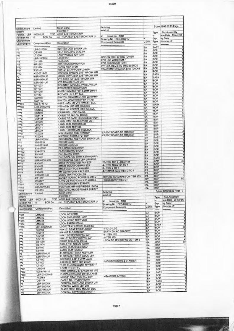
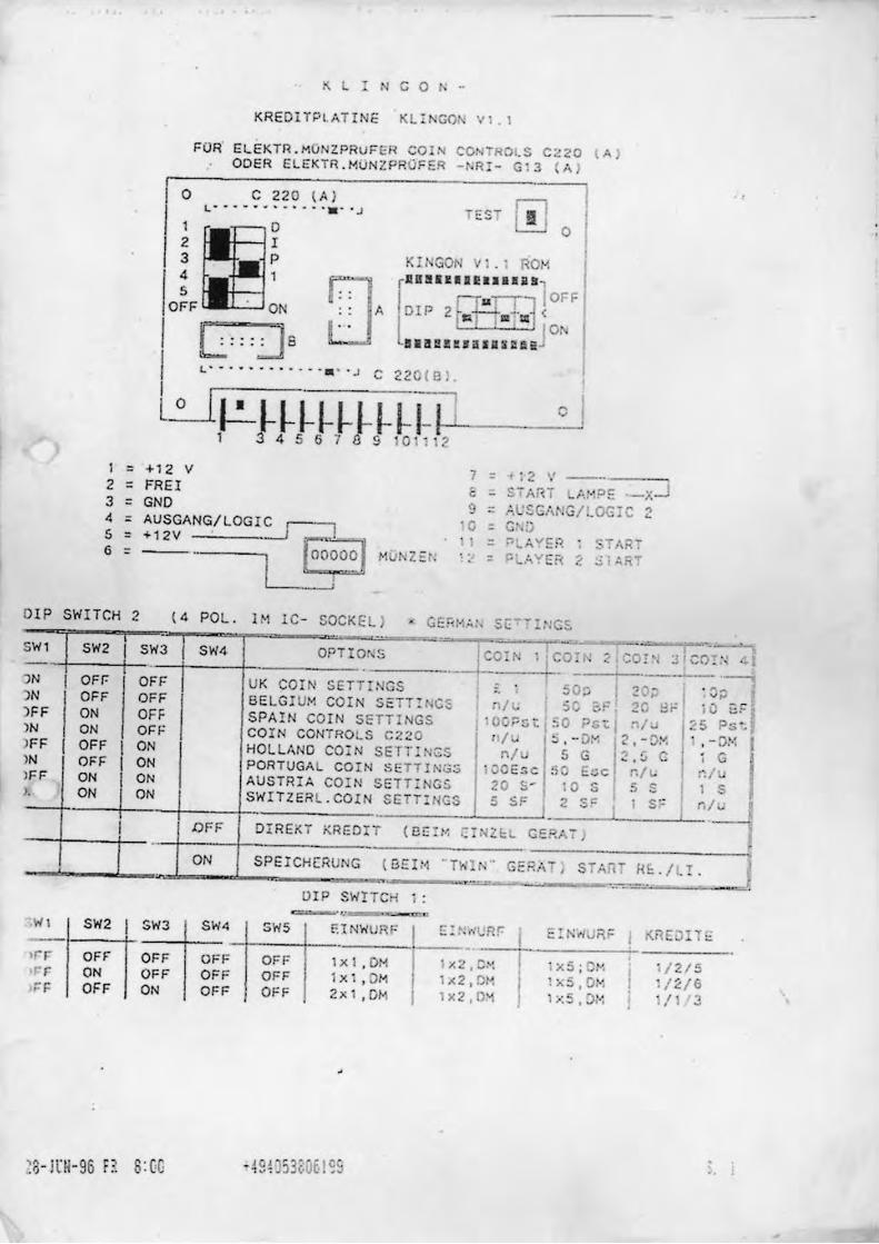
KREDI TP LATIN E KL I 'GO Vl 1
FUR ELEKTR , MO ZPRuFER CO ce, - ROI, S C,20 ( A I COER ELEKTR .MUNZPR0 FER - ~ R I - a13 A)
o C 22 0 ( A I L-- - --. ·-· · · .• · · J
'~O 2 I 3 P 4 1
O~F ' ON r, , ,
[" 'J 6 . . . . .
TEST [!]O K': NGON VI. I ROM
[
1111111 1 II! 1 •• 1 1181 'fuin OFF
A DIP 2~(
J O~ alaIlU.iJ.IJ::!Di
L 0
V 7 = V - - " +12 , 12 2 = FREI e - -ART LMo{ ?£ -x--.l 3 = GNO 9 = A ,c CA ! . / .OG: C 4 = AUSGANG/LOGlc:.J I ' 0 = .. • .. 0 5 = +12V .
EoO~1 ' 1 = ~L'; " ER _TAR7 6 = M z= ' , ' = j::L,; YER ~ Ji :. fi:" " '
I I
OIP SWITCH 2 ( 4 POL . 1 M lC - SOCKEl) .,. Gr:. , ''lAt . sc - ~ IN S
~ .. I I - - ,
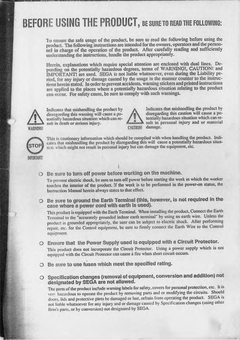
, I :c SW2 SWJ SW4 OPTI O~S COIf',; 1 ; CO~ h ._-- '-' ')N I OFr- OFF UK CO I N SETT t. GS " ~O ;. I 2 ')N OFF OFF BELG IUl< COIN SETTH;CS I ~ " of " , , )FF ON OFF SPAIN COIN SETTI GS I ' OOP5t l ' 0 ps t l n ) N ON OF F COIN CONTROLS C ~20 "I i 5 ,,, 0,' 12, )FF I OFF I ON HOlL/,NO COi N SETT : N~S nl 5 G ., -. IN OFF I ON PORTUGAL COIN SE TT1Nu:; IvO E5 C 50 Ecc n )FF ON I ON AUSTRIA COI N SET T: OS 20 S- 10 S 5 J, ON i ON SWITZER L, COI N SE n : GS 5 ~F i 2 s= I .. .. I i nFF DIREKT KRE OI T ( Cr:! M c: Z. L CERA";" ) .. -
ON SPErCH[ RUNC ( 5 £11 ·· nnr, N GE " • $T';O-= -~ ....
DI P SwnCH 1: = " 'WI SW2 I SW3 SW4 5WS F.1 NWURF ~: r :~~_ E ~ ' rl v RF ';;:-£1 OF F
OFF OFF l .xI , OM 1 ... 2 . C~ I 1 x5;~"'" r- r ON OFF OFF OFF ix ' , 0M lJ(2, DI~
I !:....S , Ot .. , ;: F OFF ON OFF OFF 2>: 1 • OM lx 2 10~ , .. :5 . J: .~
:8- I\:H-96 P S:(G , j Oj''',' " 0 0 . ", . ~J .. ' I,: ;0,1
0 •
.. i _~-~ !\ .. ' .... 0 . ... .
v;J . ~i' o 8"= i u E.~
/ J IC5 P5 ' ,
-ox ', "D~': i ' C I ; G I ~ I
S l 'S S " n/~
> ~E:./ t. !.
Kl1DlT"
, 1 215 1/ ~ / 6
i / l "
BEFORE USING THE PRODUCT, BE SURETO READ THEFOLLOWING:
WARNING,
10 ensu,e the safe usage of Ihe produci. be sure 10 read Ihe following before using Ihe product. The following inslruclions are inlended for the owners. operators and the personnel in charge of Ihe operalion of the product. After carefully reading and sufficiently underslanding Ihe inStruClions. handle Ihe produci approp~ialely_
Here in. explanalions which require special allenlion are enclosed \ViO, dual lines. Dcpending on Ihe pOlentially hazardous degrees. lem,s of WARNlNG!. CAUTION ! and lMPORTANT! are used. SEGA is not liable whatsoever. even during O,e Liability period. for any injury or damage caused by Ihe usage in Ole manner counler 10 Ihe instruclions herein staled. In order 10 preyenl accidems. wal1ling Slickers and prinled inslruclions are applied 10 Ihe places where a potenlially hazardous silualion relaling 10 the product can cur. For safely cause. be sure 10 comply with such warnings.
Indicales U,at mishandling the product by dislcgarding this waming will caus~ a potentially hazardous silUllt ion which can rcsull ill death or serious injury. ~
Indicates that mishandling U,e product by disregard ing this caution wilt cause a poI lCl1lially hazardous situation which can re-
• suh in personal injury and or material CAUTION! damage.
'nlis i ~ c3ulionary infoflmuioll which shoult.l be complied wi th when handling the product. Indicalc5 that mishandling Ihe produci by disregard ing this will Ciluse a pOlclltia.lly hazardous situaIhr . .... hich might not result in l>ersonal injury but can damagc tJIC equipment, clC.
o Be sure to turn off power before worlting ?n the machlne_ To prevent electric shock. be sure to lum off power before slaning the work in which the worker touches the interior of llie product. If the work is to be performed in Ihe power-on status, the InSlruclioll Manual herein always states t,o that effec t.
() Be sure to ground the Earth Terminal (this, however, is not required in the case where a power cord with earth Is used). l11is produci is equipped witJl lhc Eanh Tenninal. \Vhcn installing the product, Connect the Earth TcnniuiJl 10 the "accurately grounded indoor earth lenninal" by using an eanh wire. Unless the product IS grounded approprialcly, the user call be subject 10 elcclric shock. After perfomling repillr. CIC. for the COlltrol equipmcnt. be sure to firml y conllcct the Earth \Vire to the Control ,!quipmcm.
o Ensure that the Power Supply used is equipped with a Circuit Protector. 1l1is product docs not inCOrpOfnle lhe Circuil Proteclor. Using a power supply which is nOt eqUIpped with the Circuit Protector can cause a fire when short circu it occurs.
o Be sure to use fuses which meet the specified rating.
o Specification changes (removal of equipment, conversion and addition) not designated by SEGA are not allowed. The pans of tile product include waming labels for safelY , covers for personal protection. CIC. It is , ' {"f\ haz.:lrdous to opcr;lIc the product by removing part . and or modifying the circuits. Should door~ . lid ;md prolective parts be damaged or losi . rcfr:.lin from operating the product. SEGA is nOI liable whatsocvcr for any injury and or damage cau~cd by Specification changes (using Olhl!r
finn 's pans. or by cOlwclsion) 1101 designated by SEGA.

o Ensure that the product is of appropriate Electrical Specifications.
Defore installing the producl, check for Electrical Specifications. SEGA products have a name
I'laic on Wllic:11 Electrical Specifications arc described. Ensure Illal die prodUCI is compalible wil li
the power supply voltage and frequency requirements of the location.
o Install and operate the product In places where appropriate lighting is avail
able, allowing warning labels to be clearly read.
To ensure welY (or the customers. labels and printed instructions describing potentially hazard
ous situation are applied to places where accidents can be caused. Ensure that where the prOduct
is operated has sufficient ligtlling allowing the warnings 10 be re.,d. If any label is peeled orr.
.pply it again immedialely.
o When handling the Monitor, be very careful. (Applies only to the product wi
monitor). 5011"' of ule monitor (TV) parts arc subjecllo high tension vohage. Even afler lUming off powel .
SOll1e ponions are still subjeci to high tension voltage sometimes. Monilor repair aJld replacement
should be performed only by those leehnical personnel who have knowledge of elcetricily and
technical expertise.
In the case where commercially available monitors and printers arc used in this product, only the
contCnlS rclallng 10 th is product are explained herein. Some commercially available equipment
has fUllel ions and reactions nOt Slated ill 11115 manual. Read IhlS manuallogether with the specific
lns truclion Manual of such equipment
Descriptions herein contained m3Y be subJecllo improycmcllI changes without notice.
n it contents cJe';cribed herein arc full y prepared with due can: However, shou ld any question
"fiSC or efTors be fouruJ. please cOntacl SEGA. ,
INSPECTIONS IMMEDIATELY AFTER TRANSPORTING THE PRODUCT TO THE LOCATION.
NOlmally, al Ihe lime of shipmenl. SEGA producls arc in a SlalUS allowing for usage
immedialely afler transporti ng 10 Ihe local ion. Nevertheless , an irregular silualion may
occur during lransportalion. Defore lurning on power. check Ihe fOllowing points 10 en·
~u l e Ihal Ihe produel has been transported in a satisfaclory SlaIUS.
o Arc Iherc any denIed portions ordefecls (cuIS. etc.) on Ihe external surfaces of Ihc cabinel '!
o Are Caslers and Leg Adjuslers damaged?
o Do Ihe power supply vollage and frequency requircrnellls meet wi lh Ihose of the local ion?
o Are all wiring COlllleClors correcll y .and securely connecled? Unless connecled in Ihe
COITCCl direction. connector connections can not be made accurately. Do not insert con
neClors forcibly.
o Are all les of each Ie DO firnlly inserted?
o Do power cords have culS and dents?
o Do Ihe fuses used meel specified raling? Is the Circuil Proleclor in an energized SIal us?
o Al e such unils as Monilors. Conlrol equipmenl. IC BD, elc. finnl y secured? Arc all Eanl
\Vircs COnlICCICU"!
o A,e all accesso ries available?
o Call all Doors and Lids be opened wilh Ihe Accessory keys? Can Doors and Lids be
finn ly closed?
a il-
lrduc. ,rr.
wI
cr. :nt ,d
IC
11
C
========== TABLE OF CONTENTS ========== I NTRODUCTI ON TD THE OWNER' S MANUAL
1. HANDLING PRECAUTIONS. _______ • ____ ... __ ... ....... . 2. PREVENTI ON OF COUNTERFE I T I NG AND CONYERS I ON •• • .•• 3. PRECAUTIONS CONCERNING INSTAlLATION LOCATION •• ••. 4. NAME OF PARTS ••••• ••• • •• •••••••••••••••••••.•.•. 5. ACCESSORIES ..................................... _ 6. PRECAUT IONS TO BE HEEDED WHEN ASSEMBL I NG AND
MOVING THE MACHINE ............................. .. 7. HOW TO PLAy .................................... .. B. EXPLANATION OF TEST AND DATA DiSPLAy •••••••••• •••
8-1 SWITCH UNIT ............. .. ...... . .. ...... .. 8-2 TEST MODE . ................................ . B-3 MEMORY TEST •• • ••••••• •• •• ••• • • ••••• •• •••••• 8-4 I NPUT TEST ................................ . 8-5 SOUND TEST •••• •• •• • •••••• • •••• • •••••••••.•• 8-6 C. R. T. TEST .............................. .. 8-7 CO I N ASS I GNI.IENT ........................... . 8-8 GAME ASSIGNMENTS ••••••• •• ••••• •••••• •• • •••. 8-9 OUTPUT TEST ••••••••••••••••••••••••••••••••
8-10 DRIVE BD TEST ............................ .. 8-11 BOOKKEEP I NG .............................. .. 8-12 BACKUP DATA CLEAR ...................... ..
9. CONTROL PANEL(HANDLE MECHA) .. • .•. .. ....•...•.. ... 9-1 REPLAC I NG AND ADJUST I NG THE HANDLE's
(STEERING WHEEL's) V. R .. .... ......... . . . . . 9-2 GREASING ............... ; .................. . 9-3 REMOVING THE CONTROL PANEL ............... ..
10. ACCELERATOR & BRAKE ................... . ; ....... .. 1 0-1 ADJUSTIIENT AND REPLACEMENT OF VOLUME ••••••• 10-2 GREASING .... ...... ....................... ..
11. 4 SPEED SH I FTER ................................. . 11-1 REMOVING THE SHIFTER ..................... .. 11-2 REPLACEMENT OF SW I TCH . ........ . .......... .. 11-3 GREASING ................................. ..
12. CD I N SELECTOR ................ .. ................ .. 13. MONITOR ADJUSTMENTS .... ......................... . 14. REPLAC I NG THE FLUORESCENT LAMP. AND LAMPS •• •• ••• • 15. PERIODIC CHECK ............. . ................... .. 16. TROUBLESHooTi NG ................................. . 17. GAME BOARD ..................... ... .............. .
17-1 REMOV I NG THE BOARD ........................ . 17-2 COMPOSITION OF GAME BOARD • ••••••••••••••••• 17-3 I NPUT AND OUTPUT RELA T IONS ... : ............. .
18. DESIGN RELATED PARTS ............................ . 19. COMMUNICATION PLAy ............................. ..
19-1 INSTAlLATION PRECAUTIONS • •••• • •••••••••• ••• 19-2 CONNECTING THE COUMUNICATION CABLES ...... .. 19-3 SETT I NG FOR eot.o.IUN I CATION PLAY ............ . 19-4 CAUT I ONS TO BE t£EIlED !!HEN US I NG THE TEST IIOOE ..
20. PARTS LI ST ................ .... ................. . . 21. WIRE COLOR CODE TABLE .......................... .. 22. WIRING DIAGRAM ...... : .......................... .
I 2 3 4 5
6 -13 14-16 17-34 18 19 20 21 22 23 24-27 28 29 30-31 32-33 34 35-36
35-36 36 36 37-38 37-38 38 38-39 38 39 39 40 41 42 42 43 44-45 44 45 5
46-48 48-51 48 48-51 51 51 52-96
7 98-99
Insta llat Ion space
Heighl Weighl Power. maxinun current
For TAIWAII Patter. cur renl
lION I TOR
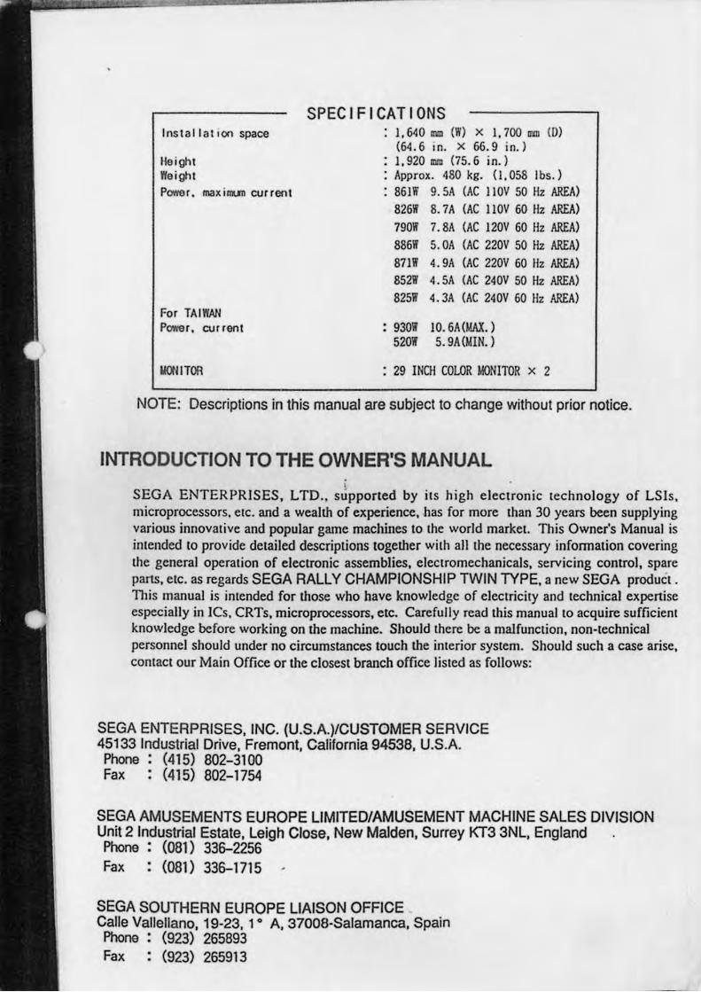
SPECIFICATIONS : I. 640 mm (W) x I, 700 am (0)
(64.6 In. X 66.9 in.) : 1,920 om (75.6 in.) : Approx. 480 kg. 0,058 Ibs.) : 861W 9.5A (AC IIOV 50 Hz AREA)
826W 8.7A (AC llOV 60 Hz AREA)
790W 7.8A (AC 120V 60 Hz AREA)
886W 5.0A (AC 220V 50 Hz AREA)
871W 4. 9A (AC nov 60 flz AREA)
852W 4.5A (AC 240V 50 Hz AREA) 825W 4. 3A (AC 240V 60 liz AREAl
: 930W 10. 6A (MAX. ) 520W 5.9A(MIN.)
: 29 INCH COLOR MONITOR X 2
NOTE: Descriptions in this manual are subject to change without prior notice.
INTRODUCTION TO THE OWNER'S MANUAL ,
SEGA ENTERPRISES, L TO .. supported by ils high electronic lechnology of LSls, microprocessors, elc. and a wealll! of experience, has for more than 30 years been supplying various innovative and popular game machines to the world market. This Owner's Manual is intended to provide detailed descriptions together with all the necessary information covering the general operation of electronic assemblies, electromechanicals, servicing control, spare parts, etc. as regards SEGA RALLY CHAMPIONSHIP TWIN TYPE, a new SEGA product . This manual is intended for those who have knowledge or electricity and technical expenise especially in ICs, CRTs, microprocessors, etc. Carefully read this manual to acquire sufficiem knowledge before working on the machine. Should there be a malfunction, non-technical personnel should under no circumstances touch the interior system. Should such a case arise, contact our Main Office or the closest branch office listed as rollows:
SEGA ENTERPRISES, INC. (U.S.A.)/CUSTOMER SERVICE 45133 Industrial Drive, Fremont, California 94538, U.S.A. Phone : (415) 802-3100 Fax: (415) 802-1754
SEGA AMUSEMENTS EUROPE LIMITED/AMUSEMENT MACHINE SALES DIVISION Unit 2 Industrial Estate, Leigh Close, New Malden, Surrey KT3 3NL, England Phone : (081) 336-2256 Fax: (081) 336-1715
SEGA SOUTHERN EUROPE LIAISON OFFICE Calle Vallellano, 19-23, 1 0 A, 37008-Salamanca, Spain Phone : (923) 265893 Fax: (923) 265913
- -- --- ---~--
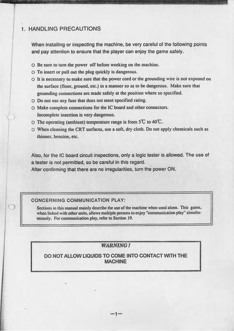
1. HANDLING PRECAUTIONS
When installing or inspecting the machine. be very careful of the following points
and pay attention to ensure that the player can enjoy the game safely.
o Be sure 10 tum Ihe power off before working on Ihe machine.
o To insert or pull oUI Ihe pfug quickly is dangerous.
o II is necessary 10 make sure Ihallhe power cord or Ihe grounding wire is not exposed on
Ihe surface (noor. ground. elc.) in a manner so as 10 be dangerous. Make sure Ihal
grounding conneclions are made safely allhe posilion where so specified.
o Do not use any fuse Ihal does nOI meel specified raling.
o Make complele conneclions for Ihe IC board and olher conneClors.
Incomplele insertion is very dangerous.
o The operaling (ambient) lemperalure range is from 5'C 1040'C.
o When cleaning Ihe CRT surfaces. use a sofl. dry clolh. Do nOI apply chemicals such as
Ihinner. benzine. elc.
Also. for the IC board circuit inspections. only a logic tester is allowed. The use of
a tester is not permitted. so be careful in this regard. After confirming thaI there are no irregularities. tur~ the power ON.
CONCERNING COMMUNICATION PLAY:
Sections in this manual mainly describe the use of lhe machine when used alone. n,is game. when linked wilh other units. allows multiple persons to enjoy "communication play" simuhancously. For communication play, relel to Section J9.
WARNING!
DO NOT ALLOW [IQUIOS TO COME INTO CONTACT WITH THE MACHINE
-1-
I
2. PREVENTION OF COUNTERFEITING AND CONVERSION
III LABELLING
To prcven! counterfeits and conversions. the following labels arc put on all the SEGA products.
When handling such goods, be sure to confirm the labels. They are used to prevent illegal acts
such as the unauthorized copying of the products and the printed circuit boards thereof or carry·
ing on business by manufacturing similar merchandise or by convening, selling or using such
products or printed circuit boards.
ORIGINAL SEAL
TIle following seal is. pUI on Ihe
machines manufactured by SEGA.
...................................
III COPYRIGHT NOTICE
LICENSE SEAL
The following seal is put on all SEGA kits.
such as the pnnlcd clrcuil board .
NO.
'nlis SEGA produc~ has the copyright notice as follows:
©SEGA 1994
This signifies that this work was disclosed in 1994 and is the propeny of
SEGA ENTERPRISES.,LTD.
-2-
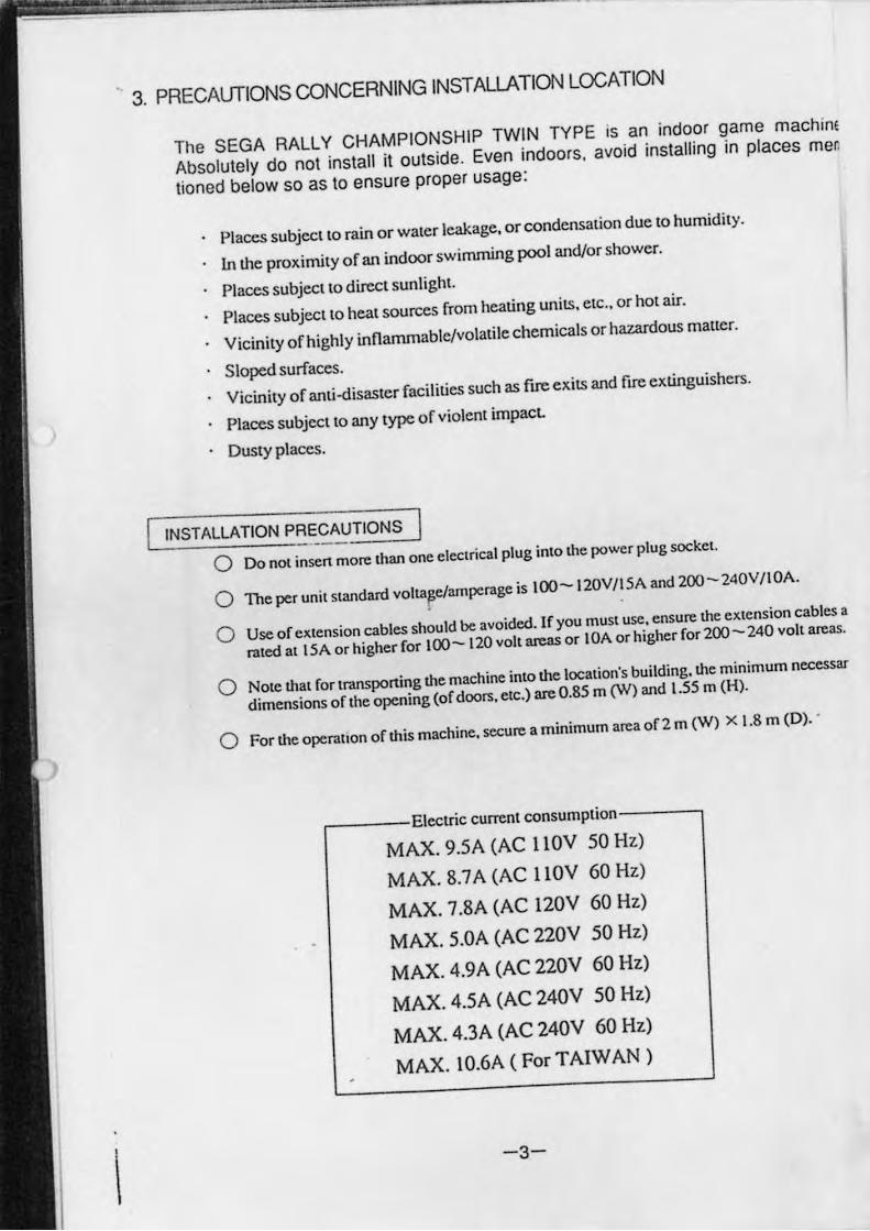
3. PRECAUTIONS CONCERNING INSTALLATION LOCATION
The SEGA RALLY CHAMPIONSHIP TWIN TYPE is an indoor game machim
Absolutely do not install it outside. Even indoors. avoid installing in places men
tioned below so as to ensure proper usage:
Places subject to rain or water leakage. or condensation due to humidity.
In the proximity of an indoor swimming pool and/or shower.
Places subject to direct sunlight.
Places subject to heat sources from heating units. etc., or hot air.
Vicinity of highly inflammable/volatile chemicals or hazardous matter.
Sloped surfaces.
Vicinity of anti-disaster facilities such as ftre exits and ftre extinguishers.
Places subject to any type of violent impacL
Dusty places.
INSTALLATION PRECAUTIONS
o Do not insen more than one electrical plug into the power plug socket .
o The per unit standard voltaFe/amperage is 100- I 20V/I SA and 200 - 240V /I OA.
o Use of cJtlension cables should be avoided. If you must use, ensure the extcnsion cables a
rated at 15A or higher for too- 120 volt BJeaS or lOA or higher for 200- 240 volt areas.
o Note that for transponing the machine into the location's building. the minimum necessar
dimensions of the opening (of doors. etc.) are 0.85 m (W) and 1.55 m (H).
o For the operation of this machine. secure a minimum area of 2 m (W) X 1.8 m (D) . .
,----Electric current consumption----,
MAX. 9.5A (AC llOV SO Hz)
MAX. 8.7 A (AC llOV 60 Hz)
MAX. 7.8A (AC 120V 60 Hz)
MAX. 5.0A (AC 220V SO Hz)
MAX. 4.9A (AC 220V 60 Hz)
MAX, 4.5A (AC 240V SO Hz)
MAX. 4.3A (AC 240V 60 Hz)
MAX. 1O.6A ( For T AIW AN )
-3-
chine men
es are oas.
iSary
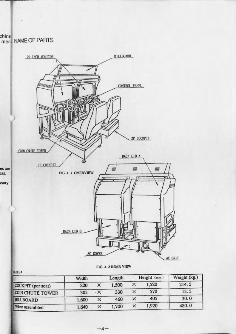
NAME OF PARTS
COCKPIT (per seat)
COIN CHUTE TOWER
BILLBOARD
When assembled
A L D
Widlh
820
305 ),600
1,640
RACK LID A \
A UN T
FIG. 4. 2 REAR VIEW
Lcnglh Heighl (mm ) Weight (kg.)
X 1,500 X 1,520 214.5 . X 330 X 570 13. 5
X 460 X 405 30.0 X 1,700 X 1,920 480.0
-4 -
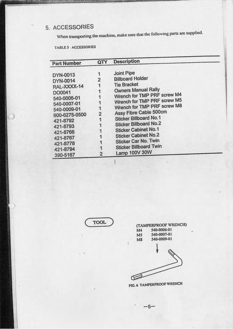
'. 5. ACCESSORIES
W hen lransponing the machine, make sure lhallhe fo llowing parts arc supplied .
TAB LE 5 ACCESSORI ES
Part Number QTY Description
DYN-0013 1 Joint Pipe
OYN-0014 2 Billboard Holder
RAL-XXXX-14 1 Tie Bracket
000041 1 Owners Manual Rally
540-0006-01 1 Wrench for TMP PRF screw M4
540-0007-01 1 Wrench forTMP PRF screw M5
540-0009-01 1 Wrench for TMP PRF screw M8
600-6275-0500 2 Assy Fibre Cable 500cm
421-8792 1 Sticker Billboard No.1
421-8793 1 Sticker Billboard No.2
421-8766 1 Sticker Cabinet No.1
421-8767 1 Sticker Cabinet No.2
421-8778 1 Sticker Car No. Twin
421-8794 1 Sticker Billboard Twin
390-5167 2 Lamp 100V 30W
( TOOL) (TAMPERPROOF WRENCH) M4 540-0006-01 M5 540-0007-0 I M8 540-0009-0 I
FIG. 6 TAMPERPROOFWRENCH
-5-
- - - - _ .. - ------_. - --_._ ...... _._---- ----- - --
6. PRECAUTIONS TO BE HEEDED WHEN ASSEMBLING AND MOVING THE MACHINE
WARNING:
• Perform the assembly work by following the procedure herein stated. Failing to comply with the instructions. for example. Inserting the plug into an outiet at the stage not mentioned in this manual might cause an electric shock accident.
• Assembling should be performed as per this manual. Since this is a complex machine. erroneous assembling may cause damage to the machine. or malfunctioning to occur .
• When assembling. be sure to perform the work by plural persons .
When carrying out the assembly work. follow the procedure in the following 7 0 item sequence:
OJ ASSEMBLING THE COCKPIT
[1J SECURING IN PLACE (LEG ADJUSTER ADJUSTMENT)
[I) INSTALLING THE BILLBOARD m INSTALLING THE AC COVERS (WIRING CONNECTION)
[[] POWER SUPPLY. AND E~RTH CONNECTION
[§J TURNING THE POWER ON
[ZJ ASSEMBLY CHECK
Note that the master key and the cashbox door key (accessories) in addition to the tools such as a plus screwdriver. wrench for M 16 hexagon bolt and socket wrench are required for the assembly work.
CAUTION: P&rform the tightening of hexagon boits described in m above after · adjusting the leg adjusters as per [n Make sure that until the leg adjuster adjustments are made. keep the hexagon boits tightened temporarily .
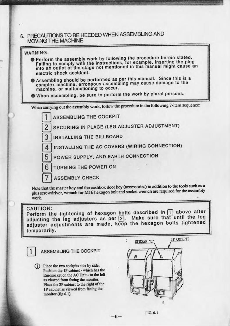
[IJ ASSEMBLING THE COCKPIT
<D Place the two cockpits side by side. Position the I P cabinet - which has the Eurosocket on the AC Unit - to the left as viewed from facing the monitor. Place the 2P cabinet to the riglU of the I P cabinet as viewed from facing the monitor (fig 6.1).
-6-
STICKER' • IT
FIG. 6. I
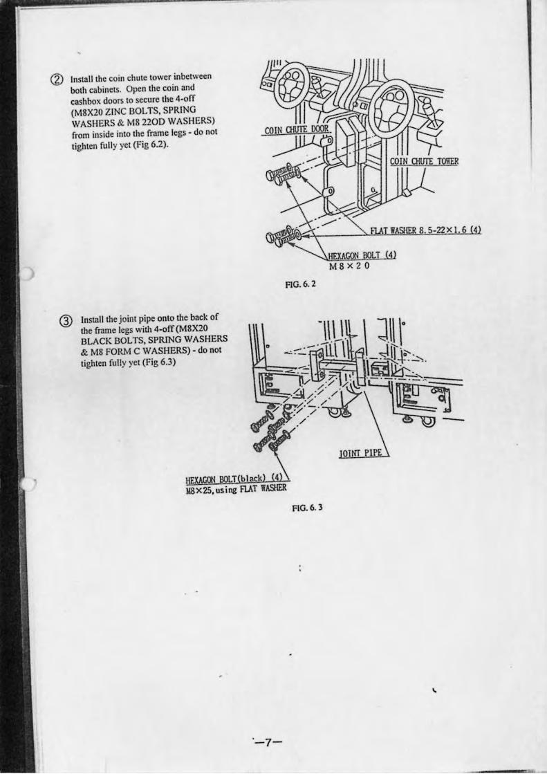
Install the coin chute tower inbctween both cabinets. Opcn the coin and cashbox doors to secure the 4-off (M8X20 ZINC BOLTS. SPRING WASHERS & M8 2200 WASHERS) from inside: into the frame legs - do not tighten [ully yet (Fig 6.2).
Insta ll the joint pipe onto the back of the [rame legs with 4-off(M8X20 BLACK BOLTS. SPRING WASHERS & M8 FORM C WASHERS) - do not tigh ten [ully yet (Fig 6.3)
'-7-
I 4 M8x20
FIG. 6. 2
FIG. 6. 3
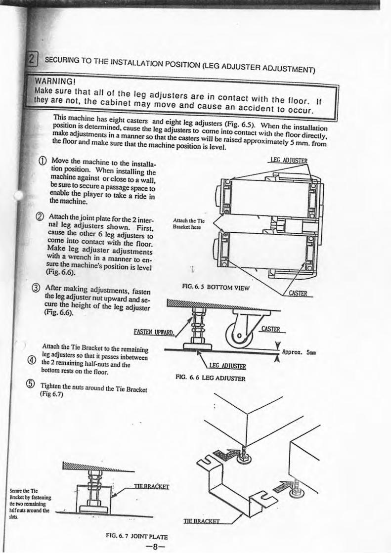
SECURING TO THE INSTALLATION POSITION (LEG ADJUSTER ADJUSTMENT)
ING! Make sure that all 01 the leg adjusters are in contact with the floor. If they are not, the cabinet may move and cause an accident to occur.
This machine has eight casters and eight leg adjusters (Fig. 6.5). When the installation position is delcnnined. cause the leg adjusters to come into contact with the floor directly. make adjustments in a manner so that the casters will be raised approximately 5 mm. from the floor and make sure that the machine position is level.
<D Move the machine to the installation position. When installing the machine against orelose to a wall, be sure to secure a passage space to enable the player to take a ride in the machine.
(2) Attach the joint plate for the 2 internal leg adjusters shown. First, cause the other 6 leg adjusters to come into contact with the floor. Make leg adjuster adjustments with a wrench in a manner to en· sure the machine's position is level (Fig. 6.6).
After making adjustments. fasten the leg adjuster nut upward and secure the height of the leg adjuster
Attach the Tie Bracket here
i
FIG. 6. 5 BOlTOM VIEW
(Fig. 6.6).
f.\SJD/ UPWIl, /: , Attach the Tie Bracket to the remaining leg adjusters so that it passes inbetween the 2 remaining half-nuts and the bonom rests on the noor.
@ Tighten the nuts around the Tie Bracket (Fig 6.7)
TtO'
FIG. 6.6 LEG ADJUSlCR
ScQR the lie 8fJdtcl by fastenmg Ihc: l'II'O rc:mainln& Uj( nuts around the IIoCs.
FIG. 6. 1 JOINT PLAlE
-8-
•
After securing (he tLfht of the adjusters. tighten all of the hexagon boilS which were
temporarily as per 1 above.
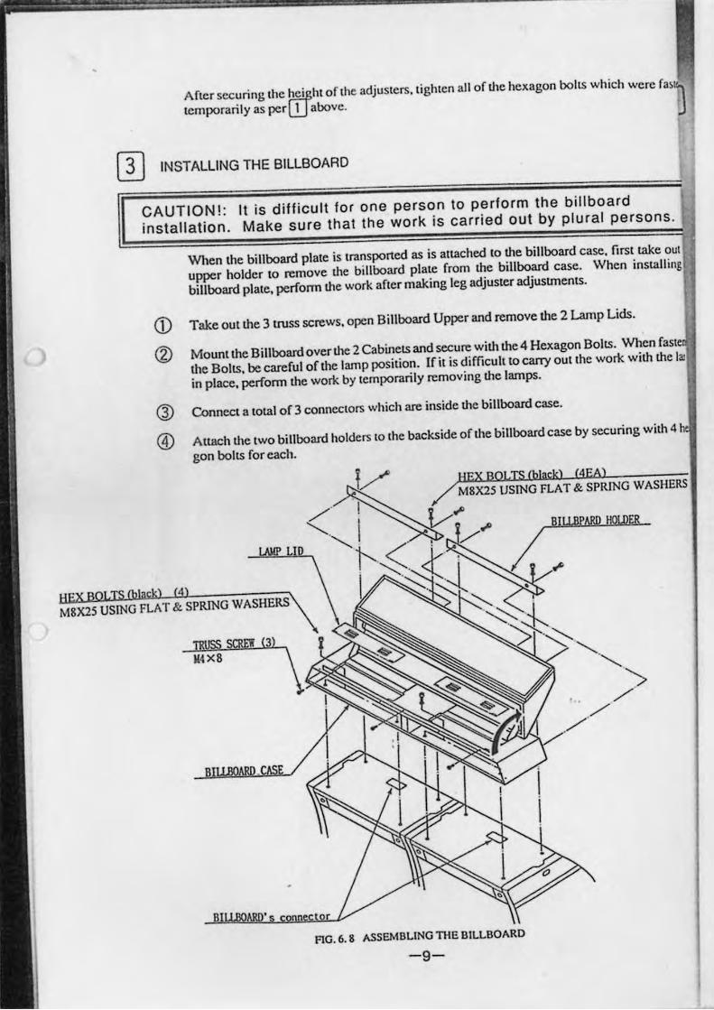
[I] INSTALLING THE BILLBOARD
CAUTION! : It is difficult for one person 10 perform the billboard
installation. Make sure thai Ihe work is carried out by plural persons .
When the billboard plate is lransported as is altached to the billboard case. first take oul
upper holder to remove Ihe billboard plate from Ihe billboard case. When installing
billboard plale. perform the work afler making leg adjusler adjustmenlS.
CD Take out the 3uuss screws. open Billboard Upper and remove the 2 Lamp Lids.
<Z:l Mount the Billboard overth. 2 CabinelS and secure with the 4 Hexagon BollS. When fasl
the BollS. be careful of the lamp position. If il is difficullto carry oUllhe work with the I~
in place. perform the work by lemporarily removing the lamps.
@ Connecl a total of 3 connectors which are inside the billboard casco
@) Altach Ihe two billboard holders 10 Ihe backside oflhe billboard case by securing Wilh 4
gon boilS for each.
HEX BOLTS (black) MEA)
BIY.BPARD HOlDER
M8X25 USING FLAT & SPRING WASHERS
TRUSS SCRE't! (3 )
U4X8
FlG. 6. 8 ASSEMBLING TIlE BILLBOARD
-9-
·e
~S .
: out lIing
lSlen
" I.,
4 he
:RS
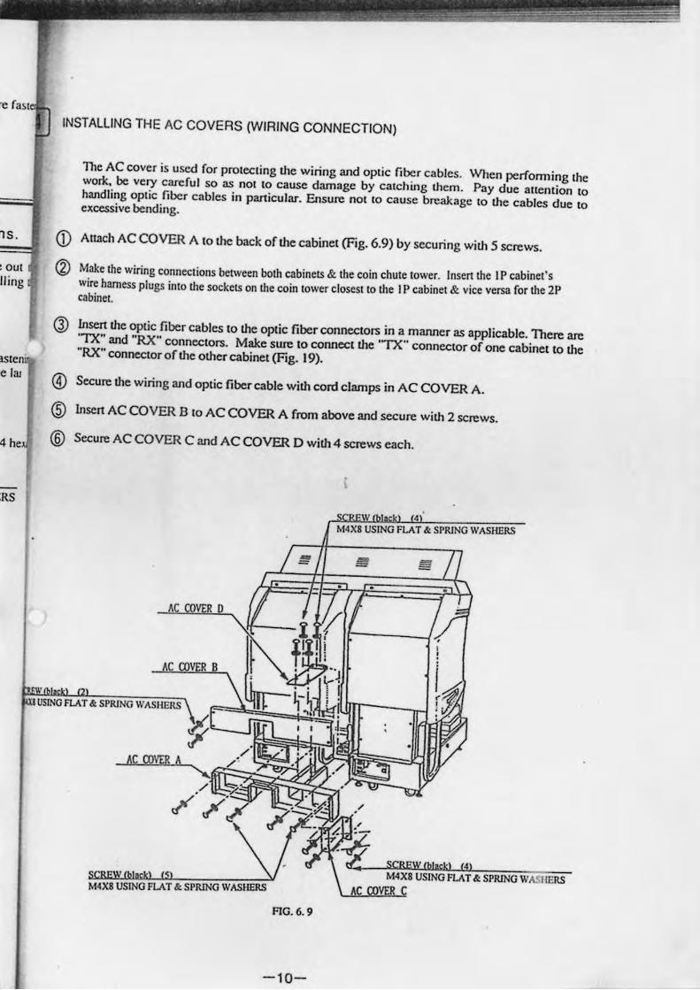
INSTALLING THE AC COVERS (WIRING CONNECTION)
<D (2)
@
The AC cover is used for protccting the wiring and optic fiber cables. When performing the work. be very careful so as not to cause dam3ge by catching them. Pay due attention 10 handling optic fiber cables in panicular. Ensure not 10 cause breakage to the cables due to excessive bending.
Attach AC COVER A to the back or the cabinet (Fig. 6.9) by securing WiU15 screws.
Make the wiring connections between both cabincts & the coin chute tower. Illsen the IP cabinet's wire harness plugs into the sockets on the coin lower closest to the J P cabinet & vice versa for the 2P cabinel.
Insen the optic fiber cables to the optic fiber connectors in a manner as applicable. There are 'TX" and "RX" connectors. Make sure to connect the 'TX" connector of one cabinet to the "RX" connector of the other cabinet (Fig. 19).
® Secure the wiring and optic fiber cable with cord clamps in AC COVER A.
® lnsen AC COVER B to AC COVER A from above and secure with 2 screws.
(§) Secure AC COVER C and AC COVER D with 4 screws each.
USING FLAT&.
, FLAT &. SPRING WASHERS
M4X8 USING M4X8USING
FIG. 6. 9
-10-
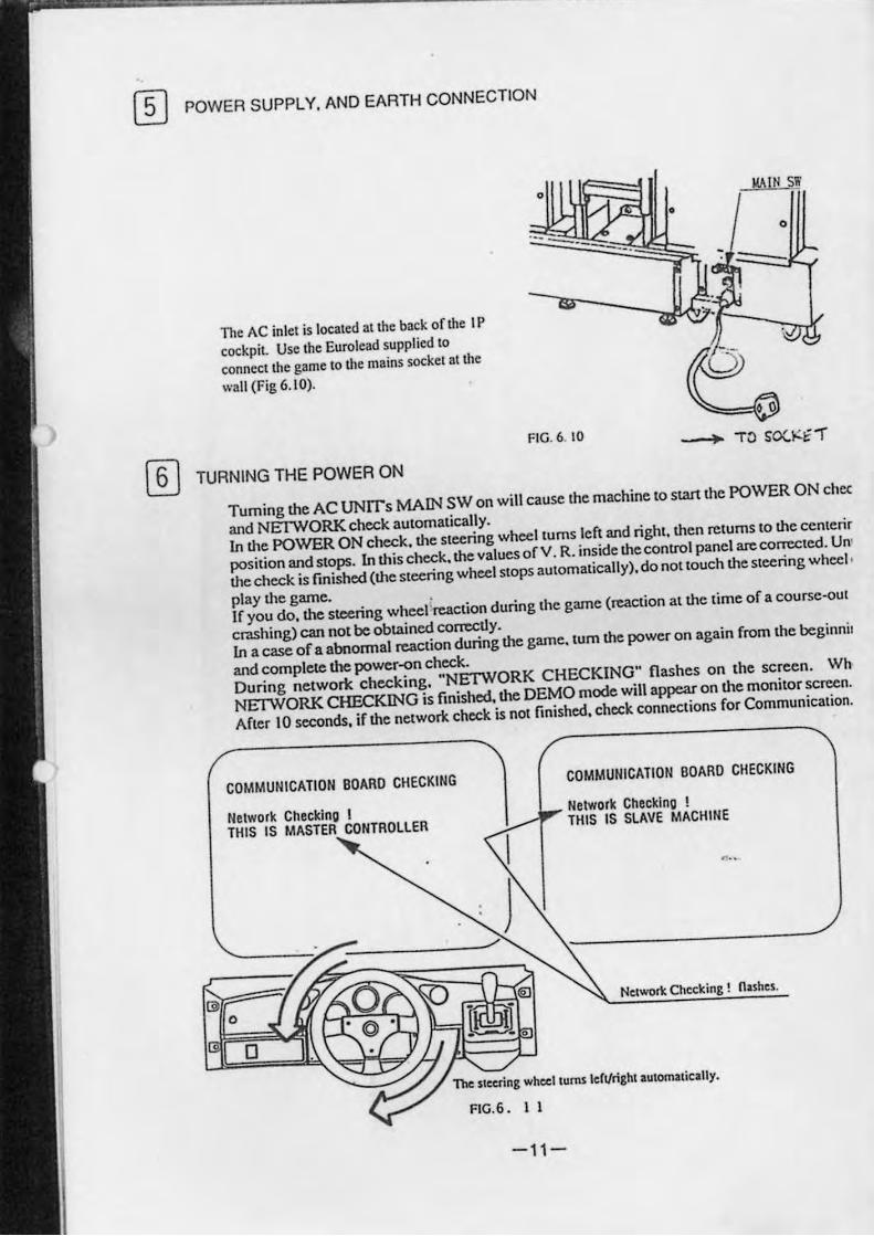
m POWER SUPPLY. AND EARTH CONNECTION
The AC inlet is located at the back of the I P
cockpit. Use the Eurolead supplied to
connect the game 10 the mains socket 3t the
wa ll (Fig 6.10).
o
"- --.;;- ---..;:- - .
FIG. 6. 10
I!r\IN S!,
• o
~ TURNING THE POWER ON
o
Turning the AC UNITs MArN SW on will cause the machine to stan the POWER ON chcc
and NElWORK check automatically.
In the POWER ON check. the Slcering wheellums left and right. then relums to the cenlenr
position and stops. In this check. the values of V . R. inside the control panel are corrected. Un'
the check is rmished (the sleering wheel SlOpS automatically). do not touch the steering wheel ,
play the game. .
If you do, the steering wheel reaction during the game (reaction at the time of a course-oU(
crashing) can not be obtained conectJy.
In a case of a abnonnal reaction during the game. lum the power on again from the beginnir
and compleIC the power-on check.
During networle checking. "NElWORK CHECKING" flashes on the screen. Wh
NElWORK CHECKING is finished. the DEMO mode will appear on the monitor screen.
After 10 seconds. if the network check is not finished. check connections for Communication.
COMMUNICATION BOARD CHECKING COMMUNICATION BOARD CHECKING
Nelwork Checking I Network Checking !
THIS IS MASTER CONTROLLER THIS IS SLAVE MACHINE
, ..
Network Checking! n:ashes.
o
o
FIC.6 . I 1
-11-
:ck
ng nil or
or
!n
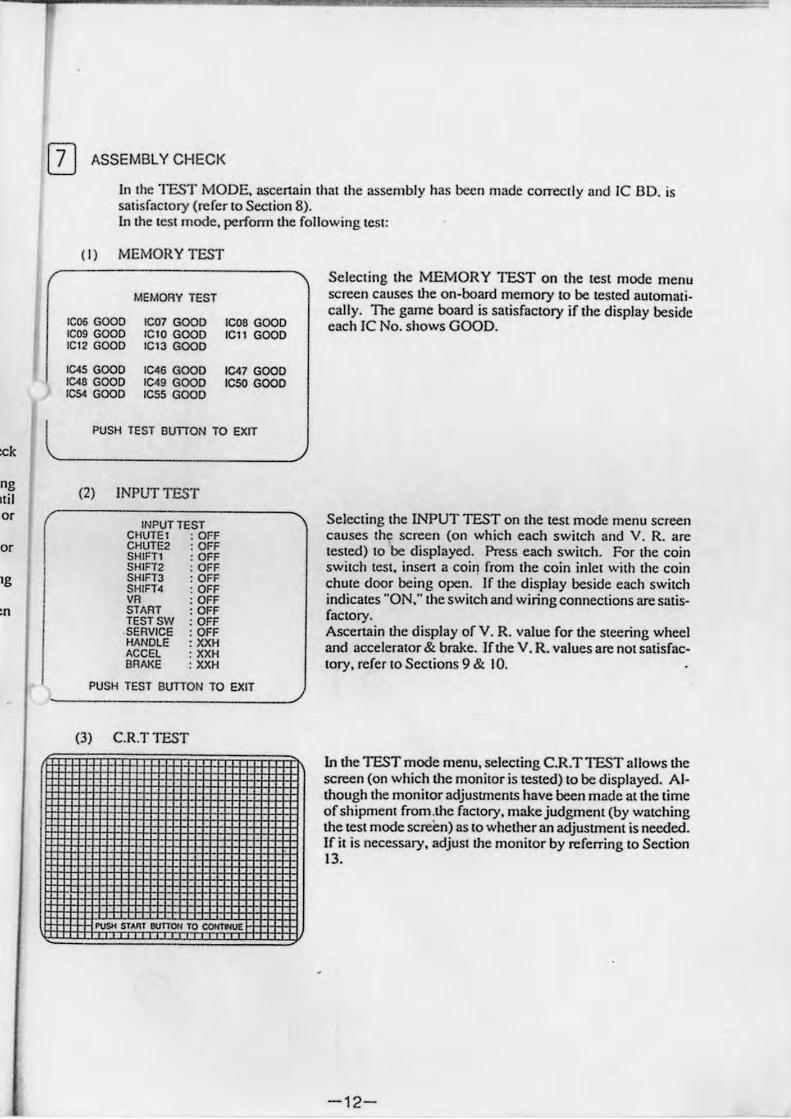
I]] ASSEMBLY CHECK
l
In Ihe TEST MODE. ascerrain ,h., Ihe .ssembly has been made correclly and IC BD. is satisfactory (rerer to Section 8). In the test mode, perfonn the following test:
(I) MEMORY TEST
IC06 GOOD lCog GOOD IC12 GOOD
1C45 GOOD 1C48 GOOD ICs< GOOD
MEMORY TEST
ICO] GOOD lelO GOOD ICl3 GOOD
IC,S GOOD IC'. GOOD ICSS GOOD
ICOS GOOD lell GOOD
IC47 GOOD ICSO GOOD
PUSH TEST BunON TO EXIT
Selecling Ihe MEMORY TEST on Ihe lest mode menu screen causes the on-board memory to be tested aUlamali· cally. The game board is satisfactory if the display beside each IC No. shows GOOD.
'-----------------/
(2) INPUT TEST
INPUT TEST CHUTE1 : OFF CHUTE2 : OFF SHin, : OFF SHIFT2 : OFF SHIFT3 : OFF SHIFT4I : OFF VA : OFF STAAT : OFF TEST SW : OFF SERVICE : OFF HANDLE : XXH ACCEl : XXH BRAKE : XXH
Selecting the INPUT TEST on the test mode menu screen causes the screen (on which each switch and V. R. arc tested) to 'be displayed. Press each switch. For the coin 5wilCh leSt, insen a coir) from the coin inlet with the coin chute door being open. If the display beside each switch indicates "ON," the switch and wiring connections are satisfactory. Ascertain the display of Y. R. value for O,e steering wheel and accelerator & brake. If the V. R. values are nOI satisfactory. refer to Sections 9 & 10.
r' \ PUSH TEST BunON TO EXIT
(3) CR.T TEST
. -
In O,e TEST mode menu. selecting C.R.T TEST allows the screen (on which the monitor is tested) to be displayed. Although the monitor adjusunents have been made at the time of shipment from .the faclory. make judgment (by watching the test mode screen) as to whether an adjustment is needed. IC it is necessary, adjust the monitor by referring to Section 13.
- 12-
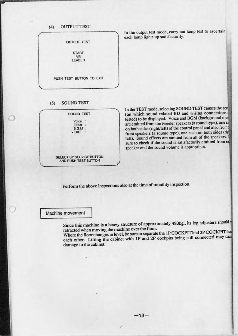
(4) OUTPUT TEST
OU TPUT TEST
START VA
LEADER
PUSH reST BunON TO EXIT
(5) SOUND TEST
SOuND TEST
VOICe
Ellect BGM
, EXIT
SELECT BY SERVICE BUTTON AND PUSH TEST BUTTON
In the OUlpUI leSI mode. carry out lamp ICSl 10 ascerta in I
tach lamp lights up salisfactoflly.
In the TEST mode. selecting SOUND TEST causes the sc
(on which sound related SO and wiring connections
tested) to be displayed. Voice and BOM (background mu
are emined from the tweeter speakers (a round type). one e
on both sides (righl/left) of the conlCol panel and also from
front speakers (3 square type) , one each on both sides (ri
left). Sound effects are emined from all of the speakers.
sure to check if the sound is satisfactorily emined from c
speaker and the sound volume is appropriate.
Perform (he above inspections also at the lime of monthly inspection.
Machine movement
Since this machine is a heavy sl1Ucture of approximately 480kg .• its leg adjusters should
relf3Cled when moving the machine over the floor.
Whecc the noorchanges in level. be sure'o separate the I P COCKPITand 2P COCKPIT f
each other. Lifting the cabinet with IP and 2P cockpits being still connected may ca
damage to the cabinet.
-13-
,
m
"
7. HOW TO PLAY
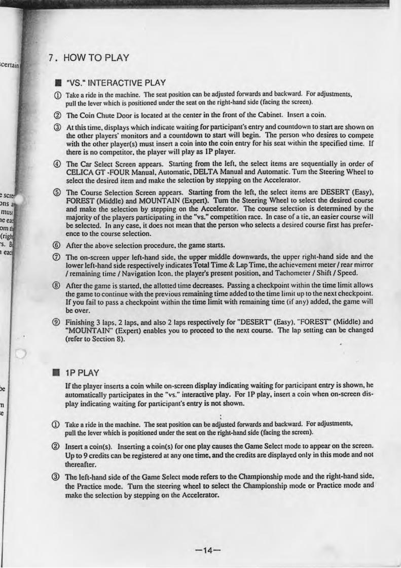
• "VS." INTERACTIVE PLAY CD Take a ride inlhe machine. TIle seat position can be adjusted forwards and backward. For adjuslmclIIs,
pull the lever which is positioned under the scat on the right.hand side (facing Ihe screen).
® The Coin Chute Door is located al the center in the front of the Cabinet. Insen a coin.
0) Allhis time. displays which indicate wailing forpanicipant's entry and countdo ...... n to stan are shown on the other players' monitors and a countdown to start will begin. The person who desires 10 compete with the other player(s) must insen a coin into the coin entry for his scat within the specified lime. If there is no competitor. the player will playas IP player.
@ The Car Select Screen appears. Starting from the left. the select items are sequentially in order of CELICA GT -FOUR Manual. Automatic. DELTA Manual and Automalic. Tum Ihe Sleering Wheel to select the desired item and make the selection by stepping on the Accelerator.
® The Course Selection Screen appears. Starting from the left. the selecl items arc DESERT (Easy). FOREST (Middle) and MOUNTAIN (Ex pen). Tum the Steering Wheel to selecl the desired course and make the selection by stepping on the Accelerator. The course selection is detennined by the majority of the players panicipating in the "ys." competition race. In case of a tic, an easier course will be selected. In any case. it does nOi mean that the person who selects a desired course first has prefer· ence to the course selection.
® After the above selection procedure. Ihe game starts.
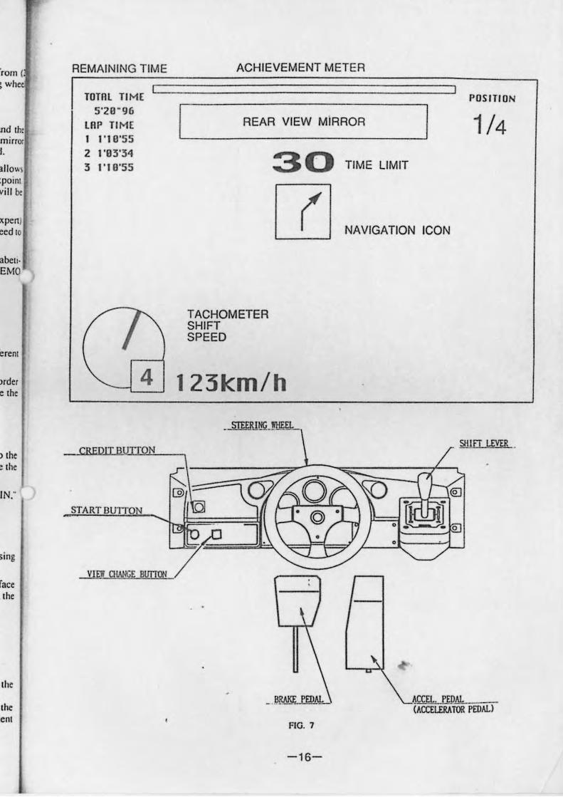
CD The on-screen upper left-hand side. Ihe upper middle downwards. the upper righI-hand side and Ihe lower left·hand side respeclively indicates Total Time & Lap Time. the achievement meier I rear mirror I remaining time I Navigation \con. Ihe pla~er's present position. and Tachomeler I Shift I Speed.
® After the game is slaned, the alloned time decreases. Passing a cheCkpoint within the lime limit allows the game locontinue with the previous remaining time added to the time limil up to the next checkpoint. If you fail 10 pass a checkpoint within the lime limit wilh remaining lime (if any) added. the game will be over.
® Finishing 3 laps. 2 laps. and also 2 laps respectively for "'DESERT' (Easy). "FOREST' (Middle) and "MOUNTAIN" (Expert) enables you 10 proceed to the neXl course. The lap sell ing can be changed (refer to Section 8) .
• 1P PLAY
lfthe player inscns a coin while on·screen display indicating wailing for participant entry is shown. he automatically panicipales in the "vs." interactive play. For IP play, insert a coin when on·screcn dis· play indicating waiting for participant's entry is not shown.
CD Take a ride in the machine. The seat position can be adjusted forwards and backward. For adjustments. pull the lever which is po~itioned under the seat on the right·hand side (facing the screen).
@ Insert a coin(s) . Inserting a coin(s) ror one play causes the Game Select mode to appear on the screen. Up to 9 credits can be registered al anyone time. and the credits are displayed only in this mode and not thereafter.
Q) The left-hand side of the Game Selecl mode refers to the Championship mode and the right-hand side. the Practice mode. Tum the Sleering wheel 10 select the Championship mode or Practice mode and make the seleclion by Slepping on Ihe Accelerator.
-14-
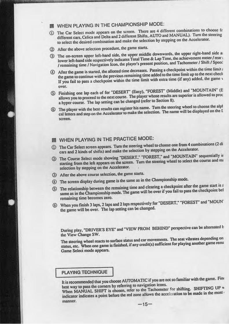
• WHEN PLAYING IN THE CHAMPIONSHIP MODE:
CD TIle Car Seicci mode appears on (he screen. There are 4 different combinations to choose fr
different cars. Celica and Delta and 2 different Shifts, AUTO and MANUAL). Tum the steering
to select the desired combination and make the selection by stepping on the Accelerator.
@ After the above selection procedure. the game stans.
Q) ·n,. on-screen upper left-hand side. the upper middle downwards. the upper right-hand side 3l
lower left-hand side respectively indicates Total Time & Lap Time. the achievement meter I rcar !
I remaining lime I Navigation Icon. the player's present position. and Tachometer I Shift I Spec
® After the game is slaned. the allotted lime decreases. Passing a checkpoint within the time limit;
the game to continue with the previous remaining time added to [he lime limit up to the next ched.
If you fail to pass a checkpoint within the time limit with extra time (if any) added. the game \
over.
® Finishing one lap each of for "DESERT' (Easy). "FOREST' (Middle) and "MOUNTAIN" (E
allows you to proceed 10 the next course. The player whose results are superior is allowed to proc
a hyper course. The lap setting can be changed (refer to Section 8).
® The player with the best results can register his name. Tum the steering wheel to choose the alpl
calleners and step on the Accelerator 10 make the selection. The name will be displayed on the r screen .
• WHEN PLAYING IN THE PRACTICE MODE:
Q) The Car Select screen appears. Tum the steering wheel to choose one from 4 combinations (2 di
cars and 2 kinds of shifts) and make the selection by stepping on the Accelerator.
@ The Course Select mode showing "DESERT." "FOREST: and ".MOUNT AIN" sequentially i.
sraning from the left appears on the screen. Tum the steering wheel to select the course and m:
selection by stepping on the Accelerator.
@ After the above course selection, the game starts.
@ 11le screen display during game is the same as in the Championship mode.
® The relationship between the remaining time and clearing a checkpoint after the game start is,
same as in the Championship mode. The game will be over if you f.ilto pass the checkpoint bel
remaining time becomes zero.
(§) When you finish 3 laps, 2 laps and 2 laps respectively for "DESERT." "FOREST' and "MOUN'
the game will be over. The lap selling can be changed.
During play. "DRIVER'S EYE" and "VIEW FROM BEHIND" perspective can be alternated b
the View Change SW.
TIle steering wheel reacts to surface status and car movements. The seat vibrates depending on
status. e(C. When one game is finished. if any credit(s) sufficient for playing another game renll
Game Seleci mode appears.
PLAYING TECHNIQUE
It is recommendet,lthat you choose AUTOMATIC if you are 1I0t so familiar with the game. Filii
best way to pass the corners by referring to navigation icons.
When MANUAL SHIFT is chosen. ",[er to the Tachometer f r shifting. SHIFTING UP ~
indicator indicates a point before the red lone allows the acceleration to be made in the most '
manner. -15-
'rom ( : whe
nd 'he minOt I.
illlo" s :poml viII Ix
XPCRl ~ed 10
abel!EMO
eren!
)rder e Ihe
IN,"
~ ing
race ,Ihe
Ihe
the em
REMAINING TIME
TOTAL TIME I
5'20 "96 LRP TIME I 1'10'55
2 1'03'34 3 "10'55
-~
4
ON
START BU1TO
Va;! Q!M!!<E BIITTOO
ACHIEVEMENT METER
I POSITION
I REAR VIEW MiRROR I 1/4
30 TIME LIMIT
[{] NAVIGATION ICON
TACHOMETER SHIFT SPEED
123km/h
SH Iff LEVER ,
@>
r l, ,
~CCEL. PEDAL (ACCELERATOR PEDAL)
FIG. 7
-16-
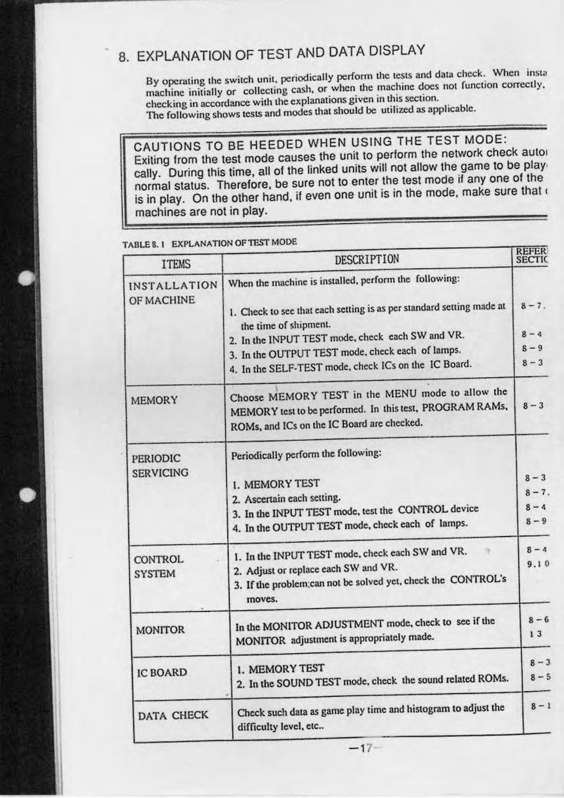
8. EXPLANATION OF TEST AND DATA DISPLAY
By opcrcning the switch unil. periodically pc.rfonn the tests and dalOi check. When insl<J
machine init ia lly or collecting cash. or when the machine does nOI function corrcctly.
checking in accordance with the explanations given in th is section.
The (ollowing shows tests and modes that should be utilized as applicable.
CAUTIONS TO BE HEEDED WHEN USING THE TEST MODE:
Exiting from the test mode causes the unit to perform the network check aUIOI
cally. During this time. all of the linked units will not allow the game to be play.
normal status. Therefore. be sure not to enter the test mode if anyone of the
is in play. On the other hand. if even one unit is in the mode. make sure that I
machines are not in play.
TABLEB. ' EXPLANAT.ONOFlCSTMODE
ITEMS OESeR I PTI ON REFER SECTIC
INSTALLATIO N When lhe machine is installed. perfonn the following :
OF MACH INE I. Check to sec that each selling is as per standard se tt ing made at B - 7 .
the lime of shipment.
2. In .he INPUT TEST mode. check each SW and YR. B - 4
3. In lile OUTPUT TEST mode. check each of lamps. 8- 9
4. In .he SELF-TEST mode. check ICs on .he IC Board. B-3
• MEMORY Choose MEMORY TEST in .he MENU mode '0 allow .he
MEMOR Y .es •• o be performed. In .his .es •• PROGRAM RAMs. 8-3
ROMs. and ICs on .he IC Board are checked.
PERIODIC Periodically perform .he following:
SERVICING l. MEMORY TEST B-3
2. Ascenain each sening. 8 - 7 .
3. In lile INPUT TEST mode .• es •• he CONTROL device 8-'
4. In lile OUTPUT TEST mode. check each of lamps. B-9
CONTROL I. In .he INPUT TEST mode. check each SW and YR. 8-4
SYSTEM 2. Adjus. or replace each SW and YR. 9.' 0
3. If lile problem:can no. be solved ye •. check lite CONTROL's
moves. -
MONITOR In lile MONITOR ADJUSTMENT mode. check.o sec if .he B-6
MONITOR adjus.men. is appropria.ely made. • J
IC BOARD I. MEMORY TEST 8-3
2. In lile SOUND TEST mode. check .he sound reIa.ed ROMs. 8- 5
. DATA CHECK Check such da.a as game play .ime and his.ogram '0 adjus •• he 8-'
difficuI.y level. e.c ..
-1 7
,I<t ll ing
'.
mati· 'ed in unils Jlher
- 8
8
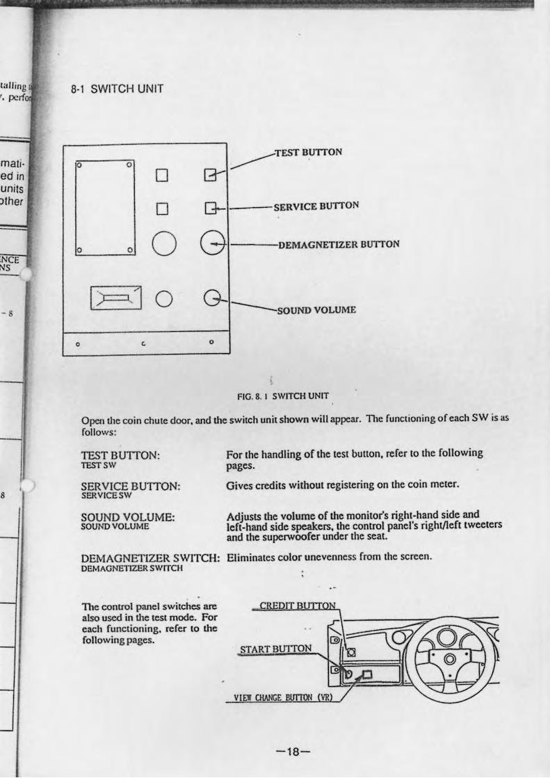
8·1 SWITCH UNIT
TEST SUlTON 0 0
0 G- -----O G- SERVICE SUlTON
0 0 O G DEMAGNETIZER BUlTON
1):=,] 0 G-----SOUND VOLUME
0 < 0
FIG. 8. I SWITCH UNIT
Open Ille coin chute door. and the switch unit shown will appear. The functioning of each SW is as follows:
TEST BUTTON: lCSTSW
SERVICE BUTTON: SERVICESW
SOUND VOLUME: SOUND VOLUME
For Ihe handling of Ihe lesl bUllon. refer 10 Ihe following pages.
Gives credils wilhoul regislering on Ihe coin meier.
Adjusts the volume of the monilor's righi-hand side and lefl-hand side s~ers. the conlrol panel's righl/lefllweelers and Ihe superwoofer under Ihe seal.
DEMAGNETIZER SWITCH: Eliminales color unevenness from Ihe screen. DEMAGNETIZER SWITCH
The conlrOl panel switches are also used in the lest mode. For each functioning. refer to the following pages.
c
START BUlTON
VI EW ClWlGE lIlITro'l VR
-18-
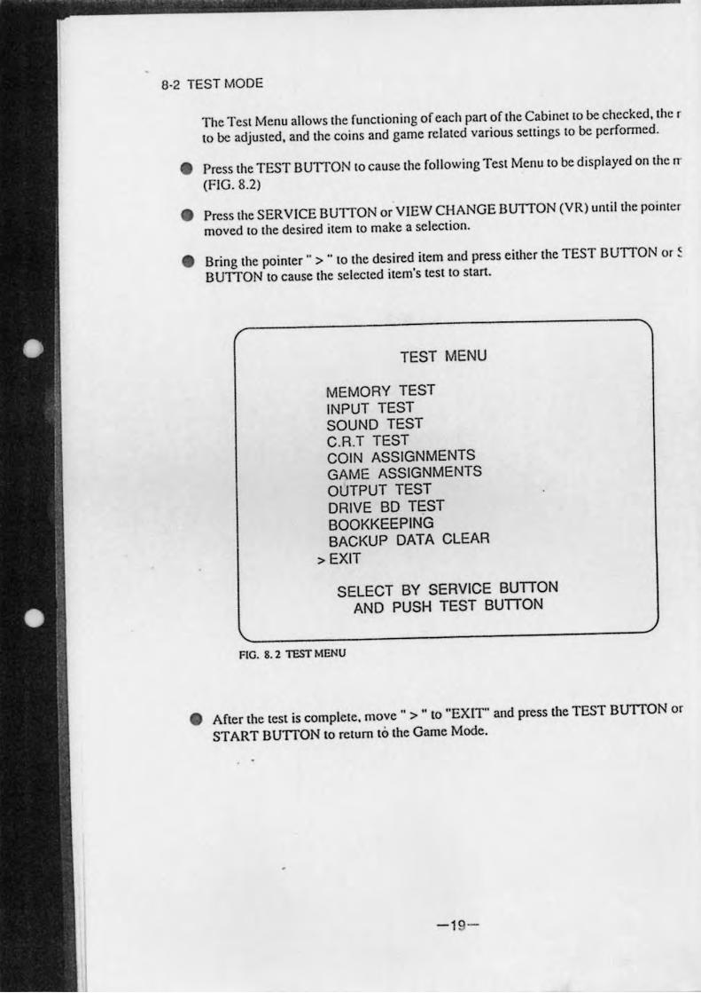
8-2 TEST MODE
The Tesl Menu allows Ihe funclioning of each pall of Ihe Cabinello be checked, Ihe r
10 be adjusled, and Ihe coins and game rel>led various scuings 10 be performed.
• Press Ihe TEST BUTTON 10 cause Ihe following Test Menu 10 be displayed on Ihe IT
(FIG. 8.2)
• Press Ihe SERVICE BUTTON or VIEW CHANGE BUTTON (VR) unlillhe poinler
moved 10 lhe desired item to make a selection.
• Bring the poinler " > .. 10 Ihe desired item and press either the TEST BUTTON or ~
BUTTON to cause Ihe selecled ilem's test 10 stall.
TEST MENU
MEMORY TEST INPUT TEST SOUND TEST C.R.T TEST COIN ASSIGNMENTS GAME ASSIGNMENTS OUTPUT TEST DRIVE BD TEST BOOKKEEPING BACKUP DATA CLEAR
> EXIT
SELECT BY SERVICE BUTTON AND PUSH TEST BUTTON
FIG. 8.2 TEST MENU
• After the lest is complele, move" > " to "EXIT" and press the TEST BUTTON or
START BUTTON to relurn to the Game Mode.
-19-
>nilor
,ilor.
> .. is
ART
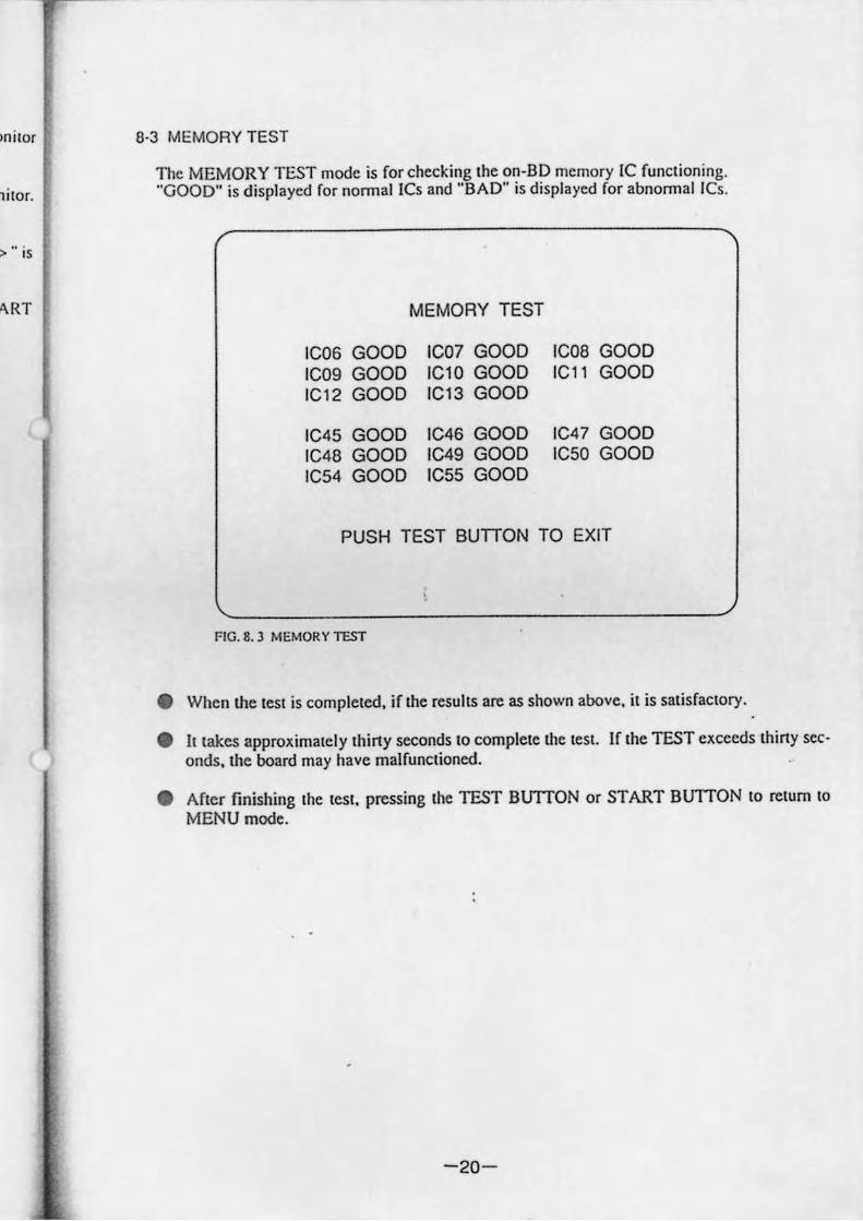
6·3 MEMORY TEST
The MEMORY TEST mode is for checking Ihe on-BD memory IC funclioning. "GOOD" is displayed for nonnal ICs and "BAD" is displayed for abnonnallCs,
MEMORY TEST
IC06 GOOD ICO? GOOD IC09 GOOD IC10 GOOD IC12 GOOD IC13 GOOD
IC45 GOOD IC46 GOOD IC4B GOOD IC49 GOOD IC54 GOOD IC55 GOOD
ICOB GOOD IC11 GOOD
IC47 GOOD IC50 GOOD
PUSH TEST BUTTON TO EXIT
FIG. 8, J MEMOR Y TEST
• When the leSI is compleled, if Ihe resuhs are as shown above, il is salisfaclOry.
• 11 lakes approximately Ihiny seconds 10 complete the lesl. If the TEST exceeds thiny sec· onds, the board may have malfunclioned.
• After finishing Ihe lesl. pressing the TEST BUTION or START BUTTON 10 return 10
MENU mode.
-20-
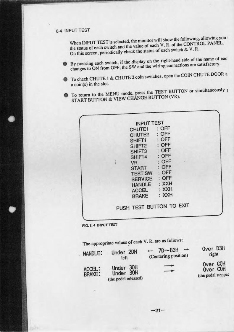
8·4 INPUT TEST
When INPUT TEST is selected. the monitor will show the following. allowing you
the status of each switch and the value of each V. R. of the CONTROL PA NEL.
On this screen. periodically check the status of each switch & V. R.
• By pressing each switch. if the display on the right·hand side of the name of cac
changes to ON from OFF. the SW and the wiring connections are satisfactory.
• To check CHUTE I & CHUTE 2 coin switches. open Ihe COIN CHUTE DOOR a
a coin(s) in the slol.
• To return to the MENU mode. press the TEST BUTTON or simultaneously I
START BUTTON & VIEW CHANGE BUTTON (VR).
INPUT TEST CHUTE1 : OFF
CHUTE2 : OFF SHIFT1 : OFF
SHIFT2 : OFF SHIFT3 : OFF
SHIFT4 : OFF VR : OFF START : OFF TESTSW : OFF
SERVICE : OFF HANDLE : XXH
ACCEL : XXH
BRAKE : XXH
PUSH TEST BUnON TO EXIT
FIG. 8. 4 INPlJr ltST
The appropriate values ~f each V. R. are as follows :
HANDLE: Under 2DH ..... 7D-83H -left (Centering position)
ACCEL: Under 30H -BRAKE: Under 30H -
(the pedal released)
-21-
Over D3H right
Over COH Over COH
(the pedal steppe<
wilch
Insen
; lilt
8·5 SOUND TEST
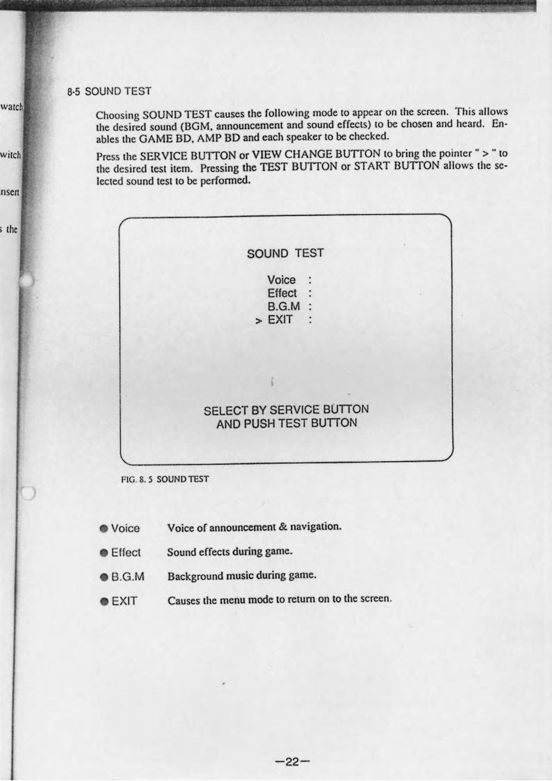
Choosing SOUND TEST causes Ihe following mode 10 appear on Ihe screen. Thi s allows Ihe desired sound (BGM. announcernenl and sound effecls) 10 be chosen and hcard. En· abies Ihc GAME BD. AMP BD and each speaker 10 be checked.
Press Ihe SERVICE BUllON or VIEW CHANGE BUllON 10 bring Ihe poin/cr" > .. 10
Ihe desired ICSI ilern. Pressing the TEST BUllON or START BUTTON allows Ihe seleclcd sound lesl 10 be perfonned.
SOUND TEST
Voice Effect B.G.M
> EXIT
SELECT BY SERVICE BUTTON AND PUSH TEST BUTTON
FIG. 8. 5 SOUNO TEST
• Voice
• Effect
• B.G.M
. EXIT
Voice of announcernenl & navigation .
Sound effects during game.
Background music during game .
Causes the menu mode to return on to the screen.
-22-
8·6 C. R. T. TEST
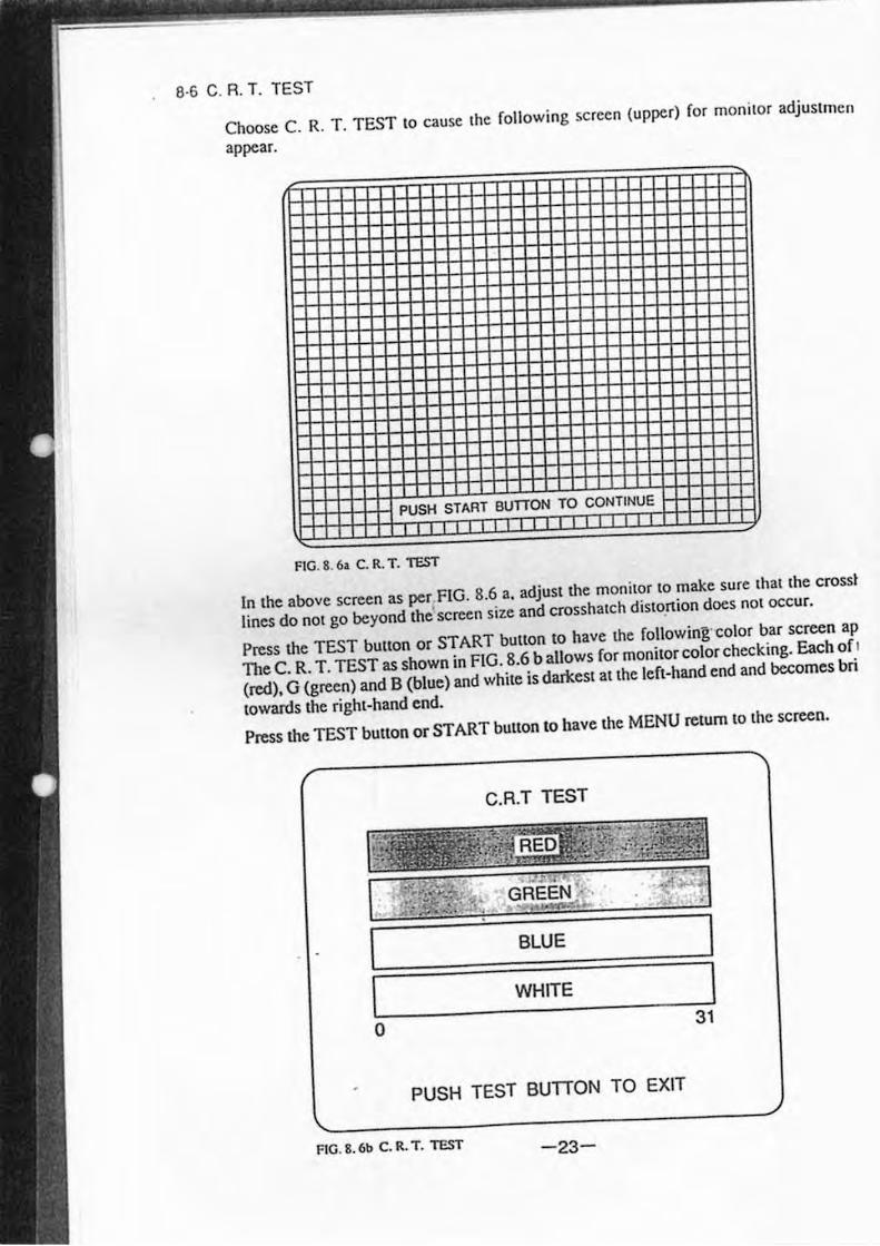
Choose C. R. T. TEST to cause the rollowing screen (upper) ror monitor adjustmcn
appear.
PUSH START BUTTON TO CONTINUE
FIG. 8. 6. C. R. T. -resT
In the above screen as per FIG. 8.6 a. adjust the monitor to make sure that the crossl
lines do not go beyond the' screen size and crosshaleh distonion docs not occur.
Press the TEST button or START button to have the rollowing·color bar screen ap
The C. R. T. TEST as shown in FIG. 8.6 ballows ror monitor color checking. Each or l
(red), G (green) and B (blue) and white is darkest at the left-hand end and becomes bri
towards the right-hand end.
Press the TEST button or START button to have the MENU return to the screen.
C.R.T TEST
BLUE
WHITE
o 31
PUSH TEST BUTTON TO EXIT
FIG. 8. 6b C. R. T. -resT -23-
Heh
:ar. eR ner
8·7 COIN ASSIGN MENT
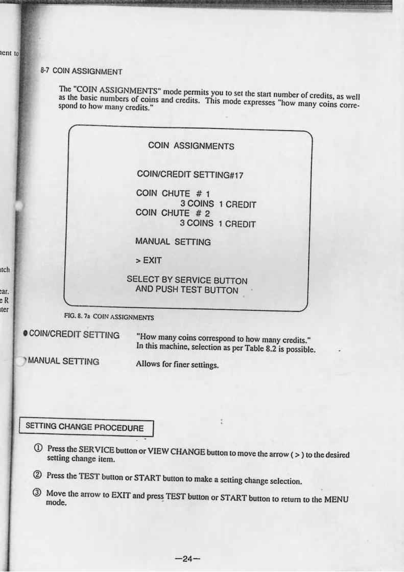
The "COIN ASSIGNMENTS" mode permits you to set the start number of credits. as well as the basic numbers of coins and credits. This mode expresses "how many coins correspond to how many credits."
COIN ASSIGNMENTS
COIN/CREDIT SETTING#17
COIN CHUTE # 1 3 COINS 1 CREDIT
COIN CHUTE # 2 3 COINS 1 CREDIT
MANUAL SETTING
> EXIT
SELECT BY SERVICE BUTTON AND PUSH TEST BUTTON
FtG. 8. 7. COtN ASStGNMEI'ITS
• COIN/CREDIT SETTING
' MANUAL SETTING
"How many coins correspond to how many credits." In this machine. selection as per Table 8.2 is possible.
Allows for finer sellings.
SETIING CHANGE PROCEDURE
Q) Press the SER VICE bUllon or VIEW CHANGE bUllon to move the arrow ( > ) to the desired selling change item.
(%) Press the TEST bUllon or START bUllon to make a selling change selection.
Q) Move the arrow to EXIT and press TEST bUllon or START bUllon to return to the MENU mode. •
-24-
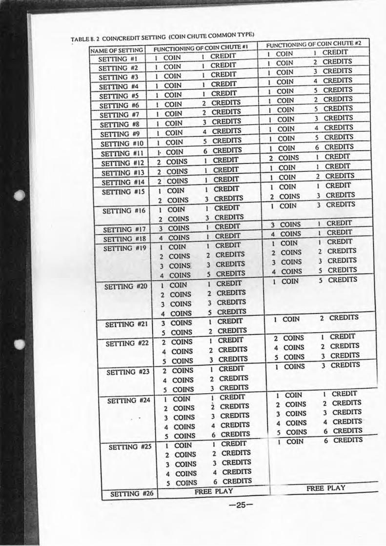
TABLE 8. 2 COINICREOIT SETTING (COIN CHUTE COMMON n'PEI
NAME OF SErrfINC FUNCTIONING OF COIN CHUTE . , FUNCTIONING OFCOIN CHUTE <2
SET11NG # 1 I COIN I CREDIT I COIN I CREDIT
SET11NG #2 I COIN I CREDIT I COIN 2 CREDITS
SET11NG #3 I COIN I CREDIT I COIN 3 CREDITS
SETI1NG #4 I COIN I CREDIT I COIN 4 CREDITS
SET11NG #5 I COIN I CREDIT I COIN 5 CREDITS
SETI1NG #6 I COIN 2 CREDITS I COIN 2 CREDITS
SETI1NG #7 I COIN 2 CREDITS I COIN 5 CREDITS
SET11NG #8 I COIN 3 CREDITS I COIN 3 CREDITS
SETTING #9 I COIN 4 CREDITS I COIN 4 CREDITS
SETTING #10 I COIN 5 CREDITS I COIN 5 CREDITS
SETI1NG #11 I· COIN 6 CREDITS I COIN 6 CREDITS
SETTING #12 2 COINS I CREDIT 2 COINS I CREDIT
SETTING HI3 2 COINS I CREDIT I COIN I CREDIT
SETTING #14 2 COINS I CREDIT I COIN 2 CREDITS
SETTING #15 I COIN I CREDIT I COIN I CREDIT
2 COINS 3 CREDITS 2 COINS 3 CREDITS
SETTING #16 I COIN I CREDIT I COIN 3 CREDITS
2 COINS 3 CREDITS
SETTING #17 3 COINS I CREDIT 3 COINS I CREDIT
SETTING #18 4 COINS I CREDIT 4 COINS I CREDIT
SETTING #19 I COIN I CREDIT I COIN I CREDIT
2 COINS 2 CREDITS 2 COINS 2 CREDITS
3 COINS 3 CREDITS 3 COINS 3 CREDITS
4 COINS 5 CREDITS 4 COINS 5 CREDITS
SETTING #20 I COIN I CREDIT I COIN 5 CREDITS
2 COINS 2 CREDITS
3 COINS 3 CREDITS
4 COINS 5 CREDITS
SETI1NG #21 3 COINS I CREDIT I COIN 2 CREDITS
5 COINS 2 CREDITS
SETI1NG #22 2 COINS I CREDIT 2 COINS I CREDIT
4 COINS 2 CREDITS 4 COINS 2 CREDITS
5 COINS 3 CREDITS 5 COINS 3 CREDITS
SETTING #23 2 COINS I CREDIT I COINS 3 CREDITS
4 COINS 2 CREDITS
5 COINS 3 CREDITS
SETI1NG #24 I COIN I CREDIT I COIN I CREDIT
2 COINS 2 CREDITS 2 COINS 2 CREDITS
. 3 COINS 3 CREDITS 3 COINS 3 CREDITS
4 COINS 4 CREDITS 4 COINS 4 CREDITS
5 COINS 6 CREDlTS 5 COINS 6 CREDITS
SETTING #25 I COIN I CREDIT I COIN 6 CREDITS
2 COINS 2 CREDITS
3 COINS 3 CREDITS
4 COINS 4 CREDITS
5 COINS 6 CREDITS
SETTING #26 FREE PLAY FREE PLAY
-25-
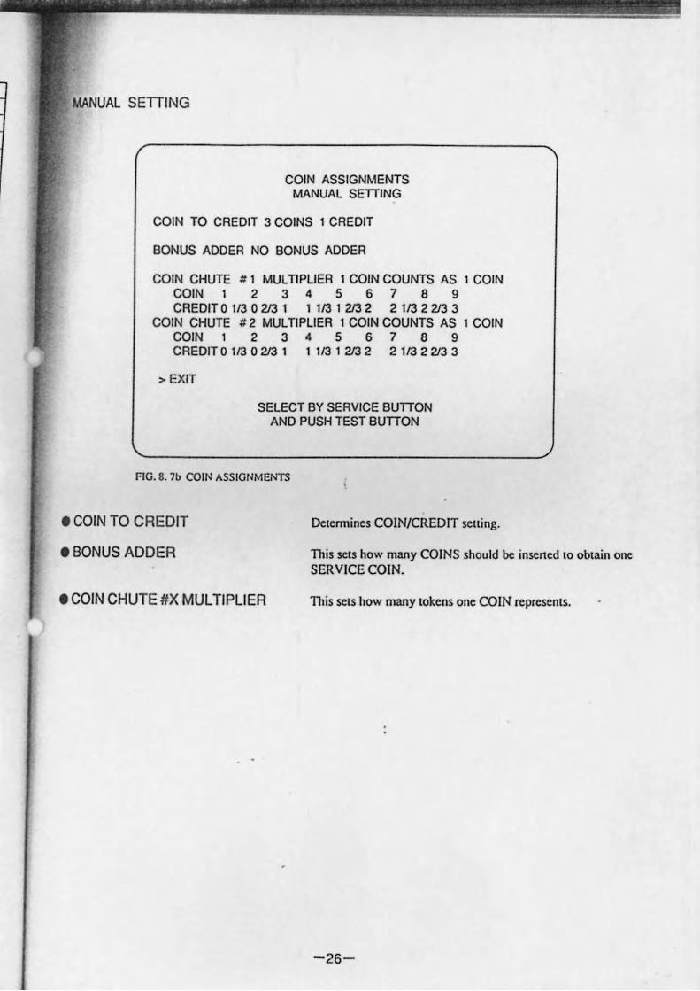
COIN ASSIGNMENTS MANUAL SETTING
COIN TO CREDIT 3 COINS 1 CREDIT
BONUS ADDER NO BONUS ADDER
COIN CHUTE # 1 MULTIPLIER 1 COIN COUNTS AS I COIN COIN 1 2 3 4 5 6 7 8 9 CREDIT 0 113 0213 1 1 113 1 213 2 2 113 2 213 3
COIN CHUTE # 2 MULTIPLIER 1 COIN COUNTS AS I COIN COIN123456789 CREDIT 0 113 0213 1 1 113 1 213 2 2 113 2 213 3
> EXIT
SELECT BY SERVICE BUTTON AND PUSH TEST BUTTON
FIG. 8. 7b COIN ASSIGNMENTS
• COIN TO CREDIT
• BONUS ADDER
• COIN CHUTE #X MULTIPLIER
Delermines COIN/CREDIT selling.
This sets how many COINS should be insened 10 oblain one SERVICE COIN.
This selS how many 10kens one COIN represents.
-26-
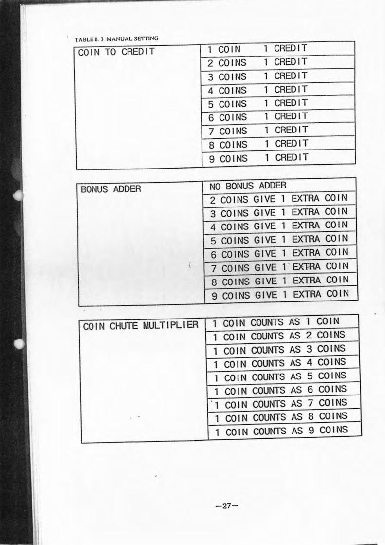
TABLE 8. ) MANUAL SEITING
COI N TO CREDIT
BONUS ADDER
COIN CHUTE MULTIPLIER
1 COIN 1 CREDIT 2 COINS 1 CREDIT
3 COINS 1 CREDIT 4 COINS 1 CREDIT 5 COINS 1 CREDIT 6 COINS 1 CREDIT 7 COINS 1 CREDIT 8 COINS 1 CREDIT
9 COINS 1 CREDIT
NO BONUS ADDER 2 COINS GIVE 1 EXTRA COIN
3 COINS GIVE 1 EXTRA COIN
4 COINS GIVE 1 EXTRA COIN
5 COINS GIVE 1 EXTRA COIN
6 COINS GIVE 1 EXTRA COIN
7 COINS GIVE l "EXJRA COIN
8 COINS GIVE 1 EXTRA COIN
9 COINS GIVE 1 EXTRA COIN
1 COIN COUNTS AS 1 COIN
1 COIN COUNTS AS 2 COINS
1 COIN COUNTS AS 3 COINS
1 COIN COUNTS AS 4 COINS
1 COIN COUNTS AS 5 COINS
1 COIN COUNTS AS 6 COINS
1 COIN COUNTS AS 7 COINS
1 COIN COUNTS AS 8 COINS
1 COIN COUNTS AS 9 COINS
-27-
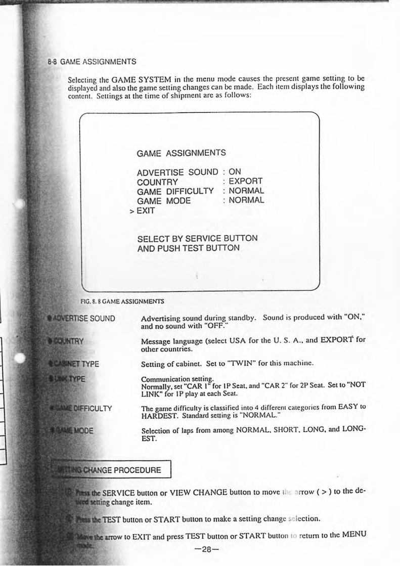
8·8 GAME ASSIGNMENTS
Selecling Ihe GAME SYSTEM in Ihe menu mode causes Ihe presenl game selling 10 be displayed and also the game selling changes can be made. Each ilem displays Ihe foll owing conlen!. SCll ings at the lime of shipment arc as fo llows:
GAME ASSIGNMENTS
ADVERTISE SOUND COUNTRY GAME DIFFICULTY GAME MODE
> EXIT
ON EXPORT NORMAL NORMAL
SELECT BY SERVICE BUTTON AND PUSH TEST BUTTON
AG. 8. 8 GAME ASSIGNMENTS
:line,,, SOUND Advenising sound during slandby . Sound is produced with "ON:' and no sound wilh "OFF."
Message language (seleci USA for {he U. S. A .. and EXPORT for olher cQUnlries.
Sclting of cabinet. Sct to "TWIN" for thi s machine .
Communication seuing. Normally, sel "CAR I" for I P Seal. and "CAR 2" for 2P Seal. SCI {o "NOT LINK" for I P play al cach Seal.
rrl<.ulLTY The game difficulty is classified into 4 differcllI categories from EASY to HARDEST. Siandard seuing is "NOR MAL."
Seleclion of laps from among NORMAL. SHORT. LONG, and LONGEST.
:tw~GE PROCEDURE
SERVICE bUllon or VIEW CHANGE bUllon to move II ' rrOW ( > ) 10 the delCIIing change ilem.
, ...... n ::"'" bUllon or START bUllon to make a selling change ,"Iection.
arrow 10 EX IT and press TEST button or START bUllon I re turn 10 Ihe MENU
-28-
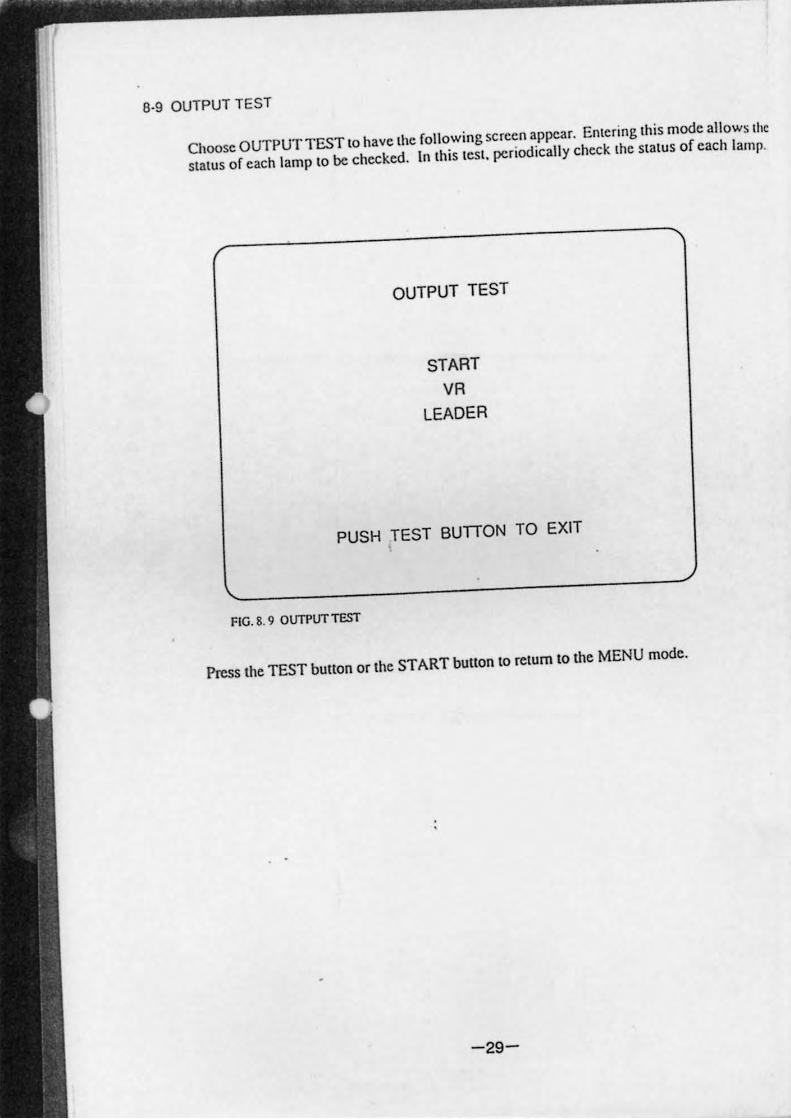
8·9 OUTPUT TEST
Choose OUTPUT TEST 10 have Ihe following screen appear. Emering Ihis mode allows Ihe
sIal us of each lamp 10 be checked. In Ihis leSI. periodically check Ihe sIal us of each lamp.
OUTPUT TEST
START
VR LEADER
PUSH TEST BUTTON TO EXIT
FIG. 8. 9 OUTPlJf TEST
Press Ihe TEST bUllon or Ihe START bUllon to return to the MENU mode.
-29-
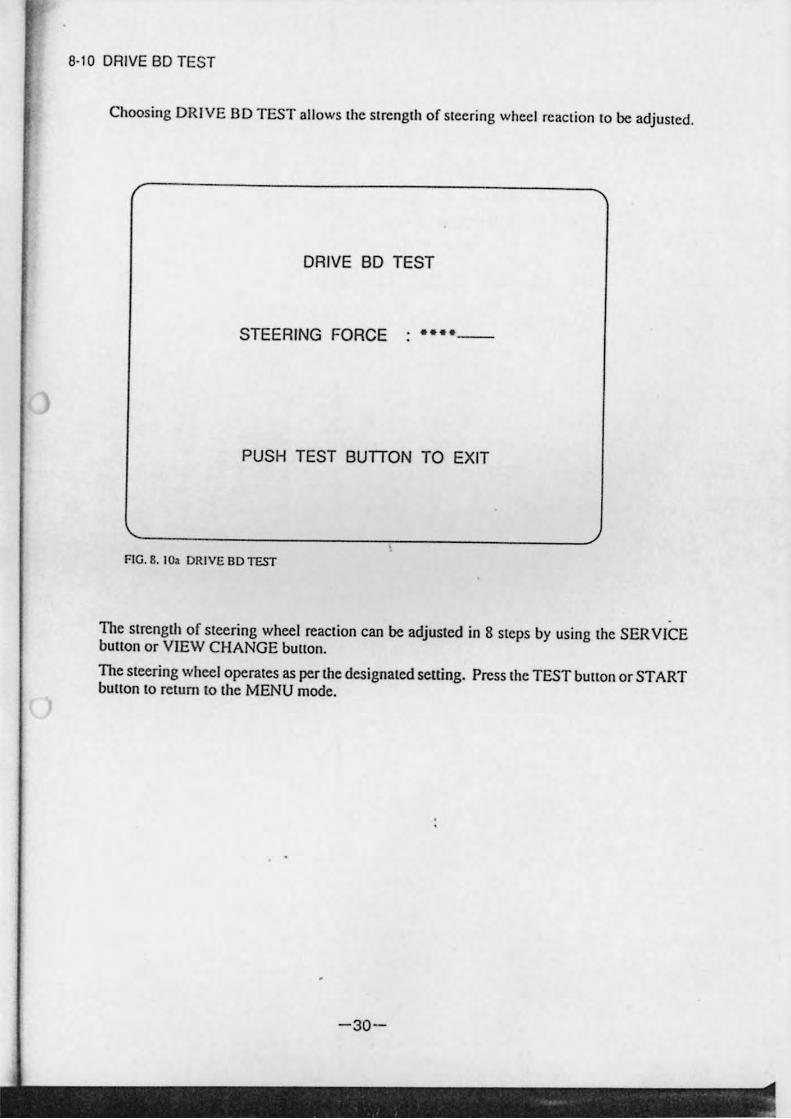
8·10 DRIVE BD TEST
Choosing DRIVE BD TEST allows lhe slrenglh of Slcering wheel rcaclion 10 be adjuslcd.
DRIVE SO TEST
STEERING FORCE ••••
PUSH TEST sunON TO EXIT
FIG. 8. 1C>.1 DR IVE BOTEST
The strength of steering wheel reaction can be adjusted in 8 SICpS by using lhe SER V ICE button or VIEW CHANGE button.
The steering wheel operales as per lhe designaled setting. Press lhe TEST button or START button 10 return to the MENU mode.
-30-
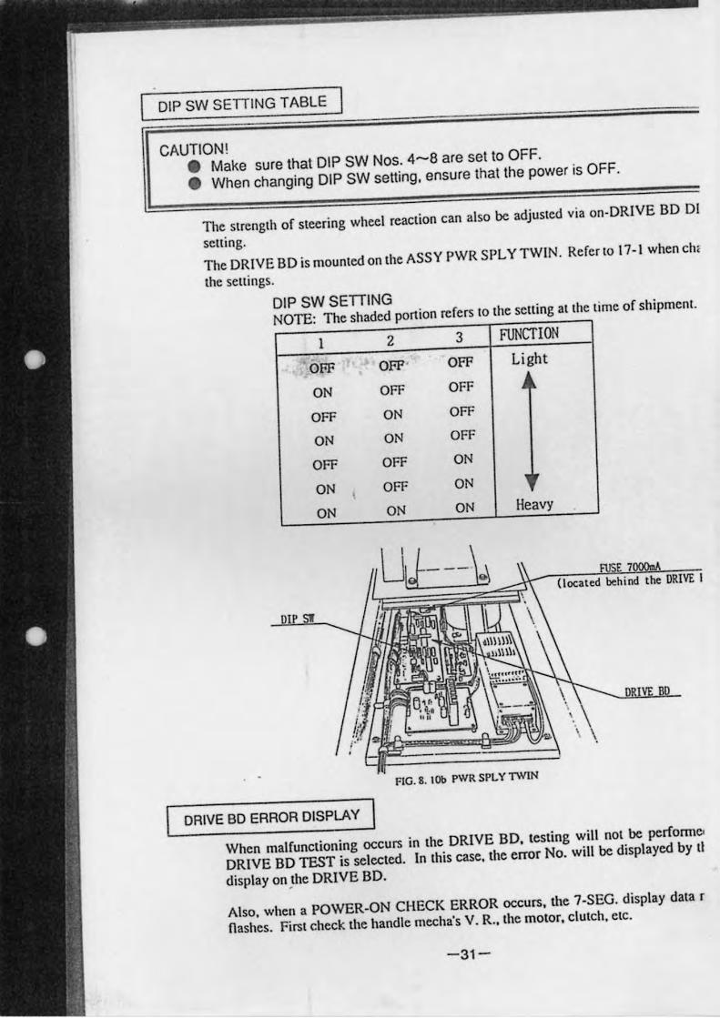
DIP SW SETIING TABLE
CAUTION! • Make sure that DIP SW Nos. 4-8 are sel to OFF.
• When changing DIP SW setting, ensure thallhe power is OFF.
The strength of steering wheel reaction can also be adjusted via on-DRIVE BD 01
setting.
The DRIVE BD is mounted on the ASSY PWR SPL Y TWIN. Referlo 17-1 when ch'
the settings.
DIP SW SETTING
NOTE: The shaded ponion refers to the setting at Ihe lime of shipment.
) 2 3 FUNCTION
OFF OFF' OFF Light
ON OFF OFF • OFF ON OFF
ON ON OFF
OFF OFF ON
ON , OFF ON ,
ON ON ON Heavy
behind the
FtG. 8. IOb PWRSPLYTWlN
DRIVE BD ERROR DISPLAY
When malfunctioning occurs in the DRIVE BD, testing will not be perfonneo
DRIVE BD TEST is selected. In this case, the error No. will be displayed by tl
display on _the DRIVE BD.
Also, when a POWER-ON CHECK ERROR occurs, the 7-SEG. display data r
nashes. First check the handle mocha's V. R., the motor, c1UICh, ciC.
-31-
f
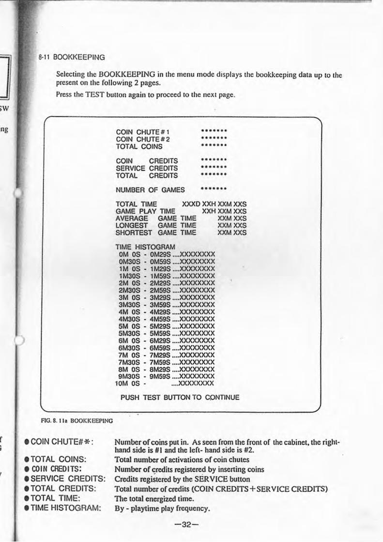
B·II BOOKKEEPING
Sclccling Ihe BOOKKEEPING in Ihe menu mode displays Ihe bookkeeping dala up 10 Ihe preseOl on Ihe following 2 pages.
Press Ihe TEST bUllon again 10 proceed 10 Ihe neXI pagc.
FlG. 8. II . BOOKKEEPING
.COIN CHUTE#*:
• TOTAL COINS: • COIN CREDITS: • SERVICE CREDITS: .TOTAL CREDITS: .TOTAL TIME: • TIME HISTOGRAM:
COIN CHUTE # I COIN CHUTE # 2 TOTAL COINS
COIN CREDITS SERVICE CREDITS TOTAL CREDITS
NUMBER OF GAMES
••••••• ••••••• •••••••
••• • ••• ••••••• •••••••
•••••••
TOTAL TIME GAME PLAY TIME
XXXD XXH XXM XXS
AVERAGE GAME TIME LONGEST GAME TIME SHORTEST GAME TIME
TIME HISTOGRAM
XXH XXMXXS XXM XXS XXMXXS XXMXXS
OM OS - OM29S .... XXXXXXXX OM30S - OM59S ... . XXXXXXXX 1 M OS - 1 M29S .... XXXXXXXX 1 M30S - 1 M59S ... . XXXXXXXX 2M OS - 2M29S .... XXXXXXXX 2M30S - 2M59S .... XXXXXXXX 3M OS - 3M29S .... XXXXXXXX 3M30S - 3M59S .... XXXXXXXX 4M OS - 4M29S .... XXXXXXXX 4M30S - 4MS9S .... XXXXXXXX 5M OS - SM29S .... XXXXXXXX 5M30S - 5MS9S .... XXXXXXXX 6M OS - 6M29S .... XXXXXXXX 6M30S - 6M59S ...• XXXXXXXX 7M OS - 7M29S •... XXXXXXXX 7M30S - 7M59S ..•. XXXXXXXX 8M OS - 8M29S .•.. XXXXXXXX 9M30S - 9M59S .... XXXXXXXX
10M OS - .... XXXXXXXX
PUSH TEST BUTTON TO CONTINUE
Number of coins PUI in. As seen from lhe froOl of lhe cabinel,lhe righlhand side is # I and lhe lefl- hand side is #2 . TOlal number of aClivalions of coin chules Number of "redils regislered by insening coins Credils regislered by lhe SERVICE bUllon TOlal number of credilS (COIN CREDITS + SERVICE CREDITS) The 10lal energized lime. By - playlime play frequency.
-32-
DESERT COURSE
TOTAL PLAY GAMES .. .
GOALS .. .
TIME
FASTEST GOAL TIME .. .
AVERAGE PLAY TIME .. .
FOREST COURSE
TOTAL PLAY GAMES .. .
GOALS .. .
TIME
FASTEST GOAL TIME .. .
AVERAGE PLAY TIME .. .
MOUNTAIN COURSE
TOTAL PLAY GAMES .. .
GOALS .. .
TIME
FASTEST GOAL TIME ...
AVERAGE PLAY TIME ._.
CHAMPIONSHIP
TOTAL PLAY GAMES ...
GOALS .. _
TIME
FASTEST GOAL TIME _.'
AVERAGE PLAY TIME ...
XXX XX GAME
XXXXXX GOAL
XX H XX M XX S
XX M XX S
XX M XX S
XXXXX GAME
XXXXXX GOAL
XX H XX M XX S
XX M XX S
XX M XX S
XXXXX GAME
XXXXXX GOAL
XX H XX M XX S
XX M XX S
XXMXXS
XXXXX GAME
XXXXXX GOAL .
XXHXXMXXS
XXMXXS
XXMXXS
PUSH TEST BUnON TO EXIT
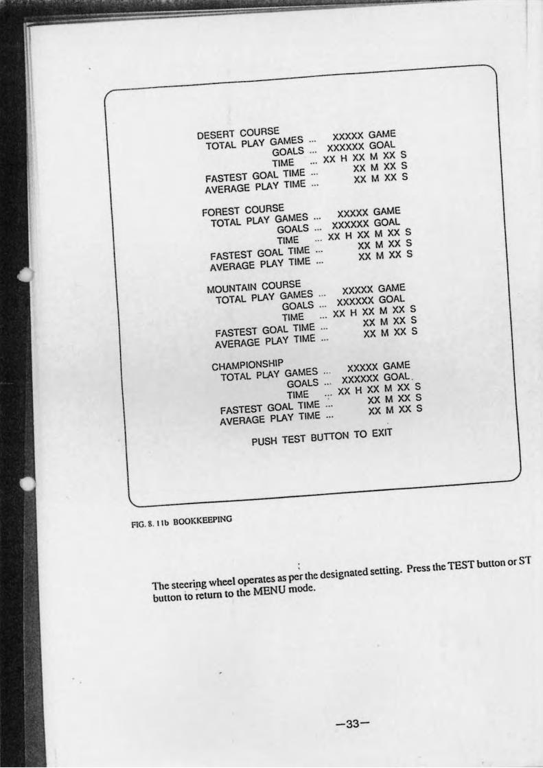
FIG. 8. lib BOOKKEEPING
The stceri!,g wheel operates as per the designaled selling. Press Ihe TEST bUllon or ST
bUllon 10 relum to the MENU mode.
-33-
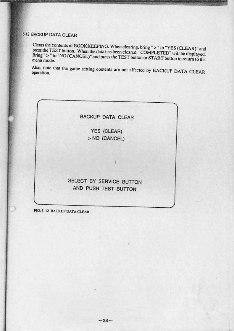
8·12 BACKUP DATA CLEAR
Clears Ihe conlcnlS of BOOKKEEPING. When ciearing. bring ., >" 10 "YES (CLEAR)" and press Ihe TEST bUllon. When Ihe dala has been cieared, "COMPLETED" will be displayed . Bring" > "10 "NO (CANCEL)" and press Ihe TEST bUllon or START bUllon 10 relurn 10 Ihe menu mode.
Also, nOle Ihal Ihe game selling conlenls arc nOI affecled by BACKUP DATA CLEAR operalion.
BACKUP DATA CLEAR
YES (CLEAR) > NO (CANCEL)
SELECT BY SERVICE BUDON AND PUSH TEST BUDON
FlG.S. 12 BACKUP DATA CLEAR
-34-
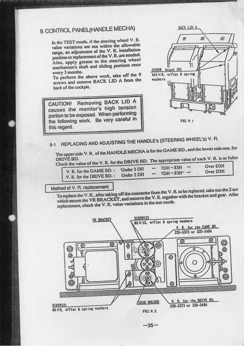
9. CONTROL PANEL(HANDLE MECHA)
in the TEST mode. if the steering wheel V. R.
value variations arc not within the allowable
range. an adjusunent of the V. R. installation
position or replacement of the V. R. an: needed.
Also. apply grease 10 the steering wheel
mechanism's shafl and sliding portions once
every 3 months.
To perfonn 'he above work. take off the 9
screws and remove BACK LID A from 'he
back of the cockpil.
CAUTION! Removing BACK LID A
causes the monitor's high tension
portion to be exposed. When performing
the following work. Be very careful in
this regard.
BA K lOA
FIG. 9. I
g., REPLACING AND ADJUSTING THE HANDLE's (STEERING WHEEL's) V. R.
11,e upper side V. R. ohhe HANDLE MOCHA is for the GAME BD .. and 'he lower side one. for
DRIVEBD. Check the value of 'he V. R. for 'he DRIVE BD. The appropria,e value of each V. R. is as folio'
V. R. forche GAME BD.: . Under 2 DH 7DH -83H - Over D3H
V. R. for 'he DRIVE BD. : Under 2 DH - 7DH -8}H~ - Over D3H
Method 01 V. R. replacement I To replace the V. R .. arcertakingofTtheconnectorrrom the V. R.lobe replaced. take ou,the 2sco
which secure the VR BRACKEr, and remove the V. R.,ogether with the bracke, and gear. Arcc.
replacement, check the V. R. value variations in the test mode.
spr I ng .. ashers FIG.9.2
-35-
1
)rthe
ows:
:rcwS • r the
Method 01 V. A. adjustment
CD Loosen the 2 screws which secure Ihe V. R. BRACKET. move the V. R. BRACKET and detach the gears.
a> Adjust the V. R. so Ihat it is consistent with the va lue ncar the centering position.
@ Cause the gears to be engaged and secure the Y. R. BRACKET. Atthis time. make sure that an appropriate backlash is obtained.
@ If the V. R. value is not appropriate when the steering wheel is at the centering position, loosen the 2 screws which secure the Y. R. gear. tum the gear holder to make a fine adjustment so that the V. R. value is within the allowable range.
® Check the Y. R. value variations by turning lhe handle.
9·2 GREASING
Once every 3 months. grease the gears. bearings. springs, and cam & arm's Sliding ponions.
9·3 REMOVING THE CONTROL PANEL
CD
®
@
@)
®
For ordinary maintenance as mentioned above. it is not necessary to remove the control panel. However. in the cases where passage space cannot be provided behind the cabinets. the entire control panel is to Ix replaced. or the monitor adju~tmellls are to be made. remove the control panel by using the following procedure:
Take off a tOlal of 4 tamperproof screws from the right-hand side and left-hand side of the control panel's front ponion .
Take orf2 Hex Bolts from underneath the control panel (with flat & spring washers).
Wiring connectors are connected in IheconlrOl panel. Pullout the control panel by paying careful attention so as nOI to damage the wiring.
Remove the wiring connectors.
When the control panel is removed. the monitor adjustment board appears.
-36-
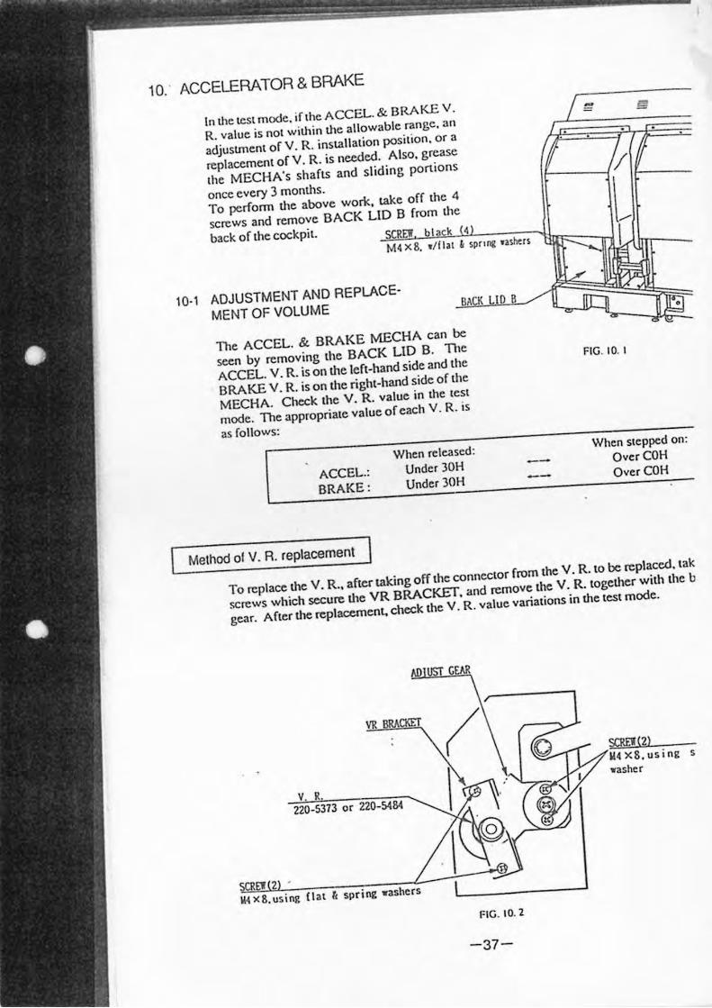
10.' ACCELERATOR & BRAKE
In tl,e les. mode. if.he ACCEL.& BRAKE v .
R. value is nol wilhin lhe allowable range. an
adjusunenl of v. R. installation position. o r a
repla""men. of V. R. is needed. Also. grease
.he MECHA's shaflS and sliding portions
once every 3 months.
To perfonn the above work. take off the 4
screws and remove BACK LID B from the
back of .he cockpil. SCREW b l k •
M4 xS. _' flil " 1prltle • .uM:rs
10·1 ADJUSTMENT AND REPLACE
MENT OF VOLUME BAK
The ACCEL. & BRAKE MECHA can be
seen by removing Ihe BACK LID B. TI,e
ACCEL. V. R. is on the lefl-hand side and Ihe
BRAKE V. R. is on the righI-hand side of Ihe
MECHA. Check the V. R. value in the tes.
mode. The appropriate value of each V. R. is
as follows:
ACCEL.: BRAKE:
Method 01 V. R. replacement
When released:
Under 30H Under 30H
-=
FIG. 10. I
When stepped on:
OverCOH OverCOH
To repta"" the V. R .. afler laking offlhe conncc.or from the V. R. to be replaced. tak
screws which secure the VR BRACKET. and remove the V. R. logetl.er wilh the b
gear. After the replacement. check the V . R. value variations in the test mode.
VR
V. R.
220-5373 or 220-5484
W4 X8.using (lat fi spr ifl£ .ashers
fiG. 10. 2
-37-
SCRf!(2) W4 X8 .using s
.. asher
Method 01 V. R. adjustment
<D Loosen the 2 screws which secure the V. R. BRACKET and move the V. R. BRACKET to disengage the gear.;.
® Cause the V. R. vatue to match with the vatue obtained when the pedat is released.
@ Cause the gear.; to be engaged and secure the V. R. BRACKET. At this time. be sure to obtain an appropriate backlash.
@) Step on the pedal and check tlte V. R. value variation.
t 0·2 GREASING
Grease the gear.; and bearings once every 3 months as a standard.
11. 4 SPEED SHIFTER
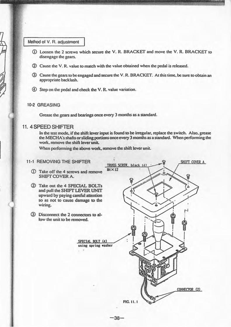
11·1
<D
®
@
In the test mode, if the shift lever input is found to be irregular, replace the switch. Atso, grease the MECHA's shafts or sliding ponions once every 3 months as a standard. When performing the work. remove the shift lever uniL When perfonning the above work. remove the shift lever unit.
REMOVING THE SHIFTER
Take off the 4 screws and remove Y4 x 12
SHIFf COVER A.
Take out the 4 SPECIAL BOLTs and pull the SHIFT LEVER UNIT upward by paying careful attention so as not to cause damage to the wiring.
Disconnect the 2 connectors to al-low the unit to be removed.
SPECIAl. BOLT (4) using spring washer
FIG. t I. t
-38-
k
('/ , I
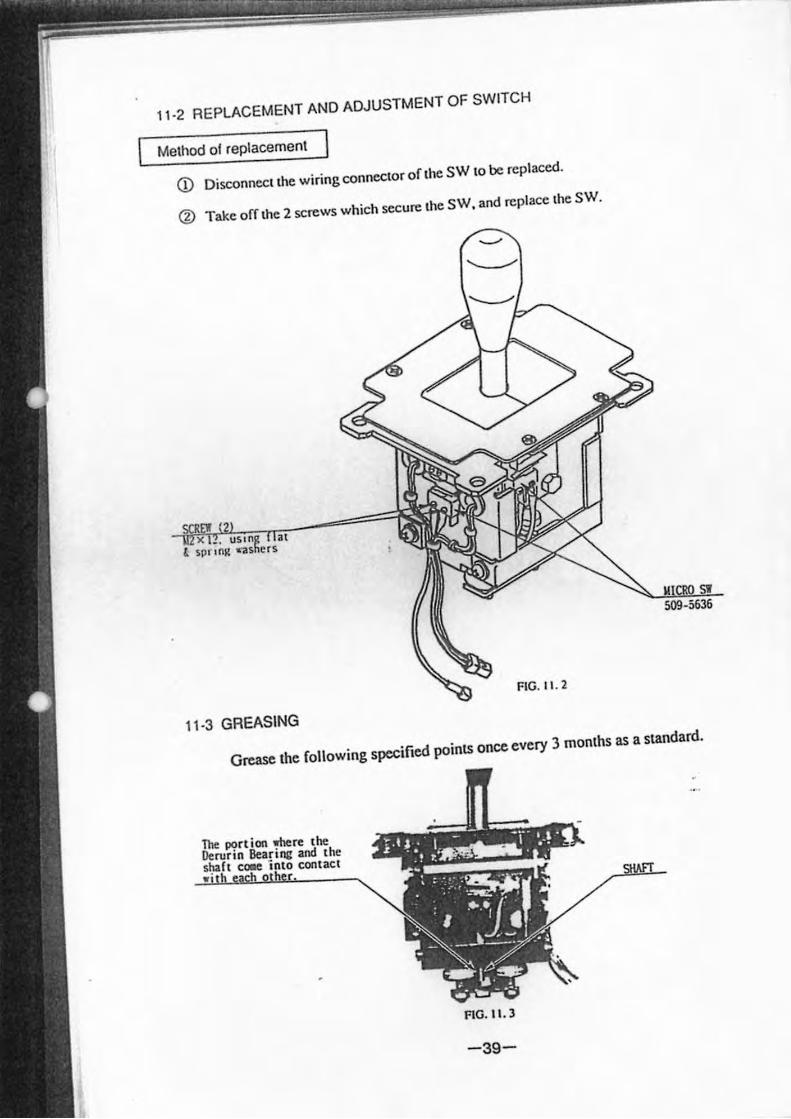
, ' .2 REPLACEMENT AND ADJUSTMENT OF SWITCH
Method 01 reptacement
CD Disconnect the wiring connector of the SW to be reptaced.
(%) Take offthe 2 screws which secure the SW, and replace the SW.
FtG. 1 I. 2
11.3 GREASING
Grease the following specified points once every 3 months as a standard.
FIG. tL3
-39-
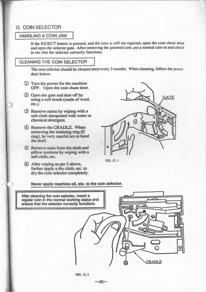
12. COIN SELECTOR
HANDLING A COIN JAM
If Ihe REJECT bUllon is pressed. and Ihe coil1 is slill nOI rejecled. open Ihe coin chule door and open Ihe seleclor gale. Afler removing Ihe jammed coin. pUI a nonnal coin in and check 10 sec Ihal Ihe seleclor correctly funclions.
CLEANING THE COIN SELECTOR
The coin Seleclor should be cleaned once every 3 momhs. When cleaning. [ollow Ihe procedure below:
CD Tum the power for Ihe machine OFF. Open the coin chute door.
@ Open the gale and dust off by using a sofl brush (made of wool. etc.).
Q) Remove stains by wiping with a soft clolh dampened wilh waler or chemical delergent.
@) Remove Ihe CRADLE. When removing Ihe retaining ring (E ring). be very careful nollO bend the shafl.
® Remove stain from Ihe shaft and pillow portions by wiping wilh a soft cloth. etc.
® After wiping as per 5 above. further apply a dry cloth. etc. to dry the coin selector completely.
.. 1'----
FIG. I~ . I
Never apply machIne oil, etc. to the coIn selector.
After cleaning the coin selector. insert a regular coin in the normal working status and ensure thaI the selector correctly functions.
FIG. 12. 2
-40-
GATE
Cd o 9
CRADLE
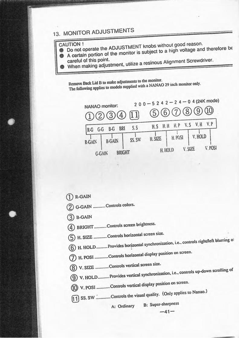
13. MONITOR ADJUSTMENTS
CAUTION ! • Do not operate the ADJUSTMENT knobs wilhoul good reason.
• A certain portion of the monitor is subject to a high voltage and therefore be
careful of this point.
• When making adjustment, utilize a resinous Alignment Screwdriver.
Remove Back. Lid B 10 make adjustments to the monitor.
The following appUes 10 models supplied ",th a NANAO 29 inch monilor only.
NANAO monitor: 2 a a - 5 2 4 2 - 2 4 - a 4 (24K mode)
®®0®®® lS l H H.P ~ S ~ H ~p
R-GAI:-' B·GAlti SS.SW I 1 I
H. SIZE H.i'C)SI I V. HOLD I
a·CAIK BRIGHT 1I. 1I0Ul \'.SIZE 1". POSI
<D R-GAIN
(Z) G·GAIN .. ......... Controls colors.
@ B-GAIN
® BRIGHT ........ .. . Control. screen brightness.
@ H. SIZE ........... . Conlrols horizontal screen size.
® H. HOLD .......... Provides ho~zontal synchronizalion. i.e .. conlrals right/lefl blurring 01
(J) H. roSI ...... .... .. ConlrOls horizonlal display posilion on scrccn.
® V. SIZE ........ .. .. Conlrals venical screen size.
® V. HOLD ....... ... Provides vertical synchronization. i.e .. controls up-<lown scrolling of
® V. POSI ........ .. .. Controls venical display posilion on screen.
[!) SS. sw .: ........... Conlrols!he visual qualily. (Only applies 10 Nanao.)
A: Ordinary B: Super-sharpness
- 41-
.
~ :
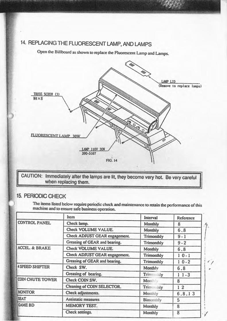
14. REPLACING THE FLUORESCENT LAMP. AND LAMPS
Open Ihe Billboard as shown 10 replace Ihe Auoresccnt Lamp and Lamps.
M4x8
UJ!P II QV 30r / 390-5167
FIC. 14
CAUTION: Immedialely after the lamps are lit. they become very hot. Be very careful w~en replacing them.
15. PERIODIC CHECK The ilems listed below require periodic check and mainlenance 10 relain the perfonnance of Ih is machine and 10 ensure safe business operation .
hem Interval Reference
CONTROL PANEL Check lamp. S Check VOLUME VALUE. Monlhly 6 . 8 Check ADJUST GEAR 9 - I
of GEAR and I 9-2 ACCEL. & BRAKE Check' Vhf " ... VALUE. "nn.h'~ 6.8
Check ADJUST GEAR Trimonthly 10- I of GEAR and , ,Iv I 0 - 2
[4 SPEED SHiffER Check SW. Monlhly 6 . 8 u of Trim· ,Jly I I -3
COIN CHUTE TOWER Check CorN SW. Mon' 8 of CorN ~'" .:TUR. Trim Illy I 2
I MUNITUR Check 6.8. I 3 ISEAT Antistatic measures 5 IOAME BD MEMORY TEST. Monthly 8
Check settings. Monthly 8
1'.
I , "/ ! . , r
, ,
./
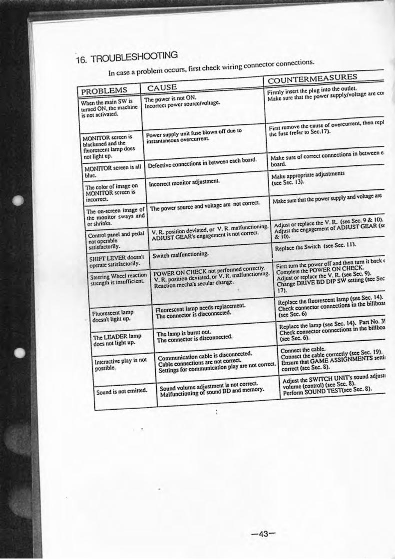
16. TROUBLESHOOTING
In case a problem occurs, firsl check wiring conneclor connections.
PROBLEMS CAUSE COUNTERMEASURES
When the. milin SW is The power is not ON. Finnl)' insen the plug into the oUllet .
turned ON. lhe machine Inc:ontcl power soun:c/voll'gc. Make surt Ihallhe power supply/voltage <lIle COl
is not activated.
MONrroR screen is Power supply unil (use blown orr due 10 First remove the cause of ovcrcumnl, then repl
blackened and lhe inSllnlane0u5 ovetCunenl the: fu.se IrdellO Se(. I7).
nuoresccnllamp does
nol1ighl up.
MONlTOR $(;Tccn is all DcJecljvc connec:1M>ns in betwccn each boIrd. Make sure of concel connections in bc:tween c
blue.
boud.
The color of image on Incorrect monitor adjustmenl. Make appropriilte adjustments
MONITOR SCTccn is (sec Sec. Il).
incorrea.
The on·screen image of 1be power source &nd VOltage Ire not conecl. Make SU~ Withe power supply and VOltage art
the monitor sways and
Of shrinks.
Control panel and pc&1 V. R. po$ilton deviated. or V. R. malfuncliomng. Adjusl or rcptKC the: V. R. (see Sec. 9 &. 10).
noc operable ADJUST GEAR's engagement jj not cancel. Adjulllhc: engagement or ADJUST GEAR (So(
salisractorily. & 101.
SHIFT LEVER doc .. ·, Switch malrunctioning. Replace: the: Switch (sec $cc. Ill.
opc:nle s<uisfactonly.
SItt:rinC Whec:1 reaction POWER ON CHECK not perronned concclly. First tum the po~r orr and then tum it back (
suenglh IS tnSUmcsenl V. R. position deviated. or V. R. malfunctioning. Complete the POWER ON CHECK.
Reaction mecha's secular change. Adjust or replaC't the: v. R. (see Sec. 9).
Change: DRIVE DO DIP SW seuing (sec SeC'
171.
AuOfe.SCtni lamp Ruoreseentl.mp needs replacement. Repl~ the nuorescentlamp (see Sec. 14).
dOesn) light up. The connc:clor is disconnected. Check connector connections in the billboar
(see Sec. 6)
The lEADER lamp The lamp is burnt out Replace the lamp (sec: Sec. 14). Put No. ) !
does nO( light up. Tbe connector is disconnected. Check connector connections in the billboa
(sec Sec. 6).
Inlenctive play is not Communication cable is disconnected. Conncelthe able.
possible. Cable connections arc not C01Tt:Ct. Connect \hi: able correctly ($CC Sec. 19).
Settings ror communication play arc flO( corrcC1. Ensure that GAME ASSIGNMEtn'S $CUil
correct (see Sec. 8).
Sound is not emilled. Sound volume adjustment is not com:c.1. Adjust the SWITCH UNITs sound adjuslJ
Malrunctioning of sound DO and memory. volume (control) (see Sec. 8).
Perform SOUND TEST(see Stt. 8).
-43-
Ich
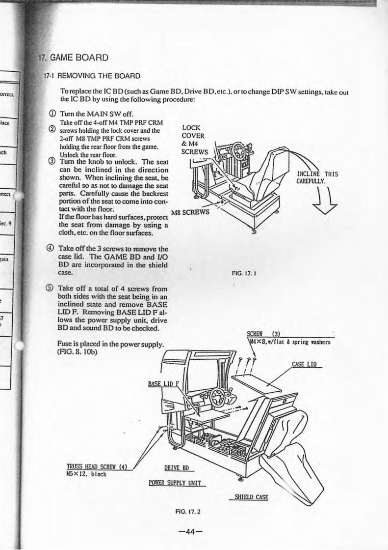
. GAME BOARD
17·1 REMOVING THE BOARD
To replace lhe IC BD(such as Game BD. Drive SD.ClC.). orlochange DIP SW sellings , lake OUI Ille IC BD by using Ihe following procedure:
(j) Tum lhe MAIN SW off. Take olTOle 4·01TM4 TMP PRF CRM
® screws holding the lock cover and the 2·01T M8 TMP PRF CRM screws holding the rear floor from the game. Unlock Ille rcar floor.
Q) Tum lhe knob 10 unlock. The seal can be inclined in the direction shown. When inclining lhe sea .. be careful SO as nOl 10 damage !he seal parts. Carefully cause lhe backresl ponion of the seat to come into con· laCl wilh lhe floor. M8 SCREWS If !he floor has hard surfaces, prolecl lhe seat from damage by us ing a clolh, clc. on lhe floor surfaces.
@) Take off lhe 3 screws 10 remove the case lid. The GAME BD and 1/0 BD are incorporated in the shield casC.
® Take off a 10lal of 4 screws from bOlh sides Wilh lhe seat being in an inclined Slate and remove BASE LID F. Removing BASE LID F allows lhe power supply uni .. drive BD and sound BD 10 be checked.
Fuse is plaoed in lhe power supply.
FIG. 17. I
(AG. 8. lOb) '~lP~~~~
DR IVl: BD
POIlER SUPPLY UNIT
Sill no CASE
FIG. 11. 2
-44-
TillS CAREFUU.Y.
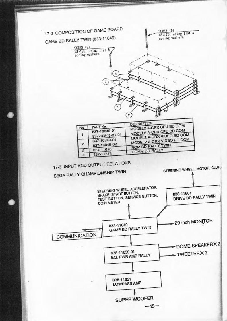
17-2 COMPOSITION OF GAME BOARD
GAME BD RALLY TWIN (833-11649)
R JOX7S. uS ing II.u &
spri ng washe rs
SCREW (8) WlX 35, using f la t &/ /
spr ing washers r
No. PART No DESCRIPTION
1 837-10848·91 MODEL2 A-CRX CPU BD COM
837-10848·01 ·91 MODEL2 A-CRX CPU BD COM
2 837-10849·01 MODEL2 A-CRX VIDEO BD COM
837-10849·02 MODEL2 A·CRX VIDEO BD COM
3 834 · 11618 ROM BO RALLY TWIN
4 837-11572 COMM BD RALLY
17-3 INPUT AND OUTPUT RELATIONS
SEGA RALLY CHAMPIONSHIP TWIN STEERING WHEEL. MOTOR. CLUTe
COMMUNICATION
STEERING WHEEL. ACCELERATOR.
BRAKE. START BUTTON.
TEST BUTTON. SERVICE BUTTON.
COIN METER
838-11661 DRIVE SO RALLY TWIN
833-11649
GAME SO RALLY TWIN f--.29 inch MONLTOR
1-=83:::8:-:-1~1::65:::0~-O-:-1 ---f.--DOME SPEAKER X 2
Ea. PWRAMP RALLY f--.TWEETERX 2
838-11651 LOWPASSAMP
SUPER WOOFER
-45-
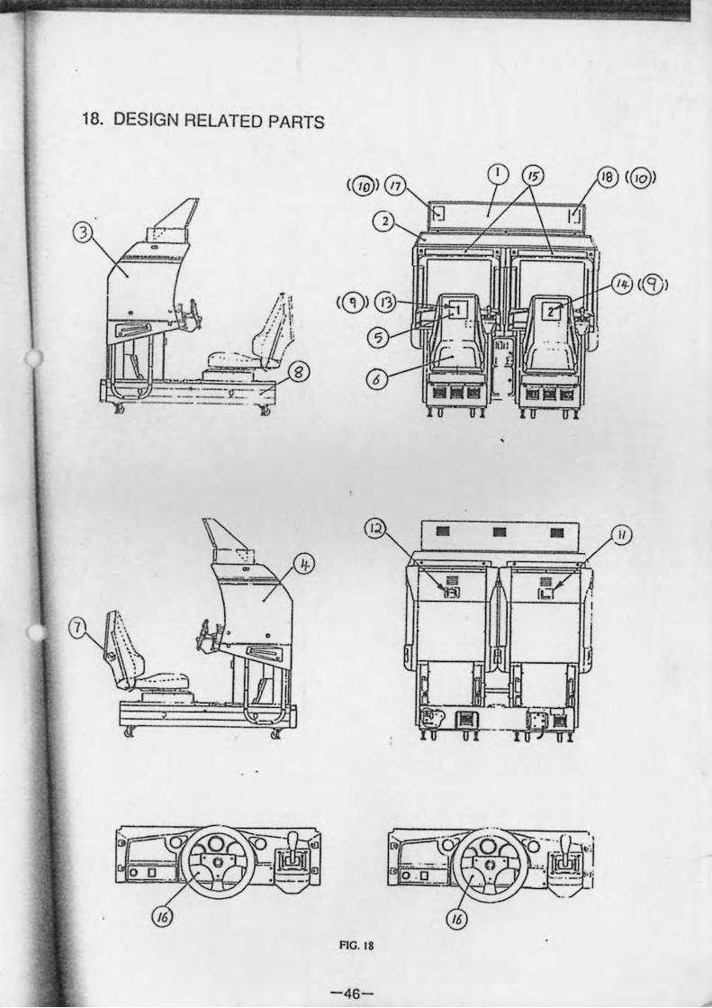
18. DESIGN RELATED PARTS
<@) /7
2 3
• • • •
• <CD)@
• !J
;-:: :."'::- .
• • • 1/
• o
, (J
RG. 18
-46-
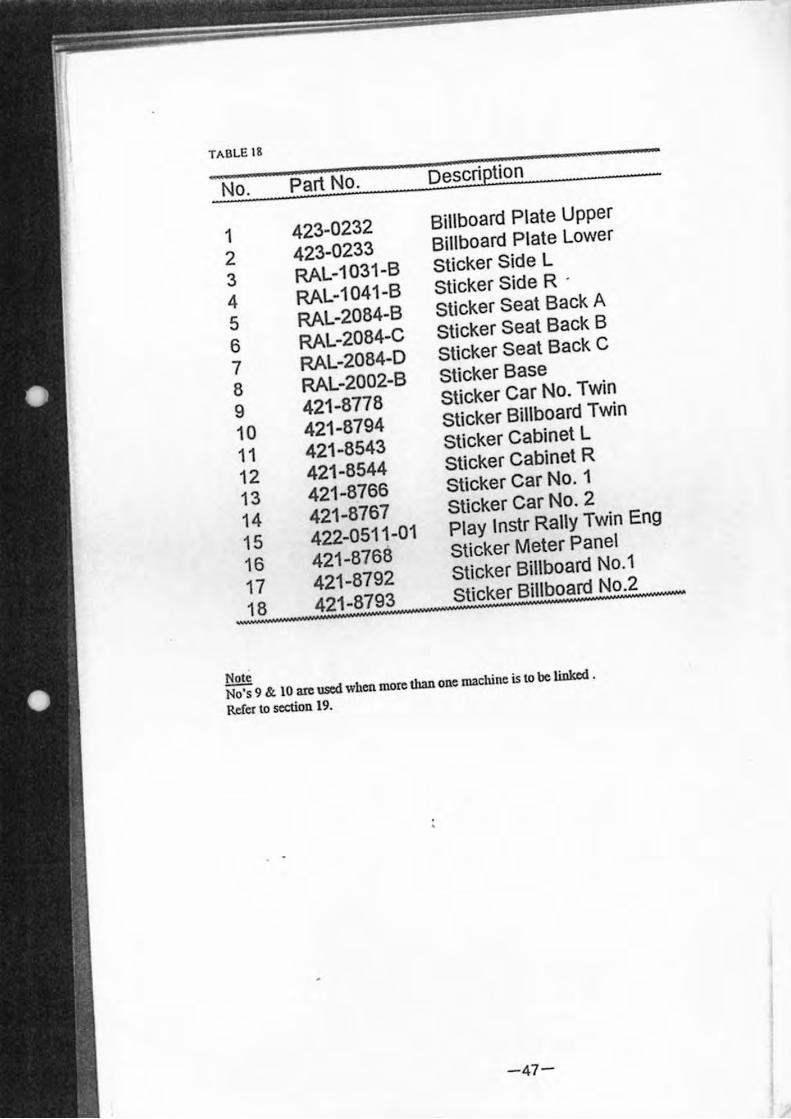
TA BLE 18
No. Part No. Description
1 423-0232 Billboard Plate Upper
2 423-0233 Billboard Plate Lower
3 RAL-1031-B Sticker Side L
4 RAL-1041-B Sticker Side R .
5 RAL-2084-B Sticker Seat Back A
6 RAL-2084-C Sticker Seat Back B
7 RAL-2084-D Sticker Seat Back C
8 RAL-2002-B Sticker Base
9 421-8778 Sticker Car No. Twin
10 421-8794 Sticker Billboard Twin
11 421-8543 Sticker Cabinet L
12 421-8544 Sticker Cabinet R
13 421-8766 Sticker Car No.1
14 421-8767 Sticker Car No.2
15 422-0511 -01 Play Instr Rally Twin Eng
16 421-8768 Sticker Meter Panel
17 421-8792 Sticker Billboard No.1
18 421-8793 Sticker Billboard No.2
Nole
No's 9 &. 10 are used when more than one machine is 10 be liDJaxI .
Refer to section 19.
-47-
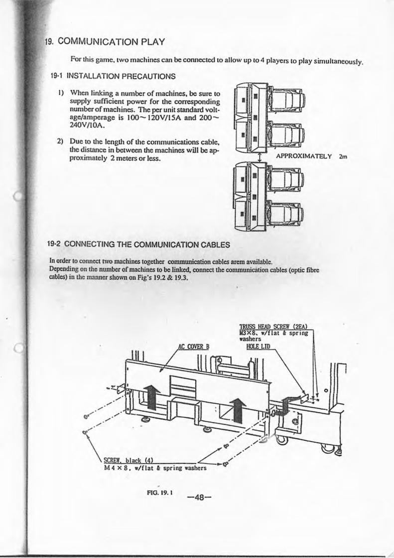
19. COMMUNICATION PLAY
For this game. twO machines can be connected to allow up to 4 players to play simultaneously.
19·1 INSTALLATION PRECAUTIONS
1) When linking a number or machines, be sure to supply sufficient power for the corresponding number of machines. The per unit sWlClan:! voltage/amperage is 100-120V/l5A and 200-240V/IOA.
• >-:=-•
• • •
'. II) ~
'. IT ] 2) Due to the length of the communications cable. the disWlce in between the machines will be approximately 2 meters or less. APPROXI MATELY 2m
• .~ II ] ~ • • • I] ]
I::::::: <:::.-
19·2 CONNECTING THE COMMUNICATION CABLES
In order to COlUlcct two machines together communication cables arem available. Depending 011 the nwnbcr of machines to be linked. connect the commwticalion cables (optic fibre cables) in the manner mown on Fig's 19.2 &. 19.3.
" IS'
SCRE'I. black (4) L:C!',,/ M -4 x 8 • • /nat " spring .-ashers
FIG. t9. t -48-
o
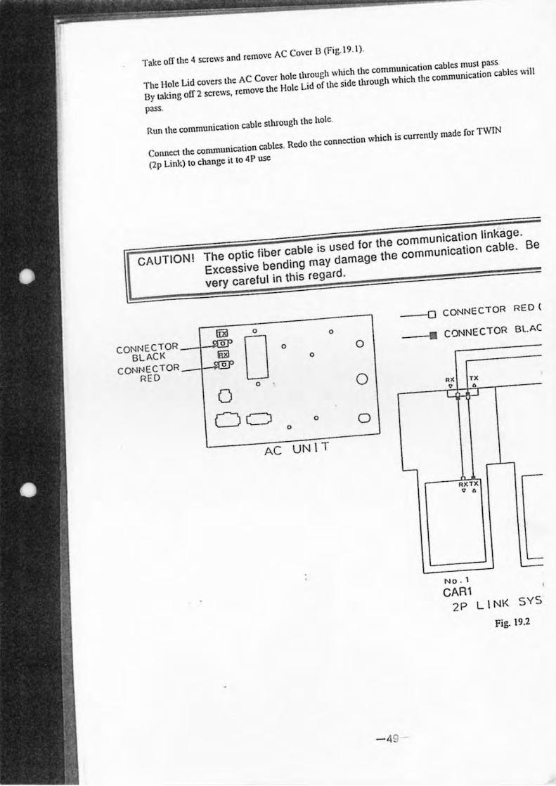
Take orr lhe 4 screws and remove AC Cover B (Fig. 19. I) .
The Hole Lid covers the AC Cover hole through which the communication cables must pass
By laking ofT 2 screws, remove Ute Hole Lid Oflhc side through which the communication cables \\;11
pass.
Run the communication cable slhrough lhe hole.
Connect the communication cables. Redo the connection which is currently made for TWfN
(2p Link) to change it (0 4P usc
CAUTION! The optic fiber cable is used for the communication linkage.
CONNECTOR BLACK
CONNECTOR RED
Excessive bending may damage the communication cable. Be
very careful in this regard.
~ 0
D 0
Wi! 0
...S@P 0
0
0 DC) 0
0
AC UNIT
0
0
0
- 49
--0
• CONNECTOR
CONNECTOR
•• TX 0
RXTX o •
•
No . 1
CARl
RED (
Bl.AC
2P LINK SYS
Fig. 19.2
ow TO • •
- ,-'-•• ,x • •
NO . ,
CAR1
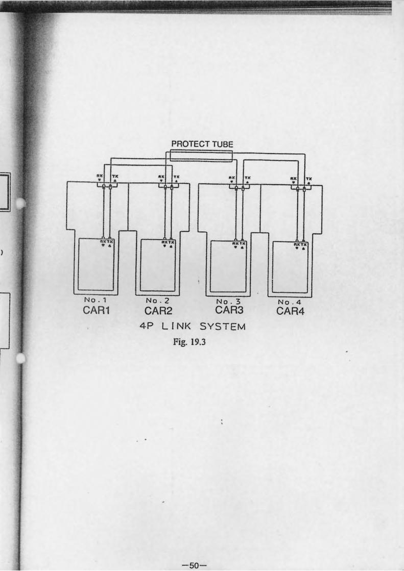
PROTECT TUBE
•• U •• U
• • • •
r-.. T. ..,. • • • •
No . 2 No . 3 CAR2 CAR3
4P LINK SYSTEM Fig. 19.3
-50-
• • .. •
~
_TO
• •
NO . 4
CAR4
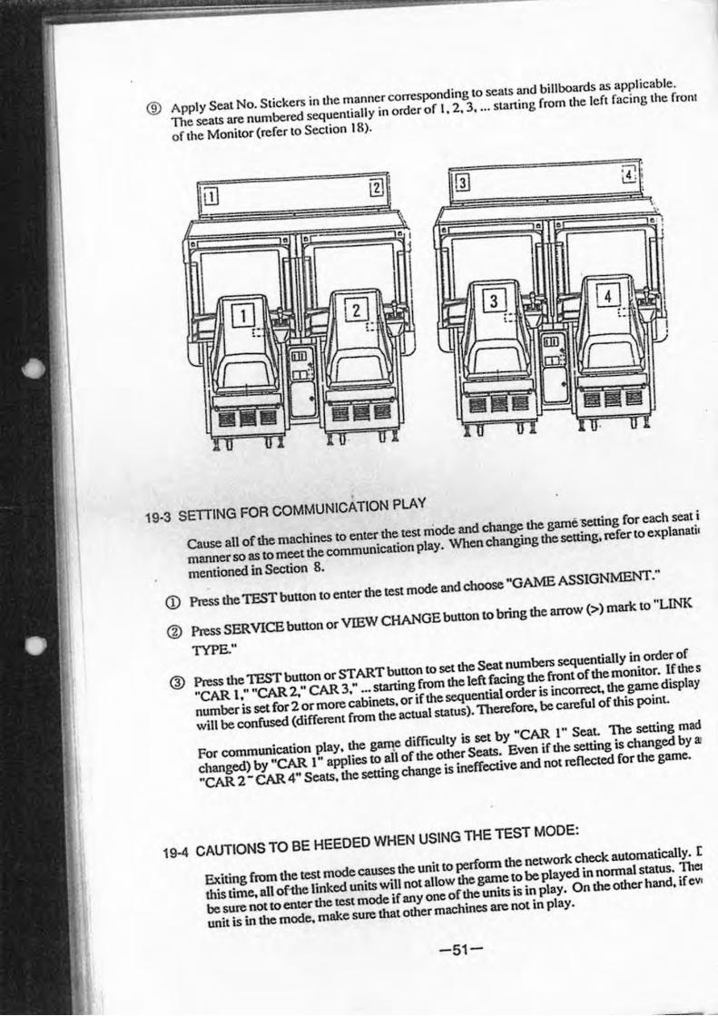
® Apply Seat No. Stickers in the manner corTesponding to seats and billboards as applicable.
The seats are numbered sequentiaUy in order of I. 2, 3 . ... starting from the Icft rac ing lhe fronl
of the Monitor (refer to Section 18).
19·3 SETIING FOR COMMUNICATION PLAY
Cause all of the machines to enter the test mode and change the game 'Setting for each seat i
manner so as to meet the communication play. When changing the setting. refer to explanati l
mentioned in Section 8.
<D Press the TEST button to enter the test mode and choose "GAME ASSIGNMENT."
® Press SERVICE button or VIEW CHANGE button to bring the arrow (» mark to "LINK
TYPE."
@ Press the TEST button or START bunon to set the Seat numbers sequentially in order of
"CAR I; "CAR 2," CAR 3; ..• starting from the left facing the front of the monitor. If thes
number is set for 2 or more cabinets. or if the sequential ottler is inconect, the game display
will be confused (different from the actual status). 1berefore. be careful of this poinL
For communication play. the g""1" difficulty is set by "CAR I" Seat. The setting mad
changed) by "CAR I" applies to all of the other Seals. Even if the setting is changed by.,
"CAR 2 - CAR 4" Seats. the setting change is ineffective and not reflected for the game.
19-4 CAUTIONS TO BE HEEDED WHEN USING THE TEST MODE:
Exiting from the test mode causes the unit to perform the network check automatically. [
this time. all ofthe linked units will not allow the game to be played in normal status. ThCI
be sure not to enter the test mode if any one of the units is in play. On the other hand. ifeVi
unit is in the mode. make sure that other machines are not in play_
-51-
•
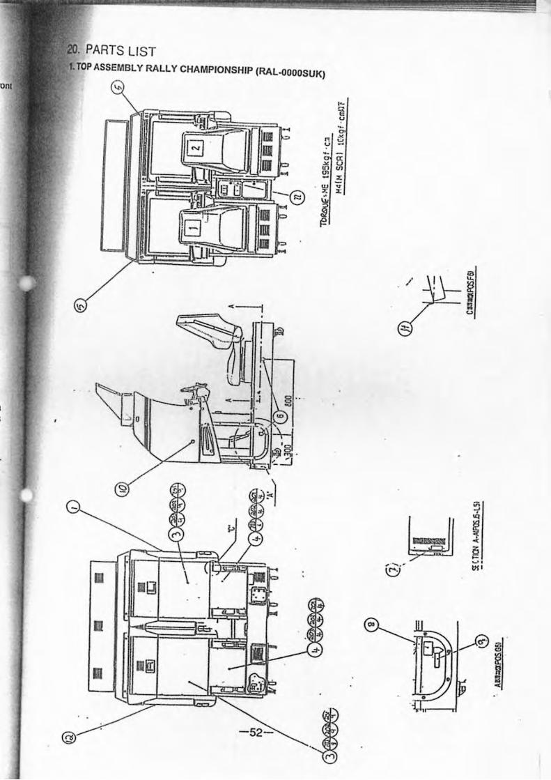
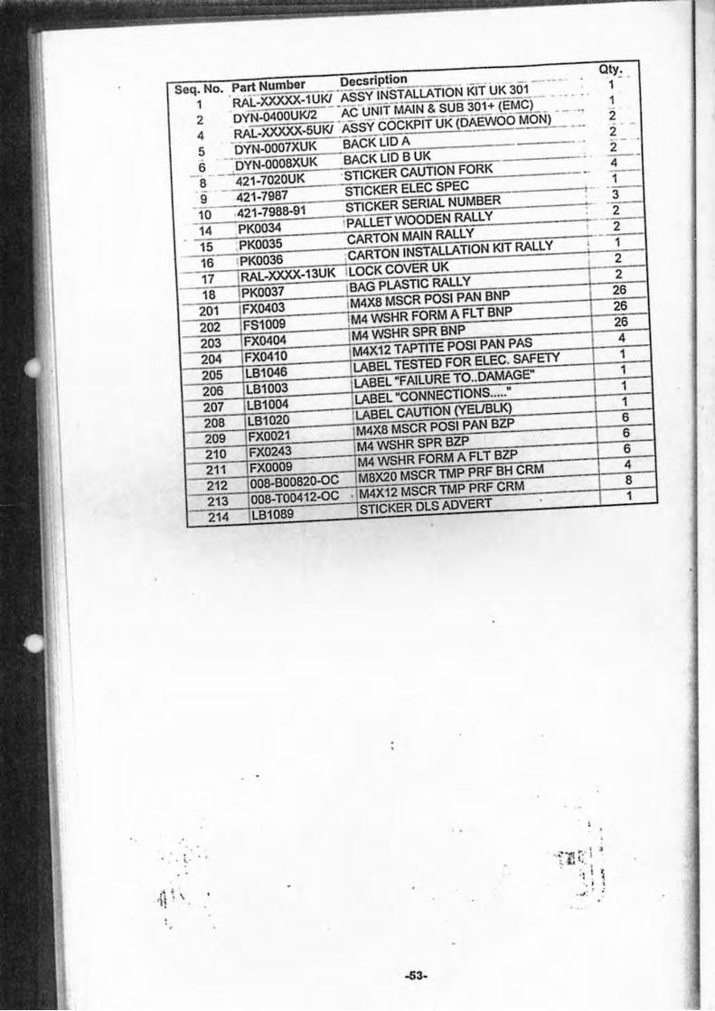
PARTS LIST TOP ASSEMBLY RALLY CHAMPIONSHIP (RAL-OOOOSUK)
.-1
.> •
• I>
III JIg \
Eb
l1li IIgj
@ -52-
•• " G u
" Q.
n ~ u -
a: ~ ~ '" - >: w v To X -i
.3-
~
;a
/ u.
~ :I <.>
""
VI -1
~ '" ! 0 -~ . , -...# Vi'
~
~. ($"'
:3 ~ R :I •
· " l · . •
· , ·jl . \ · .
4 5 Ii -OYN-OOOaXUK
- a 421-7020UK
BACK LID B UK
STICKER CAUTION FORK
-53-
.. •• ""ttI .. , I S ; J.i t ,
. ., I j . ..
. ., , ..
1 1
2 i
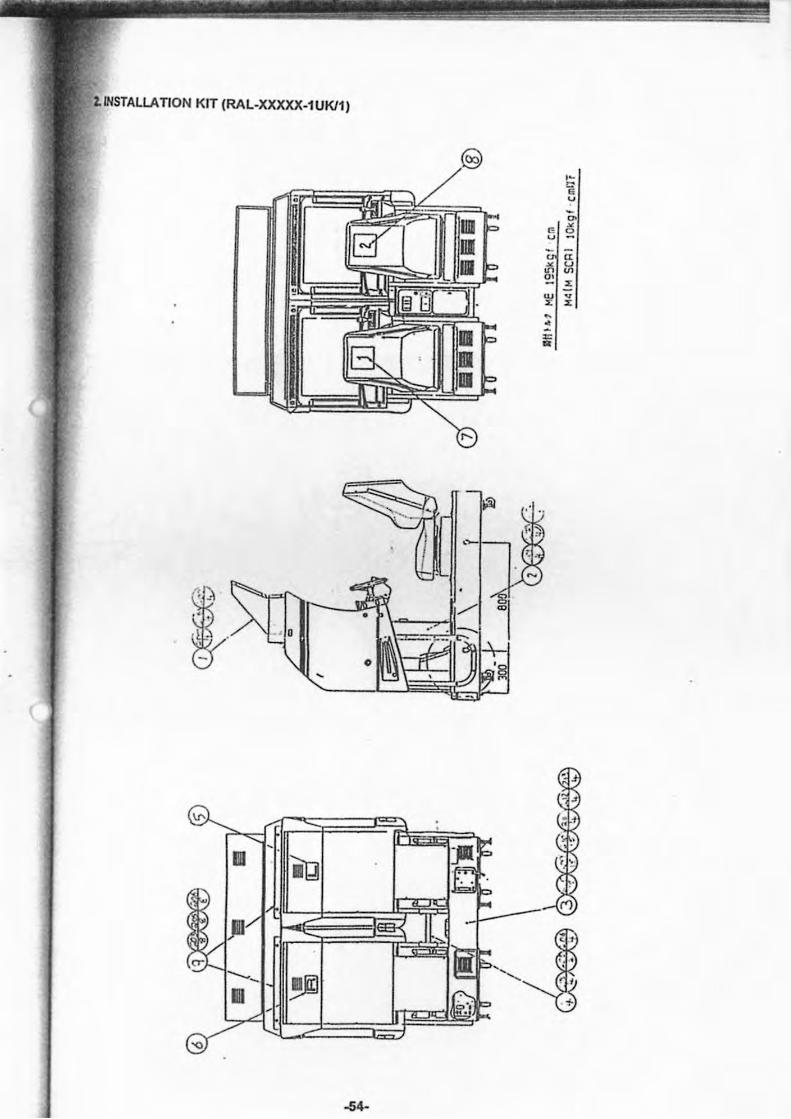
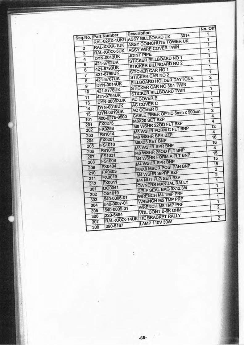
2.INSTALLA TION KIT (RAL-XXXXX-1 UKl1)
,-" • ~ '" ~ G 2 u
a: x u on v> o. x w v X X ~
• : •
I r.~
I .- '. ~
m
JII
--l1li
-54-
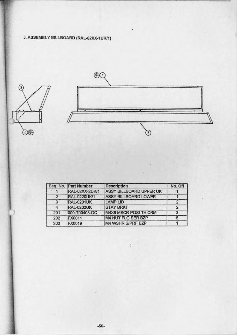
3. ASSEMBLY BILLBOARD (RAL-02XX-1 UKl1)
/J
Seq. No. Part Number Description No. Off 1 RAL-(2)()(-2UKl1 ASSY BILLBOARD UPPER UK 1
2 RAL-0220UKl1 ASSY BILLBOARD LOWER 1 3 RAL-0201UK LAMP LID 2 4 RAL-0202UK STAY BRKT 2
201 000-T00408-0C M4X8 MSCR POSI TH CRM 3 202 FX0011 M4 NUT FLG SER BZP 5 203 FX0019 M4 WSHR S/PRF BZP 1
-56-
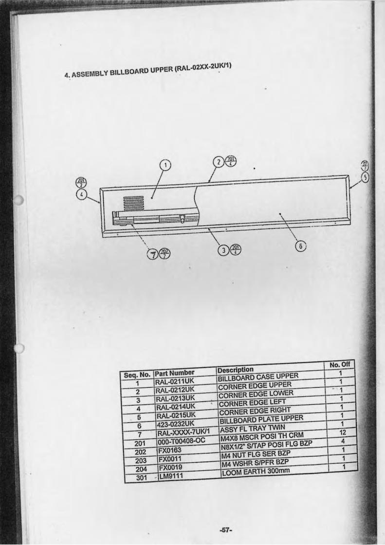
4 .. ASSEMBLY BILLBOARD UPPER (RAL-02XX-2UKl1)
-S7·
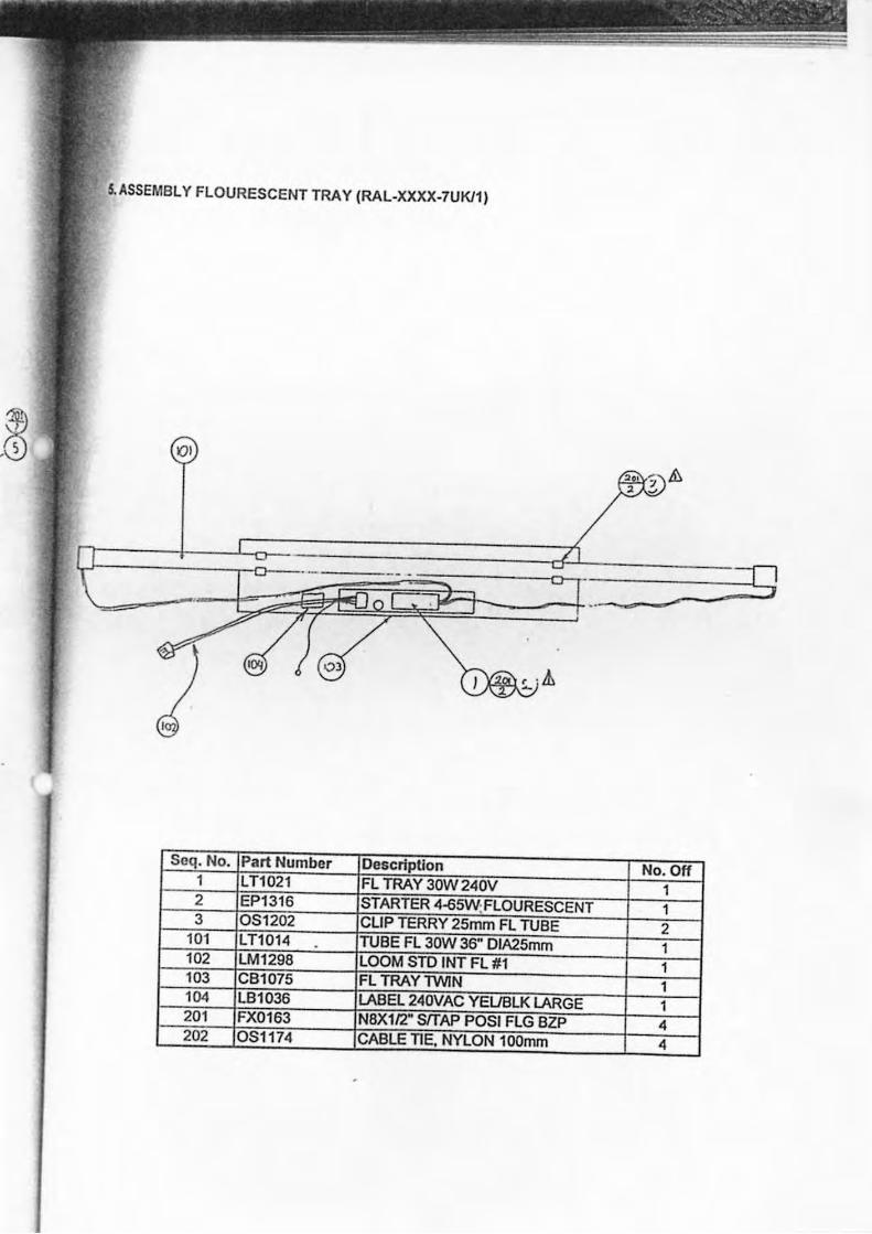
5.ASSEMBL Y FLOURESCENT TRA Y (RAL-XXXX-7UKI1)
()I
Seq. No. Part Number De&cripUon No. Off 1 LT1021 FL TRAY 30W 240V 1 2 EP1316 STARTER 4-65W:FLOURESCENT 1 3 051202 CLIP TERRY 25mm FL TUBE 2
101 LT1014 . TUBE FL 30W 36" DIA25mm 1 102 LM1298 LOOM STD INT FL #1 1 103 CB1075 FL TRAYlWIN 1 104 LB1036 LABEL 240VAC YEllBLK LARGE 1 201 FX0163 N8X112" SfTAP POSI FLG BZP 4 202 051174 CABLE TIE. NYLON 100mm 4
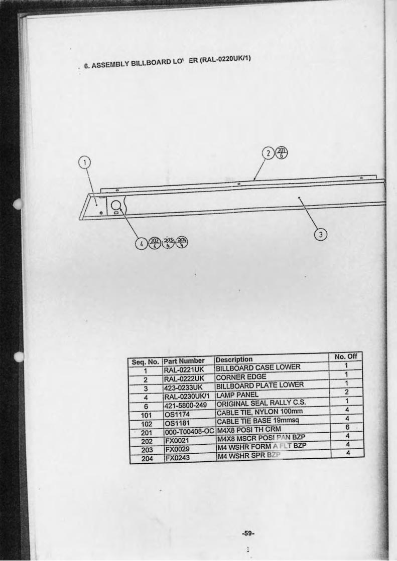
. 6. ASSEMBLY BILLBOARD LO' ER (RAL.0220UKll)
• •
Seq. No. Part Numbe, Description No. Off
1 RAL"()221 UK BILLBOARD CASE LOWER 1
2 RAL"()222UK CORNER EDGE 1
3 423..()233UK BILLBOARD PLATE LOWER 1
4 RAL"()230UKll LAMP PANEL 2
6 421·5800·249 ORIGINAL SEAL RALLY C.S. 1
101 OS1174 CABLE TIE. NYLON 100mm 4
102 OS1181 CABLE TIE BASE 19mmsq 4
201 000· T00408-OC M4X8 POSI TH CRM 6
202 FX0021 M4X8 MSCR POSlJ't,N BZP 4
203 FX0029 M4 WSHR FORM A T BZP 4
204 FX0243 M4 WSHR SPR BZ 4
-59·
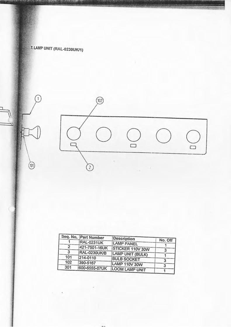
1. LAMP UNIT (RAL-02JOUKf1)
o o o o D D
z
Seq. No, Part Number Description No. Off 1 RAL-02J1UK LAMP PANEL 1 2 421-7501-16UK STICKER 11 OV JOW 3 3 RAL-0230UKfB LAMP UNIT (BULK) 1 101 214-0110 BULB SOCKET 3 102 390-5167 LAMP 110V 30W 3 301 600-{i555-07UK LOOM LAMP UNIT 1
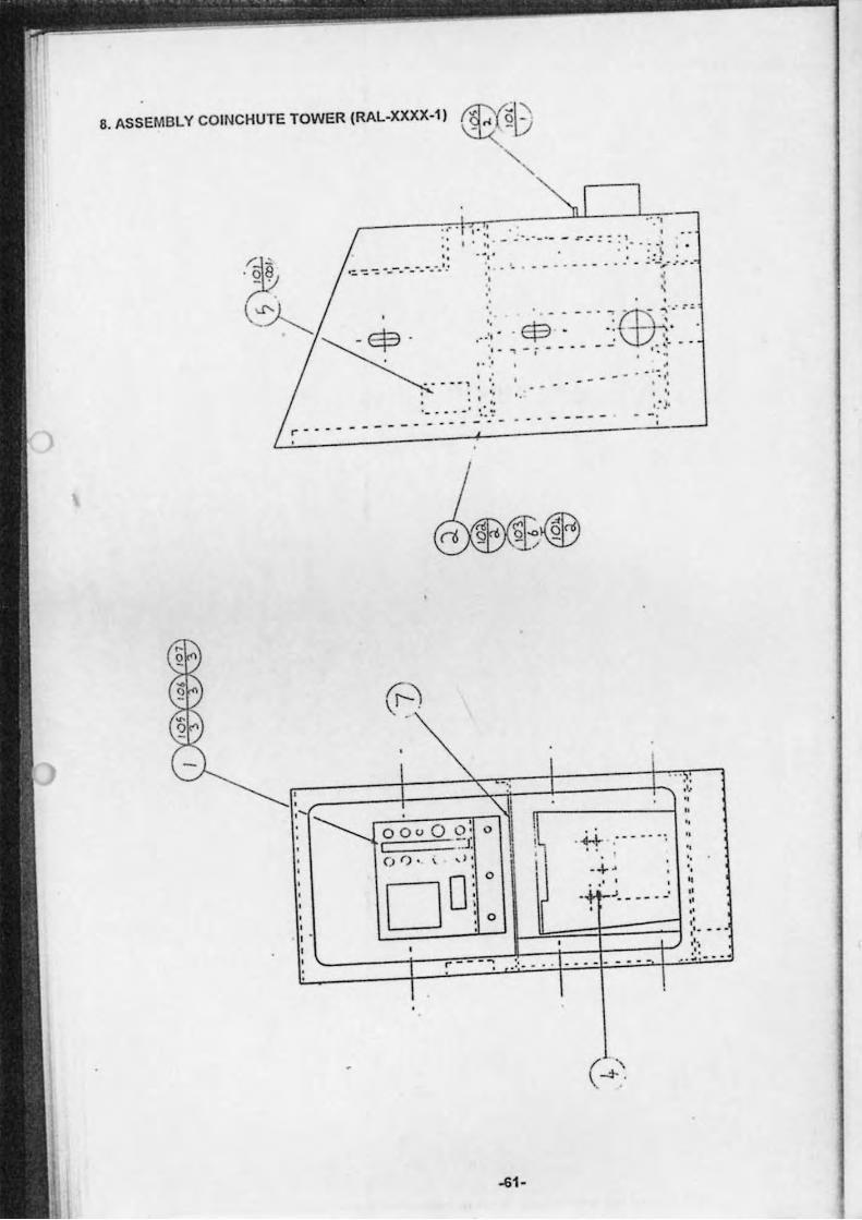
8. ASSEMBLY COINCHUTE TOWER (RAL-XXXX-l)
, , I '
o Ou I (") r).
. ,' . ,. ' "
.... ,
" - .... _ . . - r.-:: :!" :.',' , . . 4,'
"
'. '.
'-"'- " .:~
'.
0 ,
O· 0
-:J. , d ' .
. . . - - - . - _ _ .. . _ ; ·2 ...... : ... , , -_. "(fB-,.'.-, . ,
' . . . '. - - .:"
, --- -- . - : : ~ . ' .
• : ,I.
.', , " '.
.~ "
DD~ 0
0
.,' , .J. _____ ,
' . '. , " " .' " ,'- - --
r- - - - ~ . :'. _ • • • •• __ "',
~ . ~ '--.
~1-
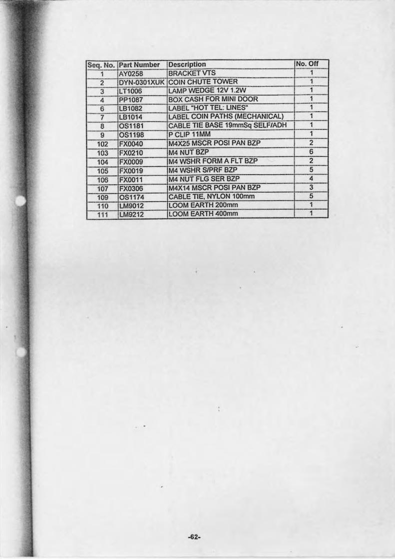
Seq. No. Part Number Description No. Off 1 AY0258 BRACKETVTS 1 2 DYN·0301 XUK COIN CHUTE TOWER 1 3 LT1006 LAMP WEDGE 12V 1.2W 1 4 PP1087 BOX CASH FOR MINI DOOR 1 6 LB1082 LABEL "HOT TEL: LINES" 1 7 LB1014 LABEL COIN PATHS (MECHANICAL) 1 8 OSl181 CABLE TIE BASE 19mmSq SELF/ADH 1 9 OSl198 P CLIP llMM 1
102 FX0040 M4X25 MSCR POSI PAN BlP 2 103 FX0210 M4 NUTBlP 6 104 FXOO09 M4 WSHR FORM A FL T BlP 2 105 FXOO19 M4 WSHR SlPRF BlP 5 106 FXOOll M4 NUT FLG SER BlP 4 107 FX0306 M4X1 4 MSCR POSI PAN BlP 3 109 OSl 174 CABLE TIE. NYLON 100mm 5 110 LM9012 LOOM EARTH 200mm 1 111 LM921 2 LOOM EARTH 400mm 1
~2-
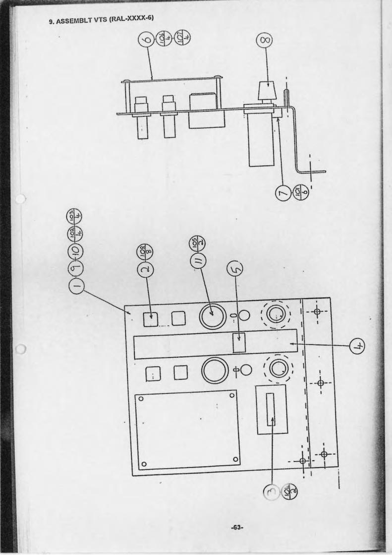
9. ASSEMBLT VTS (RAL.XXXX-6)
00
... 0 o /tA.." \y, , - -'
.+ .
00 o
! 1 _~ __
I , o
o o
-63·
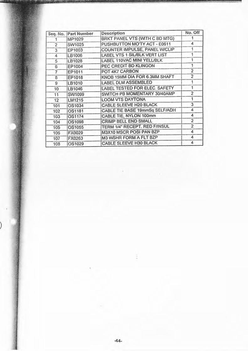
Seq. No. Part Number Description No. 011 1 MP1029 BRKT PANEL VTS (WITH C BD MTG) 1 2 SW1025 PUSHBUTTON MO'TY ACT - E0611 4 3 EP1003 COUNTER IMPULSE. PANEL W/CLIP 1 4 LB1006 LABEL VTS 1 SIUBLK VERT LIST 1 5 LB1028 LABEL 110VAC MINI YELUBLK 1 6 EP1004 PEC CREDIT BD KLiNGON 1 7 EP1011 POT4K7CARBON 2 8 EP1018 KNOB 15MM DIA FOR 6.3MM SHAFT 2 9 LB1010 LABEL DLM ASSEMBLED 1 10 LB1046 LABEL TESTED FOR ELEC. SAFETY 1 11 SW1099 SWITCH PB MOMENTARY 30/40AMP 2 12 LM1215 LOOM VTS DAYTONA 1
101 OS1034 CABLE SLEEVE H20 BLACK 3 102 OSl181 CABLE TIE BASE 19mmSq SELF/ADH 4 103 OS1174 CABLE TIE. NYLON 100mm 4
104 OS1098 CRIMP BELL END SMALL 2 105 OS1055 TERM 1/4" RECEPT. RED FIINSUL 2 106 FXOO29 M3X10 MSCR POSI PAN BZP 4 107 FX0263 M3 WSHR FORM A FL T BZP 4 108 OS1029 CABLE SLEEVE H30 BLACK 4
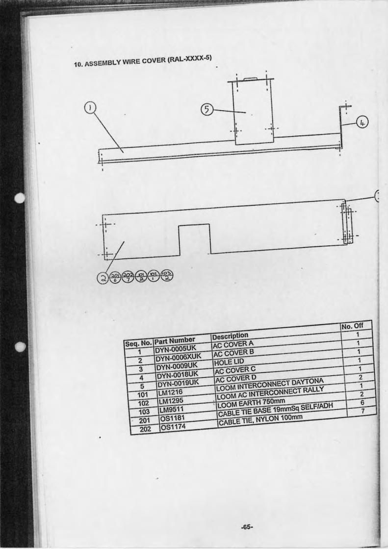
10. ASSEMBLY WIRE COVER (RAL-XXXX-5)
/
. -
"'.=. ,..... ~ :,.1\..11 'iY\!... ~
.
Seq. No. Part Number DescripUon No. Off
1 DYN-0005UK ACCOVERA 1
2 DYN-0006XUK ACCOVERB 1
3 DYN-0009UK HOLE LID 1
4 DYN-0018UK ACCOVERC 1
5 DYN-0019UK ACCOVERD 1
101 LM1216 LOOM INTERCONNECT DAYTONA 2
102 LM1295 LOOM AC INTERCONNECT RALLY 1
103 LM9511 • LOOM EARTH 750mm 2
201 051181 CABLE TIE BASE 19mmSq 5ELF/ADH 6
202 051174 CABLE TIE. NYLON 100mm 7
.
~5-
J
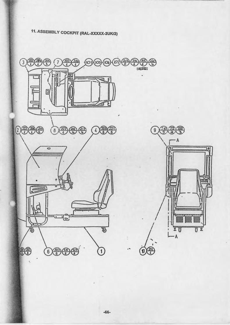
11. ASSEMBLY COCKPIT (RAL-XXXXX-2UKl2)
,
01
.'
~6-
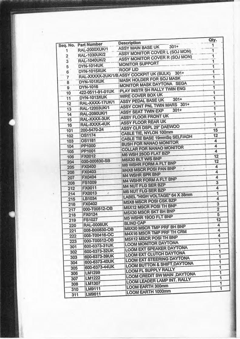
seq; No . . ~;'l~:
2 RAL- '
3 RAL-'
5 u 6 JTN-1U'
11K
_. ASSY IAI BASI
A::;:;Y 10K
;YNITOR
K 301+ t L (SOJ MOL t R (SOJ MOL
, UK (BULK) )1 +
. 1 _ . 1
.. 1 - 1 1 1
"1 7 8 9 10 11 12
-11 91 .:o1iJil I PL W
I ·17UKll
"1 1 ~ =ClR ;0:, MASK
(l ~;--+~I
13 11
.S IT P ~L l' 301+
TWIN )1+
ITlWIN 301+
VII
'UK
,K LJk 11 101 11 4 'C ,K DSPL 29"
_ 103 I1!jl fIE
05 =i1i'l1;-_ _ _ ~,£:BASE !: 10: ~ 1MB LAR )R~ 205 FX0400 =.T ' FLAT
R FORMJ, F_T
'uu
'OR lOR
206 'W/S
M4
POSI PAN
1M4 no{ 5PR BNI P
1M4 NUT'" I1AFL'r BNP
I 1 , 1
15 : 12 ; "'4 I "'4
4 12 12 4 4 4
L .• LB1' ' IM6 Nlf ~~ 5ER BZP
~2~lBW>1 ~====j~ ~tB~ZP==~ 217 ~ ~"T 31 '-64X-:;a;;;;;;-iiiiiil- + "£-.J
218 OB 12: 1')51 C =
I~ 2119 II'OSI rH
22: 301 30i
l~
1I5
11
-TO{
* 11 11
" BH
~ liiDND~ ,OB JMiiXj,o
C
II~P PRF BH
I r.lP PRF rH (;~ M
~USITHBNP
I EXT 'ITOR [ WTO,""
.~ '-.. 'II
Il
TH TH
> IN'
! f 12 4 4 4 1
Page Intentionally Left Blank
-68-
Page Intentionally Left Blank
-69-
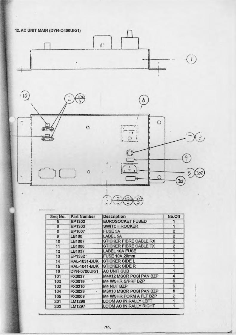
12, AC UNIT MAIN (DYN-0400UKl1)
IJ (- --'--'------
n / "
-r d-J ,
I I
c I':'~-- : , , -'~ • • # ;
i. __ , -,. 1:- . ~_._ '::Y" - --, ,.:;-";
.7n.
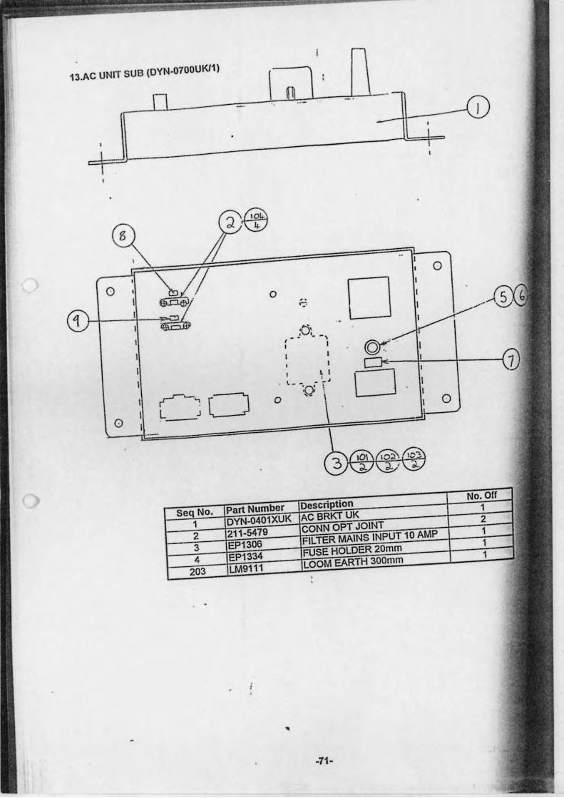
13.AC UNIT SUB (DYN.0700UKl1)
0
~-':
0 L J Cl
, •
0
0
•
0
D .. ':'
. :C5: - . . -,
I
I
,- - \ I
D . -, O i
0
-71-
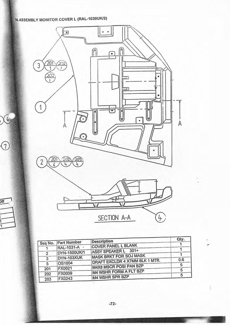
IUSSEMBL Y MONITOR COVER L (RAL-1030UKl2)
--B rr=P_':::' -::~==f . •
5if1 -SECTION A-A
Seq No. Part Number Description Qty.
1 RAL-1031-A . COVER PANEL L BLANK 1
2 DYN-1500UKl1 ASSY SPEAKER l 301+ 1
3 DYN-103XUK MASK BRKT FOR SOJ MASK 1
5 081004 DRAFT EXClDR 4 X7MM BlK 1 MTR. 0.6
201 FX0021 M4X6 MSCR POSI PAN BlP 5
202 FXOO09 M4 WSHR FORM A Fl T BlP 5
203 FX0243 M4 WSHR SPR BlP 5
-72-
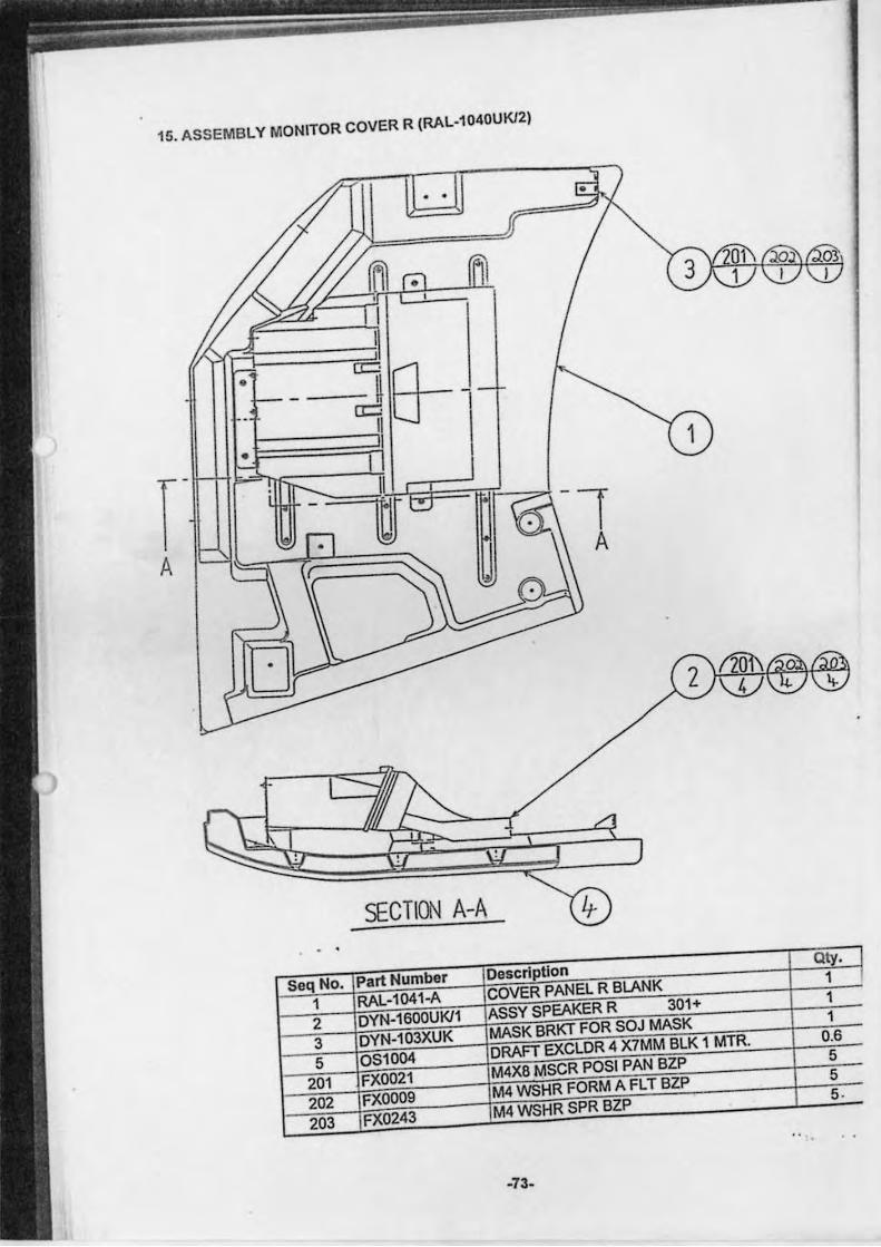
15. ASSEMBLY MONITOR COVER R (RAl.1040UKl2)
SECTI()\J A-A
Seq No. Part Number Description Qty. I
1 RAl-1041-A COVER PANEL R BLANK 1 I
2 DYN-1600UKl1 ASSY SPEAKER R 301+ 1
3 DYN-103XUK MASK BRKT FOR SOJ MASK 1
5 OSlOO4 DRAFT EXClDR 4 X7MM BlK 1 MTR. 0.6
201 FXOO21 M4X8 MSCR POSI PAN BZP 5
202 FXOOO9 M4 WSHR FORM A Fl T BZP 5
203 FX0243 M4 WSHR SPR BZP 5 .
-73.
Page Intentionally Left Blank
-74-
Page Intentionally Left Blank
-75-
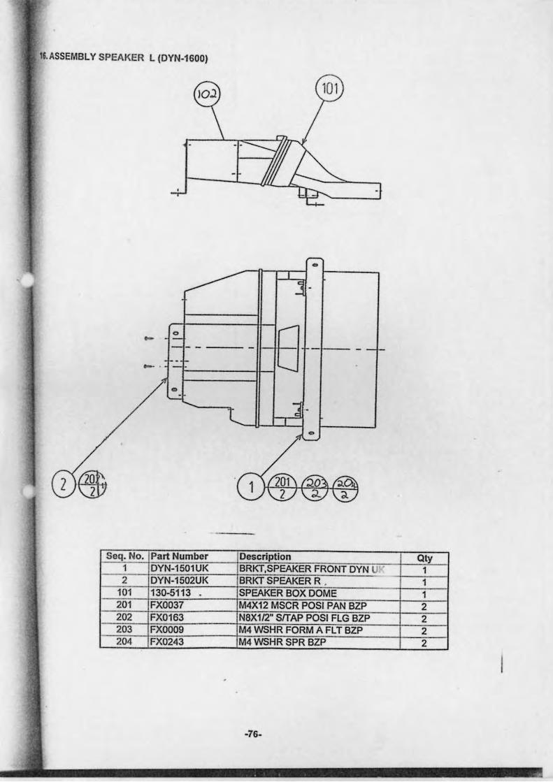
11. ASSEMBLY SPEAKER L (DYN-1600)
o --.
Seq. No. Part Number Description Qty 1 DYN-1501UK BRKT,SPEAKER FRONT DYN UV 1 2 DYN-1502UK BRKT SPEAKER R . 1
101 130-5113 SPEAKER BOX DOME 1 201 FX0037 M4X12 MSCR POSI PAN BZP 2 202 FX0163 N8Xll2" SrrAP POSI FLG BZP 2 203 FXOO09 M4 WSHR FORM A FL T BZP 2 204 FX0243 M4 WSHR SPR BZP 2
-76-
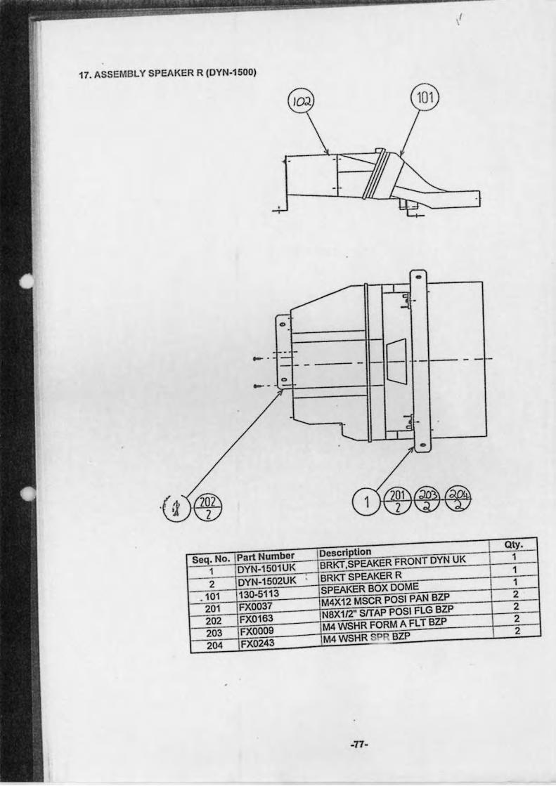
.I ,
17. ASSEMBLY SPEAKER R (DYN-1500)
•
=~ >=r=0 ====IH8-/--..
. ~
Seq. No. Part Number Description Qty.
1 DYN-1501UK BRKT.SPEAKER FRONT DYN UK 1
2 DYN-1502UK BRKT SPEAKER R 1
. 101 130-5113 SPEAKER BOX DOME 1
201 FX0037 M4X12 MSCR POSI PAN BZP 2
202 FX0163 N8X112" SlTAP POSI FLG BZP 2
203 FXOO09 M4 WSHR FORM A FLT BZP 2
204 FX0243 M4WSHR P BZP 2
-77-
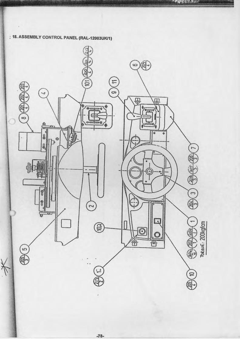
~ __ _ • ...-;.- ,";"1- ----_._-- ~--- ---~ - - --- -- -
: 18. ASSEMBLY CONTROL PANEL (RAL-12003UKll)
o
-78-
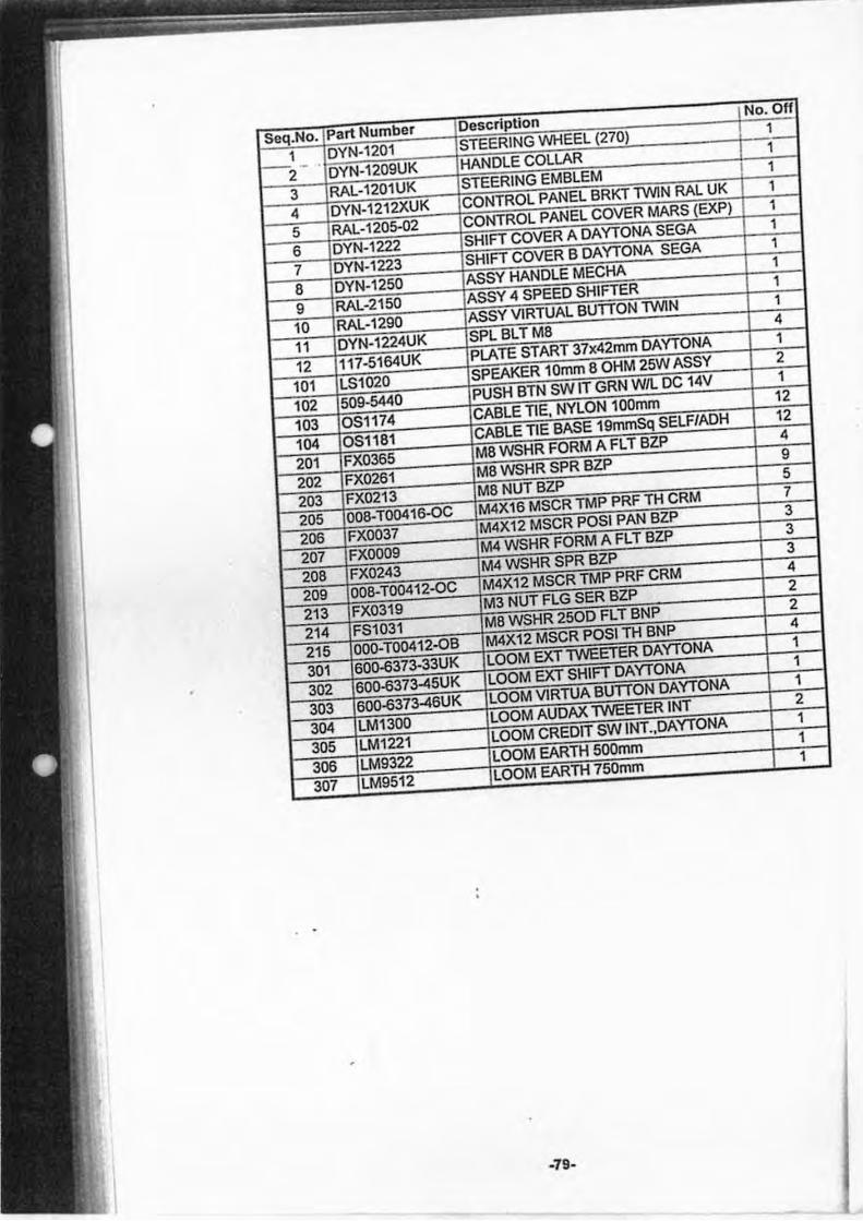
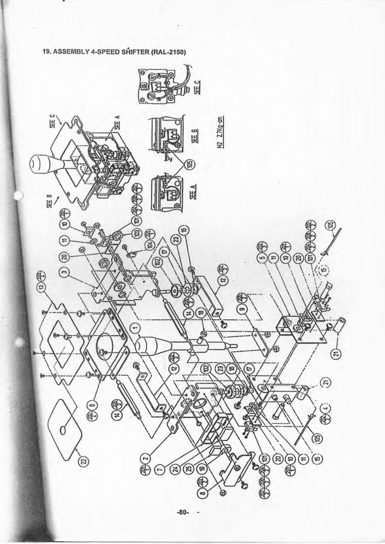
•
19. ASSEMBLY 4-SPEED SHIFTER (RAL-215D)
-80- -
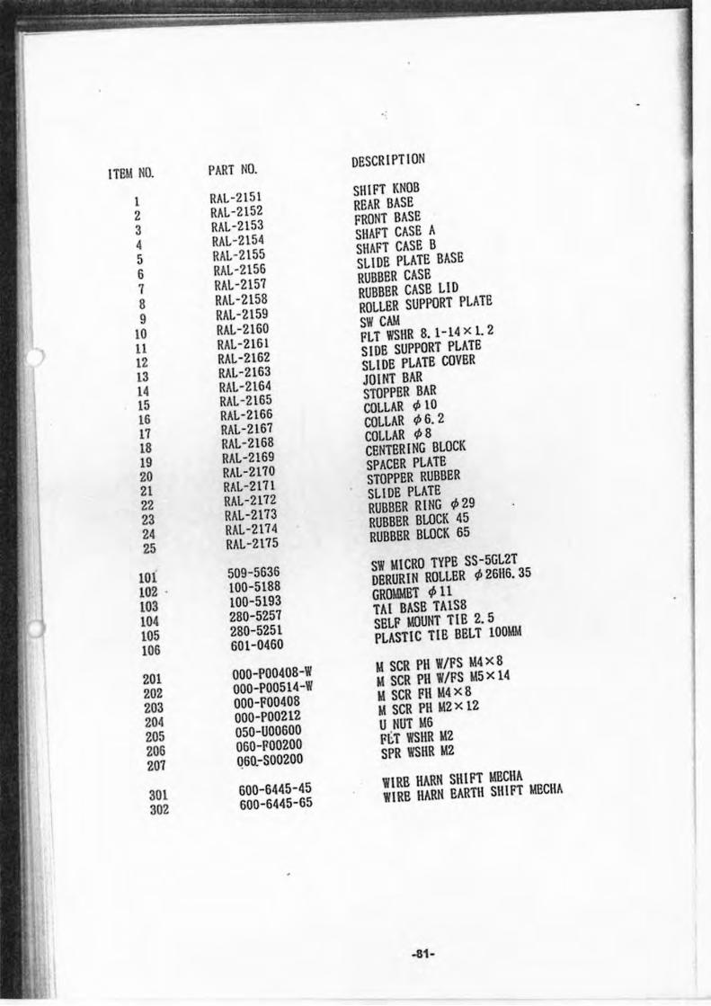
I TI!lI NO. PART NO. DESCRIPTION
1 RAL-2 151 SHIFT KNOB
2 RAL-2152 REAR BASE
3 RAL-2153 FRONT BASE
4 RAL-2154 SHAFT CASE A
5 RAL-2155 SHAFT CASE B
6 RAL-2156 SL IDE PLATE BASE
7 RAL-2157 RUBBSR CASE
8 RAL -2158 RUBBER CASB LI D
9 RAL-2159 ROLLBR SUPPORT PLATE
10 RAL-2160 SW CAM
11 RAL-2161 PLT WSIIR 8.1-14 x l. 2
12 RAL-2162 SIDE SUPPORT PLATE
13 RAL-2163 SLIDE PLATE COVER
14 RAL-2164 JOINT BAR
15 RAL-2165 STOPPBR BAR
16 RAL-2166 COLLAR ¢ 10
17 RAL-2167 COLLAR ¢6.2
18 RAL-2168 COLLAR ¢8
19 RAL-2169 CENTERING BLOCK
20 RAL-2170 SPACER PLATE
21 RAL-2l7l STOPPER RUBBER
22 RAL-2172 SLIDE PLATE
23 RAL-2173 RUBBBR RING ¢ 29
24 RAL-2174 RUBBER BLOCK 45
25 RAL-2175 RUBBSR BLOCK 65
101 509-5636 SW MICRO TYPE SS-5GL2T
102 . 100-5188 DBRURIN ROLLER ¢ 26116.35
103 100-5193 GROIdldBT ¢ 11
104 280-5257 TAl BASS TA1S8
105 280-5251 SBLP MOUNT TIB 2.5
106 601-0460 PLASTIC TIB BBLT 100MM
201 000-P00408-W M SCR PII wlPS \.14 x 8
202 000-P00514-W " SCR I'll WIPS M5 x 14
203 000-P00408 M SCR FII M4 x8
204 000-1'00212 " SCR PH M2x 12
205 050-U00600 U NUT 1d6
206 060-F00200 F~T WSHR M2
207 Q6Q-S00200 SPR WSHR "2
301 600-6445-45 WIRS IIARN SIIIFT "SCHA I 302 600-6445-65
WIRS IIARN EARTH SHIFT "BCHA
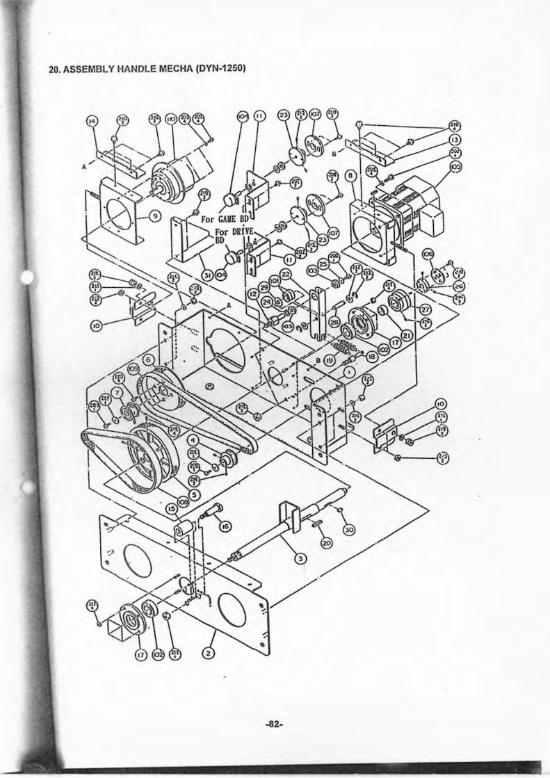
20. ASSEMBLY HANDLE MECHA (DYN-1250)
~2-
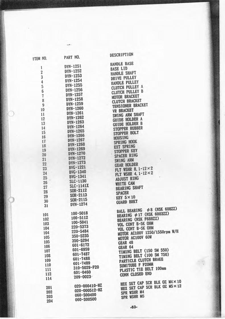
· ..
IWI ~O. PART NO. DeSCR I PTI ON
I DVN-1251 lIANDLE BASE
2 DVN-1252 BASE Ll D
3 DVN-1253 lIANDLE SHAFT
4 DVN-1254 DRIVE PULLEY
5 DVN-1255 HANDLE PULLEY
& DVN-1256 CLUTCH PULLEY A
7 DVN-12S7 CLUTCH PULLEY B
8 DVN-1258 MOTOR BRACKET
9 DVN-1259 CLUTCH BRACKET
10 DVN-1260 TENS lONER BRACKET
I I DVN-1261 VR BRACKET
12 DVN-1262 SWING ARM SHAFT
13 DVN-1263 GUIDE HOLDER A
14 DVN-1264 GUIDE HOLDER B
IS DVN-1265 STOPPER RUBBER
16 DVN-1266 STOPPER BOLT
17 DVN-1267 HOUSING
18 DVN-1268 SPRING HOOK
19 DVN-1269 EXT SPRING
20 DVN -1270 STOPPER KEV
21 DVN-1272 SPACER RING
22 DVN-1273 SWING ARM
23 BVG -1221 GEAR HOLDER
24 BVG-1340 fLT WSHR 8.1-12 )( 2
25 BVG-1341 fLT WSHR 4.1-12 )( 2
26 SLC-lI30 ADJUST RING
27 SLC-lI4IX WlIITE CAM
28 SOR-2l12 BBARING SHAfT
29 SOR-2l13 SPACER
30 SOR-2I1S KEVsxlO
31 DVN-1274 GUARD BRKT
101 100-S018 BALL BBARING If> 8 (NSK 608ll)
102 100-5112 BEAR ING If> 17 (NSK 6003lZ)
103 100-5041 BBARING (NSK F688ZZ)
104 220-5373 VOL CONT B-SK OllM
104 220-S484 VOL CaNT B-SK Oilid
105 3S0-5235 IoIOWR ACIOOV 12S0/ISSOrpm W/II
105 3S0-5294 IoIOTOR ACIOOV 60W
lOG 60i-6172 GEAR 48
107 601 -6959 GEAR 64
108 601-7487 TIMING BBLT (150 51d 550)
109 601-7488 TIMING BELT (100 51d 150)
lI0 601-1489 PARTICLE CLUTCII BRAKE
III 310-5029-F20 SUMITUBE F F20MM
ll2 601-0460 PLASTIC TIE BELT 1000n
114 209-0023- CONN CLOSED END
201 020-000410-HZ HEX SKT CAP SCR BLK OZ M4 x 10
202 020-000512-HZ \lEX SKT CAP SCR BLK OZ 1d5 x 12
203 060-S00400 SPR WSHR 1d4
204 060-S00S00 SPR WSHR idS
-83-
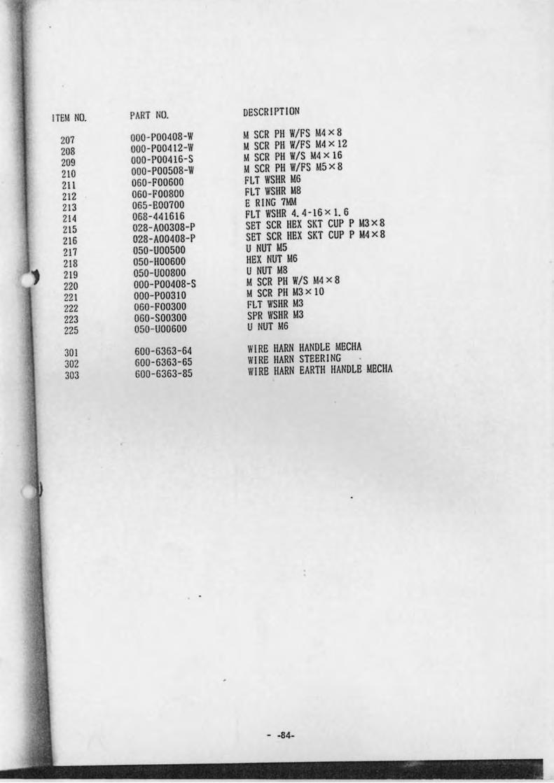
ITEM NO. PART NO. DESCR I PTI ON
207 000- P00408-W M SCR PH W/FS M4 x 8
208 OOO-P00412-W II SCR PII W/FS 114 x 12
209 000-P00416-S M SCR PH W/S 114 x 16
210 000-P00508-W M SCR PH W/FS 1015 x 8
211 060-1'00600 FLT WSIIR 1016 212 060-1'00800 FLT WSHR 118 213 065-B00700 E RING 7M!.! 214 068-441616 I'll WSIIR 4. 4 -16 x I. 6
215 028-A00308-P SET SCR IIEX SKT CUP P 113 x 8
216 028-A00408-P SET SCR IIEX SKT CUP P 1014 x 8
217 050-U00500 U NUT 1015 218 050-1100600 HEX NUT 1016 ., 219 050-U00800 U NUT 1018 220 000-P00408-S M SCR PII W/S M4 x 8 22 1 000-P00310 M SCR PII 113 x 10 222 060-1'00300 I'Ll WSIIR 1013 223 060-S00300 SPR WSHR 1013 225 050-U00600 U NUT 116
301 600-6363-64 WIRE IIARN HANDLE MECHA 302 600-6363-65 WIRE IIARN STEERING
303 600-6363-85 WIRE HARN EARTH IIANDLE MECIIA
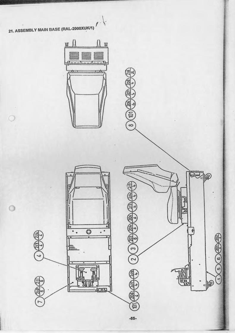
21 . ASSEMBLY MAIN BASE (RAL-2000XUKl1)
I .
y 0 [\ JJ
--... ... .. :::--~~ ".
--\
o
• •
-liS-
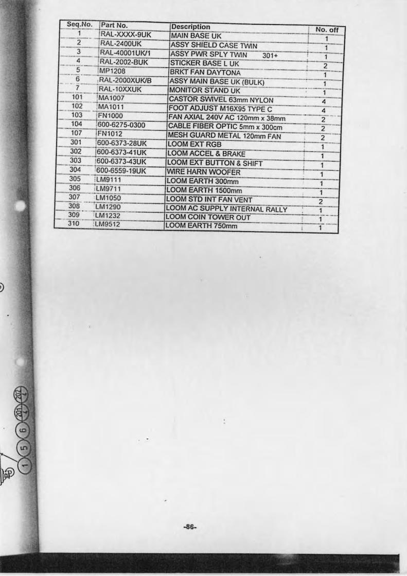
t2eq.No. Part No. Description T No. off 1 RAL-XXXJ(-9UK MAIN BASE UK I 1 ---2--RAL-2400UK ASSY SHIELD CASE lWIN 1 - 3 RAL-4000lUKiI ASSY PWR SPL Y lWIN 301+ ,
1 - 4 RAL-2002-BUK STICKER BASE L UK 2 -, 5 MP120B BRKT FAN DAYTONA 1 --'-6 RAL·2000XUKlB ASSY MAIN BASE UK (BULK) 1 - - _ .. -
---1--7 :RAL-l0XXUK MONITOR STAND UK --lo,- ' MA 1007 CASTOR SWIVEL 63mm NYLON 4
102 'MA1011 FOOT ADJUST M16X95 TYPE C 4 -- - -103 IFN1000 FAN AXIAL 240V AC 120mm x 3Bmm 2 104 ,600-6275-0300 CABLE FIBER OPTIC 5mm x 300cm 2 107 FN1012 MESH GUARD METAL 120mm FAN 2 --301 600-6373-2BUK LOOM EXTRGB I 302 600-6373-41 UK LOOM ACCEL & BRAKE 1 303 i600-6373-43UK LOOM EXT BUnON & SHIFT , 1 304 600-6559-19UK WIRE HARN WOOFER 1 305 :LM9111 LOOM EARTH 300mm 1 306 ,LM9711 LOOM EARTH 1500mm 1 .-307 LM1050 LOOM STD INT FAN VENT 2 -- . 306 LM1 290 LOOM AC SUPPLY INTERNAL RALLY 1 -- ----LOOM COIN TOWER OUT !- 309 LM 1232 I 1
'LM9512 LOOM EARTH 750mm --310 , 1
-lIS-
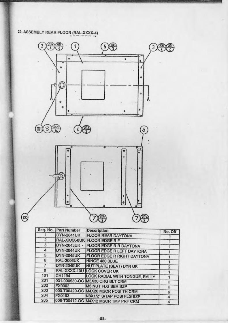
22. ASSEMBLY REAR FLOOR (RAL-XXXX-4) " -.- ... _-. "
• •
o
o
A A
• • •
6
• • • •
•
•
• • •
Seq. No. Part Number Description No. Off 1 DYN-2041UK FLOOR REAR DAYTONA 1 2 RAL-XXXX-aUK FLOOR EDGE R F 1 3 DYN-2043UK - FLOOR EDGE R R DAYTONA 1 4 DYN-2044UK FLOOR EDGE R LEFT DAYTONA 1 5 DYN-2045UK FLOOR EDGE R RIGHT DAYTONA 1 6 RAL-2006UK HINGE 480 BLUE 1 7 DYN-2049UK NUT PLATE (SEAT) DYN UK 2 8 RAL-XXXX-13U LOCK COVER UK 1
101 CH1194 LOCK RADIAL WITH TONGUE. RALLY 1 201 031-000530-OC M5X30 CRG BL T CRM f 202 FX0302 M5 NUT FLG SER BZP 8 203 000-T00420-0C M4X20 MSCR POSI TH CRM 6 204 FX0163 N8X112" SlTAP POSI FLG BZP 4 205 008-T00412-0C M4X12 MSCR TMP PRF CRM 4
-88-
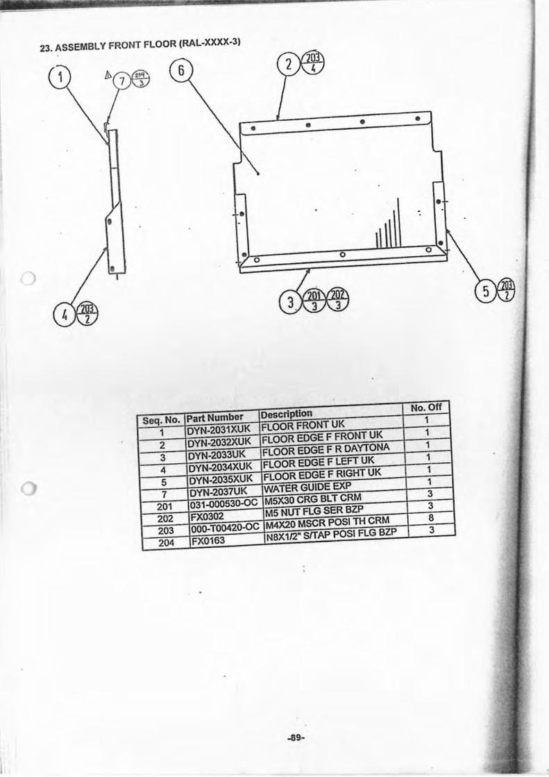
23. ASSEMBLY FRONT FLOOR (RAL-XXXX-3)
1
I • •
• • •
o o • o •
Seq. No. Part Numbe. Description No. Off
1 DYN-2031XUK FLOOR FRONT UK 1
2 DYN-2032XUK FLOOR EDGE F FRONT UK 1
3 DYN-2033UK FLOOR EDGE F R DAYTONA 1
4 DYN-2034XUK FLOOR EDGE F LEFT UK 1
5 DYN-2035XUK FLOOR EDGE F RIGHT UK 1
7 DYN-2037UK WATER GUIDE EXP 1
201 031'{)OO53Q-{)C M5X30 CRG BL T CRM 3
202 FX0302 M5 NUT FLG SER BZP 3
203 000-T00420-OC M4X20 MSCR POSI TH CRM 8
204 FX0163 N8Xll2" SlTAP POSI FLG BZP 3
. -
~9-
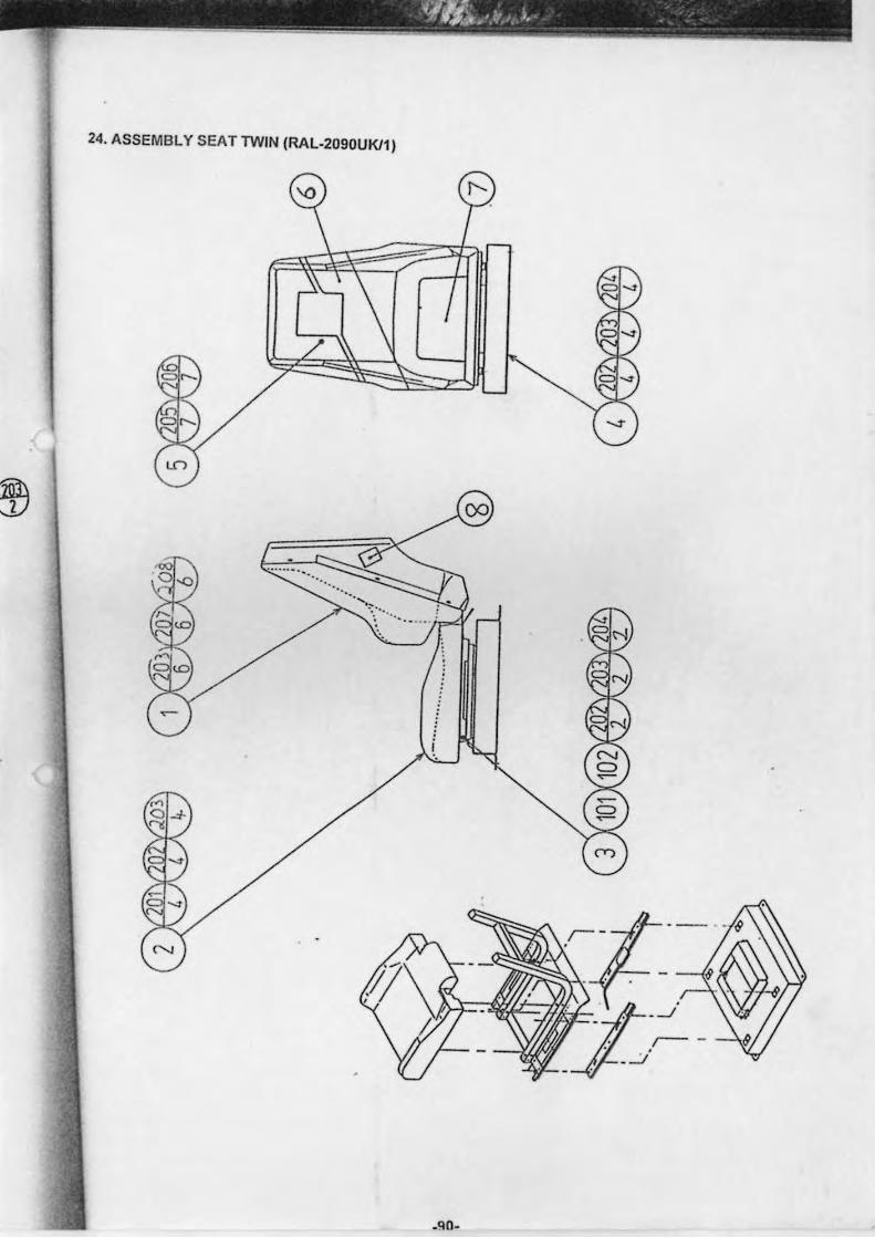
~ .. I ~.'.rr I, ) •
. - ------
24. ASSEMBL Y SEAT TWIN (RAL-2090UKll)
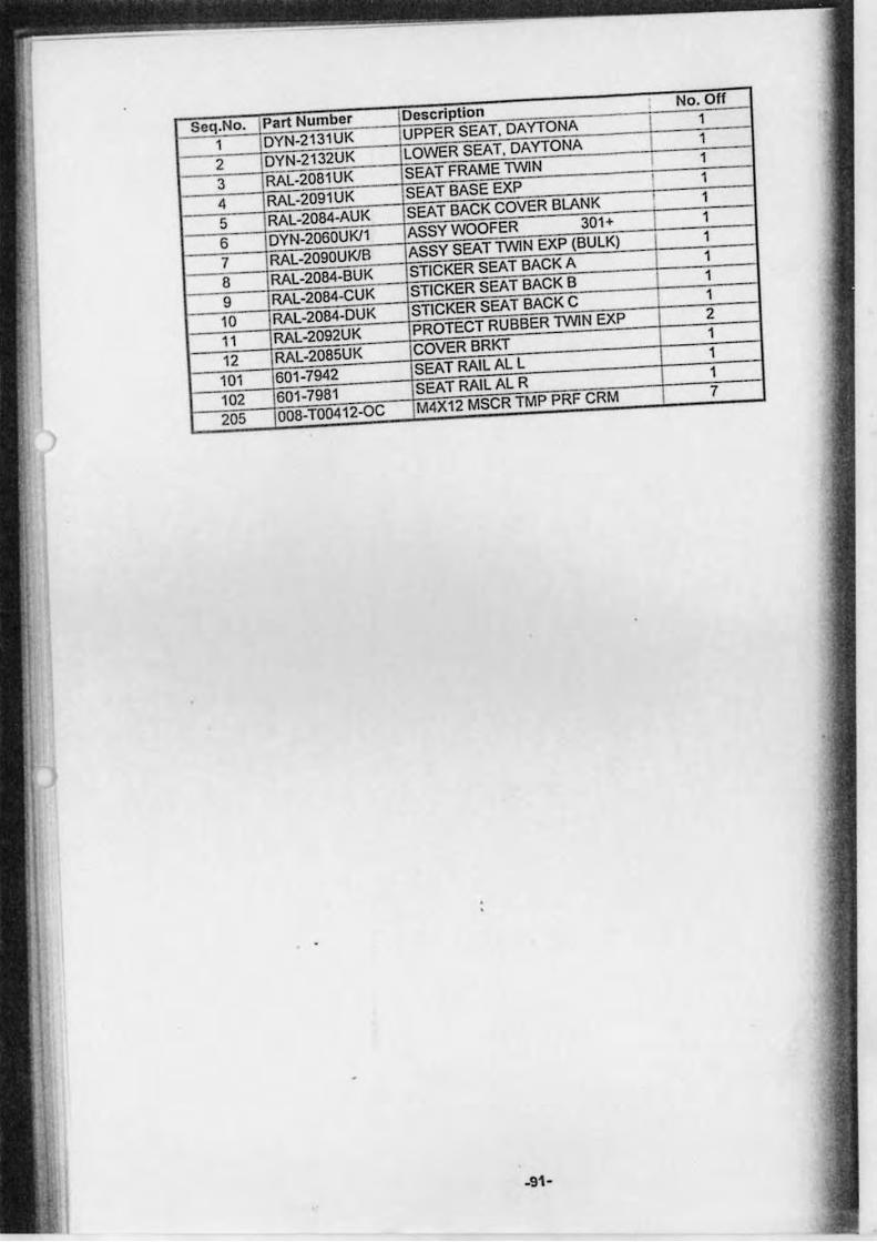
Seq.No. Part Number Description No. Off
1 DYN-2131UK UPPER SEAT. DAYTONA I 1
2 DYN-2132UK LOWER SEAT. DAYTONA I 1
3 RAL-20B1UK SEAT FRAME TWIN 1
4 RAL-2091UK SEAT BASE EXP I 1
5 RAL-2084-AUK SEAT BACK COVER BLANK I 1
6 DYN-2060UKll ASSYWOOFER 301+ 1
7 RAL-2090UKlB ASSY SEAT TWIN EXP (BULK) 1
8 RAL-2084-BUK STICKER SEAT BACK A 1
9 RAL-2084-CUK STICKER SEAT BACK B 1
10 RAL-2084-DUK STICKER SEAT BACK C I 1
11 RAL-2092UK PROTECT RUBBER TWIN EXP 2
12 RAL-2085UK COVERBRKT 1
101 601 -7942 SEAT RAIL AL L 1
102 601-7981 SEAT RAIL AL R 1
205 008-T00412-0C M4X12 MSCR TMP PRF CRM 7
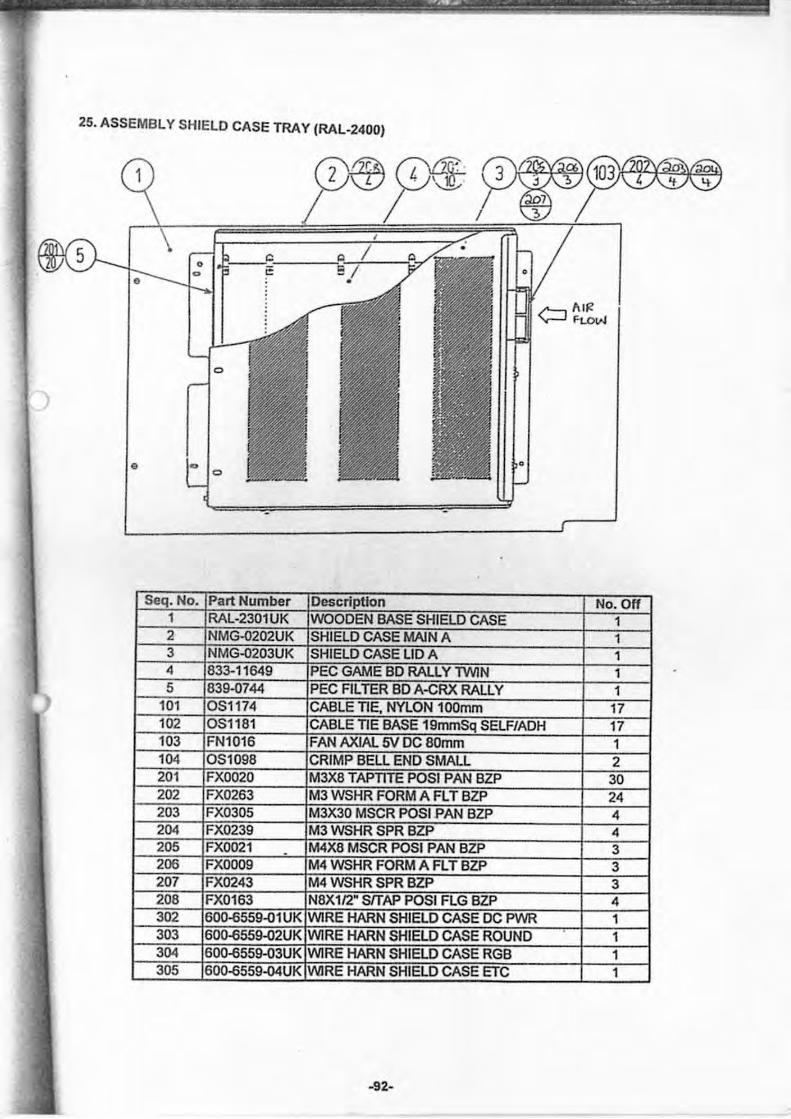
25. ASSEMBLY SHIELD CASE TRA Y (RAL-2400)
)
e
-92-
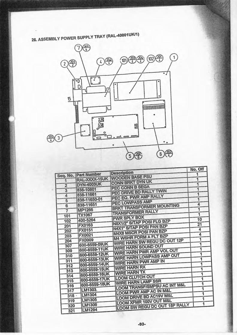
26. ASSEMBLY POWER SUPPLY TRAY (RAL-40001 UKl1)
•
\ .
\ .
-93-
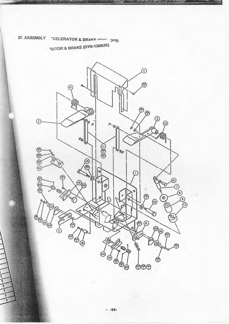
27. ASSEMBLY 'CELERATOR & BRAKe ,n"· · : J~O)
RAKE lDYN.1300UK) ~TOR&B
- .94·
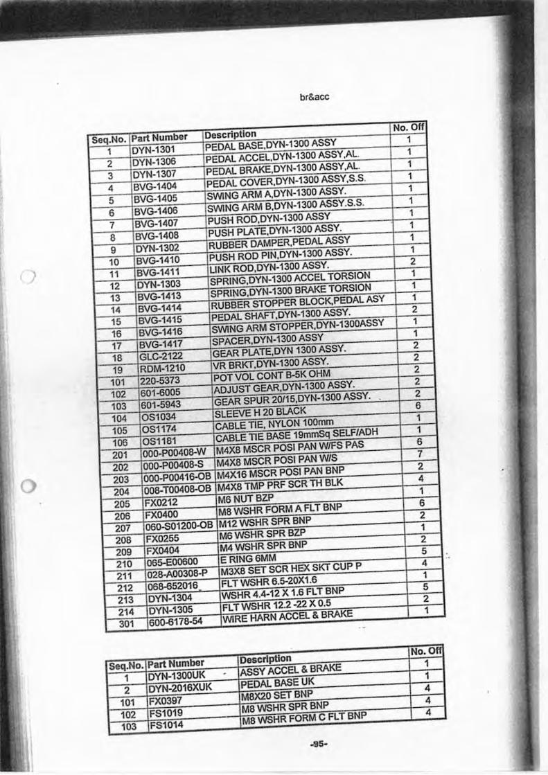
br&acc
)
Seq.No. Part Number DescrlpUon No. 0"
1 DYN-1300UK . ASSY ACCEL & BRAKE 1
2 DYN-2016XUK PEDAL BASE UK 1
101 FX0397 M8X20 SET BNP 4
102 FS1019 M8 WSHR SPR BNP 4
103 FS1014 M8 WSHR FORM C FLT BNP 4
-95-
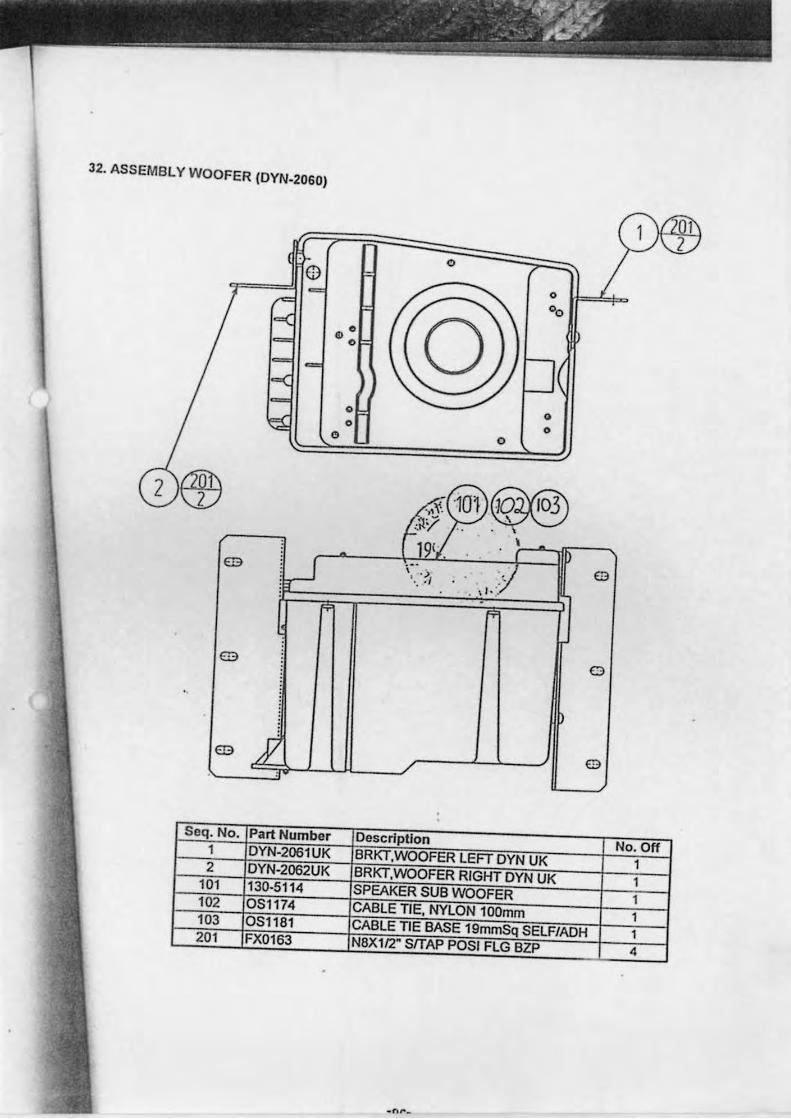
32. ASSEMBLY WO OFER (OYN-2060)
o or===='ll
rn
rn
rn
Seq. No. 1 2
101 102 103 201
:~
~
o o ..
f'
Part Number OYN·2061UK OYN-2062UK 130·5114 OSl174 OS1181 FX0163
"
o
~JOilC$@l r 19(' . . ; ,.' '." ~, " . .! 0
. r"
0
0
OescrlpUon No. Off BRKTWOOFER LEFT OYN UK 1 BRKT,WOOFER RIGHT OYN UK 1 SPEAKER SUB WOOFER 1 CABLE TIE, NYLON 100mm 1 CABLE TIE BASE 19mmSq SELF/AOH 1 NBXll2" SlTAP POSI FLG BZP 4
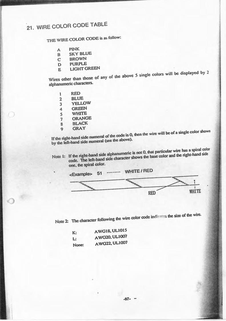
21. WIRE COLOR CODE TABLE
THE WIRE COLOR CODE is as follow:
A PINK
B SKY BLUE
C BROWN
D PURPLE
E LIGHT GREEN
Wires olher than Ihose of any of Ihe above 5 single colors will be displayed by 2
alphanumeric characters.
I RED
2 BLUE
3 YELLOW
4 GREEN
5 WHITE
7 ORANGE
8 BLACK
9 GRAY
If the right-hand side numen>! of the code is 0, then the wire will be of a single color shown
by the left-hand side numen>! (see the above).
Note I: If the righi-hand side alphanumeric is nolO, thai particular wire has a spiral color
code. 1be left-hand side character shows the base'color and the righi-hand side
one, the spin>! color.
<Example> 51 .... ..... WHITE I RED
NOle 2: TIle character following the wire color code indio"' the size of the wire.
K: AWGI8, ULlOl5
L: AWG20, ULlOO7
None: AWG22, ULlOO7
-97- -
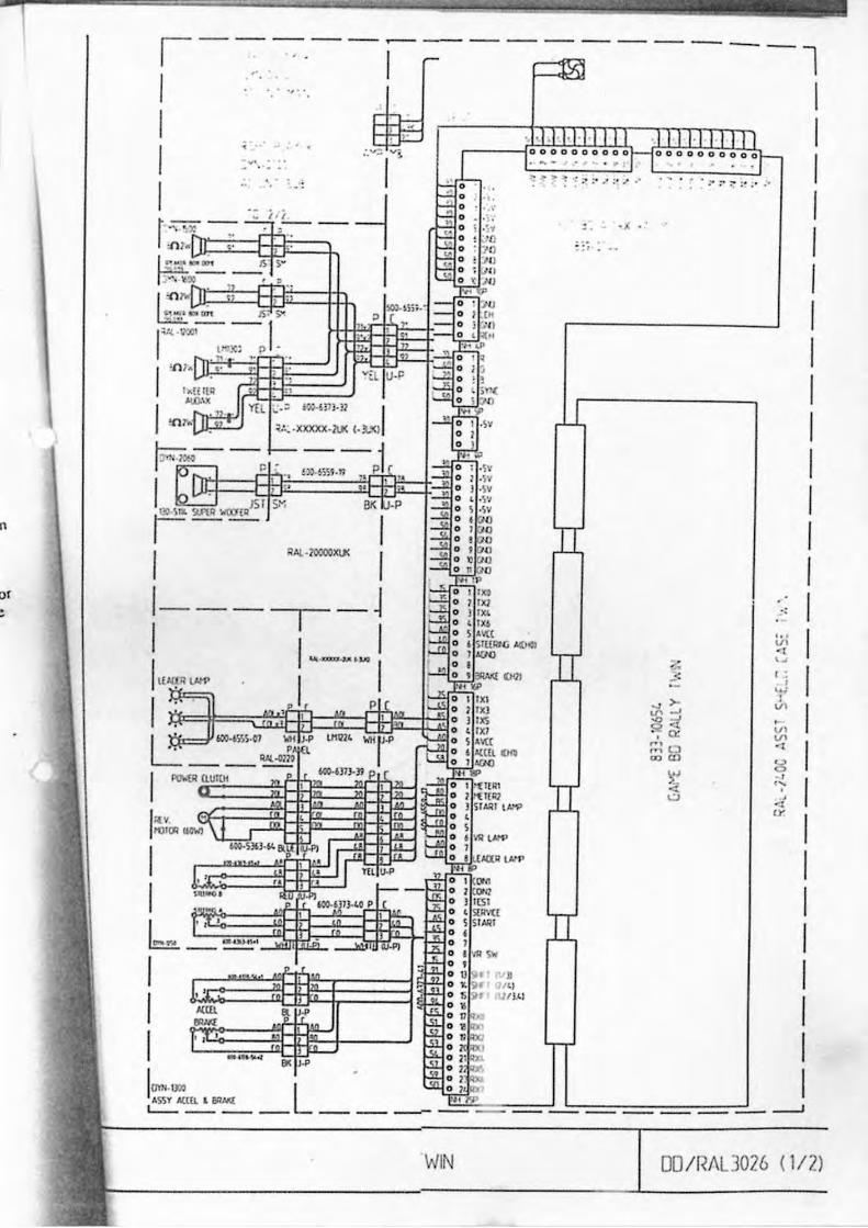
I - · 1<1 11·1+111 I'
" . ::; . ..
u
n
or
WIN
-l
1111·111111 OOOOO~o~o~r
' :- :':- ;' . ' "
'. ' VI 'I o. 1 , ~,
1
'" V'
'" .., g , " . . '" ( y
I I I I I I I
OO/RI\L]026 (lIZ )
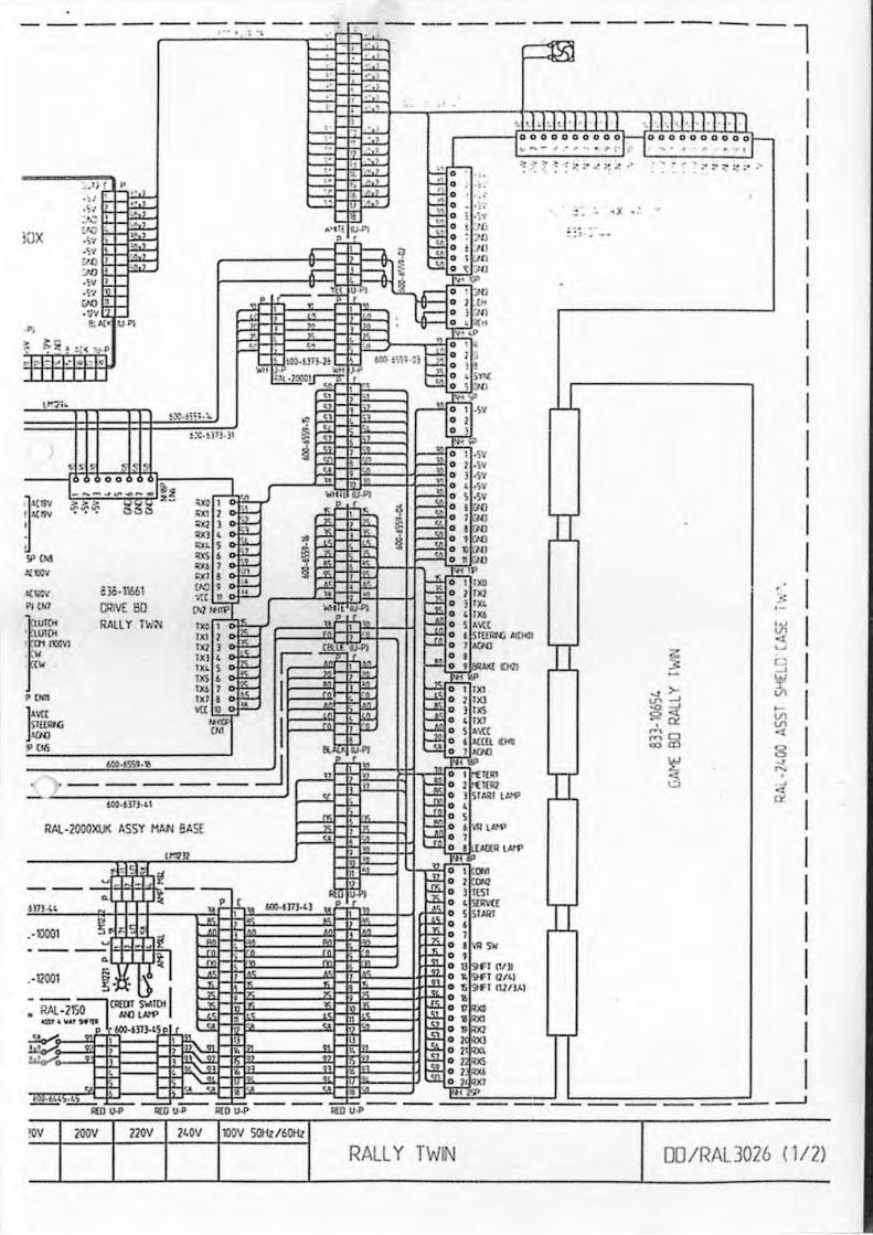
--- ---- ---- ---- ---- ---- ---- ---- ----," ' . ~ '\
_I ; f .. , . ' . ~ t .' ., .. ' .. • ~
!QX r:~ , . ,'1 • .\'1 ,
0 , :xl
, ~
. " •
.~·I
"" ' .~v .
" 1tl A( · ' .\)1II
R/.l ,lOOOXIJ( ASSY MAl< EASE
t~ J1
----,- 0001
-"o-"lH ., •
,
"" .... !Oy lOOY
"
--"'" "..
210v 21.0V
p (
, ' , •
IlOV _ / 6t'Hz
•
-:------• .' • , • .' , , ,
• .' • • , , · • ..
' ~ ,
RALLY TWIN
---- ---- ---- -----l
, d.hld' i I I I I '. 1.1 H I I IJ I 0000000000 I ....... - .. ... . ... I' 100000000001"-
..... .. . . I .... . ,
~.', ~X - , • :; .. ~~
u
TI
.:3
DO/RAU026 (1 /2l
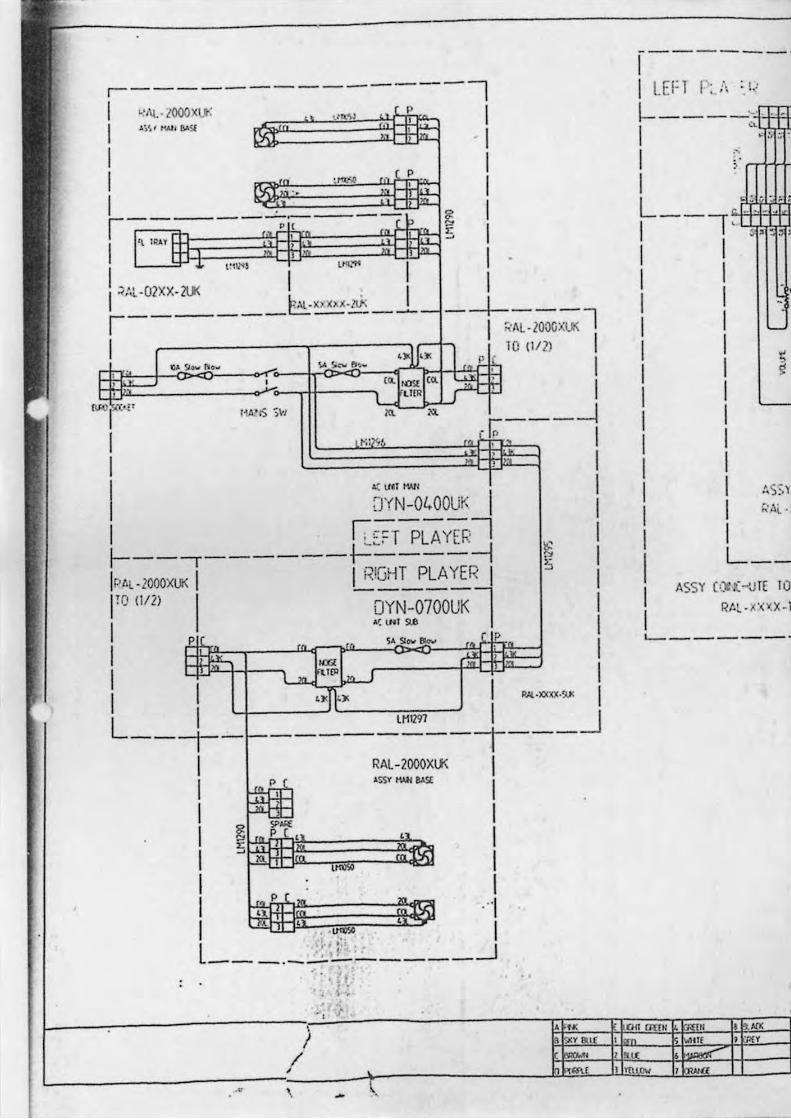
·--------------1 I ., "'-·looo x \.I<
\
I / ,
- \
" J
-
.' ,
, • !Xval(
""
------_. I I LEFT r::\ :!,
I-----~ .. '" I • " ;;
I > n+1+ I , . ... . L .... -.: .~ I --I' s,-" I I I I I I I I
I I I I I I I t,s:.) I h'.\i. -1
I L __
A55Y (,)I ~ ~,Jf( 1.1
RAl · X·(XX. I
'------_.
on m(N '" I '" I '" ) 'PrY
' ~I I mow , a
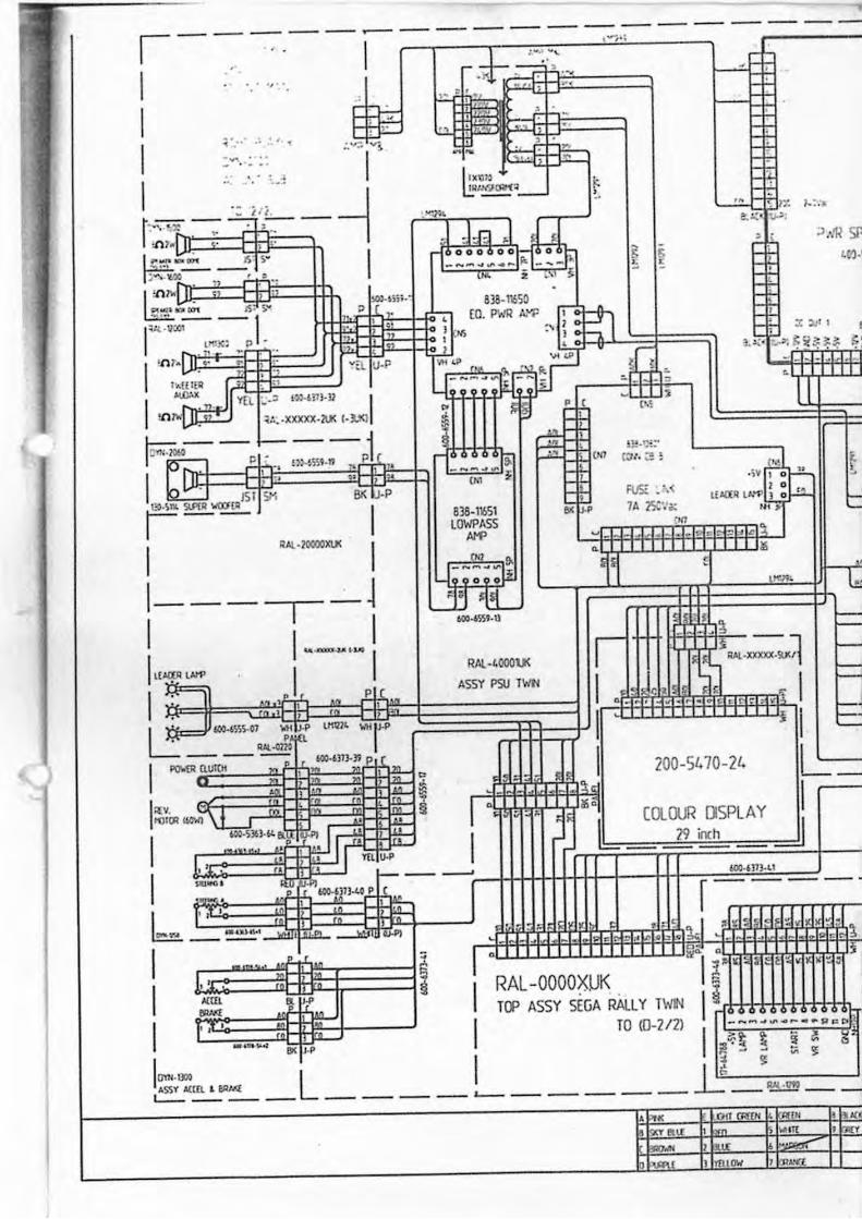
11
b I' , =,~, , ~, ""1::1 : ~ t
II I, ~ ~ i ', RAL-OOOOXUK
!! .IM:" C:u . ~ !
RJ£ • ',< 7A 25(','.
'.,
! ~bl;l l
.,
""',
1< ""'':::-''1 ~ ~ ,
COlOUR [)SPLA Y ]Jinch
s
.IIJ J 1
~ .. ,IR 51' L(I').'
t:
" l"
= -=, =: -
.:: ~~ T(J' A55Y SEGA RAlLY TWIN ,
, I' I TO (0·212) [ ----~ . - ••• "'
_ .• , , ,"3 3 ~ ~
!~"=IIl·~ _L ____ L _____ ~_~~ __ "IC • OffC'RltH ~ £H ! AU
tJ I 'ffllOW , ~l.
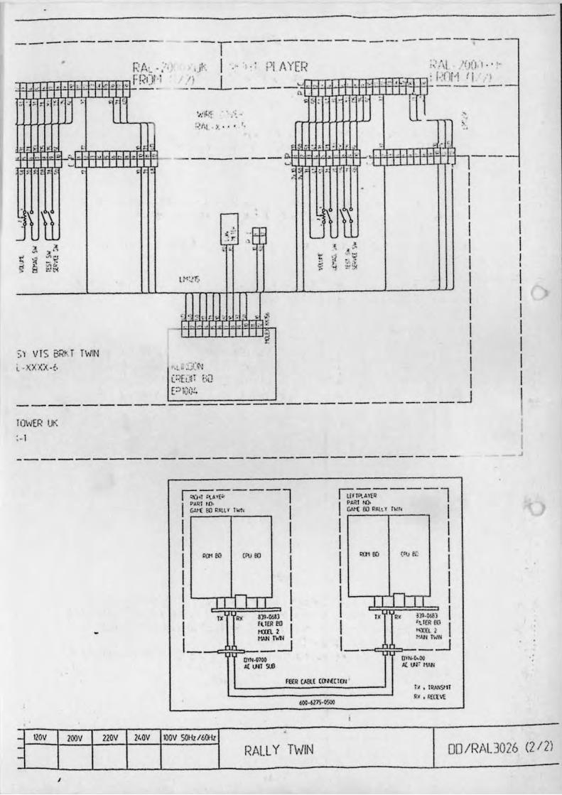
---------
. . . . ~. ,
, ,
---
, , ~
,. , ~
~ ~;!
q 2ft> i!.t'C
:" VI S OR!< [ [WIN
L · X XX:~,~,
10I4ER 1..1(
:-1
"II
-r--- --- - ----------,j~ I ·· ,·· Pi II YE I~
r-
( " ;~ .r , . -
I ~;;~A'r'(:' ---l 1
"I.,QI , I).
I 1
I I I I 1 1
~ 1'0 !ti'l t IIffl I
I I
O(H .. '''' 10 I
I I I I I I
" " O'M)U) I 11ItR flO
""" 1 t'olH l\.<fl
-~ ?-_-.l "",."" AI: IJII 5IJI
~I," .• T'[-' -------l I PJ.Rl t~
I I 1
1
I 1
1
I
GA."-( eo Q",., IWI, I
"" '"
" " M
tt\1 fi.
[TT n'l·~,n
I I I I 1
I r-.IOf 00
"" I -.l """ :WI'
OUj.t>.N J{ VI: tWl
raR (J,fl{ (01«( lO" I I • I .... ,m
" £I . m:a
1 1 ~
- IlOv IOOV ZZOV Z'OV IlOV SOHll6O-il - RALl Y TWIN 00 IRIXL3026 (212) -
,
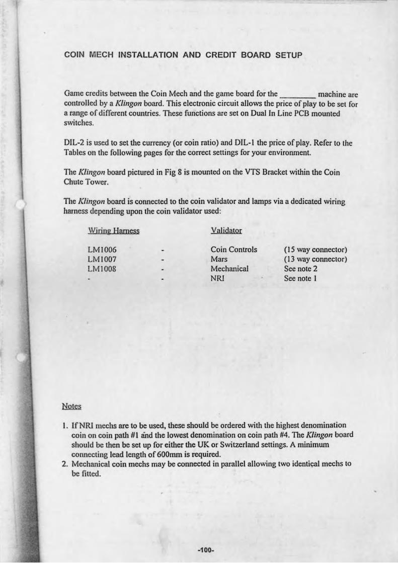
COIN MECH INSTALLATION AND CREDIT BOARD SETUP
Game credils belween Ihe Coin Mech and Ihe game board for Ihe machine are conlIolied by a Klingon board. This eleclIonic circuil allows the price of play to be SCI for a range of different countries. TI,ese functions are set on Dual In Line PCB mounled swilches.
DlL-2 is used 10 set the currency (or coin ralio) and DIL-I the price of play. Refer 10 Ihe Tables on the following pages for the correcl setlings for your environment.
TI,e Klingon board pictured in Fig 8 is mounled on the VTS Brackel within the Coin Chute Tower.
The Klingon board is cormected to the coin validator and lamps via a dedicated wiring hamess depending upon the coin validator used :
Wirjne Harness
LMI006 LMI007 LMI008
ValjdalO[
Coin ConlIols Mars Mechanical NRI
(15 way cormeclor) (13 way conneclor) See nolC 2 See note I
I. IfNRI meehs are to be used, these should be ordered with the highesl denominalion coin on coin path #1 and the lowest denomination on coin path #4 . The Klingon board should be then be set up for either the UK or Switzerland seltings. A minimum cormeeling lead length of 600mm is required.
2. Mechanical coin mechs may be cormected in parallel allowing Iwo identi",,1 meehs 10
be filted.
-100-
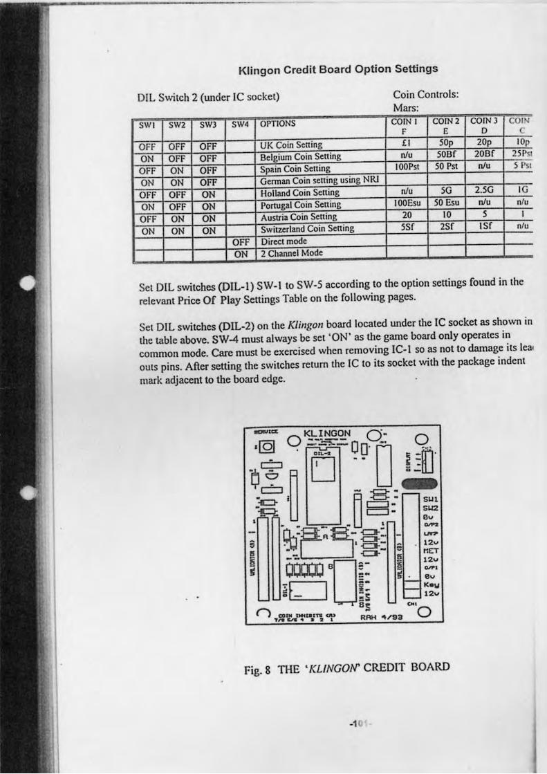
Klingon Credit Board Option Settings
OIL Switch 2 (Wlder IC socket) Coin Controls: Mars:
SWI SW2 SW) SW4 OPTIONS COIN I COIN 2 COIN) COIN F E 0
OFF OFF OFF UK Coin Setting £1 SOp 20p lOp
ON OFF OFF Belgium Coin Setting nlu soar 20ar 21PSI
OFF ON OFF Spain Coin Setting IOOPSI 50 PSI nlu 5 PSI
ON ON OFF Gennan Coin setting using NRI
OfF OFF ON Holland Coin Setting nlu 5G 2.50 IG
ON OFF ON Portugal Coin Setting 100Esu 50 Esu nlu n/u
OFF ON ON Austria Coin Selling 20 10 5
ON ON ON Switzerland Coin Setting 5Sr 2Sr Isr n/u
OFF Direcl mode ON 2 Channel Mode
Set OIL switches (DIL- I) SW-Ito SW-5 according to the option sellings found in the
relevant Price Of Play Sellings Table on the following pages.
SCI DIL switches (DIL-2) on the Klingon board located Wlder the IC socket as shown ill
the table above. SW-4 must always be set 'ON' as the game board only operates in
common mode. Care must be exercised when removing IC-I so as not to damage its lea.
outs pins. After selling the switches relum Ihe IC to its socket with the package indent
mark adjacent to the board edge.
-'''' KLINGON 0- o --,
= . - -=-.-':c:r ' A-=-' S~l - U =. SU2
~ 'tk:B~' = 5:\J . -c:I-: e 12u
I OOOll·D~: i ~ ~~!i ~;~
8t! 001
n aUN lM(~ln au R:"" .. i9~ 0 ,.,. c.-... • :a I "" -Y, 'ill
Fig. 8 THE • KLiNGON' CREOIT BOARD
-1 0
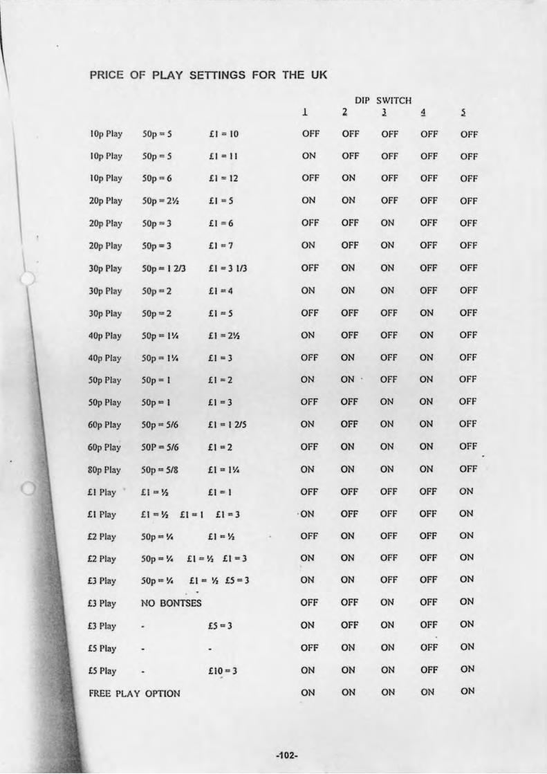
PRICE OF PLAY SETTINGS FOR THE UK
DIP SWITCH 1 Z 1 1 ~
lOp Play 501' = 5 £1 = 10 OFF OFF OFF OFF OFF
101' Play 50p = 5 £ 1 - II ON OFF OFF OFF OFF
lOp Play 50p = 6 £1 ~ 12 OFF ON OFF OFF OFF
20p Play SOp = 2Va £1 = 5 ON ON OFF OFF OFF
20p Play 50p - 3 £1 - 6 OFF OFF ON OFF OFF
20p Play 50p· 3 £1 = 7 ON OFF ON OFF OFF
\ 30p Play 50p - I 213 £1 = 3113 OFF ON ON OFF OFF
30p Play 50p = 2 £1 =4 ON ON ON OFF OFF
30p Play 50p = 2 £1 = 5 OFF OFF OFF ON OFF
40p Play 50p"'" 1'/. £1 = 2Va ON OFF OFF ON OFF
40p Play SOp = III. £1 = 3 OFF ON OFF ON OFF
50p Play 50p = I £1 = 2 ON ON OFF ON OFF
50p Play 50p = I £I = 3 OFF OFF ON ON OFF
60p Play 50p = 5/6 £1 = 1215 ON OFF ON ON OFF
60p Play 50P = 516 £1 =2 OFF ON ON ON OFF
SOp Play 50p = 518 £1 = 1'1. ON ON ON ON OFF
£1 Play £1 = IS £1 - I OFF OFF OFF OFF ON
£1 Play £1 112 Va £1 - I £1 = 3 · ON OFF OFF OFF ON
£2 Play SOp'" Y. £l o:aY, OFF ON OFF OFF ON
£2 Play SOp"'" y.. £1 ... Va £I = 3 ON ON OFF OFF ON
£3 Play SOp""' Y. £t .,. 'h £5 - 3 ON ON OFF OFF ON
£3 Play NO BONTSES OFF OFF ON OFF ON
£3 Play £5 - 3 ON OFF ON OFF ON
£5l' lay OFF ON ON OFF ON
£5 Play £10 = 3 ON ON ON OFF ON
FREE PLA V OPTION ON ON ON ON ON
-102-
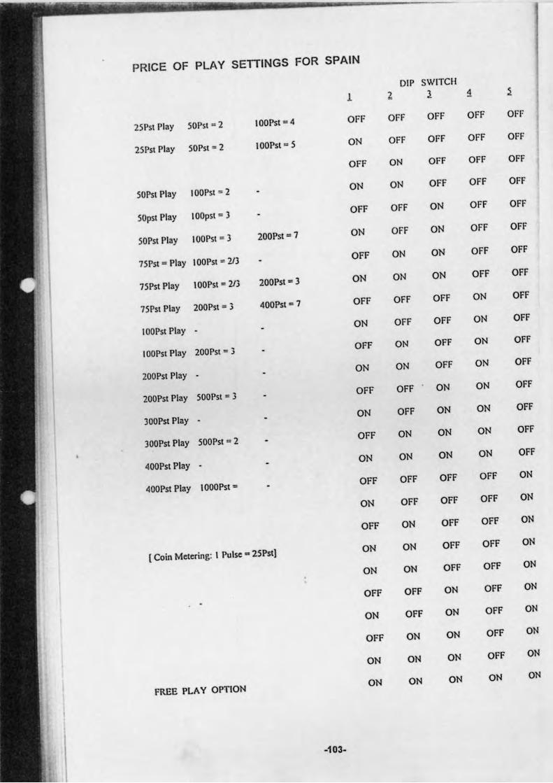
PRICE OF PLAY SETTINGS FOR SPAIN
DIP SWITCH
1 l 1 ~ ~
2SPS! Play SOps< · 2 100p,, - 4 OFF OFF OFF OFF OFf
2SP" Play SOP" • 2 lOOP,, · S ON OFF OFF OFF OFF
OFF ON OfF OFF OFF
SOPS! Play 100PSl ,. 2 ON ON OFF OFF OFF
SOpS! Play lOOpS! ' } OFF OFF ON OFF OFF
SOPSI Play IOOPSI ' } 200P,, - 1 ON OFF ON OFF OFF
1SP,,· Play lOOPS! = 2I} OFF ON ON OFF OFF
1SP" Play 100Psl · 2I3 200Psi - } ON ON ON OFF OFF
1SPS! Play 200Pst.., 3 400PSI - 1 OFF OFF OFF ON OFF
lOOP" Play ON OFF OFF ON OFF
100Psi Play 200PSl 'G 3 OFF ON OFF ON OFF
200Psi Play ON ON OFF ON OFF
200P" Play SOOPSI • 3 OFF OFF ON ON OFF
}OOPSI Play ON OFF ON ON OFF
JOOPSI Play SOOPS! ' 2 OFF ON ON ON OFF
400Psi Play ON ON ON ON OFF
400Psi Play IOOOPS! • OFF OFF OFF OFF ON
ON OFF OFF OFF ON
OFF ON OFF OFF ON
{ Coin Melering: I Pulse· 2SP"j ON ON OFF OFF ON
ON ON OFF OFF ON
OFF OFF ON OFF ON
ON OFF ON OFF ON
OFF ON ON OFF ON
ON ON ON OFF ON
FREE PLAY OPTION ON ON ON ON ON
-103-
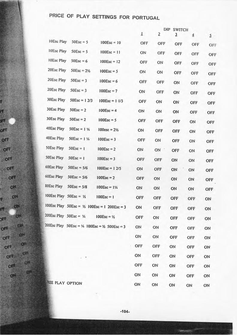
PRICE OF PLAY SETIINGS FOR PORTUGAL
01 1) SWITCH 1 Z 1 ~ ~
IOEsc Play 50E,e ~ 5 100Ese = 10 OFF OFF OFF OFF OFF
IOE,e Play 50E,e = 5 100Ese' II ON OFF OFF OFF OFF
IOEsc Play SOEse - 6 100E,e - 12 OFF ON OFf OFF 01'1'
20E,e Play SOEse = 2V, 100Ese = 5 ON ON OFF OFF OFF
20E,e Play 50Ese .. 3 100E,e = 6 OFF OFF ON OfF OFF
20E,e Play SOEse = 3 100E,e=7 ON OFF ON OFF OFf
lOEsc Play 50E,e - I 21l 100E,e - I III OFF ON ON OFf OFF
lOEse Play 50E,e - 2 100Ese - 4 ON ON ON OFF OFF
lOEsc Play 50 Ese - 2 100Ese - 5 OFF OFF OFF ON OFF
40E,e Play SOEse .,.. I '/. IOOesc D 2Y: ON OFF OFF ON OFF
40E,e Play SO Ese c I 'I. 100Ese - l OFF ON OFF ON OFF
50E,e Play 50E,e = I 100E,e • 2 ON ON OFF ON OFF
lOE,e Play 50E,e = I 100Ese - l OFF OFF ON ON OFF
60Esc Play SOEse - 5/6 I OOEse - I 215 ON OFF ON ON OFF
60E,e Play 50Ese - 516 100Ese - 2 OFF ON ON ON OFF
SOEse Play 50Ese a 518 100Esc a I V. ON ON ON ON OFF
100E,e Play 50Ese D Y, 100Ese = I OFF OFF OFF OFF ON
IOOEse Play SOEse'" 'I, I OOEse - I 200E,e = 3 ON OFF OFF OFF ON
lOOEse Play SOEse c If. IOOEse "" Y, OFF ON OFF OFF ON
lOOEse Play SOEse" Yo 100Esc - YJ 500Ese '" 3 ON ON OFF OFF ON
ON ON OFF OFF ON
OFF OFF ON OFF ON
ON OFF ON OFF ON
OFF ON ON OFf ON
ON ON ON OFF ON
PLAY OPTION ON ON ON ON ON
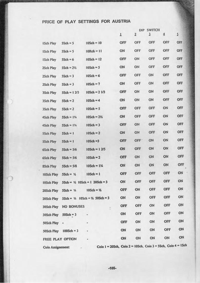
PRICE OF PLAY SETTINGS FOR AUSTRIA
DIP SWITCH
1 Z 1 1
ISeh Play 5Seh = 5 10Seh a 10 OFF OFF OFF OFF
ISeh Play 5Seh a 5 10Reh a II ON OFF OFF OFF
ISeh Play 5Seh a 6 IOSeh a 12 OFF ON OFF OFF
2Seh Play 5Seh = 2>', IOSeh - 5 ON ON OFF OFF
2Seh Play 5Seh = 3 10Seh a 6 OFF OFF ON OFF
2Sch PI3Y 5Sch • 3 10Seh a 7 ON OFF ON OFF
3Sch Play 5Seh - I 2/3 10Seh a 2 113 OFF ON ON OFF
3Seh Play 5Seh - 2 IOSeh - 4 ON ON ON OFF OFF
3Seh Play 5Sch = 2 10Seh - 5 OFF OFF OFF ON OFF
4Seh Play 5Sch = I'/. IOSch - 2V2 ON OFF OFF ON OFF
4Sch Play 55ch - t'l. 10Seh - J OFF ON OFF ON OFF
5Seh Play 5Seh - I 10Seh - 2 ON ON OFF ON OFF
5Sch Play 5Seh - I 10Sch - 3 OFF OFF " ON ON OFF
6Seh Play 5Seh = 5/6 10Seh - I 215 ON OFF ON ON OFF
6Seh Play 5Seh = 516 IOSeh · 2 OFF ON ON ON OFF
8Seh Play 5Seh = 5/8 10Sch - 1\1. ON ON ON ON OFF
10Seh Play SSch = 'h 10Sch - I OFF OFF OFF OFF ON
10Sch Play 55ch - ~ 10Seh - I 20Sch - J ON OFF OFF OFF ON
20Sch Play SSch c '/. 10Sch - 1\ OFF ON OFF OFF ON
20Sel. Play 55ch'" 'I. IOSch - YI SOSch - 3 ON ON OFF OFF ON
30Sch Play NO BONUSES OFF OFF ON OFF ON
JOSeh Play SOSch - 3 ON OFF ON OFF ON
50Seh Play OFF ON ON OFF ON
50Seh Play 100Seh = 3 ON ON ON OFF ON
FREE PLAY OPTION ON ON ON ON ON
Coin Assignement: Coin I a20Sch. Coin 2 - 10Sch. Coin) - 55th. Coin 4 - ISeh
-105-
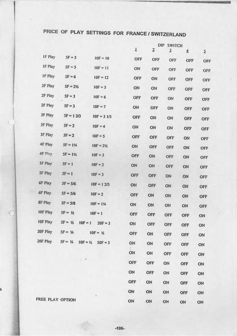
PRICE OF PLAY SETTINGS FOR FRANCE I SWITZERLAND
DIP SWITCH 1 2 1 1 ~
IF PI.y 51' - 5 101' - 10 OFF OFF OFF OFF OFF
IF PI.y 5F c 5 10F - I I ON OFF OFF OFF OFF
IF Play SF 0 6 JOF - 12 OFF ON OFF OFF OFF
2F Play 5F = 2~ 10F - 5 ON ON OFF OFF OFF
2F Play 5F - 3 10F - 6 OFF OFF ON OFF OFF
21' Play SF - 3 10F - 7 ON OFF ON OFF OFF
I 3F Play SF · I 213 JOF - 1IIl OFF ON ON OFF OFF
IF Play 5F - 2 10F ' 4 ON ON ON OFF OFF
3F Play 5F=2 10F - 5 OFF OFF OFF ON OFF
4F Play SF "'" IY. IOF - 2Y, ON OFF OFF ON OFF
4F P "Y SF - I Y. 10F - 3 OFF ON OFF ON OFF
SF Play SF - I 10F ' 2 ON ON OFF ON OFF
SF Play SF = I 10F - 3 OFF OFF ON ON OFF
6F Play SF - SI6 10F - I 215 ON OFF ON ON OFF
6F Play SF a SI6 10F - 2 OFF ON ON ON OFF
8F Play SF = 5/8 10F - 1\1. ON ON ON ON OFF
IOF Play SF*" ~ 10F - I OFF OFF OFF OFF ON
101' Play SF'" ~ 10F - I 20F - 3 ON OFF OFF OFF ON
20F Play SF "" V. IOF · Yz OFF ON OFF OFF ON
201' Play SF a v.. IOF ~ Y, 50F - 3 ON ON OFF OFF ON
ON ON OFF OFF ON
OFF OFF ON OFF ON
ON OFF ON OFF ON
OFF ON ON OFF ON
h ON ON ON OFF ON
FREE PLAY OPTION ON ON ON ON ON
-106-
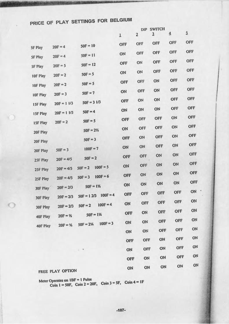
PRICE OF PLAY SETTINGS FOR BELGIUM
DIP SWITCH
1 2 1 1 ~
IF Play 20F ~ 4 50F - 10 OFF OFF OFF OFF OFF
5F Play 20F - 4 50F ~ II ON OFF OFF OFF OFF
5F Play 201' - 5 50F ~ 12 OFF ON OFF OFF OFF
10F Play 201' ~ 2 50F ~ 5 ON ON OFF OFF OFF
10F Play 20F ~ 2 50F - 5 OFF OFF ON OFF OFF
10F Play 20F- ) 50F ~ 7 ON OFF ON OFF OFF
15F Play 20F - I 1/3 50F - 3 1/3 OFF ON ON OFF OFF
IIF Play 20F-11/3 SOF-4 ON ON ON OFF OFF
ISF Play 20F - 2 SOF - 5 OFF OFF OFF ON OFF
20F Play SOF -= 2V, ON OFF OFF ON OFF
20F Play SOF-3 OFF ON OFF ON OFF
20F Play SOF-3 100F - 7 ON ON OFF ON OFF
251' Play 20F - 4/5 SOF-2 OFF OFF ON ON OFF
25F Play 20F - 4/5 50F - 2 100F - 5 ON OFF ON ON OFF
25F Play 20F - 4/5 SOF ~ 3 100F - 6 OFF ON ON ON OFF
30F Play 20F - 213 SOF - 11'1 ON ON ON ON OFF
30F Play 20F - 213 SOF - 1213 100F -4 OFF OFF OFF OFF ON
30F Play 20F - 213 SOF - 2 100F - 4 ON OFF OFF OFF ON
40F Play 20F - 1'1 SOF-IV. OFF ON OFF OFF ON
110F' Play 20F Ell 'h SOF .,. 2'1. 100F - 3 ON ON OFF OFF ON
ON ON OFF OFF ON
OFF OFF ON OFF ON
ON OFF ON OFF ON
OFF ON ON OFF ON
FREE PLAY OPTION ON ON ON ON ON
Meter Operaces on I SF · 1 Pulse
Coin I · SOF. Coin 2 - 20F. Coin 3 - SF. Coin4 - IF
·107·
Deith Leisure Limited (A $EGA COMPANY) Unit 2 Industrial Esuue
Leigh Close NcwMalde:n
Su=y Icr3 3NL United Kingdom
Tel: +014(0)81-3361222 Fax: +44 (0)81-336 1489
Customer Sctvic: Tel: +44 (0)81-949 1686
©SEGA 1995
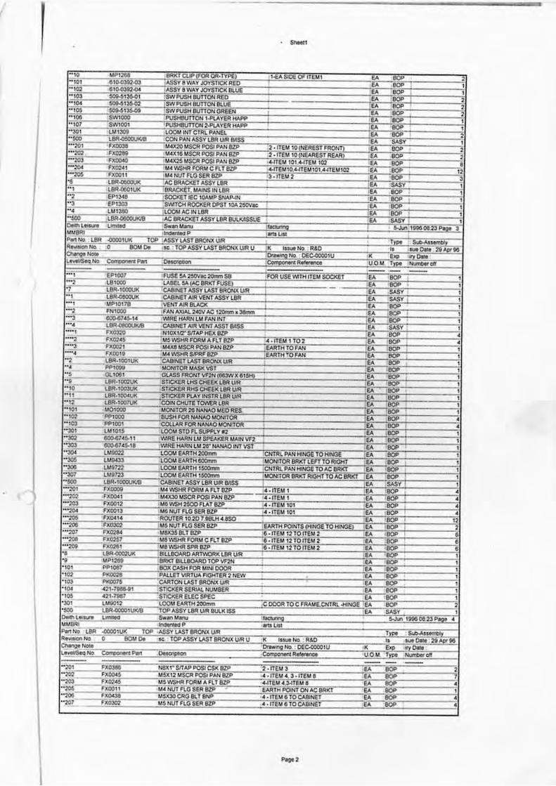
I ----------------------------
. ..... ,
I
\
Pogo'