section 4 switchgear and controlgear
TRANSCRIPT
Rules for Ships / High Speed, Light Craft and Naval Surface Craft, January 2008Pt.4 Ch.8 Sec.4 � Page 41
DET NORSKE VERITAS
SECTION 4 SWITCHGEAR AND CONTROLGEAR ASSEMBLIES
A. ConstructionA 100 General101 Applicable standards
a) Switchgear and controlgear assemblies shall generallycomply with IEC 60439-1 and IEC 60092-302 for lowvoltage equipment, and IEC 62271-200 for high voltageequipment.
b) Electronic equipment used in switchgear shall complywith environmental requirements given in Pt.4 Ch.9 Sec.5(Rules for Classification of Ships).
102 General
a) All switchboards and assemblies shall be safe against ac-cidental touching of live conductors during normal opera-tion of the switchboard or assemblies. (Interpretation ofSOLAS Ch. II-1/45.2)
b) A low voltage switchboard or assembly shall be designedto withstand the short circuit forces for minimum 1 s, cre-ated by the short circuit current and magnitude at the par-ticular point of the system without endangering theintegrity of the outer switchboard enclosure. For high volt-age equipment or assemblies, see B201.
c) For switchgear constructed and type tested in accordancewith IEC 60439-1 sections can be designed to withstandthe short-circuit stress occurring on the load side of the re-spective short-circuit protective device as stated in IEC60439-1 item 7.5.5.1.2. However, this reduced short-cir-cuit level shall not be less than 60% of the short circuit rat-ing of the main bus bars.
103 Accessibility
a) Instruments, handles, push buttons or other devices thatshould be accessible for normal operation shall be locatedon the front of switchboards and controlgear.
b) All other parts that might require operation shall be acces-sible. If placed behind doors, the interior front shall com-ply with enclosure type IP 20. When located in spacesaccessible to non-qualified personnel, fuses with accessi-ble current-carrying parts may be permitted, if the door islockable. Operation in this context means for example re-set of protective devices and replacement of control circuitfuses inside the assembly.
c) Doors, behind which equipment requiring operation isplaced, shall be hinged.
d) Hinged doors, which shall be opened for operation ofequipment, shall be provided with easily operated handlesor similar. There is also to be arrangements for keeping thedoors in open position.
e) All sections of switchboards and controlgear that requiremaintenance shall be accessible for maintenance work.
Guidance note:Normally, all connections of conductors, bus bar joints and me-chanical fastening of components and bus bars shall be accessi-ble for maintenance.
If the construction does not allow periodical maintenance, the as-sembly may be designed for maintenance free operation during a20-year service life.
---e-n-d---of---G-u-i-d-a-n-c-e---n-o-t-e---
104 MaterialsFramework, panels and doors are normally to be of steel or alu-minium alloy, and shall be of rigid construction.
Guidance note:Switchgear and assemblies constructed of other materials may beaccepted provided requirements in Sec.3 are complied with.
---e-n-d---of---G-u-i-d-a-n-c-e---n-o-t-e---
105 Circuit separation
a) There shall be arranged a separate cubicle for each gener-ator, with flame retardant partitions between the differentgenerator cubicles and between these and other cubicles.The partitions shall withstand the effect of an internal arc,and prohibit this from spreading to other cubicles.
b) Controlgear for essential or important consumers shall beseparated from each other, and from other current carryingparts, by flame retardant partitions providing protection ofthe cubicle in case of an arcing fault occurring in theneighbouring cubicle. Alternatively, an arrangement with-out flame retardant partitions may be accepted, providedthe bus bar is divided with a circuit breaker with short cir-cuit protection, located in a separate cubicle. The arrangement shall be so that maintenance work can becarried out in each unit without danger when isolated.
c) Controlgear for non-important consumers may be in-stalled in a common cubicle provided this cubicle could beeffectively isolated.
d) Consumer controlgear installed in main switchboardsshall be placed in cubicles separated from all other parts ofthe switchboard by partitions of flame retardant material.
e) Equipment for different distribution systems shall beplaced in separate switchboards (panels), or shall be sepa-rated from each other by partitions clearly marked with theactual voltages and system identifications.
f) Switchgear and controlgear assemblies supplied by differ-ent supply circuits shall not be placed in the same enclo-sure.
g) For separation due to system redundancy, see Sec.2.h) Equipment with voltage above 1 kV shall not be installed
in the same enclosure as low voltage equipment, unlesssegregation or other suitable measures are taken to ensurethat access to low voltage equipment is obtained withoutdanger.(IACS UR E11.2)
106 HandrailsMain and emergency switchboards and other switchboards re-quiring operation shall have handrails with an insulating sur-face.107 Nameplates and marking
a) Switchgear and controlgear assemblies shall be marked inaccordance with general requirements given in Sec.3 E.
b) Protection devices shall be permanently marked with volt-age, current and breaking capabilities.
c) Protection devices with adjustable settings shall havemeans that readily identify the actual setting of the protec-tive device.
d) Circuit designation for outgoing circuits and incomingfeeders shall be marked for identification.
Rules for Ships / High Speed, Light Craft and Naval Surface Craft, January 2008Pt.4 Ch.8 Sec.4 � Page 42
DET NORSKE VERITAS
e) The appropriate setting of overload protective device foreach circuit shall be permanently indicated at the locationof the protective device. (Interpretation of SOLAS Reg. II-1/45.6.2)
Guidance note:A document placed inside that assembly with the data required ind) and e) will be accepted.
---e-n-d---of---G-u-i-d-a-n-c-e---n-o-t-e---
108 "Type tested assemblies" and "Partly type tested assem-blies"
a) Electrical low voltage assemblies constructed and tested inaccordance with IEC 60092-302, item 7.1.2.101 (referringto IEC 60439-1) are accepted as long as the following con-ditions are met:
� minimum clearance distance shall be 8 mm, minimumcreepage distance shall be 16 mm
� the assembly has been type tested with impulse volt-age test in accordance with IEC 60439-1
� maximum operating temperature of bus bars shall bedocumented to be acceptable with respect to fixingmaterials and internal temperature by a full currenttype test
� maximum temperature rise at termination points forexternal cables shall be 60ºC
� such assemblies shall not be installed in machineryspace category "A".
b) For bus bar trunking systems where the conductors arefixed for the whole length with an insulating rail or simi-lar, distances in accordance with IEC 60439-1 Table 14and 16, pollution degree 3, inhomogeneous field, may beaccepted.
B. Power CircuitsB 100 Power components in assemblies101 Main bus bar sectioningSee Sec.2 for requirements regarding main bus bar division ar-rangement.102 Bus bar materials
a) Bus bars and other conductors shall normally be made ofcopper or copper covered aluminium.
b) Copper coated aluminium or pure aluminium bus bar shallbe adequately protected against corrosion by placing in anair conditioned environment, by special coating sealing ofthe aluminium or by the aluminium itself being seawaterresistant.
103 Rating of bus bars
a) The shape, configuration and cross-section shall be such thatthe temperature rise will not exceed 45°C at rated load.
b) Bus bars and other conductors with their supports shall beso mechanically or thermally dimensioned and fixed thatthey can withstand for 1 s the forces occurring by the max-imum short circuit current which can occur without detri-mental effect.
c) The cross-section of bus bars for neutral connection on anA.C. three-phase, four-wire system, and for equaliser con-nection on a D.C. system, shall be at least 50% of thecross-section for the corresponding phases (poles).
d) For maximum temperatures of bus bars in type tested andpartially type tested assemblies the requirement in A108applies.
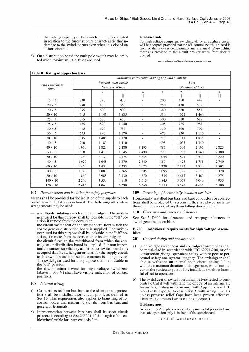
e) The maximum permissible load for copper bus bars withambient temperature 45 C is given in Table B1.
f) Rating of aluminium bus bar to be demonstrated by typetest.
104 FusesFuses shall normally comply with one of the following stand-ards:
� IEC 60269 for low voltage fuses� IEC 60282-1 for high voltage fuses.
105 Circuit breakers, on-load switches, disconnectors, andcontactors
a) Switchgear and controlgear shall comply with:
� IEC 60947 for low voltage equipment� IEC 60470, IEC 62271-100, IEC 62271-102 for high
voltage equipment.
b) All fault switching and protecting components such as cir-cuit breakers and fuses shall have a fault current withstandand interruption capacity of not less than the maximumshort circuit current at the relevant point of their installa-tion.
c) All load switches and contactors shall have a rating notless than the maximum load current at their point of instal-lation. Particularly, contactors shall be protected againstthe possibility of the contactor breaking current exceedingtheir load break capacity in fault situations.
d) Fuse switches using the fuse element as making and break-ing contacts are not accepted in place of switches, wheresuch are required. Fuse switches may be accepted as iso-lating switches.
e) The construction shall be such that accidental making orbreaking, caused by the vessel's inclination, movements,vibrations and shocks, cannot occur.
f) Undervoltage and closing coils, including contactor coils,shall allow closing of the switchgear and controlgear whenthe voltage and frequency are 85 to 110% of nominal val-ue. The undervoltage protection shall release if the voltageis below 70% or absolutely below 35% of nominal volt-age.
g) Each circuit-breaker rated more than 16 A shall be of trip-free type, i.e. the breaking action initiated by short-circuitand overcurrent relays, or by undervoltage coil, when fit-ted, shall be fulfilled independently of the position or op-eration of manual handle or of other closing devices.
106 Switch-gear
a) Each outgoing circuit on a main switchboard or a distribu-tion switchboard shall be provided with a switch for isolat-ing purposes. One of the following solutions shall apply:
� a multipole circuit breaker� a multipole fused circuit breaker� a multipole load switch and fuses.
b) It is required that all switches can be operated, and fusesbe replaced without risk of touching live parts. I.e. switch-board interior must be IP20 when operation is performedwith open door..
c) When multipole switch and fuses are used and the switchis installed between the bus bars and the fuses, the follow-ing apply:
� the switch shall have a breaking capacity of at least 6times its full-load current
Rules for Ships / High Speed, Light Craft and Naval Surface Craft, January 2008Pt.4 Ch.8 Sec.4 � Page 43
DET NORSKE VERITAS
� the making capacity of the switch shall be so adaptedin relation to the fuses� rupture characteristic that nodamage to the switch occurs even when it is closed ona short circuit.
d) On a distribution board the multipole switch may be omit-ted when maximum 63 A fuses are used.
Guidance note:For high voltage equipment switching off by an auxiliary circuitwill be accepted provided that the off�control switch is placed infront of the relevant compartment and a manual off-switchingmeans is provided at the circuit breaker when front door isopened.
---e-n-d---of---G-u-i-d-a-n-c-e---n-o-t-e---
107 Disconnection and isolation for safety purposesMeans shall be provided for the isolation of the supply to eachcontrolgear and distribution board. The following alternativearrangements may be used:
� a multipole isolating switch at the controlgear. The switch-gear used for this purpose shall be lockable in the "off" po-sition if remote from the consumer
� the circuit switchgear on the switchboard from which thecontrolgear or distribution board is supplied. The switch-gear used for this purpose shall be lockable in the "off" po-sition, if remote from the consumer or its controlgear
� the circuit fuses on the switchboard from which the con-trolgear or distribution board is supplied. For non-impor-tant consumers supplied by a distribution switchboard, it isaccepted that the switchgear or fuses for the supply circuitto this switchboard are used as common isolating device.The switchgear used for this purpose shall be lockable inthe "off" position
� the disconnection device for high voltage switchgear(above 1 000 V) shall have visible indication of contactpositions.
108 Internal wiring
a) Connections to/from bus-bars to the short circuit protec-tion shall be installed short-circuit proof, as defined inSec.13. This requirement also applies to branching of forcontrol power and measuring signals from bus bars andgenerator terminals.
b) Interconnection between bus bars shall be short circuitprotected according to Sec.2 G201, if the length of the ca-ble/wire/flexible bus bare exceeds 3 m.
109 Screening of horizontally installed bus barsHorizontally installed bus bars and bare conductors or connec-tions shall be protected by screens, if they are placed such thatthere could be a risk of anything falling down on them.110 Clearance and creepage distancesSee Sec.3 D600 for clearance and creepage distances inswitchgear and assemblies.
B 200 Additional requirements for high voltage assem-blies201 General design and construction
a) High voltage switchgear and controlgear assemblies shallbe metal-clad in accordance with IEC 62271-200, or of aconstruction giving equivalent safety with respect to per-sonnel safety and system integrity. The switchgear shallable to withstand an internal short circuit arcing failurewith the maximum duration and magnitude, which can oc-cur on the particular point of the installation without harm-ful effect to operators.
b) The switchgear or switchboard shall be type tested to dem-onstrate that it will withstand the effects of an internal arcfailure (e.g. testing in accordance with Appendix A of IEC62271-200 Type A, Accessibility A with arcing time 1 sunless pressure relief flaps have been proven effective.Then arcing time as low as 0.1 s is accepted).Guidance note:Accessibility A implies access only by instructed personnel, andthat safe operation only is in front of the switchboard.
---e-n-d---of---G-u-i-d-a-n-c-e---n-o-t-e---
Table B1 Rating of copper bus bars
With x thickness(mm)
Maximum permissible loading [A] with 50/60 HzPainted (matt-black) Bare
Numbers of bars Numbers of bars1|
2||
3|||
4|| ||
1|
2||
3|||
4|| ||
15 3 230 390 470 - 200 350 445 -20 3 290 485 560 - 250 430 53520 5 395 690 900 - 340 620 855 -
20 10 615 1 145 1 635 - 530 1 020 1 460 -25 3 355 580 650 - 300 510 615 -25 5 475 820 1 040 - 405 725 985 -30 3 415 670 735 - 350 590 700 -30 5 555 940 1 170 - 470 830 1 110 -
30 10 835 1 485 2 070 - 710 1 310 1 835 -40 5 710 1 180 1 410 - 595 1 035 1 350 -
40 10 1 050 1 820 2 480 3 195 885 1 600 2 195 2 82550 5 860 1 410 1 645 2 490 720 1 230 1 560 2 380
50 10 1 260 2 130 2 875 3 655 1 055 1 870 2 530 3 22060 5 1 020 1 645 1 870 2 860 850 1 425 1 785 2 740
60 10 1 460 2 430 3 235 4 075 1 220 2 130 2 850 3 59580 5 1 320 2 080 2 265 3 505 1 095 1 795 2 170 3 370
80 10 1 860 2 985 3 930 4 870 1 535 2 615 3 460 4 275100 10 2 240 3 530 4 610 5 615 1 845 3 075 4 040 4 935120 10 2 615 4 060 5 290 6 360 2 155 3 545 4 635 5 580
Rules for Ships / High Speed, Light Craft and Naval Surface Craft, January 2008Pt.4 Ch.8 Sec.4 � Page 44
DET NORSKE VERITAS
c) There shall be separate compartments with IP rating to atleast IP 20 towards other compartments in the cubicle forat least the following components:
� control and auxiliary devices� each main switching device� components connected to one side of the main switch-
ing device (the outgoing circuit)� components connected to the other side of the main
switching device (the bus bars).
d) Normally, partitions between the compartments shall bemade of metal. Alternatively, a partition of other materialsnot intended to be earthed is accepted, provided it is veri-fied that the safety is of at least the same standard.If the main high-voltage switchgear is subdivided into twoindependent and autonomous installations, a continuousbus bar compartment is permissible, provided that a pro-tection system (arc monitor, busbar differential protection)is installed which detects internal faults and isolates the af-fected part of the installation within 100 ms, respectivelyaccidental arcing is reliable prevented by design measures(e.g. solid insulated busbar systems).
e) Means shall be provided for the disconnection and isola-tion of all circuit breakers and fused circuit breakers, eitherby using withdrawable components or by installation ofseparate disconnectors (isolators).
ExceptionFor final feeder circuits where energising of the main switchingdevice from the load side is not possible, the cable terminals andaccessories (e.g. voltage and current transformers) may be placedin the same compartment as the main switching device.202 Mechanical interlocks
a) The arrangement in high voltage enclosures shall be suchthat all operation and functional testing is safeguardedagainst accidental touching of live parts.
b) Doors that can be opened for operation or testing of highvoltage parts (e.g. for replacement of fuses, or for func-tional testing of a circuit breaker) shall be interlocked sothat they cannot be opened before the components insidehave been isolated and made safe.
c) The openings between the contacts of a withdrawable highvoltage component and the fixed contacts, to which it isconnected in service, shall be provided with automaticshutters.
Guidance note:Front doors of circuit breaker compartments might be opened forcircuit breaker checking or emergency switching, without any in-terlocking, if high voltage parts still cannot be reached by acci-dental touching of the hands.
---e-n-d---of---G-u-i-d-a-n-c-e---n-o-t-e---
203 Control wiring
a) The wiring of auxiliary circuits shall, with the exception ofshort lengths of wire at terminals of instrument transform-ers, tripping coils, auxiliary contacts etc., be either segre-gated from the main circuit by earthed metallic partitions(e.g. metallic tubes) or separated by partitions (e.g. tubesor sheathed cables) made of flame retardant insulating ma-terial.
b) Fuses of auxiliary circuits, terminals and other auxiliaryapparatus requiring access while the equipment is in serv-ice, shall be accessible without exposing high voltageparts.
c) An alarm shall be arranged for voltage loss after the lastfuses in each auxiliary power system, where a voltage fail-ure is not self detecting.
d) A possibility for manual operation of each circuit breakershall be arranged. However, manual closing of the circuitbreakers shall not be possible if the arrangement of theauxiliary circuits is such that the protection devices are putout of action and the circuit breakers are still closed aftera power failure to the auxiliary circuits.
204 Safety earthing of high voltage circuitsEach circuit shall be fitted with an integral means of earthingand short circuiting for maintenance purposes, or alternativelyan adequate number of portable earthing and short circuitingdevices, suitable for use on the equipment in question, shall bekept on board.
C. Control and Protection CircuitsC 100 Control and instrumentation101 General
a) Requirements for power supply and distribution of controlcircuits are given in Sec.2 H200.
b) For short circuit proof installation of control cables, seeB108.
102 Control of duplicated consumers
a) Control circuits for duplicated essential and importantequipment shall be kept separated from each other, and notlocated in the same enclosure.
b) Controlgear for duplicated essential or important equip-ment shall be mutually independent and shall be dividedbetween two motor control centres or distribution boardshaving separate supplies from different sides of the mainswitchboard and/or the emergency switchboard.
c) Where switchboards are fitted with bus ties or bus links,the duplicated circuits shall be fed from different side ofthe bus tie.
d) Duplicated equipment for essential or important functionsshall not be dependent on any common circuits such as e.g.contactors for emergency stop.
103 Signal lampsSignal lamps shall be arranged so that a lamp short circuit can-not jeopardise the control system.104 Panel-instruments in general
a) Instruments, including current transformers, in switchgearand controlgear shall have a nominal accuracy of 2.5% orbetter.
b) The upper limit of the scale of ampere-meters and kilo-watt-meters shall be at least 130% of the rated full load ofthe circuit. For generators arranged for parallel operation,the scale shall be arranged for reading of reverse current orpower corresponding to at least 15% of the rated full loadof the circuit. The upper limit of the scale of each voltme-ter shall be at least 120% of the nominal voltage.
c) Amperemeters, kilowattmeters and voltmeters shall beprovided with means to indicate rated current or powerand rated voltage, respectively. Instruments shall have ef-fective screening (e.g. by metal enclosures) in order to di-minish faulty readings caused by induction from adjacentcurrent-carrying parts.
d) Frequency meters shall be able to indicate values within aranging at least 8% below and above the nominal frequen-cy.
Rules for Ships / High Speed, Light Craft and Naval Surface Craft, January 2008Pt.4 Ch.8 Sec.4 � Page 45
DET NORSKE VERITAS
105 Generator instrumentation
a) Each A.C. generator shall be provided with instrumenta-tion showing:
� current for each phase� voltage� frequency� kilowatt meter.
Instrumentation for current, voltage and frequency shall bearranged for simultaneous and continuous reading.
b) When generators are arranged for parallel operation, theyshall in addition be provided with synchronising devicesas required by Sec.2 H303.
c) Simultaneous functional reading of current and activepower shall be provided at operating station for manualoperation and synchronisation.
AlternativesSingle voltmeters and amperemeters with switches for the al-ternative readings may be accepted.Two separate frequency meters for several generators may beused, one with a change-over switch for connection to all gen-erators, the other connected to the bus bars. A "double frequen-cy meter" may be used for this purpose.106 Instrumentation for distribution systems including inand outgoing circuits of switchboardsEach secondary distribution system shall be equipped with avoltmeter.107 Instrumentation for shore connectionsThe shore connection circuit shall be equipped with:
� a phase sequence indicator� a voltmeter or signal lamp.
D. Inspection and TestingD 100 General101 Factory testing
a) Switchgear and controlgear assemblies shall be tested atthe manufacturer�s works as described in 102 to 108.
b) The manufacturer shall submit test results together withthe final documentation for the equipment. The documen-tation shall give information on make, type, serial no., andall technical data necessary for the application of theswitchboard or assembly, as well as the results of the re-quired tests.
c) The following tests are required:
� function test: all basic functions, including auxiliaryfunctions, shall be tested
� insulation resistance test� high voltage test.
102 Visual inspectionSwitchboards and assemblies are subject to a visual inspectionfor verification of general workmanship, creepage and clear-ance distances, IP rating, ventilation and quality of materialsand components.103 Function testing
a) All circuits shall be verified installed as shown in the as-build documentation.
b) Control and protection shall be tested for correct functioning.
Guidance note:Factory testing of switchgear or control gear assemblies at fullpower is normally not required.
---e-n-d---of---G-u-i-d-a-n-c-e---n-o-t-e---
104 Site testingSwitchgear or controlgear assemblies shall be subject to com-plete function tests after installation onboard. See Sec.10 D.105 Power frequency and insulation resistance test for lowvoltage assemblies
a) Switchgear and assemblies with rated voltage above 60 Vshall be subject to a voltage test between the circuits andbetween live parts and the enclosure. The test voltage shallbe minimum equal to twice the rated voltage plus 1 000 Vwith a minimum of 1 500 V. The test voltage shall be ap-plied for 1 minute at any frequency between 25 and100 Hz.
b) For switchgear and assemblies with rated voltage below60 V, the test voltage given in a) shall be minimum 500 V.
c) As an alternative to the voltage test in a), impulse voltagetest in accordance with IEC 60439-1 Section 8.3.2 can becarried out for TT and PTT low voltage assemblies
d) Insulation resistance shall be measured prior to and oncompletion of the voltage test. Insulation resistance testvoltages and acceptance values are given in Sec.5Table C3. It shall be verified that the voltage testing doesnot cause any reduction in switchgear insulation level. Theinsulation level shall be at least 1 MOhm.
Guidance note:Electronic equipment should be disconnected, short circuited andor isolated during high voltage test and insulation resistancemeasuring. The secondary winding of current transformers shall be shortcircuited and disconnected from earth during the test. The sec-ondary winding of voltage transformers shall be disconnectedduring the test.
---e-n-d---of---G-u-i-d-a-n-c-e---n-o-t-e---
106 Power frequency test for high voltage assemblies
a) Each high voltage assembly shall be subjected to a 1minute power frequency voltage test.
b) Replicas reproducing the field configuration of the highvoltage connections may replace voltage transformers orpower transformers. Overvoltage protective devices maybe disconnected or removed.
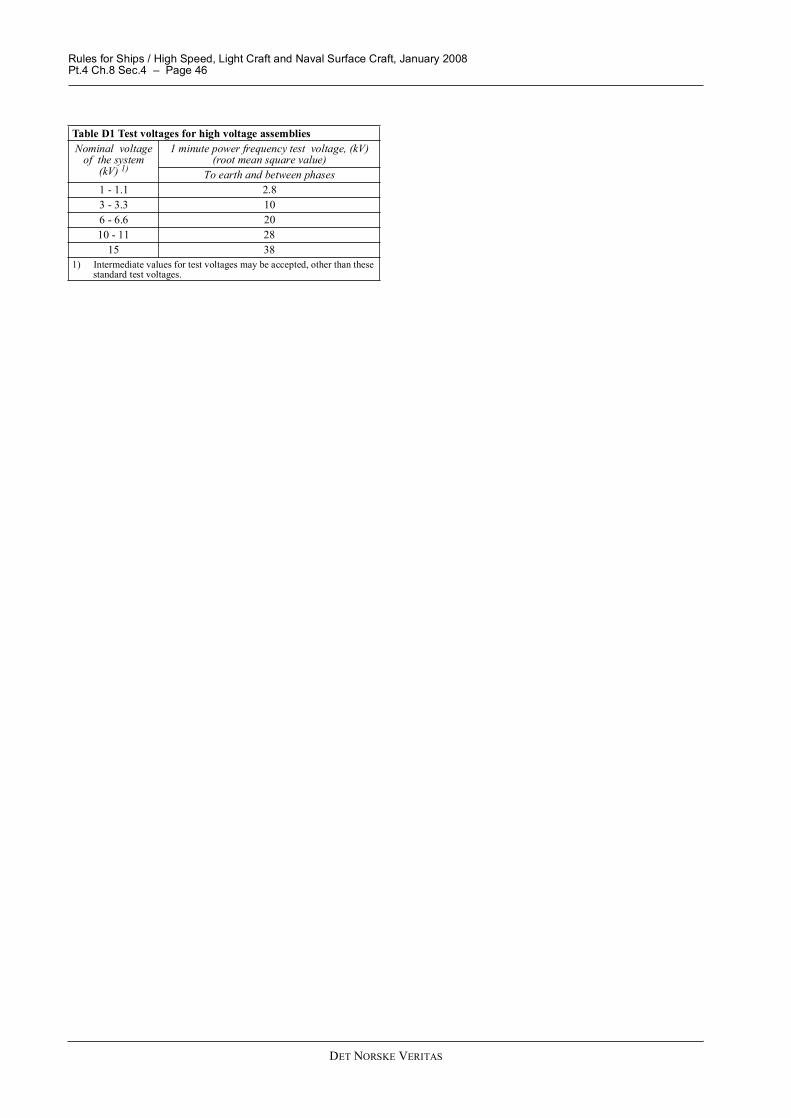
c) Test voltages are given in Table D1.d) Insulation resistance shall be measured prior to and on
completion of the voltage test. Insulation resistance testvoltages and acceptance values are given in Sec.5Table C3. It shall be verified that the voltage testing doesnot cause any reduction in switchgear insulation level.
e) All auxiliary circuits shall be subjected to a 1 minute volt-age test between the circuits and the enclosure accordingto 106.
Guidance note:The environmental conditions during voltage tests are normallyto be as specified in IEC 60060-1, "High-voltage test techniques,Part 1, General definitions and test requirements", that is temper-ature 20°C, pressure 1 013 mbar and humidity 11 g water per m³(corresponding to about 60% relative humidity). Correction fac-tors for test voltages at other environmental conditions are givenin IEC 60060-1.
---e-n-d---of---G-u-i-d-a-n-c-e---n-o-t-e---
Rules for Ships / High Speed, Light Craft and Naval Surface Craft, January 2008Pt.4 Ch.8 Sec.4 � Page 46
DET NORSKE VERITAS
Table D1 Test voltages for high voltage assembliesNominal voltage
of the system(kV) 1)
1 minute power frequency test voltage, (kV) (root mean square value)
To earth and between phases1 - 1.1 2.83 - 3.3 106 - 6.6 2010 - 11 28
15 381) Intermediate values for test voltages may be accepted, other than these
standard test voltages.
Rules for Ships / High Speed, Light Craft and Naval Surface Craft, January 2008Pt.4 Ch.8 Sec.5 � Page 47
DET NORSKE VERITAS
SECTION 5 ROTATING MACHINES
A. GeneralA 100 References101 GeneralThe design and function of rotating machines shall generallycomply with the requirements of IEC 60092-301. For basicmachine design, the relevant parts of IEC 60034 apply.
A 200 Requirements common to generators and motors201 Rating
a) Electrical machines, including any excitation system, shallbe designed for continuous duty unless otherwise clearlystated.
b) Generally, maximum environmental temperatures for ro-tating machines shall be as given in Sec.3 Table B1.
202 Insulation
a) All windings for machines shall be treated to resist mois-ture, sea air, and oil vapours.
b) For general requirements for insulation materials and ter-minations, see Sec.3 D.
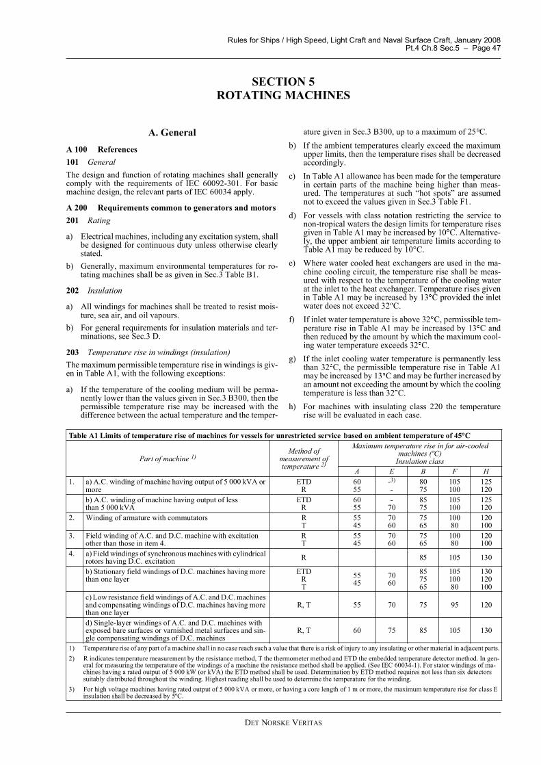
203 Temperature rise in windings (insulation)The maximum permissible temperature rise in windings is giv-en in Table A1, with the following exceptions:
a) If the temperature of the cooling medium will be perma-nently lower than the values given in Sec.3 B300, then thepermissible temperature rise may be increased with thedifference between the actual temperature and the temper-
ature given in Sec.3 B300, up to a maximum of 25 C.b) If the ambient temperatures clearly exceed the maximum
upper limits, then the temperature rises shall be decreasedaccordingly.
c) In Table A1 allowance has been made for the temperaturein certain parts of the machine being higher than meas-ured. The temperatures at such �hot spots� are assumednot to exceed the values given in Sec.3 Table F1.
d) For vessels with class notation restricting the service tonon-tropical waters the design limits for temperature risesgiven in Table A1 may be increased by 10 C. Alternative-ly, the upper ambient air temperature limits according toTable A1 may be reduced by 10°C.
e) Where water cooled heat exchangers are used in the ma-chine cooling circuit, the temperature rise shall be meas-ured with respect to the temperature of the cooling waterat the inlet to the heat exchanger. Temperature rises givenin Table A1 may be increased by 13 C provided the inletwater does not exceed 32 C.
f) If inlet water temperature is above 32 C, permissible tem-perature rise in Table A1 may be increased by 13 C andthen reduced by the amount by which the maximum cool-ing water temperature exceeds 32 C.
g) If the inlet cooling water temperature is permanently lessthan 32 C, the permissible temperature rise in Table A1may be increased by 13 C and may be further increased byan amount not exceeding the amount by which the coolingtemperature is less than 32 C.
h) For machines with insulating class 220 the temperaturerise will be evaluated in each case.
Table A1 Limits of temperature rise of machines for vessels for unrestricted service based on ambient temperature of 45°C
Part of machine 1)Method of
measurement oftemperature 2)
Maximum temperature rise in for air-cooled machines (ºC)
Insulation classA E B F H
1. a) A.C. winding of machine having output of 5 000 kVA or more
ETDR
6055
-3)
-8075
105100
125120
b) A.C. winding of machine having output of less than 5 000 kVA
ETDR
6055
-70
8575
105100
125120
2. Winding of armature with commutators RT
5545
7060
7565
10080
120100
3. Field winding of A.C. and D.C. machine with excitation other than those in item 4.
RT
5545
7060
7565
10080
120100
4. a) Field windings of synchronous machines with cylindrical rotors having D.C. excitation R 85 105 130
b) Stationary field windings of D.C. machines having more than one layer
ETDRT
5545
7060
857565
10510080
130120100
c) Low resistance field windings of A.C. and D.C. machines and compensating windings of D.C. machines having more than one layer
R, T 55 70 75 95 120
d) Single-layer windings of A.C. and D.C. machines with exposed bare surfaces or varnished metal surfaces and sin-gle compensating windings of D.C. machines
R, T 60 75 85 105 130
1) Temperature rise of any part of a machine shall in no case reach such a value that there is a risk of injury to any insulating or other material in adjacent parts.2) R indicates temperature measurement by the resistance method, T the thermometer method and ETD the embedded temperature detector method. In gen-
eral for measuring the temperature of the windings of a machine the resistance method shall be applied. (See IEC 60034-1). For stator windings of ma-chines having a rated output of 5 000 kW (or kVA) the ETD method shall be used. Determination by ETD method requires not less than six detectors suitably distributed throughout the winding. Highest reading shall be used to determine the temperature for the winding.
3) For high voltage machines having rated output of 5 000 kVA or more, or having a core length of 1 m or more, the maximum temperature rise for class E insulation shall be decreased by 5ºC.
Rules for Ships / High Speed, Light Craft and Naval Surface Craft, January 2008Pt.4 Ch.8 Sec.5 � Page 48
DET NORSKE VERITAS
204 Machine short time overloads
a) General purpose rotating machines shall be designed towithstand the following excess torque:
� A.C. induction motors and D.C. motors: 60% in ex-cess of the torque that corresponds to the rating, for 15s, without stalling or abrupt change in speed (undergradual increase of torque), the voltage and frequencybeing maintained at their rated value
� A.C. synchronous motors with salient poles: 50% inexcess of the torque that corresponds to the rating, for15 s, without falling out of synchronism, the voltage,frequency and excitation current being maintained attheir rated values
� A.C. synchronous motors with wound (induction) orcylindrical rotors: 35% in excess of the torque thatcorresponds to the rating, for 15 s, without losing syn-chronism, the voltage and frequency being maintainedat their rated value.
b) Induction motors for specific applications the excesstorque may be subject to special agreement. See IEC60034-1 clause 9.3.
c) General purpose rotating machines shall be designed towithstand the following excess current:
� A.C. generators: 50% in excess of the rated current fornot less than 30 s, the voltage and frequency beingmaintained as near the rated values as possible
� A.C. motors: 50% in excess of the rated current for notless than 120 s, the voltage and frequency being main-tained as near the rated values as possible
� commutator machines: 50% in excess of the rated cur-rent for not less than 60 s, operating at highest full-field speed.
205 BalanceMachines shall be so constructed that, when running at any andevery working speed, all revolving parts are well balanced.206 Lubrication
a) Lubrication of rotating machines shall be effective underall operating conditions.
b) Each self-lubricated sleeve bearings shall be fitted with aninspection lid and means for visual indication of oil levelor use of an oil gauge. Similar requirement applies to selfcontained oil lubricated roller bearings.
c) Provision shall be made for preventing the lubricant fromgaining access to windings or other insulated or bare cur-rent-carrying parts.
207 Shafts and shaft currents
a) Shafts shall comply with the requirements in Pt.4 Ch.4(Rules for Classification of Ships) both with regard tostrength, bearings and balancing.
b) Means shall be provided to prevent damaging levels of cir-culating currents between shaft, bearings and connectedmachinery.
c) When all bearings on a machine are insulated, the shaftshall be electrically connected to the machine's earth ter-minal.
208 Machine overspeedRotating machines shall be capable of withstanding 1.2 timesthe rated maximum speed for a period of 2 minutes.209 NameplateEach machine shall be provided with nameplate of durable,flame retardant material, giving the following information:
� make, type, serial no.� performance standard� IP rating� rated values for: output apparent power, voltage(s), fre-
quency, current(s), power factor, speed� for A.C. machines: the winding connection� thermal classification of insulation� duty type, if other than S1� maximum permissible cooling medium temperature� technical data necessary for the application of the machine� total mass.
A 300 Instrumentation of machines301 Temperature detectors embedded in stator windingAll high voltage machines, and low voltage machines having arated output above 5 000 kW (or kVA), shall be provided withtemperature detectors in their stator windings, for monitoringand alarm, also see Sec.3 D201.
Guidance note:Overvoltage protection may be required for circuits with temper-ature detectors.See Sec.12 A604 regarding rotating machines supplying or driv-ing electric propulsion and having temperature detectors embed-ded in their stator windings for monitoring and alarm.For the requirements in regard to temperature detectors, refer-ence is made to IEC 60034-11.
---e-n-d---of---G-u-i-d-a-n-c-e---n-o-t-e---
B. Additional Requirements for GeneratorsB 100 General101 GeneralExciter and voltage regulation equipment is considered as partof the generator.
Guidance note:See Pt.4 Ch.3 (Rules for Classification of Ships) regarding theprime movers' speed governor characteristics and Pt.4 Ch.9(Rules for Classification of Ships) regarding instrumentationequipment.
---e-n-d---of---G-u-i-d-a-n-c-e---n-o-t-e---
102 Automatic voltage regulatorThe AVR shall be capable of keeping the voltage within thevalues specified for stationary and dynamic variations.103 Available neutral pointGenerators with rating exceeding 1 500 kVA, and all high volt-age generators, shall be prepared for installation of equipmentfor short circuit protection of the generator windings.104 De-excitationGenerators with rating exceeding 1 500 kVA, and all high volt-age generators, shall be prepared for external signal for initia-tion of de-excitation of the generator.105 Voltage waveformFor A.C. generators, the voltage shall be approximately sinu-soidal, with a maximum deviation from the sinusoidal curve of5% of the peak value.
B 200 Voltage and frequency regulation201 Voltage build-up
a) The construction shall normally be such that the generator,when started up, takes up the voltage without the aid of anexternal electric power source.
b) External power sources may be used to take up the voltage
Rules for Ships / High Speed, Light Craft and Naval Surface Craft, January 2008Pt.4 Ch.8 Sec.5 � Page 49
DET NORSKE VERITAS
on main generators provided that redundancy for thisexternal source is arranged as required for starting ar-rangement.
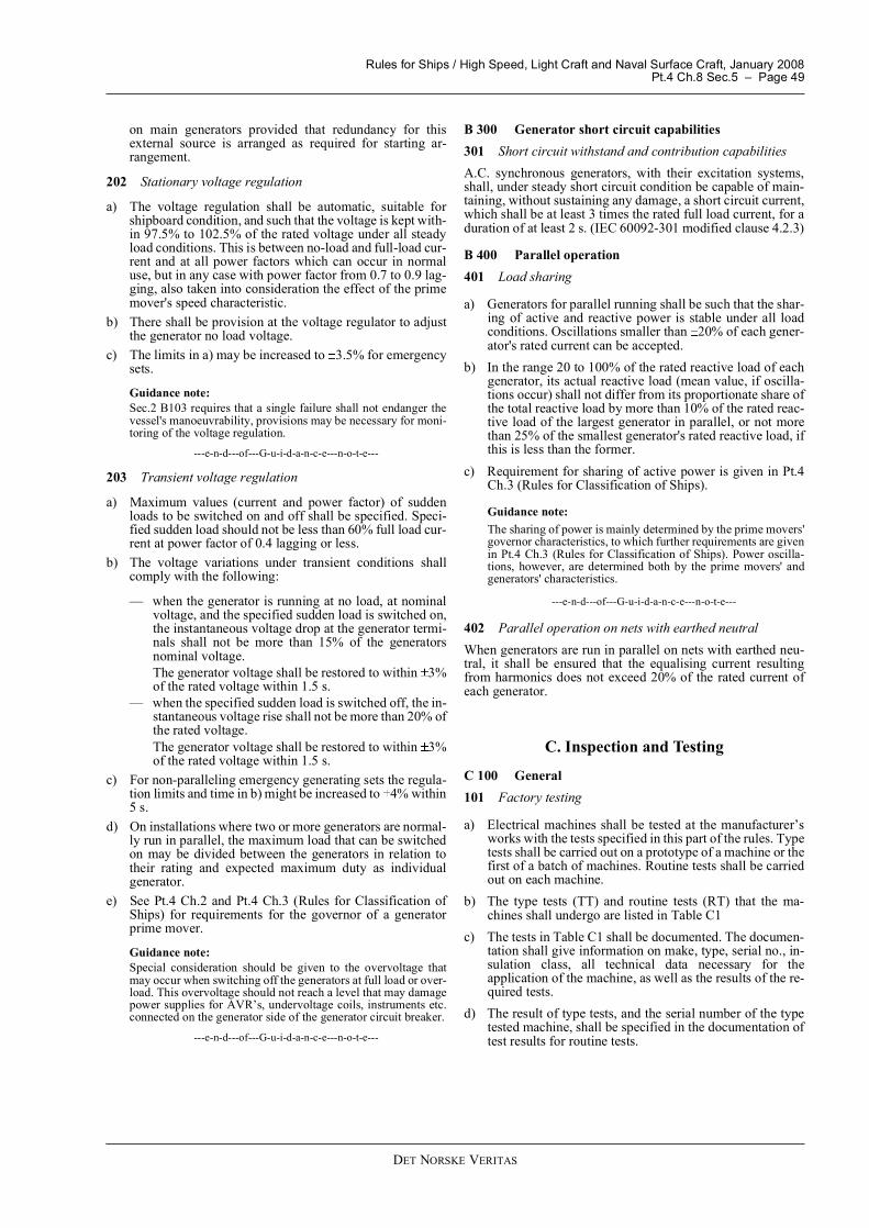
202 Stationary voltage regulation
a) The voltage regulation shall be automatic, suitable forshipboard condition, and such that the voltage is kept with-in 97.5% to 102.5% of the rated voltage under all steadyload conditions. This is between no-load and full-load cur-rent and at all power factors which can occur in normaluse, but in any case with power factor from 0.7 to 0.9 lag-ging, also taken into consideration the effect of the primemover's speed characteristic.
b) There shall be provision at the voltage regulator to adjustthe generator no load voltage.
c) The limits in a) may be increased to 3.5% for emergencysets.
Guidance note:Sec.2 B103 requires that a single failure shall not endanger thevessel's manoeuvrability, provisions may be necessary for moni-toring of the voltage regulation.
---e-n-d---of---G-u-i-d-a-n-c-e---n-o-t-e---
203 Transient voltage regulation
a) Maximum values (current and power factor) of suddenloads to be switched on and off shall be specified. Speci-fied sudden load should not be less than 60% full load cur-rent at power factor of 0.4 lagging or less.
b) The voltage variations under transient conditions shallcomply with the following:
� when the generator is running at no load, at nominalvoltage, and the specified sudden load is switched on,the instantaneous voltage drop at the generator termi-nals shall not be more than 15% of the generatorsnominal voltage.The generator voltage shall be restored to within 3%of the rated voltage within 1.5 s.
� when the specified sudden load is switched off, the in-stantaneous voltage rise shall not be more than 20% ofthe rated voltage.The generator voltage shall be restored to within 3%of the rated voltage within 1.5 s.
c) For non-paralleling emergency generating sets the regula-tion limits and time in b) might be increased to 4% within5 s.
d) On installations where two or more generators are normal-ly run in parallel, the maximum load that can be switchedon may be divided between the generators in relation totheir rating and expected maximum duty as individualgenerator.
e) See Pt.4 Ch.2 and Pt.4 Ch.3 (Rules for Classification ofShips) for requirements for the governor of a generatorprime mover.
Guidance note:Special consideration should be given to the overvoltage thatmay occur when switching off the generators at full load or over-load. This overvoltage should not reach a level that may damagepower supplies for AVR�s, undervoltage coils, instruments etc.connected on the generator side of the generator circuit breaker.
---e-n-d---of---G-u-i-d-a-n-c-e---n-o-t-e---
B 300 Generator short circuit capabilities301 Short circuit withstand and contribution capabilitiesA.C. synchronous generators, with their excitation systems,shall, under steady short circuit condition be capable of main-taining, without sustaining any damage, a short circuit current,which shall be at least 3 times the rated full load current, for aduration of at least 2 s. (IEC 60092-301 modified clause 4.2.3)
B 400 Parallel operation401 Load sharing
a) Generators for parallel running shall be such that the shar-ing of active and reactive power is stable under all loadconditions. Oscillations smaller than 20% of each gener-ator's rated current can be accepted.
b) In the range 20 to 100% of the rated reactive load of eachgenerator, its actual reactive load (mean value, if oscilla-tions occur) shall not differ from its proportionate share ofthe total reactive load by more than 10% of the rated reac-tive load of the largest generator in parallel, or not morethan 25% of the smallest generator's rated reactive load, ifthis is less than the former.
c) Requirement for sharing of active power is given in Pt.4Ch.3 (Rules for Classification of Ships).
Guidance note:The sharing of power is mainly determined by the prime movers'governor characteristics, to which further requirements are givenin Pt.4 Ch.3 (Rules for Classification of Ships). Power oscilla-tions, however, are determined both by the prime movers' andgenerators' characteristics.
---e-n-d---of---G-u-i-d-a-n-c-e---n-o-t-e---
402 Parallel operation on nets with earthed neutralWhen generators are run in parallel on nets with earthed neu-tral, it shall be ensured that the equalising current resultingfrom harmonics does not exceed 20% of the rated current ofeach generator.
C. Inspection and Testing
C 100 General101 Factory testing
a) Electrical machines shall be tested at the manufacturer�sworks with the tests specified in this part of the rules. Typetests shall be carried out on a prototype of a machine or thefirst of a batch of machines. Routine tests shall be carriedout on each machine.
b) The type tests (TT) and routine tests (RT) that the ma-chines shall undergo are listed in Table C1
c) The tests in Table C1 shall be documented. The documen-tation shall give information on make, type, serial no., in-sulation class, all technical data necessary for theapplication of the machine, as well as the results of the re-quired tests.
d) The result of type tests, and the serial number of the typetested machine, shall be specified in the documentation oftest results for routine tests.
Rules for Ships / High Speed, Light Craft and Naval Surface Craft, January 2008Pt.4 Ch.8 Sec.5 � Page 50
DET NORSKE VERITAS
Guidance note 1:Overspeed test (5)Dielectric test to be performed on rotors after overspeed test IEC60034-1-9.7.
---e-n-d---of---G-u-i-d-a-n-c-e---n-o-t-e---
Guidance note 2:High voltage tests (6)
a) A 1 minute high voltage test should be applied to a new andcompleted machine with all its parts in place under condi-tions equivalent to normal working conditions. The testshould be in accordance with IEC 60034-1-9.2 "Withstandvoltage test", and should be carried out at the maker's worksat the conclusion of the temperature-rise test.
b) For voltage levels to be used, see IEC 60034-1 Table 16,normally (for ac windings of machines between 1 kW and10 000 kW) the test voltage is 1 000 V + twice the rated volt-age with a minimum of 1 500 V.
c) After rewinding or other extensive repair of a machine, itshould be subjected to a high voltage test with a test voltageof at least 75% of that specified in IEC 60034-1-9.2.
d) On carrying out high-voltage test, it may be necessary toshort circuit semi-conductors in order to avoid damage ofsuch parts.
---e-n-d---of---G-u-i-d-a-n-c-e---n-o-t-e---
Guidance note 3:Temperature rise measurement and testing (8)
a) The temperature rise of a machine should be measured at therated output, voltage and frequency, and the temperature testshould be carried out at the duty for which the machine israted and marked, in accordance with the testing methodsspecified in IEC Publication No. 60034-1.
b) For machines with maximum continuous rating (duty typeS1), the temperature rise test should be continued until ther-
mal equilibrium has been reached, that is when the temper-ature rise varies by not more than 2°C over a period of 1 h.
c) For acceptable methods of winding temperature measure-ment and corresponding maximum temperatures, see TableA1. See Guidance note 4 regarding the variety of tempera-ture measurement methods.
d) The measurement of final winding temperature at end of thetest should be performed within the time limits given in Ta-ble C2.
e) If measurements of final winding temperature should be car-ried out by resistance measurements according to Table C2,the temperature shall be measured as a function of time aftershutdown, and correct temperature being determined by ex-trapolation back to the initial switch off time point.
f) The initial reading shall not be delayed by more than twicethe time limits given in Table C2. (See IEC 60034-1 8.6.2for extended guidance on this subject).
g) When the resistance method is used, the temperature forcopper windings, 1 - 2, may be obtained from the ratio ofthe resistances by the formula:
2 = winding temperature at the end of the test1 = winding temperature at the moment of the initial resist-
ance measurement.
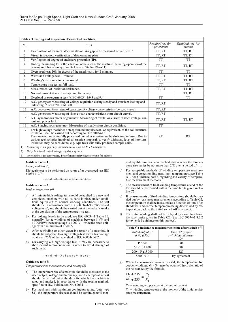
Table C1 Testing and inspection of electrical machines
No. Task Required test for generators
Required test for motors
1 Examination of technical documentation. Air gap to be measured or verified.1) TT, RT TT, RT2 Visual inspection, verification of data on name plate. TT, RT TT, RT3 Verification of degree of enclosure protection (IP). TT TT4 During the running tests, the vibration or balance of the machine including operation of the
bearing or lubrication system. Reference: 34-14 (1996-11) TT, RT TT, RT
5 Overspeed test: 20% in excess of the rated r.p.m. for 2 minutes. TT TT6 Withstand voltage test, 1 minute. TT, RT TT, RT7 Winding's resistance to be measured. TT, RT TT, RT8 Temperature-rise test at full load. TT TT9 Measurement of insulation resistance. TT, RT TT, RT
10 No load current at rated voltage and frequency. TT, RT11 Overload or overcurrent test3) (IEC 60034-1/9.3 and 9.4). TT TT12 A.C. generator: Measuring of voltage regulation during steady and transient loading and
unloading 2), see B202 and B203. TT, RT
13 A.C. generator: Measuring of open circuit voltage characteristics (no load curve). TT, RT14 A.C. generator: Measuring of short circuit characteristics (short circuit curve). TT, RT15 A.C. synchronous motor or generator: Measuring of excitation current at rated voltage, cur-
rent and power factor. TT, RT TT, RT
16 A.C. Synchronous generator: Measuring of steady short circuit condition. TT17 For high voltage machines a steep fronted impulse test, or equivalent, of the coil interturn
insulation shall be carried out according to IEC 60034-15.Tests on each separate fully processed coil after inserting in the slots are preferred. Due to various technologies involved, alternative proposals to verify withstand level of interturn insulation may be considered, e.g. type tests with fully produced sample coils.
RT RT
1) Measuring of air gap only for machines of size 1.5 MVA and above.2) Only functional test of voltage regulator system.3) Overload test for generators. Test of momentary excess torque for motors.
Table C2 Resistance measurement time after switch off Rated output, P
(kW) (kVA)Time delay after
switching off power(s)
P 50 3050 < P 200 90
200 < P 5 000 1205 000 < P By agreement
2 235õ
1 235õ
----------------------R2R1------ã
Rules for Ships / High Speed, Light Craft and Naval Surface Craft, January 2008Pt.4 Ch.8 Sec.5 � Page 51
DET NORSKE VERITAS
The temperature rise is the difference between the windingtemperature at the end of the test, and the ambient air tem-perature at the end of the test. (Alternatively the water inlettemperature at the end of the test, for water/air heat exchang-ers.)The resistance of a machine winding should be measuredand recorded using an appropriate bridge method or voltageand current method.
h) When the embedded temperature detector (ETD) method isused, there should be at least six detectors suitably distribut-ed throughout the machine windings. They should be locat-ed at the various points at which the highest temperaturesare likely to occur, and in such a manner that they are effec-tively protected from contact with the coolant. The highestreading of an ETD element should be used to determinecompliance with requirements for temperature limits.
i) When there is two or more coil-sides per slot, the ETD ele-ments should be placed between the insulated coil sides. Ifthere is only one coil-side per slot, the ETD method is not arecognised method for determination of temperature rise ortemperature limits in order to verify the compliance of therating.
j) The thermometer method is recognised in the cases in whichneither the ETD method nor the resistance method is appli-cable. See IEC 60034-1 for guidance. The measured temper-ature rises should not exceed the following values:65 K for class A insulation80 K for class E insulation90 K for class B insulation115 K for class F insulation140 K for class H insulation.
---e-n-d---of---G-u-i-d-a-n-c-e---n-o-t-e---
Guidance note 4:Alternative methods for temperature rise calculationsTemperature tests at full load may be difficult to realise for largemachines, due to insufficient test power being available. One ofthe following simulated tests, or equivalent, will be subject forapproval for synchronous generators and induction motors:- synchronous feedback, or back to back method, according to
IEEE Std. 115-1983, 6.2.2- zero power factor method, according to IEEE Std. 115-1983,
6.2.3- open-circuit and short circuit loading method, according to
IEEE Std. 115-1983, 6.2.4- �Equivalent loading and super-position techniques - Indirect
testing to determine temperature rice.", according to IEC61986.
---e-n-d---of---G-u-i-d-a-n-c-e---n-o-t-e---
Guidance note 5:Insulation resistance test (9)
a) The insulation resistance of a new, clean dry machine,should be measured immediately after the temperature testhas been carried out and after high voltage test has been car-ried out using a direct current insulation tester between:- all current carrying parts connected together and earth- all current carrying parts of different polarity or phase,
where both ends of each polarity or phase are individual-ly accessible.
The minimum values of test voltage and insulation are givenin Table C3. The temperature at which the resistance ismeasured should be near the operating temperature, or anappropriate method of calculation may be used.
b) On carrying out insulation resistance test, it may be neces-sary to short circuit semi-conductors in order to avoid dam-age to such parts.
---e-n-d---of---G-u-i-d-a-n-c-e---n-o-t-e---
Guidance note 6:Overload testing (11)Overloads as stated in A204 are difficult to test on large ma-chines. In case overloads cannot be tested, documentation or cal-culations based on manufacturers proven methods andexperience will be accepted.
---e-n-d---of---G-u-i-d-a-n-c-e---n-o-t-e---
Guidance note 7:Alternative methods for measuring excitation current at ratedvoltage, current and power factor (15)Temperature tests at full load may be difficult to realise for largemachines, due to insufficient test power being available. One ofthe following simulated tests, or equivalent, will be subject forapproval for synchronous generators and induction motors:
� load excitation, according to IEEE Std. 115-1983, 6.2.2.
---e-n-d---of---G-u-i-d-a-n-c-e---n-o-t-e---
102 Site testingAll machines shall be tested at site, after installation, so that ac-ceptable starting and running performance are verified withfull capacity of driven equipment, alternatively full generatorload. See Sec.10.
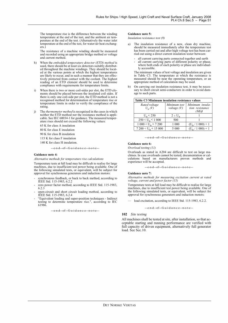
Table C3 Minimum insulation resistance valuesRated voltage
Un (V)Minimum test
voltage (V)Minimum insula-
tion resistance (M )
Un 250 2 Un 1250 < Un 1 000 500 1
1 000 < Un 7 200 1 000 (Un / 1 000) + 17 200 < Un 15 000 5 000 (Un / 1 000) + 1
Rules for Ships / High Speed, Light Craft and Naval Surface Craft, January 2008Pt.4 Ch.8 Sec.6 � Page 52
DET NORSKE VERITAS
SECTION 6 POWER TRANSFORMERS
A. GeneralA 100 General101 ReferenceThe design of transformers shall in general comply with the re-quirements of IEC 60092-303 and relevant parts of IEC 60076.
A 200 Design requirements for power transformers201 General
a) Transformers shall be double wound. Starting transform-ers and transformers feeding single consumers, as long asthe secondary consumer has the same insulation level asthe primary side, may be of autotransformer type.
b) Normally, transformers shall be of the dry air-cooled type.c) All windings for air-cooled transformers shall be treated to
resist moisture, sea air, and oil vapours.d) For the general requirements for insulation materials and
terminations, see Sec.3 D.e) For requirements for bus-bar material see Sec.4 B100.
202 Liquid immersed transformers
a) Liquid immersed transformers, filled with liquid withflashpoint above 60 C, may be accepted in engine roomsor similar spaces if provisions have been made, when in-stalled, for containing or safe draining of a total liquidleakage.
b) Normally, liquid immersed transformers shall be of thesealed type. However, conservator type may be acceptedif the construction is such that liquid is not spilled, whenthe transformer is inclined at 40°.
c) Liquid immersed conservator type transformers shall havea breathing device capable of stopping (trapping) moisturefrom entering into the insulating liquid.
d) Arrangement for containment of accidental leakage shallbe arranged.
e) A liquid gauge indicating the normal liquid level rangeshall be fitted.
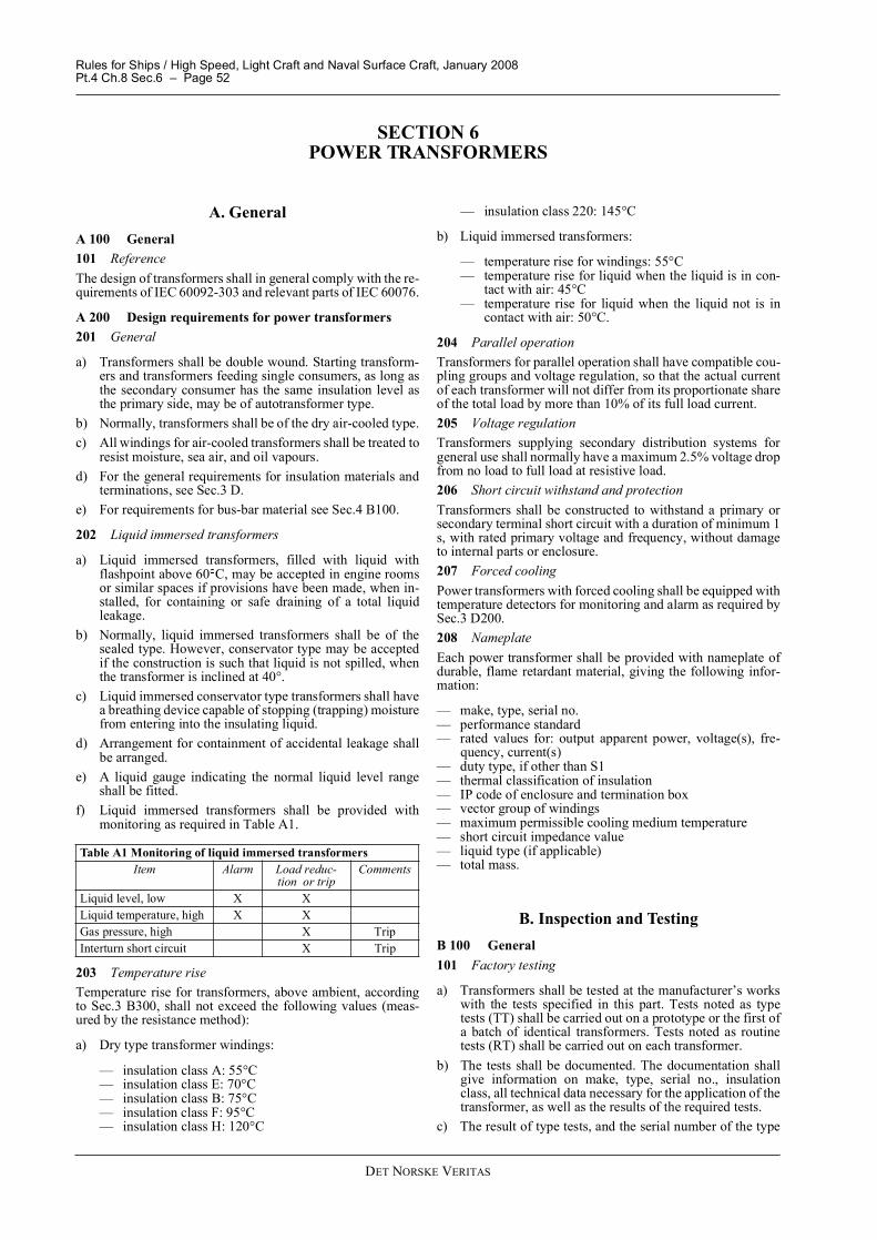
f) Liquid immersed transformers shall be provided withmonitoring as required in Table A1.
203 Temperature riseTemperature rise for transformers, above ambient, accordingto Sec.3 B300, shall not exceed the following values (meas-ured by the resistance method):
a) Dry type transformer windings:
� insulation class A: 55°C� insulation class E: 70°C� insulation class B: 75°C� insulation class F: 95°C� insulation class H: 120°C
� insulation class 220: 145°C
b) Liquid immersed transformers:
� temperature rise for windings: 55°C� temperature rise for liquid when the liquid is in con-
tact with air: 45°C� temperature rise for liquid when the liquid not is in
contact with air: 50°C.
204 Parallel operationTransformers for parallel operation shall have compatible cou-pling groups and voltage regulation, so that the actual currentof each transformer will not differ from its proportionate shareof the total load by more than 10% of its full load current.205 Voltage regulationTransformers supplying secondary distribution systems forgeneral use shall normally have a maximum 2.5% voltage dropfrom no load to full load at resistive load.206 Short circuit withstand and protectionTransformers shall be constructed to withstand a primary orsecondary terminal short circuit with a duration of minimum 1s, with rated primary voltage and frequency, without damageto internal parts or enclosure.207 Forced coolingPower transformers with forced cooling shall be equipped withtemperature detectors for monitoring and alarm as required bySec.3 D200.208 NameplateEach power transformer shall be provided with nameplate ofdurable, flame retardant material, giving the following infor-mation:
� make, type, serial no.� performance standard� rated values for: output apparent power, voltage(s), fre-
quency, current(s)� duty type, if other than S1� thermal classification of insulation� IP code of enclosure and termination box� vector group of windings� maximum permissible cooling medium temperature� short circuit impedance value� liquid type (if applicable)� total mass.
B. Inspection and TestingB 100 General101 Factory testing
a) Transformers shall be tested at the manufacturer�s workswith the tests specified in this part. Tests noted as typetests (TT) shall be carried out on a prototype or the first ofa batch of identical transformers. Tests noted as routinetests (RT) shall be carried out on each transformer.
b) The tests shall be documented. The documentation shallgive information on make, type, serial no., insulationclass, all technical data necessary for the application of thetransformer, as well as the results of the required tests.
c) The result of type tests, and the serial number of the type
Table A1 Monitoring of liquid immersed transformersItem Alarm Load reduc-
tion or tripComments
Liquid level, low X XLiquid temperature, high X XGas pressure, high X TripInterturn short circuit X Trip
Rules for Ships / High Speed, Light Craft and Naval Surface Craft, January 2008Pt.4 Ch.8 Sec.6 � Page 53
DET NORSKE VERITAS
tested transformer, shall be specified in the documentationof test results for a routine test.
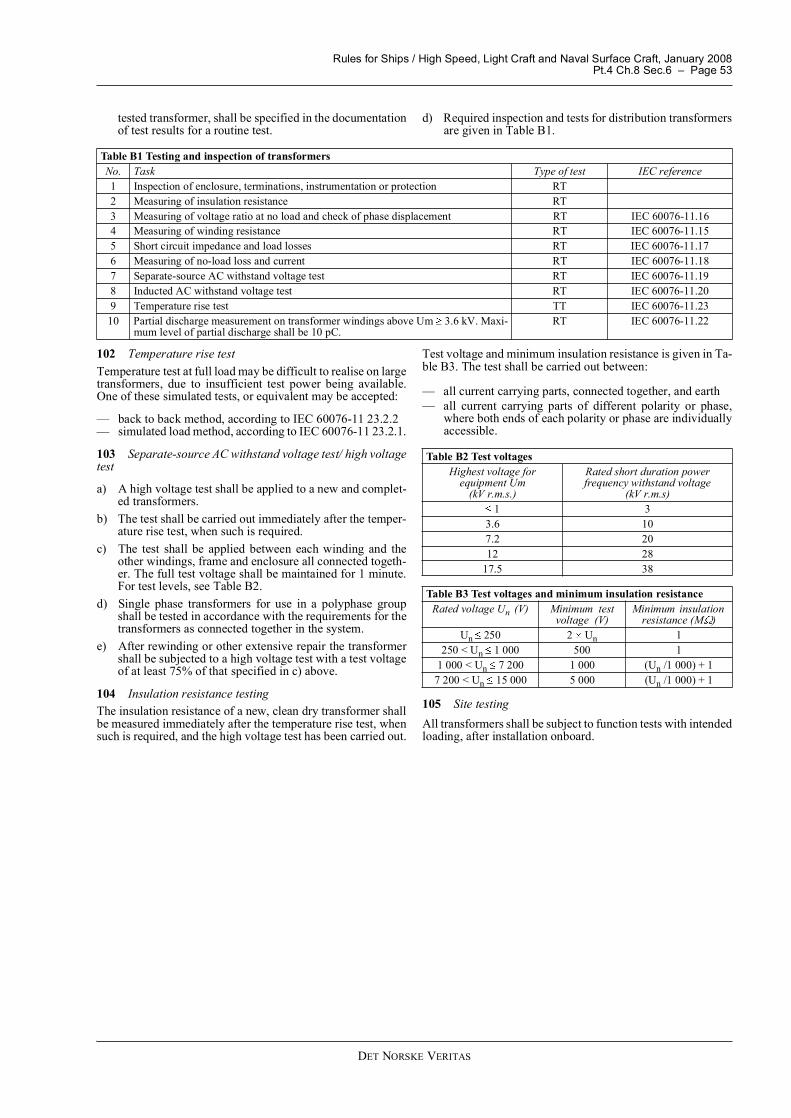
d) Required inspection and tests for distribution transformersare given in Table B1.
102 Temperature rise testTemperature test at full load may be difficult to realise on largetransformers, due to insufficient test power being available.One of these simulated tests, or equivalent may be accepted:
� back to back method, according to IEC 60076-11 23.2.2� simulated load method, according to IEC 60076-11 23.2.1.
103 Separate-source AC withstand voltage test/ high voltagetest
a) A high voltage test shall be applied to a new and complet-ed transformers.
b) The test shall be carried out immediately after the temper-ature rise test, when such is required.
c) The test shall be applied between each winding and theother windings, frame and enclosure all connected togeth-er. The full test voltage shall be maintained for 1 minute.For test levels, see Table B2.
d) Single phase transformers for use in a polyphase groupshall be tested in accordance with the requirements for thetransformers as connected together in the system.
e) After rewinding or other extensive repair the transformershall be subjected to a high voltage test with a test voltageof at least 75% of that specified in c) above.
104 Insulation resistance testingThe insulation resistance of a new, clean dry transformer shallbe measured immediately after the temperature rise test, whensuch is required, and the high voltage test has been carried out.
Test voltage and minimum insulation resistance is given in Ta-ble B3. The test shall be carried out between:
� all current carrying parts, connected together, and earth� all current carrying parts of different polarity or phase,
where both ends of each polarity or phase are individuallyaccessible.
105 Site testing All transformers shall be subject to function tests with intendedloading, after installation onboard.
Table B1 Testing and inspection of transformersNo. Task Type of test IEC reference1 Inspection of enclosure, terminations, instrumentation or protection RT2 Measuring of insulation resistance RT3 Measuring of voltage ratio at no load and check of phase displacement RT IEC 60076-11.164 Measuring of winding resistance RT IEC 60076-11.155 Short circuit impedance and load losses RT IEC 60076-11.176 Measuring of no-load loss and current RT IEC 60076-11.187 Separate-source AC withstand voltage test RT IEC 60076-11.198 Inducted AC withstand voltage test RT IEC 60076-11.209 Temperature rise test TT IEC 60076-11.23
10 Partial discharge measurement on transformer windings above Um 3.6 kV. Maxi-mum level of partial discharge shall be 10 pC.
RT IEC 60076-11.22
Table B2 Test voltages Highest voltage for
equipment Um (kV r.m.s.)
Rated short duration power frequency withstand voltage
(kV r.m.s) 1 3
3.6 107.2 2012 28
17.5 38
Table B3 Test voltages and minimum insulation resistanceRated voltage Un (V) Minimum test
voltage (V)Minimum insulation
resistance (M )Un 250 2 Un 1
250 < Un 1 000 500 11 000 < Un 7 200 1 000 (Un /1 000) + 1
7 200 < Un 15 000 5 000 (Un /1 000) + 1
Rules for Ships / High Speed, Light Craft and Naval Surface Craft, January 2008Pt.4 Ch.8 Sec.7 � Page 54
DET NORSKE VERITAS
SECTION 7 SEMI-CONDUCTOR CONVERTERS
A. General RequirementsA 100 General101 References
a) The design of semi-conductor converters shall complywith the requirements of IEC 60146-1-1 and IEC 60092-304.
b) The design of semi-conductor converters for power supplyshall in addition to a) comply with the requirements of IEC62040 series.
c) The design of semi-conductor converters for motor drivesshall in addition to a) comply with the requirements of IEC61800 series.
Guidance note:Semi-conductor converters for power supply covers systemswith converters with and without means for energy storage. UPS,battery chargers, clean power units etc.
---e-n-d---of---G-u-i-d-a-n-c-e---n-o-t-e---
A 200 Design and construction requirements201 GeneralThe design and construction of semi-conductor convertersshall comply with relevant requirements of Sec.3 and Sec.4.For control and monitoring equipment the requirements aregiven in Pt.4 Ch.9 (Rules for Classification of Ships).202 Harmonic distortion
a) Converters shall be compatible with the ship network, sothat generated line harmonics do not cause interferencewith other equipment. See Sec.2 A200.
b) Transformers, motors and reactors applied in connectionwith converters shall be designed to withstand any addi-tional stresses caused by non-sinusoidal voltages and cur-rents.
203 Creepage and clearance distances
a) For converters installed in machinery spaces of category�A�, and converters requiring DNV product certificate,creepage and clearance distances shall be in accordancewith the requirements given in Sec.3 D600.
b) Converters constructed as components and installed out-side machinery spaces of category �A�, creepage andclearance distances shall in general follow the require-ments in IEC according to pollution degree 3 and overvolt-age category III.
Guidance note:For semi-conductor converters for power supply the require-ments are given in IEC 60950-1. For semi-conductor convertersfor motor drives the requirements are given in IEC 61800-5-1
---e-n-d---of---G-u-i-d-a-n-c-e---n-o-t-e---
204 AccessibilitySemi-conductor elements, fuses or other parts likely to bechanged out, shall be so arranged that they can be removedfrom equipment without dismantling the complete unit.205 Cooling
a) Where forced cooling is provided, the apparatus is, unlessotherwise particularly required, to be so arranged that theconverter cannot remain loaded unless effective cooling is
provided, or other effective means of protection againstover temperature is provided. See also Sec.3 D200.
b) Piping shall be arranged to prevent harmful effects due toleakage or condensation, and be installed preferably in thelower part of the assembly.
c) Requirements for cooling of converters used for propul-sion are given in Sec.12.
206 Parallel operationWhen converters are operated in parallel with other of powersources, the control circuits shall ensure stable parallel opera-tion and prevent overloading of any unit.207 NameplateEach semi-conductor converter shall be provided with name-plate of durable, flame retardant material giving the followinginformation:
� make, type, serial no.� rating� IP rating� rated input voltage, frequency and current� rated output voltage, frequency and current� rated ambient temperature� duty type, if other than S1� rated output short circuit capability and time (for power
supplies)� rated cooling water temperature (if applicable).
B. Semi-conductor Converters for Power SupplyB 100 General design requirements, electrical101 Electrical rating and duty
a) The specified capacity shall at least include a 100% con-tinuous load, and a specified overload capacity given by acurrent of maximum duration of time.
b) Requirements for charger capacity are given in Sec.2D102.
102 Creepage and clearance distances
a) For converters installed in machinery spaces of category�A�, and converters requiring DNV product certificate,creepage and clearance distances shall be in accordancewith the requirements given in Sec.3 D600.
b) Converters constructed as components and installed out-side machinery spaces of category �A�, creepage andclearance distances shall in general follow the require-ments in IEC 60950-1 according to pollution degree 3 andovervoltage category III.
103 Output voltage and frequencyThe output voltage and frequency of the power supply unitsshall comply with the requirements for power supply systemsgiven in Sec.2 A.104 Short circuit current capabilitiesConverters serving as power supplies shall be able to supply ashort circuit current sufficient for selective tripping of down-stream protective devices, without suffering internal damage.Current limiting power supplies, or power supplies limited byinternal temperature may be used for single consumers.
Rules for Ships / High Speed, Light Craft and Naval Surface Craft, January 2008Pt.4 Ch.8 Sec.7 � Page 55
DET NORSKE VERITAS
105 Monitoring, alarm and protection
a) Monitoring with alarm shall be provided for:
� power supply failure and trip of unit� earth fault, except dedicated system for single con-
sumers.
b) For power supply units with batteries included, the follow-ing additional alarms shall be provided:
� when the battery is being discharged, and� when the bypass is in operation for on-line units� operation of battery protective device.
c) Alarms shall be given to the main alarm system.d) Requirements for protection of batteries and distribution
circuits are given in Sec.2 G.
B 200 System arrangement201 Back feed protectionConverters serving as power supply shall be provided withmeans to prevent reverse flow of power back to the main sys-tem. 202 By-pass arrangementFor converters serving as power supply units used as emergen-cy or transitional source of power, external bypass arrange-ment shall be provided. 203 Location of batteriesRequirements for location of batteries inside electrical assem-blies are given in Sec.2 I400.
C. Semi-conductor Converters for Motor DrivesC 100 General Design requirements, electrical101 Electrical rating and duty
a) The specified converter capacity shall at least include a100% continuous load, and a specified overload capacitygiven by a current of maximum duration of time.
b) Where required by the application, the overload capacitymay be specified in several steps with corresponding max-imum duration, or the converter rated load may be referredto a worst case duty cycle.
c) As a motor starter, the converter shall as a minimum with-stand two consecutive start attempts without being over-loaded by temperature.
d) For converter supplying motors, required torque shall beconsidered in view of the application.
102 Protection and monitoring
a) Monitoring with alarm shall be given for power supplyfailure and trip of unit
b) Converters shall have the possibility for monitoring of theoutput voltage, frequency and current.
c) Additional requirements for monitoring of converters usedin electrical propulsion systems are given in Sec.12.
103 Safety stop, shutdown
a) In drives used for applications where safety stop is re-quired the safety stop circuit shall be directly connected totrip the main power supply to the drive unit, either directlyor through the control power circuit for the circuit breaker.Guidance note:Guidance noteExamples of safety stops are Exd motors with over-temperaturetrip device, emergency stop of propulsion motors or cargopumps.
---e-n-d---of---G-u-i-d-a-n-c-e---n-o-t-e---
b) Requirements for limited shutdown functions for steeringand propulsion are given in Pt.4 Ch.14 (Rules for Classifi-cation of Ships) and Sec.12.
104 RestartIt shall be possible to restart the converter in a normal mannerafter a blackout. Manual resetting/restarting of the unit shallnot be necessary.
D. Inspection and TestingD 100 General 101 Factory testing
a) Converters shall be tested at the manufacturer�s works.Type tests (TT) shall be carried out on a prototype of aconverter or the first of a batch of identical converters.Routine tests (RT) shall be carried out on each converter.
b) The tests shall be documented. The documentation shallgive information on make, type, serial no., all technicaldata necessary for the application of the converter, as wellas the results of the required tests.
c) The result of type tests, and the serial number of the typetested converter, shall be specified in the documentation oftest results for routine tests.
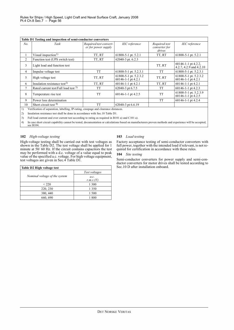
d) The type tests and routine tests that semi-conductor con-verters shall undergo are listed in Table D1.
Rules for Ships / High Speed, Light Craft and Naval Surface Craft, January 2008Pt.4 Ch.8 Sec.7 � Page 56
DET NORSKE VERITAS
102 High-voltage testing High-voltage testing shall be carried out with test voltages asshown in the Table D2. The test voltage shall be applied for 1minute at 50/ 60 Hz. If the circuit contains capacitors the testmay be performed with a d.c. voltage of a value equal to peakvalue of the specified a.c. voltage. For high voltage equipment,test voltages are given in Sec.4 Table D1.
103 Load testingFactory acceptance testing of semi-conductor converters withfull power, together with the intended load if relevant, is not re-quired for certification in accordance with these rules. 104 Site testingSemi-conductor converters for power supply and semi-con-ductor converters for motor drives shall be tested according toSec.10 D after installation onboard.
Table D1 Testing and inspection of semi-conductor convertersNo. Task Required test convert-
er for power supplyIEC reference Required test
converter for drives
IEC reference
1 Visual inspection1) TT, RT 61800-5-1 pt. 5.2.1 TT, RT 61800-5-1 pt. 5.2.12 Function test (UPS switch test) TT, RT 62040-3 pt. 6.2.3
3 Light load and function test TT, RT 60146-1-1 pt 4.2.2, 4.2.7, 4.2.9 and 4.2.10
4 Impulse voltage test TT 61800-5-1 pt. 5.2.3.1 TT 61800-5-1 pt. 5.2.3.1
5 High voltage test TT, RT 61800-5-1 pt. 5.2.3.260146-1-1 pt 4.2.1 TT, RT 61800-5-1 pt. 5.2.3.2
60146-1-1 pt 4.2.16 Insulation resistance test2) TT, RT 60146-1-1 pt 4.2.1 TT, RT 60146-1-1 pt 4.2.17 Rated current test/Full load test 3) TT 62040-3 pt 6.7.5 TT 60146-1-1 pt 4.2.3
8 Temperature rise test TT 60146-1-1 pt 4.2.5 TT 61800-5-1 pt. 5.2.3.960146-1-1 pt 4.2.5
9 Power loss determination TT 60146-1-1 pt 4.2.410 Short circuit test 4) TT 62040-3 pt 6.6.19
1) Verification of separation, labelling, IP-rating, creepage and clearance distances.2) Insulation resistance test shall be done in accordance with Sec.10 Table D1.3) Full load current and over current test according to rating as required in B101 a) and C101 a).4) In case short circuit capability cannot be tested, documentation or calculations based on manufacturers proven methods and experience will be accepted,
see B104.
Table D2 High voltage test
Nominal voltage of the systemTest voltages
a.c.r.m.s (V)
< 220 1 300220, 230 1 350380, 440 1 500660, 690 1 800
Rules for Ships / High Speed, Light Craft and Naval Surface Craft, January 2008Pt.4 Ch.8 Sec.8 � Page 57
DET NORSKE VERITAS
SECTION 8 MISCELLANEOUS EQUIPMENT
A. GeneralA 100 Socket outlets and plugs101 General
a) Socket outlets and plugs with a rated current not exceeding63 A in A.C. installations and 16 A in D.C. installations,shall be constructed for making and breaking the rated cur-rent by insertion and withdrawal of the plug, unless theyare provided with an interlock as described in b).
b) Socket outlets with a rated current above 63 A A.C. or 16A D.C. shall be provided with interlocks so that the plugcan only be inserted and withdrawn when the switch is inthe "off" position.
c) Socket outlets for portable appliances, which are not hand-held during operation (e.g. welding transformers, refriger-ated containers), shall be interlocked with a switch regard-less of rating, maximum 1 000 V can be accepted. At eachsuch socket outlet, a warning sign shall be fitted, with text:DANGER (maximum voltage) V A.C. ONLY FOR CON-NECTION OF.... (type of equipment)....
d) Higher voltage socket outlets can only be used for specialapplications.
e) All socket outlets shall be provided with an earthing con-tact, except that this may be omitted in the following cas-es:
� socket outlets on systems with voltage below 50 VA.C. or D.C.
� socket outlets with double insulated transformers forhandheld equipment
� for distribution systems with insulated neutral; socketoutlets in dry accommodation spaces where floor cov-ering, bulkhead and ceiling linings are of insulatingmaterial. The resistance of the insulating materialshall be at least 50 kOhm. Earth potential shall not bebrought into the space, for instance through earth con-ductors, piping etc.
f) Precautions shall be taken so that a plug for one voltagecannot be inserted in a socket outlet for a different voltage.Alternatively, warning signboards shall be fitted.
A 200 Lighting equipment201 General
a) The temperature rise of parts of luminaries that are in con-tact with the support shall generally not exceed 50°C.
b) The temperature limit is 40°C for parts installed in contactwith flammable materials, such as for example wood.
c) For temperature rise of terminals, see Sec.3.d) For other parts, temperatures according to recognised na-
tional or international standards, which take due consider-ation of the ambient temperatures on vessels, will beaccepted.
e) Normally, gas discharge lighting equipment shall not beused.
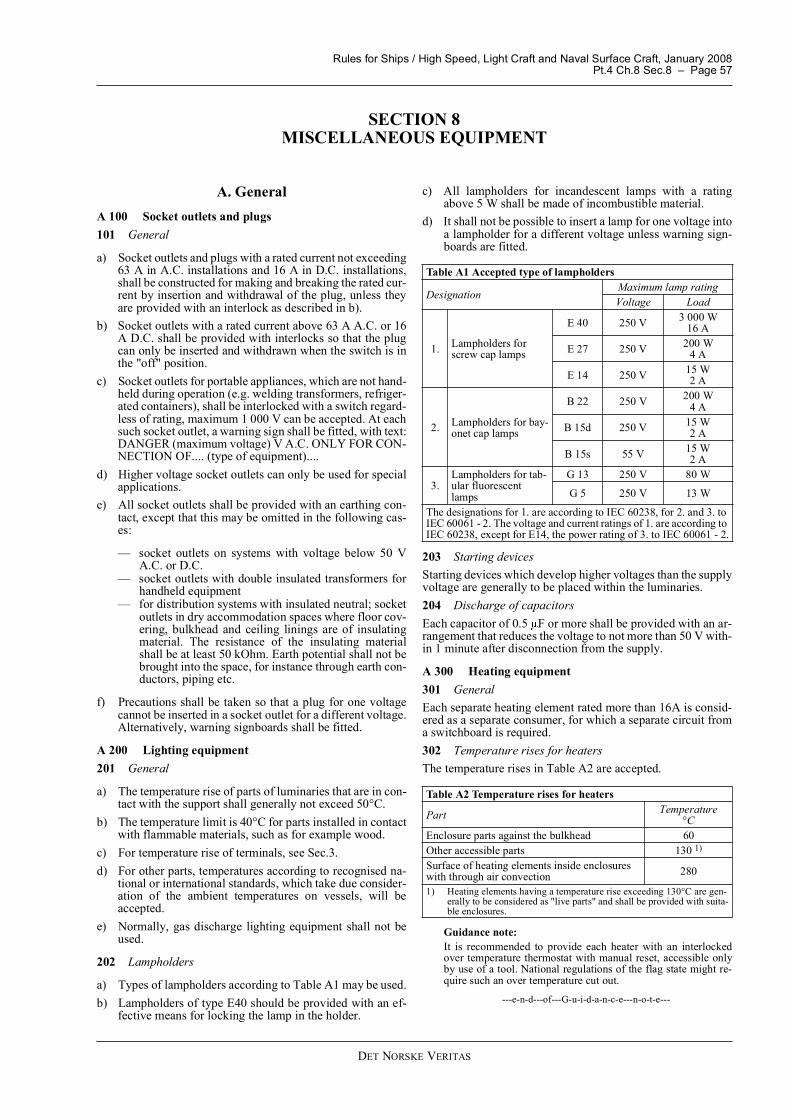
202 Lampholders
a) Types of lampholders according to Table A1 may be used.b) Lampholders of type E40 should be provided with an ef-
fective means for locking the lamp in the holder.
c) All lampholders for incandescent lamps with a ratingabove 5 W shall be made of incombustible material.
d) It shall not be possible to insert a lamp for one voltage intoa lampholder for a different voltage unless warning sign-boards are fitted.
203 Starting devicesStarting devices which develop higher voltages than the supplyvoltage are generally to be placed within the luminaries.204 Discharge of capacitorsEach capacitor of 0.5 F or more shall be provided with an ar-rangement that reduces the voltage to not more than 50 V with-in 1 minute after disconnection from the supply.
A 300 Heating equipment301 GeneralEach separate heating element rated more than 16A is consid-ered as a separate consumer, for which a separate circuit froma switchboard is required.302 Temperature rises for heatersThe temperature rises in Table A2 are accepted.
Guidance note:It is recommended to provide each heater with an interlockedover temperature thermostat with manual reset, accessible onlyby use of a tool. National regulations of the flag state might re-quire such an over temperature cut out.
---e-n-d---of---G-u-i-d-a-n-c-e---n-o-t-e---
Table A1 Accepted type of lampholders
DesignationMaximum lamp ratingVoltage Load
1. Lampholders for screw cap lamps
E 40 250 V 3 000 W16 A
E 27 250 V 200 W4 A
E 14 250 V 15 W2 A
2. Lampholders for bay-onet cap lamps
B 22 250 V 200 W4 A
B 15d 250 V 15 W2 A
B 15s 55 V 15 W2 A
3.Lampholders for tab-ular fluorescent lamps
G 13 250 V 80 W
G 5 250 V 13 W
The designations for 1. are according to IEC 60238, for 2. and 3. to IEC 60061 - 2. The voltage and current ratings of 1. are according to IEC 60238, except for E14, the power rating of 3. to IEC 60061 - 2.
Table A2 Temperature rises for heaters
Part Temperature°C
Enclosure parts against the bulkhead 60Other accessible parts 130 1)
Surface of heating elements inside enclosures with through air convection 280
1) Heating elements having a temperature rise exceeding 130°C are gen-erally to be considered as "live parts" and shall be provided with suita-ble enclosures.
Rules for Ships / High Speed, Light Craft and Naval Surface Craft, January 2008Pt.4 Ch.8 Sec.8 � Page 58
DET NORSKE VERITAS
303 Space heaters
a) Space heaters are generally to be of the convection type,and suitable for installation on bulkheads. Radiation heat-ers and other space heater types may be accepted after con-sideration in each case.
b) Space heaters are generally to be constructed with the topplate inclined about 30 , tight against the bulkhead in or-der to prevent clothing or other flammable material fromcovering the heaters.
c) Space heaters are normally to be installed on a free bulk-head space, with about 1 m free air above, and so that forexample doors cannot touch the heaters. If not constructedas specified in b), an inclined perforated plate of incom-bustible material shall be mounted above each heater.Space heaters shall not be built into casings of woodworkor other combustible material.
304 Heating batteries for ventilation systemsHeating batteries in centralised ventilation systems shall beequipped with the following safety / control functions:
� heating elements shall be interlocked with respect to theair flow either directly controlled by the power to the fanor by measuring the airflow locally at the heating element
� heating elements shall be equipped with over temperatureswitch that can be reset manually only
� heating elements shall be equipped with thermostat con-trol gear.
305 Space heaters combined with air-condition cabinetsThe following additional requirements apply for space heatersintegrated in air-conditioning cabinets:
� the maximum temperature rises specified in 302 shall becomplied with, even when the air supply is completelyshut off
� each cabinet shall be provided with an interlocked overtemperature thermostat with manual reset, accessible onlyby use of tool
� combined cabinets for ceiling installation are accepted, theceiling shall be constructed of incombustible materials.
306 Water heaters
a) Water heaters are normally to have insulated heating ele-ments and shall be installed as separate units.
b) The requirements for temperature rises specified in TableA3 apply.
c) Each water heater shall be provided with a thermostat,sensing the water temperature and maintaining this at thecorrect level.
Guidance note:Electrode heaters and electrically heated steam boilers may beaccepted after assessment of the arrangement in each case.Heating by electric elements in the ship's water tanks may be ac-cepted after design assessment of the arrangement in each case.
For pressure vessels, the requirements in Pt.4 Ch.7 (Rules forClassification of Ships) apply.
---e-n-d---of---G-u-i-d-a-n-c-e---n-o-t-e---
307 Oil heaters
a) Electric oil heaters are normally to be installed as separateunits. Heating by electric heating elements in the ship's oiltanks is generally not allowed, but may be accepted afterspecial design assessment of the arrangement in each case.
b) The requirements for temperature rises specified in TableA3 apply. In addition, the surface temperature of the heat-ing elements shall be below the boiling point of the oil, un-der normal working conditions. Further limitation of theheating elements' temperature may be required.
c) Each oil heater shall be provided with a working thermo-stat, sensing the oil temperature and maintaining this atcorrect level under normal working conditions. In addi-tion, each oil heater shall be provided with an interlockedover-temperature thermostat with manual reset, and withthe sensing device installed in close proximity to the heat-ing elements, so arranged that it will trip the elements,should they tend to overheat, or become dry. Other ar-rangements, ensuring equivalent protection, may be ac-cepted after design assessment in each case
Guidance note:Lubricating oil may deteriorate even at much lower element tem-peratures. The oil manufacturer should be consulted regardingthe maximum acceptable element temperature.
---e-n-d---of---G-u-i-d-a-n-c-e---n-o-t-e---
A 400 Cooking and other galley equipment401 General
a) Cooking equipment is generally to have insulated heatingelements. Special equipment, such as for example highfrequency ovens or electrode pots, shall be suitable for ma-rine use, and installed in accordance with the manufactur-er's instructions.
b) Electrode pots giving earth -connection of the system shallbe fed from separate isolating transformers.
c) For oil pots, the requirements for oil heaters in 307 applyd) The temperature rises in Table A3 are accepted.
Table A3 Temperature rises for cooking and other galley equipment
Part Temperature °C
Enclosure parts against the bulkhead and decks 50Other accessible surface parts, except hot plates with adjacent top plates 50
Hot plates with adjacent top plates, and heating elements No limit 1)
1) Construction and temperatures shall be such that damage and hazards are avoided, when the equipment is used as intended.
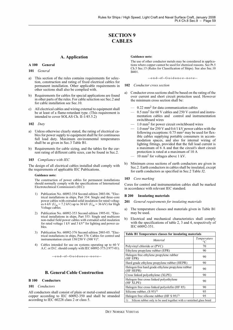
Rules for Ships / High Speed, Light Craft and Naval Surface Craft, January 2008Pt.4 Ch.8 Sec.9 � Page 59
DET NORSKE VERITAS
SECTION 9 CABLES
A. Application
A 100 General101 General
a) This section of the rules contains requirements for selec-tion, construction and rating of fixed electrical cables forpermanent installation. Other applicable requirements inother sections shall also be complied with.
b) Requirements for cables for special applications are foundin other parts of the rules. For cable selection see Sec.2 andfor cable installation see Sec.10.
c) All electrical cables and wiring external to equipment shallbe at least of a flame-retardant type. (This requirement isintended to cover SOLAS Ch. II-1/45.5.2)
102 Duty
a) Unless otherwise clearly stated, the rating of electrical ca-bles for power supply to equipment shall be for continuousfull load duty. Maximum environmental temperaturesshall be as given in Sec.3 Table B1.
b) Requirements for cable sizing, and the tables for the cur-rent rating of different cable sizes, can be found in Sec.2.
103 Compliance with IECThe design of all electrical cables installed shall comply withthe requirements of applicable IEC Publications.
Guidance note:The construction of power cables for permanent installationsshould normally comply with the specifications of InternationalElectrotechnical Commission's (IEC):
1) Publication No. 60092-354 Second edition 2003-06. "Elec-trical installations in ships, Part 354: Single and three-corepower cables with extruded solid insulation for rated voltag-es 6 kV (Um = 7.2 kV) up to 30 kV (Um = 36 kV) for HighVoltage cables.
2) Publication No. 60092-353 Second edition 1995-01. "Elec-trical installations in ships, Part 353: Single and multicorenon-radial field power cables with extruded solid insulationfor rated voltage 1 kV and 3 kV" for lighting and power ca-bles.
3) Publication No. 60092-376 Second edition 2003-05. "Elec-trical installations in ships, Part 376: Cables for control andinstrumentation circuit 150/250 V (300 V)".
4) Cables intended for use on systems operating up to 60 VA.C. or D.C. should comply with IEC 60092-375 (1977-01).
---e-n-d---of---G-u-i-d-a-n-c-e---n-o-t-e---
B. General Cable Construction
B 100 Conductors101 ConductorsAll conductors shall consist of plain or metal-coated annealedcopper according to IEC 60092-350 and shall be strandedaccording to IEC 60228 class 2 or class 5.
Guidance note:The use of other conductor metals may be considered in applica-tions where copper cannot be used for chemical reasons. See Pt.5Ch.5 Sec.15 (Rules for Classification of Ships). See also Sec.10B401.
---e-n-d---of---G-u-i-d-a-n-c-e---n-o-t-e---
102 Conductor cross section
a) Conductor cross sections shall be based on the rating of theover current and short circuit protection used. Howeverthe minimum cross section shall be:
� 0.22 mm2 for data communication cables� 0.5 mm2 for 60 V cables and 250 V control and instru-
mentation cables and control and instrumentationswitchboard wires
� 1.0 mm2 for power circuit switchboard wires� 1.0 mm2 for 250 V and 0.6/1 kV power cables with the
following exceptions: 0.75 mm2 may be used for flex-ible cables supplying portable consumers in accom-modation spaces, and also for internal wiring oflighting fittings, provided that the full load current isa maximum of 6 A and that the circuit's short circuitprotection is rated at a maximum of 10 A
� 10 mm2 for voltages above 1 kV.
b) Minimum cross sections of earth conductors are given inSec.2. Earth conductors in cables shall be insulated, exceptfor earth conductors as specified in Sec.2 Table J2.
103 Core markingCores for control and instrumentation cables shall be markedin accordance with relevant IEC standard.
B 200 Insulating materials201 General requirements for insulating materials
a) The temperature classes and materials given in Table B1may be used.
b) Electrical and mechanical characteristics shall complywith the specifications of table 2, 3 and 4, respectively ofIEC 60092-351.
Table B1 Temperature classes for insulating materials
Material Temperature°C
Polyvinyl chloride or (PVC) 70Ethylene propylene rubber (EPR) 90Halogen free ethylene propylene rubber(HF EPR) 90
Hard grade ethylene propylene rubber (HEPR) 90Halogen free hard grade ethylene propylene rubber (HF HEPR) 90
Cross linked polyethylene (XLPE) 90Halogen free cross linked polyethylene(HF XLPE) 90
Halogen free cross linked polyolefin (HF 85) 90Silicone rubber, (S 95)1) 95Halogen free silicone rubber (HF S 95)1) 951) Silicon rubber only to be used together with a varnished glass braid
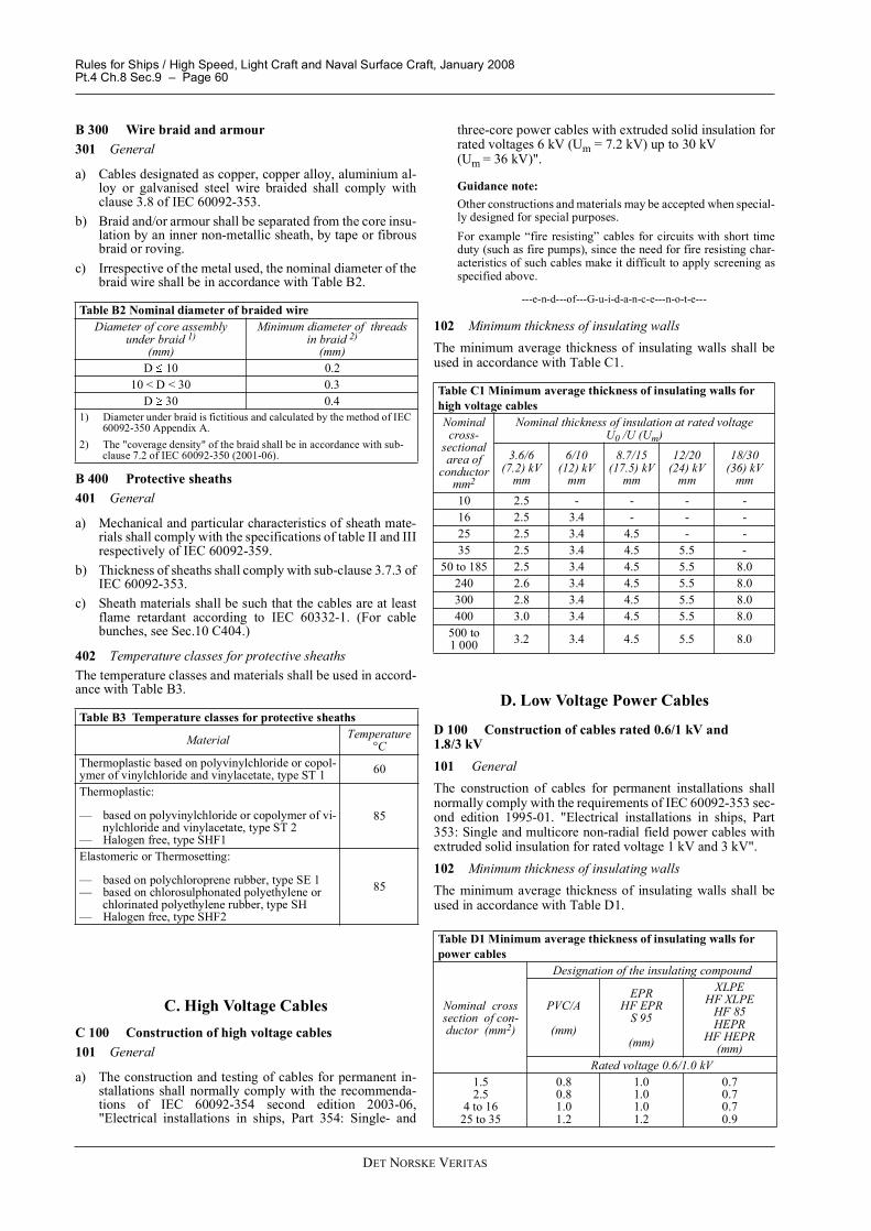
Rules for Ships / High Speed, Light Craft and Naval Surface Craft, January 2008Pt.4 Ch.8 Sec.9 � Page 60
DET NORSKE VERITAS
B 300 Wire braid and armour301 General
a) Cables designated as copper, copper alloy, aluminium al-loy or galvanised steel wire braided shall comply withclause 3.8 of IEC 60092-353.
b) Braid and/or armour shall be separated from the core insu-lation by an inner non-metallic sheath, by tape or fibrousbraid or roving.
c) Irrespective of the metal used, the nominal diameter of thebraid wire shall be in accordance with Table B2.
B 400 Protective sheaths401 General
a) Mechanical and particular characteristics of sheath mate-rials shall comply with the specifications of table II and IIIrespectively of IEC 60092-359.
b) Thickness of sheaths shall comply with sub-clause 3.7.3 ofIEC 60092-353.
c) Sheath materials shall be such that the cables are at leastflame retardant according to IEC 60332-1. (For cablebunches, see Sec.10 C404.)
402 Temperature classes for protective sheathsThe temperature classes and materials shall be used in accord-ance with Table B3.
C. High Voltage CablesC 100 Construction of high voltage cables101 General
a) The construction and testing of cables for permanent in-stallations shall normally comply with the recommenda-tions of IEC 60092-354 second edition 2003-06,"Electrical installations in ships, Part 354: Single- and
three-core power cables with extruded solid insulation forrated voltages 6 kV (Um = 7.2 kV) up to 30 kV (Um = 36 kV)".
Guidance note:Other constructions and materials may be accepted when special-ly designed for special purposes.For example �fire resisting� cables for circuits with short timeduty (such as fire pumps), since the need for fire resisting char-acteristics of such cables make it difficult to apply screening asspecified above.
---e-n-d---of---G-u-i-d-a-n-c-e---n-o-t-e---
102 Minimum thickness of insulating wallsThe minimum average thickness of insulating walls shall beused in accordance with Table C1.
D. Low Voltage Power Cables
D 100 Construction of cables rated 0.6/1 kV and 1.8/3 kV101 GeneralThe construction of cables for permanent installations shallnormally comply with the requirements of IEC 60092-353 sec-ond edition 1995-01. "Electrical installations in ships, Part353: Single and multicore non-radial field power cables withextruded solid insulation for rated voltage 1 kV and 3 kV".102 Minimum thickness of insulating wallsThe minimum average thickness of insulating walls shall beused in accordance with Table D1.
Table B2 Nominal diameter of braided wireDiameter of core assembly
under braid 1)(mm)
Minimum diameter of threads in braid 2)
(mm)D 10 0.2
10 < D < 30 0.3D 30 0.4
1) Diameter under braid is fictitious and calculated by the method of IEC 60092-350 Appendix A.
2) The "coverage density" of the braid shall be in accordance with sub-clause 7.2 of IEC 60092-350 (2001-06).
Table B3 Temperature classes for protective sheaths
Material Temperature °C
Thermoplastic based on polyvinylchloride or copol-ymer of vinylchloride and vinylacetate, type ST 1 60
Thermoplastic:
� based on polyvinylchloride or copolymer of vi-nylchloride and vinylacetate, type ST 2
� Halogen free, type SHF1
85
Elastomeric or Thermosetting:
� based on polychloroprene rubber, type SE 1� based on chlorosulphonated polyethylene or
chlorinated polyethylene rubber, type SH� Halogen free, type SHF2
85
Table C1 Minimum average thickness of insulating walls for high voltage cables Nominal cross-
sectional area of
conductormm2
Nominal thickness of insulation at rated voltage U0 /U (Um)
3.6/6(7.2) kV
mm
6/10(12) kV
mm
8.7/15 (17.5) kV
mm
12/20(24) kV
mm
18/30(36) kV
mm10 2.5 - - - -16 2.5 3.4 - - -25 2.5 3.4 4.5 - -35 2.5 3.4 4.5 5.5 -
50 to 185 2.5 3.4 4.5 5.5 8.0240 2.6 3.4 4.5 5.5 8.0300 2.8 3.4 4.5 5.5 8.0400 3.0 3.4 4.5 5.5 8.0
500 to 1 000 3.2 3.4 4.5 5.5 8.0
Table D1 Minimum average thickness of insulating walls for power cables
Nominal cross section of con-ductor (mm2)
Designation of the insulating compound
PVC/A
(mm)
EPRHF EPR
S 95
(mm)
XLPEHF XLPE
HF 85HEPR
HF HEPR(mm)
Rated voltage 0.6/1.0 kV1.52.5
4 to 1625 to 35
0.80.81.01.2
1.01.01.01.2
0.70.70.70.9