schneider electric mdrive product catalog - steven engineering
TRANSCRIPT
Intelligent motion systems
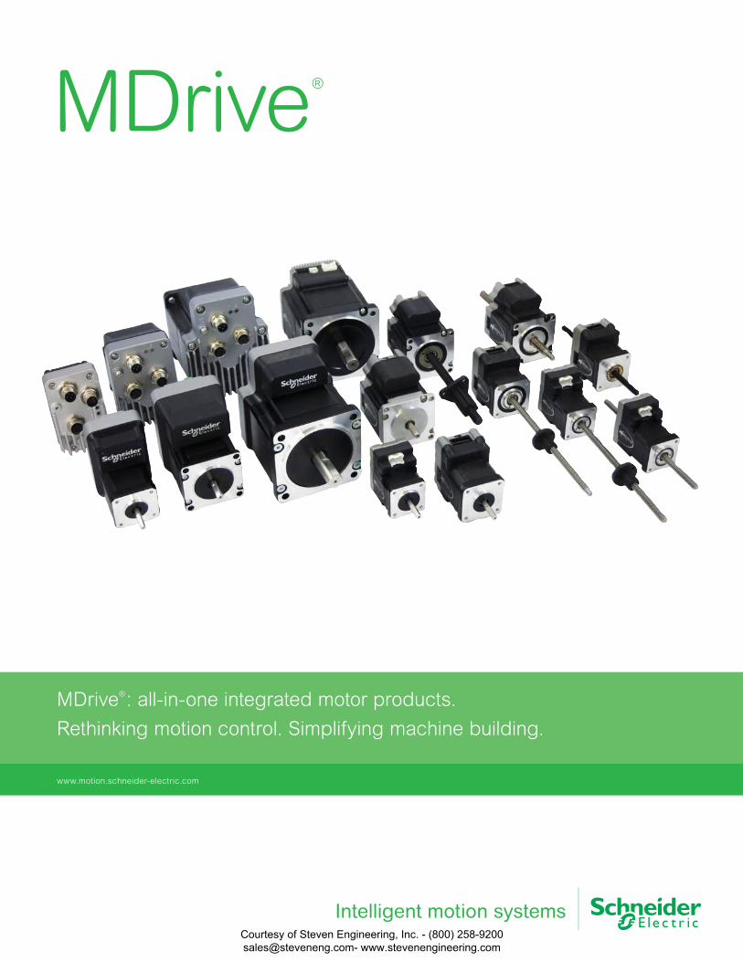
MDrive®
: all-in-one integrated motor products.
Rethinking motion control. Simplifying machine building.
www.motion.schneider-electric.com
MDrive®
Courtesy of Steven Engineering, Inc. - (800) 258-9200 [email protected] www.stevenengineering.com

Rethinkingmotion control.www.motion.schneider-electric.com Courtesy of Steven Engineering, Inc. - (800) 258-9200
[email protected] www.stevenengineering.com
ContentsOverview MDrive® integrated motors 5
Section I Lexium MDrive 6
hMT closed loop technology 7
specifi cations 8
dimensions 10
motor performance 12
part numbers 14
accessories 15
Section II MDrive Plus 16
integrated motor system advantages 17
specifi cations 18
dimensions 19
motor performance 23
part numbers 26
accessories 28
Section III MDrive Linear Actuator 30
specifi cations 31
dimensions 33
motor performance 36
part numbers 38
accessories 40
Courtesy of Steven Engineering, Inc. - (800) 258-9200 [email protected] www.stevenengineering.com

Simplifyingmachine building.www.motion.schneider-electric.com Courtesy of Steven Engineering, Inc. - (800) 258-9200
[email protected] www.stevenengineering.com
5www.motion.schneider-electric.com
MDrive is the world leader in integrated motor technology.
Delivering reliable performance to a wide range of motion applications.
Reducing machine complexity, size, and cost for machine builders.
MDrive products integrate motor, driver, controller, internal encoder and closed loop performance,
all in one compact package. Units are programmable and networkable, satisfying the motion control
requirements of many new and existing applications. And with fewer individual system components,
you save space, reduce wiring, and eliminate multiple potential failure points.
The family of MDrive integrated motors includes:
Cut installation time up to
25% by replacing multiple
individual components with
an MDrive integrated motor.
Reduce system wiring up to
40% with integrated motors,
while simplifying the EMC
concept and improving
machine reliability.
25%
40%
MDrive®
integrated motors
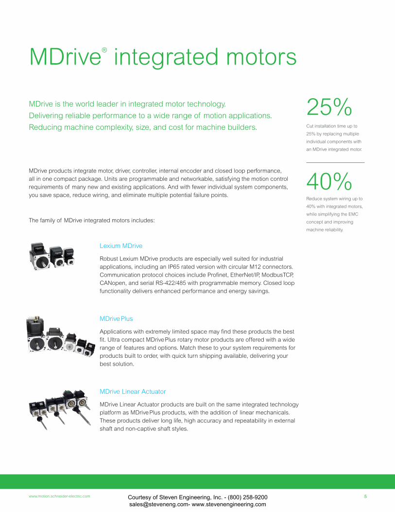
Lexium MDrive
Robust Lexium MDrive products are especially well suited for industrial
applications, including an IP65 rated version with circular M12 connectors.
Communication protocol choices include Profi net, EtherNet/IP, ModbusTCP,
CANopen, and serial RS-422/485 with programmable memory. Closed loop
functionality delivers enhanced performance and energy savings.
MDrive Plus
Applications with extremely limited space may fi nd these products the best
fi t. Ultra compact MDrive Plus rotary motor products are offered with a wide
range of features and options. Match these to your system requirements for
products built to order, with quick turn shipping available, delivering your
best solution.
MDrive Linear Actuator
MDrive Linear Actuator products are built on the same integrated technology
platform as MDrive Plus products, with the addition of linear mechanicals.
These products deliver long life, high accuracy and repeatability in external
shaft and non-captive shaft styles.
Courtesy of Steven Engineering, Inc. - (800) 258-9200 [email protected] www.stevenengineering.com
6 MDrive products assembled in USA
Features
• Built-in protection circuitry
• IP65 rating with M12 connectors
• Input power range from +12 up to +70 VDC
• Auxiliary logic power supply input
• 20 microstep resolutions to 51,200 steps/rev
• Programmable motor run and hold currents
• Extended product warranty
Motor sizes include NEMA 17, 23 & 34, all
available in 3 stack lengths. Premium high
torque motors are also an option.
Products are offered in two connector versions:
1) Pluggable Style -
includes mating connectors for direct wiring
2) M12 Circular Connector Style -
IP65-rated against water and dust ingress
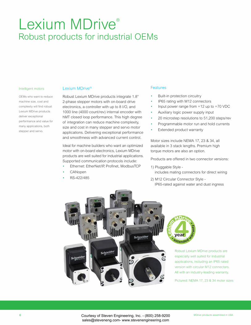
Lexium MDrive®
Robust Lexium MDrive products integrate 1.8°
2-phase stepper motors with on-board drive
electronics, a controller with up to 8 I/O, and
1000 line (4000 count/rev) internal encoder with
hMT closed loop performance. This high degree
of integration can reduce machine complexity,
size and cost in many stepper and servo motor
applications. Delivering exceptional performance
and smoothness with advanced current control.
Ideal for machine builders who want an optimized
motor with on-board electronics, Lexium MDrive
products are well suited for industrial applications.
Supported communication protocols include:
• Ethernet: EtherNet/IP, Profi net, ModbusTCP
• CANopen
• RS-422/485
Robust Lexium MDrive products are
especially well suited for industrial
applications, including an IP65 rated
version with circular M12 connectors.
All with an industry-leading warranty,
Pictured: NEMA 17, 23 & 34 motor sizes
Lexium MDrive®
Robust products for industrial OEMs
Intelligent motors
OEMs who want to reduce
machine size, cost and
complexity will fi nd robust
Lexium MDrive products
deliver exceptional
performance and value for
many applications, both
stepper and servo.
c o n d i t i o n a l
Courtesy of Steven Engineering, Inc. - (800) 258-9200 [email protected] www.stevenengineering.com
7www.motion.schneider-electric.com
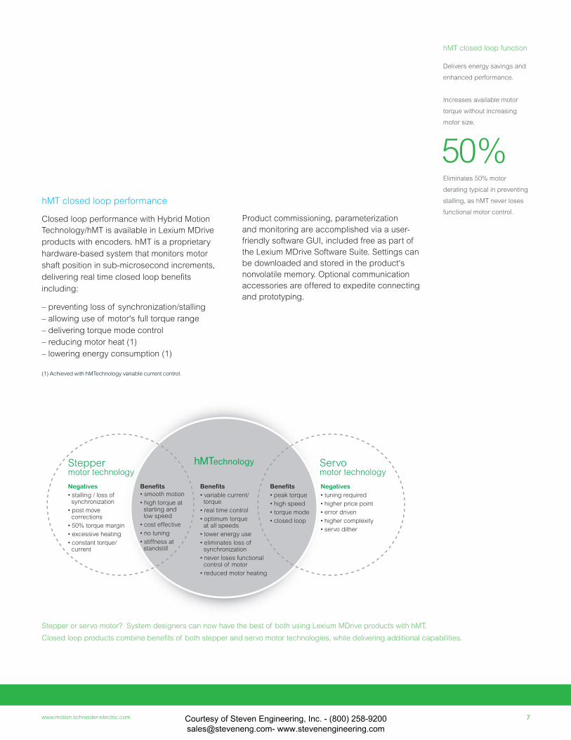
hMT closed loop function
Delivers energy savings and
enhanced performance.
Increases available motor
torque without increasing
motor size.
Eliminates 50% motor
derating typical in preventing
stalling, as hMT never loses
functional motor control.
Negatives• stalling / loss of synchronization
• post move corrections
• 50% torque margin
• excessive heating
• constant torque/ current
Benefits• smooth motion
• high torque at starting and low speed
• cost effective
• no tuning
• stiffness at standstill
Negatives• tuning required
• higher price point
• error driven
• higher complexity
• servo dither
Benefits• peak torque
• high speed
• torque mode
• closed loop
Benefits• variable current/ torque
• real time control
• optimum torque at all speeds
• lower energy use
• eliminates loss of synchronization
• never loses functional control of motor
• reduced motor heating
hMTechnologySteppermotor technology
Servomotor technology
hMT closed loop performance
Closed loop performance with Hybrid Motion
Technology/hMT is available in Lexium MDrive
products with encoders. hMT is a proprietary
hardware-based system that monitors motor
shaft position in sub-microsecond increments,
delivering real time closed loop benefi ts
including:
– preventing loss of synchronization/stalling
– allowing use of motor's full torque range
– delivering torque mode control
– reducing motor heat (1)
– lowering energy consumption (1)
(1) Achieved with hMTechnology variable current control.
50%
Product commissioning, parameterization
and monitoring are accomplished via a user-
friendly software GUI, included free as part of
the Lexium MDrive Software Suite. Settings can
be downloaded and stored in the product‘s
nonvolatile memory. Optional communication
accessories are offered to expedite connecting
and prototyping.
Stepper or servo motor? System designers can now have the best of both using Lexium MDrive products with hMT.
Closed loop products combine benefi ts of both stepper and servo motor technologies, while delivering additional capabilities.
Courtesy of Steven Engineering, Inc. - (800) 258-9200 [email protected] www.stevenengineering.com
8 MDrive products assembled in USA
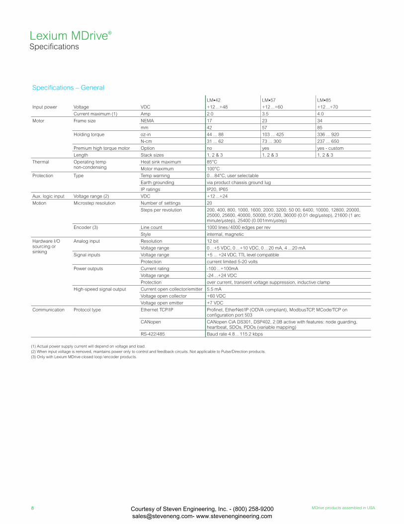
Specifi cations – General
LM•42 LM•57 LM•85
Input power Voltage VDC +12 ...+48 +12 ...+60 +12 ...+70
Current maximum (1) Amp 2.0 3.5 4.0
Motor Frame size NEMA 17 23 34
mm 42 57 85
Holding torque oz-in 44 ... 88 103 ... 425 336 ... 920
N-cm 31 ... 62 73 ... 300 237 ... 650
Premium high torque motor Option no yes yes - custom
Length Stack sizes 1, 2 & 3 1, 2 & 3 1, 2 & 3
Thermal Operating temp non-condensing
Heat sink maximum 85°C
Motor maximum 100°C
Protection Type Temp warning 0 ... 84°C, user selectable
Earth grounding via product chassis ground lug
IP ratings IP20, IP65
Aux. logic input Voltage range (2) VDC +12 ...+24
Motion Microstep resolution Number of settings 20
Steps per revolution 200, 400, 800, 1000, 1600, 2000, 3200, 50 00, 6400, 10000, 12800, 20000, 25000, 25600, 40000, 50000, 51200, 36000 (0.01 deg/µstep), 21600 (1 arc minute/µstep), 25400 (0.001mm/µstep)
Encoder (3) Line count 1000 lines / 4000 edges per rev
Style internal, magnetic
Hardware I/O sourcing or sinking
Analog input Resolution 12 bit
Voltage range 0 ...+5 VDC, 0 ...+10 VDC, 0 ... 20 mA, 4 ... 20 mA
Signal inputs Voltage range +5 ... +24 VDC, TTL level compatible
Protection current limited 5-20 volts
Power outputs Current rating -100 ...+100mA
Voltage range -24 ...+24 VDC
Protection over current, transient voltage suppression, inductive clamp
High-speed signal output Current open collector/emitter 5.5 mA
Voltage open collector +60 VDC
Voltage open emitter +7 VDC
Communication Protocol type Ethernet TCP/IP Profi net, EtherNet/IP (ODVA compliant), ModbusTCP, MCode/TCP on confi guration port 503
CANopen CANopen CiA DS301, DSP402, 2.0B active with features: node guarding, heartbeat, SDOs, PDOs (variable mapping)
RS-422/485 Baud rate 4.8 ... 115.2 kbps
(1) Actual power supply current will depend on voltage and load.
(2) When input voltage is removed, maintains power only to control and feedback circuits. Not applicable to Pulse/Direction products.
(3) Only with Lexium MDrive closed loop / encoder products.
Lexium MDrive® Specifi cations
Courtesy of Steven Engineering, Inc. - (800) 258-9200 [email protected] www.stevenengineering.com
9www.motion.schneider-electric.com
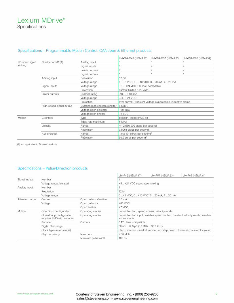
Specifi cations – Programmable Motion Control, CANopen & Ethernet products
LM•M/A/E42 (NEMA 17) LM•M/A/E57 (NEMA 23) LM•M/A/E85 (NEMA34)
I/O sourcing or sinking
Number of I/O (1) Analog input 1 1 1
Signal inputs 3 4 4
Power outputs 0 2 2
Signal outputs 1 1 1
Analog input Resolution 12 bit
Voltage range 0 ...+5 VDC, 0 ...+10 VDC, 0 ... 20 mA, 4 ... 20 mA
Signal inputs Voltage range +5 ... +24 VDC, TTL level compatible
Protection current limited 5-20 volts
Power outputs Current rating -100 ...+100mA
Voltage range -24 ...+24 VDC
Protection over current, transient voltage suppression, inductive clamp
High-speed signal output Current open collector/emitter 5.5 mA
Voltage open collector +60 VDC
Voltage open emitter +7 VDC
Motion Counters Type position, en cod er / 32 bit
Edge rate maximum 5 MHz
Velocity Range +/- 2,560,000 steps per second
Resolution 0.5961 steps per second
Accel / Decel Range 1.5 x 10⁹ steps per second2
Resolution 90.9 steps per second2
(1) Not applicable to Ethernet products.
Specifi cations – Pulse/Direction products
LM•P42 (NEMA 17) LM•P57 (NEMA 23) LM•P85 (NEMA34)
Signal inputs Number 2
Voltage range, isolated +5 ...+24 VDC sourcing or sinking
Analog input Number 1
Resolution 12 bit
Voltage range 0 ...+5 VDC, 0 ...+10 VDC, 0 ... 20 mA, 4 ... 20 mA
Attention output Current Open collector/emitter 5.5 mA
Voltage Open collector +60 VDC
Open emitter +7 VDC
Motion Open loop confi guration Operating modes pulse/direction, speed control, velocity mode
Closed loop confi guration, requires LMD with encoder
Operating modes pulse/direction input, variable speed control, constant velocity mode, variable torque mode
Encoder Outputs 6 TTL level compatible
Digital fi lter range 50 nS ... 12.9 µS (10 MHz ... 38.8 kHz)
Clock types (step mode) Step / direction, quadrature, step up / step down, clockwise / counterclockwise
Step frequency Maximum 2.56 MHz
Minimum pulse width 100 ns
Lexium MDrive® Specifi cations
Courtesy of Steven Engineering, Inc. - (800) 258-9200 [email protected] www.stevenengineering.com
10 MDrive products assembled in USA
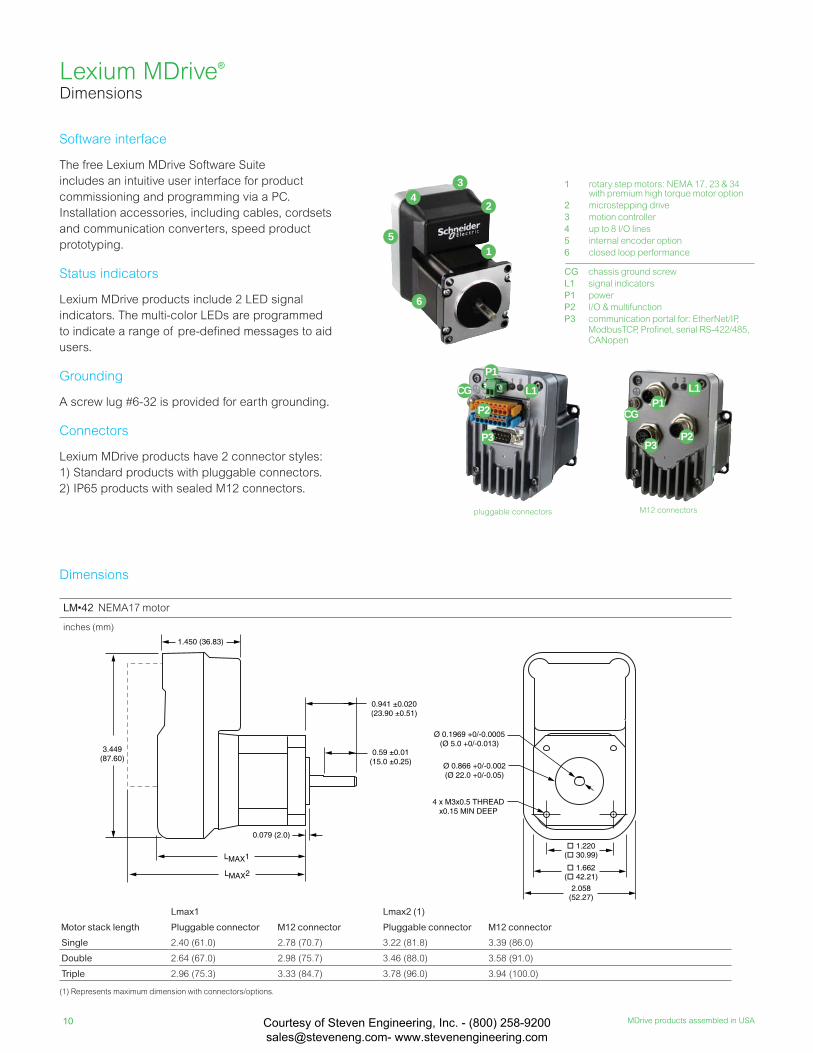
1 rotary step motors: NEMA 17, 23 & 34with premium high torque motor option
2 microstepping drive
3 motion controller
4 up to 8 I/O lines
5 internal encoder option
6 closed loop performance
LM•42 NEMA17 motor
inches (mm)
Lmax1 Lmax2 (1)
Motor stack length Pluggable connector M12 connector Pluggable connector M12 connector
Single 2.40 (61.0) 2.78 (70.7) 3.22 (81.8) 3.39 (86.0)
Double 2.64 (67.0) 2.98 (75.7) 3.46 (88.0) 3.58 (91.0)
Triple 2.96 (75.3) 3.33 (84.7) 3.78 (96.0) 3.94 (100.0)
(1) Represents maximum dimension with connectors/options.
Lexium MDrive® Dimensions
4 x M3x0.5 THREADx0.15 MIN DEEP
0.079 (2.0)
0.59 ±0.01(15.0 ±0.25)
0.941 ±0.020(23.90 ±0.51)
1.450 (36.83)
LMAX1
LMAX2
3.449(87.60)
Ø 0.866 +0/-0.002(Ø 22.0 +0/-0.05)
Ø 0.1969 +0/-0.0005(Ø 5.0 +0/-0.013)
1.220( 30.99)
1.662( 42.21)
2.058(52.27)
M12 connectors
P2
P1
P3
CG
L1
pluggable connectors
P1
CG L1
P2
P3
1
2
34
5
6
Software interface
The free Lexium MDrive Software Suite
includes an intuitive user interface for product
commissioning and programming via a PC.
Installation accessories, including cables, cordsets
and communication converters, speed product
prototyping.
Status indicators
Lexium MDrive products include 2 LED signal
indicators. The multi-color LEDs are programmed
to indicate a range of pre-defi ned messages to aid
users.
Grounding
A screw lug #6-32 is provided for earth grounding.
Connectors
Lexium MDrive products have 2 connector styles:
1) Standard products with pluggable connectors.
2) IP65 products with sealed M12 connectors.
Dimensions
CG chassis ground screw
L1 signal indicators
P1 power
P2 I/O & multifunction
P3 communication portal for: EtherNet/IP, ModbusTCP, Profi net, serial RS-422/485, CANopen
Courtesy of Steven Engineering, Inc. - (800) 258-9200 [email protected] www.stevenengineering.com

11www.motion.schneider-electric.com
LM•85 NEMA34 motor
inches (mm)
Lmax1 Lmax2 (1)
Motor stack length Pluggable connector M12 connector Pluggable connector M12 connector
Single 3.76 (95.5) 4.04 (102.7) 4.41 (112.0) 4.65 (118.2)
Double 4.33 (110.0) 4.57 (116.2) 4.98 (126.5) 5.18 (131.7)
Triple 5.90 (149.9) 6.14 (156.1) 6.55 (166.4) 6.75 (171.5)
(1) Represents maximum dimension with connectors/options.
2.26 (57.4)
LMAX1
LMAX2
0.18 (4.57)
0.23 ±0.004(5.8 ±0.1)
at shaft flat0.063 ±0.008(1.6 ±0.20)
0.81 ±0.02(20.56 ±0.51)
0.59 ±0.006(15.0 ±0.20)
1.856 ±0.008( 47.15 ±0.20)
2.22( 56.40)
Ø 1.50 ±0.002(Ø 38.10 ±0.05)
4 x Ø 0.197 +0.012/-0(4 x Ø 5.0 +0.3/-0)
Ø 0.250 +0/-0.0005(Ø 6.350 +0/-0.013)
3.81(96.8)
2.59(65.8)
3.390( 86.11)
2.739( 69.57)
4 x Ø 0.256 ±0.008(4 x Ø 6.50 ±0.20)
Ø 2.874 ±0.001(Ø 73.0 ±0.025)
Ø 0.5512 +0/-0.0004(Ø 14.0 )+0/-0.010
0.079 (2.0)
LMAX1
LMAX2
0.984 ±0.01(24.99 ±0.25)
1.461 ±0.039(37.1 ±1.0)
0.394(10.01)
1.159(29.45)
1.973(50.12)
4.65(118.12)
0.512 ±0.004(13.0 ±0.10)at shaft flat
2.566(65.19)
3.59(91.24)
Lexium MDrive® Dimensions
LM•57 NEMA23 motor
inches (mm)
Lmax1 Lmax2 (1) High torque motor
Motor stack length Pluggable connector M12 connector Pluggable connector M12 connector additional length
Single 3.17 (80.5) 3.32 (84.3) 3.91 (99.3) 4.01 (101.8) 0.15 (3.8)
Double 3.52 (89.4) 3.73 (94.8) 4.26 (108.2) 4.36 (110.7) 0.21 (5.4)
Triple 4.38 (111.3) 4.60 (116.8) 5.13 (130.3) 5.23 (133.0) 0.22 (5.5)
(1) Represents maximum dimension with connectors/options.
Courtesy of Steven Engineering, Inc. - (800) 258-9200 [email protected] www.stevenengineering.com
12 MDrive products assembled in USA
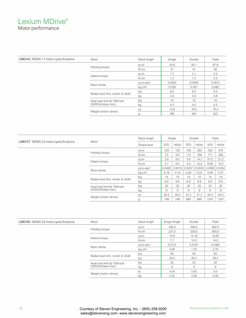
LMD•42 NEMA 17 motor specifi cations Motor Stack length Single Double Triple
Holding torqueoz-in 43.9 58.1 87.8
N-cm 31 41 62
Detent torqueoz-in 1.7 2.1 3.5
N-cm 1.2 1.5 2.5
Rotor inertiaoz-in-sec2 0.0005 0.0008 0.0012
kg-cm2 0.038 0.057 0.082
Radial load limit, center of shaftlbs 8.5 8.5 8.5
kg 3.8 3.8 3.8
Axial load limit @ 1500 rpm (5000 full steps / sec)
lbs 10 10 10
kg 4.5 4.5 4.5
Weight (motor+driver)oz 13.6 16.0 18.4
g 385 454 522
LMD•57 NEMA 23 motor specifi cations MotorStack length Single Double Triple
Torque level STD HIGH STD HIGH STD HIGH
Holding torqueoz-in 103 152 159 264 242 416
N-cm 73 107 112 186 171 294
Detent torqueoz-in 3.9 8.5 5.6 14.2 9.72 21.2
N-cm 2.7 6.0 3.9 10.0 6.86 15.0
Rotor inertiaoz-in-sec2 0.0025 0.0019 0.0037 0.0030 0.0065 0.0052
kg-cm2 0.18 0.14 0.26 0.22 0.46 0.37
Radial load limit, center of shaftlbs 15 15 15 15 15 15
kg 6.8 6.8 6.8 6.8 6.8 6.8
Axial load limit @ 1500 rpm (5000 full steps / sec)
lbs 20 20 20 20 20 20
kg 9 9 9 9 9 9
Weight (motor+driver)oz 26.4 26.4 31.2 31.2 44.0 44.0
g 748 748 885 885 1247 1247
LMD•85 NEMA 34 motor specifi cations Motor Stack length Single Single Double Triple
Holding torqueoz-in 336.0 480.0 920.0
N-cm 237.0 339.0 650.0
Detent torqueoz-in 10.9 14.16 19.83
N-cm 7.7 10.0 14.0
Rotor inertiaoz-in-sec2 0.0127 0.0191 0.0382
kg-cm2 0.90 1.35 2.70
Radial load limit, center of shaftlbs 65 65 65
kg 29.4 29.4 29.4
Axial load limit @ 1500 rpm (5000 full steps / sec)
lbs 20 20 20
kg 9 9 9
Weight (motor+driver)lb 4.45 5.65 9.0
kg 2.02 2.56 4.08
Lexium MDrive® Motor performance
Courtesy of Steven Engineering, Inc. - (800) 258-9200 [email protected] www.stevenengineering.com
13www.motion.schneider-electric.com
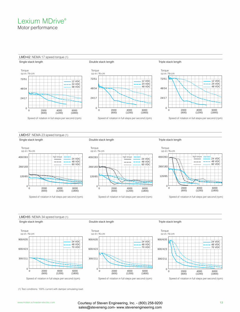
LMD•42 NEMA 17 speed torque (1)
Single stack length Double stack length Triple stack length
LMD•57 NEMA 23 speed torque (1)
Single stack length Double stack length Triple stack length
LMD•85 NEMA 34 speed torque (1)
Single stack length Double stack length Triple stack length
0 2000(600)
4000(1200)
6000(1800)
24 VDC12 VDC
48 VDC
0
48/34
72/51
24/17
0
260/183
400/283
120/85
48 VDC24 VDC
0 2000(600)
4000(1200)
6000(1800)
60 VDC
0
260/183
400/283
120/85
48 VDC24 VDC
0 2000(600)
4000(1200)
6000(1800)
60 VDC
0
260/183
400/283
120/85
48 VDC24 VDC
0 2000(600)
4000(1200)
6000(1800)
60 VDC
0
600/423
900/635
300/211
48 VDC24 VDC
0 2000(600)
4000(1200)
6000(1800)
70 VDC
0
600/423
900/635
300/211
48 VDC24 VDC
0 2000(600)
4000(1200)
6000(1800)
70 VDC
0
600/423
900/635
300/211
48 VDC24 VDC
0 2000(600)
4000(1200)
6000(1800)
70 VDC
0 2000(600)
4000(1200)
6000(1800)
24 VDC12 VDC
48 VDC
0
48/34
72/51
24/17
0 2000(600)
4000(1200)
6000(1800)
24 VDC12 VDC
48 VDC
0
48/34
72/51
24/17
(1) Test conditions: 100% current with damper simulating load.
Torqueoz-in / N-cm
Speed of rotation in full steps per second (rpm)
Torqueoz-in / N-cm
Speed of rotation in full steps per second (rpm)
Torqueoz-in / N-cm
Speed of rotation in full steps per second (rpm)
Torqueoz-in / N-cm
Speed of rotation in full steps per second (rpm)
Torqueoz-in / N-cm
Speed of rotation in full steps per second (rpm)
Torqueoz-in / N-cm
Speed of rotation in full steps per second (rpm)
Torqueoz-in / N-cm
Speed of rotation in full steps per second (rpm)
Torqueoz-in / N-cm
Speed of rotation in full steps per second (rpm)
Torqueoz-in / N-cm
Speed of rotation in full steps per second (rpm)
Lexium MDrive® Motor performance
Courtesy of Steven Engineering, Inc. - (800) 258-9200 [email protected] www.stevenengineering.com
14 MDrive products assembled in USA
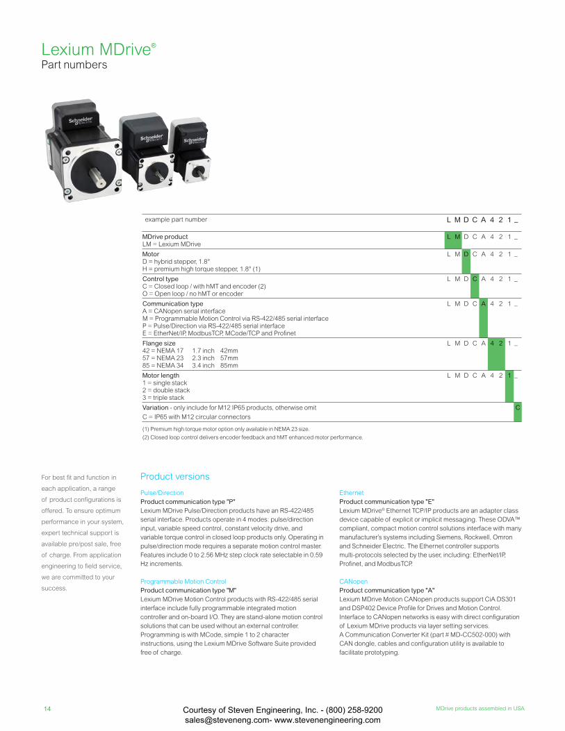
example part number L M D C A 4 2 1 –
MDrive productLM = Lexium MDrive
L M D C A 4 2 1 –
MotorD = hybrid stepper, 1.8°H = premium high torque stepper, 1.8° (1)
L M D C A 4 2 1 –
Control typeC = Closed loop / with hMT and encoder (2)O = Open loop / no hMT or encoder
L M D C A 4 2 1 –
Communication typeA = CANopen serial interface M = Programmable Motion Control via RS-422/485 serial interfaceP = Pulse/Direction via RS-422/485 serial interfaceE = EtherNet/IP, ModbusTCP, MCode/TCP and Profi net
L M D C A 4 2 1 –
Flange size42 = NEMA 17 1.7 inch 42mm 57 = NEMA 23 2.3 inch 57mm85 = NEMA 34 3.4 inch 85mm
L M D C A 4 2 1 –
Motor length1 = single stack2 = double stack3 = triple stack
L M D C A 4 2 1 –
Variation - only include for M12 IP65 products, otherwise omit
C = IP65 with M12 circular connectors
C
(1) Premium high torque motor option only available in NEMA 23 size.
(2) Closed loop control delivers encoder feedback and hMT enhanced motor performance.
For best fi t and function in
each application, a range
of product confi gurations is
offered. To ensure optimum
performance in your system,
expert technical support is
available pre/post sale, free
of charge. From application
engineering to fi eld service,
we are committed to your
success.
Lexium MDrive® Part numbers
Pulse/Direction
Product communication type "P"Lexium MDrive Pulse/Direction products have an RS-422/485
serial interface. Products operate in 4 modes: pulse/direction
input, variable speed control, constant velocity drive, and
variable torque control in closed loop products only. Operating in
pulse/direction mode requires a separate motion control master.
Features include 0 to 2.56 MHz step clock rate selectable in 0.59
Hz increments.
Programmable Motion Control
Product communication type "M"Lexium MDrive Motion Control products with RS-422/485 serial
interface include fully programmable integrated motion
controller and on-board I/O. They are stand-alone motion control
solutions that can be used without an external controller.
Programming is with MCode, simple 1 to 2 character
instructions, using the Lexium MDrive Software Suite provided
free of charge.
Ethernet
Product communication type "E"Lexium MDrive® Ethernet TCP/IP products are an adapter class
device capable of explicit or implicit messaging. These ODVA™
compliant, compact motion control solutions interface with many
manufacturer’s systems including Siemens, Rockwell, Omron
and Schneider Electric. The Ethernet controller supports
multi-protocols selected by the user, including: EtherNet/IP,
Profinet, and ModbusTCP.
CANopen
Product communication type "A"Lexium MDrive Motion CANopen products support CiA DS301
and DSP402 Device Profile for Drives and Motion Control.
Interface to CANopen networks is easy with direct configuration
of Lexium MDrive products via layer setting services.
A Communication Converter Kit (part # MD-CC502-000) with
CAN dongle, cables and configuration utility is available to
facilitate prototyping.
Product versions
Courtesy of Steven Engineering, Inc. - (800) 258-9200 [email protected] www.stevenengineering.com
15www.motion.schneider-electric.com
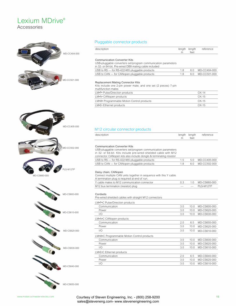
MD-CC404-000
Lexium MDrive® Accessories
description length
m
length
feet
reference
Communication Converter KitsUSB-pluggable converters set/program communication parameters
in 32- or 64-bit. Pre-wired DB9 mating cable included
USB to RS — for RS-422/485 pluggable products 1.8 6.0 MD-CC404-000
USB to CAN — for CANopen pluggable products 1.8 6.0 MD-CC501-000
Replacement Mating Connector KitsKits include one 2-pin power mate, and one set (2 pieces) 7-pin
multifunction mates
LM•P• Pulse/Direction products CK-14
LM•A• CANopen products CK-15
LM•M• Programmable Motion Control products CK-15
LM•E• Ethernet products CK-15
Pluggable connector products
M12 circular connector products
MD-CC501-000
description length
m
length
feet
reference
Communication Converter KitsUSB-pluggable converters set/program communication parameters
in 32- or 64-bit. Kits include pre-wired shielded cable with M12
connector. CANopen kits also include dongle & terminating resistor
USB to RS — for RS-422/485 pluggable products 1.5 5.0 MD-CC405-000
USB to CAN — for CANopen pluggable products 1.8 6.0 MD-CC502-000
Daisy chain, CANopenConnect multiple CAN units together in sequence with this Y cable.
A termination plug is required at end of run.
Y cable mates to M12 communication connector 0.3 1.0 MD-CS660-000
M12 bus termination (resistor) plug — — PLG-M12TP
CordsetsPre-wired shielded cables with straight M12 connectors
LM•P•C Pulse/Direction products
Communication 3.0 10.0 MD-CS600-000
Power 3.0 10.0 MD-CS620-000
I/O 3.0 10.0 MD-CS630-000
LM•A•C CANopen products
Communication 2.0 6.5 MD-CS650-000
Power 3.0 10.0 MD-CS620-000
I/O 3.0 10.0 MD-CS610-000
LM•M•C Programmable Motion Control products
Communication 3.0 10.0 MD-CS600-000
Power 3.0 10.0 MD-CS620-000
I/O 3.0 10.0 MD-CS610-000
LM•E•C Ethernet products
Communication 2.0 6.5 MD-CS640-000
Power 3.0 10.0 MD-CS620-000
I/O 3.0 10.0 MD-CS610-000
MD-CC502-000
PLG-M12TP
MD-CS660-000
MD-CC405-000
MD-CS650-000
MD-CS640-000
MD-CS620-000
MD-CS630-000
MD-CS600-000
MD-CS610-000
Courtesy of Steven Engineering, Inc. - (800) 258-9200 [email protected] www.stevenengineering.com
16 MDrive products assembled in USA
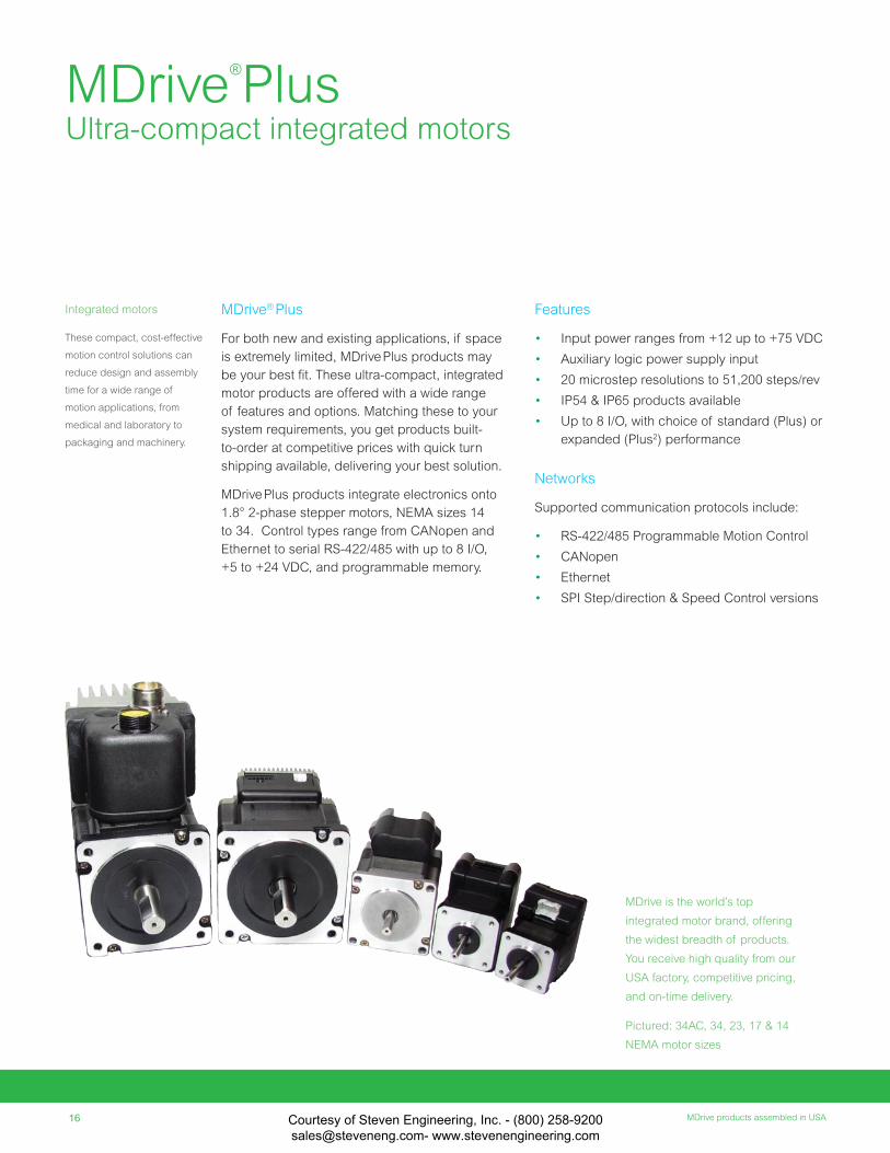
MDrive is the world’s top
integrated motor brand, offering
the widest breadth of products.
You receive high quality from our
USA factory, competitive pricing,
and on-time delivery.
Pictured: 34AC, 34, 23, 17 & 14
NEMA motor sizes
Features
• Input power ranges from +12 up to +75 VDC
• Auxiliary logic power supply input
• 20 microstep resolutions to 51,200 steps/rev
• IP54 & IP65 products available
• Up to 8 I/O, with choice of standard (Plus) or
expanded (Plus2) performance
Networks
Supported communication protocols include:
• RS-422/485 Programmable Motion Control
• CANopen
• Ethernet
• SPI Step/direction & Speed Control versions
MDrive® Plus
For both new and existing applications, if space
is extremely limited, MDrive Plus products may
be your best fi t. These ultra-compact, integrated
motor products are offered with a wide range
of features and options. Matching these to your
system requirements, you get products built-
to-order at competitive prices with quick turn
shipping available, delivering your best solution.
MDrive Plus products integrate electronics onto
1.8° 2-phase stepper motors, NEMA sizes 14
to 34. Control types range from CANopen and
Ethernet to serial RS-422/485 with up to 8 I/O,
+5 to +24 VDC, and programmable memory.
MDrive®
Plus Ultra-compact integrated motors
Integrated motors
These compact, cost-effective
motion control solutions can
reduce design and assembly
time for a wide range of
motion applications, from
medical and laboratory to
packaging and machinery.
Courtesy of Steven Engineering, Inc. - (800) 258-9200 [email protected] www.stevenengineering.com
17www.motion.schneider-electric.com
Integrated motors can reduce
space requirements up to
that of traditional motion solu-
tions. Fewer individual system
components also eliminate
multiple potential failure points.
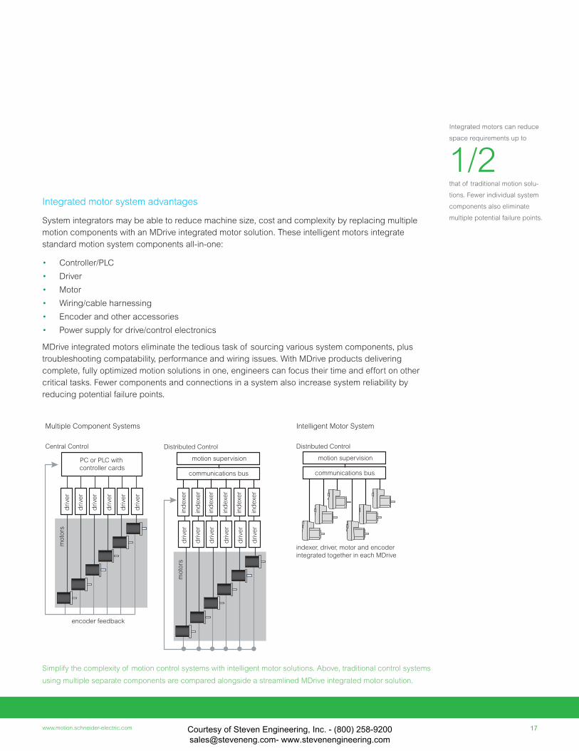
1/2Integrated motor system advantages
System integrators may be able to reduce machine size, cost and complexity by replacing multiple
motion components with an MDrive integrated motor solution. These intelligent motors integrate
standard motion system components all-in-one:
• Controller/PLC
• Driver
• Motor
• Wiring/cable harnessing
• Encoder and other accessories
• Power supply for drive/control electronics
MDrive integrated motors eliminate the tedious task of sourcing various system components, plus
troubleshooting compatability, performance and wiring issues. With MDrive products delivering
complete, fully optimized motion solutions in one, engineers can focus their time and effort on other
critical tasks. Fewer components and connections in a system also increase system reliability by
reducing potential failure points.
Simplify the complexity of motion control systems with intelligent motor solutions. Above, traditional control systems
using multiple separate components are compared alongside a streamlined MDrive integrated motor solution.
moto
rs
encoder feedback
drive
r
drive
r
drive
r
drive
r
drive
r
drive
r
PC or PLC with
controller cards
Central Control
drive
r
drive
r
drive
r
drive
r
drive
r
drive
r
moto
rsin
dexer
ind
exer
ind
exer
ind
exer
ind
exer
ind
exer
motion supervision
communications bus
Distributed Control
motion supervision
communications bus
Multiple Component Systems
Distributed Control
Intelligent Motor System
indexer, driver, motor and encoder
integrated together in each MDrive
Courtesy of Steven Engineering, Inc. - (800) 258-9200 [email protected] www.stevenengineering.com
18 MDrive products assembled in USA
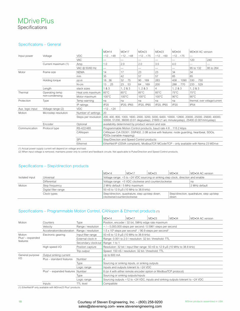
Specifi cations – General
MD•14 MD•17 MD•23 MD•23 MD•34 MD•34 AC version
Input power Voltage VDC +12 ...+48 +12 ...+48 +12 ...+75 +12 ...+60 +12 ...+75 —
VAC — — — — — 120 240
Current maximum (1) Amp 1.0 2.0 2.0 3.5 4.0 — —
VAC @ 50/60 Hz — — — — — 95 to 132 95 to 264
Motor Frame size NEMA 14 17 23 23 34 34
mm 35 42 57 57 85 85
Holding torque oz-in 18...36 32 ... 75 90 ...169 283 408 ... 1090 330 ... 750
N-cm 13 ... 25 23 ... 53 64 ... 169 200 288 ... 770 233 ... 529
Length stack sizes 1 & 3 1, 2 & 3 1, 2 & 3 4 1, 2 & 3 1, 2 & 3
Thermal Operating temp non-condensing
Heat sink maximum 85°C 85°C 85°C 85°C 75°C 75°C
Motor maximum 100°C 100°C 100°C 100°C 90°C 90°C
Protection Type Temp warning na na na na na thermal, over voltage/current
IP ratings IP20 IP20, IP65 IP20, IP65 IP20, IP65 IP20 IP54
Aux. logic input Voltage range (2) VDC +12 ...+24
Motion Microstep resolution Number of settings 20
Steps per revolution 200, 400, 800, 1000, 1600, 2000, 3200, 5000, 6400, 10000, 12800, 20000, 25000, 25600, 40000, 50000, 51200, 36000 (0.01 deg/µstep), 21600 (1 arc minute/µstep), 25400 (0.001mm/µstep)
Encoder Optional availability determined by product version and size
Communication Protocol type RS-422/485 Programmable Motion Control products, baud rate 4.8 ... 115.2 kbps
CANopen CANopen CiA DS301, DSP402, 2.0B active with features: node guarding, heartbeat, SDOs, PDOs (variable mapping)
SPI Step/Direction and Speed Control products
Ethernet EtherNet/IP (ODVA compliant), ModbusTCP, MCode/TCP – only available with Nema 23 MDrive
(1) Actual power supply current will depend on voltage and load.
(2) When input voltage is removed, maintains power only to control and feedback circuits. Not applicable to Pulse/Direction and Speed Control products.
MDrive Plus Specifi cations
Specifi cations – Step/direction products
MD•14 MD•17 MD•23 MD•34 MD•34 AC version
Isolated input Universal Voltage range: +5 to +24 VDC sourcing or sinking step clock, direction and enable
Differential Voltage range: +5 VDC clockwise and counterclockwise na
Motion Step frequency 2 MHz default / 5 MHz maximum 2 MHz default
Digital fi lter range 50 nS to 12.9 µS (10 MHz to 38.8 kHz)
Clock types Step/direction, quadrature, step up/step down, clockwise/counterclockwise
Step/direction, quadrature, step up/step down
Specifi cations – Programmable Motion Control, CANopen & Ethernet products (1)
MD•14 MD•17 MD•23 MD•34 MD•34 AC version
Motion Counters Type Position, encoder / 32 bit, 5MHz edge rate maximum
Velocity Range / resolution + / – 5,000,000 steps per second / 0.5961 steps per second
Acceleration/deceleration Range / resolution 1.5 x 10⁹ steps per second2 / 90.9 steps per second2
Motion Plus2 – expanded features
Electronic gearing Input fi lter range 50 nS to 12.9 µS (10 MHz to 38.8 kHz)
External clock in Range: 0.001 to 2.0 / resolution: 32 bit / threshold: TTL
Secondary clock out Range: 1 to 1
High speed I/O Position capture Resolution: 32 bit / input fi lter range: 50 nS to 12.9 µS (10 MHz to 38.8 kHz)
Trip output Speed: 150 nS / resolution: 32 bit / threshold: TTL
General purpose I/O
Output sinking current Up to 600 mA
Plus – standard features Number 4
Type Sourcing or sinking inputs, or sinking outputs
Logic range Inputs and outputs tolerant to +24 VDC
Plus2 – expanded features Number 8 (or 4 with either remote encoder option or ModbusTCP protocol)
Type Sourcing or sinking outputs/inputs
Logic range Sourcing outputs +12 to +24 VDC, inputs and sinking outputs tolerant to +24 VDC
Inputs TTL level Compatible
(1) EtherNet/IP only available with MDrive23 Plus2 products.
Courtesy of Steven Engineering, Inc. - (800) 258-9200 [email protected] www.stevenengineering.com
19www.motion.schneider-electric.com
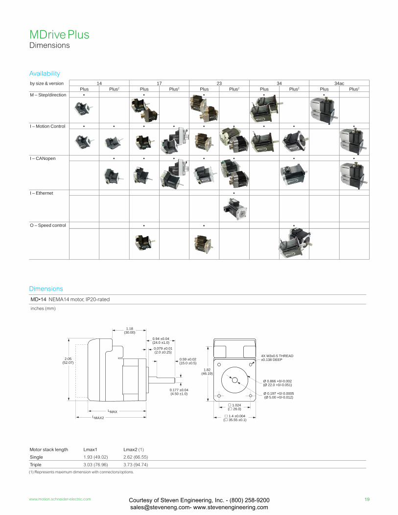
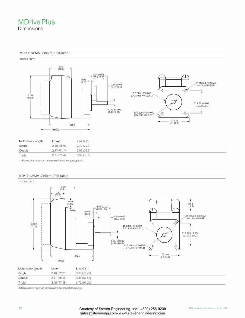
MDrive Plus Dimensions
MD•14 NEMA14 motor, IP20-rated
inches (mm)
Motor stack length Lmax1 Lmax2 (1)
Single 1.93 (49.02) 2.62 (66.55)
Triple 3.03 (76.96) 3.73 (94.74)
(1) Represents maximum dimension with connectors/options.
Ø 0.866 +0/-0.002(Ø 22.0 +0/-0.051)
Ø 0.197 +0/-0.0005(Ø 5.00 +0/-0.012)
1.4 ±0.004( 35.55 ±0.1)
4X M3x0.5 THREADx0.138 DEEP
1.82(46.19)
1.024( 26.0)
2.05(52.07)
1.18(30.00)
0.177 ±0.04(4.50 ±1.0)
0.94 ±0.04(24.0 ±1.0)
0.59 ±0.02(15.0 ±0.5)
0.079 ±0.01(2.0 ±0.25)
LMAXLMAX2
by size & version 14 17 23 34 34acPlus Plus2 Plus Plus2 Plus Plus2 Plus Plus2 Plus Plus2
M – Step/direction • • • • •
I – Motion Control • • • • • • • • •
I – CANopen • • • • • • •
I – Ethernet •
O – Speed control • • •
Dimensions
Availability
Courtesy of Steven Engineering, Inc. - (800) 258-9200 [email protected] www.stevenengineering.com
20 MDrive products assembled in USA
MDrive Plus Dimensions
MD•17 NEMA17 motor, IP65-rated
inches (mm)
Motor stack length Lmax1 Lmax2 (1)
Single 2.48 (62.71) 3.15 (79.72)
Double 2.71 (68.55) 3.38 (85.57)
Triple 3.05 (77.18) 3.72 (94.20)
(1) Represents maximum dimension with connectors/options.
MD•17 NEMA17 motor, IP20-rated
inches (mm)
Motor stack length Lmax1 Lmax2 (1)
Single 2.20 (55.9) 2.79 (70.9)
Double 2.43 (61.7) 3.02 (76.7)
Triple 2.77 (70.4) 3.37 (85.6)
(1) Represents maximum dimension with connectors/options.
2.30(58.3)
1.19(30.2)
LMAX2
LMAX
0.177 ±0.002(4.49 ±0.05)
0.08(2.0)
0.94 ±0.02(23.9 ±0.5)
0.59 ±0.02(15.0 ±0.5)
1.69( 42.9)
1.22 ±0.004( 31.0 ±0.1)
4X M3x0.5 THREADx0.15 MIN DEEP
Ø 0.866 +0/-0.002(Ø 21.996 +0/-0.051)
Ø 0.1968 +0/-0.002(Ø 4.999 +0/-0.051)
0.49(12.5)
2.792(70.9)
LMAX2
LMAX
0.177 ±0.002(4.49 ±0.05)
0.08(2.0)
0.94 ±0.02(23.9 ±0.5)
0.59 ±0.02(15.0 ±0.5)
1.38(35.1)
0.80(20.3)
Ø 0.866 +0/-0.002(Ø 21.996 +0/-0.051)
Ø 0.1968 +0/-0.0020(Ø 4.999 +0/-0.051)
1.69( 42.9)
1.220 ±0.004( 31.0 ±0.1)
4X M3x0.5 THREADx0.15 MIN DEEP
0.64(16.3)
Courtesy of Steven Engineering, Inc. - (800) 258-9200 [email protected] www.stevenengineering.com
21www.motion.schneider-electric.com
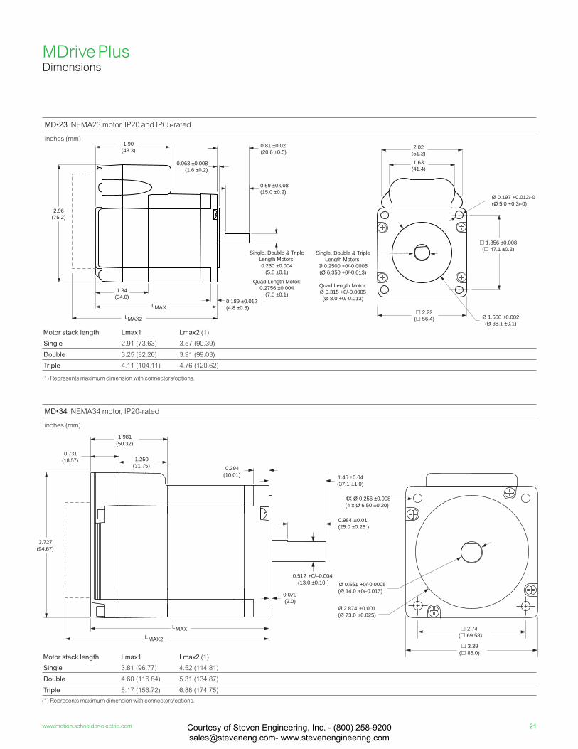
MD•34 NEMA34 motor, IP20-rated
inches (mm)
Motor stack length Lmax1 Lmax2 (1)
Single 3.81 (96.77) 4.52 (114.81)
Double 4.60 (116.84) 5.31 (134.87)
Triple 6.17 (156.72) 6.88 (174.75)
(1) Represents maximum dimension with connectors/options.
LMAX
0.394(10.01) 1.46 ±0.04
(37.1 ±1.0)
0.984 ±0.01(25.0 ±0.25 )
0.512 +0/–0.004(13.0 ±0.10 )
0.079(2.0)
0.731(18.57) 1.250
(31.75)
1.981(50.32)
3.727(94.67)
LMAX2
4X Ø 0.256 ±0.008 (4 x Ø 6.50 ±0.20)
2.74( 69.58)
3.39( 86.0)
Ø 2.874 ±0.001(Ø 73.0 ±0.025 )
Ø 0.551 +0/-0.0005(Ø 14.0 +0/-0.013)
MD•23 NEMA23 motor, IP20 and IP65-rated
inches (mm)
Motor stack length Lmax1 Lmax2 (1)
Single 2.91 (73.63) 3.57 (90.39)
Double 3.25 (82.26) 3.91 (99.03)
Triple 4.11 (104.11) 4.76 (120.62)
(1) Represents maximum dimension with connectors/options.
Single, Double & TripleLength Motors:
Ø 0.2500 +0/-0.0005(Ø 6.350 +0/-0.013)
Quad Length Motor:Ø 0.315 +0/-0.0005(Ø 8.0 +0/-0.013)
1.90(48.3)
2.96(75.2)
0.063 ±0.008(1.6 ±0.2)
0.81 ±0.02(20.6 ±0.5)
0.59 ±0.008(15.0 ±0.2)
0.189 ±0.012(4.8 ±0.3)
1.34(34.0)
LMAX
LMAX2
Single, Double & TripleLength Motors:0.230 ±0.004
(5.8 ±0.1)
Quad Length Motor:0.2756 ±0.004
(7.0 ±0.1)
2.02(51.2)
Ø 1.500 ±0.002(Ø 38.1 ±0.1)
2.22( 56.4)
Ø 0.197 +0.012/-0(Ø 5.0 +0.3/-0)
1.63(41.4)
1.856 ±0.008 ( 47.1 ±0.2)
MDrive Plus Dimensions
Courtesy of Steven Engineering, Inc. - (800) 258-9200 [email protected] www.stevenengineering.com

22 MDrive products assembled in USA
2.04(51.8)
1.22(31.0)
P2
P2
P2
P1
0.36(9.1)
0.44(11.2)
P1
7-pin non-locking spring clamp terminal strip
MDrive Plus Dimensions
MD•34AC NEMA34 motor, IP54-rated
inches (mm)
Motor stack length Lmax1 Lmax2 (1)
Single 6.1 (155.0) 7.1 (180.4)
Double 6.9 (174.3) 7.9 (199.7)
Triple 8.4 (214.3) 9.4 (239.7)
(1) Control knob option.
LMAX
Ø 0.55 +0/-0.0005(Ø 14.0 +0/-0.013)
0.08 ±0.004(2.0 ±0.1)0.40
(10.1)
0.87 ±0.010(22 ±0.25)
1.46 ±0.039(37.0 ±1.0)
LMAX22.70
(68.4)
4 x Ø 0.256 ±0.008(4 x Ø 6.50 ±0.20)
0.63 +0/-0.017(16.0 +0/-0.432) 0.20 +0/-0.002
(5.0 +0/-0.05)
5.76(146.2)
6.47(164.2)
3.46(87.8)
Ø 2.87 ±0.002(Ø 73.0 ±0.05)
0.71(18.0)
3.39( 86.0)
2.74+0/-0.010( 69.58)(+0/-0.25)
12.00 (304.8)
P1
Ø 0.97(Ø 24.6)
Ø 0.87(Ø 22.1)
Ø 0.87(Ø 22.1)
Ø 0.53(Ø 13.5)
Flying leads
IP20 connector examples
Pluggable
12-pin locking
Wire crimp
CANopen products
IDC
DB9
Ethernet products
RJ45
10-pin non-locking
IP54/65 connector examples
19-pin M23
5-pin M12
3-pin Euro AC
Lmax2 option examples
External control knob
External encoders
1.20(30.4)
1.42(36.1)
.
Differential Single-end
20 in-lb / 225 N-cmmax torque
Courtesy of Steven Engineering, Inc. - (800) 258-9200 [email protected] www.stevenengineering.com
23www.motion.schneider-electric.com
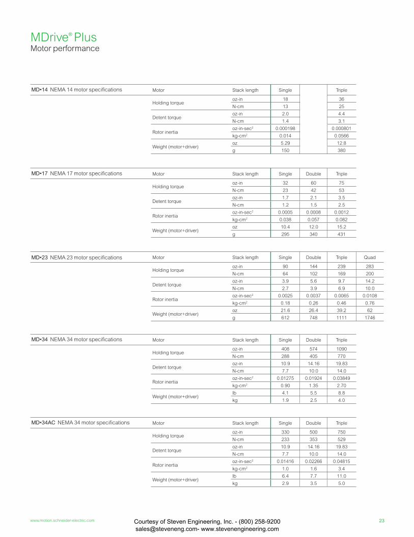
MD•14 NEMA 14 motor specifi cations Motor Stack length Single Triple
Holding torqueoz-in 18 36
N-cm 13 25
Detent torqueoz-in 2.0 4.4
N-cm 1.4 3.1
Rotor inertiaoz-in-sec2 0.000198 0.000801
kg-cm2 0.014 0.0566
Weight (motor+driver)oz 5.29 12.8
g 150 380
MD•17 NEMA 17 motor specifi cations Motor Stack length Single Double Triple
Holding torqueoz-in 32 60 75
N-cm 23 42 53
Detent torqueoz-in 1.7 2.1 3.5
N-cm 1.2 1.5 2.5
Rotor inertiaoz-in-sec2 0.0005 0.0008 0.0012
kg-cm2 0.038 0.057 0.082
Weight (motor+driver)oz 10.4 12.0 15.2
g 295 340 431
MD•23 NEMA 23 motor specifi cations Motor Stack length Single Double Triple Quad
Holding torqueoz-in 90 144 239 283
N-cm 64 102 169 200
Detent torqueoz-in 3.9 5.6 9.7 14.2
N-cm 2.7 3.9 6.9 10.0
Rotor inertiaoz-in-sec2 0.0025 0.0037 0.0065 0.0108
kg-cm2 0.18 0.26 0.46 0.76
Weight (motor+driver)oz 21.6 26.4 39.2 62
g 612 748 1111 1746
MD•34 NEMA 34 motor specifi cations Motor Stack length Single Double Triple
Holding torqueoz-in 408 574 1090
N-cm 288 405 770
Detent torqueoz-in 10.9 14.16 19.83
N-cm 7.7 10.0 14.0
Rotor inertiaoz-in-sec2 0.01275 0.01924 0.03849
kg-cm2 0.90 1.35 2.70
Weight (motor+driver)lb 4.1 5.5 8.8
kg 1.9 2.5 4.0
MD•34AC NEMA 34 motor specifi cations Motor Stack length Single Double Triple
Holding torqueoz-in 330 500 750
N-cm 233 353 529
Detent torqueoz-in 10.9 14.16 19.83
N-cm 7.7 10.0 14.0
Rotor inertiaoz-in-sec2 0.01416 0.02266 0.04815
kg-cm2 1.0 1.6 3.4
Weight (motor+driver)lb 6.4 7.7 11.0
kg 2.9 3.5 5.0
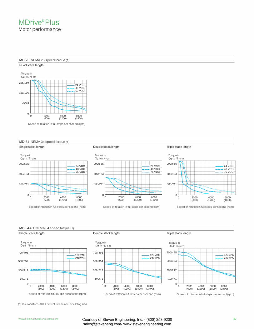
MDrive® Plus Motor performance
Courtesy of Steven Engineering, Inc. - (800) 258-9200 [email protected] www.stevenengineering.com
24 MDrive products assembled in USA
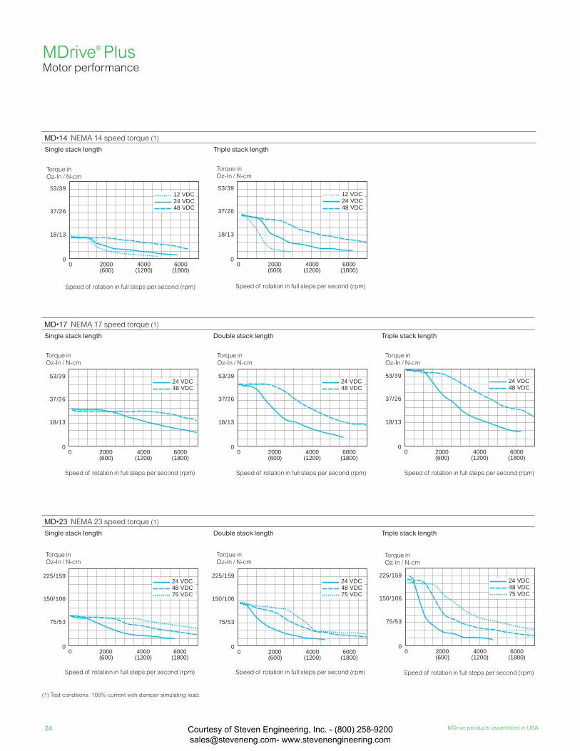
MD•14 NEMA 14 speed torque (1)
Single stack length Triple stack length
Torque in Oz-In / N-cm
Speed of rotation in full steps per second (rpm)
Torque in Oz-In / N-cm
Speed of rotation in full steps per second (rpm)
Torque in Oz-In / N-cm
Speed of rotation in full steps per second (rpm)
Torque in Oz-In / N-cm
Speed of rotation in full steps per second (rpm)
Torque in Oz-In / N-cm
Speed of rotation in full steps per second (rpm)
0
150/106
225/159
75/53
48 VDC24 VDC
0 2000(600)
4000(1200)
6000(1800)
75 VDC
0
150/106
225/159
75/53
48 VDC24 VDC
0 2000(600)
4000(1200)
6000(1800)
75 VDC
0
150/106
225/159
75/53
48 VDC24 VDC
0 2000(600)
4000(1200)
6000(1800)
75 VDC
MD•17 NEMA 17 speed torque (1)
Single stack length Double stack length Triple stack length
MD•23 NEMA 23 speed torque (1)
Single stack length Double stack length Triple stack length
0
37/26
53/39
18/13
48 VDC24 VDC
0 2000(600)
4000(1200)
6000(1800)
0
37/26
53/39
18/13
48 VDC24 VDC
0 2000(600)
4000(1200)
6000(1800)
0
37/26
53/39
18/13
48 VDC24 VDC
0 2000(600)
4000(1200)
6000(1800)
0
37/26
53/39
18/13
0 2000(600)
4000(1200)
6000(1800)
2412 VDC
48 VDCVDC
0
37/26
53/39
18/13
0 2000(600)
4000(1200)
6000(1800)
2412 VDC
48 VDCVDC
(1) Test conditions: 100% current with damper simulating load.
Torque in Oz-In / N-cm
Speed of rotation in full steps per second (rpm)
Torque in Oz-In / N-cm
Speed of rotation in full steps per second (rpm)
Torque in Oz-In / N-cm
Speed of rotation in full steps per second (rpm)
MDrive® Plus Motor performance
Courtesy of Steven Engineering, Inc. - (800) 258-9200 [email protected] www.stevenengineering.com
25www.motion.schneider-electric.com
Torque in Oz-In / N-cm
Speed of rotation in full steps per second (rpm)
Torque in Oz-In / N-cm
Speed of rotation in full steps per second (rpm)
Torque in Oz-In / N-cm
Speed of rotation in full steps per second (rpm)
0
300/212
500/354
100/71
0 2000(600)
4000(1200)
6000(1800)
8000(2400)
700/495
240 VAC120 VAC
0
300/212
500/354
100/71
0 2000(600)
4000(1200)
6000(1800)
8000(2400)
700/495
240 VAC120 VAC
0
300/212
500/354
100/71
0 2000(600)
4000(1200)
6000(1800)
8000(2400)
700/495
240 VAC120 VAC
MD•34 NEMA 34 speed torque (1)
Single stack length Double stack length Triple stack length
MD•34AC NEMA 34 speed torque (1)
Single stack length Double stack length Triple stack length
0
600/423
900/635
300/211
48 VDC24 VDC
0 2000(600)
4000(1200)
6000(1800)
75 VDC
0
600/423
900/635
300/211
48 VDC24 VDC
0 2000(600)
4000(1200)
6000(1800)
75 VDC
0
600/423
900/635
300/211
48 VDC24 VDC
0 2000(600)
4000(1200)
6000(1800)
75 VDC
MD•23 NEMA 23 speed torque (1)
Quad stack length
0
150/106
225/159
75/53
48 VDC24 VDC
0 2000(600)
4000(1200)
6000(1800)
60 VDC
(1) Test conditions: 100% current with damper simulating load.
Torque in Oz-In / N-cm
Speed of rotation in full steps per second (rpm)
Torque in Oz-In / N-cm
Speed of rotation in full steps per second (rpm)
Torque in Oz-In / N-cm
Speed of rotation in full steps per second (rpm)
Torque in Oz-In / N-cm
Speed of rotation in full steps per second (rpm)
MDrive® Plus Motor performance
Courtesy of Steven Engineering, Inc. - (800) 258-9200 [email protected] www.stevenengineering.com
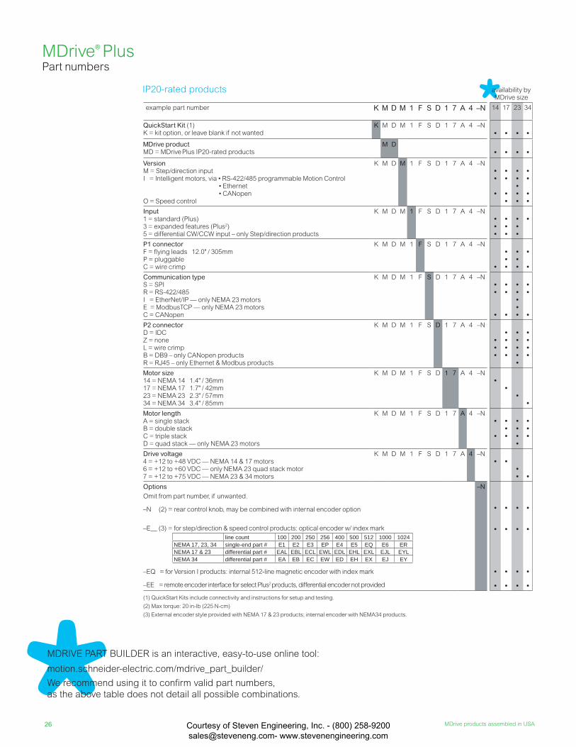
26 MDrive products assembled in USA
availability by MDrive size
example part number K M D M 1 F S D 1 7 A 4 –N 14 17 23 34
QuickStart Kit (1)K = kit option, or leave blank if not wanted
K M D M 1 F S D 1 7 A 4 –N
• • • •
MDrive productMD = MDrive Plus IP20-rated products
M D• • • •
VersionM = Step/direction inputI = Intelligent motors, via • RS-422/485 programmable Motion Control • Ethernet • CANopenO = Speed control
K M D M 1 F S D 1 7 A 4 –N••
•
••
••
•••••
••
••
Input1 = standard (Plus)3 = expanded features (Plus2)5 = differential CW/CCW input – only Step/direction products
K M D M 1 F S D 1 7 A 4 –N•••
•••
•••
•
P1 connectorF = fl ying leads 12.0" / 305mmP = pluggableC = wire crimp
K M D M 1 F S D 1 7 A 4 –N
•
•••
•••
•
•
Communication typeS = SPI R = RS-422/485I = EtherNet/IP — only NEMA 23 motorsE = ModbusTCP — only NEMA 23 motorsC = CANopen
K M D M 1 F S D 1 7 A 4 –N••
•
••
•
•••••
••
•
P2 connectorD = IDCZ = noneL = wire crimpB = DB9 – only CANopen productsR = RJ45 – only Ethernet & Modbus products
K M D M 1 F S D 1 7 A 4 –N
•••
••••
•••••
••••
Motor size14 = NEMA 14 1.4" / 36mm17 = NEMA 17 1.7" / 42mm 23 = NEMA 23 2.3" / 57mm34 = NEMA 34 3.4" / 85mm
K M D M 1 F S D 1 7 A 4 –N•
••
•
Motor lengthA = single stackB = double stackC = triple stackD = quad stack — only NEMA 23 motors
K M D M 1 F S D 1 7 A 4 –N•
•
•••
••••
•••
Drive voltage4 = +12 to +48 VDC — NEMA 14 & 17 motors6 = +12 to +60 VDC — only NEMA 23 quad stack motor7 = +12 to +75 VDC — NEMA 23 & 34 motors
K M D M 1 F S D 1 7 A 4 –N• •
•• •
OptionsOmit from part number, if unwanted.
–N (2) = rear control knob, may be combined with internal encoder option
–E__ (3) = for step/direction & speed control products: optical encoder w/ index mark
–EQ = for Version I products: internal 512-line magnetic encoder with index mark
–EE = remote encoder interface for select Plus2 products, differential encoder not provided
–N
•
•
•
•
•
•
•
•
•
•
•
•
•
•
•
•
(1) QuickStart Kits include connectivity and instructions for setup and testing.
(2) Max torque: 20 in-lb (225 N-cm)
(3) External encoder style provided with NEMA 17 & 23 products; internal encoder with NEMA34 products.
line count 100 200 250 256 400 500 512 1000 1024NEMA 17, 23, 34 single-end part # E1 E2 E3 EP E4 E5 EQ E6 ERNEMA 17 & 23 differential part # EAL EBL ECL EWL EDL EHL EXL EJL EYLNEMA 34 differential part # EA EB EC EW ED EH EX EJ EY
MDrive® PlusPart numbers
MDRIVE PART BUILDER is an interactive, easy-to-use online tool:
motion.schneider-electric.com/mdrive_part_builder/
We recommend using it to confirm valid part numbers,
as the above table does not detail all possible combinations.
IP20-rated products
Courtesy of Steven Engineering, Inc. - (800) 258-9200 [email protected] www.stevenengineering.com
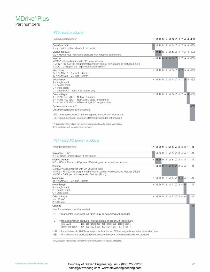
27www.motion.schneider-electric.com
example part number K M D M 2 M S Z 1 7 A 4 –EQ
QuickStart Kit (1)K = kit option, or leave blank if not wanted
K M D M 2 M S Z 1 7 A 4 –EQ
MDrive productMD = MDrive Plus IP65-rated products with industrial connectors
K M D M 2 M S Z 1 7 A 4 –EQ
VersionM2MSZ = Step/direction with SPI universal inputI4MRQ = RS-422/485 programmable motion control with expanded features (Plus2)I4MCQ = CANopen with expanded features (Plus2)
K M D M 2 M S Z 1 7 A 4 –EQ
Motor size17 = NEMA 17 1.7 inch 42mm 23 = NEMA 23 2.3 inch 57mm
K M D M 2 M S Z 1 7 A 4 –EQ
Motor lengthA = single stackB = double stackC = triple stackD = quad stack — NEMA 23 motors only
K M D M 2 M S Z 1 7 A 4 –EQ
Drive voltage4 = +12 to +48 VDC — NEMA 17 motors6 = +12 to +60 VDC — NEMA 23 D quad length motor7 = +12 to +75 VDC — NEMA 23 A, B & C length motors
K M D M 2 M S Z 1 7 A 4 –EQ
Options – encoders (2)
Omit from part number, if unwanted.
–EQ = internal encoder, 512-line magnetic encoder with index mark
–EE = remote encoder interface, differential encoder not provided
–EQ
(1) QuickStart Kits include connectivity and instructions for setup and testing.
(2) Unavailable with step/direction products.
example part number K M D M 2 M S Z 3 4 A 1 –N
QuickStart Kit (1)K = kit option, or leave blank if not wanted
K M D M 2 M S Z 3 4 A 1 –N
MDrive productMD = MDrive Plus with AC power, IP54-rating and industrial connectors
K M D M 2 M S Z 3 4 A 1 –N
VersionM2MSZ = Step/direction with SPI universal inputI4MRQ = RS-422/485 programmable motion control with expanded features (Plus2)I4MCQ = CANopen with expanded features (Plus2)
K M D M 2 M S Z 3 4 A 1 –N
Motor size34 = NEMA 34 3.4 inch 85mm
K M D M 2 M S Z 3 4 A 1 –N
Motor lengthA = single stackB = double stackC = triple stack
K M D M 2 M S Z 3 4 A 1 –N
Drive voltage1 = 120 VAC2 = 240 VAC
K M D M 2 M S Z 3 4 A 1 –N
Options Omit from part number, if unwanted.
–N = rear control knob, not IP54-rated, may be combined with encoder
–E__ = for step/direction products: internal optical encoder with index mark
–EQ = for motion control & CANopen products: internal 512-line magnetic encoder with index mark
–EE = for motion control products: remote encoder interface, differential encoder not provided
–N
(1) QuickStart Kits include connectivity and instructions for setup and testing.
MDrive® PlusPart numbers
line count 100 200 250 256 400 500 512 1000 1024differential part # EA EB EC EW ED EH EX EJ EY
IP65-rated products
IP54-rated AC power products
Courtesy of Steven Engineering, Inc. - (800) 258-9200 [email protected] www.stevenengineering.com

28 MDrive products assembled in USA
compatibility with MDrive by version & size
M
Step/
direction
I Motion
Control
I Ether
Net
I CAN
open
O
Speed
control
description reference 14 17 23 34 14 17 23 34 23 14 17 23 34 17 23 34
Communication convertersSet/program communication parameters with these
USB-pluggable, electrically isolated in-line
converters, pre-wired with mating connector
3.6 m / 12.0 feet long
10-pin non-locking IDC connector mate MD-CC300-001 • • • • • •MD-CC400-001 • • •
10-pin friction lock wire crimp connector mate MD-CC302-001 • • • • • •MD-CC402-001 • • • •
12-pin locking wire crimp connector mate MD-CC303-001 • • •MD-CC305-001 •MD-CC403-001 •
DB9 connector mate requires power supply, not provided MD-CC500-000 • • • •
Encoder cablesCables are pre-wired with mating connectors
for external single-end optical encoder
0.3 m / 1.0 feet long
ES-CABLE-2• • • • •
for external differential optical encoder
1.8 m / 6.0 feet long
ED-CABLE-6• • • • •
for internal differential optical encoder
1.8 m / 6.0 feet long
PD10-3400-FL3•
Prototype development cablesTo speed your test/development, these cables are
pre-wired with mating connectors
3.0 m / 10.0 feet long
2-pin locking wire crimp connector mate PD02-2300-FL3 • • •PD02-3400-FL3 • • • •
10-pin friction lock wire crimp connector mate PD10-1434-FL3 • • • •12-pin locking wire crimp connector mate PD12B-1434-FL3 • •
PD12B-2334-FL3 •PD12-1434-FL3 • • •
14-pin locking wire crimp connector mate PD14-2334-FL3 • • • • • •16-pin locking wire crimp connector mate PD16-1417-FL3 • • • •20-pin locking wire crimp connector mate PD20-3400-FL3 • •
PD20B-3400-FL3 •
Mating connector kitsFor making your own mating cables. Included:
5 connectors per kit. Cable material and crimp tool
not supplied
10-pin non-locking IDC connector CK-01 • • • • • • • • •10-pin friction lock wire crimp connector CK-02 • • • • • • • •12-pin locking wire crimp connector CK-03 • • •2-pin locking wire crimp connector CK-04 • • •2-pin locking wire crimp connector CK-05 • • •12-pin locking wire crimp connector CK-08 • • •14-pin locking wire crimp connector CK-09 • • • •16-pin locking wire crimp connector CK-10 • • • •20-pin locking wire crimp connector CK-11 • • •
Drive protection moduleLimits surge current and voltage to a safe level
when DC input power is switched on-and-off DPM75 • • • • • • • • • • • • • • • •
For IP20-rated products
MDrive® PlusAccessories
Courtesy of Steven Engineering, Inc. - (800) 258-9200 [email protected] www.stevenengineering.com
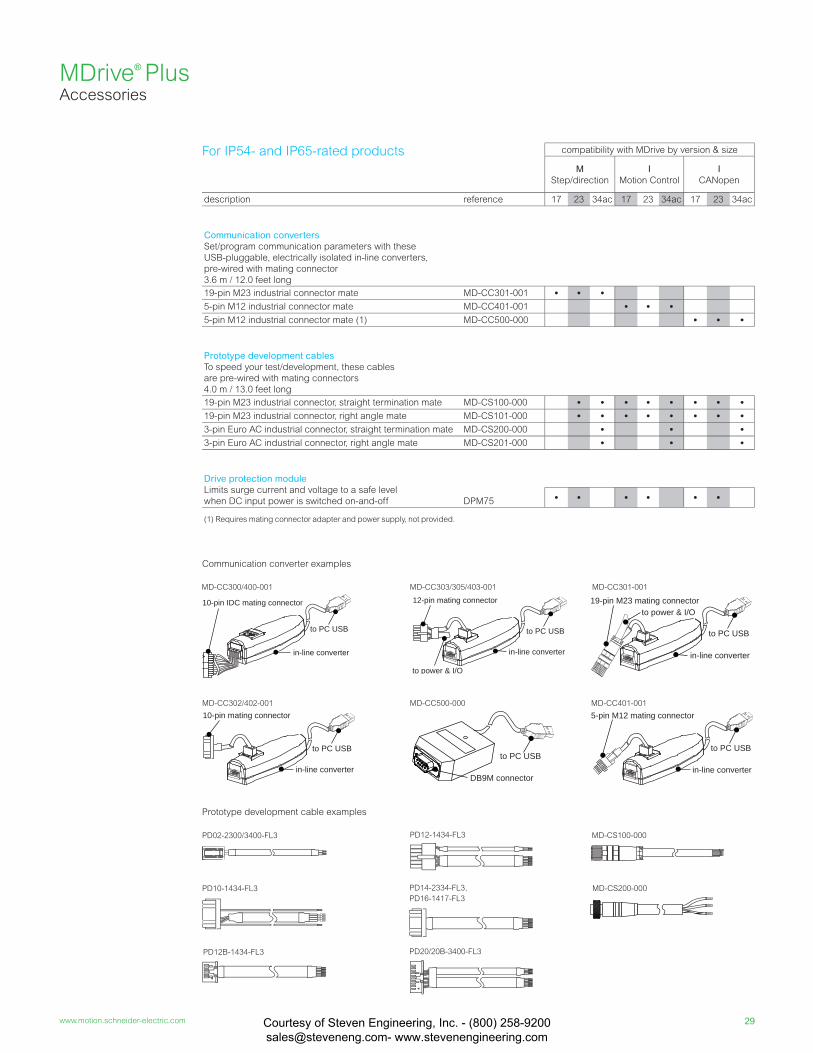
29www.motion.schneider-electric.com
compatibility with MDrive by version & size
M
Step/direction
I Motion Control
I CANopen
description reference 17 23 34ac 17 23 34ac 17 23 34ac
Communication convertersSet/program communication parameters with these
USB-pluggable, electrically isolated in-line converters,
pre-wired with mating connector
3.6 m / 12.0 feet long
19-pin M23 industrial connector mate MD-CC301-001 • • •5-pin M12 industrial connector mate MD-CC401-001 • • •5-pin M12 industrial connector mate (1) MD-CC500-000 • • •
Prototype development cablesTo speed your test/development, these cables
are pre-wired with mating connectors
4.0 m / 13.0 feet long
19-pin M23 industrial connector, straight termination mate MD-CS100-000 • • • • • • • •19-pin M23 industrial connector, right angle mate MD-CS101-000 • • • • • • • •3-pin Euro AC industrial connector, straight termination mate MD-CS200-000 • • •3-pin Euro AC industrial connector, right angle mate MD-CS201-000 • • •
Drive protection moduleLimits surge current and voltage to a safe level
when DC input power is switched on-and-off DPM75 • • • • • •
(1) Requires mating connector adapter and power supply, not provided.
MDrive® PlusAccessories
For IP54- and IP65-rated products
to PC USB
in-line converter
10-pin IDC mating connector
MD-CC300/400-001
to PC USB
in-line converter
10-pin mating connectorMD-CC302/402-001
PD02-2300/3400-FL3
PD10-1434-FL3
PD12B-1434-FL3
PD12-1434-FL3
PD14-2334-FL3,
PD16-1417-FL3
PD20/20B-3400-FL3
19-pin M23 mating connectorto power & I/O
to PC USB
in-line converter
MD-CC301-001
5-pin M12 mating connector
to PC USB
in-line converter
MD-CC401-001
MD-CS100-000
MD-CS200-000
MD-CC500-000
DB9M connector
to PC USB
12-pin mating connector
to power & I/O
to PC USB
in-line converter
MD-CC303/305/403-001
Communication converter examples
Prototype development cable examples
Courtesy of Steven Engineering, Inc. - (800) 258-9200 [email protected] www.stevenengineering.com

30 MDrive products assembled in USA
Features
• Motor sizes include NEMA 14, 17 and 23
• Standard screw lengths range from 3-24”
• Customization is available
• Maximum thrust from 50 up to 200 lbs
Networks
Supported communication protocols include:
• RS-422/485 programmable Motion Control
• CANopen
• Ethernet
• SPI Step/direction
MDrive® Linear Actuator
These all-in-one linear motion systems combine
leading integrated motor technology with linear
mechanicals to deliver long life, high accuracy
and repeatability. Two linear shaft styles are
available: non-captive shaft and external shaft.
Precision rolled lead screws are manufactured
from premium grade stainless steel with optional
Tefl on® coating. Designed specifi cally for motion
control applications, our high quality screws
deliver long life and quiet operation.
MDrive Linear Actuators are compact
linear motion systems that integrate
external and non-captive shaft linear
mechanicals with 1.8° stepper motors
and electronics for reliable, repeatable
motion.
Pictured: NEMA 14, 17 & 23 motor sizes
Intelligent linear motors
MDrive Linear Actuators
are built on the MDrive Plus
integrated motor technology
platform, with the addition of
linear motion mechanicals.
MDrive®
Linear Actuator All-in-one linear motion systems
Courtesy of Steven Engineering, Inc. - (800) 258-9200 [email protected] www.stevenengineering.com
31www.motion.schneider-electric.com
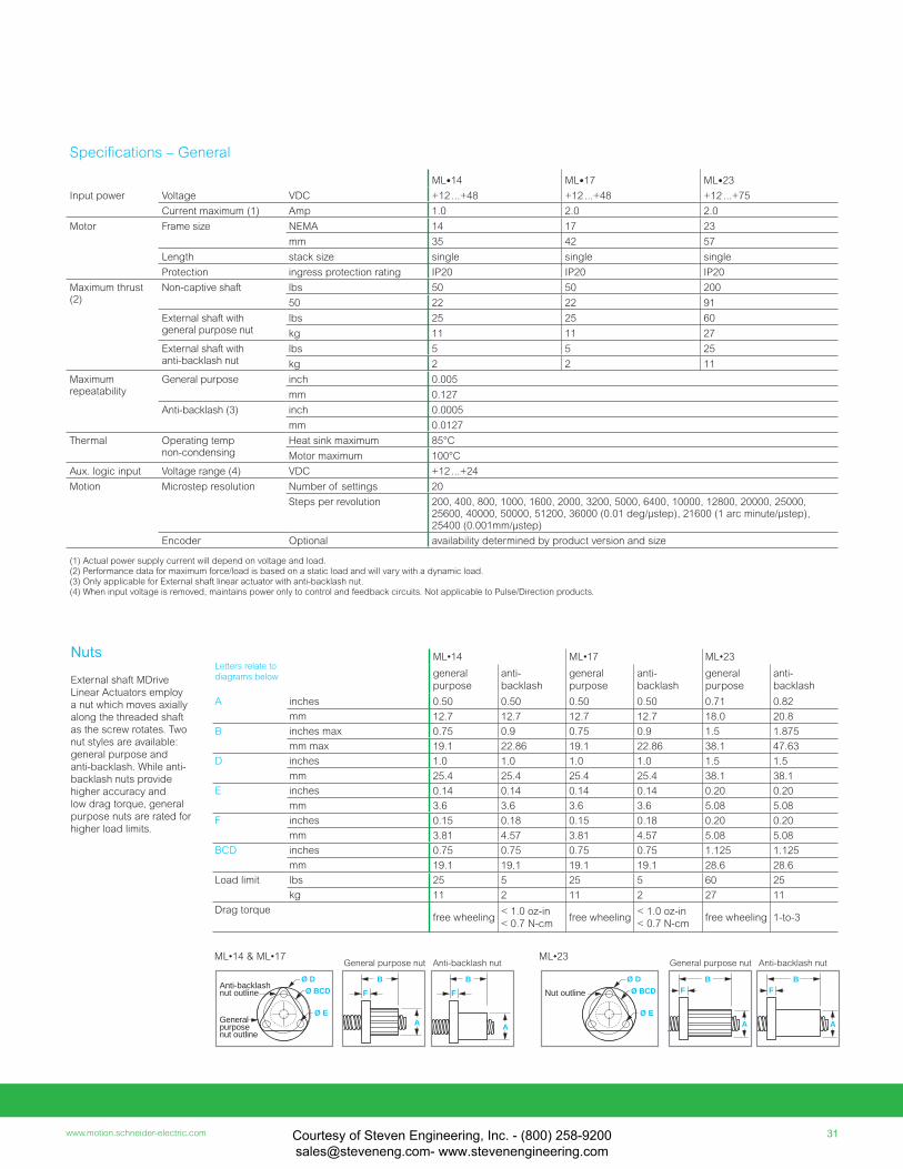
Specifi cations – General
ML•14 ML•17 ML•23
Input power Voltage VDC +12 ...+48 +12 ...+48 +12 ...+75
Current maximum (1) Amp 1.0 2.0 2.0
Motor Frame size NEMA 14 17 23
mm 35 42 57
Length stack size single single single
Protection ingress protection rating IP20 IP20 IP20
Maximum thrust (2)
Non-captive shaft lbs 50 50 200
50 22 22 91
External shaft with general purpose nut
lbs 25 25 60
kg 11 11 27
External shaft with anti-backlash nut
lbs 5 5 25
kg 2 2 11
Maximum repeatability
General purpose inch 0.005
mm 0.127
Anti-backlash (3) inch 0.0005
mm 0.0127
Thermal Operating temp non-condensing
Heat sink maximum 85°C
Motor maximum 100°C
Aux. logic input Voltage range (4) VDC +12 ...+24
Motion Microstep resolution Number of settings 20
Steps per revolution 200, 400, 800, 1000, 1600, 2000, 3200, 5000, 6400, 10000, 12800, 20000, 25000, 25600, 40000, 50000, 51200, 36000 (0.01 deg/µstep), 21600 (1 arc minute/µstep), 25400 (0.001mm/µstep)
Encoder Optional availability determined by product version and size
(1) Actual power supply current will depend on voltage and load.(2) Performance data for maximum force/load is based on a static load and will vary with a dynamic load.(3) Only applicable for External shaft linear actuator with anti-backlash nut.(4) When input voltage is removed, maintains power only to control and feedback circuits. Not applicable to Pulse/Direction products.
A
B
F
A
B
F
Ø D
Ø E
Ø BCDAnti-backlashnut outline
Generalpurposenut outline
A
BF
A
BF
General purpose nut Anti-backlash nut
Ø D
Ø E
Ø BCDNut outline
General purpose nut Anti-backlash nutML•14 & ML•17 ML•23
Letters relate to
diagrams below
ML•14 ML•17 ML•23
general
purpose
anti-
backlash
general
purpose
anti-
backlash
general
purpose
anti-
backlash
A inches 0.50 0.50 0.50 0.50 0.71 0.82
mm 12.7 12.7 12.7 12.7 18.0 20.8
B inches max 0.75 0.9 0.75 0.9 1.5 1.875
mm max 19.1 22.86 19.1 22.86 38.1 47.63
D inches 1.0 1.0 1.0 1.0 1.5 1.5
mm 25.4 25.4 25.4 25.4 38.1 38.1
E inches 0.14 0.14 0.14 0.14 0.20 0.20
mm 3.6 3.6 3.6 3.6 5.08 5.08
F inches 0.15 0.18 0.15 0.18 0.20 0.20
mm 3.81 4.57 3.81 4.57 5.08 5.08
BCD inches 0.75 0.75 0.75 0.75 1.125 1.125
mm 19.1 19.1 19.1 19.1 28.6 28.6
Load limit lbs 25 5 25 5 60 25
kg 11 2 11 2 27 11
Drag torquefree wheeling
< 1.0 oz-in
< 0.7 N-cmfree wheeling
< 1.0 oz-in
< 0.7 N-cmfree wheeling 1-to-3
Nuts
External shaft MDrive
Linear Actuators employ
a nut which moves axially
along the threaded shaft
as the screw rotates. Two
nut styles are available:
general purpose and
anti-backlash. While anti-
backlash nuts provide
higher accuracy and
low drag torque, general
purpose nuts are rated for
higher load limits.
Courtesy of Steven Engineering, Inc. - (800) 258-9200 [email protected] www.stevenengineering.com
32 MDrive products assembled in USA
threaded end smooth end none
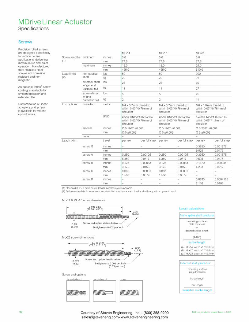
Precision rolled screws
are designed specifically
for motion control
applications, delivering
maximum life and quiet
operation. Manufactured
from stainless steel,
screws are corrosion
resistant and non-
magnetic.
An optional Teflon® screw
coating is available for
smooth operation and
extended life.
Customization of linear
actuators and screws
is available for volume
opportunities.
Screws
Straightness 0.002 per inch (0.05 per mm)
0.375(9.52)
0.50(12.7)
3.0 to 24.0(77.5 to 610.0)
Screw end option details below
0.25(6.35)
Screw end option details below
0.25(6.35)
3.0 to 18.0(77.5 to 455.0)
Straightness 0.002 per inch(0 05 )
MDrive Linear Actuator Specifi cations
Screw end options
ML•14 ML•17 ML•23
Screw lengths
(1)
minimum inches 3.0 3.0 3.0
mm 77.5 77.5 77.5
maximum inches 18.0 18.0 24.0
mm 455.0 455.0 610.0
Load limits
(2)
non-captive
shaft
lbs 50 50 200
kg 22 22 91
external shaft
w/ general
purpose nut
lbs 25 25 60
kg 11 11 27
external shaft
w/ anti-
backlash nut
lbs 5 5 25
kg 2 2 11
End options threaded metric M4 x 0.7 mm thread to within 0.03” / 0.76 mm of shoulder
M4 x 0.7 mm thread to within 0.03” / 0.76 mm of shoulder
M6 x 1.0 mm thread to within 0.03” / 0.76 mm of shoulder
UNC #8-32 UNC-2A thread to within 0.03” / 0.76 mm of shoulder
#8-32 UNC-2A thread to within 0.03” / 0.76 mm of shoulder
1/4-20 UNC-2A thread to within 0.05” / 1.3 mm of shoulder
smooth inches Ø 0.1967 ±0.001 Ø 0.1967 ±0.001 Ø 0.2362 ±0.001
mm Ø 5 ±0.003 Ø 5 ±0.003 Ø 6 ±0.003
none – – –
Lead / pitch travel per rev per full step per rev per full step per rev per full step
screw G inches – – – – 0.3750 0.001875
mm – – – – 9.525 0.0476
screw A inches 0.250 0.00125 0.250 0.00125 0.3750 0.001875
mm 6.350 0.0317 6.350 0.0317 9.525 0.0476
screw B inches 0.125 0.00063 0.125 0.00063 0.1670 0.000835
mm 3.175 0.0158 3.175 0.0158 4.233 0.0212
screw C inches 0.063 0.00031 0.063 0.00031 – –
mm 1.588 0.0079 1.588 0.0079 – –
screw D inches – – – – 0.0833 0.0004165
mm – – – – 2.116 0.0106
(1) Standard 0.1” / 2.5mm screw length increments are available.
(2) Performance data for maximum force/load is based on a static load and will vary with a dynamic load.
Length calculations
Non-captive shaft products
mounting surfaceplate thickness
+desired stroke length
+(A/B/C)
screw length
External shaft products
mounting surfaceplate thickness
–screw length
–nut length
available stroke length
(A) ML•14: add 1.4" / 35.6mm
(B) ML•17: add 1.4" / 35.6mm
(C) ML•23: add 1.8" / 45.7mm
ML•14 & ML•17 screw dimensions
ML•23 screw dimensions
Courtesy of Steven Engineering, Inc. - (800) 258-9200 [email protected] www.stevenengineering.com
33www.motion.schneider-electric.com
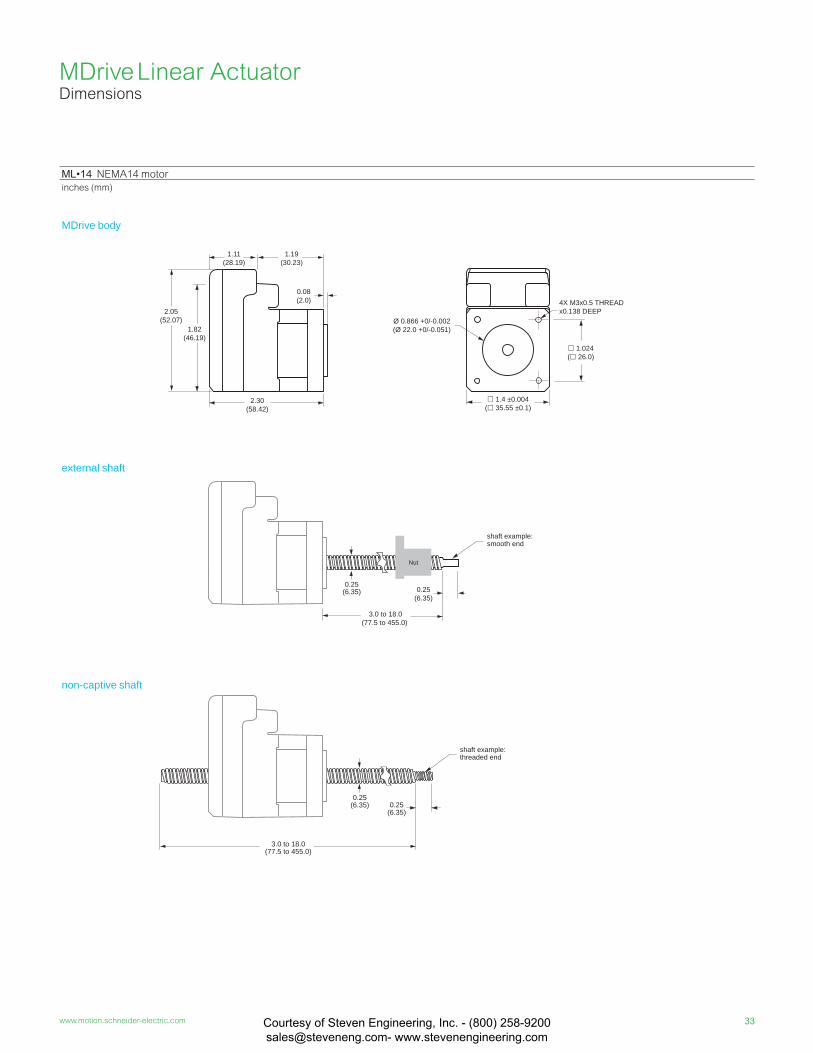
ML•14 NEMA14 motor
inches (mm)
MDrive body
external shaft
non-captive shaft
MDrive Linear Actuator Dimensions
shaft example: smooth end
shaft example: threaded end
0.25(6.35) 0.25
(6.35)
3.0 to 18.0(77.5 to 455.0)
2.05(52.07)
1.19(30.23)
0.08(2.0)
2.30(58.42)
Ø 0.866 +0/-0.002(Ø 22.0 +0/-0.051)
1.4 ±0.004( 35.55 ±0.1)
4X M3x0.5 THREADx0.138 DEEP
1.82(46.19)
1.024( 26.0)
0.25(6.35)
Nut
3.0 to 18.0(77.5 to 455.0)
0.25(6.35)
1.11(28.19)
Courtesy of Steven Engineering, Inc. - (800) 258-9200 [email protected] www.stevenengineering.com
34 MDrive products assembled in USA
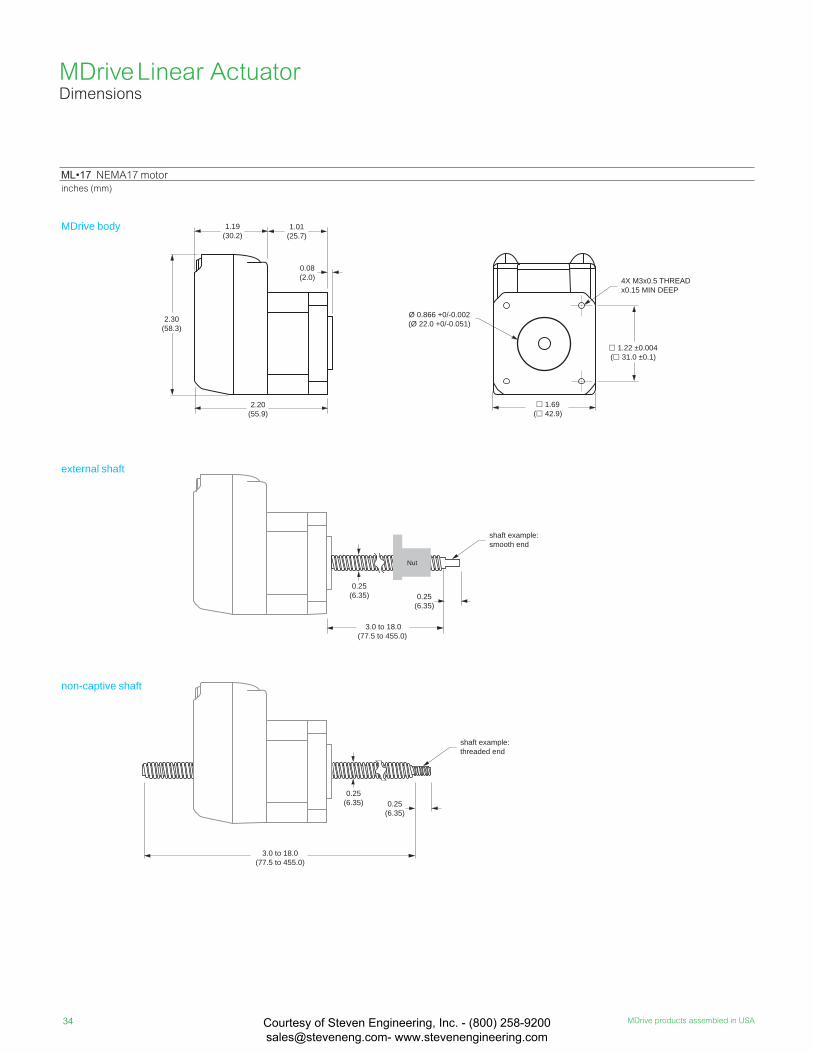
ML•17 NEMA17 motor
inches (mm)
MDrive body
external shaft
non-captive shaft
MDrive Linear Actuator Dimensions
Nut
3.0 to 18.0(77.5 to 455.0)
0.25(6.35) 0.25
(6.35)
3.0 to 18.0(77.5 to 455.0)
0.25(6.35) 0.25
(6.35)
1.69( 42.9)
1.22 ±0.004( 31.0 ±0.1)
4X M3x0.5 THREADx0.15 MIN DEEP
Ø 0.866 +0/-0.002(Ø 22.0 +0/-0.051)2.30
(58.3)
1.19(30.2)
0.08(2.0)
2.20(55.9)
shaft example: smooth end
shaft example: threaded end
1.01(25.7)
Courtesy of Steven Engineering, Inc. - (800) 258-9200 [email protected] www.stevenengineering.com
35www.motion.schneider-electric.com
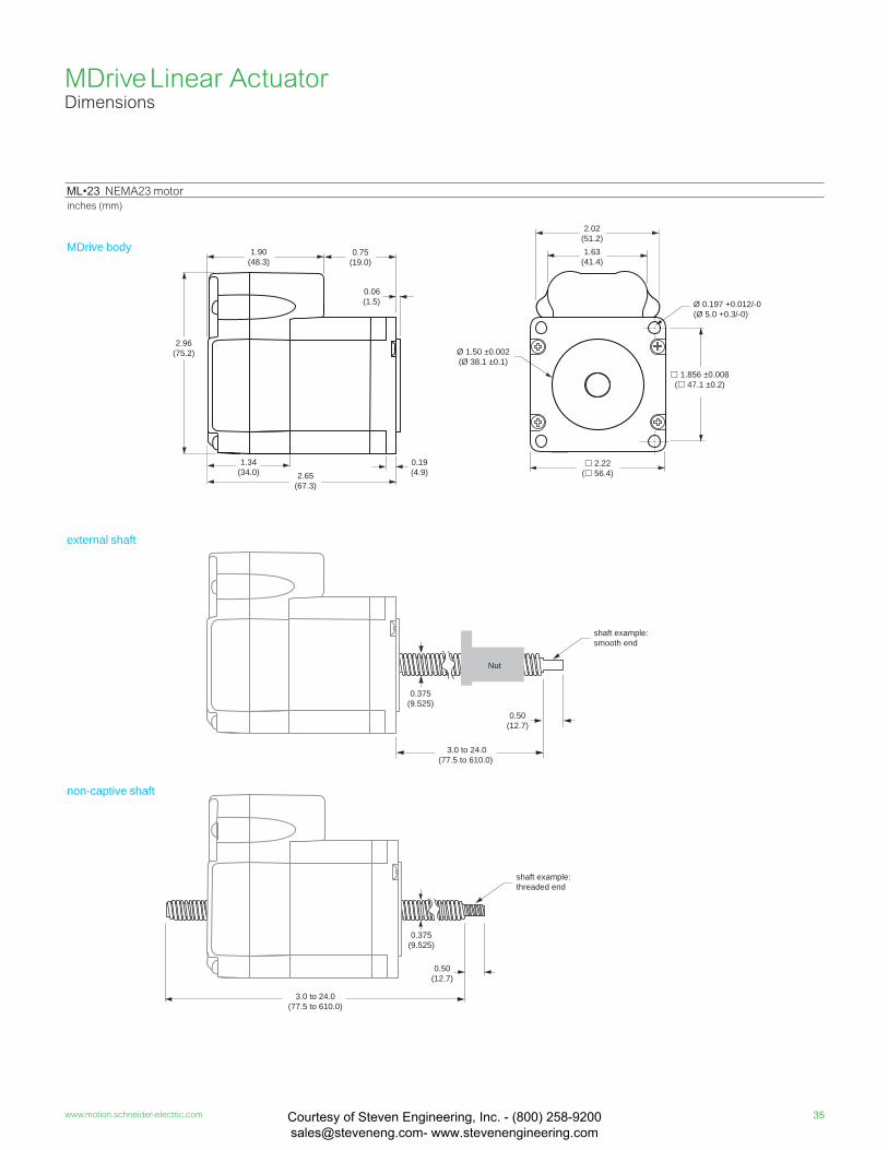
ML•23 NEMA23 motor
inches (mm)
MDrive body
external shaft
non-captive shaft
0.375(9.525)
0.50(12.7)
Nut
3.0 to 24.0(77.5 to 610.0)
0.375(9.525)
3.0 to 24.0(77.5 to 610.0)
0.50(12.7)
2.02(51.2)
Ø 1.50 ±0.002(Ø 38.1 ±0.1)
2.22( 56.4)
Ø 0.197 +0.012/-0(Ø 5.0 +0.3/-0)
1.63(41.4)
1.856 ±0.008 ( 47.1 ±0.2)
1.90(48.3)
2.96(75.2)
0.06(1.5)
1.34(34.0) 2.65
(67.3)
0.19(4.9)
0.75(19.0)
shaft example: smooth end
shaft example: threaded end
MDrive Linear Actuator Dimensions
Courtesy of Steven Engineering, Inc. - (800) 258-9200 [email protected] www.stevenengineering.com

36 MDrive products assembled in USA
ML•14 NEMA 14 motor specifi cations Motor Stack length Single
Holding torque oz-in 18
N-cm 13
Rotor inertia oz-in-sec2 0.0003
kg-cm2 0.021
Weight (without screw) oz 8.0
g 230.0
Maximum screw misalignment ° ±1
Maximum thrust (1) Non-captive shaft lbs 50
kg 22
External shaft with general purpose nut
lbs 25
kg 11
External shaft with anti-backlash nut
lbs 5
kg 2Maximum repeatability General purpose inch 0.005
mm 0.127
Anti-backlash (2) inch 0.0005
mm 0.0127
ML•17 NEMA 17 motor specifi cations Motor Stack length Single
Holding torqueoz-in 29
N-cm 20
Rotor inertiaoz-in-sec2 0.0005
kg-cm2 0.034
Weight (motor+driver)oz 9.6
g 272.2
Maximum screw misalignment ° ±1
Maximum thrust (1) Non-captive shaft lbs 50
kg 22
External shaft with general purpose nut
lbs 25
kg 11
External shaft with anti-backlash nut
lbs 5
kg 2Maximum repeatability General purpose inch 0.005
mm 0.127
Anti-backlash (2) inch 0.0005
mm 0.0127
ML•23 NEMA 23 motor specifi cations Motor Stack length Single
Holding torqueoz-in 90
N-cm 64
Rotor inertiaoz-in-sec2 0.0025
kg-cm2 0.18
Weight (motor+driver)oz 22.0
g 625.0
Maximum screw misalignment ° ±1
Maximum thrust (1) Non-captive shaft lbs 200
kg 91
External shaft with general purpose nut
lbs 60
kg 27
External shaft with anti-backlash nut
lbs 25
kg 11Maximum repeatability General purpose inch 0.005
mm 0.127
Anti-backlash (2) inch 0.0005
mm 0.0127
(1) Performance data for maximum force/load is based on a static load and will vary with a dynamic load.(2) Only applicable for External shaft linear actuator with anti-backlash nut.
MDrive Linear Actuator Motor performance
Courtesy of Steven Engineering, Inc. - (800) 258-9200 [email protected] www.stevenengineering.com

37www.motion.schneider-electric.com
00 2000
(600)4000
(1200)8000
(2400)
100/45
200/90
50/22
6000(1800)
150/67
G screwA screwB screwD screw
Load limit
00 2000
(600)4000
(1200)8000
(2400)
100/45
200/90
50/22
6000(1800)
150/67
G screwA screwB screwD screw
Load limit
00 2000
(600)4000
(1200)8000
(2400)
50/23
100/45
25/11
6000(1800)
75/34
A screwB screwC screw
Load limit
00 2000
(600)4000
(1200)8000
(2400)
50/23
100/45
25/11
6000(1800)
75/34
A screwB screwC screw
Load limit
00 2000
(600)4000
(1200)8000
(2400)
50/23
100/45
25/11
6000(1800)
75/34
A screwB screwC screw
Load limit
ML•14 NEMA 14 speed force (1) (2)
12 VDC 24 VDC 48 VDC
Force in lbs / kg
00 2000
(600)4000
(1200)8000
(2400)
50/23
100/45
25/11
6000(1800)
75/34
A screwB screwC screw
Load limit
00 2000
(600)4000
(1200)8000
(2400)
50/23
100/45
25/11
6000(1800)
75/34
A screwB screwC screw
Load limit
ML•17 NEMA 17 speed force (1) (2)
12 VDC 24 VDC 48 VDC
MD•23 NEMA 23 speed force (1) (2)
24 VDC 48 VDC 75 VDC
MDrive Linear Actuator Motor performance
(1) Test conditions: maximum force/load is based on a static load. This will vary with a dynamic load.
(2) Load limits – non-captive shaft: 50lbs/22kg for sizes 14 & 17, 200 lbs/91kg for size 23
– external shaft: determined by the nut selected
Force in lbs / kg
Speed in full steps per second (rpm)
Force in lbs / kg
Speed in full steps per second (rpm)
Force in lbs / kg
Speed of full steps per second (rpm)
Force in lbs / kg
Speed in full steps per second (rpm)
Force in lbs / kg
Speed in full steps per second (rpm)
Force in lbs / kg
Speed of rotation in full steps per second (rpm)
Force in lbs / kg
Speed of rotation in full steps per second (rpm)
Force in lbs / kg
Speed of rotation in full steps per second (rpm)
00 2000
(600)4000
(1200)8000
(2400)
50/23
100/45
25/11
6000(1800)
75/34
A screwB screwC screw
Load limit
Speed in full steps per second (rpm)
00 2000
(600)4000
(1200)8000
(2400)
100/45
200/90
50/22
6000(1800)
150/67
G screwA screwB screwD screw
Load limit
Courtesy of Steven Engineering, Inc. - (800) 258-9200 [email protected] www.stevenengineering.com

38 MDrive products assembled in USA
MDRIVE PART BUILDER is an interactive, easy-to-use online tool:
motion.schneider-electric.com/mdrive_part_builder/
We recommend using it to confirm valid part numbers,
as the above table does not detail all possible combinations.
availability by size
example part number K M L M 1 F S D 1 7 A 4 –E1 – • 14 17 23
QuickStart Kit (1)K = kit option, or leave blank if not wanted
K M L M 1 F S D 1 7 A 4 –E1 – • • • •
MDrive productML = MDrive Linear Actuator
M L• • •
VersionM = Step/direction inputI = Intelligent motors, via • RS-422/485 programmable Motion Control • Ethernet • CANopen
K M L M 1 F S D 1 7 A 4 –E1 – • •
•
•
••
•
••••
Input1 = standard (Plus)3 = expanded features (Plus2)5 = differential CW/CCW input – only Step/direction products
K M L M 1 F S D 1 7 A 4 –E1 – • •
••
•••
•••
P1 connectorF = fl ying leads 12.0" / 305mmP = pluggableC = wire crimp
K M L M 1 F S D 1 7 A 4 –E1 – •
•
•••
•••
Communication typeS = SPI R = RS-422/485I = EtherNet/IP — only NEMA 23 motorsC = CANopen
K M L M 1 F S D 1 7 A 4 –E1 – • •
•••
••••
P2 connectorD = IDCZ = noneL = wire crimpB = DB9 – only CANopen productsR = RJ45 – only EtherNet/IP products
K M L M 1 F S D 1 7 A 4 –E1 – •
•••
••••
•••••
Motor size14 = NEMA 14 1.4" / 36mm17 = NEMA 17 1.7" / 42mm 23 = NEMA 23 2.3" / 57mm
K M L M 1 F S D 1 7 A 4 –E1 – • •
••
Motor lengthA = single stack
K M L M 1 F S D 1 7 A 4 –E1 – • • • •
Drive voltage4 = +12 to +48 VDC — NEMA 14 & 17 motors7 = +12 to +75 VDC — NEMA 23 motors
K M L M 1 F S D 1 7 A 4 –E1 – • • •
•
OptionsOmit from part number, if unwanted.
–E__ = for step/direction products: externally mounted optical encoder w/ index mark
–EQ = for Version I products: internal 512-line magnetic encoder with index mark
–EE = remote encoder interface for select Plus2 products, differential encoder not provided
–E1 – •
•
•
•
•
•
•
•
•
•
Linear actuator specifi cationscomplete the part number from the table on the next page
– •
(1) QuickStart Kits include connectivity and instructions for setup and testing.
line count 100 200 250 256 400 500 512 1000 1024single-end part # E1 E2 E3 EP E4 E5 EQ E6 ERdifferential part # EAL EBL ECL EWL EDL EHL EXL EJL EYL
MDrive Linear ActuatorPart numbers
Courtesy of Steven Engineering, Inc. - (800) 258-9200 [email protected] www.stevenengineering.com
39www.motion.schneider-electric.com
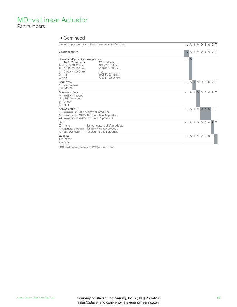
• Continued
example part number — linear actuator specifications – L A 1 M 0 6 0 Z T
Linear actuator– L
– L A 1 M 0 6 0 Z T
Screw lead / pitch by travel per rev 14 & 17 products 23 productsA = 0.250" / 6.35mm 0.200" / 5.08mmB = 0.125" / 3.175mm 0.167" / 4.233mmC = 0.063" / 1.588mm naD = na 0.083" / 2.116mmG = na 0.375" / 9.525mm
– L A
Shaft style1 = non-captive3 = external
– L A 1 M 0 6 0 Z T
Screw end fi nishM = metric threadedU = UNC threadedS = smoothZ = none
– L A 1 M 0 6 0 Z T
Screw length (1)030 = minimum 3.0" / 77.5mm all products180 = maximum 18.0" / 455.0mm 14 & 17 products240 = maximum 24.0" / 610.0mm 23 products
– L A 1 M 0 6 0 Z T
Nut Z = none – for non-captive shaft productsG = general purpose – for external shaft products A = anti-backlash – for external shaft products
– L A 1 M 0 6 0 Z T
CoatingT = Tefl on®
Z = none
– L A 1 M 0 6 0 Z T
(1) Screw lengths specifi ed in 0.1" / 2.5mm increments.
MDrive Linear ActuatorPart numbers
Courtesy of Steven Engineering, Inc. - (800) 258-9200 [email protected] www.stevenengineering.com
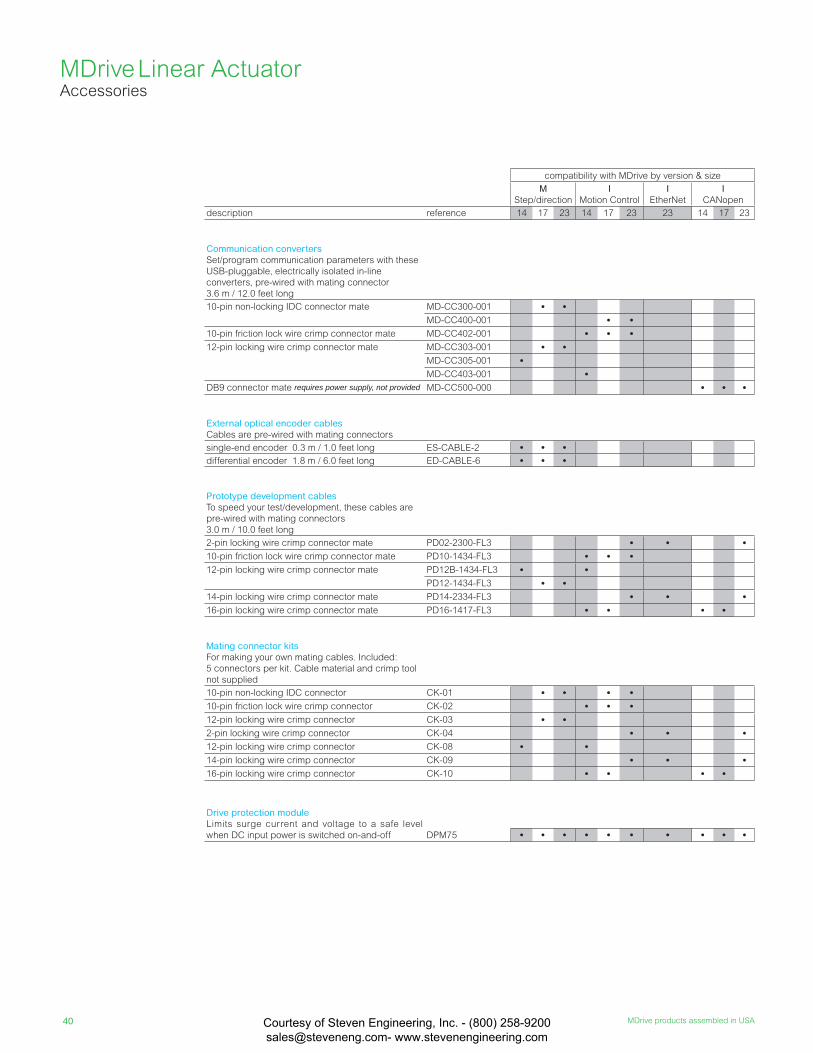
40 MDrive products assembled in USA
MDrive Linear ActuatorAccessories
compatibility with MDrive by version & size
M
Step/direction
I Motion Control
I EtherNet
I CANopen
description reference 14 17 23 14 17 23 23 14 17 23
Communication convertersSet/program communication parameters with these
USB-pluggable, electrically isolated in-line
converters, pre-wired with mating connector
3.6 m / 12.0 feet long
10-pin non-locking IDC connector mate MD-CC300-001 • •MD-CC400-001 • •
10-pin friction lock wire crimp connector mate MD-CC402-001 • • •12-pin locking wire crimp connector mate MD-CC303-001 • •
MD-CC305-001 •MD-CC403-001 •
DB9 connector mate requires power supply, not provided MD-CC500-000 • • •
External optical encoder cablesCables are pre-wired with mating connectors
single-end encoder 0.3 m / 1.0 feet long ES-CABLE-2 • • •differential encoder 1.8 m / 6.0 feet long ED-CABLE-6 • • •
Prototype development cablesTo speed your test/development, these cables are
pre-wired with mating connectors
3.0 m / 10.0 feet long
2-pin locking wire crimp connector mate PD02-2300-FL3 • • •10-pin friction lock wire crimp connector mate PD10-1434-FL3 • • •12-pin locking wire crimp connector mate PD12B-1434-FL3 • •
PD12-1434-FL3 • •14-pin locking wire crimp connector mate PD14-2334-FL3 • • •16-pin locking wire crimp connector mate PD16-1417-FL3 • • • •
Mating connector kitsFor making your own mating cables. Included:
5 connectors per kit. Cable material and crimp tool
not supplied
10-pin non-locking IDC connector CK-01 • • • •10-pin friction lock wire crimp connector CK-02 • • •12-pin locking wire crimp connector CK-03 • •2-pin locking wire crimp connector CK-04 • • •12-pin locking wire crimp connector CK-08 • •14-pin locking wire crimp connector CK-09 • • •16-pin locking wire crimp connector CK-10 • • • •
Drive protection moduleLimits surge current and voltage to a safe level
when DC input power is switched on-and-off DPM75 • • • • • • • • • •
Courtesy of Steven Engineering, Inc. - (800) 258-9200 [email protected] www.stevenengineering.com
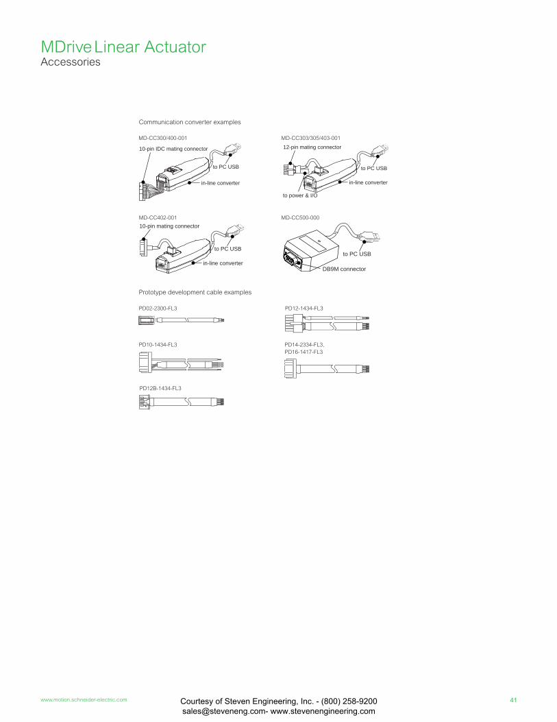
41www.motion.schneider-electric.com
to PC USB
in-line converter
10-pin IDC mating connector
MD-CC300/400-001
to PC USB
in-line converter
10-pin mating connectorMD-CC402-001
PD02-2300-FL3
PD10-1434-FL3
PD12B-1434-FL3
PD12-1434-FL3
PD14-2334-FL3,
PD16-1417-FL3
MD-CC500-000
DB9M connector
to PC USB
12-pin mating connector
to power & I/O
to PC USB
in-line converter
MD-CC303/305/403-001
Communication converter examples
Prototype development cable examples
MDrive Linear ActuatorAccessories
Courtesy of Steven Engineering, Inc. - (800) 258-9200 [email protected] www.stevenengineering.com

42 MDrive products assembled in USACourtesy of Steven Engineering, Inc. - (800) 258-9200 [email protected] www.stevenengineering.com

Ordering
Our extensive, worldwide network of Distributors offer local ap pli ca tion
support in addition to sales. To locate an authorized Dis trib u tor near you,
go to the contacts page at www.motion.schneider-electric.com.
Warranty
To obtain warranty service for products purchased from an Schneider
Electric Motion USA Distributor, please contact that Distributor to obtain
a Returned Material Authorization (RMA). If the Product was purchased
directly from Schneider Electric Motion USA, please contact Customer
Service at
[email protected] or 860-295-6102 (Eastern Time Zone).
Customer shall prepay shipping charges for Products returned to Sch-
neider Electric Motion USA for warranty service, and Schneider Electric
Motion USA will pay for return of Products to Customer by ground trans-
portation. However, Customer shall pay all shipping charges, duties and
taxes for Products returned to Schneider Electric Motion USA from outside
the United States.
Technical Support
We pride ourselves on our ability to pro vide fi rst-rate technical support.
Our friend ly and helpful technical staff have both the knowl edge and
desire to an swer all your tech ni cal inquiries.
Tel. . . . . . . . . . . . . . . . . . . . . . . . . . . +00 (1) 860 295-6102
e-mail . . . . . . . . . . . . . . . . . . . . . . . . [email protected]
Customer Service
The Schneider Electric Motion USA Customer Service Department is open
from 8:30 A.M. to 5:00 P.M., Mon day through Friday (Eastern Time Zone).
Tel. . . . . . . . . . . . . . . . . . . . . . . . . . . +00 (1) 860 295-6102
Fax . . . . . . . . . . . . . . . . . . . . . . . . . . +00 (1) 860 295-6107
e-mail . . . . . . . . . . . . . . . . . . . . . . . . [email protected]
web site . . . . . . . . . . . . . . . . . . . . . . www.motion.schneider-electric.com
DISCLAIMER: The information in this document has been care ful ly checked and is believed to
be accurate; however, no responsibility is as sumed for inaccuracies.
Schneider Electric Motion USA reserves the right to make changes without further notice to any
products herein to im prove reliability, function, or design. Schneider Electric Motion USA does
not as sume any liability arising out of the application or use of any product or circuit de scribed
herein; neither does it convey any license under its patent rights of others.
Electronics Manufacture, Material Handling
Medical Technology
Packaging, Printing, Paper
Laboratory Automation
Courtesy of Steven Engineering, Inc. - (800) 258-9200 [email protected] www.stevenengineering.com

Schneider Electric Motion USA
370 North Main Street Marlborough, CT 06447 Phone: (860) 295-6102Fax: (860) 295-6107www.motion.schneider-electric.com
Document Number MDPC
© S
chne
ider
Ele
ctri
c M
otio
n U
SA
. All
rig
hts
rese
rve
d.
December 2015
This document has beenprinted on recycled paper
Courtesy of Steven Engineering, Inc. - (800) 258-9200 [email protected] www.stevenengineering.com