saturn - squarespace
TRANSCRIPT

I __
\
MSFC-MAN -503i
SATURN
INr_EY,I.G DATA S ._ q,_03
p'_ ° S! !_ Ir-I"T
THIS PUBLICATION REPLACES MSFC-MAN-503 DATED 1 APRIL 1968
1 NOVEMBER 1968MSFC - Form 454 (Rev October 1967)


MSFC-MAN-503
Reproduction for non-government use of the information or illustrations contained inthis publication is not permitted without specific approval of the issuing service.
INSERT LATEST CHANGED PAGES.DESTROY SUPERSEDED PAGES.
LIST OF EFFECTIVEPAGESNOTE: The portion of the text affected by
the changes is indicated by a verticalline in the outer margins of the page.
TOTAL NUMBER OF PAGES IN THIS PUBLICATION IS 252, CONSISTING OF THE FOLLOWING:
Page Issue Page Issue
Title ........................... 25 Nov 1968 6-1 thru 6-34 .................... 25 Nov 1968A ............................. 25 Nov 1968 7-1 thru 7-31 .................... 25 Nov 1968i .............................. 25 Nov 1968 7-32 Blank ...................... 25 Nov 1968ii Blank ......................... 25 Nov 1968 8-1 thru 8-25 .................... 25 Nov 1968iii ............................. 25 Nov 1968 8-26 Blank ...................... 25 Nov 1968iv Blank ........................ 25 Nov 1968 9-1 thru 9-24 .................... 25 Nov 19681-1 thru 1-15 .................... 25 Nov 1968
lO-I thru 10-5 ................... 25 Nov 19681-16 Blank ...................... 25 Nov 19682-1 thru 2-18 .................... 25 Nov 1968 10-6 Blank ...................... 25 Nov 19683-1 thru 3-15 .................... 25 Nov 1968 A-l thru A-4 ..................... 25 Nov 19683-16 Blank ...................... 25 Nov 1968 B-1 thru B-3 ..................... 25 Nov 19684-1 thru 4-27 .................... 25 Nov 1968 B-4 Blank ....................... 25 Nov 19684-28 Blank ...................... 25 Nov 1968 Index 1 thru Index 7 .............. 25 Nov 19685-1 thru 5-30 .................... 25 Nov 1968 Index 8 Blank .................... 25 Nov 1968
* The asterisk indicates pages changed, added, or deleted by the current change.
NASA

MSFCoMAN-503
SATURNV FLIGHTMANUALSA-503
FOREWORD
This manual was prepared to provide the astronaut with a single source ref-erence as to the characteristics and functions of the SA-503 launch vehicle
and the AS-503 manned flight mission. A revision to the manual, incorporating
the latest released data on the vehicle and mission, will he released approx-
imately 30 days prior to the scheduled launch date.
The manual provides general mission and performance data, emergency detection
system information, a description of each stage and the IU, and a general
discussion of ground support facilities, equipment, and mission control. Abibliography identifies additional references if a more comprehensive studyis desired.
This manual is for information only and is not a control document. If a con-flict should be discovered between the manual and a control document the con-
trol document will rule.
Recommended changes or corrections to this manual should be forwarded, inwriting, to the Saturn V Systems Engineering Management Office (I-V-E), MSFC,
Attention: Mr. H.P. Lloyd; or to the Crew Safety and Procedures Branch (CF-
24), MSC, Attention: Mr. D.K. Warren.
J
Arthur Rudolph D.K. Slayton _
Manager, Saturn V Program Director of Plight
George C. Marshall Space Crew Operations
Flight Center Manned Spacecraft Center
REVISIONNOTE
The manual has been completely revised to incorporate vehicle and mission
changes and to take advantage of improvements in presentation which have been
developed since the original release. The information in the manual de-cribes the vehicle configuration 8nd mission characteristics as defined for
the C Prime mission and was prepared from information available approximately
thirty days prior to Oct. 25, 1968,
i/ii

MSFC-MAN-503
I
TABLEOF CONTENTS IPage
SECTION I General Description ........................... !-]
SECTION It Performance ................................ 2-1
SECTION III Emergency Detection and Procedures ................ 3-1
SECTION IV s-EStnge.................................. 4-1
SECTION V s-,Stage.................................. S-1
SECTION Vl S-IVB Stage ................................. 6-1
"_-_ SECTION VII Instrument Unit ............................... 7-1
SECTION VIII Ground Support Interface ......................... 8-|
SECTION IX Mission ControlMonitoring ....................... 9-1
SECTION X Mission Variables and Constraints .................. 10-1
APPENDIX A Abbreviations and Acronyms ...................... A-]
APPENDIX B Bibliography ................................ B-1
INDEX Alphabetical .............................. Index 1
iii/iv

MSFC-MAN-503
F SECTIONiGNERALDESCRIPTION
TABLE OF CONTENTS VEHICLE DESIGN GROUND RULES
SA TURN V SYSTEM DESCRIPTION .............. 1-1 SafetyLAUNCH VEHICLE DESCRIPTION ............... 1-3RANGE SAFETY AND INSTRUMENTATION ....... 1-3 Safety criteria are identified by Air Force Eastern Test RangeLV MONITORING AND CONTROL ............... 1-9 (AFETR) Safety Manual 127q and AFETR Regulation 127-9.PERCEPTIBLE PRELAUNCH EVENTS ............ 1-12POGO ....................................... 1-13 Crew safety considerations required the development of an
Emergency Detection System (EDS) with equipment located
SATURN V SYSTEM DESCRIPTION throughout the launch vehicle to detect emergencyconditions as they develop. If an emergency condition is
The Saturn V system in its broadest scope includes detected, this system will either initiate an automatic abortconceptual development, design, manufacture, sequence, or display critical data to the flight crew for theirtransportation, assembly, test, and launch. The primary analysis and reaction.mission of the Saturn V launch vehicle, three-stage-to-escapeboost launch of an Apollo Spacecraft, established the basic Each powered stage is designed with du.,d redundant rangeconcept. This mission includes a suborbital start of the third safety equipment which will effect engine cutoff andstage (S-IVB) engine for final boost into earth orbit, and propellant dispersion in the event of a launch abort aftersubsequent reignition to provide sufficient velocity for escape liftoff. Engine cutoff results from closing valves andmissions including the lunar missions, terminating the flow of fuel and oxidizer. Propellant is
dispersed by detonating linear-shaped charges, therebyLAUNCH VEHICLE DEVELOPMENT longitudinally opening the propellant tanks.
The Saturn launch vehicles are the product of a long Stage Separationevolutionary process stemming from initial studies in 1957 ofthe Redstone and Jupiter missiles. Early conceptual studies The separation of the launch vehicle stages in flight requiredincluded other proven missiles such as Thor and Titan, and design studies involving consideration of many parameters,considered pay loads ranging from earth orbiting satellites to such as time of separation, vehicle position, vehicle attitude,
f_ manned spacecraft such as Dynasoar, Mercury, Gemini, and single or dual plane separation, and the type, quantity, andeventually Apollo. location of ordnance.
The Saturn V launch vehicle evolved from the earlier Saturn The launch vehicle stages separate in flight by explosivelyvehicles as a result of the decision in 1961 to proceed with the severing a circumferential separation joint and firingApollo manned lunar mission. As the Apollo mission retrorocket motors to decelerate the spent stage. Stagedefinition became clear, conceptual design studies were separation is initiated when stage thrust decays to a valuemade, considering such parameters as structural dynamics, equal to or less than 10% of rated thrust. A short coast modestaging dynamics, and propulsion dynamics, is used to allow separation of the spent stage, and to effect
ullage settling of the successive stage prior to engine ignition.
Design trade-offs were made in certain areas to optimize thelaunch vehicle design, based on mission requirements. The A delayed dual plane separation is employed between thebest combination of design parameters for liquid propellant S-IC and S-II stages, while a single plane separation isvehicles resulted in low accelerations and low dynamic loads, adequate between the S-II and S-IVB stages.Reliability, performance and weight were among primaryfactors considered in optimizing the design. Umbilicals
Structural design carefully considered the weight factor. In the design and placement of vehicle plates, considerationStructural rigidity requirements were dictated largely by two was given to such things as size, locations, methods ofgeneral considerations: flight control dynamics and attachment, release, and retraction.propellant slosh problems. Gross dimensions (diameter &length) were dictated generally by propellant tankage size. The number of umbilicals is minimized by thecombining of
electrical connectors and pneumatic and propellant couplingsAs propulsion requirements were identified, system into common umbilical carriers. Location of the umbilicalscharacteristics emerged: thrust levels, burning times, depended upon the location of the vehicle plates, which werepropellant types and quantities. From these data, engine limited somewhat by the propellant tanking, plumbing, andrequirements and characteristics were identified, and the wiring runs inside the vehicle structure. Umbilical disconnectdesign and development of the total launch vehicle and retraction systems are redundant for reasons of reliabilitycontinued, centered around the propulsion systems, and safety.
Some of the principal design ground rules developed during Electrical Systems
/----- the conceptual phase, which were applied in the f'mal design,are discussed in the following paragraphs. An electrical load analysis of the launch vehicle provided the
1-1

MSFC-MAN-503 GENERALOESCRlZnON
basic data (voltage, frequency, and power requirements) for vehicle is moved to the launch area for prelaunchdesign of the electrical system, servicing and checkout. During most of this time, the
vehicle systems are sustained by ground supportSuch factors as reliability, weight limitations, and weight equipment. However, at T-50 seconds, power isdistributions dictated requirements to minimize electrical transferred to the launch vehicle batteries, and finalwiring, yet distribute the electrical loads and power sources vehicle systems monitoring is accomplished. In thethroughout the launch vehicle. Each stage of the vehicle has event of a hold, the launch vehicle can operate onits own independent electrical system. No electrical power is internal power for up to 12 hours before a recycletransferred between stages; only control signals are routed tbr batteries would be required.between stages.
2. While in the launch area, environmental controlPrimary flight power is supplied by wet cell batteries in each within the launch vehicle is provided bystage. The sizes, types, and characteristics are discussed in environmental control systems in the mobilesubsequent sections of this manual. Where alternating launcher (ML) and on the pad. The IU also utilizescurrent, or direct current with a higher voltage than the an equipment cooling system, in which heat isbatteries is required, inverters and/or converters convert the removed by circulation of a methanol-water coolant.battery power to the voltages and frequencies needed. During preflight, heat is removed from the coolant
by a Ground Support Equipment (GSE) coolingAll stages of the launch vehicle are electrically bonded system located on the ML. During flight, heat istogether to provide a unipotential structure, and to minimize removed from the coolant by a water sublimatorcurrent transfer problems in the common side of the power system.systems.
3. While in transit between assembly area and launchMANUFACTURE AND LAUNCH CONCEPTS area, or while in the launch area for launch
preparations, the assembled launch vehicle mustThe development of the vehicle concept required concurrent withstand the natural environment. The launchefforts in the areas of design, manufacture, transportation, vehicle is designed to withstand 99.9% winds duringassembly, checkout, and latmch, the strongest wind month, while either free standing
or under transport, with the damper systemThe size and complexity of the vehicle resulted in the attached. In the event of a nearby explosion of adecision to have detail design and manufacture of each of the facility or launch vehicle, the Saturn V will alsothree stages, the Instrument Unit (IU), and the engines withstand a peak overpressure of 0.4 psi.accomplished by separate contractors under the direction ofMSFC. 4. To more smoothly control engine ignition, thrust
buildup and liftoff of the vehicle, restraining armsThis design/manufacturing approach required the provide support and holddown at four points around s-_development of production plans and controls, and of the base of the S-IC stage. A gradual controlledtransportation and handling systems capable of handling the release is accomplished during the first six inches ofmassive sections, vertical motion.
The assembly, checkout, and launch of the vehicle required RELIABILITY AND QUALITY ASSURANCEthe development of an extensive industrial complex at KSC.Some of the basic ground rules which resulted in the KSC The Apollo Program Office, MA, has the overallcomplex described in Section VIII are: responsibility for development and implementation of the
Apollo reliability and quality assurance (R & QA) program.
I. The vehicle will be assembled and checked out in a NASA Centers are responsible for identifying and establishing
protected environment before being moved to the R & QA requirements, and for implementing an R & QAlaunch site. program to the extent necessary to assure the satisfactory
performance of the hardware for which they are responsible.
2. A final checkout will be performed at the launch site The Apollo R & QA program is defined by the Apolloprior to launch. Program Development Plan, M-D MA 500 and Apollo R &
QA Program Plan, NHB 5300-1A.
3. Once the assembly is complete, the vehicle will betransported in the erect position without Crew safety and mission success are the main elementsdisconnecting the umbilicals, around which the R & QA program is built. The primary
criterion governing the design of the Apollo system is that of
4. Automatic checkout equipment will be required, achieving mission success without unacceptable risk of life orpermanent physical disablement of the crew.
5. The control center and checkout equipment will belocated away from the launch area. It is Apollo program policy to use all currently applicable
methods to ensure the reliability and quality of theLAUNCH REQUIREMENTS Apollo/Saturn system. Some of these methods are discussed
in subsequent paragraphs.
Some of the launch requirements which have developed fromthe application of these ground rules are: Analysis of Mission Profiles
I. Several days prior to the actual launch time, the The mission profile is analyzed to determine the type and
1-2

GENERALD_SCPdrnON MSFC-M AN-503
scope of demands made on equipment and flight crew during requirements, and to satisfy stage protection requirements.each phase of the mission. This has resulted in theincorporation of design features which will enable the flight Long distance water transportation for the Saturn V stages iscrew to detect and react effectively to abnormal by converted Navy barges and landing ship dock type ocean
/'-" circumstances. This permits the flight crew to abort safely if vessels. Tie-down systems provide restraint during transit.the condition is dangerous or to continue the normal mission Ocean vessels are capable of ballasting to mate with bargesin an aRernate mode if crew safety is not involved but and dock facilities for roll-on/roll-off loading. Docks are
equipment is not operating properly, located at MSFC, KSC, Michoud, MTF, and Seal Beach,California (near Los Angeles).
Failure Effects and Criticality AnalysesAir transportation is effected by use of a modified Boeing
The modes of failure for every critical component of each B-377 (Super Guppy) aircraft. This system provides quicksystem are identified. The effect of each failure mode on the reaction time for suitable cargo requiring transcontinentaloperation of the system is analyzed, and those parts shipments. For ease in loading and unloading the aircraft,contributing most to unreliability are identified. These compatible ground support lift trailers are utilized.analyses have resulted in the identification of missioncompromising, single-point failures, and have aided in the A Saturn transportation summary is presented in figure 1-2.determination of redundancy requirements and/or designchanges. LAUNCH VEHICLE DESCRIPTION
Design Reviews GENERAL ARRANGEMENT
A systematic design review of every part, component, The Saturn V/Apollo general configuration is illustrated insubsystem, and system has been performed using figure 1-3. Also included are tables of engine data, grosscomprehensive check lists, failure effects analysis, criticality vehicle dimensions and weights, ullage and retrorocket data,ratings, and reliability predictions. These techniques have and stage contractors.enabled the designer to review the design approach forproblems not uncovered in previous analyses. In the R & QAarea, the preliminary design review (PDR) and critical design INTERSTAGE DATA FLOWreview (CDR) required by the Apollo Program Directive No.6representsspecializedapplieation of thisdiscipline. In order for the Saturn V launch vehicle and Apollo
spacecraft to accomplish their objectives, a continuous flowVEHICLE DEVELOPMENT FLOW of data is necessary throughout the vehicle. Data flow is in
both directions: from spacecraft to stages,and from stagesto
Principal milestones in the hardware and mission phases of the spacecraft. The IU serves as a central data processor, and/-" the Apollo program are shown in figure i-1. nearly all data flows through the IU.
Certification and Review Schedules Specific data has been categorized and tabulated to reflect, infigure 1-4, the type of data generated, its source and its flow.
Certificates of Flight Worthiness (COFW) function as a Each stage interface also includes a confidence loop, wired incertification and review instrument. A COFW is generated for series through interstage electrical connectors, which assureseach major piece of flight hardware. The certificate originates the Launch Vehicle Digital Computer (LVDC) in the IU thatat the manufacturing facility, and is shipped with the these connectors are mated satisfactorily.hardware wherever it goes to provide a time phased historicalrecord of the item's test results, modifications, failures, and RANGE SAFETY AND INSTRUMENTATIONrepairs.
The program managers pre-flight review (PMPFR) and the GENERALprogram directors flight readiness review (PDFRR) provide afinal assessment of launch vehicle, spacecraft, and launch In view of the hazards inherent in missile/space vehiclefacility readiness at the launch site. During the f'mal reviews, programs, certain stringent safety requirements have beenthe decision is made as to when deployment of the world established for the Air Force Eastern Test Range (AFETR).wide mission support forces should begin. Figure 1-5 illustrates the launch azimuth limits and destruct
azimuth limits for the Atlantic Missile Range (AMR).
TRANSPORTATIONPrime responsibility and authority for overall range safety is
The Saturn stage transportation system provides reliable and vested in the Commander, AFETR, Patrick AFB, Florida.economical transportation for stages and special payloads However, under a joint agreement between DOD and NASA,between manufacturing areas, test areas and KSC. The ground safety within the confines of the Kennedy Spacevarious modes of transportation encompass land, water, and Center will be managed by NASA.air routes.
To minimize the inherent hazards of the Saturn/Apollo
Each stage in the Saturn V system requires a specially program, a number of safety plans have been developed anddesigned transporter for accomplishing short distance land implemented in accordance with AFETR regulations.moves at manufacturing, test, and launch facilities. Thesetransporters have been designed to be compatible with These plans cover all phases of the Saturn/Apollo programmanufacturing areas, dock facility roll-on/roll-off from design, through launch of the vehicle, into orbit.
1-3

DESCRIPT10N 1967 1968 1969
SA.so3STAGESONDOCKKSC;START STACKING SA-503,TRANSFER TO PAD; RECYCLE
FINAL TEST PROGRAM TAPEON DOCK KSC
FINAL LVDC TAPE ON DOCK KSC
S-IC-3
S-II-3
?,
S-IVB-503
S-IU-503
LEGEND ....c.........o,,,o_.........CERTIFICATEOF FLIGHTWORTHINESS(COFWI
"_ _ CONTROL MILESTONES ......... i' VARIANCE OF UNKNOWN _ENOO_S_MENT"O,IOeSIGNOEFI.IT,ONEXTENT _ENOORS_M_NTNO,2"FGC0
A _ SUPPORT MILESTONES _E"0ORSEM.NTNO.._........ o_ENDORSEMENT NO.4 TURNOVERTOKSC
4P" COMPLETION OF SCHEDULED EVENTS _ENI[X)RSEMENTNO. SSTAGEMODSANDCOINDICATED BY SOLID SYMBOLS
<_)......,EXTENT '=FC'._SPCPR_.FUG.TR_V,_WMSFFRRJMANNEOSPACEFLIGHT-FLIGHTREADINESSREVIEW
) ) )

GENERALDESCRIPTION MS FC-MAN-503
Figure 1-2
To enhance the development and implementation of the 4. High Pressure Systems. This package includes typesrange safety program, two general safety categories have been of gases, vehicle storage locations, pressures, andestablished: ground safety and flight safety, hazards.
GROUND SAFETY 5. Special Precautionary Procedures. This packagecovers possible unsafe conditions, and includes
The ground safety program includes a ground safety plan lightning safeguards, use of complex test equipment,which calls for the development of safety packages. The and radiological testing.major categories covered by these packages are:
Also included under ground safety are provisions for launch1. Vehicle Destruct System. This package includes a area surveillance during launch activities. Surveillance
system description, circuit descriptions, schematics, methods include helicopters, search radars, and range securityordnance system description, specifications, RF personnel. Automatic plotting boards keep the range safetysystem description, installation, and checkout officer (RSO) informed of any intrusion into the launchprocedures, danger zones by boats or aircraft.
2. Ordnance Devices. This package includes descriptive To further assist the RSO in monitoring launch safety, ainformation on chemical composition and considerable amount of ground instrumentation is used. Acharacteristics, mechanical and electrical vertical-wire sky screen provides a visual reference usedspecifications and drawings, and electrical bridgewire during the initial phase of the launch to monitor vehicledata. attitude and position. Television systems photographing the
launch vehicle from different angles also provide visual
3. Propellants. This package includes descriptive data reference. Pulsed and CW tracking radars and real timeon chemical composition, quantities of each type, telemetry data provide an electronic sky screen, whichlocations in the vehicle, handling procedures, and displays on automatic plotting boards, and charts the criticalhazards, flighttrajectoryparameters.
I-5

MSFC-MAN-503 C_NERALDESCPd_nON
SATURN LAIJNCHVEHICLE
SOLID ULLAGE ROCKETAND RETROROCKETSUI_ARY
STAGE TYPE QUANTITY NOMINAL THRUST PROPELLANTGRAINAND DURATION WEIGHT
S-IC RETROROCKET 8 75,800 POUNDS* 278.0 POUNDS0.541SECONDS t
ULLAGE 4 23,000 POUNDSt 336.0 POUNDSS-II 3.75 SECONDS
RETROROCKET 4 34,810 POUNDSt 268.2 POUNDS1.52 SECONDS IU
S-IVB ULLAGE 2 3,390 POUNDSt 58.8 POUNDS
3.87 SECONDS S-IVBSTAGE
ENGINE DATA
ENGINE NOMINALTHRUST BURNSTAGE QTY MODEL EACH TOTAL TIME
S-IC 5 F-l 1,522,000 7,610,000 150.7SEC 363 FEET
S-IfS-II 5 J-2 228,000 1,140,000 367 SEC STAGE
S-IVB 1 J-2 203,000 203,000 156 & 336SEC
STAGE DIMENSIONS STAGE WEIGHTS
DIAMETER LENGTH DRY AT LAUNCH
S-IC Base 63.0 FEET 138 FEET 305,100 4,792,200(includingfins) POUNDS POUNDS S-IC
S-lC Mid-stage 33.0 FEET STAGE
S-II Stage 33.0 FEET 81.5 FEET 88,400 1,034,900POUNDS POUNDS
S-IVB Stage 21.7 FEET 59.3 FEET 33,142 262,300POUNDS POUNDS
InstrumentUnit 21.7 FEET 3.0 FEET 4,873 4,873POUNDS POUNDS
PRE-LAUNCHLAUNCH VEHICLESATURN V STAGE MANUFACTURERS GROSS WEIGHT_6,094,0/3
STAGE MANUFACTURER POUNDS
S-IC THE BOEING COMPANY
* MINIMUM VACUUM THRUST AT 12O°FS-II NORTH AMERICAN-ROCKWELL
t AT 170,000FT. AND 70°F
S-IVB McDONNELL - DOUGLAS CORP. _ NOMINAL VACUUM THRUST AT 60°F
S-IU INTERNATIONAL BUSINESS MACHINE CORP.
NOTE: THRUST VALUES, WEIGHTS, AND BURN TIMES ARE ALL APPROXIMATIONS.
Figure 1_
1-6

GENERALDESCRIPTION MSFC-MAN-503
STAGEELECTRICALINTERFACEFLOW SPACECRAFT TO IU
+28 VDC TO EDS' LV ENGINES CUTOFF TO EDS
ATTITUDE ERROR SIGNALQ-BALL PITCH AND YAW
TO SPACECRAFT S-IVB ENGINE CUTOFFAGC COI4MAJ_DPOWER
EDS LIFTOFF S-IVB IGNITION SEQUENCEEDSAUTOABORT START+28VDCFOREDS AUTOABORTDEACTIVATE+28 VDC FOR Q BALL INITIATE S-II/S-IVBS-IVB ULLAGE THRUST OK SEPAI_TIONGUIDANCE REFERENCE RELEASE SPACECRAFT CONTROLAGCLIFTOFF DISCRETEQ BALLTEMPERATURESENSING TRANSLUNARINJECTIONS-II AND S-IVB FUEL TANK INHIBIT
PRESSURE _)
LV ATTITUDE REFERENCE _ = MANUALLY INITIATEDFAILURE _)
LV RATEEXCESSIVEEDSABORTREQUEST (_S-II START/SEPARATION (_) _tvB TO tUSTAGEENGINESOUT
+28 VDC FOR TIMING= VISUALLYDISPLAYED SWITCHSELECTORADDRESS
VERIFICATIONENGINE ACTUATOR POSITIONSATTITUDE CONTROL RATE GYROS
SIGNALSATTITUDE CONTROL A_CELEROMETER
SIGNALSLOX TANK PRESSURE
S-IITO_IVB FUEL TANK PRESSURERSCR & PD EBW FIRING UNIT
+28VDCFORRETRO-ROCKET AlUMANDENGINECUTOFFONPRESSURETRANSDUCER ENGINETHRUSTOK
S-IVBENGINESTARTENABLE TELEMETRYSIGNALSS-If
_11 TO IU
ENGINE ACTUATOR POSITIONS+28VDC FOR TIMING
IU TO STAGES S-IC STAGESEPARATEDAFT INTERSTAGESEPARATED
STAGEENGINE ACTUATORCOMMANDS S-II STAGESEPARATEDSTAGEENGINE ACTUATORMEASURING S-II ENGINE OUT
VOLTAGES S-II PROPELLANTDEPLETION+28 VDCFORSWITCHINGAND SWITCHSELECTORVERIFYTIMINGSTAGESWITCHSELECTORSIGNALS S-IC FUELTANK PRESSURE
ENGINE THRUST OK(VERIFY, COMMAND, ADDRESS,READ, RESET, ENABLE) LOX TANK PRESSURE
STAGE EDS COMMAND ENGINES OFFS-IVB ATTITUDE CONTROL SYSTEMCOMMANDS S.IC TO IU
TELEMETRY CLOCK AND SYNC.
ATTITUDE CONTROL ACCELEROMETERSIGNALS
ATTITUDE CONTROL RATE GYROSIGNALS
+28 VDC FOR TIMINGENGINES OUTOUTBOARD ENGINE CUTOFFS-II ENGINES START ENABLESWITCH SELECTOR ADDRESS
VERIFYS-IC THRUST OK
Figure 1-4
1-7

MSFC-MAN-503 GENERAL DESCRIFI'[ON
HAULOVER
CANALOVE_x_X
sooo o s=._o!lSCALE IN FEET
I.,6.
_'_L _, M E R R I T T \ " ', OOM E R R I T T .
_ _::_ ' S I.A N D---;'y _ SATURN
COMPLEX 39
o
/) llO° &NASA CAUSEWAY NASA _ NASA
WEST PARKWAY WEST II PARKWAY EAST _J
! ,,,J
' _/Grc !!:N _!L .... / _ SO/UTH PROPERr{ BOUNDARY
' _ _ ENN ETT_'_ F
Figure 1-5
I-8

GENERAL DESCRn_I ON MSFC-MAN-503
In the event that the launch vehicle deviates from its planned sequence. The second command from the RSO is fortrajectory, to the degree that it will endanger life or property, propellant dispersion, and explosively opens all propellantthe RSO must command destruct by means of the range tanks.
_- safety command system. The range safety system is activeuntil the vehicle has achieved earth orbit, after which the Each powered stage of the launch vehicle is equipped withdestruct system is deactivated (safed) by command from the dual redundant command destruct antennae, receivers,ground, decoders, and ordnance to ensure positive reaction to the
destruct commands. To augment flight crew safety, the EDSFLIGHT SAFETY monitors critical flight parameters. Section 111 provides a
more detailed discussionof the EDS.Flight safety planning began during the conceptual phasesofthe program. One of the requirements of the range safety LV MONITORING AND CONTROLprogram is that, during these early phases, basic flight plans
be outlined and discussedand, prior to launch, a final flight All major LV sequencesand conditions can be monitored byplan he submitted and approved. As the program develops, the flight crew in the Command Module (CM). Normally thethe flight planning is modified to meet mission requirements. LV sequencing is accomplished and controlled automaticallyThe flight plan is f'malized as soon as mission requirements by the LVDC in the IU. There are, however, switches andbecome firm. controls in the CM with which the flight crew can assume
partial control of the LV and initiate such sequences asIn addition to the normal trajectory data given in the flight engine cutoff, early staging, LVDC update, and translunarplan, other trajectory data is required by the AFETR. This injection inhibit. A simplified functional diagram (figure I-6)data def'mes the limits of normality, maximum turning illustrates the relationships between CM lights and switchescapability of the vehicle velocity vector, instant impact point and the LV systems. Many of the lights and switchesdata, drag data for expended stages and for pieces resulting discussed briefly in subsequent paragraphs are related to thefrom destruct action, and location and dispersion EDS and are discussed in more detail in Section I11. Refer tocharacteristics of impacting stages. Section Ili also for an illustration of the CM Main Display
Console (MDC).In the event the RSO is required to command destruct thelaunch vehicle, he will do so by manually initiating two MONITORINGseparate command messages. These messages are transmittedto the launch vehicle over a UHF radio link. The first message LV Engine Status Displayshuts off propellant flow and results in all engines off. As theloss of thrust is monitored by the EDS, the ABORT light is The LV engine status display (S-51, figure 3-1) consists ofturned on in the Command Module (CM). Upon monitoring a five numbered lights. Each of these numbered lightssecond abort cue, the flight crew will initiate the abort represents the respective numbered engine on the operating
LV MONITORINGANDCONTROL
f-.Figure I-6
I-9

MSFC-MAN-503 GENERALDEscmFnoIq
stage. (e.g., light number one represents engine number one when SolI second plane separation occurs. Its second functionon the S-IC, S-II, or S-IVB stage; light number two represents occurs later in the mission and is to indicate, by cycling theengine number two on the S-IC, or S-II stage ;etc.), light on and off, the status of the S-IVB restart sequence.
Refer to S-I1 SEP light paragraph in Section III for further ._These lights are controlled by switching logic in the IU. The discussion.switching logic monitors THRUST OK pressure switches oneach engine of the operating stage and also staging and timing LV GUID Lightdiscretes from the LVDC. Figure 1-7 presents a summary ofengine status display lights operation and timing. The LV GUIDE light (Q-52, figure 3-1) indicates that the IU
navigation system stable platform (ST-124-M3) has failed.LV RATE Light The light will remain illuminated as long as the failed
condition exists. Refer to LV GUID light paragraph inThe LV RATE light (Q-50, figure 3-1) is illuminated any time Section IIl for further discussion.the LV experiences an excessive pitch, roll, or yaw rate. Thelight remains energized as long as the excessive rate condition ABORT Lightexists. Excessive rates are sensed by the EDS rate gyros in theIU. Refer to LV RATE light paragraph in Section III, and The ABORT light (N-51, figure 3-1) can be illuminated byEDS paragraph in Section VII for further discussion, command from the ground or by the EDS circuitry.
However, certain EDS circuits are inhibited during the initialS-II SEP Light phases of the launch sequence. S-ICmultiple engine cutoff is
inhibited for 14 seconds after liftoff and multiple engineThe S-11SEP light (Q-51, figure 3-1) serves a dual purpose. Its cutoff automatic abort is inhibited for 30 seconds afterfirst function is to illuminate when the S-II start command is liftoff. Refer to ABORT light paragraph of Section III forissued and then extinguish approximately 30 seconds later further discussion.
NORMAL LV ENGINE STATUS DISPLAY LIGHTS OPERATION
ENGINESSTART THRUSTOK ENGINESOFF - STAGEDISPLAY
STAGE COI_MAND LOSSOFTHRUST SEPARATIONLIGHT (LIGHTSON) (LIGHTSOFF) (LIGHTSON) (LIGHTSOFF)
NO.l FIRSTPLANES-IC Tl - 08.9 SEC TI - 0].5 SEC START T3 T3 + 00.7 SEC
S-II T3 + 01.4 SEC T3 + 05.9 SEC START T4 T4 + 00.8 SEC
IST COASTMODE
BURN T4+ 01.0SEC T4 + 05.8SEC STARTT5 LIGHTSOFFATS-IVB T5+00.7SEC
2ND LAUNCHVEHICLEBURN T6 + 9 MIN 30 SEC T6 + 9 MIN 40.6SEC STARTT7 FROM SPACECRAFTS-IVB (I'BD)
NO.2 S-IC * * * *S-II * * * *
S-IC * * * *
NO.3 S-II * * * *
S-IC * * * *NO. 4
S-II * * * *
S-IC * * STARTT2 *
NO. 5 S-II * * * *
* SAME AS LIGHT NUMBER l FOR SAME STAGE(TBD) TO BE DETERMINEDT-TIMES ARE TIME BASE TIMES. REFER TO SECTION VII FOR TIME BASE DEFINITIONS AND TOSECTION II FOR RELATED FLIGHT TIMES
Figure 1-7
1-10

GENERAL DESCRI]qlON MSFC-MAN-503
LIFTOFF - NO AUTO ABORT Lights effective for this purpose from T 3 + 1.4 seconds up to thestart of T4. This switch is also used to manually initiate
The LIFTOFF - NO AUTO ABORT lights (V-50, figure 3-1) cutoff of the S-IVB by placing the switch in the LV STAGE
f-_ arc two independent lights in an integral light/switch position. It is effective for this purpose from T4 + 1.4assembly. The LIFTOFF light is illuminated to indicate IU seconds up to the S-1VB final cutoff. If the switch is used toumbilical disconnect and LV release command. The initiate staging it must be reset to OFF in order that it can beLIFTOFF light is turned off at S-IC CECO. The NO AUTO used later for S-IVB cutoff.ABORT light is also turned on at IU umbilical disconnect andremains on to indicate no auto abort capability during the XLUNAR Switchearly phase of $4C burn. The NO AUTO ABORT lightshould go off to indicate the auto abort inhibit timers have Normal position of the XLUNAR switch (X-62, f_gure 3-1) isrun out. Refer to LIFTOFF - NO AUTO ABORT paragraph INJECT. In this position the LVDC will sequence the S-IVBof Section Ill for additional coverage, systems through the steps necessary to accomplish a restart
and inject the spacecraft into the mission trajectory. TheLV TANK PRESS Gauges XLUNAR switch can be used during certain periods of time
to inhibit restart of the S-IVB. This translunar injectionThe LV TANK PRESS Gauges (X-46, figure 3-1) indicate inhibit (TL1) is a temporary action the first time it is usedullage pressures in the S-I1 and S-IVB oxidizer tank. Prior to but if a second injection opportunity is inhibited it becomesS-II/S-IVB separation the two left-hand pointers indicate the final and no restart of the S-1VB can be subsequentlypressure in the S-II fuel tank. Subsequent to S-II/S4VB accomplished. Timing of these options is under control of theseparation these same two pointers indicate S-IVB oxidizer LVDC and is as follows:pressure. The two right-hand pointers indicate S-IVB fueltank pressureuntil LV/spacecraftseparation. 1. If the XLUNAR switch is placed in the SAFE
position prior to the start of T6 the LVDC willCONTROL accept the signal upon starting T6 and inlu"oit the
restart sequence.Through the use of switches and hand controls the flightcrew can assume partial control of the LV during certain 2. If the XLUNAR switch is placed in the SAFEperiods of flight, position after T6 is started, but prior to T6 + 41.0
seconds, the LVDC will accept the signal at T6 +TRANSLATIONAL CONTROLLER 41.0 seconds and inhibit O2H2 burner ignition and
the remainder of the restart sequence.The TRANSLATIONAL CONTROLLER (not shown infigure 3-1) can be used to accomplish several functions. A 3. If the XLUNAR switch is placed in the SAFE
manual abort sequence is initiated when the T-handle is position after O2H2 burner ignition fr6 + 41.3rotated counter-clockwise and held in that position for at seconds), but before T6 + 5 minutes 41.3 seconds,least 3 seconds. Returning the T-handle to neutral before the the LVDC will accept the signal at T6 + 5 minutes3 seconds expires results only in an engine cutoff signal 41.3 seconds and inhibit ambient repressurization.rather than a full abort sequence. Clockwise rotation of the
T-handle transfers control of the spacecraft from the CMC to 4. If the XLUNAR switch is placed in the SAFEthe stability control system. The T-handle can also provide position after ambient repressurization ( T6 + 8translation control of the CSM along one or more axes. Refer minutes 17.3 seconds), but before TLI commit atto TRANSLATIONAL CONTROLLER paragraph in SectionIII for additional discussion. T6 + 9 minutes 20 seconds, the LVDC will accept
the signal within two seconds and inhibit S-IVB
GUI DANCE Switch ignition.
The normal position of the GUIDANCE switch (X-58, figure 5. If the XLUNAR switch is placed in the SAFE3-1) is IU. In this position guidance of the LV is controlled position after TLI commit the LVDC will not acceptby the program in the LVDC. Placing the GUIDANCE switch the signal and SqVB restart will occur.in the CIVIC position is effective only during time base 5(T 5), the first portion of the coast mode. At all other times Refer to OPERATION SEQUENCE paragraph of section VIIthe switch function is blocked by the program in the LVDC. for definition of time bases.When placed in the CMC position, during T 5 , the CMC willgenerate attitude error signals for the launch vehicle flight UP TLM-IU Switchcontrol computer. Inputs from the hand controller modulatethese attitude error signals. If the switch is in the CMC Normal position of the UP TLM-IU switch (not shown inposition when T 6 begins, control of the launch vehicle is figure 3-1) is BLOCK. The switch will be in BLOCK allreturned to the LVDC automatically. This precludes a restart through boost flight. After injection into waiting orbit theof the S-IVB with an incorrect launch vehicle attitude, switch may be moved to the ACCEPT position to allow
command data to enter the onboard computers. CommandS-II/S-IVBSwitch up-data from ground control can be for up-dating the
guidance program, commanding a telemetry routine, or forThe S-II/S-IVB switch (X-60, figure 3-1) is a dual function several other purposes. Refer to COMMANDswitch. Its normal position is OFF. It is used to manually COMMUNICATIONS SYSTEMS paragraph in Section VIIinitiate the staging sequence of the S-II from the S4VB by and the COMMAND SYSTEM paragraph in Section IX forplacing the switch in the LV STAGE position. The switch is additional discussion.
l-ll

MSFC-MAN-503 GENERAL DESCRIPTION
ABORT SYSTEM - LV RATES Switch and pumps relative to the fluid in the ducts, produced laggingfluctuations of engine thrust. Space vehicle instability
The normal position of the LV RATES switch (R:63, figure resulted from a tuning of the propulsion and vehicle3-1) is AUTO. In this position the EDS rate gyros in the IU structural systems. The onset and eventual cessation of themonitor vehicle rates in all three axes and send rate signals to instability were caused by the change in the propulsivethe EDS and LVDC. The flight crew can inhibit an EDSautomatic abort due to excessive rates by placing the switch system and vehicle resonant frequencies with time.
in the OFF position. The AS-502 space vehicle instability occurred during thelatter part of the S-IC burn period. The buildup of
ABORT SYSTEM - 2 ENG OUT Switch longitudinal amplitudes started at about T + t 10 seconds,reached a peak at about T + 126 seconds, and decayed to a
The normal position of the 2 ENG OUT switch (R-60, figure negligible level by T + 140 seconds. The buildup was3-1) is AUTO. In this position the EDS will initiate an determined to be a result of the coalescence of the firstautomatic abort when it monitors a two engine out longitudinal frequency of the vehicle with the first lox linecondition. The flight crew can inhibit an automatic abort due frequency (see figure 1-9).to a two engine out condition by placing the switch in theOFF position. A stability analysisof the AS-503 S-ICstage flight indicated
that the AS-503 space vehicle (without POGO suppressionmodification) would be unstable from approximately T + 90
PERCEPTIBLE PRELAUNCH EVENTS seconds to center engine cutoff.
Prelaunch events which occur subsequent to astronaut ACCEPTABILITY CRITERIAloading (T-3 hours 40 minutes), and which may be felt orheard by the flight crew inside the spacecraft, are identifiedin figure 1-8. Other events, not shown, combine to create a Criteria were established to evaluate the acceptability of therelatively low and constant background. This background proposed solutions to the POGO phenomenon. The proposednoise includes the sounds of environmental control, solutions were required to meet the criteria listed below:propellant replenishment, control pressure gas supplies,propellant boiloff and low pressure, low volume purges. 1. Pass a preliminary screening as a technically effective
solution without major modifications or schedule
Significant noises and vibrations may be caused by the impact on AS-503.starting or stopping of an operation or they may result fromturbulent flow of gases or liquids. Figure 1-8 illustrates those 2. Provide acceptable gain margins and phase marginsevents most likely to be heard of or felt above the for allmodes under nominal/tolerance-conditions. -'_background noise or vibration.
3. Provide system reliability to include systemNearly all items shown in figure 1-8 are noise producers andeach will have individual characteristics resulting from such criticality, single point failures, and fail safethings as proximity, volume, and timing. For example, potential.pressurizing the supply spheres in the IU will be morenoticeable than pressurizing the supply and purge spheres on 4. Have no adverse impact on other space vehiclethe S-IC. Yet with both items starting at the same time, each systems.
sound will add to the other to make the total sound. When 5. Use flight qualified hardware.pressurization of the IU supply sphere ends at T-31 minutes,
it is likely that the sound of the pressurization of the S-IC 6. Have retrofit capability without schedule slippage.supply and purge will blend with the cold helium spherepressurization sound and be indiscernible as such in the CM. 7. Have no adverse impact on crew safety andIn this manner, the sounds of the remainder of the items operational or program requirements.illustrated will rise and fall, join and separate, to form thesound of the Saturn V. At approximately T-6.1 seconds all 8. Increase confidence by tests and analyses.sounds are hidden by the ignition of the engines on the S-IC.
SOLUTIONS CONSIDEREDPOGO
Ten possible solutions were initially identified by the POGOOne of the major anomalies of the AS-502 flight of April 4, working group. For each possible solution (listed in figure1968, was the POGO phenomenon. This phenomenon 1-10) a preliminary screening was made to determine theproduced an undesirable longitudinal oscillation in the space technical effectiveness, degree of modification required, andvehicle caused by a regenerative feedback of vehicle motion schedule impact. The screening showed that only two of theto the propellant feed system. A thrust oscillation buildup, possible solutions were acceptable for detailed testing and/oralong with a structural response buildup, resulted from a analytical treatment. These two solutions were theclosed loop dynamic effect involving the coupling of the helium-charged lox prevalve accumulator and the heliumlongitudinal vibration of the vehicle structure, the fluid injection at the top of the lox suction line (solutions 1 and 2vibration in the propellant ducts, and the hydraulic on figure 1-10). A complete evaluation of each solution wascharacteristics of the engine. Pressure fluctuations at the not performed since evaluation of a proposed solution ceasedpump inlets, caused by movement of the propellant ducts whenever a "No" result was obtained for any criterion.
1-12

HO
UR
S=I
:M
INU
TE
S_l
t-J
SE
CO
ND
S_'
-I
......
AS
TR
ON
AU
TLO
AD
ING
/SP
AC
EC
RA
FTCL
OS
EO
UT
S-I
IA
UX
ILIA
RY
HY
D.P
UM
POF
F
tU;I
EO
UN
OA
NTE
CS
CO
OL
AN
TPU
MPC
HE
CK
S-I
VB
CO
LDH
EL
IUMS
PH
ER
EPR
ES
SU
RIZ
AT
ION
S]$U
mm
mm
mm
ml
PR
ES
SU
RIZ
ESU
PP
LYA
ND
PU
RG
ESP
HE
RE
S
S-I
VB
NL
OX
/LH
2C
HIL
LD
OW
NPU
MPT
ES
TS
-Ill
LH2
CH
tLL
DO
WNP
UM
PTE
ST
VE
H•
RE
TR
AC
TAN
DL
OC
KC
MA
CC
ES
SAR
ML
OX
CO
NDIT
ION
ING
HE
LIU
MIN
JEC
TIO
N(10
SE
CE
VE
RY
2M
INI
S.illmmmmmmmmmmmmmmmmmmmmmmmmm,
mmmmmm,
mmmmmmmmmmmmmm
S-I
I&S
-IV
BN
FIL
LE
NG
INEH
EL
IUM
SP
HE
RE
S
S.IV
Bi
PU
RG
EST
AR
TB
OT
TL
E
S-I
VB
iP
RE
SS
UR
IZEA
PS
CO
NT
RO
LSP
HE
RE
S
S-I
[&S
-IV
Bi
PU
RG
EEN
GIN
ETH
RU
STC
HA
MB
ER
S-I
I&S
-IV
BI
CH
ILL
DO
WN
&P
RE
SS
UR
IZES
TA
RT
BO
TT
LE
CH
ILL
DO
WNE
NG
INE
TH
RU
STC
HA
MB
ER
SS
-II&S
-IV
BL
H2C
HIL
LD
OW
NPU
MPO
N_"
S-II
IP_
AU
XIL
IAR
YH
YD
.PU
MP
ON
,-."
S-I
VB
DO
S-I
VB
S-I
VB
iP
RE
SS
UR
IZEA
MB
IEN
TH
EL
IUM
SP
HE
RE
S
LE
GE
ND
SJl
iP
RE
SS
UR
IZEL
OX
TA
NK
PU
RG
ELO
XTA
NK
FILL
&D
RA
INLI
NE
LV
EV
EN
TS
-CO
NT
INU
OU
SS
-II
••
mL
VE
VE
NT
S-IN
TE
RM
ITT
EN
TS
-IV
Blm
PR
ES
SU
RIZ
ELO
XT
AN
KS
-IV
Bi
PU
RG
ELO
XT
AN
KF
ILL
&D
RA
INL
INE
SP
AC
EC
RA
FTE
VE
NT
SS
-II&
S.IV
BIN
_PR
ES
SU
RIZ
EL
H2
TA
NK
PRES
SUR
IZE
FUEL
TAN
Ks-mmmmmmmmmmmmmmmmmmmmm
mmm
PU
RG
EL
H_
FIL
L&
DR
AIN
LIN
ES4
i&
S-$
VG
UR
ET
RA
CT&
LO
CK
INT
K.
S-I
CK
SE
R.
AR
M
RE
TR
AC
T&LO
CK
S-I
CB
IIFW
D.S
ER
,AR
M
S-I
C•
IGN
ITIO
NC
OM
MA
ND
THR
US
TOK•
_r_
HO
LD
OO
WNR
EL
EA
SE&
LIF
TO
FF
•
>
_0

MSFC-MAN-503 GEN_t i_scRu,'noN
AS-502LONGITUDINAL0 CILLATIONTRENDS TO 140SE(;ONDS
,w
5.6- /
N
= OBSERVED FREQUENCYOF _". 5.4- CHAMBER PRESSURE -- p
_z OSCILLATION.--_ I° -/5.2_ _/
/ _"PREDICTED FIRST MODE
j LONGITUDINALFREQUENCY
90 100 IlO ]20 130 140 150
RANGE TIME, SECONDS
0.4-
o /---_z ENVELOPE OF DYNAMICO
_ /0.3 GIMBAL PLANE
(.mJ.-.I
(,J
/ \N o.1.
0'
90 IO0 l]O 120 13O 140 IGO
RANGE TIME, SECONDS
F_ure 1-9
]-]4

GENERALDESERIP_ON MSFC-MAN-503
ANALYSIS AND TESTING solutioncandidates.With either of the proposedsolutionstheperformance loss was negligible, main chamber and gasgenerator combusionwas stable,and the thrift decay was
A comprehensivetestingprogramwasconductedto provide not affected._" the necessary data to verify the analytical model, to
demonstrate the capability of the proposed solution, and to The use of helium-charged lox prevalves as accumulatorsassure solution compatibility with the propulsion system. (surge chambers) in each of the five propellant feed systemsThe program included evaluation of propulsion system was selected as the POGO solution. (See section IV underdynamics, definition of the operating modes, and extensive POGO Suppression for system description.) The selectedstatic test fuings, solution was considered to be superior to the helium
injection solution in seven of twelve factors considered andThe results of the analytical and experimental programs adequate in all twelve factors. This fix has been furtherdemonstrated the compatibility of both prime POGO verified by the S-IC-6 static firing test.
EVALUATIONOF SOLUTION VERSUS ACCEPTANCE CRITERIA
/ / e X,9 /2 /
#-/.e':/....
/'-" ]. HELIUM CHARGED PREVAJ_VEACCUMULATOR YES YES YES YES YES YES YES YES YES FINAl.SOLUTION
2. HELIUM INJECTIONAT TOP ** UNSTABLE INOF LOX SUCTION LINE YES YES NO YES YES YES YES YES YES 2ND NODE
3. LOX PREVALVE ACCUMULATOR
CHARGEDWITH GOX YES YES * * * * * * NO GOX CONDENSES
4. LOSSY LOX SUCTION LINE NO * * * * * * * * NEW DESIGN
5. SUCTION LINE RESTRICTION YES NO * * * * * * . EXTENSIVE NEWENGINE TESTING
6.HELIUMINJECTIONAT 90IN. SMALLFREQUENCYPOINT OF LOX SUCTION LINE NO * * * * * * * * CHANGE
7. DISCHARGELINE MAJORACCUMULATORS YES NO * * * * * * * MODIFICATION
8. SUCTION LINE MAJORACCUMULATORS YES NO * * * * * * * MODIFICATION
g. GAS INJECTIONAT LOX SMALL FREQ. CHG./PUMI) INLET NO * * * * * * * * GOX CONDENSES
IO.REDIJCEDLOX TANK
PRESSURE NO * * * * * * * * INEFFECTIVE
* UNDETERMINED ** SYSTEM DOES NOT FAIL SAFE SINCETHE LOSS OF HELIUM FLOW INANY LINE WOULD TERMINATE ANYSTABILITYGAIN ASSOCIATEDWITHTHAT LINE
Figure l-lO
1-15/1-16

MSFC-MAN-503
SECTIONIIPERFORMANCE
TABLE OF CONTENTS operating thrust level. During this period, ullage rockets arefired to seat the S-il propellant, the S-IC/S-II separation
INTRODUCTION ............................. 2-1 occurs, and the retrorockets back the S-IC stage away fromFL1GHTSEQUENCE ........................... 2-1 the flight vehicle. Threshold for engine status light OFF isFLIGHT PERFORMANCE ...................... 2-2 65% thrust. The S-II aft interstage and the LET are jettisonedPROPULSION PERFORMANCE .................. 2-13 30.5 and 36.2 seconds, respectively, after S-IC cutoff.FLIGHT L OA DS .............................. 2-16
During the S-II burn, two oxidizer-to-fuel mixture ratio (MR)INTRODUCTION shifts are programmed by the flight software. The MR, 5.0 at
engine start, is shifted to 5.5 at 2.5 seconds after S-IISaturn V launch vehicle performance characteristics, under mainstage (90% thrust level) and remains at this value untilthe constraints established by environment and mission shifted to 4.5 at 4 minutes 40 seconds after mainstage. Therequirements, are described in this section. Mission profile, 4.5 MR yields a reduced thrust at increased specific impulse.variables, requirements and constraints are described in The S-If engines are cutoff simultaneously by sensors inSection X. either the lox or LH2 tanks.
FLIGHT SEQUENCE An interval of 6.5 seconds elapses between S-II cutoff andthe time the S-IVB J-2 engine attains 90% operating thrust
The SA-503 vehicle will be launched from Launch Complex level (mainstage). During this coast period, the S-IVB ullage39 (LC-39) at the Kennedy Space Center. The flight sequence rockets are fired to seat the stage propellant, the S-II/S-IVBphases described in the following paragraphs cover the separation occurs, and retrorockets back the S-II stage awayAS-503 C Prime basic mission as well as the Option 1 from the flight vehicle. The threshold for engine status lightmission. In those phases generally applicable to both basic OFF is 65% thrust.and optional missions, significant differences betweenmissions are noted. A typical sequence of critical launch An MR of 5.0 is programmed for J-2 engine start and entirevehicle events is contained in figure 2-1. first burn. The S-IVB first burn inserts the vehicle into a 100
nautical mile (NM1) altitude, nearly circular, EPO.LAUNCH AND BOOST TO EARTH PARKING ORBIT
" CIRCULAR EARTH PARKING ORBIT (BASIC MISSION)The vehicle rises nearly vertically from the pad, forapproximately 450 feet, to clear the' tower. During this During the first revolution in EPO, the Command and Serviceperiod, a yaw maneuver is executed to provide tower Module (CSM) is separated from the launch vehicle. In earthclearance in the event of adverse wind conditions, deviation orbit, spacecraft validation operations specified by thefrom nominal flight and/or engine failure. (See figure 2-1 for mission are performed, after which the Command Modulestart and stop times for this and other maneuvers and (CM) is separated from the Service Module and returned toevents). After clearing the tower, a tilt and roll maneuver is earth.initiated to achieve the flight attitude and proper orientationfor the selected flight azimuth. For the AS-503 C Prime basic The S-IVB stage with the Instrument Unit (IU) and Lunarmission the flight azimuth is 72 degrees. For the Option 1 Test Article-B (LTA-B) is restarted during the secondmission the flight azimuth varies between 72 and 108 revolution in EPO (first injection opportunity)for injectiondegrees, depending on time and date of launch. From the end into a typical lunar trajectory.of the tilt maneuver to tilt-arrest, the vehicle flies a pitchprogram (biased for winds of the launch month) to provide a CIRCULAR EARTH PARKING ORBIT (OPTION 1near zero-lift (gravity-turn) trajectory. Tilt-arrest freezes the MISSION)pitch attitude to dampen out pitch rates prior to S-IC/S-IIseparation. The pitch attitude remains constant until At first S-IVB engine cutoff, the 70-pound thrust auxiliaryinitiation of the lterative Guidance Mode (IGM) which occurs propulsion system (APS) engines are started and operated forabout five seconds after launch escape tower (LET) jettison approximately 88 seconds. The LH2 continuous vents openduring the S-II stage flight. Figure 2-2 shows the pitch approximately 49 seconds after insertion. This ventingattitude profile from first motion to earth parking orbit provides a continuous low-level thrust to keep the S-IVB(EPO). Mach 1 is achieved approximately one minute after propellant seated against the aft bulkheads.first motion. Maximum dynamic pressure of approximately740 pounds per sqtmre foot is encountered at 1 minute 16 The normal vehicle attitude in parking orbit has Position Iseconds after first motion. S-IC center engine cutoff occurs at pointed toward the center of the earth (astronauts heads are2 minutes 5.6 seconds after first motion, to limit the vehicle down), the vehicle longitudinal axis in the inerti',d orbitalacceleration to a nominal 3.98 g. The S-IC outboard engines plane and perpendicular to the radius vector..and the noseare cutoff at 2 minutes 31 seconds after first motion, ahead. A maneuver to the appropriate attitude for landmark
sighting is performed between 45 minutes and 1.5 hours afterA time interval of 4.4 seconds elapses between S-1C cutoff insertion. The maneuver to the sighting attitude consists of aand the time the J-2 engines of the S-11 stage reach the 90% 180-degree roll, followed by a pitch maneuver, that places
2-1

MSFC-M AN-503 PERFORMANCE
the vehicle longitudinal body axis 20 degrees below the local predetermined attitude (see figure 10-3, in Section X) andhorizon. This attitude, referenced to the local horizon, is dumping residual propellant through the J-2 engines, tomaintained until the return maneuver to the normal coast obtain a decrease in velocity of approximately 80 feet perattitude, second (retrograde dmnp). This AV is designed to perturb the
trajectory so that the influence of the moon's gravitational _'While in EPO, spacecraft and lannch vehicle systems are field increases the velocity of the S-IVB/IU/LTA-Bchecked out and verified for translunar injection, sufficiently to place it in solar orbit (see figure 10-2, Section
X). Following the retrograde dump of propellants, the S-IVBTRANSLUNAR INJECTION BOOST stage is "safed" by dumping the remaining propellants and
high pressure gas bottles through the nonpropulsive ventsThe translunar injection boost is part of an ordered flight which are latched open. The slingshot mode will be simulatedsequence that begins at initiation of the preignition sequence, in the basic mission.The flight computer signals the beginning of the preignition
sequence when it determines that the vehicle position FLIGHT PERFORMANCEsatisfies a predesignated geometrical relationship with thetarget vector. At this time the computer resets to Time Base6. If a transhmar injection inhibit signal from the CM is not The typical flight performance data presented herein aresensed (not applicable to unmanned TLI of basic mission) the based on launch vehicle operational trajectory studies. Thesecomputer isstles the signals that lead to S-IVB reignition, studies were based on the requirements and constraintsThese signals include start helium heater (O2H2 burner), imposed by the AS-503 C Prime Option 1 mission.close LH2 tank continuous vent valves, ignite APS ullage
engines, restart S-IVB J-2 engine and cutoff ullage engines. FLIGHT PERFORMANCE PARAMETERS
During the preignition sequence, thrust from the continuousLH 2 vent keeps the propellants seated until O2H2 burner Flight performance parameters for a lunar orbit mission areignition. The vent is then closed to enable the burner to presented graphically in figures 2-2 through 2-20. Thesepressurize both the lox and LH2 propellant tanks. The burner parameters are shown for nominal cases for the earth parkingis a pressure-fed system and the nominal burner thrust orbit and transiunar injection boost phases. Parametersmagnitude continues to increase as the pressure in the shown include pitch attitude angle, vehicle weight, axialpropellant tanks increases_ The burner is part of a dual force, aerodynamic pressure, longitudinal acceleration,repressurization system; if the burner fails to operate inertial velocity, altitude, range, angle of attack, aerodynamicproperly, ambient helium is provided to complete tank heating indicator, inertial path angle and inertial headingrepressurization, angle.
For the basic mission, the unmanned S-IVB/IU/LTA-B is FLIGHT PERFORMANCE AND FLIGHT GEOMETRYplaced into a typical lunar transfer trajectory during the RESERVES (OPTION 1 MISSION)second revolution in EPO (first injection opportunity, Pacificwindow). Since the flight azimuth for this mission is fixed at72 degrees, there is little likelihood that a translunar Required propellant reserves for the AS-503 C Prime Optiontrajectory will beachieved. 1 mission arc comprised of two components: Flight
Performance Reserves (FPR) and Flight Geometry ReservesFor the Option 1 mission, the space vehicle at translunar (FGR). The FPR is defined as the root-sum-square (RSS)injection is placed in a free-return lunar trajectory (see figure combination of negative launch vehicle weight dispersions at10-2, Section X). The CSM, after separation from the TLI due to 3-sigrna launch vehicle subsystems andS-]VB/IU/LTA-B, coasts in the free-return trajectory, passing environmental perturbations. The FGR is defined as theretrograde, about the moon on a return path to earth. During reserve propellant required to guarantee the launch vehiclethe pass around the moon, the choice between returning capability to establish a lunar flyby trajectory at anydirectly to earth or deboosting into lunar parking orbit and earth-moon geometry. The total reserves required to providecompleting several revolutions about the moon is made. 99.865% assurance that the launch vehicle will complete itsFollowing lunar orbit, the CSM boosts out of lunar orbit into primary mission objective is the algebraic sum of the FPRa transearth trajectory. The CM is separated from the Service and the FGR.Module during the approach to earth and the CM proceedsto a Pacific Ocean landing. The FPR for the Option 1 mission is estimated to be 2,390
pounds. The FGR varies with date of launch. For the eightTwo opportunities for translunar injection are provided. For December 1968 launch days, the FGR ranges from 201 tofirst injection opportunity, S-IVB ignition occurs after 810pounds.approximately 1.5 revolutions in EPO (Pacific window). Thesecond opportunity occurs after 2.5 revolutions in EPO. The nominal payload capability is 95,557 pounds and the
required payload is 87,700 pounds. This leaves a nominalSLINGSHOT MODE propellant reserve of 7,857 pounds. The difference between
the available propellant reserve and the required propellant
Approximately 20 minutes after transhinar injection, the reserve (FGR plus FPR) is the propellant margin. ForCSM is separated from the launch vehicle. To minimize the payload critical lunar missions, the payload could beprobability of contact between the CSM and the increased by an amount equal to the propellant margin. TheS-IVB/IU/LTA-B, the trajectory of S-IVB/IU/LTA-B is propellant margins for the December 1968 launch days varyaltered by initiating the sliligshot mode. The slingshot mode from +4,657 to +5,266 pounds thus assuring launch vehicleis achieved by maneuvering the S-IVB/IU/LTA-B to a capability forinjectingtherequired payload.
2-2

e_om_cE MSFC-MAN-503
CRITICAL EVENT SEQUENCE
TIMEFROM TIMEFROM TIMEFROM TIMEFROMf'_ FIRSTMOTION REFERENCE FIRST MOTIOI_ REFERENCE
(HR:MIN:SEC) (HR:MIN:SEC) EVENT (HR:MIN:SEC) (HR:MIN:SEC) EVENT
-0:00:17.3 T1-0:00:17.6 GuidanceReferenceRelease 0:12:49.8 T5 + 0:01:28.1 S-IVBAPSUllageEngine(GRR) No.2Cutoff
0:00:0011 T1- 0:00:00.4 FirstMotion 0:13:01.9 T_i+ 0:01:40.2 BeginOrbitalNavigation0:00:00.4 T1+ 0:05:00.0 Liftoff0:00:01.4 T1+ 0:00:[11.1] BeginTowerClearanceYaw 2:41:00.6 T6 + 0:00:0011 BeginS-IVB Restart
Maneuver Preparations
0:00:09.4 T1+ 0:00:09.0 EndYaw Maneuver 2:41:41.6 T6 + 0:00:4111 LVDC Checkfor XLUNAR0:50:10.0 T ! + 0:00:09.6 PitchandRoll Initiation INJECTSignal0:00:29.0 T! + 0:00:28.6 EndRollManeuver 2:41:41.9 T6 + 0:00:41.3 02H 2 Burner(Helium0:01:00.3 T1+ 0:00:59.9 MachI Heater)On0:01:1611 T1 + 0:01:15.6 MaximumDynamicPressure 2:41:42.8 T6 + 0:00:42.2 LH2 ContinuousVentr
0:02:05.6 T2 + 0:00:0011 S-ICCenterEngineCutoff Closed0:02:27.0 T2 + 0,:00:21.4 BeginTilt Arrest 2:46:41.9 T6 + 0:05:41_ LVOCCheckfor XLUNAR0:02:31.0 T3 + 0:03:00.0 S-ICOutboardEngineCutoff INJECT Signal0:02:31.5 T3 + 0:00:00.5 S-II UllageRocketIgnition 2:49:16.9 T6+ 0:08:16.3 S-IVB ADSUllageEngine0:02:31.7 T3+0:00:00.7 Signalto SeparutionDevices No. 1 Ignition
andS-ICRetrorocketa 2:49:1711 T6 + 0:08:16.4 S-IVB APSUllageEngine0:02:31.8 T3 + 0:00:00.8 S-IC/S-II FirstPlane No.2 Ignition
SeparationComplete 2:49:17.9 T6 + 0:08:17.3 AmbientRqxmurizotion0:02:32.4 T3 + 0:00:01.4 $41 EngineStartSequonce 2:40:21_q T6 + 0:08:21.3 HdiumHeaterOff
Initiated 2:50:20.6 T6 + 0:09:20.0 TronslunerInjectionCommit0:02:33.4 T3 + 0:00:02.4 $41Ignition(StartTank 2:50:30.6 T6 + 0:09:30.0 S-IVB EngineRestartSequence
DischargeValveOpens) 2:50:33.6 T6 + 0:09:33.0 S-IVB APSUllageEngine0:02:35.4 T3 + 0:00:04.4 S-II Enginusat 90%Thrust No. 1 Cutoff0:02:3811 T3 + 0:00:05.0 S-II UllageThrustCutoff 2:50:33.7 T6 + 0:09:33.1 S-IVB APSUllageEngine0:02:37.9 T3 + 0:00:06,9 S-II FirstM R(5.5)Shift No.2 Cutoff0:03:01.5 T3 + 0:00:30.5 S-II Aft IntorstageDrop 2:50:38.4 T6 + 0:09:37.8 S-IVB Ignition,___o__ndBurn
(SecondPlaneSeparation) (StartTank DizchergnValve0:03:07.2 T3+0:00:36.2 LETJettison Opens)0:03:12.0 T3 + 0:00:40.9 InitiateIGM 2:50:40.9 T6 + 0:05:40.3 8-1VBet 90%Thrmt
_ 0:07:15.4 T3 + 0:04:44.4 841SecondMR(4.5) Shift 2:50:43.4 T6 + 0:03:42.8 S-IVBMR(5.O)Shift
0:07:32.4 T3 + 0:05:01.4 S-II FuelTank 2:55:54.9 T7 + 0:00:00]) S-IVB EngineCutoff, SecondPnmurizationFlowrutoStep Bum
0:08:29.0 T_I+ 0:06:58]) BeginChiFreeze 2:55:55.2 T7 + 0:03:00.3 LH2 ContinuousandNon-'0:08:40.1 T4 + 0:08:00.0 S-II EngineCutoff propulskmVentsOpen0:08:40.8 T4 + 0:00:00.7 S-IV8 UllegeIgnitinn 2:55:55.5 T7 + 0:00:00]) Lax NonpropulsiveVent Open0:08:40.9 T4 + 0:00:00.8 Signalto SeparationDevices 2:56:04.7 T7 + 0:00:05]) TruntionerInjection
andS-II Retrorockets 2:56:14_q T7 + 0:00:20.0 BeginOrbitalGuidance0:08:41.0 T4 + 0:05:00.9 S-II/S-IVBSeparation 2:57:15.5 T7 + 0:01:30]) Lax NonprupulaklVent
Complete Closed0:08:41.1 T4+ 0:00:01.0 S-IVB EngineStart Sequence, 2:57:34.9 T7 + 0:01:4011 BeginOrbitalNarration
FirstBurn 3:10:54.9 T7 + 0:15:00.0 LH2 Continuousa_l0:08:44.1 T4 + 0:03:0411 S-IVB Ignition(StartTank NonpropuhdwVentsClosed
DischargeValveOpens) ManeuverSpaceVehicleto0:08:46.6 T4 + 0:08:08.5 S-IVBEngineat90%Thrust CSMSeparationAttitude0:08:47.6 T4 + 0:05:07.5 EndChiFmeze 3:15:54.9 T7 + 0:20:00.0 CSMSepmltion0:08:48.7 T4 + 0:00:08.6 S-IVBUllageThrust 3:55:54.9 T7 + 1:00:0011 LH2 NonpropulelveVent
Termination Open0:08:5311 T4+ 0:00:12.9 S-IVRUllageCaseJettison 4:10:54,q T7+ 1:15:08J) LH2 NonpropulsiveVent0:11:13_0 T_,+ 0:02:32.0 BeginChiFreeze Closed0:11:21.7 T5 + 0:05:00]) S-IVBVelocity Cutoff, First 4:44:54.9 T7+ 1:49:00.0 ManeuverS-IVB/IUILTA-B to
Burn SlingshotAttitude
0:11:22.0 T5 + 0:50:50.3 S-IVB APSUllageEngine 4:55:54.9 T7 + 2:00:00.0 LH2 ContinuousVentNo.1 Ignition Open
0:! 1:22.1 T5 + 0:00:00.4 S-IVB APSUllageEngineNo. 5:07:54.9 T7 + 2:12:00.0 Start Lax Dumpfor2 Ignition Slingshot_V
0:11:31.5 T5 + 0:00:09]) Parking0 rbit Insertinn 5:12:54.9 T7 + 2:17:00.0 CompleteLax DumpSequonne0:11:41.9 T5 + 0:00:20.2 BeginOrbitalGuidance 5:12:58.1 T7 + 2:17:03_ Lax NonprupulsiveVent0:12:20.7 T5+ 0:03:59.0 LH2 ContinunusVent Open
Open 5:12:58.3 T7 + 2:17._3.4 LH2 NonprupulsiveVontOpen
0:12:49.7 T 5 + 0:01:28.0 S-IVB APS Ullage EngineNo. 1 Cutoff
Figure 2-1
2-3

MSFC-MAN-503 _ PERFORMANCE
REPRESENTATIVE OF FLIGHTAZIMUTHS FROM 72° TO I08° _"
_ 12o-I
lO0-Z
w _0-
_ 60-
40-
20-
00 1 2 3 4 5 6 7 8 9 I0 II 12 13
TIME FROM FIRST MOTION - MINUTES
Figure 2-2
TYPICALVEHICLEWEIGHTDURINGBOOSTTO PARKIN(ORBll
REPRESENTATIVEOF FLIGHT ]AZIMUTHS FROM 72° TO 108°
z 6 x
o 5 S-ICCENTERENGINECUTOFFS-ICOUTBOARDENGINECUTOFF
.-I
4 \ i"_J S-II IGNITION I I
' _ I' i S-II MR SHIFT (5.5) I I_- I _ S-IIAFTINTERSTAGEDROP I
--L.--]--' LETJETTISON J::z:''_ 3 " J J J -S-IT MR SHIFT (4.5)
]I I Ir-"S-II CUTOFF2 ,,_._; j ' ' I_S-IVB IGNITION
llr_ I J rS-IVB CUTOFF> III IFEARTHPARKING
l 3 4 6 7 8 9 I0 11 12 13TIME FROM FIRST MOTION - MINUTES
Figure 2-3
2-4

PERFORMANCE MSFC-MAN-503
REPRESE_IVE OF
hIGHT AZIMUTHS
3 F_M 72° TO 108°
0
_ 2o0
o
CENTERENGINECUTOFF
, \ S-IC _TOFF
_ / _S-II IGNITI__ Jo_ _J-
15 30 45 15 30 45 15 30 45 150 l 2 3
j TIMEFROMFIRSTMOTIONMINUTES& SECONDS
F_ure 2_
REPRESENTATIVEOF
700 /,.-,_ FLIGHTAZIMUTHSFROM72° TO 108 °
/ \o0
600
500
400l_J
/ \300 "CENTER ENGINE CUTOFF
_- --S-ICCUTOFF
(J 200 I
-S-IIIGNITION
_oo // ,<.15 30 45 l 15 30 45 2 15 30 45 3 15
TIME FROM FIRST MOTION MINUTES & SECONDS
Figure 2-5
2-5

MSFC-MAN-503 PERFORMANCE
TYPICALLONG!TUDINALACCELERATIONDURINGBOOSTTO PARKihG
---_S-IC CENTER.ENGINECUTOFF REPRESENTATI'VEOF'-" .i .-S-IC OUTBOARD ENGINE CUTOFF 72° FLIGHT AZIMUTh
_" 120- I I I
IOO-
/_- 80- MR SHIFT ---S-II CUTOFF
< i,,/ ...i/,._/ _-_ S-IVB CUTOFF
g
O' { S-II IGNITION ] ["EARTH PARKINGI S-IVB IGNITION
0 ] 2 3 4 5 6 7 8 9 lO ]1 12 13
TIME FROM FIRST MOTION - MINUTES
Figure 2-6
28,000- REPRESENTATIVEOF _i-EARTHPiRKINGI72°FLIGHTAZIMUTH24,000- I [ , _ _'2 0 BIT
- /i---
20,000- ! --S-IVB CUTOFF
, />" / _"S-II CUTOFF
16,000-0
w S-ICCUTOFF-> 12,000 "
,_=_8,000 /
4,000 /
00 1 2 3 5 6 7 8 9 I0 II 12 13
TIME FROM FIRST MOTION - MINUTES
Figure 2-7
2-6

RANGE-NAUTICALMILES
ALTITUDE-NAUTICALMILES
0r'-_
"ri_
_rrl
_C'_
f"(/)
•__._
-_
Jz
_
\,,,
_\
z!
zz
.,,d

MSFC-MAN-503 _ PERFORMANCE
]6 n I
REPRESENTATIVEOF' I i I
72° FLIGHT AZIMUTH S-II CUTOFF--_ S-IVB CUTOFF _'_14 I
m ]2 4- V
V_:]0 NG
' STARTIGM_
-_ S-IC CUTOFF7
0 l 2 3 4 5 6 7 8 9 I0 II 12
TIME FROM FIRST MOTION - MINUTES
Figure 2-10
I I l I
REPRESENTATIVE OF FLIGHT_ AZIMUTHS FROM 72° TO ]08°
•S-ICOUTBOARD
_ _ ENGINECUTOFF_o S-ICCENTER---
,o ENGINECUTOFF
_ •:_ NOTE t
_" AHI== w MAXIMUMm _/2-a dt
_ DYNAMIC /
_" PRESSURE / AHI = AERODYNAMICHEATINGINDICATORq - DYNAMICPRESSURE
_ o¢ = TOTAL ANGLE OFATTACK IN RADIANS
_ MACH --_ j VA AERODYNAMICVELOCITY_\ / t TIME FROM LIFTOFF
to : TIMEOFLIFTOFFi I I I 1
0 20 40 20 40 20 40l 2 3
TIME FROM FIRST MOTION - MINUTES & SECONDS
Figure 2-11
2-8

PERFORMANCE MSFC-MAN-503
351 l,ll ,,,REPRESENTATIVE OFi 72°FLIGHTAZIMU_
S-ICCUTOFF]25 •
! 20 • ,
° \15
< S-IVB
_'° \I S-II PARKINGz 5 O_IT
O r n
_5 I I
0 ] 3 4 5 6 7 8 9 10 11 12TIME - MINUTES
Figure 2-12
TYPICALINERTIALHEADINGANGLEDURINGBOOSTTOPARKINGORBI1REPRESENTATIVE OF72° FLIGHT AZIMUTH
S-IVB CUTOFF_
/ -- EARTH--S-ICCUTOFF PARKING
/ _ ORBIT
,<,,
•_ 7o
L,t.l
60
0 1 2 3 4 5 6 7 8 9 I0 II 12
TIME FROM FIRST MOTION - MINUTES
Figure 2-13
2-9

))
)

PERFORMANCE MSFC-MAN-503
TYPICALALTITUDEDURINGTLIBOOST
I I I ._./
REPRESENTATIVE OF72° FLIGHT AZIMUTH S-IVB CUTOFFFIRST OPPORTUNITY
/-.1
_- 1
z TLI AT 2:56:04.7t
1,4J
° /I--
mS-IVB RESTART /
/
2:50 2:51 2:52 2:53 2:54 2:55 2:56TIME FROMFIRST MOTION- HOURS:MINUTES'
Figure 2-16
,_,
500o- --T I T--REPRESENTATIVE OF72° FLIGHT AZIr_IttFIRST OPPORTUNITY
4600
4200Z
I
W
3800
2:50 2:51 2:52 2:53 2:54 2:55 2:56TIME FROM FIRST MOTION - HOURS:MINUTES
Fi_u_ 2-17
2-II

MSFC-MAN-503 PERFORMANCE
TYPICAL INERTIALPATH ANGLE DURING TLI BOOST
8 REPRESENTAT'IVEOF S'-IVBC[JI-OFF"
72° FLIGHT AZIMUTH l I "7/
7 FIRST OPPORTUNITY --
N 6N
,.-I
_ 4I--
c_ 3 TLIAT2:56:04.7_
N-2 "- /o
2:50 2:51 2:52 2:53 2:54 2:55 2:56TIME FROM FIRST MOTION - HOURS: MINUTES
Figure 2-18
TYPICAL INERTIAL HEADING ANGLE DURING ILl BOOST
I I IREPRESENTATIVE OF72 ° FLIGHT AZIMUTH
u_ FIRST OPPORTUNITY S-IVB CUTOFF-_t.u
68.
!
66 /
° /f_ 64.
.-J
I----S-IVBRESTART / TLI AT 2:56:04.7
60. I /
58
2:50 2:51 2:52 2:53 2:54 2:55 2:56TIME FROM FIRST MOTION - HOUR:MINUTES
Figure 2-19
2-12

PERFORMANCE MSFC-MAN-503
TYPICAL ANGLEOF ATTACK DURING TLI BOOST
REPRESENTATIVEOF72 ° FLIGHT AZIMUTHFIRST OPPORTUNITY
13-
11-!
< 9
o 7
_ 5
I
2:50 2:51 2:52 2:53 2:54 2:55 2:56FROM FIRST MOTION - HOURS MINUTES
Figure2-20
f'_ PROPULSIONPERFORMANCE The S-IVB stagethrust profilesfor f'wstandsecondburnsareshown in figure 2-26. The thrust level for Vast burn is
The typical propulsion performance data presented herein are approximately 203,000 pounds attained with a 5.0 MR. (Abased on flight simulations, stage and engine configuration, predicted thrust level of 230,000 pounds is attainable with aand static test f'tringdata. 5.5 MR). The S-IVB second burr is started at a 4.5 MR and is
shifted to 5.0 MR 2.5 seconds after 90% thrust is reached.PROPELLANT LOADING The thrust level for the second burr is approximately
203,000 pounds.A propellant weight summaryfor eachstageis tabulated in
figures 2-21 through 2-23. The tables break down propellant S-IC STAGEPROPELLANTWEIGHTSUMMARYuse into such categories as usable, unusable, trapped, buildup
and holddown, mainstage, thrust decay, and fuel bias. LOX RP-I
ENGtNE PERFORMANCE (POUNDS) (POUNDS)
Stage thrust versus time history for the three stages are CONSUMEDPROPELLANT 3,099,262 1,328,084graphically presented in figures 2-24 through 2-26. BUILDUPANDHOLDDOWN 67,011 18,472
MAINSTAGE 3,017,773 l,300,430
The thrust profile for the S-IC stage (figure 2-24) shows the THRUSTDECAY 5,468 3,434thrust increase from the sea level value of approximately TAILOFF 1,635 4157,648,000 pounds to approximately 9,160,000 pounds at FUEL BIAS ......... 5,333center engine cutoff, where the vehicle has attained an PRESSURIZATION 7,375 .........altitude of approximately 142,500 feet. At center enginecutoff, vehicle thrust drops to approximately 7,240,000 RESIDUALPROPELLANT 33,499 23,282pounds. TANKS 2,160 .9,950
SUCTION LINES 28,849 6,449
The S-II stage thrust profile (figure 2-25) is slightly perturbed INTERCONNECTLINES 330 .........by the aft interstage drop and launch escape tower jettison. A ENGINES 2,160 6,585significant drop in thrust level is noted at the MR shift from ENGINE CONTROLSYSTEMS ......... 2985.5 to 4.5, where the thrust drops from 1,140,000 pounds to900,000 pounds. Thrust is slightly affected subsequent to the TOTAL 3 ,132,761 1,351,366MR shift by the fuel tank pressurization flowrate step whichincreases tank pressurization to maximum. Figure 2-21
2-13

MSFC-MAN-503 PERFORMANCE
S=II STAGE PROPELLANTWEIGHT SUI_IARY S-IVB STAGE PROPELLANTWEIGHT SUYPIARY
LOX LH2 LOX LH2(POUNDS)(POUNDS) (POUNDS)(POUNDS)
USABLE PROPELLANT 785,247 150,487 USABLE PROPELLANT ]90,103 38,531MAINSTAGE 783,487 148,032 USABLE 190,]03 38,I10BiAS ....... 1,714 (INCLUDESMAINSTAGETHRUSTBUILDUP 1,573 626 FLIGHTPERFORMANCETHRUSTDECAY 187 If5 ANDFLIGHTGEOMETRY
RESERVES )
RESIDUALFUEL BIAS ...... 421
UNUSABLE PROPELLANT 8,868 4,174 UNUSABLE PROPELLANT l,057 4,819TRAPPED: 5,991 2,849 ORBITAL I12 3,467ENGINE 490 48 *FUEL LEAD ....... 55LINE 843 186 SUBSYSTEMS l0 302REClRCULATION 230 IO ENGINETRAPPED I08 IOINITIALULLAGEMASS 421 ll6 LINES TRAPPED 259 38TANKANDSUMP 4,007 2,489 TANKUNAVAILABLE 40 685
PRESSURIZATIONGAS 2,877 1,209 *BUILDUPTRANSIENTS 438 212VENTED ....... ll6 *DECAYTRANSIENTS 90 50
*FOR FIRST AND SECOND BURNS
TOTAL 794,115 154,661 TOTAL 191,160 43,350
Figure2-22 Figure2-23
TYPICALS-IC VEHI,LETHRUSTVS TIMEHISTI,RY
__ CENTERENGINECUTOFF3
!
_ 8.4" /N s
_ I- OUTBOARD
/"-" ENGINE
- CUTOFF
0 15 30 45 15 30 45 15 30 45] 2
TIME FROM HOLDDOWN ARM RELEASE- MINUTES & SECONDS
F_ure 2-24
2-14

PERFORM_CE MSFC-MAN-503
TYPICAL_-!1VEHICLETHRUSTVS TIMEHI_.;TORY1200 i t i
_" MRSHIFT(4.5)
1160 q
° Itz
1120 LLET JE1-TISONo Iz 1 AFT INTERSTAGEDROP
1080C_
_- MRSHIFT(5.5)_ 1040=)
:= ' FUELTANKlO00 PRESSURIZATIONI.u
-_ FLOWRATE(_}
STEP
S-II CUTOFF
0 1 2 3 4 5 6
TIME FROM IGNITION - MINUTES
Figure 2-25
TYPICA S-IVB VEHICLE THRUSTVS TIME HISTORY
220 220
_=21o-
i j __j200l -- A ------0
z
FIRSTS-IVBCUTOFFm _ SECONDS-IVBCUTOFFm
190-I I
_ 18o
I--- F--
uJ 170" m 170z z
w w 160
0 1 2 3 0 1 2 3 4 5 6TIME FROM SECOND IGNITION MINUTES TIME FROM FIRST IGNITION MINUTES
Figure2-26
2-15

MSFC-MAN-503 PERFORMANCE
FLIGHT LOADS Trajectory wind biasing reduces flight loads. Wind biasedtrajectories are used for launch months with predictable wind
Flight loads are dependent on the flight trajectory, associated speed magnitude and direction. Figure 2-27 shows the effectflight parameters, and wind conditions. These factors are on load indicators of a biased trajectory, non-biaseddiscussed in the following paragraphs, trajectory and design wind conditions.
WIND CRITERIA Variation in bending moment with altitude for the biasedtrajectory is shown in figure 2-28 for a typical station.
Winds have a significant effect on Saturn V launch vehicleflight loads. Wind criteria used in defining design flight loads The variation in peak bending moment with azimuth isfor the Saturn V launch vehicle was a scalar wind profile shown for 95 percentile directional winds and a wind biasedconstructed from 95 percentile windiest month speed with trajectory in figure 2-29.99 percentile shear and a 29.53 feet per second gust. Acriteria revision reduces the criteria conservatism for a gust in Axial load distribution is the same for all wind conditions.conjunction with wind shear. This is illustrated by figure 2-30 which shows the axial load
distribution at center engine cutoff (CECO).
ENGINE OUT CONDITIONS
Engine-out conditions, if they should occur, will effect the
MINIMUM LOAD INDICATORS FOR DESIGN CRITERIA vehicle loads. The time at which the malfunction occurs,WINDS AND DIRECTIONAL WINOS which engine malfunctions, peak wind speed and azimuth
orientation of the wind, are all independent variables whichCONDITION HIGH-Q CECO combine to produce load conditions. Each combination of
z ** engine-out time, peak wind velocity, wind azimuth, ando L. I. ]. 27 2. ] 4 altitude at which the maximum wind shear occurs, produces
t/_ Hca to a unique trajectory. Vehicle responses such as dynamicZ Z
ua STATION 1848 FWD 2387 AFT pressure, altitude, Mach number, angle-of-attack, engine
z * gimbal angles, yaw and attitude angle time histories vary witho. L.I. ]. 33 l. 42 the prime conditions. A typical bending moment distribution
to _" for a single S-IC control engine-out is shown in figure 2-31.t.U 0
c= o STATION 602 AFT 154] Structure test programs indicate a positive structural marginexists for this malfunction flight condition.
o L.I. l .34t--.i
_: _ SAME AS Studies indicate that the immediate structural dynamico ta STATION 2387 AFT DESIGN transients at engine-out will not cause structural failure. _,_ v-- However, certain combinations of engine failure and wind
oam WINDS
_ _o L.I. ].44 direction and magnitude may result in a divergent controlcondition which could cause loss of the vehicle.
z t- 0 STATION 602 AFTZo The "'Chi-Freeze" schedule is incorporated into the vehicle
o L.I. ]. 53 guidance program as an alternate to reduce the effect of loss_ SAME AS in thrust from an S-IC engine. (Freeze initiation and freezeo _ STATION 2387 AFT DESIGN duration are dependent upon the time at which the loss in
oa t_ thrust occurs.) This schedule holds the pitch attitude
_ _ L.I. l .SO WINDS command constant, thereby providing a higher altitudetrajectory. The higher altitude trajectory minimizes the
==_ 8 STATION 602 AFT payload losses into orbit. It also improves the vehicleengine-out dynamic response by providing a lower-velocity
• COMPRESSION entry into the maximum aerodynamic region.• * LOAD INDICATOR
A single control engine-out during S-II powered flight doesFigure 2-27 not produce load conditions which are critical.
2-16

PERFORMA_ MSFC-MAN-503
_XIMUMBENDINGMOMENTAT STATION
45"
40. _
O
= \_ 35"
' 3-.I
30 /
25
140 150 160 170 180 190 200 210
BENDING MOMENT - MILLION INCH - POUNDS
_ Figure 2-28
TYPICALVARIATIONOFPEAKBENDINGMOMENTWITHWINDAZIMUTH
A1_STATI'ON115'6FOR NOMINALC_
z FLIGHT, WIND BIASED TRAJECTORY0 I t t
I
2oo /
- \ /.J-.I
!
e jZ
NLI.I
100
0 4(3 80 120 160 200 240 280 320
, AZIMUTH- DEGREES
Figure 2-29
2-17

MSFC-MAN-503 PERFORMANCE
'YPICAL AXIAL LOAD AT CENTERENGIN CUTOFF
4000 ._
m
.- 3000; =---_ _I
Z0
-- 2000
- gI000
0
0 2 4 6 8AXIAL LOAD - MILLION POUNDS
Figure 2-30
TYPICALBENDINGMOMENTAT MINIMUM FACTOR SAFETY
I I 1 I 4000
i AT STATION 1848 FORWARD,NO. 2 ENGINE-Ogl" AT32,800FEET
- Im\ 3000
Z
N_ ,
. _ 2o00- \
1000
J
lO0 200 300 400 500BENDING MOMENT- MILLION INCH - POUNDS
Figure 2-31
2-18

MSFC-MAN-503
SECTIONIII
TABLE OF CONTENTS on the S-IC, S-II, or S-IVB stage; light number two representsengine number two on the S-1C, or S-II stage;etc.).
EMERGENCY DETECTION SYSTEM ............. 3-1EMERGENCY DETECTION SYSTEM DISPLA YS .... 3-1 These lights are controlled by switching logic in the IU. TheEMERGENCY DETECTION SYSTEM CONTROL .... 3-6 switching logic monitors thrust ok pressure switches on eachABORT CONTROLS ........................... 3-7 engine of the operating stage and also staging discretes. A
light ON indicates its corresponding engine is operating belowABORTMODES AND LIMITS ................... 3-12 a nominal thrust level (90% on F-I engines and 65% on J-2EMERGENCY MODES ......................... 3-12 engines). During staging all lights are turned OFF
momentarily to indicate physical separation has occured.EMERGENCY DETECTION SYSTEM
The displays implemented for Emergency Detection System LV RATE LIGHT(EDS) monitoring were selected to present as near as possiblethose parameters which represent the failures leading to The LV RATE light (Q-50, figure 3-1), when ON, is thevehicle abort. Whenever possible, the parameter was selected primary cue from the launch vehicle that preset overrateso that it would display total subsystem operation. Manual settings have been exceeded. It is a single cue for abort, whileabort parameters have been implemented with redundant secondary cues will be provided by FDAI indications,sensing and display to provide highly reliable indications to physiological cues, or ground information.the crewmen. Automatic abort parameters have beenimplemented triple redundant, voted two-out-of-three, to Automatic LV rate aborts are enabled automatically atprotect _gain_st single point hardware or sensing failures and liftoff, with EDS AUTO (N-60) and LV RATES AUTOinadvertent abort. (R-63) switches enabled in SC, and are active until
deactivated by the crew. EDS auto abort deactivation timesThe types of displays have been designed to provide onboard will be governed by mission rules. The automatic LV ratedetection capability for rapid rate malfunctions which may abort capability is also deactivated by the launch vehiclerequire abort. Pilot abort action must, in all eases, be based sequencer prior to center engine cutoff and is not activeon two separate but related abort cues. These cues may be during S-II or S-IVB flight.derived from the EDS displays, ground information,physiological cues, or any combination of two valid cues. In The automatic abort overrate settings are constantthe event of a discrepancy between onboard and ground throughout first stage flight. The overrate settings are:based instrumentation, onboard data will be used. The EDSdisplays and controls are shown in figure 3-1. As each is Pitch 4.0 (+ 0.5)degrees/see. Liftoff to S-IIdiscussed it is identified by use of the grid designators listed and ignitionon the border of the figure. Yaw 9.2 (+ 0.8) degrees]see. S-II ignition to S-IVB
cutoffEMERGENCY DETECTION SYSTEM DISPLAYS
Roll 20.0 (+0.5) degrees/see. Liftoff to S-IVBFLIGHT DI RECTOR ATTITUDE INDICATOR cutoff
The flight director attitude indicator (FDAI) (Q-45, figure The LV RATE light will illuminate at any time during first,3-I) provides indications of launch vehicle attitude, attitude second, or third stage flight if the LV rates exceed theserates, and attitude errors, except that attitude errors will not values.be displayed during S-II and S-IVB flight.
The LV RATE light will also light in response to a separateExcessive pitch, roll, or yaw indications provide a single cue signal to provide a second cue for a LV platform failure whilethat an abort is required. Additional abort cues will be in the "Max q" region. This circuit is only active during theprovided by the FDA1 combining rates, error, or total time the overrate portion of the auto abort system is armedattitude. Second cues will also be provided by the LV RATE (liftoff to approximately T+2 minutes).light (Q-50, figure 3-1), LV GUID light (Q-52), physiological, NOTEand MCC ground reports.
The LV RATE light may blink on and off duringThe FDAI will be used to monitor normal launch vehicle" normal staging.guidance and control events. The roll and pitch programs areinitiated simultaneously at + 10 seconds. The roll program is LV GUID LIGHTterminated when flight azimuth is reached, and the pitchprogram continues to tilt-arrest. 1GM initiate will occur The LV platform (ST-124M-3) is interrogated every 25milliseconds for the correct attitude. If an excessive attitudeapproximately five seconds after LET jettison during the S-IIstage flight, discrepancy is found during three consecutive checks on the
fine resolvers, three more checks will be performed on thecoarse resolvers. (The LV can continue the mission on the
LV ENGINES LIGHTS coarse resolvers alone.) If the coarse resolvers fail to controlwithin 15 degrees per second rate of attitude change in any
Each of the five LV ENGINES lights (S-51, figure 3-1) plane, commands sent to the flight control system to changerepresents the respective numbered engine on the operating LV attitude will be inhibited and the flight control systemstage. (e.g., light number one represents engine number one will hold the last acceptable command.
3-1

MSFC-MAN-503 EMERGENCY DETECTION
MAIN DISPLAY CONSOLEEDSI l I I I I I I l l
1 2 3 4 5 6 7 8 9 10 11 12 13 14 15 16 _ 18 19 20 21 . 22 23 24 25 26 27
B B
C C
D D
E E
F F
°_ ® ® @ ® ® ® ® ® °• uTo .¢s
- H I . .c ._ _r_--_DOROCl ,, .,TO. --V H
Im K
_T_mLIZATIONCONTROLS_STE,r ERIOR LIGHTS K
ooooooooooooooo@@ c_" _.0oooooooo@ oo ....................................................... - ...... ; ..... ' L'° ° O--
.....................oooooo?©90(oooooooo ..............°Q i
'_'_, =,,c e*,e
T T o
s OOOO00 ® u-
W W
X X
Y * Y
Z Z
AA % AA
AB AB
AC AC
AD AD
AE (_ AE
AF AF
2 3 4 5 6 7 8 9 10 11 12 13 14 15 16 17 18 19 20 21 22 23 24 25 26 27I I | I I I I I I I f I I I I I I I I I I I I I I I
Figure 3-1 (Sheet 1 of 3)
3-2
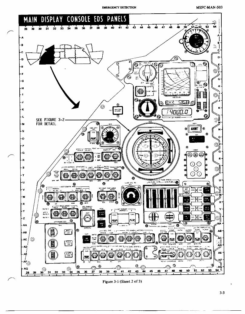
EMERGENCY DETECTION MSFC-MAN-503
3-3

MSFC-MAN-503 EUERGENCVOEa_C'nON
55 56 57 58 50 E0 81 62 63 64 65 66 67 88 69 70 71 72 73 74 75 76 77 78 79 80 81
"A A-
-B B-
-C C-
-D O-
-E E-
(_1 (osl2, (osla,
CMD TRNF
ON CM I 2
OFF $M OFF
K-
@ c.M-
.N-
O-
p.
Q.
R-
RCS CMD OFF OFF
I LAUNCH VEHICLE I U °GUIDANCE SI_SIVB X LUNAR
IU LV STAGE INJECT V-
"_ 1S691 W"
X-
!_) CMC u v OFF v SAFE _ Y"
MAIN RELEAS I _ Z"
(sTI) AA-
-AC AC-
AD-
AE-
CENTER CONSOLEAF-
AG AG -55 56 57 58 59 60 81 62 63 64 65 66 67 68 69 70 71 72 73 74 75 76 77 78 79 80 81
Figure 3-1 (Sheet 3 of 3) _-"_
3-4

EMERGENCY DETEC'_ON MSFC-MAN-503
ROLL+ ANGULAR VELOCITY-+ ATTITUDE ERROR -
PITCH & YAW INDEX
PEULER ATTITUDE ON BALL ATTITUDE I ANGULARPITCH 0 = 014° ERROR T VELOCITYYAW @ = 034° + C +ROLL _ = 330° H
TOTALA'I'I'ITUDESCALE
NOTE:YAW
ALL POLARITIESINDICATE + ATTITUDEERRORVEHICLEDYNAMICS + ANGULARVELOCITY-
Figure 3-2
A signal is sent from the LVDA to activate the LV GUID I W A R N I U G |light (Q-52, figure 3-1) in the CM at the same time the flight I Icontrol commands are inhibited. It is a single cue for abort.Second cues will be provided by the LV RATE light (only If the NO AUTO ABORT pushbutton is depressed atwhen the Auto Abort system is on) and by the FDAI (Q-45), T-O and a pad shutdown should occur, a pad abortangle of attack (qa) (W-42) meter and/or ground will result.information.
ABORT LIGHT
LIFTOF F/NO AUTO ABORT LIGHTS The ABORT light (N-51, figure 3-1) may be illuminated byground command from the Flight Director, the MissionControl Center (MCC) Booster Systems Engineer, the Flight
The L1FTOFF and NO AUTO ABORT lights (V-50, figure Dynamics Officer, the Complex 39 Launch Operations3-1) are independent indications contained in one Manager (until tower clearance at +i0 seconds), or inswitch/light assembly, conjunction with range safety booster engine cutoff and
destruct action. The ABORT light ON constitutes one abortcue. An RF voice abort request constitutes one abort cue.
The LIFTOFF light ON indicates that vehicle release hasbeen commanded and that the IU umbilical has ejected. The NOTES/C digital event timer is started by the same function. TheLIFTOFF light is turned OFF at S-ICCECO. Pilot abort action is required prior to receipt of an
ABORT light or a voice command for a largeThe NO AUTO ABORT light ON indicates that one or both percentage of the time critical launch vehicleof the spacecraft sequencers did not enable automatic abort malfunctions, particularly at liftoff and staging.capability at liftoff. Automatic abort capability can beenabled by pressing the switch/light pushbutton. If the light ANGLE OF ATTACK METERremains ON, then the crew must be prepared to back up the
_" automatic abort manually. The NO AUTO ABORT light is The angle of attack (qa) meter (W-42, figure 3-1) is timealso turned OFF at S-IC inboard engine cutoff, shared with service propulsion system (SPS) chamber
3-5

MSFC-MAN-503 EMERGENCY DETECTION
pressure, the qa display is a pitch and yaw vector summed liftoff command which enables automatic aborts. Theangle-of-attack/dynamic pressure product (qa). It is command pilot should be prepared to manually back up itsexpressed in percentage of total pressure for predicted launch start to assure timer operation.
vehicle breakup (abort limit equals 100%). It is effective as an _,abort parameter only during the high q flight region from The event timer is reset to zero automatically with abort+50 seconds to + 1minute 40 seconds, initiation.
Except as stated above, during ascent, the qa meter providestrend information on launch vehicle flight performance and MASTER ALARM LIGHTprovides a secondary cue for slow-rate guidance and controlmalfunctions. Primary cues for guidance and control There are three MASTER ALARM lights, one on Mainmalfunctions will be provided by the FDAI, physiological Display Panel 1 (K_I, figure 3-1) one on Main Display Panelcues, and/or MCC callout. 3 an.d one in the lower Equipment Bay. The three MASTER
ALARM lights ON alert the flight crew to critical spacecraftNominal angle of attack meter indications should not exceed failures or out-of-tolerance conditions identified in the25%. Expected values based on actual winds aloft will be caution and warning light array. After extinguishing theprovided by MCC prior to launch, alarm lights, action should be initiated to correct the failed or
out-of-tolerance subsystem. If crew remedial action does notACCELEROMETER correct the affected subsystem, then an abort decision must
be made based on other contingencies. Secondary abort cues
The accelerometer (N-39, figure 3-1) indicates longitudinal will come from subsystem displays, ground verification, andacceleration/deceleration. It provides a secondary cue for physiological indications.certain engine failures and is a gross indication of launchvehicle performance. The accelerometer also provides a NOTEreadout of G-forces during reentry.
The Commander's MASTER ALARM light (K-41)S-II SEP LIGHT will not illuminate during the launch phase, but the
other two MASTER ALARM lights can illuminateWith S-IC/S-II staging, the S-II SEP light (Q-51, f'gure 3-1) and their alarm tone can sound.will illuminate. The light will go out approximately 30
seconds later when the interstage structure is jettisoned. A EMERGENCY DETECTION SYSTEM CONTROLsevere overheating problem will occur if the structure is notjettisoned at the nominal time. Under the worst conditions,abort limits will be reached within 25 seconds from nominal EDS AUTO SWITCH
jettison time. Confirmation from Mission Control of _-xinterstage failure to jettison serves as the second abort cue. The EDS AUTO switch (N-60, figure 3-1) is the master
switch for EDS initiated automatic abort. When placed in theDuring the earth orbit phase of the mission the S-II SEP light AUTO position (prior to liftoff), an automatic abort will beis again used. It is turned ON to indicate the beginning of initiated if:restart preparations at T6+0.1 seconds. It is turned OFF atT6+41.6 seconds to indicate O2H2 burner ignition. It is 1. a LV structural failure occurs between the IU andturned ON again at T6+8 minutes 40 seconds and OFF again the CSM,at T6+9 minutes 20 seconds to indicate translunar injection
commit (engine start-10 seconds). 2. two or more S-IC engines drop below 90% of rated
ALTI METE R thrust,
3. LV rates exceed 4 degrees per second in pitch or yawDue to dynamic pressure, static source location, and or 20 degrees per second in roll.instrument error the altimeter (A-51, figure 3-1) is not
considered to be an accurate instrument during the launch The two engine out and LV rate portions of the auto abortphase, system can be manually disabled, individually, by the crew.
However, they are automatically disabled by the LVThe primary function of the altimeter is to provide an sequencer prior to center engine cutoff.adjustable (set for barometric pressure on launch date)reference for parachute deployment for pad/near LES aborts.However, the aerodynamic shape of the CM coupled with the PRPLNT SWITCHstatic source location produces errors up to 1300 feet.Therefore, the main parachutes must be deployed at an
The PRPLNT switch (R-58, figure 3-1) is normally in theindicated 3800 feet (depends on launch day setting) toensure deployment of 2500 feet true altitude. DUMP AUTO position prior to liftoff in order to
automatically dump the CM reaction control system (RCS)EVENT TIME R propellants, and fire the pitch control (PC) motor if an abort
is initiated during the first 42 seconds of the mission. The
The event timer (AE-51, figure 3-1) is critical because it is the propellant dump and PC motor are inhibited by the SCprimary cue for the transition of abort modes, manual sequencer at 42 seconds. The switch in the RCS CMD
sequenced events, monitoring roll and pitch program, staging, position will inhibit propellant dump and PC motor firing atand S-IVB insertion cutoff. The event timer is started by the any time.
3-6

EMERGENCY DETECTION MSFC-MAN-503
TOWER JETTISON SWITCHES ELS AUTO/MAN SWITCH
Either of two redundant Tower Jettison switches (R-66, The ELS AUTO/MAN switch (AC-49, figure 3-1) is used inf"" figure 3-1) can be used to fire the explosive bolts and the conjunction with either the automatically initiated ELS
tower jettison motor. The appropriate relays are also sequence (post-abort) or with the manually initiatedde-energized so that if an abort is commanded, the SPS abort sequence (ELS LOGIC ON). The switch is normally in thesequence and not the LES sequence will occur. The switches AUTO position as it will inhibit all ELS functions when inare momentary to the TWR JETT position. Both switches the MAN position.
should be activated to ensure that redundant signals are ELS LOGIC SWITCHinitiated.
The ELS LOGIC switch (AC-48, figure 3-1) is a switch,No other automatic functions will occur upon activation of guarded to OFF, which should only be activated duringthe Tower Jettison switches, normal reentry or following an SPS abort, and then only
below 45,000 feet altitude. If the switch is activated at anyCM/SM SEP SWITCHES time below 30,000 feet (pressure altitude), the landing
sequence will commence, i.e., LES and apex cover jettisonThe two CM/SM SEP switches (N-66, figure 3-1) are and drogue deployment. If activated below 10,000 feetredundant, momentary ON, guarded switches, spring loaded altitude, the main chutes will also deploy.to the OFF position. They are used by the Command Pilot toaccomplish CM/SM separation when required. Both switches ELS LOGIC is automatically enabled following any manualshould be activated to ensure that redundant signals are or auto EDS initiated LES abort. It should be manuallyinitiated, backed up if time permits.
These switches can 'also be used to initiate an LES abort incase of a failure in either the EDS or the translational I W AII M I N G =Icontroller. All normal post-abort events will then proceed I I
automatically. However, the CANARD DEPLOY (Y-50)pnshbutton should be depressed 11 seconds after abort Activation of ELS LOGIC switch below 30,000 feetinitiation, because canard deployment and subsequent events altitude will initiate landing sequence, i.e., LES andwill not occur if the failure was in the EDS instead of the apex cover jettison, and drogue deployment.translational controller. If the CANARD DEPLOY
pushbutton is depressed, all automatic functions from that CM RCS PRESS
_" point on will proceed normally. Any time the CM is to be separated from the SM, the CMRCS must be pressurized. The normal sequence of events for
S-II/S-IVB LV STAGE SWITCH an abort or normal CM/SM SEP is to automatically deadface
S-I1/S-IVB LV STAGE switch (X-60, figure 3-1) activation the umbilicals, pressurize the CM RCS, and then separate theapplies a signal to the LVDA to initiate the S-II/S-IVB staging CM/SM. However, if the automatic pressurization fails, thesequence. This capability is provided to allow the crew to CM RCS can be pressurized by the use of the guarded switchmanually upstage from a slowly diverging failure of the S-If (not shown) located on panel 2.stage. If the S-IVB does not have a sufficient velocityincrement (AV) available for orbit insertion, an abort can be MAIN RELEASEperformed at predetermined locations.
The MAIN RELEASE switch (AB-57, figure 3-1) is guarded
The S-II/S-IVB LV STAGE switch can also be used to to the down position. It is moved to the up position tomanually release the main chutes after the Command Module
manually initiate cutoff of the S-IVB stage, has landed. No automatic backup is provided. This switch isarmed by the ELS LOGIC switch ON and the 10k barometric
S-IVB/LM SEP SWITCH switches closed (below 10,000 feet altitude).
Activation on the S-IVB/LM SEP switch (N-70, figure 3-1) NOTEwill cause separation, by ordnance, of tension ties securingthe LM legs to the SLA and start two parallel time delays of The ELS AUTO switch must be in the AUTO0.03 seconds each. At expiration of the time delay, the LM position to allow the 14 second timer to expiretension tie firing circuit is deadfaced and the umbilical before the MAIN CHUTE RELEASE switch willguillotineisfired, operate.
ABORT CONTROLSCSM/LM FINAL SEP SWITCHES
TRANSLATIONAL CONTROLLER
The LM docking ring is simultaneously jettisoned with theTWR JETT command during an LES abort. During a normal Manual aborts will be commanded by counterclockwiseentry or an SPS abort, the ring must be jettisoned by (CCW rotation of the translational controller T-handle.actuation of either CSM/LM FINAL SEP switch (N-63, figure Clockwise (CW) rotation will transfer SC control from the
? 3-1). Failure to jettison the ring could possibly hamper command module computer (CMC) to the stability controlnormal earth landing system (ELS) functions, system (SCS).
3-7

MSFC-MAN-503 EMERGENCY DETECTION
For LES aborts, the CCW position sends redundant engine 1. Flight combustion stability monitor (FCSM) shuts itcutoff commands (engine cutoff from the SC is inhibited for down automatically.the fast 30 seconds of flight) to the launch vehicle, initiates
CM/SM separation, fires the LES motors, resets the 2. AV=0(SCSorMTVC). ._sequencer, and initiates the post abort sequence.
3. AV THRUST switches (both) OFF.For Service Propulsion System (SPS) aborts, the CCWrotation commands LV engine cutoff, resets the spacecraft NOTEsequencer and initiates the CSM/LV separation sequence.
The SPS THRUST light 0-49, figure 3-1) willThe T-handle also provides CSM translation control along one illuminate when the engine is firing.or more axes. The control is mounted approximately parallelto the SC axis; therefore, T-handle movement will cause SPS THRUST DIRECT Switchcorresponding SC translation. Translation in the ÷X axis can
also be accomplished by use of the direct ullage pushbutton; The SPS THRUST DIRECT Switch (Z-36, figure 3-1) is ahowever, rate damping is not available when using this two-position, lever lock, toggle switch. The ON positionmethod, provides a ground for the solenoid valve power and all of the
SCS logic. The engine must be turned off manually bySEQUENCER EVENT MANUAL PUSHBUTTON placing the SPS THRUST DIRECT switch in the NORMAL
position. The AV THRUST switches must be in theThe LES MOTOR FIRE, CANARD DEPLOY, CSM]LV SEP, NORMAL position (at least one) to apply power to theAPEX COVER JETT, DROGUE DEPLOY, MAIN DEPLOY, solenoids for the SPS THRUST DIRECT switch to operate.and CM RCS He DUMP, pushbuttons (X-5 l, figure 3-1)provide backup of sequenced events for both abort and
normal reentry situations. [ _lf A l[ M I II G Iq
The MAIN DEPLOY pushbutton is the primary method ofdeploying the main parachutes for pad/near pad aborts to The SPS THRUST DIRECT switch is a single pointassure deceleration to terminal velocity at touchdown failure when the AV THRUST switches are in the(downrange tipover). NORMAL position.
SPSSWITCHES AND DISPLAYS SPS Gimbal Motors/Indicators
DIRECT ULLAGE Pushbutton Four gimbal motors control the SPS engine position in thepitch and yaw planes (two in each plane). These motors are ,_,activated by four switches (AC-43, figure 3-1). The motors
When the DIRECT ULLAGE pushbutton (Y-38, figure 3-1) is should be activated one at a time due to excessive currentdepressed, a +X translation utilizing all four quads results. It drain during the start process.is the backup method for ullage maneuvers prior to an SPSburn (the prime method for ullage is the translational The gimbal thumbwheels (Z-46, figure 3-1) can be used tocontroller). The DIRECT ULLAGE switch is momentary and position the gimbals to the desired attitude as shown on themust be held until the ullage maneuver is complete. It will indicators. The indicators are analog displays time-sharednot provide rate damping, with the booster fuel and oxidizer pressure readings.
THRUST ON Pushbutton The other methods of controlling the gimbal movement isthrough the hand controller in the MTVC mode or by
The THRUST ON pushbutton (AA-38, figure 3-1) can be automatic SCS logic.used to start the SPS engine under the following conditions:
AV TH RUST (Prevalvesand Logic)I. S/C control is in the SCS mode.
The two guarded AV THRUST switches (Z-41, figure 3-1)2. Ullage is provided, apply power to the SPS solenoid prevalves and to the SCS
logic for SPS ignition. These switches must be in the3. Either of two AV THRUST switches (Z-41, figure NORMAL position before the SPS engine can be started,
3-1) ate in the NORMAL position even by the SPS THRUST DIRECT switch.
NOTE
Both switches must be OFF to shut off the engine.
Both switches must be in the OFF position to stop the engine.4. When backup for guidance and navigation start
command is required. SCS TVC Switches
SPS Engine Shutdown The SCS TVC switches (AC-39, figure 3-1) provide thrustvector control only in the SCS mode. The pitch and yaw
The SPS engine can be shut off (when f'med as described channels can be used independently, i.e., pitch control in SCSabove) in the following manner: AUTO position and yaw in either RATE CMD or ACCEL
3-8

FJ_RCE_CY])E_C'nON MSFC-MAN-503
CMD position. The three available modes are: ATT SET Switch
l. AUTO: The TVC is directed by the SCS The ATT SET switch (Q-40, f'_,ure 3-1) selects the source ofelectronics, total attitude for the ATT SET resolvers as outlined below.
Position Function Description2. RATE CMD: MTV with rate damping included.
UP IMU Applies inertial measurement3. ACCEL CMD: MTVC without rate damping, unit (IMU) gimbal resolver
s_nal to ATT SET resolvers.
EMS MODE and EMS FUNCTION Switches FDA1 error needles displaydifferences. Needles are zeroed
by maneuvering S/C or byIn order for the AV counter to operate during an SPS burn, moving the ATT SET dials.the EMS MODE switch (I-I-44, figure 3-1) and the EMS
FUNCTION switch(F-45) must be in the following positions: DOWN GDC Appfies GDC resolver signal toATT SET resolvers. FDAI error
1. EMS MODE - AUTO. needles display differencesresolved into body coordinates.
2. EMS FUNCTION-AV. Needles zeroed by moving S/Cor ATT SET dials. New attitude
re ference is established byTo set the AV counter for a desired AV burn the switcheswould be as follows: depressing GDC ALIGN button.
This will cause GDC to drive to
1. EMS MODE - AUTO null the error; hence, the GDCand ball go to ATT SET dialvalue.
2. EMS FUNCTION - AV SET
MANUAL ATTITUDE Switches
The AV/EMS SET switch (I-52, figure 3-1) is then used toplace the desired quantity on the AV display. The three MANUAL ATTITUDE switches (T-34, figure 3-1)
are only operative when the S/C is in the SCS mode of
SCS SYSTEM SWl TCHES operation.
Position Description_ AUTO RCS SELECT Switches
ACCEL CMD Provides direct RCS fh'ing as a result of movingPower to the RCS control box assembly is controlled by 16 the rotational controller out of detentswitches 0-15, figure 3-1). Individual ev_,inesmay be enabled (2.5degrees) to apply direct inputs to theor disabled as required. Power to the attitude control logic is solenoid driver amplifier_also controlled in this manner, which thereby controls allattitude hold and/or maneuvering capability using SCS RATE CMD Provides proportional rate command fromelectronics (automatic coils). The direct solenoids are not rotational controller with inputs from theaffected as all SCS electronics are bypassed by activation of BMAG's in a rate configuration.the DIRECT RCS switches.
M1N IMP Provides minimum impulse capability throughthe rotational controller.
NOTE
LIMIT CYCLE Switch
The automatic coils cannot be activated until the
RCS ENABLE is activated either by the MESC or The LIMIT CYCLE switch, when placed in the LIMITmanually. CYCLE position, inserts a psuedo-rate function which
provides the capability of maintaining low SC rates whileholding the SC attitude within the selected deadband limits
DIRECT Switches (limit cycling). This is accomplished by pulse-widthmodulation of the switching amplifier outputs. Instead of
Two DIRECT switches (W-35, f'_gure3-1) provide for manual driving the SC from ilmit-to-limit with high rates by fhing thecontrol of the SM RCS engines. Switch 1 controls power to RCS engines all the time, the engines arc fired in spurtsthe direct solenoid switches in rotational controller 1 and proportional in length and repetition rate to the switchingswitch 2 controls power to the direct solenoid switches in amplifier outputs.rotational controller 2. In the down position switch 1receives power from MNA and switch 2 receives power from Extremely _nall attitude corrections could be commanded
MNB. In the up position both switches receive power from which would cause the pulse-width of the resulting output
both MNA and MNB. Manual control is achieved by command to be of too short a duration to activate the RCS_ positioning the rotational control hardover to engage the solenoids. A one-shot multivibrator is connected in parallel to
direct solenoids for the desired axis change, ensure a long enough pulse to fire the engines.
3-9

MSFC-MAN-503 _ERGENCY DETBC'nON
RATE and A'IT DEADBAND Switches Position Description
The switching amplifier deadband can be interpreted as a rate RATE 2 BMAG Set No. 2 provides the rate displays onor an attitude (minimum) deadband. The deadband limits are the FDAI. There is no Body Mounted Attitude _a function of the RATE switch (T-39, figure 3-1 l). An Gyro (BMAG) attitude reference available.additional deadband can be enabled in the attitude control
loop with the ATT DEADBAND switch (T-38, figure 3-1).See figure 3-3 for relative rates. ATT l BMAG Set No. I provides attitude reference
on the FDAI, whileRATE 2 Set No. 2 provides the rate display.
ATTITUDE DEADBAND SWITCH POSITION
RATE 1 BMAG Set No. 1 provides the rate displays on
RATE Al'r DEADBAND the FDAI. There is no BMAG attitudeRATE DEAOBAND SWITCH POSITION referenceavailable.
SWITCH POSITION °/SEeMINIMUM MAXIMUM ENTRY EMS ROLL Switch
The ENTRY EMS ROLL switch (AE-37, figure 3-1) enables
LOW +0.2 +0.2 ° +4.2 o the EMS roll display for the earth reentry phase of the flight.
HIGH +2.0 +2.0 ° +8.0 ° ENTRY, .OffG Switch
Illumination of the .05 G light located on the EMS panel isthe cue for the crew to actuate the .05 G switch (AE-38,
Figure 3-3 figure 3-1). During atmospheric reentry (after .05 G), the SCis maneuvered about the stability roll axis rather than the
The rate commanded by a constant stick deflection body roll axis. Consequently, the yaw rate gyro generates an(Proportional Rate Mode only) is a function of the RATE undesirable signal. By couphng a component of the roll signalswitch position. The rates commanded at maximum stick into the yaw channel, the undesirable signal is cancelled. Thedeflection (soft stop) are shown in figure 3-4. .05 G switch performs this coupling function.
EMS DISPLAYSMAXIMUMPROPORTIONALRATE COMMAND
Threshold Indicator (.05 G Light)MAXIMUMPROPORTIONAL
RATE RATE COMMAND The threshold indicator (.05G light) (J-48, figure 3-1)SWITCH POSITION provides the first visual indication of total acceleration sensed
PITCH AND YAW ROLL at the reentry threshold (approximately 290,000 feet).Accelerometer output is fed to a comparison network and
LOW 0.65°/sec 0.65°/sec will illuminate the .05 G lamp when the acceleration reachesHIGH 7.0°/see 20.0 °/see .05 G. The light will come on not less than 0.5 seconds ormore than 1.5 seconds after the acceleration reaches .05 G
and turns off when it falls below .02 G (skipout).
Corridor Indicators
Figure 3-4By sensing the total acceleration buildup over a given period
SC CONT Switch of time, the reentry flight path angle can be evaluated. Thisdata is essential to determine whether or not the entry angleis steep enough to prevent superorbital "skipout."
The SC CONT switch (W-38, figure 3-1 ) selects the spacecraftcontrol as listed below: The two corridor indicator lights (J-45 and L-45, figure 3-1)
are located on the face of the roll stability indicator (K-45).
Position DescriptionIf the acceleration level is greater than 0.2 G at the end of a
CMC Selects the G&N system computer controlled ten second period after threshold (.05 G light ON), the upperSC attitude and TVC through the digital light will be illuminated. It remains ON until the G-levelauto-pilot. An auto-pilot control discrete is reaches 2 G's and then goes OFF. The lower light illuminates
if the acceleration is equal to or less than 0.2 G at the end ofalso applied to CMC.
a ten second period after threshold. This indicates a shallow
SCS The SCS system controls the SC attitude and entry angle and that the lift vector should be down for1a¢C. controlled entry, i.e., skipout will occur.
BMAG MODE Switches Roll Stability Indicator
The BMAG MODE switches (Y-33, figure 3-1) select displays The roll stability indicator (K-45, figure 3-1) provides a visual /--"for the FDAI using SCS inputs, indication of the roll attitude of the CM about the stability
3-10

EMERGENCYDETF_nON MSFC-MAN-503
axis. Each revolution of the indicator represents 360 degrees "high-G-rays" must be monitored from initial entry velocityof vehicle rotation. The display is capable of continuous down to 4000 feet per second. The "exit rays" are significantrotation in either direction. The pointer up position (0 only between the entry velocity and circular orbit velocity
_. degrees) indicates maximum lift-up vector (positive lift) and and are, therefore, only displayed on that portion of thepointer down (180 degrees) indicates maximum lift-down pattern.vector (negative lift).
The imprinted "high-G-rays" and "exit rays" enableG-V Plotter detection of primary guidance failures of the type that would
result in either atmospheric exits at supercircular speeds orThe G-V plotter assembly (G-49, figure 3-1) consists of a excessive load factors at any speed. The slope of the G-Vscroll of mylar tape and a G-indicating stylus. The tape is trace is visually compared with these rays. If the tracedriven from right to left by pulses which are proportional to becomes tangent to any of these rays, it indicates a guidancethe acceleration along the velocity vector. The stylus which malfunction and the need for manual takeover.scribes a coating on the back of the mylar scroll, is driven inthe vertical direction in proportion to the total acceleration. EMS FUNCTIONSwitch
The front surface of the mylar scroll is imprinted with The EMS FUNCTION switch (F-45, figure 3-1) is a 12patterns consisting of "high-G-rays" and "exit rays." The position selector mode switch, used as outlined in figure 3-5.
EMS FUNCTION SWITCH OPERATION
OperationalMode Switch Selection Switch Position Description
AV Mode Start at AV and AV Operationalmode for mon-rotate clockwise itori:ngAV maneuvers
_V Set Establishcircuitw forslowing AV counter forself test or as operational
AV Test Operationalmode for selftest of the AV subsystem
Self Test Start at No. l No. l Tests lower trip point ofand Entw and rotate counter- .05 G threshold con_aratorMode clockwise
No. 2 Tests higher trip point of.05 G threshold conTparator
No. 3 Tests lower trip point ofcorridor verificationcom-
parator
No. 4 Tests velocity integrationcircuitry, g-servo circuitW,G-V plotter, and the range-to-go subsystem
No. 5 Tests higher trip point ofcorridor verification
comparator
RNG Set Establishcircuitw forslowing range-to-gocounterfor operationaland test modes
Vo Set Establishcircuitry forslowing G-V plotter scrollfor operationalmode
Entry Operationalmode for monitor-ing ent_ mode
OFF Turns OFF all power exceptto the SPS thrust light andswitch lighting.
Figure 3-5
3-11

MSFC-MAN-503 EMERGENCYDETECTION
EMS MODE Switch EMERGENCY MODES
The EMS MODE switch (H-44, figure 3-1) performs the Aborts performed during the ascent phase of the mission willfollowing functions in the positions indicated: be performed by either of the two following methods:
AUTO LAUNCH ESCAPE SYSTEM
1. Acts as backup display for G&N entry. The Launch Escape System (LES) consists of a solidpropellant launch escape (LE) motor used to propel the CM a
2. Initiates the function selected by the F_MS safe distance from the launch vehicle, a tower jettison motor,FUNCTION switch, and a canard subsystem. A complete description on use of
the system can be found in the specific mission AbortSTBY Summary Document (ASD). A brief description is as follows:
1. Resets circuits following tests. Mode IA Low Altitude Mode
2. Removes power if EMS FUNCTION switch is OFF. In Mode IA, a pitch control (PC) motor is mounted normalto the LE motor to propel the vehicle downrange to ensure
MAN water landing and escape the "fireball." The CM RCSpropellants are dumped through the aft heat shield during
1. Position for manual entry and TVC modes, or auto this mode to prevent a possible fire source at landing.entry backup display.
The automatic sequence of major events from abort initiation
2. Does not permit negative acceleration spikes into is as follows:countdown circuits. Time Event
ABORT MODES AND LIMITS 00:00 AbortOx Rapid Dump
The abort mode and limits listed in figures 3-6 and 3-7 are LE and PC Motor Firebased on a nominal launch trajectory. More specific times can 00:05 Fuel Rapid Dumpbe obtained from current mission documentation. 00:11 Canards Deploy
00:14 ELSArm
NOMINAL LAUNCH CALLOUTS 00:14.4 Apex Cover Jett00:16 Drogue Deploy
The nominal launch cailouts are listed in figure 3-8 for the 00:18 He Purgeboostphaseonly. 00:28 MainDeploy
APOLLO ABORT MODES
TimePeriod Mode Description
Padto42sec ModeIA LETLow Alt
42Sectol min50sec ModeIB LETMED Aft
l min50 secto 3 min07 sec ModeIC LETHigh Aft
3 min07 secto lOmin 30sec Mode II FullLift
lOmin30 secto insertion ModeIII SPSRetroforCSM HalfLiftNo Go
lOmin 7 secto insertion ModeIV SPStoOrbitfor CSHGo
Figure 3-6
3-12

EMERGENCY DETECTION MSFC-MAN-503
ABORT LIMITS
RATES
I. Pitch and Yaw
L/O to S-IC/S-IIStaging 4° per second
Staging to SECO 9.2° per second(Excluding staging)
2. Roll
L/O to SECO 20° per second
MAX Q REGION
NOTE: The followinglimits representsingle cues and are restrictedto the time period from 50 seconds to l minute 40 seconds.Abort action should be taken only after both have reachedthreshold.
I. Angle of Attack = lO0 percent
2. Roll Error = 6 degrees
AUTOMATIC ABORT LIMITSL/O until deactivate(time to be determined)
I. Pitch and Yaw 4.0° + 0.5° per second
Roll 20.0o + 0.5° per second
2. Any Two Engines Out
NOTE: Between L/O and 2 + O, switch TWO ENG OUT AUTO to OFFfollowing confirmation of ONE ENG OUT.
3. CM/IU breakup
ENGINE FAILURE(LIO to CECO)
I. OneEngineOut ContinueMission
2. Simultaneous Loss twoor more engines Abort
3. Second engine loss fo|-Iowi ng confirmation ofone engine out Continue Mission
S-IVB TANK PRESSURE LIMITS(L/O to CSM/LVSEP)
AP LH2>L02 = 26 PSID
LO2>LH2 = 36 PSID
Figure 3-7
3-13

MSFC-MAN-503 EMERC_ DETECTION
NOMINAL LAUNCHPHASE VOICE CALLOUTS (BOOSTONLY)
TIME STATION REPORT EVENT
-0:09 LCC IGNITION S-ICIGNITIONO:O0 LCC LIFT-OFF UMBILICALDISCONNECTO:OI CDR LIFT-OFF CMDTO PllDETSTARTO:ll CDR ROLLCOMMENCE ROLLPROGRAMSTARTS0:21 CDR PITCHTRACKING PITCHRATEDETECTION0:29 CDR ROLLCOMPLETE ROLLCOMPLETE0:42 MCC MARK,MODEIB PRPLNTDUMP- RCSCMD1:50 MCC MARK,MODEIC h = IO0,O00FT,16.5NM2:00 CDR EDSMANUAL EDSRATES- OFF
EDS ENG - OFFEDS AOA- Pc
2:00 MCC GO/NO GO FOR STAGING STAGING STATUS-TWRJETT STATUS IF
REQUIRED2:00 CDR GO/NO GO FOR STAGING2:05 CDR INBOARDOFF S-ICINBOARDENG- OFF2:3] CDR OUTBOARDOFF S-ICOUTBOARDENG- OFF2:32 CDR STAGING S-IILIGHTSOFF2:33 S-IIIGNITIONCOMMAND2:36 CDR S-II65% S-II65%3:01 CDR S-IISEPLIGHTOUT S-IISEP LIGHTOUT3:07 CDR TOWERJEI-F TOWERJETTISONED
MARK,MODEII MANATT (P)- RATECMD3:I2 CDR GUIDINITIATE IGMSTARTS4:00 CDR S/C GO/NO GO
MCC GUIDANCE GO/NO GO IGM LOOKS GOOD4:30 MCC TRAJECTORYGO/NO GO TRAJECTORYSTATUS5:00 CDR S/C GO/NO GO5:53 MCC S-IVBTOORBIT
CAPABILITY6:00 CDR S/C GO/NO GO7:00 CDR S/C GO/NO GO8:00 CDR S/C GO/NO GO8:20 MCC GO/NO GO FOR STAGING STAGING STATUS8:40 CDR S-IIOFF S-IILIGHTS- ON8:41 CDR STAGING S-IVBLIGHT- OFF8:45 CDR S-IVBIGNITION S-IVBIGNITION8:46 CDR S-IVB 65% S-IVB 65%9:00 CDR S/C GO/NO GO9:45 MCC MODEIV
lO:O0 MCC CDR S/C GO/NO GO FORORBIT
ll:21 CDR SECO S-IVBLIGHTONIl:31 MCC INSERTION
Figure 3-8
The automatic sequence can be prevented, interrupted, or As in Mode IA, the crew intervention can alter the sequencereplacedbycrewaction, ofeventsif desired.
Mode IB MediumAltitude ModeIC HighAltitude
During Mode IC the LV is above the atmosphere. Therefore,Mode IB is essentially the same as Mode IA with the the canard subsystem cannot be used to induce a pitch rateexception of deleting the rapid propellant dump and PC to the vehicle. The crew will, therefore, introduce a fivemotor features. The canard subsystem was designed degree per second pitch rate into the system. The CM/towerspecifically for this altitude region to initiate a tumble in the combination will then stabilize BEF as in Mode IB. The ELSpitch plane. The CM/tower combination CG is located such would likewise deploy the parachutes at the proper altitudes.that the vehicle will stabilize (oscillations of+_30 degrees) inthe blunt-end-forward (BEF) configuration. Upon closure of An alternate method (if the LV is stable at abort) is to
barometric switches, the tower would be jettisoned and the jettison the tower manually and orient the CM to the reentryparachutes automatically deployed, attitude. This method provides a more stable entry, but
3-14

EMERGENCYDETECTION MSFC-MAN-503
requires a functioning attitude reference. Mode Ill
SERVICE PROPULSION SYSTEM The SPS engine is used to slow the CSM combination(retrograde maneuver) so as to land at a predetermined point
_- The Service Propulsion System (SPS) aborts utilize the in the Atlantic Ocean. The length of the SPS burn isService Module SPS engine to propel the CSM combination dependent upon the time of abort initiation. Uponaway from the LV, maneuver to a planned landing area, or completion of the retro maneuver, the CM will separate fromboost into a contingency orbit. The SPS abort modes are: the SM, assume the reentry attitude, and follow normal entry
procedures.Mode II
Mode IV
The SM RCS engines are used to propel the CSM away fromthe LV unless the vehicle is in danger of exploding or The SPS engine can be used to make up for a deficiency inexcessive tumble rates are present at LV/CSM separation. In insertion velocity up to approximately 3000 feet per second.these two cases the SPS engine would be used due to greater This is accomplished by holding the CSM in an inertial
AV and attitude control authority. When the CMS is a safe attitude and applying the needed &V with the SPS to acquiredistance and stable, the CM is separated from the SM and the acceptable orbital velocity. If the inertial attitude holdmaneuvered to a reentry attitude. A normal entry procedure mode is inoperative, the crew can take over manual controlis followed from there, and maneuver the vehicle using onboard data.
3-15/3-16

MSFC-MAN-503
SECTIONIV AS-ICSTGEf-.
TABLE OF CONTENTS skin panels, fabricated from 7075-T6 aluminum, are stiffenedand strengthened by ring frames and stringers.
INTRODUCTION .............................. 4-1STRUCTURE .................................. 4-1 OXIDIZER TANKENVIRONMENTAL CONTROL ................... 4-3PROPULSION ................................. 4-4 The 345,000 gallon Iox tank is the structural link betweenFLIGHT CONTROL SYSTEM ..................... 4-7 the forward skirt and the intertank section. The cylindricalPNEUMA TIC CONTROLS ........................ 4-7 tank skin is stiffened by "integrally machined" T stiffeners.PROPELLANTS ................................ 4-7 Ring baffles (figure 4-1) attached to the skin stiffenersELECTRICAL ................................ 4-13 stabilize the tank wall and serve to reduce Iox sloshing. AINSTRUMENTATION .......................... 4-18 cruciform baffle at the base of the tank serves to reduce bothORDNANCE ................................. 4-22 slosh and vortex action. Support for four helium bottles is
provided by the ring baffles. The tank is a 2219-T87INTRODUCTION aluminum alloy cylinder with ellipsoidal upper and lower
bulkheads. The skin thickness is decreased in eight steps fromThe S-IC stage (figure 4-1) is a cylindrical booster, 138 feet .254 inches at the aft section to .190 inches at the forwardlong and 33 feet in diameter, powered by five liquid section.propellant F-1 rocket engines, These engines develop anominal sea level thrust of 7,650,000 pounds total, and have INTERTANK SECTIONa burn time of 150.7 seconds. The stage dry weight isapproximately 305,100 pounds and total weight at ground The intertank structure provides structural continuityignition is approximately 4,792,200 pounds, between the lox and fuel tanks. This structure provides a lox
fill and drain interface to the intertank umbilical. One
The S-IC stage provides first stage boost of the Saturn V opening vents the fuel tank. The cor_,_ated skin panels andlaunch vehicle to an altitude of about 200,000 feet circumferential ring ft_.es are fabricated from 7075-1"6(approximately 38 miles), and provides acceleration to aluminum.increase the vehicle velocity to 7,700 feet per second(approximately 4,560 knots). It then separates from the S-II FUEL TANK
_" stage and falls to earth about 360 nautical miles downrange.The 216,000 gallon fuel tank (figure 4-1) provides the load
The stage interfaces structurally and electrically with the S-II carrying structural rink between the thrust and intertankstage. It also interfaces structurally, electrically, and structures. It is cylindrical with eliipsoidal upper and lowerpneumatically with two umbilical service arms, three tail bulkheads. Antisiosh ring baffles are located on the insideservice masts, and certain electronic systems by antennae, wall of the tank and antivortex cruciform baffles are locatedThe stage consists of: the structural airframe (figure 4-I); five in the lower bulkhead area (f'_xre 4-1). Five lox ducts (figureF-I engines; 890 vehicle monitoring points; electrical, 4-I) run from the lox tank, through the RP-I tank, andpneumatic control, and emergency flight termination terminate at the F-I engines. The fuel tank has an exclusionequipment; and eight retrorockets. The major systems of the riser, made of a lightweight foam material, bonded to thestage are: structures, propulsion, environmental control, fluid lower bulkhead of the tank to minimize unusable residualpower, pneumatic control, propellants, electrical, fuel. The 2219-T87 aluminum skin thickness is decreased ininstrumentation, and ordnance, four steps from .193 inches at the aft section to .170 inches
at the forward section.STRUCTURE
THRUST STRUCTU REThe SIC structure design reflects the requirements of F-Iengines, propellants, control, instrumentation and interfacing The thrust structure assexably (f'gure 4-1) redistributes locallysystems. The structure maintains an ultimate factor of safety applied loads of the five F-I engines into uniform loadingof at least 1.40 applied to limit load and a yield factor of about the periphery of the fuel tank. It also provides supportsafety of 1.10 on limit load. Aluminum alloy is the primary for the Ewe F-1 engines, engine accessories, base heat shield,structural material. The major components, shown in f'_lre engine f"an'ings and f'ms, propellant lines, retrorockets, and4-1, are the forward skirt, oxidizer tank, intertank section, environmental control ducts. The lower thrust ring has fourfuel tank, and thrust structure, holdd own points which support the fully loaded
Saturn/Apollo (approximately 6,000,000 pounds) and also,FORWARD SKIRT as necessary, restrain the vehicle from lifting off at full F-I
engine thrust. The skin segments are fabricated from 7075-T6
The aft end of the forward skirt (figure 4-1) is attached to aluminum alloy.the oxidizer (lox) tank and the forward end interfaces withthe S-II stage. The forward skirt has accomodations for the The base heat shield is located at the base of the S-1C stage,
forward umbilical plate, electrical and electronic canisters, forward of the engine gimbal plane. The heat shield providesand the venting of the lox tank and interstage cavity. The thermal shielding for critical engine components and base
4-1

MSFC-MAN-503 s-lcSTAGE
S-IC STAGE
FLIGHTTERMINATION FORWARDRECEIVERS(2) \ T SKIRT\ ]20.7 IN
_.L
ox -[CYLINDERS(4)LINE
69 INOXIDIZER
(LOX)TANK
_M
BAFFLE m __
ANNULAR RINGBAFFLES 262.4IN
___.._NTERTAN_ECTION
LINE F
TUNNELS(5) _,,
CENTER FUELENGINE SUCTION 517IN(RP-I)
LINES(5) [ TANK
LFUEL TUNNEL
LINES THRUSTRING
HEAT T_, 233.71N
LOWER CTHRUST
F-I ENGINES-- HEATSHIELD FAIRING(5) --FLIGHT CONTROL AND FIN
INSTRUMENTATION SERVOACTUATORRETROROCKETS
Figure4-1
4-2

SIC STAGE MSFC-MAN-503
region structural components for the duration of the flight. HAZARDOUS GAS DETECTIONThe heat shield panels are constructed of 15-7 PH stainlesssteel honeycomb, 1.00-inch thick, brazed to .010 inch steel The hazardous gas detection system monitors the atmosphereface sheets, in the forward skirt and the thrust structure compartment of
f-" the S-IC (figures 4-2 and 4-3). This system is not redundant,Each outboard F-l engine is protected from aerodynamic however, large leaks may be detected by propellant pressure
loadingtby a conically shaped engine fairing (figure 4-1). The indications displayed in the Launch Control Center.fairings-also house the retrorockets and the engine actuatorsupports. The fairing components are primarily titaniumalloy below station 115.5 and aluminum alloy above this DETECTIONstation. Four fixed, titanium covered, stabilizing finsaugment the stability of the Saturn V vehicle.
ENVI RONMENTAL CONTROL
During launch preparations the environmental control /--FORWARDsystems (ECS) protects the S-IC stage and stage equipment /UMBILICAL
from temperature extremes, excessive humidity, and P0S /PLATEhazardous gases. Conditioned air, provided by the ground JI __-:._ ............ P0S Isupport equipment environmental control unit (GSE-ECU), is - _'/__._"_S_ ............ 7<_"-'--.-'-'"
forced into the forward skirt and thrust structure where it is _.'_:..-.._',_"/"used as a temperature and humidity control medium, f _¢".--'_''_¢_'.'/_-- _:_:_'_,_
Approximately 20 minutes before the two upper stages are _ _,f_1-- .................... __ ,_._
loaded with cry°genie fluids gase°us nitr°gen (GN 2' replaces l_/'_t ORI FI CE RIFICE _iconditioned air and is introduced into the S-1C as the 0
conditioning medium. The GN 2 flow terminates at umbilical |-I_-__",:,,'_, ", ../ _.,,disconnect since the system is not needed in flight. ]!_|:_._?_..'-=, 0PEN _.:_
_ _jiiii_ ORIFICE UNIONON_ ,_.'," ; '
TheFORWARDSKI RT COMPARTMENT -ECSenvironmentalcontrol system distributes air or GN 2 to -ORIFICE I18 electrical/electronic equipment module canisters located
in the forward skirt. Onboard probes control the temperature P0S I I I P0S I V_, of the flow medium to maintain canister temperature at 80
degrees (+_20)F. Three phases of conditioning/purge flow areprovided to compensate for the three environmentalimbalances generated by ambient air changes, internal heat Figure 4-2and Iox load chill effects. Prior to launch the first phasesupplies cool, conditioned air to the canisters when onboardelectrical systems are energized before cryogenic loading. Thesecond phase occurs when relatively warm GN 2 is substitutedfor the cool air to offset temperature differences caused bythe cryogenic loading. The third phase uses a warmer GN 2flow to offset temperature decreases caused by second stageJ-2 engine thrust chamber chilldown. The air or GN 2 isvented from the canisters and overboard through vent P0S IV P0S III
openings in the forward skirt of the S-IC stage. A by-product "_ ""/-. UMBILICALof the use of the inert GN 2 purge is the reduction of gaseous PLATEhydrogen or oxygen concentrations. NO, 3
ORIFICETHRUST STRUCTURE COMPARTMENT- ECS ;_
The environmental control system discharges ak or GN 2 --ORIFICEthrough 22 orificed duct outlets directly into the upper . ,::.¢'_thrust structure compartment. The GSE-ECU supplies P0S I I Iconditioned air at two umbilical couplings during launch "_x. _preparations. At 20 minutes before cryogenic loadingcommences, the flow medium is switched to GN 2 and the _TA l 16.75temperature varied as necessary to maintain the compartmenttemperature at 80 degrees (_IO)F. The controlledtemperature compensates for temperature variations causedby ambient air change, chill effects from lox in the suctionducts, prevalves, and inter-connect ducts. The GN 2 prevents
f'_ the oxygen concentration in the compartment from goingabove6percent. Figure4-3
4-3

B
MSFC-MAN-503 s-Ic STAGE
PROPULSION inert solution serves to smooth out the combustion sequenceat engine start. Flow is terminated by a signal from an
The F-I engine is a single start, 1,530,000 pound fixed observer at the engines. At approximately T-5 minutes, 50thrust, calibrated, bipropellant engine which uses liquid gallons are supplied to top off the system to compensate foroxygen as the oxidizer and RP-I as the fuel. Engine features liquid loss that occurred during engine gimbaling. "_include a bell shaped thrust chamber with a 10:1 expansionratio, and detachable, conical nozzle extension which POGO SUPPRESSION SYSTEMincreases the thrust chamber expansion ratio to 16:1. Thethrust chamber is cooled regeneratively by fuel, and the The POCK) suppression system (figure 4-4) utilizes the loxnozzle extension is cooled by gas generator exhaust gases, prevalve cavities as surge chambers to suppress the POGOLiquid oxygen and RP-I fuel are supplied to the thrust phenomenon. The lox prevalve cavities are pressurized withchamber by a single turbopump powered by a gas generator gaseous helium (GHe) at T-11 minutes from ground supplywhich uses the same propellant combination. RP-I fuel is also by opening the POCK) suppression control valves. During theused as the turbopump lubricant and as the working fluid for initial fill period (T-I 1 to T-9 minutes), the f'dling of thethe engine fluid power system. The four outboard engines are valves is closely monitored utilizing measurements suppliedcapable of gimbaling and have provisions for supply and by the liquid level resistance thermometers R 3 (primary) andreturn of RP-I fuel as the working fluid for a thrust vector R 2 (backup). The GHe ground fill continues to maintain thecontrel system. The engine contains a heat exchanger system cavity pressure until umbilical disconnect. Followingto condition engine supplied liquid oxygen and externally umbilical disconnect the cavity pressure is maintained by thesupplied helium for stage propellant tank pressurizatien. An cold helium spheres located in the lox tank.instrumentation system monitors engine performance andoperation. External thermal insulation provides an allowable Status on system operation is monitored through twoengine environment during flight operation, pressure transducers and four liquid level resistance
thermometers. One pressure transducer (0-800 psia) monitorsENGINE OPERATING REQUIREMENTS system input pressure. A second pressure transducer (0-150
psia) monitors the pressure inside the No. l engine loxThe engine requires asource of pneumatic pressure, electrical prevalve cavity. These pressure readings are transmitted viapower, and propellants for sustained operation. A ground telemetry to ground monitors. The liquid level within thehydraulic pressure source, an inert thrust chamber prefill prevalves is monitored by four liquid level resistancesolution, gas generator igniters, gas generator exhaust igniters, thermometers in each prevalve. These thermometers transmitand hypergolic fluid are required during the engine start a "wet" (colder than -165 degrees centigrade) and a "dry"sequence. The engine is started by ground support equipment (warmer than -165 degrees centigrade) reading to ground(GSE) and is capable of only one start before reservicing, monitors.
PURGE, PREFI LL, AND THERMAL CONDITIONING ENGINE SUBSYSTEMS
A gaseous nitrogen purge is applied for thermal conditioning The subsystems of the F-1 engine shown in figure 4-5 are theand elimination of explosive hazard under each engine turbopump, checkout valve, hypergol manifold, heatcocoon. Because of the possibility of low temperatures exchanger, main fuel valve and main lox valve. Subsystemsexisting in the space between the engine and its cocoon of not shown are the gas generator, 4-way control valve, andthermal insulation, heated _itrogen is applied to this area. pyrotechnic igniters.This purge is manually operated, at the discretion of launchoperations, whenever there is a prolonged hold of thecountdown with lox onboard and with an ambient Hypergol Manifoldtemperature below approximately 55 degrees F. In any case,the purge will be turned on five minutes prior to ignition The hypergol manifold consists of a hypergol container, ancommand and continue until umbilical disconnect, ignition monitor valve (IMV), and an igniter fuel valve (IFV).
The hypergol solution is forced into the thrust chamber by
A continuous nitrogen purge is required to expel propellant the fuel where combustion is initiated upon mixing with theleakage from the turbopump lox seal housing and the gas Iox. The IFV prevents thrust chamber ignition until thegenerator lox injector. The purge pressure also improves the turbopump pressure has reached 375 psi. The IMV preventssealing characteristic of the lox seal. The purge is required opening of the main fuel valves prior to hypergolic ignition.from the time propellants are loaded and is continuous Position sensors indicate if the hypergol cartridge has been
installed. The loaded indication is a prerequisite to the firingthroughout flight, command.
A nitrogen purge prevents contaminants from accumulatingon the radiation calorimeter viewing surfaces. The purge is Control Valve - 4-Waystarted at T-52 seconds and is continued during flight.
The 4-way control valve directs hydraulic fluid to open andA gaseous nitrogen purge is required to prevent contaminants close the fuel, lox, and gas generator valves. It consists of afrom entering the Iox system through the engine lox injector f'flter manifold, a start and stop solenoid valve, and two checkor the gas generator lox injector. The purge system is valves.activated prior to engine operation and is continued untilumbilical disconnect. Turbopump
At approximately T-13 hours, an ethylene glycol solution The turbopump is a combined lox and fuel pump drivenfills the thrust tubes and manifolds of all five engines. This through a common shaft by a single gas turbine.
4-4

SIC STAGE MSFC-MAN-503
Gas Generator acting, pressure balanced, poppet type, hydraulicallyoperated valve. Movement of the poppet actuates a switch
The gas generator (GG) provides the gases for driving the which furnishes valve position signals to the telemetryturbopump. Its power output is controlled by orifices in its system. This valve is designed to remain open, at rated enginepropellant feed lines. The gas generator system consists of a pressures and flowrates, ff the opening control pressure isdual ball valve, an injector, and a combustor. Combustion is lost. Both valves must be in the closed position prior to fuelinitiated by two pyrotechnic igniters. Total propellant flow loading or engine start.rate is approximately 170 lb/sec at a Iox/RP-I mixture ratioof 0.42: 1, The dual ball valve must be closed prior to fuel Main Lox Valveloading and must remain"closed to meet an to meet aninterlock requirement for engine start. The two main lox valves on each engine control flow to the
thrust chamber. These valves are fast acting, pressureHeat Exchanger balanced, poppet type, hydraulically operated valves. A
sequencevalve operated by the poppet allows openingThe heat exchanger expands lox and cold helium for pressure to be applied to the GG valve only after both mainpropellant tank pressurization. The cold fluids, flowing lox valve poppets have moved to a partially open position.through separate heating coils, are heated by the turbopump This valve is designed to remain open, at rated engineexhaust. The warm expanded gases are then routed from the pressures and flowrates, ff the opening control pressure isheating coils to the propellant tanks, lost. Both main lox valves must be in the closed position
prior to lox loading or engine start.Main Fuel Valve
Checkout ValveThere are two main fuelvalvesperengine.They control flowof fuel to the thrust chamber. The main fuel valve is a fast The checkout valve directs ground supplied control fluid
AFT UMBILICAL LOX TANK
"_'__1 _ _" I COLD HELIUMI _e "It Ll---r'__"'"'";- ................ IIIIIIIIIIIIIIIIIIIIIIIIIIIIIII IIIIIIIIIII I STORAGETANKSFILL ---- g
TO FUEL'_
PRESSURIZATION il IPRESSURETRANSDUCERSYSTEM [0-800PSI RANGE [
CONTROL VALVES I_ 0-150 PSI RANGE=. , | , ,m I l Ill I l I I l I l l i InDOl l liB I I In I I I II II I I I I I I I i'lll I I I I I I I I II I II I I I II I II I II I I I l I I l I IJ I II I I I I I I II I I II I I I I I I II II
. . : : "
TOTLN I_ _ _ I_LIQUID LEVEL FROM FROM FROM FROM FROM
THERMETERS I t I TANK I t I TANK 4K [] TANK.
I(TYPICAL-5PLACES)_,. "_TGV_VlJ(,IAIL_"-"_ _ "........C
VALVE
(5 EACH) ENGINE NO. 5 ENGINE NO. 4 ENGINE NO. 3 ENGINENO. 2 ENGINE NO. l
,,,,,,,,GASEOUS HELIUM
LOX--_o SENSE LINE
Figure 4-4
4-5

MSFC-MAN-503 sic STAGE
from the engine back to ground during engine checkout, followed by the four outboard engines. At 2 minutes, 5Approximately 30 seconds prior to the firing command the seconds the center engine is programmed by the LVDC forvalve is actuated to the engine position. In this position it cutoff. This command also initiates time base No. 2 (T 2 +directs control fluid to the No. 2 turbopump inlet. An 0.0). The LVDC provides a backup center engine shutoff _,.ENGINE POSITION indication is required from this valve signal. The outboard engine cutoff signal initiates time baseprior to, and is interlocked with, forward umbilical No. 3 (T 3 ÷O.O).Outboard engine cutoff circuitry is enableddisconnect command, by a signal from the LVDC at T 2 + 19.5 seconds. Energizing
two or more of the four lox level sensors starts a timer.High Voltage Igniters Expiration of the timer energizes the 4-way control valve
stop solenoid on each outboard engine. The remainingFour high voltage igniters, two in the gas generator (GG) shutdown sequence of the outboard engines is the same as forbody and two in the engine thrust chamber nozzle extension the center engine as explained in Figure 4-7.ignite the GG and the fuel rich turbopump exhaust gases.They are ignited during the F-1 engine start sequence by EMERGENCY ENGINE CUTOFFapplication of a nominal 500 volts to the igniter squibs.
In an emergency, the engine will be cut off by any of theEngine Operation following methods: Ground Support Equipment (GSE)
Command Cutoff, Range Safety Command Cutoff, ThrustEngine operation is illustrated in figure 4-6 in terms of engine Not OK Cutoff, Emergency Detection System, Outboardstart sequence and transition to mainstage for a typical single Cutoff System.
engine. GSE has the capability of initiatingengine cutoff anytimeENGINE CUTOFF until umbilical disconnect. Separate command lines are
supplied through the aft umbilicals to the engine cutoffThe normal inflight cutoff sequence is center engine l-n-st, relays and prevalve close relays.
INTERFACE PANEL
FUEL INLETS
LOX IN I
MAIN LOX VALVE
GIMBAL BLOCK
LOX VALVEHYPERGOL
CHECKOUT FUELVALVE
HEAT EXCHANGER
THRUST
JRBOPUMPEXHAUSTMANIFOLD
-- THRUST CHAMBERNOZZLE EXTENSION
Figure 4-5
4-6

SIC STAGE MSFC-MAN-503
Range Safety Cutoff has the capability of engine cutoff sources are separated by check valves while return flow isanytime after liftoff. If it is determined during flight that the directed to GSE or stage by the ground checkout valve.vehicle has gone outside the established corridor, the Range Drilled passages in the hydraulic components (valves andSafety Officer will send commands to effect engine cutoff servoactuators) permit a flow of fluid to thermally condition
• and propellant dispersion, the units and to bleed gases from the fluid power system.
Three thrust OK pressure switches are located on each F-I HYDRAULIC SERVOACTUATORengine thrust chamber fuel manifold and sense main fuelinjection pressure. If the pressure level drops below the The servoactuator (figure 4-9) is the power control unit fordeactivation level of two of the three pressure switches, an converting electrical command signals and hydraulic powerengine cutoff signal is initiated. The circuitry is enabled at T 1 into mechanical outputs to gimbal the engines on the S-IC+14.0 seconds to allow the vehicle to clear the launch pad. stage. The flight control computer (IU) receives inputs from
the guidance system in the IU and sends signals to thePrior to its own deactivation, the Emergency Detection servoactuators to gimbal the outboard engines in theSystem (EDS) initiates engine cutoff when it is determined direction and magnitude required. An integral mechanicalthat two or more engines have shutdown prematurely. When feedback varied by piston position modifies the effect of thethe IU receives signals from the thrust OK logic relays that IU control signal. A built-in potentiometer senses thetwo or more engines have shutdown, the 1U initiates a signal servoactuator position and transmits this information to theto relays in the S-IC stage to shutdown the remaining engines. IU for further transmission via telemetry to the ground.S-IC engine EDS cutoff is enabled at T 1 + 30.0 seconds andcontinues until 0.8 second before center engine cutoff or The servoactuators are mounted 90 degrees apart on eachuntil deactivated, outboard engine and provide for engine gimhaling at a rate of
5 degrees per second and a maximum angle of +5.0 degreesFollowing EDS deactivation, the outboard engine cutoff square pattern.system is activated 0.1 second before center engine cutoff,and is similar in function to the EDS. Whereas the EDS PNEUMATIC CONTROLSinitiates emergency engine cutoff when any two engines are
shutdown, the outboard cutoff system monitors only the The pneumatic control system (figure 4-10) provides aoutboard engines and provides outboard engine cutoff if the pressurized nitrogen supply for command operation ofthrust OK pressure switches cause shutdown of two adjacent various pneumatic valves. Pneumatic control of the fuel andoutboard engines, lox fill and drain valves and the No. 2 lox interconnect valve
NOTE is provided directly from GSE. Lox interconnect valves No.1,3 and 4 are controlled by the onboard pneumatic system.
Loss of two adjacent outboard engines, after center
engine cutoff, could cause stage breakup. The pneumatic control system for those valves which must becontrolled during flight (fuel and lox prevalves, lox and fuel
FLIGHT CONTROL SYSTEM vent valves) is supplied by a GSE nitrogen source at 3200 psi.The system is charged through onboard control valves andfilters, a storage bottle, and a pressure regulator which
The S-IC flight control system gimbals the four outboard reduces the supplied pressure to 750 psi. There are directengines to provide attitude control during the S-IC burn lines from the GSE to the prevalve solenoid valves whichphase. See Section VII for a detailed discussion of the Saturn provide pressure for emergency engine shutdown. Orifices inV flight control, the fuel and lox prevalve lines control closing time of the
valves.FLUI D POWE R
PROPELLANTSThere are five fluid power systems on the S-IC stage, one for
each engine (Figure 4-8 shows a typical outboard engine fluid Propellants for the S-1C stage are RP-I (fuel) and liquidpower system.) The hydraulic pressure is supplied from aGSE pressure source during test, prelaunch checkout and oxygen (lox). The propellant system includes hardware forfuel fill and drain operations, tank pressurization prior to andengine start. When the engine starts, hydraulic pressure is during flight and delivery of propellants to the engines. Thegenerated by the engine turbopump. Pressure from eithersource is made available to the engine valves such as the main system is divided into two systems, the fuel system and thefuel and lox valves and igniter fuel valve. These valves are lox system. Figures 4-11 and 4-13 show the components ofsequenced and controlled by the terminal countdown the systems.sequencer, stage switch selector and by mechanical or fluidpressure means. A discussion of these components may be FUEL LOADING AND DELIVERYfound under the titles "PROPULSION" or "ELECTRICAL".Fluid under pressure also flows through a t'dter (figure 4-8) Fuel loading starts at approximately 126 hours before lift-offand to the two flight control servoactuators on each (figure 4-12) and continues at a rate of 2000 gpm until 99%outboard engine, full and then uses a 200 gpm rate until the total mass load
reaches 102% of the desired load. At T-20 minutes the
The fluid power system uses both RJ-1 ramjet fuel and RP-I propellant management GSE gives the command to begin fuelrocket propellant as hydraulic fluid. The RJ-I is used by the level adjust to the prescribed flight load level. This initiates aHydraulic Supply and Checkout Unit (GSE pressure source), limited drain. The fuel loading probe (figure 4-11), senses theRP-I of course, is the fuel used in the S-IC stage. It is mass level. The fuel vent and relief valve is opened duringpressurized by the engine turbopump. The two pressure gravity drain but must be closed for pressurized drain.
4-7

MSFC-MAN-503 s4c STAGE
_"'i-- IGNITION
_R_EPN L%_ SEQUENCER
sS,; . - •
CONTROL ....:.!]!_:.RETURN "÷"_v'F"__ " - FROM
VALVE .:;!ii_ FLUID i)iii_'__ _i.:/.:.:_ GAS LOX TANK
..::!!i:" TO ENGINE ...:':'"_ ;U_EEM _UI_EEMTANK TANK
--'::_ __ P IGNITION .;'#:'_AINLOX ..
if!" _"'l_-'.'!;_'we_L"_, MONITOR_':" VALVE_" ""
i!_HYPERGOL_ __ .:v';';' .d:'':/;" l
!i ..;.Y "..-,,.,,"Yii /.e _,.A.-o
ijLOX FUEL..4!.:":
,;o
MAIN
FUEL jVAL VE
THRUST O.K. TU_OP_pP_SSU_
SWITCH (3)
®@@
QQ _ R
IGNITEI
-- ELECTRIC__- COMBUSTION GASES..... SENSE LINE"-'-'.'.'-"ST_E FUEL_///////////_LOX.........HYPE_OLIC
Figure 4-6 (Sheet 1 of 2)
4-8

SIC STAGE MSFC-MAN-503
.k ,kh))Engine start is part of the terminal count- 19) Fuel rich turbine combustiongas is ignitedI_ down sequence.When this point in the count- _ by flame from igniters.
down is reached,the ignition sequencercon-trols starting of all five engines, a) Ignitionof this gas prevents back-
firing and burping.
_Checkout valve moves to engine return b) relatively gasThis cool (approxi-
position, matelyl,O00°F)isthecoolantforthe nozzle extension.
_,Electrical signal fires igniters (4eachengine). Combustiongas acceleratesthe turbopomp,
causing the pump dischargepressure toincrease.
a) Gas generatorcombustorand turbineexhaust ignitersburn igniter links r_
to trigger electricalsignal to _ As fuel pressure increases to approximatelystart solenoid of 4-way control valve. 375 psig, it ruptures the hypergol cart-ridge.
b) Ignitersburn approximatelysix _k,
seconds. _ The hypergolic fluid and fuel are forcedinto the thrust chamberwhere they mix with
r_ the fox to cause ignition.Start solenoid of 4-way control valve=Y directsGSE hydraulicpressure to main TRANSITIONTO MAINSTAGE
fox valves.
_'_ Ignitioncauses the combustionzone pres-sure to increase.
_Main lox valves lox to flow to thrustallow
chamber and GSE hydraulicpressure to flow
through sequence valve to open gas generator _ As pressure reaches 20 psig, the ignitionball valve. __ monitor valve directs fluid pressure to
the main fuel valves.
¢)Propellants, under tank pressure, flow intogas generatorcombustor. Fluid pressure opens main fuel valves.
_,Propellants flame of F_ Fuel thrust chamber. Asare ignited by enters pressure
igniters. Y increasesthe transitionto mainstage isaccompl ished.
_ gas passes through turbopump, [_ pressure senses
Combustion The thrust OK switch (whichheat exchanger, exhaust manifold and nozzle %#' fuel injection pressure)picks up at ap-extension, proximately1060 psi and provides a THRUST
OK signal to the IU.
Figure 4-6 (Sheet 2 of 2)
4-9

MSFC-MAN-503 s4c STAGE
ENGINECUTOFF
//_ PROGRAMMEDCUTOFF _ _,EOSCUTOFF q_ _[
#<__ _ \ \ PRESSURESWITCH -I r_'_c_ F
THRUST O.K. /
C_OUT _(_
iii:::*"_ _ _i:[:':',,,'#_"' FRo,F,O,FRO,.,_i "-. _"h_l._I_ ,;.r""I J'; FUE, ,ox FUE,_:: ""_(lf'/_'_" ,_d_l,_ .:_':" _, .:'.:;" TANK TANK TANK::: ,,,..-,_ ,::';" q ;:_:" ....., .:.:.:
iil .:..,.,.::, ,......,:,'x .,::..','I .:::: :':':':., .:.-:...-__.. ,...._, ..:.
ii /:•:- :::::: ../i:Y:"
.<:" ;it:.
ELECTRICAL....... SENSE LINE:.:.:.:.:.:.:.:.:-:.-:-:.:STAGE FUEL
"////////////////_'//_LOX
it • ma
The 4-Way Control Valve Stop Solenoid is Main Fuel Valves (2 ea) close.energized, which routes closing pressureto the following valves, rl% The Thrust Chamber pressure decay causes
the thrust OK pressure switch to drop outGas GeneratorBall Valve closes. (3 ea),
I_ IgnitionFuelValveandIgnitionMonitorMain Lox Valves (2 ea) close. L_ Valve closed.
Figure 4-7
4-10

S-IC STAGE MSFC-MAN-503
FLIGHTCONTROLSYSTEM FROM FROM FROMFUEL LOX FUELTANK TANK TANK
RETURN
GROUNDGROUND
(/ CHECKOUTVALVE
' -SERVOACTUATORRETURN DUCT
_. oot•
_ °t_o_
\
INEOUTRIGGER
ERVOACTUATORSUPPLY DUCT
CHECK
FLIGHTSUPPLYDUCT
FILTER MANIFOLD
SUPPLYDUCT
CHECKVALVE "--
_RJ-l_RP-I_/////////_L0X........RETURN FLOW
Figure 4-8
RP-1 Pressurization other four valves are sequenced by the IU to establish anadequate helium flow rate with decreasing storage bottle
Fuel tank pressurization (figure 4-11 ) is required from engine pressure.start through stage flight to establish and maintain a netpositive suction head at the fuel inlet to the engine The onboard helium storage bottles are Filled through aturbopumps. Ground supplied helium for prepressurization is filtered fill and drain line upstream from the flow controller.introduced into the cold helium line downstream from the The storage bottles are Filled to a pressure of 1400 psi priorflow controller resulting in helium flow through the engine to Iox loading. Fill is completed to 3150 psi after lox loadingheat exchanger and the hot helium line to the fuel tank when the bottles are cold.distributor. During flight, the source of fuel tankpressurization is helium from storage bottles mounted inside FIP-1 Deliverythe lox tank.
Fuel feed (figure 4-1 l) is accomplished through two 12-inchFuel tank pressure switches control the fuel vent and relief ducts which connect the fuel tank to each F-I engine. Thevalve, the GSE pressure supply during Filling operations, ducts are equipped with gimbaling and sliding joints toprepressurization before engine ignition, and pressurization compensate for motions from engine gimbaling and stageduring flight. The flight pressurization pressure switch stresses. Prevalves, one in each fuel line, serve as an
_-" actuates one of the five control valves in the flow controller emergency backup to the main engine fuel shutoff valves.to ensure a minimum pressure of 24.2 psia during flight. The The prevalves also house flowmeters which provide fiowrate
4-11

MSFC-MAN-503 sic STAGE
data via telemetry to GSE. A fuel level engine cutoff sensorin the bottom of the fuel tank, initiates engine shutdownwhen fuel is depleted if the lox sensors have failed to cut off
the engines.
LOX LOADING AND DELIVERY
As the oxidizer in the bi*propcllant propulsion system, lox isENGINE ATTACH END contained and delivered through a separate tank and delivery
system (figure 4-13). The 345,000 gallon tank is filledthrough two 6-inch fill and drain lines. Shortly after T-6hours Iox loading begins, three fill rates are used sequentially;a 300 gpm for tank chilldown, a 1500 gpm slow fill rate tostabilize the liquid level and thus prevent structural damage,and a fast f'dl rate of 10,O00 gpm. At approximately 95% fullthe rate is reduced to 1500 gpm and ceases when the loxloading level sensor automatically stops the fill mode. Loxboiloff is replenished at 500 gpm until prepressurizationOccurs.
O_TERLox Drain
The lox is drained through the two fill and drain lines (figure4-]3) and a lox suction duct drain line in the thrust structure.The total drain capability is 7,500 gpm. During lox drain,positive ullage pressure is maintained by a GSE pressuresource and two vent valves which are kept closed exceptwhen overpressure occurs.
Prior to launch, boil off in the Iox tank may be harmlesslyvented overboard; however, excessive geysering from boilingin the lox suction ducts can cause structural damage, andhigh lox temperatures near the engine inlets may preventnormal engine start. The lox bubbling system (figure 4-13)eliminates geyserillg and maintains low pump inlet ._temperatures. The helium induced convection currentscirculate lox through the suction ducts and back into thetank. Once established, thermal pumping is self sustainingand continues until the interconnect valves are closed justprior to launch.
Lox Pressurization System
Lox tank pressurization (figure 4-13) is required to ensureproper engine turbopump pressure during engine start, thrustbuildup, and fuel burn. The pressurization gas, prior to flight(prepressurization), is helium. It is supplied at 240 lbs/minfor forty seconds to the distributor in the lox tank. Lox tankpressure is monitored by three pressure switches. Theycontrol the GSE pressure source, the lox vent valve, and thelox vent and relief valve to maintain a maximum of 18 psig
TYPICAL ullage pressure. Prepressurization is maintained until T-3SERVOACTUATOR seconds and gox is used for pressurizing the lox tank during
flight. A portion of the lox supplied to each engine is
STAGE LENGTH 5 FEET diverted from the Iox dome into the engine heat exchangerATTACH END where the hot turbine exhaust transforms lox into gox. The
WEIGHT 300 POUNDS heated gox is delivered through the gox pressurization lineand a flow control valve to the distributor in the lox tank. Asensing line provides pressure feedback to the flow control
STROKE l l INCHES valve to regulate the gox flow rate and maintain ullagepressure between 18 and 20 psia.
Lox Delivery
Lox is delivered to the engine through five suction lines(figure 4-13). The ducts are equipped with gimbals and
Figure4-9 sliding joints to compensate for motions from engine
4-12

s4c STAGE MSFC-MAN-503
TV CAMERA LENS PURGE LOX VENT
_p VALVE3200 ,_ LOXVENT
PSI STORAGE_ ANDRELIEFAFT UMBILICAL FILTER CONTROL BOTTLE FILTER REGULATOR VALVEPLATENO.l VALVE
_LOXINTERCONNECT PRESSUREmI VALVE NO. 2 RELIEF
VALVE m i CONTROL
I CONTROL VALVE
I _ _VALVE
_LOX_INTERCONNECT I
VALVES NO. TYPICAL ONE ACCUMULATOR iENGINE I
AFT UMBILICAL I _LOX FILL ANDPLATE NO. 3 l _DRAIN VALVES II CONTROL
i_ CONTROL VALVEFUEL FILL AND VALVE
I _ DRAIN VALVE I
I IPREVALVE I FUELPREVALVES FUELVENT HELIUM
GROUND I VALVE FILL ANDDUMP VALVECONTROL
Figure 4-10
gimbaling and stage stresses. Pressure volume compensating energizes the control circuits, camera motors, and thrustersducts ensure constant lox flowrate regardless of the gimbaled of the film camera /_rtion of the visual instrumentationposition of the engine. Each suction line has a lox pmvalve system.which is a backup to the engine lox valve. The prevalve cavityis charged with helium and functions as an accumulatorwhich absorbsengine induced pulses to prevent POGO. During the prelaunch checkout period power for all electrical
loads, except range safety receivers, is supplied from GSE.ELECTRICAL The ran-gesafety receiversare hardwiredto batteries1and 2
in order to enhance the safety and refiability of the rangeThe electrical power system of the S-IC stage is divided into safety system. At T-SOseconds a ground command causes thethree basic subsystems: an operational power subsystem a power transfer switch to transfer the SIC electrical loads tomeasurement power subsystem and a visual instrumentation onboard battery power. However, power for engine ignitionpower subsystem. On board power is supplied by f'we28-volt and for equipment heaters (turbopump and lox valves)batteries, one each for the operation and measurement power continues to come from the GSE until terminated atsystems and three for the visual instrumentation power umbilical disconnect.system as shown in f'_xre 4-14. The battery characteristicsareshownin f_zre 4-15. DISTRIBUTORS
There are six power distributors on the S-IC stage.TheyIn f'_tre 4-16, power distribution diagram, battery number 1 facilitate the routing and distribution of power and also serveis identified as the operational power system battery. It asjunction boxes and housing for relays, diodes, switches andsupplies power to operational loads such as valve controls, other electrical equipment.purge and venting systems, pressurization systems, andsequencing and flight control. Battery number 2 is identified There are no provisions for switching or transferring poweras the measurement power system battery. It supplies power between the operational power distribution system and theto measurements loads such as telemetry systems, measurement power system. Because of this isolation, notransducers, multiplexers, and transmitters. Both batteries failure of any kind in one system can cause equipment failuresupply power to their loads through a common main power in the other system.distributor but each system is completely isolated from theother. MainPowerDistributor
In the visual instrumentation system, two batteries provide The main power distributor contains a 26-pole power transferpower for the lox tank strobe lights. The third battery switch, relays, and the electrical distribution busses. It serves
4-13

MSFC-MAN-503 s-lcSTAGE --
FUEL SUBSYSTEMS
I-- I' LOX TANK -- HELIUM BOTTLE
STORAGE
BOrrLES_ PRESSURESWITOt
HELIUM FLOW HELIUM BOTTLE FILL lCONTROLLER AFTUMBILICALNO. 2 --
i '&RELIEF VALVE I 1 '
PESSURE i
SWITCH
LOADING FLIGHTPR_E_ CONTROL
/ VALVES --CONTINUOUSLEVEL PROBE
_ DISTRIB_ER
m 1 mm HELIUM
_> _::_::_:: FUELPRESSURIZEDRP-1DRAIN REQUIRES3 HOURSMINIMUM
Figure 4-11
4-14

sac STAGE MSFC-MAN-503
_ I02%_. l--",200GAL/MIN l !> ---I........ --_.__i...... J...... .
--# '_ _---1500i I
GAL/MIN [
STARTAUTOMATIC IlOX- _--98% SEQUENCE I• iI #
"j_T"R'°I /_ [ IGNITION LIFTOFF
#1_l.2 MIN/ -lO,OOO GAL/MIN I COMMAND Ik
m ixv
OOOGAL/ I •I II I
B, 2io jf6.5 i ii I,OGAL/MI) f'_I,500 GAL/MImN l IT-126 T-il6 " " T-6.3 T-5.3 T-20 1"-10 i-3.07 T-72 T-8.9 T-3.6 T-O
HOURS _ MINIUTES SECONDS
lmADJUST TO 100% PRESSURIZETANK m
INFLIGHT
k START )RESSURIZATIONLOX mLOADING
I ILOXBUBBLING LOXBUBBLING
INFLIGHT i
PRESSURIZATIOr,_ ] LOX REPLENISH m
START PRESSURIZETANKIOXLOAD ING
Figure 4-12
as a common distributor for both operational and sequence and control relays are in the reset state.measurement power subsystems. However, each of thesesystems is completely independent of the other. The power Propulsion Distributorload is transferred from the ground source to the flightbatteries at T-50 seconds. Inflight operation of the The propulsion distributor contains relays, diodes, andmulticontact make-before-break power transfer switch is printed circuit boards for switching and distributingprevented by a brake, by mechanical construction, and by propulsion signals during launch preparation and flight.electrical circuitry. Operation of the switch several timesduring countdown verifies performance of the brake, motor, THRUSTOK Distributorcontacts, and mechanical components.
The THRUST OK distributor contains relays and printed
Sequence and Control Distributor circuit assemblies which make up the THRUST OK logicnetworks and timers required to monitor engine THRUST
The sequence and control distributor accepts command OK pressure switches and initiate engine shutdown. Signalssignals from the switch selector and through a series of from two of the three THRUST OK pressure switches on amagnetically latching relays provides a 28-volt dc command particular engine will result in an output from atwo-out-of-three voting network. This output activates ato initiate or terminate the appropriate stage function. The 0.044 second timer. If the THRUST OK condition is missinginput from the switch selector latches a relay corresponding longer than 0.044 seconds the timer output sends a signal toto the particular command. A 28-volt dc signal is routed initiate engine shutdown.through the closed contacts of the relay to the stagecomponents being commanded. The relays, one for each Timer Distributorcommand function, may be unlatched by a signal from GSE.The normally closed contacts of the relays are connected in Circuits to time the operation of relays, valves, and other
series. A 28-volt dc signal is routed through the series electromechanical devices are mounted in the timerconnected relay contacts to indicate to GSE when all distributor.
4-15

MSFC-MAN-503 s-lcSTAGE
LOXSYSTEMCOMPONENTSDISTRIBUTOR
PRESSURE
LOXVENT LOXVENTANDRELIEF VALVE
OXIDIZER TANK
LOX FILL AND DRAININTERTANKUMBILI(
Ifl DUCTNO. 3DUCT NO. 5
LOX CUTOFFSENSORS j_
_ u
(TYPICALSOUCTS) NO4FUEL TANK
_PRESSURE4ELIUMBUBBLINGIN NO. 1 SENSING& 3 INDUCES CIRCULATIONBY LINECAUSINGTHE LOX IN THESEDUCTS TO RISE THEREBY DRAW- SHUT OFiING LOX DOWN THROUGH THE OTHER VALTHREE DUCTS.
URIZATIONLINE
LOX BUBBLINGAFT UMBILI_
NO. 3 HELIUM SUCTIONLINE
DUCT NO. IDUCT NO. 2
PREIVALVE
PREPRESSURE
AFT UMBILICALLOXFILLAND NO.I
GOXFLOWMAINLOX CONTROL
VALVE (2) -- GOX INPUTS VALVE(TYPICAL 5 ENGINES)
HEAT EXCHANGER
F-lENGINE LEGEND SENSELINENO. 5 _\\_\\\\\\\\\\\\_LOX
HELIUM::::::::::::::::::::::::::::::::::FUEL
(TYPICAL5 PLACES _-_,_-_,-' GOX
Figure 4-13
4-16

s4c STAOE MSFC-MAN-503
THRUSTOK POS PROPULSION
MAINPWRDIST DIST- __IN
SEQUENCE& CONT DIST FIN DIST7MEASURINGPWR DIST
THRUSTOK DIST7 A /
FIN A / / _ / I_ MEASUREMENT
BATTERIESposIII___/_sSTIMTEcRHDsI _LTEcTORI _ ___'_""_"//f i X \ 'ATTERIES'HFIN B<_--I--------_-I -- -- -- )_ -E_Z> I l =IN SWITCH _l l-STA 184 l__j-ss)t,5,[_1 [)'_ET SELECTOR If2
X l _ MEASUREMENTDIST SEQUE/CE(,
POS Ill _ POS IV CONTROLDIST\ I / MEASURING
PWR DISTFIN C
Figure 4-14
SWITCH SELECTORS-IC BATTERY CHARACTERISTICS
The S-IC stage switch selector is the interface between theTYPE - DRY CHARGE LVDC in the IU and the S-IC stage electrical circuits. Its
function is to sequence and control various flight activitiesMATERIAL ZINC-SILVER OXIDE such as TM calibration,retrorocket h'dtlation,and
pressurization as shown in f'_ure 4-17.ELECTROLYTE POTASSIUM HYDROXIDE (KOH) IN
PURE WATER A switch selector is basically a series of low power trans/storswitches individually selected and controlled by an eight-bit
CELLS 20 WITH TAPS FOR SELECTING 18 binarycoded _dgnal-from theLVDO intheIU.A coded word,OR 19 TO REDUCE OUTPUT VOLTAGE when addressed to the S-IC switch selector, is accepted andAS REQUIRED stored in a register by means of magnetically latching relays.
The coded transmission is verified by sending theNOMINAL VOLTAGE 1.5 VDC PER ,CELL: 28 + 2 VDC complement of the stesed word back to the LVDC in the lU.
PER 18 TO 20 CELL GROUP At the proper time an output signal is initiated via theselected sv4tch selector channel to the appropriate stale)
CURRENTRATINGS BATTERY NO. 1 - OPERATIONAL operational circuit. The switch selector can control 112LOADS = 640 AMPERE/MINUTE ckcuits.BATTER_ NO. 2 - MEASUREMENT
LOADS = I250 AMPERE/MINUTE LVDC commands activate, enable, or switch stageelectricalcircuits as a function of elapsed flight time. Computer
GROSS WEIGHT BATTERY NO. l = 22 LBS. commands mclude:BATTERY NO. 2 = 55 LBS.
I. Telemetry calibration.
2. Remove telemetry calibration.Figure 4-15
3. Open helium flow control valve No. 2.Measuring Power Distributor
4. Open helium flow control valve No. 3.Each regulated S-volt dc output from the seven measuringpower supplies is brought to an individual bus in the 5. Open helium flow control valve No. 4.
_ measuring power distributor and then routed to themeasuring and telemetry systems. 6. Enable center engine cutoff.
4-17

MSFC-MAN-503 s-lc STAGE
SYSTEM
OPE_TIONAL ME_UREMENT DISTRIBUTOR MONITORPOWER SYSTEM POWER SYSTEM
I BATTERY ] ] BAKERYINO.1 NO. 2 -_-_ ENGINE C_OFF I
] I PRESSURIZ_IONI
SEQUENCE F_----_ _D CONTROL _ SEPAR_ION SYSTEM _-
DISTRIBUTOR
ME_URING POWERVOLTAGE DISTRIBUTOR SWITCHSELECTORSUPPLIES
-_ DD_SYSTEM ]ENGINE IGNITION I
SYSTEM_D iJ "!ITHRUST-OKHE_ERS _I PRESSURIZATION
DISTRIBUTORI [ SYSTEM(He) ]I
ImBILICALI 1 - _l ENGINESYSTEM IPRESSURESWITCHES ]
l , 1I15VAC400CPS
3PHASEPOWER LSYSTEMS]INSTR_ENTATION]]TELEMETRY]sYSTEMS EDSSYSTEM
Figure 4-16
7. Enable outboard engine cutoff. TELEMETRY SYSTEM
8. Ann EBW f'tring unit, retrorockets, and separation The telemetry system accepts the 890 signals produced bysystem, the measuringportion of the instrumentationsystemand
transmits them to ground stations. The telemetry equipment9. Fire EBW firing unit, retrorockets, and separation includes multiplexers, subcarrier oscillators, amplifiers,
system, modulators,tranmaitters,and an omnidirectionalsystemof- four antennae. The telemetry system uses multiplex
10. Measurementswitchover, techniques (time sharing) to transmit large quantities ofmeasurement data over a relatively small number of basic RF
In addition, a command from the emergency detection links. This equipment also includes tape recorders forsystem in the IU can shut down all S-IC stage engines, recording critical data which would otherwise be lost due to
telemetry blackout during S-II ullage and S-IC retrorocketINSTRUMENTATION firing. The recorders, which have a 3 minute record
capability, will playback the critical data during stage freeThe S-IC stage instrumentation system (figure 4-18) monitors fall.functional operations of stage systems and provides signalsfor vehicle tracking during the S-IC burn. Prior to liftoff, There are three basic types of telemetry systems in the S-ICmeasurements are telemetered by coaxial cable to ground stage (figure 4-19). The high frequency data such as vibrationsupport equipment. During flight, data is transmitted to and acoustics measurements are transmitted via twoground stations over RF links. The ODOP system uses the independent single sideband (SSB) FM telemetry links (3).doppler principle to provide vehicle position and acceleration Three pulse amplitude modulated/frequencydata during flight. Section VII provides a detailed discussion modulated/frequency modulated (PAM/FM/FM) links (l) areof the telemetry system, used for telemetering low-to-medium frequency data such as
4-18

s-lc STAGE MSFC-MAN-503
LVDC i
_" _ IU--COMMAND
INSTRUMENTUNIT RECEIV.___EER
__-_B"S'TA'GE..................
;-IISTAGE ISTAGE
SEPARATIONINITIATION
S-IC STAGE GSE CONTROLANDMONITOR ..,,CODEINPUT(8BITWORD)
r -- IL-_i'_I SEQUENCE I SWITCH _I-_CODEVERIFYsELECT(8BIT WORD)
H I..,,READ COMMANDAND CONTROL SELECTOR --STAGEDISTRIBUTOR
E I TM CALIBRATIONPROPULSION THRUSTOK AND MEASUREMENT RETRO ROCKET
NGINEIGNITION DISTRIBUTOR DISTRIBUTOR SWITCHOVER INITIATION
PROPELLANT ENGINE TIMER [CONTAINERLOADING CUTOFF DISTRIBUTOR ,rmc,-CHRi7nTin_
Figure 4-17
pressure, temperature or strain indications. Time multiplexedS-IC INSIRUMENTATIOIf-_ data from the PAM links are also routed through the PCMlinks at one third sampling rate for DDAS transmission
TV ANTENNA during preflight testing and for redundant RF tranmaission/ during flight. A pulse code modulated/digital data0O0P acquisition
SEPARATION _ system (PCM/DDAS) link (2) provides for acquisition of
CAMERAS _'__ _ 890 DATA analog and digital flight data, provides a hardwire link for
MEASUREMENTS obtaining PCM data and PAM time multiplexed data duringLOXTANK (APPROXIMATE) test and checkout and permits the redundant monitoring ofCAMERAS PAM data during flight.
SS/FM (AS-]) The PCM/DDAS system assembles and formats PCM/FM time
_ _#_ 235.0 MHz shared data so it can be sent over coaxial cables for automatic
ground checkout or over an RF link during flight.SS/FM (AS-2)
_! 256.2MHz MEASUREMENTSYSTEM
PCM/FM (AP-1) The measurement system senses performance parameters and244.3 MMz feeds signals to the telemetry system. It includes transducers,
signal conditioning, and distribution equipment necessary to
PP24/FM/FM(AF-1) provide the required measurement ranges and suitably scaledvoltage signals to the inputs of the telemetry system.252.4MH,
][ (_'i_ _I_,I__ '_ PAM/FM/FM(AF-3) The S-IC measuring system pesforms three main functions:
2 CAMERA 231.9 MHz 1. Detection of the physical phenomena to beTV ' ' measured and transformation of these phenomenaSYSTEM TAPE RECORDER into electrical signals.
2. Process and condition the measured signals into theproper form for telemetering.
f-- 3. Distribution of the data to the proper channel of theFigure4-18 telemetrysystem.
4-19

MSFC-MAN-503 s-It STAGE
Measurements fall into a number of basic categories a fiber optic bundle with a coupling lens assembly on eachdepending upon the type of measured variable, the variable end. One narrow angle lens (65 degrees) views the lower halfrate of change with time, and other considerations. Since the of the lox tank and one wide angle lens (160 degrees) viewsvehicle is subjected to maximum buffeting forces during the the upper half of the lox tank. Each camera takes 5S-IC boost phase, a number of strain and vibration frames-per-second on Ektachrome type MS (ASA64)16mmmeasurements are required. Figure 4-20 summarizes the color film for high speed cameras. A ground signal commandsmeasurements to be taken on the S-IC stage, the camera timer and both lox cameras to begin operation at
about 55 seconds before first ignition. The film is stationary
Remote Automatic Calibration System (RACS) during exposure and shortly after each flash. Film exposure iscontrolled by the strobe light flash duration and intensity. A
The RACS is used to verify measurement circuit operation narrow-angle pulsed strobe light operating from a 2,250-voltand continuity by stimulating the transducer directly, or by supply illuminates the lower half of the lox tank. Ainserting a simulated transducer signal in the signal wide-angle strobe light operates similarly to illuminate theconditioner circuit. Measurement operation is verified at 80 upper half of the lox tank. The strobe lights are turned offpercent of the maximum transducer range (high level), at 20 prior to engine cutoff (to prevent the light-sensitive loxpercent of the maximum range (low level), and at the normal cutoff sensors from initiating a premature engine cutoffrun level, signal) and are turned on again after engine cutoff.
Antennae Separation Cameras
The S-1C stage telemetry system utilizes a total of four shunt Two wide angle ( 160 degrees) movie cameras recordseparation of the Saturn V first and second stages on
fed stub antennae operating in pairs as two independent Ektachrome type MS (ASA 64) 16 mm color film at a 100antenna systems shown as system 1 and system 2 in figure4-19. Information from telemetry links operating at 240.2, frame-per-second rate through windows in the camera252.4 and 231.9 MHz is transmitted through system 1, and capsules. Separation camera recording begins about fourthe information from telemetry links operating at 235.0, seconds before separation and continues until capsule244.3, and 256.2 MHz is transmitted through system 2. ejection.
ODOP AIRBORNETELEVISION
The airborne television system (figure 4-23) provides inflightAn offset doppler (ODOP) frequency measurement system real-time visual performance information about the S-IC(figure 4-21) is an elliptical tracking system which measures engines, as well as permanent storage of the picturesthe total doppler shift in an ultra high frequency (UHF) televised. The combined images from all the cameras arecontinuous wave (CW) signal transmitted to the S-IC stage, recorded on video tape at the TV checkout system within theThe ODOP system uses a fixed station transmitter, a vehicle RF checkout station. A separate monitor provides a real-timeborne transponder, and three or more fixed station receivers image from each of the camera_ A kinescope record is madeto determine the vehicle position. In this system the up of the received video images as a permanent recordtransmitter, transponder, and one receiver describe an backup to the videotape recording.ellipsoid whose intersection with the fu'st ellipsoid is a line.The addition of the third receiver produces a third ellipsoid The transmitter and RF power amplifier are installed in anwhose intersection with the line of intersection of the first environmentally controlled equipment container. Theand second ellipsoids is a point. This point is the transponder, remaining hardware, consisting of two TV cameras,
associated optics, camera control units, and the videoFILM CAMERA register, are located on the thrust structure and in the engine
compartment. Figures 4-18 and 4-22 show the location of the
The film camera system (figure 4-22) consists of four TV system.individual film camera subsystems. Two pulse type camerasrecord lox behavior immediately preceding and during flight, TV Optical Systemand two movie (continuous running) type cameras film theseparation of the Saturn V first and second stages. Two Four twelve-element, fixed-focus TV camera objective lens,strobe lights illuminate the interior of the lox tank for the with a sixty degree viewing angle, are mounted in fourpulse cameras. Each of the four cameras is contained in a locations (figure 4-23). A removable aperture discrecoverable capsule which" is ejected following stage (waterhouse stop) can be changed from f/2 to f/22 to varyseparation, the image intensity. A quartz window, rotated by a dc motor
through a friction drive protects each objective lens. Two
When the ejection signal is given, GN 2 pressure, supplied to fixed metallic mesh scrapers removes soot from each window.the ejection cylinder, causes camera ejection. Each camera A nitrogen purge removes loose material from the windowshas a flashing light beacon and a radio transmitter to assist in and cools the protective "bird house" enclosure around therecovery, lens. Thermal insulation reduces temperature extremes.
GN 2 purges all camera capsules and optical system interfaces. Optical images are conducted from the engine area to thetelevision camera through flexible, f_er optic bundles. Image
LOX CAMERAS intensity is reduced approximately seventy percent by thefiber optic bundles. Images conducted by fiber optic bundles
Two pulse type cameras record the lox behavior through from two objective lens are combined into a dual image in aquartz windows in the forward dome of the lox tank. Visual larger bundle by a "T'" fitting. A 14-element coupling lensinformation is transferred from each window to a camera by adapts the large dual image bundle to the TV camera.
4-20

s4c STAO_ MSFC-MAN-503
TELEMETRYSYSTEMS ANTENNAEGSE
OAX y TF]..... ISCO _SSY FgF 240.2
umA_Pl PAM/FM/FMF _ J COAXIALIJ PWR I
DATA_ 270MUX_ COUPLERSYSTEMl Ill
_l_ F2 DATA_JSC0 ASSY _ 252.4-r -_lPAMIFM/FM_ Y
._2_70MUX__ II IV• DATAVlsco L. 231gl_' DATA-_ PAM/FM/FM_ _ STA. 1459.000IAN E,APOSITI
TENN E...._ 270MUX |
UA/A-_ PCMIFM I_
_SI DATA_FMMUX _ _ COAX !235.0 ,If
$2 DATA SS/FM256. II:_ r-.u_ IV
DIGITALDATATO GSE STA.1459.000 \_ I _z /
VIA COAXIALCABLE (DDAS) ANTENNAPOSITIONSI
is usedto transmitdatain thefrequency below100(3hertz.The PAM/FM/FMsystem rangeEach PAM/FM/FM link provides 14 inter-rangeinstrumentationgroup (IRIG) continuousdata channels with a maximum frequency response of 450 hertz and 27 time-sharingchannels capable of transmitting a maximum of 230 measurements (10 per channel) with asampling rate of 12 samples per second and 4 channels at 120 samples per second.
dataacquisitionlinkforanaloganddigitaldataThe PCM/FM system provides a primaryand a redundant means of monitoring data transmitted by the three PAM links. Thissystem assemblies time-shared data into a serial PCM format which is transmitted by aRF assembly and a 600 kc voltage controlledoscillator (VCO) in the PC/4/DDASassembly.
links $I and $2 transmitacousticaland vibrationdata in the frequencySS/FM system rangeof 50 to 3000 hertz. Total bandwidth of the system is 76 kHz. Each multiplexer can handleup to 80 measurements: each single sideband assembly handles 15 continuous channels. TheSS/FM system provides frequencydivision multiplexingof fifteen AM data channels on a FMcarrier.
The model 270 time division multiplexer accepts voltage inputs from 0 to 5 volts. It pro-vides outputs to the PCM/DDAS assembly and the PAM Links. Of 30 channels,3 channels(28, 39, and 30) are used for voltage reference and synchronization, 4 channels (24, 25,26, and 27) are sampled at 120 samples per second the remaining 23 channels are sub-multiplexed and sampled at 12 samples per second to accomodate 10 measurements each.
Figure 4-19 (Sheet 1 of 2)
4-21

MSFC-MAN-503 s-tcSTACE
TELEMETRY SYSTEMS
A SUB-CARRIEROSCILLATORASSEMBLY (SCO) provides the frequency multiplexing
division for
the PAM/FM/FM links. Channels 2 through 15 provide 14 continuousdata channelsand band Xhandles the time-divisionmultiplexeddata from the model 270 multiplexer. All oscillatoroutputs are mixed in an amplifier and routed to the FM transmitter in the RF assembly.
A model 245 multiplexerincreasesthe number of measurements may overwhich be transmitted
one RF link. The unit permits 80 data measurements to be time division multiplexed into16 output channels. An auxiliaryoutput is also provided for channel identification.
The voltage standing wave ratio (VSWR) monitor is used to monitor the performance of thetelemetry antenna system and the output of the telemetry transmitter.
The multicouplercouplesthree simultaneousradio frequency(RF) signals into acommon output without mutal interference and with minimum insertion loss (0.15db or less).
TheCoaxialSwitchprovidesa meansof connectingto orthe GSE coaxial transmission line
to the vehicle antennae. Switching between the two lines is accomplished by application orremoval of 28-volts DC to the switch.
The Power Dividersplits RF power between the two antennaewhile handlinganaverage power level of ]00 watts over a range of 215 to 260 MHz.
Figure 4-19 (Sheet 2 of 2)
STAGE MEASUREMENTS control unit, a transmitter and an antenna. Each camerahouses a 28-volt vidicon tube, preamplifiers, and verticalsweep circuits for 30 frames-per-second scanning. A camera
TYPE QTY control unit for each camera houses the amplifiers, fly back, ._horizontal sweep, and synchronization equipment. A video
ACCELERATION 3 register amplifies and samples every other frame from thetwo dual image video cameras. A 2.5 watt, 1710 me, FM
ACOUSTIC 4 transmitter feeds the radome covered, seven-element yagi
TEMPERATURE 252 antennaarray.
PRESSURE 164 ORDNANCE
VIBRATION 150
FLOWRATE 35 The S-IC ordnance systems include the propellant dispersion(flight termination) system (figure 4-24) and the retrorocket
POSITION l system (figure 4-25).
DISCRETESIGNALS 147PROPELLANT DISPERSIONSYSTEM
LIQUID LEVEL 22
VOLTAGE,CURRENT,FREQUENCY 11 The S-IC propellant dispersion system (PDS) provides themeans of terminating the flight of the Saturn V if it varies
TELEMETRYPOWER 19 beyond the prescribed limits of its flight path or if it becomesANGULAR VELOCITY 6 a safety hazard during the S-IC boost phase. The system is
installed on the stage in compliance with Air Force EasternSTRAIN 7l Test Range (AFETR) Regulation 127.9 and AFETR SafetyRPM 5 Manual127.1.
TOTAl. 890 The PDS is a dual channel, parallel redundant systemcomposed of two segments. The radio frequency segmentreceives, decodes, and controls the propellant dispersion
Figure4-20 commands. The ordnance train segment consists of twoexploding bridgewire (EBW) firing units, two EBW
VideoSystem detonators, one safety and arming (S&A) device (shared byboth channels), six confined detonating fuse (CDF)
A video system (figure 4-23) converts the optical image to an assemblies, two CDF tees, two CDF/flexible linear shaped _'_electronic signal. The video system consists of a camera charge (FLSC) connectors, and two FLSC assemblies.
4-22

_ic _AGE MSFC_-503
_ S-ICFORWARD
z
_S RECEIVING RECEIVING RECEIVING.
IV NO.1 NO.2 NO.3
,' iii Vi_EO o viEO
_I CENT_ I"_TION RECORDINGt"-.___i 1500.00 ST_ION
Figure 4-21
FILM CAMERA!
PULSE CAMERALOX TANK
STROBE LIGHTS
POSIV POSIII/
MOVIECAMERASEPARATION
STATION 1541.0
"_ POS II
.SE CAMERASEPARATION-- LOXTANK
FIBER OPTICS
Figure 4-22
4.-23

bISFCo_N-503 s-JcSTATE
VIDEOSYSTEMSLAVE _. l (TYPICAL)
WIN_W SC_PERI OPTIC_ IMAGE0
I
P_TECTIVEENCLOSURE_
QUA_ZWIN_W I• I
IOBJE_IVE LENS I
_ ' ,YAGI _TENNA I OPTI_L WEDGE II QUA_Z WINDOWI
DRIVE _TORI
I 1 'T_SMITTER POSITION I L 1
I It I
,REGISTER_ CONT_L mUNIT OPTICS
II I
L_ J_UPLING LENS
OPTIC_WEDGE w SLAVENO.2
/ \\
// CAMERA
_S-IC STAGEPOSITION III
l
ECTIVE
J
FLAK
TURBOPUMPS
ENGINE CENTERLINE
POSITION I
Figure 4-2,3
4-24

s-zcSTAGE MSFC-MAlq-5O3
CONFINEDDETONATINGPROPELLANTDISPERSIONCDF TEES FUSE ASSEMBLY
(2 REQUIRED)POSII
POS ISAFETY AND
ARMING DEVICE SAFETYANTENNA
CO_I4AJWDDESTRUCTCONTAINER
bRDNANCECOWLINGFOR RP-ITANK FLSC
POS IIIPOS IV
RANGE SAFETYANTENNA
CDF _ HYBRID _7ASSEMBLY RING
(2 REQUIRED)- i [ _ ] ]
O--D_OESA"TY1 I_:_IRECEIVERNO.1 IRECEIVERNO.ZJI I
1.0ESA_.[ [._SA,_DECODER DECODER
/FLSC BATTERY _ r_1 BATIIERY
CONNECTORTEES N_ L_--_'IrL" II l_ ENGINE.,-d
'CO_d_D " _ SHUTDOWNDESTRUCT
LOXTANKFLSC ASSEMBLY
CONFINED
PROPELLANT DISPERSION IDETONATING BLOCK DIAGRee4 IFUSE L
ASSEMBLIESCDF/FLSC '-- EBW I'_ _._]
DETO_IAT_I--_
[ SAFETY AND AI_4ING DEVICECONNECTOR T_ COF "T
IASSEMBLIES-_,_
RP-1 TANK
FLSC ASSEMBL_'
_11 IFL°xcTANKTANK FLSC
ASSEMBLY ASSEMBLY
Figure4-24
4-25

MSFC-MAN-503 sic STAGE
SYSTEM IFIRING SIGNAL FROMINSTRUMENTUNIT _ ,_ EBWFIRING
_@_ UNITEBW DETONATOR_ _ _,_,\t EXPLODING
'iINx_ BRIDGEWIRE
(EBW)
TOOTHER ASSEMBLYRETROROCKETS
BASEOF BASEOFRETROROCKET RETROROCKET
(TYPICAL _---.
CDF 8 PLACESINITIATOR
--PRESSUREFROM TRANSDUCER
SYSTEMIIIS IDENTICAL TO TOSYSTEMI TELEMETRY
SYSTEM AVERAGE EFFECTIVE
THRUST 87,913 LBS.EFFECTIVE BURNINGTIME 0.633 SEC.
""
NOTE:•" SYSTEM I IS TYPICAL#
,_.. FORBOTHSYSTEM
_ '_' I AND II
_'x .--) S-IC _..._...j RETROROCKET(TYPICAL8 LOCATIONS)
Figure 4-25
4-26

s-lcSTAGE MSFC-MAN-503
The S&A device (figure4-26) is a remotely controlledelectro-mechanicalordnancedevicethatisusedtomake safe
and to arm theS-IC,S-II.and S-IVB stagePDS's.The device L __ !
f-_ can complete and interrupt the explosive train by remote SOLENOID-/I
control, provide position indications to remote monitoring _ / [equipment, and provide a visual position indication. It also CDF
has a manual operation capability. The S&A device consists ASSE/,tBLI ES __ I
of a rotary solenoid assembly, a metal rotor shaft with twoexplosive inserts, and position sensing and command switches
that operate from a rotor shaft cam. In the safe mode, the VISUAL _-"_J ifv)N _.1 \ II I I
longitudinal axis of the explosive inserts are perpendicular to INDICATOR _ I_EI
the detonating wave path, thus forming a barrier to the _ j- &--_-_ _f xV-Ljql __e,,"explosive train. To arm the device, the shaft is rotated 90degrees to align the inserts between the EBW detonators andthe CDF adapters to form the initial part of the explosive
PLOSIVE I
train. _ INSERTS),Should emergency flight termination become necessary, two
,/coded radio frequency commands are transmitted to the ROTOR.. / -_ EBW ]
launch vehicle by the range safety officer. The first command _ I I DETONATORS /arms the EBW firing units and initiates S-IC engine cutoff. I I I(See figure 4-24 for block diagram of the PDS and location ofPDS components.) The second command, which is delayed topermit charging of the EBW firing units, discharges the EBW Figure 4-26firing units across the exploding bridgewire in the EBWdetonators mounted on the S&A device (see figure 4-26). The Additional redundancy is provided by interconnection of theresulting explosive wave propagates through the S&A device two confined detonating fuse (CDF) manifolds with CDFinserts to the CDF assemblies and to the CDF tees. The CDF assemblies. The exploding bridgewire (EBW) firing unit
tees propagate the wave through insulated CDF assemblies to circuits are grounded by a normally closed relay until thethe FLSC assemblies mounted on the lox and RP-I tanks, firing command is initiated by the Instrument Unit. HighThe FLSC's provide the explosive force to longitudinally voltage electrical signals are released from the two EBW firingsever the propellant tanks and disperse the propellants. There units to the EBW detonators upon vehicle deceleration toare six 88-inch FLSC sections mounted on the lox tank and 0.Sg. The signals cause the detonator bridgewires to explode,three 88-inch sections on the fuel tank. These sections are thereby detonating the surrounding explosives. The explosion
_" positioned on the propellant tanks to minimize mixing of the then propagates through the CDF manifold explosive andpropellants after the tanks are severed. CDF assemblies into the igniter assembly. The igniter
assembly located within the base of each retrorocket is then
RETROROCKETS ignited, causing a buildup and release of the gases into themain grain of the retrorocket. Each retrorocket is ignited byeither of two CDF initiators mounted on its aft structure.
The S-IC retrorockets are mounted, in pairs, (figure 4-25) in Operational ground check of the system through the firingthe fairings of the F-1 engine. At retrorocket ignition the unit is accomplished through use of pulse sensors whichforward end of the fairing is burned and blown through by absorb the high voltage impulse from the fLring unit andthe exhausting gases. Each retrorocket is pinned securely to transmit a signal through the telemetry system. The pulsethe vehicle support and pivot support fittings at an angle of sensors are removed prior to launch.7.5 degrees from center line. The thrust level developed by
seven retrorockets (one retrorocket out) is adequate to Each retrorocket is a solid propellant rocket with a caseseparate the S-IC stage a minimum of six feet from the bonded, twelve-point star, internal burning, compositevehicle in less than one second, propellant cast directly into the case and cured. The
propellant is basically ammonium perchlorate oxidizer in aThe eight retroroekets (figure 4-25), provide separation polysulfide fuel binder. The motor is 86 inches long bythrust after S-IC burnout. The firing command originates in 15-1/4 inches diameter and weights 504 pounds, nominal, ofthe Instrument Unit and activates redundant firing systems, which 278 pounds is propellant.
4-27/4-28
MSFC-MAN-503
---SE¢TION V
S-IISTAGE ITABLE OF CONTENTS weight; and cantilever loads from engine weight during S-II
boost.INTRODUCTION. ............................ 5-1STRUCTURE ................................. 5-1 BODY SHELL STRUCTUREENVIRONMENTAL CONTROL .................. 5-4PROPULSION ................................ 5-5 The body shell structure units, the forward skirt, aft skirt,FLIGHT CONTROL ........................... 5-11 and interstage are of the same basic design except that the aftPNEUMATIC CONTROLS ....................... 5-15 skirt and interstage are of generally heavier constructionPROPELLANTS ............................... 5-16 because of higher structural loads.ELECTRICAL ................................ 5-20
INSTRUMENTATION .......................... 5-22 Each unit is a cylindrical shell of semimonocoqueORDNANCE ................................. 5-24 construction, built of 7075 'aluminum alloy material,
stiffened by external hat-section stringers and stabilizedINTRODUCTION internally by circumferential ring frames. The forward skirt
has a basic skin thickness of 0.040 inch and the aft skirt and
The S-II stage provides second stage boost for the Saturn V interstage both have basic skin thicknesses of 0.071 inch.launch vehicle. The stage (figure 5-1) is 81.5 feet long, 33feet in diameter, and is powered by five liquid propellant J-2 TH RUST STRUCTU RErocket engines which develop a nominal vacuum thrust of228,000 pounds each for a total of 1,140,000 pounds. The The thrust structure, like the body shell structure, is offour outer J-2 engines are equally spaced on a 17.5 foot semimonocoque construction but in the form of a truncateddiameter circle and are capable of being gimbaled through a cone increasing in size from approximately 18 feet inplus or minus 7.0 degree pattern for thrust vector control, diameter to the 33 foot outside diameter of the airframe. It isThe fifth engine is mounted on the stage centerline and is stiffened by circumferential ring frames and hat-sectionfixed. Dry weight of the stage is approximately 88,400 stringers. Four pairs of thrust longerons (two at eachpounds (98,659 pounds including the S-IC/S-II interstage), outboard engine location) and a center engine support beamThe stage approximate gross weight is 1,034,900 pounds, cruciform assembly accept and distribute the thrust loads of
:- the J-2 engines. The shell structure is of 7075 aluminum
At engine cutoff the S-1I stage separates from the S-IVB and, alloy. A fiberglass honeycomb heat shield, supported fromfollowing a suborbital path, reenters the atmosphere where it the lower portion of the thrust structure, protects the stagedisintegrates due to reentry loads, base area from excessive temperatures during S-II boost.
The stage consists of the structural airframe, the J-2 engines, The conical shell also serves to support the major portion ofpiping, valves, wiring, instrumentation, electrical and systems o0mponents carried on the S-II, either mounted inelectronic equipment, ordnance devices, and four solid environmentally controlled equipment containers or directly
to the airframe structure (See figure 5-2).propellant ullage rockets. These are collected into thefollowing major systems: structural, environmental control,propulsion, flight control, pneumatic control, propellant, PROPELLANT TANKSTRUCTUREelectrical, instrumentation, and ordnance. The stage hasstructural and electrical interfaces with the S-IC and S-IVB The LH 2 tank consists of a long cylinder with a concave
stages; and electrical, pneumatic, and fluid interfaces with modified ellipsoidal bulkhead forward and a convex modifiedground support equipment through its umbilicals and ellipsoidal bulkhead aft. The aft bulkhead is common to theantennae, lox tank. The LH2 tank wall is composedof six cylindrical
sections which incorporate stiffning members in both thelongitudinal and circumferential directions. Wall sections and
STRUCTURE bulkheads are all fabricated from 2014 aluminum alloy andare joined together by fusion welding. The forward bulkhead
The S-II airframe (figure 5-1) consists of a body shell has a 36 inch diameter access manhole built into its center.structure (forward and aft skirts and interstage), a propellanttank structure (liquid hydrogen and liquid oxygen tanks), The common bulkhead is an adhesive-bonded sandwichand a thrust structure. The body shell structure transmits assembly employing facing sheets of 2014 aluminum alloyfirst and second stage boost loads (axial, shear, and bending and fiberglass/phenolic honeycomb core to prevent heatmoment) and stage body bending and longitudinal forces transfer and retain the cryogenic properties of the two fluidsbetween the adjacent stages, the propellant tank structure, to which it is exposed. Fiberglass core insulation thicknessand the thrust structure. The propellant tank structure holds varies from approximately 5 inches at the apex to 0.080 inchthe propellants, liquid hydrogen (LH2) and liquid oxygen at the outer extremity. No connections or lines pass through(lox), and provides structural support between the aft and " the common bulkhead. The forward skin has a "J" sectionforward skirts. The thrust structure transmits the thrust of return at the outer edge to permit peripheral attachment tothe five J-2 engines to the body shell structure; compression the LH 2 tank while the lower facing is carried through toloads from engine thrust; tension loads from idle engine provide structural continuity with the lox tank aft bulkhead.
5-1

MSFC-MAN-503 s-ii STAGE
S-II STAGE STRUCTURE
-_I- FORWARDSKIRT
I/21FEET
-SYSTEMS TUNNELVEH ICLESTATION2519
I LIQUIDHYDROGENTANK
/ (37,737CU FT)
- 56FEET
J
I LH2/LOX COMMONBULKHEAD
81-I/2FEET -_
LIQUID OXYGEN22 FEET TANK
(12,745.5CU FT)
_ A_SKIRT1,-1,__EET_HROS,STRUCTURE
INTERSTAGE
-I/4 FEET
VEHICLEtSTATION 33 FEET1541
Figure 5-1
5-2

S-II STAGE MSFC-MAN-503
S-II STAGEEQUIPMENTLOCATIONS
I. RANGE SAFETY COMMAND CONTAINER
2. THERMAL CONTROL MANIFOLD 4
3. LIQUID HYDROGEN TANK BULKHEAD
4. INSTRUMENTATION SIGNALCONDITIONERNO.2
5. INSTRUMENTATION SIGNALCONDITIONER NO. 1
G. FORWARDSKIRT 31
7. MANHOLE COVER
8. RADIO COMMAND ANTENNA - 4 PLACES
9. TELEMETRY ANTENNA - 4 PLACES
10. UMBILICAL AND SERVICE CONNECTIONS 21
11. THRUST STRUCTURE
12. INSTRUMENTATION SIGNAL CONDITIONERNO. 2
13. INSTRUMENTATIONSIGNALCONDITIONER 10
NO.3
14. INSTRUMENTATION SIGNAL CONDITIONERNO. l
15. PROPELLANT MANAGEMENT PACKAGE
16. ELECTRICAL ASSY (TIMING ANDSTAGING CENTER)
17. SERVOACTUATOR (TYPICAL)
18. ULLAGE ROCKET-4 PLACES
19. J-2 ENGINE (NO. 2)
20. HEATSHI ELD
21. ACCESS DOOR
22. ELECTRICAL POWER AND CONTROLSYSTEM
23. INTERSTAGE
24. LOX FEEDLINE
25. FLIGHT CONTROL CONTAINER
26. AFT SKIRT
27. INSTRUMENTATION CONTAINER NO. 2
28. INSTRU_NTATION CONTAINER NO. l
29. SYSTEMS TUNNEL
30. PROPELLANTDISPERSION SYSTEM POS I
31. LH2 VENTLINE AND VALVES
32. PROPELLANT MANAGEMENT ELECTRONIC 22PACKAGE
33. TELEMETERINGCONTAINERNO. 2 21
34. INSTRUMENTATION SIGNAL CONDITIONERNO.3 20 19
Figure 5-2
5-3

MSFC-MAN-503 s41STAGE
The liquid oxygen tank (figure 5-3) consists of ellipsoidal THERMAL CONTROLfore and aft halves with waffle-stiffened gore segments. Thetank is fitted with three ring-type slosh baffles to control The thermal control system (figure 5-2) provides temperaturepropellant sloshing and minimize surface disturbances and control to forward and aft skirt mounted equipmentcruciform baffles to prevent the generation of vortices at the containers. The system is put into operation shortly after the _,tank outlet ducts and to minimize residuals. A six-portsump vehicle is mated to pad facilities. Air is used as theassembly located at the lowest point of the lox tank provides conditioning medium until approximately twenty minutesa fill and drain opening and openings for five engine feed prior to liquid hydrogen (LH2) loading. At this time gaseouslines, nitrogen (GN2) is used until umbilical disconnect to preclude
the possibility of an explosion in the event of LH 2 leakage.SYSTEMS TUNNEL The change to GN 2 is made before propellant loading to
ensure that all oxygen is expelled and dissipated before a
A systems tunnel, housing electrical cables, pressurization hazard can arise. The nitrogen flow is terminated at liftoff,lines, and the tank propellant dispersion ordnance, is and no flow is provided during boost, since the equipmentattached externally from the S-ll stage aft skirt area to the container insulation is capable of maintaining equipmentforward skirt. It has a semicircular shape 22 inches wide and temperatures throughout the S-II flight trajectory.about 60 feet long. Cabling which connects the S-IC stage to ENGINE COMPARTMENT CONDITIONINGthe instrument unit also runs through this tunnel (see figures5-1 and 5-2). The engine compartment conditioning system purges the
engine and interstage areas of explosive mixtures andENVIRONMENTAL CONTROL maintains a proper temperature. Purging the compartment is
accomplished prior to propellant tanking and wheneverThe environmental control system is supplied dehumidified, propellants are on board. A 98%GN 2 atmosphere circulatingthermally-conditioned air and nitrogen from a ground source through the compartment maintains desired temperaturefor temperature control and purging of the compartments while the danger of fire or explosion resulting fromduring prelaunch operations only. propellant leakage is minimized.
LIQUIDOXYGENTANK LH2/LOXCOFI_ION
36" DOLLAR CLOSEOUT BULKHEAD CAPACITANCEPROBE
GAS[
LOX TANKVENT LINL
PROPELLANTLEVELMONITORING
EQUATORIAL STILLWELLWELD ANDULLAGE
SENSE LINE
LOXRECIRCULATION
RETURNLINES BAFFLES
3X FILL ANDDRAIN LINE
LOXVENT t AFTLOXVALVES BULKHEAD
ACCESS PANEL,
CRUCIFORM 9FOOTDOLLAR
BAFFLES SECTION
ENGINE SUPPLYLINE CONNECTION LOX
SUMP RECIRCULATION
ENGINECUTOFF ANTI-VORTEX RETURNLINESSENSORS BAFFLES
..---.,..
Figure 5-3
5-4

S-II STAGE MSFC-MAN-503
HONEYCOMBINSULATIONINSULATION PURGE LEAK DETECTION
All exposed surfaces of the LH2 tank require insulation toprevent condensation and to reduce temperature rise during TEDL POLYURETHANE
Insulation/Purge
The insulationmaterial is a foam-filled honeycomb,(figure5-4) approximately 1.6 inches thick on the LH2 tank
sidewalls, and 0.5 inch thick on the forward bulkhead. The __ _,=_lfil
insulation has a network of passages through which helium _ _'_t" ',_gas is drawn. The areas to be purged are divided into several
circuits: the LH2 tank sidewalls, forward bulkhead, the ESIVE -__/common bulkhead, the LH2 tank/forward skirt junction, and ADH /1111the lower LH2 tank/boltingringareas. NYLON-PHENOLIC / _ ....
LAMINATEDSKIN '
LeakDetection
The purge system is used in conjunction with the leakdetection system (fi_gure.5-5) in the LH2 tank sidewall,forward bulkhead, and common bulkhead areas to provide a HONEYCOMBCORE
means of detecting any hydrogen, oxygen, or air leaks while -l_j.]! IIIIdiluting or removing the leaking gases. From initiation of PURGEGROOVES _I III!
propellant loading until launch, the insulation is continuously (PASSAGES) _._ _" '_L_purged of hazardous gases and a GSE gas analyzer determinesany leakage in the purged gas. ADHESIVE-/
PRoPuLsION
The S-II stage engine system consists of five single-start J-2rocket engines utilizing liquid oxygen and liquid hydrogenfor propellants. The four outer J-2 engines are mounted TANKSKIparallel to the stage center|inc. These engines are suspendedby gimbal bearings to allow thrust vector control. The fifth
engine is fixed and is mounted on the centerline of the stage. Figure 5-4
INSULATIONPURGEAND LEAKDETECTION
/-FORWARDBULKHEAD/LEAK DETECTIONFORWARD |BULKHEAD_ _ |HELIUM r |PURGE |
|||
/-SIDEWALL ILH2 TANK /LEAK __
FROM SIDEWALL [ DETECTION
MOBILE PANELS ---" I V PUMPLAUNCHER HELIUM
PURGE
i _ YZERI
llro.co._oN --,-IBULKHEAD _ I _l
HELIUM "_'-_ LOXTANK j , |PURGE \ i, _.m ,,. emil
_-cor4MONBULKHEAD |LEAK DETECTION |
f-.
Figure5-5
5-5

MSFC-MAN-503 s41STAGE
J-2 ROCKET ENGINE state logic elements, is used to sequence the start andshutdown operations of the engine. Electrical power is stage
The J-2 rocket engine (figure 5-6) is a high performance, high supplied.altitude, engine utilizing liquid oxygen and liquid hydrogen During the burn periods, the lox tank is pressurized byas propellants. The only substances used in the engine are the flowing lox through the heat exchanger in the oxidizerpropellants and helium gas. The extremely low operating turbine exhaust duct. The heat exchanger heats the loxtemperature of the engine prohibits the use of lubricants or causing it to expand. The LH2 tank is pressurized duringother fluids. The engine features a single tubular-walled, burn periods by GH 2 from the thrust chamber fuel manifold.bell-shaped thrust chamber and two independently driven,direct drive, turbopumps for liquid oxygen and liquid Thrust vector control is achieved by gimbaling each enginehydrogen. Both turbopumps are powered in series by a single with hydraulic actuators powered by engine mountedgas generator, which utilizes the same propellants as the hydraulic pumps.thrust chamber. The main hydraulic pump is driven by theoxidizer turbopump turbine. The ratio of fuel to oxidizer is Start Preparations
controlled by bypassing liquid oxygen from the discharge Preparations for an engine start include ascertaining theside of the oxidizer turbopump to the inlet side through a positions and status of various engine and stage systems andservovalve, components. The J-2 engine electrical control system
controls engine operation by means of electrical signals. TheThe engine valves are controlled by a pneumatic system heart of the engine electrical control system is the electricalpowered by gaseous helium which is stored in a sphere inside control package ( 17, figure 5-6) which sequences and timesthe start tank. An electrical control system, which uses solid the engine start or cutoff functions.
J-2 ROCKET ENq INE
1
3
22_ 4
15 "_
22. 16 14, 5
21 ]2 12l 6
IO18
POS_q POSII IV
t VIEW ROTATED I80°POS I
I. GIMBAL 7. EXHAUSTMANIFOLD 13. STARTTANK 19. ANTI-FLOODCHECK2. FUELINLETDUCT 8. THRUSTCHAMBER DISCHARGEVALVE VALVE3. OXIDIZER INLET 9. OXIDIZER TURBINE 14. FUEL TURBOPUMP 20. HEAT EXCHANGER
DUCT BYPASSVALVE 15. FUELBLEEDVALVE 21. PROPELLANT4. OXIDIZERTURBOPUMP ]0. TURBINE BYPASS 16. GAS GENERATOR UTILIZATIONVALVE5. STARTTANK DUCT 17. ELECTRICALCONTROL 22. PNEUMATICCONTROL6. AUXILIARYFLIGHT II. MAIN FUELVALVE PACKAGE PACKAGE
INSTRUMENTATION 12. HIGH PRESSURE 18. PRIMARY FLIGHTPACKAGE FUELDUCT INSTR.PACKAGE
F_ure 5-6
5-6

Sq| STAGE MSFC-MAN-503
Engine cutoff automatically causes the electrical control present at ignition phase timer expiration, the mainstagepackage circuitry to reset itself ready for start providing all control valve energizes. Simultaneously, the sparks deenergizereset conditions are met. The LVDC issues an engine ready timer is energized and the STDV control valve is deenergized,bypass signal just prior to an engine start attempt. This causing the STDV to close. Helium pressure is vented frombypass signal acts in the same manner as a cutoff would act. the main oxidizer valve (14) and from the purge control valveThe reset signals engine ready and this allows the LVDC to through the mainstage control valve. The purge control valvesend its start command. Receipt of the start command closes, terminating the oxidizer dome and gas generatorinitiates the engine start sequence, oxidizer injector manifold purges (6). Pressure from the
mainstage control valve is routed to open the main oxidizer
ENGI NE START SEQUENCE valve (14).
A sequence valve operated by the main oxidizer valve (14)When engine start is initiated (3, figure 5-7) the spark exciters permits GHe to open the gas generator control valve (4) andin the electrical control package provide energy for the gas to close the oxidizer turbine bypass valve (13). (Flow to closegenerator (GG) and augmented spark igniter (AS1) spark the oxidizer turbine bypass valve (13) is restricted as it passesplugs (4). The helium control and ignition phase control through an orifice. The orifice controls the closing speed ofvalves, in the pneumatic control package (1), are this valve.)simultaneously energized allowing helium from the helium
tank (2) to flow through" the pneumatic regulator to the Propellants flowing into the gas generator,(16)are ignited bypneumatic control system. The helium is routed through the the sparkplugs (4). Combustion of the propellants cause theinternal check valve in the pneumatic control package (l)to hot gases to drive the turbopump (12). The turbopump'sensure continued pressure to the engine valves in the event of rotation causes propellant pressure to build up. Thehelium supply failure. The regulated helium fills a pneumatic propellant flow increases and is ignited in the thrust chamberaccumulator, closes the propellant bleed valves, (5) and by the torch from the ASl.purges (6) the oxidizer dome and gas generator oxidizer
injector manifold. The oxidizer turbopump (12) intermediate Transition into mainstage occurs as the turbopumps (12)seal cavity is continuously purged. The mainstage control accelerate to steadystate speeds. As oxidizer pump outputvalve holds the main oxidizer valve dosed and opens the pressure increases a thrust OK signal is generated by either ofpurge control valve which allows the oxidizer dome and gas the two thrust OK pressure switches (17). (Cutoff occurs if
generator oxidizer injector to be purged (6). The mainstage no signal is received before expiration of the sparkscontrol valve also supplies opening control pressure to the deenergized timer.) The ASI and GG sparks exciters areoxidizer turbine bypass valve (13). An ignition phase control deenergized at expiration of the sparks deenergized timer.
_. valve, when actuated, opens the main fuel valve (7) and the Cutoff occurs if both pressure switch actuated signals (thrustASI oxidizer valve (8) and supplies pressure to the sequence OK) are lost during mainstage operation.valve located within the main oxidizer valve (14). Fuel is
tapped from downstream of the main fuel valve for use in the Steadystate operation is maintained until a cutoff signal isASI (4). Both propellants, under tank pressure, flow through initiated. During this period, GH2 is tapped from the fuel
the stationary turbopumps (12). injection manifold to pressurize the LH 2 tank. The lox tankis pressurized by lox heated by the heat exchanger in theturbine exhaust duct.
The sequence valve, in the main fuel valve (12), opens whenthe fuel valve reaches approximately 90% open and routeshelium to the start tank discharge valve (STDV) (11) control Propellant utilization is discussed under a subsequent
valve. Simultaneously with engine start, the STDV delay paragraph heading of PROPELLANTS.timer is energized. Upon expiration of the STDV timer, andthe receipt of a stage supplied mainstage enable signal, the Nominal engine thrust and specific impulse as a function ofSTDV control valve and ignition phase timer are energized, mixture ratio for the engines are shown in figure 5-8.As the STDV control valve energizes, the discharge valveopens, allowing pressurized GH 2 to flow through the series ENGINE CUTOFFturbine drive system. This accelerates both turbopumps (12)to the proper operating levels to allow subsequent ignition The S-II J-2 engine may receive cutoff signals from severaland power build up of the gas generator (16). The different sources. These sources include engine interlock
deviations, EDS automatic and manual abort cutoffs andrelationship of fuel to lox turbopump speed buildup is propellant depletion cutoff. Each of these sources signal thecontrolled by an orifice in the oxidizer turbine bypass valve LVDC in the IU. The LVDC sends the engine cutoff signal to(13). During the start sequence the normally open oxidizer the S-II switch selector. The switch selector, in turn, signalsbypass valve (13) permits a percentage of the gas to bypass the electrical control package. The electrical control packagethe oxidizer turbine, controls all the local signals for the cutoff sequence.
Cutoff SequenceDuring this period, ASI combustion is detected by the AS1
ignition monitor. (Absence of the ignition detection signal or The engine cutoff sequence is shown graphically in figure 5-9.a start tank depressurized signal will cause cutoff at the The electrical control package receives the cutoff signal (1),
_" expiration of the ignition phase timer.) With both signals and deenergizes the mainstage and ignition phase control
5-7

MSFC-MAN-503 $4I STAGE
S-II ENGINE iTART I
START COMMAND FROM IU
FROM _ ELECTRICALFROM
LOXTANK _ CONTROL LH2TANK
__ _ PACKAGE
-- STAGESUPPLIED_ TO
MAINSTAGEENABLESIGNAL_ LH2TAN4b
70LOXTANK
nllilin
m TOLH2 FROMGSE
C)0 m TANK
© m(DO --,,.
LEGEND
..... SENSE LINE
.... HELIUM
FUEL
COMBUSTIONGASES
LOX
• |• | GASEOUS HYDROGEN
Figure 5-7 (Sheet 1 of 3)
5-B

S-II STAGE MSFC-MAN-503
I
SEQUENCE EVENT TIMEINSECONDS
T3 +PRE-IGNITION l.O 3.0 5.0 7.0 9.0 ll.O 13.0NOTE
ALL PNEUMATIC VALVES ARE CONTROLLED BY THE
PNEUMATIC CONTROL PACKAGE _WHICH IS
LOCATED ON THE ENGINE. HELIUM FOR THE
PNEUMATIC SYSTEM IS SUPPLIED BY THE CONTROL
INSIDE THE GH2 START TANK _.SPHERE
StartCommand __
(Occursat T3 + 1.4) EngineStartEngineReady Sequence
Augmented Spark Igniter (ASI) Spark Plugsand gas generator (GG) spark plugs fire.
#kJ5_ Bleed valvesstop returnflow to •"V propellant tanks.
Oxidizer dome and gas generatoroxidizer injector are purged
valveallows toflowintoMain fuel LH2engine thrust chamber and into ASI.
ASI oxidizer valve allows lox to flow to ASI
Sparksignitethepropellantsin theASI •
Stagesuppliedmainstageenablesignal •
Figure 5-7 (Sheet 2 of 3)
5-9

MSFC-MAN-503 s4[STAGE
SEQUENCE EVENT TIMEINSECONDS _-_
T3+l.O 3.0 5.0 7.0 9.0 ll.O 13.0
StarttankdischargesGH2 causing i
the LH2 and foxturbopumps turbines
buildu_ propellantpressure
turbepumpbypass valve opens to control • •
Lox
fox pump speed.
Mainoxidizervalveopensallowing •
foxtobe intoinjected thrust chamber
admitpropellants.(SparkG G valves
ignites propellants causing pressurebuild up.)
MAIN STAGE
OK switchessend OKpressure mainstage
signal to CM.
Engineout lightsgo out.
Engine reaches and maintains 90% thrustor more.
P.U.valvecontrolsmassratioby returning ifox from pump discharge to pump inlet.
Figure 5-7 (Sheet 3 of 3)
5-10

s-n STAGE MSFC-MAN-503
off pressure from the propellant bleed valves (13). This lossof pressure allows springs to open the propellant bleed valves,allowing propellants to flow back to the propellant tanks.
MALFUNCTION DETECTION
434 Each engine is provided with a system to detect malfunctionsand to affect a safe shutdown. If neither mainstage OKpressure switch has indicated sufficient thrust for mainstageoperation of the ignition phase timer, a shutdown of the
430 _ particular engine is initiated. Once an engine attainsmainstage operation, it is shut down if both malnstage OK
SPECI FI C pressure switches deactuate due to low level thrust.IMPULSE
FLIGHTCONTROLSEC. 425 -_
The center engine is fixed in place while the four outerengines are gimbaled in accordance with electrical signals
+10% from the flight control computer in the IU for thrust vector
420 control. Each outboard engine is equipped with a separate,independent, closed-loop, hydraulic control system (figure
4.5 5.0 5.5 5-10). The system includes two servoactuators, mountedENGINE MIXTURE RATIO perpendicular to each other, that provide control over the
vehicle pitch, roll and yaw axes. The servoactuators arecapable of deflecting the engine + 7 degrees in the pitch and
230 yaw planes, at the rate of 8 degrees per second.
The primary components of the hydraulic control system are
220 an auxiliary pump, a main pump, an accumulator/reservoirmanifold assembly, and two servoactuators (figures 5-10 and
210 5-11). The auxiliary pump is used prior to launch to maintainhydraulic fluid temperature between 65 and 105 degrees F.The pump delivers two gallons per minute at 3650 prig, and
THRUST 200 _" is driven by a 400-cycle motor on GSE power.LBS. X lO3
f" 190 / The main pump is mounted to and driven by the engine lox
turbopump. It is used during stage powered flight and180 delivershydraulic fluid at 8 gallons per minute at 3500 prig.
Prior to launch, the accumulator is pressurized with GN 2 and-10% filled with hydraulic fluid from the pressurized auxiliary
]70 pump flow. The reservoir is, in turn, pressurized by the4.5 5.0 5.5 accumulator through a piston-type linkage. The
ENGINE MIXTURE RATIO accumulator/reservoir manifold assembly consists of a highpressure (3500 psig) accumulator which receives highpressure fluid from the pumps and a low pressure (88 psig)reservoir which receives return fluid from the servoactuators.
Figure 5-8 During engine firing, hydraulic fluid is routed under pressurefrom the main pump to the pressure manifold of theaccum ulatortreservoir.valves in the pneumatic control package (2), while energizing
the helium control deenergize timer. The mainstage controlvalve closes the main oxidizer valve (3) and opens the purge Hydraulic fluid under pressure in the accumulator furnishescontrol valve and the oxidizer turbine bypass valve (5). The high pressure fluid for sudden demands and smooths outpurge control valve directs a helium purge (11) to the pump pulsations. This pressurized hydraulic fluid is directedoxidizer dome and GG oxidizer injector. The ignition phase to the two identical controlled, hydraulically powered,control valve closes the ASI oxidizer valve (4) and the main servoactuators. The servoactuators have a nominal operatingfuel valve (5) while opening the fast shutdown valve. The fast pressure of 3500 psig and provide the necessary forces andshutdown valve now rapidly vents the return flow from the support to accurately position the engine in response to flightGG control valve. All valves except the ASI oxidizer valve (4) control system signals. The servoactuator is a power controland oxidizer turbine bypass valve (8), are spring loaded unit that converts electrical command signals and hydraulicclosed. This causes the valves to start moving closed as soon power into mechanical outputs that gimhal the engine. Theas the pressure to open them is released. C_d3combustion aids developed force, direction, and velocity are determined by anclosing of the GG control valve, electro-hydraulic servovalve.
Expiration of the helium control deenergize timer causes the Command signals received from the guidance system arehelium control valve to close. When the helium control valve interpreted as linear variations from a known piston position.
closes, it causes the oxidizer dome and GG oxidizer injector Hydraulic fluid is then directed to either side of the actuatorpurges ( 11 ) to stop. An orifice in the locked up lines bleeds piston as required to satisfy the guidance command.
5-11

MSFC-MAN-503 s-nSTAGE
ELECTRICALCONTROLPACKAGE
CUTOFFSIGNAL__FROM LVDC
FROM FROMLOXTANK LH2TANK
TO
LH2 TANK
TOLOXTANK VALVES
PNEUMATIC |CONTROL I
FROM GSE...... TOLH2
TANK
QOQ
LEGEND
...... SENSE LINE
.... HELIUMFUEL
_LOXELECTRICAL
Figure 5-9 (Sheet 1 of 2)
5-12

S-Ii STAGE MSFC-.MAN-503
SEQUENCE EVENTS TIMEIN SECONDSFROMCUTOFFSIGNAL
0.00.l 0.2 0.3 0.4 0.5 0.6 0.7 0.8 0.9 l.O ].l 1.2
Cutoff signal from LVDC triggers _
valves in pneumatic control package.
Pneumaticpressurecloses main mm_oxidizer valve;
ASIoxidizervalve; |_
mainfuelvalve; |
GGoxidizervalve; l
iGG fuel valve and
Opens oxidizer turbine bypass valve.(WithinlO seconds.)
Thrust OK pressure switches sense adecrease in Iox pump output pressure.(This event starts time base No. 4).
NOTE
Loss of Thrust could have been
the_cause of the cutoff signal
e IL>sandv_t: have preceededprevious
Engine out lights illuminate.
Helium flow purges oxidizer dome andGG oxidizer injector.
Heliumcontroldeenergizetimerstops _roxidizer dome and GG oxidizer purge.
Propellantbleed valves open Iallowing
propellantflow. mm_i
F_urc 5-9 (Sheet 2 of 2)
5-13
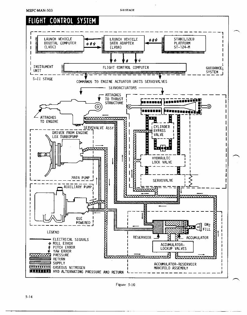
MSFC-MAN-503 s-lJSTAGE
FLIGHT CONTROLSYSTEM
LAUNCH VEHICLE _C LAUNCH VEHICLE _0_ STABILIZEDDIGITALCOMPUTER I_ 0_ DATA ADAPTER _ PLATFORM
LL_DC> ; , (LVDA) ST-124-M
@ '8 @
UNITINSTRUMENT_ FLIGHTCONTROLCOMPUTER ..... LYSTEMGUIDANCEIj
s-ii STAGECOMMANDS TO ENGINE ACTUATOR UNITS SERVOVALVES
SERVOACTOATORS3f-ATTACHESSTRUCTuRETOTHRUST)......._$giiiiililill,I_ li
I |t_Tl) i
L ATTACHES iTOENGINE I
SERVOVALVEASSY I CYLINDER Ir q BYPASS
DRIVEN FROM ENGINE II
I VALVE II LOXTURBOPUMP I .JI II I -I
I HYDRAULIC i i/I i LOCKVALVE I
I _t I J
I I
E MAINPUMP_ I 'l SERVOVALVE '_ IF AUXILIARYPUMP] i JII IIII
I I....Ii GSE I II
LI POWERED I I
LEGEND II RESERVOIR__ ACCUMULATOR
ELECTRICALSIGNALS IROLLERROR I ACCUMULATOR-
8 PITCHERROR I LOCKUPVALVESYAWERROR IPRESSURE
RETURN I:::::::::::::::::::::::::::SUPPLY I ACCUMULATOR-RESERVOIR)"i'"''°l GASEOUSNITROGEN l MANIFOLDASSEMBLYIII'ifIlllllllHYD ALTERNATINGPRESSUREAND RETURN L ............
Figure 5-10
5-14

S-ll STAGE MSFC-MAN-503
S-II ENGINEACTUATIONACCUMULATOR
AUXILIARY RESERVOIRMOTOR MANIFOLDASSEMBLYPUMP
SERVOACTUATORATTACH
POINT
GIMBAL (THRUSTSTRUCTURE)BEARINGASSEMBLY
ElMAI, SE.VOACTUATOR•HYDRAULIC GIMBAL _,_=_PUMP BEARING_ _L._J_
ASSEMBLY_ _SERVOACTUATOR __,_lj
ATTACH POINTS /'f/f _I'_
(J-2 ENGINE
Figure 5-1 1
Actuator return fluid is routed to the reservoir which stores PNEUMATIC CONTROLShydraulic fluid at sufficient pressure to supply a positivepressure at the main pump inlet. The pneumatic control system (figure 5-12) consists of the
ground pneumatic control system and the onboard
PREFLIGHT OPERATION pneumatic control system. The ground system utilizes heliumsupplied directly from a ground source and the onboardsystem utilizes helium from onboard storage spheres.
During and following propeUant loading, the hydraulicsystem fluid is intermittently recirculated by the electrically GROUND PNEUMATICSdriven auxiliary pump in order to prevent the fluid fromfreezing. Recirculation is terminated just prior to S-1C Ground supplied helium controls and actuates various valvesignition command. Recirculation is not necessary during S-IC during preflight operations. These include the vent valves, fillburn, due to the short duration of the burn. and drain valves, recirculation return line valves, and main
propellant line prevalves.
At approximately TJ,2 minutes, fluid is stored under highpressure in the accumulator by closing both hydraulic lockup ONBOARD PNEUMATICSvalves contained in the accumulator/reservoir manifoldassembly (figure 5-]0). The onboard pneumatic control systems consist of a stage
propellant valve control system and an engine pneumaticactuation and purge system.
INFLIGHT OPERATION
Stage Propellant Valve Control System
After S-IC/S 11 stage separation, an S-I1 switch selectorcommand unlocks the accumulator lookup valves, releasing The stage onboard pneumatic control system is supplied fromhigh pressure fluid to each of the two servoactuators. The the helium receiver. It is pressurized to 3000 psig ataccumulator stored fluid provides gimbaling power prior to approximately T-31 minutes. Pneumatic pressure from themain hydraulic pump operation. During S-ll mainstage helium receiver is regulated to 750 psig by the control
if"-" operation the main hydraulic pump supplies high pressure regulator and is used during flight to actuate the prevalvesfluid to the servoactuators for gimbaling, and recirculation valves.
5-15

MSFC-MAN-503 s-HSTAGE
PNEUMATICCONTROLSYSTEM
HELIUM _"RECEIVER300O SURGE
PSIG_ SPHERE(PIll Q LH2_l._.__r'-_ _ I PREVALVES
l--U ii ,-h-- (5 PLACES)750PSIGII II _W
DISCONNECTS _ RECIRCULATION(5 PLACES)
iiii _ + LoxII () FNRELIEFPREVALVES
L__ LFIJVALVE (5 PLACES)
PS G FILLAND FILLA.ODRAINVALVE DRAINVALVE
Figure 5-12
PROPELLANTS If the launch is aborted, draining of the propellant tanks canThe propellant systems supply fuel and oxidizer to the five be accomplished by pressurizing the tanks, opening the fillJ-2 rocket engines. This is accomplished by the propellant valves, and reversing the fill operation.management components and the servicing, conditioning, anddelivery subsystems. RECIRCULATION SYSTEM
PROPELLANT SERVICING SYSTEMPropellant recirculation is accomplished in order to maintain
Pad servicing operations include the filling, draining, and uniform cryogenic density and temperature and to precludepurging of propellant tanks and lines, as required during the formation of gas in propellant plumbing. This gas couldlaunchpreparations, cause cavitationin the turbopumpsduringJ-2enginestart, or
result in a slow engine start, slow thrust buildup or powerGround interface is through the umbilicals, to the fill anddrain valves, and into the propellant tanks, propellants then surges.enter the engine feed lines, stopping at the closed mainvalves. Refer to figure 5-13 for propellant loading data. The Lox Reeirculationtanks are vented by opening the tank vent valves, two per
propellant tank, to allow ullage gas to escape from the tanks. Lox conditioning by natural convection (figure 5-14) isActuation pressure for the propellant tanks vent valves is initiated shortly after start of lox fill and continues untilprovided by two separate 750-psig ground-supplied helium T-30 minutes. At that time, helium is injected into the loxsystems. One system actuates the lox tank vent valves, and recirculation return line to boost recirculation. Helium boostthe other system actuates the LH2 tank vent valves. The vent is continuous until just prior to S-II ignition. After launch
valves are open during propellant loading operations and helium is supplied from a pressurized sphere. During _..,closed for tank pressurization, recirculation, lox prevalves and recircnlation return valves
5-16

s4xSTAGE MSFC-MAN-503
PROPELLANTLOADING DATA
RATE LEVEL COUNT TIME
PROPELLANT TYPE FILL (GALLONS/MINUTE) (TANK % LEVEL) (HR: MIN: SEC)
PRECOOL 500 0 to5 T-7:04:00toFAST 5,000 5 to98 T-6:49:00tO
LOX SLOW l,000 98 tolO0 T-6:32:00toREPLENISH 0 to IO0 T-5:24:00 to T-185 seconds
PRECOOL l,000 0 to5 T-5:2]:00toFAST lO,OOO 5 to98 T-5:00:O0to
LH2 SLOW ],ODD 98 to lO0 T-4:34:34 toREPLENISH 0 to 500 T-4:29:00 to T-36 seconds
Figure 5-13
remain open. Return line valves are closed at termination of disconnect valve and ground prepressurization valves arerecirculation, opened to allow GHe at minus 275 degrees F to flow from
the ground source through the prepressurization solenoidvalve into the tank pressurization line. This line carries
Lox conditioning is accomplished by recirculating the lox helium into the propellant tank through the tank gasdown the engine feed ducts through the prevalves, the lox distributor.turbopump, into the retum lines, through the engine bleedvalves, and back into the lox tank.
Each propellant tank has a fill overpressure switch forpersonnel safety. The switch sends a signal to the GSE and is
LH2 Recirculation usedonly duringloading.
LH2 recirculation (figure 5-15) is initiated at approximately The vent valves act as relief valves allowing ullage gas to beT-30 minutes and is terminated just prior to S-1I ignition, vented directly overboard during flight. The LH2 vent valvesForced recirculation during launch and S-IC boost consists of operate between 27.5 and 29.5 psig prior to S-II ignition andclosing the LH2 feed line prevalves and starting the LH2 at 30.5 to 33 psig during S-II burn. The lox vent valves crackrecirculation pumps. A separate recirculation pump is at 42 psia and reseat at 39.5 psia.
"_" provided for each of the five feed ducts.
I,H 2 conditioning is accomplished by pumping the fuel PROPELLANT DELIVERY SUBSYSTEMSthrough the recirculation bypass valve, into the LH2 feedducts downstream of the prevalves, through the LH2 The function of the engine feed systems is to transfer theturbopump, through the LH2 bleed valve, the recirculation liquid propellants from their tanks to the J-2 rocket engines.return valve, and back into the fuel tank. Each propellant tank is provided with Five prevalves which
provide open/close control of the flow of propellants throughRecirculation is terminated by opening the prevalves, separate feedlines to each engine.stopping the pumps, and closing the recirculation return
valves. The prevalves are normally open, pneumatically actuated,electrically controlled, butterfly-gate type valves. Built-in
PREPRESSURIZATION four-way pneumatic control solenoids permit 750 +_50 psighelium pressure to actuate the prevalves. Should a loss of
After loadin_ has been completed, and shortly before liftoff, pneumatic or electrical power occur, the prevaives are springthe vent valves are closed and the propellant tanks are actuated to the open position. The prevalves remain openpressurized to their required levels by helium from ground during S-1I powered flight unless a signal is received from thesupplies. Pressurization of the propellant tanks is required engine shutdown system.prior to liftoff to provide the required net positive suctionhead (NPSH) at the turbopump inlets for engine start. It isaccomplished from a ground regulated helium source. LOX FEED SYSTEMPressurization is initiated by the terminal countdownsequencer at approximately T-3 minutes and 7 seconds for The lox Iced system furnishes lox to the five engines. Thisthe lox tank and T-1 minute and 37 seconds for the LH2 system includes four 8-inch, vacuum jacketed feed ducts, onetank. Pressurization is terminated at T-30 seconds for the lox tminsulated feed duct, and five normally open prevalves. Attank and the LH2 tank. engine start, lox flows from the tank, through the prevalves
and feed lines, to each engine. Approximately 300Both propellant tanks are pressurized in the same manner by milliseconds after main valve closure, the iox prevalves are
/"-" separate systems (figures 5-14 and 5-15). At initiation of closed, providing a redundant shutoff for the lox feedprepressurization, the tank vent valves are closed and the system.
5-17

MSFC-MAN-503 s-n STAGE
OVERFILL GASDISTRI BUTOR
FAST FILLCUTOFF
.STILLWELL
CAPACITANCEI
LOXFILLAND 5 ENGINECUTOFFIDRAIN ]SENSORSMOUNTEDiLINE iABOVESUMP
VENT/ RECIRCULATIONRELIEF SUMP RETURNVALVES --VALVE FROM
GSE
FROM
I LH2 LOX VALVETANK PREVALVE
i_ HELIUMPROPELLANT INJECTION
TO UTILIZATION SUPPLYGSE ELECTRONICS BOTTLE
FROM --LOX
dE ItLOX PU BLEED
, REPRESSUR-_ l VALVE VALVE MAIN
I IZATION M| LOX
-- VALVEI-_Z-_------_-_-_ REGULATOR- DRIVE
GASSES
W_._ FROMLH2
HEAT \EXCHANGER J-2 \
LEGEND [] _ N _I I ENGINE k
_ GOX FROMOTHER
t,e _ENGINES _ i!ELECTRICAL
:-,:;_-:._.._:_:._-::_;:_CUMBUSTIONGASESULLAGEPRESSURE
Figure 5-14
5-18

S-iI STAGE MSFC-MAN-503
LH 2 SYSTEM-PRESSURIZATIONFLOW AND CONDITIONING
VENT/RELIEFmVALVES
DISNERFILL SENSOR
FASTFILL CUTOFF SENSOR
LH2 TANKCAPACITANCE PROBE
IES AN ELECTRICALINPUT TO PROPELLAt_TUTILIZATION ELECTRONICS
(FIG. 5-14)
RECIRCULATIONLH2 PUMPFILL AND
DRAIN INECUTOFFSENSORSVALVE ATEACHOF5OUTLETS
LH2 PRE-PRESSURIZATION RECIRCULATION
RETURNVALVE TOGSE VALVE
FROM LH2GSE PREVALVE
_" PRESSUREREGULATOR
RECIRCULATIONBY-PASS
LH2 VALVE__ PURGE BLEED
GSE CHECKPURGE VALVES__ VALVE TURBO
THRUST PUMPCHAMBERINJECTORMANIFOLD
MAINFUELVALVE
LEGENDJ-2ENGINE _-_c_ COMBUSTIONGASES
...................i:::i:::i:!:!:!:!:FUEL (LH2)imi t i i-- GASEOUS HYDROGEN..... HELIUM (He)
ULLAGEPRESSURE
Figure 5-15
5-19

MSFC-MAN-503 s-u STAGE
LH2 FEED SYSTEM mass. During the propellant loading sequence, the point levelsensors are used to indicate to GSE the level of propellants in
The LH2 feed system furnishes LH2 to the five engines. This the tanks. In flight, the level sensors provide signals to the
system includes five 8-inch vacuum-jacketed feed ducts and LVDC in order to accomplish a smooth engine cutoff at _,,five normally open prevalves. The prevalves are closed propellant depletion. The capacitance probes provideoutputsfollowing tank loading and remain closed until just prior to used to operate the propellant utilization if'U) control valve.S-II ignition command. At engine start, LH2 flows from the This rotary type valve controls the quantity of lox flowing totank, through the prevalves and feed lines, to each engine, the engine. Figures 5-14 and 5-15 illustrate the componentsApproximately 425 milliseconds after main valve closure, the of the systems.prevalves are closed, providing a redundant shutoff for theLH2 feed system. PROPELLANT UTILIZATION SUBSYSTEM
LOX TANK PRESSURIZATION The PU subsystem has been modified for the AS-503 mission.Normally, the PU valve follows the signal developed from
Lox tank pressurization (figure 5-14) is initiated at S-ll inputs provided by the propellant monitoring capacitanceignition and continues until engine cutoff. Pressurization is probes. This provided for minimum propellant residuals ataccomplished with gaseous oxygen obtained by heating lox flight termination. The AS-503 modification has broken thebled from the lox turbopump outlet, closed loop and provides for LVDC controlled relays to
furnish step control signals to the PU valve. See figure 6-22When the turbine discharge pressure reaches a pressure for a representative block diagram of the PU system. Thedifferential of 100 psi, a portion of the lox supplied to the excursion effect caused by varying MR is illustrated in figureengine is diverted into the heat exchanger where it is turned 5-8.into gox. The gox flows from each heat exchanger into a
common pressurization duct through the tank pressurization Propellant Depletionregulator, and into the tank through the gas distributor. Theflowrate is varied according to the tank ullage pressure, whichis sensed by the reference pressure line connecting the tank Five discrete liquid level sensors in each propellant tankand the tank pressurization regulator. The tank pressurization provide initiation of engine cutoff upon detection ofregulator provides continuous regulation of the tank pressure propellant depletion. The LH2 tank sensors are located abovethroughout S-II powered flight, each feedline outlet while the Iox tank sensors are located
directly above the sump. The cutoff sensors will initiate asignal to shutdown the engines when two out of five engine
LH2 TANK P RESSU RIZATION cutoff signals from the same tank are received.
During $41 powered flight gaseous hydrogen (GH2) for LH2 ELECTRICAL _,tank pressurization (figure 5-15) is bled from the thrustchamber hydrogen injector manifold of each of the four The electrical system is comprised of the electrical power andoutboard engines. After S-II engine ignition, liquid hydrogen electrical control subsystems. The electrical power systemis preheated in the regenerative cooling tubes of the engine provides the S-II stage with the electrical power source andand tapped off from the thrust chamber injector manifold in distribution. The electrical control system interfaces with thethe form of GH2 to serve as a pressurizing medium. IU to accomplish the mission requirements of the stage. The
LVDC in the IU controls inflight sequencing of stageThe GH2 passes from each injector manifold into a stage functions through the stage switch selector. The stage switchmanifold, through the pressurization line and tank selector can provide up to 112 individual outputs in responsepressurization regulator, and into the tank through the LH2 to the appropriate commands. These outputs are routedtank gas distributor. The flowrate is varied according to the through the stage electrical sequence controller or theLH 2 tank ullage pressure, which is sensed by the reference separation controller to accomplish the directed operation.pressure line connecting the LH 2 tank and the tank These units are basically a network of low powerpressurization regulator, transistorized switches that can be controlled individually
and, upon command from the switch selector, provideAt approximately 5 minutes after S-II engine ignition a step properly sequenced electrical signals to control the stagepressurization command from the stage switch selector functions.activates the regulator to a fully open position, where itremains the rest of S-II boost. When the regulator is in the Figure 5-2 shows the relative location of the stage electricalfull open position, LH 2 tank pressure increases to a nominal system equipment.33 psia. Pressure in excess of 33 psia is prevented by the LH2tank vent valves. This step pressurization compensates for the ELECTR ICAL POWER SYSTEMloss of head pressure caused by the lowering of the fuel levelin the tank. The electricalpower system consistsof six dc bus systems
and a ground supplied ac bus system. In flight the electrical
PROPELLANT MANAGEMENT power system busses are energized by four zinc-silver oxidebatteries. See figure 5-16 for battery characteristics. Anintegral heater and temperature probe are included in each
The propellant management systems provide a means of battery. Power for battery heaters and for auxiliary hydraulicmonitoring and controlling propellants during all phases of pump motors is supplied by GSE and is available only duringstage operation. Continuous capacitance probes and point prelannch operations. Stage-mounted motor driven powerlevel sensors in the LH2 and Iox tanks monitor propellant transfer switches are employed to remotely disconnect all
5-20

S=II STAGE MSFC-MAN-503
batteries from busses until just before launch. Approximately 2. All instrumentation loads are supplied by the50 seconds prior to liftoff, a power transfer sequence is instrumentation dc bus.initiated which changes the source power over to the stage
_ mounted batteries. During the prelaunch checkout period all 3. All loads operational only on the ground are isolatedelectrical pov_r is supplied from GSE. from flight loads and supplied from ground power.
4. Two independent power sour_s supply theThe motorized power transfer switches have a propellant dispersion and emergency detectionmake-before-break (MBB) action to prevent power systems.interruption during transfer from ground power to unboardbatterypower. S=lI BATTERY CHARACTERISTICS
Eachpower sourcehas anindependantdistributionsystem. Type Map 4301 Dry ChargeThereareno provisionsforswitchingbetweentheprimarypower sources or their associated distribution systems. No Material A1kal i ne Si 1ver-zi ncelectrical failure of any type in one system can cause a failureintheothersystems. Electrolyte PotassiumHydroxide (KOH)in demineralized water
Distribution Cells 20 with taps to reducevoltage as required
Figure 5-17 illustrates the electrical system distribution. Theloads have been distributed between the various busses in Nominal Voltage 28 + 2 vdcaccordance with the following criteria:
35 HoursCurrent Rating Amp
l Infiight loads, critical to ndssion continuance iaht• . Gross We__.__ 165 Poundswithoutperformancedegradation,aresupplied by
themaindcbus. _ Figure 5-16
/ iNSTRUMENTATiONBUS MAINBUS LONITLONBUS RECIRCULATIONBUS [GROUNDBt_ HE RBUS
) NINE LH I PROPELLANTLOADIN BA'VFERYHEATERS/ _O1.- INSTBUMENTATION _- PRESSURIZATION (_-J- E G FO"I'- 2 ,F'_ ANDRELAY G_-
PROPELLANTDISPURSiON PROPELLANTSYSTEM IGNITION RECIRCULATON VoALI_(_NINDICATIONS iNSTRI,_ENTHEATERSI IOFS*STEMII°l- ,oN II ilP0.MOTOR']Op .R.STE.'lOPlOt -TELEMETRY IO_ SEPANAT I I I J INVERTERS I [ Oi-mtTC,qING I IlOP EDS I OJ--J-2ENGINECONTROL II II IIOJ-ENGmEsYsTON II
/ I I 10 _-PROPELLANTDISPERSIONSYSTEM2 I ] 11 II°FONO'WEACTUAT'ON[ Ii II IOFELECTmCALSEQUENCECONTROLLER]I II '11 I I/ II I°1-FU°NTD°NT"°t I I I I II t I I
TRANSFER TRANSFER TRANSFER TRANSFERSWITCH SWITCH ............... SWITCH SWITCH
I
2&VDC I I_,-voos_,#,_E.RoNRS_,,E-NOUR _,.,ERE-ROaRI I /_
] I_UHSI__IF_ RN B -- __UR' ' /_, . --?l? ?
I '_ RE_OTRPOWEROISTR'BUTIONRANE_I _ I [ I I I I I
MAINDO RECIRCULATIONDC GROUNDDC 115.Z0_VDC
Figure 5-17
5-21

MSFC-MAN-503 s-n STAGE
5. The recirculation pump motor system is supplied and R&D measurement and telemetry systems. Thefrom a 56 volt dc system (two 28 volt batteries in measurement system monitors and measures conditions onseries), the S-ll stage while the telemetry system transmits this
information to ground stations. -_The division of loads between the main dc bus and theinstrumentation dc bus leads to several advantages: closer MEASUREMENT SYSTEMvoltage regulation and freedom from voltage variations isobtained; the number of loads on the main dc bus may be The measurement system consists of transducers, signalminimized and thus potential failure modes for the bus conditioners, and distribution equipment necessary tosystem minimized; instrumentation of most stage systems is provide the required measurement ranges and to presentstill maintained after partial or total failure of the main dc suitably scaled signals to the telemetry system.bus system so that failure analysis capability is maintained.
The measurement system monitors numerous stagePrimary power is fed to high current capacity busses in the conditions and characteristics. This data is processed andpower distributor. Power is then routed to auxiliary and conditioned into a form acceptable to the telemetry systems.control distributors, or to measuring distributors forinstrumentation power. Components which require high Measurements fall into a number of basic categoriescurrent levels are supplied directly from the main power depending upon the type of measured variable, the variabledistributor busses, rate of change with time, and other considerations. Because
the stage engines are ignited in flight, a large number ofELECTRICAL CONTROL SYSTEM engine and environmental control measurements are required.
Figure 5-18 presents a summary of stage instrumentationThe electrical control system provides electrical control for data.the various stage-mounted systems to implement normalflight operations, or prelaunch operations and checkout TELEMETRY SYSTEMfunctions. The electrical control system contains most of theelectrical and electronic components that are installed on the The telemetry system accepts the signals produced by thestage and required by the various mechanical systems for measuring portion of the instrumentation system andnormal stage operation, transmits them to the ground stations. Telemetry equipment
includes signal multiplexers, subcarrier oscillators, amplifiers,The primary stimuli for the electrical control system are modulators, transmitters, RF power amplifiers, RFprovided by the IU and/or the GSE. Through the switch multiplexers and an omnidirectional system of four antennae.selector and sequence controller, various subsystems andfunctions are controlled. They include:
1. The propellant feed system which controls the fill STAGE MEASUREMENTS SUIv_IARYand drain valves and the recirculation and
conditioning valves.TYPE QTY
2. The propellant management system which helpscontrol the flU operation and the propellantutilization system during flight. Acce] erati on l 1
Acoustics 53. The pressurization system which controls the tank
prepressurization valves, inflight pressurization Discrete Signals 225
valves, and the vent/relief valves. F10w Rate l 0
4. The separation system which provides for S-IC/S-II Liquid Level 4separation, S-IT ullage rocket ignition, S-IT skirtseparation, S-II/S-IVB separation,and S-ll Miscellaneous 4retrorocket ignition. P0s i ti on 36
5. The propellant dispersion system which provides for Pressure ]92thrust termination through engine cutoff and for RPM l0explosively rupturing the propellant tanks. Strain ]6
6. The Emergency Detection System. Temperature 309
7. The starting and cutoff of the J-2 engine and the Vibration 72
monitoring of certain engine system conditions. Voltage, Current, Frequency 60
8. The operation of the propellant prevalves.
INSTRUMENTATION TOTAL 954
The S-II instrumentation system consists of both operational Figure 5-18
5-22

S-llSTAGE MSFC-MAN-503
This equipment also includes tape recorders for recording lnflight data is transmitted in the form ofcritical data during separation telemetry blackout (separation frequency-modulated RF carriers in the 225 to 260-MHzperiod) for later play back during stage free fall. The band, through the common omnidirectional antenna system.telemetry subsystems use multiplex techniques (signal mixingand time sharing) to transmit large quantities of measurement Several telemetry subsystems are provided in the S-IT stage.data over a relatively small number of basic RF links (figure Telemetry data is grouped in three general catagories: low5-19). frequency data, medium frequency data, and high frequency
ANTENNAET_oT os_ T_oT|WA'FI"S| t t |WAtts/
POWER _ COAX _ _ COAX _ POWER 1
SWITCH DIVIDERDIVIDERI- I SWITCH
RF I " HYBRIDF IRFMULTIODUPLER JUNCTION MULTICOUPLER
II % TRANStMITTER I TRANS21TTER TRAN_ITTER _
!S-I F-I F-2 F-3 S-2 P-lTRANSMITTER TRANSMITTER TRANSMITTER
227.2 MHz 241.5 MHz 234.0 MHz 229.9 MHz 236.2 MHz 248.6 MI4z
I I_- I t 11TAPERECORDERS RELAYS TIMERS TOGSE
T T TI L,SSIFM PAM/FM/FM PAM/FM/FM PAM/FM/FM SS/FM PCM/DDAS
ASS'Y IASS'Y ASS'Y ASS'Y ASS'Y ASS'Y
t t t t lI l MODULATIONTECHIQUE AND FREQUENCY
T ....... I IMULTIPLEXE_ANDI I DIGITALK_t_uuu__SUB-MULTIPLEXERSI _ ENCODER LINK NO. MODULATION FREQUENCYMHzI I. j
I BF-I PAMIFM/FM 241.5BF-2 PAM/FM/FM 234.0
DISCRETEDATA BF-3 PAM/FM/FM 229.9
BP-I PCM/FM 248.6SIGNAL
TRANSDUCERS _ CONDITIONERS BS-I SS/FM 227.2
BS-2 SS/FM 236.2
Figure 5-19
5-23

MSFC-MAN-503 s-n STA_E
data. Several different modulation techniques are employed assembly. The storage capacitor in each of the EBW firingin the telemetry systems to facilitate both quality and units is charged by 28 vdc power during the latter part ofquantity of measured parameters. These modulation S-IC boost. The trigger signal causes the storage capacitor to
techniques include: pulse amplitude modulation/frequency discharge into an EBW detonator which explodes themodulation/frequency modulation (PAM/FM/FM) and pulse bridgewire to release energy to detonate the explosive chargecode modulation/frequency modulation (PCM/FM) for in the detonator. The output of the detonators initiates eachlow-frequency data; and single sideband/frequency end of the LSC assembly.modulation (SS/FM) for high-frequency information. A pulsecode modulation/digital data acquisition system Detonation of the LSC assembly severs the tension members(PCM/DDAS) transmits measurements by coaxial cable for attaching the S-IC/S-II interstage at station 1564.automatic ground checkout of the stage.
The second plane separation ordnance is similar inThe PCM/DDAS assembly converts analog transducer signals composition and function to that of the f'u'st planeinto digital representations, combines these representations separation. The EBW firing units are installed on the S-IC/S-IIwith direct inputs, such as those from the guidance interstage slightly below the separation plane. Detonation ofcomputer, and arranges this information into a format for the LSC assembly severs the tension members attaching thetransmission to the ground station on a 600 KHz carrier S-IC/S-II interstage at station 1760.signal by means of coaxial cable for ground checkout of thestage. No heat-sensitive primary explosives are used and the
detonators are not sensitive to accidental application ofANTENNAE vehicle or gound power, static discharge, or RF energy. A
spark gap in one pin of the f'_ng circuitry prevents burnoutFour antennae, installed at 90 degree intervals (see figure of the bridgewire if power is accidentally applied.5-2), are employed to provide omnidirectional coverage. TheAntennae are linear cavity-backed slot antennae which are S-II/S-IVB third plane separation is discussed in Section VI.fed from a hybrid junction ring and power dividers.
ULLAGE ROCKET SYSTEMORDNANCE
To ensure stable flow of propellants into the J-2 engines, aThe S-II ordnance systems include the separation, ullage small forward acceleration is required to settle therocket, retrorocket, and propellant dispersion (flight propellants in their tanks. This acceleration is provided bytermination) systems, ullage rockets (figure 5-22).
SEPARATION SYSTEM The S-II ullage rocket system consists of two EBW firingunits, two EBW detonators, two CDF manifolds, nine CDF _,
The Saturn V launch vehicle system provides for separation assemblies, eight CDF initiators and four ullage rockets. CDFof an expended stage from the remainder of the vehicle. For assemblies connect the two CDF manifolds together and bothS-IC/S-II separation, a dual plane separation technique is used manifolds to each of the four ullage rockets (see blockwherein the structure between the two stages is severed at diagram on figure 5-21). The ullage rockets are mountedtwo different planes (figure 5-20). The S-lI/S-IVBseparation parallel to vehicle centerhne 90 degrees apart on theoccurs at a single plane (figure 5-20). All separations are periphery of the S-IC/S-U interstage at its aft end (figurecontrolled by the launch vehicle digital computer (LVDC) 5-20). The rocket nozzles are just above the first separationlocated in the instrument unit (IU). plane and are canted outward 10 degrees to reduce the
moment that would remit from one or more rocketsA sequence of events for S-IC/S-II/S-IVB separations and malfunctioning and to reduce exhaust plume impingement.block diagram of the separation systems is contained on With any one ullage rocket inoperative, the remaining rocketsfigure 5-21. are capable of maintaining a minimum vehicle acceleration
necessary for proper S-II engine ignition.Ordnance for first plane separation consists of two explodingbridgewire (EBW) fh-ing units, two EBW detonators, and one Each ullage rocket contains approximately 336 pounds oflinear shaped charge (LSC) assembly, which includes the LSC solid propellant, cast-in-place, in a four point star(containing 25 grains per foot of RDX) with a detonator configuration. Ammonium perchlorate composes 82 percentblock on each end (figures 5-20 and 5-21). The EBW firing of the propellant weight. The case is4130 steel. The rocket isunits are installed on the S-IC/S-II interetage slightly below approximately 89 inches long by 12-1/2 inches in diameterthe S-II In'st separation plane. The leads of the EBW firing and develops 22,700 pounds of thrust in a burn time of 3.7units are attached to the EBW detonators which are installed seconds.in the detonator blocks of the LSC assembly. The LSCdetonator blocks are installed on adjustable mounts to RETROROCKETSYSTEMprovide for length variations of the LSC assembly and thecircumference tolerances of the interstage. The LSC is routed To separate and retard the S-II stage, a deceleration isfrom the detonator blocks around the periphery of the provided by the retrorocket system.interstage.
The system consists of two EBW firing units, two EBWThe LSC is held in place by retaining clips and encased by detonators, two CDF manifolds, nine CDF assemblies, eightcovers which are secured by clips and sealed to pyrogen initiators, and four retrorockets (figure 5-22). Theenvironmentally protect the LSC. The two EBW firing units components are connected to each other in a manner similar ,--.,provide redundant signal paths for initiation of the LSC to that of the ullage rocket system (see block diagram on
5-24

S-II STAGE MSFC-MAN-503
STAGESEPARATON SYSTEMS
AFT SKIRT AFT SKIRT :_COMPRESSION
PLATE . I_ ASSEMBLY
MILD DETONATING "i__ t" ..... 1FUSE (PETN) I I/Jm _ / ',
I0 GPF ' _-. -'-_ - ' 1
__ _ _"_" " DETONATORBLOCK
_ _N,_ '_I-_NN_ F"s_'!2!/ EBW FIRING UNITS
- _,\\\\ - _ ROCKETSAFT INTERS__'k\ " / ,/---'_". ', EBW FIRING UNITS
I _ -_'-"_"_-_ _.
S-IC/S-ll SECOND SEPARATION PLANE i"-_ _-'" _CONFINED DETONATING
STATION NO. 1760 _ I S-ll FUSE (RETROROCKEI'S)S-lC/S-II FIRST SEPARATIONPLANE_ I rnld_Tl_cn r_CTA_ATTMe
STATIONNO.1_6, _ _ _'i'_L_V_°_;_T_S)-- PROTECTIVECOVER _ I__ _ EBW FIRING UNITS
_ DEI'ONATORBLOCKS
!I--- IK'_:_'_"- TENSION PLATE !_ / ..'_'X_i_ EBW FIRING UNITS
/-iDa,k\ i-/---V,,,.-<'>'._--,_'I_i l('_----- I # I "- EBWFIRINGUNITS--./2_r-'-YII_---_SEPARATION_ i D_ONATOR_LO_K__"___'R_"_[_"_ _ - PLANE / S-IC II
/ LINEAR SHAPED CHARGE (RDX) F..::D.../"t /'_', .,_\ 13"_
25 GPF ',.__--'_'.-_;_._,"
"_-)"_k.___"'k'--j_''''-CDF MANIFOLD, EBW FIRING UNIT:
Figure 5-20
5-25

MSFC-MAN-503 S41STAGE
This delay pemits the transient vehicleS-IC/S-II separation motion, associated with fi_t plane se-
_> EBW units enabled paration, to dampen out.firing
The separation command is routed to theA ground-latched interlock rende_ all S-II switch selector to trigger the ord-the EBW firing units on the Saturn V nance train and ignite the LSC for second
inoperative while the vehicle is on the plane separation. The LSC detonateS,launch pad. The interlock is released severing the S-II interstage from thewith umbilical disconnect during liftoff, S-II stage. The combined effect of ve-and the subsystem is reset to flight con- hicle acceleration and the reaction
ditions, caused by the J-2 engine exhaust plune
_> impingement retards the interstage •S-IC/S-II separation ordnance arm
S-II/S-IVB separationThe ordnance-am command is routed
through the S-II switch selector to both Physical separation is initiated by thethe S-IC stage electrical circuitry to IU at the end of the S-II boost phasesupply 28 vdc to the EBW units for first- following shutdown of the five J-2 en-
plane separation and retrorocket igni- gines. Separation requires the perfor-tion, and to the S-II stage electrical mance of the following major functions in
circuitry to supply 28 vdc to the EBW the sequence descHbed:units for ullage rocket ignition and rl_
second-plane separation. _ S-II/S-IVB separation ordnance arm
_> S-IC outboard engine cutoff followed by The ordnance-amcommand is routed
S-II ullage rocket ignition through the S-II switch selector to both
_> the S-II and S-IVB stage electrical cir-
First plane separation cuitry and carries28 vdc to the EBW fir-ing units for S-II/S-IVB separation and
Second plane separation is enabled by the retrorocket ignition.removal of an electrical interlock during r_
fi_t plane separation. _ S-II/S-IVB separationSecond plane separation Four solid propellant S-II retrockets.
(figure 5-22) are mounted at equal inter-The second plane separation command is vals on the periphery of the S-II/S-IVBgenerated by the IU approximately thirty interstage structure and are used toseconds after first plane separation, retard the S-II stage after separation.
Figure 5-21 (Sheet 1 of 2)
figure 5-21). The retrorockets are mounted 90 degrees apart PDS may be safed after the launch escape tower is jettisoned.in the aft end of S-II/S-IVB interstage between stations 2519 The system is installed in compliance with Air Force Easternand 2633 (figure 5-22). The retrorockets are canted out from Test Range (AFETR) Regulation 127-9 and AFETR Safetythe vehicle centerline approximately three degrees with the Manual 127-1.nozzles canted out nine and one-half degrees from thecenterline.
The S-II PDS is a dual channel, redundant system composed
Each retrorocket contains approximately 268.2 pounds of of two segments (figure 5-23). The radio frequency segmentcase-bonded, single-grain, solid propellant with a tapered, receives, decodes, and controls the propellant dispersionfive-pount star configuration. The 4130 steel case is 9 inches commands. The ordnance train segment consists of two EBWin diameter and 90.68 inches long. The approximate length firing units, two EBW detonators, one safety and armingand weight of the rocket are 104.68 inches and 377.5 (S&A) device (shared by both channels),sixCDF assemblies.pounds, respectively. Each produces a thrust of 34,810 two CDF tees, one LH 2 tank LSC assembly, two Iox tankpounds in 1.52 seconds of burning time. destruct charge adapters and one lox tank destruct charge
assembly.PROPELLANT DISPERSION SYSTEM
Should emergency flight termination become necessary, two
The S-II propellant dispersion system (PDS) provides for coded radio frequency commands are transmitted to thetermination of vehicle flight during the S-II boost phase if the launch vehicle by the range safety officer. The first commandvehicle flight path varies beyond its prescribed limits or if arms the EBW firing tmits (figure 5-23) and initiates S-llcontinuation of vehicle flight creates a safety hazard. The S-II stage engine cutoff. The second command, which is delayed
5-26

s-ll STAGE MSFC-MAN-SO3
S-IC/S- ANDS-II/S-IVB IEPARATION
EBWFROM FIRINGLAUNCH S-II/S-IVB UNIT LINEARSH_EDVEHICLE SEPARATION CHAR_ASSEMBLY
COMPEER+SDIGITALTRIGGERINI.U. ___EBWFIRING _IEBWDET . (S-II/S-IVBSEPARATION)
UNIT
-II/S-IVB ---- [
l RETRO F---_EBW U EBW CDF _
MANIFOLD PYROGEN [
I TRIGGER FIRINGII DET INITIATORUNIT ASSEMBLY RETRO I
EBW EBW CDF PYROGEN [ORDNANCE FIRING DET MANIFOLD INITIATORAN w UNIT ASSEMBLY ]
TYPICAL 4 PLACES I
SEPARATION EBWCONTROLLER FIRING
UNIT LINEAR SHAPEDCHARGE ASSEMBLY
EBW (SECONDPLANESEPARATION)SECONDSEPARA1
S-II STAGE_" SWITCH r I
SELECTOR PLANEI
SEPARATION CDF _t PYROGEN I
ENABLED glRING MANIFOLDUNIT ASSEMBLY INITIATOR
ULLAGE ULLAGE[ROCKET
TRIGGER EBW _ _ PYROGEN
FIRINGEB_ICDF IMANIFOLD INITIATORUNIT I _ DEl" _ ASSEMBLY [
ORDNANCE
ARM ORDNANCE[-_ EBW _ L_ TYPICAL4 PLACES___]-- UNIT LINEARSHAPED
(INTERLOCK CHARGEASSEMBLY
RELEASE) FIRST
SEPARATION I r-_ EBW (FIRSTPLANESEPARATION)
TRIGGER _ FIRINGUNIT
_" Figure 5-21 (Sheet 2 of 2)
5-27

MSFC-MAN-503 s-nSTAGE
S-II ULLAGEANDRETROROCKETS
CDFASSEMBLY
CDFOR ASSEMBLY-.RESSURE _
UREMENT-_ _," - dEI-I'ISONAI3LEFAIRING ASSY
PYROGEN _ ',EDFAIRINGINITIATOR " J_-_ PYROGEN
INITIATOR
IGNITER / f,.,l__l _\ )
ADAPTER '__ _=_ _../_ PLUGS-II ULLAGE
_ ROCKET ;-IVBINTERSTAGEASSEMBLY
--S-II/S-IVB
S-II FIELDSPLICEINTERSTAGE
SEPARATIONFIRST
ROROC ET-- ,_i._---____PLANE RET K
CDFINITIATO__
FAIRING CDFASSEMBLIES I_
TYPICALS-IIULLAGE ..
ROCKET (4 REQUIRED) CAP -
TYPICAL S-II RETROROCKET \ ..(4 REQUIRED) _-._ _-_
Figure 5-22
5-28

S4I STAGE MSFC-MAN-503
PROPELLANTDISPERSION
o_,o. PO_CO,TA,._.T o,wo_. ](EBWFIRING
POS UNITS & SAFETYII & ARMING
[ RANGE!AFETYl [ RANGE SAFETY ]POS_II'_"/"r'_._L_.-_'_"_-__ POS I CO/"_AND | | COMMAND |
III _-,,_,_ i i RECEIVER 1 [RECEIVER /
I\ POS P/I I RANGESAFETY| l RANGESAFETYIi,'--...___.___.._._1i DECODERJ LDECODER ][ ii s_NG SAFI.G
[ , _,,-..-_-_'.'-.- ._ _ CDF ASSEMBLY i L_--_GTI_EwN
f'-" . EBW
|r _ _'(,',I_ "-LH 2 TANK II II
TANK DESTRUCT _DESTRUCT ASSEMBLY--, II _ ....... /" • ..ASSEMBLY _ i _k, Ur/L3_, / i _ LH2 TANK
I CDF ASSEMBLY--.,.. II t
Figure 5-23
5-29

J
MSFC-MAN-503 S-ii STAGE
to permit charging of the EBW firing units, discharges the discussion in Section IV.storage capacitors in the EBW firing units across theexploding bridgewire in the EBW detonators mounted on the The LH2 tank linear shaped charge when detonated cuts aS&A device. The resulting explosive wave propagates through 30-foot vertical opening in the tank. The LSC assemblythe S&A device inserts to the CDF assemblies and to the CDF consists of two 15-foot sections of RDX loaded at 600 grainstees. The CDF tees, installed on the S-II forward skirt, per foot.
propagate the wave to two CDF assemblies which detonate to The lox tank destruct charges cut 13-foot lateral openings intheir respective destruct assemblies. The destruct assemblies the lox tank and the S-II aft skirt simulataneously. Theare connected by a CDF assembly to provide redundancy to destruct assembly consists of two linear explosive charges ofthe system. RDX loaded at 800 grainsper foot. The destruct chargesare
installed in a figure-eight tube mounted on the inside of the
A description of the S&A device is included in the PDS aft skirt structure near station number 1831.0.
5-30

MSFC-MAN-503
SE(TIONVI
S-IVBSTAGE
TABLE OF CONTENTS minimize LH2 boil off polyurethane insulation blocks,covered with a fiberglass sheet and coated with a sealant, are
INTRODUCTION ............................. 6-I bonded into the milled areas of the waffle patterns.STRUCTURE ................................. 6-1ENVIRONMENTAL CONTROL .................. 6-1 The walls of the tank support all loads forward of the
forward skirt attach point and transmit the thrust to thePROPULSION ................................ 6-4 payload. Attached to the inside of the LH2 tank are a 34PROPELLANTS ............................... 6-11 foot propellant utilization (PU) probe, nine cold heliumPNEUMATIC CONTROL ........................ 6-17 spheres, brackets with temperature and level sensors, aFL1GHTCONTROL ........................... 6-18 chilldown pump, a slosh baffle, a slosh deflector, and fill,A UXILIAR Y PROPULSION SYSTEM ............. 6-20 pressurization and vent pipes. Attached to thc inside of theELECTRICAL ................................ 6-22 lox tank are slosh baffles, a chilldown pump, a 13.5 foot PUINSTRUMENTATION .......................... 6-29 probe, temperature and level sensors, and fill, pressurizationORDNANCE ................................. 6-31 and vent pipes. Attached externally to the propellant tank
are helium pipes, propellant dispersion components, andINTRODUCTION wiring which passes through two tunnel fairings. The forward
edge of the thrust structure is attached to the lox tankThe Saturn S-IVB (figure 6-1) is the third booster stage. Its portion of the propellant tank.single J-2 engine is designed to boost the payload into acircular orbit on the first burn, then boost the payload to a THRUSTSTRUCTURE
proper position and velocity for lunar intercept with a second The thrust structure assembly (figure 6-1) is an inverted,burn. The stage dry weight (including interstage) is truncated cone attached at its large end to the aft dome ofapproximately 33,142 pounds. The total weight at ignition is the lox tank and attached at its small end to the engineapproximately 262,300 pounds. The major systems of the mount. It provides the attach point for the J-2 engine andstage are: structures, environmental control, propulsion, distributes the engine thrust over the entire tankflight control, pneumatics, propellants, electrical, circumference. Attached external to the thrust structure areinstrumentation and ordnance systems, the engine piping, wiring and interface panels, eight ambientSTRUCTURE helium spheres, hydraulic system, oxygen/hydrogen burner,
and some of the engine and lox tank instrumentation.The basic S-IVB stage airframe, illustrated in figure 6-1,consists of the following structural assemblies: the forward AFT SKIRT ASSEMBLY
skirt, propellant tanks, aft skirt, thrust structure, and aft The cylindrical shaped aft skirt assembly is the load bearinginterstage. These assemblies, with the exception of the structure between the LH2 tank and aft interstage. The aftpropellant tanks, are all of a skin/stringer type aluminum skirt assembly is bolted to the tank assembly at its forwardalloy airframe construction. In addition, there are two edge and connected to the aft interstage. A frangible tensionlongitudinal tunnels which house wiring, pressurization lines, tie separates it from the aft interstage at S-II separation.and propellant dispersion systems. The tunnel covers aremade of aluminum stiffened by internal fibs. These structures AFT INTERSTAGE ASSEMBLY
do not transmit primary shell loads but act only as fairings. The aft interstage is a truncated cone that provides the loadFORWARD SKI RT ASSEMBLY supporting structure between the S-IVB stage and the S-I!
stage (figure 6-1). The interstage also provides the focal pointCylindrical in shape, the forward skirt (figure 6-1) extends for the required electrical and mechanical interface betweenforward from the intersection of the liquid hydrogen (LH 2) the S-II and S-IVB stages. The S-II retrorocket motors aretank sidewall and the forward dome, providing a hard attach attached to this interstage and at separation the interstagepoint for the Instrument Unit (IU). It is the load supporting remains attached to the S-II stage.member between the LH2 tank and the IU. An access door inthe IU allows servicing of the equipment in the forward skirt. ENVIRONMENTAL CONTROLThe five environmental plates which support and thermallycondition various electronic components, such as the There are three general requirements for environmentaltransmitters and signal conditioning modules, are attached to control during checkout and flight operations of the S-IVBthe inside of this skirt. The forward umbilical plate, stage. The first is associated with ground checkout andantennae, LH2 tank flight vents and the tunnel fairings are prelaunch operations and involves thermal conditioning ofattached externally to this skirt, the environments around the electrical equipment, auxiliary
propulsion system (AlaS), and hydraulic accumulatorPROPELLANT TANK ASSEMBLY reservoir. In addition, there is a requirement for aft skirt and
interstage purging. The second involves forward skirt areaThe propellant tank assembly (figure 6-1) consists of a purging, while the third concerns inflight heat dissipation forcylindrical tank with a hemispherical shaped dome at each the electrical/electronic equipment.end, and a common bulkhead to separate the lox from theLH2. This bulkhead is of sandwich type constructionconsisting of two parallel hemispherical shaped aluminum AFTSKIRTAND INTERSTAGE THERMOCONDITIONINGalloy (2014-T6) domes bonded to and separated by a
fiberglass-phenolic honeycomb core. The internal surface of During countdown, air/GN 2 is supplied by the environmentalthe LH 2 tank is machine milled in a waffle pattern to obtain control system, which is capable of switching from air torequired tank stiffness with minimum structural weight. To GN 2 purge. Air or GN 2 is supplied at the rate of
6-1

B
MSFC-MAN-503 s-wBSTAGE
S-IVB SIAGE
----t--FORWARDSKIRT I0.2FEET
o I
.._ PROPELLANT
TANK
LH2 TANK
I0,418CU FT 44.0FEET
59.0FEET
"/ 7.0 FEETAFT SKIRT
l
5.2tFEETATTACHED)
AFT INTERSTAGE i
Figure6-]
6-2

S-IVBSTAGE MSFC-MAN-503
approximately 3600 scfm. The air purge is initiated when The subsystem consists of a temperature-controlled air orelectrical power is applied to the vehicle. GN2 flow is GN2 distribution system (figure 6-2). The purging gas passesinitiated 20 minutes prior to Iox chilldown (at T-8 hrs.) and over electrical equipment below the ring frame and flows intocontinued until liftoff. During periods of hold, GN 2 purge is the intcrstage. A duct from the skirt manifold directs air orcontinued. The aft skirt and interstage thcrmoconditioning GN 2 to a thrust structure manifold. Another duct directs theand purge subsystem provides the following: gas to a shroud covering the ambient helium bottle used to
purge lox and LH2 pump shaft seal cavities. From the thrust
1. Thermal conditioning of the atmosphere around structure manifold supply duct a portion of air or GN2 iselcctrical equipment in the aft skirt during ground directed to a shroud covering the hydraulic accumulatoroperations, reservoir.
2. Thermal conditioning of the APS, hydraulic Temperature control is accomplished by two dual elementaccumulator reservoir,and ambient helium bottle, thermistor assemblies located in the gaseous exhaust stream
of each of the APS modules. One element from each3. Purging of the aft skirt, aft interstage and thrust thermistor assembly is wired in series to sense average
structure, and the forward skirt of the S-II stage of temperature. One series is used for temperature control, theoxygen, moisture and combustible gases, other for temperature recording.
APS
MODULE _ o
LEGEND
_mlB_IPAIR FLOW
f--Figure6-2
6-3

MSFC-MAN-503 s-ira STAGE
FORWARD SKI RT THERMOCONDITIONING 203,000 pounds during first burn and 203,000 pounds duringsecond burn. The only substances used in the engine are the
The electrical/electronic equipment in the S-IVB forward propellants and helium gas. The extremely low operatingskirt area is thermally conditioned by a heat transfer temperature of the engine prohibits the use of lubricants orsubsystem using a circulating coolant for the medium, other fluids. The engine features a single, tubular-walled,Principal components of the system, located in the S-IVB' bell-shaped thrust chamber and two independently drivenstage forward skirt area, are a fluid distribution subsystem direct drive turbopumps for liquid oxygen and liquidand cold plates. The coolant is supplied to the S-IVB by the hydrogen. Both turbopumps are powered in series by a singleIU thermoconditioning system starting when electrical power gas generator, which utilizes the same propellants as theis applied to the vehicle and continuing throughout the thrust chamber. The main hydraulic pump is driven by themission. For a description of this system refer to Section VII. oxidizer turbopump turbine. The ratio of fuel to oxidizer is
controlled by bypassing liquid oxygen from the dischargeFORWARD SKI RT AREA PURGE side of the oxidizer turbopump to the inlet side through a
servovalve.
The forward skirt area is purged with GN 2 to minimize thedanger of fire and explosion while propellants are being The engine valves are controlled by a pneumatic systemloaded or stored in the stage, or during other hazardous powered by gaseous helium which is stored in a sphere insideconditions. The purge is supplied by the IU purge system the start bottle. An electrical control system, which uses solidwhich purges the entire forward skirt/IU/adapter area. The state logic elements, is used to sequence the start andtotal flow rate into this area is approximately 3500 scfm. shutdown operations of the engine. Electrical power is
supplied from aft battery No. 1.PROPULSION
During the burn periods, the lox tank is pressurized byThis stage provides vehicle propulsion twice during this flowing cold helium through the heat exchanger in themission. The first burn occurs immediately after S-II/S-IVB oxidizer turbine exhaust duct. The heat exchanger heats theseparation and lasts long enough to insert the vehicle into cold helium, causing it to expand. The LH 2 tank isearth orbit. The second burn injects the spacecraft into a high pressurized during burn periods by GH 2 from the thrustapogeeellipticalorbit, chamberfuel manifold.
At J-2 engine first burn cutoff, the auxiliary propulsion During burn periods in the pitch and yaw planes, thrustsystem (APS) ullage engines are ignited and burn until T 5 + 1 vector control is achieved by gimbaling the main engine.minute and 28 seconds, providing stabilization and settling of Hydraulic pressure for gimbal actuation is provided by thethe propellants. At APS engine ignition, the APS yaw and main hydraulic pump. During coast mode the APS enginespitch control modes are enabled (roll already active) for the give the pitch and yaw thrust vector control. Roll controlrequired attitude control of the stage payload during coast, during both the burn periods and the coast modes is achievedLH 2 continuous venting is activated at T 5 + 59.0 seconds and by firing the APS engines. _--_continues until the oxygen]hydrogen (O2/H 2) burner secondstart. Start Preparations
Prior to second burn, the systems are again readied for an Preparations for an engine start include ascertaining theengine start. Approximately 4 minutes before restart, the positions and status of various engine and stage systems andchilldown systems are reactivated to condition the lines by components. The J-2 engine electrical control systemremoving gases collected in the propellant supply system. The controls engine operation by means of electrical signals. TheO2[H 2 burner is started approximately 9 minutes prior to heart of the engine electrical control system is the electricalsecond burn to pressurize the propellant tanks ullage space control package (17, figure 5-9). It sequences and times theand to provide thrust to settle the propellants, functions required during engine start or cutoff_
LH 2 continuous venting is terminated immediately after the Each cutoff automatically causes the electrical controlO2/H 2 burner start. Approximately one minute before package circuitry to reset itself, ready for restart, providingengine start, the APS ullage engines are fired and the O2/H 2 that all reset conditions are met. The LVDC issues an engineburner is shut down. The recirculation system is deactivated ready bypass signal just prior to each engine start attempt.and engine restart is initiated. With this, the APS ullage This bypass signal acts in the same manner as a cutoff wouldengines are shut off, and the APS yaw and pitch control act. The reset signals engine ready and this allows the LVDCmodes are deenergized. The roll control mode remains active to send its start command. Receipt of the start commandthroughout the second burn. initiates the.engine start sequence.
At the end of J-2 engine second burn the APS pitch and yaw ENGINE START SEQUENCEmodes are again enabled to provide attitude control of thestage and payload during terminal coast. In addition, the lox When engine start is initiated (3, figure 6-3), the sparkand LH 2 pressures are vented through the stage exciters in the electrical control package provide energy fornonpropulsive vents, the gas generator (GG) and augmented spark igniter (ASI)
spark plugs (4). The helium control and ignition phaseJ-2 ROCKET ENGINE control valves, in the pneumatic control package (1), are
simultaneously energized, allowing helium from the heliumThe J-2 rocket engine (figure 5-9) is a high performance, tank (2) to flow through the pneumatic regulator to the
multiple restart engine utilizing liquid oxygen and liquid pneumatic control system. The helium is routed through the _.hydrogen as propellants. The engine attains a thrust of internal check valve in the pneumatic control package (1) to
6-4

S-lVBST^CE MSFC-MAN-503
S-IVBENGINESTARTFUEL INJE_IONTEMPERATURE OK
STARTCOMMAND SIGNALIt
FROM I U /
__FROM _ FROM
LOXT_K _'_ LH2TANK
TO
SEQUENCE LH2-- CONTROLLERI I
_ TOLOXT_K
1
Ilnil
/l
!
| --
__|gm
xos_
!_ . TOLH2 FROMGSE
4_C) T_K
®® _
LEGEND
_sm .- SENSE LINE
_ ....HELIUMFUEL
COMBUSTIONGASES
LOX
n lnl GASEOUSHYDROGEN
Figure 6-3 (Sheet 1 of 3)
6-5

MSFC-MAN-503 s-rVBs'r^GE
SEQUENCE EVENT TIMEINSECONDS
IT4 +S-IVB IST BURN!I,O 3.0 5.0 7.0 9.0 ll.O 13.0 15.0
S-IVB 2ND BURN !T6 +570.0 572.0 574.0 576.0 578.0 580.0 582.0 584.0
I I
PRE-IGNITION LEGENDI I
NOTE m m S-IVBISTBURN
ALL PNEUMATICVALVESARE CONTROLLEDBY THE _ S-IVB2ND BURN
PNEUMATIC CONTROL PACKAGE l_ WHICH IS
LOCATED ON THE ENGINE. HELIUM FOR THE
PNEUMATICSYSTEM IS SUPPLIED BY THE CONTROL
SPHERE INSIDETHE GH2 START TANK_>.
_> Start Command _, l___(Occursat T4 + l.O __Engine Start
and T6 + 570.0)_ w)_rSequenceEngineReady
_ AugumentedSparkIgniter(ASI)SparkPlugs I_ _and gas generator (GG) spark plugs fire.
L
_> Bleed valves return flow to propellanti_stop
tanks.
Oxidizerdome and gas generatoroxidizer __%1 injector are purged.
_> allows LH2 to flowMain fuel valve intoenginethrustchamberandintoASI. w:w__w_w_ m(w_
_> ASI oxidizer valve allows lox flow to ASI. =w_w_w___:_ _w___
_> Sparks ignite the propellantsin the ASI. T
FuelinjectiontemperatureOK signal •receivedcausing the <r
Figure 6-3 (Sheet 2 of 3)
6-6

sdw ST^G_ MSFC-MAN-503
SEQUENCE EVENT TIMEINSECONDS
S-IVB IST BURN T4 +l.O 3.0 5.0 7.0 9.0 ]l.O 13.0 15.0
S-IVB 2ND BURN T6 +570.0 572.0 574.0 576.0578.0 580.0 582.0 584.0
start tank dischargevalve to open. A
GH2 spins LH2 and fox turbopumpscausingpropellant pressureto buildup. ...a_w_ w_
Lox turbopumpbypass openvalve to control I
lox pump speed.
Main oxidizer valve opens allowing, •
lox to be injected into thrust chamber. _ .._ W__W:_
_ G G valves admit propellants. (Sparkignites propellantscausing pressurebuild up.)
AAIN STAGE
OK switches send OK •pressure mainstage
signal to CM.
No. 1 engineout light out.goes
(Remaining4 lights not operative). :_cwmoo
reachesand maintains90% thrustEngine ormore. ___
GH2 Start tank is refilledwith GH2 and LH2 ___=w_
Figure 6-3 (Sheet 3 of 3)
6-7

MSFC-MAN-503 s4vB STAGE
ensure continued pressure to the engine valves in the event of of the sparks deenergized timer. Cutoff occurs if bothhelium supply failure. The regulated helium fills a pneumatic pressure switch actuated signals (thrust OK) are lost duringaccumulator, closes the propellant bleed valves (5), and mainstage operation.purges (6) the oxidizer dome and gas generator oxidizerinjector manifold. The oxidizer turbopump (12) intermediate Steadystate operation is maintained until a cutoff signal is "_"seal cavity is continuously purged. The mainstage control initiated. During this period, gaseous hydrogen is tappedvalve holds the main oxidizer valve closed, and opens the from the fuel injection manifold to pressurize the LH 2 tank.purge control valve, which allows the oxidizer dome and gas The Iox tank is pressurized by gaseous helium heated by thegenerator oxidizer injector to be purged (6). The mainstage heat exchanger in the turbine exhaust duct. Gaseouscontrol valve also supplies opening control pressure to the hydrogen is bled from the thrust chamber fuel injectionoxidizer turbine bypass valve (13). The ignition phase control manifold, and liquid hydrogen is bled from the ASI fuel linevalve, when actuated, opens the main fuel valve (7) and the to refill start tank for engine restart. (Approximately 50AS1 oxidizer valve (8), and supplies pressure to the sequence seconds of mainstage engine operation is required to rechargevalve located within the main oxidizer valve (14). Fuel is the start tank.) During engine mainstaging propellanttapped from downstream of the main fuel valve for use in the utilization is accomplished as described in paragraphs onAS1 (4). Both propellants, under tank pressure, flow through propellant management and propellant utilizationthe stationary turbopumps (12). subsystems.
The sequence valve, in the main fuel valve (7), opens whenthe fuel valve reaches approximately 90% open, and routes Engine Cutoffhelium to the start tank discharge valve (STDV) (11) controlvalve. Simultaneously with engine start, the STDV delay The J-2 engine may receive cutoff signals from the followingtimer is energized. Upon expiration of the STDV timer and sources: EDS No.'s 1 and 2, range safety systems No.'s 1 andthe receipt of a fuel injection temperature OK signal, the 2, thrust OK pressure switches, propellant depletion sensors,STDV control valve and ignition phase timer are energized, and an IU programmed command (velocity or timed) via theAs the STDV control valve energizes, the discharge valve switch selector.opens allowing gaseous hydrogen under pressure to flowthrough the series turbine drive system. This accelerates both The switch selector, range safety system No. 2, EDS No. 2,turbopumps (I 2) to the proper operating levels to allow and the propellant depletion sensors cutoff commands aresubsequent ignition and power buildup of the gas generator tied together (but diode isolated) and sent to the electrical(16). The relationship of fuel to lox turbopump speed control package cutoff circuit. The dropout of the thrust OKbuildup is controlled by an orifice in the oxidizer turbine pressure switches removes a cutoff inhibit function in thebypass valve (13). During the start sequence, the normally electrical control package cutoff circuit. EDS No. 1 and rangeopen oxidizer bypass valve (13) permits a percentage of the safety system No. 1 cutoff commands will indirectly transfergas to bypass the oxidizer turbine, the engine control power switch to the OFF position, causing
the engine to shut down due to power loss.During this period, ASI combustion is detected by the ASIignition monitor. (Absence of the ignition detection signal, ora start tank depressurized signal, will cause cutoff at the Cutoff Sequenceexpiration of the ignition phase timer.) With both signalspresent at ignition phase timer expiration, the mainstage The engine cutoff sequence is shown graphically in figure 6-4.control valve energizes. Simultaneously, the sparks deenergize When the electrical control package receives the cutoff signaltimer is energized and the STDV control valve is deenergized, (I), it deenergizes the mainstage and ignition phase controlcausing the STDV to close. Helium pressure is vented from valves in the pneumatic control package (2), while energizingthe main oxidizer valve (14) and from the purge control valve the helium control deenergize timer. The mainstage controlthrough the mainstage control valve. The purge control valve valve closes the main oxidizer valve (3), and opens the purgedoses, terminating the oxidizer dome and gas generator control valve and the oxidizer turbine bypass valve (8). Theoxidizer injector manifold purges (6). Pressure from the purge control valve directs a helium purge (11) to themainstage control valve is routed to open the main oxidizer oxidizer dome and GG oxidizer injector. The ignition phasevalve (14). A sequence valve, operated by the main oxidizer control valve doses the ASI oxidizer valve (4) and the mainvalve (14), permits gaseous helium to open the gas generator fuel valve (5), while opening the fast shutdown valve. Thecontrol valve (4) and to close the oxidizer turbine bypass fast shutdown valve now rapidly vents the return flow fromvalve (13). Flow to close the oxidizer turbine bypass valve the GG control valve. All valves, except the ASI oxidizer(13) is restricted as it passes through an orifice, valve (4) and oxidizer turbine bypass valve (8), are spring
loaded closed. This causes the valves to start moving closed as
Propellants flowing into the gas generator(16)are ignited by soon as the pressure to open them is released. GGthe spark plugs (4). Combustion of the propellants causes the combustion pressure aids closing of the GG control valve.hot gases to drive the turbopumps (12). The turbopumpsforce propellant into the thrust chambers where it is ignitedby the torch from the ASI. Expiration of the helium control deenergize timer causes the
helium control valve to close. When the helium control valve
Transition into mainstage occurs as the turbopumps (12) closes, it causes the oxidizer dome and GG oxidizer injectoraccelerate to steadystate speeds. As the oxidizer pressure purges (11)to stop. An orifice in the locked up lines bleeds offincreases, a thrust OK signal is generated by either of the two pressure from the propellant bleed valves (13). This loss ofthrust OK pressure switches (17). (Cutoff occurs if no signal pressure allows springs to open the valves. When open, theis received before expiration of the sparks deenergized timer.) propellant bleed valves allow propellants to flow back to theThe ASI and GG spark exciters are deenergized at expiration propellant tanks.
6-8

S-IVB STAGE MSFC-MAN-503
S-IVBENGINECUTOFFELECTRICALCONTROLPACKAGE
CUTOFF SIGNALFROH LVDC
FROM FROMLOXTANK LH2TANK
TO
LH 2 TANK
TOLOX TANK
PNEUMATIC ICONTROL IPACKAGE
9 4b-,os_
TO LH2 FROM GSE0 _) G TANK
@©@@@
LEGEND
SENSE LINE.... HELIUM
FUEL_LOX
ELECTRICAL
Figure 6-4 (Sheet 1 of 2)
6-9

MSFC-MAN-503 s-rVBSTAGE
I
SEQUENCE[ EVENTS TIME IN SECONDS FROM CUTOFFSIGNAL/J 0.00.l 0.2 0.3 0.4 0.5 0.6 0.7 0.8 0.9 l.O l.l 1.2
l Cutoff from LVDC triggers _ rsignal
I valves in pneumatic package.control
Pneumaticpressure closesmain m mmoxidizer valve;
l
ASIoxidizervalve; ) m m
main fuel valve; Wmmm
GG oxidizervalve; mm
GG fuel valve and
Opens oxidizer turbine bypass valve.(WithinlO seconds.)
Thrust OK pressure switches senseloss of thrust. (This event startstime base No. 5 and No. 7.)
NOTE
Loss of Thrust could have been
th_cause of the cutoff signal
evle_tsand have preceeded previous
No. l engine out light illuminates.
Helium flow purges oxidizer dome andGG oxidizer injector.
Helium control deenergizetimerstops _Voxidizer dome and GG oxidizer purge.
Propellantbleedvalvesopen mmallowing
propellantflow. m mm
Figure6-4(Sheet 2 of 2)
(_10

S-IVB STAGE MSFC-MAN-503
Restart pressurizedutilizing a common ground sourceof cold eachtank.
The restart of the J-2 engine is identical to the initial startexcept for the Fallprocedureof the starttank. The starttank OXYGEN/HYDROGEN BURNERis filled with LH2 and GH2 during the first burn period.
The oxygen/hydrogen (O2/H2) burner (figure 6-6) uses stageTo ensure that sufficient energy will be available for spinning onboard propellants as an energy source to heat cold helium.the LH2 and iox pump turbines, a waiting period of The O2/H 2 burner use spark plugs to ignite onboardapproximately 90 minutes to 6 hours is permitted. The propellants in its combustion chamber. The chamber isminimum time is required to build sufficient pressure by surrounded by three sets of coils. Tank propellants flowwarming the start tank through natural means. The minimum through one set of coils where they are vaporized andwait is also needed to allow the hot gas turbine exhaust injected into the combustion chamber. The energy ofsystem to cool. Prolonged heating will cause a loss of energy combustion heats the cold helium in the other two sets ofin the start tank. This loss occurs when the LH2 and GH2 coils, causing it to vaporize. Gaseous helium flow iswarms and raises the gas pressure to the relief valve setting. If controlled by the LH2/lox tank repressurization controlthis venting continues over a prolonged period, the total module (dual valves). The burner produces 15 to 35 poundsstored energy will be depleted. This limits the waiting period thrust through the center of gravity as shown in figure 6-6.prior to a restart attempt to 6 hours.
PROPELLANT CONDITION INGPROPELLANTS
During filling operations, the prevalves are allowed to stay inThe propellant tank assembly accepts, stores and supplies the the open position to provide a deadhead type chilldown oflox and LH2 used for J-2 engine operation, the feed system hardware (low pressure feed duct and engine
pump), allowing temperature stabilization of this hardwareSeparate pressurization and repressurization systems (figure prior to activation of the recirculation chilldown system.6-5) are provided for each propellant tank to monitor and Approximately five minutes before liftoff, the prevalves arecontrol tank pressures, in order to assure the engine closed and recirculating chilldown flow is initiated. Itpropellant turbopump a net positive suction head (NPSH) of continues for approximately 7-1/2 minutes, until J-2 engine42 feet for lox and 150 feet for LH2 (minimum) during prestart (figure 6-7). Since lox is already a subcooled liquidengine 1st and 2nd burn. Each tank is equipped with a (no two-phase flow in the return line), prepressurization haspressure sensing switch which commands the opening or negligible effect on the flowrate. The LH2, however, becomesclosing of the respective tank pressurization or a subcooled liquid at prepressorization (eliminating two-repressurization control module valves. The control modules, phase flow in the return line), resulting in increased LH2in turn, control the passage of pressurizing gases to the tanks chilldown flow.
/_. as required. Prior to flight the ambient and cold heliumstorage bottles are Filled, and the propellant tanks are Chilldown conditioning of the engine pumps, inlet ducting
Pressurizationand Venting Systems
Time Tank PressurizationSource VentingSystem
Prior to lifteff LOX Helium ground source Through aft skirtLH2 Helium ground source ground vent line
Ist & 2nd stage boost LOX Cold helium* Non-propulsive(pressurerelief}LH2 Ambient helium** No venting required
During S-IVB Ist burn LOX I Cold helium heated in heat exchanger No venting requiredLH2 (uses GH2 bled from d-2 engine) No venting required
Earth parking orbit LOX Ambient helium** or cold helium heated Non-propulsiveby oxygen/hydrogenburner
LH2 Propulsive (8-15 pounds thrust)through forward skirt
During 2nd burn LOX _ Cold helium heated in heat exchanger No venting requiredLH2
Trans Lunar Injection LOX None required Non-propulsive(C_w.and)LH2 None Required Non-propulsive(Command)
NOTE: See Figure 2-I for specific time sequence.
*Cold helium is stored in 9 spheres in the LH2 tank.**Ambienthelium is stored in 8 spheres on the thrust structure.
Figure 6-5
6-11

MSFC-MAN-503 S-IVB STAGE
OXYGEN/HYDRO(iENBURNERCOMBUSTIONCHAMBER
INJECTORNO. INJECTOR
NO.I
HELIUMOUTLET
(LH2 t HELIUMCOIL
LH2INLET
SECONDARYHELIUMOUTLET GASEOUS(LOXTANK) OXYGEN
OUTLETS
SECONDARYHELIUMOUTLET --SHUTDOWN(LH2TANK)-- VALVE
--HELIUM _--_SECONDARY SECONDARYHELIUMINLET COILS(LH2 TANK)--
SECONDARY HELIUM
INLET(LOXTANK) NOZZLEDIRECTIONADJUSTABLE +5°
STA. OXYGEN/HYDROGENBURNER THRUST143.90 50 TANKSPRESSURIZED
T6 + 342 SEC(NOZZLEEXIT IIl 40
S-IVBSTAGE 26030'I0o 30
----_" -- III 20
J-2 IO NOTE: BURNERIGNITIONAT T6+ 42 SECSTA. 100 ENGINE I518.09C.G.ATSTARTOF 0
' ' ' z_oz_o' ' 4o6SECONDBURN 50 lO0 150 300350
TIME FROM BURNER IGNITION (SEC)
Figure6-6
6-12

S-IVB STAGE MSFC-MAN-503
RECIRCULATION SYSTEMSLEGEND
_ LOXRECIRCULATIONFLOW
RECIRCULATIONPUMP _ LH2LH2 RECIRCULATIONFLOW
LOX
;IRCULATIONCONTROL VALVE
PREVALVE
BLEED VALVE
ULATION
LH2 TURBOPUI'I_RECIRCULATIONCONTROL VALVE-
TURBOPUMPBLEED
Figure 6-7
and the engine hardware for both engine starts is command venting at any time that controlled venting of tankaccomplished by separate lox and LH2 chilldown systems, pressure is required. The lox and LH2 tanks each have aThe purpose of the chilldown is to condition the ducting and command relief and venting subsystem.engine to the proper temperature level, and to eliminatebubbles (two-phase flow) prior to pressurization. The Both lox and LH2 tank venting sequences provide forchilldown, along with the net positive suction head which is propulsive and non-propulsive venting (figure 6-5). The loxobtained by the proper pressure levels, provides the proper tank is vented through its propulsive vent duct, located in thestarting conditions, aft skirt, during loading. During flight, lox venting is
normally a relief valve function and escaping vapors arePropellants from each tank are recirculated through the feed routed through the non-propulsive vents. Specific commandsystems and return bleed lines by chilldown pumps. Check relief non-proptilsive venting is accomplished by flightvalves, prevalves, shutoff valves, and ducts control and route program or by ground command (figure 6-5). During fill.the fluids to perform the chilldown. Pneumatic pressure for LH2 venting is routed through ground vent lines to the GH2operating the shutoff valves and prevalves is supplied by the burn pond. At T-40 seconds, the vent valves are commandedstage pneumatic helium control bottle, closed and the relief valves provide venting through the
non-propulsive vents. Non-propulsive venting is continuedPROPELLANTVENTING until after the J-2 engine first burn, when, as a part of second
burn preparations, the LH 2 tank is command vented throughThe vent-relief subsystems (figure 6-9) on the stage protect the propulsive vents to provide propellant settling. Specificthe propellant tanks against overpressurization and enable venting sequences are noted in f'tgure 2-1 and figure 6-5.
6-13

MSFC-MAN-503 s-Ivs STAGE
LOX SYSTEM sequencer to close the lox ground fill valve.
Lox is stored in the aft tank of the propellant tank structure Lox Engine Supply(figure6-8)at a temperatureof -29degreesF. Totalvolumeof the tank is approximately 2830 cubic feet with an ullage A six-inch low pressure supply duct supplies lox from thevolume of approximately 108 cubic feet. The tank is tank to the engine. During engine burn, lox is supplied at aprepressurized between 38 and 41 psia and is maintained at nominal flowrate of 392 pounds per second, and at a transferthat pressure during boost and engine operation. Gaseous pressure above 37 psia. The supply duct is equipped withhelium is used as the pressurizing agent, bellows to provide compensating flexibility for engine
gimbaling, manufacturing tolerances, and thermal movementof structural connections.
LOX TANK PRESSURIZATION
NON-PROPULSIVE- Lox tank pressurization is divided into three basicVENT procedures. These procedures are called prepressurization,
ASSEMBLY pressurization, and repressurization. The termprepressurization is used for that portion of thepressurization performed on the ground prior to liftoff. Theterm pressurization is used to indicate pressurization duringengine burn periods, and lastly, repressurization indicates
VALVE pressurization just before a burn period.
R0PULSIVE The pressurant used during the three lox tank pressurizationprocedures is gaseous helium. Cold helium from a groundlENTsource (1, figure 6-9) is used during the prepressurization
I period. This ground source of cold helium is also used tocharge the nine cold helium storage spheres (2). The coldhelium storage spheres, located in the LH 2 tank, supply cold
RELIEF AND helium for both the pressurization and repressurizationRELIEF periods. The ambient helium storage spheres (3), filled byVALVE ground support equipment (26), supply an alternate source
-PRESSURE INLET of helium for use during the repressurization period.
NON-PROPULSIVE The lox tank pressure is controlled by the flight control ,-,.VENT pressure switches (4) (dual redundant), regardless of the
pressurization procedure used. These switches controlPREVAL LOW PRESSURE solenoid shutoff valves in each of the supply subsystems.
DUCT ASSEMBLY
PrepressurizationFigure 6-8
At T-167 seconds, the lox tank is pressurized (figure 6-9) byLox Fill and Drain ground support equipment. Pressure regulated cold helium
(1) passes through the lox tank pressure control module (5)The lox fill and drain valve is capable of allowing flow in and flows (6) into the lox tank. When the lox tank pressureeither direction for fill or drain operations. During tank fill, increases to 41 psia, the pressurization is completed and thethe valve is capable of flowing 1000 gpm of lox at -297 flight control pressure switch shuts off the ground supply ofdegrees F at an inlet pressure of 51 psia. Pneumatic pressure cold helium.for operating the fill and drain valve is supplied by the stagepneumatic control bottle. Pressurization
Loading begins with a precooling flowrate of 500 gpm. When After S-II/S-IVB separation at T 4 + 0.8, the lox tank flightthe 5% load level is reached, fast fill (1000 gpm) is initiated, pressure system is activated. When this system is activated,At the 98% load level, fast fill stops and a slow fill at 300 cold helium from cold helium storage spheres (2, figure 6-9)gpm begins. A fast fill.emergency cutoff sensor has been is routed through the ]ox tank pressure control module (5) toprovided to compensate for a primary control cutoff failure, the J-2 engine heat exchanger (7). When the cold heliumSlow fill is terminated at the 100% load level and this level is passes through the lox tank pressure control module (5), itsthen maintained by a replenish flowrate of 0 to 30 gpm, as pressure is reduced to approximately 385 psia. As it passesrequired. The replenish flow is maintained through the through the heat exchanger it is expanded and routed to thecomplete lox tank prepressurization operation and the 100 % lox tank. A small portion of cold helium bypasses the heatlox load operation. Liquid level during fill is monitored exchanger through a control orifice, and mixes with the hotby means of the lox mass probes, gas prior to entering the lox tank. The flight control pressure
switch (4) controls the operation of a solenoid valve in thePressure sensing switches are used to control the tank lox tank pressure control module (5) to control lox tankpressure during fill and flight. In the event of lox tank pressure to 38-41 psia. The flow (8) of the helium to the loxoverpressurization (41 + 0.5 psia) the pressure switch for the tank is monitored by a backup pressure switch (9). If normal f_'.Iox tank ground fill valve signals the ground automatic pressure regulation fails, this switch (9) will control lox tank
6-14

S-IVBSTAGE MSFC-MAN-503
m,,,-,,,,,-,I,,,,u,-,,_ ,-,,,,,-_-,-,-,C] A_IENTHELIUMA mnmumlmmm me A wmmmmnmunmmm_ STORAGE(6 SPHERES)
- " _t_ CONTINUOUS_ LATCHOPENI VENTANDI._- ! FRO"VENT MODULE _ I VENT VALVE RELIEFVALVE ( .......... GSE
19.5-21.0PSIA mm I 36.0 PSIA 134.0-37.0.PSIAIlILH2AMBIENTTANKHELIUMlimmummmmmumimmm,&mmmmmmmmmmmmmmi IREPREssURIZATIONiCONTROL MODULE!
..,)'
F h.irgh.l nh.iilbr.iit1 IM,I..... J. ..... .. ...... 1PRESSUREF'IGHT _ ...-x_mFRo.'.....,,.-.,..,, OTRANSDUCER CONTROL PRESSURIZATION "_JENGI NE m
PRESSURE COLD FROMGSE ISWITCHES HE m
TLM-.,_ 31-34 STORAGE m_SIA (9SPHERES LOXTANK TO ENGINEHEATEXCHANGER |
MODULE
LH 2CONTROL _7_._ Jm( ) -
:" LOX ,,,,,,,,,,,,eo,,,,,,,.,o,ml.,ou,CONTROL },,,,,.om.,mn"fln
_" ) TANK m m 02/H2 Im LH2 TANK BURNER IJPRESSURE FLI GHTI REPRESS-_- I.,
TRANSDUCER! CONTROL ' ! URIZATION! ''T.:" J|
,SWITCHES ,t...,.LOXTANK._r_ .....LM 38-41 IPSIA FROM REPRESS- .,,'* IBACKUP
ENGINEHEAT IRIZATION (.b )PRESSUREEXCHANGER ISWITm
L .....",".....
............ 2.....::,_...............®) UP,,im_._mi!)!_u LOXTANK I. IL',
) i i! AMBIENT HELILIM _ "l'
IFm REPRESSURIZATIONi'_._l
CONTROL MODULE I _ IPACKUP I
_" _ IPRESSURE'laso-,_s lAMBIENT HELIUM IPSIA mSTORAGE
(2 SPHERES)| n, i GASEOUS HYDROGEN
LATCH OPEN I........VENT & RELIEF
VALVE | NPV VALVE _ .... GASEOUS HELIUM
41.0-45.0PSI_ 41.0-44.0PSI| ...........LIQUID HYDROGEN
GASEOUSOXYGENLOX NON PROPULSIVEVENTS .....SENSELINE
Figure 6-9
6-15

MSFC-MAN-503 s-PeBSTAGE
pressure through operation of solenoid valves in the lox tank the lox tank vent subsystem. The lox vent and relief valve ispressure control module (5). In this manner, lox tank commanded to the open position permitting non-propulsivepressurization is maintained during all engine burn periods, venting through two non-propulsive vents placed 180 degreesAn S-IVB lox tank pressure reading becomes available in the apart. See figures 2-1 and 6-5 for the sequence of operation.command module (CM) at S-II/S-IVB separation. This
pressure is sensed by the pressure transducer (12) and is LH 2 SYSTEMrelayed to the S-II FUEL/S-1VB OXID gauges (13) in the CM
and, via telemetry, to the ground. The LH 2 is stored in an insulated tank at less than -423OF.Total volume of the tank is approximately 10,500 cubic feet
Repressurization with an ullage volume of approximately 300 cubic feet. The
LH2. tank is prepressurized to 28 psia minimum and 31 psiaThe normal repressurization procedure is initiated at T6 + maximum.48.1 seconds. It uses cold helium from the cold heliumstorage spheres (2. figure 6-9). The cold helium pressure isreduced to approximately 385 psia as it flows through the LH 2 Low Pressure Fuel Ductlox tank pressure control module (5). It next flows throughthe lox tank repressurization control (10), and into the LH 2 from the tank is supplied to the J-2 engine turbopump02/H 2 burner (11). Should the regulator in the lox tank through a vacuum jacketed low pressure 10-inch duct. Thispressure control module (5) fail, the backup pressure switch duct is capable of flowing 80-pounds per second at -423°F(9) will maintain a pressure of 350-465 psia at the 02/H 2 and at a transfer pressure of 28 psia. The duct is located inburner. The backup pressure switch controls the pressure by the aft tank side wall above the common bulkhead joint.opening or closing valves in the lox tank repressurization Bellows in this duct compensate for engine gimbaling,module (10). As the cold helium is heated in the 02/H 2 manufacturing tolerances, and thermal motion.burner it expands and is routed to the lox tank. Pressure inthe lox tank increases and is sensed by the flight control LH 2 Fill and Drainpressure switch (4) and the pressure transducer (12). The
pressure switch (4) maintains lox tank pressure between 38-41 Prior to loading, the LH2 tank is purged with helium gas. Atpsia by opening and closing solenoid shutoff valves in the lox the initiation of loading, the ground controlled combinationtank repressurization control module (10). The pressure vent and relief valve is opened, and the directional controltransducer (12) transmits a continuous pressure reading to valve is positioned to route GH 2 overboard to the burn pond.telemetry and to the LV TANK PRESS gauges (13) in the
CM. At T6 + 496.6 seconds, cryogenic repressurization is Loading begins with precool at a flow of 500 gpm. When theswitched off. Ambient repressurization is turned on at T 6 + 5% load level is reached fast fill is initiated at a flow of 3000497.6 seconds. Ambient helium from the ambient helium gpm. At the 98% load level, fast fill stops and a slow fill at -'-_-,storage spheres (3) flows through the lox tank ambient 500 gpm begins. A fast fill emergency cutoff sensor has beenhelium repressurization control module (14) to the lox tank. provided to compensate for a primary control cutoff failure.Here the pressure is sensed by the flight control pressure Slow fill is terminated at the 100% load level, and this level isswitches (4). The pressure switches (4) control lox tank then maintained by a replenish flowrate of 0 to 300 gpm, aspressure by opening or closing the control valves in the lox required. The replenish flow is maintained through the LH 2tank ambient helium, repressurization control module (14). tank prepressurization operation.Just before the engines second burn, ambient repressurization
is terminated (T 6 + 520.0 seconds) Liquid level during fill is monitored by means of the LH 2mass probes. A backup overfill sensor is provided to
NOTE terminate flow in the event of a 100%load cutoff failure.
The ambient repressurization portion of the An LH 2 vent system provides command venting of the LH 2repressurization procedure is in reality a backupprocedure. Should the O2/H 2 burner fail, ambient tank plus overpressure relief capability. Pressure sensingrepressurization ensures lox tank pressure for switches are provided to control tank pressure during fill andenginestart requirements, flight.
Lox Venting LH 2 TANK PRESSURIZATION
The lox tank vent subsystem provides for controlled Iox tank LH 2 tank pressurization is divided into three basicventing during normal stage operation and for pressnre relief procedures. These procedures are called prepressurization,venting when tank overpressures occur. The lox tank venting pressurization, and repressurization. The termsubsystem operates through a ground controlled combination prepressurization is used for that portion of thevent and relief valve. This valve is pneumatically operated pressurization performed on the ground prior to liftoff. Theupon receipt of the ground command. Prior to loading, the term pressurization is used to indicate pressurization duringvent and relief valve is placed in the open position and the engine burn periods, and lastly, repressurization indicatesboiloff of lox during loading is directed through one pressurization just before the second burn period.propulsive vent in the aft skirt of the stage (figure 6-8).
When LOX tank prepressurization commences, the valve is The pressurants used during the three LH 2 tankclosed and placed in the relief position. Over-pressures from pressurization procedures are gaseous hydrogen (GH2)the lox tank will then be vented as necessary, gaseous helium. Cold helium from a ground source (25, figure
6-9) is used during the prepressurization period. The coldA ground command non-propulsive function is available in helium storage spheres (2), located in the LH 2 tank, supply
6-16

S-IVBSTAGE MSFC-MAN-503
cold helium for use during the repressurization period. The NOTEfive ambient helium storage spheres (15), idled by groundsupport equipment (16), supply an alternate source of helium The ambient repressurization portion of thefor use during the repressurization period, repressurization procedure is in reality a backup
procedure. Should the O2/I-I 2 burner fail, ambientThe LH2 tank pressure is controlled by the flight control repressurization ensures LH 2 tank pressure forpressure switches (17) (dual redundant) regardless of the engine start requirements.pressurization procedure used. These switches control
solenoid shutoff valves in each of the supply subsystems. LH2 Venting
Prepressurization The LH 2 tank vent subsystem (figure 6-9) is equipped to
At T1-97 seconds, the LH 2 tank is prepressurized (f-gure perform either a propulsive or non-propulsive venting6-9) by ground support equipment. Cold helium (25) flows function. The non-propulsive venting is the normal modethrough the LH2 tank pressurization module (18) and into used.the LH2 tank. When the LH2 tank pressure increases to 31psia (T 1-43 seconds), the flight control pressure switch (17) The non-propulsive function is performed through the use ofshuts off the ground supply of cold helium (25) to complete a ground controlled combination vent and relief valve whichprepressurization, permits the option of routing the GH 2 through either the
ground vent lines or through non-propulsive relief venting.Pressurization The valve is in the ground vent line open position until T-40
seconds at which time it is positioned to the in-flightPressurization is controlled by the flight control pressure non-propulsive relief function. The non-propulalve vents areswitches (17, figure 6-9) which open or close solenoid valves located 180 degrees to each other so as to cancel any thrustin the LH2 tank pressurization module (18). Gaseous effect.hydrogen (19) bled from the J-2 engine flows through the
LH2 tank pressurization module (18) to the LH2 tank. As The propulsive venting function is a command functionpressure in the LH2 tank increases to 31 psia, the flight which operates through two control valves upstream of thecontrol pressure switches (17) close valves in the LH2 tank non-propulsive directional control valve. This mode vents thepressurization module to maintain tank pressure at 28-31 GH2 through two propulsive vents located axial to the stage.psia. This pressure is sensed by the pressure transducer (20) Propulsive venting provides a small additional thrust, prior toand is relayed to the S-IVB fuel gauges (21) in the CM and, second J-2 engine burn, for propellant settling. Figure 2-1via telemetry, to the ground. In this manner, LH2 tank and figure 6-5 illustrate the sequential operation of thepressurization is maintained during engine burn periods, venting subsystems.
Repressurization PNEUMATIC CONTROL
,_" The normal repressurization procedure is initiated at T6 + The pneumatic control system (figure 6-10) provides pressure48.1 seconds. It uses cold helium from the cold helium for all pneumatically operated valves on the stage and for thestorage spheres (2, figure 6-9). The cold helium pressure is engine start tank vent valve on the J-2 engine. The pneumaticreduced to approximately 385 psia as it flows through the control system is tilled with gaseous helium from groundlox tank pressure control module (5). The coldhelium next support equipment to 3200 + 100 prig. The onboardflows through the LH2 tank repressurization control (22), pneumatic control system consists of the helium fill module,and into the O2/H2 burner (11). Should the regulator in the an ambient helium bottle and a pneumatic power controllox tank pressure control module (5) fail, the backup module.pressure switch (23) will maintain a pressure of 350-465 psia
at the O2/1"12 burner. The backup pressure switch controls The helium fill module regulates and reduces the incomingthe pressure by opening or closing valves in the LH2 tank supply to 490 + 25 psia for operation of control valves duringrepressurization module (22). As the cold helium is heated in
preflight activities. The ambient helium storage bottle isthe O2/H2 burner (l l), it expands and is routed to the LH2 initially pressurized to 750 pria, and is capable of supplyingtank. Pressure in the LH2 tank increases and is sensed by the operating pressure to stage control valves at that pressure.flight control pressure switch (17) and the pressure After propellant loading has begun, and the cold heliumtransducer (20). The pressure switch (17) maintains LH2 bottles are chilled down, the pressure is raised to 3100 psiatank pi-essure between 28-31 psia by opening and closing and both the ambient and cold helium bottles are thensolenoid shutoff valves in the LH2 tank repressurization completely pressurized to their flight pressure of 3100 pria bycontrol module (22). The pressure transducer (20) transmits the time the LH2 tank reaches a 92% load level.a continuous pressure reading to telemetry and to the LVTANK PRESS gauges (21) in the CM. At T6 + 496.6 seconds, The pneumatic power control module is set at 475 prig whichcryogenic repressurization is switched off. Ambient is equivalent to 490 psia on the ground and 475 psia in orbit.repressurization is turned on at T6 + 497.6 seconds. Ambient These pressure levels are essential to the operation of thehelium from the ambient helium storage spheres (l 5) flows LH2 directional control valve, the propulsion vent shutoffthrough the LH2 tank ambient helium repressurization valve, the lox and LH2 fill and drain valves, the lox and LH2control module (24) to the LH2 tank. Here the pressure is turbopump turbine purge module, the lox chilldown pumpsensed by the flight control pressure switches (17). The purge control, the iox and LH2 prevalves and chilldown andpressure switches (17) control LH2 tank pressure by opening shutoff valves, the lox tank vent/relief valves, the LH2or closing, the control valves in the LH2 tank ambient helium propulsive vent valve, and the J-2 engine GH2 start systemrepressurization control module (24). Just before the engines vent/relief valve. Each pneumatically operated component is
f-_ second burn, ambient repressurization is terminated (T 6 + attached to a separate actuation control module containing520.0 seconds), dual solenoids, which provide on-off control.
6-17

MSFC-MAN-503 s-we STAGE
SLH2 CHILLDOWNSHUTOFF VALVE
I oT'F--'--.--r_I LOX CHILLDOWN
i _ CONTROL__ A_IENT _ SHUTOFFVALVEZ_L-_NCI I_ /HELIUM HELIUM F........ 7
AMBDISCONNECTIENT _ I_-_SPHERE SPHERE II _]_ LH2 PREVALVE
HEFILL FILLMODULE I
' 'HELIUMI3100PSIG L -- LOXPREVALVE
70° F ,I __l___ PLENUM IF.Lr_,j i ,
! _ ' ATCHOPENLOX'I .h_ i L
-J _ l_J_ _-_ _ II _ "--_l I _T I, VENT& RELIEF!II _ i VALVE(LOXNPV)
TOd-2ENGINE !
STARTTANK ;_ _ _ IVENT & RELIEF - t _ PNEUMATICPOWER IVALVE I o_ CONTROLMODULE t
_- -- .,,--_...._=, ' r,,_l,,' ,_i_ _VENT_ ' 2-_DI"ECTIONAL ENGINELIEF VALVE L_ ---J PURGEPUMPt CONTROL
L II....t LOX--J II . _ t " CHILLDOWN
_ _ Ii
IF-_ i1__ PUMP PURGE
F-- L.... JI _ I---,/ LH2 CONTINUOUS r-.... -_, -I-F t VENT REGULATOR H2 FILL & t '-
o ,,VALWMODULATOR II _ (02/H2BURNER)L_ --I-- --I,,._ __j ', I Jl LOX PROPELLANT_ _- VALVE
I iL_____L_]r--._-_]. _....
_DRAIN VALVE t ,LOX VENT &
i,,: _-I_ " ,._------J__, :,,_._ .._. RELIEF VALVE ;_L[_ ---r')LOXi _ ; VALVE
SHUTDOWN
-l--a _ L__ _ I _ _ LH2 PROPELLANT
, = y _1_ ]_VALVE
Figure 6-10
The pneumatic control system is protected from commanded to the null position to prevent damage byover-pressure by a normally open, pressure switch controlled, shifting. The engine is also nulled before engine restart tosolenoid valve. This switch maintains system pressure minimize the possibility of contact between the engine bellbetween 490 - 600 psia. and the interstage at S-II/S-IVB separation, and to minimizeFLIGHT CONTROL inertial effects at ignition. The engine is gimbaled (figure
6-1 1) in a 7.0 degrees square pattern by a closed loopThe flight control system incorporates two systems for flight hydraulic system. Mechanical feedback from the actuator toand attitude control. During powered flight, thrust vector the servovalve completes the closed engine position loop.steering is accomplished by gimbaling the J-2 engine for pitchand yaw control, and by operating the APS engines for rollcontrol. Steering during coast flight is by use of the APS When a steering command is received from the flight controlengines alone. (See Auxiliary Propulsion Systems subsection computer, a torque motor in the servovalve shifts a controlfor coast flight steering.) flapper to direct the fluid flow through one of two nozzles.
The direction of the flapper is dependent upon signalENGINE GIMBALING polarity.
During the boost and separation phase, the J-2 engine is Two actuators are used to translate the steering signals into
6-18

s-_ STAGE MSFC-MAN-503
THRUSTVECTORC)NTROLI,_.
ACCUMULATOR/RESERVOIR
SERVOACTUATOR (PITCH) 41 _ --,- _ SERVOACTUATOR (YAW)
ENGINE DRIVEN AUXILIARY
HYDRAULICPUMP LEGEND HYDRAULICPUMP
rllxll PRESSUREt t SUPPLY
RETURN
f--
Figure6-11
6-19

MSFC-MAN-503 s-ws STAGE
vector forces to position the engine.The deflection rates are integral unit mounted on the thrust structure. The reservoirproportional to the pitch and yaw steering signals from the section is a storage area for hydraulic fluid and has aflight control computer, maximum volume of 167 cubic inches.
HYDRAULIC SYSTEM During system operation, between 60 and 170 psig ismaintained in the reservoir (figure 6-12) by two pressure
Major components of the hydraulic system (figure 6-12) are operated pistons contained in the accumulator section. Inan engine driven hydraulic pump, an electrically driven addition to maintaining pressure in the reservoir, the systemauxiliary hydraulic pump, two hydraulic actuator assemblies, accumulator supplies peak system demands and dampensand an accumulator/reservoir assembly, high pressure surging.
Hydraulic Pumps Hydraulic Actuators- Pitch and Yaw
The engine driven hydraulic pump is a variable displacement The pitch and yaw actuators and servovalve (figure 6-12) aretype driven directly from the engine oxidizer turbopump. In integrally mounted and are interchangeable. The actuatorsnormal operation, the pump delivers up to 8 gpm under are linear and double acting. During powered flight, pitch andcontinuous working pressure, yaw control is provided by gimbaling the main engine, the
two actuator assemblies providing deflection ratesThe auxiliary hydraulic pump is an electrically driven pump proportional to pitch and yaw steering signals from the flightwhich is capable of supplying a minimum of 1.5 gpm of fluid control computer.to the system. This pump supplies pressure for preflightcheckout, to lock the J-2 engine in the null position during AUXILIARY PROPULSION SYSTEMboost and separation phase, and as emergency backup.During orbit, the auxiliary pump, controlled by a thermal The S-IVB auxiliary propulsion system provides three axisswitch, circulates the hydraulic fluid to maintain it between stage attitude control (f'gure 6-13) and main stage propellant+10OF and +40OF. The auxiliary pump is enabled before control during coast flight.liftoff and during coast periods.
APS CONSTRUCTION
Accumu lator/Reservoi r AssemblyThe APS engines are located in two modules 180 degrees
The accumulator/reservoir assembly (figure 6-12) is an apart on the aft skirt of the S-1VB stage (see figure 6-14). The
HYDRAULICSY'.;TEMCOMPONENTI
)
-AUX PUMP MAIN PUMP
ACCUMIJLATOR/RESERVOIRASSEMBLY
Figure 6-12
6-20

s-rvsSTATE MSFC-MAN-503
APS FUNCTIONS
_-.Figure 6-13
6-21

MSFC-MAN-503 s-Ire STAGE
AUXILIARYPROPULSIONSYSTEMCONTROlMODULE
engine uses only single valves on both the fuel and oxidizerlines.
APSOPERATION
Two of the three 150-pound thrust engines in each modulecontrol roll and yaw, while one controls pitch. The 7D-poundthrust engine in each module is used to settle the propellantsin the propellant tanks. Just prior to J-2 engine restart,propellant control is accomplished by f'uing the 70-poundthrust engines. The attitude control engines are fired forattitude correction. The minimum engine firing pulseduration is approximately 70 milliseconds. Typical operation(figure 6-18) involves a signal from the Instrument Unit (IU)to energize the pitch control relays which open the eightnormally closed quad redundant propellant valves (4oxidizer, 4 fuel) arranged in two series parallel circuits. Valveassembly failure cannot occur unless two valves fail open inseries (propellant drain), or two valves fail closed in parallel(oxidizer or fuel starvation). Single valve failures do not
OUTER MODULE affect engine efficiency or performance. The attitudedeviation dead band for roll, pitch, and yaw is+ 1degree.
HIGH PRESSURE The attitude engine control signal is composed of an attitudeHELIUM SPHU error signal and a vehicle turning rate signal. The body
mounted control EDS rate gyros, located in the IU, supplyOXIDIZER the vehicle turning rate information. Attitude error
FUEL information may come from two sources. When the IU iscontrolling the vehicle attitude, error information is supplied
150 LB PITCH by the LVDC through the flight control computer. When theENG spacecraft is controlling the vehicle, attitude error
information is obtained from the spacecraft. Limits are150 LB ROLL AND imposed by the LVDC for IU generated attitude error signals,[YAW ENGINE and by the IU flight control computer for spacecraft
generated attitude error signals. It should be noted thatattitude error limits of +_.2.5 degrees in pitch and yaw and+
70 LB ULLAGE 3.5 degrees in roll are imposed on the attitude error signals.EN(_ These error signals are used only by the auxiliary propulsibn
system. The attitude error signals from the spacecraft mayoriginate in the Apollo navigation, guidance and controlsystem or may be generated by the astronaut through manualcontrol. In any case, the limiters in the IU flight controlcomputer will limit the angular rate. These limits preventexcessive propellant usage which would result from large
Figure 6-14 angular rate commands, while driving the vehicle to thedesired attitude.
modules are detachable and are easily checked or replaced.Each module contains four engines: three 150-pound thrust The Apollo spacecraft attitude reference system can followcontrol engines (figure 6-15) and one 70-pound thrust ullage the instantaneous vehicle attitude. This is accomplished byengine (figure 6-16). Each module contains its own oxidizer, driving the command display unit servomotor with an errorfuel, and pressurization systems. A positive expulsion signal which is formed by differencing the commanded andpropellant feed subsystem is used to ensure that hypergolic actual gimbal angles. When the astronaut wishes to maintain apropellants are supplied to the engine under zero or random particular attitude orientation, he can use the computer togravity conditions. This subsystem consists of separate fuel set the command display unit command resolver to theand oxidizer propellant, tank assemblies (figure 6-17), each desired gimbal value. The difference between the commandedcontaining a bladder for propellant expulsion, individual and actual gimbal angles results in an error signal which ispropellant control modules that filter the propellants and resolved into vehicle coordinates and is given to the IU flightprovide auxiliary ports for subsystem servicing operations, control computer as an attitude error signal. The S-IVBand a propellant manifold for distribution of propellants to attitude control system then operates in the limit cycle modethe engines, aboutthiscommandattitude.
ELECTRICAL
Nitrogen tetroxide (N204), MIL-P-28539A, is used as an The electrical system of the S-IVB stage is comprised of twooxidizer and monomethyl hydrazine (MMH), M1L-P-27404, is major subsystems: the electrical power subsystem whichused as fuel for these engines. The 150-pound thrust engines consists of all power sources on the stage; and the electricalutilize eight control valves (four for fuel, four for oxidizer) in control subsystem which distributes power and controla fail safe series parallel arrangement. The 70-pound ullage signals to various loads throughout the stage.
6-22

SoIVB STAGE MSFC-MAN-503
150-POUNDTHRUSTAPSENGINE
--/QUAD HEAT SINK --,FIBERGLASS
REDUNDANT INJECTOR FLATWRAPVALVE RADIATIONSHIELD(LOWER)ASSEMBLY RADIATIONSHIELD(UPPER)
Figure 6-15_-.
PROPELLANTVALVES--_ MOUNTINGCAN---_ fGLAS 2 W2PEsTOSWRAP
\ LIr.A..,
IIII1111_I111L,NOE.O.J'i........... _...."
CERAMpIACR_LILNEEtWR-_ ABLATi VE_ _L_90° ORIENTED ABLATIVE.-i
Figure 6-16
6-23

MSFC-MAN-503 s-ivB STAGE .-
!!!!!!'1,pJI
APSSYSTEM UAD REDUNDANT FUEL FILL
FUEL TANK
ENGINE CONTROL_
VALVES (TYPICAL) LEGEND
[_"_IHELIUM
_OXIDIZER
_FUELOXIDIZER TANK
OXIDIZERFILL F_SENSE LINE
Figure 6-17
BATTE RI ES propellant utilization electronic assembly, thepropellant utilization static inverter-converter, and
On board power is supplied by four zinc[silver-oxide range safety system No. 2. The requirements ofbatteries. Two are located in the forward equipment area and redundant range safety and emergency detectiontwo in the aft equipment area. These batteries are activated systems dictated the use of a second battery in theand installed in the stage during the final prelaunch forward skirt.preparations. Heaters and instrumentation probes are anintegral part of each battery. See figure 6-19 for a table of 3. Aft bus No. 1 supplies 28 vdc power to the J-2battery characteristics and figure 6-20 for systems drawing engine, sequencer, pressure switches, all propulsionfrom the four batteries, system valveswhich are flight operational, attitude
control system modules No. 1 and No. 2, ullagerocket motor ignition and jettison system, aft
POWER DISTRI BUTION battery No. 1 and No. 2 heaters.
Two main forward busses and two main aft busses supply 4. The aft bus No. 2 provides 56 vdc power to the LH 2electrical power to all stage systems. Busses are electrically and lox chilldown inverters and to the auxiliaryisolated from each other with each main bus utilizing a power hydraulic pump motor. The high powertransfer switch to switch from GSE power to stage mounted requirements of the chilldown motors and hydraulicbatteries, pumpmotornecessitatedthe 56-voltbattery.
Figure 6-21 illustrates the electrical power distribution for CHILLDOWN INVERTERSthe S-IVB stage. The four main busses are configured toperform the following functions: The chilidown inverters are three-phase, 1500 volt-amp, solid
state power conversion devices. The purpose of the chilldowninverters is to provide electrical power to the motor driven
1. The function of forward bus No. l is to provide 28pumps for circulation of the lox and LH2, to ensure
vdc power to the telemetry transmitters, data propellant temperature stabilization at the J-2 engine inlets.acquisition system, transducers, level sensors, switchselector, range safety system No. 1, checkout PROPELLANT UTILIZATION (PU)STATIC INVERTERmeasurement group, 5 vdc excitation modules and CONVERTERthe forward battery No. l and No. 2 heaters.
The static inverter-converter is a solid state power supply2. Forward bus No. 2 supplies 28 vdc power to the which provides all the regulated ac and dc voltages necessary
6-24

S-IVB STAGE MSFC-MAN-503
1--- I I
I _G.T_,TROL 1 i__LV0Ci
J i !
+ SELECTOR jF I
SET SET
COM COM _EL COM COM ,Xi_ - -
PITCH, YAW AND ROLL
ENGINES
Figure 6-18
to operate the S-IVB stage propellant utilization electronics 4. regulated 22 vdc required for propellant utilizationassembly, bridges,
The static inverter-converter converts a 28 vdc input into the 5. 117.5 vdc floating supply used to provide propellantfollowing outputs: utilization summing potentiometer excitation,
1. l 15 vac 400 Hz required to drive propellant 6. 49 vdc floating supply required to provide excitationutilization valve positioning motors and bridge for valvefeedbackpotentiometers.rebalancing servomotors,
EXCITATION MODULES2. 2-vac, (peak-to-peak), square wave required to
convert propellant utilization error signal to The 5-volt and 20-volt excitation modules are transistorizedalternating current, power conversion devices which are used to convert the
28-vdc to the various regulated voltages required by the3. 5 vdc required to provide excitation for propellant instrumentation, signal conditioning, and emergency
f-" utilization f'me and coarse mass potentiometers, detection system transducers.
6-25

MSFC-MAN-503 s4vsSTAGE
S-IVB BATTERYCHARACTERISTICS ELECTRICAL CONTROL SUBSYSTEM
TYPE Dry charge The electricalcentre1subsystemfunctionis to distributethecommand signals required to control the electrical _x
MATERIAL Zinc/silver-oxide components of the stage.The major componentsof theelectrical control subsystemare the power and control
ELECTROLYTEPotassiumhydroxide(KOH) in pure distributors,the sequencerassembfies,and the pressurewater sensing and control devices.
SEQUENCER ASSEMBLIESCELLS 20,with taps for selecting]8 or
]9 to reduce outputvoltage asrequi red The two major elements in the stage sequencing system are
the switch selector and the stage sequencer. During flight,
NOMINAL 1.5 vdc per cell sequencingcommands are receivedfrom the IU. EachVOLTAGE 28 (+2) vdc per ]8 to 20 cell group command isin digitalformand consistsofan 8JoitwordOUTPUT Aft Battery No. 2 is made up of two accompaniedby a "read" pulse.The commands are
regular28 (+2) vdc batteriesand interpretedby theS-IVBstageattheswitchselector.
has an output of 56 (+4) vdc SwitchSelector
FORWARD FORWARD AFT AFT The switch selector is an electronic assemblyutilized as theNO. l NO. 2 NO. I NO. 2primary device for controlling the inffight sequencing of the
CURRENT ]79 AN ]2.2 AH 179 AH 49.6 AH stage.A switchselectorisutilizedineachstageofthelaunchRATING vehicle.
I The switch selector consists of relays, a diode matrix, andTwo units:
Gross 90 Ibs 20 Ibs ca. go Ibs75 IbsWeight low-power transistor switches used as relay drivers controlledby binary-coded signals from the LVDC in the IU. The(Designtargetweight) function of the switchselectoris tooperatemagnetically
latchingrelaysin the sequencerand power distributionFigure 6-19 assemblies.
The switch selector provides electrical isolation between the
BATTERYLOCATIONSANDLOADS IU and the S-IVB stage systems and decodes digital
information from the IU into discrete output commands.FORWARD CapabfliW exists to provide 112 discrete commands to the
FORWARD BATTERY stagesequencer.
BATTERY F NO. 2 StageSequencerNO. ] '_"_-h_f -- _ PROPELLANTTELEMETRY UTILIZATION The stagesequenceroperatesupon receiptof discreteinputsSECURE INVERTER- from the switchselector(and other S-WB stagesubsystems)RANGE CONVERTER and initiatesS-IVB flight functionsby supplyingor removing
power from the appropriate equipment, Sequence circuitsRECEIVER SECURE performlogisticalgatingof inputsnecessaryforsequencingNO. ] RANGE controlwithasfewtimedcommandsfromtheFLIaspossible.SWITCH RECEIVER ItcontrolsonlythosefunctionsestablishedassequencingSELECTOR _:.- -_. NO. 2 events.
_ APS MODULE PRESSURE SWITCHESLAFT
BATTERY --/ _ --'4/,,/ "_,_ Calibratablepressureswitches(calips)areusedon theS-IVBNO. ! ---_ _ \_-=-AFT stagetoperformvariouscontrolfunctions.Forexample:
J-2 ENGINE /t'4\, X_BATTERY l. LH2 TankSystemPRESSUR- L_.__ '_ t_O. 2IZATIONSYSTEM AUXILIARY a. Pressurization,groundfig,valvecontrol,
HYDRAULICATTITUDE PUMPMOTOR b. LH2tank pressurecontrolbackup,CONTROLSYSTEM LH2 AND 2. Lox Tank System
LOXELECTRICAL CHILLDOWN a. Ground f'll.l,valvecontrol,pressurization,SEQUENCER INVERTERS
b. Lox tank pressurecontrol backup,
Figure 6-20 3. Pneumatic Power System
6-26

S-IVBSTAGE MSFC-MAN-S03
ELECTRICALPOWERDISTRIBUTION
I FORWARD AFT
BATTERY BATTERYNO. 1 NO. 1
L POWER I. POWERUMBILICAL> I _TRANSFER I ---_-TRANSFER
.__ SWITCH __SWITCH
/J- __ IRANGE SAFETY
T -FL ISYSTEMNO. l
I FORWARDBUS 1 +4D31 28 VDC I I AFT BUS 1 +4Dll 28 VDC I
SELECTOR '_ Il TELEMETRY ; SWITCHES CONTROLBUS
_I AFT l&2 ENGINE
FWD&AFT _ LEVEL -- _ BATTERY -_ IGNITI_ l5 VOLT SENSORS HEATERS BUSEXCIT MOD
CONTROL ,, IULLAGEMOTORIFWD l & 2 4D31 TO I HELIUM ---._--_IGNEBWBATTERY IU j VALVE IFIRING UNITHEATERS
APS ,L IULLAGE MOTORI
MODULE ---)(P-IOETT EBW INO. l LFIRING UNIT j
_" APS ___ IMODULE SEQUENCERNO. 2
FORWARDBATTERY
NO. 2 --t LEVEL ISENSORSI.POWER AFT
V TRANSFER BATTERY
UMBILICAL>___SWITCH NO.2
/] "'-IRANGE 2 I _ POWER
_SAFETY UMBILICAL) TRANSFER
I ISYSTEMNO. SWITCH I
FORWARD BUS 2 +2D2l 28 VDC AFT BUS 2 +2D4l 56 VDC I
FWD 5 VOLT r_- PU STATIC LOX• EXCITATION INVERTER- CHILLDOWN o
MODULE.2 CONVERTER INVERTER MOTORSTARTER
PU _l_ LH2 SWITCH
ELECTRONIC AL I CHILLDOWNASSEMBLY INVERTER AUXILIARYHYDRAULICPUMP MOTOR
i
Figure6-21
6-27

MSFC-MAN-503 S-_VBSTAGE
a. Regulator backup, propulsion system solenoid valves.
b. Enginepurge, PROPELLANT MANAGEMENT
c. Lox chilldown pump container purge, The propellant management systems illustrated in figure 6-22provide a means of monitoring and controlling propellants
These pressure switches are located in either the aft section during all phases of stage operation. Continuous capacitance(thrust structure) or the forward section (interstage), probes and point level sensors in both the LH2 and lox tanksdepending upon the pressure control system in which the monitor propellant mass. Point level sensors are used duringswitch is used. the propellant loading sequence to indicate to the GSE the
level of propellants in the tanks. Level sensors signal theThe calips pressure switch employs two pressure ports, each LVDC during flight so that engine cutoff can beisolated from the other. The test port provides for remote accomplished smoothly at propellant depletion. Thecheckout without disconnecting or contaminating the capacitance probes provide outputs which are used to operateprimary pressure system. The test pressure settings are a propellant utilization (PU) control valve. The PU valve is acalibrated during manufacture of the switch to provide an rotary type valve which controls the quantity oflox flowingaccurate indication of the system pressure settings, to the engine.
Calips pressure switches utilize a single Belleville spring which PROPELLANT UTILIZATION SUBSYSTEMprovides "snap" response to actuation or deactuationpressures.This responseprovidesswitching of 28 vdc power For the AS-503 missionthe PU subsystemhasbeenmodifiedto relays in the stagesequencerfor operationandcontrol of so that it can be stepcommandedfrom the LVDC. Normally
_"-LOADING & TMPROPELLANTUTILIZATIONSYSTEM LOX MASS
ILH2TANK ITO 400 CU lINT LEVELSENSORS I
IT
_,__ 15 X LH2 MASS
MASSPROBE
LINDRICAL CAPACITOR)
} - ILOXMASS-- MASSPROBE
SLOSH (CYLINDRICALCAPACITOR)
' r
LOXTANK
z876c. I -_'_".,--'--LH2MASSLOXDEPLETION _'_," .OAOINGPo.T .T.l- -- MODULATOR
CASE I",4.s--lIc "_ ' ' "l" ARELA_A 8 C _ _',S.O' 'Z J, l 'E_E"_CLOSED LOOP* X X
!STEP 4.5 X _- 5 5 AIB [ D : SERVOAMPLIFIER
!STEPs.o x _ " Iio "ISTEP 5.5 X (_) = SERVOMOTOR
*Not programmed for AS- x-x: SUMMINGNETWORK503 mission
Figure 6-22
6-28

s-roBSTAGE MSFC-MAN-503
the PU valve would follow a signal developed from inputs During fright, radio frequency antennae convey data toprovided by propellant monitoring capacitance probes. In ground stations. See figure 6-23 for a block diagram of thethis way, propellant utilization is managed so that propellant S-IVB measurement and telemetry systems.residuals at flight termination are at a minimum. This closedloop control hasbeen broken for the AS-503 missionand MEASUREMENTSYSTEMLVDC controlledrelaysfurnishstepcontrolsignalsto the PUvalve. Monitoring functional operations of stage systems is the
purpose of the measurement subsystem. It acquiresPrior to S-IVB ignition for fin'st burn, the PU valve is functional data, conditions it, and supplies it to the telemetrycommanded to its null position. This will result in an engine system for tran_nission to the ground stations.mixture ratio (MR) of approximately 5:1 for start andthroughout f'trstburn. Various parameters, as listed in figure 6-24, are measured by
the types of transducers described in the following
Prior to S-IVB restart the PU valve is commanded to its full paragraphs.open position. This will result in a MR of approximately4.5:1 during the start sequence. Approximately 2.5 seconds 1. Temperature transducers are of two types: theafter mainstage the PU valve is commanded back to its null platinum wire whose resistance changes with aposition for a MR of approximately 5:1 for the remainder of change in temperature, and the thermocouple which
shows an output voltage increase with an increase inthe second burn. temperature. Individual bridges and dc voltage
The excursion effect caused by varying the MR is illustrated amplifiers are employed for each temperaturein figure 5-8. measurement. In cases where the temperature bridge
connects directly to the remote analogINSTRUMENTATION submultiplexer (RASM), the exteTnal de voltage
amplifier is omitted.The S-IVB stage instrumentation monitors functionaloperations of stage systems. Before liftoff, measurements are 2. Pressure Tranducers. Two basic types of pressuretelemetered by coaxial cable to ground support equipment, transducers are used, the conventional potentiometer
ANTENNAES-IVBINSTRUMENTATIOF TT
DIVIDER I
tI I C0AX_-_r0 GSESWITCH
I t
I 1 t IITRANSMITTER ITRANSMI'I-rER[1258.5MHz 1253.8 MHz I 1246.3 MHz I
I l 'l IISOLATIONAMPLIFIER
I aPC./DO/MODEt 301 ASSYI- _l IMUX _ ]I t _ _l _ TRANSLATOR
SYNC _IMODEL 2701 ,_1.: I MODEL270
I-Z,-"OAT ,"uxtI °'T'[ IMODEL4101 / I rCDEL10IRDSM I I RASM [
I t DATA tFigure6-23
6-29

MSFC-MAN-503 S-_B STAGE
TE LEM ETRY SYSTEMSTAGE MEASUREMENTS
The telemetry system consists of a pulse-code-modulatorTYPE QTY TYPE QTY (PCM) digital data acquisition system (DDAS) for prelaunch
checkout, a PCM frequency modulated (PCM/FM) system, aACCELERATION 5 MISCELLANEOUS 7 FM/FM system, and a single sideband (SS/FM) system for
launch information.ACOUSTIC 4 STRAIN 38
The PCM/F/vI system consists of two model 270 multiplexers,TEMPERATURE 146 RPM 2 one model 1D remote analog submultiplexer (RASM), one
model 410 remote digital submultiplexer (RDSM), and aPRESSURE 77 TOTAL 436 model 301 PCM assembly. The model 301 output is muted to
the IU for redundant transmission at S-band frequencies. The
VIBRATION 32 FM/FM system consists of a proportional band widthsubcarrier oscillator assembly (see) and a model 345
FLOWRATE 4 multiplexer. The SS/F2d system consists of a model 245multiplexer, a single sideband translator and an isolation
POSITION 2 amplifier. (For a more detailed description of the telemetrycomponents, see Section VII.)
DISCRETE SIGNALS 79One model 270 multiplexer will receive synchronization
LIQUID LEVEL 7 from, and input data to, the S-IVB stage DDAS. The secondmodel 270 multiplexer will receive synchronization from,
VOLTAGE, CURRENT, [ 33 and input data to, the IU DDAS. The model 270 multiplexerFREQUENCY receiving synchronization from the IU DDAS will have up to
six of its prime channels allocated to a remote analogsubmultiplexer.
Figure 6-24 Analog parameters designated as flight control data (FCD)are fed in parallel to both model 270 multiplexers. FeD
(pot) type (5000 ohms) and the strain gauge type. bi-level, or discrete functions are placed on that model 270The pot type transducers are used on 12 samples per multiplexer receiving synchronization from the IU DDAS (viasecond (S/S) measurements, and where tile summing network) and also input to the remote digitaltemperature environment is no colder than -100 submultiplexer or DDAS directly. Analog functions may bedegrees. The strain gauge transducers are used on all placed upon either model 270 multiplexer. Low level120 S/S measurements, and where it is established measurements located aft are carried by the remote analogthat temperature at the transducer will be colder submultiplexer while those forward require individualthan -100 degrees F. All strain gauge types have a amplifiers. Bi-level measurements will normally use either thehigh and low simulation calibration capability. RDSM aft or the DDAS forward.
3. Flowrneters. Conventional turbine type flowmeters RADIO-FREQUENCY SYSTEMwith frequency to direct current (de) (0 to 5 volts)converters are supplied for flow measurements. The RF subsystem consists of a PCM RF assembly,
bi-directiona] coupler, RF detectors, dc amplifiers, coaxial4. Positions of actuators and metering valves are switch, dummy load, RF power divider, and associated
measured by conventional potentiometers, cabling (figure 6-25).
5. Events are points in time where a switch opens or Omnidirectional antenna pattern coverage is provided by thecloses and are not conditioned but fed directly to folded-sleeve dipoles. One is located 11 degrees from finmultiplexers, plane toward fin plane 1; the other is located 11 degrees from
fin plane 4 toward I'm plane 3. The electrical phasing between
6. Liquid level sensors use a capacitive bridge type antennae is 180 degrees, thereby reducing nulls off the nosecontrol unit to signal and condition the and tail. The effective radiating power of the system is 20measurement for each data channel, watts nominal (+43 dbm) and 16 watts minimum.
7. Voltages, currents, and frequencies are conditioned The antennae are designed to operate with a 50-ohmto 0 to 5 volt analog signals, impedance and a voltage standing wave ratio (VSWR) no
greater than 1.5:1 over the 225 to 260 MHz band.
8. Miscellaneous measurements are conditioned to 0 to Transmitted and reflected power measurements are routed5 volts, through the DDAS for ground checkout, by use of the
bidirectional coupler to provide RF outputs without
9. Speed. Magnetic pickups with frequency to dc interferences. The coaxial switch provides a means ofconverters transform the lox and LH 2 turbopnmp connecting a dummy load to the RF assembly for groundspeeds to 0 to 5 volt analog signals, testing purpose.
The Model II PCM RF assembly uses the PCM pulse train to ,---_
An S-IVB stage measurement summary is given in figure 6-24. modulate the VHF cartier (258.5 MHz) in the transmitter.
6-30

S-IVBSTAGE MSFC-MAN-503
RFSUBSYSTEMS
Ic/oONLY/ POWER " IOCA,,,,,:,oE'rECTOR <I
I ANT 1
PCMIXMI'R'-'-_----_onu_RF AM DIRECTIONAL CHECKOUT pnWER DIVIDERI....... "1 IcOupLERI IMODULEI I
:- oo,, I ;DUMMY '(_-rooo l,_oAoiC/O ONLY/ POWER - I uL, _m_" I l Ur-'r-"'v"l ' '
F_-_ 6-25
The transmitter output is amplified in the RF power ULLAGE ROCKET SYSTEMamplifier. The radiation pattern coverage of the two antennaeis designed to provide coverage to at least two ground To provide propellant settling and thus ensure stable flow ofstations simultaneously during flight, lox and LH2 during J-2 engine start, the S-IVB stage requires
a small acceleration. This acceleration is provided by twoORDNANCE ullage rockets.
The S-IVB ordnance systems include the separation, ullagerocket, ullage rocket jettison, and propellant dispersion The S-IVB ullage rocket system (figure 6-26) consists of two
EBW fhing units, two EBW detonators, two confined(flight termination) systems, detonating fuse (CDF) manifolds, nine CDF assemblies, two
/_" SEPARATION SYSTEM separation blocks, four CDF initiators, and two ullagerockets, The EBW firing units, EBW detonators,and CDF
The third plane separation system for S-II/S-IVB is located at manifolds are mounted on the S-IVB aft skirt. The CDFthe top of the S-II/S-IVB interstage (figure 5-20). The assemblies connect the manifolds to the separation blocksseparation plane is at station 2746.5. Ordnance for the third and then to the CDF initiators. The rockets are withinplane separation consists of two exploding bridgewire (EBW) fairings mounted diametrically opposite each other on thet'Eing units, two EBW detonators, one detonator block S-IVB aft skirt. The rockets are canted outward from theassembly and a detonating fuse assembly (figure 6-26). The vehicle to reduce effects of exhaust impingement, and toEBW /'n'ing units are on the S-II/S-IVB interstage slightly reduce the resulting moment ff one rocket fail_below the third separation plane. The leads of the EBW f'tringunits are attached to the EBW detonators which are installed A separation block is used between the stage and each ullagein the detonator block assembly. The detonator block rocket to allow jettison and maintain CDF continuity. Theassembly is mounted just inside the skin of the vehicle, and separation block, an inert item, is located on the skin of theS-IVB aft skirt under the ullage rocket fairing. Each blockthe ends of the detonating fuse assembly are installed within consists of two machined pieces of aluminum. The upperthe detonator block assembly. The detonating fuse assembly piece holds the ends of the CDF assemblies to the initiators,is mounted around the periphery of the vehicle beneath the while the lower piece holds the CDF assemblies from thetension strap, manifolds. The separation block forms a housing or
connector that holds the CDF assembly ends together toThe two EBW firing units for third plane separation provide ensure propagation and to contain the detonation of theredundant signal paths for initiation of the detonating fuse connection. At jettison, the block slips apart with the lowerassembly. The functior_ of the ordnance train is similar to portion remaining on the stage and the upper portion falllqg
that described in the separation system discussion in Section away with the rocket and fairing.
V. Detonation of the detonating fuse assembly severs the Each ullage rocket has a single grain, five point startension strap attaching the S-II/S-IVB interstage at station configuration, internal burning, polymerized solid propellant2746.5 (figure 5-20). A sequence of events for that is case bonded in a 4135 steel case. The propellantS-IC/S-II/S-IVB separations and a block diagram of the weighs approximately 58.8 pounds, and burns for 3.8separation systems is contained in figure 5-21. seconds, developing a thrust of 3390 pounds (175,000 feet,
70 degrees F).At the time of separation, four retrorocket motors mountedon the interstage structure below the separation plane fire to The firing sequence begins with the arming of the EBW fh-ingdecelerate the S-II stage. For information on the S-II units by charging the storage capacitors to 2300 volts. At S-IIretrorocket system, refer to Section V. engine shutdown, the EBW units receive a trigger signal which
6-31

MSFC-MAN-503 S-lVBSTAGE
discharges the storage capacitors, releasing high energy pulses assemblies (figure 6-26) through the detonator block. Theto the EBW detonators, and thereby exploding the detonation propagates through the CDF assemblies tobridgewires. The resulting detonations propagate through the detonate and fracture the frangible nuts. This frees the boltsCDF manifolds, CDF assemblies, separation blocks and to the that secure the ullage rocket and fairing assemblies to the aft .-,,CDF initiators which cause the ullage rockets to ignite. A skirt. The spring loaded jettison assemblies propel the spentcrossover CDF assembly between CDF manifolds provides rocket and fairing assemblies away from the vehicle.redundancy and added system reliability.
PROPELLANT DISPERSIONSYSTEMULLAGE ROCKET JETTISON SYSTEM
The S-IVB propellant dispersion system (PDS) provides forTo reduce weight, the ullage rockets and their fairings are termination of vehicle flight during the S-IVB first enginejettisoned after J-2 engine start. The system, located on the firing boost burn period if the vehicle flight path variesS-IVB aft skirt, uses two EBW firing units, two EBW beyond its prescribed limits or if continuation of vehicledetonators, one detonator block, two CDF assemblies, four flight creates a safety hazard. The S-IVB PDS may be safedfrangible nuts, and two spring-loaded jettison assemblies after the launch escape tower is jettisoned. The system is(figure 6-26). installed in compliance with Air Force Eastern Test Range
(AFETR) Regulation 127-9 and AFETR Safety Manual 127-1.The EBW Firing units are armed by charging their storagecapacitors to 2300 volts about five seconds after the S-IVB The S-IVB PDS is a dual channel, parallel redtmdant systen-ullage rockets have stopped firing. A trigger signal releases the composed of two segments (figure 6-26). The radiohigh voltage pulse to explode the bridgewire in the EBW frequency segment receives, decodes and controls thedetonator. Either detonator will detonate both CDF propellant dispersion commands. The ordnance train segment
SAFETY
"_,_i_ & AI_4INGDEVICE
EXPLODING BRIDGEIWIRE (EBW) FIRING
UNITS PROPELLANTLH2 TANK DISPERSIONLINEAR SHAPED SYSTEM
CDF CHARGE (LSC)ASSEMBLIES l..'k I
ULLAGE EBW J_ III,-LOXTANK _"SYSTEMROCKETFIRINGUNITS---_ \ I!11l/I/LINEARCHARGESHAPED(LsC)CDF '\ ,X
_,o.os\EBW i _ EBWULLAGEFIRINGUNITS'----.\ \ /11!/- IRING,.,NITS
RO,ET DETONATORI ' \\ \ / VI,-DETONATORJETTISON BLOCK_.._._ \ / /lJ,_" BLOCK THIRD PLANESYSTEM cn_ ; _ _ / I ,A_./-DUAL MDF TRJ_IN SEPAP&TION
_EMBLIES ..__ _II_ "--'--_-_-",L'-./-_'_ (SEPAP&TION SYSTEM
ULLAGEROCKET/ %
_ (TYP 2 PLACES)
/ \- RETROROCKETS
(TYP 4 PLACES)
JI
Figure 6-26 (Sheet 1 of 2)
6-32

s4vBSTAGE MSFC-MAN-503
_/ HYBRID 7
POWER
14 ELECTRICAL-_P'I DIVIDERI EBW INPUTS I EBW
I FIRING I FIRINGUNITS I UNITS
ETONATORS._-_p_ RANGE SAFETY RANGE SAFEI_I
mICDF ,, ,I mCDF I CO.AND CO_A.DImMANIFOLDI--_ MANIFOLD , RECEIVER RECEIVER Il I
DECODER DECODER
_C_KK_TION [
CONTROLLER
IGNITER_ ULLAGE
ROCKET ASSEMBLY-_ULLAGE ROCKET SYSTEM LH2 TANK ASS-EEMB_Y_-_,,
ELECTRICAL "I LSCI,,PUTS ASSEMBLYEBW EBW _ r--_ ASSEMBLY
FIRING FIRINGI CDFUNIT UNIT ASSEMBLY )I, i,
I_EBW LOX TANKDETONATORS LSCASSEMBL_
PROPELLANT DISPERSIONSYSTEM
' I, ELECTRICAL INPUT 'l
EBW I EBW
FIRING FIRINGUNIT UNIT
DETONATOR t l[ I DETONATORSJBLOCK' II
CDFASSEMBLIESF_
FRANGIBLENUTS FUSE ASSEMBLY
ULLAGE ROCKETJETTISONSYSTEM THIRD PLANESEPARATIONSYSTEM
F_ure _26 (Sheet 2 of 2)
6-33

MSFC-MAN-503 s4vB STAGE
consists of two EBW f'ndng units, two EBW detonators, one through the S&A device inserts and through the remainder ofsafety and arming (S&A) device (shared by. both channels), the ordnance train to sever the LH2 and lox tanks.seven CDF assemblies, two CDF tees, and throe linear shapedcharge (LSC)assemblies. A description of the S&A device is included in the PDS
discusfion in Section IV. 1-"
Should emergency termination become necessary, two codedmessages are transmitted to the launch vehicle by the range The linear shaped charges for the LH 2 and lox tanks are RDX
loaded at 150 grains per foot. Two assemblies are used to cutsafety officer. The f'_st command arms the EBW fLring units two 20.2-foot long parallel openings in the side of the LH 2and initiates S-1VB stage engine cutoff. The second tank. One assembly is used to cut a 47-inch diameter hole incommand, which is delayed to permit charging of the EBW the bottom of the lox tank.fmng units, discharges the storage capacitors across the
exploding bridgewircs in the EBW detonators mounted on Following S-IVB engine cutoff at orbit insertion, the PDS isthe S&A device. The resulting explosive wave propagates electrically safcd by ground command.
6-34

MSFC-MAN-503
F SECTIONVII jINSTRUMENTUNIT
TABLE OF CONTENTS INTRODUCTION
INTRODUCTION . ............................ 7-1The lnstrmnent Unit (IU) is a cylindrical structure installedSTRUCTURE ................................. 7-2
_VIRONMENTAL CONTROL SYSTEM .......... 7-2 on top of the S-IVB stage (see figure 7-1). The IU contains theELECTRICAL POWER SYSTEMS ................. 7-10 guidance, navigation, and control eqtdpment which will guideEMERGENCY DETECTION SYSTEM ............. 7-13 the vehicle through its earth orbits and subsequently into its
mission trajectory. In addition, it contains telemetry,NA VIGA TION, GUIDANCE AND CONTROL ....... 7-13FLIGHT PROGRAM ........................... 7-20 communications, tracking, and crew safety systems, along
with their supporting electrical power and enviromnentalMODE AND SEQUENCE CONTROL .............. 7-21 control systems.MEASUREMENTS AND TELEMETR Y ............ 7-25RADIO COMMAND SYSTEM .................... 7-27SATURN TRACKING INSTRUMENTATION ........ 7-28 This section of the Flight Manual contains a description ofGROUND SUPPORT EQUIPMENT ................ 7-29 the physical characteristics and functional operation for theIU/SLA INTERFACE .......................... 7-30 equipment installed in the IU.
SATURNINSTRUMENTUNIT
Figure 7-1
7-1

MSFC-MAN-503 INSTRUMENT UNIT
STRUCTURE Figure 7-4 shows the relative locations of all equipmentinstalled in the 1U.
The basic IU structure is a short cylinder fabricated of analuminum alloy honeycomb sandwich material (see figure ENVIRONMENTAL CONTROL SYSTEM7-2). The structure is ['abricated from three honeycomb
sandwich segments of equal length. The top and bottom The environmental control system (ECS) maintains anedges are made from extruded aluminum channels bonded to acceptable operating environment for the IU equipmentthe honeycomb sandwich. This type of construction was during preflight and flight operations. The ECS is composedselected for its high strength-to- weight ratio, acoustical of the following:insulation,and thermal conductivity properties. The cylinder
is manufactured in three 120 degree segments (figure 7-4), 1. The thermal conditioning system (TCS) whichwhich are joined by splice plates into an integral structure.The three seglnents are the access door segment, the flight maintains a circulating coolant temperature to thecontrol computer segment, and the ST-124-M3 segment. The electronic equipment of 59 (_+1) degrees F.access door segment has an unthilical door, as well as anequipment/personnel access door. The access door has the 2. The preflight purging system which maintains arequirement to carry flight loads, and still be removable at supply of temperature and pressure regulatedany time prior to flight, air/GN 2 in the IU/S-IVB equipment area.
3. The gas-bearing supply system which furnishes GN 2to the ST- 124-M3 inertial platform gas bearings.
4. The hazardous gas detection sampling equipmentwhich monitors the IU/S-IVB forward interstage areafor the presence of hazardous vapors.
THERMAL CONDITIONING SYSTEM
Thermal conditioning panels, also called cold plates, arelocated in both the 1U and S-1VB stage; there are up tosixteen in each. Each cold plate contains tapped bolt holes ina grid pattern which provides flexibility of componentmounting.
The cooling fluid circulated through the TCS is a mixture of60% methanol and 40% demineralized water, by weight. Eachcold plate is capable of dissipating at least 420 watts.
A functional flow diagram is shown in figure 7-5. The maincoolant loop is the methanol-water mixture. Two heatexchangers are employed in the system. One is used duringthe preflight mode and employs a GSE supplied, circulating,methanol-water solution as the heat exchanging medium. The
Figure 7-2 other is the flight mode unit, and it employs demineralizedwater and the principle of sublimation to effect the cooling.
Attached to the inner surface of the cylinder are cold plates
which serve both as mounting structure and thermal The manifold, plumbing, and both accumulators areconditioning units for the electrical/electronic equipment, manually filled during the prelaunch preparations. TheMounting the electrical/electronic equipment around tile accumulators serve as dampers to absorb pressureinner circumference of the 1U leaves the center of the unit fluctuations and thermal expansion, and also as reservoirs toopen to accommodate the convex upper tank bulkhead of replace lost or expended fluids. There are flexible diaphragmsthe S-IVB stage and the landing gear of the Lunar Excursion in each accumulator, backed by low pressure GN 2.Module (LEM).
Cross section "A'" of figure 7-3 shows equipment mounting During operation of the TCS, the methanol-water coolant ispads bolted and bonded to the honeycomb structure. This circulated through a closed loop by electrically driven,method is used when equipment is not mounted on thermalconditioning cold plates. The bolts are inserted through the redundant pumps. The flow is from the heat exchanger pasthoneycomb core, and the bolt ends and nuts protrude the accumulator, through the pumps, through a temperaturethrough the outside surface. Cross section"B" shows a sensor to an orifice assembly. The orifice assembly divertsthermal conditioning cold plate mounting panel bolted to part of the coolant to the cold plates in the S-IVB stage andbrackets which, in turn, are bolted on the honeycomb part to the cold plates, gas bearing heat exchanger, inertialstructure. The bolts go through the honeycomb core with the platform, LVDC/LVDA and flight control computer in thebolt heads protruding through the outer surface. Cross IU. Return flow is through a modulating flow controlsection "("" shows the cable tray supports bolted to inserts, assembly which regulates the amount of coolant flowing intowhich are potted in the honeycomb core at the upper and the h_t exchangers or around them. Operation of this valveloweredgesof the structure, is basedon fluid temperature.
7-2

_NSTRUM_TUNIT MSFC-MAN-503
D _ I D ,
EQUIPMENT CABLE \\TRAY
COLD PLATE-
SLA INTERFACE
_ERMOUNTING
0.200 RINGr- IN.
-- 0.95 IN.FULL WALLTHICKNESS
HORIZONTALSPLICE DENSITY
i COREINNER
SPLICE _ LOWDENSITY
CORE36 IN.
_ ALUM7075-T6
.... OUTERSKIN
-- ALUMALLOY7075-T6
x_v...-v. INNER SKIN
OUTER ,ptx_SPLICE -- _<xxy..><x MOUNTING
0.125 .,.,_._
IN. _ S-IvBRINGTYPICAL SPLICE PLATEINTERFACE
TYPICAL SECTIONALATTACHMENT _ _' _-t VIEW
.25 IN.
F
Figure 7-3
7-3

MSF('-MAN -503 INSTRUMENTUNIT
During the preflight mode, tilt" stthliulator heat exchanger is which reduces the 3,000 psig to 15 psia. An orifice regtdatorinactive duc to the high ambient pressure (one atmosphere), further reduces the pressure at the acctmaulator to 5 psia, theand it ,;olcnoid valve which blocks the water flow. The differential of l0 psia being vented intothelU.preflight heat excilanger is operated froln the GSE, and coolsthe closed loop fluid. PREFLIGHT AI R/GN 2 PURGE SYSTEM
Approximately 180 seconds after liftoff, the water solenoid The preflight air/GN2 purge system (see figure 7-7) consistsvalve is opened and the sublimator heat exchanger becomes primarily of flexible ducting located above the IU payloadactive. During the period between GSE disconnect and interface. The system distributes ground supplied,sublimator activation, the residual cooling in the system is temperature and pressure regulated, filtered air or GN2sufficient to preclude equipment overheating, through openings in the ducting. During preflight phases,
ventilating air is furnished. During fueling, inert GN2 isThe sublimator clement is a porous plate. Since the furnished to prevent accumulation of a hazardous andsublimator is not activated tmtil approximately 180 seconds corrosive atmosphere.alter latmch, the ambient temperature and pressure outsidethe porous plates are quite low. Water flows readily into the GAS BEARING SUPPLYporous plates and attempts to flow through the pores.However, the water freezes when it meets the low Gaseous nitrogen, for the ST-124-M3 stable platform, istemperature of the space environment, and the resulting ice stored in a two cubic foot sphere in the IU, at a pressure ofblocks the pores (see figure 7-6). 3,000 psig (see figure 7-5). The sphere is filled by applying
high prcssnre GN2 through the umbilical, under control ofAs heat is generated by equipment, the temperature in the the IU pneumatic console. A low pressure switch monitorsmethanol-water solution rrises. This heat is transferred within the sphere and, if the pressure falls below 1,000 psig, thethe sublimator to the dcmineralized water. As the water ST-124-M3 stable platform is shut down to preclude damagetemperature rises, it causes the ice in the pores to sublilne, to the gas bearing.The vapor is vented overboard. As the heat flow decreases,ice plugs are formed in the pores, decreasing the water flow. Output of the sphere is through a filter and a pressureThus, the sublimator is a self-regulating system. GN 2 for the regulator. The regulator reduces the sphere pressure to a levelmethanol-water and water accumulators Js stored in a 165 suitable for gas bearing lubrication. Pressure at the gascubic inch sphere in the IU. at a pressure of 3,000 psig. The bearing is smnpled and applied, as a control pressure to thesphere is filled by applying high pressure GN2 through the regulator. This provides for a constant pressure across the gasumbilical. A solenoid valve controls the flow into the sphere, bearing. From the main regulator, the gas flows through aand a pressure transducer indicates to the GSE when the heat exchanger where its temperature is stabilized, thensphere is pressurized. The output of the sphere is applied to through another filter and on to the gas bearing. Spent gas isthe accumulators through a filter and a pressure regulator, then vented into the IU.
INSTRUMENTUNIT EQUIPMENTLOCATIONSIV TM ANTENNACCS PCM OM_I TRAN i
CCSOMNI ST-124MSEGMENT
C-BAND I I I * ASSEMBLYt
*AZUZA
UHFTM I SPLICE"C" IIICCS & PCM
DIRECTI( SPLICE"B' I FLIGHTCONTROLCOMPUTER
ACCESS SEGMENTASSEMBLY
ICE "A"
CCS O_I REC
ACCESS DOOR C-BAND ANTENNASEGMENTASSEMBLYI L CCSPCMOMNITRAN
UMBILICAL II*NOTUSED DOOR i VHFTM ANTENNA
Figure 7-4(Sheet 1 of 5)
7-4

INSTRUMENT UNIT MSFC-MAN-503
INSTRJMENTINITEQUPMENTLO(_,ATIONS
AUXILIARY MEASURINGPOWERDI._ RACK
FLEX TUBING ASSY
(ENVIRONMENTAL POWERCONTROLDUCTS AMPLIFIER
CABLE
SOURCE
--UHF RF ASSY
CCS TRANSPONDER
14EASURING COAXIALSWITCH
POWERDISTRIBUTOR 24 CCSCOAXIAL
SWITCH, 56-VOLT
POWER SUPPLY-- MEASURING
RACKSELECTOR
POS I
ELECTRONIC BATTERYSTRIPCONTROL HEATERS
x"-'-D30
SHUT OFF
ACCUMULATORASSY
DID
3D20 --D40
BATTERY _ BAIIERY
TELEMETRY5 POWERDIVIDER
SWITCH_ COAXIALTERMINATION
Figure 7-4 (Sheet 2 of 5)
7-5

MSFC-MAN-503 INSTRUMENT UNIT
INSTRUMENTUNITEQUIPMENTLOCATIONSMETHANOL-WATERACCUMULATOR
SWITCHAND TRANSDUCER
_COOLANT PUMP ASSY
165 CUBICINCH SPHERE
PUMP ASSY
HEATEXCHANGER ASSY'S
MODULATINGUMBILICAL
8 GN2FILL FLOWCONTROLANDVENT VALVEVALVE
POS II
F MEASURING
DISTRIBUTOR [--PI MULTIPLEXER
ASSY
RACK ITAPERECORDER _ MEASURING
RACK
AUXILIARYPOWERDISTRIBUTOR
RMAL PROBE
SLOW-SPEED _ F2MULTIPLEXERMULTIPLEXER ASSEMBLYASSY
RF COUPLER
9lO F2RF
ASSY
MEASURINGASSY VSWR
--Sl RF F2 TELEMETRYASSY ASSY
Sl TELEMETRY -ASSY
Figure 7-4 (Sheet 3 of 5)
7-6

INSTRUMENT UNIT MSFC-MAN-503
INSTRUMENTUNITEOUIPMENTLOCATIONSRF
ASSEMBLYMEASURING
MEASURINGDISTI
PCM/DDASTELEMETRY ASSY
DTRANSPONDERNO. 2
EDS _ MASTER MEASURINGVOLTAGE SUPPLY
THERMAL 12PROBE FITELEMETRYASSY
PI RF ASSY
MEASURING TELEMETRYRACK CALIBRATION
POWER ANDCONTROL ASSY
MEASURINGRACK TELEMETRY
CAL IB RATI ON
ASSY POSIII
MEASURING
REMOTE DIGITALMULTIPLEXERMODEL 410
SIGNALPROCESSOR
SWITCHSELECTOR
MODEL 2_ RACK
ENGINECUTOFF 15ENABLE
--CONTROL EDSCCSPOWER FLIGHT RATEGYRODIVIDER-- PCM/CIU CONTROL
MODEL501 COMPUTERCCS HYBRIDRING GYRO
TIMER
BATTERY STRIPHEATERS
F_ure 7-4 (Sheet 4 of 5)
7-7

MSFC-MAN-503 INSTRUMENTUNIT
INSTRUMENTINITEOUIPMENTLOCATIONS
_CONTROLDISTRIBUTOR
ST-124-M3ELECTRONICASSY
DIGITAL
THERMAL MULTIPLEXERPROBE MODEL410
ACCELEROMETER ]8 IUCOMMANDSIGNAL DECODER
LAUNCH VEHICLEDATA ADAPTER
LAUNCH VEHICLE20 DIGITALCOMPUTER
PLATFORMAC POWERSUPPLY POSIV
IBEARINGSOLENOIDVALVE
f
GAS BEARING PRESSURE REGULATORt
ASSY
BEARING
HEAT
EXCHANGER
C-BAND
TRANSPONDER ST-124-M3PLATFORM
BAI-[ERYSTRIP ASSYHEATER--
21
22 GN2 lO00PSISWITCH
23 GN2BEARINGSUPPLY(2CU.FT.)MEASURINGRACK
UHF RFFILTER
Figure 7-4 (Sheet 5 of 5)
7-8

INSTRUMENT UNIT MSFC-MAN-503
THERMALCONDITIONINGSYSTEMFLOWDIAGRAM
7-9

MSFC-MAN-503 INSTRUMENTUNIT
PASSAGE WATER
-- _ICE
VAPOR
"_ _ _SURFACE
_ TENSION'-"--ME'THANOL WATER
WATERPASSAGE POROUSPLATE
Figure 7-6
Hazardous Gas Detection during prelaunch preparations. These batteries are physicallyand electrically identical, but each is connected to a separate
The hazardous gas detection system is used to monitor for bus in a power distributor. Flight components are connectedthe presence of hazardous gases in the IU and S-IVB stage to these busses in such a manner as to distribute the electricalforward compartments during vehicle fueling. The load evenly between the batteries.monitoring operation is continuous from the start of vehiclefueling to umbilical disconnect at liftoff. An attractive feature of the silver-zinc batteries is their high
efficiency. Their ampere-hour rating is about four times as
The hazardous gas detection sampling equipment consists of great as that of a lead-acid or nickle-cadmium battery of thefour tubes which are open ended between panels 1 and 2, 7 same weight. The low temperature performance of theand 8, 13 and 14, and 19 and 20. The tubes are connected to a silver-zinc batteries is also substantially better than thequick disconect coupling on a single tube (see figure 7-8). others.
The hazardous gas detection equipment (GSE) extracts The battery characteristics are listed in figure 7-9.samples through the four tubes, and monitors the samples forthe presence of hazardous gases. POWERCONVERTERS
ELECTRICAL POWER SYSTEMS The IU electrical power systems contain a 56-volt powersupply and a 5-volt measuring voltage supply.
Primary flight power for the IU equipment is supplied bysilver zinc batteries at a nominal voltage level of 28 (_+2) vdc. 56-Volt Power SupplyDuring prelaunch operations, primary power is supplied bythe GSE. Where ac power is required within the IU, it is The 56-volt power snpply furnishes the power required bydeveloped by solid state dc to ac inverters. Power distribution the ST-124-M3 platform electronic assembly and thewithin the IU is accomplished through power distributors accelerometer signal conditioner. It is basically a dc to dcwhich are, essentially, junction boxes and switching circuits, converter that uses a magnetic amplifier as a control unit. It
converts the unregulated 28 vdc from the batteries to aBATTERIES regulated 56 vdc. The 56-volt power supply is connected to
the platform electronic assembly through the power and _-,,Silver-zinc primary flight batteries are installed in the IU control distributors.
7-10

INSTRUMENTUNIT MSFC-MAN-503
IU BATTERY CHARACTERISTICS
Type Map4240-Drycharge
Material Alkaline silver-zinc
Cells 20 (with taps for selecting18 or 19 cells if required
to reduce high voltage)
Nominal Voltage 1.5 per cell
Electrolyte Potassium hydroxide (KOH) indemi neral ized water
Dutput Voltage +28 +_2vdc
Dutput Current 35 amperes for a 10 hour loadperiod (if used within 72hours of activation)
..... Gross Weight 165 pounds each
Figure 7-9Figure 7-7
DISTRIBUTORS
The distribution system within the IU is comprised of thefollowing:
2 Measuring distributorsl Control distributor
_ I Emergency Detection System (EDS) distributorF 1Powerdistributor
2 Auxiliary power distributors./ UNION, Measuring Distributors
: The primary function of the measuring distributors is to
II
collect all measurements that are transmitted by the IUtelemetry system, and to direct them to their propertelemetry channels. These measurements are obtained frominstrumentation transducers, functional components, and
TEE ASSEMBLY, FLARED-""_ .......---_ various signal and control lines. The measuring distributorsTUBE (3 PLACES) _ "'"_',-, also distribute the output of the 5-volt measuring voltage
i _ supply throughout the measuring system.UMBILICAL PLATE _ ,.-Through switching capabilities, the measuring distributorscan change the selection of measurements monitored by the
CROSS, FLARED TUBE- telemetry system. The switching function transfers certainmeasurements to channels which had been allotted to
expended functions. If it were not for this switching, theseFigure 7-8 channels would be wasted for the remainder of the flight.
5-Volt Measuring Voltage Supply Control Distributor
The control distributor serves as an auxiliary powerThe 5-volt measuring voltage supply converts unregulated 28
distributor for IU segment 603. It provides distribution ofvdc to a closely regulated 5 (,t .005) vdc for use throughout 28-volt power to small current loads, and distributes 56 vdcthe IU measuring system. This regulated voltage is used from the 56-volt power supply to the ST-124-M3 inertialprimarily as excitation for measurement sensors platform assembly. The control distributor provides power(transducers), and as a reference voltage for inflight and signal switching during prelaunch checkout for testingcalibration of certain telemetry channels, lake the 56-volt various guidance, control, and EDS functions, requested bysupply, it is basically adc to dc converter, the launch vehicle data a.dapter through the switch selector.
7-11

MSFC-MAN-503 INSTRUMENTUNIT
Emergency Detection System Distributor Auxiliary Power Distributors
The EDS distributor provides the only electrical link between Two auxiliary power distributors supply 28 vdc power tosmall current loads. Both auxiliary power distributors receivethe spacecraft and the LV. All EDS signals from the LV are 28 vdc from each of the battery busses in the power "-"routed to the logic circuits in the EDS distributor. EDS distributor, so that current loads on each of the batteries mayoutput signals from these logic circuits are then fed to the be evenly distributed. Relays in the auxiliary powerspacecraft and to the IU telemetry. Also, EDS signals from distributors provide power ON/OFF control for IUthe spacecraft are routed back through the IU EDS logic components both during the prelaunch checkout and while incircuits before being sent to the S-IVB, S-IT, and S-IC stages, flight. These relays are controlled by the ESE and by the
switch selector.
Power Distributor IU GROUNDING
The power distributor provides primary distribution for all All IU grounding is referenced to the outer skin of the LV.28-volt power required by IU components. Inflight 28-volt The power system is grounded by means of hardwires routedbattery power, or prelaunch ESE-supplied 28-volt power, is from the power distributor COM bus to a grounding studdistributed by the power distributor, attached to the LV skin. All COM busses in the various other
distributors are wired back to the COM bus in the power
The power distributor also provides paths for command and distributor. This provides for a single point ground.measurement signals between the ESE and IU components.The power distributor connects the IU component power Equipment boxes are grounded by direct metal-to-metalreturn and signal return lines to the IU single point ground contact with cold plates or other mounting surfaces whichare common to the LV skin. Most cabling shields areand to the umbilical supply return bus. These return lines are
grounded to a COM bus in one of the distributors. However,connected to the common bus in the power distributor, where shielded cables run between equipment boxes, and notdirectly or indirectly, through one of the other distributors, through a distributor, only one end of the shield would be
grounded.Silver-zinc batteries supply the inflight 28-vdc power. Seefigure 7-10 for a typical power distribution block diagram. During prelaunch operations, the IU and GSE COM bussesEach battery is connected to a separate bus in the distributor, are referenced to earth ground. To ensure the earth groundThe flight components are connected to the busses in such a reference until after all umbilicals are ejected, two, singlemanner as to distribute the load evenly across the batteries, wire grounding cables are connected to the IU below the
TYPICAL POWERDISTRIBUTION
BATTERY J
f
AU×ILIARY POWER I AUXILIARY POWER IT T
TRACKINGJ MEASURING
CONTROL DISTRIBUTOR t SYSTEMS ] RACKS
' I DISTRIBUTOR ] I RACK'' J
, ,r t
PUMPS ELECTRONICS DISTRIBUTOR_r _r
[ TELEMETRYJ COMPUTERCONTROLFLIGHT J F-_ DC-_
Figure 7-10
7-12

INSTRUMENT UNIT MSFC-MAN-503
umbilical plates. These are the final conductors to be control colnputcr (analog) is used for the flight controldisconnectedfromthe IU. functions.
EMERGENCY DETECTIONSYSTEM In the following discussions, the terms "navigation,""guidance," and "'control" are used according to these
The EDS is one element of several crew safety systems. EDS definitions:design is a coordinated effort of crew safety personnel fromseveral NASA centers. Navigation is the determination of the flight vehicle's
present position and velocity from measurements madeThe EDS senses initial development of conditions which on board the vehicle.could cause vehicle failure. The EDS reacts to theseemergency situations in either of two ways. If breakup of the Guidance is the computation of maneuvers necessary tovehicle is imminent, an automatic abort sequence is initiated, achieve the desired flight path.If. however, the emergency condition is developing slowlyenough, or is of such a nature that the flight crew can Control is the execution of the guidance maneuver byevaluate it and take action, only visual indications are controlling the proper hardware.provided to the flight crew. Once an abort sequence has beeninitiated, either automatically or manually, it is irrevocable Consider the block diagram of the overall Saturn V guidanceand runs to completion, and control subsystem shown in figure 7-11.The three-gimbal
stabilized platform (ST-124-M3) provides a space-fixedThe EDS is comprised of sensing elements, such as signal coordinate reference frame for attitude control and forprocessing and switching circuitry, relay and diode logic navigation (acceleration) measurements. Three integratingcircuitry, electronic timers and display equipment, all located accelerometers, mounted on the gyro-stabilized inner gimbalin various places on the flight vehicle. Only that part of the of the platform, measure the three components of velocityEDS equipment located in the IU will be discussed here. resulting from vehicle propulsion. The accelerometer
measurements are sent through the launch vehicle dataThere are nine EDS rate gyros installed in the IU. Three gyros adapter (LVDA) to the LVDC. In the LVDC, themonitor each of the three axes (pitch, roll, and yaw) thus accelerometer measurements are combined with theproviding triple redundancy, computed gravitational acceleration to obtain velocity and
position of the vehicle.The control signal processor provides power to the nine EDSrate gyros, as well as receiving inputs from them. These The LVDA is the input/output device for the LVDC. itinputs are processed and sent to the EDS distributor and to performs the necessary processing of signals to make thesethe flight control computer, signals acceptable to the LVI)C.
The EDS distributor serves as a junction box and switching According to the guidance scheme (programmed into thedevice to furnish the spacecraft display panels with computer), the maneuvers required to achieve the desired endemergency sign',ds if emergency conditions exist. It also conditions are determined by the LVDC. The instantaneouscontains relay and diode logic for the automatic abort position and velocity of the vehicle are used as inputs. Thesequence, result is the required thrust direction (guidancecommand)
and the time of engine cutoff.There is an electronic timer which is activated at liftoff, andwhich produces an output 30 seconds later. This output Control of the launch vehicle can be divided into attitudeenergizes relays in the EDS distributor which "allows multiple control and discrete control functions. For attitude control,engine shutdown. This function is inhibited during the first the instantaneous attitude of the vehicle is compared with30seconds of launch, the desired vehicle attitude (computed according to the
guidance scheme). This comparison is performed in theInhibiting of automatic abort circuitry is also provided by the LVDC. Attitude correction signals are derived from theLV flight sequencing circuits through the IU switch selector, difference between the existing attitude angles (platformThis inhibiting is required prior to normal S-IC engine cutoff gimbal angles) and the desired attitude angles. In the flightand other normal LV sequencing. While the automatic abort control computer, these attitude correction signals arecapability is inhibited, the flight crew must initiate a manual combined with signals from control sensors to generate theabort, if an angular-overrate or two-engine-out condition control commands for the engine actuators. The requiredarises, thrust direction is obtained by gimbaling the engines in the
propelling stage to change the thrust direction of the vehicle.See Section Ill for a more complete discussion of the overall In the S-IC and S-ll, the four outboard engines are gimbaledEDS. Section Ill includes abort limits, displays, controls, to control roll, pitch, and yaw. Since the S-IVB stage hasdiagrams, and a description of the voting logic, only one engine, an auxiliary propulsion system (APS) is used
for roll control during powered flight. The APS providesNAVIGATION, GUIDANCE AND CONTROL complete attitude control during coast flight of the
S-IVB/IU/spacecraft.The Saturn V launch vehicle is guided from its launch padinto earth orbit by navigation, guidance and control Guidance information stored in the LVDC (e.g., position,equipment located in the IU. An all inertial system, using a velocity) can be updated through the IU command system byspace stabilized platform for acceleration and attitude data transmission from ground stations. The IU commandmeasurements, is utilized. A launch vehicle digital computer system provides the general capability of changing or(LVDC) is used to solve guidance equation's and a flight inserting information into the LVDC.
7-13

MSFC-MAN-503 INSTRUMENT UNIT
NAVIGATION,GUIDANCE CONTROLSYSTEMBLOCKDIA(iRAM
[- -'tATTITUDE CONTROL SIGNAL
LVD FROMSPACECRA_ S-ICSTAGE-- / ENGINEACTUATORS
ATTITUDE_;_ _[i ' _ _'_TYr _VDJ CORRECTION_[COMPUTERjCOMMAN_, ENGINE ACTUATORS ENGINESCO.AND
--' EDr SENSORS ENGINEACTU_ORS
__Hs_,wF.,oPROPULSION SYSTEM
INTEGRATING _S-IC STAGE
ACCELEROMETERS SWITCHSELECTOR_"_
L J S-IISTAGE
FLIGHT SEQUENCE SWITCH SELECTOR FvCOMMANDS S-IVB STAGE ___...[ TO STAGE CIRCUITRY
SWITC__ H -
I IUCOMMAND IU _ I
RECEIVER UP-DATING SWITCHSELECTOR
& INFORMATIONDECODER
Figure 7-11
NAVIGATION SCHEME and communications system.
Powered Flight Additional navigational computations are used in maintainingvehicle attitude during orbit. These computations establish a
The basic navigation scheme is shown in figure 7-12. Gimbal local vertical which is used as a reference for attitude control.resolvers supply platform position in analog form to the The attitude of thc vehicle roll axis will be maintained at 90LVDA. An analog-to-digital converter in the LVDA converts
degrees with respect to the local vertical.the signal to the digital format required by the LVDC.
Platform integrating accelerometers sense acceleration GUIDANCE COMPUTATIONScomponents, and mechanically integrate them into velocity.
The LVDA provides signal conditioning. Within the LVDC, The guidance function of the launch vehicle is accomplishedinitial velocity imparted by the spinning earth, gravitational by computing the necessary flight maneuvers to meet thevelocity, and the platform velocities are algebraically summed desired end conditions of the flight (e.g., inserting thetogether. This vehicle velocity is integrated by the LVDC to spacecraft into the desired trajectory). Guidancedetermine vehicleposition, computations are performed within the LVDC by
programmed guidance equations, which use navigation dataAcceleration can be defined as the rate-of-change (derivative) and mission requirements as their inputs. These computationsof velocity. Velocity is the rate-of-change of position are actually a logical progression of computed formulas(distance). Velocity is the integral of acceleration, and which have a guidance command as their solution. After theposition is the integral of velocity. Therefore, position is desired attitude has been determined by the "best path"obtained by integrating acceleration twice, program, the guidance computations might be reduced into
Orbital Flight tile following eqnation: X "@ = _ (See figure 7-13.)
During orbital coast flight, the navigational program where:continually computes the vehicle position, velocity, andacceleration from equations of motion which are based onvehicle conditions at the time of orbital insertion. In orbit, X is the desired attitudenavigation and guidance information in the LVDC can be @is the vehicle attitude i--,
updated by digital data transmission through the command _ is the attitude error command
7-14

|NSTRUMENT U N|T MSFC-MAN-SO3
LVDA LVDCf" ST-I24-M3
FRAME
I ANALOG I ATTITUDE
"_ _ RESOLVER_ TODIGITAL
GUI DANCEPROGRAM
VELOCITY
PROCESSOR] YlACCELEROMETERS
Figure 7-12
GUIDANCEEQUATION
d X FOUND BY GUIDANCE
- P.OG .__ d "EASUREDA DETERMINEO1L_:_II WITH DUAL -- _;_ii[iI 25 TIMES/SEC[I_"I A. TIME TILT* -- _:,/] SPEED RESOLVERS _i| BY GUIDANCE |Iii B. ITERATIVE GUIDANCE* _i_iI ON ST-I24-M3
C. ORBITAL GUIDANCE
* TERMS DEFINED IN SUBSEQUENT PAPAGRAPHS - FLIGHT PROGRAM - POWERED FLIGHT
Figure 7-I 3
CONTROL SUBSYSTEM The final computations (analog) are performed within theflight control computer. This computer is also the central
The control subsystem (figure 7-14) is designed to control switching point for command signals. From this point, theand maintain vehicle attitude by forming the steering signals are routed to their associated active stages, and to thecommands used to control the engines of the active stage, appropriate attitude control devices.
Vehicle attitude is achieved by gimbaling the four outboardengines of the S-IC stage, the four outboard engines of the CONTROL SYSTEM COMPONENTSS-ll stage, or the single engine of the S-IVB stage. Theseengines are gimbaled by hydraulic actuators. Roll attitude Control Signal Pro_rcontrol on the S-IVB stage cannot, of course, be controlledwith a single engine. Therefore, roll control of the S-IVB The control signal processor demodulates the ac signals fromstage is accomplished by the APS (see figure 7-15). During the controI-EDS rate gyros into dc analog signals, required bythe coast period of the mission, the S-IVB APS will be used the flight control computer. The control signal processorto control the vehicle attitude in all three axes. compares the output signals from the triple redundant gyros,
and selects one each of the pitch, yaw, and roll signals for theThe control system accepts guidance computations from the flight control computer. The control signal processor suppliesLVDC/LVDA guidance system. These guidance commands, the controI-EDS rate gyro package with the necessary controlwhich are actually attitude error signals, are then combined and reference voltages. EDS and DDAS rate gyro monitoringwith measured data from the various control sensors. The signals also originate within the control signal processor, thus
resultant output is the command signal to the various engine accounting for the EDS portion of the controI-EDS rate gyroactuatorsandAPSnozzles, name.
7-15

MSFC-MAN-503 INSTRUMENTUNIT
The gimbal system allows the inertial gimbal rotationalCONTROLSYSTEM BLOCK DIAGRAI freedom. Three single-degree-of-freedom gyroscopes have
their input axes aligned along an orthogonal inertial
coordinates system: XI, Y 1, and ZI of the inertial gimbal.INSTRUMENT UNITThe signal generator, which is fixed to the output axis of
I CONTROL-EDS i_ iCONTROLSIGNALRATE GYROS ,_ PROCESSOR each gyro, generates electrical signals proportional to torquedisturbances. These signals are transmitted through the servo
electronics which terminate in the gimbal pivot scrvo-torque
@" motors. The scrvo loops maintain the inner gimbal
___ FLIGHT [ rotationally fixed in inertial space.LVDC/LVDA CONTROL ICOMPUTER
I. _ I The inner gimba] has three, pendulous, integrating,S-IVB STAGE ; [ gyroscopic accelerometers, oriented along the inertial]AUXILIARY ] -c ac coordinates X1, YI, and Z 1. Each accelerometer measuring
|SYSTEM[PROPULSION't_ ___]S-IVB ] head contains a pendulous, single-degree-of-freedom gyro.I ACTUATORS The rotation of the measuring head is a measure ofI acceleration along the input axis of the accelerometer. Since
_- acceleration causes the accelerometer shaft to be displaced asS-I I STAGE JC a function of time, the shaft position (with respect to a zero
reference) is proportional to velocity, and the accelerometer
-IIACTUATORS is referred to as an integrating accelerometer.
--S-IC STAGE c Vehicle attitude is measured with respect to the inertial
S-IC platform, using dual speed (32:1) resolvers located at theI
ACTUATORS[ gimbal pivot points. The outputs of these angle encoders areconverted into a digital count in the LVDA.
During prclaunch, the ST-124-M3 platform is held aligned toFigure 7-14 the local vertical by a set of gas bearing leveling pendulums.
The pendulum output is amplified in the platform, and thenFlight Control Computer transmitt_ to the ground equipment alignment amplifier.
The flight control computer is an analog computer which The alignment amplifier provides a signal to the torque driveconverts attitude correction commands (4) and angular amplifier, and then to the platform gyro torque generator.change rates (q') into APS thruster nozzle and/or engine The vertical alignment system levels the platform to anactuator positioning commands, accuracy of+2.5 arc seconds.
Input signals to the flight control computer include:
The azimuth alignment is accomplished by means of aI. Attitude correction commands (qs) from the theodolite on the ground and two prisms on the platform -
LVDC/LVDA or spacecraft one fixed and one servo driven. The theodolite maintains the
azimuth orientation of the movable prism, and the computer2. Angular change rates (@')from the control-EDS rate
computes a mission azimuth, and programs the inner gimbalgyro package, via the control signal processor.
to that azimuth. The laying system has an accuracy of+5 arc
Since one of the inputs to the [light control computer is from seconds.the control-EDS rate gyros, an excessive attitude correctioncommands from the LVDC is limited within the flightcontrol computer to protect the vehicle structure. At approximately liftoff minus seventeen seconds, the
platform is released to maintain an inertial reference initiatedOutput signalsfrom the flight control computer include: at the launch point. At this time, the LVDC begins
navigation, using velocity accumulations derived from the1. Command signals to the engine actuators (/3c) ST-124-M3 inertial platform.
2. Command signals to the APS thruster nozzlesPlatform Electronic Assembly
3. Telemetry outputs which monitor internaloperations and functions.
The ST-124-M3 platform electronic assembly (PEA)contains
ST-124-M3 Inertial Platform Assembly the electronics, other than those located in the platform,required for the inertial gimbal and the accelerometer
The gimbal configuration of the ST-124-M3 offers unlimited stabilization. Switching electronics for controlling platformfreedom about the X & Y axes, but is limited to +45 degrees system power and checkout functions are also located in theabout its Z axis (vehicle yaw at launch). See figure 7-16. ST-124-M3 platform electronic assembly.
7-16

INSTRUMENT UNIT MSFC-MAN-503
SATURN ENGINES,ACTUATORSAND NOZZLEARRANGEMENT
""" NOTES: -,-@ R /
1. ALL SIGNAL ARROWSINDICATE POSITIVE VEHICLE "_@R ROLLOR XAXISMOVEMENTS.
2. VEHICLE PITCHES AROUND THE "Y" AXIS3. ENGINEACTUATORLAYOUTSSHOWNAS VIEWED ACTUATORAND
FROMAFTENDOFVEHICLE. NOZZLELAYOUT
4. DIRECTIONSANDPOLARITIESSHOWNARETYPICAL ,tFOR ALL STAGES. Imp
5. + _ INDICATESENGINEDEFLECTIONREQUIREDTO _vCORRECT FOR POSITIVE VEHICLE MOVEMENT. PAYLO_
6. CG = CENTER OF GRAVITY
w = NOZZLES ON INSTRUMENT "- -_,zSIT= ACTUATOR EXTENDED _'_t_r_c_ JRET = ACTUATOR RETRACTED ACTU'TOR\ j,,t,I_-P.;--V
(TYP,CAL)__
# = THRUST VECTOR ANGULAR DEFLECTION P
S-IVBSTAGE .'-I Ip
S-IC & S-II ACTUATOR LAYOUTS ATTITUDE
CONTROL S-IC& S-IIPOLARITYTABLE
NOZZLES- ACTUATORMOVEMENT
III ACTUATORNO. +_R +ev +_p
I-Y RET RET
I-P EXT RET
S-II 2-Y EXT RET
2-P RET EXT
3-Y RET EXT
"_ t t _1-P I,J I 4.PU_ ACTUATORS I 3-P EXT EXT
_,,_ ' _,I / ('TYPICALI 4-P EXT EXT
I I I 4.Y RET RET
-- CG
S-IVB POLARITY TABLE
YAWORZ ACTUATOR SIGNAL& ACTION
AXIS _ I.yNO" +¢R --_'R _"¢yI+@,EXT'
I 1-P RE1ENGINE NO.
IIV Fk
PITCH OR Y i t_ ipAXIS
p_ Ill F
Ill II F
Ill lit p
III IV F'y
Y CONDITIONSDURINGCOAST'
STAGE .+¢R -_Ri+@y t- y+¢p --@FI IV F: I F
II- IV i W ! FI II I F F 'I
'II II ' F ! Fl
I
IIIP i F
I '",v IF i ' F
Figure 7-15
7-17

MSFC-MAN-503 INSTRUMENT UNIT
PLATFORM GIMBAL CONFIGURATIOI
ROLL+X
ICHVE RT ICAL
PITCH OUTER+y GIMBAL
ORQUERESOL MOTOR
INERTIALGIMBAL
VEHICLEFRAME MIDDLE
IMBAL
RESOL
i
J --SERVOTORQUE+ZYAW --SERVOEDMOTOR
INTEGRATING PRISM
ACCELEROMETERS,-- FIXEDPRISM
-- SERVOTORQUEMOTOR
Figure 7-16
The PEA includes the following circuitry: excitation for the platform gimbal synchros. It is also thefrequency source for the resolver chain references and for
1. Amplifiers, modulators, and stabilization networks gyro and accelerometer servo systems carrier.for the platform gimbal and accelerometer servoloops The supplyproducesa three-phase,sinewaveoutputwhichis
fixed at 26 volts (rms) line-to-line at a frequency of 400 (+2. Relay logic for signal and power control 0.01) Hertz. Three single-phase, 20-volt reference outputs
(square wave) of 4.8 kHz, 1.02 kHz, and 1.6 kHz are also3. Amplifiers for the gyro and accelerometer pick-off provided. With a normal input voltage of 28 vdc, the supply
coilexcitation iscapableof producingacontinuous250vaoutput.
4. Automatic checkout selection and test circuitry for Aecelerometer Signal Conditionerservo loops
The accelerometer signal conditioner accepts the velocity5. Control circuitry for the heaters and gas supply, signals from the accelerometer optical encoders and shapes
them before they are passed on to the LVDA/LVDC.ST-124-M3AC PowerSupply
Each accelerometer requires four shapers: a sine shaper andThe ST-124-M3 platform ac power supply furnishes the cosine shaper for the active channel, and a sine shaper and '_power required to run the gyro rotors, and provides cosine shaper for the redundant channels. Also included are
7-18

INSTRUMENTUNIT MSFC-MAN-503
four buffer amplifiers for each accelerometer, one for each The LVDC is a general purpose computer which processessine and cosine output, data under control of a stored program. Data is processed
serially in two arithmetic sections which can, if so"'" Accelerometer outputs are provided for telemetry and programmed, operate concurrently. Addition, subtraction,
ground checkout in addition to the outputs to the LVDA. and logical extractions are performed in one arithmeticsection, while multiplication and division are performed in
LV Digital Computerand LV DataAdapter the other.
The principal storagedevice is a randomaccess,ferrite-coreThe LVDC and LVDA comprise a modern electronic digital memory with separate controls for data and instructioncomputer system. The LVDC is a relatively high-speed addressing. The memory can be operated in either a simplexcomputer with the LVDA serving as its input/output device, or duplex mode. In duplex operation, memory modules areAny signal to or from the computer is routed through the operated in pairs with the same data being stored in eachLVDA. The LVDA serves as central equipment for module. Readout errorsin one module are corrected by usinginterconnection and signal flow between the various systems data from its mate to restore the defective location. Inin the IU. See figure 7-17 and 7-18 for LVDC and LVDA simplex operation, each module contains different data,characteristics, which doubles the capacity of the memory. However,
simplex operation decreases the reliability of the LVDC.The LVDA and LVDC are involved ill four main operations: because the ability to correct readout errors is sacrificed. The
memory operation mode is program controlled. Temporary1. Prelaunch checkout storage is provided by static registers, composed of latches.
and by shift registers, composed of delay lines and latches.2. Navigation and guidance computations
Computer reliability is increased within the logic sections3. Vehicle sequencing by the use of triple modular redundancy. Within this
redundancy scheme, three separate logic paths are voted4. Orbital checkout, upon to correct any errors which develop.
LAUNCH VEHICLE DIGITALCOMPUTER LAUNCH,VEHICLEDATA ADAPTERCHARACTERISTICS CHARACTERISTICS
ITEM DESCRIPTION ITEM DESCRIPTION
Type General Purpose,Digital, Input/Output Seria| Processingat 512,000StoredProgram Rate BitsPerSecond
Switch 8 Bit InputMemory RandomAccess,Ferrite Selector 15 BitOutput
(Torodial) Core, with a
Capacity of 32,768words of Telemetry28 Bitseach. Command 14 BitsforInputData
Recei vetSpeed SerialProcessingat 512,000 Data 38 Data and Identification
Bits Per Seconds Transmitter Bits PlusValidityBit andParity Bit
WordMake-Up Memory 28 Bits Computer 15 BitsAddressPlus1 DataData = 26 Bits Plus 2 Interface RequestBit
ParityBits Unit lO Bitsfor InputDataPluslInstruction= 13 Bits Plus I Bit for Data Ready InterruptParity Bit
Programming 18 InstructionCodes De|ay Lines 3 Four-ChannelDelayLinesI0Arithmetic forNorma]Operation
6 ProgramControl l Four-ChannelDelayLineI Input/Output for TelemetryOperationsI Store
Output to 41 Data and Identification
Timing Computer Cycle = 82.03_ sec. Launch Com- Bits Plus DiscreteOutputsBit Time = 1.95p sec. puterClock Time = 0.49p sec.
Input From 14 Bits for Data Plus
Input/Output External,ProgramControlled RCA-IIO GCC Interrupt
Figure 7-17 Figure 7-18
7-19

MSFC-MAN-503 INSTRUMENTUNIT
FLIGHT PROGRAM When the GRR interrupt is received by the LVDC, thefollowing events take place:
A flight program is defined as a set of instructions whichcontrols the LVDC operation from seconds before liftoff I. The LVDC sets time base zero (To).until the end of the launch vehicle mission. These
instrnctions are stored within the LVDC memory. 2. Gimbal angles and accelerometer values arc sampledand stored for use by flight program routines.
The flight program performs many functions daring thelaunch vehicle mission. These functions include navigation,guidance, attitude control, event sequencing, data 3. Time and accelerometer readings are telemetered.management, ground command processing, and hardwareevaluation. 4. All flight variables are initialized.
For purposes of discussion, the flight program is divided into 5. The GCC is .signaled that the LVDC is under controlfive subelements: the powered flight major loop, the orbital of the flight program.flight program, the minor loop, interrupts, and telemetry.
During the time period between GRR and liftoff, the LVDCThe powered flight major loop contains guidance and begins to perform navigational calculations, and processes thenavigation calculations, timekeeping, and all repetitive minor loops. At T-8.9 seconds, engine ignition command isfunctions which do not occur on an interrupt basis. The issued. At T-0, liftoff occurs, and a new time base (T1) isorbital flight program consists of an executive routine initiated.concerned with IU equipment evaluation during orbit, and atelemetry time-sharing routine, to be employed while thevehicle is over receiving stations. In addition, in the orbital POWERED FLIGHT MAJOR LOOPflight program, all navigation, guidance, and timekeepingcomputations are carried out on an interrupt basis, keyed to The major loop contains the navigation and guidancethe minor loop. The minor loop contains the platform gimbal calculations, timekeeping, and other repetitive operations ofangle and accelerometer sampling routines and control the flight program, its various routines are subdivided bysystem computations. Since the minor loop is involved with function. Depending upon mode of operation and time ofvehicle control, minor loop computations are executed at the flight, the program will follow the appropriate sequence ofrate of 25 times per second during the powered phase of routines.flight. However, in earth orbit, a rate of only ten executionsper second is required for satisfactory vehicle control. The accelerometer processing routine accomplishes two main
objectives: it accumulates velocities as measured by thePRELAUNCH AND INITIALIZATION platform, and detects velocity nreasurement errors through -_'_,,
"reasonableness" tests.Until just minutes before launch, the LVDC is under control
of the ground control computer (GCC). At T-8 minutes, the The boost navigation routine combines gravitationalGCC issues a prepare-to-launch (PTL) command to the acceleration with measured platform data to computeLVDC. The PTL routine performs the following functions: position and velocity.
1. Executes an LVDC/LVDA self-test program andtelemeters the restdts The "pre-iterative'" guidance mode, or "time-tilt" guidance
program, is that part of the flight program which performs
2. Monitors accelerometer inputs, calculates the from GRR until the end of the S-IC burn. The guidanceplatform-off-level indicators, and telemeters commands issued during the time-tilt phase are functions ofaccelerometer outputs and time time only. This phase of the program is referred to as open
loop guidance, since vehicle dynamics do not affect or
3. Performs reasonableness checks on particular influence the guidance commands. When the launch vehiclehas cleared the mobile launcher, the time-tilt program firstdiscrete inputs and alerts initiates a roll maneuver to align the vehicle with the proper
4. Interrogates the LVDC error monitor register azimuth. After this command, roll and yaw commandsremain at zero, and the vehicle is gradually pitched about the
5. Keeps all flight control system ladder outputs vehicle's Y axis to its predetermined boost heading. Ratezeroed, which keeps the engines in a neutral position limiting of the output commands prevents the flight control
system from maneuvering the LV at rates which exceed safelorlaunch limits.
6. Processes the GRR interrupt and transfers LVI)Ccontrol totheflight program The iterative guidance mode (IGM) routine, or "path
adaptive" guidance, commences after second/stage ignition,
7. Samples platform gimbal angles, and continues until the end of S-IVB first burn. Cutoffoccurs when the velocity required for earth orbit has been
At T-22 seconds, the launch sequencer issues a GRR alert reached. IGM is used again during S-1VB second burn. IGM issignal to the LVEK" and GCC. At T-17 seconds, a GRR based on optimizing techniques, using the calculus ofinterrupt signal is sent to the LVDC and GCC. With the variations to determine a minimum propellant flight pathreceipt of this signal, the PTL routine transfers control of the which satisfies mission requirements. Since the IGM considers -"'-,LVDC to the flight program, vehicle dynamics, it is referred to as closed loop guidance.
7-20

INSTRUMENT UNIT MSFC-MAN-503
INTERRUPTS backup routine simulates these critical signals if they do notoccur when expected.
An interrupt routine permits interruption of the normal
program operation to free the LVDC for priority work, and In the eases of the backup routines for LO and CECO, specialmay occur at any time within the program. When an routines are established as a double safety check. In bothinterrupt occurs, the interrupt transfers LVDC control to a cases, motion as well as time are confirmed before a backupspecial subroutine which identifies the interrupt source, discrete is used. For LO, the backup routine is entered 17.5performs the necessary subroutines, and then returns to the seconds after GRR. If the vertical acceleration exceeds 6.544point in the program where the interrupt occurred. Figure ft/sec2 for four computation cycles, the vehicle is assumed to7-19 is a list of interrupts in the order of decreasing priority, be airborne and the liftoff discrete is issued. For CECO, an
assurance is made than an on-the-pad firing of the S-ll stage
INTERRUPTS cannot occur if TI is accidentally set. Before T2 can beinitiated, velocity along the downrange axis is tested for a
Decreasi nc minimum of 500 m/see.Priority Function
Refer to MODE AND SEQUENCE CONTROL, Section VII.
l Minor Loop Interrupt for a discussion of the discrete time bases T1 through T7.2 Switch Selector Interrupt3 Computer Interface Unit Interrupt Tile execution time for any given major loop, complete with4 Temporary Loss of Control minor loop computations and interrupts, is not fixed. The5 Command Receiver Interrupt average execution thne for any given major loop in powered6 Guidance Reference Release flight, complete with minor loop computation and interrupt7 S-II Propellant Depletion/Engine processing, is called the normal computation cycle for that
Cutoff mode. The computation cycle is not fixed for two reasons.
8 S-IC Propel lant Depletion/Engine First, the various flight modes of the progrmn have differentCutoff "A" computation cycle lengths. Second, even in a given flight
g S-IVB Engine Out "B" mode, the uncertainties of discrete and interrupt processing,l 0 Program Re-Cycl e (RCA-I ]0A and the variety of possible paths in the loop preclude a fixed
Interrupt) computation cycle length.II S-IC Inboard Engine Out "A"12 Command LVDA/RCA-IIOA Interrupt MODE AND SEQUENCE CONTROL
Figure7-19 Mode and sequence control involves most of theelectrical/electronic systems in the launch vehicle. However,
"_" in this section the discussion will deal mainly with the switchTELEMETRY ROUTINE selector and associated circuitry.
A programmed telemetry feature is also provided as a method The LVDC memory contains a predetermined number of setsof monitoring LVDC and LVDA operations. The telemetry of instructions which, when initiated, induce portions of theroutine transmits specified information and data to the launch vehicle electrieal/electronic systems to operate in aground via IU telemetry equipment. In orbit, telemetry data particular mode. Each mode consists of a predeterminedmust be stored at times when the vehicle is not within range sequence of events. The LVDC also generates appropriateof a ground receiving station. This operation is referred to as discrete signals such as engine ignition, engine cutoff, anddata compre_ion. The stored data is transmitted on a stage separation.time-shared basis with real-time telemetry when range
conditions are favorable. Mode selection and initiation can be accomplished by anautomatic LVDC internal command, an external command
DISCRETE BACKUPS from ground checkout equipment or 1U command system, orby the flight crew in the spacecraft.
Certain discrete events are particularly important to the flight
program, since they periodically reset the computer time base The flexibility of the mode and sequence control scheme iswhich is the reference for all sequential events. These such that no hardware modificationisrequired for modeandsignificant time base events are: flight sequence changes. The changes are accomplished by
TI Liftoff(LO) changing the instructions and programs in the LVIX"T2 S-ICcenter enginecutoff (CECO) memory.T3 S-IC outboard engine cutoff (OECO)T 4 S-II cutoff SWITCH SELECTORT 5 S-IVB cutoff(boost phase)
T6 S-IVB restart Many of the sequential operations in the launch vehicle thatT7 S-IVB cutoff (orbital phase) are controlled by the LVDC are performed through a switch
selector located in each stage. The switch selector decodesSince switch selector outputs are a function of time (relative digital flight sequence commands from the LVDA[LVDC,to one of the time bases), no switch selector output could be and activates the proper stage circuits to execute thegenerated if one of the discrete signals were missed. A backup commands. The outputs of the switch ,selector drive relays
_" routine is provided to circumvent such a failure. The discrete either in the units affected or in the stage sequencer.
7-21

MSFC-MAN-503 INSTRUMENTUNIT
Each switch selector can actiwlte, one at a time. 112 different in figure 7-21. All connections between the LVDA and thecircuits in its stage. The selection of a particular stage switch switch selectors, with the exception of the stage select inputs,selector is accomplished through the command code. Coding are connected in parallel.of flight sequence commands and decoding by the stageswitch selectors reduces the number of interface lines OPERATION SEQUENCE "-"between stages, and increases the flexibility of the system
with respect to timing and sequence. In the launch vehicle, The Saturn V operation sequence starts during the prelaunchwhich contains four switch selectors, 448 different functions phase at approximately T-24 hours, when the electricalcan be controlled, using only 28 lines from the LVDA. Flight power from the ground support equipment is applied to allsequence commands may be issued at time intervals of 100 stages of the launch vehicle. During this time, the sequencingmilliseconds, is controlled from the launch control center/mobile launcher
complex, utilizing both manual and automatic control toTo maintain power isolation between vehicle stages, the check out the functions of the entire launch vehicle. Afterswitch selectors are divided into sections. The input sections the umbilicals are disconnected, the sequencing is primarily(relay circuits) of each switch selector receive their power controlled by the flight program within the LVDC.from the IU. The output sections (decoding circuitry and
drivers) receive their power from the stage in which the Since flight sequencing is time phased, the sequencingswitch selector is located. The inputs and outputs are coupled operation is divided into seven primary time bases. Each timetogether through a diode matrix. This matrix decodes the base is related to a particular flight event. Four alternate time8-bit input code, and activates a transistorized output driver, bases have also been provided for. These time bases arethus producing a switch selector output, defined as follows:
The output signals of the LVDA switch selector register, with Time Base No. 1 (T1)the exception of the 8-bit command, are sampled at thecontrol distributor in the IU and sent to IU PCM telemetry.Each switch selector also provides three outputs to the T1 is initiated by a liftoff signal, provided by deactuation of
the liftoff relay in the IU at umbilical disconnect. However,telemetry system within its stage, as a safety measure, the LVDC will not recognize the liftoff
signal and start Tl prior to receiving guidance referenceThe switch selector is designed to execute flight sequencecommands given by the 8-bit code or by its complement, release (GRR) plus 16.0 seconds.This feature increases reliability and permits operation of thesystem, despite certain failures in the LVDA switch selector A backup method for starting T 1 is provided should theregister, line drivers, interface cabling, or switch selector LVDC fail to receive or recognize the liftoff signal. If T l isrelays, not initiated within 17.5 seconds after GRR, the LVDC will
monitor the vertical accelerometer. If a significant positive
The flight sequence commands are stored in the LVDC acceleration (in excess of l g) exists, the LVDC assumesliftoff has occurred and begins T 1. A compensating timememory, and are issued according to the flight program.
When a programmed input/output instruction is given, the adjustment is made by the LVDC.LVDC loads the 15-bit switch selector register with thecomputer data. No "negative backup" (i.e., provisions for the LVDC to
return to prelaunch conditions) is provided because, in theThe switch selector register, bits l through 8, represents the event Tl began by error, the launch vehicle could safetyflight sequence command. Bits 9 through 13 select the switch complete Tl on the pad without catastrophic results.selector to be activated. Bit 14 resets all the relays in theswitch selectors in the event data transfer is incorrect, as Time Base No. 2 (T2)indicated by faulty verification information received by the
LVDA. Bit 15 activates the addressed switch selector for The S-IC center engine is cut off by the LVDC, through theexecution of the command. The switch selector register is S-IC switch selector, at a predetermined time. At this time,loaded in two passes by the LVDC: bits 1 through 13 on the the LVDC monitors the downrange accelerometer. Iffirst pass, and either bit 14 or bit 15 on the second pass, sufficient downrange velocity exists, the LVDC will start T2.depending on the feedback code. The LVDA/LVDC receives
the complement of the code after the flight sequence Use of the downrange velocity reading provides a safeguardcommand (bits l through 8) has been picked up by the input against starting T2 on the pad, should T 1 be started withoutrelays of the switch selector. The feedback (verification liftoff. Furthermore, if T2 is not established, no subsequentinformation) is returned to the LVDA. and compared with time bases can be started. This ensures a safe vehicle,the original code in the LVDC. If the feedback agrees, the requiring at least one additional failure to render the vehicleLVDC/LVDA sends a read command to the switch selector, unsafe on the pad.If the verification is not correct, a reset command is given(forced reset), and the LVDC/LVDA reissues the 8-bitcommand in complement form. Time Base No. 3 (T3)
Figure 7-20 illustrates the Saturn V switch selector functional T 3 is initiated at S-IC outboard engine cutoff by either ofconfiguration. All switch selector control lines are connected two redundant outboard engines cutoff signals. However. thethrough the control distributor in the IU to the LVDC and LVDC must arm outboard engines propellant depletionthe electrical support equipment, cutoff prior to starting T 3. Outboard engines propellant
depletion cutoff is armed several seconds prior to calculated .,_The LVDC switch selector interconnection diagram is shown outboard engines cutoff.
7-22

INSTRUMENT UNIT MSFC-MAN-303
NOTES: SIGN_ _TURN LINES FROI_THESWITCHSELECTOr, THROUGH THE CONTROL"-" DISTRIBUTOR,TO THE LV_ ARE N_ SHOWN IN THIS FIGURE.
THE LETTE_ USED TO LABEL INTERST_E CONNECTIONS BETWEEN _ITS ARENOT A_U_ PIN OR CABLE CONNECTORS. THE LETTER CODE IS DENOTEDBELOW:
a = _DIGIT COMM_D (8 LINES)b = FORCE ESET (REGISTER)(l LINE + , RED_DANT LINE) I G_UND I
c = REGISTERVERIFICATION(8 LINES) l COMPEER ld = READ COMMAND(I LINE + 1 REDUNDANTLINE) I } A I I _ I I!f STAGESELECT LINES a b c d f g hg (l LINE + ] REDUND_T LINE)
j = b, c, d, e, f, g, BD h TO IU TELEMETRYk = EGISTER TEST )
ZERO INDICATE TO STAGE TELEMETRYSW SELOUTPUT (l LINE EACH)
m = +28 VDC FROM THE INSTRUMENT UNITE,LECTRICAL_P_RT EQUIPME_
"'"I_ de h
abLVDC _A_k,t gISELECTORL m --,_m---.----.-_ ;
CONTROL
_ANDIU _ I _de __ _l_| II 1_;:: DISTRIBUTOR°IXI I , : lU
_DIGITAL I I=I m :: +28,dc| INP_ '- I_ 1 :: 0
_HULT,_LEXERF.. ,_ °_oo,_,,,mI AUXILIARY _IiPOWERIDISTRIBUTOR
IAUXILIARY SWIT_mPOWER If20_PUTLINES SELECTOR)DISTRIBUTOR
ISTAGE TELEMETRY.,gl.--:-_I I9_a" IAND ODAS _ _I_I"bN i
STAGE+_vOo'I _OR _:_"2 °UTPUTLINES/ _:_ I
l _IYB$T&GE
IIIIIIIIIIIIIIIIIIIIIIIIIIIIIIIIIIIIIIIIIIIIII
ANDSTAGEDD_TELEMETRY__ _i_
STAGE ]A STAGE +Z8 vdc I SWITCH
CONT_L _ II_ OUTPUT LINES SELE_ORCIRCUITRY
_ll STAGEIIIIiIIIIIIIIIIIIIIIIIIIIIII_IIIIIII IIIIIIIII
ANDDDAS
STAGE I/L STAGE +28 vdc $ SWITCH ,
SELECTOR
CONTROL _ 112 OUTPUTLINESCIRCUITRY _IC STAGE
Figure 7-20
7-23

MSFC-MAN-503 INSTRUMENT UNIT
LVDC-SWITCHiELECTORINTERCONNECTIONDIAGRAM
ILVDC I15-BIT SERIAL ¢ B-BIT SERIAL
LVDA I STAGE I FLIGHT , DIGITALINPU1SELECT COMMAND IRESETIREADO MULTIPLEXER
12 I I I 113, I 1 THROUGH8 I it I l'_ I I 1 THROUGH8 I(SPARE)
8 LINES SIGNAL _I
=_" I"' "' RETURN "_8 LINES_'PARALLEL
CONTROL t U _r C )_DISTRIBUTOR +2Ev ,c{i_._,_,l
: q)i
_r I' _,_
:1 ' I'°-- l ' l_,_ q}tp qb,) l),_q_ ql SWITCHi SELECTOR
-'t ' I "w_._I , lll_ q_lt qt,P qD,_ll SWITCH--I : SELECTOR
!
. SELECTOR
J IS-IC _..,t) qbqP q_,_ q), _ q) |SWITCHJ SELECTOR
Figure 7-21
Time Base No. 4 (T4) receiving any two of four functions monitored by the LVDC.The functions are: SdVB engine out "A"; S-IVB engine out
After arming S-II lox depletion cutoff, the LVDC initiates T 4 "'B"; S-IVB velocity cutoff, which is issued by the LVDC;upon receiving either of two signals: S-ll engines cutoff, or and/or loss of thrust, determined by LVDC usingS-II engines out. The S-II engines cutoff signal is the primary accelerometer readings.signal for starting T 4. The S-ll engines out signal from thethrust OK circuitry is a backup. A redundant S-IVB cutoff command is issued at the start of
T 5 as a safeguard against having started time base 5 with theAs a safeguard against trying to separate the S-Il stage with thrust of the S-IVB engine present.the thrust of the engines present, a redundant S-II engines
cntoff command is isstied by the LVDC at the start of T4, Time Base No. 6 (T6)
Alternate Time Base No. 4a (T4a)"r6 is initiated by the LVDC upon solving the restart equation
T4a is programmed Ior use in early staging of the S-IVB with the prerequisite of approximately two hours 30 nthrutesstage. This time base is initiated by the I_VDC upon receiving in time base 5. However, the start of T 6 can be inhibited byeither of two signals: spacecraft initiation of S-11/S4VB the TRANSLUNAR INJECTION INHIBIT signal from theseparation "A", or spacecraft initiation of S-Ii/S-IVB spacecraft.separation "B". Starting of T4a is inhibited until T3 + 1.4seconds. With spacecraft control of the launch vehicle (guidance
switchover), T6 is initiated by the LVDC upon solving theTime Base No. 5 (T5) restart equation, or it can be initiated by the spacecraft
S-IVB IGNITION SEQUENCE START signal. Start ofT6, inT5 is initiated by the deactuation of the S-IVB thrust OK this case, can also be inhibited by the spacecraft ._pressure switches at S-IVB cutoff. The LVD(" startsT 5 after TRANSLUNAR INJECTION INHIBIT signal.
7-24

_nstruMEnr uNiT MSFC-MAN-503
Alternate Time BaseNo. 6a (TGa) Figure 7-22 provides a summary of the measurements madein the IU.
T6a is programmed for use should the oxygen-hydrogen
burner malfunction between the times T6 + 48 seconds and 1O MEASUREMENTSUMNARYT6 + 5 minutes and 41.3 seconds. This alternate time base is
initiated by the LVDC upon receiving an oxygen-hydrogen TYPE QTYburner malfunction signal from the S-IVB stage. Uponcompletion of T6a, the LVDC returns to TG- Accel e rati on 4
Alternate Time BaseNo. 6b (T6b) Acousti cs l
Angular Veloci ty 33TGa is programmed for use should the oxygen-hydrogenburner malfunction between the times T6 + 48 seconds and Control 21T6 + 5 minutes and 41.3 seconds. This alternate time base is F10w Rate l linitiated by the LVDC upon receivin$ an oxygen-hydrogenburner malfunction signal from the S-IVB stage. Upon Guidance 33completion of TGa, the LVDC returns to TG. Position 21
Alternate Time Base No. 6c (TGc) Pressure 14RF and Telemetry 26
TGc is programmed for use should a failure occur whichwould require a delay in the S-IVB restart attelnpt. The Signals 7lTRANSLUNAR INJECTION INHIBIT signal from the Strain 16spacecraft is required by the LVDC before this alternate timebase is initiated. Upon completion of TGc, the LVDC returns Temperature 57to TS, updated by time elapsed in T6 and T6c- Vibration 28
Time BaseNo. 7 (T7) Voltage, Current, Frequency 20
After a predetermined time, sufficient to allow the S-IVB TOTAL 356engine to establish thrust OK, the LVDC starts T7 after
receiving any two of four functions monitored by the LVDC. Figure 7-22The functions are: S-IVB engine out "A"; S-IVB engine out"B"; S-IVB engine cutoff, which is issued by the LVDC:
and/or loss of thrust, determined by LVDC using Signal conditioning is accomplished by anaplifiers oraccelerometerreadings, converters located in measuring racks. There are ten
lneasuring racks in the IU, and 20 signal conditioningAs a safeguard against starting T7 with the thrust of the modules in each. Each signal conditioning module contains,S-IVB engine present, a redundant S-IVB engine cutoff in addition to its conditioning circuitry, two relays andcommand is issued at the start of T7. circuitry to simulate its transducers at both their high range
and low range extremities. These relays, and transducerMEASUREMENTS AND TELEMETRY simulation circuitry axe used for prelaunch calibration of the
signal conditioners.The instrumentation within the IU consists of a measuringsubsystem, a telemetry subsystem, and an antenna Conditioned signals are routed to their assigned telemetrysubsystem. This instrumentation is for the purpose of channel by the measuring distributors. Switching functionsmonitoring certain conditions and events which take place connect different sets of measurements to the same telemetrywithin the IU, and for transmitting monitored signals to channels during different flight periods. These switchingground receiving stations. Telemetry data is used on the functions, controlled from the ground throngh the umbilical,ground for the following purposes: connect measurements not required during flight to digital
data acquisition system channels for ground checkout, andreturn the channels to flight measurements after checkout.1. Prior to launch, to assist in the checkout of the
launch vehicle TELEMETRY
2. During vehicle flight, for immediate determination The function of the telemetry system is to format andof vehicle condition, and for verification of transmit measurement signals received from the measuringcommands received by the IU command system distributor.
3. Postflight scientific analysis of the mission. The approximately 350 measurements made on the IU aretransmitted via four telemetry links. The three modulationtechniques used are:
MEASUREMENTSI. Pulse Code Modulation/Frequency Modulation
(PCM/FM)The requirement for measurements of great variety and
quantity has dictated the use of transducers of many types 2. Frequency Modulation/Frequency Modulationand at many locations. However, a discussion of the (FM/FM)
_- transducers used requires a level of detail beyond the scopeof this manual. 3. Single Sideband/Frequency Modulation (SS/FM)
7-25

MSFC-MAN-503 INSTRUMENT UNIT
The PCM/FM data is transmitted over a VHF band, a UHF proper multiplexing, it is possible to transmit several
band, and the CCS transponder. The SS/FM and the two different signals simultaneously from one telemetry system.FM/FM links are transmitted over separate VHF bands. Both frequency sharing and thne sharing multiplexing
techniques are used to accomplish this. Refer to figure 7-23Multiplexing for a block diagram of the IU telemetry system, t_...
In order lbr the four IU telemetry links to handle in excess of Two Model 270 multiplexers (MUX-270) are used in the IU350 separate measurements, these links must be "shared". By telemetry system. The MUX-270 is a time sharing
TELEMETRYSYSTEMDATALOWCCS/PCM
T T T o_.ATOtRECT,O.__ _ D_IONA'
CO_ TOD._I'tCA_ _"T_N.A_.y m A._ENNAs,. j '..._NSMImNG)
RF MULTICOUPLER l
2277.5 MHz 2282.5 IV_Iz
VSWRMEAS.ASSY. I
• _ __ _ UHF-RF_ _ I ASS/. CCS
:_ _ _ MOD.Ill TRANSPONDER
z T-' _ CCSOMNI(RECEIVING)
, L i ,"ASHY.MOD. II MOD. It I I MOD. II MOD. II
APE FROMl I RECORDER I S-IVB 600 kHz
[J MOD.101 J _ F _ DDASOUTPUT j
DATA PCM/DDAS
ASSY. DIGITALDATAMODEL 301
SIDEBAND ASSY.I ASSY.MOD. 601 MOD. BI I MOD. A3 I RDM
oo._i OA_A oo._,oI_o._,o_ IIc,_MOD MOD. 501MUX. MUX. J MUX. 410
t _ t ttt I IDATA AUX OUTPUT DATA DATA
FORTLMCHECKOUT DATAADAPTER
Figure 7-23
7-26

INSTRUMENTUNIT MSFC-MAN-503
multiplexer. Each one operates as a 30 x 120 (30 primary link. The MUX-245 sequentially samples 75 signals, andchannels, each sampled 120 times per second) multiplexer provides time sharing for the 15 channel SS-601 unit.with provisions for subnmltiplexing individual primarychannels to form ten subchannels, each sampled at 12 times The PCM/FM system performs a dual function, During flight,per second. Twenty-seven of the 30 primary channels are it serves as a telemetry link, and during prelaunch checkout,used for analog data, while the remainaing three are used for it serves as an IU interface with the digital GSE. PCMreferences. Ten-channel submultiplexer modules, which plug techniques provide the high degree of accuracy required forinto the MUX-270, can be use; to submultiplex any primary telemetering certain signal types. The I_'M-301 unit acceptsdata channel, providing a 10 to 1 increase in the quantity of analog inputs from MUX-270 or RDM-410 units, or directchannels, in exchange tbr a 10 to 1 decrease in sampling inputs in digital form. All inputs are digitized and encoded.rates. Any proportion of the 23 data channels can be Output of the PCM-301 unit is a serial train of digital datasubmultiplexed or sampled at the 120 per second rate. which lnodulates the PCM-RF transmitter.
All of the RF assemblies are essentially the same. All useThe MUX-270 also has an integral calibration generator for combinations of solid state and vacuum tube electronics.inflight calibration capability. Upon command, the Frequency outputs of each unit are, of course, different, andcalibration generator seeks the next available master frame, are applied to the antenna subsystem.and applies a sequence of five calibration voltages to all datachannels. Each level is sustained for one master frame, and ANTENNA SUBSYSTEMapproximately 400 milliseconds are required for the fullsequence. The antenna subsystem includes that equipment from the
output of the RF units through the radiating or receivingelements.
The Model 245 multiplexer (MUX-245) is also a time sharingtype. The MUX-245 has provisions for up to 80 analog data VSWR Monitorinputs. Outputs are read out on 16 channels. Each of these16 channels can provide a continuous single data signal or a Voltage standing wave ratio (VSWR) between the antennatime shared output of two, four, or five data signals on a and RF unit is checked and telemetered to the ground. Thetwelve second repetition cycle. The number of time shared VSWR is a ratio of RF power being reflected, and is anoutputs is dependent upon plug-in modules, of which there indication of the efficiency of the RF unit. transmissionare four types: the dummy module connects an input coupling, and antenna elements.directly to an output channel; the two-channel, four-channel,and five-channel modules provide time sharing, as indicated Multicouplerby their numbers.
The multicoupler simultaneously couples two, three, or fourRF signals into a common antenna without mutual
The Model 410 remote digital multiplexer (RDM-410) interference andwithmaximum efficiency.accepts ten lO-bit parallel words, and transfers this data tothe Model 301 PCM/DDAS according to a programmed Coaxial Switchformat.
The coaxial switch connects a coaxial transmission line toeither of two other coaxial transmission lines,
During launch vehicle staging, retrorockets create patches ofionized atmosphere which interfere with reliable transmission Power D ividerof telemetry data. To preclude loss of data, or transmissionof incorrect data, telemetry transmission is stopped at these The power divider splits RF power from one transmissiontimes, and the data is put on magnetic recording tape for line equally into two other transanission lines.transmission at a more favorable time. The tape recorderwhich accomplishes this is the Model 101, a two-channel RADIO COMMAND SYSTEMunit. Tape speed is 60 inches per second, with a recordingtime of 180 seconds. COMMAND COMMUNICATIONS SYSTEM (CCS)
The CCS provides for digital data transmission from groundLow level conditioned analog signals are fed to subcarrier stations to the LVDC. Tiffs communications link is used tooscillators (SCO). The Model B1 SCO has a capacity of 28 update guidance information, or to command certain othercontinuous data channel inputs. Each input is applied to a functions through the LVDC. Command data originates inseparate channel within the SCO, and each channel produces the Mission Control Center, and is sent to remote stations ofa different output frequency. These output frequencies are the MSFN for transmission to the launch vehicle.combined within the SCO assembly, and the composite signalis used to frequency modulate an FM-RF assembly producingthe FM/FM telemetry signals. At the time of spacecraft separation trom the IU/S-IVB, the
IU CCS transmitter will be commanded off for a short periodThe SS/FM telemetry link is made up of an FM-RF unit of time, to preclude interference with the spacecraft S-band(amplitude) modulated by SS subcarriers. The Model 601 transponder. After adequate separation of the spacecraft andsingle sideband unit (SS-601) has a capacity of 15 channels. 1U/S-IVB, the IU/S-IVB, the IU CCS transmitter will beA MUX-245 furnishes inputs to the SS-601 which, in turn, commanded on again, to provide for psnedo-random noisemodulates the FM-RF unit to produce the SS/FM telemetry (PRN) turnaround ranging, to facilitate IU/S-IVB tracking.
7-27

a
MSF('-MAN-503 INSTRUMENTUN|T
The CCS equipment located in the IU consists of: resulting digital message is pas_sed on to the commanddecoder, where it is checked for authenticity before being
I. Antenna systems passed to the LVDC. The IU PCM telemetry system verifies
a. transmitting and receiving receipt of the message. I_,,b. directional and omni
The command decoder and the LVDC are programmed for2. Antenna switching elements the acceptance of seven different message types. These seven
a. coaxialswitches messagetypesare:
b. hybridrings 1. UpdateLVDCc. powerdivi6er 2. Executeupdate
3. S-band transponder: 3. Enter switch selector modea phase coherent receiver-transmitter 4. Enter closed-loop test
5. Execute subroutine command (e.g., telemeter flight
4. Command decoder, which precludes unauthorized control measurements)command data entry. 6. Memory sector dump
7. Telemeter single memory address.
Figure 7-24 is a block diagram of the overall CCS. Command SATURN TRACKING INSTRUMENTATIONmessages are transmitted from the unified S-band groundstations on a carrier frequency of 2101.8 MHz, modulated by The purpose of radio tracking is the determination of thea subcarrier of 70 kHz, which is modulated by a digital vehicle's trajectory. Tracking data is used for mission control,message. The transmitted message is received by the airborne range safety, and post-flight evaluation of vehicletransponder, where demodulation is accomplished. The performance.
COMMANDCOMMUNICATIONSSYSTEMBLOCKDIAGRAM
i LVDA _ LVDC ] _7_7 r -_ TELEMETRY
t CCSI S-BANDTRANSPONDERI
_. _TENNA _'-F_TRANSMITTERFgI-ll 70kHz_ IU. IU
_j___ DEMOD- DECODER PCM/FMY SWITCHING I I COMMANDRECEIVER ULATORL I
2101,8 MHz VEHICLESYSTEM(IU)
GROUND STATION
PCM IMONITOR MAP TELEMETRYI_RECEIVER GROUND
STATION
-- XMTR SUB- DCS STATIONCARRIER COMPUTER
_ TO MCC
(HOUSTON)
Figure 7-24
7-28

INSTRUMENT UNIT MSFC-MAN-5fl3
The Saturn V IU carries two C-band radar transponders. The GROUND SUPPORT EQUIPMENTtracking of the latmeh vehicle may be divided into tourphases: powered flight into earth orbit, orbital flight, The IU, because of its complex nature, requires the services
,---- injection into mission trajectory, and coast flight after of many types of GSE (mechanical, pneudraulic, electrical,injection, electronic) and personnel. This section of the manual is
limited to a very brief description of the IU GSE.Contimtous tracking is required during powered flight intoearth orbit. Because of the long burning time (approximately There are three primary interfaces between the IU and its11 minutes and 17 seconds) of the three-stage launch vehicle, GSE. One is the IU access door, used during prelaunchthe end of the powered flight phase cannot be covered preparations for battery installation, ordnance servicing,sufficiently from land-based tracking stations. Therefore, servicing IU equipment, S-IVB forward dome and LEMtracking ships will be located in the Atlantic to obtain the servicing. The second interface is the unthilical, throughtracking data, during insertion, which is required for orbit which the IU is furnished with ground power, purgingdetermination. The number of stations which can "see" the air/GN 2 methanol-water for environmental control, andvehicle depends on the launch azimuth, hardwire links with electrical/electronic checkout equipment.
The third interface is the optical window, through which theguidance system ST- 124-M3 stable platfoml is aligned.
In addition, the launch vehicle will be tracked from S-bandstations at Cape Kennedy and on the Atlantic tracking ships.These stations have dual tracking capability: i.e.. they can IU ACCESS DOORsimultaneously track the two S-band transponders on thevehicle, one in the IU and the other in the Apollo spacecraft. The structure of the IU consists of three 120-degree segmentsThe S-band station on Bermuda has only a single capability, of aluminum honeycomb sandwich, joined to form aand will track the Apollo spacecraft transponder. Refer to cylindrical ring. After assembly of the IU. a door assemblyRadio Command Systems for additional information on the provides access to the electronic equipment inside theS-band equipment, structure. This access door has been designed to act as a load
supporting part of the structure in flight.During orbital flight, tracking is accomplished by S-bandstations of the MSFN and by C-band radar stations. The Work platform_, lights, and air-conditioning are used insideS-band stations, including the Deep Space Instrumentation the IU to facilitate servicing operations. When the spacecraftFacility, can track the Apollo spacecraft to the moon, and is being fueled through the IU access door. a specialwill also be involved in tracking after injection. Tracking protective cover is installed inside the IU to protectinformation collected during orbital flight may be used to components from any possible volatile fuel spillage.update the Saturn guidance before injection into mission
,_ trajectory. Approximately 20 hours before launch, the IU flightbatteries, each weighing 165 pounds, are activated in the
C-BAND RADAR battery shop and installed in the IU through the access door.
The function of the C-band radar transponder is to increase At approximately T-6 hours, the service equipment isthe range and accuracy of the radar ground stations equipped removed and the access door is secured.with AN/FPS-16, and AN/FPQ-6 radar systems. C-band radar
stations at the Kennedy Space Center, along the Atlantic IU UMBILICALMissile Range, and at many other locations around the world,provide global tracking capabilities. Two C-band radartransponders are carried in the IU to provide radar tracking The physical link between the IU and the GSE is through thecapabilities independent of the vehicle attitude. This umbilical connection, located adjacent to the access door.arrangement is more reliable than the antenna switching The umbilical is made up of numerous electrical connectors,circuits necessary if only one transponder were used. two pneudraulic couplings and an air conditioning duct. The
electrical connectors provide ground power and the
The transponder consists of a single, compact package. Major electrical/electronic signals necessary for prelaunch checkoutelements include an integrated RF head, an IF amplifier, a of the IU equipment. The pneudraulic couplings provide fordecoder, ovcrinterrogation protection circuitry, a fast circulation of GSE supplied methanol-water coolant fluid forrecovery solid-state modulator, a magnetron, a secondary the IU/S-IVB ECS. The air conditioning duct provides forpower supply, and transducers for telemetry channels. The compartment cooling air or purging GN 2.complete unit weighs 5.5 pounds, and has a volume of only100 cubic inches. The umbilical is retracted at liftoff, and a spring loaded door
on the IU closes to cover the connectors.
The transponder receives coded or single-pulse interrogation
from ground stations, and transmits a single-pulse reply in thc OPTICAL ALIGNMENTsame frequency band.
Six conditioned telemetry outputs are provided: input signal The 1U contains a window through which the ST-124-M3level, input PRF, temperature, incident power, reflected stable platform has its alignment checked and corrected by apower, and reply PRF. theodolite located in a hut on the ground and a computer
feedback loop. By means of this loop, the launch azimuthf-" The characteristics of the ('-band radar transponder are given can be monitored, updated and verified to a high degree of
in fignrc7-25. accuracy.
7-29

MSFC-MAN-503 INSTRUMENTDNIT
C-BAND TRANSPONDER CHARACTERISTICS
Receiver Characteristics
Frequency (Tunable externally) 5400 to 5900 MHz (set to 5690 ±8 MHz) _-"Frequencystability _2.0 MHzBandwidth(3db) I0 MHzOff-frequency rejection 50 db image; 80 db minimum, 0.15 to lO,O00 MHzSensitivity (99% reply) -65 dbm over entire frequency range and all environmentsMaximuminput signal -20 dbmInterrogationcode Single or double pulsePulsewidth 0.2 to 5.0Msec (singlephase),0.2 to l.O#sec (double
pulse)
Pulse spacing Continuouslysettab|e between 5 and 12Msec (set to 8 _0.05_sec)
Decoder limits ±0.25#sec accept,_ 0.85_sec reject (5 to 12psec)
Transmitter Characteristics
Frequency (Tunable externally) 5400 to 5900 Fllz (set to 5765 t2 MHz)Peak power output 400 watts minimum, 700 watts nominalPulse width ].0 _ O.l _sec
Pulse jitter O.020_sec maximum for signals above -55 dbmPulse rise time (I0% to 90%) O.Ipsec maximumDutycycle 0.002maximumVSWRof load 1.5:lmaximum
Pulse repetition rate lO to 2000 pps; overinterrogation protection allowsinterrogation at much higher rates with count-down;replies during overinterrogation meet all requirements
Transponder Characteristics
Recover time 50_sec single pulse, 62_sec double pulse maximum for inputsignal levels differing by up to 65 db (recovers to fullsensitivity with no change in transmitter reply power orfrequency with multiple radars interrogatingsimultaneously)
Fixed delay Settable 2 ± 0.1 and 3.0 to O.OIMsec (set to 3.00.01 _sec)
Delay variation with signal level 50 nanoseconds maximum from -65 dbm to 0 dbmPower requirements 24 to 30 voltsPrimary current drain 0.7 ampere standby; 0.9 ampere at lO00 ppsWeight 5.5]bs
Figure 7-25
IU/SLA INTERFACE definition and ftmction of each connector is prcscnted in thefollowing paragraphs.
MECHANICAL INTERFACE
IU/Spacecraft Interface Connector J- 1The IU and spacecraft-LM adapter (SLA) are mechanicallyaligned with three guide pins and brackets as shown in figure7-26. Thcsc pins facilitate the alignment of the close This connector provides lines for power, control, indicationtolerance interface bolt holes, as the two units are joined circuitry and EDS circuitry.during vehicle assembly. Six bolts are installed around thecircuntference of the interface and seqttentially torqued, IU/Spacecraft Interface ConnectorJ-2using a special MSFC designed wrench assembly. These sixbolts secure the IU/SLA mechanical interface. (Sec figure This connector provides lines for power, control and7-27.) indicationsfor theQ-ballcircuitryand the EDScircuitry.
ELECTRICAL INTERFACE IU/Spacecraft Interface Connector J-3
The electrical interface between the IU al_d spacecraft This connector provides lines for power, control, andconsists of three 61 pin eonncctors. (see figure 7-28.) The indication circuitry and EDS circuitry.
7-30

iNSTRUMENT UNiT MSFC-MAN-503
IU/)LA ALIGNMENT
SPACEC_
TYPICAL
3PLACES __ . 258.400DIA.i i j/fill # J iiii_111 i _
SPACECRAFT
H'_---BOLT, WASHERS,NUT
TYPICAL - 6 PLACESINSTRUMENTWIT L
Figure 7-27
.50 MIN.3
INSTRUMENT UNIT
UNTAPERED PORTION OFPIN MUST EXTEND A
I-- MIN. OF .50 BELOW F,,-3.00--,4---3.00-,4INTERFACEPLANE --- CONNECTORS
1"020 DIA iUIDEPIN 3 REQD. _[r_)._,- _I_..,7'_,,M SLA REF
_.o,o ' Ill lill_/il/ll'l -"_c_'GUIDE PIN
I__ RAFT1 [ ', I I i I I I I / INSTRUMENT
Figure 7-26 Figure 7-28
7-3 I/7-32

MSFC-MAN-5O3
r SECTIONVIIIGROUNDSUPPORTINTERFACE
TABLE OF CONTENTS platforms is provided by stairs.
LAUNCH COMPLEX 39 ........................ 8-1 High Bay AreaLC-39 FACILITIES AND EQUIPMENT ............ 8-1VEHICLE ASSEMBLY AND CHECKOUT .......... 8-16 The high bay area provides the facilities for erection and
checkout of the S-IC stage; mating and erection operations ofLAUNCH COMPLEX 39 the S-II stage, S-IVB stage, IU, and spacecraft; and integrated
checkout of the assembled space vehicle. The high bay area,Launch Complex 39 (LC-39), Kennedy Space Center, which is located in the northern section of the building, isFlorida, provides all the facilities necessary to the assembly, approximately 525 feet high, 518 feet wide, and 442 feetcheckout, and launch of the Apollo/Saturn space vehicle. The long, It contains four checkout bays, each capable ofvehicle assembly building (VAB) provides a controlled accommodating a fully assembled, Saturn V space vehicle.environment in which the vehicle is assembled and checkedout on a mobile launcher (ML). The space vehicle and the Access to the vehicle at various levels is provided from airlaunch structure are then moved as a unit by the conditioned work platforms that extend from either side ofcrawier-transporter to the launch site, where vehicle launch is the bay to completely surround the launch vehicle. Eachaccomplished after propellant loading and final checkout, platform is composed of two biparting sections which can beThe major elements of the launch complex shown in figure positioned in the vertical plane. The floor and roof of each8-1, are the vehicle assembly building (VAB), the launch section conform to and surround the vehicle. Hollow seals oncontrol center (LCC), the mobile launcher (ML), the crawler- the floor and roof of the section provide an environmentaltransporter (C-T), the crawlerway, the mobile service seal between the vehicle and the platform.structure (MSS), and the launch pad.
Each pair of opposite checkout bays is served by a 250-tonLC-39 FACILITIES AND EQUIPMENT bridge crane with a hook height of 462 feet. The wag framing
between the bays and the transfer aisle is open above theVEHICLE ASSEMBLY BUILDING 190-foot elevation to permit movement of components from
the transfer aisle to their assembly position in the checkout,,--- The VAB is located adjacent to Kennedy Parkway, about five bay.
miles north of the KSC industrial area. Its purpose is toprovide a protected environment for receipt and checkout of The high bay doors provide an inverted T-shaped openingthe propulsion stages and instrument unit (IU), erection of 456 feet in height. The lower portion of the opening is closedthe vehicle stages and spacecraft in a vertical position on the by doors which move horizontally on tracks. The upperML, and integrated checkout of the assembled space vehicle, portion of the opening is closed by seven vertically moving
doors.
The VAB, as shown in figure 8-2 is a totally enclosedstructure covering eight acres of ground. It is a structural Utility Annex
steel building approximately 525 feet high, 518 feet wide, The utility annex, located on the west side of the VAB,and 716 feet long. The siding is insulated aluminum except supports the VAB, LCC and other facilities in the VAB area.where translucent fiberglass sandwich panels are used in part It provides air conditioning, hot water, compressed air, waterof the north and south walls, for fire protection, and emergency electrical power.
The principal operational elements of the VAB are the low Helium/Nitrogen Storage-VAB Areabay area and high bay area. A 92-foot wide transfer aisleextends through the length of the VAB and divides the low The gas storage facility at the VAB provides high-pressureand high bay areas into equal segments (See figure 8-3). gaseous helium and nitrogen. It is located east of the VAB
and south of the crawlerway. The roof deck of the building isLow Bay Area removable to permit installation and removal of pressure
The low bay area provides the facilities for receiving, vessels through the roof. This facility is serviced from theuncrating, checkout, and preparation of the S-II, and S-IVB converter/compressor facility by a 6,000 psig gaseous heliumstages, and the IU. The low bay area, located in the southern line and a 6,000 psig gaseous nitrogen line.
section of the VAB, is approximately 210 feet high, 442 feet LAUNCH CONTROL CENTERwide, and 274 feet long. There are eight stage preparationand checkout cells, four of which are equipped with systemsto simulate interface operations between the stages and the The LCC (figure 8-4) serves as the focal point for overallIU. direction, control, and surveillance of space vehicle checkout
and launch. The LCC is located adjacent to the VAB and at aWork platforms, made up of fixed and folded sections, fit sufficient distance from the launch pad (three miles) toabout the various sections as required. The platforms are permit the safe viewing of liftoff without requiring site
_" bolted, to permit vertical repositioning, to the low bay hardening. An enclosed personnel and cabling bridgestructure. Access from fixed floor levels to the work connects the VAB and LCC at the third floor level.
8-1

MSFC-MAN-503 GROUND SUPPORT
LAUNCHIOMPLEX39
AUNCH AREA B
_LAUNCH AREAA
MOBILE SERVICESTRUCTURE PARKAREA --
CONVERTER/ORDNANCE
MOBILE LAUNCHER CANALREFURBISH AREA --
STORAGE
RNINGBASIN
VEHICLE ASSEMBLYBUILDING LAUNCHCONTROLCENTER
Figure 8-1
8-2

GROUNDSUPPORT MSFC-MAN-503
VEHICLEASSEMBLYBUILDING
VERTICAL _:_ASSEMBLYBUILDING
AUNCHCONTROLCENTER
Figure 8-2
VAB INTERIORHIGH BAYAREA
BAYAREA
,/
.11
Figure 8-3
8-3

MSFC-MAN-503 GROUND SUPPORT
Figure 8-4
The LCC is a four-story stnLcture approximately 380 by 180 ML refurbishing area and to the pad terminal connectionfeet. The ground floor is devoted to service and support room (PTCR) at the launch pad. Antennas on the rooffunctions such as cafeteria, offices, shops, laboratories, the provide an RF link to the launch pads and other facilities atcommunications control room, and the complex control KSC.center. The second floor houses telemetry, RF and trackingequipment, in addition to instrumentation and data MOBILE LAUNCHERreduction facilities.
The mobile launcher (figure 8-5) is a transportable steel
The third floor is divided into four separate but similar structure which, with the crawler-transporter, provides thecontrol areas, each containing a firing room, computer room, capability to move the erected vehicle to the launch pad. Themission control room, test conductor platform area, visitor ML is divided into two functional areas, the launcher base ,_,gallery, offices and frame rooms. Three of the four firing and the umbilical tower. The launcher base is the platform onrooms, contain control, monitoring and display equipment which a Saturn V vehicle is assembled in the vertical position,for atttomatic vehicle checkout and launch, transported to a launch site, and launched. The umbilical
tower, permanently erected on the base, is the means of
Direct viewing of the firing rooms and the launch area is ready access to all important levels of the vehicle during thepossible from the mezzanine level through specially designed, assembly, checkout, and servicing periods prior to launch.laminated, and tinted glass windows. Electrically controlled The equipment used in the servicing, checkout, and launch issun louvers are positioned outside the windows, installed throughout both the base and tower sections of the
ML. The intricate vehicle-to-ground interfaces are established
The display rooms, offices, launch information exchange and debugged in the convenient and protected environmentfacility (LIEF) rooms, and mechanical equipment are located of the VAB, and moved undisturbed aboard the ML to theonthefourthfloor, pad.
The electronic equipment areas of the second and third floors Launcher Basehave raised false floors to accommodate interconnectingcables and air conditioning ducts. The launcher base (figure 8-6) is a two story steel structure
25 feet high, 160 feet long, and 135 feet wide. Each of the
The power demands in this area are large and are supplied by three levels provides approximately 12,000 square feet oftwo separate systems, industrial and instrumentation. The floor space. The upper deck, designated level 0, contains, inindustrial power system supplies electric power for lighting, addition to the umbilical tower, the four holddown arms andgeneral use receptacles, and industrial units such as air the three tail service masts. Level A, the upper of the twoconditioning, elevators, pumps and compressors. The internal levels, contains 21 compartments and level B has 22instrumentation power system supplies power to the compartments. There is a 45-foot square opening through theelectronic equipment, computers, and related checkout ML base for first stage exhaust.equipment. This division between power systems is designedto protect the instrumentation power system from the Access to the base interior is provided byadverse effects of switching transients, large cycling loads, personnel/equipment access doors opening into levels A andand intermittent motor starting loads. Communication and B and equipment access hatches located on levels O and A.signal cable provisions have been incorporated into the designof the facility. Cable troughs extend from the LCC via the The base has provisions for attachment to theenclosed bridge to each ML location in the VAB high bay crawler-transporter, six launcher-to-ground mount
area. The LCC is also connected by buried cableways to the mechanisms, and four extensible support columns.
8-4

GROUNDSUPPORT MSFC-MAN-503
MOBILE LAUNCHERGSCU FLOW CONTROL VALVE BOX
IU GROUND SUPPORTIU PNEUMATICCONSOLE COOLINGUNIT(2UNITS)
S-IVB GAS HEAT EXCHANGER S-IVB PNEUMATICCONSOLE "A"
S-IVB PNEUMATIC CONSOLE "B" S-IVB APS PNEUMATICCONSOLE
S-IIPNEUMATICCONSOLES7-41A S-IILH2 HEATEXCHANGERA7-71
S-IC FWD UMBILICALS-II PNEUMATICCONSOLE S7-41B SERVICE CONSOLE S-If PNEUMATIC CONSOLE $7-41C
Figu_ 8-5 (Sheetl of 2)
8-5

MSFC-MAN-503 GROUND SUPPORT
• D I l |m[o];lll:ii&lll,Iohl|,i
_GSCU Flow Control Valve Box _>S-II PneumaticConsoles S7-4IA, B, & C i--"II Selects either GSCU for operationof one -V Regulate,control, and monitor gases for
unit while the other recircu]ates. S-II stage duringstandby, prelaunch,and
_> launch.Ground Support Cooling UnitSupplieswater-methanolto the heat ex- S-IVB Gas Heat Exchangerchanger in the IU thermal conditioning Lit Supplies cold heliumor hydrogen for thesystemto absorbheat in the IU generated following:by electronicequipment. I. Lox and FuelTankPre-Pressuriza-
tionS-lVBPneumaticConsoleA&B 2. Thrustchamberjacketchilldown
-V Regulatesand controls helium and nitrogen 3. Pressurizeengine turbine startgasesfor leak testing,functionalcheck- bottleout, propellantloading, purge, and pro- I_pellant unloading. 18_IU PneumaticConsole
"Pc Regulates,monitors, and controlspneu-
S-IVB APS PneumaticConsole matic pressure to pressurize,checkout,Regulate and distributehelium and nitro- and test the air bearing spheres and re-gen gases during checkout and propellant fated pneumaticand electro-mechanicalloading. circuitry.
_>S-IC ForwardUmbilicalService ConsoleS-II LH2 Heat ExchangerA7-71 -V Supplies nitrogen from three re-Providesgases to the S-IC stage for the gulationmodules to S-IC stagefollowing: pneumaticsystems (cameralens purge,I. Fuel tank pressurization cameraeject,and fox and fuel tank2. LOX tank pre-pressurization preservation)through the forward3. Thrust Chamberjacket chilldown umbilicalplate.
Figure 8-5 (Sheet 2 of 2)
All electrical/mechanical interfaces between vehicle systems lighting, and obstruction lights. Emergency power for the MLand the VAB or the launch site are located through or is supplied by a diesel_lriven generator located in the groundadjacent to the base structure. A number of permanent facilities. It is used for obstruction lights, emergency lighting,pedestals at the launch site provide support for the interface and for one tower elevator. Water is supplied to the ML atplatesand servicinglines, the VAB and at the pad for fire, industrialand domestic
purposes and at the refurbishment area for domesticThe base houses such items as the computer systems test sets, purposes.digital propellant loading equipment, hydraulic test sets,propellant and pneumatic lines, air conditioning and UmbilicalTowerventilating systems, electrical power systems, and watersystems. Shock-mounted floors and spring supports areprovided so that critical equipment receives less than + 0.5 g The umbilical tower is an open steel structure 380 feet highmechanically-induced vibrations. Electronic compartments which provides the support for eight umbilical service arms,within the ML base are provided with acoustical isolation to one access arm, 18 work and access platforms, distributionreduce the overall rocket engine noise level, equipment for the propellant, pneumatic, electrical and
instrumentation subsystems, and other ground supportThe air conditioning and ventilating system for the base equipment. The distance from the vertical centerline of theprovides environmental protection for the equipment during tower to the vertical centerline of the vehicle isoperations and standby. One packaged air-conditioner approximately 80 feet. The distance from the nearest verticalprovides minimal environmental conditioning and humidity column of the tower to the vertical centerline of the vehiclecontrol during transit. Fueling operations at the launch area is approximately 60 feet. Two high speed elevators service 18require that the compartments within the structure be landings, from level A of the base to the 340-foot tower level.pressurized to a pressure of three inches of water aboveatmospheric pressure and that the air supply originate from a The hammerhead crane is located on top of the umbilicalremote area free from contamination, tower. The load capacity of the crane is 25 ton when the
boom is extended up to 50 feet from the tower centerline.The primary electrical power supplied to the ML is divided When the boom is extended between 50 to 85 feet the loadinto four separate services: instrumentation, industrial, capacity is 10 ton. The hook can be raised or lowered at 30in-transit and emergency. Instrumentation and industrial feet per minute for a distance of 468 feet. The trolley speedpower systems are separate and distinct. During transit, is 110 feet per minute. The crane can rotate 360 degrees atpower from the crawler-transporter is used for the one revolution per minute. Control from each of the 18 levelswater/glycol systems, computer air conditioning, threshold is available through plug-in controls.
8-6

GROUND SUPPORT MSFC-MAN-S03
MOB LAINCHERLEVEL AND
SIDE 3 _I __
7B
O4 1SB -- -- -- _
llAB 3AB
16B _,,_ J _ "_'__'GIH,I '_
S-ICPNEUMATICCHECKOUTRACKSJ-I .A, _ ,A, TOF-'ENGINEFUELJACKB'SREGULATESCONTROLS,AND MONITORS SIDE l TO ELIMINATEENTRAPPEDAIR.
NITROGEN FOR TEST AND CHECKOUT LEVEL B (LOWER)OF PRESSURE SWITCHES AND VALVESIN STAGE PROPULSION SYSTEM.
SIDE 3L
7A
15A _ _
IOA ,A ,A SYSTEMCHECKOUT--i_ = CONSOLE1 A _t
oJ I1AB 3AB b.J
_L,
u'_ (_12A F-1 _ 4A_SAB
ENGINE16A u 'I EXHAUST E' "
_I_ CHAMBER MOTOR
13A CONTROL CENTER
14AB 6AB
SIDE 1
LEVEL A (UPPER)
HYDRAUL ICPOWER UNIT
S-IC PNEUMATICCONSOLEREGULATES FACILITYGASES S-IC HYDRAULICSUPPLY AND CHECKOUT UNITSUPPLIES OPERATING PRESSURES TO S-IC STAGE GIMBALS FOUR OUTBOARD F-I ENGINESAND S-IC PNEUMATICCHECKOUT RACKS CHECKSOUT "THRUSTOK" PRESSURE SWITCHES
CONTROLS F-I ENGINE VALVES
_- Figure 8-6
8-7

MSFC-MAN-503 GROUND SUPPORT
Holddown Arms withdrawal and ann retraction is accomplished by pneumaticand/or hydraulic systems.
The four holddown arms (figure 8-7) are mounted on the MLdeck 90 ° apart around the vehicle base. They position and Tail Service Mastshold the vehicle on the ML during the VAB checkout,movement to the pad, and pad checkout. The arm bases have The three tail service mast (TSM) assemblies, figure 8-7,sufficient strength to support the vehicle before launch and support service lines to the S-IC stage and provide a meansto withstand the dynamic loads caused by engine cutoff in an for rapid retraction at vehicle liftoff. The TSM assemblies areabort situation. The vehicle base is held with a preloaded located on level 0 of the ML base. Each TSM is aforceof 700,000 pounds at each ann. counter-balanced structure which is
pneumatically/electrically controlled and hydraulically
At engine ignition, the vehicle is restrained until proper operated. Retraction of the umbilical carder and verticalengine thrust is achieved, at which time a signal from the rotation of the mast is accomplished simultaneously tocountdown sequencer causes each of two identical pneumatic ensure no physical contact between the vehicle and mast. Thesystems to release high pressure helium to a separator carrier after retraction rotates into a hood assembly whichmechanism in each holddown arm. The unlatching interval protects it from the exhaust plume.for the four arms should not exceed 0.050 seconds. If any ofthe separators fail to operate in 0.180 seconds, release is LAUNCH PADeffected by detonating an explosive nut link.
The launch pad, figure 8-9, provides a stable foundation for
Controlled release mechanisms are used to provide a gradual the ML during Apollo/Saturn V launch and prelaunchrelease of the stage at launch, thereby keeping the dynmuic operations and an interface to the ML for ML and vehicleloads at launch within the design capability of the vehicle, systems. There are presently two pads at LC-39 locatedThe controlled release mechanisms (Figure 8-7) restrain the approximately three miles from the VAB area. Each launchvehicle during the first few inches of travel. Each controlled site is an eight sided polygon measuring approximately 3,000release mechanism consists of a bracket bolted to the feet across.
holddown arm base, a tapered pin fastened to the bracket,and a die installed on the vehicle. Upon holddown arm Launch Pad Structurerelease, each tapered pin is drawn through a die as the vehiclerises through the first six inches. This reduces the diameter of The launch pad is a cellular, reinforced concrete structurethe pin from its maximum to the diameter of the die. The with a top elevation of 48 feet above sea level (42 feet aboveforce required to draw the pins through the die decreases grade elevation). The longitudinal axis of the pad is orientedlinearly from maximum restraint at holddown release to zero north-south, with the crawlerway and ramp approach fromrestraint when the pins are free of the dies. The vehicle is the south.then free with the pins remaining in the brackets and the dies
Located within the fill under the west side of the structure _,_traveling with the vehicle. There are provisions for as many as (figure 8-10) is a two-story concrete building to house16 mechanisms per vehicle. Twelve mechanisms, using greasedpins, will be used for the SA-503 launch, environmental control and pad terminal connection
equipment. On the east side of the structure, within the fill,Service Arms is a one-story concrete building to house the high-pressure gas
storage battery. On the pad surface are elevators, staircases,
The nine service arms provide access to the launch vehicle and interface structures to provide service to the ML and theand support the service lines that are required to sustain the mobile service structure (MSS). A ramp, with a five percentvehicle as described in figure 8-8. The service arms are grade, provides access from the crawlerway. This is used bydesignated as either preflight or in flight arms. The prefight the C-T to position the ML/Saturn V and the MSS on thearms are retracted and locked against the umbilical tower support pedestals. The azimuth alignment building is locatedprior to liftoff. The in flight arms retract at vehicle liftoff, on the approach ramp in the crawlerway median strip. Aafter receiving a command signal from the service arm control flame trench 58 feet wide by 450 feet long, bisects the pad.switches located in the holddown arms. This trench opens to grade at the north end. The
700,000-pound mobile wedge-type flame deflector is
The in flight service arm launch retract sequence typically mounted on rails in the trench.consists of the four following operations: ann unlock,umbilical carrier release, carrier withdrawal, and arm An escape chute is provided to connect the ML to anretraction and latehback. At T-15 seconds the service arms underground, hardened room. This room is located in the fillare unlocked by a signal from the terminal countdown area west of the support structure. This isused by astronautssequencer. When the vehicle rises 3/4-inch, the primary liftoff and service crews in the event of a malfunction during theswitches on the holddown arms activate a pneumatic system final phase of the countdown.which unlocks the umbilical carriers and pushes each carderfrom the vehicle. If this system fails, the secondary Pad Terminal Connection Roommechanical release mechanism will be actuated when the
vehicle rises approximately two inches. If both systems fail The pad terminal connection, room (PTCR) (figure 8-10)the carrier is cammed from the vehicle when it rises provides the terminals for communication and data linkapproximately 15 inches. Upon carrier ejection, a double transmission connections between the ML or MSS and thepole switch activates both the carrier withdrawal and arm launch area facilities and between the ML or MSS and the-retraction systems. If this switch fails, it will be by-passed by LCC. This facility also accommodates the electronica signal from the secondary liftoff switches when the vehicle equipment that simulates the vehicle and the functions forrises 18 inches. Line handling devices on the S-IVB forward checkout of the facilities during the absence of the launcher _',and aft anus are also activated on carrier ejection. Carrier and vehicle.
8-8

GROUND SUPPORT MSFC-MAN-503
HOLDDOWNARMS/TAILSERVICEMAST
TOWER
ENGINE ENGINENO.2 NO.l
TAIL SERVICE
MAST i SERVICEMAST I-2
TAILSERVICE --- .... TMAST 3-4 I
I ENGINE ENGINE
NO.3 NO.4
HOLDDOWN ARM(TYP 4 PLACES)
IV
ENGINE/HOLDDOWNARM/TAIL SERVICE MAST ORIENTATION
VEHICLE
STAI13.31
DIE
TAPEREDPIN
BRACKET
CONTROLLED RELEASE MECHANISMS
HOLDDOWNARM TAILSERVICEMAST
Figure 8-7
8-9

MSFC-MAN-503 GROUND SUPPORT
CommandModuleAccessArm (preflight).mI _If f'_'interfaces. Umbilical _ Provides access to spacecraftthrough en- _-"
withdrawal by pneumatically driven com- vironmental chamber. Arm may be retrac-pound parallel linkage device. Arm may be ted or extended from LCC. Retracted 12°reconnected to vehicle from LCC. Retract park position until T-4 minutes. Extendtime is 8 seconds. Reconnect time is ap- time is 12 seconds from this position.proximately 5 minutes.
_> S-IC Forward (preflight). Providespneu-matic, electrical, and air-conditioninginterfaces. Umbilical withdrawal by pneu-matic disconnect in conjunction with pneu-maticallydriven block and tackle/lanyarddevice. Secondary mechanical system. Re-tracted at T-20 seconds. Retract time is8 seconds.
S-IIAft(preflight).Providesaccessto Jii!;!_
asVehicle'required.Armretractedprior to liftoff i!!! _i_i
S-II Intermediate (in-flight). ProvidesLH2 and fox transfer, vent line, pneu-matic, instrument cooling, electrical, andair-conditioning interfaces. Umbilicalwithdrawal systems same as S-IVB Forwardwith addition of a pneumatic cylinder ac- _iiiiiii_........ iituated lanyard system. This system oper- _ttates if primary withdrawal system fails. _iii_il/Retracttimeis 6.4 seconds (max). its;
S-II Forward (in-flight). Provides GH2 _iivent,electrical,and pneumaticinter- _=i_i!faces.Umbilicalwithdrawalsystemssame _:as S-IVB Forward. Retract time is 7.4seconds(max). t_ _ !t
,iii
t S-IVB Aft (in-flight). Provides LH2 andfox transfer, electrical, pneumatic, and iair-conditioning interfaces. Umbilicalwithdrawal systems same as S-IVB Forward.Also equipped with line handling device. _.t_:_Retract time is 7.7 seconds (max).
S-IVB Forward (in-flight). Provides fueltank vent, electrical,pneumatic,air-con-ditioning, and preflight conditioning in-terfaces. Umbilical withdrawal by pneu-matic disconnect in conjunction with pneu-matic/hydraulic redundant dual cylindersystem. Secondary mechanical system. Armalso equipped with line handling device toprotect lines during withdrawal. Retracttime is 8.4 seconds (max).
Service Module (in-flight). Provides air-conditioning, vent line, coolant, electri-cal, and pneumaticinterfaces. Umbilicalwithdrawal by pneumatic/mechanicallanyardsystem with secondary mechanical system.Retract time is 9.0 seconds (max).
Figure 8-8
8-10

GROUND SUPPORT MSFC-MAN-503
LAUNCHPAD LC-39
Figure 8-9
LAUNCH STRUCTUREEXPLODEDVIEW
>10 1 HIGH PRESSURE GAS2 PTCR 2ND FLOOR3 EGRESS SYSTEM4 PTCR TUNNEL5 ECS TUNNEL6 PTCR7 ECS BUILDING8 COOLING TOWER9 SUBSTATION
8 lO FLUSHINGANDCOOLINGTANK
Figure 8-10
8-11

MSFC-MAN-503 GROUNDSUPPORT
The PTCR is a two-story hardened structure within the fill on The ECS )om is 96 feet wide by 112 feet long and housesthe west side of the launch support structure. The launch air and titrogen handling units, liquid chillers, airpedestal and the deflector area are located immediately compresso J, a 3000-gallon water/glycol storage tank, andadjacent to this structure. Each of the floors of this structure other auxi,iary electrical and mechanical equipment.measures approximately 136 feet by 56 feet. Entry is madefrom the west side of the launch support structure at ground High Pre_ssure Gas Systemlevel into the first floor area. Instrumentation cabling fromthe PTCR extends to the ML, MSS, high-pressure gas storage The high-pressure gas storage facility at the pad provides thebattery area, lox facility, RP-I facility, LH2 facility, and launch vehicle with high-pressure heliunl and nitrogen. Thisazimuth alignment building. The equipment areas of this facility is an integral part of the east portion of the launchbuilding have elevated false floors to accommodate the support structure. It is entered from ground elevation on theinstrumentation and communication cables used for east side of the pad. The high pressure (6,000 psig) facilitiesinterconnecting instrumentation racks and terminal at the pad are provided for high pressure storage of 3,000distributors, cubic feet of gaseousnitrogenand 9,000 cubic feet of
gaseous helium.
The air conditioning system, located on the PTCR groundfloor, provides a controlled environment for personnel and LaunchPadInterfaceStructureequipment. The air conditioning system is controlledremotely from the LCC when personnel are evacuated for The launch pad interface structure (figure 8-11) provideslaunch. This system provides chilled water for the air mounting support pedestals for the ML and MSS, an enginehandling units located in the equipment compartments of the access platform, and snpport structures for fueling,ML. A hydraulic elevator serves the two floors and the pad pneumatic, electric power, and enviromnental controllevel, interfaces.
Industrial and instrumentation power is supplied from a The ML at the launch pad (as well as the VAB and refurbishnearbysubstation, area) is supported by six mount mechanismswhich are
designed to carry vertical and horizontal loading. FourEnvironmentalControl System extensible columns, located near each corner of the launcher
base exhaust chamber, also support the ML at the launch site.The ECS room located in the pad fill west of the pad These columns are designed to prevent excessive deflectionsstructure and north of the PTCR (figure 8-10) houses the of the launcher base when the vehicle is fueled and from loadequipment which furnishes temperature and/or humidity reversal in case of an abort between engine ignition andcontrolled air or nitrogen for space vehicle cooling at the pad. vehicle liftoff.
LAUNCHPADINTERFACESYSTEMENGINE _MOUNTSERVICING MECHANISM
RP-_ (6 PLACES)
PNEI
SIDE 4 SIDE 1
LH2 AND
GH2 _-_
POWER
FACILITIES
t ACCESSI STAIRWAY
-- ECS
NLOX
Figure 8-11
8-12

GROUND SUPPORT MSFC-MAN-503
The MSS is supported on the launch pad by four mounting Electrical Powermechanisms similar to those used to support the ML.
The electrical power for launch pad A is fed from the 69 kv,---. The engine servicing structure provides access to the ML deck main substation to Switching Station No. 1, where it is
for servicing of the S-IC engines and ML deck equipment, stepped down to 13.8 kv. The 13.8 kv power is then fed toSwitching Station No. 2 from where it is distributed to the
Interface structures are provided on the east and west various substations in the pad area. The output of each of theportions of the pad structure (figure 8-11) for propellant, substations is 480-volts with the exception of the 4160-voltpneumatic, power, facilities, environmental control, substations supplying power to the fire water booster pumpcommunications, control, and instrumentation systems, motors and the lox pump motors.
Apollo Emergency Ingress/Egressand EscapeSystems Fuel System Facilities
The fuel facilities, located in the northeast quadrant of theThe Apollo emergency Ingress/egress and escape systenrs pad approximately 1,450 feet from pad center, store RP-Iprovide access to and from the Command Module (CM), plusan escape route and safe quarters for the astronauts and and liquid hydrogen.
service personnel in the event of a serious malfunction prior The RP-I facility consists of three 86,000 gallon (577,000to launch. Depending upon the time available, the systemprovides alternate means of escape, i.e., by slide wire or by pound) steel storage tanks, a pump house, a circulatingelevator. Both means utilize the CM access arm as a pump, a transfer pump, two filter-separators, an 8-inchcomponent, stainless steel transfer line, RP-l foam generating building,
and necessary valves, piping, and controls. Two RP-I holdingponds, 150 feet by 250 feet with a water depth of two feet
The slide wire provides the primary means of escape through are located north of the launch pad, one on each side of thethe use of a cable attached to the LUT, a pulley suspended north-south axis. The ponds retain spilled RP-I and dischargechair, and" a terminal point 2500 feet west of the pad. The water to drainage ditches.cable is attached to the LUT at the 320 foot level (443 feet
above ground level), descends to within 20 feet off the The LH 2 facility consists of one 850,000 gallon sphericalground, and then ascends to the top of the tail tower which is storage tank, a vaporizer/heat exchanger which is used to30 feet high. The chair and slide assembly accelerate to pressurize the storage tank to 65 psig, a vacuum-jacketed,approximately 50 miles per hour. At the low point (1800 10-inch, lnvar transfer line, and a burn pond venting system.feet outward) of descent, a ferrule on the cable activates a The internal tank pressure, maintained by circulating LH2braking mechanism, which then brings the slide assembly to a from the tank through the vaporizer and back into the tank,controlled deceleration and stop. The slide wire can is sufficient to provide the proper flow of LH2 from theaccommodate a total of 11 persons from the tower, storage tank to the vehicle without using a transfer pump.
Liquid hydrogen boiloff from the storage and ML areas is"_ The secondary escape and normal egress means are the tower directed through vent-piping to bubblecapped headers
high speed elevators. These move between the 340 foot level submerged in the burn pond. The hydrogen is bubbled to theof the tower and level A at 600 feet per minute. From level surface of the 100 foot square pond where a hot wire ignitionA, egressing personnel move through a vestibule to elevator system maintains the burning process.No. 2, which then takes them down to the bottom of the
pad. Armored personnel carders are available at this point to LOX System FaciliWremove them from the pad area. If the state of emergencydoes not permit evacuation by vehicle, the personnel may The lox facility is located in the northwest quadrant of theutilize the blast room (figure 8-12). pad area, approximately 1,450 feet from the center of the
pad. The facility consists of one 900,000 gallon sphericalThe blast room is entered from level A by sliding down an storage tank, a lox vaporizer to pressurize the storage tank,escape tube which carries them into the blast room vestibule, main fill and replenish pumps, a drain basin for venting andcommonly called the rubber room. The rubber room consists dumping of lox, and two transfer lines.of a deceleration ramp and is rubber lined to prevent injuryto descending personnel. From the rubber room the egress Gaseous Hydrogen Faciliwexits into the blast room which can accommodate 20 personsfor a period of 24 hours. The blast room is hardened to This facility is located on the pad perimeter road northwestexplosive forces by being mounted on coil springs which of the liquid hydrogen facility. The facility provides GH 2 atreduce the effect of outside acceleration forces to 3 to 5 g's. 6,000 psig to the launch vehicle. The facility consists of four
storage tanks having a total capacity of 800 cubic feet, aAccess to the blast room is through blast proof doors or flatbed trailer on which are mounted liquid hydrogen tanksthrough an emergency hatch in the top. Communication and a liquid-to-gas converter, a transfer line, and necessaryfacilities are provided in the room and include an emergency valves and piping.RF link with its antenna built into the ceiling. Final exitfrom the-blast room is through the air intake duct to the air Azimuth Alignment Buildingintake facility and them to the pad perimeter. Air velocity inthe air duct is decreased to permit personnel to move through The azimuth alignment building is located in the approachthe duct. ramp to the launch structure in the median of the crawlerway
about 700 feet from the ML positioning pedestals. The._ Emergency ingress to the CM utilizes the tower high speed building houses the auto-collimator theodolite which senses,
elevator components and the CM access arm. by a light source, the rotational output of the stable
8-13

MSFC-MAN-503 GROUND SUPPORT
RUBBER
BLAST
EGRESSTUNNEL-_ PAD
ESCAPETUBE
__ ECS_'_ AIR INTAKE
BUILDING N
i ML .-
t
MOBILE320' LEVEL LAUNCHER(LUT)(APPROX)443 FT ABOVEGROUND LEVEL i
PULLEY & HARNESS.
TAIL TOWER-
SLIDE WIRE
18oo,It TO LOW POINT J'
LANDING AREA
I' 2300 FT (APPROX) m
2400FTTO WINCH
Figure 8-12
8-14

GROUND SUPPORT MSFC-MAN-503
MOBILE SERVICESTRUCTUREnplatform. A short pedestal, with a spread footing isolatedfrom the building, provides the mounting surface for thetheodolite.
Photographic Facilities
These facilities support photographic cartiera and closedcircuit television equipment to provide real-time viewing andphotographic documentation coverage. There are six camerasites in the launch pad area, each site containing an accessroad, five concrete camera pads, a target pole,communication boxes, and a power transformer with adistribution panel and power boxes. These sites coverprelaunch activities and launch operations from six differentangles at a radial distance of approximately 1,300 feet fromthe launch vehicle. Each site has four engineering sequentialcameras and one fixed, high speed, metric camera (CZR). Atarget pole for optical alignment of the CZR camera islocated approximately 225 feet from the CZR pad and isapproximately 86 feet high.
Pad Water System Facilities ?
The pad water system facilities furnish water to the launchpad area for fire protection, cooling, and quenching.Specifically, the system furnishes water for the industrialwater system, flame deflector cooling and quench, ML deckcooling and quench, ML tower fogging and service armquench, sewage treatment plant, Firex water system, lox andfuel facilities, ML and MSS fire protection, and all firehydrants in the pad area. The water is supplied from three6-inch wells, each 275 feet deep. The water is pumped fromthe wells through a desanding filter and into a 1,000,000gallon reservoir.
Air Intake Building
This building houses fans and filters for the air supply to thePTCR, pad cellular structure, and the ML base. The building Figure 8-13is located west of the pad, adjacent to the perimeter road.
structure rests on a base 135 feet by 135 feet. The top of theMSS base is 47 feet above grade. At the top, the tower is 87
Flame Deflector feet by 113 feet.
There are two flame deflectors provided at each pad; one for The MSS is equipped with systems for air conditioning,use and the other held in reserve. Their normal parking electrical power, communications networks, fire protection,position is north of the launch support structure within the nitrogen pressurization, hydraulic pressure, potable water,launch pad area. The flame deflector protects the boattail and spacecraft fueling.section of the Saturn V launch vehicle and the launch standfrom hot gases, high pressures, and flame generated by the The structure contains five work platforms which providelaunch vehicle during the period of engine ignition and access to the space vehicle. The outboard sections of theliftoff, platforms are actuated by hydrauliccylindersto open and
accept the vehicle and to close around it to provide access to
MOBILE SERVICE STRUCTURE the launch vehicle and spacecraft. The three upper platformsare fixed but can be relocated as a unit to meet changingvehicle configurations. The uppermost platform is open, with
The mobile service structure (figure 8-13) provides access to a chain-link fence for safety. The two platforms immediatelythose portions of the space vehicle which cannot be serviced below are enclosed to provide environmental control to thefrom the ML while at the launch pad. During nonlaunch spacecraft. The two lowest platforms can be adjustedperiods, the MSS is located in a parked position along side of vertically to serve different parts of the vehicle. Like thethe crawlerway, 7,000 feet from the nearest launch pad. The uppermost platform, they are open with a chainqink fenceMSS is transported to the launch site by the C-T. It is for safety.removed from the pad a few hours prior to launch andreturned to its parking area. CRAWLER-TRANSPORTER
The MSS is approximately 402 feet high, measured from The crawler-transporter (figure 8-14) is used to transport theground level, and weighs 12 million pounds. The tower mobile launcher and the mobile service structure. The ML.
8-15

MSFC-MAN-503 GROUND SUPPORT
transfer facilities, and a data link transmission cable tunnel.
The 500,000-gallon storage tank for the liquid nitrogen islocated adjacent to the equipment building that houses theevaporators for conversion of the liquid'nitrogen tohigh-pressure gas. The liquid nitrogen is transferred to thevaporizing compressors by pressurizing the storage tank.After vaporizing and compressing to 150 psig or 6,000 psig,the gaseous nitrogen is piped to the distribution linessupplying the VAB area (6,000 psig) and the pad (150 psigand 6,000 psig).
The gaseous helium is stored in tube-bank rail cars. These arethen connected to the facility via a common manifold and aflexible one-inch inside diameter high-pressure line. Thehelium passes through the CCF helium compressors whichboost its pressure from the tube-bank storage pressure to6,000 psig after which it is piped to the VAB and pad
Figure 8-14 high-pressurestoragebatteries.
with the space vehicle, is transported from the vehicle Controls and displays are located in the CCF. Mass flow ratesassembly building to the launch pad. The MSS is transported of high-pressure helium, high-pressure nitrogen, andfrom its parking area to and from the launch pad. After low-pressure nitrogen gases leaving the CCF are monitored onlaunch, the ML is transported to the refurbishment area and panels located in the CCF via cableway ducts runningsubsequently back to the VAB. The C-T is capable of lifting, between the CCF and the VAB, LCC, and launch pad.transporting, and lowering the ML or the MSS, as required,without the aid of auxiliary equipment. The C-T supplies ORDNANCE STORAGE AREAlimited electric power to the ML and the MSS during transit.
The ordnance storage area serves LC-39 in the capacity ofThe C-T consists of a rectangular chassis which is supported laboratory test area and storage area for ordnance items. Thisthrough, a suspension system by four dual-tread facility is located on the north side of the crawlerway andcrawler-trucks. The overall length is 131 feet and the overall approximately 2,500 feet north-east of the VAB. This remotewidth is 114 feet. The unit weighs approximately 6 million site was selected for maximum safety.pounds. The C-T is powered by self-contained, diesel-electricgenerator units. Electric motors in the crawler-trucks propel The ordnance storage installation, enclosed by a perimeterthe vehicle. Electric motor-driven pumps provide hydraulic fence, is comprised of three archtype magazines, two storagepower for steering and suspension control. Air conditioning buildings, one ready-storage building, an ordnance testand ventilation are provided where required, building and a guard service building. These structures are
constructed of reinforced concrete, concrete blocks, andThe C-T can be operated with equal facility in either over-burdened where required. This facility containsdirection. Control cabs are located at each end and their approximately 10,000 square feet of environmentallycontrol function depends on the direction of travel. The controlled space. It provides for storage and maintenance ofleading cab, in the direction of travel, will have complete retrorockets, ullage rockets, explosive separation devices,control of the vehicle. The rear cab will, however, have escape rockets, and destruct packages. It also includes an areaoverride controls for the rear trucks only. to test the electro-explosive devices that are used to initiate
or detonate ordnance items. A service road from this facilityMaximum C-T unloaded speed is 2 mph, 1 mph with full load connects to Saturn Causeway.on level grade, and 0.5 mph with full load on a five percentgrade. It has a 500-foot minimum turning radius and can VEHICLE ASSEMBLY AND CHECKOUTposition the ML or the MSS on the facility support pedestalswithin +_two inches. The vehicle stages and the instrument unit (IU) are, upon
arrival at KSC, transported to the VAB by special carriers.CONVERTER/COMPRESSOR FACILITY The S-IC stage is erected on a previously positioned mobile
launcher (ML) in one of the checkout bays in the high bay
The converter/compressor facility (CCF) converts liquid area. Concurrently, the S-II and S-1VB stages and the IU arenitrogen to low pressure and high pressure gaseous nitrogen delivered to preparation and checkout cells in the low bayand compresses gaseous helium to 6,000 psig. The gaseous area for inspection, checkout, and pre-erection preparations.nitrogen and helium are then supplied to the storage facilities All components of the launch vehicle, including the Apolloat the launch pad and at the VAB. The CCF is located on the spacecraft and launch escape system, are then assemblednorth side of the crawlerway, approximately at the mid-point vertically on the ML in the high bay area.between the VAB and the main crawlerway junction tolaunch padsA and B. Following assembly, the space vehicle is connected to the
LCC via a high speed data link for integrated checkout and aThe facility includes a 500,000 gallon, liquid nitrogen, Dewar simulated flight test. When checkout is completed, thestorage tank, tank vaporizers, high pressure liquid nitrogen crawler-transporter (C-T) picks up the ML, with the
pump and vaporizer units, high pressure helium compressor assembled space vehicle, and moves it to the launch site over _,_units, helium and nitrogen gas driver/purifiers, rail and truck the crawlerway.
8-16

GROUNDSUPPORT MSFC-MAN-503
At the launch site, the ML is emplaced and connected to and is sent to the vehicle by means of hardwire. The result issystem interfaces for final vehicle checkout and launch also sent back to the display console by hardwir¢.monitoring. The mobile service structure (MSS) istransported from its parking area by the C-T and positioned The digital data acquisition system (DDAS) collects theon the side of the vehicle opposite the ML. A flame deflector vehicle and support equipment responses to test commands,is moved on its track to its position beneath the blast opening formats the test data for transmission to the ML and LCC,of the ML to deflect the blast from the S-IC stage engines, and decommutates the data for display in the ML and LCC.During the prelaunch checkout, the f'mal system checks are Decommutated test data is also fed to ML and LCC computercompleted, the MSS is removed to the parking area, for processing and display, and for computer control ofpropellants are loaded and various items of support vehicle checkout. The DDAS consists of telemetryequipment are removed from the ML and the vehicle is equipment, data transmission equipment, and groundreadied for launch. After vehicle launch, the C-T transports receiving stations to perform data commutation, datathe ML to the parking area near the VAB for refurbishment, transmission, and data decommutation.
TEST SYSTEM The digital event evaluators are used to monitor the status ofinput lines and generate a time tagged printout for each
A computer controlled automatic checkout system is used to detected change in input status. High speed printers in theaccomplish the VAB (high bay) and pad testing. An LCC are connected to each DEE to provide a means for realRCA-IIOA computer and the equipment necessary to service time or post-test evaluation of discrete data. Two systemsand check out the launch vehicle are installed on the ML. (DEE-3 and DEE-6) are used to monitor discrete events.Also an RCA-ll0A computer and the display and controlequipment necessary to monitor and control the service and The DEE-3 is located in the PTCR with a printer located incheckout operations are installed in the LCC. The computers the LCC. It monitors 768 inputs associated with propellantoperate in tandem through a data link with the computer in loading, environmental control, water control, and DDAS.the ML receiving commands from and transmitting data tothe computer in the LCC. The physical arrangement of the The DEE-6 is located in the ML base with a printer andLCC and the ML are illustrated in figures 8-15 and 8-6 remote control panel in the LCC. It monitors up to 4320respectively, discrete signals from the vehicle stage umbilicals, pad and
tower ground support equipment, and the DDAS.Test System Operation
The computer complex consists of two RCA-IIOA generalTest system operation for Saturn V launch vehicle checkout purpose computers and peripheral equipment. Thisis conducted from the firing room (see figure 8-16). During equipment includes a line printer, card reader, card punch,prelaunch operations, each stage is checked out utilizing the paper tape reader, and magnetic tape transports. Thestage control and display console. Each test signal is peripheral equipment provides additional bulk storage for the
,'_" processed through the computer complex, and is sent to the computer, acts as an input device for loading test routinesvehicle. The response signal is sent from the vehicle, through into the computer memory, and as an output device tothe computer complex, and the result is monitored on the record processed data. One computer is located in the MLdisplay console. The basic elements of the test system and base and the other in the LCC behind the fining room. Thetheir functional relationship are shown in figure 8-17. computers are connected by underground hardwire. The
computer system uses a tandem philosophy of checkout andA switch on the control console can initiate individual control. The LCC computer is the main control for theoperation of a system component or call up a complete test system. It accepts control inputs from test personnel at theroutine from the computer. A CRT is also provided for test consoles in the firing room as well as inputs from tape storageconduction and evaluation, and transmits them as test commands to the ML computer.
The ML computer has the test routines stored in its memoryThe insertion of a plastic coded card key, prior to console banks. These routines are called into working memory andoperation, is a required precaution against improper program sent as discrete signals to the launch vehicle in response tocallup. Instructions, interruptions, and requests for displays the commands received from the LCC computer. The MLare entered into the system by keying in proper commands at computer reports test routine status, data responses andthe console keyboards, results of test to the LCC computer. It is through this link
that the control equipment and personnel in the fhing roomA complete test routine is called up by initiating a signal at are informed of the test progress.the control panel. The signal is sent to the patch distributorlocated in the LCC and is routed to the appropriate signal The propellant tanking computer system (PTCS) determinesconditioning equipment where the signal is prepared for and controls the quantities of fuel and oxidizer on boardacceptance by the LCC computer complex. The LCC each stage. Optimum propellant levels are maintained and loxcomputer commmunicates with the ML computer to call up and LH2 are replenished as boiloff occurs during thethe test routine. The ML computer complex sends the signal countdown. The propellant tanking operation is monitoredto the ML signal conditioning equipment and then to the on the PTCS control panel.stage relay rack equipment. The signal is then routed to theterminal distribution equipment and through the crossover Visual surveillance of launch vehicle checkout is provided todistributor to interrogate the vehicle sensors. The sensor the launch management team and for distribution to MSCoutputs are sent back to the ML computer complex for and MSFC through the operational television system (OTV).evaluation. The result is then sent to the LCC computer Sixty cameras provide this capability, 27 of which are locatedcomplex which routes the result to the stage console for on the ML, 15 in the pad area, 12 on the MSS and 6 in the
f'_ display. Manual control of vehicle functions is provided at LCC. Any camera may be requested for viewing on the 10 xthe control consoles. This control bypasses the computers 10 foot screens in the firing room.
8-17

MSFC-MAN-503 GROUND SUPPORT
LCCFACILITYLAYOUT
CORRIDOR
COMPUTER DISPLAY DISPLAYSCREENS
"_-_'J_" LAUNCHMANAGEMENTTEAM
3RD FLOORFIRING ROOM
2ND FLOORTELEMETRY AND RF
IST FLOOR
--I _ OFFICES,CAFETERIAAND DISPENSARY
Figure 8-15
8-18

GROUND SUPPORT MSFC-MAN-503
FIRINGROOM(TYPICALI
_ U CONPUTEAROOM
AUX TERMINAL ROON
ill,lit/ _''__ I_-I I_--I" 1 (I- PFA-PPATA_ FCPiTPPTTT-ni_
-- _ PATCHDIST _ CLOCK_DDAS. m
- HTT-F-ITTT-I FTT]H--I-F[TI FFTUI-[TITI-- _ PLEASREC q m,I--SPACECRAFT,.-- I
- I-1-F]-I-]-TTIT_oi I I I I I I I I I I I IIIIIIllllll
p V,E__c "t _oEE"I-- -- IIIIIIIIIIII II I I i I I I II IIIIIIIIlill
MEASREC
LVD IIIIIIIlllll IIIIIIIlllll pAT04RACKS
OOCUHENTATIOtt:ENTER Im PEASREC I_I p NE'i_I0RKS---_ 1 DT$_
Illlllllil[I _ r]-]-m i i iiilllill _.)p MEASREC _ _'--AIR CONOEQUIP_ _t----PATCH RJ_K_
-_ f I" _AsBRF "1 I" p_OPBU-_TS --i__ I_ I I II [ I I I t [ I I I I III I I ] I I I I I I I I I I I I I I I
t_ FI_IGHTCONTROL 1 t NECHANICALGSE _-_
[11 II III II III I[I I II111 I[11 III .OTES:I I I I i I I I I
1. DIR TECHSUPPORT
SHAFT _ BTABILIZATION_'m--GU] DANCE_ 2. D/DIR LYO3. MSFCPROGHGR
II I IIlll II IIIIII 4. DXRL¥OI I I I I I I I I 5. D/LAUNOtDieB, LAUNCHD]R
7. KSCDIR
I U "I i_ S-IVB pP_OPULSION/NEI_OPJ(.Sfi 8. OIR SCO9. APOLLO/SATURNII I I I II I I I ILl III _ no_
D _ -- OFFICERS-IC PROPULSIOB/N_R_ _ r S-I(pL_OPULSION/Nk-TMOR_ _ OFFICER
lillllll II IiIIII IIII lllllllillllI I I I I I I I I I I I I I I i I I I I
PAl) SAFETY
LOBBY _O RM4_ _FETY SECURITY
F [d.__LV0 j. FACILITIES i,? _ TEOI _-_ r _i_ I I Is/ llIllllllllIIlllllllllnIllJ
l LV B IU _ SC -I
CL-- ' ' _1 ' YESITOPEIRATIOINs' I ' I
, , ,, \ \ \ _I_I_I_I_I_I_I _ / /-
CONFERENCE OPERATIONST _.. T ........ I / ,_,_
I __ Vl_tlUKb t_u.Lc_l ROOH
Figure 8-16
8-19

MSFC-MAN-503 GROUND SUPPORT
FUNCTIONAL INTERCONNECTDIAGRAM
L TEST OPERATOR AND TEST CONDUCTOR DEE-3 I
!
CONTROLANDDISPLAYCONSOLES IDISPLAY&IIPRINTER
IE__ ,POWE
PATCH INTEGR.
DISTR. IAN[EQUIPMENT AND ICONTROl
A W
DEE-6SIGNAL DISTR.CORD. iANDEQUIPMENT
DDASCOMPUTER RECEIVINGCOMPLEX EQUIPMENT
HARD WIRE HARDWI_
_ DEE-3
_ _ "_=_'< _= PATCH
z _ DISTR.<o_z =< EQUIPMENT
p ,--
COMPUTER
COMPLEX COUNT __
.j ,'_
SIGNALCORD.EQUIPMENT (_
z '_ r
[ SYSTEM
"J STAGERELAY INTEGRATION_. RACKEQUIPMENT RELAYRACKS POWER_: DISTR.
t _ AND
I GROUND CONTROL
TERMINAL DDAS LINE DRIVERDISTR. DD_EQUIPMENT AND RECEIVINGSTATIONS TRANSMII-rE V
_ I
_ N)AS F
_ COAXIAL CoDISTRS. L
E
CROSSOVER_ DISTRS.
Figure 8-17
8-20

GROUND SUPPORT MSFC-MAN-503
Certain major events may be observed by members of thelaunch management team who occupy the fhst four rows in . ,the firing room. The significant launch vehicle events whichare displayed on the 10 x 10foot screen are shown in figure .... ,,.
"-" 8-18.S4_
P"EP¢h_"t.I'_
PRELAUNCH SEQUENCEwn,_C_L_TI
The prelaunchsequenceof events(seefigure 8-19)take place ,,=,,,first in the VAB and then at the pad.The VAB eventsareV-times and are referencedto completion of VAB activities. _ .....The pad events are T-times and are referenced to llftoff. ,,,.,,.,
Prior to VAB activities, the stages and components are ...... ,received at KSC. The stages and components are unloaded, sic
transported to the VAB, inspected, and erected in the ""'_'"applicable checkout bay ....0." _quE=¢_ITUaT
VAB Activities ........,,=,,,,,
The VAB activitiesare the assemblyandcheckoutactivitieswhich are completedin two major areasof the VAB - thehigh hay and the low bay. These activities requireapproximately250 clockhours and include phasesA and B Figure8-18as illustrated in figure 8-19,
The S-I1 stage is brought into the low bay area and positionedPhase A .includes the time period V-253 to V-115 and on the checkout dolly and access platforms are installed. Anencompasses the vehicle assembly and checkout activities insulation leak check, J-2 engine leak check, and propellantaccomplished prior to spacecraft assembly and installation, level probes electrical checks are made.Phase B includes the remaining activities which are completedin the VAB. The S-IVB stage is brought into the low bay area and
positioned on the checkout dolly and access platforms areLow Bay Activities. The low bay activities include receipt installed. A fuel tank inspection, J-2 engine leak test,and inspection of the S-II stage, S-IVB stage and IU, and the hydraulic system leak check, and propellant level sensorassembly and checkout of the S-II and S-IVB stages, electrical checks are made.
PHASEBREAKDOWNFORSEQUENCE EVENTl _ 253
V-TIME A
(V____ 115 B0 _ 1103 _
C ML/VEHICLE XFER & PAD MATING909
D PREPARATIONFOR COLD FLOW TESTS620
E PREPARATIONFORCDDT102 589
F PREPARATIONFOR L-I DAY25 _ 5ll
G PREPARATIONFORCRYOGENICLOADINGCDDT TIME 8 _ 494
L__ H T-TIME (PAD) TERMINAl.COUNTDOWN (SIMULATECRYOGENICS)
0_ 486I SECURE FROM CDDT
7 -- 479
J PREPARATIONFOR START OF COUNTDOWNSTARTCOUNTDOWN 102
F PREPARATIONFOR L-l DAY25
G PREPARATIONFORCRYOGENICLOADINGLOADCRYOGENICS 8
H FINALCOUNTDOWNLIFTOFF 0
"_ Figure8-19
8-21

MSFC-MAN-503 GROUNDSUPPORT
High Bay Activities. High bay activities include S-IC stage Pad Activ;_iescheckout, stage mating, stage systems tests, launch vehicle
integrated tests, space vehicle overall tests, and a simulated In general, once the vehicle and ML have been mated to theflight test. High bay checkout activities are accomplished pad facility, two major operations must be performed. The _-"using the consoles in the fLring room, the computer complex, first is to verify the readiness of the launch vehicle,and display equipment, spacecraft, and launch facility to perform the launch
sequence and the second is to complete the final launchThe S-lC stage is positioned and secured to the ML and access preparations and launch. These two operations, barring anyplatforms are installed. The umbilicals are secured to the situation which will result in a hold of more than five hours,vehicle plates. Prepower and power-on checks are made to take approximately 1085 hours to complete.ensure electrical continuity. Pneumatic, fuel, lox, and F-1
engine leak checks are made. Instrumentation, ODOP, and The functions performed to complete the checkout arerange safety system checks are made. grouped in phases as shown in figure 849. The major
functions in each of these phases are shown in relation toThe S-II stage is mated to the S-IC stage. The umbilicals are each other and are referenced from time to liftoff.secured to the vehicle plates. Pre-power and power-on checks
are made to ensure electrical continuity. Engine hydraulic At approximately "1"-1085hours, the connection of the ML toand S-II pressurization system checks are made. the launch pad facility is completed. The various supportInstrumentation, propulsion, propellant, and range safety systems (power, ECS, and pneumatics) are active and aresystem checks are made. being monitored by DDAS/computer systems. These systems
remain active throughout the entire time period since theyThe S-IVB stage is mated to the S-II stage and the IU is are required for test, checkout, and launch support.mated to the S-IVB. The S-IVB and IU umbilicals are secured
to the vehicle plates. Pre-power and power-on checks are During phase D preparations are performed on the Saturn Vmade to ensure electrical continuity. S-IVB engine hydraulic, system for cold flow checks. The purpose of these checks ispressurization, and auxiliary propulsion system leak checks to verify that the cryogenic fluids can be made available toare made. S-IVB propellant, propulsion, pressurization, and the loading equipment when required later in the countdown.range safety system checks are made. IU S-band, C-band, and Propellant loading is simulated to verify that system controlsguidance and navigation system checks are made. are functional.
Following completion of the stage system tests, launch During phase E preparations are performed on the Saturn Vvehicle integrated checks are accomplished. Vehicle system to support start of the countdown demonstration testseparation, flight control, sequence malfunction, and (CDDT). These preparations verify that the vehicle is readyemergency detection system checks are made. The spacecraft for propellant loading. The hazardous gas analyzer system is _,is then mated to the launch vehicle, activated prior to RP-I loading to protect the Saturn V
system from leakage induced hazards.
After the spacecraft is mated, space vehicle overall checks are At the completion of phase E the CDDT is begun. The CDDTmade. Two overall tests are performed. Test number 1 is duplicates very closely the actual final countdown. For thisperformed to verify RF, ordnance, pressurization, reason phases F, G, and H are duplicated in figure 849 butpropulsion, guidance and control, propellant, and emergency are illustrated only once in figure 8-20. The CDDT differsdetection system proper operation. Test number 2 is from the final countdown in that the test is stopped at theperformed to verify proper operation of all systems during an point where the S-IC ignition command would normally beautomatic firing sequence and flight sequence. This includes a given. It differs also in the fact that hypergolics are notsimulated holddown arm release, electrical umbilical ejection, loaded and installed ordnance is not armed.swing arm retraction, and firing of live ordnance in test
chambers. Flight type batteries will be used to check out The 7 hour period of phase I is constmled by the activities ofinternal power, securing from the CDDT. These activities involve draining
vehicle propellants, purging tanks, venting pressure spheres,A simulated flight test is run when the overall tests are and generally deactivating the space vehicle.completed. The simulated flight test verifies proper operationof the space vehicle during a normal minus count and an
With the completion of the CDDT, preparations for startingaccelerated plus count. A normal mission profile is followedduring this time. The simulated flight test ensures that the the actual countdown are initiated. These preparationsspace vehicle is ready for transfer to the pad. The launch include some items which would either compromise theescape system is installed on the command module of the safety of the vehicle if accomplished later in the countdownspacecraft. The ML and space vehicle are now ready for or impose additional constraints on pad access during thetransportto the pad. finalphasesof the countdown.
Vehicle Transferand Pad MatingActivities At T-102 hours, the final countdown begins. Phase Fgenerally prepares the Saturn V system for final checkout
As illustrated in figure 849, phase C consumes approximately and servicing operations required for flight.195 clock hours. Approximately eight hours are required forthe mobile launcher and space vehicle to move from the VAB Phase G ends at the start ol cryogenic loading. During thisto the launch area. The remaining time is consumed as shown time period, most of the mechanical tasks required for the I--,in figure 8-20. launch are completed.
8-22


MSFC-MAN-503 GROUND SUPPORT
The final phase of the countdown, phase H, normally covers (T-187 seconds) holds are impossible and a recycle to a pointa time span of eight hours. During this period of time in the launch sequence prior to the initiation of start tankcryogenics are loaded, conditioned, and pressurized. Final and thrust chamber chilldown is required.checks are performed on all subsystems. The propulsionsystems are serviced and prepared for launch. All onboard At T-17 seconds the S-IC forward service arm is retracted andspheres are brought up to flight pressure and the crew mans conditioned air for maintenance of instrument containerthe Command Module. temperature is no longer available. This requires a scrub of
the launch attempt since the time required for a crew toBy the time spacecraft closeout is complete, most major obtain access and reinitiate vehicle services will result in theoperations have been completed. Propellants are being instruments being subjected to operation at less thanreplenished as required to supplement cryogens lost due to minimum design temperatures. The low temperatureboiloff. Boiloff will continue until the various stage vent operation requires the recalibration of the instruments. Thevalves are closed for tank prepressurization and some vapor total time required to accomplish all of these operationsmay be noticeable, would exceed the time availablewithin a launch window.
With the start of the automatic sequence at T-187 seconds, Problems occurring after engine ignition command (T-8.9the final operations required for launch begin. All pneumatic seconds) would result in a scrub of the launch and a recycleand propellant supply lines are vented and purged to prevent to T-22 hours, the point in the launch sequence at which thedamage to the vehicle at umbilical release. The vehicle is engine service platform is removed. Recycle at this pointswitched to internal power, necessary purges are put in would require downloading of all propellants, engine flushinglaunch mode and some service arms are retracted, and replacement of expended hypergolic ignition cartridges.
Battery replacement and RP-1 loading would be requiredAt T-8.9 seconds, the S-IC ignition command is given. This before the count could be resumed at the T-22 hour point.signal, in addition to starting engine No. 5 also causes the
venting of remaining high pressure pneumatic lines. System analysis studies of the impact on the launch sequenceof scrubs occurring at specific points in the sequence have
At T-0 seconds, the launch commit signal is given, causing the established the turn-around times shown in Figure 8-21.holddown arms to retract hydraulically. These four armsrestrain the launch vehicle until a satisfactory thrust level is LAUNCH CUTOFF INTERLOCKSachieved after which the controlled release assemblies provide
for gradual release of the vehicle during liftoff. The Saturn V vehicle countdown is automatically controlledfrom T-187 seconds to T+6 seconds by the terminal
HOLD AND RECYCLE countdown sequencer (TCS), located in the mobile launcher(ML). This portion of the countdown is referred to as the
A recycle, or scrub and recycle, is reqtdred if the maximum automatic sequence.holdperiodwhichthe launchvehicle,launchcreworlaunch
support equipment can sustain is insufficient to permit Three interlocks must be activated prior to T-187 seconds tocorrection of the condition causing a hold. enable sequencer start: the TCS must be manually armed; the
firing command preparation complete summation interlockLaunch crew fatigue limits hold duration to 4 hours between must be activated; and the firing command enable switch onT-8 hours (Start Cryogenic Loading) and T-30 minutes the S-IC launch control panel must be depressed. With these(Command Module Access Arm Disconnect). A hold in three interlocks activated, the T-187 second pulse from theexcess of 4 hours during this period wii.1require recycle to countclock will start the TCS. The firing commandthe point at which Spacecraft closeout operations are preparation complete summation interlock includes manyinitiated (T-I 3 hours). An indefinite hold capability exists at critical system parameters, events, and conditions, e.g., gasthis point in the launch sequence since most vehicle systems generator valves closed, all main fuel valves closed, EDSare in a passivecondition, ready, exhaust igniters installed, ordnance preparation
complete, spacecraft ready for launch, hydraulic pressureA recycle to a point in the launch seq:aence at which the OK, ignition source voltage OK, launch support preparationCommand Module Access Arm is reconnected to the complete, all checkout valves in ground return position, IUSpacecraft is necessary if a hold occurs during the period in ready for firing, and many similar items. Improper operationwhich the Command Module Access Arm is retracted. (T-30 or failure of any of these items will inhibit activation of theto T-25 minutes). The hold period at this recycle point would firing command preparation complete summation interlockbe 4 hours, and consequently prevent the start of the TCS.
The time from T-22 minntes to T-30 seconds encompasses Once the automatic sequence has been initiated, it can bethe period during which start bottle chilldown and engine stopped only by a cutoff signal; there are no provisions forthrust chamber chilldown operations are undertaken. Heat holding.loss from interstage instrument containers during theseoperations taxes the ability of the environmental
Manual Cutoff Capabilityconditioning system to maintain the instruments whithintheir operating temperature range. A limited hold period (2minutes to 17 minutes) is possible but at the expiration of Manual closure of the cutoff switch directly initiates a cutoffthis period a recycle to a point in the launch sequence just command. This capability may be used if the test conductorprior to the start of chilldown operations is required, observes a condition serious enough to warrant cutoff.
Manual cutoff is available at any tinle from TCS start toFollowing initiation of the automatic countdown sequence umbilical separation.
8-24

GROUNDSUI_ORT MSFC-MAN-503
InstantCutoffInterlocks I
The TCS may be terminated automatically by any one of the
_._ following six cutoff interlocks:
1. S-IC stage logic cutoff. The cutoff signal is caused by MINIMUM DETERMINED(a) the presence of an engine shutdown signal on the WITH PROGRAMHOLD = 0stop solenoids from internal sources; or (b) a NO CONSIDERATION FORmalfunction in either of the redundant range safety POSITION OF NEXTcommand destruct systems. The range safetycommand receiver system check is enabled from ACTUAL WINDOW
T-17 seconds to T-50 milliseconds (ms). ._5_ T-2S :00
2. S-1C main fuel valve failure. The cutoff signal is NEW LAUNCH ATTEMPT|caused by (a) both main fuel valves on any engine lopen prior to hypergol rupture or (b) on any engine,one main fuel valve open while the other valveremains closed (to prevent lox-rich condition in theengines). For main fuel valve failure, engines will
shut down in a 3-2 sequence with the first three 20IT ,,_engines shutting down at cutoff and the other two NEW LAUNCH ATTEMPIlOO ms later. If the failure occurs in engine 2 or 4, a
preferred engine shutdown sequence _11 occur, i.e., _ I BACKOUT2, 4, and 5 followed by 1 and 3. If the failure occursin engine 1, 3, or 5, the normal engine shutdown _ . IT-15,
sequence will occur, i.e., !, 3, and 5 followed by 2 . Ib F----INEW LAUNCHATTEMPTand 4. If cutoff is caused by other than main fuel v IBACKOUTvalve failure, the normal shutdown sequence will
IOccur. _t,O
3. Sequencer power supply failure. The cutoff signal is
caused by an out-of-tolerance value of the voltage _ 101 "[-8supply. A new "I_]S under development having a I_,_,,^ [ NEW LAUNCH ATTEMPTbattery backup will eventually eliminate this Iffo- I
interlock.
4. S-IC voltage failure. The cutoff signal is caused by LAUNCHimproper voltage output from either the stage main T-5:21bus (+ 1DI1) or the stage instrumentation bus . ATTEMPT
(+lD21). b[ T-3:_T-3:40 I NEW LAUNCH ATTEMPT5. Emergency detection system (EDS) failure. The EDS [ BACKOUT I
failure interlock is enabled from T-8.9 seconds to --_t_ ..__T-50 ms. A cutoff signal is caused by one of the LAUNCH ATTEMPTthree manual cutoff commands from the spacecraft 0 ,-- , .
or loss of one of the three EDS voting logic buses. 0 10 20 30 a,O 50
6. IU failure cutoff. This interlock is enabled from RECYCLE TIME - HOURS"1"-8.9seconds to T-50 ms. During this period, a lossof IU ready to launch will initiate cutoff. The IUready to launch interlock monitors the IU powersystems, the flight computer, and the presence of theS-IC ignition command. Figure 8-21
8-25/8-26

MSFC-MAN-503
SECTIONIX
MISSIONCONTROLMONITORING
TABLE OF CONTENTS A block diagram of the basic flight control interfaces isshown in figure 9-1.
INTRODUCTION ............................. 9-1VEHICLE FLIGHT CONTROL CAPABILITY ....... 9-1 VEHICLE FLIGHT CONTROL CAPABILITYCONTINGENCY PLANNING AND EXECUTION ..... 9-8VEHICLE FLIGHT CONTROL PARAMETERS ...... 9-19 Flight operations are controlled from the MCC. The MCC isMANNED SPACE FLIGHT NETWORK ............ 9-20 staffed by flight control personnel who are trained andMSFC SUPPORT OF LAUNCH AND FLIGHT oriented on one program and mission at a time. The flightOPERATIONS ................................ 9-20 control team members perform mission planning functions
and monitor flight preparations during preflight periods.INTRODUCTION Each member becomes and operates as a specialist on some
aspect of the mission.Mission control monitoring provides, at the variousoperational levels, the information required to control, direct MCC ORGANIZATIONand evaluate the mission from prelaunch checkout throughrecovery. The monitoring function during vehicle flight The MCC has two control rooms for flight control of mannedincludes space vehicle tracking, receipt and evaluation of space flight missions. Each control room, called a Missionflight crew and launch vehicle status, transmittal of up-data Operations Control Room (MOCR), is used independently ofcommands to the onboard computer and voice the other and is capable of controlling individual missions.communications with the flight crew. The facilities used in The control of one mission involves one MOCR and athe accomplishment of the monitoring function include an designated team of flight controllers. Staff Support Roomsassembly, checkout and launch facility, a central flight (SSR's), located adjacent to the MOCR are manned by flightcontrol facility, a worldwide network of monitoring stations control specialists who provide detailed support to theand a real-time display system. MOCR. Figure 9-2 outlines the organization of the MCC for
flight control and briefly describes key responsibilities.Associated with the flight crew in mission control operations Information flow within the MOCR is shown in figure 9-3.are the following organizations and facilities:
The consoles within the MOCR and SSR's permit the1. Mission Control Center (MCC), Manned Spacecraft necessary interface between the flight controllers and the
Center, Houston, Texas. The MCC contains the spacecraft. The displays and controls on these consoles andcommunication, computer, display, and command other group displays provide the flight controllers with thesystems to enable the flight controllers to effectively capability to monitor and evaluate data concerning themonitor and control the space vehicle, mission.
2. Kennedy Space Center, Cape Kennedy, Florida. The Problems concerning crew safety and mission success arespace vehicle is assembled and launched from this identified to flight control personnel in the following ways:facility.Prelaunch, launch, and powered flight data are I. Flight crew observations,collected by the Central Instrumentation Facility(CIF) at KSC from the launch pads, CIF receivers, 2. Flight controller real-time observations,Merritt Island Launch Area (MILA), and the
downrange Air Force Eastern Test Range (AFETR) 3. Review of telemetry data received from tapestations. This data is transmitted to MCC via the recorder playback,Apollo Launch Data System (ALDS). Also located at
KSC is the Impact Predictor (1P). 4. Trend analysis of actual and predicted values,
3. Goddard Space Flight Center (GSFC), Greenbelt, 5. Review of collected data by systems specialists,Maryland. GSFC manages and operates the MannedSpace Flight Network (MSFN) and the NASA 6. Correlation and comparison with previous missionCommunications (NASCOM) networks. During data,flight, the MSFN is under operational control of theMCC. 7. Analysis of recorded data from launch complex
testing.4. George C. Marshall Space Flight Center (MSFC),
Huntsville, Alabama. MSFC, by means of the Launch
Information Exchange Facility (LIEF) and the The facilities at the MCC include an input/output processorHuntsville Operations Support Center (HOSC), designated as the Command, Communications and Telemetryprovides launch vehicle systems real-time support to System (CCATS) and a computational facility, the Real-TimeKSC and MCC for preflight, launch, and flight Computer Complex (RTCC). Figure 9-4 shows the MCCoperations, functionalconfiguration.
9-1

MSFC-MAN-503 MISSIONCONTROL
The CCATS consists of three Univac 494 general purpose at a rate of one sample per six seconds, from all stationscomputers. Two of the computers are configured so that actively tracking the spacecraft. Figure 9-5 shows data floweither may handle all of the input]output communications from iiftoff to orbital insertion.for two complete missions. One of the computers acts as adynamic standby. The third computer is used for nonmission As the launch vehicle is boosting the spacecraft to an altitudeactivities, and velocity that will allow the spacecraft to attain earth
orbit, the trajectory is calculated and displayed on consoles
The RTCC is a group of five IBM 360 large scale, general and plotboards in the MOCR and SSR's. Also displayed arepurpose computers. Any of the five computers may be telemetry data concerning status of launch vehicle anddesignated as the mission operations computer (MOC). The spacecraft systems. If the space vehicle deviates excessivelyMOC performs all the required computations and display from the nominal flight path, or if any critical vehicleformatting for a mission. One of the remaining computers condition exceeds tolerance limits, or if the safety of thewill be a dynamic standby. Another pair of computers may astronauts or range personnel is endangered, a decision isbe used for a second mission or simulation, made to abort the mission.
SPACE VEHICLE TRACKING During the orbit phase of a mission, all stations that areactively tracking the spacecraft will transmit the tracking
From liftoff of the launch vehicle to insertion into orbit, data through GSFC to the RTCC by teletype, at a frequencyof one sample every six seconds. If a thrusting maneuver is
accurate position data are required to allow the Impact performed by the spacecraft, high-speed tracking data at thePredictor (IP) and the RTCC to compute a trajectory and anorbit. These computations are required by the flight rate of five s/s is transmitted in addition to the teletype data.
controllers to evaluate the trajectory, the orbit, and/or any Any major maneuver during a mission is planned to occurabnormal situations to ensure safe recovery of the astronauts, during or just prior to acquisition by a tracking station thatThe launch tracking data are transmitted -from the AFETR can relay high-speed tracking data to the MCC. This is tosites to the IP and then to the RTCC via high-speed data ensure that data is available for the calculation of the newcommunications circuits at the rate of ten samples per second spacecraft orbit and ephemeris.(s/s). The IP also generates a state vector smooth samplewhich is transmitted to the RTCC at a rate of two s/s. (A Approximately 25 minutes prior to anticipated spacecraftstate vector is defined as spacecraft inertial position and acquisition by a tracking station, a message giving time,inertial rate of motion at an instant of time.) The message antenna position coordinates, and range is dispatched to thatfrom the 1P to the RTCC alternately contains one smoothed station. This information is computed from the ephemerisvector, then five samples of best radar data. Low speed and is used by station personnel to pre-position the antennatracking data are also transmitted via teletype (TRY) to MCC, and enable spacecraft acquisition with minimum delay.
BASICTELEMETRY,COMMAND,ANDCOMMUNICATIONINTERFACESFOR FLIGHT
LIEFGODDARD HOUSTON MARSHALL
ALDS
MSFN ] KENNEDY AFETR
Figure 9-1
9-2

MISSIONCONTROL MSFC-MAN-503
MCCORGANIZATION
_" _MISSIONDIRECTOR(MD)
I OVEP,ALL CONDUCT OFMISSION.
PUBLICAFFAIRS DOD I_LA,NAGER I
lMISSIONSTATUS RECOVERYANDOTHERTOPUBLIC MISSIONSUPPORT.
FLIGHT DIRECTOR (FD)
DECISIONS/ACTIONSON SPACEVEHICLE SYSTEMS/DYNAMICSAND MCC/MSFN OPEP,ATIONS.
1MISSION COF'_tAND SYSTEMS OPERATIONS FLIGHT DYN,a_,IICSANDCONTROLGROUP GROUP GROUP
OPERATIONS & PROCEDURES (O&P) BOOSTER SYSTEMS ENGINEERS (BSE)I FLI[..F.._LG.HT" DYNAMICS OFFICER (FDOr.tCC/MSFNMISSION CON- MONITOR STATUS OF [ ..JMONITORSP-'--P-RE'CA-UN_K_
TROL PROCEDURES; FLIGHT S-IC, S-II, S-IVB FLIGHT I ]POWERED FLIGHT EVENTS ANDCONTROL SCHEDULING;Fta.NNING;" " SYSTEMS. , ITRAJECTORIES;REENTRY EVENTSCONTROL FOP,MAT; DISPLAYS; [AND TRAJECI'ORIES.TELETYPE TP,AFFIC ,aNALYSIS. SPACECRAFI SYSTEMS ENGINEERS
MONITOR STATUS OFNETWORK CONTROL ELECTRICAl_,COMMUNICATION, RETROFIRE OFFICER (REI'RO)
INSTRUMENTATION,SEQUENTIAL, MAINTAINS UPDATED ABORT_FN CONTROL; RADAR AND LIFE SUPPORT, STABILIZ.ATION .aNDREENTRY P_; UPDATESCOMMANDHANDOVERS. AND CONTROL,PROPULSION,AND IMPACTPOINTESTIMATES.
GUID.ANCEAND NAVIC-,ATION
MAINTENANCE& OPERATIONS(M&O)| SYSTEMS. GUIDANCEOFFICER(GUIDO)MAINTENANCE,aNDOPERATION I-_OF MCC INSTALLEDEQUIPMENT. | LIFE SYSTEMS (SURGEON) MONITORSGUIDANCEFONCTIONS DURING pOWERED
IqONITORSPHYSIOLOGICALAND FLIGHT AND PRF.JqANEUVERENVIF_DNMENTAL STATUS OF
FLIGHT_ PREPAP-J_,TION.F"F'_'G'HTPLAN DETAILED I FLIGHT CREW.
IMPLEMENTATION. I
SPACECRAFT COMMUNICATORi COMMUNICATIONS(VOICEAND
EXPERIMENTACTIVITIES (EAO) ASSIGNED COl'qvbl_J_DS)WITHINFLIGHTEXPERIMENT SPACECRAFr.IMPLEMENTATION.
MISSION OPERATIONS CONT_L ROOM (MOCR)m
STAFF SUPPORT ROOMS (SSR)
I FLIGHT PROJECT I IEXPERIMENTSJ 1 VEHICLE I LIFE I I FLIGHT [DIRECTOR OFFICE SYSTEMS SYSTEMS DYN_ICS
FD SC ANALYSIS EAO BOOSTER ENVIRONMENT,aJ- FDOO&P INVESTIGATORSCSM BIOMED RETROFAO LM GUIDOEAO EXPERIMENTS AUXILIARY
COMPUTERTHE MOCR GROUPS WHICM EACIISSR SUPPORTS ARE LISTED BELOW EACH SSR BLOCK
Figure9-2
9-3

MSFC-MAN-503 MISSION CONTROL
NFORMATIONFLIIW MISSIONOPERATONS CONTRO ROOMMISSIONDIRECTOR I"-"
LAUN_ STAGE STATUS _ J' EQUIPMENTSTATUS M AND 0VEHICLE _ _ SUPERVISOR
STAGES _zZ_o _ z FLIGHT_ FLIGHT
I _ _ _ DYNAMICS
VEHICLE _ _ _ INFORMATION GROUPSYSTEMS r
I SYSTEMSSTATUS "I FLIGHTDIRE_OR [_ STATusNETWORKINETWORK_NT_LLER[
ASSISTANTFLIGHT MCC/_FN J T [DIRE_OR STATUS S/C COMMAN_ AND DATA
STATUS| FLIGHT SPACECRA_CREW _ COMMUNI_TOR
OANDPOFFICER
Figure 9-3
MCCFUN(',TIONALCONFIGURATION
fl CO,"_NI_,TIONS,I TELEMETRY iTRAJECTORY_ " REAL-TIME i
GSFC W COMMAND,AND [ _ COMMAND LOADS COMPUTER COMPLEXI
_- __ TELEMETRY [_ _ (RTCC) ['.... H SYSTEM (CCATS) _ IBM 360 I
TELEMETRY " H UNIVAC 494 | ITPJ_JECTORY • • _ ....... _ _ _.-_,_,.'_ _ _ _:_ _ _-.-._,-'COMMAND _ _ ..........................................\ .....................
\ /\ /
_ MISSIONN OPERATIONS
TELEMETRY _ _[!.i|CONTROL
, COMMAND EXECUTIVE _::_HROOM (MOCR) , DISPLAYSEXCUTE RESPONSE _ li_i::.%i!i_iiiiii_ii_i!i_iii;_i]_
T T
VOICECOORDINATION I ]
I STAFF [ , DISPLAYSSUPPORT IROOMS ["
_i_i_i_ii_ii_i_i_ii_;_::::J(_SR_
Figure9-4
9-4

MISSIONCONTROL MSFC-MAN-503
COMMAND SYSTEM affected system. Real-time commands correspond to uniquespace vehicle hardware and therefore require careful
The Apollo ground command systems have been designed to pre-mission planning to yield commands which providework closely with the telemetry and trajectory systems to alternate systems operation in the event of an anticipatedprovide a method of "closed-loop" command which includes failure. Pre-mission planning also includes commandsthe astronauts and flight controllers as vital links in the necessary to initiate mission contingency plans. Descriptionscommanding operation. For example, analysis of spacecraft of several real-time commands used by the Booster Systemdata by flight controllers results in a command to alter an Engineer follow.observed condition. The effects of the command will beobserved in subsequent data presented to the flight control The ALTERNATE SEQUENCE real-time commands permitteam. This verifies the correct execution of the command and the onboard Launch Vehicle Digital Computer (LVDC) tocloses the loop. In some cases, such as maneuvering the deviate from its normal program and enter a predefinedspacecraft, the command may not be immediately executed, alternate sequence of program steps. For to deviate from itsbut instead, the astronaut will maneuver the spacecraft at the normal program and enter a predef'med, alternate sequence ofoptimum time specified by the command. The resulting program steps. For switch selector sequence would jettisontelemetry and trajectory will reflect the maneuver and close the S4I stage and the S-IVB stage would be used to attainthe commanding loop. switch selector sequence would jettison the S-11 stage and the
S-IVB stage would be used to attain a parking orbit.
To prevent spurious commands from reaching the spacevehicle, switches on the Command Module console block The SEQUENCE INHIBIT real-time command provides the
capability to inhibit a programed sequence, usually auplink data from the onboard computers. At the appropriate maneuver. Each sequence must be separately inhibited withtimes, the flight crew will move the switches from the the command being processed immediately after LVDCBLOCK to ACCEPT position and thus permit the flow of acceptance. The maneuvers may be inhibited in any randomuplinkdata, order required during the mission. If an update for a
With a few exceptions, commands to the space vehicle fall particular command is received after the inhibit for thatinto two categories, real-time commands and command loads command, the inhibit is removed and the maneuver will(also called computer loads, computer update, loads, or occur at the update time specified.
update). Among the exceptions is the "clock word" Other examples of real-time commands are: LH 2 VENTcommand. This command is addressed to the onboard timing CLOSED, LH 2 VENT OPEN, LOX VENT OPEN,system and is used when the downlink (telemetry) time word TERMINATE, SET ANTENNA OMNI, SET ANTENNAand the ground timing system are out of tolerance. LO-GAIN, and SET ANTENNA HI-GAIN.
Real-Time Commands Real-time commands are stored prior to the mission in the
,,--_. Command Data Processor (CDP) at the applicable commandReal-time commands are used to control space vehicle site. The CDP, a Univac 642B general purpose digitalsystems or subsystems from the ground. The execution of a computer, is programed to format, encode, and outputreal-time command results in immediate reaction by the commands when a request for uplink is generated.
DATAFLOW,LIFTOFFTOORBITALINSERTION
MSFN _SD .
I SIT S_Y
_l S/6 SEC _ TTY"'_"I_
D - \ CENTER i _'_"-'K/" 8 KBp._
L SITESl* DATA ALSO SENT VIACOMMUNICATIONSSATELLITEAND RELAY STATION
Figure 9-5
9-5

MSFC-MAN-503 MISSIONCONTROL
Command Loads Other examples of command loads are: TIME BASEUPDATE, SLV PRELAUNCH TARGET UPDATE, and SLV
Command loads are generated by the real-time computer ORBIT TARGET UPDATE.complex on request of flight controllers. Command loads arebased on the latest available telemetry and/or trajectory data. DISPLAY AND CONTROL SYSTEMDue to the nature of these commands, the data structure
MCC is equipped with facilities which provide for the inputcannot be determined prior to the mission but must be of data from the MSFN and KSC over a combination of
calculated as a result of real-time data. A command load, for high-speed data, low-speed data, wide-band data, teletype,example, may define the exact conditions under which a and television channels. This data is computer processed forthrust may be applied that will change a faulty orbit to the display to the flight controllers. With this displayed data,desired orbit, detailed mission control by the MOCR and detailed support
in the various specialty areas by the SSR's are made possible.The RTCC operating personnel take data supplied by the
flight controllers requesting the command load, and by Display Systemselecting the appropriate computer program, cause thecomputer to "make up" a command load. When the load is Several methods of displaying data are used including"'ready", it is reviewed by the responsible flight controller via television (projection TV, group displays, closed circuit TV,the display system. When the load is approved it is and TV monitors), console digital readouts, and event lights.transferred via NASCOM, in the form of high-speed data The display and control system interfaces with the RTCC andand/or teletype messages, to the appropriate site and stored includes computer request, encoder multiplexer, plottingin the command data processor. The CCATS will retain the display, slide f'de, digital-to-TV converter, and telemetryload in memory where it is available for re-transmission event driver equipments (see figure 9-6).should difficulties be encountered in the transfer procedure.When the command load is properly stored in the site's The encoder multiplexer receives the display request fromcommand data processor, a load validation message is sent to the console keyboard and encodes it into digital format forthe CCATS and to the flight controller, transmission to the RTCC.
The converter slide file data distributor routes slide selectionFlight controllers typically required to generate a command data from the RTCC to reference slide files and converterload include the Booster Systems Engineer (BSE), the Flight slide files, receives RTCC control data signals required toDynamics Officer (FDO), the Guidance Officer (GUlDO), generate individual console television displays and large scaleand the Retrofire Officer (RETRO). projection displays; and distributes control signals to a video
switching matrix to connect an input video channel with anPrior to the acquisition of the space vehicle by a site, the output television viewer or projector channel.flight controllers requiring command capability during the
pass indicate their requirements to the Real-Time Command The digital-to-television conversion is accomplished byController (R/T CMD) in the CCATS area. The R/T CMD processing the digital display data into alphanumeric, specialenables the circuitry to permit the command function for the symbol, and vector displays for conversion into video signals.console/site combinations requested. This process produces analog voltages which are applied to
the appropriate element of a character-shaped beam cathodeWhen the space vehicle has been acquired by the site, it is ray tube. The resultant display image on the face of theannounced over one of the voice coordination loops and each cathode ray tube is optically mixed with the slide f'de imageflight controller executes his commands according to the and viewed by a television camera, which transmits the mixedpriority assigned by real-time decision. Disposition of each images to the TV monitors and projectors. The digital-to-TVcommand is indicated by the indicator lights on the data consists of preprogramed computer_enerated dynamiccommand panel. These indicator lights are operated by data formats which are processed and combined withCCATS in response to the verification and/or reject messages background data on film slides.received from the site. Typical Command loads (BSE) aredescribed below. Control System
The SECTOR DUMP command causes the LVDC to A control system is provided for flight controllers to exercisetelemeter the entire contents of one memory sector, or a their respective functions for mission control and technicalseries of memory sectors within the same memory module, management. This system is comprised of different groups ofFor example: this command is used to telemeter the memory consoles with television monitors, request keyboards,sector in which the navigation update parameters are stored, communications equipment, and assorted modules. TheseThe real-time TERMINATE command may by used to halt a units are assembled as required, to provide each operationalsector dump before the last block of data is telemetered. The position in the MOCR with the control and displaySECTOR DUMP command applies to the orbital phase, capabilities required for the particular mission. The console
components are arranged to provide efficient operation and
The NAVIGATION UPDATE command permits loading of convenience for the flight controller. The consolesix navigation parameters and an execution time into the configuration for the Booster System Engineer is shown inLVDC. figure 9-7. Brief descriptions of the console modules are
contained in the following paragraphs.
The SEQUENCE IN1TIATE UPDATE command permitsupdate of stored values for the time of initiation of each of The event indicator modules display discrete mission events,the pre-programmed maneuvers specified for the mission. The system modes, equipment =nodes, and vehicle system status.pre-stored values will be adjusted immediately upon the Each BSE event module consists of 18 bilevel indicatorsreceipt of the update command, which permit a total of 36 event positions per module.
9-6

MISSION CONTROL MSFC-MAN-503
Another type of event module has the capability to display The manual select keyboard (MSK) permits the flightup to 72 events. The signals affecting the lights are telemetry controller to select a TV channel, a computer-generatedinputs from the space vehicle, display format, or a reference file for viewing on the TV
monitor. The desired item is selected by use of a PBIThe ground elapsed time module shows the elapsed time three-mode switch (TV channel, reference file, displayfrom liftoff, request) and a select- number thumbwheel encoder. BSE
consoles may obtain a hardcopy of a display by use ofa PBI.The communications module provides rapid access to The hardcopy is delivered to the console via a pneumaticinternal, external, and commercial voice communications tube system.circuits. Flight controllers may monitor as well as talk overthese circuits. The summary message enable keyboard (SMEK) permits the
flight controller to instruct the RTCC to strip out selectedThe command module provides the flight controller with the data from telemetry inputs and to format this data intomeans to select and initiate real-time commands and digital-to-TV summary displays. The SMEK is also used tocommand loads for transmission to the space vehicle. The instruct the RTCC to convert data into specific teletypemodule also indicates receipt/rejection of commands to the messages to designated MSFN sites. The module containsspace vehicle and verification of proper storage of command appropriately labeled PBl's.loads in a site command data processor. The modules are
made up of pushbutton indicators (PBI's) which are labeled The TV monitor module provides viewing ofaccording totheirfunction, computer-generated displays, reference file data, closed
circuit TV within the MCC and KSC, and commercial TV.The status report module (SRM) provides flight controllers inthe MOCR with the means to report mission status to the Console modules not illustrated in figure 9-7 but used inflight director and assistant flight director and to review MOCR and SSR consoles are described below.systems status in the SSR's.
The analog meter module displays parameters in engineeringThe abort request indicator provides the capability, by toggle units. Up to 15 measurements, determined prior to theswitch action, to indicate an abort condition. This produces a mission, can be displayed. There are movable markers onpriority command to the spacecraft, each meter which are manually set to show the nominal value
CONSOLE KEYBOARDS
MANUAL _SEQUENCE DISPLAYSELECT [OVERRIDE REQUEST MESSAGE ]PHASE FORCEDENABLE [CONTROL DISPLAY
I I l LENCODER MULTIPLEXER
RTCC
/ L IIDIGITAL SLIDE ] DIGITgL
TOTV FILES ] PLOTTING ] DISPLAY
DATA DATA DATA
DISTRIBUTOR DISTRIBUTOR DISTRIBUTOR DATADISTRIBUTOR
TV X-YPLOT PROJECTION
MONITORS BOARDS PLOTTERS ACCUMULATOR LAMPSDISPLAY
Figure 9-6
9-7

MSFC-MAN-503 MISSIONCONTROL
of the parameter as well as the upper and lower limits. When Launch Mission Rulesa parameter exceeds the established tolerance, a r_:dwarninglight at the bottom of the meter is lit. The light extinghishes Launch mission rules cover the following listed items andwhen the parameter returns to tolerance or the exceeded other information as appropriate:
limit is manually extended. 1. Mandatory and highly desirable onboardinstrumentation required to collect data for flight
The forced display module (FDK) indicates to the flight control purposes or postflight evaluation.controller a violation of preprogrammed limits of specific
analog parameters as determined from the incoming data. 2. Mandatory and highly desirable onboardWhen an out-of-tolerance condition occurs, the appropriate instrumentation required to verify that the spacePBI in the module illuminates as a warning. When the flight vehicle is ready for launch.controller acknowledges the lit PBI by depressing it, a
readout indicator on the FDK will display a four digit code 3. Redline values defining upper and lower limits ofwhich identifies the display format on which the out of
parameters such as pressure, temperature, voltage,tolerance parameter appears, current, and operating time, for any
system/subsystem essential to mission success.The display request keyboard (DRK) provides a fast means of
requesting the RTCC for a specific display format. The 4. Mandatory and highly desirable range anddisplay is called up by depressing the appropriately labeled instrumentation support required to prepare andPBI. This keyboard provides the same capability as MSK in launch the space vehicle and accomplish postflightthe "display request mode" except that the callup is faster in analysis.that thumbwheel selection is not required.
5. Range safety requirements and instrumentation asCONTINGENCY PLANNING AND EXECUTIONestablished by the Air Force Eastern Test Range.
Planning for a mission begins with the receipt of missionrequirements and objectives. The planning activity results in 6. Wind and weather restrictions on the launch.specific plans for prelaunch and launch operations, preflighttraining and simulation, flight control procedures, flight crew 7. Long-range camera coverage required for the launch.activities, MSFN and MC( support, recovery operations, dataacquisition and flow, and other mission related operations. 8. Launch window definition and launch window rulesSimulations are planned and performed to test procednres pertaining to launch operations.and train flight control and flight crew teams in normal andcontingency operations. The simulation and training exercises 9. The space vehicle functional sequence.result in a state of readiness for the mission. Mission
documentation covering all aspects of the mission is 10. The time span before launch d_rine which manualdeveloped and tested during the planning and training period, cutoff will not be attempted.
Included in this documentation are the mission rules. Flight Mission Rules
MISSION RULES Flight mission rules cover the following listed items and alsomedical decision rules for appropriate mission go/no-go
Mission rules are a compilation of rules governing the points:treatment of contingency situations. The purpose of the
mission rules is to outline preplanned actions to assist in I. Mandatory and highly desirable instrumentation formaking rapid real-time decisions during prelauneh, flight, and control of the space vehicle after liftoff.recovery operations. The mission rules are based upon the
mission objectives and on the objective of maintaining a high 2. Space vehicle nominal and non-nominal subsystemdegree of confidence in crew safety during mission performance in accordance with alternate missionimplementation. The mission rules categorize the degree of capability.importance assigned to space vehicle/operational sopport
elements as follows: 3. Trajectory and guidance.
A mandatory item (M) is a space vehicle element oroperational support element that is essential for 4. Mandatory and highly desirable items of missionaccomplishment of the primary mission, which includes support in the MCC.prelaunch, flight, and recovery operations that ensure crewsafety and effective operational control as well as the 5. Mandatory and highly desirable range and MSFNattainment of the primary mission objectives, support required to support the mission after liftoff,
and for subsequent analysis and evaluation.A highly desirable item (HD) is a space vehicle or operationalsupport element that supports and enhances the 6. Rules relating to the human or medical aspects ofaccomplishment of the primary missio,:L or is essential for manned flight.accomplishment of the secondary mission objectives.
7. Recovery restrictions.Redline values are the maximum and/or minimum limits of acritical parameter (redline function) necessary to describe 8. Launch window rides pertaining to such items asvehicle, system, and component performance and operation, time of liftoff, launch azimuth, recovery, and ._Redline functions are mandatory, items, spacecraft performance limitations.
9-8
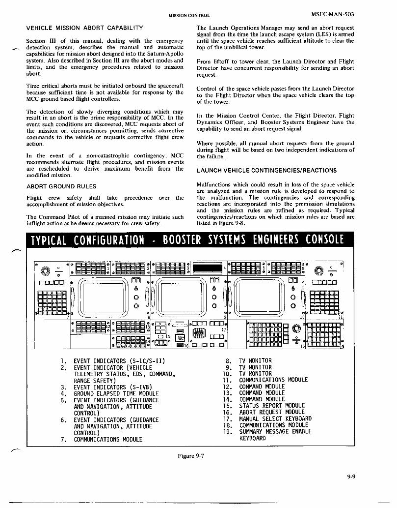
MISSION CONTROL MSFC-MAN-503
VEHICLE MISSION ABORT CAPABILITY The Launch Operations Manager may send an abort requestsignal from the time the launch escape system (LES) is armed
Section Ill of this manual, dealing with the emergency until the space vehicle reaches sufficient altitude to clear the_. detection system, describes the manual and automatic top of theumbilical tower.
capabilities for mission abort designed into the Saturn-Apollosystem. Also described in Section I11are the abort modes and From liftoff to tower clear, the Launch Director and Flightlimits, and the emergency procedures related to mission Director have concurrent responsibility for sending an abortabort, request.
Time critical aborts must be initiated onboard the spacecraft Control of the space vehicle passes from the Launch Directorbecause sufficient time is not available for response by the to the Flight Director when the space vehicle clears the topMCCgroundbasedflight controllers, of the tower.
The detection of slowly diverging conditions which mayresult in an abort is the prime responsibility of MCC. In the In the Mission Control Center, the Flight Director, Flightevent such conditions are discovered, MCC requests abort of Dynamics Officer, and Booster Systems Engineer have thethe mission or, circumstances permitting, sends corrective capability to send an abort request signal.commands to the vehicle or requests corrective flight crewaction. Wherepossible,all manualabort requestsfromthe ground
during flight will be based on two independent indications ofIn the event of a non-catastrophic contingency, MCC the failure.recommends alternate flight procedures, and mission eventsare rescheduled to derive maximum benefit from the LAUNCH VEHtCLECONTINGENCIES/REACTIONSmodified mission.
ABORT GROUND RULES Malfunctions which could result in loss of the space vehicleare analyzed and a mission rule is developed to respond to
Flight crew safety shall take precedence over the the malfunction. The contingencies and correspondingaccomplishment of mission objectives, reactions are incorporated into the premission simulations
and the mission rules are refined as required. TypicalThe Command Pilot of a manned mission may initiate such contingencies/reactions on which mission rules are based areinflight action as he deems necessary for crew safety, listed in figure 9-8.
o o=%o
-- 18
I. EVENT INDICATORS(S-IC/S-II) 8. TV MONITOR2. EVENTINDICATOR(VEHICLE 9. TV MONITOR
TELEMETRYSTATUS, EDS, COMMAND, lO. TV MONITORRANGESAFETY) II. COMMUNICATIONSMODULE
3. EVENTINDICATORS(S-IVB) 12. COMMANDMODULE4. GROUNDELAPSEDTIME MODULE 13. COMMANDMODULE5. EVENT INDICATORS(GUIDANCE 14. COMMAND MODULE
AND NAVIGATION,ATTITUDE 15. STATUSREPORTMODULECONTROL) 16. ABORTREQUESTMODULE
6. EVENT INDICATORS(GUIDANCE 17. MANUALSELECT KEYBOARDAND NAVIGATION,ATTITUDE 18. COMMUNICATIONSMODULECONTROL) 19. SUMMARYMESSAGEENABLE
7. COMMUNICATIONSMODULE KEYBOARD
Figure 9-7
9-9

J
MSFC-MAN-503 MISSIONCONTROL
TYPICAL INFLIGHTCONTINGENCIES/REACTIONS
FLIGHT SENSORSOR MISSIONCONTINGENCY TIME EFFECTMIN:SEC DISPLAYS RULEDATA
Loss of thrust 0:00- Collisionwith hold- Crew No automatic abort
for single 0:00.75 down post I. ThrustOK light Manual abort by LEScontrolengine 2. Physiological withtwocues
Ground I. ThrustOK lightI. Thrust OK light 2. Physiological2. Thrust chamber 3. Abort request
pressure light3. Longitudinal
acceleration4. Visual
Lossof thrust 0-0.03 Padfallback Crew No automaticabort
foranysingle 0:00- 1. ThrustOK light Manualabortby LESengine 00:03 2. Physiological with two cues
Ground I. ThrustOK lightI. Thrust OK light 2. Physiological2. Thrust chamber 3. Abort request3. Longitudinal light
acceleration4. Visual
Lossof thrust 0:00.75- Towercollision Crew No automaticabortfor any single 0:04.5 1. Thrust OK light available.towerside 2. Physiological Manualabortby LESengine Ground withtwocues(EngineNo. l I. Thrust OK light I. Thrust OK lightorNo.2) 2. Thrustchamber 2. Physiological
pressure 3. Abortrequest3. Longitudinal light ._
acceleration4. Visual
Lossof thrust 0:00- Possiblefalseabort Crew Recommendationfor single O:lO prior to 50 seconds I. ThrustOK light requiredto assurenocontrol engine if not covered by 2. Q-Ball may exceed false abort
above contingencies 3.2 psi (prior to50 seconds)
3. PhysiologicalGround
I. Thrust OK light2. Thrust chamber
pressure3. Longitudinal
acceleration4. Visual
Lossof thrustO:lO- Noeffects Crew No abortrequiredany single l:13 I. Thrust OK lightengine 2. Physiological
Ground
I. Thrust OK light2. Thrust chamber
pressure3. Longitudinal
acceleration4. Visual
Figure 9-8 (Sheet 1 of 9)
9-10

mssxoNCO_rrROL MSFC-MAN-503
TYPICAL INFLIGHT CONTINGENCIES/REACTIONS(CONTINUED)
FLIGHT
_-_ CONTINGENCY TIME EFFECT SENSORS OR MISSIONMIN:SEC DISPLAYS RULE DATA
Loss of thrust 1:08- Possible loss of Crew Automatic abort when
any single 1:18 control of vehicle I. Attitude rate attitude rate iscontrol engine resulting in exceeds 4°/second exceeded.
structuralbreakup 2. Thrust OK light Manual abort by LESwithin 0.6 seconds 3. Q-Ball exceeds with two cuesafter abort 3.2 psi I. Thrust OK light
Ground 2. Q-Ball limitsI. Thrust OK light exceeded2. Thrust chamber
pressure3. Longitudinal
acceleration
Loss of thrust I:18- No effect Crew No abort requiredanysingle 2:30 I. ThrustOKlightengine 2. -Physiological
Ground
I. Thrust OK light2. Thrust chamber
pressure3. Longitudinal
accelerati on
2:30- No effect Crew No abort required8:54 I. Thrust OK light
2. PhysiologicalGround
I. Thrust OK light2. Thrust chamber
pressure3. Longitudinal
acceleration
S-IVB Complete loss of Crew Abort by SPSBurn thrust I. Thrust OK light
2. PhysiologicalGround
I. Thrust OK light2. Thrust chamber
pressure3. Longitudinal
accelerati on
Loss of thrust 0:00- Loss of control Crew Automatic abort by LESany two 2:30 resulting in I. Thrust OK lights with loss of thrust foradjacent structuralbreakup 2. Physiological(if any two enginespriortcengines shutdown occurs 2 min 5 sec.
for 2 or more Manual abort after
engines at the same 2 min 5 sec. with twoLoss of thrust 0:00- time the effects engine out lights.any control 1:20 may be the same as aengineand singleenginecenterengine shutdown)
Ground
I. Thrust OK lightLoss of thrust 0:00- 2. Thrust chamber
any l:00 pressureopposite 3. Longitudinalcontrolengine acceleration
Figure 9-8 (Sheet 2 of 9)
9-11

MSFC-MAN-503 MISSIONCONTROL
TYPICAL INFLIGHTCONTINGENCIES/REACTIONS(CONTINUED)
FLIGHT SENSORSOR MISSIONCONTINGENCY TIME EFFECT
MIN:SEC DISPLAYS RULEDATA
One actuator S-IVB Lossof control Crew No automaticabort.inoperative boost I. No definedcues Manualabortby SPS(null Ground whenFDOlimitsposition) I. FDOlimits exceeded
exceeded
Anysingle 0:00- Collisionwith Crew No automaticabort.actuator 0:00.32 holddown post. I. Physiological Manual abort uponhardover Ground contactwithhold-(pitchor I. Visual downposts.yaw) 2. Lossofhydraulic
pressure3. Engine position
Any single 0:00.32- Tower collision Crew No automaticabort.actuator 0:02.1 I. Roll ratewill Manual abort by LEShardover exceed 4°/second with two cues(yaw 2. Physiological I. Rollattitudeerrorpositive Ground limitsexceededonly) I. Actuatorposition 2. Abortrequestlight
2. Loss of hydraulicpressure
3. Visual
Anysingle 0:00- No effectunless Crew No abortrequired.actuator 0:58 coveredby 1. Roll attitudehardover above errorexceeds5°
(pitchor 2. Q-Ballpressureyaw) exceeded
Ground
I. Actuator position2. Loss of hydraulic
pressure3. Visual
Anysingle 0:58- Possiblelossof Crew Automaticabortby LESactuator 1:23 control resulting I. Attitude rate when attitude ratehardover in structural exceeds 4°/second limit is exceeded.(pitchor breakup 2. Rollattitude Manualabortby LESyaw) errorexceeds5° withtwocues
3. Q-Ball exceeds I. Roll attitude limit3.2psi exceeded
Ground 2. Q-Ball limits1. Actuator position exceeded2. Loss of hydraulic 3. Engine position by
pressure ground
Anysingle l:13- Noeffect Crew Noabortrequiredactuator 2:30 I. Roll attitudehardover error
2. Q-Ball pressureexceeded
GroundI. Actuator position2. Loss of hydraulic
pressure
Figure 9-8 (Sheet 3 of 9)
%12

MISSIONCONTROL MSFC-MAN-503
TYPICAL INFLIGHT CONTINGENCIES/REACTIONS(CONTINUED)
FLIGHT_-_ CONTINGENCY TIME EFFECT SENSORSOR MISSION
MIN:SEC DISPLAYS RULEDATA
2:30- Noeffect Crew No abortrequired8:54 I. Nodefinedcues
Ground
I. Actuator position2. Loss of hydraulic
pressure
S-IVB Lossof control Crew No automaticabort.
Burn I. Attituderate ManualabortbySPSPhase exceeds lO°/second with two cues
2. L/V overrate light I. Attitude rate limitGround isexceeded
I. Actuator position 2. L/V overrate light2. Loss of hydraulic 3. Engine position
pressure (ground)
Engine S-IVB Loss of control if Crew No automaticabort.Hardover Restart restarted.Lead I. No defined cues Manual abort by SPS.
thrustwould cause Ground Do not attempt restartvehicle rotation I. Engine position
2. Loss of hydraulicpressure
Lossof both 0:00- Lossof control Crew Automaticabortby LESactuators 2:30 resultingin I. Roll rate exceeds when roll rate limit isfor same structuralbreakup 20°/second exceeded prior toengine if enginegoesto 2. Q-Ballexceeds 120seconds.
rollcorner 3.2psi Manualabortby LES•"_'- Ground with two cues
lo Engine position I. Q-Ball limit exceeded2. Loss of hydraulic (50 sec-Imin 50 sec)
pressure 2. Engineposition3. Rollrate (groundcue)
2:30- Noeffect Crew No abortrequired8:54 I. No defined cues
GroundI. Engine position2. Loss of hydraulic
pressure
Loss of both S-IVB Loss of control Crew No automatic abort.actuators Burn I. Attituderate Manualabortby SPSfor same Phase exceeds lO°/second with two cues
engine 2. L/V overrate light I. Attitude rate limitGround isexceeded
I. Engine position 2. L/V overrate light2. Loss of hydraulic 3. Engine position
pressure (ground)
Figure 9-8 (Sheet 4 of 9)
9-13

MSFC-MAN-503 MISSIONCONTROL
TYPICAL INFLIGHTCONTINGENCIES/REACTIONS(CONTINUED)
FLIGHTCONTINGENCY TIME EFFECT SENSORSOR MISSION
MIN:SEC DISPLAYS RULEDATA _--
Lossof 0:00- LOSSofcontrol Crew AbortafterInertial 0:50 resultingin I. Guidance failure 50 secondsAttitude structural light
failure after 2. Overrate light60 seconds (used as redundant
guidance failurelight from 0 to2 min 5 sec)
3. Attitude errorexceeds 5 °
GroundI. Guidance failure
light
0:50- Lossof control Crew Manualabortwith1:25 resultingin I. Guidance failure two cues
structural light I. Guidancefailurefailureduring 2. Overratelight lightthis time (used as redundant 2. Overrate lightperiod guidance failure (used as redundant
light from 0 to guidancefailure2 min5 sec) light0-2min 5 sec)
3. Attitude errorexceeds 5°
l:25- Ground Manualabortwith2:05 I. Guidance failure three cues
light I. Guidance fail light2. Overrate light3. Attitude error
exceeds 5 °
2:05- Same as above Manual abort on2:30 exceptno twocues
overrate light I. Guidance failurelight
2. Attitude errorexceeds 5°
Lossof 1:30- Lossof guidance Crew Automaticabortby LESInertial 2:30 with no structural I. Attituderate when attituderateAttitude failures exceeds 4°/second limit is exceeded.
2. Guidance failure Manual abort by LESlight with two cues
3. Q-Ball exceeds 1. Guidance failure3.2 psi(l min 30 sec lightto 1 min 50 sec) 2. Q-Ball limits
4. Attitude error exceededexceeds 5° 3. Attitude error limit
exceeded
1:30- Loss of guidance Crew No automaticabort.8:54 I. Guidance failure Manual abort by LES
light priorto towerjettisonGround or by SPS after towerI. FDO limits jettisonwith a single
exceeded cueI. Guidance failure
light2. FDO limits exceeded
F_ureg-8(Sheet 5 ofg)
9-14

MISSION CONTROL MSFC-MAN-503
TYPICAL INFLIGHT CONTINGENCIES/REACTIONS(CONTINUED)
FLIGHT SENSORSOR MlSSlOflCONTINGENCY TIME EFFECT DISPLAYS RULEDATA
_ MIN:SEC
Lossof S-IVB Lossof guidance Crew No automaticabort.inertial Burn I. Guidance failure Manual abort by SPSattitude Phase light withsinglecue
Ground I. Guidance faiIure
I. FDOlimits lightexceeded 2. FDO limitsexceeded
Lossof All Noeffect NoabortrequiredInertial StagesVelocity
Lossof All Lossof control Crew Automaticabortby LESAttitude Stages I. Attitude rate prior to 2 min 5 secError exceeds 4°/second when attitude rate limitCommands forS-IC isexceeded.Manualabort
2. Attitude rate by LES prior to towerexceeds lO°/second jettison and SPS afterfor S-II and S-IVB tower jettison with a
3. Attitudeerror single cueexceeds 5° for S-IC I. Attitude error limits
Ground exceeded(S-IConly)I. FDO limits 2. FDO limits exceeded
exceeded (all stages)
Attitude All Lossof control Crew Automaticabortby LESerror stages I. Attituderate priorto2 min5 seccommand exceeds 4°/second when attitude ratesaturated in pitch or yaw limit is exceeded.
or 2O°/second in Manual abort by LESroll for S-IC prior to tower jettison
2. Attitude rate and SPS after tower
exceeds lO°/second jettisonwith two cuesfor S-II and S-IVB I. L/V overrate lightin pitch or yaw or 2. Attitude rate20°/secondin rolI indicatorfor S-II and S-IVB 3. FDO limits exceeded
3. Attitude errorexceeds 5° for S-IC
4. L/V overrate lightGroundI. Guidance failure
light2. FDO limits
exceeded
Loss of All Loss of guidance Crew Automatic abort by LESattitude Stages I. Attituderate priorto 2 min5 seccommand exceeds 4°/second when attitude ratesignal for S-IC in limit is exceeded.
pitch or yaw Manual abort by LES2. Attitude rate prior to tower jettison
exceeds lO°/second and SPS after tower
for S-II and S-IVB jettisonwith a singlein pitch and yaw cue
3. Attitudeerror I. Attitude rateexceeds 5° for S-IC limits exceeded
Ground 2. FDO limits exceededI. FDO limits
exceeded
Figure 9-8 (Sheet 6 of 9)
9-15

MSFC-MAN-503 MISS_NCONTROL
TYPICAL INFLIGHT CONTINGENCIES/REACTIONS(CONTINUED)
FLIGHT SENSORSOR MISSIONCONTINGENCY TIME EFFECT DISPLAYS RULE DATA I-"
MIN:SEC
Attitude All Lossof control Crew Automaticabortby LESrate stages I. Attituderate priorto2 min5 secsignal exceeds 4°/second when attitude ratesaturated inpitchoryawor limitisexceeded.
20°/secondin roll Manual abort by LESforS-IC priorto tower
2. Attitude rate jettison and SPSexceeds lO°/second after tower jettisonfor S-II and S-IVB with two cuesin pitch or yaw or I. L/V overrate20°/secondin roll lightfor S-II and S-IVB 2. Attitude rate
3. Attitudeerror indicatorexceeds 5° for 3. FDO limitsS-IC exceeded
4. L/V overrate lightGroundI. Guidance failure
light2. FDO limits
exceeded
Lossof All Lossof control Crew Automaticabortby LESattitude stages I. Attituderate priorto 2 min5 secrate exceeds 4°/second when attitude ratesignal in pitch or yaw limit is exceeded.
or 20°/secondin Manual abort by LESroll for S-IC prior to tower jettison
2. Attituderate and SPS aftertower _-_exceeds ]O°/second jettisonwith two cuesfor S-II and S-IVB I. L/V overratein pitchor yaw or light20°/secondin roll 2. Attitude ratefor S-II and S-IVB indicator
3. Attitude error 3. FDO limitsexceeds5° for exceededS-IC
4. L/V overratelight
GroundI. Guidance failure
light2. FDO limits
exceeded
Lack of S-IC 2:30 No S-If ignition Lack of S-II thrust Early S-IVB stagingorfirstplane possible abortbycrew(orbitseparation notpossible)
Lack of S-II 2:57 Probable subsequent Second plane Shutdown prior tosecond plane loss of vehicle due separationindicator overheat and early S-IVBseparation toexcessive (redundant stagingrequiredby crew(includes temperature indication) only, limited timepartial betweennormaljettisonseparation) timeandexcessive
temperature may precludeground informationbackup
F_ure 9-8(Sheet 7 of 9)
9-16

MISSION CONTROL MSFC-MA_-503
TYPICAL INFLIGHT CONTINGENCIES/REACTIONS(CONTINUED)
FLIGHT SENSORSOR MISSIONCONTINGENCY TIME EFFECT DISPLAYS RULEDATA
MIN:SEC
Lack of S-II/ 8:54 No S-IVB ignition Lack of S-IVB thrust SPS abort requiredS-IVB planeseparation(includespartial )
Lossof both S-IVB Lackof rollcontrolCrew Manualcontrolby crewAPSmodules, burn Rollattitudemay withRCSwhenrollS-IVB )hases beexcessive attitudeisexcessive
GroundI. Roll attitude
Lossof S-IVB Negligible Crew ManualcontrolbyoneAPS burn I. Noindication crewwithRCSwhenS-IVB )hases rollattitudeis
exces s ive
LETfails 3:03 Vehiclemaygo Crew ShutdownS-IVBto jettison unstable I. Visual by crew where vehicle
during S-IVB 2. Attitude rate becomes oscillatory.flight i3. Vehicle Crewto useemergency
osciIIatory proceduresforGround removalof LETifI. Tower off orbitwas achieved.
indi cati on
Lossof thrust 2:31.8- Lossof control Crew No automaticabort.2 lower 6:20 I. ThrustOK lights Manualabortby LES
adjacent 2. Attituderate on2 cuespriortocontrol exceeds 4°/sec tower jettison.
engines 6:20- Failureto get 3. Rollattitude Manualabortby SPS on8:00 75 NMI orbit error 20° 2 cues after LES
4. Physiological jettison and prior toGround 5 rain50sec flight
8:00- No effect I. ThrustOK lights time.Earlystaging8:41 2. Thrustchamber toS-IVBon2 cues
pressure-zero after 5 min 50 sec3. Longitudinal flight time.
Loss of thrust 2:31.8- Loss of control acceleration Cues
2 upper 6:15 4. Attituderate I. ThrustOK lightsadjacent 5. FDO limits 2. Attitude rate 4°/seccontrol 3. Roll attitude
engines 5:15- Noeffect error20°8:41 4. Physiological
5. FDO limits
Loss of thrust 2:31.8- Loss of control2 side 7:10
adjacentcontrol 7:lO-
engines 8:41 No effect
Figure 9-8 (Sheet 8 of 9)
9-17

MSFC-MAN-503 M_SSIONCONTROL
TYPICAL INFLIGHTCONTINGENCIES/REACTIONS(CONTINUED)
FL IGHTCONTINGENCY TIME EFFECT SENSORSOR MISSION
MIN:SEC DISPLAYS RULEDATA _-"
LOSS of thrust 2:31.8- S-IVBdepletion Crow No automaticabort.center and 3:IO before N POI 1. Thrust OK lights Manual abort by LESonecontrol 2. Attituderate on2 cuespriorto
3:10- No effect exceeds 4°/sec tower jettison.3:50 3. Roll attitude Manual abort by SPS on
error 20° 2 cues after LES
4. Physiological jettison and prior toGround 5 min 50 sec flight
3:50- Failure to get I. Thrust OK lights time. Early staging7:10 75 NMI orbit 2. Thrustchamber to S-IVBon 2 cues
pressuro-zero after 5 rain50 sec3. Longitudinal flight time.
7:10- No effect acceleration Cues
8:41 4. Attituderate I. ThrustOK lights5. FDO limits 2. Attitude rate 4°/sec
3. Roll attitudeLoss of thrust 2:31.8- S-IVB depletion error 20°2 opposite 3:10 beforeN POI 4. Physiologicalengines 5. FDO limits
3:10- No effect3:50
3:50- Failure to get6:00 75 NMI orbit
6:00- No effect8:41
Loss of thrust 2:31.8- Possible loss of Crew No automaticabort.
2 adjacent /:lO control during ]. Thrust OK lights Manual abort by LEScontrol S-II flight 2. Attitude rate prior to tower jettisonengines exceeds 4°/second and by SPS after tower
prior to jettisonwith two cues7 min 55 sec I. Thrust OK lights
3. Physiological 2. Attitude rateGround exceeded prior toI. Thrust OK lights 5 min2. Thrust chamber 3. Physiological
pressure - zero3. Longitudinal
6:20- Failure to achieve acceleration EarIy staging with8:00 75 NMI orbit 4. Attitude rate two cues
8:00- No effect Continue Mission8:4I
Lossof thrust 2:31.8- S-IVBdepletion Crew Sameas 2 min 30 sec-2 opposite 3:10 beforePOI I. ThrustOK lights 5 min 50 sec abovecontrolor 2. Attituderatecenterengine exceeds 4°/secondandone 3:10- Noeffect priorto Sameas2 min30sec-control 3:50 7 min 55 sec 5 min 50 sec aboveengine 3. Physiological
Ground
3:50- Failureto I. Thrust OK lights Earlystagingwith two7:10 achieve75 NMI 2. Thrustchamber cues
orbit pressure- zero3. LongitudinalAccel.
7:10- No effect 4. Attituderate Continuemission8:41
Figure 9-8 (Sheet 9 of 9)
9-18

MISSIONCONTROL MSFC-MAN-503
VEHICLE FLIGHT CONTROL PARAMETERS NOTE
In order to pertorm flight control monitoring functions, The preceding flight controllers are located in theessential data must be collected, transmitted, processed, MOCR. The following are located in the vehicle systemdisplayed, and evaluated to determine the space vehicle's SSR.capability to start or continue the mission. Representative
parameters included in this essential data are briefly 4. The Guidance and Navigation-Digital Systems (GND)described in the following paragraphs, engineer monitors the guidance, navigation, and
PARAMETERS MONITORED BY LCC digital (sequential) BSE systems. The GND providesdetailed support to BSE No. 3. Typical parameters
The launch vehicle checkout and prelaunch operations monitored includes ST-124-M3 accelerometer andmonitored by the Launch Control Center (LCC) are briefly gyro pickups (X,Y,Z axes); and fixed position anddiscussed in Section VIII of this manual. These operations fLxed velocity (X,Y,Z components).determine the state of readiness of the launch vehicle, groundsupport, telemetry, range safety, and other operational 5. The Attitude Control and Stabilization Systemssupport systems. During the final countdown, hundreds of (ACS) engineer monitors the attitude controlparameters are monitored to ascertain vehicle, system, and System, the S-IVB hydraulic and auxiliarycomponent performance capability. Among these parameters propulsion systems, and the emergency detectionare the "redlines'. The redline values must be within the system. The ACS provides detailed support to BSE's
predetermined limits or the countdown will be halted. No. 2 and 3. Typical parameters monitored includeTypical redlines are fuel and oxidizer tank ullage pressure, hydraulic accumulator pressures, hydraulic reservoirGN 2 and helium storage sphere pressure, hydraulic supply piston position, attitude control fuel and oxidizerpressures, thrust chamber jacket temperatures, bus voltages, module temperatures, and rates excessivesIU guidance computer operations, H 2 and 0 2 concentrations, (pitch/roll/yaw).
and S-IVB oxidizer and fuel recirculation pump flow. In 6. The Engine Systems Engineer monitors the S-II andaddition to the redlines, there are a number of operational S-1VB engine system and O2/H 2 burner and providessupport elements such as ALDS, range instrumentation, detailed support to BSE No. 2. Among theground tracking and telemetry stations, ground parameters monitored are thrust chamber pressure,communications, and other ground support facilities which engine inlet lox and LH 2 pressure, pre-valve position,must be operational at specified times in the countdown, and O2/H 2 burner chamber dome temperature.
PARAMETERS MONITORED BY BOOSTER SYSTEMS 7. The Stage Systems Engineer monitors tankGROUP pressurization, repressurization, bulkhead pressure
The Booster Systems Group monitors launch vehicle systems differential, chilldown and provides detailed support(S-IC, S-II, S-IVB, and IU) and advises the flight director and to the BSE No. 2. Typical parameters monitoredflight crew of any system anomalies. They are responsible for include helium tank pressure, start tankabort actions due to failure or loss of thrust and overrate pressure/temperature, and common bulkheadconditions; for monitoring and confirming flight events and pressure.
conditions such as inflight power, stage ignition, holddown 8. The Electrical Network and Systems (ENS) engineerrelease, all engines go, roll and pitch initiate, engine cutoff, monitors the electrical systems (all LV stages), IUattitude control and stage separations; and for digital environmental control system, and range safetycommanding of LV systems, systems (safing at orbital insertion) and provides
Specific responsibilities in the group are allocated as follows: detailed support to BSE No. 3, Typical parametersmonitored include exploding bridgewire voltages,
1. The BSE No. 1 has overall responsibility for the sublimator inlet temperature, GN 2 regulator inletgroup, for connnands to the launch vehicle, and for temperature, and various bus voltages and currents.monitoring and evaluating the S-IC and S-11 flight
9. The Command Systems Engineer monitors theperformance. Typical flight control parametersmonitored include engine combustion chamber commands sent to the launch vehicle and advisespressure, engine gimbal system supply pressure, fuel BSE No. i on their status. In the event of rejectionand oxidizer tank ullage pressure, helium storage of a command by the onboard computer, hetank pressure, engine actuator (yaw/pitch/roll) determines the cause of the rejection, i.e.,position, THRUST OK pressure switches, improperly coded command, malfunction of thelongitudinal acceleration, vent valve positions, engine command system, or malfunction of the computer.
ignition/cutoff, and various bus voltages. 10. The Consumables Engineer monitors status at all
2. The BSE No. 2 supports BSE No. 1 in monitoring times of launch vehicle consumables including allthe S-II flight and assumes responsibility for high pressure spheres, APS propellants, and mainmonitoring the S-IVB burns. Parameters monitored stage propellants. He advises the BSE No. 2 ofare similar to those monitored by BSE No. 1. mission impact when consumables are depleted
beyond predicted limits.3. The BSE No. 3 monitors the attitude control,
electrical, guidance and navigation, and IU systems. PARAMETERS MONITORED BY FLIGHT DYNAMICSTypical parameters monitored include roll/pitch/yaw GROUPguidance and gimbal angles, angular rates,
,_ ST-124-M3 gimbal temperature and bearing pressure, The Flight Dynamics Group monitors and evaluates theLVDC temperature, and various bus voltages, powered flight trajectory and makes the abort decisions
9-19

MSFC-MAN-503 MISSIONCONTROL
based on trajectory violations. They are responsible for abort provides tracking, telemetry, voice and teletypeplanning, entry time and orbital maneuver determinations, communications, command, recording, and televisionrendezvous planning, inertial alignment correlation, landing capabilities. The network is specifically configured to meetpoint prediction, and digital commanding of the guidance tile requirements of each mission.systems.
MSFN stations are categorized as lunar support stationsThe MOCR positions of the Flight Dynamics Group include (deep-space tracking in excess of 15,000 miles), near-spacethe Flight Dynamics Officer (FDO), the Guidance Officer support stations with Unified S-Band (USB) equipment, and(GUIDO), and the Retrofire Officer (RETRO). The MOCR near-space support stations without USB equipment. Figurepositions are given detailed specialized support by the flight 9-9 is a matrix listing the stations by designators anddynamics SSR. capabilities. Figure 9-10 shows the geographical location of
each station.The surveillance parameters nleasured by the ground trackingstations and transmitted to the MCC are computer processed MSFN stations include facilities operated by NASA, theinto plotboard and digital displays. The flight dynamics United States Department of Defense (DUD), and thegroup compares the actual data with pre-mission calculated Australian Department of Supply (DOS).nominal data and is able to determine mission status. The
surveillance parameters include slant range, azimuth and The DUD facilities include the Eastern Test Range (ETR),elevation angles, antenna polarization angle, and other data. Western Test Range (WTR), White Sands Missile RangeFrom these measurements, space vehicle position, velocity, (WMSR), Range Instrumentation Ships (RIS), and Apolloflight path angle, trajectory, ephemeris, etc., may be Range Instrumentation Aircraft (ARIA). Recovery forcescalculated. Typical plotboard displays generated from the under DUD are not considered to be part of the MSFN.surveillance parameters are altitude versus downrangedistance, latitude versus longitude, flight path angle versus NASA COMMUNICATIONS NETWORKSinertial velocity, and latitude versus flight path angle.
The NASA Communications (NASCOM) network is aPARAMETERS MONITORED BY SPACECRAFT SYSTEMS point-to-point communications systems connecting theGROUP MSFN stations to the MCC. NASCOM is managed by the
Goddard Space Flight Center, where the primary
The Spacecraft Systems Group monitors and evaluates the communications switching center is located. Three smallerperformance of spacecraft electrical, optic'd, mechanical, and NASCOM switching centers are located at London, Honolulu,life support systems; maintains and analyzes consumables and Canberra. Patrick AFB, Florida and Wheeler AFB,status; prepares the mission log; coordinates telemetry Hawaii serve as switching centers for the DUD eastern andplayback: determines spacecraft weight and center of gravity; western test ranges, respectively. The MSFN stationsand executes digital commanding of spacecraft systems, throughout the world are interconnected by landline, /_,,
undersea cable, radio and communications satellite circuits.
The MOCR positions of this group include the Command and These circuits carry teletype, voice, and data in real-timeService Module Electrical, Environmental, and support of the missions. Figure 9-11 depicts a typicalCommunications Engineer (CSM EECOM), the CSM NASCOM configuration.Guidance, Navigation, and Control Engineer (CSM GNC), theLunar Module Electrical, Environmental, and Each MSFN USB land station has a minimum of fiveCommunications Engineer (LM EECOM), and the LM voice/data circuits and two teletype circuits. The ApolloGuidance, Navigation, and Control Engineer (LM GNC). insertion and injection ships have a similar capability throughThese positions are backed up with detailed support from the the communications satellites.vehicle systems SSR.
The Apollo Launch Data System (ALDS) between KSC andTypical parameters monitored by this group include fuel cell MSC is controlled by MSC and is not routed through GSFC.skin and condenser temperatures, fuel cell current, various The ALDS consists of wide-band telemetry, voicebattery and bus voltages, launch escape tower and motor coordination circuits, and a high speed circuit for thediscretes, AGCU drift, SPS helium tank pressure, SPS fuel Countdown and Status Transmission System (CASTS). Inand oxidizer tank pressure, and fuel and oxidizer inlet addition, other circuits are provided for launch coordination,pressure differential, tracking data, simulations, public information, television, and
recovery.PARAMETERS MONITORED BY LIFE SYSTEMS GROUP
MSFC SUPPORT OF LAUNCH AND FLIGHT
The Life Systems Group is responsible for file well being of OPERATIONSthe flight crew. The group is headed by the Flight Surgeon inthe MOCR. Aeromedical and environmental control The Marshall Space Flight Center (MSFC) by means of thespecialists in thelife systems SSR provide detailed support to Launch Information Exchange Facility (LIEF) and thethe Flight Surgeon. The group monitors the Bight crew Huntsville Operations Support (HOSC) provides real-timehealth status and environmental/biomedical parameters, support of launch vehicle prelaunch, launch, and flight
operations. MSFC also provides support via LIEF forMANNED SPACE FLIGHT NETWORK postflight data delivery and evaluation.
The Manned Space Flight Network (MSFN) is a global LAUNCH INFORMATION EXCHANGE FACILITYnetwork of ground stations, ships, and aircraft designed tosupport manned and unmanned space flight. The network The LIEF encompasses those personnel, communications,
9-20

MISSIONCONTROL MSFC-MAN-503
data processing, display, and related facilities used by the a request for analysis. The capabilities of MSFC laboratoriesMSFC launch vehicle design team to support Apollo-Saturn and the System Development Facility (SDF) are alsomission operations. The LIEF operations support available.organization is shown in figure 9-12.
PRELAUNCH WIND MONITORING
In-depth real-time support is provided for prelaunch, launch,and flight operations from HOSC consoles manned by Prelaunch flight wind monitoring analyses and trajectoryengineers who perform detailed system data monitoring and simulations are jointly performed by MSFC and MSCanalysis, personnel located at MSFC during the terminal countdown.
Beginning at T-24 hours, actual wind data is transmittedSystem support engineers from MSFC and stage contractors periodically from KSC to the HOSC. These data are used byare organized into preselected subsystem problem groups the MSFC/MSC wind monitoring team in vehicle flight digital(approximately 160 engineers in 55 groups) to support KSC simulations to verify the capability of the vehicle with theseand MSC in launch vehicle areas which may be the subject of winds. Angle of attack, engine deflections, and structural
MSFNSTATIONS/EQUIPMENTMATRIX
Sys tenls
"4issionControl Center MCC X X X X X X XI X X I
NSFN Operations Center MSFNOC X X X X X X X X X [
tCentral Instrumentation Facility CIF H
TELIV X X X X X
AscensionIsland,U.K.(NASA) ACN# X X X X X X X X X ]
IAntigua, U.K. (NASA) ANG # X X X X X X X X X X X
Antigua (D(]D-ETR) /V_T# X X X X X iX X X X X X X X X X X I
As_nsion Island (goD-ETR) _SC d X X X X X X X X X ]
Be_uda, U.IC.(NASA) BDA # X X X X X X X X X X X X X X X XI
ICanberra, Australia (WRE) CNB * X X X X X X
Vandenberg, California (DOD-WTR) CAL # X X X X X X X X I
Cape Kennedy (goD-ETR) CNV # X X H X X X X X ]
Car_arvon, Australia (WRE) CRO # X X X X X X X X X X X X X X X X X X I
USNS Coastal Sent_ (DOD-ETR) CBQ # X X X X X X X X X X I
Canton Island (NASA) CTN # X X X X X X I
Canary Islands, Spain (NASA) CYI H X X X X X x x X X X X X X X X X ]
Grand Bahama Island (goD-ETR) GBI # X X X X X X X X X X X X X I
Grand Bahamas. U.K. (NASA) GBM H X X X X X X X X X I
Goldstone, Califo_ia (NASA) GDS * iX X X X X X X IGrand Turk Island (goIJ-ETR) GTK # X X X X X X X I
Gun. U.S. (NASA) GWM # X X X X X X X X ]
Guay_as, Mexico (N_SA) GYM _ X X X x X X X X X X X X X X X l
Kokee Park, Hawaii (NASA) HAW # X X X X X X X X X ,X X X X X X X X X ]
Madrid, Spain (NASA) MAD * IX X X X X X I
Merritt Island, Florida (NASA) MIL # X X X X X X X X X X X X I
Merritt Island (goD-ETR) MLA # X X! X X I
Patrick AFB, Florida (DOD-ETR) PAT # X x i X ]
Pretoria, So. Africa (D3D-ETR) PRE # g X g X ]
USNS Hose Knot (Dgo-ETR) RNV H X X X x X X X X X X l
USFISRange Tracker ({)3D-WTR) RTR # X X X X X X X I
ITananarive, Malagasy Rep, (N&SA) TAN # X X X X X X
Corpus Christi, Texas (NASA) TEX # X X X X X X X X X X X X X X ]
White Sands, N,M. (DOD-WSMR) WHS # X X XI X X ]
Woomera. Australia (goS-NRE) NOM # X X X 1
Apollo Range Inst. Aircraft ARIA I-8 x X X x I
gSNS Huntsville (gOD - WTR) Ships: HTV X X X X X X X ]
USNS Nercury (gOd - WIR) _IER X X X X X X X X X X X J
USNS Redstone (goD - k_IR) RED X X X X X X X X X X X ]
USNS Vanguard (god - kITR) VAN X X X X X X X X X X X ]
USNS Watertown (gob - WTR) WTN X X X X X X X ]
• Lunar Support Stations# Near Space Support StationsSupplemental Stations
Figure9-9
9-21

MSFC-MAN-503 MISSIONCONTROL
loads are calculated and compared against vehicle limits, compared with similar bending moment displays in CIF.Simulations are made on either the IBM 7094 or B5500
computer and results are reported to the Launch Control LAUNCH AND FLIGHT OPERATIONS SUPPORTCenter (LCC) within 60 minutes after wind datatransmission. At T-2 1/4 hours a go/no-go recommendation is During the prelaunch period, primary support is directed totransmitted to KSC by the wind monitoring team. A KSC. Voice communications are also maintained with thego/no-go condition is also relayed to the LCC for lox and Booster Systems Group at MCC and the KSC/MCC supportLH 2 loading, engineers in CIF to coordinate preparations for the flight
phase and answer any support request.In the event of marginal wind conditions, contingency winddata balloon releases are made by KSC on an hourly basis At liftoff, primary support transfers from KSC to the MCC.after T-2 1/2 hours and a go/no-go recommendation is The HOSt2 engineering consoles provide support, as required,transmitted to KSC for each contingency release. This to the Booster Systems Group during SdVB/IU orbitalcontingency data is provided MSFC in real-time via operations, by monitoring detailed instrumentation forCIF/DATA-CORE and trajectory simulations are performed system inflight and dynamic trends, by assisting in theon-line to expedite reporting to KS(]. detection and isolation of vehicle malfunctions, and for
providing advisory contact with vehicle design specialist. ThisGround wind monitoring activities are also performed by support is normally provided from liftoff through the activeMSFC laboratory personnel for developmental tests of launch vehicle post-spacecraft separation phase,displays. Wind anemometer and strain gauge data are received approximately T + 6 hours, or until LIEF mission supportin real-time and bending moments are computed and termination.
MANNED SPACE FLIGHT NETWORK APOLLO STATIONS
180 180.
\. co s ..UOA olaeE.-rav mr"AaGUEU'O "_C,,IS'_ _,_.'_E "NN' OV _iD.. S-_" I_ _._" ,J_ PACIFICSHIP D HAWAII GUAYM+_S GRAN0 i_ ELEUTHERA CA"ARYI$. -
{" INJEC'rlO.$HIP1 TANANARIVE < • _ _x"_
NoiANOC,AN JATLANTICOCEAN
.80 LEGEND: 180
o Communications Only
_, 30' DualUSBS
s. 30' SingleUSBS• 85' Antenna
Figure 9-10
9-22

MISSION¢OlqTROL MSFC-MAN-503
BREWSTER 12 V/D-4TTY
FLATS 12 V/D-4TTY5 V/D-2TrY
6 V/D-2TTY 1 V/D-2TTY
5 V/D-2_Y _ 1 VID-2TTY
5 V/D-2TTY 6 V/D-21-[Y
'D-21-FY
INTELSAT S
iNTELSAT
F 5 V/D-2TTY
3 V/D-2TTY
l V/D-ITTY
l _D-2TTY C 3 V/D-21-fY
_D-21-rY 6 V/D-2TTY 6 V/D-2TTY
I V/D-ITTY l V/D-II-FY LEGENDV.I-FY V,TTY,HSD
I ITTY I_wAS_ IV =VOICE
V/D = VOICE DATAWBD M HSD = HIGH-SPEED DATA
I J f I WBD = WIDE-BAND DATAMSFC V-TTY MCC JX-Y/CKAFSlTV = TELEVISION
I 1V'I'FY II!wTyAOS = ATLANTIC OCEAN
ALDS HSD,WBD,TV SHIPS
V,I-FY,HSD,WBD,TV V,TTY,HSD BD IOS = INDIANOCEAN
I ISH IPS
NOTES: TTY = TELETYPE
]. NASCOM interfacepoints for ships and b. Net #2 Biomed Dataaircraft are mission dependent, c. Net #3 Network M & 0
d. Net #4 Telemetry Data/CommandData2. Additional V/D and TTY circuits between (USB)
GSFC and centers are augmentedas re- e. Net #5 Tracking Data (USB)quired.
6. One additionalvoice data circuitwill 6e
3. Communicationscircuits as shown exist availableto each Apollo station equippedat this time or will be availablefor with an 85' antenna and to Bermuda for
missions as required, high-speedtracking data.
4. Circuit routing is not necessarilyas 7. Apollo stations and ships connectedtoindicated. GSFC via Intelsat can receive at all
times, regardlessof nu_er of stations5. Voice Data Network to and from the Apollo or ships. Only two stations or ships
USB stationswill be configuredwith us- can transmit at a given time via eachage as indicated Intelsat.
a. Net #I Mission Conference 8. Apollo ship may be assigned to any ofthese areas.
Figure 9-I I
9-23

"_g-6
I-6a_r_!d
__o___z
mm
NmmIIILII
'['I
m
_,l
I
L'IIII
II
NNNa__N
_.°
m_
NOIIVZINVg_IOo.I._IOddI1S SNOIIV_FIclO-itll1o_lNo3No[sm_£O_-NVIAI-DdSI_

MSFC-MAN-503
SECTIONl ][MISSIONVARIBLESANDCONSTRAINTSTABLE OF CONTENTS In the Option 1 mission (figure 10-2) the launch vehicle
places tile spacecraft into a 100 nautical mile circular orbit.MISSION OBJECTIVES ......................... 10-1 The boost to earth orbit consists of complete burns of the
FLIGHTPROF1LES ........................... 10-1 S-lC and SJI stages and a first burn of the S-IVB stage. TheMISSION CONSTRAINTS ....................... 10-1 launch azimuth will be 72 to 108 degrees (figure 10-4) with a
launch window of December 20 to 27, 1968 or January 18 toMISSION OBJECTIVES 24, 1969. The LV/Spacecraft systems are checked out during
The mission objectives for the C Prime mission are as follows: coast in the parking orbit. The S-IVB stage is restarted overthe Pacific Ocean during the second or third revolution (fLrst
1. Verify the LV capability for a free-return, translunar or second injection opportunity) as shown in figure 10-5.injection (TLI). After escape velocity is reached, the S-IVB is cutoff and the
S-IVB/IU/Spacecraft is injected into a free-return, translunar
2. Demonstrate the restart capability of the S-IVB trajectory, where the CSM is separated from thestage. S-IVB/IU/LTA-B. The S-IVB/IU/LTA-B maneuvers to a
predetermined attitude and executes retrograde dump of3. Verify the J-2 engine modifications, residual propellants (slingshot procedure) to attain a solar
orbit. The S-IVB is then "safed" by venting residual gases.
4. Confirm S-II and S-IVB J-2 engine environment. The CSM continues on the translunar trajectory (64 to 70hours) and either goes into a lunar orbit or remains on a
5. Confirm the LV longitudinal oscillation environment free-return trajectory. The CSM transearth trajectory takesduring the S-IC burn period. 75 to 85 hours. On the approach to earth, the CM is
separated from the SM and recovered in the Pacific Ocean.
6. Verify the lox prevalve accumulators (surge
chambers) incorporated in the S-IC stage to supress MISSION CONSTRAINTSthe low frequency longitudinal oscillations (POGO
effect). Mission requirements impose the following constraints on thef-" LV/Spacecraft, trajectory profile, and mission planning
7. Demonstrate helium heater repressurization system factors.operation.
8. Verify the capability to inject the S-IVB/IU/LTA-B 1. During Time Base 5, the crew shall be capable ofissuing manual attitude commands to the LV. At
into a lunar slingshot trajectory. "hand back," the S-IVB/IU shall maintain the handback attitude in the mode (local or inertial) which is
9. Demonstrate the capability to safe the S-IVB stage, in the timeline at "hand back."
10. Verify the onboard CCS/ground system interface 2. The S-IVB restart attitude will be local horizontal.and operation in deep space environment.
FLIGHT PROFILES 3. The crew command S-IVB attitude rate limits are 0.3degrees per second in pitch and yaw, and 0.5 degrees
The C Prime mission has two planned profiles, basic and per second in roll.Option 1 as shown in figures 10-1 and 10-2. The attitudemaneuvers required during flight are shown in figure 10-3. 4. Vehicle pitch and yaw attitude rates shall not exceed
one degree per second.In the basic mission (figure 10-1) the launch vehicle places
the spacecraft into a 100 nautical mile circular earth orbit. 5. The S-IC center engine cutoff time shall occur priorThe boost to earth orbit consists of complete burns of the to attaining 4g acceleration.S-IC and S-II stages and a first burn of the S-IVB stage. TheCSM is separated from the S-1VB/IU/LTA-B during the fwst 6. The S-IVB stage will be fully loaded and have tworevolution in EPO. The S-IVB is restarted over the Pacific burn periods.
Ocean during the second revolution (first injectionopportunity) and the S-IVB/IU/LTA-B is injected into a 7. The basic mission will utilize a preselected single day
of lunar targeting for the entire launch window.lunar transfer t_ajectory. The S-IVB/IU/LTA-B maneuvers to
a predetermined attitude and executes retrograde dump of8. There will be no inflight navigation or target update.residual propellants (slingshot procedure) to attempt a solar
All profile options will be obtained by crew actionorbit. The S-IVB stage is then "safer" by venting residual (Option 1 by riding TLI burn).gases. The CSM continues in earth orbit to complete
_-" spacecraft operations. The CM then separates from the SM 9. The PU system (S-I1 and S-IVB stages) will be flownandreturnsto earth, open-loop.
10-1

MSFC-MAN-503 MtSSION
10. Pacific translunar injection opportunities (S-IVB mission profile and 72 to 108degrees for Option Irestart) during second or third revolution in EPO profile.shall be used for Option 1. If both TLI opportunitiesare inhibited by the crew, no S-IVB restart will be 12. In the basic mission profile, CSM separation occurs _--attempted, in the first revolution in EPO.
13. The maximum vehicle yaw attitude may not exceed11. The flight azimuth will be 72 degrees for the basic 45 degrees (measured from flight azimuth at launch).
BASIC MISSION PROFILE
I. BOOST TO EARTH ORBITS-IC, S-II, AND FIRST S-IVB OPERATION
2. COAST IN IO0 NAUTICAL MILEEARTH ORBIT
3. CSM SEPARATIONFROM S-IVB/IU/LTA-BDURINGFIRST REVOLUTION AND CSM ORBITAL OPERATIONS
4. S-IVB RESTART OVER THE PACIFIC OCEAN DURINGSECOND REVOLUTION (FIRSTINJECTIONOPPORTUNITY)
5. S-IVB/IU/LTA-BINJECTED INTO A TYPICALLUNAR TRANSFER TRAJECTORY
6. S-IVB/IU/LTA-BMANEUVERSTO A PREDETERMINEDATTITUDE AND EXECUTES RETROGRADE DUMP OFRESIDUAL PROPELLANTS (SLINGSHOT PROCEDURE)
7. S-IVB STAGE SAFING ACCOMPLISHED (ALL RESIDUAL
GASES VENTED) /4/
/ /
/ \ /
/ \ %// \ /!
i /I /
/t /I I /\ / /
/ // /
_----- ...-_'_1_) [_> DEPENDINGON DATE AND TIMEOF LAUNCH, S-IVB/IU/LTA-B
INJECTION WILL RESULT
IN ONE OF THE FOLLOWING:
I. IMPACT ON MOON
2. SOLAR ORBIT
3. TRANSLUNAR ORBIT
Figure I0-1
10-2

MISSION MSFC-MAN-503
OPTION MISSION PROFIL[
1. BOOST TO EARTH ORBIT 8. S-IVB/IU/LTA-BTRAJECTORYS-IC,S-II,AND FIRSTS-IVB (TRAJECTORYIS SUCHTHATTHEOPERATION INFLUENCEOFTHEMOON'S
2. COAST IN lO0 NAUTICALMILE GRAVITATIONALFIELDINCREASESEARTH ORBIT THE VELOCITY OF THE S-IVB/IU/LTA-B
3. PERFORM LV/SPACECRAFTSYSTEMS SUFFICIENTLYTO PLACE IT IN SOLARCHECKOUTDURINGCOASTIN PARKING ORBIT.)ORBIT 9. S-IVBSTAGESAFINGACCOMPLISHED
4. S-IVBRESTARTOVER THE PACIFIC (ALLRESIDUALGASESVENTED)OCEAN DURING THE SECOND OR THIRD lO. CSM TRANSLUNARTRAJECTORY (64REVOLUTION(FIRSTOR SECOND TO 70 HOURS)INJECTIONOPPORTUNITY) II. OPTIONALLUNARMISSION:EITHER
5. S-IVB SECOND BURN CUTOFF AND S-IVB/ LUNAR ORBIT OR FREE RETURNIU/SPACECRAFTINJECTED INTO A FREE TRAJECTORYRETURN TRANSLUNARTRAJECTORY 12. CSM TRANSEARTHTRAJECTORY
6. CSM SEPARATED FROM THE S-IVB/IU/LTA-B (75 TO 85 HOURS)7. S-IVB/IU/LTA-BMANEUVERS TO A I3. CM SEPARATES FROM SM
PREDETERMINED ATTITUDE AND EXECUTES 14. CM RECOVERY (PACIFIC OCEAN)RETROGRADE DUMP OF RESIDUALPROPELLANTS (SLINGSHOTPROCEDURE)
#
Figure 10-2
10-3

MSF('-MAN-503 M1SSXON
ATTITUDE MANEUVERREQUIREMENTS
EARTH PARKING ORBIT
EZI3 --ALIGN ALONG
INERTIAL LOCAL S-IVBRESTART
IHOLD [HORIZONTAL ATTITUDEITB5 TB5+0:00:20 TB6
TRANSLUNAR TRAJECTORY
__jS-IVBIIUILTA-B
ALIGNALONG CSMSEPARATION CSM SLINGSHOTINERTIAL LOCAL AND S-IVB COMMUNICATIONS SEPARATION AND COI_MUNICATIONS
1HOLD HORIZONTALI INERTIALATTITUDE1 1 ATTITUDE 1TB7 TB7+ 0:00:20 TB7+0:15:00 TB7+0:20:00 TB7+1:49:00
NOTE: VEHICLE CONFIGURATION SHOWN IS FOR OPTION IMISSION. FOR BASIC MISSION, THE CSM ISSEPARATED FROM THE S-IVB/IU/LTA-BDURING LEGENDFIRST REVOLUTION IN EPO AND ONLY THES-IVB/IU/LTA-BIS PLACED IN TLI. TIMEIS SHOWN IN HOURS:MINUTES:SECONDS. _--_ LOCALHORIZONTAL
Figure 10-3
10-4

MISSION MSFC-MAN-503
ORPOWEREDFLIt,HTINTO
75° 60° 45°
FS-IVBCUTOFFr S-II CUTOFF [
/ BERMUDA/ I _ 72°,/ oL__--_ ,/ _S-IC CUTOFF _ I I
300_ I 300
_.J
I ANTIGUA "-_ 08°15o ' 15°90° 75° 60° 45°
LONGITUDE, DEGREES
Figure 10-4
GROUNDPROJECTIONOFTRANSLUNARINJECTIONBURNS,DECEMBER21, 1968
0o 20° 40° GO° 80° I00° 120° 140° 160° 180° 160° 140° 120° lO0° 80° 60° 40° 20°
m
M
0° 20° 40° 60° 80° lO0° 120° 140° 160° 180° 160° 14O° 120° I00° 80° 60° 40° 20°
LONGITUDE - DEGREES
Figure 1_5
10-5/10-6

MSFC-MAN-503
APPFNDIXA IABBREVIATIONSANDACRONYMS
A CDF ....................... Confined Detonating FuseCDP .............. Command Data Processor, MSFN Site
A ...................................... Astronaut CDR .......................... Critical Design Reviewac .............................. Alternating Current CDR ......................... Spacecraft CommanderACCEL ................................ Acceleration CECO .......................... Center Engine CutoffACE ................. Acceptance Checkout Equipment CG ............................... Center of GravityACM ....................... Actuation Control Module CIF ................... Central Instrumentation FacilityACN ............. NASA MSFN Station, Ascension Island (Located at Kennedy Space Center)ACS .......... Attitude Control and Stabilization Systems CIU ........................ Computer Interface Unit
Engineer (Booster Systems) CKAFS ............... Cape Kennedy Air Force StationsACT'R ................................... Actuator CM .............................. Command ModuleAF ..................................... Air Force CMC ..................... Command Module ComputerAFB ................................ Air Force Base CMD .................................... CommandAFD ........................ Assistant Flight Director CNB .......... WRE MSFN Deep-Space Station, CanberraAFETR .................. Air Force Eastern Test Range CNV ........... DOD-ETR MSFN Station, Cape KennedyAGAVE ................. Automatic Gimbaled Antenna CO ..................................... Checkout
Vectoring Equipment COFW ................. Certificate of Flight WorthinessAGC ...................... Apollo Guidance Computer COM .................................... CommonA/G COMM ........... Air to Ground and Ground to Air cps ........................ Cycles per Second (Hertz)
Communications CRO ................... WRE MSFN Station, Carnarvon
AGCU .................. Apollo Guidance Control Unit CRT ............................. Cathode Ray TubeALDS ..................... Apollo Launch Data System CSM .................... Command and Service ModuleA1t ...................................... Altitude C-T ............................. Crawler-TransporterAM ........................... Amplitude Modulation CTN ............... NASA MSFN Station, Canton Islandamp ........................... Ampere or Amplifier CW ..................................... ClockwiseAMR ......................... Atlantic Missile Range CW ............................... Continuous WaveANG .................... NASA MSFN Station, Antigua CYI ............... NASA MSFN Station, Canary Islands
,"_-, Ant ...................................... Antenna CZR ....................... High Speed Metric CameraANT ................. DOD-ETR MSFN Station, AntiguaAOA ............................... Angle of Attack DAOS ............... Acquisition of Spacecraft (by a site)AOS ........................... Atlantic Ocean Ships DATA-CORE .......... CIF Telemetry Conversion SystemAPS ..................... Auxiliary Propulsion System db ........................................ DecibelARIA ............ Apollo Range Instrumentation Aircraft dbm .............. Decibels Referenced to One MilliwattASC .......... DOD-ETR MSFN Station, Ascension Island dc .................................. Direct CurrentASD ...................... Abort Summary Document DCR ..................... Destruct Command ReceiverASI ......................... Augmented Spark Igniter DCR ...................... Design Certification ReviewATT ..................................... Attitude DCS ........................ Digital Computer SystemAUTO ................................. Automatic DDAS .................. Digital Data Acquisition System
DEE ......................... Digital Event EvaluatorB deg ....................................... Degree
Dig. Comm ......................... Digital CommandBDA ................... NASA MSFN Station, Bermuda DOD ......................... Department of DefenseBIOMED ............................... Biomedical DOS ................. Department of Supply (Australia)BMAG .................. Body Mounted Attitude Gyro DRK ....................... Display Request KeyboardBEF ............................ Blunt End Forward DSKY ........ Display and Keyboard (Spacecraft GuidanceBSE ....................... Booster Systems Engineer and Control)
DTS ....................... Data Transmission SystemC
E
CAL..DOD-WTR MSFN Station, Vandenberg AFB, Californiacalips .................. Calibrationable Pressure Switch EAO ..................... Experiment Activities OfficerCAPCOM ................... Spacecraft Communicator EBW ........................... Exploding BridgewireCASTS ....... Countdown and Status Transmission System ECA ...................... Electrical Control AssemblyCBQ ...... DOD-ETR MSFN Station, USNS Coastal Sentry ECS ................... Environmental Control SystemCCATS. Command, Communications and Telemetry System ECU ...................... Environmental Control UnitCCF .................... Converter/Compressor Facility EDS ..................... Emergency Detection SystemCCS ................ Command Communications System EECOM ... Electrical, Environmental, and CommunicationsCCW .............................. Counterclockwise EngineerCDDT ................. Countdown Demonstration Test ELS .......................... Earth Landing System
A-I

MSFC-MAN-503 ABBREVIATIONS AND ACRONYMS
EMS .......................... En y Monitor System HAW .................... NASA MSFN Station, HawaiiENG ..................................... Engine HD ................. Highly Desirable Mission Rule ItemENS ........... Electrical Network am Systems Engineer He ....................................... Helium
(Booster Systems) HF ....................... High Frequency (3-30 MHz) ...-..EPO ............................ _arth Parking Orbit HOSC ............. Huntsville Operations Support CenterESE .................... Electrical Support Equipment HSD ............................... High-Speed DataETR ........................... Jgastern Test Range HTV ......... DOD-WTR MSFN Station, USNS Huntsville
Hz ...................... Hertz (one cycle per second)F
IF ..................................... Fahrenheit
F ......................................... Force IA ..................................... Input AxisFACI ............. First Article Configuration Inspection IBM ......... International Business Machines CorporationFAO ......................... Flight Activities Officer ICD ..................... Interface Control DocumentFC ............................... Flight Controller ICO ................................ Inboard CutoffFCO ........................... Flight Control Office IECO ......................... Inboard Engine CutoffFCSM .............. Flight Combustion Stability Monitor IF ........................... Intermediate FrequencyFD ................................. Flight Director IFV .............................. Igniter Fuel ValveFDAI ................ Flight Director Attitude Indicator IGM ........................ Iterative Guidance ModeFDK ......................... Forced Display Module IMP ..................................... ImpulseFDO ......................... Flight Dynamics Officer IMU ....................... Inertial Measurement UnitFET ......................... Flight Evaluation Team IMV .......................... Ignition Monitor ValveFEWG ................ Flight Evaluation Working Group in .......................................... InchFGR ....................... Flight Geometry Reserves INTELSAT ................... Communications SatelliteFLSC ................... Flexible Linear Shaped Charge IO ............................. Industrial OperationsFLTR ...................................... Filter lOS .............................. Indian Ocean ShipsFM ........................... Frequency Modulation IP .......... Impact Predictor (Located at Kennedy SpaceFPR...................... FlightPerformanceReserves Center)FRT ........................... Flight Readiness Test IRIG ................ Inter-Range Instrumentation GroupFT ................................... Foot or Feet IU ................................. Instrument UnitFTS ....................... Flight Termination System
3-KG
G ........................... Acceleration of Gravity kbps ............................ Kilobits per SecondGAL Gallon(s) kHz .................. Kilohertz (One Thousand Hertz)
.................................... KM..................................... KilometerGB1 ...... DOD-ETR MSFN Station, Grand Bahama Island KOH ........................... Potassium HydroxideGBM ......... NASA MSFN Station, Grand Bahama Island
KSC .......................... Kennedy Space CenterGCC ....................... Ground Control Computer
GDC ........................... Gyro Display Coupler LGDS ........ NASA MSFN Deep Space Station, Goldstone
CaliforniaGET ........................... Ground Elapsed Time lb(s) ..................................... Pound(s)GG ................................. Gas Generator LCC .......................... Launch Control Center
GH2 ............................. Gaseous Hydrogen LCR ............................ LIEF Control RoomGHz ..................... Gigihertz (One Billion Hertz) LE ................................. Launch EscapeGLOTRAC .................... Global Tracking System LEM ........................ Lunar Excursion ModuleGN2 .............................. Gaseous Nitrogen LES .......................... Launch Escape SystemG&N ........................ Guidance and Navigation LET .......................... Launch Escape TowerGNC .......... Guidance, Navigation and Control Engineer LOS ..................... Loss of Spacecraft (by a site)GND ........... Guidance, Navigation and Digital Systems LH2 .............................. Liquid Hydrogen
Engineer (Booster Systems) LIEF ............ Launch Information Exchange FacilityLM .................................. Lunar ModuleGOX ............................... Gaseous Oxygen
gpm ............................. Gallons per Minute LO ....................................... LiftoffGRR ...................... Guidance Reference Release lox ................................. Liquid Oxygen
LSC ........................... Linear Shaped ChargeGSE ...................... Ground Support EquipmentGSE-ECU ..... Ground Support Equipment-Environmental LSD ............................... Low-Speed Data
Control Unit LTA-B .................... Lunar Test Article, Model B
GSFC .................... Goddard Space Flight Center LV ................................ Launch VehicleGTK ........ DOD-ETR MSFN Station, Grand Turk Island LVDA .................. Launch Vehicle Data AdapterGUID ................................... Guidance LVDC ................ Launch Vehicle Digital ComputerGUIDO ............................ Guidance OfficerG-V ......................... Gravity versus Velocity MGWM .................... NASA MSFN Station, Guam
H M ...................... Mandatory Mission Rule ItemM .......................................... Mass /'---,
H2 ..................................... Hydrogen MA ................... Apollo Program Office (Symbol)
A-2

ABBREVIATIONSANDACRONYMS MSFC-MAN-503
MAD ..... NASA MSFN Deep Space Station, Madrid, Spain PAM ..................... Pulse Amplitude ModulationMAP ....................... Message Acceptance Pulse PAT ...... DOD-ETR MSFN Station, Patrick AFB, FloridaMAX ................................... Maximum PBI ........................... Push-Button Indicator
_. MCC .......................... Mission Control Center PC .................................. Pitch ControlMCP ..................... Mission Control Programmer PCM .......................... Pulse Code ModulationMCR ......................... Main Conference Room pet ....................................... PercentMD ................................ Mission Director PDFRR ...... Program Director's Flight Readiness ReviewMDC ........................... Main Display Console PDR ....................... Preliminary Design ReviewMDC .................. McDonnell-Douglas Corporation PDS ..................... Propellant Dispersion SystemMDF ........................... Mild Detonating Fuse PEA .................... Platform Electronics AssemblyMED ..................................... Medium PETN ...................... Pentaerythrite TetranitrateMER ........... DOD-WTR MSFN Station, USNS Mercury PMPFR .............. Program Manager's Preflight ReviewMESC ................ Master Event Sequence Controller POGO .......... Undesirable Launch Vehicle LongitudinalMFCO .......................... ManualFuelCutoff OscillationsMHz .................... Megahertz (One Million Hertz) POS ............................ Pacific Ocean ShipsMIL ......... NASA MSFN Station, Merritt Island, Florida POS ..................................... PositionMILA ..................... Merritt Island Launch Area POT ................................ PotentiometerM1N .................................... Minimum pps ............................... Pulses per SecondMin ....................................... Minute PRE ........ DOD-ETR MSFN Station, Pretoria, So. AfricaML ............................... Mobile Launcher PRF ...................... Pulse Repetition FrequencyMLA ..... DOD-ETR MSFN Station, Merritt Island, Florida PRN .......................... Psuedo-Random NoiseMMH ........................ Monomethyl Hydrazine PRPLNT ................................. PropellantM&O .................... Maintenance and Operations psi .......................... Pounds per Square InchMOC .................... Mission Operations Computer psia ................... Pounds per Square Inch AbsoluteMOCR ............... Mission Operations Control Room psid ............... Pounds per Square Inch DifferentialMOD ...................................... Model psig ..................... Pounds per Square Inch GaugeMOD ................................. Modification PTCR ................. Pad Terminal Connection RoomMR .................................. Mixture Ratio PTCS ............. Propellant Tanking Computer SystemMSC ....................... Manned Spacecraft Center PTL ............................. Prepare to Launchm/sec .................... Millisecond ( 1/1000 Second) PU ............................ Propellant UtilizationMSFC .................... Marshall Space Flight Center
MSFN ................... Manned Space Flight Network OMSFNOC . Manned Space Flight Network Operations Center
MSK ......................... Manual Select Keyboard QLDS ....................... Quick Look Data Station1-- MSR .......................... Mission Support Room
MSS ........................ Mobile Service StructureMTF ......................... Mississippi Test Facility RMTVC .................. Manual Thrust Vector ControlMUX .................................. Multiplexer
R .......................................... Roll
I_1 RACS ............ Remote Automatic Calibration SystemRASM ................. Remote Analog Submultiplexer
N/A ................................ Not Applicable RCR ........................ Recovery Control RoomNASA ..... National Aeronautics and Space Administration RCS ........................ Reaction Control SystemNASCOM .............. NASA Communications Network RDM ..................... Remote Digital MultiplexerNo ...................................... Number RDX ................... Cyclotrimethylene-trinitramineNPSH ...................... Net Positive Suction Head R&DO ........... Research and Development OperationsNMI ................................. Nautical Mile RDSM ................. Remote Digital Submultiplexer
RED .......... DOD-WTR MSFN Station, USNS Redstone
O RETRO ........................... Retrofire OfficerRF ............................... Radio Frequency
OA ................................... Output Axis RI ............................... Radio InterferenceOAT ......................... Overall Acceptance Test R1S ....................... Range Instrumentation ShipOBECO ...................... Outboard Engine Cutoff RKV ......... DOD-ETR MSFN Station, USNS Rose KnotOCO .............................. Outboard Cutoff RMS ............................. Root Mean SquareODOP ............................... Offset Doppler RNG ....................................... RangeOECO ........................ Outboard Engine Cutoff RP-1 ............................. Rocket Propellant02 ....................................... Oxygen R&QA ................. Reliability & Quality AssuranceO&P ....................... Operations and Procedures R&R ............................ Receive and RecordOSC .................................... Oscillator RSCR ................. Range Safety Command ReceiverOSR ....................... Operations Support Room RSDP ..................... Remote Site Data ProcessorOTV .................... Operational Television System RSO ........................... Range Safety OfficerOX ....................................... Oxidizer RSS .............................. Root Sum Square
RTC ........................... Real Time Commandp RTCC ................... Real Time Computer Complex
R/T CMD ............... Real-Time Command Controllerp ........................................... Pitch RTK ...... DOD-WTR MSFN Station, USNS Range Tracker
A-3

MSFC-MAN-503 ABBREVIATIONSANDACRONYMS
S UHF ............. UltraHigh Frequency (300-3000 MHz)USB ................................ Unified S-Band
S&A ............................. Safety and Arming USBS ......................... Unified S-Band StationSACTO ................... .Sacramento Test Operations USNS ....................... .United States Navy ShipSC .................................... Spacecraft
SCAMA ........ .Switching, Conferencing, and Monitoring VArrangement
SCO ........................... .Subcarrier Oscillator
SCS ........................ Stability Control System V ....................................... VelocitySDF .................... Systems Development Facility V ......................................... Voicesec ....................................... Second v .......................................... Volts
SECO .......................... Single Engine Cutoff v-a ................................... Volt-ampereSEP ................................... Separation VAB ....................... Vehicle Assembly BuildingSIT ........................... Systems Interface Test VAN .......... DOD-WTR MSFN Station, USNS VanguardSLA ......................... Spacecraft-l.aM Adapter V/D ............................... .Voice and DataSLV .......................... Saturn Launch Vehicle vdc ............................ Volts, Direct CurrentSM ................................. Service Module VHF ............... Very High Frequency (30-300 MHz)SMEK .............. Summary Message Enable Keyboard vswr ..................... Voltage Standing Wave RatioS/N ................................. Serial Number
SPS. ..........................." "SRA" .................... Service.Spin ReferencePr°pulsi°n SystemAxis WSRM .......................... Status Report ModuleSRO ............... Superintendent of Range Operations WBD ............................... Wide Band Data
s/s .............................. Samples per Second W/G ................................. Water/GlycolSSB ............................... Single Sideband WHS ...... DOD MSFN Station, White Sands Missile Range,SSR ........................... .StaffSupportRoom N.MexicoST- 124-M3 ................... Saturn V Stable Platform WOM .......... .WRE MSFN Station, Woomera, AustraliaSTDV ..................... Start Tank Discharge Valve WRE ......... Weapons Research Establishment, AustralianSW ................................... .Switch(ing) Departmentof SupplySYNC ................................. Synchronize WSMR ..................... White Sands Missile Range
WTN ......... DOD-WTR MSFN Station, USNS WatertownT WTR ............................ Western Test Range
TANTBD . ......... ............................NASA MSFN Station, Tananarive, MalagaSYToBe Determined X-Z .---,TCS .................... Thermal Conditioning SystemTEL IV ....... AFETR Telemetry Station at Cape Kennedy XLUNAR ............................... TranslunarTeltrac .......................... Telemetry Tracking XTAL ..................................... CrystalTEX ......... NASA MSFN Station, Corpus Christi, Texas Y .......................................... YawTLI ............................. Translunar InjectionTLM ................................... .Telemetry SYMBOLSTM .................................... .TelemetryTSM .............................. Tail Service Mast /_ .................... Thrust Vector Angular DeflectionTTY ..................................... Teletype AP ............................. Differential PressureTV ..................................... Television AV .......................... .'.. Velocity IncrementTVC .......................... Thrust Vector Control Ap ................... .Atmospheric Density IncrementTWR JETT ........................... Tower Jettison /_ sec .................................. Microsecond
.................................. Vehicle AttitudeU _ ................ .Vehicle Attitude Angular Change Rate
......................... Attitude Error CommandUDL ................................. Up-Data-Link X................................. .Desired Attitude
A-4

MSFC-MAN-503
APPENDIXB I_ BIBLIOGRAPHY
Apollo Design Certification Review; April 21, 1966; Apollo Design Certification Review Report, S-il-3 Stage; FebruaryProgram Directive No. 7. 26, 1968; SD68-125.
Apollo Flight Readiness Reviews, Part I; November 8, 1965; Design Certification Review Report, S-IVB Stage, AS-503,Apollo Program Directive No. 8. Volume 6; February 21, 1968; DAC-56644.
Apollo Mission Rules; April 12, 1967; NASA Management Dynamic Launch Decision Criteria Feasibility Study ReportInstruction 8020.9. Saturn V; January 3 l, 1967;D5-15685.
Apollo/Saturn V Facility Description; October l, 1966;Electrical Interface, Saturn V Launch Vehicle and Apollo
K-V-012. Block II CSM; January 19, 1968; 40M37521.
Apollo Test Requirements; March 1967; NHB 8080.1. Electrical Interface, S-1C/S-II, Saturn V Vehicle; October 27,1965; 40M30596.
Astrionics System Handbook, Saturn Launch Vehicle; August
15, 1966; Not numbered. Electrical Interface, S-II/S-IVB, Saturn V Vehicle; November
Automatic Terminal Countdown Sequence Interlocks 2, 1965;40M30593.
SA-502;February 16,1968;40M50547. Electrical Interface, S-IVB/Instrument Unit, Saturn VVehicle; Rev. D; December l, 1967; 40M30597.
Battery Assembly; May 19, 1965; 40M30780.
Emergency Detection and Procedures (Draft Copy) ReceivedBattery, S-IVB Aft Bus No. 2; Rev. J, February 13, 1967; from MSFC November 7, 1967;Not numbered.IA68317.
Emergency Detection and Procedures, Addendum, (DraftBattery, S-IVB Forward Bus No. l and Aft Bus No. l;Rev. L; copy); Received from MSFC November 17, 1967: NotMarch 29, 1967; IA59741. numbered.
Battery, S-IVB Forward Bus No. 2; Rev. K; February 3, 1967; Emergency Detection System Analysis, Saturn V Launch1A68316. Vehicle, SA-503; Rev. C; September 20, 1968; D5-15555-3C.
Battery Technical Manual; June l, 1967 ;IBM 66-966-0024. Emergency Detection System Description, Apollo-Saturn V;July 1, 1967; 1BM 66-966-0022.
C-Band Radar Transponder Set SST-135C; March I, 1967; IBM66-966-0008. Engine Actuation, S-II, FISR; June 30, 1966; D-515657.
Cable lnterconnection Diagram, Instrument Unit, S-1U-503; Engine Compartment Conditioning Subsystem Report,June 27, 1966; 7909181. Saturn S-II; November 15, 1963; SID 62-142.
Channel Assignments, S-IU-503; Rev. R; April 27, 1967; Environmental Control System, Operational Description of7910974. IU and S-IVB ; Rev. B ; April 28, 1965; 20M97007.
Checklist, Technical, Saturn V, Revision 15, July 1, 1968; Environmental Control System Saturn V Vehicle/LaunchNot numbered. Complex39, FISR; June 30, 1966;D5-15662.
Clearance Envelope, LEM/S-IVB/IU, Physical; Rev. B; Not F-I Engine Allocation Chart, S-IC; Rev. F; June 13, 1967;dated;13M50123. 60B37303.
Command Decoder Technical Manual; March 1, 1967; IBM Flight Control Data Requirements, Saturn Launch Vehicle,66-966-0019. AS-503;January 15, 1968;Not numbered.
Components Clearance Envelope S-IVB to IU; May 27, 1966; Flight Control Data Requirements, Saturn Launch Vehicle,13M50117. Standard;August1, 1967;Not numbered.
Composite Mechanical Schematic; Rev. J; September 1, Flight Control, Introduction to; June 16, 1967; SCD No.1968;10M30531. T.01.
f'_'- Design Certification Review Report S-IC Stage, AS-503, Flight Control System, Saturn S-II; February 1, 1965;SIDVolume 4; April 4, 1968; Not numbered. 62-140.
B-I

MSFC-MAN-503 BIBLIOGRAPHY
Flight Loads Analysis, Saturn V Launch Vehicle; AS-503 Instrument Unit-Saturn V, Functional Interlock(Manned): August 15, 1968; D5-1553 I-3A Requirement; Rev. A; May 16, 1966; 10M30554.
Flight Operations Planning and Preparation for Manned Instrument Unit System Description and Component DataOrbital Missions; (John H. Boynton and Christopher C. Kraft, (S-1U-201-212/501-515.), Saturn IB/V; Chg. June 6, 1967;Jr.) AIAA Paper No. 66-904 IBM 66-966-O006.
Flight Performance Handbook for Powered Flight Instrument Unit System Equipment, AS-500 Series,Operations: (Space Technology Laboratories, Inc.) Not Functional Block Diagram; October 1, 1966; IBMdated; Not numbered. 66-157-0003.
Flight Sequence Program, Definition of SaturnSA-503;Rev. Instrument Unit to Spacecraft Physical Requirements;C: September 26, 1968; 40M33623. August 1, 1967; 13M50303.
Fluids Requirements, Saturn V Vehicle Instrument Unit, J-2 Rocket Engine Data Manual; Chg. 4; July 10, 1968;ICD; Rev. A; March 29, 1967; 13M50099. R-3825-1.
Fluids Requirements, Saturn V Launch Vehicle, S-I1 Stage; Launch Strategy Study, Saturn V; June 14, 1968;SPAR 68-6Rev. E: March 9, 1967; 13M50097.
LIEF Operations Plan, AS-501; August 23, 1967; NotFluids Requirements, Saturn ICD, S-IVB Stage; Rev. B; Numbered.February 3, 1966: 13M50098.
Lox Tank Pressurization System, Advanced FunctionalFrequency Plan, Saturn Apollo, Instrumentation and Schematic;Rev. C;August 1, 1966; 1B62828.Communications; Rev. B; May 9, 1966; 13M60003.
Manned Spacecraft: Engineering Design & Operation (Purser,Fuel Tank Pressurization System, Advanced Functional Faget& Smith);Not numbered.Schematic; Rev. L; November 2 I, 1967; 1B62829.
Measuring Rack and Measuring Rack Selector (S-IU-204 thruGaseous Helium System, Functional Interface Fluid 212/501 thru 515);October 1, 1966;IBM 66-966-0017.Requirements; Rev. A; Febru_try 28, 1967; 651CD9401.
Mission Implementation Plan, Mission C Prime,Gaseous Nitrogen System, Functional Interface Fluid AS-503/Apollo-8;September 17, 1968;1-V-8010.Requirements; Rev. A; February 28, 1967 ; 651CD9402.
Ground Safety Plan, Apollo/Saturn IB; April 1, 1966; Mission Program Plan, Saturn Instrument Unit; July 5, 1966;K-IB-023. IBM66-966-0023.
Ground Support Equipment Fact Booklet, Saturn V Launch Mobile Launcher, Vehicle Holddown Arms and ServiceVehicle;Chg. August 25, 1967;MSFC-MAN-IO0. Platforms, Apollo Saturn V, Operations and Maintenance;
September 15, 1967 ; TM 487-MD.Hazardous Gas Detection System; June 19, 1967;MSFC-MAN-234. Model Specification for Saturn V S-II Stage; April 1, 1964;
SID 61-361.
Hold Limit and Event Constraint Analysis, SA-504; May 17,1968;SPAR68-2. Navigation, Guidance, and Control System Description;
November 1, 1966; IBM 66-966-0003.Inboard Profile, Saturn V; Rev. M; February 25, 1966;10M03369. Network Operations Document, All Flights, Goddard Space
Flight Center; December 15, 1967; Not numbered.Instrumentation Program and Components, Instrument Unit,S-IU-5-3: Rev. A; February 23, 1966; 6009048. Onboard EDS, Design Criteria, Saturn V; Rev. C; May 5,
1966; 13M65001.Instrumentation Subsystem Report; July 1, 1967; SID62-136 Operational Data Acquisition System Design Requirements
Drawing, Saturn S-IVB; Rev. F; May 23, 1966; IB38225.Instrumentation System Description; October 1, 1966; IBM65-966-002 I. Operational Trajectory AnalysisqOption 1, December Launch
Opportunity; September 24, 1968; MSFC MemoInstrumentation System Description, AS-503; September 1, R-AERO-FMT-199-68.1965 ; D5-15338-5_
Operational Trajectory, Preliminary, AS-503 C Prime MissionInstrument Unit Assembly; Rev. G; June 18, 1968; (December Launch Window); October 8, 1968; Boeing Memo10Z22501- I. 5-9600-H- 122.
Instrument Unit Environmental Control System Description, Ordnance Systems, Saturn V Launch Vehicle; April I, 1968; _-xSaturn IB/V; March 15, 1966; IBM 66-966-0009. SE 005-003-2H.
B-2

BIBLIOGRAPHY MSFC-MAN-503
Performance Prediction, S-1C Stage, for the Flight of the Saturn Data Summary Handbook; Douglas Logistics SupportApollo/Saturn 503 Vehicle: October 1968; Boeing Report Department:October I, 1965:Not numbered.D5-13600-3.
Saturn S-II General Manual; August 1, 1963; SID 63-1.POGO, Joint MSFC/MSC Plan for Apollo/Saturn V SpaceVehicle Oscillation Program, Preliminary;July 18, 1968;Not Secure Range Safety Command System for Saturn;numbered. November9, 1964;NASATMX-53162.
POGO Solution for AS-503, Certification of;August 5, 1968; Sequence and Flow of Hardware Development and KeyMPRSAT V-68-1. Inspection, Review, and Certification Checkpoints; August
30, 1966;Apollo Program Directive No. 6A.Prelaunch Checkout and Launch Operations Requirements,Saturn V Launch Vehicle; July 18, 1967; I-V-TR-501-10. Sequence of Events Time Bar; Assembly, Checkout, and
Launch; Saturn V SA-504 Vehicle, KSC; Rev. C; June 13,Program Operations Plan, MSFC, Apollo/Saturn; January 31, 1968; D5-16004-911.1966; Not numbered.
Sequence of Events Time Line Analysis; Assembly,Program Orientation, Saturn S-IVB; August 1964; SM-46688. Checkout, and Launch; Saturn V SA-504 Vehicle, KSC Pad;
Program Schedules, Status and Analysis (MSFC), Issue 25; Rev. C;June 17, 1968;D5-16004-910.
August 1, 1968; I-V-P. Spacecraft (Block I1) Description, Apollo Operations
Propulsion Control System, Saturn S-II, Description Handbook; March 1, 1967 (Revised July 29, 1968):(Preliminary): Rev. B; May 31, 1967 ; 20M97011. SM2A-03-Block 11-(1).
Propulsion Performance Prediction Update for the Translunar Specification Addendum, Saturn V Program, SA-503Injection Mission, Saturn V SA-503 C Prime, (S-II and S-IVB (MSFC); July 12, 1966; RS02W-1000003.Stages): October 15, 1968; Boeing Memo 5-9350-H-150.
Specification Baseline, Saturn V Program {SA-504 through
Propulsion Systems Handbook (Preliminary); August 4, SA-515); September 23,1966 (Revised September 15.1967);1967;D5-15660. RS02W-1000004A.
Protective Hood and Tower Installation, Tail Service Mast; Stage Flight Measurements, S-IC-3: April 15, 1967;January 26. 1968; 76K 04274. MSFC-MAN-042-3.
,----.. Range Safety; September 10, 1965; AFETRR 127-9.Stage System Description S-IC-3; April 14, 1967;
Range Safety Analysis (Preliminary), Saturn V, AS-503; MSFC-MAN-040-3.November 10, 1966; D5-15523-3.
Start Times. F-I Engine, S-IC Stage; Rev. E; August 2, 1967;
Range Safety Manual; September 10, 1965;AFETRM 127-1. 60B37301.
Recycle to Next Launch Window. Sequence of Events - Time Switch Selector, Model tl Saturn IB/V Instrument Unit: Chg.Bars - Saturn V Vehicle - KSC; October 19, 1967; March 1, 1967; IBM 66-966-0001.DS- 16004-913.
Systems and Performance Briefing, MSFC, April 27-28, 1967;
Redlines Digest. Countdown Observer, AS-503; June 6, 1968; Not numbered. Technical Checklist (MSFC), Saturn V, Rev.I-V-RLD-503 15; July 1, 1968: Not numbered.
Reference Trajectory, AS-504 Launch Vehicle; May 15, Telemetry System Manual, Saturn V, Vol. 2;Rev. A; January1968;D5-15481-1. 26, 1968:50M71535.
S-IC Flight Readiness Report;Not dated;Not numbered. Test and Checkout Requirements Document, LaunchVehicle. SA-502 through SA-510: September 29, 1967;
S-IVB Stage Project Review, Saturn, (AS-204 thru AS-515); I-V-TR-502-10.September 12, 1967; Not numbered.
Test Plan, S-IVB Stage End item: October 19, 1967;S-IVB to Instrument Unit Functional Requirements, ICD; IB66684.November 18, 1967: 13M07002.
Test Specifications and Criteria, KSC Prelaunch CheckoutS-IVB to Instrument Unit Physical Requirements; April 14, and Launch Operations, S-IVB-V; Rev. A; August 18, 1966;1965;13M50302. 1B66162.
S-IVB-V Stage End Item Test Plan: Rev_ B; April 13, 1967; Thermal Control, Subsystem Report for Saturn S-II: AprilIB66684. 15, 1965;SID 62-137.
S-IVB-V-503 Stage End Item Test Plan: Rev. B; December Timer, 30-Second, Multiple Engine Cutoff Enable; May 26,29, 1966; I B66170. 1967 ; Rev. C; 7915671-1.
B-3/B-4

MSFC-MAN-503
_ [ ALPHABETICALINDEXA C
Abort Controls, Spacecraft ....................... 3-7 Callouts, Nominal Launch ....................... 3-12translational controller ........................ 3-7 Camera System, S-IC ........................... 4-20sequencer event manual pushbuttons ............. 3-8 lox camera ................................. 4-20
SPS switches and displays ...................... 3-8 separation camera ............................ 4-20SCS system switches .......................... 3-9 C-Band Radar, IU .............................. 7-8EMS displays ............................... 3-10 Certification and Review Schedules ................ 1-3
Abort Ground Rules ............................ 9-9 Checkout Valve, S-IC ........................... 4-5ABORT Light, Spacecraft .................... 1-10, 3-5 Chilldown Inverter, S-IVB ....................... 6-24Abort Modes and Limits ......................... 3-12 Circular Earth Parking Orbit, (Basic Mission) ......... 2-1Abort Overrate Settings ......................... 3-1 Circular Earth Parking Orbit, (Option 1 Mission) ....... 2-1Aborts, Launch Escape System ................... 3-12 CM RCS PRESS Switch, Spacecraft ................ 3-7
mode IA low altitude mode .................... 3-12 CM/SM SEP Switches, Spacecraft .................. 3-7mode 1B medium altitude ...................... 3-14 Coaxial Switch, ILl Antenna Subsystem ............. 7-27mode IC high altitude ......................... 3-14 Command Communications System ................ 7-27
Aborts, Service Propulsion System ................. 3-15 Command System ............................. 9-5mode II ................................... 3-15 real-time commands ......................... 9-5mode III ................................... 3-15 command loads ............................. 9-5mode IV ................................... 3-15 Computer, Flight Control, IU ..................... 7-16
ABORT SYSTEM-2 ENG OUT Switch .............. 1-12 Computer, LV Digital, IU ........................ 7-19ABORT SYSTEM-LV RATES Switch .............. 1-12 Console, Description, Typical BSE ................. 9-6Abort, Vehicle Capability ........................ 9-9 Contingency Planning and Execution ............... 9-8Acceleration, Boost to Parking Orbit ............... 2-6 mission rules ................................ 9-8Acceleration, TLI Boost ......................... 2-10 vehicle mission abort capability ................. 9-9Accelerometer, Spacecraft ....................... 3-6 abort ground rules ........................... 9-9Access Door, IU GSE ........................... 7-29 launch vehicle contingencies/reactions ............ 9-9Accumulator/Reservoir, S-IVB .................... 6-20 Control, Launch Vehicle ........................ 1-11
t--- Aft Interstage Assembly, S-IVB ................... 6-1 translational controller ........................ l-I 1Aft Skirt Assembly, S-IVB ....................... 6-1 GUIDANCE switch .......................... 1-11Air Intake Building, Launch Pad .................. 8-15 S-II/S-IVB switch ............................ 1-11Altimeter, Spacecraft ........................... 3-6 XLUNAR switch ............................ 1-11Altitude, Boost to Parking Orbit .................. 2-5 UP TLM-IU switch ........................... I-I 1Altitude, TLI Boost ............................ 2-11 ABORT SYSTEM-LV RATES switch ............. 1-12Angle of Attack, Boost to Parking orbit ............. 2-8 ABORT SYSTEM-2 ENG OUT switch ............ 1-12
Angle of Attack Meter, Spacecraft ................. 3-5 Controlled Release Mechanism, ML ................ 8-8Angle of Attack, TLI Boost ...................... 2-13 Control Pressure, S-IC .......................... 4-13Antennae, S-IC ................................ 4-20
Control Signal Processor, IU ...................... 7-15Antennae, S4I ................................ 5-24Antenna Subsystem, IU ......................... 7-27 Control Subsystem, IU .......................... 7-15Attitude Maneuver Requirements .................. 10-4 Control System Components, IU .................. 7-15ATT SET Switch .............................. 3-9 control signal processor ....................... 7-15AUTO RCS SELECT Switches .................... 3-9 flight control computer ....................... 7-16Auxiliary Propulsion System, S-IVB ................ 6-20 ST-124-M3 inertial platform assembly ............ 7-16Axial Force, $4C and Early S4I Flight .............. 2-5 platform electronic assembly ................... 7-16Axial Load at CECO ............................ 2-18 ST-124-M3 ac power supply .................... 7-18Azimuth Alignment Building, Launch Pad ........... 8-13 accelerometer signal conditioner ................ 7-18Azimuth Limits, Range Safety .................... 1-8 LV digital computer and data adapter ............ 7-19
B Control System, Ground Pneumatic ................ 5-15Control System, MCC ........................... 9-6
Batteries, IU .................................. 7-10 Control Valve, 4-way, S-IC ....................... s sBatteries, S-IC ................................ 4-17 Converter/Compressor Facility .................... 8-16Batteries, S-IVB ............................... 6-24 Corridor Indicator, Spacecr',fft 3-10location ................................... 6-26 ....................
characteristics ............................... 6-26 Crawler-Transporter ............................ 8-15
Bending Moment at Minimum Factor of Safety ....... 2-18 Criticality Analysis ............................ 1-3Bending Moment, Normal Flight .................. 2-17 CSM/LM FINAL SEP Switch, Spacecraft ............ 3-7Bending Moment Vibration with Wind Azimuth ...... 2-17 Cutoff Capability, Manual, GSE ................... 8-25BMAG MODE Switches ......................... 3-10 Cutoff Sequence, S-II ........................... 5-7Body Shell Structure, S-If ....................... 5-1 Cutoff Sequence, S-IVB ......................... 6-8
INDEX 1

MSFC-MAN-503 ALPHABETICALINDEX
D ELS AU3 /MANUAL Switch,Spacecraft........... 3-7ELS LOOI.C Switch,Spacecraft................... 3-7
Data Adapter,LVDC, IU ........................ 7-19 Emergency DetectionSystemControls,Spacecraft.... 3-6DesignReviews................................ I-3 EDS AUTO switch........................... 3-6DirectRCS Switch,Spacecraft.................... 3-9 PRPLNT switch............................. 3-6DIRECT ULLAGE Switch,Spacecraft.............. 3-8 towerjettisonswitches........................ 3-7DiscreteBackups,IU FlightProgram ............... 7-21 CM/SM SEP switches......................... 3-7DisplayConsole,Spacecraft...................... 3-2 S-II/S-IVBSTAGE switch ..................... 3-7DisplaySystem,MCC ........................... 9-6 S-IVB/LM SEP switch ........................ 3-7Distribution,ElectricalPower,S-If................. 5-21 CSM/LM FINAL SEP switch ................... 3-7Distributors,IU ............................... 7-Il ELS AUTO/MANUAL switch .................. 3-7measuring.................................. 7-II ELS LOGIC switch........................... 3-7control.................................... 7-I1 CM RCS PRESS switch ....................... 3-7EDS ...................................... 7-12 MAIN RELEASE switch ...................... 3-7
powerc .................................... 7-12 Emergency DetectionSystem,IU .................. 7-13auxiliarypower ............................. 7-12 Emergency DetectionSystem,Spacecraft........... 3-I
Distributors,S-IC .............................. 4-13 Emergency EngineCutoff,SIC ................... 4-6main power distributor........................ 4-13 Emergency Modes ............................. 3-12sequenceand controldistributor................ 4-15 launchescapesystem ......................... 3-I2propulsiondistributor........................ 4-I5 servicepropulsionsystem...................... 3-l5thrustOK distributor......................... 4-15 EMS Displays,Spacecraft........................ 3-I0timerdistributor............................. 4-15 thresholdindicator(.05G light)................. 3-I0
measuringpower distributor.................... 4-17 corridorindicator............................ 3-I0Distributors,S-IVB ............................. 6-24 rollstabilityindicator......................... 3-I0
Dynamic Prcssure,BoosttoParkingOrbit ........... 2-5 G-V plotter................................. 3-IIEMS FUNCTION switch ...................... 3-II
E EMS MODE switch ........................... 3-11Engine Compartment Conditioning, S-II ECS ......... 5-4
EDS AUTO Switch, Spacecraft ................... 3-6 Engine Cutoff, S-IC ............................ 4-6EDS Display, Spacecraft ......................... 3-1 Engine Cutoff, S-II ............................. 5-7
flight director attitude indicator ................. 3-1 Engine Cutoff, S-IVB ........................... 6-8LV ENGINE lights ........................... 3-1 Engine Gimbaling, S-IVB ........................ 6-18LV RATE light .............................. 3-1 Engine Operating Requirements, S-IC .............. 4-4LV GUID light .............................. 3-1 Engine Operation, SIC .......................... 4-6LIFT OFF/NO AUTO ABORT lights ............. 3-5 Engine-Out Conditions .......................... 2-16ABORT light ............................... 3-5 Engine Start Preparations, S-1VB .................. 6-4angle of attack meter ......................... 3-5 Engine Start Sequence, S-II ...................... 5-7accelerometer ............................... 3-6 Engine Start Sequence, S-IVB .................... 6-4S-II SEP light ............................... 3-6 Engine Subsystems, S-IC ........................ 4-4altimeter ................................... 3-6 hypergolmanifold ........................... 4-4event timer ................................. 3-6 control valve, 4-way .......................... 4-4
MASTERALARM lights ...................... 3-6 turbopump ................................. 4-4Egress System, Launch Pad ...................... 8-13 gas generator ............................... 4-5Electrical Control Subsystem, S-IVB ............... 6-26 heat exchanger .............................. 4-5Electrical Control System, S-II .................... 5-22 main fuel valve .............................. 4-5Electrical Interface, IU/SLA ...................... 7-30 main lox valve .............................. 4-5Electrical, IU ................................. 7-10 checkout valve .............................. 4-5
batteries ................................... 7-10 high voltage igniters .......................... 4-6
power converters ............................ 7-10 engine operation ............................. 4-6distributors ................................. 7-11 ENTRY .05G Switch ........................... 3-10IU grounding ............................... 7-12 ENTRY EMS Roll Switch ....................... 3-10
Electrical, S-IC ................................ 4-13 Environmental Control System, IU ................ 7-2distributors ................................. 4-13 thermal conditioning system ................... 7-2switch selector .............................. 4-17 preflight air/GN 2 purge system ................. 7-4
Electrical, S-II ................................ 5-20 gasbearing supply ........................... 7-4power system ............................... 5-20 hazardous gas detection system ................. 7-10control system .............................. 5-22 Environmental Control System, SIC ............... 4-3
Electrical, S-IVB ............................... 6-22 forward skirt compartment .................... 4-3batteries ................................... 6-24 thrust structure compartment .................. 4-3power distribution ........................... 6-24 hazardous gas detection ....................... 4-3chilldown inverter ........................... 6-24 Environmental Control System, S-II ................ 5-4propellant utilization static inverter-converter ...... 6-22 thermal control ............................. 5-4excitation modules ........................... 6-25 engine compartment conditioning ............... 5-4electrical control subsystem .................... 6-26 insulation pttrge leak detection ................... 5-5sequencer assemblies ......................... 6-26 Environmental Control System, S4VB .............. 6-1pressure switches ............................ 6-26 aft skirt and interstage ........................ 6-1
Electrical Systems, Design Rules .................. 1-1 forward skirt ............................... 6-4
INDEX 2

At.PHABETICALINDEX MSFC-MAN-503
forward skirt area purge ....................... 6-4 HEscape System, Launch Pad ...................... 8-13Event Timer, Spacecraft ......................... 3-6 Hazardous Gas Detection System, 1U ............... -10Excitation Modules, S-IVB ....................... 6-24 Hazardous Gas Detection, S-IC .................... 4-3
HeadingAngle,Inertial,Boostto EPO.............. 2-9F Heading Angle, Inertial, TL1 Boost ................. 2-12
Heat Exchanger, S-1C ........................... 4-5Failure Effects ................................ 1-3 Heating Indicator, Aerodynamic .................. 2-8Fill and Drain, LH2, S-IVB....................... 6-16 Hold and Recycle .............................. 8-24Firing Room, LCC ... i ......................... 8-19 Holddown Arms, Mobile Launcher ................. 8-8Flame Deflector, Launch Pad ..................... 8-15 HOSC ....................................... 9-21Flight Control Parameters ....................... 9-19 Hydraulic Actuators, S-1VB ...................... 6-20FlightControl, S-1C ............................ 4-7 HydraulicPumps,S-IVB 6-20
fluidpower................................. 4-7 .........................hydraulic servoactuator ....................... 4-7 Hydraulic Servoactuator, S-IC .................... 4-7
Flight Control, S-II ............................. 5-11 Hydraulic System, S-IVB ........................ 6-20preflight operation ........................... 5-15 hydraulic pumps ............................. 6-20inflight operation ............................ 5-15 accumulator-reservoir assembly ................. 6-20
Flight Control, S-IVB ........................... 6-18 hydraulic actuators, pitch and yaw ............... 6-20engine gimbaling ............................. 6-18 Hydrogen (_aseous) Facility, Launch Pad ........... 8-13hydraulic system ............................ 6-20 Hypergol Manifold, S-IC ......................... 4-4
Flight Director Attitude Indicator ................. 3-1 IFlight Geometry Reserves ....................... 2-2
Flight Loads ................................. 2-16 Igniters, HighVoltage, S-IC ...................... 4-6wind criteria ............................... 2-16 InflightOperation,S-II. 5-15engine-outconditions......................... 2-16 .........................
Flight Mission Rules ............................ 9-8 Inertial Platform, ST-124-M3 ..................... 7-16Flight Performance ............................. 2-2 Instrumentation, S-IC ........................... 4-18Flight Performance Parameters .................... 2-2 telemetry system ............................ 4-18
measurement system ......................... 4-19FlightPerformanceReserves..................... 2-2 ODOP.. 4-20FlightProfile ................................. 10-1 ...................................Flight Program, IU ............................. 7-20 film camera ................................ 4-20
prelauncli and initialization .................... 7-20 lox camera ................................. 4-20powered flight major loop ..................... 7-20 separation camera ............................ 4-20interrupts .................................. 7-21 airborne television ........................... 4-20
,--_ telemetry routine ............................ 7-21 Instrumentation, S-II ........................... 5-22discrete backups ............................. 7-21 measurement system ......................... 5-22
Flight Safety ................................. 1-9 telemetry system ............................ 5-22antennae ................................... 5-24
Flight Sequence ............................... 2-1launch and boost to EPO ...................... 2-1 Instrumentation, S-IVB ......................... 6-29circular EPO (basic mission) .................... 2-1 measurement system ......................... 6-29circular EPO (Option 1 mission) ................. 2-1 telemetry system ............................ 6-30translunar injection boosted .................... 2-2 radio-frequency system ....................... 6-30slingshot moded ............................. 2-2 Instrument Unit ............................... 7-1
Fluid Power, S-IC .............................. 4-7 Insulation/Purge, S-II ECS ....................... 5-5Forward Skirt, S-IC ............................ 4-1 Interface Flow, Stage Electrical ................... 1-7Forward Skirt, S-IVB ........................... 6-1 Interface Structure, Launch Pad ................... 8-12
Fuel Loading and Delivery, S-IC ................... 4-7 Interlocks, Launch Cutoff ....................... 8-24RP-I pressurization .......................... 4-11 Interrupts, IU Flight Progranl ..................... 7-21RP-1 delivery ............................... 4-11 lnterstage Data Flow ........................... 1-3
Intertank Section, S-IC .......................... 4-1Fuel System Facilities, Launch Pad ................ 8-13Fuel Tank, S-IC ............................... 4-1 Inverter-Converter, S-IVB Propellant Utilization ...... 6-24
IU Equipment Locations ........................ 7-4G IU/SLA Interface .............................. 7-30
mechanical interface .......................... %30Gas Bearing Supply, IU ......................... 7-4 electrical interface ........................... 7-30Gas Generator, S-IC ............................ 4-5Grounding, IU ................................ 7-12 JGround Safety ................................ 1-5Ground Support Equipment, IU ................... 7-29 J-2 Engine, S-II ................................ 5-6
IU access door .............................. 7-29 J-2 Engine, S-IVB .............................. 6.41Uumbilical ................................ 7-29optical alignment ............................ 7-29 L
Ground Trace, Boost to EPO ..................... 10-5
Ground Trace, Boost to TLI ...................... 10-5 Launch and Boost to Earth Parking Orbit ........... 2-1Guidance Computations, IU ...................... 7-14 Launch Complex 39 ............................ 8-1GUIDANCE Switch ............................ 1-11 Launch Control Center .......................... 8-1
r--- G-V Plotter ................................... 3-11 Launch Mission Rules ........................... 9-8
INDEX 3

MSFC-MAN-503 ALPHABETICALn_Drx
Launch Pad .................................. 8-8 LV GUID Light, Spacecraft ................... 1-10,3-1structure ................................... 8-8 LV RATE Light, Spacecraft ................... 1-10,3-1pad terminal connection room .................. 8-8 LV TANK PRESS Gauges ...................... 1-11environmental control system .................. 8-12high pressure gas system ....................... 8-12 Minterface structure ........................... 8-12emergency escape system ...................... 8-13 MAIN RELEASE Switch, Spacecraft ............... 3-7electrical power ............................. 8-13 Main Fuel Valve, S-IC ........................... 4-5fuel system facilities .......................... 8-13 Main Lox Valve, S-IC ........................... 4-5lox system facilities .......................... 8-13 Malfunction Detection, S-II ...................... 5-11gaseous hydrogen facilities ..................... 8-13 Manned Space Flight Network (MSFN) ............. 9-20azimuth alignment building .................... 8-13 MANUAL ATTITUDE Switch .................... 3-9photography facilities ......................... 8-15 Manufacture and Launch Concept ................. 1-2water facilities .............................. 8-15 Master Alarm Lights, Spacecraft ................... 3-6air intake building ........................... 8-15 MCCOrganization ............................. 9-1flame deflector .............................. 8-15 Measurements and Telemetry, 1U .................. 7-25
Launch Requirements .......................... i -2 measurements ............................... 7-25Launch Vehicle Description ...................... 1-3 telemetry .................................. 7-25
general arrangement .......................... 1-3 antenna subsystems .......................... 7-27interstage data flow .......................... 1-3 Measurement System, S-IC ....................... 4-19
Launch Vehicle Development ..................... 1-1 remote automatic calibration system ............. 4-20Launch Vehicle, General Arrangement .............. 1-3 antennae ................................... 4-20LC-39 Facilities and Equipment ................... 8-1 Measurement System, S-II ....................... 5-22
vehicle assembly building ...................... 8-1 Measurement System, S-IVB ..................... 6-29launch control center ......................... 8-1 Mechanical Interface, IU/SLA .................... 7-30mobile launcher ............................. 8-4 Mission Constraints ............................ 10-1launch pad ................................. 8-8 Mission Control Monitoring ...................... 9-1mobile service structure ....................... 8-15 Mission Objectives ............................. 10-1crawler-transporter ........................... 8-15 Mission Profile Analysis ......................... 1-2converter/compressor facility ................... 8-16 Mission Rules ................................. 9-8ordnance storage area ......................... 8-16 launch mission rules .......................... 9-8
Leak Detection, S-I1ECS ........................ 5-5 flight mission rules ........................... 9-8LH2 Feed System, S-1I.......................... 5-20 Mobile launcher ............................... 8-4LH2 Recirculation, S-II ......................... 5-17 launcher base ............................... 8-4LH2 System, S-IVB ............................ 6-16 umbilical tower ............................. 8-6
LH2 low pressure fuel duct .................... 6-16 holddown arms .............................. 8-8 -_LH2 fill and drain ............................ 6-16 servicearms ................................ 8-8
LH2 Tank Pressurization, S-II .................... 5-20 tail service mast ............................. 8-8LH2 Tank Pressurization, S-IVB ................... 6-16 Mobile Service Structure ........................ 8-15
prepressurization ............................ 6-17 Mode and Sequence Control, IU ................... 7-21pressurization ............................... 6-17 switch select or .............................. 7-21repreasurization ............................. 6-17 operation sequence ........................... 7-22
LH2 Venting ................................. 6-17 Monitoring and Control, LV ...................... 1-9LIEF ....................................... 9-20 monitoring ................................. 1-9LIFTOFF/NO AUTO ABORT Lights, Spacecraft .. 1-11,3-5 control .................................... 1-11LIMIT CYCLE Switches, Spacecraft ............... 3-9 Monitoring, Launch Vehicle ...................... 1-9Low Pressure Fuel Duct, S-IVB ................... 6-16 LV engine status display ....................... 1-9Lox Engine Supply, S-IVB ....................... 6-14 LV RATE light .............................. 1-10Lox Feed System, S-II .......................... 5-17 S-II SEPlight ............................... 1-10Lox Fill and Drain, S-IVB ....................... 6-14 LV GUID light .............................. 1-10Lox Loading and Delivery, S-IC ................... 4-12 ABORT light ............................... 1-10
lox drain ................................... 4-12 LIFTOFF - NO AUTO ABORT lights ............ 1-11Iox pressurization system ...................... 4-12 LV TANK PRESS guages ...................... 1-11lox delivery ................................ 4-12 MSFC Support of Launch and Flight Operations ...... 9-20
LOXRecirculation, S-II ......................... 5-16 LIEF ..................................... 9-20Lox System Facilities, Launch Pad ................. 8-13 prelaunch wind monitoring .................... 9-21Lox System. S-IVB ............................. 6-14 launch and flight operations support ............. 9-22
lox fill and drain ............................. 6-14 Multicoupler, IU Antenna Subsystem ............... 7-27lox engine supply ............................ 6-14 Multiplexing, IU Telemetry ...................... 7-26
Lox Tank Pressurization, S-II ..................... 5-20Lox Tank Pressurization, S-IVB ................... 6-14 I_1
prepressurization ............................ 6-14pressurization ............................... 6-16 NASA Communication Network(NASCOM) ......... 9-20repressurization ............................. 6-14 Navigation, Guidance and Control, IU .............. 7-13Iox venting ................................. 6-16 navigation scheme ........................... 7-14
LV ENGINE Lights, Spacecraft ................... 3-1 guidance computations ........................ 7-14 _--LV Engine Status Display ........................ 1-9 control subsystem ........................... 7-15
INDEX 4

ALPHABETICALINDEX MSFC-MAN-503
control system components .................... 7-15 Pressure Switches, S-IVB ........................ 6-26Navigation Scheme, IU .......................... 7-14 Propellant Conditioning, S-IVB ................... 6-11
powered flight .............................. 7-14 Propellant Delivery Subsystems, S-II ............... 5-17
orbital flight ................................ 7-14 Propellant Depletion, S-II ........................ 5-20Propellant Dispersion System, S-1C ................ 4-22
O Propellant Dispersion System, S-II ................. 5-26Propellant Dispersion System, S-IVB ............... 6-32
ODOP,S-IC .................................. 4-20 PropellantLoading 2-13OperationSequence,IU ......................... 7-22 ............................Optical Alignment, IU GSE ...................... 7-29 Propellant Management, S-II ..................... 5-20Ordnance, S-IC ................................ 4-22 Propellant Management, S-IVB .................... 6-28
propellant dispersion system ................... 4-22 Propellant Servicing System, S-II ................... 5-16retrorocket system ........................... 4-27 Propellants, S-IC ............................... 4-7
Ordnance, S-II ................................ 5-24 fuel loading and delivery ...................... 4-7separation system ............................ 5-24 lox loading and delivery ....................... 4-7ullage rocket system .......................... 5-24 Propellants, S-II ............................... 5-16retrorocket system ........................... 5-24 propellant servicing system ..................... 5-16propellant dispersion system ................... 5-26 recirculation system .......................... 5-16
Ordnance, S-1VB .............................. 6-31 LH2 recirculation ............................ 5-17propellant dispersion system ................... 6-31 prepressurization ............................ 5-17separation system ............................ 6-31 propellant delivery subsystems .................. 5-17ullage rocket system .......................... 6-32 propellant utilization subsystem ................. 5-20ullage rocket jettison system ................... 6-32 lox feed system ............................. 5-20
Ordnance Storage Area .......................... 8-16 LH2 feed system ............................ 5-20Oxidizer Tank, S-IC ............................ 4-1 lox tank pressurization ........................ 5-20Oxygen/Hydrogen Burner ....................... 6-11 LH2 tank pressurization ....................... 5-20
propellant management ....................... 5-20P Propellants, S-IVB ............................. 6-11
oxygen/hydrogen burner ...................... 6-11Pad Activities, Prelaunch ........................ 8-22 propellant conditioning ....................... 6-11Parameters, BSE Group ......................... 9-19 venting .................................... 6-13Parameters, Flight Control ....................... 9-19 lox system ................................. 6-14Parameters, Flight Dynamics Group ................ 9-19 lox tank pressurization ........................ 6-14Parameters, LCC ............................... 9-19 LH2 system ................................ 6-16
_..._ Parameters, Life Systems Group ................... 9-20 LH2 tank pressurization ....................... 6-16Parameters, Spacecraft Systems Group .............. 9-20 Propellant Tank Assembly, S-IVB ................. 6-1Path Angle, Inertial, Boost to Parking Orbit .......... 2-9 Propellant Utilization, S-If ....................... 5-20Path Angle, Inertial, TLI Boost ................... 2-12 Propellant Utilization, S-IVB ..................... 6-28Perceptible Prelaunch Events ..................... 1-12 Propellant Valve Control System, S-II .............. 5-15Performance, Saturn V Launch Vehicle ............. 2-1 Propellant Weights, S-IC ......................... 2-13Phases, Prelaunch .............................. 8-21 Propellant Weights, S-II ......................... 2-14Photography Facilities, Launch Pad ................ 8-15 Propellant Weights, S-IVB .. 2-14Pitch Attitude Angle, Boost to Parking Orbit ......... 2-4 .....................Platform Electronic Assembly, IU ................. 7-16 Propulsion Performance ......................... 2-13Pneumatic Control, S-IC ......................... 4-7 Propulsion, S-IC ............................... 4-4Pneumatic Control, S-II ......................... 5-15 engine operating requirements .................. 4-4
ground pneumatics ........................... 5-15 purge, prei'fll and thermal conditioning ........... 4-4onboard pneumatics .......................... 5-15 POGO suppression system ..................... 4-4propellant valve control system ................. 5-15 engine subsystems ........................... 4-4
Pneumatic Control, S-IVB ....................... 6-17 engine cutoff ............................... 4-6POGO ....................................... 1-12 emergency engine cutoff ...................... 4-6
acceptability criteria .......................... 1-12 Propulsion, S-II ............................... 5-5solutions considered .......................... 1-12 J-2 rocket engine ............................ 5-6
POGO Suppression System ....................... 4-4 engine start sequence ......................... 5-7Power Busses, S-IVB ............................ 6-24 engine cutoff ............................... 5-7Power Converters, IU ........................... 7-10 malfunction detection ....................... 5-1 !
56 volt power supply ......................... 7-10 Propulsion, S-IVB .............................. 6-45 volt measuring voltage supplies ................ 7-11 J-2 rocket engine ............................ 6-4
Power Divider, IU Antenna Subsystem .............. 7-27 start preparations ............................ 6-4Powered Flight Major Loop, IU Flight Program ....... 7-20 engine start sequence ......................... 6-4Power Supply, 5 Volt, IU ........................ 7-11 engine cutoff ............................... 6-8Power Supply, 56 Volt, IU ....................... 7-10 cutoff sequence ............................. 6-8Power Supply, AC, ST-124-M3 .................... 7-18 restart ..................................... 6-11Preflight Operation, S-II ......................... 5-15 PRPLNT Switch, Spacecraft ...................... 3-6Prelaunch and Initialization, IU Flight Program ....... 7-20 Purge, Prefill and Thermal Conditioning, S-IC ........ 4-4
,-- Prelaunch Sequence ............................ 8-21 Purge, S-IVB Fwd Skirt ......................... 6-4Prepressurization, S-II Propellants ................. 5-17 Purge System, IU Preflight ....................... 7-4
INDEX 5

MSFC-MAN-503 _r.A_3aCAL INDEX
FI Signal Conditioner, Accelerometer ................. 7-18Slingshot Mode ................................ 2-2
Radio Command System, IU ..................... 7-27 SPS Switches and Displays, Spacecraft .............. 3-8command communications system ............... 7-27 DIRECT ULLAGE switch ..................... 3-8
Radio Frequency System, S-IVB .................. 6-30 THRUST ON switch .......................... 3-8Range, Boost to Parking Orbit .................... 2-7 SPS engine shutdown ......................... 3-8Range Safety and Instrumentation ................. 1-3 SPS THRUST DIRECT switch .................. 3-8
general .................................... 1-3 SPS gimbal motors/indicators ................... 3-8ground safety ............................... 1-5 AV thrust switches ........................... 3-8flight safety ................................ 1-9 SCS thrust vector control switches ............... 3-8
Range, TLI Boost .............................. 2-11 EMS MODE and EMS FUNCTION switches ........ 3-9RATE and ATT DEADBAND Switches ............. 3-10 Stage Separation, Design Rules .................... 1-1Real-Time Commands .......................... 9-5 Stage Sequencer, S-IVB ......................... 6-26Recirculation System, S-II ....................... 5-16 Start Preparations, S-II Engines ................... 5-6Reliability and Quality Assurance ................. 1-2 Structure, IU ................................. 7-2
analysis of mission profiles ..................... 1-2 Structure, SIC ................................ 4-1failure effects and criticality analyses ............. 1-3 forward skirt ............................... 4-1design reviews ............................... 1-3 oxidizer tank ............................... 4-1
Remote Automatic Calibration System (RACS), SIC .. 4-20 intertank section ............................ 4-1Restart, S-IVB ................................ 6-11 fuel tank ................................... 4-1Retrorocket System, S-IC ........................ 4-27 thrust structure ............................. 4-1Retrorocket System, S-II ........................ 5-24 Structure, S-II ................................ 5-1Roll Stability Indicator ......................... 3-10 body shell structure .......................... 5-1RP-I Delivery ................................. 4-11 thrust structure ............................. 5-1RP-I Pressurization ............................ 4-11 propellant tank structure ...................... 5-1
systems tunnel .............................. 5-4$ Structure, S-IVB ............................... 6-1
forward skirt assembly ........................ 6-1
S-11SEP Light, Spacecraft .................... 1-10,3-6 propellant tank assembly ...................... 6-1S-II/S-IVB Switch, Spacecraft ................. 1-11,3-7 thrust structure ............................. 6-1S-IVB/LM SEP Switch, Spacecraft ................. 3-7 aft skirt assembly ............................ 6-1Safety ..................................... 1-1,1-3 aft interstage assembly ........................ 6-1Safety and Arming Device ....................... 4-27 Support, Launch and Flight Operations, MSFC ....... 9-22Saturn Tracking Instrumentation, IU ............... 7-27 Switch Selector, IU ............................ 7-21
C-band radar ................................ 7-28 Switch Selector, S-IC ........................... 4-17Saturn V Launch Vehicle Data .................... 1-6 Switch Selector, S-1VB .......................... 6-26 _-
Saturn V System Description ..................... 1-1launch vehicle development .................... 1-1 Tvehicle design ground rules ..................... 1-1manufacture and launch concept ................ 1-2 Tail Service Masts, Mobile Launcher ................ 8-8launch requirements .......................... 1-2 Tank Structure, S-II ............................ 5-1reliability and quality assurance ................. 1-2 Telemetry, IU ................................. 7-25vehicle development flow ...................... 1-3 Telemetry Routine, ILl Flight Program .............. 7-21transportation .............................. 1-3 Telemetry, S-IC ............................... 4-18
SC CONT Switch, Spacecraft ..................... 3-10 Telemetry, S-II ................................ 5-22Schedule Summary ............................. 1-4 Telemetry, S-IVB .............................. 6-30SCS System Switches, Spacecraft .................. 3-9 Television, Airborne, SIC ....................... 4-20
AUTO RCS SELECT switches .................. 3-9 TV optical system ........................... 4-20DIRECT RCSswitch ......................... 3-9 video system ................................ 4-22ATT SET switch ............................. 3-9 Test System, Vehicle ........................... 8-16MANUAL ATTITUDE switch .................. 3-9 Thermal Conditioning System, IU .................. 7-2LIMIT CYCLE switches ....................... 3-9 Thermal Control, S-II ........................... 5-4RATE and ATT DEADBAND switches ........... 3-10 Thermoconditioning, S-IVB Aft Skirt and Interstage ... 6-1SC CONT switch ............................ 3-10 Thermoconditioning, S-IVB Forward Skirt .......... 6-4BMAG MODE switches ....................... 3-10 Threshold Indicator (.05 G Light) ................. 3-10ENTRY EMS ROLL switch .................... 3-10 THRUST ON Switch, Spacecraft .................. 3-8ENTRY .05G switch ......................... 3-10 Thrust Structure, S-IC .......................... 4-1
Separation, S-IC/S-II ........................... 5-24 Thrust Structure, S-II ........................... 5-1Separation, S-II/S-IVB .......................... 6-31 Thrust Structure, S-IVB ......................... 6-1Sequence of Events, Launch ...................... 2-3 Thrust vs Time History, S-IC ..................... 2-14Sequence of Events, Prelaunch .................... 8-23 Thrust vs Time History, S-II ...................... 2-15Sequencer Assemblies, S-IVB ..................... 6-26 Thrust vs Time History, S-IVB .................... 2-15
switch selector .............................. 6-26 Time Bases, Operation Sequence, IU ............... 7-22stage sequencer .............................. 6-26 Tower Jettison Switches, Spacecraft ............... 3-7
Sequencer Event Manual Pushbuttons, Tracking, Space Vehicle ......................... 9-2Spacecraft ................................... 3-7 Trajectory Profile, Basic Mission .................. 10-2Service Arms, Mobile Launcher ................... 8-8 Trajectory Profile, Option 1 ...................... 10-3 -_-
INDEX 6

ALPHABETICALINDEX MSFC-MAN-SC 3
Transfer and Mating, Launch Vehicle ............... 8-22 Vehide Development Flow ...................... 1.3Translational Controller, Spacecraft ............. 1-11,3-7 certification and review schedules ............... 1-3Translunar Injection Boost ....................... 2-2 Vehicle Flight Control Capability .................. 9-1Transportation ................................ 1-3 MCC organization ............................ 9-1Tunnels, SdI .................................. 5-4 space vehicle tracking ......................... 9-2Turbopump, S-IC .............................. 4-4 command system ............................ 9.5
display and control sy'.tem ..................... 9-6IJ Vehicle Flight Control Parameters ................. 9-19
parameters monitored by LCC .................. 9-19Ullage Rocket Jettison System, S-IVB .............. 6-32 parameters monitore d by BSE .................. 9-19Ullage Rocket System, S-II ....................... 5-24 parameters monitored by FDO .................. 9-19Ullage Rocket System, S-IVB ..................... 6-31 parameters monitored by SC systems group ........ 9-20Umbilicals, Design Rules ........................ 1-1 parameters monitored by life systems group ....... 9-20Umbilical, IU GSE ............................. 7-29 Vehicle Mission Abort Capability .................. 9.9UP TLM-IU Switch ............................. 1-11 Vehicle Weight, Boost to Parking Orbit ............ 2.4
Velocity, Boost to Parking Orbit .................. 2-6V Velocity, TLI Boost ............................ 2-10
Venting, Propellants, S-IVB ...................... 6-13VAB Activities ................................ 8-21 VSWRMonitor ................................ 7-27Vehicle Assembly and Checkout .................. 8-16 AV THRUST switches .......................... 3-8
test system ................................. 8-17prelaunch sequence .......................... 8-21 W
Vehicle Assembly Building ....................... 8-1low bay area ................................ 8-1 Water Facilities, Launch Pad ..................... 8-15high bay area ............................... 8-1 WindCriteria, Flight Loads ..................... 2-16utility annex ................................ 8-1 Wind Load Indicators ........................... 2-16helium/nitrogen storage ....................... 8-1 Wind Monitoring .............................. 9-21
Vehicle Design Ground Rules ..................... 1-1safety ..................................... 1-1 XYZstage separation ............................. 1-1umbilicals .................................. 1-1 XLUNAR Switch .............................. 1-1 1electrical systems ............................ 1-1
INDEX 7/8