safety precautions
TRANSCRIPT


i
Safety PrecautionsPlease read the following safety precautions carefully before installing the unit to ensure safety.
Make sure that this manual is passed on to the end user to retain for future reference.Retain this manual for future reference. When the unit is reinstalled or repaired, have this manual available to those who pro-
vide these services. Make sure that this manual is passed on to any future users.
All electric work must be performed by qualified personnel.Air tightness test must be performed by qualified personnel.
[1] General Precautions
Indicates a risk of death or serious injury.
Indicates a risk of serious injury or structural damage.
General Precautions
Do not use refrigerant other than the type in-dicated in the manuals provided with the unit and on the nameplate. Doing so may cause the unit or pipes to burst, or result in explosion or fire during use, during repair, or at the time of disposal of the unit. It may also be in violation of applicable laws. MIT-SUBISHI ELECTRIC CORPORATION cannot be held responsible for malfunctions or ac-cidents resulting from the use of the wrong type of refrigerant.
Do not install the unit in a place where large amounts of oil, steam, organic solvents, or corrosive gases, such as sulfuric gas, are present or where acidic/alkaline solutions or sprays containing sulfur are used fre-quently. These substances can compro-mise the performance of the unit or cause certain components of the unit to corrode, which can result in refrigerant leakage, wa-ter leakage, injury, electric shock, malfunc-tions, smoke, or fire.
Do not try to defeat the safety features of the unit or make unauthorized setting changes. Forcing the unit to operate the unit by de-feating the safety features of the devices such as the pressure switch or the tempera-ture switch, making unauthorized changes to the switch settings, or using accessories other than the ones recommended by Mit-subishi Electric may result in smoke, fire, or explosion.
To reduce the risk of shorting, current leak-age, electric shock, malfunctions, smoke, or fire, do not splash water on electric parts.
To reduce the risk of electric shock, mal-functions, smoke or fire, do not operate the switches/buttons or touch other electrical parts with wet hands.
To reduce the risk of pipe burst and explo-sion, do not allow gas refrigerant and refrig-erant oil to be trapped in the refrigerant circuit.
To reduce the risk of burns or frost bites, do not touch the refrigerant pipes or refrigerant circuit components with bare hands during and immediately after operation.
To reduce the risk of burns, do not touch any electrical parts with bare hands during or immediately after stopping operation.
To reduce the risk of injury from falling tools, keep children away while installing, inspecting, or repairing the unit.
Keep the space well ventilated. Refrigerant can displace air and cause oxygen starva-tion. If leaked refrigerant comes in contact with a heat source, toxic gas may be gener-ated.

ii
[2] Transportation and Installation
Always replace a fuse with one with the cor-rect current rating. The use of improperly rated fuses or a substitution of fuses with steel or copper wire may result in bursting, fire or explosion.
To reduce the risk of electric shock, smoke, and fire due to infiltration of dust and water, properly install all required covers.
To reduce the risk of electric shock, smoke, and fire due to infiltration of dust and water, properly install all required terminal block covers and insulation sheets.
To reduce the risk of electric shock, smoke, and fire due to infiltration of dust and water, properly install all required covers and pan-els on the terminal box and control box.
To reduce the risk of injury from units falling or falling over, periodically check the instal-lation base for damage.
Consult an authorized agency for the proper disposal of the unit. Refrigerant oil and re-frigerant that may be left in the unit pose a risk of fire, explosion, or environmental pol-lution.
To reduce the risk of fire or explosion, do not place flammable materials or use flam-mable sprays around the unit.
To reduce the risk of being caught in rotat-ing parts, electric shock, and burns, do not operate the unit without all required panels and guards being installed.
To reduce the risk of injury, do not sit, stand, or place objects on the unit.
The unit described in this manual is not in-tended for use with food, animals, plants, precision instruments, or art work.
To reduce the risk of water leakage and mal-functions, do not turn off the power immedi-ately after stopping operation. Leave the unit turned on for at least 5 minutes before turning off the power.
Do not install the unit over things that are vulnerable to water damage from condensa-tion dripping.
To reduce the risk of injury, electric shock, and malfunctions, do not touch or allow ca-bles to come in contact with the edges of components.
To reduce the risk of injury, do not touch the heat exchanger fins or sharp edges of com-ponents with bare hands.
Always wear protective gears when touch-ing electrical components on the unit. Sev-eral minutes after the power is switched off, residual voltage may still cause electric shock.
To reduce the risk of electric shock and burns, always wear protective gear when working on units.
To reduce the risk of injury, do not insert fin-gers or foreign objects into air inlet/outlet grills. If the unit is left on a damaged base, it may fall and cause injury.
To reduce the risk of injury, always wear protective gear when working on units.
Do not release refrigerant into the atmo-sphere. Collect and reuse the refrigerant, or have it properly disposed of by an autho-rized agency. Refrigerant poses environ-mental hazards if released into the air.
Transportation and Installation
Lift the unit by placing the slings at desig-nated locations. Support the outdoor unit securely at four points to keep it from slip-ping and sliding. If the unit is not properly supported, it may fall and cause personal injury.

iii
[3] Installation
To reduce the risk of injury, do not carry the product by the PP bands that are used on some packages.
To reduce the risk of injury, products weigh-ing 20 kg or more should be carried by two or more people.
Installation
Do not install the unit where there is a risk of leaking flammable gas.If flammable gas accumulates around the unit, it may ignite and cause a fire or explo-sion.
To reduce the risk of injury from coming in contact with units, install units where they are not accessible to people other than maintenance personnel.
To reduce the risk of injury, properly dis-pose of the packing materials so that chil-dren will not play with them.
Properly dispose of the packing materials. Plastic bags pose suffocation hazard to children.
All drainage work should be performed by the dealer or qualified personnel according to the instructions detailed in the Installa-tion Manual. Improper drainage work may cause water leakage and resultant damage to the furnishings.
Remove packing materials from the unit be-fore operating the unit. Note that some ac-cessories may be taped to the unit. Properly install all accessories that are required. Fail-ing to remove the packing materials or fail-ing to install required accessories may result in refrigerant leakage, oxygen depri-vation, smoke, or fire.
Consult your dealer and take appropriate measures to safeguard against refrigerant leakage and resultant oxygen starvation. An installation of a refrigerant gas detector is recommended.
Any additional parts must be installed by the dealer or qualified personnel. Only use the parts specified by Mitsubishi Electric. Installation by unauthorized personnel or use of unauthorized parts or accessories may result in water leakage, electric shock, or fire.
Take appropriate safety measures against wind gusts and earthquakes to prevent the unit from toppling over and causing injury.
To reduce the risk of injury from units falling or falling over, install the unit on a surface that is strong enough to support its weight.
To reduce the risk of injury from units falling or falling over, periodically check the instal-lation base for damage.
Do not install the unit over things that are vulnerable to water damage. Provide an ad-equate collective drainage system for the drain water from unit as necessary.
Do not install the unit over things that are vulnerable to water damage. When the in-door humidity exceeds 80% or if the drain water outlet becomes clogged, condensa-tion may drip from the indoor unit onto the ceiling or floor.
To reduce the risk of damage to the unit and resultant electric leak and electric shock, keep small animals, snow, and rain water from entering the unit by closing the gap in the pipe and wire access holes.
To reduce the risk of rain water or drain wa-ter from entering the room and damaging the interior, drainage work must be per-formed by your dealer or qualified person-nel according to the instructions detailed in the Installation Manual.

iv
[4] Piping Work
[5] Wiring Work
To reduce the risk of drain water overflow, install the unit horizontally, using a level.
Piping Work
To reduce the risk of injury, including frost bites, that may result from being blasted with refrigerant, use caution when operat-ing the refrigerant service valve. If refriger-ant leaks out and comes in contact with an open flame, toxic gases may be generated.
To reduce the risk of refrigerant catching fire and causing burns, remove the refriger-ant gas and the residual refrigerant oil in the pipes before heating them.
To reduce the risk of pipe damage, refriger-ant leakage, and oxygen deprivation, use pipes that meet the pipe thickness specifi-cations, which vary by the type of refriger-ant used, pipe diameter, and pipe material.
To reduce the risk of pipe burst or explo-sion, evacuate the refrigerant circuit using a vacuum pump, and do not purge the system with refrigerant.
To reduce the risk of explosion and deterio-ration of refrigerant oil caused by chloride, do not use oxygen, flammable gas, or refrig-erant that contains chloride as a pressuriz-ing gas.
To prevent explosion, do not heat the unit with refrigerant gas in the refrigerant circuit.
To reduce the risk of refrigerant leakage and resultant oxygen deprivation, use the flare nut with holes that is supplied with the re-frigerant service valve.
To reduce the risk of refrigerant leakage and resultant oxygen deprivation, use the flare nut that is supplied with the unit or its equiv-alent that meets applicable standards.
To reduce the risk of damage to the unit, and resultant refrigerant leakage and oxy-gen deprivation, tighten flare nuts to a spec-ified torque.
To reduce the risk of oxygen deprivation and gas poisoning, check for gas leakage and keep fire sources away.
Insulate pipe connections after completing the air tightness test. Performing an air tightness test with the pipe being insulated may lead to failure to detect refrigerant leak-age and cause oxygen deprivation.
To reduce the risk of pipe damage and re-sultant refrigerant leakage and oxygen deprivation, keep the field-installed pipes out of contact with the edges of compo-nents.
To reduce the risk of pipe bursting and ex-plosion due to abnormal pressure rise, do not allow any substances other than R410A (such as air) to enter the refrigerant circuit.
To reduce the risk of water leakage and re-sultant damage to the furnishings, drain piping work must be performed by your dealer or qualified personnel according to the instructions detailed in the Installation Manual.
To keep the ceiling and floor from getting wet due to condensation, properly insulate the pipes.
Wiring Work
To reduce the risk of wire breakage, over-heating, smoke, and fire, keep undue force from being applied to the wires.
To reduce the risk of wire breakage, over-heating, smoke, or fire, properly secure the cables in place and provide adequate slack in the cables so as not to stress the termi-nals.

v
[6] Relocation and Repairs
[7] Additional Precautions
To reduce the risk of injury or electric shock, switch off the main power before performing electrical work.
All electric work must be performed by a qualified electrician according to the local regulations, standards, and the instructions detailed in the Installation Manual. Capacity shortage to the power supply circuit or im-proper installation may result in malfunc-tion, electric shock, smoke, or fire.
To reduce the risk of electric shock, smoke, or fire, install an earth leakage breaker on the power supply to each unit.
To reduce the risk of electric shock, smoke, or fire, install an earth leakage breaker on the power supply to each unit. (Applicable to inverter units only)
Use properly rated breakers and fuses (earth leakage breaker, local switch <switch + fuse>, no-fuse breaker). The use of a breaker with a breaking capacity greater than the specified capacity may cause elec-tric shock, malfunctions, smoke, or fire.
Use properly rated breakers and fuses (earth leakage breaker, local switch <switch + fuse>, no-fuse breaker). The use of a breaker with a breaking capacity greater than the specified capacity may cause elec-tric shock, malfunctions, smoke, or fire. (Applicable to inverter units only)
To reduce the risk of current leakage, over-heating, smoke, or fire, use properly rated cables with adequate current carrying ca-pacity.
Proper grounding must be provided by a li-censed electrician.Do not connect the grounding wire to a gas pipe, water pipe, lightning rod, or telephone wire. Improper grounding may result in electric shock, smoke, fire, or malfunction due to electrical noise interference.
To reduce the risk of current leakage, wire breakage, smoke, or fire, keep the wiring out of contact with the refrigerant pipes and other parts, especially sharp edges.
Relocation and Repairs
To reduce the risk of refrigerant leakage, water leakage, injury, electric shock, and fire, units should only be moved or repaired by your dealer or qualified personnel.
To reduce the risk of wire shorting, electric leak, electric shock, smoke, or fire, do not perform maintenance work in the rain.
To reduce the risk of injury, electric shock, and fire, properly reinstall all removed com-ponents after completing repair work.
To reduce the risk of wire shorting, electric shock, malfunctions, or fire, keep circuit boards dust free, and do not touch them with your hands or tools.
To reduce the risk of refrigerant and water leakage, check the pipe supports and insu-lation for damage during inspection or re-pair, and replace or repair the ones that are found to be deteriorated.
Additional PrecautionsTo avoid damage to the unit, use appropri-ate tools to install, inspect, or repair the unit.

vi
To reduce the risk or malfunction, turn on the power at least 12 hours before starting operation, and leave the power turned on throughout the operating season.
Recover all refrigerant in the units, and dis-pose of it properly according to any applica-ble laws and regulations.
To reduce the risk of deterioration of refrig-erant oil and compressor malfunctions caused by a refrigerant that contains chlo-ride, such as R22, only use R410A.
Provide a maintenance access to allow for the inspection of pipes above the ceiling or the buried pipes.
Take appropriate measures against electri-cal noise interference when installing the air conditioners in hospitals or facilities with radio communication capabilities. Inverter, high-frequency medical, or wireless com-munication equipment as well as power generators may cause the air conditioning system to malfunction. Air conditioning system may also adversely affect the opera-tion of these types of equipment by creating electrical noise.
To reduce the risk of damage to the unit, leave the valves on the unit closed until re-frigerant charging is completed.
Place a wet towel on the refrigerant service valve before brazing the pipes to keep its temperature from rising above 120ºC and damaging the surrounding equipment.
Direct the blazing torch flame away from the adjacent cables and sheet metal to keep them from being overheated and damaged.
Prepare tools for exclusive use with R410A. Do not use the following tools if they have been used with the conventional refrigerant (R22): gauge manifold, charging hose, re-frigerant leak detector, check valve, refrig-erant charge spout, vacuum gauge, and refrigerant recovery equipment. R410A does not contain chloride, so leak detectors for use with older types of refrigerants will not detect an R410A leak. Infiltration of the residual refrigerant, refrigerant oil, or water on these tools may cause the refrigerant oil in the new system to deteriorate or damage the compressor.
To reduce the risk of the vacuum pump oil backflowing into the refrigerant cycle and causing the refrigerant oil to deteriorate, use a vacuum pump with a check valve.
Have a set of tools for exclusive use with R410A. Consult your nearest Mitsubishi Electric Dealer.
Keep dust, dirt, and water off charging hose and flare tool. Infiltration of dust, dirt, or wa-ter into the refrigerant circuit may cause the refrigerant oil to deteriorate or damage the compressor.
Use refrigerant piping and couplings that meet the applicable standards. For refriger-ant pipes, use pipes made of phosphorus deoxidized copper. Keep the inner and out-er surfaces of pipes and couplings clean and free of such contaminants as sulfur, ox-ides, dust, dirt, shaving particles, oil, and moisture. Failure to follow these directions may result in the deterioration of refrigerant oil or compressor damage.
Store the piping materials indoors, and keep both ends of the pipes sealed until im-mediately before brazing. Keep elbows and other joints in plastic bags. Infiltration of dust, dirt, or water into the refrigerant cir-cuit may cause the refrigerant oil to deterio-rate or damage the compressor.
Apply ester oil, ether oil, or a small amount of alkyl benzene to flares and flanges. The use and accidental infiltration of mineral oil into the system may cause the refrigerant oil to deteriorate or damage the compres-sor.
To reduce the risk of oxidized film from en-tering the refrigerant pipe and causing the refrigerant oil to deteriorate or damaging the compressor, braze pipes under nitrogen purge.
Do not use the existing refrigerant piping. A large amount of chloride that is contained in the residual refrigerant and refrigerant oil in the existing piping may cause the refriger-ant oil in the new unit to deteriorate or dam-age the compressor.
Charge refrigerant in the liquid state. If re-frigerant is charged in the gas phase, the composition of the refrigerant in the cylin-der will change, compromising the unit's performance.

vii
Do not use a charging cylinder. The use of a charging cylinder will change the composi-tion of the refrigerant, compromising the unit's performance.
Charge the system with an appropriate amount of refrigerant in the liquid phase. Refer to the relevant sections in the manu-als to calculate the appropriate amount of refrigerant to be charged. Refrigerant over-charge or undercharge may result in perfor-mance drop or abnormal stop of operation.
To reduce the risk of power capacity short-age, always use a dedicated power supply circuit.
To reduce the risk of both the breaker on the product side and the upstream breaker from tripping and causing problems, split the power supply system or provide protection coordination between the earth leakage breaker and no-fuse breaker.
Have a backup system, if failure of the unit has a potential for causing significant prob-lems or damages.

viii

CONTENTS
HWE1822B_GB
Chapter 1 Check Before Servicing1-1 Preparation for Piping Work.................................................................................................................. 11-2 Handling and Characteristics of Piping Materials, Refrigerant, and Refrigerant Oil ....................... 31-3 Working with Refrigerant Piping........................................................................................................... 71-4 Precautions for Wiring......................................................................................................................... 121-5 Cautionary notes on installation environment and maintenance.................................................... 14
Chapter 2 Restrictions2-1 System Configurations .......................................................................................................................... 12-2 Types and Maximum Allowable Length of Cables .............................................................................. 22-3 Switch Settings....................................................................................................................................... 42-4 M-NET Address Settings ....................................................................................................................... 52-5 Demand Control Overview .................................................................................................................. 112-6 System Connection Example .............................................................................................................. 122-7 Example System with an MA Remote Controller .............................................................................. 132-8 Example System with an ME Remote Controller............................................................................... 262-9 Example System with an MA and an ME Remote Controller............................................................ 282-10 Restrictions on Refrigerant Pipes ...................................................................................................... 31
Chapter 3 Major Components, Their Functions and Refrigerant Circuits3-1 External Appearance and Refrigerant Circuit Components of Outdoor Unit ................................... 13-2 Outdoor Unit Refrigerant Circuit Diagrams ......................................................................................... 33-3 Functions of the Major Components of Outdoor Unit ........................................................................ 43-4 Functions of the Major Components of Indoor Unit ........................................................................... 73-5 External Appearance and Refrigerant Circuit Components of BC Controller .................................. 83-6 BC Controller Refrigerant Circuit Diagrams ...................................................................................... 113-7 Functions of the Major Components of BC Controller ..................................................................... 13
Chapter 4 Electrical Components and Wiring Diagrams4-1 Outdoor Unit Circuit Board Arrangement ............................................................................................ 14-2 Outdoor Unit Circuit Board Components ............................................................................................ 44-3 Outdoor Unit Electrical Wiring Diagrams........................................................................................... 144-4 Transmission Booster Electrical Wiring Diagrams........................................................................... 164-5 BC Controller Circuit Board Arrangement ......................................................................................... 174-6 BC Controller Circuit Board Components ......................................................................................... 184-7 BC Controller Electrical Wiring Diagrams ......................................................................................... 20
Chapter 5 Control5-1 Dipswitch Functions and Factory Settings.......................................................................................... 15-2 Outdoor Unit Control ........................................................................................................................... 115-3 BC Controller Control .......................................................................................................................... 26
Chapter 6 Test Run6-1 Read before Test Run ............................................................................................................................ 16-2 Operation Characteristics and Refrigerant Charge ............................................................................ 26-3 Evaluating and Adjusting Refrigerant Charge..................................................................................... 36-4 The Following Symptoms Are Normal ................................................................................................. 6
Chapter 7 Troubleshooting Using Error Codes7-1 Error Code and Preliminary Error Code Lists ..................................................................................... 17-2 Error Code Definitions and Solutions: Codes [0 - 999]....................................................................... 67-3 Error Code Definitions and Solutions: Codes [1000 - 1999]............................................................... 87-4 Error Code Definitions and Solutions: Codes [2000 - 2999]............................................................. 127-5 Error Code Definitions and Solutions: Codes [3000 - 3999]............................................................. 187-6 Error Code Definitions and Solutions: Codes [4000 - 4999]............................................................. 217-7 Error Code Definitions and Solutions: Codes [5000 - 5999]............................................................. 387-8 Error Code Definitions and Solutions: Codes [6000 - 6999]............................................................. 467-9 Error Code Definitions and Solutions: Codes [7000 - 7999]............................................................. 67

CONTENTS
HWE1822B_GB
Chapter 8 Troubleshooting Based on Observed Symptoms8-1 MA Remote Controller Problems .......................................................................................................... 18-2 ME remote Controller Problems ........................................................................................................... 58-3 Refrigerant Control Problems ............................................................................................................. 108-4 Checking Transmission Waveform and for Electrical Noise Interference...................................... 158-5 Pressure Sensor Circuit Configuration and Troubleshooting Pressure Sensor Problems .......... 188-6 Troubleshooting Solenoid Valve Problems ....................................................................................... 228-7 Troubleshooting Outdoor Unit Fan Problems ................................................................................... 238-8 Troubleshooting LEV Problems.......................................................................................................... 248-9 Troubleshooting Problems with Major Components on BC Controller .......................................... 308-10 Troubleshooting Inverter Problems ................................................................................................... 448-11 Control Circuit ...................................................................................................................................... 578-12 Measures for Refrigerant Leakage ..................................................................................................... 638-13 Parts Replacement Instructions ......................................................................................................... 658-14 BC Controller Maintenance Instructions............................................................................................ 978-15 Troubleshooting Problems Using the LED Status Indicators on the Outdoor Unit ..................... 100
Chapter 9 USB Function9-1 Service Overview.................................................................................................................................... 19-2 Operation Data Collection and Storage Functions ............................................................................. 49-3 Software Rewrite Function on the USB................................................................................................ 89-4 Maintenance LED Display and Troubleshooting............................................................................... 10
Chapter 10 LED Status Indicators on the Outdoor Unit Circuit Board10-1 LED Status Indicators ............................................................................................................................ 110-2 LED Status Indicators Table.................................................................................................................. 4

HWE1822B_GB
Chapter 1 Check Before Servicing
1-1 Preparation for Piping Work ................................................................................................................ 11-1-1 Read before Servicing ............................................................................................................................ 11-1-2 Tool Preparation ..................................................................................................................................... 2
1-2 Handling and Characteristics of Piping Materials, Refrigerant, and Refrigerant Oil...................... 31-2-1 Piping Materials ...................................................................................................................................... 31-2-2 Storage of Piping Materials..................................................................................................................... 41-2-3 Pipe Processing ...................................................................................................................................... 41-2-4 Characteristics of the New and Conventional Refrigerants .................................................................... 51-2-5 Refrigerant Oil ......................................................................................................................................... 6
1-3 Working with Refrigerant Piping ......................................................................................................... 71-3-1 Pipe Brazing............................................................................................................................................ 71-3-2 Air Tightness Test ................................................................................................................................... 81-3-3 Vacuum Drying ....................................................................................................................................... 91-3-4 Refrigerant Charging............................................................................................................................. 11
1-4 Precautions for Wiring ....................................................................................................................... 121-5 Cautionary notes on installation environment and maintenance .................................................. 14

HWE1822B_GB

[1-1 Preparation for Piping Work ]
HWE1822B_GB chapter 1 - 1
1 C
heck
Bef
ore
Serv
icin
g
1 Check Before Servicing1-1 Preparation for Piping Work
1-1-1 Read before Servicing
1. Check the type of refrigerant used in the system to be serviced.Refrigerant TypeMulti air conditioner for building application CITY MULTI:R410A
2. Check the symptoms exhibited by the unit to be serviced.Refer to this service handbook for symptoms relating to the refrigerant cycle.
3. Thoroughly read the safety precautions at the beginning of this manual.
4. Preparing necessary tools: Prepare a set of tools to be used exclusively with each type of re-frigerant.For information about the correct use of tools, refer to the following page(s). [1-1-2 Tool Preparation]
5. Verification of the connecting pipes: Verify the type of refrigerant used for the unit to be moved or replaced.Use refrigerant pipes made of phosphorus deoxidized copper. Keep the inner and outer surfaces of the pipes clean and free of such contaminants as sulfur, oxides, dust, dirt, shaving particles, oil, and water.These types of contaminants inside the refrigerant pipes may cause the refrigerant oil to deteriorate.
6. If there is a leak of gaseous refrigerant and the remaining refrigerant is exposed to an open flame, a poisonous gas hydrofluoric acid may form. Keep workplace well ventilated.
7. Specifications and system requirements may differ for products manufactured at different times. Refer to the relevant chapters for specification details. Production periods can be found from the serial number as follows.
NoteInstall new pipes immediately after removing old ones to keep moisture out of the refrigerant circuit.The use of refrigerant that contains chloride, such as R22, will cause the refrigerating machine oil to deteriorate.
8XW ...
1~9: Jan to Sept.X~Z: Oct to Dec.
8: April 2018 to March 2019
(Production month)
(Production year)

[1-1 Preparation for Piping Work ]
2 - chapter 1 HWE1822B_GB
1 C
heck
Bef
ore
Serv
icin
g
1-1-2 Tool Preparation
Prepare the following tools and materials necessary for installing and servicing the unit.
Tools for use with R410A (Adaptability of tools that are for use with R22 or R407C)1. To be used exclusively with R410A (not to be used if used with R22 or R407C)
2. Tools and materials that may be used with R410A with some restrictions
3. Tools and materials that are used with R22 or R407C that may also be used with R410A
4. Tools and materials that must not be used with R410A
Tools for R410A must be handled with special care to keep moisture and dust from infiltrating the cycle.
Tools/Materials Use Notes
Gauge Manifold Evacuation and refrigerant charging Higher than 5.09MPa[738psi] on the high-pressure side
Charging Hose Evacuation and refrigerant charging The hose diameter is larger than the conventional model.
Refrigerant Recovery Cylinder Refrigerant recovery
Refrigerant Cylinder Refrigerant charging The refrigerant type is indicated. The cylinder is pink.
Charging Port on the Refrigerant Cylinder Refrigerant charging The charge port diameter is larger than that of the current port.
Flare Nut Connection of the unit with the pipes Use Type-2 Flare nuts.
Tools/Materials Use Notes
Gas Leak Detector Gas leak detection The ones for use with HFC refrigerant may be used.
Vacuum Pump Vacuum drying May be used if a check valve adapter is attached.
Flare Tool Flare processing Flare processing dimensions for the piping in the system using the new re-frigerant differ from those of R22. Re-fer to the following page(s). [1-2-1 Piping Materials]
Refrigerant Recovery Equipment Refrigerant recovery May be used if compatible with R410A.
Tools/Materials Use Notes
Vacuum Pump with a Check Valve Vacuum drying
Bender Bending pipes
Torque Wrench Tightening flare nuts Only the flare processing dimensions for pipes that have a diameter of ø12.7 (1/2") and ø15.88 (5/8") have been changed.
Pipe Cutter Cutting pipes
Welder and Nitrogen Cylinder Welding pipes
Refrigerant Charging Meter Refrigerant charging
Vacuum Gauge Vacuum level check
Tools/Materials Use Notes
Charging Cylinder Refrigerant charging Prohibited to use
Tools containing abrasive materials Pipe cutting, cut edge treatment Prohibited to use

[1-2 Handling and Characteristics of Piping Materials, Refrigerant, and Refrigerant Oil ]
HWE1822B_GB chapter 1 - 3
1 C
heck
Bef
ore
Serv
icin
g
1-2 Handling and Characteristics of Piping Materials, Refrigerant, and Refrigerant Oil
1-2-1 Piping Materials
1. Copper pipe materials
The distinction between Annealed and Drawn is made based on the strength of the pipes themselves.Annealed can easily be bent with hands. Drawn are considerably stronger than Annealed at the same thickness.
2. Types of copper pipes
3. Piping materials/Radial thicknessSelect piping materials that meet the requirements set forth in ASTM B280.
4. Thickness and refrigerant type indicated on the piping materialsAsk the pipe manufacturer for the symbols indicated on the piping material for new refrigerant (R410A).
5. Flare processingSelect piping materials that meet the requirements set forth in ASTM.
6. Flare nutSelect piping materials that meet the requirements set forth in ASTM.
Annealed Soft copper pipes (annealed copper pipes). They can easily be bent with hands.
Drawn Hard copper pipes (straight pipes). They are stronger than the Annealed at the same radial thickness.
Maximum working pressure Refrigerant type
3.45 MPa [500psi] R22, R407C etc.
4.30 MPa [624psi] R410A etc.
Do not use the existing piping!

[1-2 Handling and Characteristics of Piping Materials, Refrigerant, and Refrigerant Oil ]
4 - chapter 1 HWE1822B_GB
1 C
heck
Bef
ore
Serv
icin
g
1-2-2 Storage of Piping Materials
1. Storage location
Store the pipes to be used indoors. (Warehouse at site or owner's warehouse) If they are left outdoors, dust, dirt, or moisture may infiltrate and contaminate the pipe.
2. Sealing the pipe ends
Both ends of the pipes should be sealed until just before brazing.Keep elbow pipes and T-joints in plastic bags.
The new refrigerator oil is 10 times as hygroscopic as the conventional refrigerating machine oil (such as Suniso) and, if not handled with care, could easily introduce moisture into the system. Keep moisture out of the pipes, for it will cause the oil to deteriorate and cause a compressor failure.
1-2-3 Pipe Processing
Use a small amount of ester oil, ether oil, or alkylbenzene to coat flares and flanges.Prevent the particles that are generated during pipe cutting or cut edge treatment from entering the pipes. If abrasive materials contained in sandpaper or cutting tools enter the refrigerant circuit, they may cause the compressor, valves, or other refrigerant circuit components to fail.
Use a minimum amount of oil. Use only ester oil, ether oil, and alkylbenzene.To deburr pipes, use a reamer or other deburring tools, not sandpaper.To cut pipes, use a pipe cutter, not a grinder or other tools that use abrasive materials.When cutting or deburring pipes, do not allow cutting chips or other foreign matters to enter the pipes.If cutting chips or other foreign matters enter pipes, wipe them off the inside of the pipes.

[1-2 Handling and Characteristics of Piping Materials, Refrigerant, and Refrigerant Oil ]
HWE1822B_GB chapter 1 - 5
1 C
heck
Bef
ore
Serv
icin
g
1-2-4 Characteristics of the New and Conventional Refrigerants
1. Chemical propertyAs with R22, the new refrigerant (R410A) is low in toxicity and chemically stable nonflammable refrigerant.However, because the specific gravity of vapor refrigerant is greater than that of air, leaked refrigerant in a closed room will accumulate at the bottom of the room and may cause hypoxia.If exposed to an open flame, refrigerant will generate poisonous gases. Do not perform installation or service work in a con-fined area.
*1 When CFC11 is used as a reference*2 When CO2 is used as a reference
2. Refrigerant compositionR410A is a pseudo-azeotropic HFC blend and can almost be handled the same way as a single refrigerant, such as R22. To be safe, however, draw out the refrigerant from the cylinder in the liquid phase. If the refrigerant in the gaseous phase is drawn out, the composition of the remaining refrigerant will change and become unsuitable for use.If the refrigerant leaks out, it may be replenished.
3. Pressure characteristicsThe pressure in the system using R410A is 1.6 times as great as that in the system using R22.
New Refrigerant (HFC type) Conventional Refriger-ant (HCFC type)
R410A R407C R22
R32/R125 R32/R125/R134a R22
Composition (wt%) (50/50) (23/25/52) (100)
Type of Refrigerant Pseudo-azeotropicRefrigerant
Non-azeotropic Refrigerant
Single Refrigerant
Chloride Not included Not included Included
Safety Class A1/A1 A1/A1 A1
Molecular Weight 72.6 86.2 86.5
Boiling Point (°C/°F) -51.4/-60.5 -43.6/-46.4 -40.8/-41.4
Steam Pressure(25°C,MPa/77°F,psi) (gauge)
1.557/226 0.9177/133 0.94/136
Saturated Steam Density(25°C,kg/m3/77°F,psi)
64.0 42.5 44.4
Flammability Nonflammable Nonflammable Nonflammable
Ozone Depletion Coefficient (ODP)*1 0 0 0.055
Global Warming Coefficient (GWP)*2 2088 1774 1810
Refrigerant Charging Method Refrigerant charging in the liquid state
Refrigerant charging in the liquid state
Refrigerant charging in the gaseous state
Replenishment of Refrigerant after a Refrigerant Leak
Available Available Available
Temperature (°C/°F)
Pressure (gauge)
R410A R407C R22
MPa/psi MPa/psi MPa/psi
-20/-4 0.30/44 0.18/26 0.14/20
0/32 0.70/102 0.47/68 0.40/58
20/68 1.34/194 0.94/136 0.81/117
40/104 2.31/335 1.44/209 1.44/209
60/140 3.73/541 2.44/354 2.33/338
65/149 4.17/605 2.75/399 2.60/377

[1-2 Handling and Characteristics of Piping Materials, Refrigerant, and Refrigerant Oil ]
6 - chapter 1 HWE1822B_GB
1 C
heck
Bef
ore
Serv
icin
g
1-2-5 Refrigerant Oil
1. Refrigerating machine oil in the HFC refrigerant system
HFC type refrigerants use a refrigerating machine oil different from that used in the R22 system.Note that the ester oil used in the system has properties that are different from commercially available ester oil.
The ester oil put in HP model is different from P/EP model.Check carefully the service parts information in case of service.This unit requires refrigerant oil that is compatible with low temperature refrigerant.
2. Effects of contaminants*1
Refrigerating machine oil used in the HFC system must be handled with special care to keep contaminants out.The table below shows the effect of contaminants in the refrigerating machine oil on the refrigeration cycle.
3. The effects of contaminants in the refrigerating machine oil on the refrigeration cycle.
Refrigerant Refrigerating machine oil
R22 Mineral oil
R407C Ester oil
R410A Ester oil
*1. Contaminants is defined as moisture, air, processing oil, dust/dirt, wrong types of refrigerant, and refrigerating machine oil.
Cause Symptoms Effects on the refrigerant cycle
Water infiltration Frozen expansion valve and capillary tubes
Clogged expansion valve and capillary tubesPoor cooling performanceCompressor overheatMotor insulation failureBurnt motorCoppering of the orbiting scrollLockBurn-in on the orbiting scroll
HydrolysisSludge formation and ad-hesionAcid generationOxidizationOil degradation
Air infiltration Oxidization
Infiltration of contaminants
Dust, dirt
Adhesion to expansion valve and capillary tubes
Clogged expansion valve, capillary tubes, and drierPoor cooling performanceCompressor overheat
Infiltration of contaminants into the com-pressor
Burn-in on the orbiting scroll
Mineral oil etc.
Sludge formation and adhesion Clogged expansion valve and capillary tubesPoor cooling performanceCompressor overheat
Oil degradation Burn-in on the orbiting scroll

[1-3 Working with Refrigerant Piping ]
HWE1822B_GB chapter 1 - 7
1 C
heck
Bef
ore
Serv
icin
g
1-3 Working with Refrigerant Piping
1-3-1 Pipe Brazing
No changes have been made in the brazing procedures. Perform brazing with special care to keep foreign objects (such as oxide scale, water, and dust) out of the refrigerant system.
Example: Inside the brazed connection
1. Items to be strictly observedDo not conduct refrigerant piping work outdoors if raining.Use inert gas during brazing.Use a brazing material (BCuP-3) that requires no flux when brazing between copper pipes or between a copper pipe and copper coupling.If installed refrigerant pipes are not immediately connected to the equipment, then braze and seal both ends.
2. ReasonsThe new refrigerating machine oil is 10 times as hygroscopic as the conventional oil and is more likely to cause unit failure if water infiltrates into the system.Flux generally contains chloride. Residual flux in the refrigerant circuit will cause sludge to form.
3. NotesDo not use commercially available antioxidants because they may cause the pipes to corrode or refrigerating machine oil to deteriorate.
Use of no inert gas during brazing Use of inert gas during brazing

[1-3 Working with Refrigerant Piping ]
8 - chapter 1 HWE1822B_GB
1 C
heck
Bef
ore
Serv
icin
g
1-3-2 Air Tightness Test
No changes have been made in the detection method. Note that a refrigerant leak detector for R22 will not detect an R410A leak.
1. Items to be strictly observedPressurize the equipment with nitrogen up to the design pressure (4.15MPa[601psi]), and then judge the equipment's air tight-ness, taking temperature variations into account.Refrigerant R410A must be charged in its liquid state (vs. gaseous state).
2. ReasonsOxygen, if used for an air tightness test, poses a risk of explosion. (Only use nitrogen to check air tightness.)Refrigerant R410A must be charged in its liquid state. If gaseous refrigerant in the cylinder is drawn out first, the composition of the remaining refrigerant in the cylinder will change and become unsuitable for use.
3. NotesProcure a leak detector that is specifically designed to detect an HFC leak. A leak detector for R22 will not detect an HFC(R410A) leak.
Halide torch R22 leakage detector

[1-3 Working with Refrigerant Piping ]
HWE1822B_GB chapter 1 - 9
1 C
heck
Bef
ore
Serv
icin
g
1-3-3 Vacuum Drying
1. Vacuum pump with a reverse-flow check valve (Photo1)To prevent the vacuum pump oil from flowing into the refrigerant circuit during power OFF or power failure, use a vacuum pump with a reverse-flow check valve.A reverse-flow check valve may also be added to the vacuum pump currently in use.
2. Standard of vacuum degree (Photo 2)Use a vacuum pump that attains 0.5Torr(65Pa) or lower degree of vacuum after 5 minutes of operation, and connect it directly to the vacuum gauge. Use a pump well-maintained with an appropriate lubricant. A poorly maintained vacuum pump may not be able to attain the desired degree of vacuum.
3. Required precision of vacuum gaugeUse a vacuum gauge that registers a vacuum degree of 5Torr(650Pa) and measures at intervals of 1Torr(130Pa). (A recom-mended vacuum gauge is shown in Photo2.)Do not use a commonly used gauge manifold because it cannot register a vacuum degree of 5Torr(650Pa).
4. Evacuation timeAfter the degree of vacuum has reached 5Torr(650Pa), evacuate for an additional 1 hour. (A thorough vacuum drying re-moves moisture in the pipes.) When the outside temperature drops below 1°C (or when the saturation pressure drops below 656 Pa), continue vacuum drying for another 1 hour after the vacuum degree has reached the saturated vapor pressure of the water (ice) at the outside temperature. When performing vacuum drying at a low outside temperature, use a vacuum gauge appropriate for the temperature range.
Verify that the vacuum degree has not risen by more than 1Torr(130Pa) 1hour after evacuation. A rise by less than 1Torr(130Pa) is acceptable.If the vacuum is lost by more than 1Torr(130Pa), conduct evacuation, following the instructions in section 6. Special vacuum drying.
5. Procedures for stopping vacuum pumpTo prevent the reverse flow of vacuum pump oil, open the relief valve on the vacuum pump side, or draw in air by loosening the charge hose, and then stop the operation.The same procedures should be followed when stopping a vacuum pump with a reverse-flow check valve.
(Photo1) 15010H (Photo2) 14010
Recommended vacuum gauge: ROBINAIR 14010 Thermistor Vacuum Gauge
Degree of vacuum (reference)
Outdoor temp. -20°C (-4°F) -15°C (5°F) -10°C (14°F) -5°C (23°F) 0°C (32°F)
Degree of vacuum 0.77 Torr (103 Pa) 1.24 Torr (165 Pa) 1.95 Torr (260 Pa) 3.01 Torr (402 Pa) 4.58 Torr (611 Pa)
* Degrees of vacuum shown above are obtained based on the saturated vapor pressure of ice.* In a system using water heat exchangers, circulate water to prevent the water in the heat exchangers from freezing during vacuum drying.

[1-3 Working with Refrigerant Piping ]
10 - chapter 1 HWE1822B_GB
1 C
heck
Bef
ore
Serv
icin
g
6. Special vacuum dryingWhen 5Torr(650Pa) or lower degree of vacuum cannot be attained after 3 hours of evacuation, it is likely that water has pen-etrated the system or that there is a leak.If water infiltrates the system, break the vacuum with nitrogen. Pressurize the system with nitrogen gas to 0.5kgf/cm2G(0.05MPa) and evacuate again. Repeat this cycle of pressurizing and evacuation either until the degree of vac-uum below 5Torr(650Pa) is attained or until the pressure stops rising.Only use nitrogen gas for vacuum breaking. (The use of oxygen may result in an explosion.)
7. Triple EvacuationThe method below can also be used to evacuate the system.Evacuate the system to 4,000 microns from both service valves. System manifold gauges must not be used to measure vac-uum. A micron gauge must be used at all times. Break the vacuum with Nitrogen (N2) into the discharge service valve to 0 PSIG.Evacuate the system to 1,500 microns from the suction service valve. Break the vacuum with Nitrogen (N2) into the discharge service valve to 0 PSIG.Evacuate the system to 500 microns. System must hold the vacuum at 500 microns for a minimum of 1 hour.Conduct a rise test for a minimum of 30 minutes
8. NotesTo evacuate air from the entire systemApplying a vacuum through the check joints at the refrigerant service valve on the high and low pressure sides (BV1 and 2) is not enough to attain the desired vacuum pressure.Be sure to apply a vacuum through the check joints at the refrigerant service valve on the high and low pressure sides (BV1 and 2) and also through the check joints on the high and low pressure sides (CJ1 and 2).To evacuate air only from the outdoor unitsApply a vacuum through the check joints on the high and low pressure sides (CJ1, and 2). To evacuate air from the indoor units and extension pipes Apply a vacuum through the check joints at the refrigerant service valve on the high and low pressure sides (BV1 and 2).

[1-3 Working with Refrigerant Piping ]
HWE1822B_GB chapter 1 - 11
1 C
heck
Bef
ore
Serv
icin
g
1-3-4 Refrigerant Charging
1. ReasonsR410A is a pseudo-azeotropic HFC blend (boiling point R32=-52°C[-62°F], R125=-49°C[-52°F]) and can almost be handled the same way as a single refrigerant, such as R22. To be safe, however, draw out the refrigerant from the cylinder in the liquid phase. If the refrigerant in the gaseous phase is drawn out, the composition of the remaining refrigerant will change and be-come unsuitable for use.
2. NotesWhen using a cylinder with a siphon, refrigerant is charged in the liquid state without the need for turning it upside down. Check the type of the cylinder on the label before use.If the refrigerant leaks out, it may be replenished. The entire refrigerant does not need to be replaced. (Charge refrigerant in the liquid state.)Refer to the following page(s).[8-12 Measures for Refrigerant Leakage]
Cylinder with a siphon
Cylinder color R410A is pink. Refrigerant charging in the liquid state
Cylin-der
liquid
Valve Valve
liquid
Cylin-der
Cylinder without a siphon

[1-4 Precautions for Wiring ]
12 - chapter 1 HWE1822B_GB
1 C
heck
Bef
ore
Serv
icin
g
1-4 Precautions for WiringControl boxes house high-voltage and high-temperature electrical parts.They may still remain energized or hot after the power is turned off. When opening or closing the front cover of the control box, keep out of contact with the internal parts.Before inspecting the inside of the control box, turn off the power, leave the unit turned off for at least 10 minutes, and check that the voltage across pins 1 and 5 of connector RYPN has dropped to 20 VDC or less.It will take approximately 10 minutes until the voltage is discharged after power off.Disconnect the relay connectors (RYFAN 1 and RYFAN 2) on the outdoor unit fan before performing maintenance work. On HP72, disconnect RYFAN1 only.Before connecting or disconnecting the connector, check that the outdoor unit fan is stopped and that the voltage across pins 1 and 5 of connector RYPN has dropped to 20 VDC or less.If the outdoor unit fan is rotated by external forces such as strong winds, the main circuit capacitor can be charged and cause an electric shock. Refer to the wiring nameplate for details.Reconnect the relay connectors (RYFAN 1 and RYFAN 2) after completion of maintenance work.Before turning on the power, make sure the power-supply wire is properly connected. Also, perform a voltage check at the power-supply terminal block. (Refer to item (5) in section [6-1 Read before Test Run])When the power is on, the compressor is energized even while the compressor is stopped.It is energized to evaporate the liquid refrigerant that has accumulated in the compressor. Before connecting wiring to TB7, check that the voltage has dropped below 20 VDC.When a system controller is connected to the centralized control transmission cable to which power is supplied from the out-door unit (power jumper on the outdoor unit is connected to CN40), be aware that power can be supplied to the centralized control transmission and the system controller may detect an error and send an error notice if the outdoor unit fan is rotated by external forces, such as strong winds, even when power to the outdoor unit is turned off.When replacing the internal electrical components of the control box, tighten the screws to the recommended tightening torque as specified below.Recommended tightening torque for the internal electrical components of the control box
1 When replacing semiconductor modules (e.g., INV board, fan board), apply heatsink silicone evenly to the semiconductor module on the back of the circuit board. Next, tighten the screws holding the semiconductor module to one-third of the specified torque, and then tighten the screws to the specified torque.
2 Deviating from the recommended tightening torque may cause damage to the unit or its parts.Take the following steps to ensure that the screws are properly tightened.
1) Ensure that the spring washers are parallel to the terminal block.Even if the tightening torque is observed, if the washers are not parallel to the terminal block, then the semiconductor module is not installed properly.
Screw Recommended tightening torque (N·m)
M3 0.69
M4 1.47
M5 2.55
M6 2.75
M8 6.20
Proper installationLoose screwsSpring washers are parallel tothe terminal block

[1-4 Precautions for Wiring ]
HWE1822B_GB chapter 1 - 13
1 C
heck
Bef
ore
Serv
icin
g
2) Check the wires are securely fastened to the screw terminals.Screw the screws straight down so as not to damage the screw threads.Hold the two round terminals back to back to ensure that the screw will screw down straight. After tightening the screw, mark a line through the screw head, washer, and terminals with a permanent marker.
Example
Poor contact caused by loose screws may result in overheating and fire.Continued use of the damaged circuit board may cause overheating and fire.
Daisy-chain
Power supply terminal block, indoor-outdoor transmission line terminal block, and centralized controller transmission line
Mark a line.
Place the round terminals back to back.
Power wires, transmission lines, centralized transmission lines

[1-5 Cautionary notes on installation environment and maintenance ]
14 - chapter 1 HWE1822B_GB
1 C
heck
Bef
ore
Serv
icin
g
1-5 Cautionary notes on installation environment and maintenance
Salt-resistant unit is resistant to salt corrosion, but not salt-proof. Please note the following when installing and maintaining outdoor units in marine atmosphere.
1) Install the salt-resistant unit out of direct exposure to sea breeze, and minimize the exposure to salt water mist.2) Avoid installing a sun shade over the outdoor unit, so that rain will wash away salt deposits off the unit.3) Install the unit horizontally to ensure proper water drainage from the base of the unit. Accumulation of water in the base of the
outdoor unit will significantly accelerate corrosion.4) Periodically wash salt deposits off the unit, especially when the unit is installed in a coastal area.5) Repair all noticeable scratches after installation and during maintenance.6) Periodically check the unit, and apply anti-rust agent and replace corroded parts as necessary.

HWE1822B_GB
Chapter 2 Restrictions
2-1 System Configurations......................................................................................................................... 12-2 Types and Maximum Allowable Length of Cables............................................................................. 22-3 Switch Settings ..................................................................................................................................... 42-4 M-NET Address Settings ...................................................................................................................... 52-4-1 Address Settings List .............................................................................................................................. 52-4-2 Outdoor Unit Power Jumper Connector Connection............................................................................... 62-4-3 Outdoor Unit Centralized Controller Switch Setting ................................................................................ 62-4-4 Room Temperature Detection Position Selection ................................................................................... 72-4-5 Start/Stop Control of Indoor Units ........................................................................................................... 72-4-6 Miscellaneous Settings ........................................................................................................................... 72-4-7 Various Control Methods Using the Signal Input/Output Connector on Outdoor Unit ............................ 8
2-5 Demand Control Overview ................................................................................................................. 112-6 System Connection Example............................................................................................................. 122-7 Example System with an MA Remote Controller ............................................................................. 132-7-1 Single Refrigerant System (Automatic Indoor/Outdoor Address Startup)............................................. 132-7-2 Single Refrigerant System with Two or More LOSSNAY Units ............................................................ 152-7-3 Grouped Operation of Units in Separate Refrigerant Circuits............................................................... 172-7-4 System with a Connection of System Controller to Centralized Control Transmission Line................. 192-7-5 System with a Connection of System Controller to Indoor-Outdoor Transmission Line ....................... 212-7-6 System with Multiple BC Controllers..................................................................................................... 23
2-8 Example System with an ME Remote Controller ............................................................................. 262-8-1 System with a Connection of System Controller to Centralized Control Transmission Line................. 26
2-9 Example System with an MA and an ME Remote Controller .......................................................... 282-9-1 System with a Connection of System Controller to Centralized Control Transmission Line................. 28
2-10 Restrictions on Refrigerant Pipes ..................................................................................................... 312-10-1 Restrictions on Refrigerant Pipe Length ............................................................................................... 312-10-2 Restrictions on Refrigerant Pipe Size ................................................................................................... 382-10-3 BC Controller Connection Method ........................................................................................................ 392-10-4 Outdoor Twinning Kit ............................................................................................................................ 46

HWE1822B_GB

[2-1 System Configurations ]
HWE1822B_GB chapter 2 - 1
2 R
estr
ictio
ns
2 Restrictions2-1 System Configurations1. Table of compatible indoor units
The table below summarizes the types of indoor units that are compatible with different types of outdoor units. (1) Standard combinations
1) "Maximum total capacity of connectable indoor units" refers to the sum of the numeric values in the indoor unit model names.2) If the total capacity of the indoor units that are connected to a given outdoor unit exceeds the capacity of the outdoor unit, the
indoor units will not be able to perform at the rated capacity when they are operated simultaneously. Select a combination of units so that the total capacity of the connected indoor units is at or below the capacity of the outdoor unit whenever possible.
Outdoor units Composing units Maximum total ca-pacity of connect-able indoor units
Maximum num-ber of connect-
able indoor units
Types of connectable in-door units
HP72T/YNU-A - - 36 - 108 18 P04 - P96 modelsR410A series indoor units
HP96T/YNU-A - - 48 - 144 24
HP120T/YNU-A - - 60 - 180 30
HP144T/YSNU-A HP72T/YNU-A HP72T/YNU-A 72 - 216 36
HP192T/YSNU-A HP96T/YNU-A HP96T/YNU-A 96 - 288 48
HP240T/YSNU-A HP120T/YNU-A HP120T/YNU-A 120 - 360 50

[2-2 Types and Maximum Allowable Length of Cables ]
2 - chapter 2 HWE1822B_GB
2 R
estr
ictio
ns
2-2 Types and Maximum Allowable Length of Cables1. Wiring work (1) Notes1) Have all electrical work performed by an authorized electrician according to the local regulations and instructions in this man-
ual.2) Install external transmission cables at least 5cm [1-31/32"] away from the power supply cable to avoid noise interference.
(Do not put the control cable and power supply cable in the same conduit tube.) 3) Provide grounding for the outdoor unit as required.4) Run the cable from the electric box of the indoor or outdoor unit in such way that the box is accessible for servicing.5) Do not connect power supply wiring to the terminal block for transmission line. Doing so will damage the electronic compo-
nents on the terminal block.6) Use 2-core shielded cables as transmission cables.
Do not use a single multiple-core cable to connect indoor units that belong to different refrigerant systems. Doing so may result in signal transmission errors and malfunctions.
7) When extending the transmission cable, be sure to extend the shield wire.8) When opening and closing the front panel of the control box, do not touch the internal parts. When inspecting the inside of the
control box, be sure to turn off the power of the unit at least 10 minutes beforehand and check that the electrolytic capacitor voltage (inverter main circuit) has decreased to 20 V DC or less. (It takes about 10 minutes for the electricity to discharge after the power is turned off.)
9) The control box (inside and rear) contains high-temperature parts. Be careful even after shutting down the power.10) Before beginning service work, disconnect the fan board connector (CNINV) and the connector (CNFAN) on the INV board
or the connector (CNFAN2) on the capacitor board for the outdoor fan.Before disconnecting and connecting a connector, check that the outdoor fan is not rotating and that the voltage of the main circuit capacitor has decreased to 20 V DC or less. If the outdoor fan rotates due to a strong wind, there is a risk of an electric shock because the main circuit capacitor will be charged. Refer to the wiring nameplate for details.When the service work is finished, reconnect the connector (CNINV) on the fan board and the connector (CNFAN) on the INV board or the connector (CNFAN2) on the capacitor board.
11) When connecting wires to TB7, check that the voltage is 20 V DC or less.12) When the power is on, the compressor is energized even when it is stopped. Before turning on the power, disconnect the
power wires from the terminal block of the compressor and measure the insulation resistance of the compressor. Check that the compressor does not have a ground fault. If the insulation resistance is 1 MΩ or less, connect the power wires of the com-pressor and turn on the power of the outdoor unit. (The compressor is energized to evaporate liquid refrigerant that has ac-cumulated in the compressor.)
13) When connecting a system controller to the TB7 side of the outdoor unit, we recommend connecting a power supply unit for transmission to the TB7 side.If a system controller is connected to the TB3 side, up to three units can be connected.A system controller can be connected to the TB7 side if the power supply switch connector is disconnected from CN41 and then connected to CN40, but power will be supplied to the TB7 side even when the power of the outdoor unit is off so the system controller may log an error and generate a warning.
14) When tightening the screws, take care that the screws are not loose or overtightened. A contact fault resulting from screw looseness may cause the generation of heat and fire. Refer to the following page(s). [1-4 Precautions for Wiring]
TB3
TB7
TB3
TB7
TB3
TB7
TB3
TB7
TB3
TB7
TB3
TB7
TB3
TB7
TB3
TB7
TB3: Terminal block for indoor-outdoor transmission line TB7: Terminal block for centralized control
multiple-core cable
BC Controller Indoor unit
Remote ControllerRemote Controller
2-core shielded cable
2-core shielded cable
Outdoor unit
BC Controller Indoor unit
Outdoor unit

[2-2 Types and Maximum Allowable Length of Cables ]
HWE1822B_GB chapter 2 - 3
2 R
estr
ictio
ns
(2) Control wiringDifferent types of control wiring are used for different systems. Before performing wiring work, refer to the following page(s).[2-7 Example System with an MA Remote Controller][2-8 Example System with an ME Remote Controller][2-9 Example System with an MA and an ME Remote Controller]Types and maximum allowable length of cablesControl lines are categorized into 2 types: transmission line and remote controller line. Use the appropriate type of cables and observe the maximum allowable length specified for a given system. If a given system has a long transmission line or if a noise source is located near the unit, place the unit away from the noise source to reduce noise interference.
1) M-NET transmission line
2) Remote controller wiring
*1 MA remote controller refers to MA remote controller (PAR-20MAU, PAR-21MAAU, PAR-30MAAU), MA simple re-mote controller, and wireless remote controller.
*2 ME remote controller refers to ME remote controller, Compact ME remote controller, and LOSSNAY remote control-ler.
*3 The use of cables that are smaller than 0.75mm2 (AWG18) is recommended for easy handling.*4 When connected to the terminal block on the Simple remote controller, use cables that meet the cable size specifi-
cations shown in the parenthesis.*5 When connecting PAR-30MAAU or MA Simple remote controller, use sheathed cables with a minimum thickness of
0.3 mm2.
Cable type
Facility type All facility types
Type Shielded cable CVVS, CPEVS, MVVS
Number of cores 2-core cable
Cable size Larger than 1.25mm2 [AWG16]
Maximum transmission line dis-tance between the outdoor unit and the farthest indoor unit
200 m [656ft] max.
Maximum transmission line dis-tance for centralized control and In-door/outdoor transmission line(Maximum line distance via outdoor unit)
1000 m [3280ft] (500 m [1640ft]) max. *1
*The maximum overall line length from the power supply unit on the transmission lines for centralized control to each outdoor unit or to the system controller is 200m [656ft] max.*1 If a given system includes one or more unit or remote controller that does not
support the maximum allowable cable distance of 1000 m [3280 ft], the maxi-mum allowable cable distance in the system will be 500 m [1640 ft]. Refer to the latest catalog for information on which units and remote controllers support the maximum allowable cable distance of 1000 m [3280 ft].
MA remote controller*1 ME remote controller*2
Cable type
Type VCTF, VCTFK, CVV, CVS, VVR, VVF, VCT Shielded cables CVVS, CPEVS, and MVVS
Number of cores 2-core cable 2-core cable
Cable size 0.3 to 1.25mm2 *3 *5 [AWG22 to 16]
0.3 to 1.25mm2 *3 [AWG22 to 16] (0.75 to 1.25mm2 ) *4 [AWG18 to 16]
Maximum overall line length 200 m [656ft] max.
The section of the cable that exceeds 10m [32ft] must be included in the maximum in-door-outdoor transmission line distance.

[2-3 Switch Settings ]
4 - chapter 2 HWE1822B_GB
2 R
estr
ictio
ns
2-3 Switch Settings1. Switch setting
The necessary switch settings depend on system configuration. Before performing wiring work, refer to the following page(s).[2-7 Example System with an MA Remote Controller][2-8 Example System with an ME Remote Controller][2-9 Example System with an MA and an ME Remote Controller]If the switch settings are changed while the unit is being powered, those changes will not take effect, and the unit will not function properly.
*1. Applicable when LOSSNAY units are connected to the indoor-outdoor transmission line.*2. The outdoor units in the same refrigerant circuit are automatically designated as OC and OS in the order of capacity
from large to small (if two or more units have the same capacity, in the order of address from small to large).*3. Turn off the power to all the outdoor units in the same refrigerant circuit.*4. When setting the switch SW4 of the control board, set it with the outdoor unit power on. Refer to the following page(s).
[5-1-1 Outdoor Unit Switch Functions and Factory Settings]
Units on which to set the switches Symbol Units to which the power must be shut off
CITY MULTI indoor unit Main/sub unit IC Outdoor units *3 and Indoor units
LOSSNAY, OA processing unit *1 LC Outdoor units *3 and LOSSNAY
ATW Booster Unit BU Outdoor units and Booster Unit
Water Hex Unit AU Outdoor units and Water Hex Unit
ME remote controller Main/sub remote controller
RC Outdoor units *3
MA remote controller Main/sub remote controller
MA Indoor units
CITY MULTI outdoor unit*2 OC,OS Outdoor units *3
BC controller Main BC Outdoor units *3 and BC controller
Sub1 - 11 BS1 - 11 Outdoor units *3 *4 and BC controller

[2-4 M-NET Address Settings ]
HWE1822B_GB chapter 2 - 5
2 R
estr
ictio
ns
2-4 M-NET Address Settings
2-4-1 Address Settings List
1. M-NET Address settings(1) Address settings table
The need for address settings and the range of address setting depend on the configuration of the system.
*1. If a given address overlaps any of the addresses that are assigned to other units, use a different, unused address within the setting range.
*2. To set the outdoor unit address or the auxiliary outdoor unit address to "100," set the rotary switches to "50."*3. To set the ME remote controller address to "200," set the rotary switches to "00."*4. Some models of indoor units have two or three control boards.
Assign an address to the No.1, No. 2, and No. 3 control boards so that the No. 2 control board address equals the No. 1 control board address plus 1, and that the No. 3 control board address equals the No. 1 control board address plus 2.
*5. The outdoor units in the same refrigerant circuit are automatically designated as OC, and OS. They are designated as OC, and OS in the descending order of capacity (ascending order of address if the capacities are the same).
*6. No address settings are required for units in a system with a single outdoor unit (with some exceptions). Address setting is required if a sub BC controller is connected.
*7. If a given address overlaps any of the addresses that are assigned to other units, use a different, unused address within the setting range.
Unit or controller Sym-bol
Address setting range
Setting method Factory address setting
CITY MULTI indoor unit
Main/sub unit IC 0, 01 to 50*1 *4 *6 *7
Assign the smallest address to the main indoor unit in the group, and assign sequential address numbers to the rest of the indoor units in the same group.In an R2 system with a sub BC controller, make the set-
tings for the indoor units in the following order.(i) Indoor unit to be connected to the main BC controller(ii) Indoor unit to be connected to sub BC controller 1(iii) Indoor unit to be connected to sub BC controller 2 Make the settings for the indoor units in the way that the for-mula "(i) < (ii) < (iii)" is true.
00
M-NET adapterM-NET con-trol interfaceFree Plan adapter
LOSSNAY, OA processing unit LC 0, 01 to 50*1 *4 *6 *7
Assign an arbitrary but unique address to each of these units after assigning an address to all indoor units.
00
ATW Booster Unit BU
Water Hex Unit AU
ME remote controller
Main remote controller
RC 101 to 150 Add 100 to the smallest address of all the indoor units in the same group.
101
Sub remote controller
RC 151 to 200*3
Add 150 to the smallest address of all the indoor units in the same group.
MA remote controller MA No address settings required. (The main/sub setting must be made if 2 re-mote controllers are connected to the system.)*8
Main
CITY MULTI outdoor unit OCOS
0, 51 to 100*1 *2 *6 *7
Assign an address that equals the lowest address of the in-door units in the same refrigerant circuit plus 50.Assign sequential addresses to the outdoor units in the
same refrigerant circuit. The outdoor units in the same re-frigerant circuit are automatically designated as OC and OS. *5
00
Auxiliary out-door unit
BC controller(main)
BC 0, 51 to 100*1 *2 *6
Assign an address that equals the address of the outdoor unit in the same refrigerant system plus 1.If a given address overlaps any of the addresses that are
assigned to the outdoor units or to the sub BC controller, use a different, unused address within the setting range.
00
BC controller(sub)
BS1BS2BS3
··
BS11
51 to 100 *2
Assign an address to both the sub BC controller that equals the lowest address of the indoor units that are connected to each of them plus 50.If a sub BC controller is connected, the automatic startup
function is not available.

[2-4 M-NET Address Settings ]
6 - chapter 2 HWE1822B_GB
2 R
estr
ictio
ns
2-4-2 Outdoor Unit Power Jumper Connector Connection
There are limitations on the total number of units that are connectable to each refrigerant system. Refer to the DATABOOK for details.
*1 The need for a power supply unit for transmission lines depends on the system configuration. Some controllers, such as GB-50ADA, have a function to supply power to the transmission lines.
*2 The replacement of the power jumper connector from CN41 to CN40 must be performed on only one outdoor unit in the system.
2-4-3 Outdoor Unit Centralized Controller Switch Setting
*1 Set SW5-1 on all outdoor units in the same refrigerant circuit to the same setting.*2 When only the LM adapter is connected, leave SW5-1 to OFF (as it is).
Unit or controller Sym-bol
Address setting range
Setting method Factory address setting
System con-troller
Group remote control-ler
GRSC
201 to 250 Assign an address that equals the sum of the smallest group number of the group to be controlled and 200.
201
System remote con-troller
SRSC
Assign an arbitrary but unique address within the range listed on the left to each unit.
ON/OFF remote con troller
ANSC
Assign an address that equals the sum of the smallest group number of the group to be controlled and 200.
Schedule timer (com-patible with M-NET)
STSC
Assign an arbitrary but unique address within the range listed on the left to each unit.
202
Central controllerAE-200AG-150AGB-50ADAG(B)-50A
TRSC
0, 201 to 250
Assign an arbitrary but unique address within the range listed on the left to each unit. The address must be set to "0" to con-trol the K-control unit.
000
LM adapter SC 201 to 250 Assign an arbitrary but unique address within the range listed on the left to each unit.
247
System configu-ration
Connection to the system con-troller
Power supply unit for transmission lines
Group operation of units in a sys-tem with multiple outdoor units
Power supply switch connector connection
System with one outdoor unit
_ _ _ CN41 (Factory setting)
System with multiple outdoor units
Not connected _ Not grouped
Not required Grouped Disconnect the male connector from the fe-male power supply switch connector (CN41) and connect it to the female power supply switch connector (CN40) on only one of the outdoor units.*2
*Connect the S (shielded) terminal on the ter-minal block (TB7) on the outdoor unit whose CN41 was replaced with CN40 to the ground terminal ( ) on the electric box.
With connection to the indoor unit system
Not required Grouped/not grouped
With connection to the central-ized control system
Not required*1 (Powered from the outdoor unit)
Grouped/not grouped
Required *1 Grouped/not grouped
CN41 (Factory setting)
System configuration Centralized control switch (SW5-1) settings *1
Connection to the system controller Not connected OFF (Factory setting)Connection to the system controller Connected *2 ON

[2-4 M-NET Address Settings ]
HWE1822B_GB chapter 2 - 7
2 R
estr
ictio
ns
2-4-4 Room Temperature Detection Position Selection
To stop the fan during heating Thermo-OFF (SW1-7 and 1-8 on the indoor units to be set to ON), use the built-in thermistor on the remote controller or an optional thermistor.
1) To use the built-in sensor on the remote controller, set the SW1-1 to ON.(Factory setting: SW1-1 set to "OFF".)Some models of remote controllers are not equipped with a built-in temperature sensor. Use the built-in temperature sensor on the indoor unit instead.When using the built-in sensor on the remote controller, install the remote controller where room temperature can be detected.(Note) Factory setting for SW1-1 on the indoor unit of the All-Fresh Models is ON.
2) When an optional temperature sensor is used, set SW1-1 to OFF, and set SW3-8 to ON.When using an optional temperature sensor, install it where room temperature can be detected.
2-4-5 Start/Stop Control of Indoor Units
Each indoor unit (or group of indoor units) can be controlled individually by setting SW 1-9 and 1-10.
*1. Do not shut off power to the outdoor units. Doing so will cut off the power supply to the compressors and the heater on the outdoor units and may result in compressor malfunction when operation is restored after a power failure.
*2. Not applicable to units with a built-in drain pump and humidifier.*3. Models with a built-in drain pump cannot be turned on/off by the plug individually. All the units in the same refrigerant cir-
cuits will be turned on or off by the plug.*4. Requires that the dipswitch settings for all the units in the group be made.*5. To control the external input to and output from the air conditioners with the PLC software for general equipment via the
AE-200, set SW1-9 and SW1-10 to ON. With these settings made, the power start-stop function becomes disabled. To use the auto recovery function after power failure while these settings are made, set SW1-5 to ON.
2-4-6 Miscellaneous Settings
Cooling-only setting for the indoor unit: Cooling only model (Factory setting: SW3-1 "OFF.")When using indoor unit as a cooling-only unit, set SW3-1 to ON.
Function Operation of the indoor unit when the operation is resumed after the unit was stopped
Setting (SW1)*4 *5
9 10
Power ON/OFF by the plug*1,*2,*3
Indoor unit will go into operation regardless of its operation status before power off (power failure). (In approx. 5 minutes)
OFF ON
Automatic restoration after power failure
Indoor unit will go into operation if it was in operation when the power was turned off (or cut off due to power failure). (In approx. 5 minutes)
ON OFF
Indoor unit will remain stopped regardless of its operation status before power off (power failure).
OFF OFF

[2-4 M-NET Address Settings ]
8 - chapter 2 HWE1822B_GB
2 R
estr
ictio
ns
2-4-7 Various Control Methods Using the Signal Input/Output Connector on Outdoor Unit
(1) Various connection options
*1 For details, refer to section (2) Example of wiring connection. *2 For details, refer to section (2) Example of wiring connection and other relevant sections in the manual. [2-5 Demand Control
Overview]*3 Low-noise mode is valid when Dip SW6-8 on the outdoor unit is set to OFF. When DIP SW6-8 is set to ON, 4 levels of on-
DEMAND are possible, using different configurations of low-noise mode input and DEMAND input settings.When 2 or more outdoor units exist in one refrigerant circuit system, 8 levels of on-DEMAND are possible.
*4. By setting Dip SW6-7, the Low-noise mode can be switched between the Capacity priority mode and the Low-noise priority mode.When SW6-7 is set to ON: The low-noise mode always remains effective.When SW6-7 is set to OFF: The low noise mode is cancelled when certain outside temperature or pressure criteria are met, and the unit goes into normal operation (capacity priority mode).
*5 If multiple outdoor units are connected to the same refrigerant circuit, signal input/output settings need to be made for each outdoor unit.
*6 Take out signals from the outdoor unit that is designated as OC if multiple outdoor units in the same system. *7 If the formula TH7>5 holds true, the fan will not go into operation when the contact receives signal input. *8 When using a panel heater, change the setting using SW4. When using a base heater, error output will not be available.
Type Usage FunctionTerminal
to be used*1
Option
Input Prohibiting cooling/heating operation (thermo OFF) by an external input to the outdoor unit.
*It can be used as the DEMAND control device for each system.
DEMAND (level) CN3D*2 Adapter for external input(PAC-SC36-NA-E)
Performs a low level noise operation of the outdoor unit by an ex-ternal input to the outdoor unit. * It can be used as the silent operation device for each refrigerant system.
Low-noise mode (level) *3*4
Forces the outdoor unit to perform a fan operation by receiving sig-nals from the snow sensor.*5*7
Snow sensor signal input (level)
CN3S
Cooling/heating operation can be changed by an external input to the outdoor unit.
Auto-changeover CN3N
The operation mode of the unit can be changed from normal cool-ing operation (performance priority) to energy-saving cooling mode by an external signal input.
Energy-saving mode
CN3K
Out-put
How to extract signals from the outdoor unit *It can be used as an operation status display device.*It can be used for an interlock operation with external devices.
Operation status of the compressor*5
CN51 Adapter for external out-put(PAC-SC37-SA-E)
Error status*6*8
Low-noise mod is effective. Capacity priority mode becomes effective.
Cooling Heating Cooling Heating
TH7<30°C[86°F] and 63HS1<32kg/cm2
TH7>3°C[37°F] and 63LS>4.6kg/cm2
TH7>35°C[95°F] or 63HS1>35kg/cm2
TH7<0°C[32°F] or 63LS<3.9kg/cm2

[2-4 M-NET Address Settings ]
HWE1822B_GB chapter 2 - 9
2 R
estr
ictio
ns
(2) Example of wiring connection
CAUTION1) Wiring should be covered by insulation tube with supplementary insulation.2) Use relays or switches with IEC or equivalent standard.3) The electric strength between accessible parts and control circuit should have 2750V or more.
(1) CN51 (2) CN3S
CN51
X
Y
L1
L2
ecruos rewop pmaL
Distant control board Relay circuit 1 Outdoor unit
control board
Preparationsin the field Maximum cable
length is 10m
543
X Y
L1 : Outdoor unit error display lampL2 : Compressor operation lamp (compressor running state)X, Y : Relay (coil =<0.9W : DC12V)
1. Optional part : PAC-SC37SA-E or field supply.
3
2. Optional part : PAC-SC36NA-E or field supply.
X : Relay
Snow sensor : The outdoor fan runs when X is closed in stop mode or thermostat mode.
XCN3S
Preparationsin the field
Maximum cable length is 10m
External input adapter
Outdoor unitcontrol board
2
3
1
Contact rating voltage >= DC15VContact rating current >= 0.1AMinimum applicable load =< 1mA at DC
Relay circuit
(3) CN3N
2. Optional part : PAC-SC36NA-E or field supply.
Preparationsin the field
OFF
Cooling
ON
Heating
NormalY
OFF
ON
X
Contact rating voltage >= DC15VContact rating current >= 0.1AMinimum applicable load =< 1mA at DC
X : Cooling / HeatingY : Validity / Invalidity of XX,Y : Relay
CN3NX
Y
Relay circuit Outdoor unitcontrol board
Maximum cable length is 10m
1
2
3
2External input adapter
2External input adapter
(4) CN3D
2. Optional part : PAC-SC36NA-E or field supply.
X : Low-noise modeX : Low-noise mode
Y : Compressor ON/OFFX,Y : Relay Contact rating voltage >= DC15V
Contact rating current >= 0.1AMinimum applicable load =< 1mA at DC
Y
XCN3D
Preparationsin the field
Maximum cable length is 10m
External input adapter 2
Outdoor unitcontrol board
3
21
Relay circuit
2. Optional part : PAC-SC36NA-E or field supply.
XCN3D
Preparationsin the field
Maximum cable length is 10m
Outdoor unitcontrol board
2
3
1
X : Relay
fan frequency and maximum compressor frequency.
Contact rating voltage >= DC15VContact rating current >= 0.1AMinimum applicable load =< 1mA at DC
Low-noise mode : The noise level is reduced by controlling the maximum
Relay circuitExternal input adapter 2

[2-4 M-NET Address Settings ]
10 - chapter 2 HWE1822B_GB
2 R
estr
ictio
ns
(5) CN3K
2. Optional part : PAC-SC36NA-E or field supply.
X : Energy-saving mode commandX : Relay Contact rating voltage >= DC15V
Contact rating current >= 0.1AMinimum applicable load =< 1mA at DC
X
CN3K
Preparationsin the field
Maximum cable length is 10m
Outdoor unitcontrol board
3
21
Relay circuitExternal input adapter 2

[2-5 Demand Control Overview ]
HWE1822B_GB chapter 2 - 11
2 R
estr
ictio
ns
2-5 Demand Control Overview(1) General outline of control
Demand control is performed by using the external signal input to the 1-2 and 1-3 pins of CN3D on the outdoor units (OC and OS).Between 2 and 8 steps of demand control is possible by setting Dip SW6-8 on the outdoor units (OC and OS).
*1 Available demand functionsHP72 - HP120T/YNU-A models (single-outdoor-unit system) : 2 and 4 steps shown in the rows 1 and 2 in the table above only.HP144 - HP240T/YSNU-A models (two-outdoor-unit system OC+OS) : 2-8 steps shown in the rows 1, 2, 3, and 4 in the table above only.
*2 Signal is input to CN3D on the outdoor unit whose SW6-8 is set to ON. When SW6-8 is set to OFF on all outdoor units, the signal is input to the CN3D on the OC.Outdoor units whose SW6-8 is set to ON are selectable in a single refrigerant system.
*3 If wrong sequence of steps are taken, the units may go into the Thermo-OFF (compressor stop) mode.Ex) When switching from 100% to 50%(Incorrect) 100%→0%→50% The units may go into the Thermo-OFF mode.(Correct) 100%→75%→50%
*4 The percentage of the demand listed in the table above is an approximate value based on the compressor volume and does not necessarily correspond with the actual capacity.
*5 Notes on using demand control in combination with the low-noise mode To enable the low-noise mode, it is necessary to short-circuit 1-2 pin of CN3D on the outdoor unit whose SW6-8 is set to OFF. When SW6-8 is set to ON on all outdoor units, the following operations cannot be performed. Performing 4-step demand in combination with the low-noise operation in a single-outdoor-unit system.Performing 8-step demand in combination with the low-noise operation in a two-outdoor-unit system.
1) Contact input and control content2-step demand control
The same control as the Thermo-OFF is performed by closing 1-3 pin of CN3D.
4-step demand control (When SW6-8 is set to ON on an outdoor unit)Demand capacity is shown below.
8-step demand control (When SW6-8 is set to ON on two outdoor units)Demand capacity is shown below.
*1. The outdoor units whose SW6-8 is set to ON are designated as No. 1 and No. 2 in the order of address from small to large.Ex) When outdoor units whose SW6-8 is set to ON are designated as OC and OS, OC=No. 1 and OS=No. 2.
No Demand control switchDip SW6-8
Input to CN3D*2OC OS
1 2 steps (0-100%) OFF OFF OC
24 steps (0-50-75-100%)
ON OFF OC
3 OFF ON OS
4 8 steps (0-25-38-50-63-75-88-100%) ON ON OC and OS
CN3D
1-3
Open 100%
Close 0%
CN3D 1-2P
1-3P Open Close
Open 100% 75%
Close 0% 50%
8-step demand No.2 CN3D
1-2P Open Close
No.1 CN3D 1-2P 1-3P Open Close Open Close
Open Open 100% 50% 88% 75%
Close 50% 0% 38% 25%
Close Open 88% 38% 75% 63%
Close 75% 25% 63% 50%

[2-6 System Connection Example ]
12 - chapter 2 HWE1822B_GB
2 R
estr
ictio
ns
2-6 System Connection ExampleExamples of typical system connection are shown below.Refer to the Installation Manual that came with each device or controller for details.
(1) An example of a system to which an MA remote controller is connected
(2) An example of a system to which an ME remote controller is connected
(3) An example of a system to which both MA remote controller and ME remote controller are con-nected
System configuration Connection to the system controller Address start up for in-
door and outdoor units Notes
1 Single refrigerant system NO Automatic
address setup
2 Single refrigerant system NO Manual
address setup
Connection of multiple LOSSNAY units
3Grouping of units in different refrigerant
systemsNO Manual
address setup
4 Single refrigerant system
With connection to transmission line for centralized control
Manual address setup
5 Single refrigerant system
With connection to indoor-outdoortransmission line
Manual address setup
6 Single refrigerant system
With connection to transmission line for centralized control
Manual address setup
Connection of multiple LOSSNAY units
System configuration Connection to the system controller Address start up for indoor
and outdoor units Notes
1 Single refrigerant system
With connection to transmission line for centralized control
Manual address setup
System configuration Connection to the system controller Address start up for in-
door and outdoor units Notes
1 Single refrigerant system
With connection to transmission line for centralized control
Manual address setup
*MA remote controller and ME remote controller cannot both be connected to the same group.

[2-7 Example System with an MA Remote Controller ]
HWE1822B_GB chapter 2 - 13
2 R
estr
ictio
ns
2-7 Example System with an MA Remote Controller
2-7-1 Single Refrigerant System (Automatic Indoor/Outdoor Address Startup)
(1) Sample control wiring
(2) Cautions1) ME remote controller and MA remote controller cannot both
be connected to the same group of indoor units.2) No more than 2 MA remote controllers can be connected to
a group of indoor units. 3) When the number of the connected indoor units is as shown
in the table below, one or more transmission boosters (sold separately) are required.To connect two transmission boosters, connect them in par-allel. (Observe the maximum number of connectable indoor units that are listed in the specifications for each outdoor unit.)
The table above shows the number of transmission boost-ers that is required by the system with three BC controllers. For each BC controller added or subtracted, subtract or add two indoor units.
4) Automatic address setup is not available if start-stop input (CN32, CN51, CN41) is used for a group operation of indoor
units or when multiple indoor units with different functions are grouped in the same group. Refer to the following page(s). [2-7-2 Single Refrigerant System with Two or More LOSSNAY Units]
5) For information about connecting two or more LOSSNAY units to a system, refer to the following page(s). [2-7-2 Sin-gle Refrigerant System with Two or More LOSSNAY Units]
(3) Maximum allowable length1) Indoor/outdoor transmission line
Maximum distance (1.25mm2 [AWG16] or larger)L1 +L2+L3+L4+L5 200m[656ft]L1 +L2+L3+L11+L12+L13 200m[656ft]
2) Transmission line for centralized controlNo connection is required.
3) MA remote controller wiringMaximum overall line length (0.3 to 1.25mm2 [AWG22 to 16])m1 200m [656ft]m2+m3 200m [656ft]m4+m5 200m [656ft]*When connecting PAR-31MAA or MA Simple remote controller, use sheathed cables with a minimum thick-ness of 0.3 mm2.
IC
TB5M1M2 M1M2 M1M2
M1M2M1M2M1M2
STB151 2
00
IC
TB5S
TB151 2
00
A1 B2
MA
A1 B2
MA
A1 B2
RC
LC
TB5S
00
IC
TB5S 1 2
TB15
IC
TB5S
TB151 2
0000
IC
TB5S
TB151 2
00
A1 B2
MA
A1 B2
MA
A1 B2
MA
GroupGroup
GroupGroup
A1 B2
MA
m1
L11
m2
L4 L5
L12 L13
m3
m5
m4
Interlock operation withthe ventilation unit
*1. When BS is connected to the system, automatic address setup is not available.
BC
00
OC
00TB7
M1 M2 STB3
OS
00TB7
M1 M2 M1 M2 M1 M2STB3 TB02
M1 M2 S
*1
BS
TB02
00
SM1M2
L3L1 L2Leave the maleconnector onCN41 as it is.SW5-1 OFF
Leave the maleconnector onCN41 as it is.SW5-1 OFF
Number of transmission booster (sold separately) required
1 unit 2 units
When the P72 and P96 models are not included in the connected indoor units
27 - 50 units -
When the P72 and P96 models are included in the connected indoor units
21 - 39 units 40 - 50 units
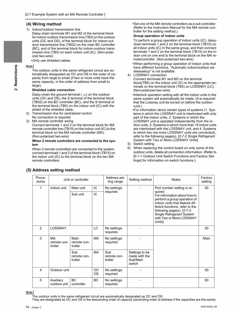
[2-7 Example System with an MA Remote Controller ]
HWE1822B_GB14 - chapter 2
2 R
estr
ictio
ns
(4) Wiring method1) Indoor/outdoor transmission line
Daisy-chain terminals M1 and M2 of the terminal block for indoor-outdoor transmission line (TB3) on the outdoor units (OC and OS), of the terminal block for indoor-out-door transmission line (TB02) on the main BC controller (BC), and of the terminal block for indoor-outdoor trans-mission line (TB5) on each indoor unit (IC). (Non-polar-ized two-wire)Only use shielded cables.
The outdoor units in the same refrigerant circuit are au-tomatically designated as OC and OS in the order of ca-pacity from large to small (if two or more units have the same capacity, in the order of address from small to large).Shielded cable connectionDaisy-chain the ground terminal ( ) on the outdoor units (OC and OS), the S terminal of the terminal block (TB02) on the BC controller (BC), and the S terminal of the terminal block (TB5) on the indoor unit (IC) with the shield of the shielded cable.
2) Transmission line for centralized controlNo connection is required.
3) MA remote controller wiringConnect terminals 1 and 2 on the terminal block for MA remote controller line (TB15) on the indoor unit (IC) to the terminal block on the MA remote controller (MA).(Non-polarized two-wire)When 2 remote controllers are connected to the sys-temWhen 2 remote controllers are connected to the system, connect terminals 1 and 2 of the terminal block (TB15) on the indoor unit (IC) to the terminal block on the two MA remote controllers.
Set one of the MA remote controllers as a sub controller. (Refer to the Instruction Manual for the MA remote con-troller for the setting method.)Group operation of indoor unitsTo perform a group operation of indoor units (IC), daisy-chain terminals 1 and 2 on the terminal block (TB15) on all indoor units (IC) in the same group, and then connect terminals 1 and 2 on the terminal block (TB15) on the in-door unit on one end to the terminal block on the MA re-motecontroller. (Non-polarized two-wire)When performing a group operation of indoor units that have different functions, "Automatic indoor/outdoor ad-dresssetup" is not available.
4) LOSSNAY connectionConnect terminals M1 and M2 on the terminal block(TB5) on the indoor unit (IC) to the appropriate ter-minals on the terminal block (TB5) on LOSSNAY (LC). (Non-polarized two-wire)Interlock operation setting with all the indoor units in the same system will automatically be made. (It is required that the Lossnay unit be turned on before the outdoo-runit.)For information about certain types of systems (1. Sys-tems in which the LOSSNAY unit is interlocked with only part of the indoor units, 2. Systems in which the LOSSNAY unit is operated independently from the in-door units, 3. Systems in which more than 16 indoor units are interlocked with the LOSSNAY unit, and 4. Systems to which two ore more LOSSNAY units are connected), refer to the following page(s). [2-7-2 Single Refrigerant System with Two or More LOSSNAY Units]
5) Switch setting6) When replacing the control board on only some of the
outdoor units, delete all connection information. (Refer to [5-1-1 Outdoor Unit Switch Functions and Factory Set-tings] for information on switch functions.)
(5) Address setting method
The outdoor units in the same refrigerant circuit are automatically designated as OC and OS.They are designated as OC and OS in the descending order of capacity (ascending order of address if the capacities are the same).
Proce-dures Unit or controller Address set-
ting range Setting method Notes Factory setting
1 Indoor unit Main unit IC No settings required.
- Port number setting is re-quiredFor information about how to perform a group operation of indoor units that feature dif-ferent functions, refer to the following page(s). [2-7-2 Single Refrigerant System with Two or More LOSSNAY Units]
00
Sub unit IC
2 LOSSNAY LC No settings required.
- 00
3 MA remote con-troller
Main remote con-troller
MA No settings required.
- Main
Sub remote con-troller
MA Sub remote con-troller
Settings to be made with the Sub/Main switch
4 Outdoor unit OCOS
No settings required.
- 00
5 Auxiliary outdoor unit
BC controller
BC No settings required.
- 00

[2-7 Example System with an MA Remote Controller ]
HWE1822B_GB chapter 2 - 15
2 R
estr
ictio
ns
2-7-2 Single Refrigerant System with Two or More LOSSNAY Units
(1) Sample control wiring
(2) Cautions1) ME remote controller and MA remote controller cannot both be
connected to the same group of indoor units.2) No more than 2 MA remote controllers can be connected to a
group of indoor units.3) When the number of the connected indoor units is as shown in
the table below, one or more transmission boosters (sold sepa-rately) are required.To connect two transmission boosters, connect them in parallel. (Observe the maximum number of connectable indoor units that are listed in the specifications for each outdoor unit.)
The table above shows the number of transmission boost-
ers that is required by the system with three BC controllers. For each BC controller added or subtracted, subtract or add two indoor units. Refer to the DATABOOK for further information about how many booster units are required for a given system.
(3) Maximum allowable length1) Indoor/outdoor transmission line
Same as 2-7-12) Transmission line for centralized control
No connection is required.3) MA remote controller wiring
Same as 2-7-1
L3
BC
53
OC
51TB7
STB3 TB02
S
IC
TB5S
TB151 2
01
IC
TB5S
TB151 2
02
A1 B2
MA
A1 B2
MA
LC
TB5S
05
IC
TB5S 1 2
TB15
IC
TB5S
TB151 2
0403
LC
TB5S
06
A1 B2
MA
* If the BC address overlaps any of the addresses that are assigned to either the OC, OS, or BS, use a different, unused address. OC, OS, and BS addresses (lowest indoor unit address in the group plus +50) have higher priority than the BS address.
IC
TB5S 1 2
TB15
IC
TB5S
TB151 2
0807
A1 B2
MA
A1 B2
MA
M1M2M1M2
L11
L4 L5
L12 L13
OS
52TB7
M1 M2 M1 M2M1 M2 M1 M2 M1 M2M1M2 M1M2 M1M2
M1M2M1M2M1M2
STB3
M1 M2TB02
S
57
BS
L1 L2GroupGroup
Group
Interlock operation with the ventilation unit
Leave the maleconnector onCN41 as it is.SW5-1 OFF
Leave the maleconnector onCN41 as it is.SW5-1 OFF
m1
m2
m3
Number of transmission booster (sold separately) required
1 unit 2 units
When the P72 and P96 models are not included in the connected indoor units
27 - 50 units -
When the P72 and P96 models are included in the connected indoor units
21 - 39 units 40 - 50 units

[2-7 Example System with an MA Remote Controller ]
HWE1822B_GB16 - chapter 2
2 R
estr
ictio
ns
(4) Wiring method1) Indoor/outdoor transmission line
Daisy-chain terminals M1 and M2 of the terminal block for indoor-outdoor transmission line (TB3) on the outdoor units (OC and OS), of the terminal block for indoor-out-door transmission line (TB02) on the main and sub BC controllers (BC and BS), and of the terminal block for in-door-outdoor transmission line (TB5) on each indoor unit (IC). (Non-polarized two-wire)Only use shielded cables.
The outdoor units in the same refrigerant circuit are au-tomatically designated as OC and OS in the order of ca-pacity from large to small (if two or more units have the same capacity, in the order of address from small to large).Shielded cable connectionDaisy-chain the ground terminal ( ) on the outdoor units (OC and OS), the S terminal of the terminal block (TB02) on BC and BS, and the S terminal of the terminal block (TB5) on the indoor unit (IC) with the shield of the
shielded cable.2) Transmission line for centralized control
No connection is required.3) MA remote controller wiring
Same as 2-7-1When 2 remote controllers are connected to the sys-temSame as 2-7-1Group operation of indoor unitsSame as 2-7-1
4) LOSSNAY connectionConnect terminals M1 and M2 on the terminal block (TB5) on the indoor unit (IC) to the appropriate terminals on the terminal block (TB5) on LOSSNAY (LC). (Non-po-larized two-wire)Interlock setting between the indoor units and LOSSNAY units must be entered on the remote control-ler. For information about how to interlock the operation of indoor and LOSSNAY units.
5) Switch settingAddress setting is required as follows.
(5) Address setting method
The outdoor units in the same refrigerant circuit are automatically designated as OC and OS.They are designated as OC and OS in the descending order of capacity (ascending order of address if the capacities are the same).
Proce-dures Unit or controller
Address setting range
Setting method NotesFac-tory set-ting
1 Indoor unit
Main unit IC 01 to 50 Assign the smallest address to the main unit in the group.In a system with a sub BC controller,
make the settings for the indoor units in the following order.
(i) Indoor unit to be connected to the main BC controller
(ii) Indoor unit to be connected to sub BC controller 1
(iii) Indoor unit to be connected to sub BC controller 2
Make the settings for the indoor units in the way that the formula "(i) < (ii) < (iii)" is true.When using additional BC controllers (3 to 11 BC controllers), make the same settings.
Port number setting is requiredTo perform a group op-
eration of indoor units that feature different functions, designate the indoor unit in the group with the greatest number of functions as the main unit.
00
Sub unit Assign sequential numbers starting with the address of the main unit in the same group +1. (Main unit address +1, main unit address +2, main unit address +3, etc.)
2 LOSSNAY LC 01 to 50 Assign an arbitrary but unique address to each of these units after assigning an ad-dress to all indoor units.
None of these addresses may overlap any of the indoor unit addresses.
00
3 MA remote controller
Main remote controller
MA No set-tings re-quired.
- Main
Sub remote controller
MA Sub remote controller
Settings to be made with the Sub/Main switch
4 Outdoor unit OCOS
51 to 100 Assign sequential address to the outdoor units in the same refrigerant circuit. The outdoor units are automatically des-
ignated as OC and OS.(Note)
To set the address to 100, set the rotary switches to 50.If the addresses that is as-
signed to the main BC con-troller overlaps any of the addresses that are assigned to the outdoor units or to the sub BC controller, use a dif-ferent, unused address with-in the setting range.The use of a sub BC control-
ler requires the connection of a main BC controller.
00
5 Auxiliary outdoor unit
BC control-ler (Main)
BC 51 to 100 OC (or OS if it exists) +1
BC control-ler (Sub)
BS Assign an address that equals the sum of the smallest address of the indoor units that are connected to the sub BC controller and 50.

[2-7 Example System with an MA Remote Controller ]
HWE1822B_GB chapter 2 - 17
2 R
estr
ictio
ns
2-7-3 Grouped Operation of Units in Separate Refrigerant Circuits
(1) Sample control wiring
(2) Cautions1) ME remote controller and MA remote controller cannot both
be connected to the same group of indoor units.2) No more than 2 MA remote controllers can be connected to
a group of indoor units.3) Do not connect the terminal blocks (TB5) on the indoor units
that are connected to different outdoor units with each other.4) Replacement of male power jumper connector (CN41) must
be performed only on one of the outdoor units.5) Provide grounding to S terminal on the terminal block for
transmission line for centralized control (TB7) on only one of the outdoor units.
6) When the number of the connected indoor units is as shown in the table below, one or more transmission boosters (sold separately) are required.To connect two transmission boosters, connect them in par-allel. (Observe the maximum number of connectable indoor units that are listed in the specifications for each outdoor unit.)
The table above shows the number of transmission
boosters that is required by the system with three BC controllers. For each BC controller added or subtracted, subtract or add two indoor units. Refer to the DATABOOK for further information about how many booster units are required for a given system.
(3) Maximum allowable length1) Indoor/outdoor transmission line
Maximum distance (1.25mm2 [AWG16] or larger)L11+L12 200m [656ft]L21+L22 200m [656ft]
2) Transmission line for centralized controlL31+L21 200m [656ft]
3) MA remote controller wiringSame as 2-7-1
4) Maximum line distance via outdoor unit (1.25mm2 [AWG16] or larger)L12(L11)+L31+L22(L21) 1000 m [3280ft] (500 m [1640ft]) *1
*1 If a given system includes one or more unit or remote controller that does not support the maximum allow-able cable distance of 1000 m [3280 ft], the maximum allowable cable distance in the system will be 500 m [1640 ft]. Refer to the latest catalog for information on which units and remote controllers support the maxi-mum allowable cable distance of 1000 m [3280 ft].
IC
TB5S
TB151 2
01
IC
TB5S
TB151 2
03
A1 B2
MA
A1 B2
MA
LC
TB5S
07
IC
TB5S 1 2
TB15
IC
TB5S
TB151 2 1 2
0402
IC
TB5 TB15S
05
A1 B2
MA
Group
IC
TB5S
TB151 2
06
A1 B2
MA
GroupGroup
Group
To be leftunconnected
m2
m3
Interlock operation withthe ventilation unitL12
L22
L11
L21
OC
Move the male connector from CN41 to CN40.SW5-1 OFF
Leave the maleconnector onCN41 as it is.SW5-1 OFF
Leave the maleconnector onCN41 as it is.SW5-1 OFF
Leave the maleconnector onCN41 as it is.SW5-1 OFF
TB3
TB7S
51
OS
TB3
TB7
M1 M2
M1 M2
M1 M2
M1 M2
M1 M2 M1 M2 M1 M2 M1 M2 M1 M2
M1 M2M1 M2M1 M2M1 M2M1 M2M1 M2
M1 M2 M1 M2
S
52
OC
TB3
TB7S
55
OS
TB3
TB7S
56
L31
To be leftunconnected
S
S
BC
TB02
53
BC
TB02
57
To be leftunconnected
To be connected
m1
m4
m5
Number of transmission boost-er (sold separately) required
1 unit 2 units
When the P72 and P96 models are not included in the connected indoor units
27 - 50 units -
When the P72 and P96 models are in-cluded in the connected indoor units 21 - 39 units 40 - 50 units

[2-7 Example System with an MA Remote Controller ]
HWE1822B_GB18 - chapter 2
2 R
estr
ictio
ns
(4) Wiring method1) Indoor/outdoor transmission line
Same as 2-7-2Shielded cable connectionSame as 2-7-2
2) Transmission line for centralized controlDaisy-chain terminals M1 and M2 on the terminal block for transmission line for centralized control (TB7) on the out-door units (OC) in different refrigerant circuits and on the OC and OS (Note a) in the same refrigerant circuit.If a power supply unit is not connected to the transmission line for centralized control, replace the power jumper con-nector on the control board from CN41 to CN40 on only one of the outdoor units.
a) The outdoor units in the same refrigerant circuit are automat-ically designated as OC and OS in the order of capacity from large to small (if two or more units have the same capacity, in the order of address from small to large).
b) If TB7's on the outdoor units in the same refrigerant circuit are not daisy-chained, connect the transmission line for the central control system to TB7 of the OC. (Note a).To main-tain the central control even during an OC failure or a power failure, connect TB7 on OC and OS together. (If there is a
problem with the outdoor unit whose power jumper was moved from CN41 to CN40, central control is not possible, even if TB7's are daisy-chained.)
c) When connecting TB7, only commence after checking that the voltage is below 20 VDC.Only use shielded cables.Shielded cable connectionDaisy-chain the S terminal on the terminal block (TB7) on the outdoor units (OC, OS) with the shield wire of the shield-ed cable. Short-circuit the earth terminal ( ) and the S ter-minal on the terminal block (TB7) on the outdoor unit whose power jumper connector is mated with CN40.
3) MA remote controller wiringSame as 2-7-1When 2 remote controllers are connected to the systemSame as 2-7-1Group operation of indoor unitsSame as 2-7-1
4) LOSSNAY connectionSame as 2-7-2
5) Switch settingAddress setting is required as follows.
(5) Address setting method
The outdoor units in the same refrigerant circuit are automatically designated as OC and OS.They are designated as OC and OS in the descending order of capacity (ascending order of address if the capacities are the same).
Proce-dures Unit or controller
Address setting range
Setting method NotesFac-tory set-ting
1 Indoor unit
Main unit IC 01 to 50 Assign the smallest address to the main unit in the group.In a system with a sub BC controller,
make the settings for the indoor units in the following order.
(i) Indoor unit to be connected to the main BC controller
(ii) Indoor unit to be connected to sub BC controller 1
(iii) Indoor unit to be connected to sub BC controller 2
Make the settings for the indoor units in the way that the formula "(i) < (ii) < (iii)" is true.When using additional BC controllers (3 to 11 BC controllers), make the same settings.
Port number setting is requiredTo perform a group op-
eration of indoor units that feature different functions, designate the indoor unit in the group with the greatest number of functions as the main unit.
00
Sub unit Assign sequential numbers starting with the address of the main unit in the same group +1. (Main unit address +1, main unit address +2, main unit address +3, etc.)
2 LOSSNAY LC 01 to 50 Assign an arbitrary but unique address to each of these units after assigning an ad-dress to all indoor units.
None of these addresses may overlap any of the indoor unit addresses.
00
3 MA remote controller
Main remote controller
MA No set-tings re-quired.
- Main
Sub remote controller
MA Sub remote controller
Settings to be made with the Sub/Main switch
4 Outdoor unit OCOS
51 to 100 Assign sequential address to the outdoor units in the same refrigerant circuit. The outdoor units are automatically des-
ignated as OC and OS.(Note)
To set the address to 100, set the rotary switches to 50.If the addresses that is as-
signed to the main BC con-troller overlaps any of the addresses that are assigned to the outdoor units or to the sub BC controller, use a dif-ferent, unused address with-in the setting range.The use of a sub BC control-
ler requires the connection of a main BC controller.
00
5 Auxiliary outdoor unit
BC control-ler (Main)
BC 51 to 100 OC (or OS if it exists) +1
BC control-ler (Sub)
BS Assign an address that equals the sum of the smallest address of the indoor units that are connected to the sub BC controller and 50.

[2-7 Example System with an MA Remote Controller ]
HWE1822B_GB chapter 2 - 19
2 R
estr
ictio
ns
2-7-4 System with a Connection of System Controller to Centralized Control Transmission Line
(1) Sample control wiringAn example of a system in which a system controller is connected to the transmission cable for the centralized control system and the power is supplied from the outdoor unit
(2) Cautions1) ME remote controller and MA remote controller cannot both be con-
nected to the same group of indoor units.2) No more than 2 MA remote controllers can be connected to a group
of indoor units.3) Do not connect the terminal blocks (TB5) on the indoor units that are
connected to different outdoor units with each other.4) Replacement of male power jumper connector (CN41) must be per-
formed only on one of the outdoor units (not required if power to the transmission line for centralized control is supplied from a controller with a power supply function, such as GB-50ADA).
5) Short-circuit the shield terminal (S terminal) and the earth terminal ( ) on the terminal block for transmission line for centralized control
(TB7) on the outdoor unit whose power jumper connector is mated with CN40.
6) When the number of the connected indoor units is as shown in the table below, one or more transmission boosters (sold separately) are required.To connect two transmission boosters, connect them in parallel. (Observe the maximum number of connectable indoor units that are listed in the specifications for each outdoor unit.)
The left table shows the number of transmission boosters that is re-quired by the system with three BC controllers. For each BC control-ler added or subtracted, subtract or add two indoor units. Refer to the DATABOOK for further information about how many booster units are required for a given system.
7) When a power supply unit is connected to the transmission line for centralized control, leave the power jumper connector on CN41 as it is (factory setting).
(3) Maximum allowable length1) Indoor/outdoor transmission line
Same as 2-7-32) Transmission line for centralized control
L31+L32(L21) 200m [656ft]3) MA remote controller wiring
Same as 2-7-14) Maximum line distance via outdoor unit
(1.25mm2 [AWG16] or larger)L32+L31+L12(L11) 1000 m [3280ft] (500 m [1640ft]) *1L32+L22(L21) 1000 m [3280ft] (500 m [1640ft]) *1L12(L11)+L31+L22(L21) 1000 m [3280ft] (500 m [1640ft]) *1*1 If a given system includes one or more unit or remote controller
that does not support the maximum allowable cable distance of 1000 m [3280 ft], the maximum allowable cable distance in the system will be 500 m [1640 ft]. Refer to the latest catalog for in-formation on which units and remote controllers support the max-imum allowable cable distance of 1000 m [3280 ft].
IC
TB5S
TB151 2
01
IC
TB5S
TB151 2
02
A1
B2
MA
A1
B2
MA
LC
TB5S
07
IC
TB5S 1 2
TB15
IC
TB5S
TB151 2
0504
LC
TB5S
08
IC
TB5S
TB151 2
03
A1
B2
MA
IC
TB5S
TB151 2
06
A1
B2
MA
A1
B2
MAm3
L31
System controller
A B S
Note1
L32
OC
To be connected
m2
m1
Note1 When only the LM adapter is connected, leave SW5-1 to OFF (as it is).Note2 LM adapters require the power supply capacity of single-phase AC 220 - 240V.
TB3
TB7S
51
OS
TB3
TB7
M1 M2 M1 M2
M1 M2M1 M2
M1 M2 M1 M2 M1 M2 M1 M2 M1 M2
M1 M2M1 M2M1 M2M1 M2M1 M2M1 M2M1 M2
M1 M2 M1 M2
S
52
OC
TB3
TB7S
55
OS
TB3
TB7S
56
Group
Group Group
Group Group
Interlock operation withthe ventilation unit
Move the male connectorfrom CN41 to CN40.SW5-1 OFF
Leave the maleconnector onCN41 as it is.SW5-1 OFF
Leave the maleconnector onCN41 as it is.SW5-1 OFF
Leave the maleconnector onCN41 as it is.SW5-1 OFF
To be left unconnected
To be left unconnected
To be left unconnected
S
BC
TB02
53
S
BC
TB02
57
L22L21
L12L11
Number of transmission booster (sold separately) required
1 unit 2 units
When the P72 and P96 models are not included in the connected indoor units
27 - 50 units -
When the P72 and P96 models are included in the connected indoor units
21 - 39 units 40 - 50 units

[2-7 Example System with an MA Remote Controller ]
HWE1822B_GB20 - chapter 2
2 R
estr
ictio
ns
(4) Wiring method1) Indoor/outdoor transmission line
Same as 2-7-2Only use shielded cables.Shielded cable connectionSame as 2-7-2
2) Transmission line for centralized controlDaisy-chain terminals A and B on the system controller, ter-minals M1 and M2 on the terminal block for transmission line for centralized control (TB7) on the outdoor units (OC) in dif-ferent refrigerant circuits and on the outdoor units (OC and OS) in the same refrigerant circuit. (Note b)If a power supply unit is not connected to the transmission line for centralized control, replace the power jumper con-nector on the control board from CN41 to CN40 on only one of the outdoor units.If a system controller is connected, set the central control switch (SW5-1) on the control board of all outdoor units to "ON."
a) The outdoor units in the same refrigerant circuit are automat-ically designated as OC and OS in the order of capacity from large to small (if two or more units have the same capacity, in the order of address from small to large).
b) If TB7's on the outdoor units in the same refrigerant circuit are not daisy-chained, connect the transmission line for the central control system to TB7 of the OC. (Note a).To main-tain the central control even during an OC failure or a power failure, connect TB7 on OC and OS together. (If there is a
problem with the outdoor unit whose power jumper was moved from CN41 to CN40, central control is not possible, even if TB7's are daisy-chained.)
c) When connecting TB7, only commence after checking that the voltage is below 20 VDC.Only use shielded cables.Shielded cable connectionDaisy-chain the S terminal of the terminal block (TB7) on the system controller, OC, and OS with the shield of the shield-ed cable. Short-circuit the earth terminal ( ) and the S ter-minal on the terminal block (TB7) on the outdoor unit whose power jumper connector is mated with CN40.
3) MA remote controller wiringSame as 2-7-1When 2 remote controllers are connected to the systemSame as 2-7-1Group operation of indoor unitsSame as 2-7-1
4) LOSSNAY connectionConnect terminals M1 and M2 on the terminal block (TB5) on the indoor unit (IC) to the appropriate terminals on the terminal block for indoor-outdoor transmission line (TB5) on LOSSNAY (LC). (Non-polarized two-wire)Indoor units must be interlocked with the LOSSNAY unit us-ing the system controller. (Refer to the operation manual for the system controller for the setting method.) Interlock set-ting from the remote controller is required if the ON/OFF re-mote controller alone or the LM adapter alone is connected.
5) Switch settingAddress setting is required as follows.
(5) Address setting method
The outdoor units in the same refrigerant circuit are automatically designated as OC and OS.They are designated as OC and OS in the descending order of capacity (ascending order of address if the capacities are the same).
Proce-dures Unit or controller
Ad-dress setting range
Setting method NotesFac-tory set-ting
1 Indoor unit
Main unit IC 01 to 50
Assign the smallest address to the main unit in the group.In a system with a sub BC controller, make
the settings for the indoor units in the fol-lowing order.
(i) Indoor unit to be connected to the main BC controller
(ii) Indoor unit to be connected to sub BC controller 1
(iii) Indoor unit to be connected to sub BC controller 2
Make the settings for the indoor units in the way that the formula "(i) < (ii) < (iii)" is true.When using additional BC controllers (3 to 11 BC controllers), make the same set-tings.
Port number setting is re-quiredTo perform a group opera-
tion of indoor units that fea-ture different functions, designate the indoor unit in the group with the greatest number of functions as the main unit.
00
Sub unit Assign sequential numbers starting with the address of the main unit in the same group +1. (Main unit address +1, main unit address +2, main unit address +3, etc.)
2 LOSSNAY LC 01 to 50
Assign an arbitrary but unique address to each of these units after assigning an address to all indoor units.
None of these addresses may over-lap any of the indoor unit addresses.
00
3 MA remote controller
Main remote con-troller
MA No set-tings re-quired.
- Make the same indoor unit group settings with the system controller as the ones that were made with the MA remote controller.
Main
Sub remote con-troller
MA Sub remote controller
Settings to be made with the Sub/Main switch
4 Outdoor unit (Note) OCOS
51 to 100 Assign sequential address to the outdoor units in the same refrigerant circuit. The outdoor units are automatically desig-
nated as OC and OS.(Note)
To set the address to 100, set the rotary switches to 50.If the addresses that is assigned to
the main BC controller overlaps any of the addresses that are as-signed to the outdoor units or to the sub BC controller, use a differ-ent, unused address within the setting range.The use of a sub BC controller re-
quires the connection of a main BC controller.
00
5 Auxiliary outdoor unit
BC control-ler (Main)
BC 51 to 100 OC (or OS if it exists) +1
BC control-ler (Sub)
BS Assign an address that equals the sum of the smallest address of the indoor units that are connected to the sub BC controller and 50.

[2-7 Example System with an MA Remote Controller ]
HWE1822B_GB chapter 2 - 21
2 R
estr
ictio
ns
2-7-5 System with a Connection of System Controller to Indoor-Outdoor Transmission Line
(1) Sample control wiring
(2) Cautions1) ME remote controller and MA remote controller cannot both be con-
nected to the same group of indoor units.2) No more than 2 MA remote controllers can be connected to a group
of indoor units.3) Do not connect the terminal blocks (TB5) on the indoor units that are
connected to different outdoor units with each other.4) Replacement of male power jumper connector (CN41) must be per-
formed only on one of the outdoor units.5) Provide grounding to S terminal on the terminal block for transmis-
sion line for centralized control (TB7) on only one of the outdoor units.
6) A maximum of three system controllers can be connected to the in-door-outdoor transmission line. (AE-200, AG-150A, GB-50ADA, or G(B)-50A are not connectable.)
7) When the total number of indoor units exceeds 20 (12 if one or more indoor units of the 72 model or above is connected), it may not be possible to connect a system controller to the indoor-outdoor trans-mission line.
8) When the number of the connected indoor units is as shown in the table below, one or more transmission boosters (sold separately) are required.To connect two transmission boosters, connect them in parallel. (Observe the maximum number of connectable indoor units that are listed in the specifications for each outdoor unit.)
The table above shows the number of transmission boosters that is
required by the system with three BC controllers. For each BC con-troller added or subtracted, subtract or add two indoor units. Refer to the DATABOOK for further information about how many booster units are required for a given system.
(3) Maximum allowable length1) Indoor/outdoor transmission line
Maximum distance (1.25mm2 [AWG16] or larger)L11+L12 200m [656ft]L21+L22 200m [656ft]L25 200m [656ft]
2) Transmission line for centralized controlL31+L21 200m [656ft]
3) MA remote controller wiringSame as 2-7-1
4) Maximum line distance via outdoor unit (1.25mm2 [AWG16] or larger)L25+L31+L12(L11) 1000 m [3280ft] (500 m [1640ft]) *1L12(L11)+L31+L22(L21) 1000 m [3280ft] (500 m [1640ft]) *1*1 If a given system includes one or more unit or remote controller
that does not support the maximum allowable cable distance of 1000 m [3280 ft], the maximum allowable cable distance in the system will be 500 m [1640 ft]. Refer to the latest catalog for in-formation on which units and remote controllers support the max-imum allowable cable distance of 1000 m [3280 ft].
IC
TB5S
TB151 2
01
IC
TB5S
TB151 2
02
A1
B2
MA
A1
B2
MA
LC
TB5S
07
IC
TB5S 1 2
TB15
IC
TB5S
TB151 2
0504
LC
TB5S
08
IC
TB5S
TB151 2
03
A1
B2
MA
IC
TB5S
TB151 2
06
A1
B2
MA
A1
B2
MA
GroupGroupGroup
Group Group
m3
Interlock operation withthe ventilation unit
OC
Connect
m2
m1
Note1 LM adapters cannot be connected to the indoor-outdoor transmission line.
TB3
TB7S
51
OS
TB3
TB7S
52
OC
TB3
TB7S
55
OS
TB3
TB7S
56
L31
A B S
L25
M2M1 M2M1
M2M1 M2M1
M2M1 M2M1 M2M1 M2M1 M2M1
M2M1M2M1M2M1M2M1M2M1M2M1
M2M1M2M1
M2M1
NotConnect
NotConnect
NotConnect
CN41 CN40 ReplaceSW5-1 OFF ON
SW5-1 OFF ON
Leave the maleconnector onCN41 as it is.
SW5-1 OFF ON
Leave the maleconnector onCN41 as it is.
SW5-1 OFF ON
Leave the maleconnector onCN41 as it is.
System controller
Note1
S
BC
TB02
53
S
BC
TB02
57
L22L21
L12L11
Number of transmission boost-er (sold separately) required
1 unit 2 units
When the P72 and P96 models are not included in the connected indoor units 27 - 50 units -
When the P72 and P96 models are in-cluded in the connected indoor units 21 - 39 units 40 - 50 units

[2-7 Example System with an MA Remote Controller ]
HWE1822B_GB22 - chapter 2
2 R
estr
ictio
ns
(4) Wiring method1) Indoor/outdoor transmission line
Daisy-chain terminals M1 and M2 of the terminal block for indoor-outdoor transmission line (TB3) on the outdoor units (OC and OS) (Note a), of the terminal block for indoor-outdoor transmission line (TB02) on the main and sub BC controllers (BC and BS), of the ter-minal block for indoor-outdoor transmission line (TB5) on each in-door unit (IC), and the S terminal of the system controller.(Non-polarized two-wire)Only use shielded cables.
a) The outdoor units in the same refrigerant circuit are automatically designated as OC and OS in the order of capacity from large to small (if two or more units have the same capacity, in the order of address from small to large).Shielded cable connectionDaisy-chain the ground terminal ( ) on the outdoor units (OC and OS), the S terminal of the terminal block (TB02) on the BC and BS, and the S terminal of the terminal block (TB5) on the indoor unit (IC) with the shield of the shielded cable.
2) Transmission line for centralized controlDaisy-chain terminals M1 and M2 on the terminal block for transmis-sion line for centralized control (TB7) on the outdoor units (OC) in different refrigerant circuits and on the OC and OS in the same re-frigerant circuit. (Note b)If a power supply unit is not connected to the transmission line for centralized control, replace the power jumper connector on the con-trol board from CN41 to CN40 on only one of the outdoor units.Set the central control switch (SW5-1) on the control board of all out-door units to "ON."
b) If TB7's on the outdoor units in the same refrigerant circuit are not
daisy-chained, connect the transmission line for the central control system to TB7 of the OC. (Note a).To maintain the central control even during an OC failure or a power failure, connect TB7 on OC and OS together. (If there is a problem with the outdoor unit whose power jumper was moved from CN41 to CN40, central control is not possible, even if TB7's are daisy-chained.)
c) When connecting TB7, only commence after checking that the volt-age is below 20 VDC.Only use shielded cables.Shielded cable connectionDaisy-chain the S terminal on the terminal block (TB7) on the out-door units (OC, OS) with the shield wire of the shielded cable. Short-circuit the earth terminal ( ) and the S terminal on the terminal block (TB7) on the outdoor unit whose power jumper connector is mated with CN40.
3) MA remote controller wiringSame as 2-7-1When 2 remote controllers are connected to the systemSame as 2-7-1Group operation of indoor unitsSame as 2-7-1
4) LOSSNAY connectionConnect terminals M1 and M2 on the terminal block (TB5) on the in-door units (IC) to the appropriate terminals on the terminal block for indoor-outdoor transmission line (TB5) on LOSSNAY (LC). (Non-po-larized two-wire)Indoor units must be interlocked with the LOSSNAY unit using the system controller. (Refer to the operation manual for the system controller for the setting method.) Interlock setting from the remote controller is required if the ON/OFF remote controller alone is con-nected.
5) Switch settingAddress setting is required as follows.
(5) Address setting method
The outdoor units in the same refrigerant circuit are automatically designated as OC and OS.They are designated as OC and OS in the descending order of capacity (ascending order of address if the capacities are the same).
Proce-dures Unit or controller
Address setting range
Setting method NotesFacto-ry set-
ting
1 Indoor unit
Main unit IC 01 to 50
Assign the smallest address to the main unit in the group.In a system with a sub BC controller, make
the settings for the indoor units in the fol-lowing order.
(i) Indoor unit to be connected to the main BC controller
(ii) Indoor unit to be connected to sub BC controller 1
(iii) Indoor unit to be connected to sub BC controller 2
Make the settings for the indoor units in the way that the formula "(i) < (ii) < (iii)" is true.When using additional BC controllers (3 to 11 BC controllers), make the same set-tings.
Port number setting is requiredTo perform a group op-
eration of indoor units that feature different functions, designate the indoor unit in the group with the greatest number of functions as the main unit.
00
Sub unit Assign sequential numbers starting with the address of the main unit in the same group +1. (Main unit address +1, main unit address +2, main unit address +3, etc.)
2 LOSSNAY LC 01 to 50
Assign an arbitrary but unique address to each of these units after assigning an address to all indoor units.
None of these addresses may overlap any of the indoor unit addresses.
00
3 MA remote controller
Main remote con-troller
MA No set-tings re-quired.
- Make the same indoor unit group settings with the system controller as the ones that were made with the MA remote controller.
Main
Sub remote con-troller
MA Sub remote controller
Settings to be made with the Sub/Main switch
4 Outdoor unit OCOS
51 to 100 Assign sequential address to the outdoor units in the same refrigerant circuit. The outdoor units are automatically desig-
nated as OC and OS.(Note)
To set the address to 100, set the rotary switches to 50.If the addresses that is as-
signed to the main BC con-troller overlaps any of the addresses that are assigned to the outdoor units or to the sub BC controller, use a dif-ferent, unused address with-in the setting range.The use of a sub BC control-
ler requires the connection of a main BC controller.
00
5 Auxiliary outdoor unit
BC control-ler (Main)
BC 51 to 100 OC (or OS if it exists) +1
BC control-ler (Sub)
BS Assign an address that equals the sum of the smallest address of the indoor units that are connected to the sub BC controller and 50.

[2-7 Example System with an MA Remote Controller ]
HWE1822B_GB chapter 2 - 23
2 R
estr
ictio
ns
2-7-6 System with Multiple BC Controllers
(1) Sample control wiring
(2) Cautions1) ME remote controller and MA remote controller cannot both be con-
nected to the same group of indoor units.2) No more than 2 MA remote controllers can be connected to a group
of indoor units.3) Do not connect the terminal blocks (TB5) on the indoor units that are
connected to different outdoor units with each other.4) Replacement of male power jumper connector (CN41) must be per-
formed only on one of the outdoor units.5) Short-circuit the S (shield) terminal of the terminal block for the cen-
tral control unit (TB7) and the ground terminal ( ) on the outdoor unit whose power jumper was moved from CN41 to CN40.
6) When the number of the connected indoor units is as shown in the table below, one or more transmission boosters (sold separately) are required. To connect two transmission boosters, connect them in parallel. (Observe the maximum number of connectable indoor units that are listed in the specifications for each outdoor unit.)
The table above shows the number of transmission boost-ers that is required by the system with three BC controllers. For each BC controller added or subtracted, subtract or add two indoor units. Refer to the DATABOOK for further information about how many booster units are required for a given system.
7) When a power supply unit is connected to the transmission line for centralized control, leave the power jumper connec-tor on CN41 as it is (factory setting).
(3) Maximum allowable length1) Indoor/outdoor transmission line
Maximum distance (1.25mm2 [AWG16] or larger)L11+L12 200m [656ft]L21+L22 200m [656ft]
2) Transmission line for centralized controlL31+L32(L21) 200m [656ft]
3) MA remote controller wiringMaximum overall line length (0.3 to 1.25mm2 [AWG22 to 16])m1 200m [656ft]m2+m3 200m [656ft]
4) Maximum line distance via outdoor unit(1.25mm2 [AWG16] or larger)L32+L31+L12(L11) 1000 m [3280ft] (500 m [1640ft]) *1L32+L22(L21) 1000 m [3280ft] (500 m [1640ft]) *1L12(L11)+L31+L22(L21) 1000 m [3280ft] (500 m [1640ft]) *1
*1 If a given system includes one or more unit or remote controller that does not support the maximum allow-able cable distance of 1000 m [3280 ft], the maximum allowable cable distance in the system will be 500 m [1640 ft]. Refer to the latest catalog for information on which units and remote controllers support the maxi-mum allowable cable distance of 1000 m [3280 ft].
L11
L21
OC
TB3
TB7S
51
L31
A B S
L32
OS
TB3
TB7
M1M2
S
52
OC
TB3
TB7S
54
OS
TB3
TB7S
55
SW5-1 OFF ON
Move the male connector from CN41 to CN40
Group
Group Group Group
Group Group Group
To be left unconnected
To be left unconnected
To be left unconnected
To be connected
M1M2
M1M2 M1M2
M1M2
M1M2
M1M2 M1M2
M1M2
*1 When only the LM adapter is connected, leave SW5-1 to OFF (as it is).*2 LM adapters require the power supply capacity of single-phase AC 220 - 240V.
IC
TB5S
TB151 2
01
IC
TB5S
TB151 2
02
IC
TB5S
TB151 2
04
IC
TB5S
TB151 2
06
A1 B2
MA
A1 B2
MA
A1 B2
MA
IC
TB5S 1 2
TB15
IC
TB5S
TB151 2
0503
L12
L22
IC
TB5S
TB151 2
07
IC
TB5S
TB151 2
08
A1 B2
MA
IC
TB5S
TB151 2
09
IC
TB5S
TB151 2
10
A1 B2
MA
A1 B2
MA
BC
BC
TB02S
53 57
TB02M1M2 S
BS
TB02S
BS
TB02S
1 1 2 1 222 12
57
1 1 2 1 1
LC
TB5S
14323 1
Numbers in the square indicate port numbers.Connection to BC controllers
56 59
Interlock operation with the ventilation unit
IC
TB5S
TB151 2
11
IC
TB5S
TB151 2
12
A1 B2
MA
61
BS
TB02S
1 2
LC
TB5S
1312
m2
m3
m1
SW5-1 OFF ON
Leave the maleconnector onCN41 as it is.
SW5-1 OFF ON
Leave the maleconnector onCN41 as it is.
SW5-1 OFF ON
Leave the maleconnector onCN41 as it is.
System controller
Note1
M1M2 M1M2 M1M2 M1M2 M1M2 M1M2 M1M2 M1M2 M1M2 M1M2
M1M2 M1M2 M1M2 M1M2 M1M2 M1M2M1M2
Number of transmission booster (sold separately) required
1 unit 2 units
When the P72 and P96 models are not included in the connected indoor units 27 - 50 units -
When the P72 and P96 models are in-cluded in the connected indoor units 21 - 39 units 40 - 50 units

[2-7 Example System with an MA Remote Controller ]
HWE1822B_GB24 - chapter 2
2 R
estr
ictio
ns
(4) Wiring method1) Indoor/outdoor transmission line
Daisy-chain terminals M1 and M2 of the terminal block for indoor-outdoor transmission line (TB3) on the outdoor units (OC and OS) (Note a), of the terminal block for in-door-outdoor transmission line (TB02) on the main and sub BC controllers (BC and BS), and of the terminal block for indoor-outdoor transmission line (TB5) on each indoor unit (IC). (Non-polarized two-wire)Only use shielded cables.
a) The outdoor units in the same refrigerant circuit are auto-matically designated as OC and OS in the order of ca-pacity from large to small (if two or more units have the same capacity, in the order of address from small to large).Shielded cable connectionDaisy-chain the ground terminal ( ) on the outdoor units (OC and OS), the S terminal of the terminal block (TB02) on the BC and BS, and the S terminal of the terminal block (TB5) on the indoor unit (IC) with the shield of the shielded cable.
2) Transmission line for centralized controlDaisy-chain terminals A and B of the system controller, M1 and M2 terminals of TB7 (terminal block for central-ized control system connection) on the outdoor units (OC) in different refrigerant systems, and M1 and M2 ter-minals of TB7 (terminal block for centralized control sys-tem connection) on the outdoor units (OC and OS ) in the same refrigerant circuit. (Note b)If a power supply unit is not connected to the transmis-sion line for centralized control, replace the power jump-er connector on the control board from CN41 to CN40 on only one of the outdoor units.When connecting a system controller, set the centralized control switch (SW5-1) on the control board of all indoor units to "ON."
b) If TB7's on the outdoor units in the same refrigerant cir-
cuit are not daisy-chained, connect the transmission line for the central control system to TB7 of the OC. (Note a).To maintain the central control even during an OC fail-ure or a power failure, connect TB7 on OC and OS to-gether. (If there is a problem with the outdoor unit whose power jumper was moved from CN41 to CN40, central control is not possible, even if TB7's are daisy-chained.)
c) When connecting TB7, only commence after checking that the voltage is below 20 VDC.Only use shielded cables.Shielded cable connectionDaisy-chain the S terminal of the terminal block (TB7) on the system controller, OC, and OS with the shield of the shielded cable. Short-circuit the earth terminal ( ) and the S terminal on the terminal block (TB7) on the outdoor unit whose power jumper connector is mated with CN40.
3) MA remote controller wiringSame as 2-7-1When 2 remote controllers are connected to the sys-temSame as 2-7-1Group operation of indoor unitsSame as 2-7-1
4) LOSSNAY connectionConnect terminals M1 and M2 on the terminal block (TB5) on the indoor unit (IC) to the appropriate terminals on the terminal block for indoor-outdoor transmission line (TB5) on LOSSNAY (LC). (Non-polarized two-wire)Indoor units must be interlocked with the LOSSNAY unit using the system controller. (Refer to the operation man-ual for the system controller for the setting method.) In-terlock setting from the remote controller is required if the ON/OFF remote controller alone or the LM adapter alone is connected.
5) Switch settingAddress setting is required as follows.

[2-7 Example System with an MA Remote Controller ]
HWE1822B_GB chapter 2 - 25
2 R
estr
ictio
ns
(5) Address setting method
The outdoor units in the same refrigerant circuit are automatically designated as OC and OS.They are designated as OC and OS in the descending order of capacity (ascending order of address if the capacities are the same).
Pro-ce-dures
Unit or controllerAddress setting range
Setting method NotesFac-tory set-ting
1 Indoor unit
Main unit IC 01 to 50 Assign the smallest address to the main unit in the group.In a system with a sub BC controller, make the set-
tings for the indoor units in the following order.(i) Indoor unit to be connected to the main BC control-
ler(ii) Indoor unit to be connected to sub BC controller 1(iii) Indoor unit to be connected to sub BC controller 2
Make the settings for the indoor units in the way that the formula "(i) < (ii) < (iii)" is true.When using additional BC controllers (3 to 11 BC controllers), make the same settings.
Port number setting is re-quiredTo perform a group opera-
tion of indoor units that feature different functions, designate the indoor unit in the group with the greatest number of func-tions as the main unit.
00
Sub unit Assign sequential numbers starting with the address of the main unit in the same group +1. (Main unit address +1, main unit address +2, main unit address +3, etc.)
2 LOSSNAY LC 01 to 50 Assign an arbitrary but unique address to each of these units after assigning an address to all indoor units.
None of these addresses may overlap any of the indoor unit ad-dresses.
00
3 MA remote control-ler
Main re-mote controller
MA No set-tings re-quired.
- Make the same indoor unit group settings with the system controller as the ones that were made with the MA remote controller.
Main
Sub re-mote con-troller
MA Sub re-mote controller
Settings to be made with the Sub/Main switch
4 Outdoor unit OCOS
51 to 100 The sum of the smallest address of the indoor units in the same system and 50.Assign sequential address to the outdoor units in the
same refrigerant circuit. The outdoor units are automatically designated as
OC and OS.(Note)
To set the address to 100, set the rotary switches to 50.
00
5 Auxilia-ry unit
BC con-troller (Main)
BC 51 to 100 OC (or OS if it exists) +1 To set the address to 100, set the rotary switches to 50.If the addresses that is assigned
to the main BC controller over-laps any of the addresses that are assigned to the outdoor units or to the sub BC control-ler, use a different, unused ad-dress within the setting range.The use of a sub BC controller
requires the connection of a main BC controller.
00
BCcontroller (Sub)
BS 51 to 100 Assign an address that equals the sum of the smallest address of the indoor units that are connected to the sub BC controller and 50.

[2-8 Example System with an ME Remote Controller ]
HWE1822B_GB26 - chapter 2
2 R
estr
ictio
ns
2-8 Example System with an ME Remote Controller
2-8-1 System with a Connection of System Controller to Centralized Control Transmission Line
(1) Sample control wiring
(2) Cautions1) ME remote controller and MA remote controller cannot both
be connected to the same group of indoor units.2) No more than 2 ME remote controllers can be connected to
a group of indoor units.3) Do not connect the terminal blocks (TB5) on the indoor units
that are connected to different outdoor units with each other.4) Replace the power jumper connector of the control board
from CN41 to CN40 on only one of the outdoor units.5) Provide an electrical path to ground for the S terminal on the
terminal block for centralized control on only one of the out-door units.
6) When the number of the connected indoor units is as shown in the table below, one or more transmission boosters (sold separately) are required.To connect two transmission boosters, connect them in par-allel. (Observe the maximum number of connectable indoor units that are listed in the specifications for each outdoor unit.)
The table above shows the number of transmission boost-ers that is required by the system with three BC controllers.
For each BC controller added or subtracted, subtract or add two indoor units. Refer to the DATABOOK for further information about how many booster units are required for a given system.
7) When a power supply unit is connected to the transmission line for centralized control, leave the power jumper connec-tor on CN41 as it is (factory setting).
(3) Maximum allowable length1) Indoor/outdoor transmission line
Same as 2-7-32) Transmission line for centralized control
Same as 2-7-43) ME remote controller wiring
Maximum overall line length (0.3 to 1.25mm2 [AWG22 to 16])m1 10m [32ft]m2+m3 10m [32ft]If the standard-supplied cable must be extended, use a cable with a diameter of 1.25mm2 [AWG16]. The section of the cable that exceeds 10m [32ft] must be included in the maximum indoor-outdoor transmission line distance described in 1).When connected to the terminal block on the Simple re-mote controller, use cables that meet the following cable size specifications: 0.75 - 1.25 mm2 [AWG18-16].
4) Maximum line distance via outdoor unit(1.25 mm2 [AWG16] or large)Same as 2-7-4
IC
TB5S
TB151 2
01
IC
TB5S
TB151 2
02
LC
TB5S
07
IC
TB5S 1 2
TB15
IC
TB5S
TB151 2
0504
LC
TB5S
08
IC
TB5S
TB151 2
03
IC
TB5S
TB151 2
06
A1 B2
RC101
A1 B2
RC102
A1 B2
RC103
Group
Group Group
Group Group
To be connected
M1M2 M1M2M1M2
M1M2 M1M2 M1M2 M1M2
L31
A B S
L32
OC
m1
TB3
TB7M1 M2S
51
OS
TB3
TB7M1M2
M1M2 M1M2
S
52
OC
TB3
TB7S
55
OS
TB3
TB7S
56
To be left unconnected
Interlock operation with the ventilation unit
*1 When only the LM adapter is connected, leave SW5-1 to OFF (as it is).*2 LM adapters require the power supply capacity of single-phase AC 220 - 240V.
System controller
Note1
SW5-1 OFF ON
Leave the maleconnector onCN41 as it is.
SW5-1 OFF ON
Leave the maleconnector onCN41 as it is.
SW5-1 OFF ON
Move the male connector from CN41 to CN40.
SW5-1 OFF ON
Leave the maleconnector onCN41 as it is.
M1M2
M1M2 M1M2
M1M2 M1M2To be left unconnected
To be left unconnected
104
A1 B2
RC154
A1 B2
RC
m3
106
A1 B2
RC
m2
S
BC
TB02
53
S
BC
TB02
57
L12L11
L22L21
M1M2
M1M2
Number of transmission booster (sold separately) required
1 unit 2 units 3 units
When the P72 and P96 models are not included in the connected indoor units
15 - 34 units
35 - 50 units -
When the P72 and P96 models are in-cluded in the connected indoor units
11 - 26 units
27 - 42 units
43 - 50 units

[2-8 Example System with an ME Remote Controller ]
HWE1822B_GB chapter 2 - 27
2 R
estr
ictio
ns
(4) Wiring method1) Indoor/outdoor transmission line
Same as 2-7-2Shielded cable connectionSame as 2-7-2
2) Transmission line for centralized controlSame as 2-7-4Shielded cable connectionSame as 2-7-4
3) ME remote controller wiringME remote controller is connectable anywhere on the in-door-outdoor transmission line.
When 2 remote controllers are connected to the sys-temRefer to the section on Switch Setting.Performing a group operation (including the group operation of units in different refrigerant circuits).Refer to the section on Switch Setting.
4) LOSSNAY connectionSame as 2-7-4
5) Switch settingAddress setting is required as follows.
(5) Address setting method
The outdoor units in the same refrigerant circuit are automatically designated as OC and OS.They are designated as OC and OS in the descending order of capacity (ascending order of address if the capacities are the same).
Proce-dures Unit or controller
Ad-dress setting range
Setting method NotesFac-tory set-ting
1 Indoor unit
Main unit IC 01 to 50
Assign the smallest address to the main unit in the group.In a system with a sub BC controller, make
the settings for the indoor units in the fol-lowing order.
(i) Indoor unit to be connected to the main BC controller
(ii) Indoor unit to be connected to sub BC controller 1
(iii) Indoor unit to be connected to sub BC controller 2
Make the settings for the indoor units in the way that the formula "(i) < (ii) < (iii)" is true.When using additional BC controllers (3 to 11 BC controllers), make the same set-tings.
Port number setting is requiredTo perform a group op-
eration of indoor units that have different func-tions, set the indoor unit in the group with the greatest number of functions as the main unit.
00
Sub unit Assign sequential numbers starting with the address of the main unit in the same group +1. (Main unit address +1, main unit address +2, main unit address +3, etc.)
2 LOSSNAY LC 01 to 50
Assign an arbitrary but unique address to each of these units after assigning an address to all indoor units.
None of these addresses may overlap any of the indoor unit addresses.
00
3 ME remote controller
Main remote con-troller
RC 101 to 150
Add 100 to the main unit address in the group
It is not necessary to set the 100s digit.To set the address to 200,
set the rotary switches to 00.
101
Sub remote con-troller
RC 151 to 200
Add 150 to the main unit address in the group
4 Outdoor unit OCOS
51 to 100 Assign sequential address to the outdoor units in the same refrigerant circuit. The outdoor units are automatically desig-
nated as OC and OS.(Note)
To set the address to 100, set the rotary switches to 50.If the addresses that is as-
signed to the main BC con-troller overlaps any of the addresses that are assigned to the outdoor units or to the sub BC controller, use a dif-ferent, unused address with-in the setting range.The use of a sub BC control-
ler requires the connection of a main BC controller.
00
5 Auxiliary outdoor unit
BC control-ler (Main)
BC 51 to 100 OC (or OS if it exists) +1
BC control-ler (Sub)
BS Assign an address that equals the sum of the smallest address of the indoor units that are connected to the sub BC controller and 50.

[2-9 Example System with an MA and an ME Remote Controller ]
HWE1822B_GB28 - chapter 2
2 R
estr
ictio
ns
2-9 Example System with an MA and an ME Remote Controller
2-9-1 System with a Connection of System Controller to Centralized Control Transmission Line
(1) Sample control wiring
(2) Cautions1) Be sure to connect a system controller.2) ME remote controller and MA remote controller cannot both be con-
nected to the same group of indoor units.3) Assign to the indoor units connected to the MA remote controller ad-
dresses that are smaller than those of the indoor units that are con-nected to the ME remote controller.
4) No more than 2 ME remote controllers can be connected to a group of indoor units.
5) No more than 2 MA remote controllers can be connected to a group of indoor units.
6) Do not connect the terminal blocks (TB5) on the indoor units that are connected to different outdoor units with each other.
7) Replace the power jumper connector of the control board from CN41 to CN40 on only one of the outdoor units.
8) Provide an electrical path to ground for the S terminal on the terminal block for centralized control on only one of the outdoor units.
9) When the number of the connected indoor units is as shown in the table at right, one or more transmission boosters (sold separately) are required.To connect two transmission boosters, connect them in parallel. (Observe the maximum number of connectable indoor units that are
listed in the specifications for each outdoor unit.)
The above table shows the number of transmission boosters that is required by the system with three BC controllers. For each BC controller added or subtracted, subtract or add two indoor units. Refer to the DATABOOK for further information about how many booster units are required for a given system.
10) When a power supply unit is connected to the transmis-sion line for centralized control, leave the power jumper connector on CN41 as it is (factory setting).
IC
TB5S
TB151 2
01
IC
TB5S
TB151 2
02
IC
TB5S
TB151 2
06
106
IC
TB5S
TB151 2
05
A1 B2
MA
A1 B2
RC
A1 B2
MA
IC
TB5S 1 2
TB15
IC
TB5S
TB151 2
0403
104A1 B2
RC
OC
TB3
TB7S
51
OS
TB3
TB7S
52
OC
TB3
TB7S
54
OS
TB3
TB7S
55
L31
A B S
L32
SW5-1 OFF ON
Leave the maleconnector onCN41 as it is.
SW5-1 OFF ON
Leave the maleconnector onCN41 as it is.
To be left unconnected
To be left unconnected
To be left unconnected
To be connected
System controller
Note1
*1 When only the LM adapter is connected, leave SW5-1 to OFF (as it is).*2 LM adapters require the power supply capacity of single-phase AC 220 - 240V.
M1M2
M1M2
M1M2
M1M2
M1M2 M1M2 M1M2
M1M2M1M2M1M2M1 M2M1 M2M1 M2
M1 M2M1 M2
S
BC
TB02
53
S
BC
TB02
56
L22L21
L12L11
SW5-1 OFF ON
Leave the maleconnector onCN41 as it is. SW5-1 OFF ON
Move the male connector from CN41 to CN40. Group Group
GroupGroup
M1M2
Number of transmission booster (sold separately) required
1 unit 2 units 3 units
When the P72 and P96 models are not included in the connected indoor units
15 - 34 units
35 - 50 units -
When the P72 and P96 models are included in the connected indoor units
11 - 26 units
27 - 42 units
43 - 50 units

[2-9 Example System with an MA and an ME Remote Controller ]
HWE1822B_GB chapter 2 - 29
2 R
estr
ictio
ns
(3) Maximum allowable length1) Indoor/outdoor transmission line
Same as 2-7-32) Transmission line for centralized control
Same as 2-7-43) MA remote controller wiring
Same as 2-7-14) ME remote controller wiring
Same as 2-8-15) Maximum line distance via outdoor unit
(1.25 mm2 [AWG16] or larger)Same as 2-7-4
(4) Wiring method1) Indoor/outdoor transmission line
Same as 2-7-2
Shielded cable connectionSame as 2-7-2
2) Transmission line for centralized controlSame as 2-7-4Shielded cable connectionSame as 2-7-4
3) MA remote controller wiring(When 2 remote controllers are connected to the system, Group operation of indoor units)Same as 2-7-1
4) ME remote controller wiring(When 2 remote controllers are connected to the system, Group operation of indoor units)Same as 2-8-1
5) LOSSNAY connectionSame as 2-7-4
6) Switch settingAddress setting is required as follows.

[2-9 Example System with an MA and an ME Remote Controller ]
HWE1822B_GB30 - chapter 2
2 R
estr
ictio
ns(5) Address setting method
The outdoor units in the same refrigerant circuit are automatically designated as OC and OS. They are designated as OC and OS in the descending order of capacity (ascending order of address if the capacities are the same).
Pro-ce-
duresUnit or controller
Ad-dress setting range
Setting method NotesFac-tory set-ting
1 Opera-tion with the MA re-mote controller
In-door unit
Main unit
IC 01 to 50
Assign the smallest address to the main unit in the group.In a system with a sub BC con-
troller, make the settings for the indoor units in the following or-der.
(i) Indoor unit to be connected to the main BC controller
(ii) Indoor unit to be connected to sub BC controller 1
(iii) Indoor unit to be connected to sub BC controller 2
Make the settings for the indoor units in the way that the formula "(i) < (ii) < (iii)" is true.When using additional BC control-lers (3 to 11 BC controllers), make the same settings.
Assign an address smaller than that of the indoor unit that is connected to the ME remote controller.Enter the same indoor unit group set-
tings on the system controller as the ones that were entered on the MA re-mote controller.To perform a group operation of indoor
units that have different functions, des-ignate the indoor unit in the group with the greatest number of functions as the main unit.Port number setting is required.
00
Sub unit
IC 01 to 50
Assign sequential numbers start-ing with the address of the main unit in the same group +1. (Main unit address +1, main unit address +2, main unit address +3, etc.)
MA re-mote con-troller
Main re-mote control-ler
MA No settings re-quired.
- Main
Sub remote control-ler
MA Sub remote control-ler
Settings to be made according to the remote controller func-tion selection
2 Opera-tion with the ME re-mote controller
In-door unit
Main unit
IC 01 to 50
Assign the smallest address to the main unit in the group.
Assign an address higher than those of the indoor units that are connected to the MA remote controller.Make the initial settings for the indoor
unit group settings via the system con-troller.To perform a group operation of indoor
units that have different functions, des-ignate the indoor unit in the group with the greatest number of functions as the main unit.Port number setting is required. Addresses that are assigned to the in-
door units that are connected to the sub BC controller should be higher than the addresses that are assigned to the in-door units that are connected to the main BC controller.
00
Sub unit
IC 01 to 50
Assign sequential numbers starting with the address of the main unit in the same group +1. (Main unit address +1, main unit address +2, main unit address +3, etc.)
ME re-mote con-troller
Main re-mote control-ler
RC 101 to 150
Add 100 to the main unit ad-dress in the group.
It is not necessary to set the 100s digit.To set the address to 200, set it to
00.
101
Sub remote control-ler
RC 151 to 200
Add 150 to the main unit ad-dress in the group.
3 LOSSNAY LC 01 to 50
Assign an arbitrary but unique address to each of these units after assigning an address to all indoor units.
None of these addresses may over-lap any of the indoor unit addresses.
00
4 Outdoor unit OCOS
51 to 100
Assign sequential address to the outdoor units in the same refrig-erant circuit. The outdoor units are automati-
cally designated as OC and OS.(Note)
To set the address to 100, set it to 50.If the addresses that is assigned to the
main BC controller overlaps any of the addresses that are assigned to the out-door units or to the sub BC controller, use a different, unused address within the setting range.The use of a sub BC controller requires
the connection of a main BC controller.
00
5 Auxiliary outdoor unit
BC controller (Main)
BC 51 to 100
OC (or OS if it exists) +1
BC controller (Sub) BS Assign an address that equals the sum of the smallest address of the indoor units that are connected to the sub BC controller and 50.

[2-10 Restrictions on Refrigerant Pipes ]
HWE1822B_GB chapter 2 - 31
2 R
estr
ictio
ns
2-10 Restrictions on Refrigerant Pipes
2-10-1 Restrictions on Refrigerant Pipe Length
(1) System that requires 16 BC controller ports or fewer <System with only the main BC controller or standard BC controller>
Piping length limitation *8 Bent equivalent lengthItem Piping in the figure Max. length Max. equivalent length Outdoor Model M (m/bent [ft./bent])Total piping length (Total length of high pressure and liquid pipes) A+B+C+D+E+a+b+c+d+e+f+g+i *1 - HP72T/YNU 0.35 [1.15']Farthest IU from OU A+D+E+i 165 [541'] 190 [623'] HP96T/YNU 0.42 [1.38']Distance between OU and BC A 110 [360'] *1 110 [360'] *1 HP120T/YNUFarthest IU from BC controller D+E+i 60 [197'] *2*3 60 [197'] *2*3
0.50 [1.64']
Height between OU and IU (OU above IU) H 50 [164'] *6 -Height between OU and IU (OU under IU) H' 40 [131'] *7 -Height between IU and BC h1 15 [49'] (10 [32']) *4 -Height between IU and IU h2 30 [98'] (20 [65']) *5 -
(m [ft.])
Note1. No Header usable on PURY system.Note2. Indoor unit sized P72-P96 should be connected to BC controller via Y shape joint CMY-R160-J1.Note3. Indoor unit sized P72-P96 does NOT share BC controller ports with other Indoor units ;Note4. As bents cause pressure loss on transportation of refrigerant, fewer bents design is better ; Piping length needs to consider the actual length and equivalent length which bents are counted. Equivalent piping length (m)=Actual piping length+"M" x Number of bent.Note5. Set DIP-SW 4-6 to ON of BC controller, in case of connected Indoor unit sized P72-P96 with 2 ports.Note6. Do not connect multiple indoor units to the same port when operating each of them in different mode (cooling, heating, stop, and thermo-off). In case of connecting multiple indoor units to the same port, connecting all indoor units to one remote controller and switching SW1-1 ON in the all connected indoor units (switch to thermostat built in the remote controller) are recommended.Note7. Indoor capactiy is described as its model size. For example, PEFY-P24NMAU-E3, its capacity is P24.Note8. Total down-stream Indoor capacity is the summary of the model size of Indoors down-stream. For example, PEFY-P24NMAU-E3 + PEFY-P06NMAU-E3: Total Indoor capacity = P24 + P06 = P30.Note9. To connect the BC controller to the main pipe, use the reducer (CMY-R301S-G, CMY-R302S-G1, or CMY-R304S-G1).Note10. Install the pipes correctly referring to the section titled "Outdoor Twinning Kit."
OU: Outdoor Unit; IU: Indoor Unit; BC: BC controller*1. Refer to the pages 36, 37.*2. Details refer to Fig. 1.*3. When the P72 or P96 model of indoor units are connected to the system, the maximum distance from the BC controller to the farthest indoor unit (indicated as "D + E + i" in the figure is 40 meters.)*4. Distance of Indoor sized P72, P96 from BC must be less than 10 m, if any.*5. Distance of Indoor sized P72, P96 from IU must be less than 20 m, if any.*6. 90 m is available depending on the model and installation conditions. For more detailed information, contact your local distributor.*7. 60 m is available depending on the model and installation conditions. For more detailed information, contact your local distributor.*8. Total length of high-pressure pipes and liquid pipes
S T
M
N
CMY-R160-J1(Gas side) IU
CMY-R160-J1(Liquid side)
BC controller
Fig. A
Fig. B Piping schemeOU: Outdoor unit, IU: Indoor unit
(T)ø19.05ID
(N)ø9.52ID(M)ø3/8"(Brazing)
(M)ø3/8"(Brazing)
(S)ø5/8"(Brazing)
(S)ø5/8"(Brazing)
226
226
Joint CMY-R160-J1 Gas side
Joint CMY-R160-J1 Liquid side
Refer to theinstallation manualfor the connection
CMY-R160-J1 (joint)
(joint_A)CMY-Y102SS-G2CMY-Y102LS-G2
CMY-R160-J1 (joint)
Pipe (Low pressure)Pipe (High pressure)
Pipe (Liquid)
Pipe (Gas)
(P04-P54)
(P04-P54)
(P72-P96) Max. 3 sets for 1 port.Total capacity < = P54
Max. 3 sets for 2 port. P54 < Total capacity < = P96 IU (each) max < = P54
BC controller (Main BC)
IU
AA
aa b
b
IU IUIU
BB
c cIU IUIU
IU
d de
ef f g g
i i
CC
H
DD
EEh1
H'
h2
Fig. 1 Piping length and height between IU and BC controller
Height difference between the main BC controllerand farthest indoor unit (m)
Pip
e le
ngth
bet
wee
n th
e m
ain
BCco
ntro
ller a
nd in
door
uni
t (m
)
Height difference between the main BC controllerand farthest indoor unit (ft)
Pip
e le
ngth
bet
wee
n th
e m
ain
BCco
ntro
ller a
nd in
door
uni
t (ft)
0
10
20
30
40
50
60
70
0 5 10 150
50
100
150
200
250
0 5 10 15 20 25 30 35 40 45
OU

[2-10 Restrictions on Refrigerant Pipes ]
32 - chapter 2 HWE1822B_GB
2 R
estr
ictio
ns
(2) System that requires more than 16 BC controller ports or with multiple BC controllers <System with one outdoor unit>
Piping length limitation *10 (m [ft.])
Bent equivalent length
Item Piping in the figure Max. length Max. equivalent length
Outdoor Model M(m/bent [ft./bent])
Total piping length (Total length of high pressure and liquid pipes) A+B+C+D+E+F+G+J+K+a+b+c+d+e+f+g+i+j+k+m+n *1 -
HP72T/YNU 0.35 [1.15']
Farthest IU from OU A+F+G+J+K+n 165 [541'] 190 [623']
HP96T/YNU 0.42 [1.38']
Distance between OU and BC A 110 [360'] *1 110 [360'] *1
HP120T/YNU
Farthest IU from BC controller D+E+i 60 [197'] *2*3 60 [197'] *2*3
0.50 [1.64']
Height between OU and IU (OU above IU) H 50 [164'] *7 -Height between OU and IU (OU under IU) H' 40 [131'] *8 -Height between IU and BC h1 15 [49'] (10 [32']) *4 -Height between IU and IU h2 30 [98'] (20 [65']) *5 -Height between BC(Main or Sub) and BC(Sub) h3 15 [49'] (10 [32']) *6 -
Farthest IU from BC controller via Sub BC controller F+G+J+K+n 90 [295'] *9 90 [295'] *9
S T
M
N
CMY-R160-J1(Gas side) IU
CMY-R160-J1(Liquid side)
BC controller
Fig. C
OU: Outdoor unit, IU: Indoor unitFig. D Piping scheme
(T)ø19.05ID
(N)ø9.52ID(M)ø3/8"(Brazing)
(M)ø3/8"(Brazing)
(S)ø5/8"(Brazing)
(S)ø5/8"(Brazing)
226
226
Joint CMY-R160-J1 Gas side
Joint CMY-R160-J1 Liquid side
Note1. No Header usable on PURY system.Note2. Indoor unit sized P72-P96 should be connected to BC controller via Y shape joint CMY-R160-J1.Note3. Indoor unit sized P72-P96 does NOT share BC controller ports with other Indoor units ;Note4. As bents cause pressure loss on transportation of refrigerant, fewer bents design is better ; Piping length needs to consider the actual length and equivalent length which bents are counted. Equivalent piping length (m)=Actual piping length+"M" x Number of bent.Note5. Set DIP-SW 4-6 to ON of BC controller, in case of connected Indoor unit sized P72-P96 with 2 ports.Note6. Do not connect multiple indoor units to the same port when operating each of them in different mode (cooling, heating, stop, and thermo-off). The indoor units connected to the same port must be set to operate in the same mode. Set them in the same group to make them run/stop in the same mode all together. For other options, enable the thermo setting on the remote controller, or set the common thermostat (optional) to run/stop the units in the same mode based on a representative temperature.Note7. The maximum total capacity of indoor units that can be connected to each sub BC controller CMB-P•NU-KB1 is 126.Note8. Indoor capactiy is described as its model size. For example, PEFY-P24NMAU-E3, its capacity is P24.Note9. Total down-stream Indoor capacity is the summary of the model size of Indoors down-stream. For example, PEFY-P24NMAU-E3 + PEFY-P06NMAU-E3 : Total Indoor capacity = P24 + P06 = P30.Note10. To connect the BC controller to the main pipe, use the reducer (CMY-R301S-G, CMY-R302S-G1, or CMY-R304S-G1).Note11. To connect the sub BC controller to the main BC controller, use the reducer (CMY-R303S-G1, CMY-R305S-G1, or CMY-R306S-G).Note12. Install the pipes correctly referring to the section titled "Outdoor Twinning Kit."Note13. Up to 11 sub BC controllers can be connected.
OU: Outdoor Unit; IU: Indoor Unit; BC: BC controller*1. Refer to the pages 36, 37.*2. Details refer to Fig. 2.*3. When the P72 or P96 model of indoor units are connected to the system, the maximum distance from the BC controller to the farthest indoor unit (indicated as "D + E + i" in the figure is 40 meters.)*4. Distance of Indoor sized P72, P96 from BC must be less than 10 m, if any.*5. Distance of Indoor sized P72, P96 from IU must be less than 20 m, if any.*6. When using 2 or more Sub BC controllers, max. height "h3" should be considered.*7. 90 m is available depending on the model and installation conditions. For more detailed information, contact your local distributor.*8. 60 m is available depending on the model and installation conditions. For more detailed information, contact your local distributor.*9. When the piping length or the vertical separation exceeds the limit specified in Fig. 2, connect a sub BC to the system. The restriction for a system with a sub BC connection is shown in Fig. 3. When a given system configuration falls within the shaded area in Fig. 3, increase the size of the high-pressure pipe and the liquid pipe between the main BC and sub BC by one size. When using P12, P15, P18, P36, or P48 model of indoor units, increase the size of the liquid branch pipe between the sub BC and indoor unit by one size. When using indoor models P54 or larger, the restrictions shown in Fig. 2 cannot be exceeded.*10. Total length of high-pressure pipes and liquid pipes
CMY-R160-J1 (joint)
CMY-R160-J1 (joint)
(P04-P54)
(P04-P54)
(P04-P54) (P04-P54) (P04-P54) (P72-P96) Max. 3 sets for 1 port.Total capacity < = P54
Max. 3 sets for 2 port. P54 < Total capacity < = P96 IU (each) max < = P54
IU
A
aa b b
IU IUIU
BB
c cIU IUIU
e e
f f gg i iCC
H
DD
EE
h1
H'
IU IU
BC controller (Sub BC) BC controller (Sub BC)BC controller (Sub BC)
j j
IUIU
kk
mm n
n
BC controller (Main BC)F
FF
G
G
GK
K
KJ
J
J
BC controller (Sub BC)
h2
IU
h1
h1
h3
dd
Pipe (LP Gas)
Pipe (HP Gas)
Pipe (Liquid)
Pipe (Gas)
Pipe(Liquid)
(joint_B)CMY-R201S-GCMY-R202S-G
(joint_A)CMY-Y102SS-G2CMY-Y102LS-G2
Pipe (Low pressure)
Pipe (High pressure)
A
OU

[2-10 Restrictions on Refrigerant Pipes ]
HWE1822B_GB chapter 2 - 33
2 R
estr
ictio
ns
Piping "A"size selection rule (mm [in.])Outdoor Model Pipe(High pressure) Pipe(Low pressure)HP72T/YNU ø15.88 [5/8"] ø19.05 [3/4"]HP96T/YNU ø19.05 [3/4"] ø22.20 [7/8"]HP120T/YNU ø19.05 [3/4"] ø28.58 [1-1/8"]
Piping "B", "C", "D", "E" size seleciton rule (mm [in.])
P55-P72 ø9.52 [3/8"] ø19.05 [3/4"]P73-P96 ø9.52 [3/8"] ø22.20 [7/8"]
Piping "F", "G", "J", "K" size selection rule (mm [in.])Total down-stream Indoor capacity Pipe(Liquid) Pipe(HP Gas) Pipe(LP Gas)P72 or less ø9.52 [3/8"] ø15.88 [5/8"] ø19.05 [3/4"]
P217 to P234 ø15.88 [5/8"] ø28.58 [1-1/8"] ø28.58 [1-1/8"]P235 to P288 ø19.05 [3/4"] ø28.58 [1-1/8"] ø34.93 [1-3/8"]P289 or above ø19.05 [3/4"] ø28.58 [1-1/8"] ø41.28 [1-5/8"]
HP: High pressure, LP: Low pressure
Piping "a", "b", "c", "d", "e", "f", "g", "i", "j", "k", "m", "n" size selection rule (mm [in.])Indoor Unit size Pipe(Liquid) Pipe(Gas)P04-P18 ø6.35 [1/4"] ø12.70 [1/2"]P24-P54 ø9.52 [3/8"] ø15.88 [5/8"]P72 ø9.52 [3/8"] ø19.05 [3/4"]P96 ø9.52 [3/8"] ø22.20 [7/8"]
Total down-stream Indoor capacity Pipe(Liquid) Pipe(Gas)P54 or less ø9.52 [3/8"] ø15.88 [5/8"]
P73 to P108 ø9.52 [3/8"] ø19.05 [3/4"] ø22.20 [7/8"]P109 to P126 ø12.70 [1/2"] ø19.05 [3/4"] ø28.58 [1-1/8"]P127 to P144 ø12.70 [1/2"] ø22.20 [7/8"] ø28.58 [1-1/8"]P145 to P216 ø15.88 [5/8"] ø22.20 [7/8"] ø28.58 [1-1/8"]
Fig. 2 Fig. 3
Selection criteria for joints_A
P73-P96 CMY-Y102LS-G2
Total down-stream Indoor capacity Joint-P72 CMY-Y102SS-G2
Selection criteria for joints_B
P121-P216 CMY-R202S-G
Total down-stream Indoor capacity Joint-P120 CMY-R201S-G
*9. When the piping length or the vertical separation exceeds the limit specified in Fig. 2, connect a sub BC to the system. The restriction for a system with a sub BC connection is shown in Fig. 3. When a given system configuration falls within the shaded area in Fig. 3, increase the size of the high-pressure pipe and the liquid pipe between the main BC and sub BC by one size. The maximum liquid branch pipe diameter is ø19.05. If a given system already has a ø19.05-pipe between the main BC and sub BC, there is no need to increase the pipe size. When using P12, P15, P18, P36, or P48 model of indoor units, increase the size of the liquid branch pipe between the sub BC and indoor unit by one size. When using indoor models P54 or larger, the restrictions shown in Fig. 2 cannot be exceeded.
IU
Fig. 2 Fig. 2
Fig. 3
MainBC
Fig. 2
Fig. 3
IU IU
SUBBC
SUBBC
Piping length and height between IU and BC controller
Height difference between Main BC controllerand farthest indoor unit (ft)
Pip
e le
ngth
bet
wee
n M
ain
BCco
ntro
ller a
nd in
door
uni
t (ft)
0
50
100
150
200
250
0 5 10 15 20 25 30 35 40 45Height difference between Main BC controller
and farthest indoor unit (ft)Pip
e le
ngth
bet
wee
n M
ain
BC c
ontro
ller,
Sub
BC c
ontro
ller,
and
indo
or u
nit (
ft)
0
50
100
150
250
200
300
0 5 10 15 20 25 30 35 40 45
*9
0 5 10 15Height difference between the main BC controller
and indoor unit (m)
0 5 10 15Height difference between the main BC controller
and indoor unit (m)
Pipe
leng
th b
etw
een
Mai
n or
Sub
BC c
ontro
ller a
nd in
door
uni
t (m
)
Pipe
leng
th b
etw
een
Mai
n BC
con
trolle
r,Su
b BC
con
trolle
r, an
d in
door
uni
t (m
)
102030405060708090
100
102030405060708090
100
*9

[2-10 Restrictions on Refrigerant Pipes ]
34 - chapter 2 HWE1822B_GB
2 R
estr
ictio
ns
(3) System that requires more than 16 BC controller ports or with multiple BC controllers <System with two outdoor units>
Piping length limitation *11 (m [ft.])
Bent equivalent length
Item Piping in the figure Max. length Max. equivalent length
Outdoor Model M(m/bent [ft./bent])
Total piping length (Total length of high pressure and liquid pipes) L+M+A+B+C+D+E+F+G+J+K+a+b+c+d+e+f+g+i+j+k+m+n *1 -Farthest IU from OU L(M)+A+F+G+J+K+n 165 [541'] 190 [623']Distance between OU and BC L(M)+A 110 [360'] *1 110 [360'] *1Farthest IU from BC controller D+E+i 60 [197'] *2 *3 60 [197'] *2*3
Height between OU and IU (OU above IU) H 50 [164'] *7 -Height between OU and IU (OU under IU) H' 40 [131'] *8 -Height between IU and BC h1 15 [49'] (10 [32']) *4 -Height between IU and IU h2 30 [98'] (20 [65']) *5) -Height between BC(Main or Sub) and BC(Sub) h3 15 [49'] (10 [32']) *6 -Distance between Main unit and Sub unit L+M 5 [16'] -Height between Main unit and Sub unit h4 0.1 [0.3'] -
Farthest IU from BC controller via Sub BC controller F+G+J+K+n 90 [295'] *9 90 [295'] *9
HP144T/YSNU 0.50 [1.64']HP192T/YSNU 0.50 [1.64']HP240T/YSNU 0.50 [1.64']
S T
M
N
CMY-R160-J1(Gas side) IU
CMY-R160-J1(Liquid side)
BC controller
Fig. E
Fig. F Piping scheme
(T)ø19.05ID
(N)ø9.52ID(M)ø3/8"(Brazing)
(M)ø3/8"(Brazing)
(S)ø5/8"(Brazing)
(S)ø5/8"(Brazing)
226
226
Joint CMY-R160-J1 Gas side
Joint CMY-R160-J1 Liquid sideNote1. No Header usable on PURY system.Note2. Indoor unit sized P72-P96 should be connected to BC controller via Y shape joint CMY-R160-J1.Note3. Indoor unit sized P72-P96 does NOT share BC controller ports with other Indoor units ;Note4. As bents cause pressure loss on transportation of refrigerant, fewer bents design is better ; Piping length needs to consider the actual length and equivalent length which bents are counted. Equivalent piping length (m)=Actual piping length+"M" x Number of bent.Note5. Set DIP-SW 4-6 to ON of BC controller, in case of connected Indoor unit sized P72-P96 with 2 ports.Note6. Do not connect multiple indoor units to the same port when operating each of them in different mode (cooling, heating, stop, and thermo-off). The indoor units connected to the same port must be set to operate in the same mode. Set them in the same group to make them run/stop in the same mode all together. For other options, enable the thermo setting on the remote controller, or set the common thermostat (optional) to run/stop the units in the same mode based on a representative temperature.Note7. The maximum total capacity of indoor units that can be connected to each sub BC controller CMB-P•NU-KB1 is P126.Note8. Indoor capactiy is described as its model size. For example, PEFY-P24NMAU-E3, its capacity is P24.Note9. Total down-stream Indoor capacity is the summary of the model size of Indoors down-stream. For example, PEFY-P24NMAU-E3 + PEFY-P06NMAU-E3 : Total Indoor capacity = P24 + P06 = P30.Note10. To connect the BC controller to the main pipe, use the reducer (CMY-R301S-G, CMY-R302S-G1, or CMY-R304S-G1).Note11. To connect the sub BC controller to the main BC controller, use the reducer (CMY-R303S-G1, CMY-R305S-G1, or CMY-R306S-G).Note12. Install the pipes correctly referring to the section titled "Outdoor Twinning Kit."Note13. Up to 11 sub BC controllers can be connected.
OU: Outdoor unit, IU: Indoor unit
OU: Outdoor Unit; IU: Indoor Unit; BC: BC controller*1. Refer to the pages 36, 37.*2. Details refer to Fig. 2.*3. When the P72 or P96 model of indoor units are connected to the system, the maximum distance from the BC controller to the farthest indoor unit (indicated as "D + E + i" in the figure is 40 meters.)*4. Distance of Indoor sized P72, P96 from BC must be less than 10 m, if any.*5. Distance of Indoor sized P72, P96 from IU must be less than 20 m, if any.*6. When using 2 or more Sub BC controllers, max. height "h3" should be considered.*7. 90 m is available depending on the model and installation conditions. For more detailed information, contact your local distributor.*8. 60 m is available depending on the model and installation conditions. For more detailed information, contact your local distributor.*9. When the piping length or the vertical separation exceeds the limit specified in Fig. 2, connect a sub BC to the system. The restriction for a system with a sub BC connection is shown in Fig. 3. When a given system configuration falls within the shaded area in Fig. 3, increase the size of the high-pressure pipe and the liquid pipe between the main BC and sub BC by one size. When using P12, P15, P18, P36, or P48 model of indoor units, increase the size of the liquid branch pipe between the sub BC and indoor unit by one size. When using indoor models P54 or larger, the restrictions shown in Fig. 2 cannot be exceeded.*10. When the high pressure piping length is 65 m or less, use ø22.2 (ø7/8) pipe. When the high pressure piping length exceeds 65 m, use ø22.2 (ø7/8) pipe until 65 m, use ø28.58 (ø1-1/8) pipe for the part that exceeds 65 m.*11. Total length of high-pressure pipes and liquid pipes
Outdoor Twinning kit (High/Low pressure)CMY-R200NCBK: Outdoor unit P192 to P240CMY-R300NCBK: Outdoor unit P264 to P336The Low pressure is to be installed in the field.The High pressure is to be installed in the field.
KJGF
IU
aa
bb
IU IUIU
BB
c cIU IUIU IU
d de e
f f g g i i
CC
H
DD
EEh1
H'
IU IU
j j
k k m m
IU
n n
F
F
G
G
J
J
K
K
BC controller (Sub BC)
BC controller (Sub BC) BC controller (Sub BC)BC controller (Sub BC)
h2
IU
h1
h1
h3
A
L L M M
h4
CMY-R160-J1 (joint)
CMY-R160-J1 (joint)
(P04-P54)
(P04-P54)
(P04-P54) (P04-P54)
(P04-P54) (P72-P96) Max. 3 sets for 1 port.Total capacity < = P54
Max. 3 sets for 2 port. P54 < Total capacity < = P96IU (each) max < = P54
BC controller (Main BC)
(joint_B)CMY-R201S-GCMY-R202S-G CMY-R203S-GCMY-R204S-GCMY-R204S-G
(joint_A)CMY-Y102SS-G2CMY-Y102LS-G2
Pipe (Low pressure)Pipe (High pressure)
Pipe (LP Gas)
Pipe (HP Gas)
Pipe (Liquid)
Pipe (Gas)Pipe(Liquid)
A
OU OU

[2-10 Restrictions on Refrigerant Pipes ]
HWE1822B_GB chapter 2 - 35
2 R
estr
ictio
ns
Piping "A"size selection rule (mm [in.])Outdoor Model Pipe(High pressure) Pipe(Low pressure)
P04-P18P24-P54
Piping "L", "M" size selection rule (mm [in.])Outdoor Model Pipe(High pressure) Pipe(Low pressure)HP72T/YNU ø15.88 [5/8"] ø19.05 [3/4"]HP96T/YNU ø19.05 [3/4"] ø22.20 [7/8"]HP120T/YNU ø19.05 [3/4"] ø28.58 [1-1/8"]
ø22.20 [7/8"] ø28.58 [1-1/8"]ø22.20 [7/8"] *10 ø34.93 [1-3/8"]
HP144T/YSNU ø22.20 [7/8"] ø28.58 [1-1/8"]HP192T/YSNUHP240T/YSNU
Piping "B", "C", "D", "E" size seleciton rule (mm [in.])
P55-P72 ø9.52 [3/8"] ø19.05 [3/4"]P73-P96 ø9.52 [3/8"] ø22.20 [7/8"]
Piping "F", "G", "J", "K" size selection rule (mm [in.])Total down-stream Indoor capacity Pipe(Liquid) Pipe(HP Gas) Pipe(LP Gas)P72 or less ø9.52 [3/8"] ø15.88 [5/8"] ø19.05 [3/4"]
P217 to P234 ø15.88 [5/8"] ø28.58 [1-1/8"] ø28.58 [1-1/8"]P235 to P288 ø19.05 [3/4"] ø28.58 [1-1/8"] ø34.93 [1-3/8"]P289 or above ø19.05 [3/4"] ø28.58 [1-1/8"] ø41.28 [1-5/8"]
HP: High pressure, LP: Low pressure
Piping "a", "b", "c", "d", "e", "f", "g", "i", "j", "k", "m", "n" size selection rule (mm [in.])Indoor Unit size Pipe(Liquid) Pipe(Gas)
ø6.35 [1/4"] ø12.70 [1/2"]ø9.52 [3/8"] ø15.88 [5/8"]
P72 ø9.52 [3/8"] ø19.05 [3/4"]P96 ø9.52 [3/8"] ø22.20 [7/8"]
Total down-stream Indoor capacity Pipe(Liquid) Pipe(Gas)P54 or less ø9.52 [3/8"] ø15.88 [5/8"]
P73 to P108 ø9.52 [3/8"] ø19.05 [3/4"] ø22.20 [7/8"]P109 to P126 ø12.70 [1/2"] ø19.05 [3/4"] ø28.58 [1-1/8"]P127 to P144 ø12.70 [1/2"] ø22.20 [7/8"] ø28.58 [1-1/8"]P145 to P216 ø15.88 [5/8"] ø22.20 [7/8"] ø28.58 [1-1/8"]
Selection criteria for joints_A
P73-P96 CMY-Y102LS-G2
Total down-stream Indoor capacity Joint-P72 CMY-Y102SS-G2
Selection criteria for joints_B
P361- CMY-R205S-G
Total down-stream Indoor capacity Joint
CMY-R204S-GP217-P234 P235-P360
P121-P216 CMY-R203S-GCMY-R202S-G
-P120 CMY-R201S-G
Piping length and height between IU and BC controller
Fig. 2 Fig. 3
*9. When the piping length or the vertical separation exceeds the limit specified in Fig. 2, connect a sub BC to the system. The restriction for a system with a sub BC connection is shown in Fig. 3. When a given system configuration falls within the shaded area in Fig. 3, increase the size of the high-pressure pipe and the liquid pipe between the main BC and sub BC by one size. The maximum liquid branch pipe diameter is ø19.05. If a given system already has a ø19.05-pipe between the main BC and sub BC, there is no need to increase the pipe size. When using P12, P15, P18, P36, or P48 model of indoor units, increase the size of the liquid branch pipe between the sub BC and indoor unit by one size. When using indoor models P54 or larger, the restrictions shown in Fig. 2 cannot be exceeded.
IU
Fig. 2 Fig. 2
Fig. 3
MainBC
Fig. 2
Fig. 3
IU IU
SUBBC
SUBBC
Height difference between Main BC controllerand farthest indoor unit (ft)
Pip
e le
ngth
bet
wee
n M
ain
BCco
ntro
ller a
nd in
door
uni
t (ft)
0
50
100
150
200
250
0 5 10 15 20 25 30 35 40 45Height difference between Main BC controller
and farthest indoor unit (ft)Pip
e le
ngth
bet
wee
n M
ain
BC c
ontro
ller,
Sub
BC c
ontro
ller,
and
indo
or u
nit (
ft)
0
50
100
150
250
200
300
0 5 10 15 20 25 30 35 40 45
*9
0 5 10 15Height difference between the main BC controller
and indoor unit (m)
0 5 10 15Height difference between the main BC controller
and indoor unit (m)
Pipe
leng
th b
etw
een
Mai
n or
Sub
BC c
ontro
ller a
nd in
door
uni
t (m
)
Pipe
leng
th b
etw
een
Mai
n BC
con
trolle
r,Su
b BC
con
trolle
r, an
d in
door
uni
t (m
)
102030405060708090
100
102030405060708090
100
*9

[2-10 Restrictions on Refrigerant Pipes ]
36 - chapter 2 HWE1822B_GB
2 R
estr
ictio
ns
Total piping length restrictions(m)[PURY-HP72, 96TNU-A, PURY-HP72, 96YNU-A]
[PURY-HP120, 144T(S)NU-A, PURY-HP120, 144Y(S)NU-A]
200
300
400
500
600
700
800
900
1000
10 20 30 40 50 60 70 80 90 100 110
Distance between outdoor unit and BC controller (m)
Tota
l ext
ende
d pi
pe le
ngth
(m)
[PURY-HP240TSNU-A, PURY-HP240YSNU-A]
200
300
400
500
600
700
800
900
1000
10 20 30 40 50 60 70 80 90 100 110
Distance between outdoor unit and BC controller (m)
Tota
l ext
ende
d pi
pe le
ngth
(m)
[PURY-HP192TSNU-A, PURY-HP192YSNU-A]
200
300
400
500
600
700
800
900
1000
10 20 30 40 50 60 70 80 90 100 110
Distance between outdoor unit and BC controller (m)
Tota
l ext
ende
d pi
pe le
ngth
(m)
200
300
400
500
600
700
800
900
1000
10 20 30 40 50 60 70 80 90 100 110
Distance between outdoor unit and BC controller (m)
Tota
l ext
ende
d pi
pe le
ngth
(m)

[2-10 Restrictions on Refrigerant Pipes ]
HWE1822B_GB chapter 2 - 37
2 R
estr
ictio
ns
Total piping length restrictions(ft.)[PURY-HP72, 96TNU-A, PURY-HP72, 96YNU-A] [PURY-HP192TSNU-A, PURY-HP192YSNU-A]
[PURY-HP120, 144T(S)NU-A, PURY-HP120, 144Y(S)NU-A] [PURY-HP240TSNU-A, PURY-HP240YSNU-A]
Distance between outdoor unit and BC controller (ft.)
Tota
l ext
ende
d pi
pe le
ngth
(ft.)
Distance between outdoor unit and BC controller (ft.)
Tota
l ext
ende
d pi
pe le
ngth
(ft.)
Distance between outdoor unit and BC controller (ft.)
Tota
l ext
ende
d pi
pe le
ngth
(ft.)
Distance between outdoor unit and BC controller (ft.)
Tota
l ext
ende
d pi
pe le
ngth
(ft.)
0
500
1000
1500
2000
30 90 150 210 270 330
0
500
1000
1500
2500
2000
30 90 150 210 270 330
0
500
1000
1500
2000
2500
3000
30 90 150 210 270 330
0
500
1000
1500
2000
2500
3000
30 90 150 210 270 330

[2-10 Restrictions on Refrigerant Pipes ]
38 - chapter 2 HWE1822B_GB
2 R
estr
ictio
ns
2-10-2 Restrictions on Refrigerant Pipe Size
(1) Between outdoor unit and BC controller (Part A)
*1 When the high pressure pipe exceeds 65 meters, the pipe diameter of the section exceeding 65 meters should be 28.58 [1-1/8"].
(2) Between BC controller and indoor units (Sections a, b, c, d, e, f, g, i, j, k, m, and n)
(3) Between the main and sub BC controllers (Sections F, G, J, and K)
Unit : mm [inch]
Outdoor units High-pressure pipe Low-pressure pipe
HP72 ø15.88 [5/8"] ø19.05 [3/4"]
HP96ø19.05 [3/4"]
ø22.2 [7/8"]
HP120
ø28.58 [1-1/8"]HP144ø22.2 [7/8"]
HP192
HP240 ø22.2 [7/8"] *1 ø34.93 [1-3/8"]
Unit : mm [inch]
Indoor unit Liquid pipe Gas pipe
P04 - P18 ø6.35 [1/4"] ø12.7 [1/2"]
P24 - P54 ø9.52 [3/8"] ø15.88 [5/8"]
P72 ø9.52 [3/8"] ø19.05 [3/4"]
P96 ø9.52 [3/8"] ø22.2 [7/8"]
Unit : mm [inch]
Total capacity of downstream indoor units High-pressure gas pipe Low-pressure gas pipe Liquid pipe
- P72 ø15.88 [5/8"] ø19.05 [3/4"]ø9.52 [3/8"]
P73 - P108ø19.05 [3/4"]
ø22.2 [7/8"]
P109 - P126
ø28.58 [1-1/8"]
ø12.7 [1/2"]P127 - P144
ø22.2 [7/8"]P145 - P216
ø15.88 [5/8"]P217 - P234
ø28.58 [1-1/8"]P235 - P288 ø34.93 [1-3/8"]ø19.05 [3/4"]
P289 - ø41.28[1-5/8"]

[2-10 Restrictions on Refrigerant Pipes ]
HWE1822B_GB chapter 2 - 39
2 R
estr
ictio
ns
2-10-3 BC Controller Connection Method
(1) Size of the pipe that fits the standard BC controller portsHP72 - HP120 models
The ports of the BC controller accommodates the pipes on P24-P54 models of indoor units.To connect other types of indoor units, follow the procedure below.
* BC controllers can only be connected to HP72 - HP120 models of outdoor units.
Unit : mm [inch]
OperationPipe sections
High-pressure side (liquid) Low-pressure side (gas)
Outdoor unit side HP72 ø15.88 [5/8"] (Brazed connection) ø19.05 [3/4"] (Brazed connection)
HP96 ø19.05 [3/4"] (Brazed connection) ø22.2 [7/8"] (Brazed connection)
HP120 ø19.05 [3/4"] (Brazed connection) ø28.58 [1-1/8"] (Brazed connection)
Indoor unit side ø9.52 [3/8"] (Brazed connection) ø15.88 [5/8"] (Brazed connection)
IndoorIndoorIndoorIndoorIndoorIndoor
BC controller
Maximum of 3 units per portTotal capacity of P54 or below (Note 1)
Branch joint (Model name:CMY-Y102S-G2) (Optional accessory)Junction pipe kit
(Model name: CMY-R160-J1)(Optional accessory)
P04-P54 models P04-P54 models P72-P96 models
A B
To outdoor unit
Connection: Brazed connection
Do not connect multiple indoor units to the same port when operating each of them in different mode (cooling, heating, stop, and thermo-off).The indoor units connected to the same port must be set to operate in the same mode. Set them in the same group to make them run/stop in the same mode all together. For other options, enable the thermo setting on the remote controller, or set the common thermostat (optional) to run/stop the units in the same mode based on a representative temperature.
Note 1

[2-10 Restrictions on Refrigerant Pipes ]
40 - chapter 2 HWE1822B_GB
2 R
estr
ictio
ns
1)
2) To connect P72 - P96 models of indoor units (or when the total capacity of indoor units exceeds P55), use a junction pipe kit and merge the two nozzles.
3) To connect multiple indoor units to a port (or to a junction pipe)Maximum total capacity of connected indoor units: P54 or below (in a system with a junction pipe: P96 or below)Maximum number of connectable indoor units: 3 unitsBranch joint: Use CMY-Y102SS-G2, CMY-Y102LS-G2 (optional accessory).(1) Size of the pipe that fits the standard BC controller ports (A, B): Select the proper size pipes based on the total capacity of the downstream indoor units, using the table below as a reference.
Unit : mm [inch]
Total capacity of indoor units Liquid pipe Gas pipe
P54 or below ø9.52 [3/8"] ø15.88 [5/8"]
P55 - P72 ø9.52 [3/8"] ø19.05 [3/4"]
P73 - P96 ø9.52 [3/8"] ø22.2 [7/8"]
Be sure to have pipe expansion of indoor unit connecting port bycutting the piping at the cutting point which depends on the indoor unit capacity.
Indoor unit connecting port
Cutting point : ø9.52 (Liquid side) or ø15.88 (Gas side) (Indoor unit model : bigger than P50)
Cutting point : ø6.35 (Liquid side) or ø12.7 (Gas side) (Indoor unit model : P50 or smaller)
Cut the piping at the cutting pointHave pipe expansion of indoor unit connecting port
Field pipe
Note:Remove burr after cutting the piping to prevent entering the piping.Check that there is no crack at the pipe expansion part.
A
B
C
D
E
F
Ⓑ Ⓒ
Ⓓ
Ⓔ
ⒻⒶ
Ⓐ
ⒻⒶ
5020
226[8-29/32"]
Supplied with a thermalinsulation cover
Liquid pipe side: 9.52[3/8”]IDGas pipe side: 19.05[3/4”]ID Liquid pipe side: 9.52[3/8”]
(Brazed connection)Gas pipe side: 15.88[5/8”](Brazed connection)

[2-10 Restrictions on Refrigerant Pipes ]
HWE1822B_GB chapter 2 - 41
2 R
estr
ictio
ns
(2) Size of the pipe that fits the main BC controller portsHP72 - HP336 models
BC controller (main)
High-pressure main pipeLiquid pipe
Connection: Brazed connection
Indoor unit Indoor unit Indoor unit Indoor unit Indoor unitIndoor unitP04-P54 models P04-P54 models P72-P96 models
Maximum of 3 units per portTotal capacity of P54 or below*Note 1
Branch joint pipeModel name: CMY-Y102S-G2)(Optional accessory)
Joint pipe kit(Model name: CMY-R160-J1)(Optional accessory)
A B
*Note 1 Do not connect multiple indoor units to the same port when operating each of them in different mode (cooling, heating, stop, and thermo-off).
The indoor units connected to the same port must be set to operate in the same mode. Set them in the same group to make them run/stop in the same mode all together. For other options, enable the thermo setting on the remote controller, or set the common thermostat (optional) to run/stop the units in the same mode based on a representative temperature.
・Restriction on installing the 2-Branch Joint Pipe CMY-R201/202/203/204/205S-G on the high-pressure piping, low-pressure piping, and liquid piping.
- Regarding the 2-Branch Joint Pipe on the high-pressure/low-pressure/liquid piping, A and B must be installed horizontally, and C must be installed upward higher than the horizontal plane of A and B.
To main BC controller To sub BC controller
A B
C
To sub BC controller
Outdoor unit
BC controller (sub)
Low-pressure main pipe
Low-pressure gas pipe
High-pressure gas pipe

[2-10 Restrictions on Refrigerant Pipes ]
42 - chapter 2 HWE1822B_GB
2 R
estr
ictio
ns
The ports of the BC controller accommodates the pipes on P24-P54 models of indoor units. To connect other types of indoor units, follow the procedure below.
1)
2) To connect P72 - P96 models of indoor units (or when the total capacity of indoor units exceeds P55), use a junction pipe kit and merge the two nozzles.
3) To connect multiple indoor units to a port (or to a junction pipe)Maximum total capacity of connected indoor units: P54 or below (in a system with a junction pipe: P96 or below)Maximum number of connectable indoor units: 3 unitsBranch joint: Use CMY-Y102SS-G2, CMY-Y102LS-G2 (optional accessory).(2) Size of the pipe that fits the main BC controller ports (A, B): Select the proper size pipes based on the total capacity of the downstream indoor units, using the table below as a reference.
Unit : mm [inch]
Total capacity of indoor units Liquid pipe Gas pipe
P54 or below ø9.52 [3/8"] ø15.88 [5/8"]
P55 - P72 ø9.52 [3/8"] ø19.05 [3/4"]
P73 - P96 ø9.52 [3/8"] ø22.2 [7/8"]
Be sure to have pipe expansion of indoor unit connecting port bycutting the piping at the cutting point which depends on the indoor unit capacity.
Indoor unit connecting port
Cutting point : ø9.52 (Liquid side) or ø15.88 (Gas side) (Indoor unit model : bigger than P50)
Cutting point : ø6.35 (Liquid side) or ø12.7 (Gas side) (Indoor unit model : P50 or smaller)
Cut the piping at the cutting pointHave pipe expansion of indoor unit connecting port
Field pipe
Note:Remove burr after cutting the piping to prevent entering the piping.Check that there is no crack at the pipe expansion part.
A
B
C
D
E
F
Ⓑ Ⓒ
Ⓓ
Ⓔ
ⒻⒶ
Ⓐ
ⒻⒶ
5020
226[8-29/32"]
Supplied with a thermalinsulation cover
Liquid pipe side: 9.52[3/8”]IDGas pipe side: 19.05[3/4”]ID Liquid pipe side: 9.52[3/8”]
(Brazed connection)Gas pipe side: 15.88[5/8”](Brazed connection)

[2-10 Restrictions on Refrigerant Pipes ]
HWE1822B_GB chapter 2 - 43
2 R
estr
ictio
ns
*1 When the high pressure pipe exceeds 65 meters, the pipe diameter of the section exceeding 65 meters should be 28.58 [1-1/8"].
Unit : mm [inch]
Outdoor units High-pressure side Low-pressure pipe
Outdoor unit side HP72 ø15.88 [5/8"] (Brazed connection) ø19.05 [3/4"] (Brazed connection)
HP96ø19.05 [3/4"] (Brazed connection)
ø22.2 [7/8"] (Brazed connection)
HP120
ø28.58 [1-1/8"] (Brazed connection)HP144ø22.2 [7/8"] (Brazed connection)
HP192
HP240 ø22.2 [7/8"]*1 (Brazed connection) ø34.93 [1-3/8"] (Brazed connection)
Indoor unit side ø9.52 [3/8"] (Brazed connection) ø15.88 [5/8"] (Brazed connection)

[2-10 Restrictions on Refrigerant Pipes ]
44 - chapter 2 HWE1822B_GB
2 R
estr
ictio
ns
(3) Size of the pipe that fits the sub BC controller ports
The ports of the BC controller accommodates the pipes on P24-P54 models of indoor units. To connect other types of indoor units, follow the procedure below.
1)
2) To connect P72 - P96 models of indoor units (or when the total capacity of indoor units exceeds P55), use a junction pipe kit and merge the two nozzles.
A B
Indoor Indoor IndoorP04-P54 models P04-P54 models P72-P96 models
Junction pipe kit(Model name: CMY-R160-J1)(Optional accessory)
BC controller (sub)To Main BC controller
Connection: Brazed connection
Maximum of 3 units per portTotal capacity of P54 or below (Note 1)
Indoor Indoor Indoor
Branch joint (Model name:CMY-Y102S-G2) (Optional accessory)
Note 1 Do not connect multiple indoor units to the same port when operating each of them in different mode (cooling, heating, stop, and thermo-off).The indoor units connected to the same port must be set to operate in the same mode. Set them in the same group to make them run/stop in the same mode all together. For other options, enable the thermo setting on the remote controller, or set the common thermostat (optional) to run/stop the units in the same mode based on a representative temperature.
Be sure to have pipe expansion of indoor unit connecting port bycutting the piping at the cutting point which depends on the indoor unit capacity.
Indoor unit connecting port
Cutting point : ø9.52 (Liquid side) or ø15.88 (Gas side) (Indoor unit model : bigger than P50)
Cutting point : ø6.35 (Liquid side) or ø12.7 (Gas side) (Indoor unit model : P50 or smaller)
Cut the piping at the cutting pointHave pipe expansion of indoor unit connecting port
Field pipe
Note:Remove burr after cutting the piping to prevent entering the piping.Check that there is no crack at the pipe expansion part.
A
B
C
D
E
F
B C
D
E
FA
A
FA
226[8-29/32"]
Supplied with a thermalinsulation cover
Liquid pipe side: 9.52[3/8”]IDGas pipe side: 19.05[3/4”]ID Liquid pipe side: 9.52[3/8”]
(Brazed connection)Gas pipe side: 15.88[5/8”](Brazed connection)

[2-10 Restrictions on Refrigerant Pipes ]
HWE1822B_GB chapter 2 - 45
2 R
estr
ictio
ns
3) To connect multiple indoor units to a port (or to a junction pipe)Maximum total capacity of connected indoor units: P54 or below (in a system with a junction pipe: P96 or below)Maximum number of connectable indoor units: 3 unitsBranch joint: Use CMY-Y102SS-G2, CMY-Y102LS-G2 (optional accessory).(3) Size of the pipe that fits the sub BC controller ports (A, B): Select the proper size pipes based on the total capacity of the downstream indoor units, using the table below as a reference.
Unit : mm [inch]
Total capacity of indoor units Liquid pipe Gas pipe
P54 or below ø9.52 [3/8"] ø15.88 [5/8"]
P55 - P72 ø9.52 [3/8"] ø19.05 [3/4"]
P73 - P96 ø9.52 [3/8"] ø22.2 [7/8"]
Unit : mm [inch]
Operation Pipe sections
Total capacity of indoor units connected to down-stream BC controller
High-pressure side (gas)
Low-pressure side (gas) Liquid pipe side
Main BC controller side- P72 ø15.88 [5/8"]
(Brazed connection)ø19.05 [3/4"]
(Brazed connection)ø9.52 [3/8"]
(Brazed connection)P73 - P108
ø19.05 [3/4"] (Brazed connection)
ø22.2 [7/8"] (Brazed connection)
P109 - P126
ø28.58 [1-1/8"] (Brazed connection)
ø12.7 [1/2"](Brazed connection)
P127 - P144ø22.2 [7/8"]
(Brazed connection)P145 - P216
ø15.88 [5/8"](Brazed connection)
P217 - P234
ø28.58 [1-1/8"](Brazed connection)P235 - P288 ø34.93 [1-3/8"]
(Brazed connection) ø19.05 [3/4"](Brazed connection)
P289 - ø41.28 [1-5/8"](Brazed connection)

[2-10 Restrictions on Refrigerant Pipes ]
46 - chapter 2 HWE1822B_GB
2 R
estr
ictio
ns
2-10-4 Outdoor Twinning Kit
The following optional Outdoor Twinning Kit is needed to use to combine multiple refrigerant pipes. Refer to section [2-10 Restric-tions on Refrigerant Pipes] for the details of selecting a proper twinning kit.
Unit: mm (in.)CMY-P200NCBK
<Deformed pipe(Accessory)>
ø25.4(ø1)(Outside diameter)
Twinning pipeø28.58(ø1-3/16)
ø28.58(ø1-3/16)(Outside diameter)
Local brazing
ø22.2(ø7/8)
ø22.2(ø7/8)Pipe cover
(Dot-dashed
ø25.4(ø1)(Outside diameter)
Note 2
High-pressure twinning pipe
Low-pressure twinning pipe
ø19.05(ø3/4)
ø19.05(ø3/4)
ø22.2(ø7/8)
ø28.58(ø1-3/16)ø22.2(ø7/8)(Outside diameter)
ø34.93(ø1-7/16)ø28.58(ø1-3/16)(Outside diameter)
(2 pcs.)(2-1/2)
(3-3/16)
(1-7
/16)
part)
(342)(13-1/2)588(23-3/16)
505(19-29/32)
160(
6-5/
16)
80
35
62
100(3-15/16)
Twinning pipe±1
5°
Note:1. Refer to the figure below for
the installation position ofthe twinning pipe.
2. Use the attached pipe to brazethe port-opening of the twinning pipe.
3. Pipe diameter is indicatedby inside diameter.
Slope of the twinning pipesare at an angle within ±15°to the horizontal plane.
The angle of the twinning pipe is within ±15° against the horizontal plane. 2. Use the attached pipe to braze the port-opening of the distributer.3. Pipe diameter is indicated by inside diameter.4. Only use the Twinning pipe by Mitsubishi (optional parts) .
Note 1. Reference the attitude angle of the twinning pipe in the figure below.
Twinning pipe
±15°
Unit: mm (in.)CMY-R100NCBK
Slope of the twinning pipesare at an angle within ±15°to the horizontal plane.
Note:1. Refer to the figure below for the installation position of the twinning pipe.
2. Use the attached pipe to braze the port-opening of the twinning pipe. 3. Pipe diameter is indicated by inside diameter.
<Deformed pipe(Accessory)>
<Deformed pipe(Accessory)>
ø25.4(ø1)(Outside diameter)
Twinning pipe
ø28.58(ø1-3/16)
ø28.58(ø1-3/16)(Outside diameter)
Local brazing
ø22.2(ø7/8)
ø22.2(ø7/8)Pipe cover
(Dot-dashed
ø25.4(ø1)(Outside diameter)
ø19.05(ø3/4)
(2-1/2)
ø22.2(ø7/8)(Outside diameter)
High-pressure twinning pipe
Low-pressure twinning pipe
ø15.88(ø11/16)
ø15.88(ø11/16)
ø19.05(ø3/4)(Outside diameter)
ø22.2(ø7/8)ø19.05(ø3/4)
(2 pcs.)
(1-5
/16)
part)
Twinning pipe
±15°
Note 2(342)(13-1/2)
588(23-3/16)
505(19-15/16)
160(
6-5/
16)
62
32
(2-3/8)60 (2-1/2)
62

HWE1822B_GB
Chapter 3 Major Components, Their Functions and Refrigerant Circuits
3-1 External Appearance and Refrigerant Circuit Components of Outdoor Unit.................................. 13-1-1 External Appearance of Outdoor Unit ..................................................................................................... 13-1-2 Outdoor Unit Refrigerant Circuits............................................................................................................ 2
3-2 Outdoor Unit Refrigerant Circuit Diagrams........................................................................................ 33-3 Functions of the Major Components of Outdoor Unit ....................................................................... 43-4 Functions of the Major Components of Indoor Unit .......................................................................... 73-5 External Appearance and Refrigerant Circuit Components of BC Controller ................................ 83-6 BC Controller Refrigerant Circuit Diagrams..................................................................................... 113-7 Functions of the Major Components of BC Controller.................................................................... 13

HWE1822B_GB

[3-1 External Appearance and Refrigerant Circuit Components of Outdoor Unit ]
HWE1822B_GB chapter 3 - 1
3 M
ajor
Com
pone
nts,
The
ir Fu
nctio
ns a
nd R
efrig
eran
t Circ
uits
3 Major Components, Their Functions and Refrigerant Circuits3-1 External Appearance and Refrigerant Circuit Components of Outdoor Unit
3-1-1 External Appearance of Outdoor Unit
PURY-HP72, HP96, HP120T(Y)NU-A
Fan guardFan guard
Fin guardFin guard
Control boxControl box
Heat exchangerHeat exchanger
Front panelFront panelFront panelFront panel
Rear panelRear panel
FanFan
Internal panelInternal panel
Drain panDrain pan
Internal panelInternal panel
Panel heaterPanel heater
Side panelSide panel
Side panelSide panel
Transformer box(YNU-A only)
Transformer box(YNU-A only)

[3-1 External Appearance and Refrigerant Circuit Components of Outdoor Unit ]
2 - chapter 3 HWE1822B_GB
3 M
ajor
Com
pone
nts,
The
ir Fu
nctio
ns a
nd R
efrig
eran
t Circ
uits
3-1-2 Outdoor Unit Refrigerant Circuits
PURY-HP72, HP96, HP120T(Y)NU-A
Four-way valve (21S4b)
Four-way valve (21S4a)
Check valve (CV2a)Check valve (CV3a)Check valve (CV6a)
Check valve (CV5a)
Linear expansion valve (LEV2d)
Solenoid valve (SV1a)
Linear expansion valve (LEV9)
Linear expansion valve (LEV4)
Linear expansion valve (LEV2a)
Linear expansion valve (LEV2b)
Solenoid valve (SV2)High-pressure side valve (BV2) Low-pressure side valve (BV1)
Oil separator
Compressor
Compressor cover
Low-pressure sensor(63LS)
High-pressure sensor(63HS1)
High-pressure switch(63H1)
Accumulator
Low-pressure check joint (CJ2)
High-pressure check joint (CJ1)

[3-2 Outdoor Unit Refrigerant Circuit Diagrams ]
HWE1822B_GB chapter 3 - 3
3 M
ajor
Com
pone
nts,
The
ir Fu
nctio
ns a
nd R
efrig
eran
t Circ
uits
3-2 Outdoor Unit Refrigerant Circuit Diagrams(1) PURY-HP72 - HP120T/YNU-A
SV
1a
Gas
-liqu
id s
epar
ator
63H
1
ST3
ST6
TH4
21S
4b
CP
1C
J1
63LS
ST1
BV
2
BV
1
AC
C
O/S
21S
4a
LEV2
aLE
V2b
SV
2H
EX
LEV2
d
CV
2a
CV
3a
CV
5a
CV
6aTH
5
LEV9Hex
for I
NV
co
olin
g
ST18
CJ2
63H
S1
ST7
TH3
TH7
CH
ECK
VA
LVE
BLO
CK
Com
p
TH15 LE
V4
Orif
ice
Rea
r
Fron
t

[3-3 Functions of the Major Components of Outdoor Unit ]
4 - chapter 3 HWE1822B_GB
3 M
ajor
Com
pone
nts,
The
ir Fu
nctio
ns a
nd R
efrig
eran
t Circ
uits
3-3 Functions of the Major Components of Outdoor Unit
Part name
Symbols (functions) Notes Usage Specifications Check method
Com-pressor
MC1(Comp1)
Adjusts the amount of circulating refrigerant by adjusting the operat-ing frequency based on the oper-ating pressure data
HP72 modelLow-pressure shell scroll compressorwirewound resistance20°C [68°F] : 0.078Ω (YNU), 0.192Ω (TNU)HP96, HP120 modelsLow-pressure shell scroll compressorwirewound resistance
20°C [68°F] : 0.087Ω (YNU), 0.219Ω (TNU)
High pres-sure sensor
63HS1 1) Detects high pressure2) Regulates frequency and pro-
vides high-pressure protec-tion
Low pres-sure sensor
63LS 1) Detects low pressure2) Provides low-pressure pro-
tection
Pres-sure switch
63H1 1) Detects high pressure2) Provides high-pressure pro-
tection
4.15MPa[601psi] OFF set-ting
Power supply trans-former
Transformer YNU only Decreases the power supply volt-age (460V) supplied to the circuit board
Primary rated voltage: 460V, 50/60HzSecondary rated voltage: 229V(No-load voltage)
Thermis-tor
TH4(Discharge temperature)
1) Detects discharge air tem-perature
2) Provides high-pressure pro-tection
Degrees Celsius Resistance check
0°C[32°F] : 698 kΩ10°C[50°F] : 413 kΩ20°C[68°F] : 250 kΩ30°C[86°F] : 160 kΩ40°C[104°F] : 104 kΩ50°C[122°F] : 70 kΩ60°C[140°F] : 48 kΩ70°C[158°F] : 34 kΩ80°C[176°F] : 24 kΩ90°C[194°F] : 17.5 kΩ100°C[212°F] : 13.0 kΩ110°C[230°F] : 9.8 kΩ
Pressure0~4.15 MPa [601psi]Vout 0.5~3.5V0.071V/0.098 MPa [14psi]Pressure [MPa]=1.38 x Vout [V]-0.69Pressure [psi]=(1.38 x Vout [V] - 0.69) x 145
GND (Black)Vout (White)Vcc (DC5V) (Red)
Con-nector
63HS1
1
1 2 3
23
Pressure0~1.7 MPa [247psi]Vout 0.5~3.5V0.173V/0.098 MPa [14psi]Pressure [MPa]=0.566 x Vout [V] - 0.283Pressure [psi]=(0.566 x Vout [V] - 0.283) x 145
GND (Black)Vout (White)Vcc (DC5V) (Red)
Con-nector
63LS
1
1 2 3
23
R = 7.465k120
R = 4057R =7.465
25/120
t
4057 273 t1
3931exp

[3-3 Functions of the Major Components of Outdoor Unit ]
HWE1822B_GB chapter 3 - 5
3 M
ajor
Com
pone
nts,
The
ir Fu
nctio
ns a
nd R
efrig
eran
t Circ
uits
Thermis-tor
TH3(Pipe temperature)
Controls defrosting during heating operation
Degrees Celsius
0°C[32°F] :15 kΩ10°C[50°F] :9.7 kΩ20°C[68°F] :6.4 kΩ25°C[77°F] :5.3 kΩ30°C[86°F] :4.3 kΩ40°C[104°F] :3.1 kΩ
Resistance check
TH7(Outdoor tem-perature)
1) Detects outdoor air tempera-ture
2) Controls fan operation
TH5(Pipe tempera-ture)
Fan operated on the 63LS and TH5 values.
TH15(Compressor shell bottom temperature)
Detects compressor shell bottom temperature
THHSInverter heat sink tem-perature
Inverter overheating protection Degrees Celsius
0°C[32°F] :161 kΩ10°C[50°F] :97 kΩ20°C[68°F] :60 kΩ25°C[77°F] :48 kΩ30°C[86°F] :39 kΩ40°C[104°F] :25 kΩ
THL DCL tem-perature
DCL overheat protection Degrees Celsius
0°C[32°F] :162.2 kΩ10°C[50°F] :98.3 kΩ25°C[77°F] :49.1 kΩ50°C[122°F] :17.6 kΩ100°C[212°F] :3.3 kΩ
Sole-noid valve
SV1aDischarge-suc-tion bypass
1) High/low pressure bypass at start-up and stopping, and capacity control during low-load operation
2) High-pressure-rise preven-tion
AC208 - 230VOpen while being powered/closed while not being pow-ered
Continuity check with a tester
SV2 Prevention of low-pressure dropRefrigerant equalization control
AC208 - 230VOpen while being powered/closed while not being pow-ered
LEV LEV2a, 2b (During cooling)Heat exchanger capacity control(During heating)Refrigerant equalization control
DC12VOpening of stepping motor driving valve 0-3000 pulses(LEV2a, 2b)0-6000 pulses(LEV2d, HP72-120)
Continuity Test with a Tester. Continuity be-tween white and orange.Continui-ty between yel-low, brown, and blue
LEV2d Heat exchanger capacity control
LEV9 Refrigerant cooling control DC12VOpening of stepping motor driving valve 0-480 pulses (direct driven type)
4-way valve
21S4a, b Changeover between heating and cooling
AC208 - 230VDead: cooling cycle Live: heating cycle
Continuity check with a tester
Part name
Symbols (functions) Notes Usage Specifications Check method
R = 15k0
R = 3460R = 15
0/80
t 3460 273 t1
2731exp
R = 17k50
R = 4016R = 17
25/120
t 4016 273 t1
3231exp
R = 3.3k100 B = 3970R =3.30/100
t 3970 273 t1
3731exp
Yellow
WhiteOrange
Brown Blue
M

[3-3 Functions of the Major Components of Outdoor Unit ]
6 - chapter 3 HWE1822B_GB
3 M
ajor
Com
pone
nts,
The
ir Fu
nctio
ns a
nd R
efrig
eran
t Circ
uits
Fan mo-tor
FAN motor 1,2 Regulates the heat exchanger ca-pacity by adjusting the operating frequency and operating the pro-peller fan based on the operating pressure.
(YNU)HP72 - HP120AC380 - 460V, 460W(TNU)HP72 - HP120AC200 - 230V, 460W
Panel heater
Panel heater Heats the panel to avoid the freeze drain
AC208V - 230V Continuity check with a tester
Part name
Symbols (functions) Notes Usage Specifications Check method

[3-4 Functions of the Major Components of Indoor Unit ]
HWE1822B_GB chapter 3 - 7
3 M
ajor
Com
pone
nts,
The
ir Fu
nctio
ns a
nd R
efrig
eran
t Circ
uits
3-4 Functions of the Major Components of Indoor Unit
Part Name
Symbol (functions) Notes Usage Specification Check method
Linear expan-sion valve
LEV 1) Adjusts superheat at the indoor heat exchanger outlet during cooling
2) Adjusts subcool at the in-door unit heat exchanger outlet during heating
DC12VOpening of stepping motordriving valve 0-(1800) pulses
Continuity between white, red, and or-ange.Continuity between yellow, brown, and blue.
Thermis-tor
TH1 (Suction air tem-perature)
Indoor unit control (Thermo)
0°C [32°F]:15 kΩ 10°C [50°F] :9.7 kΩ 20°C [68°F]:6.4 kΩ 25°C [77°F] :5.3 kΩ 30°C [86°F] :4.3 kΩ 40°C [104°F] :3.1 kΩ
Resistance check
TH2 (Pipe tempera-ture)
1) Indoor unit control (Frost prevention, Hot adjust)
2) LEV control during heat-ing operation (subcool detection).
TH3 (Gas pipe tem-perature)
LEV control during cooling op-eration (superheat detection)
TH4 Outdoor air tem-perature)*1
Indoor unit control (Thermo)
Temperature sensor (Indoor air temperature)
Indoor unit control (Thermo)
*1. Indicates gas pipe temperature on the PKFY-P VHM-E and PKFY-P VKM-E models.
Yellow
White
Red
Orange Brown Blue
M
1273+t
R0=15k R0/80=3460Rt =15exp{3460( - )}
1273

[3-5 External Appearance and Refrigerant Circuit Components of BC Controller ]
8 - chapter 3 HWE1822B_GB
3 M
ajor
Com
pone
nts,
The
ir Fu
nctio
ns a
nd R
efrig
eran
t Circ
uits
3-5 External Appearance and Refrigerant Circuit Components of BC Controller
1. CMB-P NU-J1, JA1, KA1(1) Front
(2) Rear view <J1 type>
Liquid pipe (Indoor unit side)Low-pressure pipe (sub BC controller side)
Gas pipe (Indoor unit side)
High-pressure pipe (sub BC controller side)
Liquid pipe (sub BC controller side)
TH12
TH15
TH16
TH11
LEV1
LEV3
PS1 PS3Tube in tube heat exchanger
Tube in tube heat exchangerGas/Liquid separator

[3-5 External Appearance and Refrigerant Circuit Components of BC Controller ]
HWE1822B_GB chapter 3 - 9
3 M
ajor
Com
pone
nts,
The
ir Fu
nctio
ns a
nd R
efrig
eran
t Circ
uits
(3) Rear view <JA1 type>
(4) Rear view <KA1 type>
TH12
TH15
TH16
TH11 SVM1b
SVM1
Low-pressure pipe (outdoor unit side)
LEV1
LEV3
LEV4PS1
PS3
Tube in tube heat exchanger
Gas/Liquid separator
High-pressure pipe (outdoor unit side)
Gas/Liquid separator
LEV3
LEV4 LEV1
SVM1b
SVM1TH16
TH15
TH12
TH11
PS3PS1
Tube in tube heat exchanger
Low-pressure pipe (outdoor unit side)
High-pressure pipe (outdoor unit side)

[3-5 External Appearance and Refrigerant Circuit Components of BC Controller ]
10 - chapter 3 HWE1822B_GB
3 M
ajor
Com
pone
nts,
The
ir Fu
nctio
ns a
nd R
efrig
eran
t Circ
uits
2. CMB-P NU-KB1(1) Front
(2) Rear view
Liquid pipe (Indoor unit side)
Gas pipe (Indoor unit side)
TH15
TH12
TH16
LEV3
PS3

[3-6 BC Controller Refrigerant Circuit Diagrams ]
HWE1822B_GB chapter 3 - 11
3 M
ajor
Com
pone
nts,
The
ir Fu
nctio
ns a
nd R
efrig
eran
t Circ
uits
3-6 BC Controller Refrigerant Circuit Diagrams(1) CMB-P104, 106, 108, 1012, P1016NU-J1
(2) CMB-P108, 1012, P1016NU-JA1 (main)
TH15
TH12
Gas/Liquid separator
LEV3
LEV1TH16
PS1 PS3
TH11
SVC/SVA/SVB
CVB/CVACheck valve block
Solenoid valve block
Orifice
HIC-A1 HIC-A2
HIC-B1 HIC-B2
Low-pressure pipe (outdoor unit side)
High-pressure pipe (outdoor unit side)
TH15
TH12
Gas/Liquid separator
LEV3LEV4
LEV1TH16
PS1 PS3
TH11
SVC/SVA/SVB
CVB/CVACheck valve block
Solenoid valve block
SVM1
HIC-A
HIC-B
SVM1b
OrificeLow-pressure pipe (outdoor unit side)
Low-pressure pipe (sub BC controller side)
High-pressure pipe (sub BC controller side)
High-pressure pipe (outdoor unit side)
Liquid pipe (sub BC
controller side)

[3-6 BC Controller Refrigerant Circuit Diagrams ]
12 - chapter 3 HWE1822B_GB
3 M
ajor
Com
pone
nts,
The
ir Fu
nctio
ns a
nd R
efrig
eran
t Circ
uits
(3) CMB-P1016NU-KA1 (main)
(4) CMB-P104, 108NU-KB1 (sub)
TH15
TH12
Gas/Liquid separator
LEV3LEV4
LEV1
TH16
PS1 PS3
TH11
SVC/SVA/SVB
CVB/CVACheck valve block
Solenoid valve block
SVM1
HIC-A
HIC-B
SVM1b
OrificeLow-pressure pipe (outdoor unit side)
Low-pressure pipe (sub BC controller side)
High-pressure pipe (sub BC controller side)
High-pressure pipe (outdoor unit side)
Liquid pipe (sub BCcontroller side)
TH15TH12
LEV3
TH16
PS3
SVC/SVA/SVB
CVB/CVACheck valve block
Solenoid valve block
HIC-C
OrificeLow-pressure pipe (main BC controller side)
High-pressure pipe (main BC controller side)
Liquid pipe (main BC controller side)

[3-7 Functions of the Major Components of BC Controller ]
HWE1822B_GB chapter 3 - 13
3 M
ajor
Com
pone
nts,
The
ir Fu
nctio
ns a
nd R
efrig
eran
t Circ
uits
3-7 Functions of the Major Components of BC Controller(1) J type
Part name Symbols (functions)
Part code Usage Specifications Check method
Pressure sensor
PS1 (High pres-sure side)
1) Detects high pressure2) LEV control
PS3(Intermedi-ate pres-sure)
1) Detects intermediate pressure
2) LEV control
Thermistor TH11(Liquid inlet tempera-ture)
LEV control(Liquid level control)
0°C[32°F] : 15 kΩ 10°C[50°F] :9.7 kΩ 20°C[68°F] :6.4 kΩ 25°C[77°F] :5.3 kΩ 30°C[86°F] :4.3 kΩ 40°C[104°F] :3.1 kΩ
TH12(Bypass outlet tem-perature)
LEV control (Superheat)
TH15(Bypass in-let tempera-ture)
LEV control (Superheat)
TH16 (Liquid re-frigerant tempera-ture)
LEV control (Subcool)
Solenoid valve
SVA Provides refrigerant to indoor unit in cooling operation
AC208-230VOpen while being powered/closed while not being pow-ered
Continuity check with a tester
SVB Provides refrigerant to indoor unit in heating operation
SVC Provides refrigerant to indoor unit in cooling operation
LEV LEV1 1) Liquid level control2) Pressure differential con-
trol
DC12VOpening of a valve driven by a stepping motor 41-3000 pulses
Same as indoor LEV
LEV3
Pressure0~4.15 MPa [601psi]Vout 0.5~3.5V0.071V/0.098 MPa [14psi]Pressure [MPa]=1.38 x Vout [V]-0.69Pressure [psi]=(1.38 x Vout [V] - 0.69) x 145
GND (Black)Vout (White)Vcc (DC5V) (Red)
Con-nector
PS1
1
1 2 3
23
R = 15k0
R = 3460R = 15
0/80
t 3460 273 t1
2731exp

[3-7 Functions of the Major Components of BC Controller ]
14 - chapter 3 HWE1822B_GB
3 M
ajor
Com
pone
nts,
The
ir Fu
nctio
ns a
nd R
efrig
eran
t Circ
uits
(2) JA type
Part name Symbols (functions)
Part code Usage Specifications Check method
Pressure sensor
PS1 (High pres-sure side)
1) Detects high pressure2) LEV control
PS3(Intermedi-ate pres-sure)
1) Detects intermediate pressure
2) LEV control
Thermistor TH11(Liquid inlet tempera-ture)
LEV control(Liquid level control)
0°C[32°F] : 15 kΩ 10°C[50°F] :9.7 kΩ 20°C[68°F] :6.4 kΩ 25°C[77°F] :5.3 kΩ 30°C[86°F] :4.3 kΩ 40°C[104°F] :3.1 kΩ
TH12(Bypass outlet tem-perature)
LEV control (Superheat)
TH15(Bypass in-let tempera-ture)
LEV control (Superheat)
TH16 (Liquid re-frigerant tempera-ture)
LEV control (Subcool)
Solenoid valve
SVM1 Opens during cooling and de-frost modes
AC208-230VOpen while being powered/closed while not being pow-ered
Continuity check with a tester
SVM1b Opens during cooling and de-frost modes
SVA Provides refrigerant to indoor unit in cooling operation
SVB Provides refrigerant to indoor unit in heating operation
SVC Provides refrigerant to indoor unit in cooling operation
LEV LEV1 1) Liquid level control2) Pressure differential con-
trol3) Subcool control
DC12VOpening of a valve driven by a stepping motor 41 - 3000 pulses
Same as indoor LEV
LEV3
LEV4
Pressure0~4.15 MPa [601psi]Vout 0.5~3.5V0.071V/0.098 MPa [14psi]Pressure [MPa]=1.38 x Vout [V]-0.69Pressure [psi]=(1.38 x Vout [V] - 0.69) x 145
GND (Black)Vout (White)Vcc (DC5V) (Red)
Con-nector
PS1
1
1 2 3
23
R = 15k0
R = 3460R = 15
0/80
t 3460 273 t1
2731exp

[3-7 Functions of the Major Components of BC Controller ]
HWE1822B_GB chapter 3 - 15
3 M
ajor
Com
pone
nts,
The
ir Fu
nctio
ns a
nd R
efrig
eran
t Circ
uits
(3) KA type
Part name Symbols (functions)
Part code Usage Specifications Check method
Pressure sensor
PS1 (High pres-sure side)
1) Detects high pressure2) LEV control
PS3(Intermedi-ate pres-sure)
1) Detects intermediate pressure
2) LEV control
Thermistor TH11(Liquid inlet tempera-ture)
LEV control(Liquid level control)
0°C[32°F] : 15 kΩ 10°C[50°F] :9.7 kΩ 20°C[68°F] :6.4 kΩ 25°C[77°F] :5.3 kΩ 30°C[86°F] :4.3 kΩ 40°C[104°F] :3.1 kΩ
TH12(Bypass outlet tem-perature)
LEV control (Superheat)
TH15(Bypass in-let tempera-ture)
LEV control (Superheat)
TH16 (Liquid re-frigerant tempera-ture)
LEV control (Subcool)
Solenoid valve
SVM1 Opens during cooling and de-frost modes
AC208-230VOpen while being powered/closed while not being pow-ered
Continuity check with a tester
SVM1b Opens during cooling and de-frost modes
SVA Provides refrigerant to indoor unit in cooling operation
SVB Provides refrigerant to indoor unit in heating operation
SVC Provides refrigerant to indoor unit in cooling operation
LEV LEV1 1) Liquid level control2) Pressure differential con-
trol3) Subcool control
DC12VOpening of a valve driven by a stepping motor 41 - 3000 pulses
Same as indoor LEV
LEV3
LEV4
Pressure0~4.15 MPa [601psi]Vout 0.5~3.5V0.071V/0.098 MPa [14psi]Pressure [MPa]=1.38 x Vout [V]-0.69Pressure [psi]=(1.38 x Vout [V] - 0.69) x 145
GND (Black)Vout (White)Vcc (DC5V) (Red)
Con-nector
PS1
1
1 2 3
23
R = 15k0
R = 3460R = 15
0/80
t 3460 273 t1
2731exp

[3-7 Functions of the Major Components of BC Controller ]
16 - chapter 3 HWE1822B_GB
3 M
ajor
Com
pone
nts,
The
ir Fu
nctio
ns a
nd R
efrig
eran
t Circ
uits
(4) KB type
Part name Symbols (functions)
Part code Usage Specifications Check method
Pressure sensor
PS3(Intermedi-ate pres-sure)
1) Detects intermediate pressure
2) LEV control
Thermistor TH12(Bypass outlet tem-perature)
LEV control (Superheat)
0°C[32°F] : 15 kΩ 10°C[50°F] :9.7 kΩ 20°C[68°F] :6.4 kΩ 25°C[77°F] :5.3 kΩ 30°C[86°F] :4.3 kΩ 40°C[104°F] :3.1 kΩ
TH15(Bypass in-let tempera-ture)
LEV control (Superheat)
TH16 (Liquid re-frigerant tempera-ture)
LEV control (Subcool)
Solenoid valve
SVA Provides refrigerant to indoor unit in cooling operation
AC208-230VOpen while being powered/closed while not being pow-ered
Continuity check with a tester
SVB Provides refrigerant to indoor unit in heating operation
SVC Provides refrigerant to indoor unit in cooling operation
LEV LEV3 Pressure differential control DC12VOpening of a valve driven by a stepping motor 0-2000 pulses
Same as indoor LEV
Pressure0~4.15 MPa [601psi]Vout 0.5~3.5V0.071V/0.098 MPa [14psi]Pressure [MPa]=1.38 x Vout [V]-0.69Pressure [psi]=(1.38 x Vout [V] - 0.69) x 145
GND (Black)Vout (White)Vcc (DC5V) (Red)
Con-nector
PS1
1
1 2 3
23
R = 15k0
R = 3460R = 15
0/80
t 3460 273 t1
2731exp

HWE1822B_GB
Chapter 4 Electrical Components and Wiring Diagrams
4-1 Outdoor Unit Circuit Board Arrangement........................................................................................... 14-1-1 Outdoor Unit Control Box........................................................................................................................ 1
4-2 Outdoor Unit Circuit Board Components ........................................................................................... 44-2-1 Control Board.......................................................................................................................................... 44-2-2 Power-supply board (PS Board) ............................................................................................................. 54-2-3 Inverter Board (INV Board) ..................................................................................................................... 64-2-4 Fan Board ............................................................................................................................................... 84-2-5 Noise Filter............................................................................................................................................ 104-2-6 Capacitor Board (CAP Board)............................................................................................................... 12
4-3 Outdoor Unit Electrical Wiring Diagrams ......................................................................................... 144-4 Transmission Booster Electrical Wiring Diagrams ......................................................................... 164-5 BC Controller Circuit Board Arrangement ....................................................................................... 174-5-1 BC Controller Control Box..................................................................................................................... 17
4-6 BC Controller Circuit Board Components........................................................................................ 184-6-1 BC Board .............................................................................................................................................. 184-6-2 Four-Relay Board.................................................................................................................................. 194-6-3 Ten-Relay Board................................................................................................................................... 19
4-7 BC Controller Electrical Wiring Diagrams ........................................................................................ 20

HWE1822B_GB

[4-1 Outdoor Unit Circuit Board Arrangement ]
HWE1822B_GB chapter 4 - 1
4 E
lect
rical
Com
pone
nts
and
Wiri
ng D
iagr
ams
4 Electrical Components and Wiring Diagrams4-1 Outdoor Unit Circuit Board Arrangement
4-1-1 Outdoor Unit Control Box
<HIGH VOLTAGE WARNING>Control box houses high-voltage parts.When opening or closing the front panel of the control box, do not let it come into contact with any of the internal components.Before inspecting the inside of the control box, turn off the power, keep the unit off for at least 10 minutes,and confirm that the voltage of the capacitor in the main circuit has dropped to 20 VDC or less.

[4-1 Outdoor Unit Circuit Board Arrangement ]
2 - chapter 4 HWE1822B_GB
4 E
lect
rical
Com
pone
nts
and
Wiri
ng D
iagr
ams
(1) YNU
1) Refrigerant pipes are connected to the back of the control box. Do not forcibly pull out the control box. Doing so may result in deformation of the pipe.
2) Exercise caution not to damage the front panel of the control box. Damage to this part affect the waterproof and dust proof properties of the control box and may result in damage to its internal components.
3) A Faston terminal on the inrush current resistor has a locking function. Check that the terminal is securely locked in place. Press the tab in the middle of the terminal to remove it.
4) Control box houses high temperature parts. Be well careful even after turning off the power source.5) Perform the service after disconnecting the relay connector in the INV box (RYFAN1 and RYFAN2). Before plugging
in or unplugging connectors, check that the outdoor unit fan is not rotating and that the voltage across Pin 1 (+) and Pin 5 (-) of connector RYPN in the INV box is 20 VDC or less. The capacitor may collect a charge and cause an electric shock when the outdoor unit fan rotates in windy conditions. Refer to the wiring nameplate for details.
6) To connect wiring to TB7, check that the voltage is 20 VDC or below.7) After servicing, reconnect the relay connector (RYFAN1 and RYFAN2) in the INV box as it was.8) When opening or closing the front panel of the control box, do not touch any of the internal components. Before inspecting
inside the control box, turn off the power to the unit, leave it turned off for at least 10 minutes, and check that the voltage across Pin 1 (+) and Pin 5 (-) of connector RYPN in the INV box is 20 VDC or less. It takes about 10 minutes to discharge electricity after the power supply is turned off.
9) When the power is on, the compressor is energized even while it is stopped. Before turning on the power, disconnect all power supply wires from the compressor terminal block, and measure the insulation resistance of the compressor. Check the com-pressor for a ground fault. If the insulation resistance is 1.0 MΩ or below, connect all power supply wires to the compressor and turn on the power to the outdoor unit. It is energized to evaporate the liquid refrigerant that has accumulated in the com-pressor.
DC reactor (DCL)
Fan board (left)
Capacitor board
INV board
Cooling fan
RYFAN1, RYFAN2
Fan board (right) Noise filter
Power-supply terminal block
Control board
Fuse holder
Connector RYPN (1 pin +, 5 pin -)
PS board
back side
In-rush current resistor (R1, R5) Note 3)
*The figure above shows the unit seen from the left after the front panel and the left side panel were removed.
Transmission cable terminal block (TB3, TB7)

[4-1 Outdoor Unit Circuit Board Arrangement ]
HWE1822B_GB chapter 4 - 3
4 E
lect
rical
Com
pone
nts
and
Wiri
ng D
iagr
ams
(2) TNU
1) Refrigerant pipes are connected to the back of the control box. Do not forcibly pull out the control box. Doing so may result in deformation of the pipe.
2) Exercise caution not to damage the front panel of the control box. Damage to this part affect the waterproof and dust proof properties of the control box and may result in damage to its internal components.
3) A Faston terminal on the inrush current resistor has a locking function. Check that the terminal is securely locked in place. Press the tab in the middle of the terminal to remove it.
4) Control box houses high temperature parts. Be well careful even after turning off the power source.5) Perform the service after disconnecting the relay connector in the INV box (RYFAN1 and RYFAN2). Before plugging
in or unplugging connectors, check that the outdoor unit fan is not rotating and that the voltage across Pin 1 (+) and Pin 5 (-) of connector RYPN in the INV box is 20 VDC or less. The capacitor may collect a charge and cause an electric shock when the outdoor unit fan rotates in windy conditions. Refer to the wiring nameplate for details.
6) To connect wiring to TB7, check that the voltage is 20 VDC or below.7) After servicing, reconnect the relay connector (RYFAN1 and RYFAN2) in the INV box as it was.8) When opening or closing the front panel of the control box, do not touch any of the internal components. Before inspecting
inside the control box, turn off the power to the unit, leave it turned off for at least 10 minutes, and check that the voltage across Pin 1 (+) and Pin 5 (-) of connector RYPN in the INV box is 20 VDC or less. It takes about 10 minutes to discharge electricity after the power supply is turned off.
9) When the power is on, the compressor is energized even while it is stopped. Before turning on the power, disconnect all power supply wires from the compressor terminal block, and measure the insulation resistance of the compressor. Check the com-pressor for a ground fault. If the insulation resistance is 1.0 MΩ or below, connect all power supply wires to the compressor and turn on the power to the outdoor unit. It is energized to evaporate the liquid refrigerant that has accumulated in the com-pressor.
DC reactor (DCL)
Fan board (left)
Capacitor board
INV board
Cooling fan
Fan board (right)Noise filter
Power-supply terminal block
Control board
Connector RYPN (1 pin +, 5 pin -)
RYFAN1, RYFAN2
PS board
back side
In-rush current resistor (R1, R5) Note 3)
*The figure above shows the unit seen from the left after the front panel and the left side panel were removed.
Transmission cable terminal block (TB3, TB7)

[4-2 Outdoor Unit Circuit Board Components ]
4 - chapter 4 HWE1822B_GB
4 E
lect
rical
Com
pone
nts
and
Wiri
ng D
iagr
ams
4-2 Outdoor Unit Circuit Board Components
4-2-1 Control Board
*For information about the display of SW4 function settings, refer to the following page(s). [5-1-1 Outdoor Unit Switch Func-tions and Factory Settings]
LEVDrive signal output
LED301Maintenance LED
SWU1,2Address
BU: BLUEBK: BLACKGN: GREENYE: YELLOWWH: WHITERD: RED
SW101Dip switch
Sensor input
CNFGGround
TB7Centralized control transmission terminal block
Transmission line ground terminal
TB3Indoor-outdoor transmission terminal block
CN41Centralized control system power supply OFF
CN40Centralized control system power supply ON
TP1Indoor-outdoor transmission check pin
TP2Indoor-outdoor transmission check pin
Sensor input
F001AC250V3.15A T
CNUSBUSB memory connector
Actuator drive output
SW4-6Dip switch
CNRYA72C drive signal
Abbreviated name of connector color
Example: (BU) above CN601 indicates that the connector is blue.
CN600 9 VDC input GND 12 VDC input GND
CN603 Cooling fan control signal output Inverter reset signal output
CN604 Pressure switch error signal input GND
CNPS GND 5 VDC output Power-supply signal output
CN4/4A/4B/4C Serial communication signal output GND Serial communication signal input GND
CN110 Open-phase detection signal input GND
CN51 12 VDC output Compressor ON/OFF signal output Error signal output
SWP3Push switch(Function setting)
CNPW 30 VDC output GND 30 VDC output GND
CNAC L1 N
Examples

[4-2 Outdoor Unit Circuit Board Components ]
HWE1822B_GB chapter 4 - 5
4 E
lect
rical
Com
pone
nts
and
Wiri
ng D
iagr
ams
4-2-2 Power-supply board (PS Board)
GroundGround
Ground
Ground
Ground
CN100L2-N Voltage input L2 N
CN6Zero-cross output
CNDCMAIN power-supply output 9 VDC output GND GND 13 VDC output
LED1Indoor unit system power supply
CN24VCooling fan power supply 24 V output N Locked cooling fan sensor input
CN202Indoor-outdoor transmission signal input/outputCentralized control system power-supply output
CNINT GND 5 VDC input Indoor unit system power-supply ON/OFF signal input
CN101 Cooling fan ON/OFF signal input Inverter reset signal input Locked cooling fan sensor output (+) Locked cooling fan sensor output (-)
CNFAN1FAN1INV power-supply output 17 VDC output N
CNFAN2FAN2INV power-supply output 17 VDC output N
CNINVCOMPINV power-supply output 17 VDC output N
CN30463H error detection output 3.3 VDC output GND
CN30363H pressure switch input/output
CN300Booster COMP gate voltage output P N
CNFG5Ground

[4-2 Outdoor Unit Circuit Board Components ]
6 - chapter 4 HWE1822B_GB
4 E
lect
rical
Com
pone
nts
and
Wiri
ng D
iagr
ams
4-2-3 Inverter Board (INV Board)
(1) YNU
1) When opening or closing the front panel of the control box, do not let it come into contact with any of the internal components. Before inspecting the inside of the control box, turn off the power, keep the unit off for at least 10 minutes, and confirm that the voltage across pins 1 and 5 of connector RYPN has dropped to 20 VDC or less. It takes about 10 minutes to discharge electricity after the power supply is turned off.
2) A Faston terminal on the inrush current resistor has a locking function. Make sure the cable heads are securely locked in place. Press the tab on the terminals to remove them.
3) Control box houses high temperature parts. Be well careful even after turning off the power source.4) Perform the service after disconnecting the relay connector (RYFAN1, RYFAN2). Before plugging in or unplugging
connectors, check that the outdoor unit fan is not rotating and that the voltage across pins 1 and 5 of connector RYPN is 20 VDC or less. The capacitor may collect a charge and cause an electric shock when the outdoor unit fan rotates in windy conditions. Refer to the wiring nameplate for details.
5) After servicing, reconnect the relay connector (RYFAN1, RYFAN2) of the fan as it was.6) When the power is on, the compressor or heater is energized even while the compressor is stopped. Before turning on the
power, disconnect all power supply wires from the compressor terminal block, and measure the insulation resistance of the compressor. Check the compressor for a ground fault. If the insulation resistance is 1.0 MΩ or below, connect all power supply wires to the compressor and turn on the power to the outdoor unit. It is energized to evaporate the liquid refrigerant that has accumulated in the compressor.
SC-WInverter output (W)
SC-VInverter output (V)
SC-UInverter output (U)
SC-L3Input (L3)
SC-L2Input (L2)
SC-L1Input (L1)
CNCT2Connects to ACCT with lead wire
IGBT (rear)
CN2Serial communication signal Signal input GND (MAIN circuit board) Signal output GND (MAIN circuit board)
CN19V 18 VDC GND
LED4Lit: Microcomputer is energized.Unlit: Microcomputer is not energized.
LED1Lit: Inverter operationBlinking: Inverter error
CNRY 12 VDC GND (Power-supply board)
CN-P, CN-NConnects to connectorRYPN
SC-P1DCL terminal
SC-PDCL terminal
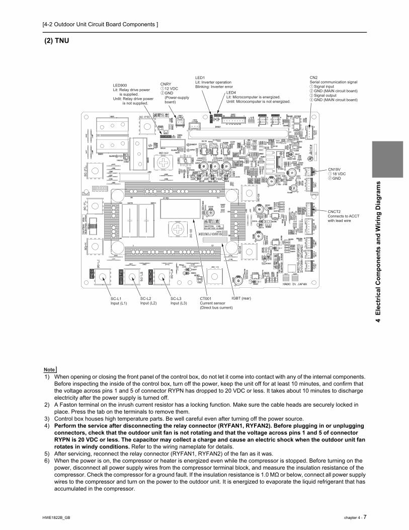
[4-2 Outdoor Unit Circuit Board Components ]
HWE1822B_GB chapter 4 - 7
4 E
lect
rical
Com
pone
nts
and
Wiri
ng D
iagr
ams
(2) TNU
1) When opening or closing the front panel of the control box, do not let it come into contact with any of the internal components. Before inspecting the inside of the control box, turn off the power, keep the unit off for at least 10 minutes, and confirm that the voltage across pins 1 and 5 of connector RYPN has dropped to 20 VDC or less. It takes about 10 minutes to discharge electricity after the power supply is turned off.
2) A Faston terminal on the inrush current resistor has a locking function. Make sure the cable heads are securely locked in place. Press the tab on the terminals to remove them.
3) Control box houses high temperature parts. Be well careful even after turning off the power source.4) Perform the service after disconnecting the relay connector (RYFAN1, RYFAN2). Before plugging in or unplugging
connectors, check that the outdoor unit fan is not rotating and that the voltage across pins 1 and 5 of connector RYPN is 20 VDC or less. The capacitor may collect a charge and cause an electric shock when the outdoor unit fan rotates in windy conditions. Refer to the wiring nameplate for details.
5) After servicing, reconnect the relay connector (RYFAN1, RYFAN2) of the fan as it was.6) When the power is on, the compressor or heater is energized even while the compressor is stopped. Before turning on the
power, disconnect all power supply wires from the compressor terminal block, and measure the insulation resistance of the compressor. Check the compressor for a ground fault. If the insulation resistance is 1.0 MΩ or below, connect all power supply wires to the compressor and turn on the power to the outdoor unit. It is energized to evaporate the liquid refrigerant that has accumulated in the compressor.
SC-L3Input (L3)
SC-L2Input (L2)
SC-L1Input (L1)
CNCT2Connects to ACCT with lead wire
CN2Serial communication signal Signal input GND (MAIN circuit board) Signal output GND (MAIN circuit board)
CN19V 18 VDC GND
LED900Lit: Relay drive power is supplied.Unlit: Relay drive power is not supplied.
CNRY 12 VDC GND (Power-supply board)
LED1Lit: Inverter operationBlinking: Inverter error
LED4Lit: Microcomputer is energized.Unlit: Microcomputer is not energized.
IGBT (rear)CT001Current sensor(Direct bus current)

[4-2 Outdoor Unit Circuit Board Components ]
8 - chapter 4 HWE1822B_GB
4 E
lect
rical
Com
pone
nts
and
Wiri
ng D
iagr
ams
4-2-4 Fan Board
(1) YNU
1) When opening or closing the front panel of the control box, do not let it come into contact with any of the internal components. Before inspecting the inside of the control box, turn off the power, keep the unit off for at least 10 minutes, and confirm that the capacitor voltage (inverter main circuit) has dropped to 20 VDC or less. It takes about 10 minutes to discharge electricity after the power supply is turned off.
2) Control box houses high temperature parts. Be well careful even after turning off the power source.3) Perform the service after disconnecting the relay connector (RYFAN1, RYFAN2). Before plugging in or unplugging
connectors, check that the outdoor unit fan is not rotating and that the voltage across pins 1 and 5 of connector RYPN is 20 VDC or less. The capacitor may collect a charge and cause an electric shock when the outdoor unit fan rotates in windy conditions. Refer to the wiring nameplate for details.
4) To connect wiring to TB7, check that the voltage is 20 VDC or below.5) After servicing, reconnect the relay connector (RYFAN1, RYFAN2) of the fan as it was.
CN81 17 VDC input GND
SW001 ON: No-load operation OFF: Normal operation OFF: Fixed Address switch Address switch
CN80 Serial communication signal input GND (Control board) Serial communication signal output GND (Control board)
DIP IPM (rear)F00110 A 400 V fuse
CNDCPBus voltage input (P)
CNINVInverter output W V U
RSH01Current detection resistor
RSH02Current detection resistor
RSH03Current detection resistor
CNDCNBus voltage input (N) LED04
Lit: Microcomputer in operation
LED01Lit: Inverter operationBlinking: Inverter error

[4-2 Outdoor Unit Circuit Board Components ]
HWE1822B_GB chapter 4 - 9
4 E
lect
rical
Com
pone
nts
and
Wiri
ng D
iagr
ams
(2) TNU
1) When opening or closing the front panel of the control box, do not let it come into contact with any of the internal components. Before inspecting the inside of the control box, turn off the power, keep the unit off for at least 10 minutes, and confirm that the capacitor voltage (inverter main circuit) has dropped to 20 VDC or less. It takes about 10 minutes to discharge electricity after the power supply is turned off.
2) Control box houses high temperature parts. Be well careful even after turning off the power source.3) Perform the service after disconnecting the relay connector (RYFAN1, RYFAN2). Before plugging in or unplugging
connectors, check that the outdoor unit fan is not rotating and that the voltage across pins 1 and 5 of connector RYPN is 20 VDC or less. The capacitor may collect a charge and cause an electric shock when the outdoor unit fan rotates in windy conditions. Refer to the wiring nameplate for details.
4) To connect wiring to TB7, check that the voltage is 20 VDC or below.5) After servicing, reconnect the relay connector (RYFAN1, RYFAN2) of the fan as it was.
F00110 A 400 V fuse
CNDCPBus voltage input (P)
RSH01Current detection resistor
RSH02Current detection resistor
RSH03Current detection resistor
CNDCNBus voltage input (N)
LED04Lit: Microcomputer in operation
LED01Lit: Inverter operationBlinking: Inverter error
CNINVInverter output W V U
CN80 Serial communication signal input GND (Control board) Serial communication signal output GND (Control board)
SW001 ON: No-load operation OFF: Normal operation OFF: Fixed Address switch Address switch
CN81 17 VDC input GND

[4-2 Outdoor Unit Circuit Board Components ]
10 - chapter 4 HWE1822B_GB
4 E
lect
rical
Com
pone
nts
and
Wiri
ng D
iagr
ams
4-2-5 Noise Filter
(1) YNU
TB13Input (L3)
TB12Input (L2)
TB11Input (L1)
Ground
Ground Ground GroundTB22Output (L2)
TB23Output (L3)
TB21Output (L1)
F1, F2, F3, F4Fuse250 VAC 6.3 A
CN2 Surge absorber circuit Surge absorber circuit

[4-2 Outdoor Unit Circuit Board Components ]
HWE1822B_GB chapter 4 - 11
4 E
lect
rical
Com
pone
nts
and
Wiri
ng D
iagr
ams
(2) TNU
TB12Input (L2)
TB13Input (L3)
TB11Input (L1)
TB22Output (L2)
TB23Output (L3)
TB21Output (L1)
Ground Ground Ground
F1, F2Fuse250 VAC 6.3 A
CN12Output L1 L2
CN13Output L2 L3
CN14 Surge absorber circuit Surge absorber circuit Open-phase detection circuit Open-phase detection circuit

[4-2 Outdoor Unit Circuit Board Components ]
12 - chapter 4 HWE1822B_GB
4 E
lect
rical
Com
pone
nts
and
Wiri
ng D
iagr
ams
4-2-6 Capacitor Board (CAP Board)
(1) TNU
1) When opening or closing the front panel of the control box, do not let it come into contact with any of the internal components. Before inspecting the inside of the control box, turn off the power, keep the unit off for at least 10 minutes, and confirm that the capacitor voltage (inverter main circuit) has dropped to 20 VDC or less. It takes about 10 minutes to discharge electricity after the power supply is turned off.
2) A Faston terminal on the inrush current resistor has a locking function. Make sure the cable heads are securely locked in place. Press the tab on the terminals to remove them.
3) Control box houses high temperature parts. Be well careful even after turning off the power source.4) Perform the service after disconnecting the relay connector (RYFAN1, RYFAN2). Before plugging in or unplugging
connectors, check that the outdoor unit fan is not rotating and that the voltage across pins 1 and 5 of connector RYPN is 20 VDC or less. The capacitor may collect a charge and cause an electric shock when the outdoor unit fan rotates in windy conditions. Refer to the wiring nameplate for details.
5) After servicing, reconnect the relay connector (RYFAN1, RYFAN2) of the fan as it was.
C1-C7Smoothing capacitor
SC-D1Connects to INV38
SC-D2Connects to INV38
SC-NBus voltage input (N)Connects to INV38
SC-PLBus voltage input (P)Connects to INV38
SC-P1LBus voltage input (P)Connects to INV38
CN-PConnects to connector RYPN
CNRYConnects to connector CNRYA
CNRY2Connects to connector CNRY
CN-NConnects to connector RYPN
SC-P1CBus voltage input (P)Connects to INV38

[4-2 Outdoor Unit Circuit Board Components ]
HWE1822B_GB chapter 4 - 13
4 E
lect
rical
Com
pone
nts
and
Wiri
ng D
iagr
ams
(2) YNU
1) When opening or closing the front panel of the control box, do not let it come into contact with any of the internal components. Before inspecting the inside of the control box, turn off the power, keep the unit off for at least 10 minutes, and confirm that the capacitor voltage (inverter main circuit) has dropped to 20 VDC or less. It takes about 10 minutes to discharge electricity after the power supply is turned off.
2) A Faston terminal on the inrush current resistor has a locking function. Make sure the cable heads are securely locked in place. Press the tab on the terminals to remove them.
3) Control box houses high temperature parts. Be well careful even after turning off the power source.4) Perform the service after disconnecting the relay connector (RYFAN1, RYFAN2). Before plugging in or unplugging
connectors, check that the outdoor unit fan is not rotating and that the voltage across pins 1 and 5 of connector RYPN is 20 VDC or less. The capacitor may collect a charge and cause an electric shock when the outdoor unit fan rotates in windy conditions. Refer to the wiring nameplate for details.
5) After servicing, reconnect the relay connector (RYFAN1, RYFAN2) of the fan as it was.
C1-C4Smoothing capacitor
CN-CAPConnects to INV42Y N N
FT-P1CConnects to INV42Y

[4-3 Outdoor Unit Electrical Wiring Diagrams ]
14 - chapter 4 HWE1822B_GB
4 E
lect
rical
Com
pone
nts
and
Wiri
ng D
iagr
ams
4-3 Outdoor Unit Electrical Wiring Diagrams(1) YNU
RSH0
1/02
/03
For c
urre
nt d
etec
tion
Cen
tral c
ontro
l tra
nsm
issi
on li
neIn
door
/Out
door
tran
smis
sion
line
LC
hoke
coi
l (fo
r hig
h fre
quen
cy n
oise
redu
ctio
n)
For i
nrus
h cu
rren
t pre
vent
ion
Res
isto
rR
1,5
HIC
byp
ass,
Con
trols
refri
gera
ntflo
w in
HIC
circ
uit
For o
peni
ng/c
losi
ng th
e di
scha
rge
suct
ion
bypa
ssS
V2
SV
1a
LEV
2a,b
21S
4aS
ymbo
l<S
ymbo
l exp
lana
tion>
63H
1
63H
S1
63LS
21S
4b
C1,C
3,
LEV
1 *1
0
DC
L
Pre
ssur
e co
ntro
l,Ref
riger
ant f
low
rate
con
trol
Sol
enoi
dva
lve
For o
peni
ng/c
losi
ng th
e by
pass
circ
uit u
nder
the
O/S
Hea
t exc
hang
er c
apac
ity c
ontr
ol(o
nly
4-w
ay v
alve
Exp
lana
tion
Pre
ssur
ese
nsor
Coo
ling/
Hea
ting
switc
hing
Pre
ssur
esw
itch
Hig
h pr
essu
re p
rote
ctio
n fo
r the
outd
oor u
nit
Dis
char
ge p
ress
ure
Low
pre
ssur
e
Cap
acito
r (in
verte
r mai
n ci
rcui
t)
Line
arex
pans
ion
valv
e
DC
reac
tor
THH
S
TH5
TH4
TB7
TB3
TB1
Ther
mis
tor
Dis
char
ge p
ipe
tem
pera
ture
AC
C in
let p
ipe
tem
pera
ture
IPM
tem
pera
ture
Pow
er s
uppl
yTe
rmin
albl
ock
*1.S
ingl
e-do
tted
lines
indi
cate
wiri
ng n
ot s
uppl
ied
with
the
unit.
*2.D
ot-d
ash
lines
indi
cate
the
cont
rol b
ox b
ound
arie
s.*3
.Ref
er to
the
Dat
a bo
ok fo
r con
nect
ing
inpu
t/out
put
s
igna
l con
nect
ors.
*4.D
aisy
-cha
in te
rmin
als
(TB
3) o
n th
e ou
tdoo
r uni
ts in
the
s
ame
refri
gera
nt s
yste
m to
geth
er.
*5.F
asto
n te
rmin
als
have
a lo
ckin
g fu
nctio
n.
Mak
e su
re th
e te
rmin
als
are
secu
rely
lock
ed in
pla
ce
afte
r ins
ertio
n. P
ress
the
tab
on th
e te
rmin
als
to
rem
oved
them
.*6
.Con
trol b
ox h
ouse
s hi
gh-v
olta
ge p
arts
.
Bef
ore
insp
ectin
g th
e in
side
of t
he c
ontro
l box
,turn
off
th
e po
wer
,kee
p th
e un
it of
f for
at l
east
10
min
utes
, and
c
onfir
m th
at th
e vo
ltage
of t
he c
onne
ctor
RY
PN
h
as d
ropp
ed to
DC
20V
or l
ess.
RYFA
N1
Noi
se F
ilter
Noi
se fi
lter
L3L2
L1
L
L3L2
L1
Surg
e ab
sorb
er
CN2
Noi
se fi
lter
6 3 1
IPM
CNIN
V
31
CNDC
Nbla
ck FAN
Boa
rd
F001
DC 4
00V
10AT
RSH0
1/02
/03
14CN
80
LED
4:C
PU
in o
pera
tion
LED
1:N
orm
al o
pera
tion(
Lit)
/ Err
or(B
link)
21CN
81gr
een
32
IPM
CNDC
Pre
d
CNIN
V
31
CNDC
Nbla
ck FAN
Boa
rd
F001
DC 4
00V
10AT
RSH0
1/02
/03
14CN
80
LED
4:C
PU
in o
pera
tion
LED
1:N
orm
al o
pera
tion(
Lit)
/ Err
or(B
link)
21CN
81gr
een
147 1 23
2
LED
2LE
D10
1SWU2
LED
301
Com
pres
sor O
N/O
FF o
utpu
tE
rror
det
ectio
n ou
tput
DC12
VCN
51
1's digit
10's
digit
*3
SWU1
SWP3
CN4A
black2
31
4CN
4bla
ck23
14
CNPS
red2
14
CN60
4gr
een
21
CN60
3blu
e21
3CN
6004
52
1
PS
Boa
rdblu
eCN
FG5
12
DB2
IPM
pow
ersu
pply
circ
uit
P
63H1
RY63
H
L3L1
L2
TB1
L1L2
L3
Pow
er S
ourc
e
3N
~
60H
z
460
V
UV
W
MS
3~
CN4B
black2
31
4
CN10
0re
d1
3
CN30
4blu
eCN30
32 1
2 1
2 1
13
21
2CN
INV
yello
wCN
FAN1
yello
w
12
45
12
4
4321CN
202
M-N
ET
pow
ersu
pply
circ
uit
CP
U p
ower
supp
ly c
ircui
t
DB1
12
CNIN
T 4
red
CNDC
CN10
1blu
e
Con
trol B
oard
31
2
12
3
31
2
12
3
CN20
2CN
201
red
63LS
63HS
1
12
CNPO
Wye
llow
13CN
3Kye
llow
13CN
3Sre
d
*3
13CN
3D1
3CN3N
blue
41CN
41 23
41CN
40 23
TP1
TP2
TB3
TB7
M1
M2
M1
M2
S
Indo
or/O
utdo
ortra
nsm
issi
onca
ble
Cen
tral c
ontro
ltra
nsm
issi
onca
ble
*4
CNAC
3 1
22
2
ON OFF
X10
X07
X09
5 51 1
CN50
6re
d21
S4b
Powe
r fai
lure
dete
ctio
n cir
cuit
CN50
7bla
ck36
SV9
SV2
X05
X06
35 16
CN50
5SV
1a
21S4
a
X03
3 1CN
503
SV10
gree
n
6
F001
AC25
0V3.
15A
TTB
7 P
ower
sel
ectin
g co
nnec
tor
black
2 1
*8
21CN
FGblu
e
LED
301
Dis
play
setti
ng/
Func
tion
setti
ng USB
TYPE
ACN
USB
CNPW2
31
4
TH2
TH5
CN21
1gr
een
1234
tCN
213
gree
nTH
612
TH3
TH7
t t
CN21
2re
d1234
Z25
3CN
TYP5
gree
n1
CNTY
P412
Z24
TH15
TH4
CN19
2gr
een
1234
LEV2
a
M
12346CN
LVB
red
LEV1
/LEV
9
M
12346
CNLV
A5
LEV2
b
M
12346
CNLV
Cblu
e
LEV9
/LEV
2d
M
12346
CNLV
Egr
een
*8
*9
*7.C
ontro
l boa
rd L
ED
dis
play
.
-+
*8
*10
CNRY
Are
d21
LED
3 *7
Mot
or(C
ompr
esso
r)
AC
CT1
AC
CT2
RYPN
U V WM
S3 ~
Fan
mot
or2(
Rig
ht)
(Hea
t exc
hang
er)
841 7
Fan
mot
or1(
Left)
(Hea
t exc
hang
er)
81gr
een
2 1
CNFA
N2RY
FAN2
PU
HY
mod
el).
Coo
ling/
Hea
ting
switc
hing
ACCT
1,ACC
T2C
urre
nt s
enso
r(A
C)
LEV
2d *
9P
ress
ure
cont
rol,R
efrig
eran
t flo
wra
te c
ontro
l
Hea
t exc
hang
er fo
r inv
erte
rLE
V9
*9,1
0
For o
peni
ng/c
losi
ng th
e by
pass
circ
uit
SV
9 *8
For c
ontin
uous
hea
ting
SV
10 *
8
Sub
cool
byp
ass
outle
t tem
pera
ture
TH2
*8TH
3P
ipe
tem
pera
ture
TH6
*8S
ubco
oled
liqu
id re
frige
rant
tem
pera
ture
TH7
OA
tem
pera
ture
TH15
Com
pres
sor s
hell
botto
m te
mpe
ratu
re
X90
1,X
902
Mag
netic
rela
y(in
verte
r mai
n ci
rcui
t)Z2
2,24
,25
Func
tion
setti
ng c
onne
ctor
CNAC
2
CNDC
Pre
d
147 1 2
Func
tion
setti
ng
LED2
Norm
al o
pera
tion(
Lit)/
Erro
r(Blin
k)LE
D3SW
6-10
is O
FF a
ndSW
4-1~
10 a
re O
FFIn
ope
ratio
n(Li
t)/In
sto
p(U
nlit)
SW6-
10 is
ON
Fun
ctio
n se
tting
by
SW
4en
able
(Lit)
/dis
able
(Unl
it)LE
D101
Nor
mal
ope
ratio
n(Li
t)/IC
Err
or(U
nlit)
*10.
Diff
eren
ce o
f app
lianc
e.M
odel
nam
eAp
plia
nce
LEV1
LEV9
*8.D
iffer
ence
of a
pplia
nce.
Mod
el n
ame
Appl
ianc
e*8
exis
t*8
do
not e
xist
*9.D
iffer
ence
of a
pplia
nce.
Mod
el n
ame
Appl
ianc
eLE
V9LE
V2d
THHS
THHS
*6
5431
MF1
Fan
mot
or(fo
r coo
ling
in c
ontro
l box
)
Z22
3CN
TYP2
black
1
M 1~
MF1
CN24
VAbla
ck2
14
++
C3C1
R5~R
8R1
~R4
FT-P
1CCN
-CAP
21CA
P Bo
ard
CN63
PWblu
e21
3
*5
3
3
Z2
U
7
F1~F
3AC
250
V6.
3AT
21
3RY
24VA
black
8 RYNF
41
Z1
U
-+
4 7
U V WM
S3~
13
CNTR
4
1CNTR
1
43251
F4 AC 6
00V
6A F
F5 AC 6
00V
6A F
Tran
sfor
mer
Box
CNTR
334
CNTR
2
T02
(Tra
nsfo
rmer
)2 234
T03
(Tra
nsfo
rmer
)
1 1
SW00
1ON1 4
SW00
1ON1 4
SW10
1ON1 4
SW4ON
1 10SW
5ON1 10
SW6ON
1 10SW
7ON1 10
For o
peni
ng/c
losi
ng th
e in
ject
ion
circ
uit
LEV
4
LEV4M
12346
CNLV
Fbla
ck
*8X1
5
CN51
02 11
43
21
TB2
F2 AC25
0V1A
F1 AC25
0V1A
Hea
ter t
rans
mis
sion
line
TB2PU
RY,T
URY
PURY
,TUR
Y
PURY
,TUR
YPU
HY,T
UHY
PUHY
,TUH
Y
PUHY
,TUH
Y
2 1 2 1 2 1 2 1
CNPH
L
CNPH
R
CNPH
BL
CNPH
BR
Ther
mos
tat
Ther
mos
tat
Ther
mos
tat
Ther
mos
tat
PHL,
R,BL
,BR
Pan
el H
eate
r
PHL
PHR
PHBL
PHBR
Heat
er
Heat
er
Heat
er
Heat
er
Grou
nd
SWS2
black
C001
~C00
6
blue
DCL
INV
Boa
rd
IPM TH
HS
41blu
e
SC-L
1
X901
X902
NR00
1
gree
n
SC-L
2
SC-L
3
SC-U
SC-P
1
SC-W
SC-V
CNRY 2 1
LED
4:C
PU
in o
pera
tion
LED
1:N
orm
al o
pera
tion(
Lit)
/ Err
or(B
link)
LED
900:
Rel
ay p
ower
sup
ply
32
U
CN19
Vye
llow
1 2
CN2 1 2 3 4
X800
X901
,X9
02
CN-P 1 2
red
CN-N 1 2
blue2 1
41
41
CNFA
N2
SC-P
CNFA
N1
SW00
1
ON 1
2
FT-P
2
FT-P
1
R1,R
5*5*5
*5
+ +
FT-P
1C*5
CNCT
2
CN-C
AP
R001
,R0
02,
R003
,R0
04,
C001
,C0
03,
C005
C002
,C0
04,
C006
R005
,R0
06
R007
,R0
08
Com
patib
le p
orts

[4-3 Outdoor Unit Electrical Wiring Diagrams ]
HWE1822B_GB chapter 4 - 15
4 E
lect
rical
Com
pone
nts
and
Wiri
ng D
iagr
ams
(2) TNU, ,
RSH0
1/02
/03
For c
urre
nt d
etec
tion
Cen
tral c
ontro
l tra
nsm
issi
on li
neIn
door
/Out
door
tran
smis
sion
line
LC
hoke
coi
l (fo
r hig
h fre
quen
cy n
oise
redu
ctio
n)
For i
nrus
h cu
rrent
pre
vent
ion
Res
isto
rR
1
HIC
byp
ass,
Con
trols
refri
gera
ntflo
w in
HIC
circ
uit
For o
peni
ng/c
losi
ng th
e di
scha
rge
suct
ion
bypa
ssSV
2
SV1a
LEV2
a,b
21S4
aS
ymbo
l<S
ymbo
l exp
lana
tion>
63H
1
63H
S163
LS
21S4
b
C1~
C7
LEV1
*10
DC
L
Pres
sure
con
trol,R
efrig
eran
t flo
wra
te c
ontro
l
Sole
noid
valv
eFo
r ope
ning
/clo
sing
the
bypa
ssci
rcui
t und
er th
e O
/S
Hea
t exc
hang
er c
apac
ity c
ontro
l(onl
y4-
way
val
veE
xpla
natio
n
Pres
sure
sens
or
Coo
ling/
Hea
ting
switc
hing
Pres
sure
switc
hH
igh
pres
sure
pro
tect
ion
for t
heou
tdoo
r uni
tD
isch
arge
pre
ssur
eLo
w p
ress
ure
Cap
acito
r (in
verte
r mai
n ci
rcui
t)
Line
arex
pans
ion
valv
e
DC
reac
tor
THH
S
TH5
TH4
TB7
TB3
TB1
Ther
mis
tor
Dis
char
ge p
ipe
tem
pera
ture
ACC
inle
t pip
e te
mpe
ratu
re
IPM
tem
pera
ture
Pow
er s
uppl
yTe
rmin
albl
ock
*1.S
ingl
e-do
tted
lines
indi
cate
wiri
ng n
ot s
uppl
ied
with
the
unit.
*2.D
ot-d
ash
lines
indi
cate
the
cont
rol b
ox b
ound
arie
s.*3
.Ref
er to
the
Dat
a bo
ok fo
r con
nect
ing
inpu
t/out
put
si
gnal
con
nect
ors.
*4.D
aisy
-cha
in te
rmin
als
(TB
3) o
n th
e ou
tdoo
r uni
ts in
the
sa
me
refri
gera
nt s
yste
m to
geth
er.
*5.F
asto
n te
rmin
als
have
a lo
ckin
g fu
nctio
n.
Mak
e su
re th
e te
rmin
als
are
secu
rely
lock
ed in
pla
ce
afte
r ins
ertio
n. P
ress
the
tab
on th
e te
rmin
als
to
rem
oved
them
.*6
.Con
trol b
ox h
ouse
s hi
gh-v
olta
ge p
arts
.
Bef
ore
insp
ectin
g th
e in
side
of t
he c
ontro
l box
,turn
off
th
e po
wer
,kee
p th
e un
it of
f for
at l
east
10
min
utes
, and
co
nfirm
that
the
volta
ge o
f the
con
nect
or R
YP
N
has
drop
ped
to D
C20
V o
r les
s.
RY
FAN
1
IPM
CN
INV
1C
ND
CN
blac
k FAN
Boar
d
F001
DC
400
V10
ATRS
H01/
02/0
3
14C
N80
LED
4:C
PU
in o
pera
tion
LED
1:N
orm
al o
pera
tion(
Lit)
/ Err
or(B
link)
21C
N81
gree
n
32
IPM
CN
DC
Pre
d
CN
INV
1C
ND
CN
blac
k FAN
Boar
d
F001
DC
400
V10
ATRS
H01/
02/0
3
14C
N80
LED
4:C
PU
in o
pera
tion
LED
1:N
orm
al o
pera
tion(
Lit)
/ Err
or(B
link)
21C
N81
gree
n
147 1
32
LED
2LE
D10
1SWU2LE
D30
1
Com
pres
sor O
N/O
FF o
utpu
tE
rror
det
ectio
n ou
tput
DC
12V
CN
51
1's digit
10's
digit
*3
SWU1
SW
P3
CN
4Abl
ack2
31
4
CN
4bl
ack
23
14
CN
PS
red2
14
CN
604
gree
n
21
CN
603
blue21
3
CN
60045
21
PS B
oard
blue
CN
FG5
12
DB
2
IPM
pow
ersu
pply
circ
uit
CN
110
blac
k2
1
P
63H
1 RY
63H
CAP
Boar
d4
1
CN
FAN
2
SC
-P1L
SC
-P1C
DC
L
FT-P
2
FT-P
1
R1
41
CN
FAN
1
+
C1~
C7
R1,
R2,
R3
2 1
CN
RY
2
2 1
CN
RY
SC
-PL
SC
-N
SC
-2L
SC
-1L
red
INV
Boa
rd
IPM
THHS
41bl
ue
SC
-P1L
X901
X902
NR
001
SC
-L1
gree
n
SC-P
LS
C-N
SC
-L2
SC
-L3 S
C-D
1
SC
-P1C
SC
-D3
SC
-D2
CN
RY
2 1
LED
4:C
PU
in o
pera
tion
LED
1:N
orm
al o
pera
tion(
Lit)
/ Err
or(B
link)
LED
900:
Rel
ay p
ower
sup
ply
L3L1
L2
TB1
L1L2
L3
Pow
er S
ourc
e 3
N~
60H
z 2
08/2
30V
UV
W
MS
3~
CN
4Bbl
ack2
31
4
32
CN
100
red
13
CN
304
blue
CN
303
2 12 1
2 1
13
21
2C
NIN
Vye
llow
CN
FAN
1ye
llow
12
45
12
4
4321CN
202
M-N
ET
pow
ersu
pply
circ
uit
CP
U p
ower
supp
ly c
ircui
t
DB
1
12
CNIN
T 4
red
CN
DC
CN10
1blu
e
Con
trol B
oard
31
2
12
3
31
2
12
3
CN
202
CN
201
red
63LS
63H
S1
12
CNPO
Wye
llow
13CN
3Kye
llow
13CN
3Sre
d
*3
13CN
3D1
3CN
3Nbl
ue
41C
N41
23
41C
N40
23
TP1
TP2
TB3
TB7
M1
M2
M1
M2
S
Indo
or/O
utdo
ortra
nsm
issi
onca
ble
Cen
tral c
ontro
ltra
nsm
issi
onca
ble
*4
CN
AC
3 1
22
2
ON
OFF
X10
X07
X09
5 51 1
CN
506
red
21S
4b
Pow
er fa
ilure
dete
ctio
n ci
rcui
t
CN
507
blac
k36
SV
9
SV
2
X05
X06
35 16
CN
505
SV
1a
21S
4a
X03
3 1C
N50
3S
V10
gree
n
6
F001
AC
250V
3.15
A T
TB7
Pow
er s
elec
ting
conn
ecto
r
blac
k2 1
*8
21C
NFG
blue
LED
301
Dis
play
setti
ng/
Func
tion
setti
ng US
B T
YP
EA
CN
US
B
CN
PW2
31
4
TH2
TH5
CN
211
gree
n1234
CN
213
gree
nTH
612
TH3
TH7
CN
212
red
1234
Z25
3C
NTY
P5
gree
n1
CN
TYP
412
Z24
TH15
TH4
CN
192
gree
n1234
LEV
2a
M
12346
CN
LVB
red
LEV
1/LE
V9
M
12346
CN
LVA
5
LEV
2b
M
12346
CN
LVC
blue
LEV9
/LEV
2d
M
12346
CN
LVE
gree
n
*8*9
*7.C
ontro
l boa
rd L
ED
dis
play
.
-+
U
*8
*10
CN
RYA
red2
1
LED
3 *7
CN
19V
yello
w1 2
CN
21 2 3 4
Mot
or(C
ompr
esso
r)
AC
CT1
AC
CT2
RY
PN
UV W
MS
3~
Fan
mot
or2(
Rig
ht)
(Hea
t exc
hang
er)
Fan
mot
or1(
Left)
(Hea
t exc
hang
er)
gree
n2 1
CN
FAN
2R
YFA
N2
PU
HY
mod
el).
Coo
ling/
Hea
ting
switc
hing
ACCT
1,ACC
T2C
urre
nt s
enso
r(AC
)
LEV2
d *9
Pres
sure
con
trol,R
efrig
eran
t flo
wra
te c
ontro
l
Hea
t exc
hang
er fo
r inv
erte
rLE
V9 *9
,10
For o
peni
ng/c
losi
ng th
e by
pass
circ
uit
SV9
*8Fo
r con
tinuo
us h
eatin
gSV
10 *8
Subc
ool b
ypas
s ou
tlet t
empe
ratu
reTH
2 *8
TH3
Pipe
tem
pera
ture
TH6
*8Su
bcoo
led
liqui
d re
frige
rant
tem
pera
ture
TH7
OA
tem
pera
ture
TH15
Com
pres
sor s
hell
botto
m te
mpe
ratu
re
X901
~X90
3M
agne
tic re
lay(
inve
rter m
ain
circ
uit)
Z22,
24,2
5Fu
nctio
n se
tting
con
nect
or
CN
AC
2
*5*5
*5
147 1
Func
tion
setti
ng
X80
0
X90
1,X
902,
LED2
Norm
al o
pera
tion(
Lit)/
Erro
r(Blin
k)LE
D3SW
6-10
is O
FF a
ndSW
4-1~
10 a
re O
FFIn
ope
ratio
n(Li
t)/In
sto
p(Un
lit)
SW6-
10 is
ON
Func
tion
setti
ng b
y S
W4
enab
le(L
it)/d
isab
le(U
nlit)
LED1
01No
rmal
ope
ratio
n(Li
t)/IC
Erro
r(Unl
it)
*10.
Diff
eren
ce o
f app
lianc
e.M
odel
nam
eAp
plian
ceLE
V1LE
V9
*8.D
iffer
ence
of a
pplia
nce.
Mod
el na
me
Appli
ance
*8 e
xist
*8 d
o no
t exis
t*9
.Diff
eren
ce o
f app
lianc
e.M
odel
nam
eAp
plian
ceLE
V9LE
V2d
THHS
THH
S blac
k *6
5431
MF1
Fan
mot
or(fo
r coo
ling
in c
ontro
l box
)
Z22
3C
NTY
P2
blac
k1
M 1~MF1
CN
24VA
blac
k2
14
(on
INV
Boa
rd)
CN
63P
Wbl
ue
21
3
3
3
Z2
U
21
3R
Y24
VAbl
ack
8R
YN
F 41
Z1
U
-+
22
3
CN
DC
Pre
d
3
52
52
SC
-U
SC
-V
SC
-W
12C
N-N12
CN
-P
X90
3
X903
15
SW
001ON
1 4
SW
001ON
1 4
SW
001
ON
21
SW
4ON1 10
SW
5ON1 10
SW
6ON1 10
SW
7ON1 10
SW
101ON
1 4
4 621
UV W
MS
3~4 621
LEV
4
M
12346
CN
LVF
blac
k
For o
peni
ng/c
losi
ng th
e in
ject
ion
circ
uit
LEV4
*8X
15C
N51
02 11
43
21
TB2
F2 AC
250V
1A
F1 AC
250V
1A
Hea
ter t
rans
mis
sion
line
TB2PU
RY,T
URY
PURY
,TUR
Y
PURY
,TUR
YPU
HY,T
UHY
PUHY
,TUH
Y
PUHY
,TUH
Y
2 1 2 1 2 1 2 1
CNPH
L
CNPH
R
CNPH
BL
CNPH
BR
PH
L
PH
R
PH
BL
PH
BR
Ther
mos
tat
Ther
mos
tat
Ther
mos
tat
Ther
mos
tat
PHL,
R,BL
,BR
Pane
l hea
ter
Hea
ter
Hea
ter
Hea
ter
Hea
ter
Gro
und
SWS2
gree
n
gree
n
CN
CT2
Com
patib
le p
orts
Noi
se F
ilter
L3L2
L1
L
Surg
e ab
sorb
er
CN
14 Powe
r fail
ure
Dete
ction
circ
uitN
oise
filte
r
6 3 1 31
CN
13
F001
,F00
2AC
250
V6.
3A T
31C
N12
L3
L2
L1
(DS+
phot
o co
upler
)
1C
N11
blac
k2
7
gree
n
Noi
se fi
lter

[4-4 Transmission Booster Electrical Wiring Diagrams ]
16 - chapter 4 HWE1822B_GB
4 E
lect
rical
Com
pone
nts
and
Wiri
ng D
iagr
ams
4-4 Transmission Booster Electrical Wiring Diagrams
220 - 240VAC
Terminal block for power supply (TB1)
L Red Red Red
White
Green
250V 5A
Grounding
Red Red
Red
U
U
White
White White
White
White
White Blue Red Red
DSA
White
White
Blue
Red
Red
Red
Red
Varistor
Varistor
Noise filter
Stabilized power supply
4
3
2
1
1
2
3
CN2 CN1
Black
Black
Black
Black
Green/Yellow
1
2
3
E
4
Choke coil
1 2
CN3
1 2 1 2
CN4
CN2
1 2
CN1 Electronic control board
Black
White
Red
Red
Black
S
B
A
S
B
A
Terminal block 2 for transmission line (TB3) Expanded (indoor unit) side
Terminal block 1 for transmission line (TB2) Expanded (outdoor unit) side

[4-5 BC Controller Circuit Board Arrangement ]
HWE1822B_GB chapter 4 - 17
4 E
lect
rical
Com
pone
nts
and
Wiri
ng D
iagr
ams
4-5 BC Controller Circuit Board Arrangement
4-5-1 BC Controller Control Box
1. CMB-P1016V-J1, JA1, KA1
Relay board
Transformer
BC board
Terminal block fortransmission line
Terminal block forpower supply

[4-6 BC Controller Circuit Board Components ]
18 - chapter 4 HWE1822B_GB
4 E
lect
rical
Com
pone
nts
and
Wiri
ng D
iagr
ams
4-6 BC Controller Circuit Board Components
4-6-1 BC Board
SW1SW2SW5 SW6SW4
Abbreviated name of connector color
ExamplesBU:BLUEBK:BLACKGN:GREENYE:YELLOWWH:WHITERD:RED
Example: (BU) above CN601 indicates that the connector is blue.

[4-6 BC Controller Circuit Board Components ]
HWE1822B_GB chapter 4 - 19
4 E
lect
rical
Com
pone
nts
and
Wiri
ng D
iagr
ams
4-6-2 Four-Relay Board
4-6-3 Ten-Relay Board

[4-7 BC Controller Electrical Wiring Diagrams ]
20 - chapter 4 HWE1822B_GB
4 E
lect
rical
Com
pone
nts
and
Wiri
ng D
iagr
ams
4-7 BC Controller Electrical Wiring Diagrams(1) CMB-P104NU-J1 model
BREA
KER(
16A)
LD1:
CP
U in
oper
atio
n
UU
MM
X06
X08
X04
X03
X05
X07
X31
X32
X33
X21
X30
X01
X02
Indo
or/o
utdo
orTr
ansm
issi
on L
ine
PO
WE
R S
UP
PLY
~208
V-23
0V60
Hz
FUSE
(16A
)
PULL
BOX
TO N
EXT
INDO
OR U
NIT
DS
A
(Yel
low
)(Yel
low
)
(Red
)
(Bla
ck)
CN36
(Gre
en)
31
F01
250V
AC6.
3A F
CN29
(Gre
en)
CN28
(Blue
)
CN27
(Red
)
ZNR0
1ZN
R02
1 3 5 7 1 3 5 7 1 3 5 7 1 3 5 7
1 5 6 7 8 9 10 11 12 13 14 15 1632 4
8 9 10 11 12 1332 41 5 6 7 14 15 16
4321 4321 4321 4321SW
2SW
1
110
SW
4
SW
5
SW
6
22 1 13 3
TB01
LEV
1LE
V3
12
34
56
PS
3
PS
1 TH16
TH15
TH12
TH11
CN
07
CN
11
CN
10
CN
031
23
21
1 2 3 487654321
CN
P3
321
CN
P13
CN
02
CN
TR(R
ed)
21
CO
NT.
B
12
34
56
CN
05
35
1C
N12
1 3
CN
26
TB02
TRS
(SH
IELD
)
L1 L2
M2
M1
1 2Z1
TYP
1
G
CN
13(R
ed)
21
T1 T2 T3 T4
4321
SV1C
SV1B
SV1A
4321SV
2BSV
2ASV
2C
4321SV
3BSV
3ASV
3C
4321SV
4BSV
4ASV
4CN
ote
1. T
B02
is tr
ansm
issi
on te
rmin
al b
lock
.N
ever
con
nect
pow
er li
ne to
it.
2. T
he in
itial
set
val
ues
of s
witc
h on
C
ON
T. B
are
as
follo
ws.
SW
1:0
SW
2:0
BC
con
trolle
rC
ircui
tbo
ard
(Sym
bol e
xpla
natio
n)
Term
inal
blo
ck(fo
r Tra
nsm
issi
on)
TB02
Term
inal
blo
ck(fo
r pow
er s
ourc
e)TB
01
Sol
enoi
d va
lve
Func
tion
setti
ng c
onne
ctor
Term
inal
Fuse
AC
250V
6.3
A F
Exp
ansi
on v
alve
Ther
mis
ter s
enso
rTr
ansf
orm
erS
ymbo
l
SV1~
4A,B
,C
Z1T1~4
F01
CONT
.B
TR TH11
,12,
15,1
6LE
V1,3
PS1,
3P
ress
ure
sens
or
Nam
e
t° t°t° t°

[4-7 BC Controller Electrical Wiring Diagrams ]
HWE1822B_GB chapter 4 - 21
4 E
lect
rical
Com
pone
nts
and
Wiri
ng D
iagr
ams
(2) CMB-P106NU-J1 model
t° t° t° t°
LD1:
CP
U in
oper
atio
n
SW
4
SW
5
SW
6
MM
UU
X02
X01
X30
X31
X03
X04
X06
X05
X32
X33
X34
X35
X21
X07
X09
X11
X08
X10
X12
ZNR0
2ZN
R01
TH16
TH15
TH12
TH11
LEV
3LE
V1
TO N
EXT
INDO
OR U
NIT
PULL
BOX
FUSE
(16A
)
BREA
KER(
16A)
PO
WE
R S
UP
PLY
~208
V-23
0V60
HzL1 L2
DSA
CN29
(Gre
en)
CN28
(Blue
)
CN27
(Red
)
CN
05(R
ed)
CN
07(Y
ello
w)
(Yel
low)
(Red
)
(Bla
ck)
S(S
HIE
LD)
M1
M2
TB02
Indo
or/o
utdo
orTr
ansm
issi
on li
ne
31
SW2
SW1
110
F01
250V
AC6.
3A F
2 23 1 3 1
TR
CN
26
3C
NTR
1
CN
121
53
65
43
21
CO
NT.
B
1 2
CN02
3
CNP1
1 2 3C
NP
3
1 2 3 4 5 6 7 8 4321
12
32
1CN
03
CN
10
CN
11
PS
1
PS
3
65
43
21
TB01
1098
42 3 1075 6432
1 2 3 41 2 3 42 3 4
98765
7531753175311
11
131211
161514131211
15 1614 1 21 42 3
4343211 2 3 41 2 3 4
53175317531
CN30
(Blac
k)
CN31
(Yell
ow)
CN36
(Gre
en)
1 2Z1
TYP
1
5 65 86 7
87
G
1 2(R
ed)
CN
13
T5
SV5C
SV5A
SV5B
1 2 3 4
T6
SV1A
SV1B
T4
SV1C
1
SV6C
SV6A
SV6B
1
SV4C
2
SV4A
3
SV4B
41 2 3 42 3 4
T3
SV3C
SV3A
SV3B
1 2 3 4
T1 T2
SV2C
SV2A
SV2B
1 2 3 4
Not
e 1
. TB
02 is
tran
smis
sion
term
inal
blo
ck.
Nev
er c
onne
ct p
ower
line
to it
.2.
The
initi
al s
et v
alue
s of
sw
itch
on C
ON
T. B
are
as
follo
ws.
SW
1:0
SW
2:0
BC
con
trolle
r
(Sym
bol e
xpla
natio
n)
Circ
uit
boar
dC
ON
T.B
Pre
ssur
e se
nsor
TR TH11
,12,
15,1
6LE
V1,
3P
S1,
3
Sym
bol
Nam
eTr
ansf
orm
erTh
erm
iste
r sen
sor
Exp
ansi
on v
alve
SV
1~6A
,B,C
Sol
enoi
d va
lve
TB01
Term
inal
blo
ck(fo
r pow
er s
ourc
e)
TB02
Term
inal
blo
ck(fo
r Tra
nsm
issi
on)
T1~6
Term
inal
F01
Fuse
AC
250V
6.3
A F
Func
tion
setti
ng c
onne
ctor
Z1

[4-7 BC Controller Electrical Wiring Diagrams ]
22 - chapter 4 HWE1822B_GB
4 E
lect
rical
Com
pone
nts
and
Wiri
ng D
iagr
ams
(3) CMB-P108NU-J1 model
t° t° t° t°
101
LD1:
CP
U in
oper
atio
n
SW
4
SW
5
SW
6
MM
UU
X30
X01
X02
X04
X03
X31
X32
X05
X06
X08
X07
X33
X10
X09
X34
X35
X21X11
X12
X20
X18
X16
X14
X19
X17
X15
X13
X39
X38
X37
X36
LEV
3LE
V1
ZNR0
1ZN
R02
(Red
)
DSA
L1TB01
L2
TO N
EX
T IN
DO
OR
UN
IT
PU
LL B
OX
FUS
E(1
6A)
BR
EA
KE
R(1
6A)
PO
WE
R S
UP
PLY
~208
V-23
0V60
Hz
CN31
(Yell
ow)
CN30
(Blac
k)
CN29
(Gre
en)
CN28
(Blue
)
CN27
(Red
)
CN
05(R
ed)
(Yel
low
)C
N07
(Bla
ck)
(Yel
low
)C
NP
1
M1
M2TB
02S
(SH
IELD
)In
door
/out
door
Tran
smis
sion
line
CN36
(Gre
en)
31
F01
250V
AC6.3
A F
SW1
SW2
1323 1 2
CN
12
33
31
57
13
57
13
57
13
75
CN34(Black)
CN33(Red)
CN32
CN35(Blue)
161613
1415
910
1112
56
78
4 45
68
79
1211
1015
1413
43
21
43
21
1 3 54321
32 41
32 41
7 1 3 5 7 1 3 5 7 1 3 5 7 1 3 5 7 1 3 5 7
1 11 4324324321432
11 12 138 9 105 6 7 14 15 16
8 9 10 11 12 135 6 7 14 15 16 1 21 2 3
34321
76
54
32
1
CN
393 1
CN
52
CO
NT.
B
65
43
21
65
43
21
1 2 3 1 2 3C
NP
3
1 2 3 4 5 6 7 8 4321
12
32
1
CN
03C
N02
CN
10
CN
11
TH11
TH12
TH15
TH16
TR
PS
1
PS
3
CN
507
65
43
211
23
45
67
13
5
13
CN
38C
N26
31C
NTR
RE
L. B
1 2Z1
TYP
1
G
1 2(R
ed)
CN
13
T1 T2 T3 T4 T5 T6
4321
SV
1CS
V1A
SV
1B
1 2 3 4
SV
2B
SV
2AS
V2C
1 2 3 4
SV
3B
SV
3AS
V3C
1 2 3 4
SV
4B
SV
4AS
V4C
1 2 3 4
SV
5B
SV
5AS
V5C
1 2 3 4
SV
6B
SV
6AS
V6C
T7 12
34
SV7B
SV7ASV7C
T8 12
34
SV8B
SV8ASV8C
Not
e 1
. TB
02 is
tran
smis
sion
term
inal
blo
ck.
Nev
er c
onne
ct p
ower
line
to it
.2.
The
initi
al s
et v
alue
s of
sw
itch
on
CO
NT.
B a
re a
s fo
llow
s.S
W1:
0S
W2:
0R
elay
RE
L.B
BC
con
trolle
rC
ircui
tbo
ard
(Sym
bol e
xpla
natio
n)
F01
Fuse
AC
250V
6.3
A F
Term
inal
T1~8
CO
NT.
B
Term
inal
blo
ck(fo
r Tra
nsm
issi
on)
TB02
Term
inal
blo
ck(fo
r pow
er s
ourc
e)TB
01
Sol
enoi
d va
lve
Exp
ansi
on v
alve
Ther
mis
ter s
enso
rTr
ansf
orm
erNam
eS
ymbo
l
SV
1~8A
,B,C
TR TH11
,12,
15,1
6LE
V1,
3P
S1,
3P
ress
ure
sens
or
Func
tion
setti
ng c
onne
ctor
Z1

[4-7 BC Controller Electrical Wiring Diagrams ]
HWE1822B_GB chapter 4 - 23
4 E
lect
rical
Com
pone
nts
and
Wiri
ng D
iagr
ams
(4) CMB-P1012, P1016NU-J1 models
t° t° t° t°
LD1:
CP
U in
oper
atio
n
MM
UU
X02
X41
X44
X47
X50
X53
X56
X01
X40
X43
X46
X49
X52
X55
X30
X42
X45
X48
X51
X54
X57
X31
X03
X04
X06
X05
X32
X33
X07
X08
X12
X11
X35
X34
X09
X10
X21
X20X19X39
X18X17X38
X37X15X16
X36X13X14
LEV
3LE
V1
ZNR0
1ZN
R02
DSA
L1 L2TB01
PULL
BOX
FUSE
(16A)
BREA
KER(
16A)
POWE
R SU
PPLY
~208
V-230
V60
Hz
TO N
EXT
INDO
OR U
NIT
M1
M2TB
02S
(SH
IELD
)In
door
/out
door
Tran
smis
sion
line
(Blu
e)
CN33(Red)
CN34(Black)
CN35(Blue)
CN36
(Gre
en)
CN31
(Yell
ow)
CN30
(Blac
k)
CN29
(Gre
en)
CN28
(Blue
)
CN27
(Red
)
(Red
)
(Yel
low
)(B
lue)
(Yel
low
)C
N07
(Red
)C
N05
(Bla
ck)
101 SW
1SW
2
CM
B-P
1016
NU
-J1
ON
LY
F01
250V
AC6.
3A F
2 213 13
21
CN
VC
C1
3
CNVC
C23
12
RE
L. B
CO
NT.
B
CN3913
13
5C
N12
CN
OU
T3
CN
OU
T1
13
1 2 387654321 4
CN
OU
T2
CN
OU
T4
65
43
21
65
43
21
1 2 3
CN
P1 1 2 3
CN
P3
1 2 3 4 5 6 7 8 4321
12
32
1C
N03
CN
02
CN
10
CN
11
TH11
TH12
TH15
TH16
TR
CN
38
31CN
TR
41 2 3 4 5 6 7 8 321
PS
1
PS
3
4 5 6 8 97 10 1211 13 1514 16 3 4211 32
8 9 10 11 12 1332 41 5 6 7 14 15 16
4321 4321 4321 4321 4321 1 2 3 43 421
CN44
(Yell
ow)
CN45
(Gre
en)
7 7531 7531
CN41
(Gre
en)
CN43
(Red
)
CN
42
5 7 7531 7531 5313
(Yel
low
)C
N40
1
5 6 7 8 9 10 11 12 13 14 15 1632 4
8 9 10 11 12 1332 4 5 6 7 14 15 16
432 4321 4321 4321 4321 1 2 3 43
32121
CN
26
53 31753175317531753175311
11
16 1613
1415
910
1112
56
78
4 45
68
79
1211
1015
1413
12
34
12
34
12
34
12
34
CN32
75
31
33
75
31
75
31
75
31
1
1 2Z1
TYP
1
SW
4
SW
5
SW
6
7 865
7 865
G
1 2(R
ed)
CN
13
T1 T2 T3 T4 T5 T6
SV
1B
SV
1AS
V1C
4321
SV
2CS
V2A
SV
2B
4321
SV
3CS
V3A
SV
3B
4321
SV
4CS
V4A
SV
4B
4321
SV
5CS
V5A
SV
5B
4321
SV
6CS
V6A
SV
6B
4321
T10
T9T8
T7
SV10B
SV10ASV10C
12
34
12
34
SV9B
SV9ASV9C
12
34
SV8B
SV8ASV8C
12
34
SV7B
SV7ASV7C
T11
T12 T1
3
T14
T15
T16SV
11C
SV11
A
SV11
B
4321
SV12
CSV
12A
SV12
B
4321
SV13
CSV
13A
SV13
B
4321
SV14
CSV
14A
SV14
B
4321
SV15
CSV
15A
SV15
B
4321
SV16
CSV
16A
SV16
B
4321Rel
ayR
EL.
BB
C c
ontro
ller
Circ
uit
boar
d
(Sym
bol e
xpla
natio
n)
CO
NT.
B
Term
inal
blo
ck(fo
r Tra
nsm
issi
on)
TB02
Term
inal
blo
ck(fo
r pow
er s
ourc
e)TB
01
Sol
enoi
d va
lve
Exp
ansi
on v
alve
Ther
mis
ter s
enso
rTr
ansf
orm
erNam
eS
ymbo
l
SV1~
16A,
B,C
TR TH11
,12,
15,1
6LE
V1,
3P
S1,
3P
ress
ure
sens
or
Term
inal
T1~1
6F0
1Fu
se A
C25
0V 6
.3A
FZ1
Func
tion
setti
ng c
onne
ctor
Not
e 1
. TB
02 is
tran
smis
sion
term
inal
blo
ck.
Nev
er c
onne
ct p
ower
line
to it
.2.
The
initi
al s
et v
alue
s of
sw
itch
on C
ON
T. B
are
as
follo
ws.
SW
1:0
SW
2:0

[4-7 BC Controller Electrical Wiring Diagrams ]
24 - chapter 4 HWE1822B_GB
4 E
lect
rical
Com
pone
nts
and
Wiri
ng D
iagr
ams
(5) CMB-P108NU-JA1 model
t° t° t° t°
LD1:
CP
U in
oper
atio
n
SVM1
MM
X12
X11
X35
X34
X09
X10
X33
X07
X08
X06
X05
X32
X31
X03
X04
X02
X01
X30
X21
X60
X36X13X14
X37X15X16
X18X17X38
X20X19X39
UZNR0
2
UZNR0
1
(Yel
low
)C
N03
3 1
CN33(Red)
CN34(Black)
CN35(Blue)
CN
39
6
0Hz
~208
V-23
0VP
OW
ER
SU
PP
LY
BREA
KER(
16A)
PU
LL B
OX
FUSE
(16A
)
TO N
EX
T IN
DO
OR
UN
ITTB
01
L2L1
CN36
(Gre
en)
CN30
(Blac
k)
CN31
(Yell
ow)
CN29
(Gre
en)
CN28
(Blue
)
CN27
(Red
)
(Red
)C
NTR
DS
A
M1
M2TB
02S
(SH
IELD
)In
door
/out
door
Tran
smis
sion
line
(Red
)C
N05
(Yel
low
)C
N07
(Bla
ck)
CN
P1
SW2
SW1
110
F01
250V
AC
6.3A
F
213 2 3 1
RE
L. B
1 3
CN
26C
N383
1
CN
125
31
76
54
32
112
34
56
7C
N50
CN
50
PS
3
PS
1
TR
TH16
TH15
TH12
TH11
CN
11
CN
10
CN
0212
32
1
1 2 3 487654321
CN
P3
321321
LEV
1LE
V3
12
34
56
12
34
56
CO
NT.
B
CN
52
12
34
56
7
1 2 3 43
32121161514765 1312111098
161514765 1098 131211
2 3 4 1 2 3 4 2 3 4 2 3 41 11
753175317531753175317
1 42 3
1 42 3
1 2 3 4531
12
34
12
34
1314
1510
1112
97
86
544
87
65
1211
109
1514
1316 16
CN32
57
31
75
31
75
31
75
13
33
CN46
(Yell
ow)
3131
12
34 4
12
3
12
3
12
3
1 2Z1
TYP
1
X62
X61
CN
47
1 3 5 6
56 6
545
6
45
6
SVM1b
78 8
7
M
LEV
4
1 2 3 4 5 6
(Gre
en)
CN
08
SW
4
SW
5
SW
6
21C
N13
(Red
)
G
T1 T2 T3 T4 T5 T6
SV
1B
SV
1AS
V1C
1 2 3 4
SV
2CS
V2A
SV
2B
4321
SV
3CS
V3A
SV
3B
4321
SV
4CS
V4A
SV
4B
4321
SV
5CS
V5A
SV
5B
4321
SV
6CS
V6A
SV
6B
4321
T7T8
SV7CSV7A
SV7B
43
21
SV8CSV8A
SV8B
43
21
(Sym
bol e
xpla
natio
n) Circ
uit
boar
dB
C c
ontro
ller
RE
L.B
Rel
ayP
ress
ure
sens
or
TR TH11
,12,
15,1
6LE
V1,
3,4
PS
1,3
SV
1~8A
,B,C
Nam
eTr
ansf
orm
erTh
erm
iste
r sen
sor
Exp
ansi
on v
alve
Sol
enoi
d va
lve
TB01
Term
inal
blo
ck(fo
r pow
er s
ourc
e)
TB02
Term
inal
blo
ck(fo
r Tra
nsm
issi
on)
CO
NT.
B
SV
M1,
SV
M1b
Sol
enoi
d va
lve
Term
inal
T1~8
Fuse
AC
250V
6.3
A F
F01
Func
tion
setti
ng c
onne
ctor
Z1Sym
bol
Not
e 1
. TB
02 is
tran
smis
sion
term
inal
blo
ck.
Nev
er c
onne
ct p
ower
line
to it
.2.
The
initi
al s
et v
alue
s of
sw
itch
on C
ON
T. B
are
as
follo
ws.
SW
1:0
SW
2:0

[4-7 BC Controller Electrical Wiring Diagrams ]
HWE1822B_GB chapter 4 - 25
4 E
lect
rical
Com
pone
nts
and
Wiri
ng D
iagr
ams
(6) CMB-P1012, P1016NU-JA1 models
t° t° t° t°
LD1:
CP
U in
oper
atio
n
SVM
1
M
M
X42
X40
X41
X43
X44
X45
X46
X47
X48
X49
X50
X51
X54
X52
X53
X57
X55
X56
UU
X30
X01
X02
X04
X03
X31
X32
X05
X06
X08
X07
X33
X10
X09
X34
X35
X11
X12
X21
X60
X16X15X37
X14X13X36
X39X19X20
X38X17X18
ZNR0
1ZN
R02
F01
250V
AC6.
3A F
CNTR
(Red
)
CN45
(Gree
n)
CN44
(Yello
w)
CN43
(Red
)
CN41
(Gree
n)
CN
40(Y
ello
w)
(Blu
e)
CN34(Black)
CN33(Red)
CN35(Blue)
PULL
BOX
FUSE
(16A
)BR
EAKE
R(16
A)
INDO
OR U
NIT
TO N
EXT
POWE
R SU
PPLY
~208
V-230
V60
HzL2L1TB
01
DSA
(Red
)C
N05
(Yel
low
)C
N07
(Bla
ck)
CN
P1
(Blu
e)C
NV
CC
1(Y
ello
w)
CN
03
M1
M2TB
02S
(SH
IELD
)In
door
/out
door
Tran
smis
sion
line
101 SW
1SW
2
CM
B-P
1016
NU
-JA
1 O
NLY
2 213 13
21
3
CN
VC
C2
31
2
RE
L. B
CO
NT.
B
CN39
13
13
5C
N12
CN
OU
T3
CN
OU
T1
13
1 2 387654321 4
CN
OU
T2
CN
OU
T4
6
6
5
5
4
4
3
3 22 11
LEV
1
LEV
3
1 2 3 1 2 3C
NP
3
1 2 3 4 5 6 7 8 4321
12
32
1C
N02
CN
10
CN
11
TH11
TH12
TH15
TH16
TR
CN
38
31
41 2 3 4 5 6 7 8 321
PS
1
PS
3
4 5 6 8 97 10 1211 13 1514 16 3 4211 32
8 9 10 11 12 1332 41 5 6 7 14 15 16
4321 4321 4321 4321 4321 1 3 43 421
7 7531 7531
CN42
5 7 7531 7531 53131
5 6 7 8 9 10 11 12 13 14 15 1632 4
8 9 10 11 12 1332 4 5 6 7 14 15 16
432 4321 4321 4321 4321 1 2 3 43
32121
CN31
(Yello
w)
CN30
(Blac
k)
CN29
(Gree
n)
CN28
(Blue
)
CN27
(Red
)
CN
26 7531753175317531753175311
11
16 1613
1415
910
1112
56
78
4 45
68
79
1211
1015
1413
12
34
12
34
12
34
12
34
CN32
75
31
33
75
31
75
31
75
31
31 31
CN36
(Gree
n)
CN46
(Yello
w)
322 3
11
2
1 2Z1
TYP
1
X62
X61
CN
47
1 3 5 6
55
66
8787
4 5 6
4 5 6SV
M1b
M(G
reen
)C
N08
654321
LEV
4
SW
4
SW
5
SW
6
G
1 2(R
ed)
CN
13
(Sym
bol e
xpla
natio
n)
Rel
ayR
EL.
BB
C c
ontro
ller
Circ
uit
boar
dC
ON
T.B
Term
inal
blo
ck(fo
r Tra
nsm
issi
on)
TB02
Term
inal
blo
ck(fo
r pow
er s
ourc
e)TB
01
Sol
enoi
d va
lve
Exp
ansi
on v
alve
Ther
mis
ter s
enso
rTr
ansf
orm
erNam
e
SV
1~16
A,B
,C
TR TH11
,12,
15,1
6LE
V1,
3,4
PS
1,3
Pre
ssur
e se
nsor
SV
M1,
SV
M1b
T1~1
6Te
rmin
alS
olen
oid
valv
e
F01
Fuse
AC
250V
6.3
A F
Z1Fu
nctio
n se
tting
con
nect
or
Sym
bol
22
SV
4AS
V4B
2 3 3 4
T5
SV
5CS
V5A
SV
5B
11
T11 2 3 4
SV
1B
1
SV
1AS
V1C
1 2 3 4
T6
SV
6CS
V6A
SV
6B
4 1
T2
SV
2CS
V2A
SV
2B
2 3 4
T4
SV
4C
3 4
T3
SV
3CS
V3A
SV
3B
SV11
BSV
11A
T11
SV11
C4321
T13
1 2 3 4
T15SV
13B
1 2 3 4
SV13
ASV
13C
SV15
BSV
15A
SV15
C
T12
1 2 3 4
SV12
BSV
12A
SV12
C
T16
1 2 3 4
SV16
BSV
16A
SV16
C
1 2 3 4
T14 SV
14B
SV14
ASV
14C
T9
SV9BSV9ASV9C
SV10BSV10ASV10C
12
34
12
34
T7
SV7BSV7ASV7C
12
34
T8
SV8BSV8ASV8C
T10
12
34
Not
e 1
. TB
02 is
tran
smis
sion
term
inal
blo
ck.
Nev
er c
onne
ct p
ower
line
to it
.2.
The
initi
al s
et v
alue
s of
sw
itch
on C
ON
T. B
are
as
follo
ws.
SW
1:0
SW
2:0

[4-7 BC Controller Electrical Wiring Diagrams ]
26 - chapter 4 HWE1822B_GB
4 E
lect
rical
Com
pone
nts
and
Wiri
ng D
iagr
ams
(7) CMB-P1016NU-KA1 model
t° t° t° t°
1
101 SW
1SW
2
33
LD1:
CP
U in
oper
atio
n
UU
DSA
(Blu
e)C
NV
CC
1(Y
ello
w)
CN
03C
N02
22
32
31
11
321
(Bla
ck)
CN
P1
123
TR
CN
381
3
CN
TR(R
ed)
31
CN
26
X02
X01
X30
7531
CN
27(R
ed) 1 3 5 7
X31
X03
X04
CN
28(B
lue)
X06
X05
X32
1 3 5 7
CN
29(G
reen
)
X08
X07
X33
531 7
CN
30(B
lack
)
X10
1 3 5 7X
34X
09
CN
31(Y
ello
w)
X12
1 3X
11X
355 7
CN
36(G
reen
)
X21
1 3
CN
46(Y
ello
w)
X60
1 3
CN
47
X62
X61
1 3 65 65
31
CN
12
ZNR0
2ZN
R01
F01
250V
AC6.
3A F
CN
OU
T3
2 3 4187654321
CN
OU
T1
87654C
N10
32
CN
P3
32 113 2 1
PS
3
PS
1 TH11
TH12
CN
11
4321TH
15
TH16
Indo
or/o
utdo
orTr
ansm
issi
on li
neTB
02S
(SH
IELD
) 16151476542 3 1312111098
42 3 1615141312111098765
11
1 21 2 3
3
~208
V-230
VPO
WER
SUPP
LY
60Hz
BREA
KER(
16A)
FUSE
(16A
)
PULL
BOX
INDO
OR U
NIT
TO N
EXT4321 1 2 3 4 4321 4321 4321 1 2 3 4
CN
OU
T4
CN
OU
T2
41 2 3 4 5 6 7 8 321
12
34
12
34
12
34
12
34
1314
1510
1112
97
86
87
612
1110
915
1413
16165
445
CN35(Blue)
X20X19X39
75
31
CN34(Black)
X18X17X38
75
31
CN33(Red)
X16X15X37
75
31
CN39
CN32
13
57
X36X13X14
CN
VC
C2
32
13 (B
lue)
1
(Yel
low
)C
N40 X41
X40
X42
1 3 5 7CN
41(G
reen
)
X44
X43
X45
CN
42
X47
X46
X48
CN43
(Red
)
X50
X49
X51
CN44
(Yell
ow)
X53
X52
3 5175317531 3 5 76542 3
2 3 654
7 12111098
11 12107 98
11
1 2 3 4 1 2
X54
CN45
(Gre
en)
X56
X55
X57
75317151413
1 2 431614 1513 5 6 87
16
1 2 3 4 585 6 71 2 43
1 2 3 4432121 3 443 1 432 6
CO
NT.
B
RE
L. B
M2
M1
TB01
L1 L2
M
M(Red
)C
N05
(Yel
low
)C
N07
6
6
5
5
4
4
3
3
2
2 11
LEV
1
LEV
3
1 2Z1
TYP
1
M(G
reen
)C
N08
654321
LEV
4
SW
4
SW
5
SW
6
21(R
ed)
CN
13
G
54321 6
SVM
1
SVM
1b
(Sym
bol e
xpla
natio
n)
Fuse
AC
250V
6.3
A F
F01
SV
M1,
1bS
olen
oid
valv
eS
olen
oid
valv
eSV
1~16
A,B,
C
TB02
Term
inal
blo
ck(fo
r Tra
nsm
issi
on)
Term
inal
blo
ck(fo
r pow
er s
ourc
e)TB
01
CO
NT.
BR
EL.
B
TR TH11
,12,
15,1
6LE
V1,
3,4
PS
1,3
Nam
eTr
ansf
orm
erTh
erm
iste
r sen
sor
Exp
ansi
on v
alve
Pre
ssur
e se
nsor
Circ
uit
boar
dR
elay
BC
con
trolle
r
T1~1
6Te
rmin
al
Func
tion
setti
ng c
onne
ctor
Z1Sym
bol
Not
e 1
. TB
02 is
tran
smis
sion
term
inal
blo
ck.
Nev
er c
onne
ct p
ower
line
to it
.2.
The
initi
al s
et v
alue
s of
sw
itch
on C
ON
T. B
are
as
follo
ws.
SW
1:0
SW
2:0
SV11
BSV
11A
T11
SV11
C4321
T13
1 2 3 4
T15SV
13B
1 2 3 4
SV13
ASV
13C
SV15
BSV
15A
SV15
C
T12
1 2 3 4
SV12
BSV
12A
SV12
C
T16
1 2 3 4
SV16
BSV
16A
SV16
C
1 2 3 4
T14 SV
14B
SV14
ASV
14C
T9
SV9BSV9ASV9C
SV10BSV10ASV10C
12
34
12
34
T7
SV7BSV7ASV7C
12
34
T8
SV8BSV8ASV8C
T10
12
34
22
SV4A
SV4B
2 3 3 4
T5
SV5C
SV5A
SV5B
11
T11 2 3 4
SV1B
1
SV1A
SV1C
1 2 3 4
T6
SV6C
SV6A
SV6B
4 1
T2
SV2C
SV2A
SV2B
2 3 4
T4
SV4C
3 4
T3
SV3C
SV3A
SV3B

[4-7 BC Controller Electrical Wiring Diagrams ]
HWE1822B_GB chapter 4 - 27
4 E
lect
rical
Com
pone
nts
and
Wiri
ng D
iagr
ams
(8) CMB-P104NU-KB1 model
t° t° t°
101 SW
1SW
2
7531
DS
A
UU
LD1:
CP
U in
oper
atio
n
L2L1TB01
CO
NT.
B
1 2 3 41 2 3 443211 2 3 4
TO N
EX
TIN
DO
OR
UN
IT
PU
LL B
OX
FUS
E(1
6A)
BR
EA
KE
R(1
6A)
60H
z
PO
WE
R S
UP
PLY
~208
V-23
0V
11
5 6 7 8 9 10 11 12 13 14 15 1632 4
8 9 10 11 12 1332 4 5 6 7 14 15 16
S(S
HIE
LD)
M2
M1TB
02In
door
/out
door
Tran
smis
sion
line
TH15
1 2 3 4
CN
11
TH12
1 2 3
CN
104 5 6 7 8
F01
250V
AC
6.3A
F
ZNR0
1ZN
R02
CN
121
35
71 3 5X3
3X0
7X0
8CN29
(Gre
en)
7531
X32
X05
X06CN
28(B
lue)
X04
X03
X31
7531CN
27(R
ed)
X30
X01
X02C
N26
CN
TR
TR
11
32
2 CN
02C
N03
(Yel
low
)
TH16
M
(Yel
low
)
LEV
3
12
34
56
CN
07
1 2Z1
TYP
1
2 13
PS
3C
NP
3321
(Red
)
SW
4
SW
5
SW
6
G
21C
N13
(Red
)
T1 T2 T3 T4
SV1A
SV1B
SV1C
1 2 3 4
SV2C
SV2A
SV2B
1 2 3 4
SV3C
SV3A
SV3B
1 2 3 4
SV4C
SV4A
SV4B
1 2 3 4
Fuse
AC
250V
6.3
A F
F01
Sol
enoi
d va
lve
SV
1~4A
,B,C
TB02
Term
inal
blo
ck(fo
r Tra
nsm
issi
on)
Term
inal
blo
ck(fo
r pow
er s
ourc
e)TB
01
CO
NT.
B
TR TH12
,15,
16LE
V3
Nam
eTr
ansf
orm
erTh
erm
iste
r sen
sor
Exp
ansi
on v
alve
Circ
uit
boar
dB
C c
ontro
ller
Term
inal
T1~4
Func
tion
setti
ng c
onne
ctor
Z1P
ress
ure
sens
orP
S3
(Sym
bol e
xpla
natio
n)S
ymbo
l
Not
e 1
. TB
02 is
tran
smis
sion
term
inal
blo
ck.
Nev
er c
onne
ct p
ower
line
to it
.2.
The
initi
al s
et v
alue
s of
sw
itch
on C
ON
T. B
are
as
follo
ws.
SW
1:0
SW
2:0

[4-7 BC Controller Electrical Wiring Diagrams ]
28 - chapter 4 HWE1822B_GB
4 E
lect
rical
Com
pone
nts
and
Wiri
ng D
iagr
ams
(9) CMB-P108NU-KB1 model
t° t° t°
101
LD1:
CP
U in
oper
atio
n
MLE
V3(Yel
low
)C
N07
(Yel
low
) SW1
SW2
13 2
CO
NT.
B
65
43
211 2 3
CN
P3
1 2 3 4 5 6 7 8 4321
12
32
1C
N03
CN
02
CN
10
CN
11
TH12
TH15
TH16
TR
PS
3
CN
507
65
43
211
23
45
67
1 2Z1
TYP
1
21C
N13
(Red
)
SW
4
SW
5
SW
6
UU
X30
X01
X02
X04
X03
X31
X32
X05
X06
X08
X07
X33
X10
X09
X34
X35 X21
X11
X12
X20
X18
X16
X14
X19
X17
X15
X13
X39
X38
X37
X36
ZNR0
1ZN
R02
(Red
)
DSA
L1TB01
L2
TO N
EXT
INDO
OR U
NIT
PULL
BOX
FUSE
(16A
)BR
EAKE
R(16
A)PO
WE
R S
UP
PLY
~208
V-23
0V60
Hz
CN31
(Yell
ow)
CN30
(Blac
k)
CN29
(Gre
en)
CN
28(B
lue)
CN
27(R
ed)
M1
M2TB
02S
(SH
IELD
)In
door
/out
door
Tran
smis
sion
line
CN36
(Gre
en)
31
F01
250V
AC6.3
A F
CN
12
33
31
57
13
57
13
57
13
75
CN34(Black)
CN33(Red)
CN32
CN35(Blue)
161613
1415
910
1112
56
78
4 45
68
79
1211
1015
1413
43
21
43
21
1 3 54321
32 41
32 41
7 1 3 5 7 1 3 5 7 1 3 5 7 1 3 5 7 1 3 5 7
1 11 4324324321432
11 12 138 9 105 6 7 14 15 16
8 9 10 11 12 135 6 7 14 15 16 1 21 2 3
34321
76
54
32
1
CN
393 1
CN
52
13
5
13
CN
38C
N26
31C
NTR
RE
L. B
G
T1 T2 T3 T4 T5 T6
4321
SV1C
SV1A
SV1B
1 2 3 4
SV2B
SV2A
SV2C
1 2 3 4
SV3B
SV3A
SV3C
1 2 3 4
SV4B
SV4A
SV4C
1 2 3 4
SV5B
SV5A
SV5C
1 2 3 4
SV6B
SV6A
SV6C
T7 12
34
SV7B
SV7ASV7C
T8 12
34
SV8B
SV8ASV8C
Rel
ayR
EL.
BB
C c
ontro
ller
Circ
uit
boar
d
F01
Fuse
AC
250V
6.3
A F
Term
inal
T1~8
CO
NT.
B
Term
inal
blo
ck(fo
r Tra
nsm
issi
on)
TB02
Term
inal
blo
ck(fo
r pow
er s
ourc
e)TB
01
Sol
enoi
d va
lve
Exp
ansi
on v
alve
Ther
mis
ter s
enso
rTr
ansf
orm
erNam
e
SV
1~8A
,B,C
TR TH12
,15,
16LE
V3
PS
3P
ress
ure
sens
or
Z1Fu
nctio
n se
tting
con
nect
or
(Sym
bol e
xpla
natio
n)S
ymbo
lN
ote
1. T
B02
is tr
ansm
issi
on te
rmin
al b
lock
.N
ever
con
nect
pow
er li
ne to
it.
2. T
he in
itial
set
val
ues
of s
witc
h on
C
ON
T. B
are
as
follo
ws.
SW
1:0
SW
2:0

HWE1822B_GB
Chapter 5 Control
5-1 Dipswitch Functions and Factory Settings ........................................................................................ 15-1-1 Outdoor Unit Switch Functions and Factory Settings ............................................................................. 15-1-2 Indoor Unit Switch Functions and Factory Settings ................................................................................ 75-1-3 Remote Controller Switch Functions and Factory Settings..................................................................... 85-1-4 BC Controller Switch Settings............................................................................................................... 10
5-2 Outdoor Unit Control .......................................................................................................................... 115-2-1 Overview ............................................................................................................................................... 115-2-2 Rotation Control .................................................................................................................................... 115-2-3 Initial Control ......................................................................................................................................... 115-2-4 Startup Control...................................................................................................................................... 125-2-5 Refrigerant Bypass Control................................................................................................................... 125-2-6 Frequency Control ................................................................................................................................ 135-2-7 Defrost Operation Control ..................................................................................................................... 145-2-8 Continuous heating mode control ......................................................................................................... 175-2-9 Refrigerant Recovery Control ............................................................................................................... 195-2-10 Outdoor Unit Fan Control...................................................................................................................... 195-2-11 Expansion valve control (LEV2a, LEV2b, and LEV2d) ......................................................................... 205-2-12 Control of Controller Cooling Function (Electronic Expansion Valve <LEV9>)..................................... 205-2-13 Injection Control (Linear Expansion Valve <LEV4>)............................................................................. 205-2-14 Control at Initial Startup ........................................................................................................................ 205-2-15 Emergency Operation Mode ................................................................................................................. 225-2-16 Operation Mode .................................................................................................................................... 245-2-17 Demand Control.................................................................................................................................... 255-2-18 Control of IH energization without the compressor in operation ........................................................... 25
5-3 BC Controller Control......................................................................................................................... 26

HWE1822B_GB

[5-1 Dipswitch Functions and Factory Settings ]
HWE1822B_GB chapter 5 - 1
5 C
ontr
ol
5 Control5-1 Dipswitch Functions and Factory Settings
5-1-1 Outdoor Unit Switch Functions and Factory Settings
(1) Control board
Switch FunctionFunction according to switch setting Switch setting tim-
ingUnits that require
switch setting (Note 2)OFF ON
SWU 1-2 Unit address setting Set to 00 or 51-100 with the dial switch Before power on C
SW5
1 Centralized control switch
Without connec-tion to the central-ized controller
With connection to the centralized con-troller
Before power onB
2 Deletion of connec-tion information Normal control Deletion Before power on A
3 -
Preset before shipment
-
4 - -
5 - -
6 - -
7 - -
8 - -
SW6
4Model setting (out-door unit/high static pressure setting)
High static pressure (Note 5)
Before power onC
5Model setting (out-door unit/high static pressure setting)
Before power onC
7Performance-priority/low-noise mode set-ting
Performance-pri-ority mode (Note 3) Quiet-priority mode Anytime after power
onA
8 Low-noise mode/step demand switching
Low-noise mode (Note 4) Step demand mode Before power on C
10Self-diagnosis moni-tor display / SW4 function setting mode switching
Self-diagnosis monitor display
SW4 function set-ting mode
Anytime after power on
C

[5-1 Dipswitch Functions and Factory Settings ]
2 - chapter 5 HWE1822B_GB
5 C
ontr
ol
SW7
1
Enables or disables the detection of the following types of in-verter compressor er-rorsACCT, DCCT sensor error(5301 Detail code 115, 116)ACCT, DCCT sensor circuit error(5301 De-tail code 117, 118)IPM open-phase/CNCT2 connection error(5301 Detail code 119)Wiring connection er-ror(5301 Detail code 120)
Error detection en-abled
Error detection dis-abled (no-load op-eration allowed)
Any time after pow-er on C
2
Enables or disables no-load operation of the left fan inverterThe unit continues no-load operation for 30 seconds and comes to an error stop. See the rele-vant pages for de-tails: [8-10-8 Checking the Fan Board for Damage at No Load]
No-load operation disabled
No-load operation enabled
Any time after pow-er on
C
3 - - - - -
4
Enables or disables no-load operation of the right fan inverterThe unit continues no-load operation for 30 seconds and comes to an error stop. See the rele-vant pages for de-tails: [8-10-8 Checking the Fan Board for Damage at No Load]
No-load operation disabled
No-load operation enabled
Any time after pow-er on
C
5 - - - - -
6 - - - - -
7 - - - - -
8 - - - - -
9Switches between the normal startup mode and the USB writer rewrite mode
Normal startup mode
USB writer rewrite mode Before power on C
Switch FunctionFunction according to switch setting Switch setting tim-
ingUnits that require
switch setting (Note 2)OFF ON

[5-1 Dipswitch Functions and Factory Settings ]
HWE1822B_GB chapter 5 - 3
5 C
ontr
ol
1) Unless otherwise specified, leave the switch to OFF where indicated by "-" or where the cells are blank, which may be set to OFF for a reason.
2) A: Only the switch on OC needs to be set for the setting to be effective.B: The switches on both the OC and OS need to be set to the same setting for the setting to be effective.C: The switches on both the OC and OS need to be set.
3) When set to the performance-priority mode, the low-noise mode will be terminated, and the units will operate in the normal mode.Cooling: Ambient temperature or the high pressure is high.Heating: When the outside air temperature is low or when the low pressure is low. Refer to the following page(s). [2-4-7 Var-ious Control Methods Using the Signal Input/Output Connector on Outdoor Unit]
4) Operation noise is reduced by controlling the compressor frequencies and the rotation speed of the outdoor unit fans.CN3D needs to be set. Refer to the following page(s). [2-4-7 Various Control Methods Using the Signal Input/Output Connec-tor on Outdoor Unit]
5) Selectable with the function switches SW6-4 and SW6-5.
6) Keep SW7-1, -2, and -4 set to OFF during normal operation. Leaving these switches to ON will disable the error-detection function and can lead to equipment damage.
7) Shaded areas ( ) indicate factory settings.
SW6-5
ON OFF
SW6-4ON 80 Pa 60 Pa
OFF 30 Pa 0 Pa

[5-1 Dipswitch Functions and Factory Settings ]
4 - chapter 5 HWE1822B_GB
5 C
ontr
ol
Switch Function
Function according to switch setting
Switch setting timing
Units that require switch setting
(Note 2)OFF (LED3 Unlit) ON (LED3 Lit)
SW4SW6-10: OFF
1-101:ON, 0:OFF
Self-diagnosis/operation monitor
Refer to the following page(s). [10 LED Sta-tus Indicators on the Outdoor Unit Circuit Board]
Anytime after power on C
SW41-10 [0:OFF, 1:ON](Note 1)SW6-10:ON
No.769 1000000011 Test run mode: ON/OFF Stops all ICs Sends a test-run sig-nal to all IC Anytime after power on A
No.817 1000110011 Starts up drive recorder Enabled Disabled Anytime after power on A
No.818 0100110011 Data collection during an error Disabled Enabled Anytime after power on A
No.832 0000001011 Cumulative compressor operation time deletion Retained Cleared Anytime after power on (OFF→ON) C
No.848 0000101011 Continuous heating cycle function Disabled Enabled After being energized and while the com-
pressor is stopped A
No.885 1010111011Fan speed setting at low outside temperature heat-ing
Depends on the setting combination with No. 885 (Note 10) (Factory setting: OFF)
After being energized and while the com-pressor is stopped B
No.886 0110111011Fan speed setting at low outside temperature heat-ing
Depends on the setting combination with No. 886 (Note 10) (Factory setting: ON)
After being energized and while the com-pressor is stopped B
No.891 1110010111 Smooth auto-shift start up mode Disabled Enabled After being energized and while the com-
pressor is stopped A
No.896 0000000111 Clearance of error history SW
OC Retained (IC/OC) Deleted (IC/OC)Anytime after power on (OFF→ON) C
OS Retained (OS) Deleted (OS)
No.897 1000000111 High sensible heat opera-tion setting
Depends on the combined setting with No. 900 (Note 8) Anytime after power on A
No.900 0010000111 High sensible heat opera-tion setting
Depends on the combined setting with No. 897 (Note 8) Anytime after power on A
No.912 0000100111 Pump down function Normal control Pump down opera-tion
After being energized and while the com-pressor is stopped A
No.913 1000100111 Forced defrost (Note 3) Normal control Forced defrost starts10 minutes after the completion of de-frost operation (OFF→ON) or 10 minutes after compressor start-up (OFF→ON)
D
No.915 1100100111 Defrost start temperature (Note 3) -10°C [14°F] -5°C [23°F] Anytime after power on B
No.916 0010100111 Defrost end temperature (Note 3) 7°C [45°F] 12°C [54°F] Anytime after power on B
No.918 0110100111 Changes the defrost timer setting (Note 3) 50 minutes 90 minutes Anytime after power on (OFF→ON) B
No.921 1001100111 Temperature/pressure unit selection °C/kgf/cm2 °F/psi Anytime after power on C
No.922 0101100111 Refrigerant amount adjust-ment Normal control Refrigerant amount
adjust modeAnytime after power on (except during initial startup/becomes ineffective 90 minutes after compressor started up.)
A
No.932 0010010111 Heating backup Disabled Enabled Anytime after power on A
No.933 1010010111 Snow sensor settingEffective only when TH7 ≤ 5 is true or the snow sensor contact input is on.
Effective when TH7 ≤ 5 is true Anytime after power on C
No.934 0110010111 Snow sensor setting Continuous fan op-eration (FAN=50%)
Intermittent fan op-eration (100% for 5 minutes ↔ 0% for 30 minutes)
Anytime after power on C
No.935 1110010111 High heating power (at low outside temperature) Effective Ineffective Anytime after power on A
No.958 0111110111 Clear the history of com-pleting initial control Retained Cleared
After being energized and while the com-pressor is stopped* Effective only OFF to ON
C
No.974 0111001111 Panel heater output Disabled Enabled After being energized and while the com-pressor is stopped C
No.982 0110101111 Target evaporation tem-perature setting Refer to Note 4). Anytime after power on A
No.997 0011001111Multiple-stage low-noise setting Disabled
After being energized and while the com-pressor is stopped A
No.1006 0111011111 After being energized and while the com-pressor is stopped A

[5-1 Dipswitch Functions and Factory Settings ]
HWE1822B_GB chapter 5 - 5
5 C
ontr
ol
1) To change the settings, set SW6-10 to ON, set SW4, and press and hold SWP3 for 2 seconds or longer (OFF↔ON).LED3 will light up when the switch setting is ON, and lights off when OFF.Use the LED3 display to confirm that the settings are properly made.The settings will need to be set again when the control board is replaced. Write down the settings on the electrical wiring drawing label.
2) A: OC: Only the switch on OC needs to be set for the setting to be effective.B: OC: The switches on both the OC and OS need to be set to the same setting for the setting to be effective.C: OC: The switches on both the OC and OS need to be set. D: OC: The switch on either the OC or OS needs to be set.
3) For details, refer to the following page(s).[5-2-7 Defrost Operation Control]4) The table below shows how the target evaporation temperature is set with SW4 (982).
*SW4 (982) setting will not automatically be restored after the control board is replaced. (The function of SW4 is explained in Note 6.) When using the function of SW4, write down the SW4 (982) setting on the control board panel, and manually reset the setting after the control board is replaced.
5) Unless otherwise specified, leave the switch to OFF where indicated by "-" or where the cells are blank, which may be set to OFF for a reason.6) The settings that are configured with SW4 (SW6-10: ON) will automatically be stored on the indoor units that support the new function*. The stored
settings will automatically be restored when the outdoor unit control board is replaced.Not applicable to SW4 (982).If none of the connected indoor units supports the new function, no configuration information will be saved. If this is the case, manually record the settings configuration on the control box panel.*The new function is supported on most units that are manufactured in December of 2012 and later. Depending on the model, this function may be
added on later date. Ask your dealer for further details.7) The table below shows the modes selectable with the function switches SW (997) and SW4 (1006).
8) The table below shows the combinations of the settings for items No. 897 and No. 900 and the target evaporating temperature setting that corresponds to each combination.
9) Shaded areas ( ) indicate factory settings.10) The table below shows the combinations of the settings for items No. 885 and No. 886 and the ratio of outdoor unit fan speed at low outside temperature
heating setting that corresponds to each combination.
Switch SW4(1006)OFF ON
SW4(997) OFF 50% mode 60% modeON 85% mode 70% mode
Switch No.900OFF ON
No.897 OFF 0°C [32°F] 9°C [48°F]ON 6°C [43°F] 14°C [57°F]
Switch No.886OFF ON
No.885 OFF Max MiddleON High Low
SW4(982) OFF → ON → OFF → ON → OFF → ON
Target evaporatingtemperature
0 [32 ] [32 ] [32 ][25 ]
-2[28 ]
0 0-4[21 ]-6

[5-1 Dipswitch Functions and Factory Settings ]
6 - chapter 5 HWE1822B_GB
5 C
ontr
ol
(2) Fan board
Only the addresses are preset before shipment (All other switches are set to OFF.) Unless otherwise specified, leave the switch to OFF where indicated by "-," which may be set to OFF for a reason.To set the address of the models equipped with a single fan, set only SW1-3 to ON (= address 5). For the models equipped with two fans, set SW1-3 to ON (= address 5) on the fan board on the right when seen from the front of the control box, and set SW1-4 to ON (= address 6) on the fan board on the left.Leave SW1-1 to OFF during normal operation. Setting this switch to ON will disable the error detection function and may result in equipment damage.
Switch FunctionFunction according to switch
setting Switch setting timingOFF ON
SW1 1 Enabling/Disabling no-load opera-tionNo-load operation will continue for approximately 30 seconds, and then the unit will come to an ab-normal stop. For details, refer to the following page(s). [8-10-8 Checking the Fan Board for Dam-age at No Load]
No-load oper-ation disabled
No-load oper-ation enabled
Anytime after power on
2 - - - -
3 Address setting. See the notes below.
0 5 Before power on
4 Address setting. See the notes below.
0 6 Before power on

[5-1 Dipswitch Functions and Factory Settings ]
HWE1822B_GB chapter 5 - 7
5 C
ontr
ol
5-1-2 Indoor Unit Switch Functions and Factory Settings
(1) Dipswitches1) SW1,3
The setting timing for SW2 is before power is turned on.Switch settings vary with different types of indoor units. Refer to the service handbooks of relevant indoor units for details.
SW3-1
OFF
OFFOFF
ON
ON
ON
OFF
ON
OFFONOFFONOFFON
Very LowLowPreset speed
Preset speed
Preset speed
Stop
StopStopStop
Switch settingSW1-7 SW1-8 Heating Cooling Cooling-only/heat pump
Heat pump
Cooling-only
Heat pump
Fan speed during Thermo-OFF
Note 2. If both SW1-7 and SW1-8 are set to ON, the fan remains stopped during heating Thermo-OFF. To prevent incorrect temperature detection due to a build-up of warm air around the indoor unit, use the built-in temperature sensor on the remote controller (SW1-1) instead of the one on the indoor unit inlet thermistor.Note 3. By setting SW3-1, SW1-7, and SW1-8 to a certain configuration, the fan can be set to remain stopped during cooling Thermo-OFF. See the table below for details.
Note 4. Switch settings vary with indoor units models. Refer to the Service Handbook for indoor units for details.
Switch Function Function according to switch setting
OFF ON
Switch setting timingNotes
SW1
SW3
1
2
3
45
6
7
8
9
10
9
10
12
3
45
6
7
8
Room temperature detection position
Clogged filter detection
Filter check reminder time setting
Outside air intakeRemote display option
Humidifier control
Self-recovery after power failure
Fan speed setting for Heating Thermo-OFF
Power source start-stop
Unit model selectionLouver
Vane
Vane swing function-
Vane angle limit setting for cooling operation
Heating 4°C [7.2°F] up
Automatic LEV value conversion function
Indoor unit inlet
100h
DisabledFan output
2500h
EnabledThermo-ON signal
Built-in sensor on the remote controller
Available
During heating operation
According to the SW1-7 setting
Heat pump
Always on while in the heating modeFan speed setting for Heating Thermo-OFF Very Low Low
Preset speed
Cooling only
Enabled
Disabled
Disabled Enabled
Enabled
Not available Available
Not available Available
Not available
Not available
AvailableNot available
Available
Not available Available
- -
- - -
Downblow B,C Horizontal
While the unit is stopped (Remote controller OFF)
Always set to OFF on PKFY-NBMU model units
Set to ON (built-in sensor on the remote controller) on All Fresh (PEFY-NMHU-E-DA, CFM(R)-E) model units
Applicable to All Fresh model units(PEFY-NMHU-E-DA, CFM(R)-E) only
Applicable to All Fresh model units(PEFY-NMHU-E-DA, CFM(R)-E) only
Always set to OFF on PKFY-NBMU model units
Set to OFF on floor-standing (PFFY) type units
Always set to Downblow B or C on PKFY-NBMU model units
Disabled
SHm setting 2°C [3.6°F]
10°C [18°F]
5°C [9°F]
15°C [27°F]
The setting depends on the model and type.The setting depends on the model and type.SCm setting
Forced heating operation at OA temp of 5 C or below
---
Note 1. Settings in the shaded areas are factory settings.(Refer to the table below for the factory setting of the switches whose factory settings are not indicated by the shaded cells.)

[5-1 Dipswitch Functions and Factory Settings ]
8 - chapter 5 HWE1822B_GB
5 C
ontr
ol
(2) Address switchActual indoor unit address setting varies in different systems. Refer to the installation manual for the outdoor unit for details on how to make the address setting.Each address is set with a combination of the settings for the 10's digit and 1's digit.(Example)When setting the address to "3", set the 1's digit to 3, and the 10's digit to 0.When setting the address to "25", set the 1's digit to 5, and the 10's digit to 2.
5-1-3 Remote Controller Switch Functions and Factory Settings
(1) MA simple remote controller (PAC-YT52CRA)There are switches on the back of the top case. Remote controller Main/Sub and other function settings are performed using these switches. Ordinarily, only change the Main/Sub setting of SW1. (The factory settings are ON for SW1, 2, and 3 and OFF for SW4.)
The MA remote controllers (PAR-21MAAU, PAR-30MAAU) do not have the switches listed above. Refer to the installation manual for the function setting.
ON
1 2 3 4
ON
1 2 3 4 5 6 7 8 9 10
The figure at left shows that the switches 1 through 5 are set to ON and 6 through 10 are set to OFF.
Comment Switch setting timing
Before power on
Before power on
Before power on
Before power on
OFFONSW contents MainSW No.
1Remote controller Main/Sub setting Main Set one of the two remote controllers at one
group to “ON”.
2Temperature displayunits setting Celsius When the temperature is displayed in
[Fahrenheit], set to “OFF”.
3Cooling/heating display in AUTO mode Yes When you do not want to display “Cooling” and
“Heating” in the AUTO mode, set to “OFF”.
4Indoor temperature display Yes
Sub
Fahrenheit
No
No When you want to display the indoor temperature, set to “ON”.

[5-1 Dipswitch Functions and Factory Settings ]
HWE1822B_GB chapter 5 - 9
5 C
ontr
ol
(2) ME remote controller (PAR-F27MEA-US)Set the address of the remote controller with the rotary switch.
To set addresses, use a precision slotted screw driver [(-), 2.0 mm [0.08 in] (w)], and do not apply than 19.6N. The use of any other tool or applying too much load may damage the switch.
The ME remote controllers (PAR-U01MEDU) do not have the switches listed above. Refer to the installation manual for the function setting.
0123456789 0123456789
012345678901234567
8 9
10's digit 1's digit(left) (right)
Remote controller unit
Rotary switch
Example: In case of address 108
Address setting range Setting method
Main remote controller 101-150 Add 100 to the smallest address of all the indoor units in the same group.
Sub remote controller 151-200 Add 150 to the smallest address of all the indoor units in the same group.
Setting of rotary switch Address No.
01-99*1 101-199 with the 100's digit automatically being set to 1*2
00 200
*1. At factory shipment, the rotary switch is set to 01.
*2. The address range that can be set with the ME remote controller is between 101 and 200. When the dials are set to a number between 01 and 99, the 100's digit is automatically set to [1]. When the dials are set to 00, the 100's digit is automatically set to [2].

[5-1 Dipswitch Functions and Factory Settings ]
10 - chapter 5 HWE1822B_GB
5 C
ontr
ol
5-1-4 BC Controller Switch Settings
Model setting
* Replacement circuit board is for use with the G, GA, GB, HA, and HB models.
Switch FunctionFunction according to switch setting
Switch setting timingOFF ON
SW4
1 Model setting R410A - Always leave this switch to OFF.
2 - 5 - - - -
6 No. of ports 1 2 Before being energized
7, 8 - - - -
SW5
1 - 6 - - - -
7 Model setting Refer to the table below. Before being energized
8 Model setting Refer to the table below. Before being energized
SW5-8
OFF ON
SW5-7OFF J type
ON JA (KA) type KB type

[5-2 Outdoor Unit Control ]
HWE1822B_GB chapter 5 - 11
5 C
ontr
ol
5-2 Outdoor Unit Control
5-2-1 Overview
The outdoor units are designated as OC and OS in the order of capacity from large to small (if two or more units have the same capacity, in the order of address from small to large).The setting of outdoor unit can be verified by using the self-diagnosis switch (SW4).
The OC determines the operation mode and the control mode, and it also communicates with the indoor units.The OS exercises autonomous distributed control (over defrost, error detection, and actuator control etc.) according to the operation/control mode signals that are sent from the OC.
5-2-2 Rotation Control
At the initial startup, outdoor units start up in the order of "OC and OS." When the cumulative operation time of the OC reaches two hours, the OS will start up before the OC at the next start up.Startup sequence rotation is performed while all the indoor units are stopped. (Even after two hours of operation, startup se-quence rotation is not performed while the compressor is in operation.)In a system with multiple outdoor units (OC and OS), when the integrated operation time of the unit in operation (either OC or OS) reaches one hour during a cooling operation at low outside temperature, that unit will stop and the other unit will go into operation.Two-outdoor-unit combination models will start rotation control when either of the outdoor units operates for four hours in total.For information about rotation control at initial startup, refer to the following page(s). [5-2-14 Control at Initial Startup]Performing startup sequence rotation does not change the basic operation of OC and OS. Only startup sequence is changed.Startup sequence of the outdoor units can be checked with the self-diagnosis switch (SW4) on the OC.
5-2-3 Initial Control
When the power is turned on, the initial processing of the microcomputer is given top priority.During the initial processing, control processing of the operation signal is suspended. (The control processing is resumed after the initial processing is completed. Initial processing involves data processing in the microcomputer and initial setting of each of the LEV opening. This process will take up to 5 minutes.)During the initial processing, the LED monitor on the outdoor unit's control board displays S/W version → refrigerant type → Model and capacity → and communication address in turn every second.
SW4 (SW6-10:OFF) Display
The unit is designated as the OC: "OC" appears on the display.The unit is designated as the OS: "OS" appears on the display.
ON
1 2 3 4 5 6 7 8 9 10
ON
1 2 3 4 5 6 7 8 9 10
The figure at left shows that the switches 1 through 5 are set to ON and 6 through 10 are set to OFF.
SW4 (SW6-10:OFF) Display
OC→OS: "OC" and the "OC" address appear alternately on the display.OS→OC: "OS" and the "OS" address appear alternately on the display.ON
1 2 3 4 5 6 7 8 9 10
ON
1 2 3 4 5 6 7 8 9 10
The figure at left shows that the switches 1 through 5 are set to ON and 6 through 10 are set to OFF.

[5-2 Outdoor Unit Control ]
12 - chapter 5 HWE1822B_GB
5 C
ontr
ol
5-2-4 Startup Control
The upper limit of frequency during the first 3 minutes of the operation is 50 Hz.When the power is turned on, normal operation will start after the initial start-up mode has been completed (with a restriction on the frequency).In the Heating-Only or Heating-Main operation, the unit will not start when TH7 > 25°C. In the test run mode, the unit will start when TH7 > 25°C.
5-2-5 Refrigerant Bypass Control
(1) Bypass solenoid valve (SV1a) (ON [energized] = Open)
(2) Bypass solenoid valve (SV2) (ON [energized] = Open)
On the module system, SV2 may open to balance the liquid refrigerant level depending on the TdSH values of both outdoor units. SV2 closes when TdSH is larger, and opens when TdSH is smaller. SV2 opens for maximum 1 minute and then closes.TdSH = TH4 - Tc
Operation SV1aON OFF
When starting-up the compressor of each outdoor unit
ON for 4 minutes.
After the restoration of thermo or 3 minutes after restart
ON for 4 minutes.
During cooling or heating operation with the compressor stopped
Always ON. Exception: OFF when 63HS1-63LS is 0.2MPa[29psi] or less
After the operation has stopped ON for 3 minutes. Exception: OFF when 63HS1-63LS is 0.2MPa[29psi] or less
During defrost operation ON
While the compressor is operating at the minimum frequency and when the low pres-sure (63LS) drops (3 or more minutes after compressor startup)
When the low pressure (63LS) drops below 0.23 Mpa [33 psi] during cooling-only or cooling-main operation.
When the low pressure (63LS) drops below 0.38 Mpa [55 psi] during cooling-only or cooling-main operation.
When high pressure (63HS1) rises When 63HS1 exceeds 3.62MPa[525psi]
When 63HS1 is 3.43MPa [497 psi] or below in 30 seconds
Operation SV2ON OFF
When high pressure (63HS1) rises during heating operation
While the compressor is operating at the minimum frequency and when 63HS1 exceeds 3.43 MPa [497 psi] during heating-only or heating-main operation
When 63HS is 2.65 MPa [384 psi] or below
When low pressure (63LS) drops during heating operation
When 63HS is below 1.47 MPa [213 psi] and 63LS is below 0.25 MPa [36 psi]
When 63HS is above 1.72 MPa [249 psi] or 63LS is above 0.39 MPa [56 psi]
Others Always OFF (Closed)

[5-2 Outdoor Unit Control ]
HWE1822B_GB chapter 5 - 13
5 C
ontr
ol
5-2-6 Frequency Control
Depending on the capacity required, the frequency of the compressor is controlled to keep constant evaporation temperature (0°C [32°F] = 0.71 MPa [103 psi]) during cooling operation, and condensing temperature (49°C [120°F] = 2.88 MPa [418 psi]) during heating operation. The table below summarizes the operating frequency ranges of the inverter compressor during normal operation.The OS in the multiple-outdoor-unit system operates at the actual compressor frequency value that is calculated by the OS based on the preliminary compressor frequency value that the OC determines.
The maximum frequency during heating operation depends on the outside air temperature and the dipswitch settings.
(1) Pressure limitThe upper limit of high pressure (63HS1) is preset, and when it exceeds the upper limit, the frequency is decreased every 15 seconds.The actuation pressure is when the high-pressure reading on 63HS1 is 3.58MPa[519psi].
(2) Discharge temperature limitDischarge temperature (TH4) of the compressor in operation is monitored, and when it exceeds the upper limit, the frequency is decreased every minute.Operating temperature is 110°C [230°F].
(3) Periodic frequency controlFrequency control other than the ones performed at start-up, upon status change, and for protection is called periodic frequen-cy control (convergent control) and is performed in the following manner.Periodic control cyclePeriodic control is performed after the following time has passed30 seconds after either compressor start-up or the completion of defrost operation30 seconds after frequency control based on discharge temperature or pressure limitThe amount of frequency changeThe amount of frequency change is controlled to approximate the target value based on the evaporation temperature (Te) and condensing temperature (Tc).
ModelFrequency/cooling Frequency/heating
Max Min Max Min
P72 52Hz 10Hz 93Hz 27Hz
P96 65Hz 18Hz 115Hz 37Hz
P120 74Hz 18Hz 137Hz 37Hz

[5-2 Outdoor Unit Control ]
14 - chapter 5 HWE1822B_GB
5 C
ontr
ol
5-2-7 Defrost Operation Control
(1) Starting the defrost operationThe defrost cycle will start when all of the three conditions (outside temperature, cumulative compressor operation time, and pipe temperature) under <Condition 1>, <Condition 2>, or <Condition 3> are met.
1) Pipe temperature(TH3)
The defrost cycle will not start if other outdoor units are in the defrost cycle or until a minimum of 10 minutes have passed since the completion of the last defrost cycle.If 10 minutes have passed since compressor startup or since the completion of a defrost cycle, a forced defrost cycle can be started by setting DIP SW4 (913) to ON. Even if the defrost-prohibit timer is set to 90 minutes, the actual defrost-prohibit time for the next defrost cycle is 50 minutes if the last defrost cycle took 12 minutes. All units in the heating mode will simultaneously go into the defrost cycle in a system with multiple units. The units that are not in operation may or may not go into the defrost cycle, depending on the cumulative operation time of their compressors.All units in the heating mode will simultaneously go into the defrost cycle in a system with multiple units.
Condition 1 Condition 2 Condition 3
Outside temperature (TH7)
-5ºC [23ºF] or above -5ºC [23ºF] or below
Cumulative compressor operation time
50 minutes or more 90 minutes or more if the defrost prohibit timer is set to 90.
250 minutes or more
Pipe temperature(TH3)
The pipe temperature has stayed below the temperatures in the table below (Note1) for three minutes.
(HP72 - HP120)The pipe temperature has stayed below the value ob-tained from the formula "Out-side temperature (TH7) - 5ºC [23ºF] " for three minutes, or the 63LS reading has stayed below the value obtained from the for-mula "1.5 + 0.02 x (20+TH7)" for three minutes.
The pipe temperature has stayed below the temperatures in the table below (Note1) for three minutes
HP72 - HP96 HP120
SW4 (915) OFF -10ºC -8ºC
SW4 (915) ON -5ºC -5ºC

[5-2 Outdoor Unit Control ]
HWE1822B_GB chapter 5 - 15
5 C
ontr
ol
(2) Defrost operation
* When PWFY-AU model units are connected, SVA and SVC on the BC should be set to ON.* On the module system, both outdoor units start in the defrost mode regardless of the operation mode before the defrost
operation.* The compressor frequency is fixed at 60Hz for 3 minutes.* The compressor frequency is fixed at 60Hz when the compressor bottom SH (TH15 - Te) ≤ 10ºC [18ºF].
Outdoor unit Compressor frequency Model Compressor frequency
HP72 model 107Hz
HP96, HP120 models 121Hz
Outdoor unit fan Stopped
SV1a ON (open)
LEV2a, 2b 3000
LEV2d 20
LEV4 0
LEV9 480
21S4a, 21S4b OFF
SV2 OFF (closed), ON (open)
BC controller LEV1 J type: 3000, JA type: 3000, KA type: 3000
LEV3(a) J type: 3000, JA type: 3000, KA type: 3000, KB type: 60 (full closed)
LEV4 (JA and KA types only)
JA type: 3000, KA type: 3000
SVM1 (JA and KA types only)
ON
SVM1b (JA and KA types only)
ON
SVB OFF
SVA Ports that are connected to the indoor units in cooling Thermo-ON Other ports: OFF

[5-2 Outdoor Unit Control ]
16 - chapter 5 HWE1822B_GB
5 C
ontr
ol
(3) Stopping the defrost operationThe defrost cycle ends when 12 minutes have passed *1since the beginning of the cycle, or when the pipe temperatures (TH3) have been continuously detected for 4 minutes (when SW4 (916) is set to OFF) or 2 minutes (when SW4 (916) is set to ON) that exceeds the values in the table below.The defrost cycle will not end for two minutes once started unless one of the following conditions is met: Pipe temperature reaches 25°C [77°F] and SW4 (916) is set to OFF OR α*2 =25°C+TH7°C [77°F+TH7°F] and SW4 (916) is set to ON.In the multiple-outdoor-unit system, defrosting is stopped on all units at the same time. *1 The compressor frequency is fixed at 60Hz when the compressor bottom SH (TH15 - Te) ≤ 10ºC [18ºF]. And the defrost
mode may continue even after 12 minutes. *2 (5°C [41°F] ≤ α ≤ 25°C [77°F]).
(4) Problems during defrost operationIf a problem is detected during defrost operation, the operation will be stopped, and the defrost prohibition time based on the integrated compressor operation time will be set to 20 minutes.The unit will stop after the defrost operation when the total time of “compressor bottom SH (TH15 – Te) ≤ 10ºC [18ºF]” reaches 3 minutes.
(5) Change in the number of operating indoor units during defrost operationEven when there is a change in the number of operating indoor units during defrost operation, the operation will continue, and an adjustment will be made after the completion of the defrost operation.Defrost operation will be continued, even if the indoor units stop or under the Thermo-OFF conditions until it has run its course.
ModelTH3
SW4 (916) OFF SW4 (916) ON
HP72 - HP120 models 7°C [45°F] 12°C [54°F]

[5-2 Outdoor Unit Control ]
HWE1822B_GB chapter 5 - 17
5 C
ontr
ol
5-2-8 Continuous heating mode control
(1) Continuous heating mode start conditionsContinuous heating mode will start when all the conditions listed in the table below are met (outside temperature, cumulative compressor operation time, and piping temperature).However, even when the conditions are met, after the maximum number of consecutive continuous heating operation shown below is performed, the reverse defrost operation will be performed one time.
Maximum number of consecutive continuous heating operations
(2) Valve operation during Continuous heating cycle1) When Single unit
Continuous heating operation is performed in the order shown below.On a single unit model of HP72-HP144, defrosting is performed on the front and rear heat exchangers separately. Operation patterns are shown in the table below.
Single unit Combination units
Outside temperature (TH7)
1.0°C [33.8°F] ≤ TH7 < 7.0°C [44.6°F] -5.0°C [23.0°F] ≤ TH7 < 7.0°C [44.6°F]
Cumulative compressor operation time
When 50 minutes have passed When 50 minutes have passed
Piping temperature (TH3)
TH7 − 10°C [50°F] < TH3 < 2.0°C [35.6°F] TH7 − 10°C [50°F] < TH3 < 2.0°C [35.6°F]
7 times
Front HEX defrosting Rear HEX defrosting
Outdoor unit fan 1 Stopped Stopped
Outdoor unit fan 2 Stopped Stopped
SV1a OFF
SV2 OFF
LEV2a 200 3000
LEV2b 1500 400
LEV2c -
LEV2d 6000 20
21S4a OFF ON
21S4b ON OFF
21S4c -

[5-2 Outdoor Unit Control ]
18 - chapter 5 HWE1822B_GB
5 C
ontr
ol
2) When combination of unitsFor a combination of units, operation is split so that there is a unit for defrosting and a unit for the heating operation. If one of the combination of units is operated, the stopped unit is started, the unit that was operating is defrosted, and then the unit that was stopped before the control began is defrosted. At that time, operation by the outdoor units that make up the combination is as shown in the table below.
*1 The valve will turn off if TH4>80°C is met while defrosting of the second unit is performed while the unit is in operation.
(3) Continuous heating mode end conditions Continuous heating mode will end when the Continuous heating mode time in the table below is reached.
When the Continuous heating mode ends, the frequency is reduced once.
Unit in defrost cycle Unit in operation
Outdoor unit fan 1 Stopped In operation
Outdoor unit fan 2 Stopped In operation
SV1a ON*1 OFF
SV2 ON*1 OFF
LEV2a 1000 According to refrigerant equalization control
LEV2b 1000 According to refrigerant equalization control
LEV2c -
LEV2d 6000 According to refrigerant equalization control
21S4a OFF ON
21S4b OFF ON
21S4c -
Single unit Combination units
Continuous heating mode time When 10 minutes have passed When 10 minutes have passed

[5-2 Outdoor Unit Control ]
HWE1822B_GB chapter 5 - 19
5 C
ontr
ol
5-2-9 Refrigerant Recovery Control
Refrigerant recovery is performed for each BC port during heating operation to prevent the refrigerant from accumulating in-side the units that are stopped (in the fan mode), in the cooling mode, or in the heating Thermo-OFF mode.It is also performed during cooling operation to prevent an excessive amount of refrigerant from accumulating in the outdoor heat exchanger.
Starting criteria for the refrigerant recovery cycle (during Cooling-only, Cooling-main, Heating-only, or Heating-main mode)The refrigerant recovery mode starts when all of the following conditions are met:
1) When 5 minutes have passed in the Heating-only or Heating-main mode or 30 seconds have passed in the Cooling-only or Cooling-main mode since the completion of the previous refrigerant recovery cycle AND the when following conditions are met. TH4 > 105°C [221°F]
2) When the port is not in the 4-minute restart delay mode
Starting criteria for the refrigerant recovery cycle (during Cooling-only, Cooling-main, Heating-only, or Heating-main mode)
1) When the port is in the cooling Thermo-OFF, fan, or stop mode SVC at the port turns on for 30 seconds.
2) The opening of LEV1 and LEV3 is increased.
5-2-10 Outdoor Unit Fan Control
(1) Control methodDepending on the capacity required, the rotation speed of the outdoor fan is controlled by the inverter to keep a constant con-densing temperature (outside temperature + 10°C [50°F]) during cooling operation and a constant evaporation temperature (0°C [32°F] = 0.71 MPa [103 psi]) during heating operation.The OS in the multiple-outdoor-unit system operates at the actual outdoor unit fan control value that is calculated by the OS based on the preliminary outdoor unit fan control value that the OC determines.
(2) ControlOutdoor unit fan stops while the compressor is stopped (except in the presence of input from snow sensor).The fan operates at full speed for 5 seconds after start-up.(Only when TH7<0°C [32°F])The outdoor unit fan stops during defrost operation.Both fans operate on the HP72, HP96, and HP120 models of outdoor units.
(3) Outdoor heat exchanger capacity control patternOutdoor fan rotation control is supported.As the operation pattern number increases, the refrigerant bypassing the outdoor heat exchanger increases. As the operation pattern number increases, the capacity difference becomes smaller between cooling operation and heating operation.In each mode, the four-way valve and the expansion valve operate as shown in the table below. The expansion valve may open or close during the refrigerant equalization control or the evaporation temperature control. See [5-2-11 Expansion valve control (LEV2a, LEV2b, and LEV2d)]
*During the liquid-balance operation in a system with combined units, the opening of LEV2d may fluctuate, but never goes beyond the value listed, to maintain a constant ratio of openings between LEV2d and LEV2a.
Model Operation mode
Operation patterns
Four-way valve LEV
21S4a 21S4b 21S4c LEV2a LEV2b LEV2c LEV2d
HP72, HP96, HP120 models
Cooling-onlyCooling-main
1 OFF OFF - 3000 3000 - 20
2 OFF ON - 3000 41 - 800
3 OFF ON - 3000 41 - 6000
4 OFF ON - 1000 41 - 6000
Heating-only 1 ON ON - 3000 3000 - 20
Heating-main 1 ON ON - 3000 3000 - 20
2 ON ON - 3000 3000 - 1000*
Defrost 1 OFF OFF - 3000 3000 - 20

[5-2 Outdoor Unit Control ]
20 - chapter 5 HWE1822B_GB
5 C
ontr
ol
(4) Evaporation temperature control (Expansion valves LEV2a and LEV2b)LEV is controlled every 30 seconds so that the temperature at the bypass inlet (TH15) of the BC controller is in a constant range during heating-main operation.
5-2-11 Expansion valve control (LEV2a, LEV2b, and LEV2d)
The default opening levels of the expansion valves LEV2a and LEV2b are shown in Section [5-2-10 Outdoor Unit Fan Control]. When the following control (1) or (2) is performed during heating-only or heating-main operation, the valves open or close.
(1) Refrigerant equalization controlOn the combination models, to equalize the refrigerant amount between OC and OS, the opening levels of LEV2a and LEV2b are controlled depending on the difference of TdSH between OC and OS. During the refrigerant equalization control, the open-ing levels of LEV2a and LEV2b change on each unit. The LEV opening levels of the unit having smaller TdSH is lower than those of the unit with larger TdSH. Therefore, the opening levels of LEV2a and LEV2b are sometimes smaller than the default opening levels.TdSH = TH4-Tc
(2) Evaporation temperature controlLEV is controlled every 30 seconds so that the temperature at the bypass inlet (TH15) of the BC controller is in a constant range during the heating-only or heating-main operation.
5-2-12 Control of Controller Cooling Function (Electronic Expansion Valve <LEV9>)
Control of controller cooling function is performed individually for OC and OS.The opening of LEV9 is adjusted every three seconds to keep the controller heatsink temperature (THHS) below the threshold value, which is determined by the setting of the outside temperature (TH7).
5-2-13 Injection Control (Linear Expansion Valve <LEV4>)
LEV4 opening is adjusted every 30 seconds to keep the discharge temperature (TH4) within the predetermined range.Injection control starts when the outside temperature (TH7) drops below 5°C (41°F).
5-2-14 Control at Initial Startup
When started up for the first time before 12 hours have elapsed after power on, the unit goes into the initial startup mode.At the completion of the initial operation mode on the OC and OS, they will go into the normal control mode.
(1) Single-outdoor-unit system
Initial startup mode starts.
Initial startup mode complete
Completed when one of the following three conditions is met.
50 ≤ F ≤ 60HzCompleted when the integrated operation time reaches 35 minutes.F < 50HzCompleted when the integrated operation time reaches 90 minutes.Completed if the cumulative compressor operation time exceeds 120 minutes, and the discharge superheat (TH4-Tc) of approximately 25 degrees or above is registered for one continuous minute within 5 minutes of startup.

[5-2 Outdoor Unit Control ]
HWE1822B_GB chapter 5 - 21
5 C
ontr
ol
(2) Two-outdoor-unit system
1 Qj:Total capacity (models) codeFor information about capacity codes, refer to the following page(s). [5-1-2 Indoor Unit Switch Functions and Factory Set-tings]
The compressor on the OC starts up.
The total operating load of the indoor unit after 5 minutes of operation is P96 or above.
(*1 Qj 50)
Initial startup mode starts.
F 60Hz
Yes
No
The compressor on the OC remains in operation, and the compressor on the OS starts up.
The compressor on the OC starts up.
Both the OC and OS stop.The startup sequence of the OC and OS is rotated.
The compressor on the OS starts up.
*2
*3
*2The air conditioning load is too small for both the OC and the OS tosimultaneously stay in operation.*3The air conditioning load is high enough for both OC and OS tosimultaneously stay in operation.
Initial startup mode complete
Completed when one of the following three conditions is met.50 ≤ F ≤ 60Hz (both OC and OS)Completed when the integrated operation time reaches 35 minutes.F < 50Hz (both OC and OS)Completed when the integrated operation time reaches 90 minutes.Completed if the cumulative compressor operation time exceeds 120 minutes, and the discharge superheat (TH4-Tc) of approximately 25 degrees or above is registered for one continuous minute within 5 minutes of startup.
Completed when one of the following three conditions is met.50 ≤ F ≤ 60Hz (OC)Completed when the integrated operation time reaches 35 minutes.F < 50Hz (OC)Completed when the integrated operation time reaches 90 minutes.Completed if the cumulative compressor operation time exceeds 120 minutes, and the discharge superheat (TH4-Tc) of approximately 25 degrees or above is registered for one continuous minute within 5 minutes of startup.
Completed when one of the following three conditions is met.50 ≤ F ≤ 60Hz (OS)Completed when the integrated operation time reaches 35 minutes.F < 50Hz (OS)Completed when the integrated operation time reaches 90 minutes.Completed if the cumulative compressor operation time exceeds 120 minutes, and the discharge superheat (TH4-Tc) of approximately 25 degrees or above is registered for one continuous minute within 5 minutes of startup.

[5-2 Outdoor Unit Control ]
22 - chapter 5 HWE1822B_GB
5 C
ontr
ol
5-2-15 Emergency Operation Mode
1. Problems with the outdoor unitSystems with two outdoor units have a mode that allows one of the outdoor units to perform a backup operation when the other outdoor unit in the system malfunctions.This mode can be started by performing an error reset via the remote controller.
(1) Starting the emergency operation1) When an error occurs, the error source and the error code will be displayed on the display on the remote controller.2) The error is reset using the remote controller.3) If an error code appears that permits an emergency operation in step 1) above, (See the table below.), the retry operation
starts.4) If the same error is detected during the retry operation (step 3 above), an emergency operation can be started by resetting
the error via the remote controller.Error codes that permit an emergency operation (Applicable to both OC and OS)
Emergency operation pattern (2 outdoor units)
1) If an attempt is made to put into operation a group of indoor units whose total capacity exceeds the maximum allowable ca-pacity, some of the indoor units will go into the same condition as Thermo-OFF.
Trouble source Error codes that permit an emergency operation
Error code description
CompressorFan motorInverter
0403 Serial communication error
4220,4225,4226 Bus voltage drop
4230,4235 Heatsink overheat protection
4240,4245 Overload protection
4250,4255,4256 Overcurrent relay trip
5110 Heatsink temperature sensor failure (THHS)
5301 Current sensor/circuit failure
5305,5306 Position error
Thermistor TH3 5103 Pipe temperature sensor failure
TH4 5104 Discharge temperature sensor failure
TH5 5105 Accumulator inlet temperature sensor failure
TH7 5107 Outside air temperature sensor failure
TH15 5115 Compressor shell bottom temperature sensor fault
Power 4102 Open phase
4115 Power supply sync signal abnormality
OC
OC failure patternTroubleNormalPermitted PermittedPermitted Permitted
60%
CoolingHeating
NormalTrouble
OS failure pattern
OSEmergency operation
Maximum total capacity of indoor units (Note 1)

[5-2 Outdoor Unit Control ]
HWE1822B_GB chapter 5 - 23
5 C
ontr
ol
(2) Ending the emergency operation1) End conditions
When one of the following conditions is met, emergency operation stops, and the unit makes an error stop.When the integrated operation time of compressor in cooling mode has reached four hours.When the integrated operation time of compressor in heating mode has reached two hours.When an error is detected that does not permit the unit to perform an emergency operation.
2) Control at or after the completion of emergency operationAt or after the completion of emergency operation, the compressor stops, and the error code reappears on the remote con-troller.If another error reset is performed at the completion of an emergency mode, the unit repeats the procedures in section (1) above.To stop the emergency mode and perform a current-carrying operation after correcting the error, perform a power reset.
2. Communication circuit failure or when some of the outdoor units are turned offThis is a temporary operation mode in which the outdoor unit that is not in trouble operates when communication circuit failure occurs or when some of the outdoor units are turned off.
(1) Starting the emergency operation (When the OC is in trouble)1) When an error occurs, the error source and the error code appear on the display on the remote controller.2) Reset the error via the remote controller to start an emergency operation.
Precautions before servicing the unitWhen the OC is in trouble, the OS temporarily takes over the OC's function and performs an emergency operation. When this happens, the indoor unit connection information are changed.In a system that has a billing function, a message indicating that the billing system information has an error may appear on the TG-2000A. Even if this message appears, do not change (or set) the refrigerant system information on the TG-2000A. After the completion of an emergency operation, the correct connection information will be restored.
(2) Starting the emergency operation (When the OS is in trouble)1) A communication error occurs. → An emergency operation starts in approximately six minutes.
Error codes that permit an emergency operation (Applicable to both OC and OS)
Emergency operation pattern (2 outdoor units)
1) If an attempt is made to put into operation a group of indoor units whose total capacity exceeds the maximum allowable ca-pacity, some of the indoor units will go into the same condition as Thermo-OFF.
(3) Ending the emergency operationWhen communication is restored, the emergency mode is cancelled, and the units go into the normal operation mode.
Trouble source
Circuit board failure or the power to the outdoor units is off
66076608
No acknowledgement errorNo response error
Error codes that permit an emergency operation Error code description
OC
CoolingHeating
OC failure patternTroubleNormalPermitted PermittedPermitted Permitted
NormalTrouble
OS failure pattern
OSEmergency operation
Maximum total capacity of indoor units (Note 1)
Capacity that matches the total capacity of the operable outdoor units

[5-2 Outdoor Unit Control ]
24 - chapter 5 HWE1822B_GB
5 C
ontr
ol
5-2-16 Operation Mode
(1) Indoor unit operation modeThe operation mode can be selected from the following 6 modes using the remote controller.
(2) Outdoor unit operation mode
When units in cooing and heating coexist, the operation mode (cooling main mode or heating main mode) will be determined, based on the refrigerant pressure in the R2 refrigerant circuit and speed variation data.
(3) Operation pattern for automatic cooling/heating modeWhen the automatic cooling/heating mode is selected from remote controller functions, the indoor temperature will be detect-ed in pattern as shown in the figure below, and the operation mode (cooling or heating) will automatically be selected.
(4) Relationship between the operation mode and the load capacity (kW) (within a system)
1 Cooling mode
2 Heating mode
3 Dry mode
4 Automatic cooling/heating mode
5 Fan mode
6 Stopping mode
1 Cooling only mode All indoor units in operation are in cooling mode.
2 Heating only mode All indoor units in operation are in heating mode.
3 Cooling main mode Coexistence of units in cooling and heating modes.
4 Heating main mode Coexistence of units in cooling and heating modes.
5 Stopping mode All indoor units are in fan mode or stopping mode.
+1.5ºC
+0.5ºC
-0.5ºC
-1.5ºC
Set temp
+1ºC
-1ºC
Cooling
3 minutes
3 minutes
Switches to cooling mode
Switches to heating mode
Cooling
Cooling
Cooling
Cooling
HeatingHeating Heating
Fan Fan Fan Fan Fan
Fan
Fan
When it detects more than 1.5 degrees difference against set temperature for more than 3-min continuously, operation mode change to cooling mode.*If it comes under 1.5 degrees difference again, it need to count 3 minutes from at that time.
When it detects more than 1.5 degrees difference against set temperature for more than 3-min continuously, operation mode change to heating mode.*If its over 1.5 degrees difference again, it need to count 3 minutes from that time.
Cooling load capacity
Heating load capacity+Cooling load
capacity
Heating load capacity
Heating load capacity+Cooling load
capacity
100(%)
Cooling onlymode
Cooling mainmode
Heating mainmode
Total heat recovery mode
Heating onlymode
100(%)
Heating load (%)
Heating load
X100 = Cooling load (%)
=
Cooling load
X 100
0
0

[5-2 Outdoor Unit Control ]
HWE1822B_GB chapter 5 - 25
5 C
ontr
ol
5-2-17 Demand Control
Cooling/heating operation can be prohibited (Thermo-OFF) by an external input to the indoor units.
When DIP SW6-8 is set to ON, the 4-step DEMAND control is enabled. Eight-step demand control is possible in the system with two outdoor units.
For details, refer to the following page(s). [2-4-7 Various Control Methods Using the Signal Input/Output Connector on Outdoor Unit]
5-2-18 Control of IH energization without the compressor in operation
IH is used to heat the compressor motor on the stopped outdoor unit to make liquid refrigerant in the compressor evaporate or to keep liquid refrigerant from flooding the compressor.
Initial power on after power is turned on: Stays on for 12 hours, and then transitions to the operation that is performed while the compressor is stoppedWhen the compressor is stopped: Stays on for 30 minutes after the compressor stopped, and then repeats the off-on cycle at 30-minute intervalsLit LED1 on the INV board indicates that the INV board is energized by an IH.

[5-3 BC Controller Control ]
26 - chapter 5 HWE1822B_GB
5 C
ontr
ol
5-3 BC Controller Control1. Control of SVA, SVB, and SVC
SVA, SVB, and SVC turn on or off depending on the operation mode of the branch.
2. Control of SVM1 snd SVM1bSVM turns on or off depending on the operation mode.
3. Control of LEVLEV opening (sj) is controlled as follows depending on the operation mode.
Mode
Cooling Heating Stopped Defrost
Port
SVA ON OFF OFF OFF
SVB OFF ON OFF OFF
SVC ON OFF OFF OFF
Operation mode Cooling only Cooling main Heating only Heating main Defrost Stopped
SVM1,1b ONPressure dif-ferential con-trol*1
*1. Pressure differential control: The detected differential pressure (PS1 and PS3) is controlle every minute so as to be within a certain range.
OFF OFF ON OFF
Operation mode Cooling only Cooling main Heating only Heating
main Defrost Stopped
J, JA, KAtype
LEV1 3000 Liquid level control*1dif-ferential control*2
*1. Liquid level control: The liquid level detected by the liquid inlet temperature (TH11 sensor) is controlled so as to be within a certain range.
*2. Pressure differential control: The detected differential pressure (PS1 and PS3) is controlle every minute so as to be within a certain range.
85*3 85*3
*3. Can be 85 or more due to pressure rise on the liquid side (PS1).
3000 900
LEV3 Superheat control*4
*4. Superheat control: The amound of superheat that is calculated on the bypass inlet and outlet temperature (TH12, TH15) is controlled every minute so as to be within a certain range.
Pressure dif-ferential con-trol*2
Pressure dif-ferential con-trol*2
3000 41
LEV4(JA and KA types
only)41 41
Pressure dif-ferential con-trol*2
Pressure dif-ferential con-trol*2
3000 41
KBtype LEV3 Superheat
control*4Superheat control*4 60 60 60 60

HWE1822B_GB
Chapter 6 Test Run
6-1 Read before Test Run........................................................................................................................... 16-2 Operation Characteristics and Refrigerant Charge ........................................................................... 26-3 Evaluating and Adjusting Refrigerant Charge ................................................................................... 36-3-1 Refrigerant Overcharge and undercharge .............................................................................................. 36-3-2 Checking the Refrigerant Charge during Operation................................................................................ 36-3-3 Maximum refrigerant charge ................................................................................................................... 36-3-4 Refrigerant Charge Adjustment Mode .................................................................................................... 4
6-4 The Following Symptoms Are Normal ................................................................................................ 6

HWE1822B_GB

[6-1 Read before Test Run ]
HWE1822B_GB chapter 6 - 1
6 T
est R
un
6 Test Run6-1 Read before Test Run(1) Check for refrigerant leak and loose cables and connectors.
(2) When opening or closing the front panel of the control box, do not let it come into contact with any of the internal components.
Before inspecting the inside of the control box, turn off the power, leave the unit turned off for at least 10 minutes, and check that the voltage across pins 1 and 5 of connector RYPN has dropped to 20 VDC or less. (It takes approximately 10 minutes to discharge electricity after the power is turned off.)Control box houses high temperature parts. Be well careful even after turning off the power source.Disconnect the relay connectors (RYFAN 1 and RYFAN 2) on the outdoor unit fan before performing maintenance work. (Be-fore connecting or disconnecting the connector, check that the outdoor unit fan is stopped and that the voltage across pins 1 and 5 of connector RYPN has dropped to 20 VDC or less. If the outdoor unit fan is turned by strong winds, the main circuit capacitor will be energized and poses an electric shock hazard. Refer to the wiring diagram name plate for details.To connect wiring to TB7, check that the voltage is 20 VDC or below.Reconnect the relay connectors (RYFAN 1 and RYFAN 2) on the outdoor unit fan after completion of maintenance work.
(3) Measure the insulation resistance between the power supply terminal block and the ground with a 500V megger and make sure it reads at least 1.0Mohm.
Do not operate the unit if the insulation resistance is below 1.0Mohm.Do not apply megger voltage to the terminal block for transmission line. Doing so will damage the controller board.The insulation resistance between the power supply terminal block and the ground could go down to close to 1Mohm imme-diately after installation or when the power is kept off for an extended period of time because of the accumulation of refrigerant in the compressor.If insulation resistance reads at least 1 MΩ, by turning on the main power and keeping it on for at least 12 hours, the refrigerant in the compressor will evaporate and the insulation resistance will go up.Do not measure the insulation resistance of the terminal block for transmission line for the unit remote controller.
(4) When the power is turned on, the compressor is energized even while it is not operating.
Before turning on the power, disconnect all power supply wires from the compressor terminal block, and measure the insula-tion resistance of the compressor.Check the compressor for a ground fault. If the insulation resistance is 1.0 MΩ or below, connect all power supply wires to the compressor and turn on the power to the outdoor unit. (The liquid refrigerant in the compressor will evaporate by energiz-ing the compressor.)
(5) Make sure the valves on both the high-pressure and low-pressure sides are fully open.
Securely tighten the cap.
(6) Check the phase sequence and the voltage of the power supply.When the voltage is out of the ±10% range, or when the phase voltage difference is more than 2%, please discuss the counter-measure with the customer.
(7) [When a transmission booster is connected]Turn on the transmission booster before turning on the outdoor units.
If the outdoor units are turned on first, the connection information for the refrigerant circuit may not be properly recognized.In case the outdoor units are turned on before the transmission booster is turned on, perform a power reset on the outdoor units after turning on the power booster.
(8) Turn on the main power at least 12 hours before test run.
Insufficient powering time may result in compressor damage.
(9) When a power supply unit is connected to the transmission line for centralized control(*), per-form a test run with the power supply unit being energized. Leave the power jumper connector on CN41 as it is (factory setting).*Includes the cases where power is supplied to the transmission line from a system controller with a power-supply function

[6-2 Operation Characteristics and Refrigerant Charge ]
2 - chapter 6 HWE1822B_GB
6 T
est R
un
6-2 Operation Characteristics and Refrigerant ChargeIt is important to have a clear understanding of the characteristics of refrigerant and the operating characteristics of air conditioners before attempting to adjust the refrigerant amount in a given system.
The following shows items of particular importance.1) During cooling operation, the amount of refrigerant in the accumulator is the smallest when all indoor units are in operation.2) During heating operation, the amount of refrigerant in the accumulator is the largest when all indoor units are in operation.3) General tendency of discharge temperatureDischarge temperature tends to rise when the system is short on refrigerant.Changing the amount of refrigerant in the system while there is refrigerant in the accumulator has little effect on the discharge temperature.The higher the pressure, the more likely it is for the discharge temperature to rise.The lower the pressure, the more likely it is for the discharge temperature to rise.
4) When the amount of refrigerant in the system is adequate, the compressor shell temperature is 10 to 60°C [18 to 108°F] higher than the low pressure saturation temperature (Te).→ If the temperature difference between the compressor shell temperature and low pressure saturation temperature (Te) is smaller than 5°C [9°F], an overcharging of refrigerant is suspected.

[6-3 Evaluating and Adjusting Refrigerant Charge ]
HWE1822B_GB chapter 6 - 3
6 T
est R
un
6-3 Evaluating and Adjusting Refrigerant Charge
6-3-1 Refrigerant Overcharge and undercharge
Overcharging or undercharging of refrigerant can cause the following symptoms: Before attempting to adjust the amount of refrigerant in the system, thoroughly check the operating conditions of the system. Then, adjust the refrigerant amount by running the unit in the refrigerant amount adjust mode.
6-3-2 Checking the Refrigerant Charge during Operation
Operate all indoor units in either cooling-only or heating-only mode, and check such items as discharge temperature, subcool-ing, low pressure, suction temperature, and shell bottom temperature to estimate the amount of refrigerant in the system.
6-3-3 Maximum refrigerant charge
There is a limit to the amount of refrigerant that can be charged into a unit. Observe the maximum refrigerant charge in the table below.HP72-240Y(T)(S)NU-A
The system comes to an abnormal stop, displaying 1500 (overcharged refrigerant) on the controller.
Overcharged refrigerant
The operating frequency does not reach the set frequency, and there is a problem with performance.
Insufficient refrigerant amount
The system comes to an abnormal stop, displaying 1102 (abnormal discharge tempera-ture) on the controller.
Symptoms Conclusion
Discharge temperature is high. (Normal discharge temperature is below 95°C [203°F].) Slightly under-charged refrigerant
Low pressure is unusually low.
Suction superheat is large. (Normal suction superheat is less than 20°C [36°F].)
Compressor shell bottom temperature is high. (The difference between the compressor shell bottom temperature and low pressure saturation temperature (Te) is greater than 60°C [108°F].)
Discharge superheat is small. (Normal discharge superheat is greater than 10°C [18°F].) Slightly overcharged refrigerant
Compressor shell bottom temperature is low. (The difference between the compressor shell bot-tom temperature and low pressure saturation temperature (Te) is less than 5°C [9°F].)
Total index of the outdoor units P72 P96 P120 P144 P192 P240
Factory charge (kg) (oz) 5.2(184)
8.0(283)
8.0(283)
10.8(381)
16.0(565)
16.0(565)
Maximum additional refrigerant charge on site (kg) (oz)
28.3(999)
33.5(1182)
39.5(1394)
38.5(1359)
58(2046)
74(2611)
Maximum refrigerant charge (kg) (oz) 33.5(1182)
41.5(1464)
47.5(1676)
49.3(1739)
74(2611)
90(3175)

[6-3 Evaluating and Adjusting Refrigerant Charge ]
4 - chapter 6 HWE1822B_GB
6 T
est R
un
6-3-4 Refrigerant Charge Adjustment Mode
When the function switch (SW4 (922)) on the main board on the outdoor unit (OC only) is turned to ON, the unit goes into the refrigerant amount adjust mode, and operation <A> below is followed.
The unit will not go into the refrigerant amount adjust mode when the switch on the OS is set to ON.
Operation <A>When the unit is in the refrigerant amount adjust mode, the LEV on the indoor unit does not open as fully as it nor-mally does during cooling operation to secure subcooling.
1) Adjust the refrigerant amount using TH4, TH3, Tc, SC11 (on the BC), and SC16 (on the BC) according to the flowchart on the next page. Check the TH4, TH3, Tc, SC11 (on the BC), and SC16 (on the BC) values according to the flowchart. The TH4, TH3, Tc, SC11 (on the BC), and SC16 (on the BC) values can be displayed by setting the self-diagnosis switch (SW4 (SW6-10): OFF)) on the control board of the OC or OS.
2) There may be cases when the refrigerant amount may seem adequate for a short while after starting the unit in the refrigerant amount adjust mode but turn out to be inadequate later on (when the refrigerant system stabilizes).When the amount of refrigerant is truly adequate.All the following formulas are true:3°C [5.4°F] ≤ SC11 (on the BC) on the outdoor unit ≤ 10°C [18°F]10°C [18°F] ≤ SC16 (on the BC) on the outdoor unit5°C [9°F] ≤ SH on the indoor unit ≤ 15°C [27°F]The refrigerant amount may seem adequate at the moment, but may turn out to be inadequate later on.Any of the following formulas is true:SC11 (on the BC) on the outdoor unit < 3°C [5.4°F]SC11 (on the BC) on the outdoor unit > 10°C [18°F]SC16 (on the BC) on the outdoor unit < 10°C [18°F]SH on the indoor unit < 5°C [9°F]In this case, check the refrigerant amount after all the following formulas become true:3°C [5.4°F] ≤ SC11 (on the BC) on the outdoor unit ≤ 10°C [18°F]10°C [18°F] ≤ SC16 (on the BC) on the outdoor unit5°C [9°F] ≤ SH on the indoor unit ≤ 15°C [27°F]
3) If the high pressure is not at least 2.0 MPa [290 psi], a correct judgment will not be possible for refrigerant adjustment. Perform the adjustment when the outdoor air temperature is at least 20°C.
4) Refrigerant amount adjust mode automatically ends 90 minutes after beginning. When this happens, by turning off the SW4 (922) and turning them back on, the unit will go back into the refrigerant amount adjust mode.
Self-diagnosis swithes on TH4
Self-diagnosis swithes on TH3
Self-diagnosis switch on SC11 (on the BC)
Self-diagnosis switch on SC16 (on the BC)
Self-diagnosis swithes on Tc
ON
1 2 3 4 5 6 7 8 9 10
ON
1 2 3 4 5 6 7 8 9 10
ON
1 2 3 4 5 6 7 8 9 10
ON
1 2 3 4 5 6 7 8 9 10
ON
1 2 3 4 5 6 7 8 9 10
ON
1 2 3 4 5 6 7 8 9 10
The figure at left shows that the switches 1 through 5 are set to ON and 6 through 10 are set to OFF.

[6-3 Evaluating and Adjusting Refrigerant Charge ]
HWE1822B_GB chapter 6 - 5
6 T
est R
un
YES
YES
YES
YES
YES
YES
YES
YES YES
YES
NO
NO
NO
NO
NO
NO
NO
NO
NO
Start
Put all indoor units in the test run mode and run the units in cooling mode.
Has it been at least 30 minutes since
start up?
3°C[5.4°F]≤SH on all indoor units.
Has the LEV opening been stabilizedon all indoor units ?
NODoes the following hold true? SC11 < 5°C[9°F]
YES
NODoes the following hold true ?3°C[5.4°F]≤SC11≤10°C[18°F]
(on the BC)
Gradually add refrigerant from the service port on the low- pressure side.
Keep the unit running for 5 minutes after adjusting the refrigerant amount to determine its adequacy.
Keep the unit running for 5 minutes after adjusting the refrigerant amount to determine its adequacy.
Turn on SW4 (922) on the OC.
Adjustment completeTurn off SW4 (922) on the OC.
Has the initial start-upmode been completed?
Gradually add refrigerant from the service port on the low -pressure side.
Gradually add refrigerant from the service port on the low -pressure side.
Keep the unit running for 5 minutes after adjusting the refrigerant amout to determine its adequacy.
Gradually add refrigerant from the service port on the low- pressure side.
Gradually draw out refrigerant from the service port on the low pressure side.
Is the TH4 value of the OC and OSat or below 100°C [212°F]?
Has the operating frequency of the compressor on the OC and OS
become stable?
Does the following hold true ?TH4≤95°C[203°F] on the OC and OS
Does the following hold true ?10°C[18°F]≤SC16 (on the BC)
Operation of the Refrigerant Amount Adjust Mode
When the unit is the refrigerant amount adjust mode, the LEV on the indoor unit does not open as fully as it normally does during cooling operation to secure subcooling.
Note
1) SW4(922) on the OS is invalid, and the unit will not go into the refrigerant amount adjust mode.
2) There may be cases when the refrigerant amount may seem adequate for a short while after starting the unit in the refrigerant amount adjust mode but turn out to be inadequate later on (when the refrigerant system stabilizes).
3) High pressure must be at least 2.0MPa[290psi] to enable a proper adjustment of refrigerant amount to be made.
4) Refrigerant amount adjust mode automatically ends 90 minutes after beginning.
When this happens, by turning off the SW4(922) and turning them back on, the unit will go back into the refrigerant amount adjust mode.
CAUTIONDo not release the extracted refrigerant into the air.
CAUTIONCharge liquid refrigerant (as opposed to gaseous refrigerant) into the system.If gaseous refrigerant is charged into the system, the composition of the refrigerant in the cylinder will change and may result in performance loss.

[6-4 The Following Symptoms Are Normal ]
6 - chapter 6 HWE1822B_GB
6 T
est R
un
6-4 The Following Symptoms Are Normal
Symptoms Remote controller display Cause
The indoor unit does not start after starting cooling (heating) operation.
"Cooling (heating)" icon blinks on the
display.
The unit cannot perform a heating (cooling) operation when other indoor units on the same refrigerant system, are performing a cooling (heating) operation.
The auto vane adjusts its posi-tion by itself.
Normal display
After an hour of cooling operation with the auto vane in the vertical posi-tion, the vane may automatically move into the horizontal position. Louver blades will automatically move into the horizontal position while the unit is in the defrost mode, pre-heating stand-by mode, or when the thermostat triggers unit off.
The fan speed changes during heating. Normal display Very Low fan speed when "Thermo-OFF.' Changes from Very Low to pre-
set fan speed when "Thermo-ON" depending on pipe temperature.
The fan stops during heating operation. Defrost The fan remains stopped during defrost operation.
The fan keeps running after the unit has stopped. Unlit When the auxiliary heater is turned on, the fan operates for one minute
after stopping to dissipate heat.
The fan speed does not reach the set speed when operation switch is turned on. STAND BY
The fan operates at extra low speed for 5 minutes after it is turned on or until the pipe temperature reaches 35°C[95°F], then it operates at low speed for 2 minutes, and finally it operates at the set speed. (Pre-heating stand-by)
When the main power is turned on, the display shown on the right appears on the in-door unit remote controller for 5 minutes.
"HO" or "PLEASE WAIT" icons blink
on the display.
The system is starting up. Wait until the blinking display of "HO" or "PLEASE WAIT" go off.
The drain pump keeps run-ning after the unit has stopped.
UnlitThe drain pump stays in operation for three minutes after the unit in the cooling mode is stopped.
The drain pump is running while the unit is stopped. Unlit When drain water is detected, the drain pump goes into operation even
while the unit is stopped.
Indoor unit makes noise during cooling/heating changeover.
Normal displayThis noise is made when the refrigerant circuit is reversed and is normal.
Sound of the refrigerant flow is heard from the indoor unit im-mediately after starting opera-tion.
Normal displayThis is caused by the transient instability of the refrigerant flow and is nor-mal.
Warm air sometimes comes out of the indoor units that are not in the heating mode. Normal display
This is due to the fact that the LEVs on some of the indoor units are kept slightly open to prevent the refrigerant in the indoor units that are not op-erating in the heating mode from liquefying and accumulating in the com-pressor. It is part of a normal operation.
In a short while after the out-door unit stops, the unit makes a clicking sound. No display
After the unit stops and before the unit performs pressure equalization, the pressure difference temporarily becomes small and the check valve may vibrate and make a sound. This is temporary and does not imply a problem.

HWE1822B_GB
Chapter 7 Troubleshooting Using Error Codes
7-1 Error Code and Preliminary Error Code Lists .................................................................................... 17-2 Error Code Definitions and Solutions: Codes [0 - 999] ..................................................................... 67-2-1 Error Code [0403] ................................................................................................................................... 67-2-2 Error Code [0404] ................................................................................................................................... 7
7-3 Error Code Definitions and Solutions: Codes [1000 - 1999] ............................................................. 87-3-1 Error Code [1102] ................................................................................................................................... 87-3-2 Error Code [1301] ................................................................................................................................... 97-3-3 Error Code [1302] (during operation) .................................................................................................... 107-3-4 Error Code [1302] (at startup) ............................................................................................................... 117-3-5 Error Code [1500] ................................................................................................................................. 11
7-4 Error Code Definitions and Solutions: Codes [2000 - 2999] ........................................................... 127-4-1 Error Code [2500] (Models with a drain sensor) ................................................................................... 127-4-2 Error Code [2500] (Models with a float switch) ..................................................................................... 137-4-3 Error Code [2502] (Models with a drain sensor) ................................................................................... 147-4-4 Error Code [2502] (Models with a float switch) ..................................................................................... 157-4-5 Error Code [2503] ................................................................................................................................. 167-4-6 Error Code [2600] ................................................................................................................................. 177-4-7 Error Code [2601] ................................................................................................................................. 17
7-5 Error Code Definitions and Solutions: Codes [3000 - 3999] ........................................................... 187-5-1 Error Code [3121] ................................................................................................................................. 187-5-2 Error Code [3511] ................................................................................................................................. 197-5-3 Error Code [3512] ................................................................................................................................. 20
7-6 Error Code Definitions and Solutions: Codes [4000 - 4999] ........................................................... 217-6-1 Error Code [4102] ................................................................................................................................. 217-6-2 Error Code [4106] ................................................................................................................................. 227-6-3 Error Code [4109] ................................................................................................................................. 227-6-4 Error Code [4114] ................................................................................................................................. 237-6-5 Error Code [4116] ................................................................................................................................. 237-6-6 Error Code [4121] ................................................................................................................................. 237-6-7 Error Code [4124] ................................................................................................................................. 247-6-8 Error Codes [4220, 4225, 4226] Detail Code 108................................................................................. 257-6-9 Error Codes [4220, 4225, 4226] Detail Code 108................................................................................. 267-6-10 Error Codes [4220, 4225, 4226] Detail Code 109................................................................................. 277-6-11 Error Code [4220] Detail Code 110....................................................................................................... 277-6-12 Error Codes [4220, 4225, 4226] Detail Code 111, 112......................................................................... 287-6-13 Error Code [4220] Detail Code 123....................................................................................................... 287-6-14 Error Code [4220] Detail Code 129....................................................................................................... 297-6-15 Error Codes [4220, 4225, 4226] Detail Code 131................................................................................. 297-6-16 Error Codes [4220, 4225, 4226] Detail Code 131................................................................................. 297-6-17 Error Code [4230] Detail Code 125....................................................................................................... 307-6-18 Error Codes [4235, 4236] Detail Code 125........................................................................................... 307-6-19 Error Codes [4240, 4245, 4246]............................................................................................................ 317-6-20 Error Codes [4240, 4245, 4246]............................................................................................................ 317-6-21 Error Codes [4250, 4255, 4256] Detail Code 101................................................................................. 327-6-22 Error Codes [4250, 4255, 4256] Detail Code 104................................................................................. 337-6-23 Error Codes [4250, 4255, 4256] Detail Code 105................................................................................. 347-6-24 Error Codes [4250, 4255, 4256] Detail Codes 106 and 107 ................................................................. 35

HWE1822B_GB
7-6-25 Error Code [4250] Detail Codes 121, 128, and 122.............................................................................. 367-6-26 Error Codes [4255, 4256] Detail Code 137........................................................................................... 367-6-27 Error Code [4260] ................................................................................................................................. 37
7-7 Error Code Definitions and Solutions: Codes [5000 - 5999] ........................................................... 387-7-1 Error Codes [5101, 5102, 5103, 5104].................................................................................................. 387-7-2 Error Codes [5103,5104,5105,5107,5115]............................................................................................ 397-7-3 Error Code [5110] ................................................................................................................................. 407-7-4 Error Codes [5111,5112,5115,5116]..................................................................................................... 407-7-5 Error Code [5201] ................................................................................................................................. 417-7-6 Error Code [5201,5203] ........................................................................................................................ 417-7-7 Error Code [5301] Detail Code 115....................................................................................................... 427-7-8 Error Code [5301] Detail Code 115....................................................................................................... 427-7-9 Error Code [5301] Detail Code 117....................................................................................................... 437-7-10 Error Code [5301] Detail Code 119....................................................................................................... 437-7-11 Error Code [5301] Detail Code 120....................................................................................................... 447-7-12 Error Code [5301] Detail Code 127....................................................................................................... 447-7-13 Error Codes [5305, 5306] Detail Code 135........................................................................................... 457-7-14 Error Codes [5305, 5306] Detail Code 136........................................................................................... 457-7-15 Error Code [5701] ................................................................................................................................. 45
7-8 Error Code Definitions and Solutions: Codes [6000 - 6999] ........................................................... 467-8-1 Error Code [6201] ................................................................................................................................. 467-8-2 Error Code [6202] ................................................................................................................................. 467-8-3 Error Code [6600] ................................................................................................................................. 467-8-4 Error Code [6601] ................................................................................................................................. 477-8-5 Error Code [6602] ................................................................................................................................. 487-8-6 Error Code [6603] ................................................................................................................................. 497-8-7 Error Code [6606] ................................................................................................................................. 497-8-8 Error Code [6607] Error Source Address = Outdoor Unit (OC)............................................................. 507-8-9 Error Code [6607] Error Source Address = BC controller (BC)............................................................. 507-8-10 Error Code [6607] Error Source Address = Indoor Unit (IC) ................................................................. 517-8-11 Error Code [6607] Error Source Address = LOSSNAY (LC)................................................................. 537-8-12 Error Code [6607] Error Source Address = ME Remote Controller ...................................................... 547-8-13 Error Code [6607] Error Source Address = System Controller ............................................................. 557-8-14 Error Code [6607] All Error Source Addresses ..................................................................................... 567-8-15 Error Code [6607] No Error Source Address ........................................................................................ 577-8-16 Error Code [6608] ................................................................................................................................. 587-8-17 Error Code [6831] ................................................................................................................................. 597-8-18 Error Code [6832] ................................................................................................................................. 607-8-19 Error Code [6833] ................................................................................................................................. 617-8-20 Error Code [6834] ................................................................................................................................. 627-8-21 Error Code [6840] ................................................................................................................................. 637-8-22 Error Code [6841] ................................................................................................................................. 637-8-23 Error Code [6842] ................................................................................................................................. 647-8-24 Error Code [6843] ................................................................................................................................. 657-8-25 Error Code [6846] ................................................................................................................................. 66
7-9 Error Code Definitions and Solutions: Codes [7000 - 7999] ........................................................... 677-9-1 Error Code [7100] ................................................................................................................................. 677-9-2 Error Code [7101] ................................................................................................................................. 687-9-3 Error Code [7102] ................................................................................................................................. 69

HWE1822B_GB
7-9-4 Error Code [7105] ................................................................................................................................. 707-9-5 Error Code [7106] ................................................................................................................................. 707-9-6 Error Code [7107] ................................................................................................................................. 717-9-7 Error Code [7110] ................................................................................................................................. 727-9-8 Error Code [7111] ................................................................................................................................. 727-9-9 Error Code [7113] ................................................................................................................................. 737-9-10 Error Code [7117] ................................................................................................................................. 757-9-11 Error Code [7130] ................................................................................................................................. 76

HWE1822B_GB

[7-1 Error Code and Preliminary Error Code Lists ]
HWE1822B_GB chapter 7 - 1
7 T
roub
lesh
ootin
g U
sing
Err
or C
odes
7 Troubleshooting Using Error Codes7-1 Error Code and Preliminary Error Code Lists
Error Code
Prelimi-nary error code
Error (prelim-inary) detail code
Error code definition
Searched unit
Notes
0403430043054306
156
(Note)
Serial communication error/Panel communication error O O (page 6)
0404 - - Indoor unit EEPROM abnormality O (page 7)
1102 1202 - Discharge temperature fault O (page 8)
1301 - - Low pressure fault O (page 9)
1302 1402 - High pressure fault O (page 10)
1500 1600 - Refrigerant overcharge O (page 11)
- 1605 - Preliminary suction pressure fault O
2500 - - Drain sensor submergence O (page 12)
2502 - - Drain pump fault O O (page 14)
2503 - - Drain sensor (Thd) fault O O (page 16)
2600 - - Water leakage O (page 17)
2601 - - Water supply cutoff O (page 17)
3121 - - Out-of-range outside air temperature O (page 18)
3511 3611 - Refrigerant overcooling O (page 19)
3512 3612 - Locked cooling fan O (page 20)
4102 4152 - Open phase O (page 21)
4106 - - Transmission power supply fault O (page 22)
4109 - - Indoor unit fan operation error O (page 22)
4114 - - Indoor unit fan motor error O (page 23)
4116 - - RPM error/Motor error O O (page 23)
4121 4171 − Function setting error O (page 23)
4124 - − Electric system not operate due to damper abnor-mality O (page 24)
422042254226(Note)
432043254326
(Note)
[0] Backup operation O
[108] Abnormal bus voltage drop O (page 25)
[109] Abnormal bus voltage rise O (page 27)
[110] BUS voltage error O (page 27)
[111] Logic error O (page 28)
[112] Logic error O (page 28)
[123] Voltage boost control error O (page 28)
[129] Control power-supply fault O (page 29)
[131] Low bus voltage at startup O (page 29)
423042354236
433043354336
[125] Heatsink overheat protection O (page 30)
Out
door
uni
t
Indo
or u
nit
BC
con
trolle
r
LOS
SN
AY
Rem
ote
cont
rolle
r

[7-1 Error Code and Preliminary Error Code Lists ]
2 - chapter 7 HWE1822B_GB
7 T
roub
lesh
ootin
g U
sing
Err
or C
odes
424042454246
4340 - Overload protection O (page 31)
425042554256(Note)
435043554356
(Note)
[0] Backup operation O
[101] IPM error O (page 32)
[104] Short-circuited IPM/Ground fault O (page 33)
[105] Overcurrent error due to short-circuited motor O (page 34)
[106] Instantaneous overcurrent (S/W detection) O (page 35)
[107] Overcurrent (effective value)(S/W detection) O (page 35)
[121] DCL overcurrent breaker error (hardware detec-tion) O (page 36)
[122] DCL overcurrent breaker error (software detection) O (page 36)
4250 4350 [128] DCL overcurrent breaker error (hardware detec-tion) O (page 36)
42554256
43554356 [137] Step-out fault O (page 36)
4260 - - Heatsink overheat protection at startup O (page 37)
5101 1202 - Temperature sensor fault
Return air temperature (TH21) O (page 38)
OA processing unit inlet temperature (TH4) O (page 38)
5102 1217 - Temperature sensor fault
Indoor unit pipe tempera-ture (TH22) O (page 38)
OA processing unit pipe temperature (TH2) O (page 38)
5103 1205 00 Temperature sensor fault
Indoor unit gas-side pipe temperature (TH23) O (page 38)
OA processing unit gas-side pipe temperature (TH3)
O (page 38)
Pipe temperature at heat exchanger outlet (TH3) O (page 39)
5104 1202 - Temperature sensor fault
OA processing unit intake air temperature (TH1) O (page 38)
Outside temperature (TH24) O
(page 38)Detectable only by the All-Fresh type in-door units
Outdoor unit discharge temperature (TH4) O (page 39)
5105 1204 - Temperature sensor fault
Accumulator inlet tempera-ture (TH5) O (page 39)
5107 1221 - Temperature sensor fault Outside temperature (TH7) O (page 39)
5115 1203 - Temperature sensor fault (Outdoor unit)
Compressor shell bottom temperature (TH15) O (page 39)
Error Code
Prelimi-nary error code
Error (prelim-inary) detail code
Error code definition
Searched unit
Notes
Out
door
uni
t
Indo
or u
nit
BC
con
trolle
r
LOS
SN
AY
Rem
ote
cont
rolle
r

[7-1 Error Code and Preliminary Error Code Lists ]
HWE1822B_GB chapter 7 - 3
7 T
roub
lesh
ootin
g U
sing
Err
or C
odes
5110 1214[0] Backup operation O
01 Temperature sensor fault
Heatsink temperature (THHS) O (page 40)
5111 - -Temperature sensor fault(BC controller)
Liquid inlet temperature (TH11) O (page 40)
5112 - -
Temperature sensor fault(BC controller)
Bypass outlet temperature (TH12) O (page 40)
5115 - - LEV3 outlet temperature (TH15) O (page 40)
5116 - - LEV3 inlet temperature (TH16) O (page 40)
5201 - - High-pressure sensor fault (63HS1) O (page 41)
5201 1402 - High-pressure sensor fault (Outdoor unit HPS/BC controller PS1) O O (page 41)
5203 - - Intermediate pressure sensor fault (BC controller PS3) O (page 41)
5301 4300
[0] Backup operation O
[115] ACCT sensor fault O (page 42)
[117] ACCT sensor circuit fault O (page 43)
[119] Open-circuited IPM/Loose ACCT connector O (page 43)
[120] Faulty ACCT wiring O (page 44)
[127] DCL electric current circuit error O (page 44)
53055306
43054306
[0] Backup operation O
[135] Position detection error at startup O (page 45)
[136] Position detection error during operation O (page 45)
5701 - - Loose float switch connector O (page 45)
6201 - - Remote controller board fault (nonvolatile memory error) O (page 46)
6202 - - Remote controller board fault (clock IC error) O (page 46)
6600 -[001] Detection of overlapped address in centralized
control system O O O O O (page 46)
[002] Detection of overlapped address in indoor unit sys-tem O O O O O (page 46)
6601 -[001] Detection of polarity setting error in centralized
control system O O O (page 47)
[002] Detection of polarity setting error in indoor unit sys-tem O O O (page 47)
6602 -[001] Transmission processor hardware error in central-
ized control system O O O O O (page 48)
[002] Transmission processor hardware error in indoor unit system O O O O O (page 48)
Error Code
Prelimi-nary error code
Error (prelim-inary) detail code
Error code definition
Searched unit
Notes
Out
door
uni
t
Indo
or u
nit
BC
con
trolle
r
LOS
SN
AY
Rem
ote
cont
rolle
r

[7-1 Error Code and Preliminary Error Code Lists ]
4 - chapter 7 HWE1822B_GB
7 T
roub
lesh
ootin
g U
sing
Err
or C
odes
6603 -[001] Transmission Bus-Busy error in centralized control
system O O O O O (page 49)
[002] Transmission Bus-Busy error in indoor unit system O O O O O (page 49)
6606 - [003] Communication error between device processor on circuit board and M-NET processor O O O O O (page 49)
6607 - - No ACK error O O O O O (page 50)
6608 - - No response error O O O O O (page 58)
6831 - - MA controller signal reception error (No signal re-ception) O O (page 59)
6832 - - MA remote controller signal transmission error (Synchronization error) O O (page 60)
6833 - - MA remote controller signal transmission error (H/W error) O O (page 61)
6834 - - MA controller signal reception error (Start bit de-tection error) O O (page 62)
6840 - - A control communication reception error O (page 63)
6841 - - A control communication synchronism not recover O (page 63)
6842 - - A control communication transmission/reception hardware trouble O (page 64)
6843 - - A control communication start bit detection error O (page 65)
6846 - - Start-up time over O (page 66)
7100 - - Total capacity error O (page 67)
7101 - - Capacity code setting error O O O (page 68)
7102 - - Wrong number of connected units O O (page 69)
7105 - - Address setting error O (page 70)
7106 - - Attribute setting error O (page 70)
7107 - - Port setting error O (page 71)
7110 - - Connection information signal transmission/recep-tion error O (page 72)
7111 - - Remote controller sensor fault O O (page 72)
7113 - - Function setting error (improper connection of CN-TYP) O O (page 73)
7117 - - Model setting error O (page 75)
7130 - - Incompatible unit combination O O (page 76)
Error Code
Prelimi-nary error code
Error (prelim-inary) detail code
Error code definition
Searched unit
Notes
Out
door
uni
t
Indo
or u
nit
BC
con
trolle
r
LOS
SN
AY
Rem
ote
cont
rolle
r

[7-1 Error Code and Preliminary Error Code Lists ]
HWE1822B_GB chapter 7 - 5
7 T
roub
lesh
ootin
g U
sing
Err
or C
odes
The last digit in the check error codes in the 4000's and 5000's and two-digit detail codes indicate if the codes apply to inverter on fan inverter.ExampleCode 4225 (detail code 108): Bus voltage drop in the fan inverter systemCode 4230 : Heatsink overheat protection in the inverter system
<Compressor inverter>
<Fan inverter>
The last digit Inverter system
0 or 1 Compressor inverter system
5 or 6 Fan inverter system
INV board Outdoor units Overload protec-tion Imax (Arms)
Current effective value error (Arms)
Current peak value error (Apeak)
Temperature protection TOL (°C)
INV42Y HP72YNU
27 33 56 95INV42Y HP96YNU
INV42Y HP120YNU
INV38 HP72TNU 48 58 99
95INV38 HP96TNU51 61 104
INV38 HP120TNU
INV board Outdoor units Overload protec-tion Imax (Arms)
Current peak value error (Apeak)
INV/S15Y
HP72YNU
4.5 8.5HP96YNU
HP120YNU
INVS/16Y
HP72TNU
6.5 12HP96TNU
HP120TNU

[7-2 Error Code Definitions and Solutions: Codes [0 - 999] ]
6 - chapter 7 HWE1822B_GB
7 T
roub
lesh
ootin
g U
sing
Err
or C
odes
7-2 Error Code Definitions and Solutions: Codes [0 - 999]
7-2-1 Error Code [0403]
1. Error code definitionSerial communication error
2. Error definition and error detection methodSerial communication error between the control board and the INV board on the compressor, and between the control board and the Fan boardDetail code 1: Between the control board and the INV board Detail code 5, 6: Between the control board and the Fan board
3. Cause, check method and remedy(1) Faulty wiring
Check the following wiring connections.1) Between Control board and Fan board
2) Between control board and INV board
3) Between power-supply board and INV board
4) Between power-supply board and Fan board
(2) PS board failureReplace the PS board if the LED on the INV board, Fan board, or control board is not lit.Using the detail codes, check the status of the LEDs on the circuit boards below.
Detail code 1: LED on the INV boardDetail code 5: LED on the right Fan boardDetail code 6: LED on the left Fan board
*When the power-supply board is normal, all LEDs will be lit.(3) INV board failure, Fan board failure and Control board failure
If the problem persists after a power reset, replace the INV board, FAN board, or control board.(4) Incorrect DIPSW setting on the Fan board
Make sure the DIPSW on the Fan board are set as follows.Models with a single fan
DIPSW 1-3: ON(All other switches: OFF)
Models with two fansDIPSW 1-3 on the right Fan board: ON (All other switches: OFF)DIPSW 1-4 on the left Fan board: ON (All other switches: OFF)
Control board FAN board
CN4A CN80
CN4B CN80
Control board INV board
CN4 CN2
Power-supply board INV board
CNINV CN19V
Power-supply board FAN board
CNFAN1 CN81
CNFAN2 CN81

[7-2 Error Code Definitions and Solutions: Codes [0 - 999] ]
HWE1822B_GB chapter 7 - 7
7 T
roub
lesh
ootin
g U
sing
Err
or C
odes
7-2-2 Error Code [0404]
1. Error code definitionIndoor unit control-related errors
2. Error definition and error detection methodIndoor controller boardAbnormal if data cannot be read normally from the nonvolatile memory of the indoor controller board.
3. Cause, check method and remedy
Note: Refer also to the Service Handbook for the indoor units.
Cause Check method and remedy
Defective indoor controller board Replace indoor controller board.

[7-3 Error Code Definitions and Solutions: Codes [1000 - 1999] ]
8 - chapter 7 HWE1822B_GB
7 T
roub
lesh
ootin
g U
sing
Err
or C
odes
7-3 Error Code Definitions and Solutions: Codes [1000 - 1999]
7-3-1 Error Code [1102]
1. Error code definitionDischarge temperature fault
2. Error definition and error detection method1) If the discharge temperature of 120 °C [248°F] or more is detected during the operation (the first detection), the outdoor unit
stops once, turns to anti-restart mode for 3 minutes, and restarts after 3 minutes automatically.2) If the discharge temperature of 120° C [248°F] or more is detected again (the second detection) within 5 minutes after the
second stop of the outdoor unit described above, the mode will be changed to 3 - minute restart mode, then the outdoor unit will restart in 3 minutes.
3) If the discharge temperature of 120°C [248°F] or more is detected (the third detection) within 5 minutes after the stop of the outdoor unit described above (regardless of the first or the second stop), the outdoor unit will make an error stop, and the error code "1102" will be displayed.
4) If the discharge temperature of 120°C [248°F] or more is detected more than 5 minutes after the previous stop of the outdoor unit, the detection is regarded as the first detection, and the operation described in step 1 above will start.
5) For 5 minutes after the stop (the first stop or the second stop) of the outdoor unit, preliminary errors will be displayed on the LED display.
3. Cause, check method and remedy
Cause Check method and remedy
(1) Gas leak, gas shortage Refer to the following page(s). [6-3 Evaluating and Adjusting Refrigerant Charge]
(2) Overload operation Check operating conditions and operation status of indoor/outdoor units.
(3) LEV failure on the indoor unit Perform a heating operation and check the operation.Cooling: LEV on the indoor unitBC controller LEV1,3
SVM1,2SVA,C
Heating: LEV on the indoor unitBC controller LEV3, 4
SVBSV4a, SV4b, SV4c, SV4d
Refer to the following page(s). [8-8 Troubleshooting LEV Problems]
(4) BC controller LEV malfunctionCooling only : LEV3Cooling main : LEV1,3Heating only or heating main : LEV3, 4Defrost : LEV3, 4
(5) BC controller SVM1 and 2 malfunction→ Cooling only or defrost
(6) BC controller SVA malfunction→ Cooling only or cooling main
(7) BC controller SVB malfunction→ Heating only or heating main
(8) Actuation failure in the four-way valve (21S4a, 21S4b, or 21S4c) or the expansion valve (LEV2a, LEV2b, or LEV2c)→heating only, heating main
(9) Port address setting error. Confirm the port address of the indoor unit.
(10) Closed ball valve Confirm that the ball valve is fully open.
(11) Outdoor fan (including fan parts) failure, mo-tor failure, or fan controller malfunctionRise in discharge temp. by low pressure drawing for (3) - (11).
Check the fan on the outdoor unit. Refer to the following page(s). [8-7 Troubleshooting Outdoor Unit Fan Problems]
(12) Gas leak between low and high pressures(4-way valve failure, Compressor failure, So-lenoid valve (SV1a) failure)
Perform a cooling or heating operation and check the opera-tion.
(13) Thermistor failure(TH4)
Refer to the following page(s). [7-7-2 Error Codes [5103,5104,5105,5107,5115]]
(14) Input circuit failure on the controller board thermistor
Check the inlet air temperature on the LED monitor.

[7-3 Error Code Definitions and Solutions: Codes [1000 - 1999] ]
HWE1822B_GB chapter 7 - 9
7 T
roub
lesh
ootin
g U
sing
Err
or C
odes
7-3-2 Error Code [1301]
1. Error code definitionLow pressure fault
2. Error definition and error detection methodWhen starting the compressor from Stop Mode for the first time if low pressure reads 0.098MPa [14psi] immediately before start-up, the operation immediately stops.
3. Cause, check method and remedy Cause Check method and remedy
(1) Inner pressure drop due to a leakage. Refer to the following page(s). [8-5-3 Comparing the Low-Pressure Sensor Measurement and Gauge Pressure]
(2) Low pressure sensor failure
(3) Short-circuited pressure sensor cable due to torn outer rubber
(4) A pin on the male connector is missing.
(5) Disconnected wire
(6) Failure of the low pressure input circuit on the controller board

[7-3 Error Code Definitions and Solutions: Codes [1000 - 1999] ]
10 - chapter 7 HWE1822B_GB
7 T
roub
lesh
ootin
g U
sing
Err
or C
odes
7-3-3 Error Code [1302] (during operation)
1. Error code definitionHigh pressure fault 1 (Outdoor unit)
2. Error definition and error detection method1) If the pressure of 3.78MPa [548psi] or higher is detected by the pressure sensor during operation (the first detection), the out-
door stops once, turns to antirestart mode for 3 minutes, and restarts after 3 minutes automatically.2) If the pressure of 3.78MPa [548psi] or higher is detected by the pressure sensor again (the second detection) within 30 min-
utes after the first stop of the outdoor unit, the outdoor unit stops once, turns to anti-restart mode for 3 minutes, and restarts after 3 minutes automatically.
3) If the pressure of 3.87MPa [561psi] or higher is detected by the pressure sensor (the third detection) within 30 minutes of the second stop of the outdoor unit, the outdoor unit will make an error stop, and the error code "1302" will be displayed.
4) If the pressure of 3.78MPa [548psi] or higher is detected more than 30 minutes after the stop of the outdoor unit, the detection is regarded as the first detection, and the operation described in step 1 above will start.
5) For 30 minutes after the stop of the outdoor unit, preliminary errors will be displayed on the LED display.6) The outdoor unit makes an error stop immediately when not only the pressure sensor but also the pressure switch detects
4.15+0,-0.15 MPa [601+0,-22 psi]3. Cause, check method and remedy
Cause Check method and remedy
(1) Indoor unit LEV actuation failure Perform a heating operation and check the operation.Cooling: Four-way valves
(21S4a, 21S4b, and 21S4c) on the outdoor unitExpansion valves (LEV2a, 2b, 2c, and 2d)LEV on the indoor unitBC controller LEV1,3,SVM1,1b,2,2b, SVA
Heating: LEV on the indoor unitBC controller LEV3,SVM2,2b, SV4a,SV4b, SV4c,SV4d
Refer to the following page(s). [8-8 Troubleshooting LEV Problems]
(2) BC controller LEV malfunction Heating only or heating main: Indoor LEV 3, 4Defrost: LEV3, 4
(3) BC controller SVM1 and 2 malfunction→Cooling only or defrost
(4) BC controller SVA and SVC malfunction→Cooling only or cooling main
(5) BC controller SVB malfunction →Heating only or heating mainSolenoid valve actuation failure (SV4a, SV4b, SV4c, or SV4d) →Cooling only or cooling main
(6) Actuation failure in the four-way valve (21S4a, 21S4b, or 21S4c) or the expansion valve (LEV2a, LEV2b, LEV2c, or LEV2d) →Cool-ing-only or cooling-main
(7) Port address setting error. Confirm the port address of the indoor unit.(8) Refrigerant service valve actuation failure Confirm that the refrigerant service valve is fully (9) Short cycle on the indoor unit side Check the indoor units for problems and correct
them, if any.(10) Clogged filter on the indoor unit(11) Reduced air flow due to dirty fan on the indoor unit fan(12) Dirty heat exchanger of the indoor unit
(13) Indoor fan (including fan parts) failure or motor failureItems (7) through (12) above reduce the condensing capability of the unit, resulting in high-pressure rise during heating operation.
(14) Short cycle on the outdoor unit Check the outdoor units for problems and correct them, if any.
(15) Dirty heat exchanger of the outdoor unit
(16) Outdoor fan (including fan parts) failure, motor failure, or fan con-troller malfunctionItems (13) through (15) above reduce the condensing capability of the unit, resulting in high-pressure rise during cooling operation.
Check the fan on the outdoor unit.Refer to the following page(s). [8-7 Troubleshooting Outdoor Unit Fan Problems]
(17) Solenoid valve (SV1a) malfunction The by-pass valve (SV1a) can not control rise in high pressure.
Refer to the following page(s). [8-6 Troubleshooting Solenoid Valve Problems]
(18) Thermistor failure (TH3, TH7) Refer to the following page(s). [7-7-2 Error Codes [5103,5104,5105,5107,5115]]
(19) Pressure sensor failure Refer to the following page(s). [8-5-1 Comparing the High-Pressure Sensor Measurement and Gauge Pressure]
(20) Failure of the thermistor input circuit and pressure sensor input cir-cuit on the controller board
Check the sensor temperature/pressure on the LED moni-tor.

[7-3 Error Code Definitions and Solutions: Codes [1000 - 1999] ]
HWE1822B_GB chapter 7 - 11
7 T
roub
lesh
ootin
g U
sing
Err
or C
odes
7-3-4 Error Code [1302] (at startup)
1. Error code definitionHigh pressure fault 2 (Outdoor unit)
2. Error definition and error detection methodIf the pressure of 0.098MPa [14psi] or lower is registered on the pressure sensor immediately before start-up, it will trigger an abnormal stop, and error code "1302" will be displayed.
3. Cause, check method and remedy
7-3-5 Error Code [1500]
1. Error code definitionRefrigerant overcharge
2. Error definition and error detection methodAn error can be detected by the shell bottom superheat (TH15 - Te).
1) If the formula "compressor bottom SH (TH15 - Te) ≤ 10ºC [18ºF]" is satisfied during operation (first detection), the outdoor unit stops, goes into the 3-minute restart mode, and starts up in three minutes.
2) If the formula "compressor bottom SH (TH15 - Te) ≤ 10ºC [18ºF]" is satisfied again within 40 minutes of the first stoppage of the outdoor unit (second detection), the unit comes to an abnormal stop, and the error code "1500" appears.
3) If the formula "compressor bottom SH (TH15 - Te) ≤ 10ºC [18ºF]" is satisfied 40 minutes or more after the first stoppage of the outdoor unit, the same sequence as Item 1) above (first detection) is followed.
4) For 40 minutes after the stop of the outdoor unit, preliminary errors will be displayed on the LED display.5) If the formula "compressor bottom SH (TH15 - Te) ≤ 10ºC [18ºF]" is satisfied during the defrost operation and if the formula
"compressor bottom SH (TH15 - Te) ≤ 10ºC [18ºF]" is also satisfied after the defrost operation, the same sequence as Item 1) above (first detection) is followed.
3. Cause, check method and remedy
(21) Thermistor mounting problem (TH3, TH7) Check the sensor temperature/pressure on the LED monitor.
(22) Disconnected male connector on the pressure switch (63H1) or disconnected wire
(23) Open phase in the power-supply due to improper power-supply wiring
Refer to item (6) in section [6-1 Read before Test Run].
Cause Check method and remedy
(1) Inner pressure drop due to a leakage. Refer to the following page(s). [8-5-1 Comparing the High-Pressure Sensor Measurement and Gauge Pressure](2) Pressure sensor failure
(3) Shorted-circuited pressure sensor cable due to torn outer rubber
(4) A pin on the male connector on the pressure sensor is missing or contact failure
(5) Disconnected pressure sensor cable
(6) Failure of the pressure sensor input circuit on the controller board
(7) Open phase in the power-supply due to improper power-supply wiring
Refer to item (6) in section [6-1 Read before Test Run].
Cause Check method and remedy
(1) Overcharged refrigerant Refer to the following page(s). [6-3 Evaluating and Adjust-ing Refrigerant Charge]
(2) Thermistor input circuit failure on the control board Check the temperature and pressure readings on the sen-sor that are displayed on the LED monitor.
(3) Faulty mounting of thermistor (TH4, TH15) Check the temperature and pressure readings on the thermistor that are displayed on the LED monitor.

[7-4 Error Code Definitions and Solutions: Codes [2000 - 2999] ]
12 - chapter 7 HWE1822B_GB
7 T
roub
lesh
ootin
g U
sing
Err
or C
odes
7-4 Error Code Definitions and Solutions: Codes [2000 - 2999]
7-4-1 Error Code [2500] (Models with a drain sensor)
1. Error code definitionDrain sensor submergence
2. Error definition and error detection method1) If an immersion of the drain sensor in the water is detected while the unit is in any mode other than the Cool/Dry mode and
when the drain pump goes from OFF to ON, this condition is considered preliminary water leakage. While this error is being detected, humidifier output cannot be turned on.
2) If the immersion of the sensor in the water is detected four consecutive times at an hour interval, this is considered water leak-age, and "2500" appears on the monitor.
3) Detection of water leakage is also performed while the unit is stopped.4) Preliminary water leakage is cancelled when the following conditions are met:One hour after the preliminary water leakage was detected, it is not detected that the drain pump goes from OFF to ON.The operation mode is changed to Cool/Dry.The liquid pipe temperature minus the inlet temperature is -10°C [-18°F] or less.
3. Cause, check method and remedy
Cause Check method and remedy
(1) Drain water drainage problemClogged drain pumpClogged drain pipingBackflow of drain water from other units
Check for proper drainage.
(2) Adhesion of water drops to the drain sensorTrickling of water along the lead wireRippling of drain water caused by filter clogging
1) Check for proper lead wire installation.
2) Check for clogged filter.
(3) Failure of the relay circuit for the solenoid valve Replace the relay.
(4) Indoor unit control board failureDrain sensor circuit failure
If the above item checks out OK, replace the indoor unit control board.

[7-4 Error Code Definitions and Solutions: Codes [2000 - 2999] ]
HWE1822B_GB chapter 7 - 13
7 T
roub
lesh
ootin
g U
sing
Err
or C
odes
7-4-2 Error Code [2500] (Models with a float switch)
1. Error code definitionDrain sensor submergence
2. Error definition and error detection method1) If an immersion of the float switch in the water is detected while the unit is in any mode other than the Cool/Dry mode and
when the drain pump goes from OFF to ON, this condition is considered preliminary water leakage. While this error is being detected, humidifier output cannot be turned on.
2) If the drain pump turns on within one hour after preliminary water leakage is detected and the above-mentioned condition is detected two consecutive times, water leakage error water leakage is detected, and "2500" appears on the monitor.
3) Detection of water leakage is also performed while the unit is stopped.4) Preliminary water leakage is cancelled when the following conditions are met:One hour after the preliminary water leakage was detected, it is not detected that the drain pump goes from OFF to ON.The operation mode is changed to Cool/Dry.The liquid pipe temperature minus the inlet temperature is - 10°C [-18°F] or less.
3. Cause, check method and remedy
<Reference>
Cause Check method and remedy
(1) Drain water drainage problemClogged drain pumpClogged drain pipingBackflow of drain water from other units
Check for proper drainage.
(2) Stuck float switchCheck for slime in the moving parts of the float switch.
Check for normal operation of the float switch.
(3) Float switch failure Check the resistance with the float switch turned on and turned off.
6 minutes6 minutes
15 seconds
15 seconds 15
seconds15
seconds15
seconds
ON
OFF
ON
OFF
Drain pump operation triggered by a submergence of the liquid level sensor (except during the Cooing/Dry mode)
Drain pump output
Float switch input
Submergence of the sensor
Submergence of the sensor Preliminary water leakage
Submergence of the sensor Water leakage
Sensor in the airSensor in the air
Within 1-hour periodWithin 1-hour period

[7-4 Error Code Definitions and Solutions: Codes [2000 - 2999] ]
14 - chapter 7 HWE1822B_GB
7 T
roub
lesh
ootin
g U
sing
Err
or C
odes
7-4-3 Error Code [2502] (Models with a drain sensor)
1. Error code definitionDrain pump fault
2. Error definition and error detection method1) Make the drain sensor thermistor self-heat by passing current through it. If the temperature rise is small, it is interpreted that
the sensor is immersed in water. This condition is considered to be a preliminary error, and the unit goes into the 3-minute restart delay mode.
2) If another episode of the above condition is detected during the preliminary error, this is considered a drain pump error, and "2502" appears on the monitor.
3) This error is always detected while the drain pump is in operation.4) The following criteria are met when the criteria for the forced stoppage of outdoor unit (system stoppage) are met.
"Liquid pipe temperature-inlet temperature ≤ -10°C [-18°F]" has been detected for 30 minutes.The immersion of drain sensor is detected 10 consecutive times.The conditions that are listed under items 1) through 3) above are always met before the criteria for the forced stoppage
of the outdoor unit.5) The indoor unit that detected the conditions that are listed in item 4) above brings the outdoor unit in the same refrigerant
circuit to an error stop (compressor operation prohibited), and the outdoor unit brings all the indoor units in the same refrigerant circuit that are in any mode other than Fan or Stop to an error stop. "2502" appears on the monitor of the units that came to an error stop.
6) Forced stoppage of the outdoor unitDetection timing: The error is detected whether the unit is in operation or stopped.
7) Ending criteria for the forced stoppage of outdoor unitPower reset the indoor unit that was identified as the error source and the outdoor unit that is connected to the same refrig-erant circuit.Forced stoppage of the outdoor unit cannot be cancelled by stopping the unit via the remote controller.(Note) Items 1) - 3) and 4) - 7) are detected independently from each other.
The address and attribute that appear on the remote controller are those of the indoor unit (or OA processing unit) that caused the error.
3. Cause, check method and remedy
Cause Check method and remedy
(1) Drain pump failure Check for proper functioning of the drain pump.
(2) Drain water drainage problemClogged drain pumpClogged drain piping
Check for proper drainage.
(3) Adhesion of water drops to the drain sensorTrickling of water along the lead wireRippling of drain water caused by filter clogging
1) Check for proper lead wire installation.
2) Check for clogged filter.
(4) Indoor unit control board failureDrain pump drive circuit failureDrain heater output circuit failure
If the above item checks out OK, replace the indoor unit control board.
(5) Wrong dipswitch setting on the indoor unit controller boardDipswitch for the new indoor unit controller board
was wrongly set to "unit model without drain pump" instead of "unit model with drain pump" when the board was replaced.
Check for proper dipswitch model setting on the indoor unit controller board.
(6) Items (1) through (4) above and an indoor unit elec-tronic valve closure failure (leaky valve) occurred si-multaneously.
Check the solenoid valves on the indoor unit for leaks.

[7-4 Error Code Definitions and Solutions: Codes [2000 - 2999] ]
HWE1822B_GB chapter 7 - 15
7 T
roub
lesh
ootin
g U
sing
Err
or C
odes
7-4-4 Error Code [2502] (Models with a float switch)
1. Error code definitionDrain pump fault
2. Error definition and error detection method1) The immersion of sensor tip in water is detected by the ON/OFF signal from the float switch.
Submergence of the sensorWhen it is detected that the float switch has been ON for 15 seconds, it is interpreted that the sensor tip is immersed in water.
Sensor in the airWhen it is detected that the float switch has been OFF for 15 seconds, it is interpreted that the sensor tip is not immersed in water.
2) If it is detected that the float switch has been ON for 3 minutes after the immersion of the sensor tip was detected, this is con-sidered a drain pump failure, and "2502" appears on the monitor.The total time it takes for this error to be detected is 3 minutes and 15 seconds, including the time it takes for the first im-
mersion of the sensor tip to be detected.3) Detection of drain pump failure is performed while the unit is stopped.4) The following criteria are met when the criteria for the forced stoppage of outdoor unit (system stoppage) are met.
"Liquid pipe temperature-inlet temperature ≤ -10°C [-18°F]" has been detected for 30 minutes.It is detected by the float switch that the sensor tip has been immersed in water for 15 minutes or more.The conditions that are listed under items 1) through 3) above are always met before the criteria for the forced stoppage
of the outdoor unit.5) The indoor unit that detected the conditions that are listed in item 4) above brings the outdoor unit in the same refrigerant
circuit to an error stop (compressor operation prohibited), and the outdoor unit brings all the indoor units in the same refrigerant circuit that are in any mode other than Fan or Stop to an error stop. "2502" appears on the monitor of the units that came to an error stop.
6) Forced stoppage of the outdoor unitDetection timing: The error is detected whether the unit is in operation or stopped.
7) Ending criteria for the forced stoppage of outdoor unitPower reset the indoor unit that was identified as the error source and the outdoor unit that is connected to the same refrig-erant circuit.Forced stoppage of the outdoor unit cannot be cancelled by stopping the unit via the remote controller.(Note) Items 1) - 3) and 4) - 7) are detected independently from each other.
The address and attribute that appear on the remote controller are those of the indoor unit (or OA processing unit) that caused the error.
3. Cause, check method and remedyCause Check method and remedy
(1) Drain pump failure Check for proper functioning of the drain pump mechanism
(2) Drain water drainage problemClogged drain pumpClogged drain piping
Check for proper drainage.
(3) Stuck float switchCheck for slime in the moving parts of the float switch.
Check for normal operation of the float switch.
(4) Float switch failure Check the resistance with the float switch turned on and turned off.
(5) Indoor unit control board failureDrain pump drive circuit failureFloat switch input circuit failure
Replace indoor unit control board.
(6) Wrong dipswitch setting on the indoor unit controller boardDipswitch for the new indoor unit controller board was
wrongly set to "unit model without drain pump" instead of "unit model with drain pump" when the board was replaced.
Check for proper dipswitch model setting on the in-door unit controller board.
(7) Items (1) through (5) above and an indoor unit electronic valve closure failure (leaky valve) occurred simultane-ously.
Check the solenoid valves on the indoor unit for leaks.

[7-4 Error Code Definitions and Solutions: Codes [2000 - 2999] ]
16 - chapter 7 HWE1822B_GB
7 T
roub
lesh
ootin
g U
sing
Err
or C
odes
7-4-5 Error Code [2503]
1. Error code definitionDrain sensor (Thd) fault
2. Error definition and error detection methodIf the open or short circuit of the thermistor has been detected for 30 seconds, this condition is considered to be a preliminary error, and the unit goes into the 3-minute restart delay mode.If another episode of the above condition is detected during the preliminary error, this is considered a drain sensor error.(If the short or open circuit of the thermistor is no longer detected, normal operation will be restored in 3 minutes.)This error is detected when one of the following conditions are met.
During Cool/Dry operationLiquid pipe temperature minus inlet temperature is equal to or smaller than -10°C [-18°F] (except during the defrost cycle)When the liquid temperature thermistor or suction temperature thermistor or short or open circuited.Drain pump is in operation.One hour has elapsed since the drain sensor went off.
Short: 90°C [194 °F] or aboveOpen: - 20°C [-4 °F] or below
3. Cause, check method and remedyCause Check method and remedy
(1) Faulty connector (CN31) insertion. 1) Check for connector connection failure.Reinsert the connector, restart the operation, and check for proper operation.
(2) Broken or semi-broken thermistor wire 2) Check for a broken thermistor wire.
(3) Thermistor failure 3) Check the resistance of the thermistor.0°C[32 °F]:6.0 kΩ 10°C[50 °F]:3.9 kΩ 20°C[68°F]:2.6 kΩ 30°C[86°F]:1.8 kΩ 40°C[104 °F]:1.3 kΩ
(4) Indoor unit control board (error detection circuit) failure
4) Replace the indoor unit control board if the problem recurs when the unit is operated with the No.-1 and No.-2 pins on the drain sensor connector (CN31) being short-circuited.If the above item checks out OK, there are no problems with the drain sensor.Turn off the power and turn it back on.

[7-4 Error Code Definitions and Solutions: Codes [2000 - 2999] ]
HWE1822B_GB chapter 7 - 17
7 T
roub
lesh
ootin
g U
sing
Err
or C
odes
7-4-6 Error Code [2600]
1. Error code definitionWater leakage
2. Cause, check method and remedyCheck that water does not leak from the pipes in such as the humidifier.
7-4-7 Error Code [2601]
1. Error code definitionWater supply cutoff
2. Cause, check method and remedy
Cause Check method and remedy
(1) The water tank of the humidifier is empty. Check the amount of supply water. Check for the solenoid valve and for the connection.
(2) The solenoid valve for humidification is OFF. Check the connector.
(3) Disconnected float switch Check the connecting part.
(4) Poor operation of float switch Check for the float switch.
(5) Frozen water tank Turn off the power source of the water tank to defrost, and turn it on again.

[7-5 Error Code Definitions and Solutions: Codes [3000 - 3999] ]
18 - chapter 7 HWE1822B_GB
7 T
roub
lesh
ootin
g U
sing
Err
or C
odes
7-5 Error Code Definitions and Solutions: Codes [3000 - 3999]
7-5-1 Error Code [3121]
1. Error code definitionOut-of-range outside air temperature
2. Error definition and error detection methodWhen the thermistor temperature of -33°C[-27°F] or below has continuously been detected for 3 minutes during heating op-eration (during compressor operation), the unit makes an error stop and "3121" appears on the display. (Use the OC therm-istor temperature to determine when two outdoor units are in operation.)The compressor restarts when the thermistor temperature is -31°C[-24°F] or above (both OC and OS) during error stop. (The error display needs to be canceled by setting the remote controller.)Outdoor temperature error is canceled if the units stop during error stop. (The error display needs to be canceled by setting the remote controller.)
3. Cause, check method and remedyCheck the following factors if an error is detected, without drop in the outdoor temperature.
<Reference>
Cause Check method and remedy
(1) Thermistor failure Check thermistor resistance.
(2) Pinched lead wire Check for pinched lead wire.
(3) Torn wire coating Check for wire coating.
(4) A pin on the male connector is missing or contact failure
Check connector.
(5) Disconnected wire Check for wire.
(6) Thermistor input circuit failure on the control board
Check the intake temperature of the sensor with the LED monitor.When the temperature is far different from the actual tem-perature, replace the control board.
TH7Open detection
-40 C [ -40 F ] and below (130 k )Short detection
110 C [230 F ] and above (0.4 k )

[7-5 Error Code Definitions and Solutions: Codes [3000 - 3999] ]
HWE1822B_GB chapter 7 - 19
7 T
roub
lesh
ootin
g U
sing
Err
or C
odes
7-5-2 Error Code [3511]
1. Error code definitionRefrigerant overcooling
2. Error definition and error detection method1) If the condition "THHS ≤ A*1 °C remains true for continuous 6 minutes and 30 seconds" is met (for the first time) during oper-
ation, the outdoor unit will stop, go into the three-minute restart delay mode, and then automatically resume operation after three minutes have passed.
2) If the condition "THHS ≤ A*1 °C remains true for continuous 6 minutes and 30 seconds" is met again (for the second time) within 30 minutes of the first stoppage of the outdoor unit explained above, the outdoor unit will stop, go into the three-minute restart delay mode, and then automatically resume operation after three minutes have passed.
3) If the condition "THHS ≤ A*1 °C remains true for continuous 6 minutes and 30 seconds" is met again (for the third time) within 30 minutes of the second stoppage of the outdoor unit explained above and before the condition "THHS > A*1 °C remains true for continuous 2 minutes" has been met, the unit will come to an abnormal stop, and this error will be indicated as "3511."
4) If the condition "THHS ≤ A*1 °C remains true for continuous 6 minutes and 30 seconds" is met (regardless of the first or second time) after 30 minutes of the first occurrence or after the condition "THHS > A*1 °C remains true for continuous 2 minutes" has been met, it is considered as the first occurrence, and the unit will follow the same behavior as the one described in item 1) above.
5) For 30 minutes after the stoppage of the outdoor unit, or the period up to the time when the condition "THHS > A*1 °C remains true for continuous 2 minutes" has been met is considered as a preliminary error, and this state will be indicated on the LED.
*1 During cooling: A = Outside temperature TH7; During heating: A = Evaporation temperature Te
3. Cause, check method and remedy
Cause Check method and remedy
(1) Outdoor unit LEV9 malfunction Check the operation of unit in the Cooing or in the Heating mode.LEV9Refer to [8-8 Troubleshooting LEV Problems].
(2) THHS failure 1) Check the IGBT on the INV board for proper mounting.
2) Check the THHS sensor reading on the LED.→ Replace the INV board if the THHS value is abnormal.
(3) Thermistor failure (TH7) Resistance value of the thermistor
(4) Low-pressure sensor fault Refer to [8-5 Pressure Sensor Circuit Configuration and Troubleshooting Pressure Sensor Problems]

[7-5 Error Code Definitions and Solutions: Codes [3000 - 3999] ]
20 - chapter 7 HWE1822B_GB
7 T
roub
lesh
ootin
g U
sing
Err
or C
odes
7-5-3 Error Code [3512]
1. Error code definitionCooling fan locking
2. Error definition and error detection methodThe motor on the cooling fan locks during operation.
3. Cause, check method and remedyCause Check method and remedy
(1) Locked cooling fan motor Check the fan blades for objects obstructing the rotation of the cooling fan.
(2) Cooling fan motor trouble Disconnect the wiring from the cooling fan motor, and check the insulation resistance and the coil resistance of the motor. Replace the motor if problems are found. Criteria for insulation failure: Insulation failure if below 1 MΩWire disconnection: Normal if coil resistance is between 56 and 65 Ω
(3) Contact failure Check the wiring between CN101 and CN63PW.Check the wiring between CN24V and RY24V.Check the RY24V terminal block for problems.
(4) Circuit board fault If no problems are found with the items above, replace the control board and the PS board.

[7-6 Error Code Definitions and Solutions: Codes [4000 - 4999] ]
HWE1822B_GB chapter 7 - 21
7 T
roub
lesh
ootin
g U
sing
Err
or C
odes
7-6 Error Code Definitions and Solutions: Codes [4000 - 4999]
7-6-1 Error Code [4102]
1. Error code definitionOpen phase
2. Error definition and error detection methodAn open phase of the power supply was detected at power on.
The open phase of the power supply may not always be detected if a power voltage from another circuit is applied.
3. Cause, check method and remedy
Cause Check method and remedy
(1) Power supply problemOpen phase voltage of the power supplyPower supply voltage drop
Check the input voltage to the power supply terminal block TB1.Possible open phase in the power-supply due to improper pow-
er-supply wiring. (Refer to item (6) in section [6-1 Read before Test Run].)
(2) Noise filter problemCoil problemCircuit board failure
Check the coil connections.Check for coil burnout.
(3) Wiring failure [TNU models]Check the wiring between CN13 on the noise filter and CNAC on the control board.Check the wiring between CN11 on the noise filter and CN110 on the control board.[YNU models]Confirm that the voltage at the control board connector CNAC is 190 V or above.If the voltage is below 190, check the wiring between each of the following.TB21/TB22/TB23 of the noise filter - CN2 of the noise filter - Transformer Box - CNAC of the control board.
(4) Blown fuse [TNU models]Check that F001 on the control board is not blown.→If a blown fuse is found, check for a short-circuiting or earth fault of the actuator.Check noise filter fuses F001 and F002.→If a blown fuse is found, check for a short-circuiting or earth fault of the actuator.[YNU models]Check the fuse F001 on the control board and the fuses F4 and F5 next to the power-supply terminal block for a blown fuse.→If a blown fuse is found, check for a short-circuiting or earth fault of the actuator.
(5) Control board failure Replace the control board if none of the above is causing the problem.

[7-6 Error Code Definitions and Solutions: Codes [4000 - 4999] ]
22 - chapter 7 HWE1822B_GB
7 T
roub
lesh
ootin
g U
sing
Err
or C
odes
7-6-2 Error Code [4106]
1. Error code definition<Transmission power supply fault Error detail code FF (Outdoor unit)>2. Error definition and error detection method
Transmission power output failure
3. Cause 1) Wiring failure2) Transmission power supply cannot output voltage because overcurrent was detected.3) Voltage cannot be output due to transmission power supply problem. 4) Transmission voltage detection circuit failure
4. Check method and remedyCheck the transmission power supply circuit on all outdoor units in a given refrigerant circuit for problems. [8-11-2 Trouble-shooting Problems with Outdoor Unit Transmission Power Supply Circuit]
1. Error code definition<Transmission power supply fault other than error detail code FF (Outdoor unit)>2.Error definition and error detection method
Transmission power reception failure
3.CauseOne of the outdoor units stopped supplying power, but no other outdoor units start supplying power.
4.Check method and remedyCheck the transmission power supply circuit on all outdoor units in a given refrigerant circuit for problems. [8-11-2 Trouble-shooting Problems with Outdoor Unit Transmission Power Supply Circuit]
7-6-3 Error Code [4109]
1. Error code definitionIndoor unit fan operation error
2. Error definition and error detection method1) Connector CN28 has remained open-circuited for 100 consecutive secondsduring operation.
3. Cause, check method and remedyCause Check method and remedy
(1) Auxiliary relay fault The coil or the wiring of the auxiliary relay connected to CN28 is faulty.
(2) Connector (CN28) is disconnected. Check the connector for proper connection.
(3) Blown fuse Check the fuse on the control circuit board.
(4) Motor error (thermistor error inside the motor) Check the unit fan for proper operation in the test run mode. If no problems are found with items 1 through 3 above and the fan does not operate, replace the motor.

[7-6 Error Code Definitions and Solutions: Codes [4000 - 4999] ]
HWE1822B_GB chapter 7 - 23
7 T
roub
lesh
ootin
g U
sing
Err
or C
odes
7-6-4 Error Code [4114]
1. Error code definitionIndoor unit fan motor error
2. Error definition and error detection methodWhen the fan motor output from the indoor unit circuit board is ON and when the rotation speed input from the fan motor cannot be detected for 30 seconds or more
3. Cause, check method and remedy
7-6-5 Error Code [4116]
1. Error code definitionRPM error/Motor error
2. Error definition and error detection methodLOSSNAY
The motor keep running even if the power is OFF.The thermal overload relay is ON. (Only for the three-phase model)
Indoor unitIf detected less than 180rpm or more than 2000rpm, the indoor unit will restart and keep running for 3 minutes.If detected again, the display will appear.
3. Cause, check method and remedy
7-6-6 Error Code [4121]
1. Error code definitionFunction setting error
2. Error source, cause, check method and remedy
Cause Check method and remedy
(1) Fan motor connector contact failure Check the fan motor connector CNMF for proper connection.
(2) Indoor unit circuit board failure Remove the fan motor connector CNMF and check the voltage at the indoor unit circuit board.Testing point 1. 280 VDC (Between CNMF1 (+) and CNMF4 (-)) 2. 15 VDC (Between CNMF5 (+) and CNMF4 (-))Replace the indoor unit circuit board if the voltage is abnormal. If the 4114 error persists after the indoor unit circuit board is replaced, replace the fan motor as well.
(3) Fan motor fault Replace the fan motor if the voltage is normal in step (2) above. If the 4114 error persists after the fan motor is replaced, replace the in-door unit circuit board as well.
Cause Check method and remedy
(1) Board failure Replace the board.
(2) Motor malfunction Check for the motor and the solenoid switch.
(3) Solenoid switch malfunction
Error source Cause Check method and remedy
Outdoor unit (1) Dip switch setting error on the control board Check the SW6-1 setting on the control board
(2) Connector connection error on the control board
Check that nothing is connected to the connector CNAF on the control board.
(3) Control board failure Replace the control board if no problems are found with the two items above.

[7-6 Error Code Definitions and Solutions: Codes [4000 - 4999] ]
24 - chapter 7 HWE1822B_GB
7 T
roub
lesh
ootin
g U
sing
Err
or C
odes
7-6-7 Error Code [4124]
1. Error code definitionElectric system not operate due to damper abnormality
2. Error definition and error detection methodWhen the damper is not located at the designated position.
3. Cause, check method and remedy When the damper is not located at the designated position.
1) Check there is something that interferes the opening or closing movement of the damper.2) If damper does not open or close, turn OFF the power supply and measure the resistance of the damper lock motors (ML1,
ML2) and the damper motor (MV2).The resistance value is normal each. →Replace the indoor electronic control P.C. board.The resistance value is not normal each. →Replace the motor that indicates the abnormal value.
3) If damper opens or closes, measure the voltage between CN1X1 (+) and (-) and the voltage between CN1Y1 (+) and (-) during the damper open by pressing VANE CONTROL button.There is not 0V DC between CN1X1 (+) and (-). →Replace the damper limit switch (open)There is not 5V DC between CN1X1 (+) and (-). →Replace the damper limit switch (close)
4) If damper opens or closes and voltages in 3) are normal, measure the voltage between CN1X1 (+) and (-) and the voltage between CN1Y1 (+) and (-) during the damper close by pressing VANE CONTROL button.There is not 5V DC between CN1X1 (+) and (-). →Replace the damper limit switch (open)There is not 0V DC between CN1X1 (+) and (-). →Replace the damper limit switch (close)There is 5V DC between CN1X1 (+) and (-) and 0V DC between CN1X1 (+) and (-). →Replace the indoor electronic control P.C. board.
Note: Refer also to the Service Handbook for the indoor units.
Part name Check method and criteria Figure
Damper lock motorRight(ML1)
Measure the resistance between the terminals with a tester.(Part temperature: 10°C ~ 30°C)
Color of the lead wire NormalBRN-other one 235Ω~255Ω
Damper lock motorLeft(ML2)
Damper motor(MV2)
Measure the resistance between the terminals with a tester.(Part temperature: 10°C ~ 30°C)
Color of the lead wire NormalBRN-other one 282Ω~306Ω
RED
YLWBRN
ORN
ROTOR
GRN
CN151
Indoor electroniccontrol P.C. Board
JR06JR05IC101
CN1X1 CN1Y1
CN152CN211CN212
Fuse(F11)VARISTOR(NR11)
R111 C111 T11

[7-6 Error Code Definitions and Solutions: Codes [4000 - 4999] ]
HWE1822B_GB chapter 7 - 25
7 T
roub
lesh
ootin
g U
sing
Err
or C
odes
7-6-8 Error Codes [4220, 4225, 4226] Detail Code 108
1. Error code definitionAbnormal bus voltage drop (Detail code 108) (YNU)
2. Error definition and error detection methodIf Vdc 289V or less is detected during Inverter operation. (S/W detection)
3. Cause, check method and remedy(1) Power supply environment
Check the power-supply wiring for an open phase. Refer to item (6) in section [6-1 Read before Test Run].Find out if there was a (momentary) power failure.Check whether the power voltage (Between L1 and L2, L2 and L3, and L1 and L3) is 414 V or less across all phases.
(2) Voltage drop detected4220INV42YCheck the voltage at relay connector RYPN while the inverter is stopped.If the voltage is 420 V or above, check the following items.
1) Check the LED monitor to see if the bus voltage is above 289 V, and replace the inverter board if it is 289 V or below. 2) Check the coil (L) connections and for broken wiring.3) Check the wiring connections between noise filter board and INV board.4) If the problem persists after reboot, replace the INV board.
If the voltage is below 420 V, check the following items.1) Check the coil (L) connections and for broken wiring.2) Check the wiring connections between noise filter board and INV board and between INV board and R1 through R5.3) Check the in-rush current resistor. Refer to the following page(s). [8-10-13 Simple Check on Inverter Circuit Compo-
nents]4) If the problem persists after reboot, replace the INV board.
4225, 4226Check the voltage at relay connector RYPN while the inverter is stopped. If the voltage is below 420 V, check the following items.
1) Check for proper connections of noise filter coil and DC reactor, and for broken wiring.2) Check the wiring connections between INV board and FAN board.3) Check item for 4220
Replace the FAN board if no problems are found.Check the voltage at connector RYPN while the inverter is stopped. If the voltage is 420 V or above, check the following items.
1) Check the state of the wiring connections between the INV board and the Fan board.2) Check contents 4220
Replace the Fan board if no problems are found.
(3) Control board failureCheck that 12VDC is applied to connector CN72 on the control board while the inverter is operating. If voltage is absent or the wrong voltage is applied, check the fuse F01. Replace the control board if no problems are found with the fuse.
For inverter-related error codes, refer to the following page(s). [8-10 Troubleshooting Inverter Problems]

[7-6 Error Code Definitions and Solutions: Codes [4000 - 4999] ]
26 - chapter 7 HWE1822B_GB
7 T
roub
lesh
ootin
g U
sing
Err
or C
odes
7-6-9 Error Codes [4220, 4225, 4226] Detail Code 108
1. Error code definitionAbnormal bus voltage drop (Detail code 108) (TNU)
2. Error definition and error detection methodIf Vdc 160V or less is detected during Inverter operation. (S/W detection)
3. Cause, check method and remedy(1) Power supply environment
Check the power-supply wiring for an open phase. Refer to item (6) in section [6-1 Read before Test Run].Find out if there was a (momentary) power failure.Check whether the power voltage (Between L1 and L2, L2 and L3, and L1 and L3) is 188 V or less across all phases.
(2) Voltage drop detected4220INV38Check the voltage at relay connector RYPN while the inverter is stopped.If the voltage is 253 V or above, check the following items.
1) Check the LED monitor to see if the bus voltage is above 160 V, and replace the inverter board if it is 160 V or below.2) Check the coil (L) connections and for broken wiring.3) Check the wiring connections between noise filter board and INV board and between INV board and capacitor board.4) If the problem persists after reboot, replace the INV board.
If the voltage is below 253 V, check the following items.1) Check the coil (L) connections and for broken wiring.2) Check the wiring connections between noise filter board and INV board, between INV board and capacitor board, and
between INV board and R1.3) Check the in-rush current resistor. Refer to the following page(s). [8-10-13 Simple Check on Inverter Circuit Compo-
nents]4) If the problem persists after reboot, replace the INV board.
4225, 4226Check the voltage at relay connector RYPN while the inverter is stopped. If the voltage is below 420 V, check the following items.
1) Check for proper connections of noise filter coil and DC reactor, and for broken wiring.2) Check the wiring connections between INV board and FAN board.3) Check item for 4220
Replace the FAN board if no problems are found.Check the voltage at connector RYPN while the inverter is stopped. If the voltage is 420 V or above, check the following items.
1) Check the state of the wiring connections between the INV board and the Fan board.2) Check contents 4220
Replace the Fan board if no problems are found.
(3) Control board failureCheck that 12VDC is applied to connector CN72 on the control board while the inverter is operating. If voltage is absent or the wrong voltage is applied, check the fuse F01. Replace the control board if no problems are found with the fuse.
For inverter-related error codes, refer to the following page(s). [8-10 Troubleshooting Inverter Problems]

[7-6 Error Code Definitions and Solutions: Codes [4000 - 4999] ]
HWE1822B_GB chapter 7 - 27
7 T
roub
lesh
ootin
g U
sing
Err
or C
odes
7-6-10 Error Codes [4220, 4225, 4226] Detail Code 109
1. Error code definitionAbnormal bus voltage rise (Detail code 109)
2. Error definition and error detection methodIf Vdc 830V is detected during inverter operation. (YNU)If Vdc 400V is detected during inverter operation. (TNU)
3. Cause, check method and remedy(1) Different voltage connection
Check the power supply voltage on the power supply terminal block (TB1).(2) INV board failure
If the problem recurs, replace the INV board or fan board.In the case of 4220: INV boardIn the case of 4225 and 4226: Fan board
For inverter-related error codes, refer to the following page(s). [8-10 Troubleshooting Inverter Problems]
7-6-11 Error Code [4220] Detail Code 110
1. Error code definitionVDC error (Detail code 110)
2. Error definition and error detection methodBUS voltage error When Vdc is equal to or greater than 814 volts (hardware detection) (YNU)BUS voltage error When Vdc is equal to or greater than 407 volts (hardware detection) (TNU)
3. Cause, check method and remedyDetails of 4220 error: See No. 108 and 109.
For inverter-related error codes, refer to the following page(s). [8-10 Troubleshooting Inverter Problems]

[7-6 Error Code Definitions and Solutions: Codes [4000 - 4999] ]
28 - chapter 7 HWE1822B_GB
7 T
roub
lesh
ootin
g U
sing
Err
or C
odes
7-6-12 Error Codes [4220, 4225, 4226] Detail Code 111, 112
1. Error code definitionLogic error (Detail code 111, 112)
2. Error definition and error detection methodHardware errorIf only the hardware error logic circuit operates, and no identifiable error is detected.
3. Cause, Check method and remedyIn the case of 4220
In the case of 4225 and 4226
For inverter-related error codes, refer to the following page(s). [8-10 Troubleshooting Inverter Problems]
7-6-13 Error Code [4220] Detail Code 123
1. Error code definitionVoltage boost control error (Detail code 123)(outdoor unit)
2. Error definition and error detection methodWhen a drop in power supply voltage or a malfunction in the booster circuit is detected
3. Cause, check method and remedy
For inverter-related error codes, refer to the following page(s). [8-10 Troubleshooting Inverter Problems]
Cause Check method and remedy
(1) External noise Refer to the following page(s). [8-10-2 Checking the Inverter Board Error Detection Circuit]
(2) INV board failure
Cause Check method and remedy
(1) External noise Refer to the following page(s). [8-10-7 Checking the Fan Board Error Detection Circuit at No Load][8-10-8 Checking the Fan Board for Damage at No Load][8-10-9 Checking the Fan Board for Damage with Load]
(2) Fan board failure
Cause Check method and remedy
(1) Inverter-output-related items
Refer to the following page(s). [8-10-2 Checking the Inverter Board Error Detection Circuit]
Refer to the following page(s). [8-10-3 Checking the Compressor for Ground Fault and Coil Resistance Problems]
Refer to the following page(s). [8-10-4 Checking the Inverter for Damage at No-Load]
Refer to the following page(s). [8-10-5 Checking the Inverter for Damage during Compressor Operation]
Refer to the following page(s). [8-10-10 Checking the Installation Conditions]

[7-6 Error Code Definitions and Solutions: Codes [4000 - 4999] ]
HWE1822B_GB chapter 7 - 29
7 T
roub
lesh
ootin
g U
sing
Err
or C
odes
7-6-14 Error Code [4220] Detail Code 129
1. Error code definitionControl power supply error (Detail code 129)(outdoor unit)
2. Error definition and error detection methodINV42Y, and INV38Detection of insufficient drive voltage for relays on INV board
3. Cause, check method and remedy
For inverter-related error codes, refer to the following page(s). [8-10 Troubleshooting Inverter Problems]
7-6-15 Error Codes [4220, 4225, 4226] Detail Code 131
1. Error code definitionLow bus voltage at startup (Detail code 131) (YNU)
2. Error definition and error detection methodWhen Vdc 289 V is detected just before the inverter operation. (YNU)
3. Cause, check method and remedy(1) Inverter main circuit failure
Same as detail code 108 of 4220 error
For inverter-related error codes, refer to the following page(s). [8-10 Troubleshooting Inverter Problems]
7-6-16 Error Codes [4220, 4225, 4226] Detail Code 131
1. Error code definitionLow bus voltage at startup (Detail code 131) (TNU)
2. Error definition and error detection methodWhen Vdc 160 V is detected just before the inverter operation. (TNU)
3. Cause, check method and remedy(1) Inverter main circuit failure
Same as detail code 108 of 4220 error
For inverter-related error codes, refer to the following page(s). [8-10 Troubleshooting Inverter Problems]
Cause Check method and remedy
(1) Contact failure <INV42Y, and INV38>
Check the connectors CNRY on INV board and CNRYA on MAIN board for proper connections.
(2) Voltage check Disconnect the connector CNRYA from the control board and check the voltage at the connector CNRYA. If a voltage of 13 V is not output, replace the control board and the PS board.
(3) Inverter board failure If the problem persists after reboot, replace the INV board.

[7-6 Error Code Definitions and Solutions: Codes [4000 - 4999] ]
30 - chapter 7 HWE1822B_GB
7 T
roub
lesh
ootin
g U
sing
Err
or C
odes
7-6-17 Error Code [4230] Detail Code 125
1. Error code definitionHeatsink overheat protection (Detail code 125)
2. Error definition and error detection methodWhen the heat sink temperature (THHS) remains at or above TOH is detected.
3. Cause, check method and remedy
For inverter-related error codes, refer to the following page(s). [8-10 Troubleshooting Inverter Problems]
7-6-18 Error Codes [4235, 4236] Detail Code 125
1. Error code definitionHeatsink overheat protection (Detail code 125) (outdoor unit)
2. Error definition and error detection methodDetection of fan INV heatsink temperature (THHS) ≥ 100°C
3. Cause, check method and remedy
For inverter-related error codes, refer to the following page(s). [8-10 Troubleshooting Inverter Problems]
models TOH
INV42Y, INV38 100°C
Cause Check method and remedy
(1) Fan board failure Refer to the following page(s). [8-10-7 Checking the Fan Board Error Detection Circuit at No Load][8-10-8 Checking the Fan Board for Damage at No Load][8-10-9 Checking the Fan Board for Damage with Load]
(2) THHS failure 1) Check for proper installation of the INV board and FAN board IGBT. (Check for proper installation of the IGBT heatsink.)
2) Check the THHS sensor reading on the LED monitor.→If an abnormal value appears, replace the INV board.
(3) Outdoor unit LEV9 malfunc-tion
Check the operation of the unit in the Cooing or in the Heating mode.LEV9Refer to the following page(s). [8-8 Troubleshooting LEV Problems]
(4) Low-pressure sensor fault Refer to the following page(s). [8-5 Pressure Sensor Circuit Configuration and Troubleshooting Pressure Sensor Problems]
Cause Check method and remedy
(1) FAN board fault Refer to the following page(s). [8-10-7 Checking the Fan Board Error Detection Circuit at No Load][8-10-8 Checking the Fan Board for Damage at No Load][8-10-9 Checking the Fan Board for Damage with Load]
(2) Outdoor unit fan failure 1) Check the outdoor unit fan for proper operation.Check the fan motor if problems are found with the operation of the fan.Refer to the following page(s). [8-10-6 Checking the Fan Motor for Ground Fault and Coil Resistance Problems]
(3) Air passage blockage 1) Check the heatsink and the duct for blockage.Refer to the following page(s). [8-10-15 Checking the Fan Inverter Heatsink for Clogging]
(4) THHS failure 1) Check the IGBT heatsink for proper mounting.
2) Check the THHS sensor reading on the LED.→ Replace the INV board if the THHS value is abnormal.

[7-6 Error Code Definitions and Solutions: Codes [4000 - 4999] ]
HWE1822B_GB chapter 7 - 31
7 T
roub
lesh
ootin
g U
sing
Err
or C
odes
7-6-19 Error Codes [4240, 4245, 4246]
1. Error code definitionOverload protection (YNU)
2. Error definition and error detection methodIf the output current of "(Iac) >Imax (Arms)" or "THHS > TOL" is continuously detected for 10 minutes during inverter operation. Refer to the following page(s). [7-1 Error Code and Preliminary Error Code Lists]
3. Cause, check method and remedy
For inverter-related error codes, refer to the following page(s). [8-10 Troubleshooting Inverter Problems]
7-6-20 Error Codes [4240, 4245, 4246]
1. Error code definitionOverload protection (TNU)
2. Error definition and error detection methodIf the output current of "(Iac) >Imax (Arms)" or "THHS > TOL" is continuously detected for 10 minutes during inverter operation. Refer to the following page(s). [7-1 Error Code and Preliminary Error Code Lists]
3. Cause, check method and remedy
For inverter-related error codes, refer to the following page(s). [8-10 Troubleshooting Inverter Problems]
Cause Check method and remedy
(1) IPM contact failure Check the IPM and cooling plate for proper contact. (Remove the inverter board, and check the IPM heatsink grease.)
(2) Air passage blockage Check that the heat sink cooling air passage is not blocked
(3) Power supply environment Power supply voltage is 414 V or above.
(4) Inverter, FAN board failure Refer to the following page(s). [8-10 Troubleshooting Inverter Problems]
(5) Compressor failure Check that the compressor has not overheated during operation.→ Check the refrigerant circuit (oil return section).Refer to the following page(s). [8-10-3 Checking the Compressor for Ground Fault and Coil Resistance Problems]
(6) The model selection switches (SW5-3 - 5-8) on the outdoor unit are set incorrectly.
Check the setting for the model selection switch on the outdoor unit (Dipswitches SW5-3 - 5-8 on the outdoor unit control board).For switch settings, refer to the following page(s). [7-9-2 Error Code [7101]]
Cause Check method and remedy
(1) IPM contact failure Check the IPM and cooling plate for proper contact. (Remove the inverter board, and check the IPM heatsink grease.)
(2) Air passage blockage Check that the heat sink cooling air passage is not blocked
(3) Power supply environment Power supply voltage is 188 V or above.
(4) Inverter, FAN board failure Refer to the following page(s). [8-10 Troubleshooting Inverter Problems]
(5) Compressor failure Check that the compressor has not overheated during operation.→ Check the refrigerant circuit (oil return section).Refer to the following page(s). [8-10-3 Checking the Compressor for Ground Fault and Coil Resistance Problems]
(6) The model selection switches (SW5-3 - 5-8) on the outdoor unit are set incorrectly.
Check the setting for the model selection switch on the outdoor unit (Dipswitches SW5-3 - 5-8 on the outdoor unit control board).For switch settings, refer to the following page(s). [7-9-2 Error Code [7101]]

[7-6 Error Code Definitions and Solutions: Codes [4000 - 4999] ]
32 - chapter 7 HWE1822B_GB
7 T
roub
lesh
ootin
g U
sing
Err
or C
odes
7-6-21 Error Codes [4250, 4255, 4256] Detail Code 101
1. Error code definitionIPM error (Detail code 101)
2. Error definition and error detection methodIn the case of 4250If an overcurrent is detected by the overcurrent detection circuit (INV42Y: R100, INV38 (CT001)) on the INV board. In the case of 4255 and 4256IPM error signal is detected.
3. Cause, check method and remedyIn the case of 4250
In the case of 4255 and 4256
For inverter-related error codes, refer to the following page(s). [8-10 Troubleshooting Inverter Problems]
Cause Check method and remedy
(1) Inverter output related Refer to the following page(s). [8-10-2 Checking the Inverter Board Error Detection Circuit][8-10-3 Checking the Compressor for Ground Fault and Coil Resistance Problems][8-10-4 Checking the Inverter for Damage at No-Load][8-10-5 Checking the Inverter for Damage during Compressor Operation][8-10-10 Checking the Installation Conditions]Check the IGBT module resistance value of the INV board, if no problems are found. [8-10-14 Troubleshooting Problems with IGBT Module]
(2) The model selection switches (SW5-3 - 5-8) on the outdoor unit are set incorrectly.
Check the setting for the model selection switch on the outdoor unit (Dipswitches SW5-3 - 5-8 on the outdoor unit control board).For switch settings, refer to the following page(s). [7-9-2 Error Code [7101]]
(3) Open phase in the power-supply due to improper power-supply wiring.
Refer to item (6) in section [6-1 Read before Test Run].
Cause Check method and remedy
(1) Fan motor abnormality Refer to the following page(s). [8-10-6 Checking the Fan Motor for Ground Fault and Coil Resistance Problems]
(2) Fan board failure Refer to the following page(s). [8-10-7 Checking the Fan Board Error Detection Circuit at No Load][8-10-8 Checking the Fan Board for Damage at No Load][8-10-9 Checking the Fan Board for Damage with Load]

[7-6 Error Code Definitions and Solutions: Codes [4000 - 4999] ]
HWE1822B_GB chapter 7 - 33
7 T
roub
lesh
ootin
g U
sing
Err
or C
odes
7-6-22 Error Codes [4250, 4255, 4256] Detail Code 104
1. Error code definitionShort-circuited IPM/Ground fault (Detail code 104)
2. Error definition and error detection methodWhen IPM/IGBT short damage or grounding on the load side is detected just before starting the inverter.
3. Cause, check method and remedyIn the case of 4250
In the case of 4255 and 4256
For inverter-related error codes, refer to the following page(s). [8-10 Troubleshooting Inverter Problems]
Cause Check method and remedy
(1) Grounding fault compressor Refer to the following page(s). [8-10-3 Checking the Compressor for Ground Fault and Coil Resistance Problems]
(2) Inverter output related Refer to the following page(s). [8-10-2 Checking the Inverter Board Error Detection Circuit][8-10-3 Checking the Compressor for Ground Fault and Coil Resistance Problems][8-10-4 Checking the Inverter for Damage at No-Load][8-10-5 Checking the Inverter for Damage during Compressor Opera-tion][8-10-10 Checking the Installation Conditions]
Cause Check method and remedy
(1) Grounding fault of fan motor Refer to the following page(s). [8-10-6 Checking the Fan Motor for Ground Fault and Coil Resistance Problems]
(2) Fan board failure Refer to the following page(s). [8-10-7 Checking the Fan Board Error Detection Circuit at No Load][8-10-8 Checking the Fan Board for Damage at No Load][8-10-9 Checking the Fan Board for Damage with Load]

[7-6 Error Code Definitions and Solutions: Codes [4000 - 4999] ]
34 - chapter 7 HWE1822B_GB
7 T
roub
lesh
ootin
g U
sing
Err
or C
odes
7-6-23 Error Codes [4250, 4255, 4256] Detail Code 105
1. Error code definitionOvercurrent error due to short-circuited motor (Detail code 105)
2. Error definition and error detection methodWhen a short is detected on the load side just before starting the inverter operation.
3. Cause, Check method and remedyIn the case of 4250
In the case of 4255 and 4256
For inverter-related error codes, refer to the following page(s). [8-10 Troubleshooting Inverter Problems]
Cause Check method and remedy
(1) Short - circuited compressor Refer to the following page(s). [8-10-3 Checking the Compressor for Ground Fault and Coil Resistance Problems]
(2) Output wiring Check for a short circuit.
Cause Check method and remedy
(1) Short - circuited fan motor Refer to the following page(s). [8-10-6 Checking the Fan Motor for Ground Fault and Coil Resistance Problems]
(2) Output wiring Check for a short circuit.

[7-6 Error Code Definitions and Solutions: Codes [4000 - 4999] ]
HWE1822B_GB chapter 7 - 35
7 T
roub
lesh
ootin
g U
sing
Err
or C
odes
7-6-24 Error Codes [4250, 4255, 4256] Detail Codes 106 and 107
1. Error code definitionInstantaneous overcurrent (Detail code 106)Overcurrent (effective value) (Detail code 107)
2. Error definition and error detection methodWhen a current above the specified value is detected by the electric current sensor.Refer to the relevant pages for the details of model names and the specified values.
3. Cause, check method and remedyIn the case of 4250
In the case of 4255 and 4256
For inverter-related error codes, refer to the following page(s). [8-10 Troubleshooting Inverter Problems]
Cause Check method and remedy
(1) Inverter output related Refer to the following page(s). [8-10-2 Checking the Inverter Board Error Detection Circuit][8-10-3 Checking the Compressor for Ground Fault and Coil Resistance Prob-lems][8-10-4 Checking the Inverter for Damage at No-Load][8-10-5 Checking the Inverter for Damage during Compressor Operation][8-10-10 Checking the Installation Conditions]Check the IGBT module resistance value of the INV board, if no problems are found. [8-10-14 Troubleshooting Problems with IGBT Module]
(2) The model selection switches (SW5-3 - 5-8) on the outdoor unit are set in-correctly.
Check the setting for the model selection switch on the outdoor unit (Dipswitches SW5-3 - 5-8 on the outdoor unit control board).For switch settings, refer to the following page(s). [7-9-2 Error Code [7101]]
Cause Check method and remedy
(1) Fan board failure Refer to the following page(s). [8-10-7 Checking the Fan Board Error Detection Circuit at No Load][8-10-8 Checking the Fan Board for Damage at No Load][8-10-9 Checking the Fan Board for Damage with Load]
(2) Outdoor unit fan failure Check the outdoor unit fan for proper operation.Check the fan motor if problems are found with the operation of the fan.Refer to the following page(s). [8-10-6 Checking the Fan Motor for Ground Fault and Coil Resistance Problems]
(3) Air passage blockage Check that the heat sink cooling air passage is not blocked
(4) The model selection switches (SW5-3 - 5-8) on the outdoor unit are set in-correctly.
Check the setting for the model selection switch on the outdoor unit (Dipswitches SW5-3 - 5-8 on the outdoor unit control board).For switch settings, refer to the following page(s). [7-9-2 Error Code [7101]]

[7-6 Error Code Definitions and Solutions: Codes [4000 - 4999] ]
36 - chapter 7 HWE1822B_GB
7 T
roub
lesh
ootin
g U
sing
Err
or C
odes
7-6-25 Error Code [4250] Detail Codes 121, 128, and 122
1. Error code definitionDCL overcurrent error (H/W) (Detail code 121 and 128)(outdoor unit) DCL overcurrent error (S/W) (Detail code 122) (outdoor unit)
2. Error definition and error detection methodWhen a DCL overcurrent is detected by the electric current sensor
3. Cause, check method and remedy
For inverter-related error codes, refer to the following page(s). [8-10 Troubleshooting Inverter Problems]
7-6-26 Error Codes [4255, 4256] Detail Code 137
1. Error code definitionMotor synchronization loss (Detail code 137)
2. Error definition and error detection methodFan motor locking was detected during operation.
3. Cause, check method and remedy
For inverter-related error codes, refer to the following page(s). [8-10 Troubleshooting Inverter Problems]
Cause Check method and remedy
(1) Inverter-output-related items
Refer to the following page(s). [8-10-2 Checking the Inverter Board Error Detection Circuit]
Refer to the following page(s). [8-10-3 Checking the Compressor for Ground Fault and Coil Resistance Problems]
Refer to the following page(s). [8-10-4 Checking the Inverter for Damage at No-Load]
Refer to the following page(s). [8-10-5 Checking the Inverter for Damage during Compressor Operation]
Refer to the following page(s). [8-10-10 Checking the Installation Conditions]
Cause Check method and remedy
(1) Fan motor locking Check the fan blades for objects obstructing fan rotation.
(2) Fan motor failure Refer to the following page(s).[8-10-6 Checking the Fan Motor for Ground Fault and Coil Resistance Problems]
(3) Fan board failure Refer to the following page(s).[8-10-7 Checking the Fan Board Error Detection Circuit at No Load][8-10-8 Checking the Fan Board for Damage at No Load][8-10-9 Checking the Fan Board for Damage with Load]

[7-6 Error Code Definitions and Solutions: Codes [4000 - 4999] ]
HWE1822B_GB chapter 7 - 37
7 T
roub
lesh
ootin
g U
sing
Err
or C
odes
7-6-27 Error Code [4260]
1. Error code definitionHeatsink overheat protection at startup
2. Error definition and error detection methodWhen heatsink temperature (THHS) remains at or above TOH for 10 minutes or longer after inverter startup
3. Cause, check method and remedySame as 4230 error
models TOH
INV42Y, INV38Y 100˚C

[7-7 Error Code Definitions and Solutions: Codes [5000 - 5999] ]
38 - chapter 7 HWE1822B_GB
7 T
roub
lesh
ootin
g U
sing
Err
or C
odes
7-7 Error Code Definitions and Solutions: Codes [5000 - 5999]
7-7-1 Error Codes [5101, 5102, 5103, 5104]
1. Error code definition5101Return air temperature sensor (TH21) fault (Indoor unit)Return air temperature sensor (TH4) fault (OA processing unit)
5102Pipe temperature sensor (TH22) fault (Indoor unit) Pipe temperature sensor (TH2) fault (OA processing unit)
5103Gas-side pipe temperature sensor (TH23) fault (Indoor unit)Gas-side pipe temperature sensor (TH3) fault (OA processing unit)
5104Intake air temperature sensor (TH1) fault (OA processing unit)Intake air temperature sensor (TH24) fault (All-fresh (100% outdoor air) type indoor unit)
2. Error definition and error detection methodIf a short or an open is detected during thermostat ON, the outdoor unit turns to anti-restart mode for 3 minutes. When the error is not restored after 3 minutes (if restored, the outdoor unit runs normally), the outdoor unit makes an error stop.Short: detectable at 90°C [194°F] or higherOpen: detectable at -40°C [-40°F] or lowerSensor error at gas-side cannot be detected under the following conditions.
During heating operationDuring cooling operation for 3 minutes after the compressor turns on.
3. Cause, check method and remedy
Cause Check method and remedy
(1) Thermistor failure Check the thermistor resistor.0°C [32°F]: 15 kΩ10°C [50°F]: 9.7 kΩ20°C [68°F] : 6.4 kΩ30°C [86°F] : 4.3 kΩ40°C [104°F] : 3.1 kΩ
(2) Connector contact failure
(3) Disconnected wire or partial disconnected thermistor wire
(4) Unattached thermistor or contact failure
(5) Indoor board (detection circuit) failure Check the connector contact.When no fault is found, the indoor board is a failure.

[7-7 Error Code Definitions and Solutions: Codes [5000 - 5999] ]
HWE1822B_GB chapter 7 - 39
7 T
roub
lesh
ootin
g U
sing
Err
or C
odes
7-7-2 Error Codes [5103,5104,5105,5107,5115]
1. Error code definition5103Heat exchanger outlet temperature sensor (TH3) fault (Outdoor unit)
5104Discharge temperature sensor (TH4) fault (Outdoor unit)
5105Accumulator inlet temperature sensor (TH5) fault (Outdoor unit)
5107Outside temperature sensor (TH7) fault (Outdoor unit)
5115Compressor shell bottom temperature sensor (TH15) fault (Outdoor unit)
2. Error definition and error detection methodWhen a short (high temperature intake) or an open (low temperature intake) of the thermistor is detected (the first detection), the outdoor unit stops, turns to anti-restart mode for 3 minutes, and restarts when the detected temperature of the thermistor.When a short or an open is detected again (the second detection) after the first restart of the outdoor unit, the outdoor unit stops, turns to anti-restart mode for 3 minutes, and restarts in 3 minutes when the detected temperature is within the normal range.When a short or an open is detected again (the third detection) after the previous restart of the outdoor unit, the outdoor unit makes an error stop.When a short or an open of the thermistor is detected just before the restart of the outdoor unit, the outdoor unit makes an error stop, and the error code "5102", "5103", "5104", "5105", "5107", or "5115" will appear.During 3-minute antirestart mode, preliminary errors will be displayed on the LED display.A short or an open described above is not detected for 10 minutes after the compressor start, during defrost mode, or for 3 minutes after defrost mode.
3. Cause, check method and remedy
<Reference>
Cause Check method and remedy
(1) Thermistor failure Check thermistor resistance.
(2) Pinched lead wire Check for pinched lead wire.
(3) Torn wire coating Check for wire coating.
(4) A pin on the male connector is missing or contact failure
Check connector.
(5) Disconnected wire Check for wire.
(6) Thermistor input circuit failure on the control board
Check the intake temperature of the sensor with the LED monitor.When the temperature is far different from the actual tem-perature, replace the control board.
TH3TH4TH5TH7TH15
Open detection-40 °C [ -40 °F ] and below (130 kΩ and above ) 0 °C [ 32 °F ] and below (698 kΩ and above)-40 °C [ -40 °F ] and below (130 kΩ and above)-40 °C [ -40 °F ] and below (130 kΩ and above )-40 °C [ -40 °F ] and below (130 kΩ and above )
Short detection 110 °C [230 °F ] and above (0.4 kΩ and below )240 °C [464 °F ] and above (0.57 kΩ and below ) 70 °C [158 °F ] and above (1.13 kΩ and below )110 °C [230 °F ] and above (0.4 kΩ and below )110 °C [230 °F ] and above (0.4 kΩ and below )

[7-7 Error Code Definitions and Solutions: Codes [5000 - 5999] ]
40 - chapter 7 HWE1822B_GB
7 T
roub
lesh
ootin
g U
sing
Err
or C
odes
7-7-3 Error Code [5110]
1. Error code definitionHeatsink temperature sensor (THHS) fault (Detail code 01)
2. Error definition and error detection methodWhen a short or an open of THHS is detected just before or during the inverter operation.
3. Cause, check method and remedy
For inverter-related error codes, refer to the following page(s). [8-10 Troubleshooting Inverter Problems]
7-7-4 Error Codes [5111,5112,5115,5116]
1. Error code definition5111Liquid inlet temperature sensor (TH11) fault (BC controller)
5112Bypass outlet temperature sensor (TH12) fault (BC controller)
5115LEV3(a) outlet temperature sensor (TH15) fault (BC controller)
5116LEV3(a) inlet temperature sensor (TH16) fault (BC controller)
2. Error definition and error detection methodIf a shorted (high temperature intake) or open (low temperature intake) thermistor (TH11, TH12, TH15, or TH16) is detected during operation, the unit makes an error stop, and an error code "5111," "5112," "5115," or "5116" appears on the display. Detection of a short- or open-circuit as described above is suspended during the defrost cycle and for 3 minutes after the operation mode is changed.
3. Cause, check method and remedy
<Reference>
Cause Check method and remedy
(1) INV board failure If the problem recurs when the unit is put into operation, replace the INV board.
Cause Check method and remedy
(1) Thermistor failure Check thermistor resistance.
(2) Pinched lead wire Check for pinched lead wire.
(3) Torn wire coating Check for wire coating.
(4) A pin on the male connector is missing or contact failure
Check connector.
(5) Disconnected wire Check for wire.
(6) Thermistor input circuit failure on the control board
Check the intake temperature of the sensor with the LED monitor.When the temperature is far different from the actual temperature, replace the control board.
TH11TH12TH15TH16
Open detection-40 C [ -40 F ] and below (130 k )-40 C [ -40 F ] and below (130 k )-40 C [ -40 F ] and below (130 k )-40 C [ -40 F ] and below (130 k )
Short detection110 C [230 F ] and above (0.57 k )110 C [230 F ] and above (0.57 k )110 C [230 F ] and above (0.57 k )110 C [230 F ] and above (0.57 k )

[7-7 Error Code Definitions and Solutions: Codes [5000 - 5999] ]
HWE1822B_GB chapter 7 - 41
7 T
roub
lesh
ootin
g U
sing
Err
or C
odes
7-7-5 Error Code [5201]
1. Error code definitionHigh-pressure sensor fault (63HS1)
2. Error definition and error detection methodIf the high pressure sensor detects 0.098MPa [14psi] or less during the operation, the outdoor unit stops once, turns to anti-restart mode for 3 minutes, and restarts after 3 minutes when the detected high pressure sensor is 0.098MPa [14psi] or more.If the high pressure sensor detects 0.098MPa [14psi] or less just before the restart, the outdoor unit makes an error stop, and the error code "5201" will appear.During 3-minute antirestart mode, preliminary errors will be displayed on the LED display.A error is not detected for 3 minutes after the compressor start, during defrost operation, or 3 minutes after defrost operation.
3. Cause, check method and remedy
7-7-6 Error Code [5201,5203]
1. Error code definition5201High-pressure sensor fault (BC controller PS1)
5203Intermediate pressure sensor fault (BC controller PS3)
2. Error definition and error detection methodWhen a pressure sensor reading of 4.06 MPa [589 psi] or above OR 0.098Mpa[142psi] or below is detected, error codes "5201" OR "5203" will appear.The unit will continue its operation by using other sensors as a backup.
3. Cause, check method and remedy
Cause Check method and remedy
(1) High pressure sensor failure Refer to the following page(s). [8-5-1 Com-paring the High-Pressure Sensor Measure-ment and Gauge Pressure]
(2) Pressure drop due to refrigerant leak
(3) Torn wire coating
(4) A pin on the male connector is missing or contact failure
(5) Disconnected wire
(6) High pressure sensor input circuit failure on the control board
Cause Check method and remedy
(1) High pressure sensor failure Refer to the following page(s). [8-5-1 Com-paring the High-Pressure Sensor Measure-ment and Gauge Pressure]
(2) Torn wire coating Check for damaged wire coating
(3) A pin on the male connector is missing or contact failure Check whether a connector pin is missing
(4) Disconnected wire Check for disconnected or broken wire
(5) High pressure sensor input circuit failure on the control board Check the temperature detected by the sen-sor from the LED monitor. If the temperature is significantly different from the actual tem-perature, replace the control board.

[7-7 Error Code Definitions and Solutions: Codes [5000 - 5999] ]
42 - chapter 7 HWE1822B_GB
7 T
roub
lesh
ootin
g U
sing
Err
or C
odes
7-7-7 Error Code [5301] Detail Code 115
1. Error code definitionACCT sensor fault (Detail code 115) (YNU)
2. Error definition and error detection methodWhen the formula "output current < 1.8 Arms" remains satisfied for 10 seconds while the inverter is in operation.
3. Cause, check method and remedy
For inverter-related error codes, refer to the following page(s). [8-10 Troubleshooting Inverter Problems]
7-7-8 Error Code [5301] Detail Code 115
1. Error code definitionACCT sensor fault (Detail code 115) (TNU)
2. Error definition and error detection methodWhen the formula "output current < 2.0 Arms" remains satisfied for 10 seconds while the inverter is in operation.
3. Cause, check method and remedy
For inverter-related error codes, refer to the following page(s). [8-10 Troubleshooting Inverter Problems]
Cause Check method and remedy
(1) Contact failure Check the connector (CNCT2) on the INV board for proper connection.
(2) INV output phase loss Check the output wire for proper connection.
(3) ACCT sensor failure Refer to the following page(s). [8-10-13 Simple Check on Inverter Circuit Components]
(4) Compressor failure Refer to the following page(s). [8-10-3 Checking the Compressor for Ground Fault and Coil Resistance Prob-lems]
(5) INV board failure Replace the INV board if the problem persists after the operation is resumed.

[7-7 Error Code Definitions and Solutions: Codes [5000 - 5999] ]
HWE1822B_GB chapter 7 - 43
7 T
roub
lesh
ootin
g U
sing
Err
or C
odes
7-7-9 Error Code [5301] Detail Code 117
1. Error code definitionACCT sensor circuit fault (Detail code 117)
2. Error definition and error detection methodWhen an error value is detected with the ACCT detection circuit just before the inverter starts
3. Cause, check method and remedy
For inverter-related error codes, refer to the following page(s). [8-10 Troubleshooting Inverter Problems]
7-7-10 Error Code [5301] Detail Code 119
1. Error code definitionOpen-circuited IPM/Loose ACCT connector (Detail code 119)
2. Error definition and error detection methodPresence of enough current cannot be detected during the self-diagnostic operation immediately before inverter startup.
3. Cause, check method and remedy
For inverter-related error codes, refer to the following page(s). [8-10 Troubleshooting Inverter Problems]
Cause Check method and remedy
(1) INV board failure Refer to the following page(s). [8-10-2 Checking the Inverter Board Error Detection Circuit][8-10-4 Checking the Inverter for Damage at No-Load][8-10-5 Checking the Inverter for Damage during Compressor Operation]
(2) Compressor failure Refer to the following page(s). [8-10-3 Checking the Compressor for Ground Fault and Coil Resistance Problems]
Cause Check method and remedy
(1) ACCT sensor disconnection Check the connector CNCT2 on the INV board for proper connection. Check the ACCT for proper connection.
(2) ACCT sensor failure Refer to the following page(s). [8-10-13 Simple Check on Inverter Circuit Components]
(3) Inverter failure Refer to the following page(s). [8-10-4 Checking the Inverter for Damage at No-Load][8-10-5 Checking the Inverter for Damage during Compressor Oper-ation]
(4) Compressor failure Refer to the following page(s). [8-10-3 Checking the Compressor for Ground Fault and Coil Resis-tance Problems]

[7-7 Error Code Definitions and Solutions: Codes [5000 - 5999] ]
44 - chapter 7 HWE1822B_GB
7 T
roub
lesh
ootin
g U
sing
Err
or C
odes
7-7-11 Error Code [5301] Detail Code 120
1. Error code definitionFaulty ACCT wiring (Detail code 120)
2. Error definition and error detection methodPresence of target current cannot be detected during the self-diagnostic operation immediately before startup.
3. Cause, check method and remedy
For inverter-related error codes, refer to the following page(s). [8-10 Troubleshooting Inverter Problems]
7-7-12 Error Code [5301] Detail Code 127
1. Error code definitionDCL electric current circuit error (Detail code 127)(outdoor unit)
2. Error definition and error detection methodWhen an abnormal value in the DCL electric current sensor detection circuit is detected
3. Cause, check method and remedy
For inverter-related error codes, refer to the following page(s). [8-10 Troubleshooting Inverter Problems]
Cause Check method and remedy
(1) ACCT sensor connection error Check the ACCT for proper connection.Refer to the following page(s). [8-10-13 Simple Check on Inverter Cir-cuit Components]
(2) ACCT sensor failure Refer to the following page(s). [8-10-13 Simple Check on Inverter Circuit Components]
(3) Inverter failure Refer to the following page(s). [8-10-4 Checking the Inverter for Damage at No-Load][8-10-5 Checking the Inverter for Damage during Compressor Oper-ation]
(4) Compressor failure Refer to the following page(s). [8-10-3 Checking the Compressor for Ground Fault and Coil Resis-tance Problems]
Cause Check method and remedy
(1) Contact failure Check the wiring between CNCT1A and CNCT1B.
(2) Incorrect installation Check the wiring of SC-L terminal (YNU) or SC-B terminal (TNU).
(3) INV board failure If the problem persists after restart operation, replace the in-verter board.

[7-7 Error Code Definitions and Solutions: Codes [5000 - 5999] ]
HWE1822B_GB chapter 7 - 45
7 T
roub
lesh
ootin
g U
sing
Err
or C
odes
7-7-13 Error Codes [5305, 5306] Detail Code 135
1. Error code definitionCurrent sensor fault (Detail code 135)
2. Error definition and error detection methodDetection of output current below 0.2 Arms for 10 continuous seconds while fan motor is in operation
3. Cause, check method and remedy
For inverter-related error codes, refer to the following page(s). [8-10 Troubleshooting Inverter Problems]
7-7-14 Error Codes [5305, 5306] Detail Code 136
1. Error code definitionCurrent sensor/circuit fault (Detail code 136)
2. Error definition and error detection methodDetection of abnormal value by the current detection circuit before the startup of fan motor
3. Cause, check method and remedy
For inverter-related error codes, refer to the following page(s). [8-10 Troubleshooting Inverter Problems]
7-7-15 Error Code [5701]
1. Error code definitionLoose float switch connector
2. Error definition and error detection methodDetection of the disconnected float switch (open-phase condition) during operation
3. Cause, check method and remedy(1) CN4F disconnection or contact failure
Check for disconnection of the connector (CN4F) on the indoor unit control board.
Cause Check method and remedy
(1) Open output phase of fan board Check the output wiring from the fan board for proper con-nection.
(2) Fan motor error Refer to the following page(s). [8-10-6 Checking the Fan Motor for Ground Fault and Coil Resistance Problems]
(3) Fan board failure Refer to the following page(s). [8-10-7 Checking the Fan Board Error Detection Circuit at No Load][8-10-8 Checking the Fan Board for Damage at No Load][8-10-9 Checking the Fan Board for Damage with Load]
Cause Check method and remedy
(1) Fan board fault Refer to the following page(s). [8-10-7 Checking the Fan Board Error Detection Circuit at No Load][8-10-8 Checking the Fan Board for Damage at No Load][8-10-9 Checking the Fan Board for Damage with Load]

[7-8 Error Code Definitions and Solutions: Codes [6000 - 6999] ]
46 - chapter 7 HWE1822B_GB
7 T
roub
lesh
ootin
g U
sing
Err
or C
odes
7-8 Error Code Definitions and Solutions: Codes [6000 - 6999]
7-8-1 Error Code [6201]
1. Error code definitionRemote controller board fault (nonvolatile memory error)
2. Error definition and error detection methodThis error is detected when the data cannot be read out from the built-in nonvolatile memory on the remote controller.
3. Cause, check method and remedy(1) Remote controller failure
Replace the remote controller.
7-8-2 Error Code [6202]
1. Error code definitionRemote controller board fault (clock IC error)
2. Error definition and error detection methodThis error is detected when the built-in clock on the remote controller is not properly functioning.
3. Cause, check method and remedy(1) Remote controller failure
Replace the remote controller.
7-8-3 Error Code [6600]
1. Error code definitionAddress overlaps
2. Error definition and error detection methodAn error in which signals from more than one indoor units with the same address are receivedDetail code 001: Detection of overlapped address in centralized control systemDetail code 002: Detection of overlapped address in indoor unit system
The address and attribute that appear on the remote controller indicate the controller that detected the error.
3. Cause, check method and remedyCause Check method and remedy
(1) Two or more of the following have the same address: Outdoor units, BC controllers, indoor units, LOSSNAY units, controllers such as ME remote controllers. <Example>6600 "01" appears on the remote controllerUnit #01 detected the error. Two or more units in the system have 01 as their ad-dress.
Find the unit that has the same address as that of the error source.Once the unit is found, correct the address. Then, turn off the outdoor units, indoor units, BC controllers, and LOSSNAY units, keep them all turned off for at least five minutes, and turn them back on.When air conditioning units are operating normally despite the address overlap errorCheck the transmission wave shape and noise on the transmission line.Refer to the following page(s). [8-4 Checking Transmission Waveform and for Electrical Noise Interference]
(2) Signals are distorted by the noise on the transmission line.

[7-8 Error Code Definitions and Solutions: Codes [6000 - 6999] ]
HWE1822B_GB chapter 7 - 47
7 T
roub
lesh
ootin
g U
sing
Err
or C
odes
7-8-4 Error Code [6601]
1. Error code definitionPolarity setting error
2. Error definition and error detection methodThe error detected when transmission processor cannot distinguish the polarities of the M-NET transmission line.
3. Cause, check method and remedyCause Check method and remedy
(1) No voltage is applied to the M-NET transmission line that AG-150A/GB-50ADA/PAC-YG50ECA/BAC-HD150 are connected to.
Check if power is supplied to the M-NET transmission line of the AG-150A/GB-50ADA/PAC-YG50ECA/BAC-HD150, and correct any problem found.
(2) M-NET transmission line to which AE-200/AG-150A/GB-50ADA/PAC-YG50ECA/BAC-HD150 are con-nected is short-circuited.
(3) When two or more power supplies are connected to the M-NET

[7-8 Error Code Definitions and Solutions: Codes [6000 - 6999] ]
48 - chapter 7 HWE1822B_GB
7 T
roub
lesh
ootin
g U
sing
Err
or C
odes
7-8-5 Error Code [6602]
1. Error code definitionTransmission processor hardware error
2. Error definition and error detection methodAlthough "0" was surely transmitted by the transmission processor, "1" is displayed on the transmission line.Detail code 001: Transmission processor hardware error in centralized control systemDetail code 002: Transmission processor hardware error in indoor unit system
The address/attribute appeared on the display on the remote controller indicates the controller where an error oc-curred.
3. Cause1) When the wiring work of or the polarity of either the indoor or outdoor transmission line is performed or is changed while the
power is on, the transmitted data will collide, the wave shape will be changed, and an error will be detected.2) Grounding fault of the transmission line3) When grouping the indoor units that are connected to different outdoor units, the male power supply connectors on the multiple
outdoor units are connected to the female power supply switch connector (CN40).4) When the power supply unit for transmission lines is used in the system connected with MELANS, the male power supply
connector is connected to the female power supply switch connector (CN40) on the outdoor unit.5) Controller failure of the source of the error6) When the transmission data is changed due to the noise on the transmission line7) Voltage is not applied on the transmission line for centralized control (in case of grouped indoor units connected to different
outdoor units or in case of the system connected with MELANS)
4. Check method and remedy
NO Tightly reconnect the male power supply connector to the female power supply switch connector (CN40).
YES
YES
YES
YES
YES
YES
NO
NO
NO
NO
Is the transmission line work performed while the power is on?
Check the power source of the indoor unit.
198 / 264V?
Check the transmission line work is performed and the shielded wire is treated properly.
Grounding fault or does the shielded wire contact with the transmission line?
System ?
Faulty power source work
Improper transmission line work
Turn off the power source of outdoor/indoor units, and turn them on again.
NO
Investigation into the transmission line noise
Noise exist?
Controller failure of the source of the error
*For the investigation method, follow <Investigation method of transmission wave shape/noise>
Investigation into the cause of the noise
Correct the error.
System with the power supply unit for transmission lines
Is the male power supply connector connected to the female power supply switch connector (CN40) on only one of the outdoor unit?
Is the male power supply connector connected to the female power supply switch connector (CN40) ?
Confirm that the power supply connector on the outdoor unit is not plugged into CN40.
Confirm that the power supply connector on the outdoor unit is not plugged into CN40.
Disconnect the male power supply on CN40 and connect it to CN41
Single-outdoor-unit system Multiple-outdoor-unit system

[7-8 Error Code Definitions and Solutions: Codes [6000 - 6999] ]
HWE1822B_GB chapter 7 - 49
7 T
roub
lesh
ootin
g U
sing
Err
or C
odes
7-8-6 Error Code [6603]
1. Error code definitionTransmission line bus busy error
2. Error definition and error detection methodGenerated error when the command cannot be transmitted for 4-10 minutes in a row due to bus-busyGenerated error when the command cannot be transmitted to the transmission line for 4-10 minutes in a row due to noiseDetail code 001: Transmission Bus-Busy error in centralized control systemDetail code 002: Transmission Bus-Busy error in indoor unit system
The address/attribute appeared on the display on the remote controller indicates the controller where an error oc-curred.
3. Cause, check method and remedy
7-8-7 Error Code [6606]
1. Error code definitionCommunication error between device processor and transmission processor or M-NET processor
2. Error definition and error detection methodCommunication error between device processor on circuit board and transmission processor or M-NET processorDetail code 003: Communication error between device processor on circuit board and M-NET processor
The address/attribute appeared on the display on the remote controller indicates the controller where an error oc-curred.
3. Cause, check method and remedy
Cause Check method and remedy
(1) The transmission processor cannot be transmit-ted as the short-wavelength voltage like noise ex-ists consecutively on the transmission line.
Check the transmission wave shape and noise on the transmission line.Refer to the following page(s). [8-4 Checking Transmis-sion Waveform and for Electrical Noise Interference]→ No noise indicates that the error source controller is a
failure.→ If noise exists, investigate the noise.
(2) Error source controller failure
Cause Check method and remedy
(1) Data is not properly transmitted due to accidental erroneous operation of the controller of the error source.
Turn off the power source of the outdoor and the indoor units.(When the power source is turned off separately, the microcomputer will not be reset, and the error will not be corrected.)→ If the same error occurs, the error source controller is
a failure.(2) Error source controller failure

[7-8 Error Code Definitions and Solutions: Codes [6000 - 6999] ]
50 - chapter 7 HWE1822B_GB
7 T
roub
lesh
ootin
g U
sing
Err
or C
odes
7-8-8 Error Code [6607] Error Source Address = Outdoor Unit (OC)
1. Error code definitionNo ACK error
2. Error definition and error detection methodThe error is detected when no acknowledgement (ACK signal) is received after the transmission. (eg. When the data is trans-mitted six times in a row with 30 seconds interval, the error is detected on the transmission side.)
The address/attribute appeared on the display on the remote controller indicates the controller which did not provide the response (ACK).
3. Cause, check method and remedy
7-8-9 Error Code [6607] Error Source Address = BC controller (BC)
1. Error code definitionNo ACK error
2. Error definition and error detection methodThe error is detected when no acknowledgement (ACK signal) is received after the transmission. (eg. When the data is trans-mitted six times in a row with 30 seconds interval, the error is detected on the transmission side.)
The address/attribute appeared on the display on the remote controller indicates the controller which did not provide the response (ACK).
3. Cause, check method and remedy
Cause Check method and remedy
(1) Incidental cause 1) Turn off the power source of the outdoor unit, and turn it on again.
(2) Contact failure of transmission line of OC or IC 2) If the error is accidental, it will run normally. If not, check the causes (2) - (5).
(3) Decrease of transmission line voltage/signal by exceed-ing acceptable range of transmission wiring.Farthest: 200 m [656ft] or lessRemote controller wiring:10m [32ft] or less
(4) Erroneous sizing of transmission line (Not within the range below). Wire diameter:1.25mm2 [AWG16] or more
(5) Outdoor unit control board failure
Cause Check method and remedy
(1) Incidental cause 1) Turn off the power to the outdoor unit and the BC controller, leave them turned off for at least 5 min-utes, and then turn them back on.
(2) When BC controller address is changed or modified during operation.
2) If the error is accidental, it will run normally. If not, check the causes (2) - (5).
(3) Faulty or disconnected transmission wiring of BC control-ler
(4) Disconnected connector of BC controller (CN02)
(5) Faulty control board of BC controller

[7-8 Error Code Definitions and Solutions: Codes [6000 - 6999] ]
HWE1822B_GB chapter 7 - 51
7 T
roub
lesh
ootin
g U
sing
Err
or C
odes
7-8-10 Error Code [6607] Error Source Address = Indoor Unit (IC)
1. Error code definitionNo ACK error
2. Error definition and error detection methodThe error is detected when no acknowledgement (ACK signal) is received after the transmission. (eg. When the data is trans-mitted six times in a row with 30 seconds interval, the error is detected on the transmission side.)
The address/attribute appeared on the display on the remote controller indicates the controller which did not provide the response (ACK).
3. Cause, check method and remedy
(1) Troubleshooting problems for indoor units (A)
Error display
ME remote controller (RC), MA remote controller (MA) System controller (SC)
Types of refrigerant systems
Single refrigerant system Grouped operation of multi-ple refrigerant systems
Types of indoor units experiencing problems
Part of the indoor units (IC) are experiencing
problems.
All indoor units (IC) in the same system are
experiencing problems.All indoor units (IC) are experiencing problems.
Troubleshooting prob-lems for indoor units (A)
Troubleshooting problems for indoor units (A)
Troubleshooting prob-lems for indoor units (A)
Troubleshooting prob-lems for all units (B)
Troubleshooting prob-lems for indoor units (B)
& &
Troubleshooting problems for all units (A)
Troubleshooting prob-lems for all units (B)
Cause Check method and remedy
(1) Incidental cause 1) Turn off the outdoor/indoor units for 5 or more min-utes, and turn them on again.
(2) When IC unit address is changed or modified during op-eration.
2) If the error is accidental, it will run normally. If not, check the causes (2) - (6).
(3) Faulty or disconnected IC transmission wiring
(4) Disconnected IC connector(CN2M)
(5) Indoor unit controller failure
(6) ME remote controller failure

[7-8 Error Code Definitions and Solutions: Codes [6000 - 6999] ]
52 - chapter 7 HWE1822B_GB
7 T
roub
lesh
ootin
g U
sing
Err
or C
odes
(2) Troubleshooting problems for indoor units (B) Cause Check method and remedy
(1) When the power supply unit for transmission lines is used and the male power supply connector is connected to the female power supply switch connector (CN40) for the transmission line for centralized control
1) Check voltage of the transmission line for central-ized control.20 V or more: Check (1) on the left.Less than 20 V: Check (2) on the left.
(2) Disconnection or shutdown of the power source of the power supply unit for transmission line
(3) System controller (MELANS) malfunction 2) Check the causes of the error in items (1) through (3) in the "Cause" column.

[7-8 Error Code Definitions and Solutions: Codes [6000 - 6999] ]
HWE1822B_GB chapter 7 - 53
7 T
roub
lesh
ootin
g U
sing
Err
or C
odes
7-8-11 Error Code [6607] Error Source Address = LOSSNAY (LC)
1. Error code definitionNo ACK error
2. Error definition and error detection methodThe error is detected when no acknowledgement (ACK signal) is received after the transmission. (eg. When the data is trans-mitted six times in a row with 30 seconds interval, the error is detected on the transmission side.)
The address/attribute appeared on the display on the remote controller indicates the controller which did not provide the response (ACK).
3. Cause, check method and remedy
(1) Troubleshooting problems for LOSSNAY units
Error display
ME remote controller (RC), MA remote controller (MA)
Types of refrigerant systems
Single refrigerant system Grouped operation of multiple refrigerant systems
Troubleshooting problems for LOSSNAY units
Troubleshooting problems for LOSSNAY units
&
Troubleshooting problems for all units (A)
Cause Check method and remedy
(1) Incidental cause 1) Turn off the power source of LOSSNAY and turn it on again.
(2) The power source of LOSSNAY has been shut off. 2) If the error is accidental, it will run normally.If not, check the causes (2) - (6).
(3) When the address of LOSSNAY is changed in the middle of the operation
(4) Faulty or disconnected transmission wiring of LOSSNAY
(5) Disconnected connector (CN1) on LOSSNAY
(6) Controller failure of LOSSNAY

[7-8 Error Code Definitions and Solutions: Codes [6000 - 6999] ]
54 - chapter 7 HWE1822B_GB
7 T
roub
lesh
ootin
g U
sing
Err
or C
odes
7-8-12 Error Code [6607] Error Source Address = ME Remote Controller
1. Error code definitionNo ACK error
2. Error definition and error detection methodThe error is detected when no acknowledgement (ACK signal) is received after the transmission. (eg. When the data is trans-mitted six times in a row with 30 seconds interval, the error is detected on the transmission side.)
The address/attribute appeared on the display on the remote controller indicates the controller which did not provide the response (ACK).
3. Cause, check method and remedy
(1) Troubleshooting problems for ME remote controllers
Error display
ME remote controller (RC), MA remote controller (MA) System controller (SC)
Types of refrigerant sys-tems
Single refrigerant system Grouped operation of mul-tiple refrigerant systems
Types of indoor units experiencing problems
Part of the indoor units (IC) are experiencing
problems.
All indoor units (IC) in the same system are experi-
encing problems.All indoor units (IC) are experiencing problems.
Troubleshooting problems for ME remote controllers
Troubleshooting prob-lems for ME remote con-
trollers
Troubleshooting prob-lems for ME remote con-
trollersTroubleshooting prob-lems for all units (B)
Troubleshooting prob-lems for all units (B)
& &
Troubleshooting prob-lems for all units (A)
Troubleshooting prob-lems for indoor units (B)
Cause Check method and remedy
(1) Incidental cause 1) Turn off the power source of the outdoor unit for 5 minutes or more, and turn it on again.
(2) Faulty transmission wiring at IC unit side. 2) If not, check the causes (2) - (5).
(3) Faulty wiring of the transmission line for ME remote con-troller
(4) When the address of ME remote controller is changed in the middle of the operation
(5) ME remote controller failure

[7-8 Error Code Definitions and Solutions: Codes [6000 - 6999] ]
HWE1822B_GB chapter 7 - 55
7 T
roub
lesh
ootin
g U
sing
Err
or C
odes
7-8-13 Error Code [6607] Error Source Address = System Controller
1. Error code definitionNo ACK error
2. Error definition and error detection methodThe error is detected when no acknowledgement (ACK signal) is received after the transmission. (eg. When the data is trans-mitted six times in a row with 30 seconds interval, the error is detected on the transmission side.)
The address/attribute appeared on the display on the remote controller indicates the controller which did not provide the response (ACK).
3. Cause, check method and remedy
(1) Troubleshooting problems for system controllers
Error display
ME remote controller (RC), MA remote controller (MA)
Type of unit/controller in error
Part of the ME remote con-trollers (RC) are experi-
encing problems.
All indoor units (IC) in the same system are experi-
encing problems.
All ME remote controllers (RC) are experiencing
problems.
Troubleshooting problems for system controllers
Troubleshooting prob-lems for all units (B)
Troubleshooting prob-lems for all units (B)
&
Troubleshooting prob-lems for all units (C)
Cause Check method and remedy
(1) Incidental cause 1) Turn off the power source of the outdoor unit for 5 minutes or more, and turn it on again.
(2) Faulty wiring of the transmission line for ME remote con-troller
2) If not, check the causes (2) - (4).
(3) When the address of ME remote controller is changed in the middle of the operation
(4) ME remote controller failure

[7-8 Error Code Definitions and Solutions: Codes [6000 - 6999] ]
56 - chapter 7 HWE1822B_GB
7 T
roub
lesh
ootin
g U
sing
Err
or C
odes
7-8-14 Error Code [6607] All Error Source Addresses
1. Error code definitionNo ACK error
2. Error definition and error detection methodThe error is detected when no acknowledgement (ACK signal) is received after the transmission. (eg. When the data is trans-mitted six times in a row with 30 seconds interval, the error is detected on the transmission side.)
The address/attribute appeared on the display on the remote controller indicates the controller which did not provide the response (ACK).
3. Cause, check method and remedy(1) Troubleshooting problems for all units (A)
(2) Troubleshooting problems for all units (B)
(3) Troubleshooting problems for all units (C)
Cause Check method and remedy
(1) Disconnection or short circuit of the transmission line for the outdoor unit on the terminal block for centralized con-trol line connection (TB7)
1) Check the causes of (1) - (4). If the cause is found, correct it. If no cause is found, check 2).
(2) When multiple outdoor units are connected and the pow-er source of one of the outdoor units has been shut off.
2) Check the LED displays for troubleshooting on oth-er remote controllers whether an error occurs.
(3) The male power supply connector of the outdoor unit is not connected to the female power supply switch connec-tor (CN40).
When an error is presentCheck the causes of the error indicated by the error codes listed in item (4) in the "Cause" col-umn. When no errors are present
Indoor unit circuit board failure
(4) The male power supply connectors on 2 or more outdoor units are connected to the female power supply switch connector (CN40) for centralized control.
If an error occurs, after the unit runs normally once, the following causes may be considered.Total capacity error (7100)Capacity code error (7101)Error in the number of connected units (7102)Address setting error (7105)
Cause Check method and remedy
(1) Total capacity error (7100) 1) Check the LED display for troubleshooting on the outdoor unit.When an error is present
Check the causes of the error indicated by the error codes listed in items (1) through (4) in the "Cause" column. When no errors are present
Check the causes of the error in items (5) through (7) in the "Cause" column.
(2) Capacity code error (7101)
(3) Error in the number of connected units (7102)
(4) Address setting error (7105)
(5) Disconnection or short circuit of the transmission line for the outdoor unit on the terminal block for centralized con-trol line connection (TB7)
(6) Turn off the power source of the outdoor unit
(7) Malfunction of electrical system for the outdoor unit
Cause Check method and remedy
(1) When the power supply unit for transmission lines is used and the male power supply connector is connected to the female power supply switch connector (CN40) for the transmission line for centralized control
Check the causes of the error in items (1) through (3) in the "Cause" column.
(2) Disconnection or shutdown of the power source of the power supply unit for transmission line
(3) System controller (MELANS) malfunction

[7-8 Error Code Definitions and Solutions: Codes [6000 - 6999] ]
HWE1822B_GB chapter 7 - 57
7 T
roub
lesh
ootin
g U
sing
Err
or C
odes
7-8-15 Error Code [6607] No Error Source Address
1. Error code definitionNo ACK error
2. Error definition and error detection methodThe error is detected when no acknowledgement (ACK signal) is received after the transmission. (eg. When the data is trans-mitted six times in a row with 30 seconds interval, the error is detected on the transmission side.)
The address/attribute appeared on the display on the remote controller indicates the controller which did not provide the response (ACK).
3. Cause, check method and remedy Cause Check method and remedy
(1) Although the address of ME remote controller has been changed after the group is set using ME remote control-ler, the indoor unit is keeping the memory of the previous address. The same symptom will appear for the registra-tion with SC.
Delete unnecessary information of non-existing address which some indoor units have.Use either of the following two methods for dele-tion.
(2) Although the address of LOSSNAY has been changed af-ter the interlock registration of LOSSNAY is made using ME remote controller, the indoor unit is keeping the mem-ory of the previous address.
1) Address deletion by ME remote controllerDelete unnecessary address information using the manual setting function of ME remote controller. Refer to the ME remote controller instructions manual for detail.
2) Deletion of connection information of the outdoor unit by the deleting switch
Note that the above method will delete all the group settings set via the ME remote controller and all the interlock settings between LOSSNAY units and indoor units.
Procedures1) Turn off the power source of the outdoor unit,
and wait for 5 minutes.2) Turn on the dip switch (SW5-2) on the outdoor
unit control board. 3) Turn on the power source of the outdoor unit,
and wait for 5 minutes.4) Turn off the power source of the outdoor unit,
and wait for 5 minutes.5) Turn off the dip switch (SW5-2) on the outdoor
unit control board.6) Turn on the power source of the outdoor unit.

[7-8 Error Code Definitions and Solutions: Codes [6000 - 6999] ]
58 - chapter 7 HWE1822B_GB
7 T
roub
lesh
ootin
g U
sing
Err
or C
odes
7-8-16 Error Code [6608]
1. Error code definitionNo response error
2. Error definition and error detection methodWhen no response command is returned although acknowledgement (ACK) is received after transmission, an error is detect-ed.When the data is transmitted 10 times in a row with 3 seconds interval, an error is detected on the transmission side.
The address/attribute appeared on the display on the remote controller indicates the controller where an error oc-curred.
3. Cause1) The transmission line work is performed while the power is on, the transmitted data will collide, and the wave shape will be
changed.2) The transmission is sent and received repeatedly due to noise.3) Decrease of transmission line voltage/signal by exceeding acceptable range of transmission wiring.
Farthest:200m [656ft] or lessRemote controller wiring:12m [39ft] or less
4) The transmission line voltage/signal is decreased due to erroneous sizing of transmission line.Wire diameter: 1.25mm2[AWG16] or more
4. Check method and remedy1) When an error occurs during commissioning, turn off the power sources for the outdoor unit, indoor unit, BC controller, and
LOSSNAY for 5 or more minutes, and then turn them on again. When they return to normal operation, the cause of the error is the transmission line work performed with the power on.If an error occurs again, check the cause 2).
2) Check 3) and 4) above.If the cause is found, correct it. If no cause is found, check 3).
3) Check the transmission waveform, and check the transmission line for electrical noise. For details, refer to the following page(s). [8-4 Checking Transmission Waveform and for Electrical Noise Interference]Noise is the most possible cause of the error "6608".

[7-8 Error Code Definitions and Solutions: Codes [6000 - 6999] ]
HWE1822B_GB chapter 7 - 59
7 T
roub
lesh
ootin
g U
sing
Err
or C
odes
7-8-17 Error Code [6831]
1. Error code definitionMA remote controller signal reception error (No signal reception)
2. Error definition and error detection methodCommunication between the MA remote controller and the indoor unit is not done properly. No proper data has been received for 3 minutes.
3. Cause1) Contact failure of the remote controller lines of MA remote controller or the indoor unit.2) All the remote controllers are set to SUB.3) Failure to meet wiring regulationsWire lengthWire sizeNumber of remote controllersNumber of indoor units
4) The remote controller is removed after the installation without turning the power source off.5) Noise interference on the remote controller transmission lines6) Faulty circuit that is on the indoor board and performs transmission/ reception of the signal from the remote controller7) Problems with the circuit on the remote controller that sends or receives the signals from the remote controller
4. Check method and remedy1) Check for disconnected or loose transmission lines for the indoor units or MA remote controllers.2) Confirm that the power is supplied to the main power source and the remote controller line.3) Confirm that MA remote controller's capacity limit is not exceeded.4) Check the sub/main setting of the MA remote controllers.One of them must be set to MAIN.5) Diagnose the remote controller (described in the remote controller installation manual).
[OK]: no problems with the remote controller (check the wiring regulations)[NG]: Replace the MA remote controller.[6832, 6833, ERC]: Due to noise interference <Go to 6)>
6) Check the transmission waveform, and check the MA remote controller line for electrical noise. For details, refer to the follow-ing page(s). [8-4 Checking Transmission Waveform and for Electrical Noise Interference]
7) When no problems are found with items 1) through 6), replace the indoor unit board or the MA remote controller.The following status can be confirmed on LED1 and 2 on the indoor unit board.If LED1 is lit, the main power source of the indoor unit is turned on.If LED2 is lit, the MA remote controller line is being powered.

[7-8 Error Code Definitions and Solutions: Codes [6000 - 6999] ]
60 - chapter 7 HWE1822B_GB
7 T
roub
lesh
ootin
g U
sing
Err
or C
odes
7-8-18 Error Code [6832]
1. Error code definitionMA remote controller signal transmission error (Synchronization error)
2. Error definition and error detection methodMA remote controller and the indoor unit is not done properly.Failure to detect opening in the transmission path and unable to send signals
Indoor unit: 3 minutesRemote controller: 6 seconds
3. Cause1) Contact failure of the remote controller lines of MA remote controller or the indoor unit2) 2 or more remote controllers are set to MAIN3) Overlapped indoor unit address4) Noise interference on the remote controller lines5) Failure to meet wiring regulationsWire lengthWire sizeNumber of remote controllersNumber of indoor units
6) Problems with the circuit on the remote controller that sends or receives the signals from the remote controller
4. Check method and remedy1) Check for disconnected or loose transmission lines for the indoor units or MA remote controllers.2) Confirm that the power is supplied to the main power source and the remote controller line.3) Confirm that MA remote controller's capacity limit is not exceeded.4) Check the sub/main setting of the MA remote controllers.One of them must be set to MAIN.5) Diagnose the remote controller (described in the remote controller installation manual).
[OK]: no problems with the remote controller (check the wiring regulations)[NG]: Replace the MA remote controller.[6832, 6833, ERC]: Due to noise interference <Go to 6)>
6) Check the transmission waveform, and check the MA remote controller line for electrical noise. For details, refer to the follow-ing page(s). [8-4 Checking Transmission Waveform and for Electrical Noise Interference]
7) When no problems are found with items 1) through 6), replace the indoor unit board or the MA remote controller.The following status can be confirmed on LED1 and 2 on the indoor unit board.If LED1 is lit, the main power source of the indoor unit is turned on.If LED2 is lit, the MA remote controller line is being powered.

[7-8 Error Code Definitions and Solutions: Codes [6000 - 6999] ]
HWE1822B_GB chapter 7 - 61
7 T
roub
lesh
ootin
g U
sing
Err
or C
odes
7-8-19 Error Code [6833]
1. Error code definitionMA remote controller signal transmission error (Hardware error)
2. Error definition and error detection methodCommunication between the MA remote controller and the indoor unit is not done properly.An error occurs when the transmitted data and the received data differ for 30 times in a row.
3. Cause1) Contact failure of the remote controller lines of MA remote controller or the indoor unit2) 2 or more remote controllers are set to MAIN3) Overlapped indoor unit address4) Noise interference on the remote controller lines5) Failure to meet wiring regulationsWire lengthWire sizeNumber of remote controllersNumber of indoor units
6) Problems with the circuit on the remote controller that sends or receives the signals from the remote controller
4. Check method and remedy1) Check for disconnected or loose transmission lines for the indoor units or MA remote controllers.2) Confirm that the power is supplied to the main power source and the remote controller line.3) Confirm that MA remote controller's capacity limit is not exceeded.4) Check the sub/main setting of the MA remote controllers.One of them must be set to MAIN.5) Diagnose the remote controller (described in the remote controller installation manual).
[OK]: no problems with the remote controller (check the wiring regulations)[NG]: Replace the MA remote controller.[6832, 6833, ERC]: Due to noise interference <Go to 6)>
6) Check the transmission waveform, and check the MA remote controller line for electrical noise. For details, refer to the follow-ing page(s). [8-4 Checking Transmission Waveform and for Electrical Noise Interference]
7) When no problems are found with items 1) through 6), replace the indoor unit board or the MA remote controller.The following status can be confirmed on LED1 and 2 on the indoor unit board.If LED1 is lit, the main power source of the indoor unit is turned on.If LED2 is lit, the MA remote controller line is being powered.

[7-8 Error Code Definitions and Solutions: Codes [6000 - 6999] ]
62 - chapter 7 HWE1822B_GB
7 T
roub
lesh
ootin
g U
sing
Err
or C
odes
7-8-20 Error Code [6834]
1. Error code definitionMA remote controller signal reception error (Start bit detection error)
2. Error definition and error detection methodCommunication between the MA remote controller and the indoor unit is not done properly.No proper data has been received for 2 minutes.
3. Cause1) Contact failure of the remote controller lines of MA remote controller or the indoor unit.2) All the remote controllers are set to SUB.3) Failure to meet wiring regulationsWire lengthWire sizeNumber of remote controllersNumber of indoor units
4) The remote controller is removed after the installation without turning the power source off.5) Noise interference on the remote controller transmission lines6) Faulty circuit that is on the indoor board and performs transmission/ reception of the signal from the remote controller7) Problems with the circuit on the remote controller that sends or receives the signals from the remote controller
4. Check method and remedy1) Check for disconnected or loose transmission lines for the indoor units or MA remote controllers.2) Confirm that the power is supplied to the main power source and the remote controller line.3) Confirm that MA remote controller's capacity limit is not exceeded.4) Check the sub/main setting of the MA remote controllers.One of them must be set to MAIN.5) Diagnose the remote controller (described in the remote controller installation manual).
[OK]: no problems with the remote controller (check the wiring regulations)[NG]: Replace the MA remote controller.[6832, 6833, ERC]: Due to noise interference <Go to 6)>
6) Check the transmission waveform, and check the MA remote controller line for electrical noise. For details, refer to the follow-ing page(s). [8-4 Checking Transmission Waveform and for Electrical Noise Interference]
7) When no problems are found with items 1) through 6), replace the indoor unit board or the MA remote controller.The following status can be confirmed on LED1 and 2 on the indoor unit board.If LED1 is lit, the main power source of the indoor unit is turned onIf LED2 is lit, the MA remote controller line is being powered.

[7-8 Error Code Definitions and Solutions: Codes [6000 - 6999] ]
HWE1822B_GB chapter 7 - 63
7 T
roub
lesh
ootin
g U
sing
Err
or C
odes
7-8-21 Error Code [6840]
1. Error code definitionIndoor-outdoor communication: Reception error
2. Error definition and error detection methodAbnormal if indoor controller board could not receive any signal normally for 6 minutes after turning the power onAbnormal if indoor controller board could not receive any signal normally for 3 minutes.Consider the unit as abnormal under the following condition. When 2 or more indoor units are connected to an outdoor unit, indoor controller board could not receive a signal for 3 minutes from outdoor controller circuit board, a signal which allows outdoor controller circuit board to transmit signals.
3. Cause, check method and remedy
Note: Refer also to the Service Handbook for the indoor units.
7-8-22 Error Code [6841]
1. Error code definitionA control communication synchronism not recover
2. Error definition and error detection methodIndoor/outdoor unit communication error (Outdoor unit)Abnormal if "0" receiving is detected 30 times continuously though outdoor controller circuit board has transmitted "1".Abnormal if outdoor controller circuit board could not find blank of transmission path for 3 minutes.
3. Cause, check method and remedy
Note: Refer also to the Service Handbook for the indoor units.
Cause Check method and remedy
(1) Contact failure, short circuit or miswiring (converse wiring) of in-door/outdoor unit connecting wire.
Check disconnecting or looseness of indoor /outdoor unit connecting wire of indoor unit or outdoor unit. Check all the units in case of twin/triple/quadruple indoor unit system.
(2) Defective transmitting receiving circuit of outdoor controller cir-cuit board.
Turn the power off, and on again to check. If abnormality generates again, replace indoor controller board or outdoor controller circuit board.(3) Defective transmitting receiving circuit of indoor controller board.
(4) Noise has entered into indoor/outdoor unit connecting wire.
(5) Defective fan motor Turn the power off, and detach fan motor from connector (CNF1, 2). Then turn the power on again. If abnormality is not dis-played, replace fan motor. If abnormality is displayed, replace outdoor controller circuit board.
(6) Defective rush current resistor of outdoor power circuit board Check the rush current resistor on outdoor power circuit board with tester. If open is de-tected, replace the power circuit board.
Cause Check method and remedy
(1) Indoor/outdoor unit connecting wire has contact failure. Check disconnection or looseness of indoor/outdoor unit connecting wire.
(2) Defective communication circuit of outdoor controller circuit board.
Turn the power off, and on again to check. Replace outdoor controller circuit board if ab-normality is displayed again.
(3) Noise has entered power supply.
(4) Noise has entered indoor/outdoor unit connecting wire.

[7-8 Error Code Definitions and Solutions: Codes [6000 - 6999] ]
64 - chapter 7 HWE1822B_GB
7 T
roub
lesh
ootin
g U
sing
Err
or C
odes
7-8-23 Error Code [6842]
1. Error code definitionIndoor-outdoor communication: Transmission error
2. Error definition and error detection methodIndoor/outdoor unit communication error (Transmitting error)Abnormal if "1" receiving is detected 30 times continuously though indoor controller board has transmitted "0".
3. Cause, check method and remedy
Note: Refer also to the Service Handbook for the indoor units.
Cause Check method and remedy
(1) Defective transmitting receiving circuit of indoor controller board Turn the power off, and on again to check. If abnormality generates again, replace indoor controller board.(2) Noise has entered into power supply.
(3) Noise has entered into outdoor control wire.

[7-8 Error Code Definitions and Solutions: Codes [6000 - 6999] ]
HWE1822B_GB chapter 7 - 65
7 T
roub
lesh
ootin
g U
sing
Err
or C
odes
7-8-24 Error Code [6843]
1. Error code definitionA control communication start bit detection error
2. Error definition and error detection methodIndoor/outdoor unit communication errorAbnormal if indoor controller board could not receive any signal normally for 6 minutes after turning the power on.Abnormal if indoor controller board could not receive any signal normally for 3 minutes.Consider the unit as abnormal under the following condition. When 2 or more indoor units are connected to an outdoor unit, indoor controller board could not receive a signal for 3 minutes from outdoor controller circuit board, a signal which allows outdoor controller circuit board to transmit signals.
3. Cause, check method and remedy
1. Error code definitionA control communication start bit detection error
2. Error definition and error detection methodIndoor/outdoor unit communication error (Outdoor unit)Abnormal if outdoor controller circuit board could not receive anything normally for 3 minutes.
3. Cause, check method and remedy
Note: Refer also to the Service Handbook for the indoor units.
Cause Check method and remedy
(1) Contact failure, short circuit or miswiring (converse wiring) of in-door/outdoor unit connecting wire
Check disconnecting or looseness of indoor /outdoor unit connecting wire of all indoor units or outdoor units.
(2) Defective transmitting receiving circuit of outdoor controller cir-cuit board.
Turn the power off, and on again to check. If abnormality generates again, replace indoor controller board or outdoor controller circuit board.Note: other indoor controller board may have defect.
(3) Defective transmitting receiving circuit of indoor controller board.
(4) Noise has entered into indoor/outdoor unit connecting wire.
(5) Defective fan motor Turn the power off, and detach fan motor from connector (CNF1, 2). Then turn the power on again. If abnormality is not dis-played, replace fan motor. If abnormality is displayed, replace outdoor controller circuit board.
(6) Defective rush current resistor of outdoor power circuit board Check the rush current resistor on outdoor power circuit board with tester. If open is de-tected, replace the power circuit board.
Cause Check method and remedy
(1) Contact failure of indoor/outdoor unit connecting wire Check disconnection or looseness of indoor/outdoor unit connecting wire of indoor or out-door units.
(2) Defective communication circuit of outdoor controller circuit board
Turn the power off, and on again to check. Replace indoor controller board or outdoor controller circuit board if abnormality is dis-played again.(3) Defective communication circuit of indoor controller board
(4) Noise has entered into indoor/outdoor unit connecting wire.

[7-8 Error Code Definitions and Solutions: Codes [6000 - 6999] ]
66 - chapter 7 HWE1822B_GB
7 T
roub
lesh
ootin
g U
sing
Err
or C
odes
7-8-25 Error Code [6846]
1. Error code definitionStart-up time over
2. Error definition and error detection methodStart-up time over The unit cannot finish start-up process within 4 minutes after power on.
3. Cause, check method and remedy
Note: Refer also to the Service Handbook for the indoor units.
Cause Check method and remedy
(1) Contact failure of indoor/outdoor unit connecting wire Check disconnection or looseness or polarity of indoor/outdoor unit connecting wire of in-door and outdoor units.
(2) Diameter or length of indoor/outdoor unit connecting wire is out of specified capacity.
Check the following: Diameter of the cables used for indoor-outdoor lines; maximum line distance between indoor and outdoor units (max. 50 m); maximum line distance be-tween indoor units (daisy-changed cables) (max. 30 m); and if flat cables such as VVF is used, make sure they are connected in the order of S1, S2, and S3.
(3) 2 or more outdoor units have refrigerant address "0". (In case of group control)
When units are controlled as groups, check the refrigerant address (SW1 (3-6) on the outdoor unit control board settings) for dupli-cates.
(4) Noise has entered into power supply or indoor/outdoor unit con-necting wire.
Check the transmission lines for problems.

[7-9 Error Code Definitions and Solutions: Codes [7000 - 7999] ]
HWE1822B_GB chapter 7 - 67
7 T
roub
lesh
ootin
g U
sing
Err
or C
odes
7-9 Error Code Definitions and Solutions: Codes [7000 - 7999]
7-9-1 Error Code [7100]
1. Error code definitionTotal capacity error
2. Error definition and error detection methodThe model total of indoor units in the system with one outdoor unit exceeds limitations.
3. Error source, cause, check method and remedy, Error source Cause Check method and remedy
Outdoor unit (1) The Qj total of indoor units in the system with one outdoor unit exceeds the following table.
1) Check the Qj total (capacity code total) of indoor units connected.
2) Check the Qj setting (capacity code) of the con-nected indoor unit set by the switch (SW2 on in-door unit board).
When the model name set by the switch is differ-ent from that of the unit connected, turn off the power source of the outdoor and the indoor units, and change the setting of the Qj (capacity code).
(2) The model selection switches (SW5-3 - 5-8) on the outdoor unit are set incorrectly.
Check the setting for the model selection switch on the outdoor unit (Dipswitches SW5-3 - 5-8 on the outdoor unit control board).
(3) The outdoor unit and the auxiliary unit (OS) that is connected to the same system are not prop-erly connected.
Confirm that the TB3 on the OC and OS are properly connected.
72 model96 model
120 model144 model168 model192 model216 model240 model264 model288 model312 model336 model
108144180216252288324360396432468504
Capacity totalModel
72 model 96 model120 model144 model168 model
Model SW5
OFF ON OFF OFFON ON OFF OFFOFF OFF ON OFFON ON ON OFFOFF OFF OFF ON
OFFOFFOFFOFFOFF
3 4 5 6ONONONONON
7 8

[7-9 Error Code Definitions and Solutions: Codes [7000 - 7999] ]
68 - chapter 7 HWE1822B_GB
7 T
roub
lesh
ootin
g U
sing
Err
or C
odes
7-9-2 Error Code [7101]
1. Error code definitionCapacity code setting error
2. Error definition and error detection method Connection of incompatible (wrong capacity code) indoor unit or outdoor unit
3. Error source, cause, check method and remedyError source Cause Check method and remedy
Outdoor unitIndoor unit
(1) The model name (capacity code) set by the switch (SW2) is wrong.
1) Check the model name (capacity code) of the in-door unit which has the error source address set by the switch (SW2 on indoor unit board).When the model name set by the switch is differ-ent from that of the unit connected, turn off the power source of the outdoor and the indoor units, and change the setting of the capacity code.
*The capacity of the indoor unit can be con-firmed by the self-diagnosis function (SW1 operation) of the outdoor unit.
Outdoor unit (2) The model selection switches (SW5-3 - 5-8) on the outdoor unit are set incorrectly.
Check the setting for the model selection switch on the outdoor unit (Dipswitches SW5-3 - 5-8 on the outdoor unit control board).
72 model 96 model120 model144 model168 model
Model SW5
OFF ON OFF OFFON ON OFF OFFOFF OFF ON OFFON ON ON OFFOFF OFF OFF ON
OFFOFFOFFOFFOFF
3 4 5 6ONONONONON
7 8

[7-9 Error Code Definitions and Solutions: Codes [7000 - 7999] ]
HWE1822B_GB chapter 7 - 69
7 T
roub
lesh
ootin
g U
sing
Err
or C
odes
7-9-3 Error Code [7102]
1. Error code definitionWrong number of connected units
2. Error definition and error detection method The number of connected indoor units is "0" or exceeds the allowable value.
3. Error source, cause, check method and remedyError source Cause Check method and remedy
Outdoor unit (1) Number of indoor units connected to the outdoor terminal block (TB3) for indoor/ outdoor transmis-sion lines exceeds limitations described below.
1) Check whether the number of units con-nected to the outdoor terminal block (TB3) for indoor/ outdoor transmission lines does not exceed the limitation. (See (1) and (2) on the left.)
2) Check (2) - (3) on the left.
3) Check whether the transmission line for the terminal block for centralized control (TB7) is not connected to the terminal block for the indoor/outdoor transmission line (TB3).
4) Check the setting for the model selection switch on the outdoor unit (Dipswitches SW5-7 on the outdoor unit control board).
(2) Disconnected transmission line from the outdoor unit or BC controller
(3) Short-circuited transmission lineWhen (2) and (3) apply, the following display will appear.
ME remote controllerNothing appears on the remote controller be-cause it is not powered.MA remote controller
"HO" or "PLEASE WAIT" blinks.
(4) The model selection switch (SW5-7) on the out-door unit is set to OFF. (Normally set to ON)
(5) Outdoor unit address setting error The outdoor units in the same refrigerant circuit do not have sequential address numbers.
Restriction on the number of unitsNumber of units
0 or 1
0 or 1
1(HP72 - HP120 models only)
0 - 11
18 : 72 model24 : 96 model30 : 120 model36 : 144 model48 : 192 model50 : 240 model
1 : HP72 - HP120 models2 : HP140 - HP240 models
Total number of indoor units
Number of BC controllers
Number of Main BC controllersNumber of Sub BC controllersTotal number of LOSSNAY units (During auto address start-up only)
Total number of outdoor units

[7-9 Error Code Definitions and Solutions: Codes [7000 - 7999] ]
70 - chapter 7 HWE1822B_GB
7 T
roub
lesh
ootin
g U
sing
Err
or C
odes
7-9-4 Error Code [7105]
1. Error code definitionAddress setting error
2. Error definition and error detection methodErroneous setting of OC unit addressErroneous setting of BC controller address
3. Cause, check method and remedy
7-9-5 Error Code [7106]
1. Error code definitionAttribute setting error
2. Error definition and error detection method
Error source Cause Check method and remedy
Outdoor unitBC controller
Erroneous setting of OC unit address The address of outdoor unit is not being set to 51 - 100.The address of BC controller is not set to 51 - 100.
Check that the outdoor unit and BC controller addresses are set to 00 or a number between 51 and 100.If the outdoor unit address is out of the valid range, reset the address with the power to the outdoor unit turned off.If the BC controller address is out of the valid range, reset the address with the power to both the outdoor unit and BC controller turned off.
Error source Cause Check method and remedy
- A remote controller for use with indoor units, such as the MA remote controller, is connected to the OA processing unit whose attribute is FU.
To operate the OA processing unit directly via a re-mote controller for use with indoor units, such as the MA remote controller, set the DIP SW 3-1 on the OA processing unit to ON.
SW3-1
OFF
ON
Interlocked operation with the indoor unit
Operation Method
Direct operation via the MA remote controller

[7-9 Error Code Definitions and Solutions: Codes [7000 - 7999] ]
HWE1822B_GB chapter 7 - 71
7 T
roub
lesh
ootin
g U
sing
Err
or C
odes
7-9-6 Error Code [7107]
1. Error code definitionPort setting error
2. Error definition and error detection methodThe port with wrong number is connected to the indoor unit.The model total connected to the port is greater than the specifi-cation.
3. Cause, check method and remedyError source Cause Check method and remedy
BC controller (1) Model total of indoor units per each port or per each port merge is greater than the specification.
Before resetting the port number using the port number setting switch or the model using the model (capacity code) setting switch, turn off the power of the outdoor unit, the BC controller and the indoor unit.
(2) 4 or more indoor units are connected to the same port.
(3) When two ports are used, the port with the smaller number is not connected to the indoor unit.
(4) For the address of the BC controller (Sub 1 - 11), 50 is not added to the smallest indoor unit address, which is connected to the BC controller (Sub 1 - 11).
(5) In the system to which multiple BC controllers are connected, the indoor unit address connected to the BC controller is not set as shown below.(i) The indoor unit address which is connected to
the BC controller (main)(ii) The indoor unit address which is connected to
the BC controller (Sub N)(iii) The indoor unit address which is connected to
the BC controller (Sub N + 1)Address setting
(i)<(ii)<(iii)*(ii) and (iii) can be reversed.
Single branchingTwo branches merge
Total port number Model total5496
Change the port No.
Is there a BC controller (Sub)?
Are 4 or more indoor units connected to the same port?
Is the model total of indoor units connected to the same port
greater than the item (1)?
When two ports are used, is the port with the smallest number
connected to the indoor unit?
YES
YES
NO
YES
YES
NO
For the address of the BC controller (Sub), is 50 added to
the smallest indoor unit address, which is connected to the
BC controller (Sub)?
Is the address of the indoor unit, which is connected to the the BC controller (Main) ,smaller than
that of the indoor, which is connected to the BC controller
(Sub 1 - 11)?
YES
YES
YES
NO
NO
NO
NO
NO
Change the port No.
NO Change the BC controller (Sub) address.
NO
NO
Change the indoor unit address or change the BC controller address
YESChange the port No.
YES Change the set indoor unit model (capacity code).
Port No. setting error?
Port No. setting error?
The wrong model (capacity code) is set.
Adjust the piping connection to the port.
Adjust the piping connection to the port.
Is the formula "Address of the indoor unit connected to BC
controller (sub N)" < "Indoor unit address of the BC controller (sub
N + 1)" true?

[7-9 Error Code Definitions and Solutions: Codes [7000 - 7999] ]
72 - chapter 7 HWE1822B_GB
7 T
roub
lesh
ootin
g U
sing
Err
or C
odes
7-9-7 Error Code [7110]
1. Error code definitionConnection information signal transmission/reception error
2. Error definition and error detection methodThe given indoor unit is inoperable because it is not properly connected to the outdoor unit in the same system.
3. Error source, cause, check method and remedy
7-9-8 Error Code [7111]
1. Error code definitionRemote controller sensor fault
2. Error definition and error detection methodThis error occurs when the temperature data is not sent although the remote controller sensor is specified.
3. Error source, cause, check method and remedy
Error source Cause Check method and remedy
Outdoor unit (1) Power to the transmission booster is cut off. 1) Confirm that the power to the transmission booster is not cut off by the booster being connected to the switch on the indoor unit. (The unit will not function properly unless the transmission booster is turned on.)
(2) Power resetting of the transmission booster and outdoor unit.
→Reset the power to the outdoor unit.
(3) Wiring failure between OC and OS 2) Confirm that the TB3 on the OC and OS are properly connected.
(4) Broken wire between OC and OS. 3) Check the model selection switch on the out-door unit (Dipswitch SW5-7 on the control board.). (5) The model selection switch (SW5-7) on the
outdoor unit is set to OFF. (Normally set to ON)
Error source Cause Check method and remedy
Indoor unit OA process-ing unit
The remote controller without the temperature sensor (the wireless remote controller or the ME compact remote controller (mounted type)) is used and the remote controller sen-sor for the indoor unit is specified. (SW1-1 is ON.)
Replace the remote controller with the one with built-in temperature sensor.

[7-9 Error Code Definitions and Solutions: Codes [7000 - 7999] ]
HWE1822B_GB chapter 7 - 73
7 T
roub
lesh
ootin
g U
sing
Err
or C
odes
7-9-9 Error Code [7113]
1. Error code definitionFunction setting error (improper connection of CNTYP)
2. Error source, cause, check method and remedyError source Cause Check method and remedy
Outdoor unit (1) Wiring fault (Detail code 15)
(2) Loose connectors, short-cir-cuit, contact failure
1) Check the connector CNTYP5 on the control board for proper connec-tion.
2) Check the connector CNTYP4 on the control board for proper connec-tion.
(Detail code 14)
(3) Incompatible control board and INV board (replacement with a wrong circuit board)
1) Check the settings of SW5-3 through SW5-6 on the control board.
(4) DIP SW setting error on the control board
2) Check the connector CNTYP4 on the control board for proper connec-tion.
(Detail code 12)
1) Check the settings of SW5-3 through SW5-6 on the control board.
2) Check the connector CNTYP2 on the control board for proper connec-tion.
3) Check the connector CNTYP5 on the control board for proper connec-tion.
4) Check the connector CNTYP on the INV board for proper connection.
(Detail code 16)
1) Check the settings of SW5-3 through SW5-6 on the control board.
2) Check the connector CNTYP5 on the control board for proper connec-tion.
3) Check the connector CNTYP2 on the control board for proper connec-tion.
4) Check the wiring between the control board and INV board.Refer to the following page(s). [7-2-1 Error Code [0403]]
5) Check the connector CNTYP on the INV board for proper connection.
(Detail codes 56, 66)
1) Check the settings of SW5-3 through SW5-6 on the control board.
2) Check the wiring between the control board and the Fan INV board.Refer to the following page(s). [7-2-1 Error Code [0403]]
3) Make sure the FAN INV board has been properly replaced.
(Detail code 0, 1, 5, 6)
1) Check the wiring between the control board and INV board.Refer to the following page(s). [7-2-1 Error Code [0403]]
2) Check the settings of SW5-3 through SW5-6 on the control board.
3) Check the connector CNTYP5 on the control board for proper connec-tion.
(Detail code Miscellaneous)
*If a set-model-name identification error occurs, check the detail code on the unit on which the error occurred. The detail code that appears on other units will be different from the ones shown above.

[7-9 Error Code Definitions and Solutions: Codes [7000 - 7999] ]
74 - chapter 7 HWE1822B_GB
7 T
roub
lesh
ootin
g U
sing
Err
or C
odes
BC controller (1) Wiring fault 1) Check the connector TYP1 on the control board.
(2) Loose connectors, short-cir-cuit, contact failure
2) Check the settings of SW4-1, SW5-7, and SW5-8 on the control board.
(3) DIP SW setting error on the control board
Error source Cause Check method and remedy

[7-9 Error Code Definitions and Solutions: Codes [7000 - 7999] ]
HWE1822B_GB chapter 7 - 75
7 T
roub
lesh
ootin
g U
sing
Err
or C
odes
7-9-10 Error Code [7117]
1. Error code definitionModel setting error
2. Error source, cause, check method and remedyError source Cause Check method and remedy
Outdoor unit (1) Wiring fault (Detail code 15)
(2) Loose connectors, short-circuit, con-tact failure
1) Check the connector CNTYP5 on the control board for proper connection.
(Detail code 14)
1) Check the connector CNTYP4 on the control board for proper connection.
(Detail code 12)
1) Check the connector CNTYP2 on the control board for proper connection.
2) Check the connector CNTYP5 on the control board for proper connection.
3) Check the connector CNTYP on the INV board for proper connection.
(Detail code 16)
1) Check the connector CNTYP5 on the control board for proper connection.
2) Check the connector CNTYP2 on the control board for proper connection.
3) Check the wiring between the control board and INV board.Refer to the following page(s). [7-2-1 Error Code [0403]]
4) Check the connector CNTYP on the INV board for proper connection.
(Detail codes 56, 66)
1) Check the wiring between the control board and the Fan INV board.Refer to the following page(s). [7-2-1 Error Code [0403]]
2) Make sure the FAN INV board has been properly re-placed.
(Detail code 0, 1, 5, 6)
1) Check the wiring between the control board and INV board.Refer to the following page(s). [7-2-1 Error Code [0403]]
2) Check the settings of SW5-3 through SW5-6 on the control board.
3) Check the connector CNTYP5 on the control board for proper connection.
(Detail code Miscellaneous)
*If a set-model-name identification error occurs, check the detail code on the unit on which the error occurred. The detail code that appears on other units will be dif-ferent from the ones shown above.

[7-9 Error Code Definitions and Solutions: Codes [7000 - 7999] ]
76 - chapter 7 HWE1822B_GB
7 T
roub
lesh
ootin
g U
sing
Err
or C
odes
7-9-11 Error Code [7130]
1. Error code definitionIncompatible unit combination
2. Error definition and error detection methodThe check code will appear when the indoor units and BC controller with different refrigerant systems are connected.
3. Error source, cause, check method and remedyError source Cause Check method and remedy
Outdoor unit The connected indoor unit is for use with R22. Incorrect type of indoor units are connected. The M-NET connection adapter is connected to the indoor unit system in a system in which the Slim Model (A control) of units are con-nected to the M-NET.
Check the connected indoor unit model.Check whether the connecting adapter for M-NET is not connected to the indoor unit.(Connect the connecting adapter for M-NET to the outdoor unit.)
BC controller Due to a function setting failure in the BC con-troller, the BC controller is recognized as in-tended for use with R22 or R407C only.
Check the connector TYP1 on the control board of the BC controller.
(1) Wiring fault
(2) Loose connectors, short-circuit, contact failure

HWE1822B_GB
Chapter 8 Troubleshooting Based on Observed Symptoms
8-1 MA Remote Controller Problems......................................................................................................... 18-1-1 The LCD Does Not Light Up. .................................................................................................................. 18-1-2 The LCD Momentarily Lights Up and Then Goes Off. ............................................................................ 28-1-3 "HO" and "PLEASE WAIT" Do Not Go Off the Screen. .......................................................................... 38-1-4 Air Conditioning Units Do Not Operate When the ON Button Is Pressed. .............................................. 4
8-2 ME remote Controller Problems .......................................................................................................... 58-2-1 The LCD Does Not Light Up. .................................................................................................................. 58-2-2 The LCD Momentarily Lights Up and Then Goes Off. ............................................................................ 68-2-3 "HO" or "Waiting for ···" Does Not Go Off the Screen............................................................................. 78-2-4 "88", "Request denied." Appears on the LCD. ........................................................................................ 9
8-3 Refrigerant Control Problems............................................................................................................ 108-3-1 Units in the Cooling Mode Do Not Operate at Expected Capacity........................................................ 108-3-2 Units in the Heating Mode Do Not Operate at Expected Capacity. ...................................................... 128-3-3 Outdoor Units Stop at Irregular Times. ................................................................................................. 14
8-4 Checking Transmission Waveform and for Electrical Noise Interference .................................... 158-4-1 M-NET................................................................................................................................................... 158-4-2 MA Remote Controller .......................................................................................................................... 17
8-5 Pressure Sensor Circuit Configuration and Troubleshooting Pressure Sensor Problems......... 188-5-1 Comparing the High-Pressure Sensor Measurement and Gauge Pressure......................................... 188-5-2 High-Pressure Sensor Configuration (63HS1, PS1, PS3) .................................................................... 198-5-3 Comparing the Low-Pressure Sensor Measurement and Gauge Pressure.......................................... 208-5-4 Low-Pressure Sensor Configuration (63LS) ......................................................................................... 21
8-6 Troubleshooting Solenoid Valve Problems...................................................................................... 228-7 Troubleshooting Outdoor Unit Fan Problems.................................................................................. 238-8 Troubleshooting LEV Problems ........................................................................................................ 248-8-1 General Overview on LEV Operation.................................................................................................... 248-8-2 Possible Problems and Solutions ......................................................................................................... 278-8-3 Coil Removal Instructions ..................................................................................................................... 28
8-9 Troubleshooting Problems with Major Components on BC Controller......................................... 308-9-1 Pressure Sensor ................................................................................................................................... 308-9-2 Temperature Sensor ............................................................................................................................. 328-9-3 Troubleshooting Flowchart for LEVs..................................................................................................... 368-9-4 Troubleshooting Flowchart for Solenoid Valves.................................................................................... 418-9-5 BC Controller Transformer.................................................................................................................... 43
8-10 Troubleshooting Inverter Problems .................................................................................................. 448-10-1 Inverter-Related Problems and Solutions ............................................................................................. 448-10-2 Checking the Inverter Board Error Detection Circuit ............................................................................. 468-10-3 Checking the Compressor for Ground Fault and Coil Resistance Problems ........................................ 468-10-4 Checking the Inverter for Damage at No-Load ..................................................................................... 478-10-5 Checking the Inverter for Damage during Compressor Operation........................................................ 478-10-6 Checking the Fan Motor for Ground Fault and Coil Resistance Problems ........................................... 488-10-7 Checking the Fan Board Error Detection Circuit at No Load ................................................................ 488-10-8 Checking the Fan Board for Damage at No Load................................................................................. 488-10-9 Checking the Fan Board for Damage with Load ................................................................................... 498-10-10 Checking the Installation Conditions..................................................................................................... 508-10-11 Solutions for the Main Breaker Trip ...................................................................................................... 508-10-12 Solutions for the Main Earth Leakage Breaker Trip .............................................................................. 51

HWE1822B_GB
8-10-13 Simple Check on Inverter Circuit Components ..................................................................................... 528-10-14 Troubleshooting Problems with IGBT Module ...................................................................................... 538-10-15 Checking the Fan Inverter Heatsink for Clogging ................................................................................. 56
8-11 Control Circuit..................................................................................................................................... 578-11-1 Control Power Supply Function Block................................................................................................... 578-11-2 Troubleshooting Problems with Outdoor Unit Transmission Power Supply Circuit .............................. 59
8-12 Measures for Refrigerant Leakage .................................................................................................... 638-13 Parts Replacement Instructions ........................................................................................................ 658-13-1 Ensuring Maintenance Space (Preparation for the Maintenance of Refrigerant Circuit Parts)............. 658-13-2 Notes on Wiring Installation .................................................................................................................. 668-13-3 Four-way Valve Replacement Procedure (Applicable to four-way valves 21S4a and 21S4b) ............. 678-13-4 Replacement Procedure for the Check Valve Block Assembly ............................................................ 738-13-5 Compressor Replacement Procedure................................................................................................... 808-13-6 Removal Instructions for the Control Box ............................................................................................. 828-13-7 Transformer box replacement instructions............................................................................................ 848-13-8 Maintenance Procedure for the Drain Pan............................................................................................ 868-13-9 Maintenance Procedures for the Heat Exchanger ................................................................................ 888-13-10 Accumulator Replacement Procedure .................................................................................................. 95
8-14 BC Controller Maintenance Instructions .......................................................................................... 978-15 Troubleshooting Problems Using the LED Status Indicators on the Outdoor Unit ................... 100

[8-1 MA Remote Controller Problems ]
HWE1822B_GB chapter 8 - 1
8 T
roub
lesh
ootin
g B
ased
on
Obs
erve
d Sy
mpt
oms
8 Troubleshooting Based on Observed Symptoms8-1 MA Remote Controller Problems
8-1-1 The LCD Does Not Light Up.
1. PhenomenaEven if the operation button on the remote controller is pressed, the display remains unlit and the unit does not start running. (Power indicator ( ) is unlit and no lines appear on the remote controller.)
2. Cause1) The power is not supplied to the indoor unit.The main power of the indoor unit is not on.The connector on the indoor unit board has come off.The fuse on the indoor unit board has melted.Transformer failure and disconnected wire of the indoor unit.
2) Incorrect wiring for the MA remote controllerDisconnected wire for the MA remote controller or disconnected line to the terminal block.Short-circuited MA remote controller wiringIncorrect wiring of the MA remote controller cablesIncorrect connection of the MA remote wiring to the terminal block for transmission line (TB5) on the indoor unitWiring mixup between the MA remote controller cable and 220-240 VAC power supply cableReversed connection of the wire for the MA remote controller and the M-NET transmission line on the indoor unit
3) The number of the MA remote controllers that are connected to an indoor unit exceeds the allowable range (2 units). 4) The length or the diameter of the wire for the MA remote controller are out of specification.5) Short circuit of the wire for the remote display output of the outdoor unit or reversed polarity connection of the relay.6) The indoor unit board failure7) MA remote controller failure
3. Check method and remedy1) Check the voltage at the MA remote controller terminals.If the voltage is between DC 9 and 12V, the remote controller is a failure.If no voltage is applied, check the causes 1) and 3) and if the cause is found, correct it.If no cause is found, refer to 2).
2) Disconnect the remote controller cable from TB15 (MA remote controller terminal) on the indoor unit, and check the voltage across the terminals on TB15.If the voltage is between DC 9 and 12 V, check the causes 2) and 4) and if the cause is found, correct it.If no voltage is applied, check the cause 1) and if the cause is found, correct it.If no cause is found, check the wire for the remote display output (relay polarity).If no further cause is found, replace the indoor unit board.

[8-1 MA Remote Controller Problems ]
2 - chapter 8 HWE1822B_GB
8 T
roub
lesh
ootin
g B
ased
on
Obs
erve
d Sy
mpt
oms
8-1-2 The LCD Momentarily Lights Up and Then Goes Off.
1. PhenomenaWhen the remote controller operation SW is turned on, the operation status briefly appears on the display, then it goes off, and the display lights out immediately, and the unit stops.
2. Cause1) The power for the M-NET transmission line is not supplied from the outdoor unit. For details, refer to the following page(s).[8-
11-2 Troubleshooting Problems with Outdoor Unit Transmission Power Supply Circuit]2) Short circuit of the transmission line.3) Incorrect wiring of the M-NET transmission line on the outdoor unit.Disconnected wire for the MA remote controller or disconnected line to the terminal block.The indoor transmission line is connected incorrectly to the transmission terminal block for centralized controller (TB7).The male power supply connectors on the multiple outdoor units are connected to the female power supply switch connector (CN40).In the system to which the power supply unit for transmission lines is connected, the male power supply connector is connect-ed to the female power supply switch connector (CN40) on the outdoor unit.
4) Disconnected M-NET transmission line on the indoor unit side.5) Disconnected wire between the terminal block for M-NET line (TB5) of the indoor unit and the indoor unit board (CN2M) or
disconnected connector.
3. Check method and remedyWhen 2) and 3) above apply, check code 7102 will be displayed on the self-diagnosis LED.
YES
YES
YES
YES
NO
NO
NO
NO
Same symptom for all units in a system with one outdoor unit?
Check the self-diagnosis LED
Check item 1) in the "Cause" column.
Check items 2) and 3) in the "Cause" column.
Check item 4) in the "Cause" column.
Measure voltages of the terminal block for transmission line (TB5) on the indoor unit.
17 - 30V?
Check item 5) in the "Cause" column.
Error found?
Indoor unit board or MA remote controller failure
Correct the error.
Is the error code 7102 displayed?

[8-1 MA Remote Controller Problems ]
HWE1822B_GB chapter 8 - 3
8 T
roub
lesh
ootin
g B
ased
on
Obs
erve
d Sy
mpt
oms
8-1-3 "HO" and "PLEASE WAIT" Do Not Go Off the Screen.
1. Phenomena"HO" or "PLEASE WAIT" display on the remote controller does not disappear, and no operation is performed even if the button is pressed. ("HO" or "PLEASE WAIT" display will normally turn off 5 minutes later after the power on.)
2. Cause1) The power for the M-NET transmission line is not supplied from the outdoor unit. For details, refer to the following page(s). [8-
11-2 Troubleshooting Problems with Outdoor Unit Transmission Power Supply Circuit]2) Short-circuited transmission line3) Incorrect wiring of the M-NET transmission line on the outdoor unit.Disconnected wire for the MA remote controller or disconnected line to the terminal block.The indoor transmission line is connected incorrectly to the transmission terminal block for centralized controller (TB7).The male power supply connectors on the multiple outdoor units are connected to the female power supply switch connector (CN40).In the system to which the power supply unit for transmission lines is connected, the male power supply connector is connect-ed to the female power supply switch connector (CN40) on the outdoor unit
4) Disconnected M-NET transmission line on the indoor unit.5) Disconnected wire between the terminal block for M-NET line (TB5) of the indoor unit and the indoor unit board (CN2M) or
disconnected connector.6) Incorrect wiring for the MA remote controllerShort-circuited wire for the MA remote controllerDisconnected wire for the MA remote controller (No.2) and disconnected line to the terminal block.Reversed daisy-chain connection between groupsIncorrect wiring for the MA remote controller to the terminal block for transmission line connection (TB5) on the indoor unitThe M-NET transmission line is connected incorrectly to the terminal block (TB15) for the MA remote controller.
7) The sub/main setting of the MA remote controller is set to sub.8) 2 or more main MA remote controllers are connected.9) Indoor unit board failure (MA remote controller communication circuit)10) Remote controller failure11) Outdoor unit failure (Refer to the following page(s). [8-15 Troubleshooting Problems Using the LED Status Indicators on the
Outdoor Unit])
3. Check method and remedyWhen 2) and 3) above apply, check code 7102 will be displayed on the self-diagnosis LED.
YES
YES
YES
NO
NO
YES
YES
NO
NO
NO
Check the self-diagnosis LED
Error found?
Error found?
Replace the ME remote controller with the MA remote controller
17 - 30V?
Same symptom for all units in a system with one outdoor unit?
Correct the error.
Measure voltages of the terminal block for transmission line (TB5) on the indoor unit.
Is the error code 7102 displayed?
Indoor unit board or MA remote controller failure
Check item 1) in the "Cause" column.
Check items 2) and 3) in the "Cause" column.
Check item 4) in the "Cause" column.
Check items 5) and 6) in the "Cause" column.

[8-1 MA Remote Controller Problems ]
4 - chapter 8 HWE1822B_GB
8 T
roub
lesh
ootin
g B
ased
on
Obs
erve
d Sy
mpt
oms
8-1-4 Air Conditioning Units Do Not Operate When the ON Button Is Pressed.
1. PhenomenaEven if the operation button on the remote controller is pressed, the indoor and the outdoor units do not start running.
2. Check method and remedy
YES
Blin
king
?
Is the
remo
te co
ntroll
er po
were
d?
NO
NO
NO
YES
YES
Whe
n al
l wire
s us
ed fo
r gr
oupi
ng a
re d
isco
nnec
ted,
is a
t le
ast o
ne o
f the
LED
2 on
the
grou
ped
indo
or u
nits
lit?
YES
Che
ck th
e da
isy-
chai
ned
cabl
es fo
r pro
blem
s.
Is the
re an
indo
or un
it on
which
LED2
is tu
rned
off?
If ope
rated
after
wards
, err
or 66
02 or
66
07 oc
curs.
Chec
k the
volta
ge be
twee
n the
MA r
emote
contr
oller
termi
nals
(A an
d B).
9-13V
DC if
the vo
ltage
is ap
plied
an
d 0V
if no v
oltag
e is a
pplie
d.
Is L
ED1
on th
e in
door
uni
t co
ntro
l boa
rd lit
?(B
links
for 2
or 3
sec
onds
ap
prox
imat
ely
ever
y 20
sec
onds
)
Does
the n
umbe
r of th
e MA
remote
contr
ollers
that
are
conn
ected
to an
indo
or un
it exc
eed t
he al
lowab
le ran
ge (2
units
)?
Blink
ing?
(Turn
s on m
omen
tarily
ap
proxim
ately
every
20
seco
nds)
*Afte
r cor
rect
ing
the
erro
r, da
isy-c
hain
th
e wi
re fo
r the
MA
rem
ote
cont
rolle
r aga
in.
See
sect
ion
8-1-
1 Th
e LC
D Do
es N
ot L
ight
Up.
See
sec
tion
8-1-
1 Th
e LC
D
Doe
s N
ot L
ight
Up.
See
sect
ions
8-
1-1
The
LCD
Does
Not
Lig
ht U
p an
d 8-
1-2
The
LCD
Mom
enta
rily
Ligh
ts
Up a
nd T
hen
Goe
s O
ff.
See
sec
tion
8-1-
3 "H
O"a
nd
"PLE
AS
E W
AIT
" D
o N
ot G
o O
ff th
e S
cree
n.
See
sec
tion
8-1-
2 Th
e LC
D
Mom
enta
rily
Ligh
ts U
p an
d Th
en G
oes
Off.
No.
1 R
efrig
eran
t circ
uit c
heck
See
sec
tion
8-1-
2 Th
e LC
D
Mom
enta
rily
Ligh
ts U
p an
d Th
en G
oes
Off.
Che
ck th
e m
alfu
nctio
ning
re
frige
rant
circ
uit.
Che
ck fo
r the
M-N
ET
trans
mis
sion
line
.
Rep
lace
the
indo
or u
nit c
ontro
l boa
rd.
Con
nect
onl
y tw
o re
mot
e co
ntro
llers
to a
sys
tem
.
Che
ck w
heth
er th
e sc
rew
on
the
wire
is n
ot lo
ose.
Is L
ED2
on th
e in
door
uni
t co
ntro
l boa
rd b
linkin
g?
Whe
n the
unit i
s ope
rated
with
the
remo
te co
ntroll
er, w
ill "O
N"
appe
ar on
the d
isplay
?
Is "C
entra
lized
" di
spla
yed?
"HO"
/"PLE
ASE
WAI
T" ke
eps
blink
ing on
the M
A rem
ote co
ntroll
er.
Is on
ly the
powe
r sou
rce of
the
indoo
r unit
turn
turne
d on a
gain?
DEM
AND
by M
ELAN
S?
Exte
rnal
ther
mo
inpu
t set
ting?
(SW
3-3=
ON)
Does
an
erro
r occ
ur w
hen
the
powe
r is
rese
t?
Does
the u
nit w
ork p
rope
rly
when
the w
ire fo
r the
MA
remo
te co
ntroll
er is
da
isy-ch
ained
again
?
Is L
ED1
on th
e in
door
un
it co
ntro
l boa
rd li
t?
Does
the M
A re
mote
contr
oller
wo
rk pr
oper
ly wh
en it
is co
nnec
ted
to the
spec
ified i
ndoo
r unit
?
Does
an er
ror o
ccur
whe
n the
powe
r is re
set?
Runn
ing gr
oup o
pera
tion w
ith
the M
A re
mote
contr
oller
?
Is th
e un
it gr
oupe
d wi
th th
e eq
uipm
ent p
acka
ge
indo
or u
nit?
No fa
ult w
ith th
e eq
uipm
ent
pack
age
indo
or u
nit?
Does
an er
ror o
ccur
whe
n the
powe
r is re
set?
Chec
k tha
t no e
rror o
ccurs
in ot
her in
door
units
.
Che
ck th
e in
door
uni
t on
whi
ch L
ED2
is li
t.
All t
he in
door
uni
t po
wer f
ailu
re?
All t
he in
door
uni
t p
ower
failu
re?
Erro
r disp
lay?
Erro
r disp
lay?
Ther
mo
is O
FF?
Is o
pera
tion
poss
ible
?
Shor
t circ
uit o
f the
re
mot
e co
ntro
ller?
After t
urning
the po
wer on
, check
wheth
er "HO
"/"PL
EASE
WAIT"
is dis
played
on the
remote
contro
ller.
Afte
r mor
e th
an 2
0 se
cond
s si
nce
turn
ing
the
pow
er o
n, is
LED
2 ch
eck
of th
e in
door
con
trol b
oard
stil
l di
spla
yed?
Is the
oper
ation
by M
ELAN
S for
bidde
n or t
he in
put fr
om ex
terna
l con
trol
equip
ment
allow
ed (S
WC=
ON)?
Is th
e co
mpu
lsor
y th
erm
o O
FF (S
WA)
sw
itch
set t
o "2
" or "
3"?
Alth
ough
No.
1 re
frige
rant
circ
uit
is no
rmal,
No.
2 or
No.
3 re
frige
rant
circ
uit re
main
stop
ped.
Runn
ing gr
oup o
perat
ion w
ith
the M
A rem
ote co
ntroll
er?
Does
the i
ndoo
r unit
mak
e an
insta
ntane
ous s
top?
Powe
r sup
ply
volta
geAC
198~
264V
?
NO
YES
NO
NO
NO
NO
NO
NO
NO
NOWhe
n no
erro
r occ
urs
NO
NO
NO
Keep
dis
play
ing
for 5
or m
ore
min
utes
.
NO
NO
NO
NO
NO
NO
NO
NO
NO
NO
NO
NO
Che
ck th
e po
wer
sup
ply.
Che
ck th
e w
ire fo
r th
e re
mot
e co
ntro
ller.NO
Rep
lace
the
indo
or u
nit c
ontro
l boa
rd.
NO
NO
NO
NO
NO
Rep
lace
the
MA
rem
ote
cont
rolle
r.
NO
Repl
ace
the
rem
ote
cont
rolle
r or
the
indo
or c
ontro
l boa
rd.
YES
Rep
lace
the
indo
or u
nit c
ontro
l bo
ard
whe
re a
n er
ror o
ccur
s.
Keep
the
oper
atio
n.
NO
NO
NO
NO
Keep
the
oper
atio
n.
YES
YES
YES
YES
Pow
er o
n
YES
Ref
er to
7-1
Erro
r Cod
e an
d Pr
elim
inar
yEr
ror C
ode
List
s fo
r the
dis
play
ed e
rror c
ode.
YES
Nor
mal
Turn
s of
f with
in a
ppro
xim
atel
y 5
min
utes
.Af
ter t
he m
ain
pow
er o
n, s
tart
the
MA
rem
ote
cont
rolle
r. "H
O" d
ispl
ay w
ill ap
pear
. YES
Nor
mal
"C
entra
lized
" is
disp
laye
d.
YES Ref
er to
the
erro
r cod
e lis
t.
YES
YES
YES
Nor
mal
YES
Nor
mal
(Is th
e th
erm
o O
FF
sign
al in
put?
)
YES
Set t
he S
WA
to "1
".
YES
Ref
er to
7-1
Erro
r Cod
e an
d Pr
elim
inar
yEr
ror C
ode
List
s fo
r the
dis
play
ed e
rror c
ode.
YES
YES
YES
YES
Chec
k th
e eq
uipm
ent
pack
age
indo
or u
nit.
YES Rep
lace
the
rem
ote
cont
rolle
r or
the
indo
or c
ontro
l boa
rd.
Rep
lace
the
indo
or u
nit c
ontro
l boa
rd.
YES
YES
YES
Rep
lace
the
rem
ote
cont
rolle
r or
the
indo
or c
ontro
l boa
rd.
Nor
mal
(O
pera
te th
e un
it w
ith
exte
rnal
con
trol e
quip
men
t)
YES
YES R
epla
ce th
e in
door
un
it co
ntro
l boa
rd.
Che
ck th
e po
wer
sup
ply.
YES
YES
YES
YES
Chec
k the
volta
ge be
twee
n the
MA r
emote
contr
oller
termi
nal b
locks
(TB1
5) (A
and B
).9-1
3VDC
if the
volta
ge
is ap
plied
and 0
V if n
o volt
age
is ap
plied
.
NO
Disc
onne
cted
wire
for
the
rem
ote
cont
rolle
r?Di
scon
nect
ed w
ire to
th
e te
rmin
al b
lock
?Di
scon
necte
d rela
y con
necto
r?
NO
Are t
he le
ngth
or the
diam
eter
of the
wire
for M
A rem
ote co
ntroll
er ou
t of s
pecif
icatio
n?
NO
YES
YES Use
the
wire
that
mee
ts th
e sp
ecifi
catio
n.
Rep
lace
the
wire
for t
he M
A re
mot
e co
ntro
ller.
YES
Che
ck fo
r the
wire
for
the
rem
ote
cont
rolle
r.
Keep
the
oper
atio
n.
YES
Rep
lace
the
indo
or
unit
cont
rol b
oard
.
YES
YES
YES
Pow
er o
n

[8-2 ME remote Controller Problems ]
HWE1822B_GB chapter 8 - 5
8 T
roub
lesh
ootin
g B
ased
on
Obs
erve
d Sy
mpt
oms
8-2 ME remote Controller Problems
8-2-1 The LCD Does Not Light Up.
1. PhenomenaEven if the operation button on the remote controller is pressed, the display remains unlit and the unit does not start running.(Remote controller is not powered.)
2. Cause1) The power for the M-NET transmission line is not supplied from the outdoor unit.2) Short circuit of the transmission line.3) Incorrect wiring of the M-NET transmission line on the outdoor unit.Disconnected wire for the MA remote controller or disconnected line to the terminal block.The indoor transmission line is connected incorrectly to the transmission terminal block for centralized controller (TB7).
4) Disconnected transmission line on the remote controller.5) Remote controller failure6) Outdoor unit failure (For details, refer to the following page(s). [8-15 Troubleshooting Problems Using the LED Status Indica-
tors on the Outdoor Unit])
3. Check method and remedy1) Check voltage of the transmission terminal block for of the ME remote controller.If voltage between is 17V and 30V → ME remote controller failure When voltage is 17V or less → For details, refer to the following page(s). [8-11-2 Troubleshooting Problems with Outdoor Unit Transmission Power Supply Circuit]
2) When 2) and 3) above apply, check code 7102 will be displayed on the self-diagnosis LED.

[8-2 ME remote Controller Problems ]
6 - chapter 8 HWE1822B_GB
8 T
roub
lesh
ootin
g B
ased
on
Obs
erve
d Sy
mpt
oms
8-2-2 The LCD Momentarily Lights Up and Then Goes Off.
1. PhenomenaWhen the remote controller operation SW is turned on, a temporary operation display is indicated, and the display lights out immediately.
2. Cause1) The power is not supplied to the indoor unit.The main power of the indoor unit (208/230 VAC) is not on.The connector on the indoor unit board has come off.The fuse on the indoor unit board has melted.Transformer failure and disconnected wire of the indoor unitThe indoor unit board failure
2) The outdoor control board failureAs the indoor unit does not interact with the outdoor unit, the outdoor unit model cannot be recognized.
3. Check method and remedy
YES
YES
YES
YES
YES
NO
NO
NO
NO
NO
NO
YES
*1 *1
Check LED1 on the indoor unit control board.
Is it lit?
When it is lit When it is off or cannot be checked
Check for the change of LED display by operating dip switch for self-diagnosis.
Check voltage of the power supply terminal on the indoor unit.
AC220V?
Check the fuse on the circuit board.
Melted? Check 200V circuit for short circuit and ground fault
Check the connection of the connector.
Check the main power of the power supply wire Turn on the
power again.
Connector contact failure Disconnected?
Check the resistance value of the transformer
Within specification? Check the cause of the disconnected transformer. Ground fault on the circuit board Ground fault of the sensor and the LEV
Check self-diagnosis function of outdoor unit
Changed?
Changed?
Outdoor unit board failure
Check self-diagnosis function of outdoor unit after the power on.
Accidental error
Indoor unit control board failure
Correct the error.
*1. Refer to the parts catalog “transformer check”.

[8-2 ME remote Controller Problems ]
HWE1822B_GB chapter 8 - 7
8 T
roub
lesh
ootin
g B
ased
on
Obs
erve
d Sy
mpt
oms
8-2-3 "HO" or "Waiting for ···" Does Not Go Off the Screen.
1. Phenomena"HO" or "Waiting for ···" display on the remote controller does not disappear, and no operation is performed even if the button is pressed.
2. CauseWithout using MELANS1) Outdoor unit address is set to "00"2) A wrong address is set.The address of the indoor unit that is connected to the remote controller is incorrect. (It should equal the ME remote controller address minus 100.)A wrong address is set to the ME remote controller. (100 must be added to the address of the indoor unit.)
3) Faulty wiring of the terminal block for transmission line (TB5) of the indoor unit in the same group with the remote controller.4) The centralized control switch (SW5-1) on the outdoor unit is set to ON.5) Disconnection or faulty wiring of indoor unit transmission line.6) Disconnection between the terminal block for M-NET line connection (TB5) of the indoor unit and the male connector (CN2M)7) The male power supply connectors on 2 or more outdoor units are connected to the female power supply switch connector
(CN40) for the transmission line for centralized control.8) Outdoor unit control board failure9) Indoor unit control board failure10) Remote controller failureInterlocking control with MELANS1) No group registration is made using MELANS. (The indoor unit and the ME remote controller are not grouped.)2) Disconnected transmission line for centralized control (TB7) of the outdoor unit3) The male power supply connector is connected to CN40 on more than one outdoor unit, or the connector is connected to CN40
on the outdoor unit in the system to which a power supply unit for transmission line is connected.Using MELANS1) When MELANS is used, "HO" or "Waiting for ···" display on the remote controller will disappear when the indoor unit and the
local remote controller (ME remote controller) are grouped.If "HO" does not disappear after the registration, check items 1) through 3) in the "Cause" column of the section on interlocked control with MELANS.

[8-2 ME remote Controller Problems ]
8 - chapter 8 HWE1822B_GB
8 T
roub
lesh
ootin
g B
ased
on
Obs
erve
d Sy
mpt
oms
3. Check method and remedy
YES
YES
YES
YES
YES
YES
YES
NO
NO*1
*1. When the outdoor unit address is set to 1 - 50, the address will be forcibly set to 100.
NO
NO
NO
NO
NO
Without using MELANS
Are all the units in the system experiencing the same problem?
Check the address of the outdoor unit.
51 - 100?
Check the centralized centralizedswitch (SW5-1) on the outdoor unit.
ON?
Indoor unit control board failure
A wrong address is set to the outdoor unit.
Wrong switch setting Change it from ON to OFF.
A wrong address is set to the ME remote controller.
A wrong address is set to the indoor unit.
Wrong wiring of the M-NET transmission line of the indoor unit
Disconnected connector (CN2M)
Correct the error.
Disconnected?
17 - 30V?
ME remote controller- 100?
Check the address of the indoor unit to be coupled.
Indoor unit + 100?
Check the address of the ME remote controller on which "HO" is displayed.
Check connection between indoor M-NET transmission terminal block (TB5) and the male connector (CN2M)
Measure voltages of the terminal block for M-NET transmission line on the indoor unit.
Indoor unit board or remote controller failure

[8-2 ME remote Controller Problems ]
HWE1822B_GB chapter 8 - 9
8 T
roub
lesh
ootin
g B
ased
on
Obs
erve
d Sy
mpt
oms
8-2-4 "88", "Request denied." Appears on the LCD.
1. Phenomena"88", "Request denied." appears on the remote controller when the address is registered or confirmed.
2. Cause, check method and remedyCause Check method and remedy
An error occurs when the address is registered or con-firmed. (common)
1. A wrong address is set to the unit to be coupled. (1) Confirm the address of unit to be coupled.
2. The transmission line of the unit to be coupled is dis-connected or is not connected.
(2) Check the connection of transmission line.
3. Circuit board failure of the unit to be coupled (3) Check voltage of the terminal block for transmission line of the unit to be coupled.
1) Normal if voltage is between 17 and 30 VDC.
4. Improper transmission line work 2) Check (5) in case other than 1).
Generates at interlocking registration between LOSSNAY and the indoor unit
5. The power of LOSSNAY is OFF. (4) Check for the main power of LOSSNAY.
Generates at confirmation of controllers used in the system in which the indoor units connected to different outdoor units are grouped
6. The power of the outdoor unit to be confirmed has been cut off.
(5) Check the power supply of the outdoor unit which is coupled with the unit to be confirmed.
7. Transmission line is disconnected from the terminal block for central control system connection (TB7) on the outdoor unit.
(6) Check that the transmission line for centralized control (TB7) of the outdoor unit is not disconnect-ed.
8. When the indoor units connected to different outdoor units are grouped without MELANS, the male power supply connector is not connected to the female power supply switch connector (CN40) for the trans-mission line for centralized control.
(7) Check voltage of the transmission line for central-ized control.
9. The male power supply connectors on 2 or more out-door units are connected to the female power supply switch connector (CN40) for the transmission line for centralized control.
1) Normal when voltage is between 10V and 30V
10. In the system to which MELANS is connected, the male power supply connector is connected to the fe-male power supply switch connector (CN40) for the transmission line for centralized control.
2) Check 8 - 11 described on the left in case other than 1).
11. Short circuit of the transmission line for centralized control

[8-3 Refrigerant Control Problems ]
10 - chapter 8 HWE1822B_GB
8 T
roub
lesh
ootin
g B
ased
on
Obs
erve
d Sy
mpt
oms
8-3 Refrigerant Control Problems
8-3-1 Units in the Cooling Mode Do Not Operate at Expected Capacity.
1. PhenomenaAlthough cooling operation starts with the normal remote controller display, the capacity is not enough.
2. Cause, check method and remedy
Cause Check method and remedy
1. Compressor frequency does not rise sufficiently.Faulty detection of pressure sensor.Protection works and compressor frequency does
not rise due to high discharge temperatureProtection works and compressor frequency does
not rise due to high pressurePressure drops excessively.
(1) Check pressure difference between the detected pressure by the pressure sensor and the actual pres-sure with self-diagnosis LED.→ If the accurate pressure is not detected, check the pressure sensor. Refer to the following page(s). [8-5-1 Comparing the High-Pressure Sensor Measurement and Gauge Pressure]
Note: Lower inlet pressure by the low pressure sensor than the actual pressure causes insufficient capacity.SW4 setting (SW6-10: OFF)
(2) Check temperature difference between the evaporat-ing temperature (Te) and the target evaporating tem-perature (Tem) with self-diagnosis LED.
Note: Higher Te than Tem causes insufficient capacity.SW4 setting (SW6-10: OFF)
Note: Protection works and compressor frequency does not rise even at higher Te than Tem due to high discharge temperature and high pressure.At high discharge temperature:Refer to the following page(s). [7-3-1 Error Code [1102]]At high pressure:Refer to the following page(s). [7-3-3 Error Code [1302] (during operation)]
2. Indoor unit LEV malfunction Refer to the following page(s).[8-8 Troubleshooting LEV Problems]
Insufficient refrigerant flows due to LEV malfunc-tion (not enough opening) or protection works and compressor frequency does not rise due to pres-sure drop.Refrigerant leak from LEV on the stopping unit
causes refrigerant shortage on the running unit.
High pressure sensor
Low pressure sensor
SW4
SW4
ON
1 2 3 4 5 6 7 8 9 10
ON
1 2 3 4 5 6 7 8 9 10
Evaporatingtemperature Te
Target evaporatingtemperature Tem
SW4
SW4
ON
1 2 3 4 5 6 7 8 9 10
ON
1 2 3 4 5 6 7 8 9 10
ON
1 2 3 4 5 6 7 8 9 10
The figure at left shows that the switches 1 through 5 are set to ON and 6 through 10 are set to OFF.

[8-3 Refrigerant Control Problems ]
HWE1822B_GB chapter 8 - 11
8 T
roub
lesh
ootin
g B
ased
on
Obs
erve
d Sy
mpt
oms
Cause Check method and remedy
3. RPM error of the outdoor unit FAN Refer to the following page(s).[8-7 Troubleshooting Outdoor Unit Fan Problems][7-3-3 Error Code [1302] (during operation)]Motor failure or board failure, or airflow rate de-
crease due to clogging of the heat exchangerThe fan is not properly controlled as the outdoor
temperature cannot be precisely detected by the temperature sensor.The fan is not properly controlled as the pressure
cannot be precisely detected by the pressure sen-sor.
4. Long piping lengthThe cooling capacity varies greatly depending on the pressure loss. (When the pressure loss is large, the cooling capacity drops.)
Check the piping length to determine if it is contributing to performance loss.Piping pressure loss can be estimated from the tem-perature difference between the indoor unit heat ex-changer outlet temperature and the saturation temperature (Te) of 63LS. →Correct the piping.5. Piping size is not proper (thin)
6. Insufficient refrigerant amountProtection works and compressor frequency does not rise due to high discharge temperature.
Refer to item 1 (Compressor frequency does not rise sufficiently.) on the previous page. Refer to the following page(s). [6-3 Evaluating and Ad-justing Refrigerant Charge]
7. Clogging by foreign object Check the temperature difference between in front of and behind the place where the foreign object is clog-ging the pipe (upstream side and downstream side). When the temperature drops significantly, the foreign object may clog the pipe.→ Remove the foreign object inside the pipe.
8. The indoor unit inlet temperature is excessively low. (Less than 15°C [59°F] WB)
Check the inlet air temperature and for short cycling. Change the environment where the indoor unit is used.
9. Compressor failureThe amount of circulating refrigerant decreases due to refrigerant leak in the compressor.
Check the discharge temperature to determine if the refrigerant leaks, as it rises if there is a leak.
10. BC controller LEV 3 actuation failure Sufficient liquid refrigerant is not be supplied to the indoor unit as sufficient sub cool cannot be secured due to LEV3 malfunction.
Refer to the following page(s).[8-8 Troubleshooting LEV Problems]It most likely happens when there is little difference or no difference between TH12 and TH15.
11. BC controller LEV4 operation failure(BC controller on JA and KA types only)LEV4 fails to close, preventing BC controller from en-suring sufficient subcool. As a result, the indoor unit is not supplied with a sufficient amount of liquid re-frigerant.
Refer to the following page(s).[8-8 Troubleshooting LEV Problems]This problem may occur when SC16 and SH2 are small and when the difference between TH5 of the outdoor unit and the evaporation temperature (Te) is small.
12. TH12, TH15 and 63HS1 sensor failure or faulty wir-ingLEV3 is not controlled normally.
Check the thermistor.Check wiring.
13. The restrictions on pipe lengths have not been ob-served
Refer to the following page(s). [2-10 Restrictions on Refrigerant Pipes]
14. LEV9 malfunctionNot enough refrigerant is provided to the indoor or outdoor unit due to high-low pressure bypass that re-sults from the malfunction of LEV9.
Refer to the following page(s). [8-8 Troubleshooting LEV Problems]
15. Open phase in the power-supply due to improper power-supply wiring
Make sure that the power-supply wiring is properly connected. (Refer to item (6) in section [6-1 Read be-fore Test Run].) Possible open phase.

[8-3 Refrigerant Control Problems ]
12 - chapter 8 HWE1822B_GB
8 T
roub
lesh
ootin
g B
ased
on
Obs
erve
d Sy
mpt
oms
8-3-2 Units in the Heating Mode Do Not Operate at Expected Capacity.
1. PhenomenaAlthough heating operation starts with the normal remote controller display, the capacity is not enough.
2. Cause, check method and remedyCause Check method and remedy
1. Compressor frequency does not rise sufficiently.Faulty detection of pressure sensor.Protection works and compressor frequency does
not rise due to high discharge temperatureProtection works and compressor frequency does
not rise due to high pressure.
(1) Check pressure difference between the detected pressure by the pressure sensor and the actual pressure with self-diagnosis LED.→ If the accurate pressure is not detected, check the pressure sensor. Refer to the following page(s). [8-5-1 Comparing the High-Pressure Sensor Mea-surement and Gauge Pressure]
Note: Higher inlet pressure by the high pressure sensor than the actual pressure causes insufficient capac-ity.SW4 setting (SW6-10: OFF)
(2) Check the difference between the condensing tem-perature (Tc) and the target condensing tempera-ture (Tcm) with self-diagnosis LED.
Note: Higher Tc than Tcm causes insufficient capacity.SW4 setting (SW6-10: OFF)
Note: Protection works and compressor frequency does not rise even at lower Tc than Tcm due to high dis-charge temperature and high pressure.At high discharge temperature:Refer to the following page(s). [7-3-1 Error Code [1102]]At high pressure:Refer to the following page(s). [7-3-3 Error Code [1302] (during operation)]
High pressure sensor
Low pressure sensor
SW4
SW4
ON
1 2 3 4 5 6 7 8 9 10
ON
1 2 3 4 5 6 7 8 9 10
Condensingtemperature Tc
Target condensingtemperature Tcm
ON
1 2 3 4 5 6 7 8 9 10
ON
1 2 3 4 5 6 7 8 9 10
SW4
SW4
ON
1 2 3 4 5 6 7 8 9 10
The figure at left shows that the switches 1 through 5 are set to ON and 6 through 10 are set to OFF.

[8-3 Refrigerant Control Problems ]
HWE1822B_GB chapter 8 - 13
8 T
roub
lesh
ootin
g B
ased
on
Obs
erve
d Sy
mpt
oms
Cause Check method and remedy
2. Indoor unit LEV malfunctionInsufficient refrigerant flows due to LEV malfunction (not enough opening).
Refer to the following page(s).[8-8 Troubleshooting LEV Problems]
3. Temperature reading error on the indoor unit piping temperature sensor If the temperature reading on the sensor is higher than the actual temperature, it makes the subcool seem smaller than it is, and the LEV opening de-creases too much.
Check the thermistor.
4 RPM error of the outdoor unit FAN Refer to the following page(s).[8-7 Troubleshooting Outdoor Unit Fan Problems]
Motor failure or board failure, or airflow rate de-crease, pressure drop due to clogging of the heat exchanger leading to high discharge temperatureThe fan is not properly controlled as the tempera-
ture cannot be precisely detected with the piping sensor.
5. Insulation failure of the refrigerant piping
6. Long piping lengthExcessively long piping on the high pressure side causes pressure loss leading to increase in the high pressure.
Confirm that the characteristic of capacity drop due to piping length.→ Change the pipe
7. Piping size is not proper (thin)
8. Clogging by foreign object Check the temperature difference between the up-stream and the downstream of the pipe section that is blocked. Since blockage in the extended section is difficult to locate, operate the unit in the cooling cycle, and follow the same procedures that are used to locate the blockage of pipe during cooling operation.→ Remove the blockage in the pipe.
9. The indoor unit inlet temperature is excessively high.(exceeding 28°C [82°F])
Check the inlet air temperature and for short cy-cling. Change the environment where the indoor unit is used.
10. Insufficient refrigerant amountProtection works and compressor frequency does not rise due to low discharge temperatureRefrigerant recovery operation is likely to start.
Refer to item 1 (Compressor frequency does not rise sufficiently.) on the previous page. Refer to the following page(s). [6-3 Evaluating and Adjusting Refrigerant Charge]
11. Compressor failure (same as in case of cooling) Check the discharge temperature.
12. BC controller LEV3 or LEV4 actuation failure A drop in the low pressure that is caused either by a blockage of liquid pipe or by a pressure loss and the resultant slowing of refrigerant flow causes a tenden-cy for the discharge temperature to rise.
Refer to the following page(s). [8-8 Troubleshooting LEV Problems]
13. LEV9 malfunctionNot enough refrigerant is provided to the indoor or outdoor unit due to high-low pressure bypass that re-sults from the malfunction of LEV9.
Refer to the following page(s). [8-8 Troubleshooting LEV Problems]
14. Open phase in the power-supply due to improper power-supply wiring
Make sure that the power-supply wiring is properly connected. (Refer to item (6) in section [6-1 Read before Test Run].) Possible open phase.

[8-3 Refrigerant Control Problems ]
14 - chapter 8 HWE1822B_GB
8 T
roub
lesh
ootin
g B
ased
on
Obs
erve
d Sy
mpt
oms
8-3-3 Outdoor Units Stop at Irregular Times.
1. PhenomenaOutdoor unit stops at times during operation.
2. Cause, check method and remedyCause Check method and remedy
The first stop is not considered as an error, as the unit turns to anti-restart mode for 3 minutes as a pre-liminary error.
(1) Check the mode operated in the past by displaying preliminary error history on LED display with SW4.
Error mode
1. Abnormal high pressure (2) Reoperate the unit to find the mode that stops the unit by displaying preliminary error history on LED display with SW4.
2. Abnormal discharge air temperature
3. Heatsink thermistor failure → Refer to the reference page for each error mode.*Display the indoor piping temperature table with SW4 to check whether the freeze proof operation runs properly, and check the temperature.
4. Thermistor failure
5. Pressure sensor failure Refer to the following page(s). [10 LED Status Indi-cators on the Outdoor Unit Circuit Board]
6. Over-current break
7. Refrigerant overcharge
8. Refrigerant cooling error
Note1: Frost prevention tripping only under cooling mode may be considered in addition to the above. (Freeze protection is detected by one or all indoor units.)
Note2: Even the second stop is not considered as an error when some specified errors occur. (eg. The third stop is considered as an error when the thermistor error occurs.)

[8-4 Checking Transmission Waveform and for Electrical Noise Interference ]
HWE1822B_GB chapter 8 - 15
8 T
roub
lesh
ootin
g B
ased
on
Obs
erve
d Sy
mpt
oms
8-4 Checking Transmission Waveform and for Electrical Noise Interference
8-4-1 M-NET
Control is performed by exchanging signals between the outdoor unit and the indoor unit (ME remote controller) through M-NET transmission. Noise interference on the transmission line will interrupt the normal transmission, leading to erroneous op-eration.
(1) Symptoms caused by noise interference on the transmission line
(2) Wave shape check
Wave shape checkCheck the wave pattern of the transmission line with an oscilloscope. The following conditions must be met.
1) Small wave pattern (noise) must not exist on the transmission signal. (Minute noise (approximately 1V) can be generated by DC-DC converter or the inverter operation; however, such noise is not a problem when the shield of the transmission line is grounded.)
2) The sectional voltage level of transmission signal should be as follows.
Cause Erroneous operation Error code Error code definition
Noise interference on the transmission line
Signal is transformed and will be misjudged as the signal of another address.
6600 Address overlap
Transmission wave pattern is transformed due to the noise creating a new signal
6602 Transmission pro-cessor hardware er-ror
Transmission wave pattern is transformed due to the noise, and will not be received normally leading to no acknowledgement (ACK).
6607 No ACK error
Transmission cannot be performed due to the fine noise.
6603 Transmission line bus busy error
Transmission is successful; however, the acknowl-edgement (ACK) or the response cannot be re-ceived normally due to the noise.
66076608
No ACK errorNo response error
Logic Voltage level of the transmission line
0 VHL = 2.5V or higher
1 VBN = 1.3V or below
[With transmission]
[Without transmission]
No fine noise allowed
No fine noise allowed
52 52 52 52 52
VBN
VHL
Logic "0" Logic "1"

[8-4 Checking Transmission Waveform and for Electrical Noise Interference ]
16 - chapter 8 HWE1822B_GB
8 T
roub
lesh
ootin
g B
ased
on
Obs
erve
d Sy
mpt
oms
(3) Check method and remedy1) Measures against noise
Check the followings when noise exists on the wave or the errors described in (1) occur.
2) Check the followings when the error "6607" occurs, or "HO" appears on the display on the remote controller.
Error code definition Remedy
Check that the wiring work is performed ac-cording to wiring specifications.
1. The transmission line and the power line are not wired too closely.
Isolate the transmission line from the power line (5cm [1-31/32"] or more). Do not insert them in the same conduit.
2. The transmission line is not bundled with that for another systems.
The transmission line must be isolated from another transmission line.When they are bundled, erroneous operation may be caused.
3. The specified wire is used for the transmission line.
Use the specified transmission line.Type: Shielded wire CVVS/CPEVS/MVVS (For ME remote control-ler)Diameter: 1.25mm2 [AWG16] or more (Remote controller wire: 0.3 - 1.25mm2 [AWG22-16])
4. When the transmission line is daisy-chained on the indoor unit terminals, are the shields daisy-chained on the terminals, too?
The transmission is two-wire daisy-chained. The shielded wire must be also daisy-chained.When the shielded cable is not daisy-chained, the noise cannot be reduced enough.
Check that the grounding work is performed according to grounding specifi-cations.
5. Is the shield of the indoor-outdoor transmission ca-ble grounded to the earth terminal on the outdoor unit?
Connect the shield of the indoor-outdoor transmission cable to the earth terminal ( ) on the outdoor unit.If no grounding is provided, the noise on the transmission line can-not escape leading to change of the transmission signal.
6. Check the treatment meth-od of the shield of the transmission line (for cen-tralized control).
The transmission cable for centralized control is less subject to noise interference if it is grounded to the outdoor unit whose power jumper cable was moved from CN41 to CN40 or to the power sup-ply unit.The environment against noise varies depending on the distance of the transmission lines, the number of the connected units, the type of the controllers to be connected, or the environment of the installation site. Therefore, the transmission line work for central-ized control must be performed as follows.
(1) When no grounding is provided: Ground the shield of the transmission cable by connecting to the outdoor unit whose power jumper connector was moved from CN41 to CN40 or to the power supply unit.
(2) When an error occurs even though one point grounding is provided: Ground the shield on all outdoor units.
Error code definition Remedy
7. The farthest distance of transmission line is 200m [656ft] or longer.
Check that the farthest distance from the outdoor unit to the indoor unit and to the remote controller is within 200m [656ft].
8. The types of transmission lines are different. Use the specified transmission line.Type: Shielded wire CVVS/CPEVS/MVVS (For ME remote control-ler)Diameter: 1.25mm2 [AWG16] or more (Remote controller wire: 0.3-1.25mm2 [AWG22-16])
9. Outdoor unit circuit board failure Replace the outdoor unit control board or the power supply board for the transmission line.
10. Indoor unit circuit board failure or remote con-troller failure
Replace the indoor unit circuit board or the remote controller.
11. The MA remote controller is connected to the M-NET transmission line.
Connect the MA remote controller to the terminal block for MA re-mote controller (TB15).

[8-4 Checking Transmission Waveform and for Electrical Noise Interference ]
HWE1822B_GB chapter 8 - 17
8 T
roub
lesh
ootin
g B
ased
on
Obs
erve
d Sy
mpt
oms
8-4-2 MA Remote Controller
The communication between the MA remote controller and the indoor unit is performed with current tone burst.
(1) Symptoms caused by noise interference on the transmission lineIf noise is generated on the transmission line, and the communication between the MA remote controller and the indoor unit is interrupted for 3 minutes in a row, MA transmission error (6831) will occur.
(2) Confirmation of transmission specifications and wave pattern
A, B : No polarityAcross terminal No. 1-2 : Power supply (9V to 12VDC)
Satisfies the formula 12 msec/bit 5% Voltage among terminals must be between DC9 and 12 V.
TB15
AB
12
MA remote controller
Transmission waveform (Across terminal No.1 - 2)
DC9~12V
Logic 1 Logic 0 Logic 1 Logic 1
12msec 12msec 12msec 12msec
Indoor unit

[8-5 Pressure Sensor Circuit Configuration and Troubleshooting Pressure Sensor Problems ]
18 - chapter 8 HWE1822B_GB
8 T
roub
lesh
ootin
g B
ased
on
Obs
erve
d Sy
mpt
oms
8-5 Pressure Sensor Circuit Configuration and Troubleshooting Pressure Sensor Problems
8-5-1 Comparing the High-Pressure Sensor Measurement and Gauge Pressure
By configuring the digital display setting switch (SW4 (when SW6-10 is set to OFF)) as shown in the figure below, the pressure as measured by the high-pressure sensor appears on the LED1 on the control board.
(1) While the sensor is stopped, compare the gauge pressure and the pressure displayed on self-diagnosis LED1.
1) When the gauge pressure is between 0 and 0.098MPa [14psi], internal pressure is caused due to gas leak. 2) When the pressure displayed on self-diagnosis LED1 is between 0 and 0.098MPa [14psi], the connector may be defective or
be disconnected. Check the connector and go to (4). 3) When the pressure displayed on self-diagnosis LED1 exceeds 4.15MPa [601psi], go to (3).4) If other than 1), 2) or 3), compare the pressures while the sensor is running. Go to (2).(2) Compare the gauge pressure and the pressure displayed on self-diagnosis LED1 while the sen-
sor is running. (Compare them by MPa [psi] unit.)1) When the difference between both pressures is within 0.098MPa [14psi], both the high pressure sensor and the control board
are normal. 2) When the difference between both pressures exceeds 0.098MPa [14psi], the high pressure sensor has a problem. (perfor-
mance deterioration) 3) When the pressure displayed on self-diagnosis LED1 does not change, the high pressure sensor has a problem.(3) Remove the high pressure sensor from the control board to check the pressure on the self-di-
agnosis LED1.1) When the pressure displayed on self-diagnosis LED1 is between 0 and 0.098MPa [14psi], the high pressure sensor has a
problem.2) When the pressure displayed on self-diagnosis LED1 is approximately 4.15MPa [601psi], the control board has a problem. (4) Remove the high pressure sensor from the control board, and short-circuit between the No.2
and 3 connectors (63HS1, PS1, PS3) to check the pressure with self-diagnosis LED1.1) When the pressure displayed on the self-diagnosis LED1 exceeds 4.15MPa [601psi], the high pressure sensor has a problem.2) If other than 1), the control board has a problem.
SW4ON
1 2 3 4 5 6 7 8 9 10
ON
1 2 3 4 5 6 7 8 9 10
The figure at left shows that the switches 1 through 5 are set to ON and 6 through 10 are set to OFF.

[8-5 Pressure Sensor Circuit Configuration and Troubleshooting Pressure Sensor Problems ]
HWE1822B_GB chapter 8 - 19
8 T
roub
lesh
ootin
g B
ased
on
Obs
erve
d Sy
mpt
oms
8-5-2 High-Pressure Sensor Configuration (63HS1, PS1, PS3)
The high pressure sensor consists of the circuit shown in the figure below. If DC 5V is applied between the red and the black wires, voltage corresponding to the pressure between the white and the black wires will be output, and the value of this voltage will be converted by the microcomputer. The output voltage is 0.071V per 0.098MPa [14psi].
The pressure sensor on the body side is designed to connect to the connector. The connector pin number on the body side is different from that on the control board side.
Body side Control board side
Vcc Pin 1 Pin 3
Vout Pin 2 Pin 2
GND Pin 3 Pin 1
0
0.5 [73]
1.0 [145]
1.5 [218]
2.0 [290]
2.5 [363]
3.0 [435]
3.5 [508]
4.0 [580]
4.5 [653]
0 0.5 1 1.5 2 2.5 3 3.5
Output voltage (V)
Pr
essu
re (M
Pa
[psi
])
Connector
63HS11 2 3
1 2
3
GND (Black)
Vout (White)
Vcc (DC 5 V)(Red)
Pressure 0 ~ 4.15 MPa [601psi] Vout 0.5 ~ 3.5 V 0.071 V / 0.098 MPa [14 psi]

[8-5 Pressure Sensor Circuit Configuration and Troubleshooting Pressure Sensor Problems ]
20 - chapter 8 HWE1822B_GB
8 T
roub
lesh
ootin
g B
ased
on
Obs
erve
d Sy
mpt
oms
8-5-3 Comparing the Low-Pressure Sensor Measurement and Gauge Pressure
By configuring the digital display setting switch (SW4 (when SW6-10 is set to OFF)) as shown in the figure below, the pressure as measured by the low-pressure sensor appears on the LED1 on the control board.
(1) While the sensor is stopped, compare the gauge pressure and the pressure displayed on self-diagnosis LED1.
1) When the gauge pressure is between 0 and 0.098MPa [14psi], internal pressure is caused due to gas leak. 2) When the pressure displayed on self-diagnosis LED1 is between 0 and 0.098MPa [14psi], the connector may be defective or
be disconnected. Check the connector and go to (4). 3) When the pressure displayed on self-diagnosis LED1 exceeds 1.7MPa [247psi], go to (3).4) If other than 1), 2) or 3), compare the pressures while the sensor is running. Go to (2).(2) Compare the gauge pressure and the pressure displayed on self-diagnosis LED1 while the sen-
sor is running. (Compare them by MPa [psi] unit.)1) When the difference between both pressures is within 0.03MPa [4psi], both the low pressure sensor and the control board are normal.2) When the difference between both pressures exceeds 0.03MPa [4psi], the low pressure sensor has a problem. (performance dete-
rioration) 3) When the pressure displayed on the self-diagnosis LED1 does not change, the low pressure sensor has a problem.(3) Remove the low pressure sensor from the control board to check the pressure with the self-
diagnosis LED1 display.1) When the pressure displayed on the self-diagnosis LED1 is between 0 and 0.098MPa [14psi], the low pressure sensor has a
problem.2) When the pressure displayed on self-diagnosis LED1 is approximately 1.7MPa [247psi], the control board has a problem. When the outdoor temperature is 30°C [86°F] or less, the control board has a problem. When the outdoor temperature exceeds 30°C [86°F], go to (5).
(4) Remove the low pressure sensor from the control board, and short-circuit between the No.2 and 3 connectors (63LS:CN202) to check the pressure with the self-diagnosis LED1.
1) When the pressure displayed on the self-diagnosis LED1 exceeds 1.7MPa [247psi], the low pressure sensor has a problem. 2) If other than 1), the control board has a problem.(5) Remove the high pressure sensor (63HS1) from the control board, and insert it into the connec-
tor for the low pressure sensor (63LS) to check the pressure with the self-diagnosis LED1.1) When the pressure displayed on the self-diagnosis LED1 exceeds 1.7MPa [247psi], the control board has a problem. 2) If other than 1), the low-pressure sensor has a problem.
SW4ON
1 2 3 4 5 6 7 8 9 10
ON
1 2 3 4 5 6 7 8 9 10
The figure at left shows that the switches 1 through 5 are set to ON and 6 through 10 are set to OFF.

[8-5 Pressure Sensor Circuit Configuration and Troubleshooting Pressure Sensor Problems ]
HWE1822B_GB chapter 8 - 21
8 T
roub
lesh
ootin
g B
ased
on
Obs
erve
d Sy
mpt
oms
8-5-4 Low-Pressure Sensor Configuration (63LS)
The low pressure sensor consists of the circuit shown in the figure below. If DC5V is applied between the red and the black wires, voltage corresponding to the pressure between the white and the black wires will be output, and the value of this voltage will be converted by the microcomputer. The output voltage is 0.173V per 0.098MPa [14psi].
The pressure sensor on the body side is designed to connect to the connector. The connector pin number on the body side is different from that on the control board side.
Body side Control board side
Vcc Pin 1 Pin 3
Vout Pin 2 Pin 2
GND Pin 3 Pin 1
0
0.2 [29]
0.4 [58]
0.6 [87]
0.8 [116]
1.0 [145]
1.2 [174]
1.4 [203]
1.6 [232]
1.8 [261]
0 0.5 1 1.5 2 2.5 3 3.5 Output voltage (V)
Pr
essu
re (M
Pa
[psi
])
Connector
63LS1 2 3
12
3
GND (Black)
Vout (White)
Vcc (DC 5 V)(Red)
Pressure 0 ~ 1.7 MPa [247psi]Vout 0.5 ~ 3.5 V 0.173 V / 0.098 MPa [14 psi]

[8-6 Troubleshooting Solenoid Valve Problems ]
22 - chapter 8 HWE1822B_GB
8 T
roub
lesh
ootin
g B
ased
on
Obs
erve
d Sy
mpt
oms
8-6 Troubleshooting Solenoid Valve ProblemsCheck whether the output signal from the control board and the operation of the solenoid valve match.Setting the self-diagnosis switch (SW4) as shown in the figures below causes the ON signal of each relay to be output to the LED's.Each LED shows whether the relays for the following parts are ON or OFF. LEDs light up when relays are on.
The circuits on some parts are closed when the relays are ON. Refer to the following instructions.
When a valve malfunctions, check if the wrong solenoid valve coil is not attached the lead wire of the coil is not disconnected, the connector on the board is not inserted wrongly, or the wire for the connector is not disconnected.
(1) In case of 21S4a, 21S4b (4-way switching valve)About this 4-way valveWhen not powered: Conducts electricity between the oil separator outlet and heat exchanger AND the gas ball valve (BV1) and the accumulator to com-plete the circuit for the cooling cycle. When powered: The electricity runs between the oil separator and the gas ball valve, and between the heat exchanger and the accumulator. This circulation is for heating.
Check the LED display and the intake and the discharge temperature for the 4-way valve to check whether the valve has no faults and the electricity runs between where and where.Do not touch the pipe when checking the temperature, as the pipe on the oil sep-arator side will be hot. (Before checking the inlet and outlet temperatures, check that LEV2a and LEV2b are open. Refer to [8-8 Trou-bleshooting LEV Problems].)
Do not give an impact from outside, as the outer hull will be deformed leading to the malfunction of the inner valve.
(2) In case of SV1a (Bypass valve)This solenoid valve opens when powered (Relay ON).
1) At compressor start-up, the SV1a turns on for 4 minutes, and the operation can be checked by the self-diagnosis LED display and the closing sound.
2) To check whether the valve is open or closed, check the change of the SV1a downstream piping temperature while the valve is being powered.Even when the valve is closed, high-temperature refrigerant flows inside the capillary next to the valve. (Therefore, temperature of the downstream piping will not be low with the valve closed.)
(3) In the case of SV2 (Bypass valve) This solenoid valve opens when powered (Relay ON).The relay turns on in the following cases:63HS1 is above 3.43 MPa (497 psi) even when the compressor operates at the minimum frequency in the heating-only or heating-main mode.63LS is below 0.25 MPa (36 psi) and 63HS is below 1.47 MPa (213 psi) within 8 minutes after the recovery from defrosting in the heating-only or heating-main mode, or 3 minutes after and within 12 minutes after the start of the compressor. To see whether the valve is open or closed, check the change in the SV2 downstream piping temperature while the valve is being powered. Do not touch the pipe to check the valve status because hot gas flows while the valve is open.
SW4 (SW6-10:OFF) DisplayLD1 LD2 LD3 LD4 LD5 LD6 LD7 LD8
Upper 21S4a SV1a SV2
Lower 21S4b
Upper
Lower
SW4ON
1 2 3 4 5 6 7 8 9 10
SW4ON
1 2 3 4 5 6 7 8 9 10
ON
1 2 3 4 5 6 7 8 9 10
The figure at left shows that the switches 1 through 5 are set to ON and 6 through 10 are set to OFF.

[8-7 Troubleshooting Outdoor Unit Fan Problems ]
HWE1822B_GB chapter 8 - 23
8 T
roub
lesh
ootin
g B
ased
on
Obs
erve
d Sy
mpt
oms
8-7 Troubleshooting Outdoor Unit Fan Problems(1) Fan motor (common items)The number of revolutions of the outdoor fan is controlled by inverter. Check the number of revolutions of the fan while mon-itoring the inverter output indicated by the self-diagnosis LED.When starting the fan, the fan runs at full speed for 5 seconds.When setting the DIP SW4 (when SW6-10 is set to OFF) as shown in the figure below, the inverter output [%] will appear. 100% indicates the full speed and 0% indicates the stopping.
As the revolution of the fan changes under control, at the interphase or when the indoor unit operation capacity is low, the revolution of the fan may change.If the fan does not move or it vibrates, Fan board problem or fan motor problem is suspected. When checking the fan motor for problems by shutting down the power, be sure to disconnect the motor wire from the fan board. If a short-circuited fan board malfunctions, it will keep the fan motor from rotating smoothly. For details, refer to the following page(s).[8-10-6 Checking the Fan Motor for Ground Fault and Coil Resistance Problems][8-10-7 Checking the Fan Board Error Detection Circuit at No Load][8-10-8 Checking the Fan Board for Damage at No Load][8-10-9 Checking the Fan Board for Damage with Load]
SW4 SW4Fan 1 Fan 2
ON
1 2 3 4 5 6 7 8 9 10
ON
1 2 3 4 5 6 7 8 9 10
ON
1 2 3 4 5 6 7 8 9 10
The figure at left shows that the switches 1 through 5 are set to ON and 6 through 10 are set to OFF.

[8-8 Troubleshooting LEV Problems ]
24 - chapter 8 HWE1822B_GB
8 T
roub
lesh
ootin
g B
ased
on
Obs
erve
d Sy
mpt
oms
8-8 Troubleshooting LEV Problems
8-8-1 General Overview on LEV Operation
LEV operationLEV are stepping-motor-driven valves that operate by receiving the pulse signals from the indoor and outdoor unit control boards.
(1) Outdoor LEV (LEV2a, 2b, and 2d), Indoor LEV and BC controller LEV The valve opening changes according to the number of pulses.
1) Control boards (indoor unit) and LEV (indoor unit LEV and BC controller LEV 3 (KB type))
2) Control boards (outdoor unit and BC controller), LEV (BC controller LEV1, LEV3 (J, JA, KA types), LEV4) and the outdoor unit LEV (LEV2a, 2b, and 2d)
Note. The connector numbers on the intermediate connector and the connector on the control board differ. Check the color of the lead wire to judge the number.
Control board
Drive circuit
LEV
M
5
5
2
2
1
1
3
3 4
4
6
6
DC12V
Red
Intermediate connector
Brown
Blue
Orange
Yellow
White Red OrangeWhite
Brown
Blue
Yellow
6
5
4 4
3
2
1
3
2
1
4
3
2
1
ø4
ø3
ø2
ø1
ø4
ø3
ø2
ø1
Control board
Drive circuit
LEV
M
52
13
4
6
DC12V
Red
Blue
Orange
Yellow
White
OrangeWhite
Blue
Yellow
Red
6
5
4
3
2
1

[8-8 Troubleshooting LEV Problems ]
HWE1822B_GB chapter 8 - 25
8 T
roub
lesh
ootin
g B
ased
on
Obs
erve
d Sy
mpt
oms
3) Pulse signal output and valve operation
4) LEV valve closing and opening operation
Output state Output (phase) number 1 2 3 4
1 ON OFF OFF ON2 ON ON OFF OFF3 OFF ON ON OFF
4 OFF OFF ON ON
Output pulses change in the following orders when the Valve is closed; 1 2 3 4 1 Valve is open; 4 3 2 1 4
*1. When the LEV opening angle does not change, all the output phases will be off.*2. When the output is open phase or remains ON, the motor cannot run smoothly, and rattles and vibrates.
*When the power is turned on, the valve closing signal of 2200 pulses will be output from the indoor board to LEV to fix the valve position. It must be fixed at point A.
When the valve operates smoothly, no sound from LEV or no vibration occurs, however, when the pulses change from E to A in the chart or the valve is locked, a big sound occurs.
*Whether a sound is generated or not can be determined by holding a screwdriver against it, then placing your ear against the handle.
Val
ve o
peni
ng (r
efrig
eran
t flo
w ra
te)
Valve closed
Valve open
E
B
80 - 100 pulses
Pulses
Fully open: 1400 pulsesA
CD

[8-8 Troubleshooting LEV Problems ]
26 - chapter 8 HWE1822B_GB
8 T
roub
lesh
ootin
g B
ased
on
Obs
erve
d Sy
mpt
oms
(2) Outdoor LEV (LEV4, LEV9)The valve opening changes according to the number of pulses.
1) Connections between the outdoor control board and LEV9 (outdoor expansion valve)
2) Pulse signal output and valve operation
3) LEV valve closing and opening operation
LEV
DC 12V
Outdoor control board
M
4
6
2
35
1
4
5
6
3
2
1
4
5
6
3
2
1
4
3
2
1
Red
Brown
Blue
Orange
Yellow
White
Drive circuit
1 2 3 4 5 6 7 8
1 ON OFF OFF OFF OFF OFF ON ON
2 ON ON ON OFF OFF OFF OFF OFF
3 OFF OFF ON ON ON OFF OFF OFF
4 OFF OFF OFF OFF ON ON ON OFF
Output pulses change in the following orders when the Valve is open; 1 2 3 4 5 6 7 8 1 Valve is closed; 8 7 6 5 4 3 2 1 8
*1. When the LEV opening angle does not change, all the output phases will be off.*2. When the output is open phase or remains ON, the motor cannot run smoothly, and rattles and vibrates.
Output (phase) number
Output state
*Upon power on, the indoor unit circuit board sends a 520 pulsesignal to the indoor unit LEV to determine the valve position and always brings the valve to the position as indicated by " A " in the diagram. (Pulse signal is output for approximately 17 seconds.)
When the valve operates smoothly, there is no sound from the LEV and no vibration occurs, but when the valve is locked, noise is generated.
*Whether a sound is generated or not can be determined by holding a screwdriver against it, then placing your ear against the handle.
*If liquid refrigerant flows inside the LEV, the sound may become smaller.
B
A
Fully open: 480 pulses
Pulses
Val
ve o
peni
ng (r
efrig
eran
t flo
w ra
te)
Valve closed
Valve open

[8-8 Troubleshooting LEV Problems ]
HWE1822B_GB chapter 8 - 27
8 T
roub
lesh
ootin
g B
ased
on
Obs
erve
d Sy
mpt
oms
8-8-2 Possible Problems and Solutions
Malfunction mode
Judgment method Remedy LEV
Microcomput-er driver circuit failure
Disconnect the control board connector and connect the check LED as shown in the figure below.
resistance : 0.25W 1kΩLED : DC15V 20mA or moreWhen the main power is turned on, the indoor unit circuit board outputs pulse signals to the indoor unit LEV for 10 seconds. If any of the LED remains lit or unlit, the drive circuit is faulty.
When the drive circuit has a problem, replace the control board.
Indoor unit, Outdoor unit and BC control-ler
LEV mecha-nism is locked
If the LEV is locked, the drive motor runs idle, and makes a small clicking sound.When the valve makes a closing and opening sound, the valve has a problem.
Replace the LEV. Indoor unit, Outdoor unit and BC control-ler
Disconnected or short-circuit-ed LEV motor coil
Measure resistance between the coils (red - white, red -or-ange, red - yellow, red - blue) using a tester. They are nor-mal if resistance is 100Ω ± 10%.
Replace the LEV coils. Outdoor unit (LEV2a, LEV2b, LEV2d) and BC control-ler (LEV3 (G1, GA1, HA1, KB type), LEV1 (G1 type))
Measure resistance between the coils (red - white, red -or-ange, brown - yellow, brown - blue) using a tester. They are normal if resistance is 150Ω ± 3%.
Replace the LEV coils. Indoor unit and BC controller (LEV1 (GA1, HA1, J, JA, KA type), LEV3 (J, JA, KA type))
Measure the resistance between coils (red - white, red - or-ange, brown - yellow, brown - blue) with a tester. When the resistance is in the range of 46Ω ± 3%, the LEV is normal.
Replace the LEV coils. Outdoor (LEV1, LEV4, LEV9)
Incomple seal-ing(leak from the valve)
When checking the refrigerant leak from the indoor LEV, run the target indoor unit in the fan mode, and the other in-door units in the cooling mode. Then, check the liquid tem-perature (TH22) with the self-diagnosis LED. When the unit is running in the fan mode, the LEV is fully closed, and the temperature detected by the thermistor is not low. If there is a leak, however, the temperature will be low. If the tempera-ture is extremely low compared with the inlet temperature displayed on the remote controller, the LEV is not properly sealed, however, if there is a little leak, it is not necessary to replace the LEV when there are no effects to other parts.
If there is a large amount of leakage, re-place the LEV.
Indoor unit
Faulty wire connections in the connector or faulty con-tact
1.
Check for loose pins on the connector and check the colors of the lead wires visually
Check the continuity at the points where an er-ror occurs.
Indoor unit, Outdoor unit and BC control-ler2
.Disconnect the control board's connector and conduct a continuity check using a tester.
654321
1 k LED
Thermistor(liquid piping temperature detection)
Linear Expansion Valve

[8-8 Troubleshooting LEV Problems ]
28 - chapter 8 HWE1822B_GB
8 T
roub
lesh
ootin
g B
ased
on
Obs
erve
d Sy
mpt
oms
8-8-3 Coil Removal Instructions
(1) Outdoor unit LEV (LEV4, LEV9)1) Component
As shown in the figure, the outdoor LEV is made in such a way that the coils and the body can be separated.
2) Removing the coilsFasten the body tightly at the bottom (Part A in the figure) so that the body will not move, then pull out the coils toward the top. If the coils are pulled out without the body gripped, undue force will be applied and the pipe will be bent.
3) Installing the coilsFix the body tightly at the bottom (Part A in the figure) so that the body will not move, then insert the coils from the top, and insert the coil stopper securely in the pipe on the body. If the coils are pushed without the body gripped, undue force will be applied and the pipe will be bent. Hold the body when pulling out the coils to prevent so that the pipe will not be bent.
CoilsStopper
Lead wire
Body
Part A
Part A

[8-8 Troubleshooting LEV Problems ]
HWE1822B_GB chapter 8 - 29
8 T
roub
lesh
ootin
g B
ased
on
Obs
erve
d Sy
mpt
oms
(2) Outdoor unit LEV (LEV2a, 2b, and 2d)1) Components
The outdoor unit LEV consists of a coil and a valve body that can be separated from each other.
2) Removing the coilSecurely hold the LEV at the bottom (as indicated by A in the figure), and turn the coil. After checking that the stopper is re-moved, pull up and out the coil.When removing the coil, hold the LEV body securely to prevent undue force from being placed on the pipe and bending the pipe.
3) Installing the coilSecurely hold the bottom of the LEV (Part A in the figure), insert the coil from above, and turn the coil until the coil stopper is properly installed on the LEV body.When removing the coil, hold the LEV body securely to prevent undue force from being placed on the pipe and bending the pipe.
Stopper
Lead wire
CoilBody
Part A
Stopper
Stopper
Part A

[8-9 Troubleshooting Problems with Major Components on BC Controller ]
30 - chapter 8 HWE1822B_GB
8 T
roub
lesh
ootin
g B
ased
on
Obs
erve
d Sy
mpt
oms
8-9 Troubleshooting Problems with Major Components on BC Controller
8-9-1 Pressure Sensor
Troubleshooting flow chart for pressure sensor
Check whether the pressure sensor or the connectors of P1 and P3 are connected, properly
All the compressors of the outdoor units to which the BC controller is connected are stopped.
Check P1 and P3 on the self-diagnosis LED, and check that the detected pressure is 0.098MPa [14psi] or more.
On the self-diagnosis monitor, measure Outdoor high-pressure 63HS1 Outdoor low-pressure 63LS BC controller pressure P1 (liquid side) and P3 (intermediate part)Check whether the result is63HS1 P1 P3 63LS
START
Repair the fault.
Fix the relation between the refrigerant piping and the transmission line.
Fix the relation between the refrigerant piping and the transmission line.
Replace the pressure sensor. Replace the board.
Restore contact failure.
Check whether the contact of the pressure sensor connector in trouble is not faulty.
OK?
OK?
Check that the difference between each detected pressure is 0.098MPa [14psi] or less.
OK?
Both the board and the pressure sensor are normal.
OK? Is Pd P1 P3 Ps? Remove the pressure sensor connector from the board, and check the pressure.
OK?
OK?
Check whether the refrigerant pipe and the transmission line are connected correctly between the outdoor unit and the BC controller.
OK?
Operating at the moment?
Check whether the refrigerant pipe and the transmission line are connected correctly between the indoor unit and the BC controller.
OK?
YES Note 2
Note 1
NO
YES
YES
YES
Note 3
Note 4
NO
NO
NO
NO
YES
NO
NO
YES
YES
YES
NO
NO
YES
NO
YES
NO
NO
10 minutes or longer after the operation stops?
Pressure 0MPa [0psi]
6MPa [870psi] pressure or more is displayed.
Replace the failed sensor with a normal sensor to see if the correct pressure measurement is displayed.
Short-circuit between connecter pins #2 and #3 on the circuit board, and check the pressure.

[8-9 Troubleshooting Problems with Major Components on BC Controller ]
HWE1822B_GB chapter 8 - 31
8 T
roub
lesh
ootin
g B
ased
on
Obs
erve
d Sy
mpt
oms
1) BC controller: Phenomena when the pressure sensor is connected wrongly (reverse connection of P1 and P3) to the board.
2) Check the self-diagnosis switch (Outdoor control board SW4 and SW6).
3) Check whether CNP1 (liquid side) connector on the BC controller control board and the connector CNP2 (intermediate part) are not disconnected or not loose.
4) Check the pressure value on the self-diagnosis switch (same as note 2) with the connector of the applied pressure sensor is disconnected from the board.
Cooling-only Heating only
Heating main
Non-cooling Indoor heating SC small Heating indoor Thermo ON Especially noise is large.
Indoor heating SC smallHeating indoor Thermo ON Especially noise is large.
Cooling-main
Symptoms
SC11 large SC16 small PHM large
SC11 large SC16 small PHM large
Non-cooling Normal SC11 largeSC16 small PHM large
SW4 setting value
Symbol
63HS1
PS1
63LS
PS3
PS3
ON
1 2 3 4 5 6 7 8 9 10
ON
1 2 3 4 5 6 7 8 9 10
ON
1 2 3 4 5 6 7 8 9 10
ON
1 2 3 4 5 6 7 8 9 10
ON
1 2 3 4 5 6 7 8 9 10
ON
1 2 3 4 5 6 7 8 9 10
ON
1 2 3 4 5 6 7 8 9 10
ON
1 2 3 4 5 6 7 8 9 10
ON
1 2 3 4 5 6 7 8 9 10
ON
1 2 3 4 5 6 7 8 9 10
PS3ON
1 2 3 4 5 6 7 8 9 10
ON
1 2 3 4 5 6 7 8 9 10
PS3ON
1 2 3 4 5 6 7 8 9 10
ON
1 2 3 4 5 6 7 8 9 10
PS3ON
1 2 3 4 5 6 7 8 9 10
ON
1 2 3 4 5 6 7 8 9 10
SW6 setting value
PS3ON
1 2 3 4 5 6 7 8 9 10
ON
1 2 3 4 5 6 7 8 9 10
PS3ON
1 2 3 4 5 6 7 8 9 10
ON
1 2 3 4 5 6 7 8 9 10
PS3ON
1 2 3 4 5 6 7 8 9 10
ON
1 2 3 4 5 6 7 8 9 10
PS3ON
1 2 3 4 5 6 7 8 9 10
ON
1 2 3 4 5 6 7 8 9 10
PS3ON
1 2 3 4 5 6 7 8 9 10
ON
1 2 3 4 5 6 7 8 9 10
PS3ON
1 2 3 4 5 6 7 8 9 10
ON
1 2 3 4 5 6 7 8 9 10
PS3ON
1 2 3 4 5 6 7 8 9 10
ON
1 2 3 4 5 6 7 8 9 10
Outdoor high
pressure
Outdoor low pressure
BC controller pressure
(liquid side)
BC controller pressure
(intermediate part)
Sub BC controller pressure
(intermediate part) (Sub 1)
Sub BC controller pressure
(intermediate part) (Sub 2)
Sub BC controller pressure
(intermediate part) (Sub 3)
Sub BC controller pressure
(intermediate part) (Sub 4)
Sub BC controller pressure
(intermediate part) (Sub 5)
Sub BC controller pressure
(intermediate part) (Sub 6)
Sub BC controller pressure
(intermediate part) (Sub 7)
Sub BC controller pressure
(intermediate part) (Sub 8)
Sub BC controller pressure
(intermediate part) (Sub 9)
Sub BC controller pressure
(intermediate part) (Sub 10)
Sub BC controller pressure
(intermediate part) (Sub 11)
Measurement data SW4 setting value Symbol SW6 setting value Measurement
data
ON
1 2 3 4 5 6 7 8 9 10
The figure at left shows that the switches 1 through 5 are set to ON and 6 through 10 are set to OFF.

[8-9 Troubleshooting Problems with Major Components on BC Controller ]
32 - chapter 8 HWE1822B_GB
8 T
roub
lesh
ootin
g B
ased
on
Obs
erve
d Sy
mpt
oms
8-9-2 Temperature Sensor
Pull out the thermistor connector in trouble from the board.
Measure the temperature of the thermistor in trouble. (actual measurement value)
Check the thermistor resistor.
Compare the temperature corresponding to the resistance measured by the thermistor and the temperature measured by a commercially available thermometer, and check whether there is no difference between them.
Insert the connector of the thermistor in trouble into the board, check the sensor inlet temperature on the LED monitor, and check the temperature difference.
START
Normal
Troubleshooting instructions for thermistor
Replace the thermistorTemperature difference
Temperature difference Check for contact failure.
Replace the control board.
Note 1
Note 2
Note 2
Note 3
YES
NO
YES
NO

[8-9 Troubleshooting Problems with Major Components on BC Controller ]
HWE1822B_GB chapter 8 - 33
8 T
roub
lesh
ootin
g B
ased
on
Obs
erve
d Sy
mpt
oms
1) For the connectors on the board, TH11 and TH12 are connected to CN10, and TH15 and TH16 are connected to CN11. Dis-connect the connector in trouble, and check the sensor of each number.
2) Pull out the sensor connector from the I/O board, Do not pull the sensor by holding the lead wire.Measure the resistance with such as a tester.Compare the measured value with that of shown in the table below. When the result is 10%, it is normal.
3) Check the self-diagnosis switch (Outdoor control board SW4 and SW6).
Measurement data SW4 setting valueSymbol
Liquid inlet temperature TH11
TH12
TH12
TH12
TH15
TH16
TH12
TH15
TH16
TH15
TH16
TH15
TH16
Bypass outlet temperature
Bypass inlet temperature
Bypass inlet temperature
Bypass outlet temperature
Bypass inlet temperature
Bypass inlet temperature
Bypass outlet temperature
Bypass inlet temperature
Bypass inlet temperature
Bypass outlet temperature
Bypass inlet temperature
Bypass inlet temperature
J, JA, KA(Standard / main)
KB(Sub 1)
KB(Sub 2)
KB(Sub 3)
ON
1 2 3 4 5 6 7 8 9 10
SW6 setting value
ON
1 2 3 4 5 6 7 8 9 10
ON
1 2 3 4 5 6 7 8 9 10
ON
1 2 3 4 5 6 7 8 9 10
ON
1 2 3 4 5 6 7 8 9 10
ON
1 2 3 4 5 6 7 8 9 10
ON
1 2 3 4 5 6 7 8 9 10
ON
1 2 3 4 5 6 7 8 9 10
ON
1 2 3 4 5 6 7 8 9 10
ON
1 2 3 4 5 6 7 8 9 10
ON
1 2 3 4 5 6 7 8 9 10
ON
1 2 3 4 5 6 7 8 9 10
ON
1 2 3 4 5 6 7 8 9 10
ON
1 2 3 4 5 6 7 8 9 10
ON
1 2 3 4 5 6 7 8 9 10
ON
1 2 3 4 5 6 7 8 9 10
ON
1 2 3 4 5 6 7 8 9 10
ON
1 2 3 4 5 6 7 8 9 10
ON
1 2 3 4 5 6 7 8 9 10
ON
1 2 3 4 5 6 7 8 9 10
ON
1 2 3 4 5 6 7 8 9 10
ON
1 2 3 4 5 6 7 8 9 10
ON
1 2 3 4 5 6 7 8 9 10
ON
1 2 3 4 5 6 7 8 9 10
ON
1 2 3 4 5 6 7 8 9 10
ON
1 2 3 4 5 6 7 8 9 10
ON
1 2 3 4 5 6 7 8 9 10
The figure at left shows that the switches 1 through 5 are set to ON and 6 through 10 are set to OFF.

[8-9 Troubleshooting Problems with Major Components on BC Controller ]
34 - chapter 8 HWE1822B_GB
8 T
roub
lesh
ootin
g B
ased
on
Obs
erve
d Sy
mpt
oms
Measurement data SW4 setting valueSymbol SW6 setting value
TH12
TH12
TH12
TH15
TH16
TH12
TH15
TH16
TH12
TH15
TH16
TH15
TH16
TH15
TH16
KB(Sub 6)
KB(Sub 5)
KB(Sub 7)
KB(Sub 8)
Bypass outlet temperature
Bypass inlet temperature
Bypass inlet temperature
Bypass outlet temperature
Bypass inlet temperature
Bypass inlet temperature
Bypass outlet temperature
Bypass inlet temperature
Bypass inlet temperature
Bypass outlet temperature
Bypass inlet temperature
Bypass inlet temperature
Bypass outlet temperature
Bypass inlet temperature
Bypass inlet temperature
KB(Sub 9)
ON
1 2 3 4 5 6 7 8 9 10
ON
1 2 3 4 5 6 7 8 9 10
ON
1 2 3 4 5 6 7 8 9 10
ON
1 2 3 4 5 6 7 8 9 10
ON
1 2 3 4 5 6 7 8 9 10
ON
1 2 3 4 5 6 7 8 9 10
ON
1 2 3 4 5 6 7 8 9 10
ON
1 2 3 4 5 6 7 8 9 10
ON
1 2 3 4 5 6 7 8 9 10
ON
1 2 3 4 5 6 7 8 9 10
ON
1 2 3 4 5 6 7 8 9 10
ON
1 2 3 4 5 6 7 8 9 10
ON
1 2 3 4 5 6 7 8 9 10
ON
1 2 3 4 5 6 7 8 9 10
ON
1 2 3 4 5 6 7 8 9 10
ON
1 2 3 4 5 6 7 8 9 10
ON
1 2 3 4 5 6 7 8 9 10
ON
1 2 3 4 5 6 7 8 9 10
ON
1 2 3 4 5 6 7 8 9 10
ON
1 2 3 4 5 6 7 8 9 10
ON
1 2 3 4 5 6 7 8 9 10
ON
1 2 3 4 5 6 7 8 9 10
ON
1 2 3 4 5 6 7 8 9 10
ON
1 2 3 4 5 6 7 8 9 10
ON
1 2 3 4 5 6 7 8 9 10
ON
1 2 3 4 5 6 7 8 9 10
ON
1 2 3 4 5 6 7 8 9 10
ON
1 2 3 4 5 6 7 8 9 10
ON
1 2 3 4 5 6 7 8 9 10
ON
1 2 3 4 5 6 7 8 9 10
ON
1 2 3 4 5 6 7 8 9 10
The figure at left shows that the switches 1 through 5 are set to ON and 6 through 10 are set to OFF.

[8-9 Troubleshooting Problems with Major Components on BC Controller ]
HWE1822B_GB chapter 8 - 35
8 T
roub
lesh
ootin
g B
ased
on
Obs
erve
d Sy
mpt
oms
TH12
TH12
TH15
TH16
TH15
TH16
Bypass outlet temperature
Bypass inlet temperature
Bypass inlet temperature
Bypass outlet temperature
Bypass inlet temperature
Bypass inlet temperature
KB(Sub 11)
KB(Sub 10)
ON
1 2 3 4 5 6 7 8 9 10
ON
1 2 3 4 5 6 7 8 9 10
ON
1 2 3 4 5 6 7 8 9 10
ON
1 2 3 4 5 6 7 8 9 10
ON
1 2 3 4 5 6 7 8 9 10
ON
1 2 3 4 5 6 7 8 9 10
ON
1 2 3 4 5 6 7 8 9 10
ON
1 2 3 4 5 6 7 8 9 10
ON
1 2 3 4 5 6 7 8 9 10
ON
1 2 3 4 5 6 7 8 9 10
ON
1 2 3 4 5 6 7 8 9 10
ON
1 2 3 4 5 6 7 8 9 10
Measurement data SW4 setting valueSymbol SW6 setting value
ON
1 2 3 4 5 6 7 8 9 10
The figure at left shows that the switches 1 through 5 are set to ON and 6 through 10 are set to OFF.

[8-9 Troubleshooting Problems with Major Components on BC Controller ]
36 - chapter 8 HWE1822B_GB
8 T
roub
lesh
ootin
g B
ased
on
Obs
erve
d Sy
mpt
oms
8-9-3 Troubleshooting Flowchart for LEVs
Check whether the electric expansion valve and the solenoid valve connector are not disconnected or not loose.
Run the cooling operation or the heating operation in the system in trouble (only in one system).
No cooling capacityNo heating capacity
Repair the fault.Fault is found.
Note 1
NO
Check that LEV1 is fully open. Check that LEV1 is fully closed.
Check that SVA and SVC are ON. Check that SVA and SVC are OFF.
Cooling or heating operation
Note 2
Heating operation
Check whether LEV3 is controlling superheat.
Check LEV1.
Check LEV3.
Check SVA and SVC.
Check SVB.
LEV1 is fully open.
Check whether LEV 3 is controlled by the value of the differential pressure.
LEV1 is fully closed.
Note 3
Note 2
Note 3YES
NO
Cooling operation
Superheat control OK Differential pressure OK
YES
NO
Check that SVB is OFF. Check that SVB is ON.
SVA, SVC ON SVA, SVC OFF
YES
YES
NO
Completed
SVB OFF SVB ON
YES
YES
YES
YES
NO
NO
NO
NO
NO
Check whether LEV4 is fully closed.
Check LEV4.
LEV4 is fully closed.
YES
Differential pressure OK
YES
NO NO
Check whether LEV4 is controlled by the value of the differential pressure.

[8-9 Troubleshooting Problems with Major Components on BC Controller ]
HWE1822B_GB chapter 8 - 37
8 T
roub
lesh
ootin
g B
ased
on
Obs
erve
d Sy
mpt
oms
1) BC controller: Phenomena when LEV is connected wrongly (reverse connection of LEV1 and LEV3 or LEV4) to the board.
2) BC controller: Phenomena when LEV is connected wrongly (reverse connection of LEV3 and LEV4) to the board
3) Check method of fully open state or fully closed state of LEVCheck LEV opening (pulse) on the self-diagnosis LED (Outdoor control board SW1).Full open: 3000 pulsesFully closed: 41 pulses (In the case of heating-only mode, however, the pulse may become 41 or more.)When LEV is fully open, measure the temperature at the upstream and downstream pipes of LEV, and make sure that there is no temperature difference.When LEV is fully closed, check that there is no refrigerant flowing sound.
Phenomena
Cooling-only Cooling-main Heating only Heating main
Non-coolingSH12 small, SC11 smallSC16 small, branch pipe SC smallBC controller sound
Non-cooling and non-heatingSH12 small, SC11 smallSC16 large, but branch pipe SC smallBC controller sound PHM large
Indoor heating SC small PHM large
Non-coolingIndoor heating SC small
PHM large
Phenomena
Cooling-only Cooling-main Heating only Heating main
Non-coolingSH12 large, SC11 smallSC16 small, branch pipe SC small
Non-coolingSH12 large, SC11 smallSC16 small, branch pipe SC small
SH12 large Non-coolingSH12 large, SC16 small

[8-9 Troubleshooting Problems with Major Components on BC Controller ]
38 - chapter 8 HWE1822B_GB
8 T
roub
lesh
ootin
g B
ased
on
Obs
erve
d Sy
mpt
oms
4) Refer to the chart below to judge LEV opening controlled by the values of the differential pressure and of the superheat. (BC controller LEV basic operation characteristic)
Part Malfunction mode
Operation mode Content Standards of judgment on
unit stable operation
J, JA, KA type
LEV1
Inclined to close
Heating onlyHeating-mainCooling-main
Difference between high pressure (P1) and interme-diate pressure (P3) is large.
0.3 to 0.4MPa[44 to 58psi]
Inclined to open
Difference between high pressure (P1) and interme-diate pressure (P3) is small.
LEV3
Inclined to close
Cooling-onlyCooling-main SH12 is large. SH12 < 20°C [36°F]
Heating onlyHeating-main
Difference between high pressure (P1) and interme-diate pressure (P3) is small.
0.3 to 0.4MPa[44 to 58psi]
Inclined to open
Cooling-onlyCooling-main SC16 and SH12 are small. SC16 > 3°C [5.4°F]
SH12 > 3°C [5.4°F]
Heating onlyHeating-main
Difference between high pressure (P1) and interme-diate pressure (P3) is large.
0.3 to 0.4MPa[44 to 58psi]
LEV4(JA and KA types only)
Inclined to close
Heating-onlyHeating-main
Difference between high pressure (P1) and interme-diate pressure (P3) is small.
0.3 to 0.4MPa[44 to 58 psi]
Inclined to open
Cooling-onlyCooling-mainHeating-onlyHeating-main
SC16 is small. SC16 > 3°C [5.4°F]
Difference between high pressure (P1) and interme-diate pressure (P3) is large.
0.3 to 0.4MPa[44 to 58 psi]
KB type LEV3
Inclined to close
Cooling-onlyCooling-main SH12 is large. SH12 < 20°C [36°F]
Inclined to open
Cooling-onlyCooling-main SH12 is small. SH12 > 3°C [5.4°F]

[8-9 Troubleshooting Problems with Major Components on BC Controller ]
HWE1822B_GB chapter 8 - 39
8 T
roub
lesh
ootin
g B
ased
on
Obs
erve
d Sy
mpt
oms
Self-diagnosis LED
Measurement data SW4 setting value Symbol
LEV1 opening -
LEV3 opening -
LEV4 opening(JA and KA only) -
BC controller bypass outlet superheat SH12
SC16
SC11
-
BC controller intermediate part
subcool
BC controller liquid-side subcool
LEV3 opening
J, JA, KA(Standard / main)
KB(Sub 1)
-LEV3 openingKB(Sub 2)
-LEV3 openingKB(Sub 3)
-LEV3 openingKB(Sub 4)
-LEV3 openingKB(Sub 5)
-LEV3 openingKB(Sub 6)
-LEV3 openingKB(Sub 7)
-LEV3 openingKB(Sub 8)
-LEV3 openingKB(Sub 9)
-LEV3 openingKB(Sub 10)
-LEV3 openingKB(Sub 11)
ON
1 2 3 4 5 6 7 8 9 10
SW6 setting value
ON
1 2 3 4 5 6 7 8 9 10
ON
1 2 3 4 5 6 7 8 9 10
ON
1 2 3 4 5 6 7 8 9 10
ON
1 2 3 4 5 6 7 8 9 10
ON
1 2 3 4 5 6 7 8 9 10
ON
1 2 3 4 5 6 7 8 9 10
ON
1 2 3 4 5 6 7 8 9 10
ON
1 2 3 4 5 6 7 8 9 10
ON
1 2 3 4 5 6 7 8 9 10
ON
1 2 3 4 5 6 7 8 9 10
ON
1 2 3 4 5 6 7 8 9 10
ON
1 2 3 4 5 6 7 8 9 10
ON
1 2 3 4 5 6 7 8 9 10
ON
1 2 3 4 5 6 7 8 9 10
ON
1 2 3 4 5 6 7 8 9 10
ON
1 2 3 4 5 6 7 8 9 10
ON
1 2 3 4 5 6 7 8 9 10
ON
1 2 3 4 5 6 7 8 9 10
ON
1 2 3 4 5 6 7 8 9 10
ON
1 2 3 4 5 6 7 8 9 10
ON
1 2 3 4 5 6 7 8 9 10
ON
1 2 3 4 5 6 7 8 9 10
ON
1 2 3 4 5 6 7 8 9 10
ON
1 2 3 4 5 6 7 8 9 10
ON
1 2 3 4 5 6 7 8 9 10
ON
1 2 3 4 5 6 7 8 9 10
ON
1 2 3 4 5 6 7 8 9 10
ON
1 2 3 4 5 6 7 8 9 10
ON
1 2 3 4 5 6 7 8 9 10
ON
1 2 3 4 5 6 7 8 9 10
ON
1 2 3 4 5 6 7 8 9 10
1 2 3 4 5 6 7 8 9 10 1 2 3 4 5 6 7 8 9 10
ON ON
ON
1 2 3 4 5 6 7 8 9 10
The figure at left shows that the switches 1 through 5 are set to ON and 6 through 10 are set to OFF.

[8-9 Troubleshooting Problems with Major Components on BC Controller ]
40 - chapter 8 HWE1822B_GB
8 T
roub
lesh
ootin
g B
ased
on
Obs
erve
d Sy
mpt
oms
Troubleshooting Flowchart for LEV
6
6
54321
54321
251346
ToLEV
LED10 k
Start
BrownRedBlue
OrangeYellowWhite
BrownRedBlue
OrangeYellowWhite
OK?NO
YES
OK?NO
YES
Repair the fault.
Repair the fault.
OK?NO
YES
OK?NO
YES Replace LEV.
OK?NO
YES Replace LEV.
Replace LEV.
OK?NO
YES Replace the board in trouble.
Completed
Check for pins not fully inserted on the connectorand check the colors of the lead wires visually.
Intermediate connector Control board
Check that no refrigerant leaks from LEV.
Pull out the connector from the board, and check that the electricity runs with a tester.The wiring side of CN05 and 07: Among 1, 3 and 5, and among 2, 4 and 6
Check the resistance between each coil with a tester (between red and white, red and orange, brown and yellow and brown and blue), and check that the resistance is 150 (100 ) within 10%.
Connect the LED for check, which is as shown in the right figure, to the board connector, and check that the LED keeps lighting for 10 seconds.
When LEV is fully closed : tick soundWhen LEV is fully open : no soundCheck the above.

[8-9 Troubleshooting Problems with Major Components on BC Controller ]
HWE1822B_GB chapter 8 - 41
8 T
roub
lesh
ootin
g B
ased
on
Obs
erve
d Sy
mpt
oms
8-9-4 Troubleshooting Flowchart for Solenoid Valves
(1) Solenoid valve (SVA, SVB, SVC)
Stop the operation of the applied BC remote controller system.
Faulty judgment of solenoid valve
Faulty judgment of solenoid valve Solenoid valve failure
Replace the control board. Replace the solenoid valve coil.
Repair the fault.
Replace the control board.
Stop the operation
Note 1
Check whether the wire to the solenoid valve is not connected wrongly, or the connector is not loose.
No fault
Check the operation sound of the solenoid valve to be magnetized at the time of turning on the remote controller.
Makes a tick sound.
Check the relay output with the self-diagnosis LED, and check whether the operation corresponds with the operation mode.
Corresponds
Measure the temperature at the upstream and downstream pipes of the solenoid valve.When the solenoid valve is ON : There is no temperature difference.When the solenoid valve is OFF : There is a temperature difference.
OK
Remove the solenoid valve coil, and check that there is a suction force.
There is a suction force.
Note 2
Note 2
Note 2
Measure the temperature at the upstream and downstream pipes of the solenoid valve, and compare them.There is no temperature difference. : OKThere is a temperature difference. : NO
OK
Run the cooling or heating operation of the refrigerant system of the solenoid valve in trouble.
NO
NO
NO
Stop the unit with the remote controller.
Remove the solenoid valve connector, and check that the electricity runs through the solenoid valve coil.
The electricity runs.
Output 200V
NO
NO NO
NO
YES
YES
YES
YES
YES
YES
YES
YES
YES
Turn on the remote controller with the connector of the solenoid valve in troubledisconnected, and check that the control board outputs 200V.

[8-9 Troubleshooting Problems with Major Components on BC Controller ]
42 - chapter 8 HWE1822B_GB
8 T
roub
lesh
ootin
g B
ased
on
Obs
erve
d Sy
mpt
oms
Check whether the BC board output signal corresponds with the solenoid valve operation correspond.
1) SVA, SVB, SVCSVA, SVB, and SVC turn on or off according to the indoor unit operation mode.
SVM1, SVM1bSVM1 and SVM1b turn on or off according to the indoor unit operation mode.
2) SVA, SVB, SVCMeasure the temperature at the upstream and downstream pipes and of SVA.Measure the temperature at the upstream and downstream pipes and of SVB.
Mode
Cooling Heating Stopped Defrost Fan
Port
SVA ON OFF OFF OFF OFF
SVB OFF ON OFF OFF OFF
SVC ON OFF OFF OFF ON
Operation mode Cooling only Cooling main Heating only Heating main Defrost Stopped
SVM1,SVM1b ON
Pressure dif-ferential con-trol OFF or
ONOFF OFF ON OFF
3
1
2

[8-9 Troubleshooting Problems with Major Components on BC Controller ]
HWE1822B_GB chapter 8 - 43
8 T
roub
lesh
ootin
g B
ased
on
Obs
erve
d Sy
mpt
oms
8-9-5 BC Controller Transformer
* Before measuring the resistance, pull out the connector.
Normal Abnormal
CNTR(1)-(3) about 58 Ω.Open-phase or shorting
CN03(1)-(3) about 1.6 Ω.
CNTR CN03BC controller control board
Red White Red Red

[8-10 Troubleshooting Inverter Problems ]
44 - chapter 8 HWE1822B_GB
8 T
roub
lesh
ootin
g B
ased
on
Obs
erve
d Sy
mpt
oms
8-10 Troubleshooting Inverter Problems
8-10-1 Inverter-Related Problems and Solutions
Replace only the compressor if only the compressor is found to be defective. (Overcurrent will flow through the inverter if the compressor is damaged, however, the power supply is automatically cut when overcurrent is detected, protecting the inverter from damage. Make sure that the model selection switches on the outdoor unit (Dip switches SW5-3 through 5-8 on the out-door unit control board) are set correctly. For switch settings, refer to the following page(s). [7-9-2 Error Code [7101]])Replace only the fan motor if only the fan motor is found to be defective. (Overcurrent will flow through the inverter if the fan motor is damaged, however, the power supply is automatically cut when overcurrrent is detected, protecting the inverter from damage.)Replace the defective components if the inverter is found to be defective.If both the compressor and the inverter are found to be defective, replace the defective component(s) of both devices.
(1) Inverter-related problems: Troubleshooting and remedies1) Inside the inverter is a large capacity electrolytic capacitor, and the residual voltage that remains after the main power is turned
off presents a risk of electric shock. Before inspecting the inside of the control box, turn off the power, leave the unit turned off for at least 10 minutes, and check that the voltage across pins 1 (+) and 5 (-) of relay connector RYPN has dropped to 20 VDC or less. (It takes approximately 10 minutes to discharge electricity after the power is turned off.)
2) Perform the service after disconnecting the relay connectors of the outdoor unit fan (RYFAN1 and RYFAN2). Before plugging in or unplugging connectors, check that the outdoor unit fan is not rotating and that the voltage across Pin 1 (+) and Pin 5 (-) of connector RYPN is 20 VDC or less. The capacitor may collect a charge and cause an electric shock when the outdoor unit fan rotates in windy conditions. Refer to the wiring nameplate for details.
3) Reconnect the relay connectors (RYFAN 1 and RYFAN 2) after completion of maintenance work.4) The IPM on the inverter becomes damaged if there are loose screws are connectors. If a problem occurs after replacing some
of the parts, mixed up wiring is often the cause of the problem. Check for proper connection of the wiring, screws, connectors, and Faston terminals.
5) To avoid damage to the circuit board, do not connect or disconnect the inverter-related connectors with the main power turned on.
6) Faston terminals have a locking function. Make sure the terminals are securely locked in place after insertion.
7) When the IPM or IGBT is replaced, apply a thin layer of heat radiation grease that is supplied evenly to these parts. Wipe off any grease that may get on the wiring terminal to avoid terminal contact failure.
8) Faulty wiring to the compressor damages the compressor. Connect the wiring in the correct phase sequence.9) When the power is turned on, the compressor is energized even while they are not operating. Before turning on the power,
disconnect all power supply wires from the compressor terminal block, and measure the insulation resistance of the compres-sor. Check the compressor for a ground fault. If the insulation resistance is 1.0 MΩ or below, connect all power supply wires to the compressor, and turn on the power to the outdoor unit. (The liquid refrigerant in the compressor will evaporate by en-ergizing the compressor.)
Press the tab on the terminals to remove them.

[8-10 Troubleshooting Inverter Problems ]
HWE1822B_GB chapter 8 - 45
8 T
roub
lesh
ootin
g B
ased
on
Obs
erve
d Sy
mpt
oms
Error display/failure condition Measure/inspection item
[1] Inverter related errors4250, 4255, 4256, 4220, 4225, 4226, 4230, 4240, 4260, 5301, 5305, 5306, 0403
Implement solutions that correspond to the error codes or preliminary error codes. [7-1 Error Code and Preliminary Error Code Lists]
[2] Main power breaker trip Refer to the following page(s). [8-10-11 Solutions for the Main Breaker Trip]
[3] Main power earth leakage breaker trip Refer to the following page(s). [8-10-12 Solutions for the Main Earth Leakage Breaker Trip]
[4] Only the compressor does not operate. Check the inverter frequency on the LED monitor. If the frequency indi-cates that the units are in operation, refer to the following page(s). [8-10-5 Checking the Inverter for Damage during Compressor Operation]
[5] The compressor vibrates violently at all times or makes an abnor-mal sound.
Refer to the following page(s). [8-10-5 Checking the Inverter for Dam-age during Compressor Operation]
[6] Compressor rotation speed does not reach the specified speed. <1> Check for problems with compressor current and heatsink tem-perature.
<2> Check for imbalance in power supply voltage. *Approximate target: 3% or less.
[7] Only the fan motor does not operate. Check the inverter frequency on the LED monitor. If the frequency indi-cates that the units are in operation, refer to the following page(s). [8-10-7 Checking the Fan Board Error Detection Circuit at No Load][8-10-8 Checking the Fan Board for Damage at No Load][8-10-9 Checking the Fan Board for Damage with Load]
[8] The fan motor shakes violently at all times or makes an abnormal sound.
Check the inverter frequency on the LED monitor. If the frequency indi-cates that the units are in operation, refer to the following page(s). [8-10-7 Checking the Fan Board Error Detection Circuit at No Load][8-10-8 Checking the Fan Board for Damage at No Load][8-10-9 Checking the Fan Board for Damage with Load]
[9] Noise is picked up by the peripheral device <1> Check that power supply wiring of the peripheral device does not run close to the power supply wiring of the outdoor unit.
<2> Check if the inverter output wiring is not running parallel to the power supply wiring and the transmission lines.
<3> Check that the shielded wire is used as the transmission line when it is required, and check that the grounding work is performed prop-erly on the shielded wire.
<4> Meg failure for electrical system other than the inverter
<5> Attach a ferrite core to the inverter output wiring. (Contact the fac-tory for details of the service part settings.)
<6> Provide separate power supply to the air conditioner and other electric appliances.
<7> If the problem suddenly appeared, inverter output may have had a ground fault. For details, refer to the following page(s). [8-10-5 Checking the Inverter for Damage during Compressor Operation]
*Contact the factory for cases other than those listed above.
[10] Sudden malfunction (as a result of external noise.) <1> Check that the grounding work is performed properly.
<2>Check that the shielded wire is used as the transmission line when it is required, and check that the grounding work is performed prop-erly on the shielded wire.
<3>Check that neither the transmission line nor the external connec-tion wiring does not run close to another power supply system or does not run through the same conduit pipe.
* Contact the factory for cases other than those listed above.

[8-10 Troubleshooting Inverter Problems ]
46 - chapter 8 HWE1822B_GB
8 T
roub
lesh
ootin
g B
ased
on
Obs
erve
d Sy
mpt
oms
8-10-2 Checking the Inverter Board Error Detection Circuit
*1 Output voltage is present at the inverter output wiring terminal. To avoid short-circuiting and ground fault, do not let the terminal come in contact with the unit or the compressor, and use caution not to damage the terminal.
8-10-3 Checking the Compressor for Ground Fault and Coil Resistance Problems
Items to be checked Phenomena Remedy
(1) Stop the unit. Remove power supply.
1) Overcurrent error Error code: 4250Detail code: No. 101, 104, 105, 106, and 107
Replace the INV board.
(2) Disconnect the inverter output wires from the compressor terminals (U, V, W).*1
2) Logic errorError code: 4220Detail code: No. 111
Replace the INV board.
(3) Apply power supply. 3) ACCT sensor circuit failure Error code: 5301Detail code: No.117
Replace the INV board.
(4) Put the outdoor unit into operation.
4) IPM open Error code: 5301Detail code: No.119
Normal
Items to be checked Phenomena Remedy
Disconnect the compressor wir-ing, and check the compressor Meg, and coil resistance.
1) Compressor Meg failureError if less than 1 MΩ.
Check that there is no liquid refrigerant in the compressor. If there is none, replace the compres-sor.
2) Compressor coil resistance failureCoil resistance valueHP72 model0.078 Ω (YNU), 0.192 Ω (TNU)HP96, HP120 models0.087 Ω (YNU), 0.219 Ω (TNU)
Replace the compressor.

[8-10 Troubleshooting Inverter Problems ]
HWE1822B_GB chapter 8 - 47
8 T
roub
lesh
ootin
g B
ased
on
Obs
erve
d Sy
mpt
oms
8-10-4 Checking the Inverter for Damage at No-Load
*1 Output voltage is present at the inverter output wiring terminal. To avoid short-circuiting and ground fault, do not let the terminal come in contact with the unit or the compressor, and use caution not to damage the terminal.
8-10-5 Checking the Inverter for Damage during Compressor Operation
Items to be checked Phenomena Remedy
(1) Stop the unit. Remove power supply.
1) Inverter-related problems are detected. Set SW7-1 on the MAIN board to ON, and go to [8-10-2 Checking the Invert-er Board Error Detection Circuit].When the MAIN board software ver-
sion is 26.23 or earlier, this function will not be enabled. In such a case, update the software to the latest ver-sion.
(2) Disconnect the inverter output wires from the compressor terminals (U, V, W).*1
2) Inverter voltage is not output at the termi-nals (U, V, and W)
Replace the INV board.
(3) Set SW7-1 on the MAIN board to ON.
3) There is an voltage imbalance between the wires. Greater than 5% imbalance or 5V
Replace the INV board.
(4) Apply power supply.
(5) Put the outdoor unit into operation.Check the inverter output voltage after the inverter output frequency has sta-bilized.
4) There is no voltage imbalance between the wires.
Normal*When done checking, set SW7-1 on the MAIN board back to as it was.
Items to be checked Phenomena Remedy
Put the outdoor unit into opera-tion.Check the inverter output volt-age (at the compressor terminal) after the inverter output frequen-cy has stabilized.<INV42Y, 38>
1) Overcurrent-related problems occur im-mediately after compressor startup.Error code : 4250Detail code : 101, 102, 106, 107
a. Check items [8-10-2 Checking the Inverter Board Error Detection Cir-cuit]through [8-10-4 Checking the Inverter for Damage at No-Load]for problems.
b. Check that high and low pressures are balanced.
c. Check that no liquid refrigerant is present in the compressor and that there is no liquid backflow.→Go to "d." when the problem per-sists after compressor startup was repeated several times.
d. Check that there is a pressure dif-ference between high and low pressures after compressor start-up.→Check the high pressure with LED monitor for changes.Replace the compressor if there is no pressure difference. (the com-pressor may be locked.)
2) There is a voltage imbalance between the wires after the inverter output voltage is stabilized. Greater than the larger of the following values: imbalance of 5% or 5V
Replace the INV board if there is a volt-age imbalance.

[8-10 Troubleshooting Inverter Problems ]
48 - chapter 8 HWE1822B_GB
8 T
roub
lesh
ootin
g B
ased
on
Obs
erve
d Sy
mpt
oms
8-10-6 Checking the Fan Motor for Ground Fault and Coil Resistance Problems
8-10-7 Checking the Fan Board Error Detection Circuit at No Load
8-10-8 Checking the Fan Board for Damage at No Load
Items to be checked Phenomena Remedy
Remove fan motor winding. Check insulation resistance and coil resis-tance.
1) Fan motor insulation failure.If < 1 MΩ, Defect.
Change fan motor.
2) Fan motor wire failure.Target coil resistance: Approx. 10 Ω.(Changes with temperature)
Change fan motor.
Items to be checked Phenomena Remedy
(1) Stop the unit. Turn off the breaker. *Be sure to turn off the power.
1) An error other than current sensor er-ror (5305, 5306: Detail code 135) is detected during operation.
Replace the fan board.
(2) Disconnect the output wiring to the fan motor. Disconnect connector RY-FAN1. (On a model with two fan motors, RYFAN1 corre-sponds to the right fan and RYFAN2 corresponds to the left fan (when seen from the front).)
2) Current sensor fault Error code: 5305, 5306Detail code: 135
Normal *When done checking, reconnect all connectors as they were. Unless they are properly reconnected, cur-rent sensor fault will not be resolved.
(3) Turn on the breaker.
(4) Operate the unit.
Items to be checked Phenomena Remedy
(1) Stop the unit. Turn off the breaker.*Be sure to turn off the power.
1) An error other than the current sen-sor error (5305, 5306 Detail code 135) is detected within 30 seconds from the startup of operation.
Replace the fan board.
(2) To allow for the disconnection of output wiring from the fan motor, disconnect connector RYFAN1. (On a model with two fan motors, RYFAN1 cor-responds to the right fan and RYFAN2 corresponds to the left fan (when seen from the front).)
2) Inter-wire voltage imbalance of 5 V or above
Replace the fan board.
(3) Set SW7-2 on the control board to ON. On a model with two fan motors, set SW7-2 (left fan when seen from the front) or SW7-4 (right fan when seen from the front) to ON.
3) No inter-wire voltage imbalance ex-ists. A current sensor error (Detail code 135) is detected 30 seconds af-ter the startup of operation, and the operation stops.
Normal *When done checking, reconnect all connectors as they were. Unless they are properly reconnected, cur-rent sensor fault will not be resolved.
(4) Turn on the breaker.
(5) Operate the unit

[8-10 Troubleshooting Inverter Problems ]
HWE1822B_GB chapter 8 - 49
8 T
roub
lesh
ootin
g B
ased
on
Obs
erve
d Sy
mpt
oms
8-10-9 Checking the Fan Board for Damage with Load
Items to be checked Phenomena Remedy
(1) Turn off breaker. 1) The operation stops within 20 seconds of startup and a step-out error or an overcurrent error occurs. Check code: 4255, 4256Detail code: 101, 106, 107, 137
Check for fan motor lock.→If locked, change for fan motor.If the same error is still present after changing fan motor, change Fan board. →If not locked, refer to 3) & 4).
(2) Turn on breaker. 2) Motor synchronization loss or electrical current overload during operationCheck code: 4255, 4256Detail code: 101, 106, 107, 137
a. Check for gusts or windy conditions.b. Go to [8-10-7 Checking the Fan
Board Error Detection Circuit at No Load]if not windy.
c. After checking [8-10-8 Checking the Fan Board for Damage at No Load], and there is no problem, change Fan board.
d. If replacing Fan board doesn't re-solve issue, change fan motor.
(3) Operate unit. 3) Sensor error during operation Check code: 5305, 5306Detail code: 135, 136
a. Check for disconnection of fan in-verter output wiring and for broken wiring.
b. If the error is not associated with any of the items above, replace the fan board.
c. Change fan motor if Fan board change doesn't resolve issue.
4) Voltage overload error Check code: 4225, 4226Detail code: 109
a. Check for gusts or windy conditions.b. Change Fan board if it is not windy.
5) Load short circuit Check code: 4255, 4256.Detail code: 105
a. Check [8-10-6 Checking the Fan Motor for Ground Fault and Coil Resistance Problems] and [8-10-7 Checking the Fan Board Error De-tection Circuit at No Load]. If no problem, then check wiring forshort circuit.
b. If there is no problem with item a. above, change fan motor.
c. If same error after motor change, change Fan board.
6) After RPM has stabilized, voltage unbal-ance of 5%, or 5V.
a. If voltage is unbalanced, go to [8-10-7 Checking the Fan Board Error Detection Circuit at No Load]
b. After checking [8-10-8 Checking the Fan Board for Damage at No Load], and there is no problem, change Fan board.
c. If replacing Fan board doesn't re-solve issue, change fan motor.

[8-10 Troubleshooting Inverter Problems ]
50 - chapter 8 HWE1822B_GB
8 T
roub
lesh
ootin
g B
ased
on
Obs
erve
d Sy
mpt
oms
8-10-10 Checking the Installation Conditions
8-10-11 Solutions for the Main Breaker Trip
Items to be checked Phenomena Remedy
(1) Check refrigerant charge. Overcharge of refrigerant Return to correct refrigerant charge.
(2) Check outdoor unit branch in-stallation.
The branch approach <500 mm. Make branch approach >500mm
Is the branch angle < ±15° to horizontal? Make branch angle < ±15°
Items to be checked Phenomena Remedy
[1] Check the breaker capacity. Use of a non-specified break-er
Replace it with a specified breaker.
[2] Perform Meg check between the terminals on the power terminal block TB1.
Zero to several ohm, or Meg failure
Check each part and wiring.Refer to the following page(s). [8-10-13 Simple Check on Inverter Circuit Compo-nents]IGBT moduleRush current protection resistorElectromagnetic relayDC reactor
[3] Turn on the power again and check again.
1) Main power breaker trip
2) No remote control display
[4] Turn on the outdoor unit and check that it operates normally.
1) Operates normally without tripping the main breaker.
a) The wiring may have been short-circuit-ed. Search for the wire that short-circuit-ed, and repair it.
b) If item a) above is not the cause of the problem, refer to [8-10-2 Checking the Inverter Board Error Detection Circuit] - [8-10-9 Checking the Fan Board for Damage with Load]
2) Main power breaker trip

[8-10 Troubleshooting Inverter Problems ]
HWE1822B_GB chapter 8 - 51
8 T
roub
lesh
ootin
g B
ased
on
Obs
erve
d Sy
mpt
oms
8-10-12 Solutions for the Main Earth Leakage Breaker Trip
Earth leakage current measurement methodFor easy on-site measurement of the earth leakage current, enable the filter with a measurement instrument that has filter functions as below, clamp all the power supply wires, and measure.Recommended measurement instrument: CLAMP ON LEAK HiTESTER 3283 made by HIOKI E.E. CORPORATIONWhen measuring one device alone, measure near the device's power supply terminal block.
Items to be checked Phenomena Remedy
[1] Check the earth leakage breaker capacity and the sensitivity cur-rent.
Use of a non-specified earth leakage breaker
Replace with a regulation earth leakage breaker.
[2] Check the resistance at the power supply terminal block TB1 with a megger.
Failure resistance value Check each part and wiring.Refer to the following page(s). [8-10-13 Simple Check on Inverter Circuit Compo-nents]IGBT moduleRush current protection resistorElectromagnetic relayDC reactor
[3] Disconnect the compressor wir-ings and check the resistance of the compressor with a megger.
Failure compressor if the insu-lating resistance value is not in specified range.Failure when the insulating re-sistance value is 1 MΩ or less.
Check that there is no liquid refrigerant in the compressor. If there is none, replace the compressor.
[4] Disconnect the fan motor wirings and check the resistance of the fan motor with a megger.
Failure fan motor if the insulat-ing resistance value is not in specified range.Failure when the insulating re-sistance value is 1 MΩ or less.
Replace the fan motor.

[8-10 Troubleshooting Inverter Problems ]
52 - chapter 8 HWE1822B_GB
8 T
roub
lesh
ootin
g B
ased
on
Obs
erve
d Sy
mpt
oms
8-10-13 Simple Check on Inverter Circuit Components
Turn off the power to the unit, and leave it turned off for at least 10 minutes. Check that the voltage across pins 1 (+) and 5 (-) of the connector RYPN1 is 20 VDC or less before removing components from the control box.
Part name Judgment method
IGBT module Refer to the following page(s). [8-10-14 Troubleshooting Problems with IGBT Module]
Rush current pro-tection resistorR1, R5
Measure the resistance between terminals R1 and R5: 22 Ω±10%
Electromagnetic relay72C
This electromagnetic relay is rated at DC12V and is driven by a coil. Check the resistance between terminals
DC reactor DCL
Measure the resistance between terminals: 1Ω or lower (almost 0 Ω)Measure the resistance between terminals and the chassis: ∞
Current sensor ACCT
Disconnect the wiring connector from CNCT2, and measure the inter-teminal resistance: 280Ω±30ΩBetween pins 1 and 2 (U-phase), pins 3 and 4 (W-phase)
4 3
21
Coil
Contact
INV boardX901, X902
Across pins 1-2
INV boardFT-P1 and FT-P2
*Faston terminal removed
160Ω ± 10%
INV board CNRYOpen: ∞
INV board CNRYAt a voltage input of
12 VDC: 0Ω
Check pointINV35Y, INV42Y
Checking criteria
INV boardX101, X102, X103
Across pins 1-2
INV boardFT100 and FT101
*Faston terminal removed
INV37YCINV board
X901, X902, X903Across pins 1-2
INV boardFT-P1 and FT-P2
*Faston terminal removed
INV38INV board
X100, X101, X102, X103Across pins 1-2
INV boardFT100 and FT101
*Faston terminal removed
INV39C
INV boardSC-U
ACCT-U
*Check ACCT wiring for correct phase and direction.
ACCT-W
SC-V SC-W
U W

[8-10 Troubleshooting Inverter Problems ]
HWE1822B_GB chapter 8 - 53
8 T
roub
lesh
ootin
g B
ased
on
Obs
erve
d Sy
mpt
oms
8-10-14 Troubleshooting Problems with IGBT Module
Measure the resistances between each pair of terminals on the IGBT with a tester, and use the results for troubleshooting.The terminals on the INV board are used for the measurement.
1) Notes on measurementCheck the polarity before measuring. (On the tester, black normally indicates plus.)Check that the resistance is not open (∞ Ω) or not shorted (to 0 Ω).The values are for reference, and the margin of errors is allowed.The result that is more than double or half of the result that is measured at the same measurement point is not allowed.Disconnect all the wiring connected the INV board, and make the measurement.
2) Tester restrictionUse the tester whose internal electrical power source is 1.5V or greaterUse the dry-battery-powered tester.
(The accurate diode-specific resistance cannot be measured with the button-battery-powered card tester, as the applied volt-age is low.)Use a low-range tester if possible. A more accurate resistance can be measured.

[8-10 Troubleshooting Inverter Problems ]
54 - chapter 8 HWE1822B_GB
8 T
roub
lesh
ootin
g B
ased
on
Obs
erve
d Sy
mpt
oms
INV board outline drawing
<INV42Y>
Reference resistance value
Black (+)
SC-P CN-N SC-L1 SC-L2 SC-L3L
Red (-)
SC-P - - 5-200 Ω 5-200 Ω 5-200 Ω
CN-N - - ∞ ∞ ∞
SC-L1 ∞ 5-200 Ω - - -
SC-L2 ∞ 5-200 Ω - - -
SC-L3 ∞ 5-200 Ω - - -
Black (+)
SC-P1 CN-N SC-U SC-V SC-W
Red (-)
SC-P1 - - 5-200 Ω 5-200 Ω 5-200 Ω
CN-N - - ∞ ∞ ∞
SC-U ∞ 5-200 Ω - - -
SC-V ∞ 5-200 Ω - - -
SC-W ∞ 5-200 Ω - - -
SC-L1
SC-L2
SC-L3
SC-U
CN-N
SC-P
SC-P1
SC-V
SC-W

[8-10 Troubleshooting Inverter Problems ]
HWE1822B_GB chapter 8 - 55
8 T
roub
lesh
ootin
g B
ased
on
Obs
erve
d Sy
mpt
oms
INV board outline drawing
<INV38>
Reference resistance value
Black (+)
SC-L1 SC-L2 SC-L3L SC-PL SC-N1
Red (-)
SC-L1 - - - ∞ 5-200 Ω
SC-L2 - - - ∞ 5-200 Ω
SC-L3 - - - ∞ 5-200 Ω
SC-PL 5-200 Ω 5-200 Ω 5-200 Ω - -
SC-N1 ∞ ∞ ∞ - -
Black (+)
SC-P1L SC-N2 SC-D1 SC-D2 SC-D3
Red (-)
SC-P1L - - 5-200 Ω 5-200 Ω 5-200 Ω
SC-N2 - - ∞ ∞ ∞
SC-D1 ∞ 5-200 Ω - - -
SC-D2 ∞ 5-200 Ω - - -
SC-D3 ∞ 5-200 Ω - - -
SC-L3 SC-D1(SC-U)
SC-D2(SC-V)
SC-D3(SC-W)
SC-L2SC-L1
SC-N2SC-P1L
SC-PL
SC-N1

[8-10 Troubleshooting Inverter Problems ]
56 - chapter 8 HWE1822B_GB
8 T
roub
lesh
ootin
g B
ased
on
Obs
erve
d Sy
mpt
oms
8-10-15 Checking the Fan Inverter Heatsink for Clogging
Check the fan inverter heatsink for clogging by removing part of the duct and checking inside the duct.
To remove the duct, follow the procedures 1) through 2) below.Reassemble the components in the reverse order as they were removed.
1) Remove the front service panel.
Service panel
Top section of the duct
Remove the two screws holding the top section of the duct.
2) Remove the upper section of the duct by unscrewing the screws on the control box shown in the figure below. Check inside the duct for clogging, and remove any foreign objects found.

[8-11 Control Circuit ]
HWE1822B_GB chapter 8 - 57
8 T
roub
lesh
ootin
g B
ased
on
Obs
erve
d Sy
mpt
oms
8-11 Control Circuit
8-11-1 Control Power Supply Function Block
1) YNU
AC power source (YNU: 460 VAC)Control system (5-30 VDC)
TB2
TB15
TB5
* MA remote controllers and ME remote controllers cannot be used together.(Both the ME and MA remote controller can be connected to a system with a system controller.)
A, B
A, B
220-240 VAC AC Power source
To next unit(Indoor unit)
MA
rem
ote
cont
rolle
r wiri
ng(N
on-p
olar
2 w
ire) 17-30 VDC
9-12 VDC
Terminal block for power source
Terminal block for MA remote controller
Terminal block for transmission line connection17-30 VDC
Terminal block for transmission line for centralized control(24-30 VDC)
TB7
Indoor/outdoor transmission block(24-30 VDC)
TB3
ME remote controller
MA remote controller
Indoor unit
TB1AC Power sourceYNU: 460 VACPower-supply terminal block
Out
door
uni
t
CN40
Inverter boardRectifier
Rectifier
72CDCL
5 V power supply
Smoothing capacitor Inverter
Microcomputer
Inverter drive circuit
CompressorNoise filter
Fuse
Surge protector
Solenoid valveFour-way valve
Control board
Fuse
Microcomputer
FAN board
FuseHeat exchanger fan
Microcomputer5 V power supply
FAN board
FuseHeat exchanger fan
Microcomputer5 V power supplyTransmission power-supply
detection circuitRelay drive circuit
Inverter-reset circuit
Relay/LEV drive circuit
Noise filter board
USB circuit
DC-DC converter
DC-DC converter
Circulating fan control circuit
Regulator
5 V power supply
18 V power supply
DC-DC converter
30 V power supply
17 V power supply
DC-DC converter
24 V power supply
9 V power supply
12 V power supply3.3 V power supply
Power-supply board
72CLEV
Filter boardNoise filter
Circulating fan
Inverter drive circuit
Inverter
Inverter drive circuit
Inverter
Fuse
Transformer Transformer
Transformer box

[8-11 Control Circuit ]
58 - chapter 8 HWE1822B_GB
8 T
roub
lesh
ootin
g B
ased
on
Obs
erve
d Sy
mpt
oms
2) TNU
AC power source (TNU: 208-230 VAC)Control system (5-30 VDC)
TB2
TB15
TB5
* MA remote controllers and ME remote controllers cannot be used together.(Both the ME and MA remote controller can be connected to a system with a system controller.)
A, B
A, B
220-240 VAC AC Power source
To next unit(Indoor unit)
MA
rem
ote
cont
rolle
r wiri
ng(N
on-p
olar
2 w
ire) 17-30 VDC
9-12 VDC
Terminal block for power source
Terminal block for MA remote controller
Terminal block for transmission line connection17-30 VDC
Terminal block for transmission line for centralized control(24-30 VDC)
TB7
Indoor/outdoor transmission block(24-30 VDC)
TB3
ME remote controller
MA remote controller
Indoor unit
M-NET transmission line(Non-polar 2 wire)
TB1AC Power sourceTNU: 208-230 VACPower-supply terminal block
Out
door
uni
t
CN40
Inverter boardRectifier
Rectifier
72CDCL
5 V power supply
Smoothing capacitor Inverter
Microcomputer
Inverter drive circuit
CompressorNoise filter
Fuse Fuse
Surge protector
Solenoid valveFour-way valve
Control board
Fuse
Microcomputer
FAN board
FuseHeat exchanger fan
Microcomputer5 V power supply
FAN board
FuseHeat exchanger fan
Microcomputer5 V power supplyTransmission power-supply
detection circuitRelay drive circuit
Inverter-reset circuit
Relay/LEV drive circuit
Noise filter board Capacitor board
Power-supply detection circuit
USB circuit
DC-DC converter
DC-DC converter
Circulating fan control circuit
Regulator
5 V power supply
18 V power supply
DC-DC converter
30 V power supply
17 V power supply
DC-DC converter
24 V power supply
9 V power supply
12 V power supply3.3 V power supply
Power-supply board
72CLEV
Filter boardNoise filter
Circulating fan
Inverter drive circuit
Inverter
Inverter drive circuit
Inverter

[8-11 Control Circuit ]
HWE1822B_GB chapter 8 - 59
8 T
roub
lesh
ootin
g B
ased
on
Obs
erve
d Sy
mpt
oms
8-11-2 Troubleshooting Problems with Outdoor Unit Transmission Power Supply Circuit
1) YNU
YES
YES
NO
NO
A B
NO
8-12 VDC
Fuse F4 is blown.
YES
YES
YES
YES
YES
NO
NO
NO
NO
NO
NO
24-30 VDC
24-30 VDC
24-30 VDC
24-30 VDC
24-30 VDC
YES
NO
24-30 VDC
YES
YES
NO
NO
NO
YES
YES
Fuse F4 isblown.
Check the voltage at the indoor/outdoor transmission terminal block (TB3) of outdoor unit.
Check whether the transmission line is disconnected, check for contact failure, and repair the problem.
Check if the indoor/outdoor transmission line is not short-circuited, and repair the problem.
Check the wiring between the control board and power-supply board, and also check connectors CNPW, CNPS, CN202, and CNINT for proper connections.
Check the wiring between the control board and power-supply board, and also check connectors CNPW, CNPS, CN202, and CNINT for proper connections.
Correct wiring problems, and tighten loose connectors.
Correct wiring problems, and tighten loose connectors.
Disconnect CN100 on the power-supply board, replace F4, and turn on the power supply.
Check the voltage at TB3 after removing transmission line from TB3.
Check whether the male connector is connected to the female power supply connector (CN40).
Connected
Check voltage of terminal block for centralized control (TB7).
Check voltage of TB7 by removing transmission line from TB7.
Check the voltage across pins 3 and 4 of CNPW on the control board.
Check the voltage across pins 1 and 2 of CNPW on the control board.
Check the voltage across pins 1 and 2 of CN600 on the control board.
Check the wiring between the control board and power-supply board, and also check connectors CN600 and CNDC for proper connections.
Check the wiring between the noise filter board and power-supply board, and also check connectors CN2, CNTR1, CNTR4, RYNF and CN100 for proper connections.
Fix the wiring and connector disconnection.
Correct wiring problems, and tighten loose connectors.
Check for shorted transmission line or power feed collision for centralized control.
Replace the control board.
YES
NO
Any problems with wiring or loose connectors?
Is there a wiring error or a connector
disconnection?
Check the voltage across pins 4-1 of CNPS on the control board.
YES Replace the Transformer in the Transformer Box.
Replace the control board.
Replace the power-supply board.3.25-3.35 VDC
YES
NO
Replace the power-supply board.
Any problems with wiring or loose connectors?
Any problemswith wiring or loose
connectors?
Check fuse F4 to the left of power supply terminal block TB1.

[8-11 Control Circuit ]
60 - chapter 8 HWE1822B_GB
8 T
roub
lesh
ootin
g B
ased
on
Obs
erve
d Sy
mpt
oms
YES
NO
414-506 VAC
NO
YES
Is there conductivity between them?
A B
YES
NO
Any problems with wiring or loose connectors? Correct wiring problems, and tighten loose connectors.
Replace the power-supply board.
YES
Any loosescrews?
NO
Tighten loose screws.
Replace the noise filter
Check the power-supply wiring and the main power supply, and correct any problems found.
Turn the power supply back on.
Check the wiring between the noise filter board and TB1 of power supply terminal block for proper connections.
Check the voltage across L1 and L2 of power supply terminal block TB1.
Check for conductivity between TB11 and TB21 and between TB12 and TB22.
Check TB11, TB12, TB21, TB22 on the noise filter for loose screws.

[8-11 Control Circuit ]
HWE1822B_GB chapter 8 - 61
8 T
roub
lesh
ootin
g B
ased
on
Obs
erve
d Sy
mpt
oms
2) TNU
YES
YES
NO
NO
A B
NO
8-12 VDC
Fuse F001 is blown.
YES
YES
YES
YES
YES
NO
NO
NO
NO
NO
NO
24-30 VDC
24-30 VDC
24-30 VDC
24-30 VDC
24-30 VDC
YES
NO
24-30 VDC
YES
YES
NO
NO
NO
YES
YES
Fuse F001is blown.
Check the voltage at the indoor/outdoor transmission terminal block (TB3) of outdoor unit.
Check whether the transmission line is disconnected, check for contact failure, and repair the problem.
Check if the indoor/outdoor transmission line is not short-circuited, and repair the problem.
Check the wiring between the control board and power-supply board, and also check connectors CNPW, CNPS, CN202, and CNINT for proper connections.
Check the wiring between the control board and power-supply board, and also check connectors CNPW, CNPS, CN202, and CNINT for proper connections.
Correct wiring problems, and tighten loose connectors.
Correct wiring problems, and tighten loose connectors.
Disconnect CN12 on the noise filter board, replace F001, and turn on the power supply.
Check the voltage at TB3 after removing transmission line from TB3.
Check whether the male connector is connected to the female power supply connector (CN40).
Connected
Check voltage of terminal block for centralized control (TB7).
Check voltage of TB7 by removing transmission line from TB7.
Check the voltage across pins 3 and 4 of CNPW on the control board.
Check the voltage across pins 1 and 2 of CNPW on the control board.
Check the voltage across pins 1 and 2 of CN600 on the control board.
Check the wiring between the control board and power-supply board, and also check connectors CN600 and CNDC for proper connections.
Check the wiring between the noise filter board and power-supply board, and also check connectors CN12 and CN100 for proper connections.
Fix the wiring and connector disconnection.
Correct wiring problems, and tighten loose connectors.
Check for shorted transmission line or power feed collision for centralized control.
Replace the control board.
YES
NO
Any problems with wiring or loose connectors?
Is there a wiring error or a connector
disconnection?
Check the voltage across pins 4-1 of CNPS on the control board.
YESReplace the noise filter.
Replace the control board.
Replace the power-supply board.3.25-3.35 VDC
Check fuse F001 on the noise filter board.
YES
NO
Replace the power-supply board.
Any problems with wiring or loose connectors?
Any problemswith wiring or loose
connectors?

[8-11 Control Circuit ]
62 - chapter 8 HWE1822B_GB
8 T
roub
lesh
ootin
g B
ased
on
Obs
erve
d Sy
mpt
oms
YES
NO
187-253 VAC
NO
YES
Is there conductivity between them?
A B
YES
NO
Any problems with wiring or loose connectors? Correct wiring problems, and tighten loose connectors.
Replace the power-supply board.
YES
Any loosescrews?
NO
Tighten loose screws.
Replace the noise filter
Check the power-supply wiring and the main power supply, and correct any problems found.
Turn the power supply back on.
Check the wiring between the noise filter board and TB1 of power supply terminal block for proper connections.
Check the voltage across L1 and L2 of power supply terminal block TB1.
Check for conductivity between TB12 and pin 3 of CN12 and between TB11 and pin 1 of CN12.
Check TB11-TB23 on the noise filter for loose screws.

[8-12 Measures for Refrigerant Leakage ]
HWE1822B_GB chapter 8 - 63
8 T
roub
lesh
ootin
g B
ased
on
Obs
erve
d Sy
mpt
oms
8-12 Measures for Refrigerant Leakage1. Leak spot: In the case of extension pipe for indoor unit (Cooling season)1) Mount a pressure gauge on the service check joint (CJ2) on the low-pressure side.2) Connect the service port on the high-pressure gas service valve (BV2) to that on the low-pressure gas service valve (BV1)
using a charge hose.3) Stop all the indoor units. While the compressor is being stopped, turn the high-pressure gas service valve (BV2) on the outdoor
unit 45 degrees in the close direction as shown below, and fully open the low-pressure gas service valve (BV1). (Do not close BV2 completely. Closing BV2 will cause the unit to stop in step 4.)*Pump down operation can be performed with BV1 and BV2 open. It will take less to collect refrigerant when BV2 is closed 45 degrees.
4) Stop all the indoor units; turn on SW4 (912) on the outdoor unit control board while the compressor is being stopped. (Pump down mode will start, and all the indoor units will run in cooling test run mode.)
5) In the pump down mode (SW4 (912)), all the indoor units and compressors will automatically stop when the low pressure (63LS) reaches 0.383MPa [55psi] or less or 15 minutes have passed after the pump mode started. Stop all the indoor units and compressors when the pressure indicated by the pressure gauge, which is on the check joint (CJ2) for low-pressure ser-vice, reaches 0.383MPa [55psi] or 20 minutes pass after the pump down operation is started.
6) Close the service ball valve (BV1) on the low-pressure pipe and the service ball valve (BV2) on the high-pressure pipe on the outdoor unit.
7) Collect the refrigerant that remains in the extended pipe for the indoor unit. Do not discharge refrigerant into the atmosphere when it is collected.
8) Repair the leak.9) After repairing the leak, vacuum*1the extension pipe and the indoor unit. 10) To adjust refrigerant amount, open the ball valves (BV1 and BV2) inside the outdoor unit, and turn off SW4 (912).
2. Leak spot: In the case of outdoor unit (Cooling season)(1) Run all the indoor units in the cooling test run mode.1) To run the indoor unit in test run mode, turn SW4 (769) on the outdoor unit control board to ON.2) Change the setting of the remote controller for all the indoor units to the cooling mode.3) Check that all the indoor units are performing a cooling operation.
(2) Check the SC16 value.(This value can be displayed on the LED by setting the self-diagnosis switch SW4 (SW6-10: OFF) on the outdoor unit control board.)
1) When SC16 is 10°C [18°F] or above: Go to the next item (3).2) When the SC16 value is below 10°C [18°F]: After the compressor has stopped, extract the refrigerant in the system, repair
the leak, evacuate the air from the system *1, and charge the system with refrigerant. (If the leak is in the outdoor unit, follow the same procedure as listed under "heating season.")
(3) Stop all the indoor units, and stop the compressor.1) To stop all the indoor units and the compressors, turn SW4 (769) on the outdoor control board from ON to OFF.2) Check that all the indoor units are being stopped.
*1. For details, refer to the following page(s). [1-3-3 Vacuum Drying]
SC16 self-diagnosis switch
45°
ON
1 2 3 4 5 6 7 8 9 10
ON
1 2 3 4 5 6 7 8 9 10
The figure at left shows that the switches 1 through 5 are set to ON and 6 through 10 are set to OFF.

[8-12 Measures for Refrigerant Leakage ]
64 - chapter 8 HWE1822B_GB
8 T
roub
lesh
ootin
g B
ased
on
Obs
erve
d Sy
mpt
oms
(4) Close the ball valves (BV1 and BV2).(5) Collect the refrigerant that remains inside the outdoor unit. Do not discharge refrigerant into air
into the atmosphere when it is collected.(6) Repair the leak.(7) After repairing the leak, replace the dryer with the new one, and perform evacuation*1 inside the
outdoor unit. (8) To adjust refrigerant amount, open the ball valves (BV1 and BV2) inside the outdoor unit.
3. Leak spot: In the case of extension pipe for indoor unit (Heating season)(1) Run all the indoor units in heating test run mode.1) To run the indoor unit in test run mode, set SW4 (769) on the outdoor unit control board to ON.2) Change the setting of the remote controller for all the indoor units to the heating mode.3) Check that all the indoor units are performing a heating operation.
(2) Stop all the indoor units, and stop the compressor.1) To stop all the indoor units and the compressors, turn SW4 (769) on the outdoor control board from ON to OFF.2) Check that all the indoor units are stopped.
(3) Close the ball valves (BV1 and BV2).(4) Collect the refrigerant that remains inside the indoor unit. Do not discharge refrigerant into air
into the atmosphere when it is collected.(5) Repair the leak.(6) After repairing the leak, perform evacuation of the extension pipe*1for the indoor unit, and open
the ball valves (BV1 and BV2) to adjust refrigerant.
4. Leak spot: In the case of outdoor unit (Heating season)1) Collect the refrigerant in the entire system (outdoor unit, extended pipe and indoor unit). Do not discharge refrigerant into the
atmosphere when it is collected.2) Repair the leak.3) Repair the leak, and evacuate the air from the entire system *1. Then, calculate the proper amount of refrigerant to be added
(outdoor unit + extension pipe + indoor unit), and charge the system with that amount. For details, refer to the following page(s). [6-3-3 Maximum refrigerant charge]
*1. For details, refer to the following page(s). [1-3-3 Vacuum Drying]

[8-13 Parts Replacement Instructions ]
HWE1822B_GB chapter 8 - 65
8 T
roub
lesh
ootin
g B
ased
on
Obs
erve
d Sy
mpt
oms
8-13 Parts Replacement Instructions
8-13-1 Ensuring Maintenance Space (Preparation for the Maintenance of Refrigerant Circuit Parts)
(1) Remove the front panel from the unit by unscrewing the 14 screws. (See Figure 1.) *Figure 1 shows the unit without the front panel.
(2) Remove the fin guard by unscrewing the 12 screws. (See Figure 1.) (3) Remove the cable straps holding the weak and strong electrical wirings. (See Figure 2.)(4) Remove the center pillar by unscrewing the five screws. (See Figure 1.) (5) Remove the drain pan cover by unscrewing the screw and cutting the cable tie. (See Figures 2 and 3.) When re-placing the drain pan cover, make sure that the silicon tube is properly placed on the defrost pipe, and then fix the
drain pan cover in place with a cable tie.(6) Remove the drain pan by unscrewing the two screws. (See Figure 2.) Be sure to remove the two rod holders holding the check joints to the drain pan. (Figures 2 and 3 show the cable ties to be cut.)(7) Remove the two cable straps holding the weak electrical wiring and the two cable straps holding the strong electrical wiring
from the control box. (See Figure 4.)(8) Place the excess weak and strong electrical wirings in the space at the base legs as shown in Figure 5 to keep them from
being caught during maintenance work.
This step completes the procedure for ensuring maintenance space.
Figure 1
Figure 2
Figure 3
Rod holderDrain pan cover
Fin guard
Center pillar
Control box
Silicon tube (white) and cable tie
Drain pan
Cable strap for holding weak electrical wiring (front)
Figure 4
Figure 5
Base leg
Protective tape
Silicon tube
Defrost pipe
Cable strap for holding strong electrical wiring (back)
Cable strap for holding strong electrical wiring
Cable strap for holding weak electrical wiring
Cut the cable tie.

[8-13 Parts Replacement Instructions ]
66 - chapter 8 HWE1822B_GB
8 T
roub
lesh
ootin
g B
ased
on
Obs
erve
d Sy
mpt
oms
8-13-2 Notes on Wiring Installation
If wiring was disconnected during maintenance, reconnect the wiring as follows.Isolate the strong and the weak electrical wiring to avoid noise interference.
FRONT VIEWCONTROL BOX
PILLAR CLEFT VIEW
CONTROL BOX
Fix the wires in place with cable straps.<SENSOR WIRE><LEV WIRE>
Fix the wires in place with cable straps.<PANEL HEATER WIRE>
Bundle excess wiring inside the control box, and fix it in place with a cable tie.<SENSOR WIRE><LEV WIRE>
Clamp the wires in place.<SENSOR WIRE><LEV WIRE>
Fix the wires in place with cable straps.<HIGH VOLTAGE WIRE><PANEL HEATER WIRE>
Fix the wires in place with cable straps.<HIGH VOLTAGE WIRE><FAN MOTOR WIRE (RIGHT) (HIGH VOLTAGE)><PANEL HEATER WIRE><TRANSFORMER BOX WIRE (YNU)>
Fix the wires in place to leave no space between the rubber bushes and the wires.Fix the wires in place to leave no space between the notches on the rubber bushes and the wires.
Fix the wires in place with cable straps.<HIGH VOLTAGE WIRE>
Fix the wires in place with cable straps.<SENSOR WIRE><LEV WIRE>
Cable strap<UNUSED>
LEFT VIEW (TOP)
LEFT VIEW (BOTTOM)
CONTROL BOX
CONTROL BOX
BOTTOM VIEWCONTROL BOX
Fix the wires in place with cable straps.<FAN MOTOR WIRE (HIGH VOLTAGE)><PANEL HEATER WIRE><TRANSFORMER BOX WIRE (YNU)>
Fix the wires in place with cable straps.<HIGH VOLTAGE WIRE>
Fix the wires in place with cable straps.<SENSOR WIRE><LEV WIRE>
Fix the wires in place with cable straps.<SENSOR WIRE><LEV WIRE>
Fix the wires in place with cable straps.<FAN MOTOR WIRE (HIGH VOLTAGE)><PANEL HEATER WIRE><TRANSFORMER BOX WIRE (YNU)>
Fix the wires in place with cable straps.<HIGH VOLTAGE WIRE>
Clamp the wires in place.<COMP WIRE (HIGH VOLTAGE)>
Thread the wire through the rubber bush.<COMP WIRE (HIGH VOLTAGE)>

[8-13 Parts Replacement Instructions ]
HWE1822B_GB chapter 8 - 67
8 T
roub
lesh
ootin
g B
ased
on
Obs
erve
d Sy
mpt
oms
8-13-3 Four-way Valve Replacement Procedure (Applicable to four-way valves 21S4a and 21S4b)
Four-way valve coil (21S4a) Four-way valve coil (21S4b)
LEV coil (LEV2d)
Figure 5-1
Figure 6
Figure 5-2
Figure 5-3
(5) Remove the coils, coil covers, pipe covers, and adjacent wiring of the four-way valve and LEV. (See Figures 5-1 through 5-3.)
(6) Cut the band on the pipe cover and the rubber spacer on the heat-exchanger side to remove them. (See Figure 6.)
Remove the five pipe covers adjacent to the four-way valves.*Save the pipe covers for later use.
Remove the pipe cover adjacent to the brazed section of the heat exchanger.*Save the pipe cover for later use.
Rubber spacer band
Compressor cover (top)
Compressor cover (front)Figure 2
Figure 1
Cable tie
TH4
TH15
Figure 3Compressor cover (left)
Rubber bush
Figure 4
Explained below is the procedure for replacing four-way valve (21S4a) (on the left when seen from the front of the unit) and four-way valve (21S4b) (on the right when seen from the front of the unit). Secure sufficient work space before starting maintenance work. (See 8-13-1 Ensuring Maintenance Space (Preparation for the Maintenance of Refrigerant Circuit Parts).)(1) Remove the top compressor cover by unscrewing the three screws. (See Figure 1.) Remove the compressor cover by unhooking the hooks on the back.(2) Remove the front compressor cover by unscrewing the four screws. (See Figure 2.) (3) Cut the two cable ties holding TH4 and TH15, and remove the wiring from the rubber bush on the left compressor cover.
(See Figure 3.) (4) Remove the left compressor cover by unscrewing the two screws. (See Figure 4.)

[8-13 Parts Replacement Instructions ]
68 - chapter 8 HWE1822B_GB
8 T
roub
lesh
ootin
g B
ased
on
Obs
erve
d Sy
mpt
oms
Four-way valve (21S4a)
Four-way valve (21S4a)
Four-way valve (21S4a) LEV (LEV2d)
Remove the braze here.
Remove the braze here. Remove the braze here.
Cut the pipe here.
Remove the braze here.
Cut the pipe here.
Remove the braze here.
Remove the braze here.
Replacement procedure for the four-way valve (21S4a)(7A) Cut the pipe below four-way valve (21S4a) and in the middle with a pipe cutter as shown in the figure.
Cut the pipe below four-way valve (21S4a) and in the back with a pipe cutter as shown in the figure.After cutting the pipe in three sections as indicated in the figure, remove the braze at the three areas shown in Figure 7.
(8A) Remove the pipe below four-way valve (21S4a) and on the front by removing the braze at the three areas shown in Figure 8.
Figure 7
Figure 8
The replacement parts for this part is included with the replacement kit that contains four-way valves (21S4a and 21S4b). Use the parts included with the four-way valve.
After being removed, leave the pipes at the bottom inside the unit. (Once removed from the unit, it will be difficult to re-place the pipes.)
*Notes on replacing refrigerant circuit components (four-way valve, solenoid valve, and LEV) Be sure to perform non-oxidized brazing. Before heating the pipes, wrap the refrigerant circuit components with a wet towel to keep the temperature of the components from rising above 120°C. After brazing is done, check that the brazing is done properly and check for leaks before vacuum-drying the pipes. Direct the brazing torch flame away from the wiring and sheet metals inside the unit not to damage them. Wet felt sheets listed below (or its equivalent), and place them around the areas to be brazed to protect the heat exchanger, pipes, and pipe covers from being damaged from the brazing torch flame.
Recommended felt sheets: Spatter felt 50CF-11 (5t x 1 m x 1 m) by TRUSCO Nakayama Felt sheets that meet the JIS standard (JIS A 1323 type A "Flame retardant testing method for spark droplets of
welding and gas cutting on fabric sheets in construction works")

[8-13 Parts Replacement Instructions ]
HWE1822B_GB chapter 8 - 69
8 T
roub
lesh
ootin
g B
ased
on
Obs
erve
d Sy
mpt
omsFour-way valve (21S4a)
Four-way valve (21S4a)
Four-way valve (21S4a)
Four-way valve (21S4b)
Remove the braze here.
Area to be brazed
Area to be brazed
Cut the pipe here.
Severed pipe
Four-way valve (21S4a)
(9A) Remove four-way valve (21S4a) by removing the braze from the area above four-way valve (21S4a) as shown in Figure 9.
(10A) Mount a new four-way valve (21S4a). Figure 10 shows how to position a new four-way valve.
(11A) To make it easier to connect four-way valve (21S4a), cut the pipe end below the raised hole (cut off the section covered with brazing filler) on the pipe with a pipe cutter. Cut the pipe with an expanded end that is included with four-way valve (21S4a) to the same length as the pipe that was removed from the on-site pipe. (See Figure 11.)
(12A) Mount four-way valve (21S4a) to the pipe below four-way valve (21S4a) and on the back. A total of four areas require brazing, including the area indicated in (11A) and the areas indicated in Figure 12.
Figure 9
Figure 10
Figure 11
Figure 12
When seen from above, four-way valves (21S4a and 21S4b) are tilted by 15°.
Pipe diameter: φ19.05ID of the pipe with an extended end: φ22.2
Cut the pipe with an expanded end that is included with four-way valve (21S4a) so that the section of the pipe excluding the extended end will be the same length as the pipe that was removed from the on-site pipe.
*The included pipe with an expanded end is 100 mm long. Cut it to the appropriate length.
Use the parts included with four-way valve (21S4a).
15°

[8-13 Parts Replacement Instructions ]
70 - chapter 8 HWE1822B_GB
8 T
roub
lesh
ootin
g B
ased
on
Obs
erve
d Sy
mpt
oms
Four-way valve (21S4a)
Four-way valve (21S4a)
LEV (LEV2d)
Area to be brazed
Area to be brazed
(13A) Install the pipe below four-way valve (21S4a) and in the middle by brazing at the three areas shown in Figure 13.
(14A) Install the pipe below four-way valve (21S4a) and on the front by brazing at the three areas shown in Figure 14.
This step completes the replacement procedure for four-way valve (21S4a). Re-place the components that were removed as they were.
Figure 13
Figure 14
Use the parts included with four-way valve (21S4a).
Reinstall these pipes.

[8-13 Parts Replacement Instructions ]
HWE1822B_GB chapter 8 - 71
8 T
roub
lesh
ootin
g B
ased
on
Obs
erve
d Sy
mpt
oms
Four-way valve (21S4b) Four-way valve (21S4b)
Four-way valve (21S4b)
Four-way valve (21S4b)
Remove the braze here.
Remove the braze here.
Remove the braze here.
Remove the braze here.
Cut the pipe here. Cut the pipe here.
Remove the braze here.
Remove the braze here.
Figure 15
Figure 16
Figure 17
The replacement parts for this part is included with the replacement kit that contains four-way valves (21S4a and 21S4b). Use the parts included with the four-way valve.
After being removed, leave the pipes at the bottom inside the unit. (Once removed from the unit, it will be difficult to re-place the pipes.)
A cap for sealing the refrigerant pipe is included with the replacement kit that contains four-way valve (21S4b). Replace the cap with the one included with the four-way valve.
Replacement procedure for the four-way valve (21S4b)(15B) Cut the pipe below four-way valve (21S4b) and in the middle with a pipe cutter as shown in the figure.
After cutting the pipe where indicated in the figure, remove the braze at the two areas shown in Figure 15.
(16B) Remove the pipe below four-way valve (21S4b) and on the front by removing the braze at the two areas shown in Figure 16.
(17B) Remove four-way valve (21S4b) by removing the braze from the area above four-way valve (21S4b) as shown in Figure 17.

[8-13 Parts Replacement Instructions ]
72 - chapter 8 HWE1822B_GB
8 T
roub
lesh
ootin
g B
ased
on
Obs
erve
d Sy
mpt
oms
Four-way valve (21S4b)
Cut the pipe here.
Four-way valve (21S4b)
Four-way valve (21S4b)
Figure 18
Figure 19
Figure 20
(18B) To make it easier to connect four-way valve (21S4b), cut the pipe between the section above four-way valve (21S4b) and the pipe bend with a pipe cutter. Cut the pipe with an expanded end that is included with four-way valve (21S4b) to the same length as the pipe that was removed from the on-site pipe. (See Figure 18.)
(19B) Mount four-way valve (21S4b) to the pipe below four-way valve (21S4b) and in the middle. A total of five areas require brazing, including the area indicated in (18B) and the areas indicated in Figure 19. Mount four-way valve (21S4b) horizontal to four-way valve (21S4a) as shown in (10A).
(20B) Install the pipe below four-way valve (21S4b) and on the front by brazing at the two areas shown in Figure 20.
This step completes the replacement procedure for four-way valve (21S4b). Re-place the components that were removed as they were.
Severed pipe
Area to be brazed
Area to be brazed
Area to be brazed
Area to be brazed
Pipe diameter: φ19.05ID of the pipe with an extended end: φ19.05
Cut the pipe with an expanded end that is included with four-way valve (21S4b) so that the section of the pipe excluding the extended end will be the same length as the pipe that was removed from the on-site pipe.
Use the parts included with four-way valve (21S4a).
When installing four-way valve (21S4b), first braze the pipe outside the unit and then install it to the unit.
Reinstall these pipes.
*The included pipe with an expanded end is 100 mm long. Cut it to the appropriate length.
Area to be brazed

[8-13 Parts Replacement Instructions ]
HWE1822B_GB chapter 8 - 73
8 T
roub
lesh
ootin
g B
ased
on
Obs
erve
d Sy
mpt
oms
8-13-4 Replacement Procedure for the Check Valve Block Assembly
Figure 1
Figure 4
Figure 6-1
Figure 6-2 (Four-way valve, solenoid valve, LEV coil, coil cover)
Figure 6-3 (adjacent pipe covers)
Figure 2 Figure 3
Explained below is the procedure for replacing the check valve block assembly.(1) Remove the top compressor cover by unscrewing the three screws. (See Figure 1.)
Remove the compressor cover by unhooking the hooks on the back.(2) Remove the front compressor covers by unscrewing the four screws. (See Figure 2.) (3) Cut the two tie bands holding TH4 and TH15, and remove the wiring from the rubber bush on the left compressor cover.
(See Figure 3.) (4) Remove the left compressor cover by unscrewing the two screws. (See Figure 4.)(5) Remove the saddle and the rubber spacers on the compressor by unscrewing the screw. (See Figure 5.)
(6) Remove the coils, coil covers, pipe covers, and adjacent wirings of the four-way valves, solenoid valves, and LEVs. (See Figures 6-1 through 6-3.)
Compressor cover (top)
Compressor cover (front)
Four-way valve coil (21S4a)
LEV coil (LEV2a)
LEV coil(LEV2b)
LEV coil(LEV9)
Four-way valve coil (21S4b)
Solenoid valve coil(SV2)
LEV coil(LEV2d)
Remove the adjacent pipe covers.*Save the pipe covers for later use.
Rubber bush
Cable tie
TH15
TH4
Compressor cover (left)
Figure 5
Rubber spacers (2 pieces)
Screw to be removed
Saddle

[8-13 Parts Replacement Instructions ]
74 - chapter 8 HWE1822B_GB
8 T
roub
lesh
ootin
g B
ased
on
Obs
erve
d Sy
mpt
oms
Figure 7
Figure 9 LEV9 assembly
(7) Cut the bands on the TH3 wiring, and remove the pipe covers and rubber spacer on the heat-exchanger side. (See Figure 7.)
Check valve block replacement procedure(9) Remove the braze at the three areas circled in the figure to remove LEV9 assembly. (See Figure 9.)
LEV9LEV9
Remove the braze here.
Remove the braze here.
Remove the braze here.
Rubber spacer and band
TH3 wiring, pipe coverRemove the pipe cover adjacent to the brazed area of the heat exchanger.*Save the pipe covers for later use.
Rubber spacer and band
*Notes on replacing refrigerant circuit parts (check valve block assemblies, four-way valves, solenoid valves, and LEVs) Be sure to perform non-oxidized brazing. Before heating the pipes, wrap the refrigerant circuit components with a wet towel to keep the temperature of the components from rising above 120°C. After brazing is done, check that the brazing is done properly and check for leaks before vacuum-drying the pipes. Direct the brazing torch flame away from the wiring and sheet metals inside the unit not to damage them. Wet felt sheets listed below (or its equivalent), and place them around the areas to be brazed to protect the heat exchanger, pipes, and pipe covers from being damaged from the brazing torch flame.
Recommended felt sheets: Spatter felt 50CF-11 (5t x 1 m x 1 m) by TRUSCO Nakayama Felt sheets that meet the JIS standard (JIS A 1323 type A "Flame retardant testing method for spark droplets of
welding and gas cutting on fabric sheets in construction works")
(8) Remove the pipe covers and the thermal insulation on the compressor. (See Figure 8.)
Figure 8
Remove the two pipe covers.* Save the pipe covers for later
use.
Thermal insulation* Save the thermal insulation for later use.

[8-13 Parts Replacement Instructions ]
HWE1822B_GB chapter 8 - 75
8 T
roub
lesh
ootin
g B
ased
on
Obs
erve
d Sy
mpt
oms
Figure 10 SV2 assembly
(10) Remove the braze at the two areas circled in Figure 10 to remove SV2 assembly. (See Figure 10.)
Remove the braze here.
Remove the braze here.
SV2
SV2
LEV4 assembly
(11) Cut the pipe with a pipe cutter at the area shown in Figure 11. Remove the braze at the area circled in Figure 11 to remove LEV4 assembly. (See Figure 11.)
Figure 11
Injection pipeInjection pipe
LEV4
Rubber spacer
LEV4
Remove the braze here.
Remove the braze here.
Cut the pipe here.
The replacement parts for this part is included with the replacement kit that contains check valve block assembly. Use the pipe included with the check valve.
Cut the pipe here.
Leave the rubber spacer attached.
Figure 12
LEV2a and LEV2b assemblies
(12) Remove the braze at the three areas circled in Figure 12 to remove LEV2a and 2b assembly. (See Figure 12.)
Remove the braze here.
Remove the braze here.
Remove the braze here.
LEV2a
LEV2b
LEV2a LEV2b

[8-13 Parts Replacement Instructions ]
76 - chapter 8 HWE1822B_GB
8 T
roub
lesh
ootin
g B
ased
on
Obs
erve
d Sy
mpt
oms
Figure 13-1
Figure 13-2
(13) Cut the pipe below four-way valves (21S4a and 21S4b) with a pipe cutter as shown in the figure.Remove the braze at the areas circled in the figure to remove 21S4a and 21S4b assemblies. (2 areas to be cut. 5 areas to remove braze from. See Figure 13-2.)
Four-way valve (21S4a and 21S4b) assemblies
Remove the braze here.
Four-way valve (21S4b)
LEV2d
Four-way valve (21S4a)
Remove the braze here.
Cut the pipe here.
Cut the pipe here.
Remove the braze here.
Remove the braze here.
Remove the braze here.
Remove the braze here.
Cut the pipe here.
Cut the pipe here.
Four-way valve (21S4b) Four-way valve (21S4b)
The replacement parts for this part is included with the replacement kit that contains check valve block assembly. Use the pipe included with the check valve.
Check valve block
Gas-liquid separator
Four-way valve (21S4a) Four-way valve (21S4a)
LEV2d LEV2d

[8-13 Parts Replacement Instructions ]
HWE1822B_GB chapter 8 - 77
8 T
roub
lesh
ootin
g B
ased
on
Obs
erve
d Sy
mpt
oms
Figure 14
Figure 15
(14) Remove the braze from the pipe where circled in the figure, and unscrew the two screws on the check valve block fixing plate to remove the check valve block assembly. (2 areas to remove braze from. 2 screws to be removed. See Figure 14.)
(15) Remove the braze from the pipe that connects to the gas-liquid separator (where circled in the figure), remove the two screws on the check valve block fixing plate, and replace the check valve block assembly with a new one. (1 area to remove braze from. 2 screws to be removed. 1 area to be brazed. See Figure 15.)
Remove the braze here.
Rear view
Gas-liquid separator
Remove the braze here.
(Replacement parts)Area to be brazed
Remove the braze here.
Check valveCheck valve block
Screws to be removed
Screws to be removed
Check valve block assembly(Replacement parts)
Position the pipe perpendicular to the horizontal plane of the sheet metal (when seen from above), and braze it on.
(53°)
Screws to be removed
Check valve block assembly
Figure 16-1
(16) Re-place the four-way valves (21S4a and 21S4b) that were removed in step (13). Figure 16-1 shows how to position a new four-way valves.Replace the center pipe below four-way valves (21S4a and 21S4b). (3 areas to remove braze from. 2 areas to be brazed. See Figure 16-2.)
Four-way valve (21S4a) Four-way valve (21S4b)
Four-way valve (21S4b)Four-way valve (21S4a) Remove the pipe
that was cut in step (13).
LEV2d
Area to be brazed
15°
When seen from above, four-way valves 21S4a and 21S4b are tilted by 15°.
Replace the pipe that was cut in step (13) with the pipe included with the check valve block assembly.
Four-way valve 21S4a and 21S4b assemblies
Figure 16-2

[8-13 Parts Replacement Instructions ]
78 - chapter 8 HWE1822B_GB
8 T
roub
lesh
ootin
g B
ased
on
Obs
erve
d Sy
mpt
oms
Figure 17
Figure 18
Four-way valve (21S4a) Four-way valve (21S4b)
(17) To make it easier to connect four-way valves (21S4a and 21S4b), cut the pipes above four-way valves (21S4a and 21S4b) with a pipe cutter. Cut the pipe with an expanded end that is included with the check valve block assembly to the same length as the pipe that was removed from the on-site pipe. (See Figure 17.)
(18) Re-place the check valve block assembly that was replaced in step (15). (2 areas to be brazed. 2 screws. See Figure 18.)
Four-way valve (21S4b)Four-way valve
(21S4a)
Area to be brazed
Screw position
Cut the pipe here. Cut the pipe here.
Severed pipe
Pipe diameter: φ19.05ID of the pipe with an extended end: φ22.2
Pipe diameter: φ19.05ID of the pipe with an extended end: φ19.05
Cut the pipe with an expanded end that is included with the check valve block assembly so that the section of the pipe excluding the extended end will be the same length as the pipe that was removed from the on-site pipe.
*The included pipe with an expanded end is 100 mm long. Cut it to the appropriate length.
100
mm

[8-13 Parts Replacement Instructions ]
HWE1822B_GB chapter 8 - 79
8 T
roub
lesh
ootin
g B
ased
on
Obs
erve
d Sy
mpt
oms
Figure 19
(19) Re-place the check valve assemblies (21S4a and 21S4b) whose pipes were replaced in step (16). (8 areas to be brazed. See Figure 19.)
(21) Re-place the components that were removed as they were. This step completes the check valve block assembly replace-ment procedure.
(20) Re-place the LEV4 assembly that was removed in step (11) as it was. (3 areas to be brazed. See Figure 20.)
Four-way valve (21S4a)
Four-way valve (21S4a)
LEV2d
Check valve block
Area to be brazed
Four-way valve (21S4b)Four-way valve
(21S4b)
Area to be brazed
Area to be brazed
Area to be brazed
Area to be brazed
Area to be brazed
Area to be brazed
Area to be brazed
Area to be brazed
LEV2d
Replace the pipe that was cut in step (13) with the pipe included with the check valve block assembly.
Figure 20
Rubber spacer
A
A
Area to be brazedArea to be brazed
Area to be brazed
Area to be brazed
45°
LEV4
LEV4
Injection pipe
Injection pipe
Braze with the rubberspacer attached.Replace the pipe that
was cut in step (11)with the pipe included with the check valveblock assembly.

[8-13 Parts Replacement Instructions ]
80 - chapter 8 HWE1822B_GB
8 T
roub
lesh
ootin
g B
ased
on
Obs
erve
d Sy
mpt
oms
8-13-5 Compressor Replacement Procedure
1. HP72,HP96,HP120T/YNU-A
Figure 7
Explained below are the procedures for replacing the compressor. Secure sufficient work space before starting replacement work. (See 8-13-1 Ensuring Maintenance Space (Preparation for the Maintenance of Refrigerant Circuit Parts).)(1) Remove the top compressor cover by unscrewing the three screws. (See Figure 1.) Remove the compressor cover by unhooking the hooks on the back.(2) Remove the front compressor cover by unscrewing the four screws. (See Figure 2.) (3) Cut the two cable ties holding TH4 and TH15, and remove the wiring from the rubber bush on the left compressor cover.
(See Figure 3.)(4) Remove the right and left compressor covers by unscrewing the four screws. (See Figure 4.) (5) Remove the saddle and the rubber spacers on the compressor by unscrewing the screw. (See Figure 5.)(6) Remove the cover of the compressor terminal block box, mounting support metal, and the mounting plate by unscrewing
the two screws. (See Figure 6.)
(7) Remove thermal insulation 1 and thermal insulation 2. (See Figure 7.)(8) Remove the duct by unscrewing one screw. (See Figure 8.)
Compressor cover (top)
Compressor cover (front)
Figure 2Figure 1
Cable tie
TH4
TH15
Figure 3Compressor cover (left)
Rubber bush
Figure 4
Figure 8
Suction pipe (Figure 9)
Figure 5Figure 6
Rubber spacers (2 pieces)
Terminal block box
Mounting support metal
Mounting plateScrew to be removed
Screws to beremovedSaddle
Injection pipe (Figure 10)
Discharge pipe (Figure 11)
Thermal insulation 2Thermal insulation 1Compressor
Duct (Figure 8)

[8-13 Parts Replacement Instructions ]
HWE1822B_GB chapter 8 - 81
8 T
roub
lesh
ootin
g B
ased
on
Obs
erve
d Sy
mpt
oms
After replacing the compressor, set SW4 (832) and (958) to “ON” before conducting a test run.After the test run has completed, set SW4 (832) and (958) to “OFF.”
Figure 9
(12) Remove the four bolts holding the compressor down. (See Figure 12.) The two bolts in the front are also holding down the metal sheets.(13) Tilting the compressor will cause the refrigerant oil to leak. Seal the pipe where it was cut or removed at the brazed section.(14) Braze the suction pipe using a wet recommended felt sheet. Use caution not to damage the control box, ACC,
compressor cover, or dumper during brazing. (See Figure 13.)
(15) The recommended tightening torque for the compressor fixing bolts is 3.0 N·m. Fasten the bolts using a torque wrench or other tool that can apply the specified torque.
(16) Re-place the compressor covers in the reverse order as they were removed.*Hold the TH15 wiring in place with the bands to keep the wiring from coming in contact with insulation 2. (See Figures 3 and 7.)
Figure 12
Control box
Attach the supplied pipe.
ACC
Compressor
Wet recommended felt sheet
Figure 13
Damper
Area to be brazedCompressor fixing bolts
Compressor fixing metal sheets and bolts
(9) Remove the pipe cover and the damper, and cut the suction pipe where indicated in Figure 9. (10) Remove the pipe covers, and then remove the braze. (See Figure 10.) * Do not force the injection pipe to deform.(11) Remove the compressor discharge pipe by cutting the pipe where indicated in Figure 11 or by removing the braze.
Figure 11
Damper and cable tie
Pipe cover
Cut the suction pipe here.
Cut the compressor discharge pipe here.
Figure 10Remove the braze here.
Remove the two pipe covers.* Save the pipe
covers for later use.
S-module (Length: 260 mm)L-module (Length: 350 mm)
S-module (Length: 260 mm)L-module (Length: 350 mm)
S-module (Length: 260 mm)L-module (Length: 350 mm)
*Precautions for replacing the compressor Be sure to perform non-oxidized brazing. Before heating the pipes, wrap the refrigerant circuit components with a wet towel to keep the temperature of the components from rising above 120°C. After brazing is done, check that the brazing is done properly and check for leaks before vacuum-drying the pipes. Direct the brazing torch flame away from the wiring and sheet metals inside the unit not to damage them. Wet felt sheets listed below (or its equivalent), and place them around the areas to be brazed to protect the heat exchanger, pipes, and pipe covers from being damaged from the brazing torch flame.
Recommended felt sheets: Spatter felt 50CF-11 (5t x 1 m x 1 m) by TRUSCO Nakayama Felt sheets that meet the JIS standard (JIS A 1323 type A "Flame retardant testing method for spark droplets of
welding and gas cutting on fabric sheets in construction works")

[8-13 Parts Replacement Instructions ]
82 - chapter 8 HWE1822B_GB
8 T
roub
lesh
ootin
g B
ased
on
Obs
erve
d Sy
mpt
oms
8-13-6 Removal Instructions for the Control Box
1. L module(1) YNU
[Removing the duct]Unscrew the two screws indicated with arrows in Figure 1-a, and pull up the duct to remove it.(Figure 1-b shows the unit after the duct was removed.)
[Figure 1-b]
[Figure 1]
[Figure 2]
[Figure 3]
[Figure 3-a]
[Figure 4]
[Figure 1-a]
[Removing the refrigerant cooling pipes]Remove the braze at the two areas indicated with arrows in Figure 2.Before removing the pipes, collect the refrigerant.Refer to "Notes on replacing refrigerant circuit components."
[Removing the remaining relevant components]Unscrew the four screws indicated with arrows in Figure 3.The arrow indicated with dotted lines is located where indicated in Figure 3-a. Pull the unscrewed part forward, and unhook the part indicated with Arrow to remove the part from the base of the unit.
*Notes on replacing the control box (when replacing the refrigerant cooling pipes) Be sure to perform non-oxidized brazing. Before heating the pipes, wrap the refrigerant circuit components with a wet towel to keep the temperature of the components from rising above 120°C. After brazing is done, check that the brazing is done properly and check for leaks before vacuum-drying the pipes. Direct the brazing torch flame away from the wiring and sheet metals inside the unit not to damage them. Wet felt sheets listed below (or its equivalent), and place them around the areas to be brazed to protect the heat exchanger, pipes, and pipe covers from being damaged from the brazing torch flame.
Recommended felt sheets: Spatter felt 50CF-11 (5t x 1 m x 1 m) by TRUSCO Nakayama Felt sheets that meet the JIS standard (JIS A 1323 type A "Flame retardant testing method for spark droplets of
welding and gas cutting on fabric sheets in construction works")
A
B
To remove the rest of the components from the pillar, unscrew the two screws indicated with Arrow in Figure 4.
C
Explained below are the procedures for replacing the L module control boxes. Before replacement, perform the procedures described in "8-13-7 Transformer box replacement instructions 1. L module (YNU models only)."
Ⓐ
Ⓐ
Ⓐ ⒷⒶ Ⓒ
Ⓒ

[8-13 Parts Replacement Instructions ]
HWE1822B_GB chapter 8 - 83
8 T
roub
lesh
ootin
g B
ased
on
Obs
erve
d Sy
mpt
oms
(2) TNU
[Removing the duct]Unscrew the two screws indicated with arrows in Figure 1-a, and pull up the duct to remove it.(Figure 1-b shows the unit after the duct was removed.)
[Figure 1-b]
[Figure 1]
[Figure 2]
[Figure 3]
[Figure 3-a]
[Figure 4]
[Figure 1-a]
[Removing the refrigerant cooling pipes]Remove the braze at the two areas indicated with arrows in Figure 2.Before removing the pipes, collect the refrigerant.Refer to "Notes on replacing refrigerant circuit components."
[Removing the remaining relevant components]Unscrew the four screws indicated with arrows in Figure 3.The arrow indicated with dotted lines is located where indicated in Figure 3-a. Pull the unscrewed part forward, and unhook the part indicated with Arrow to remove the part from the base of the unit.
*Notes on replacing the control box (when replacing the refrigerant cooling pipes) Be sure to perform non-oxidized brazing. Before heating the pipes, wrap the refrigerant circuit components with a wet towel to keep the temperature of the components from rising above 120°C. After brazing is done, check that the brazing is done properly and check for leaks before vacuum-drying the pipes. Direct the brazing torch flame away from the wiring and sheet metals inside the unit not to damage them. Wet felt sheets listed below (or its equivalent), and place them around the areas to be brazed to protect the heat exchanger, pipes, and pipe covers from being damaged from the brazing torch flame.
Recommended felt sheets: Spatter felt 50CF-11 (5t x 1 m x 1 m) by TRUSCO Nakayama Felt sheets that meet the JIS standard (JIS A 1323 type A "Flame retardant testing method for spark droplets of
welding and gas cutting on fabric sheets in construction works")
A
B
To remove the rest of the components from the pillar, unscrew the two screws indicated with Arrow in Figure 4.
C
Ⓐ
Ⓐ
ⒶⒷⒶ Ⓒ
Ⓒ

[8-13 Parts Replacement Instructions ]
84 - chapter 8 HWE1822B_GB
8 T
roub
lesh
ootin
g B
ased
on
Obs
erve
d Sy
mpt
oms
8-13-7 Transformer box replacement instructions
1. L module (YNU models only)
Figure 1
Figure 2
(1) Ensure there is adequate work space. (See 8-13-1.)(2) Remove the control box cover. (5 screws as shown in Fig. 1.)(3) Unstrap the cable straps holding the transformer box wiring, and disconnect the wiring connectors and the grounding wire. (5 cable straps, 3 connectors, and 1 grounding screw as shown in Fig. 2.)
Connector
Cable strap
Cable strap
Cable strap
Cable strap
Relay connectorGrounding screw

[8-13 Parts Replacement Instructions ]
HWE1822B_GB chapter 8 - 85
8 T
roub
lesh
ootin
g B
ased
on
Obs
erve
d Sy
mpt
oms
Figure 3
Figure 4
Figure 5
(4) Unscrew the screw holding the transformer box, and move the box as shown in the figure. (3 screws as shown in Figure 3.)(5) Remove the transformer box. (Figure 4)
(6) Lift the transformer box to the position as shown in the figure, move the box to the designated position, and screw it down. (3 screw as shown in Figure 5.)
*Use caution not to damage the heat exchanger fins or pipes and wires in the adjacent areas when replacing the transformer box.
Transformer box
Screw down.(3 locations)

[8-13 Parts Replacement Instructions ]
86 - chapter 8 HWE1822B_GB
8 T
roub
lesh
ootin
g B
ased
on
Obs
erve
d Sy
mpt
oms
8-13-8 Maintenance Procedure for the Drain Pan
[Drain pan removal procedure](1) Remove the front panel from the unit by unscrewing the 14 screws. (See Figure 1.) (2) Remove the fin guard and the center pillar by unscrewing the 11 screws shown in Figure 2. Remove the cable straps from the center pillar. (See Figure 2.) (3) Cut the cable tie, unscrew the screw, and pull the drain cover out to the right. (See Figure 3.) (4) Remove the two rod holders holding the check joints in place, using a wrench. (See Figure 4.)(5) Remove the drain pan by unscrewing the two screws. (See Figure 5.) (6) Clean the drain pan and the drain pan cover. (See Figure 6.) Remove dust and dirt from the drain groove.
Front panel
Fin guard (left) Fin guard (right)
Cable tie
Screw
Pull out toward the right.
Check joint
Rod holders
Center pillar
Cable strap
Figure 2Figure 1
Figure 4Figure 3
Figure 5 Figure 6
Pull the drain pan forward and down.
Drain pan cover Drain pan

[8-13 Parts Replacement Instructions ]
HWE1822B_GB chapter 8 - 87
8 T
roub
lesh
ootin
g B
ased
on
Obs
erve
d Sy
mpt
oms
[Drain pan mounting procedure] *Reuse the drain pan mounting screws from the replaced drain pan. (M5 x 16 mm with a nylon washer)(1) Screw down the drain pan with two screws. (See Figure 7.) (2) Hold the check joints to the drain pan with two rod holders. (See Figure 8.)(3) Make sure that the silicon tube is properly placed on the defrost pipe, and then place the drain pan cover. Place the drain pan cover along the defrost pipe, and fit it to the drain pan. (See Figures 9 and 10.)(4) Thread a cable tie through the rectangle hole on the screwed-down drain cover, and hold the silicon tube and the defrost
pipe together in place. (See Figure 11.)(5) Screw down the fin guards, center pillar, and front panel with 14 screws. (See Figure 12.)
Drain pan
Silicon tube
Defrost pipe
Defrost pipe
Cable tie
Check joint
Rod holders
Fin guard (left) Fin guard (right)
Center pillar
Figure 7 Figure 8
Figure 9 Figure 10
Figure 11Figure 12
Make sure that the tab on the drain pan is properly placed in the groove, and screw down the drain pan with two screws (front and back).
Make sure that the silicon tube is properly placed on the defrost pipe, and then place the drain pan cover.
Align the drain pan and the cover.
Front panel

[8-13 Parts Replacement Instructions ]
88 - chapter 8 HWE1822B_GB
8 T
roub
lesh
ootin
g B
ased
on
Obs
erve
d Sy
mpt
oms
8-13-9 Maintenance Procedures for the Heat Exchanger
1. L-module
(1) Remove the two front panels from the unit by unscrewing the 14 screws. (See Figure 2.) (2) Remove the fin guard by unscrewing the 12 screws. (See Figure 2.) (3) Remove the cable straps holding the weak and strong electrical wirings. (See Figure 3.)(4) Remove the center pillar by unscrewing the 5 screws. (See Figure 2.) (5) Remove the drain pan cover by unscrewing the screw and cutting the cable tie. (See Figures 3 and 4.) When re-placing the drain pan cover, make sure that the silicon tube is properly placed on the defrost pipe, and then fix the
drain pan cover in place with a cable tie.(6) Remove the drain pan by unscrewing the 2 screws. (See Figure 3.) Be sure to remove the two rod holders holding the check joints to the drain pan. (See Figure 4.)
(7) Remove the cover from the control box by unscrewing the 5 screws. (See Figure 5.) (8) Remove the cable straps to disconnect the wiring. (See Figure 6.)
Drain pan cover
Silicon tube
Defrost pipe
Fin guard
Figure 2
Drain pan
Figure 3
Drain pan cover
Figure 4
Rod holder
Cable strap
Figure 5 Figure 6
Control box cover
Center pillar
Figure 1
Front heat exchangerFront of the unit
Rear heat exchanger
Cable strap for holding strong electrical wiring
Cable strap for holding weak electrical wiring

[8-13 Parts Replacement Instructions ]
HWE1822B_GB chapter 8 - 89
8 T
roub
lesh
ootin
g B
ased
on
Obs
erve
d Sy
mpt
oms
(9) Remove the fin guards and wiring covers from the right, left, and rear of the unit casing. (12 screws as shown in Figure 7.)
* If fin guards are installed, they are screwed. In the case, the number of unscrewing screw is 24.
(10) Disconnect the connectors of the panel heater wiring. Bundle the excessive disconnected panel heater wiring with adhesive tape or other materials. (4 locations as shown in Figure 8.)
Before removing the protective tube After removing the protective tube
Unit wiring
Cable tie
Protective tube
Panel heater wiring
Unit wiring
Connector
Panel heater wiring
Right fin guard (sold separately)
Figure 7 Right Figure 7 Rear Figure 7 Left
Figure 8 Right Figure 8 Rear Figure 8 Left
Rear fin guard (sold separately)
Rear wiring cover
Rear wiring cover
Rear wiring cover
Left fin guard (sold separately)
Right wiring cover
Unit wiring
Unit wiringUnit wiring
Unit wiring
Panel heater wiring
Panel heater wiring
Left panel heater
Right panel heaterRear panel heater
Panel heater wiring
Right wiring cover
Right panel heater
Rear panel heater
Left panel heater
Left wiring cover
Left wiring cover
*
*
*
Left wiring cover

[8-13 Parts Replacement Instructions ]
90 - chapter 8 HWE1822B_GB
8 T
roub
lesh
ootin
g B
ased
on
Obs
erve
d Sy
mpt
oms
(11) Remove the fan guard by unscrewing the 12 screws. (See Figure 9.) (12) Insert a spacer between the control box and the heat exchanger.(13) Remove the cable tie that is holding the motor ASSY and the unit wiring.
Remove the motor ASSY by unscrewing the 16 screws, using caution not to disconnect the motor wiring or not to damage the fan. (See Figure 10.)
(14) Remove the unit wiring from the left frame (See Figure 11).Bundle all excess unit wirings including those that have been removed so that they do not interfere with the replacement of the heat exchanger.
(15) Remove the front pillar by unscrewing the 7 screws. (See Figure 12.) (16) Disconnect the TH7 sensor holder from the front pillar. (See Figure 12 Rear.)(17) Remove the TH7 wiring from the heat exchanger by cutting the cable tie. (See Figure 13.)
*Use the supplied spacers.Use the spacers 60 (D) x 250 (W) x 60 (H) when replacing the heat exchangers for the maintenance of the accumulator and the pipes.
Motor ASSY
Motor ASSY
Fan
Figure 10
Rear
Front pillar
TH7
ConnectorFront pillar
Control box
Front heat exchanger
Fan guard
Figure 9
Spacer *
Spacer *
Figure 12
Figure 11
Figure 13
Spacer *
TH7
Cable tie
Cable tie
Remove the TH7 wiring from the front heat exchanger.
Front heat exchanger
Left frame
Left frameProtective wire rubber
Unit wiring

[8-13 Parts Replacement Instructions ]
HWE1822B_GB chapter 8 - 91
8 T
roub
lesh
ootin
g B
ased
on
Obs
erve
d Sy
mpt
oms
(18) To remove the front heat exchanger, first remove the front, left, right, and center frames by unscrewing the 14 screws. (See Figure 14.) To remove the rear heat exchanger, remove the rear frame in addition to the front, left, right, and center frames by unscrewing the 16 screws. (See Figure 14.)
(19) Unscrew the two screws each on the right and left panels. (See Figure 15 Right and Left.) (20) Remove the left front pillar by unscrewing the 9 screws. (See Figure 15 Front and Left.) (21) Remove the right front pillar by unscrewing the 5 screws. (See Figure 15 Front and Right)
*Use the supplied spacers. Use the spacers 60 (D) X 250 (W) X 60 (H) when replacing the heat exchangers for the maintenance of the accumulator and the pipes.
Right frame
Front frame
Left frame
Left front pillar Right front pillar
Left panel Right panelSpacer *
Figure 15 FrontFigure 15 Left Figure 15 Right
Center frame
Figure 14
Rear frame
Connection of the pillar to the rear heat exchanger (4 screws)

[8-13 Parts Replacement Instructions ]
92 - chapter 8 HWE1822B_GB
8 T
roub
lesh
ootin
g B
ased
on
Obs
erve
d Sy
mpt
oms
(22) Before removing the front heat exchanger, protect the surrounding electrical components and the pipe cover with a recommended felt soaked in water, and then remove the braze from four areas. (See Figure 16)To remove the rear heat exchanger, remove the braze from four areas. (See Figure 17)
Removal of the rear heat exchanger (Figure 17)
Removal of the front heat exchanger (Figure 16)
Brazed areaBrazed area
Notes for replacing refrigerant circuit components (heat exchanger)Be sure to perform non-oxidized brazing.After brazing is done, check that the brazing is done properly and check for leaks before vacuum-drying the pipes.Direct the brazing torch flame away from the wiring and sheet metals inside the unit not to damage them.Place the wet felt sheets listed below (or their equivalents) around the areas to be brazed to protect the heat exchanger, pipes, and pipe covers from being damaged from the brazing torch flame.
Recommended felt sheets: Spatter felt 50CF-11 (5t x 1 m x 1 m) by TRUSCO Nakayama Felt sheets that meet the JIS standard (JIS A 1323 type A "Flame retardant testing method for spark droplets of welding and gas cutting on fabric sheets in construction works")

[8-13 Parts Replacement Instructions ]
HWE1822B_GB chapter 8 - 93
8 T
roub
lesh
ootin
g B
ased
on
Obs
erve
d Sy
mpt
oms
Connection of the pillar to the front heat exchanger 4 screws
Connection of the pillar to the rear heat exchanger 4 screws
Loosen the screws.
(23) To remove the front heat exchanger, loosen 4 screws on the right side of the right rear pillar. (See Figure 18.) To remove the rear heat exchanger, loosen 4 screws on the back of the right rear pillar. (See Figure 19.) Remove the screw holding the pillar to the rear heat exchanger support.
Loosen the screws.
Unscrew the screws.
Removing the front heat exchanger (Figure 18)
Removing the rear heat exchanger (Figure 19)
(24) Remove the heat exchanger by diagonally lifting it up, using caution not to damage the fins or the pipes.
Removing the front heat exchanger (Figure 20)
Removing the rear heat exchanger (Figure 21)

[8-13 Parts Replacement Instructions ]
94 - chapter 8 HWE1822B_GB
8 T
roub
lesh
ootin
g B
ased
on
Obs
erve
d Sy
mpt
oms
(25) After removing the heat exchangers, dispose of the front and the rear heat exchanger supports. (See Figures 22 and 23.)The front and the rear heat exchanger supports do not need to be installed. (The front and the rear heat exchanger supports are for suppressing vibration during transportation.)
(26) Re-place the front and the rear heat exchangers in the reverse order as they were removed.Re-place the components that were removed as they were.Re-place each unit wiring according to the wiring color and identification label (attached to the wiring protective tube) shown in the table below.
Figure 22
Figure 23
Front heat exchanger
Front heat exchanger support
Unscrew the screw.
Rear heat exchanger support
Center pillar
Unscrew the screws.
Figure 24
L
L
R
R
BRBL
BRBL
Yellow Blue Red White
L-L L-R L-BL L-BR
Wiring color
Identification label
Right frame
Left frame
Rear frame

[8-13 Parts Replacement Instructions ]
HWE1822B_GB chapter 8 - 95
8 T
roub
lesh
ootin
g B
ased
on
Obs
erve
d Sy
mpt
oms
8-13-10 Accumulator Replacement Procedure
1. L-module(1) Remove the front heat exchanger. Refer to 8-13-9 Maintenance Procedures for the Heat Exchanger for details.(2) Remove the top, front, and right compressor covers. Refer to 8-13-5 Compressor Replacement Procedure for details.(3) Remove the duct from the control box. Refer to the control box replacement procedure for details.(4) Remove the right and inside (right) panels by unscrewing the eight screws. (See Figures 1 and 2.)
(5) Unscrew the two screws from the right accumulator fixing plate. (See Figures 3 and 5.) (6) Unscrew the two screws from the rear accumulator fixing plate. (See Figures 3 and 4.) (7) Remove the four screws from the accumulator legs. (See Figure 6.)
Figure 1 Figure 2
Figure 5
Figure 4 Figure 6
Accumulator
Right panel
Inside panel (right)
Accumulator
Accumulator
Control box duct
Compressor cover
Heat exchanger (front)
Transformar box (YNU)
Heat exchanger (rear)
Heat exchanger (rear)
Figure 3
Fixing plate (rear)
Fixing plate (right)

[8-13 Parts Replacement Instructions ]
96 - chapter 8 HWE1822B_GB
8 T
roub
lesh
ootin
g B
ased
on
Obs
erve
d Sy
mpt
oms
(8) Remove the braze at the four areas on the accumulator inlet and outlet pipes shown in Figure 7.
(9) Re-place the accumulator in the reverse order as it was removed. Re-place the components that were removed as they were.
Figure 7Suction pipe
Inlet pipeSuction pipe (Outlet pipe)
*Notes on replacing refrigerant circuit components (accumulator) Be sure to perform non-oxidized brazing. Before heating the pipes, wrap the refrigerant circuit components with a wet towel to keep the temperature of the components from rising above 120°C. After brazing is done, check that the brazing is done properly and check for leaks before vacuum-drying the pipes. Direct the brazing torch flame away from the wiring and sheet metals inside the unit not to damage them. Wet felt sheets listed below (or its equivalent), and place them around the areas to be brazed to protect the heat exchanger, pipes, and pipe covers from being damaged from the brazing torch flame.
Recommended felt sheets: Spatter felt 50CF-11 (5t x 1 m x 1 m) by TRUSCO Nakayama Felt sheets that meet the JIS standard (JIS A 1323 type A "Flame retardant testing method for spark droplets of
welding and gas cutting on fabric sheets in construction works")

[8-14 BC Controller Maintenance Instructions ]
HWE1822B_GB chapter 8 - 97
8 T
roub
lesh
ootin
g B
ased
on
Obs
erve
d Sy
mpt
oms
8-14 BC Controller Maintenance Instructions1. Service panel
2. Control box
*Special care must be taken when replacing heavy parts.
Work procedure Explanatory figure
<KB type, J type, and 4-, 6-, 8-branch types>1) Remove the control box by unscrewing the four fixing
screws. (Figure 1)2) Unscrew the four service panel fixing screws. (Figure 2)3) Remove the top panel by unscrewing the nine fixing
screws. (Figure 2)<For J-type, 12- and 16-branch types, JA-type, and KA-type>1) Remove the service panel (1) by unscrewing the two fix-
ing screws. (Figure 3)2) Remove the control box by unscrewing the four fixing
screws. (Figure 3)3) Remove the top panel by unscrewing the 10 fixing
screws. (Figure 4)4) Remove the service panel (2) by unscrewing the two fix-
ing screws. (Figure 4)
Work procedure Explanatory figure
(1) To check the inside of the control box, re-move the two lock nuts on the control box cover.
1) Check the terminal connection of the power wire or of the transmission line.
2) Check the transformer.3) Check the address switch.(2) When the control board is replaced, the
followings must be noted.(1) Check that the board type is J1, JA1, or KA1.(2) Check that the wire and the connector are
properly connected.
It is not required to remove the two fixing screws on the control box when checking the inside.
CMB-P1016NU-J1, JA1, KA1
Service panel
Service panel (1)
Service panel (2)
Ceiling panel
Ceiling panel
(Figure 1)
(Figure 2)
(Figure 3)
(Figure 4)
Control Box
Control Box
BC controller boardRelay board
Transformer
Terminal block for transmission line
Power supply terminal block

[8-14 BC Controller Maintenance Instructions ]
98 - chapter 8 HWE1822B_GB
8 T
roub
lesh
ootin
g B
ased
on
Obs
erve
d Sy
mpt
oms
3. Removing the drain pan
4. Thermistor (liquid pipe/gas pipe temperature detection)
Work procedure Explanatory figure
1) Remove the fixing screw on the long side of the bottom panel.(Four places encircled by circles in Figure 1)
2) To prevent the bottom panel from falling, of the four screws indicated with triangles in Figure 1, only loosen (but not remove) the two screws that are diagonally lo-cated or on the opposite ends of the long side of the pan-el (either (1) and (3), (2) and (4), (1) and (4), or (2) and (3)). Remove the two remaining screws.
3) As shown in the enlarged view of Figure 1, the fastening screw hole on the short side looks like two circles in dif-ferent shape joined together (double-snowman shape). Slide the bottom panel in the direction of the arrow, and remove it in the downward direction. (Figure 2)
4) When removing the drain pan, hold the protruded area of the panel or the socket and pull it straight down, using caution not to let it come into contact with the sheet met-al. (Figure 3) If the drain pan comes into contact with the sheet metal, the drain pan may be scraped, leading to water leakage.
Installing the bottom panel1) Of the four screws indicated with triangles in Figure 1,
partially tighten the two screws that are diagonally locat-ed (either (1) and (3), or (2) and (4)).
2) Thread the screw into the double-snowman shaped hole, move the panel in the opposite direction as when it was removed in step 3) above, set the screw into the smaller circle, and tighten the screw to hold the panel in place.
3) Tighten the remaining screws.
Do not stay directly underneath the unit when working with the bottom plate. Remove the drain piping to re-move the drain pan. Check that no water has accumu-lated in the drain pan.
*Special care must be taken when replacing heavy parts.
Work procedure Explanatory figure
(1) Remove the service panel.1) See the right figure and the section [3-5 External Ap-
pearance and Refrigerant Circuit Components of BC Controller] for information on TH11, TH12, TH15, and TH16.
(2) Remove the lead wire of the piping sensor from the control board.
1) TH11,TH12 (CN10)2) TH15,TH16 (CN11)(3) Pull out the temperature sensor from the
temperature sensor housing, and replace the temperature sensor with the new one.
(4) Connect the lead wire of the temperature sensor securely on the control board.
CMB-P1016NU-KA1
(Figure 1)(1)
(2)
(3)
(4)
(Figure 2)
(Figure 3)
Slide direction
Bottom panel(Enlarged view of Figure 1)
Socket
Drain panProtrusion
TH11 TH15
TH12
TH16

[8-14 BC Controller Maintenance Instructions ]
HWE1822B_GB chapter 8 - 99
8 T
roub
lesh
ootin
g B
ased
on
Obs
erve
d Sy
mpt
oms
5. Pressure sensor
6. LEV
7. Solenoid valve
Work procedure Explanatory figure
(1) Remove the service panel.1) See the right figure and the section [3-5 External Ap-
pearance and Refrigerant Circuit Components of BC Controller] for information on pressure sensors PS1 and PS3.
(2) Remove the pressure sensor connector in trouble from the control board, and insu-late the connector.
1) Liquid-side pressure sensor (CNP1)2) Intermediate-part pressure sensor (CNP3)(3) Attach a new pressure sensor to the place
which is shown in the figure, and insert the connector to the control board.
When gas leaks from the pressure sensor, repair the leak, and follow the instructions above if required.
CMB-P1016NU-KA1
Work procedure Explanatory figure
(1) Remove the service panel. (2) Replace the LEV in trouble.
Secure enough service space in the ceiling for welding operation, and conduct the work carefully.If required, dismount the unit from the ceiling, and conduct the work.
CMB-P1016NU-KA1
*Special care must be taken when replacing heavy parts.
Work procedure Explanatory figure
(1) Remove the service panel. (2) Remove the connector of the solenoid
valve in trouble.(3) Remove the solenoid valve coil.1) The coils on the solenoid valves SVA, SVB, SVC,
SVM1, and SVM1b can be serviced through the inspec-tion door. SVC is accessible for replacement by remov-ing the drain pan.
CMB-P1016NU-KA1
PS3 PS1
SVM1
LEV4LEV1 LEV3
SVM1b
Solenoid valve

[8-15 Troubleshooting Problems Using the LED Status Indicators on the Outdoor Unit ]
100 - chapter 8 HWE1822B_GB
8 T
roub
lesh
ootin
g B
ased
on
Obs
erve
d Sy
mpt
oms
8-15 Troubleshooting Problems Using the LED Status Indicators on the Outdoor Unit
If the LED error display appear as follows while all the SW4 switches and SW6-10 are set to OFF, check the items under the ap-plicable item numbers below.1. Error code appears on the LED display.
Refer to the following page(s). [7-1 Error Code and Preliminary Error Code Lists]
2. LED is blank.Take the following troubleshooting steps.
(1) Refer to the section on troubleshooting the transmission power supply circuit, if the voltage across pins 1 through 3 of CNDC on the control panel is outside the range between 220 VDC and 380 VDC. [8-11-2 Troubleshooting Problems with Outdoor Unit Transmission Power Supply Circuit]
(2) If the LED error display becomes lit when the power is turned on with all the connectors on the control board except CNDC disconnected, there is a problem with the wiring to those connec-tors or with the connectors themselves.
(3) If nothing appears on the display under item (2) above AND the voltage between pins 1 and 3 of CNDC is within the range between 220 VDC and 380 VDC, control board failure is suspected.
3. Only the software version appears on the LED display.(1) Only the software version appears while the transmission cables to TB3 and TB7 are discon-
nected.1) Wiring failure between the control board and PS board. (CN62, CNPS, CNIT, CNS2, CN102)2) If item 1) checks out OK, the transmission line power supply board failure is suspected.3) If items 1) and 2) check out OK, control board failure is suspected.
(2) If the LED shows the same display as the initial display upon disconnection of transmission lines (TB3, TB7), there is a problem with the transmission lines or with the connected devices. [10-1-2 Initial LED Display]

HWE1822B_GB
Chapter 9 USB Function
9-1 Service Overview .................................................................................................................................. 19-1-1 Function Overview .................................................................................................................................. 19-1-2 System Structure .................................................................................................................................... 29-1-3 Necessary Materials ............................................................................................................................... 3
9-2 Operation Data Collection and Storage Functions............................................................................ 49-2-1 Preparation ............................................................................................................................................. 49-2-2 Storing Data on a USB Memory Stick..................................................................................................... 49-2-3 Collecting Operation Data....................................................................................................................... 69-2-4 Precautions ............................................................................................................................................. 7
9-3 Software Rewrite Function on the USB .............................................................................................. 89-3-1 Preparation ............................................................................................................................................. 89-3-2 Rewriting Software.................................................................................................................................. 89-3-3 Precautions ............................................................................................................................................. 9
9-4 Maintenance LED Display and Troubleshooting ............................................................................. 109-4-1 Maintenance LED Display Content List ................................................................................................ 109-4-2 Troubleshooting .................................................................................................................................... 13

HWE1822B_GB

[9-1 Service Overview ]
HWE1822B_GB chapter 9 - 1
9 U
SB F
unct
ion
9 USB Function9-1 Service Overview
9-1-1 Function Overview
The control board has a USB port that allows the use of the following two functions.
1. Collection and storage of operation dataOperation information from indoor units, outdoor units, and other equipment and devices in the system are collected and stored in the flash memory in the control board of the outdoor unit (OC).The data can be transferred and stored in a USB memory stick.Operation data in the multiple-outdoor-unit system will be saved on the OC unit.Attempting to collect the operation data from the OS unit will result in an error.
2. Software rewrite functionThe software on outdoor units can be rewritten using a USB memory stick.For detailed information about each function, refer to Section [9-2 Operation Data Collection and Storage Functions] and Sec-tion [9-3 Software Rewrite Function on the USB].For information regarding the maintenance LED display content and regarding troubleshooting, refer to Section [9-4 Mainte-nance LED Display and Troubleshooting].

[9-1 Service Overview ]
2 - chapter 9 HWE1822B_GB
9 U
SB F
unct
ion
9-1-2 System Structure
(1) Control board on the outdoor unit
CN601
SWP3Push switch(Function setting)
LED301Maintenance LED
CNUSBUSB memory connector
SW4Dip switch
SW6-10
SW7-9

[9-1 Service Overview ]
HWE1822B_GB chapter 9 - 3
9 U
SB F
unct
ion
9-1-3 Necessary Materials
The use of the USB function requires a USB memory stick and a portable battery charger.See below for the types of USB memory stick and portable charger that can be used.
(1) USB memory stickUse a USB memory stick that meets the following specifications.USB 2.0 compatibleFormatted in FAT 32Without a security function
(2) Portable battery chargerUse a portable battery charger that meets the following specifications for rewriting the software.USB 2.0 compatible Voltage and amperage rating of 5 V and 2.1 A (MAX)Supports the energy-saving modeA battery charger not compatible with the energy-saving mode may turn off while the data are being collected or while the S/W is being re-written, and these actions may not be completed successfully.
A LEAD WIRE ASSY USB is required to connect the control board and the portable charger. Use a cable that meets the following specifications.[Type A male] - [Male XA connector for the PCB] USB cable. For details of “LEAD WIRE ASSY USB”, please contact the
sales office.The connector on the control board side is a female XA connector for the PCB.

[9-2 Operation Data Collection and Storage Functions ]
4 - chapter 9 HWE1822B_GB
9 U
SB F
unct
ion
9-2 Operation Data Collection and Storage FunctionsOperation data of the units collected on the outdoor unit can be recorded in the flash memory of the control board. These data can also be exported to and recorded in a USB memory stick. See Section [9-2-2 Storing Data on a USB Memory Stick] for information on storing data on a USB memory stick. See Section [9-2-3 Collecting Operation Data] for information on the collection of operation data.
9-2-1 Preparation
A USB memory stick and a portable battery charger are required to store data on a USB memory stick (not supplied).Prepare a USB memory stick and a portable battery charger as described in Section [9-1-3 Necessary Materials].
9-2-2 Storing Data on a USB Memory Stick
Store operation data recorded in the flash memory on the control board in a USB memory stick.The content of the stored file can be confirmed using the maintenance tool.Operation data should be stored in a dedicated mode (Store Mode).
1. Procedure(1) Preparation of a USB memory stick1) Since the size of the saved file containing operation data is 50 MB, prepare a USB memory stick with 50 MB or more available
memory. A USB memory stick which has other data in it may also be used. However, it is recommended to clear the remaining data in advance to prevent any malfunctions.The saved file is named "MNTXXX.MT." XXX represents a serial number from 000 to 100. Since files named "MNT101.MT" or more cannot be created, unnecessary folders and files should be deleted.
(2) Storing data on a USB memory stickData can be stored to a USB memory stick either with the main power to the outdoor unit turned on (Method 2) or off (Method 1). For safety reasons, it is recommended to store the data on a USB memory stick with the main power to the outdoor unit turned off (Method 1). If turning off the power is not feasible, take appropriate measures to ensure safety.
[Method 1 (recommended)] Storing data on a USB memory stick with the main power to the outdoor unit turned off<Starting up the unit in the data storage mode>Turn off the main power to the outdoor unit.Connect a USB memory stick to the USB port (CNUSB) on the control board.With SWP3 (ENTER) being held down, connect the portable battery charger to the XA connector (CN601) for the PCB, and supply power to the control board. Wait for five seconds until the USB memory stick is recognized.[USB] will appear on the monitoring LED301. If "USB" does not appear, refer to Section 1.(1) in [9-4-2 Troubleshooting].
When [USB] has appeared on the LED, lift the finger off SWP3 (ENTER).The unit is now in the data storage mode.<Storing data>Press SWP3 (ENTER). If the data storage process has properly started, the progress (0-99) will be shown on the monitoring LED 301.[End] on the LED indicates successful completion of the data storage process.*It takes approximately five minutes for the data storage process to be completed.
<Ending the data storage mode>When done storing data, disconnect the portable battery charger from the control board.Then disconnect the USB memory stick from the control board.Turn the main power to the outdoor unit back on.If the data collection process needs to be started, check the operation data collection status by following the procedures ex-plained in [9-2-3 Collecting Operation Data]and making the necessary settings.

[9-2 Operation Data Collection and Storage Functions ]
HWE1822B_GB chapter 9 - 5
9 U
SB F
unct
ion
[Method 2] Storing data on a USB memory stick with the main power to the outdoor unit turned on<Starting up the unit in the data storage mode>Stop the operation of all indoor units. *Although operation data can be collected without stopping all indoor units, doing so may be detected as a communication error.Connect a USB memory stick to the USB port (CNUSB) on the control board. Wait for five seconds until the USB memory stick is recognized.Press and hold SWP3 (ENTER) for approximately 10 seconds until [USB] appears on the monitoring LED 301.
When [USB] has appeared on the LED, lift the finger off SWP3 (ENTER). The unit is now in the data storage mode.<Storing data>Press SWP3 (ENTER). If the data storage process has properly started, the progress (0-99) will be shown on the monitoring LED 301.[End] on the LED indicates successful completion of the data storage process. *It takes approximately five minutes for the data storage process to be completed.
<Ending the data storage mode>When done storing data, disconnect the USB memory stick from the control board.Press and hold SWP3 (ENTER) for approximately 10 seconds until [End] disappears from the monitoring LED 301.Restart the indoor and outdoor units that were stopped to perform data storage.If the data collection process needs to be started, check the operation data collection status by following the procedures ex-plained in [9-2-3 Collecting Operation Data]and making the necessary settings.
(3) Confirmation of stored fileConfirm that the operation data is stored in the USB memory stick. Insert the USB memory stick into a computer, and check the contents in the memory stick. Check that there is the following file in the memory stick.File: MNTXXX.MT“XXX” represents serial numbers from “000” to “100.”

[9-2 Operation Data Collection and Storage Functions ]
6 - chapter 9 HWE1822B_GB
9 U
SB F
unct
ion
9-2-3 Collecting Operation Data
This function is used to collect the operation data of the outdoor and indoor units via M-NET, and record the data in the flash memory on the control board. When the memory is full, it is overwritten from the first segment.The settings for checking the status of operation data collection, for starting/ending data collection, and for continuing/stop-ping error-data collection are made, using the switches on the control board. The items to be set are shown in the table below. The data collection setting is enabled by default, and the setting for error data collection during an error is disabled by default.
*When setting the switch SW4 on the control board, make sure the outdoor unit is energized.Also use Section [5-1 Dipswitch Functions and Factory Settings] as a reference.
The procedure for making the operation data settings is shown below.1. Operation procedure(1) Status Confirmation1) Confirm the current status of operation data collection by setting the switches on the control board following the table shown
above.Switch setting: SW6-10: OFFSW4: 28Check the status on the maintenance LED display (LED301).* For details, refer to Section [9-4-1 Maintenance LED Display Content List]When “ON” or “OFF” is displayed, go to step (2) and the later steps.When “Err” is displayed, go to step (3) and the later steps.When “F-Er” is displayed, it indicates an error in the flash memory on the control board.Refer to Section [9-4-2 Troubleshooting]
(2) Setting Start and End of data collection1) Set the switches on the control board by following the table shown above.
Switch setting: SW6-10: ONSW4: 817
2) Press SWP3 (ENTER).With each switch operation, the setting can be alternately switched ON and OFF.3) After conducting step (1), check that the operating condition is stable.
Data collection start: OFF (Enabled)Data collection end: ON (Disabled)Setting procedure is now complete.
(3) Settings for error-data collection during an errorStops or continues error-data collection when an error occurs.
1) Referring to the table above, set the control switches.Switch setting: SW6-10: ONSW4: 818Stop collecting error-data when an error occurs: OFFContinue collecting error-data when an error occurs: ON
2) To set the switches, press SWP3 (ENTER). Each pressing of SWP3 (ENTER) toggles between ON and OFF. Error data in the 6000's and the 7000's will be collected, regardless of the SW4 (818) settings.
(4) Restarting data collection1) If “Err” is shown, it indicates that data collection is being suspended for some reason, even though data collection is enabled.
To restart, it is necessary to set the switches on the control board. Referring to (2)-1) and (2)-2), set the switches on the control board from OFF (original setting) to ON, and then to OFF again, and make sure the switches settings are indicated as being ON, following the instructions in (1)-1).
SwitchFunction
Operation set by the switch Timing for switch
operationUnit for settingSW6-10 SW4 (0: OFF, 1: ON) OFF
(LED3 OFF)ON
(LED3 ON)
OFF NO.28 00111000000 Data being col-lected - -
Anytime after
power-onOC setting necessary
ON NO.817 10001100110 Data collection enabled Enabled Disabled
Anytime after
power-onOC setting necessary
ON NO.818 01001100110 Data collection during an error Disabled Enabled
Anytime after
power-onOC setting necessary

[9-2 Operation Data Collection and Storage Functions ]
HWE1822B_GB chapter 9 - 7
9 U
SB F
unct
ion
9-2-4 Precautions
For dealing with display on the maintenance LED and other problems, refer to Section [9-4 Maintenance LED Display and Troubleshooting].
1. Storage of data in a USB memory stickTake extra care regarding electric shock during the work on the control board, such as the insertion of the USB memory stick.Before starting in Normal Mode, remove the USB memory stick from the control board.Storing data in the USB memory stick may take a long time resulting in OS and communication errors. These errors affect neither storing process nor unit operation. If an error occurs, refer to [9-4-2 Troubleshooting].After normal startup, set the operation status of the air-conditioning units to the original status.USB memory sticks may become unusable due to unexpected damage or memory shortage. It is recommended to take extra USB memory sticks to the site.If only the OS is operated due to problems with the OC, collect data also from the OS by following the same operation proce-dure as for OC. Refer to Section [9-2-2 Storing Data on a USB Memory Stick].
2. Collection of operation dataThe collection of operation data does not start immediately after power-on, but does after ten minutes.When the operation data are being collected from AE-200/AE-50/EW-50 or the Maintenance Tool, the function to collect out-door unit (OC) data with a USB memory stick will not be available for use.

[9-3 Software Rewrite Function on the USB ]
8 - chapter 9 HWE1822B_GB
9 U
SB F
unct
ion
9-3 Software Rewrite Function on the USBThe USB memory stick may be used to rewrite the software of the outdoor unit in the same way as using a ROM writer.
9-3-1 Preparation
Prepare a USB memory stick and a portable battery charger.A LEAD WIRE ASSY USB for connecting the control board and the charger is also necessary.Make sure the portable battery charger is sufficiently charged. Prepare a countermeasure program file "******.mot" for the intended model.Copy the software rewrite program file "******.mot" onto the root folder of the USB memory stick.Install only one program and only in the root folder of the USB memory stick.
9-3-2 Rewriting Software
The procedure is shown below.
1. Operation procedure(1) Starting software rewrite mode1) Shut down the power for the outdoor unit. Make sure the power for the control board is off.
This is done by confirming LED2 is off.2) Turn on switches SW7-9 of the control board.3) Insert the USB memory stick into the USB port (CNUSB) on the control board.4) Connect the portable battery charger to the XA connector (CN601) for the PCB.
The power of the control board will turn on. Wait for five seconds until the USB memory stick is recognized.5) Make sure the display “Pro” is shown on the maintenance LED (LED301)
This shows that Software Rewrite Mode has been started.
(2) Performing software rewriting1) Wait for 5 seconds after “Pro” appeared on the LED, and press SWP3 (ENTER) to start software rewrite.
When the rewrite process is in progress, progress bars move as shown below.
2) If "End" is displayed on the LED, the rewrite process has been completed correctly. * Generally, this process takes about five minutes.
(3) Confirmation of operation1) Disconnect the portable battery charger from the XA connector (CN601) for the PCB. The control board will be turned off.2) Remove the USB memory stick from the USB port (CNUSB) on the control board.3) Turn off the switches SW7-9 on the control board.4) Turn on the outdoor unit, and check that the versions of the outdoor unit and the software are the same.
The version of the software may be found using the maintenance tool or other means.Perform a test run, and check for normal operation.
Maintenance LED Display

[9-3 Software Rewrite Function on the USB ]
HWE1822B_GB chapter 9 - 9
9 U
SB F
unct
ion
9-3-3 Precautions
For dealing with the displays shown on the maintenance LED and other problems, refer to Section [9-4 Maintenance LED Display and Troubleshooting]
Take care to choose the correct countermeasure program for the intended model and version.Store only one software rewrite program on the USB memory stick.If this requirement is not met, software rewrite may not start.Be cautious of electric shock when connecting an USB memory stick or a portable battery charger to the control board.Connect the portable battery charger to the LEAD WIRE ASSY USB and then to the control board.Make sure the portable battery charger is sufficiently charged. Rewrite error may occur if battery charge is insufficient. Take care not to forget to remove the USB memory stick in step (3) - 2) or forget to turn off SW7-9 in step (3) - 3). [9-3-2 Rewriting Software] If these precautions are not taken, the system may not start normally.When rewriting ended unsuccessfully, redo the procedure from step (1) - 3). [9-3-2 Rewriting Software]When rewriting ended unsuccessfully, the system may be started in Software Rewrite Mode instead of using the switches on the control board.Also refer to Section [9-4-2 Troubleshooting].If software cannot be successfully rewritten using an USB memory stick, use a ROM writer to rewrite the software.A battery charger not compatible with the energy-saving mode may turn off while the data are being collected or while the S/W is being re-written, and these actions may not be completed successfully.

[9-4 Maintenance LED Display and Troubleshooting ]
10 - chapter 9 HWE1822B_GB
9 U
SB F
unct
ion
9-4 Maintenance LED Display and Troubleshooting
9-4-1 Maintenance LED Display Content List
The following table shows the maintenance LED displays for each function.When dealing with the errors shown on the display, refer to Section [9-4-2 Troubleshooting]
1. Storing data on a USB memory stickNo. Switch Meaning Maintenance LED Display Description
1
Not ap-plicable
Storage Mode activated
“USB” Storage Mode to USB mem-ory stick is active. Storage is en-abled. See Section [9-4-2 Troubleshooting]1-(1) and 1- (2).
2 Storage in progress
0 to 99 is displayed. Status of the data storage to the USB memory stick is shown by the progress rate.
3 Storage completed
“END” The storage process has been completed successfully.
4 Error (USB memory side)
“Er01” The storage process cannot be started due to failure of the USB memory stick. See Section [9-4-2 Troubleshooting]1- (3).
“Er02” The storage process was stopped due to failure of the USB memory stick during processing. See Section [9-4-2 Troubleshoot-ing]1- (4).
5 Error (control board side)
“Er10” The storage process cannot be started due to failure of the con-trol board. See Section [9-4-2 Trou-bleshooting]1- (5).
~

[9-4 Maintenance LED Display and Troubleshooting ]
HWE1822B_GB chapter 9 - 11
9 U
SB F
unct
ion
2. Collecting operation data
Collect data from both OC and OS from multiple-outdoor unit systems. System operation data are stored on OC, and compressor operation time of OS and switch settings are stored on OS.When importing the OS data to the Maintenance Tool, an import error may appear. This error indicates that no data are avail-able for import and does not indicate equipment failure.
No. Switch Meaning Maintenance LED Display Description
6
SW6-10: OFF SW4: No.28
Collection in progress
“ON” OC is collecting operation da-ta. A blinking display indicates that data collection is temporarily sus-pended. No switch setting is neces-sary. Data collection will be resumed automatically. See Sec-tion [9-4-2 Troubleshooting]2-(1).
7 Collection suspended
“OFF” Collection of operation data is suspended.
8 Flash memory error
“F-Er” Collection of operation data is suspended due to failure in the flash memory used to store opera-tion data. It may be necessary to change the board. See Section [9-4-2 Troubleshooting]2-(2).
9 Error
“Err” Error was found due to the fail-ure in units. After addressing the cause, data collection needs to be restated. See Section [9-4-2 Trou-bleshooting]2- (3).

[9-4 Maintenance LED Display and Troubleshooting ]
12 - chapter 9 HWE1822B_GB
9 U
SB F
unct
ion
3. Rewriting softwareNo. Switch Meaning Maintenance LED Display Description
10
SW7-9: ON
Rewrite Mode activated
“PRO” Software rewrite mode is ac-tive. Software rewrite is enabled. See Section [9-4-2 Troubleshoot-ing]3-(1), 3-(2) and 3- (3).
11 Rewrite in progress
Software rewrite is in progress. Bars are displayed in turn.
12 Software rewrite has been completed.
“END” Software rewrite has been completed successfully.
13 Error (USB memory side)
“Er01” Software rewrite process cannot be started due to failure of the USB memory stick. See Section [9-4-2 Troubleshooting]3- (4).
“Er02” Software rewrite was stopped due to failure of the USB memory stick during the software rewrite process. See Section [9-4-2 Troubleshooting]3- (5).
14 Error (control board side)
“Er10” Software rewrite was not completed due to failure in deleting the existing software. See Section [9-4-2 Troubleshooting]3- (6).
“Er11” Software rewrite has not been completed due to failure in writing new software. See Section [9-4-2 Troubleshooting]3- (6).

[9-4 Maintenance LED Display and Troubleshooting ]
HWE1822B_GB chapter 9 - 13
9 U
SB F
unct
ion
9-4-2 Troubleshooting
Troubleshooting of USB functions are shown below.The displays on the maintenance LED described in Section [9-4-1 Maintenance LED Display Content List]may also be used as a reference.
1. Storing on a USB memory stick(1) Maintenance LED does not display "USB."
(Meaning or Cause)The system was not started in Storage Mode.The USB memory stick is not connected. Or, switch SWP3 may not be pressed deeply enough.(Solution)Check the connection of the USB memory stick, and try again using Section [9-2-2 Storing Data on a USB Memory Stick]as a reference.Hold down the switch SWP3 until "USB" is displayed on the maintenance LED.If the problem persists, there may be a problem with the USB memory stick.Check if the USB memory stick meets the specification described in Section [9-1-3 Necessary Materials](1) USB memory stick.If compliance is confirmed, the USB memory stick may be broken. Replace it with a new one.
(2) Pressing the switch SWP3 does not start data storage, and the maintenance LED continues to display "USB."(Meaning or Cause)There may be a problem with the USB memory stick.(Solution)Check the connection of the USB memory stick.If no problem is found, the USB memory stick may be at fault.Check that the USB memory stick meets the specification described in Section [9-1-3 Necessary Materials](1) USB memory stick.If compliance is confirmed, the USB memory stick may be broken. Replace it with a new one.
(3) Maintenance LED displays "Er01."(Meaning or Cause)Because there was a problem regarding the USB memory before the start of data storage, data storage has not been com-pleted.Error Er01 occurs when SWP3 on the control board is pressed to rewrite the software immediately after power is supplied to the USB-connected control board.(When the software rewriting is started before the control board recognizes the USB memory stick.)(Solution)Check the connection of the USB memory stick.If no problem is found, the USB memory stick may be at fault.Check the following four items.After supplying power to the USB-connected control board, wait at least five seconds before pressing SWP3 on the control board to rewrite software because it takes approximately five seconds for the control board to recognize the USB memory stick.Compliance of the USB memory stick to the specification described in Section [9-1-3 Necessary Materials](1) USB memory stick.Available free space of the USB memory stick exceeding 50 MB.The maximum number of folders or files is not exceeded. When files are created in the USB memory stick, the upper limit of files is 101, including those files from "MNT000.MT" to "MNT100.MT."Delete unnecessary folders or files.
When there is no problem in the above, the USB memory stick may be broken. Replace it with a new one.
(4) Maintenance LED displays "Er02."(Meaning or Cause)Because there was a problem regarding the USB memory during data storage, data storage is unfinished.For example, if the USB memory stick is disconnected during data storage, this display appears on the maintenance LED.(Solution)Check the connection of the USB memory stick.If no problem was found, remove the USB memory stick from the control board and insert it again. Then conduct data storage referring to Section [9-2-2 Storing Data on a USB Memory Stick].

[9-4 Maintenance LED Display and Troubleshooting ]
14 - chapter 9 HWE1822B_GB
9 U
SB F
unct
ion
(5) Maintenance LED displays "Er10."(Meaning or Cause)Because there was a problem regarding the control board during data storage, data storage is unfinished.(Solution)Perform data storage again.Remove the USB memory stick from the control board and insert it again. Then conduct data storage using Section [9-2-2 Storing Data on a USB Memory Stick]as a reference.
If this still does not correct the problem, there may be a problem with the control board.
(6) System does not start in Normal Mode.(Meaning or Cause)The USB memory stick may be left connected.(Solution)Remove the USB memory stick from the control board by referring to <Ending the data storage mode> under Section [9-2-2 Storing Data on a USB Memory Stick]. Then press SWP3 (ENTER). If the problem is not resolved, turn off the power to the outdoor unit, and restart the unit.
(7) Unit cannot be started in the data storage mode.(Meaning or Cause)There may be problems with the control board.(Solution)Take the two measures 1 and 2 explained in (2) Storing data on a USB memory stick in 1 Procedure under [9-2-2 Storing Data on a USB Memory Stick].If the unit cannot be started up in the data storage mode by following either of the two methods 1 or 2, the control board may be malfunctioning.
2. Collecting operation data(1) Maintenance LED displays blinking "ON."
(Meaning or Cause)Despite data collection function being enabled, it is not started yet.There may be two causes.Firstly, the initialization process immediately after the system startup may have inhibited the start of data collection.Secondly, M-NET communication may be underway to enable maintenance tools or collect AE-200/AE-50/EW-50 logs.(Solution)After a certain time, the problem will resolve itself, requiring no corrective actions.
(2) Maintenance LED displays "F-Er."(Meaning or Cause)Because there was a problem with the flash memory used to store operation data, the collection of operation data is unfin-ished.(Solution)Restart the outdoor unit, check the status of data collection.If the LED displays "F-Er," the flash memory may be broken.Depending on the local conditions, replace the control board.When the flash memory is not working correctly, data collection and storage to a memory stick cannot be performed, but the outdoor unit itself functions normally.
(3) Maintenance LED displays blinking "Err."(Meaning or Cause)An error occurred in the unit, suspending data collection.(Solution)After resolving the error, resume data collection, referring to 1. Operation procedure (4) Restarting data collection under Sec-tion [9-2-3 Collecting Operation Data].

[9-4 Maintenance LED Display and Troubleshooting ]
HWE1822B_GB chapter 9 - 15
9 U
SB F
unct
ion
3. Rewriting software(1) Maintenance LED does not display "Pro."
(Meaning or Cause)The system is not started in Software Rewrite Mode.Switches SW7-9 on the control board may not be in the ON position, or the portable charger may not be charged sufficiently.(Solution)Make sure switches SW7-9 are ON using Section [9-3-2 Rewriting Software]as a reference.Restart using a fully charged portable charger or a different charger.Check that the power-supply units (outdoor units/power-supply expansion unit) are turned off.
(2) Pressing the switch for starting the storage process does not start the process, and Mainte-nance LED continues to display "Pro."(Meaning or Cause)There may be a problem with the USB memory stick.(Solution)Check the connection of the USB memory stick.If no problem is found, the USB memory stick may be at fault.Check if the USB memory stick meets the specification described in Section [9-1-3 Necessary Materials](1) USB memory stick.If compliance is confirmed, the USB memory stick may be broken. Replace it with a new one.
(3) At the time of the system start after "END" was displayed, Maintenance LED displays "Pro."(Meaning or Cause)The system was started in Software Rewrite Mode.Switches SW7-9 on the control board may not be in the OFF position.If the switches are in the OFF position, it means the software rewrite process has failed.(Solution)After turning off control board switches SW7-9, turn on the system again.If the switches are in the OFF position, it means the software rewrite process has failed.Try rewriting the software again by following the procedure detailed in 1 (1) Starting software rewrite mode under Section [9-3-2 Rewriting Software]. If the problem persists, rewrite the software, using a ROM writer.
(4) Maintenance LED displays "Er01."(Meaning or Cause)Because an error occurred in the USB memory stick before the start of software rewrite, software rewrite has not been com-pleted.Error Er01 occurs when SWP3 on the control board is pressed to rewrite the software immediately after power is supplied to the USB-connected control board.(When the software rewriting is started before the control board recognizes the USB memory stick.)(Solution)Check the connection of the USB memory stick.If no problem is found, the USB memory stick may be at fault.Check the following five items.After supplying power to the USB-connected control board, wait at least five seconds before pressing SWP3 on the control board to rewrite software because it takes approximately five seconds for the control board to recognize the USB memory stick.Compliance of the USB memory stick to the specification of Section [9-1-3 Necessary Materials](1) USB memory stick.The countermeasure program file "******.mot” for the intended model is used.The countermeasure program is not for a different model or version.The countermeasure program file "******.mot” is stored in the root folder. It is not stored in another folder.Make sure that the program file "******.mot” is stored in the root folder of the USB memory and not in any folder created on the USB memory stick.
When there is no problem in the above, the USB memory stick may be broken. Replace it with a new one. After data storage is competed, follow the procedure starting with the step explained in 1. Operation procedure (1) Starting software rewrite mode under [9-3-2 Rewriting Software].

[9-4 Maintenance LED Display and Troubleshooting ]
16 - chapter 9 HWE1822B_GB
9 U
SB F
unct
ion
(5) Maintenance LED displays "Er02."(Meaning or Cause)Software rewrite is suspended due to a problem with the USB memory stick during the software rewrite process.For example, if the USB memory stick is disconnected during data storage, this display appears on the maintenance LED.(Solution)Check the connection of the USB memory stick.If no problems are found, follow the procedure starting with the step explained in 1. Operation procedure (1) Starting software rewrite mode under [9-3-2 Rewriting Software].
(6) Maintenance LED displays "Er10” or "Er11.”(Meaning or Cause)Because there was a problem in the control board during the software rewrite process, software rewrite has not been com-pleted.(Solution)Try rewriting the software again by following the procedure detailed in 1. Operation procedure (1) Starting software rewrite mode under Section [9-3-2 Rewriting Software]. If the problem persists, rewrite the software, using a ROM writer.
(7) Service monitor LED lights off while the S/W is being re-written, and the process cannot be completed. (Meaning or Cause)The re-writing process may not have been completed due to a power-supply interruption from the battery charger. (Solution)Make sure the battery charger is compatible with the low-current mode.If a battery charger that is compatible with the low-current mode is not available, re-write the S/W using a ROM writer.

HWE1822B_GB
Chapter 10 LED Status Indicators on the Outdoor Unit Circuit Board
10-1 LED Status Indicators........................................................................................................................... 110-1-1 How to Read the LED ............................................................................................................................. 110-1-2 Initial LED Display................................................................................................................................... 210-1-3 Clock Memory Function .......................................................................................................................... 3
10-2 LED Status Indicators Table ................................................................................................................ 4

HWE1822B_GB

[10-1 LED Status Indicators ]
HWE1822B_GB chapter 10 - 1
10 L
ED S
tatu
s In
dica
tors
on
the
Out
door
Uni
t Circ
uit B
oard
10 LED Status Indicators on the Outdoor Unit Circuit Board10-1 LED Status Indicators
10-1-1 How to Read the LED
By setting the DIP SW 4-1 through 4-10 (Set SW6-10 to OFF.)(Switch number 10 is represented by 0), the operating condition of the unit can be monitored on the service monitor. (Refer to the table on the following pages for DIP SW settings.) The service monitor uses 4-digit 7-segment LED to display numerical values and other types of information.
Pressure and temperature are examples of numerical values, and operating conditions and the on-off status of solenoid valve are examples of flag display.
In the example above, 1 through 9 are set to ON, and 10 is set to OFF.
1) Display of numerical valuesExample: When the pressure data sensor reads 18.8kg/cm2 (Item No. 58)The unit of pressure is in kg/cm2
Use the following conversion formula to convert the displayed value into a value in SI unit.Value in SI unit (MPa) = Displayed value (kg/cm2) x 0.098
2) Flag display Example: When 21S4a, 21S4b, SV1a are ON. (Item No. 3)
Example: 3-minutes restart mode (Item No. 14)
SW4ON
1 2 3 4 5 6 7 8 9 10
7SEG LED
LD1 LD2 LD3 LD4 LD5 LD6 LD7 LD8
Upper
Lower
LD1 LD2 LD3 LD4 LD5 LD6 LD7 LD8

[10-1 LED Status Indicators ]
2 - chapter 10 HWE1822B_GB
10 L
ED S
tatu
s In
dica
tors
on
the
Out
door
Uni
t Circ
uit B
oard
10-1-2 Initial LED Display
From power on until the completion of initial settings, the following information will be displayed on the monitor screen.(Displays No. 1 through No. 4 in order repeatedly.)
After the initial settings have been completed, the information on these items can be checked by making the switch setting that corresponds to No. 517 in the LED display table.
Only item No. 1 "Software Version" appears on the display if there is a wiring failure between the control board and the trans-mission line power supply board or if the circuit board has failed. LED may not light up at all.
No Item Display Remarks
1
Software version
[0103] : Version 1.03
2
Refrigerant type
[ 410] : R410A
3
Model and capacity [H-20] : Cooling/Heating 20 HPFor the first few minutes after power on, the capacity of each outdoor unit is displayed. Thereafter, the com-bined capacity is displayed.
4
Communication address
[ 51] : Address 51

[10-1 LED Status Indicators ]
HWE1822B_GB chapter 10 - 3
10 L
ED S
tatu
s In
dica
tors
on
the
Out
door
Uni
t Circ
uit B
oard
10-1-3 Clock Memory Function
The outdoor unit has a simple clock function that enables the unit to calculate the current time with an internal timer by receiv-ing the time set by the system controller, such as AG-150A.If an error (including a preliminary error) occurs, the error history data and the error detection time are stored into the service memory.The error detection time stored in the service memory and the current time can be seen on the service LED.
1) Use the time displayed on the service LED as a reference.2) The date and the time are set to "00" by default. If a system controller that sets the time, such as AG-150A is not connected,
the elapsed time and days since the first power on will be displayed.If the time set on a system controller is received, the count will start from the set date and the time.
3) The time is not updated while the power of the indoor unit is turned off. When the power is turned off and then on again, the count will resume from the time before the power was turned off. Thus, the time that differs the actual time will be displayed. (This also applies when a power failure occurs.)The system controller, such as AG-150A, adjusts the time once a day. When the system controller is connected, the time will be automatically updated to the correct current time after the time set by the system controller is received. (The data stored into the memory before the set time is received will not be updated.)
(1) Reading the time data:1) Time display
Example: 12 past 9
2) Date displayWhen the main controller that can set the time is connectedExample: May 10, 2003
When the main controller that can set the time is not connectedExample: 52 days after power was turned on
* Disappears if the time data is deviated due to a power failure, or if a system controller that sets the time is not connected.
Alternate display
* Appears between the year and the month, and nothing appears when the date is displayed.
Year Month Date
Alternate display
Day count
* Appears between the year and the month, and nothing appears when the date is displayed.

[10 - 2 LED Status Indicators Table]10
LED
Sta
tus
Indi
cato
rs o
n th
e O
utdo
or U
nit C
ircui
t Boa
rd
4 - chapter 10 HWE1822B_GB
11LE
D S
tatu
s In
dica
tors
on
the
Out
door
Uni
t Circ
uit B
oard
10-2
LED
Sta
tus
Indi
cato
rs T
able
Cur
rent
dat
a
No.
SW4
(SW
6 - 9
: OFF
, SW
6-10
: OFF
)Ite
mD
ispl
ayU
nit
(A, B
) *1R
emar
ks12
3456
7890
LD1
LD2
LD3
LD4
LD5
LD6
LD7
LD8
OC
OS
000
0000
0000
Rel
ay o
utpu
t dis
play
1
Com
p in
ope
ra-
tion
72C
OC
CPU
in o
pera
tion
AA
Che
ck (e
rror)
disp
lay
1 O
C/O
S er
ror
0000
to 9
999
(Add
ress
and
erro
r cod
es h
ighl
ight
ed)
BB
110
0000
0000
Che
ck (e
rror)
disp
lay
2 O
C/O
S er
ror
0000
to 9
999
(Add
ress
and
erro
r cod
es h
ighl
ight
ed)
AA
Dis
play
of t
he la
test
pre
limin
ary
erro
rIf
no p
relim
inar
y er
rors
are
de-
tect
ed, "
----"
app
ears
on
the
dis-
play
.
201
0000
0000
Che
ck (e
rror)
disp
lay
3 (In
clud
ing
IC a
nd B
C)
0000
to 9
999
(Add
ress
and
erro
r cod
es h
ighl
ight
ed)
BIf
no e
rrors
are
det
ecte
d, "-
---"
appe
ars
on th
e di
spla
y.
311
0000
0000
Rel
ay o
utpu
t di
spla
y 2
Top
21S4
aC
H11
SV1a
SV2
AA
Botto
m21
S4b
400
1000
0000
Rel
ay o
utpu
t di
spla
y 3
Top
21S4
cA
ABo
ttom
510
1000
0000
Rel
ay o
utpu
t di
spla
y 4
Top
Opt
iona
l 200
V
outp
utC
H21
AA
Botto
m
711
1000
0000
Spec
ial c
ontro
l
Ret
ry o
pera
tion
Emer
genc
y op
-er
atio
n
Com
mun
icat
ion
erro
r bet
wee
n th
e O
C a
nd O
S
Com
mun
icat
ion
erro
r3-
min
ute
rest
art
dela
y m
ode
BB
910
0100
0000
Com
mun
icat
ion
dem
and
ca-
paci
ty00
00 to
999
9B
BIf
not d
eman
ded
cont
rolle
d, "-
---" [
% ]
appe
ars
on th
e di
spla
y.
1001
0100
0000
Con
tact
poi
nt d
eman
d ca
pac-
ity00
00 to
999
9B
If no
t dem
ande
d co
ntro
lled,
"----
" [ %
] ap
pear
s on
the
disp
lay.
1111
0100
0000
Exte
rnal
sig
nal
(Ope
n in
put c
onta
ct p
oint
)C
onta
ct p
oint
de-
man
dLo
w-n
oise
mod
e(C
apac
ity p
riorit
y )
Snow
sen
sor
Coo
ling-
heat
ing
chan
geov
er(C
oolin
g)
Coo
ling-
heat
ing
chan
geov
er(H
eatin
g)A
A
1200
1100
0000
Exte
rnal
sig
nal
(Ope
n in
put c
onta
ct p
oint
)Lo
cked
coo
ling
fan
Low
-noi
se m
ode
(Qui
et p
riorit
y)A
A
1310
1100
0000
Coo
ling
fan
out-
put
1401
1100
0000
Out
door
uni
t ope
ratio
n st
atus
BC o
pera
tion
sign
alW
arm
-up
mod
e3-
min
utes
rest
art
mod
eC
ompr
esso
r in
oper
atio
nPr
elim
inar
y er
ror
Erro
r
3-m
inut
es re
star
t af
ter i
nsta
nta-
neou
s po
wer
fail-
ure
Prel
imin
ary
low
pr
essu
re e
rror
AA
1511
1100
0000
OC
/OS
iden
tific
atio
nO
C/O
SA
A*1
A: T
he c
ondi
tion
of e
ither
OC
or O
S is
dis
play
ed in
divi
dual
ly. B
: The
con
ditio
n of
the
entir
e re
frige
rant
sys
tem
is d
ispl
ayed
.

[10 - 2 LED Status Indicators Table]
10 L
ED S
tatu
s In
dica
tors
on
the
Out
door
Uni
t Circ
uit B
oard
HWE1822B_GB chapter 10 - 5
1600
0010
0000
Indo
or u
nit
chec
kTo
pU
nit N
o. 1
Uni
t No.
2U
nit N
o. 3
Uni
t No.
4U
nit N
o. 5
Uni
t No.
6U
nit N
o. 7
Uni
t No.
8B
The
lam
p th
at c
orre
spon
ds to
th
e un
it th
at c
ame
to a
n ab
nor-
mal
sto
p lig
hts.
Th
e la
mp
goes
off
whe
n th
e er
-ro
r is
rese
t. Ea
ch u
nit t
hat c
omes
to a
n ab
-no
rmal
uni
t will
be g
iven
a s
e-qu
entia
l num
ber i
n as
cend
ing
orde
r sta
rting
with
1.
Botto
mU
nit N
o. 9
Uni
t No.
10
Uni
t No.
11
Uni
t No.
12
Uni
t No.
13
Uni
t No.
14
Uni
t No.
15
Uni
t No.
16
1710
0010
0000
Top
Uni
t No.
17
Uni
t No.
18
Uni
t No.
19
Uni
t No.
20
Uni
t No.
21
Uni
t No.
22
Uni
t No.
23
Uni
t No.
24
Botto
mU
nit N
o. 2
5U
nit N
o. 2
6U
nit N
o. 2
7U
nit N
o. 2
8U
nit N
o. 2
9U
nit N
o. 3
0U
nit N
o. 3
1U
nit N
o. 3
2
1801
0010
0000
Top
Uni
t No.
33
Uni
t No.
34
Uni
t No.
35
Uni
t No.
36
Uni
t No.
37
Uni
t No.
38
Uni
t No.
39
Uni
t No.
40
Botto
mU
nit N
o. 4
1U
nit N
o. 4
2U
nit N
o.43
Uni
t No.
44
Uni
t No.
45
Uni
t No.
46
Uni
t No.
47
Uni
t No.
48
1911
0010
0000
Top
Uni
t No.
49
Uni
t No.
50
Botto
m
2000
1010
0000
Indo
or u
nit
Ope
ratio
n m
ode
Top
Uni
t No.
1U
nit N
o. 2
Uni
t No.
3U
nit N
o. 4
Uni
t No.
5U
nit N
o. 6
Uni
t No.
7U
nit N
o. 8
BLi
t dur
ing
cool
ing
Blin
king
dur
ing
heat
ing
Unl
it w
hile
the
unit
is s
topp
ed o
r in
the
fan
mod
e
Botto
mU
nit N
o. 9
Uni
t No.
10
Uni
t No.
11
Uni
t No.
12
Uni
t No.
13
Uni
t No.
14
Uni
t No.
15
Uni
t No.
16
2110
1010
0000
Top
Uni
t No.
17
Uni
t No.
18
Uni
t No.
19
Uni
t No.
20
Uni
t No.
21
Uni
t No.
22
Uni
t No.
23
Uni
t No.
24
Botto
mU
nit N
o. 2
5U
nit N
o. 2
6U
nit N
o. 2
7U
nit N
o. 2
8U
nit N
o. 2
9U
nit N
o. 3
0U
nit N
o. 3
1U
nit N
o. 3
2
2201
1010
0000
Top
Uni
t No.
33
Uni
t No.
34
Uni
t No.
35
Uni
t No.
36
Uni
t No.
37
Uni
t No.
38
Uni
t No.
39
Uni
t No.
40
Botto
mU
nit N
o. 4
1U
nit N
o. 4
2U
nit N
o.43
Uni
t No.
44
Uni
t No.
45
Uni
t No.
46
Uni
t No.
47
Uni
t No.
48
2311
1010
0000
Top
Uni
t No.
49
Uni
t No.
50
Botto
m
2400
0110
0000
Indo
or u
nit
ther
mos
tat
Top
Uni
t No.
1U
nit N
o. 2
Uni
t No.
3U
nit N
o. 4
Uni
t No.
5U
nit N
o. 6
Uni
t No.
7U
nit N
o. 8
BLi
t whe
n th
erm
osta
t is
onU
nlit
whe
n th
erm
osta
t is
off
Botto
mU
nit N
o. 9
Uni
t No.
10
Uni
t No.
11
Uni
t No.
12
Uni
t No.
13
Uni
t No.
14
Uni
t No.
15
Uni
t No.
16
2510
0110
0000
Top
Uni
t No.
17
Uni
t No.
18
Uni
t No.
19
Uni
t No.
20
Uni
t No.
21
Uni
t No.
22
Uni
t No.
23
Uni
t No.
24
Botto
mU
nit N
o. 2
5U
nit N
o. 2
6U
nit N
o. 2
7U
nit N
o. 2
8U
nit N
o. 2
9U
nit N
o. 3
0U
nit N
o. 3
1U
nit N
o. 3
2
2601
0110
0000
Top
Uni
t No.
33
Uni
t No.
34
Uni
t No.
35
Uni
t No.
36
Uni
t No.
37
Uni
t No.
38
Uni
t No.
39
Uni
t No.
40
Botto
mU
nit N
o. 4
1U
nit N
o. 4
2U
nit N
o.43
Uni
t No.
44
Uni
t No.
45
Uni
t No.
46
Uni
t No.
47
Uni
t No.
48
2711
0110
0000
Top
Uni
t No.
49
Uni
t No.
50
Botto
m
2800
1110
0000
Driv
e re
cord
er s
tatu
sD
rive
reco
rder
is s
topp
ed (O
FF).:
"OFF
"D
rive
reco
rder
is in
ope
ratio
n (O
N).:
"ON
"D
rive
reco
rder
is in
ope
ratio
n, b
ut u
nabl
e to
sta
rt fo
r a c
erta
in re
ason
. *1: "
ON
" fla
shes
.O
n-bo
ard
flash
erro
r *2: "
F-Er
"D
rive
reco
rder
has
aut
omat
ical
ly s
topp
ed d
ue to
a s
erio
us e
rror i
n th
e sy
stem
. "Er
r"
B
3710
1001
0000
BC o
pera
tion
mod
eC
oolin
g-on
ly O
NC
oolin
g-on
ly
OFF
Hea
ting-
only
ON
Hea
ting-
only
O
FFM
ixed
-mod
e O
NM
ixed
-mod
e O
FFFa
nSt
opB
3911
1001
0000
Out
door
uni
t Ope
ratio
n m
ode
Perm
issi
ble
stop
Stan
dby
Coo
ling
Coo
ling-
mai
nH
eatin
gH
eatin
g-m
ain
AA
4201
0101
0000
Out
door
uni
t con
trol m
ode
Stop
Ther
mo
OFF
Abno
rmal
sto
pSc
hedu
led
con-
trol
Initi
al s
tart
upD
efro
stO
il ba
lanc
eLo
w fr
eque
ncy
oil r
ecov
ery
AA
4311
0101
0000
War
m-u
p m
ode
Ref
riger
ant r
e-co
very
Con
tinuo
us h
eat-
ing
2C
ontin
uous
hea
t-in
g 1
AA
4510
1101
0000
TH4
-99.
9 to
999
.9A
ATh
e un
it is
[°C
]46
0111
0100
00TH
3-9
9.9
to 9
99.9
AA
4711
1101
0000
TH7
-99.
9 to
999
.9A
A48
0000
1100
00TH
6-9
9.9
to 9
99.9
AA
5001
0011
0000
TH5
-99.
9 to
999
.9A
A54
0110
1100
00TH
9-9
9.9
to 9
99.9
AA
5600
0111
0000
THH
S1-9
9.9
to 9
99.9
AA
The
unit
is [°
C]
5801
0111
0000
Hig
h-pr
essu
re s
enso
r dat
a-9
9.9
to 9
99.9
AA
The
unit
is [k
gf/c
m2 ]
59
1101
1100
00Lo
w-p
ress
ure
sens
or d
ata
-99.
9 to
999
.9A
A
Cur
rent
dat
a
No.
SW4
(SW
6 - 9
: OFF
, SW
6-10
: OFF
)Ite
mD
ispl
ayU
nit
(A, B
) *1R
emar
ks12
3456
7890
LD1
LD2
LD3
LD4
LD5
LD6
LD7
LD8
OC
OS
*1 A
: The
con
ditio
n of
eith
er O
C o
r OS
is d
ispl
ayed
indi
vidu
ally
. B: T
he c
ondi
tion
of th
e en
tire
refri
gera
nt s
yste
m is
dis
play
ed.

[10 - 2 LED Status Indicators Table]10
LED
Sta
tus
Indi
cato
rs o
n th
e O
utdo
or U
nit C
ircui
t Boa
rd
6 - chapter 10 HWE1822B_GB
6201
1111
0000
TH15
-99.
9 to
999
.9A
ATh
e un
it is
[°C
]63
1111
1100
00TH
11-9
9.9
to 9
99.9
AA
7401
0100
1000
TH16
-99.
9 to
999
.9A
A75
1101
0010
00TH
17-9
9.9
to 9
99.9
AA
7600
1100
1000
TH18
-99.
9 to
999
.9A
A78
0111
0010
00 Q
j00
00 to
999
9B
B79
1111
0010
00 Q
jc00
00 to
999
9B
B80
0000
1010
00 Q
jh00
00 to
999
9B
B81
1000
1010
00Ta
rget
Tc
-99.
9 to
999
.9B
The
unit
is [°
C]
8201
0010
1000
Targ
et T
e-9
9.9
to 9
99.9
B83
1100
1010
00Tc
-99.
9 to
999
.9A
A84
0010
1010
00Te
-99.
9 to
999
.9A
A86
0110
1010
00To
tal f
requ
enci
es (O
C+O
S)00
00 to
999
9B
Con
trol d
ata
[ Hz
]87
1110
1010
00To
tal f
requ
ency
of e
ach
unit
0000
to 9
999
AA
8800
0110
1000
CO
MP
frequ
ency
0000
to 9
999
AA
9111
0110
1000
CO
MP
oper
atin
g fre
quen
cy
0000
to 9
999
AA
The
unit
is [r
ps]
Out
put f
requ
ency
of t
he in
verte
r de
pend
s on
the
type
of c
om-
pres
sor a
nd e
qual
s th
e in
tege
r m
ultip
les
(x1,
x2
etc.
) of t
he o
p-er
atin
g fre
quen
cy o
f the
com
-pr
esso
r.
9200
1110
1000
Num
ber o
f tim
es e
rror o
c-cu
rred
durin
g cr
ankc
ase
heat
ing
by c
ompr
esso
r mot
or00
00 to
999
9A
AN
umbe
r of t
imes
INV
erro
r oc-
curre
d du
ring
IH c
rank
case
he
atin
g by
com
pres
sor m
otor
9310
1110
1000
All A
K (O
C+O
S)00
00 to
999
9B
9401
1110
1000
AK00
00 to
999
9A
A95
1111
1010
00FA
N1
0000
to 9
999
AA
Fan
outp
ut [
% ]
9600
0001
1000
Fan
inve
rter o
utpu
t rpm
(F
AN1)
0000
to 9
999
AA
[rpm
]
9710
0001
1000
FAN
200
00 to
999
9A
AFa
n ou
tput
[ %
]
9801
0001
1000
Fan
inve
rter o
utpu
t rpm
(F
AN2)
0000
to 9
999
AA
[rpm
]
101
1010
0110
00LE
V5a
0000
to 9
999
AA
104
0001
0110
00LE
V200
00 to
999
9A
A10
510
0101
1000
LEV4
0000
to 9
999
AA
107
1101
0110
00LE
V5b
0000
to 9
999
AA
108
0011
0110
00C
OM
P op
erat
ing
curre
nt (D
C)
00.0
to 9
99.9
AA
Peak
val
ue[A
]10
910
1101
1000
LEV2
b00
00 to
999
9A
A11
001
1101
1000
LEV2
c00
00 to
999
9A
A
111
1111
0110
00C
OM
P bu
s vo
ltage
00.0
to 9
99.9
AA
The
unit
is[ V
]11
200
0011
1000
LEV2
d00
00 to
999
9A
A11
310
0011
1000
LEV9
0000
to 9
999
AA
114
0100
1110
00AL
h0:
-, 1
: Low
, 2: M
id, 3
: Hig
hA
A
Cur
rent
dat
a
No.
SW4
(SW
6 - 9
: OFF
, SW
6-10
: OFF
)Ite
mD
ispl
ayU
nit
(A, B
) *1R
emar
ks12
3456
7890
LD1
LD2
LD3
LD4
LD5
LD6
LD7
LD8
OC
OS
*1 A
: The
con
ditio
n of
eith
er O
C o
r OS
is d
ispl
ayed
indi
vidu
ally
. B: T
he c
ondi
tion
of th
e en
tire
refri
gera
nt s
yste
m is
dis
play
ed.

[10 - 2 LED Status Indicators Table]
10 L
ED S
tatu
s In
dica
tors
on
the
Out
door
Uni
t Circ
uit B
oard
HWE1822B_GB chapter 10 - 7
116
0010
1110
00N
umbe
r of t
imes
the
unit
wen
t in
to th
e m
ode
to re
med
y w
et
vapo
r suc
tion
0000
to 9
999
B
117
1010
1110
00C
OM
P O
pera
tion
time
Upp
er 4
dig
its00
00 to
999
9A
ATh
e un
it is
[ h ]
118
0110
1110
00C
OM
P O
pera
tion
time
Low
er 4
dig
its00
00 to
999
9A
A
121
1001
1110
00Ba
ckup
mod
eAb
norm
al p
res-
sure
rise
Hig
h-pr
essu
re
drop
Low
-pre
ssur
e dr
opAb
norm
al T
d ris
eH
igh-
pres
sure
du
ring
defro
st
cycl
e
Con
trol b
ox te
m-
pera
ture
rise
AA
Stay
s lit
for 9
0 se
cond
s af
ter t
he
com
plet
ion
of b
acku
p co
ntro
l
123
1101
1110
00C
OM
P nu
mbe
r of s
tart-
stop
ev
ents
Upp
er 4
dig
its00
00 to
999
9A
AC
ount
-up
at s
tart-
upTh
e un
it is
[Tim
e]
124
0011
1110
00C
OM
P nu
mbe
r of s
tart-
stop
ev
ents
Low
er 4
dig
its00
00 to
999
9A
A
129
1000
0001
00In
tegr
ated
ope
ratio
n tim
e of
co
mpr
esso
r (fo
r rot
atio
n pu
r-po
se)
0000
to 9
999
BTh
e un
it is
[ h
]
178
0100
1101
00Er
ror h
isto
ry 1
0000
to 9
999
BB
Addr
ess
and
erro
r cod
es h
igh-
light
edIf
no e
rrors
are
det
ecte
d,
"----
" ap
pear
s on
the
disp
lay.
Prel
imin
ary
erro
r inf
orm
atio
n of
th
e O
S do
es n
ot a
ppea
r on
the
OC
.N
eith
er p
relim
inar
y er
ror i
nfor
-m
atio
n of
the
OC
nor
erro
r inf
or-
mat
ion
of th
e IC
app
ears
on
the
OS.
179
1100
1101
00
Erro
r det
ails
of i
nver
ter
Erro
r det
ails
of i
nver
ter (
0001
-012
0)A
A18
000
1011
0100
Er
ror h
isto
ry 2
0000
to 9
999
BB
181
1010
1101
00
Erro
r det
ails
of i
nver
ter
Erro
r det
ails
of i
nver
ter (
0001
-012
0)A
A18
201
1011
0100
Er
ror h
isto
ry 3
0000
to 9
999
BB
183
1110
1101
00
Erro
r det
ails
of i
nver
ter
Erro
r det
ails
of i
nver
ter (
0001
-012
0)A
A18
400
0111
0100
Er
ror h
isto
ry 4
0000
to 9
999
BB
185
1001
1101
00
Erro
r det
ails
of i
nver
ter
Erro
r det
ails
of i
nver
ter (
0001
-012
0)A
A18
601
0111
0100
Er
ror h
isto
ry 5
0000
to 9
999
BB
187
1101
1101
00
Erro
r det
ails
of i
nver
ter
Erro
r det
ails
of i
nver
ter (
0001
-012
0)A
A18
800
1111
0100
Er
ror h
isto
ry 6
0000
to 9
999
BB
189
1011
1101
00
Erro
r det
ails
of i
nver
ter
Erro
r det
ails
of i
nver
ter (
0001
-012
0)A
A19
001
1111
0100
Er
ror h
isto
ry 7
0000
to 9
999
BB
191
1111
1101
00
Erro
r det
ails
of i
nver
ter
Erro
r det
ails
of i
nver
ter (
0001
-012
0)A
A19
200
0000
1100
Er
ror h
isto
ry 8
0000
to 9
999
BB
193
1000
0011
00
Erro
r det
ails
of i
nver
ter
Erro
r det
ails
of i
nver
ter (
0001
-012
0)A
A19
401
0000
1100
Er
ror h
isto
ry 9
0000
to 9
999
BB
195
1100
0011
00
Erro
r det
ails
of i
nver
ter
Erro
r det
ails
of i
nver
ter (
0001
-012
0)A
A19
600
1000
1100
Er
ror h
isto
ry 1
000
00 to
999
9B
B19
710
1000
1100
Er
ror d
etai
ls o
f inv
erte
rEr
ror d
etai
ls o
f inv
erte
r (00
01-0
120)
AA
198
0110
0011
00Er
ror h
isto
ry o
f inv
erte
r(A
t the
tim
e of
last
dat
a ba
ck-
up b
efor
e er
ror)
0000
to 9
999
BB
199
1110
0011
00Er
ror d
etai
ls o
f inv
erte
rEr
ror d
etai
ls o
f inv
erte
r (00
01-0
120)
AA
Cur
rent
dat
a
No.
SW4
(SW
6 - 9
: OFF
, SW
6-10
: OFF
)Ite
mD
ispl
ayU
nit
(A, B
) *1R
emar
ks12
3456
7890
LD1
LD2
LD3
LD4
LD5
LD6
LD7
LD8
OC
OS
*1 A
: The
con
ditio
n of
eith
er O
C o
r OS
is d
ispl
ayed
indi
vidu
ally
. B: T
he c
ondi
tion
of th
e en
tire
refri
gera
nt s
yste
m is
dis
play
ed.

[10 - 2 LED Status Indicators Table]10
LED
Sta
tus
Indi
cato
rs o
n th
e O
utdo
or U
nit C
ircui
t Boa
rd
8 - chapter 10 HWE1822B_GB
Dat
a be
fore
err
or
No.
SW4
(SW
6-9:
OFF
, SW
6-10
: OFF
)Ite
mD
ispl
ayU
nit
(A, B
) *1R
emar
ks12
3456
7890
LD1
LD2
LD3
LD4
LD5
LD6
LD7
LD8
OC
OS
201
1001
0011
00
Out
door
uni
t ope
ratio
n st
atus
BC o
pera
tion
sign
alW
arm
-up
mod
e3-
min
utes
rest
art
mod
eC
ompr
esso
r in
oper
atio
nPr
elim
inar
y er
ror
Erro
r
3-m
inut
es re
star
t af
ter i
nsta
nta-
neou
s po
wer
fail-
ure
Prel
imin
ary
low
pr
essu
re e
rror
AA
202
0101
0011
00O
C/O
S id
entif
icat
ion
OC
/OS
AA
203
1101
0011
00BC
ope
ratio
n m
ode
Coo
ling-
only
ON
Coo
ling-
only
O
FFH
eatin
g-on
ly O
NH
eatin
g-on
ly
OFF
Mix
ed-m
ode
ON
Mix
ed-m
ode
OFF
Fan
Stop
AA
205
1011
0011
00O
utdo
or u
nit O
pera
tion
mod
ePe
rmis
sibl
e st
opSt
andb
yC
oolin
gC
oolin
g-m
ain
Hea
ting
Hea
ting-
mai
nA
A
208
0000
1011
00O
utdo
or u
nit c
ontro
l mod
eSt
opTh
erm
o O
FFAb
norm
al s
top
Sche
dule
d co
n-tro
lIn
itial
sta
rt up
Def
rost
Oil
bala
nce
Low
freq
uenc
y oi
l rec
over
yA
A
209
1000
1011
00R
efrig
eran
t re-
cove
ryC
ontin
uous
hea
t-in
g 2
Con
tinuo
us h
eat-
ing
1A
A
211
1100
1011
00R
elay
out
put d
ispl
ay 1
Com
p in
ope
ra-
tion
72C
OC
Alw
ays
litA
A
212
0010
1011
00R
elay
out
put
disp
lay
2To
p21
S4a
CH
11SV
1aSV
2A
ABo
ttom
21S4
b
213
1010
1011
00
Rel
ay o
utpu
t di
spla
y 3
Top
21S4
cLi
t whi
le p
ower
to
the
indo
or u
nits
is
bei
ng s
uppl
ied
AA
Botto
m
214
0110
1011
00R
elay
out
put
disp
lay
4To
pO
ptio
nal 2
00 V
ou
tput
CH
21A
ABo
ttom
216
0001
1011
00TH
4-9
9.9
to 9
99.9
AA
The
unit
is [°
C]
217
1001
1011
00TH
3-9
9.9
to 9
99.9
AA
218
0101
1011
00TH
7-9
9.9
to 9
99.9
AA
219
1101
1011
00TH
6-9
9.9
to 9
99.9
AA
221
1011
1011
00TH
5-9
9.9
to 9
99.9
AA
225
1000
0111
00TH
9-9
9.9
to 9
99.9
AA
The
unit
is [°
C]
227
1100
0111
00TH
HS1
-99.
9 to
999
.9A
ATh
e un
it is
[°C
]22
910
1001
1100
Hig
h-pr
essu
re s
enso
r dat
a-9
9.9
to 9
99.9
AA
The
unit
is [k
gf/c
m2 ]
23
001
1001
1100
Low
-pre
ssur
e se
nsor
dat
a-9
9.9
to 9
99.9
AA
233
0101
0111
00TH
15-9
9.9
to 9
99.9
AA
The
unit
is [°
C]
234
0101
0111
00TH
11-9
9.9
to 9
99.9
AA
235
1101
0111
00TH
16-9
9.9
to 9
99.9
AA
236
0011
0111
00TH
17-9
9.9
to 9
99.9
AA
237
1011
0111
00TH
18-9
9.9
to 9
99.9
AA
238
0111
0111
00AL
h0:
-, 1
: Low
, 2: M
id, 3
: Hig
hA
A24
910
0111
1100
Qj
0000
to 9
999
BB
250
0101
1111
00 Q
jc00
00 to
999
9B
B25
111
0111
1100
Qjh
0000
to 9
999
BB
252
0011
1111
00Ta
rget
Tc
-99.
9 to
999
.9B
The
unit
is [°
C]
253
1011
1111
00Ta
rget
Te
-99.
9 to
999
.9B
254
0111
1111
00Tc
-99.
9 to
999
.9A
ATh
e un
it is
[°C
]25
511
1111
1100
Te-9
9.9
to 9
99.9
AA
*1 A
: The
con
ditio
n of
eith
er O
C o
r OS
is d
ispl
ayed
indi
vidu
ally
. B: T
he c
ondi
tion
of th
e en
tire
refri
gera
nt s
yste
m is
dis
play
ed.

[10 - 2 LED Status Indicators Table]
10 L
ED S
tatu
s In
dica
tors
on
the
Out
door
Uni
t Circ
uit B
oard
HWE1822B_GB chapter 10 - 9
257
1000
0000
10To
tal f
requ
enci
es (O
C+O
S)00
00 to
999
9B
Con
trol d
ata
[ Hz
]25
801
0000
0010
Tota
l fre
quen
cy o
f eac
h un
it00
00 to
999
9A
A25
911
0000
0010
CO
MP
frequ
ency
0000
to 9
999
AA
264
0001
0000
10Al
l AK
(OC
+OS)
0000
to 9
999
B26
510
0100
0010
AK00
00 to
999
9A
A26
601
0100
0010
FAN
100
00 to
999
9A
AFa
n in
verte
r out
put [
% ]
267
1101
0000
10Fa
n in
verte
r out
put r
pm
(FAN
1)00
00 to
999
9A
A[rp
m]
268
0011
0000
10FA
N2
0000
to 9
999
AA
Fan
inve
rter o
utpu
t [ %
]
269
1011
0000
10Fa
n in
verte
r out
put r
pm
(FAN
2)00
00 to
999
9A
A[rp
m]
272
0000
1000
10LE
V5a
0000
to 9
999
AA
275
1100
1000
10LE
V200
00 to
999
9A
A27
600
1010
0010
LEV4
0000
to 9
999
AA
278
0110
1000
10LE
V5b
0000
to 9
999
AA
279
1110
1000
10C
OM
P op
erat
ing
curre
nt (D
C)
00.0
to 9
99.9
AA
Peak
val
ue[A
]28
201
0110
0010
CO
MP
bus
volta
ge00
.0 to
999
.9A
ATh
e un
it is
[ V
]28
311
0110
0010
LEV2
b00
00 to
999
9A
A28
400
1110
0010
LEV2
c00
00 to
999
9A
A28
510
1110
0010
LEV2
d00
00 to
999
9A
A28
601
1110
0010
LEV9
0000
to 9
999
AA
288
0000
0100
10C
OM
P O
pera
tion
time
Upp
er
4 di
gits
0000
to 9
999
AA
The
unit
is [
h ]
289
1000
0100
10C
OM
P O
pera
tion
time
Low
er
4 di
gits
0000
to 9
999
AA
294
0110
0100
10C
OM
P nu
mbe
r of s
tart-
stop
ev
ents
Upp
er 4
dig
its00
00 to
999
9A
AC
ount
-up
at s
tart-
upTh
e un
it is
[Tim
e]
295
1110
0100
10C
OM
P nu
mbe
r of s
tart-
stop
ev
ents
Low
er 4
dig
its00
00 to
999
9A
A
300
0011
0100
10In
tegr
ated
ope
ratio
n tim
e of
co
mpr
esso
r (fo
r rot
atio
n pu
r-po
se)
0000
to 9
999
BTh
e un
it is
[ h
]
301
1011
0100
10Po
wer
sup
ply
unit
OC
/OS ↔
Add
ress
B
Dat
a be
fore
err
or
No.
SW4
(SW
6-9:
OFF
, SW
6-10
: OFF
)Ite
mD
ispl
ayU
nit
(A, B
) *1R
emar
ks12
3456
7890
LD1
LD2
LD3
LD4
LD5
LD6
LD7
LD8
OC
OS
*1 A
: The
con
ditio
n of
eith
er O
C o
r OS
is d
ispl
ayed
indi
vidu
ally
. B: T
he c
ondi
tion
of th
e en
tire
refri
gera
nt s
yste
m is
dis
play
ed.

[10 - 2 LED Status Indicators Table]10
LED
Sta
tus
Indi
cato
rs o
n th
e O
utdo
or U
nit C
ircui
t Boa
rd
10 - chapter 10 HWE1822B_GB
Dat
a on
indo
or u
nit s
yste
m
No.
SW4
(SW
6-9:
OFF
, SW
6-10
: OFF
)Ite
mD
ispl
ayU
nit
(A, B
) *1R
emar
ks12
3456
7890
LD1
LD2
LD3
LD4
LD5
LD6
LD7
LD8
OC
OS
351
1111
1010
10
IC1
Addr
ess/
capa
city
cod
e00
00 to
999
900
00 to
999
9B
Dis
play
ed a
ltern
atel
y ev
ery
5 se
cond
s35
200
0001
1010
IC2
Addr
ess/
capa
city
cod
e00
00 to
999
900
00 to
999
935
310
0001
1010
IC3
Addr
ess/
capa
city
cod
e00
00 to
999
900
00 to
999
935
401
0001
1010
IC4
Addr
ess/
capa
city
cod
e00
00 to
999
900
00 to
999
935
511
0001
1010
IC5
Addr
ess/
capa
city
cod
e00
00 to
999
900
00 to
999
935
600
1001
1010
IC6
Addr
ess/
capa
city
cod
e00
00 to
999
900
00 to
999
935
710
1001
1010
IC7
Addr
ess/
capa
city
cod
e00
00 to
999
900
00 to
999
935
801
1001
1010
IC8
Addr
ess/
capa
city
cod
e00
00 to
999
900
00 to
999
935
911
1001
1010
IC9
Addr
ess/
capa
city
cod
e00
00 to
999
900
00 to
999
936
000
0101
1010
IC10
Add
ress
/cap
acity
cod
e00
00 to
999
900
00 to
999
936
110
0101
1010
IC11
Add
ress
/cap
acity
cod
e00
00 to
999
900
00 to
999
936
201
0101
1010
IC12
Add
ress
/cap
acity
cod
e00
00 to
999
900
00 to
999
936
311
0101
1010
IC13
Add
ress
/cap
acity
cod
e00
00 to
999
900
00 to
999
936
400
1101
1010
IC14
Add
ress
/cap
acity
cod
e00
00 to
999
900
00 to
999
936
510
1101
1010
IC15
Add
ress
/cap
acity
cod
e00
00 to
999
900
00 to
999
936
601
1101
1010
IC16
Add
ress
/cap
acity
cod
e00
00 to
999
900
00 to
999
936
711
1101
1010
IC17
Add
ress
/cap
acity
cod
e00
00 to
999
900
00 to
999
936
800
0011
1010
IC18
Add
ress
/cap
acity
cod
e00
00 to
999
900
00 to
999
936
910
0011
1010
IC19
Add
ress
/cap
acity
cod
e00
00 to
999
900
00 to
999
937
001
0011
1010
IC20
Add
ress
/cap
acity
cod
e00
00 to
999
900
00 to
999
937
111
0011
1010
IC21
Add
ress
/cap
acity
cod
e00
00 to
999
900
00 to
999
937
200
1011
1010
IC22
Add
ress
/cap
acity
cod
e00
00 to
999
900
00 to
999
937
310
1011
1010
IC23
Add
ress
/cap
acity
cod
e00
00 to
999
900
00 to
999
937
401
1011
1010
IC24
Add
ress
/cap
acity
cod
e00
00 to
999
900
00 to
999
937
511
1011
1010
IC25
Add
ress
/cap
acity
cod
e00
00 to
999
900
00 to
999
937
600
0111
1010
IC26
Add
ress
/cap
acity
cod
e00
00 to
999
900
00 to
999
937
710
0111
1010
IC27
Add
ress
/cap
acity
cod
e00
00 to
999
900
00 to
999
937
801
0111
1010
IC28
Add
ress
/cap
acity
cod
e00
00 to
999
900
00 to
999
937
911
0111
1010
IC29
Add
ress
/cap
acity
cod
e00
00 to
999
900
00 to
999
938
000
1111
1010
IC30
Add
ress
/cap
acity
cod
e00
00 to
999
900
00 to
999
938
110
1111
1010
IC31
Add
ress
/cap
acity
cod
e00
00 to
999
900
00 to
999
938
201
1111
1010
IC32
Add
ress
/cap
acity
cod
e00
00 to
999
900
00 to
999
938
311
1111
1010
IC33
Add
ress
/cap
acity
cod
e00
00 to
999
900
00 to
999
938
400
0000
0110
IC34
Add
ress
/cap
acity
cod
e00
00 to
999
900
00 to
999
938
510
0000
0110
IC35
Add
ress
/cap
acity
cod
e00
00 to
999
900
00 to
999
938
601
0000
0110
IC36
Add
ress
/cap
acity
cod
e00
00 to
999
900
00 to
999
938
711
0000
0110
IC37
Add
ress
/cap
acity
cod
e00
00 to
999
900
00 to
999
938
800
1000
0110
IC38
Add
ress
/cap
acity
cod
e00
00 to
999
900
00 to
999
938
910
1000
0110
IC39
Add
ress
/cap
acity
cod
e00
00 to
999
900
00 to
999
939
001
1000
0110
IC40
Add
ress
/cap
acity
cod
e00
00 to
999
900
00 to
999
939
111
1000
0110
IC41
Add
ress
/cap
acity
cod
e00
00 to
999
900
00 to
999
939
200
0100
0110
IC42
Add
ress
/cap
acity
cod
e00
00 to
999
900
00 to
999
9*1
A: T
he c
ondi
tion
of e
ither
OC
or O
S is
dis
play
ed in
divi
dual
ly. B
: The
con
ditio
n of
the
entir
e re
frige
rant
sys
tem
is d
ispl
ayed
.

[10 - 2 LED Status Indicators Table]
10 L
ED S
tatu
s In
dica
tors
on
the
Out
door
Uni
t Circ
uit B
oard
HWE1822B_GB chapter 10 - 11
393
1001
0001
10IC
43 A
ddre
ss/c
apac
ity c
ode
0000
to 9
999
0000
to 9
999
BD
ispl
ayed
alte
rnat
ely
ever
y 5
seco
nds
394
0101
0001
10IC
44 A
ddre
ss/c
apac
ity c
ode
0000
to 9
999
0000
to 9
999
395
1101
0001
10IC
45 A
ddre
ss/c
apac
ity c
ode
0000
to 9
999
0000
to 9
999
396
0011
0001
10IC
46 A
ddre
ss/c
apac
ity c
ode
0000
to 9
999
0000
to 9
999
397
1011
0001
10IC
47 A
ddre
ss/c
apac
ity c
ode
0000
to 9
999
0000
to 9
999
398
0111
0001
10IC
48 A
ddre
ss/c
apac
ity c
ode
0000
to 9
999
0000
to 9
999
399
1111
0001
10IC
49 A
ddre
ss/c
apac
ity c
ode
0000
to 9
999
0000
to 9
999
400
0000
1001
10IC
50 A
ddre
ss/c
apac
ity c
ode
0000
to 9
999
0000
to 9
999
408
0001
1001
10IC
1 Su
ctio
n te
mpe
ratu
re-9
9.9
to 9
99.9
BTh
e un
it is
[°C
]40
910
0110
0110
IC2
Suct
ion
tem
pera
ture
-99.
9 to
999
.941
001
0110
0110
IC3
Suct
ion
tem
pera
ture
-99.
9 to
999
.941
111
0110
0110
IC4
Suct
ion
tem
pera
ture
-99.
9 to
999
.941
200
1110
0110
IC5
Suct
ion
tem
pera
ture
-99.
9 to
999
.941
310
1110
0110
IC6
Suct
ion
tem
pera
ture
-99.
9 to
999
.941
401
1110
0110
IC7
Suct
ion
tem
pera
ture
-99.
9 to
999
.941
511
1110
0110
IC8
Suct
ion
tem
pera
ture
-99.
9 to
999
.941
600
0001
0110
IC9
Suct
ion
tem
pera
ture
-99.
9 to
999
.941
710
0001
0110
IC10
Suc
tion
tem
pera
ture
-99.
9 to
999
.941
801
0001
0110
IC11
Suc
tion
tem
pera
ture
-99.
9 to
999
.941
911
0001
0110
IC12
Suc
tion
tem
pera
ture
-99.
9 to
999
.942
000
1001
0110
IC13
Suc
tion
tem
pera
ture
-99.
9 to
999
.942
110
1001
0110
IC14
Suc
tion
tem
pera
ture
-99.
9 to
999
.942
201
1001
0110
IC15
Suc
tion
tem
pera
ture
-99.
9 to
999
.942
311
1001
0110
IC16
Suc
tion
tem
pera
ture
-99.
9 to
999
.942
400
0101
0110
IC17
Suc
tion
tem
pera
ture
-99.
9 to
999
.942
510
0101
0110
IC18
Suc
tion
tem
pera
ture
-99.
9 to
999
.942
601
0101
0110
IC19
Suc
tion
tem
pera
ture
-99.
9 to
999
.942
711
0101
0110
IC20
Suc
tion
tem
pera
ture
-99.
9 to
999
.942
800
1101
0110
IC21
Suc
tion
tem
pera
ture
-99.
9 to
999
.942
910
1101
0110
IC22
Suc
tion
tem
pera
ture
-99.
9 to
999
.943
001
1101
0110
IC23
Suc
tion
tem
pera
ture
-99.
9 to
999
.943
111
1101
0110
IC24
Suc
tion
tem
pera
ture
-99.
9 to
999
.943
200
0011
0110
IC25
Suc
tion
tem
pera
ture
-99.
9 to
999
.943
310
0011
0110
IC26
Suc
tion
tem
pera
ture
-99.
9 to
999
.943
401
0011
0110
IC27
Suc
tion
tem
pera
ture
-99.
9 to
999
.943
511
0011
0110
IC28
Suc
tion
tem
pera
ture
-99.
9 to
999
.943
600
1011
0110
IC29
Suc
tion
tem
pera
ture
-99.
9 to
999
.943
710
1011
0110
IC30
Suc
tion
tem
pera
ture
-99.
9 to
999
.943
801
1011
0110
IC31
Suc
tion
tem
pera
ture
-99.
9 to
999
.943
911
1011
0110
IC32
Suc
tion
tem
pera
ture
-99.
9 to
999
.944
000
0111
0110
IC33
Suc
tion
tem
pera
ture
-99.
9 to
999
.944
110
0111
0110
IC34
Suc
tion
tem
pera
ture
-99.
9 to
999
.944
201
0111
0110
IC35
Suc
tion
tem
pera
ture
-99.
9 to
999
.9
Dat
a on
indo
or u
nit s
yste
m
No.
SW4
(SW
6-9:
OFF
, SW
6-10
: OFF
)Ite
mD
ispl
ayU
nit
(A, B
) *1R
emar
ks12
3456
7890
LD1
LD2
LD3
LD4
LD5
LD6
LD7
LD8
OC
OS
*1 A
: The
con
ditio
n of
eith
er O
C o
r OS
is d
ispl
ayed
indi
vidu
ally
. B: T
he c
ondi
tion
of th
e en
tire
refri
gera
nt s
yste
m is
dis
play
ed.
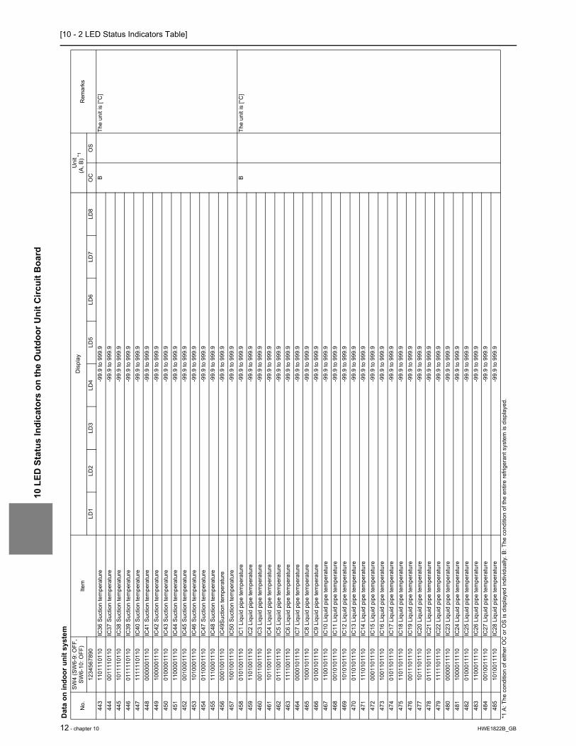
[10 - 2 LED Status Indicators Table]10
LED
Sta
tus
Indi
cato
rs o
n th
e O
utdo
or U
nit C
ircui
t Boa
rd
12 - chapter 10 HWE1822B_GB
443
1101
1101
10IC
36 S
uctio
n te
mpe
ratu
re-9
9.9
to 9
99.9
BTh
e un
it is
[°C
]44
400
1111
0110
IC37
Suc
tion
tem
pera
ture
-99.
9 to
999
.944
510
1111
0110
IC38
Suc
tion
tem
pera
ture
-99.
9 to
999
.944
601
1111
0110
IC39
Suc
tion
tem
pera
ture
-99.
9 to
999
.944
711
1111
0110
IC40
Suc
tion
tem
pera
ture
-99.
9 to
999
.944
800
0000
1110
IC41
Suc
tion
tem
pera
ture
-99.
9 to
999
.944
910
0000
1110
IC42
Suc
tion
tem
pera
ture
-99.
9 to
999
.945
001
0000
1110
IC43
Suc
tion
tem
pera
ture
-99.
9 to
999
.945
111
0000
1110
IC44
Suc
tion
tem
pera
ture
-99.
9 to
999
.945
200
1000
1110
IC45
Suc
tion
tem
pera
ture
-99.
9 to
999
.945
310
1000
1110
IC46
Suc
tion
tem
pera
ture
-99.
9 to
999
.945
401
1000
1110
IC47
Suc
tion
tem
pera
ture
-99.
9 to
999
.945
511
1000
1110
IC48
Suc
tion
tem
pera
ture
-99.
9 to
999
.945
600
0100
1110
IC49
Suct
ion
tem
pera
ture
-99.
9 to
999
.945
710
0100
1110
IC50
Suc
tion
tem
pera
ture
-99.
9 to
999
.945
801
0100
1110
IC1
Liqu
id p
ipe
tem
pera
ture
-99.
9 to
999
.9B
The
unit
is [°
C]
459
1101
0011
10IC
2 Li
quid
pip
e te
mpe
ratu
re-9
9.9
to 9
99.9
460
0011
0011
10IC
3 Li
quid
pip
e te
mpe
ratu
re-9
9.9
to 9
99.9
461
1011
0011
10IC
4 Li
quid
pip
e te
mpe
ratu
re-9
9.9
to 9
99.9
462
0111
0011
10IC
5 Li
quid
pip
e te
mpe
ratu
re-9
9.9
to 9
99.9
463
1111
0011
10IC
6 Li
quid
pip
e te
mpe
ratu
re-9
9.9
to 9
99.9
464
0000
1011
10IC
7 Li
quid
pip
e te
mpe
ratu
re-9
9.9
to 9
99.9
465
1000
1011
10IC
8 Li
quid
pip
e te
mpe
ratu
re-9
9.9
to 9
99.9
466
0100
1011
10IC
9 Li
quid
pip
e te
mpe
ratu
re-9
9.9
to 9
99.9
467
1100
1011
10IC
10 L
iqui
d pi
pe te
mpe
ratu
re-9
9.9
to 9
99.9
468
0010
1011
10IC
11 L
iqui
d pi
pe te
mpe
ratu
re-9
9.9
to 9
99.9
469
1010
1011
10IC
12 L
iqui
d pi
pe te
mpe
ratu
re-9
9.9
to 9
99.9
470
0110
1011
10IC
13 L
iqui
d pi
pe te
mpe
ratu
re-9
9.9
to 9
99.9
471
1110
1011
10IC
14 L
iqui
d pi
pe te
mpe
ratu
re-9
9.9
to 9
99.9
472
0001
1011
10IC
15 L
iqui
d pi
pe te
mpe
ratu
re-9
9.9
to 9
99.9
473
1001
1011
10IC
16 L
iqui
d pi
pe te
mpe
ratu
re-9
9.9
to 9
99.9
474
0101
1011
10IC
17 L
iqui
d pi
pe te
mpe
ratu
re-9
9.9
to 9
99.9
475
1101
1011
10IC
18 L
iqui
d pi
pe te
mpe
ratu
re-9
9.9
to 9
99.9
476
0011
1011
10IC
19 L
iqui
d pi
pe te
mpe
ratu
re-9
9.9
to 9
99.9
477
1011
1011
10IC
20 L
iqui
d pi
pe te
mpe
ratu
re-9
9.9
to 9
99.9
478
0111
1011
10IC
21 L
iqui
d pi
pe te
mpe
ratu
re-9
9.9
to 9
99.9
479
1111
1011
10IC
22 L
iqui
d pi
pe te
mpe
ratu
re-9
9.9
to 9
99.9
480
0000
0111
10IC
23 L
iqui
d pi
pe te
mpe
ratu
re-9
9.9
to 9
99.9
481
1000
0111
10IC
24 L
iqui
d pi
pe te
mpe
ratu
re-9
9.9
to 9
99.9
482
0100
0111
10IC
25 L
iqui
d pi
pe te
mpe
ratu
re-9
9.9
to 9
99.9
483
1100
0111
10IC
26 L
iqui
d pi
pe te
mpe
ratu
re-9
9.9
to 9
99.9
484
0010
0111
10IC
27 L
iqui
d pi
pe te
mpe
ratu
re-9
9.9
to 9
99.9
485
1010
0111
10IC
28 L
iqui
d pi
pe te
mpe
ratu
re-9
9.9
to 9
99.9
Dat
a on
indo
or u
nit s
yste
m
No.
SW4
(SW
6-9:
OFF
, SW
6-10
: OFF
)Ite
mD
ispl
ayU
nit
(A, B
) *1R
emar
ks12
3456
7890
LD1
LD2
LD3
LD4
LD5
LD6
LD7
LD8
OC
OS
*1 A
: The
con
ditio
n of
eith
er O
C o
r OS
is d
ispl
ayed
indi
vidu
ally
. B: T
he c
ondi
tion
of th
e en
tire
refri
gera
nt s
yste
m is
dis
play
ed.

[10 - 2 LED Status Indicators Table]
10 L
ED S
tatu
s In
dica
tors
on
the
Out
door
Uni
t Circ
uit B
oard
HWE1822B_GB chapter 10 - 13
486
0110
0111
10IC
29 L
iqui
d pi
pe te
mpe
ratu
re-9
9.9
to 9
99.9
BTh
e un
it is
[°C
]48
711
1001
1110
IC30
Liq
uid
pipe
tem
pera
ture
-99.
9 to
999
.948
800
0101
1110
IC31
Liq
uid
pipe
tem
pera
ture
-99.
9 to
999
.948
910
0101
1110
IC32
Liq
uid
pipe
tem
pera
ture
-99.
9 to
999
.949
001
0101
1110
IC33
Liq
uid
pipe
tem
pera
ture
-99.
9 to
999
.949
111
0101
1110
IC34
Liq
uid
pipe
tem
pera
ture
-99.
9 to
999
.949
200
1101
1110
IC35
Liq
uid
pipe
tem
pera
ture
-99.
9 to
999
.949
310
1101
1110
IC36
Liq
uid
pipe
tem
pera
ture
-99.
9 to
999
.949
401
1101
1110
IC37
Liq
uid
pipe
tem
pera
ture
-99.
9 to
999
.949
511
1101
1110
IC38
Liq
uid
pipe
tem
pera
ture
-99.
9 to
999
.949
600
0011
1110
IC39
Liq
uid
pipe
tem
pera
ture
-99.
9 to
999
.949
710
0011
1110
IC40
Liq
uid
pipe
tem
pera
ture
-99.
9 to
999
.949
801
0011
1110
IC41
Liq
uid
pipe
tem
pera
ture
-99.
9 to
999
.949
911
0011
1110
IC42
Liq
uid
pipe
tem
pera
ture
-99.
9 to
999
.950
000
1011
1110
IC43
Liq
uid
pipe
tem
pera
ture
-99.
9 to
999
.950
110
1011
1110
IC44
Liq
uid
pipe
tem
pera
ture
-99.
9 to
999
.950
201
1011
1110
IC45
Liq
uid
pipe
tem
pera
ture
-99.
9 to
999
.950
311
1011
1110
IC46
Liq
uid
pipe
tem
pera
ture
-99.
9 to
999
.950
400
0111
1110
IC47
Liq
uid
pipe
tem
pera
ture
-99.
9 to
999
.950
510
0111
1110
IC48
Liq
uid
pipe
tem
pera
ture
-99.
9 to
999
.950
601
0111
1110
IC49
Liq
uid
pipe
tem
pera
ture
-99.
9 to
999
.950
711
0111
1110
IC50
Liq
uid
pipe
tem
pera
ture
-99.
9 to
999
.9
Dat
a on
indo
or u
nit s
yste
m
No.
SW4
(SW
6-9:
OFF
, SW
6-10
: OFF
)Ite
mD
ispl
ayU
nit
(A, B
) *1R
emar
ks12
3456
7890
LD1
LD2
LD3
LD4
LD5
LD6
LD7
LD8
OC
OS
*1 A
: The
con
ditio
n of
eith
er O
C o
r OS
is d
ispl
ayed
indi
vidu
ally
. B: T
he c
ondi
tion
of th
e en
tire
refri
gera
nt s
yste
m is
dis
play
ed.

[10 - 2 LED Status Indicators Table]10
LED
Sta
tus
Indi
cato
rs o
n th
e O
utdo
or U
nit C
ircui
t Boa
rd
14 - chapter 10 HWE1822B_GB
Setti
ng d
ata
No.
SW4
(SW
6-9:
OFF
, SW
6-10
: OFF
)Ite
mD
ispl
ayU
nit
(A, B
)*1R
emar
ks12
3456
7890
LD1
LD2
LD3
LD4
LD5
LD6
LD7
LD8
OC
OS
512
0000
0000
01Se
lf-ad
dres
sAl
tern
ate
disp
lay
of s
elf a
ddre
ss a
nd u
nit m
odel
AA
513
1000
0000
01IC
/FU
add
ress
Cou
nt-u
p di
spla
y of
num
ber o
f con
nect
ed u
nits
B51
401
0000
0001
RC
add
ress
Cou
nt-u
p di
spla
y of
num
ber o
f con
nect
ed u
nits
B51
511
0000
0001
BC/B
S/TU
add
ress
Cou
nt-u
p di
spla
y of
num
ber o
f con
nect
ed u
nits
516
0010
0000
01O
S ad
dres
sC
ount
-up
disp
lay
of n
umbe
r of c
onne
cted
uni
tsB
517
1010
0000
01Ve
rsio
n/C
apac
ityS/
W v
ersi
on →
Ref
riger
ant t
ype →
Mod
el a
nd c
apac
ity →
Com
mun
icat
ion
addr
ess
AA
518
0110
0000
01O
C a
ddre
ssO
C a
ddre
ss d
ispl
ayB
*1 A
: The
con
ditio
n of
eith
er O
C o
r OS
is d
ispl
ayed
indi
vidu
ally
. B: T
he c
ondi
tion
of th
e en
tire
refri
gera
nt s
yste
m is
dis
play
ed.

[10 - 2 LED Status Indicators Table]
10 L
ED S
tatu
s In
dica
tors
on
the
Out
door
Uni
t Circ
uit B
oard
HWE1822B_GB chapter 10 - 15
Dat
a on
indo
or u
nit s
yste
m
No.
SW4
(SW
6-9:
OFF
, SW
6-10
: OFF
)Ite
mD
ispl
ayU
nit
(A, B
) *1R
emar
ks12
3456
7890
LD1
LD2
LD3
LD4
LD5
LD6
LD7
LD8
OC
OS
523
1101
0000
01IC
1 G
as p
ipe
tem
pera
ture
-99.
9 to
999
.9B
The
unit
is [°
C]
524
0011
0000
01IC
2 G
as p
ipe
tem
pera
ture
-99.
9 to
999
.952
510
1100
0001
IC3
Gas
pip
e te
mpe
ratu
re-9
9.9
to 9
99.9
526
0111
0000
01IC
4 G
as p
ipe
tem
pera
ture
-99.
9 to
999
.952
711
1100
0001
IC5
Gas
pip
e te
mpe
ratu
re-9
9.9
to 9
99.9
528
0000
1000
01
IC6
Gas
pip
e te
mpe
ratu
re-9
9.9
to 9
99.9
529
1000
1000
01
IC7
Gas
pip
e te
mpe
ratu
re-9
9.9
to 9
99.9
530
0100
1000
01
IC8
Gas
pip
e te
mpe
ratu
re-9
9.9
to 9
99.9
531
1100
1000
01
IC9
Gas
pip
e te
mpe
ratu
re-9
9.9
to 9
99.9
532
0010
1000
01
IC10
Gas
pip
e te
mpe
ratu
re-9
9.9
to 9
99.9
533
1010
1000
01
IC11
Gas
pip
e te
mpe
ratu
re-9
9.9
to 9
99.9
534
0110
1000
01
IC12
Gas
pip
e te
mpe
ratu
re-9
9.9
to 9
99.9
535
1110
1000
01
IC13
Gas
pip
e te
mpe
ratu
re-9
9.9
to 9
99.9
536
0001
1000
01
IC14
Gas
pip
e te
mpe
ratu
re-9
9.9
to 9
99.9
537
1001
1000
01
IC15
Gas
pip
e te
mpe
ratu
re-9
9.9
to 9
99.9
538
0101
1000
01
IC16
Gas
pip
e te
mpe
ratu
re-9
9.9
to 9
99.9
539
1101
1000
01
IC17
Gas
pip
e te
mpe
ratu
re-9
9.9
to 9
99.9
540
0011
1000
01
IC18
Gas
pip
e te
mpe
ratu
re-9
9.9
to 9
99.9
541
1011
1000
01
IC19
Gas
pip
e te
mpe
ratu
re-9
9.9
to 9
99.9
542
0111
1000
01
IC20
Gas
pip
e te
mpe
ratu
re-9
9.9
to 9
99.9
543
1111
1000
01
IC21
Gas
pip
e te
mpe
ratu
re-9
9.9
to 9
99.9
544
0000
0100
01
IC22
Gas
pip
e te
mpe
ratu
re-9
9.9
to 9
99.9
545
1000
0100
01
IC23
Gas
pip
e te
mpe
ratu
re-9
9.9
to 9
99.9
546
0100
0100
01
IC24
Gas
pip
e te
mpe
ratu
re-9
9.9
to 9
99.9
547
1100
0100
01
IC25
Gas
pip
e te
mpe
ratu
re-9
9.9
to 9
99.9
548
0010
0100
01
IC26
Gas
pip
e te
mpe
ratu
re-9
9.9
to 9
99.9
549
1010
0100
01
IC27
Gas
pip
e te
mpe
ratu
re-9
9.9
to 9
99.9
550
0110
0100
01
IC28
Gas
pip
e te
mpe
ratu
re-9
9.9
to 9
99.9
551
1110
0100
01
IC29
Gas
pip
e te
mpe
ratu
re-9
9.9
to 9
99.9
552
0001
0100
01
IC30
Gas
pip
e te
mpe
ratu
re-9
9.9
to 9
99.9
553
1001
0100
01
IC31
Gas
pip
e te
mpe
ratu
re-9
9.9
to 9
99.9
554
0101
0100
01
IC32
Gas
pip
e te
mpe
ratu
re-9
9.9
to 9
99.9
555
1101
0100
01
IC33
Gas
pip
e te
mpe
ratu
re-9
9.9
to 9
99.9
556
0011
0100
01
IC34
Gas
pip
e te
mpe
ratu
re-9
9.9
to 9
99.9
557
1011
0100
01
IC35
Gas
pip
e te
mpe
ratu
re-9
9.9
to 9
99.9
558
0111
0100
01
IC36
Gas
pip
e te
mpe
ratu
re-9
9.9
to 9
99.9
559
1111
0100
01
IC37
Gas
pip
e te
mpe
ratu
re-9
9.9
to 9
99.9
560
0000
1100
01
IC38
Gas
pip
e te
mpe
ratu
re-9
9.9
to 9
99.9
561
1000
1100
01
IC39
Gas
pip
e te
mpe
ratu
re-9
9.9
to 9
99.9
562
0100
1100
01
IC40
Gas
pip
e te
mpe
ratu
re-9
9.9
to 9
99.9
563
1100
1100
01
IC41
Gas
pip
e te
mpe
ratu
re-9
9.9
to 9
99.9
564
0010
1100
01
IC42
Gas
pip
e te
mpe
ratu
re-9
9.9
to 9
99.9
*1 A
: The
con
ditio
n of
eith
er O
C o
r OS
is d
ispl
ayed
indi
vidu
ally
. B: T
he c
ondi
tion
of th
e en
tire
refri
gera
nt s
yste
m is
dis
play
ed.

[10 - 2 LED Status Indicators Table]10
LED
Sta
tus
Indi
cato
rs o
n th
e O
utdo
or U
nit C
ircui
t Boa
rd
16 - chapter 10 HWE1822B_GB
565
1010
1100
01
IC43
Gas
pip
e te
mpe
ratu
re-9
9.9
to 9
99.9
BTh
e un
it is
[°C
]56
601
1011
0001
IC
44 G
as p
ipe
tem
pera
ture
-99.
9 to
999
.956
711
1011
0001
IC45
Gas
pip
e te
mpe
ratu
re-9
9.9
to 9
99.9
568
0001
1100
01IC
46 G
as p
ipe
tem
pera
ture
-99.
9 to
999
.956
910
0111
0001
IC47
Gas
pip
e te
mpe
ratu
re-9
9.9
to 9
99.9
570
0101
1100
01IC
48 G
as p
ipe
tem
pera
ture
-99.
9 to
999
.957
111
0111
0001
IC49
Gas
pip
e te
mpe
ratu
re-9
9.9
to 9
99.9
572
0011
1100
01IC
50 G
as p
ipe
tem
pera
ture
-99.
9 to
999
.957
310
1111
0001
IC1S
H-9
9.9
to 9
99.9
BTh
e un
it is
[°C
]57
401
1111
0001
IC2S
H-9
9.9
to 9
99.9
575
1111
1100
01IC
3SH
-99.
9 to
999
.957
600
0000
1001
IC4S
H-9
9.9
to 9
99.9
577
1000
0010
01IC
5SH
-99.
9 to
999
.957
801
0000
1001
IC6S
H-9
9.9
to 9
99.9
579
1100
0010
01IC
7SH
-99.
9 to
999
.958
000
1000
1001
IC8S
H-9
9.9
to 9
99.9
581
1010
0010
01IC
9SH
-99.
9 to
999
.958
201
1000
1001
IC10
SH-9
9.9
to 9
99.9
583
1110
0010
01IC
11SH
-99.
9 to
999
.958
400
0100
1001
IC12
SH-9
9.9
to 9
99.9
585
1001
0010
01IC
13SH
-99.
9 to
999
.958
601
0100
1001
IC14
SH-9
9.9
to 9
99.9
587
1101
0010
01IC
15SH
-99.
9 to
999
.958
800
1100
1001
IC16
SH-9
9.9
to 9
99.9
589
1011
0010
01IC
17SH
-99.
9 to
999
.959
001
1100
1001
IC18
SH-9
9.9
to 9
99.9
591
1111
0010
01IC
19SH
-99.
9 to
999
.959
200
0010
1001
IC20
SH-9
9.9
to 9
99.9
593
1000
1010
01IC
21SH
-99.
9 to
999
.959
401
0010
1001
IC22
SH-9
9.9
to 9
99.9
595
1100
1010
01IC
23SH
-99.
9 to
999
.959
600
1010
1001
IC24
SH-9
9.9
to 9
99.9
597
1010
1010
01IC
25SH
-99.
9 to
999
.959
801
1010
1001
IC26
SH-9
9.9
to 9
99.9
599
1110
1010
01IC
27SH
-99.
9 to
999
.960
000
0110
1001
IC28
SH-9
9.9
to 9
99.9
601
1001
1010
01IC
29SH
-99.
9 to
999
.960
201
0110
1001
IC30
SH-9
9.9
to 9
99.9
603
1101
1010
01IC
31SH
-99.
9 to
999
.960
400
1110
1001
IC32
SH-9
9.9
to 9
99.9
605
1011
1010
01IC
33SH
-99.
9 to
999
.960
601
1110
1001
IC34
SH-9
9.9
to 9
99.9
607
1111
1010
01IC
35SH
-99.
9 to
999
.9
Dat
a on
indo
or u
nit s
yste
m
No.
SW4
(SW
6-9:
OFF
, SW
6-10
: OFF
)Ite
mD
ispl
ayU
nit
(A, B
) *1R
emar
ks12
3456
7890
LD1
LD2
LD3
LD4
LD5
LD6
LD7
LD8
OC
OS
*1 A
: The
con
ditio
n of
eith
er O
C o
r OS
is d
ispl
ayed
indi
vidu
ally
. B: T
he c
ondi
tion
of th
e en
tire
refri
gera
nt s
yste
m is
dis
play
ed.

[10 - 2 LED Status Indicators Table]
10 L
ED S
tatu
s In
dica
tors
on
the
Out
door
Uni
t Circ
uit B
oard
HWE1822B_GB chapter 10 - 17
608
0000
0110
01IC
36SH
-99.
9 to
999
.9B
The
unit
is [°
C]
609
1000
0110
01IC
37SH
-99.
9 to
999
.961
001
0001
1001
IC38
SH-9
9.9
to 9
99.9
611
1100
0110
01
IC39
SH-9
9.9
to 9
99.9
612
0010
0110
01
IC40
SH-9
9.9
to 9
99.9
613
1010
0110
01
IC41
SH-9
9.9
to 9
99.9
614
0110
0110
01
IC42
SH-9
9.9
to 9
99.9
615
1110
0110
01
IC43
SH-9
9.9
to 9
99.9
616
0001
0110
01
IC44
SH-9
9.9
to 9
99.9
617
1001
0110
01
IC45
SH-9
9.9
to 9
99.9
618
0101
0110
01
IC46
SH-9
9.9
to 9
99.9
619
1101
0110
01
IC47
SH-9
9.9
to 9
99.9
620
0011
0110
01
IC48
SH-9
9.9
to 9
99.9
621
1011
0110
01
IC49
SH-9
9.9
to 9
99.9
622
0111
0110
01
IC50
SH-9
9.9
to 9
99.9
623
1111
0110
01
IC1S
C-9
9.9
to 9
99.9
BTh
e un
it is
[°C
]62
400
0011
1001
IC
2SC
-99.
9 to
999
.962
510
0011
1001
IC
3SC
-99.
9 to
999
.962
601
0011
1001
IC
4SC
-99.
9 to
999
.962
711
0011
1001
IC
5SC
-99.
9 to
999
.962
800
1011
1001
IC
6SC
-99.
9 to
999
.962
910
1011
1001
IC
7SC
-99.
9 to
999
.963
001
1011
1001
IC
8SC
-99.
9 to
999
.963
111
1011
1001
IC
9SC
-99.
9 to
999
.963
200
0111
1001
IC
10SC
-99.
9 to
999
.963
310
0111
1001
IC
11SC
-99.
9 to
999
.963
401
0111
1001
IC
12SC
-99.
9 to
999
.963
511
0111
1001
IC
13SC
-99.
9 to
999
.963
600
1111
1001
IC
14SC
-99.
9 to
999
.963
710
1111
1001
IC
15SC
-99.
9 to
999
.963
801
1111
1001
IC
16SC
-99.
9 to
999
.963
911
1111
1001
IC
17SC
-99.
9 to
999
.964
000
0000
0101
IC
18SC
-99.
9 to
999
.964
110
0000
0101
IC
19SC
-99.
9 to
999
.964
201
0000
0101
IC
20SC
-99.
9 to
999
.964
311
0000
0101
IC
21SC
-99.
9 to
999
.964
400
1000
0101
IC
22SC
-99.
9 to
999
.964
510
1000
0101
IC
23SC
-99.
9 to
999
.964
601
1000
0101
IC
24SC
-99.
9 to
999
.964
711
1000
0101
IC
25SC
-99.
9 to
999
.964
800
0100
0101
IC
26SC
-99.
9 to
999
.964
910
0100
0101
IC
27SC
-99.
9 to
999
.965
001
0100
0101
IC
28SC
-99.
9 to
999
.9
Dat
a on
indo
or u
nit s
yste
m
No.
SW4
(SW
6-9:
OFF
, SW
6-10
: OFF
)Ite
mD
ispl
ayU
nit
(A, B
) *1R
emar
ks12
3456
7890
LD1
LD2
LD3
LD4
LD5
LD6
LD7
LD8
OC
OS
*1 A
: The
con
ditio
n of
eith
er O
C o
r OS
is d
ispl
ayed
indi
vidu
ally
. B: T
he c
ondi
tion
of th
e en
tire
refri
gera
nt s
yste
m is
dis
play
ed.

[10 - 2 LED Status Indicators Table]10
LED
Sta
tus
Indi
cato
rs o
n th
e O
utdo
or U
nit C
ircui
t Boa
rd
18 - chapter 10 HWE1822B_GB
651
1101
0001
01
IC29
SC-9
9.9
to 9
99.9
BTh
e un
it is
[°C
]65
200
1100
0101
IC
30SC
-99.
9 to
999
.965
310
1100
0101
IC31
SC-9
9.9
to 9
99.9
654
0111
0001
01
IC32
SC-9
9.9
to 9
99.9
655
1111
0001
01
IC33
SC-9
9.9
to 9
99.9
656
0000
1001
01
IC34
SC-9
9.9
to 9
99.9
657
1000
1001
01
IC35
SC-9
9.9
to 9
99.9
658
0100
1001
01
IC36
SC-9
9.9
to 9
99.9
659
1100
1001
01
IC37
SC-9
9.9
to 9
99.9
660
0010
1001
01
IC38
SC-9
9.9
to 9
99.9
661
1010
1001
01
IC39
SC-9
9.9
to 9
99.9
662
0110
1001
01
IC40
SC-9
9.9
to 9
99.9
663
1110
1001
01
IC41
SC-9
9.9
to 9
99.9
664
0001
1001
01
IC42
SC-9
9.9
to 9
99.9
665
1001
1001
01
IC43
SC-9
9.9
to 9
99.9
666
0101
1001
01
IC44
SC-9
9.9
to 9
99.9
667
1101
1001
01
IC45
SC-9
9.9
to 9
99.9
668
0011
1001
01
IC46
SC-9
9.9
to 9
99.9
669
1011
1001
01
IC47
SC-9
9.9
to 9
99.9
670
0111
1001
01
IC48
SC-9
9.9
to 9
99.9
671
1111
1001
01
IC49
SC-9
9.9
to 9
99.9
672
0000
0101
01
IC50
SC-9
9.9
to 9
99.9
Dat
a on
indo
or u
nit s
yste
m
No.
SW4
(SW
6-9:
OFF
, SW
6-10
: OFF
)Ite
mD
ispl
ayU
nit
(A, B
) *1R
emar
ks12
3456
7890
LD1
LD2
LD3
LD4
LD5
LD6
LD7
LD8
OC
OS
*1 A
: The
con
ditio
n of
eith
er O
C o
r OS
is d
ispl
ayed
indi
vidu
ally
. B: T
he c
ondi
tion
of th
e en
tire
refri
gera
nt s
yste
m is
dis
play
ed.

[10 - 2 LED Status Indicators Table]
10 L
ED S
tatu
s In
dica
tors
on
the
Out
door
Uni
t Circ
uit B
oard
HWE1822B_GB chapter 10 - 19
Setti
ng d
ata
No.
SW4
(SW
6-9:
OFF
, SW
6-10
: OFF
)Ite
mD
ispl
ayU
nit
(A, B
)* 1R
emar
ks12
3456
7890
LD1
LD2
LD3
LD4
LD5
LD6
LD7
LD8
OC
OS
676
0010
0101
01
INV
boar
d S/
W v
ersi
on0.
00 to
99.
99A
A67
911
1001
0101
Fa
n bo
ard
(add
ress
5) S
/W v
ersi
on0.
00 to
99.
99A
A68
000
0101
0101
Fa
n bo
ard
(add
ress
6) S
/W v
ersi
on0.
00 to
99.
99A
A68
800
0011
0101
C
urre
nt ti
me
00:0
0 to
23:
59A
AH
our:
min
ute
689
1000
1101
01
Cur
rent
tim
e -2
00.0
0 to
99.
12/1
to 3
1Ye
ar a
nd m
onth
, and
dat
e al
ter-
nate
dis
play
690
0100
1101
01
Tim
e of
erro
r det
ectio
n 1
00:0
0 to
23:
59H
our:
min
ute
691
1100
1101
01
Tim
e of
erro
r det
ectio
n 1-
200
.00
to 9
9.12
/1 to
31
Year
and
mon
th, a
nd d
ate
alte
r-na
te d
ispl
ay69
200
1011
0101
Ti
me
of e
rror d
etec
tion
200
:00
to 2
3:59
Hou
r: m
inut
e
693
1010
1101
01
Tim
e of
erro
r det
ectio
n 2-
200
.00
to 9
9.12
/1 to
31
Year
and
mon
th, a
nd d
ate
alte
r-na
te d
ispl
ay69
401
1011
0101
Ti
me
of e
rror d
etec
tion
300
:00
to 2
3:59
Hou
r: m
inut
e
695
1110
1101
01Ti
me
of e
rror d
etec
tion
3-2
00.0
0 to
99.
12/1
to 3
1Ye
ar a
nd m
onth
, and
dat
e al
ter-
nate
dis
play
696
0001
1101
01
Tim
e of
erro
r det
ectio
n 4
00:0
0 to
23:
59H
our:
min
ute
697
1001
1101
01
Tim
e of
erro
r det
ectio
n 4-
200
.00
to 9
9.12
/1 to
31
Year
and
mon
th, a
nd d
ate
alte
r-na
te d
ispl
ay69
801
0111
0101
Ti
me
of e
rror d
etec
tion
500
:00
to 2
3:59
Hou
r: m
inut
e
699
1101
1101
01
Tim
e of
erro
r det
ectio
n 5-
200
.00
to 9
9.12
/1 to
31
Year
and
mon
th, a
nd d
ate
alte
r-na
te d
ispl
ay70
000
1111
0101
Ti
me
of e
rror d
etec
tion
600
:00
to 2
3:59
Hou
r: m
inut
e
701
1011
1101
01
Tim
e of
erro
r det
ectio
n 6-
200
.00
to 9
9.12
/1 to
31
Year
and
mon
th, a
nd d
ate
alte
r-na
te d
ispl
ay70
201
1111
0101
Ti
me
of e
rror d
etec
tion
700
:00
to 2
3:59
AA
Hou
r: m
inut
e
703
1111
1101
01
Tim
e of
erro
r det
ectio
n 7-
200
.00
to 9
9.12
/1 to
31
Year
and
mon
th, a
nd d
ate
alte
r-na
te d
ispl
ay70
400
0000
1101
Ti
me
of e
rror d
etec
tion
800
:00
to 2
3:59
Hou
r: m
inut
e
705
1000
0011
01
Tim
e of
erro
r det
ectio
n 8-
200
.00
to 9
9.12
/1 to
31
Year
and
mon
th, a
nd d
ate
alte
r-na
te d
ispl
ay70
601
0000
1101
Ti
me
of e
rror d
etec
tion
900
:00
to 2
3:59
Hou
r: m
inut
e
707
1100
0011
01
Tim
e of
erro
r det
ectio
n 9-
200
.00
to 9
9.12
/1 to
31
Year
and
mon
th, a
nd d
ate
alte
r-na
te d
ispl
ay70
800
1000
1101
Ti
me
of e
rror d
etec
tion
1000
:00
to 2
3:59
Hou
r: m
inut
e
709
1010
0011
01
Tim
e of
erro
r det
ectio
n 10
-200
.00
to 9
9.12
/1 to
31
Year
and
mon
th, a
nd d
ate
alte
r-na
te d
ispl
ay
710
0110
0011
01
Tim
e of
last
dat
a ba
ckup
bef
ore
er-
ror
00:0
0 to
23:
59H
our:
min
ute
711
1110
0011
01
Tim
e of
last
dat
a ba
ckup
bef
ore
er-
ror -
200
.00
to 9
9.12
/1 to
31
Year
and
mon
th, a
nd d
ate
alte
r-na
te d
ispl
ay*1
A: T
he c
ondi
tion
of e
ither
OC
or O
S is
dis
play
ed in
divi
dual
ly. B
: The
con
ditio
n of
the
entir
e re
frige
rant
sys
tem
is d
ispl
ayed
.

[10 - 2 LED Status Indicators Table]10
LED
Sta
tus
Indi
cato
rs o
n th
e O
utdo
or U
nit C
ircui
t Boa
rd
20 - chapter 10 HWE1822B_GB
Dat
a on
indo
or u
nit s
yste
m
No.
SW4
(SW
6-9:
OFF
, SW
6-10
: OFF
)Ite
mD
ispl
ayU
nit
(A, B
)* 1R
emar
ks12
3456
7890
LD1
LD2
LD3
LD4
LD5
LD6
LD7
LD8
OC
OS
714
0101
0011
01
IC1
LEV
open
ing
0000
to 9
999
BFu
lly o
pen:
200
071
511
0100
1101
IC
2 LE
V op
enin
g00
00 to
999
971
600
1100
1101
IC
3 LE
V op
enin
g00
00 to
999
971
710
1100
1101
IC
4 LE
V op
enin
g00
00 to
999
971
801
1100
1101
IC
5 LE
V op
enin
g00
00 to
999
971
911
1100
1101
IC
6 LE
V op
enin
g00
00 to
999
972
000
0010
1101
IC
7 LE
V op
enin
g00
00 to
999
972
110
0010
1101
IC
8 LE
V op
enin
g00
00 to
999
972
201
0010
1101
IC
9 LE
V op
enin
g00
00 to
999
972
311
0010
1101
IC
10 L
EV o
peni
ng00
00 to
999
972
400
1010
1101
IC
11 L
EV o
peni
ng00
00 to
999
972
510
1010
1101
IC
12 L
EV o
peni
ng00
00 to
999
972
601
1010
1101
IC
13 L
EV o
peni
ng00
00 to
999
972
711
1010
1101
IC
14 L
EV o
peni
ng00
00 to
999
972
800
0110
1101
IC
15 L
EV o
peni
ng00
00 to
999
972
910
0110
1101
IC
16 L
EV o
peni
ng00
00 to
999
973
001
0110
1101
IC
17 L
EV o
peni
ng00
00 to
999
973
111
0110
1101
IC
18 L
EV o
peni
ng00
00 to
999
973
200
1110
1101
IC
19 L
EV o
peni
ng00
00 to
999
973
310
1110
1101
IC
20 L
EV o
peni
ng00
00 to
999
973
401
1110
1101
IC
21 L
EV o
peni
ng00
00 to
999
973
511
1110
1101
IC
22 L
EV o
peni
ng00
00 to
999
973
600
0001
1101
IC
23 L
EV o
peni
ng00
00 to
999
973
710
0001
1101
IC
24 L
EV o
peni
ng00
00 to
999
973
801
0001
1101
IC
25 L
EV o
peni
ng00
00 to
999
973
911
0001
1101
IC
26 L
EV o
peni
ng00
00 to
999
974
000
1001
1101
IC
27 L
EV o
peni
ng00
00 to
999
974
110
1001
1101
IC
28 L
EV o
peni
ng00
00 to
999
974
201
1001
1101
IC
29 L
EV o
peni
ng00
00 to
999
974
311
1001
1101
IC
30 L
EV o
peni
ng00
00 to
999
974
400
0101
1101
IC
31 L
EV o
peni
ng00
00 to
999
974
510
0101
1101
IC
32 L
EV o
peni
ng00
00 to
999
974
601
0101
1101
IC
33 L
EV o
peni
ng00
00 to
999
974
711
0101
1101
IC
34 L
EV o
peni
ng00
00 to
999
974
800
1101
1101
IC
35 L
EV o
peni
ng00
00 to
999
974
910
1101
1101
IC
36 L
EV o
peni
ng00
00 to
999
975
001
1101
1101
IC
37 L
EV o
peni
ng00
00 to
999
975
111
1101
1101
IC
38 L
EV o
peni
ng00
00 to
999
975
200
0011
1101
IC
39 L
EV o
peni
ng00
00 to
999
975
310
0011
1101
IC
40 L
EV o
peni
ng00
00 to
999
975
401
0011
1101
IC
41 L
EV o
peni
ng00
00 to
999
975
511
0011
1101
IC
42 L
EV o
peni
ng00
00 to
999
9*1
A: T
he c
ondi
tion
of e
ither
OC
or O
S is
dis
play
ed in
divi
dual
ly. B
: The
con
ditio
n of
the
entir
e re
frige
rant
sys
tem
is d
ispl
ayed
.

[10 - 2 LED Status Indicators Table]
10 L
ED S
tatu
s In
dica
tors
on
the
Out
door
Uni
t Circ
uit B
oard
HWE1822B_GB chapter 10 - 21
756
0010
1111
01
IC43
LEV
ope
ning
0000
to 9
999
BFu
lly o
pen:
200
075
710
1011
1101
IC
44 L
EV o
peni
ng00
00 to
999
975
801
1011
1101
IC
45 L
EV o
peni
ng00
00 to
999
975
911
1011
1101
IC
46 L
EV o
peni
ng00
00 to
999
976
000
0111
1101
IC
47 L
EV o
peni
ng00
00 to
999
976
110
0111
1101
IC
48 L
EV o
peni
ng00
00 to
999
976
201
0111
1101
IC
49 L
EV o
peni
ng00
00 to
999
976
311
0111
1101
IC
50 L
EV o
peni
ng00
00 to
999
976
400
1111
1101
IC
1 O
pera
tion
mod
e
0000
: Sto
p 00
01: V
entil
atio
n 00
02: C
oolin
g 00
03: H
eatin
g 00
04: D
ry
B76
510
1111
1101
IC
2 O
pera
tion
mod
e76
601
1111
1101
IC
3 O
pera
tion
mod
e76
711
1111
1101
IC
4 O
pera
tion
mod
e76
800
0000
0011
IC
5 O
pera
tion
mod
e76
910
0000
0011
IC
6 O
pera
tion
mod
e77
001
0000
0011
IC
7 O
pera
tion
mod
e77
111
0000
0011
IC
8 O
pera
tion
mod
e77
200
1000
0011
IC
9 O
pera
tion
mod
e77
310
1000
0011
IC
10 O
pera
tion
mod
e77
401
1000
0011
IC
11 O
pera
tion
mod
e77
511
1000
0011
IC
12 O
pera
tion
mod
e77
600
0100
0011
IC
13 O
pera
tion
mod
e77
710
0100
0011
IC
14 O
pera
tion
mod
e77
801
0100
0011
IC
15 O
pera
tion
mod
e77
911
0100
0011
IC
16 O
pera
tion
mod
e78
000
1100
0011
IC
17 O
pera
tion
mod
e78
110
1100
0011
IC
18 O
pera
tion
mod
e78
201
1100
0011
IC
19 O
pera
tion
mod
e78
311
1100
0011
IC
20 O
pera
tion
mod
e78
400
0010
0011
IC
21 O
pera
tion
mod
e78
510
0010
0011
IC
22 O
pera
tion
mod
e78
601
0010
0011
IC
23 O
pera
tion
mod
e78
711
0010
0011
IC
24 O
pera
tion
mod
e78
800
1010
0011
IC
25 O
pera
tion
mod
e78
910
1010
0011
IC
26 O
pera
tion
mod
e79
001
1010
0011
IC
27 O
pera
tion
mod
e79
111
1010
0011
IC
28 O
pera
tion
mod
e79
200
0110
0011
IC
29 O
pera
tion
mod
e79
310
0110
0011
IC
30 O
pera
tion
mod
e79
401
0110
0011
IC
31 O
pera
tion
mod
e79
511
0110
0011
IC
32 O
pera
tion
mod
e79
600
1110
0011
IC
33 O
pera
tion
mod
e
Dat
a on
indo
or u
nit s
yste
m
No.
SW4
(SW
6-9:
OFF
, SW
6-10
: OFF
)Ite
mD
ispl
ayU
nit
(A, B
)* 1R
emar
ks12
3456
7890
LD1
LD2
LD3
LD4
LD5
LD6
LD7
LD8
OC
OS
*1 A
: The
con
ditio
n of
eith
er O
C o
r OS
is d
ispl
ayed
indi
vidu
ally
. B: T
he c
ondi
tion
of th
e en
tire
refri
gera
nt s
yste
m is
dis
play
ed.

[10 - 2 LED Status Indicators Table]10
LED
Sta
tus
Indi
cato
rs o
n th
e O
utdo
or U
nit C
ircui
t Boa
rd
22 - chapter 10 HWE1822B_GB
797
1011
1000
11
IC34
Ope
ratio
n m
ode
0000
: Sto
p 00
01: V
entil
atio
n 00
02: C
oolin
g 00
03: H
eatin
g 00
04: D
ry
B79
801
1110
0011
IC
35 O
pera
tion
mod
e79
911
1110
0011
IC
36 O
pera
tion
mod
e80
000
0001
0011
IC
37 O
pera
tion
mod
e80
110
0001
0011
IC
38 O
pera
tion
mod
e80
201
0001
0011
IC
39 O
pera
tion
mod
e80
311
0001
0011
IC
40 O
pera
tion
mod
e80
400
1001
0011
IC
41 O
pera
tion
mod
e80
510
1001
0011
IC
42 O
pera
tion
mod
e80
601
1001
0011
IC
43 O
pera
tion
mod
e80
711
1001
0011
IC
44 O
pera
tion
mod
e80
800
0101
0011
IC
45 O
pera
tion
mod
e80
910
0101
0011
IC
46 O
pera
tion
mod
e81
001
0101
0011
IC
47 O
pera
tion
mod
e81
111
0101
0011
IC
48 O
pera
tion
mod
e81
200
1101
0011
IC
49 O
pera
tion
mod
e81
310
1101
0011
IC
50 O
pera
tion
mod
e81
401
1101
0011
IC
1 fil
ter
0000
to 9
999
BH
ours
sin
ce la
st m
aint
enan
ce
[ h ]
815
1111
0100
11IC
2 fil
ter
0000
to 9
999
816
0000
1100
11IC
3 fil
ter
0000
to 9
999
817
1000
1100
11IC
4 fil
ter
0000
to 9
999
818
0100
1100
11IC
5 fil
ter
0000
to 9
999
819
1100
1100
11IC
6 fil
ter
0000
to 9
999
820
0010
1100
11IC
7 fil
ter
0000
to 9
999
821
1010
1100
11IC
8 fil
ter
0000
to 9
999
822
0110
1100
11IC
9 fil
ter
0000
to 9
999
823
1110
1100
11IC
10 fi
lter
0000
to 9
999
824
0001
1100
11IC
11 fi
lter
0000
to 9
999
825
1001
1100
11IC
12 fi
lter
0000
to 9
999
826
0101
1100
11IC
13 fi
lter
0000
to 9
999
827
1101
1100
11IC
14 fi
lter
0000
to 9
999
828
0011
1100
11IC
15 fi
lter
0000
to 9
999
829
1011
1100
11IC
16 fi
lter
0000
to 9
999
830
0111
1100
11IC
17 fi
lter
0000
to 9
999
831
1111
1100
11IC
18 fi
lter
0000
to 9
999
832
0000
0010
11IC
19 fi
lter
0000
to 9
999
833
1000
0010
11IC
20 fi
lter
0000
to 9
999
834
0100
0010
11IC
21 fi
lter
0000
to 9
999
835
1100
0010
11IC
22 fi
lter
0000
to 9
999
836
0010
0010
11IC
23 fi
lter
0000
to 9
999
837
1010
0010
11IC
24 fi
lter
0000
to 9
999
838
0110
0010
11IC
25 fi
lter
0000
to 9
999
839
1110
0010
11IC
26 fi
lter
0000
to 9
999
Dat
a on
indo
or u
nit s
yste
m
No.
SW4
(SW
6-9:
OFF
, SW
6-10
: OFF
)Ite
mD
ispl
ayU
nit
(A, B
)* 1R
emar
ks12
3456
7890
LD1
LD2
LD3
LD4
LD5
LD6
LD7
LD8
OC
OS
*1 A
: The
con
ditio
n of
eith
er O
C o
r OS
is d
ispl
ayed
indi
vidu
ally
. B: T
he c
ondi
tion
of th
e en
tire
refri
gera
nt s
yste
m is
dis
play
ed.

[10 - 2 LED Status Indicators Table]
10 L
ED S
tatu
s In
dica
tors
on
the
Out
door
Uni
t Circ
uit B
oard
HWE1822B_GB chapter 10 - 23
840
0001
0010
11IC
27 fi
lter
0000
to 9
999
BH
ours
sin
ce la
st m
aint
enan
ce
[ h ]
841
1001
0010
11IC
28 fi
lter
0000
to 9
999
842
0101
0010
11IC
29 fi
lter
0000
to 9
999
843
1101
0010
11IC
30 fi
lter
0000
to 9
999
844
0011
0010
11IC
31 fi
lter
0000
to 9
999
845
1011
0010
11IC
32 fi
lter
0000
to 9
999
846
0111
0010
01
IC33
filte
r00
00 to
999
984
711
1100
1011
IC
34 fi
lter
0000
to 9
999
848
0000
1010
11
IC35
filte
r00
00 to
999
984
910
0010
1011
IC
36 fi
lter
0000
to 9
999
850
0100
1010
11
IC37
filte
r00
00 to
999
985
111
0010
1011
IC
38 fi
lter
0000
to 9
999
852
0010
1010
11
IC39
filte
r00
00 to
999
985
310
1010
1011
IC
40 fi
lter
0000
to 9
999
854
0110
1010
11
IC41
filte
r00
00 to
999
985
511
1010
1011
IC
42 fi
lter
0000
to 9
999
856
0001
1010
11
IC43
filte
r00
00 to
999
985
710
0110
1011
IC
44 fi
lter
0000
to 9
999
858
0101
1010
11
IC45
filte
r00
00 to
999
985
911
0110
1011
IC
46 fi
lter
0000
to 9
999
860
0011
1010
11
IC47
filte
r00
00 to
999
986
110
1110
1011
IC
48 fi
lter
0000
to 9
999
862
0111
1010
11
IC49
filte
r00
00 to
999
986
311
1110
1011
IC
50 fi
lter
0000
to 9
999
Dat
a on
indo
or u
nit s
yste
m
No.
SW4
(SW
6-9:
OFF
, SW
6-10
: OFF
)Ite
mD
ispl
ayU
nit
(A, B
)* 1R
emar
ks12
3456
7890
LD1
LD2
LD3
LD4
LD5
LD6
LD7
LD8
OC
OS
*1 A
: The
con
ditio
n of
eith
er O
C o
r OS
is d
ispl
ayed
indi
vidu
ally
. B: T
he c
ondi
tion
of th
e en
tire
refri
gera
nt s
yste
m is
dis
play
ed.

[10 - 2 LED Status Indicators Table]10
LED
Sta
tus
Indi
cato
rs o
n th
e O
utdo
or U
nit C
ircui
t Boa
rd
24 - chapter 10 HWE1822B_GB
Oth
er ty
pes
of d
ata
No.
SW4
(SW
6-9:
OFF
, SW
6-10
: OFF
)Ite
mD
ispl
ayU
nit
(A, B
) *1R
emar
ks12
3456
7890
LD1
LD2
LD3
LD4
LD5
LD6
LD7
LD8
OC
OS
871
1110
0110
11
U-p
hase
cur
rent
effe
ctiv
e va
l-ue
1-9
9.9
to 9
99.9
AA
The
unit
is [
A ]
872
0001
0110
11
W-p
hase
cur
rent
effe
ctiv
e va
l-ue
1-9
9.9
to 9
99.9
AA
873
1001
0110
11
Pow
er fa
ctor
pha
se a
ngle
1-9
9.9
to 9
99.9
AA
The
unit
is [
deg
]
880
0000
1110
11
Con
trol b
oard
Res
et c
ount
er0
to 2
54A
ATh
e un
it is
[ tim
e ]
881
1000
1110
11
INV
boar
dR
eset
cou
nter
0 to
254
AA
884
0010
1110
11
Fan
boar
d (a
ddre
ss 5
) res
et
coun
ter
0 to
254
AA
The
unit
is [
time
]
885
1010
1110
11
Fan
boar
d (a
ddre
ss 6
) res
et
coun
ter
0 to
254
AA
980
0010
1011
11M
-NET
pro
cess
or S
/W v
ersi
on0.
00 to
99.
99A
A*1
A: T
he c
ondi
tion
of e
ither
OC
or O
S is
dis
play
ed in
divi
dual
ly. B
: The
con
ditio
n of
the
entir
e re
frige
rant
sys
tem
is d
ispl
ayed
.

[10 - 2 LED Status Indicators Table]
10 L
ED S
tatu
s In
dica
tors
on
the
Out
door
Uni
t Circ
uit B
oard
HWE1822B_GB chapter 10 - 25
Cur
rent
dat
a
No.
SW4
(SW
6-9:
ON
, SW
6-10
:OFF
)Ite
mD
ispl
ayU
nit
(A, B
)*1R
emar
ks12
3456
7890
LD1
LD2
LD3
LD4
LD5
LD6
LD7
LD8
OC
OS
1024
0000
0000
0010
2510
0000
0000
1026
0100
0000
0010
2711
0000
0000
1028
0010
0000
0010
2910
1000
0000
1030
0110
0000
0010
3111
1000
0000
1032
0001
0000
0010
3310
0100
0000
1034
0101
0000
0010
3511
0100
0000
1036
0011
0000
0010
3710
1100
0000
1038
0111
0000
0010
3911
1100
0000
1040
0000
1000
0010
4110
0010
0000
1042
0100
1000
0010
4311
0010
0000
1044
0010
1000
0010
4510
1010
0000
1046
0110
1000
0010
4711
1010
0000
1048
0001
1000
0010
4910
0110
0000
1050
0101
1000
0010
5111
0110
0000
1052
0011
1000
0010
5310
1110
0000
1054
0111
1000
0010
5511
1110
0000
1056
0000
0100
0010
5710
0001
0000
1058
0100
0100
0010
5911
0001
0000
1060
0010
0100
0010
6110
1001
0000
1062
0110
0100
0010
6311
1001
0000
1064
0001
0100
0010
6510
0101
0000
*1 A
: The
con
ditio
n of
eith
er O
C o
r OS
is d
ispl
ayed
indi
vidu
ally
. B: T
he c
ondi
tion
of th
e en
tire
refri
gera
nt s
yste
m is
dis
play
ed.

[10 - 2 LED Status Indicators Table]10
LED
Sta
tus
Indi
cato
rs o
n th
e O
utdo
or U
nit C
ircui
t Boa
rd
26 - chapter 10 HWE1822B_GB
1066
0101
0100
0010
6711
0101
0000
1068
0011
0100
0010
6910
1101
0000
1070
0111
0100
0010
7111
1101
0000
1072
0000
1100
0010
7310
0011
0000
1074
0100
1100
0010
7511
0011
0000
1076
0010
1100
0010
7710
1011
0000
1078
0110
1100
0010
7911
1011
0000
1080
0001
1100
0010
8110
0111
0000
1082
0101
1100
0010
8311
0111
0000
1084
0011
1100
0010
8510
1111
0000
1086
0111
1100
0010
8711
1111
0000
1088
0000
0010
0010
8910
0000
1000
1090
0100
0010
0010
9111
0000
1000
1092
0010
0010
0010
9310
1000
1000
1094
0110
0010
0010
9511
1000
1000
1096
0001
0010
0010
9710
0100
1000
1098
0101
0010
0010
9911
0100
1000
1100
0011
0010
0011
0110
1100
1000
1102
0111
0010
0011
0311
1100
1000
1104
0000
1010
0011
0510
0010
1000
1106
0100
1010
0011
0711
0010
1000
1108
0010
1010
00
Cur
rent
dat
a
No.
SW4
(SW
6-9:
ON
, SW
6-10
:OFF
)Ite
mD
ispl
ayU
nit
(A, B
)*1R
emar
ks12
3456
7890
LD1
LD2
LD3
LD4
LD5
LD6
LD7
LD8
OC
OS
*1 A
: The
con
ditio
n of
eith
er O
C o
r OS
is d
ispl
ayed
indi
vidu
ally
. B: T
he c
ondi
tion
of th
e en
tire
refri
gera
nt s
yste
m is
dis
play
ed.

[10 - 2 LED Status Indicators Table]
10 L
ED S
tatu
s In
dica
tors
on
the
Out
door
Uni
t Circ
uit B
oard
HWE1822B_GB chapter 10 - 27
1109
1010
1010
0011
1001
1010
1000
1111
1110
1010
0011
1200
0110
1000
1113
1001
1010
0011
1401
0110
1000
1115
1101
1010
0011
1600
1110
1000
1117
1011
1010
0011
1801
1110
1000
1119
1111
1010
0011
2000
0001
1000
1121
1000
0110
0011
2201
0001
1000
1123
1100
0110
0011
2400
1001
1000
1125
1010
0110
0011
2601
1001
1000
1127
1110
0110
0011
2800
0101
1000
1129
1001
0110
0011
3001
0101
1000
1131
1101
0110
0011
3200
1101
1000
1133
1011
0110
0011
3401
1101
1000
1135
1111
0110
0011
3600
0011
1000
1137
1000
1110
0011
3801
0011
1000
1139
1100
1110
0011
4000
1011
1000
1141
1010
1110
0011
4201
1011
1000
1143
1110
1110
0011
4400
0111
1000
1145
1001
1110
0011
4601
0111
1000
1147
1101
1110
0011
4800
1111
1000
1149
1011
1110
0011
5001
1111
1000
1151
1111
1110
00
Cur
rent
dat
a
No.
SW4
(SW
6-9:
ON
, SW
6-10
:OFF
)Ite
mD
ispl
ayU
nit
(A, B
)*1R
emar
ks12
3456
7890
LD1
LD2
LD3
LD4
LD5
LD6
LD7
LD8
OC
OS
*1 A
: The
con
ditio
n of
eith
er O
C o
r OS
is d
ispl
ayed
indi
vidu
ally
. B: T
he c
ondi
tion
of th
e en
tire
refri
gera
nt s
yste
m is
dis
play
ed.

[10 - 2 LED Status Indicators Table]10
LED
Sta
tus
Indi
cato
rs o
n th
e O
utdo
or U
nit C
ircui
t Boa
rd
28 - chapter 10 HWE1822B_GB
1152
0000
0001
00R
elay
out
put d
ispl
ay B
C
(Mai
n)
SVM
1SV
M2
SVM
1bSV
M2b
21S4
aB
The
21S4
a va
lue
will
be d
is-
play
ed o
nly
whe
n a
WC
B is
con
-ne
cted
to th
e sy
stem
.
1153
1000
0001
00SV
A1SV
B1SV
C1
SVA2
SVB2
SVC
2B
SVA3
SVB3
SVC
3SV
A4SV
B4SV
C4
1154
0100
0001
00SV
A5SV
B5SV
C5
SVA6
SVB6
SVC
6B
SVA7
SVB7
SVC
7SV
A8SV
B8SV
C8
1155
1100
0001
00SV
A9SV
B9SV
C9
SVA1
0SV
B10
SVC
10B
SVA1
1SV
B11
SVC
11SV
A12
SVB1
2SV
C12
1156
0010
0001
00SV
A13
SVB1
3SV
C13
SVA1
4SV
B14
SVC
14B
SVA1
5SV
B15
SVC
15SV
A16
SVB1
6SV
C16
1157
1010
0001
00SV
A17
SVB1
7SV
C17
SVA1
8SV
B18
SVC
18B
SVA1
9SV
B19
SVC
19SV
A20
SVB2
0SV
C20
1158
0110
0001
00R
elay
out
put d
ispl
ay B
C
(Sub
1)SV
A1SV
B1SV
C1
SVA2
SVB2
SVC
2B
SVA3
SVB3
SVC
3SV
A4SV
B4SV
C4
1159
1110
0001
00SV
A5SV
B5SV
C5
SVA6
SVB6
SVC
6B
SVA7
SVB7
SVC
7SV
A8SV
B8SV
C8
1160
0001
0001
00SV
A9SV
B9SV
C9
SVA1
0SV
B10
SVC
10B
SVA1
1SV
B11
SVC
11SV
A12
SVB1
2SV
C12
1161
1001
0001
00SV
A13
SVB1
3SV
C13
SVA1
4SV
B14
SVC
14B
SVA1
5SV
B15
SVC
15SV
A16
SVB1
6SV
C16
1162
0101
0001
00B
1163
1101
0001
00R
elay
out
put d
ispl
ay B
C
(Sub
2)SV
A1SV
B1SV
C1
SVA2
SVB2
SVC
2B
SVA3
SVB3
SVC
3SV
A4SV
B4SV
C4
1164
0011
0001
00SV
A5SV
B5SV
C5
SVA6
SVB6
SVC
6B
SVA7
SVB7
SVC
7SV
A8SV
B8SV
C8
1165
1011
0001
00SV
A9SV
B9SV
C9
SVA1
0SV
B10
SVC
10B
SVA1
1SV
B11
SVC
11SV
A12
SVB1
2SV
C12
1166
0111
0001
00SV
A13
SVB1
3SV
C13
SVA1
4SV
B14
SVC
14B
SVA1
5SV
B15
SVC
15SV
A16
SVB1
6SV
C16
1167
1111
0001
00B
1168
0000
1001
00R
elay
out
put d
ispl
ay B
C
(Sub
3)SV
A1SV
B1SV
C1
SVA2
SVB2
SVC
2B
SVA3
SVB3
SVC
3SV
A4SV
B4SV
C4
1169
1000
1001
00SV
A5SV
B5SV
C5
SVA6
SVB6
SVC
6B
SVA7
SVB7
SVC
7SV
A8SV
B8SV
C8
1170
0100
1001
00SV
A9SV
B9SV
C9
SVA1
0SV
B10
SVC
10B
SVA1
1SV
B11
SVC
11SV
A12
SVB1
2SV
C12
1171
1100
1001
00SV
A13
SVB1
3SV
C13
SVA1
4SV
B14
SVC
14B
SVA1
5SV
B15
SVC
15SV
A16
SVB1
6SV
C16
1172
0010
1001
00B
Cur
rent
dat
a
No.
SW4
(SW
6-9:
ON
, SW
6-10
:OFF
)Ite
mD
ispl
ayU
nit
(A, B
)*1R
emar
ks12
3456
7890
LD1
LD2
LD3
LD4
LD5
LD6
LD7
LD8
OC
OS
*1 A
: The
con
ditio
n of
eith
er O
C o
r OS
is d
ispl
ayed
indi
vidu
ally
. B: T
he c
ondi
tion
of th
e en
tire
refri
gera
nt s
yste
m is
dis
play
ed.

[10 - 2 LED Status Indicators Table]
10 L
ED S
tatu
s In
dica
tors
on
the
Out
door
Uni
t Circ
uit B
oard
HWE1822B_GB chapter 10 - 29
1173
1010
1001
00R
elay
out
put d
ispl
ay B
C
(Sub
4)SV
A1SV
B1SV
C1
SVA2
SVB2
SVC
2B
SVA3
SVB3
SVC
3SV
A4SV
B4SV
C4
1174
0110
1001
00SV
A5SV
B5SV
C5
SVA6
SVB6
SVC
6B
SVA7
SVB7
SVC
7SV
A8SV
B8SV
C8
1175
1110
1001
00SV
A9SV
B9SV
C9
SVA1
0SV
B10
SVC
10B
SVA1
1SV
B11
SVC
11SV
A12
SVB1
2SV
C12
1176
0001
1001
00SV
A13
SVB1
3SV
C13
SVA1
4SV
B14
SVC
14B
SVA1
5SV
B15
SVC
15SV
A16
SVB1
6SV
C16
1177
1001
1001
00B
1178
0101
1001
00R
elay
out
put d
ispl
ay B
C
(Sub
5)SV
A1SV
B1SV
C1
SVA2
SVB2
SVC
2B
SVA3
SVB3
SVC
3SV
A4SV
B4SV
C4
1179
1101
1001
00SV
A5SV
B5SV
C5
SVA6
SVB6
SVC
6B
SVA7
SVB7
SVC
7SV
A8SV
B8SV
C8
1180
0011
1001
00SV
A9SV
B9SV
C9
SVA1
0SV
B10
SVC
10B
SVA1
1SV
B11
SVC
11SV
A12
SVB1
2SV
C12
1181
1011
1001
00SV
A13
SVB1
3SV
C13
SVA1
4SV
B14
SVC
14B
SVA1
5SV
B15
SVC
15SV
A16
SVB1
6SV
C16
1182
0111
1001
00B
1183
1111
1001
00R
elay
out
put d
ispl
ay B
C
(Sub
6)SV
A1SV
B1SV
C1
SVA2
SVB2
SVC
2B
SVA3
SVB3
SVC
3SV
A4SV
B4SV
C4
1184
0000
0101
00SV
A5SV
B5SV
C5
SVA6
SVB6
SVC
6B
SVA7
SVB7
SVC
7SV
A8SV
B8SV
C8
1185
1000
0101
00SV
A9SV
B9SV
C9
SVA1
0SV
B10
SVC
10B
SVA1
1SV
B11
SVC
11SV
A12
SVB1
2SV
C12
1186
0100
0101
00SV
A13
SVB1
3SV
C13
SVA1
4SV
B14
SVC
14B
SVA1
5SV
B15
SVC
15SV
A16
SVB1
6SV
C16
1187
1100
0101
00B
1188
0010
0101
00R
elay
out
put d
ispl
ay B
C
(Sub
7)SV
A1SV
B1SV
C1
SVA2
SVB2
SVC
2B
SVA3
SVB3
SVC
3SV
A4SV
B4SV
C4
1189
1010
0101
00SV
A5SV
B5SV
C5
SVA6
SVB6
SVC
6B
SVA7
SVB7
SVC
7SV
A8SV
B8SV
C8
1190
0110
0101
00SV
A9SV
B9SV
C9
SVA1
0SV
B10
SVC
10B
SVA1
1SV
B11
SVC
11SV
A12
SVB1
2SV
C12
1191
1110
0101
00SV
A13
SVB1
3SV
C13
SVA1
4SV
B14
SVC
14B
SVA1
5SV
B15
SVC
15SV
A16
SVB1
6SV
C16
1192
0001
0101
00B
1193
1001
0101
00R
elay
out
put d
ispl
ay B
C
(Sub
8)SV
A1SV
B1SV
C1
SVA2
SVB2
SVC
2B
SVA3
SVB3
SVC
3SV
A4SV
B4SV
C4
Cur
rent
dat
a
No.
SW4
(SW
6-9:
ON
, SW
6-10
:OFF
)Ite
mD
ispl
ayU
nit
(A, B
)*1R
emar
ks12
3456
7890
LD1
LD2
LD3
LD4
LD5
LD6
LD7
LD8
OC
OS
*1 A
: The
con
ditio
n of
eith
er O
C o
r OS
is d
ispl
ayed
indi
vidu
ally
. B: T
he c
ondi
tion
of th
e en
tire
refri
gera
nt s
yste
m is
dis
play
ed.

[10 - 2 LED Status Indicators Table]10
LED
Sta
tus
Indi
cato
rs o
n th
e O
utdo
or U
nit C
ircui
t Boa
rd
30 - chapter 10 HWE1822B_GB
1194
0101
0101
00SV
A5SV
B5SV
C5
SVA6
SVB6
SVC
6B
SVA7
SVB7
SVC
7SV
A8SV
B8SV
C8
1195
1101
0101
00SV
A9SV
B9SV
C9
SVA1
0SV
B10
SVC
10B
SVA1
1SV
B11
SVC
11SV
A12
SVB1
2SV
C12
1196
0011
0101
00SV
A13
SVB1
3SV
C13
SVA1
4SV
B14
SVC
14B
SVA1
5SV
B15
SVC
15SV
A16
SVB1
6SV
C16
1197
1011
0101
00B
1198
0111
0101
00R
elay
out
put d
ispl
ay B
C
(Sub
9)SV
A1SV
B1SV
C1
SVA2
SVB2
SVC
2B
SVA3
SVB3
SVC
3SV
A4SV
B4SV
C4
1199
1111
0101
00SV
A5SV
B5SV
C5
SVA6
SVB6
SVC
6B
SVA7
SVB7
SVC
7SV
A8SV
B8SV
C8
1200
0000
1101
00SV
A9SV
B9SV
C9
SVA1
0SV
B10
SVC
10B
SVA1
1SV
B11
SVC
11SV
A12
SVB1
2SV
C12
1201
1000
1101
00SV
A13
SVB1
3SV
C13
SVA1
4SV
B14
SVC
14B
SVA1
5SV
B15
SVC
15SV
A16
SVB1
6SV
C16
1202
0100
1101
00B
1203
1100
1101
00R
elay
out
put d
ispl
ay B
C
(Sub
10)
SVA1
SVB1
SVC
1SV
A2SV
B2SV
C2
BSV
A3SV
B3SV
C3
SVA4
SVB4
SVC
4
1204
0010
1101
00SV
A5SV
B5SV
C5
SVA6
SVB6
SVC
6B
SVA7
SVB7
SVC
7SV
A8SV
B8SV
C8
1205
1010
1101
00SV
A9SV
B9SV
C9
SVA1
0SV
B10
SVC
10B
SVA1
1SV
B11
SVC
11SV
A12
SVB1
2SV
C12
1206
0110
1101
00SV
A13
SVB1
3SV
C13
SVA1
4SV
B14
SVC
14B
SVA1
5SV
B15
SVC
15SV
A16
SVB1
6SV
C16
1207
1110
1101
00B
1208
0001
1101
00R
elay
out
put d
ispl
ay B
C
(Sub
11)
SVA1
SVB1
SVC
1SV
A2SV
B2SV
C2
BSV
A3SV
B3SV
C3
SVA4
SVB4
SVC
4
1209
1001
1101
00SV
A5SV
B5SV
C5
SVA6
SVB6
SVC
6B
SVA7
SVB7
SVC
7SV
A8SV
B8SV
C8
1210
0101
1101
00SV
A9SV
B9SV
C9
SVA1
0SV
B10
SVC
10B
SVA1
1SV
B11
SVC
11SV
A12
SVB1
2SV
C12
1211
1101
1101
00SV
A13
SVB1
3SV
C13
SVA1
4SV
B14
SVC
14B
SVA1
5SV
B15
SVC
15SV
A16
SVB1
6SV
C16
1212
0011
1101
00B
1213
1011
1101
00B
1214
0111
1101
00BC
(Mai
n/St
anda
rd) T
H11
-99.
9 to
999
.9B
1215
1111
1101
00BC
(Mai
n) T
H12
-99.
9 to
999
.9B
1216
0000
0011
00BC
(Mai
n) T
H15
-99.
9 to
999
.9B
1217
1000
0011
00BC
(Mai
n) T
H16
-99.
9 to
999
.9B
Cur
rent
dat
a
No.
SW4
(SW
6-9:
ON
, SW
6-10
:OFF
)Ite
mD
ispl
ayU
nit
(A, B
)*1R
emar
ks12
3456
7890
LD1
LD2
LD3
LD4
LD5
LD6
LD7
LD8
OC
OS
*1 A
: The
con
ditio
n of
eith
er O
C o
r OS
is d
ispl
ayed
indi
vidu
ally
. B: T
he c
ondi
tion
of th
e en
tire
refri
gera
nt s
yste
m is
dis
play
ed.

[10 - 2 LED Status Indicators Table]
10 L
ED S
tatu
s In
dica
tors
on
the
Out
door
Uni
t Circ
uit B
oard
HWE1822B_GB chapter 10 - 31
1218
0100
0011
00BC
(Mai
n) P
S1-9
9.9
to 9
99.9
B12
1911
0000
1100
BC (M
ain)
PS3
-99.
9 to
999
.9B
1220
0010
0011
00BC
(Mai
n) S
C11
(WC
B SC
14)
-99.
9 to
999
.9B
The
SC14
val
ue w
ill be
dis
-pl
ayed
whe
n a
WC
B is
con
nect
-ed
to th
e sy
stem
.12
2110
1000
1100
BC (M
ain)
SH
12-9
9.9
to 9
99.9
B12
2201
1000
1100
BC (M
ain)
SH
13-9
9.9
to 9
99.9
B12
2311
1000
1100
BC (M
ain)
SC
16-9
9.9
to 9
99.9
B12
2400
0100
1100
BC (M
ain)
LEV
100
00 to
999
9B
LEV1
ope
ning
1225
1001
0011
00BC
(Mai
n) L
EV2
0000
to 9
999
BLE
V2 o
peni
ng12
2601
0100
1100
BC (M
ain)
LEV
300
00 to
999
9B
LEV3
ope
ning
1227
1101
0011
00BC
(Mai
n) L
EV4
0000
to 9
999
BLE
V4 o
peni
ng12
2800
1100
1100
B12
2910
1100
1100
B12
3001
1100
1100
B12
3111
1100
1100
BC (S
ub1)
TH
12-9
9.9
to 9
99.9
B12
3200
0010
1100
BC (S
ub1)
TH
15-9
9.9
to 9
99.9
B12
3310
0010
1100
BC (S
ub1)
TH
16-9
9.9
to 9
99.9
B12
3401
0010
1100
1235
1100
1011
00BC
(Sub
1) P
S3-9
9.9
to 9
99.9
B12
3600
1010
1100
BC (S
ub1)
LEV
300
00 to
999
9B
LEV3
ope
ning
1237
1010
1011
00B
1238
0110
1011
00B
1239
1110
1011
00BC
(Sub
2) T
H12
-99.
9 to
999
.9B
1240
0001
1011
00BC
(Sub
2) T
H15
-99.
9 to
999
.9B
1241
1001
1011
00BC
(Sub
2) T
H16
-99.
9 to
999
.9B
1242
0101
1011
0012
4311
0110
1100
BC (S
ub2)
PS3
-99.
9 to
999
.9B
1244
0011
1011
00BC
(Sub
2) L
EV3
0000
to 9
999
BLE
V3 o
peni
ng12
4510
1110
1100
B12
4601
1110
1100
B12
4711
1110
1100
BC (S
ub3)
TH
12-9
9.9
to 9
99.9
B12
4800
0001
1100
BC (S
ub3)
TH
15-9
9.9
to 9
99.9
B12
4910
0001
1100
BC (S
ub3)
TH
16-9
9.9
to 9
99.9
B12
5001
0001
1100
1251
1100
0111
00BC
(Sub
3) P
S3-9
9.9
to 9
99.9
B12
5200
1001
1100
BC (S
ub3)
LEV
300
00 to
999
9B
LEV3
ope
ning
1253
1010
0111
00B
1254
0110
0111
00B
1255
1110
0111
00BC
(Sub
4) T
H12
-99.
9 to
999
.9B
1256
0001
0111
00BC
(Sub
4) T
H15
-99.
9 to
999
.9B
1257
1001
0111
00BC
(Sub
4) T
H16
-99.
9 to
999
.9B
1258
0101
0111
0012
5911
0101
1100
BC (S
ub4)
PS3
-99.
9 to
999
.9B
Cur
rent
dat
a
No.
SW4
(SW
6-9:
ON
, SW
6-10
:OFF
)Ite
mD
ispl
ayU
nit
(A, B
)*1R
emar
ks12
3456
7890
LD1
LD2
LD3
LD4
LD5
LD6
LD7
LD8
OC
OS
*1 A
: The
con
ditio
n of
eith
er O
C o
r OS
is d
ispl
ayed
indi
vidu
ally
. B: T
he c
ondi
tion
of th
e en
tire
refri
gera
nt s
yste
m is
dis
play
ed.

[10 - 2 LED Status Indicators Table]10
LED
Sta
tus
Indi
cato
rs o
n th
e O
utdo
or U
nit C
ircui
t Boa
rd
32 - chapter 10 HWE1822B_GB
1260
0011
0111
00BC
(Sub
4) L
EV3
0000
to 9
999
BLE
V3 o
peni
ng12
6110
1101
1100
B12
6201
1101
1100
B12
6311
1101
1100
BC (S
ub5)
TH
12-9
9.9
to 9
99.9
B12
6400
0011
1100
BC (S
ub5)
TH
15-9
9.9
to 9
99.9
B12
6510
0011
1100
BC (S
ub5)
TH
16-9
9.9
to 9
99.9
B12
6601
0011
1100
1267
1100
1111
00BC
(Sub
5) P
S3-9
9.9
to 9
99.9
B12
6800
1011
1100
BC (S
ub5)
LEV
300
00 to
999
9B
LEV3
ope
ning
1269
1010
1111
00B
1270
0110
1111
00B
1271
1110
1111
00BC
(Sub
6) T
H12
-99.
9 to
999
.9B
1272
0001
1111
00BC
(Sub
6) T
H15
-99.
9 to
999
.9B
1273
1001
1111
00BC
(Sub
6) T
H16
-99.
9 to
999
.9B
1274
0101
1111
0012
7511
0111
1100
BC (S
ub6)
PS3
-99.
9 to
999
.9B
1276
0011
1111
00BC
(Sub
6) L
EV3
0000
to 9
999
BLE
V3 o
peni
ng12
7710
1111
1100
B12
7801
1111
1100
B12
7911
1111
1100
BC (S
ub7)
TH
12-9
9.9
to 9
99.9
B12
8000
0000
0010
BC (S
ub7)
TH
15-9
9.9
to 9
99.9
B12
8110
0000
0010
BC (S
ub7)
TH
16-9
9.9
to 9
99.9
B12
8201
0000
0010
1283
1100
0000
10BC
(Sub
7) P
S3-9
9.9
to 9
99.9
B12
8400
1000
0010
BC (S
ub7)
LEV
300
00 to
999
9B
LEV3
ope
ning
1285
1010
0000
10B
1286
0110
0000
10B
1287
1110
0000
10BC
(Sub
8) T
H12
-99.
9 to
999
.9B
1288
0001
0000
10BC
(Sub
8) T
H15
-99.
9 to
999
.9B
1289
1001
0000
10BC
(Sub
8) T
H16
-99.
9 to
999
.9B
1290
0101
0000
1012
9111
0100
0010
BC (S
ub8)
PS3
-99.
9 to
999
.9B
1292
0011
0000
10BC
(Sub
8) L
EV3
0000
to 9
999
BLE
V3 o
peni
ng12
9310
1100
0010
B12
9401
1100
0010
B12
9511
1100
0010
BC (S
ub9)
TH
12-9
9.9
to 9
99.9
B12
9600
0010
0010
BC (S
ub9)
TH
15-9
9.9
to 9
99.9
B12
9710
0010
0010
BC (S
ub9)
TH
16-9
9.9
to 9
99.9
B12
9801
0010
0010
1299
1100
1000
10BC
(Sub
9) P
S3-9
9.9
to 9
99.9
B13
0000
1010
0010
BC (S
ub9)
LEV
300
00 to
999
9B
LEV3
ope
ning
1301
1010
1000
10B
1302
0110
1000
10B
Cur
rent
dat
a
No.
SW4
(SW
6-9:
ON
, SW
6-10
:OFF
)Ite
mD
ispl
ayU
nit
(A, B
)*1R
emar
ks12
3456
7890
LD1
LD2
LD3
LD4
LD5
LD6
LD7
LD8
OC
OS
*1 A
: The
con
ditio
n of
eith
er O
C o
r OS
is d
ispl
ayed
indi
vidu
ally
. B: T
he c
ondi
tion
of th
e en
tire
refri
gera
nt s
yste
m is
dis
play
ed.
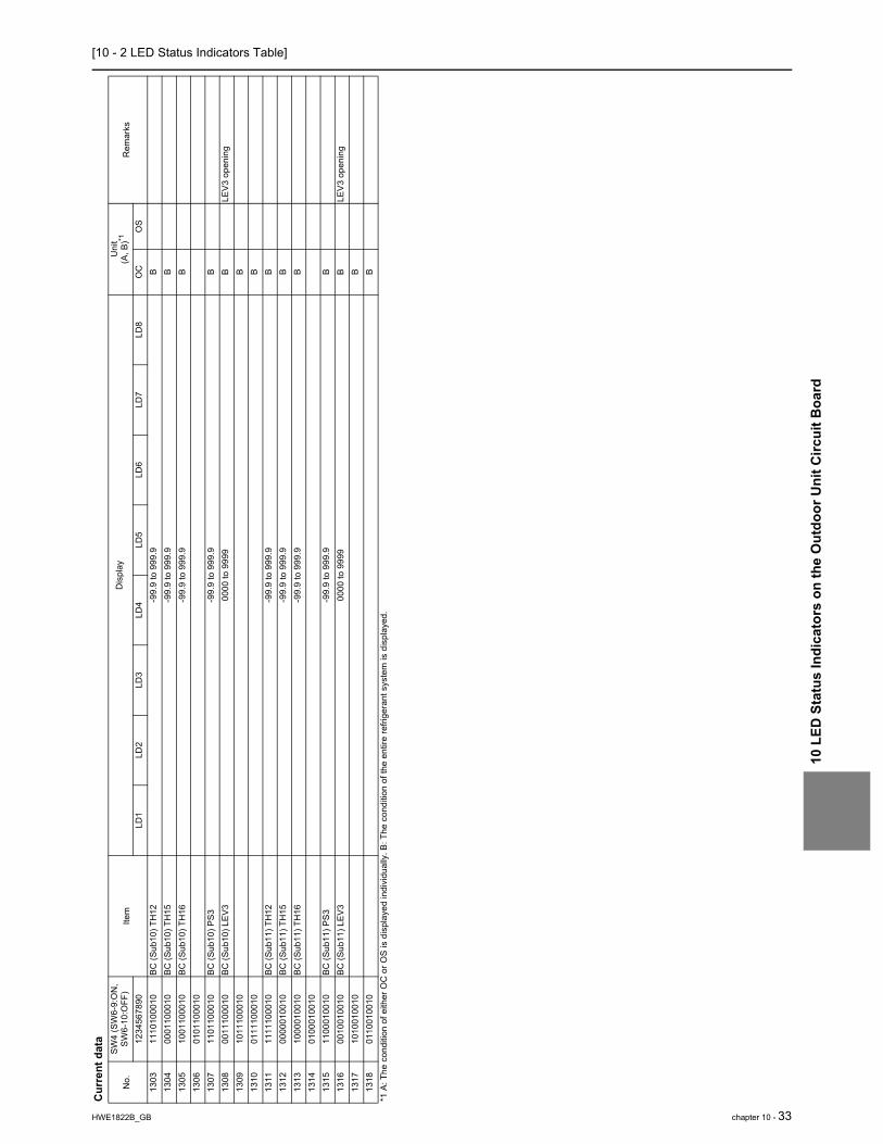
[10 - 2 LED Status Indicators Table]
10 L
ED S
tatu
s In
dica
tors
on
the
Out
door
Uni
t Circ
uit B
oard
HWE1822B_GB chapter 10 - 33
1303
1110
1000
10BC
(Sub
10) T
H12
-99.
9 to
999
.9B
1304
0001
1000
10BC
(Sub
10) T
H15
-99.
9 to
999
.9B
1305
1001
1000
10BC
(Sub
10) T
H16
-99.
9 to
999
.9B
1306
0101
1000
1013
0711
0110
0010
BC (S
ub10
) PS3
-99.
9 to
999
.9B
1308
0011
1000
10BC
(Sub
10) L
EV3
0000
to 9
999
BLE
V3 o
peni
ng13
0910
1110
0010
B13
1001
1110
0010
B13
1111
1110
0010
BC (S
ub11
) TH
12-9
9.9
to 9
99.9
B13
1200
0001
0010
BC (S
ub11
) TH
15-9
9.9
to 9
99.9
B13
1310
0001
0010
BC (S
ub11
) TH
16-9
9.9
to 9
99.9
B13
1401
0001
0010
1315
1100
0100
10BC
(Sub
11) P
S3-9
9.9
to 9
99.9
B13
1600
1001
0010
BC (S
ub11
) LEV
300
00 to
999
9B
LEV3
ope
ning
1317
1010
0100
10B
1318
0110
0100
10B
Cur
rent
dat
a
No.
SW4
(SW
6-9:
ON
, SW
6-10
:OFF
)Ite
mD
ispl
ayU
nit
(A, B
)*1R
emar
ks12
3456
7890
LD1
LD2
LD3
LD4
LD5
LD6
LD7
LD8
OC
OS
*1 A
: The
con
ditio
n of
eith
er O
C o
r OS
is d
ispl
ayed
indi
vidu
ally
. B: T
he c
ondi
tion
of th
e en
tire
refri
gera
nt s
yste
m is
dis
play
ed.

[10 - 2 LED Status Indicators Table]10
LED
Sta
tus
Indi
cato
rs o
n th
e O
utdo
or U
nit C
ircui
t Boa
rd
34 - chapter 10 HWE1822B_GB
Dat
a be
fore
err
or
No.
SW4
(SW
6 - 9
: ON
, SW
6-10
: OFF
)Ite
mD
ispl
ayU
nit
(A, B
) *1R
emar
ks12
3456
7890
LD1
LD2
LD3
LD4
LD5
LD6
LD7
LD8
OC
OS
1550
0111
0000
01BC
(Mai
n/St
anda
rd) T
H11
-99.
9 to
999
.9B
1551
1111
0000
01BC
(Mai
n) T
H12
-99.
9 to
999
.9B
1552
0000
1000
01BC
(Mai
n) T
H15
-99.
9 to
999
.9B
1553
1000
1000
01BC
(Mai
n) T
H16
-99.
9 to
999
.9B
1554
0100
1000
0115
5511
0010
0001
BC (M
ain)
PS3
-99.
9 to
999
.9B
1556
0010
1000
0115
5710
1010
0001
1558
0110
1000
0115
5911
1010
0001
1560
0001
1000
01BC
(Mai
n) L
EV1
0000
to 9
999
BLE
V1 o
peni
ng15
6110
0110
0001
BC (M
ain)
LEV
200
00 to
999
9B
LEV2
ope
ning
1562
0101
1000
01BC
(Mai
n) L
EV3
0000
to 9
999
BLE
V3 o
peni
ng15
6311
0110
0001
BC (M
ain)
LEV
400
00 to
999
9B
LEV4
ope
ning
1564
0011
1000
0115
6510
1110
0001
1566
0111
1000
0115
6711
1110
0001
BC (S
ub1)
TH
12-9
9.9
to 9
99.9
B15
6800
0001
0001
BC (S
ub1)
TH
15-9
9.9
to 9
99.9
B15
6910
0001
0001
BC (S
ub1)
TH
16-9
9.9
to 9
99.9
B15
7001
0001
0001
1571
1100
0100
01BC
(Sub
1) P
S3-9
9.9
to 9
99.9
B15
7200
1001
0001
BC (S
ub1)
LEV
300
00 to
999
9B
LEV3
ope
ning
1573
1010
0100
0115
7401
1001
0001
1575
1110
0100
01BC
(Sub
2) T
H12
-99.
9 to
999
.9B
1576
0001
0100
01BC
(Sub
2) T
H15
-99.
9 to
999
.9B
1577
1001
0100
01BC
(Sub
2) T
H16
-99.
9 to
999
.9B
1578
0101
0100
0115
7911
0101
0001
BC (S
ub2)
PS3
-99.
9 to
999
.9B
1580
0011
0100
01BC
(Sub
2) L
EV3
0000
to 9
999
BLE
V3 o
peni
ng15
8110
1101
0001
1582
0111
0100
0115
8311
1101
0001
BC (S
ub3)
TH
12-9
9.9
to 9
99.9
B15
8400
0011
0001
BC (S
ub3)
TH
15-9
9.9
to 9
99.9
B15
8510
0011
0001
BC (S
ub3)
TH
16-9
9.9
to 9
99.9
B15
8601
0011
0001
1587
1100
1100
01BC
(Sub
3) P
S3-9
9.9
to 9
99.9
B15
8800
1011
0001
BC (S
ub3)
LEV
300
00 to
999
9B
LEV3
ope
ning
1589
1010
1100
0115
9001
1011
0001
1591
1110
1100
01BC
(Sub
4) T
H12
-99.
9 to
999
.9B
*1 A
: The
con
ditio
n of
eith
er O
C o
r OS
is d
ispl
ayed
indi
vidu
ally
. B: T
he c
ondi
tion
of th
e en
tire
refri
gera
nt s
yste
m is
dis
play
ed.

[10 - 2 LED Status Indicators Table]
10 L
ED S
tatu
s In
dica
tors
on
the
Out
door
Uni
t Circ
uit B
oard
HWE1822B_GB chapter 10 - 35
1592
0001
1100
01BC
(Sub
4) T
H15
-99.
9 to
999
.9B
1593
1001
1100
01BC
(Sub
4) T
H16
-99.
9 to
999
.9B
1594
0101
1100
0115
9511
0111
0001
BC (S
ub4)
PS3
-99.
9 to
999
.9B
1596
0011
1100
01BC
(Sub
4) L
EV3
0000
to 9
999
BLE
V3 o
peni
ng15
9710
1111
0001
1598
0111
1100
0115
9911
1111
0001
BC (S
ub5)
TH
12-9
9.9
to 9
99.9
B16
0000
0000
1001
BC (S
ub5)
TH
15-9
9.9
to 9
99.9
B16
0110
0000
1001
BC (S
ub5)
TH
16-9
9.9
to 9
99.9
B16
0201
0000
1001
1603
1100
0010
01BC
(Sub
5) P
S3-9
9.9
to 9
99.9
B16
0400
1000
1001
BC (S
ub5)
LEV
300
00 to
999
9B
LEV3
ope
ning
1605
1010
0010
0116
0601
1000
1001
1607
1110
0010
01BC
(Sub
6) T
H12
-99.
9 to
999
.9B
1608
0001
0010
01BC
(Sub
6) T
H15
-99.
9 to
999
.9B
1609
1001
0010
01BC
(Sub
6) T
H16
-99.
9 to
999
.9B
1610
0101
0010
0116
1111
0100
1001
BC (S
ub6)
PS3
-99.
9 to
999
.9B
1612
0011
0010
01BC
(Sub
6) L
EV3
0000
to 9
999
BLE
V3 o
peni
ng16
1310
1100
1001
1614
0111
0010
0116
1511
1100
1001
BC (S
ub7)
TH
12-9
9.9
to 9
99.9
B16
1600
0010
1001
BC (S
ub7)
TH
15-9
9.9
to 9
99.9
B16
1710
0010
1001
BC (S
ub7)
TH
16-9
9.9
to 9
99.9
B16
1801
0010
1001
1619
1100
1010
01BC
(Sub
7) P
S3-9
9.9
to 9
99.9
B16
2000
1010
1001
BC (S
ub7)
LEV
300
00 to
999
9B
LEV3
ope
ning
1621
1010
1010
0116
2201
1010
1001
1623
1110
1010
01BC
(Sub
8) T
H12
-99.
9 to
999
.9B
1624
0001
1010
01BC
(Sub
8) T
H15
-99.
9 to
999
.9B
1625
1001
1010
01BC
(Sub
8) T
H16
-99.
9 to
999
.9B
1626
0101
1010
0116
2711
0110
1001
BC (S
ub8)
PS3
-99.
9 to
999
.9B
1628
0011
1010
01BC
(Sub
8) L
EV3
0000
to 9
999
BLE
V3 o
peni
ng16
2910
1110
1001
1630
0111
1010
0116
3111
1110
1001
BC (S
ub9)
TH
12-9
9.9
to 9
99.9
B16
3200
0001
1001
BC (S
ub9)
TH
15-9
9.9
to 9
99.9
B16
3310
0001
1001
BC (S
ub9)
TH
16-9
9.9
to 9
99.9
B16
3401
0001
1001
Dat
a be
fore
err
or
No.
SW4
(SW
6 - 9
: ON
, SW
6-10
: OFF
)Ite
mD
ispl
ayU
nit
(A, B
) *1R
emar
ks12
3456
7890
LD1
LD2
LD3
LD4
LD5
LD6
LD7
LD8
OC
OS
*1 A
: The
con
ditio
n of
eith
er O
C o
r OS
is d
ispl
ayed
indi
vidu
ally
. B: T
he c
ondi
tion
of th
e en
tire
refri
gera
nt s
yste
m is
dis
play
ed.

[10 - 2 LED Status Indicators Table]10
LED
Sta
tus
Indi
cato
rs o
n th
e O
utdo
or U
nit C
ircui
t Boa
rd
36 - chapter 10 HWE1822B_GB
1635
1100
0110
01BC
(Sub
9) P
S3-9
9.9
to 9
99.9
B16
3600
1001
1001
BC (S
ub9)
LEV
300
00 to
999
9B
LEV3
ope
ning
1637
1010
0110
0116
3801
1001
1001
1639
1110
0110
01BC
(Sub
10) T
H12
-99.
9 to
999
.9B
1640
0001
0110
01BC
(Sub
10) T
H15
-99.
9 to
999
.9B
1641
1001
0110
01BC
(Sub
10) T
H16
-99.
9 to
999
.9B
1642
0101
0110
0116
4311
0101
1001
BC (S
ub10
) PS3
-99.
9 to
999
.9B
1644
0011
0110
01BC
(Sub
10) L
EV3
0000
to 9
999
BLE
V3 o
peni
ng16
4510
1101
1001
1646
0111
0110
0116
4711
1101
1001
BC (S
ub11
) TH
12-9
9.9
to 9
99.9
B16
4800
0011
1001
BC (S
ub11
) TH
15-9
9.9
to 9
99.9
B16
4910
0011
1001
BC (S
ub11
) TH
16-9
9.9
to 9
99.9
B16
5001
0011
1001
1651
1100
1110
01BC
(Sub
11) P
S3-9
9.9
to 9
99.9
B16
5200
1011
1001
BC (S
ub11
) LEV
300
00 to
999
9B
LEV3
ope
ning
1653
1010
1110
0116
5401
1011
1001
1655
1110
1110
01
Dat
a be
fore
err
or
No.
SW4
(SW
6 - 9
: ON
, SW
6-10
: OFF
)Ite
mD
ispl
ayU
nit
(A, B
) *1R
emar
ks12
3456
7890
LD1
LD2
LD3
LD4
LD5
LD6
LD7
LD8
OC
OS
*1 A
: The
con
ditio
n of
eith
er O
C o
r OS
is d
ispl
ayed
indi
vidu
ally
. B: T
he c
ondi
tion
of th
e en
tire
refri
gera
nt s
yste
m is
dis
play
ed.
