rules for the survey and construction of steel
TRANSCRIPT

17-393
RULES FOR THE SURVEY AND CONSTRUCTION OF STEEL SHIPS
Part CSR-B&T Common Structural Rules for Bulk Carriers and Oil Tankers
Rules for the Survey and Construction of Steel Ships Part CSR-B&T 2018 AMENDMENT NO.1
Rule No.45 5 March 2018
Resolved by Technical Committee on 31 January 2018
NIPPON KAIJI KYOKAI

1
Rule No.45 5 March 2018 AMENDMENT TO THE RULES FOR THE SURVEY AND CONSTRUCTION OF STEEL SHIPS “Rules for the survey and construction of steel ships” has been partly amended as follows:
Part CSR-B&T COMMON STRUCTURAL RULES FOR BULK CARRIERS AND OIL TANKERS
Part 1 GENERAL HULL REQUIREMENTS
Chapter 1 RULE GENERAL PRINCIPLES
Section 4 SYMBOLS AND DEFINITIONS
Fig.1 has been amended as follows.
Fig. 1 Concave Stem Contour
2
3. Definitions
3.1 Principal Particulars Paragraph 3.1.5 has been amended as follows. 3.1.5 Draughts T, the draught in m, is the summer load line draught for the ship in operation, measured from the moulded baseline at midship. Note this may be less than the maximum permissible summer load waterline draught. TSC is the scantling draught, in m, at which the strength requirements for the scantlings of the ship are met and represents the full load condition. The scantling draught TSC is to be not less than that corresponding to the assigned freeboard. The draught of ships to which timber freeboards are assigned corresponds to the loading condition of timber, and the requirements of the Society are to be applied to this draught. TBAL is the minimum design normal ballast draught amidships, in m, at which the strength requirements for the scantlings of the ship are met. This normal ballast draught is the minimum draught of ballast conditions including ballast water exchange operation, if any, for any ballast conditions in the loading manual including both departure and arrival conditions. TBAL-H is the minimum design heavy ballast draught, in m, at which the strength requirements for the scantlings of the ship are met. This heavy ballast draught is to be considered for ships having heavy ballast condition. Table 7 has been amended as follows.
Table 7 Definition of Terms
Terms Definition
(Omitted)
Duct keel A keel built of plates in box form extending the length of the cargo tank. It is used to house ballast and other piping leading forward which otherwise would have to run through the cargo tanks and/or ballast tanks.
(Omitted)
Propeller post The forward post of stern frame, which is bored for propeller shaft.
(Omitted)
Rudder post After post of stern frame to which the rudder is hung (also called stern post).
(Omitted)
Stern The after end of the vessel.
Stern frame The heavy strength member in single or triple screw ships, combining the rudder post. The heavy strength members attached to the after end of a hull to form the ship’s stern. It includes rudder post, propeller post, and aperture for the propeller.
(Omitted)

3
Chapter 2 GENERAL ARRANGEMENT DESIGN
Section 2 SUBDIVISION ARRANGEMENT
1.1 Number and Disposition of Watertight Bulkheads Paragraph 1.1.1 has been amended as follows. 1.1.1 All ships are to have at least the following transverse watertight bulkheads:
(a) One collision bulkhead. (b) One aft peak bulkhead. (c) One bulkhead at each end of the machinery space. One bulkhead forward of the
machinery space, and one bulkhead at the aft end of the machinery space which may be the aft peak bulkhead.
Section 4 ACCESS ARRANGEMENT
2. Cargo Area and Forward Spaces
2.1 General Paragraph 2.1.1 has been amended as follows. 2.1.1 Ship structure access manual Means of access Ship structures subject to overall and close-up inspection and thickness measurements are to be provided with means of access which are to be described in a “Ship Structure Access Manual”. Reference is made to SOLAS, Ch II-1, Reg 3-6. Each space is to be provided with means of access as regulated in SOLAS, Ch II-1, Reg 3-6. This requirement applies to:
・ Oil tankers ・ Bulk carriers having a length of 150 m or above, irrespective of their gross tonnage.
4
Chapter 3 STRUCTURAL DESIGN PRINCIPLES
Section 2 NET SCANTLING APPROACH
Symbols
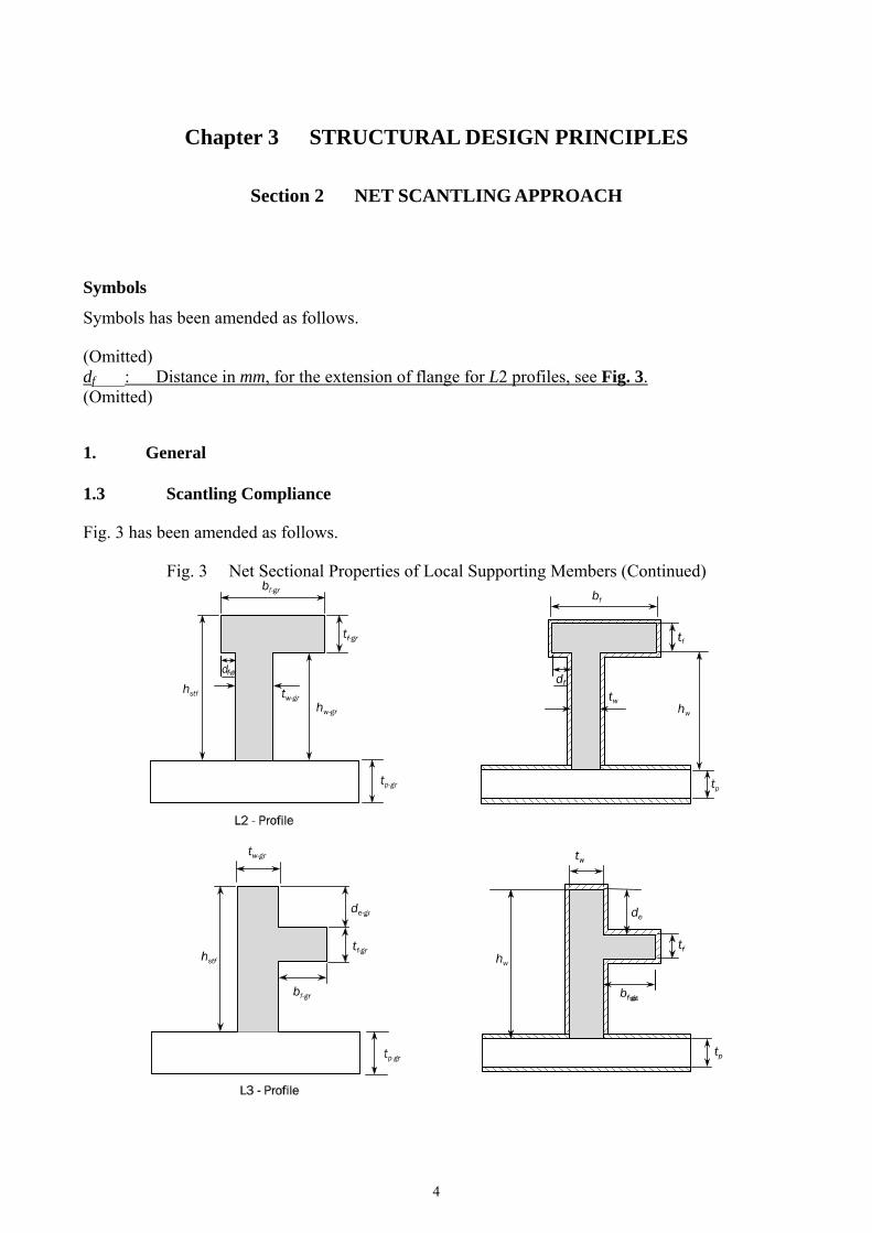
Symbols has been amended as follows. (Omitted) df : Distance in mm, for the extension of flange for L2 profiles, see Fig. 3. (Omitted)
1. General
1.3 Scantling Compliance Fig. 3 has been amended as follows.
Fig. 3 Net Sectional Properties of Local Supporting Members (Continued)

5
Section 6 STRUCTURAL DETAIL PRINCIPLES
10. Bulkhead Structure
10.4 Corrugated Bulkheads Paragraph 10.4.10 has been amended as follows. 10.4.10 Upper stool The upper stool, when fitted, is to have a height:
・ Between two and three Not less than two times the corrugation depth, for bulk carriers. ・ At least one corrugation depth, for oil tankers.
Rectangular stools are to have a height in general equal to twice the depth of corrugations, measured from the deck level and at the hatch side girder or at the inner hull as applicable. Brackets or deep webs are to be fitted to connect the upper stool to the deck transverse or hatch end beams. The upper stool of a transverse bulkhead is to be properly supported by deck girders or deep brackets between the adjacent hatch end beams. The width of the upper stool bottom plate is generally to be the same as that of the lower stool top plate. The stool top of non-rectangular stools of bulk carriers is to have a width not less than twice the depth of corrugations. The ends of stool side ordinary stiffeners when fitted in a vertical plane, are to be attached to brackets at the upper and lower end of the stool. The stool is to be fitted with diaphragms in line with and effectively attached to longitudinal deck girders extending to the hatch end coaming girders or transverse deck primary supporting members. Scallops in the brackets and diaphragms in way of the connection to the stool bottom plate are to be avoided.

6
Section 7 STRUCTURAL IDEALISATION
Symbols
Symbols has been amended as follows. (Omitted) tw : Net web thickness, in mm For bulb profiles, see 1.4.1. bf : Breadth of flange, in mm, see Ch 3, Sec 2, Fig. 2. For bulb profiles, see Table 1 and
Table 21.4.1. (Omitted)
1. Structural Idealisation of Stiffeners and Primary Supporting Members
1.4 Geometrical Properties of Stiffeners and Primary Supporting Members Paragraph 1.4.3 has been amended as follows. 1.4.3 Effective shear depth of stiffeners The effective shear depth of stiffeners, dshr, in mm, is to be taken as:
wpstfshr thd sin
wplcpstfcstfshr ttthd sin5.05.0
where: hstf : Height of stiffener, in mm, as defined in Ch 3, Sec 2, Fig.2. tp : Net thickness of the stiffener attached plating, in mm, as defined in Ch 3, Sec 2, Fig.
2. tc-stf : Corrosion addition, in mm, of considered stiffener as given in Ch 3, Sec 3. tc-pl : Corrosion addition, in mm, of attached plate of the stiffener considered as given in
Ch 3, Sec 3.
w : Angle, in deg, as defined in Fig. 14. w is to be taken as 90 degrees if the angle is
greater than or equal to 75 degrees. Paragraph 1.4.4 has been amended as follows. 1.4.4 Elastic net section modulus and net moment of inertia of stiffeners The elastic net section modulus, Z, in cm3 and the net moment of inertia, I, in cm4 of stiffeners, in cm3, is to be taken as:
wstfZZ sin
wstII 2sin
where: Zstf : Net section modulus of the stiffener, in cm3, considered perpendicular to its attached
plate, i.e. with w = 90 deg. Ist : Net moment of inertia of the stiffener, in cm4, considered perpendicular to its
attached plate, i.e. with w = 90 deg.

7
w : Angle, in deg, as defined in Fig. 14. w is to be taken as 90 degrees if the angle is
greater than or equal to 75 degrees.
Fig. 14 Angle between Stiffener Web and Attached Plating
Paragraph 1.4.6 has been amended as follows. 1.4.6 Effective net plastic section modulus of stiffeners The effective net plastic section modulus, Zpl, of stiffeners, in cm3, which is used for assessment against impact loads, is to be taken as:
1000
12
2000
2ctrffwww
pl
hAthfZ
for 9075 w
1000
cossin12
2000
sin2wctrfwctrffwwww
pl
bhAthfZ
for 75w
where: (Omitted) hw : Depth of stiffener web, in mm, taken equal to:
・ For T, L (rolled and built-up) profiles and flat bar, as defined in Ch 3, Sec 2, Fig. 2.
・ For L2 and L3 profiles as defined in Ch 3, Sec 2, Fig. 3. ・ For bulb profiles, to be taken as defined in Ch 3, Sec 2, Fig. 31.4.1.
: Coefficient equal to:
4
1231
: Coefficient equal to:
・ f
w
ctrfff
shrbw
b
t
htb
ft
210
806
2
22
for L profiles without a mid-span tripping bracket,
but not to be taken greater than 0.5. ・ 5.0 for other cases.
Af : Net cross sectional area of flange, in mm2: ・ Af = 0 for flat bar stiffeners. ・ Af = bf tf for other stiffeners.
bf-ctr : Distance from mid thickness of stiffener web to the centre of the flange area: ・ bf-ctr = 0.5 (bf - tw-gr) for rolled angle profiles and bulb profiles. ・ bf-ctr = 0 for T profiles. ・ For bulb profiles as given in Table 1 and Table 2.
hf-ctr : Height of stiffener measured to the mid thickness of the flange:

8
・ hf-ctr = hstf – 0.5 tf hw + 0.5 tf for profiles with flange of rectangular shape except for L3 profiles and for bulb profiles.
・ hf-ctr = hstf – de – 0.5 tf hw – de – 0.5 tf for L3 profiles as defined in Ch 3, Sec 2, Fig. 23.
・ For bulb profiles as given in Table 1 and Table 2. de : Distance from upper edge of web to the top of the flange, in mm, for L3 profiles, see
Ch 3, Sec 2, Fig. 23. fb : Coefficient taken equal to:
・ fb = 0.8 for flanges continuous through the primary supporting member, with end bracket(s).
・ fb = 0.7 for flanges sniped at the primary supporting member or terminated at the support without aligned structure on the other side of the support, and with end bracket(s).
・ fb = 1.0 for other stiffeners. tf : Net flange thickness, in mm.
・ tf = 0 for flat bar stiffeners. ・ For bulb profiles as given in Table 1 and Table 2 tf is defined in 1.4.1.
Table 1 and Table 2 have been deleted, and Table 3 has been renumbered to Table 1.
Table 1 Characteristic Flange Data for HP Bulb Profiles, See Fig. 15
hstf (mm) dw (mm) bf-gr (mm) tf-gr (mm) bf-ctr (mm) hf-ctr (mm)
200 171 40 14.4 10.9 188
220 188 44 16.2 12.1 206
240 205 49 17.7 13.3 225
260 221 53 19.5 14.5 244
280 238 57 21.3 15.8 263
300 255 62 22.8 16.9 281
320 271 65 25.0 18.1 300
340 288 70 26.4 19.3 318
370 313 77 28.8 21.1 346
400 338 83 31.5 22.9 374
430 363 90 33.9 24.7 402
Note 1: Characteristic flange data converted to net scantlings are given as: bf ≈ bf-gr + 2 tw tf = tf-gr - tc tw = tw-gr - tc

9
Table 2 Characteristic Flange Data for JIS Bulb Profiles, See Fig. 15
hstf (mm) dw (mm) bf-gr (mm) tf-gr (mm) bf-ctr (mm) hf-ctr (mm)
180 156 34 11.9 9.0 170
200 172 39 13.7 10.4 188
230 198 45 15.2 11.7 217
250 215 49 17.1 12.9 235
Note 1: Characteristic flange data converted to net scantlings are given as: bf ≈ bf-gr + 2 tw
tf = tf-gr - tc tw = tw-gr - tc
Table 31 Strake Considered in a Given EPP
(Omitted) Fig. 15 has been deleted, and Fig. 16 to Fig. 25 have been renumbered to Fig. 15 to Fig. 24.
Fig. 15 Characteristic Data for Bulb Profiles
Fig. 1615 Effective Shear Area in way of Web Openings (Omitted)
Fig. 1716 Elementary Plate Panel (EPP) Definition
(Omitted)
Fig. 1817 Strake Considered in a Given EPP (Omitted)

10
Fig. 1918 Load Calculation Point (LCP) for Longitudinal Framing (Omitted)
Fig. 2019 Load Calculation Point for Transverse Framing
(Omitted)
Fig. 2120 Load Calculation Point for Horizontal Framing on Transverse Vertical Structure (Omitted)
Fig. 2221 Load Calculation Point for Vertical Framing on Transverse Vertical Structure
(Omitted)
Fig. 2322 LCP for Plate Buckling – Hull Girder Stresses (Omitted)
Fig. 2423 Reference Point for Calculation of Section Modulus and Hull Girder Stress for
Local Scantling Assessment (Omitted)
Fig. 2524 Definition of Pressure for Vertical Stiffeners
(Omitted) Paragraph 1.4.8 has been amended as follows. 1.4.8 Shear area of primary supporting members with web openings The effective web height, heff, in mm, to be considered for calculating the effective net shear area, Ash-n50 is to be taken as the lesser of the following, where the third formula is only taken into account for an opening located at a distance less than hw /3 from the cross-section considered.
heff = hw heff = hw3 + hw4 heff = hw1 + hw2 + hw4 where: hw: Web height of primary supporting member, in mm. hw1, hw2, hw3, hw4 : Dimensions as shown in Fig. 1615.
2. Plates
2.1 Idealisation of EPP Paragraphs 2.1.1 and 2.1.2 have been amended as follows. 2.1.1 EPP An elementary plate panel (EPP) is the unstiffened part of the plating between stiffeners and/or primary supporting members. The plate panel length, a, and breadth, b, of the EPP are defined respectively as the longest and shortest plate edges, as shown in Fig. 1716. 2.1.2 Strake required thickness The required thickness of a plate strake is to be taken as the greatest value required for each EPP within that strake. The requirements given in Table 31 are to be applied for the selection of strakes to be considered as shown in Fig. 1817.
11
The maximum corrosion addition within a strake is to be applied according to Ch 3, Sec 3, 1.2.4.
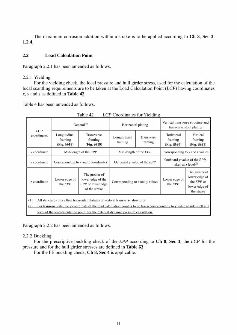
2.2 Load Calculation Point Paragraph 2.2.1 has been amended as follows. 2.2.1 Yielding For the yielding check, the local pressure and hull girder stress, used for the calculation of the local scantling requirements are to be taken at the Load Calculation Point (LCP) having coordinates x, y and z as defined in Table 42. Table 4 has been amended as follows.
Table 42 LCP Coordinates for Yielding
LCP coordinates
General(1) Horizontal plating Vertical transverse structure and
transverse stool plating
Longitudinal framing
(Fig. 1918)
Transverse framing
(Fig. 2019)
Longitudinal framing
Transverse framing
Horizontal framing
(Fig. 2120)
Vertical framing
(Fig. 2221)
x coordinate Mid-length of the EPP Mid-length of the EPP Corresponding to y and z values
y coordinate Corresponding to x and z coordinates Outboard y value of the EPP Outboard y value of the EPP,
taken at z level(2)
z coordinate Lower edge of
the EPP
The greater of lower edge of the
EPP or lower edge of the strake
Corresponding to x and y valuesLower edge of
the EPP
The greater of lower edge of
the EPP or lower edge of
the strake
(1) All structures other than horizontal platings or vertical transverse structures.
(2) For transom plate, the y coordinate of the load calculation point is to be taken corresponding to y value at side shell at z
level of the load calculation point, for the external dynamic pressure calculation.
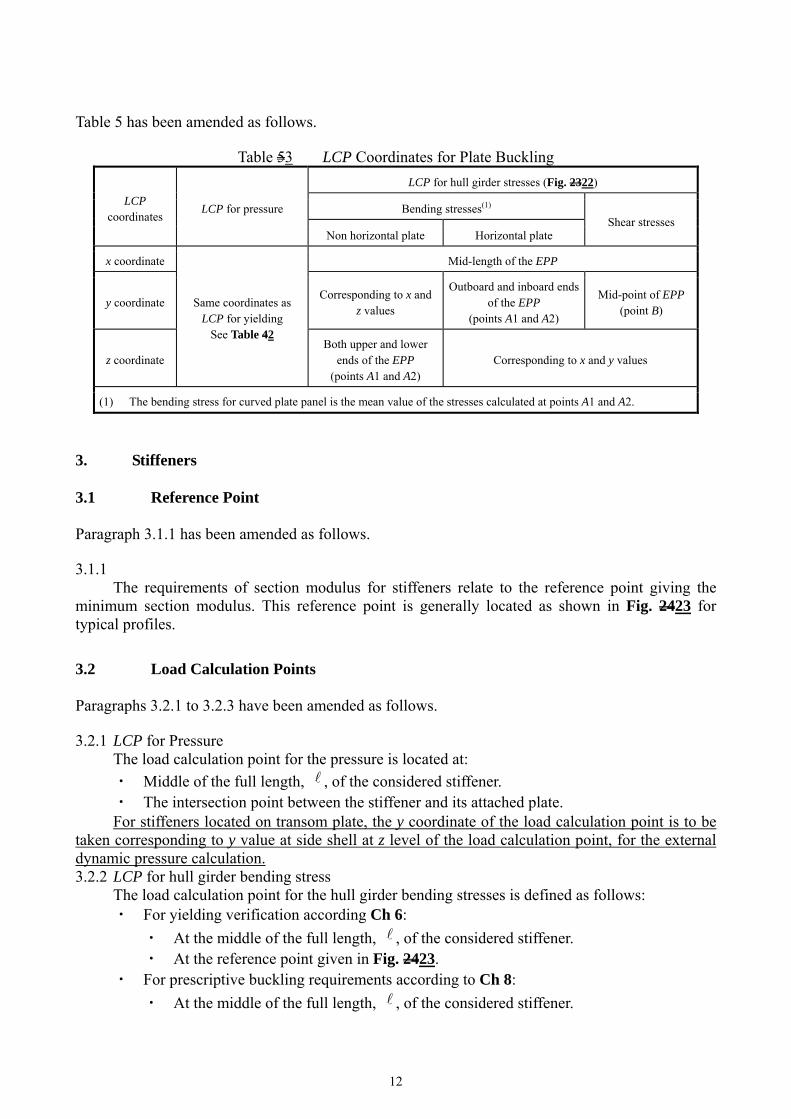
Paragraph 2.2.2 has been amended as follows. 2.2.2 Buckling For the prescriptive buckling check of the EPP according to Ch 8, Sec 3, the LCP for the pressure and for the hull girder stresses are defined in Table 53. For the FE buckling check, Ch 8, Sec 4 is applicable.
12
Table 5 has been amended as follows.
Table 53 LCP Coordinates for Plate Buckling
LCP coordinates
LCP for pressure
LCP for hull girder stresses (Fig. 2322)
Bending stresses(1) Shear stresses
Non horizontal plate Horizontal plate
x coordinate
Same coordinates as LCP for yielding
See Table 42
Mid-length of the EPP
y coordinate Corresponding to x and
z values
Outboard and inboard ends of the EPP
(points A1 and A2)
Mid-point of EPP (point B)
z coordinate Both upper and lower
ends of the EPP (points A1 and A2)
Corresponding to x and y values
(1) The bending stress for curved plate panel is the mean value of the stresses calculated at points A1 and A2.
3. Stiffeners
3.1 Reference Point Paragraph 3.1.1 has been amended as follows. 3.1.1 The requirements of section modulus for stiffeners relate to the reference point giving the minimum section modulus. This reference point is generally located as shown in Fig. 2423 for typical profiles.
3.2 Load Calculation Points Paragraphs 3.2.1 to 3.2.3 have been amended as follows. 3.2.1 LCP for Pressure The load calculation point for the pressure is located at:
・ Middle of the full length, , of the considered stiffener. ・ The intersection point between the stiffener and its attached plate.
For stiffeners located on transom plate, the y coordinate of the load calculation point is to be taken corresponding to y value at side shell at z level of the load calculation point, for the external dynamic pressure calculation. 3.2.2 LCP for hull girder bending stress The load calculation point for the hull girder bending stresses is defined as follows:
・ For yielding verification according Ch 6:
・ At the middle of the full length, , of the considered stiffener. ・ At the reference point given in Fig. 2423.
・ For prescriptive buckling requirements according to Ch 8:
・ At the middle of the full length, , of the considered stiffener.

13
・ At the intersection point between the stiffener and its attached plate. 3.2.3 Non-horizontal stiffeners The lateral pressure, P is to be calculated as the maximum between the value obtained at middle of the full length, , and the value obtained from the following formulae:
2LU pp
P
when the upper end of the vertical stiffener is below the lowest zero pressure
level.
21 Lp
P
when the upper end of the vertical stiffener is at or above the lowest zero
pressure level, see Fig. 2524. where:
1 : Distance, in m, between the lower end of vertical stiffener and the lowest zero pressure level.
PU, PL : Lateral pressures at the upper and lower end of the vertical stiffener span , respectively.
4. Primary Supporting Members
4.1 Load Calculation Point Paragraph 4.1.1 has been amended as follows. 4.1.1 The load calculation point is located at the middle of the full length, S , at the attachment
point of the primary supporting member with its attached plate. However, for primary supporting members in the cargo hold region the requirements in Pt 2, Ch 1, Sec 4, 4, as applicable, for bulk carriers and Pt 2, Ch 2, Sec 3, 1 for oil tankers are to be followed. For primary supporting members located on transom plate, the y coordinate of the load calculation point is to be taken corresponding to y value at side shell at z level of load calculation point for the external dynamic pressure calculation.
14
Chapter 4 LOADS
Section 4 HULL GIRDER LOADS
2. Vertical Still Water Hull Girder Loads
2.2 Vertical Still Water Bending Moment Paragraph 2.2.4 has been amended as follows. 2.2.4 Permissible vertical still water bending moment in flooded condition at sea The permissible vertical still water bending moments in flooded condition Msw-f at any longitudinal position are to envelop:
・ The most severe still water bending moments, in hogging and sagging conditions, respectively, for the intact and flooded seagoing loading conditions defined in Ch 4, Sec 8. Loading conditions encountered during ballast water exchange need not to be considered for the flooded condition.
・ The most severe still water bending moments for the intact and flooded seagoing loading conditions defined in the loading manual.
・ The permissible still water bending moment defined in 2.2.2 increased by 10%.
2.3 Vertical Still Water Shear Force Paragraph 2.3.5 has been amended as follows. 2.3.5 Permissible still water shear force in flooded condition at sea The permissible vertical still water shear forces, Qsw-f for oil tankers and bulk carriers, in flooded condition at any longitudinal position are to envelop:
・ The most severe still water shear forces, positive or negative, for the flooded seagoing loading conditions defined in Ch 4, Sec 8 after shear force correction in case of bulk carrier. Loading conditions encountered during ballast water exchange need not be considered for the flooded condition.
・ The most severe still water shear forces for the flooded seagoing loading conditions defined in the loading manual after shear force correction in case of bulk carrier.
・ The permissible still water shear force is defined in 2.3.3.

15
Section 5 EXTERNAL LOADS
Symbols
Symbols has been amended as follows. (Omitted) PW,WL : Wave pressure at the waterline, kN/m2, for the considered dynamic load case.
WWLW PP , for 2/yBy
and LCTz
(Omitted) ZSD : Z coordinate, in m, of the midpoint of stiffener span, or of the middle of the plate field.
1. Sea Pressure
1.4 External Dynamic Pressures for Fatigue Assessments Paragraph 1.4.3 has been amended as follows. 1.4.3 Hydrodynamic pressures for FSM load cases The hydrodynamic pressures, PW, for FSM-1 and FSM-2 load cases, at any load point, in kN/m2, are to be obtained from Table 21.
where:
CSRwyzpahpFS L
LCfkkffP
1250
CSRwyzpahpFS L
LCfkkffP
1250
(Omitted)
3. External Impact Pressures for the Bow Area
3.2 Bottom Slamming Pressure Paragraphs 3.2.1 and 3.2.2 have been amended as follows. 3.2.1 The bottom slamming pressure PSL, in kN/m2, for the bottom slamming design load scenario is to be evaluated for the following two cases:
Case 1: An empty ballast tank or a void space in way of the bottom shell.
etSLSLCSRSL cfLgP 10 for 170CSRL m
1130 cetSLSLSL ecfgP for 170CSRL m
Case 2: A full ballast tank in way of the bottom shell.

16
zzgcfLgP topftSLSLCSRSL 25.110 for 170CSRL m
zzgecfgP topc
ftSLSLSL 25.1130 1 for 170CSRL m
where: (Omitted)
TF-e : Design slamming draught at the FP to be provided by the Designer. TF-e is not to be greater than the minimum draught at the FP indicated in the loading manual for all seagoing conditions where any of the ballast tanks within the bottom slamming region are empty. This includes all loading conditions with tanks inside the bottom slamming region that use the ‘sequential’ ballast water exchange method, if relevant.
TF-f : Design slamming draught at the FP to be provided by the Designer. TF-f is not to be greater than the minimum draught at the FP indicated in the loading manual for all seagoing conditions where all ballast tanks within the bottom slamming region are full. This includes all loading conditions with tanks inside the bottom slamming region that use the ‘flow-through’ ballast water exchange method, if relevant.
(Omitted) 3.2.2 Loading manual information The loading guidance information is to clearly state the design slamming draughts and the ballast water exchange method used for each ballast tank, if any.

17
4. External Pressures on Superstructure and Deckhouses
4.3 Sides of Superstructures Paragraph 4.3.1 has been amended as follows. 4.3.1 The design pressure for the external sides of superstructures, PSI, in kN/m2, is to be taken as:
where:
LC
BFWSI TzCcCP
10
207.01.2
LCSD
BFWSI TzCcCP
10
207.01.2
cF : Distribution factor according to Table 32.
4.4 End Bulkheads of Superstructures and Deckhouse Walls Paragraph 4.4.1 has been amended as follows. 4.4.1 The external pressure for the aft and forward external bulkheads of superstructures and deckhouse walls, in kN/m2, is to be taken as:
SCdbcnA TzffffP SCSDdbcnA TzffffP but is not to be less than PA-min.
(Omitted)

18
Section 6 INTERNAL LOADS
Symbols
Symbols has been amended as follows. (Omitted) PPV : Setting of Design vapour pressure relief valve, in kN/m2, if fitted, but not less than 25 kN/m2. (Omitted)
ST : Density of steel, in t/m3, to be taken as 7.87.85. (Omitted) Table 13 has been amended as follows.
Table 13 Design Testing Load Height zST
Compartment zST
Double bottom tanks (1) The greater of the following:
zST = ztop + hair zST = zbd
Hopper side tanks, topside tanks, double side tanks, fore and aft peaks used as tank
The greater of the following: zST = ztop + hair zST = ztop + 2.4
Tank bulkheads, deep tanks, fuel oil bunkers
The greater of the following: zST = ztop + hair zST = ztop + 2.4
zST = ztop + 0.1 PPV
Ballast hold zST = zh + 0.9
Chain locker (if aft of collision bulkhead) zST = ztop zc
Independent tanks The greater of the following:
zST = ztop + hair zST = ztop + 0.9
Ballast ducts Testing load height corresponding to ballast pump
maximum pressure
where:
zbd : Z coordinate, in m, of the bulkhead deck.
zh : Z coordinate, in m, of the top of hatch coaming.
zc : Z coordinate, in m, of the top of the chain pipe.
(1) For double bottom tanks connected with hopper side tanks, topside tanks or double side tanks, zST
corresponding to "Hopper side tanks, topside tanks, double side tanks, fore and aft peaks used as
tank, cofferdams" is applicable.

19
Section 8 LOADING CONDITIONS
2. Common Design Loading Conditions
2.3 Seagoing Conditions Paragraph 2.3.1 has been amended as follows. 2.3.1 The following seagoing loading conditions are to be included, as a minimum, in the loading manual:
(a) Homogeneous cargo loading condition including a condition at the scantling draught. Homogeneous loading conditions are to not include filling of ballast tanks in departure conditions.
(b) Ballast condition where the ballast tanks may be full, partially full or empty. Where ballast tanks are partially full, the conditions in 2.2.1 are to be complied with. All cargo tanks/holds are to be empty including cargo tanks/holds suitable for the carriage of water ballast at sea. The propeller is to be fully immersed. The trim is to be by the stern and is not to exceed 0.015LLL.
(c) Conditions covering ballast water exchange procedures, if any, with the calculations of intermediate conditions just before and just after ballasting and/or deballasting any ballast tank.
4. Bulk Carriers
4.1 Specific Design Loading Condition Paragraph 4.1.1 has been amended as follows. 4.1.1 Seagoing conditions The following seagoing loading conditions are to be included, as a minimum, in the loading manual:
(a) Cargo loading conditions as defined in 4.1.2 to 4.1.4. (b) Heavy ballast condition where the ballast tanks may be full, partially full or empty.
Where ballast tanks are partially full, the conditions in 2.2.1 are to be complied with. The propeller immersion /Dp is to be at least 60%. The trim is to be by the stern and is not to exceed 0.015LLL. The moulded forward draught is not to be taken less than the smaller of 0.03LCSRLLLor 8m.
4.2 Design Load Combinations for Direct Strength Analysis Paragraph 4.2.1 has been amended as follows. 4.2.1 Applicable general loading patterns The following loading patterns are to be applied:
20
(a) Any cargo hold carrying MFull with fuel oil tanks in way of the cargo hold, if any, being 100% full and ballast water tanks in the double bottom in way of the cargo hold being empty, at scantling draught.
(b) Any cargo hold carrying minimum 50% of MH, with all double bottom tanks in way of the cargo hold being empty, at scantling draught.
(c) Any cargo hold taken empty, with all double bottom tanks in way of the cargo hold being empty, at the deepest ballast draught. Where a topside and double bottom tank are permanently connected as a common tank, the following conditions are to be considered: ・ The topside and double bottom tank empty, ・ The topside and double bottom tank full.
5. Standard Loading Conditions for Fatigue Assessment
5.1 Oil Tanker Paragraph 5.1.1 has been amended as follows. 5.1.1 The standard loading conditions to be applied to oil tankers for fatigue assessment as required in Ch 9, Sec 1, 6.2, are defined in Table 22 to Table 24. Where fuel oil tanks, other oil tanks or fresh water tanks are arranged in way of the cargo hold region, the filling level of them are to be taken as full for direct strength analysis according to Ch 7 and Ch 9, Sec 5. For simplified stress analysis according to Ch 9, Sec 4, the filling level of them are to be taken as half height, measured from ztop to the lowest point of tank.
5.2 Bulk Carriers Paragraph 5.2.1 has been amended as follows. 5.2.1 The standard loading conditions to be applied to bulk carriers for fatigue assessment as required in Ch 9, Sec 1, 6.3 are defined in Table 25, to Table 31 according to their additional service feature notations and the location of the assessed details. Where fuel oil tanks, other oil tanks or fresh water tanks are arranged in way of the cargo hold region, the filling level of them are to be taken as full for direct strength analysis according to Ch 7 and Ch 9, Sec 5. For simplified stress analysis according to Ch 9, Sec 4, the filling level of them are to be taken as half height, measured from ztop to the lowest point of tank.

21
Chapter 5 HULL GIRDER STRENGTH
Appendix 2 HULL GIRDER ULTIMATE CAPACITY
2. Incremental-iterative Method
2.3 Load-end Shortening Curves Paragraph 2.3.1 has been amended as follows. 2.3.1 Stiffened plate element and stiffener element Stiffened plate element and stiffener element composing the hull girder transverse sections may collapse following one of the modes of failure specified in Table 1.
・ Where the plate members are stiffened by non-continuous longitudinal stiffeners, the stress of the element is to be obtained in accordance with 2.3.3 to 2.3.8, taking into account the non-continuous longitudinal stiffener. In calculating the total forces for checking the hull girder ultimate strength, the area of non-continuous longitudinal stiffener is to be assumed as zero.
・ Where the opening is provided in the stiffened plate element, the considered area of the stiffened plate element is to be obtained by deducting the opening area from the plating in calculating the total forces for checking the hull girder ultimate strength. The consideration of the opening is in accordance with the requirement in Ch 5, Sec 1, 1.2.9 to 1.2.13.
・ For stiffened plate element, the effective width of plate for the load shortening portion of the stress-strain curve is to be taken as full plate width, i.e. to the intersection of other plate or longitudinal stiffener – neither from the end of the hard corner element nor from the attached plating of stiffener element, if any. In calculating the total forces for checking the hull girder ultimate strength, the area of the stiffened plate element is to be taken between the hard corner element and the stiffener element or between the hard corner elements, as applicable.

22
Chapter 6 HULL LOCAL SCANTLING
Section 2 LOAD APPLICATION
1. Load Combination
1.2 Lateral Pressures Paragraph 1.2.2 has been amended as follows. 1.2.2 Lateral pressure in flooded conditions Watertight boundaries of compartments not intended to carry liquids, excluding hull envelope shell envelope, are to be subjected to lateral pressure in flooded conditions.
2. Design Load Sets
2.1 Application of Load Components Table 1 has been amended as follows.
Table 1 Design Load Sets
Item Design load
set Load
componentDraught
Design load
Loading condition
(Omitted)
Compartments not carrying liquids
FD-1 (6) Pin TSC S+D Flooded condition
FD-2 (6) Pin - S Flooded condition
(Omitted)
(Omitted)
(6) FD-1 and FD-2 are not applicable to external shell and corrugations of transverse vertically corrugated bulkhead
separating cargo holds. Requirement in flooded conditions of transverse corrugated bulkhead are given in Pt 2,
Ch 1, Sec 3, 3. FD-1 and FD-2 are to be considered for strength deck whenever applicable.
(Omitted)

23
Section 4 PLATING
Symbols
Symbols has been amended as follows. (Omitted) : Coefficient taken equal to:
・ In intact condition: ・ 70.0 for inner bottom and bilge hopper tank plating in cargo holds of bulk
carriers, ・ 00.1 for other cases.
・ In flooded condition: ・ 00.1 for collision bulkheads for acceptance criteria set AC-S,
・ 95.0 for collision bulkheads for acceptance criteria set AC-SD,
・ 15.1 for other watertight boundaries of compartments.
2. Special Requirements
2.6 Supporting Structure in way of Corrugated Bulkheads Paragraph 2.6.3 has been amended as follows. 2.6.3 Upper stool
(a) The net thickness of the stool bottom plate is not to be less than that required for the attached corrugated bulkhead and is to be of at least the same material yield strength as the attached corrugation. The extension of the top plate beyond the corrugation is not to be less than the as-built flange thickness of the corrugation.
(b) The net thickness of the lower portion of stool side plating is not to be less than 80% of the upper part of the bulkhead plating as required by 1.2 and Pt 2, Ch 1, Sec 3, 3.1, as applicable, whichever is the greater, where the same material is used. If material of different yield strength is used, the required thickness is to be adjusted by the ratio of the two material factors k as defined in Ch 3, Sec 1, 2.2.1. the greater of the following, ・ The net thickness obtained from 1.1, ・ 80% of the net thickness of the upper part of the bulkhead plating as required by
・ 1.2, ・ Pt 2, Ch 1, Sec 3, 3.1, or Pt 2, Ch 2, Sec 3, 2.2.1 as applicable, where the same material is used.
If materials of different yield strength are used, the required thickness is to be adjusted by the ratio of the two material factors k as defined in Ch 3, Sec 1, 2.2.1.
24
Section 5 STIFFENERS
Symbols
Symbols has been amended as follows. (Omitted) : Coefficient taken equal to:
・ In intact condition:
・ 90.0for inner bottom and bilge hopper tank plating in cargo holds of bulk
carriers,
・ 00.1for other cases.
・ In flooded condition: as defined in Ch 6, Sec 4 for flooded condition.
1. Stiffeners subject to Lateral Pressure
1.1 Yielding Check Paragraph 1.1.2 has been amended as follows. 1.1.2 Section modulus The minimum net section modulus, Z in cm3, is not to be taken less than the greatest value calculated for all applicable design load sets as defined in Ch 6, Sec 2, 2.1.3, given by:
eHsbdg
bdg
RCf
sPZ
2
with sC not to be taken greater than 1.0. (Omitted)
Paragraph 1.1.3 has been amended as follows. 1.1.3 Group of stiffeners Scantlings of stiffeners based on requirements in 1.1.1 and 1.1.2 may be decided based on the concept of grouping designated sequentially placed stiffeners of equal scantlings on a single stiffened panel between primary supporting members. The scantling of the group is to be taken as the greater of the following:
・ The average of the required scantling of all stiffeners within a group. ・ 90% of the maximum scantling required for any one stiffener within the group.

25
Section 6 PRIMARY SUPPORTING MEMBERS AND PILLARS
Symbols
Symbols has been amended as follows. (Omitted) : Coefficient taken equal to:
・ In intact condition: ・ = 0.90 for primary supporting members attached to inner bottom and or bilge
hopper tank plating in cargo holds of bulk carriers, ・ = 1.00 for other cases.
・ In flooded condition: as defined in Ch 6, Sec 4 for flooded condition.

26
Chapter 7 DIRECT STRENGTH ANALYSIS
Section 2 CARGO HOLD STRUCTURAL STRENGTH ANALYSIS
4. Load Application
4.4 Procedure to Adjust Hull Girder Shear Forces and Bending Moments Paragraph 4.4.9 has been amended as follows. 4.4.9 Procedure to adjust vertical and horizontal bending moments outside midship cargo hold region To reach the vertical hull girder target values at each frame and transverse bulkhead position, as defined in 4.3.2, the vertical bending moment adjustments, mvi, are to be applied at web frames and transverse bulkhead positions of the finite element model, as shown in Fig. 19. The vertical bending moment adjustment at each longitudinal location, i, is to be calculated as follows:
12
aftfore
afti
aftYlineloadFEMVtargv xx
xxMiMiMiMif
12
aftfore
aftiaftYlineloadFEMVtargv xx
xxMiMiMiMif
1
02
1 i
jvjvi m
ififm
tn
jvjendv mm
0_
(Omitted) Fig. 19 has been amended as follows.
Fig. 19 Adjustments of Bending Moments outside Midship Cargo Hold Region
mhi can be substituted to mvi in this figure and mi is the positive bending moment in FE coordinate system.
27
Section 3 LOCAL STRUCTURAL STRENGTH ANALYSIS
2. Local Areas to be Assessed by Fine Mesh Analysis
2.1 List of Mandatory Structural Details Paragraph 2.1.5 has been amended as follows. 2.1.5 Connections between deck and double bottom longitudinal stiffeners and adjoining structures of transverse bulkhead Fine mesh analysis is to be carried out for the connections of deck and double bottom longitudinal stiffeners and adjoining structures of transverse bulkhead, either plane or corrugated bulkhead. The adjoining structures of transverse bulkhead include the structural members in way of the bulkhead, the partial deck girders and partial double bottom girders, if any. For example, the following structural members are to be assessed, some of them being shown in Fig. 3:
・ At least one pair of connections between inner and outer bottom longitudinal stiffeners and adjoining structures of transverse bulkhead.
・ At least one pair of connections between inner and outer bottom longitudinal stiffeners and adjoining structures of adjacent floor to the transverse bulkhead.
・ At least one connection between deck longitudinal stiffener (fitted above or below deck) and adjoining vertical structure of transverse oil tight bulkhead.
・ Connection between deck longitudinal partial girder on top of transverse oil tight bulkheads when fitted and adjoining vertical structure of transverse oil tight bulkhead.
・ Connection between bottom longitudinal partial girder in way of transverse oil tight bulkheads when fitted and adjoining vertical structure of transverse oil tight bulkhead.
The selection of the connections between longitudinal and vertical stiffeners to be analysed is to be based on the maximum relative deflection between supports, i.e. between floor and transverse bulkhead or between deck transverse and transverse bulkhead. Where there is a significant variation in end connection arrangement between stiffeners or scantlings, analyses of additional connections may be required by the Society. Outside the midship cargo hold region, the scantlings of the connections as given above are not to be less than the required scantlings obtained for the midship cargo hold region unless an equivalent strength is demonstrated by fine mesh analysis.

28
Chapter 8 BUCKLING
Section 2 SLENDERNESS REQUIREMENTS
Fig. 1 has been amended as follows.
Fig. 1 Stiffener Scantling
Table 1 has been amended as follows.
Table 1 Slenderness Coefficients
Type of Stiffener Cw Cf
Angle, L2 and L3 bars 75 12
T-bars 75 12
Bulb bars 45 -
Flat bars 22 -

29
Section 5 BUCKLING CAPACITY
Symbols
Symbols has been amended as follows. (Omitted) de: Distance from upper edge of web to the top of the flange, in mm, as defined in Ch 3, Sec 2,
Fig. 3. ef : Distance from attached plating to centre of flange, in mm, as shown in Fig.1 to be taken as:
wf he for flat bar profile.
fwf the 5.0 for bulb profile.
fwf the 5.0 for angle, L2 and Tee profiles.
fewf tdhe 5.0 for L3 profile.
(Omitted) Fig. 1 has been amended as follows.
Fig. 1 Stiffener Cross Sections

30
2. Buckling Capacity of Plates and Stiffeners
2.2 Plate capacity 2.2.4 Correction factor Flong Table 2 has been amended as follows.
Table 2 Correction Factor Flong
Structural element types Flong c
Unstiffened Panel 1.0 N/A
Stiffened Panel
Stiffener not fixed at both ends 1.0 N/A
Stiffener fixed at both
ends
Flat bar (1) 1 cFlong for 1
p
w
t
t
1
3
p
wlong t
tcF for 1
p
w
t
t
0.10
Bulb profile 0.30
Angle, L2 and L3 profiles 0.40
T profile 0.30
Girder of high rigidity (e.g. bottom transverse)
1.4 N/A
U type profile fitted on hatch cover (2)
・ Plate on which the U type profile is fitted
・ For b2 < b1 : Flong =1
・ For b2 b1 :
3
2
1 155.055.1p
wlong t
tc
b
bF
・ Other plate of the U type profile: Flong =1
0.2
(1) tw is the net web thickness, in mm, without the correction defined in 2.3.2.
(2) b1 and b2 are defined in Pt 2, Ch 1, Sec 5, Fig. 1.

31
Table 3 has been amended as follows.
Table 3 Buckling Factor and Reduction Factor for Plane Plate Panels
Case Stress ratio
Aspect ratio
Buckling factor K Reduction factor C
(Omitted)
2
01
12
2
2
9.64.2
100
)1(1
112
f
FK trany
When 0y :
1yC
When 0y :
2
2 )(1
RHFR
cC y
where: 25.1)12.025.1( c
)/1( cR for c
22.0R for c
ccc /88.0115.0
0/191.0
1 12
c
KF p
5.022 p for 31 2 p
c1 as defined in 2.2.3
RTTc
H
)4(
22
3
1
15
14
T
6 )1)(1(1 f
6
)14
)(6
1(6.01
f
but not greater than 2
35.05.14
34
10
)239.64.2100)(1(
1200
212
3
22
fff
FFK tran
trany
)239.64.2100)(1(
1200
212
3
22
fff
FK tran
y
16
)141
(6.01 f
but not greater than 235.05.14
032 ff
1
61
3
11
1
f
032 ff
1
31
5.1
)3
2)(1(9)2(
1 41
f
032 ff

32
34
10
1
5.11
For 5.1 :
1
1)
31(16
12 4
1
f
232 f
03 f
For 5.1 :
1
11
1
5.121
f
1
)161( 24
2f
f
03 f
2
4 ));5.1(5.1( Minf
1
175.0
01 f
242 3
448)1(31.21 ff
31.1
1
81.1)1(3 4
43
fff
24 ));5.1(5.1( Minf
34
1
3
2
1972.5
fFK trany
where:
24.5
31
81.15
53f
ff
25 ));1(1(
16
9 Maxf
(Omitted)
2.3 Stiffeners Paragraph 2.3.4 has been amended as follows. 2.3.4 Ultimate buckling capacity When 0 wba , the ultimate buckling capacity for stiffeners is to be checked
according to the following interaction formula:
1
SReH
wbac
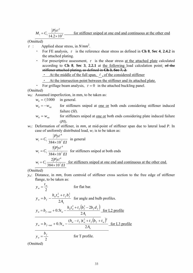
where: (Omitted) M1: Bending moment, in Nmm, due to the lateral load P:
3
2
11024
sP
CM i for continuous stiffener
3
2
1108
sP
CM i for sniped stiffener
33
3
2
1 102.14
sPCM i for stiffener sniped at one end and continuous at the other end
(Omitted) : Applied shear stress, in N/mm2.
・ For FE analysis, is the reference shear stress as defined in Ch 8, Sec 4, 2.4.2 in the attached plating.
・ For prescriptive assessment, is the shear stress at the attached plate calculated according to Ch 8, Sec 3, 2.2.1 at the following load calculation point: of the stiffener attached plating, as defined in Ch 3, Sec 7, 2. ・ At the middle of the full span, , of the considered stiffener
・ At the intersection point between the stiffener and its attached plate. ・ For grillage beam analysis, 0 in the attached buckling panel.
(Omitted) w0: Assumed imperfection, in mm, to be taken as:
10000 w in general.
naww 0 for stiffeners sniped at one or both ends considering stiffener induced
failure (SI).
naww 0 for stiffeners sniped at one or both ends considering plate induced failure
(PI). w1: Deformation of stiffener, in mm, at mid-point of stiffener span due to lateral load P. In
case of uniformly distributed load, w1 is to be taken as:
EI
sPCw i 7
4
110384
in general
EI
sPCw i 7
4
110384
5
for stiffeners sniped at both ends
EI
sPCw i 7
4
1 10384
2
for stiffeners sniped at one end and continuous at the other end.
(Omitted) yw: Distance, in mm, from centroid of stiffener cross section to the free edge of stiffener
flange, to be taken as:
2w
w
ty for flat bar.
s
ffwwfw A
btthby
2
22 for angle and bulb profiles.
s
ffffwwwoutfw A
dbbtthtby
2
25.0
22 for L2 profile
s
wffwfwwoutfw A
tbttthtby
2
)(5.0
22 for L3 profile
2f
w
by for T profile.
(Omitted)

34
Table 5 has been amended as follows.
Table 5 Moments of Inertia
Flat bars (1) Bulb, angle, L2, L3 and T profiles
IP 4
3
103wwth
42
2
103
5.0
ff
ffw eAteA
IT
w
www
h
tth63.01
103 4
3
f
fff
ff
wwff
b
ttb
te
ttte63.01
1035.063.01
103
5.04
3
4
3
I 6
33
1036wwth
wf
wffff
AA
AAbeA 6.2
1012 6
22
for bulb and angle, L2 and L3 profiles.
6
23
1012fff etb
for T profiles.
(1) tw is the net web thickness, in mm. tw red as defined in 2.3.2 is not to be used in this table.
35
Chapter 9 FATIGUE
Section 2 STRUCTURAL DETAILS TO BE ASSESSED
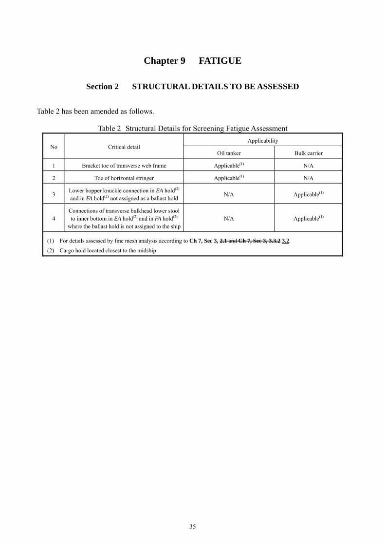
Table 2 has been amended as follows.
Table 2 Structural Details for Screening Fatigue Assessment
No Critical detail Applicability
Oil tanker Bulk carrier
1 Bracket toe of transverse web frame Applicable(1) N/A
2 Toe of horizontal stringer Applicable(1) N/A
3 Lower hopper knuckle connection in EA hold(2) and in FA hold(2) not assigned as a ballast hold
N/A Applicable(1)
4 Connections of transverse bulkhead lower stool to inner bottom in EA hold(2) and in FA hold(2)
where the ballast hold is not assigned to the shipN/A Applicable(1)
(1) For details assessed by fine mesh analysis according to Ch 7, Sec 3, 2.1 and Ch 7, Sec 3, 3.3.2 3.2.
(2) Cargo hold located closest to the midship

36
Table 3 has been amended as follows.
Table 3 Structural Details to be Assessed by Very Fine Mesh Analysis if Not Designed in accordance with Detail Design Standard
No Critical detail Corresponding detail design
standard
Applicability
Oil tanker Bulk carrier
1 Radiused upper hopper knuckle connection (intersection of knuckled inner side plate, side girder and transverse
web) at the most critical frame location.(1) Ch 9, Sec 6, 4 One cargo tank(4)
Ballast hold of double side bulk carrier
2 Corrugations of transverse bulkheads to lower stool or
inner bottom plating connection.(2)(3) Ch 9, Sec 6, 6 and
Ch 9, Sec 6, 7One cargo tank(4) Ballast hold
3 Corrugations of transverse bulkheads to upper stool.(2)(3) Ch 9, Sec 6, 6 N/A Ballast hold
4
Cruciform heel connections between side stringers in double side and transverse bulkhead horizontal
stringers, for the stringer closest to the mid depth and for the uppermost one.
Ch 9, Sec 6, 5 One cargo tank(4) N/A
5 Lower and upper side frame bracket toes at the most
critical frame position.(1) Ch 9, Sec 6, 8 N/A
FA hold(4), EA hold(4) and ballast hold of single skin bulk carrier
6 Cut out for longitudinal stiffeners in web-frame without
web stiffener connection. Ch 9, Sec 6, 2.1 One cargo tank(4)
FA hold(4), EA hold(4) and ballast hold
7 Scallops in way of block joints on strength deck close to
mid hold (and down to 0.1D from deck corner). Ch 9, Sec 6, 3 One cargo tank(4)
FA hold(4), EA hold(4) and ballast hold
(1) The most critical frame position is generally, but not necessarily, located closest to the mid length of the hold. Where a
swash bulkhead is fitted, this is generally located closest to the mid length between the swash bulkhead and the oil-tight
bulkhead.
(2) Stool connections at each end of the hold are to be checked unless these are symmetrical about mid-hold.
(3) Position at the mid breadth or length location of the largest hold in the considered transverse or longitudinal section.
(4) Cargo hold located closest to the midship.
Titles of Table 8 to Table 10 have been amended as follows.
Table 8 Hot Spots for Corrugated Transverse Bulkhead to Lower Stool Connection
Table 9 Hot Spots for Corrugated Transverse Bulkhead to Lower Stool - Intersecting Shedder Plates and Single Sided Shedder Plate
Table 10 Hot Spots for Corrugated Transverse Bulkhead to Lower Stool or Inner Bottom Plating
Connection

37
Section 3 FATIGUE EVALUATION
6. Weld Improvement Methods
6.2 Weld Toe Burr Grinding Paragraph 6.2.1 has been amended as follows. 6.2.1 The weld may be machined using a burr grinding tool to produce a favourable shape to reduce stress concentrations and remove defects at the weld toe, see Fig. 5. In order to eliminate defects, such as intrusions, undercuts and cold laps, the material in way of the weld toe is to be removed. The depth of grinding shall be at least 0.5 mm below the bottom of any visible undercut. The total depth of the burr grinding is not to be greater than the lesser of 2 mm and of 7% the local gross thickness of the machined plate. Any undercut not complying with this requirement is to be repaired by an approved method. Fig. 6 has been amended as follows.
Fig. 6 Extent of Weld Toe Burr Grinding to Remove Inter-bead Toes on Weld Face
leg : Weld leg length.
w: Width of groove.
d: Depth of grinding to be 0.5 mm d 1 mm.
38
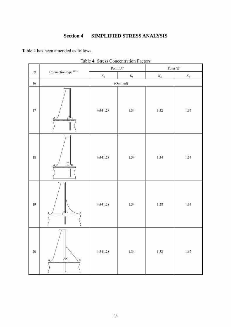
Section 4 SIMPLIFIED STRESS ANALYSIS
Table 4 has been amended as follows.
Table 4 Stress Concentration Factors
ID Connection type (2) (3) Point ‘A’ Point ‘B’
Ka Kb Ka Kb
16 (Omitted)
17
1.341.28 1.34 1.52 1.67
18
1.341.28 1.34 1.34 1.34
19
1.341.28 1.34 1.28 1.34
20
1.341.28 1.34 1.52 1.67

39
Table 4 Stress Concentration Factors (Continued)
ID Connection type (2) (3) Point ‘A’ Point ‘B’
Ka Kb Ka Kb
21
1.341.28 1.34 1.52 1.67
22
1.341.28 1.34 1.34 1.34
23
1.341.28 1.34 1.28 1.34
24
1.341.28 1.34 1.52 1.67
25 (1)
1.28 for d 150
1.36 for 150 < d 250
1.45 for d > 250
1.40 for d 150
1.50 for 150 < d 250
1.60 for d > 250
1.14 for d 150
1.24 for 150 < d 250
1.34 for d > 250
1.25 for d 150
1.36 for 150 < d 250
1.47 for d > 250

40
Table 4 Stress Concentration Factors (Continued)
ID Connection type (2) (3) Point ‘A’ Point ‘B’
Ka Kb Ka Kb
26
1.28 1.34 1.34 1.47
27
1.52 1.67 1.34 1.47
28
1.52 1.67 1.34 1.47
29
1.341.28 1.34 1.34 1.47
30
1.341.28 1.34 1.34 1.47

41
Section 6 DETAIL DESIGN STANDARD
Table 8 has been amended as follows.
Table 8 Design Standard H – Upper Hopper Knuckle Connection Detail, Radiused Type, Oil Tankers and Double Side Bulk Carrier
Connections of transverse webs in double side tanks to hopper tanks Hopper corner connections employing radiused knuckle between side longitudinal bulkhead and hopper sloping plating
Critical areas Design standard H
Note 1: Distance from side stringer to centre of knuckle is to be as small as
practicable, but is not to exceed 50 mm. Note 2: The knuckle radius is not to be less than 4.5tas-built or 100 mm,
whichever is the greater, where tas-built is the as-built thickness of the knuckle part, according to Ch 12, Sec 1, 3 and 4.
Note 3: Additional transverse brackets offset at a suitable distance on either side of transverse floor/hopper connection.
Note 4: Additional longitudinal bracket on the side of sloping plate. Note 5: Longitudinal and/or transverse brackets may be omitted if it can be
demonstrated that the girder provides sufficient support at the knuckle line, i.e. that fatigue requirements according to Ch 9, Sec 5 and local strength analysis requirements according to Ch 7, Sec 3 are fulfilled.
Critical locations

42
(Omitted)
Table 11 has been amended as follows.
Table 11 Design Standard K – Transverse or Longitudinal Corrugated Bulkhead Connection
Detail, Oil Tanker
Connections of transverse or longitudinal bulkhead with lower stool - oil tanker
Critical areas Design standard K
Critical locations
Critical location Connections of lower stool top plate to corrugated transverse or longitudinal bulkheads.
(Omitted)
43
Chapter 10 OTHER STRUCTURES
Section 1 FORE PART
3. Structure subjected to Impact Loads
3.3 Bow Impact Paragraph 3.3.6 has been amended as follows. 3.3.6 Primary supporting members
(Omitted) (g) The net web thickness of each primary supporting member, tw, in mm including
decks/bulkheads in way of the side shell is not to be less than:
crbW
BIFBw
bPt
sin
crW
BIFBw
bPt
sin
where:
W : Angle, in deg, between the primary supporting member web and the shell plate,
see Fig. 5.
crb cr : Critical buckling stress in compression of the web of the primary supporting
member or deck/bulkhead panel in way of the applied load given by Ch 8, Sec 5, 3.1.12.2.3, in N/mm2. In the calculation, both x and y given in
Ch 8, Sec 5, 2.2.3 are to be considered and UP-B is to be applied.
4. Additional Scantling Requirements
4.1 Plate Stem Paragraph 4.1.2 has been amended as follows. 4.1.2 Breasthooks and diaphragm plating The net thickness of breasthooks/diaphragm plates in way of bow impact strengthening area defined in 3.3.1, tw, in mm, is not to be less than:
23570eH
w
Rst
where: s: Spacing of stiffeners on the web, as defined in Ch 1, Sec 4, Table 5, in mm. Where no
stiffeners are fitted, s is to be taken as the depth of the web.
44
Section 3 AFT PART
2. Aft Peak
Paragraph 2.2 has been amended as follows.
2.2 Stiffening of Floors and Girders in Aft Peak 2.2.1 Stiffeners on the floors and girders in aft peak ballast or fresh water tanks above propeller are to be designed in accordance with 2.2.2 and 2.2.3. This applies for stiffeners located in an area extending longitudinally between the forward edge of the rudder and the after end of the propeller boss and transversely within the diameter of the propeller. 2.2.12 The height of stiffeners, hstf, in mm, on the floors and girders are not to be less than:
stfstfh 80 for flat bar stiffeners.
stfstfh 70 for bulb profiles and flanged stiffeners.
where:
stf : Length of stiffener, in m, as shown in Fig. 1. Length need not be taken greater than 5 m.
2.2.23 Stiffeners on the floors and girders in aft peak ballast or fresh water tanks above propeller are to be arranged with brackets. This apply for stiffeners located in an area extending longitudinally between the forward edge of the rudder and the after end of the propeller boss and transversely within the diameter of the propeller. End brackets are to be provided as follows:
・ Brackets are to be fitted at the lower and upper ends when tstf exceeds 4 m.
・ Brackets are to be fitted at the lower end when tstf exceeds 2.5 m.
where:
tstf : Total length of stiffener, in m, as shown in Fig. 1.
3. Stern Frames
3.3 Connections Paragraph 3.3.1 has been amended as follows. 3.3.1 Connections with hull structure Stern frames are to be effectively attached to the aft structure and the required scantling for the lower part of the stern frame the propeller post is to be extended forward from the aft end of the propeller post, at the centerline of the propeller shaft, to a length not less than 1500 + 6 L2 mm, in order to provide an effective connection with the keel. However, the stern frame need not extend beyond the aft peak bulkhead.
45
4. Special Scantling Requirements for Shell Structure
4.1 Shell Plating Paragraph 4.1.2 has been amended as follows. 4.1.2 Heavy shell plates Heavy shell plates are to be fitted locally in way of the heavy plate floors as required by 2.1.1. The net thickness of heavy shell plates is not to be less than the value given in 4.1.1. Outboard of the heavy floors, the heavy shell plates may be reduced in thickness in as gradual a manner as practicable. Where the horn plating is radiused into the shell plating, the radius at the shell connection, r in mm, is not to be less than:
28.0150 Lr
46
Section 4 TANKS SUBJECT TO SLOSHING
2. Scantling Requirements
2.2 Stiffeners Paragraph 2.2.1 has been amended as follows. 2.2.1 Net section modulus The net section modulus, Z in cm3, of stiffeners subjected to sloshing pressures is not to be less than:
eHsbdg
bdgslh
RCf
sPZ
2
where: fbdg: Bending moment factor:
fbdg = 12 for stiffeners fixed against rotation at each end. This is generally to be applied for scantlings of all continuous stiffeners.
fbdg = 8 for stiffeners with one or both ends not fixed against rotation. This is generally to be applied to discontinuous stiffeners.
Cs: Permissible bending stress coefficient to be taken as defined in Table 2.: ・ For members subject to hull girder stress: coefficient to be taken as defined in Table
2. ・ Cs = Cs-max for other cases
Pslh: The greater of Pslh-ing, Pslh-t or Pslh-min as specified in 1.3. Cs-max: Coefficient as defined in Table 3.

47
Chapter 11 SUPERSTRUCTURES, DECKHOUSES AND HULL OUTFITTING
Section 3 EQUIPMENT
1. General
1.1 Application Paragraph 1.1.3 has been amended as follows. 1.1.3 The Equipment Number (EN) formula for the required anchoring equipment is based on an assumed maximum current speed of 2.5 m/s, maximum wind speed of 25 m/s and a maximum scope of chain cable between of 6 and 10. The scope of chain cable is defined as the ratio between the length of chain paid out and the waters depth. For ships with length greater than 135 m, alternatively the required anchoring equipment can be considered applicable to a maximum current speed of 1.54 m/s, a maximum wind speed of 11 m/s and waves with maximum significant height of 2 m. It is assumed that under normal circumstances a ship will uses only one bow anchor and chain cable at a time.
2. Equipment Number Calculation
2.1 Requirements Paragraph 2.1.1 has been amended as follows. 2.1.1 Anchors and chains are to be in accordance with Table 1 and the quantity, mass and sizes of these are to be determined by the equipment number (EN), given by:
ABhEN 1.023/2 where: h: Effective height, in m, from the summer load waterline to the top of the uppermost house,
to be obtained in accordance with the following formula:
nFB hhh
When calculating h, sheer and trim are to be disregarded. For the lowest tier h is to be measured at centerline from the upper deck or from a notional deck line where there is local discontinuity in the upper deck, as shown in Fig. 1.
hFB: Freeboard amidships from the summer load waterline to the upper deck, in m. hn: Height, in m, at the centreline of superstructure or of deckhouse tier ‘n’ having a breadth
greater than B/4. Where a house having a breadth greater than B/4 is above a house with a breadth of B/4 or less, the upper house is to be included and the lower ignored (see in Fig. 1).

48
A: A Side projected area, in m2, in profile view, of the parts of the hull, superstructures and houses above the summer load waterline which are within the length LCSR and also have a breadth greater than B/4.
Fixed screens or bulwarks 1.5 m or more in height are to be regarded as parts of houses when determining h and A. In particular, the hatched area shown in Fig. 2 is to be included. The height of hatch coamings and that of any deck cargo, such as containers, may be disregarded when determining h and A.
Fig. 1 Effective Heights of Deckhouses Measurement of heights
Summer Load waterline
hFB
h1
h2
h3
Notional deck line
Upper deck

49
3. Anchoring Equipment
Paragraph 3.1 has been amended as follows.
3.1 General 3.1.1 General Two bower anchors are to be connected to chain cable and stowed in position ready for use. A third anchor is recommended to be provided as a spare bower anchor and is listed for guidance only; it is not required as a condition of classification. 3.1.2 Design Anchors are to be of an approved design. The design of anchor heads is to be such as to minimise stress concentrations. In particular, the radii, on all parts of cast anchor heads are to be as large as possible, especially where there is considerable change of section. If the anchor design is different from standard or approved anchor types, drawing of the anchor, including material specification, is to be submitted for approval. The anchors are to be of an approved type and satisfy the testing conditions as per the Society’s requirements. 3.1.3 Testing All anchors and chain cables are to be tested at establishments and on machines recognised by the Society, under the supervision of surveyors or other representatives of the Society and in accordance with the relevant requirements of Part L. Test certificates showing particulars of weights of anchors, or size and weight of cable and of the test loads applied are to be available. These certificates are to be examined by the surveyor when the anchors and cables are placed onboard the ship. Paragraph 3.3 has been amended as follows.
3.3 High and Super High Holding Power Anchors 3.3.1 General Where agreed by the owner, consideration will be given to the use of special types of anchors. High Holding Power (HHP) and Super High Holding Power (SHHP) anchors, i.e. anchors for which a holding power higher than at least twice that of ordinary anchors has been proved according to the applicable requirements of Part L, do not require prior adjustment or special placement on the sea bottom. 3.3.2 HHP or SHHP anchor mass Where HHP or SHHP anchors are used as bower anchors, the mass of each anchor is to be not less than 75% or 50%, respectively, of that the mass required for ordinary stockless anchors in Table 1. The mass of SHHP anchors is to be, in general, less than or equal to 1500 kg. 3.3.3 Application High holding power anchors are to be of a design that will ensure that the anchors will take effective hold of the sea bed without undue delay and will remain stable, for holding forces up to those required by 3.3.4, irrespective of the angle or position at which they first settle on the sea bed when dropped from a normal type of hawse pipe. A demonstration of these abilities may be required. The design approval of high holding power anchors may be given as a general/type approval, and listed in a published document by the Society. 3.3.4 Testing An anchor for which approval is sought as a high holding power (HHP) anchor, is to be tested
50
at sea to show that it has a holding power of twice that approved for a standard stockless anchor of the same mass. If approval is sought for a range of sizes, then at least two are to be tested. The smaller of the two anchors is to have a mass not less than one-tenth of that of the larger anchor. The larger of the two anchors tested is to have a mass not less than one-tenth of that of the largest anchor for which approval is sought. Each test is to comprise a comparison between at least two anchors: one ordinary stockless bower anchor and one HHP anchor. The masses of the anchors are to be approximately equal. The tests are generally to be carried out by means of a tug. The pull is to be measured by a dynamometer or determined from recently verified data of the tug's bollard pull as a function of propeller rpm. During the test, the length of the chain cable on each anchor is to be sufficient to obtain an approximately horizontal pull on the anchor. Generally, a horizontal distance between anchor and tug equal to 10 times the water depth will be sufficient. For SHHP, the tests are to be conducted on at least three different types of bottom, which may be soft mud or silt, sand or gravel, and hard clay or similarly compacted material. Paragraph 3.5 has been amended as follows.
3.5 Chain Lockers and stowed anchors 3.5.1 General The chain locker is to have adequate capacity and be of a suitable form to provide for the proper stowage of the chain cable, allowing an easy direct lead for the cable into the chain pipes when the cable is fully stowed. Port and starboard cables are to have separate spaces. The chain locker boundaries and access openings are to be watertight. Provisions are to be made to minimise the probability of the chain locker being flooded in bad weather. Adequate drainage facilities for the chain locker are to be provided. Chain or spurling pipes are to be of suitable size and provided with chafing lips. 3.5.2 Application Securing of the inboard ends of chain cables Provisions are to be made for securing the inboard ends of the chain to the structure. This attachment and its supporting structure are to be able to withstand a force of not less than 15% or more than 30% of the minimum breaking strength of the fitted chain cable. The fastening of the chain to the ship is to be arranged in such a way that in case of an emergency, when the anchor and chain have to be sacrificed, the chain can be readily released from an accessible position outside the chain locker. 3.5.3 Securing of stowed anchors Anchor lashings are to be designed to resist a load at least corresponding to twice the anchor mass plus 10 m of cable without exceeding 40% of the yield strength of the lashing material.
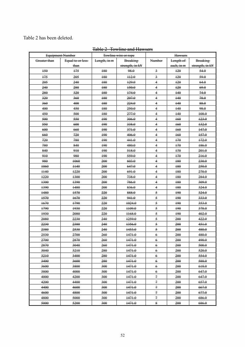
3.9 Tow lines and Mooring Line Paragraph 3.9.1 has been amended as follows. 3.9.1 General Mooring lines and towlines are not required as a condition of Classification. The hawsers and towlines listed in Table 2 are intended as a guide. Where the tabular breaking strength is greater than 490 kN, the breaking strength and the number of individual hawsers given in Table 2 may be modified, provided that their product is not less than that of the breaking strength and the number of hawsers given in the Table 2.

51
The designer is to provide the following information: • Towing line:
• Length, in m, • Breaking strength, in kN.
• Mooring lines: • Number • Length of each, in m, • Breaking strength, in kN.
Side projected area including that of deck cargoes as given by the loading manual is to be taken into account for selection of towing/mooring lines.
52
Table 2 has been deleted.
Table 2 Towline and Hawsers Equipment Number Towline wire or rope Hawsers
Greater than Equal to or less than
Length, in m
Breaking strength, in kN
Number Length of each, in m
Breaking strength, in kN
150 175 180 98.0 3 120 54.0
175 205 180 112.0 3 120 59.0
205 240 180 129.0 4 120 64.0
240 280 180 150.0 4 120 69.0
280 320 180 174.0 4 140 74.0
320 360 180 207.0 4 140 78.0
360 400 180 224.0 4 140 88.0
400 450 180 250.0 4 140 98.0
450 500 180 277.0 4 140 108.0
500 550 190 306.0 4 160 123.0
550 600 190 338.0 4 160 132.0
600 660 190 371.0 4 160 147.0
660 720 190 406.0 4 160 157.0
720 780 190 441.0 4 170 172.0
780 840 190 480.0 4 170 186.0
840 910 190 518.0 4 170 201.0
910 980 190 559.0 4 170 216.0
980 1060 200 603.0 4 180 230.0
1060 1140 200 647.0 4 180 250.0
1140 1220 200 691.0 4 180 270.0
1220 1300 200 738.0 4 180 284.0
1300 1390 200 786.0 4 180 309.0
1390 1480 200 836.0 4 180 324.0
1480 1570 220 888.0 5 190 324.0
1570 1670 220 941.0 5 190 333.0
1670 1790 220 1024.0 5 190 353.0
1790 1930 220 1109.0 5 190 378.0
1930 2080 220 1168.0 5 190 402.0
2080 2230 240 1259.0 5 200 422.0
2230 2380 240 1356.0 5 200 451.0
2380 2530 240 1453.0 5 200 480.0
2530 2700 260 1471.0 6 200 480.0
2700 2870 260 1471.0 6 200 490.0
2870 3040 260 1471.0 6 200 500.0
3040 3210 280 1471.0 6 200 520.0
3210 3400 280 1471.0 6 200 554.0
3400 3600 280 1471.0 6 200 588.0
3600 3800 300 1471.0 6 200 618.0
3800 4000 300 1471.0 6 200 647.0
4000 4200 300 1471.0 7 200 647.0
4200 4400 300 1471.0 7 200 657.0
4400 4600 300 1471.0 7 200 667.0
4600 4800 300 1471.0 7 200 677.0
4800 5000 300 1471.0 7 200 686.0
5000 5200 300 1471.0 8 200 686.0

53
Table 2 Towline and Hawsers (Continued) Equipment Number Towline wire or rope Hawsers
Greater than Equal to or less than
Length, in m
Breaking strength, in kN
Number Length of each, in m
Breaking strength, in kN
5200 5500 300 1471.0 8 200 696.0
5500 5800 300 1471.0 8 200 706.0
5800 6100 300 1471.0 8 200 706.0
6100 6500 300 1471.0 9 200 716.0
6500 6900 300 1471.0 9 200 726.0
6900 7400 300 1471.0 10 200 726.0
7400 7900 300 1471.0 11 200 726.0
7900 8400 300 1471.0 11 200 735.0
8400 8900 300 1471.0 12 200 735.0
8900 9400 300 1471.0 13 200 735.0
9400 10000 300 1471.0 14 200 735.0
10000 10700 - - 15 200 735.0
10700 11500 - - 16 200 735.0
11500 12400 - - 17 200 735.0
12400 13400 - - 18 200 735.0
13400 14600 - - 19 200 735.0
14600 16000 - - 21 200 735.0

54
Section 4 SUPPORTING STRUCTURE FOR DECK EQUIPMENT AND FITTINGS
2. Anchoring Windlass and Chain Stopper
2.1 General Paragraphs 2.1.4 and 2.1.5 have been amended as follows. 2.1.4 These requirements are to be assessed based on gross net scantlings. 2.1.5 The following load cases are to be examined for the anchoring operation, as appropriate:
(a) Windlass where chain stoppers is provided are fitted but not attached to the windlass: 45% of BS.
(b) Windlass where no chain stopper is not provided is fitted or the chain stopper is attached to the windlass: 80% of BS.
(c) Chain stopper: 80% of BS. where: BS: Minimum breaking strength of the chain cable.
Paragraph 2.1.12 has been amended as follows. 2.1.12 The stresses resulting from anchoring design loads induced in the supporting structure are not to be greater than the following permissible values:
・ Normal stress, 1.00ReH ・ Shear stress, 0.58ReH 0.60ReH
Paragraph 2.1.15 has been amended as follows. 2.1.15 The stresses resulting from green sea design loads induced in the supporting structure are not to be greater than the following permissible values:
・ Normal stress, 1.00ReH ・ Shear stress, 0.58ReH 0.60ReH
3. Mooring Winches
3.1 General Paragraphs 3.1.6 and 3.1.7 have been amended as follows. 3.1.6 Corrosion model These requirements are to be assessed based on gross net scantlings.
55
3.1.7 Each of the following load cases are to be examined for design loads due to mooring operation:
(a) Mooring winch at maximum pull: 100% of the Rated Pull. (b) Mooring winch with brake effective: 100% of the Holding Load. (c) Line strength: 125% of the breaking strength of the mooring line (hawser) according to
Ch 11, Sec 3, Table 2 for the ship’s corresponding equipment number provided by the designer (refer to Sec 3, 3.9).
Rated pull and holding load are defined in 3.1.3 and 3.1.4. The design load is to be applied through the mooring line according to the arrangement shown on the mooring arrangement plan.
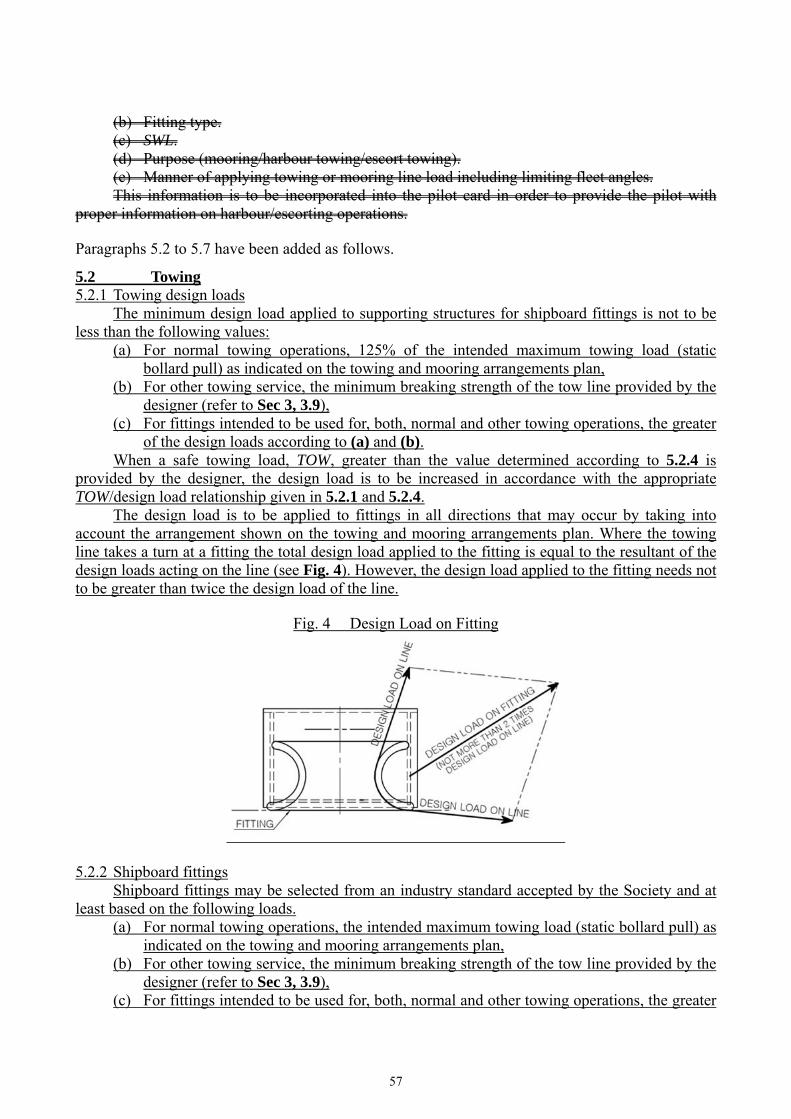
5. Bollards and Bitts, Fairleads, Stand Rollers, Chocks and Capstans
Paragraph 5.1 has been amended as follows.
5.1 General 5.1.1 Shipboard fittings (bollards and bitts, fairleads, stand rollers and chocks) and capstans used for mooring and towing operations are to be fitted to the deck or bulwark structures. Article 5 provides requirements applicable to the design and construction of shipboard fittings and supporting structures used for the normal towing at bow, side and stern and mooring operations as well as the strength of supporting structures of winches and capstans. Normal towing means towing operations necessary for manoeuvring in ports and sheltered waters associated with the normal operations of the ship. Where a ship is equipped with shipboard fittings intended to be used for other towing services, the strength of these fittings and their supporting structures are to comply with the requirements of this Article. 5.1.2 Where fairleads are fitted in bulwarks, the thickness of bulwarks may need to be increased. See Ch 11, Sec 2, 2.2. Article 5 is not applicable to design and construction of shipboard fittings and supporting structures used for special towing services defined as:
(a) Escort towing: Towing service, in particular, for laden oil tankers required in specific estuaries. Its main purpose is to control the ship in case of failures of the propulsion or steering system. It should be referred to local escort requirements and guidance given by, e.g., the Oil Companies International Marine Forum (OCIMF)
(b) Canal transit towing: Towing service for ships transiting, e.g. the Panama Canal. It should be refereed to local canal transit requirements.
(c) Emergency towing for oil tankers: Towing service to assist tankers in case of emergency. For the emergency towing arrangements, ships subject to SOLAS regulation II-1/3-4 Paragraph 1 are to comply with that regulation and resolution MSC.35(63) as may be amended.
5.1.3 The structural arrangement is to provide continuity of strength. The structural arrangement of the ship’s structure in way of the shipboard fittings and their seats and in way of capstans is to be such that abrupt changes of shape or section are to be avoided in order to minimise stress concentrations. Sharp corners and notches are to be avoided, especially in highly stressed areas. Where fairleads are fitted in bulwarks, the thickness of bulwarks may need to be increased.

56
See Ch 11, Sec 2, 2.2. 5.1.4 The supporting structure is to be dimensioned to ensure that for the loads specified in 5.1.6 to 5.1.8 5.2.1 and 5.3.1, the stresses do not exceed the permissible values given in 5.1.9 5.5. The capability of the structure to resist buckling failure is to be assured according to Ch 8. 5.1.5 These requirements are to be assessed based on net scantlings. 5.1.6 Design loads for the supporting structure for shipboard fittings are to be according to:
(a) In the case of normal towing in harbour or manoeuvring operations, 125% of the maximum towline load as indicated on the towing and mooring arrangement plan.
(b) In the case of towing service other than that experienced in harbour or manoeuvring operations, such as escort service, the nominal breaking strength of towline.
(c) In the case of mooring operations, 125% of the nominal breaking strength of the mooring line (hawser) according to Ch 11, Sec 3, Table 2 for the ship’s corresponding equipment number.
5.1.7 The design load for the supporting structure for capstans is to taken as 125% of the maximum hauling in force. 5.1.8 The assessment of the structure is to consider lines of action of the applied design load, taking into account the particular arrangements proposed; however, the total load applied for towing and mooring scenarios described in 5.1.6 need not be more than twice the design load on the mooring line or towline. The acting point for the force on the shipboard fittings is to be taken as the attachment point of the mooring line or towline, or at a change in its direction. 5.1.9 For the design load specified in 5.1.6 to 5.1.8, the stresses induced in the supporting structure and welds are not to exceed the following permissible values:
・ Normal stress, 1.00ReH ・ Shear stress, 0.60ReH
5.1.10 The following requirements on Safe Working Load apply for a single post basis (i.e. no more than one turn of one cable).
(a) The SWL used for normal towing operations, e.g. harbour/manoeuvring is not to exceed 80% of the design load per 5.1.6 item (a); and the SWL used for other towing operations, e.g. escort is not to exceed the design load per 5.1.6 item (b). For deck fittings used for both normal and other towing operations, the greater of the design loads of 5.1.6 item (a) and 5.1.6 item (b) is to be used.
(b) The SWL for mooring operations is not to exceed 80% of the design load per 5.1.6 item (c).
(c) The SWL of each deck fitting is to be marked (by weld bead or equivalent) on the deck fittings used for towing and/or mooring.
(d) The towing and mooring arrangements plan mentioned in 5.1.11 is to define the method of use of towing lines and/or mooring lines.
5.1.11 The SWL for the intended use for each deck fitting is to be stated in the towing and mooring arrangements plan available onboard for consistency for the guidance of the Master. For each deck fitting, the following is to be included:
(a) Location on the ship.
57
(b) Fitting type. (c) SWL. (d) Purpose (mooring/harbour towing/escort towing). (e) Manner of applying towing or mooring line load including limiting fleet angles.
This information is to be incorporated into the pilot card in order to provide the pilot with proper information on harbour/escorting operations. Paragraphs 5.2 to 5.7 have been added as follows.
5.2 Towing 5.2.1 Towing design loads The minimum design load applied to supporting structures for shipboard fittings is not to be less than the following values:
(a) For normal towing operations, 125% of the intended maximum towing load (static bollard pull) as indicated on the towing and mooring arrangements plan,
(b) For other towing service, the minimum breaking strength of the tow line provided by the designer (refer to Sec 3, 3.9),
(c) For fittings intended to be used for, both, normal and other towing operations, the greater of the design loads according to (a) and (b).
When a safe towing load, TOW, greater than the value determined according to 5.2.4 is provided by the designer, the design load is to be increased in accordance with the appropriate TOW/design load relationship given in 5.2.1 and 5.2.4. The design load is to be applied to fittings in all directions that may occur by taking into account the arrangement shown on the towing and mooring arrangements plan. Where the towing line takes a turn at a fitting the total design load applied to the fitting is equal to the resultant of the design loads acting on the line (see Fig. 4). However, the design load applied to the fitting needs not to be greater than twice the design load of the line.
Fig. 4 Design Load on Fitting
5.2.2 Shipboard fittings Shipboard fittings may be selected from an industry standard accepted by the Society and at least based on the following loads.
(a) For normal towing operations, the intended maximum towing load (static bollard pull) as indicated on the towing and mooring arrangements plan,
(b) For other towing service, the minimum breaking strength of the tow line provided by the designer (refer to Sec 3, 3.9),
(c) For fittings intended to be used for, both, normal and other towing operations, the greater

58
of the loads according to (a) and (b). Towing bitts (double bollards) may be chosen for the towing line attached with eye splice if the industry standard distinguishes between different methods to attach the line, i.e. figure-of-eight or eye splice attachment. When the shipboard fitting is not selected from an accepted industry standard, the strength of the fitting and of its attachment to the ship is to be in accordance with the requirements of this Article. Towing bitts (double bollards) are required to resist the loads caused by the towing line attached with eye splice. 5.2.3 Towing force acting point The acting point of the towing force on shipboard fittings is to be taken at the attachment point of a towing line or at a change in its direction. For bollards and bitts the attachment point of the towing line is to be taken not less than 4/5 of the tube height above the base (see Fig. 5).
Fig. 5 Attachment point of the towing line
5.2.4 Safe Towing Load (TOW) The Safe Towing Load (TOW), in t, is the load limit for towing purpose. The following requirements for Safe Towing Load (TOW) apply for the use with no more than one line. If not otherwise chosen, for towing bitts (double bollards) TOW is the load limit for a towing line attached with eyesplice.
(a) TOW used for normal towing operations is not to exceed 80% of the design load given in 5.2.1(a).
(b) TOW used for other towing operations is not to exceed 80% of the design load given in 5.2.1(b).
(c) For fittings used for both normal and other towing operations, the greater of the safe towing loads in (a) and (b) above is to be used.
(d) For fittings intended to be used for, both, towing and mooring, 5.3 applies to mooring. TOW of each shipboard fitting is to be marked by weld bead or equivalent, on the deck fittings used for towing. For fittings intended to be used for, both, towing and mooring, SWL, in t, according to 5.3.4 is to be marked in addition to TOW.
5.3 Mooring 5.3.1 Mooring design loads The minimum design load applied to supporting structures for shipboard fittings is not to be less than 115% of the minimum breaking strength of the mooring line provided by the designer (refer to Sec 3, 3.9)
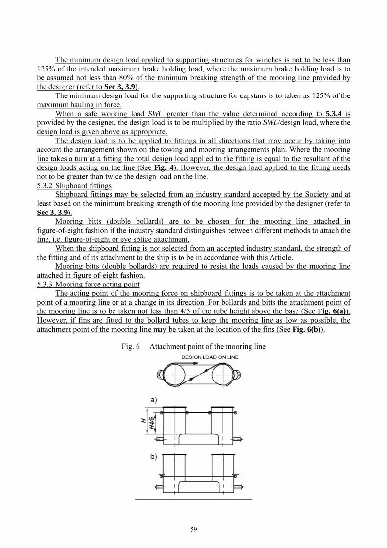
59
The minimum design load applied to supporting structures for winches is not to be less than 125% of the intended maximum brake holding load, where the maximum brake holding load is to be assumed not less than 80% of the minimum breaking strength of the mooring line provided by the designer (refer to Sec 3, 3.9). The minimum design load for the supporting structure for capstans is to taken as 125% of the maximum hauling in force. When a safe working load SWL greater than the value determined according to 5.3.4 is provided by the designer, the design load is to be multiplied by the ratio SWL/design load, where the design load is given above as appropriate. The design load is to be applied to fittings in all directions that may occur by taking into account the arrangement shown on the towing and mooring arrangements plan. Where the mooring line takes a turn at a fitting the total design load applied to the fitting is equal to the resultant of the design loads acting on the line (See Fig. 4). However, the design load applied to the fitting needs not to be greater than twice the design load on the line. 5.3.2 Shipboard fittings Shipboard fittings may be selected from an industry standard accepted by the Society and at least based on the minimum breaking strength of the mooring line provided by the designer (refer to Sec 3, 3.9). Mooring bitts (double bollards) are to be chosen for the mooring line attached in figure-of-eight fashion if the industry standard distinguishes between different methods to attach the line, i.e. figure-of-eight or eye splice attachment. When the shipboard fitting is not selected from an accepted industry standard, the strength of the fitting and of its attachment to the ship is to be in accordance with this Article. Mooring bitts (double bollards) are required to resist the loads caused by the mooring line attached in figure of-eight fashion. 5.3.3 Mooring force acting point The acting point of the mooring force on shipboard fittings is to be taken at the attachment point of a mooring line or at a change in its direction. For bollards and bitts the attachment point of the mooring line is to be taken not less than 4/5 of the tube height above the base (See Fig. 6(a)). However, if fins are fitted to the bollard tubes to keep the mooring line as low as possible, the attachment point of the mooring line may be taken at the location of the fins (See Fig. 6(b)).
Fig. 6 Attachment point of the mooring line

60
5.3.4 Safe Working Load (SWL) The Safe Working Load (SWL), in t, is the load limit for mooring purpose. The following requirements on Safe Working Load apply for the use with no more than one mooring line. Unless a greater SWL is provided by the designer, the SWL is not to exceed the minimum breaking strength of the mooring line provided by the designer (refer to Sec 3, 3.9). The SWL of each deck fitting is to be marked (by weld bead or equivalent) on the deck fittings used for mooring. For fittings intended to be used for, both, mooring and towing, TOW, in t, according to 5.2.4 is to be marked in addition to SWL.
5.4 Supporting structure 5.4.1 Shipboard fittings for towing and mooring, winches and capstans for mooring are to be located on stiffeners and/or girders, which are part of the deck construction so as to facilitate efficient distribution of the towing or mooring loads. Other arrangements may be accepted (for chocks in bulwarks, etc.) provided the strength is confirmed adequate for the intended service. 5.4.2 The reinforced structural members beneath shipboard fittings are to be effectively arranged for any variation of direction (horizontally and vertically) of the towing/mooring forces acting upon the shipboard fittings (see Fig. 7).
Fig. 7 Attachment point of the mooring line
5.4.3 Shipboard fittings (bollards and bitts, fairleads, stand rollers and chocks) and capstans used for mooring and/or towing operations are to be fitted to the deck or bulwark structures. 5.4.4 The structural arrangement is to provide continuity of strength. Proper alignment of fittings and supporting structure is to be ensured. The structural arrangement of the ship’s structure in way of the shipboard fittings and their seats and in way of capstans is to be such that abrupt changes of shape or section are to be avoided in order to minimise stress concentrations. Sharp corners and notches are to be avoided, especially in highly stressed areas.
5.5 Acceptance criteria 5.5.1 For the design load specified in 5.2.1 and 5.3.1, the stresses induced in the shipboard fittings, the supporting structure and welds are not to exceed the following permissible values defined in 5.5.3 and 5.5.4, as applicable:

61
5.5.2 The strength assessment of the shipboard fittings can be performed by means of either beam theory or grillage analysis, or by finite element analysis. At the discretion of the Society, load tests of the fittings may be accepted as alternative to strength assessment by above mentioned analysis. 5.5.3 For strength assessment with beam theory or grillage analysis, the permissible stresses to be considered are the following:
・ Normal stress: 1.00 ReH. ・ Shear stress: 0.60 ReH.
Normal stress is the sum of bending stress and axial stress with the corresponding shearing stress acting perpendicular to the normal stress. No stress concentration factors are taken into account. 5.5.4 For strength assessment with finite element analysis, the von Mises equivalent stress to be considered is not to exceed ReH. For strength calculations by means of finite elements, the geometry is to be modelled as realistically as possible. The ratio of element length to width is not to exceed 3. Girders are to be modelled using shell or plane stress elements. Symmetric girder flanges may be modelled by beam or truss elements. The element height of girder webs must not exceed one-third of the web height. In way of small openings in girder webs the web thickness is to be reduced to a mean thickness over the web height. Large openings are to be modelled. Stiffeners may be modelled by using shell, plane stress, or beam elements. Stresses are to be read from the centre of the individual element. For shell elements the stresses are to be evaluated at the mid plane of the element.
5.6 Corrosion addition of the fittings 5.6.1 The corrosion addition, tc, of the fittings is not be less than the following values:
(a) For pedestals and foundations on deck which are not part of a fitting according to an accepted industry standard, 2.0 mm.
(b) For shipboard fittings not selected from an accepted Industry standard, 2.0 mm. 5.6.2 In addition to the corrosion addition the wear allowance, tw, for shipboard fittings not selected from an accepted Industry standard is not to be less than 1.0 mm, added to surfaces which are intended to regularly contact the line.
5.7 Towing and mooring arrangements plan 5.7.1 The SWL and TOW for the intended use for each deck fitting is to be stated in the towing and mooring arrangements plan available onboard for the guidance of the Master. It is to be noted that TOW is the load limit for towing purpose and SWL that for mooring purpose. For each deck fitting, the following is to be included on the arrangement plan:
(a) Location on the ship, (b) Fitting type, (c) SWL and or TOW, (d) Purpose (mooring, harbour towing, other towing), (e) Manner of applying towing or mooring line load including limiting fleet angles.
Item (c) with respect to items (d) and (e), is subject to approval by the Society.

62
5.7.2 The information provided on the plan is to include:
(a) The arrangement of mooring lines showing number of lines (N), (b) The minimum breaking strength of each mooring line (MBL), (c) The acceptable environmental conditions:
・ 30 second mean wind speed from any direction ・ Maximum current speed acting on bow or stern (±10°).
This information is to be incorporated into the pilot card in order to provide the pilot with proper information on harbor and other towing operations. 5.7.3 The towing and mooring arrangements plan is to define the method of use of towing lines and/or mooring lines.
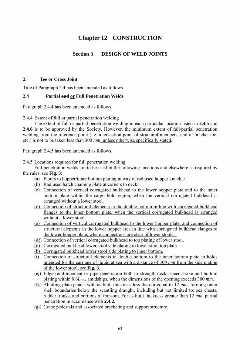
63
Chapter 12 CONSTRUCTION
Section 3 DESIGN OF WELD JOINTS
2. Tee or Cross Joint
Title of Paragraph 2.4 has been amended as follows.
2.4 Partial and or Full Penetration Welds Paragraph 2.4.4 has been amended as follows. 2.4.4 Extent of full or partial penetration welding The extent of full or partial penetration welding in each particular location listed in 2.4.5 and 2.4.6 is to be approved by the Society. However, the minimum extent of full/partial penetration welding from the reference point (i.e. intersection point of structural members, end of bracket toe, etc.) is not to be taken less than 300 mm, unless otherwise specifically stated. Paragraph 2.4.5 has been amended as follows. 2.4.5 Locations required for full penetration welding Full penetration welds are to be used in the following locations and elsewhere as required by the rules, see Fig. 3:
(a) Floors to hopper/inner bottom plating in way of radiused hopper knuckle. (b) Radiused hatch coaming plate at corners to deck. (c) Connection of vertical corrugated bulkhead to the lower hopper plate and to the inner
bottom plate within the cargo hold region, when the vertical corrugated bulkhead is arranged without a lower stool.
(d) Connection of structural elements in the double bottom in line with corrugated bulkhead flanges to the inner bottom plate, when the vertical corrugated bulkhead is arranged without a lower stool.
(e) Connection of vertical corrugated bulkhead to the lower hopper plate, and connection of structural elements in the lower hopper area in line with corrugated bulkhead flanges to the lower hopper plate, where connections are clear of lower stools.
(df) Connection of vertical corrugated bulkhead to top plating of lower stool. (g) Corrugated bulkhead lower stool side plating to lower stool top plate. (h) Corrugated bulkhead lower stool side plating to inner bottom. (i) Connection of structural elements in double bottom to the inner bottom plate in holds
intended for the carriage of liquid at sea with a distance of 300 mm from the side plating of the lower stool, see Fig. 3.
(ej) Edge reinforcement or pipe penetration both to strength deck, sheer strake and bottom plating within 0.6LCSR amidships, when the dimensions of the opening exceeds 300 mm.
(fk) Abutting plate panels with as-built thickness less than or equal to 12 mm, forming outer shell boundaries below the scantling draught, including but not limited to: sea chests, rudder trunks, and portions of transom. For as-built thickness greater than 12 mm, partial penetration in accordance with 2.4.2.
(gl) Crane pedestals and associated bracketing and support structure.

64
(hm) For toe connections of longitudinal hatch coaming end bracket to the deck plating, full penetration weld for a distance of 0.15 Hc from toe of side coaming termination bracket is required, where Hc is the hatch coaming height.
(in) Rudder horns and shaft brackets to shell structure. (jo) Thick flanges of long transverse web frames to side web frames. Thick flanges of long
longitudinal girder to bulkhead web frames. Paragraph 2.4.6 has been amended as follows. 2.4.6 Locations required for full or partial penetration welding Partial penetration welding as defined in 2.4.2, is to be used in the following locations. Additional locations may be required based on other criteria, such as fatigue assessment as given in Ch 9 (see examples in Fig. 3):
(a) Connection of hopper sloping plate to longitudinal bulkhead (inner hull). (b) Longitudinal/transverse bulkhead primary supporting member end connections to the
double bottom. (c) Corrugated bulkhead lower stool side plating to lower stool top plate. (d) Corrugated bulkhead lower stool side plating to inner bottom. (ec) Corrugated bulkhead lower stool supporting floors to inner bottom. (fd) Corrugated bulkhead gusset and shedder plates. (ge) Lower 15% of the length of built-up corrugation of vertical corrugated bulkheads (hf) Structural elements in double bottom below bulkhead primary supporting members and
stool plates, except in way of 2.4.5(i). (ig) Lower hopper plate to inner bottom. (jh) Horizontal stringers on bulkheads in way of their bracket toe and the heel.

65
Fig. 3 has been amended as follows.
Fig. 3 High Stress Areas Welding (examples)
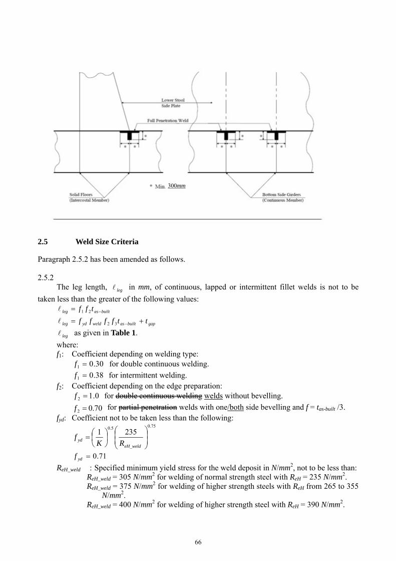
66
2.5 Weld Size Criteria Paragraph 2.5.2 has been amended as follows. 2.5.2 The leg length, leg in mm, of continuous, lapped or intermittent fillet welds is not to be
taken less than the greater of the following values:
builtasleg tff 21
gapbuiltasweldydleg ttffff 32
leg as given in Table 1.
where: f1: Coefficient depending on welding type:
30.01 f for double continuous welding.
38.01 f for intermittent welding. f2: Coefficient depending on the edge preparation:
0.12 f for double continuous welding welds without bevelling.
70.02 f for partial penetration welds with one/both side bevelling and f = tas-built /3. fyd: Coefficient not to be taken less than the following:
75.0
_
5.02351
weldeHyd RK
f
71.0ydf
ReH_weld : Specified minimum yield stress for the weld deposit in N/mm2, not to be less than: ReH_weld = 305 N/mm2 for welding of normal strength steel with ReH = 235 N/mm2. ReH_weld = 375 N/mm2 for welding of higher strength steels with ReH from 265 to 355
N/mm2. ReH_weld = 400 N/mm2 for welding of higher strength steel with ReH = 390 N/mm2.
300mm
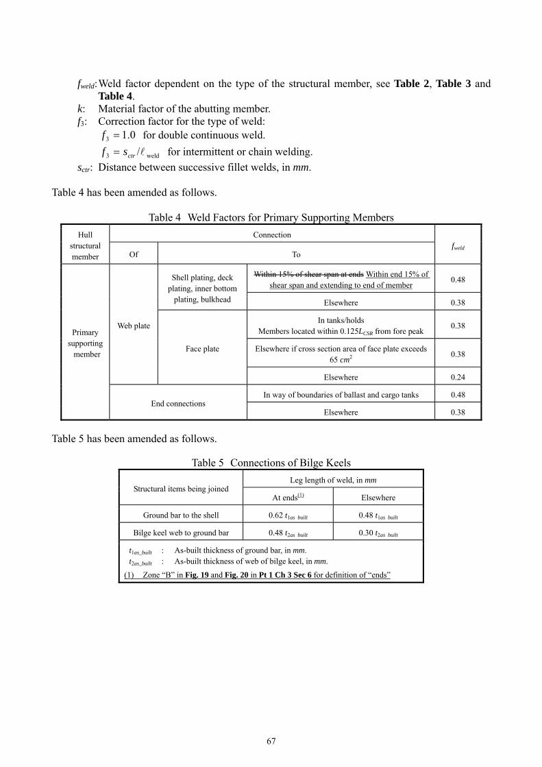
67
fweld: Weld factor dependent on the type of the structural member, see Table 2, Table 3 and Table 4.
k: Material factor of the abutting member. f3: Correction factor for the type of weld:
0.13 f for double continuous weld.
weld3 /ctrsf for intermittent or chain welding.
sctr: Distance between successive fillet welds, in mm. Table 4 has been amended as follows.
Table 4 Weld Factors for Primary Supporting Members
Hull structural member
Connection fweld
Of To
Primary supporting member
Web plate
Shell plating, deck plating, inner bottom
plating, bulkhead
Within 15% of shear span at ends Within end 15% of shear span and extending to end of member
0.48
Elsewhere 0.38
Face plate
In tanks/holds Members located within 0.125LCSR from fore peak
0.38
Elsewhere if cross section area of face plate exceeds 65 cm2
0.38
Elsewhere 0.24
End connections In way of boundaries of ballast and cargo tanks 0.48
Elsewhere 0.38
Table 5 has been amended as follows.
Table 5 Connections of Bilge Keels
Structural items being joined Leg length of weld, in mm
At ends(1) Elsewhere
Ground bar to the shell 0.62 t1as built 0.48 t1as built
Bilge keel web to ground bar 0.48 t2as built 0.30 t2as built
t1as_built : As-built thickness of ground bar, in mm. t2as_built : As-built thickness of web of bilge keel, in mm.
(1) Zone “B” in Fig. 19 and Fig. 20 in Pt 1 Ch 3 Sec 6 for definition of “ends”
68
Chapter 13 SHIP IN OPERATION – RENEWAL CRITERIA
Section 1 PRINCIPLES AND SURVEY REQUIREMENTS
1. Principles
1.3 Requirements for Documentation Paragraph 1.3.2 has been amended as follows. 1.3.2 Hull girder sectional properties The Midship section plan to be supplied onboard the ship is to include the minimum required hull girder sectional properties, as defined in Ch 5, Sec 1, for the typical representative transverse sections of all cargo holds.

69
Part 2 SHIP TYPES
Chapter 1 BULK CARRIERS
Section 3 HULL LOCAL SCANTLING
1. Cargo Hold Side Frames of Single Side Bulk Carriers
1.4 Provided Support at Upper and Lower Connections of Side Frames Paragraph 1.4.2 has been amended as follows. 1.4.2 Net connection area of brackets The net connection area, Ai, in cm2, of the lower or upper connecting bracket to the i-th supporting longitudinal stiffener is not to be taken less than to comply with the following formula:
3
lg,21
104.0 i
bktii
k
ksZA
iSFTibkteHii PsRdA 32
, 1002.0
where: Zi : Net section modulus, in cm3, of the i-th longitudinal stiffener on the side or
hopper/topside tank supporting the lower/upper end connecting bracket of the side frame, as applicable.
1 : As defined in 1.4.1. kbkt : Material factor for the bracket. klg,i : Material factor for the i-th longitudinal stiffener. Ai : The offered net connection area of the bracket connecting with the i-th longitudinal
stiffener, in cm2.
Tid , : As defined in 1.4.1.
ibkteHR , : The specified minimum yield stress of the bracket connecting with the i-th
longitudinal stiffener, in N/mm2, s : The space of the side frame, in mm.
4. Allowable Hold Loading for BC-A & BC-B Ships in Flooded Conditions
4.1 Evaluation of Double Bottom Capacity and Allowable Hold Loading Paragraph 4.1.4 has been amended as follows. 4.1.4 Allowable hold loading The allowable hold loading, in t, is to be taken as:

70
FVW c
1
where: (Omitted)
st : Density of steel, in t/m3, to be taken as 7.87.85.

71
Section 5 CARGO HATCH COVERS
7. Weathertightness, Closing Arrangement, Securing Devices and Stoppers
7.2 Gaskets Paragraph 7.2.1 has been amended as follows. 7.2.1 The weight of hatch covers and any cargo stowed thereon, together with inertia forces generated by ship motions, are to be transmitted to the ship’s structure through steel to steel contact. This may be achieved by providing continuous skirt plates on the hatch covers or by means of defined bearing pads.
EFFECTIVE DATE AND APPLICATION 1. The effective date of the amendments is 1 July 2018. 2. Notwithstanding the amendments to the Rules, the current requirements apply to ships for
which the date of contract for construction* is before the effective date. 3. Notwithstanding the provision of preceding 2., the amendments to the Rules may apply to
ships for which the date of contract for construction* is before the effective date upon request. * “contract for construction” is defined in the latest version of IACS Procedural Requirement
(PR) No.29.
IACS PR No.29 (Rev.0, July 2009) 1. The date of “contract for construction” of a vessel is the date on which the contract to build the vessel is signed between the prospective
owner and the shipbuilder. This date and the construction numbers (i.e. hull numbers) of all the vessels included in the contract are to be declared to the classification society by the party applying for the assignment of class to a newbuilding.
2. The date of “contract for construction” of a series of vessels, including specified optional vessels for which the option is ultimately exercised, is the date on which the contract to build the series is signed between the prospective owner and the shipbuilder.
For the purpose of this Procedural Requirement, vessels built under a single contract for construction are considered a “series of vessels” if they are built to the same approved plans for classification purposes. However, vessels within a series may have design alterations from the original design provided: (1) such alterations do not affect matters related to classification, or (2) If the alterations are subject to classification requirements, these alterations are to comply with the classification requirements in effect
on the date on which the alterations are contracted between the prospective owner and the shipbuilder or, in the absence of the alteration contract, comply with the classification requirements in effect on the date on which the alterations are submitted to the Society for approval.
The optional vessels will be considered part of the same series of vessels if the option is exercised not later than 1 year after the contract to build the series was signed.
3. If a contract for construction is later amended to include additional vessels or additional options, the date of “contract for construction” for such vessels is the date on which the amendment to the contract, is signed between the prospective owner and the shipbuilder. The amendment to the contract is to be considered as a “new contract” to which 1. and 2. above apply.
4. If a contract for construction is amended to change the ship type, the date of “contract for construction” of this modified vessel, or vessels, is the date on which revised contract or new contract is signed between the Owner, or Owners, and the shipbuilder.
Note: This Procedural Requirement applies from 1 July 2009.