safety rules for the construction and installation of lifts
TRANSCRIPT
Document type: European Standard Document subtype: Document stage: Formal Vote Document language: E STD Version 2.8f
CEN/TC 10 Date: 2018-01
FprEN 81-41:2018
CEN/TC 10
Secretariat: AFNOR
Safety rules for the construction and installation of lifts — Special lifts for the transport of persons and goods — Part 41: Vertical lifting platforms intended for use by persons with impaired mobility
Sicherheitsregeln für die Konstruktion und den Einbau von Aufzügen — Spezielle Aufzüge für den Personen- und Gütertransport — Teil 41: Vertikale Plattformaufzüge für Personen mit eingeschränkter Beweglichkeit
Règles de sécurité pour la construction et l'installation des élévateurs — Élévateurs spéciaux pour le transport des personnes et des charges — Partie 41 : Plates-formes élévatrices verticales à l'usage des personnes à mobilité réduite
ICS: 11.180.10 ; 14.180 ; 91.140.90 ; 94.400
Descriptors:
FprEN 81-41:2018 (E)
2
Contents
Page
European foreword ....................................................................................................................................................... 6
Introduction .................................................................................................................................................................... 7
1 Scope .................................................................................................................................................................... 9
2 Normative references ................................................................................................................................. 10
3 Terms and definitions ................................................................................................................................ 12
4 List of significant hazards ......................................................................................................................... 17
5 Safety requirements and/or protective measures .......................................................................... 21 5.1 General requirements for lifting platforms ........................................................................................ 21 5.1.1 General ............................................................................................................................................................. 21 5.1.2 Pattern of use ................................................................................................................................................. 21 5.1.3 Guarding .......................................................................................................................................................... 21 5.1.4 Access for maintenance, repair and inspection ................................................................................ 22 5.1.5 Speed................................................................................................................................................................. 23 5.1.6 Rated load ....................................................................................................................................................... 23 5.1.7 Load control ................................................................................................................................................... 24 5.1.8 Platform dimensions ................................................................................................................................... 24 5.1.9 Mechanical strength of the platform ..................................................................................................... 24 5.1.10 Resistance to operating forces ................................................................................................................ 26 5.1.11 Protection of equipment against harmful external influences ................................................... 26 5.1.12 Degree of protection for outdoor use ................................................................................................... 26 5.2 Platform support/guide system (including any scissor mechanism) ....................................... 27 5.2.1 Platform support/guide system ............................................................................................................. 27 5.3 Safety gear and overspeed governor..................................................................................................... 28 5.3.1 Safety gear ...................................................................................................................................................... 28 5.3.2 Overspeed governor .................................................................................................................................... 29 5.4 Driving units and drive systems ............................................................................................................. 30 5.4.1 General requirements ................................................................................................................................ 30 5.4.2 Braking system ............................................................................................................................................. 32 5.4.3 Emergency/manual operation ................................................................................................................ 33 5.4.4 Additional requirements for rack and pinion drive ........................................................................ 35 5.4.5 Additional requirements for rope, flat belt, toothed belt, chain suspension drive and
traction drive ................................................................................................................................................. 36 5.4.6 Additional requirements for screw and nut drive ........................................................................... 39 5.4.7 Additional requirements for guided chain system .......................................................................... 42 5.4.8 Additional requirements for scissors mechanism drive ............................................................... 44 5.4.9 Additional requirements for hydraulic drive .................................................................................... 44 5.4.10 Additional requirements for counterweighted traction system ................................................. 53 5.4.11 Additional requirements for rope and flat belt traction system ................................................ 54 5.4.12 Traction sheaves, pulleys and sprockets in the liftway.................................................................. 54 5.4.13 Ascending carrier overspeed protection means ............................................................................... 55 5.5 Electric installation and equipment ...................................................................................................... 56 5.5.1 General ............................................................................................................................................................. 56 5.5.2 Conductors of different circuits .............................................................................................................. 58 5.5.3 Insulation resistance of the electric installation .............................................................................. 59
FprEN 81-41:2018 (E)
3
5.5.4 Lighting ............................................................................................................................................................. 59 5.5.5 Socket outlet ................................................................................................................................................... 59 5.5.6 Drive contactors ............................................................................................................................................ 59 5.5.7 Motors supplied directly from AC mains .............................................................................................. 60 5.5.8 Creepage and clearance distances and enclosure requirements ................................................ 60 5.5.9 Electromagnetic compatibility ................................................................................................................ 61 5.5.10 Protection against electric faults ............................................................................................................ 61 5.5.11 Electric/Electronic safety devices .......................................................................................................... 61 5.5.12 Protection of the driving motor ............................................................................................................... 66 5.5.13 Electric wiring ................................................................................................................................................ 66 5.5.14 Additional requirements for battery powered supply ................................................................... 66 5.5.15 Control devices .............................................................................................................................................. 68 5.5.16 Emergency alarm devices .......................................................................................................................... 70 5.5.17 Cable-less controls ....................................................................................................................................... 71 5.5.18 Control of inspection operation .............................................................................................................. 71 5.6 Specific requirements for lifting platform enclosures .................................................................... 71 5.6.1 General ............................................................................................................................................................. 71 5.6.2 Top clearance ................................................................................................................................................. 72 5.6.3 Risks for persons working in the liftway ............................................................................................. 72 5.6.4 Enclosure construction ............................................................................................................................... 72 5.6.5 Glass ................................................................................................................................................................... 74 5.6.6 Inspection doors and traps ....................................................................................................................... 75 5.6.7 Ventilation ....................................................................................................................................................... 75 5.7 Fire protection ............................................................................................................................................... 75 5.8 Enclosed liftway entrances ....................................................................................................................... 76 5.8.1 General ............................................................................................................................................................. 76 5.8.2 Swing hinged landing doors ...................................................................................................................... 76 5.8.3 Height of landing doors .............................................................................................................................. 76 5.8.4 Construction of landing doors .................................................................................................................. 77 5.8.5 Door locking ................................................................................................................................................... 78 5.8.6 Emergency unlocking .................................................................................................................................. 79 5.8.7 Protection during door operation .......................................................................................................... 80 5.9 Platform ........................................................................................................................................................... 80 5.9.1 Construction ................................................................................................................................................... 80 5.9.2 Sensitive edges, photo cells or light curtains. ..................................................................................... 80 5.9.3 Toe guard ......................................................................................................................................................... 83 5.9.4 Floor covering ................................................................................................................................................ 83 5.9.5 Ceilings ............................................................................................................................................................. 84 5.9.6 Control panel .................................................................................................................................................. 84 5.9.7 Handrail ........................................................................................................................................................... 84 5.9.8 Glass ................................................................................................................................................................... 84 5.9.9 Tip up seat ....................................................................................................................................................... 84 5.9.10 Supporting structure ................................................................................................................................... 85
6 Verification of safety requirements and/or protective measures .............................................. 85 6.1 Verification of design .................................................................................................................................. 85 6.2 Verification tests ........................................................................................................................................... 89 6.2.1 Overspeed safety device ............................................................................................................................. 89 6.2.2 Ascending overspeed protection ............................................................................................................ 89 6.2.3 Rupture valve/Restrictor .......................................................................................................................... 89 6.2.4 Safety gear ....................................................................................................................................................... 89 6.2.5 Self-sustaining system ................................................................................................................................ 89 6.2.6 Stopping safety device ................................................................................................................................ 89 6.2.7 Landing door locking devices ................................................................................................................... 89 6.2.8 Safety circuits containing electronic components ............................................................................ 89
FprEN 81-41:2018 (E)
4
6.2.9 Self-monitoring ............................................................................................................................................. 89 6.3 Verification tests on each vertical lifting platform before first use ........................................... 90
7 Information for use ..................................................................................................................................... 91 7.1 Introduction ................................................................................................................................................... 91 7.2 General ............................................................................................................................................................. 91 7.3 Signals and warning devices .................................................................................................................... 91 7.3.1 Information to be displayed ..................................................................................................................... 91 7.4 Emergency manual operation ................................................................................................................. 91 7.5 Main electric switch .................................................................................................................................... 92 7.6 Fragile roof ..................................................................................................................................................... 92 7.7 No goods .......................................................................................................................................................... 92 7.8 Operating instructions ............................................................................................................................... 92 7.9 Accompanying documents (in particular: Instruction handbook) ............................................ 92 7.9.1 General ............................................................................................................................................................. 92 7.9.2 Instruction manual ...................................................................................................................................... 94 7.9.3 Marking ............................................................................................................................................................ 94 7.9.4 Building clearance requirements ........................................................................................................... 95
(normative) Electronic components: failure exclusion ............................................................. 96
(informative) Guidance in selection of lifting platforms ......................................................... 101 B.1 Introduction ................................................................................................................................................. 101 B.2 Selection of lifting platforms .................................................................................................................. 101 B.2.1 Suitability ...................................................................................................................................................... 101 B.2.2 Control devices ............................................................................................................................................ 101 B.2.3 Location of the lifting platform ............................................................................................................. 101 B.2.4 Duty cycle ...................................................................................................................................................... 102 B.3 Electric supply and lighting .................................................................................................................... 102 B.4 Maintenance ................................................................................................................................................. 102
(informative) Recommendations for the provisions and use of specially adapted control devices, switches and sensors ................................................................................................ 103
C.1 Control devices ............................................................................................................................................ 103 C.2 Assistance ..................................................................................................................................................... 103 C.3 Specially adapted switches ..................................................................................................................... 103
(informative) In-use periodic examination, tests and servicing .......................................... 104 D.1 Periodic examinations and tests .......................................................................................................... 104 D.2 Servicing ........................................................................................................................................................ 104
(normative) Safety components – Tests procedures for verification of conformity ..... 105 E.1 General provisions ..................................................................................................................................... 105 E.2 Test report .................................................................................................................................................... 106 E.3 Screw and nut (not self sustaining system) stopping safety device ......................................... 107 E.3.1 General provisions ..................................................................................................................................... 107 E.3.2 Check on the characteristic of the stopping safety device ........................................................... 107 E.3.3 Comments ..................................................................................................................................................... 109 E.3.4 Test report .................................................................................................................................................... 109 E.4 Self sustaining system .............................................................................................................................. 110
(informative) Noncircular elastomeric coated steel suspension applications on lifting platforms .......................................................................................................................................... 111
F.1 Properties and tolerances ....................................................................................................................... 111 F.1.1 Classification ................................................................................................................................................ 111 F.1.2 Dimension tolerances ............................................................................................................................... 111 F.2 Replacement criteria ................................................................................................................................ 111 F.2.1 Replacement of members........................................................................................................................ 111

FprEN 81-41:2018 (E)
5
F.2.2 Replacement due to wear ....................................................................................................................... 112 F.2.3 Replacement due to damage .................................................................................................................. 112
(informative) Building interfaces .................................................................................................... 113 G.1 General provisions .................................................................................................................................... 113 G.2 Support of Guide Rails.............................................................................................................................. 113 G.3 Ventilation of the enclosed liftway ...................................................................................................... 113 G.3.1 General .......................................................................................................................................................... 113 G.3.2 Ventilation of the enclosed liftway ...................................................................................................... 114
Annex ZA (informative) Relationship between this European Standard and the Essential Requirements of EU Directive 2006/42/EC aimed to be covered............................................ 116
Bibliography .............................................................................................................................................................. 117

FprEN 81-41:2018 (E)
6
European foreword
This document (FprEN 81-41:2018) has been prepared by Technical Committee CEN/TC 10 “Lifts, escalators and moving walks”, the secretariat of which is held by AFNOR.
This document is currently submitted to the Formal Vote.
This document will supersede EN 81-41:2010.
This document has been prepared under a mandate given to CEN by the European Commission and the European Free Trade Association, and supports essential requirements of EU Directive 2006/42/EC OF THE EUROPEAN PARLIAMENT AND OF THE COUNCIL of 17 May 2006 on machinery, and amending Directive 95/16/EC.
For relationship with EU Directive, see informative Annex ZA, which is an integral part of this document.
FprEN 81-41:2018 (E)
7
Introduction
The population of Europe is ageing and the prevalence of disability, including disability associated with the ageing process, is increasing. Older people and people with disabilities at present are estimated to number some 80 million people – a large and growing proportion of the European Union population. The changing demography presents both opportunities and challenges for the Union. The economic, social and cultural potential of older people and people with disabilities is underexploited at present. However there is a growing recognition that society needs to exploit this potential for the economic and social benefit of society generally.
This is one of the reasons that led to this standard on vertical lifting platforms for people with impaired mobility being one means to provide accessibility to buildings.
This standard is a type C standard as stated in EN ISO 12100.
The machinery concerned and the extent to which hazards, hazardous situations and events are covered are indicated in the scope of this standard.
When provisions of this type C standard are different from those which are stated in type A and type B standards the provisions of this type C standard take precedence over the provisions of the other standards, for machines that have been designed and built according to the provisions of this type C standard.
The lifting platforms defined in this standard are suitable for type A and type B wheelchairs as defined in EN 12183 and/or EN 12184. The lifting platforms are equally suitable for persons either with or without impaired mobility.
Those items relevant to lifting platforms referenced within EN 81-70 have been included within this standard.
This standard does not only address the essential health and safety requirements of the Machinery Directive, but additionally states minimum rules for the installation of lifting platforms into buildings/constructions. There may be regulations for the construction of building, etc. in some countries which cannot be ignored.
It is essential that minimum passageways conform to national building regulations and are not obstructed by any open door or trap and/or any protection means provided for working areas outside of the enclosed liftway where fitted according to the maintenance instructions.
Assumptions
With the aim of clarifying the intentions of the standard and avoiding doubts when applying it, the following assumptions were made when producing it:
a) Vertical lifting platforms are installed in both new and existing buildings.
b) For existing buildings where space is not available, other dimensions may be considered. Local building regulations should be observed.
c) Liftways contain only that equipment associated with a specific lifting platform. All counterweights or balance weights are in the same liftway as the carrier.
d) Equipment is installed in a machinery space.

FprEN 81-41:2018 (E)
8
e) Relevant risks have been considered for each component that may be incorporated in a complete lift installation and rules have been drawn up accordingly. Components are:
1) designed in accordance with the usual engineering practice and calculation codes, including all failure modes;
2) of sound mechanical and electric construction.
f) general hazards due to hydraulic, pneumatic, etc. equipment are dealt with according to relevant B level standards for common use;
g) materials known to be harmful materials, such as asbestos are not to be used as part of the machine.
h) Components are kept in good repair and working order, in accordance with the maintenance manual, so that the required characteristics remain despite wear.
i) By design of the load bearing elements, safe operation of the machine is ensured for loads ranging from zero to, the dynamic operating maximum working load and to the maximum static load.
j) To ensure the safe functioning, the operating temperature range of the equipment will take into account the conditions of the place of use of the machinery, inside the maximum range of ambient temperature between + 5 °C and + 40 °C. For very hot or cold environments extra requirements may be necessary.
k) Negotiations have been made between the customer and the manufacturer about:
1) environmental conditions;
2) civil engineering conditions; see 7.4.1.3;
3) other aspects related to the place of installation;
4) the use and places of use of the machinery;
5) the place of installation allows a safe use for the machine;
6) any additional fire protection requirements;
7) suitability for the user (see Annex B).

FprEN 81-41:2018 (E)
9
1 Scope
1.1 This document deals with safety requirements for construction, installation, maintenance and dismantling of electrically powered vertical lifting platforms affixed to a building structure intended for use by persons with impaired mobility:
— travelling vertically between predefined levels along a guided path whose inclination to the vertical does not exceed 15°;
— intended for use by persons with or without a wheelchair;
— supported or sustained by rack and pinion, rope traction drive, noncircular elastomeric-coated steel suspension members (hereafter called flat belt), traction drive, rope positive drive, chains, toothed belts, screw and nut, guided chain, scissors mechanism or hydraulic jack (direct or indirect);
— with enclosed liftways;
— with a speed not greater than 0,15 m/s;
— with platforms where the carrier is not completely enclosed.
1.2 This document deals with all significant hazards relevant to lifting platforms, when they are used as intended and under the conditions foreseen by the manufacturer (see Clause 4).
1.3 This document does not specify the additional requirements for:
— operation in severe conditions (e.g. extreme climates, strong magnetic fields);
— lightning protection;
— operation subject to special rules (e.g. potentially explosive atmospheres);
— handling of materials, the nature of which could lead to dangerous situations;
— vertical lifting platforms whose primary function is the transportation of goods;
— vertical lifting platforms whose carriers are completely enclosed;
— vertical lifting platforms prone to vandalism;
— hazards occurring during manufacture;
— earthquakes, flooding;
— firefighting, evacuation and behaviour during a fire;
— noise and vibrations;
— the design of concrete, hard core, timber or other foundation or building arrangement;
— the design of anchorage bolts to the supporting structure;
— type C wheelchairs as defined in EN 12183 and/or EN 12184.
NOTE For the actual type of machinery, noise is not considered a significant nor relevant hazard.

FprEN 81-41:2018 (E)
10
1.4 This document is not applicable to Vertical Lifting Platforms intended for use by persons with impaired mobility which are manufactured before the date of its publication as an EN.
2 Normative references
The following documents, in whole or in part, are normatively referenced in this document and are indispensable for its application. For dated references, only the edition cited applies. For undated references, the latest edition of the referenced document (including any amendments) applies.
EN 81-20:2014, Safety rules for the construction and installation of lifts — Lifts for the transport of persons and goods — Part 20: Passenger and goods passenger lifts
EN 81-50:2014, Safety rules for the construction and installation of lifts — Examinations and tests — Part 50: Design rules, calculations, examinations and tests of lift components
EN 81-58, Safety rules for the construction and installation of lifts — Examination and tests — Part 58: Landing doors fire resistance test
EN 349, Safety of machinery — Minimum gaps to avoid crushing of parts of the human body
HD 384.6.61 S1, Electrical installations of buildings — Part 6: Verification — Chapter 61: Initial verification
EN 953, Safety of machinery — Guards — General requirements for the design and construction of fixed and movable guards
EN 12015, Electromagnetic compatibility — Product family standard for lifts, escalators and moving walks — Emission
EN 12016, Electromagnetic compatibility — Product family standard for lifts, escalators and moving walks — Immunity
EN 12183, Manual wheelchairs — Requirements and test methods
EN 12184, Electrically powered wheelchairs, scooters and their chargers — Requirements and test methods
EN 12385-4, Steel wire ropes — Safety — Part 4: Stranded ropes for general lifting applications
EN 12600:2002, Glass in building — Pendulum test — Impact test method and classification for flat glass
EN 13015, Maintenance for lifts and escalators – Rules for maintenance instructions
EN 13411 (all parts), Terminations for steel wire ropes — Safety
EN 16005:2012, Power operated pedestrian doorsets — Safety in use — Requirements and test methods
EN 50214, Flat polyvinyl chloride sheathed flexible cables
EN 60204-1:2006, Safety of machinery — Electrical equipment of machines — Part 1: General requirements (IEC 60204-1:2005, modified)
EN 60204-32, Safety of machinery — Electrical equipment of machines — Part 32: Requirements for hoisting machines (IEC 60204-32)
EN 60529, Degrees of protection provided by enclosures (IP Code) (IEC 60529)
FprEN 81-41:2018 (E)
11
EN 60664-1:2007, Insulation coordination for equipment within low-voltage systems — Part 1: Principles, requirements and tests (IEC 60664-1:2007)
EN 60747-5 (all parts), Discrete semiconductor devices and integrated circuits — Part 5: Optoelectronic devices (IEC 60747-5, all parts)
EN 60947-1:2007, Low-voltage switchgear and controlgear — Part 1: General rules (IEC 60947-1:2007)
EN 60947-4-1, Low-voltage switchgear and controlgear — Part 4-1: Contactors and motor-starters — Electromechanical contactors and motor-starters (IEC 60947-4-1)
EN 60947-5-1, Low-voltage switchgear and controlgear — Part 5-1: Control circuit devices and switching elements — Electromechanical control circuit devices (IEC 60947-5-1)
EN 61249-2 (all parts), Materials for printed boards and other interconnection structures — Part 2: Sectional specification set for reinforced base materials, clad and unclad (IEC 61249-2 series)
EN 61558-1, Safety of power transformers, power supplies, reactors and similar products — Part 1: General requirements and tests (IEC 61558-1)
EN 61800-5-2:2007, Adjustable speed electrical power drive systems — Part 5-2: Safety requirements — Functional (IEC 61800-5-2:2007)
EN 62326-1, Printed boards — Part 1: Generic specification (IEC 62326-1)
EN ISO 7010:2012, Graphical symbols — Safety colours and safety signs — Registered safety signs (ISO 7010:2011)
EN ISO 12100:2010, Safety of machinery — General principles for design — Risk assessment and risk reduction (ISO 12100:2010)
EN ISO 13850, Safety of machinery — Emergency stop function — Principles for design (ISO 13850)
EN ISO 13857:2008, Safety of machinery — Safety distances to prevent hazard zones being reached by upper and lower limbs (ISO 13857:2008)
EN ISO 14121-1, Safety of machinery — Risk assessment — Part 1: Principles (ISO 14121-1:2007)
ISO 606, Short-pitch transmission precision roller and bush chains, attachments and associated chain sprockets
ISO 6336 (all parts), Calculation of load capacity of spur and helical gears
ISO 7000:2014, Graphical symbols for use on equipment — Registered symbols
ISO 13050, Synchronous belt drives — Metric pitch, curvilinear profile systems G, H, R and S, belts and pulleys
IEC 60417:2002 DB, Graphical symbols for use on equipment — 12-month subscription to regularly updated online database comprising all graphical symbols published in IEC 60417
FprEN 81-41:2018 (E)
12
3 Terms and definitions
For the purposes of this document, the terms and definitions given in EN ISO 12100 and the following apply.
3.1 balancing weight mass which saves energy by balancing all or part of the mass of the unloaded lifting platform
3.2 carrier part of the lifting platform by which persons are supported in order to be lifted or lowered
3.3 competent person person, suitably trained and qualified by knowledge and practical experience, and provided with the necessary instructions to enable the required work to be carried out safely
3.4 cord diameter diameter of a circle that circumscribes the cross section of a cord and is used for evaluating diameter ratio
3.5 cord pitch spacing between adjacent cord centrelines in the noncircular elastomeric coated steel suspension member
3.6 counterweight mass which ensures traction
[SOURCE: EN 81-20:2014, 3.8]
3.7 down direction valve electrically controlled valve in a hydraulic circuit for controlling the descent of the lifting platform
3.8 drive unit unit, including the motor, that drives and stops the lifting platform
3.9 electric safety chain total of the electric safety devices, which can either be switches or safety circuits, connected in series with each other
3.10 electric safety contact contact in which the separation of the circuit breaking elements is made by positive means
3.11 electric safety device either an electric switch incorporating one or more electric safety contacts, or a safety circuit

FprEN 81-41:2018 (E)
13
3.12 enclosed liftway space in which the lifting platform and any counterweight or balancing weight travels and which is fully bounded by the bottom of the pit and a solid enclosure (but not necessarily a roof) and landing doors
3.13 existing building building which has been previously occupied and constructed prior to the requirement for a lifting platform
3.14 final limit device electric safety device operated by the lifting platform in the event of over-travel of the normal operation stop
3.15 full load pressure static pressure exerted on the piping directly connected to the jack, the platform with the rated load being at rest at the highest landing level
3.16 guide rails rigid components that provide guiding for the platform
3.17 guided chain chain which can be either fixed or moving, and which is completely guided over its entire length such that it can transmit a load either in thrust or tension
3.18 guided chain system platform supported, raised and lowered by means of one or more guided chain transmission units
3.19 impaired mobility difficulty in using stairs because of impairment
Note 1 to entry: Examples of persons with impaired mobility include, but are not restricted to: wheelchair users, persons with pushchair, persons with walking difficulties, persons using walking aids, carers for persons with impaired mobility and/or children with impaired mobility and elderly persons.
3.20 lifting platform device permanently installed to serve predefined landings comprising a guided platform whose characteristics are primarily intended to permit the access of persons with impaired mobility
3.21 load carrying nut internally threaded component which carries the load in conjunction with a screw
3.22 machinery space volume(s) inside or outside of the well where the machinery as a whole or in parts is placed, including the working areas associated with the machinery
Note 1 to entry: A machinery cabinet with its associated working area(s) is considered as a machinery space

FprEN 81-41:2018 (E)
14
[SOURCE: EN 81-20:2014, 3.29]
3.23 maximum static load possible static overload based on platform area, or maximum working load, whichever is highest
3.24 maximum working load rated load + overload of one person (equivalent to 75 kg)
3.25 mechanical blocking device device that, when set in position, guarantees a minimum safety space beneath the platform for the purposes of maintenance and inspection
3.26 noncircular elastomeric-coated steel suspension members noncircular suspension member (hereafter called flat belt), such as an elastomeric coated steel belt comprising steel cords arranged in parallel and moulded within a coating
3.27 noncircular elastomeric-coated steel suspension member, minimum breaking force (MBF) actual value of breaking force that the noncircular elastomeric coated steel suspension member shall meet or exceed in a tensile test
3.28 noncircular elastomeric-coated steel suspension member width dimension of the cross-section of the moulded noncircular suspension member, measured in the direction of sheave axis
3.29 overspeed governor device which, when the lift attains a predetermined speed, causes the lift to stop, and if necessary causes the safety gear to be applied
[SOURCE: EN 81-20:2014, 3.33]
3.30 overload additional load which is permissible based upon one person
3.31 positive drive drive which drives the lifting platform not reliant on friction by drum and ropes or by sprockets and chains or by positive belts, directly linked to the drive motor
3.32 pressure relief valve valve which limits the pressure to a pre-determined value by exhausting fluid
[SOURCE: EN 81-20:2014, 3.39]
3.33 public access location where the users are unknown
FprEN 81-41:2018 (E)
15
3.34 rated load load which is intended to be carried in normal operation 3.35 rated speed design speed of the lifting platform
3.36 re-levelling movements operation, after the lifting platform has stopped, to permit stopping position to be corrected during loading or unloading
3.37 restrictor valve in which the inlet and outlet are connected through a restricted passageway
[SOURCE: EN 81-20:2014, 3.47]
3.38 rupture valve valve designed to close automatically when the pressure drop across the valve, caused by the increased flow in a pre-determined flow direction exceeds a pre-set amount
[SOURCE: EN 81-20:2014, 3.48]
3.39 safety circuit circuit containing contacts and/or electronic components which is regarded to fulfill demands of an electric safety device
[SOURCE: EN 81-20:2014, 3.49]
3.40 safety factor ratio, either of the yield load (proof stress RP0,2), or the ultimate tensile load to the load that can be imposed upon a member by the rated load for a particular material under static or dynamic conditions
3.41 safety gear mechanical device for stopping in the down direction, and maintaining stationary on the guide rails, the carrier, counterweight or balancing weight in case of overspeeding or breaking of the suspension
[SOURCE: EN 81-20:2014, 3.51, adapted]
3.42 safety nut internally threaded component which is linked to the load carrying nut but is unloaded during normal service which is capable of carrying the load if the load carrying nut should break
3.43 screw external threaded component which carries the load in conjunction with the load carrying nut and in certain circumstances the load imposed by the safety nut
FprEN 81-41:2018 (E)
16
3.44 self-sustaining system system that, under free running conditions, ensure that the speed of the platform decreases
3.45 sensitive edge device attached to an edge to provide protection against trapping, shearing or crushing hazards 3.46 “shut-off” valve manually operated two-way valve which can permit or prevent flow in either direction
3.47 slack rope/chain device device, or combination of devices, arranged to stop the lifting platform, should any suspension rope or chain slacken by a pre-determined amount
3.48 steel cord assembly of steel strands each comprising steel wires, helically laid around a central core strand
3.49 stopping safety device mechanical device for stopping the relative rotation between screw and nut in case of overspeeding and stopping the lifting platform and maintaining it stationary
3.50 toe guard vertical component extending downwards from the platform entrance
3.51 traction system system whose suspension ropes or flat belts are driven by friction of the driving sheave of the machine
3.52 transmission unit assembly comprising the chain or toothed belt, and its associated elements, sprocket wheel, return housing, guided elements
3.53 unintended movement non-commanded movement of the lifting platform with landing doors open within the unlocking zone, excluding movements resulting from loading/unloading operation and re-levelling movements
3.54 unlocking zone zone, extending above and below a landing, in which the platform floor needs to be positioned to enable the corresponding landing door(s) to be unlocked
3.55 user person making use of the services of the platform
FprEN 81-41:2018 (E)
17
4 List of significant hazards
This clause contains all the significant hazards, hazardous situations and events, as far as they are dealt with in this standard, identified by risk assessment as significant for this type of machinery and which require action to eliminate or reduce the risk.
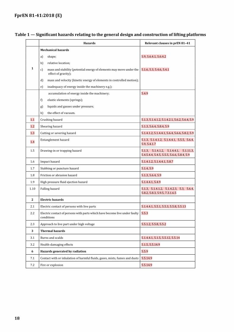
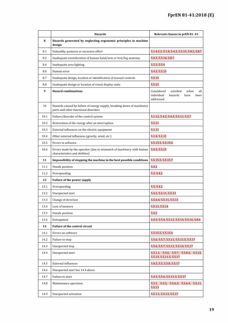
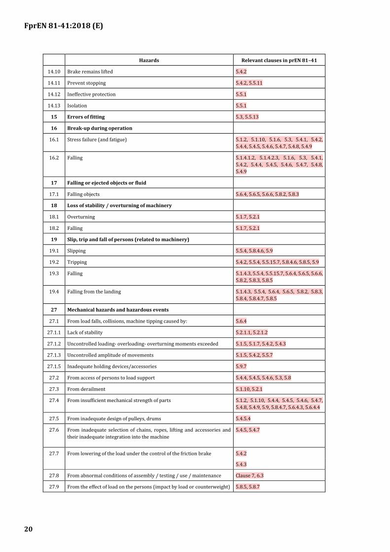
Table 1 shows the hazards which have been identified and where the corresponding requirements have been formulated in this standard, in order to limit the risk or reduce these hazards in each situation.
The significant hazards are based upon EN ISO 12100. Also shown are the subclause references to the safety requirements and/or protective measures in this standard.
Before supplying any lifting platform, it is important to review the risks in Table 1 to check that all site specific hazards have been identified in this clause.
FprEN 81-41:2018 (E)
18
Table 1 — Significant hazards relating to the general design and construction of lifting platforms
Hazards Relevant clauses in prEN 81–41
1
Mechanical hazards
a) shape; 5.9, 5.6.4.1, 5.6.4.2
b) relative location;
c) mass and stability (potential energy of elements may move under the
effect of gravity);
5.1.6, 5.3, 5.4.6, 5.4.1
d) mass and velocity (kinetic energy of elements in controlled motion);
e) inadequacy of energy inside the machinery e.g.);
accumulation of energy inside the machinery; 5.4.9
f) elastic elements (springs);
g) liquids and gasses under pressure;
h) the effect of vacuum.
1.1 Crushing hazard 5.1.3, 5.1.4.1.2, 5.1.4.2.1, 5.6.2, 5.6.4, 5.9
1.2 Shearing hazard 5.1.3, 5.6.4, 5.8.4, 5.9
1.3 Cutting or severing hazard 5.1.4.1.2, 5.1.4.4.1, 5.6.4, 5.6.6, 5.8.2, 5.9
1.4 Entanglement hazard 5.1.3, 5.1.4.1.2, 5.1.4.4.1, 5.5.5, 5.6.4,
5.9, 5.4.1.7
1.5 Drawing-in or trapping hazard 5.1.3, 5.1.4.1.2, 5.1.4.4.1, 5.1.11.3,
5.4.5.4.4, 5.4.5, 5.5.5, 5.6.6, 5.8.4, 5.9
1.6 Impact hazard 5.1.4.1.2, 5.1.4.4.1, 5.8.7
1.7 Stabbing or puncture hazard 5.1.4, 5.9
1.8 Friction or abrasion hazard 5.1.3, 5.6.4, 5.9
1.9 High pressure fluid ejection hazard 5.1.4.4.1, 5.4.9
1.10 Falling hazard 5.1.3, 5.1.4.1.2, 5.1.4.2.3, 5.3, 5.6.4,
5.8.2, 5.8.3, 5.9.5, 7.3.1.6.5
2 Electric hazards
2.1 Electric contact of persons with live parts 5.1.4.4.1, 5.5.1, 5.5.3, 5.5.8, 5.5.13
2.2 Electric contact of persons with parts which have become live under faulty
conditions
5.5.3
2.3 Approach to live part under high voltage 5.5.1.2, 5.5.8, 5.5.2
3 Thermal hazards
3.1 Burns and scalds 5.1.4.4.1, 5.1.5, 5.5.12, 5.5.14
3.2 Health-damaging effects 5.1.5, 5.5.14.9
6 Hazards generated by radiation 5.5.9
7.1 Contact with or inhalation of harmful fluids, gases, mists, fumes and dusts 5.5.14.9
7.2 Fire or explosion 5.5.14.9
FprEN 81-41:2018 (E)
19
Hazards Relevant clauses in prEN 81–41
8 Hazards generated by neglecting ergonomic principles in machine
design
8.1 Unhealthy postures or excessive effort 5.1.4.2.2, 5.1.8, 5.4.3, 5.5.15, 5.8.2, 5.8.7
8.2 Inadequate consideration of human hand/arm or foot/leg anatomy 5.4.3, 5.5.14, 5.8.7
8.4 Inadequate area lighting 5.5.3, 5.5.4
8.6 Human error 5.4.3, 5.5.15
8.7 Inadequate design, location or identification of manual controls 5.5.15
8.8 Inadequate design or location of visual display units 5.5.15
9 Hazard combinations Considered satisfied when all
individual hazards have been
addressed
10 Hazards caused by failure of energy supply, breaking down of machinery
parts and other functional disorders
10.1 Failure/disorder of the control system 5.1.12, 5.4.2, 5.4.3, 5.5.11, 5.5.7
10.2 Restoration of the energy after an interruption 5.5.11
10.3 External influences on the electric equipment 5.1.11
10.4 Other external influences (gravity, wind, etc.) 5.1.4, 5.1.11
10.5 Errors in software 5.5.15.5, 5.5.15.6
10.6 Errors made by the operator (due to mismatch of machinery with human
characteristics and abilities)
5.4.3, 5.5.15
11 Impossibility of stopping the machine in the best possible conditions 5.5.15.5, 5.5.15.7
11.1 Unsafe position 5.4.2
11.2 Overspeeding 5.3, 5.4.2
13 Failure of the power supply
13.1 Overspeeding 5.3, 5.4.2
13.2 Unexpected start 5.4.2, 5.5.11, 5.5.13
13.3 Change of direction 5.5.6.4, 5.5.11, 5.5.13
13.4 Loss of memory 5.5.11, 5.5.14
13.5 Unsafe position 5.4.2
13.6 Entrapment 5.4.3, 5.5.4, 5.5.11, 5.5.14, 5.5.16, 5.8.6
14 Failure of the control circuit
14.1 Errors on software 5.5.15.5, 5.5.15.6
14.2 Failure to stop 5.5.6, 5.5.7, 5.5.11, 5.5.11.5, 5.5.17
14.3 Unexpected stop 5.5.6, 5.5.7, 5.5.11, 5.5.14, 5.5.17
14.4 Unexpected start 5.5.1.1, 5.5.6, 5.5.7, 5.5.8.2, 5.5.12,
5.5.13, 5.5.11.5, 5.5.17
14.5 External influences 5.4.3, 5.5, 5.5.8, 5.5.17
14.6 Unexpected start See 14.4 above
14.7 Failure to start 5.4.3, 5.5.6, 5.5.11.3, 5.5.17
14.8 Maintenance operation 5.5.1, 5.5.5, 5.5.6.3, 5.5.6.4, 5.5.11,
5.5.13
14.9 Unexpected activation 5.5.1.1, 5.5.13, 5.5.17
FprEN 81-41:2018 (E)
20
Hazards Relevant clauses in prEN 81–41
14.10 Brake remains lifted 5.4.2
14.11 Prevent stopping 5.4.2, 5.5.11
14.12 Ineffective protection 5.5.1
14.13 Isolation 5.5.1
15 Errors of fitting 5.3, 5.5.13
16 Break-up during operation
16.1 Stress failure (and fatigue) 5.1.2, 5.1.10, 5.1.6, 5.3, 5.4.1, 5.4.2,
5.4.4, 5.4.5, 5.4.6, 5.4.7, 5.4.8, 5.4.9
16.2 Falling 5.1.4.1.2, 5.1.4.2.3, 5.1.6, 5.3, 5.4.1,
5.4.2, 5.4.4, 5.4.5, 5.4.6, 5.4.7, 5.4.8,
5.4.9
17 Falling or ejected objects or fluid
17.1 Falling objects 5.6.4, 5.6.5, 5.6.6, 5.8.2, 5.8.3
18 Loss of stability / overturning of machinery
18.1 Overturning 5.1.7, 5.2.1
18.2 Falling 5.1.7, 5.2.1
19 Slip, trip and fall of persons (related to machinery)
19.1 Slipping 5.5.4, 5.8.4.6, 5.9
19.2 Tripping 5.4.2, 5.5.4, 5.5.15.7, 5.8.4.6, 5.8.5, 5.9
19.3 Falling 5.1.4.3, 5.5.4, 5.5.15.7, 5.6.4, 5.6.5, 5.6.6,
5.8.2, 5.8.3, 5.8.5
19.4 Falling from the landing 5.1.4.3, 5.5.4, 5.6.4, 5.6.5, 5.8.2, 5.8.3,
5.8.4, 5.8.4.7, 5.8.5
27 Mechanical hazards and hazardous events
27.1 From load falls, collisions, machine tipping caused by: 5.6.4
27.1.1 Lack of stability 5.2.1.1, 5.2.1.2
27.1.2 Uncontrolled loading- overloading- overturning moments exceeded 5.1.5, 5.1.7, 5.4.2, 5.4.3
27.1.3 Uncontrolled amplitude of movements 5.1.5, 5.4.2, 5.5.7
27.1.5 Inadequate holding devices/accessories 5.9.7
27.2 From access of persons to load support 5.4.4, 5.4.5, 5.4.6, 5.3, 5.8
27.3 From derailment 5.1.10, 5.2.1
27.4 From insufficient mechanical strength of parts 5.1.2, 5.1.10, 5.4.4, 5.4.5, 5.4.6, 5.4.7,
5.4.8, 5.4.9, 5.9, 5.8.4.7, 5.6.4.3, 5.6.4.4
27.5 From inadequate design of pulleys, drums 5.4.5.4
27.6 From inadequate selection of chains, ropes, lifting and accessories and
their inadequate integration into the machine
5.4.5, 5.4.7
27.7 From lowering of the load under the control of the friction brake 5.4.2
5.4.3
27.8 From abnormal conditions of assembly / testing / use / maintenance Clause 7, 6.3
27.9 From the effect of load on the persons (impact by load or counterweight) 5.8.5, 5.8.7
FprEN 81-41:2018 (E)
21
Hazards Relevant clauses in prEN 81–41
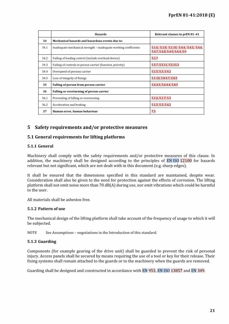
34 Mechanical hazards and hazardous events due to:
34.1 Inadequate mechanical strength – inadequate working coefficients 5.1.6, 5.1.8, 5.1.10, 5.4.4, 5.4.5, 5.4.6,
5.4.7, 5.4.8, 5.4.9, 5.6.4, 5.9
34.2 Failing of loading control (include overload device) 5.1.7
34.3 Failing of controls in person carrier (function, priority) 5.5.7, 5.5.11, 5.5.15.3
34.4 Overspeed of persons carrier 5.1.5, 5.3, 5.4.2
34.5 Loss of integrity of fixings 5.1.10, 5.8.4.7, 5.8.5
35 Falling of person from person carrier 5.6.4.3, 5.6.4.4, 5.8.5
36 Falling or overturning of person carrier
36.1 Preventing of falling or overturning 5.1.6, 5.1.7, 5.3
36.2 Acceleration and braking 5.1.5, 5.3, 5.4.2
37 Human error, human behaviour 7.3
5 Safety requirements and/or protective measures
5.1 General requirements for lifting platforms
5.1.1 General
Machinery shall comply with the safety requirements and/or protective measures of this clause. In addition, the machinery shall be designed according to the principles of EN ISO 12100 for hazards relevant but not significant, which are not dealt with in this document (e.g. sharp edges).
It shall be ensured that the dimensions specified in this standard are maintained, despite wear. Consideration shall also be given to the need for protection against the effects of corrosion. The lifting platform shall not emit noise more than 70 dB(A) during use, nor emit vibrations which could be harmful to the user.
All materials shall be asbestos free.
5.1.2 Pattern of use
The mechanical design of the lifting platform shall take account of the frequency of usage to which it will be subjected.
NOTE See Assumptions – negotiations in the Introduction of this standard.
5.1.3 Guarding
Components (for example gearing of the drive unit) shall be guarded to prevent the risk of personal injury. Access panels shall be secured by means requiring the use of a tool or key for their release. Their fixing systems shall remain attached to the guards or to the machinery when the guards are removed.
Guarding shall be designed and constructed in accordance with EN 953, EN ISO 13857 and EN 349.

FprEN 81-41:2018 (E)
22
5.1.4 Access for maintenance, repair and inspection
5.1.4.1 Working areas on the platform
5.1.4.1.1 Where machinery is to be maintained or inspected from the platform and if this work requires movement of the platform or is likely to result in uncontrolled and unexpected platform movement, the following applies.
5.1.4.1.2 Any kind of uncontrolled and unexpected movement of the platform resulting from maintenance/inspection that can be dangerous to persons carrying out maintenance/inspection work shall be prevented by a mechanical device. Such device shall ensure a minimum 300 mm clear space between the parts of the platform and rigid parts of the liftway where there is a risk of crushing. Monitoring of this device to ensure that the device is in the passive position before normal operation, shall be by means of an electric safety device in accordance with 5.5.11.
5.1.4.1.3 Any necessary devices for emergency operation and for dynamic tests (such as brake tests, traction tests, safety gear tests) shall be arranged so that they can be operated from outside of the enclosed liftway.
5.1.4.2 Working areas under the platform
5.1.4.2.1 Where the lifting platform is to be maintained or inspected from underneath the platform the following applies:
a) If a clear distance of 500 mm minimum is not available under the platform when at its lowest position, a manually positioned mechanical blocking device shall be provided to enable the platform to be held in a raised position and to create a free distance of at least 500 mm between the floor of the working area and the lowest parts of the platform. The device shall be able to stop the platform travelling downwards at rated speed with maximum working load.
b) The blocking device shall be in position from outside the pit and shall be provided with an electric safety device in accordance with 5.5.11 that detects the correct positioning of the mechanical blocking device and which will disable the carrier and landing controls and enable any inspection control station. The function shall be clearly marked with its intended purpose and position.
c) The opening of any door providing access to the pit shall be by use of a key, see 5.8.6, and prevent operation of the lifting platform; visible information shall be available if the blocking device is not in its active position. The return of the platform to normal service shall only be made by operation of a reset device placed outside of the liftway and accessible to authorized persons only.
d) Where it is necessary to move the platform from the pit, an inspection control station according to 5.5.18 shall be available for use.
e) Areas of the pit that are accessible to persons shall be able to support at any position the mass of 2 persons, each counting for 1 000 N, without permanent deformation.
5.1.4.2.2 When the platform is in the position according to 5.1.4.2.1 a), it shall be possible to leave the working area easily and safely.
5.1.4.2.3 Any necessary devices for emergency operation and for dynamic tests, such as brake tests, traction tests, safety gear tests, shall be arranged so that they can be operated from outside of the enclosed liftway.
FprEN 81-41:2018 (E)
23
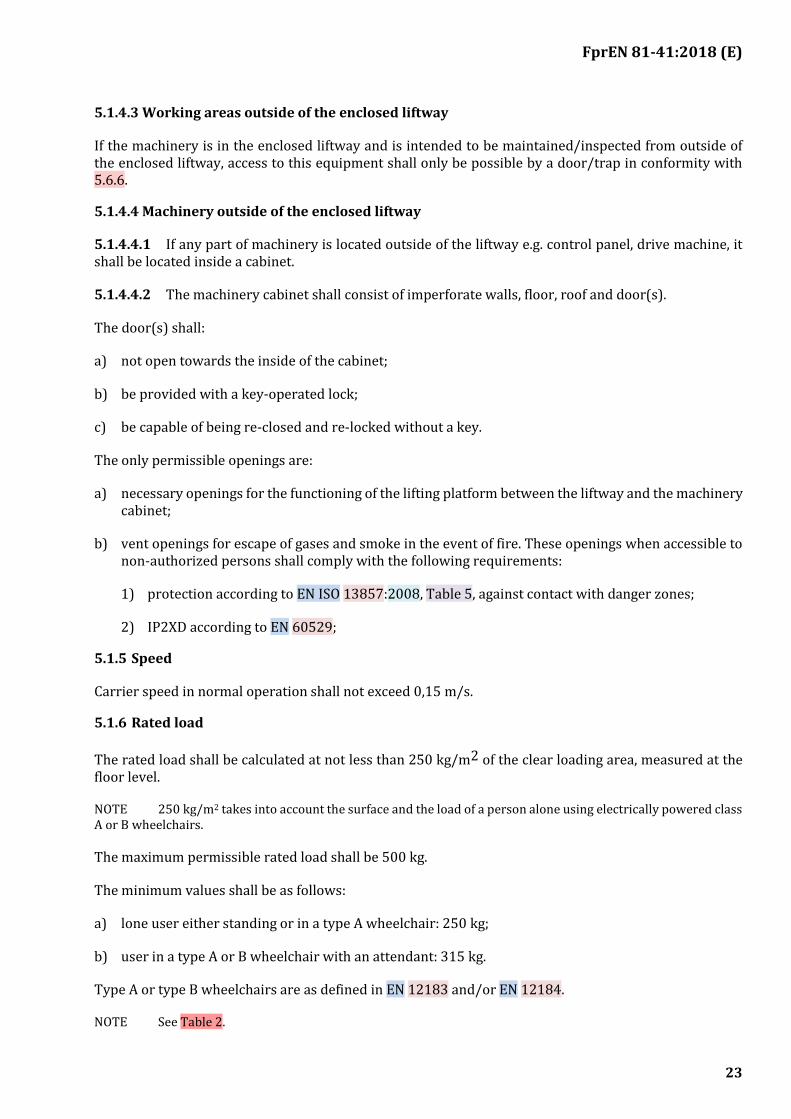
5.1.4.3 Working areas outside of the enclosed liftway
If the machinery is in the enclosed liftway and is intended to be maintained/inspected from outside of the enclosed liftway, access to this equipment shall only be possible by a door/trap in conformity with 5.6.6.
5.1.4.4 Machinery outside of the enclosed liftway
5.1.4.4.1 If any part of machinery is located outside of the liftway e.g. control panel, drive machine, it shall be located inside a cabinet.
5.1.4.4.2 The machinery cabinet shall consist of imperforate walls, floor, roof and door(s).
The door(s) shall:
a) not open towards the inside of the cabinet;
b) be provided with a key-operated lock;
c) be capable of being re-closed and re-locked without a key.
The only permissible openings are:
a) necessary openings for the functioning of the lifting platform between the liftway and the machinery cabinet;
b) vent openings for escape of gases and smoke in the event of fire. These openings when accessible to non-authorized persons shall comply with the following requirements:
1) protection according to EN ISO 13857:2008, Table 5, against contact with danger zones;
2) IP2XD according to EN 60529;
5.1.5 Speed
Carrier speed in normal operation shall not exceed 0,15 m/s.
5.1.6 Rated load
The rated load shall be calculated at not less than 250 kg/m2 of the clear loading area, measured at the floor level.
NOTE 250 kg/m2 takes into account the surface and the load of a person alone using electrically powered class A or B wheelchairs.
The maximum permissible rated load shall be 500 kg.
The minimum values shall be as follows:
a) lone user either standing or in a type A wheelchair: 250 kg;
b) user in a type A or B wheelchair with an attendant: 315 kg.
Type A or type B wheelchairs are as defined in EN 12183 and/or EN 12184.
NOTE See Table 2.

FprEN 81-41:2018 (E)
24
5.1.7 Load control
The platform shall be fitted with a device to prevent normal starting, excluding re-levelling of hydraulic drives in the event of overload on the platform. The overload is considered to occur when the rated load is exceeded by 75 kg.
In the event of overload:
a) users shall be informed by an audible and visible signal on the platform;
b) landing doors shall remain unlocked, when the platform is in the unlocking zone.
5.1.8 Platform dimensions
5.1.8.1 The clear loading area of the platform including any sensitive edge, photo cell or light curtain, shall not exceed 2 m2, measured at the floor level.
5.1.8.2 For new buildings with public access the plan dimensions of the platform floor, including any sensitive edge, photo cells or light curtain, to accommodate a standard type A or type B wheelchair according to EN 12183 and/or EN 12184, shall be equal to or greater than those given in Table 2. Handrail projections shall not be included in the dimension calculation.
For existing buildings and buildings without public access, other dimensions may be considered.
Table 2 — Minimum dimensions of platform
Dimensions in millimetres
Principal use Minimum plan dimensions Minimum rated load
(width × length) kg
Type A and B wheelchairs with an attendant and adjacent entrances
1 100 × 1 400 385
Type A and B wheelchairs 900 × 1 400 315
Lone user, either standing or in a type A wheelchair 800 × 1 250 250
5.1.9 Mechanical strength of the platform
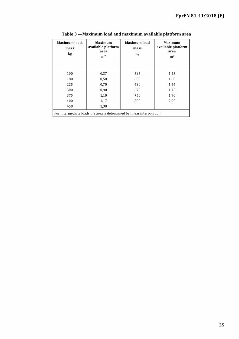
Mechanical strength of the platform shall be such that foreseeable misuse (e.g.: too many persons) is taken into consideration. Therefore the platform and its associated suspension attachments, shall be designed to support the load as determined in Table 3, or maximum working load, whichever is highest, plus an additional load of 25 % i.e. giving a static test coefficient of 1,25.
FprEN 81-41:2018 (E)
25
Table 3 —Maximum load and maximum available platform area
Maximum load,
mass
kg
Maximum available platform
area
m2
Maximum load
mass
kg
Maximum available platform
area
m2
100
180
225
300
375
400
450
0,37
0,58
0,70
0,90
1,10
1,17
1,30
525
600
630
675
750
800
1,45
1,60
1,66
1,75
1,90
2,00
For intermediate loads the area is determined by linear interpolation.
FprEN 81-41:2018 (E)
26
5.1.10 Resistance to operating forces
5.1.10.1 The complete lifting platform installation shall resist, without permanent deformation, the forces imposed on it during normal operation, during the application of the safety devices and at impact on mechanical stops when travelling at the rated speed. However, local deformation that does not affect the operation of the lifting platform arising from the safety gear gripping device is permissible.
5.1.10.2 Guiding components, their attachments and joints shall withstand deflections due to uneven loading without affecting normal operation.
5.1.10.3 A fatigue stress analysis shall be made for all load bearing components and joints, which are critical to fatigue. This analysis shall take into account the degree of stress fluctuation and the number of stress cycles, which can be a multiple of the number of load cycles.
Each load cycle shall be at the worst case condition and at least consist of one start (acceleration from rest to rated speed), 5 m travel and one stop (deceleration from rated speed).
The analysis shall be made by test and shall be conducted at 33,33 % without load, with 33,33 % half of the rated load and 33,33 % at rated load.
The minimum number of load cycles shall be 50 000.
Fixings shall be specified to ensure that their integrity is maintained during normal operation.
5.1.11 Protection of equipment against harmful external influences
5.1.11.1 General
All mechanical and electric components shall be protected from the harmful and hazardous effects of external influences that will be encountered at the proposed installation site, e.g.:
— the ingress of water and solid bodies;
— the effects of humidity, temperature, corrosion, atmospheric pollution, solar radiation, etc.;
— the actions of flora, fauna, etc.
5.1.11.2 Protection
Moisture shall be prevented from entering the liftway or drainage shall be provided.
The protection shall be designed and constructed and the lifting platform shall be installed in such a manner that the influences mentioned in 5.1.11.1 do not prevent the lifting platform from operating safely and reliably.
It shall not be possible for moisture to accumulate on the enclosed liftway floor.
5.1.11.3 Guarding of equipment from mechanical damage
Guarding shall be designed and constructed in accordance with EN 953, EN ISO 13857 and EN 349.
5.1.12 Degree of protection for outdoor use
For outdoor use, lifting platforms shall have a sufficient degree of protection for electric equipment depending on site conditions, see assumptions, which is not less than IP54 as defined in EN 60529.
FprEN 81-41:2018 (E)
27
5.2 Platform support/guide system (including any scissor mechanism)
5.2.1 Platform support/guide system
5.2.1.1 Horizontal clearance
Platform support/guide system shall be provided to retain and guide the platform throughout its travel. The system shall ensure that a maximum horizontal clearance of 20 mm between the inner surface of the enclosed liftway enclosure and platform components, on its accessible open sides, is maintained throughout the entire travel of the platform, under maximum working load conditions.
5.2.1.2 Tilting
Platform support/guide system shall ensure that the platform edges cannot tilt more than ± 10 mm from the horizontal when:
a) the rated load is distributed over the most unfavourable half of the length of the platform; and
b) the rated load is distributed over the most unfavourable half of the width of the platform.
5.2.1.3 Material
Platform support/guide system structural members shall be made of metal.
5.2.1.4 General provisions concerning guide rails
The guide rails, their joints and attachments shall be sufficient to withstand the loads and forces imposed on them in order to ensure a safe operation of the lifting platform.
The aspects of safe operation of the lifting platform concerning guide rails are:
a) platform carrier, counterweight, or balance weight guidance shall be ensured;
b) deflections shall be limited to such an extent, that due to them:
1) unintended unlocking of the doors shall not occur;
2) operation of the safety devices shall not be affected; and
3) collision of moving parts with other parts shall not be possible.
NOTE EN 81–20:2014, 5.7 and EN 81–50:2014, 5.10 describes a method of selecting guide rails. An example for a calculation based on the method in EN 81–50:2014, 5.10 is given in EN 81–50:2014, Annex C.
5.2.1.5 Guide rails for traction drive lifting platform
When the carrier or counterweight is at its highest position of travel, including over travel, its guide rail lengths shall be such as would accommodate a further guided travel of at least 0,05 m.
5.2.1.6 Guide rails for positive lifting platform
5.2.1.6.1 The guided travel of the carrier upwards from the top floor until it strikes the upper end stops shall be at least 0,05 m. The carrier shall be guided to the limit of its end stop stroke.
5.2.1.6.2 When the balancing weight, if there is one, is at its highest position of travel, including over travel, its guide rail lengths shall be such as would accommodate a further guided travel of at least 0,05 m.

FprEN 81-41:2018 (E)
28
5.3 Safety gear and overspeed governor
5.3.1 Safety gear
5.3.1.1 General
The lifting platform shall be provided with a safety gear. The safety gear shall operate in the downward direction to stop and sustain the platform with the maximum static load as defined in Table 3. There are three exceptions to this requirement as follows:
a) direct acting hydraulic jack drives do not require a safety gear (see 5.4.9.12);
b) when the platform is driven by a self-sustaining rotating screw or nut, together with a safety nut (see 5.4.6).
c) when the platform is driven by screw and nut with an overspeed governor according to 5.3.2 and a brake system according to 5.4.2.2. or stopping safety device according to 5.4.6.1.3.
The safety gear shall be fitted on the platform, except on lifting platforms driven by guided chain where the safety gear may be fitted remote from the platform, provided the requirements of 5.4.7 for the guided chain drive are fulfilled.
When the safety gear is applied, no decrease in the tension of any rope or chain or other mechanism used for applying the safety gear shall release the safety gear.
The safety gear shall be capable of stopping and sustaining the platform, carrying its maximum static load, within a distance of 150 mm from where the safety gear is engaged.
The safety gear shall be designed to grip the guide rail, or equivalent element, securely.
Any shaft, jaw, wedge or support that forms part of the safety gear and that is stressed during its operation shall be made of metal.
The application of the safety gear shall not cause the platform to change inclination by more than 5 %.
On traction drive systems a safety gear which has the additional function of operating in upward direction shall be used in accordance with EN 81-20:2014, 5.6.6, if the balancing factor is larger than 5 %.
In order to ensure tripping of the overspeed governor before a dangerous speed can be reached (see EN 81-50:2014, 5.3.2.3.1), the maximum distance between tripping points on the governor shall not exceed 250 mm related to the movement of the governor rope.
5.3.1.2 Actuation
The safety gear shall be mechanically tripped before the platform exceeds a speed of 0,3 m/s by an overspeed governor, except on indirectly suspended hydraulic system, counterweight or balancing weight, where the safety gear may be tripped by a safety rope which is independent of the means of suspension or by slackening or breaking of a suspension rope or chain. The safety rope shall be in accordance with 5.3.2.2.
If the overspeed governor derives its drive from a main suspension chain, belt, rope or similar, the safety gear shall also be operated by a mechanism actuated by breaking, or slackening of, the means of suspension.
FprEN 81-41:2018 (E)
29
5.3.1.3 Release
When a safety gear has tripped its release and return of the lifting platform to service, shall require the intervention of a competent person.
Release of the safety gear on the carrier, counterweight or balancing weight shall only be possible by raising the carrier, counterweight or balancing weight.
5.3.1.4 Access for inspection
The safety gear shall be accessible for inspection and testing.
5.3.1.5 Electric checking
When the safety gear is engaged, an electric device conforming to 5.5.11 and activated by the safety gear shall immediately initiate stopping and shall prevent the starting of the machine.
5.3.2 Overspeed governor
5.3.2.1 General
Any traction drive to the overspeed governor shall be independent of the main traction drive on traction system lifting platforms.
Overspeed governors using only traction to produce the tripping force shall have grooves which:
— have been submitted to an additional hardening process; or
— have an undercut in accordance with EN 81-50:2014, 5.11.2.3.1
The direction of rotation, corresponding to the operation of the safety gear, shall be marked on the overspeed governor.
If the overspeed governor is adjustable, the final setting shall be sealed in such a way to prevent re-adjustment without breaking the seal.
The overspeed governor or another device shall, by means of an electric safety device in accordance with 5.5.11, initiate the stopping of the drive unit at the latest at the moment the tripping speed of the overspeed governor is reached.
If after release of the safety gear (5.3.1.3) the overspeed governor does not automatically reset itself, an electric safety device in accordance with 5.5.11 shall prevent the starting of the lifting platform while the overspeed governor is not in the reset position.
The breakage or excessive rope stretch of the governor rope shall cause the machine to stop by means of an electric safety device in accordance with 5.5.11.
The tensile force in the overspeed governor rope produced by the governor, when tripped, shall be at least the greater of the following two values:
— twice that necessary to engage the safety gear; or
— 300 N.
5.3.2.2 Overspeed governor rope, safety rope
The rope shall be a wire rope designed for that purpose.
FprEN 81-41:2018 (E)
30
The minimum breaking load of the rope shall be related by a safety factor of at least 8:
a) to the tensile force produced in the rope of the overspeed governor or the safety rope when tripped taking into account a friction factor μmax equal to 0,2 for traction type overspeed governor;
b) to the force required to operate the safety gear or clamping device for safety ropes.
The ratio between the pitch diameter of the pulleys for the overspeed governor rope and the nominal rope diameter shall be at least 25.
5.3.2.3 Accessibility
a) The overspeed governor shall be accessible and reachable for inspection and maintenance;
b) If located in the liftway the overspeed governor shall not be accessible to the user;
c) If located in the liftway the overspeed governor shall be accessible and reachable from outside the liftway;
d) The above requirement does not apply if the following three conditions are fulfilled:
1) the tripping of the overspeed governor for test is effected by means of a remote control, except cableless, from outside the liftway whereby an involuntary tripping is not effected and the actuation device is not accessible to unauthorized persons; and
2) the overspeed governor is accessible for inspection and maintenance from the lifting platform or from the pit; and
3) the overspeed governor for the carrier, respectively the counterweight or balancing weight returns after tripping automatically into the normal position, as the carrier, respectively the counterweight or balancing weight is moved in the upward direction.
5.4 Driving units and drive systems
5.4.1 General requirements
5.4.1.1 Drive system
The selected drive system shall be in accordance with one of the systems specified in 5.4.4 to 5.4.11.
5.4.1.2 Direction of travel
All types of drive systems, except hydraulic, shall be powered in both directions of travel.
5.4.1.3 Geared drive units
Safety factors used in the design of geared drive units shall be maintained, even after taking full account of the effects of wear, calculated using the designed life of the lifting platform.
Unless forming an integral part of its shaft or driving unit every sheave, rope drum, spur gear, worm and worm wheel or brake drum or disk shall be fixed to its shaft or other driving unit by one of the following methods:
a) sunk keys;
b) splines;
FprEN 81-41:2018 (E)
31
c) cross pinning;
Gearing shall be guarded using imperforate material.
5.4.1.4 Intermediate drives
If chain or belt intermediate drives are employed, then the following conditions shall be met:
a) the output drive gearing shall be on the load side of the chain or belt intermediate drive and either;
b) the output drive gearing shall be self-sustaining;
or
c) the brake shall be on the load side of the chain or belt intermediate drive and a minimum of 2 belts or chains shall be used. The integrity of the chain or belt shall be monitored by an electric safety device in accordance with 5.5.11.
5.4.1.5 Intermediate drive with two chains
As an alternative to the conditions stated in 5.4.1.4, a system with two chains intermediate drive may be used. The intermediate chain shall be monitored by an electric safety device in accordance with 5.5.11 that disconnects the supply to the motor and brake in the event of breakage of any chain.
5.4.1.6 Protection for abnormal extension
Protection in the case of abnormal extension, slack rope/flat belt or slack chain/toothed belt shall be provided as follows:
a) In the case of two rope or two chain suspension of the car an electric safety in accordance with 5.5.11 shall cause the machine to stop in case of abnormal relative extension of one rope or chain;
b) For positive drive lifts and hydraulic lifts, if the risk of slack rope (or chain) exists, an electric safety device in accordance with 5.5.11 shall cause the machine to stop when slack occurs.
After stopping, normal operation shall be prevented.
For hydraulic lifts with two or more jacks this requirement applies for each suspension set.
5.4.1.7 Protection for sheaves, pulleys and sprockets
For sheaves, pulleys, chain wheels, sprockets and overspeed governors, provisions shall be made to avoid:
a) bodily injury;
b) the ropes/flat belts/chains/ toothed belts leaving the pulleys/sprockets, if slack;
c) the introduction of objects between ropes/flat belts/chains/ toothed belts and pulleys/sprockets.
The devices used shall be constructed so that the rotating parts are visible, and do not hinder examination and maintenance operation. If they are perforated the gaps shall comply with EN ISO 13857:2008, Table 4.
The dismantling shall be necessary only in the following cases:
FprEN 81-41:2018 (E)
32
a) replacement of a rope/flat belts/chains/toothed belts;
b) replacement of a pulley/sprocket;
c) re-cutting of the sheaves, pulleys or sprockets.
5.4.2 Braking system
5.4.2.1 General
An electro-mechanical friction brake shall be fitted (except on hydraulically driven lifting platforms which conform to 5.4.9) which operates automatically in the event of loss of:
a) The power supply;
b) The supply to the control circuits.
The brake shall be capable of bringing the lifting platform smoothly to rest and holding it firmly in position with maximum working load and capable of holding the platform firmly with the maximum static load. The brake shall be mechanically applied and electrically held off. The brake shall not be released in normal operation unless the electric supply is simultaneously applied to the lifting platform motor. Band brakes shall not be used.
5.4.2.2 Electro-mechanical brake
5.4.2.2.1 General:
Brake linings shall be of incombustible material and shall be so secured that normal wear will not weaken their fastenings. Residual magnetism shall not prevent the brake from being applied when the electric supply to the driving motor is interrupted.
5.4.2.2.2 All the mechanical components of the brake which take part in the application of the braking action on the drum or disk shall be installed in two sets. If one of the components is not working due to failure of a component a sufficient braking effort to slow down, stop and hold the platform, travelling downwards at rated speed and with rated load and upward with empty carrier shall continue to be exercised.
Any solenoid plunger is considered to be a mechanical part, any solenoid coil is not.
5.4.2.2.3 In the case of self-sustaining drive systems, 5.4.2.2.2 may be omitted.
5.4.2.2.4 Any brake capable of being released by hand shall require constant effort to keep the brake held off. The operation can be mechanical (e.g. lever) or electrically powered by an automatically rechargeable emergency supply.
5.4.2.2.5 In the case of traction drive, the brake manually released and the carrier loaded with:
less than or equal to or (q-0,1) · Q
or
greater than or equal to, (q+0,1) · Q
where:
FprEN 81-41:2018 (E)
33
q is the balance factor indicating the amount of counterbalance of the rated load by the counterweight, and
Q is the rated load,
it shall be possible to move the carrier to an adjacent floor by:
a) either natural movement due to gravity; or
b) manual operation consisting of:
1) mechanical means, present on site, or
2) electric means, powered by supply independent from the mains, present on site.
5.4.2.2.6 The brake shoe or pad pressure shall be exerted by guided compression springs or weights.
5.4.2.2.7 The component on which the brake operates shall be coupled to the traction sheave or drum or sprocket or toothed pulley or nut or screw by direct and positive mechanical means, unless the final driving element is self-sustaining or the drive system complies with 5.4.1.5.
In the case of using a brake direct acting on the driving nut, self-monitoring shall include verification of correct lifting or dropping of the mechanism or verification of the braking force. If a failure is detected, the next normal start of the lifting platform shall be prevented.
5.4.2.2.8 The interruption of the current to the brake shall be effected by at least two independent electric devices, whether or not they are those, which cause the interruption of the current feeding the lift machine. If one of the contactors has not opened the main contacts whilst the carrier is stationary, further movement of the platform shall be prevented, at the latest, before the next change in the direction of motion.
Braking shall become effective without supplementary delay after opening of the brake release circuit.
NOTE A passive acting electric component that reduces sparking (e.g. diode, capacitor or varistors) is not considered as a means of delay.”
5.4.2.2.9 When the motor of the lift functions as a generator, it shall not be possible for the electric device operating the brake to be fed by the driving motor.
5.4.2.3 Stopping / levelling accuracy
Under intended use:
— The stopping accuracy of the lifting platform shall be ± 10 mm.
— A re-levelling accuracy of ± 20 mm shall be maintained.
— Stopping distances shall be no greater than 20 mm in response to operation of an electric safety device in accordance with 5.5.11.
5.4.3 Emergency/manual operation
5.4.3.1 General
An emergency control device shall be provided.
FprEN 81-41:2018 (E)
34
The maximum time to move the platform to the nearest landing where the door can be opened shall be 15 min.
This emergency operation shall only be possible by an authorized or competent person from a position outside the liftway but with full control of the movement.
Where emergency operation is achieved by means of a manually operated hand-winding device, an electric safety device in accordance with 5.5.11 shall provide protection against inadvertent operation of the normal controls when under emergency operation. Where the manual effort is greater than 30 N to overcome, the release of the brake by emergency hand-winding, there shall be provided a means of releasing the brake. Controlled movement shall be possible under all circumstances.
If the means for movement the platform can be driven by the platform movement, then it shall be a smooth spokeless wheel. If the means is removable, it shall be located in an easily accessible place in the machinery space.
Emergency operation on hydraulic lifting platforms shall comply with 5.4.9.16.
Alternatively, a standby power supply or device may be used for operation. The standby power supply shall be capable of bringing the platform with maximum working load to a landing. An electric safety device in accordance with 5.5.11 shall provide protection against inadvertent operation of the normal controls when under emergency operation. When on emergency electric operation, the following conditions shall be met:
a) Maximum speed not greater than 0,05 m/s.
b) Only hold-to-run controls;
c) the following electric safety devices may be bridged:
1) slack rope/flat belt/chain/toothed belt device;
2) emergency stop;
3) safety gear electric safety device and overspeed governor electric safety device;
4) sensitive edges, photo cells or light curtains.
Where a standby battery is used, either
a) means shall be provided to inform the user as soon as the capacity is lower than needed for emergency operation, or
b) a service warning to inform the user that the standby battery shall be replaced after a certain period, defined by the manufacturer.
5.4.3.2 Means to actuate emergency operation
The means to actuate the emergency operation shall be located in either:
— the machinery cabinet, or
— on the emergency and tests panel(s).
FprEN 81-41:2018 (E)
35
5.4.3.3 Indication of direction of movement
If a hand winding wheel is provided for emergency operation, the direction of movement of the carrier shall be clearly indicated on the machine, close to the hand winding wheel.
If the wheel is not removable, the indication may be on the wheel itself.
5.4.4 Additional requirements for rack and pinion drive
5.4.4.1 General
The platform shall be supported, raised and lowered by means of one or more pinions, meshing with the rack. The drive shall be by means of one or more motors.
Steps shall be taken to prevent the penetration of foreign bodies between each drive or safety pinion and geared rack.
5.4.4.2 Load distribution
When there is more than one drive pinion in mesh with the rack, then either a self-adjusting means shall be provided to effectively share the loading on each drive pinion or the drive system shall be so designed as to accommodate all normal conditions of load distribution between the pinions.
5.4.4.3 Pinion
The driving pinion shall be designed with a safety factor not less than 2 against the endurance limit for tooth strength. Each pinion shall possess a minimum safety factor of 1,4 against the endurance limit for pitting. The safety factors used in the design of any driving pinion shall be maintained, even after taking full account of the effects of dynamic loading, wear and fatigue likely to arise during the designed life of the driving pinion and associated components. Undercutting of the gear teeth shall be avoided. The pinion shall be fixed slip free and wear free to the output shaft in accordance with 5.4.1.3.
5.4.4.4 Rack
5.4.4.4.1 The racks shall be securely attached. Joints in the rack shall be accurately aligned to avoid faulty meshing or damage to teeth.
5.4.4.4.2 The rack shall be made of material having properties matching those of the pinion in terms of wear and shall be designed according to ISO 6336 (all parts), with regard to tooth strength and pitting. If the rack is subjected to a compressive load, a minimum factor of safety of 3 against buckling shall apply.
The rack shall possess a minimum safety factor of 2,0 against the yield strength, taking into account the maximum wear as stated in the manufacturer’s instruction handbook.
5.4.4.5 Rack/pinion engagement
5.4.4.5.1 Means shall be provided to maintain the rack and all the driving and safety device pinions in correct mesh under every load condition. Such means shall not rely upon the platform guide rollers or shoes.
The correct mesh shall be when the pitch circle diameter of the pinion is coincident with, or not more than 1/3 of the module beyond the pitch line of the rack.
5.4.4.5.2 Further means shall be provided to ensure that in the event of failure of the means provided in accordance with 5.4.4.5.1, the pitch circle diameter of the pinion shall never be more than 2/3 of the module out beyond the pitch line of the rack.
FprEN 81-41:2018 (E)
36
5.4.4.5.3 Means shall be provided to ensure that the width of the rack is always in full lateral engagement with pinion teeth of full form.
5.4.4.5.4 Further means shall be provided to ensure that in the event of failure of the means specified in 5.4.4.5.3, not less than 90 % of the width of the rack shall be in lateral engagement with pinion teeth of full form.
5.4.4.5.5 The pinion teeth and the rack teeth shall be square to each other in all planes, within a tolerance of ± 0,5°.
5.4.5 Additional requirements for rope, flat belt, toothed belt, chain suspension drive and traction drive
5.4.5.1 General
The following methods of drive are permissible:
a) use of a drum and ropes;
b) use of sprockets and chains;
c) use of traction sheave and ropes;
d) use of traction sheave and flat belts; or
e) use of toothed pulleys and toothed belts.
5.4.5.2 Ropes, chains, flat belts and toothed belts
5.4.5.2.1 Platforms and balancing weights shall be suspended from steel wire ropes, flat belts with cord made of steel wire, toothed belts or steel chains with parallel links (Galle type) or roller chains.
5.4.5.2.2 The ropes shall correspond to the following requirements:
a) the nominal diameter of the ropes shall be at least 5 mm;
b) the other characteristics (construction, extension, ovality, flexibility, tests…) shall at least correspond to those specified in EN 12385-5.
5.4.5.2.3 The flat belt shall correspond to the following requirements:
— Carbon or alloy steel wire shall be used for the cord, wire tensile strength shall be from 1 570 N/mm2
to 3 500 N/mm2;
— Steel wires or cords may be plated with corrosion reducing materials.
— Elastomeric coating material may be polyurethane or other suitable material.
— the other characteristics (construction, grade, extension, tolerances, tests, replacement criteria…) shall at least correspond to those specified in the informative Annex F.
5.4.5.2.4 Chains shall comply with the requirements of ISO 606.
5.4.5.2.5 Toothed belts shall comply with the requirements of ISO 13050.
5.4.5.2.6 The safety factor of the suspension means shall be minimum:
FprEN 81-41:2018 (E)
37
— 12 for ropes;
— 12 for flat belts;
— 12 for toothed belts;
— 10 for chains.
The safety factor is the ratio between the minimum breaking load of one suspension means and the maximum force in this suspension means, when the carrier is stationary at the lowest landing, with its rated load. For positive and hydraulic drives the safety factor of balancing weight suspension means shall be calculated as above in relation to the weight of the balancing weight.
5.4.5.2.7 The minimum number of suspension means shall be two. Suspension means shall be independent.
5.4.5.3 Rope/chain/flat belt/toothed belt terminations
5.4.5.3.1 The junction between the rope/flat belt/toothed belt/chain and the termination shall be able to resist at least 80 % of the minimum breaking load of the rope/flat belt/toothed belt /chain.
5.4.5.3.2 The ends of the ropes/flat belts shall be fixed to the platform, balancing weight or suspension points by means according to EN 13411 (all parts).
5.4.5.3.3 The devices for adjusting the length of ropes/flat belts/toothed belts/chains shall be made in such a way that these devices cannot work loose after adjustment.
5.4.5.4 Pulley, drum and sprocket
5.4.5.4.1 The ratio between the pitch diameter of pulleys or drums and the nominal diameter of the suspension ropes shall be at least 25, regardless of the number of strands. The ropes shall be type certified for the ratio used.
5.4.5.4.2 The ratio between the pitch diameter of pulleys and the nominal cord diameter of belt shall be at least 40, regardless of the number of strands. The belts shall be type certified for the ratio used.
5.4.5.4.3 Drums shall be helically grooved and the grooves shall be suited to the ropes used. There shall only be one layer of rope wound on the drum. When the platform rests on its stops, one and a half turns of rope shall remain in the grooves of the drum. The angle of deflection (fleet angle) of the ropes in relation to the grooves shall not exceed 4°.
5.4.5.4.4 The fixing of the ropes on drums shall be carried out using a system of blocking with wedges, or using at least two clamps, or any other system with equivalent safety.
5.4.5.4.5 All driving sprockets shall be made from metal and have a minimum of 16 machine-cut teeth. A minimum of 8 teeth shall be engaged. The minimum angle of engagement shall be 140°.
5.4.5.4.6 All driving toothed pulleys shall be made from metal and have a minimum of 24 teeth. A minimum of 12 teeth shall be engaged. The minimum angle of engagement shall be 140°.
5.4.5.4.7 Means shall be provided to avoid jamming owing to miss feeding or slackening of the chains/toothed belt and to prevent the chains/toothed belt from leaving the sprockets or riding over the teeth of the sprockets/toothed pulleys.
Guards shall be fitted to prevent trapping hazards between sprocket/toothed pulleys and chain/toothed belt or chain/toothed belt and any other part.

FprEN 81-41:2018 (E)
38
5.4.5.5 Distribution of load between the suspension means
5.4.5.5.1 An automatic device shall be provided for equalizing the tension of suspension means, at least at one of their ends.
5.4.5.5.2 For chains/toothed belt engaging with sprockets/toothed pulleys, the ends fixed to the platform as well as the ends fixed to the balancing weight shall be provided with such equalization devices. The equalisation device need not be automatic if the suspension ropes are not close coupled.
5.4.5.5.3 For chains/toothed belts in the case of multiple return sprockets/pulleys on the same shaft, these sprockets/pulleys shall be able to rotate independently.
5.4.5.5.4 If springs are used to equalize the tension they shall work in compression.
5.4.5.6 Precautions against free fall, excessive speed, unintended carrier movement and creeping of the carrier — General provisions
5.4.5.6.1 Devices, or combinations of devices and their actuation shall be provided to prevent the carrier from:
a) free fall;
b) excessive speed, either downwards, or up and down in the case of traction lifting platforms;
c) unintended movement, with open doors.
5.4.5.6.2 For traction and positive drive lifting platforms the protection means according to Table 4 shall be provided.

FprEN 81-41:2018 (E)
39
Table 4 — Protection means for traction and positive drive lifting platforms
Hazardous situation Protection means Tripping means
Free fall and excessive speed in down direction of carrier
Safety gear 5.3.1 Overspeed governor 5.3.2
Free fall of counterweight or balancing weight in the case of EN 81–20:2014, 5.2.5.4
Safety gear 5.3.1 Overspeed governor (5.3.2) or
- tripping by breakage of suspension means(EN 81–20:2014, 5.6.2.2.2), or
- tripping by safety rope (EN 81–20:2014, 5.6.2.2.3)
Excessive speed in up direction (traction lifting platforms only)
See 5.4.13 Ascending carrier overspeed protection means 5.4.13
Unintended carrier movement with open doors
Protection against unintended carrier movement (EN 81–20:2014, 5.6.7) or self-sustaining drive systems, verified according to the test requirements in EN 81-50 and tested according to the test requirements in EN 81-20.
Protection against unintended carrier movement shall be provided according to EN 81-20:2014, 5.6.
5.4.6 Additional requirements for screw and nut drive
5.4.6.1 Precautions against free fall and descent with excessive speed of the platform
5.4.6.1.1 Devices, or combinations of devices and their actuation, according to Table 5, shall be provided to prevent the platform from:
a) free fall; or
b) descent with excessive speed.
Table 5 — Combinations of precautions against free fall of the platform and descent with excessive speed
FREE FALL DESCENT WITH EXCESSIVE SPEED
Safety nut (5.4.6.1.4) Stopping safety device according to 5.4.6.1.3 tripped by an over speed governor according to 5.3.2.
OR An overspeed governor according to 5.3.2 in
combination with a brake system according to 5.4.2.2a
OR
Self-sustaining screw and nut system.
aIn this case, the brake shall be designed to slow down, stop and hold the platform, travelling downwards at tripping speed and with rated load
5.4.6.1.2 The friction coefficient of a self-sustaining screw and nut system shall be calculated to be not more than 0,06.
FprEN 81-41:2018 (E)
40
NOTE The figure above is based on a friction factor of 0,075 and with a safety factor of 1,25.
5.4.6.1.3 Stopping safety device:
5.4.6.1.3.1 When required by 5.4.6.1.1, the stopping safety device shall satisfy the following conditions:
The stopping safety device shall operate only in the downward direction. The stopping safety device shall be capable of stopping the relative rotation between screw and nut with the platform carrying the maximum working load, at the tripping speed of the over speed governor and maintaining it stationary.
5.4.6.1.3.2 Stopping safety devices shall be of the progressive type.
5.4.6.1.3.3 The tripping of stopping safety devices shall be by means according to 5.4.6.1.1. Stopping safety devices shall not be tripped by devices which operate electrically, hydraulically or pneumatically.
5.4.6.1.3.4 The average retardation in case of a descent with the tripping speed defined in 5.3.1.2 and with the maximum working load shall lie between 0,2 g and 1 g.
5.4.6.1.3.5 The release of the stopping safety device shall only be possible by raising the platform. After its release, the stopping safety device shall be in a condition to operate normally.
5.4.6.1.3.6 If the stopping safety device is adjustable, the final setting shall be sealed.
5.4.6.1.3.7 When the stopping safety device operates, the floor of the platform with or without the load uniformly distributed shall not incline more than 5 % from its normal position.
5.4.6.1.3.8 When the stopping safety device is engaged, an electric safety device in accordance with 5.5.11 shall immediately initiate stopping of the machine if the platform is travelling downwards and prevent starting.
5.4.6.1.3.9 The stopping safety device is regarded as a safety component and shall be verified according to the requirements of Annex E.
5.4.6.1.4 Safety nut:
A second unloaded safety nut shall be provided to carry the load in the event of failure of the driving nut such as to afford an equivalent degree of safety to that specified in 5.3.1.
The failure of the driving nut shall activate either:
— an electric safety device in accordance with 5.5.11 that shall initiate a break in the electric supply to the motor and brake; or
— a mechanical disconnection of the safety nut from the drive system.
The safety nut shall be prevented from rotating, either by self-sustaining screw and nut system or by positive means.
This disconnection shall make the safety nut unaffected by the motor and brake movements.
Consideration shall be given to the need for protection to the electric safety device against the effects of pollution and vibration.
When required by 5.4.6.1.1, a safety nut shall be designed according to 5.4.6.2.3.3.2.
5.4.6.1.5 Electronic overspeed detection
FprEN 81-41:2018 (E)
41
The architecture of the safety structure shall be such that any single random failure is detected and the system shall go into a safe state (SIL 2) according to 5.5.11. Verified in accordance to 6.2.8.
NOTE Safety Integration Level, SIL, is defined in EN 81-20 as a discreet level (one out of a possible three) for specifying the safety-integrity requirements of the safety functions allocated to the programmable electronic safety-related system, where safety-integrity level 3 has the highest level of safety integrity and safety-integrity level 1 has the lowest.
5.4.6.2 Drive of the platform
5.4.6.2.1 Possible drive types
Only direct acting drive is allowed.
If several screws and nuts are used it shall not be possible to disequilibria in load and travel. If the lifting platform inclination becomes greater than 1 % the lifting platform shall be stopped.
5.4.6.2.2 General provisions for the screw
5.4.6.2.2.1 Positive mechanical means shall be provided to prevent separation of sections of a multiple section screw column. Joints in the screw shall be accurately aligned to avoid faulty meshing or damage to the nuts. It shall be possible to inspect the joints of the screw.
5.4.6.2.2.2 Calculation of the screw: Screws under tensile loads shall be designed such that a safety factor of at least 5 is ensured. This includes joints under maximum load and torque imposed by the machinery and platform. Top fitting shall be designed such that a safety factor of at least 5 against ultimate tensile load is ensured.
Screw under compressive loads shall be designed such that, under full load compression on maximum length of screw, imposed by the maximum load including the platform, a safety factor of at least 3 against buckling is ensured.
5.4.6.2.3 General provisions for nuts
5.4.6.2.3.1 The material of the load carrying nut shall be of less hardness than the mating screw.
5.4.6.2.3.2 It shall be possible to inspect and determine the wear of the load carrying nut. The inspection criteria shall be detailed in the instruction handbook.
5.4.6.2.3.3 Calculation of nuts: The load carrying nut shall, at state of maximum wear, be designed such that a safety factor of at least 5 against ultimate tensile load is ensured under maximum working load and torque conditions.
The safety nut and its connection to the load carrying nut, shall be designed such that a safety factor of at least 5 against ultimate tensile load is ensured under maximum load and torque conditions, including dynamic forces caused by collapsing load carrying nut.
5.4.6.2.4 Connection platform/nut
5.4.6.2.4.1 In case of a lifting platform, with compressive loads on the screw, the connection between the platform and the nut(s) shall be flexible.
5.4.6.2.4.2 The load-screw mechanism shall be designed to prevent separation of the platform from the mechanism during use by positive mechanical means.

FprEN 81-41:2018 (E)
42
5.4.7 Additional requirements for guided chain system
5.4.7.1 General
5.4.7.1.1 Introduction
The platform shall be supported, raised and lowered by means of one or more transmission units. The drive shall be by means of one or more motors.
Steps shall be taken to prevent the penetration of foreign bodies between the chain and its associated elements.
5.4.7.1.2 Shaft, sprockets and safety gear
All sprocket(s) and the safety gear in 5.4.7.2.3 shall be securely fixed to their output shaft according to requirements in 5.4.1.3.
5.4.7.1.3 Load distribution
When there is more than one transmission unit, the sprockets shall be positively coupled to each other, according to 5.4.1.3.
5.4.7.1.4 Sprocket(s)
Each sprocket shall be designed with regard to tooth strength and pitting and shall take into account the requirements of 5.1.10.3 concerning fatigue stress analysis.
Each sprocket shall possess a minimum safety factor of 2,0 against the endurance limit for tooth strength, taking into account the maximum wear as stated in the manufacturer's instruction handbook.
Each sprocket shall possess a minimum safety factor of 1,4 against the endurance limit for pitting.
5.4.7.1.5 Guide elements for the chain
The chain shall be completely guided over its entire length such that it may transmit a load either in thrust or tension.
All driving sprockets shall be made from metal and have a minimum of 16 machine cut teeth. A minimum of 8 teeth shall be engaged.
The guide elements, which guide the chain in X-direction (see Figure 1), shall not allow for more than 5 % of wear on the chain roller diameter.
The guide elements, which protect the chain in Z-direction (see Figure 1), shall not allow for less than 15 % of wear on the inside width of the chain roller.
FprEN 81-41:2018 (E)
43
Key
1 chain guide rail
Figure 1 — Guide elements for the chain
5.4.7.1.6 Guided chain
The chain shall be of the roller chain according to ISO 606, and be pre-stretched to 50 % of tensile strength.
The safety factor for the chain, which works in the transmission unit, shall not be less than 3 against ultimate tensile load.
5.4.7.1.7 Buckling calculation
The chain guides elements under compressive loads and with maximum wearing according to 5.4.7.1.5 shall be designed such that, under full load compression on maximum length of guide elements, imposed by the maximum load including the platform, a safety factor of at least 3 against buckling is ensured.
FprEN 81-41:2018 (E)
44
5.4.7.2 Transmission unit
5.4.7.2.1 General
Each transmission unit shall be designed with regard to chain force acting in any direction. A fatigue stress analysis shall be made according to 5.1.10.3.
5.4.7.2.2 Drive of the platform
The platform shall be driven by means of one or more transmission units, and driven by one or more motors.
The drive motor(s) shall be coupled to the transmission unit by a positive drive system, according to 5.4.1.3 that cannot be disengaged.
5.4.7.2.3 Safety gear
The platform shall be provided with a safety gear capable of operating in the downward direction and capable of stopping a platform carrying the maximum working load, at the tripping speed of the overspeed governor. The safety gear can be situated directly to the transmission units, if it is positively coupled to both transmission units, according to 5.4.1.3.
5.4.8 Additional requirements for scissors mechanism drive
All types of drive including their requirements, detailed in this standard shall equally apply to the drive for the scissor mechanism.
5.4.9 Additional requirements for hydraulic drive
5.4.9.1 General provisions
The two following methods of drive are permissible:
a) direct acting;
b) indirect acting.
If several jacks are used to raise the platform, they shall be hydraulically connected to ensure pressure equilibrium.
For indirect acting method of drive, requirements according to 5.4.5.2 and 5.4.5.3 apply.
5.4.9.2 Jack
5.4.9.2.1 Pressure calculations
The cylinder and the ram shall be designed such that under the forces resulting from a pressure equal to 2,3 times the full load pressure a safety factor of at least 1,7 referred to the proof stress RP0,2 is
ensured.
For the calculation of the elements of telescopic jacks with hydraulic synchronizing means, the full load pressure shall be replaced by the highest pressure, which occurs in an element due to the hydraulic synchronizing means. It may be possible that, due to incorrect adjustment of the hydraulic synchronizing means, abnormally high pressure conditions arise during installation. This shall be taken into account.
FprEN 81-41:2018 (E)
45
In the thickness calculations a value shall be added of 1,0 mm for cylinder walls and cylinder bases, and 0,5 mm for walls of hollow rams for single and telescopic jacks.
The calculations shall be carried out according to EN 81-50:2014, 5.13.1.
5.4.9.2.2 Buckling calculations
Jacks under compressive loads shall fulfil the following requirements:
— They shall be designed such that, in their fully extended position, and under the forces resulting from a pressure equal to 1,4 times full load pressure a safety factor of at least two against buckling is ensured.
— The calculations shall be carried out according to EN 81-50:2014, 5.13.2.
5.4.9.2.3 Tensile stress calculations
Jacks under tensile loads shall be designed such that under the forces resulting from a pressure equal to 1,4 times full load pressure a safety factor of at least 2 referred to the proof stress RP0,2 is ensured.
5.4.9.2.4 Limitation of the ram stroke
Means shall be provided to stop the ram at the end of its stroke.
The design of the stop shall be such that the average retardation of the platform does not exceed 1 gn and
that in case of an indirect acting lifting platform the retardation does not result in slack rope or chain.
5.4.9.2.5 Means of protection
If a jack extends into the ground it shall be installed in a protective tube. If it extends into other spaces it shall be suitably protected. The installation of the jack shall be designed such that the protection can be easily inspected for corrosion.
In the same manner:
a) the rupture valve(s)/restrictor(s);
b) the rigid pipes connecting a rupture valve(s)/restrictor(s) with the cylinder;
c) the rigid pipes connecting rupture valve(s)/restrictor(s) with each other;
shall be protected.
Leak and scrape fluid from the cylinder head shall be collected.
The jack shall be provided with an air-venting device.
5.4.9.3 Connection platform/ram (cylinder)
5.4.9.3.1 In case of a direct acting lifting platform the connection between the platform and the ram (cylinder) shall not be rigid.
5.4.9.3.2 The connection between the platform and the ram (cylinder) shall be so constructed to support the weight of the ram (cylinder) and the additional dynamic forces. The connection means shall be secured.
FprEN 81-41:2018 (E)
46
5.4.9.3.3 In case of a ram made with more than one section, the connections between the sections shall be so constructed to support the weight of the suspended ram sections and the additional dynamic forces.
5.4.9.3.4 In the case of indirect acting lifting platforms, the head of the ram (cylinder) shall be guided.
This requirement does not apply for pulling jacks provided the pulling arrangement prevents bending forces on the ram.
5.4.9.3.5 In the case of indirect acting lifting platforms, no parts of the ram head guiding system shall be incorporated within the vertical projection of the platform.
5.4.9.4 Telescopic jacks
The following requirements apply additionally:
5.4.9.4.1 Stop shall be provided between successive sections to prevent the rams from leaving their respective cylinders.
5.4.9.4.2 The length of the bearing of each section of a telescopic jack without external guidance shall be at least 2 times the diameter of the respective ram.
5.4.9.4.3 These jacks shall be provided with mechanical or hydraulic synchronizing means.
5.4.9.4.4 When ropes or chains are used as synchronizing means the following requirements apply:
a) there shall be at least two independent ropes or chains;
b) pulley and sprockets shall be protected;
c) the safety factor shall be at least:
1) 12 for ropes;
2) 10 for chains.
The safety factor is the ratio between the minimum breaking load of one rope (or chain) and the maximum force in this rope (or chain).
For the calculation of the maximum force the following shall be taken into consideration:
1) the force resulting from the full load pressure;
2) the number of ropes (or chains);
d) a device shall be provided which prevents the speed of the platform in downward movement exceeding the rated speed downward vd by more than 0,15 m/s in the event of failure of the
synchronizing means.
5.4.9.5 Piping
5.4.9.5.1 General
Piping and fittings, which are subject to pressure (connections, valves, etc.) as in general all components of the hydraulic system shall:
— be appropriate to the hydraulic fluid used;
FprEN 81-41:2018 (E)
47
— be designed and installed in such a way to avoid any abnormal stress due to fixing, torsion or vibration;
— be protected against damage, in particular of mechanical origin.
Pipes and fittings shall be appropriately fixed and accessible for inspection.
If pipes (either rigid or flexible) pass through walls or floor they shall be protected by means of ferrules, the dimensions of which allow the dismantling, if necessary, of the pipes for inspection.
No coupling shall be sited inside a ferrule.
5.4.9.5.2 Rigid pipes
Rigid pipes and fittings between cylinder and non-return valve or down direction valve(s) shall be designed such that under the forces resulting from a pressure equal to 2,3 times the full load pressure a safety factor of at least 1,7 referred to the proof stress RP0,2 is ensured.
In the thickness calculations a value shall be added of 1,0 mm for the connection between the cylinder and the rupture valve, if any, and 0,5 mm for the other rigid pipes.
The calculations shall be carried out according to EN 81-50:2014, 5.13.1.
When telescopic jacks with more than 2 stages and hydraulic synchronizing means are used an additional safety factor of 1,3 shall be taken into account for the calculation of the pipes and fittings between the rupture valve and the non-return valve or the down direction valve(s).
Pipes and fittings, if any, between the cylinder and the rupture valve shall be calculated on the same pressure basis as the cylinder.
5.4.9.5.3 Flexible hoses
The flexible hose between cylinder and non-return valve or down direction valve shall be selected with a safety factor of at least 8 relating full load pressure and bursting pressure.
The flexible hose and its couplings between cylinder and non-return valve or down direction valve shall withstand without damage a pressure of five times full load pressure, this test to be carried out by the manufacturer of the hose assembly.
The flexible hose shall be marked in an indelible manner with:
a) the name of the manufacturer or the trade mark;
b) the test pressure;
c) the date of the test.
The flexible hose shall be fixed with a bending radius not less than that indicated by the hose manufacturer.
5.4.9.6 Stopping the machine and checking its stopped condition
A stop of the machine due to the operation of an electric safety device shall be controlled as detailed below.
FprEN 81-41:2018 (E)
48
Upwards motion: For upward motion, the supply to the electric motor shall be interrupted by at least two independent contactors, the main contacts of which shall be in series in the motor supply circuit.
Downwards motion: For downward motion, the supply to the down direction valve(s) shall be interrupted either:
1) by at least two independent electric devices connected in series; or
2) directly by the electric safety device.
5.4.9.7 Failure in contacts
If whilst the lifting platform is stationary, one of the contactors has not opened the main contacts or one of the electric devices has not opened, a further start shall be prevented, at the latest at the next change in the direction of motion.
5.4.9.8 Shut-off valve
A shut-off valve shall be provided. It shall be installed in the circuit which connects the cylinder(s) to the non-return valve and the down direction valve(s).
5.4.9.9 Non-return valve
A non-return valve shall be provided. It shall be installed in the circuit between the pump(s) and the shut-off valve.
The non-return valve shall be capable of holding the lifting platform with the maximum static load at any point when the supply pressure drops below the minimum operating pressure.
The closing of the non-return valve shall be effected by the hydraulic pressure from the jack and by at least one guided compression spring and/or by gravity.
5.4.9.10 Pressure relief valve
A pressure relief valve shall be provided. It shall be connected to the circuit between the pump(s) and the non-return valve. The hydraulic fluid shall be returned to the tank.
The pressure relief valve shall be adjusted to limit the pressure to a maximum of 140 % of the full load pressure.
If necessary due to high internal losses (head loss, friction), the pressure relief valve may be set to a greater value but not exceeding 170 % of full load pressure. In this case, for the calculations of the hydraulic equipment (including jack) a fictitious full load pressure equal to 1/1,4 times the selected pressure setting shall be used.
In the buckling calculation the over pressure factor of 1,4 shall then be replaced by a factor corresponding to the increased setting of the pressure relief valve.
5.4.9.11 Down direction valves
Down direction valves shall be held open electrically. Their closing shall be affected by the hydraulic pressure from the jack and by at least one guided compression spring per valve.

FprEN 81-41:2018 (E)
49
5.4.9.12 Protection against platform free fall and descent with excessive speed
One of the protection methods listed in Table 6 shall be used:
5.4.9.12.1 Rupture valve
When required as per Table 6, a rupture valve, fitted directly to the cylinder outlet, which in the event of failure of any part of the hydraulic circuit (excluding the jack) shall arrest the descent of the platform. The rupture valve shall be either:
— integral with the cylinder;
— or directly and rigidly flange mounted;
— or placed close to the cylinder and connected to it by means of short rigid pipes, having welded, flanged or threaded connections;
— or connected directly to the cylinder by threading. The rupture valve shall be provided with a thread ending with a shoulder; the shoulder shall butt up against the cylinder.
Other types of connections such as compression fittings or flared fittings are not permitted between the cylinder and the rupture valve.
The rupture valve shall be capable of stopping the platform in downward movement, and maintaining it stationary. The rupture valve shall be tripped at the latest when the speed reaches a value equal to rated speed downwards vd plus 0,15 m/s.
Rupture valves shall be calculated as the cylinder.
5.4.9.12.2 Restrictor
When required as per Table 6, a restrictor, fitted directly to the cylinder outlet, which in the event of failure of any part of the hydraulic circuit (excluding the jack) shall prevent the downward speed of the platform with maximum working load exceeding the rated speed. The restrictor shall be either:
— integral with the cylinder;
— or directly and rigidly flange mounted;
— or placed close to the cylinder and connected to it by means of short rigid pipes, having welded, flanged or threaded connections;
— or connected directly to the cylinder by threading. The restrictor shall be provided with a thread ending with a shoulder. The shoulder shall butt up against the cylinder.
Other types of connections such as compression fittings or flared fittings are not permitted between the cylinder and the restrictor.
5.4.9.13 Filters
In the circuit between the tank and the pump(s), and in the circuit between the shut-off valve and the down direction valve(s), filters or similar devices shall be installed. The filter or similar device between the shut-off valve and the down direction valve shall be accessible for inspection and maintenance.
FprEN 81-41:2018 (E)
50
5.4.9.14 Checking the pressure
A pressure gauge shall be provided. It shall be connected to the circuit between the non-return valve or the down direction valve(s) and the shut-off valve.
A gauge shut-off valve shall be provided between the main circuit and the connection for the pressure gauge.
The connection shall be provided with an internal thread of either M 20 × 1,5 or G 1/2”.
5.4.9.15 Tank
The tank shall be designed and constructed for:
a) easy check of the level of the hydraulic fluid in the tank;
b) easy filling and draining.
5.4.9.16 Emergency operation
5.4.9.16.1 Moving the platform downwards
The lifting platform shall be provided with a manually operated emergency lowering valve allowing the platform, even in the case of a power failure, to be lowered to a level where the passengers can leave the platform. The emergency lowering valve is to be positioned outside of the liftway.
The speed of the platform shall not exceed 0,15 m/s.
The operation of this valve shall require a continual manual force.
This valve shall be protected against involuntary action.
In the case of indirect acting lifting platforms where slack rope/chain can occur, manual operation of the valve shall not cause the sinking of the ram beyond that causing the slack rope/chain.
5.4.9.16.2 Moving the platform upwards
A hand-pump which causes the platform to move in the upwards direction shall be permanently installed for every lifting platform whose platform is fitted with a safety gear.
The hand-pump shall be connected to the circuit between the non-return valve or down direction valve(s) and the shut-off valve.
The hand-pump shall be equipped with a pressure relief valve limiting the pressure to 2,3 times the full load pressure.
5.4.9.17 Protection against creeping of the platform
5.4.9.17.1 Devices, or combinations of devices and their actuation, according to Table 6, shall be provided on lifting platforms with hydraulic drive to prevent the platform from creeping from a landing level by more than ± 20 mm and likewise, creeping below the lower end of the unlocking zone.
5.4.9.17.2 The anti-creep switching device shall be an electric safety contact or device in conformity with 5.5.11, Table 8.
FprEN 81-41:2018 (E)
51
On hydraulic lifting platforms, if power operated landing doors are supplied, they shall guarantee to be able to close even during any loss of normal power supply unless a pawl device is provided to maintain the platform at the landing level.
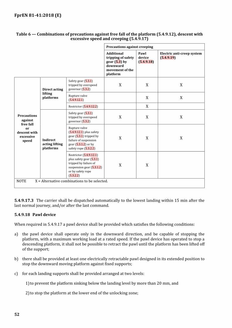
FprEN 81-41:2018 (E)
52
Table 6 — Combinations of precautions against free fall of the platform (5.4.9.12), descent with excessive speed and creeping (5.4.9.17)
Precautions against creeping
Additional tripping of safety gear (5.3) by downward movement of the platform
Pawl device (5.4.9.18)
Electric anti-creep system (5.4.9.19)
Precautions
against free fall
or descent with
excessive speed
Direct acting lifting platforms
Safety gear (5.3.1)
tripped by overspeed
governor (5.3.2) X X X
Rupture valve
(5.4.9.12.1)
X X
Restrictor (5.4.9.12.2) X
Indirect acting lifting platforms
Safety gear (5.3.1)
tripped by overspeed
governor (5.3.2) X X X
Rupture valve
(5.4.9.12.1) plus safety
gear (5.3.1) tripped by
failure of suspension
gear (5.3.1.2) or by
safety rope (5.3.2.2)
X X X
Restrictor (5.4.9.12.1)
plus safety gear (5.3.1)
tripped by failure of
suspension gear (5.3.1.2)
or by safety rope
(5.3.2.2)
X X
NOTE X = Alternative combinations to be selected.
5.4.9.17.3 The carrier shall be dispatched automatically to the lowest landing within 15 min after the last normal journey, and/or after the last command.
5.4.9.18 Pawl device
When required in 5.4.9.17 a pawl device shall be provided which satisfies the following conditions:
a) the pawl device shall operate only in the downward direction, and be capable of stopping the platform, with a maximum working load at a rated speed. If the pawl device has operated to stop a descending platform, it shall not be possible to retract the pawl until the platform has been lifted off of the support;
b) there shall be provided at least one electrically retractable pawl designed in its extended position to stop the downward moving platform against fixed supports;
c) for each landing supports shall be provided arranged at two levels:
1) to prevent the platform sinking below the landing level by more than 20 mm, and
2) to stop the platform at the lower end of the unlocking zone;
FprEN 81-41:2018 (E)
53
d) the movement of the pawl(s) to the extended position shall be effected by guided compression spring(s) and/or by gravity;
e) the supply to the electric retraction device shall be interrupted when the machine is stopped;
f) the design of the pawl(s) and supports shall be such that, whatever the position of the pawl, during upward movement the platform cannot be stopped nor any damage caused;
g) when several pawls are provided precautions shall be taken to ensure that all pawls engage on their respective supports even in the case of the disconnection of the electric power supply during a downward movement of the platform;
h) an electric device, which complies with the requirements of 5.5.11 shall prevent any normal down movement of the platform when a pawl is not in the retracted position.
5.4.9.19 Electric anti-creep system
When required in 5.4.9.17 an electric anti-creep system shall be provided which will energize the platform independent of the position of the doors, when the platform is in a zone which extends from a maximum of 20 mm below the landing level to the lower end of the unlocking zone.
5.4.9.20 Control of levelling, re-levelling and anti-creeping with doors open
Operation with doors open is permitted in the unlocking zone to permit levelling, re-levelling or electric anti -creeping at the corresponding floor level.
Movement of the lifting platform with landing doors open is permitted for levelling, re-levelling and anti-creeping on condition that:
a) all movement of the lifting platform outside the unlocking zone shall be prevented by at least one switching device mounted in the bridge or shunt of the door and lock electric safety devices;
b) this switching device shall:
1) either be an electric safety contact in conformity with 5.5.11.2, or
2) be connected in such a way as to satisfy the requirements for safety circuits in 5.5.11.3;
c) if the operation of the devices is dependent upon an indirect mechanical link to the lifting platform, e.g. by rope, belt or chain, the breaking of or slack in the connecting link shall cause the machine to stop through the action of an electric safety device in accordance with 5.5.11;
d) during levelling operations, the means for making the electric safety devices of doors inoperative shall only function after the stopping signal for this landing has been given.
5.4.10 Additional requirements for counterweighted traction system
5.4.10.1 Counterweight and balance weight
In positive drive systems, counterweights shall not be used. The use of a balancing weight is permitted.
5.4.10.2 General
5.4.10.2.1 If the counterweight or the balancing weight incorporates filler weights, necessary measures shall be taken to prevent their displacement. To this effect they shall be mounted in a frame and secured within the frame.
FprEN 81-41:2018 (E)
54
5.4.10.2.2 Pulleys and/or sprockets fixed to the counterweight or to the balancing weight shall have protection according to 5.4.1.7
5.4.10.3 Guarding of counterweight or balancing weight
The travelling area of the counterweight or the balancing weight shall be guarded by means of screens, which comply with the following:
— If this screen is perforated, EN ISO 13857:2008, 4.2.4.1 shall be respected;
— This screen shall extend from the lowest point of the counterweight resting on its end stops or balancing weight in its lowest position to a minimum height of 2,0 m from the pit floor;
— In no case shall it be more than 0,30 m from the pit floor to the lowest part of the screen.
— The width shall be at least equal to that of the counterweight or balancing weight;
5.4.10.4 Extreme position of carrier, counterweight and balancing weight
When the counterweight rests on its end stops the following two conditions shall be satisfied at the same time:
— the carrier guide rail lengths shall be such as would accommodate a further guided travel, of at least 0,05 m.
— the free vertical distance, expressed in metres, between the lowest parts of the roof of the liftway and the highest pieces of equipment fixed on the carrier, shall be at least 0,05 m.
5.4.11 Additional requirements for rope and flat belt traction system
NOTE 1 Examples of rope design considerations are given in EN 81–50:2014, 5.11.
Rope and flat belt traction shall be such that the following three conditions are fulfilled:
a) The carrier shall be maintained at floor level without slip when loaded to 125 % of the greater of the maximum static load as determined in Table 3 or the maximum working load.
b) It shall be ensured that any emergency braking causes the carrier whether empty or with rated load, to decelerate to stop.
c) It shall not be possible to raise the empty carrier or the counterweight to a dangerous position if either the carrier or the counterweight is stalled; either:
1) the ropes/flat belts shall slip on the traction sheave; or
2) the machine shall be stopped by an electric safety device in accordance with 5.5.11
NOTE 2 Some lifting of the carrier or counterweight is acceptable provided there is no risk of crushing at the extremes of travel or falling back of the carrier or counterweight causing impact forces on the means of suspension and excessive retardation of the carrier.
5.4.12 Traction sheaves, pulleys and sprockets in the liftway
Traction sheaves, pulleys and sprockets may be installed in the liftway above the lowest landing level on condition that there shall be retaining devices to prevent diverter pulleys/sprockets from falling in the
FprEN 81-41:2018 (E)
55
event of a mechanical failure. These devices shall be able to support the weight of the pulley/sprockets and the suspended loads; 5.1.4 applies.
5.4.13 Ascending carrier overspeed protection means
5.4.13.1 The means, comprising speed monitoring and speed reducing elements, shall detect overspeed of the ascending carrier (see 5.4.13.9), and shall cause the carrier to stop. The means shall be active in:
— normal operation;
— manual rescue operation, unless there is a direct visual observation of the machine or the speed is limited by other means to less than 115 % of rated speed.
5.4.13.2 The means shall be capable of performing as required in 5.4.13.1 without assistance from any lifting platform component that, during normal operation, controls the speed or retardation, or stops the carrier, unless there is built-in redundancy and correct operation is self-monitored. In the case of using the machine brake, self-monitoring could include verification of correct lifting or dropping of the mechanism or verification of the braking force. If a failure is detected, the next normal start of the lifting platform shall be prevented. Self-monitoring is verified according to 6.2.9. A mechanical linkage to the carrier, whether or not such linkage is used for any other purpose, may be used to assist in this performance.
5.4.13.3 The means shall act on:
— the carrier; or
— the counterweight; or
— the rope system (suspension); or
— the traction sheave;
— the same shaft as the traction sheave provided the shaft is only statically supported in two points.
5.4.13.4 The means shall operate an electric safety device in accordance with 5.5.11 if it is engaged.
5.4.13.5 The release of the means shall not require access to the liftway. Access is permitted through openings on the carrier
5.4.13.6 After the release of the means the return of the lifting platform to normal operation shall require the intervention of a competent maintenance person.
5.4.13.7 After its release, the means shall be in a condition to operate.
5.4.13.8 If the means requires external energy to operate, the absence of energy shall cause the lifting platform to stop and keep it stopped. This does not apply for guided compression springs.
5.4.13.9 The speed-monitoring element of the lifting platform to cause the ascending carrier overspeed protection means to actuate shall be, either:
a) an overspeed governor conforming to the requirements of 5.3.2 or
b) a device conforming to the requirements of 5.3.2.
5.4.13.10 The ascending carrier overspeed protection means is regarded as a safety component and shall be verified according to the requirements in 6.2.2.
FprEN 81-41:2018 (E)
56
5.4.13.11 On the ascending carrier overspeed protection means a data plate shall be fixed indicating:
a) the name of the manufacturer;
b) the actual tripping speed for which it has been adjusted;
c) the type of ascending carrier overspeed protection means.
5.4.13.12 Motor run time limiter:
5.4.13.12.1 Traction drive lifting platforms shall have a motor run time limiter causing the de-energizing of the machine, and keep it de-energized, if:
— the machine does not rotate when a start is initiated;
— the carrier/counterweight is stopped in downwards movement by an obstacle that causes the ropes/flat belts to slip on the traction sheave.
5.4.13.12.2 The motor run time limiter shall function in a time which does not exceed the time for travelling the full travel in normal operation, plus 10 s, with a minimum of 20 s if the full travel time is less than 10 s.
5.4.13.12.3 The return to normal operation shall only be possible by manual resetting by a competent maintenance person. On restoration of the power after a supply disconnection, maintaining the machine in the stopped position is not necessary.
5.4.13.12.4 The motor run time limiter shall not affect the movement of the carrier under either the inspection operation or the emergency electric operation.
5.5 Electric installation and equipment
5.5.1 General
5.5.1.1 Power supply
Lifting platforms shall be connected to a dedicated power supply conforming with EN 60204-1, terminating at a main switch and fuse or overload with a means to lock it in the ‘off’ position or disconnected state (see EN 60204-1:2006, 5.6). Supply to outlets on the lifting platform shall be provided with a 30 mA RCD. The requirement for the supply to be dedicated does not apply to battery operated lifting platforms.
The main switch shall not interrupt the circuits supplying the following:
— any lighting associated with the lifting platform (see 5.5.4);
— the power socket outlet provided for maintenance purposes (see 5.5.5).
The requirements of EN 60204-1:2006, 4.3 and Clause 5 apply.
5.5.1.2 Electric installation
The electric installation and equipment shall comply with the requirements of EN 60204-1. The nominal main DC voltage or the AC voltage between conductors and between conductors and earth shall not exceed 250 volts for control and safety circuits. Mains supplied control circuits, other than line to earthed neutral supplies, shall be derived from the secondary winding of an isolating transformer complying

FprEN 81-41:2018 (E)
57
with EN 61558-1. One line of the control circuit shall be earthed (or grounded on isolated circuits) and the other line shall be fused in accordance with Figure 2.
FprEN 81-41:2018 (E)
58
Key
1 isolating transformer
2 primary supply
3 control circuit
Figure 2 — Control circuit supply
SELV protected circuits in accordance with IEC 60364 (all parts) may be considered as an alternative provided an equivalent level of safety can be ensured.
Equivalent requirements for battery powered lifting platforms are given within 5.5.14.
The requirements of EN 60204-1:2006, 7.2.7 apply.
The operating voltage of the drive unit shall not be greater than 500 V.
5.5.2 Conductors of different circuits
The requirements of EN 60204-1:2006, 13.1.3 apply.
FprEN 81-41:2018 (E)
59
5.5.3 Insulation resistance of the electric installation
The insulation resistance shall be measured between each live conductor and earth.
Minimum values of insulation resistance shall be taken from Table 7.
Table 7 — Insulation resistance
Nominal circuit voltage Test voltage (DC) Insulation resistance
(V) (V) (MΩ)
SELV 250 ≥ 0,25
≤ 500 500 ≥ 0,5
> 500 1 000 ≥ 1,0
When the circuit includes electronic devices, phase and neutral conductors shall be connected together during measurement.
5.5.4 Lighting
5.5.4.1 The lighting at the floor of the platform, at the platform control devices and the vicinity of the landings doors shall be not less than 50 lx. Lighting used shall minimize glare, reflection, confusing shadows or pools of light and dark. Where a light switch is provided, it shall be protected against unauthorized operation. Lifting platforms shall be fitted with an automatically rechargeable emergency supply, which is capable of feeding at least a lamp with a lighting level of 5lx for one hour in the case of an interruption of the normal lighting supply. This lighting shall come on automatically upon failure of the normal lighting supply.
5.5.4.2 The platform shall be continuously illuminated except when the carrier is parked and the doors are closed.
5.5.5 Socket outlet
An electric output socket shall be provided adjacent to the lifting platform for local lighting during inspection and servicing.
The requirements of EN 60204-1:2006, Clause 15 apply.
5.5.6 Drive contactors
5.5.6.1 Main contactors (as required in 5.5.7) shall be to a minimum specification of:
a) utilization category AC-3 for contactors for AC motors; and
b) utilization category DC-3 for contactors for DC motors.
as specified in EN 60947-4-1.
5.5.6.2 If, because of the power they carry, relays shall be used to operate the main contactors, those relays shall belong to the following categories as specified in EN 60947-5-1:
a) AC 15 for relays controlling AC contactors;
b) DC 13 for relays controlling DC contactors.
FprEN 81-41:2018 (E)
60
5.5.6.3 Each contactor specified in 5.5.6.1 and 5.5.6.2 shall operate such that:
a) if one of the “break” contacts (i.e. normally closed) is closed, then all the “make” contacts are open; and
b) if one of the “make” contacts (i.e. normally open) is closed, all the break contacts are open.
5.5.6.4 Contactors for reversing the direction of travel shall be electrically interlocked.
5.5.7 Motors supplied directly from AC mains
5.5.7.1 The supply to the motor and brake shall be interrupted by two independent contactors, the contacts of which shall be in series in the motor and brake supply circuits. If, whilst the lifting platform is stationary, one of the contactors has not opened the main contacts, further movement of the lifting platform shall be prevented at the latest at the next change in the direction of motion.
5.5.7.2 AC or DC motors controlled and supplied by solid-state elements. One of the following methods shall be used:
a) as 5.5.7.1; or
b) a system consisting of:
1) a contactor interrupting the current at all poles. The coil of the contactor shall be released at least before each change in direction. If the contactor does not release, any further movement of the lifting platform shall be prevented;
2) an independent control device blocking the flow of energy in the static elements;
3) a monitoring device to verify the blocking of the flow of energy each time the lifting platform is stationary.
If, during a normal stopping period, the blocking by the static elements is not effective, the monitoring device shall cause the contactor to release and any further movement of the lifting platform shall be prevented; or
c) Electric circuit satisfying EN 81-20:2014, 5.11.2.3: this means is regarded as a safety component and shall be verified according to the requirements in to 6.2.8; or
d) An adjustable speed electric power drive system with a safe torque off (STO) function according to EN 61800-5-2:2007, 4.2.2.2 fulfilling SIL3 requirements, with a hardware fault tolerance of at least 1.
5.5.7.3 The electric supply to the drive motor and brake shall be interrupted following the termination of a direction control signal or following the failure of the electric supply or upon the operation of any electric safety device.
5.5.8 Creepage and clearance distances and enclosure requirements
5.5.8.1 Enclosure requirements
The live parts of controllers and electric safety contacts shall be located within a protective enclosure of at least IP2X.
Covers shall be retained by clamping devices requiring the use of a tool for their removal.
FprEN 81-41:2018 (E)
61
Additionally, for the electronic parts, the ambient temperature for use as stated by the manufacturer shall be taken into account. Where the ambient temperature limits set in EN 60204-32 are exceeded, the appropriate means (such as heating or cooling) shall be used.
The requirements of EN 60204-1:2006, 6.2.2 and 11.2.1 apply.
5.5.8.2 Creepage and clearance distances
Creepage and clearance distances for power circuits, safety circuits and any components connected after safety circuits or electric safety contacts and whose failure would cause an unsafe condition shall conform to the requirements of EN 60947-1:2007, Table 15 in accordance with the working voltage. Minimum pollution degree 2. The printed wiring material column is not to be used.
5.5.9 Electromagnetic compatibility
The electromagnetic compatibility shall comply with the requirements of EN 12015 and EN 12016.
5.5.10 Protection against electric faults
Any single fault listed below, occurring in the electric equipment of the lifting platform, shall not, on its own, be the cause of dangerous malfunction of the lifting platform:
a) absence of voltage;
b) voltage drop;
c) phase reversal on multi-phase supplies;
d) insulation fault between an electric circuit and metalwork or earth;
e) short circuit or open circuit, change of value or function in an electric component such as, for example, resistor, capacitor, transistor or lamp;
f) non attraction, or incomplete attraction, of the moving armature of a contactor or relay;
g) non separation of the moving armature of a contactor or relay;
h) non opening or non-closing of a contact;
i) loss of continuity of a conductor.
The non-opening of an electric safety contact need not be considered.
The earthing of an energized circuit, in which there is an electric safety device, shall cause the immediate halt and prevent re-starting of the lifting platform.
5.5.11 Electric/Electronic safety devices
5.5.11.1 General provisions
5.5.11.1.1 During operation of one of the electric safety devices required in several clauses, movement of the machine shall be prevented or it shall be caused to stop immediately as indicated in 5.5.11.4. A list of such devices is given in Table 8.
The electric safety devices shall consist of:

FprEN 81-41:2018 (E)
62
a) either one or more electric safety contacts satisfying 5.5.11.2 directly cutting the supply to the contactors referred to in 5.5.7 or their relay-contactors;
b) or safety circuits satisfying 5.5.11.3, consisting of one or a combination of the following:
1) either one or more electric safety contacts satisfying 5.5.11.2 not directly cutting the supply to the contactors referred to in 5.5.7 or their relay-contactors;
2) contacts not satisfying the requirements of 5.5.11.2;
3) components in accordance with Annex A.
Table 8 — Electric safety devices
Devices Relevant clauses
Door locking safety device for:
a) closed position of landing doors; 5.8.5.2
b) locking of landing doors at limits of unlocking zone. 5.8.5.3
Belt safety device for detecting slack in a suspension rope or chain 5.4.1.6
Emergency stop device 5.5.15.5
Devices operated by sensitive edges, surfaces, photo cells or light curtains 5.9.2
Final limit device 5.5.15.6
Safety gear device 5.3.1.5
Screw/nut drive failure device 5.4.6.1.4
Trap door device 5.6.6.3
Stop device for working area 5.1.4.2.1, 5.1.4.1
Stopping safety device 5.4.6.1.3
Drive control 5.5.6, 5.5.7
Levelling, re-levelling and anti-creep 5.4.9.18.2
5.5.11.1.2 Apart from exceptions permitted in this standard (see 5.4.9.19 Electric anti-creep system, 5.4.9.20 Control of levelling, re-levelling and anti-creeping with doors open) no electric equipment shall be connected in parallel with an electric safety device.
Connections to different points of the electric safety chain are only permitted for gathering information. The devices used for that purpose shall fulfil the requirements for safety circuits according to 5.5.11.3.
5.5.11.1.3 The effects of internal or external induction or capacity shall not cause failure of electric safety devices.
5.5.11.1.4 An output signal emanating from an electric safety device shall not be altered by an extraneous signal emanating from another electric device placed further down the same circuit, which would cause a dangerous condition to result.
5.5.11.1.5 In safety circuits comprising two or more parallel channels, all information other than that required for parity checks shall be taken from one channel only.
5.5.11.1.6 Circuits which record or delay signals shall not, even in event of fault, prevent or appreciably delay the stopping of the machine through the functioning of an electric safety device, i.e. the stopping shall occur in the shortest time compatible with the system.
FprEN 81-41:2018 (E)
63
5.5.11.1.7 The construction and arrangement of the internal power supply units shall be such as to prevent the appearance of false signals at outputs of electric safety devices due to the effects of switching.
5.5.11.2 Electric safety contacts
5.5.11.2.1 The operation of an electric safety contact shall be by positive separation of the circuit-breaking devices. This separation shall occur even if the contacts have welded together.
The design of an electric safety contact shall be such as to minimize the risk of a short-circuit resulting from component failure.
NOTE Positive opening is achieved when all the contact-breaking elements are brought to their open position and when for a significant part of the travel there are no resilient members (e.g. springs) between the moving contacts and the part of the actuator to which the actuating force is applied.
5.5.11.2.2 The electric safety contacts shall be provided for a rated insulation voltage of 250 V if the enclosure provides a degree of protection of at least IP 4X, or 500 V if the degree of protection of the enclosure is less than IP 4X.
The electric safety contacts shall belong to the following categories as defined in EN 60947-5-1:
a) AC-15 for safety contacts in AC circuits;
b) DC-13 for safety contacts in DC circuits.
5.5.11.2.3 If the degree of protection is equal or less than IP4X, the clearances shall be at least 3 mm, the creepage distances at least 4 mm and the distances for breaking contacts at least 4 mm after separation. If the protection is better than IP4X the creepage distance can be reduced to 3 mm.
5.5.11.2.4 In the case of multiple breaks, the distance after separation between the contacts shall be at least 2 mm.
5.5.11.2.5 Abrasion of conductive material shall not lead to short circuiting of contacts.
5.5.11.3 Safety circuits
5.5.11.3.1 Safety circuits shall comply with the requirements of 5.5.11 relative to the appearance of a fault.
5.5.11.3.2 Furthermore, as illustrated by Figure 3 the following requirements shall apply.
FprEN 81-41:2018 (E)
64
Figure 3 — Diagram for assessing safety circuits
5.5.11.3.2.1 If one fault combined with a second fault can lead to a dangerous situation, the lifting platform shall be stopped at the latest at the next operating sequence in which the first faulty element should participate.
FprEN 81-41:2018 (E)
65
All further operation of the lifting platform shall be impossible as long as this fault persists.
The possibility of the second fault occurring after the first, and before the lifting platform has been stopped by the sequence mentioned above is not considered.
5.5.11.3.2.2 If two faults which by themselves do not lead to a dangerous situation, when combined with a third fault can lead to a dangerous situation, the lifting platform shall be stopped at the latest at the next operating sequence in which one of the faulty elements should participate.
The possibility of the third fault leading to a dangerous situation before the lifting platform has been stopped by the sequence mentioned above is not considered.
5.5.11.3.2.3 If a combination of more than three faults is possible, then the safety circuit shall be designed with multiple channels and a monitoring circuit checking the equal status of the channels.
If a different status is detected the lifting platform shall be stopped.
In case of two channels the function of the monitoring circuit shall be checked prior to a re-start of the lifting platform at the latest, and in case of failure, re-starting shall not be possible.
5.5.11.3.2.4 On restoration of the power supply after it has been disconnected, maintenance of the lifting platform in the stopped position is not necessary, provided that during the next sequence stopping is re-imposed in the cases covered by 5.5.11.3.2.1 up to 5.5.11.3.2.3.
5.5.11.3.2.5 In redundancy-type circuits measures shall be taken to limit as far as possible the risk of defects occurring simultaneously in more than one circuit arising from a single cause.
5.5.11.3.3 Safety circuits containing electronic components are regarded as safety components and shall be verified in accordance with 6.2.8.
5.5.11.4 Operation of electric safety devices
When operating to ensure safety, an electric safety device shall prevent the setting in motion of the machine or initiate immediately its stopping.
The electric safety devices shall act directly on the equipment controlling the supply to the machine in accordance with the requirements of 5.5.7.
If, because of the power to be transmitted, relay contactors are used to control the machine, these shall be considered as equipment directly controlling the supply to the machine for starting and stopping.
5.5.11.5 Actuation of electric safety devices
The components actuating the electric safety devices shall be built so that they are able to function properly under the mechanical stresses resulting from continuous normal operation.
If the devices for actuating electric safety devices are through the nature of their installation accessible to persons, they shall be so built that these electric safety devices cannot be rendered inoperative by simple means.
NOTE A magnet or a bridge piece is not considered a simple means.
In the case of redundancy-type safety circuits, it shall be ensured by mechanical or geometric arrangements of the transmitter elements that a mechanical fault shall not cause loss of redundancy.
FprEN 81-41:2018 (E)
66
5.5.12 Protection of the driving motor
Driving motors shall be protected against overloading and potentially damaging excess currents by means of a device, which automatically disconnects the supply. The device may automatically re-set after an appropriate interval.
Where protection is provided by means of a temperature-monitoring device, it is permissible for the lifting platform to continue in operation to a normal stop at a landing to allow passenger to leave the platform. An automatic return to normal operation of the platform shall only occur after sufficient cooling down.
5.5.13 Electric wiring
5.5.13.1 Conductors, insulation and earth bonding
For the cross sectional areas of conductors see EN 60204-1:2006, 12.4.
5.5.13.2 Insulation
The requirements in EN 60204-1:2006, 13.1.3 shall apply.
All exposed metalwork, other than conductors, liable to become electrically charged shall be earth bonded, see 6.3.1 h), referring to the earth bond test.
5.5.13.3 Trailing cables
Trailing electric power and control cables shall be securely clamped at each end to ensure no mechanical load is transmitted to cable terminations. It is required that flat cables shall be constructed in accordance with EN 50214.
5.5.13.4 Terminals and connectors
5.5.13.4.1 General:
Connectors and devices of the plug-in type shall be protected by position or design against accidental misconnection.
5.5.13.4.2 Terminations shall cause no damage to the conductors or insulation.
5.5.13.4.3 Mains input terminals shall be conveniently accessible within the equipment and shall be correctly identified.
5.5.13.5 Electric identification
Terminals, connectors and electric components shall be marked with a suitable means of identification. See EN 60204-1:2006, 13.2.
5.5.14 Additional requirements for battery powered supply
5.5.14.1 For battery powered lifting platforms, the control circuit voltage shall not exceed 60 V.
5.5.14.2 A fuse shall be fitted in line with the battery supply near the negative pole of the battery, which is only accessible by the use of an appropriate tool(s). This fuse shall isolate the battery supply within 0,5 s of the supply being short-circuited and within 5 s of twice-average peak current being drawn.

FprEN 81-41:2018 (E)
67
5.5.14.3 The charging arrangement for the batteries shall be as Figure 4 a) for AC charging and Figure 4 b) for DC charging. The maximum voltage potential when measured with respect to earth shall be as EN 60204-1:2006, 6.2.
a) AC charge contacts
b) DC charge contacts
Key
1 AC – DC converter
2 DC – DC converter
3 control circuit 60 V max
4 see note
5 charge contacts
NOTE The symbol denotes the negative side of the battery supply is connected to the chassis of the lifting platform.
Earthing is not required on SELV-protected charging circuits
Figure 4 — Charging supply for battery-powered lifting platforms
5.5.14.4 Battery terminals and charge contacts shall be physically protected against short-circuiting.
5.5.14.5 A secure location or fixing for the batteries shall be provided.
5.5.14.6 A battery isolating switch shall be provided which will isolate the control and drive motor circuits.
5.5.14.7 The arrangements for the charging of the battery shall be such that if the lifting platform is brought to rest out of the reach of the charge contacts, this shall be indicated to the user visually and audibly.
5.5.14.8 The carriage platform chassis shall be earthed as shown in Figure 4.
5.5.14.9 Batteries shall not leak. Batteries shall not emit fumes during normal operation, including charging.

FprEN 81-41:2018 (E)
68
5.5.15 Control devices
5.5.15.1 Control devices shall be provided at each landing and on the platform. See Table 9.
Table 9 — Control devices
Element Requirements
Minimum dimension of the active part of the buttons Inscribed circle with a diameter of 20 mm
Identification of active part of buttons Identifiable visually and by touch from face plate or surrounds
Identification of faceplate Colour to contrast with its surrounds
Operating force 2,5 – 5,0 N
Mechanical operating feed back Required to inform user that the pushed button has been operated
Position of symbol Preferable on active part (or 10–15 mm left of it)
Size of symbol (relief) 15 - 40 mm
Height of relief Minimum 0,8 mm
Distance between active parts of call buttons Minimum 10 mm
Distance between groups of call buttons and other group of buttons
Minimum twice the distance between active parts of call buttons
Minimum height between the floor level and the centre line of any button
850 mm
Maximum height between the platform floor level and the centre line of the highest button on platform
1 200 mm (preferably 1 100 mm)
Maximum height between the landing floor level and the centre line of the highest button on landing
1 100 mm
On a platform suitable for wheelchairs, the minimum lateral space between the centre line of any buttons to a corner in the platform or outside the landing
400 mm
Carrier operating controls should be clearly labelled as hold-to-run.
5.5.15.2 Control devices shall operate as follows:
5.5.15.2.1 Control devices located on the platform, which are used to control the movement of the platform shall be dependent upon hold-to-run.
5.5.15.2.2 Control devices located at landings, which are used to control the movement of the platform shall not be hold-to-run. This is to ensure the conditions of 5.5.15.3 can be met.
NOTE When the user has difficulty in operating normal control devices, it may be necessary to consider special devices to suit the particular disability providing the platform hold-to-run feature is maintained. Recommendations for such devices are given in Annex C.
5.5.15.3 Platform operation shall override landing operation and it shall not be possible to initiate a call from any landing if the platform is not located at a fixed landing.
5.5.15.4 There shall be a minimum delay of 5 s before the lifting platform can be started from the landings when the landing door of the landing at which the lifting platform is resting is closed.
5.5.15.5 An emergency stopping device in accordance with EN ISO 13850 shall be fitted on the platform and in the pit that, when operated, shall directly interrupt the electric safety chain.

FprEN 81-41:2018 (E)
69
This device on the platform shall be clearly visible and accessible to the user and easy to operate.
FprEN 81-41:2018 (E)
70
5.5.15.6 Final limit devices
Final limit devices shall be provided.
They shall be set to function as close as possible to the lower or upper landing levels, without risk of accidental operation.
The final limit devices shall open:
— directly by positive mechanical separation of the circuits feeding the motor and brake; or
— an electric safety device in accordance with 5.5.11.
The opening of the final limit device shall prevent further movement of the lifting platform in both directions of travel. The return to service of the lifting platform shall require the intervention of a competent maintenance person.
Actuation of the final limit devices shall be effected:
a) either directly by the carrier at the top and bottom of the liftway; or
b) indirectly by a device which is linked to the carrier, e.g. by a rope, belt or chain. In this case, breakage of or slack in this linkage shall cause the machine to stop by means of an electric safety device in accordance with 5.5.11.
In the case of positive drive system, actuation of the final limit devices shall be effected:
a) either by a device linked to the movement of the machine; or
b) directly by the carrier at the top and the bottom of the liftway.
5.5.15.7 The means provided to normally stop the lifting platform at the landings shall be independent of the final limit device.
5.5.15.8 The lower final limit device may be omitted in the case of hydraulic drives or those drives incorporating slack rope or slack chain electric safety devices. In addition, the lower final limit devices may be omitted when the design of the drive system is such that over travel beyond the normal limits of travel is not possible, even without the use of mechanical end stops.
The lower final limit device may be omitted if the lower terminal limit switch is an electric safety device in accordance with 5.5.11.
5.5.16 Emergency alarm devices
5.5.16.1 In order to call for outside assistance, passengers shall have available in the platform an easily recognizable and accessible device for this purpose. This device shall allow a two-way voice communication by a permanent contact with a rescue service.
5.5.16.2 Emergency alarm device shall be equipped with a standby power source (such as battery back-up and charger), in case of the interruption of the normal power supply. The duration of the standby power source shall be at least one hour.
The emergency alarm device should work even in event of electric power supply failure. In the case of connection to a public telephone network, 5.5.16.2 might not apply.
FprEN 81-41:2018 (E)
71
5.5.16.3 An intercom system, or similar device, powered by the emergency supply referred to in 5.5.4, shall be installed between the inside of the platform or in the working area under the platform and the cabinet if a direct acoustic communication between the machine space/cabinet and the liftway is not possible.
5.5.17 Cable-less controls
5.5.17.1 The cable-less control system shall be designed to work with a single lifting platform. It shall be designed such that the lifting platform shall not respond to signals from another lifting platform or other cable-less control system (for example, by use of an appropriate frequency spectrum, coded signals and range).
On platforms installed in public buildings, the cable-less control system shall be in a fixed position in order that it cannot be removed.
5.5.17.2 The cable less communication link shall be designed so as to be fail-safe in the event of signal failure.
5.5.18 Control of inspection operation
To facilitate inspection and maintenance, a readily accessible inspection control station may be provided.
The inspection control station shall be brought into operation by a device (inspection operation switch) which shall satisfy the requirements for electric safety devices in accordance with 5.5.11.
This device, which shall be bi-stable, shall be protected against involuntary operation.
The following conditions for functioning shall be satisfied simultaneously:
a) engagement of the inspection operation shall neutralize the normal operation controls;
b) the movement of the platform shall be dependent on a constant pressure on a push-button protected against accidental operation and with the direction of movement clearly indicated;
c) the control device shall also incorporate an emergency stopping device;
d) the operation of the lifting platform shall remain dependent on the electric safety devices.
5.6 Specific requirements for lifting platform enclosures
5.6.1 General
See the example in Figure 5.

FprEN 81-41:2018 (E)
72
Figure 5 — Example of vertical lifting platform with enclosed liftway
5.6.2 Top clearance
When the lifting platform is in contact with the upper mechanical stop, the vertical clearance between the floor of the platform and the lowest parts of overhead obstacles shall not be less than 2 m.
5.6.3 Risks for persons working in the liftway
If there is a risk for persons working in the liftway being trapped and no means are provided to escape, through the liftway, alarm devices shall be installed at places where this risk exists. The alarm devices shall fulfil the requirements of 5.5.16.2 and 5.5.16.3.
No other services may be installed in the liftway except ones related to the lifting platform installation.
5.6.4 Enclosure construction
5.6.4.1 Each wall of the enclosure shall form a continuous vertical smooth surface and be composed of hard elements.
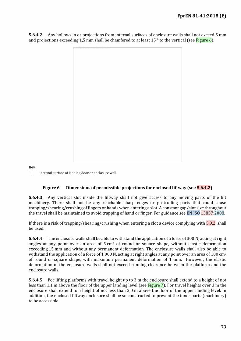
FprEN 81-41:2018 (E)
73
5.6.4.2 Any hollows in or projections from internal surfaces of enclosure walls shall not exceed 5 mm and projections exceeding 1,5 mm shall be chamfered to at least 15 ° to the vertical (see Figure 6).
Key
1 internal surface of landing door or enclosure wall
Figure 6 — Dimensions of permissible projections for enclosed liftway (see 5.6.4.2)
5.6.4.3 Any vertical slot inside the liftway shall not give access to any moving parts of the lift machinery. There shall not be any reachable sharp edges or protruding parts that could cause trapping/shearing/crushing of fingers or hands when entering a slot. A constant gap/slot size throughout the travel shall be maintained to avoid trapping of hand or finger. For guidance see EN ISO 13857:2008.
If there is a risk of trapping/shearing/crushing when entering a slot a device complying with 5.9.2. shall be used.
5.6.4.4 The enclosure walls shall be able to withstand the application of a force of 300 N, acting at right angles at any point over an area of 5 cm2 of round or square shape, without elastic deformation exceeding 15 mm and without any permanent deformation. The enclosure walls shall also be able to withstand the application of a force of 1 000 N, acting at right angles at any point over an area of 100 cm2 of round or square shape, with maximum permanent deformation of 1 mm. However, the elastic deformation of the enclosure walls shall not exceed running clearance between the platform and the enclosure walls.
5.6.4.5 For lifting platforms with travel height up to 3 m the enclosure shall extend to a height of not less than 1,1 m above the floor of the upper landing level (see Figure 7). For travel heights over 3 m the enclosure shall extend to a height of not less than 2,0 m above the floor of the upper landing level. In addition, the enclosed liftway enclosure shall be so constructed to prevent the inner parts (machinery) to be accessible.
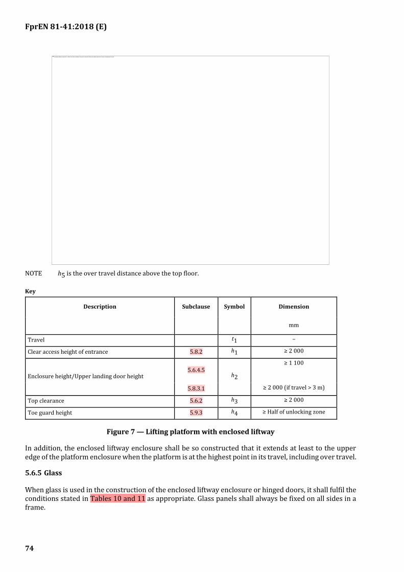
FprEN 81-41:2018 (E)
74
NOTE h5 is the over travel distance above the top floor.
Key
Description Subclause Symbol Dimension
mm
Travel t1 –
Clear access height of entrance 5.8.2 h1 ≥ 2 000
Enclosure height/Upper landing door height 5.6.4.5
h2
≥ 1 100
5.8.3.1 ≥ 2 000 (if travel > 3 m)
Top clearance 5.6.2 h3 ≥ 2 000
Toe guard height 5.9.3 h4 ≥ Half of unlocking zone
Figure 7 — Lifting platform with enclosed liftway
In addition, the enclosed liftway enclosure shall be so constructed that it extends at least to the upper edge of the platform enclosure when the platform is at the highest point in its travel, including over travel.
5.6.5 Glass
When glass is used in the construction of the enclosed liftway enclosure or hinged doors, it shall fulfil the conditions stated in Tables 10 and 11 as appropriate. Glass panels shall always be fixed on all sides in a frame.
FprEN 81-41:2018 (E)
75
Table 10 — Flat glass panels to be used in walls of enclosed liftway or of the platform
Type of glass
Diameter of inscribed circle
1 m maximum 2 m maximum
Minimum thickness (mm)
Minimum thickness (mm)
Laminated toughened or
laminated tempered
8 (4 + 4 + 0,76)
10 (5 + 5 + 0,76)
Laminated 10
(5 + 5 + 0,76) 12
(6 + 6 + 0,76)
Table 11 — Glass panels to be used in hinged doors
Dimensions in millimetres
Type of glass Minimum thickness Maximum diameter of inscribed circle
Toughened 8 100
Toughened and laminated 8
1 000 (4 + 4 + 0,76)
Laminated 10
1 000 (5 + 5 + 0,76)
Where the requirements of Tables 10 and 11 are not fulfilled the glass shall be tested according to EN 81-50:2014, 5.14.
5.6.6 Inspection doors and traps
5.6.6.1 Inspection doors and traps shall not interfere with the travel of the platform.
5.6.6.2 Inspection doors and traps shall be capable of being opened from outside with the aid of a special key or tool.
5.6.6.3 Inspection doors and traps shall be mechanically locked and electrically controlled in accordance with 5.5.11.1.1.
5.6.7 Ventilation
5.6.7.1 The enclosed lift well shall be provided with ventilation apertures.
5.6.7.2 The effective area of ventilation apertures shall be at least 2 % of the clear loading area. The gaps round the landing doors may be taken into account in the calculation of the area of ventilation holes, up to 50 % of the required effective area.
5.6.7.3 Ventilation apertures shall be built or arranged in such a way that it is not possible to pass a straight rigid rod 10 mm in diameter through the enclosed liftway from the inside.
NOTE see also Annex G.
5.7 Fire protection
Landing doors shall comply with the regulations relevant to the fire protection for the building concerned. EN 81-58 defines a method of fire test.
FprEN 81-41:2018 (E)
76
5.8 Enclosed liftway entrances
5.8.1 General
Enclosed liftway entrances shall be protected by landing doors.
5.8.2 Swing hinged landing doors
The clear width of the platform and its entrance and of the landing entrances shall be not less than 800 mm.
However for use by standing lone users (not intended for wheelchairs type A and B), in buildings with private access only, a clear width of the entrances of 500 mm is permitted providing national regulations permit.
The clear height of the entrance shall not be less than 2 000 mm.
Openings giving access to the platform shall be provided with landing doors which:
a) are imperforate;
b) are self-closing; a hold open feature is permitted providing that:
1) if the doors contribute to the fire rating of the building they shall close automatically on activation of a fire management device;
2) if it is possible for a platform to move away from the floor unsupervised, the doors shall close automatically;
c) do not open into the enclosed liftway;
d) require a force to open them which is not more than 40 N at the handle; and
e) landing doors with manual opening shall be provided with a vision panel or platform here indication when the door or gate is made of non-transparent material and is over 1,1 m in height. The vision panel shall comply with the following:
1) be not less than 60 mm in width;
2) have its lower edge located between 300 mm and 900 mm above the floor level;
3) have a minimum glazed area per landing door of 0,015 m2 with a minimum of 0,01 m2 per vision panel.
Doors supplied in accordance with EN 81-20, where the vision panel is located higher than 900 mm from the bottom of the door are permitted, providing platform here indication is provided in accordance with EN 81-20:2014, 5.3.7.2.1 b).
5.8.3 Height of landing doors
5.8.3.1 Upper level
For lifting platforms with travel height up to 3 m the door shall extend to a height of not less than 1,1 m above the floor of the upper landing level (see Figure 7). For travel heights over 3 m the door shall extend to a height of not less than 2,0 m at each floor, including the upper landing level.
FprEN 81-41:2018 (E)
77
In addition, the landing door at the upper level shall be so constructed that it extends at least to the upper edge of the platform enclosure when the platform is at the highest point in its travel including over travel.
5.8.3.2 Lower and intermediate levels
The height of the landing door protecting a enclosed liftway entrance at the lower or intermediate level shall correspond to the full height of the entrance or extend to the top edge of the enclosed liftway enclosure, whichever is the smaller.
5.8.3.3 Existing buildings
The minimum clear height of the entrance of a landing door may be reduced but shall be the maximum allowed by the building constraints, however not less than 1,80 m. When the height is less than 2,0 m, suitable warnings shall be appropriately placed in the platform and at the landing.
5.8.4 Construction of landing doors
5.8.4.1 Inner surface
The inside of the landing doors shall form a continuous hard smooth vertical surface.
Any hollows in or projections from internal surfaces of landing doors shall not exceed 5 mm and projections exceeding 1,5 mm shall be chamfered to at least 15° to the vertical (see Figure 6).
5.8.4.2 Alignment
The inner surface of the landing doors shall form a continuous plane with the interior surface of the enclosed liftway.
5.8.4.3 Glazing
Any glazing materials used in landing doors shall conform to 5.6.5.
5.8.4.4 Clearances
Any gap under, over, at side of or between the landing doors shall be not greater than 6 mm throughout the travel and over travel of the platform.
5.8.4.5 Guiding of doors
Landing doors shall be designed to avoid, during normal operation, jamming or displacement at the extremities of their travel.
5.8.4.6 Sills
The entrance shall be provided with a sill or ramp, of sufficient strength to withstand the passage of rated loads on to the platform.
Ramps shall be fitted on all platform access edges incorporating a step greater than 10 mm high. They shall have an inclination, which is no greater than as given below. A step of up to 10 mm high is permissible at the leading edge of any ramp.
Ramping inclinations shall not be greater than:
a) 1:4 on a vertical rise up to 50 mm;
b) 1:6 on a vertical rise up to 75 mm;
FprEN 81-41:2018 (E)
78
c) 1:8 on a vertical rise up to 100 mm; and
d) 1:12 on a vertical rise over 100 mm.
5.8.4.7 Strength of landing doors
Doors, with their locks, shall have a mechanical strength such that in the locked position and when a force of 300 N, being evenly distributed over an area of 5 cm2 in round or square section, is applied at right angles to the panel at any point on either face they shall:
a) resist without permanent deformation;
b) resist without elastic deformation greater than 15 mm;
c) during and after such a test the safety function of the door shall not be affected.
The doors shall also be able to withstand the application of a force of 1 000 N, acting at right angles at any point over an area of 100 cm2 of round or square shape, with maximum permanent deformation of 1 mm.
5.8.5 Door locking
5.8.5.1 It shall not be possible in normal operation to open a landing door when the platform is more than 50 mm from the sill level of that door.
5.8.5.2 It shall not be possible to make the lifting platform start or continue in motion with a landing door open. The closed position shall be detected by an electric safety device in accordance with 5.5.11.
Figure 8 — Examples of locking elements
5.8.5.3 It shall not be possible to make the lifting platform start or continue in motion with a landing door unlocked when the lifting platform is more than 50 mm from the sill level of that door. This may be achieved by means of an electric safety contact bridging the locking contact within the unlocking zone. An electric safety device in accordance with 5.5.11 shall detect whether the locking elements are properly engaged. The electric safety contact shall not close until the locking elements are engaged by at least 7 mm. See Figure 8.
5.8.5.4 The connection between one of the contact elements which opens the circuit and the device which mechanically locks shall be positive and failsafe, but adjustable if necessary.
5.8.5.5 The locking elements and their fixings shall be resistant to shock.
5.8.5.6 The engagement of the locking elements shall be achieved in such a way that a force in the opening direction of the door does not diminish the effectiveness of locking.
FprEN 81-41:2018 (E)
79
5.8.5.7 The lock shall resist, without permanent deformation, a minimum force of 3 000 N, on the locking element at the level of the lock and in the direction of opening of the door.
The locking action shall be effected and maintained by the action of gravity, permanent magnets, or springs. The springs shall act by compression, be guided and of such dimensions that, at the moment of unlocking, the coils are not compressed solid.
In the event of the permanent magnet (or spring) no longer fulfilling its function, gravity shall not cause unlocking.
If the locking element is maintained in position by the action of a permanent magnet, it shall not be possible to neutralize its effect by simple means (e.g. heat or shock).
The locking device shall be protected against the risk of an accumulation of dust which could hinder its proper functioning.
5.8.5.8 Locks on landing doors shall be located at, or close to, the closing edge of the door and shall continue to lock effectively should the door sag.
5.8.5.9 The locking devices shall be designed and situated to be inaccessible from the outside and the inside when in normal use and shall be protected against deliberate misuse. Inspection of the working parts shall be easy, as, for example, by use of a vision panel.
5.8.6 Emergency unlocking
5.8.6.1 It shall only be possible to unlock a landing door from the outside with the aid of a special key or tool such as that to fit the unlocking triangle shown in figure 9. After emergency opening, it shall be possible to close and lock the door without the use of a tool.
5.8.6.2 The doors shall either;
be fitted with an interlocking device controlled by the position of the carrier that prevents the unlocking of a landing door unless the carrier is in the unlocking zone of that door
or
it shall only be possible to emergency unlock the landing doors of the extreme landings, both doors shall be provided with a blocking device according to 5.1.4.2.1 c).
FprEN 81-41:2018 (E)
80
Figure 9 — Unlocking triangle
5.8.7 Protection during door operation
5.8.7.1 The operation of any power operated door shall comply with EN 16005:2012, 4.6.4.1.
5.8.7.2 To allow users to enter and leave the lifting platform unhindered, the door dwell time shall be initially set to 5 s. The control system shall allow the door dwell time to be adjustable between 2 s and 20 s. The means of the adjustments shall not be accessible to users.
5.9 Platform
5.9.1 Construction
Vertical parts of the platform shall be able to withstand the application of a force of 300 N, acting at right angles at any point over an area of 5 cm2 of round or square shape without elastic deformation exceeding 15 mm and without any permanent deformation. Vertical parts of the platform shall also be able to withstand the application of a force of 1 000 N, acting at right angles at any point over an area of 100 cm2 of round or square shape, with maximum permanent deformation of 1 mm
Where the driving, guiding or lifting mechanisms present hazards at the sides of a platform, the mechanisms shall be guarded to protect the users. The guarding shall be smooth, hard and continuous.
5.9.2 Sensitive edges, photo cells or light curtains.
5.9.2.1 General:
Platforms shall have a sensitive edge, photo cell, light curtain located along the floor edges (first beam maximum 35 mm from the floor) of any open sides. Sensitive edges, photo cells or light curtains are also required on any other surfaces of the platform if there is a risk of crushing between parts of the platform and an adjacent surface. There is considered to be a risk of crushing if the part of the structure is less than 100 mm to an adjacent surface.
5.9.2.2 The operation of any sensitive edge, photo cells or light curtain, shall initiate a break in the electric supply to the motor and brake in the direction in which the lifting platform is operating. This shall be achieved by the use of a safety switch or safety circuit in accordance with 5.5.11.

FprEN 81-41:2018 (E)
81
5.9.2.3 The operation of these devices shall stop the lifting platform before the average force of 30 N is exceeded. The average force required to operate any sensitive edge shall not exceed 30 N when measured at each end and the midpoint.
5.9.2.4 The horizontal distance between the platform sensitive edges, photo cells or light curtains (5.9.2) and the enclosure or between platform and landing sills shall not exceed 20 mm (see Figure 10 and Figure 11).
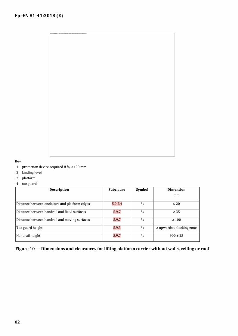
FprEN 81-41:2018 (E)
82
Key
1 protection device required if b4 < 100 mm
2 landing level
3 platform
4 toe guard
Description Subclause Symbol Dimension
mm
Distance between enclosure and platform edges 5.9.2.4 b3 ≤ 20
Distance between handrail and fixed surfaces 5.9.7 b4 ≥ 35
Distance between handrail and moving surfaces 5.9.7 b4 ≥ 100
Toe guard height 5.9.3 h5 ≥ upwards unlocking zone
Handrail height 5.9.7 h6 900 ± 25
Figure 10 — Dimensions and clearances for lifting platform carrier without walls, ceiling or roof
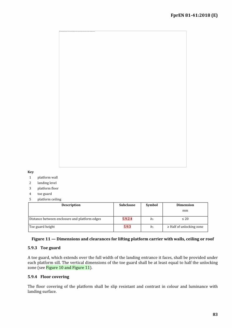
FprEN 81-41:2018 (E)
83
Key
1 platform wall
2 landing level
3 platform floor
4 toe guard
5 platform ceiling
Description Subclause Symbol Dimension
mm
Distance between enclosure and platform edges 5.9.2.4 b3 ≤ 20
Toe guard height 5.9.3 h5 ≥ Half of unlocking zone
Figure 11 — Dimensions and clearances for lifting platform carrier with walls, ceiling or roof
5.9.3 Toe guard
A toe guard, which extends over the full width of the landing entrance it faces, shall be provided under each platform sill. The vertical dimensions of the toe guard shall be at least equal to half the unlocking zone (see Figure 10 and Figure 11).
5.9.4 Floor covering
The floor covering of the platform shall be slip resistant and contrast in colour and luminance with landing surface.
FprEN 81-41:2018 (E)
84
5.9.5 Ceilings
Where ceilings are provided to the platform carrier, maintenance shall be carried out from the platform floor. The roof of the carrier above the ceiling shall be able to support the mass of at least one person, counting for 1 000 N on an area of 0,2 m × 0,2 m, without permanent deformation.
The opening of any door providing access to the top of the ceiling shall be by use of a key and prevent normal operation of the lifting platform. The return of the platform to normal service shall only be made by operation of a reset device placed outside of the liftway and accessible to authorized persons only.
Labels giving warning against treading on the top of the roof of the ceiling shall be provided, see 7.6.1.
5.9.6 Control panel
The following equipment shall be located on one side of the platform:
a) control devices (see 5.5.15);
b) an emergency stop device (see 5.5.15.5);
c) an emergency alarm control device (see 5.5.16).
Items a), b) and c) shall be positioned in the zone specified in Table 9.
5.9.7 Handrail
A handrail shall be installed at least on one side wall of the platform. The gripping part of this handrail shall have cross-sectional dimensions between 30 mm and 45 mm with a minimum radius of 10 mm. The free space between the fixed wall and the gripping part shall be minimum 35 mm. This clearance dimension shall be increased to a minimum of 100 mm if the handrail is adjacent to a moving surface. The height of the top edge of the gripping part shall be within (900 ± 25) mm from the platform floor.
If the handrail position obstructs the buttons or controls the handrail shall be interrupted so that clear accesses to the buttons or controls are provided.
Where the handrail projects into the clear access space of any landing door, the projecting ends of handrails shall be closed and turned towards the wall to minimize the risk of injury.
5.9.8 Glass
When glass is used in structural vertical parts of the platform it shall fulfil the conditions of Table 10. Mirrors or other glass finishes, where used on the carrier, shall comply with mode B or C according to EN 12600:2002, Annex C, if broken.
5.9.9 Tip up seat
Where a tip-up seat is provided, the seat shall have the following characteristics:
1) the seat height from the floor 500 mm ± 20 mm;
2) the depth 300 mm to 400 mm;
3) the width 400 mm to 500 mm;
4) the supported mass 100 kg.
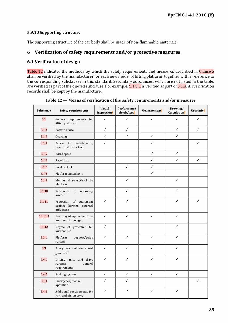
FprEN 81-41:2018 (E)
85
5.9.10 Supporting structure
The supporting structure of the car body shall be made of non-flammable materials.
6 Verification of safety requirements and/or protective measures
6.1 Verification of design
Table 12 indicates the methods by which the safety requirements and measures described in Clause 5 shall be verified by the manufacturer for each new model of lifting platform, together with a reference to the corresponding subclauses in this standard. Secondary subclauses, which are not listed in the table, are verified as part of the quoted subclause. For example, 5.1.8.1 is verified as part of 5.1.8. All verification records shall be kept by the manufacturer.
Table 12 — Means of verification of the safety requirements and/or measures
Subclause Safety requirements Visual
inspectiona
Performance
check/testb Measurementc
Drawing/
Calculationd User infoe
5.1 General requirements for
lifting platforms
✓ ✓ ✓ ✓ ✓
5.1.2 Pattern of use ✓ ✓ ✓ ✓
5.1.3 Guarding ✓ ✓ ✓ ✓
5.1.4 Access for maintenance,
repair and inspection
✓ ✓ ✓
5.1.5 Rated speed ✓ ✓
5.1.6 Rated load ✓ ✓ ✓
5.1.7 Load control ✓ ✓
5.1.8 Platform dimensions ✓
5.1.9 Mechanical strength of the
platform
✓ ✓
5.1.10 Resistance to operating
forces
✓ ✓
5.1.11 Protection of equipment
against harmful external
influences
✓ ✓ ✓ ✓
5.1.11.3 Guarding of equipment from
mechanical damage
✓ ✓ ✓ ✓
5.1.12 Degree of protection for
outdoor use
✓ ✓
5.2.1 Platform support/guide
system
✓ ✓ ✓ ✓
5.3 Safety gear and over speed
governorf
✓ ✓ ✓ ✓
5.4.1 Driving units and drive
systems - General
requirements
✓ ✓ ✓ ✓
5.4.2 Braking system ✓ ✓ ✓ ✓
5.4.3 Emergency/manual
operation
✓ ✓ ✓
5.4.4 Additional requirements for
rack and pinion drive
✓ ✓ ✓ ✓
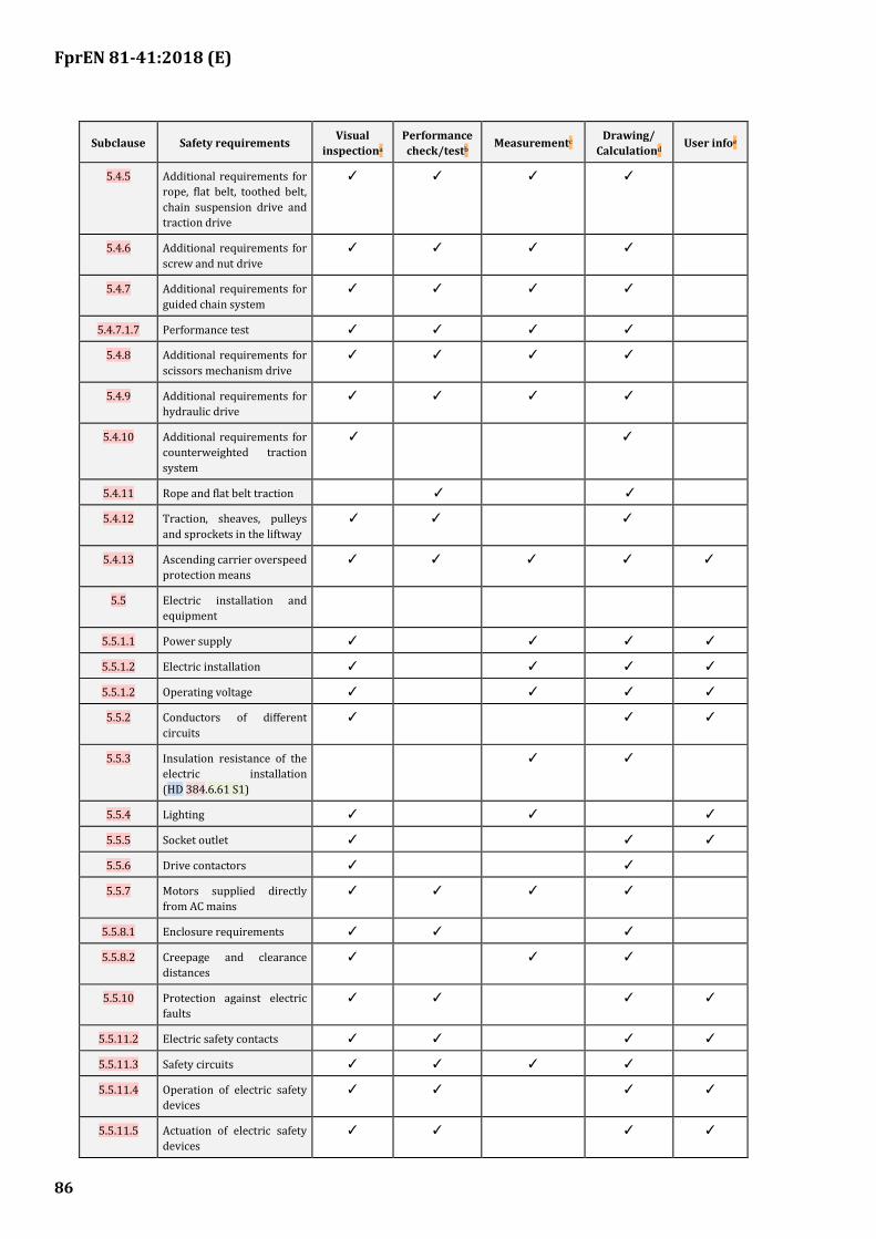
FprEN 81-41:2018 (E)
86
Subclause Safety requirements Visual
inspectiona
Performance
check/testb Measurementc
Drawing/
Calculationd User infoe
5.4.5 Additional requirements for
rope, flat belt, toothed belt,
chain suspension drive and
traction drive
✓ ✓ ✓ ✓
5.4.6 Additional requirements for
screw and nut drive
✓ ✓ ✓ ✓
5.4.7 Additional requirements for
guided chain system
✓ ✓ ✓ ✓
5.4.7.1.7 Performance test ✓ ✓ ✓ ✓
5.4.8 Additional requirements for
scissors mechanism drive
✓ ✓ ✓ ✓
5.4.9 Additional requirements for
hydraulic drive
✓ ✓ ✓ ✓
5.4.10 Additional requirements for
counterweighted traction
system
✓ ✓
5.4.11 Rope and flat belt traction ✓ ✓
5.4.12 Traction, sheaves, pulleys
and sprockets in the liftway
✓ ✓ ✓
5.4.13 Ascending carrier overspeed
protection means
✓ ✓ ✓ ✓ ✓
5.5 Electric installation and
equipment
5.5.1.1 Power supply ✓ ✓ ✓ ✓
5.5.1.2 Electric installation ✓ ✓ ✓ ✓
5.5.1.2 Operating voltage ✓ ✓ ✓ ✓
5.5.2 Conductors of different
circuits
✓ ✓ ✓
5.5.3 Insulation resistance of the
electric installation
(HD 384.6.61 S1)
✓ ✓
5.5.4 Lighting ✓ ✓ ✓
5.5.5 Socket outlet ✓ ✓ ✓
5.5.6 Drive contactors ✓ ✓
5.5.7 Motors supplied directly
from AC mains
✓ ✓ ✓ ✓
5.5.8.1 Enclosure requirements ✓ ✓ ✓
5.5.8.2 Creepage and clearance
distances
✓ ✓ ✓
5.5.10 Protection against electric
faults
✓ ✓ ✓ ✓
5.5.11.2 Electric safety contacts ✓ ✓ ✓ ✓
5.5.11.3 Safety circuits ✓ ✓ ✓ ✓
5.5.11.4 Operation of electric safety
devices
✓ ✓ ✓ ✓
5.5.11.5 Actuation of electric safety
devices
✓ ✓ ✓ ✓
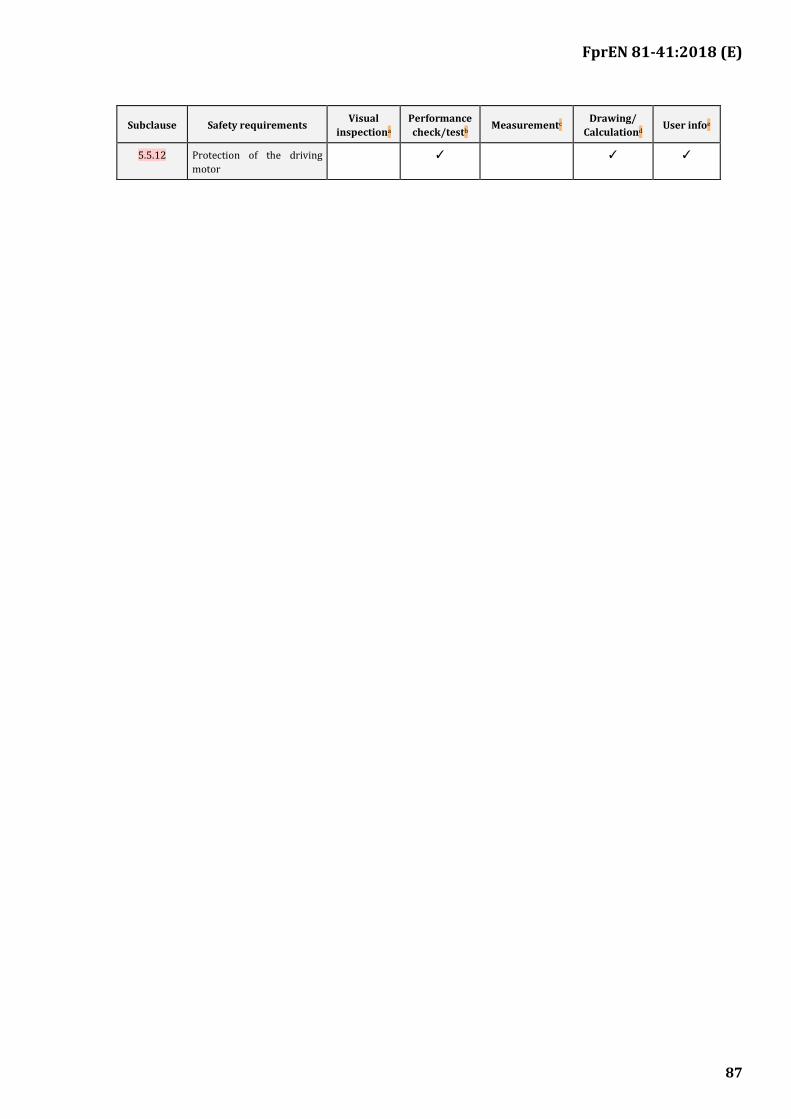
FprEN 81-41:2018 (E)
87
Subclause Safety requirements Visual
inspectiona
Performance
check/testb Measurementc
Drawing/
Calculationd User infoe
5.5.12 Protection of the driving
motor
✓ ✓ ✓
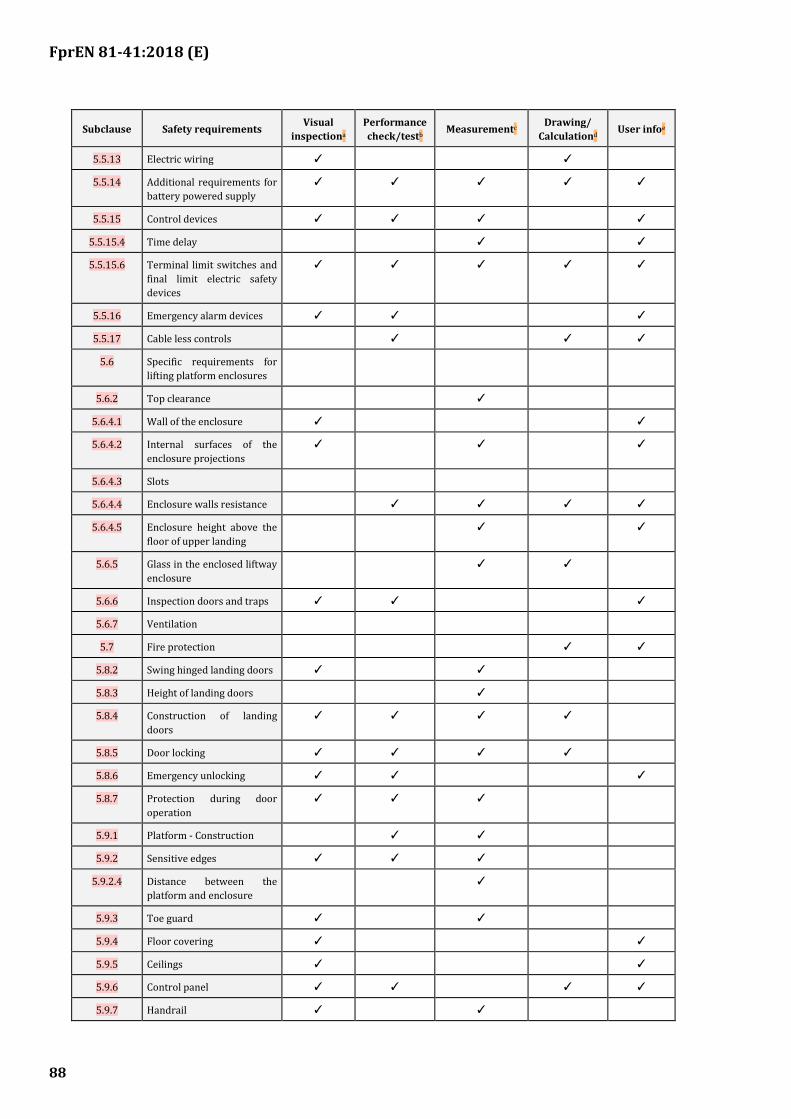
FprEN 81-41:2018 (E)
88
Subclause Safety requirements Visual
inspectiona
Performance
check/testb Measurementc
Drawing/
Calculationd User infoe
5.5.13 Electric wiring ✓ ✓
5.5.14 Additional requirements for
battery powered supply
✓ ✓ ✓ ✓ ✓
5.5.15 Control devices ✓ ✓ ✓ ✓
5.5.15.4 Time delay ✓ ✓
5.5.15.6 Terminal limit switches and
final limit electric safety
devices
✓ ✓ ✓ ✓ ✓
5.5.16 Emergency alarm devices ✓ ✓ ✓
5.5.17 Cable less controls ✓ ✓ ✓
5.6 Specific requirements for
lifting platform enclosures
5.6.2 Top clearance ✓
5.6.4.1 Wall of the enclosure ✓ ✓
5.6.4.2 Internal surfaces of the
enclosure projections
✓ ✓ ✓
5.6.4.3 Slots
5.6.4.4 Enclosure walls resistance ✓ ✓ ✓ ✓
5.6.4.5 Enclosure height above the
floor of upper landing
✓ ✓
5.6.5 Glass in the enclosed liftway
enclosure
✓ ✓
5.6.6 Inspection doors and traps ✓ ✓ ✓
5.6.7 Ventilation
5.7 Fire protection ✓ ✓
5.8.2 Swing hinged landing doors ✓ ✓
5.8.3 Height of landing doors ✓
5.8.4 Construction of landing
doors
✓ ✓ ✓ ✓
5.8.5 Door locking ✓ ✓ ✓ ✓
5.8.6 Emergency unlocking ✓ ✓ ✓
5.8.7 Protection during door
operation
✓ ✓ ✓
5.9.1 Platform - Construction ✓ ✓
5.9.2 Sensitive edges ✓ ✓ ✓
5.9.2.4 Distance between the
platform and enclosure
✓
5.9.3 Toe guard ✓ ✓
5.9.4 Floor covering ✓ ✓
5.9.5 Ceilings ✓ ✓
5.9.6 Control panel ✓ ✓ ✓ ✓
5.9.7 Handrail ✓ ✓

FprEN 81-41:2018 (E)
89
Subclause Safety requirements Visual
inspectiona
Performance
check/testb Measurementc
Drawing/
Calculationd User infoe
5.9.8 Glass ✓ ✓
5.9.9 Tip up seat ✓ ✓
a Visual inspection will be used to verify the features necessary for the requirement by visual examination of the components supplied.
b A performance check / test will verify that the features provided perform their function in such a way that the requirement is met.
c Measurement will verify by the use of instruments that requirements are met, to the specified limits.
d Drawings / calculations will verify that the design characteristics of the components provided meet the requirements.
e Verify, that the relevant point is dealt with in the instruction handbook or by marking.
f See verification tests for safety gear and overspeed governor.
verified according to the test requirements in EN 81-50 and tested according to the test requirements in EN 81-20.
6.2 Verification tests
6.2.1 Overspeed safety device
Test for overspeed safety device shall be made according to EN 81-50:2014, 5.4.
6.2.2 Ascending overspeed protection
Ascending overspeed protection means test shall be made according to EN 81-50:2014, 5.7
6.2.3 Rupture valve/Restrictor
Test for rupture valve/restrictor shall be made according to EN 81-50:2014, 5.9.
6.2.4 Safety gear
Test for safety gear shall be made according to EN 81-50:2014, 5.3.
6.2.5 Self-sustaining system
Test for self-sustaining system shall be made according to E.4.
6.2.6 Stopping safety device
Test for stopping safety device shall be made according to E.3.
6.2.7 Landing door locking devices
Tests for landing door locking devices shall be made according to EN 81-50:2014, 5.2.
6.2.8 Safety circuits containing electronic components
Tests for safety circuits containing electronic components shall be made according to EN 81-50:2014, 5.6.
6.2.9 Self-monitoring
Tests for self-monitoring tests shall be made according to EN 81-50:2014, 5.8.3.2.5.
FprEN 81-41:2018 (E)
90
6.3 Verification tests on each vertical lifting platform before first use
6.3.1 Completion of installation and prior to being put into service, lifting platforms shall be subjected to a thorough examination and test by a competent person in accordance with the following:
a) all control devices function correctly;
b) all door locking devices operate correctly;
c) stopping distance when the carrier is travelling downwards with rated speed with maximum working load is within specified limits;
d) Where two set of brakes are provided, it shall be verified by practical tests that where one brake set is not working a sufficient braking effort is exerted to stop and hold the carrier, travelling downwards at rated speed and with rated load;
e) all electric safety devices function correctly;
f) the suspension elements and their attachments are in order;
g) the correct clearance dimensions from the surrounding structure are maintained throughout the full travel of the lifting platform;
h) the lifting platform shall be subjected to electric tests by instruments to include insulation and earth continuity;
i) verify that the polarity of the mains supply connection is correct;
j) tests to verify correct tripping speed of the overspeed governor (or on hydraulic systems, the rupture valve) and correct function of the safety gear at rated load and speed shall be carried out;
k) verify that the mechanism for emergency/manual operation operates correctly;
l) the emergency alarm device when activated operates correctly;
m) the mechanical blocking device is provided and effective;
n) all notices, etc., are correctly displayed;
o) triggering of overload detection device operates correctly (rated load + 75 kg);
p) undergo without failure a dynamic test, with the maximum working load at the rated speed;
q) undergo without permanent deformation a static test with rated load multiplied by a coefficient of 1,25;
r) check safety nut rotates, check distance between the load carrying nut and the safety nut and check correctly positioned safety nut electric contact device.
s) On traction drive systems with counterweight the three conditions in 5.4.11 shall be tested. On traction drive systems with counterweight, a test of the ascending carrier overspeed protection device. The test shall be made while the empty carrier is ascending at not less than rated speed, using only this device for braking.
t) Sealing of the final setting of the stopping safety device.
FprEN 81-41:2018 (E)
91
6.3.2 A test and examination document which declares at least all the information and the results of all checks on-site listed above shall be completed and held by the installer.
7 Information for use
7.1 Introduction
Operating instructions shall include advice that the safety gear shall only be released and reset by a competent person.
7.2 General
EN ISO 12100 details the general requirements for information, location and nature of the information for use, signals and warning devices, markings, signs (pictograms), written warnings, accompanying documents (in particular the instruction handbook).
7.3 Signals and warning devices
7.3.1 Information to be displayed
7.3.1.1 General
Notices bearing the following minimum information shall be displayed on the platform:
7.3.1.2 Rated load
The rated load and the maximum number of persons.
Size of text or symbols shall be at least 10 mm upper case and 7 mm lower case.
7.3.1.3 Function devices
The function of all devices controlling the operation of the lifting platforms shall be identified, see 5.5.15.1.
7.3.1.4 Emergency alarm device
If the emergency alarm device specified in 5.5.16 is activated with a button, the button shall be coloured yellow and shall be identified by a bell symbol, Symbol No. 5013 in IEC 60417:2002 DB.
7.3.1.5 Disabled persons symbol
On lifting platforms with public access, an International Symbol of Access-ISA, Symbol No. 0100 of ISO 7000:2014 shall be displayed at each landing. The height of the symbol shall be not less than 50 mm.
7.4 Emergency manual operation
7.4.1 Detailed step by step emergency manual operating instructions in accordance with 5.4.3. shall be displayed in a prominent position adjacent to the emergency device.
7.4.2 Where it is possible for the device to be operated to move the platform in both the up and down direction a direction label indicating the direction of movement of the platform, when the device is operated, shall be fitted in a prominent position.
7.4.3 On hydraulic powered lifting platforms, a notice bearing the following legend shall be displayed adjacent to the manual lowering value:

FprEN 81-41:2018 (E)
92
“DANGER — Emergency Lowering Valve”.
7.5 Main electric switch
7.5.1 The switch for the main electric supply to the lifting platform shall be identified.
7.5.2 For hydraulically powered lifting platforms the switch identification shall also bear the following legend:
“Switch off only when the lifting platforms is at the lowest level”.
7.6 Fragile roof
7.6.1 A safety label shall be affixed to the roof of the carrier in a position which is clearly visible from any access door. The label shall at least comprise the warning sign, Fragile roof, from EN ISO 7010:2012.
The notice should be large enough (minimum 300 mm) and prominently positioned to make it immediately visible to any person who may try to gain access.
7.6.2 Located on the platform sill toe-guard shall be the following warning text, on the sides that have intermediate landings:
“HAZARD OF FALLING INTO THE LIFTWAY - MOVE THE PLATFORM TO THE LANDING LEVEL –
IF THIS IS NOT POSSIBLE, THE RESCUE OPERATION OF PERSONS MUST BE CARRIED OUT ONLY BY A COMPETENT PERSON”
7.7 No goods
On lifting platforms with public access, a sign shall be affixed to indicate that the lifting platform is not intended for the transport of goods.
7.8 Operating instructions
7.8.1 On lifting platforms where assistance to users is not available, operating instructions shall be provided.
7.8.2 The information for the user shall be provided as detailed in EN ISO 12100:2010, 6.4.
7.9 Accompanying documents (in particular: Instruction handbook)
7.9.1 General
7.9.1.1 Information provided by the manufacturer, to the lifting platform owner, shall accompany the lifting platforms, as detailed in EN ISO 12100:2010, 6.4.5, which includes the following:
a) A general description of the lifting device including the following basic characteristics:
1) the basic characteristics of the lifting platform;
2) the characteristics of any ropes and/or chains;
3) the plans of installation in the building;
4) hydraulic circuit diagrams (using symbols from ISO 1219-1);

FprEN 81-41:2018 (E)
93
The circuit diagrams may be limited to the circuits for the overall understanding of the safety considerations. The abbreviations used with the symbols shall be explained by means of a nomenclature;
5) the full load pressure;
6) the characteristics or type of hydraulic fluid;
7) the characteristics of each incoming supply:
rated voltage, number of phases and frequency (if AC);
full load current;
short circuit rating at the point of incoming supply terminals
b) the intended use as detailed in 1.1;
c) specific warnings against any foreseeable misuse;
d) training on the practical operation of the lifting platforms;
e) recommended intervals for routine inspection and servicing, including the specification of spare parts where the use of incorrect parts would affect the safety of the lifting platform;
f) warning of residual risks;
g) information regarding the conditions for the stability of the lifting platform during transportation, assembly, use, dismantling when out of service, testing and any foreseeable breakdowns;
h) a copy of the verification tests in 6.3.1;
i) a statement highlighting that the lifting platform shall not be used for fire-fighting or evacuation during a fire;
j) a repeat of the information with which the machinery is marked;
k) instructions for use of the controls;
l) alarm system;
m) emergency operations, including the method to be followed in the event of an accident or breakdown including:
1) the use of the emergency unlocking key, detailing the essential precautions to be taken in order to avoid accidents which could result from an unlocking which was not followed by effective relocking; This key shall be available on the site of the lift installation and accessible only to authorized persons.
2) rescue operation: in particular, detailed instructions shall be given on the procedures which may be used by a trained and authorised person on site and when a competent person must be called to undertake the rescue procedure e.g. when a safety device has set and requires to be released, including the identification of special tools, if any.
n) instructions for correct replacement type of batteries, maintenance period and type of charger;
FprEN 81-41:2018 (E)
94
o) the operating method to be followed in the event of accident or breakdown; if a blockage is likely to occur, the operating method to be followed so as to enable the equipment to be safely unblocked;
p) the specifications of spare parts to be used, when these affect the health and safety of operators;
q) a test report detailing the static and dynamic tests carried out by or for the manufacturer or their authorized representative;
r) a statement that the emission sound pressure level at the operators position shall not exceed 70 dB(A);
s) how to inspect the screw and the wear of the nut;
t) information for checking the wear of the guide element;
u) information that the final setting of the stopping safety device shall be sealed.
7.9.1.2 An electric circuit wiring diagram showing the electric connections and components, together with all necessary identification markings (see 5.5.13.5);
The electric schematic diagrams may be limited to the circuits for the overall understanding of the safety considerations and use IEC 60617-DB symbols. Any graphical symbol not shown in IEC 60617-DB shall be separately shown and described on the diagrams or supporting documents. The symbols and identification of components and devices shall be consistent throughout all documents and on the lift.
The abbreviations used with the symbols shall be explained by means of a nomenclature.
If the electric schematic diagram has several alternatives, it shall be indicated which alternative is valid e.g. by listing of the applicable alternative solutions;
7.9.1.3 Information and assembly instructions, including:
a) forces imposed upon the building structure;
b) anchorage requirements.
7.9.1.4 Maintenance instructions including an instruction manual shall inform about the identification and use of the special tools.
7.9.2 Instruction manual
The instruction manual shall give the necessary information about the normal use of the lift and rescue operation as described in EN 13015 and in particular about the use of the emergency unlocking key, detailing the essential precautions to be taken in order to avoid accidents which could result from an unlocking which was not followed by effective relocking.
This key shall be available on the site of the lift installation and accessible only to authorized persons.
The emergency unlocking key shall have a label attached drawing attention to the danger which may be involved in using this key and the need to make sure that the door is locked after it has been closed.
7.9.3 Marking
Each lifting platform shall be marked legibly and indelibly with the following minimum particulars:
FprEN 81-41:2018 (E)
95
a) the business name and full address of the manufacturer and, where applicable, their authorized representative;
b) year of construction;
c) designation of series or type, if any;
d) serial or identification number;
e) rating information; voltage, frequency, power, rated load.
7.9.4 Building clearance requirements
The following information shall be supplied within the installation manual and the instruction handbook:
The dimensions of working areas in front of machinery cabinets shall be sufficient to permit easy and safe working on equipment.
In particular there shall be provided at least a clear height of 2 m at working areas, and:
a) a clear horizontal working area of at least 0,50 m × 0,60 m for maintenance and inspection of parts at points where this is necessary;
b) a clear horizontal space in front of the control panels and cabinets, defined as follows:
1) depth, measured from the external surface of the enclosures, at least 0,70 m;
2) width, the greater of the following values: 0,50 m or the full width of the cabinet or panel.
Only for existing buildings, the minimum clear height may be reduced but shall be the maximum allowed by the building constraints, however not less than 1,80 m. When the height is less than 2,0 m, suitable warnings shall be appropriately placed at the cabinet.
FprEN 81-41:2018 (E)
96
(normative)
Electronic components: failure exclusion
The faults to be considered in the electric equipment of a lifting platform are listed in 5.5.11.
Failure exclusion shall only be considered provided that components are applied within their worst case limits of characteristics, value, temperature, humidity, voltage and vibrations.
The following Table A.1 describes the conditions under which the faults envisaged in 5.5.11 can be excluded.
In the table:
— the ” NO ” in the cell means: failure not excluded, i.e. shall be considered;
— the unmarked cell means: the identified fault type is not relevant.
NOTE Design guidelines.
Some dangerous situations are recognized coming from the possibility of bridging one or several electric safety contacts by short circuiting or by local interruptions of common lead (earth) combined with one or several other failures. It is good practice to follow the recommendations given below, when information is collected from the safety chain for control purposes, for remote control, alarm control, etc.:
— design the board and circuits with distances in accordance with Specifications 3.1 and 3.6 of Table A.1;
— organize common of the connections to the safety chain on the printed circuit board so that the common to the contactors or relay-contactors as mentioned in 5.5.11 will switch off at interruption of the common lead on the print board;
— make always failure analyses for the safety circuits as mentioned in 5.5.11.3.2; if modifications or additions are made after the lifting platform installation the failure analyses involving new and existing equipment shall be carried out again;
— always use outside (out of element) resistors as protective devices of input elements; internal resistor of the device should not be considered as safe;
— components shall only be used within the manufacturer specification;
— backwards voltage coming from electronics shall be considered; using galvanically separated circuits can solve the problems in some cases;
— electric installations regarding earthing should be in accordance with HD 384.5.54 S1; in that case, the interruption of the earth from the building to the controller collection bar (rail) can also be excluded.
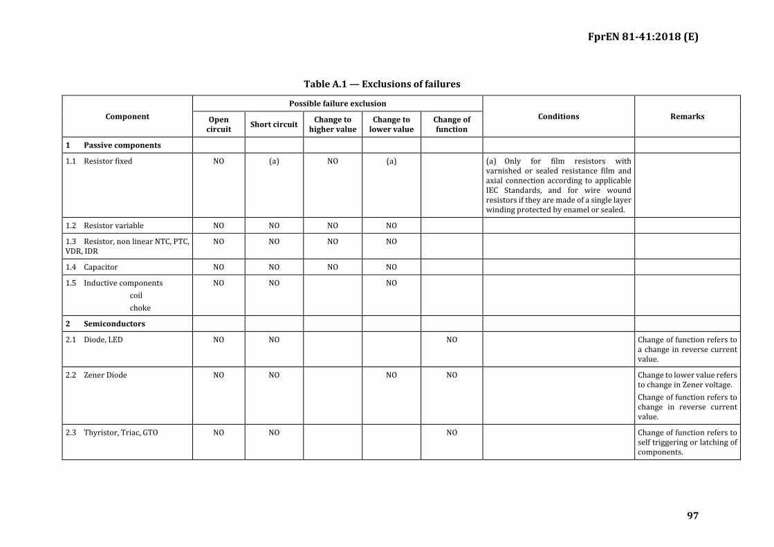
FprEN 81-41:2018 (E)
97
Table A.1 — Exclusions of failures
Component
Possible failure exclusion
Conditions Remarks Open circuit
Short circuit Change to
higher value Change to
lower value Change of function
1 Passive components
1.1 Resistor fixed NO (a) NO (a) (a) Only for film resistors with varnished or sealed resistance film and axial connection according to applicable IEC Standards, and for wire wound resistors if they are made of a single layer winding protected by enamel or sealed.
1.2 Resistor variable NO NO NO NO
1.3 Resistor, non linear NTC, PTC, VDR, IDR
NO NO NO NO
1.4 Capacitor NO NO NO NO
1.5 Inductive components
coil
choke
NO NO NO
2 Semiconductors
2.1 Diode, LED NO NO NO Change of function refers to a change in reverse current value.
2.2 Zener Diode NO NO NO NO Change to lower value refers to change in Zener voltage.
Change of function refers to change in reverse current value.
2.3 Thyristor, Triac, GTO NO NO NO Change of function refers to self triggering or latching of components.
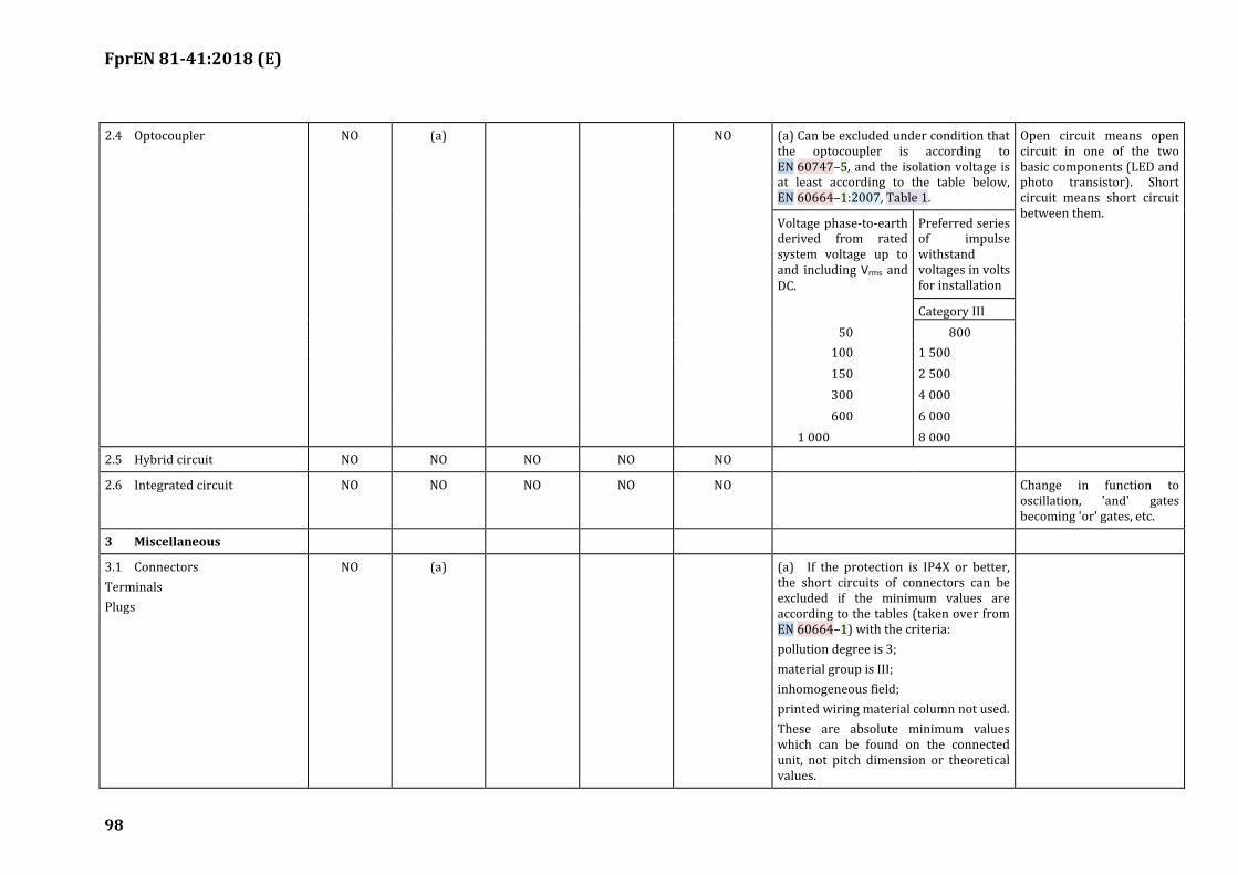
FprEN 81-41:2018 (E)
98
2.4 Optocoupler NO (a) NO (a) Can be excluded under condition that the optocoupler is according to EN 60747–5, and the isolation voltage is at least according to the table below, EN 60664–1:2007, Table 1.
Open circuit means open circuit in one of the two basic components (LED and photo transistor). Short circuit means short circuit between them.
Voltage phase-to-earth derived from rated system voltage up to and including Vrms and DC.
Preferred series of impulse withstand voltages in volts for installation
Category III
50 800
100 1 500
150 2 500
300 4 000
600 6 000
1 000 8 000
2.5 Hybrid circuit NO NO NO NO NO
2.6 Integrated circuit NO NO NO NO NO Change in function to oscillation, 'and' gates becoming 'or' gates, etc.
3 Miscellaneous
3.1 Connectors
Terminals
Plugs
NO (a) (a) If the protection is IP4X or better, the short circuits of connectors can be excluded if the minimum values are according to the tables (taken over from EN 60664–1) with the criteria:
pollution degree is 3;
material group is III;
inhomogeneous field;
printed wiring material column not used.
These are absolute minimum values which can be found on the connected unit, not pitch dimension or theoretical values.
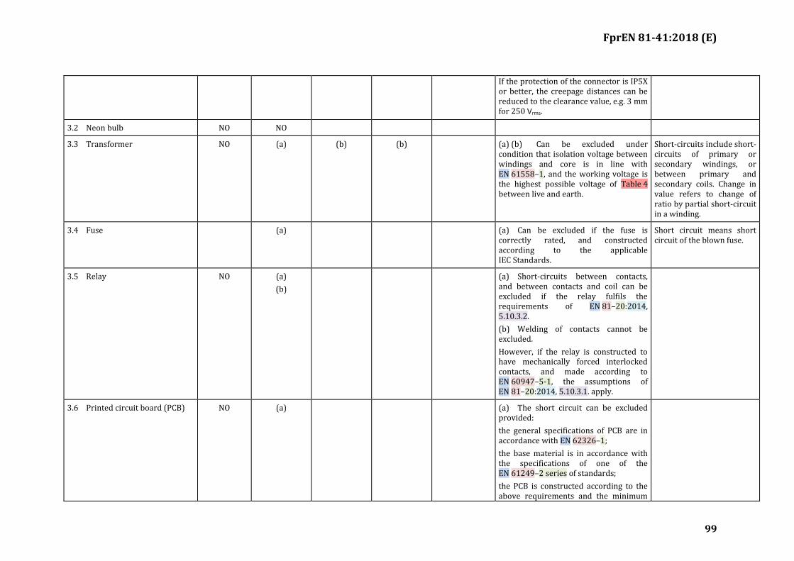
FprEN 81-41:2018 (E)
99
If the protection of the connector is IP5X or better, the creepage distances can be reduced to the clearance value, e.g. 3 mm for 250 Vrms.
3.2 Neon bulb NO NO
3.3 Transformer NO (a) (b) (b) (a) (b) Can be excluded under condition that isolation voltage between windings and core is in line with EN 61558–1, and the working voltage is the highest possible voltage of Table 4 between live and earth.
Short-circuits include short-circuits of primary or secondary windings, or between primary and secondary coils. Change in value refers to change of ratio by partial short-circuit in a winding.
3.4 Fuse (a) (a) Can be excluded if the fuse is correctly rated, and constructed according to the applicable IEC Standards.
Short circuit means short circuit of the blown fuse.
3.5 Relay NO (a)
(b)
(a) Short-circuits between contacts, and between contacts and coil can be excluded if the relay fulfils the requirements of EN 81–20:2014, 5.10.3.2.
(b) Welding of contacts cannot be excluded.
However, if the relay is constructed to have mechanically forced interlocked contacts, and made according to EN 60947–5-1, the assumptions of EN 81–20:2014, 5.10.3.1. apply.
3.6 Printed circuit board (PCB) NO (a) (a) The short circuit can be excluded provided:
the general specifications of PCB are in accordance with EN 62326–1;
the base material is in accordance with the specifications of one of the EN 61249–2 series of standards;
the PCB is constructed according to the above requirements and the minimum
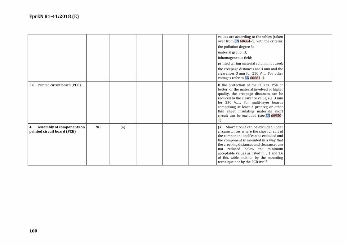
FprEN 81-41:2018 (E)
100
values are according to the tables (taken over from EN 60664–1) with the criteria:
the pollution degree 3;
material group III;
inhomogeneous field;
printed wiring material column not used;
the creepage distances are 4 mm and the clearances 3 mm for 250 Vrms. For other voltages refer to EN 60664–1.
3.6 Printed circuit board (PCB) If the protection of the PCB is IP5X or better, or the material involved of higher quality, the creepage distances can be reduced to the clearance value, e.g. 3 mm for 250 Vrms. For multi-layer boards comprising at least 3 prepreg or other thin sheet insulating materials short circuit can be excluded (see EN 60950–1).
4 Assembly of components on printed circuit board (PCB)
NO (a) (a) Short circuit can be excluded under circumstances where the short circuit of the component itself can be excluded and the component is mounted in a way that the creeping distances and clearances are not reduced below the minimum acceptable values as listed in 3.1 and 3.6 of this table, neither by the mounting technique nor by the PCB itself.
FprEN 81-41:2018 (E)
101
(informative)
Guidance in selection of lifting platforms
B.1 Introduction
The guidance given in this annex is to assist in the selection of a lifting platform. It reminds suppliers and purchasers and installers of additional factors that will require their attention.
B.2 Selection of lifting platforms
B.2.1 Suitability
B.2.1.1 When selecting a lifting platform, consider the abilities of the user and if the needs of the user are likely to change in the future.
B.2.1.2 Select a lifting platform with a rated load that is capable of carrying the maximum foreseeable load.
B.2.1.3 Ensure that the user(s) can be safely transported on the lifting platform, whether sitting, standing or seated in a wheelchair.
B.2.1.4 Where either manual or automatic operation is optionally available for devices such as doors consider which is more appropriate for the user.
B.2.1.5 Ensure that there are means of escape in the event of fire.
NOTE prEN 81–41 is based upon hold-to-run platform controls for normal operation. When the emergency evacuation system of the building is activated it is possible to actuate an automatic return of the platform to a safe building exit floor and to shut the lifting platform down. It is for national building authorities to decide whether a system such as this, should be considered for lifting platforms.
B.2.2 Control devices
B.2.2.1 Consider the position, type and number of controls that would suit users with differing disabilities.
B.2.2.2 Consider whether a key switch, electronic card or similar means is necessary to restrict the use of the lifting platform to authorized users.
B.2.3 Location of the lifting platform
Check whether the proposed location of the lifting platform is suitable. For example, check:
a) that the installation fits the best way possible into the existing environment and path network;
b) that the site location and proposed supporting structure is strong enough to support the lifting platform;
FprEN 81-41:2018 (E)
102
c) that there is an unobstructed manoeuvring space of 1 500 mm × 1 500 mm, for buildings without public access where space is restricted, smaller dimensions can be considered, or a straight access route at least 900 mm wide;
d) that the class of protection against external influences is adequate for the intended application.
B.2.4 Duty cycle
The anticipated maximum number of journeys per hour should be determined by the purchaser and communicated to the supplier.
B.3 Electric supply and lighting
Ensure that a suitable electric supply is available.
Ensure that lighting to a minimum value of 50 lx is available on the landings whilst the lifting platform is in use.
B.4 Maintenance
Ensure that the purchaser is informed of requirements for the examination, testing and servicing of the lifting platforms and of any associated national regulatory requirements.
FprEN 81-41:2018 (E)
103
(informative)
Recommendations for the provisions and use of specially adapted control
devices, switches and sensors
C.1 Control devices
C.1.1 It is recommended that the operation of the lifting platform is by means of conventional pushbuttons, joysticks or similar devices, except where these are unsuitable due to the disability of the user.
C.1.2 In such cases, the control device placement, whether on a wall, wheelchair, pendant, etc., should be such that accidental operation by the user is minimized.
C.1.3 Regardless of the type of control switches/devices used, a bi-stable electric safety device in accordance with 5.5.11 shall be fitted on the lifting platform in accordance with 5.5.15.5. Additional stopping devices, which are either specially adapted switches or remotely controlled, may also be fitted.
C.2 Assistance
C.2.1 If the disability of a dedicated user is such that an adapted switch or a remote control device cannot be operated to control the lifting platform, other technical solutions may be sought that could enable the user to operate the lifting platform. Only if such a solution is not available should the assistance of others be sought.
C.3 Specially adapted switches
C.3.1 Where switches such as low force switches, blowpipe operated switches or pull-cords are used, the design should be such that their immunity to electric and mechanical interference will prevent accidental operation of the lifting platform.
C.3.2 Such a switch may be used to stop the lifting platform if required, in addition to the stopping devices referred to in C.1.3.

FprEN 81-41:2018 (E)
104
(informative)
In-use periodic examination, tests and servicing
D.1 Periodic examinations and tests
The lifting platforms should be thoroughly examined at intervals not exceeding 12 months (national regulations may require an interval less or more than this, however, the maximum required interval, specified by the manufacturer must not be exceeded), particular attention being given, upon which a report should be prepared, to the effectiveness of the following features:
a) interlocking devices;
b) electric safety circuits;
c) earthing continuity;
d) supporting and suspension means for lifting, for example joint of the screw and wear of the nut;
e) driving unit and brakes;
f) devices for preventing free fall and descent and ascent with excessive speed e.g. safety gear;
g) alarm system;
h) safety edges;
i) inspection of internal surfaces (distances, surfaces and sharp edges);
j) inspection of guides and guide shoes or rollers;
k) lighting and emergency lighting.
D.2 Servicing
Regular servicing should be carried out as specified in the Instruction Handbook provided by the manufacturer.
FprEN 81-41:2018 (E)
105
(normative)
Safety components – Tests procedures for verification of conformity
E.1 General provisions
The precision of the instruments shall allow, unless particularly specified, measurements to be made within the following tolerances:
a) ± 1 % masses, forces, distances, speeds;
b) ± 2 % accelerations, retardations;
c) ± 5 % voltages, currents;
d) ± 5 °C temperatures;
e) recording equipment shall be capable of detecting signals, which vary in time of 0,01 s;
f) ± 2,5 % flow rate;
g) ± 1 % pressure P ≤ 200 kPa;
h) ± 5 % pressure P > 200 kPa.
FprEN 81-41:2018 (E)
106
E.2 Test report
The examination certificate shall contain the following information.
TEST REPORT
Name of the examiner: ……………………………………………………………………………………………………………………..
examination certificate: ……………………………………………………………………………………………………………………
examination N°: ……………………………………………………………………………………………………………………………….
1 Category, type and make or trade name: ………………………………………………………………………………..
2 Manufacturer's name and address: ………………………………………………………………………………………..
3 Name and address of certificate holder: ………………………………………………………………………………..
4 Date of submission for examination: ……………………………………………………………………………………..
5 Certificate issued on the basis of the following requirement: …………………………………………………
6 Test laboratory (if any): ……………………………………………………………………………………………………….
7 Date and number of report: ………………………………………………………………………………………………….
8 Date of examination: ……………………………………………………………………………………………………………
9 The following documents, bearing the examination number shown above, are annexed to this certificate: ………………………………………………………………………………………………………………………………………
10 Any additional information: …………………………………………………………………………………………………
Place: ………………………………………………………….
(Date)
(Signature)
FprEN 81-41:2018 (E)
107
E.3 Screw and nut (not self sustaining system) stopping safety device
E.3.1 General provisions
The range of use provided shall be stated, i.e.:
a) minimum and maximum total masses;
b) maximum rated speed and maximum tripping speed;
c) detailed information shall be provided on the materials used, the type of screw and its design.
E.3.2 Check on the characteristic of the stopping safety device
E.3.2.1 Test sample
There shall be submitted a complete test rig with: guide rails, frame, screw/nut system, motor, brakes, cushioned stops, speed governor, test load and stopping safety device.
The travel of the test rig shall be so long that the frame under free running conditions reaches the tripping speed of the speed governor at least 2 m before it strikes the cushioned stops under all conditions.
The frame shall be adapted for loading test loads in order to reach the minimum and maximum total mass.
The test rig shall be designed for the maximum total mass.
The brakes shall be possible to release to create free running conditions.
E.3.2.2 Test
E.3.2.2.1 Method of test
The test shall be carried out in free running. Direct or indirect measurements shall be made of:
a) the total height of the fall;
b) the braking distance on the screw;
c) the sliding distance of the overspeed governor, or that of the device used in its place;
d) the total travel of the elements forming the spring.
Measurements a) and b) shall be recorded as a function of the time. The following shall be determined:
e) the average braking force;
f) the greatest instantaneous braking force;
g) the smallest instantaneous braking force.
FprEN 81-41:2018 (E)
108
E.3.2.2.2 Test procedure
E.3.2.2.2.1 Stopping safety device for a single total mass
There shall be carried out four tests with the total mass (P+Q). Between each test the friction parts shall be allowed to return to their normal temperature.
During the tests several sets of friction parts may be used. However, one set of parts shall be capable of three tests.
E.3.2.2.2.2 Stopping safety device certified for different total masses
Adjustment in stages or continuous adjustment. Two series of tests shall be carried out for:
— maximum; and
— the minimum value applied for.
E.3.2.2.3 Determination of the braking force of the stopping safety device
E.3.2.2.3.1 Stopping safety device for a single total mass
The braking force of which the stopping safety device is capable for the given adjustment is taken as equal to the average braking forces determined during the tests.
A check shall be made that the average values determined during the test lie within a range of ± 25 % in relation to the value of the braking force defined above.
E.3.2.2.3.2 Stopping safety device for different total masses
Adjustments in stages or continuous adjustment.
The braking force of which the stopping device is capable shall be calculated as laid down in E.3.2.2.3.1 for the maximum and minimum values applied for.
E.3.2.2.4 Checking after the tests
a) The deformations and modifications (for example cracks, deformations or wear of the gripping elements, appearance of the rubbing surfaces) shall be checked.
b) If necessary, the stopping safety device assembly and the gripping elements shall be photographed in order to reveal deformations or fractures.
E.3.2.3 Calculation of the permissible total mass
E.3.2.3.1 Stopping safety device for a single total mass
The permissible total mass shall be calculated using the following formula:
(𝑃 + 𝑄) =𝐵
16
where
FprEN 81-41:2018 (E)
109
(P+Q) permissible mass (kg);
B braking force (N) determined in accordance with E.3.2.2.3.
16 a constant (N/kg)
E.3.2.3.2 Stopping safety device for different total masses
E.3.2.3.2.1 Adjustment in stages
The permissible total mass shall be calculated for each adjustment as laid down in E.3.2.3.1.
E.3.2.3.2.2 Continuous adjustment
The permissible total mass shall be calculated as laid down in E.3.2.3.1 for the maximum and minimum values applied for and in accordance with the formula proposed for the intermediate adjustments.
E.3.2.4 Possible modification to the adjustments
If, during the tests, the values found differ by more than 20 % from those expected by the applicant, other tests may be made with their agreement, after modification of the adjustments if necessary.
NOTE If the braking force is clearly greater than that allowed for, the total mass used during the test would be clearly smaller than that which one would be led to authorize by calculation E.3.2.3.1 and consequently the test would not allow the conclusion that the stopping safety device is able to dissipate the required energy with the total mass resulting from the calculation.
E.3.3 Comments
a) When it is applied to a given lifting platform, the mass stated by the installer shall not differ from the permissible total mass defined in E.3.2.3 by ± 7,5 %;
b) a check shall be made that the possible travel of the gripping elements is sufficient under the most unfavourable conditions (accumulation of tolerance);
c) the friction parts shall be suitably retained so that it can be certain that they will be in place at the moment of operation;
d) it shall be checked that the travel of the components forming the spring is sufficient.
E.3.4 Test report
The test report shall indicate the following:
a) information according to EN 81-50:2014, 5.7.5;
b) type and application of stopping device;
c) the limits of the permissible total masses (see E.3.3 a));
d) the tripping speed of the overspeed governor;
e) the type of screw/ nut system;

FprEN 81-41:2018 (E)
110
f) the state of lubrication of the screw.
E.4 Self sustaining system
The system shall be tested to ensure that under free running conditions, the speed of the platform decreases within 0,4 m under maximum working load conditions.

FprEN 81-41:2018 (E)
111
(informative)
Noncircular elastomeric coated steel suspension applications on lifting
platforms
F.1 Properties and tolerances
F.1.1 Classification
Noncircular elastomeric coated steel suspension member should be classified by their width and thickness, number of cords, cord diameter, cord material, cord assembly and coating material, including its friction coefficient with its permitted counterparts (traction sheave) and minimum breaking force. These data and the name of the manufacturer shall be listed in a data tag.
Table F.1 — Tolerances on nominal noncircular elastomeric-coated steel suspension members sizes
Load on Suspension Member Tolerance
Width Thickness Flatness
Min. Max. Min. Max.
0 to 10 % MBF −5 % +5 % −5 % +5 % 3 %
F.1.2 Dimension tolerances
Tolerances on cord diameter shall be:
— +3 % maximum at no load;
— −1 % minimum at 10 % of minimum breaking force.
The dimensional tolerances of the noncircular elastomeric coated steel suspension members shall be as indicated in Table F.1.
F.2 Replacement criteria
F.2.1 Replacement of members
F.2.1.1 Replacement members shall be as specified by the original lifting platform manufacturer or be at least equivalent in strength, weight, and design.
F.2.1.2 When replacing suspension members, all members in a set shall be replaced, except as permitted by F.3.3.3.
F.2.1.3 The members in the set shall be new, all from the same manufacturer and of the same material, friction coefficient with its permitted counterparts (traction sheave), strength, construction, and dimension.
F.2.1.4 Data tags shall be applied.
FprEN 81-41:2018 (E)
112
F.2.1.5 Suspension member fastenings shall conform to the original lifting platform manufacturer specifications.
F.2.2 Replacement due to wear
The noncircular elastomeric coated steel suspension member shall be replaced when:
— the steel cords, strands or wires break through the elastomeric coating; or
— the elastomeric coating has been worn so that any steel cord is exposed to wear; or
— there is evidence of red rouging on any part of the noncircular elastomeric coated steel suspension member;
— if any one member is replaced due to wear, the complete set of similarly utilized members on that lifting platform shall be replaced.
F.2.3 Replacement due to damage
F.2.3.1 The noncircular elastomeric coated steel suspension member shall be replaced when load carrying cords are damaged by an exterior source. Damage to the member coating itself is not a criterion for replacement as long as load-carrying cords have not been damaged or exposed to wear.
F.2.3.2 The noncircular elastomeric coated steel suspension member shall be replaced if the member is permanently kinked, bent, or deformed in any way.
F.2.3.3 If one member of a set is damaged during installation or acceptance testing prior to being subjected to lifting platform service, it is permissible to replace the damage member only. The suspension members, including the damaged member, shall not have been shortened since their original installation.
F.2.3.3.1 The member data for the replacement member shall correspond to the original member data.
F.2.3.3.2 The replacement member shall be provided with a data tag.
F.2.3.3.3 The dimensions of any of the remaining members shall comply with Table F.1.
F.2.3.3.4 The tension of the new replacement member shall be checked and adjusted as necessary If proper equalization of the member tension cannot be maintained after 6 months, the entire set of suspension members shall be replaced.
F.2.3.3.5 The replacement member shall be provided with the type of suspension member fastening used with the other members.

FprEN 81-41:2018 (E)
113
(informative)
Building interfaces
G.1 General provisions
The building structure should be constructed to withstand loads and forces to which it is subjected to by lifting platform equipment. If not specified differently in this standard for particular applications, this loads and forces are:
— values resulting from the static masses; and
— values resulting from moving masses and their emergency operation. The dynamic effect is represented by a factor of 2.
G.2 Support of Guide Rails
It is important that the guide rails of the lifting platform are supported in such a way that the effects of movement of the building structure to which they are connected is minimized.
When considering buildings constructed of concrete, blockwork or bricks it can be assumed that the guide rail brackets which support the guides will not be subjected to displacement caused by movement of the well walls (other than compression).
However, where the guide brackets are connected to the building fabric by steel beams, or by connection to timber frames, there may be deflection of this structure due to the load imposed by the car through the guides and guide brackets. Additionally there may be movement of the lift supporting structure due to external forces such a wind loading, snow loading, etc.
Any deflection of these beams or frames should be taken into account during the calculations of the guide rails. The total permissible deflection of the guide rails for the safe operation of the safety gear, etc, shall include any displacement of the guide rail due to deflection of the building fabric and the deflection of the guide itself, due to the load imparted on it by the carrier.
It is therefore important that the persons responsible for the design and fabrication of these supporting structures communicate with the lift provider in order to ensure that they are suitable under all load conditions.
G.3 Ventilation of the enclosed liftway
G.3.1 General
See Assumptions.
The requirement to suitably ventilate the enclosed liftway is often contained within local building regulations, either specifically, or as a general requirement as would be given for any building space where machinery is installed or people are accommodated (for leisure, work, etc.). As such this standard cannot provide exacting guidance on the specific requirements to ventilate such areas while enclose liftway are part of one larger and often complex total build environment.
FprEN 81-41:2018 (E)
114
To do so would bring conflict to these national requirements. However some general guidance can be given.
G.3.2 Ventilation of the enclosed liftway
The safety and comfort of persons riding in the lift, working in the enclosed liftway or those who may become entrapped in the carrier or enclosed liftway should the carrier become stalled between floors depends on many factors:
— Ambient temperature of the enclosed liftway as part of the building or even totally stand alone;
— Exposure to direct sunlight;
— Volatile Organic Component, CO2, air quality;
— Fresh air access in enclosed liftway;
— Size of well, both in cross sectional area and height;
— Number, size, gaps around and location of landing doors;
— Expected heat output from installed equipment;
— Firefighting and smoke evacuation strategy and related BMS (building management system);
— Humidity, dust and fumes;
— Air flow (heat /cooling) and energy saving building technology applied;
— Air tightness of the enclosed liftway and the entire building.
The carrier should be provided with sufficient ventilation aperture to ensure adequate flow of air for the maximum number of permitted occupants (see 5.6.7).
During normal operation and maintenance of the lifting platform, generally the gaps around the landing doors, the opening/closing of these doors and the pump effect of the lifting platform travelling within the enclosed liftway may be sufficient to provide for human needs the necessary air exchange between the staircases, lobbies and the enclosed liftway.
However for technical needs and in some cases for human needs, the air tightness of the enclosed liftway and the entire building, the environmental conditions, particularly higher ambient temperature, radiation, humidity, air quality, will result in the need for a permanent or on demand ventilation aperture(s) and/or (combined with) forced ventilation and/or fresh air entry. This can only be decided on a case by case basis. Furthermore in the event of a prolonged stoppage (considering normal and accidental conditions) of the carrier, further sufficient ventilation should be provided.
In particular attention should be given for those buildings (new and in case of refurbishing) in which energy efficient design and technology is present.
Enclosed liftway are not intended to be used as a means to ventilate other areas of the building.
In some cases this can be an extremely dangerous practice, such as industrial environments or underground car parks, where the drawing of dangerous gasses through the well may cause additional
FprEN 81-41:2018 (E)
115
risk to persons travelling in the carrier. Under these considerations, the stale air from other areas of the building should not be used to ventilate the enclosed liftway.
Where the enclosed liftway forms part of a fire fighting shaft particular care needs to be taken.
In these cases advice should be obtained by those who specialize in such equipment or from local building and fire regulations.
In order to allow the person responsible for the work on the building or construction to determine if/what ventilation needs to be provided related to the total lift installation as part of the building, the installer of the lift should provide the necessary information to allow suitable calculations and appropriate building design to be made. In other words they should keep each other informed of the facts necessary for and on the other hand, take the appropriate steps to ensure the proper operation and safe use and maintenance of the lift within the building.

FprEN 81-41:2018 (E)
116
Annex ZA (informative)
Relationship between this European Standard and the Essential Requirements of EU Directive 2006/42/EC aimed to be covered
This European Standard has been prepared under a Commission’s standardization request M/549 COMMISSION IMPLEMENTING DECISION C(2016) 5884 final of 21.9.2016 to provide one voluntary means of conforming to essential requirements of directive 2006/42/EC OF THE EUROPEAN PARLIAMENT AND OF THE COUNCIL of 17 May 2006 on machinery, and amending Directive 95/16/EC.
Once this standard is cited in the Official Journal of the European Union under that directive, compliance with the normative clauses of this standard given in Table ZA.1 confers, within the limits of the scope of this standard, a presumption of conformity with the corresponding essential requirements of that directive, and associated EFTA regulations.
Table ZA.1 — Correspondence between this European Standard and directive 2006/42/EC OF THE EUROPEAN PARLIAMENT AND OF THE COUNCIL of 17 May 2006 on machinery, and
amending Directive 95/16/EC
Essential Requirements of Directive
Clause(s)/sub-clause(s) of this EN
Remarks/Notes
All requirements are covered All clauses
WARNING 1 — Presumption of conformity stays valid only as long as a reference to this European Standard is maintained in the list published in the Official Journal of the European Union. Users of this standard should consult frequently the latest list published in the Official Journal of the European Union.
WARNING 2 — Other Union legislation may be applicable to the product(s) falling within the scope of this standard.
FprEN 81-41:2018 (E)
117
Bibliography
[1] EN 81-70:2003, Safety rules for the construction and installations of lifts — Particular applications for passenger and good passengers lifts — Part 70: Accessibility to lifts for persons including persons with disability
[2] EN 13501-1, Fire classification of construction products and building elements — Part 1: Classification using data from reaction to fire tests
[3] IEC 60364 (all parts), Low-voltage electrical installations
[4] EN 60950-1, Information technology equipment — Safety — Part 1: General requirements (IEC 60950-1)
[5] EN 61508-1, Functional safety of electrical/electronic/programmable electronic safety-related systems — Part 1: General requirements (IEC 61508-1)
[6] HD 384.5.54 S1, Electrical installation of buildings — Part 5: Selection and erection of electrical equipment — Chapter 54: Earthing arrangements and protective conductors
[7] Directive 2006/42/EC of the European Parliament and of the Council of 17 May 2006 on machinery, and amending Directive 95/16/EC (recast)