mohawk lifts - operation and maintenance manual
TRANSCRIPT
OPERATION AND MAINTENANCE MANUAL IMPORTANT SAFETY INSTRUCTIONS (SAVE THESE INSTRUCTIONS)
Mohawk Lifts, LLC. P.O. Box 11065 Vrooman Ave
Amsterdam, NY 12010 (800) 833-2006(518) 842-1431
FAX: (518) 842-1289 www.mohawklifts.com
X=23, 26, 30, 33, 36, 48
Noiselevels 70dB(A)
“Before proceeding with installation, operating, servicing, or maintain the lift, the user must read the manual carefully...”

MV-B00000920 MOHAWK V-B SERIES: VERTICAL RISE DRIVE-ON MANUAL 77,000 LB MODEL 1-1
INDEX .................... ENGLISH
IMPORTANT SAFETY INSTRUCTIONS ............................................ 1-1
1. GENERAL INFORMATION ........................................... 1-1 1.1. MARKING DATA ............................................................................. 1-1 1.2. ASSISTANCE .................................................................................. 1-1 1.3. INTELLECTUAL AND INDUSTRIAL PROPERTY .......................... 1-1 1.4. DESCRIPTION OF PERSONNEL .................................................. 1-1
2. DESCRIPTION OF THE MACHINE ................................ 2-1 2.1. EXPECTED USE ............................................................................. 2-1 2.2. TECHNICAL DATA ......................................................................... 2-1 2.3. NOMENCLATURE .......................................................................... 2-1 2.4. OVERALL DIMENSIONS ................................................................ 2-1 2.5. LOADING CONDITIONS ................................................................. 2-1 2.6. JACKING BEAM .............................................................................. 2-1
3. SAFETY ....................................................................... 3-1 3.1. GENERAL SAFETY REGULATIONS ............................................. 3-1 3.2. PRECAUTION ................................................................................. 3-2 3.3. OWNER/EMPLOYER RESPONSIBILITIES ................................... 3-3 3.4. IMPROPER USE ............................................................................. 3-4 3.5. SAFETY DEVICE FEATURES ........................................................ 3-5 3.6. RESIDUAL RISKS ........................................................................... 3-6 3.7. STICKERS AND PLATES ............................................................... 3-7
4. INSTALLATION ............................................................. 4-1 4.1. TRANSPORT AND HANDLING ...................................................... 4-1 4.2. INSTALLATION ............................................................................... 4-3
4.2.1. Installation sequence ................................................... 4-3 4.3. PLACE OF INSTALLATION ............................................................ 4-4 4.4. CONNECTING THE LIFT................................................................ 4-5 4.5. CONNECTING THE LIFT’S COMMANDS ...................................... 4-5
4.5.1. Hydraulic connections .................................................. 4-5
4.5.2. Pneumatic connection ................................................. 4-7 4.5.3. Electric connection ...................................................... 4-8
4.6. FILLING OF THE CIRCUIT MASTER-SLAVE .............................. 4-11 4.7. LIFT POSITION ............................................................................. 4-12 4.8. EXTENSIONS INSTALLATION (IF PRESENT) ............................ 4-13 4.9. CHECK .......................................................................................... 4-14 4.10. ANCHORAGE CAPSULE INSTALLATION ................................... 4-15 4.11. CHECKS BEFORE USE ............................................................... 4-16 4.12. FINAL TESTING ............................................................................ 4-17 4.13. LIFT OPERATIONAL TEST .......................................................... 4-17
4.13.1. Lift Operation ..............................................................4-17 4.13.2. Caution .......................................................................4-17 4.13.3. To Load a Typical Vehicle ..........................................4-17 4.13.4. To Raise the Lift .........................................................4-17 4.13.5. To Lower the Lift .........................................................4-17
5. USE ............................................................................... 5-1 5.1. OPERATION COMMANDS ............................................................. 5-1
6. MAINTENANCE ........................................................... 6-1 6.1. ORDINARY/EXTRAORDINARY MAINTENANCE .......................... 6-1 6.2. TABLE ADJUSTMENT PROCEDURES ......................................... 6-3
6.2.1. Maximum pressure valve calibration ............................ 6-3 6.2.2. Photocell ..................................................................... 6-4 6.2.3. Parachute valve ........................................................... 6-5 6.2.4. Platforms levelling ....................................................... 6-6 6.2.5. Unblocking safety locks ............................................... 6-7 6.2.6. Bleeding air from the volumetric circuit ........................ 6-7
6.3. EMERGENCY MANUAL LOWERING ............................................ 6-8 6.4. ABNORMAL OPERATION .............................................................. 6-9 6.5. . LIFT LOCKOUT/TAGOUT PROCEDURE .................................. 6-10
7. ACCESSORIES .......................................................................... 7-1

MV-B00000920 MOHAWK V-B SERIES: VERTICAL RISE DRIVE-ON MANUAL 77,000 LB MODEL 1-1
READ ALL INSTRUCTIONS
IMPORTANT SAFETY INSTRUCTIONS
When using your garage equipment, basic safety precautions should always be followed, including the following:
1. Read all instructions.
2. Care must be taken as burns can occur from touching hot parts.
3. Do not operate equipment with a damaged cord or if the equipment has been dropped or damaged until it has been examined by a qualified service
person.
4. Do not let a cord hang over the edge of the table, bench, or counter or come in contact with hot manifolds or moving fan blades.
5. If an extension cord is necessary, a cord with a current rating equal to ormore than that of the equipment should be used. Cords rated for less
current than the equipment may overheat. Care should be taken to arrange the cord so that it will not be tripped over or pulled.
6. Always unplug equipment from electrical outlet when not in use. Never use the cord to pull the plug from the outlet. Grasp plug and pull to
disconnect.
7. Let equipment cool completely before putting away. Loop cord loosely around equipment when storing.
8. To reduce the risk of fire, do not operate equipment in the vicinity of open containers of flammable liquids (gasoline).
9. Adequate ventilation should be provided when working on operating internal combustion engines.
10. Keep hair, loose clothing, fingers, and all parts of body away from moving parts.
11. To reduce the risk of electric shock, do not use on wet surfaces or expose to rain.
12. Use only as described in this manual. Use only manufacturer's recommended attachments.
13. ALWAYS WEAR SAFETY GLASSES. Everyday eyeglasses only have impact resistant lenses, they are not safety glasses.
14. To reduce the risk of injury, close supervision is necessary when this product will be used around children. (Pertains to cabinets only.)
15. To reduce the risk of injury, never overload the drawers or shelves. Refer to loading instructions.
16. To reduce the risk of electric shock or fire, never overload receptacles. Refer to markings for the proper load on receptacles.
SAVE THESE INSTRUCTIONS

MV-B00000920 MOHAWK V-B SERIES: VERTICAL RISE DRIVE-ON MANUAL 77,000 LB MODEL 1-1
1. GENERAL INFORMATION
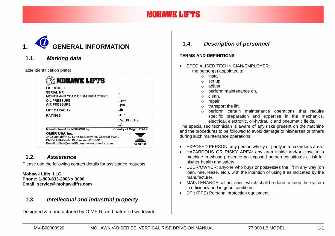
1.1. Marking data Table identification plate:
1.2. Assistance Please use the following contact details for assistance requests : Mohawk Lifts, LLC. Phone: 1-800-833-2006 x 3000 Email: [email protected]
1.3. Intellectual and industrial property
Designed & manufactured by O.ME.R. and patented worldwide.
1.4. Description of personnel TERMS AND DEFINITIONS
SPECIALISED TECHNICIAN/EMPLOYER: the person(s) appointed to:
o install, o set up, o adjust o perform maintenance on, o clean, o repair o transport the lift. o perform certain maintenance operations that require
specific preparation and expertise in the mechanics, electrical, electronic, oil-hydraulic and pneumatic fields.
The specialised technician is aware of any risks present on the machine and the procedures to be followed to avoid damage to his/herself or others during such maintenance operations.
EXPOSED PERSON: any person wholly or partly in a hazardous area.
HAZARDOUS OR RISKY AREA: any area inside and/or close to a machine in whose presence an exposed person constitutes a risk for his/her health and safety.
USER/OWNER: anyone who buys or possesses the lift in any way (on loan, hire, lease, etc.), with the intention of using it as indicated by the manufacturer.
MAINTENANCE: all activities, which shall be done to keep the system in efficiency and in good condition.
DPI: (PPE) Personal protection equipment.

MV-B00000920 MOHAWK V-B SERIES: VERTICAL RISE DRIVE-ON MANUAL 77,000 LB MODEL 2-1
2. DESCRIPTION OF THE MACHINE
Addressees: - USER/OWNER; - SPECIALISED TECHNICIAN/EMPLOYER.
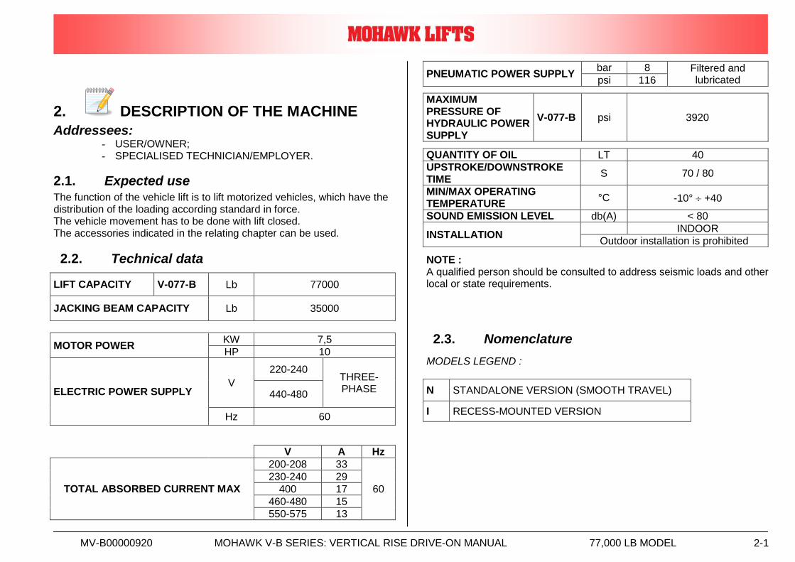
2.1. Expected use The function of the vehicle lift is to lift motorized vehicles, which have the distribution of the loading according standard in force. The vehicle movement has to be done with lift closed. The accessories indicated in the relating chapter can be used.
2.2. Technical data
LIFT CAPACITY V-077-B Lb 77000
JACKING BEAM CAPACITY Lb 35000
MOTOR POWER KW 7,5
HP 10
ELECTRIC POWER SUPPLY V
220-240 THREE-PHASE
440-480
Hz 60
V A Hz
TOTAL ABSORBED CURRENT MAX
200-208 33
60
230-240 29
400 17
460-480 15
550-575 13
PNEUMATIC POWER SUPPLY bar 8 Filtered and
lubricated psi 116
MAXIMUM PRESSURE OF HYDRAULIC POWER SUPPLY
V-077-B psi 3920
QUANTITY OF OIL LT 40
UPSTROKE/DOWNSTROKE TIME
S 70 / 80
MIN/MAX OPERATING TEMPERATURE
°C -10° +40
SOUND EMISSION LEVEL db(A) < 80
INSTALLATION INDOOR
Outdoor installation is prohibited
NOTE : A qualified person should be consulted to address seismic loads and other local or state requirements.
2.3. Nomenclature
MODELS LEGEND :
N STANDALONE VERSION (SMOOTH TRAVEL)
I RECESS-MOUNTED VERSION
MV-B00000920 MOHAWK V-B SERIES: VERTICAL RISE DRIVE-ON MANUAL 77,000 LB MODEL 2-2
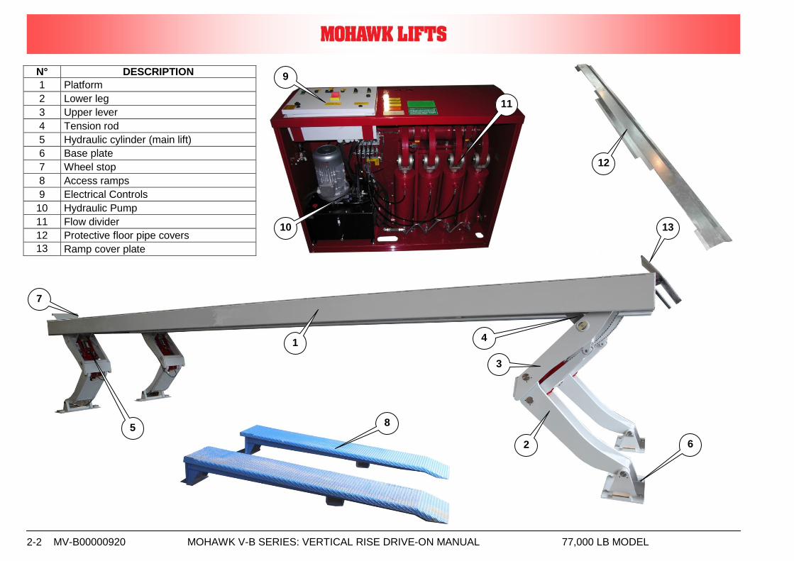
N° DESCRIPTION
1 Platform
2 Lower leg
3 Upper lever
4 Tension rod
5 Hydraulic cylinder (main lift)
6 Base plate
7 Wheel stop
8 Access ramps
9 Electrical Controls
10 Hydraulic Pump
11 Flow divider
12 Protective floor pipe covers
13 Ramp cover plate
12
1
2
3
4
5
6
7
9
10
11
8
13
MV-B00000920 MOHAWK V-B SERIES: VERTICAL RISE DRIVE-ON MANUAL 77,000 LB MODEL 2-1
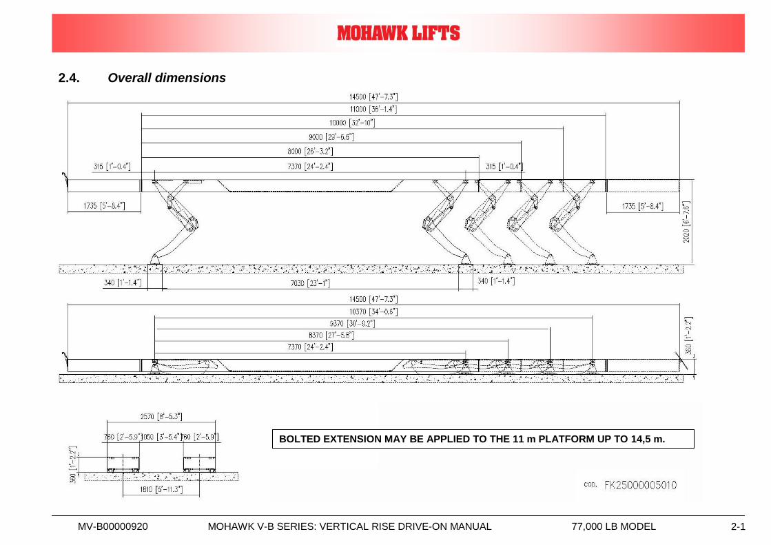
2.4. Overall dimensions
BOLTED EXTENSION MAY BE APPLIED TO THE 11 m PLATFORM UP TO 14,5 m.

MV-B00000920 MOHAWK V-B SERIES: VERTICAL RISE DRIVE-ON MANUAL 77,000 LB MODEL 2-1
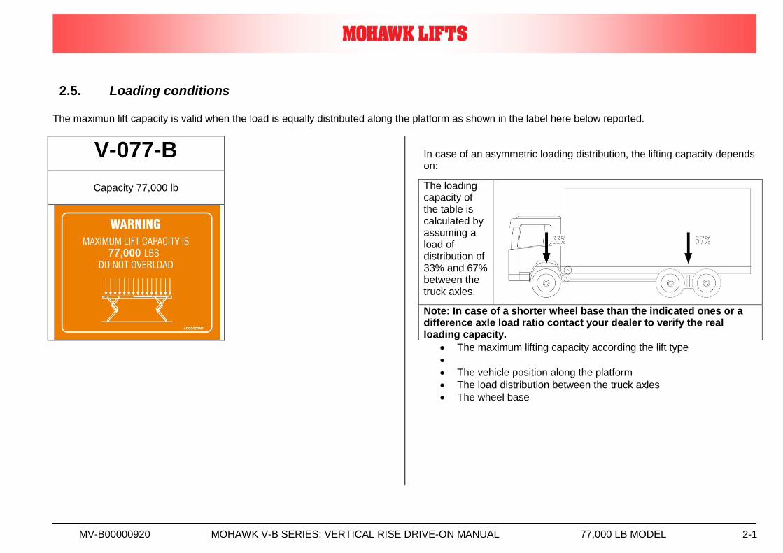
2.5. Loading conditions The maximun lift capacity is valid when the load is equally distributed along the platform as shown in the label here below reported.
V-077-B
Capacity 77,000 lb
In case of an asymmetric loading distribution, the lifting capacity depends on:
The maximum lifting capacity according the lift type
The vehicle position along the platform
The load distribution between the truck axles
The wheel base
The loading capacity of the table is calculated by assuming a load of distribution of 33% and 67% between the truck axles.
Note: In case of a shorter wheel base than the indicated ones or a difference axle load ratio contact your dealer to verify the real loading capacity.

MV-B00000920 MOHAWK V-B SERIES: VERTICAL RISE DRIVE-ON MANUAL 77,000 LB MODEL 2-1
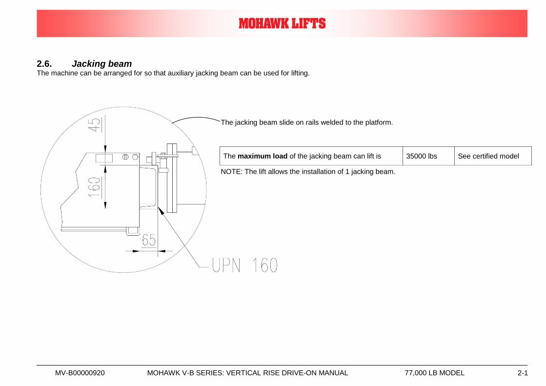
2.6. Jacking beam The machine can be arranged for so that auxiliary jacking beam can be used for lifting.
The jacking beam slide on rails welded to the platform. NOTE: The lift allows the installation of 1 jacking beam.
The maximum load of the jacking beam can lift is 35000 lbs See certified model

MV-B00000920 MOHAWK V-B SERIES: VERTICAL RISE DRIVE-ON MANUAL 77,000 LB MODEL 3-1
3. SAFETY
Addressees: - USER/OWNER; - SPECIALISED TECHNICIAN/EMPLOYER.
3.1. General safety regulations
For quick reference by operator, this manual must:
be kept in a well known, easily accessible place
be kept in good condition Before proceeding with installation and use of the machine, the user must read the manual carefully, especially the safety rules.
“Before proceeding with installation, operating, servicing, or maintain the lift, the user must read the manual carefully...” The machine should be used by authorised, trained personnel only. The user (owner and/or employee) must make sure that the fitter has provided:
all accessories
the spares provided with the lift
this operation and maintenance manual
Use as described in this manual only. Always use the accessories recommended by the manufacturer. Mohawk Lifts LLC. declines all responsibility for non-compliance with the indications given in this manual.
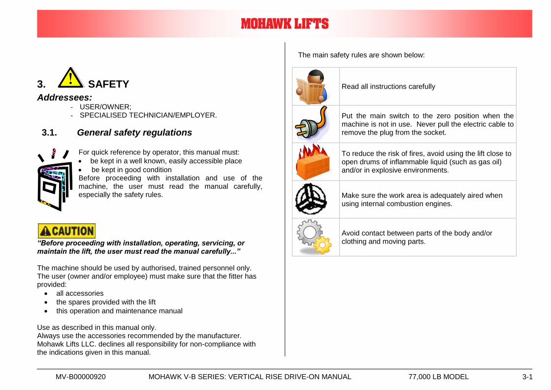
The main safety rules are shown below:
Read all instructions carefully
Put the main switch to the zero position when the machine is not in use. Never pull the electric cable to remove the plug from the socket.
To reduce the risk of fires, avoid using the lift close to open drums of inflammable liquid (such as gas oil) and/or in explosive environments.
Make sure the work area is adequately aired when using internal combustion engines.
Avoid contact between parts of the body and/or clothing and moving parts.
MV-B00000920 MOHAWK V-B SERIES: VERTICAL RISE DRIVE-ON MANUAL 77,000 LB MODEL 3-2
3.2. Precaution
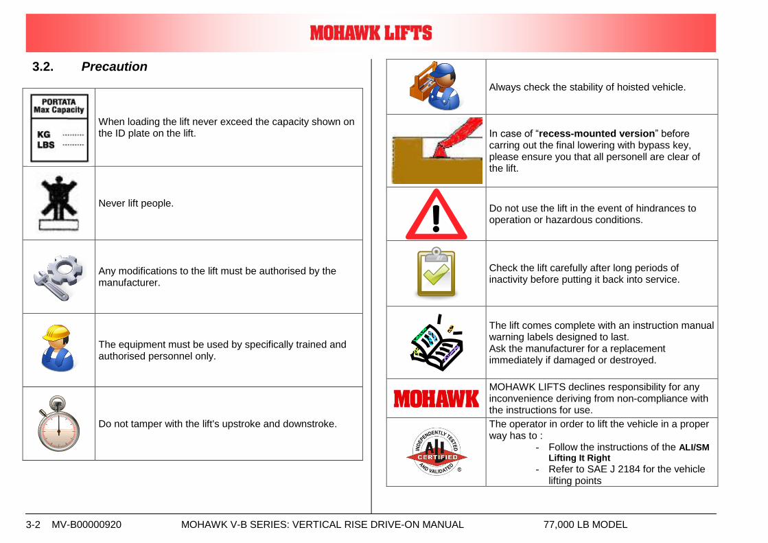
When loading the lift never exceed the capacity shown on the ID plate on the lift.
Never lift people.
Any modifications to the lift must be authorised by the manufacturer.
The equipment must be used by specifically trained and authorised personnel only.
Do not tamper with the lift's upstroke and downstroke.
Always check the stability of hoisted vehicle.
In case of “recess-mounted version” before carring out the final lowering with bypass key, please ensure you that all personell are clear of the lift.
Do not use the lift in the event of hindrances to operation or hazardous conditions.
Check the lift carefully after long periods of inactivity before putting it back into service.
The lift comes complete with an instruction manual warning labels designed to last. Ask the manufacturer for a replacement immediately if damaged or destroyed.
MOHAWK LIFTS declines responsibility for any inconvenience deriving from non-compliance with the instructions for use.
The operator in order to lift the vehicle in a proper way has to :
- Follow the instructions of the ALI/SM Lifting It Right
- Refer to SAE J 2184 for the vehicle lifting points
MV-B00000920 MOHAWK V-B SERIES: VERTICAL RISE DRIVE-ON MANUAL 77,000 LB MODEL 3-3
3.3. Owner/Employer Responsibilities
The owner/employer:
Shall ensure that lift operators are qualified and that they are trained in the safe use and operation of the lift using the manufacturer’s operating instructions; ALI/SM, “Lifting It Right” safety manual; ALI/ST, “Safety Tips” card; ANSI/ALI ALOIM, Standard for Automotive Lifts – Safety Requirements for Operation, Inspection and Maintenance; ALI/WL Series, ALI Uniform Warning Label Decals/Placards; and in the case of frame engaging lifts, ALI/LP-Guide, “Quick Reference Guide – Vehicle Lifting Points for Frame Engaging Lifts”.
Shall establish procedures to periodically inspect the lift in accordance with the lift manufacturer’s instructions or ANSI/ALI ALOIM, Standard for Automotive Lifts – Safety Requirements for Operation, Inspection and Maintenance; and the employer shall ensure that lift inspectors are qualified and that they are adequately trained in the inspection of the lift.
Shall establish procedures to periodically maintain the lift in accordance with the lift manufacturer’s instructions or ANSI/ALI ALOIM, Standard for Automotive Lifts – Safety Requirements for Operation, Inspection and Maintenance; and the employer shall ensure that lift maintenance personnel are qualified and that they are adequately trained in the maintenance of the lift.
Shall maintain the periodic inspection and maintenance records recommended by the manufacturer or ANSI/ALI ALOIM, Standard for Automotive Lifts – Safety Requirements for Operation, Inspection and Maintenance.
Shall display the lift manufacturer’s operating instructions; ALI/SM, “Lifting It Right” safety manual; ALI/ST, “Safety Tips” card; ANSI/ALI ALOIM, Standard for Automotive Lifts – Safety Requirements for Operation, Inspection and Maintenance; ALI/WL Series, ALI Uniform Warning Label Decals/Placards; and in the case of frame engaging lifts, ALI/LP-Guide, “Quick Reference Guide – Vehicle Lifting Points for Frame Engaging Lifts”; in a conspicuous location in the lift area convenient to the operator. Shall review and understand the proper requirements outlined in ANSI/ALI ALIS, Safety Requirements for Installation and Service of Automotive Lifts.
MV-B00000920 MOHAWK V-B SERIES: VERTICAL RISE DRIVE-ON MANUAL 77,000 LB MODEL 3-4
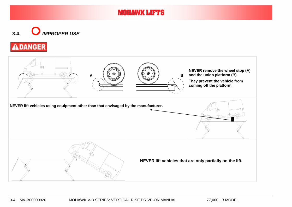
3.4. IMPROPER USE
NEVER remove the wheel stop (A) and the union platform (B).
They prevent the vehicle from coming off the platform.
NEVER lift vehicles using equipment other than that envisaged by the manufacturer.
NEVER lift vehicles that are only partially on the lift.
A B
MV-B00000920 MOHAWK V-B SERIES: VERTICAL RISE DRIVE-ON MANUAL 77,000 LB MODEL 3-5
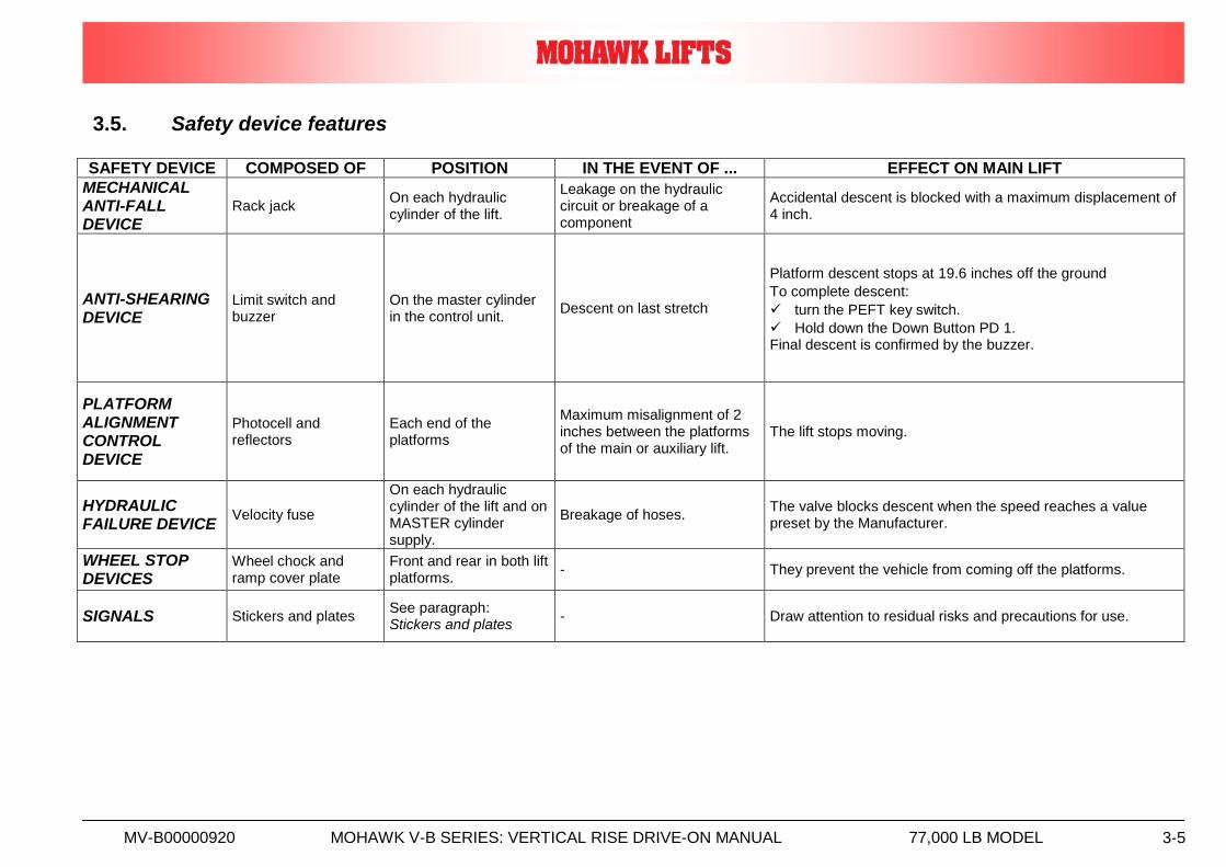
3.5. Safety device features
SAFETY DEVICE COMPOSED OF POSITION IN THE EVENT OF ... EFFECT ON MAIN LIFT
MECHANICAL ANTI-FALL DEVICE
Rack jack On each hydraulic cylinder of the lift.
Leakage on the hydraulic circuit or breakage of a component
Accidental descent is blocked with a maximum displacement of 4 inch.
ANTI-SHEARING DEVICE
Limit switch and buzzer
On the master cylinder in the control unit.
Descent on last stretch
Platform descent stops at 19.6 inches off the ground
To complete descent:
turn the PEFT key switch.
Hold down the Down Button PD 1. Final descent is confirmed by the buzzer.
PLATFORM ALIGNMENT CONTROL DEVICE
Photocell and reflectors
Each end of the platforms
Maximum misalignment of 2 inches between the platforms of the main or auxiliary lift.
The lift stops moving.
HYDRAULIC FAILURE DEVICE
Velocity fuse
On each hydraulic cylinder of the lift and on MASTER cylinder supply.
Breakage of hoses. The valve blocks descent when the speed reaches a value preset by the Manufacturer.
WHEEL STOP DEVICES
Wheel chock and ramp cover plate
Front and rear in both lift platforms.
- They prevent the vehicle from coming off the platforms.
SIGNALS Stickers and plates See paragraph: Stickers and plates
- Draw attention to residual risks and precautions for use.
MV-B00000920 MOHAWK V-B SERIES: VERTICAL RISE DRIVE-ON MANUAL 77,000 LB MODEL 3-6
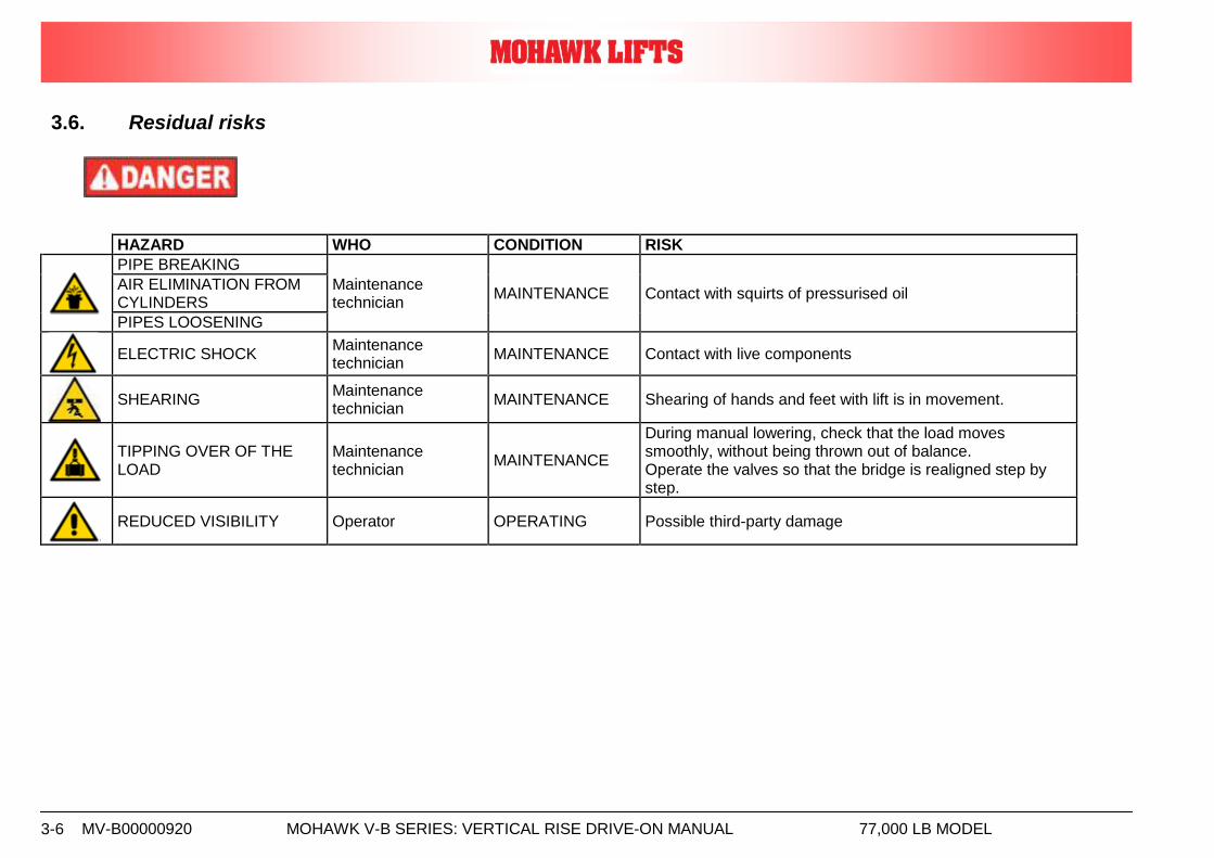
3.6. Residual risks
HAZARD WHO CONDITION RISK
PIPE BREAKING
Maintenance technician
MAINTENANCE Contact with squirts of pressurised oil AIR ELIMINATION FROM CYLINDERS
PIPES LOOSENING
ELECTRIC SHOCK
Maintenance technician
MAINTENANCE Contact with live components
SHEARING
Maintenance technician
MAINTENANCE Shearing of hands and feet with lift is in movement.
TIPPING OVER OF THE LOAD
Maintenance technician
MAINTENANCE
During manual lowering, check that the load moves smoothly, without being thrown out of balance. Operate the valves so that the bridge is realigned step by step.
REDUCED VISIBILITY Operator OPERATING Possible third-party damage
MV-B00000920 MOHAWK V-B SERIES: VERTICAL RISE DRIVE-ON MANUAL 77,000 LB MODEL 3-7
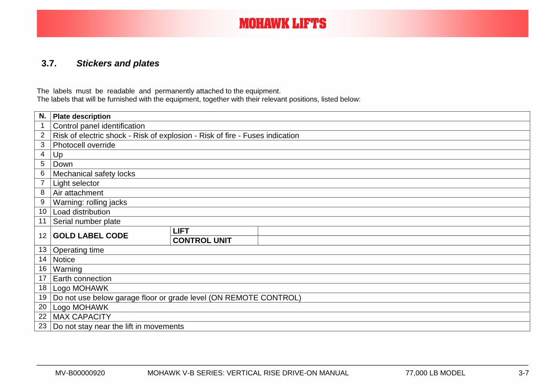
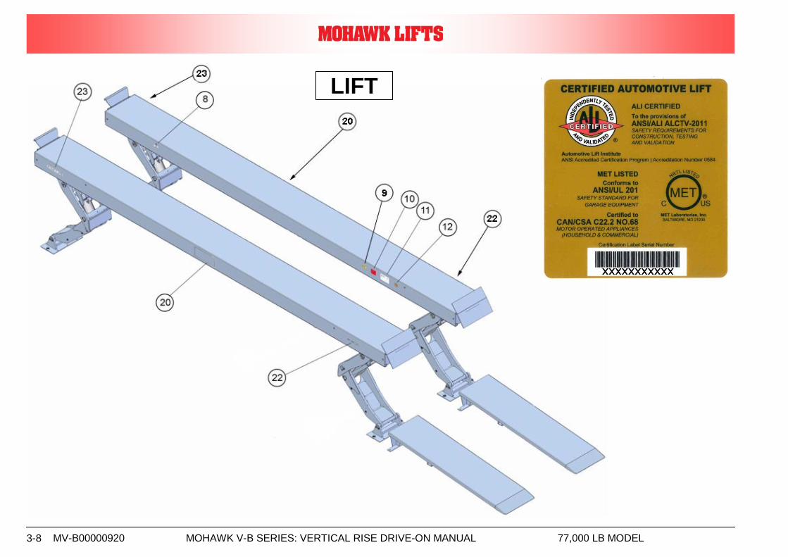
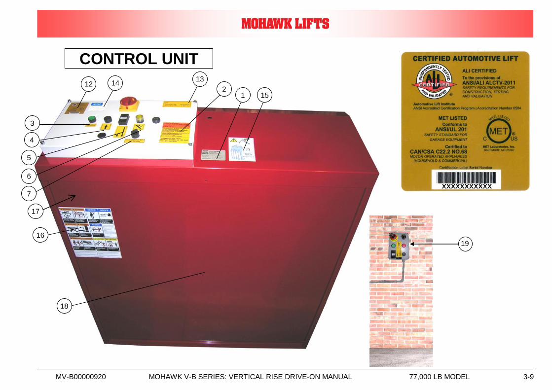
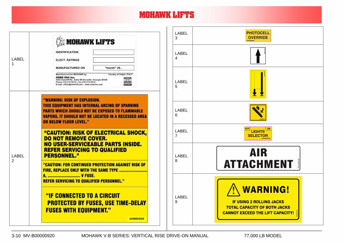
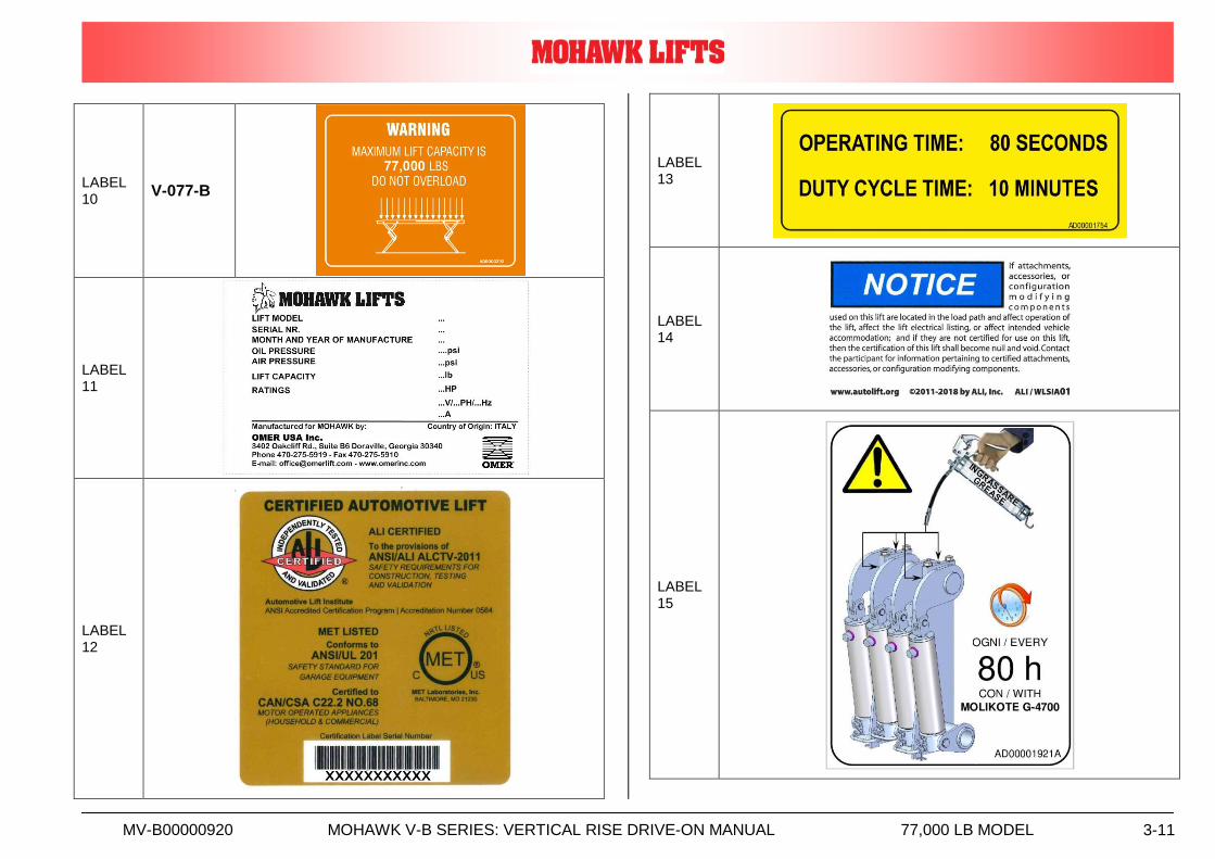
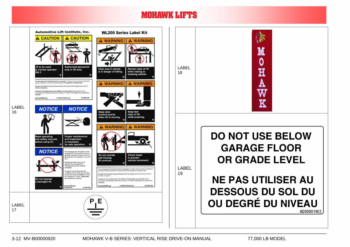
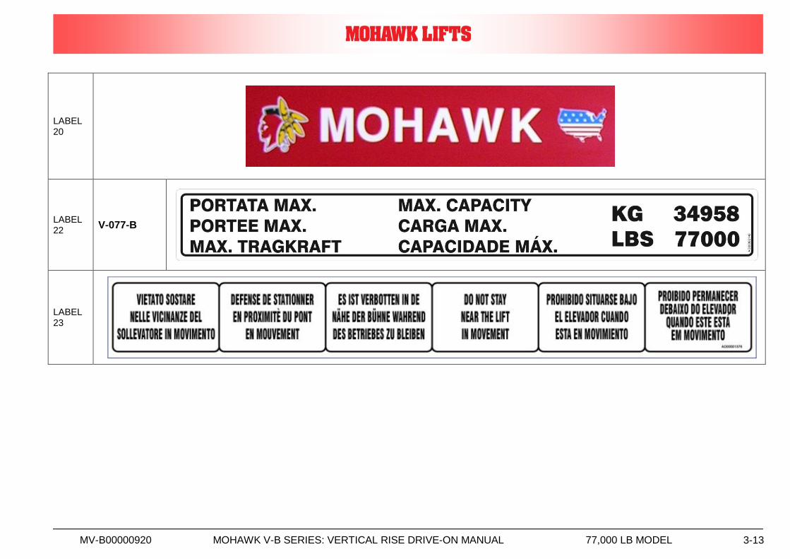
3.7. Stickers and plates The labels must be readable and permanently attached to the equipment. The labels that will be furnished with the equipment, together with their relevant positions, listed below:
N. Plate description
1 Control panel identification 2 Risk of electric shock - Risk of explosion - Risk of fire - Fuses indication 3 Photocell override 4 Up 5 Down 6 Mechanical safety locks 7 Light selector 8 Air attachment 9 Warning: rolling jacks 10 Load distribution 11 Serial number plate
12 GOLD LABEL CODE LIFT
CONTROL UNIT 13 Operating time 14 Notice 16 Warning 17 Earth connection 18 Logo MOHAWK 19 Do not use below garage floor or grade level (ON REMOTE CONTROL) 20 Logo MOHAWK 22 MAX CAPACITY 23 Do not stay near the lift in movements
MV-B00000920 MOHAWK V-B SERIES: VERTICAL RISE DRIVE-ON MANUAL 77,000 LB MODEL 3-8
LIFT
MV-B00000920 MOHAWK V-B SERIES: VERTICAL RISE DRIVE-ON MANUAL 77,000 LB MODEL 3-9
CONTROL UNIT
19
12 14 13
2 1 15
16
18
3
4
5
6
7
17
MV-B00000920 MOHAWK V-B SERIES: VERTICAL RISE DRIVE-ON MANUAL 77,000 LB MODEL 3-10
LABEL 1
LABEL 2
LABEL 3
LABEL 4
LABEL 5
LABEL 6
LABEL 7
LABEL 8
LABEL 9
MV-B00000920 MOHAWK V-B SERIES: VERTICAL RISE DRIVE-ON MANUAL 77,000 LB MODEL 3-11
LABEL 10
V-077-B
LABEL 11
LABEL 12
LABEL 13
LABEL 14
LABEL 15
MV-B00000920 MOHAWK V-B SERIES: VERTICAL RISE DRIVE-ON MANUAL 77,000 LB MODEL 3-12
LABEL 16
LABEL 17
LABEL 18
LABEL 19
MV-B00000920 MOHAWK V-B SERIES: VERTICAL RISE DRIVE-ON MANUAL 77,000 LB MODEL 3-13
LABEL 20
LABEL 22
V-077-B
LABEL 23

MV-B00000920 MOHAWK V-B SERIES: VERTICAL RISE DRIVE-ON MANUAL 77,000 LB MODEL 4-1
4. INSTALLATION
Addressees: - SPECIALISED TECHNICIAN/EMPLOYER.
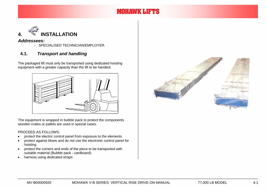
4.1. Transport and handling
The packaged lift must only be transported using dedicated hoisting equipment with a greater capacity than the lift to be handled.
The equipment is wrapped in bubble pack to protect the components wooden crates or pallets are used in special cases. PROCEED AS FOLLOWS:
protect the electric control panel from exposure to the elements
protect against blows and do not use the electronic control panel for hoisting
protect the corners and ends of the piece to be transported with suitable material (Bubble pack - cardboard).
harness using dedicated straps
MV-B00000920 MOHAWK V-B SERIES: VERTICAL RISE DRIVE-ON MANUAL 77,000 LB MODEL 4-2
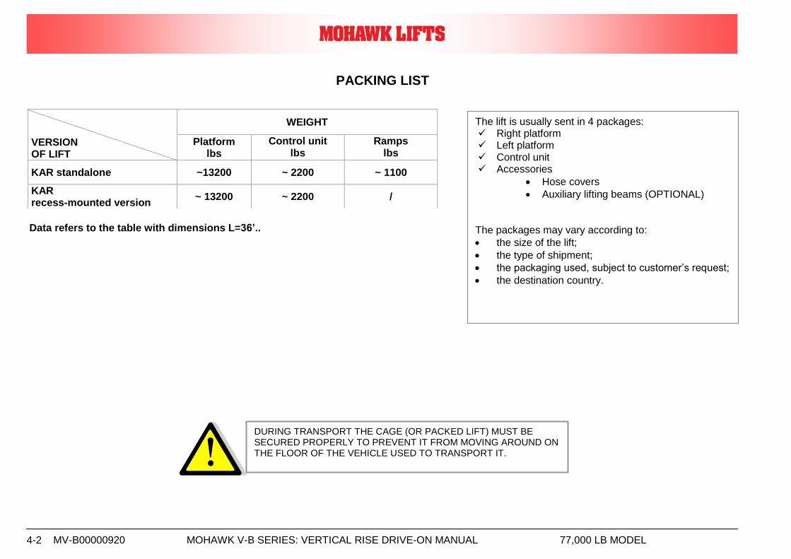
PACKING LIST
Data refers to the table with dimensions L=36’..
VERSION OF LIFT
WEIGHT
Platform lbs
Control unit lbs
Ramps lbs
KAR standalone ~13200 ~ 2200 ~ 1100
KAR recess-mounted version
~ 13200 ~ 2200 /
DURING TRANSPORT THE CAGE (OR PACKED LIFT) MUST BE SECURED PROPERLY TO PREVENT IT FROM MOVING AROUND ON THE FLOOR OF THE VEHICLE USED TO TRANSPORT IT.
The lift is usually sent in 4 packages: Right platform Left platform Control unit Accessories
Hose covers
Auxiliary lifting beams (OPTIONAL) The packages may vary according to:
the size of the lift;
the type of shipment;
the packaging used, subject to customer’s request;
the destination country.
MV-B00000920 MOHAWK V-B SERIES: VERTICAL RISE DRIVE-ON MANUAL 77,000 LB MODEL 4-3
4.2. Installation See the installation and parts reference section of this manual for diagrams and part list that will assist you during the installation process. Use these diagrams and part list together with the following written instructions. Insure that the lift installation complies with ANSI/ALI/ALIS Safety Requirements for Installation and Service of Automotive Lifts.
4.2.1. Installation sequence
The installation sequence is as follows: 1. Check the bay layout 2. Unpack the lift 3. Check the lift components 4. Position the lift 5. Connect air lines 6. Connect hydraulic lines 7. Connect electrical cables 8. Run the lift 9. Level shim and anchor 10. Complete the lift with accessories 11. Final check 12. Clean 13. Train user and owner
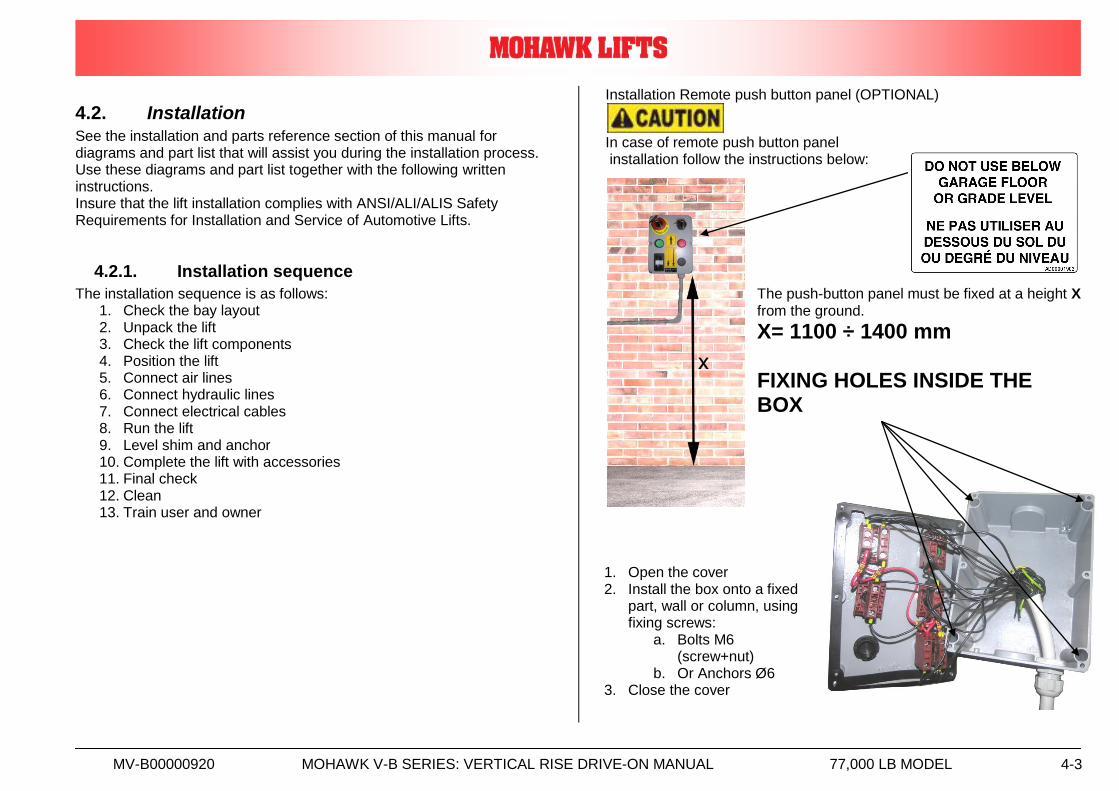
Installation Remote push button panel (OPTIONAL)
In case of remote push button panel installation follow the instructions below:
The push-button panel must be fixed at a height X from the ground. X= 1100 ÷ 1400 mm FIXING HOLES INSIDE THE BOX
1. Open the cover 2. Install the box onto a fixed
part, wall or column, using fixing screws:
a. Bolts M6 (screw+nut)
b. Or Anchors Ø6 3. Close the cover
MV-B00000920 MOHAWK V-B SERIES: VERTICAL RISE DRIVE-ON MANUAL 77,000 LB MODEL 4-4
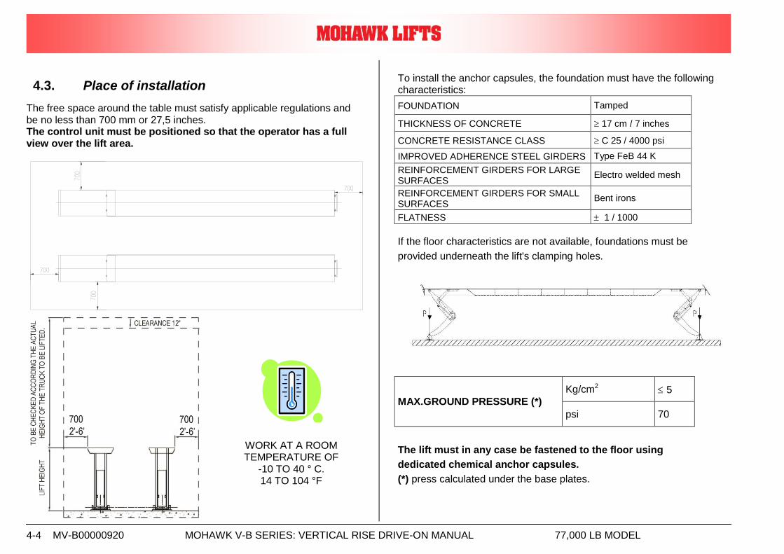
4.3. Place of installation
The free space around the table must satisfy applicable regulations and be no less than 700 mm or 27,5 inches. The control unit must be positioned so that the operator has a full view over the lift area.
To install the anchor capsules, the foundation must have the following characteristics:
FOUNDATION Tamped
THICKNESS OF CONCRETE 17 cm / 7 inches
CONCRETE RESISTANCE CLASS C 25 / 4000 psi
IMPROVED ADHERENCE STEEL GIRDERS Type FeB 44 K
REINFORCEMENT GIRDERS FOR LARGE SURFACES
Electro welded mesh
REINFORCEMENT GIRDERS FOR SMALL SURFACES
Bent irons
FLATNESS 1 / 1000
If the floor characteristics are not available, foundations must be
provided underneath the lift's clamping holes.
MAX.GROUND PRESSURE (*)
Kg/cm2 5
psi 70
The lift must in any case be fastened to the floor using
dedicated chemical anchor capsules.
(*) press calculated under the base plates.
WORK AT A ROOM TEMPERATURE OF
-10 TO 40 ° C. 14 TO 104 °F
MV-B00000920 MOHAWK V-B SERIES: VERTICAL RISE DRIVE-ON MANUAL 77,000 LB MODEL 4-5
4.4. Connecting the lift
Follow the sequence of operations given below:
1. connect the hoses provided, which lead out of the control unit with their respective inputs to the lift
(see paragraphs: Hydraulic, pneumatic, electrical connection).
2. Fill the circuit MASTER/SLAVE and remove air from the same circuit.
(see paragraphs: Filling of the circuit Master-Slave)
3. Fix the legs of the lift with the raw plugs at the correct distance and perfectly levelled.
(see paragraphs: Lift position and Anchorage capsule installation )
4. Carry out all due tests before using the lift.
(see paragraphs: Check and Checks before use)
The control unit must be positioned so that the operator has a full view over the lift area.
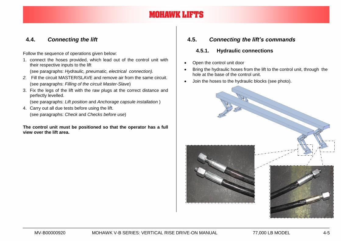
4.5. Connecting the lift’s commands
4.5.1. Hydraulic connections
Open the control unit door
Bring the hydraulic hoses from the lift to the control unit, through the hole at the base of the control unit.
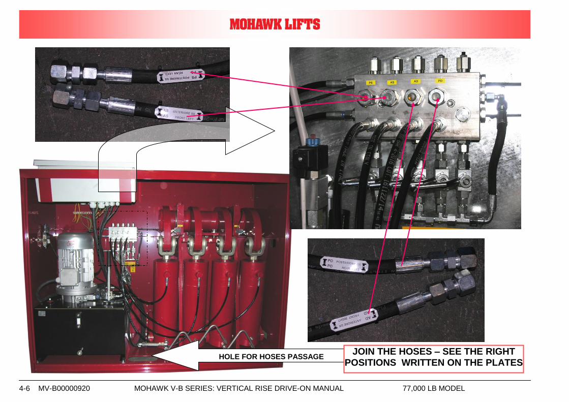
Join the hoses to the hydraulic blocks (see photo).
MV-B00000920 MOHAWK V-B SERIES: VERTICAL RISE DRIVE-ON MANUAL 77,000 LB MODEL 4-6
HOLE FOR HOSES PASSAGE
JOIN THE HOSES – SEE THE RIGHT POSITIONS WRITTEN ON THE PLATES
MV-B00000920 MOHAWK V-B SERIES: VERTICAL RISE DRIVE-ON MANUAL 77,000 LB MODEL 4-7
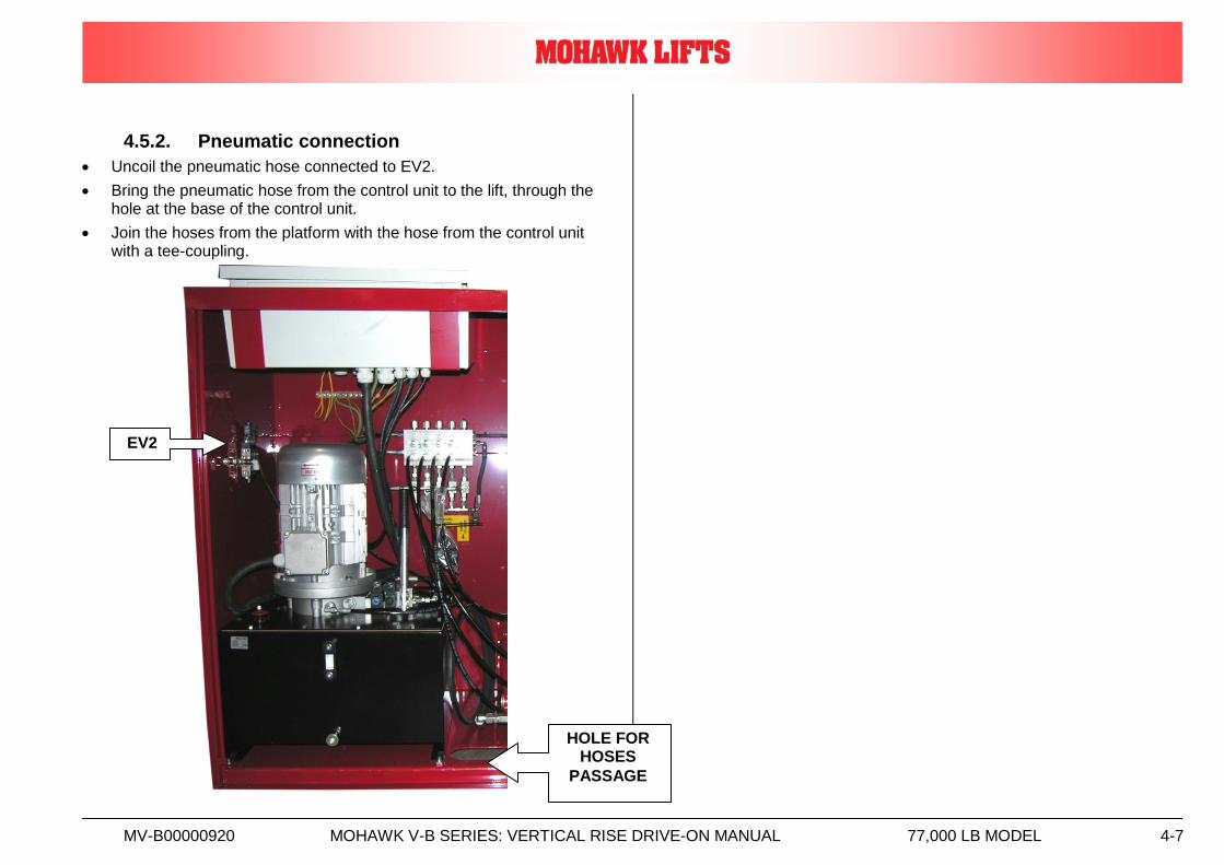
4.5.2. Pneumatic connection
Uncoil the pneumatic hose connected to EV2.
Bring the pneumatic hose from the control unit to the lift, through the hole at the base of the control unit.
Join the hoses from the platform with the hose from the control unit with a tee-coupling.
HOLE FOR HOSES
PASSAGE
EV2
MV-B00000920 MOHAWK V-B SERIES: VERTICAL RISE DRIVE-ON MANUAL 77,000 LB MODEL 4-8
4.5.3. Electric connection A) LIFT SUPPLY
The electric supply system must include:
a main switch with a circuit breaker;
fuses or thermal magnet protection suited to the machine's characteristics;
device against accidental contact, for protection.
The switch must be positioned in the immediate vicinity of the machine in full compliance with local accident prevention regulations.
Power cables must have a suitable section for absorbing current, without deviations for other utilities.
Electric systems must be created according to the state of the art by a qualified electrician who must check the earthing system's efficiency.
The power cable must be locked in the dedicated cable gland and the electric panel must be carefully closed to assure the envisaged IP 54 protection.
Only connect the machine to type approved sockets with an earth cable of proven efficiency.
Periodically have qualified personnel check the correct tightening of the electric cables of the various components.
Power cables must have a suitable section for absorbing current, without deviations for other utilities
Electrical system shall be designed to meet all local / national codes and shall be properly grounded
Attention:
power the lift's electrics system using a line fitted with a mains switch and without any other junctions.
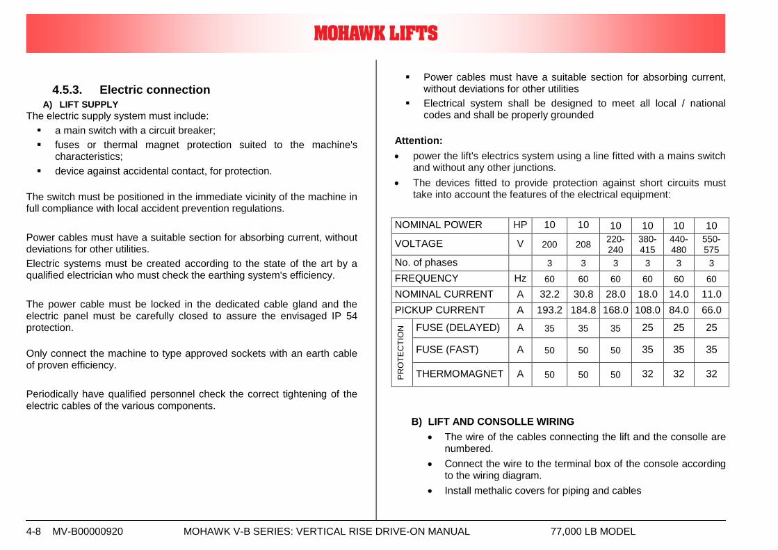
The devices fitted to provide protection against short circuits must take into account the features of the electrical equipment:
NOMINAL POWER HP 10 10 10 10 10 10
VOLTAGE V 200 208 220-240
380-415
440-480
550-575
No. of phases 3 3 3 3 3 3
FREQUENCY Hz 60 60 60 60 60 60
NOMINAL CURRENT A 32.2 30.8 28.0 18.0 14.0 11.0
PICKUP CURRENT A 193.2 184.8 168.0 108.0 84.0 66.0
PR
OT
EC
TIO
N
FUSE (DELAYED) A 35 35 35 25 25 25
FUSE (FAST) A 50 50 50 35 35 35
THERMOMAGNET A 50 50 50 32 32 32
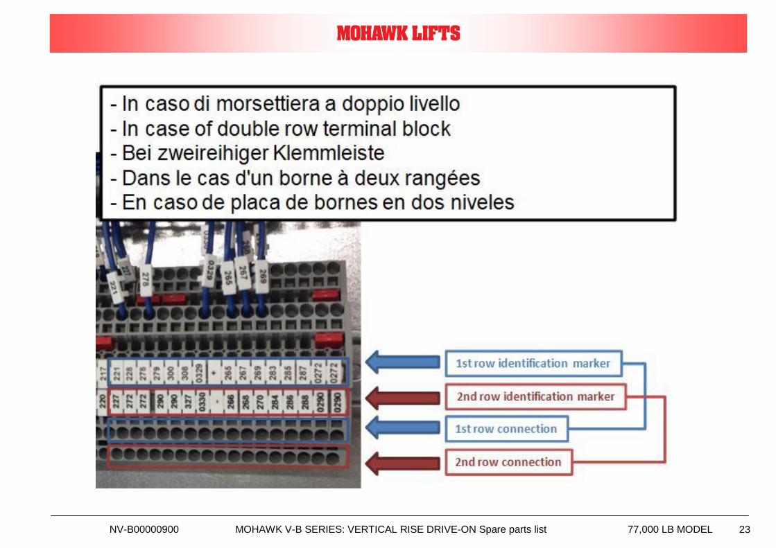
B) LIFT AND CONSOLLE WIRING
The wire of the cables connecting the lift and the consolle are numbered.
Connect the wire to the terminal box of the console according to the wiring diagram.
Install methalic covers for piping and cables
MV-B00000920 MOHAWK V-B SERIES: VERTICAL RISE DRIVE-ON MANUAL 77,000 LB MODEL 4-9
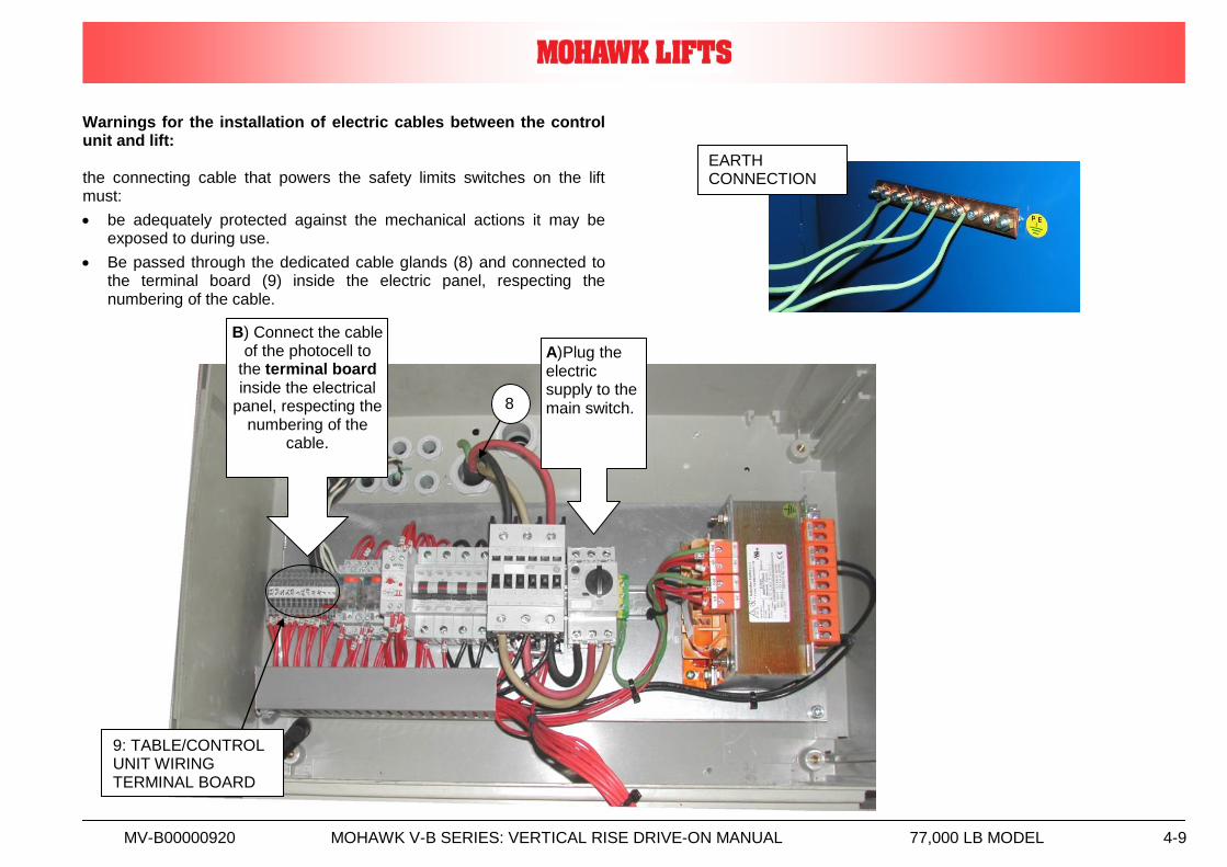
Warnings for the installation of electric cables between the control unit and lift: the connecting cable that powers the safety limits switches on the lift must:
be adequately protected against the mechanical actions it may be exposed to during use.
Be passed through the dedicated cable glands (8) and connected to the terminal board (9) inside the electric panel, respecting the numbering of the cable.
9: TABLE/CONTROL UNIT WIRING TERMINAL BOARD
8
A)Plug the electric supply to the main switch.
B) Connect the cable of the photocell to
the terminal board inside the electrical
panel, respecting the numbering of the
cable.
EARTH CONNECTION
MV-B00000920 MOHAWK V-B SERIES: VERTICAL RISE DRIVE-ON MANUAL 77,000 LB MODEL 4-10
MV-B00000920 MOHAWK V-B SERIES: VERTICAL RISE DRIVE-ON MANUAL 77,000 LB MODEL 4-11
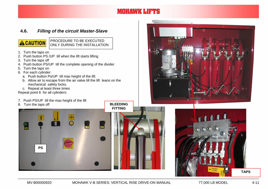
4.6. Filling of the circuit Master-Slave
1. Turn the taps on 2. Push button PS /UP till when the lift starts lifting 3. Turn the taps off 4. Push button PS/UP till the complete opening of the divider 5. Turn the taps on 6. For each cylinder:
a. Push button Ps/UP till max height of the lift. b. Allow air to escape from the air valve till the lift leans on the
mechanical safety locks. c. Repeat at least three times
Repeat point 6 for all cylinders: 7. Push PS/UP till the max height of the lift 8. Turn the taps off
PS
PROCEDURE TO BE EXECUTED ONLY DURING THE INSTALLATION
TAPS
BLEEDING
FITTING
MV-B00000920 MOHAWK V-B SERIES: VERTICAL RISE DRIVE-ON MANUAL 77,000 LB MODEL 4-12
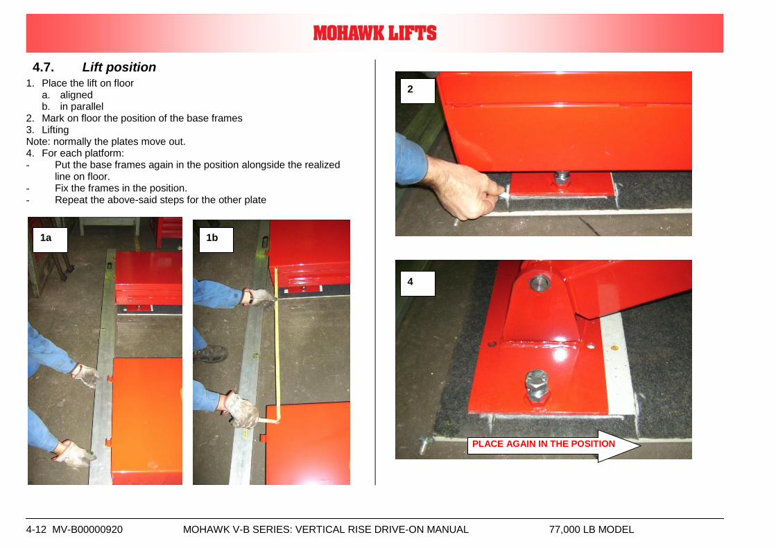
4.7. Lift position
1. Place the lift on floor a. aligned b. in parallel
2. Mark on floor the position of the base frames 3. Lifting Note: normally the plates move out. 4. For each platform: - Put the base frames again in the position alongside the realized
line on floor. - Fix the frames in the position. - Repeat the above-said steps for the other plate
1a 1b
2
4
PLACE AGAIN IN THE POSITION
MV-B00000920 MOHAWK V-B SERIES: VERTICAL RISE DRIVE-ON MANUAL 77,000 LB MODEL 4-13
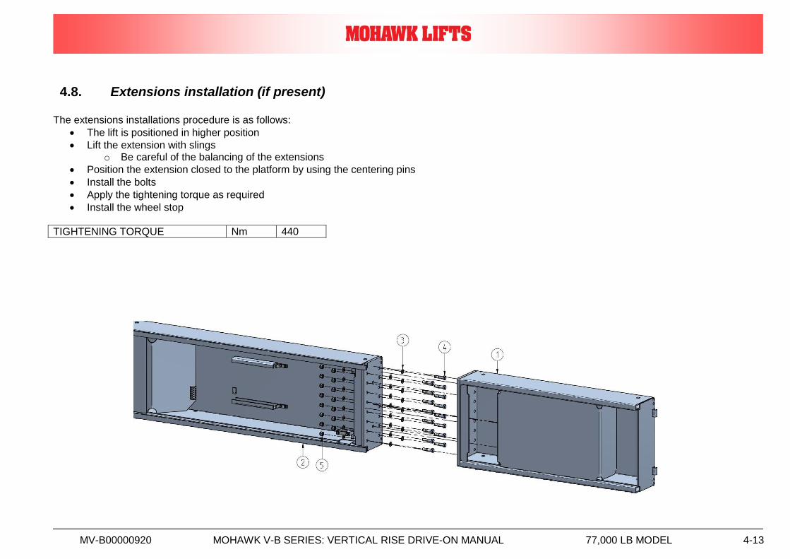
4.8. Extensions installation (if present) The extensions installations procedure is as follows:
The lift is positioned in higher position
Lift the extension with slings o Be careful of the balancing of the extensions
Position the extension closed to the platform by using the centering pins
Install the bolts
Apply the tightening torque as required
Install the wheel stop
TIGHTENING TORQUE Nm 440
MV-B00000920 MOHAWK V-B SERIES: VERTICAL RISE DRIVE-ON MANUAL 77,000 LB MODEL 4-14
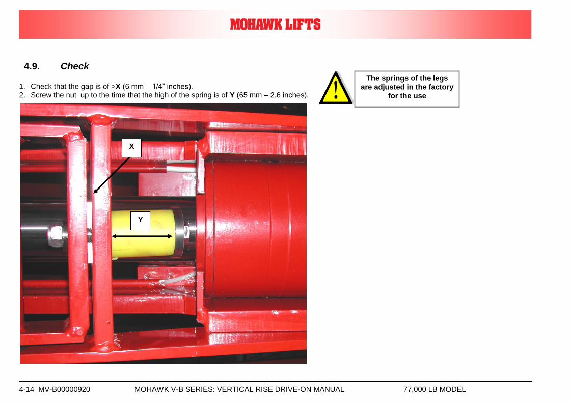
4.9. Check
1. Check that the gap is of >X (6 mm – 1/4” inches). 2. Screw the nut up to the time that the high of the spring is of Y (65 mm – 2.6 inches).
Y
X
The springs of the legs are adjusted in the factory
for the use
MV-B00000920 MOHAWK V-B SERIES: VERTICAL RISE DRIVE-ON MANUAL 77,000 LB MODEL 4-15
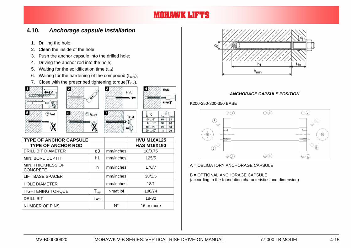
4.10. Anchorage capsule installation
1. Drilling the hole;
2. Clean the inside of the hole;
3. Push the anchor capsule into the drilled hole;
4. Driving the anchor rod into the hole;
5. Waiting for the solidification time (trel)
6. Waiting for the hardening of the compound (tcure);
7. Close with the prescribed tightening torque(Tinst).
ANCHORAGE CAPSULE POSITION
K200-250-300-350 BASE
A = OBLIGATORY ANCHORAGE CAPSULE B = OPTIONAL ANCHORAGE CAPSULE (according to the foundation characteristics and dimension)
TYPE OF ANCHOR CAPSULE HVU M16X125
TYPE OF ANCHOR ROD HAS M16X190
DRILL BIT DIAMETER d0 mm/inches 18/0.75
MIN. BORE DEPTH h1 mm/inches 125/5
MIN. THICKNESS OF CONCRETE
h mm/inches 170/7
LIFT BASE SPACER mm/inches 38/1.5
HOLE DIAMETER mm/inches 18/1
TIGHTENING TORQUE Tinst Nm/ft lbf 100/74
DRILL BIT TE-T 18-32
NUMBER OF PINS N° 16 or more
MV-B00000920 MOHAWK V-B SERIES: VERTICAL RISE DRIVE-ON MANUAL 77,000 LB MODEL 4-16
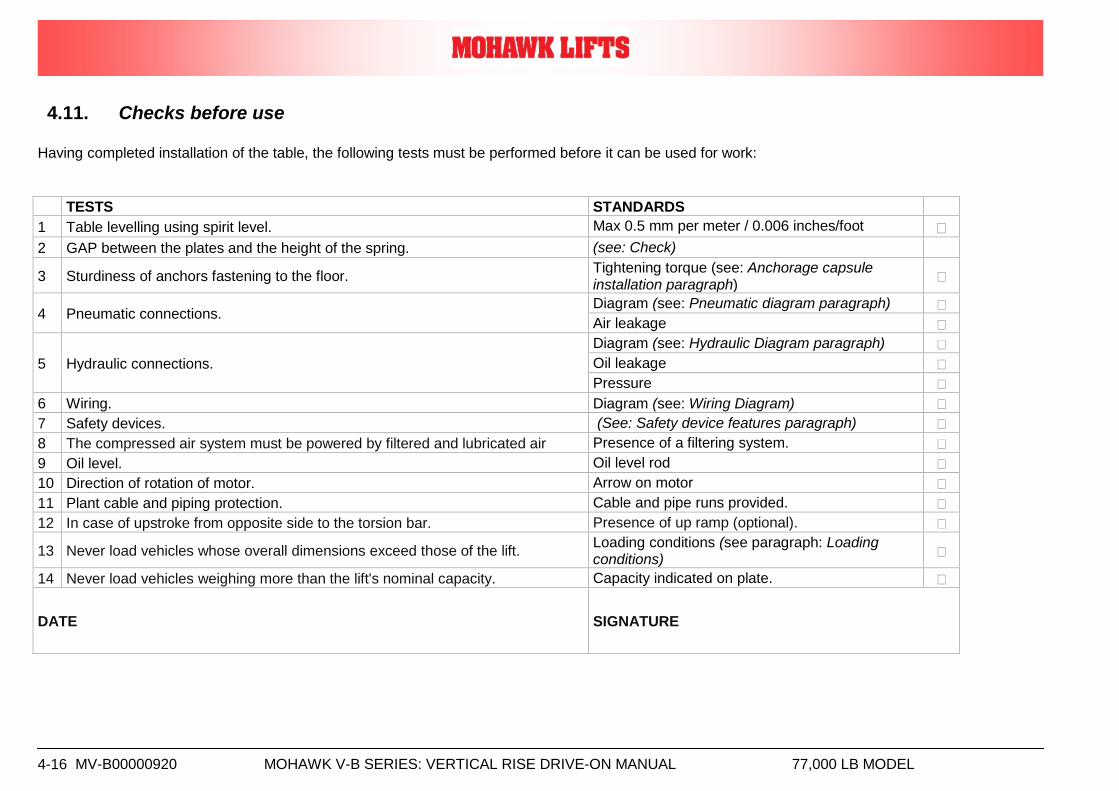
4.11. Checks before use Having completed installation of the table, the following tests must be performed before it can be used for work:
TESTS STANDARDS
1 Table levelling using spirit level. Max 0.5 mm per meter / 0.006 inches/foot
2 GAP between the plates and the height of the spring. (see: Check)
3 Sturdiness of anchors fastening to the floor. Tightening torque (see: Anchorage capsule installation paragraph)
4 Pneumatic connections. Diagram (see: Pneumatic diagram paragraph)
Air leakage
5 Hydraulic connections.
Diagram (see: Hydraulic Diagram paragraph)
Oil leakage
Pressure
6 Wiring. Diagram (see: Wiring Diagram)
7 Safety devices. (See: Safety device features paragraph)
8 The compressed air system must be powered by filtered and lubricated air Presence of a filtering system.
9 Oil level. Oil level rod
10 Direction of rotation of motor. Arrow on motor
11 Plant cable and piping protection. Cable and pipe runs provided.
12 In case of upstroke from opposite side to the torsion bar. Presence of up ramp (optional).
13 Never load vehicles whose overall dimensions exceed those of the lift. Loading conditions (see paragraph: Loading conditions)
14 Never load vehicles weighing more than the lift's nominal capacity. Capacity indicated on plate.
DATE SIGNATURE
MV-B00000920 MOHAWK V-B SERIES: VERTICAL RISE DRIVE-ON MANUAL 77,000 LB MODEL 4-17
4.12. Final testing
The static and dynamic load tests with overloads are performed at the Manufacturer's premises.
The user may perform nominal load tests (with a 10% tolerance admitted for maximum valve calibration) with distribution of the loads as described in the Loading conditions paragraph of the installation, use and maintenance manual.
Tests can be carried out with the following “overloading factors”
STATIC TEST overload 125 %
DINAMIC TEST overload 110 %
With loading distributed according the foreseen scheme of the machine in the charter “Loading conditions”.
4.13. LIFT OPERATIONAL TEST
4.13.1. Lift Operation
✓ Perform pre-operation check list item by item
✓ Ensure lift is completely lowered
✓ Position vehicle on the lift
4.13.2. Caution
✓ Avoid sudden “starts and stops” during loading and unloading of vehicle
4.13.3. To Load a Typical Vehicle
✓ Position vehicle on the lift runways by using the approaching ramp. Make
sure the center of gravity is located equally between the legs . The individual axle weight should not exceed two-thirds of the lift capacity.
✓ Set vehicle parking brake and chock tires.
✓ Make sure vehicle is neither front nor rear heavy.
4.13.4. To Raise the Lift
✓ Push up button (PS) to raise the lift by about 10”
✓ Check for the vehicle movement and weight distribution. Raise to desired
height if secure.
✓ DO NOT WORK UNDER A LIFT THAT IS NOT IN THE LOCK POSITION.
4.13.5. To Lower the Lift
✓ Inspect the lifting area to insure all personnel and debris have been cleared
away.
✓ Push the down button (PDA) and the lift will first disengage the safety locks,
then start its descent.
✓ Once the lift reaches 120mm from (5 inches) the unit will stop, to allow the
operator to check for potential pinch problems. Depress both PDA and PDB to lower the lift to the final lowered position.
✓ Lower lift completely to the floor. Carefully drive off the vehicle from the lift
runways
INSURE THIS MANUAL ALONG WITH OPERATION AND MAINTENANCE INSTRUCTION ARE DELIVERED TO THE OWNER/ USER/EMPLOYER
MV-B00000920 MOHAWK V-B SERIES: VERTICAL RISE DRIVE-ON MANUAL 77,000 LB MODEL 4-18
.
INSURE THIS MANUAL ALONG WITH OPERATION AND MAINTENANCE INSTRUCTION ARE DELIVERED TO THE OWNER/ USER/EMPLOYER
MV-B00000920 MOHAWK V-B SERIES: VERTICAL RISE DRIVE-ON MANUAL 77,000 LB MODEL 5-1
5. USE
Adressees: - USER/OWNER; - SPECIALISED TECHNICIAN/EMPLOYER.
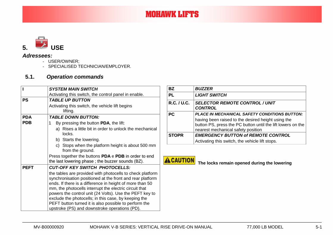
5.1. Operation commands
The locks remain opened during the lowering
II SYSTEM MAIN SWITCH
Activating this switch, the control panel in enable.
PPSS TABLE UP BUTTON
Activating this switch, the vehicle lift begins lifting.
PPDDAA
PPDDBB
TABLE DOWN BUTTON:
1 By pressing the button PPDDAA, the lift:
a) Rises a little bit in order to unlock the mechanical locks.
b) Starts the lowering.
c) Stops when the platform height is about 500 mm from the ground.
Press together the buttons PPDDAA e PPDDBB iinn oorrddeerr ttoo eenndd
tthhee llaasstt lloowweerriinngg pphhaassee ;; tthhee bbuuzzzzeerr ssoouunnddss (BBZZ).
PPEEFFTT CUT-OFF KEY SWITCH PHOTOCELLS:
the tables are provided with photocells to check platform synchronisation positioned at the front and rear platform ends. If there is a difference in height of more than 50 mm, the photocells interrupt the electric circuit that powers the control unit (24 Volts). Use the PEFT key to exclude the photocells; in this case, by keeping the PEFT button turned it is also possible to perform the upstroke (PS) and downstroke operations (PD).
BBZZ BUZZER
PPLL LIGHT SWITCH
RR..CC.. // UU..CC.. SELECTOR REMOTE CONTROL / UNIT CONTROL
PPCC PLACE IN MECHANICAL SAFETY CONDITIONS BUTTON:
having been raised to the desired height using the button PS, press the PC button until the lift lowers on the nearest mechanical safety position
SSTTOOPPRR EMERGENCY BUTTON of REMOTE CONTROL
Activating this switch, the vehicle lift stops.
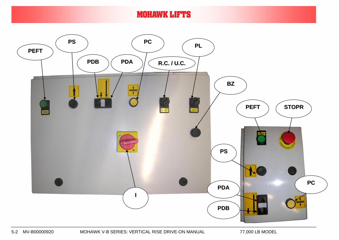
MV-B00000920 MOHAWK V-B SERIES: VERTICAL RISE DRIVE-ON MANUAL 77,000 LB MODEL 5-2
PPSS
II
PPDDBB
PPEEFFTT
PPDDAA
PPLL
BBZZ
PPCC
RR..CC.. // UU..CC..
PPEEFFTT SSTTOOPPRR
PPSS
PPDDBB
PPCC PPDDAA
MV-B00000920 MOHAWK V-B SERIES: VERTICAL RISE DRIVE-ON MANUAL 77,000 LB MODEL 6-1
6. MAINTENANCE
Addressees: - A: USER/OWNER; - B: SPECIALISED TECHNICIAN/EMPLOYER. - NOTE: trained lift service personnel
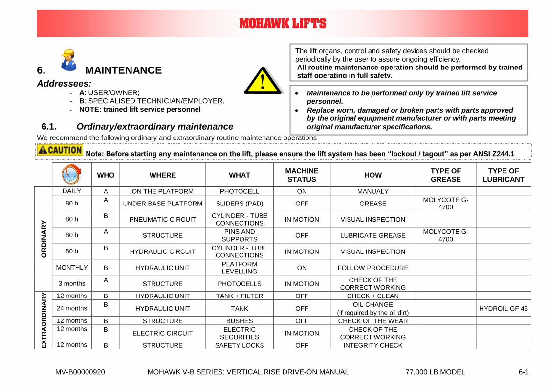
6.1. Ordinary/extraordinary maintenance We recommend the following ordinary and extraordinary routine maintenance operations
WHO WHERE WHAT
MACHINE STATUS
HOW TYPE OF GREASE
TYPE OF LUBRICANT
OR
DIN
AR
Y
DAILY A ON THE PLATFORM PHOTOCELL ON MANUALY
80 h A
UNDER BASE PLATFORM SLIDERS (PAD) OFF GREASE MOLYCOTE G-
4700
80 h B
PNEUMATIC CIRCUIT CYLINDER - TUBE
CONNECTIONS IN MOTION VISUAL INSPECTION
80 h A
STRUCTURE PINS AND
SUPPORTS OFF LUBRICATE GREASE
MOLYCOTE G-4700
80 h B
HYDRAULIC CIRCUIT CYLINDER - TUBE
CONNECTIONS IN MOTION VISUAL INSPECTION
MONTHLY B HYDRAULIC UNIT PLATFORM LEVELLING
ON FOLLOW PROCEDURE
3 months A
STRUCTURE PHOTOCELLS IN MOTION CHECK OF THE
CORRECT WORKING
EX
TR
AO
RD
INA
RY
12 months B HYDRAULIC UNIT TANK + FILTER OFF CHECK + CLEAN
24 months B
HYDRAULIC UNIT TANK OFF OIL CHANGE
(if required by the oil dirt) HYDROIL GF 46
12 months B STRUCTURE BUSHES OFF CHECK OF THE WEAR
12 months B ELECTRIC CIRCUIT
ELECTRIC SECURITIES
IN MOTION CHECK OF THE
CORRECT WORKING
12 months B STRUCTURE SAFETY LOCKS OFF INTEGRITY CHECK
The lift organs, control and safety devices should be checked periodically by the user to assure ongoing efficiency. All routine maintenance operation should be performed by trained staff operating in full safety.
Maintenance to be performed only by trained lift service personnel.
Replace worn, damaged or broken parts with parts approved by the original equipment manufacturer or with parts meeting
original manufacturer specifications.
Note: Before starting any maintenance on the lift, please ensure the lift system has been “lockout / tagout” as per ANSI Z244.1
MV-B00000920 MOHAWK V-B SERIES: VERTICAL RISE DRIVE-ON MANUAL 77,000 LB MODEL 6-2
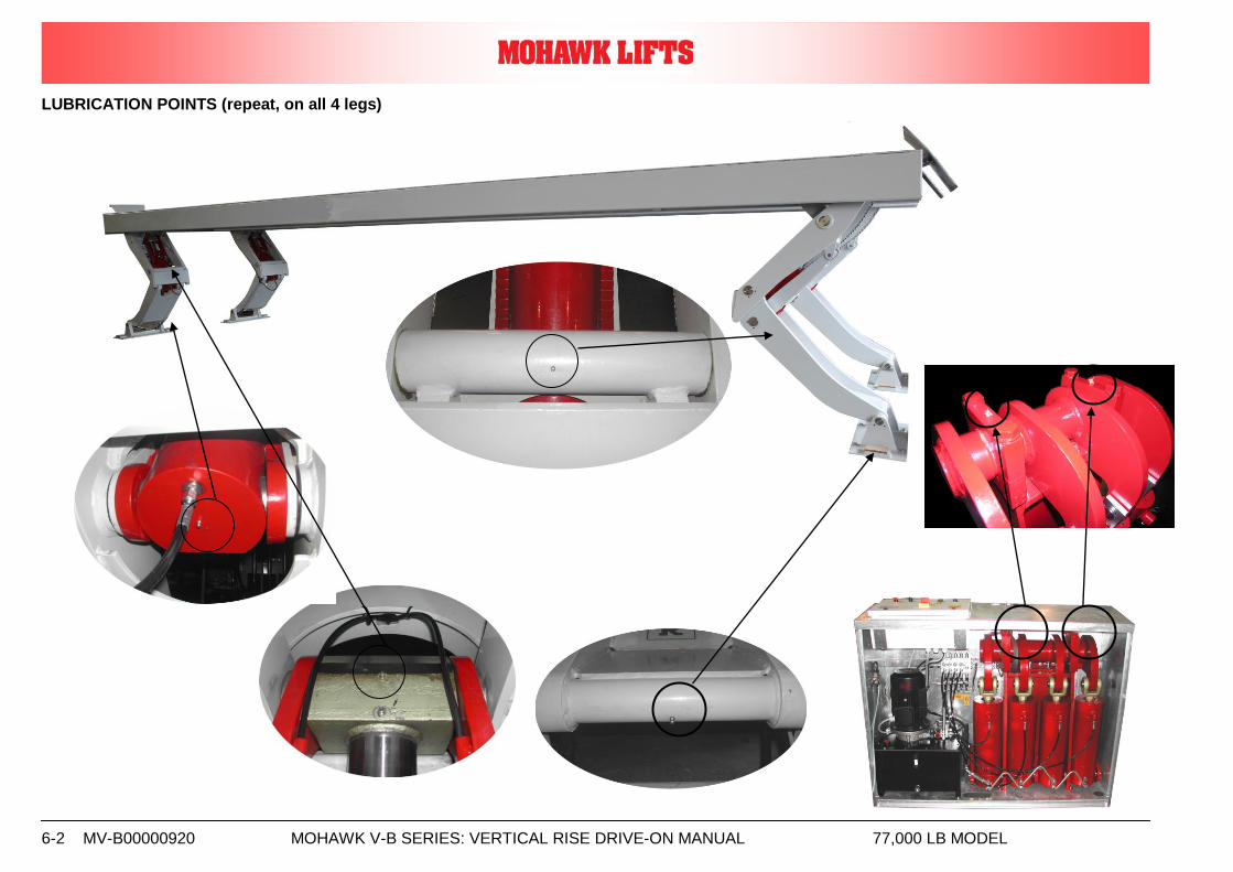
LUBRICATION POINTS (repeat, on all 4 legs)
MV-B00000920 MOHAWK V-B SERIES: VERTICAL RISE DRIVE-ON MANUAL 77,000 LB MODEL 6-3
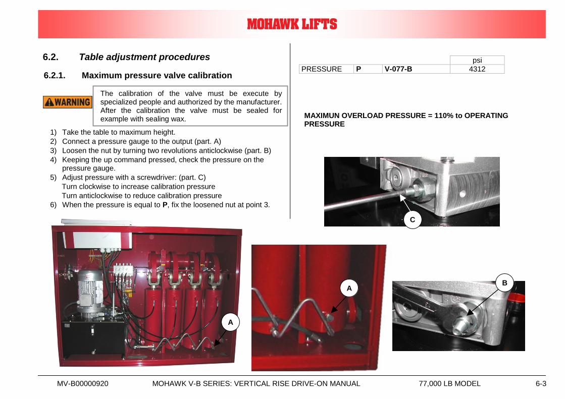
6.2. Table adjustment procedures
6.2.1. Maximum pressure valve calibration
1) Take the table to maximum height.
2) Connect a pressure gauge to the output (part. A)
3) Loosen the nut by turning two revolutions anticlockwise (part. B)
4) Keeping the up command pressed, check the pressure on the pressure gauge.
5) Adjust pressure with a screwdriver: (part. C)
Turn clockwise to increase calibration pressure
Turn anticlockwise to reduce calibration pressure
6) When the pressure is equal to P, fix the loosened nut at point 3.
MAXIMUN OVERLOAD PRESSURE = 110% to OPERATING PRESSURE
psi
PRESSURE P V-077-B 4312
C
A
A
B
The calibration of the valve must be execute by specialized people and authorized by the manufacturer. After the calibration the valve must be sealed for example with sealing wax.
MV-B00000920 MOHAWK V-B SERIES: VERTICAL RISE DRIVE-ON MANUAL 77,000 LB MODEL 6-4
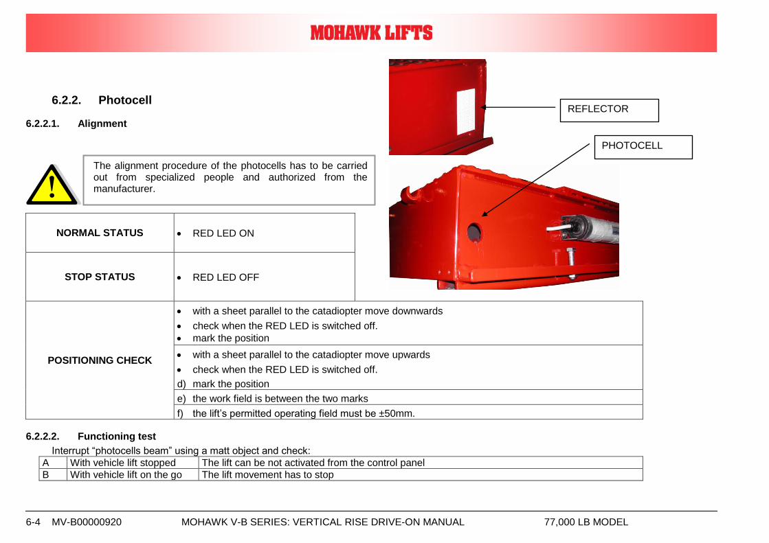
6.2.2. Photocell
6.2.2.1. Alignment
NORMAL STATUS RED LED ON
STOP STATUS RED LED OFF
POSITIONING CHECK
with a sheet parallel to the catadiopter move downwards
check when the RED LED is switched off.
mark the position
with a sheet parallel to the catadiopter move upwards
check when the RED LED is switched off.
d) mark the position
e) the work field is between the two marks
f) the lift’s permitted operating field must be ±50mm.
6.2.2.2. Functioning test
Interrupt “photocells beam” using a matt object and check:
A With vehicle lift stopped The lift can be not activated from the control panel
B With vehicle lift on the go The lift movement has to stop
The alignment procedure of the photocells has to be carried out from specialized people and authorized from the manufacturer.
PHOTOCELL
REFLECTOR
MV-B00000920 MOHAWK V-B SERIES: VERTICAL RISE DRIVE-ON MANUAL 77,000 LB MODEL 6-5
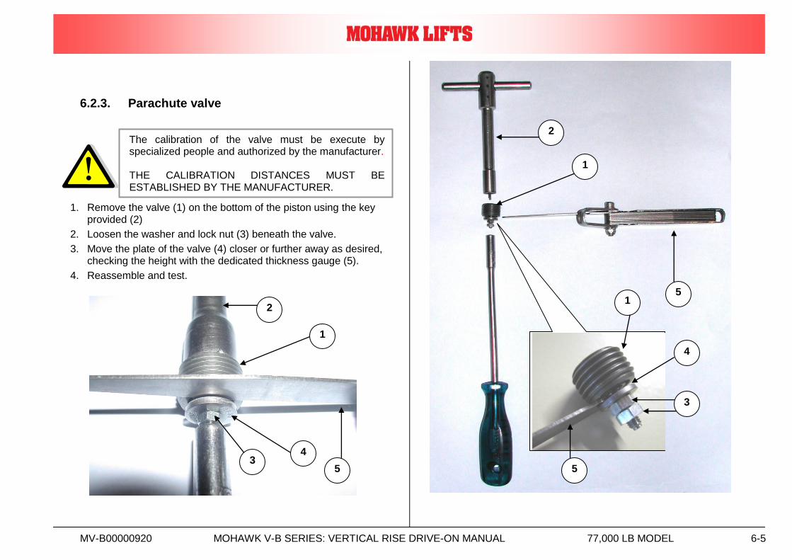
6.2.3. Parachute valve
1. Remove the valve (1) on the bottom of the piston using the key provided (2)
2. Loosen the washer and lock nut (3) beneath the valve.
3. Move the plate of the valve (4) closer or further away as desired, checking the height with the dedicated thickness gauge (5).
4. Reassemble and test.
5
1
2
1
4
5 3
2
4
3
5
1
The calibration of the valve must be execute by specialized people and authorized by the manufacturer. THE CALIBRATION DISTANCES MUST BE ESTABLISHED BY THE MANUFACTURER.
MV-B00000920 MOHAWK V-B SERIES: VERTICAL RISE DRIVE-ON MANUAL 77,000 LB MODEL 6-6
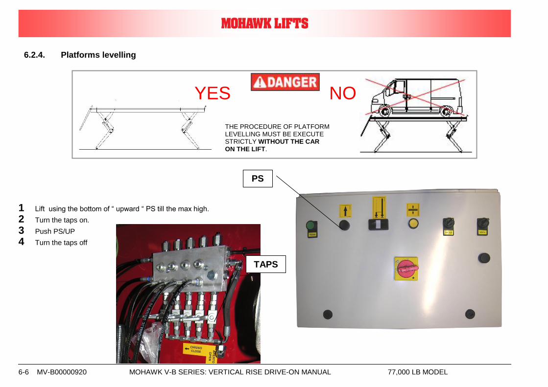
6.2.4. Platforms levelling
1 Lift using the bottom of “ upward “ PS till the max high.
2 Turn the taps on.
3 Push PS/UP
4 Turn the taps off
PS
THE PROCEDURE OF PLATFORM
LEVELLING MUST BE EXECUTE STRICTLY WITHOUT THE CAR ON THE LIFT.
TAPS
YES NO
MV-B00000920 MOHAWK V-B SERIES: VERTICAL RISE DRIVE-ON MANUAL 77,000 LB MODEL 6-7
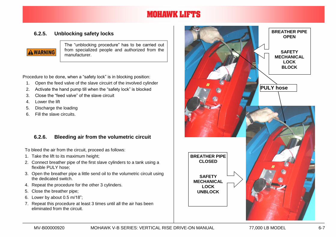
6.2.5. Unblocking safety locks
Procedure to be done, when a “safety lock” is in blocking position:
1. Open the feed valve of the slave circuirt of the involved cylinder
2. Activate the hand pump till when the “safety lock” is blocked
3. Close the “feed valve” of the slave circuit
4. Lower the lift
5. Discharge the loading
6. Fill the slave circuits.
6.2.6. Bleeding air from the volumetric circuit
To bleed the air from the circuit, proceed as follows:
1. Take the lift to its maximum height;
2. Connect breather pipe of the first slave cylinders to a tank using a flexible PULY hose;
3. Open the breather pipe a little send oil to the volumetric circuit using the dedicated switch.
4. Repeat the procedure for the other 3 cylinders.
5. Close the breather pipe;
6. Lower by about 0.5 m/18”;
7. Repeat this procedure at least 3 times until all the air has been eliminated from the circuit.
PULY hose
BREATHER PIPE OPEN
SAFETY MECHANICAL
LOCK
BLOCK
BREATHER PIPE CLOSED
SAFETY MECHANICAL
LOCK
UNBLOCK
The “unblocking procedure” has to be carried out from specialized people and authorized from the manufacturer.
MV-B00000920 MOHAWK V-B SERIES: VERTICAL RISE DRIVE-ON MANUAL 77,000 LB MODEL 6-8
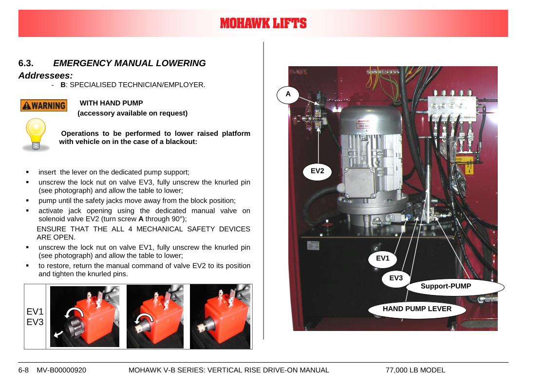
6.3. EMERGENCY MANUAL LOWERING
Addressees: - B: SPECIALISED TECHNICIAN/EMPLOYER.
WITH HAND PUMP
(accessory available on request)
Operations to be performed to lower raised platform with vehicle on in the case of a blackout:
insert the lever on the dedicated pump support;
unscrew the lock nut on valve EV3, fully unscrew the knurled pin (see photograph) and allow the table to lower;
pump until the safety jacks move away from the block position;
activate jack opening using the dedicated manual valve on solenoid valve EV2 (turn screw A through 90°);
ENSURE THAT THE ALL 4 MECHANICAL SAFETY DEVICES ARE OPEN.
unscrew the lock nut on valve EV1, fully unscrew the knurled pin (see photograph) and allow the table to lower;
to restore, return the manual command of valve EV2 to its position and tighten the knurled pins.
EV1 EV3
EV3 Support-PUMP
EV1
A
EV2
HAND PUMP LEVER
MV-B00000920 MOHAWK V-B SERIES: VERTICAL RISE DRIVE-ON MANUAL 77,000 LB MODEL 6-9
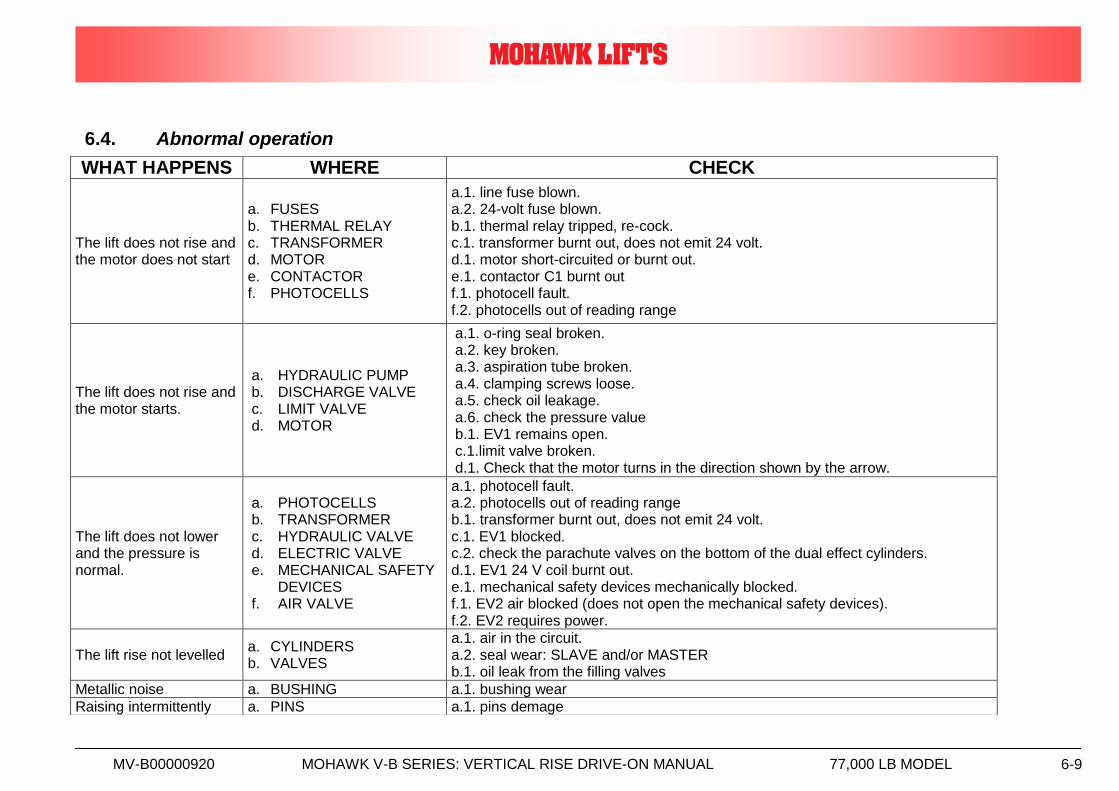
6.4. Abnormal operation
WHAT HAPPENS WHERE CHECK
The lift does not rise and the motor does not start
a. FUSES b. THERMAL RELAY c. TRANSFORMER d. MOTOR e. CONTACTOR f. PHOTOCELLS
a.1. line fuse blown. a.2. 24-volt fuse blown. b.1. thermal relay tripped, re-cock. c.1. transformer burnt out, does not emit 24 volt. d.1. motor short-circuited or burnt out. e.1. contactor C1 burnt out f.1. photocell fault. f.2. photocells out of reading range
The lift does not rise and the motor starts.
a. HYDRAULIC PUMP b. DISCHARGE VALVE c. LIMIT VALVE d. MOTOR
a.1. o-ring seal broken. a.2. key broken. a.3. aspiration tube broken. a.4. clamping screws loose. a.5. check oil leakage. a.6. check the pressure value b.1. EV1 remains open. c.1.limit valve broken. d.1. Check that the motor turns in the direction shown by the arrow.
The lift does not lower and the pressure is normal.
a. PHOTOCELLS b. TRANSFORMER c. HYDRAULIC VALVE d. ELECTRIC VALVE e. MECHANICAL SAFETY
DEVICES f. AIR VALVE
a.1. photocell fault. a.2. photocells out of reading range b.1. transformer burnt out, does not emit 24 volt. c.1. EV1 blocked. c.2. check the parachute valves on the bottom of the dual effect cylinders. d.1. EV1 24 V coil burnt out. e.1. mechanical safety devices mechanically blocked. f.1. EV2 air blocked (does not open the mechanical safety devices). f.2. EV2 requires power.
The lift rise not levelled a. CYLINDERS b. VALVES
a.1. air in the circuit. a.2. seal wear: SLAVE and/or MASTER b.1. oil leak from the filling valves
Metallic noise a. BUSHING a.1. bushing wear
Raising intermittently a. PINS a.1. pins demage
MV-B00000920 MOHAWK V-B SERIES: VERTICAL RISE DRIVE-ON MANUAL 77,000 LB MODEL 6-10
6.5. . Lift lockout/tagout procedure Purpose This procedure establishes the minimum requirements for the lockout of energy that could cause injury to personnel by the operation of lifts in need of repair or being serviced. All employees shall comply with this procedure. Responsibility The responsibility for assuring that this procedure is followed is binding upon all employees and service personnel from outside service companies (i.e., Authorized Rotary Installers, contactors, etc.). All employees shall be instructed in the safety significance of the lockout procedure by the facility owner/manager. Each new or transferred employee along with visiting outside service personnel shall be instructed by the owner/manager (or assigned designee) in the purpose and use of the lockout procedure. Preparation Employees authorized to perform lockout shall ensure that the appropriate energy isolating device (i.e., circuit breaker, fuse, disconnect, etc.) is identified for the lift being locked out. Other such devices for other equipment may be located in close proximity of the appropriate energy isolating device. If the identity of the device is in question, see the shop supervisor for resolution. Assure that proper authorization is received prior to performing the lockout procedure. Sequence of Lockout Procedure 1) Notify all affected employees that a lockout is being performed and
the reason for it. 2) Unload the subject lift. Shut it down and assure the disconnect switch
is “OFF” if one is provided on the lift.
3) The authorized lockout person operates the main energy isolation device removing power to the subject lift.
If this is a lockable device, the authorized lockout person places the assigned padlock on the device to prevent its unintentional reactivation. An appropriate tag is applied stating the person’s name, at least 3” x 6” in size, an easily noticeably color, and states not to operate device or remove tag.
If this device is a non-lockable circuit breaker or fuse, replace with a “dummy” device and tag it appropriately as mentioned above.
4) Attempt to operate lift to assure the lockout is working. Be sure to return any switches to the “OFF” position.
5) The equipment is now locked out and ready for the required maintenance or service.
Restoring Equipment to Service 1) Assure the work on the lift is complete and the area is clear of tools,
vehicles, and personnel. 2) At this point, the authorized person can remove the lock (or dummy
circuit breaker or fuse) & tag and activate then energy isolating device so that the lift may again be placed into operation.
Rules for Using Lockout Procedure Use the Lockout Procedure whenever the lift is being repaired or serviced, waiting for repair when current operation could cause possible injury to personnel, or for any other situation when unintentional operation could injure personnel. No attempt shall be made to operate the lift when the energy isolating device is locked out.
MV-B00000920 MOHAWK V-B SERIES: VERTICAL RISE DRIVE-ON MANUAL 77,000 LB MODEL 7-1
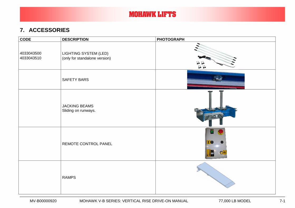
7. ACCESSORIES
CODE DESCRIPTION PHOTOGRAPH
4033043500
4033043510
LIGHTING SYSTEM (LED)
(only for standalone version)
SAFETY BARS
JACKING BEAMS Sliding on runways.
REMOTE CONTROL PANEL
RAMPS

MV-B00000920 MOHAWK V-B SERIES: VERTICAL RISE DRIVE-ON MANUAL 77,000 LB MODEL 7-1
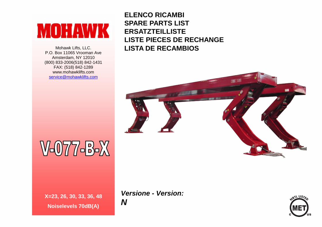
ELENCO RICAMBI
SPARE PARTS LIST
ERSATZTEILLISTE
LISTE PIECES DE RECHANGE
LISTA DE RECAMBIOS
Mohawk Lifts, LLC. P.O. Box 11065 Vrooman Ave
Amsterdam, NY 12010 (800) 833-2006(518) 842-1431
FAX: (518) 842-1289 www.mohawklifts.com
Versione - Version:
N X=23, 26, 30, 33, 36, 48
Noiselevels 70dB(A)
NV-B00000900 MOHAWK V-B SERIES: VERTICAL RISE DRIVE-ON Spare parts list 77,000 LB MODEL 2
NV-B00000900 MOHAWK V-B SERIES: VERTICAL RISE DRIVE-ON Spare parts list 77,000 LB MODEL 3
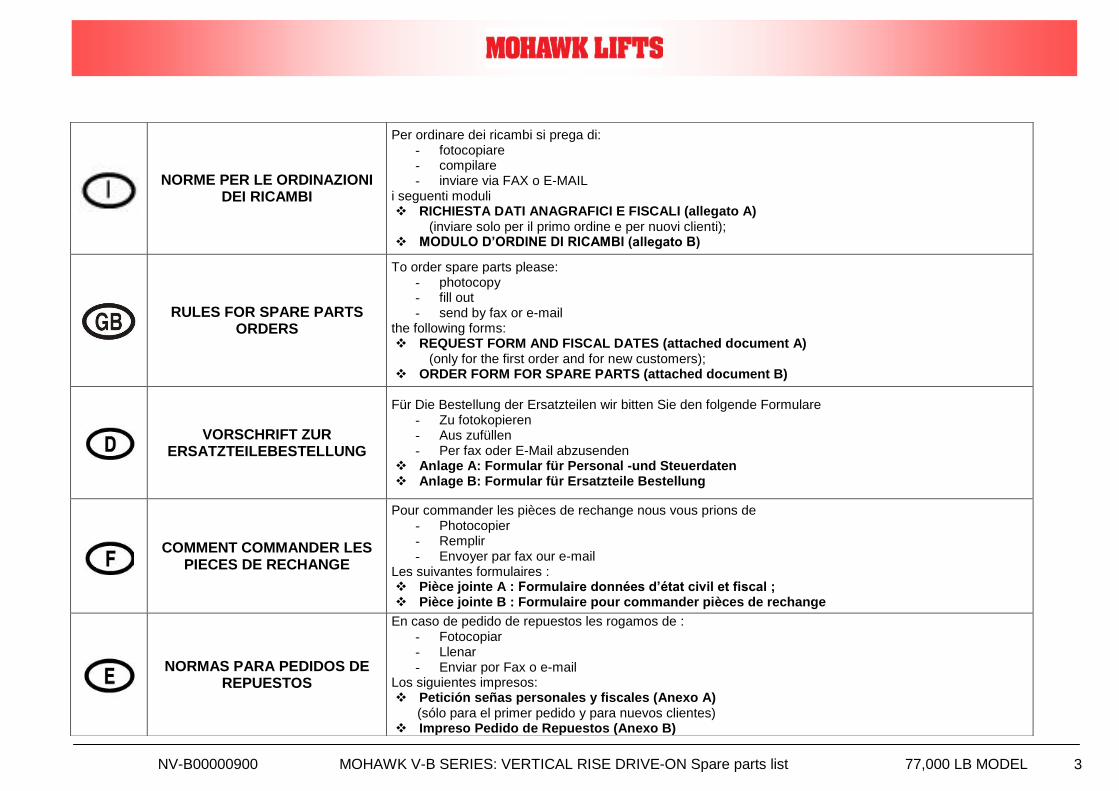
NORME PER LE ORDINAZIONI DEI RICAMBI
Per ordinare dei ricambi si prega di: - fotocopiare - compilare - inviare via FAX o E-MAIL
i seguenti moduli RICHIESTA DATI ANAGRAFICI E FISCALI (allegato A)
(inviare solo per il primo ordine e per nuovi clienti); MODULO D’ORDINE DI RICAMBI (allegato B)
RULES FOR SPARE PARTS ORDERS
To order spare parts please: - photocopy - fill out - send by fax or e-mail
the following forms: REQUEST FORM AND FISCAL DATES (attached document A)
(only for the first order and for new customers); ORDER FORM FOR SPARE PARTS (attached document B)
VORSCHRIFT ZUR ERSATZTEILEBESTELLUNG
Für Die Bestellung der Ersatzteilen wir bitten Sie den folgende Formulare - Zu fotokopieren - Aus zufüllen - Per fax oder E-Mail abzusenden
Anlage A: Formular für Personal -und Steuerdaten Anlage B: Formular für Ersatzteile Bestellung
COMMENT COMMANDER LES PIECES DE RECHANGE
Pour commander les pièces de rechange nous vous prions de - Photocopier - Remplir - Envoyer par fax our e-mail
Les suivantes formulaires : Pièce jointe A : Formulaire données d’état civil et fiscal ; Pièce jointe B : Formulaire pour commander pièces de rechange
NORMAS PARA PEDIDOS DE REPUESTOS
En caso de pedido de repuestos les rogamos de : - Fotocopiar - Llenar - Enviar por Fax o e-mail
Los siguientes impresos: Petición señas personales y fiscales (Anexo A) (sólo para el primer pedido y para nuevos clientes) Impreso Pedido de Repuestos (Anexo B)
NV-B00000900 MOHAWK V-B SERIES: VERTICAL RISE DRIVE-ON Spare parts list 77,000 LB MODEL 4
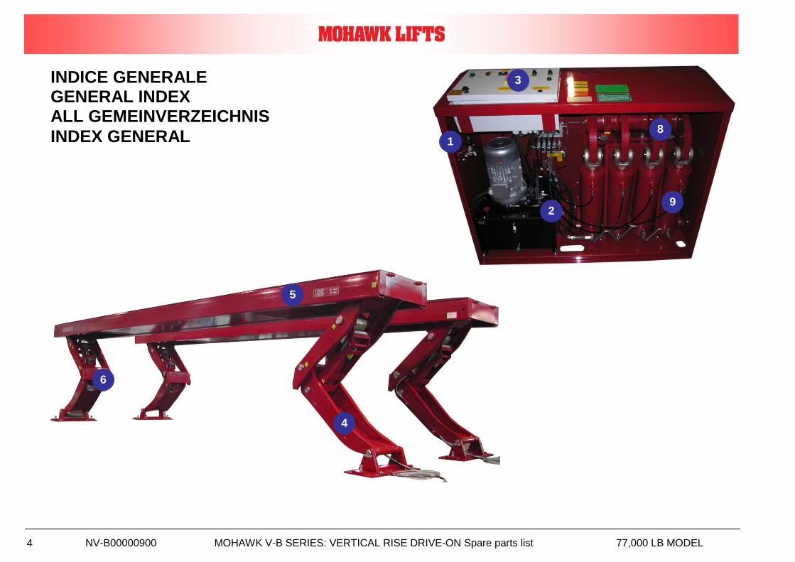
4
5
6
INDICE GENERALE GENERAL INDEX ALL GEMEINVERZEICHNIS
INDEX GENERAL
2
3
1
9
8
NV-B00000900 MOHAWK V-B SERIES: VERTICAL RISE DRIVE-ON Spare parts list 77,000 LB MODEL 5
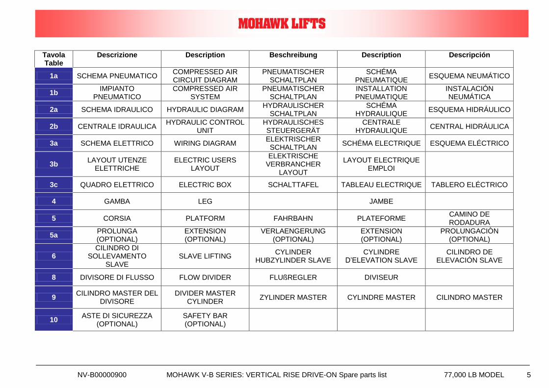
Tavola Table
Descrizione Description Beschreibung Description Descripción
1a SCHEMA PNEUMATICO COMPRESSED AIR CIRCUIT DIAGRAM
PNEUMATISCHER SCHALTPLAN
SCHÉMA PNEUMATIQUE
ESQUEMA NEUMÁTICO
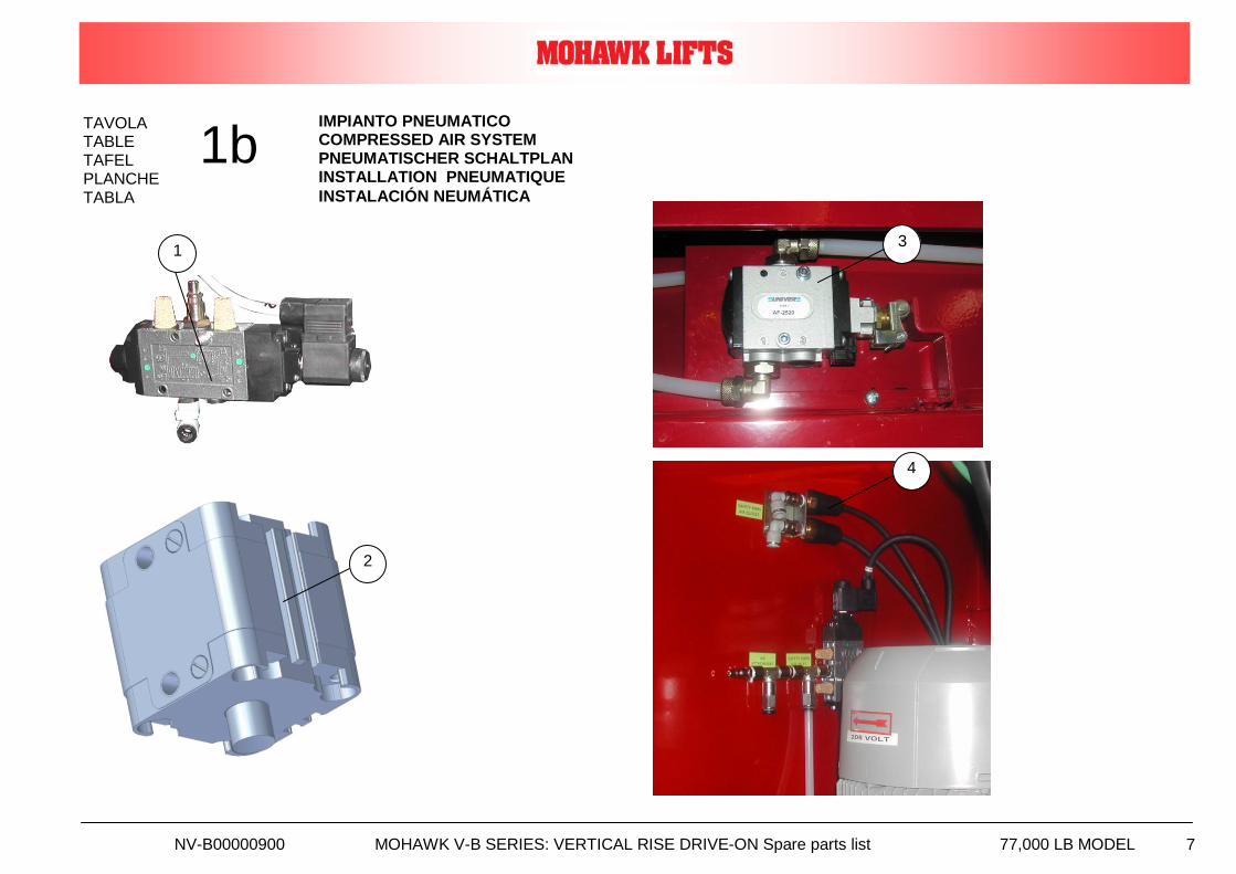
1b IMPIANTO
PNEUMATICO COMPRESSED AIR
SYSTEM PNEUMATISCHER
SCHALTPLAN INSTALLATION PNEUMATIQUE
INSTALACIÓN NEUMÁTICA
2a SCHEMA IDRAULICO HYDRAULIC DIAGRAM HYDRAULISCHER
SCHALTPLAN SCHÉMA
HYDRAULIQUE ESQUEMA HIDRÁULICO
2b CENTRALE IDRAULICA HYDRAULIC CONTROL
UNIT HYDRAULISCHES STEUERGERÄT
CENTRALE HYDRAULIQUE
CENTRAL HIDRÁULICA
3a SCHEMA ELETTRICO WIRING DIAGRAM ELEKTRISCHER SCHALTPLAN
SCHÉMA ELECTRIQUE ESQUEMA ELÉCTRICO
3b LAYOUT UTENZE
ELETTRICHE ELECTRIC USERS
LAYOUT
ELEKTRISCHE VERBRANCHER
LAYOUT
LAYOUT ELECTRIQUE EMPLOI
3c QUADRO ELETTRICO ELECTRIC BOX SCHALTTAFEL TABLEAU ELECTRIQUE TABLERO ELÉCTRICO
4 GAMBA LEG JAMBE
5 CORSIA PLATFORM FAHRBAHN PLATEFORME CAMINO DE RODADURA
5a PROLUNGA (OPTIONAL)
EXTENSION (OPTIONAL)
VERLAENGERUNG (OPTIONAL)
EXTENSION (OPTIONAL)
PROLUNGACIÒN (OPTIONAL)
6 CILINDRO DI
SOLLEVAMENTO SLAVE
SLAVE LIFTING CYLINDER
HUBZYLINDER SLAVE CYLINDRE
D’ELEVATION SLAVE CILINDRO DE
ELEVACIÓN SLAVE
8 DIVISORE DI FLUSSO FLOW DIVIDER FLUßREGLER DIVISEUR
9 CILINDRO MASTER DEL
DIVISORE DIVIDER MASTER
CYLINDER ZYLINDER MASTER CYLINDRE MASTER CILINDRO MASTER
10 ASTE DI SICUREZZA
(OPTIONAL) SAFETY BAR (OPTIONAL)
NV-B00000900 MOHAWK V-B SERIES: VERTICAL RISE DRIVE-ON Spare parts list 77,000 LB MODEL 6
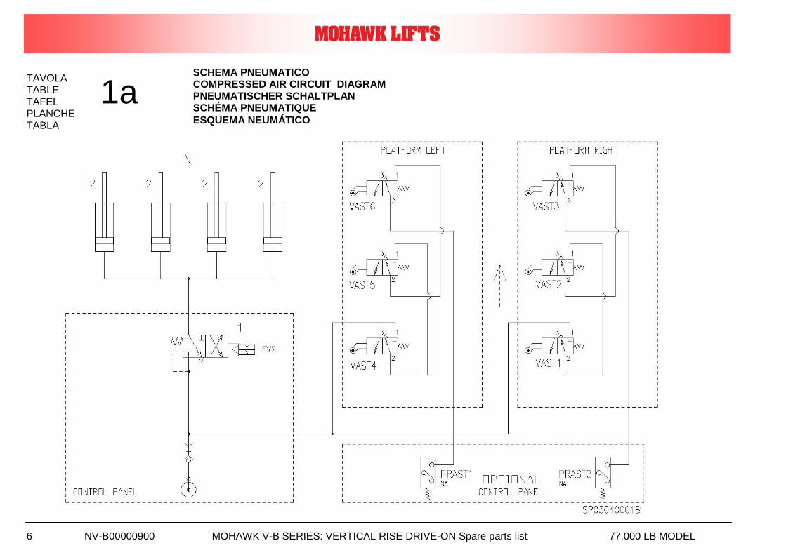
TAVOLA TABLE TAFEL PLANCHE
TABLA
1a SCHEMA PNEUMATICO COMPRESSED AIR CIRCUIT DIAGRAM PNEUMATISCHER SCHALTPLAN SCHÉMA PNEUMATIQUE
ESQUEMA NEUMÁTICO
NV-B00000900 MOHAWK V-B SERIES: VERTICAL RISE DRIVE-ON Spare parts list 77,000 LB MODEL 7
TAVOLA TABLE TAFEL PLANCHE
TABLA 1
1b IMPIANTO PNEUMATICO COMPRESSED AIR SYSTEM PNEUMATISCHER SCHALTPLAN INSTALLATION PNEUMATIQUE
INSTALACIÓN NEUMÁTICA
2
3
4
NV-B00000900 MOHAWK V-B SERIES: VERTICAL RISE DRIVE-ON Spare parts list 77,000 LB MODEL 8
Rif. Ref.
Sigla Abbr.
Descrizione Description Beschreibung Description Descripción Q.tà Q.ty
Codice Code
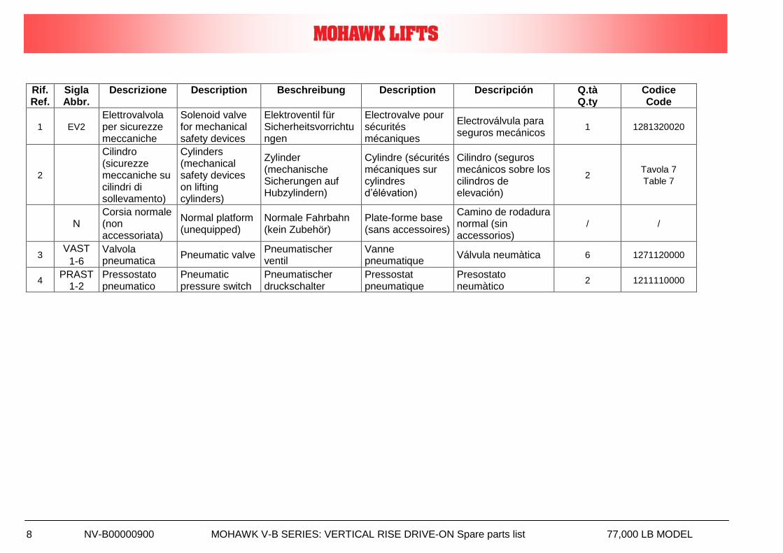
1 EV2
Elettrovalvola per sicurezze meccaniche
Solenoid valve for mechanical safety devices
Elektroventil für Sicherheitsvorrichtungen
Electrovalve pour sécurités mécaniques
Electroválvula para seguros mecánicos
1 1281320020
2
Cilindro (sicurezze meccaniche su cilindri di sollevamento)
Cylinders (mechanical safety devices on lifting cylinders)
Zylinder (mechanische Sicherungen auf Hubzylindern)
Cylindre (sécurités mécaniques sur cylindres d’élévation)
Cilindro (seguros mecánicos sobre los cilindros de elevación)
2 Tavola 7
Table 7
N Corsia normale (non accessoriata)
Normal platform (unequipped)
Normale Fahrbahn (kein Zubehör)
Plate-forme base (sans accessoires)
Camino de rodadura normal (sin accessorios)
/ /
3 VAST
1-6
Valvola pneumatica
Pneumatic valve Pneumatischer ventil
Vanne pneumatique
Válvula neumàtica 6 1271120000
4 PRAST
1-2 Pressostato pneumatico
Pneumatic pressure switch
Pneumatischer druckschalter
Pressostat pneumatique
Presostato neumàtico
2 1211110000
NV-B00000900 MOHAWK V-B SERIES: VERTICAL RISE DRIVE-ON Spare parts list 77,000 LB MODEL 9
TAVOLA TABLE TAFEL PLANCHE
TABLA
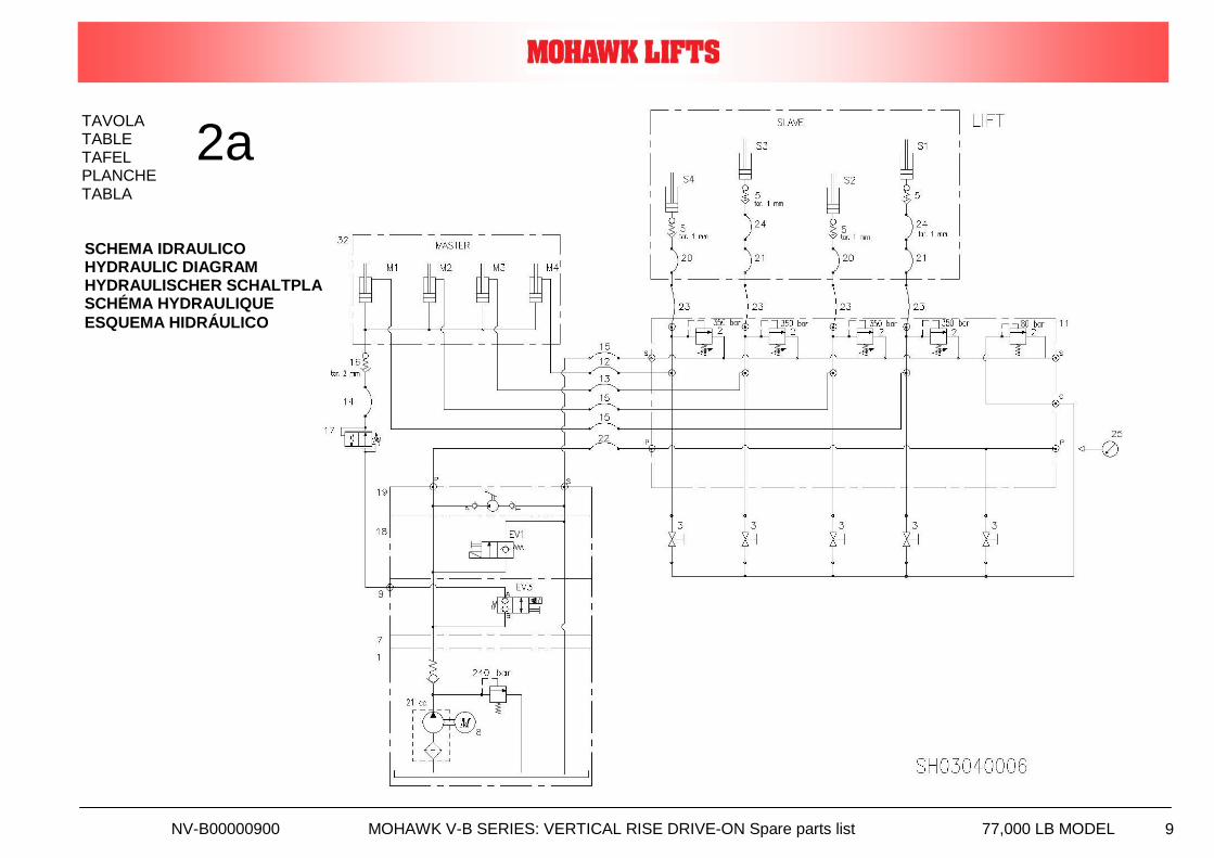
2a
SCHEMA IDRAULICO HYDRAULIC DIAGRAM HYDRAULISCHER SCHALTPLAN SCHÉMA HYDRAULIQUE
ESQUEMA HIDRÁULICO
NV-B00000900 MOHAWK V-B SERIES: VERTICAL RISE DRIVE-ON Spare parts list 77,000 LB MODEL 10
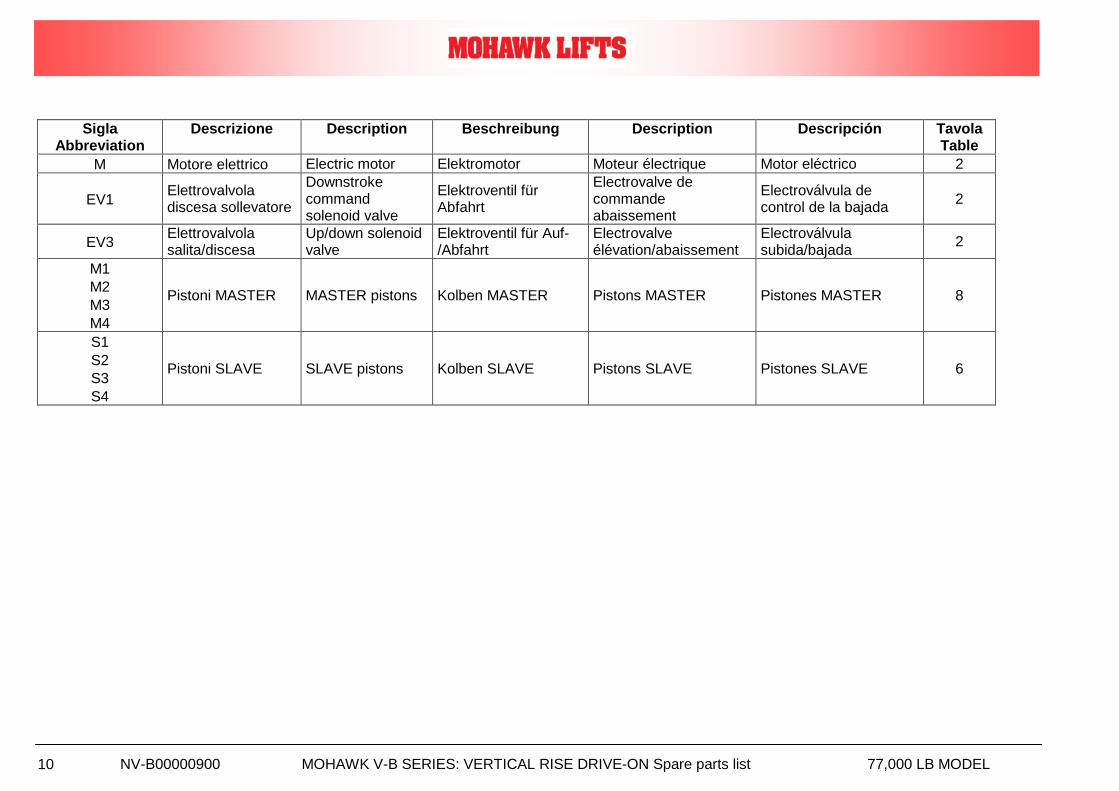
Sigla Abbreviation
Descrizione Description Beschreibung Description Descripción Tavola Table
M Motore elettrico Electric motor Elektromotor Moteur électrique Motor eléctrico 2
EV1 Elettrovalvola discesa sollevatore
Downstroke command solenoid valve
Elektroventil für Abfahrt
Electrovalve de commande abaissement
Electroválvula de control de la bajada
2
EV3 Elettrovalvola salita/discesa
Up/down solenoid valve
Elektroventil für Auf-/Abfahrt
Electrovalve élévation/abaissement
Electroválvula subida/bajada
2
M1
M2
M3
M4
Pistoni MASTER MASTER pistons Kolben MASTER Pistons MASTER Pistones MASTER 8
S1
S2
S3
S4
Pistoni SLAVE SLAVE pistons Kolben SLAVE Pistons SLAVE Pistones SLAVE 6
NV-B00000900 MOHAWK V-B SERIES: VERTICAL RISE DRIVE-ON Spare parts list 77,000 LB MODEL 11
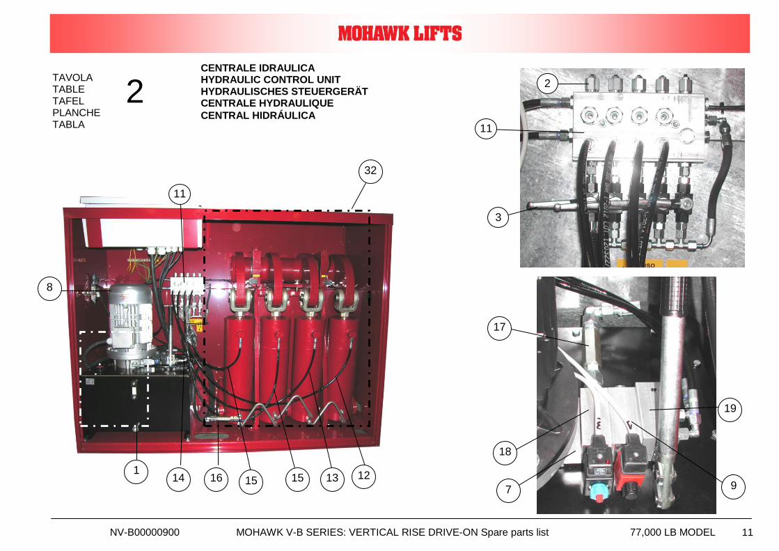
TAVOLA TABLE TAFEL PLANCHE TABLA
2 CENTRALE IDRAULICA HYDRAULIC CONTROL UNIT HYDRAULISCHES STEUERGERÄT CENTRALE HYDRAULIQUE
CENTRAL HIDRÁULICA
9 7
32
8
1
19
17
3
11
2
18
11
15 13 12 15 16 14
NV-B00000900 MOHAWK V-B SERIES: VERTICAL RISE DRIVE-ON Spare parts list 77,000 LB MODEL 12
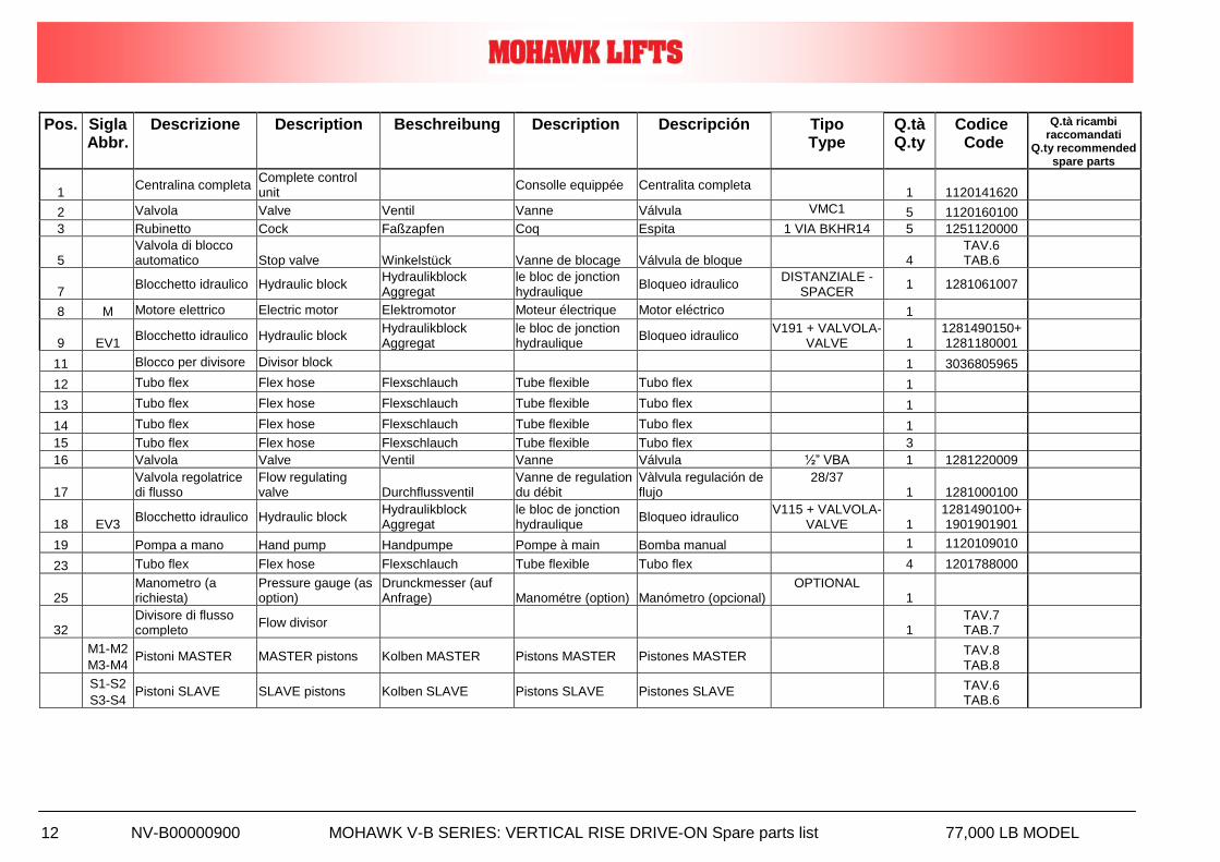
Pos. Sigla Abbr.
Descrizione Description Beschreibung Description Descripción Tipo Type
Q.tà Q.ty
Codice Code
Q.tà ricambi raccomandati
Q.ty recommended spare parts
1 Centralina completa
Complete control unit
Consolle equippée Centralita completa
1 1120141620
2 Valvola Valve Ventil Vanne Válvula VMC1 5 1120160100
3 Rubinetto Cock Faßzapfen Coq Espita 1 VIA BKHR14 5 1251120000
5 Valvola di blocco automatico Stop valve Winkelstück Vanne de blocage Válvula de bloque
4
TAV.6 TAB.6
7 Blocchetto idraulico Hydraulic block
Hydraulikblock Aggregat
le bloc de jonction hydraulique
Bloqueo idraulico DISTANZIALE -
SPACER 1 1281061007
8 M Motore elettrico Electric motor Elektromotor Moteur électrique Motor eléctrico 1
9 EV1 Blocchetto idraulico Hydraulic block
Hydraulikblock Aggregat
le bloc de jonction hydraulique
Bloqueo idraulico V191 + VALVOLA-
VALVE 1 1281490150+ 1281180001
11 Blocco per divisore Divisor block 1 3036805965
12 Tubo flex Flex hose Flexschlauch Tube flexible Tubo flex 1
13 Tubo flex Flex hose Flexschlauch Tube flexible Tubo flex 1
14 Tubo flex Flex hose Flexschlauch Tube flexible Tubo flex 1
15 Tubo flex Flex hose Flexschlauch Tube flexible Tubo flex 3
16 Valvola Valve Ventil Vanne Válvula ½” VBA 1 1281220009
17 Valvola regolatrice di flusso
Flow regulating valve Durchflussventil
Vanne de regulation du débit
Vàlvula regulación de flujo
28/37 1 1281000100
18 EV3 Blocchetto idraulico Hydraulic block
Hydraulikblock Aggregat
le bloc de jonction hydraulique
Bloqueo idraulico V115 + VALVOLA-
VALVE 1 1281490100+ 1901901901
19 Pompa a mano Hand pump Handpumpe Pompe à main Bomba manual 1 1120109010
23 Tubo flex Flex hose Flexschlauch Tube flexible Tubo flex 4 1201788000
25 Manometro (a richiesta)
Pressure gauge (as option)
Drunckmesser (auf Anfrage) Manométre (option) Manómetro (opcional)
OPTIONAL 1
32 Divisore di flusso completo
Flow divisor
1 TAV.7 TAB.7
M1-M2
M3-M4 Pistoni MASTER MASTER pistons Kolben MASTER Pistons MASTER Pistones MASTER
TAV.8 TAB.8
S1-S2
S3-S4 Pistoni SLAVE SLAVE pistons Kolben SLAVE Pistons SLAVE Pistones SLAVE
TAV.6 TAB.6
NV-B00000900 MOHAWK V-B SERIES: VERTICAL RISE DRIVE-ON Spare parts list 77,000 LB MODEL 13
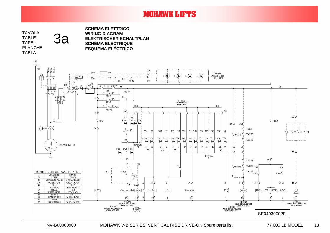
TAVOLA TABLE TAFEL PLANCHE TABLA
3a SCHEMA ELETTRICO WIRING DIAGRAM ELEKTRISCHER SCHALTPLAN SCHÉMA ELECTRIQUE
ESQUEMA ELÉCTRICO
SE04030002E
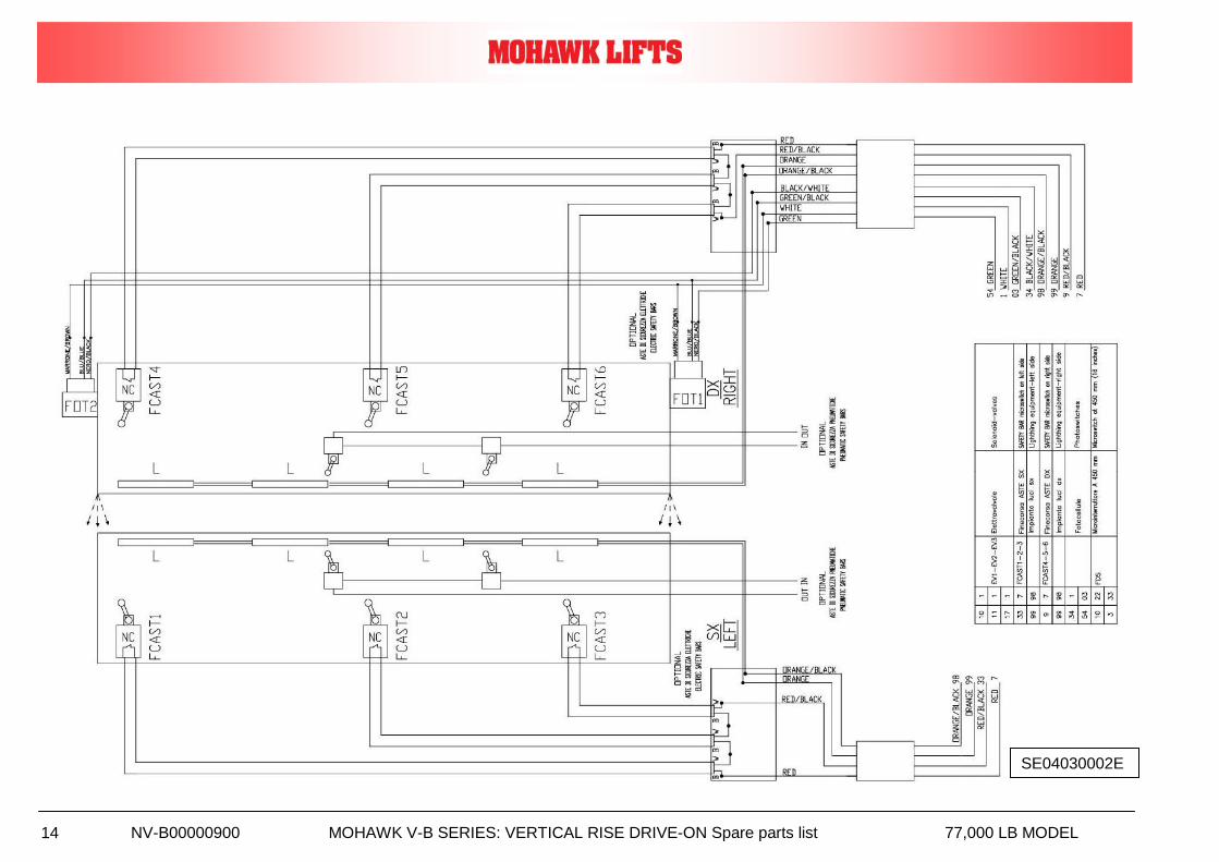
NV-B00000900 MOHAWK V-B SERIES: VERTICAL RISE DRIVE-ON Spare parts list 77,000 LB MODEL 14
SE04030002E
NV-B00000900 MOHAWK V-B SERIES: VERTICAL RISE DRIVE-ON Spare parts list 77,000 LB MODEL 15
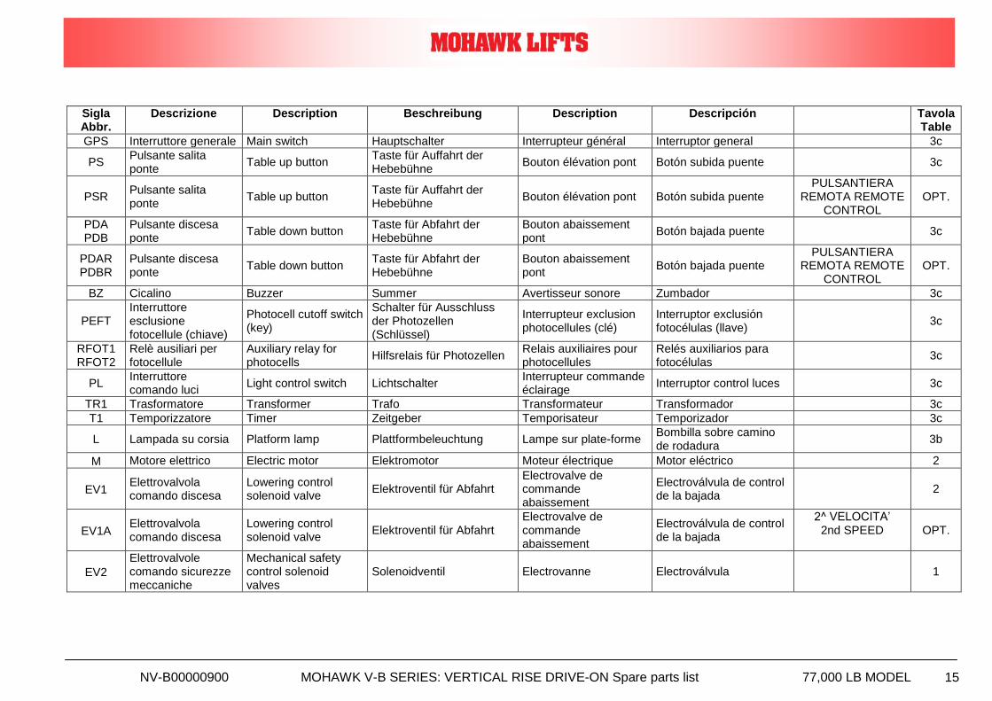
Sigla Abbr.
Descrizione Description Beschreibung Description Descripción Tavola Table
GPS Interruttore generale Main switch Hauptschalter Interrupteur général Interruptor general 3c
PS Pulsante salita ponte
Table up button Taste für Auffahrt der Hebebühne
Bouton élévation pont Botón subida puente
3c
PSR Pulsante salita ponte
Table up button Taste für Auffahrt der Hebebühne
Bouton élévation pont Botón subida puente PULSANTIERA
REMOTA REMOTE CONTROL
OPT.
PDA PDB
Pulsante discesa ponte
Table down button Taste für Abfahrt der Hebebühne
Bouton abaissement pont
Botón bajada puente
3c
PDAR PDBR
Pulsante discesa ponte
Table down button Taste für Abfahrt der Hebebühne
Bouton abaissement pont
Botón bajada puente PULSANTIERA
REMOTA REMOTE CONTROL
OPT.
BZ Cicalino Buzzer Summer Avertisseur sonore Zumbador 3c
PEFT Interruttore esclusione fotocellule (chiave)
Photocell cutoff switch (key)
Schalter für Ausschluss der Photozellen (Schlüssel)
Interrupteur exclusion photocellules (clé)
Interruptor exclusión fotocélulas (llave)
3c
RFOT1 RFOT2
Relè ausiliari per fotocellule
Auxiliary relay for photocells
Hilfsrelais für Photozellen Relais auxiliaires pour photocellules
Relés auxiliarios para fotocélulas
3c
PL Interruttore comando luci
Light control switch Lichtschalter Interrupteur commande éclairage
Interruptor control luces
3c
TR1 Trasformatore Transformer Trafo Transformateur Transformador 3c
T1 Temporizzatore Timer Zeitgeber Temporisateur Temporizador 3c
L Lampada su corsia Platform lamp Plattformbeleuchtung Lampe sur plate-forme Bombilla sobre camino de rodadura
3b
M Motore elettrico Electric motor Elektromotor Moteur électrique Motor eléctrico 2
EV1 Elettrovalvola comando discesa
Lowering control solenoid valve
Elektroventil für Abfahrt Electrovalve de commande abaissement
Electroválvula de control de la bajada
2
EV1A Elettrovalvola comando discesa
Lowering control solenoid valve
Elektroventil für Abfahrt Electrovalve de commande abaissement
Electroválvula de control de la bajada
2^ VELOCITA’ 2nd SPEED OPT.
EV2
Elettrovalvole comando sicurezze meccaniche
Mechanical safety control solenoid valves
Solenoidventil Electrovanne Electroválvula
1
NV-B00000900 MOHAWK V-B SERIES: VERTICAL RISE DRIVE-ON Spare parts list 77,000 LB MODEL 16
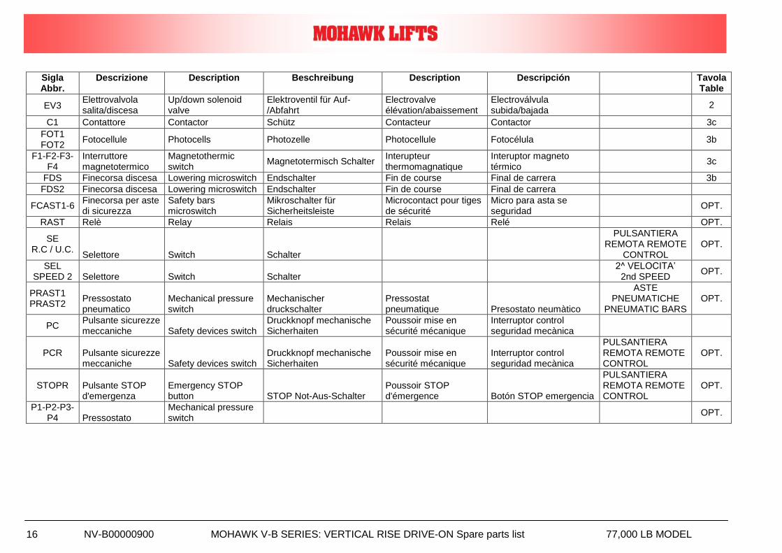
Sigla Abbr.
Descrizione Description Beschreibung Description Descripción Tavola Table
EV3 Elettrovalvola salita/discesa
Up/down solenoid valve
Elektroventil für Auf-/Abfahrt
Electrovalve élévation/abaissement
Electroválvula subida/bajada
2
C1 Contattore Contactor Schütz Contacteur Contactor 3c
FOT1 FOT2
Fotocellule Photocells Photozelle Photocellule Fotocélula
3b
F1-F2-F3-F4
Interruttore magnetotermico
Magnetothermic switch
Magnetotermisch Schalter Interupteur thermomagnatique
Interuptor magneto térmico
3c
FDS Finecorsa discesa Lowering microswitch Endschalter Fin de course Final de carrera 3b
FDS2 Finecorsa discesa Lowering microswitch Endschalter Fin de course Final de carrera
FCAST1-6 Finecorsa per aste di sicurezza
Safety bars microswitch
Mikroschalter für Sicherheitsleiste
Microcontact pour tiges de sécurité
Micro para asta se seguridad
OPT.
RAST Relè Relay Relais Relais Relé OPT.
SE R.C / U.C.
Selettore Switch Schalter
PULSANTIERA REMOTA REMOTE
CONTROL OPT.
SEL SPEED 2 Selettore Switch Schalter
2^ VELOCITA’ 2nd SPEED
OPT.
PRAST1 PRAST2
Pressostato pneumatico
Mechanical pressure switch
Mechanischer druckschalter
Pressostat pneumatique Presostato neumàtico
ASTE PNEUMATICHE
PNEUMATIC BARS OPT.
PC Pulsante sicurezze meccaniche Safety devices switch
Druckknopf mechanische Sicherhaiten
Poussoir mise en sécurité mécanique
Interruptor control seguridad mecànica
PCR Pulsante sicurezze meccaniche Safety devices switch
Druckknopf mechanische Sicherhaiten
Poussoir mise en sécurité mécanique
Interruptor control seguridad mecànica
PULSANTIERA REMOTA REMOTE CONTROL
OPT.
STOPR Pulsante STOP d'emergenza
Emergency STOP button STOP Not-Aus-Schalter
Poussoir STOP d'émergence Botón STOP emergencia
PULSANTIERA REMOTA REMOTE CONTROL
OPT.
P1-P2-P3-P4 Pressostato
Mechanical pressure switch
OPT.
NV-B00000900 MOHAWK V-B SERIES: VERTICAL RISE DRIVE-ON Spare parts list 77,000 LB MODEL 17
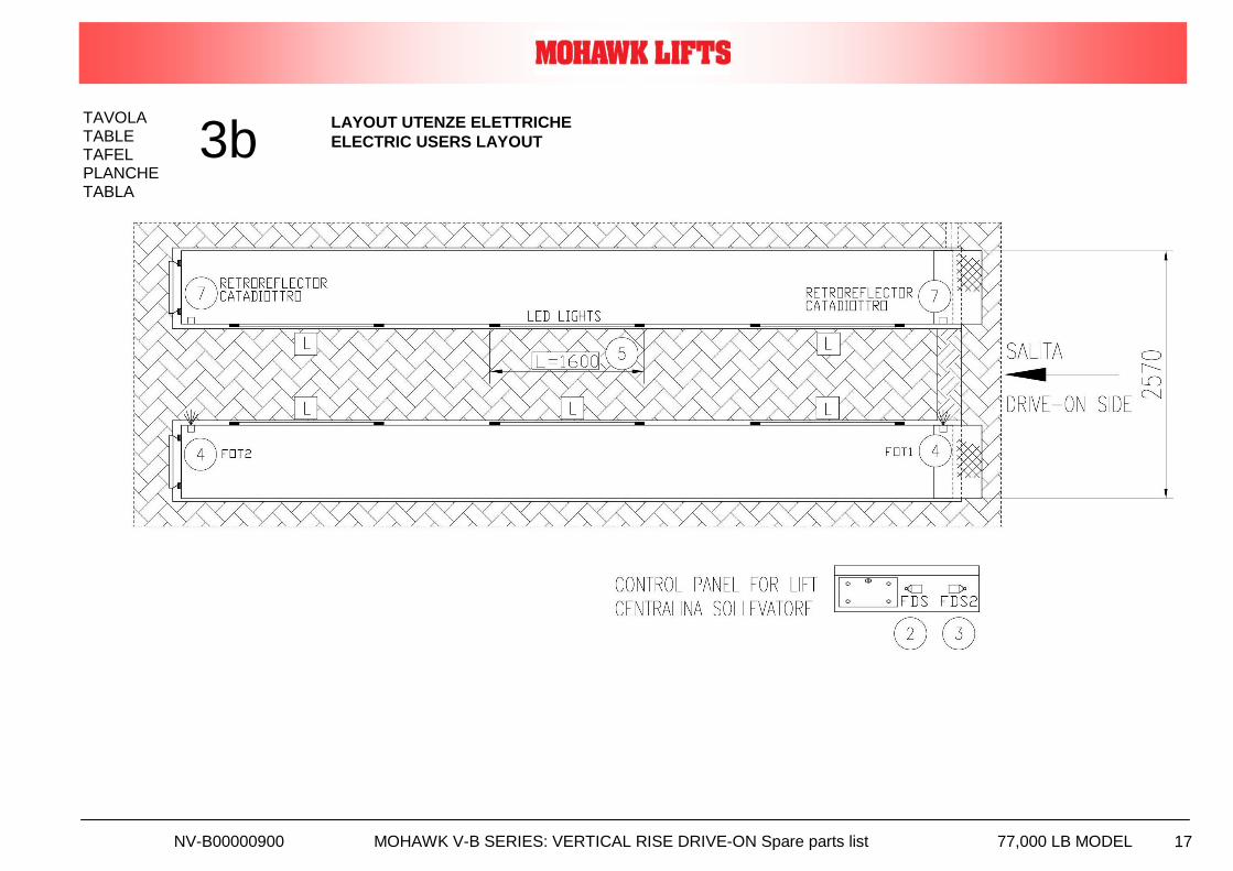
TAVOLA TABLE TAFEL PLANCHE TABLA
3b LAYOUT UTENZE ELETTRICHE
ELECTRIC USERS LAYOUT
NV-B00000900 MOHAWK V-B SERIES: VERTICAL RISE DRIVE-ON Spare parts list 77,000 LB MODEL 18
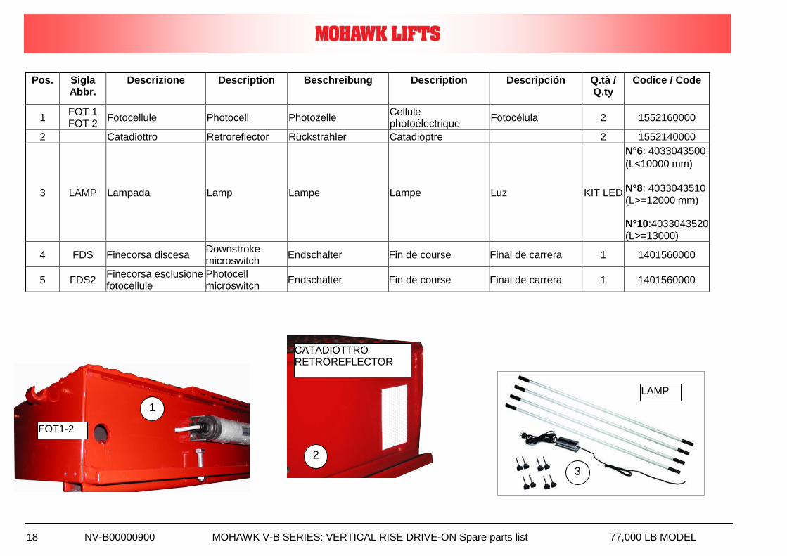
Pos. Sigla Abbr.
Descrizione Description Beschreibung Description Descripción Q.tà / Q.ty
Codice / Code
1 FOT 1 FOT 2
Fotocellule Photocell Photozelle Cellule photoélectrique
Fotocélula 2 1552160000
2 Catadiottro Retroreflector Rückstrahler Catadioptre 2 1552140000
3 LAMP Lampada Lamp Lampe Lampe Luz KIT LED
N°6: 4033043500
(L<10000 mm)
N°8: 4033043510 (L>=12000 mm) N°10:4033043520 (L>=13000)
4 FDS Finecorsa discesa Downstroke microswitch
Endschalter Fin de course Final de carrera 1 1401560000
5 FDS2 Finecorsa esclusione fotocellule
Photocell microswitch
Endschalter Fin de course Final de carrera 1 1401560000
1
FOT1-2
2
CATADIOTTRO RETROREFLECTOR
3
LAMP
NV-B00000900 MOHAWK V-B SERIES: VERTICAL RISE DRIVE-ON Spare parts list 77,000 LB MODEL 19
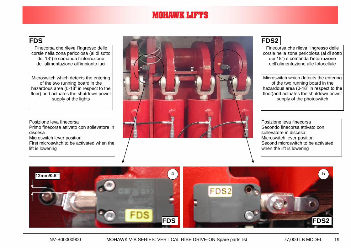
FDS FDS2
Finecorsa che rileva l’ingresso delle corsie nella zona pericolosa (al di sotto
dei 18”) e comanda l’interruzione dell’alimentazione all’impianto luci
Finecorsa che rileva l’ingresso delle corsie nella zona pericolosa (al di sotto
dei 18”) e comanda l’interruzione dell’alimentazione alle fotocellule
Microswitch which detects the entering of the two running board in the
hazardous area (0-18” in respect to the floor) and actuates the shutdown power
supply of the lights
Microswitch which detects the entering of the two running board in the
hazardous area (0-18” in respect to the floor)and actuates the shutdown power
supply of the photoswitch
FDS FDS2
4 5
Posizione leva finecorsa Primo finecorsa attivato con sollevatore in discesa Microswitch lever position First microswitch to be activated when the lift is lowering
Posizione leva finecorsa Secondo finecorsa attivato con sollevatore in discesa Microswitch lever position Second microswitch to be activated when the lift is lowering
12mm/0.5”
NV-B00000900 MOHAWK V-B SERIES: VERTICAL RISE DRIVE-ON Spare parts list 77,000 LB MODEL 20
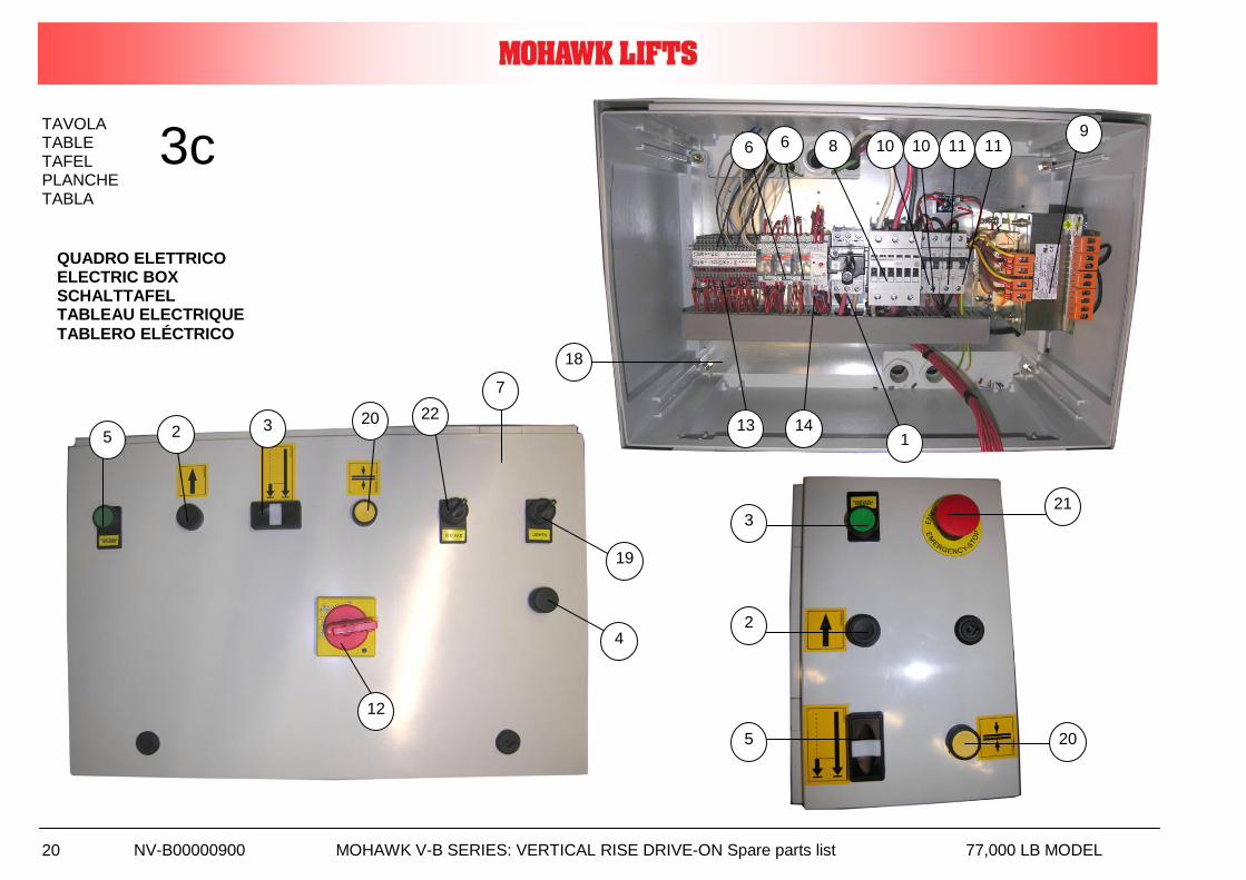
TAVOLA TABLE TAFEL PLANCHE TABLA
3c
QUADRO ELETTRICO ELECTRIC BOX SCHALTTAFEL TABLEAU ELECTRIQUE
TABLERO ELÉCTRICO
9
1
8 10 10 11 11
13
18
14
6 6
5
19
7
2 3
12
4
20 22
5
2
3 21
20
NV-B00000900 MOHAWK V-B SERIES: VERTICAL RISE DRIVE-ON Spare parts list 77,000 LB MODEL 21
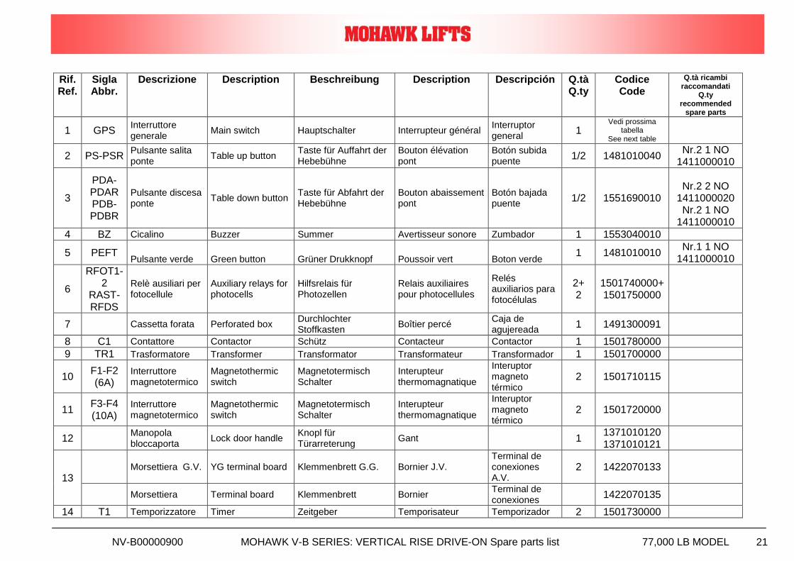
Rif. Ref.
Sigla Abbr.
Descrizione Description Beschreibung Description Descripción Q.tà Q.ty
Codice Code
Q.tà ricambi raccomandati
Q.ty recommended
spare parts
1 GPS Interruttore generale
Main switch Hauptschalter Interrupteur général Interruptor general
1 Vedi prossima
tabella See next table
2 PS-PSR Pulsante salita ponte
Table up button Taste für Auffahrt der Hebebühne
Bouton élévation pont
Botón subida puente
1/2 1481010040 Nr.2 1 NO
1411000010
3
PDA-PDAR PDB-PDBR
Pulsante discesa ponte
Table down button Taste für Abfahrt der Hebebühne
Bouton abaissement pont
Botón bajada puente
1/2 1551690010
Nr.2 2 NO
1411000020 Nr.2 1 NO
1411000010
4 BZ Cicalino Buzzer Summer Avertisseur sonore Zumbador 1 1553040010
5 PEFT Pulsante verde Green button Grüner Drukknopf Poussoir vert Boton verde
1 1481010010 Nr.1 1 NO
1411000010
6
RFOT1-2
RAST-RFDS
Relè ausiliari per fotocellule
Auxiliary relays for photocells
Hilfsrelais für Photozellen
Relais auxiliaires pour photocellules
Relés auxiliarios para fotocélulas
2+ 2
1501740000+ 1501750000
7 Cassetta forata Perforated box Durchlochter Stoffkasten
Boîtier percé Caja de agujereada
1 1491300091
8 C1 Contattore Contactor Schütz Contacteur Contactor 1 1501780000
9 TR1 Trasformatore Transformer Transformator Transformateur Transformador 1 1501700000
10 F1-F2 (6A)
Interruttore magnetotermico
Magnetothermic switch
Magnetotermisch Schalter
Interupteur thermomagnatique
Interuptor magneto térmico
2 1501710115
11 F3-F4 (10A)
Interruttore magnetotermico
Magnetothermic switch
Magnetotermisch Schalter
Interupteur thermomagnatique
Interuptor magneto térmico
2 1501720000
12 Manopola bloccaporta
Lock door handle Knopl für Türarreterung
Gant 1 1371010120 1371010121
13 Morsettiera G.V. YG terminal board Klemmenbrett G.G. Bornier J.V.
Terminal de conexiones A.V.
2 1422070133
Morsettiera Terminal board Klemmenbrett Bornier Terminal de conexiones
1422070135
14 T1 Temporizzatore Timer Zeitgeber Temporisateur Temporizador 2 1501730000
NV-B00000900 MOHAWK V-B SERIES: VERTICAL RISE DRIVE-ON Spare parts list 77,000 LB MODEL 22
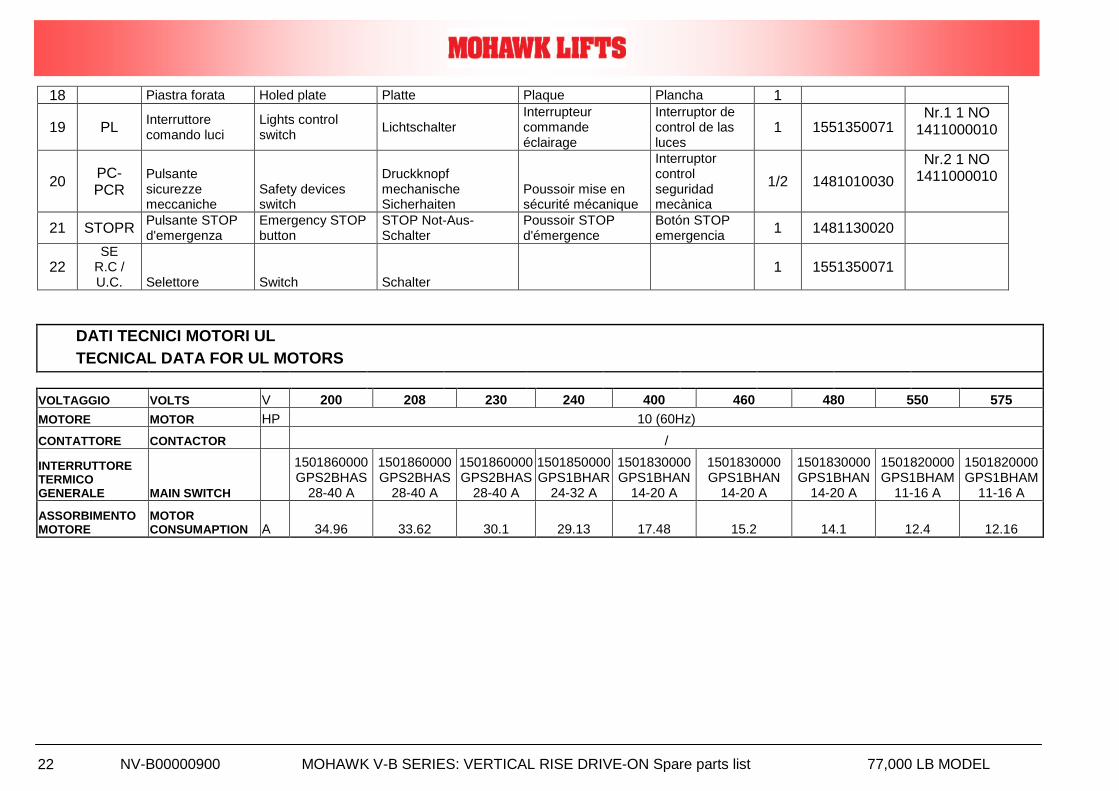
18 Piastra forata Holed plate Platte Plaque Plancha 1
19 PL Interruttore comando luci
Lights control switch
Lichtschalter Interrupteur commande éclairage
Interruptor de control de las luces
1 1551350071 Nr.1 1 NO
1411000010
20 PC-PCR
Pulsante sicurezze meccaniche
Safety devices switch
Druckknopf mechanische Sicherhaiten
Poussoir mise en sécurité mécanique
Interruptor control seguridad mecànica
1/2 1481010030
Nr.2 1 NO 1411000010
21 STOPR Pulsante STOP d'emergenza
Emergency STOP button
STOP Not-Aus-Schalter
Poussoir STOP d'émergence
Botón STOP emergencia
1 1481130020
22 SE
R.C / U.C. Selettore Switch Schalter
1 1551350071
DATI TECNICI MOTORI UL
TECNICAL DATA FOR UL MOTORS
VOLTAGGIO VOLTS V 200 208 230 240 400 460 480 550 575
MOTORE MOTOR HP 10 (60Hz)
CONTATTORE CONTACTOR /
INTERRUTTORE TERMICO GENERALE MAIN SWITCH
1501860000 GPS2BHAS
28-40 A
1501860000 GPS2BHAS
28-40 A
1501860000 GPS2BHAS
28-40 A
1501850000 GPS1BHAR
24-32 A
1501830000 GPS1BHAN
14-20 A
1501830000 GPS1BHAN
14-20 A
1501830000 GPS1BHAN
14-20 A
1501820000 GPS1BHAM
11-16 A
1501820000 GPS1BHAM
11-16 A
ASSORBIMENTO MOTORE
MOTOR CONSUMAPTION A 34.96 33.62 30.1 29.13 17.48 15.2 14.1 12.4 12.16
NV-B00000900 MOHAWK V-B SERIES: VERTICAL RISE DRIVE-ON Spare parts list 77,000 LB MODEL 23
NV-B00000900 MOHAWK V-B SERIES: VERTICAL RISE DRIVE-ON Spare parts list 77,000 LB MODEL 24
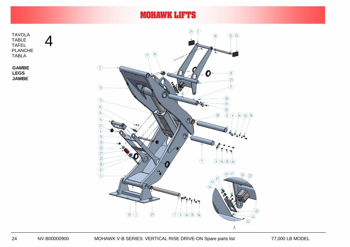
TAVOLA TABLE TAFEL PLANCHE TABLA
4
GAMBE LEGS
JAMBE
NV-B00000900 MOHAWK V-B SERIES: VERTICAL RISE DRIVE-ON Spare parts list 77,000 LB MODEL 25
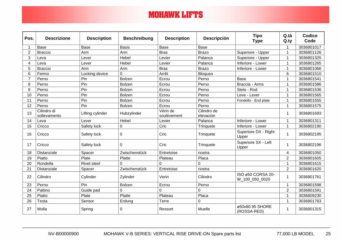
Pos. Descrizione Description Beschreibung Description Descripción Tipo Type
Q.tà Q.ty
Codice Code
1 Base Base Basis Base Base 1 3036801017
2 Braccio Arm Arm Bras Brazo Superiore - Upper 1 3036801126
3 Leva Lever Hebel Levier Palanca Superiore - Upper 1 3036801325
4 Leva Lever Hebel Levier Palanca Inferiore - Lower 1 3036801265
5 Braccio Arm Arm Bras Brazo Inferiore - Lower 1 3036801066
6 Fermo Locking device 0 Arrêt Bloqueo 6 3036801510
7 Perno Pin Bolzen Ecrou Perno Base 1 3036801541
8 Perno Pin Bolzen Ecrou Perno Braccia - Arms 1 3036801586
9 Perno Pin Bolzen Ecrou Perno Stelo - Rod 1 3036801536
10 Perno Pin Bolzen Ecrou Perno Leve - Lever 1 3036801565
11 Perno Pin Bolzen Ecrou Perno Fondello - End plate 1 3036801555
12 Perno Pin Bolzen Ecrou Perno 1 3036801575
13 Cilindro di sollevamento
Lifting cylinder Hubzylinder Vérin de soulévement
Cilindro de elevación
1 3036801693
14 Leva Lever Hebel Levier Palanca Inferiore - Lower 1 3036801311
15 Cricco Safety lock 0 Cric Trinquete Inferiore - Lower 1 3036802190
16 Cricco Safety lock 0 Cric Trinquete Superiore DX - Right Upper
1 3036802195
17 Cricco Safety lock 0 Cric Trinquete Superiore SX - Left Upper
1 3036802196
18 Distanziale Spacer Zwischenstück Entretoise riostra 4 3036801050
19 Piatto Plate Platte Plateau Placa 2 3036801605
20 Rondella Rivet steel 0 0 0 1 3036801615
21 Distanziale Spacer Zwischenstück Entretoise riostra 2 3036801620
22 Cilindro Cylinder Zylinder Verin Cilindro ISO ø50 CORSA 20- W_100_050_0020
1 3036801761
23 Perno Pin Bolzen Ecrou Perno 1 3036801598
24 Pattino Guide pad 0 0 0 2 3036801591
25 Piatto Plate Platte Plateau Placa 1 3036809230
26 Testa Sensor Erdung Terre 0 1 3036801763
27 Molla Spring 0 Ressort Muelle ø50x80 95 SHORE (ROSSA-RED)
1 3036801315
NV-B00000900 MOHAWK V-B SERIES: VERTICAL RISE DRIVE-ON Spare parts list 77,000 LB MODEL 26
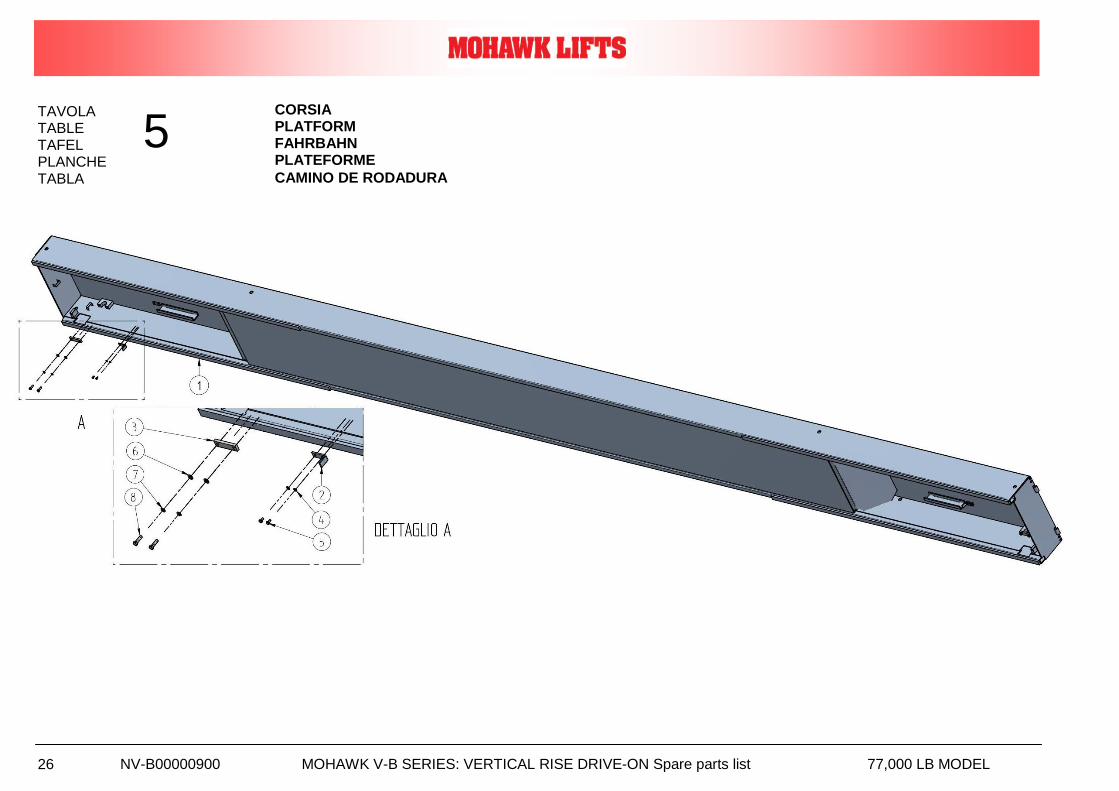
TAVOLA TABLE TAFEL PLANCHE
TABLA
5 CORSIA PLATFORM FAHRBAHN PLATEFORME
CAMINO DE RODADURA
NV-B00000900 MOHAWK V-B SERIES: VERTICAL RISE DRIVE-ON Spare parts list 77,000 LB MODEL 27
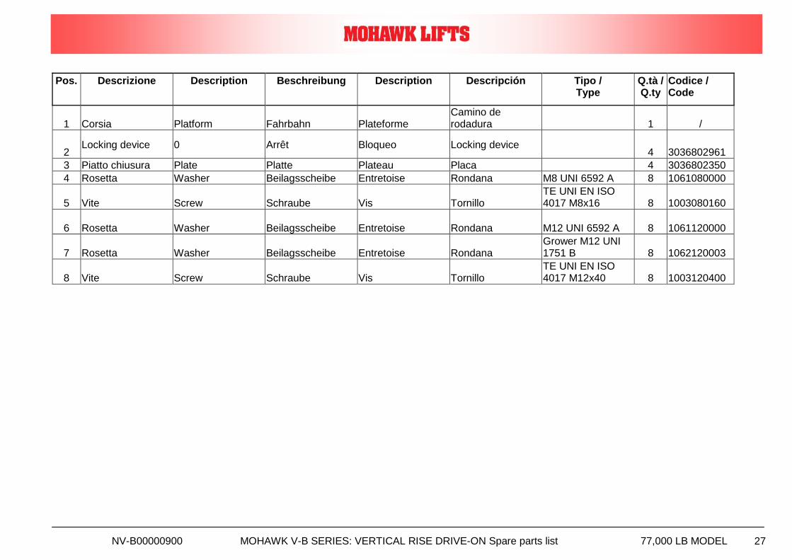
Pos. Descrizione Description Beschreibung Description Descripción Tipo / Type
Q.tà / Q.ty
Codice / Code
1 Corsia Platform Fahrbahn Plateforme Camino de rodadura 1 /
2 Locking device 0 Arrêt Bloqueo Locking device
4 3036802961
3 Piatto chiusura Plate Platte Plateau Placa 4 3036802350
4 Rosetta Washer Beilagsscheibe Entretoise Rondana M8 UNI 6592 A 8 1061080000
5 Vite Screw Schraube Vis Tornillo TE UNI EN ISO 4017 M8x16 8 1003080160
6 Rosetta Washer Beilagsscheibe Entretoise Rondana M12 UNI 6592 A 8 1061120000
7 Rosetta Washer Beilagsscheibe Entretoise Rondana Grower M12 UNI 1751 B 8 1062120003
8 Vite Screw Schraube Vis Tornillo TE UNI EN ISO 4017 M12x40 8 1003120400
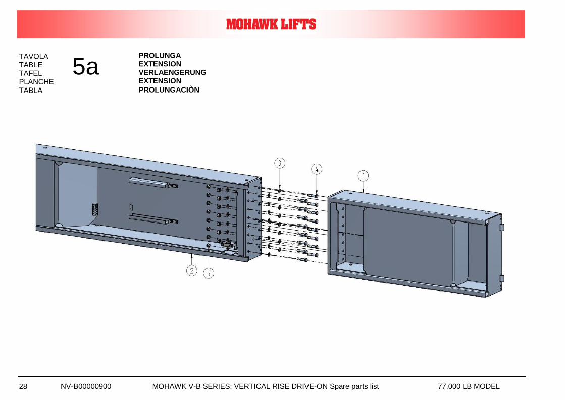
NV-B00000900 MOHAWK V-B SERIES: VERTICAL RISE DRIVE-ON Spare parts list 77,000 LB MODEL 28
TAVOLA TABLE TAFEL PLANCHE
TABLA
5a PROLUNGA EXTENSION VERLAENGERUNG EXTENSION
PROLUNGACIÒN
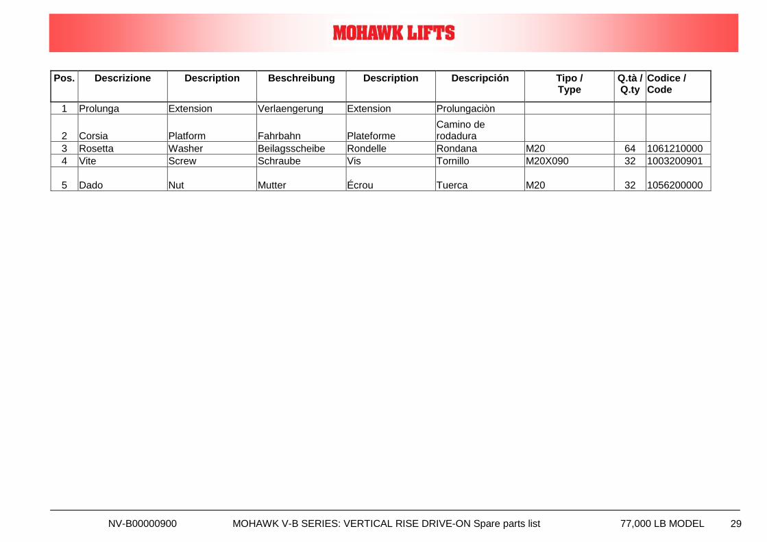
NV-B00000900 MOHAWK V-B SERIES: VERTICAL RISE DRIVE-ON Spare parts list 77,000 LB MODEL 29
Pos. Descrizione Description Beschreibung Description Descripción Tipo / Type
Q.tà / Q.ty
Codice / Code
1 Prolunga Extension Verlaengerung Extension Prolungaciòn
2 Corsia Platform Fahrbahn Plateforme Camino de rodadura
3 Rosetta Washer Beilagsscheibe Rondelle Rondana M20 64 1061210000
4 Vite Screw Schraube Vis Tornillo M20X090 32 1003200901
5 Dado Nut Mutter Écrou Tuerca M20 32 1056200000
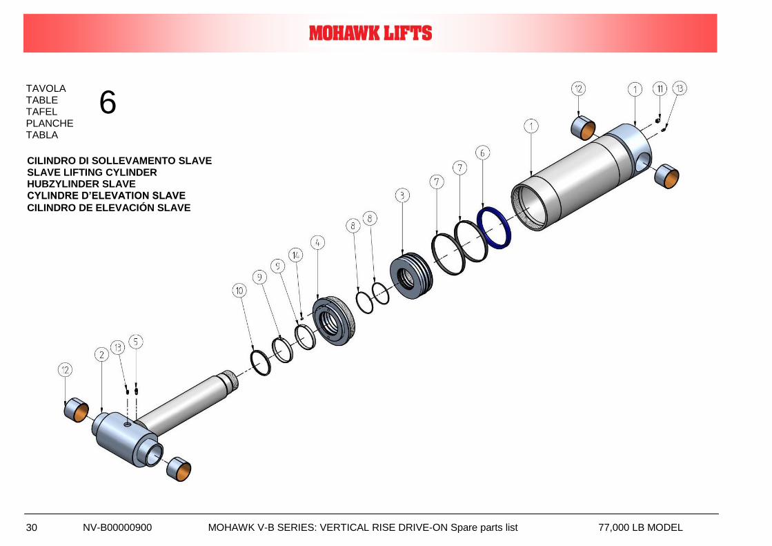
NV-B00000900 MOHAWK V-B SERIES: VERTICAL RISE DRIVE-ON Spare parts list 77,000 LB MODEL 30
TAVOLA TABLE TAFEL PLANCHE
TABLA
6
CILINDRO DI SOLLEVAMENTO SLAVE SLAVE LIFTING CYLINDER HUBZYLINDER SLAVE CYLINDRE D’ELEVATION SLAVE
CILINDRO DE ELEVACIÓN SLAVE
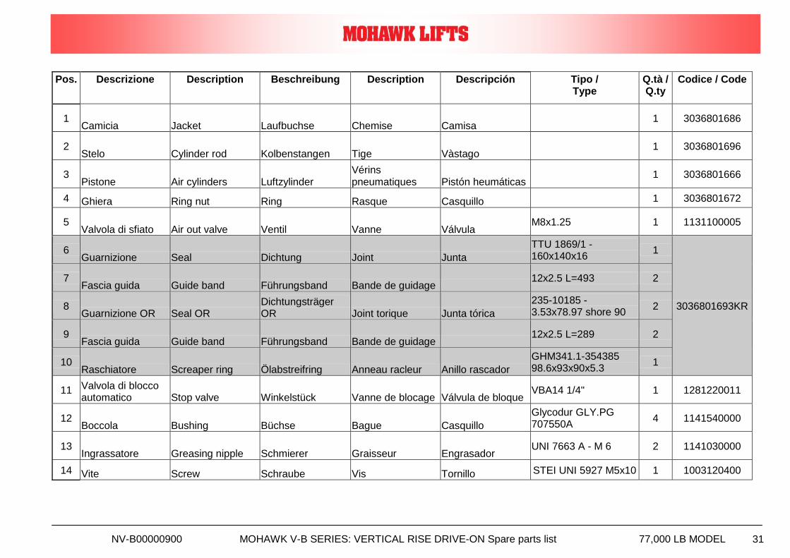
NV-B00000900 MOHAWK V-B SERIES: VERTICAL RISE DRIVE-ON Spare parts list 77,000 LB MODEL 31
Pos. Descrizione Description Beschreibung Description Descripción Tipo / Type
Q.tà / Q.ty
Codice / Code
1 Camicia Jacket Laufbuchse Chemise Camisa
1 3036801686
2 Stelo Cylinder rod Kolbenstangen Tige Vàstago
1 3036801696
3 Pistone Air cylinders Luftzylinder
Vérins pneumatiques Pistón heumáticas
1 3036801666
4 Ghiera Ring nut Ring Rasque Casquillo 1 3036801672
5 Valvola di sfiato Air out valve Ventil Vanne Válvula
M8x1.25 1 1131100005
6 Guarnizione Seal Dichtung Joint Junta
TTU 1869/1 - 160x140x16
1
3036801693KR
7 Fascia guida Guide band Führungsband Bande de guidage
12x2.5 L=493 2
8 Guarnizione OR Seal OR
Dichtungsträger OR Joint torique Junta tórica
235-10185 - 3.53x78.97 shore 90
2
9 Fascia guida Guide band Führungsband Bande de guidage
12x2.5 L=289 2
10 Raschiatore Screaper ring Ölabstreifring Anneau racleur Anillo rascador
GHM341.1-354385 98.6x93x90x5.3
1
11 Valvola di blocco automatico Stop valve Winkelstück Vanne de blocage Válvula de bloque
VBA14 1/4" 1 1281220011
12 Boccola Bushing Büchse Bague Casquillo
Glycodur GLY.PG 707550A
4 1141540000
13 Ingrassatore Greasing nipple Schmierer Graisseur Engrasador
UNI 7663 A - M 6 2 1141030000
14 Vite Screw Schraube Vis Tornillo STEI UNI 5927 M5x10 1 1003120400
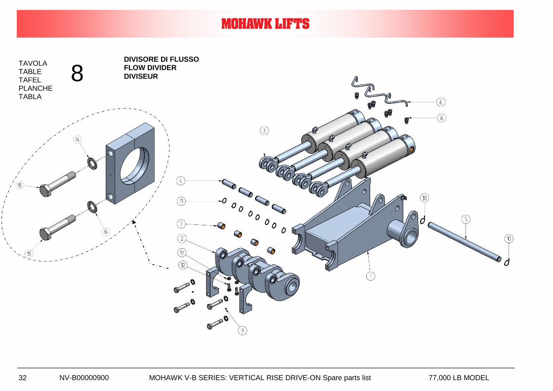
NV-B00000900 MOHAWK V-B SERIES: VERTICAL RISE DRIVE-ON Spare parts list 77,000 LB MODEL 32
TAVOLA TABLE TAFEL PLANCHE TABLA
8 DIVISORE DI FLUSSO FLOW DIVIDER
DIVISEUR
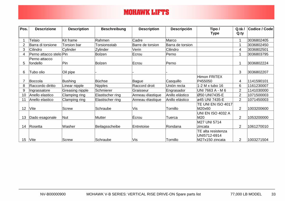
NV-B00000900 MOHAWK V-B SERIES: VERTICAL RISE DRIVE-ON Spare parts list 77,000 LB MODEL 33
Pos. Descrizione Description Beschreibung Description Descripción Tipo / Type
Q.tà / Q.ty
Codice / Code
1 Telaio Kit frame Rahmen Cadre Marco 1 3036802405
2 Barra di torsione Torsion bar Torsionsstab Barre de torsion Barra de torsion 1 3036802450
3 Cilindro Cylinder Zylinder Verin Cilindro 4 3036802501
4 Perno attacco stelo Pin Bolzen Ecrou Perno 1 3036803795
5 Perno attacco fondello Pin Bolzen Ecrou Perno 1 3036802224
6 Tubo olio Oil pipe - - - 3 3036802207
7 Boccola Bushing Büchse Bague Casquillo Himon FRITEX P455050 4 1141590101
8 Raccordo diritto Linear nipple Nipples Raccord droit Unión recta 1-2 M x tubo 16 6 1161230007
9 Ingrassatore Greasing nipple Schmierer Graisseur Engrasador UNI 7663 A - M 6 2 1141030000
10 Anello elastico Clamping ring Elastischer ring Anneau élastique Anillo elástico Ø50 UNI7435-E 2 1071500003
11 Anello elastico Clamping ring Elastischer ring Anneau élastique Anillo elástico ø45 UNI 7435-E 2 1071450003
12 Vite Screw Schraube Vis Tornillo TE UNI EN ISO 4017 M20x60 2 1003200600
13 Dado esagonale Nut Mutter Écrou Tuerca UNI EN ISO 4032 A M20 2 1053200000
14 Rosetta Washer Beilagsscheibe Entretoise Rondana M27 UNI 5714 zincata 2 1061270010
15 Vite Screw Schraube Vis Tornillo
TE alta resistenza UNI5712-6914 M27x150 zincata 2 1003271504
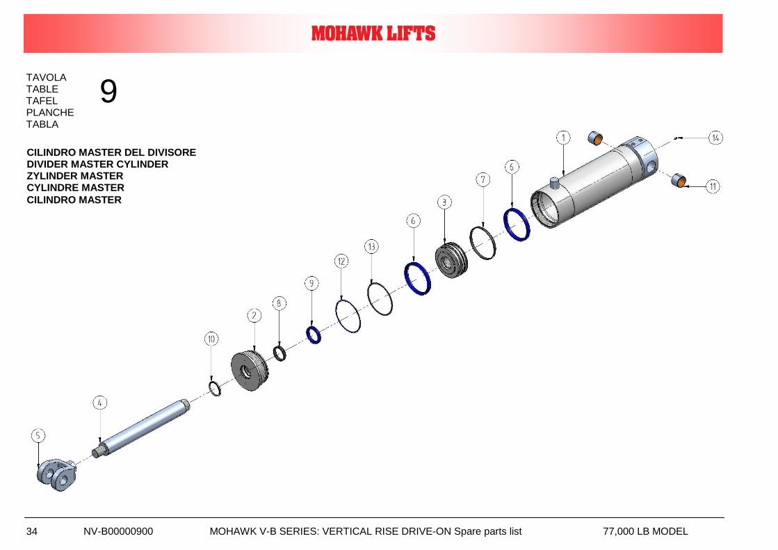
NV-B00000900 MOHAWK V-B SERIES: VERTICAL RISE DRIVE-ON Spare parts list 77,000 LB MODEL 34
TAVOLA TABLE TAFEL PLANCHE
TABLA
9
CILINDRO MASTER DEL DIVISORE DIVIDER MASTER CYLINDER ZYLINDER MASTER CYLINDRE MASTER
CILINDRO MASTER
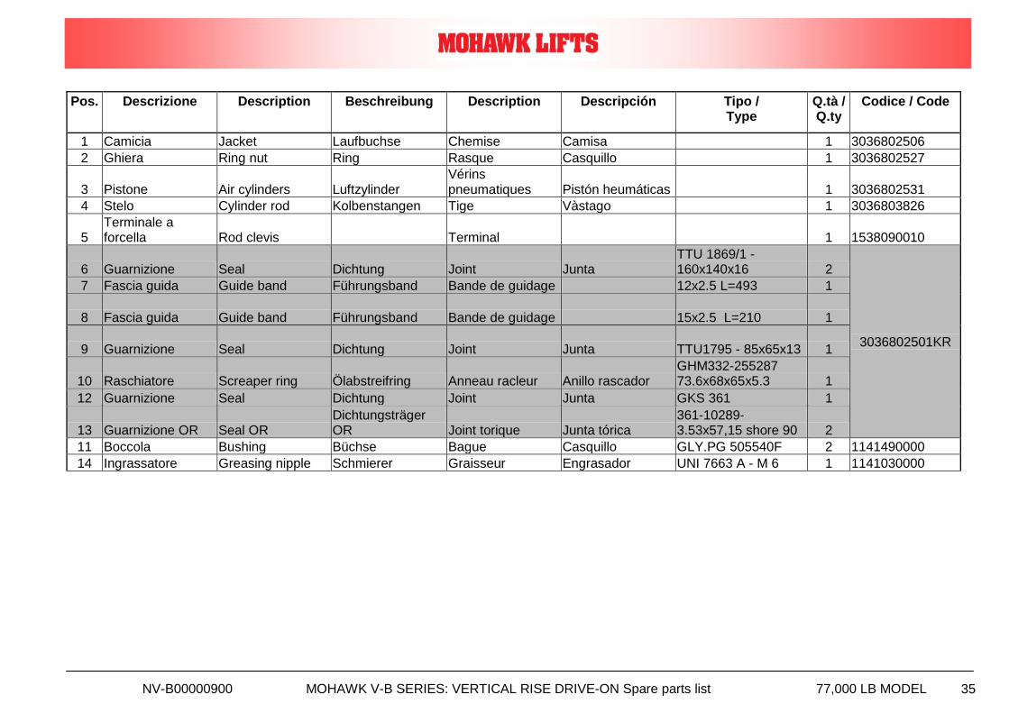
NV-B00000900 MOHAWK V-B SERIES: VERTICAL RISE DRIVE-ON Spare parts list 77,000 LB MODEL 35
Pos. Descrizione Description Beschreibung Description Descripción Tipo / Type
Q.tà / Q.ty
Codice / Code
1 Camicia Jacket Laufbuchse Chemise Camisa 1 3036802506
2 Ghiera Ring nut Ring Rasque Casquillo 1 3036802527
3 Pistone Air cylinders Luftzylinder Vérins pneumatiques Pistón heumáticas 1 3036802531
4 Stelo Cylinder rod Kolbenstangen Tige Vàstago 1 3036803826
5 Terminale a forcella Rod clevis Terminal 1 1538090010
6 Guarnizione Seal Dichtung Joint Junta TTU 1869/1 - 160x140x16 2
3036802501KR
7 Fascia guida Guide band Führungsband Bande de guidage 12x2.5 L=493 1
8 Fascia guida Guide band Führungsband Bande de guidage 15x2.5 L=210 1
9 Guarnizione Seal Dichtung Joint Junta TTU1795 - 85x65x13 1
10 Raschiatore Screaper ring Ölabstreifring Anneau racleur Anillo rascador GHM332-255287 73.6x68x65x5.3 1
12 Guarnizione Seal Dichtung Joint Junta GKS 361 1
13 Guarnizione OR Seal OR Dichtungsträger OR Joint torique Junta tórica
361-10289- 3.53x57,15 shore 90 2
11 Boccola Bushing Büchse Bague Casquillo GLY.PG 505540F 2 1141490000
14 Ingrassatore Greasing nipple Schmierer Graisseur Engrasador UNI 7663 A - M 6 1 1141030000
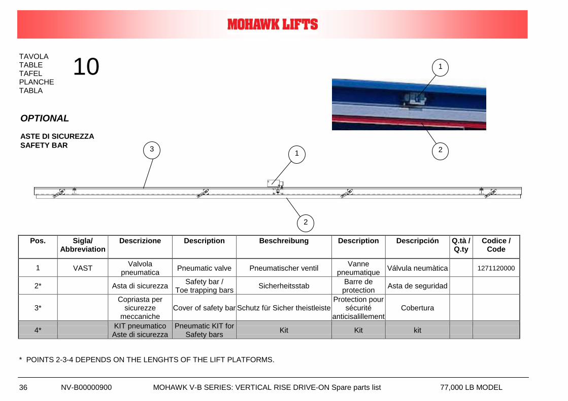
NV-B00000900 MOHAWK V-B SERIES: VERTICAL RISE DRIVE-ON Spare parts list 77,000 LB MODEL 36
TAVOLA TABLE TAFEL PLANCHE
TABLA
Pos. Sigla/ Abbreviation
Descrizione Description Beschreibung Description Descripción Q.tà / Q.ty
Codice / Code
1 VAST Valvola
pneumatica Pneumatic valve Pneumatischer ventil
Vanne pneumatique
Válvula neumàtica 1271120000
2* Asta di sicurezza Safety bar /
Toe trapping bars Sicherheitsstab
Barre de protection
Asta de seguridad
3* Copriasta per
sicurezze meccaniche
Cover of safety bar Schutz für Sicher theistleiste Protection pour
sécurité anticisalillement
Cobertura
4* KIT pneumatico Aste di sicurezza
Pneumatic KIT for Safety bars
Kit Kit kit
* POINTS 2-3-4 DEPENDS ON THE LENGHTS OF THE LIFT PLATFORMS.
10
OPTIONAL ASTE DI SICUREZZA
SAFETY BAR 1
2
3
1
2
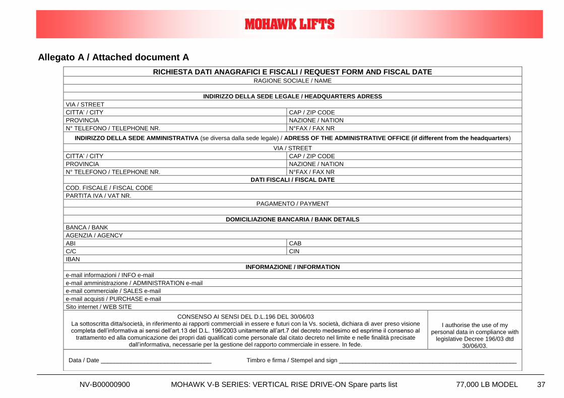
NV-B00000900 MOHAWK V-B SERIES: VERTICAL RISE DRIVE-ON Spare parts list 77,000 LB MODEL 37
Allegato A / Attached document A
RICHIESTA DATI ANAGRAFICI E FISCALI / REQUEST FORM AND FISCAL DATE RAGIONE SOCIALE / NAME
INDIRIZZO DELLA SEDE LEGALE / HEADQUARTERS ADRESS
VIA / STREET
CITTA’ / CITY CAP / ZIP CODE
PROVINCIA NAZIONE / NATION
N° TELEFONO / TELEPHONE NR. N°FAX / FAX NR
INDIRIZZO DELLA SEDE AMMINISTRATIVA (se diversa dalla sede legale) / ADRESS OF THE ADMINISTRATIVE OFFICE (if different from the headquarters)
VIA / STREET
CITTA’ / CITY CAP / ZIP CODE
PROVINCIA NAZIONE / NATION
N° TELEFONO / TELEPHONE NR. N°FAX / FAX NR
DATI FISCALI / FISCAL DATE
COD. FISCALE / FISCAL CODE
PARTITA IVA / VAT NR.
PAGAMENTO / PAYMENT
DOMICILIAZIONE BANCARIA / BANK DETAILS
BANCA / BANK
AGENZIA / AGENCY
ABI CAB
C/C CIN
IBAN
INFORMAZIONE / INFORMATION
e-mail informazioni / INFO e-mail
e-mail amministrazione / ADMINISTRATION e-mail
e-mail commerciale / SALES e-mail
e-mail acquisti / PURCHASE e-mail
Sito internet / WEB SITE
CONSENSO AI SENSI DEL D.L.196 DEL 30/06/03 La sottoscritta ditta/società, in riferimento ai rapporti commerciali in essere e futuri con la Vs. società, dichiara di aver preso visione completa dell’informativa ai sensi dell’art.13 del D.L. 196/2003 unitamente all’art.7 del decreto medesimo ed esprime il consenso al
trattamento ed alla comunicazione dei propri dati qualificati come personale dal citato decreto nel limite e nelle finalità precisate dall’informativa, necessarie per la gestione del rapporto commerciale in essere. In fede.
I authorise the use of my personal data in compliance with
legislative Decree 196/03 dtd 30/06/03.
Data / Date _________________________________ Timbro e firma / Stempel and sign _____________________________________________________

NV-B00000900 MOHAWK V-B SERIES: VERTICAL RISE DRIVE-ON Spare parts list 77,000 LB MODEL 38
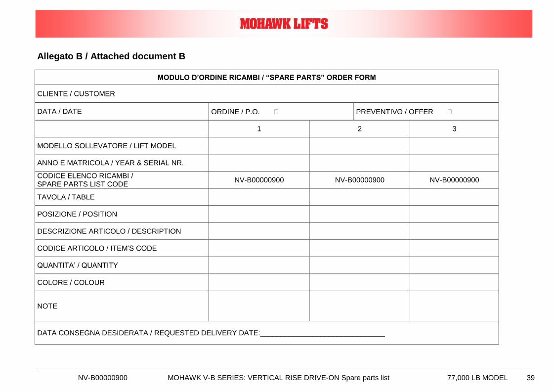
NV-B00000900 MOHAWK V-B SERIES: VERTICAL RISE DRIVE-ON Spare parts list 77,000 LB MODEL 39
Allegato B / Attached document B
MODULO D’ORDINE RICAMBI / “SPARE PARTS” ORDER FORM
CLIENTE / CUSTOMER
DATA / DATE ORDINE / P.O. PREVENTIVO / OFFER
1 2 3
MODELLO SOLLEVATORE / LIFT MODEL
ANNO E MATRICOLA / YEAR & SERIAL NR.
CODICE ELENCO RICAMBI / SPARE PARTS LIST CODE
NV-B00000900 NV-B00000900 NV-B00000900
TAVOLA / TABLE
POSIZIONE / POSITION
DESCRIZIONE ARTICOLO / DESCRIPTION
CODICE ARTICOLO / ITEM’S CODE
QUANTITA’ / QUANTITY
COLORE / COLOUR
NOTE
DATA CONSEGNA DESIDERATA / REQUESTED DELIVERY DATE:_______________________________

NV-B00000900 MOHAWK V-B SERIES: VERTICAL RISE DRIVE-ON Spare parts list 77,000 LB MODEL 40
VEHICLE LIFTING DPT. Mohawk Lifts, LLC.
P.O. Box 11065 Vrooman Ave Amsterdam, NY 12010
(800) 833-2006(518) 842-1431 FAX: (518) 842-1289 www.mohawklifts.com
LOGBOOK: Register of periodic adjustments and checks – LIFTS PLOBOLIFT92A-M Page 1 of 9
LOGBOOK: REGISTER OF PERIODIC CHECKS
LIFTS
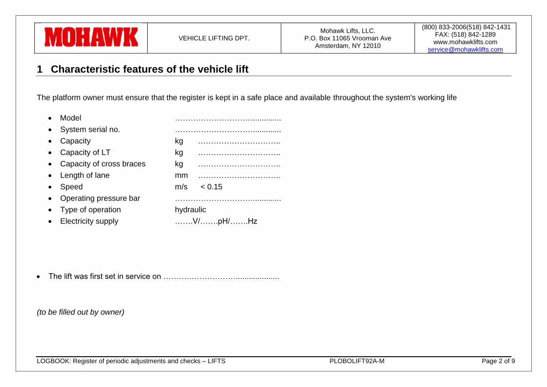
VEHICLE LIFTING DPT. Mohawk Lifts, LLC.
P.O. Box 11065 Vrooman Ave Amsterdam, NY 12010
(800) 833-2006(518) 842-1431 FAX: (518) 842-1289 www.mohawklifts.com
LOGBOOK: Register of periodic adjustments and checks – LIFTS PLOBOLIFT92A-M Page 2 of 9
1 Characteristic features of the vehicle lift
The platform owner must ensure that the register is kept in a safe place and available throughout the system's working life
Model ……………………….…............
System serial no. ………………………….............
Capacity kg …………………………..
Capacity of LT kg …………………………..
Capacity of cross braces kg …………………………..
Length of lane mm …………………………..
Speed m/s < 0.15
Operating pressure bar ………………………….............
Type of operation hydraulic
Electricity supply …….V/…….pH/…….Hz
The lift was first set in service on ……….………………....................
(to be filled out by owner)
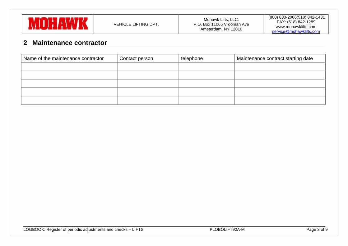
VEHICLE LIFTING DPT. Mohawk Lifts, LLC.
P.O. Box 11065 Vrooman Ave Amsterdam, NY 12010
(800) 833-2006(518) 842-1431 FAX: (518) 842-1289 www.mohawklifts.com
LOGBOOK: Register of periodic adjustments and checks – LIFTS PLOBOLIFT92A-M Page 3 of 9
2 Maintenance contractor
Name of the maintenance contractor Contact person telephone Maintenance contract starting date
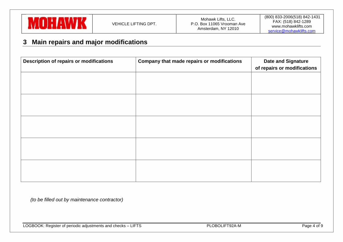
VEHICLE LIFTING DPT. Mohawk Lifts, LLC.
P.O. Box 11065 Vrooman Ave Amsterdam, NY 12010
(800) 833-2006(518) 842-1431 FAX: (518) 842-1289 www.mohawklifts.com
LOGBOOK: Register of periodic adjustments and checks – LIFTS PLOBOLIFT92A-M Page 4 of 9
3 Main repairs and major modifications
Description of repairs or modifications Company that made repairs or modifications Date and Signature
of repairs or modifications
(to be filled out by maintenance contractor)
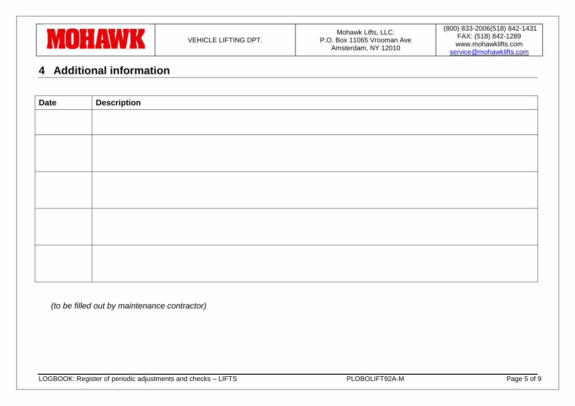
VEHICLE LIFTING DPT. Mohawk Lifts, LLC.
P.O. Box 11065 Vrooman Ave Amsterdam, NY 12010
(800) 833-2006(518) 842-1431 FAX: (518) 842-1289 www.mohawklifts.com
LOGBOOK: Register of periodic adjustments and checks – LIFTS PLOBOLIFT92A-M Page 5 of 9
4 Additional information
Date Description
(to be filled out by maintenance contractor)
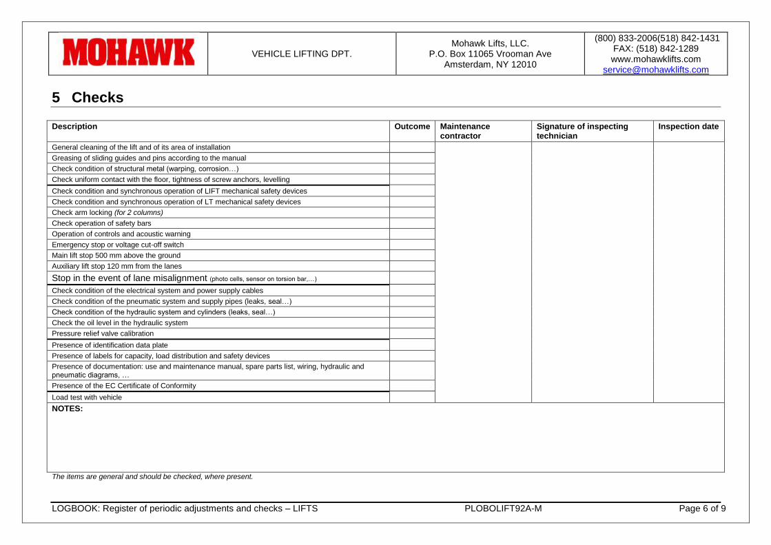
VEHICLE LIFTING DPT. Mohawk Lifts, LLC.
P.O. Box 11065 Vrooman Ave Amsterdam, NY 12010
(800) 833-2006(518) 842-1431 FAX: (518) 842-1289 www.mohawklifts.com
LOGBOOK: Register of periodic adjustments and checks – LIFTS PLOBOLIFT92A-M Page 6 of 9
5 Checks
Description Outcome Maintenance contractor
Signature of inspecting technician
Inspection date
General cleaning of the lift and of its area of installation
Greasing of sliding guides and pins according to the manual
Check condition of structural metal (warping, corrosion…)
Check uniform contact with the floor, tightness of screw anchors, levelling
Check condition and synchronous operation of LIFT mechanical safety devices
Check condition and synchronous operation of LT mechanical safety devices
Check arm locking (for 2 columns)
Check operation of safety bars
Operation of controls and acoustic warning
Emergency stop or voltage cut-off switch
Main lift stop 500 mm above the ground
Auxiliary lift stop 120 mm from the lanes
Stop in the event of lane misalignment (photo cells, sensor on torsion bar,…)
Check condition of the electrical system and power supply cables
Check condition of the pneumatic system and supply pipes (leaks, seal…)
Check condition of the hydraulic system and cylinders (leaks, seal…)
Check the oil level in the hydraulic system
Pressure relief valve calibration
Presence of identification data plate
Presence of labels for capacity, load distribution and safety devices
Presence of documentation: use and maintenance manual, spare parts list, wiring, hydraulic and pneumatic diagrams, …
Presence of the EC Certificate of Conformity
Load test with vehicle
NOTES:
The items are general and should be checked, where present.
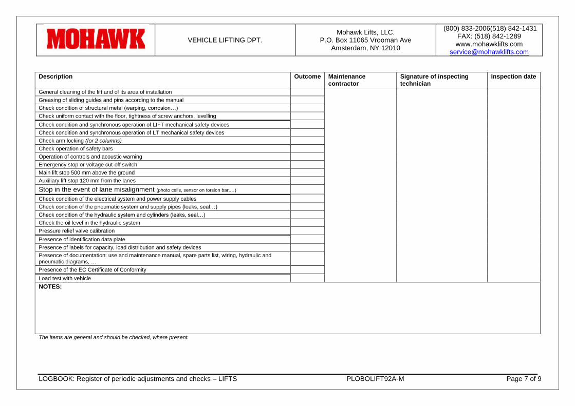
VEHICLE LIFTING DPT. Mohawk Lifts, LLC.
P.O. Box 11065 Vrooman Ave Amsterdam, NY 12010
(800) 833-2006(518) 842-1431 FAX: (518) 842-1289 www.mohawklifts.com
LOGBOOK: Register of periodic adjustments and checks – LIFTS PLOBOLIFT92A-M Page 7 of 9
Description Outcome Maintenance contractor
Signature of inspecting technician
Inspection date
General cleaning of the lift and of its area of installation
Greasing of sliding guides and pins according to the manual
Check condition of structural metal (warping, corrosion…)
Check uniform contact with the floor, tightness of screw anchors, levelling
Check condition and synchronous operation of LIFT mechanical safety devices
Check condition and synchronous operation of LT mechanical safety devices
Check arm locking (for 2 columns)
Check operation of safety bars
Operation of controls and acoustic warning
Emergency stop or voltage cut-off switch
Main lift stop 500 mm above the ground
Auxiliary lift stop 120 mm from the lanes
Stop in the event of lane misalignment (photo cells, sensor on torsion bar,…)
Check condition of the electrical system and power supply cables
Check condition of the pneumatic system and supply pipes (leaks, seal…)
Check condition of the hydraulic system and cylinders (leaks, seal…)
Check the oil level in the hydraulic system
Pressure relief valve calibration
Presence of identification data plate
Presence of labels for capacity, load distribution and safety devices
Presence of documentation: use and maintenance manual, spare parts list, wiring, hydraulic and pneumatic diagrams, …
Presence of the EC Certificate of Conformity
Load test with vehicle
NOTES:
The items are general and should be checked, where present.
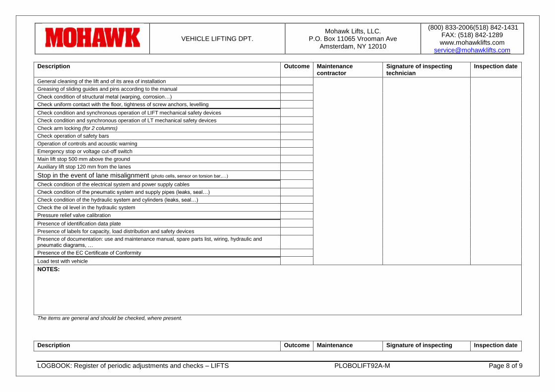
VEHICLE LIFTING DPT. Mohawk Lifts, LLC.
P.O. Box 11065 Vrooman Ave Amsterdam, NY 12010
(800) 833-2006(518) 842-1431 FAX: (518) 842-1289 www.mohawklifts.com
LOGBOOK: Register of periodic adjustments and checks – LIFTS PLOBOLIFT92A-M Page 8 of 9
Description Outcome Maintenance contractor
Signature of inspecting technician
Inspection date
General cleaning of the lift and of its area of installation
Greasing of sliding guides and pins according to the manual
Check condition of structural metal (warping, corrosion…)
Check uniform contact with the floor, tightness of screw anchors, levelling
Check condition and synchronous operation of LIFT mechanical safety devices
Check condition and synchronous operation of LT mechanical safety devices
Check arm locking (for 2 columns)
Check operation of safety bars
Operation of controls and acoustic warning
Emergency stop or voltage cut-off switch
Main lift stop 500 mm above the ground
Auxiliary lift stop 120 mm from the lanes
Stop in the event of lane misalignment (photo cells, sensor on torsion bar,…)
Check condition of the electrical system and power supply cables
Check condition of the pneumatic system and supply pipes (leaks, seal…)
Check condition of the hydraulic system and cylinders (leaks, seal…)
Check the oil level in the hydraulic system
Pressure relief valve calibration
Presence of identification data plate
Presence of labels for capacity, load distribution and safety devices
Presence of documentation: use and maintenance manual, spare parts list, wiring, hydraulic and pneumatic diagrams, …
Presence of the EC Certificate of Conformity
Load test with vehicle
NOTES:
The items are general and should be checked, where present.
Description Outcome Maintenance Signature of inspecting Inspection date
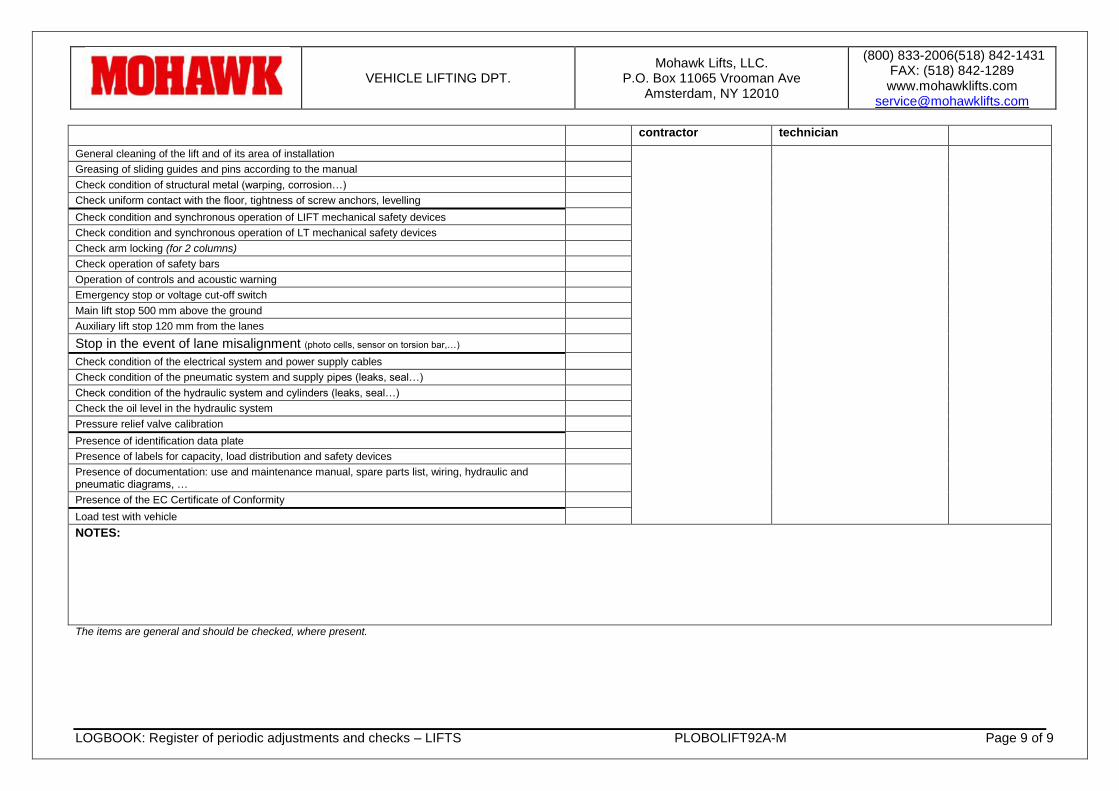
VEHICLE LIFTING DPT. Mohawk Lifts, LLC.
P.O. Box 11065 Vrooman Ave Amsterdam, NY 12010
(800) 833-2006(518) 842-1431 FAX: (518) 842-1289 www.mohawklifts.com
LOGBOOK: Register of periodic adjustments and checks – LIFTS PLOBOLIFT92A-M Page 9 of 9
contractor technician
General cleaning of the lift and of its area of installation
Greasing of sliding guides and pins according to the manual
Check condition of structural metal (warping, corrosion…)
Check uniform contact with the floor, tightness of screw anchors, levelling
Check condition and synchronous operation of LIFT mechanical safety devices
Check condition and synchronous operation of LT mechanical safety devices
Check arm locking (for 2 columns)
Check operation of safety bars
Operation of controls and acoustic warning
Emergency stop or voltage cut-off switch
Main lift stop 500 mm above the ground
Auxiliary lift stop 120 mm from the lanes
Stop in the event of lane misalignment (photo cells, sensor on torsion bar,…)
Check condition of the electrical system and power supply cables
Check condition of the pneumatic system and supply pipes (leaks, seal…)
Check condition of the hydraulic system and cylinders (leaks, seal…)
Check the oil level in the hydraulic system
Pressure relief valve calibration
Presence of identification data plate
Presence of labels for capacity, load distribution and safety devices
Presence of documentation: use and maintenance manual, spare parts list, wiring, hydraulic and pneumatic diagrams, …
Presence of the EC Certificate of Conformity
Load test with vehicle
NOTES:
The items are general and should be checked, where present.
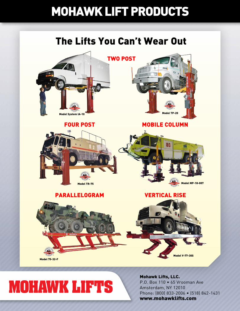
AND VALIDATED
AND VALIDATED
Model System IA-10
AND VALIDATED
Model TP-20
Model MP-18-007
Model V-77-30S
AND VALIDATED
Model TR-75
AND VALIDATED
Model 75-32-F
The Lifts You Can’t Wear Out
TWO POST
FOUR POST MOBILE COLUMN
PARALLELOGRAM VERTICAL RISE
MOHAWK LIFT PRODUCTS
Mohawk Lifts, LLC.P.O. Box 110 • 65 Vrooman Ave Amsterdam, NY 12010Phone: (800) 833-2006 • (518) 842-1431www.mohawklifts.com