robust localization system using visible light communication
TRANSCRIPT
HAL Id: tel-02863495https://hal.univ-lorraine.fr/tel-02863495
Submitted on 10 Jun 2020
HAL is a multi-disciplinary open accessarchive for the deposit and dissemination of sci-entific research documents, whether they are pub-lished or not. The documents may come fromteaching and research institutions in France orabroad, or from public or private research centers.
L’archive ouverte pluridisciplinaire HAL, estdestinée au dépôt et à la diffusion de documentsscientifiques de niveau recherche, publiés ou non,émanant des établissements d’enseignement et derecherche français ou étrangers, des laboratoirespublics ou privés.
Robust localization system using Visible LightCommunication technology for underground mines
Fabián Seguel
To cite this version:Fabián Seguel. Robust localization system using Visible Light Communication technology for under-ground mines. Networking and Internet Architecture [cs.NI]. Université de Lorraine; Universidad deSantiago de Chile, 2020. English. �NNT : 2020LORR0012�. �tel-02863495�

AVERTISSEMENT
Ce document est le fruit d'un long travail approuvé par le jury de soutenance et mis à disposition de l'ensemble de la communauté universitaire élargie. Il est soumis à la propriété intellectuelle de l'auteur. Ceci implique une obligation de citation et de référencement lors de l’utilisation de ce document. D'autre part, toute contrefaçon, plagiat, reproduction illicite encourt une poursuite pénale. Contact : [email protected]
LIENS Code de la Propriété Intellectuelle. articles L 122. 4 Code de la Propriété Intellectuelle. articles L 335.2- L 335.10 http://www.cfcopies.com/V2/leg/leg_droi.php http://www.culture.gouv.fr/culture/infos-pratiques/droits/protection.htm
Ecole doctorale IAEM Lorraine
Robust localization system usingVisible Light Communication
technology for underground mines
THESE
presentee et soutenue publiquement le 12 Mars 2020
pour l’obtention du
Doctorat de l’Universite de Lorraine
(Mention Automatique, Traitement du signal et des images, Genie informatique)
par
Fabian Esteban SEGUEL GONZALEZ
Composition du jury
Rapporteurs : Professeur Millaray Curilem Universidad de La FronteraProfesseur Francois Spies Universite de Franche-Comte
Examinateurs : Professeur Pablo Adasme Universidad de Santiago de ChileProfesseur Ismael Soto Universidad de Santiago de Chile(Directeur de these)Professeur Patrick Charpentier Universite de Lorraine(Directeur de these)aıtre de Conferences Nicolas Krommenacker Universite de Lorraine(Co-directeur de these)
Centre de Recherche en Automatique de Nancy — UMR 7039
Remerciements
First and foremost, I want to thank my supervisors Ismael Soto, Patrick Charpentier and Nico-las Krommenacker. This work would not have been possible without their immense support,guidance and knowledge. But, most important without their friendship and the excellent workenvironment that we were involved during the preparation of this thesis. I hope sincerely ourcollaboration will not stop once this document is submitted.
I would also like to express my sincere gratitude to the reviewers of my thesis Prof. MillarayCurilem and Prof. Francois Spies, for the time and e�ort they have put in reviewing and assessingmy work. Their ideas, feedback and questions have been invaluable.
My most sincere thanks also goes to Prof. Pablo Adasme, Prof. Hector Kaschel and Prof. IvánJirón for evaluating my work throughout the whole PhD period. Their guidance and directionshelp me to �nish my work in time.
I also want to thank all of my lab friends for the exchanges of knowledge and skills and, mostimportant, les apéros and unforgettable moments we have enjoyed and shared inside and outsidethe lab.
Last but by no means least, I would like to thank my family. There are no words to expresshow grateful I am to them. They are the most important people in my world and I dedicate thisthesis to them.
i
Contents
List of Figures v
List of Tables viii
Chapter 1
Introduction
1.1 Visible light positioning systems for indoor environments . . . . . . . . . . . . . . 1
1.2 Motivation . . . . . . . . . . . . . . . . . . . . . . . . . . . . . . . . . . . . . . . . 4
1.3 Contributions . . . . . . . . . . . . . . . . . . . . . . . . . . . . . . . . . . . . . . 4
1.4 Publications . . . . . . . . . . . . . . . . . . . . . . . . . . . . . . . . . . . . . . . 6
1.4.1 Journal ISI articles . . . . . . . . . . . . . . . . . . . . . . . . . . . . . . . 6
1.4.2 Conference articles . . . . . . . . . . . . . . . . . . . . . . . . . . . . . . . 7
Chapter 2
Current positioning technologies in underground mines 9
2.1 Introduction . . . . . . . . . . . . . . . . . . . . . . . . . . . . . . . . . . . . . . . 9
2.2 Importance and challenges of positioning in underground mines . . . . . . . . . . 11
2.3 Requirements of positioning systems . . . . . . . . . . . . . . . . . . . . . . . . . 12
2.3.1 Accuracy . . . . . . . . . . . . . . . . . . . . . . . . . . . . . . . . . . . . 12
2.3.2 Output data . . . . . . . . . . . . . . . . . . . . . . . . . . . . . . . . . . 13
2.3.3 Precision . . . . . . . . . . . . . . . . . . . . . . . . . . . . . . . . . . . . 14
2.3.4 Coverage . . . . . . . . . . . . . . . . . . . . . . . . . . . . . . . . . . . . 15
2.3.5 Cost . . . . . . . . . . . . . . . . . . . . . . . . . . . . . . . . . . . . . . . 15
2.3.6 Required infrastructure . . . . . . . . . . . . . . . . . . . . . . . . . . . . 15
2.3.7 Robustness . . . . . . . . . . . . . . . . . . . . . . . . . . . . . . . . . . . 16
2.3.8 Scalability . . . . . . . . . . . . . . . . . . . . . . . . . . . . . . . . . . . . 16
2.3.9 Update rate . . . . . . . . . . . . . . . . . . . . . . . . . . . . . . . . . . . 17
2.3.10 Number of users . . . . . . . . . . . . . . . . . . . . . . . . . . . . . . . . 17
2.3.11 Market maturity . . . . . . . . . . . . . . . . . . . . . . . . . . . . . . . . 17
ii
2.3.12 Intrusiveness . . . . . . . . . . . . . . . . . . . . . . . . . . . . . . . . . . 17
2.3.13 Approval . . . . . . . . . . . . . . . . . . . . . . . . . . . . . . . . . . . . 18
2.4 Classi�cation of positioning systems for underground mines . . . . . . . . . . . . 18
2.4.1 Technological principle . . . . . . . . . . . . . . . . . . . . . . . . . . . . . 19
2.4.2 System topology . . . . . . . . . . . . . . . . . . . . . . . . . . . . . . . . 24
2.4.3 Deployment . . . . . . . . . . . . . . . . . . . . . . . . . . . . . . . . . . . 25
2.5 Systems proposed in literature . . . . . . . . . . . . . . . . . . . . . . . . . . . . . 26
2.6 Conclusions . . . . . . . . . . . . . . . . . . . . . . . . . . . . . . . . . . . . . . . 32
Chapter 3
Visible light communications channel modelling in underground mines 34
3.1 Introduction . . . . . . . . . . . . . . . . . . . . . . . . . . . . . . . . . . . . . . . 34
3.2 Illumination standards . . . . . . . . . . . . . . . . . . . . . . . . . . . . . . . . . 36
3.3 Mathematical model . . . . . . . . . . . . . . . . . . . . . . . . . . . . . . . . . . 38
3.3.1 Visible Light Communications System Con�guration . . . . . . . . . . . . 39
3.3.2 Light sources . . . . . . . . . . . . . . . . . . . . . . . . . . . . . . . . . . 40
3.3.3 Light detectors . . . . . . . . . . . . . . . . . . . . . . . . . . . . . . . . . 43
3.3.4 Light propagation model . . . . . . . . . . . . . . . . . . . . . . . . . . . . 44
3.4 Conclusions . . . . . . . . . . . . . . . . . . . . . . . . . . . . . . . . . . . . . . . 52
Chapter 4
Visible light positioning methods 53
4.1 Introduction . . . . . . . . . . . . . . . . . . . . . . . . . . . . . . . . . . . . . . . 53
4.2 Main characteristics of VLP for their underground mine application . . . . . . . . 54
4.2.1 Characteristics based on detector technology . . . . . . . . . . . . . . . . 54
4.2.2 VLC characteristics for di�erent positioning topologies implementation . . 55
4.3 Visible light positioning methods classi�cation . . . . . . . . . . . . . . . . . . . . 56
4.3.1 Range based methods . . . . . . . . . . . . . . . . . . . . . . . . . . . . . 56
4.3.2 Range free methods . . . . . . . . . . . . . . . . . . . . . . . . . . . . . . 64
4.3.3 Fingerprinting (FP) . . . . . . . . . . . . . . . . . . . . . . . . . . . . . . 66
4.4 Robustness and characteristics analysis of VLP methods . . . . . . . . . . . . . . 67
Chapter 5
Design and implementation of a low-cost/large-scale visible light positioning
system 68
5.1 Introduction . . . . . . . . . . . . . . . . . . . . . . . . . . . . . . . . . . . . . . . 68
5.2 Uplink for remote positioning . . . . . . . . . . . . . . . . . . . . . . . . . . . . . 68
iii
5.3 Visible light communications downlink . . . . . . . . . . . . . . . . . . . . . . . . 70
5.4 Visible light communications receiver . . . . . . . . . . . . . . . . . . . . . . . . . 71
Chapter 6
Design and implementation of a novel range free positioning method for robust
visible light positioning in underground mines 75
6.1 Introduction . . . . . . . . . . . . . . . . . . . . . . . . . . . . . . . . . . . . . . . 75
6.2 System description . . . . . . . . . . . . . . . . . . . . . . . . . . . . . . . . . . . 76
6.3 Network architecture based positioning method: Convex polygon positioning (CPP) 77
6.4 Enhance of position accuracy using imaging receivers (IR-CPP) . . . . . . . . . . 83
6.5 Simulation results . . . . . . . . . . . . . . . . . . . . . . . . . . . . . . . . . . . . 85
6.5.1 Square room . . . . . . . . . . . . . . . . . . . . . . . . . . . . . . . . . . 86
6.5.2 Tunnel section . . . . . . . . . . . . . . . . . . . . . . . . . . . . . . . . . 92
6.6 Real implementation of CPP method using VLP testing platform . . . . . . . . . 94
Chapter 7
Conclusions and perspectives 100
7.1 Conclusion . . . . . . . . . . . . . . . . . . . . . . . . . . . . . . . . . . . . . . . . 100
7.2 Perspectives . . . . . . . . . . . . . . . . . . . . . . . . . . . . . . . . . . . . . . . 101
7.2.1 Reduce the size of proposed receiver . . . . . . . . . . . . . . . . . . . . . 101
7.2.2 Energy e�ciency . . . . . . . . . . . . . . . . . . . . . . . . . . . . . . . . 102
7.2.3 Mobility and Tracking . . . . . . . . . . . . . . . . . . . . . . . . . . . . . 102
Bibliography 104
iv
List of Figures
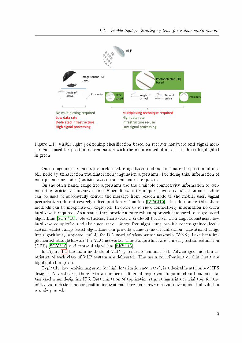
1.1 Visible light positioning classi�cation based on receiver hardware and signal mea-surement used for position determination with the main contribution of this thesishighlighted in green . . . . . . . . . . . . . . . . . . . . . . . . . . . . . . . . . . 3
1.2 Process diagram of contributions in this thesis . . . . . . . . . . . . . . . . . . . . 5
2.1 Blockage of GNSS signal in (a) deep open cast mine and (b) underground mine . 102.2 Di�erent types of mines based on their excavation (a) room-and-pillar and (b)
longwall mining . . . . . . . . . . . . . . . . . . . . . . . . . . . . . . . . . . . . . 122.3 Estimated positioning error from CDF with a 90% of con�dence level . . . . . . 132.4 Di�erent localization estimation (a) accurate and precise (b) accurate but not
precise (c) not accurate but precise and (d) neither accurate nor precise . . . . . 142.5 Proposed taxonomy for the analysis of positioning systems . . . . . . . . . . . . . 162.6 Proposed taxonomy for the analysis of positioning systems . . . . . . . . . . . . . 182.7 Classi�cation based on technological principle . . . . . . . . . . . . . . . . . . . . 192.8 Di�erent localization system topologies (a) Remote positioning, (b) Self position-
ing and (c) Indirect Positioning . . . . . . . . . . . . . . . . . . . . . . . . . . . . 25
3.1 Current to Luminous �ux curve of the LED light Cree XLamp CXB1512 [Des15] 353.2 Block diagram of an IMDD optical wireless communication system . . . . . . . . 353.3 Typical light output comparison between white LED and incandescent light bulb
as function of operating hours[Lum] . . . . . . . . . . . . . . . . . . . . . . . . . 373.4 El Teniente underground mine light deployment (a) Transportation tunnel (b)
Machinery working inside the tunnel(images by Codelco) . . . . . . . . . . . . . . 383.5 Di�erent systems con�gurations for VLC link, PD is placed in the miner's helmet:
(a) directed LOS, (b) nondirected LOS, (c) di�use, and (d) tracked . . . . . . . . 403.6 Electromagnetic spectrum [Min] . . . . . . . . . . . . . . . . . . . . . . . . . . . . 413.7 Huma eye's response based on the 1978 CIE data (http://www.ecse.rpi.edu/ schu-
bert/ Light-Emitting-Diodes-dot-org) . . . . . . . . . . . . . . . . . . . . . . . . . 423.8 . . . . . . . . . . . . . . . . . . . . . . . . . . . . . . . . . . . . . . . . . . . . . . 433.9 . . . . . . . . . . . . . . . . . . . . . . . . . . . . . . . . . . . . . . . . . . . . . . 443.10 Line of sight (LOS) VLC link . . . . . . . . . . . . . . . . . . . . . . . . . . . . . 453.11 Visible light communications channel model with tilted and rotated receiver . . . 463.12 Visible light communications channel model with tilted and rotated transmitter . 473.13 Di�use and specular re�ection from a glossy surface (Image retrieved from Juds
et.al. (1988) [Jud88]) . . . . . . . . . . . . . . . . . . . . . . . . . . . . . . . . . . 483.14 non-Line of sight (n-LOS) VLC link . . . . . . . . . . . . . . . . . . . . . . . . . 49
v

3.15 Walls geometry (a) traditional plane wall and (b) underground mine wall withrandomly oriented surface . . . . . . . . . . . . . . . . . . . . . . . . . . . . . . . 49
3.16 Signal blockage due to shadowing in underground mines . . . . . . . . . . . . . . 503.17 Scattering patterns (a) Rayleigh, (b) Mie, and (c) Non-selective scattering . . . . 51
4.1 Advantages of indoor VLP systems . . . . . . . . . . . . . . . . . . . . . . . . . . 544.2 Positioning method process diagram for (a) range based methods, (b) range free
methods and, (c) �ngerprinting . . . . . . . . . . . . . . . . . . . . . . . . . . . . 574.3 Visible light positioning system topology classi�cation . . . . . . . . . . . . . . . 584.4 Ranging information from RSS measurements (a) ideal ranging and (b) ranging
estimation with uncertainty σd . . . . . . . . . . . . . . . . . . . . . . . . . . . . 594.5 Power versus distance measurements of ED light Cree XLamp CXB1512 . . . . . 594.6 Lateration method in two dimensions based on RSS ranging . . . . . . . . . . . . 604.7 Lateration method in two dimensions based on TOA ranging . . . . . . . . . . . 614.8 Hyperbolic lateration method in two dimensions based on TDOA ranging . . . . 624.9 Angle of arrival based positioning method in two dimensions . . . . . . . . . . . . 634.10 Angle of arrival based positioning method in two dimensions with unknown re-
ceiver orientation . . . . . . . . . . . . . . . . . . . . . . . . . . . . . . . . . . . . 644.11 Convex position estimation . . . . . . . . . . . . . . . . . . . . . . . . . . . . . . 66
5.1 Single chip transceiver nRF905 . . . . . . . . . . . . . . . . . . . . . . . . . . . . 695.2 Packet error rate versus distance for nRF905 . . . . . . . . . . . . . . . . . . . . . 705.3 Transmitter design schematic . . . . . . . . . . . . . . . . . . . . . . . . . . . . . 715.4 Real implementation of VLC transmitter (a) general overview and (b) modulator
in detail . . . . . . . . . . . . . . . . . . . . . . . . . . . . . . . . . . . . . . . . . 715.5 Random time slot access schematic . . . . . . . . . . . . . . . . . . . . . . . . . . 725.6 Frequency access schematic . . . . . . . . . . . . . . . . . . . . . . . . . . . . . . 735.7 PDA36A2 photodetector . . . . . . . . . . . . . . . . . . . . . . . . . . . . . . . . 735.8 Oscilloscope used as digital to analog converter . . . . . . . . . . . . . . . . . . . 735.9 Proposed receiver architecture . . . . . . . . . . . . . . . . . . . . . . . . . . . . . 74
6.1 Di�erent LED arrangements for VLC networks (a) Lattice architecture and (b)Tunnel architecture . . . . . . . . . . . . . . . . . . . . . . . . . . . . . . . . . . . 76
6.2 Sample graph with blue (dotted), green solid) and red (dashed) lines . . . . . . . 776.3 Di�erence height distance measurements (a) raw measurements and (b) �ltered
measurements . . . . . . . . . . . . . . . . . . . . . . . . . . . . . . . . . . . . . . 786.4 Broadcast VLC Packet . . . . . . . . . . . . . . . . . . . . . . . . . . . . . . . . . 796.5 Convex bounding box for the mobile node position . . . . . . . . . . . . . . . . . 806.6 Overlapped cell to bounding box with binary indicator of Equation (6.6) equals
to one . . . . . . . . . . . . . . . . . . . . . . . . . . . . . . . . . . . . . . . . . . 816.7 Unfeasible point elimination based on connectivity feasibility check . . . . . . . . 826.8 New feasible vertices using overlapped non-connected cells . . . . . . . . . . . . . 826.9 Set of vertices found by using connectivity and infrastructure information . . . . 826.10 Convex polygon for feasible positioning area . . . . . . . . . . . . . . . . . . . . . 836.11 Detector architectures: (a) single photodetector and (b) imaging receiver . . . . . 846.12 Intersection pattern of feasible localization area based on (a) single PD and (b)
imaging receiver . . . . . . . . . . . . . . . . . . . . . . . . . . . . . . . . . . . . . 846.13 CPP performance using a single PD for (a) ∆hji=2 m and (b) ∆hji=1.5 m . . . 87
vi
6.14 CPP performance using a imaging receiver for (a) ∆hji=2 m and (b) ∆hji=1.5 m 876.15 Comparison of best PD architectures for (a) ∆hji=2 m and (b) ∆hji=1.5 m . . . 886.16 Two dimensional coverage representation for ∆hji=2 m (a) FOV=60◦, (b) FOV=80◦
and (c) FOV=100◦ . . . . . . . . . . . . . . . . . . . . . . . . . . . . . . . . . . . 896.17 Method performance using an 80◦ FOV detector for (a) RSS trilateration and (b)
CPP . . . . . . . . . . . . . . . . . . . . . . . . . . . . . . . . . . . . . . . . . . . 906.18 Impact of mismatch measurements on receiver's heigth using PD(IR3) architecture
for (a)∆hij = 1.5 meters and (b)∆hij = 2 meters . . . . . . . . . . . . . . . . . . 916.19 Impact of tilting and rotation angles using PD(IR3) architecture for (a) ∆hij = 1.5
meters and (b)∆hij = 2 meters . . . . . . . . . . . . . . . . . . . . . . . . . . . . 926.20 CPP performance using a single PD in tunnel scenario for (a) ∆hji=2 m and (b)
∆hji=1.5 m . . . . . . . . . . . . . . . . . . . . . . . . . . . . . . . . . . . . . . . 936.21 CPP performance using a imaging receiver in tunnel scenario for (a) ∆hji=2 m
and (b) ∆hji=1.5 m . . . . . . . . . . . . . . . . . . . . . . . . . . . . . . . . . . 936.22 Comparison of best PD architectures for (a) ∆hji=2 m and (b) ∆hji=1.5 m . . . 946.23 Two dimensional coverage representation in tunnel scenario for ∆hji=2 m (a)
FOV=60◦, (b) FOV=80◦ and (c) FOV=100◦ . . . . . . . . . . . . . . . . . . . . 956.24 Real square room VLC platform for VLP testing . . . . . . . . . . . . . . . . . . 966.25 Photodetector receiver in the testing grid for CPP VLP method validation . . . . 976.26 Two dimensional received power representation in testing platform for ∆hji=2.25
m and FOV=60◦ (a) ID1 VLC beacon and (b) ID2 VLC beacon . . . . . . . . . . 986.27 Performance of CPP method using the testing VLP platform . . . . . . . . . . . 99
7.1 Portable helmet mounted device for VLP in underground mines . . . . . . . . . . 1027.2 Zero energy mobile VLC receiver . . . . . . . . . . . . . . . . . . . . . . . . . . . 103
vii
List of Tables
2.1 Miners tracking systems requirements based on MINERS Act [10906] . . . . . . . 202.2 Proposed positioning systems for underground mines . . . . . . . . . . . . . . . . 312.3 Pros and cons of visible light positioning technology in underground mines . . . . 32
3.1 Illumination requirements for di�erent working zones of underground mines (Tableadapter from [Com]) . . . . . . . . . . . . . . . . . . . . . . . . . . . . . . . . . . 36
3.2 Comparison between proposed and state-of-art VLC underground mines channelmodels . . . . . . . . . . . . . . . . . . . . . . . . . . . . . . . . . . . . . . . . . . 39
3.3 Comparison of di�erent VLC system con�gurations . . . . . . . . . . . . . . . . . 413.4 E�ect of special underground tunnel characteristics in VLC channel model . . . . 52
4.1 Comparison of VLP based on receiver characteristics . . . . . . . . . . . . . . . . 554.2 Topologies and technologies for VLP in underground mines . . . . . . . . . . . . 554.3 Summary of range based, range free and �ngerprinting positioning methods (Table
adapted from [AIA+17]) . . . . . . . . . . . . . . . . . . . . . . . . . . . . . . . . 67
6.1 Parameters for computational simulation . . . . . . . . . . . . . . . . . . . . . . . 866.2 Frequencies of VLC beacon nodes . . . . . . . . . . . . . . . . . . . . . . . . . . . 95
viii
Chapter 1
Introduction
Sommaire
1.1 Visible light positioning systems for indoor environments . . . . . . 1
1.2 Motivation . . . . . . . . . . . . . . . . . . . . . . . . . . . . . . . . . . 4
1.3 Contributions . . . . . . . . . . . . . . . . . . . . . . . . . . . . . . . . . 4
1.4 Publications . . . . . . . . . . . . . . . . . . . . . . . . . . . . . . . . . . 6
1.4.1 Journal ISI articles . . . . . . . . . . . . . . . . . . . . . . . . . . . . . . 6
1.4.2 Conference articles . . . . . . . . . . . . . . . . . . . . . . . . . . . . . . 7
1.1 Visible light positioning systems for indoor environments
The aperture of Global Positioning system (GPS) for civilian usage and the discontinuance ofselectivity availability (SA) in May 2000 produced a boost in positioning industry and locationbased services(LBS). Although contemporary Global Navigation Satellite System (GNSS) out-door positioning has become precise and ubiquitous, it has not been capable to overcome di�erentissues when dealing with indoor or dense metropolitan environments. Line of sight (LOS) signalcan be blocked in metropolitan areas by high buildings and. Moreover, in indoor scenarios, suchas, interior of buildings and tunnels, complete signal lost is experienced since GNSS signals arenot capable to penetrate concrete, metal or ground [Van08].
Indoor positioning market is expected to obtain revenues for a value of US$ 10 billion by2020 [Bus15]. Whilst satellite based navigation dominates outdoor scenarios, no overall sin-gle technology alternative exist for indoor environments and, many di�erent technologies havebeen proposed as feasible solutions. Most of the indoor positioning systems (IPS) that can befound in literature are based on radio frequency (RF) technology, magnetic �elds, or acousticsignals [LLY+15]. Among them, Wireless Fidelity (Wi�) based IPS have been preferred sincethis technology is commonly integrated in o�-the-shelf devices and it re-uses already availableinfrastructure (Wi� access points) to provide position information [LDBL07, HNP+15]. Themain disadvantage of Wi� based IPS is the large positioning errors can be always found (e.g.6 ∼ 8 m) in purely Wi�-based positioning even though, reasonable accuracy can be achieved[LYS+14].
In the recent years, visible light communications (VLC) has gained attention of researchers.This, mainly because of the recent advances in the manufacture of lighting emitting diodes(LEDs) [HCWZ15].
1
1.1. Visible light positioning systems for indoor environments
The rapid development of VLC networks has encouraged researchers to propose positioningsolutions based on this technology. Visible light positioning (VLP) systems or VLC based po-sitioning has several advantages compared to RF based IPS. LEDs can be modulated at highfrequencies. Due to this, VLC systems are capable to provide high data rate wireless com-munication, using already deployed lighting infrastructure [PFHM15]. LED lights are energye�cient, they have a longer life expectancy than other lighting devices and, they are a coste�ective solution [HNP+15]. Moreover, joint illumination/VLC is perceived as a green technol-ogy [TWL+15, JWLL18]. VLC has a larger unlicensed spectrum compared to RF systems. Ithas a high spatial reuse (privacy) and does not interfere with RF waves. VLC systems can beused in RF-denied environments, such as, hospitals and air planes [WWY14, PFHM15]. One ofthe most important characteristics of VLP is the high accuracy that can be achieved in indoorenvironments compared to RF based systems [DY16].
Visible light positioning systems are often classi�ed in two di�erent groups based on thereceiver hardware used for signal detection (as shown in Figure 1.1), i.e, image sensor (IS) basedVLP and, photo detector (PD) based VLP [HY16].
Image sensors provide more useful LED position information than PD counterpart. In addi-tion to this, light sources can be directly separated using the spatial multiplexing of the imageand no complementary technique is required [DY16]. Most of the o�-the-shelf devices have al-ready incorporated cameras. Due to his, IS-based positioning methods are easy to implementand inexpensive [ZHQ+18, KZKP15]. The main disadvantage of IS-VLP systems is that IS-basedVLC networks have a very limited data rate. Due to this, IS-based networks are not expected tobe massively implemented for future wireless networks (no infrastructure re-use) which are sup-posed to deliver high data rates [DY16]. In addition to this, VLP demands a high computationale�ort to process the image stream.
On the other hand, PD-based VLC systems can provide high data rate communication [HY16,HLC+15]. Moreover, PDs are inexpensive and easy to install. In order to separate the signal frommultiple sources, the usage of multiplexing techniques is required. Depending on the multiplexingtechnique used to separate the sources, the required hardware for the system can increase incomplexity and a�ect the performance of positioning method [YNA+17, HNP+15].
Localization methods can be classi�ed in two types. This classi�cation is based on whetherthey use distance estimation (range based) or other type of information to compute mobilenode's position (range free) [Mau12]. Range based methods use a distance estimation to per-form positioning. Some range based methods are trilateration, multilateration and angulation.Distance estimation is derived from received signal characteristics, such as, signal strength, timeof propagation and received phase/angle. Among them, receiver signal strength (RSS) is thesimplest method to estimate ranging information. RSS measurements are relatively easy toobtain and, most of the devices are built with the required hardware to measure the receivedsignal power level in dBm or a received signal strength indicator (RSSI). In order to estimatethe distance from RSS measurements, a precise model of signal propagation is required. Dueto this, model precision has high impact in the algorithm performance. On the other hand,despite provide a more precise distance estimation than RSS methods, time of propagation andreceived phase/angle measurements have several drawbacks on its hardware implementation.Time of propagation measurement can be divided in time of arrival (TOA) and time di�erenceof arrival (TDOA) methods. TOA measurements require precise synchronization of transmittersand receivers. This synchronization is very di�cult to provide. On the other hand, TDOA andphase/angle measurements require synchronization at the receiver side to estimate the range.In addition to this, in order to perceive the di�erence in time of arrival, the receiver must beequipped with a high sampling frequency device.
2
1.1. Visible light positioning systems for indoor environments
VLP
Image sensor (IS) based
Angle of arrival
Proximity
Photodetector (PD) based
RSS based
Angle of arrival
Time of arrival
Proximity
No multiplexing requiredLow data rateDedicated infrastructureHigh signal processing
Multiplexing technique requiredHigh data rateInfrastructure re-useLow signal processing
Figure 1.1: Visible light positioning classi�cation based on receiver hardware and signal mea-surement used for position determination with the main contribution of this thesis highlightedin green
Once range measurements are performed, range based methods estimate the position of mo-bile node by trilateration/multilateration/angulation algorithms. For doing this, information ofmultiple anchor nodes (position-aware transmitters) is required.
On the other hand, range free algorithms use the available connectivity information to esti-mate the position of unknown node. Since di�erent techniques such as equalization and codingcan be used to successfully deliver the message from beacon node to the mobile user, signalperturbations do not severely a�ect position estimation [LYWJ10]. In addition to this, thesemethods can be inexpensively deployed. In order to retrieve connectivity information no extrahardware is required. As a result, they provide a more robust approach compared to range basedalgorithms [SGY+16]. Nevertheless, there exist a trade-o� between their high robustness, lowhardware complexity and their accuracy. Range free algorithms provide coarse-grained local-ization whilst range based algorithms can provide a �ne-grained localization. Traditional rangefree algorithms, proposed mainly for RF-based wireless sensor networks (WSN), have been im-plemented straightforward for VLC networks. These algorithms are convex position estimation(CPE) [SGY+16] and centroid algorithm [SKS+16].
In Figure 1.1 the main methods of VLP systems are summarized. Advantages and charac-teristics of each class of VLP system are delivered. The main contributions of this thesis arehighlighted in green.
Typically, low positioning error (or high localization accuracy), is a desirable attribute of IPSdesigns. Nevertheless, there exist a number of di�erent requirements parameters that must beanalysed when designing IPS. Determination of application requirements is a crucial step for anyinitiative to design indoor positioning systems since here, research and development of solutionis underpinned.
3
1.2. Motivation
1.2 Motivation
Underground mining is expected to lead the mining industry in the near future. Due to theadvance of electronic devices and communications technologies, new safety regulations must beaccomplished in order to operate underground mines safely and optimally. In 2006, US govern-ment update their safety policies and introduce the PUBLIC LAW109-236 [10906]. Because ofthis, underground tracking is nowadays mandatory for underground mine operations. This newregulation establishes that current, or immediately pre-accident location of all underground per-sonnel must be delivered over ground. Despite the recent advances of tracking and positioningsystems for indoor environments, underground mines are a unique scenario which poses di�erentconstraints to current technologies. Due to this, it is important to analyse in detail the maincharacteristic of di�erent localization systems for underground mines (UM) that can be found inliterature.
Most of the VLP methods have been evaluated in highly controlled scenarios were a dense andwell deployed VLC network exist, i.e., interior of buildings, supermarkets, o�ce and car parking.On the contrary, underground mine is a dynamic and hazardous environment by nature. As oreexploitation continues, mine expands. Therefore, it can be considered as a semi-structured en-vironment [FFCM17] where some assumptions of tunnel geometry can be made. Moreover, dueto the characteristics of mining tunnels, low control on communication infrastructure exist and,a strategic deployment of required devices can not always be done. Additionally, undergroundmines are considered by several researchers as one of the most di�cult scenarios. Undergroundmining operations involve various hazardous conditions, such as, in-mine vehicular/human acci-dents, �re and explosions, collapses, toxic gases emanation and �oods, among others. In additionto this, workers, machinery and in-mine equipment are exposed to extreme conditions, such as,high levels of humidity (up to 90 % or above [YGAM09]), airborne dust and extreme heat. Theseconditions have not only an impact on workers performing labours inside the tunnel but also onthe functioning of electronic devices. The feasibility of using a VLP system under such conditionscapable of ful�lling positioning requirements remains an open question. We address this questionin our work.
1.3 Contributions
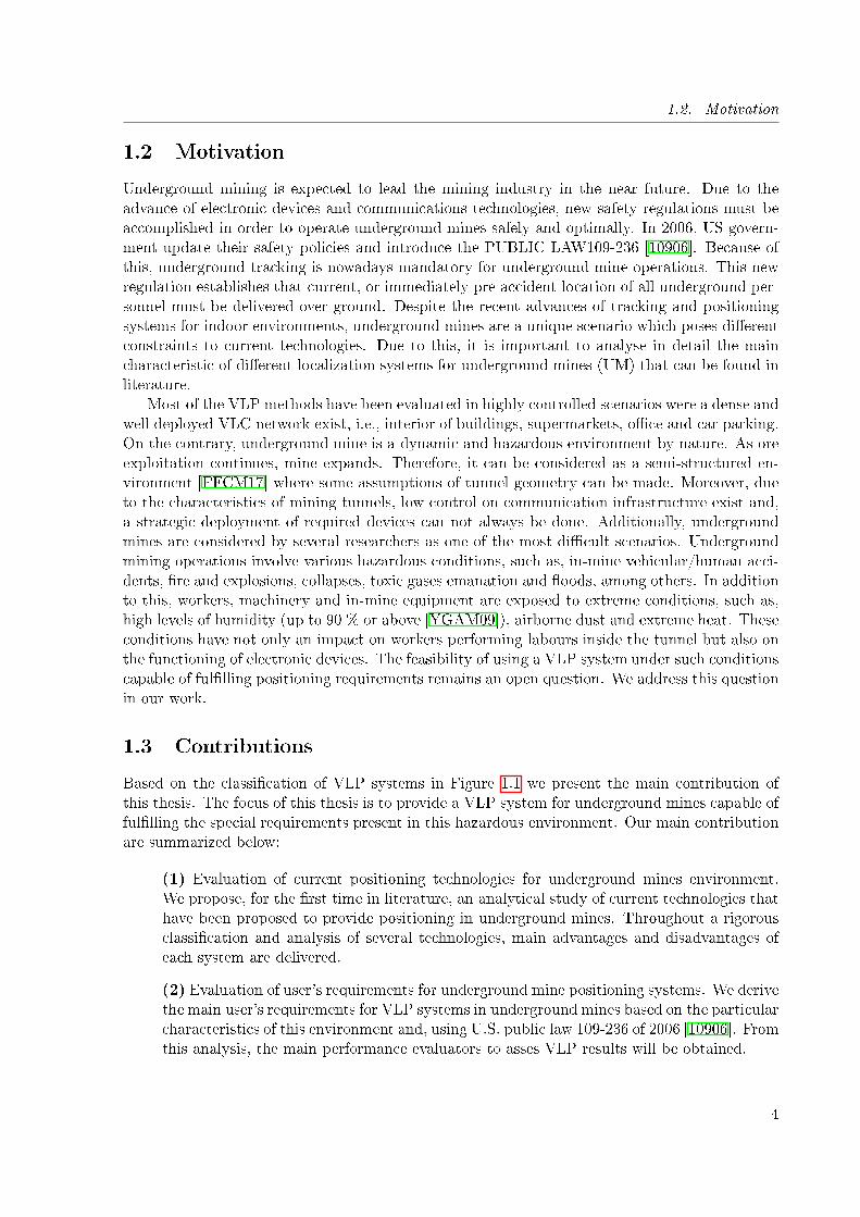
Based on the classi�cation of VLP systems in Figure 1.1 we present the main contribution ofthis thesis. The focus of this thesis is to provide a VLP system for underground mines capable offul�lling the special requirements present in this hazardous environment. Our main contributionare summarized below:
(1) Evaluation of current positioning technologies for underground mines environment.We propose, for the �rst time in literature, an analytical study of current technologies thathave been proposed to provide positioning in underground mines. Throughout a rigorousclassi�cation and analysis of several technologies, main advantages and disadvantages ofeach system are delivered.
(2) Evaluation of user's requirements for underground mine positioning systems. We derivethe main user's requirements for VLP systems in underground mines based on the particularcharacteristics of this environment and, using U.S. public law 109-236 of 2006 [10906]. Fromthis analysis, the main performance evaluators to asses VLP results will be obtained.
4
1.3. Contributions
(3) Implementation of an underground mine VLC channel model simulator. We proposea generic model for VLC channel in underground mines. This channel model takes intoaccount several characteristics of underground mines that are not present in traditionalmodels (higher temperatures, non orthogonality of walls, partial and total signal blockage,etc.). The simulator can be used not only to evaluate VLP systems but also the performanceof VLC in underground mines.
(4) Analytical study of VLP in underground mines environment. Using the proposed chan-nel model for underground mines we develop, for the �rst time in literature, an analyticalstudy of VLP performance in underground mines.
(5) Design of a positioning system topology optimized for VLP in underground mines. Wedesign a positioning system topology in order to ful�l the user's requirement of VLP inunderground mines. This design is used in order to develop real hardware implementationof a VLP system. This contribution is detailed in Chapter 4.
(6) Implementation of a low-cost/large-scale VLP system. We implement a low-cost/large-scale VLP system for underground mines. Di�erent VLP systems are evaluated using thishardware implementation. The platform can be used to test not only the proposed methodsin this thesis but also further developments.
(7) Design and implementation of a robust range free VLP method. We provide the �rstrange free VLP method designed using spatial reuse characteristics of VLC systems. Weimplemented and evaluate our method using the low-cost/large-scale hardware proposedin this thesis. Our proposition is compared with traditional others range free methodsdesigned for RF communications. Contributions (1) and (2), detailed in Chapter 2, deliveruser requirements and positioning characteristics in underground mines.
(8) Evaluation of VLP robustness requirements. We study the robustness of several posi-tioning methods under the scenario of underground mines. We compare the results of ourproposed systems with a traditional RF based positioning method. Our evaluation provideessential insights to choose the adequate VLP system in underground mines environment.
Contributions(1) & (2)
•Determine userrequirementsand undergroundmines characteristics
Contributions(3) & (4)
•VLP characteristicsforundergroundmines
Contribution(5)
•Design a VLP system’sarchitecture forundergroundmines
Contribution(6)
• Implement a low cost/largescale VLP system formethod testing
Contribution(7)
•Propose a novel positioningmethodcomptible withthe ndergroundmines characteristics
Contribution(8)
•Demostrate therobustness of the proposedalgorithm in a simulatedenvironment
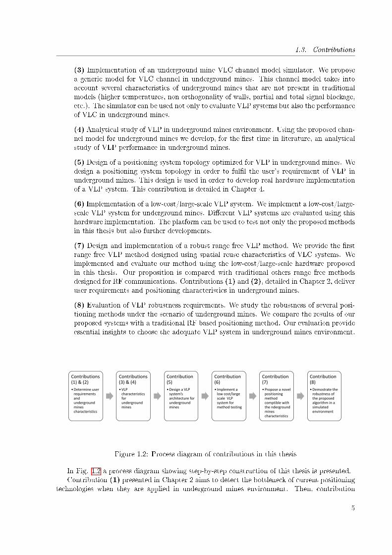
Figure 1.2: Process diagram of contributions in this thesis
In Fig. 1.2 a process diagram showing step-by-step construction of this thesis is presented.Contribution (1) presented in Chapter 2 aims to detect the bottleneck of current positioning
technologies when they are applied in underground mines environment. Then, contribution
5
1.4. Publications
(2), delivered in the same chapter, is used to determine user's speci�cations for this particularscenario. Proper design of a VLP system must be done after a rigorous evaluation of requirements.
Further on, once underground positioning requirements and characteristics are established,an evaluation of VLC performance in underground environment is delivered. Contributions (3)and (4) are used to determine the limitations of several VLP systems in underground mines.These results will be compared with the requirements derived from contributions (1) and (2)in order to determine the best architecture to can guarantee positioning service in the proposedscenario. Contributions (3) and (4) are presented in Chapter 3 and 4 respectively.
Once the main limitations of VLP in underground mines are determined and user's require-ments are established, a VLP positioning system is designed and implemented. Contribution (5)uses limitations, capabilities and users requirements detailed in Chapters 2, 3 and 4 to design alow-cost/large-scale hardware architecture for underground mines, which is detailed in Chapter5. Contribution (6), delivered in the same chapter, exploits this design to implement a real worldplatform that will be used to evaluate the performance of visible light positioning methods.
Contribution (7) present a novel robust range free positioning method. Contrary to mostof the methods existing in literature, our proposal has not been derived straightforward fromRF based methods. The proposed algorithm uses special characteristics of VLC to enhance theposition estimation performance. Insights of our method are delivered in Chapter 6.
Finally, contribution (8) evaluates the performance of our proposal using the large scale/lowcost method testing platform of contribution (6).
1.4 Publications
1.4.1 Journal ISI articles
1. Fabian Seguel, Ismael Soto, Cesar Azurdia, Pablo Palacios, Nicolas Krommenacker, PatrickCharpentier, Underground mine positioning: A survey, To be submitted to: IEEE commu-nications surveys and tutorials
2. Soto I., Nilson Rodrigues R., Massuyama G., Seguel F.,Palacios Játiva P., Azurdia-MezaC.A., Krommenacker N, A Hybrid VLC-RF Portable Phasor Measurement Unit for DeepTunnels. Sensors 2020, 20, 790, DOI: https://doi.org/10.3390/s20020367
3. Palacios Játiva P., Román Cañizares M., Azurdia-Meza C.A., Zabala-Blanco D., DehghanFiroozabadi A., Seguel F., Montejo-Sánchez S., Soto I., Interference Mitigation for VisibleLight Communications in Underground Mines Using Angle Diversity Receivers. Sensors2020, 20, 367, DOI: https://doi.org/10.3390/s20020367
4. Fabian Seguel, Nicolas Krommenacker, Patrick Charpentier, Ismael Soto, A novel rangefree visible light positioning algorithm for imaging receivers, Optik, Volume 195, 2019,163028, ISSN 0030-4026, DOI: https://doi.org/10.1016/j.ijleo.2019.163028
5. Seguel, Fabian; Krommenacker, Nicolas; Charpentier, Patrick; Soto, Ismael: 'Visible lightpositioning based on architecture information: method and performance', IET Communi-cations, 2019, 13, (7), p. 848-856, DOI: 10.1049/iet-com.2018.5623
6. Dehghan Firoozabadi, Ali and Azurdia-Meza, Cesar and Soto, Ismael and Seguel, Fabianand Krommenacker, Nicolas and Iturralde, Daniel and Charpentier, Patrick and Zabala-Blanco, David, A Novel Frequency Domain Visible Light Communication (VLC) Three-
6
1.4. Publications
Dimensional Trilateration System for Localization in Underground Mining, Applied Sci-ences, Volume 9 (7), 2019, ISSN 2076-3417, DOI: https://doi.org/10.3390/app9071488
7. F. Seguel, A. Dehghan Firoozabadi, P. Adasme, I. Soto, N. Krommenacker, Cesar Azurdia-Meza, A novel strategy for LED re-utilization for visible light communications, Optik, Vol-ume 151, 2017, Pages 88-97, ISSN 0030-4026, DOI: https://doi.org/10.1016/j.ijleo.2017.10.121.
8. D. Iturralde, F. Seguel, I. Soto, C. Azurdia and S. Khan, "A new VLC system for localiza-tion in underground mining tunnels," in IEEE Latin America Transactions, vol. 15, no. 4,pp. 581-587, April 2017. DOI: 10.1109/TLA.2017.7896341
1.4.2 Conference articles
1. Convex polygon positioning for homogeneous optical wireless networks F Seguel, N Krom-menacker, P Charpentier, V Bombardier, I Soto 2018 International Conference on IndoorPositioning and Indoor Navigation (IPIN) DOI: 10.1109/IPIN.2018.8533863
2. A range free localization method for overlapped optical attocells using neighbor's informa-tion F Seguel, I Soto, N Krommenacker, P Charpentier, P Adasme 2018 11th InternationalSymposium on Communication Systems, Networks and Signal processing (CSNDSP) DOI:10.1109/CSNDSP.2018.8471895
3. Seguel, Fabian; Soto, Ismael; Adasme, Pablo; Krommenacker, Nicolas; Charpentier, Patrick;Potential and challenges of VLC based IPS in underground mines, 2017 First South Ameri-can Colloquium on Visible Light Communications (SACVLC) DOI: 10.1109/SACVLC.2017.8267610
4. Multiple speaker localization and identi�cation through multiple camera and visible lightcommunication L Florent, F Seguel, K Nicolas, C Patrick, P Bertrand 2018 Global LIFICongress (GLC), 1-4 DOI: 10.23919/GLC.2018.8319102
5. Spatial time division multiple access for visible light communication networks P Adasme,F Seguel, I Soto, E San Juan 2017 First South American Colloquium on Visible LightCommunications (SACVLC) DOI: 10.1109/SACVLC.2017.8267605
6. New Formulations for an Optimal Connectivity Approach for Mobile Ad-hoc Networks PAdasme, I Soto, F Seguel International Conference on Mobile Web and Information Sys-tems, 250-262 Proposed energy based method for light receiver localization in undergroundmining D Aguirre, AD Firoozabadi, F Seguel, I Soto 2016 IEEE International Conferenceon Automatica (ICA-ACCA) DOI: 10.1109/ICA-ACCA.2016.7778460
7. Comparison between FastICA and InfoMax for the blind separation of audio signals ESan Juan, I Soto, P Adasme, L Cañete, F Seguel, W Gutierrez, 2018 11th InternationalSymposium on Communication Systems, Networks and Signal processing (CSNDSP) DOI:10.1109/CSNDSP.2018.8471822
8. Probabilistic Constrained Approach for Clustering in Multi-Cell Wireless Networks PAdasme, I Soto, E San Juan, F Seguel, N Krommenacker 2018 11th International Sym-posium on Communication Systems, Networks and Signal processing (CSNDSP) DOI:10.1109/CSNDSP.2018.8471847
7
1.4. Publications
9. Optical Wireless Communications for Ubiquitous Computing Fabián Seguel, Ismael Soto,Pablo Adasme, Belarmino Núñez. 17th International Conference on Informatics and Semi-otics in Organisations (ICISO) DOI: 10.1007/978-3-319-42102-5
8
Chapter 2
Current positioning technologies inunderground mines
Sommaire
2.1 Introduction . . . . . . . . . . . . . . . . . . . . . . . . . . . . . . . . . 9
2.2 Importance and challenges of positioning in underground mines . . 11
2.3 Requirements of positioning systems . . . . . . . . . . . . . . . . . . . 12
2.3.1 Accuracy . . . . . . . . . . . . . . . . . . . . . . . . . . . . . . . . . . . 12
2.3.2 Output data . . . . . . . . . . . . . . . . . . . . . . . . . . . . . . . . . 13
2.3.3 Precision . . . . . . . . . . . . . . . . . . . . . . . . . . . . . . . . . . . 14
2.3.4 Coverage . . . . . . . . . . . . . . . . . . . . . . . . . . . . . . . . . . . 15
2.3.5 Cost . . . . . . . . . . . . . . . . . . . . . . . . . . . . . . . . . . . . . . 15
2.3.6 Required infrastructure . . . . . . . . . . . . . . . . . . . . . . . . . . . 15
2.3.7 Robustness . . . . . . . . . . . . . . . . . . . . . . . . . . . . . . . . . . 16
2.3.8 Scalability . . . . . . . . . . . . . . . . . . . . . . . . . . . . . . . . . . . 16
2.3.9 Update rate . . . . . . . . . . . . . . . . . . . . . . . . . . . . . . . . . . 17
2.3.10 Number of users . . . . . . . . . . . . . . . . . . . . . . . . . . . . . . . 17
2.3.11 Market maturity . . . . . . . . . . . . . . . . . . . . . . . . . . . . . . . 17
2.3.12 Intrusiveness . . . . . . . . . . . . . . . . . . . . . . . . . . . . . . . . . 17
2.3.13 Approval . . . . . . . . . . . . . . . . . . . . . . . . . . . . . . . . . . . 18
2.4 Classi�cation of positioning systems for underground mines . . . . . 18
2.4.1 Technological principle . . . . . . . . . . . . . . . . . . . . . . . . . . . . 19
2.4.2 System topology . . . . . . . . . . . . . . . . . . . . . . . . . . . . . . . 24
2.4.3 Deployment . . . . . . . . . . . . . . . . . . . . . . . . . . . . . . . . . . 25
2.5 Systems proposed in literature . . . . . . . . . . . . . . . . . . . . . . 26
2.6 Conclusions . . . . . . . . . . . . . . . . . . . . . . . . . . . . . . . . . . 32
2.1 Introduction
The rapid advance of wireless communications technologies as well as personal devices has allowedthe deployment of di�erent positioning systems. Positioning systems were originally created by
9

2.1. Introduction
the need of mobile users to orient in unknown environments [Wer14]. Nowadays, the mostused positioning system is the Global Positioning Systems (GPS). GPS is capable to providea large coverage and low cost positioning for outdoor environment. This technology has beenused to enable di�erent services in areas such as transportation, gaming, health and disastermanagement, among others [RGKR07]. In particular, open pit (also named open cast) miningoperations have been using global navigation satellite systems (GNSS) based location basedservices (LBS) for many applications in the last 20 years. Some of these GNSS-based LBS are:drill positioning for precisely excavation of blast holes, �eet management for process optimization,collision avoidance and, transit control for safety management, among others [ER02]. Positioningsystems used in open cast mines have reached a high level of trustworthiness in the industry.Systems such as, Computer Aided Earthmoving System (CAES) and Aquila Drill Managementprovided by Caterpillar-Minestar, Wenco and Modular �eet management systems are nowadayswidely used in mining industry. Despite the large usage of GNSS-based LBS in open cast mining,this type of system su�ers from di�erent issues when facing more complex environments, suchas, deep mining pits or con�ned areas. Satellite's signal is partially blocked in deep mining pitsdue to the presence of relatively high obstacles. Moreover, complete signal lost is experiencedin underground miens and con�ned environments since the signal is not capable to penetrateconcrete, metal or ground as shown in Fig. 2.1 [Van08].
GNSS signal
(a)
GNSS signal
(b)
Figure 2.1: Blockage of GNSS signal in (a) deep open cast mine and (b) underground mine
As ore exploitation continues, shallow deposits are becoming exhausted and new veins con-taining high grade mineral are encountered in deeper layers of earth. Underground mining is,therefore, becoming more attractive due to their merits in terms of safety, production rates,decreasing costs and environmental friendly production [RNSA14]. Commonly, the deposits ex-ploited by open pit mining are shallow and they have a relatively uniform geology. On the con-trary, underground operation is preferred for deeper deposits which are not necessarily uniformlydistributed. Due to this, underground mines are typically extensive labyrinths that employ ahuge number of employees working over an area on many square kilometres [MP78].
In the recent years, due to the current advance of wireless technologies, new safety stan-dards have been appointed in order to operate underground mines safely.In January of 2006,an explosion occurred at the Sago mine in Buckhannon, West Virginia. The rescue team hadno way to communicate with the trapped miners, and did not know where they were located
10
2.2. Importance and challenges of positioning in underground mines
(Twelve miners died in this disaster). Following these disasters, the U.S. government changedtheir safety policies for underground mines. In June 15, 2006 the congress introduced the PUB-LIC LAW 109�236(M) Mine Improvement and New Emergency Response (MINER) [10906] toamend the mine safety and health act of 1977. The main goal of this new standard is to providewireless communications and, position information of personnel inside the mine following anunderground accident. The implementation of such systems has encountered various challengesdue to the particular conditions of underground mines.
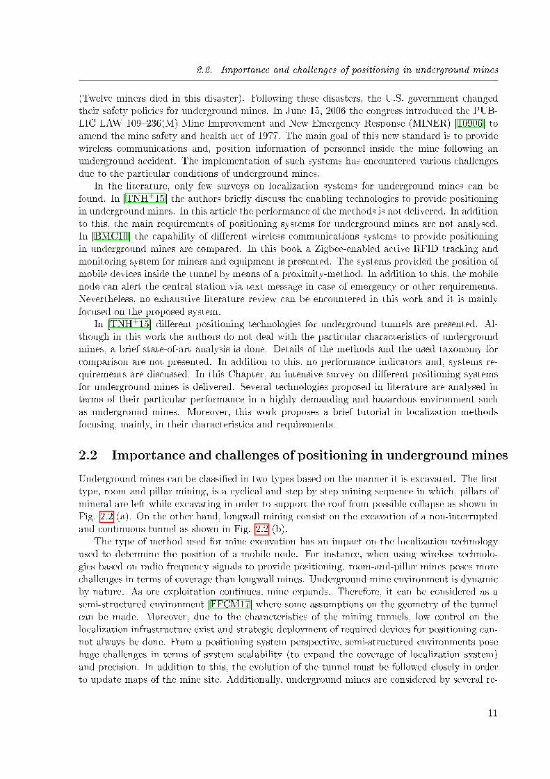
In the literature, only few surveys on localization systems for underground mines can befound. In [TNH+15] the authors brie�y discuss the enabling technologies to provide positioningin underground mines. In this article the performance of the methods is not delivered. In additionto this, the main requirements of positioning systems for underground mines are not analysed.In [BMC10] the capability of di�erent wireless communications systems to provide positioningin underground mines are compared. In this book a Zigbee-enabled active RFID tracking andmonitoring system for miners and equipment is presented. The systems provided the position ofmobile devices inside the tunnel by means of a proximity-method. In addition to this, the mobilenode can alert the central station via text message in case of emergency or other requirements.Nevertheless, no exhaustive literature review can be encountered in this work and it is mainlyfocused on the proposed system.
In [TNH+15] di�erent positioning technologies for underground tunnels are presented. Al-though in this work the authors do not deal with the particular characteristics of undergroundmines, a brief state-of-art analysis is done. Details of the methods and the used taxonomy forcomparison are not presented. In addition to this, no performance indicators and, systems re-quirements are discussed. In this Chapter, an intensive survey on di�erent positioning systemsfor underground mines is delivered. Several technologies proposed in literature are analysed interms of their particular performance in a highly demanding and hazardous environment suchas underground mines. Moreover, this work proposes a brief tutorial in localization methodsfocusing, mainly, in their characteristics and requirements.
2.2 Importance and challenges of positioning in underground mines
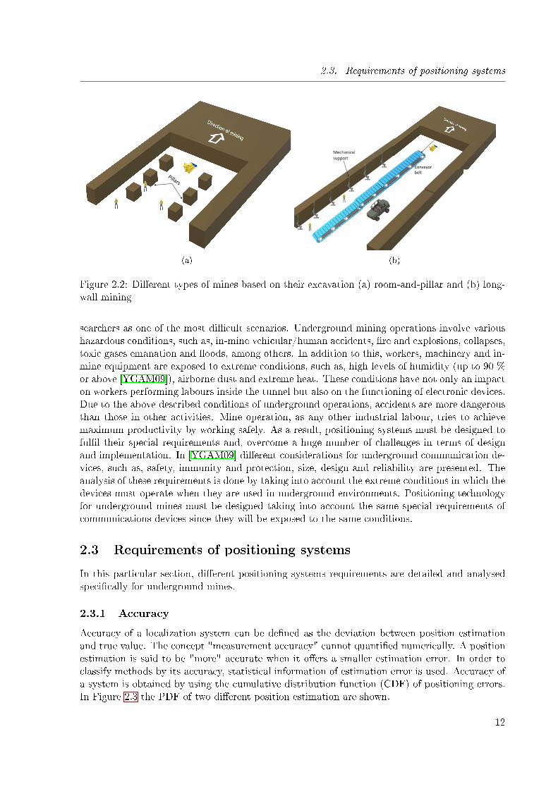
Underground mines can be classi�ed in two types based on the manner it is excavated. The �rsttype, room-and-pillar mining, is a cyclical and step-by-step mining sequence in which, pillars ofmineral are left while excavating in order to support the roof from possible collapse as shown inFig. 2.2 (a). On the other hand, longwall mining consist on the excavation of a non-interruptedand continuous tunnel as shown in Fig. 2.2 (b).
The type of method used for mine excavation has an impact on the localization technologyused to determine the position of a mobile node. For instance, when using wireless technolo-gies based on radio frequency signals to provide positioning, room-and-pillar mines poses morechallenges in terms of coverage than longwall mines. Underground mine environment is dynamicby nature. As ore exploitation continues, mine expands. Therefore, it can be considered as asemi-structured environment [FFCM17] where some assumptions on the geometry of the tunnelcan be made. Moreover, due to the characteristics of the mining tunnels, low control on thelocalization infrastructure exist and strategic deployment of required devices for positioning can-not always be done. From a positioning system perspective, semi-structured environments posehuge challenges in terms of system scalability (to expand the coverage of localization system)and precision. In addition to this, the evolution of the tunnel must be followed closely in orderto update maps of the mine site. Additionally, underground mines are considered by several re-
11
2.3. Requirements of positioning systems
(a)
Conveyor belt
(b)
Figure 2.2: Di�erent types of mines based on their excavation (a) room-and-pillar and (b) long-wall mining
searchers as one of the most di�cult scenarios. Underground mining operations involve varioushazardous conditions, such as, in-mine vehicular/human accidents, �re and explosions, collapses,toxic gases emanation and �oods, among others. In addition to this, workers, machinery and in-mine equipment are exposed to extreme conditions, such as, high levels of humidity (up to 90 %or above [YGAM09]), airborne dust and extreme heat. These conditions have not only an impacton workers performing labours inside the tunnel but also on the functioning of electronic devices.Due to the above described conditions of underground operations, accidents are more dangerousthan those in other activities. Mine operation, as any other industrial labour, tries to achievemaximum productivity by working safely. As a result, positioning systems must be designed toful�l their special requirements and, overcome a huge number of challenges in terms of designand implementation. In [YGAM09] di�erent considerations for underground communication de-vices, such as, safety, immunity and protection, size, design and reliability are presented. Theanalysis of these requirements is done by taking into account the extreme conditions in which thedevices must operate when they are used in underground environments. Positioning technologyfor underground mines must be designed taking into account the same special requirements ofcommunications devices since they will be exposed to the same conditions.
2.3 Requirements of positioning systems
In this particular section, di�erent positioning systems requirements are detailed and analysedspeci�cally for underground mines.
2.3.1 Accuracy
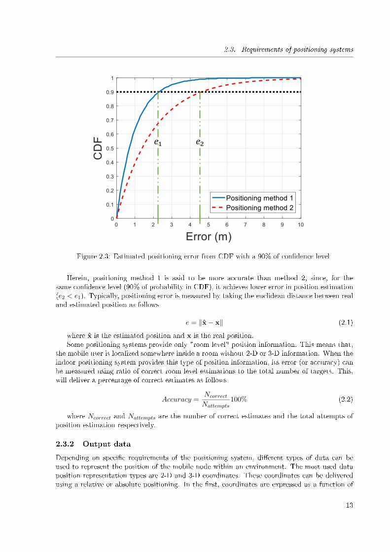
Accuracy of a localization system can be de�ned as the deviation between position estimationand true value. The concept "measurement accuracy" cannot quanti�ed numerically. A positionestimation is said to be "more" accurate when it o�ers a smaller estimation error. In order toclassify methods by its accuracy, statistical information of estimation error is used. Accuracy ofa system is obtained by using the cumulative distribution function (CDF) of positioning errors.In Figure 2.3 the PDF of two di�erent position estimation are shown.
12
2.3. Requirements of positioning systems
𝑒1 𝑒2
Figure 2.3: Estimated positioning error from CDF with a 90% of con�dence level
Herein, positioning method 1 is said to be more accurate than method 2, since, for thesame con�dence level (90% of probability in CDF), it achieves lower error in position estimation(e2 < e1). Typically, positioning error is measured by taking the euclidean distance between realand estimated position as follows
e = ‖x− x‖ (2.1)
where x is the estimated position and x is the real position.Some positioning systems provide only "room level" position information. This means that,
the mobile user is localized somewhere inside a room without 2-D or 3-D information. When theindoor positioning system provides this type of position information, its error (or accuracy) canbe measured using ratio of correct room level estimations to the total number of targets. This,will deliver a percentage of correct estimates as follows
Accuracy =Ncorrect
Nattempts100% (2.2)
where Ncorrect and Nattempts are the number of correct estimates and the total attempts ofposition estimation respectively.
2.3.2 Output data
Depending on speci�c requirements of the positioning system, di�erent types of data can beused to represent the position of the mobile node within an environment. The most used dataposition representation types are 2-D and 3-D coordinates. These coordinates can be deliveredusing a relative or absolute positioning. In the �rst, coordinates are expressed as a function of
13
2.3. Requirements of positioning systems
0 0.1 0.2 0.3 0.4 0.5 0.6 0.7 0.8 0.9 1
x axis (m)
0
0.1
0.2
0.3
0.4
0.5
0.6
0.7
0.8
0.9
1
y ax
is (
m)
EstimatedReal
(a)
0 0.1 0.2 0.3 0.4 0.5 0.6 0.7 0.8 0.9 1
x axis (m)
0
0.1
0.2
0.3
0.4
0.5
0.6
0.7
0.8
0.9
1
y ax
is (
m)
EstimatedReal
(b)
0 0.1 0.2 0.3 0.4 0.5 0.6 0.7 0.8 0.9 1
x axis (m)
0
0.1
0.2
0.3
0.4
0.5
0.6
0.7
0.8
0.9
1
y ax
is (
m)
EstimatedReal
(c)
0 0.1 0.2 0.3 0.4 0.5 0.6 0.7 0.8 0.9 1
x axis (m)
0
0.1
0.2
0.3
0.4
0.5
0.6
0.7
0.8
0.9
1
y ax
is (
m)
EstimatedReal
(d)
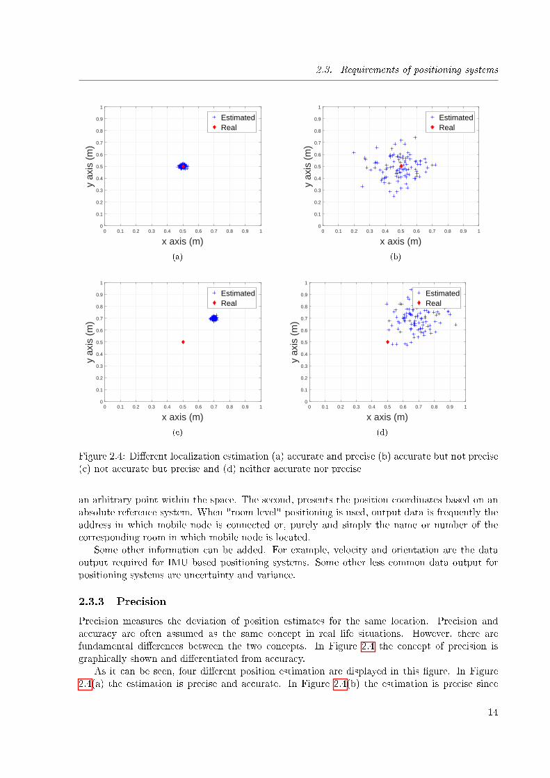
Figure 2.4: Di�erent localization estimation (a) accurate and precise (b) accurate but not precise(c) not accurate but precise and (d) neither accurate nor precise
an arbitrary point within the space. The second, presents the position coordinates based on anabsolute reference system. When "room level" positioning is used, output data is frequently theaddress in which mobile node is connected or, purely and simply the name or number of thecorresponding room in which mobile node is located.
Some other information can be added. For example, velocity and orientation are the dataoutput required for IMU based positioning systems. Some other less common data output forpositioning systems are uncertainty and variance.
2.3.3 Precision
Precision measures the deviation of position estimates for the same location. Precision andaccuracy are often assumed as the same concept in real life situations. However, there arefundamental di�erences between the two concepts. In Figure 2.4 the concept of precision isgraphically shown and di�erentiated from accuracy.
As it can be seen, four di�erent position estimation are displayed in this �gure. In Figure2.4(a) the estimation is precise and accurate. In Figure 2.4(b) the estimation is precise since
14
2.3. Requirements of positioning systems
but not accurate since the exist a high dispersion in position estimations. On the other hand,Figure 2.4(c) shown precise but not accurate estimations since the dispersion is low but theerror between the real position and the estimated position is high. Finally, Figure 2.4(d) showsposition estimation that is neither accurate or precise since the error and dispersion of estimatesare high.
2.3.4 Coverage
The coverage of a positioning system can be de�ned as the spatial extension in which the per-formance of the system must be guaranteed [Mau12]. Three categories of coverage are available:
• Local coverage: Local coverage is refereed to a small and well-de�ned area which could bea room or a building. Local coverage is not extendable (or scalable). Its coverage is de�nedin m, m2 or m3.
• Scalable coverage: This type of systems have the ability of extend the area of coverage byadding hardware infrastructure. In addition to this, the system must not compromise itsaccuracy when extending its coverage.
• Global coverage: Is a system that can perform worldwide. Only GNSS system and celestialnavigation can be considered in this category.
2.3.5 Cost
The cost of a positioning system can be divided in di�erent sub-categories where not only mon-etary price is considered.
• Time cost: considers the time required to install and administrate the positioning system.
• Capital cost: The capital cost considers the infrastructure cost (prices per mobile and staticdevices) and salaries of support personnel.
• Maintenance cost: Is the cost for maintain the system functioning.
• Space cost: Takes into account the amount of required infrastructure and hardware's size.
2.3.6 Required infrastructure
The required infrastructure refers to the deployed hardware needed to perform positioning. Therequired infrastructure may vary depending on the localization solution. As an example, noinfrastructure is required for pedestrian dead reckoning. On the other hand, dedicated infras-tructure must be deployed for RFID and some Bluetooth based solutions. In these applicationshardware is deployed in order to provide exclusively location services. Finally, Wi� and visiblelight communications (VLC) based positioning solutions are considered as pre-deployed infras-tructure since they use the already deployed network to provide communication and positioning.In section 2.4.3 a more detailed insight of required infrastructure is delivered.
15
2.3. Requirements of positioning systems
2.3.7 Robustness
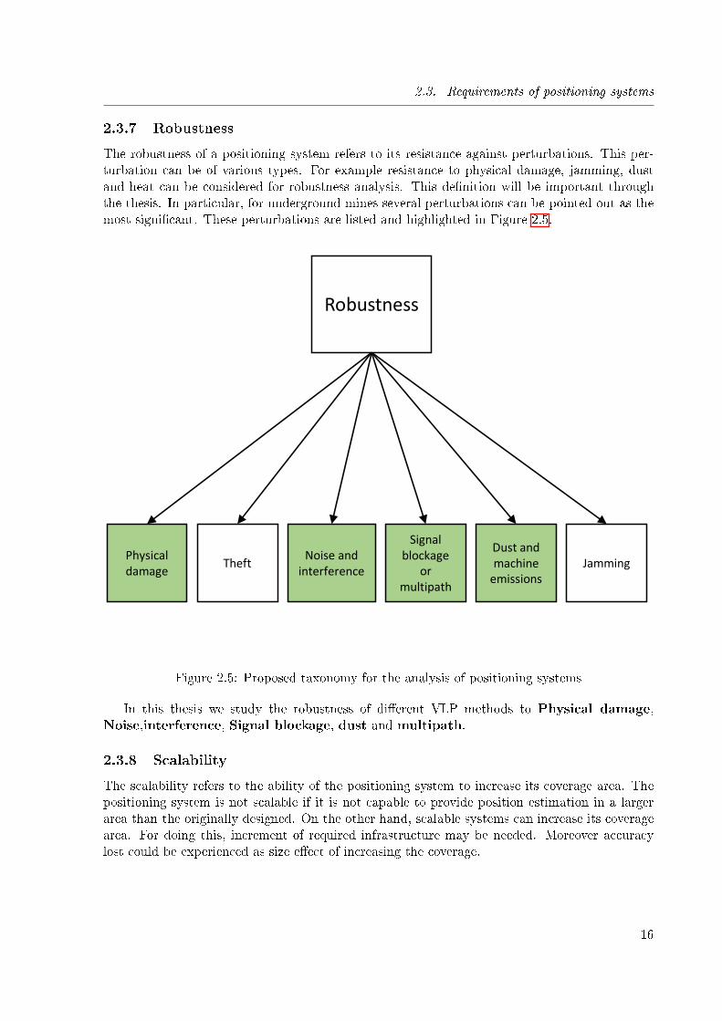
The robustness of a positioning system refers to its resistance against perturbations. This per-turbation can be of various types. For example resistance to physical damage, jamming, dustand heat can be considered for robustness analysis. This de�nition will be important throughthe thesis. In particular, for underground mines several perturbations can be pointed out as themost signi�cant. These perturbations are listed and highlighted in Figure 2.5.
Robustness
Physical damage
TheftNoise and
interference
Signal blockage
or multipath
Dust and machine
emissionsJamming
Figure 2.5: Proposed taxonomy for the analysis of positioning systems
In this thesis we study the robustness of di�erent VLP methods to Physical damage,Noise,interference, Signal blockage, dust and multipath.
2.3.8 Scalability
The scalability refers to the ability of the positioning system to increase its coverage area. Thepositioning system is not scalable if it is not capable to provide position estimation in a largerarea than the originally designed. On the other hand, scalable systems can increase its coveragearea. For doing this, increment of required infrastructure may be needed. Moreover accuracylost could be experienced as size e�ect of increasing the coverage.
16
2.3. Requirements of positioning systems
2.3.9 Update rate
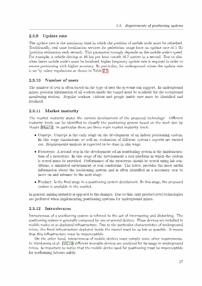
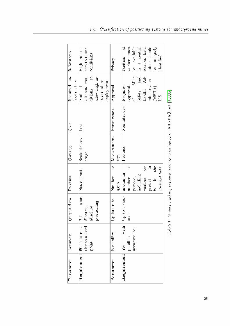
The update rate is the maximum time in which the position of mobile node must be refreshed.Traditionally, real time localization services for pedestrian usage have an update rate of 1 Hz(position estimation each second). This parameter strongly depends on the mobile node's speed.For example, a vehicle driving at 16 km per hour travels 16.7 meters in a second. Due to this,when faster mobile node's must be localized, higher frequency update rate is required in order toensure positioning with higher accuracy. In particular, for underground mines the update rateis set by safety regulations as shown in Table 2.1.
2.3.10 Number of users
The number of user is often based on the type of user the systems can support. In undergroundmines, position information of all workers inside the tunnel must be available for the overgroundmonitoring station. Regular workers, visitors and people inside cars must be identi�ed andlocalized.
2.3.11 Market maturity
The market maturity states the current development of the proposed technology. Di�erentmaturity levels can be identi�ed to classify the positioning system based on the work don byMautz [Mau12]. In particular there are three main market maturity levels
• Concept: Concept is the early stage on the development of an indoor positioning system.In this stage simulations, as well as, evaluation of di�erent system's aspects are carriedout. Requirements analysis is expected to be done in this stage.
• Prototype: A second step in the development od an positioning system is the implementa-tion of a prototype. In this stage of the development a real platform in which the systemis tested must be provided. Performance of the prototype should be tested using lab con-ditions, a simulated environment or real conditions. The latter, provides the most usefulinformation about the positioning system and is often identi�ed as a necessary step tomove on and advance to the next stage.
• Product: Is the �nal stage in a positioning system develpment. In this stage, the proposedsystem is available in the market.
In general, mining industry is opposed to the changes. Due to this, only product level technologiesare preferred when implementing positioning systems for underground mines.
2.3.12 Intrusiveness
Intrusiveness of a positioning system is refereed to the act of interrupting and disturbing. Thepositioning system is generally composed by one or several devices. These devices are installed inmobile nodes or as deployed infrastructure. Due to the particular characteristics of undergroundmines, the �xed infrastructure deployed inside the tunnel must be as low as possible. It meansthat this infrastructure must be imperceptible.
On the other hand, intrusiveness of mobile devices must comply some other requirements.In Mardonova et.al. [MC18] di�erent wearable devices are analysed for its usage in undergroundmines. Is important to notice that the mobile device used for positioning must be imperceptiblefor performing labours safely.
17
2.4. Classi�cation of positioning systems for underground mines
2.3.13 Approval
Some regulations stablish the need of approval from governmental or private agencies for theimplementation of positioning systems in some environments. As an example, the MINERS-Actof 2006 [10906] establishes the need of approval from Mine Safety and Health Administration(MISHA) in order to be capable of functioning in an underground mine.
2.4 Classi�cation of positioning systems for underground mines
Positioning systems are used to determined the position of a person and/or device relative to akwown position or within a coordinate system [ZB11]. Basically, any Positioning system has twomain components, i.e., "known" nodes and "unknown" nodes. Known nodes are aware of theirposition. On the other hand, position of unknown nodes is to be determined by the positioningsystem. Known nodes are also named as anchor nodes, reference nodes or beacon nodes in theliterature whilst unknown nodes are often named as dumb nodes, target node or to-be-locatednodes [LYWJ10].
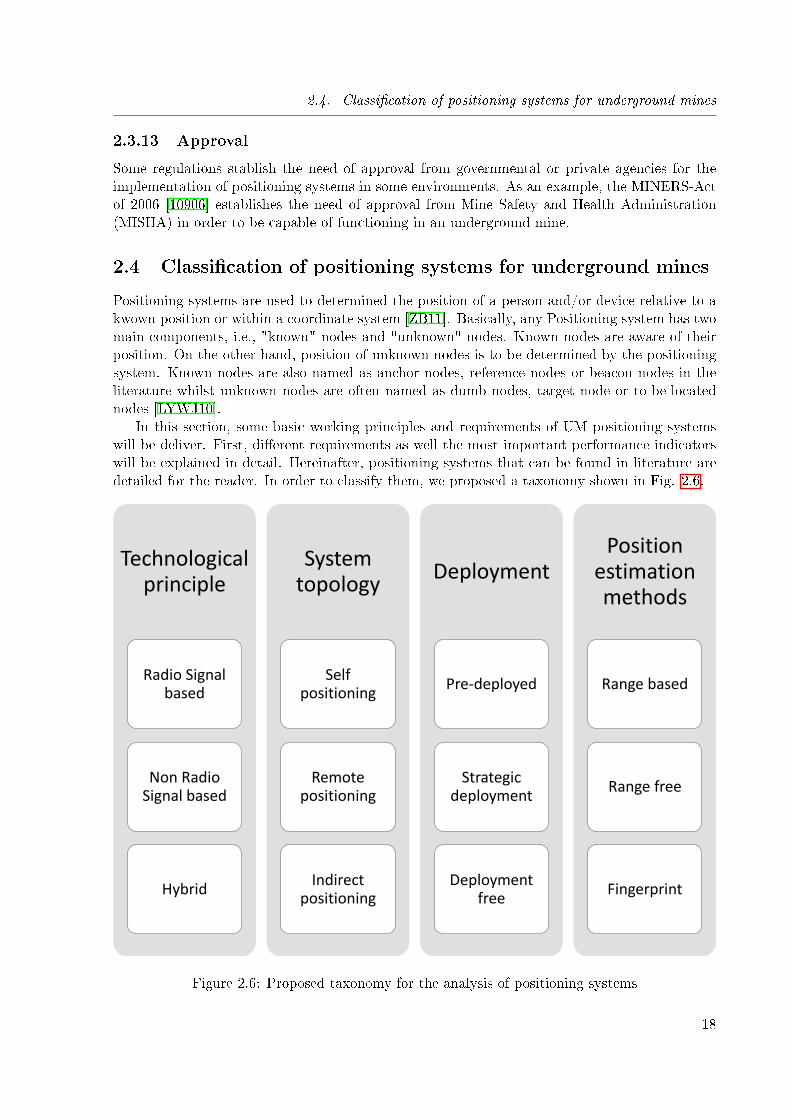
In this section, some basic working principles and requirements of UM positioning systemswill be deliver. First, di�erent requirements as well the most important performance indicatorswill be explained in detail. Hereinafter, positioning systems that can be found in literature aredetailed for the reader. In order to classify them, we proposed a taxonomy shown in Fig. 2.6.
Technological principle
Radio Signal based
Non Radio Signal based
Hybrid
System topology
Self positioning
Remote positioning
Indirect positioning
Deployment
Pre-deployed
Strategic deployment
Deployment free
Position estimation methods
Range based
Range free
Fingerprint
Figure 2.6: Proposed taxonomy for the analysis of positioning systems
18
2.4. Classi�cation of positioning systems for underground mines
The proposed taxonomy classi�es positioning systems by using four di�erent characteristics.Each element of the proposed taxonomy is explained in detail below.
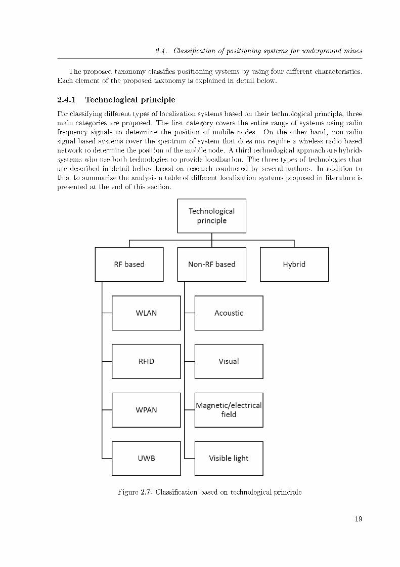
2.4.1 Technological principle
For classifying di�erent types of localization systems based on their technological principle, threemain categories are proposed. The �rst category covers the entire range of systems using radiofrequency signals to determine the position of mobile nodes. On the other hand, non-radiosignal based systems cover the spectrum of system that does not require a wireless-radio basednetwork to determine the position of the mobile node. A third technological approach are hybridssystems who use both technologies to provide localization. The three types of technologies thatare described in detail bellow based on research conducted by several authors. In addition tothis, to summarize the analysis a table of di�erent localization systems proposed in literature ispresented at the end of this section.
Figure 2.7: Classi�cation based on technological principle
19
2.4. Classi�cation of positioning systems for underground mines
Parameter
Accuracy
Outputdata
Precision
Coverage
Cost
Required
in-
frastructure
Robustness
Requirement60.96m
rela-
tive
toa�xed
point
2-D
coor-
dinates,
absolute
positioning
Not
de�ned
Scalable
cov-
erage
Low
Ambient
without
con-
ditions
toallowhighin-
frastructure
deployment
High
robust-
nessto
tunnel
conditions
Parameter
Scalability
Updaterate
Number
ofusers
Marketmatu-
rity
Intrusiveness
Approval
Privacy
RequirementYes
with
possible
accuracy
lost
Upto
60sec-
onds
maximum
number
ofpersons,
including
visitors
ex-
pected
tobe
inthe
coverage
area
Product
Non
intrusive
Requires
approval
ofMine
Safety
and
Health
Ad-
ministration
(MSHA),
U.S.
Position
ofworkers
must
be
available
ina
central
station.Each
miner
should
be
uniquely
identi�ed
Table2.1:
Minerstrackingsystem
srequirem
ents
based
onMIN
ERSAct
[10906]
20
2.4. Classi�cation of positioning systems for underground mines
Radio signal based systems
Radio signal based systems are those that use the radio-frequency spectrum of the electromag-netic waves to determine the position of the mobile node. Radio signal based systems has theadvantage that they can be used to provide two main pillars of location based services, i.e., helpin the position estimation process and the capability to transmit wireless information allowingmobility of the unknown node. Underground mines are a very challenging environment for radiofrequency based signals. Behaviour of RF signals is di�erent in mine tunnels than in any otherregular environment. This, due to the physical shape of the tunnel can cause signal scattering,multipath propagation and blockage (pillars, U turns, etc.). Moreover, tunnel walls are composedby di�erent materials depending on the mine site. Due to this, electromagnetic characteristicssuch as dielectricity and conductivity of each tunnel are unique and they have an e�ect on theradio frequency signal propagation. The proposed radio signal based system must cope withthese challenges.
• Wireless Local Area Networks (WLAN): WLAN (IEEE 802.11) is a well stablish wirelesscommunications technology in various industry sectors. WLAN standards use the Indus-trial, Scienti�c and Medical (ISM) bands in 5 and 2.4 GHz to provide full-duplex wirelesscommunications. This type of networks are thought to deliver data transmission within arate between 1 to 108 Mbps and a coverage range between 50 and 150 meters depending onthe characteristic of the environment and line-of-sight (LOS) is not required for data trans-mission. Experimental demonstration of WLAN , in particular IEEE 802.11b standardhas been conducted in [YGAM09]. The mine site where WLAN was tested correspondto a longwall tunnel. Ranges up to 150 meters were achieved, whereas 802.11b devicesare expected to provide a maximum range of 50 meters. In case WLAN is provided asalready-deployed communications infrastructure, localization systems can be rapidly deliv-ered without requiring any further deployment. WLAN standards provide the capabilityto implement diverse position estimation methods. Particularly, proximity and laterationmethods are preferred since o�-the-shelf devices are equipped with the required hardware.
• Radio Frequency Identi�cation (RFID): This type of systems are capable to store andretrieve data using radio waves. RFID systems comprise two main components i.e., RFIDreader and RFID tags. RFID reader is capable to obtain the information stored in RFIDtags using a pre-de�ned protocol. RFID tags can be classi�ed in three groups, these are:passive tags,semi passive tags and active tags. Active tags transmit their information toreader previous to a query or independently. Since active tags are equipped with batteriesthey are capable to working with low-power received signals. In addition to this, theycan be associated easily with di�erent type of sensors. Nevertheless, due to the usage ofbatteries, tey are more expensive and have a more limited lifetime compared to passiveand semi passive tags. Semi passive tags are known also as battery-assisted tags use theirbattery prior to a reader query in order to increase its communication range. They havea battery life of about �ve years and once it is drown they acts as passive tags. Theircoverage range is between active and passive tags (<10 meters). Passive RFID tags arecapable to operate without a battery. The RF signal coming from the reader power ups anintegrated circuit that generates the response to the reader's query. Their main drawbackis its short communication range (3-5 meters). Usually, RFID reader and tags are notpre-installed as communication infrastructure. Due to this, this type of system needs tobe deployed for a speci�c purpose. Moreover, due to its short coverage range, strategicdeployment of readers is required in order to provide full coverage.
21
2.4. Classi�cation of positioning systems for underground mines
• Wireless personal area networks (WPAN): WPAN, standardized in IEEE 802.15 have beenextensively investigated in underground environments. These networks o�er bi-directionalwireless communications. Compared to WLAN their coverage range is much shorter andthey do not posses pre-deployed infrastructure. Standards such as IEEE 802.15.4a andECMA-368 (which will be discussed next) include positioning features. Nevertheless, theyhave not been used extensively in positioning systems intended for underground mines. Inparticular, two standards are preferred for using in underground scenarios, i.e., Bluetooth(IEEE 802.15.1) and ZigBee (IEEE 802.15.4). Each WPAN standard di�ers signi�cantlyin their physical layer. Due to this, each standard will be detailed separately below.
Bluetooth: This type of systems have a maximum coverage range of up to 10 m dependingon the propagation conditions of the environment when a class 3 transmitter with a poweroutput of 1 mW are used. They use the ISM band in 2.4 GHz to provide wireless commu-nication with a rate between 1 and 3 Mbps. In general, o�-the-shelf bluetooth devices arenot equipped with the necessary hardware to provide lateration-based positioning. Due tothis, proximity methods are preferred in this type of systems since no extra hardware isrequired.|ZigBee: ZigBee technology is a low data rate WPAN standard with data rate up to 250Kbps operating in the band of 2.4 GHz. This standard is also speci�ed for 868�870-MHzand 902�928-MHz bands at 20 and 40 kbps, respectively. ZigBee networks are principallyintended for low cost and low power monitoring and control applications. The coveragerange of ZigBee nodes in indoor environments is 20 to 30 meters. ZigBee technology is ca-pable to provide lateration and cell of origin based positioning using o�-the-shelf devices.
• Ultra Wide Band (UWB): Ultra wide band systems have been subject of extensive re-search as a promising candidate for WPAN applications, sensor networks and ubiquitouscomputing [CFT12]. Due to its large bandwidth usage, regulation of these type of systemsrequired a completely di�erent approach. For instance, frequency channels assignation ofsuch large widths to speci�c users are not feasible because free spectrum is not available.For instance, ECMA-368 standard for WPAN uses the frequency band of 3 to 10 GHz.IEEE 802.15.4a include for the �rst time UWB and designated operating frequencies inthree ranges: bellow 1GHz, between 3 and 5 GHz, and between 6 and 10 GHz. UWBtechnology has extensively adopted for localization systems where accuracy on the order of1 meter is required. Its high accuracy is due to the precise time-of-�ight range estimationachieved by its large bandwidth. IEEE 802.15.4a is an example of a standard capable toprovide ranging accuracy of 1 meter or better.
Non-radio signal based systems
• Acoustic systems: In contrast to electromagnetic waves used by RF systems, acoustic sig-nals are mechanical waves. Mechanical waves are transmitted by the oscillation pressurein a medium such as air or building materials. Acoustic position estimation can be basedon ultrasound or audible sound. The estimated range of acoustic based positioning sys-tems is about 10 meters due to the speci�c decay pro�le of the airborne acoustic channel.Lateration based methods can be easily implemented using this type of systems using amicrophone array at the receiver side. Acoustic systems are severely a�ected by multipathpropagation, directivity of transducers and noise. In addition to this, increasing the powerof the signal is not a feasible alternative since loud sound signals from nodes to be localized
22
2.4. Classi�cation of positioning systems for underground mines
are energy-demanding which decreases the battery lifetime.
• Inertial Navigation Systems: INS estimate the mobile node position, velocity and orien-tation from an Inertial Measurement Unit(IMU). The inertial measurement unit consistof three motion sensors (orthogonally arranged accelerometers), three angular rate sensors(Gyroscopes) and/or a magnetometer (measuring the strength and/or direction of a mag-netic �eld). This type of systems provides independent operability. Due to this, they donot required a deployed infrastructure to estimate the mobile node position. When initialposition and orientation of the mobile device are known, subsequent positions, orientationsand velocities can be updated continuously via Dead Reckoning (DR) without the need forexternal reference positions. The accuracy of the propagated position depends heavily onthe quality of the initially provided position and orientation. Accelerometer measurementsare also corrupted by noise. Due to this, INS decrease their accuracy over the travelleddistance.
• Signage and Maps: Signage and maps are traditionally the most available approach forhuman navigation in indoor environments. Actual position is provided by using staticsignalling and, in order to help the mobile user to reach his destination, a partial orcomplete map display of the environment is provided. Nowadays, new signs and maps arereplacing this traditional approach. For instance, cameras and mobile devices can replaceuser's sight and reasoning to provide positioning and navigation. In [XYY+17] the usageof a camera to scan unique "markers" is proposed. By doing so, the unique mark providesinformation to a mobile phone application to determine actual position. On the otherhand, the approach proposed in [DAMG15] tries to match the complete acquired imageswith a database of the building's �oor plan. If a match is found, the current location isdisplayed.
• Magnetic/electrical �eld: Contrary to electromagnetic waves (RF systems), magnetic wavesare capable to penetrate walls inside buildings without propagation error. Due to this, mag-netic �eld based localization systems does not su�er from several drawbacks encountered inelectromagnetic systems, such as, multipath and signal delay e�ects among others. Whenusing magnetic �elds for indoor positioning, a distinction on the nature of the magnetic�eld must be done. Two di�erent types of systems can be considered, natural magnetic�eld based system and arti�cial magnetic �eld based system. Additionally, natural can beclassi�ed in two sub-types, geomagnetism and permanent magnets. Geomagnetism basedsystems use the natural earth's magnetic �eld to provide positioning. Inherent structureon interior tunnels produce disturbances on the natural �eld. These variations can be usedas a �ngerprint to determine the mobile node position. On the other hand, permanentmagnets can be used in the mobile node. Magnetic �eld sensors place at known placesmeasure the magnetic density �ux produced bu the magnet in order to determine its po-sition. The second type of localization systems based on magnetic �elds use arti�ciallygenerated magnetic �elds. In this type of systems, a variable electrical current circulatingin concentric coils is used to create the arti�cial and controlled magnetic �eld (Lenz e�ect).Usually, the arti�cially induced magnetic �elds have a short coverage range (less than 3 m)and, due to this, their application is limited to small volumes.
• Visible light communications (VLC): These systems use the visible spectrum of electromag-netic waves to provide communication. This type of systems have recently emerged andhas been subject of extensive research for the research community. The recent advances
23
2.4. Classi�cation of positioning systems for underground mines
in lighting technology, in particular lighting emitting diodes (LED) have transformed VLCsystem in a feasible and applicable technology. VLC technology transmits information bymodulating the intensity of an optical source at a rate much more faster than the responsetime of human's eye making the change on the optical source unnoticeable. As a conse-quence, VLC systems are capable to provide illumination and wireless communication atthe same time. As the lighting infrastructure is assume to be pre-deployed, only a fewmodi�cation on the lighting devices is required. These systems used require mostly line-of-sight (LOS). In addition to this, VLC link is used mostly to provide the downlink and,hybridization with RF and Infra-red (IR) systems is proposed to provide full-duplex com-munication. In literature, the term visible light positioning (VLP) stands for localizationsystems that use VLC to provide positioning. In general, many of the approaches thatused in RF based positioning systems can be encountered in VLP.
Hybrid systems
as it can be seen, numerous technologies can be used to provide positioning. Each technologyposses their own pros and cons in terms of performance, coverage, etc. Due to this, the idea ofcombining di�erent types of localization technologies to overcome di�culties and/or improve thesystem's performance arises. The main problem of this type of systems is that there does notexist an uni�ed systematic evaluation on the possible trade-o�s and drawbacks of using di�erenttechnologies simultaneously for localization purposes. In the literature, diverse hybrid local-ization systems be encountered. They are mainly focused in increase the performance (mainlyaccuracy) and coverage of traditional single-technology approaches.
2.4.2 System topology
The deployment of anchor nodes as well as the mobility of dumb nodes has an important ef-fect on the performance of the localization system. [DMS98]. Localization systems can beclassi�ed in three di�erent groups considering the topology of the system, i.e., self-positioning,remote-positioning and indirect-positioning. This classi�cation is useful when evaluating a po-sitioning system for a particular application. Di�erent approaches will be classi�ed based onwhere the position measurements are performed and where the obtained position information isused. [DMS98]. The three categories are detailed below.
• Remote positioning: In this type of systems the anchor nodes receive the signal originatedfrom or re�ecting o� the dumb node. Measurements of the signal are transmitted to acentral station where they are used to estimate a position as shown in Fig.2.8(a). Thesetype of positioning systems are used in centralized LBS.
• Self Positioning: In self positioning systems the dumb node performs the measurement ofthe signal sent by the anchor nodes and uses these measurements to perform localization.Using this type of topology the mobile node or user is aware of its position. Nevertheless,this position information can be only used in distributed applications as shown in Fig.2.8(b).
• Indirect Positioning: When the networks used to perform localization is capable to transmitdata indirect positioning topology can be used. In this scheme the estimated position byself-positioning or remote-positioning can be re-transmitted as illustrated in Fig.2.8(c).When the self positioning system sends its information to a remote or central station isreferred to as indirect remote-positioning. On the other hand, when a remote positioning
24
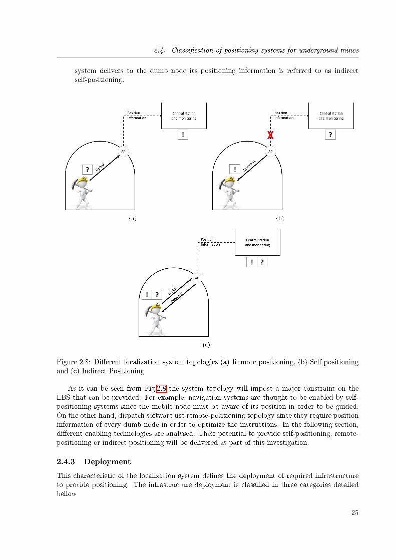
2.4. Classi�cation of positioning systems for underground mines
system delivers to the dumb node its positioning information is referred to as indirectself-positioning.
!
?
(a)
!
?
(b)
! ?
! ?
(c)
Figure 2.8: Di�erent localization system topologies (a) Remote positioning, (b) Self positioningand (c) Indirect Positioning
As it can be seen from Fig.2.8 the system topology will impose a major constraint on theLBS that can be provided. For example, navigation systems are thought to be enabled by self-positioning systems since the mobile node must be aware of its position in order to be guided.On the other hand, dispatch software use remote-positioning topology since they require positioninformation of every dumb node in order to optimize the instructions. In the following section,di�erent enabling technologies are analysed. Their potential to provide self-positioning, remote-positioning or indirect positioning will be delivered as part of this investigation.
2.4.3 Deployment
This characteristic of the localization system de�nes the deployment of required infrastructureto provide positioning. The infrastructure deployment is classi�ed in three categories detailedbellow
25
2.5. Systems proposed in literature
• Pre-Deployed: In this type of localization systems the required infrastructure is alreadydeployed in the scenario. In particular, systems that uses the wireless communicationinfrastructure (WLAN, VLC, etc.) to provide localization are the most representativesystems.
• Strategic Deployment: This type of systems require special deployment of localization in-frastructure to provide positioning. Systems such as RFID, magnetic, acoustics and WPANbased systems are some examples of localization technologies that require the installationof dedicated infrastructure to determine the position of the mobile node.
• Deployment-Free: These systems do not require infrastructure deployment to provide po-sitioning. Usually, inertial sensors and map knowledge are used in indoor scenarios.
2.5 Systems proposed in literature
In current literature, di�erent systems have been proposed to deal with the problem of under-ground mine positioning. In this section each proposal is presented and analysed.
In Table 2.2 the main contributions existing in literature are presented. These undergroundmine positioning systems have been evaluated based on their technological principle, topology,infrastructure requirements, accuracy and implementation.
When RF technology is used for underground positioning Zig-bee technology is preferredamong the others. Di�erent range based and range free methods can be implemented by usingthis technology. In particular TOF and RSS based range free methods are preferred since thistype of networks are capable to provide signal strength measurements and propagation timemeasurements without requiring additional hardware. The main problem of using Zig-bee tech-nology to provide localization services is that this type of networks have a low data rate. Dueto this, communications applications are constrained to low data-rate demanding services. Someproposals have been evaluated in real scenario reaching level meter accuracy.
On the other hand, WLAN networks are capable to provide higher data rates. Due to thisWLAN architecture can be used as a pre deployed networks that provides wireless communi-cations with localization capabilities. RSSI based range based and �ngerprinting methods arepreferred since WLAN devices do not require extra hardware to measure the signal strength.
UWB and Bluetooth technology have been also proposed to face the positioning problem inunderground mines. Despite achieving a high accuracy in real scenarios, these techniques arenot cost e�ective. In general, UWB devices are expensive and Bluetooth solution requires a highnumber of devices deployed inside the tunnel to reach acceptable coverage and accuracy.
26
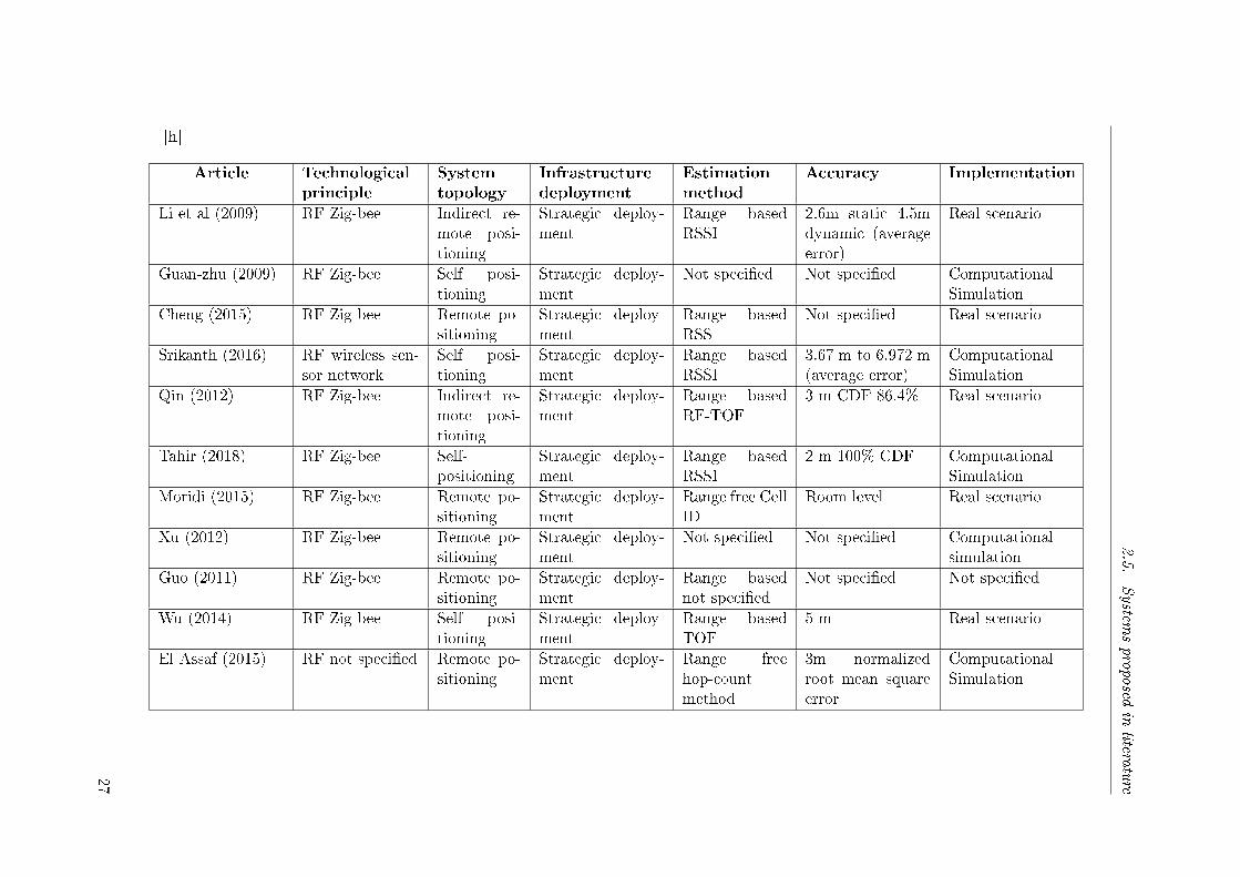
2.5.
System
sproposed
inlitera
ture
[h]
Article Technologicalprinciple
Systemtopology
Infrastructuredeployment
Estimationmethod
Accuracy Implementation
Li et al (2009) RF Zig-bee Indirect re-mote posi-tioning
Strategic deploy-ment
Range basedRSSI
2.6m static 4.5mdynamic (averageerror)
Real scenario
Guan-zhu (2009) RF Zig-bee Self posi-tioning
Strategic deploy-ment
Not speci�ed Not speci�ed ComputationalSimulation
Cheng (2015) RF Zig-bee Remote po-sitioning
Strategic deploy-ment
Range basedRSS
Not speci�ed Real scenario
Srikanth (2016) RF wireless sen-sor network
Self posi-tioning
Strategic deploy-ment
Range basedRSSI
3.67 m to 6.972 m(average error)
ComputationalSimulation
Qin (2012) RF Zig-bee Indirect re-mote posi-tioning
Strategic deploy-ment
Range basedRF-TOF
3 m CDF 86.4% Real scenario
Tahir (2018) RF Zig-bee Self-positioning
Strategic deploy-ment
Range basedRSSI
2 m 100% CDF ComputationalSimulation
Moridi (2015) RF Zig-bee Remote po-sitioning
Strategic deploy-ment
Range free CellID
Room level Real scenario
Xu (2012) RF Zig-bee Remote po-sitioning
Strategic deploy-ment
Not speci�ed Not speci�ed Computationalsimulation
Guo (2011) RF Zig-bee Remote po-sitioning
Strategic deploy-ment
Range basednot speci�ed
Not speci�ed Not speci�ed
Wu (2014) RF Zig-bee Self posi-tioning
Strategic deploy-ment
Range basedTOF
5 m Real scenario
El Assaf (2015) RF not speci�ed Remote po-sitioning
Strategic deploy-ment
Range freehop-countmethod
3m normalizedroot mean squareerror
ComputationalSimulation
27
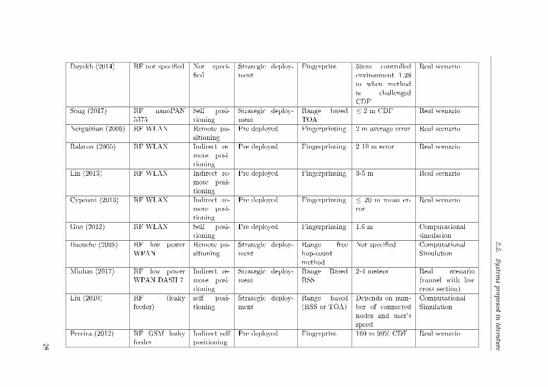
2.5.
System
sproposed
inlitera
ture
Dayekh (2014) RF not speci�ed Not speci-�ed
Strategic deploy-ment
Fingerprint 50cm controlledenvironment 1.28m when methodis challengedCDF
Real scenario
Song (2017) RF nanoPAN5375
Self posi-tioning
Strategic deploy-ment
Range basedTOA
≤ 2 m CDF Real scenario
Nerguizian (2006) RF WLAN Remote po-sitioning
Pre deployed Fingerprinting 2 m average error Real scenario
Ralston (2005) RF WLAN Indirect re-mote posi-tioning
Pre deployed Fingerprinting 2-10 m error Real scenario
Lin (2013) RF WLAN Indirect re-mote posi-tioning
Pre deployed Fingerprinting 3-5 m Real scenario
Cypriani (2013) RF WLAN Indirect re-mote posi-tioning
Pre deployed Fingerprinting ≤ 20 m mean er-ror
Real scenario
Guo (2012) RF WLAN Self posi-tioning
Pre deployed Fingerprinting 1.6 m Computationalsimulation
Baouche (2008) RF low powerWPAN
Remote po-sitioning
Strategic deploy-ment
Range freehop-countmethod
Not speci�ed ComputationalSimulation
Minhas (2017) RF low powerWPAN DASH-7
Indirect re-mote posi-tioning
Strategic deploy-ment
Range BasedRSS
2-4 meters Real scenario(tunnel with lowcross section)
Liu (2010) RF (leakyfeeder)
self posi-tioning
Strategic deploy-ment
Range based(RSS or TOA)
Depends on num-ber of connectednodes and user'sspeed
ComputationalSimulation
Pereira (2012) RF GSM leakyfeeder
Indirect selfpositioning
Pre deployed Fingerprint 160 m 90% CDF Real scenario
28
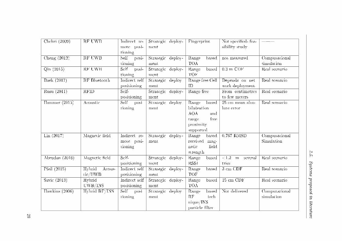
2.5.
System
sproposed
inlitera
ture
Chehri (2009) RF UWB Indirect re-mote posi-tioning
Strategic deploy-ment
Fingerprint Not speci�ed- fea-sibility study
��
Cheng (2012) RF UWB Self posi-tioning
Strategic deploy-ment
Range basedTOA
not measured Computationalsimulation
Qin (2015) RF UWB Self posi-tioning
Strategic deploy-ment
Range basedTOF
0.3 m CDF Real scenario
Baek (2017) RF Bluetooth Indirect selfpositioning
Strategic deploy-ment
Range free CellID
Depends on net-work deployment
Real scenario
Rusu (2011) RFID Self-positioning
Strategic deploy-ment
Range free From centimetresto few meters
Real scenario
Hammer (2015) Acoustic Self posi-tioning
Strategic deploy-ment
Range basedbilateationAOA andrange freeproximitysupported
25 cm mean abso-lute error
Real scenario
Lin (2017) Magnetic �eld Indirect re-mote posi-tioning
Strategic deploy-ment
Range basedreceived mag-netic �eldstrength
0.767 RMSD ComputationalSimulation
Abrudan (2016) Magnetic �eld Self-positioning
Strategic deploy-ment
Range basedRSSI
<1.2 m severaltries
Real scenario
Pfeil (2015) Hybrid Acous-tic/UWB
Indirect selfpositioning
Strategic deploy-ment
Range basedTOF
3 cm CDF Real scenario
Savic (2013) HybridUWB/INS
Indirect selfpositioning
Strategic deploy-ment
Range basedTOA
15 cm CDF Real scenario
Hawkins (2006) Hybrid RF/INS Self posi-tioning
Strategic deploy-ment
Range basedRF tech-nique/INSparticle �lter
Not delivered Computationalsimulation
29
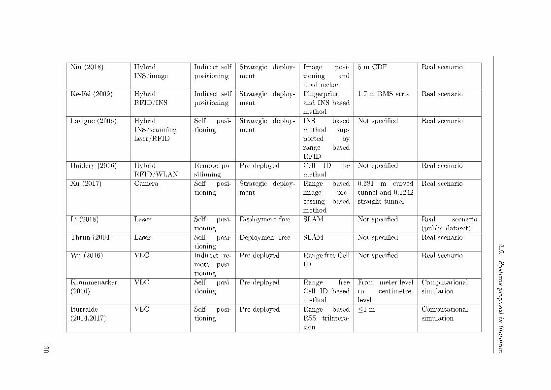
2.5.
System
sproposed
inlitera
ture
Niu (2018) HybridINS/image
Indirect selfpositioning
Strategic deploy-ment
Image posi-tioning anddead reckon
5 m CDF Real scenario
Ke-Fei (2009) HybridRFID/INS
Indirect selfpositioning
Strategic deploy-ment
Fingerprintand INS basedmethod
1.7 m RMS error Real scenario
Lavigne (2006) HybridINS/scanninglaser/RFID
Self posi-tioning
Strategic deploy-ment
INS basedmethod sup-ported byrange basedRFID
Not speci�ed Real scenario
Haidery (2016) HybridRFID/WLAN
Remote po-sitioning
Pre deployed Cell ID likemethod
Not speci�ed Real scenario
Xu (2017) Camera Self posi-tioning
Strategic deploy-ment
Range basedimage pro-cessing basedmethod
0.381 m curvedtunnel and 0.1242straight tunnel
Real scenario
Li (2018) Laser Self posi-tioning
Deployment free SLAM Not speci�ed Real scenario(public dataset)
Thrun (2004) Laser Self posi-tioning
Deployment free SLAM Not speci�ed Real scenario
Wu (2016) VLC Indirect re-mote posi-tioning
Pre deployed Range free CellID
Not speci�ed Real scenario
Krommenacker(2016)
VLC Self posi-tioning
Pre deployed Range freeCell ID basedmethod
From meter-levelto centimetre-level
Computationalsimulation
Iturralde(2014,2017)
VLC Self posi-tioning
Pre deployed Range basedRSS trilatera-tion
≤1 m Computationalsimulation
30
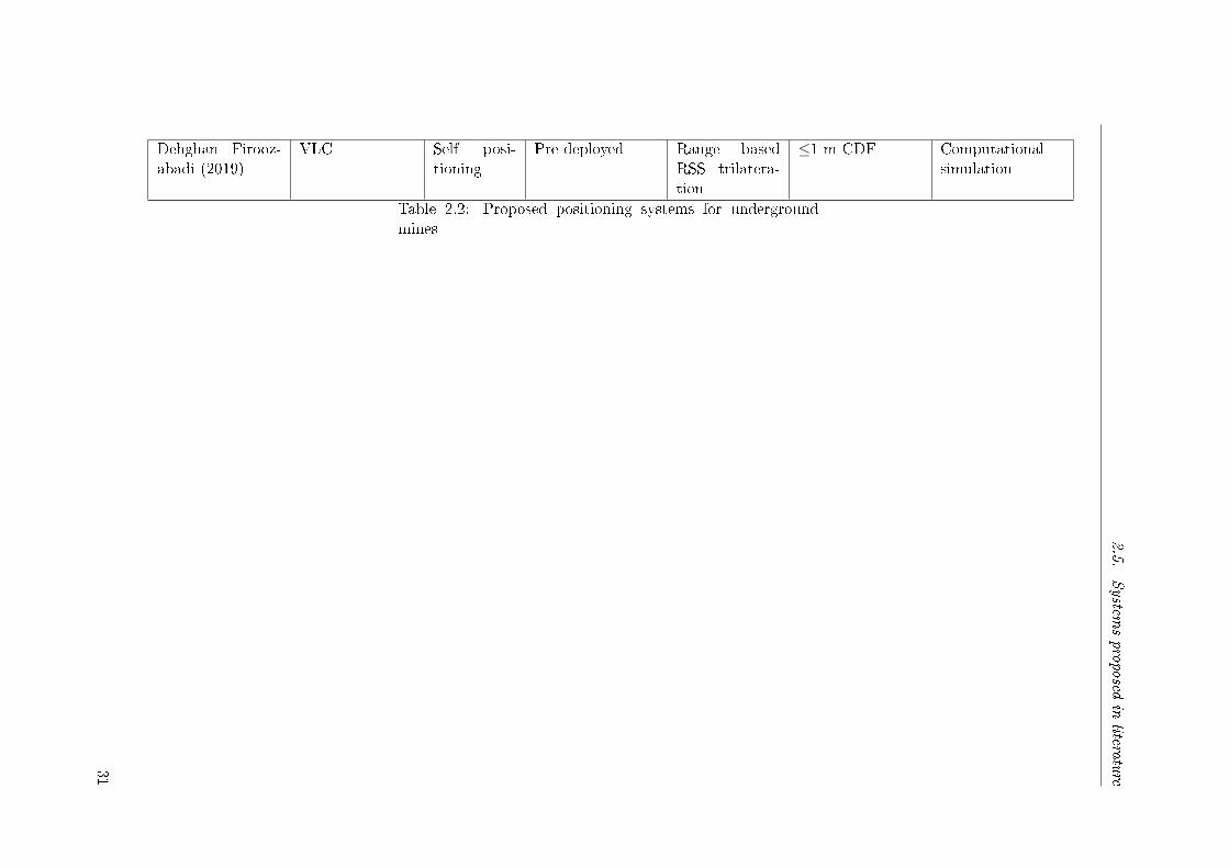
2.5.
System
sproposed
inlitera
ture
Dehghan Firooz-abadi (2019)
VLC Self posi-tioning
Pre deployed Range basedRSS trilatera-tion
≤1 m CDF Computationalsimulation
Table 2.2: Proposed positioning systems for undergroundmines
31
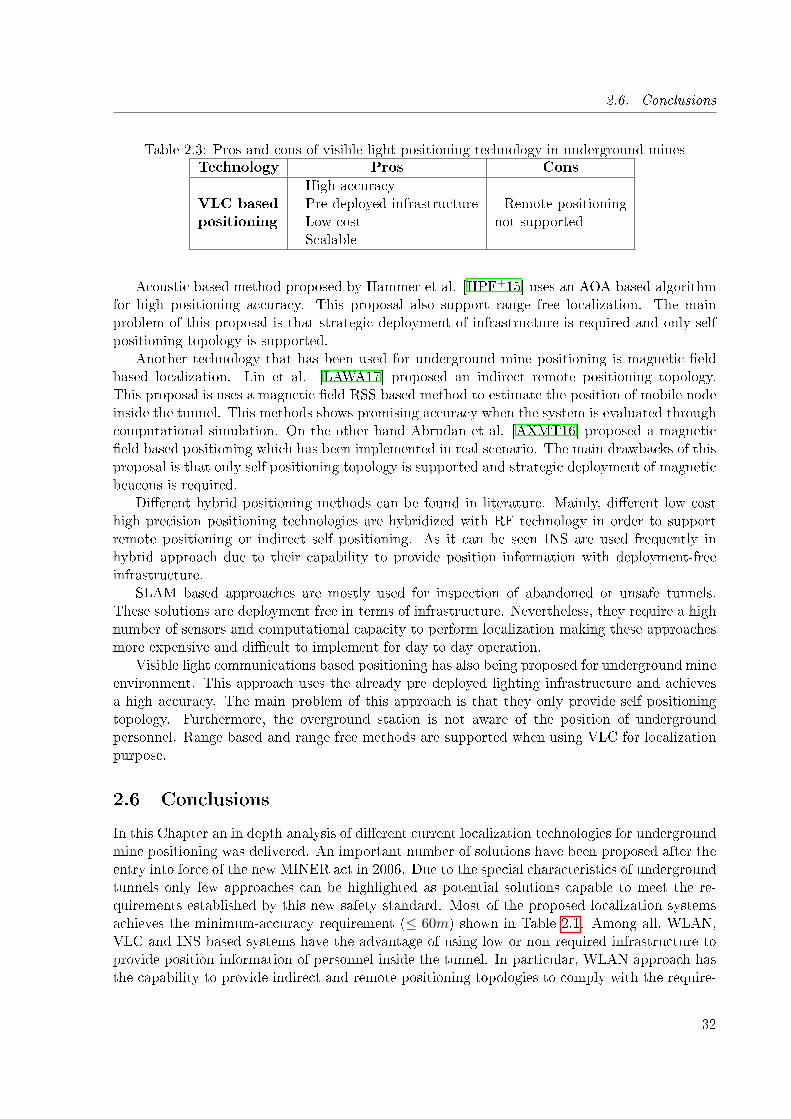
2.6. Conclusions
Table 2.3: Pros and cons of visible light positioning technology in underground minesTechnology Pros Cons
VLC basedpositioning
- High accuracy- Pre-deployed infrastructure- Low cost- Scalable
- Remote positioningnot supported
Acoustic based method proposed by Hammer et al. [HPF+15] uses an AOA based algorithmfor high positioning accuracy. This proposal also support range free localization. The mainproblem of this proposal is that strategic deployment of infrastructure is required and only selfpositioning topology is supported.
Another technology that has been used for underground mine positioning is magnetic �eldbased localization. Lin et al. [LAWA17] proposed an indirect remote positioning topology.This proposal is uses a magnetic �eld RSS based method to estimate the position of mobile nodeinside the tunnel. This methods shows promising accuracy when the system is evaluated throughcomputational simulation. On the other hand Abrudan et al. [AXMT16] proposed a magnetic�eld based positioning which has been implemented in real scenario. The main drawbacks of thisproposal is that only self positioning topology is supported and strategic deployment of magneticbeacons is required.
Di�erent hybrid positioning methods can be found in literature. Mainly, di�erent low costhigh precision positioning technologies are hybridized with RF technology in order to supportremote positioning or indirect self positioning. As it can be seen INS are used frequently inhybrid approach due to their capability to provide position information with deployment-freeinfrastructure.
SLAM based approaches are mostly used for inspection of abandoned or unsafe tunnels.These solutions are deployment free in terms of infrastructure. Nevertheless, they require a highnumber of sensors and computational capacity to perform localization making these approachesmore expensive and di�cult to implement for day to day operation.
Visible light communications based positioning has also being proposed for underground mineenvironment. This approach uses the already pre deployed lighting infrastructure and achievesa high accuracy. The main problem of this approach is that they only provide self positioningtopology. Furthermore, the overground station is not aware of the position of undergroundpersonnel. Range based and range free methods are supported when using VLC for localizationpurpose.
2.6 Conclusions
In this Chapter an in depth analysis of di�erent current localization technologies for undergroundmine positioning was delivered. An important number of solutions have been proposed after theentry into force of the new MINER act in 2006. Due to the special characteristics of undergroundtunnels only few approaches can be highlighted as potential solutions capable to meet the re-quirements established by this new safety standard. Most of the proposed localization systemsachieves the minimum-accuracy requirement (≤ 60m) shown in Table 2.1. Among all, WLAN,VLC and INS based systems have the advantage of using low or non required infrastructure toprovide position information of personnel inside the tunnel. In particular, WLAN approach hasthe capability to provide indirect and remote positioning topologies to comply with the require-
32
2.6. Conclusions
ment of overground monitoring along with high speed wireless communications. On the otherhand, INS and VLC solutions can only provide self positioning. Due to this, they require to behybridized with some other wireless communication technology in order to report the positionestimation to the overground central monitoring station for emergency response.
In Table 2.3 the main pros and cons of VLC technology are summarized. These featureswill be taken into account to design a feasible visible light positioning solution for undergroundmine localization. As it can be seen this novel technology has the potential to be implementedin underground environment since it ful�ls cost, infrastructure, scalability and accuracy require-ments. The main drawback to be solved in order to reach the topology requirement of MINERact [10906] is the lack of uplink communication. This problem will be addressed later on inChapter 5.
33
Chapter 3
Visible light communications channelmodelling in underground mines
Sommaire
3.1 Introduction . . . . . . . . . . . . . . . . . . . . . . . . . . . . . . . . . 34
3.2 Illumination standards . . . . . . . . . . . . . . . . . . . . . . . . . . . 36
3.3 Mathematical model . . . . . . . . . . . . . . . . . . . . . . . . . . . . . 38
3.3.1 Visible Light Communications System Con�guration . . . . . . . . . . . 39
3.3.2 Light sources . . . . . . . . . . . . . . . . . . . . . . . . . . . . . . . . . 40
3.3.3 Light detectors . . . . . . . . . . . . . . . . . . . . . . . . . . . . . . . . 43
3.3.4 Light propagation model . . . . . . . . . . . . . . . . . . . . . . . . . . . 44
3.4 Conclusions . . . . . . . . . . . . . . . . . . . . . . . . . . . . . . . . . . 52
3.1 Introduction
Any optical communications link consist in two basics elements. The �rst is a light source whichis used at the transmitter side to transport digital information to the receiver. Then, at receiverside, an electronic element transforms and demodulate the optical signal in order to recover thetransmitted data.
There are a bunch of methods to transmit information by using optical sources. Amongthem, intensity modulation with direct detection (IM/DD) appears as the de facto method ofimplementing optical wireless communications due to its reduced cost and complexity [Bar12,KB97].
In IM/DD systems, the optical intensity of the source is directly modulated by varying thedrive current ILED since the transmit optical power, Pt, is proportional to ILED as see in Figure3.1.
At the receiver side, a photodetector element is used in order to integrate tens of thousandsof very short wavelengths of the incident optical signal which generates a photocurrent. Thephotocurrent is directly proportional to the power of the incident optical signal.
In Figure 3.2 and IM/DD scheme is presented. At the transmitter side and LED light is usedto convey information. At the receiver side a photodetector (PD) is used.
34
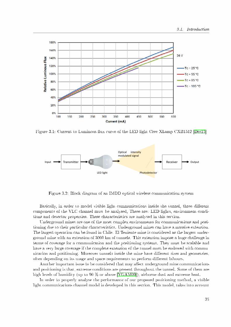
3.1. Introduction
Figure 3.1: Current to Luminous �ux curve of the LED light Cree XLamp CXB1512 [Des15]
Transmitter ReceiverInput Output
Optical intensitymodulated signal
LED light Photodetector
Figure 3.2: Block diagram of an IMDD optical wireless communication system
Basically, in order to model visible light communications inside the tunnel, three di�erentcomponents of the VLC channel must be analysed, These are: LED lights, environment condi-tions and detector properties. These characteristics are analysed in this section.
Underground mines are one of the most complex environments for communications and posi-tioning due to their particular characteristics. Underground mines can have a massive extension.The largest operation can be found in Chile. El Teniente mine is considered as the largest under-ground mine with an extension of 3000 km of tunnels. This extension impose a huge challenge interms of coverage for a communication and the positioning systems. They must be scalable andhave a very large coverage if the complete extension of the tunnel must be endowed with commu-nication and positioning. Moreover tunnels inside the mine have di�erent sizes and geometries,often depending on its usage and space requirements to perform di�erent labours.
Another important issue to be considered that may a�ect underground mine communicationsand positioning is that, extreme conditions are present throughout the tunnel. Some of them arehigh levels of humidity (up to 90 % or above [YGAM09]), airborne dust and extreme heat.
In order to properly analyse the performance of our proposed positioning method, a visiblelight communications channel model is developed in this section. This model, takes into account
35

3.2. Illumination standards
several factors present in underground mines that are not considered in traditional VLC channelmodelling.
In order to develop VLC channel model that analyse the particular characteristics of under-ground mines, we must take into consideration the illumination standards of underground miningand the environmental conditions that will a�ect the communication link.
In the next sections, these parameters will be analysed and, a visible light communicationchannel model for underground mines will be provided.
3.2 Illumination standards
Illumination standards will provide an insight on deployed infrastructure and arti�cial illumina-tion constraints inside an underground mine. Illumination is a key factor in VLC networks sincethe coverage is strongly related to lighting infrastructure. Due to this, deployed infrastructureof the application scenario must be study in order to verify its feasible implementation.
Commonly, illumination in indoor environments is regulated by safety and health govern-mental institutions. In particular for underground mines many di�erent regulations in termsof illumination requirements can be found. Each country has their own regulations in terms ofsafe illumination. In addition to this, illumination criteria is not uniform for every undergroundoperation. The level of illumination in a mine zone changes depending on the labour carried outas shown in Table 3.1. Some countries does not have a clear threshold on illumination require-ments. As an example, Chilean regulation for safety and heath remove underground mines fromthe illumination regulations in the Article 103: ""Every workplace, with exception of undergroundmines or similar workplaces, must be illuminated with natural or arti�cial light".
Table 3.1: Illumination requirements for di�erent working zones of underground mines (Tableadapter from [Com])
CountryMine zone (lx)
Shafts LoadingAroundmachines
Haulages Headings Workshop
Belgium 20-50 20 25 10 - -
Hungary 41-100 40-80 20-50 2-10 - 20-50
Canada 21 - - 21 53 -
Poland 30 30 10 2-10 5-15 30
UK (British Coal) 70 30 - 2.5 - 50-150
European Coaland Steel community
40-90 15-80 - 5-15 10-30 -
Proper illumination in underground mines is important due to di�erent safety and healthaspects. In particular the The National Institute for Occupational Safety and Health (NIOSH)of U.S. states that many of the higher frequency risks in mining are related to the challenge ofinadequate lighting. These include slip, trip, and fall (STF) hazards which can be more di�cultto detect in low light [The15]. In addition to this, the worker age is another important factor totake into account since 40% less light reaching the retina of a 45-yr-old person compared to a24-years-old person.
In addition to the standardization issue on lighting infrastructure, there is another conditionfor the deployment of VLC based networks, i.e., the usage of LED lights as the main illuminationdevice. The selected device for illumination purposes must comply with some properties in order
36
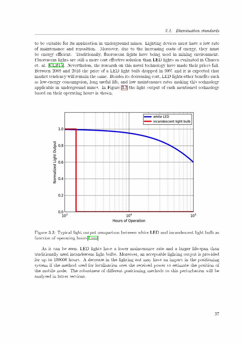
3.2. Illumination standards
to be suitable for its application in underground mines. Lighting devices must have a low rateof maintenance and reposition. Moreover, due to the increasing costs of energy, they mustbe energy e�cient. Traditionally, �uorescent lights have being used in mining environment.Fluorescent lights are still a more cost e�ective solution than LED lights as evaluated in Chuecoet. al. [CLB15]. Nevertheless, the research on this novel technology have made their prices fall.Between 2008 and 2016 the price of a LED light bulb dropped in 90% and it is expected thatmarket tendency will remain the same. Besides its decreasing cost, LED lights other bene�ts suchas low-energy consumption, long useful life, and low maintenance rates making this technologyapplicable in underground mines. In Figure 3.3 the light output of each mentioned technologybased on their operating hours is shown.
Figure 3.3: Typical light output comparison between white LED and incandescent light bulb asfunction of operating hours[Lum]
As it can be seen, LED lights have a lower maintenance rate and a larger life-span thantraditionally used incandescent light bulbs. Moreover, an acceptable lighting output is providedfor up to 100000 hours. A decrease in the lighting out may have an impact in the positioningsystem if the method used for localization uses the received power to estimate the position ofthe mobile node. The robustness of di�erent positioning methods to this perturbation will beanalysed in latter sections.
37
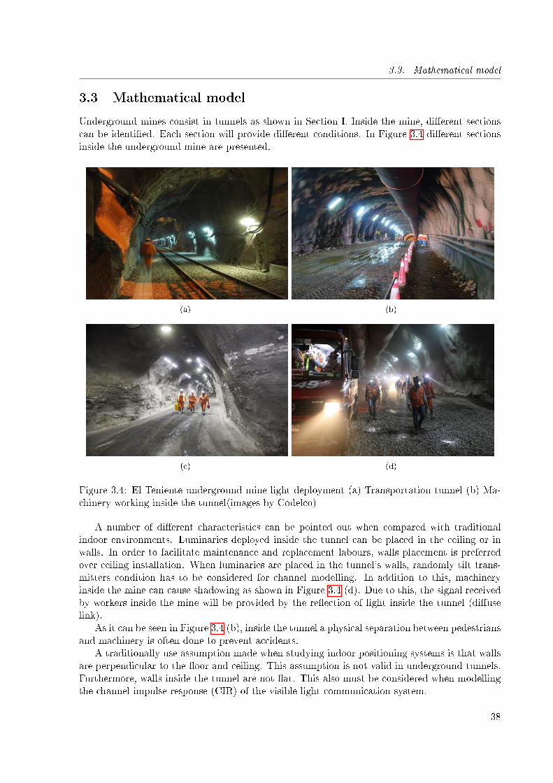
3.3. Mathematical model
3.3 Mathematical model
Underground mines consist in tunnels as shown in Section I. Inside the mine, di�erent sectionscan be identi�ed. Each section will provide di�erent conditions. In Figure 3.4 di�erent sectionsinside the underground mine are presented.
(a) (b)
(c) (d)
Figure 3.4: El Teniente underground mine light deployment (a) Transportation tunnel (b) Ma-chinery working inside the tunnel(images by Codelco)
A number of di�erent characteristics can be pointed out when compared with traditionalindoor environments. Luminaries deployed inside the tunnel can be placed in the ceiling or inwalls. In order to facilitate maintenance and replacement labours, walls placement is preferredover ceiling installation. When luminaries are placed in the tunnel's walls, randomly tilt trans-mitters condition has to be considered for channel modelling. In addition to this, machineryinside the mine can cause shadowing as shown in Figure 3.4 (d). Due to this, the signal receivedby workers inside the mine will be provided by the re�ection of light inside the tunnel (di�uselink).
As it can be seen in Figure 3.4 (b), inside the tunnel a physical separation between pedestriansand machinery is often done to prevent accidents.
A traditionally use assumption made when studying indoor positioning systems is that wallsare perpendicular to the �oor and ceiling. This assumption is not valid in underground tunnels.Furthermore, walls inside the tunnel are not �at. This also must be considered when modellingthe channel impulse response (CIR) of the visible light communication system.
38
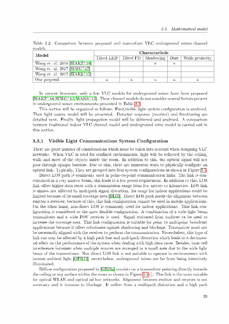
3.3. Mathematical model
Table 3.2: Comparison between proposed and state-of-art VLC underground mines channelmodels
ModelCharacteristic
Tilted LED Tilted PD Shadowing Dust Walls geometry
Wang et. al. 2018 [WAKZ+18] x x
Wang et. al. 2017 [WWC+17]
Wang et. al. 2017 [WAKS+17]
Our proposal x x x x x
In current literature, only a few VLC models for underground mines have been proposed[WAKZ+18, WWC+17, WAKS+17]. These channel models do not consider several factors presentin underground mines environments presented in Table 3.2
This section will be organized as follows: First,visible light system con�guration is analysed.Then light source model will be presented. Detector response (receiver) and functioning aredetailed next. Finally, light propagation model will be delivered and analysed. A comparisonbetween traditional indoor VLC channel model and underground mine model is carried out inthis section.
3.3.1 Visible Light Communications System Con�guration
There are great number of considerations which must be taken into account when designing VLCnetworks. When VLC is used for con�ned environments, light will be re�ected by the ceiling,walls and most of the objects inside the room. In addition to this, the optical signal will notpass through opaque barriers. Due to this, there are numerous ways to physically con�gure anoptical link. Typically, They are grouped into four system con�gurations as shown in Figure 3.5.
Direct LOS path is commonly used in point-to-point communication links. The link is con-centrated in a very narrow beam, this leads to a low power requirement. In addition to this, LOSlink o�ers higher data rates with a transmission range from few meters to kilometres. LOS linkis almost not a�ected by multipath signal distortion. Its usage for indoor applications could belimited because of its small coverage area [BL05]. Direct LOS path needs the alignment betweenemitter a receiver, because of this, this link con�guration cannot be used in mobile applications.On the other hand, non-direct LOS is commonly used for indoor applications. This link con-�guration is considered as the most �exible con�guration. A combination of a wide light beamtransmitters and a wide FOV receiver is used. Signal scattered from surfaces ca be used toincrease the coverage area. This link con�guration is suitable for point to multipoint broadcastapplications because it o�ers robustness against shadowing and blockage. Transmitter must notbe necessarily aligned with the receiver to perform the communication. Nevertheless, this type oflink can may be a�ected by a high path loss and multipath distortion which leads to a detrimen-tal e�ect on the performance of the system when dealing with high data rates. Besides, inter-cellinterference increases when multiple sources are arranged in a small area due to the wide lightbeam of the transmitters. Non-direct LOS link is not suitable to operate in environments withintense ambient light [GPR12], nevertheless, underground mines are far from being intensivelyilluminated.
Di�use con�guration proposed in [GB79a] consists on a transmitter pointing directly towardsthe ceiling or any surface within the room as shown in Figure 3.5 c). This link is the most suitablefor optical WLAN and optical ad-hoc networks. Alignment between emitter and receiver is notnecessary and is immune to blockage. It su�ers from a multipath distortion and a high path
39
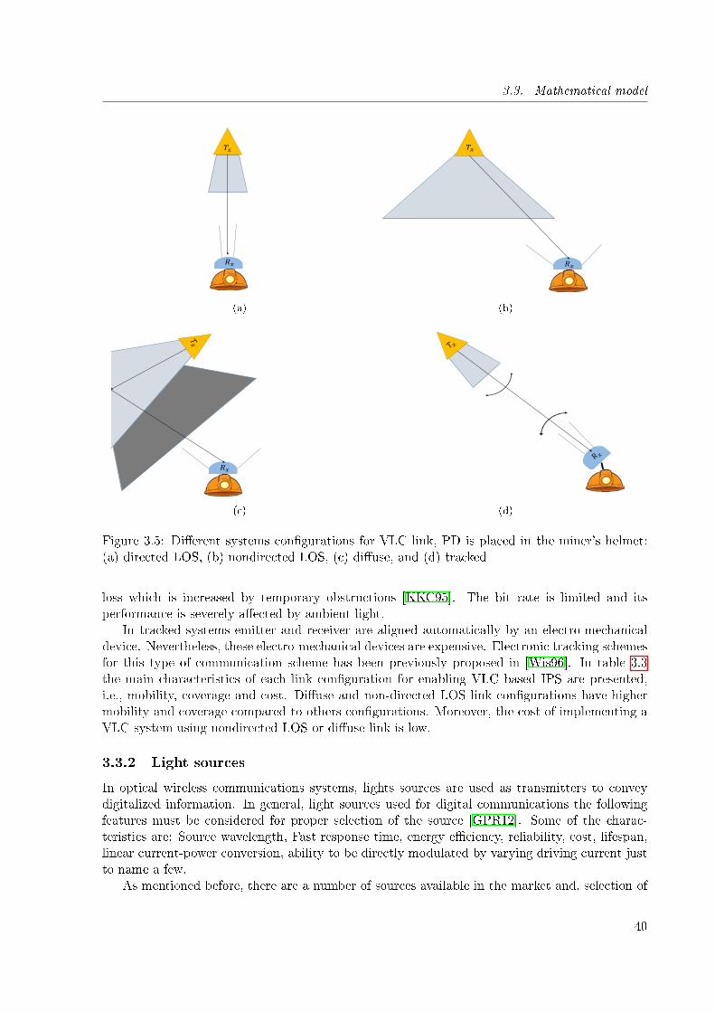
3.3. Mathematical model
𝑇𝑥
𝑅𝑥
(a)
𝑇𝑥
𝑅𝑥
(b)
𝑅𝑥
(c) (d)
Figure 3.5: Di�erent systems con�gurations for VLC link, PD is placed in the miner's helmet:(a) directed LOS, (b) nondirected LOS, (c) di�use, and (d) tracked
loss which is increased by temporary obstructions [KKC95]. The bit rate is limited and itsperformance is severely a�ected by ambient light.
In tracked systems emitter and receiver are aligned automatically by an electro-mechanicaldevice. Nevertheless, these electro-mechanical devices are expensive. Electronic tracking schemesfor this type of communication scheme has been previously proposed in [Wis96]. In table 3.3the main characteristics of each link con�guration for enabling VLC based IPS are presented,i.e., mobility, coverage and cost. Di�use and non-directed LOS link con�gurations have highermobility and coverage compared to others con�gurations. Moreover, the cost of implementing aVLC system using nondirected LOS or di�use link is low.
3.3.2 Light sources
In optical wireless communications systems, lights sources are used as transmitters to conveydigitalized information. In general, light sources used for digital communications the followingfeatures must be considered for proper selection of the source [GPR12]. Some of the charac-teristics are: Source wavelength, Fast response time, energy e�ciency, reliability, cost, lifespan,linear current-power conversion, ability to be directly modulated by varying driving current justto name a few.
As mentioned before, there are a number of sources available in the market and, selection of
40
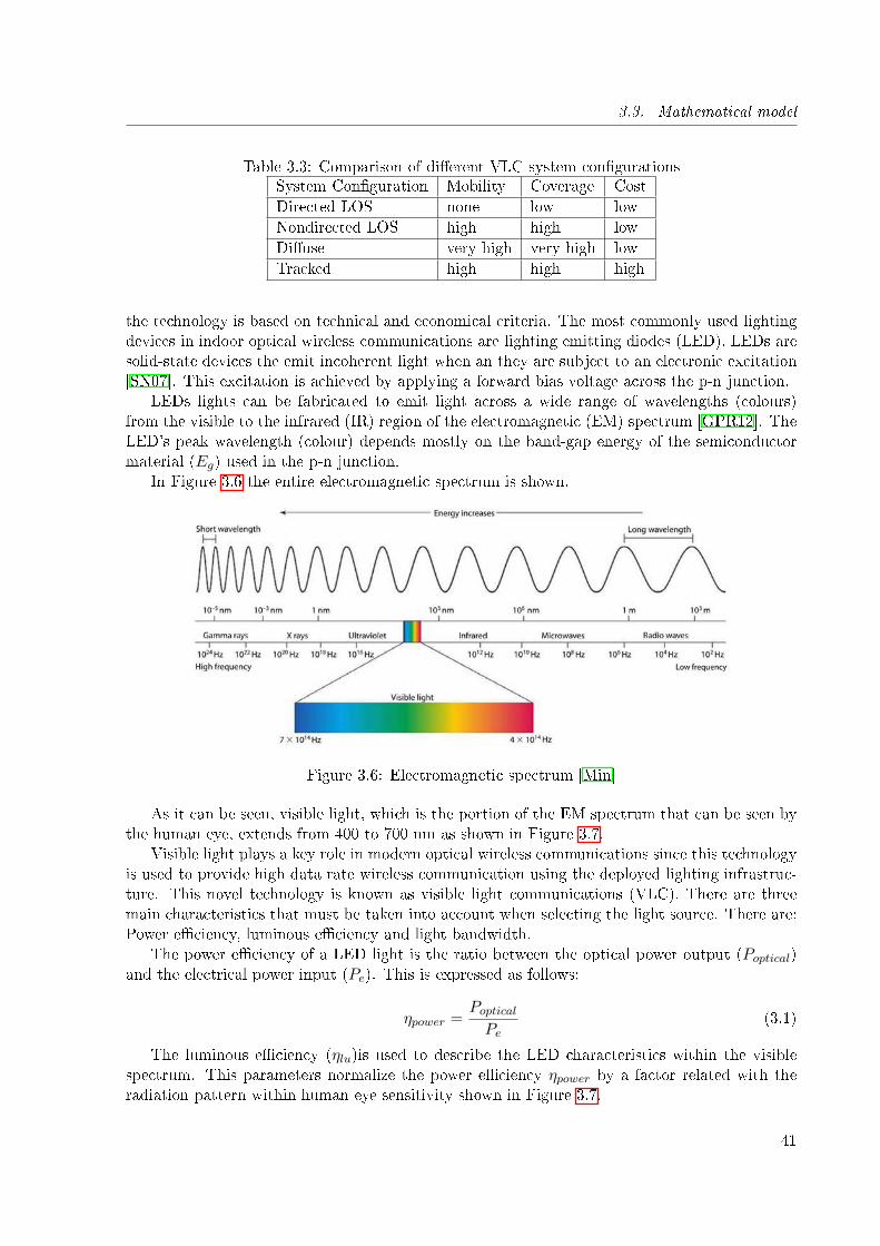
3.3. Mathematical model
Table 3.3: Comparison of di�erent VLC system con�gurationsSystem Con�guration Mobility Coverage Cost
Directed LOS none low low
Nondirected LOS high high low
Di�use very high very high low
Tracked high high high
the technology is based on technical and economical criteria. The most commonly used lightingdevices in indoor optical wireless communications are lighting emitting diodes (LED). LEDs aresolid-state devices the emit incoherent light when an they are subject to an electronic excitation[SN07]. This excitation is achieved by applying a forward bias voltage across the p-n junction.
LEDs lights can be fabricated to emit light across a wide range of wavelengths (colours)from the visible to the infrared (IR) region of the electromagnetic (EM) spectrum [GPR12]. TheLED's peak wavelength (colour) depends mostly on the band-gap energy of the semiconductormaterial (Eg) used in the p-n junction.
In Figure 3.6 the entire electromagnetic spectrum is shown.
Figure 3.6: Electromagnetic spectrum [Min]
As it can be seen, visible light, which is the portion of the EM spectrum that can be seen bythe human eye, extends from 400 to 700 nm as shown in Figure 3.7.
Visible light plays a key role in modern optical wireless communications since this technologyis used to provide high data rate wireless communication using the deployed lighting infrastruc-ture. This novel technology is known as visible light communications (VLC). There are threemain characteristics that must be taken into account when selecting the light source. There are:Power e�ciency, luminous e�ciency and light bandwidth.
The power e�ciency of a LED light is the ratio between the optical power output (Poptical)and the electrical power input (Pe). This is expressed as follows:
ηpower =PopticalPe
(3.1)
The luminous e�ciency (ηlu)is used to describe the LED characteristics within the visiblespectrum. This parameters normalize the power e�ciency ηpower by a factor related with theradiation pattern within human eye sensitivity shown in Figure 3.7.
41
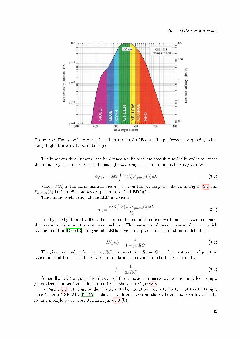
3.3. Mathematical model
Figure 3.7: Huma eye's response based on the 1978 CIE data (http://www.ecse.rpi.edu/ schu-bert/ Light-Emitting-Diodes-dot-org)
The luminous �ux (lumens) can be de�ned as the total emitted �ux scaled in order to re�ectthe human eye's sensitivity to di�erent light wavelengths. The luminous �ux is given by:
φflux = 683
∫V (λ)Poptical(λ)dλ (3.2)
where V (λ) is the normalization factor based on the eye response shown in Figure 3.7 andPoptical(λ) is the radiation power spectrum of the LED light.
The luminous e�ciency of the LED is given by
ηlu =683
∫V (λ)Poptical(λ)dλ
Pe(3.3)
Finally, the light bandwidth will determine the modulation bandwidth and, as a consequence,the maximum data rate the system can achieve. This parameter depends on several factors whichcan be found in [GPR12]. In general, LEDs have a low pass transfer function modelled as:
H(jw) =1
1 + jwRC(3.4)
This, is an equivalent �rst-order jRC low-pass �lter. R and C are the resistance and junctioncapacitance of the LED. Hence, 3 dB modulation bandwidth of the LED is given by
fc =1
2πRC(3.5)
Generally, LED angular distribution of the radiation intensity pattern is modelled using ageneralized Lambertian radiant intensity as shown in Figure 3.8.
In Figure 3.8 (a), angular distribution of the radiation intensity pattern of the LED lightCree XLamp CXB1512 [Des15] is shown. As it can be seen, the radiated power varies with theradiation angle φj as presented in Figure 3.8 (b).
42
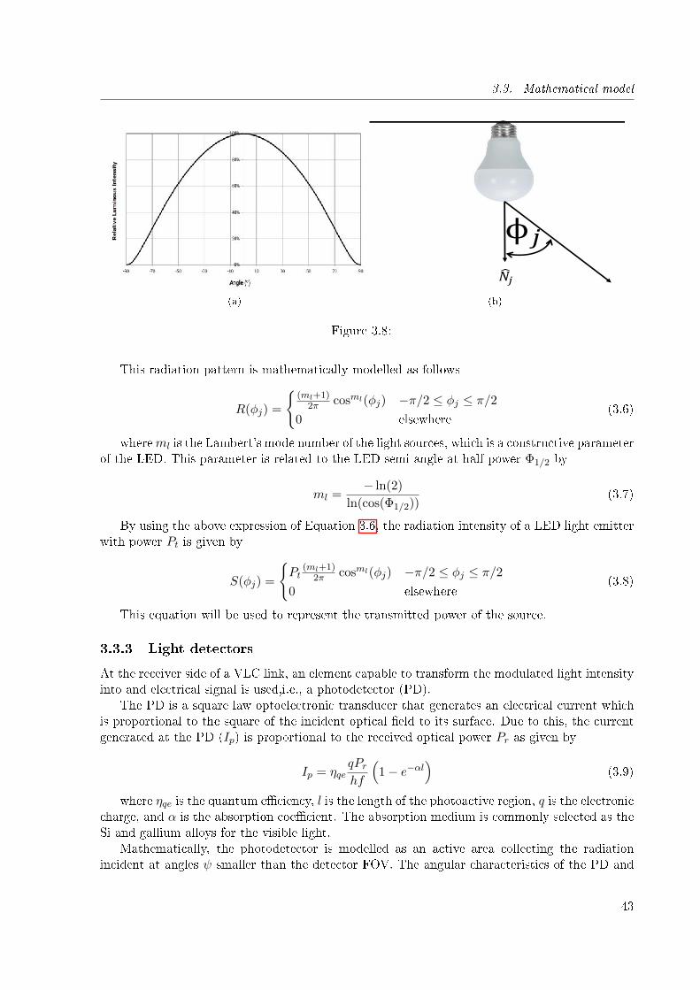
3.3. Mathematical model
(a)
𝑁𝑗
ϕ𝑗
(b)
Figure 3.8:
This radiation pattern is mathematically modelled as follows
R(φj) =
{(ml+1)
2π cosml(φj) −π/2 ≤ φj ≤ π/20 elsewhere
(3.6)
whereml is the Lambert's mode number of the light sources, which is a constructive parameterof the LED. This parameter is related to the LED semi-angle at half power Φ1/2 by
ml =− ln(2)
ln(cos(Φ1/2))(3.7)
By using the above expression of Equation 3.6, the radiation intensity of a LED light emitterwith power Pt is given by
S(φj) =
{Pt
(ml+1)2π cosml(φj) −π/2 ≤ φj ≤ π/2
0 elsewhere(3.8)
This equation will be used to represent the transmitted power of the source.
3.3.3 Light detectors
At the receiver side of a VLC link, an element capable to transform the modulated light intensityinto and electrical signal is used,i.e., a photodetector (PD).
The PD is a square law optoelectronic transducer that generates an electrical current whichis proportional to the square of the incident optical �eld to its surface. Due to this, the currentgenerated at the PD (Ip) is proportional to the received optical power Pr as given by
Ip = ηqeqPrhf
(1− e−αl
)(3.9)
where ηqe is the quantum e�ciency, l is the length of the photoactive region, q is the electroniccharge, and α is the absorption coe�cient. The absorption medium is commonly selected as theSi and gallium alloys for the visible light.
Mathematically, the photodetector is modelled as an active area collecting the radiationincident at angles ψ smaller than the detector FOV. The angular characteristics of the PD and
43
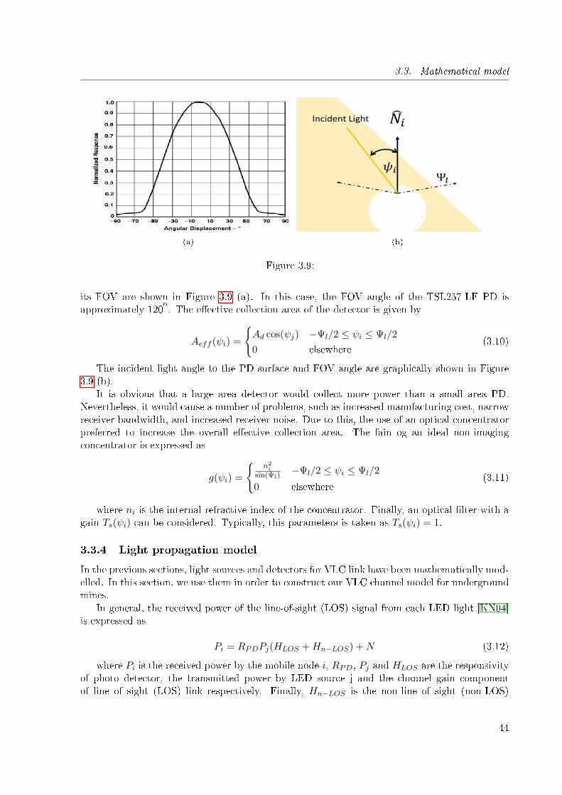
3.3. Mathematical model
(a)
𝑁𝑖
𝜓𝑖Ψ𝑙
Incident Light
(b)
Figure 3.9:
its FOV are shown in Figure 3.9 (a). In this case, the FOV angle of the TSL257-LF PD isapproximately 120
o. The e�ective collection area of the detector is given by
Aeff (ψi) =
{Ad cos(ψj) −Ψl/2 ≤ ψi ≤ Ψl/2
0 elsewhere(3.10)
The incident light angle to the PD surface and FOV angle are graphically shown in Figure3.9 (b).
It is obvious that a large area detector would collect more power than a small area PD.Nevertheless, it would cause a number of problems, such as increased manufacturing cost, narrowreceiver bandwidth, and increased receiver noise. Due to this, the use of an optical concentratorpreferred to increase the overall e�ective collection area. The fain og an ideal non-imagingconcentrator is expressed as
g(ψi) =
{n2i
sin(Ψl)−Ψl/2 ≤ ψi ≤ Ψl/2
0 elsewhere(3.11)
where ni is the internal refractive index of the concentrator. Finally, an optical �lter with again Ts(ψi) can be considered. Typically, this parameters is taken as Ts(ψi) = 1.
3.3.4 Light propagation model
In the previous sections, light sources and detectors for VLC link have been mathematically mod-elled. In this section, we use them in order to construct our VLC channel model for undergroundmines.
In general, the received power of the line-of-sight (LOS) signal from each LED light [KN04]is expressed as
Pi = RPDPj(HLOS +Hn−LOS) +N (3.12)
where Pi is the received power by the mobile node i, RPD, Pj and HLOS are the responsivityof photo detector, the transmitted power by LED source j and the channel gain componentof line of sight (LOS) link respectively. Finally, Hn−LOS is the non-line of sight (non-LOS)
44
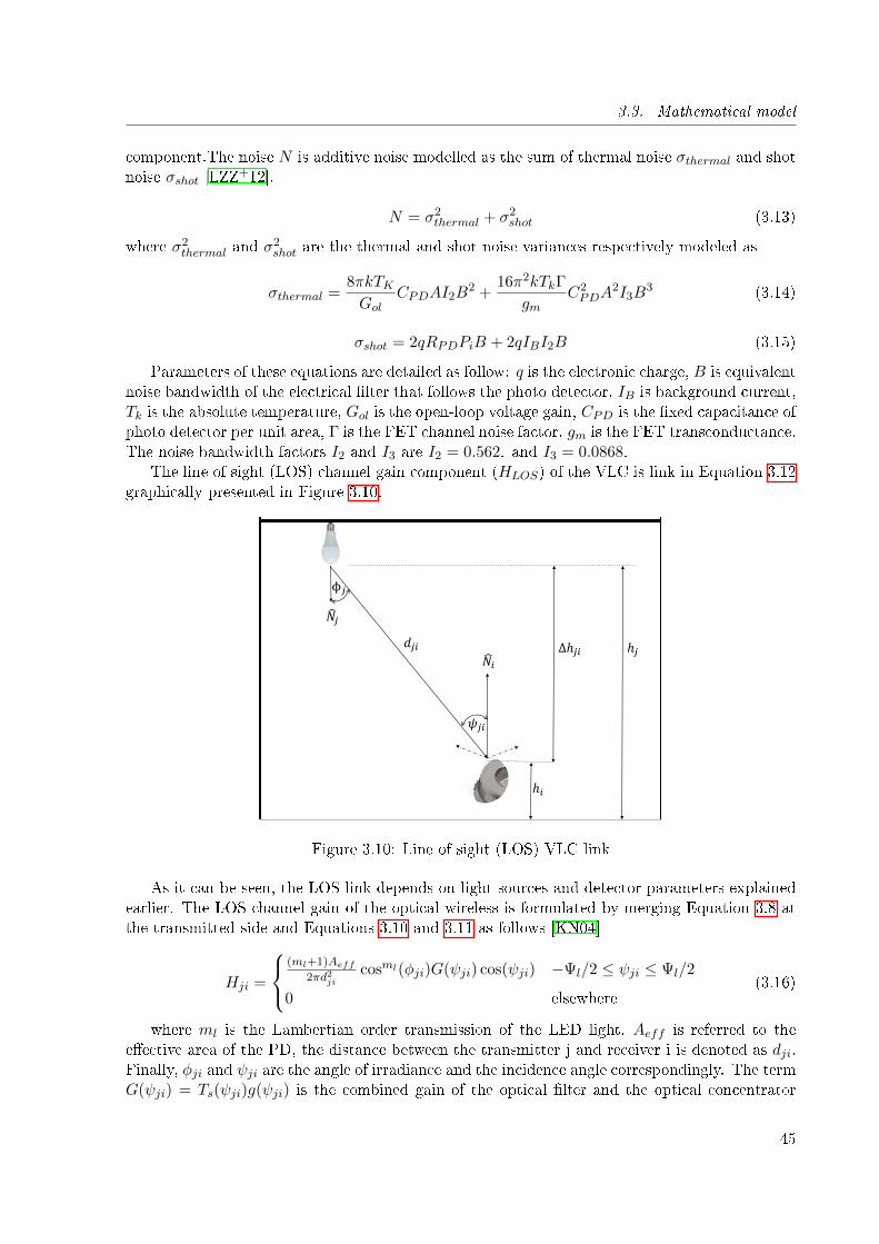
3.3. Mathematical model
component.The noise N is additive noise modelled as the sum of thermal noise σthermal and shotnoise σshot [LZZ
+12].
N = σ2thermal + σ2
shot (3.13)
where σ2thermal and σ
2shot are the thermal and shot noise variances respectively modeled as
σthermal =8πkTKGol
CPDAI2B2 +
16π2kTkΓ
gmC2PDA
2I3B3 (3.14)
σshot = 2qRPDPiB + 2qIBI2B (3.15)
Parameters of these equations are detailed as follow: q is the electronic charge, B is equivalentnoise bandwidth of the electrical �lter that follows the photo detector, IB is background current,Tk is the absolute temperature, Gol is the open-loop voltage gain, CPD is the �xed capacitance ofphoto detector per unit area, Γ is the FET channel noise factor, gm is the FET transconductance.The noise bandwidth factors I2 and I3 are I2 = 0.562. and I3 = 0.0868.
The line of sight (LOS) channel gain component (HLOS) of the VLC is link in Equation 3.12graphically presented in Figure 3.10.
𝑁𝑗
𝑁𝑖
𝜓𝑗𝑖
ϕ𝑗
𝑑𝑗𝑖 ∆ℎ𝑗𝑖 ℎ𝑗
ℎ𝑖
Figure 3.10: Line of sight (LOS) VLC link
As it can be seen, the LOS link depends on light sources and detector parameters explainedearlier. The LOS channel gain of the optical wireless is formulated by merging Equation 3.8 atthe transmitted side and Equations 3.10 and 3.11 as follows [KN04]
Hji =
(ml+1)Aeff
2πd2jicosml(φji)G(ψji) cos(ψji) −Ψl/2 ≤ ψji ≤ Ψl/2
0 elsewhere(3.16)
where ml is the Lambertian order transmission of the LED light, Aeff is referred to thee�ective area of the PD, the distance between the transmitter j and receiver i is denoted as dji.Finally, φji and ψji are the angle of irradiance and the incidence angle correspondingly. The termG(ψji) = Ts(ψji)g(ψji) is the combined gain of the optical �lter and the optical concentrator
45
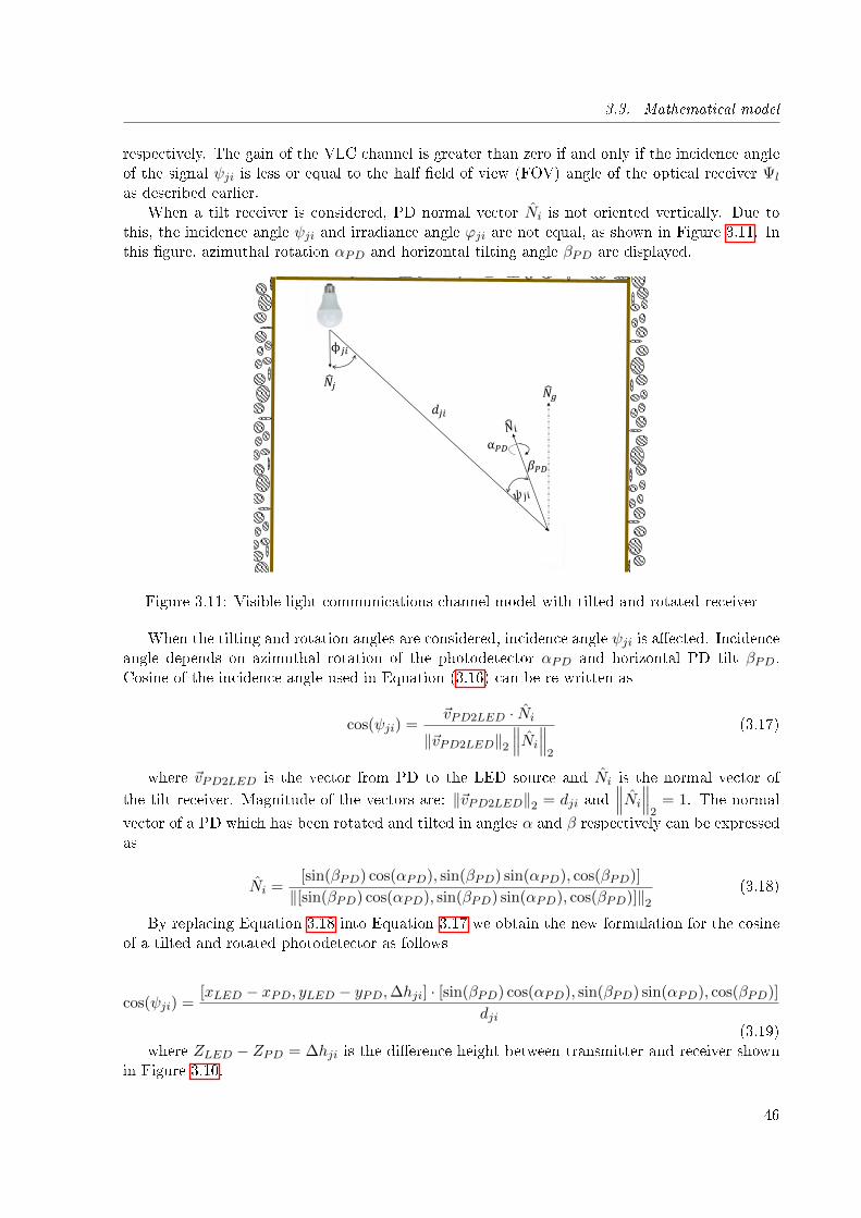
3.3. Mathematical model
respectively. The gain of the VLC channel is greater than zero if and only if the incidence angleof the signal ψji is less or equal to the half �eld of view (FOV) angle of the optical receiver Ψl
as described earlier.When a tilt receiver is considered, PD normal vector Ni is not oriented vertically. Due to
this, the incidence angle ψji and irradiance angle ϕji are not equal, as shown in Figure 3.11. Inthis �gure, azimuthal rotation αPD and horizontal tilting angle βPD are displayed.
𝑁𝑗
ϕ𝑗𝑖
𝑑𝑗𝑖
⍺𝑃𝐷
𝛽𝑃𝐷
𝑁𝑔
Figure 3.11: Visible light communications channel model with tilted and rotated receiver
When the tilting and rotation angles are considered, incidence angle ψji is a�ected. Incidenceangle depends on azimuthal rotation of the photodetector αPD and horizontal PD tilt βPD.Cosine of the incidence angle used in Equation (3.16) can be re-written as
cos(ψji) =~vPD2LED · Ni
‖~vPD2LED‖2∥∥∥Ni
∥∥∥2
(3.17)
where ~vPD2LED is the vector from PD to the LED source and Ni is the normal vector of
the tilt receiver. Magnitude of the vectors are: ‖~vPD2LED‖2 = dji and∥∥∥Ni
∥∥∥2
= 1. The normal
vector of a PD which has been rotated and tilted in angles α and β respectively can be expressedas
Ni =[sin(βPD) cos(αPD), sin(βPD) sin(αPD), cos(βPD)]
‖[sin(βPD) cos(αPD), sin(βPD) sin(αPD), cos(βPD)]‖2(3.18)
By replacing Equation 3.18 into Equation 3.17 we obtain the new formulation for the cosineof a tilted and rotated photodetector as follows
cos(ψji) =[xLED − xPD, yLED − yPD,∆hji] · [sin(βPD) cos(αPD), sin(βPD) sin(αPD), cos(βPD)]
dji(3.19)
where ZLED − ZPD = ∆hji is the di�erence height between transmitter and receiver shownin Figure 3.10.
46
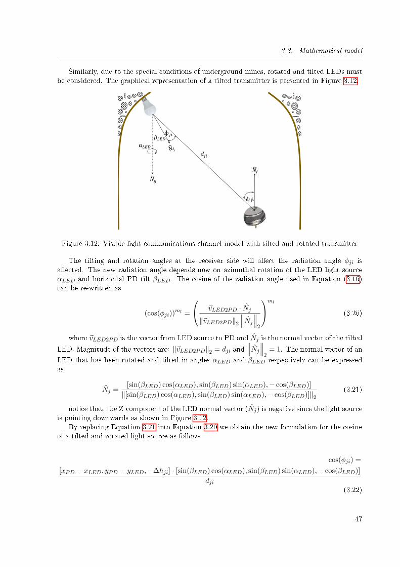
3.3. Mathematical model
Similarly, due to the special conditions of underground mines, rotated and tilted LEDs mustbe considered. The graphical representation of a tilted transmitter is presented in Figure 3.12.
𝑁𝑖
ϕ𝑗𝑖
𝑑𝑗𝑖
⍺𝐿𝐸𝐷
𝛽𝐿𝐸𝐷
𝑁𝑔
Figure 3.12: Visible light communications channel model with tilted and rotated transmitter
The tilting and rotation angles at the receiver side will a�ect the radiation angle φji isa�ected. The new radiation angle depends now on azimuthal rotation of the LED light sourceαLED and horizontal PD tilt βLED. The cosine of the radiation angle used in Equation (3.16)can be re-written as
(cos(φji))ml =
~vLED2PD · Nj
‖~vLED2PD‖2∥∥∥Nj
∥∥∥2
ml
(3.20)
where ~vLED2PD is the vector from LED source to PD and Nj is the normal vector of the tilted
LED. Magnitude of the vectors are: ‖~vLED2PD‖2 = dji and∥∥∥Nj
∥∥∥2
= 1. The normal vector of an
LED that has been rotated and tilted in angles αLED and βLED respectively can be expressedas
Nj =[sin(βLED) cos(αLED), sin(βLED) sin(αLED),− cos(βLED)]
‖[sin(βLED) cos(αLED), sin(βLED) sin(αLED),− cos(βLED)]‖2(3.21)
notice that, the Z-component of the LED normal vector (Nj) is negative since the light sourceis pointing downwards as shown in Figure 3.12.
By replacing Equation 3.21 into Equation 3.20 we obtain the new formulation for the cosineof a tilted and rotated light source as follows
cos(φji) =
[xPD − xLED, yPD − yLED,−∆hji] · [sin(βLED) cos(αLED), sin(βLED) sin(αLED),− cos(βLED)]
dji(3.22)
47
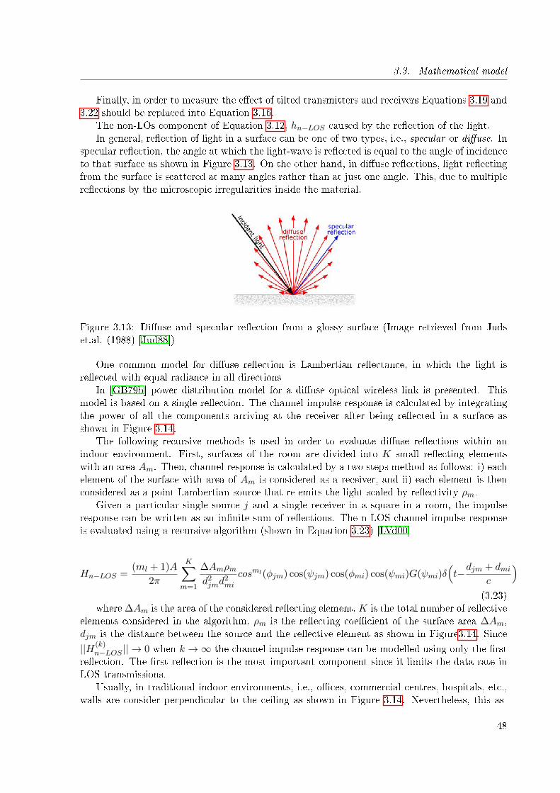
3.3. Mathematical model
Finally, in order to measure the e�ect of tilted transmitters and receivers Equations 3.19 and3.22 should be replaced into Equation 3.16.
The non-LOs component of Equation 3.12, hn−LOS caused by the re�ection of the light.In general, re�ection of light in a surface can be one of two types, i.e., specular or di�use. In
specular re�ection, the angle at which the light-wave is re�ected is equal to the angle of incidenceto that surface as shown in Figure 3.13. On the other hand, in di�use re�ections, light re�ectingfrom the surface is scattered at many angles rather than at just one angle. This, due to multiplere�ections by the microscopic irregularities inside the material.
Figure 3.13: Di�use and specular re�ection from a glossy surface (Image retrieved from Judset.al. (1988) [Jud88])
One common model for di�use re�ection is Lambertian re�ectance, in which the light isre�ected with equal radiance in all directions
In [GB79b] power distribution model for a di�use optical wireless link is presented. Thismodel is based on a single re�ection. The channel impulse response is calculated by integratingthe power of all the components arriving at the receiver after being re�ected in a surface asshown in Figure 3.14.
The following recursive methods is used in order to evaluate di�use re�ections within anindoor environment. First, surfaces of the room are divided into K small re�ecting elementswith an area Am. Then, channel response is calculated by a two steps method as follows: i) eachelement of the surface with area of Am is considered as a receiver, and ii) each element is thenconsidered as a point Lambertian source that re-emits the light scaled by re�ectivity ρm.
Given a particular single source j and a single receiver in a square in a room, the impulseresponse can be written as an in�nite sum of re�ections. The n-LOS channel impulse responseis evaluated using a recursive algorithm (shown in Equation 3.23) [LVd00]
Hn−LOS =(ml + 1)A
2π
K∑m=1
∆Amρmd2jmd
2mi
cosml(φjm) cos(ψjm) cos(φmi) cos(ψmi)G(ψmi)δ(t−djm + dmi
c
)(3.23)
where ∆Am is the area of the considered re�ecting element, K is the total number of re�ectiveelements considered in the algorithm, ρm is the re�ecting coe�cient of the surface area ∆Am,djm is the distance between the source and the re�ective element as shown in Figure3.14. Since
||H(k)n−LOS || → 0 when k →∞ the channel impulse response can be modelled using only the �rst
re�ection. The �rst re�ection is the most important component since it limits the data rate inLOS transmissions.
Usually, in traditional indoor environments, i.e., o�ces, commercial centres, hospitals, etc.,walls are consider perpendicular to the ceiling as shown in Figure 3.14. Nevertheless, this as-
48
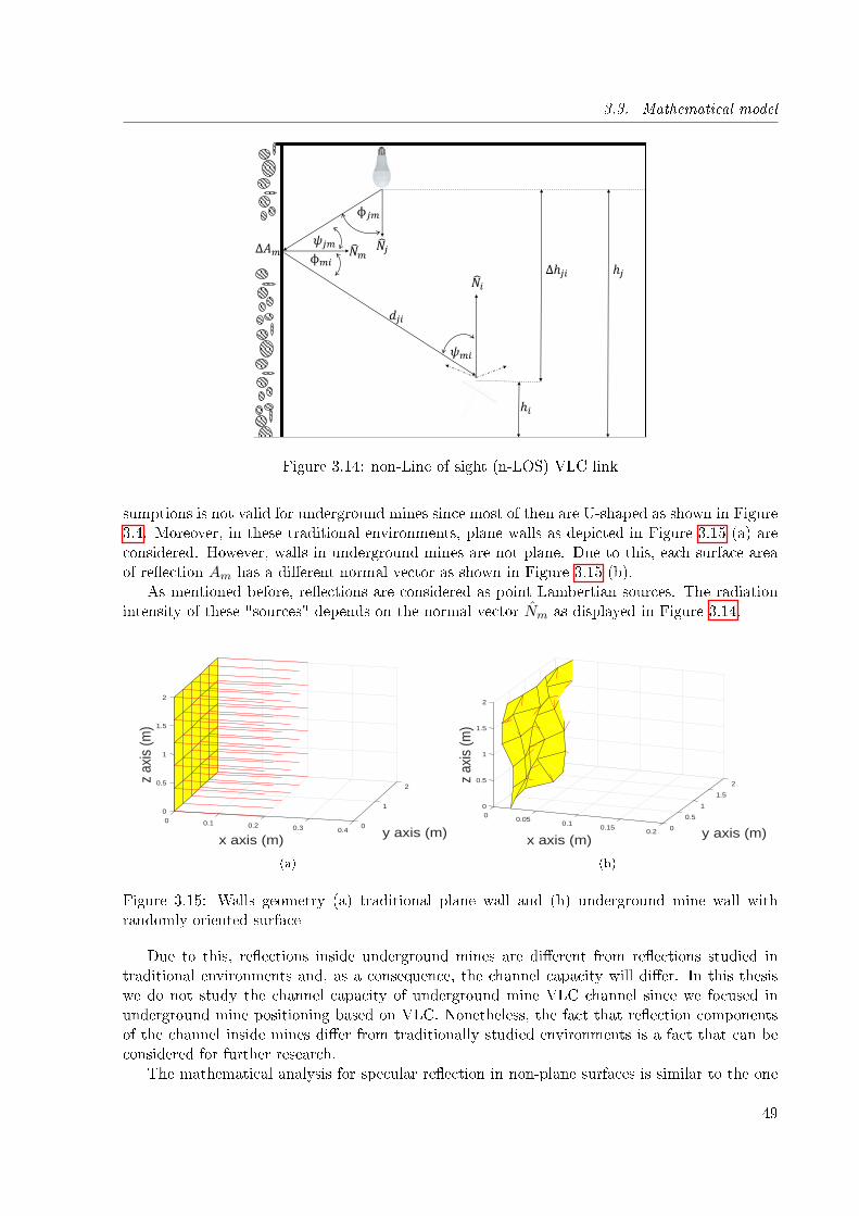
3.3. Mathematical model
𝑁𝑗
𝑁𝑖
𝜓𝑚𝑖
ϕ𝑗𝑚
𝑑𝑗𝑖
∆ℎ𝑗𝑖 ℎ𝑗
ℎ𝑖
𝑁𝑚
𝜓𝑗𝑚
ϕ𝑚𝑖
Δ𝐴𝑚
Figure 3.14: non-Line of sight (n-LOS) VLC link
sumptions is not valid for underground mines since most of then are U-shaped as shown in Figure3.4. Moreover, in these traditional environments, plane walls as depicted in Figure 3.15 (a) areconsidered. However, walls in underground mines are not plane. Due to this, each surface areaof re�ection Am has a di�erent normal vector as shown in Figure 3.15 (b).
As mentioned before, re�ections are considered as point Lambertian sources. The radiationintensity of these "sources" depends on the normal vector Nm as displayed in Figure 3.14.
2
y axis (m)
10
0.5
0
x axis (m)
1
0.1
z ax
is (m
)
0.2 0
1.5
0.3
2
0.4
(a)
2
1.5
y axis (m)
100
0.5
0.50.05
x axis (m)
1
z ax
is (m
)
0.1
1.5
0.15 00.2
2
(b)
Figure 3.15: Walls geometry (a) traditional plane wall and (b) underground mine wall withrandomly oriented surface
Due to this, re�ections inside underground mines are di�erent from re�ections studied intraditional environments and, as a consequence, the channel capacity will di�er. In this thesiswe do not study the channel capacity of underground mine VLC channel since we focused inunderground mine positioning based on VLC. Nonetheless, the fact that re�ection componentsof the channel inside mines di�er from traditionally studied environments is a fact that can beconsidered for further research.
The mathematical analysis for specular re�ection in non-plane surfaces is similar to the one
49
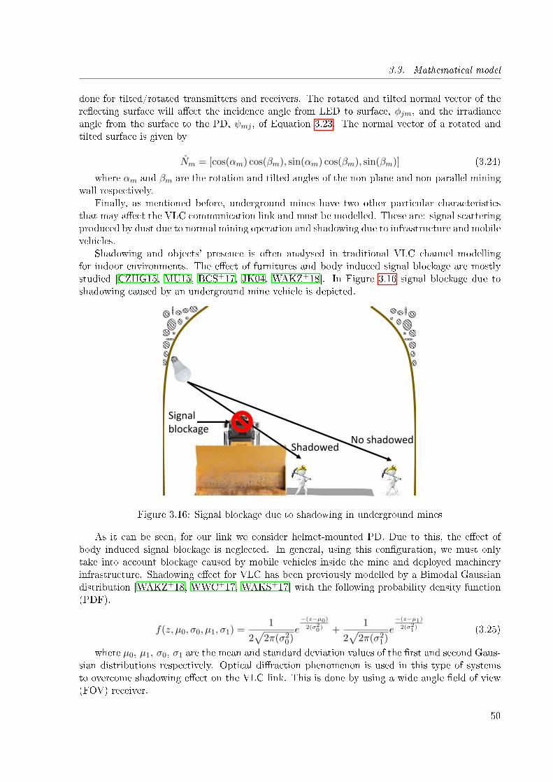
3.3. Mathematical model
done for tilted/rotated transmitters and receivers. The rotated and tilted normal vector of there�ecting surface will a�ect the incidence angle from LED to surface, φjm, and the irradianceangle from the surface to the PD, ψmj , of Equation 3.23. The normal vector of a rotated andtilted surface is given by
Nm = [cos(αm) cos(βm), sin(αm) cos(βm), sin(βm)] (3.24)
where αm and βm are the rotation and tilted angles of the non-plane and non-parallel miningwall respectively.
Finally, as mentioned before, underground mines have two other particular characteristicsthat may a�ect the VLC communication link and must be modelled. These are: signal scatteringproduced by dust due to normal mining operation and shadowing due to infrastructure and mobilevehicles.
Shadowing and objects' presence is often analysed in traditional VLC channel modellingfor indoor environments. The e�ect of furnitures and body induced signal blockage are mostlystudied [CZHG15, MU15, BCS+17, JK04, WAKZ+18]. In Figure 3.16 signal blockage due toshadowing caused by an underground mine vehicle is depicted.
No shadowedShadowed
Signalblockage
Figure 3.16: Signal blockage due to shadowing in underground mines
As it can be seen, for our link we consider helmet-mounted PD. Due to this, the e�ect ofbody induced signal blockage is neglected. In general, using this con�guration, we must onlytake into account blockage caused by mobile vehicles inside the mine and deployed machineryinfrastructure. Shadowing e�ect for VLC has been previously modelled by a Bimodal Gaussiandistribution [WAKZ+18, WWC+17, WAKS+17] with the following probability density function(PDF).
f(z, µ0, σ0, µ1, σ1) =1
2√
2π(σ20)e
−(z−µ0)2(σ20) +
1
2√
2π(σ21)e
−(z−µ1)2(σ21) (3.25)
where µ0, µ1, σ0, σ1 are the mean and standard deviation values of the �rst and second Gaus-sian distributions respectively. Optical di�raction phenomenon is used in this type of systemsto overcome shadowing e�ect on the VLC link. This is done by using a wide angle �eld of view(FOV) receiver.
50
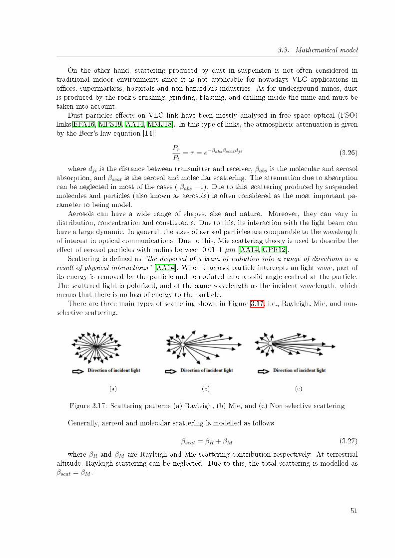
3.3. Mathematical model
On the other hand, scattering produced by dust in suspension is not often considered intraditional indoor environments since it is not applicable for nowadays VLC applications ino�ces, supermarkets, hospitals and non-hazardous industries. As for underground mines, dustis produced by the rock's crushing, grinding, blasting, and drilling inside the mine and must betaken into account.
Dust particles e�ects on VLC link have been mostly analysed in free space optical (FSO)links[EFA16, MPS19, AA14, MMJ18]. In this type of links, the atmospheric attenuation is givenby the Beer's law equation [14]:
PrPt
= τ = e−βabsβscatdji (3.26)
where dji is the distance between transmitter and receiver, βabs is the molecular and aerosolabsorption, and βscat is the aerosol and molecular scattering. The attenuation due to absorptioncan be neglected in most of the cases ( βabs =1). Due to this, scattering produced by suspendedmolecules and particles (also known as aerosols) is often considered as the most important pa-rameter to being model.
Aerosols can have a wide range of shapes, size and nature. Moreover, they can vary indistribution, concentration and constituents. Due to this, its interaction with the light beam canhave a large dynamic. In general, the sizes of aerosol particles are comparable to the wavelengthof interest in optical communications. Due to this, Mie scattering theory is used to describe thee�ect of aerosol particles with radius between 0.01�1 µm [AA14, GPR12].
Scattering is de�ned as "the dispersal of a beam of radiation into a range of directions as aresult of physical interactions" [AA14]. When a aerosol particle intercepts an light wave, part ofits energy is removed by the particle and re-radiated into a solid angle centred at the particle.The scattered light is polarized, and of the same wavelength as the incident wavelength, whichmeans that there is no loss of energy to the particle.
There are three main types of scattering shown in Figure 3.17, i.e., Rayleigh, Mie, and non-selective scattering.
(a) (b) (c)
Figure 3.17: Scattering patterns (a) Rayleigh, (b) Mie, and (c) Non-selective scattering
Generally, aerosol and molecular scattering is modelled as follows
βscat = βR + βM (3.27)
where βR and βM are Rayleigh and Mie scattering contribution respectively. At terrestrialaltitude, Rayleigh scattering can be neglected. Due to this, the total scattering is modelled asβscat = βM .
51
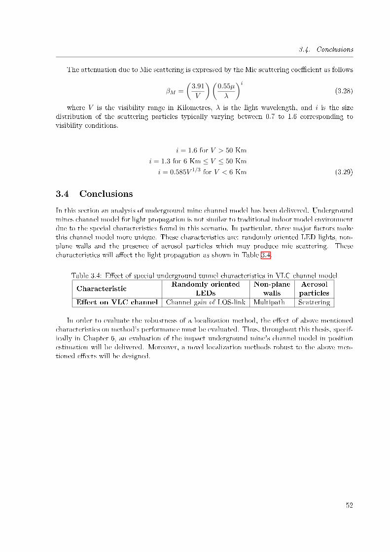
3.4. Conclusions
The attenuation due to Mie scattering is expressed by the Mie scattering coe�cient as follows
βM =
(3.91
V
)(0.55µ
λ
)i(3.28)
where V is the visibility range in Kilometres, λ is the light wavelength, and i is the sizedistribution of the scattering particles typically varying between 0.7 to 1.6 corresponding tovisibility conditions.
i = 1.6 for V > 50 Km
i = 1.3 for 6 Km ≤ V ≤ 50 Km
i = 0.585V 1/3 for V < 6 Km (3.29)
3.4 Conclusions
In this section an analysis of underground mine channel model has been delivered. Undergroundmines channel model for light propagation is not similar to traditional indoor model environmentdue to the special characteristics found in this scenario. In particular, three major factors makethis channel model more unique. These characteristics are: randomly oriented LED lights, non-plane walls and the presence of aerosol particles which may produce mie scattering. Thesecharacteristics will a�ect the light propagation as shown in Table 3.4.
Table 3.4: E�ect of special underground tunnel characteristics in VLC channel model
CharacteristicRandomly oriented
LEDsNon-plane
wallsAerosolparticles
E�ect on VLC channel Channel gain of LOS-link Multipath Scattering
In order to evaluate the robustness of a localization method, the e�ect of above mentionedcharacteristics on method's performance must be evaluated. Thus, throughout this thesis, specif-ically in Chapter 6, an evaluation of the impact underground mine's channel model in positionestimation will be delivered. Moreover, a novel localization methods robust to the above men-tioned e�ects will be designed.
52
Chapter 4
Visible light positioning methods
Sommaire
4.1 Introduction . . . . . . . . . . . . . . . . . . . . . . . . . . . . . . . . . 53
4.2 Main characteristics of VLP for their underground mine application 54
4.2.1 Characteristics based on detector technology . . . . . . . . . . . . . . . 54
4.2.2 VLC characteristics for di�erent positioning topologies implementation . 55
4.3 Visible light positioning methods classi�cation . . . . . . . . . . . . . 56
4.3.1 Range based methods . . . . . . . . . . . . . . . . . . . . . . . . . . . . 56
4.3.2 Range free methods . . . . . . . . . . . . . . . . . . . . . . . . . . . . . 64
4.3.3 Fingerprinting (FP) . . . . . . . . . . . . . . . . . . . . . . . . . . . . . 66
4.4 Robustness and characteristics analysis of VLP methods . . . . . . 67
4.1 Introduction
In the recent years, visible light communications (VLC) has gained attention of researchers dueto its capability to provide high data rate wireless communication [PFHM15] and high accuracypositioning in indoor environments [DY16]. Moreover, VLC is a cost e�ective solution sinceit uses the already deployed lighting infrastructure to provide both, illumination and wirelesscommunication.
The advantages of using VLC to provide indoor position systems have encouraged the re-searchers to propose numerous solutions. Some of the most important advantages are displayedin Figure 4.1. In particular, it is important for the development of our proposal to notice thatVLP positioning systems are immune to interference. As mentioned in Section 2.3.7, thisthesis search for a positioning system robust to interference.
Di�erent VLP methods have been introduced in literature. Most of them have been adaptedfrom existing methods in RF networks. In this section the main characteristics of di�erent VLPmethods are delivered. First, the main capabilities of VLC to provide positioning in undergroundtunnels are analysed. Then, main VLP methods are classi�ed and explained in detail. Finally,the most suitable positioning method for underground mine tunnels is proposed.
53
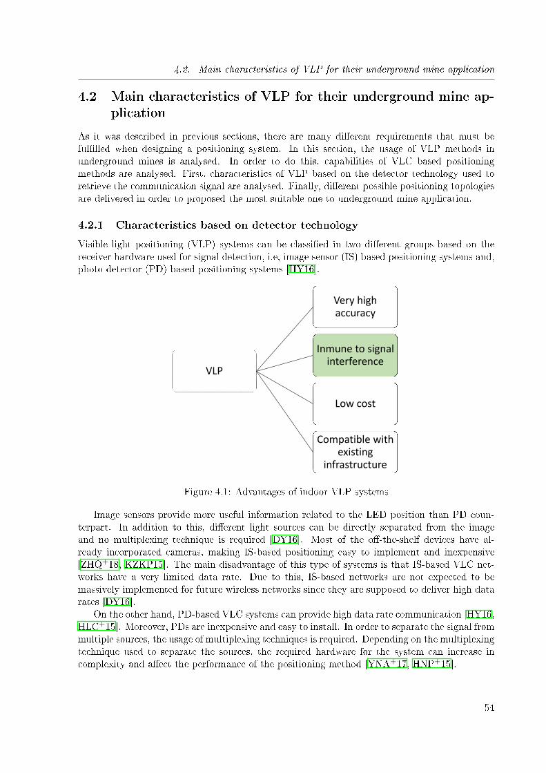
4.2. Main characteristics of VLP for their underground mine application
4.2 Main characteristics of VLP for their underground mine ap-plication
As it was described in previous sections, there are many di�erent requirements that must beful�lled when designing a positioning system. In this section, the usage of VLP methods inunderground mines is analysed. In order to do this, capabilities of VLC based positioningmethods are analysed. First, characteristics of VLP based on the detector technology used toretrieve the communication signal are analysed. Finally, di�erent possible positioning topologiesare delivered in order to proposed the most suitable one to underground mine application.
4.2.1 Characteristics based on detector technology
Visible light positioning (VLP) systems can be classi�ed in two di�erent groups based on thereceiver hardware used for signal detection, i.e, image sensor (IS) based positioning systems and,photo detector (PD) based positioning systems [HY16].
VLP
Very highaccuracy
Inmune to signalinterference
Low cost
Compatible withexisting
infrastructure
Figure 4.1: Advantages of indoor VLP systems
Image sensors provide more useful information related to the LED position than PD coun-terpart. In addition to this, di�erent light sources can be directly separated from the imageand no multiplexing technique is required [DY16]. Most of the o�-the-shelf devices have al-ready incorporated cameras, making IS-based positioning easy to implement and inexpensive[ZHQ+18, KZKP15]. The main disadvantage of this type of systems is that IS-based VLC net-works have a very limited data rate. Due to this, IS-based networks are not expected to bemassively implemented for future wireless networks since they are supposed to deliver high datarates [DY16].
On the other hand, PD-based VLC systems can provide high data rate communication [HY16,HLC+15]. Moreover, PDs are inexpensive and easy to install. In order to separate the signal frommultiple sources, the usage of multiplexing techniques is required. Depending on the multiplexingtechnique used to separate the sources, the required hardware for the system can increase incomplexity and a�ect the performance of the positioning method [YNA+17, HNP+15].
54
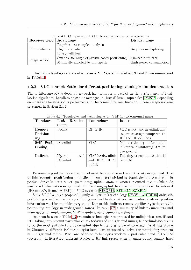
4.2. Main characteristics of VLP for their underground mine application
Table 4.1: Comparison of VLP based on receiver characteristicsReceiver type Advantage Disadvantage
PhotodetectorRequires less complex analysisHigh data rateEnergy-e�cient
Requires multiplexing
Image sensorSuitable for angle of arrival based positioningMinimally a�ected by multipath
Limited data rateHigh power consumption
The main advantages and disadvantages of VLP systems based on PD and IS are summarizedin Table 4.1.
4.2.2 VLC characteristics for di�erent positioning topologies implementation
The architecture of the deployed network has an important e�ect on the performance of local-ization algorithm. Localization can be arranged in three di�erent topologies [DMS98] dependingon where the localization is performed and the communication direction. These categories werepresented in Section 2.4.2.
Table 4.2: Topologies and technologies for VLP in underground minesTopology Link Require-
mentsTechnology Issues
RemotePosition-ing
Uplink RF or IR VLC is not used in uplink dueto low coverage compared toRF and IR solutions
Self Posi-tioning
Downlink VLC No positioning informationin central monitoring stationoverground
Indirect Uplink andDownlink
VLC for downlinkand RF or IR foruplink
Full duplex communication isrequired
Personnel's position inside the tunnel must be available in the control site overground. Dueto this, remote positioning or indirect remote-positioning topologies are preferred. Toperform direct/indirect remote positioning, uplink communication is required since mobile nodemust send information overground. In literature, uplink has been mainly provided by infrared(IR) or radio frequency (RF) in VLC systems [PJRQ+11, PFHM15, KZKP15].
Since VLC has been proposed mainly as downlink technology [ZWW+15, CBH16] only self-positioning or indirect remote-positioning are feasible alternatives. As mentioned above, positioninformation must be available overground. Due to this, indirect remote-positioning is the suitablepositioning topology in underground mines. In table 4.2 a summary of link requirements andmain issues for implementing VLP in underground tunnels are shown.
As it can be seen in Table 4.2 two main technologies are proposed for uplink, these are, IR andRF. Taking into account particular characteristics of underground mines, RF technologies seemsto be the most suitable to provide uplink due to its long range of coverage. As it was shownin Chapter 2, di�erent RF technologies have been proposed to solve the positioning problemin underground mines. Each one of these technologies work in a particular band of the EMspectrum. In literature, di�erent studies of RF link propagation in underground tunnels have
55
4.3. Visible light positioning methods classi�cation
been carried out recently in order to determine the most suitable band for telecommunicationsapplications.
There exist a bunch of literature about wireless communications and propagation modellingin underground mines. In particular Forooshani et al. [FBMN13] provides a deep survey forRF propagation in this scenario. Signal propagation is usually a�ected by several parameterssuch as operating frequency, mine tunnel size, and transmitter-receiver position. In this thesiswe do not study the e�ect of this parameters for uplink propagation. Nevertheless our choicesare supported by extensive literature that can be found throughout this thesis. In particular thefollowing section the most proper frequency and con�guration for underground application willbe selected.
4.3 Visible light positioning methods classi�cation
VLP methods can be classi�ed in tree types [AJ19]. This classi�cation is based on whether theyrequire a distance (range) estimation or some other signal information to compute mobile node'sposition [Mau12].
In general, three main positioning approaches are used for VLP systems : (1) range-basedmethods, (2) range-free methods, and (3) �ngerprinting.
Range based, range free and �ngerprinting process diagrams are presented in Figure 4.2As it can be seen, distance measurement dependent (range based) and �ngerprinting methods
require more information to estimate the position of mobile node than distance measurementindependent methods (range free).
In this section the three types of visible light positioning methods will be analysed using thetaxonomy presented in Figure 4.3. Each algorithm will be explained and the main pros and consof their implementation in underground mines' VLP systems will be presented.
4.3.1 Range based methods
Range based algorithms determine the mobile node position by using a distance estimation. Thethree main range based methods are lateration, hyperbolic lateration and angulation. The be-fore mentioned methods require a distance estimation to perform localization. This estimationis derived from signal characteristics, such as, received signal strength, time of propagation, andreceived phase/angle. Receiver signal strength (RSS) based ranging is the simplest method toderive distance estimation. RSS measurements are relatively easy to obtain and, most of thedevices are built with the required hardware to measure received signal power level in dBm or areceived signal strength indicator (RSSI). In order to estimate the distance from RSS measure-ments, a precise model of signal propagation is required. Due to this, model precision has highimpact in algorithm performance. On the other hand, despite provide a more precise distanceestimation than RSS methods, time of propagation and received phase/angle measurements haveseveral drawbacks on their hardware implementation. Time of propagation measurement can bedivided in time of arrival (TOA) and time di�erence of arrival (TDOA) methods. TOA mea-surements require precise synchronization of transmitters and receivers which is very di�cult toprovide. On the other hand, TDOA and phase/angle measurements require synchronization atthe receiver side to estimate the range. In addition to this, to perceive the di�erence in time ofarrival, receivers must be equipped with a high sampling frequency device. This, due to the highspeed of optical signals.
Once range measurements are performed, range based methods estimate the position of themobile node by trilateration/multilateration/angulation algorithms. For doing this, informa-
56
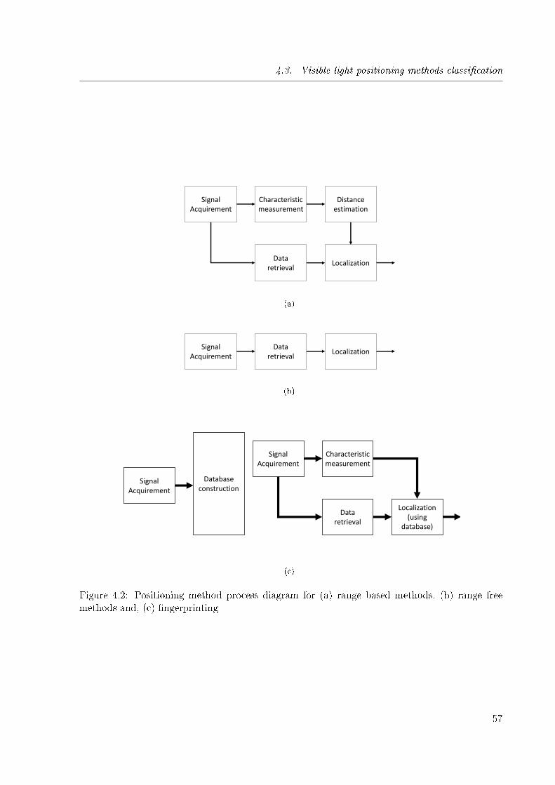
4.3. Visible light positioning methods classi�cation
Signal Acquirement
Dataretrieval
Characteristic measurement
Distance estimation
Localization
(a)
Signal Acquirement
Dataretrieval
Localization
(b)
Signal Acquirement
Database construction
Signal Acquirement
Dataretrieval
Characteristic measurement
Localization (using
database)
(c)
Figure 4.2: Positioning method process diagram for (a) range based methods, (b) range freemethods and, (c) �ngerprinting
57
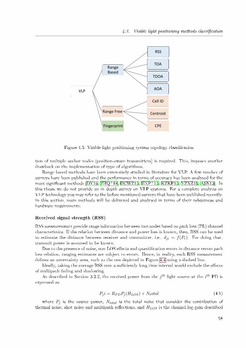
4.3. Visible light positioning methods classi�cation
VLP
RangeBased
RSS
TOA
TDOA
AOA
Range Free
Cell ID
Centroid
CPEFingerprint
Figure 4.3: Visible light positioning system topology classi�cation
tion of multiple anchor nodes (position-aware transmitters) is required. This, imposes anotherdrawback on the implementation of type of algorithms.
Range based methods have been extensively studied in literature for VLP. A few number ofsurveys have been published and the performance in terms of accuracy has been analysed for themost signi�cant methods [DY16, ZHQ+18, HCWZ15, HNP+15, KZKP15, YZXZ15, ASN13]. Inthis thesis we do not provide an in depth survey on VLP systems. For a complete analysis onVLP technology you may refer to the before mentioned surveys that have been published recently.In this section, main methods will be delivered and analysed in terms of their robustness andhardware requirements.
Received signal strength (RSS)
RSS measurements provide range information between two nodes based on path loss (PL) channelcharacteristics. If the relation between distance and power loss is known, then, RSS can be usedto estimate the distance between receiver and transmitter, i.e., dji = f(Pr). For doing that,transmit power is assumed to be known.
Due to the presence of noise, non-LOS e�ects and quanti�cation errors in distance versus pathloss relation, ranging estimates are subject to errors. Hence, in reality, each RSS measurementde�nes an uncertainty area, such as the one depicted in Figure 4.4 using a dashed line.
Ideally, taking the average RSS over a su�ciently long time interval would exclude the e�ectsof multipath fading and shadowing.
As described in Section 3.2.2, the received power from the jth light source at the ith PD isexpressed as
Pji = RPDPj(HLOS) +Ntotal (4.1)
where Pj is the source power, Ntotal is the total noise that consider the contribution ofthermal noise, shot noise and multipath re�ections, and HLOS is the channel log gain described
58

4.3. Visible light positioning methods classi�cation
𝑑𝑗𝑖
(a)
𝑑𝑗𝑖
𝜎𝑑
(b)
Figure 4.4: Ranging information from RSS measurements (a) ideal ranging and (b) rangingestimation with uncertainty σd
in Equation 3.16. In Figure 4.5, received power versus distance plot for a LED light model CreeXLamp CXB1512 is shown.
2.15 2.2 2.25 2.3 2.35 2.4 2.45
Distance dji (m)
0
0.2
0.4
0.6
0.8
1
1.2
1.4
1.6
1.8
Rec
eive
d po
wer
Figure 4.5: Power versus distance measurements of ED light Cree XLamp CXB1512
In this �gure mean RSS value from 100 samples is taken instead instantaneous RSS value.As it can be seen, there exist a non-linear relation between the received power by the PD, andthe distance between transmitter and receiver.
Notice that, the received power depends also on the signal's received angle (Equation 3.16).In order to solve this problem, a scaling factor RSS method was proposed in [KKY+13] when noother devices such as gyroscopes or accelerometers are incorporated at the receiver. Some othermethods use PD arrays [SES13] and cross correlation function between transmitter and receiver[LYC+14] in order to deal with angle diversity at receiver's side. In general, RSS based methodincreases its accuracy when a large number of LEDs are perceived [NJM13], multipath e�ectsare neglected and non-tilt receivers are considered.
In order to obtain a unique position estimation we require several estimated ranges. Forexample, in order to obtain an unique estimate for 2-D positioning, at least three range mea-
59
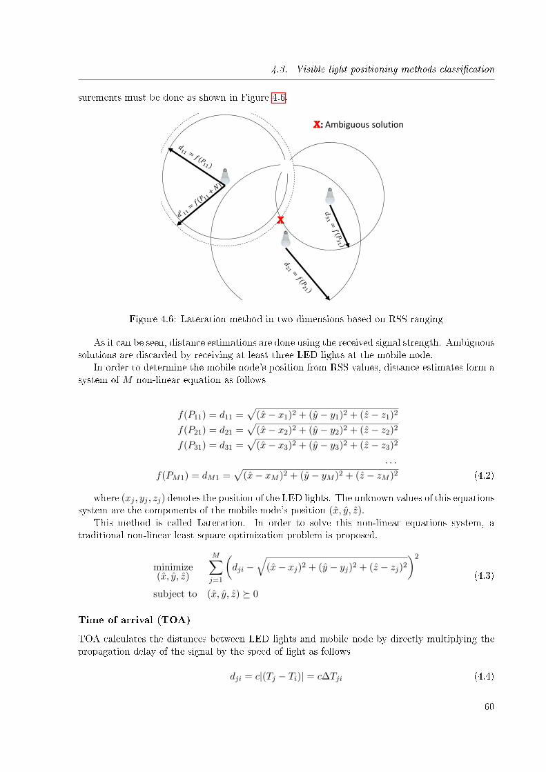
4.3. Visible light positioning methods classi�cation
surements must be done as shown in Figure 4.6.
X
X: Ambiguous solution
Figure 4.6: Lateration method in two dimensions based on RSS ranging
As it can be seen, distance estimations are done using the received signal strength. Ambiguoussolutions are discarded by receiving at least three LED lights at the mobile node.
In order to determine the mobile node's position from RSS values, distance estimates form asystem of M non-linear equation as follows
f(P11) = d11 =√
(x− x1)2 + (y − y1)2 + (z − z1)2
f(P21) = d21 =√
(x− x2)2 + (y − y2)2 + (z − z2)2
f(P31) = d31 =√
(x− x3)2 + (y − y3)2 + (z − z3)2
. . .
f(PM1) = dM1 =√
(x− xM )2 + (y − yM )2 + (z − zM )2 (4.2)
where (xj , yj , zj) denotes the position of the LED lights. The unknown values of this equationssystem are the components of the mobile node's position (x, y, z).
This method is called Lateration. In order to solve this non-linear equations system, atraditional non-linear least square optimization problem is proposed.
minimize(x, y, z)
M∑j=1
(dji −
√(x− xj)2 + (y − yj)2 + (z − zj)2
)2
subject to (x, y, z) � 0
(4.3)
Time of arrival (TOA)
TOA calculates the distances between LED lights and mobile node by directly multiplying thepropagation delay of the signal by the speed of light as follows
dji = c|(Tj − Ti)| = c∆Tji (4.4)
60
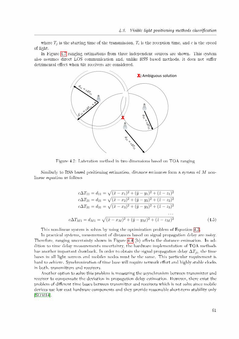
4.3. Visible light positioning methods classi�cation
where Tj is the starting time of the transmission, Ti is the reception time, and c is the speedof light.
In Figure 4.7 ranging estimations from three independent sources are shown. This systemalso assumes direct LOS communication and, unlike RSS based methods, it does not su�erdetrimental e�ect when tilt receivers are considered.
X
X: Ambiguous solution
Figure 4.7: Lateration method in two dimensions based on TOA ranging
Similarly to RSS based positioning estimation, distance estimates form a system of M non-linear equation as follows
c∆T11 = d11 =√
(x− x1)2 + (y − y1)2 + (z − z1)2
c∆T21 = d21 =√
(x− x2)2 + (y − y2)2 + (z − z2)2
c∆T31 = d31 =√
(x− x3)2 + (y − y3)2 + (z − z3)2
. . .
c∆TM1 = dM1 =√
(x− xM )2 + (y − yM )2 + (z − zM )2 (4.5)
This non-linear system is solves by using the optimization problem of Equation 4.3.In practical systems, measurement of distances based on signal propagation delay are noisy.
Therefore, ranging uncertainty shown in Figure 4.4 (b) a�ects the distance estimation. In ad-dition to time delay measurements uncertainty, the hardware implementation of TOA methodshas another important drawback. In order to obtain the signal propagation delay ∆Tji, the timebases in all light sources and mobiles nodes must be the same. This particular requirement ishard to achieve. Synchronization of time base will require network e�ort and highly stable clocksin both, transmitters and receivers.
Another option to solve this problem is measuring the asynchronism between transmitter andreceiver to compensate the deviation in propagation delay estimation. However, there exist theproblem of di�erent time bases between transmitter and receivers which is not solve since mobiledevices use low cost hardware components and they provide reasonable short-term stability only[SDM14].
61
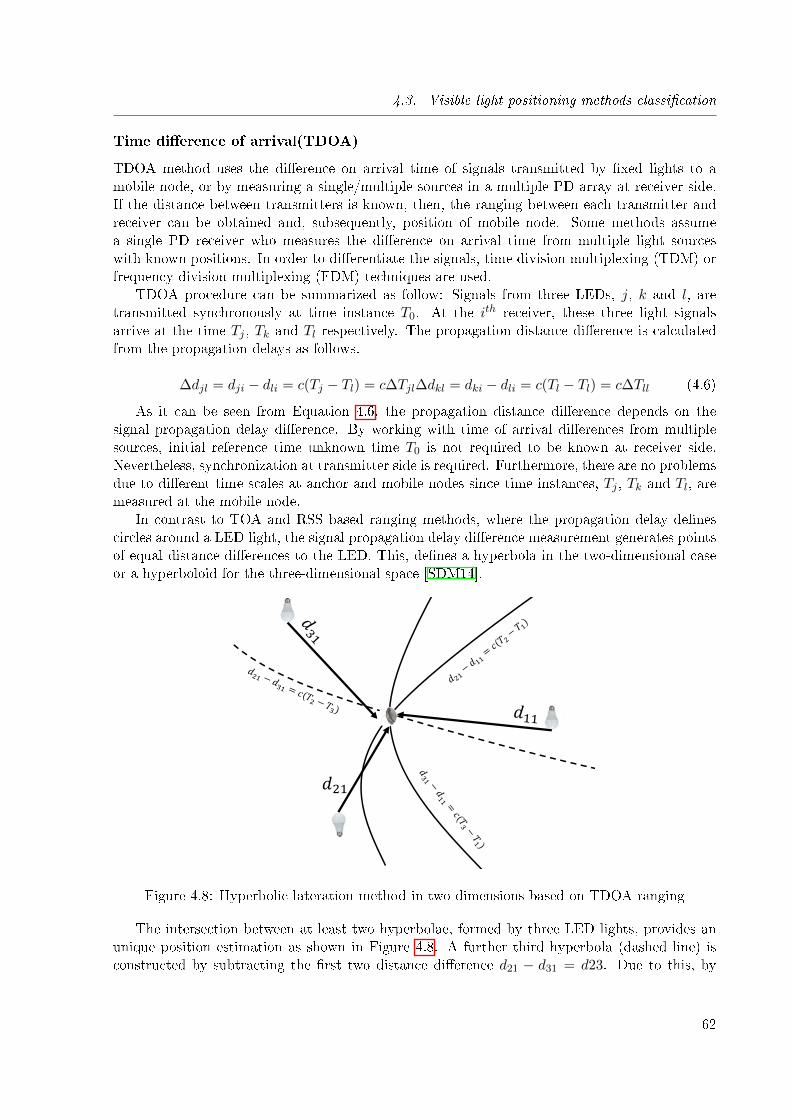
4.3. Visible light positioning methods classi�cation
Time di�erence of arrival(TDOA)
TDOA method uses the di�erence on arrival time of signals transmitted by �xed lights to amobile node, or by measuring a single/multiple sources in a multiple PD array at receiver side.If the distance between transmitters is known, then, the ranging between each transmitter andreceiver can be obtained and, subsequently, position of mobile node. Some methods assumea single PD receiver who measures the di�erence on arrival time from multiple light sourceswith known positions. In order to di�erentiate the signals, time division multiplexing (TDM) orfrequency division multiplexing (FDM) techniques are used.
TDOA procedure can be summarized as follow: Signals from three LEDs, j, k and l, aretransmitted synchronously at time instance T0. At the ith receiver, these three light signalsarrive at the time Tj , Tk and Tl respectively. The propagation distance di�erence is calculatedfrom the propagation delays as follows.
∆djl = dji − dli = c(Tj − Tl) = c∆Tjl∆dkl = dki − dli = c(Tl − Tl) = c∆Tll (4.6)
As it can be seen from Equation 4.6, the propagation distance di�erence depends on thesignal propagation delay di�erence. By working with time of arrival di�erences from multiplesources, initial reference time unknown time T0 is not required to be known at receiver side.Nevertheless, synchronization at transmitter side is required. Furthermore, there are no problemsdue to di�erent time scales at anchor and mobile nodes since time instances, Tj , Tk and Tl, aremeasured at the mobile node.
In contrast to TOA and RSS based ranging methods, where the propagation delay de�nescircles around a LED light, the signal propagation delay di�erence measurement generates pointsof equal distance di�erences to the LED. This, de�nes a hyperbola in the two-dimensional caseor a hyperboloid for the three-dimensional space [SDM14].
𝑑21
Figure 4.8: Hyperbolic lateration method in two dimensions based on TDOA ranging
The intersection between at least two hyperbolae, formed by three LED lights, provides anunique position estimation as shown in Figure 4.8. A further third hyperbola (dashed line) isconstructed by subtracting the �rst two distance di�erence d21 − d31 = d23. Due to this, by
62
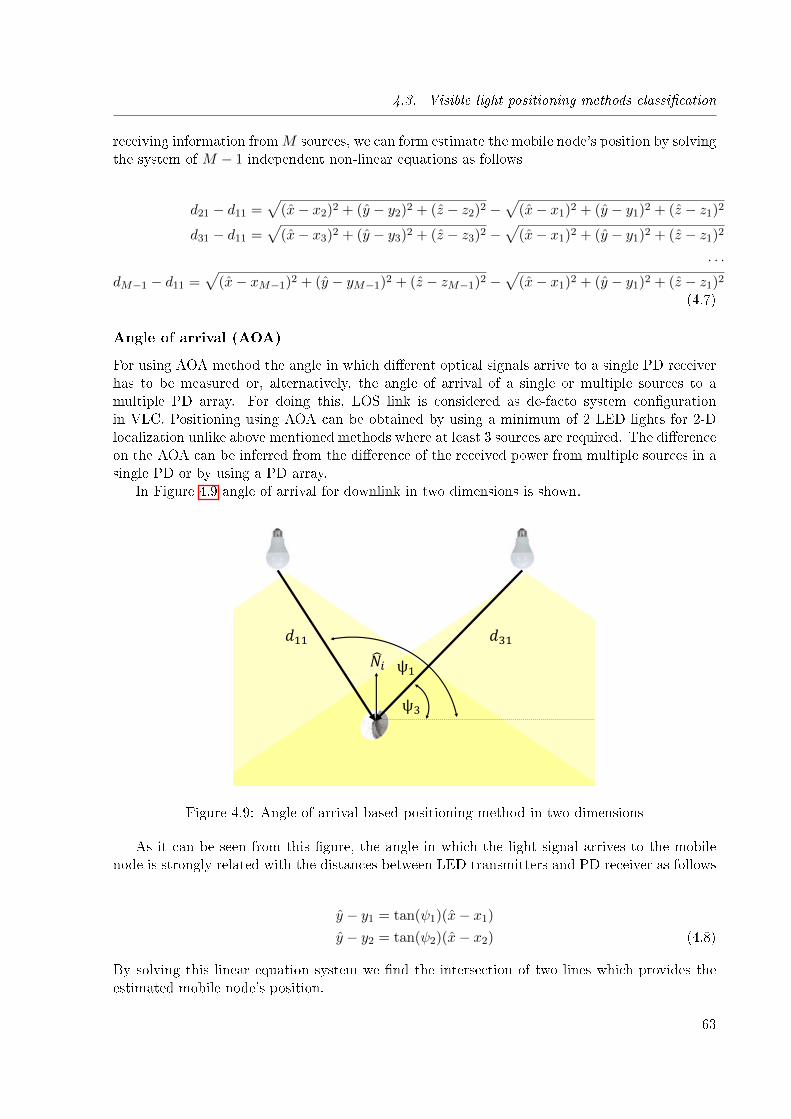
4.3. Visible light positioning methods classi�cation
receiving information fromM sources, we can form estimate the mobile node's position by solvingthe system of M − 1 independent non-linear equations as follows
d21 − d11 =√
(x− x2)2 + (y − y2)2 + (z − z2)2 −√
(x− x1)2 + (y − y1)2 + (z − z1)2
d31 − d11 =√
(x− x3)2 + (y − y3)2 + (z − z3)2 −√
(x− x1)2 + (y − y1)2 + (z − z1)2
. . .
dM−1 − d11 =√
(x− xM−1)2 + (y − yM−1)2 + (z − zM−1)2 −√
(x− x1)2 + (y − y1)2 + (z − z1)2
(4.7)
Angle of arrival (AOA)
For using AOA method the angle in which di�erent optical signals arrive to a single PD receiverhas to be measured or, alternatively, the angle of arrival of a single or multiple sources to amultiple PD array. For doing this, LOS link is considered as de-facto system con�gurationin VLC. Positioning using AOA can be obtained by using a minimum of 2 LED lights for 2-Dlocalization unlike above mentioned methods where at least 3 sources are required. The di�erenceon the AOA can be inferred from the di�erence of the received power from multiple sources in asingle PD or by using a PD array.
In Figure 4.9 angle of arrival for downlink in two dimensions is shown.
𝑑31𝑑11
ψ1
ψ3
𝑁𝑖
Figure 4.9: Angle of arrival based positioning method in two dimensions
As it can be seen from this �gure, the angle in which the light signal arrives to the mobilenode is strongly related with the distances between LED transmitters and PD receiver as follows
y − y1 = tan(ψ1)(x− x1)
y − y2 = tan(ψ2)(x− x2) (4.8)
By solving this linear equation system we �nd the intersection of two lines which provides theestimated mobile node's position.
63
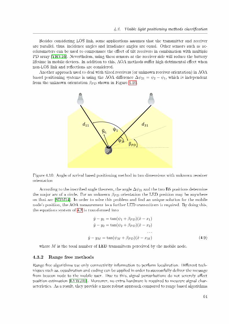
4.3. Visible light positioning methods classi�cation
Besides considering LOS link, some applications assumes that the transmitter and receiverare parallel, thus, incidence angles and irradiance angles are equal. Other sensors such as ac-celerometers can be used to compensate the e�ect of tilt receivers in combination with multiplePD array [YHV16]. Nevertheless, using these sensors at the receiver side will reduce the batterylifetime in mobile devices. In addition to this, AOA methods su�er high detrimental e�ect whennon-LOS link and re�ections are considered.
Another approach used to deal with tilted receivers (or unknown receiver orientation) in AOAbased positioning systems is using the AOA di�erence ∆ψ21 = ψ2 − ψ1, which is independentfrom the unknown orientation βPD shown in Figure 4.10.
𝑑31𝑑11ψ1
ψ3β𝑃𝐷
Figure 4.10: Angle of arrival based positioning method in two dimensions with unknown receiverorientation
According to the inscribed angle theorem, the angle ∆ψ21 and the two BS positions determinethe major arc of a circle. For an unknown βPD orientation the LED position may be anywhereon that arc [SDM14]. In order to solve this problem and �nd an unique solution for the mobilenode's position, the AOA measurement to a further LED transmitters is required. By doing this,the equations system of 4.8 is transformed into
y − y1 = tan(ψ1 + βPD)(x− x1)
y − y2 = tan(ψ2 + βPD)(x− x2)
. . .
y − yM = tan(ψM + βPD)(x− xM ) (4.9)
where M is the total number of LED transmitters perceived by the mobile node.
4.3.2 Range free methods
Range free algorithms use only connectivity information to perform localization. Di�erent tech-niques such as, equalization and coding can be applied in order to successfully deliver the messagefrom beacon node to the mobile user. Due to this, signal perturbations do not severely a�ectposition estimation [LYWJ10]. Moreover, no extra hardware is required to measure signal char-acteristics. As a result, they provide a more robust approach compared to range based algorithms
64
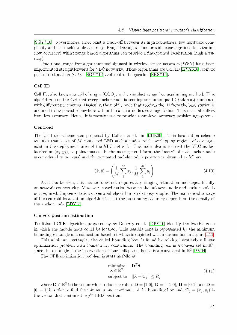
4.3. Visible light positioning methods classi�cation
[SGY+16]. Nevertheless, there exist a trade-o� between its high robustness, low hardware com-plexity and their achievable accuracy. Range free algorithms provide coarse-grained localization(low accuracy) whilst range based algorithms can provide a �ne-grained localization (high accu-racy).
Traditional range free algorithms mainly used in wireless sensor networks (WSN) have beenimplemented straightforward for VLC networks. These algorithms are Cell ID [KVAS16], convexposition estimation (CPE) [SGY+16] and centroid algorithm [SKS+16].
Cell ID
Cell ID, also known as cell of origin (COO), is the simplest range free positioning method. Thisalgorithm uses the fact that every anchor node is sending out an unique ID (address) combinedwith di�erent parameters. Basically, the mobile node that receives the ID from the base station isassumed to be placed somewhere within the anchor node's coverage radius. This method su�ersfrom low accuracy. Hence, it is mostly used to provide room-level accuracy positioning systems.
Centroid
The Centroid scheme was proposed by Bulusu et al. in [BHE00]. This localization schemeassumes that a set of M connected LED anchor nodes, with overlapping regions of coverage,exist in the deployment area of the VLC network. The main idea is to treat the VLC nodes,located at (xj , yj), as point masses. In the most general form, the "mass" of each anchor nodeis considered to be equal and the estimated mobile node's position is obtained as follows.
(x, y) =
(1
M
M∑1
xj ,1
M
M∑1
yj
)(4.10)
As it can be seen, this method does not requires any ranging estimation and depends fullyon network connectivity. Moreover, coordination between the unknown node and anchor node isnot required. Implementation of centroid algorithm is relatively simple. The main disadvantageof the centroid localization algorithm is that the positioning accuracy depends on the density ofthe anchor node [LDY15].
Convex position estimation
Traditional CPE algorithm proposed by by Doherty et al. [DPE01] identify the feasible zonein which the mobile node could be located. This feasible zone is represented by the minimumbounding rectangle of a connection-based set which is depicted with a dashed line in Figure 4.11.
This minimum rectangle, also called bounding box, is found by solving iteratively a linearoptimization problem with connectivity constraints. The bounding box is a convex set in R2,since the rectangle is the intersection of four halfspaces, hence is a convex set in R2 [BV04].
The CPE optimization problem is state as follows
minimizex ∈ R2
DT x
subject to ‖x−Cj‖ ≤ Rj(4.11)
whereD ∈ R2 is the vector which takes the valuesD = [1 0], D = [−1 0], D = [0 1] and D =[0 − 1] in order to �nd the minimum and maximum of the bounding box and, Cj = (xj , yj) isthe vector that contains the jth LED position.
65
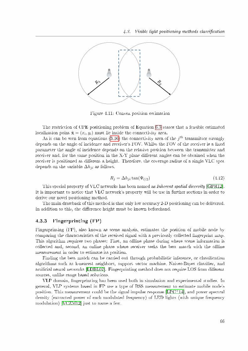
4.3. Visible light positioning methods classi�cation
Figure 4.11: Convex position estimation
The restriction of CPE positioning problem of Equation 6.3 states that a feasible estimatedlocalization point x = (xi, yi) must lie inside the connectivity area.
As it can be seen from equations (3.16) the connectivity area of the jth transmitter stronglydepends on the angle of incidence and receiver's FOV. Whilst the FOV of the receiver is a �xedparameter the angle of incidence depends on the relative position between the transmitter andreceiver and, for the same position in the X-Y plane di�erent angles can be obtained when thereceiver is positioned at di�erent a height. Therefore, the coverage radius of a single VLC spotdepends on the variable ∆hji as follows.
Rj = ∆hji tan(Ψl/2) (4.12)
This special property of VLC networks has been named as Inherent spatial diversity [GPR12].It is important to notice that VLC network's property will be use in further sections in order toderive our novel positioning method.
The main drawback of this method is that only low accuracy 2-D positioning can be delivered.In addition to this, the di�erence height must be known beforehand.
4.3.3 Fingerprinting (FP)
Fingerprinting (FP), also known as scene analysis, estimates the position of mobile node bycomparing the characteristics of the received signal with a previously collected �ngerprint map.This algorithm requires two phases: First, an o�ine phase during where scene information iscollected and, second, an online phase where receiver seeks the best match with the o�inemeasurement in order to estimate its position.
Finding the best match can be carried out through probabilistic inference, or classi�cationalgorithms such as k-nearest neighbors, support vector machine, Naives-Bayes classi�er, andarti�cial neural networks [LDBL07]. Fingerprinting method does not require LOS from di�erentsources, unlike range based solutions.
VLP domain, �ngerprinting has been used both in simulation and experimental studies. Ingeneral, VLP systems based in FP use a type of RSS measurement to estimate mobile node'sposition. This measurement could be the signal impulse response [LPC+14], and power spectraldensity (extracted power of each modulated frequency) of LED lights (with unique frequencymodulation) [VCZM12] just to name a few.
66
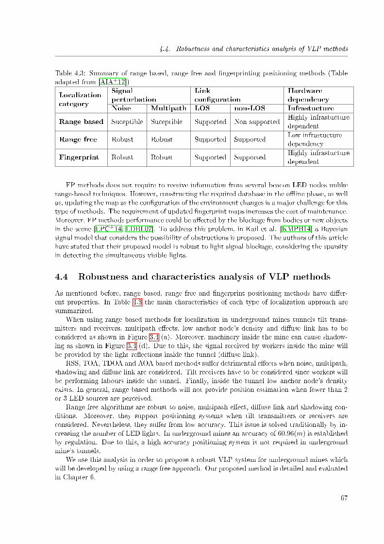
4.4. Robustness and characteristics analysis of VLP methods
Table 4.3: Summary of range based, range free and �ngerprinting positioning methods (Tableadapted from [AIA+17])
Localizationcategory
Signalperturbation
Linkcon�guration
Hardwaredependency
Noise Multipath LOS non-LOS Infrastucture
Range based Suceptible Suceptible Supported Non supportedHighly infrastucturedependent
Range free Robust Robust Supported SupportedLow infrastucturedependency
Fingerprint Robust Robust Supported SupportedHighly infrastucturedependent
FP methods does not require to receive information from several beacon LED nodes unlikerange-based techniques. However, constructing the required database in the o�ine phase, as wellas, updating the map as the con�guration of the environment changes is a major challenge for thistype of methods. The requirement of updated �ngerprint maps increases the cost of maintenance.Moreover, FP methods performance could be a�ected by the blockage from bodies or new objectsin the scene [LPC+14, LDBL07]. To address this problem, in Kail et al. [KMPB14] a Bayesiansignal model that considers the possibility of obstructions is proposed. The authors of this articlehave stated that their proposed model is robust to light signal blockage, considering the sparsityin detecting the simultaneous visible lights.
4.4 Robustness and characteristics analysis of VLP methods
As mentioned before, range based, range free and �ngerprint positioning methods have di�er-ent properties. In Table 4.3 the main characteristics of each type of localization approach aresummarized.
When using range based methods for localization in underground mines tunnels tilt trans-mitters and receivers, multipath e�ects, low anchor node's density and di�use link has to beconsidered as shown in Figure 3.4 (a). Moreover, machinery inside the mine can cause shadow-ing as shown in Figure 3.4 (d). Due to this, the signal received by workers inside the mine willbe provided by the light re�ections inside the tunnel (di�use link).
RSS, TOA, TDOA and AOA based methods su�er detrimental e�ects when noise, multipath,shadowing and di�use link are considered. Tilt receivers have to be considered since workers willbe performing labours inside the tunnel. Finally, inside the tunnel low anchor node's densityexists. In general, range based methods will not provide position estimation when fewer than 2or 3 LED sources are perceived.
Range free algorithms are robust to noise, multipath e�ect, di�use link and shadowing con-ditions. Moreover, they support positioning systems when tilt transmitters or receivers areconsidered. Nevertheless, they su�er from low accuracy. This issue is solved traditionally by in-creasing the number of LED lights. In underground mines an accuracy of 60.96(m) is establishedby regulation. Due to this, a high accuracy positioning system is not required in undergroundmine's tunnels.
We use this analysis in order to propose a robust VLP system for underground mines whichwill be developed by using a range free approach. Our proposed method is detailed and evaluatedin Chapter 6.
67
Chapter 5
Design and implementation of alow-cost/large-scale visible light
positioning system
Sommaire
5.1 Introduction . . . . . . . . . . . . . . . . . . . . . . . . . . . . . . . . . 68
5.2 Uplink for remote positioning . . . . . . . . . . . . . . . . . . . . . . . 68
5.3 Visible light communications downlink . . . . . . . . . . . . . . . . . 70
5.4 Visible light communications receiver . . . . . . . . . . . . . . . . . . 71
5.1 Introduction
In this section we provide the design and the hardware implementation of a low cost/large scalevisible light positioning system. As a result of this design, a VLP testing platform has beenimplemented at the Center for research in automatic at Nancy (CRAN) of the Université deLorraine. This hardware implementation is used to deliver di�erent positioning techniques fromPD to camera based positioning methods. In addition to this, the design will be done in orderto support di�erent multiplexing techniques and data rates of up to 20 Kbps. As detailed inprevious sections, the proposed VLP system must provide indirect remote positioning topology.In addition to this, it must be scalable and have a low cost on its implementation. This chapteris organized as follows: First the uplink technology use for remote positioning capabilities asdetailed in table 4.2 is presented, a coverage analysis is done by measuring the package successratio. Further on, the VLC transmitter hardware architecture is presented. Finally, the receiveris detailed and real data obtained from the implemented platform is delivered.
5.2 Uplink for remote positioning
As depicted in Table 4.2 VLC technology requires to be hybridized in order to support remotepositioning technologies. Among all wireless communications technologies RF and IR are usedto support uplink communication. IR communications have a short range of coverage (about 10m). On the other hand RF has shown to cover a large area inside tunnels. Di�erent RF bands
68
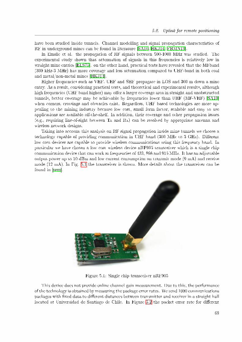
5.2. Uplink for remote positioning
have been studied inside tunnels. Channel modelling and signal propagation characteristics ofRF in underground mines can be found in literature [SA10, HKJ14, FBMN13].
In Emslie et al. the propagation of RF signals between 500-1000 MHz was studied. Theexperimental study shown that attenuation of signals in this frequencies is relatively low instraight mine entries [ELS75]. on the other hand, practical tests have revealed that the MFband(300 kHz-3 MHz) has more coverage and less attenuation compared to UHF-band in both coaland metal/non-metal mines [HKJ14].
Higher frequencies such as VHF, UHF and SHF propagate in LOS and 300 m down a mineentry. As a result, considering practical tests, and theoretical and experimental results, althoughhigh frequencies (UHF band higher) may o�er a larger coverage area in straight and unobstructedtunnels, better coverage may be achievable by frequencies lower than UHF (MF-VHF) [SA10]when corners, crossings and obstacles exist. Regardless, UHF based technologies are more ap-pealing to the mining industry because low cost, small form factor, scalable and easy to useapplications are available o�-the-shelf. In addition, their coverage and other propagation issues(e.g., requiring line-of-sight between Tx and Rx) can be resolved by appropriate antenna andwireless network designs.
Taking into account this analysis on RF signal propagation inside mine tunnels we choose atechnology capable of providing communication in UHF band (300 MHz to 3 GHz). Di�erentlow cost devices are capable to provide wireless communications using this frequency band. Inparticular we have chosen a low cost wireless device nRF905 transceiver which is a single chipcommunication device that can work at frequencies of 433, 868 and 915 MHz. It has an adjustableoutput power up to 10 dBm and low current consumption on transmit mode (9 mA) and receivemode (12 mA). In Fig. 5.1 the transceiver is shown. More details about the transceiver can befound in [sem].
Figure 5.1: Single chip transceiver nRF905
This device does not provide online channel gain measurement. Due to this, the performanceof the technology is obtained by measuring the package error rates. We send 1000 communicationspackages with �xed data to di�erent distances between transmitter and receiver in a straight halllocated at Universidad de Santiago de Chile. In Figure 5.2 the packet error rate for di�erent
69
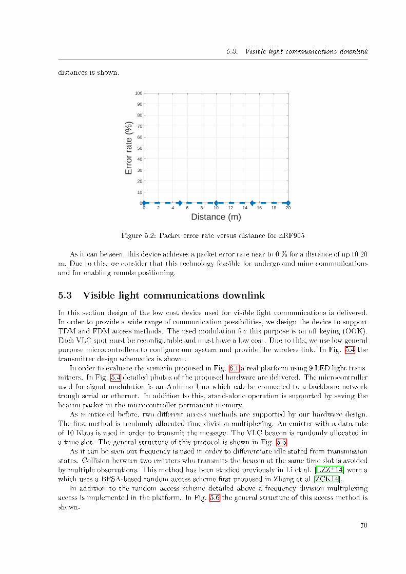
5.3. Visible light communications downlink
distances is shown.
0 2 4 6 8 10 12 14 16 18 20
Distance (m)
0
10
20
30
40
50
60
70
80
90
100
Err
or r
ate
(%)
Figure 5.2: Packet error rate versus distance for nRF905
As it can be seen, this device achieves a packet error rate near to 0 % for a distance of up t0 20m. Due to this, we consider that this technology feasible for underground mine communicationsand for enabling remote positioning.
5.3 Visible light communications downlink
In this section design of the low cost device used for visible light communications is delivered.In order to provide a wide range of communication possibilities, we design the device to supportTDM and FDM access methods. The used modulation for this purpose is on-o�-keying (OOK).Each VLC spot must be recon�gurable and must have a low cost. Due to this, we use low generalpurpose microcontrollers to con�gure our system and provide the wireless link. In Fig. 5.4 thetransmitter design schematics is shown.
In order to evaluate the scenario proposed in Fig. 6.1 a real platform using 9 LED light trans-mitters. In Fig. 5.4 detailed photos of the proposed hardware are delivered. The microcontrollerused for signal modulation is an Arduino Uno which cab be connected to a backbone networktrough serial or ethernet. In addition to this, stand-alone operation is supported by saving thebeacon packet in the microcontroller permanent memory.
As mentioned before, two di�erent access methods are supported by our hardware design.The �rst method is randomly allocated time division multiplexing. An emitter with a data rateof 10 Kbps is used in order to transmit the message. The VLC beacon is randomly allocated ina time slot. The general structure of this protocol is shown in Fig. 5.5.
As it can be seen out frequency is used in order to di�erentiate idle stated from transmissionstates. Collision between two emitters who transmits the beacon at the same time slot is avoidedby multiple observations. This method has been studied previously in Li et al. [LZZ+14] were awhich uses a BFSA-based random access scheme �rst proposed in Zhang et al [ZCK14].
In addition to the random access scheme detailed above a frequency division multiplexingaccess is implemented in the platform. In Fig. 5.6 the general structure of this access method isshown.
70
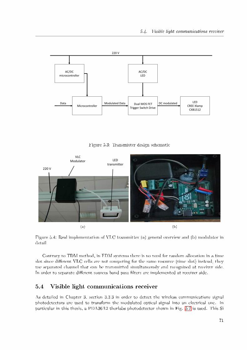
5.4. Visible light communications receiver
MicrocontrollerData
AC/DC microcontroller
AC/DC LED
Dual MOS FET Trigger Switch Drive
Modulated Data LEDCREE Xlamp
CXB1512
DC modulated
220 V
Figure 5.3: Transmitter design schematic
220 V
VLC Modulator LED
transmitter
(a) (b)
Figure 5.4: Real implementation of VLC transmitter (a) general overview and (b) modulator indetail
Contrary to TDM method, in FDM systems there is no need for random allocation in a timeslot since di�erent VLC cells are not competing for the same resource (time slot) instead, theyuse separated channel that can be transmitted simultaneously and recognized at receiver side.In order to separate di�erent sources band pass �lters are implemented at receiver side.
5.4 Visible light communications receiver
As detailed in Chapter 3, section 3.3.3 in order to detect the wireless communications signalphotodetectors are used to transform the modulated optical signal into an electrical one. Inparticular in this thesis, a PDA36A2 thorlabs photodetector shown in Fig. 5.7 is used. This Si
71
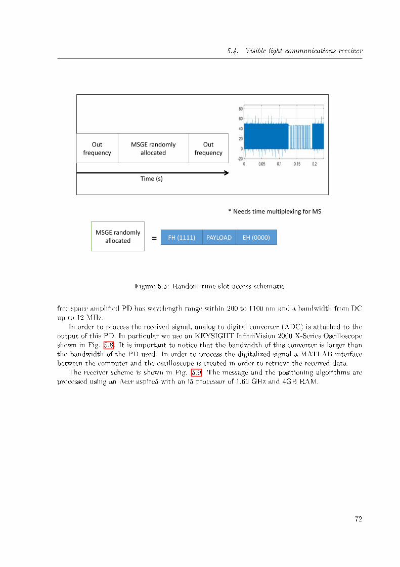
5.4. Visible light communications receiver
MSGE randomly allocated
Out frequency
Out frequency
MSGE randomly allocated FH (1111) PAYLOAD EH (0000)
* Needs time multiplexing for MS
Time (s)
=
Figure 5.5: Random time slot access schematic
free space ampli�ed PD has wavelength range within 200 to 1100 nm and a bandwidth from DCup to 12 MHz.
In order to process the received signal, analog to digital converter (ADC) is attached to theoutput of this PD. In particular we use an KEYSIGHT In�niiVision 2000 X-Series Oscilloscopeshown in Fig. 5.8. It is important to notice that the bandwidth of this converter is larger thanthe bandwidth of the PD used. In order to process the digitalized signal a MATLAB interfacebetween the computer and the oscilloscope is created in order to retrieve the received data.
The receiver scheme is shown in Fig. 5.9. The message and the positioning algorithms areprocessed using an Acer aspire5 with an i5 processor of 1.60 GHz and 4GB RAM.
72
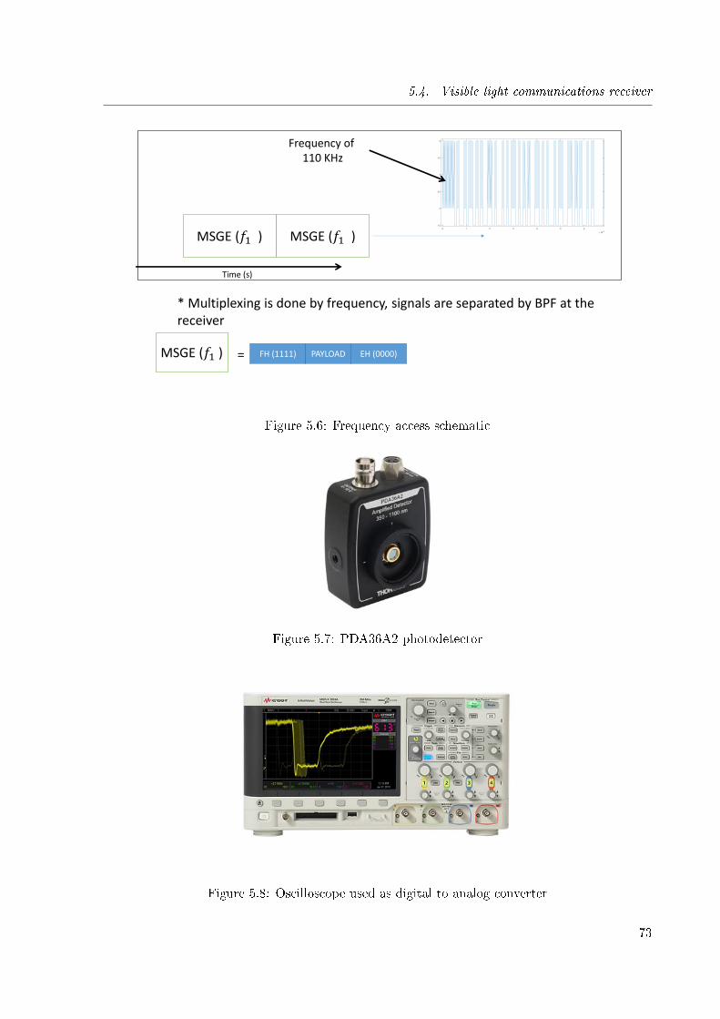
5.4. Visible light communications receiver
Frequency of 110 KHz
MSGE (𝑓1 )
* Multiplexing is done by frequency, signals are separated by BPF at the receiver
MSGE (𝑓1 )
MSGE (𝑓1 ) FH (1111) PAYLOAD EH (0000) =
Frequency of 110 KHz
Time (s)
Figure 5.6: Frequency access schematic
Figure 5.7: PDA36A2 photodetector
Figure 5.8: Oscilloscope used as digital to analog converter
73
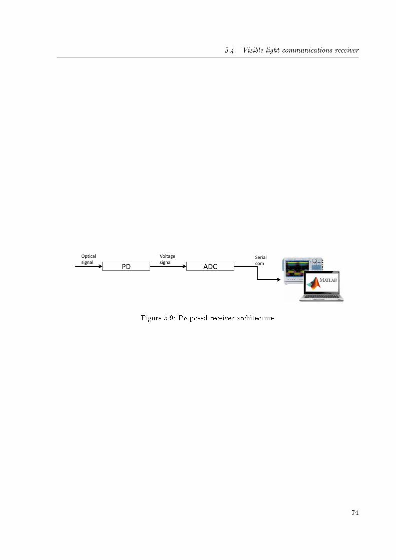
5.4. Visible light communications receiver
PD
Optical signal
Voltage signal
ADC
Serial com
Figure 5.9: Proposed receiver architecture
74
Chapter 6
Design and implementation of a novelrange free positioning method forrobust visible light positioning in
underground mines
Sommaire
6.1 Introduction . . . . . . . . . . . . . . . . . . . . . . . . . . . . . . . . . 75
6.2 System description . . . . . . . . . . . . . . . . . . . . . . . . . . . . . . 76
6.3 Network architecture based positioning method: Convex polygonpositioning (CPP) . . . . . . . . . . . . . . . . . . . . . . . . . . . . . . 77
6.4 Enhance of position accuracy using imaging receivers (IR-CPP) . . 83
6.5 Simulation results . . . . . . . . . . . . . . . . . . . . . . . . . . . . . . 85
6.5.1 Square room . . . . . . . . . . . . . . . . . . . . . . . . . . . . . . . . . 86
6.5.2 Tunnel section . . . . . . . . . . . . . . . . . . . . . . . . . . . . . . . . 92
6.6 Real implementation of CPP method using VLP testing platform . 94
6.1 Introduction
As it was detailed in precious chapters VLP system have its merits to be implemented in under-ground mines for monitoring of personnel inside the tunnel. In chapter 5 a low cost/large scalehardware VLP system was detailed. This design and implementation hybridize VLC technologywith a low cost-large coverage RF hardware in order to enable remote positioning which solvesthe problem enunciated in Chapter 2.
In Chapter 4 di�erent VLP methods were evaluated in terms of their robustness. As a conse-quence range free positioning methods has been chosen due to their merits in terms of robustnessagainst: signal perturbations, link con�guration and hardware dependency. Nowadays, most ofthe range VLP free methods that can be found in literature are used straightforward from RFbased solutions. In this chapter, we introduce a novel range free positioning method that usesintersect characteristics of VLC networks in order to increase the robustness and accuracy.
75
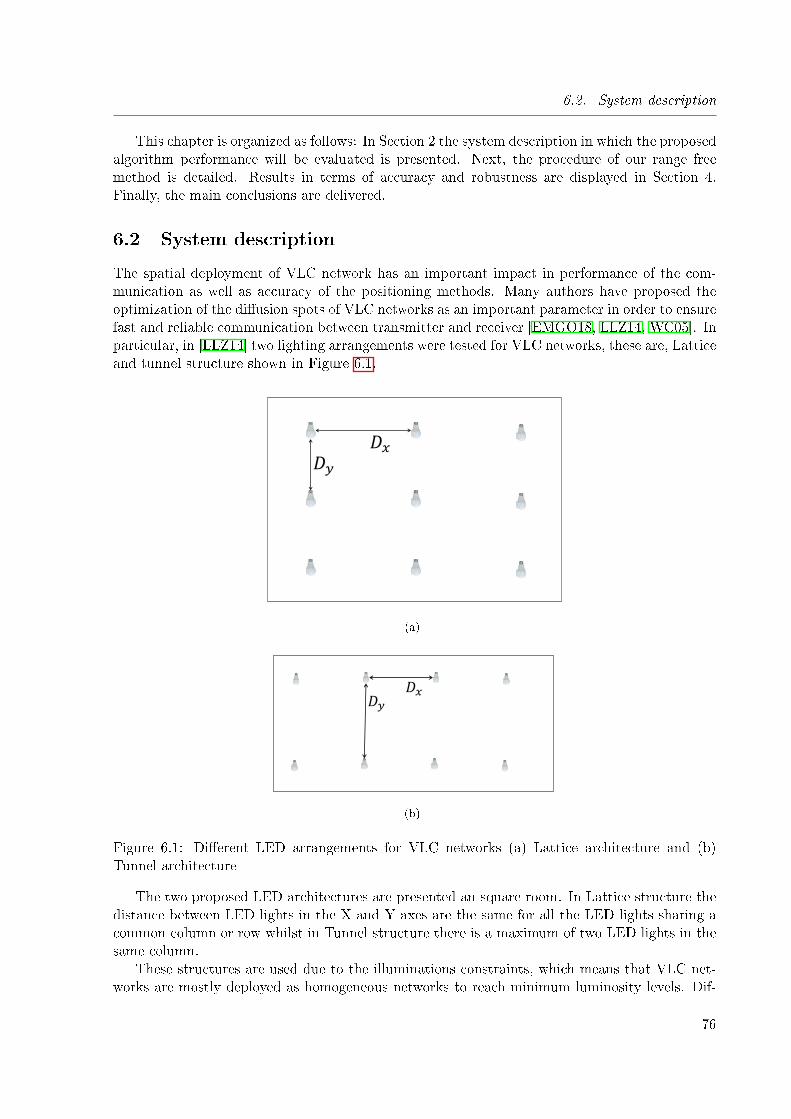
6.2. System description
This chapter is organized as follows: In Section 2 the system description in which the proposedalgorithm performance will be evaluated is presented. Next, the procedure of our range freemethod is detailed. Results in terms of accuracy and robustness are displayed in Section 4.Finally, the main conclusions are delivered.
6.2 System description
The spatial deployment of VLC network has an important impact in performance of the com-munication as well as accuracy of the positioning methods. Many authors have proposed theoptimization of the di�usion spots of VLC networks as an important parameter in order to ensurefast and reliable communication between transmitter and receiver [EMGO18, LLZ14, WC05]. Inparticular, in [LLZ14] two lighting arrangements were tested for VLC networks, these are, Latticeand tunnel structure shown in Figure 6.1.
𝐷𝑦
𝐷𝑥
(a)
𝐷𝑦𝐷𝑥
(b)
Figure 6.1: Di�erent LED arrangements for VLC networks (a) Lattice architecture and (b)Tunnel architecture
The two proposed LED architectures are presented an square room. In Lattice structure thedistance between LED lights in the X and Y axes are the same for all the LED lights sharing acommon column or row whilst in Tunnel structure there is a maximum of two LED lights in thesame column.
These structures are used due to the illuminations constraints, which means that VLC net-works are mostly deployed as homogeneous networks to reach minimum luminosity levels. Dif-
76
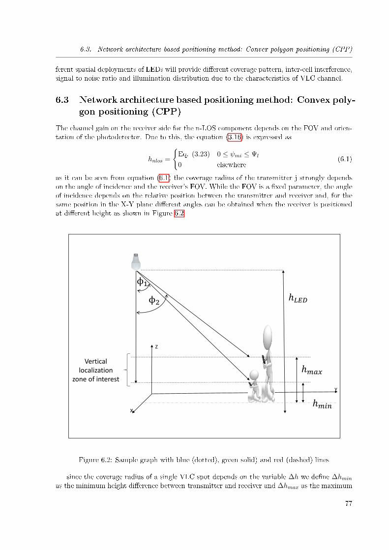
6.3. Network architecture based positioning method: Convex polygon positioning (CPP)
ferent spatial deployments of LEDs will provide di�erent coverage pattern, inter-cell interference,signal to noise ratio and illumination distribution due to the characteristics of VLC channel.
6.3 Network architecture based positioning method: Convex poly-gon positioning (CPP)
The channel gain on the receiver side for the n-LOS component depends on the FOV and orien-tation of the photodetector. Due to this, the equation (3.16) is expressed as
hnlos =
{Eq. (3.23) 0 ≤ ψmi ≤ Ψl
0 elsewhere(6.1)
as it can be seen from equation (6.1) the coverage radius of the transmitter j strongly dependson the angle of incidence and the receiver's FOV. While the FOV is a �xed parameter, the angleof incidence depends on the relative position between the transmitter and receiver and, for thesame position in the X-Y plane di�erent angles can be obtained when the receiver is positionedat di�erent height as shown in Figure 6.2
ϕ1
ℎ𝑚𝑖𝑛
ℎ𝑚𝑎𝑥
ϕ2
X
Y
Z
Vertical localization
zone of interest
ℎ𝐿𝐸𝐷
Figure 6.2: Sample graph with blue (dotted), green solid) and red (dashed) lines
since the coverage radius of a single VLC spot depends on the variable ∆h we de�ne ∆hminas the minimum height di�erence between transmitter and receiver and ∆hmax as the maximum
77
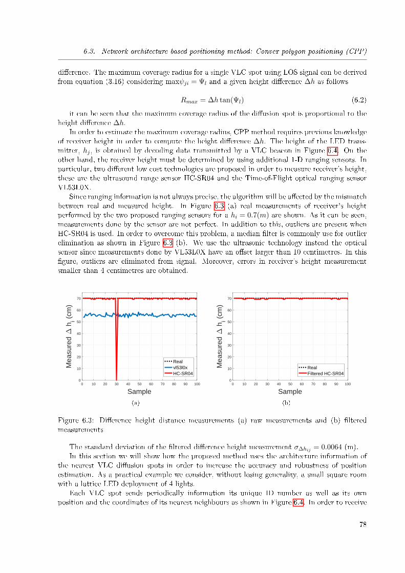
6.3. Network architecture based positioning method: Convex polygon positioning (CPP)
di�erence. The maximum coverage radius for a single VLC spot using LOS signal can be derivedfrom equation (3.16) considering maxψji = Ψl and a given height di�erence ∆h as follows
Rmax = ∆h tan(Ψl) (6.2)
it can be seen that the maximum coverage radius of the di�usion spot is proportional to theheight di�erence ∆h.
In order to estimate the maximum coverage radius, CPP method requires previous knowledgeof receiver height in order to compute the height di�erence ∆h. The height of the LED trans-mitter, hj , is obtained by decoding data transmitted by a VLC beacon in Figure 6.4. On theother hand, the receiver height must be determined by using additional 1-D ranging sensors. Inparticular, two di�erent low cost technologies are proposed in order to measure receiver's height,these are the ultrasound range sensor HC-SR04 and the Time-of-Flight optical ranging sensorVL53L0X.
Since ranging information is not always precise, the algorithm will be a�ected by the mismatchbetween real and measured height. In Figure 6.3 (a) real measurements of receiver's heightperformed by the two proposed ranging sensors for a hi = 0.7(m) are shown. As it can be seen,measurements done by the sensor are not perfect. In addition to this, outliers are present whenHC-SR04 is used. In order to overcome this problem, a median �lter is commonly use for outlierelimination as shown in Figure 6.3 (b). We use the ultrasonic technology instead the opticalsensor since measurements done by VL53L0X have an o�set larger than 10 centimetres. In this�gure, outliers are eliminated from signal. Moreover, errors in receiver's height measurementsmaller than 4 centimetres are obtained.
0 10 20 30 40 50 60 70 80 90 100
Sample
0
10
20
30
40
50
60
70
Mea
sure
d ∆
hi (
cm)
Realvl53l0xHC-SR04
(a)
0 10 20 30 40 50 60 70 80 90 100
Sample
0
10
20
30
40
50
60
70
Mea
sure
d ∆
hi (
cm)
RealFiltered HC-SR04
(b)
Figure 6.3: Di�erence height distance measurements (a) raw measurements and (b) �lteredmeasurements
The standard deviation of the �ltered di�erence height measurement σ∆hij = 0.0064 (m).In this section we will show how the proposed method uses the architecture information of
the nearest VLC di�usion spots in order to increase the accuracy and robustness of positionestimation. As a practical example we consider, without losing generality, a small square roomwith a lattice LED deployment of 4 lights.
Each VLC spot sends periodically information its unique ID number as well as its ownposition and the coordinates of its nearest neighbours as shown in Figure 6.4. In order to receive
78

6.3. Network architecture based positioning method: Convex polygon positioning (CPP)
information from multiple sources the algorithm requires the usage of a multiple access techniquesuch as frequency division multiplexing (FDM), time division multiplexing (TDM) code divisionmultiplexing (CDM) or other [PL18]. The low cost7large scale platform presented in Section 5support both, TDM and FDM.
For this example we consider that the mobile node is connected to three LED lights as shownin Figure 6.5. It receives simultaneously the VLC beacon shown in 6.4 from each connected light.
𝐶𝑗 𝐶𝑁2...𝐶𝑁1
𝐶𝑁𝑛𝐶𝑁3
ConnectedCell
NeighborsCells
𝐶𝑗 = [𝐶𝑒𝑙𝑙 𝐼𝐷, 𝑥𝑗 , 𝑦𝑗 , 𝑧𝑗]
𝐶𝑁𝑘= [𝐶𝑒𝑙𝑙 𝐼𝐷, 𝑥𝑁𝑘
, 𝑦𝑁𝑘, 𝑧𝑁𝑘
]
Figure 6.4: Broadcast VLC Packet
As it can be seen the mobile node receives position information from the connected node and,additionally, its neighbours. The proposed method uses both, connected and non-connected cellsto perform localization of the unknown node.
First, connected cells are used by using the traditional CPE algorithm. The feasible zone inwhich the MN could be located is represented by the minimum bounding rectangle of the feasibleconnection-based set. This minimum rectangle, also called bounding box, is found by solvingiteratively a linear optimization problem with connectivity constraints. The bounding box is aconvex set in R2, since the rectangle is the intersection of four half-spaces, hence is a convex setin R2 [BV04].
The CPE optimization problem is state as follows
minimizex ∈ R2
DTx
subject to ‖x−Cj‖ ≤ Rj(6.3)
whereD ∈ R2 is the vector which takes the valuesD = [1 0], D = [−1 0], D = [0 1] and D =[0 − 1] in order to �nd the minimum and maximum of the bounding box. The restriction of theproblem states that the feasible point x must lie in the connectivity area. CPE method estimatesposition of the MN as the bounding box centroid as shown in Figure 6.5. Our proposed methoduses this bound box as the �rst step of the procedure.
For the second step, neighbour cells overlapped with the bounding box are found. Since thecoverage radius and the central position of each neighbour cell is known by the MN it can performan overlapping condition testing algorithm. The overlapped condition state next is tested foreach known neighbour and the bounding box set already found in the �rst step.
79
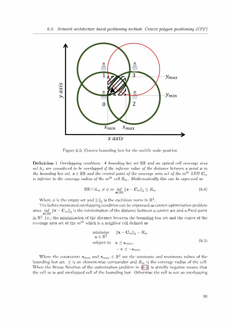
6.3. Network architecture based positioning method: Convex polygon positioning (CPP)
0
1 3
2
𝑥𝑚𝑖𝑛 𝑥𝑚𝑎𝑥
𝑦𝑚𝑎𝑥
𝑦𝑚𝑖𝑛
𝑥 𝑎𝑥𝑖𝑠
𝑦 𝑎
𝑥𝑖𝑠
Figure 6.5: Convex bounding box for the mobile node position
De�nition 1 Overlapping condition: A bounding box set BB and an optical cell coverage areaset Aj are considered to be overlapped if the inferior value of the distance between a point x inthe bounding box set, x ∈ BB and the central point of the coverage area set of the mth LED Cm
is inferior to the coverage radius of the mth cell Rm. Mathematically this can be expressed as
BB ∩ Am 6= φ⇔ infx∈BB
‖x−Cm‖2 ≤ Rm (6.4)
Where φ is the empty set and ‖.‖2 is the euclidean norm in R2.The before mentioned overlapping condition can be expressed as convex optimization problem
since infx∈BB
‖x−Cm‖2 is the minimization of the distance between a convex set and a �xed point
in R2, i.e., the minimization of the distance between the bounding box set and the center of thecoverage area set of the mth which is a neighbor cell de�ned as
minimizex ∈ R2
‖x−Cm‖2 −Rm
subject to x � xmax,
− x � −xmin
(6.5)
Where the constraints xmin and xmax ∈ R2 are the minimum and maximum values of thebounding box set, � is an element-wise comparator and Rm is the coverage radius of the cell.When the �tness function of the optimization problem in (6.5) is strictly negative means thatthe cell m is and overlapped cell of the bounding box. Otherwise the cell is not an overlapping
80
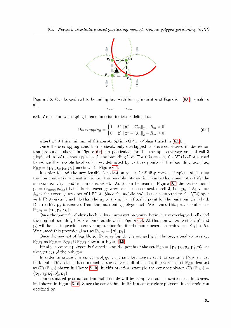
6.3. Network architecture based positioning method: Convex polygon positioning (CPP)
0
1
2
3
𝑥𝑚𝑖𝑛 𝑥𝑚𝑎𝑥
𝑷𝟏
𝑷𝟐 𝑷𝟑
𝑷𝟒
Figure 6.6: Overlapped cell to bounding box with binary indicator of Equation (6.6) equals toone
cell. We use an overlapping binary function indicator de�ned as
Overlapping =
{1 if ‖x∗ −Cm‖2 −Rm < 0
0 if ‖x∗ −Cm‖2 −Rm ≥ 0(6.6)
where x∗ is the minimum of the convex optimization problem stated in (6.5).Once the overlapping condition is check, only overlapped cells are considered in the reduc-
tion process as shown in Figure 6.6. In particular, for this example coverage area of cell 3(depicted in red) is overlapped with the bounding box. For this reason, the VLC cell 3 is usedto reduce the feasible localization set delimited by vertices points of the bounding box, i.e.,PBB = {p1,p2,p3,p4} as shown in Figure 6.6.
In order to �nd the new feasible localization set, a feasibility check is implemented usingthe non connectivity constraints, i.e., the possible intersection points that does not satisfy thenon-connectivity condition are discarded. As it can be seen in Figure 6.7 the vertex pointp3 = (xmax, ymax) is inside the coverage area of the non-connected cell 3, i.e., p3 ∈ A3 whereA3 is the coverage area set of LED 3. Since the mobile node is not connected to the VLC spotwith ID 3 we can conclude that the p3 vertex is not a feasible point for the positioning method.Due to this, p3 is removed from the positioning polygon set. We named this provisional set asPCP1 = {p1,p2,p4}.
Once the point feasibility check is done, intersection points between the overlapped cells andthe original bounding box are found as shown in Figure 6.8. At this point, new vertices p′1 andp′2 will be use to provide a convex approximation for the non-convex constraint ‖x−Cj‖ > Rj .We named this provisional set as PCP2 = {p′1,p′2}
Once the new set of feasible set PCP2 is found, it is merged with the provisional vertices setPCP1 as PCP = PCP1 ∪ PCP1 shown in Figure 6.9.
Finally, a convex polygon is formed using the points of the set PCP = {p1,p2,p4,p′1,p′2} as
the vertices of the polygon.In order to create this convex polygon, the smallest convex set that contains PCP is must
be found. This set has been named as the convex hull of the feasible vertices set PCP denotedas CH (PCP ) shown in Figure 6.10. In this practical example the convex polygon CH (PCP ) ={p1,p2,p
′1,p′2,p4}
The estimated position on the mobile node will be computed as the centroid of the convexhull shown in Figure 6.10. Since the convex hull in R2 is a convex close polygon, its centroid canobtained by
81
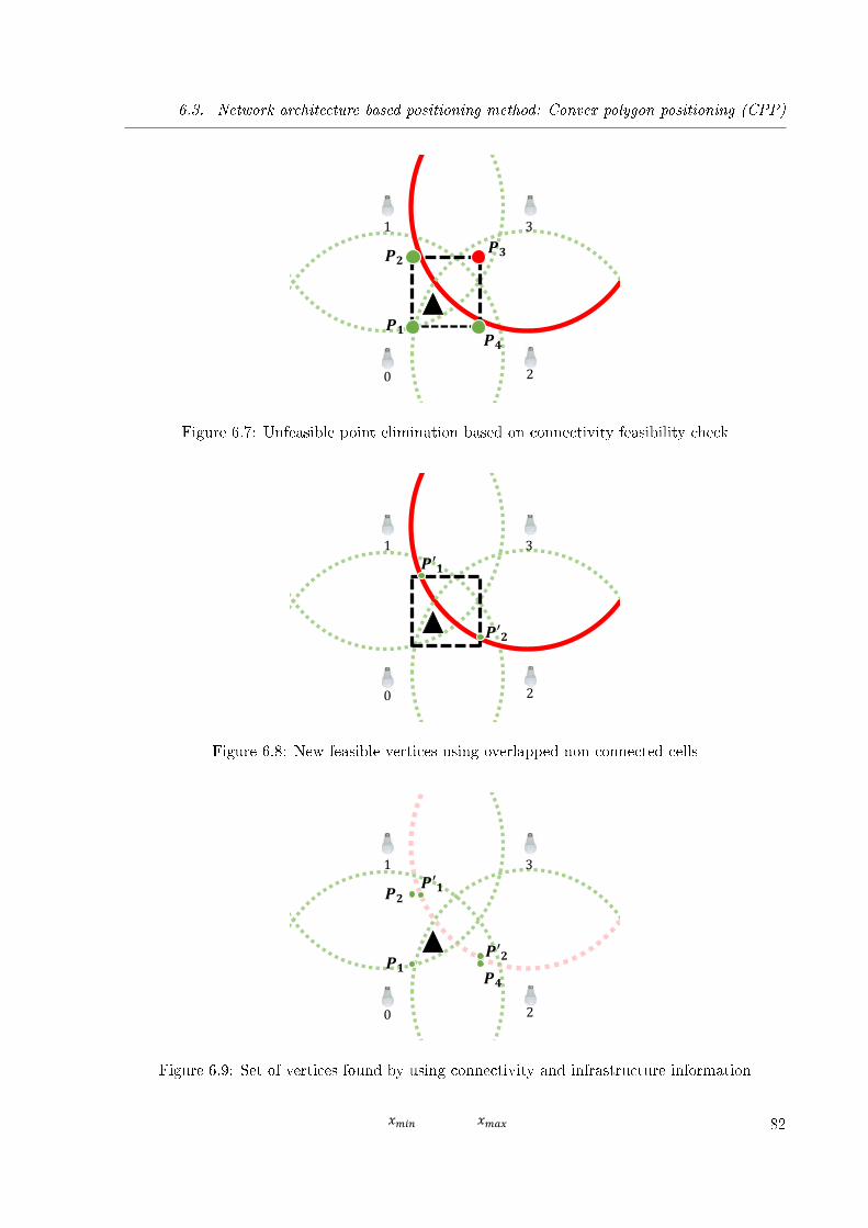
6.3. Network architecture based positioning method: Convex polygon positioning (CPP)
0
1
2
3
𝑥𝑚𝑖𝑛 𝑥𝑚𝑎𝑥
𝑷𝟏
𝑷𝟐
𝑷𝟒
𝑷𝟑
Figure 6.7: Unfeasible point elimination based on connectivity feasibility check
0
1 3
2
𝑥𝑚𝑖𝑛 𝑥𝑚𝑎𝑥
𝑷′𝟏
𝑷′𝟐
Figure 6.8: New feasible vertices using overlapped non-connected cells
0
1 3
2
𝑥𝑚𝑖𝑛 𝑥𝑚𝑎𝑥
𝑷′𝟏
𝑷′𝟐 𝑷𝟏
𝑷𝟐
𝑷𝟒
Figure 6.9: Set of vertices found by using connectivity and infrastructure information
82
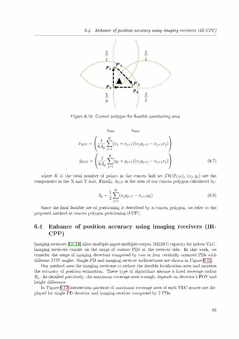
6.4. Enhance of position accuracy using imaging receivers (IR-CPP)
0
1 3
2
𝑥𝑚𝑖𝑛 𝑥𝑚𝑎𝑥
𝑷′𝟏
𝑷′𝟐 𝑷𝟏
𝑷𝟐
𝑷𝟒
Figure 6.10: Convex polygon for feasible positioning area
xMN =
1
6Ap
K∑j=1
(xj + xj+1)(xjyj+1 − xj+1xj)
yMN =
1
6Ap
K∑j=1
(yj + yj+1)(xjyj+1 − xj+1xj)
(6.7)
where K is the total number of points in the convex hull set CH (PCP ), (xj , yj) are thecomponents in the X and Y axis. Finally, ACP is the area of our convex polygon calculated by:
Ap =1
2
K∑j=1
(xjyj+1 − xj+1yj) (6.8)
Since the �nal feasible are of positioning is described by a convex polygon, we refer to theproposed method as convex polygon positioning (CPP).
6.4 Enhance of position accuracy using imaging receivers (IR-CPP)
Imaging receivers [GC18] allow multiple-input-multiple-output (MIMO) capacity for indoor VLC.Imaging receivers consist on the usage of various PDs at the receiver side. In this work, weconsider the usage of imaging detectors composed by two or four vertically oriented PDs withdi�erent FOV angles. Single PD and imaging receiver architectures are shown in Figure 6.11.
Our method uses the imaging receivers to reduce the feasible localization area and increasethe accuracy of position estimation. These type of algorithms assume a �xed coverage radiusRj . As detailed previously, the maximum coverage area strongly depends on detector's FOV andheight di�erence.
In Figure 6.12 intersection patterns of maximum coverage area of each VLC source are dis-played for single PD detector and imaging receiver composed by 2 PDs.
83
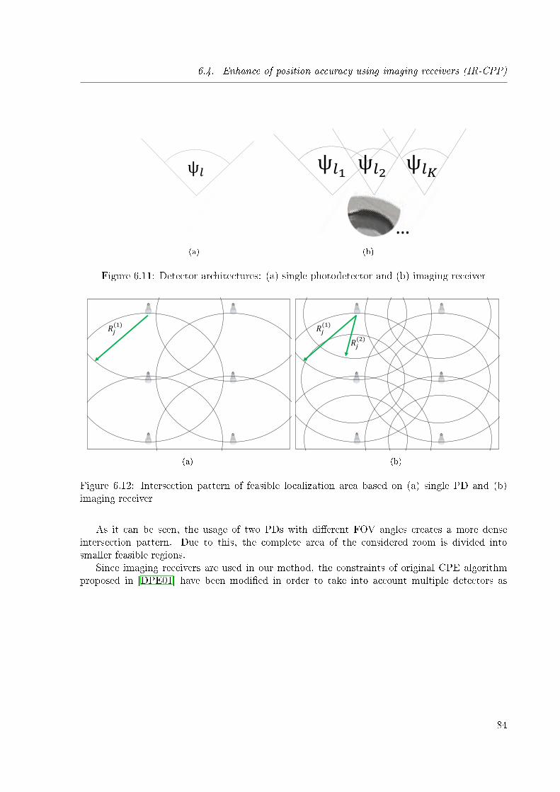
6.4. Enhance of position accuracy using imaging receivers (IR-CPP)
ψ𝑙
(a)
ψ𝑙1 ψ𝑙𝐾ψ𝑙2
…(b)
Figure 6.11: Detector architectures: (a) single photodetector and (b) imaging receiver
𝑅𝑗(1)
(a)
𝑅𝑗(1)
𝑅𝑗(2)
(b)
Figure 6.12: Intersection pattern of feasible localization area based on (a) single PD and (b)imaging receiver
As it can be seen, the usage of two PDs with di�erent FOV angles creates a more denseintersection pattern. Due to this, the complete area of the considered room is divided intosmaller feasible regions.
Since imaging receivers are used in our method, the constraints of original CPE algorithmproposed in [DPE01] have been modi�ed in order to take into account multiple detectors as
84
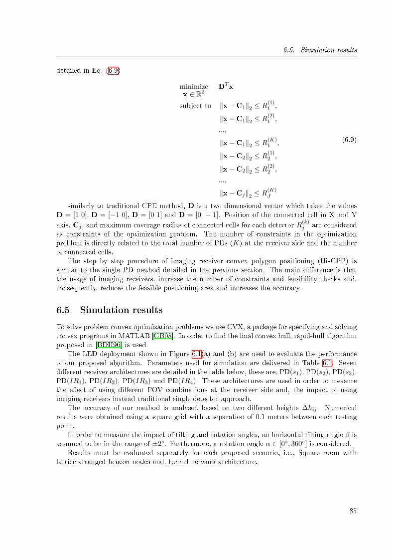
6.5. Simulation results
detailed in Eq. (6.9)
minimizex ∈ R2
DTx
subject to ‖x−C1‖2 ≤ R(1)1 ,
‖x−C1‖2 ≤ R(2)1 ,
...,
‖x−C1‖2 ≤ R(K)1 ,
‖x−C2‖2 ≤ R(1)2 ,
‖x−C2‖2 ≤ R(2)2 ,
...,
‖x−Cj‖2 ≤ R(K)J
(6.9)
similarly to traditional CPE method, D is a two dimensional vector which takes the valuesD = [1 0], D = [−1 0], D = [0 1] and D = [0 − 1]. Position of the connected cell in X and Y
axis, Cj , and maximum coverage radius of connected cells for each detector R(k)j are considered
as constraints of the optimization problem. The number of constraints in the optimizationproblem is directly related to the total number of PDs (K) at the receiver side and the numberof connected cells.
The step by step procedure of imaging receiver convex polygon positioning (IR-CPP) issimilar to the single PD method detailed in the previous section. The main di�erence is thatthe usage of imaging receivers, increase the number of constraints and feasibility checks and,consequently, reduces the feasible positioning area and increases the accuracy.
6.5 Simulation results
To solve problem convex optimization problems we use CVX, a package for specifying and solvingconvex programs in MATLAB [GB08]. In order to �nd the �nal convex hull, rapid-hull algorithmproposed in [BDH96] is used.
The LED deployment shown in Figure 6.1(a) and (b) are used to evaluate the performanceof our proposed algorithm. Parameters used for simulation are delivered in Table 6.1. Sevendi�erent receiver architectures are detailed in the table below, these are, PD(s1), PD(s2), PD(s3),PD(IR1), PD(IR2), PD(IR3) and PD(IR4). These architectures are used in order to measurethe e�ect of using di�erent FOV combinations at the receiver side and, the impact of usingimaging receivers instead traditional single detector approach.
The accuracy of our method is analysed based on two di�erent heights ∆hij . Numericalresults were obtained using a square grid with a separation of 0.1 meters between each testingpoint.
In order to measure the impact of tilting and rotation angles, an horizontal tilting angle β isassumed to be in the range of ±2◦. Furthermore, a rotation angle α ∈ [0◦, 360◦] is considered.
Results must be evaluated separately for each proposed scenario, i.e., Square room withlattice arranged beacon nodes and, tunnel network architecture.
85
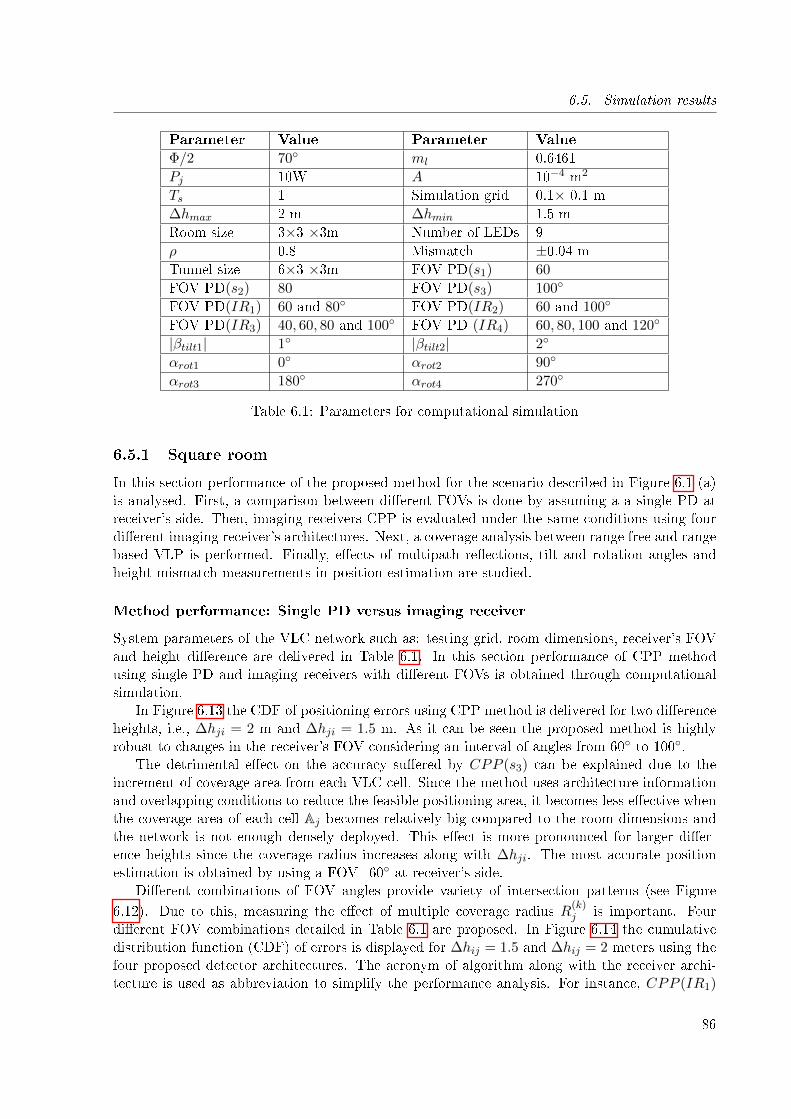
6.5. Simulation results
Parameter Value Parameter Value
Φ/2 70◦ ml 0.6461
Pj 10W A 10−4 m2
Ts 1 Simulation grid 0.1× 0.1 m
∆hmax 2 m ∆hmin 1.5 m
Room size 3×3 ×3m Number of LEDs 9
ρ 0.8 Mismatch ±0.04 m
Tunnel size 6×3 ×3m FOV PD(s1) 60
FOV PD(s2) 80 FOV PD(s3) 100◦
FOV PD(IR1) 60 and 80◦ FOV PD(IR2) 60 and 100◦
FOV PD(IR3) 40, 60, 80 and 100◦ FOV PD (IR4) 60, 80, 100 and 120◦
|βtilt1| 1◦ |βtilt2| 2◦
αrot1 0◦ αrot2 90◦
αrot3 180◦ αrot4 270◦
Table 6.1: Parameters for computational simulation
6.5.1 Square room
In this section performance of the proposed method for the scenario described in Figure 6.1 (a)is analysed. First, a comparison between di�erent FOVs is done by assuming a a single PD atreceiver's side. Then, imaging receivers CPP is evaluated under the same conditions using fourdi�erent imaging receiver's architectures. Next, a coverage analysis between range free and rangebased VLP is performed. Finally, e�ects of multipath re�ections, tilt and rotation angles andheight mismatch measurements in position estimation are studied.
Method performance: Single PD versus imaging receiver
System parameters of the VLC network such as: testing grid, room dimensions, receiver's FOVand height di�erence are delivered in Table 6.1. In this section performance of CPP methodusing single PD and imaging receivers with di�erent FOVs is obtained through computationalsimulation.
In Figure 6.13 the CDF of positioning errors using CPP method is delivered for two di�erenceheights, i.e., ∆hji = 2 m and ∆hji = 1.5 m. As it can be seen the proposed method is highlyrobust to changes in the receiver's FOV considering an interval of angles from 60◦ to 100◦.
The detrimental e�ect on the accuracy su�ered by CPP (s3) can be explained due to theincrement of coverage area from each VLC cell. Since the method uses architecture informationand overlapping conditions to reduce the feasible positioning area, it becomes less e�ective whenthe coverage area of each cell Aj becomes relatively big compared to the room dimensions andthe network is not enough densely deployed. This e�ect is more pronounced for larger di�er-ence heights since the coverage radius increases along with ∆hji. The most accurate positionestimation is obtained by using a FOV=60◦ at receiver's side.
Di�erent combinations of FOV angles provide variety of intersection patterns (see Figure
6.12). Due to this, measuring the e�ect of multiple coverage radius R(k)j is important. Four
di�erent FOV combinations detailed in Table 6.1 are proposed. In Figure 6.14 the cumulativedistribution function (CDF) of errors is displayed for ∆hij = 1.5 and ∆hij = 2 meters using thefour proposed detector architectures. The acronym of algorithm along with the receiver archi-tecture is used as abbreviation to simplify the performance analysis. For instance, CPP (IR1)
86
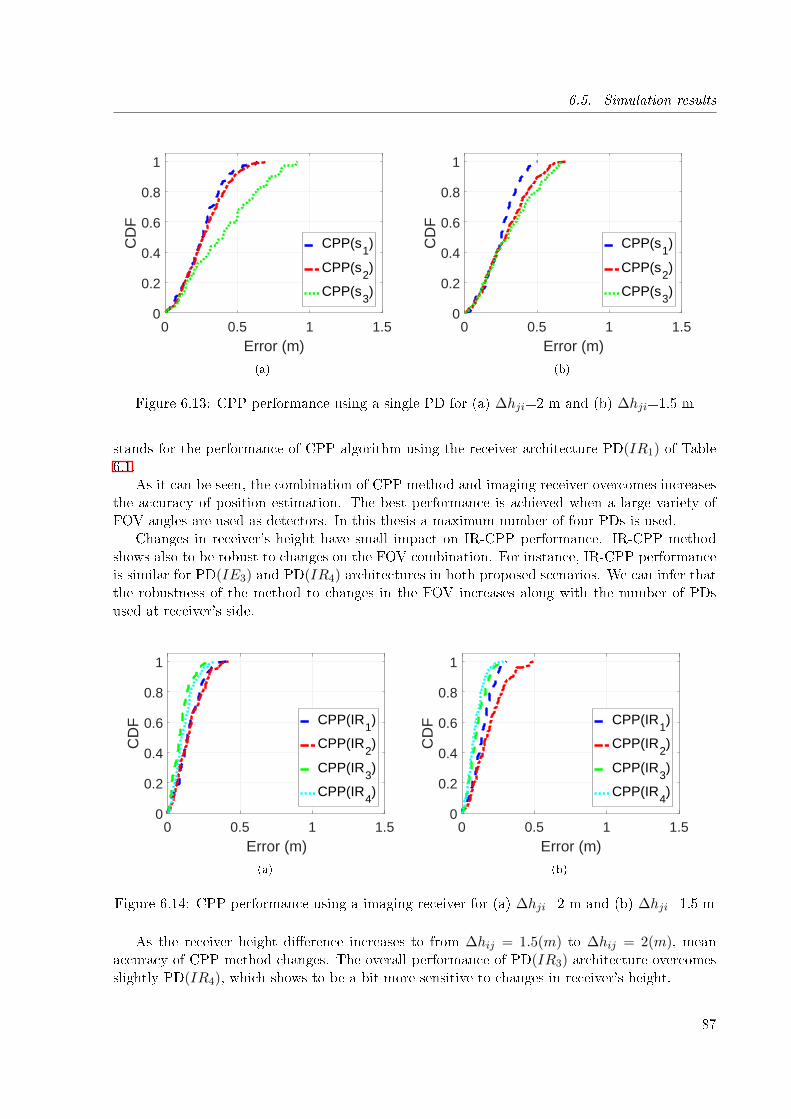
6.5. Simulation results
0 0.5 1 1.5Error (m)
0
0.2
0.4
0.6
0.8
1
CD
F
CPP(s1)
CPP(s2)
CPP(s3)
(a)
0 0.5 1 1.5Error (m)
0
0.2
0.4
0.6
0.8
1
CD
F
CPP(s1)
CPP(s2)
CPP(s3)
(b)
Figure 6.13: CPP performance using a single PD for (a) ∆hji=2 m and (b) ∆hji=1.5 m
stands for the performance of CPP algorithm using the receiver architecture PD(IR1) of Table6.1.
As it can be seen, the combination of CPP method and imaging receiver overcomes increasesthe accuracy of position estimation. The best performance is achieved when a large variety ofFOV angles are used as detectors. In this thesis a maximum number of four PDs is used.
Changes in receiver's height have small impact on IR-CPP performance. IR-CPP methodshows also to be robust to changes on the FOV combination. For instance, IR-CPP performanceis similar for PD(IE3) and PD(IR4) architectures in both proposed scenarios. We can infer thatthe robustness of the method to changes in the FOV increases along with the number of PDsused at receiver's side.
0 0.5 1 1.5Error (m)
0
0.2
0.4
0.6
0.8
1
CD
F CPP(IR1)
CPP(IR2)
CPP(IR3)
CPP(IR4)
(a)
0 0.5 1 1.5Error (m)
0
0.2
0.4
0.6
0.8
1
CD
F CPP(IR1)
CPP(IR2)
CPP(IR3)
CPP(IR4)
(b)
Figure 6.14: CPP performance using a imaging receiver for (a) ∆hji=2 m and (b) ∆hji=1.5 m
As the receiver height di�erence increases to from ∆hij = 1.5(m) to ∆hij = 2(m), meanaccuracy of CPP method changes. The overall performance of PD(IR3) architecture overcomesslightly PD(IR4), which shows to be a bit more sensitive to changes in receiver's height.
87
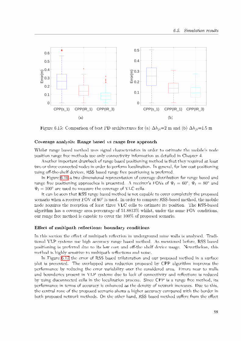
6.5. Simulation results
CPP(s_1) CPP(IR_1) CPP(IR_3)
0
0.1
0.2
0.3
0.4
0.5
0.6
Err
or(m
)
(a)
CPP(s_1) CPP(IR_1) CPP(IR_3)
0
0.1
0.2
0.3
0.4
0.5
Err
or(m
)
(b)
Figure 6.15: Comparison of best PD architectures for (a) ∆hji=2 m and (b) ∆hji=1.5 m
Coverage analysis: Range based vs range free approach
Whilst range based method uses signal characteristics in order to estimate the mobile's nodeposition range free methods use only connectivity information as detailed in Chapter 4.
Another important drawback of range based positioning method is that they required at leasttwo or three connected nodes in order to perform localization. In general, for low cost positioningusing o�-the-shelf devices, RSS based range free positioning is preferred.
In Figure 6.16 a two dimensional representation of coverage distribution for range based andrange free positioning approaches is presented. A receiver's FOVs of Ψl = 60◦, Ψl = 80◦ andΨl = 100◦ are used to measure the coverage of VLC cells.
It can be seen that RSS range based method is not capable to cover completely the proposedscenario when a receiver FOV of 60◦ is used. In order to compute RSS-based method, the mobilenode requires the reception of least three VLC cells to estimate its position. The RSS-basedalgorithm has a coverage area percentage of 51.8813% whilst, under the same FOV conditions,our range free method is capable to cover the 100% of proposed scenario.
E�ect of multipath re�ections: boundary conditions
In this section the e�ect of multipath re�ection in underground mine walls is analysed. Tradi-tional VLP systems use high accuracy range based method. As mentioned before, RSS basedpositioning is preferred due to its low cost and o�-the shelf device usage. Nevertheless, thismethod is highly sensitive to multipath re�ections and noise.
In Figure 6.17 the error of RSS based trilateration and our proposed method in a surfaceplot is presented. The overlapped area reduction proposed by CPP algorithm improves theperformance by reducing the error variability over the considered area. Errors near to wallsand boundaries present in VLP systems due to lack of connectivity and re�ections is reducedby using disconnected cells in the localization process. Since CPP is a range free method, itsperformance in terms of accuracy is enhanced as the density of network increases. Due to this,the central zone of the proposed scenario shows a higher accuracy compared with the border inboth proposed network methods. On the other hand, RSS based method su�ers from the e�ect
88
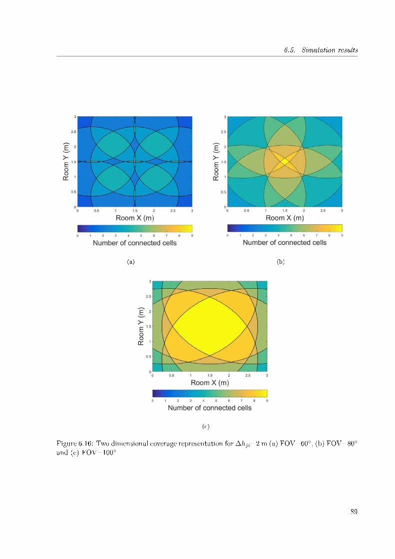
6.5. Simulation results
(a) (b)
(c)
Figure 6.16: Two dimensional coverage representation for ∆hji=2 m (a) FOV=60◦, (b) FOV=80◦
and (c) FOV=100◦
89

6.5. Simulation results
0 0.5 1 1.5 2 2.5 3
Room X (m)
0
0.5
1
1.5
2
2.5
3
Roo
m Y
(m
)
0 0.2 0.4 0.6 0.8 1Error (m)
(a)
0 0.5 1 1.5 2 2.5 3
Room X (m)
0
0.5
1
1.5
2
2.5
3
Roo
m Y
(m
)
0 0.2 0.4 0.6 0.8 1Error (m)
(b)
Figure 6.17: Method performance using an 80◦ FOV detector for (a) RSS trilateration and (b)CPP
of multipath re�ections. It can be seen in Figure 6.17 (a) the RSS based method su�ers a highimpact from boundary conditions.
90
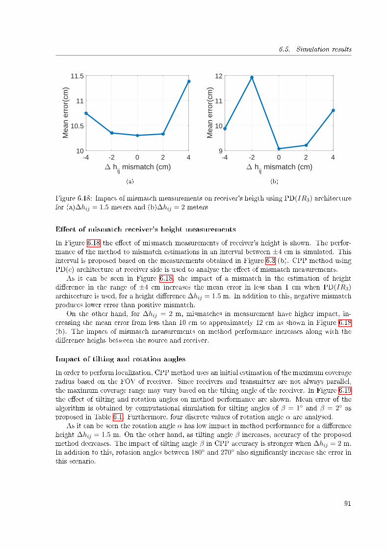
6.5. Simulation results
-4 -2 0 2 4∆ h
ij mismatch (cm)
10
10.5
11
11.5
Mea
n er
ror(
cm)
(a)
-4 -2 0 2 4∆ h
ij mismatch (cm)
9
10
11
12
Mea
n er
ror(
cm)
(b)
Figure 6.18: Impact of mismatch measurements on receiver's heigth using PD(IR3) architecturefor (a)∆hij = 1.5 meters and (b)∆hij = 2 meters
E�ect of mismatch receiver's height measurements
In Figure 6.18 the e�ect of mismatch measurements of receiver's height is shown. The perfor-mance of the method to mismatch estimations in an interval between ±4 cm is simulated. Thisinterval is proposed based on the measurements obtained in Figure 6.3 (b). CPP method usingPD(c) architecture at receiver side is used to analyse the e�ect of mismatch measurements.
As it can be seen in Figure 6.18, the impact of a mismatch in the estimation of heightdi�erence in the range of ±4 cm increases the mean error in less than 1 cm when PD(IR3)architecture is used, for a height di�erence ∆hij = 1.5 m. In addition to this, negative mismatchproduces lower error than positive mismatch.
On the other hand, for ∆hij = 2 m, mismatches in measurement have higher impact, in-creasing the mean error from less than 10 cm to approximately 12 cm as shown in Figure 6.18(b). The impact of mismatch measurements on method performance increases along with thedi�erence height between the source and receiver.
Impact of tilting and rotation angles
In order to perform localization, CPP method uses an initial estimation of the maximum coverageradius based on the FOV of receiver. Since receivers and transmitter are not always parallel,the maximum coverage range may vary based on the tilting angle of the receiver. In Figure 6.19the e�ect of tilting and rotation angles on method performance are shown. Mean error of thealgorithm is obtained by computational simulation for tilting angles of β = 1◦ and β = 2◦ asproposed in Table 6.1. Furthermore, four discrete values of rotation angle α are analysed.
As it can be seen the rotation angle α has low impact in method performance for a di�erenceheight ∆hij = 1.5 m. On the other hand, as tilting angle β increases, accuracy of the proposedmethod decreases. The impact of tilting angle β in CPP accuracy is stronger when ∆hij = 2 m.In addition to this, rotation angles between 180◦ and 270◦ also signi�cantly increase the error inthis scenario.
91
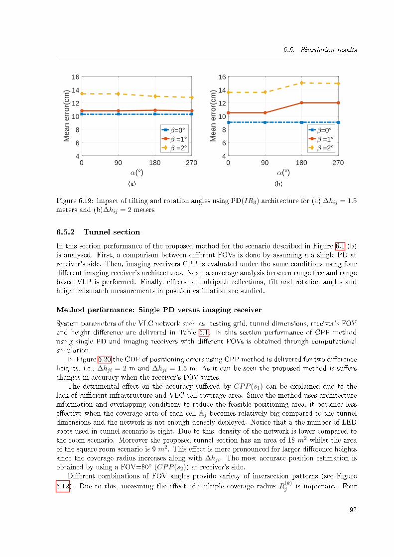
6.5. Simulation results
0 90 180 270α(°)
4
6
8
10
12
14
16
Mea
n er
ror(
cm)
β=0°β =1°β =2°
(a)
0 90 180 270α(°)
4
6
8
10
12
14
16
Mea
n er
ror(
cm)
β=0°β =1°β =2°
(b)
Figure 6.19: Impact of tilting and rotation angles using PD(IR3) architecture for (a) ∆hij = 1.5meters and (b)∆hij = 2 meters
6.5.2 Tunnel section
In this section performance of the proposed method for the scenario described in Figure 6.1 (b)is analysed. First, a comparison between di�erent FOVs is done by assuming a a single PD atreceiver's side. Then, imaging receivers CPP is evaluated under the same conditions using fourdi�erent imaging receiver's architectures. Next, a coverage analysis between range free and rangebased VLP is performed. Finally, e�ects of multipath re�ections, tilt and rotation angles andheight mismatch measurements in position estimation are studied.
Method performance: Single PD versus imaging receiver
System parameters of the VLC network such as: testing grid, tunnel dimensions, receiver's FOVand height di�erence are delivered in Table 6.1. In this section performance of CPP methodusing single PD and imaging receivers with di�erent FOVs is obtained through computationalsimulation.
In Figure 6.20 the CDF of positioning errors using CPP method is delivered for two di�erenceheights, i.e., ∆hji = 2 m and ∆hji = 1.5 m. As it can be seen the proposed method is su�erschanges in accuracy when the receiver's FOV varies.
The detrimental e�ect on the accuracy su�ered by CPP (s1) can be explained due to thelack of su�cient infrastructure and VLC cell coverage area. Since the method uses architectureinformation and overlapping conditions to reduce the feasible positioning area, it becomes lesse�ective when the coverage area of each cell Aj becomes relatively big compared to the tunneldimensions and the network is not enough densely deployed. Notice that a the number of LEDspots used in tunnel scenario is eight. Due to this, density of the network is lower compared tothe room scenario. Moreover the proposed tunnel section has an area of 18 m2 whilst the areaof the square room scenario is 9 m2. This e�ect is more pronounced for larger di�erence heightssince the coverage radius increases along with ∆hji. The most accurate position estimation isobtained by using a FOV=80◦ (CPP (s2)) at receiver's side.
Di�erent combinations of FOV angles provide variety of intersection patterns (see Figure
6.12). Due to this, measuring the e�ect of multiple coverage radius R(k)j is important. Four
92
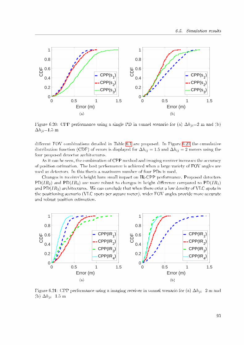
6.5. Simulation results
0 0.5 1 1.5Error (m)
0
0.2
0.4
0.6
0.8
1
CD
F
CPP(s1)
CPP(s2)
CPP(s3)
(a)
0 0.5 1 1.5Error (m)
0
0.2
0.4
0.6
0.8
1
CD
F
CPP(s1)
CPP(s2)
CPP(s3)
(b)
Figure 6.20: CPP performance using a single PD in tunnel scenario for (a) ∆hji=2 m and (b)∆hji=1.5 m
di�erent FOV combinations detailed in Table 6.1 are proposed. In Figure 6.21 the cumulativedistribution function (CDF) of errors is displayed for ∆hij = 1.5 and ∆hij = 2 meters using thefour proposed detector architectures.
As it can be seen, the combination of CPP method and imaging receiver increases the accuracyof position estimation. The best performance is achieved when a large variety of FOV angles areused as detectors. In this thesis a maximum number of four PDs is used.
Changes in receiver's height have small impact on IR-CPP performance. Proposed detectorsPD(IR2) and PD(IR4) are more robust to changes in height di�erence compared to PD(IR1)and PD(IR3) architectures. We can conclude that when there exist a low density of VLC spots inthe positioning scenario (VLC spots per square meter), wider FOV angles provide more accurateand robust position estimation.
0 0.5 1 1.5Error (m)
0
0.2
0.4
0.6
0.8
1
CD
F CPP(IR1)
CPP(IR2)
CPP(IR3)
CPP(IR4)
(a)
0 0.5 1 1.5Error (m)
0
0.2
0.4
0.6
0.8
1
CD
F CPP(IR1)
CPP(IR2)
CPP(IR3)
CPP(IR4)
(b)
Figure 6.21: CPP performance using a imaging receiver in tunnel scenario for (a) ∆hji=2 m and(b) ∆hji=1.5 m
93
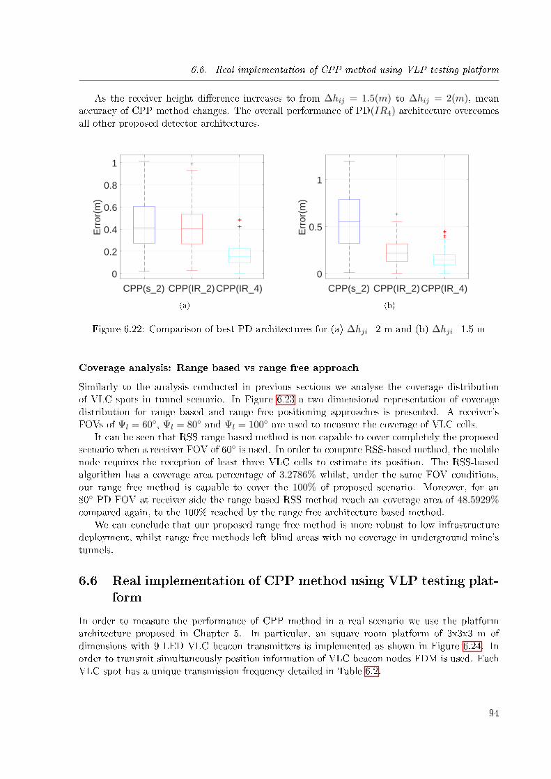
6.6. Real implementation of CPP method using VLP testing platform
As the receiver height di�erence increases to from ∆hij = 1.5(m) to ∆hij = 2(m), meanaccuracy of CPP method changes. The overall performance of PD(IR4) architecture overcomesall other proposed detector architectures.
CPP(s_2) CPP(IR_2)CPP(IR_4)
0
0.2
0.4
0.6
0.8
1
Err
or(m
)
(a)
CPP(s_2) CPP(IR_2)CPP(IR_4)
0
0.5
1
Err
or(m
)(b)
Figure 6.22: Comparison of best PD architectures for (a) ∆hji=2 m and (b) ∆hji=1.5 m
Coverage analysis: Range based vs range free approach
Similarly to the analysis conducted in previous sections we analyse the coverage distributionof VLC spots in tunnel scenario. In Figure 6.23 a two dimensional representation of coveragedistribution for range based and range free positioning approaches is presented. A receiver'sFOVs of Ψl = 60◦, Ψl = 80◦ and Ψl = 100◦ are used to measure the coverage of VLC cells.
It can be seen that RSS range based method is not capable to cover completely the proposedscenario when a receiver FOV of 60◦ is used. In order to compute RSS-based method, the mobilenode requires the reception of least three VLC cells to estimate its position. The RSS-basedalgorithm has a coverage area percentage of 3.2786% whilst, under the same FOV conditions,our range free method is capable to cover the 100% of proposed scenario. Moreover, for an80◦ PD FOV at receiver side the range based RSS method reach an coverage area of 48.5929%compared again, to the 100% reached by the range free architecture based method.
We can conclude that our proposed range free method is more robust to low infrastructuredeployment, whilst range free methods left blind areas with no coverage in underground mine'stunnels.
6.6 Real implementation of CPP method using VLP testing plat-form
In order to measure the performance of CPP method in a real scenario we use the platformarchitecture proposed in Chapter 5. In particular, an square room platform of 3x3x3 m ofdimensions with 9 LED VLC beacon transmitters is implemented as shown in Figure 6.24. Inorder to transmit simultaneously position information of VLC beacon nodes FDM is used. EachVLC spot has a unique transmission frequency detailed in Table 6.2.
94
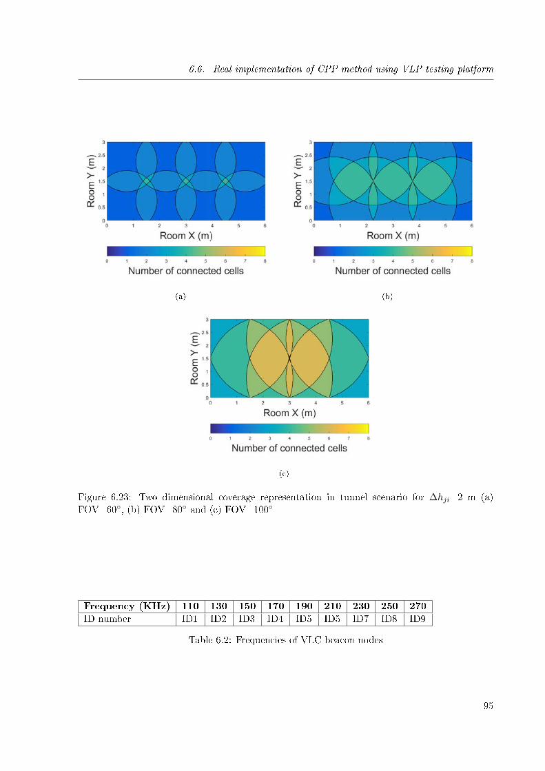
6.6. Real implementation of CPP method using VLP testing platform
(a) (b)
(c)
Figure 6.23: Two dimensional coverage representation in tunnel scenario for ∆hji=2 m (a)FOV=60◦, (b) FOV=80◦ and (c) FOV=100◦
Frequency (KHz) 110 130 150 170 190 210 230 250 270
ID number ID1 ID2 ID3 ID4 ID5 ID5 ID7 ID8 ID9
Table 6.2: Frequencies of VLC beacon nodes
95
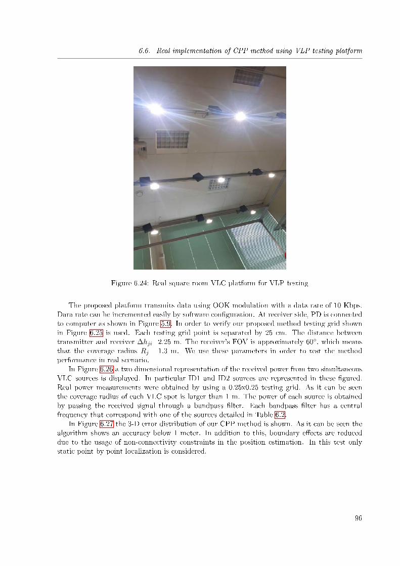
6.6. Real implementation of CPP method using VLP testing platform
Figure 6.24: Real square room VLC platform for VLP testing
The proposed platform transmits data using OOK modulation with a data rate of 10 Kbps.Dara rate can be incremented easily by software con�guration. At receiver side, PD is connectedto computer as shown in Figure 5.9. In order to verify our proposed method testing grid shownin Figure 6.25 is used. Each testing grid point is separated by 25 cm. The distance betweentransmitter and receiver ∆hji=2.25 m. The receiver's FOV is approximately 60◦, which meansthat the coverage radius Rj= 1.3 m. We use these parameters in order to test the methodperformance in real scenario.
In Figure 6.26 a two dimensional representation of the received power from two simultaneousVLC sources is displayed. In particular ID1 and ID2 sources are represented in these �gured.Real power measurements were obtained by using a 0.25x0.25 testing grid. As it can be seenthe coverage radius of each VLC spot is larger than 1 m. The power of each source is obtainedby passing the received signal through a bandpass �lter. Each bandpass �lter has a centralfrequency that correspond with one of the sources detailed in Table 6.2.
In Figure 6.27 the 3-D error distribution of our CPP method is shown. As it can be seen thealgorithm shows an accuracy below 1 meter. In addition to this, boundary e�ects are reduceddue to the usage of non-connectivity constraints in the position estimation. In this test onlystatic point by point localization is considered.
96
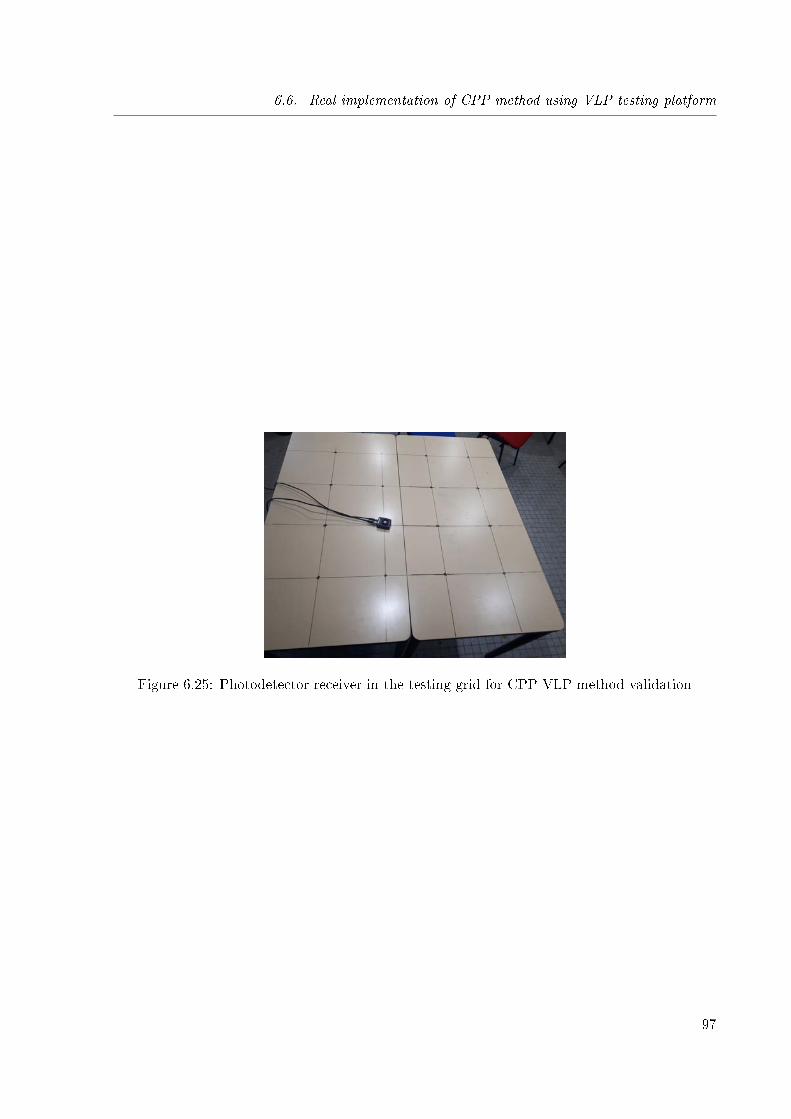
6.6. Real implementation of CPP method using VLP testing platform
Figure 6.25: Photodetector receiver in the testing grid for CPP VLP method validation
97
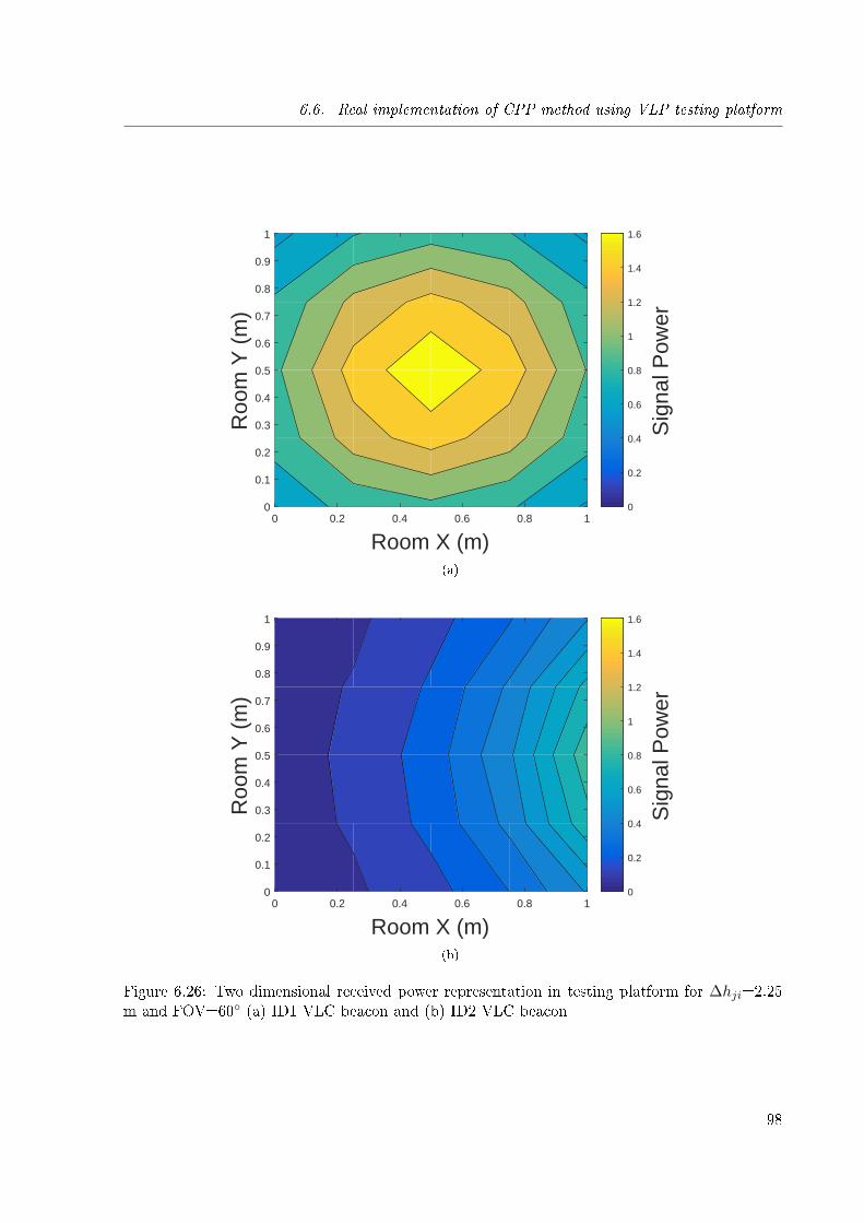
6.6. Real implementation of CPP method using VLP testing platform
0 0.2 0.4 0.6 0.8 1
Room X (m)
0
0.1
0.2
0.3
0.4
0.5
0.6
0.7
0.8
0.9
1R
oom
Y (
m)
0
0.2
0.4
0.6
0.8
1
1.2
1.4
1.6
Sig
nal P
ower
(a)
0 0.2 0.4 0.6 0.8 1
Room X (m)
0
0.1
0.2
0.3
0.4
0.5
0.6
0.7
0.8
0.9
1
Roo
m Y
(m
)
0
0.2
0.4
0.6
0.8
1
1.2
1.4
1.6
Sig
nal P
ower
(b)
Figure 6.26: Two dimensional received power representation in testing platform for ∆hji=2.25m and FOV=60◦ (a) ID1 VLC beacon and (b) ID2 VLC beacon
98
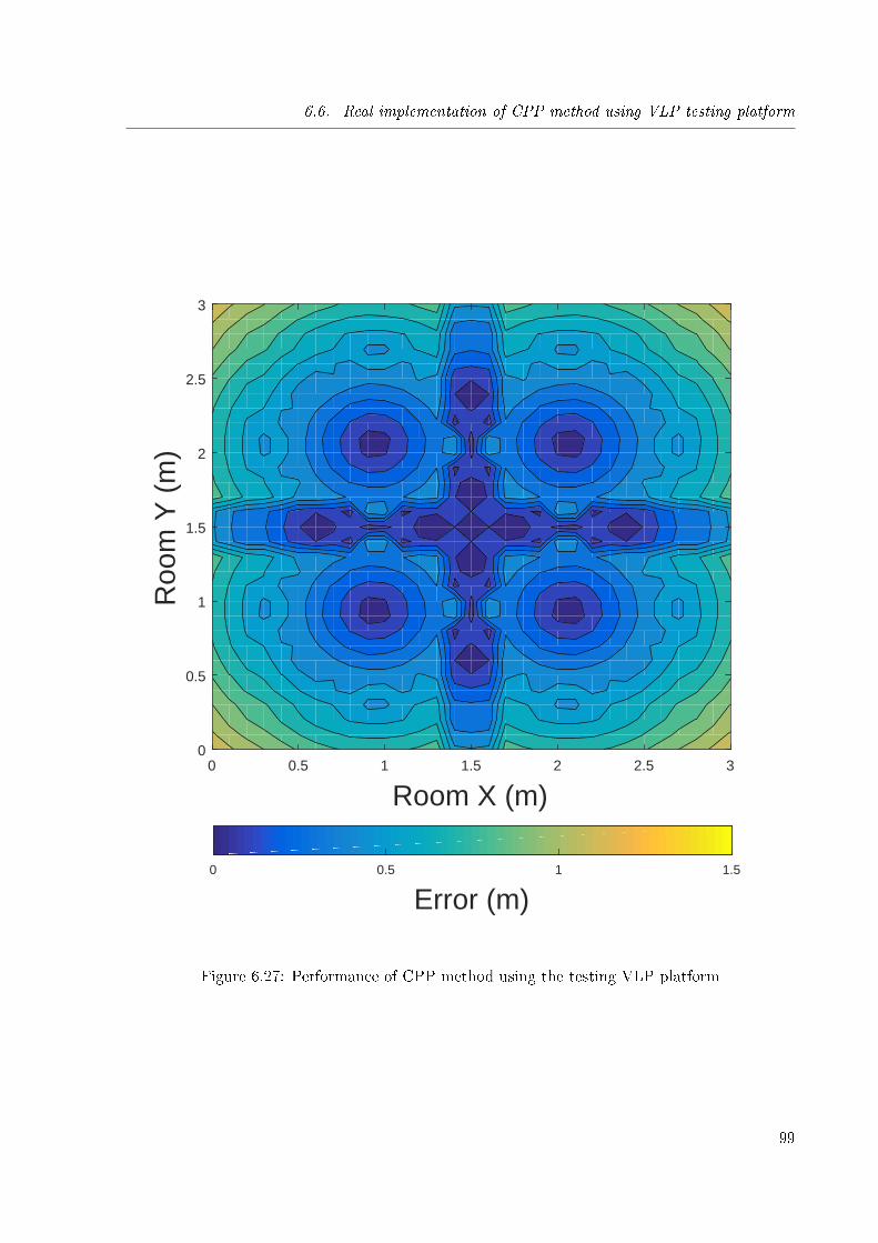
6.6. Real implementation of CPP method using VLP testing platform
0 0.5 1 1.5 2 2.5 3
Room X (m)
0
0.5
1
1.5
2
2.5
3
Roo
m Y
(m
)
0 0.5 1 1.5
Error (m)
Figure 6.27: Performance of CPP method using the testing VLP platform
99
Chapter 7
Conclusions and perspectives
Sommaire
7.1 Conclusion . . . . . . . . . . . . . . . . . . . . . . . . . . . . . . . . . . 100
7.2 Perspectives . . . . . . . . . . . . . . . . . . . . . . . . . . . . . . . . . . 101
7.2.1 Reduce the size of proposed receiver . . . . . . . . . . . . . . . . . . . . 101
7.2.2 Energy e�ciency . . . . . . . . . . . . . . . . . . . . . . . . . . . . . . . 102
7.2.3 Mobility and Tracking . . . . . . . . . . . . . . . . . . . . . . . . . . . . 102
7.1 Conclusion
Visible Light Communication (VLC) has gained the interest as a feasible future wireless com-munications technology due to its merits in terms of data rate, con�dentiality and safety. As aconsequence, visible light positioning methods have emerged in the recent years as a technologythat uses lighting communication infrastructure to provide high accuracy and low cost positioninformation. In literature, most of the VLP methods have been proposed for low-complexityand safe indoor scenarios such as interior buildings, o�ces, parkings, etc. However, in somehazardous industrial scenarios most of these scenario conditions are not satis�ed as describedin Chapter 1 and 2. Due to this, a complete analysis of current positioning technologies andvisible light communication link under extreme environmental conditions in indoor environmentsis required.
Di�erent parameters must be considered when designing a positioning system. Nowadays,di�erent positioning solutions for underground mines exist in the market. These solutions use awide range of technologies from acoustic to radio-frequency in order to localize workers inside amine tunnel. Each of them su�ers from critical drawbacks in terms of accuracy, scalability, costand deployment.
Speci�cally, in Chapter 2 we analyze the already existent positioning methods for under-ground mines. An extensive discussion and study of this technologies identi�es the main strengthsand weaknesses of each proposed technology. The main drawbacks of the already proposed tech-nologies are, as mentioned before, their accuracy, scalability and cost. Accuracy of the systemestablished in the MINER act. [10906] is used in order to select a feasible method. As under-ground tunnel expands, also the positioning system must cover a larger area and, as a conse-quence, the cost of this localization will increase. Due to this, the system must be scalable andhave a low cost of implementation. Underground mines must be illuminated using arti�cial lights
100
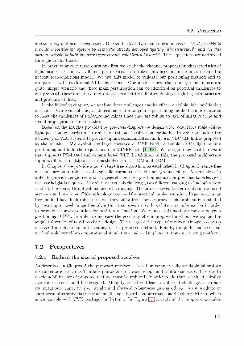
7.2. Perspectives
due to safety and health regulation. Due to this fact, two main question arises: "Is it possible toprovide a positioning system by using the already deployed lighting infrastructure?" and "Is thissystem capable to ful�l the user requirements established by law?". These questions are addressedthroughout the thesis.
In order to answer these questions �rst we study the channel propagation characteristics oflight inside the tunnel. Di�erent perturbations are taken into account in order to deliver thenearest real-conditions model. We use this model to validate our positioning method and tocompare it with traditional VLP algorithms. Our model shows that underground mines arequite unique scenario and three main perturbation can be identi�ed as potential challenges toour proposal, these are: tilted and rotated transmitters, limited deployed lighting infrastructureand presence of dust.
In the following chapter, we analyse these challenges and its e�ect to visible light positioningmethods. As a result of this, we determine that a range free positioning method is more suitableto meet the challenges of underground mines since they are robust to lack of infrastructure andsignal propagation characteristics.
Based on the insights provided by previous chapters we design a low cost/large scale visiblelight positioning hardware in order to test our localization methods. In order to tackle thede�ciency of VLC systems to provide uplink communication an hybrid VLC/RF link is proposedas the solution. We exploit the large coverage of UHF band to enable visible light remotepositioning and ful�l the requirements of MINER act. [10906]. We design a low cost hardwarethat supports PD-based and camera based VLP. In addition to this, the proposed architecturesupport di�erent multiple access methods such as, FDM and TDM.
In Chapter 6 we provide a novel range free algorithm. as established in Chapter 3, range freemethods are more robust to the speci�c characteristics of underground mines. Nevertheless, inorder to provide range free and, in general, low cost position estimation previous knowledge ofreceiver height is required. In order to meet this challenge, two di�erent ranging technologies werestudied, these are: IR optical and acoustic ranging. The latter showed better results in terms odaccuracy and precision. This technology was used for practical implementation. In general, rangefree method have high robustness but they su�er from low accuracy. This problem is combatedby creating a novel range free algorithm that uses network architecture information in orderto provide a convex solution for position estimation. We named this methods convex polygonpositioning (CPP). In order to increase the accuracy of our proposed method, we exploit theangular diversity of novel receiver's design. The usage of this type of receivers (image receivers)increase the robustness and accuracy of the proposed method. Finally, the performance of ourmethod is delivered by computational simulations and real implementation on a testing platform.
7.2 Perspectives
7.2.1 Reduce the size of proposed receiver
As described in Chapter 5 the proposed receiver is based on commercially available laboratoryinstrumentation such as Thorlabs photodetector, oscilloscope and Matlab software. In order toreach mobility, size of proposed method must be reduced. In order to do that, a helmet suitablesize transceiver should be designed. Mobility issued will lead to di�erent challenges such as :computational capacity, size, weight and physical robustness among others. An immediate orshort-term alternative is to use an small single board computer such as Raspberry Pi zero whichis compatible with CVX package for Python. In Figure 7.1 a draft of the proposed portable
101
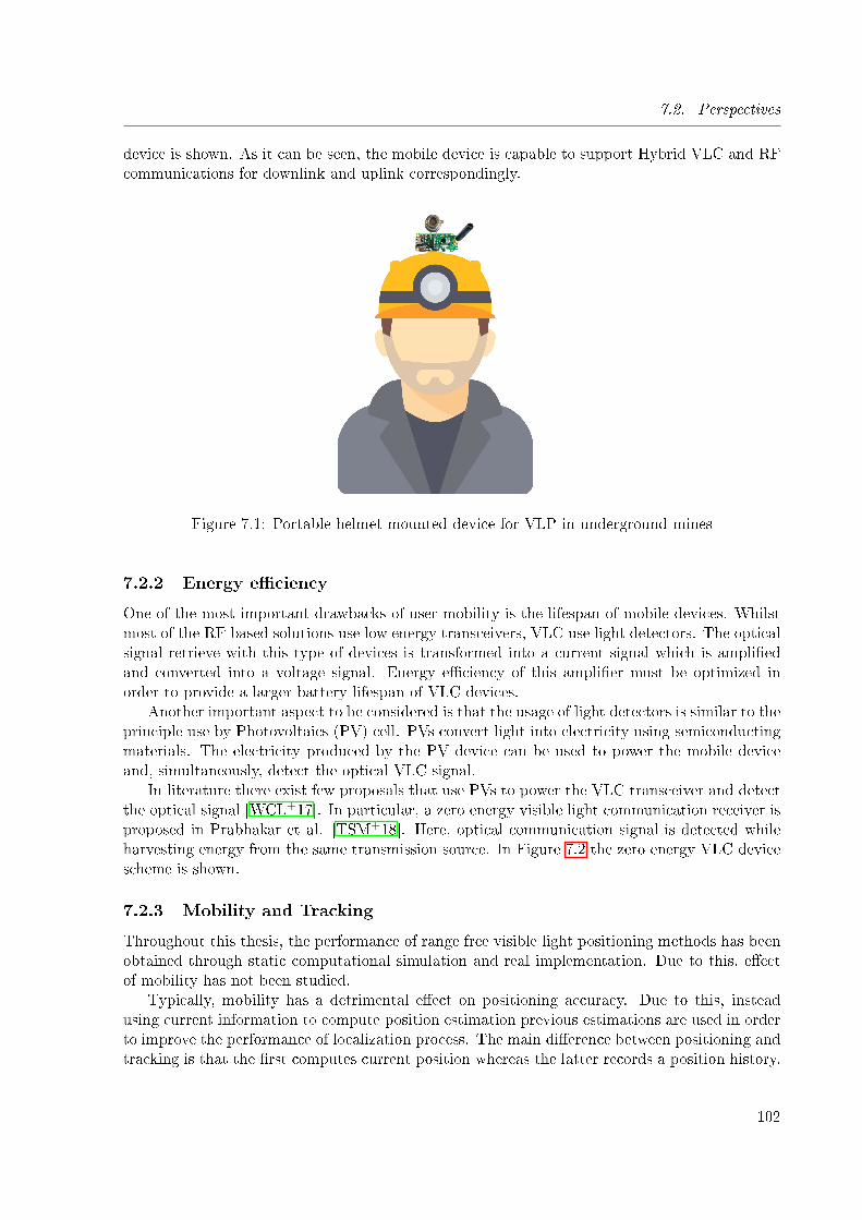
7.2. Perspectives
device is shown. As it can be seen, the mobile device is capable to support Hybrid VLC and RFcommunications for downlink and uplink correspondingly.
Figure 7.1: Portable helmet mounted device for VLP in underground mines
7.2.2 Energy e�ciency
One of the most important drawbacks of user mobility is the lifespan of mobile devices. Whilstmost of the RF based solutions use low energy transceivers, VLC use light detectors. The opticalsignal retrieve with this type of devices is transformed into a current signal which is ampli�edand converted into a voltage signal. Energy e�ciency of this ampli�er must be optimized inorder to provide a larger battery lifespan of VLC devices.
Another important aspect to be considered is that the usage of light detectors is similar to theprinciple use by Photovoltaics (PV) cell. PVs convert light into electricity using semiconductingmaterials. The electricity produced by the PV device can be used to power the mobile deviceand, simultaneously, detect the optical VLC signal.
In literature there exist few proposals that use PVs to power the VLC transceiver and detectthe optical signal [WCL+17]. In particular, a zero energy visible light communication receiver isproposed in Prabhakar et al. [TSM+18]. Here, optical communication signal is detected whileharvesting energy from the same transmission source. In Figure 7.2 the zero energy VLC devicescheme is shown.
7.2.3 Mobility and Tracking
Throughout this thesis, the performance of range free visible light positioning methods has beenobtained through static computational simulation and real implementation. Due to this, e�ectof mobility has not been studied.
Typically, mobility has a detrimental e�ect on positioning accuracy. Due to this, insteadusing current information to compute position estimation previous estimations are used in orderto improve the performance of localization process. The main di�erence between positioning andtracking is that the �rst computes current position whereas the latter records a position history.
102
7.2. Perspectives
Power + signal detection
Photovoltaic pannel
Figure 7.2: Zero energy mobile VLC receiver
Di�erent methods can be found in literature to provide tracking capabilities for VLP systems.Among them, particle �lters and extended Kalman �lter are the most used methods [GZK14].Most of the accuracy enhancement techniques have been applied to range based positioningmethods.
Further developments on trajectory �ltering using mobility and tracking techniques can behybridized with range free positioning methods in order to increase the robustness of positionestimation.
103
Bibliography
[10906] 109th Congress. Mine Improvement and New Emergency Response, 2006.
[AA14] Abdulsalam Ghalib Alkholidi and Khaleel Saeed Altowij. Free Space Optical Com-munications � Theory and Practices. In Contemporary Issues in Wireless Com-munications. InTech, nov 2014.
[AIA+17] Ammar M. A. Abu Znaid, Mohd. Yamani Idna Idris, Ainuddin Wahid Abdul Wa-hab, Liana Khamis Qabajeh, and Omar Adil Mahdi. Sequential Monte Carlo Lo-calization Methods in Mobile Wireless Sensor Networks: A Review. Journal ofSensors, 2017:1�19, apr 2017.
[AJ19] Milad Afzalan and Farrokh Jazizadeh. Indoor Positioning Based on Visible LightCommunication. ACM Computing Surveys, 52(2):1�36, may 2019.
[ASN13] Jean Armstrong, Y. Sekercioglu, and Adrian Neild. Visible light positioning:a roadmap for international standardization. IEEE Communications Magazine,51(12):68�73, dec 2013.
[AXMT16] Traian E. Abrudan, Zhuoling Xiao, Andrew Markham, and Niki Trigoni. Under-ground Incrementally Deployed Magneto-Inductive 3-D Positioning Network. IEEETransactions on Geoscience and Remote Sensing, 54(8):4376�4391, 2016.
[Bar12] John R. Barry. Wireless Infrared Communications. Springer Science & BusinessMedia, Boston, MA, 2012.
[BCS+17] Behlouli, P. Combeau, S. Sahuguede, A. Julien-Vergonjanne, C. Le Bas, and L. Ave-neau. Impact of physical and geometrical parameters on visible light communicationlinks. In 2017 Advances in Wireless and Optical Communications (RTUWO), pages73�76. IEEE, nov 2017.
[BDH96] C. Bradford Barber, David P. Dobkin, and Hannu Huhdanpaa. The quickhull algo-rithm for convex hulls. ACM Transactions on Mathematical Software, 22(4):469�483, dec 1996.
[BHE00] N. Bulusu, J. Heidemann, and D. Estrin. GPS-less low-cost outdoor localizationfor very small devices. IEEE Personal Communications, 7(5):28�34, 2000.
[BL05] Dioén Biosca Rojas and Jorge Luís López Presmanes. Generalización del algoritmode trazado de rayos de Monte Carlo modi�cado para el cálculo de la respuesta alimpulso de canales ópticos infrarrojos en interiores. Universidad, Ciencia y Tec-nología, 9(33):17�25, 2005.
104
[BMC10] L. K. Bandyopadhyay, P. K. Mishra, and S. K. Chaulya. Wireless Communicationin Underground Mines. Springer US, New York, NY, 1 edition, 2010.
[Bus15] BusinessWire. Retail Indoor Location Market Breaks US$10 Billion in 2020, SaysABI Research, 2015.
[BV04] Stephen P. Boyd and Lieven. Vandenberghe. Convex optimization. CambridgeUniversity Press, New York, USA, 2004.
[CBH16] Cheng Chen, Dushyantha A. Basnayaka, and Harald Haas. Downlink performanceof optical attocell networks. Journal of Lightwave Technology, 34(1):137�156, 2016.
[CFT12] Abdellah Chehri, Paul Fortier, and Pierre Martin Tardif. Characterization of theUltra-Wideband Channel in Con�ned Environments with Di�racting Rough Sur-faces. Wireless Personal Communications, 62(4):859�877, feb 2012.
[CLB15] Francisco Chueco, Fernando L??pez, and Miguel Bobadilla. Technical and economicevaluation of �uorescent and LED luminaires in underground mining. A case study:New mine level of El Teniente. Energy and Buildings, 93(August):16�22, 2015.
[Com] Safety in Mines Research Advisory Committee. Final Project Report, Assessmentof World-wide Illumination and Visibility Standards in Coal Mines ,COL 451.
[CZHG15] Petr Chvojka, Stanislav Zvanovec, Paul Anthony Haigh, and Zabih Ghassemlooy.Channel Characteristics of Visible Light Communications Within Dynamic IndoorEnvironment. Journal of Lightwave Technology, 33(9):1719�1725, may 2015.
[DAMG15] Edith Deretey, Mirza Tahir Ahmed, Joshua A. Marshall, and Michael Greenspan.Visual indoor positioning with a single camera using PnP. In 2015 InternationalConference on Indoor Positioning and Indoor Navigation, IPIN 2015. Institute ofElectrical and Electronics Engineers Inc., dec 2015.
[Des15] Product Description. Cree R© XLamp R© CXB1512 LED Datasheet, 2015.
[DMS98] C. Drane, M. Macnaughtan, and C. Scott. Positioning GSM telephones. IEEECommunications Magazine, 36(4):46�54, 59, apr 1998.
[DPE01] L. Doherty, K.S.J. Pister, and L. El Ghaoui. Convex position estimation in wirelesssensor networks. In Proceedings IEEE INFOCOM 2001. Conference on ComputerCommunications. Twentieth Annual Joint Conference of the IEEE Computer andCommunications Society (Cat. No.01CH37213), volume 3, pages 1655�1663, An-chorage, USA, 2001. IEEE.
[DY16] Trong-Hop Do and Myungsik Yoo. An in-Depth Survey of Visible Light Commu-nication Based Positioning Systems. Sensors, 16(5):678, 2016.
[EFA16] Maged Abdullah Esmail, Habib Fathallah, and Mohamed-Slim Alouini. An Exper-imental Study of FSO Link Performance in Desert Environment. IEEE Communi-cations Letters, 20(9):1888�1891, sep 2016.
[ELS75] Alfred G. Emslie, Robert L. Lagace, and Peter F. Strong. Theory of the Propagationof UHF Radio Waves in Coal Mine Tunnels. IEEE Transactions on Antennas andPropagation, 23(2):192�205, 1975.
105
[EMGO18] Mahmoud W Eltokhey, Korany R Mahmoud, Zabih Ghassemlooy, and Salah S AObayya. Optimization of intensities and locations of di�use spots in indoor opticalwireless communications. Optics Communications, 410(May):1�7, 2018.
[ER02] Ahmed. El-Rabbany. Introduction to GPS : the Global Positioning System. ArtechHouse, 2002.
[FBMN13] Arghavan Emami Forooshani, Shahzad Bashir, David G. Michelson, and SimaNoghanian. A survey of wireless communications and propagation modeling in un-derground mines. IEEE Communications Surveys and Tutorials, 15(4):1524�1545,2013.
[FFCM17] Andre Ferreira, Duarte Fernandes, Andre Catarino, and Joao Monteiro. Localiza-tion and Positioning Systems for Emergency Responders: a Survey. IEEE Commu-nications Surveys & Tutorials, pages 1�1, 2017.
[GB79a] F.R. Gfeller and U. Bapst. Wireless in-house data communication via di�use in-frared radiation. Proceedings of the IEEE, 67(11):1474 � 1486, 1979.
[GB79b] F.R. Gfeller and U. Bapst. Wireless in-house data communication via di�use in-frared radiation. Proceedings of the IEEE, 67(11):1474�1486, 1979.
[GB08] Michael C. Grant and Stephen P. Boyd. Graph Implementations for NonsmoothConvex Programs. In Blondel Vincent, Boyd Stephen, and Kimura Hidenori, ed-itors, Recent Advances in Learning and Control, pages 95�110. Springer London,London, UK, 2008.
[GC18] Amit Kumar Gupta and Ananthanarayanan Chockalingam. Performance of MIMOModulation Schemes With Imaging Receivers in Visible Light Communication.Journal of Lightwave Technology, 36(10):1912�1927, may 2018.
[GPR12] Z. Ghassemlooy, W. Popoola, and S. Rajbhandari. Optical wireless communications:system and channel modelling with Matlab R©. CRC Press, 2012.
[GZK14] Divya Ganti, Weizhi Zhang, and Mohsen Kavehrad. VLC-based indoor positioningsystem with tracking capability using Kalman and particle �lters. In 2014 IEEEInternational Conference on Consumer Electronics (ICCE), pages 476�477. IEEE,jan 2014.
[HCWZ15] R Hou, Y Chen, J Wu, and H Zhang. A Brief Survey of Optical Wireless Commu-nication. In 13th Australasian Symposium on Parallel and Distributed Computing(AusPDC 2015), volume 163, pages 41�50, Sydney, Australia, 2015.
[HKJ14] Andrej Hrovat, Gorazd Kandus, and Tomavz Javornik. A Survey of Radio Propaga-tion Modeling for Tunnels. IEEE Communications Surveys & Tutorials, 16(2):658�669, 2014.
[HLC+15] Xingxing Huang, Jiehui Li, Nan Chi, Yiguang Wang, Yuanquan Wang, and ChaoYang. Experimental demonstration for high speed integrated visible light communi-cation and multimode �ber communication system. IET Optoelectronics, 9(5):207�210, oct 2015.
106
[HNP+15] Naveed Ul Hassan, Aqsa Naeem, Muhammad Adeel Pasha, Tariq Jadoon, and ChauYuen. Indoor Positioning Using Visible LED Lights. ACM Computing Surveys,48(2):1�32, nov 2015.
[HPF+15] F. Hammer, M. Pichler, H. Fenzl, A. Gebhard, and C. Hesch. An acoustic positionestimation prototype system for underground mining safety. Applied Acoustics,92:61�74, 2015.
[HY16] Phat Huynh and Myungsik Yoo. VLC-Based Positioning System for an IndoorEnvironment Using an Image Sensor and an Accelerometer Sensor. Sensors (Basel,Switzerland), 16(6):783�799, may 2016.
[JK04] S. Jivkova and M. Kavehrad. Shadowing and blockage in indoor optical wirelesscommunications. In GLOBECOM '03. IEEE Global Telecommunications Confer-ence (IEEE Cat. No.03CH37489), pages 3269�3273. IEEE, 2004.
[Jud88] Scott M. Juds. Photoelectric sensors and controls : selection and application. M.Dekker, 1988.
[JWLL18] Ruonan Ji, Shaowei Wang, Qingquan Liu, and Wei Lu. High-Speed Visible LightCommunications: Enabling Technologies and State of the Art. Applied Sciences,8(4):589, apr 2018.
[KB97] J.M. Kahn and J.R. Barry. Wireless infrared communications. Proceedings of theIEEE, 85(2):265�298, 1997.
[KKC95] J.M. Kahn, W.J. Krause, and J.B. Carruthers. Experimental characterization ofnon-directed indoor infrared channels. IEEE Transactions on Communications,43(2/3/4):1613�1623, feb 1995.
[KKY+13] Hyun-Seung Kim, Deok-Rae Kim, Se-Hoon Yang, Yong-Hwan Son, and Sang-KookHan. An Indoor Visible Light Communication Positioning System Using a RFCarrier Allocation Technique. Journal of Lightwave Technology, 31(1):134�144, jan2013.
[KMPB14] Georg Kail, Patrick Maechler, Nicholas Preyss, and Andreas Burg. Robust asyn-chronous indoor localization using LED lighting. In 2014 IEEE International Con-ference on Acoustics, Speech and Signal Processing (ICASSP), pages 1866�1870.IEEE, may 2014.
[KN04] Toshihiko Komine and Masao Nakagawa. Fundamental analysis for visible-lightcommunication system using LED lights. IEEE Transactions on Consumer Elec-tronics, 50(1):100�107, feb 2004.
[KVAS16] Nicolas Krommenacker, Oscar C. Vasquez, Miguel D. Alfaro, and Ismael Soto. Aself-adaptive cell-ID positioning system based on visible light communications inunderground mines. In 2016 IEEE International Conference on Automatica (ICA-ACCA), pages 1�7, Curico, Chile, oct 2016. IEEE.
[KZKP15] Dilukshan Karunatilaka, Fahad Zafar, Vineetha Kalavally, and RajendranParthiban. LED Based Indoor Visible Light Communications: State of the Art.IEEE Communications Surveys & Tutorials, 17(3):1649�1678, 2015.
107
[LAWA17] Shih Chun Lin, Abdallah Awadh Alshehri, Pu Wang, and Ian F. Akyildiz. MagneticInduction-Based Localization in Randomly-Deployed Wireless Underground SensorNetworks. IEEE Internet of Things Journal, 4662(c):1�11, 2017.
[LDBL07] Hui Liu, Houshang Darabi, Pat Banerjee, and Jing Liu. Survey of wireless indoorpositioning techniques and systems. IEEE Transactions on Systems, Man andCybernetics Part C: Applications and Reviews, 37(6):1067�1080, 2007.
[LDY15] Shelei Li, Xueyong Ding, and Tingting Yang. Analysis of Five Typical LocalizationAlgorithms for Wireless Sensor Networks. Wireless Sensor Network, 07(04):27�33,apr 2015.
[LLY+15] Dimitrios Lymberopoulos, Jie Liu, Xue Yang, Romit Roy Choudhury, VladoHandziski, and Souvik Sen. A realistic evaluation and comparison of indoor locationtechnologies. In Proceedings of the 14th International Conference on InformationProcessing in Sensor Networks - IPSN '15, pages 178�189, New York, New York,USA, 2015. ACM Press.
[LLZ14] Jian-hui Liu, Qing Li, and Xiao-yi Zhang. Cellular Coverage Optimization forIndoor Visible Light Communication and Illumination Networks. Journal of com-munications, 9(11):891�898, 2014.
[LPC+14] Li Liqun, Hu Pan, Peng Chunyi, Shen Guobin, and Zhao Feng. Epsilon: a visiblelight based positioning system. In NSDI'14 Proceedings of the 11th USENIX Con-ference on Networked Systems Design and Implementation, pages 331�343, Seattle,2014.
[Lum] Lumileds. Lumen Maintenance and Reliability.
[LVd00] Cipriano R. Lomba, Rui T. Valadas, and A. M. de Oliveira Duarte. E�cient simu-lation of the impulse response of the indoor wireless optical channel. InternationalJournal of Communication Systems, 13(7-8):537�549, nov 2000.
[LYC+14] Wu Liu, Chao Yang, Yiqin Chen, Qi Yang, and Dawei Zhang. An Indoor Po-sitioning System Based on Cross-correlation in Visible Light Communication. InAsia Communications and Photonics Conference 2014, page AW3G.4, Washington,D.C., nov 2014. OSA.
[LYS+14] Hongbo Liu, Jie Yang, Simon Sidhom, Yan Wang, Yingying Chen, and Fan Ye.Accurate WiFi Based Localization for Smartphones Using Peer Assistance. IEEETransactions on Mobile Computing, 13(10):2199�2214, oct 2014.
[LYWJ10] Yunhao Liu, Zheng. Yang, Xiaoping Wang, and Lirong Jian. Location, localization,and localizability, volume 25. Springer, New York, USA, 2010.
[LZZ+12] Penghua Lou, Hongming Zhang, Xie Zhang, Minyu Yao, and Zhengyuan Xu. Fun-damental analysis for indoor visible light positioning system. 2012 1st IEEE Inter-national Conference on Communications in China Workshops, ICCC 2012, pages59�63, 2012.
[LZZ+14] Jinxing Li, Youping Zhao, Jing Zhang, Rui Jiang, Cheng Tao, Zhenhui Tan, andInformation Engineering. Radio Channel Measurement and Characterization for
108
Wireless Communications in Tunnels. In 2014 IEEE/CIC International Conferenceon Communications in China (ICCC), pages 554�559. IEEE, oct 2014.
[Mau12] Rainer Mautz. Indoor Positioning Technologies, 2012.
[MC18] Mokhinabonu Mardonova and Yosoon Choi. Review of Wearable Device Technologyand Its Applications to the Mining Industry. Energies, 11(3):547, mar 2018.
[Min] Mini Physics. The Electromagnetic Spectrum.
[MMJ18] Fadel Abdul-Zahra Murad, Ibrahim Abdullah Murdas, and Ali Raji Jabbar. DustE�ect on The Performance of Optical Wireless Communication System, 2018.
[MP78] J.N. Murphy and H.E. Parkinson. Underground mine communications. Proceedingsof the IEEE, 66(1):26�50, 1978.
[MPS19] Shubham Mahajan, Davinder Prakesh, and Harjeevan Singh. Performance Analysisof Free Space Optical System Under Di�erent Weather Conditions. In 2019 6thInternational Conference on Signal Processing and Integrated Networks (SPIN),pages 220�224. IEEE, mar 2019.
[MU15] Farshad Miramirkhani and Murat Uysal. Channel Modeling and Characterizationfor Visible Light Communications. IEEE Photonics Journal, 7(6):1�16, dec 2015.
[NJM13] Tuan Nguyen, Yeong Min Jang, and Yeong Min Jang. Highly Accurate IndoorThree-Dimensional Localization Technique in Visible Light Communication Sys-tems. The Journal of Korean Institute of Communications and Information Sci-ences, 38, sep 2013.
[PFHM15] Parth H. Pathak, Xiaotao Feng, Pengfei Hu, and Prasant Mohapatra. Visible LightCommunication, Networking, and Sensing: A Survey, Potential and Challenges.IEEE Communications Surveys and Tutorials, 17(4):2047�2077, 2015.
[PJRQ+11] R. Perez-Jimenez, J. Rufo, C. Quintana, J. Rabadan, and F. J. Lopez-Hernandez.Visible light communication systems for passenger in-�ight data networking. In2011 IEEE International Conference on Consumer Electronics (ICCE), pages 445�446. IEEE, jan 2011.
[PL18] Gregary Prince and Thomas Little. Two-Phase Framework for Indoor PositioningSystems Using Visible Light. Sensors, 18(6):1917, jun 2018.
[RGKR07] Jonathan Raper, Georg Gartner, Hassan Karimi, and Chris Rizos. Applicationsof location�based services: a selected review. Journal of Location Based Services,1(2):89�111, jun 2007.
[RNSA14] Farshad Rashidi-Nejad, Fidelis Suorineni, and Bahareh Asi. Open pit or blockcaving? A numerical ranking method for selection. In 2014 SOMP Annual Meeting,number 1, pages 183�199, South Africa, 2014.
[SA10] Zhi Sun and Ian F. Akyildiz. Channel modeling and analysis for wireless networksin underground mines and road tunnels. IEEE Transactions on Communications,58(6):1758�1768, 2010.
109
[SDM14] Stephan. Sand, Armin. Dammann, and Christian. Mensing. Positioning in wirelesscommunications systems. Wiley, 2014.
[sem] Nordic semiconductors. Single chip 433/868/915 MHz Transceiver nRF905.
[SES13] Se-Hoon Yang, Eun-Mi Jung, and Sang-Kook Han. Indoor Location EstimationBased on LED Visible Light Communication Using Multiple Optical Receivers.IEEE Communications Letters, 17(9):1834�1837, sep 2013.
[SGY+16] Ge Shi, Ge Shi, Yong Li, Li Xi, and Baitao Zang. A Robust Method for IndoorLocalization Based on Visible Light Communication. In 2016 2nd IEEE Interna-tional Conference on Computer and Communications (ICCC), pages 2154�2158,Chengdu, China, oct 2016. IEEE.
[SKS+16] Santosh Subedi, Goo-Rak Kwon, Seokjoo Shin, Suk-seung Hwang, and Jae-YoungPyun. Beacon based indoor positioning system using weighted centroid localiza-tion approach. In 2016 Eighth International Conference on Ubiquitous and FutureNetworks (ICUFN), pages 1016�1019. IEEE, jul 2016.
[SN07] S. M. Sze and Kwok Kwok Ng. Physics of semiconductor devices. Wiley-Interscience, 2007.
[The15] The National Institute for Occupational Safety and Health (NIOSH). Mining Topic:Illumination, 2015.
[TNH+15] Linus Thrybom, Jonas Neander, Ewa Hansen, Krister Landernas, and Kris-ter Landernäs. Future challenges of positioning in underground mines. IFAC-PapersOnLine, 28(10):222�226, jan 2015.
[TSM+18] Prabhakar T, Vishwas Shashidhar, G S Aishwarya Meghana, R. Venkatesha Prasad,and Garani Vittal Pranavendra. Zero energy visible light communication receiverfor embedded applications. ACM SIGBED Review, 15(2):37�43, jun 2018.
[TWL+15] Anagnostis Tsiatmas, Frans MJ Willems, Jean-Paul MG Linnartz, Stan Baggen,and Jan WM Bergmans. Joint illumination and visible-Light Communication sys-tems: Data rates and extra power consumption. In 2015 IEEE International Con-ference on Communication Workshop (ICCW), pages 1380�1386. IEEE, jun 2015.
[Van08] Craig. Van Slyke. Information communication technologies : concepts, methodolo-gies, tools and applications. Information Science Reference, New York, USA, 2008.
[VCZM12] Jayakorn Vongkulbhisal, Bhume Chantaramolee, Yan Zhao, and Waleed S. Mo-hammed. A �ngerprinting-based indoor localization system using intensity modula-tion of light emitting diodes. Microwave and Optical Technology Letters, 54(5):1218�1227, may 2012.
[WAKS+17] Jia Wang, Ahmed Al-Kinani, Jian Sun, Wensheng Zhang, and Cheng-Xiang Wang.A path loss channel model for visible light communications in underground mines.In 2017 IEEE/CIC International Conference on Communications in China (ICCC),pages 1�5. IEEE, oct 2017.
110
[WAKZ+18] Jia Wang, Ahmed Al-Kinani, Wensheng Zhang, Cheng-Xiang Wang, and Li Zhou.A general channel model for visible light communications in underground mines.China Communications, 15(9):95�105, sep 2018.
[WC05] Damon W K Wong and George C K Chen. Optimization of spot pattern in indoordi�use optical wireless local area networks. Optics Express, 13(8):317�324, 2005.
[WCL+17] Jhao Ting Wu, Chi Wai Chow, Yang Liu, Chin Wei Hsu, and Chien Hung Yeh.Performance enhancement technique of visible light communications using passivephotovoltaic cell. Optics Communications, 392:119�122, jun 2017.
[Wer14] Martin Werner. Indoor location-based services: Prerequisites and foundations, vol-ume 9783319106. 2014.
[Wis96] D.R. Wisely. A 1 Gbit/s optical wireless tracked architecture for ATM delivery. InIEE Colloquium on Optical Free Space Communication Links, volume 1996, pages14�14. IEE, 1996.
[WWC+17] Lang Wang, Chunyue Wang, Xuefen Chi, Linlin Zhao, and Xiaoli Dong. OptimizingSNR for indoor visible light communication via selecting communicating LEDs.Optics Communications, 387(November 2016):174�181, 2017.
[WWY14] Shaoen Wu, Honggang Wang, and Chan-hyun Youn. Visible light communicationsfor 5G wireless networking systems: from �xed to mobile communications. Network,IEEE, 28(December):41�45, 2014.
[XYY+17] Zirui Xu, Wei Yang, Kaiming You, Wei Li, and Young Il Kim. Vehicle autonomouslocalization in local area of coal mine tunnel based on vision sensors and ultrasonicsensors. PLoS ONE, 12(1):1�31, 2017.
[YGAM09] Serhan Yarkan, Sabih Guzelgoz, Huseyin Arslan, and Robin Murphy. UndergroundMine Communications: A Survey. IEEE Communications Surveys & Tutorials,11(3):125�142, 2009.
[YHV16] Muhammad Yasir, Siu-Wai Ho, and Badri N. Vellambi. Indoor Position TrackingUsing Multiple Optical Receivers. Journal of Lightwave Technology, 34(4):1166�1176, feb 2016.
[YNA+17] Ali Yassin, Youssef Nasser, Mariette Awad, Ahmed Al-Dubai, Ran Liu, Chau Yuen,Ronald Raulefs, and Elias Aboutanios. Recent Advances in Indoor Localization:A Survey on Theoretical Approaches and Applications. IEEE CommunicationsSurveys & Tutorials, 19(2):1327�1346, 2017.
[YZXZ15] Kun Yan, Haiyan Zhou, Hailin Xiao, and Xiangli Zhang. Current status of indoorpositioning system based on visible light. In 2015 15th International Conference onControl, Automation and Systems (ICCAS), pages 565�569, Busan, South Korea,oct 2015. IEEE.
[ZB11] Seyed A Reza Zekavat and Michael Buehrer. Handbook of Position Location: The-ory, Practice, and Advances. Wiley, 2011.
111
[ZCK14] Weizhi Zhang, M. I. Sakib Chowdhury, and Mohsen Kavehrad. Asynchronous in-door positioning system based on visible light communications. Optical Engineering,53(4):045105, apr 2014.
[ZHQ+18] Yuan Zhuang, Luchi Hua, Longning Qi, Jun Yang, Pan Cao, Yue Cao, YongpengWu, John Thompson, and Harald Haas. A Survey of Positioning Systems Using Vis-ible LED Lights. IEEE Communications Surveys and Tutorials, 1(February):1963� 1988, 2018.
[ZWW+15] Rong Zhang, Jiaheng Wang, Zhaocheng Wang, Zhengyuan Xu, Chunming Zhao,and Lajos Hanzo. Visible light communications in heterogeneous networks: Pavingthe way for user-centric design. IEEE Wireless Communications, 22(2):8�16, apr2015.
112

Résumé
En raison des progrès des appareils électroniques et des technologies de communication, de nou-velles règles de sécurité doivent être appliquées a�n d'exploiter les mines souterraines de façonsécuritaire et optimale. En 2006, le gouvernement américain a mis à jour ses politiques de sécu-rité et a adopté la PUBLIC LAW109-236. De ce fait, le suivi de personnel à l'intérieur destunnels souterrains est aujourd'hui obligatoire pour l'exploitation des mines. Cette nouvelle ré-glementation établit que l'emplacement actuel, ou immédiatement avant l'accident, de tout lepersonnel souterrain doit être livré à une station de surveillance extérieure. Malgré les récentsprogrès des systèmes de suivi et de positionnement pour les environnements intérieurs, les minessouterraines constituent un cadre unique, qui impose des contraintes di�érentes aux technologiesactuelles. Au cours des dernières années, les communications par lumière visible (Visible LightCommunications - VLC) ont attiré l'attention des chercheurs, grâce principalement aux progrèsrécents dans la fabrication des diodes électroluminescentes (Light Emitting Diodes LEDs). Ledéveloppement rapide des systèmes VLC a encouragé les chercheurs à proposer des solutionsde positionnement basées sur cette technologie. Le positionnement par lumière visible (VLP)présentent plusieurs avantages par rapport aux méthodes de positionnement traditionnelles. Laplupart des méthodes VLP ont été évaluées dans des scénarios où il existe un réseau VLC denseet bien déployé. Les mines souterraines constituent de leur côté un environnement dynamique etdangereux par nature, et la plupart des hypothèses faites pour les environnements intérieurs tra-ditionnels ne sont pas respectées. La faisabilité de l'utilisation d'un système VLP dans de tellesconditions et capable de répondre aux exigences de positionnement reste une question ouverte.Par conséquent, le principal problème à résoudre dans la présente thèse est la conception et ledéveloppement de systèmes de positionnement pour mine souterraine, basés sur la communica-tion par lumière visible. Le chapitre 2 vise à détecter les contraintes et limites des technologiesde positionnement actuelles lorsqu'elles sont appliquées en milieu minier souterrain. En plus decela, les exigences de positionnement basées sur la loi MINER sont présentées. Le chapitre 3,nous permet de présenter une évaluation de la performance des VLC en milieu souterrain. Lamise en ÷uvre d'un simulateur de modèle de canal VLC pour les mines outerraines sert à déter-miner les limites de plusieurs systèmes VLP dans les mines souterraines. Ainsi, au chapitre 4, uneétude analytique des VLP pour les tunnels souterrains est réalisée a�n de déterminer la meilleurearchitecture garantissant le service de positionnement tout en répondant aux exigences de locali-sation. A partir des principales limitations du VLP dans les mines souterraines et des exigences �utilisateur �, un système de positionnement VLP est conçu et mis en ÷uvre. Le chapitre 5 utiliseles limitations, les capacités et les exigences de positionnement pour concevoir une architecturede positionnement à faible coût et à grande échelle. En utilisant cette conception, nous avonsdéveloppé une plate-forme réelle pour évaluer la performance des méthodes de positionnementpar lumière visible. Au chapitre 6, une nouvelle méthode de positionnement robuste est présen-tée. Contrairement à la plupart des méthodes existantes dans la littérature, notre propositionn'est pas directement dérivée des méthodes basées sur les RF. L'algorithme proposé utilise lescaractéristiques spéciales de la communication par lumière visible pour améliorer la performancede l'estimation de la position. La robustesse de notre méthode à plusieurs perturbations (erreursdans la mesure de la hauteur, des angles d'inclinaison, et la propagation par trajets multiples àcause de ré�exions de la lumière sur les murs) a été testée.
113
Mots-clés: Indoor positioning, Visible light communications, underground mines.
Abstract
Advances in electronics and communications technology have created new safety regulationsthat must be applied in order to operate underground mines safely and optimally. In 2006, theU.S. government updated its safety policies and adopted PUBLIC LAW109-236. As a result,monitoring of personnel inside underground tunnels is now mandatory for mining operations.This new regulation establishes that the current location, or immediately prior to the accident,of all underground personnel must be delivered to an external monitoring station. Despite re-cent advances in tracking and positioning systems for indoor environments, underground minesprovide a unique environment that places di�erent constraints on current technologies. In recentyears, Visible Light Communications (VLC) has attracted the attention of researchers, mainlydue to recent advances in the manufacture of Light Emitting Diodes (LEDs). The rapid develop-ment of VLC systems has encouraged researchers to propose positioning solutions based on thistechnology. Visible light positioning (VLP) has several advantages over traditional positioningmethods. Most VLP methods have been evaluated in scenarios where a dense and well-deployedVLC network exists. Underground mines, on the other hand, are a dynamic and inherently haz-ardous environment and most of the assumptions made for traditional indoor environments arenot met. The feasibility of using a VLP system under such conditions and capable of meetingpositioning requirements remains an open question. Therefore, the main problem to be solved inthis thesis is the design and development of positioning systems for underground mines, basedon visible light communication. Chapter 2 aims at detecting the constraints and limitations ofcurrent positioning technologies when applied in an underground mining environment. In addi-tion, the positioning requirements based on the MINER law are presented. Chapter 3, allowsus to present an evaluation of the performance of VLCs in an underground environment. Theimplementation of a VLC channel model simulator for underground mines is used to determinethe limits of several VLP systems in underground mines. Thus, in Chapter 4, an analytical studyof VLPs for underground tunnels is carried out to determine the best architecture to guaranteethe positioning service while meeting the location requirements. Based on the main limitations ofthe VLP in underground mines and the user requirements, a VLP positioning system is designedand implemented. Chapter 5 uses the positioning limitations, capabilities and requirements todesign a low-cost, large-scale positioning architecture. Using this design, we have developed areal-world platform to evaluate the performance of visible light positioning methods. In Chapter6, a new robust positioning method is presented. Unlike most existing methods in the literature,our proposal is not directly derived from RF-based methods. The proposed algorithm uses thespecial characteristics of visible light communication to improve the performance of position es-timation. The robustness of our method to multiple perturbations (errors in the measurementof height, tilt angles, and multipath propagation due to light re�ections from walls) has beentested.
Keywords: Indoor positioning, Visible light communications, underground mines.
114
Titre de la thèse:
Système robuste de localisation par lumière visible : application au domaine
de l'exploitation des mines souterraines
(Robust localization system using Visible Light Communication technology for
underground mines)
Présenté par M. Fabián Esteban SEGUEL GONZÁLEZ
Pour l’obtention du Doctorat de l’Université de Lorraine Mention Automatique,
Génie Informatique.
Sous la direction de: Professeur Patrick CHARPENTIER et Maitre de conférences
Nicolas KROMMENACKER
Introduction et Motivation
L'ouverture du système de positionnement global (global positioning system - GPS)
à l'usage civil et l'arrêt de la selectivity availability (SA) en mai 2000 ont fait
progresser l'industrie du positionnement et aux services basés sur la localisation
(LBS). Alors que la Géolocalisation et Navigation par un Système de Satellites
(GNSS) est devenu précis et omniprésent, il n'a pas été capable de surmonter les
différents problèmes rencontrés dans les environnements intérieurs ou les scénarios
métropolitains denses. Le signal en ligne de vue (line-of-sight - LOS) peut être
bloqué par des bâtiments élevés dans les zones métropolitaines. Dans les scénarios
d'intérieur, comme à l'intérieur des bâtiments et des tunnels, le signal est
complètement perdu car les signaux GNSS ne peuvent pas pénétrer le béton, le
métal ou le sol.
Alors que la navigation en extérieur est dominé par le GNSS, il n'existe pas de
solution technologique unique pour les environnements intérieurs et de nombreuses
technologies ont été proposées comme solutions possibles. La plupart des systèmes
de positionnement intérieur (indoor positioning systems - IPS) que l'on trouve dans
la littérature sont basés sur la technologie des radiofréquences (RF), des champs
magnétiques ou des signaux acoustiques [1]. Parmi eux, les IPS basés sur la
technologie Wireless Fidelity (Wifi) sont la solution préféré car cette technologie est
couramment intégrée dans les dispositifs disponibles sur le marché et réutilise
l’infrastructures déjà disponible (points d'accès Wifi) pour fournir des informations de
position [2], [3]. Le principal inconvénient de l'IPS basé sur le Wifi est que des
grandes erreurs de positionnement peuvent toujours être trouvées (par exemple 6
m 8 m) dans le positionnement purement Wifi même si une précision raisonnable
peut être obtenue [4].
En raison des progrès des appareils électroniques et des technologies de
communication, de nouvelles règles de sécurité doivent être appliquées afin
d'exploiter les mines souterraines de façon sécuritaire et optimale. En 2006, le
gouvernement américain a mis à jour ses politiques de sécurité et a adopté la
PUBLIC LAW109-236 [5]. De ce fait, le suivi de personnel à l’intérieur des tunnels
souterrains est aujourd'hui obligatoire pour l'exploitation des mines. Cette nouvelle
réglementation établit que l'emplacement actuel, ou immédiatement avant l'accident,
de tout le personnel souterrain doit être livré à une station de surveillance extérieure.
Malgré les récents progrès des systèmes de suivi et de positionnement pour les
environnements intérieurs, les mines souterraines constituent un cadre unique, qui
impose des contraintes différentes aux technologies actuelles.
Au cours des dernières années, les communications par lumière visible (Visible Light
Communications - VLC) ont attiré l'attention des chercheurs, grâce principalement
aux progrès récents dans la fabrication des diodes électroluminescentes (Light
Emitting Diodes LEDs). Le développement rapide des systèmes VLC a encouragé
les chercheurs à proposer des solutions de positionnement basées sur cette
technologie. Le positionnement par lumière visible (visible light positioning - VLP)
présentent plusieurs avantages par rapport aux méthodes de positionnement
traditionnelles.
La plupart des méthodes VLP ont été évaluées dans des scénarios où il existe un
réseau VLC dense et bien déployé. Les mines souterraines constituent de leur côté
un environnement dynamique et dangereux par nature, et la plupart des hypothèses
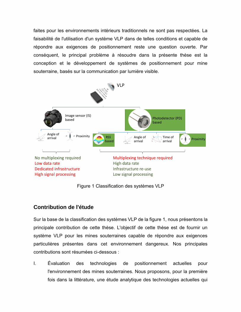
faites pour les environnements intérieurs traditionnels ne sont pas respectées. La
faisabilité de l'utilisation d'un système VLP dans de telles conditions et capable de
répondre aux exigences de positionnement reste une question ouverte. Par
conséquent, le principal problème à résoudre dans la présente thèse est la
conception et le développement de systèmes de positionnement pour mine
souterraine, basés sur la communication par lumière visible.
Figure 1 Classification des systèmes VLP
Contribution de l'étude
Sur la base de la classification des systèmes VLP de la figure 1, nous présentons la
principale contribution de cette thèse. L'objectif de cette thèse est de fournir un
système VLP pour les mines souterraines capable de répondre aux exigences
particulières présentes dans cet environnement dangereux. Nos principales
contributions sont résumées ci-dessous :
I. Évaluation des technologies de positionnement actuelles pour
l'environnement des mines souterraines. Nous proposons, pour la première
fois dans la littérature, une étude analytique des technologies actuelles qui
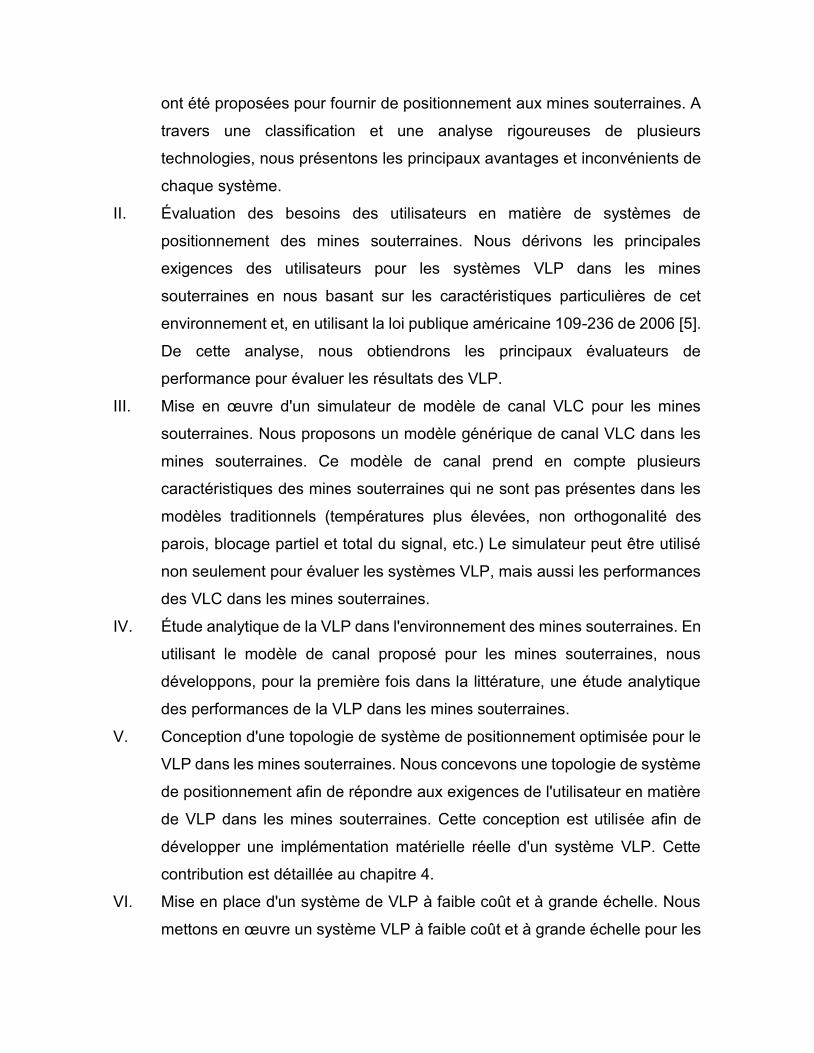
ont été proposées pour fournir de positionnement aux mines souterraines. A
travers une classification et une analyse rigoureuses de plusieurs
technologies, nous présentons les principaux avantages et inconvénients de
chaque système.
II. Évaluation des besoins des utilisateurs en matière de systèmes de
positionnement des mines souterraines. Nous dérivons les principales
exigences des utilisateurs pour les systèmes VLP dans les mines
souterraines en nous basant sur les caractéristiques particulières de cet
environnement et, en utilisant la loi publique américaine 109-236 de 2006 [5].
De cette analyse, nous obtiendrons les principaux évaluateurs de
performance pour évaluer les résultats des VLP.
III. Mise en œuvre d'un simulateur de modèle de canal VLC pour les mines
souterraines. Nous proposons un modèle générique de canal VLC dans les
mines souterraines. Ce modèle de canal prend en compte plusieurs
caractéristiques des mines souterraines qui ne sont pas présentes dans les
modèles traditionnels (températures plus élevées, non orthogonalité des
parois, blocage partiel et total du signal, etc.) Le simulateur peut être utilisé
non seulement pour évaluer les systèmes VLP, mais aussi les performances
des VLC dans les mines souterraines.
IV. Étude analytique de la VLP dans l'environnement des mines souterraines. En
utilisant le modèle de canal proposé pour les mines souterraines, nous
développons, pour la première fois dans la littérature, une étude analytique
des performances de la VLP dans les mines souterraines.
V. Conception d'une topologie de système de positionnement optimisée pour le
VLP dans les mines souterraines. Nous concevons une topologie de système
de positionnement afin de répondre aux exigences de l'utilisateur en matière
de VLP dans les mines souterraines. Cette conception est utilisée afin de
développer une implémentation matérielle réelle d'un système VLP. Cette
contribution est détaillée au chapitre 4.
VI. Mise en place d'un système de VLP à faible coût et à grande échelle. Nous
mettons en œuvre un système VLP à faible coût et à grande échelle pour les
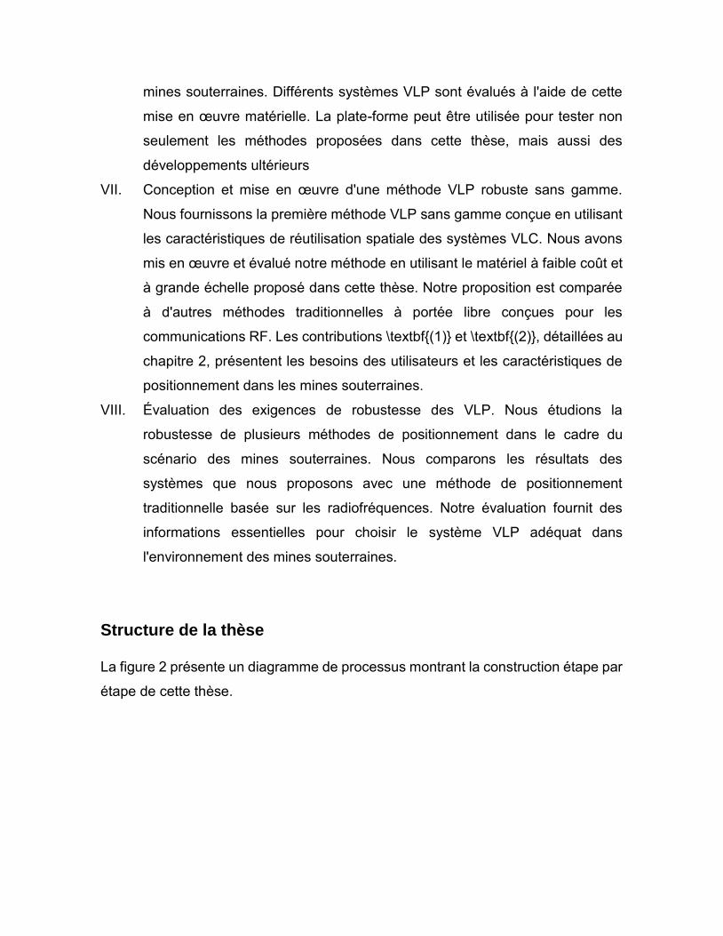
mines souterraines. Différents systèmes VLP sont évalués à l'aide de cette
mise en œuvre matérielle. La plate-forme peut être utilisée pour tester non
seulement les méthodes proposées dans cette thèse, mais aussi des
développements ultérieurs
VII. Conception et mise en œuvre d'une méthode VLP robuste sans gamme.
Nous fournissons la première méthode VLP sans gamme conçue en utilisant
les caractéristiques de réutilisation spatiale des systèmes VLC. Nous avons
mis en œuvre et évalué notre méthode en utilisant le matériel à faible coût et
à grande échelle proposé dans cette thèse. Notre proposition est comparée
à d'autres méthodes traditionnelles à portée libre conçues pour les
communications RF. Les contributions \textbf{(1)} et \textbf{(2)}, détaillées au
chapitre 2, présentent les besoins des utilisateurs et les caractéristiques de
positionnement dans les mines souterraines.
VIII. Évaluation des exigences de robustesse des VLP. Nous étudions la
robustesse de plusieurs méthodes de positionnement dans le cadre du
scénario des mines souterraines. Nous comparons les résultats des
systèmes que nous proposons avec une méthode de positionnement
traditionnelle basée sur les radiofréquences. Notre évaluation fournit des
informations essentielles pour choisir le système VLP adéquat dans
l'environnement des mines souterraines.
Structure de la thèse
La figure 2 présente un diagramme de processus montrant la construction étape par
étape de cette thèse.
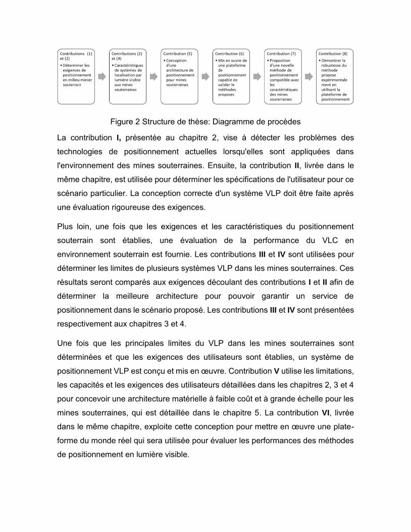
Figure 2 Structure de thèse: Diagramme de procèdes
La contribution I, présentée au chapitre 2, vise à détecter les problèmes des
technologies de positionnement actuelles lorsqu'elles sont appliquées dans
l'environnement des mines souterraines. Ensuite, la contribution II, livrée dans le
même chapitre, est utilisée pour déterminer les spécifications de l'utilisateur pour ce
scénario particulier. La conception correcte d'un système VLP doit être faite après
une évaluation rigoureuse des exigences.
Plus loin, une fois que les exigences et les caractéristiques du positionnement
souterrain sont établies, une évaluation de la performance du VLC en
environnement souterrain est fournie. Les contributions III et IV sont utilisées pour
déterminer les limites de plusieurs systèmes VLP dans les mines souterraines. Ces
résultats seront comparés aux exigences découlant des contributions I et II afin de
déterminer la meilleure architecture pour pouvoir garantir un service de
positionnement dans le scénario proposé. Les contributions III et IV sont présentées
respectivement aux chapitres 3 et 4.
Une fois que les principales limites du VLP dans les mines souterraines sont
déterminées et que les exigences des utilisateurs sont établies, un système de
positionnement VLP est conçu et mis en œuvre. Contribution V utilise les limitations,
les capacités et les exigences des utilisateurs détaillées dans les chapitres 2, 3 et 4
pour concevoir une architecture matérielle à faible coût et à grande échelle pour les
mines souterraines, qui est détaillée dans le chapitre 5. La contribution VI, livrée
dans le même chapitre, exploite cette conception pour mettre en œuvre une plate-
forme du monde réel qui sera utilisée pour évaluer les performances des méthodes
de positionnement en lumière visible.
La contribution VII présente une nouvelle méthode robuste de positionnement sans
portée. Contrairement à la plupart des méthodes existant dans la littérature, notre
proposition n'est pas directement dérivée des méthodes basées sur les RF.
L'algorithme proposé utilise des caractéristiques spéciales de la VLC pour améliorer
les performances d'estimation de la position. Le chapitre 6 donne un aperçu de notre
méthode.
Finalement, la contribution VIII évalue la performance de notre proposition en
utilisant la plate-forme d'essai de la méthode à grande échelle/faible coût de la
contribution VI. L'algorithme proposé utilise les caractéristiques spéciales de la
communication par lumière visible pour améliorer la performance de l'estimation de
la position. La robustesse de notre méthode à plusieurs perturbations (erreurs dans
la mesure de la hauteur, des angles d'inclinaison, et la propagation par trajets
multiples à cause de réflexions de la lumière sur les murs) a été testée.
Références
[1] D. Lymberopoulos, J. Liu, X. Yang, R. R. Choudhury, V. Handziski, and S.
Sen, “A realistic evaluation and comparison of indoor location technologies,”
in Proceedings of the 14th International Conference on Information Processing
in Sensor Networks - IPSN ’15, 2015, pp. 178–189.
[2] X. Liu, H. Makino, S. Kobayashi, and Y. Maeda, “Design of an Indoor Self-
Positioning System for the Visually Impaired - Simulation with RFID and
Bluetooth in a Visible Light Communication System,” in 2007 29th Annual
International Conference of the IEEE Engineering in Medicine and Biology
Society, 2007, pp. 1655–1658.
[3] N. U. Hassan, A. Naeem, M. A. Pasha, T. Jadoon, and C. Yuen, “Indoor
Positioning Using Visible LED Lights,” ACM Comput. Surv., vol. 48, no. 2, pp.
1–32, Nov. 2015.
[4] H. Liu, J. Yang, S. Sidhom, Y. Wang, Y. Chen, and F. Ye, “Accurate WiFi
Based Localization for Smartphones Using Peer Assistance,” IEEE Trans.
Mob. Comput., vol. 13, no. 10, pp. 2199–2214, Oct. 2014.

[5] 109th Congress, “Mine Improvement and New Emergency Response,” Public
Law. pp. 109–236, 2006.