rf based remote controlled
TRANSCRIPT

PROJECT REPORTPROJECT REPORT
ONONRF BASED REMOTE CONTROLLED
POWER OFF SWITCH

CONTENTS
1. Introduction
2. Block diagram
3. Circuit diagram
4. Working of circuit
5. PCB layout
6. Parts and price list
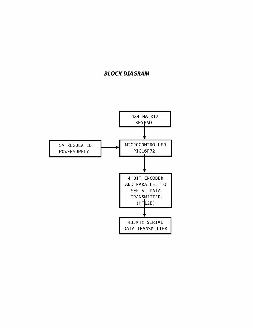
4X4 MATRIX KEYPAD
MICROCONTROLLER PIC16F72
4 BIT ENCODER AND PARALLEL TO
SERIAL DATA TRANSMITTER
(HT12E)
433MHz SERIAL DATA TRANSMITTER
5V REGULATED POWERSUPPLY
BLOCK DIAGRAM
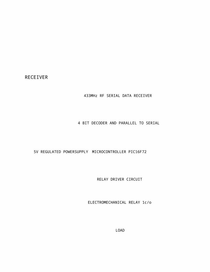
ELECTROMECHANICAL RELAY 1c/o
MICROCONTROLLER PIC16F72
4 BIT DECODER AND PARALLEL TO SERIAL
433MHz RF SERIAL DATA RECEIVER
5V REGULATED POWERSUPPLY
RELAY DRIVER CIRCUIT
LOAD
RECEIVER
CIRCUIT DIAGRAM
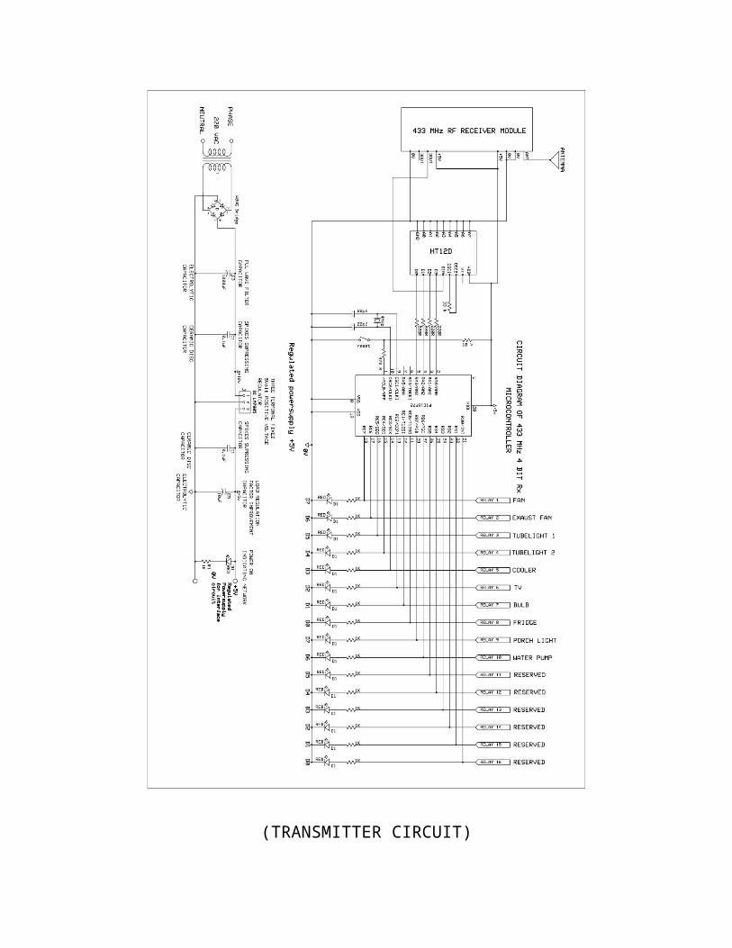
(TRANSMITTER CIRCUIT)
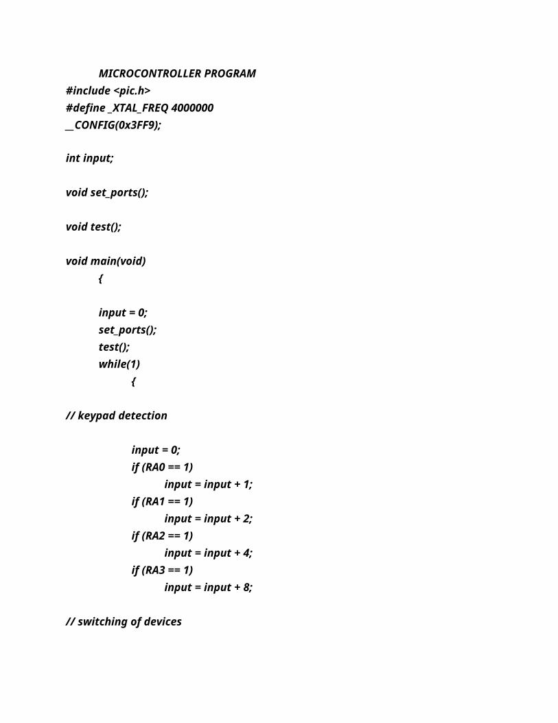
MICROCONTROLLER PROGRAM#include <pic.h>#define _XTAL_FREQ 4000000__CONFIG(0x3FF9);
int input;
void set_ports();
void test();
void main(void)
input = 0;set_ports();test();while(1)
// keypad detection
input = 0;if (RA0 == 1)
input = input + 1;if (RA1 == 1)
input = input + 2;if (RA2 == 1)
input = input + 4;if (RA3 == 1)
input = input + 8;
// switching of devices
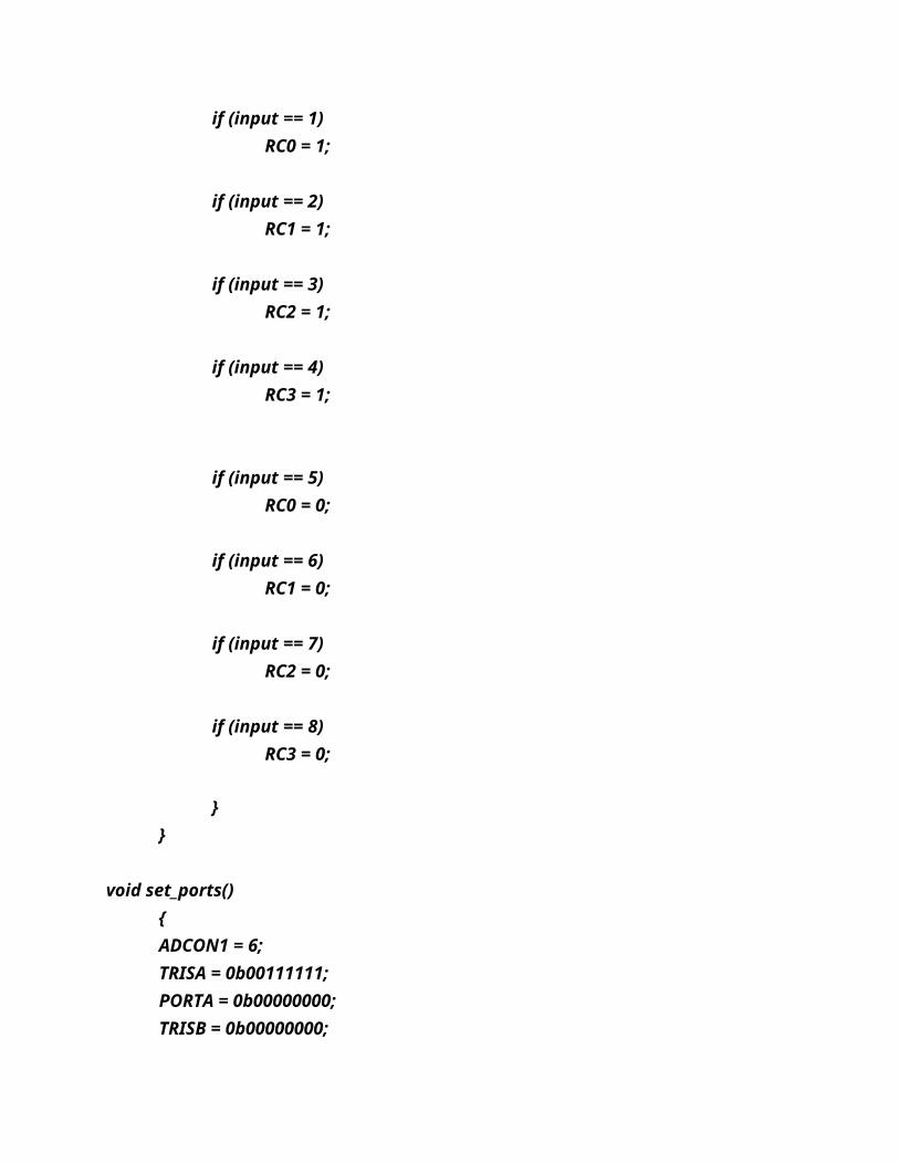
if (input == 1)RC0 = 1;
if (input == 2)RC1 = 1;
if (input == 3)RC2 = 1;
if (input == 4)RC3 = 1;
if (input == 5)RC0 = 0;
if (input == 6)RC1 = 0;
if (input == 7)RC2 = 0;
if (input == 8)RC3 = 0;
void set_ports()ADCON1 = 6;TRISA = 0b00111111;PORTA = 0b00000000;TRISB = 0b00000000;
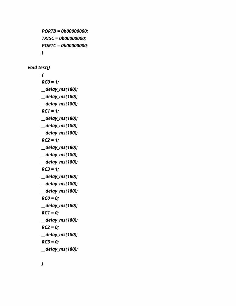
PORTB = 0b00000000;TRISC = 0b00000000;PORTC = 0b00000000;
void test()RC0 = 1;__delay_ms(180);__delay_ms(180);__delay_ms(180);RC1 = 1;__delay_ms(180);__delay_ms(180);__delay_ms(180);RC2 = 1;__delay_ms(180);__delay_ms(180);__delay_ms(180);RC3 = 1;__delay_ms(180);__delay_ms(180);__delay_ms(180);RC0 = 0;__delay_ms(180);RC1 = 0;__delay_ms(180);RC2 = 0;__delay_ms(180);RC3 = 0;__delay_ms(180);
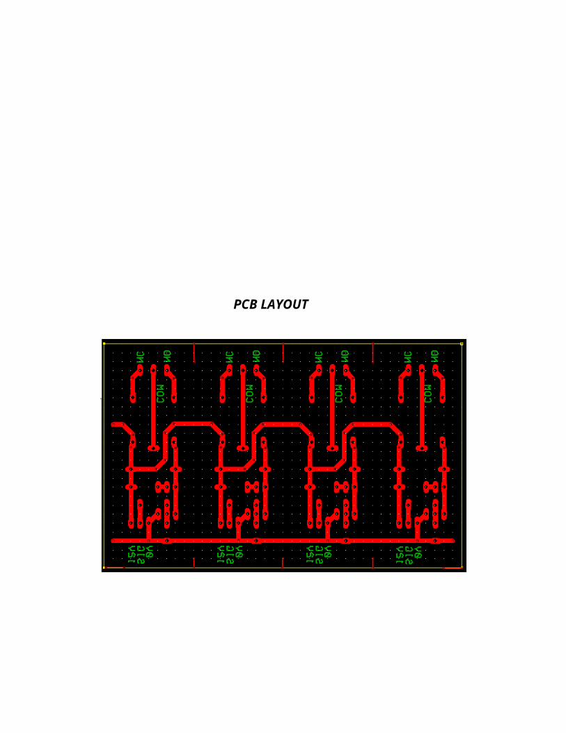
PCB LAYOUT
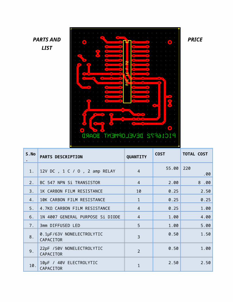
PARTS AND PRICELIST
S.No. PARTS DESCRIPTION QUANTITY COST TOTAL COST
1. 12V DC , 1 C / O , 2 amp RELAY 4 55.00 220 .00
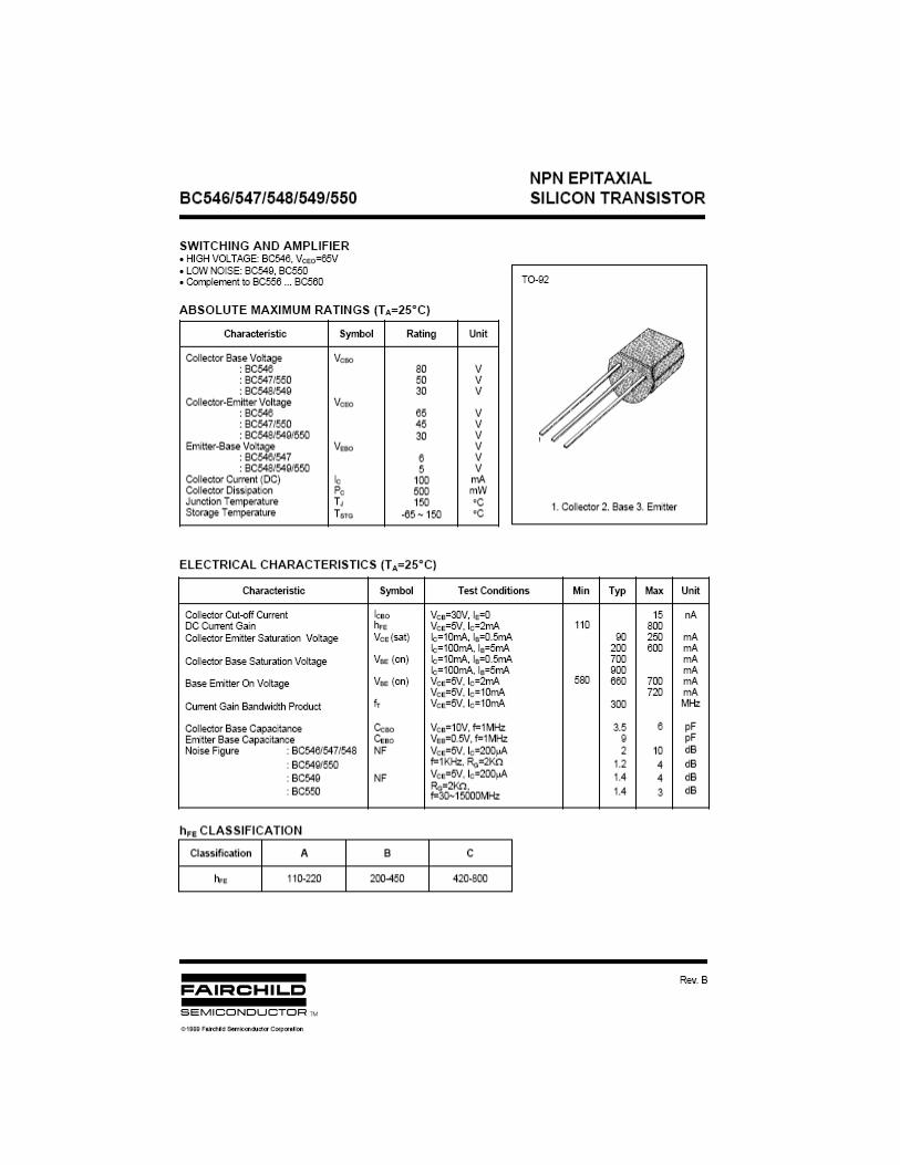
2. BC 547 NPN Si TRANSISTOR 4 2.00 8 .00
3. 1K CARBON FILM RESISTANCE 10 0.25 2.50
4. 10K CARBON FILM RESISTANCE 1 0.25 0.25
5. 4.7KΩ CARBON FILM RESISTANCE 4 0.25 1.00
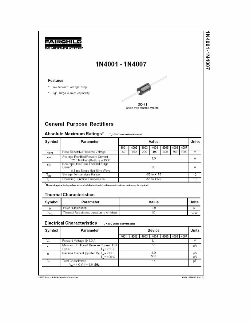
6. 1N 4007 GENERAL PURPOSE Si DIODE 4 1.00 4.00
7. 3mm DIFFUSED LED 5 1.00 5.00
8. 0.1µF/63V NONELECTROLYTIC CAPACITOR 3 0.50 1.50
9. 22pF /50V NONELECTROLYTIC CAPACITOR 2 0.50 1.00
10. 10µF / 40V ELECTROLYTIC CAPACITOR 1 2.50 2.50
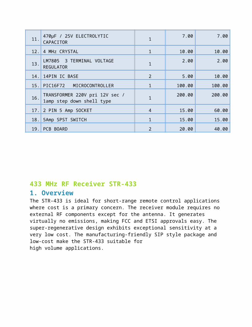
11. 470µF / 25V ELECTROLYTIC CAPACITOR 1 7.00 7.00
12. 4 MHz CRYSTAL 1 10.00 10.00
13. LM7805 3 TERMINAL VOLTAGE REGULATOR 1 2.00 2.00
14. 14PIN IC BASE 2 5.00 10.00
15. PIC16F72 MICROCONTROLLER 1 100.00 100.00
16. TRANSFORMER 220V pri 12V sec / 1amp step down shell type 1 200.00 200.00
17. 2 PIN 5 Amp SOCKET 4 15.00 60.00
18. 5Amp SPST SWITCH 1 15.00 15.00
19. PCB BOARD 2 20.00 40.00
433 MHz RF Receiver STR-4331. OverviewThe STR-433 is ideal for short-range remote control applications where cost is a primary concern. The receiver module requires no external RF components except for the antenna. It generates virtually no emissions, making FCC and ETSI approvals easy. The super-regenerative design exhibits exceptional sensitivity at a very low cost. The manufacturing-friendly SIP style package and low-cost make the STR-433 suitable for high volume applications.
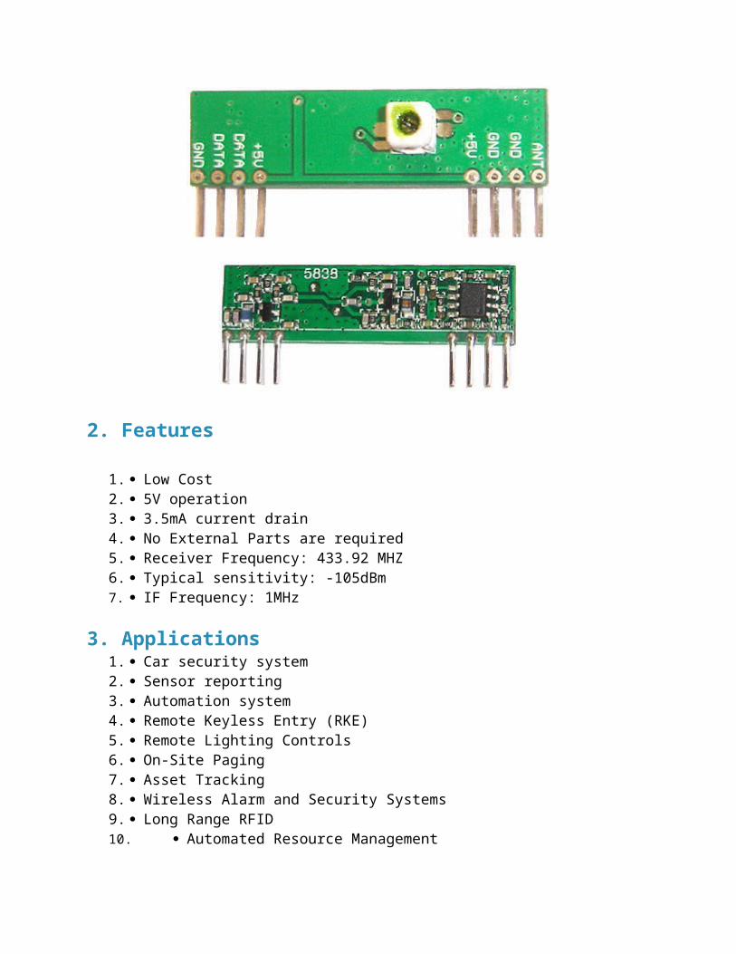
2. Features
1. Low Cost2. 5V operation3. 3.5mA current drain4. No External Parts are required5. Receiver Frequency: 433.92 MHZ6. Typical sensitivity: -105dBm7. IF Frequency: 1MHz
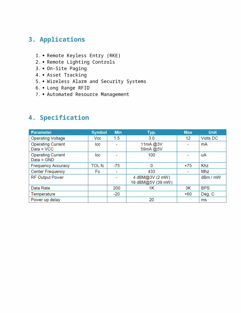
3. Applications1. Car security system2. Sensor reporting3. Automation system4. Remote Keyless Entry (RKE)5. Remote Lighting Controls6. On-Site Paging7. Asset Tracking8. Wireless Alarm and Security Systems9. Long Range RFID10. Automated Resource Management
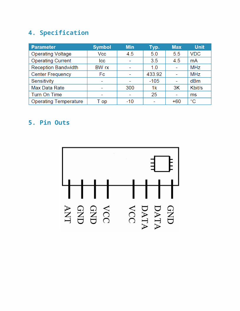
4. SpecificationParameter Symbol Min Typ. Max Unit
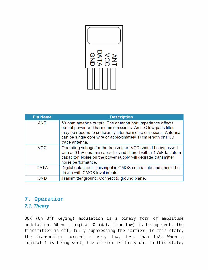
5. Pin OutsPin
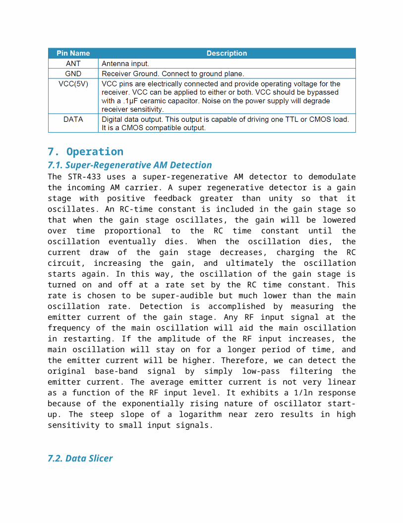
7. Operation7.1. Super-Regenerative AM DetectionThe STR-433 uses a super-regenerative AM detector to demodulatethe incoming AM carrier. A super regenerative detector is a gainstage with positive feedback greater than unity so that itoscillates. An RC-time constant is included in the gain stage sothat when the gain stage oscillates, the gain will be loweredover time proportional to the RC time constant until theoscillation eventually dies. When the oscillation dies, thecurrent draw of the gain stage decreases, charging the RCcircuit, increasing the gain, and ultimately the oscillationstarts again. In this way, the oscillation of the gain stage isturned on and off at a rate set by the RC time constant. Thisrate is chosen to be super-audible but much lower than the mainoscillation rate. Detection is accomplished by measuring theemitter current of the gain stage. Any RF input signal at thefrequency of the main oscillation will aid the main oscillationin restarting. If the amplitude of the RF input increases, themain oscillation will stay on for a longer period of time, andthe emitter current will be higher. Therefore, we can detect theoriginal base-band signal by simply low-pass filtering theemitter current. The average emitter current is not very linearas a function of the RF input level. It exhibits a 1/ln responsebecause of the exponentially rising nature of oscillator start-up. The steep slope of a logarithm near zero results in highsensitivity to small input signals.
7.2. Data Slicer
The data slicer converts the base-band analog signal from thesuper-regenerative detector to a CMOS/TTL compatible output.Because the data slicer is AC coupled to the audio output, thereis a minimum data rate. AC coupling also limits the minimum andmaximum pulse width. Typically, data is encoded on the transmitside using pulse-width modulation (PWM) or non-return-to-zero(NRZ). The most common source for NRZ data is from a UARTembedded in a micro-controller. Applications that use NRZ dataencoding typically involve microcontrollers. The most commonsource for PWM datais from a remote control IC such as the HC-12E from Holtek orST14 CODEC from Sunrom Technologies. Data is sent as a constantrate square-wave. The duty cycle of that square wave willgenerally be either 33% (a zero) or 66% (a one). The data sliceron the STR-433 is optimized for use with PWM encoded data, thoughit will work with NRZ data if certain encoding rules arefollowed.
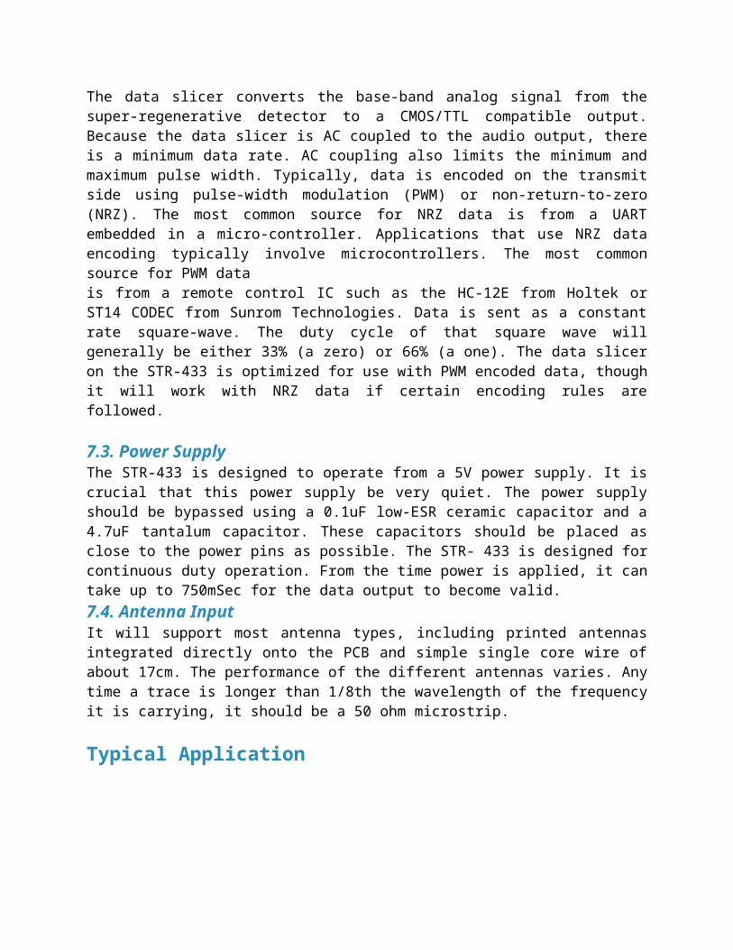
7.3. Power SupplyThe STR-433 is designed to operate from a 5V power supply. It iscrucial that this power supply be very quiet. The power supplyshould be bypassed using a 0.1uF low-ESR ceramic capacitor and a4.7uF tantalum capacitor. These capacitors should be placed asclose to the power pins as possible. The STR- 433 is designed forcontinuous duty operation. From the time power is applied, it cantake up to 750mSec for the data output to become valid.7.4. Antenna InputIt will support most antenna types, including printed antennasintegrated directly onto the PCB and simple single core wire ofabout 17cm. The performance of the different antennas varies. Anytime a trace is longer than 1/8th the wavelength of the frequencyit is carrying, it should be a 50 ohm microstrip.
Typical Application
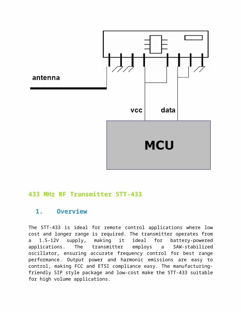
433 MHz RF Transmitter STT-433
1. Overview
The STT-433 is ideal for remote control applications where lowcost and longer range is required. The transmitter operates froma 1.5-12V supply, making it ideal for battery-poweredapplications. The transmitter employs a SAW-stabilizedoscillator, ensuring accurate frequency control for best rangeperformance. Output power and harmonic emissions are easy tocontrol, making FCC and ETSI compliance easy. The manufacturing-friendly SIP style package and low-cost make the STT-433 suitablefor high volume applications.
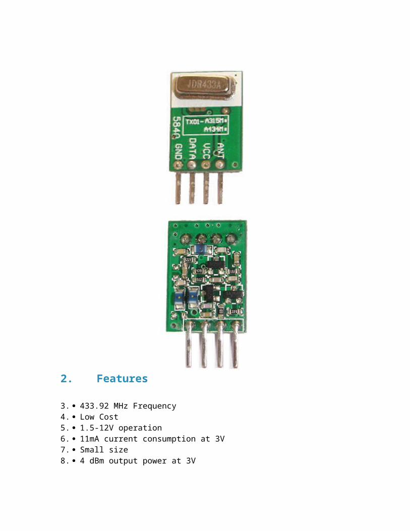
2. Features
3. 433.92 MHz Frequency4. Low Cost5. 1.5-12V operation6. 11mA current consumption at 3V7. Small size8. 4 dBm output power at 3V
3. Applications
1. Remote Keyless Entry (RKE)2. Remote Lighting Controls3. On-Site Paging4. Asset Tracking5. Wireless Alarm and Security Systems6. Long Range RFID7. Automated Resource Management
4. SpecificationParameter Symbol
7. Operation7.1. Theory
OOK (On Off Keying) modulation is a binary form of amplitudemodulation. When a logical 0 (data line low) is being sent, thetransmitter is off, fully suppressing the carrier. In this state,the transmitter current is very low, less than 1mA. When alogical 1 is being sent, the carrier is fully on. In this state,
the module current consumption is at its highest, about 11mA witha 3V power supply. OOK is the modulation method of choice forremote control applications where power consumption and cost arethe primary factors. Because OOK transmitters draw no power whenthey transmit a 0, they exhibit significantly better powerconsumption than FSK transmitters. OOK data rate is limited bythe start-up time of the oscillator. High-Q oscillators whichhave very stable center frequencies take longer to start-up thanlow-Q oscillators. The start-up time of the oscillator determinesthe maximum data rate that the transmitter can send.
7.2. Data Rate
The oscillator start-up time is on the order of 40uSec, which limits the maximum data rate to 4.8 kbit/sec.
7.3. SAW stabilized oscillator
The transmitter is basically a negative resistance LC oscillator whose center frequency is tightly controlled by a SAW resonator. SAW (Surface Acoustic Wave) resonators are fundamental frequency devices that resonate at frequencies much higher than crystals.
8. Typical Application
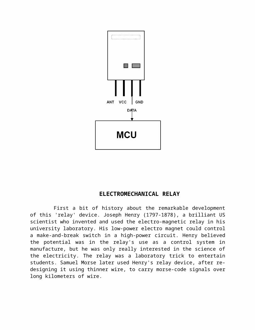
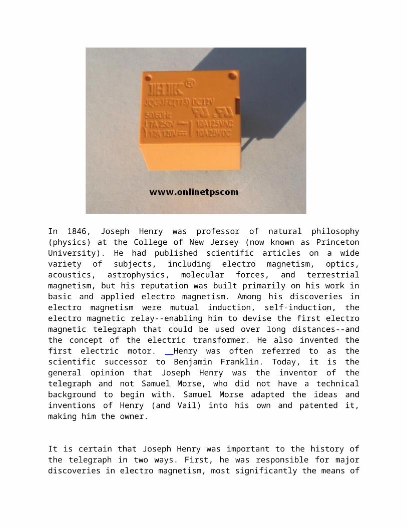
ELECTROMECHANICAL RELAY
First a bit of history about the remarkable developmentof this 'relay' device. Joseph Henry (1797-1878), a brilliant USscientist who invented and used the electro-magnetic relay in hisuniversity laboratory. His low-power electro magnet could controla make-and-break switch in a high-power circuit. Henry believedthe potential was in the relay's use as a control system inmanufacture, but he was only really interested in the science ofthe electricity. The relay was a laboratory trick to entertainstudents. Samuel Morse later used Henry's relay device, after re-designing it using thinner wire, to carry morse-code signals overlong kilometers of wire.
In 1846, Joseph Henry was professor of natural philosophy(physics) at the College of New Jersey (now known as PrincetonUniversity). He had published scientific articles on a widevariety of subjects, including electro magnetism, optics,acoustics, astrophysics, molecular forces, and terrestrialmagnetism, but his reputation was built primarily on his work inbasic and applied electro magnetism. Among his discoveries inelectro magnetism were mutual induction, self-induction, theelectro magnetic relay--enabling him to devise the first electromagnetic telegraph that could be used over long distances--andthe concept of the electric transformer. He also invented thefirst electric motor. Henry was often referred to as thescientific successor to Benjamin Franklin. Today, it is thegeneral opinion that Joseph Henry was the inventor of thetelegraph and not Samuel Morse, who did not have a technicalbackground to begin with. Samuel Morse adapted the ideas andinventions of Henry (and Vail) into his own and patented it,making him the owner.
It is certain that Joseph Henry was important to the history ofthe telegraph in two ways. First, he was responsible for majordiscoveries in electro magnetism, most significantly the means of
constructing electromagnets that were powerful enough totransform electrical energy into useful mechanical work at adistance. Much of Morse's telegraph did indeed rest upon Henry'sdiscovery of the principles underlying the operation of suchelectromagnets. Below are a couple other thoughts collected fromthe Smithsonian Institute (of which Henry was First Secretary),and Harvard University:
"... Secondly, Henry became an unwilling participant in the protracted litigation over thescope and validity of Samuel Morse's patents. ..."
"... Joseph Henry began his research into electro magnetism in 1827, while he was aninstructor at the Albany Academy in New York. By 1830, he achieved two majorbreakthroughs .... His first crucial innovation, which he demonstrated in June 1828, wasto combine Schweigger's multiplier with Sturgeon's electro magnet to obtain anextremely powerful magnet. While Sturgeon loosely wrapped a few feet of uninsulatedwire around a horseshoe magnet, Henry tightly wound his horseshoe with several layersof insulated wire. In March 1829 he demonstrated an electro magnet with 400 turns, orabout 35 feet, of insulated wire. This magnet, Henry remarked later, "possessedmagnetic power superior to that of any before known."
"... Henry did set out to demonstrate the practicality of an electro magnetic telegraphimmediately after his paper appeared. His prototype consisted of a small battery andan "intensity" magnet connected through a mile of copper bell-wire strung throughouta lecture hall. In between the poles of this horseshoe electro magnetic he placed apermanent magnet. When the electro magnetic was energized, the permanent magnetwas repelled from one pole and attracted to the other; upon reversing battery polarity,the permanent magnet returned to its original position. ... Henry caused the permanentmagnet to tap a small office bell. He consistently demonstrated this arrangement to hisclasses at Albany during 1831 and 1832."
A relay is an electrically operated switch. Many relaysuse an electromagnet to operate a switching mechanismmechanically, but other operating principles are also used.Relays are used where it is necessary to control a circuit by a
low-power signal (with complete electrical isolation betweencontrol and controlled circuits), or where several circuits mustbe controlled by one signal. The first relays were used in longdistance telegraph circuits, repeating the signal coming in fromone circuit and re-transmitting it to another. Relays were usedextensively in telephone exchanges and early computers to performlogical operations.A type of relay that can handle the high power required todirectly control an electric motor is called a contactor. Solid-state relays control power circuits with nomoving parts, insteadusing a semiconductor device to perform switching. Relays withcalibrated operating characteristics and sometimes multipleoperating coils are used to protect electrical circuits fromoverload or faults; in modern electric power systems thesefunctions are performed by digital instruments still called"protective relays".
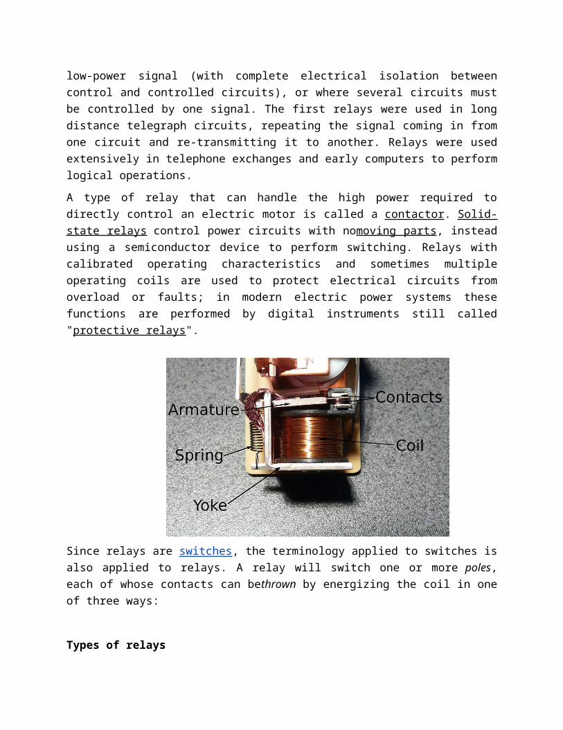
Since relays are switches, the terminology applied to switches isalso applied to relays. A relay will switch one or more poles,each of whose contacts can bethrown by energizing the coil in oneof three ways:
Types of relays
1. Latching relay2. Reed relay3. Mercury-wetted relay4. Polarized relay5. Machine tool relay6. Contactor relay7. Solid-state relay8. Solid state contactor relay9. Buchholz relay10. Forced-guided contacts relay11. Overload protection relay
Pole and throw
1. Normally-open (NO) contacts connect the circuit when therelay is activated; the circuit is disconnected when therelay is inactive. It is also called a Form Acontact or"make" contact. NO contacts can also be distinguished as"early-make" or NOEM, which means that the contacts willclose before the button or switch is fully engaged.
2. Normally-closed (NC) contacts disconnect the circuit whenthe relay is activated; the circuit is connected when therelay is inactive. It is also called a Form Bcontact or"break" contact. NC contacts can also be distinguished as"late-break" or NCLB, which means that the contacts willstay closed until the button or switch is fully disengaged.
3. Change-over (CO), or double-throw (DT), contacts control twocircuits: one normally-open contact and one normally-closedcontact with a common terminal. It is also called a FormC contact or "transfer" contact ("break before make"). Ifthis type of contact utilizes a "make before break"functionality, then it is called a Form D contact. Thefollowing designations are commonly encountered:
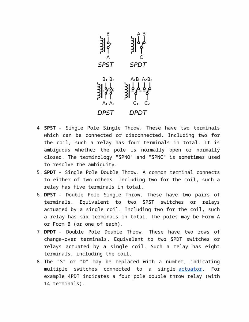
4. SPST – Single Pole Single Throw. These have two terminalswhich can be connected or disconnected. Including two forthe coil, such a relay has four terminals in total. It isambiguous whether the pole is normally open or normallyclosed. The terminology "SPNO" and "SPNC" is sometimes usedto resolve the ambiguity.
5. SPDT – Single Pole Double Throw. A common terminal connectsto either of two others. Including two for the coil, such arelay has five terminals in total.
6. DPST – Double Pole Single Throw. These have two pairs ofterminals. Equivalent to two SPST switches or relaysactuated by a single coil. Including two for the coil, sucha relay has six terminals in total. The poles may be Form Aor Form B (or one of each).
7. DPDT – Double Pole Double Throw. These have two rows ofchange-over terminals. Equivalent to two SPDT switches orrelays actuated by a single coil. Such a relay has eightterminals, including the coil.
8. The "S" or "D" may be replaced with a number, indicatingmultiple switches connected to a single actuator. Forexample 4PDT indicates a four pole double throw relay (with14 terminals).
9. EN 50005 are among applicable standards for relay terminalnumbering; a typical EN 50005-compliant SPDT relay'sterminals would be numbered 11, 12, 14, A1 and A2 for the C,NC, NO, and coil connections, respectively.
In short, this man, Joseph Henry, was a scientist and physicistby heart and a true teacher to his students. As a reward, they(not his students) stole his ideas and scientific experiments.For that reason I'm convinced that Morse was a fraud, preying onthe ideas and inventions (like the telegraph) of others andputting his patent on it (obtained on October 3, 1837). I docredit Samuel Morse, however, for the morse-code, which is stillused to this date and no person without a 5-wpm morse-codequalification exam can call him/herself a Advanced Radio Amateur!(see Fig. a).
Since this important day in 1836, when Joseph Henry transmitteda small electrical current down a wire to energize a remote coiland the completed circuit ringing a bell some 150 years ago, therelay has undergone steady evolution and today's relays are farremoved from the crude and clumsy relays of Henry's days. In ourmillennium, solid-state has replaced the actual relay in manycircuits, especially in AC applications. To sum it all up, therelay (and solenoids) have survived the tube, transistor, andintegrated circuit (IC) eras.
Basically, a relay is an electrically operated switch, andactually the predecessor of the transistor. Solenoids are relaysalso but the very large types which carry huge amounts ofcurrent. Relays are the smaller types. Relays come in threetypes: electro mechanical, solid-state, and so-called hybridswhich are a combination of the first two. There are also some
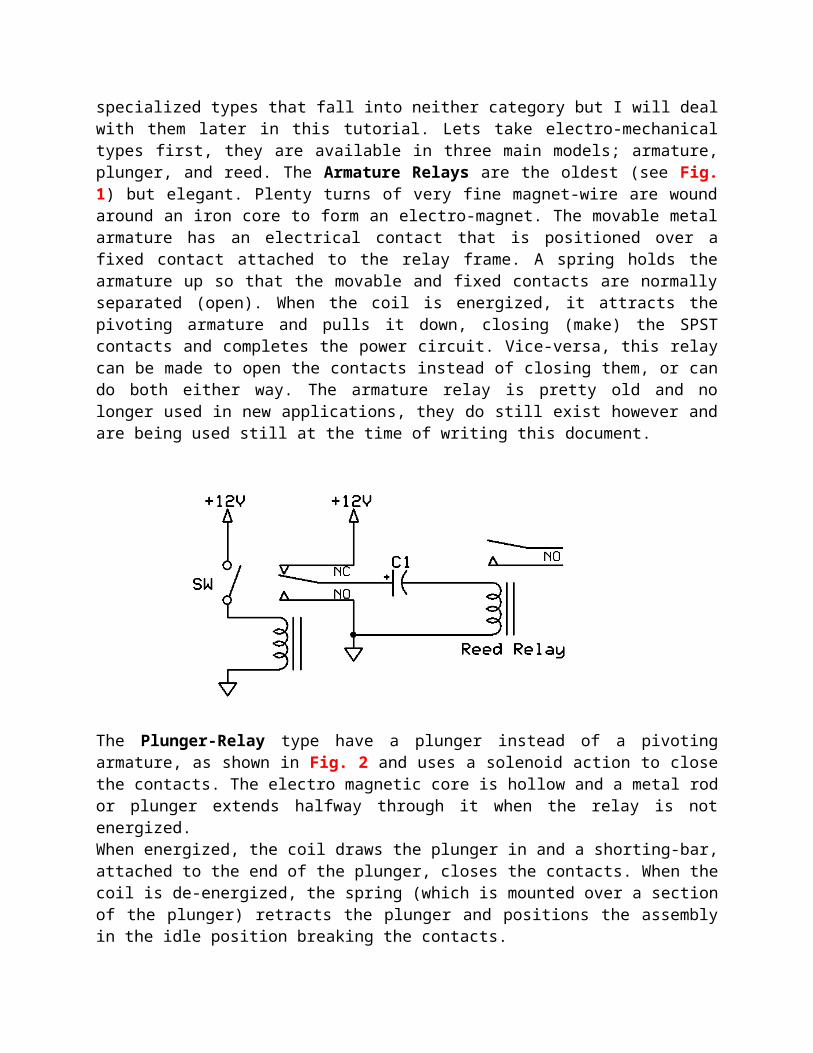
specialized types that fall into neither category but I will dealwith them later in this tutorial. Lets take electro-mechanicaltypes first, they are available in three main models; armature,plunger, and reed. The Armature Relays are the oldest (see Fig.1) but elegant. Plenty turns of very fine magnet-wire are woundaround an iron core to form an electro-magnet. The movable metalarmature has an electrical contact that is positioned over afixed contact attached to the relay frame. A spring holds thearmature up so that the movable and fixed contacts are normallyseparated (open). When the coil is energized, it attracts thepivoting armature and pulls it down, closing (make) the SPSTcontacts and completes the power circuit. Vice-versa, this relaycan be made to open the contacts instead of closing them, or cando both either way. The armature relay is pretty old and nolonger used in new applications, they do still exist however andare being used still at the time of writing this document.
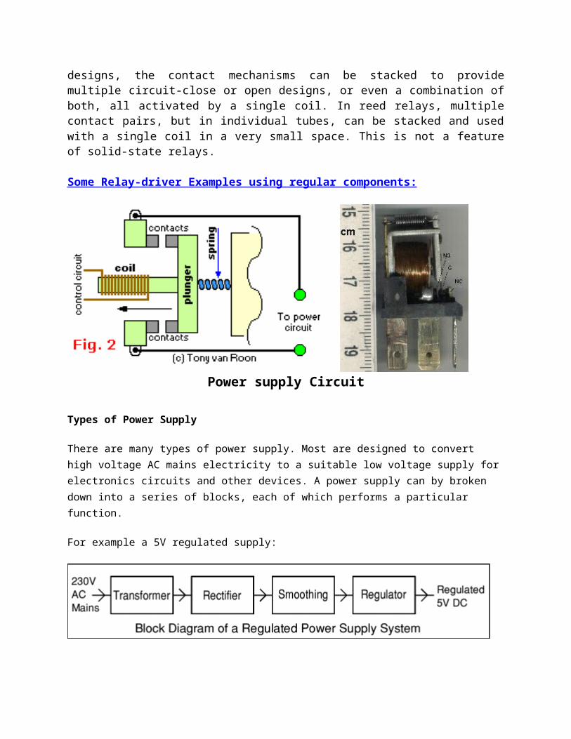
The Plunger-Relay type have a plunger instead of a pivotingarmature, as shown in Fig. 2 and uses a solenoid action to closethe contacts. The electro magnetic core is hollow and a metal rodor plunger extends halfway through it when the relay is notenergized.When energized, the coil draws the plunger in and a shorting-bar,attached to the end of the plunger, closes the contacts. When thecoil is de-energized, the spring (which is mounted over a sectionof the plunger) retracts the plunger and positions the assemblyin the idle position breaking the contacts.
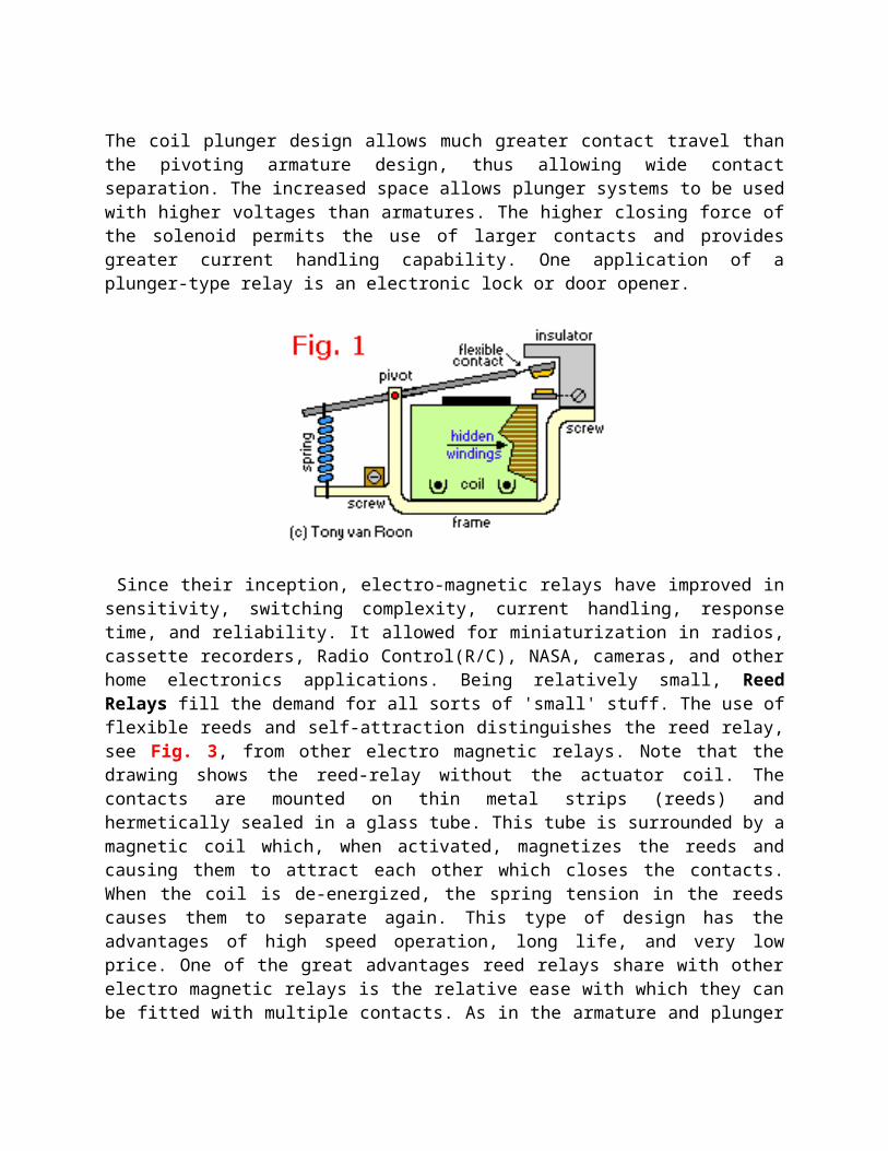
The coil plunger design allows much greater contact travel thanthe pivoting armature design, thus allowing wide contactseparation. The increased space allows plunger systems to be usedwith higher voltages than armatures. The higher closing force ofthe solenoid permits the use of larger contacts and providesgreater current handling capability. One application of aplunger-type relay is an electronic lock or door opener.
Since their inception, electro-magnetic relays have improved insensitivity, switching complexity, current handling, responsetime, and reliability. It allowed for miniaturization in radios,cassette recorders, Radio Control(R/C), NASA, cameras, and otherhome electronics applications. Being relatively small, ReedRelays fill the demand for all sorts of 'small' stuff. The use offlexible reeds and self-attraction distinguishes the reed relay,see Fig. 3, from other electro magnetic relays. Note that thedrawing shows the reed-relay without the actuator coil. Thecontacts are mounted on thin metal strips (reeds) andhermetically sealed in a glass tube. This tube is surrounded by amagnetic coil which, when activated, magnetizes the reeds andcausing them to attract each other which closes the contacts.When the coil is de-energized, the spring tension in the reedscauses them to separate again. This type of design has theadvantages of high speed operation, long life, and very lowprice. One of the great advantages reed relays share with otherelectro magnetic relays is the relative ease with which they canbe fitted with multiple contacts. As in the armature and plunger
designs, the contact mechanisms can be stacked to providemultiple circuit-close or open designs, or even a combination ofboth, all activated by a single coil. In reed relays, multiplecontact pairs, but in individual tubes, can be stacked and usedwith a single coil in a very small space. This is not a featureof solid-state relays.
Some Relay-driver Examples using regular components:
Power supply Circuit
Types of Power Supply
There are many types of power supply. Most are designed to convert high voltage AC mains electricity to a suitable low voltage supply forelectronics circuits and other devices. A power supply can by broken down into a series of blocks, each of which performs a particular function.
For example a 5V regulated supply:
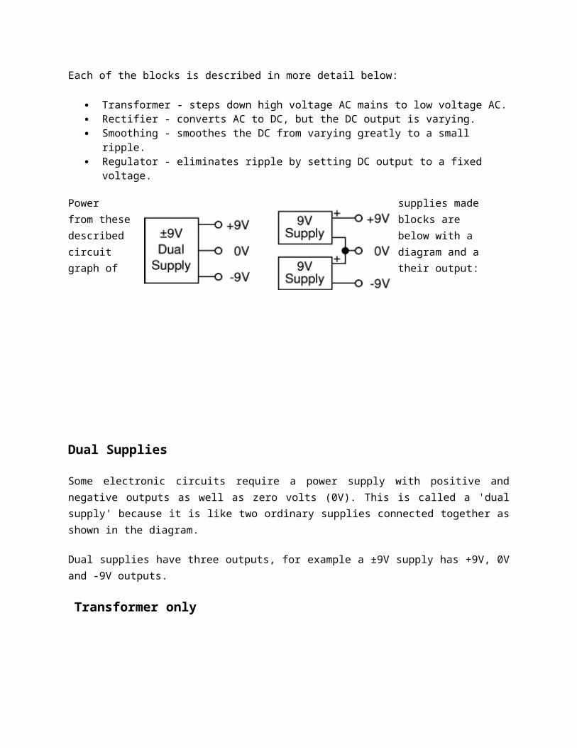
Each of the blocks is described in more detail below:
Transformer - steps down high voltage AC mains to low voltage AC. Rectifier - converts AC to DC, but the DC output is varying. Smoothing - smoothes the DC from varying greatly to a small
ripple. Regulator - eliminates ripple by setting DC output to a fixed
voltage.
Power supplies made from these blocks are described below with a circuit diagram and a graph of their output:
Dual Supplies
Some electronic circuits require a power supply with positive andnegative outputs as well as zero volts (0V). This is called a 'dualsupply' because it is like two ordinary supplies connected together asshown in the diagram.
Dual supplies have three outputs, for example a ±9V supply has +9V, 0Vand -9V outputs.
Transformer only
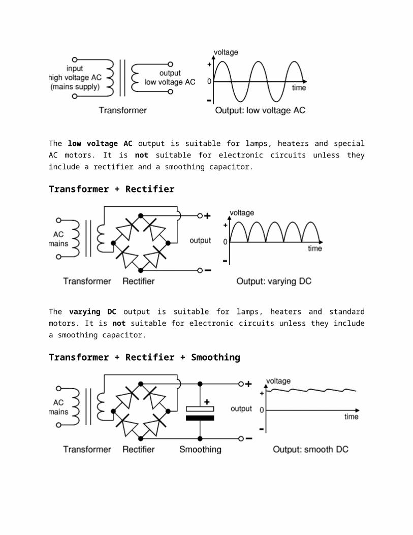
The low voltage AC output is suitable for lamps, heaters and specialAC motors. It is not suitable for electronic circuits unless theyinclude a rectifier and a smoothing capacitor.
Transformer + Rectifier
The varying DC output is suitable for lamps, heaters and standardmotors. It is not suitable for electronic circuits unless they includea smoothing capacitor.
Transformer + Rectifier + Smoothing
The smooth DC output has a small ripple. It is suitable for most electronic circuits.
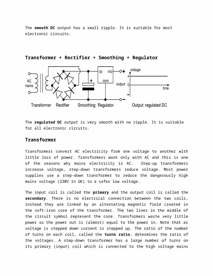
Transformer + Rectifier + Smoothing + Regulator
The regulated DC output is very smooth with no ripple. It is suitable for all electronic circuits.
Transformer
Transformers convert AC electricity from one voltage to another withlittle loss of power. Transformers work only with AC and this is oneof the reasons why mains electricity is AC. Step-up transformersincrease voltage, step-down transformers reduce voltage. Most powersupplies use a step-down transformer to reduce the dangerously highmains voltage (230V in UK) to a safer low voltage.
The input coil is called the primary and the output coil is called thesecondary. There is no electrical connection between the two coils,instead they are linked by an alternating magnetic field created inthe soft-iron core of the transformer. The two lines in the middle ofthe circuit symbol represent the core. Transformers waste very littlepower so the power out is (almost) equal to the power in. Note that asvoltage is stepped down current is stepped up. The ratio of the numberof turns on each coil, called the turns ratio, determines the ratio ofthe voltages. A step-down transformer has a large number of turns onits primary (input) coil which is connected to the high voltage mains
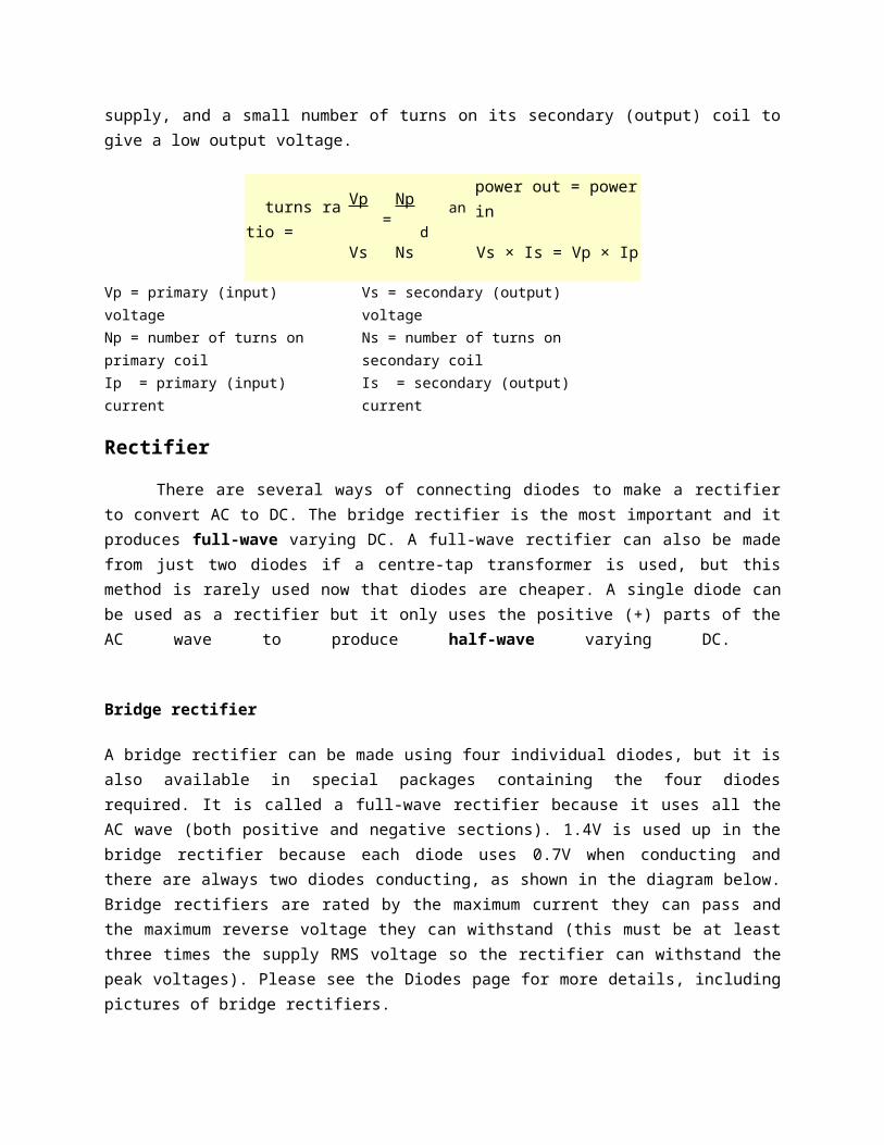
supply, and a small number of turns on its secondary (output) coil togive a low output voltage.
turns ratio =
Vp =
Np and
power out = power in
Vs Ns Vs × Is = Vp × Ip
Vp = primary (input) voltageNp = number of turns on primary coilIp = primary (input) current
Vs = secondary (output) voltageNs = number of turns on secondary coilIs = secondary (output) current
Rectifier
There are several ways of connecting diodes to make a rectifierto convert AC to DC. The bridge rectifier is the most important and itproduces full-wave varying DC. A full-wave rectifier can also be madefrom just two diodes if a centre-tap transformer is used, but thismethod is rarely used now that diodes are cheaper. A single diode canbe used as a rectifier but it only uses the positive (+) parts of theAC wave to produce half-wave varying DC.
Bridge rectifier
A bridge rectifier can be made using four individual diodes, but it isalso available in special packages containing the four diodesrequired. It is called a full-wave rectifier because it uses all theAC wave (both positive and negative sections). 1.4V is used up in thebridge rectifier because each diode uses 0.7V when conducting andthere are always two diodes conducting, as shown in the diagram below.Bridge rectifiers are rated by the maximum current they can pass andthe maximum reverse voltage they can withstand (this must be at leastthree times the supply RMS voltage so the rectifier can withstand thepeak voltages). Please see the Diodes page for more details, includingpictures of bridge rectifiers.
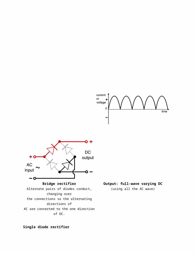
Bridge rectifierAlternate pairs of diodes conduct,
changing overthe connections so the alternating
directions ofAC are converted to the one direction
of DC.
Output: full-wave varying DC(using all the AC wave)
Single diode rectifier

A single diode can be used as a rectifier but this produces half-wavevarying DC which has gaps when the AC is negative. It is hard tosmooth this sufficiently well to supply electronic circuits unlessthey require a very small current so the smoothing capacitor does notsignificantly discharge during the gaps. Please see the Diodes pagefor some examples of rectifier diodes.
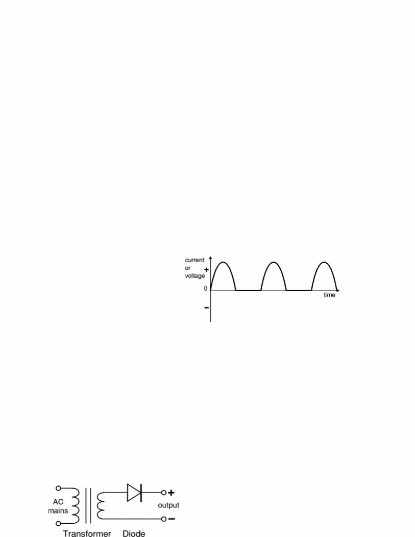
Single diode rectifier Output: half-wave varying DC(using only half the AC wave)
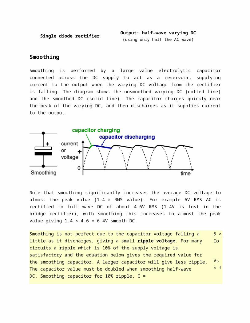
Smoothing
Smoothing is performed by a large value electrolytic capacitorconnected across the DC supply to act as a reservoir, supplyingcurrent to the output when the varying DC voltage from the rectifieris falling. The diagram shows the unsmoothed varying DC (dotted line)and the smoothed DC (solid line). The capacitor charges quickly nearthe peak of the varying DC, and then discharges as it supplies currentto the output.
Note that smoothing significantly increases the average DC voltage toalmost the peak value (1.4 × RMS value). For example 6V RMS AC isrectified to full wave DC of about 4.6V RMS (1.4V is lost in thebridge rectifier), with smoothing this increases to almost the peakvalue giving 1.4 × 4.6 = 6.4V smooth DC.
Smoothing is not perfect due to the capacitor voltage falling a little as it discharges, giving a small ripple voltage. For many circuits a ripple which is 10% of the supply voltage is satisfactory and the equation below gives the required value for the smoothing capacitor. A larger capacitor will give less ripple. The capacitor value must be doubled when smoothing half-wave DC. Smoothing capacitor for 10% ripple, C =
5 ×Io
Vs × f
C = smoothing capacitance in farads (F)Io = output current from the supply in amps (A)Vs = supply voltage in volts (V), this is the peak value of the unsmoothed DCf = frequency of the AC supply in hertz (Hz), 50Hz in the UK
Regulator
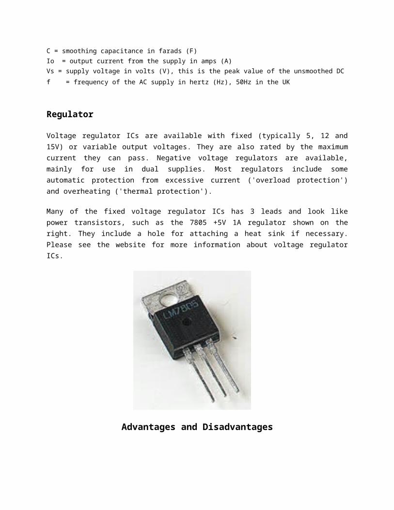
Voltage regulator ICs are available with fixed (typically 5, 12 and15V) or variable output voltages. They are also rated by the maximumcurrent they can pass. Negative voltage regulators are available,mainly for use in dual supplies. Most regulators include someautomatic protection from excessive current ('overload protection')and overheating ('thermal protection').
Many of the fixed voltage regulator ICs has 3 leads and look likepower transistors, such as the 7805 +5V 1A regulator shown on theright. They include a hole for attaching a heat sink if necessary.Please see the website for more information about voltage regulatorICs.
Advantages and Disadvantages
REFERENCES
REFERENCES
[1] Dogan Ibrahim, “Microcontroller Based temperature andhumidityMonitoring and Control”, Elsevier Science & Technology Books,pp 1-7, pp 129-144, September 2002.
[2] Atmel Corporation, “8-bit Microcontroller with 8K Bytes In-SystemProgrammable Flash”, pp 1- 6, 109-137, 245-260, September 2007.
[3] National Semiconductor Corporation, “LM34 Precision Fahrenheittemperature and humiditySensors”, pp 1- 6, November 2000.
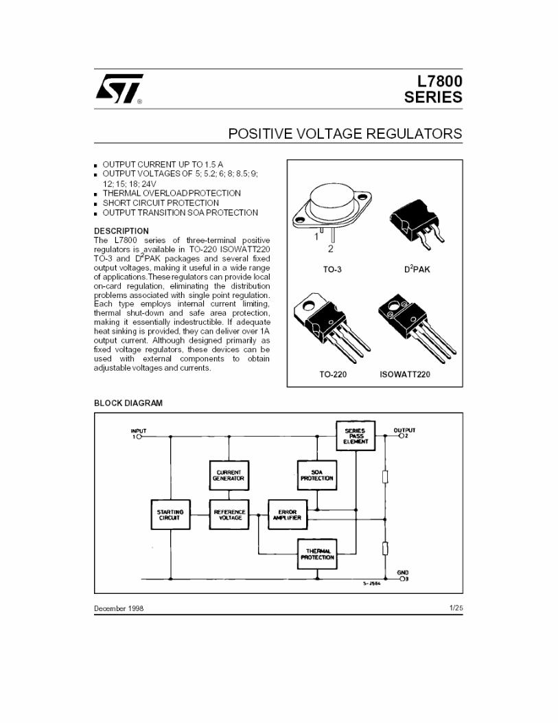
[4] STMicroelectronics, “L78xxC-L78xxC Positive voltage regulators”,pp 1-7, August 2007.
[5] HITACHI, “HD44780U Dot Matrix Liquid Crystal DisplayController/Driver”, pp 1-9, pp 22-29, 1998.
[6] Fairchild Semiconductor, “2N7000 N-Channel Enhancement Mode FieldEffect Transistor”, November 1995.
[7] Microchip, “Brushless DC (BLDC) Motor Fundamentals”, pp 1-18, July2003.
[8] T.C.Lun, “Microcontroller for Variable Speed BLDC Fan ControlSystem”, Freescale Semiconductor.
[9] Michael Barr, “Introduction to Pulse Width Modulation (PWM)”, July2003, Retrieved on November 8, 2010 From the World Wide Web:http://www.oreillynet.com/pub/a/network/synd/2003/07/02/pwm.html?page=last&x-maxdepth=0
[10] Rodney H.G. Tan, Y.H. Goh, Y.Q. Wong and V.H.Mok, “EnergyEfficient Cooling Fan for PC Chassis”, IEEE conference on Innovative
Technologies in Intelligent Systems and Industrial Applications, July2009
[11] STMicroelectronics, “AN2680 Application Note: Fan speedcontroller based on STDS75 or STLM75 digital temperature andhumiditysensor and ST72651AR6 MCU”, February 2008.
[12] Mike Robbins, “Motors and Microcontrollers 101”, NerdKits,Retrieved on October 8, 2010 From the World Wide Web:http://www.nerdkits.com/videos/motors_and_microcontrollers_101/
[13] Sourceforge.net, “WINAVR”, Retrieved on November 10, 2010 Fromthe World Wide Web:http://winavr.sourceforge.net/
[14] Muhammad Sadiq Bin Sahari, “Programmable Switching Power Supply”,pp 19-24, May 2009.
[15] Eric B. Weddington, “WinAVR User Manual – 20050214”, February2005, Retrieved on November 10, 2010 From the World Wide Web:http://winavr.sourceforge.net/WinAVR-user-manual.html
DATA SHEETS