revolutio - nasa technical reports
TRANSCRIPT
Join the Soluti I
n
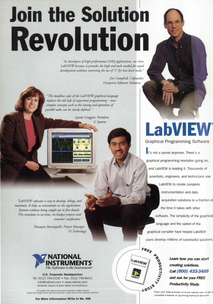
Revolutio /ts rkvekJp= of higb-pajormnnu DAQ applications, wt! chose
Lab VIEW buause it provitks the high-md wofs nmkd for rapid tkvekJpmmt without rtStricting the use orC'for kJw-kutl needs. n
Jim Campbe/~ Cofoundn; Viewpoint oftwart Solutions
"The dataflow styk of the Lab VIEW graphical umguAge replaces the old styk ofsequmtial programming- now, compkx COllUpts fJ/ch as the timing and operation of paraLkl tasks can be ckarLy defined. n
"Lab VIEW software is easy to rkvekJp, tkbug, arui maintain. It helps us concmtrau on the application
featurtS without being caught up in fine tktaifs. This translntes to on-time, on-budget projl'cts and
customer satisfaction. n
Niranjan Ravulnpalli, Project Managa VI uchno/Qgy
LabVI Graphical Programming Software
I t's not a secret anymore. There's a
graphical programming revolution going on,
and LabVIEW is leading it. Thousands of
scientists, engineers, and technicians use
LabVIEW to create complete
instrumentation and data
acquisition solutions in a fraction of
the time it takes with other
software. The simplicity of the graphical
language and the speed of the
graphical compiler have helped LabVIEW
users develop millions of successful solutions.
FIl~~
NATIONAL INSTRUMENTSlI
The Software is the I/lstnlnle/l~
U.S. Corporate Headquarters Tel: (512) 79W100 • Fax: (512) 7948411
[email protected] • www.natinst.com Wor1dWIde netwofl< of direct offices and distributors.
c ~ 1997 NabcnIIInI&nmIIntS Corpor;s.ot M ,... I8SI!!ned.
Procb::IInII~""" failed .. traiernIrkI 01 traDe: names at dlew fIISP8dNe~
For More Information Write In No. 600
A
"'0 C C! n "'f ... ~ ~
Leam how you can start
creating solutions.
Call (BOO) 433-348B
C; ,,(\\\~
and ask for your FREE
Productivity Study.
POint your Web browser to www.natinst.com to get 8 complete schedule of upcomll'lg techr-..cel semlners.
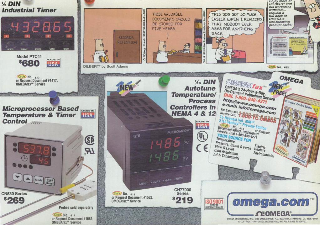
~D'N Industrial Timer
Model PTC41 !Wii'; ij! $680 ijibm
~No .• 12 or Request Document '1417, OMEGAfax'" Service
If
DILBERT- by Scott Adams
Microprocessor Based lira! Temperature & Timer Uibm Control
Probes sold separately
ClrclV No. 814
or Request Document *1682, OMEGAfax'" Service
Tl6E VALUABLE DOCUI"'\E.!IlT5 SIJ.OUlD BE STORED FOR FIVE YEARS
Enjoy more of D/LBERT" and his workplace witticism ... request s full deck of OMEGA's Iste-breaklng product cerdsl
)
~6DIN Autotune
Temperature/ Process
Controllers in NEMA4& 12
@t1}?J.&~axSM OMEGA's 24-Hour-a_Day On-Demand PUbliShing Servtce DIAL 1.8000114804271 httP~/w""""o"'eg.oco", 8-"'ail: iIJ'O@o",egaocO/JJ
For Sallis and~-aDI_ •• _ • .6l344.'" Service Call: "-BUI -TC-OIWE'Qj( To Request VOl, MMtIIt 21st Cemuryn.. Preview Edition
® (E:
O~ No. ·'e Or Request oC~ment #9983, OMEGAfaX'" Service, Dial 1-800-848_4271 -YOUR SOURCE FOR
Temperature Electric Pressure, Strain & Force Heaters Flow & LeVel EnVironmental Data AcqUISition
PH & Conductivity
OMEGA ENGINEERING. INC •• ONE OMEGA DRIVE, P.O. 80X 4047, STAMFORD, CT. 06907-01147 o COPYRIGHT 1997 OMEGA ENGINEERING. INC. AlL RIGHTS RESERVED
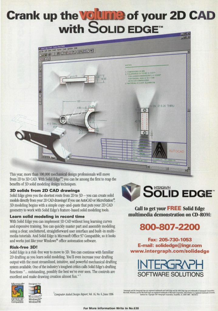
Crank up the of your 2D CA D with SOLID EDGE™
This year, more than 100,000 mechanical design professionals will move from 2D to 3D CAD. With Solid Edge"'~ you can be among the first to reap the benefits of 3D solid modeling design techniques.
3D solids from 2D CAD drawings Solid Edge gives you the shortest route from 20 to 3D - you can create solid models directly from your 2D CAD drawings! If you use AutoCAD or MicroStation~ 3D modeling begins with a simple copy-and-paste that puts your 20 CAD geometry to work with Solid Edge's feature-based solid modeling tools.
Learn solid modeling in record time With Solid Edge you can implement 3D CAD without long learning curves and expensive training. You can quickly master part and assembly modeling using a clear, uncluttered, straightforward user interface and built-in multimedia tutorials. And Solid Edge is Microsoft Office 97 Compatible, so it looks and works just like your Windows® office automation software.
Risk-free 3D! Solid Edge is a risk-free way to move to 3D. You can continue with familiar 2D drafting as you learn solid modeling. You'll even increase your drafting output with the most streamlined, intuitive, and powerful mechanical drafting system available. One of the industry's toughest critics calls Solid Edge's drafting functions" ... outstanding, possibly the best we've ever seen. The controls are excellent and make drawing creation almost fun." I
Microsotr Designed for
~j~~: . Microsoft" WindowsNT" Wind~
IComputer A ided Design Report, Vol. 16, No. 6, Juoe 1996
NOHS
1 OIVEKSlOJtS N wM 2 TOLER,t.HCE JS TO 8E +1. 001-'
rOR UN EAR otwENS ON S. 0,002"" fDA R,t,DlAt..,ANO.,.. 0 1 FOR ~OULAR DIMENSIONS
3 htATEIHAL.ISC.~ST At-UWINUW
2X I2J 635 THRU
SOLiD EDGE~ Call to get your FREE Solid Edge
multimedia demonstration on CD-ROM:
800-807·2200 Fax: 205-730-1053
E-mail: [email protected] www.intergraph.com/solidedge
I NTErG?I\?H SOFlWARE SOLUTIONS
For M ore Information Write In No.630

lD. teSTEQUllY Brand New ~ TQ Instrument Rack
System Fully Assembled. from $1,249
Brand New (SRSj ~ Stanford
Research Systems SR780 2-Ch., 102 kHz FIT Network Signal Analyzer Only S9,950! Save as much as 50% over competing models.
~ SRSDS345 30MHz Function ~nerator $1,595
~ SRS SR630 16 Channel Thennocouple Monitor $1,495
XA TR 'X Brand New ~ Xantrex XFR-Series
Power Supplies 1,200 Watts $1,350ea.
~ Xantrex XHR-Series Power Supplies 1,000 Watts $1,795
ReNewed™ .. Hewlett-Packard
3325A SynthesizedIFunction Generator 111Hz to 21 MHz $2,995
ReNewed ' ~ Hewlett-Packard
8591E/l0/21 Spectrum Analyzer 9kHz to 1.8GHz 14,995
Re e ved™ .. Environmental
Chambers and Ovens Thermotron, Tenney. Envirotronics & More
irektronix /
Brand New .. Tektronix
Real-TIme Digital Scopes TDS 200 Series 60 or 1001Hz, 1 Gs/s from 995
Big Savings.
Get Big Savings on Test Equipment from TestEquity.
Brand New + ReNEWeS Test Equipment Yes, you can save up to 50% on high-quality test equipment; all the top brand names, including Hewlett-Packard, Tektronix and Fluke. And now there's brand new TQ Instrument Racks, brand new Xantrex Power supplies and brand new test equipment from Stanford Research Systems, all priced up to 50% less than competing models! Call or log-on for the catalog that includes the latest arrivals and sale priced specials that will solve your test requirements at the best price.
-
1-800-426-3457 Local or Inti. call (805) 498-9933 • FAX (805) 498-3733 Ready to answer your cOl from 6:30 l1li, Pocific Tillie, Monday 1IJu friday
TestEquity is your authorized stocking distributor of Tektronix oscilloscopes.
http://WWW.testequity.com For More Infonnation Write In No.548
6
TECH BRIEFS
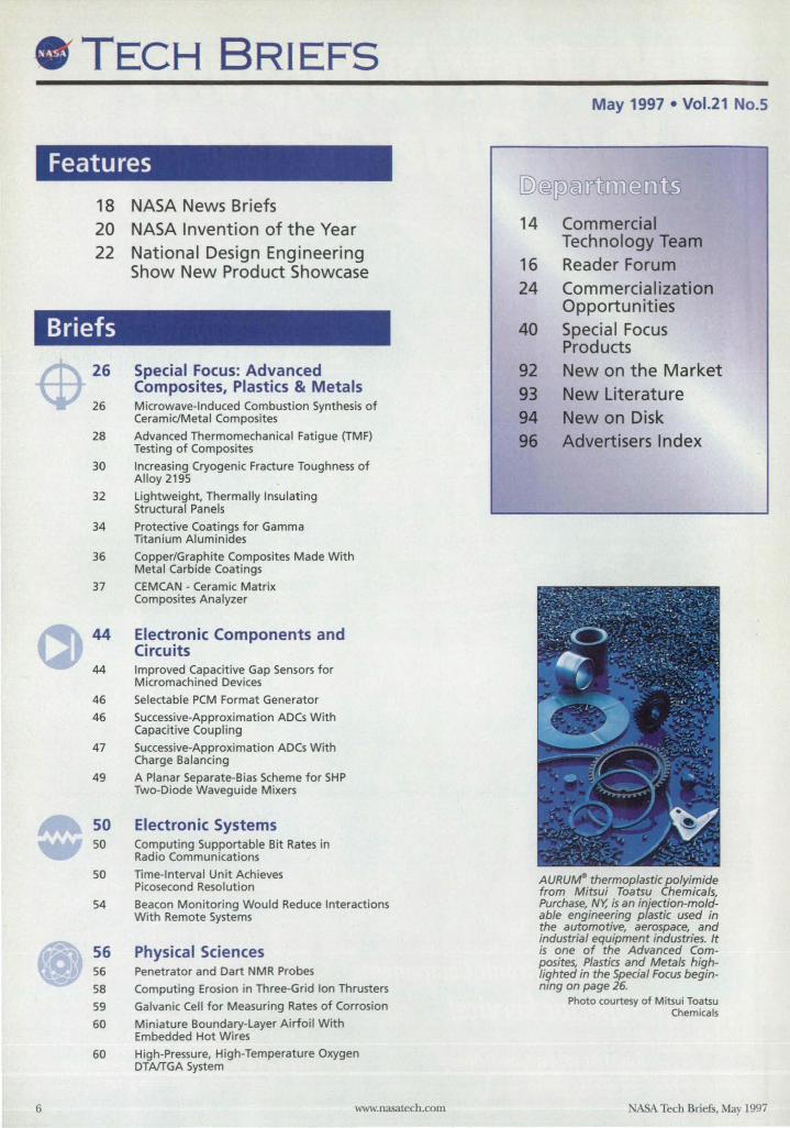
Features
18 NASA News Briefs 20 NASA Invention of the Year 22 National Design Engineering
Show New Product Showcase
Briefs
26 Special Focus: Advanced Composites, Plastics & Metals
26 Microwave-Induced Combustion Synthesis of CeramidMetal Composites
28 Advanced Thermomechanical Fatigue (TMF) Testing of Composites
30 Increasing Cryogenic Fracture Toughness of Alloy 2195
32 Lightweight, Thermally Insulating Structural Panels
34 Protective Coatings for Gamma Titanium Aluminides
36 Copper/Graphite Composites Made With Metal Carbide Coatings
37 CEMCAN - Ceramic Matrix Composites Analyzer
44 Electronic Components and Circuits
44 Improved Capacitive Gap Sensors for Micromachined Devices
46 Selectable PCM Format Generator
46 Successive-Approximation ADCs With Capacitive Coupling
47 Successive-Approximation ADCs With Charge Balancing
49 A Planar Separate-B ias Scheme for SHP Two-Diode Waveguide Mixers
50 Electronic Systems 50 Computing Supportable Bit Rates in
Radio Communications
50 Time-Interval Unit Achieves Picosecond Resolution
54 Beacon Monitoring Would Reduce Interactions With Remote Systems
56 Physical Sciences 56 Penetrator and Dart NMR Probes
58 Computing Erosion in Three-Grid Ion Thrusters
59 Galvanic Cell for Measuring Rates of Corrosion
60 Miniature Boundary-Layer A irfoi l With Embedded Hot W ires
60 High-Pressure, High-Temperature Oxygen DTA/TGA System
www.nasaa.ech.com
May 1997 • Vol.21 No.5
[Q)@[p)&1u.n. II.
I~
14
16 24
40
92 93 94 96
Commercial Technology Team Reader Forum Commercialization Opportunit ies Special Focus Products New on t he Market New Literature New on Disk Advertisers Index
AURU""- thermoplastic polyimide from Mitsui Toatsu Chemicals, Purchase, NY, is an injection-moldable engineering plastic used in the automotive, aerospace, and industrial equipment industries. It is one of the Advanced Composites, Plastics and Metals highlighted in the Special Focus beginning on page 26.
Photo courtesy of M itsui Toatsu Chemica ls
NASA Tech Briefs, May 1997
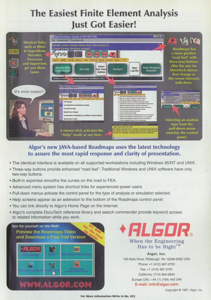
The Easiest Finite Element Analysis Just Got Easier!
Algor's new JAVA-based Roadmaps uses the latest technology to assure the most rapid response and clarity of presentation.
• The identical interface is available on all supported workstations including Windows 95/NT and UNIX.
• Three-way buttons provide enhanced "road feel". Traditional Windows and UNIX software have only two-way buttons.
• Built-in expertise smooths the curves on the road to FEA.
• Advanced menu system has shortcut links for experienced power users.
• Pull-down menus activate the control panel for the type of analysis or simulation selected.
• Help screens appear as an extension to the bottom of the Roadmaps control panel.
• You can link directly to Algor's Home Page on the Internet.
• Algor's complete DocuTech reference library and search commander provide keyword access to related information while you work.
• When the Engineering Has to be Right™
Algor, Inc. 150 Beta Drive, Pittsburgh, PA 15238-2932 USA
Phone: +1 (412) 967-2700
Fax: +1 (412) 967-2781
California: (714) 564-0844
Europe (UK): +44 (1) (784) 442 246
E-mail: [email protected] Copyright © 1997, Algor, Inc.
For More Infonnation Write In No. 625
Contents continued
64 64
65
66 66 66
Materials Growing Small-Diameter, Single-Crystal Oxide Fibers
Si3N.-Based Fiber-Coating Material for Ceramic Composites
Computer Software Improved 3DGRAPE
Software for Efficient Packing of Cargo
70 Mechanics 70 Gripper for Testing Composite-Material Tubes
70
73
74
Screens Would Suppress Flow-Induced Resonances in Cavities
Liquid-Vaporizing Microthrusters .
Technique for Calibration of a Shearographic Instrument
76 Machinery/Automation 76 Enhancement of the NA4 Gear-Vibration
Diagnostic Parameter
78 Automatic Regulation of Material Level in Industrial Blender
78 Vibration-Isolation System for Industrial Blender
79 Apparatus for Testing Sliding Seals for Hypersonic Engines
81 Manufacturing/Fabrication 81 Sputter Texturing To Prepare Surfaces
for Bonding
82 Fiducial Grids for High-Resolution Beam Lithography
84
84
85
86
88
Mathematics and Information Sciences Software for Managing Multidimensional Data Files
Algorithm for Improving a Mathematical Model
Collar Grids for Computing Flows at Intersections
Software for Transforming Data Formats
This document was prepared under the sponsorsllip of the ational Aeronautics and Space Administration. Neither Associated Business Publications Co., Ltd. nor the United States Government nor any person acting on behalf of the nited tates Government assumes any liability resulting from the use of the information conlained in this document, or warrants that such use ... ill be free from privately owned rights. The U.S. Government does not endorse any commercial product, process, or activity identified in this publication.
Permissions: Authorization to photocopy iteJru for internal or personal use, or the internal or personal use of specific clients, is granted by Associated Business Publications, provided that the flat fee of $3.00 per copy be paid directly to !he Copyright Clearance Center (21 Congress SL, Salem, MA 01970) . For those organizations that have been granted a photocopy license by CCC, a separate system of payment has been arranged. The fee code for users of the Transactional Reporting Service is: ISS 014!>-319X194 $3.00+ .00
89 89
Life Sciences Instrument Measures Populations of Microbes in Water
91 91
91
Books and Reports Analysis of the Defect Structure of B2 FeAI Alloys
VPS Fabrication of Parts to Withstand High Temperatures
Special Supplement
Electronics Tech Briefs Follows page 80 in selected editions only.
On the cover: More than 65,000 attendees and 3,000 exhibitors took part in National Manufacturing Week, held in March. Consisting of three industry shows - the National Design Enflineering Show (NOES), the National Industrtal Automation Show, and the National Plant Engineering & Management Show - the event marked the introduction of new products, including four series of gearmotors from Bison Gear and Engineering of Downers Grove, IL. A showcase of other new products introduced at the show begins on page 22.
Photo courtesy of Bison Gear and Engineering
NA.SA Ttch 8rnfi, ISSN 014!'>-319X, USPS 75().(170, copyright e 1997 in U.S. is published monthly by Associated Business Publications Co., Ltd., 317 Madison Ave., New York, NY 10017-5391. The copyright information does not include the (U.S. rights to) individual tecb briefs that are upplied by ASA.. Ed.itorial, sales, production, and circulation offices at 317 Madison Ave., ew York, NY 10017-5391. Subscription for non-qualified subscribers in !he U.S., Panama Canal Zone, and Pueno Rico, $75.00 for 1 year; $125 for 2 years; $200.00 for 3 years. Single copies $10.00. Foreign sub criptions one-year U.S. Fund $195.00. Remit by check, draft, postal, expre orders or VISA, MasterCard, and American Express. Other remittances at sender', risk. Address all communications for subscriptions or circulation to NA.SA T«h 8rnfi, 317 Madison Ave., New York, NY looI7-S!\91. Second-class postage paid at New York, NY and additional mailing offices.
8 www.nasatech.com ABA Tech Briefs, May 1997
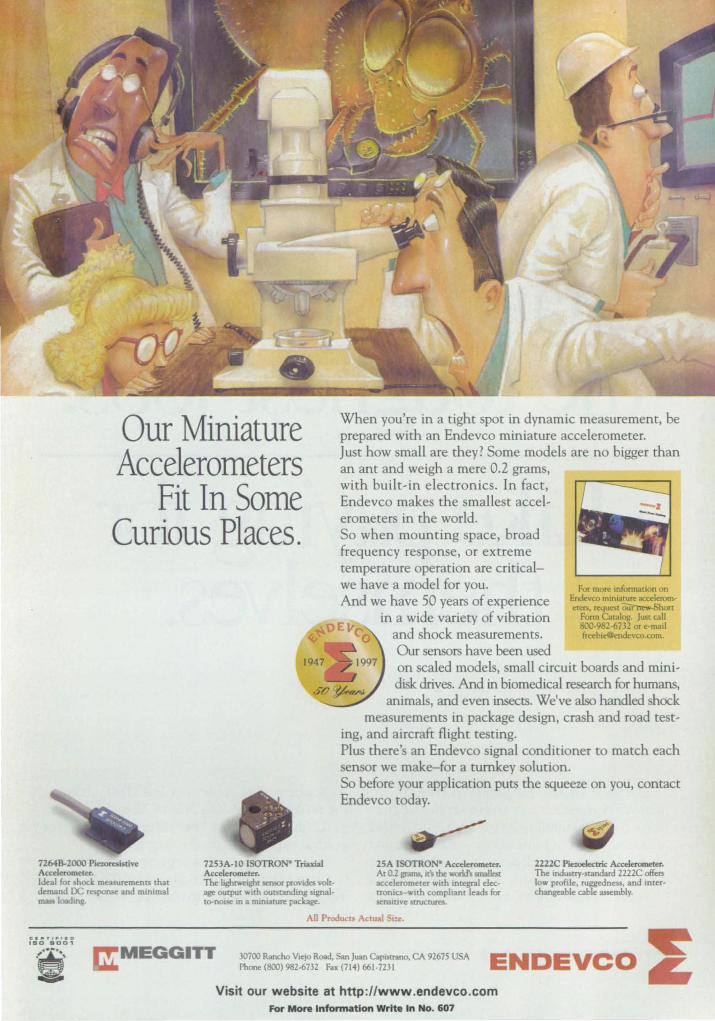
Our Miniature Accelerometers
Fit In Some Curious Places.
72648-2000 Pie:oreoistive Accelerometer. Ideal for shod: measuremem:s thal demand DC res!",,,,,e and minimal ma.o loaJmg.
7253A.IO ISOTRO • Triaxial Accelerometer. The lightweight sensor provides volt· age output WIth outslanding signallO-nol5e m a miniature package.
When you're in a tight spot in dynamic measurement, be prepared with an Endevco miniature accelerometer. Just how small are they? Some models are no bigger than an ant and weigh a mere 0.2 grams, with built-in electronics. In fact, Endevco makes the smallest accelerometers in the world. So when mounting space, broad frequency response, or extreme temperature operation are criticalwe have a model for you. And we have 50 years of experience
in a wide variety of vibration and shock measurements. Our sensors have been used
For more infonnation on Eodevco mlnl.cure accderom~ters, request ~hort
Fonn Ca,oiog. Ju>t call 800·982·6732 or e.mail freeb",@endevco.com.
on scaled models, small circuit boards and minidisk drives. And in biomedical research for humans,
animals, and even insects. We've also handled shock measurements in package design, crash and road test
ing, and aircraft flight testing. Plus there's an Endevco signal conditioner to match each sensor we make-for a turnkey solution. So before your application puts the squeeze on you, contact Endevco today.
25A ISOTRO • Acxeleromerer. At 0.2 grams, rrs Ihr world's smaIIest accelerometer with integral dectronia-wlth compliant leads for stnSlove $UUCQues.
2222C PieweIectric Acc:e:I~. The mdustry.standard 2Z22C offers low profile, ruggedness, and inter· changeable cable assembly.
30700 Rancho Viejo Road, San Juan CaPl$tranO, CA 92675 USA EN DEVCO ~ Phone(800) 982-6732 Fax (714) 661·n31 ..
Visit our website at http://www.endevco.com For More Information Write In No. 607

Vespel® parts can handle some of
the to est jobs. epayingfor
themselves.
Everyone knows that Vespel~ polyimide parts improve performance in severe service applications by withstanding extreme heat, friction, pressure and contamination - with minimal or no lubrication. But now manufacturers who use Vespel parts in general applications are beginning to notice improvements
http://www.dupont.com/enggpolymers/americas
somewhere else: the bottom line. That's because the reliability and long life of Vespel parts can make them the most cost-effective choice for general applications in the long term.
If your applications require parts that can withstand extreme temperatures (-350°F to 550°F), Vespel should be your first choice. Vespel should
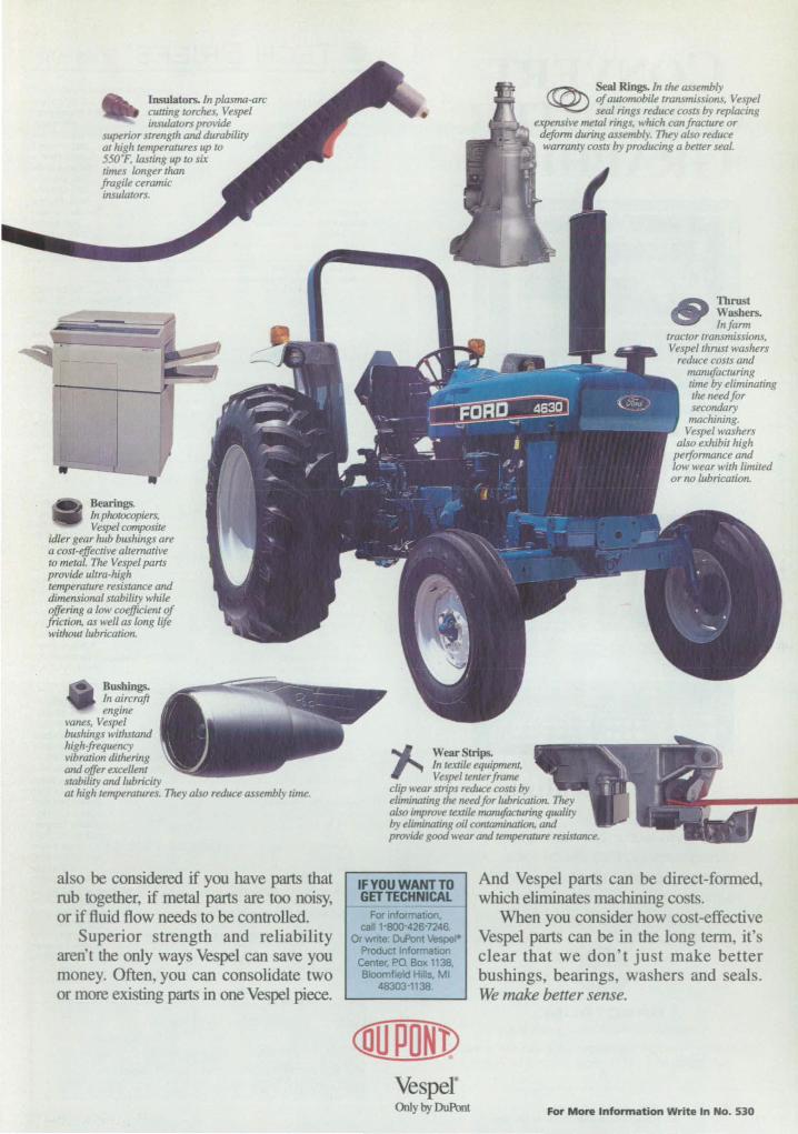
Insulators. In p/asma-arc cutting torches, Vespel insulntors provide
sllperior strength and durability at high temperatures up to 550·F, /arting up to six times longer than fragile ceramic insulators.
Bearings. III photocopiers, Vespel composite
idler gear hub bushings are a cost-effective alternative to melat. The Vespel pans provide Ililra-high lemperature resislance and dimensional slability while offering a low coefficient of friction, as well as long life without lubrication.
Bus~ in aircraft ellgine
vanes, Vespel bushings withstand high-frequency vibration dithering and offer excellent stability and lubricity al high temperatures. They also reduce assembly time.
al 0 be considered if you have parts that rub together, if metal parts are too noisy, or if fluid flow needs to be controlled.
Superior strength and reliability aren't the only ways Vespel can save you money. Often, you can consolidate two or more existing parts in one Vespel piece.
~ Seal Rings. In the assembly of auTomobile transmissions, Vespel seal rings reduce costs by replacing
expensive metal rings, which canfracture or deform d/lring assembly. They also reduce warranty costs by prodllcing a bener seal.
Thrust Washers. Infarm
tractor transmissions, Vespelthrust washers
redl/ce costs and manufacturing time by eliminating lheneedfor secondary machining.
Vespel washers also exhibil high
perjomJance and low wear with limited or no II/bricalion.
~ WearStrips. 111 textile eqllipment, Vespel tenrerJrame
"' 1-1 --:]1 __ ~ ~~ 4
i~ 1 11.,...· .... clip wear strips red/ICe costs by eliminating the need for lubrication. They
• : .. ' 1 also improve textile manufacturing quality by eliminating oil conramiJUJlion, and ',. ,\ , provide good wear and temperature resistance.
IF YOU WANT TO GET TECHNICAL
For informatIon. call 1-800-426-7246.
Or wote: Dll'ont VespeI'" Product InformatJon
Center. PO Box 1138. BloomfIeld HIlls. MI
48303-1138.
C[(JPONl! Vesper Only by DuPont
And Vespel parts can be direct-formed, which eliminates machining co ts.
When you con ider how cost-effective Vespel parts can be in the long term, it s clear that we don't ju t make better bu lings bearings, washers and seals. We make better sense.
For More Infonnation Write In No. 530
CONVERT COMPUTER GRAPHICS
TO VIDEO
.... -----.... ------
RGB/Videolink-VIDEO SCAN CONVERTERS
Up to 1600 x 1280 pixel input Analog output I NTSC, PAL S-Video, CAV
Digital output I CCIR 601 Flicker filter
Autosync Video overlay Pan & Zoom
Simple external connections
SPECTRUM -A visual communications company 'w
950 Marina Village Parkw a y Alameda, CA 94501 Tel: (510) 814-7000 Fax: (510) 814-7026
12 For More Information Write In No. 400
TECH BRIEFS WIlfA ABP
Pubhshed by ....................................................... Assodated Business Publications PresldentlChief Executive Offk er ........................ .. . ...................... BiII Schnirring PublISher ............................................ " ............................. .Joseph T. Pramberger VKe PresIdent of Sales ............................................................................... BiII Hague Ch,ef Editor ............................................................................................ Unda L Bell Editor, Market Focus Editions ................................................................. Robert a arte Productlon Manager ........................................................................... Donna Pituras AdvertISing Coordinator .......................... ........................................... Margery Koen Advertising Coordinator, Market Focus Edit ions ................................. .John Iwanciw Art DIrector .................................................... ....................................... Lois Erlacher Assistant Art Director .............. ............................................................. Gene Aguirre Circulation Director .......................................................................... Martin J. Horan AssIstant Circulallon Director ... .. .............................................................. Lori Ramos Telemarketing Specialist ..................................................... .................. Evelyn Mars Assistant to Reader SelVice Manager ................................................ Damiana Garcia
BRIEFS & SUPPORTING UTERATURE: Wntten and produced for NASA by Advanced Testing Technologies, Inc., Hauppauge, NY 11788 TechnkaVManaging Editor ..................................................................... Ted Selinsky Sr. Technical Analyst .......... ............. ..................... ....... .............. Dr. Larry Grunberger Art Manager ....................................................................................... Eric Starstrom Staff WnterslEditors ... ........................................ Dr. Theron Cole, George Watson,
Howard Fall<, Gail Pyke Graphics ............................................................................................ Robert Simons Editorial & Production .............................. ..... .Joan Schmiemann, Caroline Weaver
Becky D. Bentley
NASA: NASA Tech Briefs are provided by the National Aeronautics and Space Administration, Technology Transfer Division, Washington, DC: Administrator .................................................................................. Daniel S. Goldin Director, Commercial Technology ............ .. ... ............... .... .......... Dr. Robert Norwood Publications Director ..................................................................................... Carl Ray
ASSOOATED BUSINESS PUBUCATIONS 317 Madison Avenue, New York, NY 10017-5391 (212) 490-3999 FAX (212) 986-7864 PresidenVCh,ef Executive Officer ......................................................... Bill Schnirring Executive Vice PresidenVChief Operating Officer ................... Domenic A. Mucchetti Treasurer ............. ...... .... ...... ........ ..... ...................... .......... .... .. .Joseph T. Pramberger CrediVCollection ....... .............. ....... ... ................ ..... ...... ........ .. .............. Felecia Lahey Staff Accountant ...................................................................................... Larry Duze Director of MarketinglNew Business Development ............ ............. George L DeFeis Exhibition Sales Manager ...... ..................... ...................................... .... Wayne Pierce Exhibition Sales Representative ............................................................ Joanna Upton Human Resources Manager. ................ ..... ... ... .............. ... .......... .. .. Lourdes Del Valle MIS Manager ........................................... .. .................... ................... .. Ted Morawski Webmaster ......................................................................................... Albert Sunseri Assistant MIS Manager ....................... ........ ......... ........... ... .. ... ...... ............... Pak Tong Network Administrator ................... ........................ ............. ............... Dmitry Master Office Manager ........................... ...................................................... Sylvia Valentin Mailroom Operations .... .. ..... .. .. ... .............. ......... Alfredo Vasquez, Rose 0 ' Addozio Administrative Assistant .................................................................. Christine Saluzzi
NASA TECH BRIEFS ADVERTISING ACCOUNT EXECUTIVES Headquarters .................................................................................... (212) 490·3999 NY, NJ (Area Code 201), Eastern Canada John Waddell
at (212) 490-3999 PA, DE, NJ (Area Code 908,609), VA, DC, MD, WV ............................. .... Tara Morie
at (610) 640-3118 Eastern MA, NH, ME, RI ......................................... Paul Gillespie at (508) 429·8907
Bill Doucette at (508) 429·9861 Western MA, CT, VT ............ ... ......... .... ............................. ................... George Watts
at (802) 824·5546 Southeast, South Central ................................................................. Robert Hubbard
at (910) 299-77 54 DH, MI, IN, Ky .............. ................... ....... .......... ................ .... .......... .. Louise Clemens
at (216) 397-7477 IL, WI, MD, lA, MN, NO, SO, NE, KS, Central Canada .............................. Paul Tucker
at (773) 296-2040 N. Calif., CO .............................................................................................. BiII Hague
at (408) 730-6800 WA, OR, 10, MT, WY, VT, Western Canada .......................... BiII Madden; Bill Hague
at (206) 858-7575 S. CaIIT., A2, NM, NV (For NASA Tech Briefs) ................. .................... Blake Dahlgren
at (310) 288-0391 S. Calif, A2, NM, NV (For Electronics and Laser Tech Briefs) .................. Richard Ayer
Jane Hayward at (714) 366-9089
TechDeck Postcard Sales ....................................................... .. ................ .Janet Krebs at (773) 296-2040
_ • . .,. ..... Briefs home page: http://www.nasatech.com I1fIllliii$1lDthe editor: ntb_editOmindspring.com
about advertising opportunities:
A5A Tech Briefs, May 1997

Calk---#17: How to buy- t e world's faStest 3D workstation when you thin you can't afford it.
If you think fast graphics automatically means
big bucks, you haven't seen the new DIGITAL
Personal Workstation family. ot only does
this Alpha workstation run Window NT- and
DIGITAL rx· 3D graphics applications
faster than any other workstation, but its price
is unbeatable. For example, in the Bench95
benchmark running ProlE GI EER~ the
DIGITAL Personal Workstation 500a scored
DlGrrAL Penonal Workstation Jor Window. Nl' and
DlGrrAL UNlX
Choice qf 4JJMHz or 500MHz
A/pM 2 t J 64 pro~$o",
ECC SDRAM memory 0-2MJJ LJ cacM
5 PCI aloU (2 PCI, 3 PCUISA)
DIGrDlL PowerSlOrmo 3D Graphics, Act:dPro SuMs, Molrox Milknium Graphics
a record-setting low 56
minutes, 59% faster than
the next fastest competitor
for less than balfthe price.*
Our family of Intel· and
Alpha platfonns gives you
support for thousands of
Win32 applications. Add
to this DIGITAUs wealth of
service and support which
provides seamless inter
operability between your
UNIX and Windows T
operating systems, and you
can't ask for more. For less.
For your nearest reseller,
call i-BOO-DIGITAL, or for more information,
visit www.workstation.digital.com.
For More InfornwltJon Write In No. 610
PWW ·OIGITAL OPws 50012MB cache. 4040T. 21· dlap'.', 2SeMB memory. CIlROM. "-' _"" _ PRICE; $'5,200. SGlIndIgo 2. , ....... RIIIDOO, Sold IMA\CT, ~ "*""Y. 21' dIopIor. CIlROM. "-' _ 89 _PRJCE;_O[)jgola~~II/fI7.DIG/1lIoL_" OIGITALIogo ___ ".-",, ___ •
-r-. ... _"'""'''''- ~Catpor-.. ____ NT .f. regIstered Ir.demart. of U,croaoh \n It1. US. end othar countti .. PRt1IENGINE£R ... -"" _ '" __ ~ Ca!pcnbL UN1X ... -""_ .... u.s. __ ........... __ _ x.<Ooon lid.
NASA Commercial Technology Team
NASA's R&D efforts produce a robust supply of promising technologies with applications in many industries. A key mechanism in identifying commercial applications for this technology is NASA's national network of commercial technology organizations. The network includes ten NASA field centers, six Regional Technology Transfer Centers (RITCs), the National Technology Transfer Center (NTTC), business support organizations, and a full tie-in with the Federal Laboratory Consortium (FLC) for Technology Transfer. Call (206) 683-1005 for the FLC coordinator in your area.
NASA's Technology Sources If you need further information about new technologies presented in NASA Tech Briefs, request the Technical Support Package (TSP) indicated at the end of the brief. If a TSP is not available, the Commercial Technology Office at the NASA field center that sponsored the research can provide you with additional information and, if applicable, refer you to the innovator(s). These centers are the source of all NASA-developed technology.
Ames Research Goddard Space Johnson Space lJIngley Research Mal$hall Space Cenler Flight Cenler Center CenI8r Alght Cenler Selected techno- Selected techno- Selected techno- Selected techno- Selected techno-logical strengths: logical strengths: logical strengths: logical strengths: logical strengths: Fluid Dynamics; Earth and Artificial Aerodynamics; Materials; Ufe Sciences; Planetary Intelligence Flight Systems; Manufacturing; Earth and Science and Human Materials; Nondestructive Atmospheric Missions; LlDAR; Computer Structures; Evaluation; Sciences; CryogeniC Interface; Sensors; Biotechnology; Information, Systems; Ufe Sciences; Measurements; Space
Communications, Tracking; Human Space Information Propulsion;
and Intelligent Telemetry; Flight Operations; Sciences. Controls and
Systems; Command. Avionics; Sensors; Dr. Joseph S. Dynamics;
Human Factors. George Alcom Communications. Heyman Structures;
Bruce Webbon (301) 286-5810 Hank Davis (804) 864-6006 Microgravity
(415) 604-6646 galcom@gsfc. (713) 483-0474 j.s.heyman Processing.
bwebbon@mail. nasa.gov [email protected]. @/arc.nasa.gov Harry Craft
arc.nasa.gov nasagov (205) 544-5419
Jet PropulSion harry.craft@msfc.
Dryden Flight Laboratory Kennedy Space nasa.gov
Research Center Selected techno- Center lewis Research Selected techno- logical strengths: Selected techno- CenIer logical strengths: NearlDeep- logical strengths: Selected techno- Stennis Space
Center Aerodynamics; Space Mission Environmental logical strengths: Selected techno-Aeronautics Engineering; Monitoring; Aeropropulsion; logical strengths: Flight Testing; M icrospacecraft; Sensors; Corrosion Communications; Propulsion Aeropropulsion; Space Protection; Energy
Flight Systems; Communications; Bio-Sclences; Technology; Systems;
Thermal Testing; Information Process Modeling; High TesVMonitoring;
Integrated Systems; Work Planning! Temperature Remote Sensing;
Systems Test Remote Sensing; Control; Materials Nonintrusive
and Validation. Robotics. Meteorology. Research. Instrumentation.
Lee Duke Merle McKenzie Bil/Sheehan Ann Heyward Kirk Sharp
(805) 258-3802 (818) 354-2577 (407) 867-2544 (216) 433-3484 (601) 688-1929
[email protected]. merle.mckenzie@ bil/sheehan-l@ ann.o.heyward@ ksharp@
nasagov ccmail.jp/.nasa.gov ksc.nasa.gov /erc.nasa.gov ssc.nasa.gov
NASA-Sponsored Commercial Technology Organizations These organizations were established to provide rapid access to NASA and other federal R&D and foster collaboration between public and private sector organizations. They also can direct you to the appropriate point of contact within the Federal Laboratory Consortium. To reach the Regional Technology Transfer Center nearest you, call (800) 472-6785.
Dr. David Moran Dr. William Gasko Gary Sera National Technology Center for Technology Mid-Continent Transfer Center Commercialization Technology Transfer (800) 678-6882 Massachusetts Center
Ken Dozier Far-West Technology Transfer Center University of Southem Califomia (213) 743-2353
Technology Park Texas A&M University (508) 870-0042 (409) 845-8762
J. Ronald Thornton Southern Technology Applications Center University of Florida (904) 462-3913
Lani S. Hummel Mid-Atlantic Technology Applications Center University of Pittsburgh (412) 383-2500
Chris Coburn Great Lakes Industrial Technology Transfer Center Battelle Memorial Institute (216) 734-0094
NASA ON-LINE: Go to NASA's Commercial Technology Network (CTN) on the World Wide Web at http://nctn.hq.nasa.gov to search NASA technology resources, find commercialization opportunities, and leam about NASA's national network of programs, organizations, and services dedicated to technology transfer and commercialization.
NASA Program Offices At NASA Headquarters there are seven major program offices that develop and oversee technology projects of potential interest to industry. The street address for these strategic business units is: NASA Headquarters, 300 ESt. SW, Washington, DC 20546.
Gene Pawlik Small Business Innovation Research Program (SBIR) (202) 358-4661 [email protected]. nasa.gov
Dr. Robert Norwood Office of Space Access and Technology (Code X) (202) 358-2320 [email protected]. nasa.gov
Philip Hodge Office of Space Flight (Code M) (202) 358-1417 [email protected]. nasa.gov
Gerald Johnson Office of Aeronautics (Code R) (202) 358-4711 gjohnson@aeromail. hq.nasa.gov
Bill Smith Office of Space Sciences (CodeS) (202) 358-2473 [email protected]. hq.nasa.gov
Bert Hansen Office of Microgravity Science Applications (Code U) (202) 358-1958 [email protected]/msa. hq.nasa.gov
Granville Paules Office of Mission to Planet Earth (Code Y) (202) 358-0706 gpau/[email protected]. nasa.gov
NASAls Business Facilitators NASA has established several organizations whose objectives are to establish joint sponsored research agreements and incubate small start-up companies with significant business promise.
Karen Robbins American Technology Initiative Menlo Park, CA (415) 325-5353
Dr. Jill Fabricant Johnson Technology Commercialization Center Houston, TX (713) 335-1250
John Gee Ames Technology Commercialization Center Sunnyvale, CA (408) 734-4700
Dan Morrison Mississippi Enterprise for Technology Stennis Space Center, MS (800) 746-4699
If you are Interested In information, applications, and services relating to satellite and aerial data for Earth resources, contact: Dr. Stan Morain, Earth Analysis Center, (505) 277-3622. For software developed with NASA funding, contact the Computer Software Management and Information Center (COSMIC) at phone: (706) 542-3265; Fax: (706) 542-4807; E-mail: http://www.cosmic.uga.edu or [email protected].
14 WY .. 'W.nasatech.com ASA Tech Briefs, May 1997
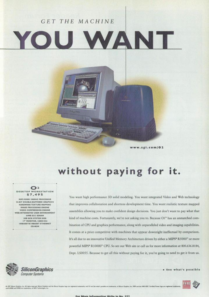
GET THE MACHINE
02 DESKTOP WORKSTATION
$7.495 H1P5 RSOOO .IOMHZ PftOCESSOR
12kBIT DOUBLE· 8UfFERED GRAPHICS
HARDWARE TEXTUAl: HAPPING
IMAGE PROCESSING ENGINE
VIDEO COMPRESSION ENGINE
~ W Ea· IHTEGRATED USER ENViRONMENT . "'HB ECC SORAH
1GB SCSl SYSTEM DISK. U- HONITOR. 'UOXI014
I OOBASETXlI GaMET ET"HER.NET
en-ROM
www.s gt. c o m/ 0 2
withou t paying for it.
You want higb performance 3D solid modeling. You want integrated Video and Web technology
tbat improves collaboration and shortens development time. You want realistic texture mapped
assemblies allowing you to make confident design decisions. You just don't want to pay wbat that
kind of machine costs. Fortunately, we're not asking you to. Because 02~ bas an unmatched com-
bination of CPU and graphics performance, along with unparalleled video and imaging capabilities.
It comes at a price competitive with machines that appear downright ineffectual by comparison.
It's all due to an innovative Unified Memory Architecture driven by either a MIPS- R5000~ or more
powerful MIPS- RIOOOO'" CPU. So see our Web site or call us for more information at 800.636.8184,
Dept. LS0055. Because to get all this without paying for it, you're going to need to get it from us.
SiliconGraphics ............................................................................................................................................ See wha t' s po s sibl e
Comp(Jfer Systems
I=nr Mftnl I nfnl"l'l'latinn Writo In Nn -;77
Get your product line in sync with custom OEM timing solutions.
Mime-Version: 1.0
To: jki rk, Senior Engineer
From: mscott y, Systems Engineer
Date: 04/10/97 19:13:54 PM
Subject: HELPI
Our new applications need differ ent timing
solutions: chip sets for our embeddsd boards,
plug-in bus-level modules, network synchroniz
ation instruments. Who does good custom work?
Better yet, is there a single source of supply?
To: mscotty, Systems Engineer
From: jki rk, Senior Engineer
Date: 04/11/97 OB:22:47 AM
Subject: Re: HELP!
You betl Check out Datum's wide range of custom
OEM timing solutions e www.datum.com
Custom OEM Modules from Datum.
16
The value-added approach to synchronization.
Get the facts. Call 1·800-348-0648 for the free application note.
lor nt'orl\' three detude,_ DutUfll lilt ho, treutt:d feu)·
\\"orld tinH: k fn:l)Ul'IH \" \olutioll\ for thl' Ill",t rigorOll\
nlilituf\" lind h:lt.'UHll oppli«(ltioll\ \\"()rld\\"idt,. Todu\". U\
the luryt'\t })f(l\-idt'f of pr('(i\iol1 timiny produ{(\, we offl'r
our lU\hHlll'f\ u \\'('ulth of tt'( hnitul kno\\"!t·dyl' tlnd
fl'\OUnt', to "loin' u hroud 'pel trulll of t'H'rnlu\' prohlt'll1\
4~ Datum Inc T H MA.,TERS () F TIM I
It·j 40" .'iIS 4161 t", 401'; S7R 41(" ""\\'\\'.dnllllll.( (lTll t'-Illllil ... nlt''';(d dlltlllll.l (Ill)
For More Information Write In No. 401
~ __ R_e_a_d_e_r_~_o_r_u_m __ -,I ~ Reader Farum is devoted to the thoughts, concerns, questwns, ;
and comments oj our readers. If you have a comment, a ques- : tion regarding a SPecific technical problem, or an answer to a : question that appeared in a recent issue, send your letter to the I address below. :
In response to a letter by Jeffrey P. Kaylin in the January Reader Forum regarding the use of magnetic hoof protectors for horses, the Albert Roy Davis Research Laboratory in Green Cove Springs, FL has been researching biomagnetics since 1928, and has published its results. Mr. Kaylin may want to read them.
John Forgette [email protected]
Reader Joseph Hunter inquired in the March Reader Forum about a source of image compression software that will run on PCs, based on fractal reduction of the images. Iterated Systems of Norcross, GA (770-840-0029) distributes a package called The Desktop Fractal Design System through Academic Press (AP). This is a quasi-tutorial system, but I'm sure that if he contacted Iterated Systems, they also would have more industrially oriented products. The AP office that handles the tutorial product is located in San Diego.
Howard Mark, PhD The Near Infrared Research Corp.
Suffern, NY
I am looking for precision distance measuring equipment (laser, sound, etc.) with accuracy to 0.002". I would appreciate any suggestions on where to locate such equipment.
Alan Lieberman Techneglas Columbus, OH
In the January Reader Forum, a reader requested help in finding a source of graphite or other light material. I suggest Fibre Glast Developments Corp. of Brookville, OH (800-214-8571). I have used them for many years in my fiberglass projects. They offer fiberglass, epoxies, gel coats, and carbon fiber for purchase in small quantities, as well as videotapes, books, and classes for working in various media.
Rick Markowski Advanced Assembly Automation
Dayton,OH
Send your letters to the Editor at: Reader Forum, NASA Tech Briefs, 317 Madison Ave., Ste. 1900, New York, NY 10017. Fax: 212-986-7864; E-mail: [email protected] Please include your name, company (if applicable) , address, and phone number or e-mail address.
NASA Tech Briefs, May 1997
I
The MATH
~
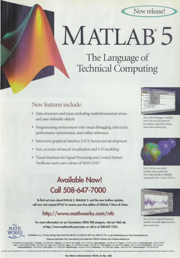
New release!
AT LA B®5 The Language of
Technical COll1puting
New features include: • Data structures and types, including multidimensional arrays
and user-definable objects
• Programming environment with visual debugging, interactive performance optimization, and online references
• Interactive graphical interface (GUI) layout and development
• Fast, accurate advanced visualization and 3-D modeling
• Visual interfaces for Signal Processing and Control System Toolboxes and a new release of SIMULINK·
Available Now! Call 508-647-7000
., find out more about MAnAB 5, SIMUUNK 2, and the new toolbox updates, cD! now and request KP167 10 receive your free edition of MA7IAB 5 News & Noles.
hHp:/ /www.mathworks.com/nlb For more infonnation on our Ccnnection.s CSNVAR progam, visit our Web site
at http://www~.<<IIfI/oem, or c;cj us at 508-047-72S3.
New editor/debugger simplifies MAI1AB code development for alia lysis, algorithm design. and system prototyping.
MATLAB lets you model complex data graphically. Here, Iighri1Ig effects highlight topography data. Source: NOAA.
New GUlS;1I ignal Processing Toolbox 4.0 make signal QIUlIysis
faster alld easier.
lhtWWarb. R. . 24 P!iII PIll Way, IIaIU, lIAOI760-ISOO USA o lei: (508)647·7000 o lax: (508)647.7101 0 .-iIIu@maII .... k>.aa 0 bHp;//~
~ appIII1IIiIies: bnp://wwJlllllbworts.mmnewjabUlml oll/JW in £dumIioR: http-j/~
The MaIhW<IIos Is repraseriId it AusIraIlI: + 61·2-9922-6311 • Benelux: + 31-0182-53-7&14 • SIl!ZiI: + 5S-11-816-3144 ' Czech Repo.dc: + 42·2-6&-44-114' _ + 01·33-41·14-61·14 ' GannMly/Aullrla: + 49-241-410750 IndII: + 91-8G-S-549338 ' iIrIII: + !f12.3.661-6151 • bIy: +39-11-2~ • Jopar. + 81~10 ' I<mI: + 82·2-556-1257 • Now l.eIIIand: + 64-7-0-9102 ' PoIInd: + 48-12·11-33-48 ' ScIndnaYfa: + -463-15-30-22 ~ + 65-&12-4222. SouIII Afrka: + 21·11~· Spoh'Por1ugaI:. ~15-4!Hl4' SwiIzartIIld: + 41-31.Q2-0288 • TaIwen: + aa&-2-601-31B1' Unfted KJngdom: + 44-1223-423-200
01991 by The MalIIWoriaJ. Inc>. All Righls _ . MATlAB and SIMUUNK are registered tredernar1cs of The MaIhWor1<s, Inc. Other prodods or bmnd names are trademarks or registered trademarks oflhel, respective _.
fot' More Information Write In No. 660
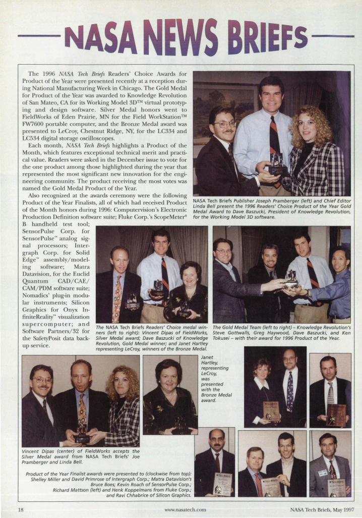
NA A The 1996 1tSA Tech Briefs Readers' Choice Award for
Product of the Year were pre ented recently at a reception during ational Manufacturing Week in Chicago. The Gold Medal for Product of the Year was awarded to Knowledge Revolution of an Mateo, CA for its Working Model 3DTM virtual prototyping and de ign oftware. ilver Medal honors went to FieldWorks of Eden Prairie, M for the Field WorkStation ™ FW7600 portable computer, and the Bronze Medal award was pre ented to Le roy, Che tnut Ridge, NY, for the LC334 and LC534 digital storage oscilloscope.
Each month, 1tSA Tech Briefs highlights a Product of the Month, which features exceptional technical merit and practical value. Readers were asked in the December is ue to vote for the one product among those highlight d during the year that repre ented the most ignificant new innovation for the engineering community. The product receiving the most vote was named the Gold Medal Product of the Year.
AI 0 recognized at the awards ceremony were the following Product of the Year Finalists, all of which had received Product of the Month honors during 1996: Computervision's Electronic Production Definition software suite; Fluke Corp.'s B handheld test tool;
ensorPulse Corp. for Sen orPul e~ analog ignal processors; Intergraph Corp. for olid Edge~ as embly/modeling software; Matra Datavision, for the Euclid Quantum CAD/ CAE/ CAM/ PDM oftware suite;
REFS
omadics' plug-in modular instruments; Silicon Graphics for Onyx InfiniteReality~ vi ualization supercomputer; and Software Partners/ 32 for the SafetyPosit data back-
The NASA Tech Briefs Readers' Choice medal winners (left to right): Vincent Dipas of FieldWorks, Silver Medal award; Dave Baszucki of Knowledge Revolution, Gold Medal winner; and Janet Hartley representing LeCroy, winners of the Bronze Medal.
The Gold Medal Team (left to right) - Knowledge Revolution's Steve Gottwalls, Greg Haywood, Dave Baszucki, and Ken Tokusei - with their award for 1996 Product of the Year.
up service.
Vincent Dipas (center) of FieldWorks accepts the Silver Medal award from NASA Tech Briefs' Joe Pramberger and Linda Bell.
Product of the Year Finalist awards were presented to (clockwise from top): Shelley Miller and David Primrose of Intergraph Corp.; Matra Datavision's
Bruce Boes; Kevin Roach of SensorPulse Corp.; Richard Mattson (left) and Henk Koppelmans from Fluke Corp.;
and Ravi Chhabrice of Silicon Graphics.
Janet Hartley, representing LeCroy, was presented with the Bronze Medal award.
18 www.nasat.ech.com ASA Tech Briefs, May 1997
The ext Generation Internet ( GI) initiative could, by 2002, result in information flowing 1,000,000 time faster than today's home computer modems and 1,000 times faster than a standard Tl bu iness computer line. NASA's Ame Research Center was named lead institution for NASA's 30 million portion of the three-year, 300 million federal project to develop the NGI. NASA has teamed with the ational Science Foundation, the Defense Advanced Research Projects Agency, the Department of Energy, the National Institutes of Health, and the adonal Institute of Standards and Technology to conduct R&D that could interconnect core sites with high-speed lines late this year.
According to Christine Falsetti, NGI project manager at NASA Ames, the GI initially will be a national network, "but we are looking for international partners to meet our global needs. Technical advances wiU spin off from NGI, and industry will put improvements into the old In ternet to make it work better and faster." The project will include connecting computer networks of regional core organizations. For example, the federal government will hook up about 100 universities, research labs, and other institutions at 100 times the present speed. NASA has five sites - Ames, Goddard Space Flight Center, Langley Research Center, Lewis Research Center, and Jet Propulsion Laboratory - connected at a speed of 155 Mb that will soon be COD
verted to 622 Mh. . Falsetti expects medical use of NGI to
be significant. "You'U go to your local doctor, and he will be able to consult with specialists across the globe. That means you can get access to the best medical expertise in the world." he believes that the NGI will enable new Internet applications, such as viewing high-quality video programs on demand.
For more information, contact John Bluck of NA :As Ames Researr:h Center at 415-604-9000, or visit th~ Ames Public Affairs h{)mt page at: http://ccfarc.nasa.gov/dx.
The Computer Software Management and Information Center (COSMIC) at the University of Georgia has signed a three-year Space Act Agreement with ASA LO distribute ASA's software technology to private industry. As a research division of the University of Georgia, COSMIC has worked with
ASA (or the past 31 years to transfer ASA software to the public.
NASA Tech Briefs, May 1997
"I think COSMIC is the first and, currently, the only technology transfer entity that operates independent of external financial support," explained Tim Peacock, COSMIC Director. COSMIC markets ASA programs that have Significant technology and commercial potential. COSMIC checks each program's operation to ensure that it gives accurate re ults. It also supplies supporting documentation to help program users. The majority of COSMIC's software packages include full source code for limitless re-use of programs.
FOT 1n01'e infonnation, contact Tim Peacock of COSMIC at 706-542-3265; e-mail: [email protected]. uga. rou.
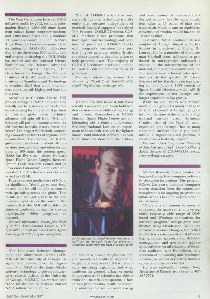
You won't be able LO see it, but ASA scientists may soon give household windows a new look - while saving energy and money. Researchers at NASA's Marshall Space Flight Center are collaborating with scientists at Lawrence Berkeley National Lab on an experiment in space witll Aerogel, the lighte t known solid material. Aerogel has only three times the density of air; a block
NASA scientist Dr. David Noever watches as a half-inch of Aerogel insulation protects a chocolate candy from the heat of a blow torch.
the size of a human weighs les than one pound, yet is able to support the weight of a compact car. It has tremendous insulating capability, and when made on the ground, is hazy or smoky in appearance. If scientists are able to make the material transparent, a ho t of new products may result for insulating windows that will conserve energy
www.nasarech.com
and save money. A one-inch thkk Aerogel window has the same insulation value as 15 panes of glass and trapped air, which means an equivalent conventional window would have to be 10 inches thick.
Last April, ASA produced 16 test sample of Aerogel aboard a Starfire Rocket in a ub-orbital flight. Dr. Laurent Sibille, a member of the threeman Marshall team, said samples produced in microgravity indicated a change in the microstructure of the material, compared to ground sample. The results were achieved after seven minutes of low gravity. Dr. David
oever said his Marshall team is preparing for the January 1998 launch of Space Shuttle Discovery, which will fly the experiment to test Aerogel with longer exposure to low gravity.
While no one knows why Aerogel made on the ground is smoky instead of clear, it is known that Aerogel is a good insulator because of the material's large internal surface area. Raymond Cronise, also of the Marshall team, explained that Aerogel "has so many sides and surfaces that if you could unfold a sugar-(;ube-sized portion, it could cover a basketball court."
FOT more information, contact Steve Roy of Marshall SPace Flight Center's Office of Media Services at 205-544-4159; e-mail: steve. [email protected].
NASA's Kennedy Space Center has begun offering free computer software to education institutions. The program follows last year's one-time computer system donation from the center, and complements an ongoing program that allows schools to claim surplus computer hardware.
"There is a continuous turnover of software at the space center and we regularly receive a wide range of DOSbased and Windows applications for our loan program,~ said program coordinator Doug Hendriksen. While the oftware inventory changes, the center
usually has a selection of word processing, graphics, spreadsheets, database management, and pecialized application software for all educational levels. Also available, said Hendriksen, is a election of networking and Macintosh
software, as well as keyboards, mouses, cables, and other accessorie .
FOT mOTe information, rontact Doug Hendriksen ofKermedy Space Center at 407-867-2551.
19
NASAls Government
Invention the Year
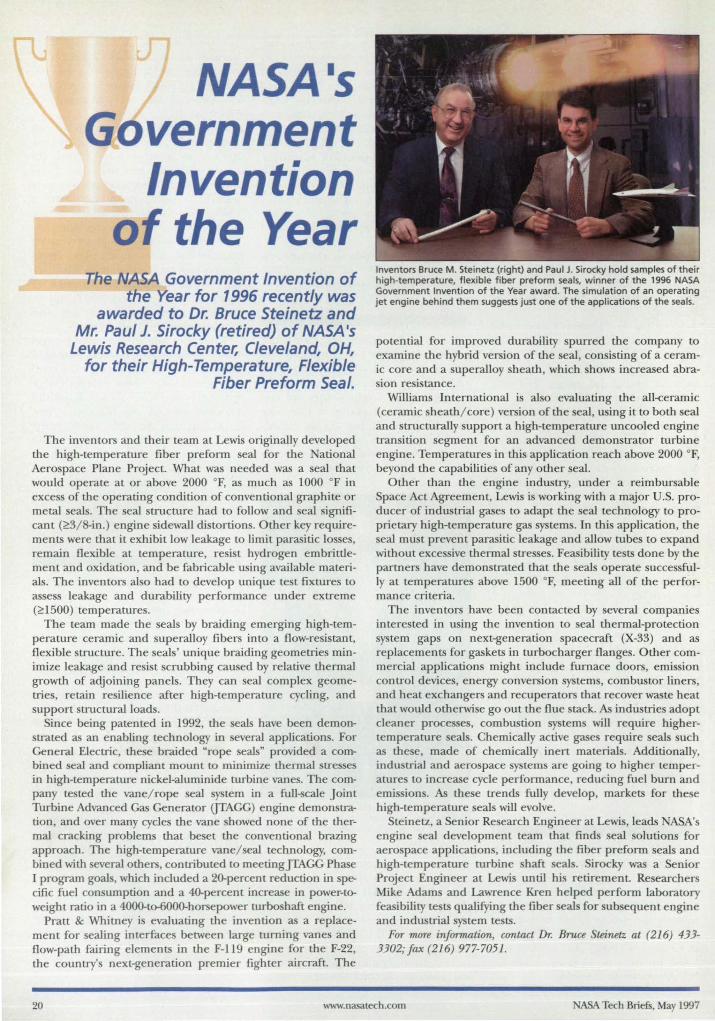
The NASA Government Invention of the Year for 1996 recently was
awarded to Dr. Bruce Steinetz and Mr. Paul J. Sirocky (retired) of NASA's
Lewis Research Center, Cleveland, OH, for their High-Temperature, Flexible
Fiber Preform Seal.
The inventors and their team at Lewis originally developed the high-temperature fiber preform eal for the ational Aerospace Plane Project. What was needed was a seal that would operate at or above 2000 OF, as much as 1000 OF in excess of the operating condition of conventional graphite or metal seal. The eal tructure had to follow and seal ignificant (~3/8-in.) engine sidewall di tortion . Other key requirements were that it exhibit low leakage to limit parasitic losses, remain flexible at temperature, resist hydrogen embrittlement and oxidation, and be fabricable using available materials. The inventors also had to develop unique te t fixtures to as ess leakage and durability performance under extreme (~1500) temperature.
The team made the seals by braiding emerging high-temperature ceramic and uperalloy fibers into a flow-resistant, flexible structure. The seals' unique braiding geometries minimize leakage and resist scrubbing caused by relative thermal growth of adjoining panel . They can seal complex geometrie, retain re ilience after high-temperature cycling, and support structural loads.
ince being patented in 1992, the eal have been demonstrated as an enabling technology in everal applications. For General Electric, these braided "rope eal" provided a combined eal and compliant mount to minimize thermal stresses in high-temperature nickel-aluminide turbine vanes. The company tested the vane/rope eal system in a full~cale Joint Turbine Advanced Gas Generator UTAGG) engine demon tration, and over many cycles the vane howed none of the thermal cracking problem that beset the conventional brazing approach. The high-temperature vane/ eal technology, combined with several others, contributed to meetingJTAGG Phase I program goal, which included a 20-percent reduction in specific fuel consumption and a 4O-percent increase in power-toweight ratio in a 4000-to-6000-horsepower turbo haft engine.
Pratt & Whitney is evaluating the invention as a replacement for ealing interfaces between large turning vanes and flow-path fairing elements in the F-1l9 engine for the F-22, the country's next-generation premier fighter aircraft. The
Inventors Bruce M. Steinetz (right) and Paul J. Sirocky hold samples of their high-temperature, flexible fiber preform seals, winner of the 1996 NASA Government Invention of the Year award. The simulation of an operating jet engine behind them suggests just one of the applications of the seals.
potential for improved durability purred the company to examine the hybrid version of the eal, consisting of a ceramic core and a superalloy heath, which how increased abra-ion resi tance.
William International is al 0 evaluating the all-ceramic (ceramic heath/core) version of the eal, u ing it to both ea1 and structurally upport a high-temperature uncooled engine transition egment for an advanced demonstrator turbine engine. Temperatures in this application reach above 2000 OF, beyond the capabilitie of any other eal.
Other than the engine industry, under a reimbursable Space Act Agreement, Lewis is working with a major U.S. producer of industrial gases to adapt the eal technology to proprietary high-temperature gas ystems. In thi application, the seal must prevent parasitic leakage and allow tube to expand without exce sive thermal tre es. Feasibility tests done by the partner have demonstrated that the seal operate successfully at temperature above 1500 OF, meeting all of the performance criteria.
The inventors have been contacted by several companies interested in using the invention to seal thermal-protection system gaps on next-generation spacecraft (X-33) and as replacements for gaskets in turbocharger flanges. Other commercial applications might include furnace doors, emi sion control devices, energy conver ion sy tern, combustor liners, and heat exchangers and recuperators that recover waste heat that would otherwise go out the flue stack. As industries adopt cleaner proce e, combustion system will require highertemperature eal. Chemically active gase require seals such as the e, made of chemically inert materials. Additionally, industrial and aerospace sy terns are going to higher temperature to increase cycle performance, reducing fuel burn and emi ion. As the e trend fully develop, markets for these high-temperature seals will evolve.
teinetz, a Senior Re earch Engineer at Lewi ,leads ASA's engine eal development team that finds seal olution for aerospace application , including the fiber preform seal and high-temperature turbine haft seal . Sirocky was a enior Project Engineer at Lewi until his retirement. Researchers Mike Adam and Lawrence Kren helped perform laboratory feasibility tests qualifying the fiber eals for ub equent engine and industrial system tests.
For more information, contact Dr. Bruce Steinelz at (216) 433-3302;Jax (216) 977-7051.
20 www.nasatech.com A5A Tech Briefs, May 1997
Only Bentley's comprehensive mechanical engineering products do it all in a single system. !licroStatioo Modelcr-: Provides all of the
Here's where it all comes together. Now you can design, document information you need for design and manufacturing, and share your ideas all within a fully integrated environment. including assembly management and simulation.
Bendey has assembled a complete offering of mechanical l\JicroStatioo- MasterPieceN
: An intuitive engineering products. Products that cover every aspect of visualization tool for advanced rendering and
mechanical engineering design, streaml.ining every step of your workflow. Bentley's Single Engineering Model helps you move through the product cycle from conceptual design to manufacturing, through simulation, analysis, preproduction, engineering and manufacturing. When you make changes to your design, all components-including documentation-are updated automatically, virtually eliminating errors and omissions.
The Bentley Engineering Back Office'" range of products unites desktop engineering systems with enterprise IT and database systems for information sharing via the Internet. Best of all, our products are scalable to meet the demands of your projectsbringing together best-in-class applications into a single, powerful solution.
Go from concept to final design with Bendey. CaIl 1-800-BE iTLEY for a free demo CD or visit www.bendey.com.
mechanism imulations.
lUicroStation TeamMateN 96: robust workflow nod document management product.
COSMOS~I- DESIGNER II: For fully integrated tructural analysis u in~ state-of-the-art FFE
(Fast Finite Element) analysis technology.
ADA'IS-~IS Meclumisms: For assembly simulation. evaluation of motion paths and calculation of joint forces.
E PRIT~IS~: An integrated range of heet metal d ign and roanufacturin~ produc~.
MoldDe ignN: An innovative product for designing
mold bases for the injection mold industry.
610-458-5000 • 800-BENTLEY - FAX: 610-458-1060 • www.bentley.com MicroStation and ~UcroS",don Modeler are registered trademarks; E~neering Back Office. MasterPIece, ThamMate, MoidIleslgn, Bendeyand the "8" Bentley logo are uadeltlJlIks of Bendey Systems, Inoorpomted. COSMOSIM and FFE are registered trademarks oC SuucrumJ Researcb & Analysis Corp. ESPRlT/MS is •
trademark of DP Technology Corp. ADAMS is. registered trademark oC Mechanical Dynamics, Inc. C 1997 Bendey Systems, Incorporated BENTLEY
National Design · EngilJe7Hij'~t~!£){)!JRroduct Showcase The fol/owing products were introduced at the NatIonal Design Engineering Show.
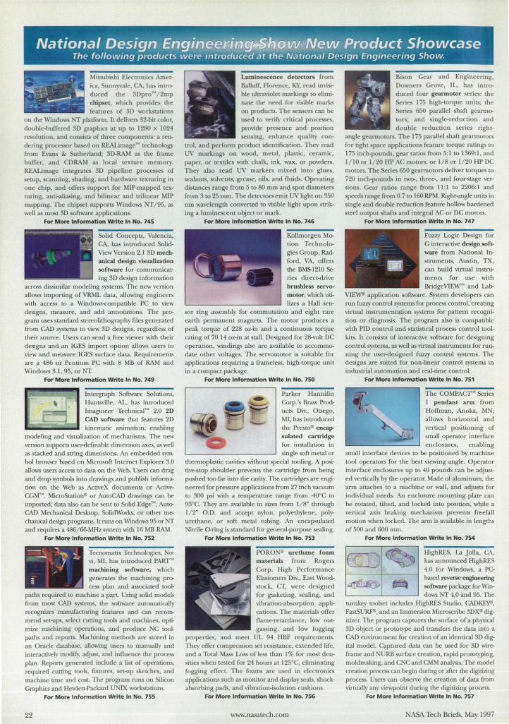
Mitsubishi E1eclTonics America, Sunn ,,'ale, , has inlToduced the 3Dpro"'/2mp chipset, which prO\ides the feature of 3D workstations
on the ""Indo" platform. It delh'ers 32-bit color, double-buffered 3D graphics at up to 12 0 x 1024 resolution, and consi ts of three components: a rendering processor based on R£ALimage'" technology from Evans & utherland; 3D-RAM as the frame buffer, and DRAM as local texture memory. REALimage integrates 3D pipeline processes of setup, scanning, shading, and hardware texturing in one chip, and offers support for MIP-mapped texturing, anti-aliasing, and bilinear and lTilinear "'ill mapping. The chipset supports Windows /95, as well as most 3D software applications.
For More Information Write In No. 745
Solid Concepts, Valencia, CA, has inlToduced SolidView Version 2.1 3D mechanical design visualization software for communicating 3D design information
across dissimilar modeling systems. The new version allows importing of VRML data, allowing engineers with access to a Windows<ompatible PC to view designs, measure, and add annotations. The program uses standard stereolithography files generated from CAD systems to view 3D designs, regardless of their source. Users can send a free viewer with their designs and an IGES import option allows users to view and measure IGES surface data. Requirements are a 486 or Pentium PC with 8 MB of RAM and Windows 3.1, 95, or Nf.
For More Information Write In No. 749
Intergraph Software Solutions, Huntsville, AL. has introduced lmagineer Technical'" 2.0 2D CAD software that features 2D kinematic animation, enabling
modeling and visuali1.ation of mechanisms. The new version supportS user-definable dimension axes, as well as stacked and sITing dimensions. An embedded ~ bol browser based on Microsoft Internet Explorer 3.0 allows users access to data on the Web. Users can drag and drop symbols into drawings and publish inform,.. tion on the Web as ActiveX documents or ActiveCGM'". MicroStationtl or AutoCAD drawings can be imported; data also can be sent to Solid Edge'", AutoCAD Mechanical Desktop, SolidWorks, or other mechanical design programs. It runs on WUldows 95 or Nf and requires a 486/66-MHz system with 16 MB RAM.
For More Information Write In No. 752
Tecnomatix Technologies, Novi, MI, has inlToduced pAJIT"' machining software, which generates the machining process plan and associated tool
paths required to machine a part. Using solid models from most CAD systems, the software automatically recognizes manufacturing (eatures and can recommend set-ups, select cutting tools and machines, optimize machining operations, and produce C toolpaths and reportS. Machining methods are stored in an Oracle database, allowing users to manually and interactively modifY, adjust, and influence the process plan. ReportS generated include a list of operations, required cutting tools, fixtures, set-up sketches, and machine time and COSL The program runs on Silicon Graphics and Hewlett-Packard UNIX workstations.
For More Information Wri te In No. 755
22
Luminescence d etectors from BalIuff, Florence, KY, read imi ible ullTa\iolet markings to eliminate the need for ,isible marks on products. The ensors can be used to verify critical processes, pro\ide presence and position ensing, enhance quality con-
1T01, and perform product identification. They read UV markings on wood, metal, plastic, ceramic, paper, or textiles with cbalk, ink, wax, or powders. They also read markers mixed into glues, sealants, solvents, grease, oils, and fluids. Operating distance range from 5 to 80 rum and spot diameters from 3 to 25 rum. The detectors emit UV light on 350 nm wavelength converted to visible light upon swing a luminescent object or mark.
For More Information Write In No. 746
Kollmorgen Motion Technologie Group, Radford, VA, offers the BMS-1210 Series direct-drive brushless servomotor, which utilizes a Hall sen
sor ring assembly for commutation and eight rare earth permanent magnets. The motor produces a peak torque of 228 oz-in and a continuous torque rating of70.14 oz-in at stall. Designed for 28-volt DC operation, windings also are available to accommodate other voltages. The sel>'omotor is sttitable for applications requiring a frameless, high-torque unit in a compact package.
For More Information Write In No. 750
Parker Hannifin Gorp. 's Brass Products Div., Otsego, MI, has introduced the Presto'" encapsulated cartridge (or installation in single soft metal or
thermoplastic cavities without special tooling. A positive-stop shoulder prevents the cartridge from being pushed too far into the cavity. The cartridges are engineered for pressure applications from 27 inch vacuum to 300 psi with a temperature range from -4{)'C to 93'C. They are available in sizes from 1/8" through 1/2" O.D. and accept nylon, polyethylene, polyurethane, or soft metal tubing. An encapsulated Nitrile O-ring is standard for general-purpose sealing.
For More Information Write In No. 753
foam materials from Rogers Corp. High Performance Elastomers Div., East Woodstock, cr, were designed for gasketing, sealing, and vibration-absorption applications. The materials offer Oame-retardance, low outgassing, and low fogging
properties, and meet UL 94 HBF requirements. They offer com pre ion set resistance, extended life, and a Total Mass Loss of less than I % for most densities when tested for 24 hours at 125'C, eliminating fogging effecL The foams are used in eleclTonics applications such as monitor and display seals, shockabsorbing pads, and vibration-isolation cushions.
For More Information Write In No. 756
www.nasatech.com
Bison Gear and Engineering, Downers Grove, IL, has introduced four gearmotor eries: the
ries 175 high-torque units; the Serie 650 parallel shaft geannotors; and single-reduction and double reduction series right
angle gearmotors. The 175 parallel haft gearrnotors for tight space applications feature torque ratings to 175 inch-pounds, gear ratios from 5:1 to 1369:1 , and 1/10 or 1/20 HP AC motors, or 1/8 or 1/20 HP DC motors. The Series 650 gearmotors deliver torques to 720 inch-pounds in two-, three-, and four-stage versions. Gear ratios range from 11:1 to 2206:1 and peeds range from 0.7 to 160 RPM. Right-angle units in
single and double reduction feature hollow hardened steel output hafts and integral AC or DC motors.
For More Information Write In No. 747
Fuzzy Logic Design for G interactive design software from ational Instruments, Austin , TX, can build virtual instruments for use with BridgeVIEW'" and Lal>
VIEW<!> application software. System developers can run fuzzy conlTol systems for process conlTol, creating virtual instrumentation systems for pattern recognition or diagnosis. The program also is compatible with PID control and statistical proce control toolkits. It consists of interactive software for designing conlTol systems, as well as virtual instruments for run
ning the user-designed fuzzy conlTol systems. The designs are suited for non-linear conlTol systems in industrial automation and real-time control.
For More Information Write In No. 751
The COMPACT'" Series 1 pendant arm from HolTman, Anoka, MN,
allows horizontal and vertical posi tioning of small operator interface enclosures, enabling
small interface devices to be positioned by machine tool operators for the best viewing angle. Operator interface enclosures up to 40 pounds can be adjusted vertically by the operator. Made of aluminum, the arm attaches to a machine or wall, and adjusts for individual needs. An enclosure mounting plate can be rotated, tilted, and locked into position, while a vertical axis braking mechanism prevents freefall motion when locked. The arm is available in lengths of 500 and 600 rnm.
For More Information Write In No. 754
HighRES, La Jolla, GA., has announced HighRES 4.0 for Windows, a PC based reverse engineering software package for Windows IT 4.0 and 95. The
turnkey toolset includes HighRES Studio, CADK£¥I, FastSU~, and an Immersion Microscribe 3DXtI digitizer. The program captures the surface of a physical 3D object or prototype and ITansfers the data into a CAD environment for creation of an identical 3D digital model. Captured data can be used for 3D wir~ frame and URB surface creation, rapid prototyping, moldmaking, and CNC and CMM analysis. The model creation process can begin during or after the digitizing process. Users can ohsel>'e the creation of data from virtually any viewpoint during the digitizing proce
For More Information Write In No. 757
ASA Tech Briefs, May 1997
National Design Engi~~fY.e,w;Product Showcase
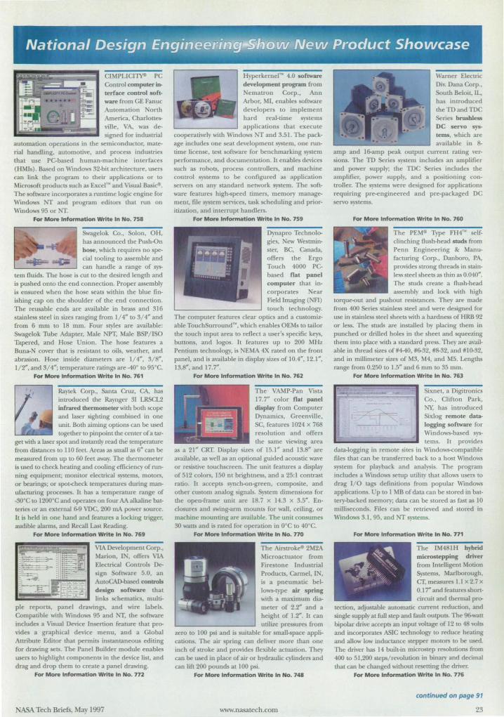
CThfPUCI~ PC Control computer interface conlrol soft· ware from GE Fanuc Automation Nonh America, Charlolles\'ille, VA, was designed for indusuial
automation operations in the semiconductor, material handling, automotive, and process indusuies that use PC-based human·machine interfaces (HMIs). Based on Windows 32-bit arc.hitecture, users can link the program to their applications or LO Microsoft produclS such as Excel'· and Visual Basi~.
The software incorporates a runtime logic engine for Window NT and program editors thaL run on Windows 95 or NT.
For More Information Write In No. 158
Swagelok Co., Solon, OH, has annollnced the Push-On bose, which requires no special tooling to assemble and can handle a range of sys
tem fluids. The bose is Clltto the desired length and is pusbed onto the end connection. Proper assembly is ensured when the hose sealS within the blue finishing cap on the shoulder of the end connection. The reusable ends are available in brass and 316 stainless leel in sizes ranging from 1/ 4" to 3/ 4" and from 6 mm to 18 mm. Four styles are available: Swagelok Tllbe Adapter, Male NPT, Male BSP / ISO Tapered, and Hose Union. The hose features a Buna·N cover that is resistant to oils, weather, and abrasion . Hose inside diameters are 1/4", 3/ S", 1/r, and 3/ 4"; temperature ratings are -40· to 95·C.
For More Information Write In No. 161
Raytek Corp., Santa Cruz, CA, has introduced the Raynger 31 LRSCL2 infrared thermometer with both scope and laser sighting combined in one uniL Both aiming options can be used together to pinpoinl the center of a tar
get ",th a laser spot and instantly read the temperature from distances to 110 feeL Areas as small as 6" can be measured from up to 60 feet away. The thermometer is used to check heating and cooling efficiency of running equipment; monitor elecuical systems, motors, or bearings; or spot<heck temperatures during manufacturing processes. It has a temperature range of ·3O· C to 12OO· C and operates on four AA alkaline batteries or an external 6-9 VDC, 200 rnA power source. it is held in one hand and features a locking uigger, audible alarms, and Recall Last Reading.
For More Information Write In No. 769
VIA Developm~m Corp., ~on, IN, offers VIA Elecuical Controls Design Software 5.0, an AutoQ\D.based conlrols design software lhal links schematics. multi·
pie reports, panel drawings, and wire labels. Compatible with \V'mdows 95 and IT, the software includes a VISual Device Insertion feature that provides a grapbical device menu. and a Global AluibuLe Editor that permilS instantaneous editing for dra .... ing sets. The Panel Builder module enables users LO highlight components in lhe del-ice list., and drag and drop them to create a panel drawing.
For More Information Write In No. nz
NASA Tech Briefs, May 1997
Hyperkemel~ 4.0 software development program from , ematron Corp., Ann Arbor, ~U, enables software developers to implement hard real· time sYSLems applications lhat exeCULe
cooperatively "1lh \\'indows IT and 3.51. The pack· age indlldes one seat developmenl sy tern, one run· time license, test software for benchmarking system performance, and documentation. II enables devices such as robolS, process controllers. and machine control systems to be configured as application servers on an)' standard network system. The soft· ware features high-speed timers, memory management., file system senices, task scheduling and prioritization, and inlerrupt handlers.
For More Information Write In No. 159
Dynapro Technologies, New Westmin· ster, Be, Canada, offers the Ergo Touch 4000 PCbased flat panel computer that in· corporates Near Field Imaging (NFl) touch technology.
The computer features clear optics and a customizable TouchSurronnd"', which enables OEMs to tailor the touch input area [0 reflect a user's specific keys, buttons, and logos. It features lip to 200 MHz Pentium Lechnology, is NEMA 4X rated on the from panel, and is available in display sizes of 1004", 12.1", 13.S", and 17.7".
For More Information Write In No. 162
The VAMP-Pan Vista 17.7" color !lat panel display from Computer Dynamics, Greenville, SC, features 1024 X 768 resolution and offers the same viewing area
as a 21" CRT. Display sizes of 15.1" and 13.S" are available, as well as an optional guided acoustic wave or resistive tOllcbscreen. The uniL features a display of 512 colors, 150 nr brightne ,and a 25:1 contraSt ratio. it accepts Slnch-on-green. composite, and other custom analog signals. ystem dimensions for the open-frame unil are IS.7 x 14.3 x 3.5". Enclosures and s"ing.arm mounts for wall, ceiling, or machine mounting are available. The unil consumes 30 waIlS and is rated for operation in O' C 10 40· C.
For More Information Write In No. no
The AirstrOk ... 2M2A Microactuator from Fireslone I nduslrial ProduclS, Carmel, lN, is a pneumatic bellows-t)'pe air spring with a maximum diameter of 2.2'" and a height of 1.2'". It can utilize pressures from
zero to 100 psi and is suitable for maIl-space appli· cations. The air pring can deliver more than one inch of stroke and prmides flexible actuation. They can be used in place of air or h draulic C)1inders and can lift 200 pounds at 100 psi.
For More Information Write In No. 148
w\\w.nasatech.com
Warner Elecuic Div. Dana Corp., South Beloit., !L, has in troduced the TO and TOC Series brushless DC servo systems, which are a.-ai.lable in S
amp and 16-amp peak OUtpUl current rating versions. The TO Series sysLem includes an amplifier and power supply; the TDC Series includes the ampli6er, power supply, and a positioning controller. The systems were designed for applications requiring pre-engineered and pre-packaged DC ervo systems.
For More Information Write In No. 160
The PEM. Type FH4'" self. clinching flush-head studs from Penn Engineering & Manufacturing Corp., Danboro, PA, provides strong threads in stainless steel sheets as thin as 0.040". The studs create a flush-head assembly and lock with high
Lorque-out and pushout resistances. They are made from 400 Series stainless steel and were designed for use in stainless steel sheets with a hardness of HRB 92 or less. The studs are installed by placing lhem in punched or drilled holes in the sheet and squeezing them into place with a standard press. They are available in thread sizes ofif4.40, #6-32, #S-32, and #10-32, and in millimeter sizes of M3, M4, and MS. Lengths range from 0.250 to 1.5" and 6 mm to 35 mm.
For More Information Write In No. 163
Sixnet., a Digitronics Co. , Clifton Park, NY, has introduced Sixlog remote dala· logging software for Windows·based ''}'S
terns. It provides data-logging in remote sites in Windows<ompatible files that can be transferred back to a hosL Windows system for playback and analysis. The program includes a Windows setup utility that allows users to drag I/O tags definitions from popular Windows applications. Up to 1 ?iB of data can be stored in battery-backed memory; dala can be sLored as fast as 10 milliseconds. Files can be reuieved and slored in Windows 3.1, 95, and NT systems.
For More Information Write In No. 111
The IM-4S1H hybrid microstepping driver from Intelligent }'10oon Systems, Marlborougb. cr. measures 1.1 x 2.7 x 0.1 r and fearures hort· circuiL and tbennaJ pr~
LeCtion, adjustable automatic current reduction, and single supply at full tep and fault outputs. The 9tH.an bipolar drive accepts an input ,'Oltage of 12 to 48 ,'Olts and incorporateS ASIC technology to reduce beating and allow low indnCtance stepper motors to be used. The dri\-er has 14 built-in microsLep resolutions from 400 to 51 ,200 steps/ revolution in binary' and decimal that can be changed "ithout resetting lhe dri~er.
For More Information Write In No. 776
continued on page 91
23
("j Commercialization Opportunities
Lightweight, Thermally Insulating Structural Panels
Successive-~proximation ADCs With Capacitive Coupling
tructural panels have been developed with superior thermal-insulation properties. Compared with earlier panels, these have about 50 percent Ie mass density and 30 percent less thermal conductivity.
Prototype of analog-t<Hligital converter (ADC) circuits have been developed that will be incorporated into advanced video cameras. The e AD contribute to miniaturization and offer other feature .
(See page 32.) (See page 46.)
24
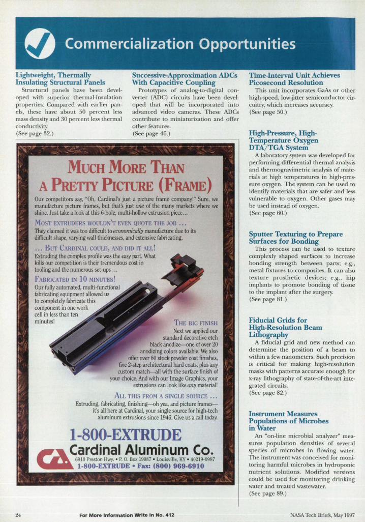
MUCH MORE THAN A PRETIY PICfURE (FRAME)
Our competitors say, "Oh, Cardinal's just a picture frame company!" Sure, we manufacture picture frames, but that's just one of the many markets where we shine. Just take a look at this 6-hole, multi-hollow extrusion piece ...
Mo T EXTRL1)ER WOULD, 'T EvE,' QUOTE THE JOB •.• They claimed it was too difficult to economically manufacture due to its difficult shape, varying wall thicknesses, and extensive fabricating.
.•. BL'T CAROL AL COL'LD, AND DID IT ALL! Extruding the complex profile was the easy part. What kills our competition is their tremendous cost in tooling and the numerous set-ups ...
FABRICATED I 10 ftllNlJTES! Our fully automated, multi-functional fabricating equipment allowed us to completely fabricate this component in one work cell in less than ten minutes! THE BIG FINISH
Next we applied our standard decorative etch
black anodize--one of over 20 anodizing colors available. We also
offer over 60 stock powder coat fmishes, five 2-step architectural hard coats, plus any custom match-all with the surface finish of
your choice. And with our Image Graphics, your extrusions can look like any material!
ALL THIS FROM A SINGLE OURCE •.• Extruding, fabricating, finishing-oh yea, and picture frames
it's all here at Cardinal, your single source for high-tech aluminum extrusions since 1946. Give us a call today.
I-800-EXTRUDE ,,~ ~~~~o!~~~lp.~!~!:':1!~V~'~4~£;7 ~ 1-800-EXTRUDE • Fax: (800) 969-6910
For More Information Write In No. 412
Time-Interval Unit Achieves Picosecond Resolution
Thi unit incorporates GaAs or other high- peed, lowjitter emiconductor circuitry, which increase accuracy. ( ee page 50.)
High-Pressure, HighTemperature Oxygen DTA/ TGA System
A laboratory system was developed for performing differential thermal analysis and thermogravimetric analysis of materials at high temperatures in high-pressure oxygen. The system can be used to identify material that are safer and less vulnerable to oxygen. Other gases may be used instead of oxygen. (See page 60.)
Sputter Texturing to Prepare Surfaces for Bonding
This process can be used to texture complexly shaped surfaces to increase bonding strength between parts; e.g., metal fixtures to composites. It can also texture prosthetic devices; e.g., hip implants to promote bonding of tissue to the implant after the surgery. (See page 81.)
Fiducial Grids for High-Resolution Beam Lithography
A fiducial grid and new method can determine the position of a beam to within a few nanometers. Such precision is critical for making high-resolution masks with patterns accurate enough for x-ray lithography of state-of-the-art integrated circuits. (See page 82. )
Instrument Measures ~opulations of Microbes mWater
An "on-line microbial analyzer" measures population densitie of several specie of microbes in flowing water. The instrument was conceived for monitoring harmful microbes in hydroponic nutrient solutions. Modified versions could be used for monitoring drinking water and treated wastewater. (See page 89. )
ASA Tech Briefs, May 1997
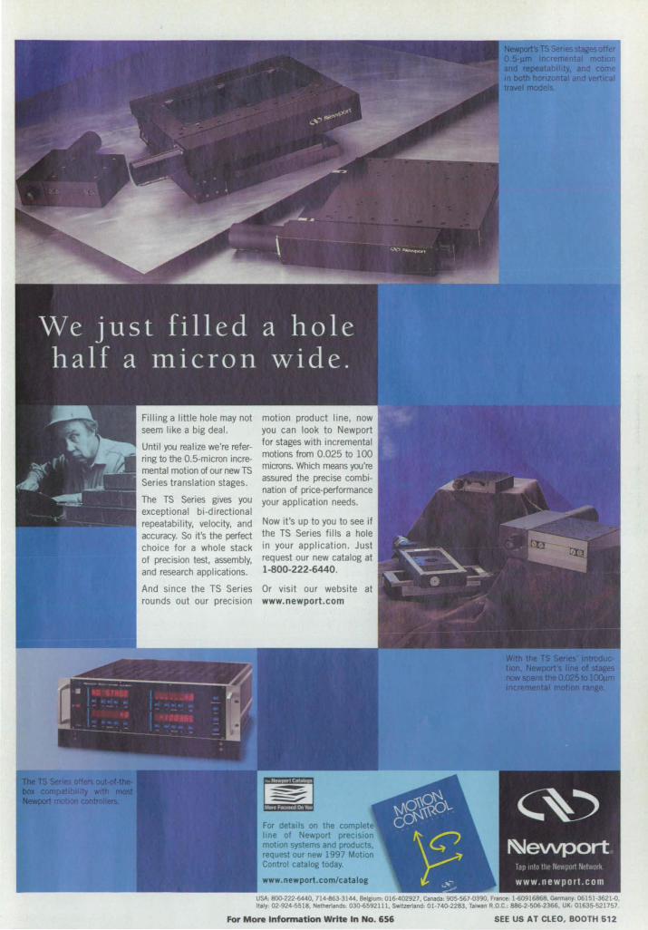
Until you realize we're referring to the O.5-micron incremental motion of our new TS Series translation stages.
The TS Series gives you exceptional bi-directional repeatability, velocity, and accuracy. So it's the perfect choice for a whole stack of precision test, assembly, and research appl ications.
And since the TS Series
motion product line, now you can look to Newport for stages with incremental motions from 0.025 to 100 microns. Which means you're assured the precise combination of price-performance your application needs.
Now it's up to you to see if the TS Series fills a hole in your application. Just request our new catalog at 1-800-222-6440.
Or visit our website rounds out our precision www.newport.com
USA, 800-222-6440. 714-&3·314-4. Belgium, 016-102927. Canada, 905-567.()390, France, 1-60916868. ~ 06151·3621-0, Italy. 02·924-5518, Netherlands, 03Q.6592111, SWltzorland, 01·74()'2283, T."",," R.O.C., 886-2·51)6.2366, UK, 01635-521757.
For More Infonnation Write In No. 656 SEE US AT CLEO, BOOTH 612
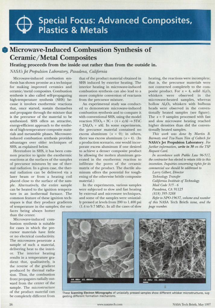
Microwave-Induced Combustion Synthesis of Ceramic/ Metal Composites Heating proceeds from the inside out rather than from the outside in. NASAs Jet Propulsion Laboratory, Pasadena, California
Microwave-induced combustion synthesis has shown promise as a technique for making improved ceramics and ceramic/ metal composites. Combustion synthe is is also called self-propagating high-temperature synthesis (SHS) because it involve exothermic reactions that, once started, sustain themselves and propagate through the mixture that is the precursor of the material to be synthesized. SHS offers an attractive, energy-efficient approach to the synthesis of high-temperature composite materials and metastable phases. Microwaveinduced combustion synthesis provides advantages over older techniques of SHS, as explained below.
Heretofore in SHS, it has been common practice to ignite the exothermic reactions at the surfaces of the samples of precursor mixtures by use of thermal radiation. In a given case, the thermal radiation can be delivered via a laser beam or from a heating coil placed close to the surface of the sample. Alternatively, the entire sample can be heated to the ignition temperature .in an isothermal furnace . The common feature of these ignition techniques is that they produce gradients of temperature in the samples; the surfaces being always hotter than the center.
that of the product material obtained in SHS induced by exterior heating. The interior heating in microwave-induced combustion synthesis can also lead to a more complete conversion of reactants from the precursor mixture.
An experimental study was conducted to demonstrate microwave-induced combustion synthesis and to compare it with conventional SHS, using the model reaction 3Ti02 + 3C + (4 + x)Al ~ 3TiC + 2Ai20 3 + xAl. In some experiments, the precursor material contained no excess aluminum (x = 0) ; in others, there was excess aluminum (x = 4). (In a production scenario, one would incorporate excess aluminum if one desired to achieve a denser composite product by allowing the molten aluminum generated in the exothermic reaction to infiltrate the pores of the ceramic matrix of the product. The ductile aluminum offers the potential for toughening of the otherwise brittle composite material.)
In the experiments, various samples were subjected to slow and fast heating by external and microwave techniques, and some of the samples were uniaxially pressed at levels from 200 to 1,400 psi (1.4 to 9.7 MPa). In all the cases of slow
heating, the reaction were incomplete; that is, the precursor materials were not converted completely to the composite product. For x = 4, solid Al20 g
whiskers were observed in the microwave-heated samples, whereas hollow Al20 g whiskers with bulbous heads were observed in the conventionally heated sample (see figure) . The x = 0 samples proces ed with fast and slow microwave heating reached higher densities than did the conventionally heated samples.
This work was done by Martin B. Barmatz. and Tz.u-Yuan Yiin of Caltech for NASA's Jet Propulsion Laboratory. For further information, write in 30 on the TSP Req'uest Card.
In accordance with Public Law 96-517, the contractor has elected to retain title to this invention. Inquiries concerning rights for its commercial use should be addressed to
Larry Gilbert, Director Technology Transfer California Institute of Technology Mail Code 315 - 6 Pasadena, CA 91125 (818) 395-3288 Refer to NPO-19637, volume and number
of this NASA Tech Briefs issue, and the page number:
Microwave-induced combustion synthesis is suitable for cases in which the precursor materials have little or no electrical conductivity. The microwaves penetrate a sample of such a material, delivering heat to the interior. The interior heating results in a temperature gradient that, qualitatively, is the reverse of the gradient produced by thermal radiation. Thus, the combustion front propagates radially outward from the center of the sample. The microstructure of the product material can be completely different from
These Scanning Electron Micrographs of uniaxially pressed samples show different whisker microstructures. suggesting different formation mechanisms.
26 www.nasatech .com ASA Tech Briefs, May 1997
Try Corel AD FREE! ' Call1-800-772-6735 for a fully functioning, 3Q.day trial version! 'fee for Slipping and handhng is requi:ed.
You are eligibJe to upgrade to the precision and
3D flexibility of CoreiCAD!
Professional 3D solid modeling at a realistic price CoreICAD'" is a 32-bit design tool that allows easy, accurate modeling of real-world objects in 3~. A fully customizable interface and the industry.standard ADS· solid modeling system will gIVe you the flexibility to conceptualize, construct and revise product models and prototypes on the PC. Wrth powerful Boolean operations, advanced blending. extrusions. 20 drafting features, symbols. models and more, CorelCAD will help you add a whole new dimension to all your design projects!
Corel is a regist!In!d lrademarr and CoreICAD is a tradematt< of COt1II Cor)lora!Jon iI Canada, the Urited StJtes ancUor other COU1Iries. ACIS Is a regis1ered tradematt< of Spatial Technology Inc. AI other procilct and ~ names ani traiIemaI1Is or ~ IrademaI1<s of IhIIr respedIYe ~
Academic version also available!
Featu es: • ACIS- -based 3D solid modeling • Advanced Boolean operations • Realistic materials and rendering • Customizable user interface
Incl d s: . 100 sample drawings . 120 TrueType- fonts . 600+ 3D symbols . 7,000+ 20 drafting symbols
www.coreI.com CaM .. lor IauoIIllerablnI 1-613-728-0826 elQ. 3080
Document # 1162
For More Information Write In No. 645
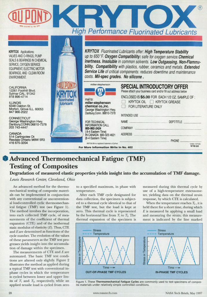
KRYTOX /Wflcatioos: VN...VES AND O-RINGS, PUMP SEftLS & BEARINGS IN CHEMICN... SERVICE, OXYGEN SERVICE EQUIPMENT, ELECTRIC MOTOR BEARINGS, AND CLEAN ROOM ENVIRONMENT.
CALIFORNIA 12261 Foothill Blvd. Sylmar CAL 91342 818896-4714
ILLINOIS 6348 Oakton St. Morton, Grove ILL 60053 847966-2022
CONNECTICUT George Washington Hwy. Danbury,CONN.06810-7378 203 743-4447
CANADA 514 Carlingview Dr. RexdaJe Ontario M9W 5R3 416675-3204
KRYTOX Fluorinated Lubricants offer: High Temperature Stability up to 650 oF. Oxygen Compatibility: safe for oxygen service. Chemical inertness. Insoluble in common solvents. Low Outgassing. Non-Flammability. Compatibility with plastics, rubber, ceramics and metals. Extended Service Life of critical components: reduces downtime and maintenance costs. Mil-spec grades. No silicone. ---------------------------------------------------------------------------_.-miller·stephenson
=9= mail to: miller-stephenson chemical co. line. George Washington Hwy. Danbury,Conn. 00810-7378
SPECIAL INTRODUCTORY OFFER Please attach your business card and/or fill out address below
ENCLOSED IS $5.00 FOR EACH 112 OZ. SAMPLE OF : o KRYTOX OIL 0 KRYTOX GREASE o FOR LITERATURE ONLY
INlENDED USE ___________ _
FOR TECHNICAL NAME ---_____ DEPTmTLE _ __ _ INFORMATION CALL 800-992-2424 COMPANY ( 8-4 Eastern Time) IN CANADA 800-323 4621 ADDRESS -------______ _ (8-4 Eastern Time) __________ PHONE ____ _ ICRYTOX®iI . ~tfadem«I(oIOIRonI
For More Information Write In No. 402 12:J6.11 PI2O NTB\6R
• Advanced Thermomechanical Fatigue (TMF) Testing of Composites Degradation of measured elastic properties yields insight into the accumulation of TMF damage. Lewis Research Center, Cleveland, Ohio
An advanced method for the thermomechanical testing of composite materials can he implemented in conjunction with any conventional or unconventiona1load-controlled cyclic thermomechanical fatigue (TMF) test (see Figure 1) . The method involves the incorporation, into each collected TMF cycle, of measurements of the coefficient of thermal expansion (erE) and of the i othermal static modulus of elasticity (E). Thus, erE and E are determined as functions of the cycle num her. The evolution of the value of these parameters as the TMF test progresses yields insight into the accumulation of damage within the specimen.
The measurements of erE and E are automated. The basic TMF test conditions are altered only slightly. Figure 2 illustrates the method as applied during a typical TMF te t with conventional inphase cycles in which the temperature is cycled between lower and upper limits of Tl and T2, re pectively, while an applied ten i1e load is cycled from zero
28
to a specified maximum, in phase with temperature.
After each TMF cycle de ignated for data collection, the specimen is subjected to a thermal cycle identical to that of the TMF test, but the load is kept at zero. This thermal cycle is represented by the horizontal line from 1\ to 'Ez. The thermal expansion of the specimen is
-- Stress -- Temperature
~ :l
~ Q) Co E f!! o en en ~ I
U5 Time--
OUT -OF-PHASE TMF CYCLES
measured during this thermal cycle by use of a high-temperature extensometer, yielding data on the thermal strain response, by which CfE is calculated.
When the temperature reaches T2 , it is held there for a short time, during which E is measured by applying a small load and measuring the strain; this measurement is indicated by the line marked
Stress Temperature
~ :l
~ Q) Co E Q) t-
0 ~ ~
U5 Time--
IN-PHASE TMF CYCLES
Figure 1. These Thermomechanical Fatigue Cycles are commonly used to test specimens of composite materials under relatively simple controlled conditions.
www.nasatech .com ASA Tech Briefs, May 1997
New Ultradur· S PBT alloy significantly reduces your part warpage and distortion
when compared to conventional glass-filled (GF) PBTs and other resins.
The source is BASF. Ultradur S PBT alloy also has improved surface appearance and flowabi/ity.
The GF PBT is Ultradur S. Additionally, the lower density of Ultradur S PBT alloy helps you produce parts
The savings are real. more economically Upon reflection, these benefits derive from only one source.
To learn how Ultradur S PST alloy and other Ultradur PST products work for your application,
contact SASF at 1-800-BC RESIN, visit our web site http://www.bast.com, or receive fax-on
demand information at 1-800-TOPFAX-1.
BASf PlastIc Materials is (lS-9000 and ISO 9002 certified.
We don't make your products, We help make them better.-
BASF For More Information Write In No. 604
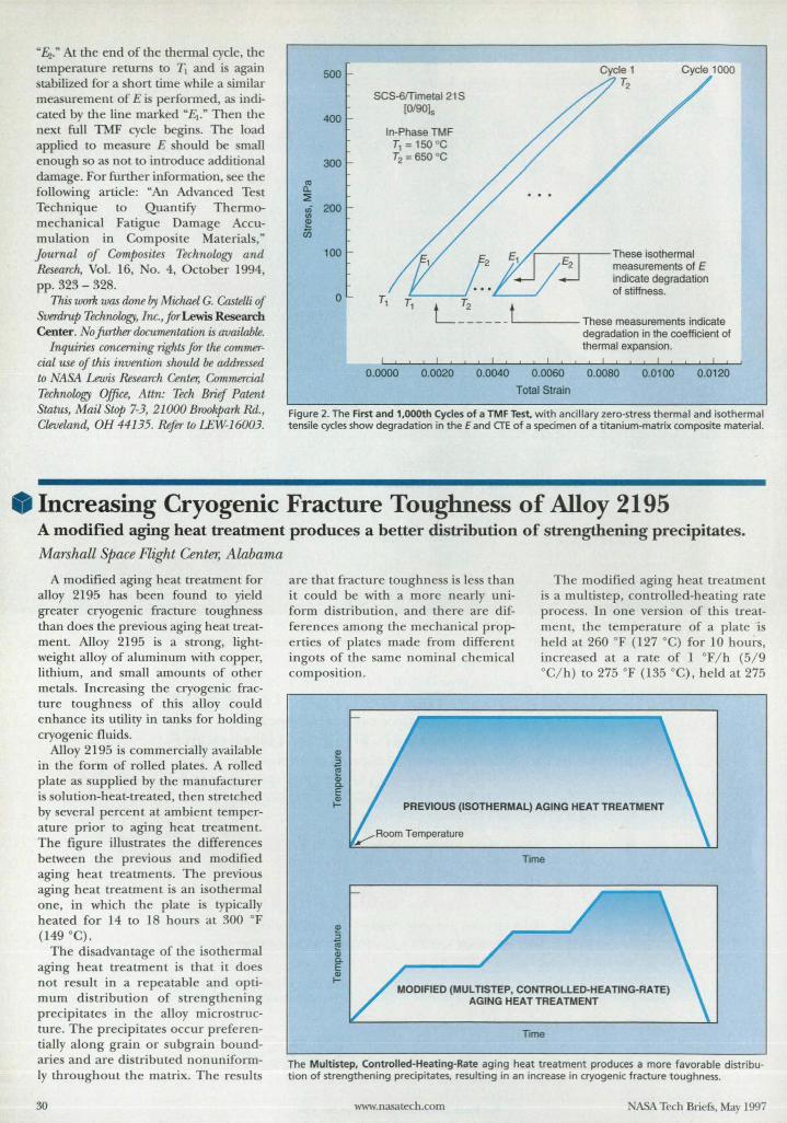
"&." At the end of the thermal cycle, the temperature returns to 1\ and is again tabilized for a short time while a imilar
measurement of E is performed, as indicated by the line marked "E] ." Then the next full TMF cycle begins. The load applied to measure E should be mall enough so as not to introduce additional damage. For further information, see the following article: "An Advanced Test Technique to Quantify Thermomechanical Fatigue Damage Accumulation in Composite Materials," Journal of Composites Technolog;y and Research, Vol. 16, o. 4, October 1994, pp. 323 - 328.
This work was done I7y Michael G. Castelli of Sverdrup Technowg;y, Inc., for Lewis Research Center. No further documentation is availahle.
Inquiries concerning rights for the commercial use of this invention should be addressed to NASA Lewis Research Center, Commercial Technowg;y Office, Attn: Tech Brief Patent Status, Mail Stap 7-3, 21000 Brookpark Rd., Cleveland, OH 44135. Refer to LEW-J6003.
ttl Q.
::E
500
400
300
.; 200 III ~ ii5
100
o
SCS-6fTimetaI21S [O/901s
In·Phase TMF T1 =150 °C T2 = 650 °C
Cycle 1000
/ r--=-,.---These isothermal measurements of E indicate degradation of stiffness.
L:~ ____ tL.. ____ These measurements indicate degradation in the coefficient of thermal expansion.
I , , ! 1 , I , , ! ! I , I , , I , , I I
0.0000 0.0020 0.0040 0.0060 0.0080 0.0100 0.0120
Total Strain
Figure 2. The First and 1,OOOth Cycles of a TMF Test. with ancillary zero-stress thermal and isothermal tensile cycles show degradation in the E and CTE of a specimen of a titanium-matrix composite material.
__ Increasing Cryogenic Fracture Toughness of Alloy 2195 A modified aging heat treatment produces a better distribution of strengthening precipitates.
Marshall Space Flight Center, Alabama
A modified aging heat treatment for alloy 2195 has been found to yield greater cryogenic fracture toughness than does the previous aging heat treatment. Alloy 2195 is a strong, lightweight alloy of aluminum with copper, lithium, and small amounts of other metals. Increasing the cryogenic fracture toughness of this alloy could enhance its utility in tanks for holding cryogenic fluids.
Alloy 2195 is commercially available in the form of rolled plates. A rolled plate as supplied by the manufacturer is solution-heat-treated, then stretched by several percent at ambient temperature prior to aging heat treatment. The figure illustrates the differences between the previous and modified aging heat treatments. The previous aging heat treatment is an isothermal one, in which the plate is typically heated for 14 to 18 hours at 300 OF (149 °C).
The disadvantage of the isothermal aging heat treatment is that it does not result in a repeatable and optimum distribution of strengthening precipitates in the alloy microstructure. The precipitates occur preferentially along grain or subgrain boundaries and are distributed nonuniformIy throughout the matrix. The results
30
are that fracture toughness is less than it could be with a more nearly uniform distribution, and there are differences among the mechanical properties of plates made from different ingots of the same nominal chemical com position.
The modified aging heat treatment is a multistep, controlled-heating rate process. In one version of this treatment, the temperature of a plate is held at 260 OF (127 °C) for 10 hours, increased at a rate of 1 OF / h (5/ 9 °C/ h) to 275 OF (135 °C), held at 275
PREVIOUS (ISOTHERMAL) AGING HEAT TREATMENT
Time
MODIFIED (MULnSTEP, CONTROLLED-HEATING-RATE) AGING HEAT TREATMENT
Time
The Multistep, Controlied-Heating-Rate aging heat treatment produces a more favorable distribution of strengthening precipitates, resulting in an increase in cryogenic fracture toughness.
www.nasatech.com NASA Tech Briefs, May 1997
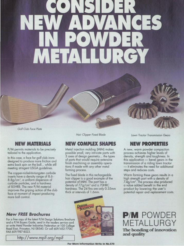
Golf Club Face Plate
NEW MATERIALS P 1M permits materials to be precisely tailored to the application.
In this case, a face for golf club irons designed to produce more friction and extra bock spin on the boll ... while still meeting stringent USGA guidelines.
The copper-nickel-tin-tungsten carbide inserts have a density range of 8.6 -8.8g/cm 3
, a uniform dispersion of carbide porticles, and a hardness of 85HRB. The new P 1M material improves the griping action of the club face at moment of impact producing more boll control.
New FREE Brochures
Hair Clipper Fixed Blade
NEW COMPLEX SHAPES Metal injection molding (MIMI makes possible small, very intricate ports with 3 axes of design geometry ... the types of ports that would require extensive finish machining or assembly operations iF made with any other metal Forming process.
The fixed blade in this rechargeoble hair clipper is a good example of the potential of MIM. The port has a density of Zlg/cm 3 and a 70HRC hardness. The 24 fins are only O.35mm thick at intervals of 1 .6mm.
C
For a free copy of the latest P/M Design Solutions Brochure and a P/M Buyers Guide, send in the readers service cord or write Metal Powder Industries Federation at 105 Col/ege Rood East, Princeton, NJ 08540. Or call 609/452-7700; FAX 609/987-8523.
http://www.mpif.org/mpif For More Information Write In No.670
Lawn Tractor Transmission Gears
NEW PROPERTIES A new, warm powder compaction process achieves higher levels of density, strength and toughness. In this application - bevel gears in the transmission of a riding lawn tractor - it eliminates the need far additional steps and reduces costs.
Warm Forming these gears results in a high strength port with a density of 7.4g/cm3
• The process also produced a value added benefit in the end product by lowering the user's potential repair and replacement costs.
P/M POWDER METALLURGY The bonding of innovation and quality
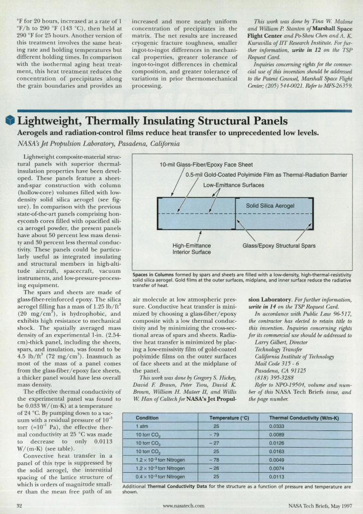
OF for 20 hour, increased at a rate of 1 °F/ h to 290 of (143°C), then held at 290 OF for 25 hours. Another version of this treatment involves the arne heating rate and holding temperatures but different holding times. In comparison with the isothermal aging heat treatment, this heat treatment reduce the concentration of precipitate along the grain boundaries and provides an
increased and more nearly uniform concentration of precipitates in the matrix. The net results are increased cryogenic fracture toughness, maIler ingot-to-ingot difference in mechanical properties, greater tolerance of ingot-to-ingot differences in chemical composition, and greater tolerance of variations in prior thermo mechanical processing.
This work was done by Tina W Malone and WiUiam P. Stanton of Marshall Space Flight Center andPo-Slwu Chen andA. K. Kuruvilla of IIT Research Institute. For further information, write in 12 on the TSP Request Card.
Inquiries concerning rigllts for the commercial use of this invention should. be addressed to the Patent Counsel, MarslwU Space Flight Center; (205) 544-0021. Refer to MFS-26359.
Lightweight, Thermally Insulating Structural Panels Aerogels and radiation-control films reduce heat transfer to unprecedented low levels.
NASA's Jet Propulsion Laboratory, Pasadena, California
Ligh tweight composite-material structural panels with superior thermaJinsulation properties have been developed. These panels feature a sheetand-spar con truction with column (hollow-core) volumes fi lledwith l o~
density solid silica aerogel (see figure). In comparison with the previous state-of-the-art panels comprising honeycomb cores filled with opacified silica aerogel powder, the present panels have about 50 percent less mass density and 30 percent less thermal conductivity. These panels could be particularly useful as integrated insulating and structural members in high-altitude aircraft, spacecraft, vacuum instruments, and low-pressure-processing equipment.
The spars and sheets are made of glass-fiber-reinforced epoxy. The silica aerogel fillinr, has a mass of l.25 Ib/ ft3
(20 mg/ cm ), is hydrophobic, and exhibits high resistance to mechanical shock. The spatially averaged mass density of an experimental I-in. (2.54-cm)-thick panel, including the sheets, spars, and insulation, was found to be 4.5 lb/ fe (72 mg/ cm3
). Inasmuch as most of the mass of a panel comes from the glass-fiber/ epoxy face sheets, a thicker panel would have less overall mass density.
The effective thermal conductivity of the experimental panel was found to be 0.033 W/(m·K) ata temperature of24 °C. By pumping down to a vacuum with a residual pressure of 10-3
torr (",10-1 Pa), the effective thermal conductivity at 25 °C was made to decrease to on ly 0.0113 W/(m·K) ( ee table) .
Convective heat transfer in a panel of this type is suppressed by the solid aerogel, the interstitial spacing of the lattice structure of which is orders of magnitude smaller than the mean free path of an
32
10-mil Glass-Fiber/Epoxy Face Sheet
/
o.s-mil Gold-Coated Polyimide Film as Thermal-Radiation Barrier
~ Low~EmIHa",e So""""
[~----------~---j;!~~-~;~-~~~~--:J ! T
High-Emittance Interior Surface
Glass/Epoxy Structural Spars
Spaces in Columns formed by spars and sheets are fi lled w ith a low-density, high-thermal-resistivity solid silica aerogel. Gold f ilms at t he outer surfaces, midplane, and inner surface reduce the radiative transfer of heat.
air molecule at low atmospheric pressure. Cond uctive heat transfer is minimized by choosing a glass-fiber / epoxy composite with a low thermal conductivity and by min imizing the cross-sectional areas of spars and sheets. Radiative heat transfer is minimized by placing a low-emissivity film of gold-coated polyimide films on the ou ter su rfaces of face sheets and at the midplane of the panel.
This work was done by Gregory S. Hickey, David F. Braun, Peter Tsou, David K. Brown, William H. Mateer II, and Willis W Han of Caltech for NASA's Jet Propul-
sion Laboratory. For further information, write in 14 on the TSP Request Card.
In accordance with Public Law 96-517, the contractor has elected to retain title to this invention. Inquiries concerning rights for its commercial use should be addressed to
Larry Gilbert, Director Technology Transfer California Institute of Technology Mail Code 315 - 6 Pasadena, CA 91125 (818) 395-3288 Refer to NPO-19504, volume and num
ber of this ABA Tech Briefs issue, and the page number.
Condition Temperature (OC) Thermal Conductivity (W/m-K)
1 aIm 25 0.0333
10 torr CO2 -79 0.0089
10 torr CO2 -27 0.0126
10 torr CO2 25 0.0163
1.2 x 1 Q-3 torr Nitrogen -78 0.0049
1.2 x 1 Q-3 torr Nitrogen -26 0.0074
0.4 x 1 Q-3 torr Nitrogen 25 0.0113 ..
Additional Thermal ConductiVity Data f or the structure as a function of pressure and temperature are shown.
www.nasatech.com ASA Tech Briefs, May 1997
$~685* for 20 channels
Whether you need a data logger or an
automated test solution, the lIP 34970A
offers you uncomprornised functionality
and performance. And the features you
need to get the job done. Like built-in
HP-IB and RS-232 interfaces. A standard
three-year warranty. And a price tag that
fits within your budget.
PERFORMANCE • 6 1/2 digits resolution (22 bits ) • Built-in signal conditioning measures thermocouples, RTOs,
& Thermistors; ac/dc Volts & Current; Resistance; Frequencv & Period
• Scanning up to 250 channels per second • Non·volatile 50,000 reading storage with timestamp
THREE-SLOT FLEXIBILITY • Multiplexing and Actuation • Digital I/O, Analog output, Event counting • RF switching up to 2 GHz • 4 x 8 Matrix switching
WINDOWS® SOFTWARE • HP BenchUnk Oata logger application included • HP VEE and LabVIEW drivers available
"I'll tell you mO're about how the HP 34970A can meet all your data acquisition needs-Jor an unbelievably low price. Just give me a call at HP DIRECT, 1-800-452-4844~* Ext. 5263." Check out our on-line HP Basic Instruments (BI) Catalog at http://WUlW.hp.comlin!oIbidaq1 Faxback: 1-800-800-5281, Document 12254.
-U Jistpna "In Ccmodo.. mIIl-8(IO.:l87-31S.. _ .. "uml>Pr TMAltS.
Wmdows® is a U.S. registered trademark of Microsoft Corporation. LabVIEW® is a U.S. registered trademark of National Instruments Corporation.
For More Information Write In NO.675
Flip. HEWLETT a:~ PACKARD
Protective Coatings for Gamma Titanium Aluminides These coatings could be used to make lightweight components for turbine engines. Lewis Research Center, Cleveland, Ohio
Coating al10ys of general compo ition Til Al/ X (where X denotes Cr, Fe, or another uitable metal) have been developed recently to protect gamma titanium aluminide (y-TiAl)based alloys. At half the density of
850 ·C in turbine engine. Replacement of superalloys by y-TiAI-based alloy would increa e thrust-to-weight ratios in the engine and reduce the costs of operating them. However, protective coating are needed because bare y-TiAl-ba ed alloys do not re ist oxidation adequately and are potentially susceptible to embrit-
uperalloy, y-TiAl-ba ed alloys are promising candidate materials for use at temperatures between 600 and
34
In today's environmentally-conscious world, it's survival of the fittest. Costeffective and environmentally safe hard coat anodizing enhances the basic properties of aluminum such as, low density, high dielectric constant, thermal conductivity, lubricity, malleability, and ductility with a hardness comparable to a C·70 Rockwell after hard coat. Resist the elements of rust and corrosion, moisture, heat, cold, friction, and the basic element of surprise!
It's a matter of "WHOOOS" product will last. Let us anodize your sample part for free. Call, fax or write:
It's not how it's made. It's how it's made to last. Fort Wayne Anodizing
Full Anodizing and Impregnation Services 2535 Wayne Trace ' Ft. Wayne. Indiana 46803 ' Phone 219·424-1030 ' Fax 219-420-4006
Toll Free 800-347-1030
For More Information Write In No. 403
tlement by oxygen and nitrogen; this is especially true at temperatures above 750 to 850 · C.
Aluminizing treatments, conventional MCrAlY (M = Ni or Fe) coating allo ,and ceramic coating for y-TiAlbased alloy have not proven successful becau e of poor mechanical propertie , mismatch of thermal expansion coefficients, or chemical incompatibility. Promising coating alloys have previously been identified in the Til Al/ Cr system: These alloys exhibit excellent resistance to oxidation and are generally compatible with the y substrate alloys. However, prior to the development of the pre ent Til Al/ Cr alloy, the alloys in this system had been found to be extremely brittle.
A Ti/ Cr / Al coating alloy developed at NASA Lewis exhibits excellent compatibility with substrates and orne improvement in mechanical properties, without sacrifice of resistance to oxidation. The alloy composition, Ti/51.25Al/ 12.25Cr (the numbers indicate atomic percentages), was selected 0 that the microstructure consists of the ypha e with a minor volume of the oxidation-re istant Laves phase Ti(Cr,Alh By basing the coating alloy on the yphase, one optimizes mechanical properties and compatibility with y substrates. The volume fraction of the Laves phase is kept to a minimum because it is extremely brittle.
The Ti / 51.25AI/12.25Cr coating alloy was applied to a substrate of the y alloy Ti/48Al/ 2Cr/2 b by low-pressure plasma spraying. Oxidation tests at temperature' of 800 and 1,000 · C in air indicated that the coating alloy successfully protected the sub trate from oxidation (see figure). Evaluation of the isothermal fatigue behavior of the coated substrate at high temperatures in air is in progress.
The fundamental studies that led to the development of the Ti/ 51.25AI / 12.25Cr alloy also provided a basis for the selection of new oxidation-resistant Ti/ AI / X alloys . One such alloy is Ti/53Al/ llFe. Thi alloy is potentially useful as a reaction barrier between conventional FeCrAlY oxidation-resistant coating and y-TiAl-based substrates. FeCrAlY coatings are not chemically compatible with titanium aluminides, and form brittle reaction products. The Ti/53Al/ IIFe alloy
ASA Tech Briefs, May 1997
THINGS THAT SEEM TO LAST AN ETERNITY
a. Fruitcake
b. Root canal
c. Opera
d. Parts lu.bricated with Krylo~
Why do components with DuPont Krytox la t practically forever?
For tarter, Krytox· lubricants are ba ed on exclu jve space-age fluoropolymer technology. Available in oil, grease and dry fLlm, Krytox provide long-lasting lubrication over the broade t range of temperature (-70°F to 650°F) in even the most extreme conditions. Krytox is also compatible with metals, elastomers, engineering plastic - and all chemicals including oxygen - which means it' nonflammable, chemically inen, and insoluble in solvents and water. It's clean, white. and it tay
bttp:/IwwwJubricants.dupont.com
put. with virtually no change in phy ical propertie over time. And if you're looking for a clean solution to the assembly and
operation of moving parts. try easy-to-apply Krytox dry film. Whether your application i automotive. aerospace, small
motors, paper making or chemical proce ing. you just can't get a longer-lasting lubricant than Krytox . For more information, call 1-800-424-7502. Krytox . Lubrication beyond your highest expectations. C[(}POR!?
KrytOX'" perIDlmanre lubricant,
For More Information Write In No. 662
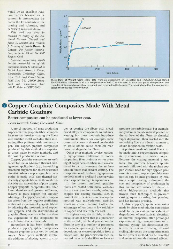
would be an excellent reaction barrier becau e its Fe content i intermediate between the Fe contents of the coating and substrate, and becau e it re i ts oxidation.
This work was done by Michael P Brady of the ational Research Council and James L. mialek and William J. Brindley of Lewis Research Center. For further infonna(ion, write in 79 on the TSP Request Card.
Inquiries concerning rights for the commercial use of this invention should be addres ed to
1.0 r-----------------------------------------------,
0.8
1: 0.4 Cl
'Qj
~
0.2
Coated
Time, hours 'ASA Lewis Research Center,
Commercial Technology Offue, Attn: Tech Brief Patent Status, Mail tf11 7-3, 21000 Brookpark Rd., Cleveland, OH 44135. Refer to LEW-20003.
These Plots of Weight Gains show data from an experiment on uncoated and TI/51 .25Ail12.25Cr-coated nt48AI12Cr12Nb substrates in air at a temperature of 800 'C in a furnace. At each data point. the specimen was cooled in air to room temperature, weighed, and returned to the furnace. The data indicate that the coating protected the substrate from oxidation .
• Copper/Graphite Composites Made With Metal Carbide Coatings Better composites can be produced at lower cost. Lewis Research Center, Cleveland, Ohio
A novel method of mass-producing copper-matrix/ graphite-fiber composite material involves coating the fibers with suitable metal carbides, then infiltrating fiber preforms with molten copper. The copper/ graphite composites produced by this method are uperior to those made by older methods, and the co t of production i lower.
Copper/ graphite composites are wellsuited for use in advanced thermal-management applications (e.g., heat-sinking tructuraI upports for microelectronic
circuits). When a copper/ graphite composite is made with high-thermal-conductivity graphite fibers, its thermal conductivity can exceed that of pure copper. Copper/ graphite compo ites also offer lower clensitie and greater sti1:fne e, relative to pure copper. Yet another advantage of copper/ graphite composites arises from the negative coefficients of thermal expansion of graphite fibers; by adjusting the proportions of copper and graphite and the di tributions of graphite fibers, one can tailor the thermal expansions of the compo ites to match those of other materials.
Heretofore, it has been difficult to produce copper/ graphite composite because graphite i not wet by molten copper. Some prior methods involve the addition of alloying agents to cop-
36
per or coating the fibers with metalbased alloys or compounds to enhance wetting, but these methods introduce unde irable effects; for example, some cause reductions in thermal conductivity, while others cau chemical reactions that degrade the fibers.
Other prior methods involve, variously, high-pressure infiltration of molten copper into fiber preforms or hot pressing of copper-coated fibers into consolidated forms to overcome the surfaceten ion forces that prevent wetting. The composites made by the e high-pre sure methods tend to swell and develop voids when expo ed to high temperatures.
In the present method, graphite fibers are coated with metal carbide that are wet by molten metals, including copper. The coating material u ed in most of the experiments to develop the method was molybdenum carbide, which was chosen because it offers the advantage of low den ity, low solubility in copper, and relatively low cost.
In a given case, the carbide, or el e a metal or other layer that is a precursor to the carbide, can be deposited on the fibers by any of a number of processes; for example, sputtering, chemical vapor deposition, or electrodeposition from a molten salt. The precursor can then be reacted on or with the fiber urfaces to
www.nasatech.com
produce the carbide coats. For example, molybdenum metal can be deposited on the surfaces of the fibers by chemical vapor deposition, then reacted with the underlying fibers in a heat treatment to obtain molybdenum carbide coats.
A preform made of coated fibers can be made into a copper-matrix composite by immer ing it in molten copper. Because the coating material is wettable, the preform becomes spontaneously infiltrated with the molten copper, without need for high applied pres-ure. As a result, copper/ graphite com
posites can be mass-produced by relatively imple casting techniques; the cost and complexity of production by this method are reduced, relative to older high-pressure method that involve uch technique as pressure casting, squeeze casting, hot pressing, and hot i ostatic pre sing.
Unlike copper/ graphite composites made by older methods, the compo ites made by the present method exhibit no degradation of mechanical, electrical, or thermal properties after prolonged expo ure to high temperatures or to thermal cycling. 0 dimensional hysteresis is ob erved during thermal cycling. Moreover, the composites made by the present method can be remelted and recast without detrimental effects.
ASA Tech BriefS, May 1997
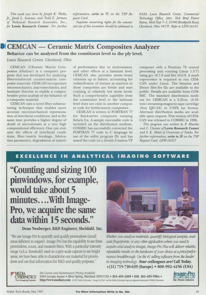
This work was done by Joseph K. Weeks, Jr., Jared L. Sommer, and Todd E. Jarman of Technical Research Associates, Inc., for Lewis Research Center. For further
information, write in 71 on the TSP Request Card.
Inqui1Us concerning rights for the commercial use of this invention should be addressed to
~ Lewis Research Center; Commerr:ial Technology Office, Attn: Tech Brief Patent Status, MailStqp 7-3, 21000 Brookpark Road, Cleveltmd, Ohio 44135. Refer to LEW-16103.
CEMCAN - Ceramic Matrix Composites Analyzer Behavior can be analyzed from the constituent level to the ply level. Lewis Research Center; Cleveland, Ohio
CEMCAN (CEramic Matrix Composites ANalyzer) is a computer program that was de\'eloped for analyzing fiber-reinforced ceramic-matrix composite materials. CEMCAN incorporates micromechanics, macromechanks, and laminate theories to enable a com prehen ive point analysis of the behavior of a composite material.
CEMCAN uses a novel fiber substructuring technique that enables more accurate micromechanical repre entation of interfacial conditions, and at the same time provides a higher degree of detail of microstresses at a very high computational efficiency. One can evaluate the effects of interfacial conditions, fiber/matrix breakage, fabrication parameters, degradation of materi-
al performance due to environment, and other effects at a laminate level. CEMCAN also provides stress/ strain relations up to failure, accounting for redistribution of stresses as matrices in these composites are brittle and start cracking at relatively low tress levels. Such a comprehensive capability from the constituent level to the laminate level does not exist in another computer code for brittle-matrix composites.
CEMCAN i written in FORTRAN 77 for Sun4-series computer running Solaris 2.x. A sample executable code is included on the distribution medium. COSMIC has successfully converted the FORTRAN 77 code to C language by use of the utility program f2c and has tested the code on a Zenith Z-station VP
"Counting and sizing 100 pinwindows, for example, would take about 5 minutes .... With hnagePro, we acquire the same data withiri 15 seconds."
Dean Neuberger, R&D Engineer, Sheldahl, Inc.
computer with a Pentium 75 central processing unit running Linux 1.3.71 using gcc v2.7.0 and libc v5.0.9. A math coproces or is required to run GEMCAN under Linux. The binaries and library files for f2c are available to the public. Details are available from COSMIC. The standard distribution medium for CEMCAN is a 0.25-in. (6.35-mm) streaming-magnetic-tape cartridge (Sun QIC-24) in UNIX tar format. Alternate distribution media are available upon request. This version of GEMCAN was released to COSMIC in 1996.
This program was written by P. Murthy and C. Chamis of Lewis Research Center and S. K. Mital of University of Toledo. For further infllT'Tnation, write in 20 on the TSP Request Card. LEW-16327
"We use lInage-Pro to quantify and qualify pinwindows ( mall areas deficient in copper). lIn age-Pro has the capability to see these pinwindows, coun~ and measure them. With a particular intensi~' range (a.k.a. threshold) used on a grey-scale capture to see bright areas, we have been able to characterize our material for pinwindows and use that infonnation for R&D and quality p~."
WbedJer you analyze materials, quantify biological samples evaluate fingerprints, or any otiJer application where you need «> acquire and analyze images, Image-Pro Plus will deliver reliable, ltpeatable results on the hardware of your choice at a pice/performance breakthrough. Use tbe # I selling SOjhlXll'e.from the leader in imaging tedJJwlogy -YOllr colleagues are! Call Today. +(31) 715-730-639 (Europe) • 800-992-4256 (USA)
MEDIA Site license and Maintenance Pricmg Amiloble CYBfRNETlCS 8484 Georgia Avenue · ilver pring, Mat'}iaod 20910 U • 301-495-3305 • FAX 301-495-5964 • The '"""I!ins &<pens hnp:/Iwww.mediacy.com Cl9'}7 MIdi2~ - Inq-ProPlus" mdIbtMldi2C)!JemttiakJgD ... l!giomd~afMldi2Cjilomeba.
NASA Tech Briefs, May 1997 For More Information Write In No. 404 37
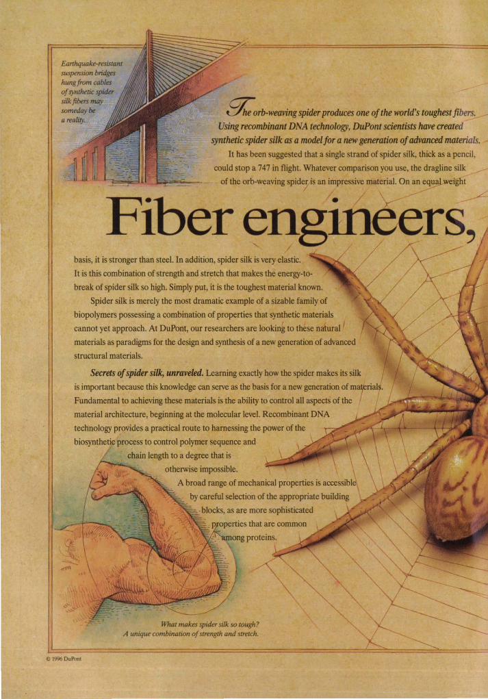
Earthquake-resistam suspension bridges hungfrom cables of synthetic spider silk fibers may someday be a reality.
~rb-WeaVing spider produces one of the world's toughestfibers. Using recombinant DNA technology, DuPont scientists have created
synthetic spider silk as a model for a new generation of advanced materials. It has been suggested that a single strand of spider silk, thick as a pencil,
could stop a 747 in flight. Whatever comparison you use, the dragline silk
of the orb-weaving spider is an impressive material. On an equl!,lwetglit .---
Fiber engineers, //
basis, it is stronger than steel. In addition, spider silk is very elastic.
It is this combination of strength and stretch that makes the energy-to
break of spider silk so high. Simply put, it is the toughest material known.
Spider silk is merely the most dramatic example of a sizable family of
biopolymers possessing a combination of properties that synthetic materials
cannot yet approach. At DuPont, our researchers are looking to these natural '
materials as paradigms for the design and synthesis of a new generation of advanced
structural materials.
Secrets of spider silk, unraveled. Learning exactly how the spider makes its silk
is important because this knowledge can serve as the basis for a new generation of rna brial .
Fundamental to achieving these materials is the ability to control all aspects of the
material architecture, beginning at the molecular level. Recombinant DNA
technology provides a practical route to harnessing the power of the
biosynthetic process to control polymer sequence and
chain length to a degree that is
otherwise impossible.
A broad range of mechanical properties is accessible
by careful selection of the appropriate building
- - . blocks, as are more sophisticated
..... --=-- -~- What makes spider silk so tough? A unique combination of strength alld streiCh.
C 1996 DuPont
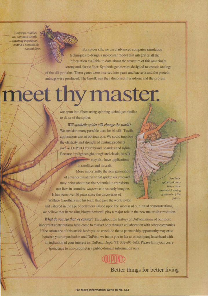
,
For spider silk, we used advanced computer simulation
~~11leS to design a molecular model that integrates all the
More importantly, the new gene. of advanced materials that spider silk
bring about bas the potential to traniSfdJ.
our lives in oountless ways we can scarcely ~~~~
bas been over 50 years since the discoveries of Carothers and his team that gave the world nylon
and ~ in Jhe a&9 Qf ~ Based upon the success of our initial demonstrations,
I. ita. that ~ biosynabe&iSwiIl play. major role in the new materials revolution.
>jfI":aro,,, •• ,_rtwttllilftlt1 'l\roupout the history ofDuPmt, many of our most
A~_~ .. iJ)utiiOiliiji:~~ to,madl:etaoly tJuouab ~ with other companies. ·<:<,.)lEr(li!' __ oe Olf.tIIi!l.-tJo· ,.. ... ., CCQ'.lllde that a pattnefsblp opportunity may eDt
___ ~ at¥! ~_iavite.yop wk •• company1etterbead with
aniQttlYbl Of)wi interest te: Dal\1Dt, l>qrt. Nt. 002-69S-16lS. Please limit your oorre~~.b)_~~~~~~.
((JPotm Better things for better living
For ..... In'o ..... _ .,... In No. 152
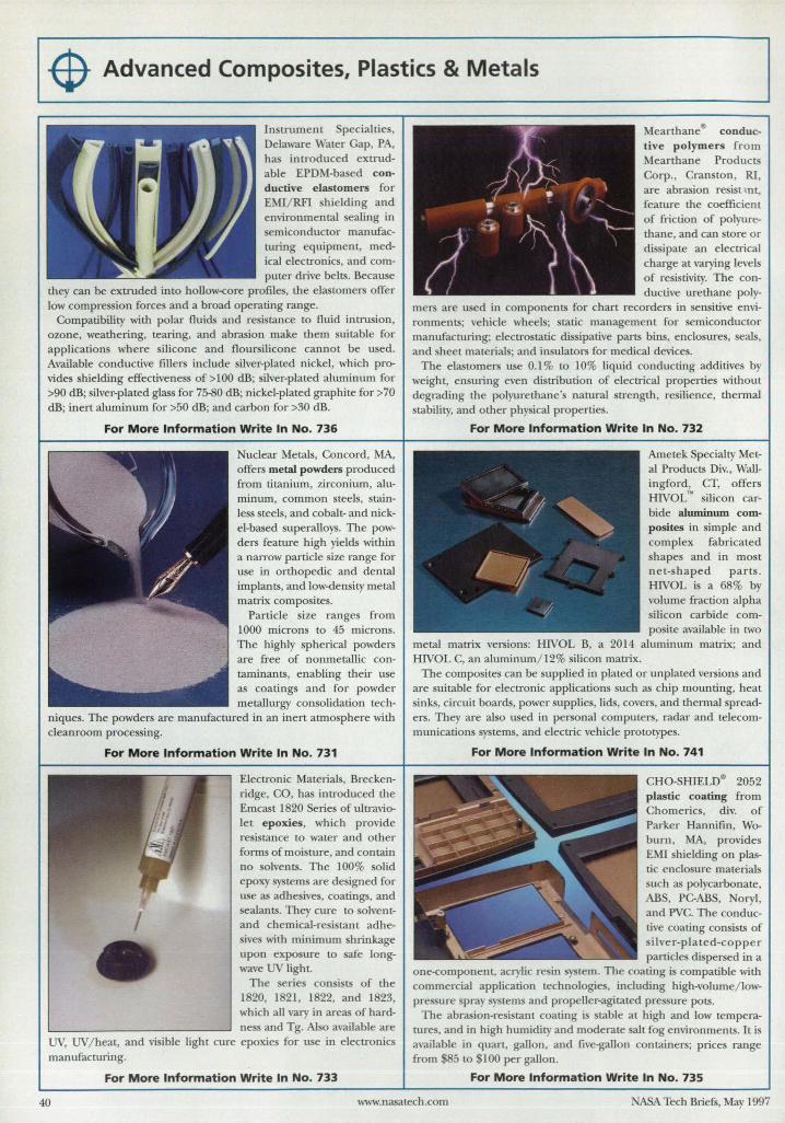
$- Advanced Composites, Plastics & Metals
ductive elastomers for EMI/RFI shielding and environmental eating in semiconductor manufacturing equipment, medical electronics, and computer drive belts. Because
they can be extruded into hoUow-<:ore profile , the elastomers offer low compression forces and a broad operating range.
Compatibility with polar fluids and re istance to fluid intrusion, ozone, weathering, tearing, and abrasion make them suitable for applications where silicone and floursilicone cannot be used. Available conductive fillers include ilver-plated nickel, which provides shielding effectiveness of >100 dB; silver-plated aluminum for >90 dB; silver-plated glass for 75-80 dB; nickel-plated graphite for >70 dB; inert aluminum for >50 dB; and carbon for >30 dB.
For More Information Write In No. 736
I
uclear Metals, Concord, MA, offers metal powders produced from titanium, zirconium, aluminum, common steels, stainIe s steels, and cobalt- and nickel-based superaUoys. The powders feature high yields within a narrow particle size range for use in orthopedic and dental implants, and low-density metal
Electronic Materials, Breckenridge, CO, has introduced the Emcast 1820 Series of ultraviolet epoxies, which provide resistance to water and other forms of moi ture, and contain no solvents. The 100% solid epoxy systems are designed for use as adhesives, coatings, and sealants. They cure to solventand chemical-re istant adhesives with minimum shrinkage upon exposure to afe longwave UV light.
The series consists of the 1820, 1821 , 1822, and 1823, which all vary in areas of hardness and Tg. Also available are
UV; UV / heat, and visible light cure epoxies for use in electronics manufacturing.
For More Information Write In No. 733
Mearthanee conductive polymers from Mearthane Products Corp., Cranston, RI, are abrasion resist 111t, feature the coefficient of friction of polyurethane, and can store or dis ipate an e lectrical charge at varying levels of resistivi ty. The conductive urethane poly
mers are u ed in components for chart recorders in sensitive environments; vehicle wheels; static management for semiconductor manufacturing; electrostatic dis ipative parts bins, enclosures, seals, and sheet materials; and insulators for medical device .
The elastomers use 0.1 % to 10% liquid conducting additives by weight, ensuring even distribution of electrical properties without degrading the polyurethane 's natural strength, resilience, thermal stability, and other physical properties.
For More Information Write In No. 732
Ametek Specialty Metal Products Div., Wallingford, CT, offers HIVOL" silicon carbide aluminum composites in simple and complex fabricated shapes and in most net-shaped parts . HlVOL is a 68% by volume fraction alpha silicon carbide composite available in two
metal matrix versions: HlVOL B, a 2014 aluminum matrix; and HIVOL C, an a1uminum/ 12% silicon matrix.
The composites can be supplied in plated or unplated versions and are suitable for electronic applications such as chip mounting, heat sinks, circuit boards, power supplies, lids, covers, and thermal spreaders. They are also used in personal computers, radar and telecommunications systems, and electric vehicle prototypes.
For More Information Write In No. 741
CHO-SHIELDe 2052 plastic coating from Chomerics, div. of Parker Hannifin, Woburn, MA, provides EMI shielding on plastic enclosure materials such as polycarbonate, ABS, PC-ABS, oryl, and PVC. The conductive coating consists of silver-pIa ted-copper particles dispersed in a
one-<:omponent, acrylic resin system. The coating is compatible with commercial application technologies, including high-volume/ lowpressure spray systems and propeller-agitated pressure pots.
The abrasion-resistant coating is stable at high and low temperatures, and in high humidity and moderate sail fog environments. It is available in quart, gallon, and five-gallon containers; prices range from 85 to 100 per gallon.
For More Information Write In No. 735
40 www.nasatech.com ASA Tech Briefs, May 1997
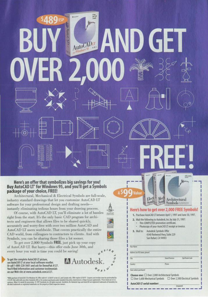
Here's an offer that symbolizes big savings for you! Buy AutoCAD LT for Windows 95, and you'll get a Symbols package of your choice, FREE!
Architectural, Mechanical & Electrical ymbols are full-scale, industry standard drawings that let you cu tomize utoCAD LT oftware for your profe ional de ign and drafting needs
instanLly eliminating tediou hours from your drawing proce . Of course, with utoC D LT. you'll eliminate a lot of ha Ie
right from the tart. It' the only basic CAD program for architects and engineers that allows files to be hared quickly, accurately and worry-fr e with over two million AutoCAD and
utoC D LT u ers world\l";de. That covers practically th entire CAD world from colleagues to contractors to clients. And wiLll
ymbols, you can be sharing Lho e file a lot ooner. To gel ov r 2,000 ymhal FREE. ju t pick up your copy
of utoC D LT. But hurry-this offer end June 30th, and every hour you wait i time you could be -aving!
To get the complete AutoCAD IT picture, see AutoCAD IT at your local software reseller. Or call 1-800 .. 218-3601 and ask for DemoPakA 127. You'll find information and rustomer testimonials on our Web site at www.autodesk.comIa127.
~Autodesk.
"Wi pMNl<"IvMWJOIor_tS.0II!r .... ~·6lYJ/flioIhrU5.""'~...,..0II!r .... 6IYJ/fI. ~""' ....... _ ... fIIII1JII'IIld'" 7fl1191.1IcII ...... "" __ ""'''lorpnodon~ __ ~_or''''''_.-."..._ .. ioU5. __ U ..... "'PfOC!'IIIg.Cl997,,-.1nc.AltfgIIIs_AIIIl>do*.Ihr_logoIlldAwCAD ........ _"AuIDde5t. .. AI.""'_ ....... _ ... dIe_,,_...,.,..._
'-,
ere's 1. Purchase AutoCAD LT between April 1.1997 and June 30.1997.
2. Mail the following to Autodesk,lnc.by July 31.1997: • This COMPlETED promotion certificate. • Photocopy of your AutoCAD IT re<eipt or invoice.
3. Mail to: Autodesk Symbols Offer
--....-
4340 Redwood Hwy. Suite 229 San Rafael, (}., 94903
-...... Choose one: 0 OVer 2.000 Archite<tural Symbols o Over 3.600 Mechanical Symbols 0 Over 2,500 Be<trical Symbols
AutoCAD lTserial number: ____ ..,......,....". ___ _ L ___________ ~ ____ ~
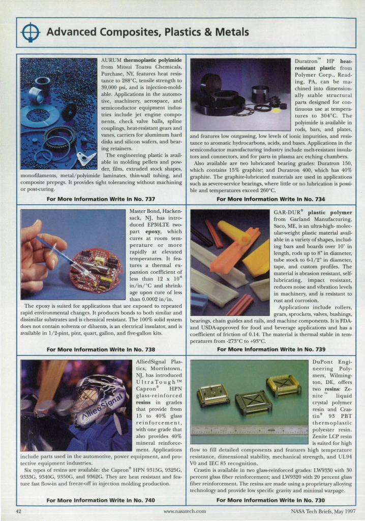
-$ Advanced Composites, Plastics & Metals
AURUM thermoplastic poJyimide from Mitsui Toatsu Chemical. Purchase, NY, features heat resistance to 288· C, tensile strength to 39,000 p i, and is injection-moldable. Applications in the automotive, machinery, aerospace, and semiconductor equipment industries include jet engine components, check valve balls, spline couplings, heat-resistant gears and vanes, carriers for aluminum hard disks and silicon wafers, and bear-
Master Bond, Hackensack, Nj, has introduced EP30LTE twopart epoxy, which cures at room temperature or more rapidly at elevated temperatures. It features a thermal expansion coefficient of less than 12 x 10~ in/inr C and shrinkage upon cure of less than 0.0002 in/ in.
The epoxy is suited for applications that are exposed to repeated rapid environmental changes. It produces bonds to both similar and dissimilar substrates and is chemical resistant. The 100% solid system does not contain solvents or diluents, is an electrical insulator, and is available in 1/ 2-pint, pint, quart, gallon, and five-gallon kits.
For More Information Write In No. 738
AlliedSignal Plastics, Morristown, I'!J, has in trod uced UltraTough™ Capron'" HPN glass-reinforced resins in grades that provide from 15 to 40% glass reinforcement, with one grade that also provides 40% mineral reinforcement. Applications
include parts used in the automotive, power equipment, and protective equipment industries.
Six types of resins are available: the Capron'" HP 9315G,9325G, 9333G, 9340G, 9350G, and 9362G. They are heat resistant and feature fast flow-in and freeze-off in injection molding production.
For More Information Write In No. 740
Duratron'" HP heatresistant plastic from Polymer Corp., Reading, PA, can be machined into dimensionally stable tructural parts designed for continuous use at temperatures to 304·C. The polyimide is available in rods, bars, and plates,
and features low outgassing, low levels of ionic impurities, and resistance to aromatic hydrocarbons, acids, and bases. Applications in the semiconductor manufacturing industry include melt-resistant insulators and connectors, and for parts in plasma arc etching chambers.
Also available are two lubricated bearing grades: Duratron 150, which contains 15% graphite; and Duratron 400, whicb has 40% graphite. The graphite-lubricated materials are u ed in applications such as severe-service bearings, where little or no lubrication is possible and temperatures exceed 260°C.
For More Information Write In No. 734
GAR-DUR'" plastic polymer from Garland Manufacturing, Saco, ME, is an ultra-high- molecular-weight plastic material available in a variety of shapes, including bars and boards over 10' in length, rods up to 8" in diameter, tube stock to 6-1/2" in diameter, tape, and custom profiles. The material is abrasion resistant, selflubricating, impact resistant, reduces noise and vibration level~ in machinery, and is resistant to rust and corrosion.
Applications include rollers, gears, sprockets, valves, bushings,
bearings, chain guides and rails, and machine components. It is FDAand USDA-approved for food and beverage applications and has a coefficient of friction of 0.14. The material is thermal stable in temperatures from -273°C to +93°C.
For More Information Write In No. 739
DuPont Engineering Po lymers, Wilmington, DE, offers two resins: Zenite liquid crystal polymer resin and Crastin'" 93 PBT thermoplastic polyester re in. Zenite LCP resin is suited for high
flow to fill detailed components and features high temperature resistance, dimensional stability, mechanical strength, and UL94 VO and IEC 85 recognition .
Crastin is available in two glass-reinforced grades: LW9330 with 30 percent glass fiber reinforcement; and LW9320 with 20 percent glass fiber reinforcement. The resins are made using a proprietary alloying technology and provide low specific gravity and minimal warpage.
For More Information Write In No. 730
42 www.nasatech.com NASA Tecb Briefs, May 1997
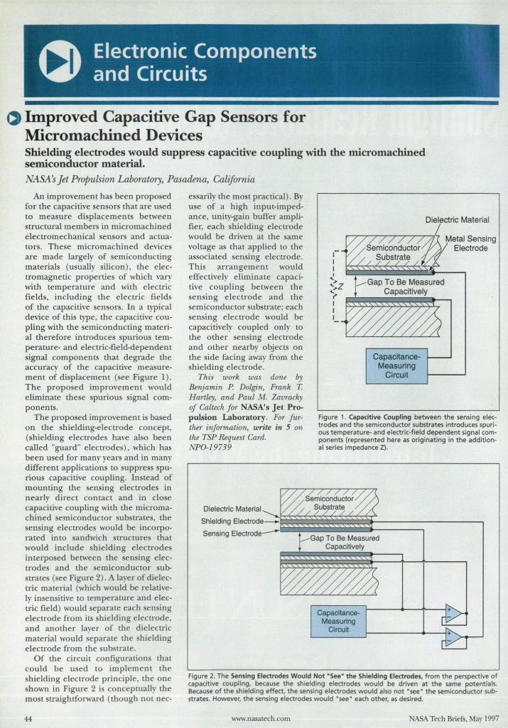
Improved Capacitive Gap Sensors for Micromachined Devices Shielding electrodes would suppress capacitive coupling with the micro machined semiconductor material. NASAj Jet Propulsion Laboratory, Pasadena, California
An improvement has been proposed for the capacitive sensors that are used to measure displacements between structural members in micromachined electromechanical sensors and actuators. These micromachined devices are made largely of semiconducting materials (usually silicon), the electromagnetic properties of which vary with temperature and with electric fields, including the electric fields of the capacitive sensors. In a typical device of this type, the capacitive coupling with the semiconducting material therefore introduces spurious temperature- and electric-field-dependent signal components that degrade the accuracy of the capacitive measurement of displacement (see Figure 1) . The proposed improvement would eliminate these spurious signal components.
The proposed improvement is based on the shielding-electrode concept, (shielding electrodes have also been called "guard" electrodes), which has been used for many years and in many different applications to suppress spurious capacitive coupling. Instead of mounting the sensing electrodes in nearly direct contact and in close capacitive coupling with the micromachined semiconductor substrates, the sensing electrodes would be incorporated into sandwich structures that would include shielding electrodes interposed between the sensing electrodes and the semiconductor substrates (see Figure 2) . A layer of dielectric material (which would be relatively insensitive to temperature and electric field) would separate each sensing electrode from its shielding electrode, and another layer of the dielectric material would separate the shielding electrode from the substrate.
Of the circuit configurations that could be used to implement the shielding electrode principle, the one shown in Figure 2 is conceptually the most straightforward (though not nec-
44
essarily the most practical). By use of a high input-impedance, unity-gain buffer amplifier, each shielding electrode would be driven at the same voltage as that applied to the associated sensing electrode. This arrangement would effectively eliminate capacitive coupling between the sensing electrode and the semiconductor substrate; each sensing electrode would be capacitively coupled only to the other sensing electrode and other nearby objects on the side facing away from the shielding electrode.
This work was done by Benjamin P. Dolgin, Frank T. Hartley, and Paul M. Zavracky of Caltech for NASA's Jet Propulsion Laboratory. For further information, write in 5 on the TSP Request Card. NPO-19739
II I I
:;Z ( I I I
CapacitanceMeasuring
Circuit
Figure 1. Capacitive Coupling between the sensing elE!ctrodes and the semiconductor substrates introduces spurious temperature- and electric-field dependent signal components (represented here as originating in the additional series impedance Z) .
Dielectric Material---...
Shielding Electrode---.~~~~~~~~~~=====~-----l Sensing Electrode-~
CapacitanceMeasuring
Circuit
Figure 2. The Sensing Electrodes Would Not ·See" the Shielding Electrodes, from the perspective of capacitive coupling, because the shielding electrodes would be driven at the same potentials. Because of the shielding effect, the sensing electrodes would also not "see" the semiconductor substrates. However, the sensing electrodes would 'see' each other, as desired.
www.nasatech.com NASA Tech Briefs, May 1997
DuPont Vertrel® has more answers for your precision cleaning needs. The DuPont Vertrel® family of solvents offers the versatility and
performance you've been looking for. A broad range of Vertrel®
cleaning and defluxing alternatives provide you with the solution
that best fits your application.
More than just cleaning Vertrel® is the best and only solution for an your needs. It uses
advanced HFC (hydrofluorocarbon) technology to bring solutions to
rin iog and drying applications. It's also an outstanding carrier fluid
for tluorolubricants and ilicone.
All formulations are environmentally acceptable as alternatives to
ozone-depleting sub tance . And low toxicity and nonflammability
make Vertrelfl safe to u e.
To learn more about confident solutions from DuPont Vertrelfl,
call1-800-441-9281.
Vertrel· is a registered trademark of DuPont.
For More Information Write In No. 552
<[(JpotID
Vertrele
Only by DuPont
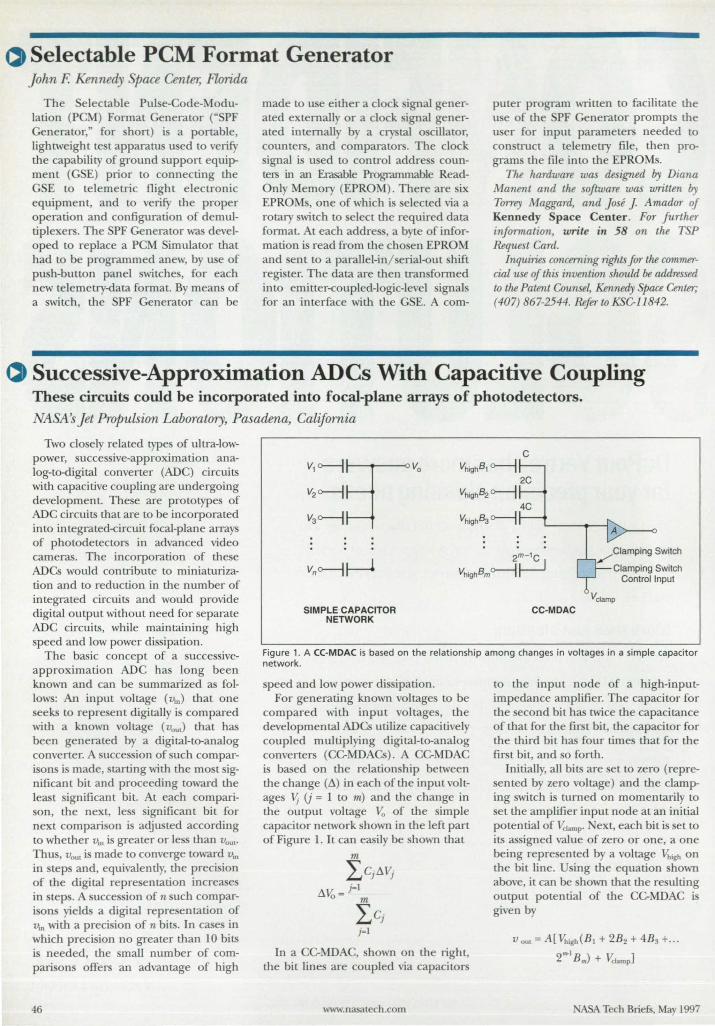
Selectable PCM Format Generator John F. Kennedy Space Center, Florida
The Selectable Pulse-Code-Modulation (PCM) Format Generator ("SPF Generator," for short) is a portable, lightweight test apparatus used to verify the capability of ground support equipment (GSE) prior to connecting the GSE to telemetric flight electronic equipment, and to verify the proper operation and configuration of demultiplexers. The SPF Generator was developed to replace a PCM Simulator that had to be programmed anew, by use of push-button panel switches, for each new telemetry-data format. By means of a switch, the SPF Generator can be
made to use either a clock signal generated externally or a clock ignal generated internally by a cry tal 0 cillator, counters, and comparators. The clock ignal is used to control addre coun-
ters in an Erasable Programmable ReadOnly Memory (EPROM). There are six EPROMs, one of which is selected via a rotary wi.tch to select the required data format. At each addre ,a byte of information i read from the chosen EPROM and sent to a parallel-inl erial-out shift register. The data are then transformed into emit:ter-coupled-logic-level signals for an interface with the GSE. A com-
puter program written to facilitate the u e of the SPF Generator prompts the user for input parameters needed to construct a telemetry file, then programs the file into the EPROMs.
The hardware was designed by Diana Manent and the software was written by Torrey Maggard, and Jose J. Amador of Kennedy Space Center. FOT further information, write in 58 on the TSP Request Card.
Inquilies concerning lights for the commercial use of this invention should be addressed to the Patent Counse~ Kennedy Space Center; (407) 867-2544. Refer to KSC-1l842.
~ Successive-Approximation ADCs With Capacitive Coupling These circuits could be incorporated into focal-plane arrays of photo detectors.
NASA s Jet Propulsion Laboratory, Pasadena, California
Two closely related types of ultra-Iowpower, successive-approximation analog-to-digital converter (ADC) circuits with capacitive coupling are undergoing development. These are prototypes of ADC circuits that are to be incorporated into integrated-circuit focal-plane arrays of photodetectors in advanced video cameras. The incorporation of these ADCs would contribute to miniaturization and to reduction in the number of integrated circuits and would provide digital output without need for separate ADC circuits, while maintaining high speed and low power dissipation.
The basic concept of a successiveapproximation ADC has long been known and can be summarized as follows: An input voltage (v,n) that one seeks to represent digitally is compared with a known voltage (vou,) that has been generated by a digital-to-analog converter. A succession of such com parisons is made, starting with the most significant bit and proceeding toward the least significant bit. At each comparison, the next, less significant bit for next comparison is adjusted according to whether v'n is greater or less than VOU!'
Thus, Vout is made to converge toward v'n
in steps and, equivalently, the precision of the digital representation increase in steps. A succession of n such comparisons yields a digital representation of YlO with a precision of n bits. In cases in which precision no greater than 10 bits is needed, the small number of comparisons offers an advantage of high
46
C
VhighBl 0---1 2C
VhighB:! 0---1 4C
Vhigh8:J 0---1
SIMPLE CAPACITOR NETWORK
CC-MDAC
Figure 1. A ((-MDA( is based on the relationship among changes in voltages in a simple capacitor network.
speed and low power dissipation. For generating known voltages to be
compared with input voltages, the developmental ADCs utilize capacitively coupled multiplying digital-to-analog converters (CC-MDAC ). A CC-MDAC is based on the relationship between the change (~) in each of the input voltages ~ (j = 1 to m) and the change in the output voltage Vo of the simple capacitor network shown in the left part of Figure 1. It can easily be shown that
m
lCj~Vj ~Vo = j~l
m
l Cj j~l
In a CC-MDAC, shown on the right, the bit lines are coupled via capacitors
www.nasatech.com
to the input node of a hi gh-inputimpedance amplifier. The capacitor for the second bit has twice the capacitance of that for the first bit, the capacitor for the third bit has four times that for the first bit, and so forth.
Initially, all bits are set to zero (repre-ented by zero voltage) and the damp
ing switch is turned on momentarily to set the amplifier input node at an initial potential of Vclarop' ext, each bit is set to its assigned value of zero or one, a one being represented by a voltage Vrugh on the bit line. sing the equation shown above, it can be shown that the resulting output potential of the CC-MDAC is given by
V out = A[ \'J,igh(B1 + 2B2 + 4B3 + ... 2 ... 1 B m) + Vdamp]
ASA Tech Briefs, May 1 997
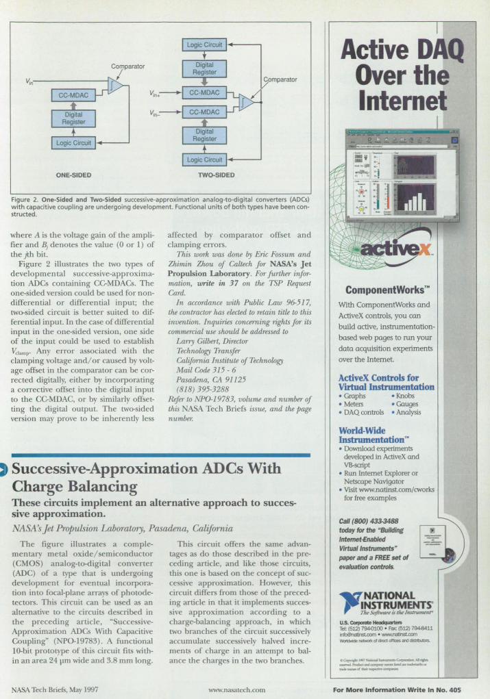
v.n·----------------1~
ONE-SIDED TWO-SIDED
Figure 2. One-Sided and Two-Sided successive-approximation analog-to-digital converters (ADCs) with capacitive coupling are undergoing development. Functional units of both types have been constructed.
where A is the voltage gain of the amplifier and BJ denotes the value (0 or 1) of the jth bit.
Figure 2 illustrates the two types of developmental successive-approximation ADCs containing CC-MDACs. The one-sided version could be used for nondifferential or differential input; the two- ided circuit is better suited to differential input In the case of differential input in the one-sided version, one side of the input could be used to establish 'Vc'.mp' Any error associated with the clamping voltage and/or caused by volLage offset in the comparator can be corrected digitally, either by incorporating a corrective offset into the digital input to the CC-MDAC, or by similarly offsetting the digital output. The two-sided version may prove to be inherently les
affected by comparator offset and clamping errors.
This work was done by Eric Fossum and Zhimin Zhou of Callech for NASA's Jet Propulsion Laboratory. Fur further information, write in 37 on the TSP Request Card.
In accordance with Public Law 96-517, the contractor has elected to retain title to this invention. Inquiries concerning rights for its commercial use shuuld be addressed to
Larry Gilbert, Director Technology Transfer California Institute of Technology Mail Code 315 - 6 Pasadena, CA 91125 (818) 395-3288
Refer to NP0-19783, volume and number of this NASA Tech Briefs issue, and the page number.
Successive-Approximation ADCs With Charge Balancing These circuits implement an alternative approach to successive approximation.
'ASA s Jet Propulsion Laboratory, Pasadena, California
The figure illu u-ate a complementary metal oxide/ emiconductor (CMOS) analog-to-digital converter (ADC) of a type that is undergoing development for eventual incorporation into focal-plane arm of photodelectors. This circuit can be used as an alternative to the circuits de cribed in the preceding article, "SuccessiveApproximation ADCs With Capacitive Coupling~ ( PO-19783). A functional lO-bit prototype of this circuit fits within an area 24 J.IIIl wide and 3.8 mm long.
ABA Tech BriefS, May 1997
This circuit offers the same advantage as do tho e de cribed in the preceding article, and like those circuits, thi one is based on the concept of successive approximation. However, this circuit differs from tho e of the preceding article in that it implements successive approximation according to a charge-balancing approach, in which two branche of the circuit succe sively accumulate succe ively halved increments of charge in an attempt to balance the charges in the two branches.
www.nasatech.com
Active D Q Over the Interne
ComponenlWorksn•
With ComponentWorks and ActiveX controls, you can build active, instrumentationbased web pages to run your data acquisition experiments over the Internet.
ActiveX Controls for VlI'huIllnstnunentation • Gmphs • Knobs • Meters • Gauges • DAQ amtrols • Analysis
World-Wide Instrumentation'" • Download experiments
developed in ActiveX and VB-script
• Run Internet Explorer or Netscape Navigator
• Visit www.natinst.com/cworks for free examples
Call (BOO) 433-3488 today fol the "Building Intemet-Enabled Virtual Instruments" paper and a FREE set of evaluation controls.
..a: NATIONAL ,-Jt'~!Y~!!!',.
u.s. COIporaIe ~ Tel: (512) 794<)100 • FaIc (5l2) 7948411 ~ ._.namsu:om __ otdolea.oIf<:esand_
o.~l991Ni11a11l~~Alrpa ___ I'lodua~"""_~""~a' tllIIk_ddlcif,..,.... .........
For More Infonnation Write In No. 405
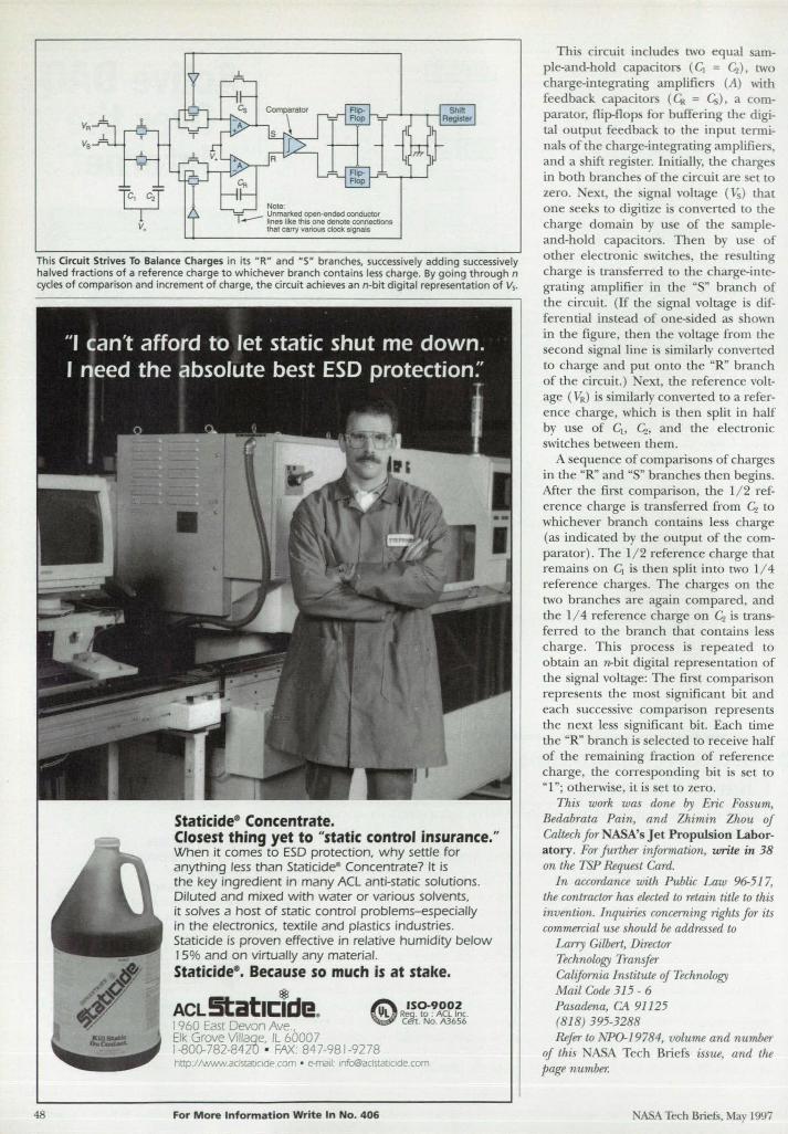
This Circuit Strives To Balance Charges in its HRH and ·S· branches, successively adding successively halved fractions of a reference charge to whichever branch contains less charge. By going through n cycles of comparison and increment of charge, the circuit ach ieves an n-bit digital representation of V,.
48
Staticidee Concentrate. Closest thing yet to "static control insurance." When it comes to ESD protection, why settle for anything less than Staticide· Concentrate? It is the key ingredient in many ACL anti-static solutions. Diluted and mixed with water or various solvents, it solves a host of static control problems-especially in the electronics, textile and plastics industries. Staticide is proven effective in relative humidity below J 5% and on virtually any material. Staticidee• Because so much is at stake.
ACL !!tatll:Tde. J 960 East Devon Ave., Elk Grove Villaqe, IL 60007
IS0-9002 IJL R!'9. to ; ACL Inc. cen. No. A3656
1-800-782-8420 • FAX: 847-981-9278 http://wwwaclsratJodecom • e-maIl [email protected]
For More Information Write In No. 406
Thi circuit include two equal ample-and-hold capacitor (~= 4 ). two charge-integrating amplifiers (A) with feedback capacitors (~ = G;) . a comparator. flip-flop for buffering the digital output feedback to the input terminals of the charge-integrating amplifiers. and a hift regi ter. Initially the charges in both branche of the circuit are et to zero. ext. the ignal voltage (V. ) that one seeks to digitize i converted to the charge domain by u e of the sampleand-hold capacitors. Then by u e of other electronic witche. the re ulting charge i transferred to the charge-integrating amplifier in the US" branch of the circuit. (If the ignal voltage is differential in tead of one- ided as hown in the figure. then the voltage from the econd ignal line i imilarly converted
to charge and put onto the URn branch of the circuit.) ext. the reference voltage (VR ) i imilarly converted to a reference charge. which is then split in half by use of Clo 4. and the electronic switches between them.
A equence of comparisons of charges in the UR" and US" branches then begins. After the fir t compari on. the 1/ 2 reference charge is transferred from 4 to whichever branch contain Ie s charge (as indicated by the output of the comparator). The 1/ 2 reference charge that remains on ~ is then split into two 1/4 reference charge . The charges on the two branches are again compared. and the 1/ 4 reference charge on 4 is transferred to the branch that contains less charge. This process is repeated to obtain an rc-bit digital representation of the signal voltage: The fir t comparison repre ents the most ignificant bit and each successive comparison represents the next less significant bit. Each time the "R" branch is selected to receive half of the remaining fraction of reference charge. the corre ponding bit is set to "1"; otherwise. it is set to zero.
This work was done by Eric Fossum. Bedabrata Pain. and Zhimin Zhou of Caltech for NASA's Jet Propulsion Laboratory. For further information. write in 38 on the TSP Request Card.
In accordance with Public Law 96-517. the contractor has elected to retain title to this invention. Inquiries concerning rights for its commercial use should be addressed to
Larry Gilbert. Director Technology Transfer California Institute of Technology Mail Code 315 - 6 Pasadena. CA 91125 (818) 395-3288 Refer to NPO-19784, volume and number
of this ASA Tech Briefs issue, and the page number.
NASA Tech Briefs. May 1997
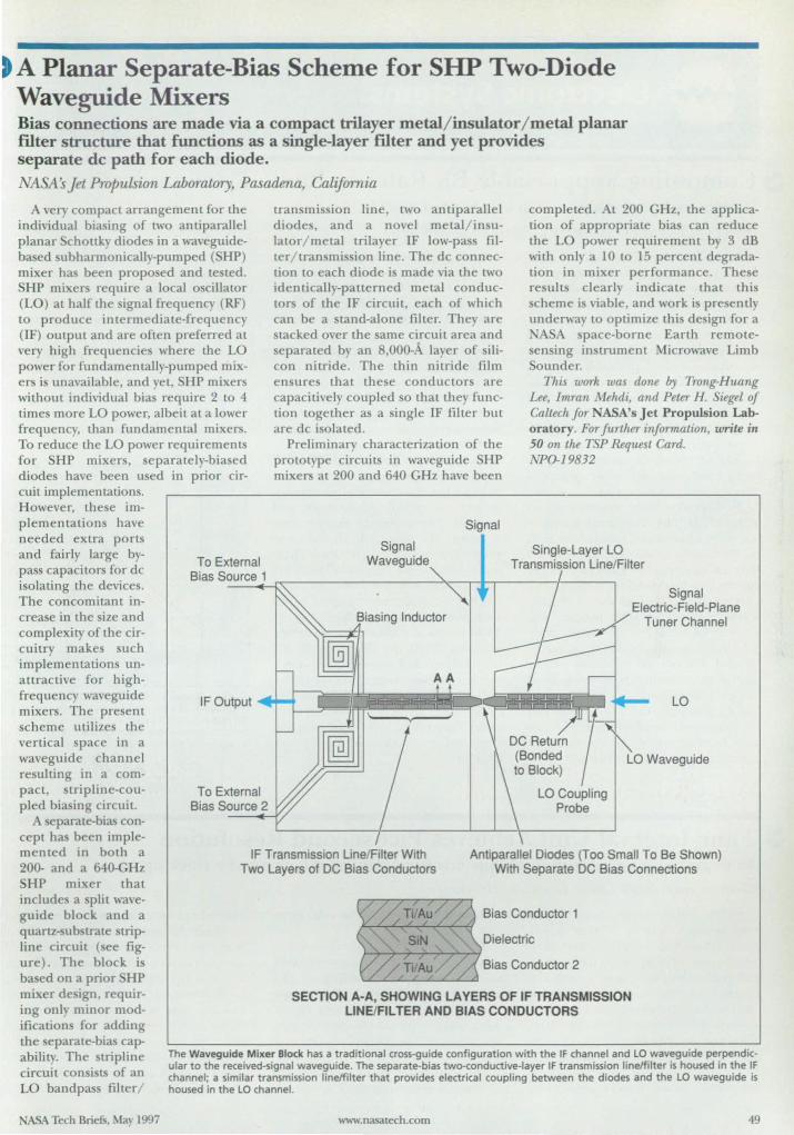
t A Planar Separate-Bias Scheme for SHP Two-Diode Waveguide Mixers Bias connections are made via a compact trilayer metal/ insulator/ metal planar Hlter structure that functions as a single-layer ffiter and yet provides separate dc path for each diode.
~SA s jet Propulsion Laboratory, Pasadena, California
A very compact arrangement for the individual biasing of two antiparallel planar chottky diodes in a waveguidebased ubharmonicaJly-pumped (SHP) mixer has been proposed and le led. SHP mixer require a local 0 cillaLOr (LO) at half the signal frequency (RF) to produce intermediate-frequency (IF) output and are of Len prefened at very high frequencies where the LO power for fundamentally-pumped mixers i unavailable, and yet, SHP mixers wiLhom indi\~dual bias require 2 to 4 times more LO power, albeit at a lower frequency, than fundamental mixer. To reduce the LO power requirements for SHP mixers, separately-biased diodes have been u ed in prior circuit implementations. H owever, the e im-p lementations have needed extra ports and fairly large bypass capacitors for dc isolating the devices. The concomitant in-crease in the ize and complexity of the cir-cuitry makes such implementations un-attractive for high-frequency waveguide mixers. The present scheme utilize the vertical space in a waveguide channel resulting in a compact, slripline-coupled biasing circuit.
A separate-bias concept ha been imple-
To External Bias Source 1
IF Output
To External Bias Source 2
lran mission line, two anti parallel diodes, and a novel metal/in ulaLOr/ metal trilayer IF low-pass filter/ transmission line. The dc conneclion to each diode is made via the two identically-patterned metal conductor of the IF circuit, each of which can be a stand-alone filter. They are tacked over the same circuil area and
separated by an 8,000-A layer of silicon nitride. The thin nitride film ensures lhat these conductors are capacitively coupled so Lhat they function together as a single IF filter but are dc isolated.
Preliminary characterization of Lhe prototype circuits in waveguide HP mixers at 200 and 640 GHz have been
Signal Waveguide
Signal
completed. At 200 GHz, the application of appropriate bias can reduce the LO power requirement by 3 dB with only a 10 to 15 percent degradation in mixer performance. The e results clearly indicate that this cherne is viable, and work i presently
unden\'ay to optimize tllis design for a ASA pace-borne Earth remote
ensing instrument Microwave Limb Sounder.
This WO'rk was done by Trang-Huang Lee, Imran Mehdi, and Peter H. Siegel of Caltech for NASA's Jet Propulsion Laboratory. For further infonnation, write in 50 on the TSP Request CaTd. NPO-J9832
~ Signal I Electric-Field-Plane V Tuner Channel
~/1
LO
memed in both a 200- and a 640-GHz SHP mixer that include a plit wave-
IF Transmission Line/Filter With Two Layers of DC Bias Conductors
Antiparallel Diodes (Too Small To 8e Shown) With Separate DC Bias Connections
guide block and a quartz- ub trate trip-line circuit ( ee fig-ure). The block is based on a prior HP mixer de ign, requir-ing only minor mod-ifications for adding the separate-bias capability. The tripline circuit consists of an LO bandpass filter/
ASA Tech Briefs, May 1997
Bias Conductor 1
Dielectric
Bias Conductor 2
SECTION A-A, SHOWING LAYERS OF IF TRANSMISSION LIN ElFi L TER AND BIAS CONDUCTORS
The Waveguide Mixer Block has a traditional cross-guide configuration with the IF channel and LO waveguide perpendicular to the received-signal waveguide. The separate-bias two-conductive-Iayer IF transmission lineJfilter is housed in the IF channel; a similar transmission lineJfilter that provides electrical coupling between the diodes and the LO waveguide is housed in the LO channel.
www.nasatech.com 49
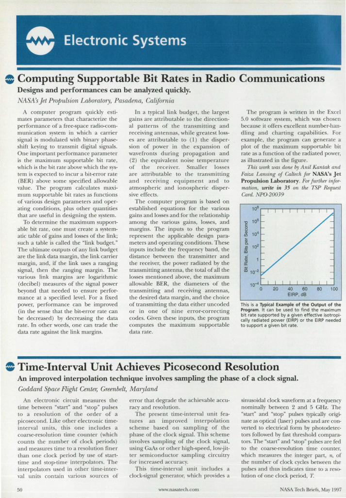
• Computing Supportable Bit Rates in Radio Communications Designs and performances can be analyzed quickly. NASA's Jet Propulsion Laboratory, Pasadena, California
A computer program quickly estimates parameLer that characterize the performance of a free-space radio-communication system in which a carrier signal is modulated with binary phaseshift keying to transmit digital signals. One important performance parameter is the maximum supportable bit rate, which is the bit rate above which the system i expected to incur a bit-error rate (BER) above some specified allowable value. The program calculates maximum supportable bit rates as functions of various design parameters and operating conditions, plus other quantities that are useful in designing the system.
To determine the maximum supportable bit rate, one must create a systematic table of gains and 10 ses of the link; such a table is called the "link budget." The ultimate outputs of any link budget are the link data margin, the link carrier margin, and, if the link uses a ranging signal, then the ranging margin. The various link margins are logarithmic (decibel) measures of the signal power beyond that needed to ensure performance at a specified level. For a fixed power, performance can be improved (in the sense that the bit-error rate can be decreased) by decreasing the data rate. In other words, one can trade the data rate against the link margins.
In a typical link budget, the large t gains are attributable to the directional patterns of the transmitting and receiving antennas, while greatest losses are attributable to (1) the dispersion of power in the expan ion of wavefronts during propagation and (2) the equivalent noise temperature of the receiver. Smaller 10 es are attributable to the transmitting and receiving equipment and to atmo pheric and ionospheric dispersive effects.
The computer program is based on established equations for the various gains and losses and for the relationship among the various gains, losses, and margins. The inputs to the program repre ent the applicable design parameters and operating condition . These inputs include the frequency band, the distance between the transmitter and the receiver, the power radiated by the transmitting antenna, the total of all the losses mentioned above, the maximum allowable BER, the diameters of the transmitting and receiving antennas, the desired data margin, and the choice of transmitting the data either uncoded or in one of nine error-correcting codes. Given these inputs, the program computes the maximum supportable data rate .
The program is written i:n the Excel 5.0 oftware system, which was chosen because it offer excellent number-handling and cbarting capabilities. For example, the program can generate a plot of the maximum supportable bit rate as a function of the radiated power, as illustrated in the figure.
This work was done by Anil Kantak and Faiza Lansing of Caltech for NASA's J et Propulsion Laborator y. For further information, write ill 35 on the TSP Request Cm·d. NP0-20039
li;
~ 102 iIi 2 til a: iIi 10-2
10-4 '-",---'--'--'---'---I.--'_J...-.J.--l o 20 40 60
EIRP, dB 80 100
This is a Typical Example of the Output of the Program. It can be used to find the maximum bit rate supported by a given effective isotropically radiated power (EIRP) or the EI RP needed to support a given bit rate.
• Time-Interval Unit Achieves Picosecond Resolution An improved interpolation technique involves sampling the phase of a clock signal. Goddard Space Flight Center; Greenbelt, Maryland
An electronic circuit measure the time betw'een "start" and "stop" pulses to a resolution of the order of a picosecond. Like other electronic timeinterval units, thi one includes a coarse-resolution time counter (which counts the number of clock periods) and measures time to a resolution finer than one clock period by use of starttime and stop-time interpolators. The interpolators used in other time-interval units contain various sources of
50
error that degrade the achievable accuracy and resolution.
The present time-interval unit feature an improved interpolation scheme based on sampling of the phase of the clock signal. This scheme involves sampling of the clock signal, using GaAs or other high- peed, lowjitter emiconductor sampling circuitry for increased accuracy.
This time-interval unit includes a clock-signal generator, which provides a
www.nasatech.com
sinusoidal clock waveform at a frequency nominally between 2 and 5 GHz. The "start" and "stop" pulses typically originate as optical (laser) pulses and are converted to electrical form by photodetector followed by fast threshold comparators. The "start" and .. top" pulses are fed to the coarse-resolution time counter, which measures the in teger part, 11., of the number of clock cycles between the pulses and thus indicates time to a resolution of one clock period, T.
NASA Tech Briefs, May 1997
Backup 64 GB An Hour To The Strongest Tape Ever Made
[5 6 6
Plug Compatible With
Alliant Alpha Micro
Altos Amdahl Apollo
Arix AT&T
Basic-4 Bull
Concurrent Convergent
Data General Digital
GouldlEncore Harris
Honeywell HP
IBM PC/Compatible IBM MidrangeJMainframe
ICl Intergraph Macintosh
McDonnell Dougla. Motorola
NCR NeXT Novell Pertee: Prime
Pyramid Sequent
Silicon Graphics Stratus
Sun Texas Instruments
Unisys Ultimate
Wang Windows NT
eusv TAPE stATUS 11 .,. ----
Let's face it, your backup is only as good as your tape. And all the performance
in the world won't get your data back if your tape is weak or dirty. Fortunately,
there's no need to compromise. The CY-8000 is the safest, the most
reliable, and the fastest 8mm tape drive on the market.
The CY-8000 uses Advanced Metal Evaporated media, a
100% cobalt, 2-layer tape that features a diamond-like coating for
exceptional durability. And it's the only 8mm drive with a built-in head cleaner
to keep the tape path free of contaminants, further ensuring data integrity and
virtually eliminating the time and expense associated with cleaning kits.
In addition to superior design, the CY-8000 offers unbeatable performance. Able
to store 25 GB at 3 MBS, uncompressed, you can achieve up to 125 GB at 9 MBS
with optional data compression. With 257% more capacity and 500%
greater speed" than industry standard 8mm drives, the CY-8000 can
backup faster to fewer tapes. 7be ,.,_mo, iks'g" of tbe
,tIrE lOpe ,..r..s 1/ sWahie lor }(J.(J(X)passes
For maximum flexibility, our exclusive Advanced SCSI
Processor option provides five recording modes - striping,
mirroring, cascade, independent, and offline copy/verify. So you can
easily make duplicate tapes for off-site storage or data exchange, build fault
tolerance, or simply maximize performance to accomplish bigger backups in
less time. With the Advanced SCSI Processor, you've got a complete data
storage management tool.
Available in a single or multi-drive desktop, rack mount, or library
configuration, the CY-8000 is scalable to 15.75 terabytes. If you need to
ensure the safety of your company's critical data, don't trust anything less.
Automall acasr to up wsi.r dmftOM
J 26 tapes .,Ib t;Jurmtefllge1tl
Ill{JI!hbTary
• Uncompressed; CY.SOOO performance advantages are even more impressive with data compression.
(757) 833-9000 ,r----,.""-., f::""':: :: ~NETICS - -- .. -- .. -- - --- -- - ----- .. - _. ---- .... -- .. -- _ .. - .- .. ----- .. ------ - - -- -
111 Cybernetics Way • Yorktown, VA 23693 • Fax (757) 833-9300
For More Information Write In No.562
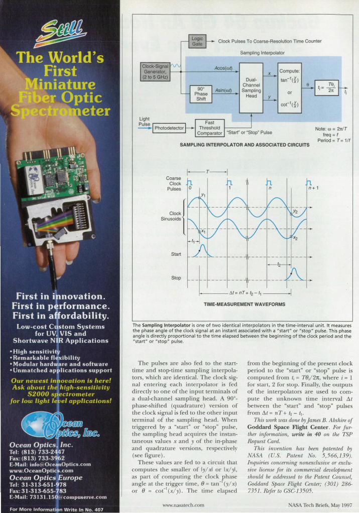
Clock Pulses To Coarse-Resolution Time Counter
Acos(oo~
Asln(ool)
Sampling Interpolator
DualChannel Sampling
Head
x Compute:
tan-l(~)
or
Note: 00 = 2rrJT Iraq = f
Period = T = 1/f SAMPLING INTERPOLATOR AND ASSOCIATED CIRCUITS
Coarse Clock
Pulses
Start
Stop
I-T-j
TIME-MEASUREMENT WAVEFORMS
The Sampling Interpolator is one of two identical interpolators in the t ime-interval unit. It measures the phase angle of the clock signal at an instant associated with a "start" or "stop" pulse. This phase angle is directly proportional to the t ime elapsed between the beg inning of the clock period and the "start " or "stop" pulse.
The pul es are also fed to the tarttime and top-time sampling interpolators, which are identical. The clock ignal entering each interpolator i fed directly to one of the input terminal of a dua(...channel ampling head. A 90°_ phase-shifted (quadrature) ver ion of the clock signal is fed to the other input terminal of the ampLing head. When triggered by a " tart" or " top· pulse, the ampling head acquire the instantaneou value x and y of the in-phase and quadrature version, re pectively ( ee figure).
The e value are fed to a circuit that compute the maller of Iyl x! or Ixlyl, as part of computing the clock ?,hase angle at the trigger time, (J = Lan - (yl x) or (J = coC I (xl y). The time elapsed
www.nasatech. om
from the beginning of the pre ent clock period to the "start" or "stop" pu l e i computed from t, = T(Jj 21t, where i = 1 for start, 2 for stop. Finally, the outputs of the interpolator are used to compute the unknown time interval /1t between the " tart" and " top" pul es from /1t = nT+ /..z - tl .
This work was done by James B. Abshire of Goddard Space Flight Center. For further information, write in 40 on the TSP lUquest Card.
This invention has been patented by :ASA (U . . Patent o. 5,566,139).
Inquiries concerning nonexclusive or exclusive license for its commercial development should be addressed to the Patent Counsel, Goddard SPace Flight Center; (301 ) 286-7351. lUfer to GSC-13505.
Tech Briefs, May 1997
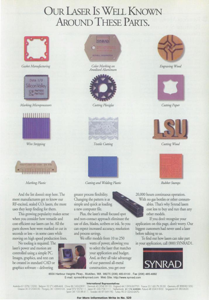
OUR LAsER Is WEI I I KNOWN AROUND THESE PARfS.
GdSket Manufacturing
Marking Microprocessors
Wt're Stripping
Marking Plastic
And the list doesn't stop here. The more manufacrurers get to know our RF-excited, sealed CO~ lasers, the more uses they keep 6nrung for them.
This growing popularity makes sense when you consider how versatile and cost-efficient our lasers can be. All the pans shown here were marked or CUt in seconds or less - in some cases while moving on !Ugh speed production lines.
No tooling is required. The laser's power and motion are controlled using a simple Pc. Images, graphics and text can be created in standard CAD or graphics software - delivering
Color Marking on AnodizedAluminum
Cutting Pkxiglas
T extik Cutting
Cutting and Welding Plastic
greater process flexibility. Changing the pattern is as simple and quick as loacling a new computer file.
Plus, the laser's small focused spot and non-contact approach eliminate the use of rues, blades, scribers or ink. So you can expect increased accuracy. resolution and process savin~.
We offer models from 1 ° ro 250 wattS of power, allowing you to select the laser mat matches your application and budget. And, as they all take advantage of our patented all-meta! construction, you get over
Engraving Wood
Cutting Paper
Cutting Wood
Rubber Stamps
20,000 hours continuous operation. With no gas bottles or other consum
abies. That's why Synrad lasers cost less to buy and run than any other models.
If you don't recognize your application on this page, don't worry. Our biggest customers had never used a laser before ta!king to us.
To find out how lasers can take part in your application, call (800) SYNRADl.
SYNRAD 6500 Harbour Heights Pkwy .• Mukilteo. WA 98275 (206) 483-6100 . Fax (206) 48~882
E-mail: [email protected] Web Site: http://www.synrad.com
tn!emotional Representatives Auslro/'o 61 1376115200. BeIg urn 32 (711488·44-11. Ch.oa 86 143-658-Q Denmorl: 451354130133 England 44 !1295~267755. flO"'" 33 1-60795900 Germany 49 898W 1350.
Greece 30 312-045-50 Hungcny 36 1·269<l105 Isroel972 9574111 japan 81 (33) 758-111 Nelherlonds 31 172.46060. Poland 48 224·318-02 $;ngopo<e 65 382·2633. $po;n 34 1·35.88.61' s-Jen 46 87·569-190. Turkey 90 2·122-63-2670
For More Information Write In No. 520
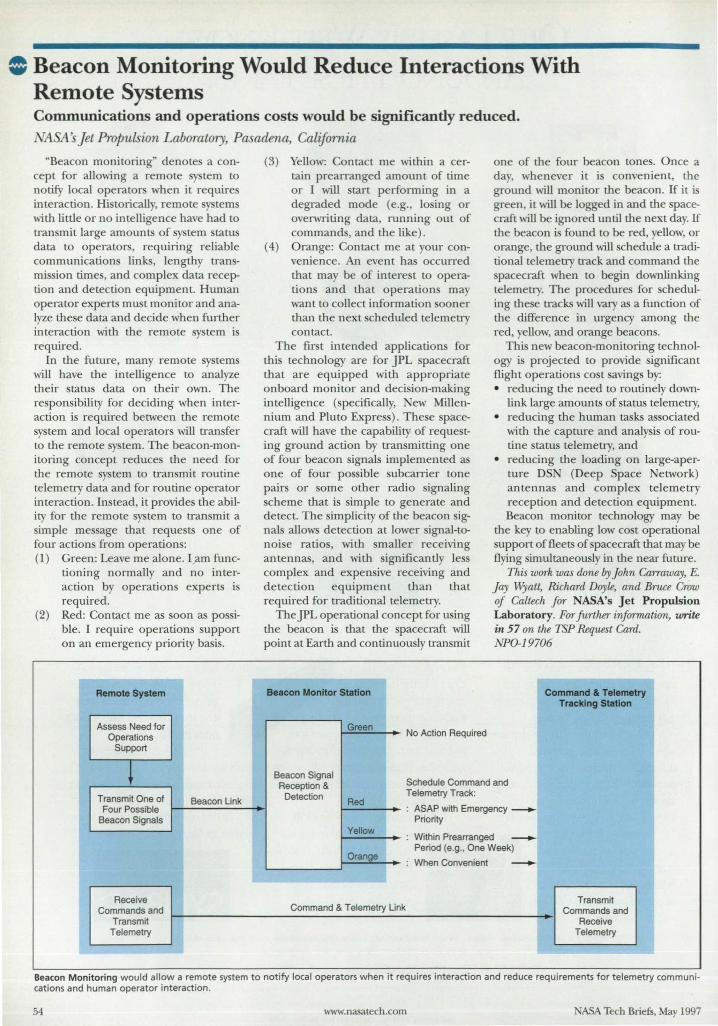
• Beacon Monitoring Would Reduce Interactions With Remote Systems Communications and operations costs would be significantly reduced.
i1SA ~ Jet Propulsion Laboratory, Pasadena, California
"Beacon monitoring" denotes a concept for allowing a remote y tern to notify local operators when it requires interaction. Hi torically, remote tern with Little or no intelligence have had to transmit large amounts of ystem tatu data to operator, requiring reliable communication links, lengthy transmission time , and complex data reception and detection equipment. Human operator experts must monitor and analyze these data and decide when further interaction with the remote system is required.
In the future, many remote y tern will have the intelligence to analyze their status data on their own. The responsibility for deciding when interaction is required between the remote system and local operators will transfer to the remote ystem. The beacon-monitoring concept reduces the need for the remote ystem to transmit routine telemetry data and for routine operator interaction. Instead, it provides the ability for the remote system to tran mit a simple message that requests one of four actions from operations: (1) Green: Leave me alone. I ,am func
tioning normally and no interaction by operations experts is required.
(2) Red: Contact me as soon as possible. I require operations support on an emergency priority basis.
Remote System
Assess Need for Operations
Support
l Transmit One of Beacon Unk
Four Possible Beacon Signals
Receive Commands and
Transmit I
Telemetry
(3) Yellow: Contact me within a certain prearranged amount of time or I will tart performing in a degraded mode (e.g. , 10 ing or overwriting data, running out of command, and the like).
(4) Orange: Contact me at your convenience. An event has occurred that may be of interest to operations and that operation may want to collect information ooner than the next scheduled telemetry contact.
The first intended applications for this technology are for JPL spacecraft that are equipped with appropriate on board monitor and decision-making intelligence (specifically, New Millennium and Pluto Express). These spacecraft will have the capability of requesting ground action by transmitting one of four beacon signals implemented as one of four possible subcarrier tone pairs or some other radio signaling scheme that is simple to generate and detect. The simplicity of the beacon ignals allows detection at lower ignal-tonoise ratios, with smaller receiving antennas, and with significantly less complex and expensive receiving and detection equipment than that required for traditional telemetry.
The JPL operational concept for u ing the beacon is that the spacecraft will point at Earth and continuously transmit
Beacon Monitor Station
Green I No Action Required
one of the four beacon tone . Once a day, whenever it i convenient, the ground will monitor the beacon. If it is green, it will be logged in and the pacecraft will be ignored until the next day. If the beacon is found to be red, yellow, or orange, the ground will chedule a traditional telemetry track and command the pacecraft when to begin downlinking
telemetry. The procedures for cheduling these tracks will vary as a function of tlle difference in urgency among the red, yellow, and orange beacons.
This new beacon-monitoring technology is projected to provide significant flight operations co t avings by: • reducing the need to routinely down
link large amounts of status telemetry, • reducing the human tasks associated
with the capture and analysis of routine status telemetry, and
• reducing the loading on large-aperture DS (Deep Space etwork) antennas and complex telemetry reception and detection equipment. Beacon monitor technology may be
the key to enabling low co t operational support of fleets of pacecraft that may be flying simultaneously in the near future.
This work was done by John Carraway, E. Jay Wyatt, Richard Dayle, and Bruce Crow of Caltech for NASA's Jet Propulsion Laboratory. For further information, write in 57 on the TSP Request Card. NPO-19706
Command & Telemetry Tracking Station
Beacon Signal Schedule Command and Reception & Telemetry Track: Detection
Red : ASAP with Emergency _
Priority Yellow
Within Prearranged : -Orange
Period (e.g., One Week)
: When Convenient -Command & Telemetry Unk I
Transmit Commands and
Receive Telemetry
Beacon Monitoring would allow a remote system to notify local operators when It requires interaction and reduce requirements for telemetry communications and human operator interaction.
54 www.nasatech.com NASA Tech Briefs, May 1997
World's Fastest AID Cards for ISA and PCI Bus
~ .~. -~ .
500 MSPS AID Card for PCI Bus
CompuScope 8500/PCI
• 500 MSPS Real Time Sampling AID Card
• 8 Bit Resolution
• 100 MB/s Data Transfer Rate to PC Memory
• Real-Time Capture to PC Memory at 100 MSPS
• Up to 2 Meg Memory
• 250 MHz Bandwidth
Cal 1-800-567-GAGE 4 2 4 3
Ask for extension 3406
• up to 100 MSPS,12 Bit AiD Card on ISA Bus
• Up to 250 MSPS, 2 GS/s , 8 Bit AiD Card on ISA Bus
• 16 Meg Memory
• Up to 16 Cards in one Industrial PC
• Drivers in DOS, QNX, Win 3.1, Win 95 and Win NT
Support for HP VEE, LabVIEW, LabWindows eVI, ...
a GAGE APPLIED SCIENCES (U.S.) INC. 1233 Shelburne Road, Suite 400 South Burlington, VT 05403 Tel: 1-800-567-4243 Fax: 1-800·780·8411 e-mail: [email protected] web site: http://www.gage-applied.com
From Outside the U.S. contact, Gage Applied Sciences Inc., 5610 Bois Franc, Montreal, ac, Canada, H4S 1A9 Tel: 514·337-6893 Fax: 514·337·9844
For More Information Write In No. 540
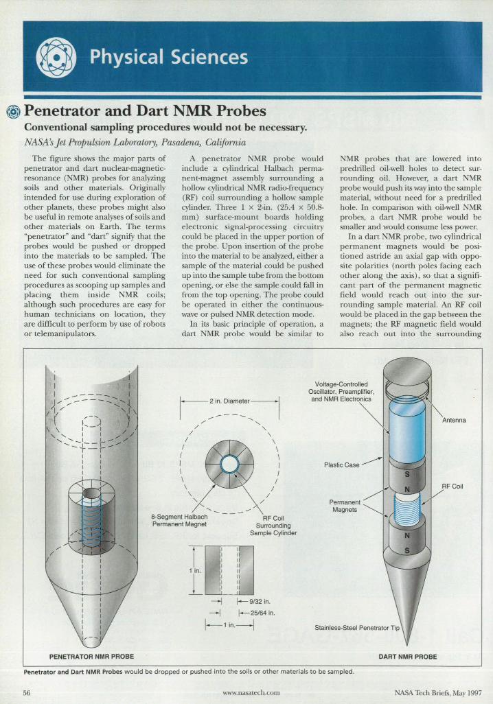
@ Penetrator and Dart NMR Probes Conventional sampling procedures would not be necessary.
r;1SA s Jet Propulsion Laboratory, Pasadena, California
The figure shows the major parts of penetrator and dart nuclear-magneticresonance (NMR) probes for analyzing soil and other materials. Originally intended for use during exploration of other planets, these probes might also be useful in remote analyses of soils and other materials on Earth. The terms "penetrator" and "dart" signify that the probes would be pushed or dropped into the materials to be sampled. The use of these probes would eliminate the need for such conventional sampling procedures as scooping up samples and placing them inside MR coils; although such procedures are easy for human technicians on location, they are difficult to perform by use of robots or telemanipulators.
A penetrator NMR probe would include a cylindrical Halbach permanent-magnet assembly urrounding a hollow cylindrical NMR radio-frequency (RF) coil surrounding a hollow sample cylinder. Three 1 x 2-in. (25.4 x 50.8-mm) surface-mount board holding electronic signal-processing circuitry could be placed in the upper portion of the probe. Upon insertion of the probe into the material to be analyzed, either a sample of the material could be pushed up into the sample tube from the bottom opening, or else the sample could fall in from the top opening. The probe could be operated in either the continuouswave or pulsed NMR detection mode.
In its basic principle of operation, a dart NMR probe would be similar to
NMR probe that are lowered into predrilled oil-well holes to detect surrounding oil. However, a dart NMR probe would push its way into the sample material, without need for a predrilled hole. In comparison with oil-well NMR probes, a dart MR probe would be smaller and would consume less power.
In a dart NMR probe, two cylindrical permanent magnets would be positioned astride an axial gap with opposite polarities (north poles facing each other along the axis), so that a significant part of the permanent magnetic field would reach out into the surrounding ample material. An RF coil would be placed in the gap between the magnets; the RF magnetic field would also reach out into the surrounding
I-~:~a~:r~ Voltage-Controlled
Oscillator, Preamplifier, and NMR Electronics
PENETRATOR NMR PROBE
/' ...... , / " / \
/ \ 1 \ I \ I I \ I
\\/ /1 " / .....
...... - ...-a·Segment Halbach Permanent Magnet
1 in.
RFCoil Surrounding
Sample Cylinder
25/64 in.
1-1in.-I
Plastic Case
Permanent Magnets
Stainless-Steel Penetrator Tip
DART NMR PROBE
FCoil
Penetrator and Dart NMR Probes would be dropped or pushed into the soils or other materials to be sampled.
56 www.nasatech.com NASA Tech Brie fs , May 1997
I I I I
• I I I , I I I I I I I I
~--------~- ----------- - ---- -- -------------.
Sarnoff Corporation name DaWck§{3.~f.f ~ep~~ Q,£ter phone 609 734 2000 fax 609 734 222]
address 201 Washington Rd Princeton, NJ 08540-6449
notes
www.sarnoff.com New name, same great ideas.
,-- ,-I ' I I I I I I
r' ." I I I ---------------, ----------'* ..... _-------------
Pardon us for Name Dropping ...
David. arnoff Re earch Center ha gro\\ n 0 far and 0 wide of our beginning that we need a new name to reflect our broader cope.
and information technology that i changing }our world. From consumer electronic to diagnostic imaging. we have a name for developIng products that open new opportunities and add depth to existIng market - which i why arnoff advance have led to the formation of 8 ne\\ pinoff companies.
Le s i more.· arnoff Corporation i our new name. Fewer word Greater breadth. And the ame innO\ative approach that helped create high-definition TV ... atellite-to-home \ ideo ... Developments as vital and per onal a dIgital tools that improve breast cancer diagnosi .
arnoff Corporation i at the heart and forefront of the "digital re\olutJon . \\e create and commercialize electronic. biomedical
As information technology radically changes the way we live and learn •• arnoff Corporation has the talent, skill. and outlook to evolve world-changing concepts.
arnoff Corporation ... Our name for the future.
SARNOFF Corp oration
Cllanging the World with Technology
For More Information
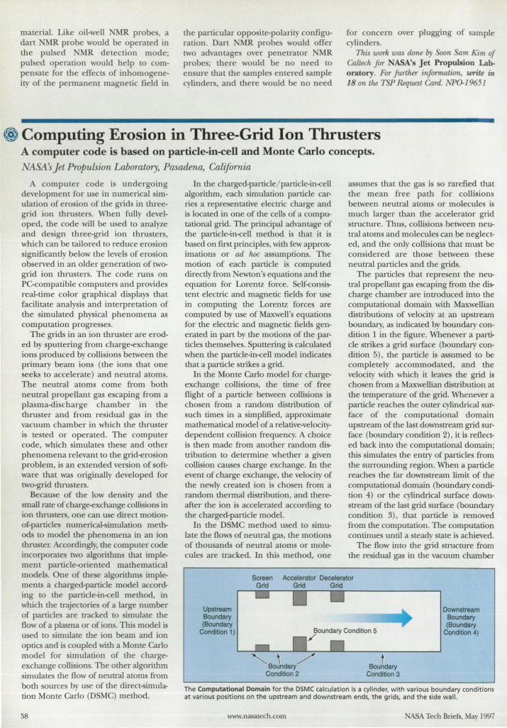
material. Like oil-well NMR probe a dan 1R probe would be operated in the pul ed MR detection mode; pulsed operation would help to compen ate for the effects of inhomogeneity of the permanent magnetic field in
the particular oppo ite-polarity configuration. Dart MR probe would offer two ad\'antage over penetrator NMR probe; there would be no n d to
en ure that the ample entered ample c linders, and there would be no need
for concern over plugging of ample cylinders.
This work was done by oon Sam Kim of Caltech for NASA's J et Propulsion Laboratory. For further information, write in 18 on the TSP Requ t Card. NPO-19651
* Computing Erosion in Three-Grid Ion Thrusters A computer code is based on particle-in-cell and Monte Carlo concepts.
NASA' Jet Propulsion Laboratory, Pasadena, Califamia
A computer code is undergoing development for u e in numerical imulation of ero ion of the grid in threegrid ion thrusters. When fully developed, the code will be used to analyze and de ign three-grid ion thruster, which can be tailored to reduce ero ion significantly below the levels of ero ion ob erved in an older generation of twogrid ion thru ters. The code run on PC-compatible computers and provide real-time color graphical displays that facilitate analy is and interpretation of the simulated phy ical phenomena as computation progresse .
The grids in an ion thruster are eroded by puttering from charge-exchange ions produced by colli ions between the primary beam ions (the ions that one eeks to accelerate) and neutral atoms.
The neutral atoms come from both neutral propellant gas escaping from a plasma-di charge chamber in the thruster and from residual gas in the vacuum chamber in which the thru ter is te ted or operated. The computer code, which simulates these and other phenomena relevant to the grid-erosion problem, is an extended version of software tllat was originally developed for two-grid thrusters.
Because of the low den ity and the small rate of charge-exchange collisions in ion thrusters, one can use direct motionof-particle numerical~imulation methods to model the phenomena in an ion thru ter. Accordingly, the computer code incorporates two algorithms that implement particle-oriented mathematical models. One of these algorithms implements a charged-particle model according to the particle-in-cell method, in which me trajectorie of a large number of particles are tracked to imulate the flow of a plasma or of ions. This model is used to simulate the ion beam and ion optics and is coupled with a Monte Carlo model for imulation of the chargeexchange collisions. The other algorithm simulates me flow of neutral atoms from bom sources by use of the direct~imulation Monte Carlo (DSMC) method.
58
In the charged-particle/ particle-in-cell algorithm, each imulation particle carrie a repre entative electric charge and is located in one of the cell of a computational grid. The principal advantage of the particle-in-cell method is that it is based on first principle, with few approximation or ad hoc as umptions. The motion of each particle i computed directly from Newton' equation and the equation for Lorentz force. elf-consistent electric and magnetic fields for use in computing tlle Lorentz force are computed by use of Ma,.."well' equation for the electric and magnetic fields generated in part by the motion of me particle them elves. puttering is calculated when me particle-in-cell model indicate that a particle trike a grid.
In the Monte Carlo model for chargeexchange collision, the time of free flight of a particle between collisions is chosen from a random distribution of uch time in a implified, approximate
mathematical model of a relative-velocitydependent collision frequency. A choice is then made from another random distribution to determine whether a given collision causes charge exchange. In me event of charge exchange, the velocity of the newly created ion is cho en from a random thermal distribution, and thereafter me ion is accelerated according to the charged-particle model.
In the D Me method u ed to imulate the flow of neutral gas, me motion of thousands of neutral atom or molecule are tracked. In this method, one
as ume that the gas is 0 rarefied that the mean free path for coUi ions between neutral atom or molecule is much larger than the accelerator grid tructure. Thu , colli ions between neu
tral atom and molecule can be neglected, and the only collisions that mu t be considered are tho e between the e neutral particle and the grids.
The particle that represent the neutral propellant gas e caping from the discharge chamber are introduced into the computational domain with Maxwellian distributions of velocity at an up tream boundary, as indicated by boundary condition 1 in me figure. Whenever a particle strike a grid surface (boundary condition 5), me particle is assumed to be completely accommodated, and the velocity witll which it leave the grid is cho en from a Maxwellian distribution at the temperature of the grid. Whenever a particle reache the outer cylindrical urface of the computational domain up tream of the last down tream grid surface (boundary condition 2), it is reflected back into the computational domain; this imulate the entry of particles from me surrounding region. When a particle reaches me far downstream limit of the computational domain (boundary condition 4) or the cylindrical urface down-tream of the last grid urface (boundary
condition 3), that particle is removed from the computation. The computation continue until a teady tate is achieved.
The flow into the grid structure from the re idual gas in the vacuum chamber
Screen Accelerator Decelerator
Upstream Boundary (Bounda/)'
Condition 1)
Grid Grid Grid
Boundary Condition 5 /
Downstream Boundary (Boundary
Condition 4)
The Computational Domain for the DSMC calculation is a cylinder, with various boundary conditions at various pOSitions on the upstream and downstream ends, the grids, and the side wall.
www.nasatech.com ASA Tech Briefs, May 1997
is calculated similarly, except that the boundary conditions are different. The calcuJation of this flow serves to validate the DSMC algorithm, inasmuch as the density of neutral atoms or molecuJes in the steady state must become approximately uniform at the density of the residual gas in the vacuum chamber. The densities of neutral atoms or molecuJes oir tained from the two Monte Carlo calculations are summed, and the sum is used as the neutral-particle density for the chargeexchange and sputtering calcuJations.
Predictions made by this computer code were compared with measurements taken in experiments on ion thrusters with several different three-grid configurations. The code predicted the differences among the purveyances of these configurations. It predicted the insensiti .... ity of the current impinging on the accelerator grid to the pressure of the residual gas, but predicted too small a value for this current. The code also predicted the dependence of the decelerator-grid current on pressure and the fact that significant erosion can be caused by ions extracted from a weakly ionized downstream plasma.
This wlJ/"k was done by Quem Zhang, Xiaohang Peng, and Dennis Keefer of ERC, Inc., for NASA's Jet Propulsion Laboratory. For fUrther information, write in 72 on the TSP Request Card. NP0-30017
W Galvanic Cell for Measuring Rates of Corrosion Marshall SPace Flight Center; Alabama
A galvanic cell can serve as a simple apparatus for measuring rates of galvanic corrosion of di similar metals. Such a cell can be con tructed by filling a glas beaker wiLh an electrolyte like that encountered in the corrosive environment, (e.g., 0.1 M aCI repre enting a coastal environment), partly immersing coupons of the two dissimilar metals in the olution, attaching wires to the dry pans of the coupon , and connecting the free ends of the wire to the terminals of an ammeter. The galvanic current indicated by the ammeter is directly related to the rate of corrosion.
This work was done by S. Rachel Klwshbin, John R Emmcns, and Martin W Kendig of Boeing North American, Inc., for Marshall Space Flight Center. For further information, write in 54 on the TSP Request Card. MFS-30J03
NASA Tech Briefs, May 1997
Essential for planning, tracking, reporting, presenting, and organizing your work!
In the engineering world, nothing happens \\.;thout a schedule and everything comes ~~!(Il!" under grueling scrutiny That!; why you need Milestones, Etc .• 5.0 from KIDASA. Milestones, Etc. project scheduling software makes scheduling work and communicating the progress fast and easy. You can create master schedules contaIning instant h}perlinks to deiailed schedules, documentation, finaridaI iriformaLion, even web pages. And with buih in. roject wizards, spell-checking,
imp9rt ca , datagraphs, and more, .M11d10t1~:s, E~:hIs We sophisticated features you
to more effective in your job now. II ~~j,~~;:..project scheduling software offers I I~ See for yourself. Call today, and
Milestones, Etc. for just $169.00. Or web site at www.kidasa.com. and
WII~I:I'IIII01l- NOW! --
For More Information Wr ite In No. 408
• Spiral, flat, molded-Io-shape, wire-wound, etCh-foil, transparent.
• Broad range of materials available. • Mounting choices: pressure
sensitive adhesive, lamination, vulcanization and mechanical fastening.
• Multiple-watt denSity. • Ideal for medical, food equipment,
aerospace and appliance applications.
• Design kits available.
Jisit us on e eb 01 h>tp f;
IXO 9001 CERTIFIED • I
• Heaters recognized by international approval agencies
• Integrated Elmwood thermostats and sensors.
Call 1-800-ELMWOOD with your size and configuration, or for more information.
Elmwood ....... Sensors
Thermal Sensing and Control Technology ... Worldwide
el~ oodsensors.com 500 Narragansett Pork Drive, Pawtuckel, RI 02861, U.S.A., Tel: 401-727-1300, Fox: 401-728-5390
For More Information Write In No_ 409 59
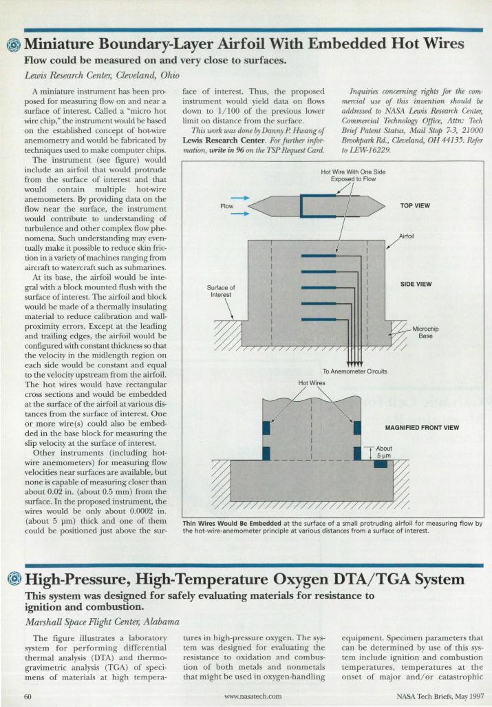
~ Miniature Boundary-Layer Airfoil With Embedded Hot Wires Flow could be measured on and very close to surfaces.
Lewis Research Center, Cleveland, Ohio
A miniature instrument has been pm· posed for measuring flow on and near a surface of interest. Called a "micro hot wire chip," the instrument would be based on the established concept of hot-wire anemometry and would be fabricated by techniques used to make computer chips.
The instrument (see figure) would include an airfoil that would protrude from the surface of interest and that would contain multiple hot-wire anemometers. By providing data on the flow near the surface, th.e instrument would contribute to understanding of turbulence and other complex flow phenomena. Such understanding may eventually make it possible to reduce skin friction in a variety of machines ranging from aircraft to watercraft such as submarines.
At its base, the airfoil would be integral with a block mounted flush with the surface of interest. The airfoil and block would be made of a thermally insulating material to reduce calibration and wallproximity errors. Except at the leading and trailing edges, the airfoil would be configured with constant thickness so that the velocity in the midlength region on each side would be constant and equal to the velocity upstream from the airfoil. The hot wires would have rectangular cross sections and would be embedded at the surface of the airfoil at various distances from the surface of interest. One or more wire(s) could also be embedded in the base block for measuring the slip velocity at the surface of interest.
O ther instruments (including hotwire anemometers) for measuring flow velocities near surfaces are available, but none is capable of measuring closer than about 0.02 in. (about 0.5 mm) from the surface. In the proposed instrument, the wires would be only about 0.0002 in. (about 5 pm) thick and one of them could be positioned just above the sur-
face of interest. Thus, the proposed instrument would yield data on flows down to 1/ 100 of the previous lower limit on distance from the surface.
This work was done 17), Danny P. Hwang of Lewis Research Center. For further information, write in 96 on the TSP Request Card.
Inquiries concerning rights for the cornmercial use of this invention should be addressed to NASA Lewis Research Center, Commercial Technology Office, Attn: Tech Brief Patent Status, Mail Stop 7-3, 21000 Brookpark Rd., Cleveland, OH 44135. Refer to LEW--16229.
Hot Wire With One Side Exposed to Flow
/,
FIO~<~~I _ fD TOP VIEW
Airfoil ,/
To Anemometer Circuits
Hot Wires
~ I MAGNIFIED FRONT VIEW
Thin Wires Would Be Embedded at the surface of a small protruding airfoil for measuring f low by the hot-wire-anemometer principle at various distances from a surface of interest.
* High-Pressure, High-Temperature Oxygen DTA/TGA System This system was designed for safely evaluating materials for resistance to ignition and combustion.
Marshall Space Flight Center, Alabama
The figure illustrates a laboratory system for performing differential thermal analysis (DTA) and thermogravimetric analysis (TGA) of specimens of materials at high tempera-
60
tures in high-pressure oxygen. The system was designed for evaluating the resistance to oxidation and combustion of both metals and nonmetals that might be used in oxygen-handling
www.nasatech.com
equipment. Specimen parameters that can be determined by use of this system include ignition and combustion temperatures, temperatures at the onset of major andl or catastrophic
NASA Tech Briefs, May 1997
NEW FROM A5TRO-MEDI
~D Channels' Brilliant Monitor'
Huge Memory' Laser Resolution Chart'
UE FIELD RECOR ER®
• Bright, High Response Monitor • 10, 20 or 30 Waveform Channels • Laser Quality (300 dpi) Chart Resolution • Huge 512 KSample Memory per Channel
for Data Capture and Analysis • True Portability: Internal BaUery and AC • Record up to 500 V Peak (Isolated) at 25 kHz
Response • Analyze Data with FFT, etc. • On-Board Floppy Drive for Setup and Memory
Transfer • Wide Format 11-Inch Chart
The all-new Dash 10 lets you receive up to 30 waveform channels (DC to 25 kHz) , see the data in real time on the bright high-speed vacuum fluorescent monitor, record with laser quality fidelity, and at the same time capture the data for playback and analysis. Now you can do all this on a truly portable package powered by internal battery or AC. The Dash 10 comes with a powerful software package, has a floppy disk for updates and data archiving, plus RS-232 and GPIB.
Phone, fax or write for details!
m tAstlO-Afed;/nc. Astro·Med Industrial Park, West Warwick, Rhode Island 02893 Phone: (401) 828·4000 • Toll-Free (800) 343-4039 • Fax: (401) 822-2430 In Canada Telephone 1-80Q.565-2216
Safes and Service Centers throughout the U.S. and Canada
Astro-Med is system certified to ISO 9001 For More Information Write In No. 558
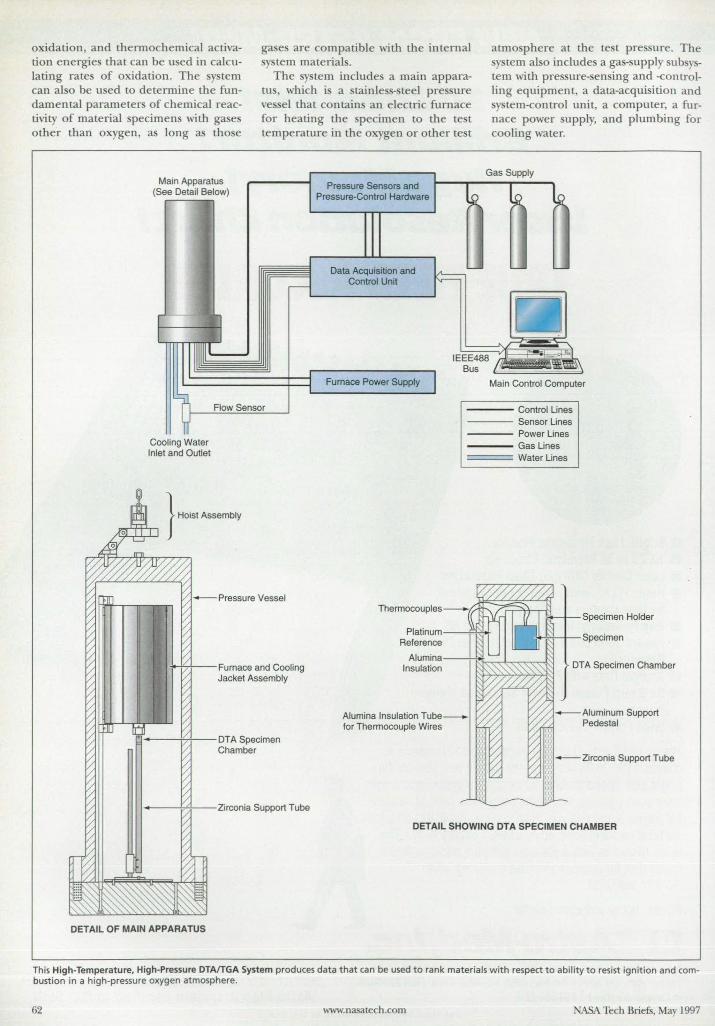
oxidation, and thermochemical actinltion energies that can be u ed in calculating rate of oxidation. The y tern can al 0 be used to determine the fundamental parameter of chemical reactivity of material pecimens with gases other than oxygen, a long as tho e
Main Apparatus See Detail Below)
r'- n I H
gase are compatible with the internal y tern materials.
The sy tern include a main apparatu , which is a tainle - teel pre ure ve sel that contain an electric furnace for heating the pecimen to the te t temperature in the 0 gen or other te t
Pressure Sensors and
~ Pressure-Control Hardware
~J Data Acquisition and Control Unit v---
atmo phere at the te t pre sure. The y tern also includes a gas-supply sub ys
tern with pre ure-sen ing and -controlling equipment, a data-acquisition and
tem-control unit, a computer, a furnace power upply, and plumbing for cooling water.
Gas Supply
~ ~
J J ~
-" - , 111111 ' IEEE488 1A ~\ Bus
1 Cooling Water Inlet and Outlet
Flow Sensor
*"f4f--Furnace and Cooling Jacket Assembly
~~o-----l'7+---DTA Specimen Chamber
1-----lT:l--Zirconia Support Tube
DETAIL OF MAIN APPARATUS
Furnace Power Supply Main Control Compute
Control Lines Sensor Lines Power Lines
---- Gas Lines = === Water Lines
Alumina Insulation Tube_ for Thermocouple Wires
Specimen Holder
C+ N-+-Specimen
DT A Specimen Chamber
-Aluminum Support Pedestal
- Zirconia Support Tube
DETAIL SHOWING DTA SPECIMEN CHAMBER
This High-Temperature, High-Pressure DTAITGA System produces data that can be used to rank materials with respect to ability to resist ignition and combustion in a high-pressure oxygen atmosphere.
62 www.nasalech.com ASA Tech Briefs, May 1997
The pecimen is contained in a DTA or TGA assembly within the main apparatus. The e two as emblies are interchangeable with respect to mounting in the main apparatus. Each as embly comprises a DTA or TGA specimen chamber on lOP of a zirconia upport tube on an adjustable-height platform. The pecimen chambers are made of alumina, which was cho en for its stability, chemical inertnes , and low electrical conductivity at high temperatures in oxidizing atmosphere .
The DTA assembly contains four Pt/(Pl/ l0 percent Rh ) (type-S) thermocouples, which measure the furnace-control, furnace-monitor, specimen, and reference temperatures. The specimen and reference thermocouples are connected in a differential arrangement that yields an additional temperature-related difference between the specimen- and referencethermocouple voltages. The TGA assembly (not shown in the figure) includes a microbalance, small pressure-resistan t chambers for a servo photocell and source of light, a specimen-mounting subassembly, a counterbalance subassembly, a tare ubassembly, and a balance stand.
The system has the following unique features: • It yields useful readings at tempera
tures up to 1,500 °C (about 1,800 K) and pressures up to 34.5 MPa in both the DTA and TGA modes.
• The position and dimensions of the furnace are chosen to maximize the working space available for the TGA or DTA assembly and minimize the convection of heated gas, Thi minimization of convection (especially at high temperature and pressure) is essential for TGA.
• The electrical and mechanical subsy tem and the computer hardware and oftware are fully accessible, so that the user can perform adjustments for special situations.
• The ystem operates safely, even though it contains oxygen at high temperature and pre sure.
• Ignition, combu cion, and onset-ofoxidation temperatures can be measured to within approximately 1.6 °C This work was done by james W
Bransford of james W Bransford & Associates for Marshall Space Flight Center. For further infonnation, write in 44 on th.e TSP Request Card.
Inquiries concermng rights for flu commercial use of this invention should he addressed to tluJ Patent CQUnse~ Marshall Space Flight Center; (205) 544-0021. Refer to MFS-26419.
ASA Tech Briefs, May 1997
:ttj
OEMs, be confused no more.
The Setra Mass tv1onitor has it all.
It's modular, easy to Install and
highly accurate, /Ind unlike most load cells, it gives you direct digital
output - no ND converter
requred. That's because the
Setra Mass tv1onttor uses our patented variable capacitance
ceramic sensor technology.
No wonder Designfax gave
the Setra Mass Monitor five stars.
/Ind no wonder there are aver 2,CXXl units in
service today. So don't put up with mass
confusion. Call Setra at 1-800-25-SETRA.
FAX: 1-508-264-0292 11"I'QUIIl 11111111111111 I U 11111111,'11 11111 III '11111111 111111111
1I111111'II~hIlII:::111111 II Ilmllul
The technology leader in precision weighing.
For More Information Write In No, 410
Solutions to Your Surface Enhancement Problems
Are Just a Mouse-click Away! - Open location
Open location: I http://www.magnaplate.com I ( Cancel ) n Open J
Visit our site for new ideas on treating metal surfaces for: Corrosion resistance _ Wear resistance _ Mold release FDA/USDA codes _ Chemical attack. Friction control
Browse our web site and you'll uncover technical data and application examples of our broad range of high-tech, space age coatings. Just click on the base metal you're using and the surface enhancement coatings we recommend will appear on the screen. Or check the pages filled with engineenng data for each coating. Our interactive response mechanism lets you initiate a personal dialogue with surface enhancement specialists who can offer Immediate assistance.
General Magnaplate Linden, NJ _ E-Mail: [email protected] _ 1-800-852-3301 _ Fax: 908-862-6110
For More Information Write In No. 411 63
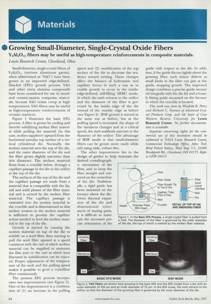
Growing Small-Diameter, Single-Crystal Oxide Fibers Y~5012 fibers may be useful as high-temperature reinforcements in composite materials. Lewis Research Center, Cleveland, Ohio
mall-diameter, ingle-cry tal fiber of Y01s012 (yttrium aluminum garnet, often abbreviated as "Y Gn
) have been grown in an improved edge-defined, film-fed (EFG) growth process. YAG and other yttria alumina compound have been considered for use in metaland ceramic-matrix composite material ; becau e YAG re ists creep at high temperatures, YAG fibers may be useful as high-temperanlre reinforcements of ceramic mau;ce .
Figure 1 illustrate the basic EFG process. A fiber is grown by cooling and thereby solidifying molten fiber material while pulling the material (in this case, molten sapphire) upward from the horizontal annular top urface of a vertical cylindrical die. ormally, the molten material wets the top of the die, and the outer diameter of the die and the fiber grows slightiy narrower than this diameter. The molten material flows from a crucible below, through a capillary passage in the die to the orifice at the top of the die.
The surfaces of the top of the die and the capillary passage are made from a material that is compatible with the liquid and solid phase of the fiber material and is wetted by the molten fiber material. The capillary pas age is extended into the molten material in the crucible and is dimensioned so that surface tension in the molten material is sufficient to provide the capillary action needed to feed the molten material to the top of the die.
Growth is started by causing the molten material on top of the die to solidify on a seed fiber, then tarting to pull the seed fiber upward at a speed con istent with tile rate at which molten material can be supplied to maintain the film and/ or the rate at which heat liberated by solidification can be rejected. Proper adjustment of the temperature of the melt and the pulling speed makes it possible to grow a cry talline fiber continuously.
The present EFG proce incorporates two improvements ( ee Figure 2). One of the improvements is a combination of (l ) an increase in the pulling
64
peed and (2) modification of the top urface of the die to decrease the ten
dency toward wetting. These change affect the balance of hydro tatic and capillary forces in uch a way as to enable growth to occur in the in ideedge-defined, self-filling (IESF) mode, in which the melt retracts to the orifice and the diameter of the fiber i governed by the in ide edge of the die instead of the outside edge as before (see Figure 2) . IESF growth is started in the same way as before, but as the pulling peed is increa ed, the hape of the meni cu change and at a critical peed, the melt uddenly narrows to the
diameter of the orifice. The advantage of IESF mode is that small-diameter fibers can be grown more easily while still using wide, robu t dies.
The other improvement lies in the design of guides to help maintain the
-- -:;:>"-
guide with re peel to the die. In addition , if the guide fits too tightiy about the growing fiber, such minor d fects as mall kinks in the fiber can jam at the
guide, stopping growth. The improved de ign combines a preci e guide mounted integrally with the die lid and a loosely fitting guide mounted on the furnace in which the crucible is located.
This work was done by Winfield B. Perry and Richard C. Ventura oj Advanced Crystal Products Corp. and Ali ayiT of Case Western Reseroe University fOT Lewis Research Center . 0 JuTther documentation is available.
Inquiries concerning rights JOT the commercial use of this invention should be addr-essed to 1\ 1\ Lewis Research Center; Commercial Technology Office, Attn: Tech Brief Patent Status, Mail Stop 7-3, 21000 BmokparkRd., Cleveland, OH 44135. Refer to LEW-160 13.
Fiber-Growth Tip at Topo! Die
t
desired crystallographic orientation of the fiber, and to keep the fiber traight and centered on the centerline of the die. Traditionally, a rigid guide has been mounted on the furnace above the die. Given thermal expansion of the die and
a-'r:EI~,,"",,;;-+Capiliary Tube (Parto! Die)
-Die Melt
dimensional toler- Heater Crucible DETAIL OF TOP OF DIE
AND EMERGING FIBER ance of mating parts, it i difficult to maintain the nece ary precise orientation of the
Figure 1. In the Basic EFG Process, a single-crystal fiber is pulled from a melt. The diameter of the fiber is governed by the outer diameter of the die, the top of which is wetted by the molten fiber material.
IESF MODE
Figure 2. VAG Fibers are shown here growing in the basic EFG and the IESF modes from a die with an outer diameter of 250 IJm and an inner diameter of 75 IJm. In the IESF mode, the melt retracts to the orifice, so that the diameter of the growing fiber is governed by the inner diameter of the die.
www.nasalech.com ASA Tech Briefs, May 1997
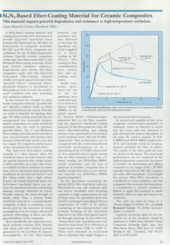
• Si3N4-Based Fiber-Coating Material for Ceramic Composites This material imparts graceful degradation and resistance to high-temperature oxidation. Lewis Research Center, Cleveland Ohio
A Si, .based coating material and coating proce have been developed to provide improved interfacial layers between SiC fibers and the iC fiber or Si3 4-matrix of composite materials. SiC/SiC and iC/Si, 4 composites are candidates for use in high-temperature turbines. Typically, ceramic composite of this type have been made with C- and B -based fiber-coating materials, which have limited oxidation re istance. Experiments have shown SiC/Sis 4
compo ites made wiu} this improved Si ~ .-based fiber-coating material exhibit very good (good in terms of the "graceful failure" explained below) interfacial behavior as determined in fiber-push-out tests, in both the as-fabricated condition and after annealing and oxidation exposure.
In the context of a ceramic or other brittle composite material, "graceful failure" denotes a failure mode in which fibers debond from the matrix. This failure mode is desirable for limiting damage. The fiber-coating materials that are incorporated into nonoxide ceramicmatrix composites are weak interfacial materials that are used to promote graceful failure. The C- and B -based fiber-coating materials mentioned above have not performed well because they become oxidized easily and in a way that can impair the long-term performance of the composites that contain them.
This improved Sis I-based coating material is a silica former; when the interfacial layers are fully formed, they are porous mixtures that consist largely of Si, 4 and Si02• a class, silica formers exhibit excellent resistance to oxidation, and are among the mo t promising candidate to ucceed interfacial C and B . When made with a high volume fraction of uitably dispersed pore, the Si ,based interfacial layers can perform the interfacial function of limiting damage through diversion of cracks. Porosity reduces the hear strength of brittle olids. Thus, a porous, brittle interfacial material in a ceramic-matrix composite is likely to constitute a preferred path for the diversion of cracks propagating from me matrix; this would promote debonding of fibers and thus graceful failure of me composite.
More specifically, me improved interfacial material contains Si 4 bonded with silica, and wim tailored porosity generated by me pyrolysis of organic microspheres. In the fiber-coating
NASA Tech Briefs, May 1997
120
100 .'
.~##.
process, the precursor mixture destined to become me interfacial material is applied a a slurry coating on iC fibers. The coating is then consolidated in slow calcination and annealing treatments.
80
/';' ..... . _ • ~ ". Annealed 500 h
/ •• ' •• ' /. \. Oxidized 100 h ". at 1 35O ' C
b // \ __ atl.300 · C •••••• : ••••
- \ ---- '" I CD
Q.
::. ::i ~ iii
60
40
I \ ,
I Oxidized 1 00 h at 1.200 · C I
As Fabricated , Small composite specimens for use in the experimen ts were made with reaction-bonded silicon nitride (RBSN) as me
"- - - Oxidized 25 h at 1.400 · C
./~. ...... Oxidized 100 h at 1.400 · C
oL-__ ~ ____ ~ ____ L-__ ~~ __ -L ____ ~ __ ~ ____ ..J
o 40
Displacement. 11m
The Fiber-Push·Out Behavior. after various treatments. of a sample SCS-O/RBSN minicomposite with porous interphase is shown.
matrix materi-al, Textron SCS-O (chemical-vapordeposited SiC) as me fiber material, and tJle improved interfacial coating material. In tJle fiber-push-out tests, me mean fiber-debonding and sliding stresses of me specimens in the as-fabricated condition were ",60 and 50 MPa, respectively. This performance can be compared wim the current benchmark interfacial performances of (a) a debonding stress of 10 MPa characteristic of a composite mat is similar except mat me fiber material i SiC with a Cbased coating (an SCS-6-fiber/RBS -matrix compo he) and (b) lack of pu h-otlt in another composite that i imilar except mat there is no imerfa
cial material (an SCS-O-fiber/ RB matrix composite).
In the pecimen containing the porous Si! 4/ i02 interfacial material, fiber-push-out was till achieved after two severe durability tests involving expo ure to high temperature. In one of these tests, the specimen were uJr. jected to prolonged annealing in 2 at a temperature of 1,350 ·C to induce coarsening of the micro rructure and promote bonding of tJle interfacial material to me fiber and matrix materials through sintering. In me omer te t, 1.0-mm-mick wafer specimens were oxidized for time from 25 to 100 hours, at temperatures from 1,200 to 1,400 0c. These were intended as accelerated tests to imulate what might happen to
www.nasatech.com
the interfacial layers in service. In un notched samples of tJle mini
composite (as-fabricated, annealed, or oxidized) tested to fracture in bending, the crack pam was observed to pass mrough me porous interphase in all case. In control sample of SCSO/RBSN and SCS-6/RBS oxidized for 50 h and similarly te Led in bending, fracture included the fiber in places. The results of the fiber push-out tests are shown in the figure. The interfacial performance was not impaired by the high-temperature expo ures: the stresses needed for debonding and sliding remained in the range of 80 ± 20 MPa typically observed for SiC/SiC composite with a B interphase. Accordingly, the porous I~ 4/Si02 interphase is con idered LO re i t oxidation, and the compo ite that contain thi interphase is conidered to urvive oxidation. Efforts to apply thi material to smalldiameter fibers in tow and weave are underway.
This work was done by Linus U. J. Thomas-Ogbuji of NYMA, Inc., Jor Lewis Research Center. No further documentation is available.
Inquiries concerning rights for the commercial use of this invention should be addressed to ~ Lewis Research Center; ~mmercial Technology Office, Attn: Tech Brief Patent talus, Mail Swp 7-3, 21000 Brookpark Rd., Cleveland, OH 44135. Refer to LEW-16261.
65
tj Improved 3DGRAPE "3DCRAPE/ AL" denotes the Three
Dimensional Crids About Anything by Pois on' Equation/ The Ame -Langley Technology Update computer program. 3D CRAPE/ AL is a ignificantly improved ver ion of 3DCRAPE, which has been widely distributed and has been described previou Iy in I1SA Tech Briefs. 3D CRAPE/ AL generates volume grid by iteratively solving Pois on's Equation in three dimen-ions. The terms on the right side of
the equation are designed so that userspecified grid-cell heights and user-pecified grid-cell skewne s near
boundary surfaces are obtained automatically, with little intervention by the u er. Ver atility was a high priority in the development of this code, and as a result, the code can generate grids in almost any three-dimensional physical domain. 3DCRAPE/ AL can be run in batch mode like the original 3DCRAPE, and it offers a graphical user interface (CUI) on Silicon Craphics, Inc. (SCI) computers.
3DCRAPE/ AL reads in predefined data, generates a grid, and writes it out. For those boundary surfaces which are of interest ("the body"), it expects to read X,Y,Z coordinates of surface grid points that the user has defined previously by use of other software. Other boundary surfaces of less in terest ("the outer boundary") can be found by the program itself, using simple analytic shapes. The grid can consist of multiple blocks, and the program is capable of finding its own internal block-to-block boundary surfaces.
3DCRAPE/ AL offers a significant number of features that were not offered by 3DCRAPE. In 3DCRAPE/ AL, grid quality is enhanced by reformulated con trol terms in Poisson's Equation. The u er can specify arbitrary angles with which lines are to inter ect boundaries; that is, these angles are no longer limited to the single value of 90° everywhere. Better grid quality re ults from the addition of Thomas & Middlecoff (T&M) c1u -tering terms for cases in which all six faces of a block are read in. The user can choose terms of either the Steger & Sorenson or the T&M type, or a blend between the two types that gives good cell size and kewness control at
66
quality is evaluated by computing and printing maxima, minima, medians, and averages of cell heights and nonorthogonality, at boundaries and in the in terior of the blocks of the fini hed grid.
Other features in 3D CRAPE/ AL provide for peedier convergence. Initialization is improved by tranfinite interpolation (for cases with six fixed boundary surface), which either offers a final grid or speeds convergence. The use of Erlich ' ad hoc method for computing locally optimum relaxation parameters for a ucce sive-over-relaxation ( OR) solver in the code can also speed convergence. In addition, convergence can be accelerated when the code is vectorized in any of the three coordinate directions (when installed on Cray computers), allowing the longest possible vector length in each block. These features, combined with careful code optimization, result in a speedup over the previou code by approximately a factor of four.
Val"iou other features that a sist in the input of data are also offered by 3DCRAPE/ AL. These features include two input filters: (1) an input filter that accepts CRIDCEN (ARC-13371) output as input and converts it to 3D CRAPE/ AL input and (2) an input filter that reads input designed for the original 3DCRAPE and reformats it for use with 3D CRAPE/ AL. For more versatile input, required cell heights and kewness at read-in surfaces can be specified by the user at each point from a file, a complete grid generated elsewhere can be read in, and an elliptic solver in 3D CRAPE/ AL can be run a few steps to smooth the grid. More extensive error checking of input data has been implemented, and a CUI (for SCI computer) enables the user to watch selected grid urfaces while the grid solver in 3D CRAPE is iterating. The CUI also enables the user to suspend the iterative proces and plot convergence histories.
3D CRAPE/ AL is written in FORTRAN 77 for U IX-based computers. The graphical mode of 3D CRAPE/ AL makes u e of the Iris Craphics Library (ICL) and is written in FORTRAN 77 for SCI IRIX machine. An ANSI standard FORTRAN compiler is required
www.nasatech.com
ample input and output are included on the di tribution medium. The batch mode of 3DCRAPE/ AL has been ucce full y implemented on the following computer : an SCI Indig02 running IRIX 5.2, a un4 running unOS 4.1.3, a
un4 running olaris 2.4, an IBM RS/ 6000 running AlX 4, an HP 9000/ 720 running HP-UX 9.03, and a Cray Y-MP running U ICOS 8.0.3.4. The graphical mode of 3D CRAPE/ AL has been successfully implemented on an SCI Indig02 running IRIX 5.2. The standard distribution medium for 3D CRAPE/ AL is a 0.25-in. (6.35-mm) streaming-magnetic-tape cartridge (Sun QIC-24) in UNIX tar format. Alternative distribution media and formats are available upon request. An electronic copy of the documentation in PostScript format is included on the distribution media. 3D CRAPE/ AL was released to COSMIC in 1996.
This program was written by Reese L. Sorenson for Ames Research Center. For further information, write in 27 on the TSP Request Card. ARC-14069
o Software for Efficient Packing of Cargo
The Stowage Tactics for User Flights (STUF) computer program enables space-station users to develop schemes for efficient packing of their cargo. U ers determine which trays to use and where those trays are located in a towage rack. Locations of cargo items
in a tray can be determined by computer, or a user can place items as desired . The weight and center of gravity of each item are monitored. Any out-of-bounds condition for a packed tray or rack is highlighted for corrective action. STUF can also combine many users' packing schemes into one cargo manife t; this enables a
ASA Center to integrate all user stowage for a space-station mission.
After a file representing user cargo data is read by STUF, cargo is tentatively assigned to a stowage tray and checked for interference with items already assigned to the tray. Any items that do not fit the curren t tray are as igned to subsequent trays, if possible. Once all trays are loaded, the user determines the location of each tray in
ASA Tech Briefs, May 1997
~~= ""fHJE EASIES'~r WAY '~ro LEARN [~;;~~~INC '. .... FEA ~YE 'T: 01\1 CDQflOM! ""'·""·'''··:L"" J •. "": Have a question? Simply enter the keyword(s) into Algor's Search ~' . .' '.' _ Commander. and it will take you to the answer with full color pictures,
i~~~~ti ... " ', animation, FEA screen shots and sound. Directly enhanced from the :i:~ - 1,.5000+ copy selling book. Finite Element Modeling in Engineering Practice. ,-.,-.. --,--_~.;.( ' by Dr. Constantine Spyrakos. this CD-ROM demonstrates practical
',,,,,, .. 1 11"'111 EUI\'IENI M()[)III~,(, I V ., .... , .. ! Fll\;lfI [IIMfNI fl.1()DI"" I A
. ::,.,.. .. --;0,., . ·.'i' -.. \
Buy the CD and get one softcover book for an additional $19! Ideal for travel or home reading.
See order form for details,
Order by Phone:
North America: 1 800-4 L Europe: +44 (1) (784) 442 246
Others: +1 (412) 967-2700 Fax: +1 (412) 967-2781
Questions answered in Dr. Spyrakos' CD-ROM and book:
• Which type of analysis is the best for my problem?
• What is the best element type for the appIicaUon? How can I combine different types of elements? How do I model cracks, holes and discontinuities?
• When and where should I use a finer mesh? • How do I identify modeling errors? • Are my results accurate? • How do I interpret my results?
approaches to using FEA in real-world situations. It will teach you the basic and advanced skills you need to use any finite element analysis software without being bogged down in heavy theory.
Full-color 3-D graphics and animation bring FEA down to earth without all the confusing theories. Keep open as an on-screen reference guide while you work.
See a sample version at .a\ c fa d
______ ,State _Zlp _Country_
549.00 Phone ( _____ ,Fax(
E-mail ______________ _
$19.00 i----------t--+--t----l You Have Three Ways To Pay: o Charge to Credit Card No.: Date Card exPIres __ $89.00
$50.00' per
format type
Card HoIde(s Nama
Authorized Signature Date __ _ o Wire transfer ABA Routing Code: 043000261 Account No.: 010-5064 Mellon Bank, Pittsburgh, PA USA
a pace- tation rack. The anal tical re ults returned by T F become inputs to a broad r pace- tation cargo manife t.
The u er interface for T F i primarily menu-driven. T F provide two operational modes for tra packing: automatic and interactive. The interactive mode i the quicke t to u e when packing hundred of item, and it re ults in the be t packing efficiency. The automatic mode enable the computer to determine where each cargo item is to be placed. single u-ay size selected by the user is then used
repeated! for all tra s. On e a et of u-ay has been packed,
the u er rna wi h to place tho e u-a into spac - tation racks. towage racks con tain locker assemblie pecifically designed to hold certain tra size. Although ST F allow a user to determine where a tra i located within the rack, T F \vill not place the u-ay there if the location cannot accommodate it. If a tJ-ay-packing olution i later edited, T F automatically updates mass propertie for the rack that contain that tray.
ST F can accommodate 9,999,999
We build instruments. But we're in the business of providing solutions. l'vfKS builds rhe mosr exacting and reliable gas managemenr insrrumenrarion in me world -
tnsrrumenrs that measure, control, iso\are, calibrare and analyze gases in many different
vacuum processes. But to our cus[Omers. our real produns are the solur;ons our insuumenrs
bring [0 mese manufacruring processes. a we build products mat are more rcpeatable. more
accurate and offer me highest levd of performance. We focus on excellence around rhe
process, from our research and development people who listen [0 your needs, to innovarive
engineering and design systems. [0 a solid worldwide engineering, sales and service nerwork mat
helps you bring our products together [0 creare a solurion. Because when you're in me business
of providing solutions, norhing les than the most complete solution will do.
68
To find out more about MKS solutions, call us at 1-800-227-8766.
Six h.<TUck Road Andover. MA. USA 01810 Tel: (508) 975-13~0 Fax: (508) 975-0093
e-mail: mbl?mbinst.com hnp:llwww.mbinst.com (l1997 MKS Inmumen ... Inc. All righ .. rcsc:rved.
For More Inf ormation Write In No. 413
cargo item 999 tray, and 99 racks per packing operation. Packing foam must be accounted for as part of each cargo item. T F doe not add the propertie of foam to the rna propertie of an item.
T F i written to run with De ignCAD 3-D and is available only as object code for IBM PC-compatible computer. It has been ucces full implemented on a 4 6 DX2 computer under M DO 5.0. T F require DesignCAD 3-D v4.0, 640K of randomacce memory, a gr-aphics display, and a hard disk drive. A printer is highly de irab\e for capturing T F output. The standard di tribution medium for STUF is one 3.5-in. (S.S9-cm), l.44MB, MS-DOS-format diskette. An electronic copy of !.he documentation in ASCII format i included on the distribution medium. STUF wa released to COSMIC in 1996 and is a copyrighted work with all copyright vested in ASA.
This program was written by Vance Houston of Marshall Space Flight Cente r . For further information, write in 29 on the TSP Request Card. MFS-31 101
COSMIC, ASA' Software Technology Transfer Center, has an inven tory of over SOO software package that originally were developed by ASA and its contractors for the U.S. space program. These package have a wide range of applications other than space exploration and are u ed by indu try, academic institutions, and other government agencie .
For further information about oftware available from CO MIC, or to receive a free diskette catalog, contact COSMIC at:
COSMIC The University of Georgia 382 East Broad Street Athens, GA 30602-4272
Phone: 706-542-3265 Fax: 706-542-4807 e-mail: [email protected] WWW: http://www.cosmic.uga.edu
ASA Tech Briefs, May 1997
o..r .................. .-..
............... _U. II I. on ICe. Itn
-.-....-..u-( .... ~ ,":.1 -_ .. -... ............... ------- -.
........ -~ ............ .,.... • 1 F ' I'JMlll
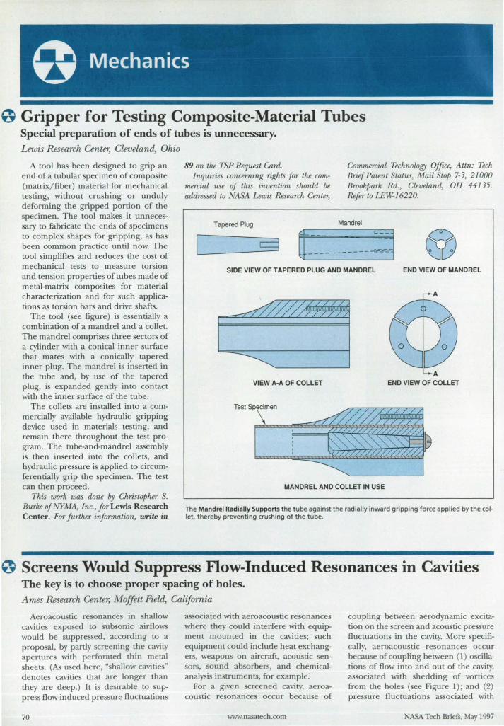
o Gripper for Testing Composite-Material Tubes Special preparation of ends of tubes is unnecessary.
Lewis &search Center, Cleveland, Ohio
A tool has been designed to grip an end of a tubular specimen of composite (matrix/fiber) material for mechanical te ting, without cru hing or unduly deforming the gripped portion of the specimen. The tool make it unnece -sary to fabricate the ends of pecimens to complex hape for gripping, as has been common practice until now. The tool simplifie and reduce the cost of mechanical te ts to measure torsion and tension propertie of tube made of metal-matrix compo ites for material characterization and for such application as torsion bars and drive shafts.
The tool ( ee figure) is e entially a combination of a mandrel and a collet. The mandrel comprises three sector of a cylinder with a conical inner surface that mates with a conically tapered inner plug. The mandrel i inserted in the tube and, by u e of the tapered plug, is expanded gendy into contact with the inner surface of the tube.
The collets are installed into a commercially available hydraulic gripping device used in materials te ting, and remain there throughout the te t program. The tube-and-mandrel assembly is then inserted into the collets, and hydraulic pre sure is applied to circumferentially grip the specimen. The test can then proceed.
This work was done by Christopher S. Burke of NYMA, Inc., for Lewis Research Center . For further information, write in
89 on the TSP Request Card. Inquiries concerning rights for the com
mercial use of this invention should be addressed to ~SA Lewis Research Center,
Tapered Plug
[
Commercial Technology Office, Attn: Tech Brief Patent tatus, Mail Stop 7-3, 21000 Brookpark Rd., Cleveland, OH 44135. Refer to LEW-J6220.
Mandrel
SIDE VIEW OF TAPERED PLUG AND MANDREL END VIEW OF MANDREL
VIEW A·A OF COLLET END VIEW OF COLLET
MANDREL AND COLLET IN USE
The Mandrel Radially Supports the tube against the radially inward gripping force applied by the collet, thereby preventing crushing of the tube.
o Screens Would Suppress Flow-Induced Resonances in Cavities The key is to choose proper spacing of holes.
Ames &search Center, Moffett Field, California
Aeroacoustic re onances in hallow cavities exposed to ub onic airflows would be up pres ed, according to a proposal, by partly screening the cavity apertures with perforated thin metal sheets. (As u ed here, "shallow cavities" denotes cavities that are longer than they are deep.) It is desirable to suppress flow-induced pres ure fluctuations
70
as ociated with aeroacoustic re onance where they could interfere with equipment mounted in the cavities; such equipment could include heat exchangers, weapons on aircraft, acoustic sensors, sound absorbers, and chemicalanalysi instruments, for example.
For a given creened cavity, aeroacoustic resonances occur because of
www.nasatech.com
coupling between aerodynamic excitation on the creen and acoustic pressure fluctuations in the cavity. More specifically, aeroacoustic resonances occur because of coupling between (1) oscillations of flow into and out of the cavity, as ociated with shedding of vortice from the holes (see Figure 1) ; and (2) pres ure fluctuations associated with
ASA Tech Briefs, May 1997
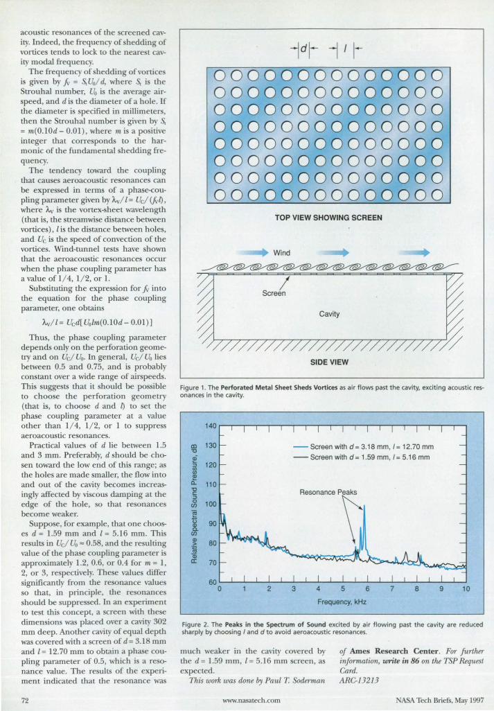
acoustic re onances of the creened cavity. Indeed, the frequency of hedding of vortices tends to lock to the nearest cavity modal frequency.
The frequency of shedding of vortices is given by .fv = s.. Uo/ d, where s.. is the Strouhal number, Uo i the average airspeed, and d is the diameter of a hole. If the diameter is specified in millimeters, then the Strouhal number is given by s.. = m(O.lOd - 0.01), where m is a positive integer that corresponds to the harmonic of the fundamental shedding frequency.
The tendency toward the coupling that causes aeroacoustic resonances can be expressed in terms of a phase-coupiing parameter given by A.v/ l = Uc/ (.fvl), where 'A.v is the vortex-sheet wavelength (that is, the streamwise distance between vortices), l is the distance between holes, and Uc is the speed of convection of the vortices. Wind-tunnel tests have shown that the aeroacoustic resonances occur when the phase coupling parameter has a value of 1/ 4, 1/ 2, or 1.
Substituting the expression for.fv into the equation for the phase coupling parameter, one obtains
A.v/ 1= Ucd[Uolm(0.10d- 0.01)]
Thus, the phase coupling parameter depends only on the perforation geometry and on Uc/ Uo. In general, Uc/ Uo lies between 0.5 and 0.75, and is probably constant over a wide range of airspeeds. This suggests that it should be possible to choose the perforation geometry (that is, to choose d and l) to set the phase coupling parameter at a value other than 1/ 4, 1/ 2, or 1 to suppress aeroacoustic resonances.
Practical values of d lie between 1.5 and 3 mm. Preferably, d should be chosen toward the low end of this range; as the holes are made smaller, the flow into and out of the cavity becomes increasingly affected by viscous damping at the edge of the hole, so that resonances become weaker.
Suppose, for example, that one chooses d = 1.59 mm and 1 = 5.16 mm. This results in Uc/ Uo '" 0.58, and dIe resulting value of the phase coupling parameter is approximately 1.2, 0.6, or 0.4 for m = 1, 2, or 3, respectively. These values differ significantly from the resonance values o that, in principle, the resonances
should be suppressed. In an experiment to test this concept, a screen with these dimensions was placed over a cavity 302 mm deep. Anomer cavity of equal depth was covered wim a screen of d= 3.18 mm and l = 12.70 nun to obtain a phase coupling parameter of 0.5, which is a resonance value. The results of the experiment indicated mat me resonance was
72
00000000000000 00000000000000 00000000000000 00000000000000 00000000000000 00000000000000 00000000000000 00000000000000
TOP VIEW SHOWING SCREEN
Wind
SIDE VIEW
Figure 1. The Perforated Metal Sheet Sheds Vortices as air flows past the cavity, exciting acoustic resonances in the cavity.
140
co 130 '0
-- Screen with d= 3.18 mm,l= 12.70 mm
~ -- Screen with d = 1.59 mm, 1= 5.16 mm 120 :::l
(/) (/)
~ 0.. 110 '0 c :::l 0 100 rn ~ U 90 Q) a. rn Q)
80 > ~ Q) II: 70
60 0 2 3 4 5 6 7 8 9 10
Frequency, kHz
Figure 2. The Peaks in the Spectrum of Sound excited by air flowing past the cavity are reduced sharply by choosing I and d to avoid aeroacoustic resonances.
much weaker in the cavity covered by the d = 1.59 mm, 1= 5.16 mm screen, as expected.
This work was done by Paul T Sodennan
www.nasatech .com
of Ames Research Center. For further information, write ill 86 on the TSP Request Card. ARC-13213
NASA Tech Briefs, May 1997
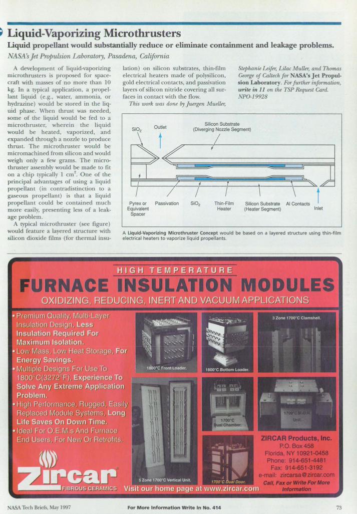
~ Liquid-Vaporizing Microthrusters Liquid propellant would substantially reduce or eliminate containment and leakage problems. NASA's Jet Propulsion Laboratory, Pasadena, California
A development of liquid-vaporizing microthnlSters is proposed for spacecraft with masses of no more than 10 kg. In a typical application, a propelLant Liquid (e.g., water, ammonia, or hydrazine) would be stored in the liquid phase. When thrust was needed, some of the liquid would be fed to a micro thruster, wherein the liquid would be heated, vaporized, and expanded through a nozzle to produce thrust. The micro thruster would be micro machined from silicon and would weigh only a few grams. The microthruster assembly would be made to fit on a chip typically 1 cm2
• One of the principal advantages of using a liquid propellant (in contradistinction to a gaseous propellant) is that a liquid propellant could be contained much more easily, presenting less of a leakage problem.
A typical microthruster (see figure) would feature a layered structure with silicon dioxide films (for thermal insu-
ASA Tech Briefs, May 1997
lation) on silicon substrates, thin-film electrical heaters made of polysilicon, gold electrical contacts, and passivation layers of silicon nitride covering all surfaces in contact with the flow.
This work was done by Juergen Muell£r,
Stephanie Leifer, Lilac Mull£r, and Thomas George of Caltech for NASA's Jet Propulsion Laboratory. For further information, write in 11 on the TSP Request Card. NPO-19928
Si02 Outlet
Silicon Substrate (Diverging Nozzle Segment)
Pyrex or Equivalent
Spacer
Passivation
I Thin-Film
Heater
, Silicon Substrate (Heater Segment)
AI Contacts Inlet
A Uquid-Vaporizing Microthruster Concept would be based on a layered structure using thin-film electrical heaters to vaporize liquid propellants.
For More Information Write In No. 414 73
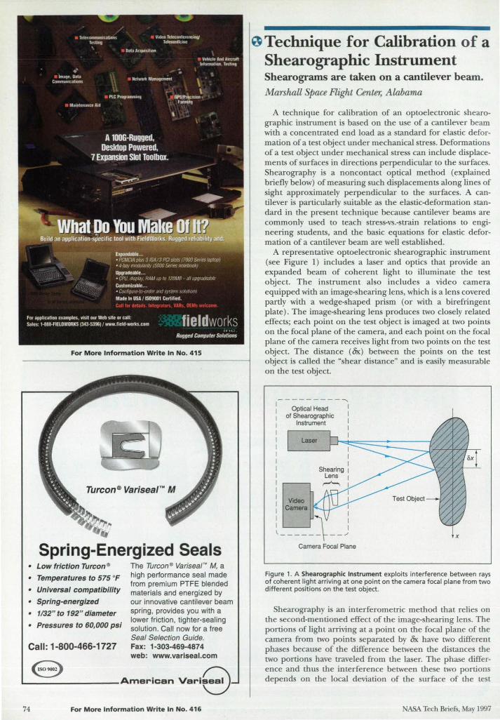
For More Information Write In No. 415
Spring-Energized Seals • Low friction Turcon e
• Temperatures to 575 of
• Universal compatibility
• Spring-energized
• 1/32" to 192" diameter
• Pressures to 60,000 psi
Call : 1-800-466-1727
The Turcone Variseal N M, a high performance seal made from premium PTFE blended materials and energized by our innovative cantilever beam spring, provides you with a lower friction, tighter-sealing solution. Call now for a free Seal Selection Guide. Fax: 1-303-469-4874 web: www.variseal.com e '"-______ ___ American
74 For More Information Wr ite In No. 416
0 Technique for Calibration of a Shearographic Instrument Shearograms are taken on a cantilever beam. Marshall Space Flight Center, Alabama
A technique for calibration of an optoelectronic shearographic in trument is based on the use of a cantilever beam with a concentrated end load as a tandard for elastic deformation of a test object under mechanical stre . Deformations of a test object under mechanical stre s can include displacements of surfaces in directions perpendicular to the surfaces. Shearography is a noncontact optical method (explained briefly below) of measuring such displacements along lines of ight approximately perpendicular to the surfaces. A can
tilever is particularly suitable as the elastic-deformation standard in the present technique because cantilever beams are commonly u ed to teach stress-vs.-strain relations to engineering students, and the basic equation for elastic deformation of a cantilever beam are well established.
A representative optoelectronic shearographic instrument (see Figure 1) includes a laser and optics that provide an expanded beam of coherent light to illuminate the test object. The instrument also includes a video camera equipped with an image-shearing lens, which is a lens covered partly with a wedge-shaped prism (or with a birefringent plate). The image-shearing lens produces two closely related effects; each point on the test object is imaged at two points on the focal plane of the camera, and each point on the focal plane of the camera receives light from two points on the test object. The distance (Ox) between the points on the test object is called the ·shear distance" and is easily measurable on the test object.
----------.... Optical Head
of Shearographic Instrument
I I I I I
I I I
Shearing I Lens I
r-"-.. I I
Video I Camera I
I I I
Camera Focal Plane
x
Figure 1. A Shearographic Instrument exploits interference between rays of coherent light arriving at one point on the camera focal plane from two different positions on the test object.
Shearography is an interferometric method that relies on the second-mentioned effect of the image-shearing lens. The portions of light arriving at a point on the focal plane of the camera from two points eparated by Ox have two different phases because of the difference between the distances the two portion have traveled from the laser. The phase difference and thus the interference between these two portions depend on the local deviation of the surface of the test
ASA Tech Briefs, May 1997
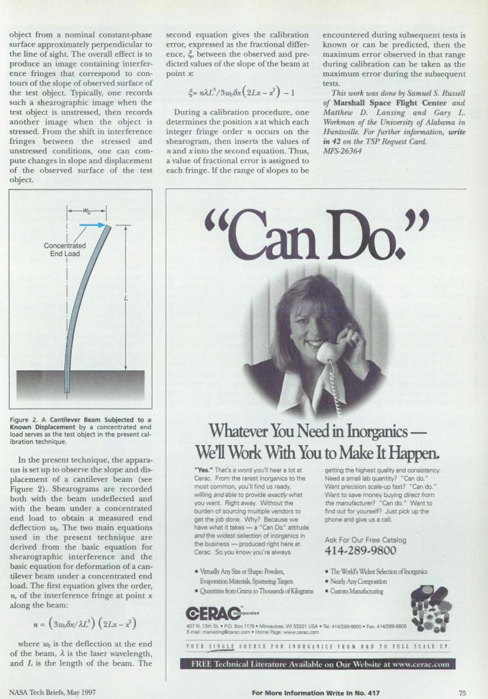
object from a nominal constant-phase surface approximately perpendicular to the line of sight. The overall effect is to produce an image containing imerference fringes that correspond to contours of the slope of observed surface of the test object. Typically. one records such a shearographic image when the test object is unstressed. then records another image when the object is stressed. From the shift in interference fringes between the stressed and unstressed conditions. one can compute changes in slope and displacement of the observed surface of the test object.
Figure 2. A cantilever Beam Subjected to a Known Displacement by a concentrated end load serves as the test object in the present calibration technique.
In the present technique. the apparatus i set up to observe the slope and displacement of a cantilever beam (see Figure 2). Shearograms are recorded both with the beam undeflected and with the beam under a concentrated end load to obtain a measured end deflection !Lb. The two main equations used in the present technique are derived from the basic equation for shearographic interference and the basic equation for deformation of a cantilever beam under a concentrated end load. The first equation gives the order. n, of the interference fringe at point x along the beam:
n = (3 !LbOx/ ll!) (2Lx - X2)
where 1L\l is the deflection at the end of the beam, ,t is the laser wavelength. and L is the length of the beam. The
NASA Tech Briefs. May 1997
second equation gives the calibration error. expressed as the fractional difference. ~. between the observed and predicted values of the slope of the beam at point x:
~= n)..I} /3u.u8x (2Lx - i) - 1
During a calibration procedure, one determines the position xat which each integer fringe order n occurs on the shearogram, then inserts the values of nand xinto the second equation. Thus, a value of fractional error is assigned to each fringe. If the range of slopes to be
encountered during subsequent tests is known or can be predicted. then the maximum error observed in that range during calibration can be taken as the maximum error during the subsequent tests.
This work was dune by Samuel S. RusseU of Marshall Space Flight Center and Matthew D. Lansing and Gary L. Workman of the University of Alabama in Huntsville. For further information, write in 42 on the TSP Request Card. MFS-26364
"
Whatever You Need in Inorganics -We'll Work With You to 1v1ake It Happen. · Yes.- That's a word you 'll hear a lot at Cerae. From the rarest inorganics to the most common. you'lI find us ready, willing and able to provide exactly what you want. Right away Without the burden of sourcing multiple vendors to get the Job done. Why? Because we have what it takes - a • Can Do" attitude andthe widest selection of inorganics in the bUSiness - produced right here at Cerac. So you know you're always
• \inuaIJy Any Size or Shajx:: A:!wdets. Evaporatial Matfrials, 5(xmering TaJg!:IS
• ~6anGramsro llruwds<i~
getting the highest quality and consistency. Need a small lab quantity? "Can do." Want precision scale-up fast? "Can do." Want to save money buying direct from the manufacturer? "Can do." Want to find out for yourself? Just pick up the phone and give us a call.
Ask For Our Free Catalog
414 .. 289 .. 9800
• The ~s WJdest Selection cilrnganics • Nearly AnyCooqxmJn
• Custtm Manuf.lauring
407 N. 13th St • P.O Box 1178 • M,1wau ee. WI 53201 USA · Tel: 414/289-9800 • fax; 41A/289-9805 """"j: matltetJngClcerac.com • Home Page www""""""",
YOUR SINGLE SOUICE fOR INOIGANICS 11011 RID TO FULL StAlE UP.
For More Information Write In No, 417 75
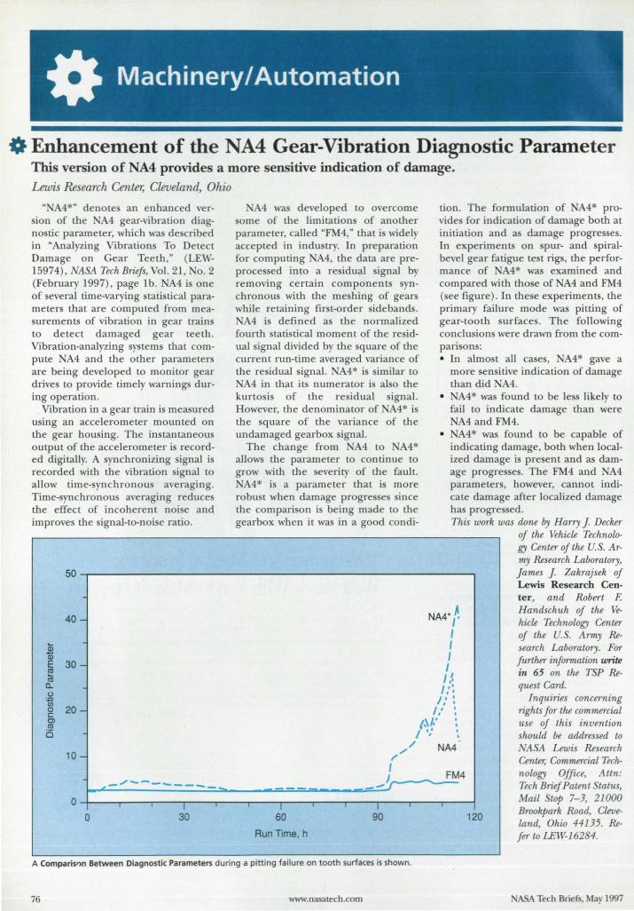
0. Enhancement of the NA4 Gear-Vibration Diagnostic Parameter This version of NA4 provides a more sensitive indication of damage. Lewis Research Center, Cleveland, Ohio
"NA4*" denote an enhanced ver-ion of the A4 gear-vibration diag
no tic parameter, which wa de cribed in "Analyzing Vibration To Detect Damage on Gear Teeth," (LEW-15974), 1111 Tech Briejs, Vol. 21, 0.2 (February 1997), page lb. A4 is one of several time-varying statistical parameters that are computed from measurements of vibration in gear train to detect damaged gear teeth. Vibration-analyzing sy tern that compute A4 and the other parameters are being developed to monitor gear drives to provide timely warning during operation.
Vibration in a gear train i measured using an accelerometer mounted on the gear housing. The in tantaneous output of the accelerometer i recorded digitally. A synchronizing signal is recorded with the vibration signal to allow time-synchronous averaging. Time-synchronous averaging reduces the effect of incoherent noise and improves the signal-to-noise ratio.
4 wa developed to overcome orne of the limitation of another
parameter, called "FM4," that i widely accepted in indu try. In preparation for computing A4, the data are preproces ed into a residual ignal by removing certain components ynchronous with the meshing of gears while retaining fir t-order sidebands.
A4 is defined a the normalized fourth tatistical moment of the residual ignal divided by the quare of the current run-time averaged variance of the re idual signal. A4* is similar to NA4 in that its numerator is al 0 the kurtosis of the residual ignal. However, the denominator of A4* is the square of the variance of the undamaged gearbox ignal.
The change from A4 to NA4* allows the parameter to continue to grow with the severity of the fault.
A4* is a parameter that is more robust when damage progre e since the comparison i being made to the gearbox when it was in a good condi-
tion. The formulation of A4* provide for indication of damage both at initiation and a damage progresses. In experiments on spur- and spiralbevel gear fatigue test rigs, the performance of A4* was examined and compared with tho e of A4 and FM4 (see figure). In these experiments, the primary failure mode was pitting of gear-tooth surface. The following conclusions were drawn from the compari on : • In almo t all ca es, A4* gave a
more sensitive indication of damage than did A4.
•
•
A4* was found to be less likely to fail to indicate damage than were
A4and FM4. A4* was found to be capable of
indicating damage, both when localized damage i pre ent and a damage progre e. The FM4 and A4 parameter, however, cannot indicate damage after localized damage has progres ed. This work was done by Harry J Decker
of the Vehicle Technology Center of the U. S. A rmy Research Laboratory,
50.-------------------------------------------------_. Jatnes J Zakrajsek of Lewis Research Center, and Robert F. Handschuh of the Vehicle Technology Center of the u.s. Army Re-
CD a;
40 -
~ 30 -~
0... .2 iii g 20-g> a
10 - "
NA4} I I I 1 I:' I::
I,' : I,' :
(~/,' : I ,,' ~
",/ NA4
I I ........ FM4
-/ ...... -------- __ '.... __ """'Jr---.... _--~~----------~~----~==~~-----=~
O~--.r_-,_---~I ---r---.----'I----~---r---.lr---,----.--~
o 30 60 90 120
Run Time, h
A Comparisf)n Between Diagnostic Parameters during a pitting failure on tooth surfaces is shown.
76 www.nasatech.com
search Laboratory. For further information write in 65 on the TSP Request Card.
Inquiries concerning rights for the commercial use of this invention should be addressed to
I1SA Lewis Research Center, Commercial Technology Office, Attn: Tech Brief Patent Status, Mail Stop 7-3, 21000 Brookpark Road, Cleveland, Ohio 44135. Re-fer to LEW-16284.
ASA Tech Briefs, May 1997
CLEO'97 SPONSORED BY IEEE/Lasers and Electro-Optlcs Society OSA - Optical Society of Amenca
In Cooperation with. Quantum Electronics DIvision of the
European Phys al 0ptIcaJ Society Japanese Quantum ElectronICS Joint Group
QELS'97 SPONSORED BY APS 0 s on of Laser Science EEE Lasers and Efectro.OptIcs Society
OSA Optlca Society of AmerIca
I' I'
o Automatic Regulation of Material Level in Industrial Blender Marshall Space Flight Center, Alabama
A control ystem automatically regulate the level of material in an indu -trial blender in which maintaining the correct level is necessary for both product quality and safety. The blender includes a mixing chamber with a turbine-type head that mixes two powder streams that enter from the top, with a liquid tream that enters from the bottom. The resulting blend flows out of the chamber
through a discharge gate at its bottom. The level-regulating control y tern includes two level ensors on the side of the chamber, one slightly above the other. The outputs of these sensors are fed to a programmable-logic controller (PLC) that, in turn, controls a linear actuator that varies the opening of the discharge gate. The PLC modulates the gate opening to maintain the material level between the two ensor.
WeMean M/cad EXPO is port of the industry's largest engineering computer
system show and conference oriented to mechanical design engineers and their management with focus on CAD/CAM/CAE as well as EDM/PDM and Inter/Intranet technology.
• Test the newest products from leading hardware and software vendors
• See how to integrate CAD/CAM/W in a variety of apprlCCllions
• See how Intemet/ lntranets influence CAD/ CAM/Wand EDM/PDM
• Discover how to shorten time to market • Evaluate crdferent operating envil'ftllllllf!
.• • and much more.
sponsored by: Computer-Aided Engineering and Mochine Design
c ;: &. -... 1:1 C -;: &. • JUNf 18·19, 1997
~/~~gCAD~~~Q;17 j.Qo;o,1 For more information about Mlcad EXPO and how you ~~~ ~O\~' can attend orexhibil, reach us 01: ::;.~ 'fV~~~~~~\\~o~ (800) 451-1196 • {610}458-7689, ~ •• \ ~~,\\~.~ or fax {610}458-7171. ~y .<#~ Please reference extension 209. ~
78 For More Information Write In No. 418
A third sensor on the chamber lid provides redundant protection against flooding: if the material level rises to near the lid, the output of this sensor triggers all emergency shutdown of all material feeders.
This work was done by Joel Crook of Thiokol Corp. for Marshall Space Flight Center. For further information, write in 82 on the TSP Request Card. MFS-31127
0-Vibration-Isolation System for Industrial Blender Marshall Space Flight Center; Alabama
A pneumatic suspension system for the industrial blender described in the preceding article suppresses low-frequency vibrations generated by the motor that drives the blender. I t is necessary to suppress these vibrations because they can affect feed rates of the materials to be mixed and thereby alter the composition of the blend beyond narrow tolerances. The suspension system includes air bladders that support an outrigger frame that, in turn, supports the blender frame. When the bladders are inflated to a nominal pressure of 50 psig (gauge pressure of 0.34 MPa), the outrigger floats between upper and lower limit stops. Flexible inlet and outlet connections are needed to accommodate the flotation: The liquid-supply line is a polytetrafluoroethylene-lined hose enclosed in stainless-steel braid. The powder-supply lines are convoluted hoses. A specially designed flexible outlet assembly includes a sloped enclo ed trough that enters a vertical discharge pipe tl1rough a loosely fitting notch in the pipe. A boot on this assembly encloses the process stream and accommodates the flotation of the blender as a whole, the motion of the discharge gate, and the motion of a transparent cover on the top of the pipe that moves with the discharge-gate actuator linkage.
This work was done by Joel Crook of Thiokol Corp. for Marshall Sp ace Fligh t Center . For further information, write in 81 on the TSP Request Card. MFS-31126
ASA Tech Briefs, May 1997
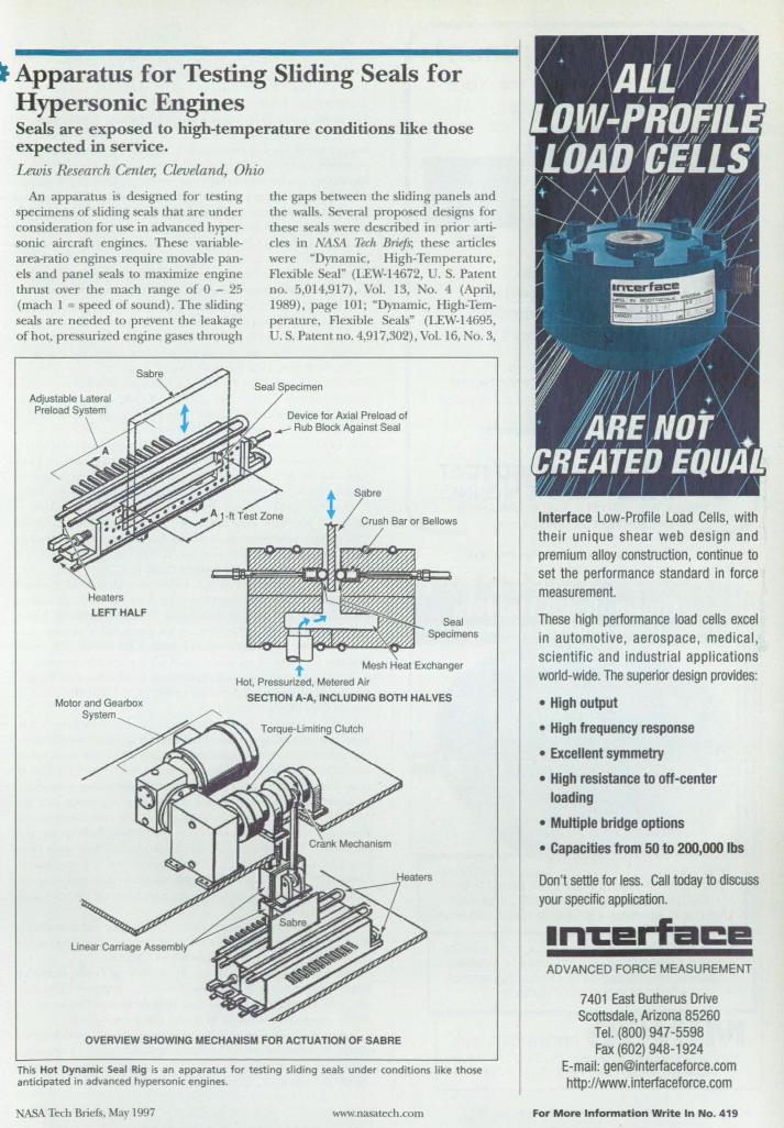
.. Apparatus for Testing Sliding Seals for Hypersonic Engines Seals are exposed to high-temperature conditions like those expected in service.
Lewis Research Center, Cleveland, Ohio
An apparatus is de igned for te ring specimens of tiding eals that are under consideration for use in advanced hyper-onic aircraft engines. These variable
area-ratio engines require movable panels and panel seals to maximize engine thru t over the mach range of 0 - 25 (mach 1 = speed of ound) . The tiding eals are needed to prevent the leakage
of hot, pre urized engine gase through
Heaters
LEFT HALF
the gap between the tiding panels and the walls. Several propo ed de igns for the e eal were described in prior article in (ASA Tech Bri£/s; these articles were "Dynamic, High-Temperature, Flexible eal" (LEW-14672, . S. Patent no. 5,014,917), 01. 13, o. 4 (April, 1989) . page 101 ; "Dynamic. High-Temperatur , Flexible eals" (LEW-14695, U. S. Patent no. 4,917,302) , Vol. 16. 0. 3,
Seal Specimen
Device for Axial Preload of __ Rub Block Against Seal
Seal Specimens
Hot. Pressurized. Metered Air
Motor and Gearbox System
SECTION A-A, INCLUDING BOTH HALVES
OVERVIEW SHOWING MECHANISM FOR ACTUATION OF SABRE
This Hot Dynamic Seal Rig is an apparatus for testing sliding seals under conditions like those anticipated in advanced hypersonic engines.
ASA Tech Briefs. May 1997 www.nasalech.com
Interface Low-Profile Load Cells. with the ir unique shear web design and premium alloy construction. continue to set the performance standard in force measurement.
These high performance load cells excel in automotive . aerospace, medical , scientific and industrial applications world-wide. The superior design provides:
• High output
• High frequency response
• Excellent symmetry
• High resistance to off-center loading
• Multiple bridge options
• Capacities from 50 to 200,000 Ibs
Don't settle for less. Call today to discuss your specific application.
In-':E!I fa!:E! ADVANCED FORCE MEASUREMENT
7401 East Butherus Drive Scottsdale, Arizona 85260
Tel. (800) 947-5598 Fax (602) 948-1924
E-mail: [email protected] http://www.interfaceforce.com
For More Informatio n Write In No. 419
Testing Equipment Quality Equipment for Your
Testing Needs
-- ---
. - . Pictured Above:
• Series 3210 Furnace (left), • Series 3610 Oven (middle) ,
• and Ultrasonic Test Blocks (right)
Other Test Equipment: Universal Testing Machines, Creep Testers,
Extensometers, Asphalt Testers, and Accessories
Standard and Custom Equipment
THE MARK OF RELIABILITY N. RPPLI~D TI;;;01 _ 6yoT~Mo.IHC.
Phone: 4121283-1212, Fax: 4121283-6570 Online: http:/twww.atspa.com
For More Information Write In No. 420
Flexible etched-foil shapes, profiled or mUl-tiple elements . Efficient heat transfer: Up to 110 Wfln2
• 200°C polyimide, 235°C rubber, 600°C mica, 120°C transparent insulations . Optional sensors & controllers
Precise, reliable heating . Minimal space, mass, & design overhead . Medical diagnostic instruments . Aerospace devices . Commercial appliances . Packaging machinery
• Scientific instruments . Electronics
MIN CO PRODUCTS, INC. 7300 Commerce Lane . Minneapolis, MN 55432-3177 U.S.A.
Telephone: (612) 571-3121 . FAX: (612) 571-0927
80 For More Information Write In No. 421
(March, 1992), page 71; "High-Temperature, Flexible, PressureAssisted Brush Seal" (LEW-15086, U. . Patent no. 5,076,590),
01. 17, o. 2 (February, 1993), page 74; and "High-Temperature, Flexible, Fiber-Preform Seal n (LEW-15085, U. S. Patent no. 5,0 2,293), Vol. 17, 0.2 (February, 1993), page 75.
Using air as the test gas, the apparatu can measure leakage at temperatures from ambient to 815 °C (1500 OF) and differential pre ures up to 690 kPa (100 psi). The performance of the seal specimens can be measured while ealing against flat or distorted walls. In the apparatus, two horizontal eal pecimens are preloaded against opposite sides of a device called a "sabre," which is a plate that imulates an engine wall and is slid transversely to the axes of the seals (that is, vertically) to simulate the scrubbing motions anticipated in engines. The urface of the sabre can be made flat or distorted and smooth or rough, as needed, to test the performance and durability of the seal specimens.
The length of the seal specimens and the corresponding long horizontal dimension of the sabre is about 30 em (l ft). The range of vertical motion of the sabre is ±5 cm (±2 in.).The abre is moved vertically by use of a motor, gearbox, and crank; the average vertical speed is adjustable from 0 to 5 cml s (0 to 2 in./s). The vertical position of the sabre is measured by a linear variabledifferential transformer. The number of cycles of vertical motion is measured by a cycle counter connected to the crankshaft.
Rub blocks (not shown in the figure) prevent leakage at the ends of the seal specimens. The rub blocks are machined to seal precisely against the ends of the sabre. By use of pressurized bellows, the rub blocks are pneumatically preloaded, both against the sabre and lengthwise against the ends of the seal specimens.
The seal specimens can be preloaded against the sabre in either of two ways depending on the sealing concept under test; either variable-preload forces can be applied by pressurized bellows, or else the seal specimens can be crushed to a fixed extent by use of a shimmed crush bar.
Metered, pressurized air is supplied to a plenum in the base of the apparatus, upstream from (below) the seal specimens. Four 3.5-kW electrical-resistance air heaters operating under digital control with temperature feedback are threaded into the base. The plenum contains a mesh heat exchanger, which diffuses the flows of air and heat. Each heater is controlled by a digital controller with temperature feedback. The heaters can supply air at a temperature of 815 °C ( 1,500 OF) at a flow rate of 0.009 kgl s (0.02 Ibi s) .
Leakage past the seal specimens is measured by flowmeters, which are placed upstream of the heaters to eliminate the need to capture and cool the leaking hot gas. The differential pressure across the seal specimens is measured by use of pressure taps, immediately upstream of the seal specimens, connected to room-temperature pressure transducers via tubes that are >15 cm long to prevent heating of the pressure transducers. Pressures in the seal cavities and in the preload bellows are also measured. The temperature of the impinging hot air is measured by thermocouples just upstream of the seal specimens. Load cells in the linear carriage assembly that supports the sabre measure seal drag; that is, friction between the seal specimens and the sabre.
ASA Lewis used this test fixture to evaluate the hot sliding durability performance of a number of candidate hypersonic engine seals, as documented in ASA TP-3483.
This work was done by Bruce M. Steinetz of Lewis Research Center, Jeffrey H. MiUer and Paul J Sirocky of Sverdrup Technology, Inc., and Lawrence A. hen of Case Western Reserve University. Fur further information, write in 83 on the TSP Request Card.
Inquiries concerning rights fur the commercial use of this invention should be addressed to NASA Lewis Research Center; Commercial Technology Offue, Attn: Tech Brief Patent Status, Mail Stop 7-3, 21000 Brookpark Rd., Cleveland, OH 44135. Refer toLEW-1621l.
NASA Tech Briefs, May 1997
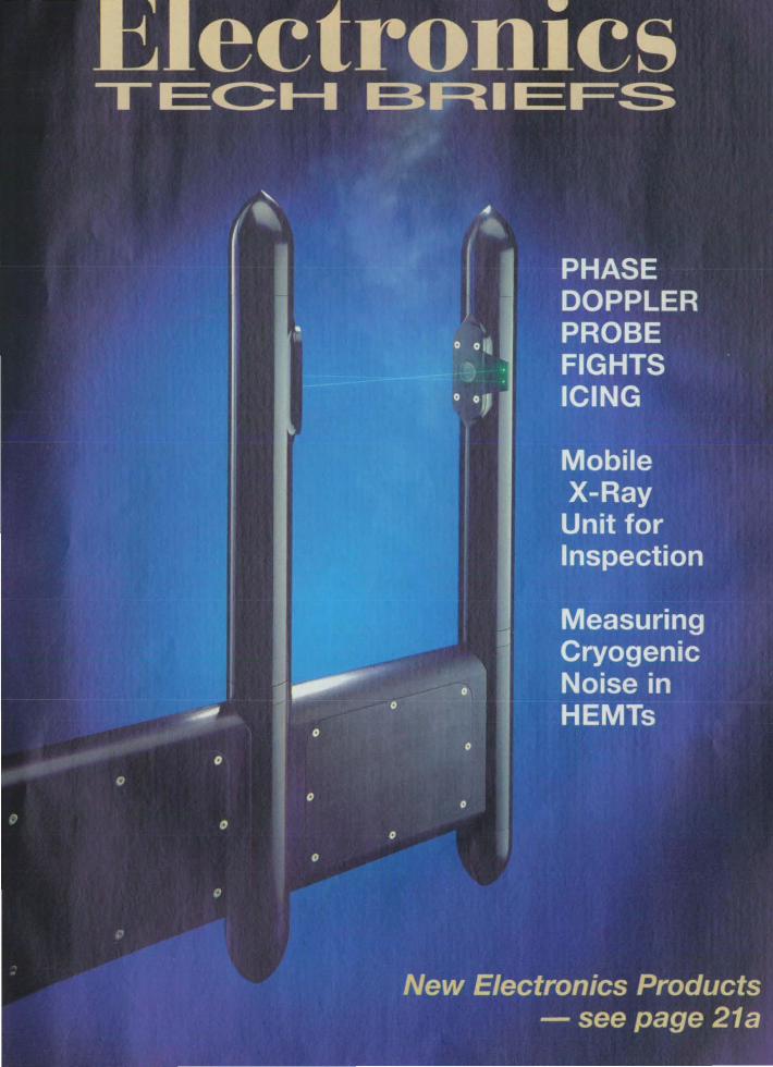
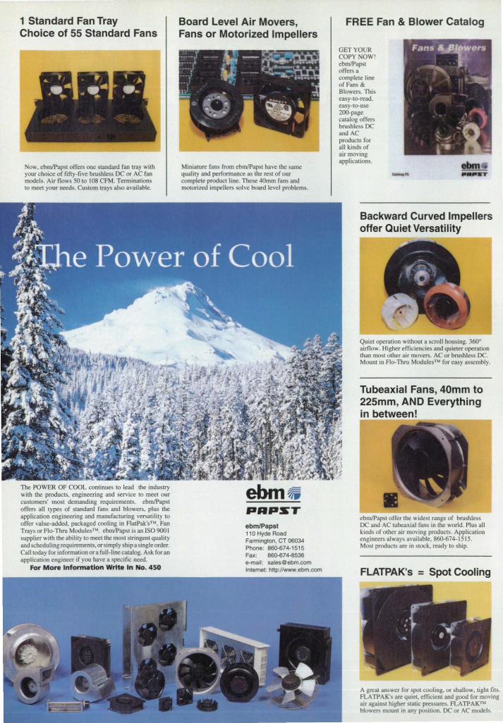
1 Standard Fan Tray Choice of 55 Standard Fans
ow, ebmlPap t offe", one standard fan tray with your choice of fifty-five brushless DC or AC fan models. Air nows 50 to 108 CFM. Termination to meet your needs. Custom trays also available.
The POWER OF COOL continues to lead the indu try with the products, engineering and service to meet our custome",' most demanding requirements. ebm/Papst offe", all types of standard fans and blowe"" plus the application engineering and manufacturing ve",atility to offer value-added, packaged cooling in F1atPak'sTM, Fan Trays or Flo-Thru Modules™. ebm/Pap t is an [SO 9001 supplier with the ability to meet the most stringent quality and scheduling requirements, orsimply ship a single order. Call today for information or a full-line catalog. Ask for an application engineer if you have a specific need.
For More Information Write In No. 450
Board Level Air Movers, Fans or Motorized Impellers
Miniature fans from ebm/Pap t have the same quality and performance as the rest of our complete product line. These 40mm fans and motorized impelle", olve board level problems.
PAPsr ebm/Papst 11 0 Hyde Road Farmington, CT 06034 Phone: 860-674-1515 Fax: 860-674-8536 e-mail: [email protected] Internet: http://www.ebm.com
FREE Fan & Blower Catalog
GET YOUR COPY OW! ebmlPap t offe", a complete line of Fans & Blowers. This easy-to-read. easy·to-use 200-page catalog offe", brush less DC andAC products for all kinds of air moving applications.
Backward Curved Impellers offer Quiet Versatility
Quiet operation without a scroll housing. 360° airOow. Higher efficiencies and quieter operation than most other air move",. AC or bru hless DC. Mount in Flo-Thru Modules™ for easy assembly.
Tubeaxial Fans, 40mm to 225mm, AND Everything in between!
ebm/Papst offer the wide t range of brush less DC and AC tubeaxial fans in the world. Plus all kinds of other air moving products. Application enginee", always available, 860-674-1515. Most products are in stock, ready to ship.
FLATPAK's = Spot Cooling
A great answer for spot cooling, or shallow, tight fits. FLATPAK's are quiet. efficient and good for moving air against higher stat,c pressures. FLATPAKno blowelS mount in any position. DC or AC models.
Elect • on cs I EC::I I I3FlIEFS
Electronics Tech Briefs Supplement to NASA Tech Briefs May 1997 Issue Published by Associated Business Publications
FEATURE 2a Advanced Probe Fights Icing and Corrosion
ELECTRONICS TECH BRIEFS 60 Mobile X-Ray Unit 6a Three-Dimensional Long-Trace Profilometer
100 Fast, High-Sensitivity Dew-Point/ Frost-Point Hygrometer
12a Polarimetric Microwave Radiometry for Measuring Ocean Winds
150 Toughened High-Temperature Ceramic
On the cover:
160 Measuring Complex Permittivity of a MicrowaveHeated Sample
180 Noise ond Impedance Generator for Cryogenic Testing of HEMTs
200 Low-Cost Aluminum Nitride Microelectronic Packaging
'V
DEPARTMENirS r ,
21 a New Products j~
,-j-.
The ADA-l 00 Airbome Droplet Analyzer icing probe from Aerometrics Inc., Sunnyvale, CA, is intended for use with the company's phose Doppler system both on board aircraH and in simulated icing conditions such as those creoted in NASA's Lewis Research Center Icing Research Tunnel. NASA Lewis has supported the development of the laser instrumentation for analyZing icing and corrosion. See feoture article on page 20. Photo courtesy Aerometrics Inc.
Announcing our new
High-Temperature BNC Connectors
A cost effective alternative for meeting the requirements of an increased temperature environment .
• PC Mount . Right Angle . Vertical . Standard/Low Profile . sons ohm
ALELECTRONICS INC. 1 10421 Burnham Dr. N.W .• Bldg. 4. Gig Harbor. WA, USA 98332 1 D E~U""nf_del","oni,,.,om • httpJ{www .• deloct.~i ... =m
May 1997 For More Information Write In No. 451
Call or fax for Information. samples or quotation.
PHONE (206) 851-8005 FAX (206) 851-8090
la
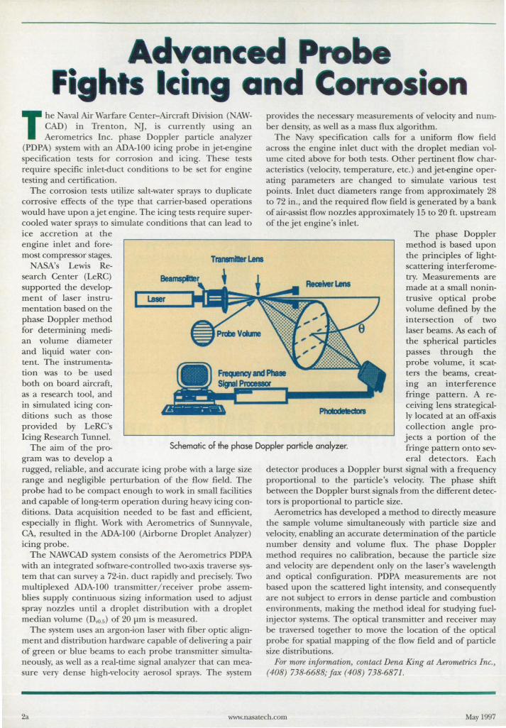
Advanc--~ Fi hts Ic·
The aval Air Warfare Center-Aircraft Divi ion ( AWCAD) in Trenton, G, is currentl using an Aerometrics Inc. phase Doppler particle analyzer
(PDPA) system with an ADA-IOO icing probe in jet-engine specification tests for corrosion and icing. These te ts require specific inlet-duct conditions to be set for engine testing and certification.
The corrosion tests utilize salt-water sprays to duplicate corrosive effects of the type that carrier-based operations would have upon a jet engine. The icing tests require supercooled water sprays to simulate conditions that can lead to ice accretion at the engine inlet and fore-most compressor stages.
NASA's Lewis Research Center (LeRC) supported the development of laser instrumentation based on the phase Doppler method for determining median volume diameter and liquid water content. The instrumentation was to be used both on board aircraft, as a research tool, and in simulated icing conditions such as those provided by LeRC's
Trananiller lMs
nd Cor ....... si provide the necessary measurements of velocity and number density, as well as a mass flux algorithm.
The avy specification calls for a uniform flow field acro s the engine inlet duct with the droplet median volume cited above for both tests. Other pertinent flow characteristics (velocity, temperature, etc.) and jet-engine operating parameters are changed to simulate various test points. Inlet duct diameters range from approximately 28 to 72 in., and the required flow field is generated by a bank of air-assist flow nozzles approximately 15 to 20 ft. upstream of the jet engine's inlet.
The phase Doppler method is based upon the principles of lightscattering interferometry. Measurements are made at a small non intrusive optical probe volume defined by the intersection of two laser beams. As each of the spherical particles passes through the probe volume, it scatters the beams, creating an interference fringe pattern. A receiving lens strategically located at an off-axis collection angle pro
Icing Research Tunnel. The aim of the pro
gram was to develop a
Schematic of the phase Doppler particle analyzer. jects a portion of the fringe pattern onto sev-
rugged, reliable, and accurate icing probe with a large size range and negligible perturbation of the flow field. The probe had to be compact enough to work in small facilities and capable of long-term operation during heavy icing conditions. Data acquisition needed to be fast and efficient, especially in flight. Work with Aerometrics of Sunnyvale, CA, resulted in the ADA-IOO (Airborne Droplet Analyzer) icing probe.
The NAWCAD system consists of the Aerometrics PDPA with an integrated software-controlled two-axis traverse system that can survey a 72-in. duct rapidly and precisely. Two multiplexed ADA-IOO transmitter/ receiver probe assemblies supply continuous sizing information used to adjust spray nozzles until a droplet distribution with a droplet median volume (D'{).5) of 20 ]lm is measured.
The system uses an argon-ion laser with fiber optic alignment and distribution hardware capable of delivering a pair of green or blue beams to each probe transmitter simultaneously, as well as a real-time signal analyzer that can measure very dense high-velocity aerosol sprays. The system
eral detectors. Each detector produces a Doppler burst signal with a frequency proportional to the particle's velocity. The phase shift between the Doppler burst signals from the different detectors is proportional to particle size.
Aerometrics has developed a method to directly measure the sample volume simultaneously with particle size and velocity, enabling an accurate determination of the particle number density and volume flux. The phase Doppler method requires no calibration, because the particle size and velocity are dependent only on the laser's wavelength and optical configuration. PDPA measurements are not based upon the scattered light intensity, and consequently are not subject to errors in dense particle and combustion environments, making the method ideal for studying fuelinjector systems. The optical transmitter and receiver may be traversed together to move the location of the optical probe for spatial mapping of the flow field and of particle size distributions.
FOT mOTe information, contact Dena King at Aerometrics Inc., (408) 738-6688; fax (408) 738-6871.
2a www.nasatech .com May 1997
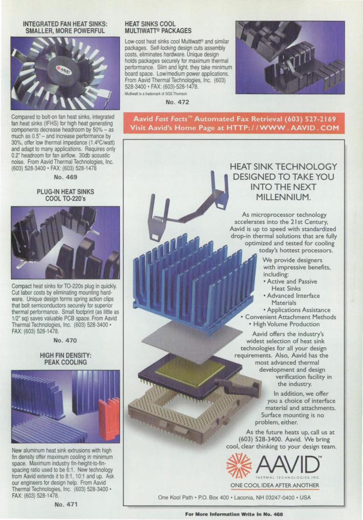
INTEGRATED FAN HEAT SINKS: SMALLER, MORE POWERFUL
Compared to bolt-on fan heat sinks, integrated fan heat sinks (IFHS) for high heat generating components decrease headroom by 50% - as much as 0.5" - and increase performance by 30%, offer low thermal impedance (1.49Clwatt) and adapt to many applications. Requires only 0.2" headroom for fan airflow. 30db acoustic noise. From Aavid Thermal Technologies, Inc. (603) 528-3400' FAX: (603) 528-1478
No. 469
PLUG-IN HEAT SINKS COOL TO-220'5
Compact heat sinks for TO-220s plug in quickly. Cut labor costs by eliminating mounting hard· ware. Unique design forms spring action clips that bolt semiconductors securely for superior thermal performance. Small footprint (as little as 1/2" sq) saves valuable PCB space. From Aavid Thermal Technologies, Inc. (603) 528-3400 • FAX: (603) 528-1478.
No. 470
New aluminum heat sink extrusions with high fin density offer maximum cooling in minimum space. Maximum industry fin-heighl-to-finspacing ratio used to be 6:1. New technology from Aavid extends it to 8:1, 10:1 and up. Ask our engineers for design help. From Aavid Thermal Technologies, Inc. (603) 528-3400 • FAX: (603) 528·1478.
No. 471
HEAT SINKS COOL MULTlWAl"J'® PACKAGES
Low-cost heat sinks cool Multiwatt and similar packages. Self-locking design cuts assembly costs, eliminates hardware. Unique design holds packages securely for maximum thermal performance. Slim and light, they take minimum board space. Low/medium power applications. From Aavid Thermal Technologies, Inc. (603) 528-3400' FAX: (603)-528·1478. MoIIMatt is a trademark 01 SGS Thomson
No. 472
HEAT SINK TECHNOLOGY DESIGNED TO TAKE YOU
INTO THE NEXT MILLENNIUM.
As microprocessor technology accelerates into the 21 st Century,
Aavid is up to speed with standardized drop-in thermal solutions that are fully
optimized and tested for cooling today's hottest processors.
We provide designers with impressive benefits, including: • Active and Passive
Heat Sinks • Advanced Interface
Materials • Applications Assistance
• Convenient Attachment Methods • High Volume Production
Aavid offers the industry's widest selection of heat sink
technologies for all your design requirements. Also, Aavid has the
most advanced thermal development and design
verification facility in the industry.
In addition. we offer you a choice of interface
material and attachments. Surface mounting is no
problem. either.
As the future heats uP. call us at (603) 528-3400. Aavid. We bring
cool, clear thinking to your design team.
ONE COOL IDEA AFTER ANOTHER
One Kool Path· P.O. Box 400' Laconia, NH 03247-0400 • USA
For More Information Write In No. 468

POWERED By MOTOROLA.
Universal Remote Motorola integrated chip sets
put the power ;n w1iversa1 remotes. And S1natter remote controls mean JOI:I can rontroI VCRs, ITs and
AJillio systems with pIS! one tollch.
AN Receiver Solutions Motorola has l...ln.-I to brit,,,
)fessionoJ Q1tdid'"'..~ home'Owith ~Iine of24-bit DrPs.1fnd that gives yOIl the capal;7i1ity to master music,
movteS lind games.
Cordless Phone Walkie talkies were the forerunners to rordJess p.00nes. NOlI! Motorola has embedi1ed that technology into todt!Y's cordless phones, givJngYOI/
die freedom to uxJk tiui tiilk.
AnydUng is possible. So if you can dream it, we can help you do it And we're in the business of taking risks
so our customers don't have to. In fact, we continually set benchmarks in many of our customers' industries.
Our products have helped make everydUng from cordless phones and video games to the next generation of
flat-panel plasma displays possible. And with hundreds of devices for the consumer electronics market, engineers worldwide are realizing the infinite possibilities of their furore. From Consumer Electronics to
WIred and WIreless Communications, Motorola products power the innovative solutions that enable your sua:ess.
VISit us at http://motorola.comlsps or call 1-800-521-6274 (Ref #297).
® MOTOROLA Semiconductor Products Sector
What you never thought possible.'"
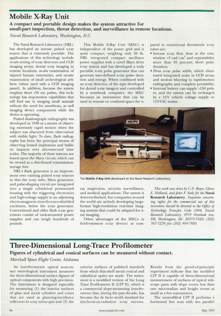
Mobile X-Ray Unit A compact and portable design makes the system attractive for small-part inspection, threat detection, and surveillance in remote locations.
aval Research Laboratory, Washington, D. C.
The aval Research Laboratory (NRL) has developed an inten e pulsed x-ray source that is extremely portable. The applications of thi technology include in-situ testing of x-ray detectors and CCD imaging arrays, dental x-ray imaging in remote location , in-situ examination of injured human extremities, and on-site examination of mall archeological artifacts (when used with a CCD imaging panel). In addition, because the system employs short (50 ns) pulse , this technology has stop-motion capabilities that will find use in imaging small animals without the need for anesthesia, as well imaging device components while the device is operating.
Pulsed shadowgraph radiography was developed in 1938 as a means of observing extremely rapid motion when the subject was obscured from observation with visible light. To date, flash radiography has been the principal means of observing lensed implosions and ballistic impacts over microsecond time scales. The majority of these systems are based upon the Marx circuit, which can be viewed as a distributed transmissionstorage line.
Thi Mobile X-Ray Unit (MXU) i independent of the power grid and i quite compact, weighing only 26 lb.
RL integrated compact oscillator power upplies with a novel Marx drive x-ray sy tern and has developed a truly portable x-ray pul e generator that can generate user-defined x-ray pulse duration and energy. When combined with an x-ray detector, of the type developed for dental x-ray imagery and controlled by a notebook computer, the MXU becomes an in trument that can be used in remote or confined pace for x-
pared to tran itional thermionic x-ray tube are: • Inten e x-ra flux: do e at the tube
window >3 rad/ cm2 and repeatability more than 95 percent; hort pul e duration;
• 50-n x-ray pul e width, which eliminated integrated noi e in CCD arrays and motion blurring in rapid-motion radiography, and complete portability;
• Internal battery can supply >150 pulses, and the y tern can be recharged by a 12-V vehicle voltage supply or 115-VAC mains.
NRL's flash generator is an improvement over existing pulsed x-ray sources in that the x-ray tube, Marx generator, and pulse-shaping circuit are integrated into a ingle cylindrical pressurized housing with the triggering electronics and high-voltage supply in an adjoining electromagnetic-interference-shielded enclosure, below the x-ray generator. Conventional and older flash x-ray generators consist of rack-mounted power supplies and can weigh hundreds of pounds.
The Mobile X-Ray Unit developed at the Naval Research Laboratory.
ray inspection , security surveillance, and medical applications. The system is detector-limited, but companies around the world are actively developing largeformat high-resolution real-time imaging systems that could be adapted for xray imaging.
Other advantage of the MXUs (a field-emission x-ray device) as com-
This work was done by c.N. Boyer, Glenn E. Holland, and John F. Seely for the Naval Research Laboratory. Inquiries concerning rights for the commercial use of this invention should be directed to the Office of Technology Transfer, Code 1004, Naval Research Laboratory, 4555 Overlook Ave. Sw, Washington, DC 20375-5320; (202) 767-7229;fax (202) 404-7920.
Three-Dimensional Long-Trace Protllometer Figures of cylindrical and conical surfaces can be measured without contact. Marshall Space Flight Center, Alabama
An interferometric optical noncontact metrological in trument measures the three-dimensional surface figures of optical components with high precision. The instrument is designed especially for measuring (1) the interior surfaces of glass and metal cylinders and cones that are u ed as glancing-incidence reflectors in x-ray telescopes and (2) the
6a
exterior urfaces of polished mandrels from which thin-shell metal conical and cylindrical optics are made. The instrument i a modified version of the Long Trace Profilometer II (LTP II), which is a commercial slope-measuring interferometer that, during the past decade, has become the de facto world standard for synchrotron-radiation x-ray mirrors.
www.nasatech.com
Results from the proof-of-principle experiment indicate that the modified LTP II is capable of three-dimen ional measurement of urfaces of typical telescope parts with slope errors Ie s than one microradian and height errors as small as a few nanometers.
The unmodified LTP II performs a horizontal line scan with two parallel
May 1997
How valuable is creativity?
Why settle lor a design that will just work •••
hat i it's used to design a better, more cost-effective (rcuif?
when you can now create your ideal solution.
And that means you get a better circuit design. Enabling your creativity to develop the ideal design
in less time-MicroSim's Family of EOA products delivers
the flexibility and unique capabilities that help you do just that. Each
has features designed to work together. They a(celerate your design process.
You can immediately see results of your design changes. This kind of power and
flexibility can only come from one company- MicroSim
PSPICE ANALOG/DIGITAL SIMULATION
SCHEMATIC ENTRY PLO SYNTHESIS PC BOARD LAYOUT DESIGNLAB START-TO-
FINISH SYSTEM
~ MicroSim~
Setting the standard for Desktop EDATM
Contact MicroSim at 1.800.245.3022 or 714.770.3022 You can visit our Web site: http://www.microsim.(om B-mail: [email protected]
For More Information Write In No. 452
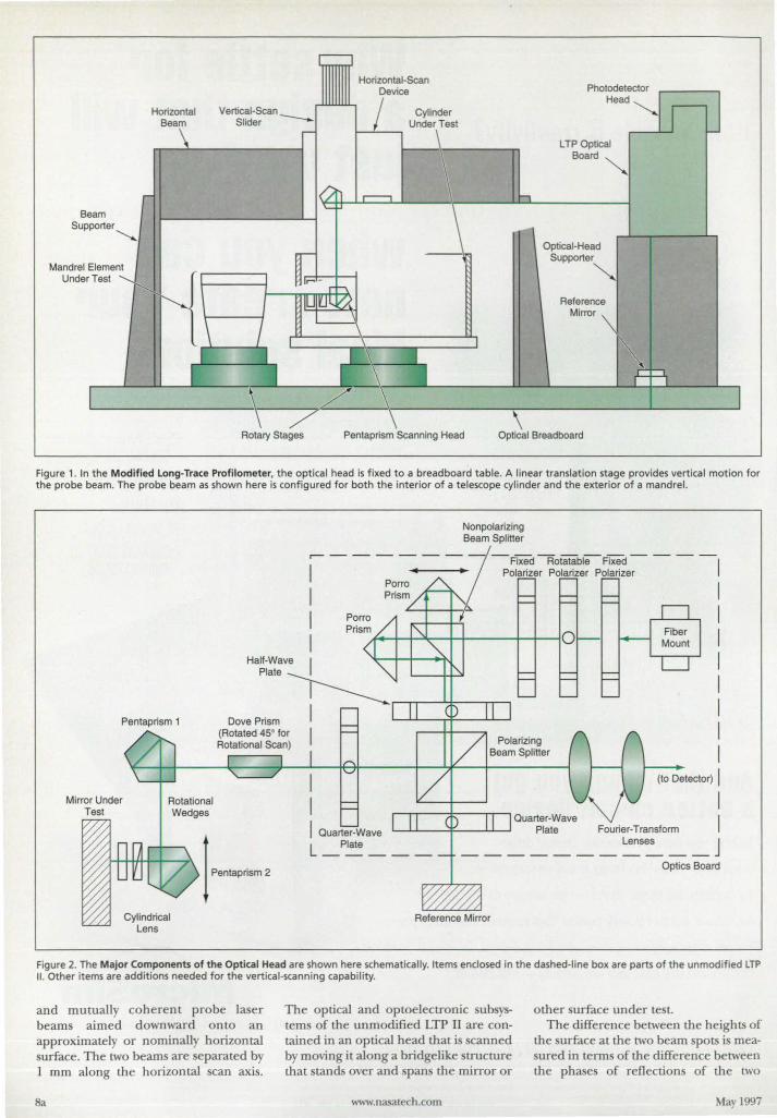
Vertical-Scan
Horizontal-Scan Device
Horizontal Beam Slider --
Cylinder Under Test
Beam Supporter
Mandrel Element Under Test
1----''----, lTP Optical
Board
Optical-Head Supporter
Reference Mirror
Rotary Stages Pentaprism Scanning Head Optical Breadboard
Figure 1. In the Modified Long-Trace Profilometer, the optical head is fixed to a breadboard table. A linear translation stage provides vertical motion for the probe beam. The probe beam as shown here is configured for both the interior of a telescope cylinder and the exterior of a mandrel.
Pentaprism 1
Cylindrical lens
Nonpolarizing Beam Splitter
-Fixed RotatableFixed- - -Polarizer Polarizer Polarizer
(to Detector) I
Quarter-Wave Plate Fourier-Transform
lenses J -----------
Optics Board
Reference Mirror
Figure 2. The Major Components of the Optical Head are shown here schematically. Items enclosed in the dashed-line box are parts of the unmodified LTP II. Other items are additions needed for the vertical-scanning capability.
and mutually coherent probe laser beams aimed downward onto an approximately or nominally horizontal surface_ The two beam are eparated by 1 mm along the horizontal scan axis.
Sa
The optical and optoelectronic ubsysterns of the unmodified LTP II are contained in an optical head that is scanned by moving it along a bridgelike structure that stands over and spans the mirror or
www.nasatech .com
other surface under test-The difference between the heights of
the urface at the two beam pots i measured in terms of the difference between the phases of reflection of the two
May 1997
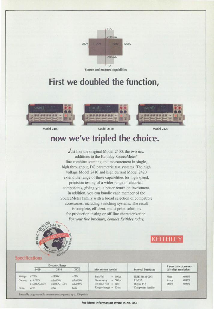
Source and measure capabilities
First we doubled the function,
Model 2400 Model 2410 Model 2420
now we've tripled the choice. Just like the original Model 2400, the two new
additions to the Keithley SouIceMeter-line combine sourcing and measurement in ingle,
high throughput, DC parametric test systems. The high voltage Model 2410 and high current Model 2420
extend the range of these capabilities for high speed, precision testing of a wider range of electrical
components, giving you a better return on investment. In addition, you can bundle each member of the
SourceMeter family with a broad selection of compatible accessorie , including switching ystems. The result
is complete, efficien4 mUlti-point solutions for production testing or off-line characterization.
For your free brochure, contact Keithley today. ~l~~ .. ....
~\t :\\).1.48·616/ •... ~~~ ". 5~ ... &- .
:;:;. a KEITHLEY
S ification Dynamic Range 1 year basic accuracy:
2400 2410 2420 Max system speeds: External interface: (5 'I,.digit resolution)
\obltage ±2OOV ±1I00v ±(lJV Passlfail = 500ps IEEE-488 (SePI) \obIts 0.01% Cumru ±IAI20V ±IAl20V ±3A120V Tomemol)' = 500ps RS-232 Amps 0.02%
±IOOmAI200V ±20mAl11OOV ±IAI(lJV TolEEE-488 = Ims Digital VO Ohms 0.04%
Power 22W nw fXiW Range change = I3ms Component handler
IntemalJy programmable mea<ruremem sequence up to 100 poinli.
For More Information Write In No. 453
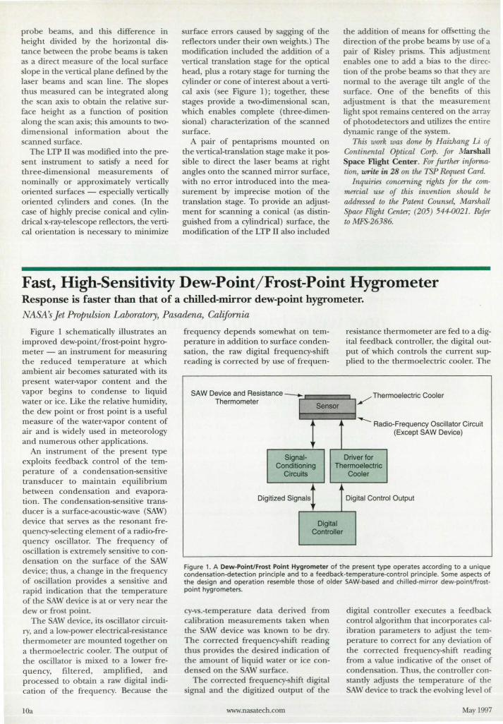
probe beam , and thi difference in height divided by the horizontal distance b tween the probe beam is taken as a direct measure of the local urface lope in the vertical plane defined b the
laser beam and can line. The lope thu measured can be integrated along the can axi to obtain the relative urface height as a function of po ition along the can axi ; thi amounts to twodimensional information about the canned urface.
The LTP II was modified into the present in trument to atisfy a need for three-dimen ional measurements of nominally or approximately vertically oriented urface - e pecially verticall oriented cylinders and cone. (In the case of highly preci e conical and cylindrical x-ray-telescope reflectors, the vertical orientation is nece ary to minimize
urface errors caused b sagging of the reflectors under their own weights.) The modification induded the addition of a vertical tran lation tage for the optical head, plus a rotary tage for turning the cylinder or cone of intere t about a vertical axi (ee Figure 1) ; together, the e tage provide a two-dimen ional can,
which enable complete (three-dimenional) characterization of the canned urface.
pair of pentapri m mounted on the vertical-tran !ation tage make it po -ible to direct the laser beam at right
angles onto the canned mirror urface, with no error introduced into the meaurement by impreci e motion of the
tran lation tage. To provide an adjustment for canning a conical (as di tingui hed from a cylindrical) urface, the modification of the LTP II al 0 included
the addition of mean for otE e tring the direction of the probe beam by u e of a pair of Risle prism. This adjustment enable one to add a bias to the direction of the probe beam 0 that the are normal to the average tilt angle of the urface. One of the benefits of thi
adju tment i that the measurement light pot remain centered on the array of photodetectors and utilize the en tire dynamic range of the tern.
This work was done by Haizhang Li of Continental Optical Corp. for Marshall Space Flight Center . For further infonnation, write in 28 on the TSP Request Card.
Inquiries concerning rights for the commercial use of this invention should be addressed to the Patent Counse~ Marshall Space Flight Center; (205) 544-0021. Refer to M.FS-26386.
Fast, High-Sensitivity Dew-Point/Frost-Point Hygrometer Response is faster than that of a chilled-mirror dew-point hygrometer. NASA s Jet Propulsion Laboratory, Pasadena, California
Figure 1 chematically illu trate an improved dew-point/ fro t-point hygrometer - an instrument for measuring the reduced temperature at which ambient air becomes saturated with its present water-vapor content and the vapor begins to condense to liquid water or ice. Like the relative humidity, the dew point or frost point i a u eful measure of the water-vapor content of air and i widely u ed in meteorology and numerous other applications.
An instrument of the present type exploits feedback control of the temperature of a conden ation-sen itive transducer to maintain equilibrium between con den ation and evaporation. The conden ation- ensitive transducer is a surface-acoustic-wave (SAW) device that erves as the resonant frequency-selecting element of a radio-frequency oscillator. The frequency of o dilation i extremely sensitive to conden ation on the surface of the AW device; thus, a change in the frequency of oscillation provide a sen itive and rapid indication that the temperature of the SAW device i at or very near the dew or frost point.
The AW device, its oscillator circuitry, and a low-power electrical-resi tance thermometer are mounted together on a thermoelectric cooler. The output of the oscillator is mixed to a lower frequency, filtered , amplified, and proces ed to obtain a raw digital indication of the frequency. Because the
lOa
frequency depends omewhat on temperature in addition to surface condenation, the raw digital frequency- hift
reading is corrected by u e of frequen-
SAW Device and Resist Thermometer
ance _
Signal-
Sensor
re i tance thermometer are fed to a digital feedback controller, the digital output of which controls the current upplied to the thermoelectric cooler. The
/ The rmoelectric Cooler
--- Radi o-Frequency Oscillator Circuit (Except SAW Device)
Driver for Conditioning Thermoelectric
Circuits Cooler
Di gitized Signals Digital Control Output
Digital Controller
Figure 1. A Dew-Point/Frost Point Hygrometer of the present type operates according to a unique condensation-detection principle and to a feedback-temperature-control principle. Some aspects of the design and operation resemble those of older SAW-based and chilled-mirror dew-pointJfrostpoint hygrometers.
cy-v .-temperature data derived from calibration measurements taken when the SAW device was known to be dry. The corrected frequency-shift reading thus provide the desired indication of the amount of liquid water or ice conden ed on the SAW surface.
The corrected frequency-shift digital signal and the digitized output of the
www.nasatech.com
digital controller executes a feedback control algorithm that incorporates calibration parameter to adju t the temperature to correct for any deviation of the corrected frequency- hift reading from a value indicative of the onset of conden ation . Thus, the controller con-tantly adjusts the temperature of the AW device to track the evolving level of
May 1997

We'll Catch You On The Web. Visit us at http://smallestpharlap.com to see how you can develop embedded applications that take full advantage of the web.
Phar Lap's TNT Embedded ToolSuite® Realtime Edition, complete with Realtime ETSlM Kernel, now comes with our robust networking protocol-ETS TCP/lP! This cutting edge feature allows your customers' mainframes, workstations, or PCs to communicate with products on the factory floor, in the Jab, or at remote sites-all using Web technology!
As a result, electronic OEMs can use this technology to create intelligent machines
and instruments for an unlimited number of applications such as medical instruments, robotics, avionics equipment etc.
In addition, we support a variety of network protocols as well as industry standard tools such as VISUal C++, Borland C++, CodeView, and Turbo DebuggeL
And because Phar Lap's TNT Embedded ToolSuite comes with development tools, a Realtime ETS Kernel, and now ETS TCP l IP, it is a one-stop shopping product with enormous power!
To find out more, catch us on the ·World's Smallest Web Server" today at URL htn>:/lsmallest.pharlap.com or call a Phar Lap sales representative! You'll be surprised how powerful the Web can be.
The 32-Bit x86 Experts
Embedded Development - Simply on Target TM
Phar Lap Software, Inc. 60 Aberdeen Avenue, Cambridge, MA 02138 • Tel: (617) 661-1510 • Fax: (617) 876-2972 • http://www.pharlap.com
For More Information Write In No. 454
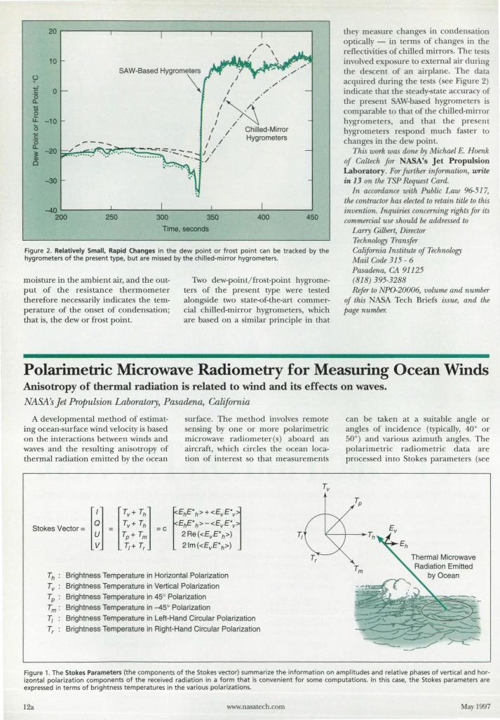
20
10
U ° 'E 0 0 Q.
1ii e u. -10 15 'E ·0 Q.
-20
~ -30
-40 200 250 300
·1 1
1 I /
/'.A.../ I /~
I / Chilled-Mirror I / Hygrometers
I . 1/ ./
350 400 450
Time, seconds
Figure 2. Relatively Small, Rapid Changes in the dew point or frost point can be tracked by the hygrometers of the present type, but are missed by the chilled-mirror hygrometers.
moi ture in the ambient air, and the output of the resistance thermometer therefore neces arily inclicates the temperature of the onset of condensation; that is, the dew or frost point.
Two dew-point/fro t-point hygrometers of the pre ent type were te ted along ide two tate-of-the-art commercial chilled-mirror hygrometers, which are based on a similar principle in that
they measure change in condensation optically - in term of change in the reflectivitie of chilled mirrors. The te ts involved expo ure to external air during the de cent of an airplane. The data acquired during the te ts ( ee Figure 2) inclicate that the teady-state accuracy of the pre ent AW-based h grometers is comparable to that of the chilled-mirror h grometer, and that the pre ent hygrometers re pond much faster to change in the dew point.
This work was done by Michael E. Hoenk of Caltech f<fr NASA's Jet Propulsion Laboratory. FM further information, write in 13 on the TSP Request Card.
In accMdance with Public Law 96-517, the wntractor has elected to retain title to this invention. Inquiries concerning rights fM its commercial use should be addressed to
Larry Gilbert, DirectM Technology Transfer CalifMnia Institute of Technology Mail Code 315 - 6 Pasadena, CA 91125 (818) 395-3288 Refer to NP0-20006, volume and number
of this ASA Tech Brief: issue, and the page number.
Polarimetric Microwave Radiometry for Measuring Ocean Winds Anisotropy of thermal radiation is related to wind and its effects on waves.
NASA s Jet Propulsion Laboratory, Pasadena, California
A developmental method of estimating ocean-surface wind velocity is based on the interactions between winds and waves and the resulting anisotropy of thermal radiation emitted by the ocean
surface. The method involves remote ensing by one or more polarimetric
microwave radiometer() aboard an aircraft, which circle the ocean location of interest so that measurements
Th : Brightness Temperature in Horizontal Polarization
Tv : Brightness Temperature in Vertical Polarization
Tp : Brightness Temperature in 45° Polarization
T m: Brightness Temperature in -45° Polarization
T, Brightness Temperature in Lett-Hand Circular Polarization
Tr : Brightness Temperature in Right-Hand Circular Polarization
T,
can be taken at a suitable angle or angle of incidence (typically, 40° or 50°) and variou azimuth angle. The polarimetric radiometric data are proces ed into Stokes parameters (see
Thermal Microwave
Figure 1. The Stokes Parameters (the components of the Stokes vector) summarize the information on amplitudes and relative phases of vertical and horizontal polarization components of the received radiation in a form that is convenient for some computations. In this case, the Stokes parameters are expressed in terms of brightness temperatures in the various polarizations.
12a www.nasatech.com May 1997
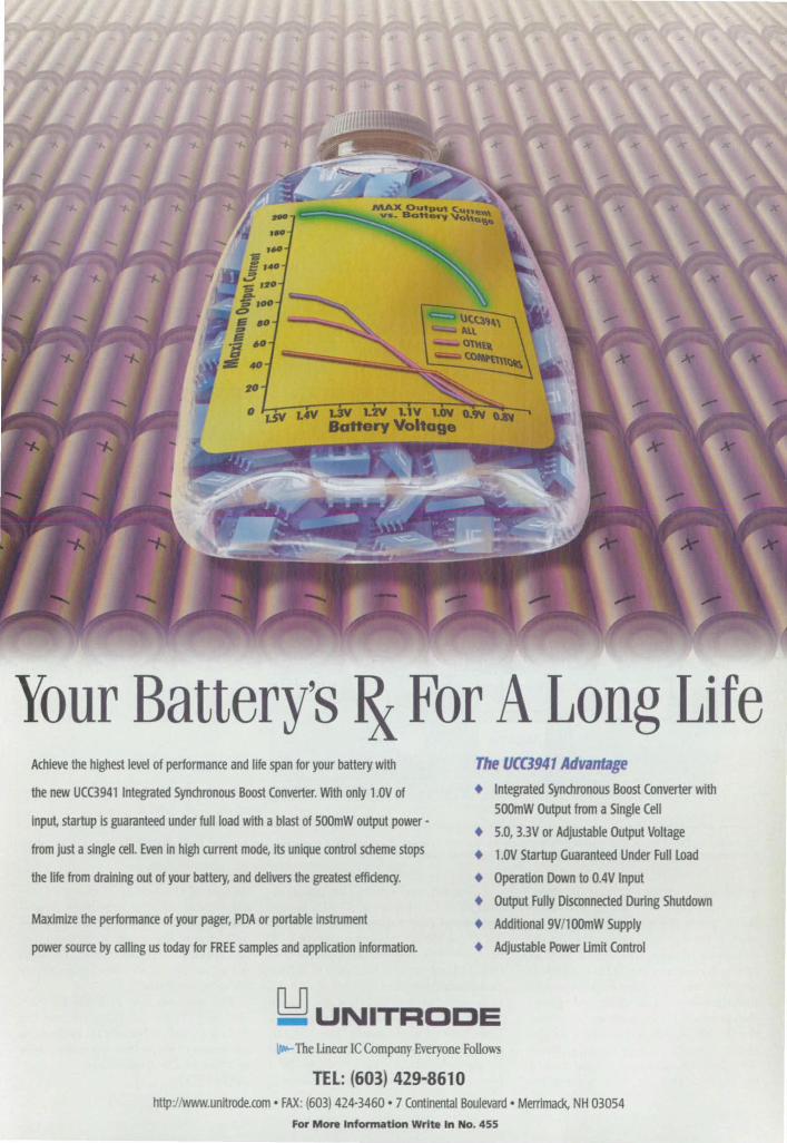
Your Battery's & For A Long Life Achieve the highest level of performance and life span for your battery with
the new UCC3941 Integrated Synchronous Boost Converter. WIth only 1.0V of
Input, startup is guaranteed under full load with a blast of SOOmW output power·
from just a single cell. Even in high current mode, its unique control scheme stops
the life from draining out of your battery, and delivers the greatest effldency.
Maximize the performance of your pager, PDA or portable instrument
power source by calling us today for FREE samples and application information.
The VCC3941 Advantage
• Integrated Synchronous Boost Converter with 500mW Output from a Single Cell
• 5.0, BV or Adjustable Output Voltage
• 1.0V Startup Guaranteed Under Full Load
• Operation Down to 0.4V Input
• Output Fully Disconnected During Shutdown
• Additional9V/l00mW Supply
• Adjustable Power Umit Control
~ UNITRODE ~ The Unear Ie Company Everyone Follows
TEL: (603) 429-8610 http://Www.unitrode.com • FAX: (603) 424-3460 • 7 Continental Boulevard· Merrimack, NH 03054
For More Infonnatlon Write In No_ 455
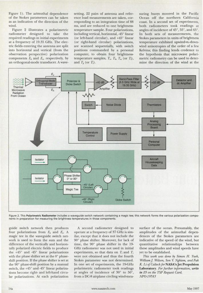
Figure I}. The azimuthal dependence of the Stoke parameters can be taken as an indication of the direction of the wind.
Figure 2 illustrate a polarimetric radiometer designed to take the required readings in initial experiments at a frequency of 19.35 GHz. The electric fields entering the antenna are split into horizontal and vertical (from the observation perspective) polarization components En and E", respectively, by an orthogonal-mode tran ducer. A wave-
setting, 22 pairs of antenna and reference load measurements are taken, corresponding to an integration time of 88 ms, and are reduced to one brightne -temperature ample. Four polarization, including vertical, horizontal, -45° linear (or left-hand circular), and +45° linear (or right-hand circular) polarizations, are canned equentially, with switch positions commanded by a personal computer, to obtain four brightnesstemperature samples, Tv, T", T .. (or Tl),
and T" (or Tr).
suring buoys moored in the Pacific Ocean off the northern CalifOrnia coasL In a second et of experiments, both radiometers took readings at angle of incidence of 45°, 55°, and 65°. In both ets of measurements, the Stokes parameters in units of brightness temperature exhibited upwind-vs.-downwind anisotropies of the order of a few Kelvins; this finding lends credence to the hypothesi that microwave polarimetric radiometry can be u ed to determine the direction of the wind at the
~ ~
~
~
Polarizer & Dicke Switch
Band-Pass Aher >-'~-I (6.5 GHz Wide at
Detec:tor and de AmplIfier
Thermal Microwave Radiation
From Ocean
Temperature Control
+450 (Right Circular)
19.35GHz)
Noise Diode
Dicke Switch
Thermistors
Analog ProcessIng
Board
Personal Computet
Aircraft Housekeeping
Data
Figure 2. This Polarimetric Radiometer includes a waveguide switch network containing a magic tee; this network forms the various polarization components in preparation for measuring the brightness temperatures in those components.
guide switch network then produces four polarizations from En and E". A magic tee in the waveguide switch network is used to form the sum and the difference of the vertically and horizontally polarized electric fields to produce the +45° and -45° linear polarizations with the phase shifter set at the 0° phaseshift position. If the phase shifter is set at the 90° phase-shift po ition by a manual switch, the +45° and -450 linear polarizations become right- and left-hand circular polarizations. At each polarization
14a
A second radiometer designed to operate at a frequency of 37 GHz is similar, except that it does not include the 90° phase shifter. Moreover, for lack of time, the 90° phase shifter in the 19-GHz radiometer was not used in initial experiments, so that data on T{ and Tr were not obtained and thus the fourth Stokes parameter was not determined. In one set of experiments, the 19-GHz polarimetric radiometer took readings at angles of incidence of 30° to 50°, from a DC-8 airplane circling wind-me a-
www.nasatech.com
surface of the ocean. Presumably, the amplitudes of the azimuthal dependences of the Stokes parameters are indicative of the speed of the wind, but quantitative relationships between these amplitudes and wind speeds have yet to be established.
This wark was done by Simon H. Yueh, William J. Wilson, Son V. Nghiem, and Fuk K. Li of Caltech far NASA's Jet Propulsion Laboratory. Far further inJarmation, write in 15 on the TSP Request Card. NPO-19583
May 1997
Toughened High-Temperature Ceramic A low-cost advanced ceramic with high strength and toughness, high thermal shock resistance, and good electrical characteristics has been developed for l OOO·oC applications. Lockheed Martin Vought Systems, Dallas, Texas
Advanced ceramic materials that exhibit high strength and toughness with good thermal shock resistance and low dielectric properties are needed for emerging high-temperature engineering applications. A recently developed in-situ reinforced barium aluminosilicate (BAS) glass-ceramic shows promi e of meeting many of the requirements for these types of application with the added benefit of low-cost fabrication through densification by pressurele sintering. The BAS glass ceramic is toughened through in-situ growth of whisker-like B-silicon nitride (Si5N4)
grains resulting from the (l-B Si3N4 phase transformation. Developed for mi sile radomes, the material's other potential application include components in electronic packaging, low-loss electric windows, armor, cutting tools, and other structural applications.
A Si3 4/BAS slurry is prepared by ball-milling mixtures of high-content (l-
i, 4, barium carbonate, aluminum oxide, and silicon dioxide along with a fugitive binder and a di persanl. The resulting slurry can be used for slip-casting of components or can be further processed by spray-drying to yield a flowing powder for u e in the fabrication of parts by conventional dry pressing or cold i 0 tatic pres 'ing methods.
The organic materials are burned out and the "green" components are densifled by pre urele intering at temperatures between ] 750-1800 ac. During den ification. the material reache a temperature at which the BA constituents and the Si, ~ react to form a liquid phase. Transformation of the
is 4 take place in the presence of the Hquid phase, during which whi ker-like elongated 6-phase i, 4 grains are formed. Upon cooling, the whisker-like grains (reinforcement phase) are urrounded b}' a secondary matrix phase compo ed of crystalline BAS to form an in-situ reinforced barium alumino iIi-
May 1997
Semiconductor Processing •• Memory Repolr • laser Material Processing
iorlcmg & MachIn ng
Cutting & 0 ng
Weld ng & Treat ng
Imaging and Fabrication DIgital Radiography
High Resolutoon Focsrmlle
Molenallnspedlon
Rapid Protolyping
Biel-Medlcal Systems Dermatology
Ophthalmology
Anolylicollnslrumenlation
Canfocat Microscopy
Laser Projection Induslr 01 CAD Prolectlon
loser EntertaInment
W ith a world of experience and insta llat ions in loser· based system applications,
Cambridge Technology, Inc. offers the highest performance optical scanning
solutions to meet the needs of the most demanding optical system requirements.
With a complete line of High Performance Moving Coil and Moving Magnet
Galvanometers for large apertures and small, our patented technology offers
pOSitioning speeds up to 1 KHz and mlcro·radion level pOSitioning accuracy
W ith a strang commofment and locus on the continued Innovot on ond
Introducllon 01 high performance optical scanning products, Cambridge Technology
IS the obv ous cholLe ana partner for all your pOSit ioning requirements
..., CMlr Technical Sales Engineers or Trained Field RepresetdaIiYes help you reach new levels of optical scanning speed, accuracy I11III produdiviIyo
-= Cambrlc;tge § Technology
..... 7 row WAIf (TEM.TeI.(03}-3226-1671 Fa(I3) .... 1673 _ anus ...... 89013S-ll.FaIl9IB2561 FIAHCl IOPTIlASCDnIposaImTel.33(II6l79S9",.-. ...... 31 _ 1 •• I._lid. Tel. 44 (01 1933461666 faa 44 (01 1933461699 usa.w.ec..t "''''''_111...",.,._ 771-2899 tIIf NETHBWIDS Ion tm. Techeology Tel 31 58 513S 611 faa 3150 S713lM WWII SIIperWII Campaay.
lit iI. 1116-2·701326, Falll6-2-18l3S31 _ IIlI.c.,M.IIL il.82-42'&I-8070. Fa82-42.&I-81J73 I5IIB. 1 Hew Tedv1oIogy
U lid. Tel (972)3sn 8686 Fa(972)3S714641 IUIJ ICriIIIlmlrumennsrl Tel 39 (6)35402933, faa 39 (6)35402979
CamIIridge TechitoIogy Corporate 0IIb: 109 s.ith Place e Cambridge, MA 02131
TeL 617. 441-0600- Fax 617-497-8800 ehHp:/Iwww.camtech.com
For More Information Write 7n No. 456 15a
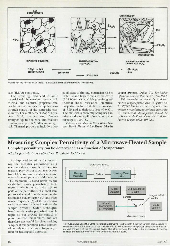
BAS CONSTITUENTS
STARTING POWDERS
..
TRANSFORMATION a -p-SI3N"
MICR08EcnON
MICROSTRUCTURE OF DENSE BAS-SI3N"
aSISN" + BAS CONSTITUENTS SINTERING COOLING
- L1QUID .... S
Process for the formation of in-situ reinforced Barium Aluminosilicate Composites.
cate (IRBAS) composite. The resulting advanced ceramic
material exhibits excellent mechanical, thermal, and electrical properties and can be tailored to specific applications through control of the compo ite constituents. For a 30-percent BAS/ 70-percent Si3N4 COmpOSItiOn, flexure strengths up to 565 MPa and fracture toughne se up to 5.74 MPa-..Jm are typical. Thermal propertie include a low
coefficient of thermal expan ion (3.8 X
10-6/"C) and high thermal conductivity (9.19 W/(cm- K)), which provides good thermal shock re istance. Electrical properties include a dielectric con tant of 7.75 and a dielectric 10 of 0.001. The material is currently being u ed in missile radome applications at temperature up to 1000 °C.
This work was done by Kerry Richardson and David Hunn of Lockheed Martin
Vought Systems, Dallas, TX. For further infanna/ion contact them at (972) 603-9844.
Thi invention is owned by Lockheed Martin Vought Systems, and U.S. patent no. 5,358,912 has been issued. Inquiries concerning nonexclusive or exclusive license for its commercial development should be addressed to the Patent Counsel at Lockheed Martin Vought, (972) 603-9207.
Measuring Complex Permittivity of a Microwave-Heated Sample Complex permittivity can be determined as a function of temperature.
NASA s Jet Propulsion Laboratory, Pasadena, California
An improved technique for measuring the complex permittivity of a microwave-heated sample of dielectric material provides for simultaneous control of heating power and/ or measurement of the temperature of the ample. This technique i based partly on the e tablished cavity perturbation technique, in which the real and imaginary parts of the permittivity of a mall sample are calculated from the values of the resonance quality factor (Q) and resonance frequency (fr) of the microwave cavity measured with and without the sample present. O lder techniques based on the cavity perturbation technique do not provide for control of power and/or temperature, and are therefore not useful for characterizing samples at temperatures above ambient when only one microwave frequency is used for heating and detection.
16a
Infrared Thermometer .. ---+-----4. or Pyrometer
Microwave Cavity
This Apparatus Uses the Same Resonant Microwave Field to both heat the sample and measure its complex permittivity. The apparatus includes circuitry that controls the power dissipated in the sample and the walls of the microwave cavity. plus other circuitry that adjusts the microwave frequency to track the resonance of the cavity with the sample present.
www.nasatech.com May 1997
The complex pennittivity of a dielectric material is a measure of its microwave-absorption properties and of some other physical and chemical properties. The complex permittivity is often called the complex "dielectric constant" even Lhough it is not constant; indeed, one could use the present tecbnique to measure the change in the complex permittivity of a sample during microwave beating and/ or other processing to monitor the extent to which the material has been converted to the desired end condition.
In the pre ent technique, one uses the ame microwave field to both heat the
sample in a controlled manner and measure its complex pennittivity. The apparatus used in this technique (see figure) includes a microwave source, the frequency and power of which can both be controlled. The frequency of the source is made to track j.., even as j; changes somewhat with Lhe condition of the heated sample; the f,-tracking technique was described in "Measuring Q and j.. of a Microwave Cavity: Part II" (NPO-19356), NASA Tech Briefs. Vol. 19, No. 12 (December 1995), page 36. Controlling the frequency in this way confers two benefits: First, because the frequency is always at or close to j;, power is delivered efficiently to heat the sample even as the dielectric parameters of the sample change during continued heating. Second, j; can be continuously monitored by use of a frequency counter connected directly to the output of the oscillator.
Diode detector are used to measure the forward power (Pr) traveling from the microwave source to the microwave cavity and the reflected power (PR) traveling from the cavity back to the source, o that the net power transmitted into
(and thus dissipated in) the cavity (PT )
can be calculated from PT = PF - PR' The apparatus includes computer-controlled circuitry for maintaining PT at a de ired value. A third diode detector connected to a magnetic-field coupler in the microwave cavity mea ure a power (Po) that can be hown to be proportional to the energy (~1) tored in the resonant electromagnetic field in the cavity.
The total power transmitted inLO the cavity can be expressed as PT = Ps + PIA + PE where Ps is the power dissipated in heating the sample, PIA is the power dis-ipated in heating the wall of the cavity,
and PE is the power 10 s in the input electronics. By continuously maintaining the critical coupling between the micro\\'ave source and cavity using an automatic impedance tracking technique developed previously, the reflected power will
May 1997
be zero and power dissipated in the electronics will be equal to the power dissipated in the cavity. The resonance quality factor of the cavity is then given by Qr 21tj;4.i1 PT. By virtue of the equation for the power-iiissipation components, one can write 1/QT= 2(I/ Qw+ l / Qs), where Qw = 21tj;EMI PI\" and Qs = 21tj;EMI Ps. Then the reciprocal of the quality factor associated with the sample is given by l / Qs = 1/ 2/ QT - l / Qw. Provided that the temperantre of the wall is maintained approximately constant (e.g., by cooling it with water) Q.w is independent of PT and of the tern perature (7) of the sample. By making substitutions from
the equations and definitions above, the equation for l / Qs can be rewritten as 1/ Qs = PT/21tj..~1 Po - 11 Qw, where ~ is the factor of proportionality between 4J and Po (~ = E,.J Po). ~ depends only on the geometry of the cavity and magnetic coupler and can be determined from a low-power calibration measurement in the absence of the ample. By use of cavity perturbation theory, one can compute the complex pennittivity of the sample from 1/ Qs.
In a typical experiment, one ets PT to a desired value while measuring Tby use of a pyrometer or other noncontact device. Once T settles to a steady value,
This is the world's most advanced data recorder.
And dat's DAT.
Less is more. The Sony PC200 Series IS an entire new
generation of data recorders. The smallest go-anywhere recorders aVailable. With
features and performance that PUI themln a class by themselves. And WIth configuratIons
Irom 2 10 64 channels. bandwidths from OC to 100 KHz, and even a hybrid lor
SImultaneous wideband analog and/or digItal data. there's a model to precisely
lit your reqUIrements.
The OAT advantage. Sony PIoneered DA~ and we know how to gel the mosl OUI 01 It The new PC200 Series can
record up 10 6 hOUrs of data WIth an ovel"all transfel" rate of up 103072 Mbps. Good data.
wrth a dynamiC range grealer than. BOdS. Nothing else comes close
The ins and outs. SInce small SIZ9 enhances portabllrtv. Sony
provides an RS232C for OO$Ite remote control VIa laptop. palmtop. your chooce Goong the
other way. the SCSI PCIFSOO Irlterface provides optimum data transfer to your
PC Of worI<.station Because the faster your data becomes JI1formation. the better
The soft stuff. Imbedded In every PC200 Senes recorder
IS Table 01 Contents software for las! and easy searcres on the computer. You can
write each recordIng block's sub data such as 10. ADDRESS. and RANGE.
Even TIME CODE And. with Sony's powerful PCscan no data acquisition software. turning your data inlo Information was navel" easier.
PCscan- MKJI_ ",_1153241 ""'*' OOtItro/S al>gh{1lIrforrrlaro6Af)""". _S<. up 10 4 GbyIe 01 analog stDrBge, hiQ/l.,- SBB/dJ. resJ-l1fnB wave ~ 1&11'1{1. and '- dBla fotmIIl"""""'. 1haI_~ __ MddBl.lloI7
The Sony advantage. 01 course, wilen you choose the PC200 Senes dala recorders, you choose Sony. and you know whal that means in terms 01 constant technology advancement and leadershIP, rugged reliabIlity. and lull support. Only Sony could make data recording exerting Give us a call and we'lI tell you just how excIting rt gets All OAT and more
SONY. Sony Prwclslon TocI>noIogy _ . Inc.
137 west _ Lane • Orange, CA 92865 (714) 92HI630· Fax (714) 921-1162 _ ... ---_ .. _-
For More Information Write In No. 457 17a
lumitex® SolidState Backlighting Brighter, more uniform light at lower power.
• Ideal for high volume, cost sensitive applications • Mechanical design holds LCD's, reducing product
assembly and material costs
• Rapid design and prototype turnaround.
18a
For more information. contact Lumitex (1-800-969-5483; fax: 216-243-8402) or your local Lumitex representative.
o 1996 lumttex, Inc.. II rights resrrwd
I Lumitex·, Inc. Lumltex SoIidSIa1e is LIGHT. .. in any form
=: ~1~ 8443 Dow Circle :~ Stroogsville. OH 44136
For More Information Write In No_ 458
Project and Cut C
(E
Make Your Own Prototype Circuit Boards
• Five models available to meet your application
• Compare our easy to operate software
• Input Gerber, Excellon, dxf or HPGL files
• 60,000 rpm available for fine geometries
• Automated thru-hole plating process
• One year warranty. Ask about our support team.
For more details. view our Web site: httpJ/www.lpktcadcam.com
Call Today 1-800-345-5753 IPICFCAD/CAM Fax: (503) 643-3662 Email: [email protected] SYSTEMS. INC.
For More Inf ormation Write In No. 459
one measure f,. and PD' One then increase PT in step and repeats the measurement procedure at each tep to accumulate ets of data on PT,f,., and PD at various increments of Tcorre ponding to the increments of PT' From the e data, one obtain 1/ Qs as a function of Tand thus aI 0 the complex permittivity of the ample malerial as a function of T.
This work was dcne by Martin Bannatz and Henry W. Jackson of Caltech for NASA's Jet Propulsion Laboratory. For further information, write in 97 on the TSP Request Card. NPO-19773
Noise and Impedance Generator for Cryogenic Testing of HEMTs Spurious effects from room-temperature test circuits would be reduced. NASA's Jet Propulsion Laboratory, Pasadena, California
A monolithic, integrated, coolable probe is being developed for use in measuring the cryogenic noi e parameter of high-electroD-mobility transistors (HEMTs) at the wafer-processing stage of production. The integrated circuitry in the probe would include a noise source and impedance generator integrated with a coplanar-waveguide probe circuit.
This development is prompted by a fundamental physical limitation on the accuracy and repeatability oflow-temperature HEMT noise-parameter measurements performed with commercial noise sources and impedance generators, which operate at room temperature: In preparation for uch a measurement, one attaches a room-temperature noi e ource and impedance generator to the room-temperature ports of cryogenic, coplanar on-wafer probes. The probes are lossy and introduce noi e temperatures comparable to or greater than the noise temperature of the device under test (DUT). For example, in a typical test in the frequency range of 2 to 18 CHz, the noise-temperature measurement error can go beyond ±25 K, while the noi e temperature of the DUT is <10 K.
To obtain the most accurate and repeatable measurements of noise parameters at low tern peratures, one should place the impedance generator within a waveguide wavelength (at the te t- ignal frequency) of the DUT and should use a noi e ource with a noise temperature comparable to that of the
DUT. The developmental probe would be designed to atisfy these requirements. The probe would be compatible with other cryogenic probes designed for measuring cattering (S) parameter over a frequency range of 1 to 40 CHz. The integration and use of probes of both type would enable the efficien t, accurate, and nondestructive characterization of HEMTs and of circuits that contain them. The u e of the e probe in characterizing HEMTs under cryogenic conditions at the wafer level would eliminate the need for the expense and labor of dicing, mounting, and wire bonding needed to characterize HEMTs by pre ent technique .
The figure illustrates some aspects of alternative proposed designs. Calibrated noise diode would be in erted in a coplanar-waveguide circuit that would be coupled to the impedance generator. The topology of the impedance generator would have to be chosen to enable integration into the coplanarwaveguide formal and to reduce resonant mode . One of two
May 1997
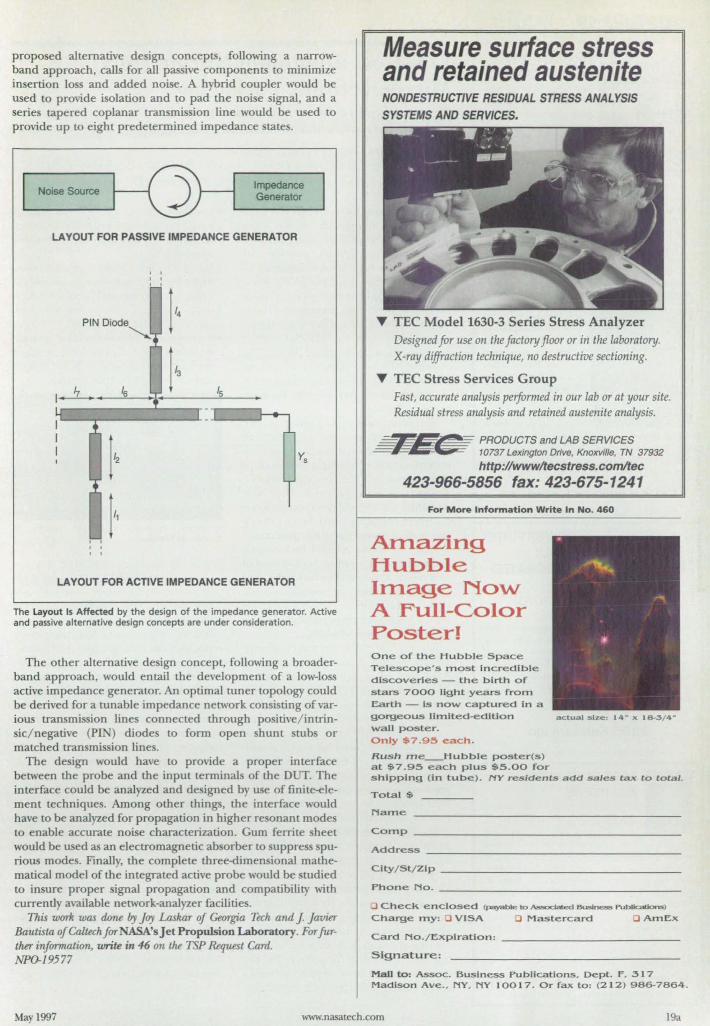
proposed alternative design concepts, following a narrowband approach, calls for all passive components to minimize in ertion loss and added noise. A hybrid coupler would be used to provide isolation and to pad the noise signal, and a series tapered coplanar transmission line would be used to provide up to eight predetermined impedance states.
Noise Source Impedance Generator
LAYOUT FOR PASSIVE IMPEDANCE GENERATOR
LAYOUT FOR ACTIVE IMPEDANCE GENERATOR
The Layout Is Affected by the design of the impedance generator. Active and passive alternative design concepts are under consideration.
The other alternative design concept, following a broaderband approach, would entail the development of a low-loss active impedance generator. An optimal tuner topology could be derived for a tunable impedance network consisting ofvarious transmission lines connected through positive/intrin-ie/negative (PIN) diode to form open hunt stubs or
matched transmission lines. The design would have to provide a proper interface
between the probe and the input terminals of the DUT. The interface could be analyzed and designed by use of finite-element techniques. Among other things, the interface would have to be analyzed for propagation in higher resonant modes to enable accurate noise characterization. Gum ferrite sheet would be used as an electromagnetic absorber to suppress spurious modes. Finally, the complete thretXtimensional mathematical model of the integrated active probe would be studied to insure proper signal propagation and compatibility with currendy available network-analyzer facilities.
This wurk was dune by Joy Laskar of Georgia Tech and J Javier Bautista of Caltech forNASNs Jet Propulsion Laboratory. For further information, write in 46 on the TSP &quest Card. NPO-19577
Measure surface stress and retained austenite NONDESTRUCTIVE RESIDUAL STRESS ANALYSIS SYSTEMS AND SERVICES.
T TEC Mode11630-3 Series Stress Analyzer Designed Jor use on the factory floor or in the laboratory. X-ray diffraction technique, no destructive sectioning.
T TEC Stress Services Group Fast, accurate analysis performed in our lab or at your site. Residual stress analysis and retained austenite analysis.
-#hO- PRODUCTS and LAB SERVICES = - 10737 Lexington Drive, Knoxville, TN 37932
http://www/tecstress.comltec 423-966-5856 fax: 423-675-1241
For More Information Write In No. 460
Amazing Hubble Image Now A Full-Color Poster! One of the Hubble Space Telescope's most Incredible discoveries - the birth of stars 7000 light years from Earth - is now captured in a gorgeous IIrnited-edltion wall poster.
Only $7.95 each .
Rush me_Hubble poster(s) at $7.9S each plus $5.00 for
actuol size: 14- x J 8-3/4-
shipping (In tube). NY residents add sales t;a.x to total.
Total $
Name
Comp ___________________ _
Address __________________ __
Clty/St/Zlp _________________ _
Phone No. _________________ __
:J Check enclosed (payable to AssocIated BusIness PUblIcatIons)
Charge my: a VISA 0 Mastercard a ArnEx
Card No./Expiratlon:
Signature:
Mall to: Assoc. Business Publications, Dept. F, 317 Madison Ave., NY, NY 10017. Or fax to: (212) 986-7864.
May 1997 www.nasatech.com 19a
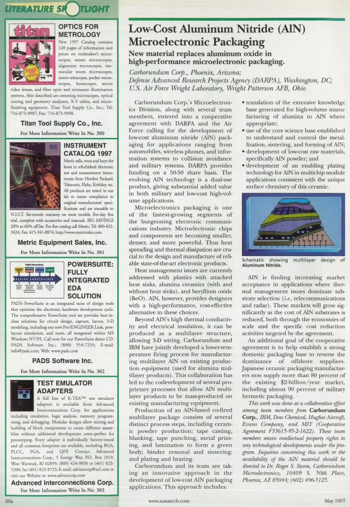
'LIGHT
<:w 1997 Catalog com"ins 120 p:oges of information and prices on toolmaker's micro
scopes. stereo microscopes. alignment microscopes, monocular 7.oom microscopes. micro-td=pes, pocket microscopes, borescopes. micro
video lenses, and fiber optic and miniature illumination systems. Also described "'" centering microscopes, optical cutting tool geomecry analyzers, X-Y rables, and microfinishing equipment. TItan Tool upply Co., Inc.; Tel: 716-873-9907; Fax: 716-873-9998.
Titan Tool Supply Co., Inc.
For More Informacion Write In No. 300
INSTRUMENT CATALOG 1997 Metric sells, rents and buys the larest in refurbished decounic [est and measurm1etlr instruments from Hew/en Packard, Tektronix, Fluke. Keithley, = All prodUCts are tested in our lab [Q insure compliance [Q
otiginal manufacturers' specifications and are rraceable [Q
N.LS.T. Six-month warranty on mO${ models, five..d.ay &.r trial, complete with a=ries and manuals. BIG SAVINGS 20% [Q 60% off list. For &.r catalog call Metric; Tel: 800-432-3424; Fax: 415-341-8874; http://www.metricsales.com.
Metric Equipment Sales, Inc.
For More Information Write In No. 301
----_ __ oa_ - _ ... _-_IICI_ ... _.-
POWERSUITE: FULLY INTEGRATED EDA SOLUTION
PADS-PowerSuire is an integrated suite of design tools that optimize the electronic hardware development eycle. The comprehensive PowerSuite tool set provides best-inclass solutions for circuit design, capture. layout, 3-D modeling. including our new Pro/ENGINEER Link, postlayout simulation. and more, all integrated within MS Windows NT/95. Call now for our PowerSuite demo CD. PADS Software Inc.; (800) 554-7253; E-mail: [email protected]; Web: www.pads.com
PADS Software Inc.
For More Information Write In No. 302
TEST EMULATOR ADAPTERS A full line of K-TEA TM test emulator adapters is available from Advanced Interconnections Corp. for applications
including emulation. logic analysis. memory programming. and debugging. Modular designs allow mixing and building of block components to create different assemblies without additional devdopment costs-perfect for protoryping. Every "dapter is individually factory-tested and all common footprints are available, including BGA. PLCC. PGA. and QFP. Contact Advanced Interconnections Corp .• 5 Energy Way, P.O. Box 1019. West Warwick. Rl 02893; (800) 424-9850 or (401 ) 823-5200; fax (401 ) 823-8723; E-mail: [email protected] visit OUI Website at: WVIW.advinccorp.com
Advanced Interconnections Corp. For More Informarion Wrire In No. 303
20a
Low-Cost Aluminum Nitride (AlN) Microelectronic Packaging New material replaces aluminum oxide in high-performance microelectronic packaging. Carborundum Corp., Phoenix, Arizona; Defense Advanced Research Projects Agency (DARPA), Washington, DC;
.S. Air Force Wright Laboratory, Wright Patterson AFB, Ohio
Carborundum Corp.' Microelectronic Divi ion, along with everal team members, entered into a cooperative agreement with DARPA and the Air Force calling for the development of low-co t aluminum nitride (AI ) packaging for application ranging from automobiles, \virele phones, and information ystems to collision avoidance and military sy terns. DARPA provides funding on a 50-50 share basis. The evolving AIN technology is a dual-use product, giving substantial added value in both military and low-cost high-volume applications.
Microelectronics packaging i one of the fastest-growing egments of the burgeoning electronic communications industry. Microelectronic chips and components are becoming smaller, denser, and more powerful. Thus heat spreading and thermal dissipation are crucial to the de ign and manufacture of reliable state-of-the-art electronic products.
Heat management is ues are currently addre sed with plastics with attached heat sinks, alumina ceramics (with and without heat sinks), and beryllium oxide (BeO). AlN, however, provides de igners with a high-performance, cost-effective alternative to these choices.
Beyond AIN's high thermal conductivity and electrical insulation, it can be produced as a multilayer tructure, allowing 3-D wiring. Carborundum and mM have jointly developed a lower-temperature firing process for manufacturing multilayer AI on existing production equipment (used for alumina multilayer products). This collaboration has led to the codevelopment of everal proprietary proce ses that allow AlN multilayer products to be mas -produced on existing manufacturing equipment.
Production of an AI -based co-fired multilayer package con ists of several di tinct process step, including ceramic powder production; tape casting, blanking, tape punching, metal printing, and lamination to form a green body; binder removal and sintering; and plating and brazing.
Carborundum and its team are taking an innovative approach in the development of low-cost AI packaging application. Thi approach includes:
www.nasatech.com
• tran lation of the exten ive knowledge base generated for high-volume manufacturing of alumina to AlN where appropriate;
• use of the core cience base e tablished to understand and control the metallization, intering, and forming of AlN;
• development of low-cost raw material , specifically AI powder; and
• development of an enabling plating technology for AlN in multichip module application consi tent with the unique urface chemistry of this ceramic.
Schematic showing multilayer design of Aluminum Nitride.
AI is finding increa ing market acceptance in applications where thermal management is ues dominate substrate selection (i.e., telecommunications and radar). These markets will grow significantly as the cost of AI ub trates is reduced, both through the economies of scale and the specific cost reduction activities targeted by the agreement.
An additional goal of the cooperative agreement is to help establish a strong domestic packaging base to reverse the dominance of offi hore uppliers. Japane e ceramic packaging manufacturers now supply more than 80 percent of the existing 2-billion/ year market, including almost 90 percent of military hermetic packaging.
This wurk was done as a coilaharative effart a71WTlg team members from Carborundum Corp., IBM, Dow Chemica~ Hughes Aircraft, Evans Company, and MIT (Cooperative Agreement F33615-95-2-1622). These team members retain inteUectual property rights to any technological developments under the ~ gram. Inquiries concerning this wurk ar the availahility of the ALN material should be directed to Dr. Roger . Stonn, Caroarundum Microelectronics, 10409 S. 50th Place, Phoenix, AZ 85044; (602) 496-5125.
May 1997
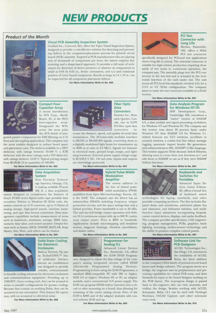
NEW PRODUCTS
Product of the Month Visual PCB Assembly Inspection System GenRad Jnc., Concord, MA, offers the Viper Visual InspecLion )'Stem, designed to provide a co t-effecri\"e solurion for detecring and preveming defects in the componem-placement process for printed circuit board (PCB) assembly. Targeled at PCB manufacturers who are placing ten of thousands of components per hour, the lem employs line scanning and a shape-based approach. It provides a full suite of tech· niques for detecLion of device presence or absence on components as small as 0.04 b) 0.02 in., de-ice orientation, and x/ . and rotational poi riO" of every board componenL Boards as large as 14 x 18 in. can be inspecled for all component placement defects.
A recent inlroduction by AVX Corp., Myrtle Beach, SC. is the 0612 four-capacitor array. Designated the W3A series, the array joins the AVX family of inte
graled passive components fOT EMl filtering on I/O lines and decoupling applications. The company sa} the array enables designers to reduce board space and placemem costs. The series is available in a PO dielectric with ratings between 16-100 V; a X7R dielectric with the same ratings; and a Y5V dielectric with ratings between 16-50 V. l)'pical pricing ranges from 0.06-$0.13 in quantities of 100,000.
For More Information Write In No. 802
Data Acquisition System ony Precision Technol·
ogy America, Orange, CA., is making available PCsc-dIl MK II, a data acqui ition
system de igned to complement the features of Sony's PC200 series digiral audio tape portable data recorders. Wrilten in Windows 95 32-bit code, the system controls an A/D convener. up to 4 Cbytes of analog storage. high~peed search, real-time moni· toring, and tape data format conversion. Data management capabililJes include measuremem of areas such as maximum. minimum, average, RMS. time, numeric data V".uue. and sound monitor. Output formats uch as binary. ASCII, DADiSP, MATLAB. Snap Master. tar, Wave, and others can be chosen.
For More Information WrIt. In No. 805
Solid-State Cooling for Electronic Endosures Meleor. Trenton. ~. says its TechniCOOLTN line of solid-state thennoelectric air conditioners was designed to provide reliable, em;ronmenral·
Iy friendly cooling solutions for electronic enclosur and communications equipmenL Pro\iding up to 1500 BTU/hour cooling each, they can be arra)-ed in series or parallel configurations for greater cooling. Because they contain no working fluids. they can be mounted in any orientation. They feature DC opera· tion, with no acoustical or electrical noise.
For Mont Information WrIte In No. 808
May 1997
For Motw InfonNrtIon _ In No. 800
Fiber Optic Data Converters Enlrelec Inc .• Brolr sard, Quebec. Canada, says its ILPH Fa fiber optic data converters in~
crease the distance, speed, and quality of serial data transmission. The 22.5-mm-wide modules interface to RS-232 or RS-422485 signals, converting them to
a digirally modulated light beam for lransmission up to 4000 m at rates to 2.5 Mb/s. Signals are immune to electrical noise, ground loops, surges. and lightning lransients. External power supply voltage range is 20.4-28.8 V DC, 150 rnA max. Inputs and outputs are ovenoltage protected.
For Mono Information _ In No. 803
Hybrid Pulse-Width Modulation Amplifier The newest addition to the line of hybrid pulsewidth modulation (PWM)
amplifiers from Apex Microtechnology, Tucson, AZ, is the SA02. The company says the de\ice ha an industry-first 250-k.Hx S\\-irching frequency, unique protection circuits, and the pace savings that only a hybrid provides. Power bandwidth is OUt to 25 kHz. The unit has full bridge output operarion and delivers lOA continuous output with up to 800 VI continUOLLS ouqlUt power. Price is $295 in hundr ds. Applications include microstepping and brushless mOlors. magnetic bearings. vibration cancellation, and shaker tables.
For More Information Write In No. 806
Programmer for Analog ICs Ad\'3nced Linear Devices Inc., unnyvale, CA, offers th~ Eloo EPAD Program
igned to adjust the bias voltage of the company' analog integrated circuits called EPAD (Electrically Programmed Analog De\ices). Programming;' done using the £100 Programmer. a tandard lB~f<ompatible PC with 386 or higher.
DO 3.0 or higher. Windows 3X or 95, an adapter module, and a conventional 15-V power supply. The El00 can program EPADs before insertion into a circuit or after mounting on a board. thLLS allowing for tnmmmg of the entire analog circuiL Price of the Eloo is $499 and of the adapter modules "ith control software $149 and up.
For More Infonnation Writ. In No. 809
www.nasatech.com
PCI Test Connector with long life Meritec. Painesville, OH, offers a 32-bit PCI tesl connector
specifically designed for PO-card test applications where long life is critical. The universal connector is suitable for high-volume production requiring thousands of rest cycles in continuoLLS operation. the company says. The assembly plugs into the PO con· nectors in the rest bed and is actuated by the hori-20nral insertion of the card under teSL The unit meets all PO local bLLS standards (revision 2.0) for a 3.3-V or 5-V 32-bil configuration. The company plan to make the test connector available in a 64-bit ver ion.
For Mo", InformatIon Write In No. 801
Data Analysis Program for Windows NT 195 D P Development Corp., Cambridge, MA, introduces a "native" version of DADiSP
4.0, a data analysis and signal processing worksheet, for Wmdows NT and Windows 95. The company says this version runs about 30 percent faster under Wmdows NT than DADiSP 4.0 for Wmdows 3.1. Added features are CUI windows, scrollbars in zoomed windows. a combo box line editor; message logging, automatic import heade.r file generation, and enhancements to SPL. DADiSP's Clike language. This version suppons 32-bit dynamic linked libraries, allowing users to create their own functions in C and add them to DADiSP to use as if they were DADiSP built-in functions.
For Mont InformatIon Writ. In No. B04
Keyboards and Switches for Portables Advanced Input Devices, Coeur d'Alene, ID, offers a broad line of keyboard switch
technologies for laptop, notebook, and other portable computing products. The line includes flat· panel dome and membrane. mid-lravel plastic key and elastomer, and full-travel switches, and multifunction inpul subsystems incorporating keypads, cursor control device. di pla)'s, and audio feedback. The company provides specification. CAD engineering. program management, PCB., graphics, backlighting, screening, surface-mount technology, and the ability to produce complex conlrOl panels.
For More Information _ In No. 807
= = oJ' ......... _ Ifill _.~_
,/ · . . '. · ..... . · ... . · ..... .
Software link for PCB Designers
CCEL Technologies Inc., San Diego, CA. announces the availability of ACCEL Relay, the latest addition
to the company's EDA fumily of printed-circuit board layoul and design software. The program serves as a bridge: the engineer uses ilS preplacement and prerouting capabilities for critical PCB areas. and then forwards his input to the board designer working on the PCB la)'OUL The in-progress design is passed back to the engineer, wbo can ~ew, annotate, and redline the design. Be ides working with ACCEL Schematic, Relay 12.1 can be wed with Viewlogic Wormew, 0rCAD Capture, and other scbematic entry lools.
For More Information WrIte In No. 810
21a
IRSTCHOICE
When it comes to power, serious designers think of TAMURA. Our extensive family of products includes linears, switchers, converters, wall plug-ins and power transformers.
For world-class manufacturing, reliability and responsibility, go to the source: TAMURA.
Fax your power needs
today to (909) 676-9482.
Q Tamura quality circles the electron world.
e ~B~~~O~S~~~:!~~9/~~70~~~ See us at MD&M East '97, booth #1848 For More Information Write In No. 461
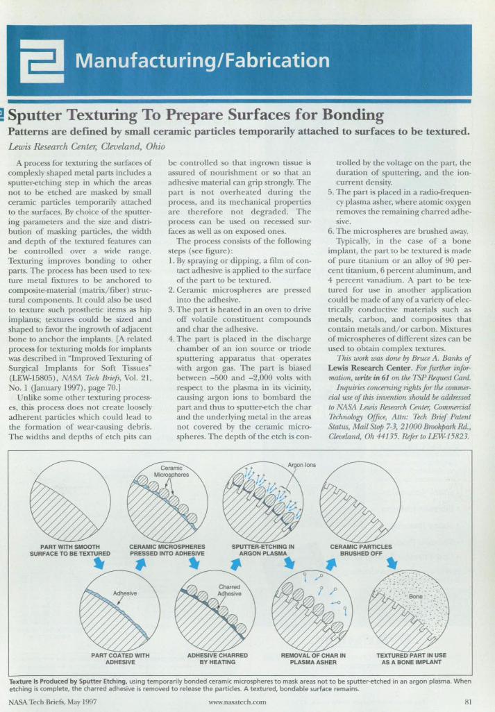
! Sputter Texturing To Prepare Surfaces for Bonding Patterns are defined by small ceramic particles temporarily attached to surfaces to be textured.
Lewis .&search Center, Cleveland, Ohio
A process for texturing the surfaces of complexly shaped metal parts include a sputter-etching step in which the areas not to be etched are masked by mall ceramic particles temporarily attached to the surfaces. By choice of the sputtering parameters and the size and distribution of masking particles, the width and depth of the textured features can be controlled over a wide range. Texturing improves bonding to other parts. The process has been used to texture metal fixtures to be anchored to composite-material (matrix/fiber) structural components. It could also be used to texture such prosthetic items as hip implants; textures could be sized and shaped to favor the ingrowth of adjacent bone to anchor the implants. [A related proces for texturing molds for implants was described in "Improved Texturing of Surgical Implants for Soft Tissues" (LEW-15805), NASA Tech Briefs, Vol. 21, No.1 (January 1997), page 70.]
Unlike some other texturing processes, this process does not create 100 ely adherent particles which could lead to the formation of wear-causing debris. The widths and depths of etch pits can
be controlled so that ingrown tissue is assured of nourishment or so that an adhesive material can grip strongly. The part i not overheated during the process, and its mechanical properties are therefore not degraded. The process can be u ed on recessed surfaces as welJ as on exposed ones.
The process consists of the following steps (see figure): 1. By spraying or dipping, a film of con
tact adhesive is applied to the surface of the part to be textured.
2. Ceramic microspheres are pressed into the adhesive.
3. The part is heated in an oven to drive off volatile constituent compounds and cllar the adhesive.
4. The part is placed in the discharge chamber of an ion source or triode sputtering apparatus that operates with argon gas. The part is biased between - 500 and -2,000 volts with respect to the plasma in its vicinity, causing argon ions to bombard the part and thus to sp utter-etch the char and the underlying metal in the areas not covered by the ceramic microspheres. The depth of the etch is COD-
PART WITH SMOOTH SURFACE TO BE TEXTURED
CERAMIC MICROSPHERES SPUTTER-ETCHING IN PRESSED INTO ADHESIVE ARGON PLASMA
~ .. ~-.. ~~
trolled by the voltage on the part, the duration of sputtering, and the ioncurrent den ity.
5. The part is placed in a radio-frequency plasma asher, where atomic oxygen removes the remaining chan·ed adheive.
6. The microspheres are brushed away. Typically, in the case of a bone
implant, the part to be textured is made of pure titanium or an alloy of 90 percent titanium, 6 percent aluminum, and 4 percent vanadium. A part to be textured for use in another application could be made of any of a variety of electrically conductive materials such as metals, carbon, and composites that contain metals and/or carbon. Mixtures of microspheres of different sizes can be used Lo obtain complex textures.
This work was dime by Bruce A. Banks of Lewis Research Center. For further information, write in 61 on the TSP Request CaTd.
Inquiries concerning Tights for the commercial use of this invention should be addressed to NASA Lewis Research Center, Ommurrcial Technology Office, Attn: Tech Brief Patent Status, Mail Stop 7-3, 21000 Brookpark Rd., Cleuew.nd, Oh 44135. Refer to l.EW-15823.
PART COATED WITH ADHESIVE
ADHESIVE CHARRED BY HEATING
REMOVAL OF CHAR IN PLASMA ASHER
TEXTURED PART IN USE AS A BONE IMPlANT
Texture Is Produced by Sputter Etching. using temporarily bonded ceramic microspheres to mask areas not to be sputter-etched in an argon plasma. When etching is complete, the charred adhesive is removed to release the particles. A textured, bondable surface remains.
NASA Tech Briefs, May 1997 www.nasatech.com 81
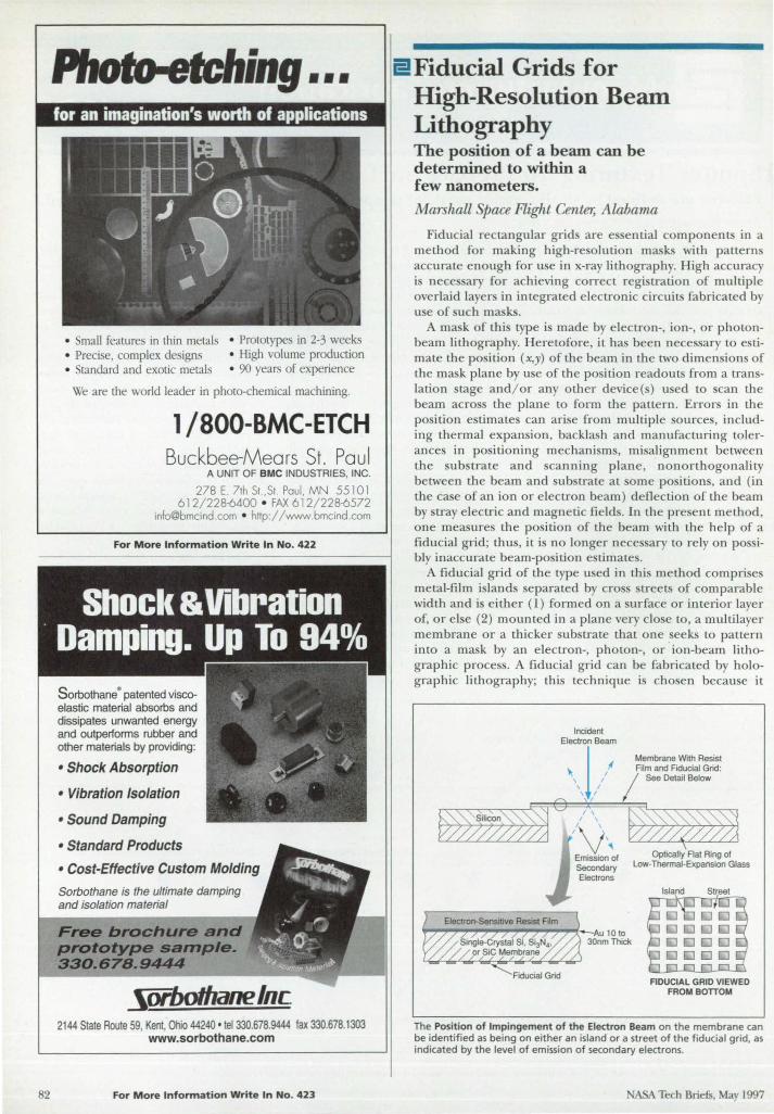
82
Phofo.etching ••• for an imagination's worth of applications
• Small features in thin metals • Prototype in 2-3 weeks • Preci e, complex design • High volume production • tanclard and exotic metal • 90 years of experience
We are the world leader in photo-chemical machining.
1/800-BMC-ETCH Buckbee-Mears St. Paul
A UNIT OF BMC INDUSTRIES, INC.
278 E. 71h SI. ,SI. Paul, MN 5510 1 612/228-6400 • FAX 612/228-6572
[email protected] • http://www.bmcind.com
For More Information Write In No. 422
Sorbothane· patented viscoelastic material absorbs and dissipates unwanted energy and outperforms rubber and other materials by providing:
• Shock Absorption
• Vibration Isolation
• Sound Damping
• Standard Products
• Cost-Effective Custom Molding
Sorbothane is the ultimate damping and isolation material
Free brochure and prototype sample. 330.67B.9444
~OfboIhanelnc 2144 State Route 59, Kent, Ohio 44240 ' tel 330.678.9444 fax 330.678.1303
www.sorbothane.com
For More Information Write In No. 423
E!Fiducial Grids for High-Resolution Beam Lithography The position of a beam can be determined to within a few nanometers.
Marshall pace Flight Center, Alabama
Fiducial rectangular grid are e ential components in a method for making high-re olution rna ks with pattern accurate enough for u e in x-ray lithography. High accuracy i nece sary for achieving correct regi tration of multiple overlaid layer in integrated electronic ircuits fabricated by u e of uch rna k .
A rna k of thi type i made by electron-, ion-, or photonbeam lithography. Heretofore, it has been nece sary to e timate the po ition (x,y) of the beam in the two dimension of the ma k plane by u e of the position readouts from a translation stage and/ or any other device( ) used to can the beam acros the plane to form the pattern. Error in the position e timates can ari e from multiple ources, including thermal expan ion, backla h and manufacturing tolerances in positioning mechanisms, misalignment between the ubstrate and scanning plane, nonorthogonality between the beam and ub trate at orne positions, and (in the case of an ion or electron beam) deflection of the beam by stray electric and magnetic field. In the pre ent method, one mea ures the position of the beam with the help of a fiducial grid; thus, it is no longer nece ary to rely on possibly inaccurate beam-position estimates.
A fiducia l grid of the type u ed in thi method comprise metal-film i lands eparated by cross treets of comparable width and i either (1) formed on a surface or interior layer of, or else (2) mounted in a plane very clo e to a multilayer membrane or a thicker substrate that one seeks to pattern into a mask by an electron-, photon-, or ion-beam lithographic process. A fiducial grid can be fabricated by holographic lithography; this technique is cho en becau e it
Incident Electron Beam
\ I Film and Fiducial Grid:
\ , j Membrane With Resist
/' / See Detail Below
~~~~~q€C~~)/==~~
WJ~ /' ,,~
Rducial Grid
Emission of Optically Flat Ring of Secondary Low-Thermal-Expansion Glass
Electrons
Island Street
FIDUCIAL GRID VtEWED FROM BOnOM
The Position of Impingement of the Electron Beam on the membrane can be identified as being on either an island or a street of the fiducial grid, as indicated by the level of emission of secondary electrons.
ASA Tech Briefs, May 1997
can be manipulated to obtain a set of cross gratings that are free of distortion or in which the distortion is exactly predictable. The gratings constitute a set of (x,y) position references across the area to be patterned by the canning beam.
The method can be practiced in many different versions. depending on specific application. The figure illustrates an application that involves electron-beam Lithography on a substrate with an electron-sensitive resist film on its top surface and a fiducial grid on its bottom surface. For measurement of position. the beam is attenuated so that it is not inten e enough to produce appreciable changes in the electronsensitive resi t film yet is intense enough to cause emission of a measurable current of secondary electrons. This curreD[ can be measured by use of channel electron multipliers or other devices like those used to measure secondary electrons in scanning electron microscopes.
The secondary-clectron yields of the islands and streets differ in a known way. Thus. at any in tant as the beam is scanned across the grid. the level of the secondary-electron signal indicates whether the beam is impinging on an island or a streel. If a raster scan is performed, then the secondary-electron readout can be processed, along with th e scanning parameters and the scanning-apparatus readouts, by use of algorithms based on established techniques for analysis of moire and interference fringes. These techniques make it possible to determine (x.y) position to within a fraction of the spatial period of the fiducial grid. In a typical case, the spatial period would be 200 nm, and one could determine the position of the beam to within 20 nm or less.
This work was done by Henry J. Smith, Erik H. Anderson, and Mark L. Schattenburgh oj Massachusetts Institute oj Technology jor Marshall Space Flight Center. For jurther injormation, write in 56 on the TSP Request Card.
In accordance with Public Law 96-517, the contractor has elected to retain title to this invention. Inquiries concerning rights jor its cOlnmercial use should be addressed to
Massachusetts Institute of Technology
77 Massachusetts Avenue Cambridge, A-:lA 02139 Refer to MFS-26300, volume and num
ber oj this ASA Tech Briefs isS1U, and the page number.
NASA Tech Brie1S, May 1997
Weather Proof, Ruggedized, Portable Industrial pes
IN Lite Indusmal Notebook • 1 FulH.englh/Height AT Expansion Slot, 2 Type II
(01 1 Type III) P(MCIA Slots. • Inlel166MHz Pentium" Processol with
MNIf. Technology. Up to 64MB DRAM. • Dual Builtin Power Supplies,
AC (4()'440Hz) and DC (l &36V). • Meets Mi~Spec. IP Lite Industrial Portable • 5 AT/PCI Slots, 3 Full, 2 Half.lenQ1h. • Intel 200MHz Pentium'" Processor with
MMX Technology. Up to 128MB DRAM.
Both Portables Feature: • Full Magnesium Die-Cost Casing. • ShockjVibrotion and EMljEMC Prolection. • lOA' m VGA or 12.1' XVGA (1024 x 768)
Color DiSplays. • 3 Year Warranty, CE Approval.
Call 1-800-KONTRON 80()'566-8766 • 714·851-1 872 http://www.kontron.com
KONTRON ELEKTRONIK
KONT~ON ElEKTRON., IS AN ISO 900 I CERTIFIED COMPANY
For More Information Write In No. 424
Extreme Environments High Performance Cable Harnesses
• Single and Multimode
• Single and Multichannel
• Easy Maintenance and Cleaning
• High-Reliability Ruggedized Connectors • Low Insertion Loss
• High Return Loss No Mandrel Wraps! Contact us for nwre details
See Us in... New Orleans at SUPfRCOM'97, Orlando at CABLf-TfC'97, June
For More Information Write In No. 425 83
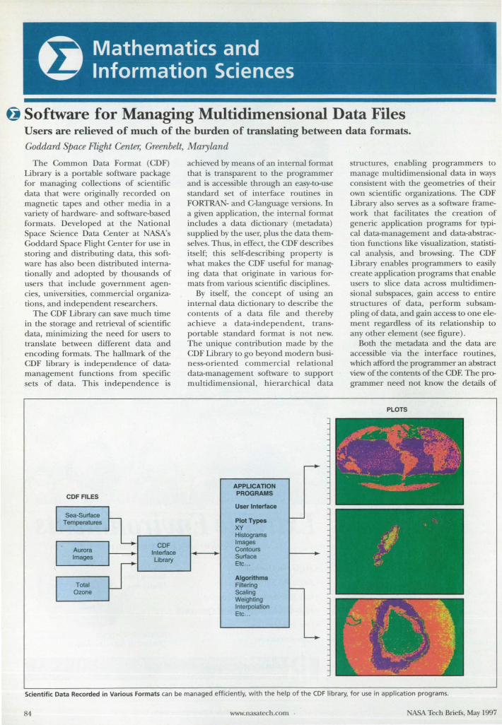
tj Software for Managing Multidimensional Data Files Users are relieved of much of the burden of translating between data formats.
Goddard Space Flight Center, Greenbelt, Maryland
The Common Data Format (CDF) Library is a portable software package for managing collections of scientific data that were originally recorded on magnetic tapes and other media in a variety of hardware- and software-based formats. Developed at the National Space Science Data Center at NASA's Goddard Space Flight Center for use in storing and distributing data, this software has also been distributed internationally and adopted by thousands of users that include government agencies, universities, commercial organizations, and independent researchers.
The CDF Library can save much time in the storage and retrieval of scientific data, minimizing the need for users to translate between different data and encoding formats. The hallmark of the CDF library is independence of datamanagement functions from specific sets of data. This independence is
CDF FILES
Sea-Surface Temperatures
,. Aurora ~ Images
COF Interface Ubrary
Total Ozone
achieved by means of an internal format that is transparent to the programmer and is accessible through an easy-to-use standard set of interface routines in FORTRAN- and C-Ianguage versions. In a given application, the internal format includes a data dictionary (metadata) supplied by the user, plus the data them-elves. Thus, in effect, the CDF describes
itself; this self-describing property is what makes the CDF useful for managing data that originate in various formats from various scientific disciplines.
By itself, the concept of using an internal data dictionary to describe the contents of a data file and thereby achieve a data-independent, transportable standard format is not new. The unique contribution made by the CDF Library to go beyond modern business-oriented commercial relational data-management software to support multidimensional, hierarchical data
-+
APPUCATION PROGRAMS
User Interface
Plot Types I--XV Histograms Images Contours Surface Etc ...
Algorithms Filtering I--Scaling Weighting Interpolation Etc ...
'----
structures, enabling programmers to man,age multidimensional data in ways consi tent with the geometries of their own cientific organizations. The CDF Library al 0 serve as a software framework that facilitates the creation of generic application programs for typical data-management and data-abstraction functions like visualization, statistical analysis, and browsing. The CDF Library enables programmers to easily create application programs that enable users to slice data across multidimensional subspaces, gain access to entire structures of data, perform subsampling of data, and gain access to one element regardless of its relationship to any other element (see figure).
Both the metadata and the data are accessible via the interface routines, which afford the programmer an abstract view of the contents of the CDF. The programmer need not know the details of
PLOTS
Scientific Data Recorded in Various Formats can be managed efficiently, with the help of the COF library, for use in application programs.
84 www.nasatech.com NASA Tech Briefs, May 1997
(and is isolated from) the CDF physical storage and the underlying software structure. The programmer does not have to perform low-level input/ output functions to physically pack or unpack data or metadata into or out of files; the COF software does this for the programmer. The physical files (CDF files) generated by the CDF Library can be retrieved directly or sequentially and can be stored on disks for access via a FOKfRAN or C interface. The isolation of the programmer and user from the physical storage and the underlying software structure also make it possible to enhance the implementation of the CDF as new hardware and software become available.
This work was done by Gregory Gauchers, Jason Mathews, Jeff Love, and Howard Leckners of Goddard Space Flight Center . For further information, write in 70 on the TSP Request Card. GSC-13633
:J Algorithm for Improving a Mathematical Model Linear least-squares solutions with optimal step sizes are iterated. Marshall Space Flight Center, Alabama
The Analytical Model Improvement (AMI) computer program implements an iterative algorithm for improving a mathematical model of a physical system. The algorithm adjusts the parameters in the model to obtain a closer match between data on the behavior of the system as calculated b)I the model and the corresponding data obtained by experiment. The original application for which AMI was developed involves a vibrating tructure represented by a finite-element model, the data of interest being the shapes (eigenvectors) and natural frequencies (eigenvalues) of the vibrational modes and the parameters of interest being the design parameters of the strucUtre.
AMI was developed with recognition that in a general case, both the experimental data and the mathematical model can contain errors. AMI seeks a least-squares best fit between tlle model and experimental data. The process begins with calculation of an error vector, 6, the elements of which consist of differences between the experimental
NASA Tech Briel5, May 1997
For More Information Write In No. 442
Why Is the WIN-3O the ideal solution for all your data acquisition system designs? The WIN-30's own microprocessor and FlFO buffers are able to take maximum advantage of its 1 MHz AID converter without requirjng expens ive d ed icated RAM. Along with s uch advanced data
United Electronic Industries
transfer capabilities as RepStr and Block Mode DMA, they work together to create the most powerful and efficient system available for continuous hjgh-speed data acquisition.
(Look for Reason #2 next month: "The best 32-bit OS support.")
Call for your free (olalog: (800) 829-4632
Immediale info 01 our web site:
http://www.ueidaq.(om
Ten Dexter Ave. Tel: (6 17) 924-1155 Watertown, MA 02172 Fox: (6 17) 924-1441 E·mail: [email protected]
For More Information Write In No. 444 85
86
For More Information Write In No. 427
III Load Cells Force/Torque
Sensors
Catalog Includes: Gram Sensors Thru Hole Load Cells Tension Load Cells Low Profile Load Cells Mini Load Cells Load Pins Torque/Sensors Transducer Indicators
Special OEM Sensors
"..' Transducer Techniques • (909) 676-3965 FAX (909) 676-1200
e-mai l : tti@ttlo adcells.com URL: http ://www.ttload cells.com
43178 BUSINESS PARK DRIVE B-l0l • TEMECULA, CA 92590
For More Information Writ e In No. 428
and model data. Typically. the e data are the eigenvalue and the components of the eigenvectors. At first. it is as umed that the following linear approximation applie :
6=J8. where 8 i a vector of de ign-parameter change needed to bring the experimental and model data into agreement andJ i the Jacobian matrix that contain partial derivative of the model eigenquantitie with respect to the de ign parameter.
ingular-vaille decompo ition i used to find a earch direction in parameter pace. which i identical to the linear leastquare olution 8.
Because ignificant nonlinearitie are often pre ent. the linear least- quare olution can diverge from the true solution. making it nece ary to olve the model-improvement problem iteratively. as a sequence of linear least- quare problem. On each iteration. one mu t find a fraction. a. of the linear least-quares solution that yield an optimal match between the
experimental and model data; in other words. on each iteration. the problem becomes one of finding a (O::;a::::;l) uch that 8 = a8 yields a minimum value of an error measure (called the "residual") given by r= 1612,
AMI implements two alternative method for approximating the eigenquantitie and finding a value of a that minimize r. One method involves the use of a variation of the method of moving asymptote; the other method involve the use of a generalized quadratic equation. In both methods. secondorder approximations of the eigenquantities are obtained by u e of first and econd partial derivative of the eigenquantitie with respect to the de ign parameters. The first derivative are determined by a finite-difference technique. After the first update cycle. the first derivative can then be compared to the first derivatives from the previous cycle to estimate the primary second derivatives. also via a finile-difference technique. However. when a econd derivative::; O. a mall positive number is substituted; this provides a so-called convex approximation . which yield a unique solution.
The second-order approximations of the eigenquantitie provide an e timate of r that depends only on a; that is.
r(a) = 16(a)12 A one-dimen ional line-search optimization routine in the International Math and Statistics Library (IMSL) computer program i used to find the value of a that minimizes r( a). Then a is used to update the design variables via 8 = a8. This completes the computational cycle. Then using the updated design variable. a new cycle can be started. The iteration is stopped when equential vectors of design variables converge.
This work was done by Matthew F. Orr, Jr., of Marshall Space Flight Center . For further inforowlion, write in 21 on the TSP Request Card. MFS-31179
@Collar Grids for Computing Flows at Intersections Collar grids resolve the interaction regions and provide communication between component grids. Ames Research Center, Moffett Field, California
Collar grid are placed at inter ection of surface in an improved version of the chimera overlapping-grid cherne that i used in computing flow fields about aircraft and other complicated bodies. In the chimera scheme. multiple overlapping component grid that conform to the urfaces of
A5A Tech Briefs. May 1997
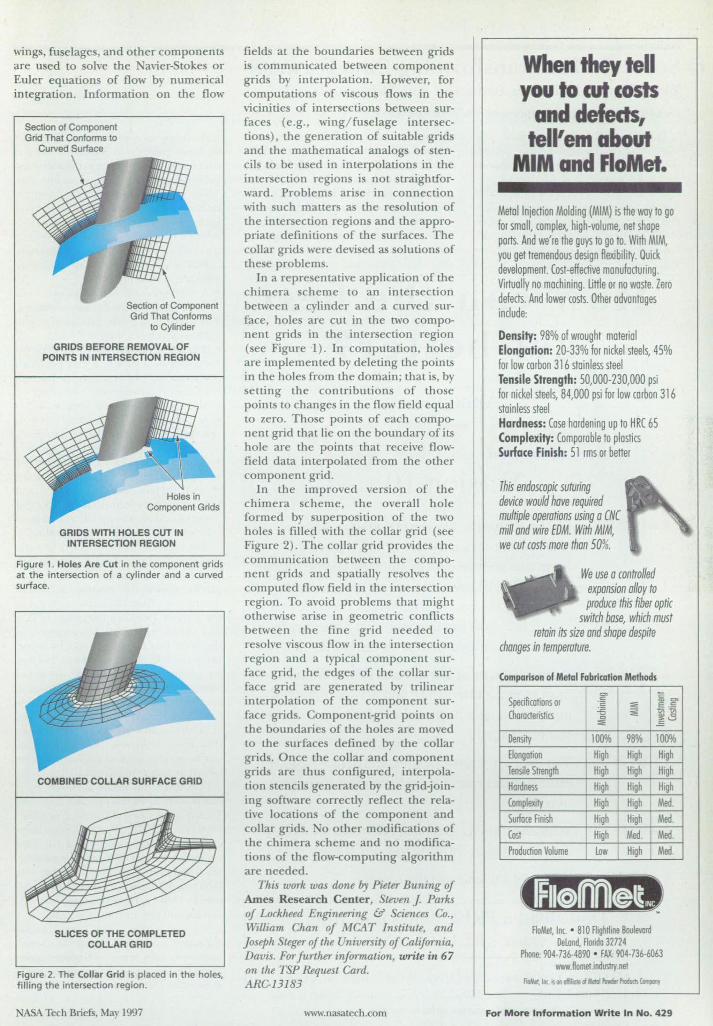
wings, fuselages, and other components are used to solve the Navier-Stokes or Euler equations of flow by numerical integration. Information on the flow
Section of Component Grid That Conforms to
Curved Surface
GRIDS BEFORE REMOVAL OF POINTS IN INTERSECTION REGION
GRIDS WITH HOLES CUT IN INTERSECTION REGION
Figure 1. Holes Are Cut in the component grids at the intersection of a cylinder and a curved surface.
COMBINED COLLAR SURFACE GRID
SLICES OF THE COMPLETED COLLAR GRID
Figure 2. The Collar Grid is placed in the holes, filling the intersection region.
ASA Tech Briefs, May 1997
fields at the boundaries between grids is communicated between component grids by interpolation. However, for computations of viscous flows in the vicinities of intersections between surfaces (e.g. , \ving/ fuselage intersections) , the generation of suitable grids and the mathematical analogs of stencils to be used in interpolations in the intersection regions is not straightforward . Problems arise in connection with such matters as the resolution of the intersection regions and the appropriate definitions of the surfaces. The collar grids were devised as solutions of these problems.
In a representative application of the chimera scheme to an intersection between a cylinder and a curved surface, holes are cut in the two component grids in the intersection region (see Figure 1). In computation, holes are implemented by deleting the points in the holes from the domain; that is, by setting the contributions of those points to changes in the flow field equal to zero. Those points of each component grid that lie on the boundary of its hole are the points that receive flowfield data interpolated from the other component grid.
In the improved version of the chimera scheme, the overall hole formed by superposition of the two holes is filleq. wi th the collar grid (see Figure 2). The collar grid provides the communication between the component grids and spatially resolves the computed flow field in the intersection region. To avoid problems that might otherwise arise in geometric conflicts between the fine grid needed to resolve viscous flow in the intersection region and a typical component surface grid , the edges of the collar surface grid are generated by trilinear interpolation of the component surface grids. Component-grid points on the boundaries of the holes are moved to the urfaces defined by the collar grids. Once the coUar and component grid are thus configured, interpolation stencils generated by the gridjoining software correctly reflect the relative locations of the component and collar grids. 0 other modifications of the chimera scheme and no modifications of the flow-computing algorithm are needed.
This work was done lJ.y Pieler Buning af Ames Research Center, Steven J. Parks af Lcckheed Engineering & Sciences Ca. , William Chan af MCAT Institute, and Joseph Steger of the University of California, Davis. For further information, write in 67 an the TSP Request Card. ARC-13183
www.nasatech.com
When they tell you to cut costs
and defects, tell' em about
MIM and FloMet.
Metal Injection Molding (MIM) is the way to go for small, complex, high-volume, net shape ports. And we're the guys to go to. With MIM, you get tremendous design flexibility. Quick development. Cost-effective manufacturing. Virtually no mochining. Uttle or no waste. Zero defects. And lower costs. Other advantages include:
Density: 98% of wrought material Elongation: 20-33% for nickel steels, 45% for low carbon 316 stainless steel Tensile Strength: 50,000-230,000 psi for nickel steels, 84,000 psi for low corban 316 stainless steel Hardness: Case hardening up to HRC 65 Complexity: Comparable to plastics Surface Finish: 51 rms or better
This endoscopic suturing device would have required multiple operations using a CNC mill and wire EDM. With MIM, we cut costs more than 50%.
We use a controlled expansion alloy to produce this fiber optic
switch base, which must retain its size and shape despite
changes in temperature.
Comparison of Metal Fabrication Methods
Specifica~ons or .~ == Characteristics .:s ~
0 ::e
Density 10lYlh 98% Elongation High High Tensile SITenglh High High Hardness High High Complexity High High Surioce Finish High High Cos! High Med. Production Volume Low I High
AoMel, Inc • 81 0 F1 igh~ine 8aulevold Delond, FlO/ida 32724
<= ., "" E -1§ t; ~
~8
100% High High High Med. Med. Med. Med.
Phone: 904·736-4890 • FAX: 904-736-6063 WIWI.ftometindustry.ne!
AoMel, in<. 6 OIloffiliol! oIlI.enII ftMder Pmdum Compooy
For More Information Write In No. 429
tj Software for Transforming Data Formats This program features a menu- and table-driven user interface.
Goddard Space Flight Center, Greenbelt, Maryland
The Flight Dynamics Orbital and Mission Aids Transformation ystem (FORMATS) computer program collects data in the formats in which they are generated and distributes them in the same formats or any of a wide variety of different formats, as specified by users. FORMATS was developed for use in reformatting and distributing data generated during cientific pacecraft mission , but its
adaptability to multiple formats may also be useful in terrestrial applications; for example, transforming data generated by laboratory instruments.
Because FORMATS incorporate selectable oftware components needed to transform data among many different formats, expensive reprogramming is not necessary to satisfy requirements for each new data-distribution task. A menu- and
How can the best get better?
. . . Announcing
LABTECH
LABTECH
LABTECH
LABTECH
LABTECH
LABTECH
Version 10 For fifteen years, the world's most popular pc software for data acquisition and control. Now with remote data monitoring via the Internet or any TCPIIP network ... which means that for a fraction of the cost of a dedicated network or leased line, you can transport real-time data from remote sites a thousand times faster than before.
Supports the most 110 devices (1000) from the most manufacturers (55), and allows mixing of input and output devices from different manufacturers.
The indu try's most flexible software - allows different data rates for each channel, variable over time.
With an intuitive, graphical interface, the easie t data acquisition software to learn & use.
The original, and still the best.
Download a FREE demo now from www.LABTECH.com
LABTECH • 400 Research Drive, Wilmington, MA 01887 Tel: 508-657-5400 • Fax: 508-658-9972 • [email protected]
For More Information Write In No. 443
table-driven user interface in FORMATS makes it po ible to elect the needed data-format-tran formation oftware components quickly and thus at low cost. There is minimal need for intervention by the user during execution of the program. The program also includes faulttolerant feature; for example, it repeats attempts to transmit data until it ucceeds.
FORMATS includes the following software subsystems: • A small executive subsystem to start or
top the execution of other subsystems; • A poller that finds data products in
local or remote sites; • A transformation ubsystem that rec
ognizes data products and performs operations (for example, validation or reformatting) on the data as directed by tables and templates;
• A transmission subsystem that is responsible for di tributing data products to their respective destinations;
• An optional user-interface subsystem for displaying me ages associated with the validity of processed data products; and
• A tables subsystem that enables the use of text files to specify the steps to be executed for each data product. The heart of FORMATS is a generic
data-transformation engine that can navigate any data file, regardless of its complexity, under the control of textual description of the file format, written in the Format Template Language (FTL). The sizes of individual data elements in files to be processed can range from one bit to two billion bytes. Formats that can be accommodated include those of American Standard Code for Information Interchange (ASCll) , Extended BinaryCoded Decimal In terchange Code (EBCDIC) , and special floating-point data types. Moreover, any time format can be accommodated, and data can be nested or structured in any defined way.
FORMATS can reside anywhere on a compu ter network that operates under the Transmission Control Protocol/Internet Protocol (TCP/ IP) . FORMATS has been executed on IBM RS6000 and HP 9000 computers under UNIX and is portable to any computer that uses the Microsoft Wmdows NT operating system. Approximately 1MB of random-access memory and 2MB of disk memory are required.
This wark was dune by Alan T. Johns, Dougf.as B. ReingvlO., arui ~E Gxm ofCSC CnmmunicatWns Industry Services for Goddard Spare Flight Center. For further injcmrw.tion, write in 66 on the TSP Request Card. GSG13827
NASA Tech Briefs, May 1997
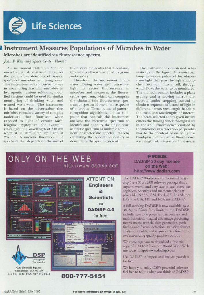
• Instrument Measures Populations of Microbes in Water Microbes are identified via fluorescence spectra. John F. Kennedy Space Center, Florida
An instrument called an ·on-line microbiological analyzer" measures the population densities of several species of microbes in flowing water. The instrument was conceived for use in monitoring harmful microbes in hydroponic nutrient olutions; modified versions could be used for similar mon itoring of drinking water and treated waste-water. The instrument i based on the observation that microbes contain a variety of complex molecules that fluoresce when expo ed to ligh t of certain wavelengths; tryptophan, for example, emi ts ligh t at a wavelength of 348 nm when it is stimulated by light at 287 nm. A microbe fluoresces in a spectnlffi that depends on the mix of
fluorescent molecules that it contains; this mix is characteristic of its genus and species.
Therefore, the instrument illuminates flowing water with ultraviolet light to excite fluorescence in microbes and measure the fluorescence spectrum, which can comprise the characteristic fluorescence spectrum or spectra of one or more species of microbe. Then, by use of pattemrecognition algorithms, a host computer that controls the instrument analyzes the measured spectrum to identify and quantify the single characteristic spectrum or multiple componen l characteristic spectra, thereby estimating the population density or den ities of the species present.
The instrument is illustrated schematically in the figure. A xenon flash lamp generates pulses of broad-spectrum light that pass through a monochromator and into a cell, through which flows the water to be monitored. The monochromator includes a plane grating and a moving mirror that operate under stepping control to obtain a sequence of beams of light in different narrow-wavelength bands at the excitation wavelengths of interest. The beam selected at any given instant en ters the flowing water through a slit in the cell. Fluorescence emitted by the microbes in a direction perpendicular to the incident beam of ligh t is band-pass filtered at a fluorescence wavelength of interest and measured
ONLY ON THE WEB
DSP Corporation
One Kendall Square Cambridge, AlA 02139
617-577-1133, FAX: 617·577-8211
ABA Tech Briefs, May 1997
http ://www.dadisp .com
ATTENTION: Engineers
& Scientists
use DADiSP 4.0
for free!
800-777·5151
The DADiSP Worksheet (pronounced "daydisp") is a $1.895.00 software package that's super-powerful and very easy-co-use. Every day engineers scientists and mathematicians at rlaces like ASA, GM, Ford. GE, Los Alamos Labs, the CV\, FBI and SA use DADiSPl
A full working DADiSP is now available on a 30 day trill! basis for a limited time. DADiSP includes over 500 powerful data analysis and math functions - signal and image processing, matrix math; artificial dara generation. peak finding and fealure detection. statistics, fourier analysis. calculus, and trigonometry functions, and 3Smunding quality graphics output.
We encourage you to download a free trial copy ofDADi P from our World Wide Web site today: hnp:llwww.dadisp.com
Use DADiSP to impon and analyze YOllrdata for free.
We hope you enjoy DSP' s powerful softwarefeel free to tell us what you think ofDADiSPl
For More Information Write In No. 431 89
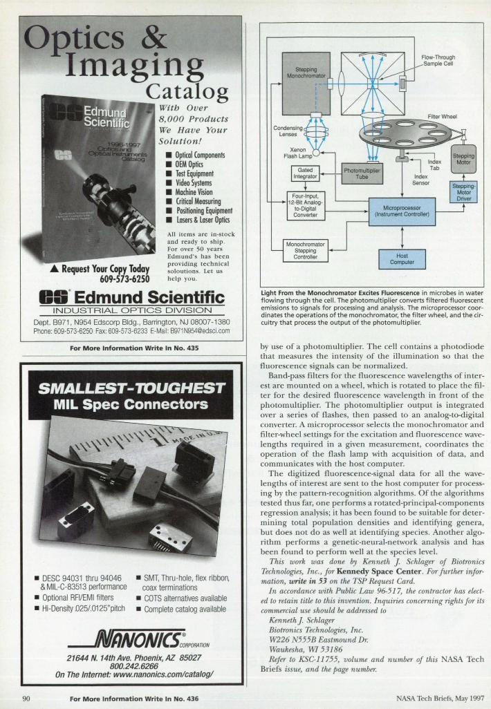
Op,tics ~
90
maglng Catalog
With Over 8, 000 Products We H ave Your So l ution!
• Optical Components • OEM Optics • Test Equipment • Video Systems • Mochine Vision • Critical Measuring • Positioning Equipment • Losers & Laser Optics
~ Request Your Copy Today 609-573-6250
All items are in-stock and ready to sbip. For over 50 years Edmund 's bas been providing technical soloutions. Let us belp you .
Oil· Edmund Scientific INDUSTRIAL OPTICS DIVISION
Dept. B971, N954 Edscorp Bldg., Barrington, NJ 08007 -1380 Phone: 609-573-6250 Fax: 609-573-6233 E-Mail: [email protected]
For More Inform at ion Write In No_ 435
SMALLEST-~UGHEST MIL Spec Connectors
• DESC 94031 thru 94046 & MIL-C-83513 performance
• Optional RFVEMI filters • Hi-Density D25/.0125"pitch
• SMT, Thru-hole, flex ribbon, coax terminations
• COTS alternatives available • Complete catalog available
-AIJNONICS;RP0P.4T1ON 21644 N. 14th Ave. Phoenix, AZ 85027
800.242.6266 On The Internet: www.nanonics.comlcatalogl
For M ore Information Write In No. 436
Stepping Monochromator
Flow-Through Sample Cell
Sensor
Microprocessor (Instrument Controller)
light From the Monochromator Excites Fluorescence in microbes in water flowing th rough the cell. The photomult ipl ier converts filtered fluorescent emissions to signals for processing and ana lysis. The microprocessor coordinates the operations of the monochromator, the filter wheel, and the circu itry that process the output of the photomultiplier.
by use of a photomultiplier. T he cell contains a photodiode that mea ures the intensity of the illumination so that the fluorescence signal can be normalized.
Band-pass filter for the fluorescence wavelength of interest are mounted on a wheel, wh ich is rotated to p lace the fi lter for the desired fluore cence wavelength in fro n t of the photomul tiplier. The photomultiplier output is integrated over a series of flashes, then passed to an analog-to-digital converter. A microprocessor selects the monoch romator and filter-wheel settings for the excitation and fluorescence wavelengths required in a given measurement, coordinates the operation of the flash lamp with acqu isition of data, and communicates with the host computer.
The digitized fluorescence-signal data for all the wavelengths of intere tare ent to the host computer for processing by the pattern-recognition algorithms. Of the algorithms tested thu far, one performs a rotated-principal-components regression analysis; it has been foun d to be suitable for determining total population densities and identifying genera, but does not do as well at identifying species. Another algorithm perform a genetic-neural-network analysis and has been found to perform well at the specie level.
This work was done by Kenneth J. Schlager of Biotronics Technologies, Inc., for Kennedy Space Center. For further information, write in 53 on the TSP Request Card.
In accordance with Public Law 96-517, the contractor has elected to retain title to this invention. Inquiries concerning rights for its commercial use should be addressed to
Kenneth J. Schlager Biotronics Technologies, Inc. W226 '555B EastmoundDr. Waukesha, WI 53186 Refer to KSC-11755, volume and number of this ABA Tech
Briefs issue, and the page number.
NASA Tech Briefs, May 1997
• Analysis of the Defect Structure of B2 FeAl Alloys
A report presents a tudy of the defect tructure of the B2 phase of FeAl alloys. In the study, the BFS method was used to analyze the defect structure of FeAl from the perspective of energy considerations at zero absolute temperature. The BFS method is based on the idea that the energy of formation of an alloy can be calculated as a superposition of contribution from individual nonequivalent atoms in the alloy. BFS calculations were performed on a large number of candidate ordered structures to determine the configurations of lowest energy and to search for states that could be metastable. Overall, the results of the calculation were found to provide a description of the defect structure consistent with available experimental data: For example, the calculations were successful in deter-
continued from page 23
mining the phase field of the B2 tructure; the re ults were consistent with experimental observations that the B2 phase is stable at aluminum contents up to about 52 atomic percent. The results were also in qualitative agreement with experimental observations that the lattice parameter increases with aluminum content.
This work was done byJohn Ferrante and Ronald D. Noebe of Lewis Research Center, Guillermo Bozzolo of Analex corp., and Carlos Amador of Universidad National Aut6noma de Mexico. To obtain a copy of the report, "Analysis of the Defect Structure of B2 FeAl Alloys, »write in 76 on the TSP Request Card.
Inquiries concerning rights for the commercial use of this invention should be addressed to NASA Lewis Research Center; Commercial Technology Office, Attn: Tech Brief Patent Status, Mail Stap 7-3, 21000 Brookpark Road, Cleveland, Ohio 44135. Refer to LEW-16426.
E! VPS Fabrication of Parts To Withstand High Temperatures
A short paper reviews the state of the art of making refractory-metal and ceramic/refractory-metal composite objects by vacuum plasma spraying (VPS) of the constituent materials onto graphite mandrels. In large part, the paper reiterate description of elected aspects of VPS fabrication technology of high-temperature parts as reported in prior articles in NASA Tech Briefs.
This work was done by Philip D. Krotz of Rockwell International Corp. and William M. Davis of Boeing North American, Inc., for Marshall Space Flight Center. To obtain a copy of the paper, ·Vacuum Plasma Spray Fabrication of Solar Thermal Rocket Engines, n write in 55 on the TSP Request Card. MFS-30104
National Design : Engi~~gW,JRroduct Showcase
Colder Products, St. Paul , MN, offers Sixrube'" multiple-line couplings that connect up to six fluid or pneumatic lines simultaneously. They
fearure thuml>-Iatch connection and snap-in panel mount, as well as Oow paths made of acetal or polypropylene materials. They connect 1/ 16" or 1/ 8" m lUbe sues. Applications include Quid managemelll and pneumatic control SYSlems, factory automation, machine tools, biomedical instrumentation, and testing equipmenL
For More Information Write In No. n7
MSC/ lnCheck CAD simulation software from MaG eal-Schwendler Corp., Los Angeles, CA, p"" .ides mechanical imulation capabilities to users of Autodesk Mechanjcal Desktop CAD/ solid modeling system in a \\~mdows interface. A Simulation Wizard guides users step-by-step through the simulation process. The software uses the 3D solid model in Mechanical Desktop as a basis for its simulation model. Materials, environmental loads, and boundary conditions and imutation results are processed within Mechanical Desktop.
fM More Infonnation Write In No. 764
NASA Tech BrielS, May 1997
DuPont Special!)' Chemical , Deepwater, ~, offers KryTech paraffin wax ail-purpose lubricant that protects against dirt, grime. and water. The lubricant is formulated with Krytox· fluo
ropolymer and 10 other ingredients, including paraffin waxes and synthetic oils. The lubricant is applied wet to chains, cables. lock mechanisms. and hinges. As it sets, it forms a hard, dry wax film that repels din, grit, grime, and water. Although the wax film sheds with nonnal wear, the Krytox: remains and bonds to metal friction surfaces. The lubricant provides bigh-temperarure resistance, nonfiammabili!)" and non reactivity to chemicals in bearings, gaskets, seals, and other parts.
For More Information Write In No. n9
The G3 and G4 right-angle gearheads from Bodine Electric, hicago, II., mate to CXlSting AC, nc, and brushless motors and run for more than 20,000 hours continuously. Both models ha\·e a "ide. single, em-eloping wonn gear to permit an increase in load capacity and longer life. The SG3 is a\-ailable 'lith six ratios and an output torque capacity of97 inlbs. The SG4 comes "ith five ratios and an output capacity of 168 in-Ibs. The enclosed gearbeads fearure Viton , double up, bidirectional helix seals on the input and output shafts, as well as permanently lubricated gear housing. Four mounting surfaces are offered and a single-, doubl.,., or hollow·drive shaft is available.
For More Information Write In No. 766
www.nasatech.com
Aromat Corporation, ew Providence, NJ, has introduced the FPO pockel-sized programmable logic controller (PLC) that is available in 10. 14, 16, and 32 I/ O base units. with relay or transistor outputs. Relay units have remo\-able tennina! strips; transistors have connectors. The PLC expands to 128 1/ 0 with maximum volume of ~1/2 X 4-1 / 8 X 2-3/ 8w
•
Simultaneous dual-axis motion control with up to 10 KHz pul~ outpul provides high.,;peed control of stepper or servo motors. Fearures include four-function math. an optional second RS-232C port, four high-speed inputs, ron-time edit for ·on-the-Oy" program changes, and Fpsoft'" Windows programming software.
For More Information WrIte In No. 780
Eastern Air Device, Dover. NH, offers linear actuator motors that work "ith a variety of ball screw assemblies. Motors are a\-ailable as complete assemblies or the hub can be built to accommodate user-installed ball screw housings. The motor design allows for a shaft to tra\-el completely through the center of the motor. Available in three frame sues, the motors accommodate ViU)ing ball screw diamete~ The size 23 (2.25w diameter) motor accommodates up to a 5/ 16" ball screw; the size 34 (3.38") up to a 3/ 8-screw; and the size 42, up to a 5/ 8" screw. They offer voltage ratings from 1.4 to 24 VDC.
For More Information Write In No_ 767
91
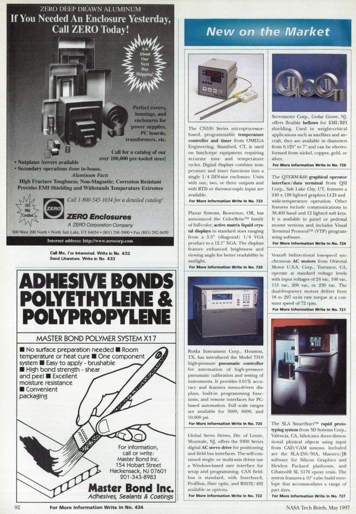
NaIiIIat& konn ...... bIe
Cd for a attalog of oar over 1110.000 pre-tooled sizesl
• SeaJaduy operatloDs done in-house. Aluminum Facts
IUgb Fracture Toughness; Non-Magnetic; Corrosion Resistant Provides EMI Shielding and Withstands Temperature Extremes
~": ~ ColII·8JJO·545·1034 fi'" d''''.d """"
CriIooI ZERO Enclosures A ZERO Corporation Company
500 West 200 North· North Salt Lake, UT 84054 • (801) 298-5900 • Fax (80 1) 292-9450
Intt.'nll't addn· ... ': http: //\\\\\\.It:rfH.:orp.nun
Cal Me. I'm Interested. Write in No. 432 Send Uteretta'e. Write in No. 433
ADHESIVE BONDS POLYETHYLENE & POLYPROpnENE
MASTER BOND POLYMER SYSTEM X17
• No surface preparation needed . Room temperature or heat cure . One component system . Easy to apply - brushable • High bond strength - shear and peel . Excellent moisture resistance • Convenient packaging
For information, call or write:
Master Bond Inc. 154 Hobart Street
Hackensack, NJ 07601 201 -343-8983
Adhesives, Sealants & Coatings
92 For More Information Write In No. 434
New · onltfj~JMarket
microprocessorbased, programmable temperature controller and timer from OMEGA Engineering, Stamford, cr, is used on batch-type equipment requiring accurate time and temperature cycles. Digital rusplays combine temperature and timer functions into a single 1/ 4 DIN-size enclosure. Units with one, two, or three outputs and with RTD or thennocouple input are available. For More Information Write In No. 723
Planar Systems, Beavenon, OR, has announced the ColorBrite™ family
of fu ll-color, active matrix liquid crystal displays in standard sizes ranging from a 5.5" (diagonal) 1/ 4 VGA product to a 12.1" XGA. The displays feature enhanced brightness and viewing angle for better readability in sunlight-For More Information Write In No. 720
bigh-pressure pneumatic controller for automation of high-pressure pneumatic calibration and testing of insmunents. It provides 0.01 % accuracy and features menu-driven displays, built-in programming functions, and remote interfaces for PC based automation. Full scale ranges are available for 3000, 6000, and 10,000 psi. For More Information Write In No. 725
Global Se,,'o Drives, Div. of Lenze, Montvale, Nj, offers the 9300 Series digital AC servo drive for positioning and field bus interfaces. The self-contained single- or multi-axis drives use a Wmdows-based user interface for setup and programming. CAN fieldbus is standard, with Imerbus-S, Profibus, [tber optic, and RS232/ 4 2 available as options. For More Information Write In No. 722
hielding. U ed in weight-critical applications such as satellites and aircraft, they are available in diameters from 0.125" to 7" and can be electroformed from nickel, copper, gold, or silver. For More Information Write In No. 126
The QTERM-K60 graphical operator interfacel data terminal from QS) Corp., Salt Lake City, UT, features a 240 x 128 lighted graphics LCD and wide-temperature operation. Other features include communications to 3 ,400 baud and 12 lighted soft keys. It is available in panel or pedestal mount versions an includes Visual Terminal Protocol™ (VTP) programming software. For More Information Write In No. 724
Vexta® bidirectional low-speed synchronous AC motors from Oriental Motor U.S.A. Corp., Torrance, CA, operate at standard voltage levels with input voltages of24 vac, 100 vac, 115 vac, 200 vac, or 230 va.c. The dual-frequency mOtors deliver from 18 to 297 oz-in rate torque at a constant peed of 72 rpm.
The LA SmartStan™ rapid prototyping system from 3D Systems Corp., Valencia, CA, fabricates thre<><limensional physical objects using input from CAD/ CAM systems. Included are the SLA-250/ 30A, Maestro/ JR software for iIi con Graphics and Hewlett Packard platforms, and Cibatool® SL 5170 epoxy resin. The system features a 10" cube build envelope that accommodates a range of pan sizes. For More Information Write In No. 727
ASA Tech Briefs, May 1997
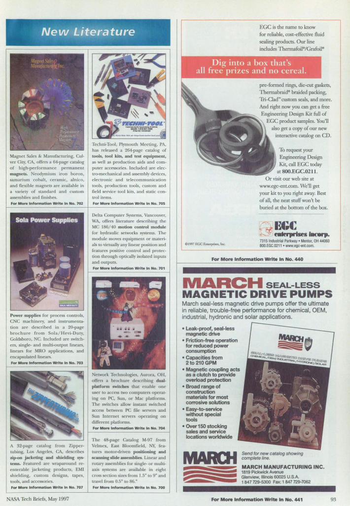
Magnet Sales & Manufacnuing, Cul"cr City, CA, offers a 64-page catalog of high-performance permanent magnets, Neodymium iron boron, samarium cobalt, ceramic, alnico, and flexible magnets are available in a variety of standard and custom assemblies and finishes. For More Infonnatlon Write In No. 702
Power supplies for process controls, CNC machinery, and instrumentalion are described in a 20-page brochure from Sola/Hevi-Duly, Goldsboro, C. Included are switchel'S, single- and multi-oulpul lineal'S, linears for MRO applications, and encapsulated Iinears. For Mont Inf ......... tion WrIte In No. 703
A 32-page catalog from Zipperlubing, Los Angeles, CA, describes zip-ou jacketing and shielding systems. Fealured are wraparound reeoterable jacketing products, EM! shielding. custom designs. lapes, lools, and accessories. For More Information Write In No, 707
NASA Tech BriefS, May 1997
Tecbni-Tool, Plymouth Meeting, PA, has released a 264-page catalog of tools, tool kits, and test equipment:, as well as production aids and computer accessories. lncluded are electro-mechanical and assembly devices, electronic and telecommunication lools, production toOls, custom and field service tool kits, and Slatic control items. For More Infonnation Write In No. 705
Della Computer Systems, Vancouver, WA, ofters lilerawre describing the MC 186/40 mouon control module for hydraulic selworks systems. The module moves equipment or materials to vinually any linear position and features positive control and protection through optically isolated inputs and outputs.
et»'Ork TechnolOgies, AlU'ora, OH, offers a brochure describing dualplatform switches that enable one user to access lWO compute .... operating on PC, un, or Mac platforms. The swilChes allow instanl swilCbed
un [ntemel sen...,rs operating on different platforms. For More l"""""-tIon Write In No. 704
The 4~page Catalog M-97 from Velmex. Easl Bloomfield, IY, features motor-driven positioning and scanning slide assemblies. linear and rotary assemblies for single- or multiaxis systems are available in eight cross section sizes from 1.5" to 9" and travel from OS to 86." For More tnformation WrIte In No. 700
EGC is the name to know for reliable, cost -e£fucrive fluid sealing products. Our line includes Thennafoile/Grnfoil-
pre-formed rings, die~t gaskets, Thermabraid- braided packing, Tri-CIadN custom seals, and more. And right now you can get a free Engineering Design Kit full of
EGC product samples. You'll also get a copy of our new
interactive catalog on CD.
To request your Engineering Design Kit, call EGC today
at SOO.EGC.0211. Or visit our web site at
www.egc-ent.com. We'll get your kit to you right away. Best of all, the neat stuff won't be buried at the bottom of the box.
..... a;£ ..... ~ eIderprIses I..,..
7315 IndustrIal Par1<way' Mentor, OH 44060 8OO.EGC.0211 • www.egc-ent.com.
For Mont Infonnatlon Write In No. 440
MARCH SEAL-LESS MAGNETIC DRIVE PUMPS March seal-less magnetic drive pumps offer the Ultimate in reliable, trouble-free performance for chemical, OEM, industrial, hydronic and solar applications.
• Leak-proof, seal-less magnetic drive
• Friction-free operation for reduced power consumption
• Capacities from 2to 210 GPM
• Magnetic coupling acts as a clutch to provide over1oad protection
• Broad range of construction materials for most colTOsive solutions
• Easy-ta-service without special tools
• Over 150 stocking sales and service locations worldwide
Send for new catalog showing complete line.
MARCH MANUFACTURING INC. rt 1819 Pickwick Avenue
Glenview, Illinois 60025 U.SA 1847729-5300 Fax: 1 847729-1062
For More Inionnation Write In No. 441 93
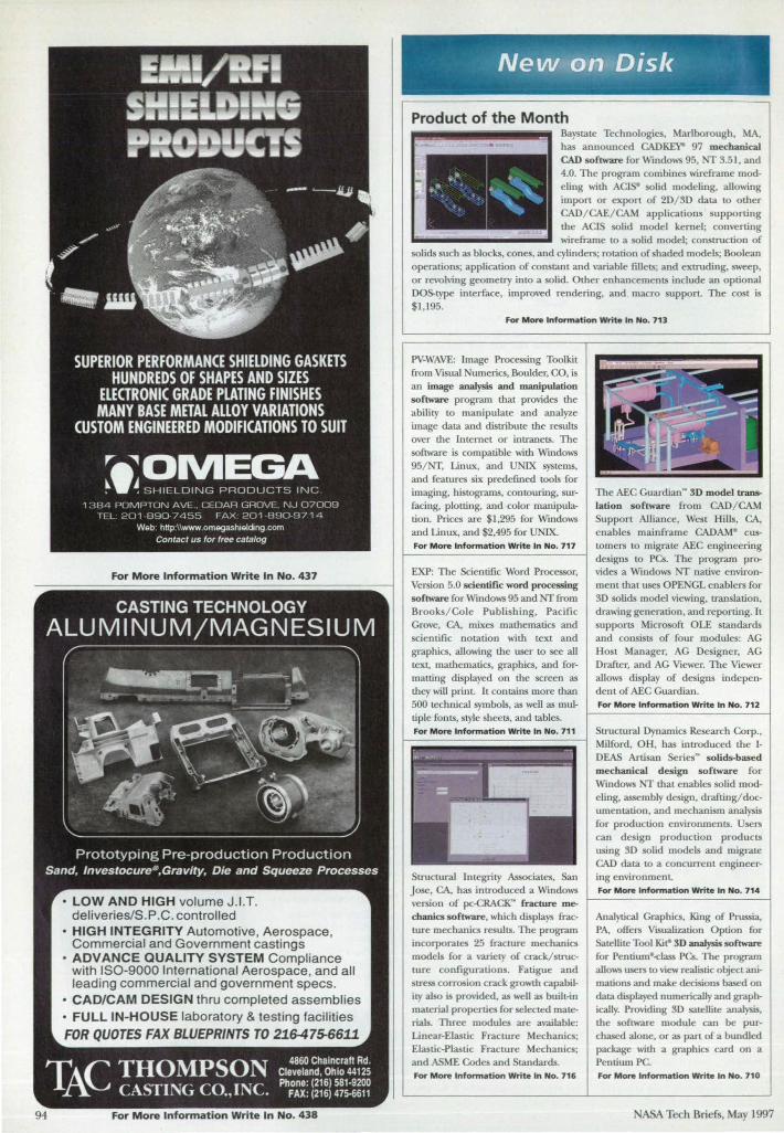
For More Information Write In No, 437
• LOW AND HIGH volume J.I.T. deliveries/S.P .C. controlled
• HIGH INTEGRITY Automotive, Aerospace, Commercial and Government castings
• ADVANCE QUALITY SYSTEM Compliance with ISO-9000 International Aerospace, and all leading commercial and government specs.
• CAD/CAM DESIGN thru completed assemblies • FULL IN-HOUSE laboratory & testing facilities FOR QUOTES FAX BLUEPRINTS TO 21647~6611
TflC THOMPSON ~ CASTING CO.,INC.
4860 Chaincraft Rd. Cleveland, Ohio 44125 Phone: (216) 581·9200
FAX: (216) 475,6611
94 For More Information Write In No, 438
I ,
NeWAQ'QrDisk
Product of the Month Baystate Technologies, Marlborough, MA, has announced GADKEY" 97 mechanical CAD software forWtndows 95, NT 3.51, and
.. I "'. ' .~ .. . , ' . ' 'oS '. '. i ~, .....
~ i ~
I
4.0. The program combines wireframe modeling with ACI solid modeling, allowing impon or expon or 2D/3D data to other GAD/CAE/CAM applications supporting the ACIS solid model kernel; converting wireframe to a solid model; construction of
solids uch as blocks, cones, and cylinders; rotation of shaded models; Boolean operations; application of constant and variable fillets; and extruding, sweep, or revolving geometry into a solid. Other enhancements include an optional DOS-type interface, improved reudering, and macro supporL The cost is $1,195.
For More Information Write In No. 713
PV-WAVE: Image Processing Toolkit from Visual Numerics, Boulder, CO. is an image analysis and manipulation software program that provides the ability to manipulate and analyze image data and distribute the results over the Internet or intraneLS. The software is compatible with Wmdows 95/NT, Linux, and UNIX systems, and features six predefined tools for imaging, histograms, contOuring, surfacing, plotting, and color manipulation. Prices are $1,295 for Windows and Linux, and $2,495 for UNIX. For More Information Write In No. 717
EXP: The Scientific Word Processor, Version 5.0 scientific word processing software for Windows 95 and NT from Brooks/Cole Publishing, Pacific Grove, CA, mixes mathematics and scientific notation with text and graphics, allowing the user to see all text, mathematics, graphics, and formatting displayed on d,e screen as they will print. It contains more than 500 technical symbols, as well as multiple fonts, style sheets, and tables. For More Infonnation Write In No. 711
Structural Integrity Associates, San Jose, CA, has introduced a Wrndows version of pc-CRACK'" fracture mechanics software, which displays fracture mechanics results. The program incorporates 25 fracture mechanics models for a variety of crack/structure configurations. Fatigue and stress corrosion crack growth capability also is provided, as well as builL-in material properties for selected materials. Three modules are available: Linear-Elastic Fracture Mechanics; Elastic-Plastic Fracture Mechanics; and ASME Codes and Standards. For More Infonnat/on Write In No. 716
The AEC Guarclian~ 3D model translation software from CAD/ CAM Support Alliance, West Hills, CA, enables mainframe CADAM· customers to migrate AEC engineering designs to PCS. The program provides a Windows NT native environment that uses OPENGL enablers for 3D solids model viewing, translation, drawing generation, and reporting. It suppons Microsoft OLE standards and consists of four modules: AG Host Manager, AG Designer, AG Drafter, and AG Viewer. The Viewer allows display of designs independent of AEC Guardian. For More Information Write In No. 712
StrucLural Dynamics Research Corp., Milford, OH, has introduced the IDEAS Artisan Series~ solids-based mechanical design software for Windows NT that enables solid modeling, assembly design, drafting/documentation, and mechanism analysis for production environments. Users can design production products using 3D solid models and migrate GAD data LO a concurrent engineer. ing environment. For More Information Write In No. 714
Analytical Graphics, King of Prussia, PA, offers Visualization Option for Satellite Tool Ki~ 3D analysis software for Pentium-<Jass PCS. The program allows users to view realistic ol!iect animations and make decisions based on data displayed numerically and graphically. Providing 3D satellite analysis. the software module can be purchased alone, or as part of a bundled package with a graphics card on a Pentium PC. For More Information Write In No. 71 0
NASA Tech Briefs, May 1997
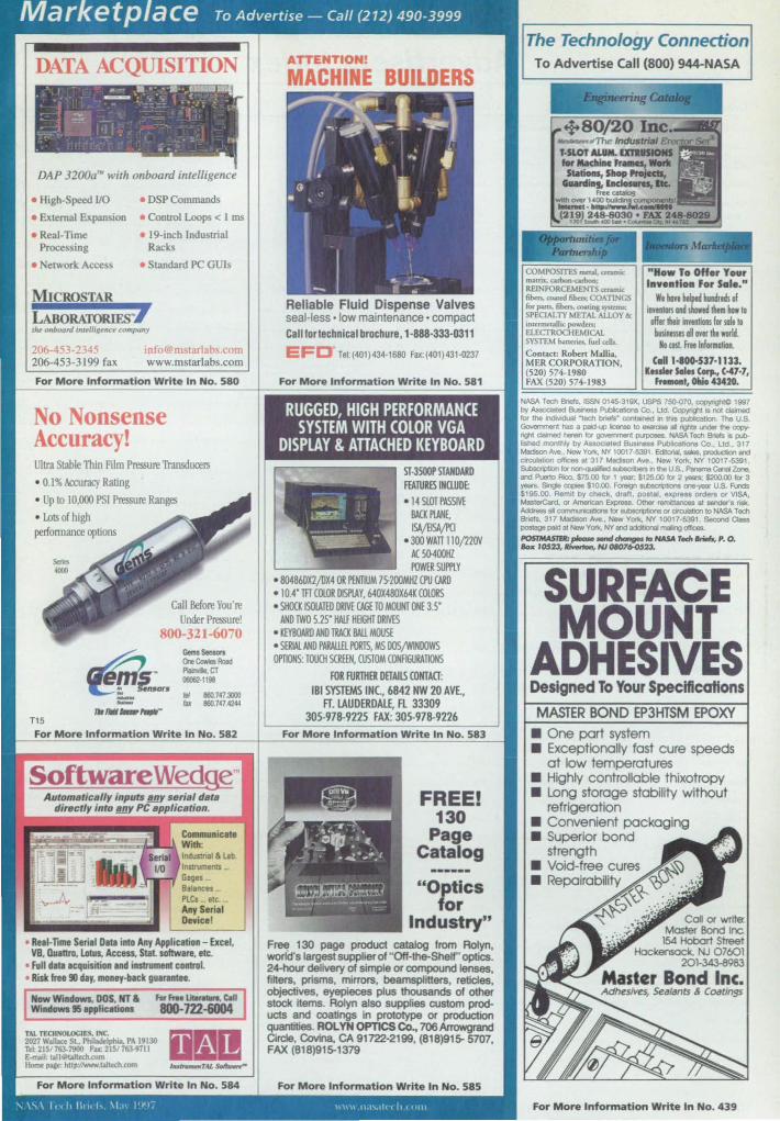
Marketplace To Advertise - Call (212) 490-3999
DATA ACQUISITION • - , I. • . F ~~·_,~·~~-~ ·:"0 . 1
: ! ..... . ---- .- (: ' . \-' ; j =r.: ITJ - .~. '
.... ~ . , .~ . t # -; . ::.
· , . . . . - ,. ,
DAP 3200a'" with onboard intelligence
• High-Speed 110
• External Expansion
• ReaI-TlDle Processing
• etwork Access
MICROSTAR
• DSP Commands
• Control Loops < I ms
• 19-inch Industrial Racks
• Standard PC GUls
LABORATORIES)' 'h~ onboard inttlligf!nct company
206-4)3-2 A5 206-453-3199 fax
mfo@mstarlat .. com www.mstarlabs.com
For More Information Write In No. 580
No Nonsense Accuracy! Ultra Stable Thin Film Pressure Transducers
• 0.1% Accuracy Rating • Up to 10,000 PSI Pressure Ranges • Lots of high perlonnance options
T15
Call Before You're Under Pressure!
800-321-6070 Gems Sentors One CowIoo Road Plar!vle,cr 060Ii2·1198
IilI 1160.747.3000 tax 1160.747.4244
For More Information Write In No. 582
SoftwareWed~
• Real· Time Serial Data into Any Application - Excel, VB, IWattro, Lotus. Access, Stat. software, etc.
• fuJI data acquisition and instrument control. • Risk free 90 day, money-back gOBrantee.
TAL TECle ·OWClES. INC. 2027 WiIIl>a SL. Philadelph ... PA 19130 Tt~ 215/763-7900 I'u: 2151 763-9n1 &-lIlliI: 1>11et>Jt«h.com Home page: http-jlwww.l>1tzch.com
For More Information Write In No. 584
ATTENTION!
MACHINE BUILDERS
~I~.~ • G " I. I \
\' I'~I:~ ~ - .-~ . ..
Reliable Fluid Dispense Valves seal-less· low maintenance· compact Call for technical brochure,1-888-333-0311
EFD Tel:(401)434-1680 Fax:(401)431-0237
For More Information Write In No. 581
I RUGGED, HIGH PERFORMANCE SYSTEM WITH COLOR VGA
DISPLAY & ATTACHED KEYBOARD ST·3500P STANDARD FfATURESINUUDE:
• 14 SLOTPASSIV~ BACK PlANE, ISAjElSA/l'CI
- 300 WAn 11O/220V Il. 5(}400HZ POWER SUPPlY
- 80486DX2jDX4 OR PENTIUM 75-200MHZ CPU CARD - 10.4' m COLOR DISPlAY, 640X480X64K COLORS - SHOO: ISOlATED DRIVE CAGE TO MOUNT ONE 35'
AND TWO 5.25' HAlf HEIGHT DRIVES - KEYBOARD AND ruCK BAll MOUSE • S£RlAl.AND PARAll.El PORlS, MS OOS/WlNOOWS OmONS: TOUCH SCREfN, CUSTOM CONRGURATlONS
FOR FURTHER DETAILS CONlAa: IBI SYSTEMS INC, 6842 NW 20 AVE.,
FT. LAUDERDAlE, n 33309 305-978-9225 FAX: 305-978-9226
FREE! 130
Page Catalog
"Optics for
Industry" FreE! 130 page product catalog from Rolyn, world's largest supplier of "Off-the-Shelf' optics. 24-hour delivery of simple or compound lenses, filters, prisms, mirrors, beamsplitters, reticles, objectives, eyepieces plus thousands of other stock items. Rolyn also supplies custom products and coatings in prototype or production QUantities. ROL YN OPTICS Co., 706 Arrowgrand Circle, Covina. CA 91722-2199, (818}915- ST07, FAX (818}915-1379
For More Information Write In No. 585
"''> \ 1",10 III .. I, \1.1\ 1'1~'i \\11" lI.t",I<·(" 1"'"
The Technology Connection To Advertise Call (800) 944-NASA
COMPOSITES meal. annuc rDautt.. arbon-carbon; REINFORCEMENTS ccr.uruc fib<n, 0>0..d fibcn; COATINGS fOe pans. fiben. <XNDin&_ SPECIAL 11' MIT AL ALLOY & ituermet:a1lic: powders; ELECTROCHEMrCAL SYSTEM "'n<ries. fud <dis. Conraa: Robcn Millia, MF.RCORPORATION, (520) 574-1980 FAX (520) 574-1983
"How To GHar Your Invention For Sal •• n
We hoyt helped mdrtds of imnlorl u4 shoed them how 10 offer their innnHollI for IQIa 10
billinesses aU onr lhe world. 10 (ost. FreelnfOl1l1OHon.
C.1I1-I00.537-1133, le .. l., 541 ... Corp., C-47-7,
'_1,01lI043420.
NASA Tech Bnefs. ISSN 0145-319X. USPS 750-070. copyrightC 1997 by AssocIated Buslness PubIIcatlons Co .. Ud. CopyngI11Is not __ fo< the -..J 'Iech _to· conlained on Ih>s pobIfcation. The U.S. GcM.nmonI has a JlOId-<4:> IIan>e to "'""""'" .. rfgI'O .mer the ~ "ltd - her .... for gcMlf1lI'IIO<'d puposes. NASA Tectt _ Is p<bfished monlhly by Assoclaled Business publlcabonS Co .. Ltd .. 317 MadIson Ave .. New Yori<. NY 10017-5391. Edtorial. _. producIion and Clfcura_ offICeS 81317 MadISOO Ave .. New YOf1<. NY 10017·5391. Subocription for ~..-n the U.S .. Panama CMaI Zone. and Pu&!o Rico. $75.00 fo< 1 yaw; $125.00 for 2 ~ S2OO.00 for 3 years. SOtgIe oop;es $10.00. Foreign ~ one-)'IB' u.s. Hrds $195.00. Remit by chacko draft. pOlla!. express orders or VISA, MaslerCard. or Amencan E>pr .... Other remrtlances at ...--s risk. Ad<tess .. COIM'UlICUIion8 for ~ ex cort:tJatm to NASA Tectt Bnefs. 317 Madison Ave .. New YotI<. NY 10017·5391. Secor'd Class postage paid at New Yor1<, NY and edQtIonaI maIing otIIces. P05TMASJH: please -.d ~ ... HAs. Ted! /Jrieb, P. O. 80.< 10523, __ HI 0II076-C$23.
SURFACE MOUNT
ADHESIVES Designed To Your Specifications
• One part system • Exceptionally fast cure speeds
at low temperatures • Highly controllable thixotropy • Long storage stability without
refrigeration • Convenient packaging • Superior bond
strength • Void-free cures • Repairability
For More Information Write In No. 439
Advertisers Index Company Web Site
Write in Number Page
AID Electronics Inc. .............. ...........• www.adelectronics.com ...... ..... .451 ..................... _ ....... Ia
Aavid Thenna\ Technologies ............ www.aavidcom ............ _ ............ 468472 ._ ................... 33
ACL Statidde ........................ .. ............ www.aclstatid de.com ........•......... 400 ...................... _ .... .. 4S
Adaptive Research ...•.......................... _w.adapti~.com ...... 635 .............•...... CO III
Advanced Interconnections COrp ............... .... www.advintcorp.com .................. 303 ............................ 2Oa
Aerospace Optics Inc. .... _. __ ................................................ _ ................•... 622 ........................... _.43
Algor. lnc. .......................................... www.algor.com ............................ 625 ................................ 7
American Variseal ................................ www.variseal.com ........................ 416 .............................. 74
APD .............................. .......................... www.algor.com/APD .............•.... 680 .............................. 67
Applied Test Systems. Inc ................... www.atspa.com ....•....................... 420 .............................. 80
Astro-Med. lnc ..... .. .... ............. ............. www.astro-med.com .................... 558 .............................. 61
Autodesk AutoCAD LT ....... ...... ......... www.autodesk.com/ aI27 ................................................ 41
BASF Plastic Materials .. .. .......... .. .... .. .. www.basf.com .............................. 604 ................ .. .. .......... 29
Bentley Systems ................................. . www.bentley.com ........................ 650 .............................. 21
Buckbee-Mears SL Paul ..... .... ............. www.bmdnd.com ........................ 422 .............................. 82
BVQI... ............................ .. .............. .................. .. ......................................... 570 .............................. 71
Cambridge Technology ....... ........... .. .. www.camtech.com ...................... 456 ............................ 15a
Cardinal Aluminum Co ............................. .... ............................................ ..41 2 .............................. 24
Cerac Incorporated ........ .. .... .............. www.cerac.com ............................ 417 .............................. 75
CLEO/ Qels '97 ................................. ................... ..... .... ........ .. .. ................. 510 .............................. 77
Corel Corporation .......... .. .. .... .... .. ...... www.corel.com ............ .. .. ............ 645 .............................. 27
Cybernetics ............................ .. ......................... ....................... .. ................... .562 .............................. 51
Datum Inc .................................... .. .... ... www.datum.com .......................... 401 .............................. 16
Digi.Key Corporation ...... .. ........... ..... www.digikey.com ........ .. .............. 636 ................ ......... ....... 5
Digital Equipment Corporation ...... www.workstation.digital.com. .... 610 ............................. .1 3
DSP Development Corporation ...... www.dadisp.com .......................... 431 .............................. 89
DuPont ................ .. .. ................ .. .. .... .................... .. ...... .......... ...................... 652 .......... .............. 38-39
DuPont Krytox ............. ... ...... .. ............ www.lubricants.duponLcom ...... 662 ................... ........... 35
DuPont Vertrel ...... .... .. .......... .... .. ... ......... ......................... .. ...... ................. 552 .............................. 45
DuPont Vespel .......... www.duponLcom/ enggpolymers/ americas ..... . 530 .... .. .... .... .. .. .. .... 1().11
EBM/ Papst ........................... ... ...... ...... www.ebm.com ............................. . 450 ......... ..... ...... COV 1Ia
Edmund Scientific Co ....... .... .. .. .............. ............... ............................. ...... 435 ............ ................ .. 90
EFD .......................... .................................................................................... 581... .... ........ ............... 95
EGC Enterprises Inc. .... .. .. .... ........... ... www.egc-ent com .............. .. ......... 440 .............................. 93
Elmwood Semors ............... ... ...... .. ...... www.eJmwoodsemors.com ........ 409 .............................. 59
Endevt:o ................. .. .. ....................... www.endevco.com ...................... 607 ................................ 9
FieldWorks Inc . .... .... .. .... .................... www.fieldworks.com .... .. ............ 415 .............................. 74
FloMe~ Inc ......................................... www.flomeLindustry.net ............ 429 .............................. 87
Fon Wayne Anodizing .......... .. ............................................................ 403 .............................. 34
Gage Applied Sciences (U.S.) lnc .................. .. ..... W><.w.gage-appliedcom .............. 540 .... ............. _ ........... 55
Gems SemoB ........... ................................................................ .. .. .. ....... 582 .... .. .... .. .................. 95
General Magnaplat.e COrp ................. www.magnaplat.e.com .............. ..411 .......... .. .................. 63
Hewlett·Packard COmpany ................ www.hp.com/ info/bidaql ........ 675 ................. _ ... _ ...... 33
ffil Systems Inc ............................... ............................................................ 583 .............................. 95
Interfuce ............... .. ............................. www.interfuceforce.com ............ 419 .. .. ................... ....... 79
Int.ergraph COrporation ............. wwwJntergraph.com/solidedge ...... 630 ................................ 2
IOtech. lnc ......................................... www.iot.ech.com .......................... 32().332 ................ 64A-B
Keithley Instruments. Inc ........... ...... www.keithley.com ........................ 453 .............................. 9a
Kidasa SOftware. lnc. .......................... www.kidasa.com .......................... 408 .............................. 59
KoDtron Elektronik ............................ www.kontron.com ............ ........ ..424 .............................. 83
Company Web Site Write in Number Page
Labtech .................................................. ""'w.Labtech.com ................ ...... 443 ........................... _.
LPKF ..................... ................ _ ............. www.lpkfcadcam.com ................ 459 .................. .......... 183
Lumite" . Inc. .......................................................................... _ .................. 458 ............... ............. ISa
M/cad Expo ·97 .......................... _ ...... www.mcadexpo.com ................. .418 .............................. 78
March Manufacturing lnc ............................................................. .. ........ 441 .......... .................... 93
Master Bond Inc ....................................................................................... 434.439 .................. 92.95
The MathWorks, Inc ......................... """'w.mathworks.com/NTB ........ 660 .................. 16A·B. 17
Media Cybernetics .............................. www.mediacy.com ............ .......... 404 ......... ..................... 37
Metal Powder Indusoies Federation ...................... www.mpif.org/mpif ...... _ ............ 670 .............................. 31
Meoic Equipment Sales. lnc ..... ........ www.metricsales.com .................. 301 ............................ 2Oa
Micro Sim ........................................... . www.microsim.com .......... .. ....... .452 .............................. 7.
Microstar Laboratories ...................... www.mstarlabs.com .................... 580 .............................. 95
Miller-Stephenson Chemical Company. lnc ..... ............ .......................... 402 .............................. 28
Minco Product<;, Inc ............................................ .. ................................. 421 .............................. 80
MKS Instruments. Inc. ..................... www.mksinsLcolll ........................ 41 3 ............................. 68
Motorol. Semiconductor ................ ...... ............. .. ...... .. .... .. ....................................................... 43-5.
Nanonics Corporation ...................... www.nallonics.com/catalog! .... 436 ...... .. .................... .. 90
National Instruments Corporation .......... .. .. w..w.nabnsLcom .................... .. .... 600.405 ........ COV ll.47
ewpon Corporation ........................ www.newponcom www.newponcom/catalog ........ 656 ..... .. ................... .... 25
Ocean Optics. Inc . ........ .. .................... www.OceanOptics.com .......... .. .. 407 .............................. 52
Omega Engineering Inc ................... w..w.omegacom .......... ................ 612-616 ...... .................. 1
Omega Shielding Products Inc . .. .. .... www.omegashielding.com ......... .437 ............................ .. 94
PADS Software Inc ............................. www.pads.com ............................ 302 ............................ 2Oa
Parametric Technology Corporation ................ www.ptproducts.com ................. 575 .................... 4, 48A·D
Phar·Lap SOftware. 1nc. ...................... www.pharlap.com ........................ 454 ............................ ll a
Research SYSlems. Inc. ...................... www.rsinc.com .... ........................ 515 .................... COV N
RGB Spectrum .................................... www.rgb.com ................... .. .... .. ... 400 .............................. 1 2
Rifocs Corporation .............. ............ .. www.rifocs.com .................. .......... 425 .............................. 83
Rolyn Optics Co ................................ .................................................... ..... 585 .............................. 95
Sarnoff Corporation ............ .............. www.samoff.com ........ ................ 590 ..... .. ...................... .57
Setra Systems ................................. ............................................................. 410 ................ .............. 63
Sierra Vacuum Technology ........ .. .......................... ............ .. .. .. ................ 442 .............................. 85
Silicon Graphics, Inc ..... ............................................................................ 577 .................... .. .. ... ... 15
Sony Precision Technology America ...................................................... 457 ... _ ...................... .I7a
SOrbothane Inc. .................................. www.sorbothane.com .................. 423 .............................. 82
Spaulding Composites Co ....................................................................... 427 .............................. 86
Synrad .................................................. www.synrad com ............... .. ......... 520 ............................. .53
TAL Technologies ..................... .. .. ..... www.taltech .com .......................... 584 ................... .. ......... 95
Tamura Corporation of America .................................. .. .. .................... ..461 .... .............. COV N a
TEe ProduclS ...................................... www/tecstress.com/tec .............. 460 ..................... ....... I9a
TestEqui ty lnc. .................................... www.testequity.com .................... 548 ................................ 3
Thompson Casting Co .• Inc ........................................................... _ ........ 438 .............................. 94
Titan Tool Supply Co .• Inc ............................ .. ............... .......................... 300 ............................ 2Oa
Transducer Techniques. Inc ............. www.ttloadceJls.com .................... 428 .............................. 86
United Electronic lndustries lnc ..... _ w.ueidaq.com ........ .. ............. .444 .............................. 85
Unitrode Integrated Circui ts .................................. .. ............................... .455 ............................ 13a
Wolfram Research ....... .......... www.wolfram.com/applications/cnl ...... 545 .............................. 69
Zero Enclosures .................................. www.zerocorp.com ...................... 432.433 ...................... 92
Zircar Products, Inc. ................... .. ... . www.zircar.com ........................... .414 ........................... .. . 73
96 www.nasatech.com ASA Tech Briefs. May 1997
~ ______ ~C~r~a~t~e~R~e~v~o~l~u~t~l~·o~n~a~r~~R~e~s~u~l~t~~F~a~s~t~~
Visualize your dara wirh
lOla, rhe Inuractiv( Data
lAnguag(, and see results in a
whole new way.
IOL software's array-orienred
archirecrure is designed for
high-performance processing
of large, complex dara. Thar's
why ir's rhe srandard in the
Easily creare amazing graph- world's preeminent medical,
ics wirh IDL sofrware's milirary, engineering & sci-
accelerared 3D sysrem. Want
ro spin or fly-rhrough a
surface? No problem. Shade
and illuminare wirh multiple
lighr sources?
ence organizarions. 10 L is so
efficienr rhar a few lines of
IOL can do rhe job of hun
dreds of lines of C or Fornan.
And , irs objecr-orienred
sysrem lers you develop
sophisricared applicarions
from reusable code modules.