reviews carbon-based materials for lithium-ion batteries, electrochemical capacitors, and their...
TRANSCRIPT
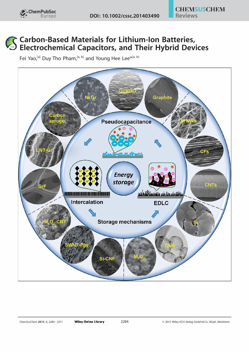
Carbon-Based Materials for Lithium-Ion Batteries,Electrochemical Capacitors, and Their Hybrid DevicesFei Yao,[a] Duy Tho Pham,[a, b] and Young Hee Lee*[a, b]
ChemSusChem 2015, 8, 2284 – 2311 Ó 2015 Wiley-VCH Verlag GmbH & Co. KGaA, Weinheim2284
ReviewsDOI: 10.1002/cssc.201403490

1. Introduction
With a fast-growing economy and human population, ourglobal energy consumption has been dramatically increased.[1]
Thus, the issue of the sustainability of energy supplies has at-tracted worldwide concern owing to a crisis in the rapid deple-
tion of fossil energy resources along with serious environmen-
tal pollution issues.[2, 3] It is well known that solar cells andwindmills not only exhibit limited application scopes but also
require energy-storage systems because of their remote loca-tions.[4] In addition, a rapidly developing market for portable
electronic devices and hybrid electrical vehicles has also led toan urgent demand for mature energy-storage systems in
modern society.
Systems for electrochemical energy storage convert chemi-cal energy into electrical energy. To value the energy content
of a system, terms of “energy density” (or “specific energy”)and “power density” (or “specific power”) are used. “Energy
density” is expressed in watt-hours per liter (W h L¢1) or inwatt-hours per kilogram (W h kg¢1) and “power density” is ex-pressed in watts per liter (W L¢1) or in watts per kilogram
(W kg¢1).[5] To compare the performance of various energy-stor-age devices, a reprehensive chart known as the Ragone plot isshown in Figure 1. In such a plot, the specific energy is plottedversus specific power.[2] Among various energy-storage devices,it is clear that electrochemical capacitors (ECs) and supercapa-citors can be considered as high power density systems with
relatively low energy density, whereas lithium-ion batteries
(LIBs) alone with high energy density show relatively low
power characteristics.LIBs and ECs share some common features. They both con-
sist of two electrodes that are in contact with the electrolyte.Requirements for electron and ion conduction in electrodesand electrolyte are valid for both systems. Furthermore, elec-
tron and ion transport are separated during the charge/dis-charge processes.[5] On the other hand, historically, differences
between LIBs and ECs do exist. For instance, compared to tra-
ditional ECs, the electrodes of which are composed of thesame materials (activated carbons) and therefore exhibit the
same electrochemical potential, an inherent potential differ-ence exists between the electrode materials in LIBs. The poten-
tial difference between the two electrodes in LIBs, for example,a graphite anode and a lithium cobalt oxide cathode, is ideally
A rapidly developing market for portable electronic devicesand hybrid electrical vehicles requires an urgent supply of
mature energy-storage systems. As a result, lithium-ion batter-ies and electrochemical capacitors have lately attracted broad
attention. Nevertheless, it is well known that both deviceshave their own drawbacks. With the fast development of nano-science and nanotechnology, various structures and materials
have been proposed to overcome the deficiencies of both de-vices to improve their electrochemical performance further. In
this Review, electrochemical storage mechanisms based oncarbon materials for both lithium-ion batteries and electro-chemical capacitors are introduced. Non-faradic processes(electric double-layer capacitance) and faradic reactions (pseu-
docapacitance and intercalation) are generally explained. Elec-trochemical performance based on different types of electro-
lytes is briefly reviewed. Furthermore, impedance behaviorbased on Nyquist plots is discussed. We demonstrate the influ-
ence of cell conductivity, electrode/electrolyte interface, andion diffusion on impedance performance. We illustrate that re-
laxation time, which is closely related to ion diffusion, can be
extracted from Nyquist plots and compared between lithium-ion batteries and electrochemical capacitors. Finally, recent
progress in the design of anodes for lithium-ion batteries, elec-trochemical capacitors, and their hybrid devices based on car-
bonaceous materials are reviewed. Challenges and future per-spectives are further discussed.
Figure 1. Specific power against specific energy, also called a Ragone plot,for various electrical energy-storage devices. Reprinted with permission fromRef. [2] Copyright 2008, Macmillan Publishers, Ltd.
[a] Dr. F. Yao,+ D. T. Pham,+ Prof. Y. H. LeeCenter for Integrated Nanostructure Physics, Institute for Basic ScienceSungkyunkwan UniversitySuwon 440-746 (Republic of Korea)E-mail : [email protected]
[b] D. T. Pham,+ Prof. Y. H. LeeDepartment of Energy Science, Department of PhysicsSungkyunkwan UniversitySuwon 440-746, Republic of Korea)
[++] These authors contributed equally to this work.
This publication is part of a Special Issue on “Sustainable Chemistry atSungkyunkwan University”. To view the complete issue, visit :http://onlinelibrary.wiley.com/doi/10.1002/cssc.v8.14/issuetoc.
ChemSusChem 2015, 8, 2284 – 2311 www.chemsuschem.org Ó 2015 Wiley-VCH Verlag GmbH & Co. KGaA, Weinheim2285
Reviews

constant through discharge or charge, but the working voltageof ECs linearly declines with the extent of charge.[6] Further-
more, charge storage takes place by a faradic reaction (redoxreactions) at the electrode in the case of LIBs. This is a diffu-
sion-controlled slow-rate process and is also the origin of thelow power density of LIBs. However, in the case of ECs, charges
mainly form at the interface of the electrode and electrolyteby means of a non-faradic reaction through the formation of
electrical double layers. Although this process exhibits a fast
rate of ion diffusion to give rise to higher power density, theconfinement of charges on the surface of the electrode leads
to a low energy density for ECs. Nevertheless, it should benoted that these differences between LIBs and ECs are becom-
ing less clear because of the intervention of innovative con-cepts such as asymmetric supercapacitors and Li-ion hybrid su-
percapacitors.Recently, LIBs and ECs have attracted attention from both in-
dustry and academia owing to the emergence of nanomateri-als and nanotechnologies. Carbon-based materials including
carbon nanotubes (CNTs), carbon nanofibers (CNFs), graphene,and their composites have been widely studied as electrode
materials for both devices. Compared to traditional electrode
materials, for example, graphite or activated carbons (ACs),these new types of carbon materials exhibit differences not
only in dimensionality and morphology but also in the distri-bution of chemical bonding, which allows mixtures of local
electronic structures between sp2 and sp3.[7] Therefore, the car-rier-transport properties are different from classic carbon mate-
rials if they are in contact with the reactants. Novel carbon ma-
terials with high accessible surface areas and short diffusionlengths for ions open new perspectives for high energy and
high power density devices. In this Review, on the basis ofwork performed in our group on batteries and supercapacitors
with carbon-based materials, we will first provide a brief de-scription of the fundamentals of electrochemical energy-stor-
age devices. Storage mechanisms, influence of electrolyte, im-
pedance behavior, and effect of the active mass loading/thick-ness are discussed. Furthermore, electrode performance based
on different carbon materials will also be reviewed. Finally,general conclusions and perspectives are given.
2. Fundamentals
2.1. Storage mechanism
In storing charges through an electrochemical reaction, thereare basically two charge-storage mechanisms that exist : a non-
faradic process and a faradic reaction. The non-faradic processinvolves no charge transfer but only electrostatic force be-
tween charged ions and the electrode. This is mostly observed
in electric double-layer capacitance (EDLC) in ECs, for whichthe cations and anions in the electrolyte are attached on bothelectrodes with an applied voltage to form two ideal doublecharged layers. No electrochemical reaction is involved during
ion adsorption (charging). Electrons are released through anouter circuit to generate electricity during ion desorption (dis-
charging) back to the electrolyte. For the faradic process, themajor mechanism for carbon materials can be classified intopseudocapacitance, which occurs at the surface of the materi-
als, and intercalation, which normally refers to a bulk reaction.Some other mechanisms still exist, for instance, alloying with
Si-based materials and conversion for some transition-metalcompounds.[5, 7] However, these mechanisms have been wildly
reviewed and are beyond the scope of this work.
2.1.1. Non-faradic reaction (electric double-layer capacitance)
Conventional dielectric capacitors store energy by the accumu-
lation of charges on two parallel metal plate electrodesthrough a dielectric layer under an applied voltage (see Fig-
Young Hee Lee is a director of the
Center for Integrated Nanostructure
Physics, Institute for Basic Science. He
is also a professor in the Department
of Energy Science and Department of
Physics at Sungkyunkwan University,
Korea. He received his BSc degree in
physics from Chonbuk National Univer-
sity, Korea, and his PhD degree in
physics from Kent State University,
USA. His research interests include ex-
ploration of unprecedented physical
and chemical properties of 2 D layered materials and carbon-based
materials and their applications to electronic devices and energy
storage.
Fei Yao received her PhD degree in
energy science from Sungkyunkwan
University, Korea, and her second PhD
degree in physics from Ecole Polytech-
nique, France, in 2013. She continues
her postdoctoral research at the
Center for Integrated Nanostructure
Physics, Sungkyunkwan University. Her
current research projects include the
design of new electrode materials for
Li-ion batteries, carbon-based materials
as catalysts for the oxygen reduction
reaction, and novel materials for elec-
tronic devices.
Duy Tho Pham is a PhD candidate in
the Department of Energy Science at
Sungkyunkwan University, Korea. He
received his BSc degree in material sci-
ence from Hanoi University of Science
and Technology, Vietnam, in 2010. His
research involves the synthesis of
nanomaterials and the fabrication of
energy-storage devices mainly focused
on carbon-based materials.
ChemSusChem 2015, 8, 2284 – 2311 www.chemsuschem.org Ó 2015 Wiley-VCH Verlag GmbH & Co. KGaA, Weinheim2286
Reviews

ure 2 a). The capacitance (C) of such a capacitor is expressed
by [Eq. (1)]:
C ¼ Ae0er
dð1Þ
in which er is the dielectric constant, e0 is the permittivity of
vacuum, A is the area of one metal plate, and d is the separa-tion distance between the two electrodes. This capacitance islimited because of the small charge storage area (A) and the
large separation distance (d on the micrometer scale). In con-trast, ECs based on EDLC can store much more energy because
of the large surface area of porous materials, for which a dou-bley charged layer is established on a porous surface of each
electrode, and this gives rise to a charge separation distance of
the order of 1 nm or less.[3]
The concept of EDLC was first reported by von Helmholtz inthe 19th century and was then further modified by Gouy, Chap-
man, and Stern.[3, 6] EDLC is established by storing charges inthe double layer formed at an electrode/electrolyte interface
upon application of an electric field.[8] The accumulation of
charges is a non-faradic process ; no electron transfer takesplace through the electrode interface. During charging, elec-
trons move from the positive electrode to the negative elec-trode through an external circuit. Whereas in the electrolyte,
anions move toward the positive electrode and the cationsmove toward the negative electrode. The reverse process hap-
pens during discharging. This charge-storage process is com-pletely reversible, which leads to excellent cycling stability and
power density of the EDL capacitors. The most common elec-trode materials utilized for EDLC are based on carbons, such asACs, CNTs, and graphene.[3, 9, 10]
The capacitance of an EDL capacitor is also estimated byEquation (1),[6] but in this case, er is the dielectric constant of
the electrolyte, A is the accessible surface area of the electrode,and d is the effective thickness of the EDL (or Debye length),
which is the separation distance between the electrode surface
and the electrolyte ion layer (see Figure 2 b). There is clearlya relationship between capacitance (C) and accessible surface
area (A). Notably, the accessible surface area is different fromthe specific surface area (SSA) measured by the Brunauer–
Emmet–Teller (BET) method. There is no linear relationship be-tween capacitance and BET surface area, because not all pores
of the electrode are accessible to the electrolyte ions.[4] Opti-mized pore-size distribution and surface wettability are neces-
sary to enhance the accessible surface area, which increasesthe EDLC.
2.1.2. Faradic reaction
2.1.2.1. Pseudocapacitance
Pseudocapacitance was first investigated by Conway and co-
authors in the 1960s.[6] Different from EDLC, pseudocapaci-tance stores charges by means of a fast and reversible faradicredox reaction at the electrode surfaces, as shown in Fig-
ure 3 a.[6] If a potential is applied across the electrode/electro-lyte interface, charge transfer takes place, similar to the electro-
chemical process in batteries. The pseudocapacitance is de-
rived from [Eq. (2)]:
C ¼ d Dqð Þd DVð Þ ð2Þ
in which Dq is the charge acceptance and DV is the change inpotential. Commonly active materials for such redox reactions
include several transition-metal oxides (e.g. , RuO2, MnO2, TiO2,NiO, V2O5, ZnO, WO3, Co3O4, and Fe2O3), conducting polymers
[e.g. , polyaniline (PANi), polypyrrole (PPy), and polythiophene
(PTh)] , and surface functional groups in carbons (e.g. , oxygenand nitrogen).[9, 11, 12] Although the pseudocapacitance can be
10–100 times higher than the EDLC,[13] it suffers from lowpower density and poor cycling stability owing to the slow
faradic process and the naturally poor electrical conductivity ofthe electrode materials.
Figure 2. Schematic illustration of a) a conventional dielectric capacitor andb) an electrochemical capacitor.
Figure 3. Schematic illustration of different storage mechanisms. Faradic re-actions include a) pseudocapacitance and c) intercalation. b) The non-faradicprocess is represented by EDLC. Combing either a/b) or b/c) forms d) anasymmetric supercapacitor or e) a Li-ion supercapacitor.
ChemSusChem 2015, 8, 2284 – 2311 www.chemsuschem.org Ó 2015 Wiley-VCH Verlag GmbH & Co. KGaA, Weinheim2287
Reviews

2.1.2.2. Intercalation
Intercalation is a simple, solid-state redox reaction in whichions are inserted into host materials. During intercalation,
mobile guest ions such as Li+ , Na+ , and K+ in the electrolyteare inserted into a solid layered material but the primary struc-
tural features are maintained with only a minimal amount ofvolume expansion.[14] Apart from protons, the smallest ion, Li+ ,
is considered to be one of the best ion candidates for the in-
tercalation reaction. In electrochemical storage, the concept of“intercalation” was first applied to cathode materials for lithi-um-ion batteries by Whittingham in the 1970s.[15] Transition-metal oxides and chalcogenides with stable layered or tunnel
structures were adopted as host materials. The redox reactiontakes place only on the host lattice, whereas no faradaic
changes occur in the guest ions.[16] Later on, carbonaceous ma-
terials were widely used as anodes in lithium-ion batteries byforming graphitic intercalation compounds (GICs) with a well-
known configuration of LixCn. During the charging process,positively charged lithium ions intercalate into negatively
charged graphite layers; the ions maintain their ionic statesrather than adopting their metallic states, as shown in Fig-
ure 3 c. The electrostatic force between the Li ions and graph-
ite can provide the energy to overcome van der Waals forcesbetween the graphene layers and thus the layer distance in
graphite expands. In an extreme case of intercalation, the com-plete separation of graphene layers, so-called exfoliation, can
occur. This kind of technique has been used in the exfoliationof graphite and other layered structures.
2.1.3. Hybrid structure
To achieve high energy and high power density for energy-
storage devices, hybrid devices that combine the fast charge/discharge and long cycle life of EDLC with the high charge-
storage capacity of either pseudocapacitance or intercalation(a few reports also outline the use of alloy/conversion materi-
als) have attracted much attention over the past fewyears.[9, 17–20] There are two different types of hybrid devices:asymmetric supercapacitors and Li-ion supercapacitors(Figure 3). An asymmetric supercapacitor combines a pseudoca-
pacitive electrode with an EDLC one (see Figure 3 d). Note thatthe device with both pseudocapacitive electrodes but differentmaterials for each is also defined as an asymmetric supercapa-citor.[21–25] Li-ion supercapacitors comprise a Li insertion anodeand an EDLC cathode, as indicated in Figure 3 e. Because they
operate through different electrochemical-storage mechanismsand in different electrode-potential ranges, the hybrid devices
can perform over a wide potential window, which leads to an
increase in the energy density while maintaining a high powerdensity. Increasing the potential window is critical to increase
the energy density, as the energy density is proportional to thesquare of the voltage. The design and optimization of appro-
priate electrode materials are key issues to obtain high electro-chemical performance of the hybrid energy-storage devices.
2.2. Electrolyte
The electrolyte, as one of the most important components ofthe cell, participates in all reactions inside the electrochemical
device. The role of the electrolyte is to serve as the mediumfor ion transfer between the electrodes. Also, the interfaces be-
tween the electrolyte and the two electrodes closely influencethe performance of the cells. In particular, in LIBs, both the
anode and the cathode materials are not stable with respect
to the electrolyte solution. Therefore, formation of a protectivelayer at the solid (electrodes) electrolyte interface (SEI) through
electrolyte decomposition at the onset of cell operation is con-sidered one of the most effective ways to protect the electrode
materials and to prevent further severe electrolyte decomposi-tion.[26, 27] Nevertheless, the formation of a SEI consumes Li ions
from the electrolyte, and therefore, it is detrimental to cell per-
formance, especially in the first charge process. Thus, toreduce this irreversible process, SEI formation needs to be
minimized. As a result, the choice of the electrolyte compo-nents directly affects the formation of a Li+-conducting SEI
layer and, thus, the irreversible capacity and cycle life of a bat-tery.
The stability of the electrolyte can be described by the volt-
age range beyond which the electrolyte will be either oxidizedor reduced, and this is known as the electrochemical window.
The energy density of a device can be described according tothe following equations [Eq. (3)]:[2]
E ¼ QV or E ¼ 12
CV2 ð3Þ
in which E is the energy density, V is the operation voltage, Q
is the capacity (mAh g¢1 or mAh cm¢3) of the battery, and C isthe capacitance (F g¢1 or F cm¢3) of the EC. Therefore, the elec-
trochemical window of the electrolyte is closely related to the
energy density of the storage device. In addition, the electro-lyte not only affects the energy density of the cell but also the
rate of mass flow or ion conductivity, which is related to thepower density of the device.[16] Thus, choosing the electrolyte
wisely is one of the most important steps for constructinga successful electrochemical energy-storage cell. An electrolyte
must exhibit high electrochemical stability and high ionic con-
ductivity; be composed of small solvated ions; have low vis-cosity, low toxicity, and high purity; and be low costing. In
general, three types of electrolytes are widely used: aqueouselectrolytes, organic electrolytes, and ionic liquids (ILs).
2.2.1. Aqueous electrolytes
Aqueous electrolytes present several advantages, including
low viscosity, small solvated ion size, low price, and an ionicconductivity that is two orders of magnitude higher than thatof non-aqueous electrolytes.[28, 29] More importantly, aqueous
electrolytes are environmentally friendly and nonexplosive,which is practically very important. Electrochemical cells con-
taining aqueous electrolytes usually do not require the strictassembly conditions that are needed for cells containing non-
ChemSusChem 2015, 8, 2284 – 2311 www.chemsuschem.org Ó 2015 Wiley-VCH Verlag GmbH & Co. KGaA, Weinheim2288
Reviews

aqueous electrolytes, as it is not necessary to prevent the inva-sion of water vapor; this reduces costs and makes electro-
chemical cells containing aqueous electrolytes adaptable formany practical applications.[30] The main disadvantage of aque-
ous electrolytes is their narrow electrochemical potentialwindow, which is only approximately 1.23 V as a result of the
decomposition of water. This fact limits the cell voltage and,therefore, the energy density of the cell. The operational volt-
age can be increased by using special structural designs, which
require more careful investigation.[31]
Aqueous electrolytes have been widely used in ECs and bat-teries. In the case of ECs, KOH, H2SO4, and Na2SO4 are com-monly used in aqueous-based ECs with normally higher capaci-
tance and power than ECs with organic electrolytes and ILs. Inthe case of rechargeable batteries, it is well known that KOH
and H2SO4 electrolytes are also used in commercialized re-
chargeable aqueous batteries, such as nickel metal hydride (Ni-MH), nickel–cadmium (Ni-Cd), and lead-acid (Pb-acid) batter-
ies.[31] These early-stage aqueous batteries suffer from a lowcell working voltage, low energy density, and also poor cycling
stability because of pulverization of their structure or an irre-versible reaction of the electrode materials (dissolution/deposi-
tion of Pb or Cd).[28, 29] Recently, an aqueous solution containing
a Li-containing solvent, such as LiNO3 and Li2SO4, has beenadopted to develop aqueous rechargeable lithium-ion batter-
ies after the initial report from Sony in 1994.[32–38] A mixture ofLiOH/LiCl in water is considered a typical aqueous electrolyte
for Li-O2 batteries.[39, 40] In addition to lithium-ion-based aque-ous electrolytes, sodium-ion- and potassium-ion-based aque-
ous electrolytes have also been used in aqueous rechargeable
sodium and potassium batteries.[41, 42] Many up-to-date Reviewson these new types of aqueous electrolyte batteries can be
found; this topic is also beyond the scope of our Review and,therefore, will not be elaborated in detail herein.[28, 30, 43, 44]
Although significant progress has recently been achieved withregard to these aqueous rechargeable devices, they are still in
their infancy and will require more comprehensive examination
in the future.
2.2.2. Organic electrolytes
In accordance with requests to increase the operation poten-tial window of aqueous electrolytes, organic electrolytes thatnormally provide an electrochemical window of 3 V are consid-
ered as alternatives to aqueous electrolytes.[5] Organic electro-lytes usually consist of certain salts and non-aqueous com-
pounds (solvents) that allow the salts to dissolve to sufficientconcentrations. Thus, solvents with strong polar groups, such
as C=O and C�N, are preferred because of their high dielectricconstants. An eligible organic electrolyte needs to maintain
good electrochemical stability, especially to the surfaces of the
electrodes. Furthermore, it should display low viscosity toallow facile ion transport.
In ECs, tetraethylammonium tetrafluoroborate (TEABF4), tet-raethylphosphonium tetrafluoroborate (TEPBF4), and ortriethyl-
methylammonium tetrafluoroborate (TEMABF4) are often usedas organic salts.[9] Acetonitrile (AN) and propylene carbonate
(PC) are the most commonly used solvents. In LIBs, LiPF6/cycliccarbonates [e.g. , ethylene carbonate (EC)]/linear carbonates
[e.g. , diethyl carbonate (DEC) and dimethyl carbonate (DMC)]is the most popular composition of the battery electrolyte.[31]
LiPF6 exhibits reasonable conductivity, ionic mobility, and ther-mal stability relative to other lithium salts, and furthermore, its
dissociation constant is also acceptable. As for ethylene car-bonate, it shows a high dielectric constant and low viscosity.
The most desirable property of ethylene carbonate compared
to other solvents (i.e. , PC) is that it forms an effective SEI layeron the graphite anode at the beginning of the charging pro-
cess, and this prevents further vigorous degradation betweenthe electrode and electrolyte. As a result, a stable electrochem-
ical environment can be assured in the following reactions.Spectroscopic investigations have shown that the SEI is com-posed of two layers : an inorganic layer on the anode surface
mainly containing Li2CO3 and LiF, which comes from decompo-sition of the cyclic carbonate solvent and the LiPF6 salt, and
a second porous organic layer on top of the inorganic one.The total thickness of both layers ranges from 2 nm to several
tens of nanometers.[27] Using linear carbonates as a cosolventwith ethylene carbonate can suppress the melting tempera-
ture, decrease the viscosity, and expand the electrochemical
window of the electrolyte.[16]
Although the application of an organic electrolyte allows the
energy density of the device to be increased by widening thecell voltage, several drawbacks need to be considered. The sol-
vated ion size is relatively large; therefore, ion transport is slowand, thus, the ionic conductivity in organic electrolytes is lower
than that in aqueous electrolytes. Also, organic electrolytes are
usually toxic and unstable in air, which leads to complicatedcell fabrication and high production capital. In addition, it is of
note that organic liquid carbonate electrolytes used in LIBsusually decompose at voltages less 5 V, and therefore, applica-
tions of high-voltage cathodes, for instance, LiNiPO4, witha voltage higher than 5 V versus Li/Li+ are limited.[45]
2.2.3. Ionic liquids
ILs are solvent-free, liquid forms of organic salts that have lowmelting temperatures (<100 8C).[10] ILs have attracted great at-tention over the last decade as promising electrolytes forenergy-storage devices. ILs display a particularly wide electro-chemical potential window (up to 5.7 V).[11, 12] Such a wide volt-age range not only benefits the energy density of the devicebut also provides better cathodic stability relative to that pro-vided by organic electrolytes, especially for high-voltage cath-ode materials, as already mentioned. Furthermore, ILs are non-
volatile and nonflammable, which are very attractive propertiesfrom a battery safety point of view. In addition, their low vapor
pressure and high thermal stability are also favorable featuresfor electrolytes, especially for batteries that operate at hightemperatures.
Nevertheless, even though ILs are entirely composed of ions,they are not perfectly dissociated molten salts and still suffer
from certain degrees of ion associations.[46] Therefore, ion mo-bility is severely hindered by both the size and charge of the
ChemSusChem 2015, 8, 2284 – 2311 www.chemsuschem.org Ó 2015 Wiley-VCH Verlag GmbH & Co. KGaA, Weinheim2289
Reviews
cluster.[47] Furthermore, only a limited family of anions can pro-duce a liquid at room temperature, which highly limits the
commercial development of IL-based electrolytes.[48] Represen-tative compositions of commonly used ILs in electrochemical
storage systems consist of cations such as imidazolium andpyrrolidinium and anions such as tetrafluoroborate [BF4]¢ , bis-(trifluoromethanesulfonyl)amide [NTf2]¢ , bis(fluorosulfonyl)i-mide [FSI]¢ , and hexafluorophosphate [PF6]¢ .[10, 49] In the caseof LIBs, the issue is more complicated owing to dissolution of
Li+ into the bulk liquid and its influence on ion transport. Amajor concern of IL electrolytes in LIBs is whether they canform a protective SEI layer on the electrodes to prevent elec-trolyte decomposition. Recent research suggests that IL con-
sisting of cyano group (C�N) incorporated cations can en-hance the interfacial properties of a Li+/IL system, therefore, to
form a SEI layer.[48, 50–52] Similarly, small imide ion containing
anions can increase the rate of charge transport and preventirreversible intercalation of IL cations at graphitic carbon elec-
trodes by providing a protective layer.[49, 51–54]
To reduce viscosity and to increase ionic conductivity, organ-
ic solvents have been used as additives to dilute ILs. In thecase of ECs, AN and PC are widely used, and an improvement
in capacitance has been realized.[13, 14] In the case of LIBs, ethyl-
ene carbonate and vinylene carbonate have been tested, anda SEI can be formed from these organic additives in a way sim-
ilar to that of classical organic electrolytes, as mentioned inSection 2.2.2.[51, 55] However, this approach reduces the operat-
ing voltage of the device because of the presence of organicsolvents. Moreover, other problems such as toxicity and flam-
mability may be encountered.[10]
2.3. Impedance behavior
One of the key factors to achieve a high power density andlong cycling life for an energy-storage device is cell resistance.
This resistance consists of electrode resistance, contact resist-ance between the electrode and electrolyte, ion-diffusion re-
sistance in the electrolyte and through the porous structure,and any charge-transfer resistance. The lower the resistance,
the better the performance. Given that a capacitive compo-nent always presents in an electrochemical system under an al-ternating current, alternating current impedance analysis is
more appropriate to determine the power capability of thedevice.[4] The impedance characteristics define the voltage
drop over the device if a current is applied and can be ex-pressed as follows [Eq. (4)]:
Z fð Þ ¼ V fð ÞI fð Þ ¼ Z 0 þ jZ 00 ð4Þ
in which j is the imaginary number, Z’ is the real part of the im-pedance that indicates the overall resistance of the cell, and Z’’is the imaginary part that refers to capacitive behavior of thedevice.[6] Z’ includes resistance of the electrode and electrolyte,
contact resistance, and any faradic resistance. Z’’ is related tothe mechanism of charge storage (i.e. , EDLC, pseudocapaci-
tance, or intercalation) and usually involves diffusion-controlledreaction of the electrolyte ions.
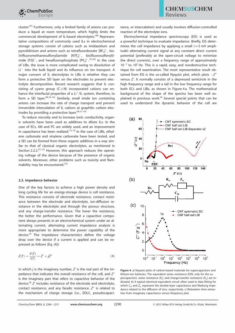
Electrochemical impedance spectroscopy (EIS) is used asa powerful technique to evaluate impedance. Briefly, EIS deter-mines the cell impedance by applying a small (�5 mV ampli-tude) alternating current signal at any constant direct current
potential (preferably at the open-circuit voltage to minimizethe direct currents), over a frequency range of approximately
10¢2 to 105 Hz. This is a rapid, easy, and nondestructive tech-nique for cell examination. The most representative result ob-tained from EIS is the so-called Nyquist plot, which plots ¢Z’’versus Z’. It normally consists of a depressed semicircle in thehigh frequency range and a tail in the low frequency range for
both ECs and LIBs, as shown in Figure 4 a. The mathematicalbackground of the shape of the spectra has been well ex-
plained in previous work.[4] Several special points that can be
used to understand the dynamic behavior of the cell are
Figure 4. a) Nyquist plots of carbon-based materials for supercapacitors andlithium-ion batteries. The equivalent series resistance (ESR, only for the su-percapacitor), series resistance (Rs), and charge-transfer resistance (Rct) are in-dicated. b) A typical electrical equivalent circuit often used in data fitting forwhich Cdl and Zw represent the double-layer capacitance and Warburg impe-dance related to the diffusion of ions, respectively. c) Relaxation time extrac-tion from imaginary capacitance versus frequency plot.
ChemSusChem 2015, 8, 2284 – 2311 www.chemsuschem.org Ó 2015 Wiley-VCH Verlag GmbH & Co. KGaA, Weinheim2290
Reviews

shown in Figure 4 a. The first point for which Z’’= 0 comesfrom the series resistance (Rs) of the cell, which includes the re-
sistance of the current collector, electrode, electrolyte, separa-tor, and any contact resistance. The diameter of the semicircle
indicates the emergence of a faradic reaction, which comesfrom the charge-transfer resistance (Rct) at the interface be-tween the electrode and electrolyte or the porous structure ofthe electrode materials.[6] The tail that shows almost linear be-havior implies a diffusion-controlled process of ions into the
bulk material.In general, a smaller Rct and a steeper slope of the tail can
be observed in aqueous electrolyte based ECs relative to thatobserved for organic electrolyte based LIBs, as can be seen in
Figure 4 a. In the case of CNT-based symmetric ECs with a KOHelectrolyte (Figure 4 a, &), the smaller Rct and the almost vertical
line indicate a small charge-transfer resistance at the elec-
trode/electrolyte interface and EDLC behavior with fast ion dif-fusion in the electrolyte, respectively. On the contrary, a CNF-
based half-cell LIB with a LiPF6/EC/DMC electrolyte (Figure 4 a,*) displays a larger Rct and a smaller slope, which represent
faradic behavior with a slow rate of Li+ ion diffusion. Notably,the value of Z’ at the second point of Z’’= 0 is also known as
equivalent series resistance (ESR) in the case of ECs if the kinet-
ic-controlled process is dominant (i.e. , if the slope of the tail isnear 908).
The interpretation of the Nyquist plot normally relies on theconstruction of a suitable electrical equivalent circuit (EEC) to
represent the electrochemical system and quantitative deter-mination of the relevant electrical parameters. The most com-
monly used EEC model is based on Randles circuit, as shown
in Figure 4 b. Nevertheless, in most cases, the Nyquist plotcannot be simulated unambiguously by a single model, which
complicates the data interpretation process. Other useful infor-mation that can be extracted from EIS is the imaginary capaci-
tance (C’’) versus frequency plot. This imaginary part of capaci-tance is calculated from Equation (5):
C 00 ¼ Z 0
w Zj j2 ð5Þ
Here, C = C’¢jC’’; C is the total effective capacitance, C’ is thereal part component of C, and w is the angular frequency. C’’reaches a maximum at a frequency f0, which yields a relaxationtime of t= 1/f0 = 2p/w. The relaxation time, also called the RCtime constant, is a measure of the time that is required to dis-
charge 50 % of the total energy stored in the device.[56] Thisvalue is closely related to ion diffusion, as the time for electron
transport in the electrode is rapid and negligible relative tothat for ion transport in the device. A small value of t implies
that the device can show high power (or rate capability). Fig-
ure 4 c displays typical examples of a C’’ versus frequency plot.The CNT-based symmetric EC exhibits a relaxation time of 1 s
(Figure 4 c, &), which corresponds to a typically high responsefor EDLC. In contrast, the CNF-based half-cell LIB exhibits an
extremely long relaxation time (Figure 4 c, *), which is beyondthe frequency range of approximately 10¢2 to 105 Hz. In gener-
al, smaller values of Rs and Rct, a steeper slope of the tail, anda shorter relaxation time are preferred for fast ion diffusion
and, therefore, high power capability of the device. Below,some important factors that affect these parameters will be in-
troduced.
2.3.1. Cell conductivity
The value of Rs is very sensitive to the contact resistance of allthe components in the cell, such as the electrolyte and separa-tor, and also to the conductivity of the active materials. For theelectrolyte, an aqueous electrolyte containing relatively smallions and good ion conductivity is widely used in ECs and aque-ous batteries to reduce the resistance and to improve the
power density. A simple comparison was done to illustrate theeffect of the cell components on Rs by using the same CNF
anodes and the identical LiPF6/EC/DMC electrolyte. The onlydifference between these two half cells was that one of the
cells consisted of a two-layer separator. The cell with the one-layer separator (Figure 4 a, *) shows a smaller Rs than the one
with the bilayer separators (Figure 4 a, *).
Among the characteristics of the different materials, theelectrical conductivity of the specific materials is one of the
most important factors in connection with the impedance and,therefore, the rate performance of the device. Improving the
conductivity of the active material can reduce Rs. In the case ofcarbon materials, the electrical conductivity is significantly af-
fected by two primary factors : intrinsic material structure andfunctionality.[57] Crystalline sp2 carbon atoms (e.g. , CNTs and
graphene) generally have higher electrical conductivity than
amorphous carbons (e.g. , ACs and CNFs). The higher surfacearea of carbon materials leads to poor conductivity.[56, 58]
Oxygen functional groups often decrease electrical conductivi-ty because they create sp3 hybridization and inhibit electron
transport between the intrinsic crystal structures of the carbonmaterials.[57] Heat treatment at high temperature is necessary
to reduce the functional groups or to increase the graphitic
portion of the carbons, which thus improves electrical conduc-tivity.[58, 59] Most of the active materials for pseudocapacitance
(metal oxides/hydroxides, conducting polymers) display low in-trinsic electrical conductivity. Therefore, adding highly conduc-
tive carbons into these materials provides a way to reduce Rs
of the electrodes. This will be further discussed in Section 2.3.2.
2.3.2. Electrode/electrolyte interface
As previously mentioned, Rct mostly occurs at the interface ofthe electrode and electrolyte. In the case of ECs, surface func-
tionalities can enhance the wettability of carbonaceous elec-trodes, but they reduce electrical conductivity. This results in
an improvement in electrolyte accessibility, which leads to
a smaller value of Rct and efficient charge storage through theinterface.[9, 60–63]
In the case of LIBs, the situation of the electrode/electrolyteinterface is more complicated owing to the formation of the
SEI layer. Actually, the formation of the SEI layer can sometimesbe observed through EIS (Figure 5). The common understand-
ChemSusChem 2015, 8, 2284 – 2311 www.chemsuschem.org Ó 2015 Wiley-VCH Verlag GmbH & Co. KGaA, Weinheim2291
Reviews

ing is that the small semicircle at higher frequencies is attribut-
ed to the presence of the SEI layer and the larger semicircle atlower frequencies is associated with Rct. However, the first sem-
icircle is usually neglected if it is too small to be recognized,especially if the cell is newly fabricated.[64] Theoretically, the SEI
layer in LIBs is supposed to be ionically conductive and shouldremain stable after the first few cycles. However, an SEI layer
can continuously form at the freshly exposed surface of elec-
trode materials that exhibit large volume expansion, for exam-ple, the Si electrode. As a result, Li-ion consumption from the
electrolyte is more severe than that of carbon-based materials.Moreover, for an aged LIB, there is a possibility that
the SEI layer will be weakened by a secondary reac-tion with HF and the formation of transition-metal
clusters in the long run, which not only deteriorate
the stability of the electrode/electrolyte interface butalso trigger Li plating and severe safety problems.[65]
Thus, a stable SEI layer that can prevent further elec-trolyte decomposition and protect the anode materi-
al from structural degradation induced by co-interca-lation of the solvent is one of the key factors to
reach satisfactory performance in LIBs.
2.3.3. Ion diffusion
As mentioned above, the slope of the tail in the Ny-
quist plot can be different depending on the diffu-sion-controlled reaction, which is mainly affected bythe size of the electrolyte ions and the porosity of
the electrode. During the charge/discharge process,electrolyte ions diffuse into or away from the elec-
trode surface. This process induces a limitation onion transport in the energy-storage device. Therefore, design-ing electrode materials with reasonable surface areas and po-rosities is very important to improve the ion-diffusion process,especially in the case of ECs. Owing to the small size of the Li
ion, porosity engineering in LIBs is not as important as in ECs.Thus, the following content will focus on the influence of theporosity for ECs. Porous carbon electrodes generally comprisethree types of pores: micropores (diameter<2 nm), mesopores(diameter = 2–50 nm), and macropores (diameter>50 nm).[4]
Micropores display a high surface area to volume ratio and
contribute to the BET surface area the most. Micropores withdiameters of 0.7–1 nm provide the best capacitive per-formance.[66, 67] However, structures containing only microporesare not desirable, because they restrict ion diffusion deep into
the bulk active materials. Moreover, mesopores also contributeto the surface area and provide a pathway for the ions to
access the internal micropores. Macropores have a negligiblecontribution to the surface area, but they can act as transport
avenues to the interior of the carbon network.[68]
An appropriate pore-size distribution is necessary to ensurea high accessible surface area and rapid ion diffusion thus toenhance both the energy and power density of carbon materi-al based ECs. Ion diffusion is significantly improved if meso-
pores are dominant in the porous electrodes.[56] Microporouscarbons exhibit high capacitance at low scan rates, whereas
mesoporous carbons possess good capacitive performance at
high rate measurement. Recently, our group demonstratedthat vertically aligned MWCNTs (v-MWCNTs) outperform ran-
domly entangled SWCNTs (re-SWCNT) in terms of rate capabili-ty.[56] The v-MWCNTs are mainly mesoporous in structure,
whereas a major contribution of the surface area of re-SWCNTscomes from micropores. The micro-supercapacitor-based on v-
MWCNTs yields a relaxation time of 0.76 ms in aqueous Li2SO4
electrolyte and 2.23 ms in organic LiPF6 electrolyte. This ismuch smaller than the relaxation times of 17.7 and 35.96 ms
for the re-SWCNT-based device (Figure 6).
2.4. Effect of mass loading/thickness
Notably, the mass loading and thickness of an electrode mate-rial usually affect the performance of energy-storage cells. For
example, a small mass loading and a small thickness of theactive material are preferred if investigating intrinsic chargestorage. Nevertheless, the overall gravimetric energy and
power density may be overestimated.[69] A large mass loadingof the active materials in the electrodes is necessary to obtain
high energy density in practice, but this increases the total dif-fusion length, which sometimes leads to poor energy and
Figure 5. Schematic representation of a Nyquist plot containing SEI-relatedsemicircles.
Figure 6. Comparative complex capacitance plots for 10 mm long v-MWCNTs and1.2 mm thick re-SWCNTs in a) Li2SO4 and b) LiPF6. c) Schematic of ion diffusion throughv-MWCNT- and re-SWCNT-based microdevices. Reprinted with permission from Ref. [56] .Copyright 2013, Macmillan Publishers, Ltd.
ChemSusChem 2015, 8, 2284 – 2311 www.chemsuschem.org Ó 2015 Wiley-VCH Verlag GmbH & Co. KGaA, Weinheim2292
Reviews

power density.[56] Therefore, it is necessary to indicate the load-ing amount or film thickness with mass density to compare
the storage gravimetric energy and power performance pre-cisely. Figure 7 indicates the effect of mass loading on superca-
pacitor performance. The data are reproduced from Li and co-
workers.[70] Two different electrodes based on chemically con-
verted graphene (CCG) were employed. The H2SO4-mediatedCCG (CCG/H2SO4) film with a mass density of 1.33 g cm¢3 was
prepared by capillary pressure of the CCG hydrogel filmthrough controlled removal of a H2SO4 solution trapped in the
gel. The dried CCG film (mass density of 1.49 g cm¢3) was fabri-
cated directly by vaporizing water under vacuum inside theCCG hydrogel film without exchanging any miscible solutions.
The supercapacitors were assem-bled by using 1.0 m H2SO4 elec-
trolyte and were tested at cur-rent densities of 0.1 and 1 A g¢1.It is clear that the capacitance
decreases as the mass loading ofthe active materials increaseswith identical electrode materialsand electrolytes used in the cell.
This is evidence of ion-diffusionlimitations at large material load-
ings. A similar phenomenon was
also noticed in the case of LIBswith thicker films.[71] Besides, it is
necessary to specify the currentdensity or scan rate applied
during the measurements toprovide reasonable comparison
between different devices. This
is because larger amount ofcharges can be stored with
smaller current densities owingto a longer time for more reac-
tions to occur.[69] As seen inFigure 7, both CCG/H2SO4 and
dried CCG films exhibit higher capacitances at a low currentdensity of 0.1 A g¢1 than at a high current density of 1 A g¢1.
3. Carbon-Based Materials as Anodes in LIBs
3.1. Graphite as an anode in LIBs
Graphite, as a highly crystalline graphitic carbon, is a well-de-
fined layered structure and is the most common anode in LIBs.The stacking order of graphene layers in graphite consists ofAB (hexagonal graphite) and ABC (rhombohedra graphite).Two major changes in graphite occur from a structural point ofview upon intercalation of Li ions into graphite layers: one, the
stacking order of the graphene layers shifts to AA stacking;two, the interlayer distance between the graphene layers in-
creases slightly (�10.3 %) as a result of lithium intercalation, asshown in Figure 8 a, b. The maximum lithium content in graph-ite is one Li guest atom per six carbon host atoms (i.e. , LiC6) at
ambient pressure according to the following equation[Eq. (6)]:[72]
6 Cþ x Liþ þ x e¢ ! Lix C6 ð5Þ
in which x = 1 in LixC6. In LiC6, the Li ions avoid occupation of
the nearest neighbor sites owing to Columbic repulsive forces,which yields a maximum Li-storage capacity of 372 mAh g¢1, as
indicated in the bottom panel of Figure 8 b. It is known thatthe Li intercalation reaction occurs only at the edge plane of
graphite. Through the basal plane, intercalation is possible
only at defect sites. The diffusion pathway of Li ions will be fur-ther discussed below.[73–77]
Figure 7. Capacitance dependence on loading mass of active electrode ma-terials. Reproduced with permission from Ref. [70]. Copyright 2013, Ameri-can Association for the Advancement of Science.
Figure 8. a) Schematic illustration of graphite with AB stacking order; the layer distance (�0.34 nm) is indicated.b) Stacking order of graphene layers shifts to AA stacking after Li intercalation with an increased interlayer dis-tance (�0.37 nm). Li ions occupy the nearest neighbor sites, as shown in the bottom panel. c) Charge/dischargeprofile of graphite carbon. Reproduced with permission from Ref. [14] . Copyright 1998, Wiley-VCH. d) Stage forma-tion phenomenon corresponding to c); the stage indices are indicated.
ChemSusChem 2015, 8, 2284 – 2311 www.chemsuschem.org Ó 2015 Wiley-VCH Verlag GmbH & Co. KGaA, Weinheim2293
Reviews
An important feature of Li intercalation into graphite is“stage formation” (Figure 8 c). Stage formation implies stepwise
formation of a periodic pattern of unoccupied graphitic layergaps at a low concentration of Li.[14, 78–83] This stepwise process
can be described by the stage index, s (s = I, II, III, IV), which isequal to the number of graphene layers between two nearest
guest layers (Figure 8 d). Note that stage IV is not indicated inthe figure, because the Li concentration is too low in the gra-
phene layers. It is also known as a dilute stage if s> IV.[79, 81, 82]
Stage formation can be easily observed in a charge/dischargeprofile in the form of a plateau by constant current measure-ments for a graphite anode. The plateaus indicate the coexis-tence of two phases. The formation of stages II, IIL (a transitionstage between stage II and stage III), III, and IV were identifiedfrom experimental electrochemical curves[80, 81] and were con-
firmed by X-ray diffraction and Raman spectroscopy.[79, 83–85]
Two factors determine the formation of stages during Li inter-calation into graphite: one, the energy required to expand the
van der Waals gap between two graphene layers; two, the re-pulsive interactions between the guest species. Therefore,
compared to a random distribution of Li in the graphitic layersduring the charge process, Li ions prefer first to occupy van
der Waals gaps with a high Li ion density to reach an energeti-
cally stable state.[14]
Ideally, Li+ intercalation into graphite should be fully reversi-
ble, and the Li-storage capacity should not exceed372 mAh g¢1 according to the LiC6 configuration. However, the
charge accumulated in the first cycle is usually larger than themaximum theoretical specific capacity. Relative to the first
charge, the first discharge capacity is much smaller. The excess
amount of charge generated in the first cycle, which cannotbe recovered, can be ascribed to the formation of a SEI layer.
Decomposition of the electrolyte usually takes place at lessthan 1 V versus Li/Li+ and appears as the first plateau in the
charge curve (Figure 8 c).[14, 75, 80, 83] Because of the irreversibleconsumption of lithium and the electrolyte, a correspondingcharge loss exists, so-called “irreversible specific charge” (Fig-
ure 8 c). Reversible lithium intercalation is called “reversiblespecific charge”.
3.2. Nanocarbons as anodes in LIBs
The limited capacity of graphite has hindered the further de-velopment of battery technology. Researchers have beenstruggling for a long time to develop new materials and new
structures to meet the ever-growing demands of the market.The emergence of nanoscience and nanotechnology, which led
to a revolution in basic materials science and engineering, pro-vided new opportunities to improve the performance of anodematerials. Nanocarbon materials enable electrode reactions to
occur that cannot take place for materials composed of micro-meter-sized particles. The diffusion time constant (t) for Li ions
is given by Equation (7):
t ¼ L2
Dð7Þ
in which L is the diffusion length and D is the diffusion con-stant.[76]
The reduced dimensions significantly increase the rate oflithium insertion/removal and electron transport because of
the short distances for Li-ion transport within the particles.[86]
High surface area permits a high contact area with the electro-lyte and, hence, high Li-ion flux across the interface. The strainassociated with intercalation is expected to be better accom-modated in nanosized carbons. Owing to the advantages men-
tioned above, nanocarbon materials have been extensively in-vestigated as anodes for LIBs. The discovery of nanoscale
carbon materials includes CNTs, CNFs, and graphene, whichhad a profound impact on the development of clean energystorage and conversion systems. Low-dimensional carbons ex-hibit novel properties that are often superior to those of their
bulk carbon counterparts, and this is associated with de-creased size, unique shape, and defects. Therefore, the mecha-nism of Li storage and anodic behavior could be very differentfrom bulk graphite. Compared to the charge/discharge curveof graphite, the phenomenon of stage formation cannot be
observed. The special feature of nanocarbon anode materials isthat they exhibit a larger voltage hysteresis between the
charge and discharge processes than graphite, which resem-
bles hard carbon materials.[14, 86, 87] Table 1 summarizes theanode performance with respect to the highlighted electrode
materials published in the literature.
3.2.1. Carbon nanotubes as anode materials
As an allotrope of graphite, CNTs are good candidates for lithi-
um batteries because of their unique structure (1 D cylindricaltubule of a graphite sheet), high conductivity [106 S m¢1 at
300 K for single-walled CNTs (SWCNTs) and >105 S m¢1 forMWCNTs], low density, high rigidity (Young’s modulus of the
order of 1 TPa), and high tensile strength (up to 60 GPa).[88] All
of these unique properties make them attractive candidatesfor the anodes of LIBs. Many theoretical studies related to the
storage mechanisms of lithium ions in CNTs have been done inthe past few years by using different calculation methods.[89–96]
The main conclusions can be briefly summarized as follows:One, Li ions can be stored both outside the tube and inside
the tube. The outer surface is more energetically favorable.Upon increasing the diameter of the tube, the adsorption ener-
gies of both the external and internal sites change.[89, 92] Two, Lidiffusion through the sidewall of CNTs is forbidden, but Li ionscan enter tubes through topological defects containing at
least nine-membered rings or through the ends of open-endednanotubes.[90, 92, 94, 97] Three, Li ions can intercalate at the intersti-
tial spaces between nanotubes.[92, 95, 96]
Experimentally, the capacity of raw CNTs varies significantly
depending on their structures and morphologies. In general,
SWCNTs display a capacity range from 300 to 600 mAh g¢1 andMWCNTs exhibit a capacity range of approximately 450 to
600 mAh g¢1. Kawasaki et al. have reported that the reversibleLi-ion storage capacity of metallic SWCNTs is five times higher
than that of semiconducting SWCNTs. They attribute the originof the capacity difference to the difference in the Li-ion ad-
ChemSusChem 2015, 8, 2284 – 2311 www.chemsuschem.org Ó 2015 Wiley-VCH Verlag GmbH & Co. KGaA, Weinheim2294
Reviews
sorption potential.[93] Jaber-Ansari et al. have observed a similar
phenomenon. Furthermore, they have noticed that metallicSWCNTs display higher capacity only if they are not bundled.
On the contrary, for bundled SWCNTs, the capacity of semicon-ducting SWCNTs can reach a level comparable to that of metal-
lic SWCNTs.[91] Studies suggest that aligned CNTs can allowbetter contact with the current collector and increase ion diffu-
sivity to significantly improve the bulk electron-transport prop-
erties, which thereby allows improved rate capabilities.[98–100]
Furthermore, CNTs with shorter lengths, which can be pro-
duced under proper growth conditions, by ball milling or bysolid-state cutting [NiO or FeS etching during chemical vapor
deposition (CVD) growth] , have been reported to displaybetter performance.[101–106] This is because Li diffusion and in-tercalation/de-intercalation are limited through longer CNTs.
Opening the cap of CNTs or creating defective sites on theside walls through gas/liquid phase chemical etching or ballmilling can further improve the capacity.[104–110] A comprehen-sive Review regarding the influence of the morphology of
CNTs on anode performance can be found in Ref. [106]In addition to the morphology engineering of CNTs, doping
CNTs with heteroatoms has been demonstrated to be an effec-tive way to improve the electrochemical performance of CNTanodes. Among different heteroatoms, N and B, the atomic
sizes of which are close to that of carbon, are the preferredcandidates.[111, 112] Most reports regarding doping of CNTs are
based on N doping. It is well known that N contains five va-lence electrons for bonding with carbon atoms. Owing to the
higher electronegativity of N, it will withdraw electrons from C
atoms and, therefore, change the electronic properties of CNTs.Both theoretical studies and experimental work demonstrate
that N doping can increase the conductivity and reactivity ofCNTs.[111–115] Thus, the diffusion and storage mechanism of Li in
CNTs may vary.[111, 112] It has been reported that graphitic N andpyridinic N can play a role in improving capacity.[115, 116] Recent
work has shown that N-doped CNT electrodes normally display
higher reversible capacity and rate capability than raw CNTanodes.[111, 115, 117–119] The improved performance can be attribut-
ed to structural defects that enhance Li-ion absorption and iondiffusion. To be more specific, it is suggested that the N-
doping process generates a disordered carbon structure withextrinsic defects, and this enhances the Li-intercalation proper-
ties. Moreover, N doping can improve reactivity and electrical
conductivity, which leads to increased active sites to absorb Liions, and this can enhance capacity. N-Doped CNTs exhibiting
better electrolyte wettability and a larger interlayer distancebetween the tube layers can also be effective factors to im-
prove electrochemical storage performance.[118, 120]
Storage mechanisms in CNTs as described above are nowwell accepted. Nevertheless, there are still several issues that
need to be addressed before CNTs can be considered as anelectrode material for industrial use. Precise control of theirstructural morphologies such as the number of walls, diameter,length, and metallicity is required to improve reproducibility of
the data. Furthermore, electrode fabrication processes such aspurification, stable dispersion, and post-treatment should also
be refined. Furthermore, the high irreversible capacity, limited
lithium-storage capacity, and large hysteresis of the voltagewindow of CNTs still hinder their use as replacements for
graphite-based anodes. It might be desirable to combine CNTswith other non-carbon materials, and this will be described in
Section 3.2.4.
3.2.2. Carbon nanofibers as anode materials
As a very similar carbon family member to CNTs, CNFs can be
prepared mainly through two methods. One is catalytic CVD,and the other is electrospinning followed by annealing.[121]
Compared to CNFs prepared by the CVD method, CNFs pro-duced by electrospinning display noticeable advantages in
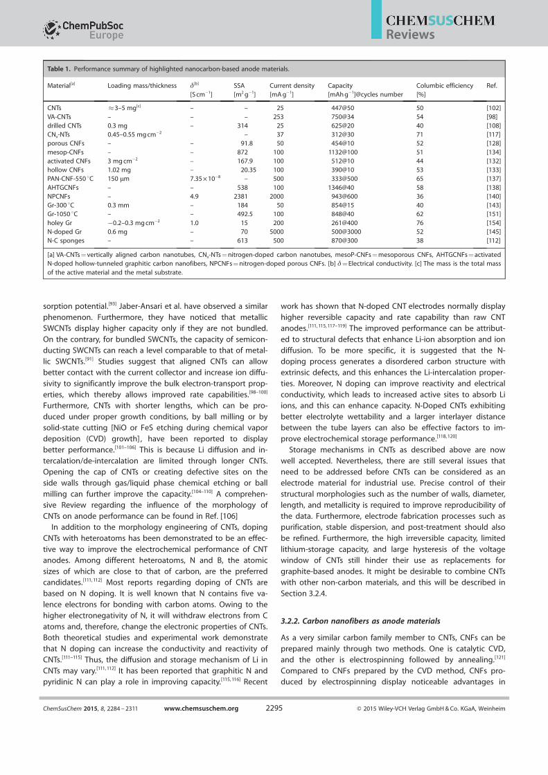
Table 1. Performance summary of highlighted nanocarbon-based anode materials.
Material[a] Loading mass/thickness d[b]
[S cm¢1]SSA[m2 g¢1]
Current density[mA g¢1]
Capacity[mAh g¢1]@cycles number
Columbic efficiency[%]
Ref.
CNTs �3–5 mg[c] – – 25 447@50 50 [102]VA-CNTs – – – 253 750@34 54 [98]drilled CNTs 0.3 mg – 314 25 625@20 40 [108]CNx-NTs 0.45–0.55 mg cm¢2 – 37 312@30 71 [117]porous CNFs – – 91.8 50 454@10 52 [128]mesop-CNFs – – 872 100 1132@100 51 [134]activated CNFs 3 mg cm¢2 – 167.9 100 512@10 44 [132]hollow CNFs 1.02 mg – 20.35 100 390@10 53 [133]PAN-CNF-550 8C 150 mm 7.35 Õ 10¢8 – 500 333@500 65 [137]AHTGCNFs – – 538 100 1346@40 58 [138]NPCNFs – 4.9 2381 2000 943@600 36 [140]Gr-300 8C 0.3 mm – 184 50 854@15 40 [143]Gr-1050 8C – – 492.5 100 848@40 62 [151]holey Gr ¢0.2–0.3 mg cm¢2 1.0 15 200 261@400 76 [154]N-doped Gr 0.6 mg – 70 5000 500@3000 52 [145]N-C sponges – – 613 500 870@300 38 [112]
[a] VA-CNTs = vertically aligned carbon nanotubes, CNx-NTs = nitrogen-doped carbon nanotubes, mesoP-CNFs = mesoporous CNFs, AHTGCNFs = activatedN-doped hollow-tunneled graphitic carbon nanofibers, NPCNFs = nitrogen-doped porous CNFs. [b] d = Electrical conductivity. [c] The mass is the total massof the active material and the metal substrate.
ChemSusChem 2015, 8, 2284 – 2311 www.chemsuschem.org Ó 2015 Wiley-VCH Verlag GmbH & Co. KGaA, Weinheim2295
Reviews
that the films are free-standing in nature, they are easy to fab-ricate, and are low costing. Compared to CNTs and graphene,
CNFs as anodes in LIBs have been less reviewed. Therefore, wewill review CNFs in more detail in this part. A polyacrylonitrile
[PAN, (C3H3N)n]-derived CNF web (PAN-CNF) has been used asan anode material.[122] The PAN-CNF web shows a reversibledischarge capacity (450 mAh g¢1) after annealing at 1000 8Cthat is slightly higher than that shown by graphite at a currentdensity of 30 mA g¢1. However, the coulombic efficiency israther low owing to the high irreversible capacity(500 mAh g¢1) induced by the formation of a SEI.
To increase the surface area and to facilitate Li-ion diffusion,porous CNFs were brought into focus.[123–126] Ji and Zhang have
fabricated a two-component nanofiber PAN/poly-l-acetic acid(PLLA) through electrospinning.[127] After postannealing, PLLA
is eliminated during the carbonization of PAN, and therefore,
porous CNFs are generated. According to EIS measurements,this type of porous CNF exhibits much faster charge transfer at
the electrode–electrolyte interface and also more efficient lithi-um-ion diffusion than nonporous CNFs. The discharge capacity
is approximately 435 mAh g¢1 after 50 cycles at a current densi-ty of 50 mA g¢1, which is better than that of nonporous CNFs.
Nevertheless, the columbic efficiency is still low in the first
cycle. The authors have also fabricated porous CNFs by usingSiO2 as a pore generator and in situ CNF activation with
ZnCl2.[128, 129] Porosity can also be created by KOH treatment onelectrospun CNFs.[130–132] Hollow CNFs fabricated by the coaxial
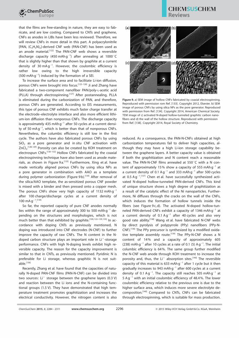
electrospinning technique have also been used as anode mate-rials, as shown in Figure 9 a.[133] Furthermore, Xing et al. have
made vertically aligned porous CNFs by using silica NPs as
a pore generator in combination with AAO as a templateduring polymer carbonization (Figure 9 b).[134] After removal of
the silica/AAO template, the as-sensitized porous CNF powderis mixed with a binder and then pressed onto a copper mesh.
The porous CNFs show very high capacity of 1132 mAh g¢1
after 100 charge/discharge cycles at a current density of
100 mA g¢1.[134]
So far, the reported capacity of pure CNF anodes normallylies within the range of approximately 300 to 500 mAh g¢1 de-
pending on the structures and morphologies, which is notmuch better than that exhibited by graphite.[109, 122–129, 135] In ac-cordance with doping CNTs as previously mentioned, Ndoping was introduced into CNF electrodes (N-CNF) to further
improve the capacity of raw CNFs. The N content in the N-doped carbon structure plays an important role in Li+-storageperformance. CNFs with high N-doping levels exhibit high re-
versible capacity. The reason for the capacity improvement issimilar to that in CNTs, as previously mentioned. Pyridinic N is
preferable for Li storage, whereas graphitic N is not suit-able.[136]
Recently, Zhang et al. have found that the capacities of natu-
rally N-doped PAN-CNF films (PAN-N-CNF) can be divided intotwo sources: Li+ storage between the graphene layers (0.3 V)
and reaction between the Li ions and the N-containing func-tional groups (1.5 V). They have demonstrated that high tem-
perature treatment promotes graphitization and increases theelectrical conductivity. However, the nitrogen content is also
reduced. As a consequence, the PAN-N-CNFs obtained at highcarbonization temperatures fail to deliver high capacities, al-
though they may have a high Li-ion storage capability be-tween the graphene layers. A better capacity value is obtained
if both the graphitization and N content reach a reasonablevalue. The PAN-N-CNF films annealed at 550 8C with a N con-
tent of approximately 15 % show a capacity of 555 mAh g¢1 at
a current density of 0.1 A g¢1 and 333 mAh g¢1 after 500 cyclesat 0.5 A g¢1.[137] Chen et al. have successfully synthesized acti-
vated N-doped hollow-tunneled PAN-derived CNFs. This kindof unique structure shows a high degree of graphitization as
a result of the catalytic effect of the Ni nanoparticles. Further-more, Ni diffuses through the cracks on the wall of the CNFs,
which induces the formation of hollow tunnels inside the
fibers (see Figure 9 c, d). The activated N-doped hollow-tun-neled PAN-derived CNFs exhibit a capacity of 1346 mAh g¢1 at
a current density of 0.1 A g¢1 after 40 cycles and also verygood rate ability.[138] Wang et al. have fabricated N-CNF websby direct pyrolysis of polypyrrole (PPy) nanofibers (PPy-N-CNF).[136] The PPy precursor is synthesized by a modified oxida-
tive template assembly route.[139] The PPy-N-CNF shows a Ncontent of 14 % and a capacity of approximately 605(238) mAh g¢1 after 10 cycles at a rate of 0.1 (5) A g¢1. The initial
columbic efficiency is 64 %. The same group further modifiedthe N-CNF web anode through KOH treatment to increase the
porosity and, thus, the Li+ absorption sites.[140] The reversiblecapacity of this material is 633 mAh g¢1 after 1 cycle but it then
gradually increases to 943 mAh g¢1 after 600 cycles at a current
density of 0.1 A g¢1. The capacity still reaches 505 mAh g¢1 at5 A g¢1 with an initial coulombic efficiency of 48.4 %. The lower
coulombic efficiency relative to the previous one is due to thehigher surface area, which induces more severe electrolyte de-
composition.[140] Compared to CNTs, CNFs can be fabricatedthrough electrospinning, which is suitable for mass production.
Figure 9. a) SEM image of hollow CNFs fabricated by coaxial electrospinning.Reproduced with permission rom Ref. [133] . Copyright 2012, Elsevier. b) SEMimage of porous CNFs by using silica NPs as the pore generator. Reproducedwith permission from Ref. [134] . Copyright 2014, American Chemical Society.TEM image of c) activated N-doped hollow-tunneled graphitic carbon nano-fibers and d) the wall of the hollow structure. Reproduced with permissionfrom Ref. [138] . Copyright 2014, Royal Society of Chemistry.
ChemSusChem 2015, 8, 2284 – 2311 www.chemsuschem.org Ó 2015 Wiley-VCH Verlag GmbH & Co. KGaA, Weinheim2296
Reviews
In addition, CNFs also benefit from their cheap price. However,drawbacks such as high irreversible capacity, short cycle life,
and lack of improvement in capacity are still challengingissues. Therefore, further extensive studies need to be done so
that CNFs can outperform the graphite anode.
3.2.3. Graphene as an anode material
Graphene composed of sp2 carbon atoms bonded into a 2 Dsheet with the thickness of a single atom emerged and attract-ed broad attention in the field of energy storage. The goodconductivity, high mechanical strength, high carrier mobility,and high surface area of graphene have made it an attractiveelectrode material for the anode of LIBs.[86, 141] The reported ca-
pacity of graphene anodes can easily reach over 1000 mAh g¢1,which is almost three times higher than that of graphite
anodes.[141–146] The superb storage capacity is attributed to theunique interaction between the Li ions and the graphene
layers besides the mechanisms of intercalation and Li adsorp-tion in cavities or interstitial spaces, as mentioned above for
CNTs.[86, 92, 95, 96, 141, 144] It is assumed that Li ions can be
absorbed on both sides of graphene by forminga Li2C6 stoichiometry[147] or that they can be trapped
at the benzene ring to form a covalent bond be-tween two Li atoms to yield a LiC2 configuration.[148]
To achieve high capacity and good rate capability,carefully engineered layer spacings between the reas-
sembled graphene nanosheets, the defective sites, or
nanopores on the graphene plane for Li diffusionneed to be considered. Experimentally, pure gra-
phene sheets reduced by different methods havebeen reported,[143, 149–151] and a capacity in the range
of approximately 500 to 200 mAh g¢1 can be ach-ieved.[143, 149–151] CNTs and C60 have been introduced to
expand the layer distance in graphene.[152] The per-
formance is improved in both cases. The anode ca-pacity of C60-incorporated graphene increases up to
784 mAh g¢1 compared to 540 mAh g¢1 for pure gra-phene sheets.[149] Furthermore, porous graphene or
holey graphene paper has also been demonstratedto achieve high capacity and high rate capability for
LIBs.[153–155] It has been suggested that grapheneedge defects and vacancies are desirable for improv-
ing the reversible capacity. Moreover, oxygen-con-taining functional groups that lead to the formationof a SEI layer are responsible for the loss of irreversi-ble capacity.[144, 146, 152, 156–160] In addition, similar toCNTs and CNFs, heteroatom doping has been widely
studied to improve the performance of grapheneanodes.[112, 120, 161–170] Besides typical N doping, B, S, and P
doping, individually or as co-dopants, has also been reported
in the case of graphene electrodes.[160, 167–169] The improved per-formance is due to multiple factors, as explained in Sec-
tion 3.2.1 for N-doped CNTs. Related reports have been exten-sively reviewed.[118, 120, 159]
Clearly, for lithium-ion storage, single-layer graphene sheetsproduced by CVD with the LiC6 configuration is not a promising
electrode material. Nevertheless, it is an attractive candidatefor fundamental study of the mechanism of Li diffusion. In thecase of graphite, one ambiguity in understanding the diffusionpathway of lithium ions is the coexistence of both an edge
plane and a basal plane in the sample. Therefore, lithium-iondiffusion through the basal plane cannot exclusively be ob-
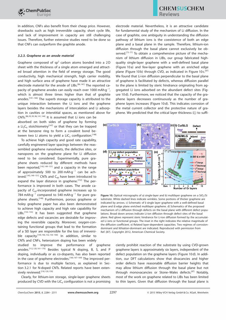
served.[73–77] To obtain a comprehensive picture of the mecha-nism of lithium diffusion in LIBs, our group fabricated high-quality single-layer graphene with a well-defined basal plane
(Figure 10 a) and few-layer graphene with an enriched edgeplane (Figure 10 b) through CVD, as indicated in Figure 10 c.[87]
We found that Li-ion diffusion perpendicular to the basal planeof graphene is facilitated by defects, whereas diffusion parallel
to the plane is limited by steric hindrance originating from ag-gregated Li ions adsorbed on the abundant defect sites (Fig-
ure 10 d). Furthermore, we noticed that the capacity of the gra-
phene layers decreases continuously as the number of gra-phene layers increases (Figure 10 d). This indicates corrosion of
the metal current collector and the protective nature of gra-phene. We predicted that the critical layer thickness (lc) to suffi-
ciently prohibit reaction of the substrate by using CVD-growngraphene layers is approximately six layers, independent of the
defect population on the graphene layers (Figure 10 d). In addi-tion, our DFT calculations show that divacancies and higherorder defects have reasonable diffusion barrier heights that
may allow lithium diffusion through the basal plane but notthrough monovacancies or Stone–Wales defects.[87] Notably,
most of the work on graphene related to LIBs has been limitedto thin layers. Given that diffusion through the basal plane is
Figure 10. Optical micrographs of a) single-layer and b) multilayer graphene on a SiO2/Sisubstrate. White dashed lines indicate wrinkles. Some portions of thicker graphene areindicated by arrows. c) Schematic of i) single layer graphene with a well-defined basalplane and ii) edge plane enriched multilayer graphene. d) Schematics of the proposedmechanism of Li diffusion through defects on the basal plane with different defect popu-lations. Broad down arrows indicate Li-ion diffusion through defect sites of the basalplane. Red glows represent steric hindrance for Li-ion diffusion formed by the accumulat-ed Li ions or functional groups. The inset in the right indicates the relative magnitude ofthe diffusion coefficient. e) Related layer-dependent capacities. Two regimes of corrosion-dominant and lithiation-dominant are indicated. Reproduced with permission fromRef. [87] . Copyright 2012, American Chemical Society.
ChemSusChem 2015, 8, 2284 – 2311 www.chemsuschem.org Ó 2015 Wiley-VCH Verlag GmbH & Co. KGaA, Weinheim2297
Reviews
not possible, special care should be taken to prevent restack-ing of the graphene layers and to maintain facile ion diffusion
without reducing the capacity and rate capability.
3.2.4. Carbon-based composites as anode materials
Although anode performance can be improved relative to that
of graphite by employing different nanocarbon materials or byengineering their structures, an improvement in the electro-
chemical storage of Li ions is still not satisfactory for applica-tions in energy technologies. Fortunately, alloy/dealloy mecha-
nism based materials (e.g. , Si, Ge, Sn, and SnO2) and conver-sion mechanism based transition-metal compounds such as
oxides, phosphides, sulfides, and nitrides (e.g. , MxNy : M = Fe,Cu, Mn, Ni, Co, Ro, Mo; N = O, P, N, S) can display higher rever-sible capacities than intercalation-based carbonaceous materi-
als.[26, 141, 171] Nevertheless, large capacity fading, poor cyclinglife induced by their relatively low conductivity, large volume
change, and unstable SEI formation hinder real applications ofthese kinds of materials.[141, 172] An efficient way to improve the
performance of anodes is to combine high-capacity materials
with carbon-based materials by forming a composite. In sucha hybrid system, the carbon-based material can provide good
conductivity and also function as a strain buffer to confinevolume changes of the host materials. This kind of composite
anode has been widely reviewed.[26, 141, 171–173] Herein, we willtake the carbon–silicon hybrid structure as a simple example
to demonstrate the idea.
Silicon as a high lithium storage capacity material (specificcapacity of 3572 mAh g¢1 at room temperature, corresponding
to Li15Si4) was recently proposed. Yet, the large volume expan-sion up to 400 % during charge/discharge causes severe struc-
tural pulverization, which makes this material impractical.[174, 175]
For example, a Si thin film deposited on a metal substrate by
chemical vapor deposition experiences the formation of cracks
during cycling, and therefore, contact loss between the activeSi material and the current collector takes place, which leads
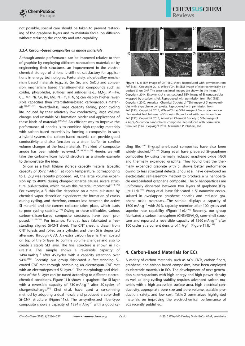
to poor cycling stability.[175] Owing to these difficulties, variouscarbon–silicon-based composite structures have been pro-posed.[71, 176–193] For instance, Fu et al. have fabricated a free-standing aligned Si-CNT sheet. The CNT sheet is drawn from
CNT forests and rolled on a cylinder, and then Si is depositedafterward through CVD. An extra carbon layer is then coated
on top of the Si layer to confine volume changes and also tocreate a stable SEI layer. The final structure is shown in Fig-ure 11 a. The sample shows a reversible capacity of
1494 mAh g¢1 after 45 cycles with a capacity retention over94 %.[183] Recently, our group fabricated a free-standing Si-
coated CNF mat through combining an electrospun CNF matwith an electrodeposited Si layer.[71] The morphology and thick-
ness of the Si layer can be tuned according to different electro-
chemical conditions. Figure 11 b shows a spaghetti-like Si layerwith a reversible capacity of 730 mAh g¢1 after 50 cycles of
charge/discharge.[71] Choi et al. have used a co-spinningmethod by adopting a dual nozzle and produced a core–shell
Si–CNF structure (Figure 11 c). The as-synthesized fiber-typecomposite shows a capacity of 1384 mAh g¢1 with a good cy-
cling life.[189] Si–graphene-based composites have also been
widely studied.[190–193] Xiang et al. have prepared Si–graphenecomposites by using thermally reduced graphene oxide (rGO)
and thermally expanded graphite. They found that the ther-mally expanded graphite with Si shows better performance
owing to less structural defects. Zhou et al. have developed an
electrostatic self-assembly method to produce a Si nanoparti-cle encapsulated graphene composite. The Si nanoparticles are
uniformally dispersed between two layers of graphene (Fig-ure 11 d).[193] Wang et al. have fabricated a Si nanowire encap-
sulated in overlapped graphene sheaths and reduced gra-phene oxide overcoats. The sample displays a capacity of1600 mAh g¢1 with 80 % capacity retention after 100 cycles and
superior rate capability (Figure 11 e).[192] Recently, our groupfabricated a carbon nanosphere (CNS)/Si/Al2O3 core–shell struc-
ture and reported a reversible capacity of 1560 mAh g¢1 after100 cycles at a current density of 1 A g¢1 (Figure 11 f).[194]
4. Carbon-Based Materials for ECs
A variety of carbon materials, such as ACs, CNTs, carbon fibers,
graphene, and carbon-based composites, have been employedas electrode materials in ECs. The development of next-genera-
tion supercapacitors with high energy and high power density
as well as long cycling stability requires advanced carbon ma-terials with a high accessible surface area, high electrical con-
ductivity, appropriate pore size and pore volume, scalable pro-duction, safety, and low cost. Table 2 summarizes highlighted
materials on improving the electrochemical performance ofECs recently published.
Figure 11. a) SEM image of CNT-Si-C sheet. Reproduced with permission romRef. [183] . Copyright 2013, Wiley-VCH. b) SEM image of electrochemically de-posited Si on CNF. The cross-sectional images are shown in the insets.[71]
Copyright 2014, Elsevier. c) A cross-sectional SEM image of Si nanoparticleswrapped by a carbon shell. Reproduced with permission from Ref. [189].Copyright 2012, American Chemical Society. d) TEM image of Si nanoparti-cles with a graphene composite. Reproduced with permission fromRef. [193] . Copyright 2012, Wiley-VCH. e) SEM image of Si–carbon nanoca-bles sandwiched between rGO sheets. Reproduced with permission fromRef. [192] . Copyright 2013, American Chemical Society. f) SEM image ofa Al2O3–Si–carbon nanospheres composite. Reproduced with permissionfrom Ref. [194]. Copyright 2014, Macmillan Publishers, Ltd.
ChemSusChem 2015, 8, 2284 – 2311 www.chemsuschem.org Ó 2015 Wiley-VCH Verlag GmbH & Co. KGaA, Weinheim2298
Reviews

4.1. Activated carbons for ECs
Activated carbons have been used as com-mercialized electrode materials for ECs be-
cause of their large SSA, relatively goodelectrical conductivity, high chemical/ther-
mal stability, and low cost. ACs are usuallysynthesized from various types of initial
carbon precursors (e.g. , coal, pitch, coco-
nut shells, bamboo, cellulose, and poly-mers) by physical and/or chemical activa-
tion.[195] In the case of physical activation,carbon precursors are carbonized under an
inert atmosphere followed by activation inthe temperature range of 600 to 1200 8C in
the presence of oxidizing gases (e.g. ,
steam, O2, and CO2).[196] Chemical activationis usually done by mixing carbonaceous
materials with activating agents (e.g. , KOH,NaOH, H3PO4, and ZnCl2) followed by heat
treatment at 400–900 8C under an inert at-mosphere.[196, 197] ACs produced by chemi-
cal activation usually have higher yields of
the products and higher SSAs than ACsproduced by physical activation.[196] Acti-
vating conditions affect the porosity andelectrochemical performance of ACs signifi-
cantly.[195, 198–200] A large content of micro-porosity (50–78 %) can be generated by
CO2 physical activation. In contrast, a rela-
tively low content (19–48 %) is achieved bysteam activation.[9] During chemical activa-
tion, a high activation temperature, a longactivation time, and a large mass ratio of
the activation agent/precursor usually leadto an increase in the SSA, pore volume,
and average pore size.[9, 63, 201–204]
Carbon precursors also play an impor-tant role. Natural precursors (e.g. , coal,pitch, petroleum coke, and biomass mate-rials) are commonly used for the commer-
cial production of ACs because of theirabundance and low cost.[195, 203, 205–215] These
ACs exhibit different SSAs in the range of1000 to 3500 m2 g¢1, which results in a spe-cific capacitance (Cs) of 150–350 F g¢1 in
aqueous electrolytes and 100–200 F g¢1 innon-aqueous electrolytes. For instance,
Peng et al. , have reported a method forthe preparation of ACs by high-tempera-
ture carbonization and KOH activation of
waste tea leaves (Figure 12 a).[208] The ob-tained ACs exhibit high SSAs ranging from
2245 to 2841 m2 g¢1. ECs made with theseACs perform the maximum Cs of 330 F g¢1
at a current density of 1 A g¢1 in aqueousKOH electrolyte. However, these naturally Ta
ble
2.Su
mm
ary
of
the
hig
hlig
hte
dca
rbo
n-b
ased
mat
eria
lsfo
rEC
s.
Elec
tro
de
mat
eria
l[a]
Mas
sd
ensi
ty[g
cm¢3
]M
ass
load
ing
/th
ickn
ess
SSA
[m2
g¢1
]d
[b]
[Scm
¢1]
Cs@
scan
rate
Elec
tro
lyte
[c] ;p
ote
nti
alw
ind
ow
Ener
gy
den
sity
@p
ow
erd
ensi
tyC
ycle
sC
R[d
]
[%]
Ref
.
tea
leaf
bas
edA
C–
8m
gcm
¢222
45–2
841
–33
0F
g¢1
@1
Ag¢1
2m
KO
H;1
V–
2000
�92
[208
]p
om
elo
-bas
edA
C–
–21
05–
43.5
Fg¢1
@0.
5A
g¢1
1m
NaN
O3;1
,7V
17.1
Wh
kg¢1
@0.
42kW
kg¢1
1100
�90
[214
]lig
nin
-der
ived
AC
–5–
8m
gcm
¢211
48–
102.
3F
g¢1
@1
mV
s¢1
6m
KO
H;0
.8V
8.34
Wh
kg¢1
@–
––
[215
]P
Py-
bas
edA
C–
300
mm
3432
–�
300
Fg¢1
@0.
1A
g¢1
EMIM
BF 4
;4.5
V–
1000
0�
108
[201
]SW
CN
T0.
7515
0m
m35
7–
180
Fg¢1
@1
mA
cm¢2
7.5
nK
OH
;0.9
V�
7W
hkg¢1
@20
kWkg¢1
––
[234
]N
A-C
NT
�0.
495–
6m
gcm
¢298
8–
98F
g¢1
@1
Ag¢1
BM
IMB
F 4/A
N;3
.5V
59W
hkg¢1
@1.
75kW
kg¢1
1000
091
[246
]SW
CN
Tfil
m–
––
–14
0F
g¢1
@20
mV
s¢1
1m
LiC
lO4/
EC/D
EC/D
MC
;3V
43.7
Wh
kg¢1
@19
7.3
kWkg¢1
––
[247
]p
ure
stSW
CN
T0.
510
0m
m13
0021
160
Fg¢1
@1
Ag¢1
1m
Et4N
BF 4
/AN
;4V
94W
hkg¢1
@21
0kW
kg¢1
1000
>96
[251
]PA
N-b
ased
CN
F–
–70
5–
100
Fg¢1
@2
mV
s¢1
1m
Et4N
BF 4
/AN
;2.3
V�
8W
hkg¢1
@�
20kW
kg¢1
––
[255
]N
-do
ped
po
rou
sC
NF
–3.
4m
gcm
¢2�
562.
5–
202
Fg¢1
@1
Ag¢1
6m
KO
H;1
V�
7.1
Wh
kg¢1
@�
0.15
kWkg¢1
3000
–[2
58]
MW
CN
T-C
MF/
/CN
F–
40m
m–
–6.
3m
Fcm
¢1@
2m
Vs¢
1g
elH
3PO
4/P
VA;1
V0.
7m
Wh
cm¢1
@13
.7m
Wcm
¢110
00�
90[2
63]
CN
T/g
rap
hen
eb
ased
CM
F�
0.6
–39
610
230
0F
cm¢3
@26
.7m
Acm
¢3g
elH
3PO
4/P
VA;0
.9V
10.4
mW
hcm
¢3@�
1.8
Wcm
¢310
000
93[2
59]
rGO
0.94
4.5
mg
cm¢2
630
�45
255
Fg¢1
@0.
5A
g¢1
6m
KO
H;1
V–
1200
93[2
82]
LSG
�0.
048
7.6
mm
1520
17.3
827
6F
g¢1
@5
Ag¢1
EMIM
BF 4
;4V
1.36
mW
hcm
¢3@�
1W
cm¢3
1000
097
[290
]a-
MEG
O�
0.4
4m
gcm
¢2�
3100
�5
166
Fg¢1
@5.
7A
g¢1
BM
IMB
F 4/A
N;3
.5V
70W
hkg¢1
@25
0kW
kg¢1
1000
097
[294
]co
mp
ress
eda-
MEG
O0.
754.
2m
gcm
¢270
7�
2.1
147
Fg¢1
@1.
2A
g¢1
BM
IMB
F 4/A
N;3
.5V
48W
hL¢
1 @�
17kW
L¢1
––
[296
]P
SS-G
O–
45m
m–
–19
0F
g¢1
@0.
1A
g¢1
TEA
BF 4
/PC
;2.7
V38
Wh
kg¢1
@61
Wkg¢1
1486
088
[310
]EM
-CC
G1.
251–
10m
gcm
¢2�
167
�25
260
Fcm
¢3@
0.1
Ag¢1
EMIM
BF 4
/AN
;3.5
V�
88W
hL¢
1 @�
75kW
L¢1
5000
�95
[70]
ac-G
r/SW
CN
T1.
061.
2m
gcm
¢265
2�
394
211
Fcm
¢3@
0.5
Ag¢1
EMIM
BF 4
;4V
117
Wh
L¢1 @
424
kWL¢
110
000
98.2
[311
]n
c-P
DD
A-G
r1.
1211
.8m
m66
3–
348
Fcm
¢3@
0.3
Acm
¢3g
elH
2SO
4/P
VA;1
V6.
7m
Wh
cm¢3
@0.
1W
cm¢3
5000
092
[312
]V
2O5-
CN
F–
–�
700
0.1
214
Fg¢1
@2
mV
s¢1
2m
KC
l;1
V45
Wh
kg¢1
@15
6W
kg¢1
1000
�80
[328
]PA
Ni-
GO
––
––
555
Fg¢1
@0.
2A
g¢1
1m
H2S
O4;1
V–
2000
92[3
43]
gra
ph
ene/
PAN
i–
––
–64
0F
g¢1
@0.
2A
g¢1
1m
H2S
O4;1
V–
1000
90[3
16]
PAN
i-rG
O/C
F–
––
–46
4F
g¢1
@0.
5A
g¢1
1m
H2S
O4;1
V–
1000
�89
[341
]
[a]
NA
-CN
T=
Nit
rog
en-d
op
edan
dac
tiva
ted
CN
T,SW
CN
H=
sin
gle
-wal
led
carb
on
nan
oh
orn
,LS
G=
lase
r-sc
rib
edg
rap
hen
e,a-
MEG
O=
acti
vate
dm
icro
wav
eex
folia
ted
GO
,P
SS=
po
lyso
diu
m4-
styr
ensu
lfon
ate,
EM-
CC
G=
elec
tro
lyte
-med
iate
dch
emic
ally
con
vert
edg
rap
hen
e,ac
-Gr/
SWC
NT
=ac
tiva
ted
gra
ph
ene/
SWC
NT,
nc-
PD
DA
-Gr=
nan
och
ann
eled
po
ly(d
ially
ldim
eth
ylam
mo
niu
mch
lori
de)
-med
iate
drG
O.
[b]
d=
Elec
tric
alco
nd
uct
ivit
y;
[c]
EMIM
BF 4
=1-
Eth
yl-3
-met
hyl
imid
azo
lium
tetr
aflu
oro
bo
rate
,B
MIM
BF 4
=1-
bu
tyl-
3-m
eth
ylim
idaz
oliu
mte
traf
luo
rob
ora
te,
Et4N
BF 4
=te
trae
thyl
amm
on
ium
tetr
aflu
oro
bo
rate
,P
VA=
po
lyvi
nyl
alco
ho
l.[d
]C
R=
Ch
arg
ere
ten
tio
n.
ChemSusChem 2015, 8, 2284 – 2311 www.chemsuschem.org Ó 2015 Wiley-VCH Verlag GmbH & Co. KGaA, Weinheim2299
Reviews

derived ACs usually suffer from several drawbacks, such as lowcarbon purity and variations in their properties. Recently, vari-
ous polymers, such as polystyrene-based resins, polyfurfuryl al-cohols, phenol formaldehyde resins, polyaniline, and polypyr-
role (PPy), have attracted much attention as carbon precursors
as a result of their commercial availability, uniform structure,and high carbon purity.[201, 202, 216–219] Wei and co-workers have
presented a novel method to synthesize ACs based on thedirect KOH activation of PPy.[201] The as-produced ACs have
a highly disordered porous carbon structure without graphiteribbons and crystalline impurities. An ultrahigh SSA up to3400 m2 g¢1 with pore sizes in the range of 0.5 to 4 nm are ob-
tained, which result in an outstanding Cs of approximately300 F g¢1 in 1-ethyl-3-methylimidazolium tetrafluoroborate
(EMIMBF4) ionic liquid at 60 8C (Figure 12 b, c). This Cs value is100–300 % higher than that of commercial carbons and other
reported carbon-based materials for ECs.The porosity of ACs is also an important factor influencing
the capacitive performance. Numerous studies have beendone to increase the SSA.[58, 201, 220–224] It is expected that witha higher SSA, more electrolyte ions can be stored at the solid
electrolyte interface. However, there is no proportionality be-tween the SSA (measured by BET) and Cs.
[4] The pore-size distri-
bution (PSD) significantly affects Cs. A broad PSD with a widerange of average pore sizes (0.7–15 nm) may lead to a linear
constant of Cs.[225] A narrow PSD with monodispersed pores
can increase Cs and the energy density.[226] The optimum poresize depends on the size of the electrolyte ions. Recently, Pohl-
mann et al. have demonstrated that the existence of a PSDand/or constrictions at the entrance of the pores leads to
significant changes in the Cs of ACs.[227] A total surfacearea with average micropore sizes above 1 nm is not accessible
to the ionic liquid N-butyl-N-methylpyrrolidiniumbis(trifluoro-methanesulfonyl)imide(PYR14TFSI).
Another important factor ofACs is surface functionalities
(e.g. , oxygen-, nitrogen-, phos-phorus-, and sulfur-containinggroups).[63, 115, 228–231] Surface func-tionalities not only enhance thewettability of the electrodes butalso give additional pseudocapa-citance. However, the presence
of some active surface oxidesand moisture in organic electro-
lytes leads to instability and
a large resistance in ACs. Theycan also decompose organic
electrolytes and ionic liquid.[68]
Therefore, surface functionalities
of ACs should be optimized toimprove the cycling life of AC-
based ECs.
Although ACs are state-of-the-art electrode materials for com-
mercial ECs, their applications are still limited owing to theirlow energy density and relatively low rate capability. The high
SSA of ACs cannot assure their high electrochemical per-formance, as control of the PSD and pore structure is still chal-
lenging. Therefore, producing ACs to achieve both a high SSA
and an optimized PSD with an interconnected pore structure,short pore length, and controlled surface chemistry is required
to improve the energy density while maintaining a high powerdensity and a high cycling stability of AC-based ECs.
4.2. Carbon nanotubes for ECs
Over the last decades, CNTs have been intensively investigatedfor EC applications because of their unique internal structure,
high electrical conductivity, mechanical strength, and chemicaland thermal stability.[3, 232, 233] CNTs are generally used for high-
power electrode materials, as their energy density is still lowbecause of the limitation of surface area (usually
>500 m2 g¢1).[59, 60, 232–234]
With the presence of mesopores coming from the centralcanal and/or tube entanglement, CNTs have excellent access to
the electrolyte.[235] Our group demonstrated that most of theBET surface area of SWCNT electrodes synthesized by direct-
current arc discharge contributes to the theoretically estimatedspecific capacitance.[234] Although the SWCNT electrode has
a reasonable surface area (357 m2 g¢1), its intrinsic capacitance
can reach 50.4 mF cm¢2, which is much higher than thatreached by ACs (<10 mF cm¢2). This increased capacitance is
due to the abundant PSD at lower pore sizes of 30–50 æ,which is estimated from BET measurements. Heat treatment at
high temperature is necessary to increase Cs and to reduce theresistance of the SWCNT electrode. The electrode performs
Figure 12. a) Schematic illustration of the production of ACs by using waste tea leaves. Reproduced with permis-sion from Ref. [208] . Copyright 2012, Elsevier. b) SEM image at 700 8C and c) nonlocal density functional theoryPSD of the PPy-derived ACs activated at three different temperatures. Reproduced with permission fromRef. [201] . Copyright 2012, Wiley-VCH.
ChemSusChem 2015, 8, 2284 – 2311 www.chemsuschem.org Ó 2015 Wiley-VCH Verlag GmbH & Co. KGaA, Weinheim2300
Reviews

with a maximum Cs of 180 F g¢1 and a measured power densityof 20 kW kg¢1 at an energy density of 7 W h kg¢1 in 7.5 n KOH
solution.Structural properties of CNTs such as diameter, length, elec-
trical resistance, surface area, and doping play important rolesin electrochemical performance.[236, 237] The capacitance ofsmaller diameter CNTs is usually higher than that of largerones, which is due to the higher specific surface area in thenetwork of smaller CNTs.[238] The low resistance of CNT electro-
des ensures the high power of ECs. To reduce the contact re-sistance, CNTs can be grown directly on current collectors suchas graphite[239] and Inconel alloy.[240] For example, Shaijumonet al. have synthesized arrays of CNTs and gold nanowire
(AuNW) multisegmented hybrid structures through a combina-tion of CVD and electrodeposition method.[241] Owing to the
well-adhered interface between the CNTs and the AuNW seg-
ment, a very low ESR of 0.48 W is achieved for the CNT/AuNWelectrode. This is much smaller than the large value of 3.4 W
for the CNT-only electrode. This results in excellent electro-chemical performance with a maximum power density of ap-
proximately 48 kW kg¢1. Increasing the SSA is a promising alter-native way to improve the Cs and the energy density of CNTs.
Several efforts directed at resolving this issue by using activa-
tion treatments (chemical and/or physical) have been report-ed.[242–245] Activation significantly enhances the SSA of the CNTs
by opening their end tips and by introducing defects, and italso creates functional groups that contribute to the additional
pseudocapacitance.[9] Recently, Yun et al. have shown thatCNTs prepared by KOH activation and subsequent nitrogen
doping possess a SSA of 988 m2 g¢1 with a hierarchical pore
structure and rough surface, which are advantageous featuresfor fast ion diffusion.[246] N doping changes the band structure
of the CNTs, which results in improved electrical properties.ECs made with these N-doped activated CNTs exhibit a high
energy density of 59 W h kg¢1 at a power density of1750 W kg¢1 in 1-butyl-3-methylimidazolium tetrafluoroborate
(BMIMBF4)/AN ionic liquid.
CNTs have found potential applications in flexible ECs.[247–249]
In these devices, CNT films act as highly conductive and flexi-
ble active materials, and they also increase the effective surfacearea in the electrodes, which maximizes the efficiency of thin-
film CNT based ECs. In addition, a direct comparison betweenaligned and entangled CNTs has been reported, and aligned
electrodes are better than entangled CNTs in terms of rate ca-pability.[56, 242, 250–252] Aligned CNTs possess relatively regular porestructures and conductive channels. This leads to a higher ef-
fective SSA, facilitates fast electron-ion transportation, and pro-vides improved charge-storage and power properties, which is
highly desirable for high-rate applications. As mentioned inSection 2.3.3, our group demonstrated that micro-supercapaci-
tors based on v-MWCNTs (aligned CNTs) show better ion diffu-
sion than devices based on re-SWCNTs (entangled CNTs, seeFigure 6).[56]
Despite excellent electrical conductivity and flexibility, CNTsstill suffer from limited SSAs, difficult purification, and high
production costs, and these are major obstacles precludingtheir practical application in high-energy performance ECs.
Hence, much effort is still required to develop cost-effectiveand high-quality CNTs.
4.3. Carbon fibers for ECs
Carbon fibers (CFs) are of great interest for EC applications, asthey are inexpensive and massively synthesized by various
methods (e.g. , electrospinning and vapor growth) with variablefiber diameters, porosities, and surface chemistries.[11, 253–257]
Similar to CNTs, CFs possess a high surface area to volumeratio, good electrical conductivity, and good flexibility. Thepore size and SSA of CFs can be controlled through physical orchemical activation.[126] Our group reported the preparation of
PAN-based CNF paper through electrospinning, followed byone-step carbonization/activation under a CO2 atmosphere attemperatures from 700 to 1000 8C.[255] ECs based on this CNF
paper exhibit high power densities (up to �20 kW kg¢1) withinsignificant degradation in energy densities (�5–8 W h kg¢1)
and outperform commercial AC-based ECs. The better per-formance can be attributed both to the high intrinsic conduc-
tivity of the CNFs and to the high diffusion rate of ions in the
opened mesopores produced by CO2 activation. Recently, ithas been demonstrated that N doping can improve electrical
conductivity and wettability and, thus, the capacitance per-formance of CFs.[257–260] For instance, Yu’s group have present-
ed a highly capacitive material based on N-doped porous CNFssynthesized by carbonization of macroscopic-scale CNFs
coated with PPy at a temperature of 900 8C.[258] The resulting
CNFs display a Cs of 202 F g¢1 at a current density of 1 A g¢1 in6 m aqueous KOH electrolyte. This kind of N-doped CNF repre-
sents a promising candidate for an efficient EC electrode mate-rial.
Owing to good electrical conductivity and mechanical prop-erties, CFs have attracted increasing attention for wearable
fiber-shaped ECs.[259, 261–265] Loading highly capacitive materials
on CFs is an efficient approach to improve the electrochemicalperformance of devices. Recently, our group reported a coaxial
fiber supercapacitor that was fabricated by using carbon mi-crofiber (CMF) bundles coated with MWCNTs as the core elec-
trode and CNF paper as the outer electrode (Figure 13).[263] Thedevice exhibits a capacitance up to 6.3 mF cm¢1 (86.8 mF cm¢2)at a core electrode diameter of 230 mm and a measuredenergy density of 0.7 mW h cm¢1 (9.8 mW h cm¢2) at a power
density of 13.7 mW cm¢1 (189.4 mW cm¢2) in H3PO4/polyvinyl al-cohol (PVA) gel electrolyte. These results are much higher thanthose reported for previous studies on wearable fiber-shaped
ECs. The device shows excellent cycling stability and negligiblechange in capacitance after 1808 of bending. The high electro-
chemical performance of the device has been attributed toa high effective surface area as a result of its coaxial configura-
tion and also to the high electrical conductivity of the all-
carbon electrode materials.Several challenges still remain to industrialize CFs as elec-
trode materials for ECs. Free-standing webs of CFs are oftenbrittle, which restricts their application to flexible and wearable
devices. The large-scale production of CFs with precise controlof fiber diameter, porosity, and distribution of the active com-
ChemSusChem 2015, 8, 2284 – 2311 www.chemsuschem.org Ó 2015 Wiley-VCH Verlag GmbH & Co. KGaA, Weinheim2301
Reviews

ponents to optimize their energy-storage capabilities is anoth-er issue.
4.4. Graphene for ECs
Graphene has a high specific surface area, high flexibility, highchemical stability, and extremely high electronic and thermal
conductivity, all of which make it attractive for potential appli-cations in ECs.[266] Up to now, numerous methods have been
employed for the large-scale synthesis of high-quality gra-
phene, including mechanical cleavage from graphite,[267] epi-taxial growth,[268, 269] CVD growth,[270, 271] solvothermal synthe-
sis,[272] and exfoliation and reduction from chemically oxidizedgraphite.[273, 274] Among them all, exfoliation and reduction from
chemically oxidized graphite are the most explored and ap-plied methods for EC applications because of their simple
processing facilities, large-scale production possibilities, andlow cost.[275] However, these methods suffer from disadvantag-
es of possessing highly oxygen-containing functional groupsand defects, which lead to low electrical conductivity of the as-derived graphene.
Many reduction methods have been reported to achievehigh-quality rGO. At the very beginning, hydrazine was used as
a chemical agent to reduce GO.[276] Cs values of 135 and99 F g¢1were obtained in aqueous and organic electrolytes, re-
spectively. Although hydrazine rGO implies exciting potential
for high-performance ECs, the high toxicity of hydrazine isa major drawback. Therefore, a variety of environmentally
friendly chemical agents (e.g. , NaBH4, hydrobromic acid, l-as-corbic acid, iron, and aluminum) have been developed.[277–281]
Recently, Lei et al. have reported a facile and green route toreduce GO by using urea.[282] The as-fabricated rGO electrodes
exhibit a gravimetric capacitance of 255 F g¢1 anda volumetric capacitance of 196 F cm¢3 at a current
density of 0.5 A g¢1.Capacitance retention of 93 %after 1200 cycles is obtained. Thus, these electrodes
outperform previous rGO electrodes prepared byusing hydrazine and NaBH4 as the reductants.
Other than chemical reduction, rGO can be pro-duced from GO by thermal annealing,[283–286] micro-
wave irradiation,[287] focused solar irradiation,[288] andelectrochemical reduction.[289] Our group presenteda physical route to fabricate highly crystalline gra-phene sheets through high-temperature annealing(1900 8C), under vacuum (1.3 Õ 10¢3 Pa), of functional
graphene sheets obtained from graphite oxide bylow temperature thermal exfoliation.[285] The obtained
graphene sheets possess no appreciable oxygen con-
tent, which results in a high electrical conductivity ofapproximately 56 500 S m¢1; this is comparable to
100 900 S m¢1 of the precursor graphite. Kaner andco-workers have reported a simple and rapid way to
reduce GO films by using a laser from a standardLightScribe DVD optical drive.[290] The produced films,
called laser-scribed graphene (LSG), are mechanically
robust, highly electrically conductive, and possessa SSA of 1520 m2 g¢1. The LSG-based ECs exhibit ul-
trahigh gravimetric Cs of 276 F g¢1 in EMIMBF4 ionic liquid andexcellent cycling stability. However, these LSG films have very
small mass density of approximately 0.048 g cm¢3, which re-sults in a low volumetric Cs of the device.
To increase the SSA of graphene-based materials, preparing
porous structures has recently attracted much attention. It hasbeen demonstrated that curved or crumpled graphene sheets
can enhance both the surface area accessible to the electrolyteand ion transport, which thus enhances the energy density
and rate performance.[18, 291–293] Chemical activation is anothereffective way to produce porous graphene.[294–297] Zhu et al.
have reported the KOH activation of microwave-exfoliated GO
powders.[294] The activated microwave exfoliated GO (a-MEGO)possesses a high SSA up to 3100 m2 g¢1, which results in
a high energy density of 70 W h kg¢1 at a maximum powerdensity of 250 kW kg¢1 in ionic liquid.
Restacking of graphene layers during the reduction processis a big challenge for graphene-based EC applications. This re-
stacking makes the graphene structure dense without retain-ing the effective surface area for ion accessibility, and thisleads to poor energy and power performance. Therefore, sev-eral efforts have been done to prevent graphene restacking byusing incorporated spacers, such as nanocarbons (e.g. , carbon
spheres, particles, and CNTs),[298–302] metal oxide/hydroxidenanoparticles,[303–305] polymers,[306–308] and water molecules.[309]
For instance, our group presented a new GO material interca-
lated by polysodium 4-styrensulfonate (PSS) for high-per-formance ECs.[306, 310] The interlayer distance of the PSS–GO is
increased by approximately 1 æ relative to that of the originalGO (Figure 14 a, b).[310] The PSS–GO electrodes exhibit a Cs of
190 F g¢1 in organic electrolyte (i.e. , TEABF4). A high energydensity of 38 W h kg¢1 at a power density of 61 W kg¢1 can be
Figure 13. Schematic illustration of the fabrication of a coaxial fiber supercapacitor.a) MWCNTs are dispersed in sodium dodecylbenzenesulfonate (NaDDBs) solution.b) MWCNTs are deposited onto planar CMFs by spray coating. c) The MWCNTs/CMFs areassembled into bundles after removing the surfactant. d, f) SEM images of a single un-coated CMF and a single CMF coated with MWCNTs. e) SEM image of a MWCNTs/CMFbundle. g) SEM image of a CNF film and its enlargement in upper right (the inset is a digi-tal photo of the bendable CNF film). h) After soaking with polymer electrolyte, the coreMWCNTs/CMF bundle was wrapped with the separator and CNF film. i) Schematic anddigital photo of a coaxial fiber supercapacitor. Reprinted with permission from Ref. [263].Copyright 2013, American Chemical Society.
ChemSusChem 2015, 8, 2284 – 2311 www.chemsuschem.org Ó 2015 Wiley-VCH Verlag GmbH & Co. KGaA, Weinheim2302
Reviews

obtained. More interestingly, Li’s group recently re-ported a simple soft approach enabling the sub-
nanometer-scale integration of graphene sheets withan electrolyte (e.g. , H2SO4 or EMIMBF4).[70] The films of
electrolyte-mediated chemically converted graphene(EM-CCG) possess a continuous ion-transport network
and controllable high mass densities (�0.13–1.33 g cm¢3, Figure 14 c, d). As a result, ECs based onthe EM-CCG film can obtain a volumetric energy den-
sity of 60 W h L¢1 in ionic liquid.Lately, our group reported the synthesis of SWCNT-
bridged graphene 3 D building blocks through theCoulombic interaction of positively charged SWCNTsgrafted by cetyltrimethylammonium bromide withnegatively charged graphene oxide sheets, followed
by KOH activation.[311] The as-obtained activated gra-
phene/SWCNT (ac-Gr/SWCNT) films possess pillaredSWCNTs intercalated into nanoporous graphene
layers, which enhances the accessible surface areaand allows fast ion diffusion (Figure 15). These ac-Gr/
SWCNT films are free standing and flexible and reveala high electrical conductivity of 39 400 S m¢1 and
a reasonable mass density of 1.06 g cm¢3. As a conse-
quence, supercapacitors based on these films exhibitsuperior performance in neat EMIMBF4 electrolyte
with a maximum energy density of 117.2 W h L¢1 or110.6 W h kg¢1 at a maximum power density of 424 kW L¢1 or
400 kW kg¢1, which is based on the thickness or mass of thetotal active material. In other work, we present the facile and
scalable fabrication of a nanochanneled poly(diallyldimethy-
lammonium chloride)-mediated rGO (nc-PDDA-Gr) film formicro-supercapacitors.[312] The as-synthesized film possesses
high packing density (1.12 g cm¢3) and efficient 2 D ion-trans-port pathways as a result of veinlike-textured nanochannels.
The micro-supercapacitor based on this nc-PDDA-Gr film givesa high volumetric energy density of 6.7 mW h cm¢3 at a volu-
metric power density of 0.1 W cm¢3, a high volumetric capaci-
tance of 348 F cm¢3, long cycling stability (92 % charge reten-tion after 50 000 cycles), and fast frequency response (33 ms).
The use of pseudocapacitive spacers (e.g. , metal oxides/hy-droxides and conducting polymers) is another interesting ap-
proach to prevent restacking of graphene.[303–308] These spacersnot only efficiently avoid agglomeration of graphene but also
contribute additional pseudocapacitance to the total Cs of theEC devices. Several N-rich polymers (e.g. , melamine, cyana-mide, and PANi)[313–316] can also be used as N-doping precursors
that enhance the electrical conductivity, wettability, and capac-itance of graphene-based electrodes. These kinds of graphene-
based composites will be discussed in Section 4.5.In spite of tremendous achievements, graphene still faces
some serious challenges for commercial EC applications such
as the production of high-quality graphene on a large scale,with low cost, and by environmentally friendly procedures.
Therefore, scalable, cost-effective, and environmentally friendlyapproaches to produce graphene without irreversible restack-
ing are in urgent demand. In addition, comprehensive studieson the relationship between the structural and physical prop-
erties of graphene and its electrochemical behavior are neces-sary.
Figure 14. a) SEM image of PSS-GO. b) XRD patterns of pristine graphite, GO, and PSS-GO. Reproduced with permission from Ref. [310] . Copyright 2009, American Chemical So-ciety. c, d) SEM images of cross sections of the obtained EM-CCG films containing 78.9and 27.2 vol % H2SO4, corresponding to packing densities of 0.42 and 1.33 g cm¢3, respec-tively. e) XRD patterns of the EM-CCG films and dried CCG film with varied packing densi-ties. Reproduced with permission from Ref. [70]. Copyright 2013, American Associationfor the Advancement of Science.
Figure 15. Schematic illustration of the fabrication of the ac-Gr/SWCNThybrid nanostructure. a) The cetyltrimethylammonium bromide (CTAB) graft-ed SWCNTs are positively charged, and the GO layers are negatively chargedbecause of their functional groups. b) Schematic of the 3 D SWCNT-bridgedgraphene block. Reprinted with permission from Ref. [311]. Copyright 2015,American Chemical Society.
ChemSusChem 2015, 8, 2284 – 2311 www.chemsuschem.org Ó 2015 Wiley-VCH Verlag GmbH & Co. KGaA, Weinheim2303
Reviews
4.5. Carbon-based composites for ECs
Although carbon structures (e.g. , ACs, CNTs, CFs, and gra-phene) possess good properties for EC applications such as
high SSA, high electrical conductivity, and high mechanicalstrength, their capacitance is still low, as most of them exhibit
EDLC behavior. Moreover, pseudocapacitive materials (e.g. ,metal oxides/hydroxides and conducting polymers) that exhib-
it high charge-storage capacity, environmental friendliness, and
low cost have attracted great interest for ECs. However, thesekinds of materials suffer from poor electrical conductivity and
mechanical degradation during faradic charge/discharge.[3]
Therefore, making composites requires a strategy to utilize the
synergistic effects of all the active materials, which will lead tohigh electrochemical performance of the composite-based ECs.
Much work has been done to prepare carbons–metal oxide/
hydroxide composites as electrodes for ECs, including AC–metal oxide/hydroxide,[317–319] CNT–metal oxide/hydrox-
ide,[320–324] CF–metal oxide/hydroxide,[325–329] graphene–metaloxide/hydroxide,[22, 330–336] and 3 D porous carbon–metal oxide/
hydroxide.[18, 337, 338] For example, our group reported an ultra-thin V2O5 layer electrodeposited on electrospun PAN-based
CNFs.[328] The 3 nm thick V2O5-deposited CNF electrode exhibits
a very high capacitance of 1308 F g¢1 in 2 m KCl electrolyte. Ifonly the thin oxide layer is considered, it contributes over 90 %
of the total capacitance (214 F g¢1). This high capacitance per-formance is attributed to the large external surface area of the
CNFs and the numerous active sites of the ultrathin V2O5 layerfor the redox reaction.
Conducting polymers (e.g. , PANi, PPy, and PTh) are another
attractive pseudocapacitive material for EC applications. It hasbeen demonstrated that the electrochemical performance of
conducting polymers can be significantly improved if com-bined with carbon-based materials (e.g. , ACs, CNTs, CFs, and
graphene).[9, 315, 316, 339–343] For instance, Wei et al. have demon-strated that the combination of 1 D PANi nanowires with 2 DGO nanosheets avoids restacking of graphene, which results in
a high Cs of up to 555 F g¢1 and good cycling stability.[343] Fenget al. have presented a new one-step large-scale electrochemi-cal synthesis of graphene/PANi composite films with a highlevel of N doping.[316] EC electrodes made with these films pos-sess high SSAs, high conductivity, fast redox properties, andperfect layered/encapsulated structures, all of which lead to
a high Cs of 640 F g¢1 with a retention life of 90 % after1000 charge/discharge cycles. More recently, Liu and co-work-ers have reported a PANi–rGO/CF composite paper that is
highly conductive, light, and flexible.[341] The PANi–rGO/CFpaper with a PANi deposition time of 72 h exhibits a Cs of
464 F g¢1 based on the masses of PANi and rGO, which is muchlarger than that of the rGO/CF paper (212 F g¢1).
Carbon-based composites have significantly improved
energy performance of storage devices. However, severalissues still remain, including low loadings of the active materi-
als, reasonable Cs, poor rate capability, short cycling life, andcomplex processing route. Hence, the optimization of proce-
dures to obtain low-costing composites on large scale withhigh electrochemical performance still needs to be addressed.
5. Carbon-Based Materials for Hybrid Energy-Storage Devices
Asymmetric supercapacitors and Li-ion supercapacitors are two
types of well-known hybrid devices (Figure 3). Two electrodes(anode and cathode) within the cell exhibit two different po-
tentials in the same electrolyte owing to differences in their in-herent electrochemical potentials and charge-storage mecha-
nisms (e.g. , EDLC, pseudocapacitance, or intercalation). Gener-
ally, carbon materials incorporated with active pseudocapaci-tance or Li-insertion materials can be used as anodes and high
SSA carbon materials are used as EDLC-type cathodes. Repre-sentative hybrid devices based on carbonaceous materials are
summarized in Table 3.
5.1. Asymmetric supercapacitors
Owing to their high SSAs (up to 3400 m2 g¢1) and low cost,
ACs are common EDLC-type electrode materials.[344–346] For in-stance, Qu et al. have reported an asymmetric supercapacitor
composed of AC and MnO2 in a K2SO4 electrolyte.[344] The fabri-
cated device recycles the reversibly between 0 and 1.8 V withan energy density of 17 W h kg¢1 at a power density of
2 kW kg¢1. As a result of the nonfaradic reaction on the ACanode and the fast absorption/desorption reaction on the
active surface of MnO2, excellent cycling behavior with nomore than 6 % capacitance loss after 23 000 cycles is obtained.
To achieve a higher operating voltage, Wang et al. have pre-
pared a non-aqueous activated mesocarbon microbead//MnO2
nanowire-sphere asymmetric supercapacitor by using 1 mEt4NBF4 in acetonitrile as the electrolyte.[347] This device per-forms over a wide voltage range (0.0–3.0 V) with a high Cs of
228 F g¢1 at a scan rate of 10 mV s¢1, which leads to a highenergy density of 128 W h kg¢1 on the basis of the total mass
of the active materials and maintains desirable cycling stability
and rate capability.Flexible and wearable asymmetric supercapacitors have
been extensively investigated as emerging energy-storage de-vices. In such devices, the carbon network (e.g. , CNTs and
CNFs) provides a flexible support that can be decorated withhigh pseudocapacitive materials, and it also significantly en-hances the electrical conductivity of the composite electrodes.Zhou and co-workers have reported the fabrication of a flexible
asymmetric supercapacitor based on SWNT/In2O3 nanowireand SWNT/MnO2 nanowire.[21] In this design, charges can bestored not only through electrochemical double-layer capaci-
tance from the SWCNT films but also through a reversible fara-dic process from the transition-metal oxide nanowires. The op-
timized device displays a high Cs of 184 F g¢1, an energy densi-ty of 25.5 W h kg¢1, and a power density of 50.3 kW kg¢1 with
a 2 V potential window. In other work, superior electrochemical
performance with a high energy density of 50 W h kg¢1 ata power density of 1000 W kg¢1 over the potential range of 0
to 2.8 V has been reported for a a-Fe2O3/MWCNT//MWCNTasymmetric supercapacitor.[348] These interesting results are at-
tributed to the incorporation of MWCNTs into the a-Fe2O3
anode, which leads to a decrease in the internal resistance and
ChemSusChem 2015, 8, 2284 – 2311 www.chemsuschem.org Ó 2015 Wiley-VCH Verlag GmbH & Co. KGaA, Weinheim2304
Reviews

an improvement in both ion diffusion and the integrity of the
a-Fe2O3-containing films. More recently, Long et al. have re-ported the synthesis of nitrogen-doped carbon networks
through the carbonization of PANi-coated bacterial cellu-
lose.[231] The as-obtained carbon network serves as a substrateto obtain high capacitance electrode materials such as AC and
carbon/MnO2 hybrid materials and also serves as a conductivenetwork to integrate the active electrode materials. As a conse-
quence, the as-assembled AC//carbon–MnO2 asymmetric su-percapacitor performs a high energy density of 63 W h kg¢1 in
1.0 m Na2SO4 aqueous electrolyte with an operating voltage of
2 V. In addition, this asymmetric supercapacitor exhibits an ex-cellent cycling performance with 92 % specific capacitance re-
tention after 5000 cycles.Recently, graphene with a particular 2 D structure, high SSA,
and high electrical conductivity has been introduced to en-hance the electrochemical performance of asymmetric super-
capacitor electrodes.[22, 25, 340, 349–352] For example, Zhang et al.
have reported an asymmetric supercapacitor fabricated byusing RuO2-modified rGO and PANi-modified rGO as the anodeand cathode, respectively.[350] Owing to the broadened poten-tial window in an aqueous electrolyte (1.4 V), the fabricated
device exhibits a maximum energy density of 26.3 W h kg¢1
and a power density of 49.8 kW kg¢1, which is about two times
higher than that of symmetric supercapacitors based on rGO–RuO2 (12.4 W h kg¢1) and rGO–PANi (13.9 W h kg¢1) electrodes.In other work, our group presented a self-assembled reduced
graphene oxide (rGO)/MnO2 (GrMnO2) composite as a positiveelectrode and a rGO/MoO3 (GrMoO3) composite as a negative
electrode for asymmetric supercapacitors based on an aqueousNa2SO4 electrolyte (Figure 16).[22] Owing to synergistic effects
between the highly conductive graphene and the highly pseu-
docapacitive metal oxides, these two hybrid nanostructureelectrodes exhibit high charge transport and expand the op-
erational voltage window of the asymmetric device to 2.0 V inspite of using an aqueous electrolyte. The device shows a maxi-
mum specific capacitance of 307 F g¢1 and a high energy den-sity of 42.6 W h kg¢1 at a power density of 276 W kg¢1.
5.2. Li-ion supercapacitors
The combination of the fast charging rate and high power
density of supercapacitors with the high energy density of LIBsmakes Li-ion supercapacitors the most promising energy-stor-
age devices that can satisfy various demands for future practi-cal applications. In this hybrid structure, the capacitive cathode
requires high capacitance and fast ion transport, whereas the
Li-insertion anode needs to have high Li-storage capacity.Therefore, carbon-based materials with high SSAs and appro-
priate micro/mesoporous structures are usually employed ascathodes, whereas various Li-based compounds such as
LiMn2O4, Li4Ti5O12, and LiTi2(PO4)3 are widely used asanodes.[17, 18, 353, 354] This part introduces some novel carbon-
Figure 16. a) Schematic illustration of the fabricated asymmetric supercapa-citor device based on the GrMnO2 composite as the positive electrode andGrMoO3 as the negative electrode. High-magnification TEM images ofb) GrMnO2 composite showing graphene coating the particles of flowerlikeMnO2 and c) GrMoO3 composite showing graphene wrapping MoO3 nano-sheets. Reproduced with permission from Ref. [22] . Copyright 2013, Wiley-VCH.
Table 3. The electrochemical performance of hybrid energy-storage devices based on various carbon-based materials.
Electrode material[a] Electrolyte[b] Potential window[V]
E [W h kg¢1]@P [kW kg¢1]
Cycles CR[c] [%] Ref.
MnO2//AC 1 m K2SO4 (aq) 1.8 17@2 23 000 >94 [344]MnO2//AMCMB 1 m Et4NBF4/AN (org) 3 128@– 1200 >96 [347]SWNT/In2O3//SWNT/MnO2 1 m Na2SO4 (aq) 2 [email protected] – – [21]a-Fe2O3/MWCNT//MWCNT 1 m LiClO4/EM/DCM (org) 2.8 50@�1 600 – [348]carbon-MnO2//AC 1 m Na2SO4 (aq) 2 63@�0.23 5000 92 [231]rGO-RuO2//rGO-PANi 2 m H2SO4 (aq) 1.4 26.3@�0.15 2500 �70 [350]rGO/MnO2//rGO/MoO3 1 m Na2SO4 (aq) 2 42.6@�0.28 1000 – [22]Li4Ti5O12/AC//AC 1 m LiPF6/EC/DEC (org) 3 32@6 4000 �70 [354]carbon-coated LiTi2(PO4)3//AC 1 m Li2SO4 (aq) 1.2 27@�0.1 1000 >85 [353]B-Si/SiO2/C//AC 1 m LiPF6/DEC/DMC (org) 2.5 128@�0.2 6000 70 [20]graphite//a-MEGO 1 m LiPF6/EC/DEC (org) 4 147.8@– – – [17]Fe3O4/graphene//3DGraphene 1 m LiPF6/DEC/DMC (org) 3 [email protected] 1000 �70 [19]
[a] AMCMB= activated mesocarbon microbead, a-MEGO = activated microwave exfoliated GO, 3DGraphene = graphene-based 3 D porous carbon. [b] aq =
Aqueous electrolyte, org = organic electrolyte. [c] CR = Charge retention.
ChemSusChem 2015, 8, 2284 – 2311 www.chemsuschem.org Ó 2015 Wiley-VCH Verlag GmbH & Co. KGaA, Weinheim2305
Reviews
based materials as electrodes in such Li-ion supercapacitorsthat exhibit outstanding electrochemical performance.
Using AC as a cathode and Li4Ti5O12/AC as an anode, Choiet al. have prepared a hybrid Li-ion supercapacitor that dis-
plays a high energy density of 32 W h kg¢1 at a high powerdensity of 6 kW kg¢1 in 1 m LiPF6/EC/DEC electrolyte.[354] In
other work, Luo and Xia report a hybrid device based on anAC cathode and a carbon-coated LiTi2(PO4)3 anode in 1 mLi2SO4 aqueous electrolyte.[353] This Li-ion supercapacitor shows
a slooping voltage profile from 0.3 to 1.5 V, delivers a capacityof 30 mAh g¢1 and an energy density of 27 W h kg¢1, and main-tains over 85 % of its initial energy density after 1000 charge/discharge cycles. More recently, Wang and co-workers have
fabricated a hybrid Li-ion supercapacitor constructed of a Si-based anode and a porous carbon cathode in 1 m LiPF6/DEC/
DMC electrolyte.[20] The as-fabricated device shows both high
power and high energy density; a high energy density of128 W h kg¢1 at 1229 W kg¢1 can be achieved. Even if the
power density increases to the level of a conventional superca-pacitor (9704 W kg¢1), an energy density of 89 W h kg¢1 can be
obtained. This device also exhibits excellent cycling stability(capacity retention of 70 % after 6000 cycles) and a low self-dis-
charge rate (voltage retention of 82 % after 50 h).
To improve the capacitance of Li-ion supercapacitor catho-des, other carbon materials with higher SSAs and electrical
conductivities relative to that of ACs have been employed.Stoller et al. report a cathode material based on a-MEGO.[17] As
a result of the high SSA of a-MEGO (3100 m2 g¢1), the as-fabri-cated Li-ion supercapacitor with graphite as the anode in 1 mLiPF6/EC/DEC electrolyte displays a high Cs of 266 F g¢1 at an
operating potential of 4 V and yields a high energy density fora packaged cell of 53.2 W h kg¢1. In other work, Chen and co-
workers prepare a graphene-based 3 D porous carbon material(3DGraphene) with a high surface area (�3355 m2 g¢1) as a pos-
itive electrode material.[19] By using Fe3O4/graphene nanocom-posite as the negative electrode material and 1 m LiPF6/EC/
DEC/DMC as the electrolyte, the hybrid Li-ion supercapacitor
Fe3O4/graphene//3DGraphene shows an ultrahigh energy den-sity of 147 W h kg¢1 at a power density of 150 W kg¢1, which re-
mains at an energy density of 86 W h kg¢1 even at a highpower density of 2587 W kg¢1.
Although hybrid energy-storage devices have achieved nota-ble progress in developing high electrochemical performance,
challenges such as safety, cost effectiveness, ease of fabrica-tion, and environmental issues still remain. In addition, suchdevices usually suffer from poor rate capability and limited cy-cling life owing to faradic redox reaction at the anodes. Strat-egies to enhance the electrical conductivity and porosity and
to prevent the pulverization of anode materials urgently needto be addressed.
6. Summary and Outlook
In this Review, we covered fundamental electrochemical stor-age principles of lithium-ion batteries (LIBs), electrochemical
capacitors (ECs), and their hybrid devices. Furthermore, re-search efforts towards the development of carbonaceous ma-
terial based electrodes have been reviewed by highlighting re-search progress from our group. Novel materials and tech-
niques have paved a way to the design and fabrication of ap-propriate nanostructured electrodes for high energy densityand high power density devices. Nevertheless, the per-formance of these devices needs to be improved substantiallyto meet the requirements of both high energy and power den-sity for future systems. Optimizing the electrical conductivity,
electrode/electrolyte interface, and ion diffusion of electrodematerials not only improves power density but also leads tohigh charge-storage capacity of LIBs and ECs, as well as hybriddevices. If graphene or carbon nanotubes (CNTs) are used asa powder, solution, or paste, an approach with a binder is
a prerequisite. Although charge-storage performance withsuch samples is outstanding if the loading is small, this per-
formance is not guaranteed if the loading is increased owing
to limited ion diffusion. From an industry point of view, this isa serious limitation for real-life applications. Another issue is
the trade-off between volumetric and gravimetric quantities.For example, highly porous carbons have low mass density,
which is certainly advantageous for gravimetric energy densityand power density but yields poor volumetric values. To main-
tain reasonable volumetric and gravimetric values, a medium
mass density without sacrificing ion diffusion time is required.To compare electrode performance among the various data,
mass density with sample thickness or loading should be pro-vided.
It is clear that nanocarbon materials provide opportunitiesto deliver better electrochemical performance than commer-
cially available state-of-the-art materials for LIB anodes (e.g. ,
graphite) and ECs [e.g. , activated carbons (ACs)] as a result oftheir unique structures. Besides, careful structural engineering
can further increase the capacity and rate capability of nano-carbon materials. For instance, nitrogen doping improves the
conductivity and wettability of the material and also generatesmore active sites for ion absorption or reaction. However, the
nitrogen content and composition of nitrogen bonds need to
be carefully considered. The creation of pores or defective siteson nanocarbon materials by using chemical/physical activation
or template-assisted methods gives rise to higher surfaceareas, which leads to a fast rate of ion diffusion and more ab-
sorption/reaction sites. Nevertheless, the generation of an ex-cessive amount of pores or defects decreases the graphitiza-tion of the nanocarbon materials and, therefore, degrades the
electrical conductivity of the electrode. This is eventually detri-mental for capacity and rate capability. In addition, the low co-
lumbic efficiency at the first cycle in LIBs comes from the largeirreversible capacity induced by vigorous electrolyte decompo-sition at large surface areas. This cannot be avoided in highlyporous or defective electrodes. For ECs, a high specific surfacearea and an appropriate pore-size distribution of the electrode
materials are required to facilitate high capacitance and fastpower delivery. Therefore, optimizing the structural parameters
of electrode materials is needed to compensate several tradeoffs, including mass density versus porosity and electrical con-ductivity versus porosity, which further improves energy andpower density of the energy-storage devices.
ChemSusChem 2015, 8, 2284 – 2311 www.chemsuschem.org Ó 2015 Wiley-VCH Verlag GmbH & Co. KGaA, Weinheim2306
Reviews

In general, carbon materials with good conductivity, highstructure stability, and efficient pathways for ion diffusion are
desirable for electrodes of both LIBs and ECs, as well as fortheir hybrid devices. However, each device requires specific
electrode materials with more specific properties because ofthe different charge-storage mechanisms. Layered carbons
(e.g. , graphite and graphite oxides) are usually employed ashost materials for intercalation of Li ions in LIB anodes. Emerg-
ing graphene-based composites with controllable interlayer
distances could be promising candidates for LIB anodes. Thecombination of carbon materials possessing high conductivity
and structure stability with Li-insertion or pseudocapacitancematerials possessing high storage capacity are necessary to im-
prove the energy and power performance of LIBs and pseudo-capacitors. In the (EDL) capacitors, porous carbons with a highelectrolyte-accessible surface area and a reasonable mass den-
sity are required for the electrodes. Heteroatom doping ofcarbon-based materials could be another solution to improve
storage capacity but should be carefully designed to avoidconductivity degradation and structural deterioration. The un-derlying mechanism of dopant-induced performance improve-ment should be further explored. Noble hybrid device struc-
tures such as asymmetric supercapacitors or hybrid Li-ion su-
percapacitors could provide opportunities to further improvedevice performance. In such hybrid systems, the selection of
materials for the positive and negative electrodes should beoptimized. The high rate capability and long cycle life of
(EDLC) cathodes as well as the high charge-storage capacity ofredox faradic anodes should not be sacrificed. In addition, the
mass ratio of both electrodes should be optimized to balance
the specific capacity to obtain an optimal energy density.
Acknowledgements
This work was supported by the Institute for Basic Science (IBS,
EM1304) and in part by BK-Plus through the Ministry of Educa-tion, Korea.
Keywords: carbon · electrochemical capacitors · impedance ·lithium-ion batteries · nanostructures
[1] S. Chu, A. Majumdar, Nature 2012, 488, 294.[2] P. Simon, Y. Gogotsi, Nat. Mater. 2008, 7, 845.[3] L. L. Zhang, X. S. Zhao, Chem. Soc. Rev. 2009, 38, 2520.[4] A. Ghosh, Y. H. Lee, ChemSusChem 2012, 5, 480.[5] M. Winter, R. J. Brodd, Chem. Rev. 2004, 104, 4245.[6] B. E. Conway, Electrochemical Supercapacitors : Scientific Fundamentals
and Technological Applications, Kluwer Academic Press/Plenum Pub-lishers, New York, 1999 and citations therein.
[7] D. S. Su, R. Schlçgl, ChemSusChem 2010, 3, 117.[8] J. R. Miller, R. A. Outlaw, B. C. Holloway, Science 2010, 329, 1637.[9] J. Yan, Q. Wang, T. Wei, Z. Fan, Adv. Energy Mater. 2014, 4, 1300816.
[10] G. Wang, L. Zhang, J. Zhang, Chem. Soc. Rev. 2012, 41, 797.[11] M. Zhi, C. Xiang, J. Li, M. Li, N. Wu, Nanoscale 2013, 5, 72.[12] M. Seredych, D. Hulicova-Jurcakova, G. Q. Lu, T. J. Bandosz, Carbon
2008, 46, 1475.[13] B. E. Conway, V. Birss, J. Wojtowicz, J. Power Sources 1997, 66, 1.[14] M. Winter, J. O. Besenhard, M. E. Spahr, P. Nov�k, Adv. Mater. 1998, 10,
725.[15] M. S. Whittingham, Science 1976, 192, 1126.
[16] K. Xu, Chem. Rev. 2004, 104, 4303.[17] M. D. Stoller, S. Murali, N. Quarles, Y. Zhu, J. R. Potts, X. Zhu, H.-W. Ha,
R. S. Ruoff, Phys. Chem. Chem. Phys. 2012, 14, 3388.[18] S. B. Ma, K. W. Nam, W. S. Yoon, X. Q. Yang, K. Y. Ahn, K. H. Oh, K. B.
Kim, Electrochem. Commun. 2007, 9, 2807.[19] F. Zhang, T. Zhang, X. Yang, L. Zhang, K. Leng, Y. Huang, Y. Chen,
Energy Environ. Sci. 2013, 6, 1623.[20] R. Yi, S. Chen, J. Song, M. L. Gordin, A. Manivannan, D. Wang, Adv.
Funct. Mater. 2014, 7433.[21] P. C. Chen, G. Shen, Y. Shi, H. Chen, C. Zhou, ACS Nano 2010, 4, 4403.[22] J. Chang, M. Jin, F. Yao, T. H. Kim, V. T. Le, H. Yue, F. Gunes, B. Li, A.
Ghosh, S. Xie, Y. H. Lee, Adv. Funct. Mater. 2013, 23, 5074.[23] J. Xu, Q. Wang, X. Wang, Q. Xiang, B. Liang, D. Chen, G. Shen, ACS
Nano 2013, 7, 5453.[24] P. Yang, Y. Ding, Z. Lin, Z. Chen, Y. Li, P. Qiang, M. Ebrahimi, W. Mai,
C. P. Wong, Z. L. Wang, Nano Lett. 2014, 14, 731.[25] C. Long, T. Wei, J. Yan, L. Jiang, Z. Fan, ACS Nano 2013, 7, 11325.[26] X.-M. Liu, Z. d. Huang, S. w. Oh, B. Zhang, P.-C. Ma, M. M. F. Yuen, J.-K.
Kim, Compos. Sci. Technol. 2012, 72, 121.[27] A. Lewandowski, A. Swiderska-Mocek, J. Power Sources 2009, 194, 601.[28] Z. Chang, Y. Yang, M. Li, X. Wang, Y. Wu, J. Mater. Chem. A 2014, 2,
10739.[29] J.-Y. Luo, W.-J. Cui, P. He, Y.-Y. Xia, Nat. Chem. 2010, 2, 760.[30] Y. Wang, J. Yi, Y. Xia, Adv. Energy Mater. 2012, 2, 830.[31] F. Beck, P. Rìetschi, Electrochim. Acta 2000, 45, 2467.[32] W. Li, J. R. Dahn, D. S. Wainwright, Science 1994, 264, 1115.[33] G. Wang, L. Fu, N. Zhao, L. Yang, Y. Wu, H. Wu, Angew. Chem. Int. Ed.
2007, 46, 295; Angew. Chem. 2007, 119, 299.[34] C. Wu, Z. Hu, W. Wang, M. Zhang, J. Yang, Y. Xie, Chem. Commun.
2008, 3891.[35] M. Minakshi, P. Singh, D. R. G. Mitchell, T. B. Issa, K. Prince, Electrochim.
Acta 2007, 52, 7007.[36] L. Liu, F. Tian, M. Zhou, H. Guo, X. Wang, Electrochim. Acta 2012, 70,
360.[37] X. Wang, Q. Qu, Y. Hou, F. Wang, Y. Wu, Chem. Commun. 2013, 49,
6179.[38] X. Wang, Y. Hou, Y. Zhu, Y. Wu, R. Holze, Sci. Rep. 2013, 3, 1401.[39] P. He, Y. Wang, H. Zhou, Electrochem. Commun. 2010, 12, 1686.[40] J.-G. Zhang, D. Wang, W. Xu, J. Xiao, R. E. Williford, J. Power Sources
2010, 195, 4332.[41] B. Zhang, Y. Liu, X. Wu, Y. Yang, Z. Chang, Z. Wen, Y. Wu, Chem.
Commun. 2014, 50, 1209.[42] J. F. Whitacre, A. Tevar, S. Sharma, Electrochem. Commun. 2010, 12, 463.[43] J. Lu, L. Li, J.-B. Park, Y.-K. Sun, F. Wu, K. Amine, Chem. Rev. 2014, 114,
5611.[44] H.-X. Yang, J.-F. Qian, J. Inorg. Mater. 2013, 28, 1165.[45] J. B. Goodenough, K.-S. Park, J. Am. Chem. Soc. 2013, 135, 1167.[46] K. J. Fraser, E. I. Izgorodina, M. Forsyth, J. L. Scott, D. R. MacFarlane,
Chem. Commun. 2007, 3817.[47] D. R. MacFarlane, M. Forsyth, E. I. Izgorodina, A. P. Abbott, G. Annat, K.
Fraser, Phys. Chem. Chem. Phys. 2009, 11, 4962.[48] M. Egashira, H. Todo, N. Yoshimoto, M. Morita, J.-I. Yamaki, J. Power
Sources 2007, 174, 560.[49] D. R. MacFarlane, N. Tachikawa, M. Forsyth, J. M. Pringle, P. C. Howlett,
G. D. Elliott, J. H. Davis, M. Watanabe, P. Simon, C. A. Angell, Energy En-viron. Sci. 2014, 7, 232.
[50] L. Zhao, J.-i. Yamaki, M. Egashira, J. Power Sources 2007, 174, 352.[51] M. Ishikawa, T. Sugimoto, M. Kikuta, E. Ishiko, M. Kono, J. Power Sources
2006, 162, 658.[52] M. Galinski, A. Lewandowski, I. Stepniak, Electrochim. Acta 2006, 51,
5567.[53] T. Sato, T. Maruo, S. Marukane, K. Takagi, J. Power Sources 2004, 138,
253.[54] M. Holzapfel, C. Jost, P. Novak, Chem. Commun. 2004, 2098.[55] J. Xu, J. Yang, Y. NuLi, J. Wang, Z. Zhang, J. Power Sources 2006, 160,
621.[56] A. Ghosh, V. T. Le, J. J. Bae, Y. H. Lee, Sci. Rep. 2013, 3, 2939.[57] A. Davies, A. Yu, Can. J. Chem. Eng. 2011, 89, 1342.[58] L. Zhang, F. Zhang, X. Yang, G. Long, Y. Wu, T. Zhang, K. Leng, Y.
Huang, Y. Ma, A. Yu, Y. Chen, Sci. Rep. 2013, 3, 1408.
ChemSusChem 2015, 8, 2284 – 2311 www.chemsuschem.org Ó 2015 Wiley-VCH Verlag GmbH & Co. KGaA, Weinheim2307
Reviews

[59] K. H. An, W. S. Kim, Y. S. Park, Y. C. Choi, S. M. Lee, D. C. Chung, D. J.Bae, S. C. Lim, Y. H. Lee, Adv. Mater. 2001, 13, 497.
[60] J. Y. Lee, K. H. An, J. K. Heo, Y. H. Lee, J. Phys. Chem. B 2003, 107, 8812.[61] W. Li, D. Chen, Z. Li, Y. Shi, Y. Wan, G. Wang, Z. Jiang, D. Zhao, Carbon
2007, 45, 1757.[62] E. Iyyamperumal, S. Wang, L. Dai, ACS Nano 2012, 6, 5259.[63] L. Zhao, L.-Z. Fan, M.-Q. Zhou, H. Guan, S. Qiao, M. Antonietti, M.-M. Ti-
tirici, Adv. Mater. 2010, 22, 5202.[64] W. Waag, S. K�bitz, D. U. Sauer, Appl. Energy 2013, 102, 885.[65] B. Scrosati, J. Hassoun, Y.-K. Sun, Energy Environ. Sci. 2011, 4, 3287.[66] E. Raymundo-PiÇero, K. Kierzek, J. Machnikowski, F. B¦guin, Carbon
2006, 44, 2498.[67] J. Chmiola, G. Yushin, Y. Gogotsi, C. Portet, P. Simon, P. L. Taberna, Sci-
ence 2006, 313, 1760.[68] A. G. Pandolfo, A. F. Hollenkamp, J. Power Sources 2006, 157, 11.[69] J. Zhang, X. S. Zhao, ChemSusChem 2012, 5, 818.[70] X. Yang, C. Cheng, Y. Wang, L. Qiu, D. Li, Science 2013, 341, 534.[71] F. Yao, B. Li, K. So, J. Chang, T. H. Ly, A. Q. Vu, H. Mun, C. S. Cojocaru, H.
Yue, S. Xie, Y. H. Lee, Carbon 2014, 79, 563.[72] T. Enoki, M. Suzuki, M. Endo, Graphite Intercalation Compounds and Ap-
plications, Oxford University Press, New York, 2003.[73] B. Jungblut, E. Hoinkis, Phys. Rev. B 1989, 40, 10810.[74] K. Persson, V. A. Sethuraman, L. J. Hardwick, Y. Hinuma, Y. S. Meng, A.
van der Ven, V. Srinivasan, R. Kostecki, G. Ceder, J. Phys. Chem. Lett.2010, 1, 1176.
[75] T. Placke, V. Siozios, R. Schmitz, S. F. Lux, P. Bieker, C. Colle, H. W. Meyer,S. Passerini, M. Winter, J. Power Sources 2012, 200, 83.
[76] T. Tran, K. Kinoshita, J. Electroanal. Chem. 1995, 386, 221.[77] Y. Yamada, K. Miyazaki, T. Abe, Langmuir 2010, 26, 14990.[78] J. O. Besenhard, H. P. Fritz, Angew. Chem. Int. Ed. Engl. 1983, 22, 950;
Angew. Chem. 1983, 95, 954.[79] D. Billaud, F. X. Henry, M. Lelaurain, P. Willmann, J. Phys. Chem. Solids
1996, 57, 775.[80] C. Wang, I. Kakwan, A. J. Appleby, F. E. Little, J. Electroanal. Chem.
2000, 489, 55.[81] A. Funabiki, M. Inaba, T. Abe, Z. Ogumi, J. Electrochem. Soc. 1999, 146,
2443.[82] E. Hazrati, G. A. de Wijs, G. Brocks, Phys. Rev. B 2014, 90, 155448.[83] V. A. Sethuraman, L. J. Hardwick, V. Srinivasan, R. Kostecki, J. Power
Sources 2010, 195, 3655.[84] M. Inaba, H. Yoshida, Z. Ogumi, T. Abe, Y. Mizutani, M. Asano, J. Electro-
chem. Soc. 1995, 142, 20.[85] M. D. Levi, E. Levi, Y. Gofer, D. Aurbach, E. Vieil, J. Serose, J. Phys. Chem.
B 1999, 103, 1499.[86] D. S. Su, R. Schlçgl, ChemSusChem 2010, 3, 136.[87] F. Yao, F. Gìnes, H. Q. Ta, S. M. Lee, S. J. Chae, K. Y. Sheem, C. S. Cojo-
caru, S. S. Xie, Y. H. Lee, J. Am. Chem. Soc. 2012, 134, 8646.[88] C. de Las Casas, W. Li, J. Power Sources 2012, 208, 74.[89] Y. Liu, H. Yukawa, M. Morinaga, Comput. Mater. Sci. 2004, 30, 50.[90] C. Garau, A. Frontera, D. QuiÇonero, A. Costa, P. Ballester, P. M. Dey�,
Chem. Phys. Lett. 2003, 374, 548.[91] L. Jaber-Ansari, H. Iddir, L. A. Curtiss, M. C. Hersam, ACS Nano 2014, 8,
2399.[92] T. Kar, J. Pattanayak, S. Scheiner, J. Phys. Chem. A 2001, 105, 10397.[93] S. Kawasaki, T. Hara, Y. Iwai, Y. Suzuki, Mater. Lett. 2008, 62, 2917.[94] V. Meunier, J. Kephart, C. Roland, J. Bernholc, Phys. Rev. Lett. 2002, 88,
075506.[95] B. Song, J. Yang, J. Zhao, H. Fang, Energy Environ. Sci. 2011, 4, 1379.[96] J. Zhao, A. Buldum, J. Han, J. Ping Lu, Phys. Rev. Lett. 2000, 85, 1706.[97] K. Nishidate, M. Hasegawa, Phys. Rev. B 2005, 71, 245418.[98] D. T. Welna, L. Qu, B. E. Taylor, L. Dai, M. F. Durstock, J. Power Sources
2011, 196, 1455.[99] H. Zhang, G. Cao, Y. Yang, Z. Gu, J. Electrochem. Soc. 2008, 155, K19.
[100] H. Zhang, G. Cao, Z. Wang, Y. Yang, Z. Shi, Z. Gu, Electrochim. Acta2010, 55, 2873.
[101] S. Yang, J. Huo, H. Song, X. Chen, Electrochim. Acta 2008, 53, 2238.[102] X. X. Wang, J. N. Wang, H. Chang, Y. F. Zhang, Adv. Funct. Mater. 2007,
17, 3613.[103] X. X. Wang, J. N. Wang, L. F. Su, J. Power Sources 2009, 186, 194.[104] B. Gao, C. Bower, J. D. Lorentzen, L. Fleming, A. Kleinhammes, X. P.
Tang, L. E. McNeil, Y. Wu, O. Zhou, Chem. Phys. Lett. 2000, 327, 69.
[105] N. Pierard, A. Fonseca, Z. Konya, I. Willems, G. Van Tendeloo, J. B. Nagy,Chem. Phys. Lett. 2001, 335, 1.
[106] Z. Xiong, Y. Yun, H.-J. Jin, Materials 2013, 6, 1138.[107] H. Shimoda, B. Gao, X. Tang, A. Kleinhammes, L. Fleming, Y. Wu, O.
Zhou, Phys. Rev. Lett. 2001, 88, 015502.[108] H. S. Oktaviano, K. Yamada, K. Waki, J. Mater. Chem. 2012, 22, 25167.[109] J. Y. Eom, H. S. Kwon, J. Liu, O. Zhou, Carbon 2004, 42, 2589.[110] S. Klink, E. Ventosa, W. Xia, F. La Mantia, M. Muhler, W. Schuhmann,
Electrochem. Commun. 2012, 15, 10.[111] L. G. Bulusheva, A. V. Okotrub, A. G. Kurenya, H. Zhang, H. Zhang, X.
Chen, H. Song, Carbon 2011, 49, 4013.[112] X. Li, X. Zhu, Y. Zhu, Z. Yuan, L. Si, Y. Qian, Carbon 2014, 69, 515.[113] C.-C. Kaun, B. Larade, H. Mehrez, J. Taylor, H. Guo, Phys. Rev. B 2002,
65, 205416.[114] S. Lim, R. Li, W. Ji, J. Lin, Phys. Rev. B 2007, 76, 195406.[115] N. Gavrilov, I. A. Pasti, M. Vujkovic, J. Travas-Sejdic, G. Ciric-Marjanovic,
S. V. Mentus, Carbon 2012, 50, 3915.[116] Y. Wu, S. Fang, Y. Jiang, Solid State Ionics 1999, 120, 117.[117] W. Ren, D. Li, H. Liu, R. Mi, Y. Zhang, L. Dong, L. Dong, Electrochim.
Acta 2013, 105, 75.[118] W. J. Lee, U. N. Maiti, J. M. Lee, J. Lim, T. H. Han, S. O. Kim, Chem.
Commun. 2014, 50, 6818.[119] X. Huang, R. Zhang, X. Zhang, G. Wen, H. Yu, Y. Zhou, Scr. Mater. 2012,
67, 987.[120] J. P. Paraknowitsch, A. Thomas, Energy Environ. Sci. 2013, 6, 2839.[121] M. Inagaki, Y. Yang, F. Kang, Adv. Mater. 2012, 24, 2547.[122] C. Kim, K. S. Yang, M. Kojima, K. Yoshida, Y. J. Kim, Y. A. Kim, M. Endo,
Adv. Funct. Mater. 2006, 16, 2393.[123] G. Larsen, R. Spretz, R. Velarde-Ortiz, J. Mater. Chem. 2004, 14, 1533.[124] A. L. Yarin, E. Zussman, J. H. Wendorff, A. Greiner, J. Mater. Chem. 2007,
17, 2585.[125] C. Kim, Y. I. Jeong, B. T. N. Ngoc, K. S. Yang, M. Kojima, Y. A. Kim, M.
Endo, J.-W. Lee, Small 2007, 3, 91.[126] C. Kim, B. T. N. Ngoc, K. S. Yang, M. Kojima, Y. A. Kim, Y. J. Kim, M. Endo,
S. C. Yang, Adv. Mater. 2007, 19, 2341.[127] L. Ji, X. Zhang, Nanotechnology 2009, 20, 155705.[128] L. Ji, Z. Lin, A. J. Medford, X. Zhang, Carbon 2009, 47, 3346.[129] L. Ji, X. Zhang, Electrochem. Commun. 2009, 11, 684.[130] S.-H. Yoon, S. Lim, Y. Song, Y. Ota, W. Qiao, A. Tanaka, I. Mochida,
Carbon 2004, 42, 1723.[131] M. Sevilla, A. B. Fuertes, Energy Environ. Sci. 2011, 4, 1765.[132] C. Chen, R. Agrawal, Y. Hao, C. Wang, ECS J. Solid State Sci. Technol.
2013, 2, M3074.[133] B.-S. Lee, S.-B. Son, K.-M. Park, W.-R. Yu, K.-H. Oh, S.-H. Lee, J. Power
Sources 2012, 199, 53.[134] Y. Xing, Y. Wang, C. Zhou, S. Zhang, B. Fang, ACS Appl. Mater. Interfaces
2014, 6, 2561.[135] W. E. Tenhaeff, O. Rios, K. More, M. A. McGuire, Adv. Funct. Mater. 2014,
24, 86.[136] Z. Wang, X. Xiong, L. Qie, Y. Huang, Electrochim. Acta 2013, 106, 320.[137] B. Zhang, Y. Yu, Z.-L. Xu, S. Abouali, M. Akbari, Y.-B. He, F. Kang, J.-K.
Kim, Adv. Energy Mater. 2014, 4, 1301448.[138] Y. Chen, X. Li, X. Zhou, H. Yao, H. Huang, Y.-W. Mai, L. Zhou, Energy En-
viron. Sci. 2014, 7, 2689.[139] Z. Liu, X. Zhang, S. Poyraz, S. P. Surwade, S. K. Manohar, J. Am. Chem.
Soc. 2010, 132, 13158.[140] L. Qie, W.-M. Chen, Z.-H. Wang, Q.-G. Shao, X. Li, L.-X. Yuan, X.-L. Hu,
W.-X. Zhang, Y.-H. Huang, Adv. Mater. 2012, 24, 2047.[141] S. Goriparti, E. Miele, F. De Angelis, E. Di Fabrizio, R. Proietti Zaccaria, C.
Capiglia, J. Power Sources 2014, 257, 421.[142] H. J. Hwang, J. Koo, M. Park, N. Park, Y. Kwon, H. Lee, J. Phys. Chem. C
2013, 117, 6919.[143] D. Pan, S. Wang, B. Zhao, M. Wu, H. Zhang, Y. Wang, Z. Jiao, Chem.
Mater. 2009, 21, 3136.[144] J. Hou, Y. Shao, M. W. Ellis, R. B. Moore, B. Yi, Phys. Chem. Chem. Phys.
2011, 13, 15384.[145] Z.-L. Wang, D. Xu, H.-G. Wang, Z. Wu, X.-B. Zhang, ACS Nano 2013, 7,
2422.[146] T. Bhardwaj, A. Antic, B. Pavan, V. Barone, B. D. Fahlman, J. Am. Chem.
Soc. 2010, 132, 12556.[147] T. Zheng, W. Xing, J. R. Dahn, Carbon 1996, 34, 1501.
ChemSusChem 2015, 8, 2284 – 2311 www.chemsuschem.org Ó 2015 Wiley-VCH Verlag GmbH & Co. KGaA, Weinheim2308
Reviews

[148] K. Sato, M. Noguchi, A. Demachi, N. Oki, M. Endo, Science 1994, 264,556.
[149] E. Yoo, J. Kim, E. Hosono, H.-s. Zhou, T. Kudo, I. Honma, Nano Lett.2008, 8, 2277.
[150] P. Guo, H. Song, X. Chen, Electrochem. Commun. 2009, 11, 1320.[151] P. Lian, X. Zhu, S. Liang, Z. Li, W. Yang, H. Wang, Electrochim. Acta
2010, 55, 3909.[152] C. Tang, Q. Zhang, M.-Q. Zhao, J.-Q. Huang, X.-B. Cheng, G.-L. Tian, H.-
J. Peng, F. Wei, Adv. Mater. 2014, 26, 6100.[153] S. Yin, Y. Zhang, J. Kong, C. Zou, C. M. Li, X. Lu, J. Ma, F. Y. C. Boey, X.
Chen, ACS Nano 2011, 5, 3831.[154] X. Zhao, C. M. Hayner, M. C. Kung, H. H. Kung, ACS Nano 2011, 5, 8739.[155] Y. Fang, Y. Lv, R. Che, H. Wu, X. Zhang, D. Gu, G. Zheng, D. Zhao, J. Am.
Chem. Soc. 2013, 135, 1524.[156] A. Abouimrane, O. C. Compton, K. Amine, S. T. Nguyen, J. Phys. Chem.
C 2010, 114, 12800.[157] H. Wang, C. Zhang, Z. Liu, L. Wang, P. Han, H. Xu, K. Zhang, S. Dong, J.
Yao, G. Cui, J. Mater. Chem. 2011, 21, 5430.[158] L. Wang, Z. Sofer, J. Luxa, M. Pumera, J. Mater. Chem. C 2014, 2, 2887.[159] K. N. Wood, R. O’Hayre, S. Pylypenko, Energy Environ. Sci. 2014, 7,
1212.[160] Z.-S. Wu, W. Ren, L. Xu, F. Li, H.-M. Cheng, ACS Nano 2011, 5, 5463.[161] D. Cai, S. Wang, P. Lian, X. Zhu, D. Li, W. Yang, H. Wang, Electrochim.
Acta 2013, 90, 492.[162] T. Hu, X. Sun, H. Sun, G. Xin, D. Shao, C. Liu, J. Lian, Phys. Chem. Chem.
Phys. 2014, 16, 1060.[163] Z.-J. Jiang, Z. Jiang, ACS Appl. Mater. Interfaces 2014, 6, 19082.[164] X. Li, D. Geng, Y. Zhang, X. Meng, R. Li, X. Sun, Electrochem. Commun.
2011, 13, 822.[165] Y. Liu, X. Wang, Y. Dong, Z. Wang, Z. Zhao, J. Qiu, J. Mater. Chem. A
2014, 2, 16832.[166] C. Ma, X. Shao, D. Cao, J. Mater. Chem. 2012, 22, 8911.[167] X. Ma, G. Ning, C. Qi, C. Xu, J. Gao, ACS Appl. Mater. Interfaces 2014, 6,
14415.[168] X. Ma, G. Ning, Y. Sun, Y. Pu, J. Gao, Carbon 2014, 79, 310.[169] C. Zhang, N. Mahmood, H. Yin, F. Liu, Y. Hou, Adv. Mater. 2013, 25,
4932.[170] A. L. M. Reddy, A. Srivastava, S. R. Gowda, H. Gullapalli, M. Dubey, P. M.
Ajayan, ACS Nano 2010, 4, 6337.[171] C.-H. Lai, M.-Y. Lu, L.-J. Chen, J. Mater. Chem. 2012, 22, 19.[172] S. L. Candelaria, Y. Shao, W. Zhou, X. Li, J. Xiao, J.-G. Zhang, Y. Wang, J.
Liu, J. Li, G. Cao, Nano Energy 2012, 1, 195.[173] L. Ji, Z. Lin, M. Alcoutlabi, X. Zhang, Energy Environ. Sci. 2011, 4, 2682.[174] T. D. Hatchard, J. R. Dahn, J. Electrochem. Soc. 2004, 151, A838.[175] J. P. Maranchi, A. F. Hepp, A. G. Evans, N. T. Nuhfer, P. N. Kumta, J. Elec-
trochem. Soc. 2006, 153, A1246.[176] R. Zhang, Y. Du, D. Li, D. Shen, J. Yang, Z. Guo, H. K. Liu, A. A. Elzatahry,
D. Zhao, Adv. Mater. 2014, 26, 6749.[177] G. Jeong, J.-G. Kim, M.-S. Park, M. Seo, S. M. Hwang, Y.-U. Kim, Y.-J. Kim,
J. H. Kim, S. X. Dou, ACS Nano 2014, 8, 2977.[178] W. J. Lee, T. H. Hwang, J. O. Hwang, H. W. Kim, J. Lim, H. Y. Jeong, J.
Shim, T. H. Han, J. Y. Kim, J. W. Choi, S. O. Kim, Energy Environ. Sci.2014, 7, 621.
[179] T. D. Bogart, D. Oka, X. Lu, M. Gu, C. Wang, B. A. Korgel, ACS Nano2014, 8, 915.
[180] F. M. Hassan, V. Chabot, A. R. Elsayed, X. Xiao, Z. Chen, Nano Lett.2014, 14, 277.
[181] R. Yi, F. Dai, M. L. Gordin, H. Sohn, D. Wang, Adv. Energy Mater. 2013, 3,1507.
[182] B. Wang, X. Li, T. Qiu, B. Luo, J. Ning, J. Li, X. Zhang, M. Liang, L. Zhi,Nano Lett. 2013, 13, 5578.
[183] K. Fu, O. Yildiz, H. Bhanushali, Y. Wang, K. Stano, L. Xue, X. Zhang, P. D.Bradford, Adv. Mater. 2013, 25, 5109.
[184] Y. Park, N.-S. Choi, S. Park, S. H. Woo, S. Sim, B. Y. Jang, S. M. Oh, S.Park, J. Cho, K. T. Lee, Adv. Energy Mater. 2013, 3, 206.
[185] X. Zhou, L.-J. Wan, Y.-G. Guo, Small 2013, 9, 2684.[186] N. T. Hieu, J. Suk, D. W. Kim, J. S. Park, Y. Kang, J. Mater. Chem. A 2014,
2, 15094.[187] H. Wu, G. Zheng, N. Liu, T. J. Carney, Y. Yang, Y. Cui, Nano Lett. 2012,
12, 904.[188] L. Ji, X. Zhang, Energy Environ. Sci. 2010, 3, 124.
[189] T. H. Hwang, Y. M. Lee, B.-S. Kong, J.-S. Seo, J. W. Choi, Nano Lett. 2012,12, 802.
[190] X. Zhou, Y.-X. Yin, L.-J. Wan, Y.-G. Guo, Chem. Commun. 2012, 48, 2198.[191] H. Xiang, K. Zhang, G. Ji, J. Y. Lee, C. Zou, X. Chen, J. Wu, Carbon 2011,
49, 1787.[192] B. Wang, X. Li, X. Zhang, B. Luo, M. Jin, M. Liang, S. A. Dayeh, S. T. Pic-
raux, L. Zhi, ACS Nano 2013, 7, 1437.[193] X. Zhou, Y.-X. Yin, L.-J. Wan, Y.-G. Guo, Adv. Energy Mater. 2012, 2, 1086.[194] B. Li, F. Yao, J. J. Bae, J. Chang, M. R. Zamfir, D. T. Le, D. T. Pham, H. Yue,
Y. H. Lee, Sci. Rep. 2015, 5, 7659.[195] L. Wei, G. Yushin, Carbon 2011, 49, 4830.[196] J. Wang, S. Kaskel, J. Mater. Chem. 2012, 22, 23710.[197] M. Sevilla, R. Mokaya, Energy Environ. Sci. 2014, 7, 1250.[198] G. Hasegawa, M. Aoki, K. Kanamori, K. Nakanishi, T. Hanada, K. Tadana-
ga, J. Mater. Chem. 2011, 21, 2060.[199] D. Hulicova-Jurcakova, A. M. Puziy, O. I. Poddubnaya, F. Su�rez-Garc�a,
J. M. D. Tascûn, G. Q. Lu, J. Am. Chem. Soc. 2009, 131, 5026.[200] T. E. Rufford, D. Hulicova-Jurcakova, K. Khosla, Z. Zhu, G. Q. Lu, J. Power
Sources 2010, 195, 912.[201] L. Wei, M. Sevilla, A. B. Fuertes, R. Mokaya, G. Yushin, Adv. Funct. Mater.
2012, 22, 827.[202] Y. Lv, F. Zhang, Y. Dou, Y. Zhai, J. Wang, H. Liu, Y. Xia, B. Tu, D. Zhao, J.
Mater. Chem. 2012, 22, 93.[203] J. Wang, M. Chen, C. Wang, J. Wang, J. Zheng, J. Power Sources 2011,
196, 550.[204] I.-J. Kim, S. Yang, M.-J. Jeon, S.-I. Moon, H.-S. Kim, Y.-P. Lee, K.-H. An, Y.-
H. Lee, J. Power Sources 2007, 173, 621.[205] W. Chen, H. Zhang, Y. Huang, W. Wang, J. Mater. Chem. 2010, 20, 4773.[206] W.-S. Choi, W.-G. Shim, D.-W. Ryu, M.-J. Hwang, H. Moon, Microporous
Mesoporous Mater. 2012, 155, 274.[207] X. He, R. Li, J. Qiu, K. Xie, P. Ling, M. Yu, X. Zhang, M. Zheng, Carbon
2012, 50, 4911.[208] C. Peng, X.-b. Yan, R.-t. Wang, J.-w. Lang, Y.-j. Ou, Q.-j. Xue, Electrochim.
Acta 2013, 87, 401.[209] C.-W. Huang, C.-T. Hsieh, P.-L. Kuo, H. Teng, J. Mater. Chem. 2012, 22,
7314.[210] G. Dobele, T. Dizhbite, M. V. Gil, A. Volperts, T. A. Centeno, Biomass Bio-
energy 2012, 46, 145.[211] X. Li, W. Xing, S. Zhuo, J. Zhou, F. Li, S.-Z. Qiao, G.-Q. Lu, Bioresour. Tech-
nol. 2011, 102, 1118.[212] W. Huang, H. Zhang, Y. Huang, W. Wang, S. Wei, Carbon 2011, 49, 838.[213] K.-Y. Lee, H. Qian, F. Tay, J. Blaker, S. Kazarian, A. Bismarck, J. Mater. Sci.
2013, 48, 367.[214] C. Peng, J. Lang, S. Xu, X. Wang, RSC Adv. 2014, 4, 54662.[215] D. Saha, Y. Li, Z. Bi, J. Chen, J. K. Keum, D. K. Hensley, H. A. Grappe,
H. M. Meyer, S. Dai, M. P. Paranthaman, A. K. Naskar, Langmuir 2014,30, 900.
[216] G. Sun, K. Li, L. Xie, J. Wang, Y. Li, Microporous Mesoporous Mater.2012, 151, 282.
[217] Z. Zheng, Q. Gao, J. Power Sources 2011, 196, 1615.[218] S.-J. Han, Y.-H. Kim, K.-S. Kim, S.-J. Park, Curr. Appl. Phys. 2012, 12, 1039.[219] V. Ruiz, A. G. Pandolfo, J. Power Sources 2011, 196, 7816.[220] Y. J. Kim, C.-M. Yang, K. C. Park, K. Kaneko, Y. A. Kim, M. Noguchi, T.
Fujino, S. Oyama, M. Endo, ChemSusChem 2012, 5, 535.[221] M.-J. Jung, E. Jeong, S. I. Lee, Y.-S. Lee, J. Ind. Eng. Chem. 2012, 18, 642.[222] T. Ohta, I.-T. Kim, M. Egashira, N. Yoshimoto, M. Morita, J. Power Sources
2012, 198, 408.[223] D. Tashima, H. Yoshitama, T. Sakoda, A. Okazaki, T. Kawaji, Electrochim.
Acta 2012, 77, 198.[224] S. L. Candelaria, B. B. Garcia, D. Liu, G. Cao, J. Mater. Chem. 2012, 22,
9884.[225] T. A. Centeno, O. Sereda, F. Stoeckli, Phys. Chem. Chem. Phys. 2011, 13,
12403.[226] S. Kondrat, C. R. Perez, V. Presser, Y. Gogotsi, A. A. Kornyshev, Energy
Environ. Sci. 2012, 5, 6474.[227] S. Pohlmann, B. Lobato, T. A. Centeno, A. Balducci, Phys. Chem. Chem.
Phys. 2013, 15, 17287.[228] M. P. Bichat, E. Raymundo-PiÇero, F. B¦guin, Carbon 2010, 48, 4351.[229] D.-W. Wang, F. Li, L.-C. Yin, X. Lu, Z.-G. Chen, I. R. Gentle, G. Q. Lu, H.-M.
Cheng, Chem. Eur. J. 2012, 18, 5345.
ChemSusChem 2015, 8, 2284 – 2311 www.chemsuschem.org Ó 2015 Wiley-VCH Verlag GmbH & Co. KGaA, Weinheim2309
Reviews
[230] C. Wang, Y. Zhou, L. Sun, P. Wan, X. Zhang, J. Qiu, J. Power Sources2013, 239, 81.
[231] C. Long, D. Qi, T. Wei, J. Yan, L. Jiang, Z. Fan, Adv. Funct. Mater. 2014,24, 3953.
[232] D. N. Futaba, K. Hata, T. Yamada, T. Hiraoka, Y. Hayamizu, Y. Kakudate,O. Tanaike, H. Hatori, M. Yumura, S. Iijima, Nat. Mater. 2006, 5, 987.
[233] S. Iijima, Nature 1991, 354, 56.
[234] K. H. An, W. S. Kim, Y. S. Park, J. M. Moon, D. J. Bae, S. C. Lim, Y. S. Lee,Y. H. Lee, Adv. Funct. Mater. 2001, 11, 387.
[235] E. Frackowiak, K. Metenier, V. Bertagna, F. B¦guin, Appl. Phys. Lett.2000, 77, 2421.
[236] G. Che, B. B. Lakshmi, E. R. Fisher, C. R. Martin, Nature 1998, 393, 346.[237] C. Niu, E. K. Sichel, R. Hoch, D. Moy, H. Tennent, Appl. Phys. Lett. 1997,
70, 1480.[238] H.-J. Ahn, J. I. Sohn, Y.-S. Kim, H.-S. Shim, W. B. Kim, T.-Y. Seong, Electro-
chem. Commun. 2006, 8, 513.[239] J. H. Chen, W. Z. Li, D. Z. Wang, S. X. Yang, J. G. Wen, Z. F. Ren, Carbon
2002, 40, 1193.[240] S. Talapatra, S. Kar, S. K. Pal, R. Vajtai, L. CiL, P. Victor, M. M. Shaijumon,
S. Kaur, O. Nalamasu, P. M. Ajayan, Nat. Nanotechnol. 2006, 1, 112.[241] M. M. Shaijumon, F. S. Ou, L. Ci, P. M. Ajayan, Chem. Commun. 2008,
2373.[242] W. Lu, L. Qu, K. Henry, L. Dai, J. Power Sources 2009, 189, 1270.
[243] E. Frackowiak, S. Delpeux, K. Jurewicz, K. Szostak, D. Cazorla-Amoros, F.B¦guin, Chem. Phys. Lett. 2002, 361, 35.
[244] Q. Jiang, M. Z. Qu, G. M. Zhou, B. L. Zhang, Z. L. Yu, Mater. Lett. 2002,57, 988.
[245] B.-J. Yoon, S.-H. Jeong, K.-H. Lee, H. Seok Kim, C. Gyung Park, J.Hun Han, Chem. Phys. Lett. 2004, 388, 170.
[246] Y. S. Yun, G. Yoon, K. Kang, H.-J. Jin, Carbon 2014, 80, 246.[247] Z. Niu, W. Zhou, J. Chen, G. Feng, H. Li, W. Ma, J. Li, H. Dong, Y. Ren, D.
Zhao, S. Xie, Energy Environ. Sci. 2011, 4, 1440.[248] L. Hu, M. Pasta, F. L. Mantia, L. Cui, S. Jeong, H. D. Deshazer, J. W. Choi,
S. M. Han, Y. Cui, Nano Lett. 2010, 10, 708.[249] M. Kaempgen, C. K. Chan, J. Ma, Y. Cui, G. Gruner, Nano Lett. 2009, 9,
1872.[250] B. Zhang, J. Liang, C. L. Xu, B. Q. Wei, D. B. Ruan, D. H. Wu, Mater. Lett.
2001, 51, 539.[251] A. Izadi-Najafabadi, S. Yasuda, K. Kobashi, T. Yamada, D. N. Futaba, H.
Hatori, M. Yumura, S. Iijima, K. Hata, Adv. Mater. 2010, 22, E235.[252] A. Izadi-Najafabadi, T. Yamada, D. N. Futaba, M. Yudasaka, H. Takagi, H.
Hatori, S. Iijima, K. Hata, ACS Nano 2011, 5, 811.[253] Y.-E. Miao, W. Fan, D. Chen, T. Liu, ACS Appl. Mater. Interfaces 2013, 5,
4423.[254] S. Hu, S. Zhang, N. Pan, Y.-L. Hsieh, J. Power Sources 2014, 270, 106.[255] E. J. Ra, E. Raymundo-PiÇero, Y. H. Lee, F. B¦guin, Carbon 2009, 47,
2984.
[256] Z. Jin, X. Yan, Y. Yu, G. Zhao, J. Mater. Chem. A 2014, 2, 11706.[257] Y. Fan, Z. Zhao, Q. Zhou, G. Li, X. Wang, J. Qiu, Y. Gogotsi, Carbon
2013, 58, 128.[258] L.-F. Chen, X.-D. Zhang, H.-W. Liang, M. Kong, Q.-F. Guan, P. Chen, Z.-Y.
Wu, S.-H. Yu, ACS Nano 2012, 6, 7092.[259] D. Yu, K. Goh, H. Wang, L. Wei, W. Jiang, Q. Zhang, L. Dai, Y. Chen, Nat.
Nanotechnol. 2014, 9, 555.[260] D. Yu, K. Goh, Q. Zhang, L. Wei, H. Wang, W. Jiang, Y. Chen, Adv. Mater.
2014, 26, 6790.[261] T. Chen, L. Dai, J. Mater. Chem. A 2014, 2, 10756.[262] Y. Meng, Y. Zhao, C. Hu, H. Cheng, Y. Hu, Z. Zhang, G. Shi, L. Qu, Adv.
Mater. 2013, 25, 2326.[263] V. T. Le, H. Kim, A. Ghosh, J. Kim, J. Chang, Q. A. Vu, D. T. Pham, J.-H.
Lee, S.-W. Kim, Y. H. Lee, ACS Nano 2013, 7, 5940.[264] J. Ren, L. Li, C. Chen, X. Chen, Z. Cai, L. Qiu, Y. Wang, X. Zhu, H. Peng,
Adv. Mater. 2013, 25, 1155.[265] X. Xiao, T. Li, P. Yang, Y. Gao, H. Jin, W. Ni, W. Zhan, X. Zhang, Y. Cao, J.
Zhong, L. Gong, W.-C. Yen, W. Mai, J. Chen, K. Huo, Y.-L. Chueh, Z. L.Wang, J. Zhou, ACS Nano 2012, 6, 9200.
[266] J. Zhu, D. Yang, Z. Yin, Q. Yan, H. Zhang, Small 2014, 10, 3480.[267] K. S. Novoselov, A. K. Geim, S. V. Morozov, D. Jiang, Y. Zhang, S. V. Du-
bonos, I. V. Grigorieva, A. A. Firsov, Science 2004, 306, 666.
[268] K. V. Emtsev, A. Bostwick, K. Horn, J. Jobst, G. L. Kellogg, L. Ley, J. L.McChesney, T. Ohta, S. A. Reshanov, J. Rohrl, E. Rotenberg, A. K.Schmid, D. Waldmann, H. B. Weber, T. Seyller, Nat. Mater. 2009, 8, 203.
[269] P. W. Sutter, J.-I. Flege, E. A. Sutter, Nat. Mater. 2008, 7, 406.[270] K. S. Kim, Y. Zhao, H. Jang, S. Y. Lee, J. M. Kim, K. S. Kim, J.-H. Ahn, P.
Kim, J.-Y. Choi, B. H. Hong, Nature 2009, 457, 706.[271] X. Li, W. Cai, J. An, S. Kim, J. Nah, D. Yang, R. Piner, A. Velamakanni, I.
Jung, E. Tutuc, S. K. Banerjee, L. Colombo, R. S. Ruoff, Science 2009,324, 1312.
[272] M. Choucair, P. Thordarson, J. A. Stride, Nat. Nanotechnol. 2009, 4, 30.[273] S. Stankovich, D. A. Dikin, G. H. B. Dommett, K. M. Kohlhaas, E. J.
Zimney, E. A. Stach, R. D. Piner, S. T. Nguyen, R. S. Ruoff, Nature 2006,442, 282.
[274] D. Li, M. B. Muller, S. Gilje, R. B. Kaner, G. G. Wallace, Nat. Nanotechnol.2008, 3, 101.
[275] X. Huang, Z. Zeng, Z. Fan, J. Liu, H. Zhang, Adv. Mater. 2012, 24, 5979.[276] M. D. Stoller, S. Park, Y. Zhu, J. An, R. S. Ruoff, Nano Lett. 2008, 8, 3498.[277] L. Lai, H. Yang, L. Wang, B. K. Teh, J. Zhong, H. Chou, L. Chen, W. Chen,
Z. Shen, R. S. Ruoff, J. Lin, ACS Nano 2012, 6, 5941.[278] Y. Chen, X. Zhang, D. Zhang, P. Yu, Y. Ma, Carbon 2011, 49, 573.[279] X. Zhang, Z. Sui, B. Xu, S. Yue, Y. Luo, W. Zhan, B. Liu, J. Mater. Chem.
2011, 21, 6494.[280] Z. Fan, K. Wang, T. Wei, J. Yan, L. Song, B. Shao, Carbon 2010, 48, 1686.[281] Z.-J. Fan, W. Kai, J. Yan, T. Wei, L.-J. Zhi, J. Feng, Y.-m. Ren, L.-P. Song, F.
Wei, ACS Nano 2010, 5, 191.[282] Z. Lei, L. Lu, X. S. Zhao, Energy Environ. Sci. 2012, 5, 6391.[283] S. R. C. Vivekchand, C. Rout, K. S. Subrahmanyam, A. Govindaraj,
C. N. R. Rao, J. Chem. Sci. 2008, 120, 9.[284] W. Lv, D.-M. Tang, Y.-B. He, C.-H. You, Z.-Q. Shi, X.-C. Chen, C.-M. Chen,
P.-X. Hou, C. Liu, Q.-H. Yang, ACS Nano 2009, 3, 3730.[285] M. Jin, T. H. Kim, S. C. Lim, D. L. Duong, H. J. Shin, Y. W. Jo, H. K. Jeong,
J. Chang, S. Xie, Y. H. Lee, Adv. Funct. Mater. 2011, 21, 3496.[286] M. Jin, H.-K. Jeong, T.-H. Kim, K. P. So, Y. Cui, W. J. Yu, E. J. Ra, Y. H. Lee,
J. Phys. D 2010, 43, 275402.[287] Y. Zhu, S. Murali, M. D. Stoller, A. Velamakanni, R. D. Piner, R. S. Ruoff,
Carbon 2010, 48, 2118.[288] V. Eswaraiah, S. S. Jyothirmayee Aravind, S. Ramaprabhu, J. Mater.
Chem. 2011, 21, 6800.[289] Y. Shao, J. Wang, M. Engelhard, C. Wang, Y. Lin, J. Mater. Chem. 2010,
20, 743.[290] M. F. El-Kady, V. Strong, S. Dubin, R. B. Kaner, Science 2012, 335, 1326.[291] C. Liu, Z. Yu, D. Neff, A. Zhamu, B. Z. Jang, Nano Lett. 2010, 10, 4863.[292] Z. Fan, Q. Zhao, T. Li, J. Yan, Y. Ren, J. Feng, T. Wei, Carbon 2012, 50,
1699.[293] J. Yan, Y. Xiao, G. Ning, T. Wei, Z. Fan, RSC Adv. 2013, 3, 2566.[294] Y. Zhu, S. Murali, M. D. Stoller, K. J. Ganesh, W. Cai, P. J. Ferreira, A.
Pirkle, R. M. Wallace, K. A. Cychosz, M. Thommes, D. Su, E. A. Stach,R. S. Ruoff, Science 2011, 332, 1537.
[295] L. L. Zhang, X. Zhao, M. D. Stoller, Y. Zhu, H. Ji, S. Murali, Y. Wu, S. Per-ales, B. Clevenger, R. S. Ruoff, Nano Lett. 2012, 12, 1806.
[296] S. Murali, N. Quarles, L. L. Zhang, J. R. Potts, Z. Tan, Y. Lu, Y. Zhu, R. S.Ruoff, Nano Energy 2013, 2, 764.
[297] T. Kim, G. Jung, S. Yoo, K. S. Suh, R. S. Ruoff, ACS Nano 2013, 7, 6899.[298] Z. Lei, N. Christov, X. S. Zhao, Energy Environ. Sci. 2011, 4, 1866.[299] Z. Fan, J. Yan, L. Zhi, Q. Zhang, T. Wei, J. Feng, M. Zhang, W. Qian, F.
Wei, Adv. Mater. 2010, 22, 3723.[300] M.-Q. Zhao, Q. Zhang, J.-Q. Huang, G.-L. Tian, T.-C. Chen, W.-Z. Qian, F.
Wei, Carbon 2013, 54, 403.[301] J. Yan, T. Wei, B. Shao, F. Ma, Z. Fan, M. Zhang, C. Zheng, Y. Shang, W.
Qian, F. Wei, Carbon 2010, 48, 1731.[302] N. Jung, S. Kwon, D. Lee, D.-M. Yoon, Y. M. Park, A. Benayad, J.-Y. Choi,
J. S. Park, Adv. Mater. 2013, 25, 6854.[303] W. Shi, J. Zhu, D. H. Sim, Y. Y. Tay, Z. Lu, X. Zhang, Y. Sharma, M. Sriniva-
san, H. Zhang, H. H. Hng, Q. Yan, J. Mater. Chem. 2011, 21, 3422.[304] Q. Qu, S. Yang, X. Feng, Adv. Mater. 2011, 23, 5574.[305] H. Wang, H. S. Casalongue, Y. Liang, H. Dai, J. Am. Chem. Soc. 2010,
132, 7472.[306] H.-K. Jeong, M. Jin, E. J. Ra, K. Y. Sheem, G. H. Han, S. Arepalli, Y. H. Lee,
ACS Nano 2010, 4, 1162.[307] D.-W. Wang, F. Li, J. Zhao, W. Ren, Z.-G. Chen, J. Tan, Z.-S. Wu, I. Gentle,
G. Q. Lu, H.-M. Cheng, ACS Nano 2009, 3, 1745.
ChemSusChem 2015, 8, 2284 – 2311 www.chemsuschem.org Ó 2015 Wiley-VCH Verlag GmbH & Co. KGaA, Weinheim2310
Reviews
[308] P. A. Mini, A. Balakrishnan, S. V. Nair, K. R. V. Subramanian, Chem.Commun. 2011, 47, 5753.
[309] X. Yang, J. Zhu, L. Qiu, D. Li, Adv. Mater. 2011, 23, 2833.[310] H.-K. Jeong, M. H. Jin, K. H. An, Y. H. Lee, J. Phys. Chem. C 2009, 113,
13060.[311] D. T. Pham, T. H. Lee, D. H. Luong, F. Yao, A. Ghosh, V. T. Le, T. H. Kim, B.
Li, J. Chang, Y. H. Lee, ACS Nano 2015, 9, 2018.[312] J. Chang, S. Adhikari, T. H. Lee, B. Li, F. Yao, D. T. Pham, V. T. Le, Y. H.
Lee, Adv. Energy Mater. 2015, 1500003.[313] F. Ma, H. Zhao, L. Sun, Q. Li, L. Huo, T. Xia, S. Gao, G. Pang, Z. Shi, S.
Feng, J. Mater. Chem. 2012, 22, 13464.[314] Z. Wen, X. Wang, S. Mao, Z. Bo, H. Kim, S. Cui, G. Lu, X. Feng, J. Chen,
Adv. Mater. 2012, 24, 5610.[315] M. Xue, F. Li, J. Zhu, H. Song, M. Zhang, T. Cao, Adv. Funct. Mater. 2012,
22, 1284.[316] X.-M. Feng, R.-M. Li, Y.-W. Ma, R.-F. Chen, N.-E. Shi, Q.-L. Fan, W. Huang,
Adv. Funct. Mater. 2011, 21, 2989.[317] Y. J. Lee, H. W. Park, S. Park, I. K. Song, Curr. Appl. Phys. 2012, 12, 233.[318] A. Yuan, Q. Zhang, Electrochem. Commun. 2006, 8, 1173.[319] C. Lin, J. A. Ritter, B. N. Popov, J. Electrochem. Soc. 1999, 146, 3155.[320] Z. Chen, Y. Qin, D. Weng, Q. Xiao, Y. Peng, X. Wang, H. Li, F. Wei, Y. Lu,
Adv. Funct. Mater. 2009, 19, 3420.[321] W. Chen, Z. Fan, L. Gu, X. Bao, C. Wang, Chem. Commun. 2010, 46,
3905.[322] X. Zhang, W. Shi, J. Zhu, D. J. Kharistal, W. Zhao, B. S. Lalia, H. H. Hng,
Q. Yan, ACS Nano 2011, 5, 2013.[323] L. Basiricý, G. Lanzara, Nanotechnology 2012, 23, 305401.[324] X. Wang, G. Li, Z. Chen, V. Augustyn, X. Ma, G. Wang, B. Dunn, Y. Lu,
Adv. Energy Mater. 2011, 1, 1089.[325] C.-M. Chuang, C.-W. Huang, H. Teng, J.-M. Ting, Compos. Sci. Technol.
2012, 72, 1524.[326] M. Zhi, A. Manivannan, F. Meng, N. Wu, J. Power Sources 2012, 208,
345.[327] L. Yang, S. Cheng, Y. Ding, X. Zhu, Z. L. Wang, M. Liu, Nano Lett. 2012,
12, 321.[328] A. Ghosh, E. J. Ra, M. Jin, H.-K. Jeong, T. H. Kim, C. Biswas, Y. H. Lee,
Adv. Funct. Mater. 2011, 21, 2541.[329] X. Lu, T. Zhai, X. Zhang, Y. Shen, L. Yuan, B. Hu, L. Gong, J. Chen, Y.
Gao, J. Zhou, Y. Tong, Z. L. Wang, Adv. Mater. 2012, 24, 938.[330] M.-S. Wu, Y.-P. Lin, C.-H. Lin, J.-T. Lee, J. Mater. Chem. 2012, 22, 2442.[331] Y.-Q. Zhao, D.-D. Zhao, P.-Y. Tang, Y.-M. Wang, C.-L. Xu, H.-L. Li, Mater.
Lett. 2012, 76, 127.[332] Z.-S. Wu, G. Zhou, L.-C. Yin, W. Ren, F. Li, H.-M. Cheng, Nano Energy
2012, 1, 107.
[333] X. Zhao, L. Zhang, S. Murali, M. D. Stoller, Q. Zhang, Y. Zhu, R. S. Ruoff,ACS Nano 2012, 6, 5404.
[334] C. Xiang, M. Li, M. Zhi, A. Manivannan, N. Wu, J. Mater. Chem. 2012, 22,19161.
[335] H. Kim, M.-Y. Cho, M.-H. Kim, K.-Y. Park, H. Gwon, Y. Lee, K. C. Roh, K.Kang, Adv. Energy Mater. 2013, 3, 1500.
[336] Y. Hou, L. Chen, P. Liu, J. Kang, T. Fujita, M. Chen, J. Mater. Chem. A2014, 2, 10910.
[337] L. Hu, W. Chen, X. Xie, N. Liu, Y. Yang, H. Wu, Y. Yao, M. Pasta, H. N. Al-shareef, Y. Cui, ACS Nano 2011, 5, 8904.
[338] X.-C. Dong, H. Xu, X.-W. Wang, Y.-X. Huang, M. B. Chan-Park, H. Zhang,L.-H. Wang, W. Huang, P. Chen, ACS Nano 2012, 6, 3206.
[339] H. Jiang, J. Ma, C. Li, J. Mater. Chem. 2012, 22, 16939.[340] J. Yan, Q. Wang, C. Lin, T. Wei, Z. Fan, Adv. Energy Mater. 2014, 4,
1400500.[341] L. Liu, Z. Niu, L. Zhang, W. Zhou, X. Chen, S. Xie, Adv. Mater. 2014, 26,
4855.[342] H. Fan, H. Wang, N. Zhao, X. Zhang, J. Xu, J. Mater. Chem. 2012, 22,
2774.[343] J. Xu, K. Wang, S.-Z. Zu, B.-H. Han, Z. Wei, ACS Nano 2010, 4, 5019.[344] Q. T. Qu, P. Zhang, B. Wang, Y. H. Chen, S. Tian, Y. P. Wu, R. Holze, J.
Phys. Chem. C 2009, 113, 14020.[345] T. Tomko, R. Rajagopalan, M. Lanagan, H. C. Foley, J. Power Sources
2011, 196, 2380.[346] H. A. Mosqueda, O. Crosnier, L. Athouel, Y. Dandeville, Y. Scudeller, P.
Guillemet, D. M. Schleich, T. Brousse, Electrochim. Acta 2010, 55, 7479.[347] H. Q. Wang, Z. S. Li, Y. G. Huang, Q. Y. Li, X. Y. Wang, J. Mater. Chem.
2010, 20, 3883.[348] X. Zhao, C. Johnston, P. S. Grant, J. Mater. Chem. 2009, 19, 8755.[349] B. G. Choi, M. Yang, W. H. Hong, J. W. Choi, Y. S. Huh, ACS Nano 2012,
6, 4020.[350] J. Zhang, J. Jiang, H. Li, X. S. Zhao, Energy Environ. Sci. 2011, 4, 4009.[351] J. Yan, Z. Fan, W. Sun, G. Ning, T. Wei, Q. Zhang, R. Zhang, L. Zhi, F.
Wei, Adv. Funct. Mater. 2012, 22, 2632.[352] Z. Zhang, F. Xiao, L. Qian, J. Xiao, S. Wang, Y. Liu, Adv. Energy Mater.
2014, 4, 1400064.[353] J. Y. Luo, Y. Y. Xia, J. Power Sources 2009, 186, 224.[354] H. S. Choi, J. H. Im, T. Kim, J. H. Park, C. R. Park, J. Mater. Chem. 2012,
22, 16986.
Received: December 31, 2014Revised: April 20, 2015Published online on July 3, 2015
ChemSusChem 2015, 8, 2284 – 2311 www.chemsuschem.org Ó 2015 Wiley-VCH Verlag GmbH & Co. KGaA, Weinheim2311
Reviews