reuse of architectural knowledge in spl development
TRANSCRIPT
Reuse of Architectural Knowledge in SPLDevelopment ?
Pedro O. Rossel1,2, Daniel Perovich1, and Marıa Cecilia Bastarrica1
1 CS Department, Universidad de Chile{dperovic,cecilia}@dcc.uchile.cl
2 Dept. Ingenierıa Informatica, Univ. Catolica de la Santısima [email protected]
Abstract. Software Product Lines (SPL) promote reuse within an ap-plication domain in an organized fashion. Preimplemented software com-ponents are arranged according to a product line architecture (PLA).Balancing possibly conflicting quality attributes of all potential productsmakes PLA design a challenging task. Moreover, if quality attributes arepart of the variabilities of the SPL, then a unique PLA may result highlyinconvenient for particular configurations. We consider the PLA as a setof architectural decisions organized by the features in the Feature Model.A particular product architecture (PA) is defined as the subset of deci-sions associated to the chosen features for the product. Architecturalknowledge is then reused among products and when new features arerequired in the SPL. Variability at the quality attribute level will impactthe style of the resulting architecture, thus choosing different quality fea-tures will produce PAs following different styles, even within the sameSPL. We use MDE techniques to operationalize this procedure and weillustrate the technique showing how different products with differentPAs are built using the case of a Meshing Tool SPL.
1 Introduction
Software product lines (SPL) are frameworks for organized and planned reuseof core assets within a particular application domain [5]. Software componentsare typical reusable assets, but there are several others as well: software re-quirements, documentation, test cases, and most importantly the product linearchitecture (PLA). A PLA identifies the variabilities of the SPL at the designlevel: some components are optional, some others are mandatory, and for othersthere is a series of different alternatives that may be chosen. A PLA also de-fines the structure that is shared by all products in the SPL, and as such, it hasa determinant impact on the quality attributes the products exhibit. We haveworked with a meshing tool SPL for a couple of years and we have defined a? The work of Pedro O. Rossel was partially supported by grant No. UCH 0109 from
MECESUP, Chile and by grant of the Departamento de Postgrado y Postıtulo de laVicerrectorıa de Asuntos Academicos of Universidad de Chile. The work of DanielPerovich has been partly funded by CONICYT Chile.
PLA for it [1], considering variability at the functional level, as most authorsdo. This PLA seems to work well for most cases, and its tiers style [3] makes itnicely portable and extensible, not necessarily penalizing its performance [6].
But there are circumstances where variability should be at the quality at-tribute level, and then an explicitly defined PLA may not be the best solution forall the products in the SPL. For example, in the case of meshing tools, we havefound that when parallel implementations for the algorithms are required [9, 17],then not only a different deployment view is required to show the distributedsetting, but also new components in charge of dividing the mesh among differentprocessors and synchronizing the results are required as part of the tiers archi-tecture too. Therefore the PLA cannot be reused directly as it is, and to the bestof our knowledge there is no systematic approach for adapting the PLA to newcircumstances derived from changes in quality attributes once it is designed.
In this paper, we assume that the domain model is defined using a FeatureModel (FM) [8, 11], and each product in the SPL can be characterized with afeature configuration model (FCM), i.e. a FM where all variabilities are resolved.Features in the FM correspond to critical functional and quality requirementsdocumented in separate artifacts, hence, we consider variability at both func-tional and quality level. Following the approach in [18], we consider the PLA asa set of architectural decisions organized by the features in the FM, and eachparticular product architecture (PA) is defined as the subset of decisions asso-ciated to the chosen features for the product [15]. Architectural knowledge isthen reused among products and when new features are required in the SPL.Variability at the quality attribute level will impact the style of the resultingarchitecture, thus choosing different quality features will produce PAs followingdifferent styles, even within the same SPL. We code these decisions as modeltransformations, so each PA could be built as a sequence of model transforma-tions associated to the corresponding FCM [7]. The case of the meshing toolSPL is used along the paper to illustrate our proposal. The case study wasimplemented using the ATL Bundle 2.0 UML2 Version for Windows consist-ing of Eclipse 3.3.0 with the ATL plug-in pre-installed. Also, the FeaturePluginr0.6.6 and OrangevoltXSLT 1.0.7 plug-ins were required. We defined all meta-models using KM3 so as to generate the corresponding ECore versions. Also,text-to-model and model-to-text transformations were implemented in XSLT,and model-to-model and meta-transformations were coded in ATL.
The rest of the paper is organized as follows. In Sect. 2 there is a discussionon related work. Section 3 describes how the PLA is defined as a set of modeltransformations, and how this implicit PLA is used for deriving particular PAs.Section 4 summarizes some conclusions and presents ongoing and future work.
2 Related work
In a previous work [15] we have built software architectures by resolving require-ments one by one and recording the resulting rationale as the sequence of modeltransformations. In [16] we applied this approach for automating the complete
application engineering stage in the context of software product lines. We dealtwith variability at the functional level exclusively. Then, the resulting PLAswere guided by a single architectural style shared among all products of theSPL. In this paper, we extend these previous work by considering variability atthe quality level. Then, different architectural styles may guide the design struc-ture of different products, making apparent the need to structure and documentappropriately the architectural knowledge so reuse is feasible.
Matinlassi shows his QAMT technique in [13] for transforming architecturemodels to new models according to defined quality requirements, i.e., refactoringarchitecture. This approach is similar to ours, but it does not explicitly documentwhich requirements are changing, and therefore this knowledge is only kept bythe architect.
In [20] a systematic approach for dynamical reconfiguration of the PA formobile settings is presented. The authors go a step further applying MDE tech-niques for automating this approach [19]. However, configuring and dynamicallyreconfiguring the PLA for them do not mean to change the PLA style sincequality attributes are not change drivers. Also the binding time for mobile ap-plications is runtime, while for meshing tools is design time, and thus we havethe opportunity to adapt the PA to the particular needs in advance.
The approach followed in [4] is similar to ours in the sense that they also usefeature models and transformations for product derivation. However, they focuson functionality configuration directly building products and not putting muchstress on architectures. Our goal is to build the PA that best fits the requiredand selected quality attributes.
In [12], a procedure is provided for building a PLA based on the qualityattributes, and using architectural patterns for this purpose as we do. How-ever, they focus on generating the PLA and not on particular modifications inquality requirements and how this impacts the architecture. On the other hand,in [14] the QRF method is proposed for establishing traceability between qualityattributes and the PLA, but mainly based on goals.
In [2], the Category Theory concept of commuting diagram is used to ex-pose the foundation for MDE, SPL and Computation Design. A set of arrowsare associated to features, and a feature model indicates which are the validcombinations of feature usage. They apply MDE to define a DSL that eases thegeneration of some of these arrows. While we use feature models for the samepurpose, in our approach we use MDE differently. Our artifacts are actuallymodels, and we define the arrows that build the PAs in terms of model trans-formations, not as meta-transformations that generate the arrows as [2] does.Combining SPL and MDE is also our goal.
3 Documenting the PLA Implicitly
The goal of our process is automating the Application Design stage of the SPL.Once the desired functionality and quality attributes of a new product are de-
fined, the PA should be automatically derived using the knowledge developedand organized during Domain Analysis and Domain Design.
3.1 Assumptions and Rationale
Features represent functionality and quality attributes. Commonalities and vari-abilities in a SPL usually define the expected functionality of the products whilethe expected quality attributes are shared among all products. We also includequality attributes as part of the feature model since in several settings they mayalso be considered as variabilities. In all cases, we assume that requirementsrepresented by each feature are specified in a separate artifact.Features lead architecture construction. Domain Design traditionally focuses onthe construction of the PLA that embodies the critical design decisions thataddress functionality and quality, and also commonalities and variabilities ofthe SPL. In our approach, we organize these decisions in terms of the featuresin the Feature Model, which in turn, guide the compositional structure of theproduct architecture. Each feature that may be selected as part of a productinspires a set of architectural decisions that guides the construction of part ofthe PA that includes that feature. Decisions are made locally to each particularfeature, only considering its close context, i.e., direct member features or siblings.Record the architecting activity, not the architecture. In our approach, we recordthe product line architecting activity instead of the PLA. For each feature inthe Feature Model, we preserve the set of decisions involved in providing thisfeature by the architecture. Such decisions are explicitly recorded as the set ofactions that must be performed on a PA to support the feature. These actionsare described in terms of model transformation rules that output a fragmentof the PA model when the particular feature is present in the product. Then,the whole set of model transformation rules corresponding to the features in theFeature Configuration Model constitutes the core of the model transformationthat produces a particular PA.Incrementally develop the SPL. In our process, the (implicit) PLA can be builtincrementally. While a complete Feature Model is usually built during DomainAnalysis, the associated design decisions can be produced incrementally by ad-dressing only those features that are required by each particular product underdevelopment and afterward they can be reused in subsequent products includingthe same features. Our modularization strategy not only favors incrementality,but also evolvability as changes in the SPL scope have restricted impact on otherdeveloped artifacts besides the Feature Model itself. The development effort isgreater for the first products as decisions for all commonalities must be developedas they will participate in all products.
3.2 Model-Driven Architecture Development
Domain Analysis. The metamodel we use for building the Feature Model isthat proposed by Czarnecki et al. [8]; we depict it in Figure 1. All Features in
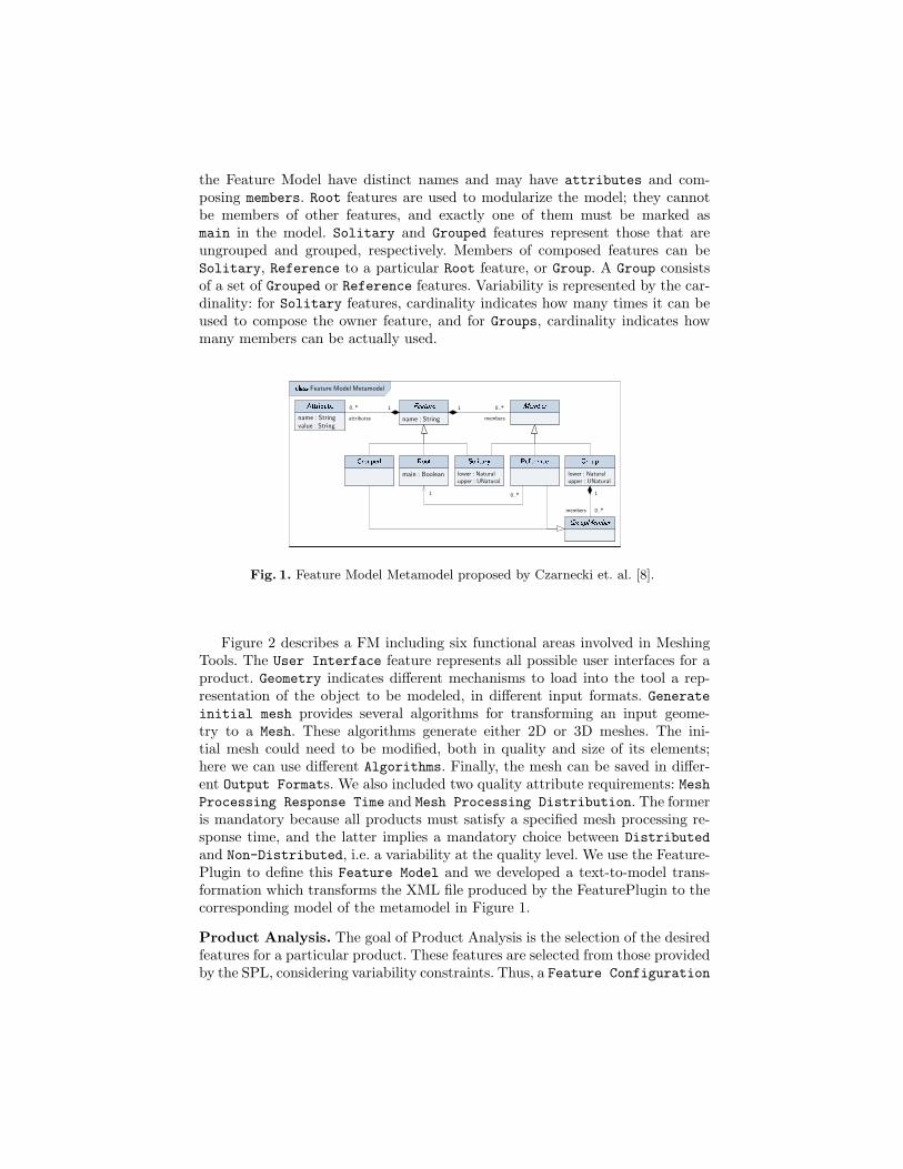
the Feature Model have distinct names and may have attributes and com-posing members. Root features are used to modularize the model; they cannotbe members of other features, and exactly one of them must be marked asmain in the model. Solitary and Grouped features represent those that areungrouped and grouped, respectively. Members of composed features can beSolitary, Reference to a particular Root feature, or Group. A Group consistsof a set of Grouped or Reference features. Variability is represented by the car-dinality: for Solitary features, cardinality indicates how many times it can beused to compose the owner feature, and for Groups, cardinality indicates howmany members can be actually used.
Feature Model Metamodel
name : String
lower : Natural
upper : UNaturalmain : Boolean
0..*1
lower : Natural
upper : UNatural
0..*1
members
0..*
1
members
name : String
value : Stringattributes
10..*
Fig. 1. Feature Model Metamodel proposed by Czarnecki et. al. [8].
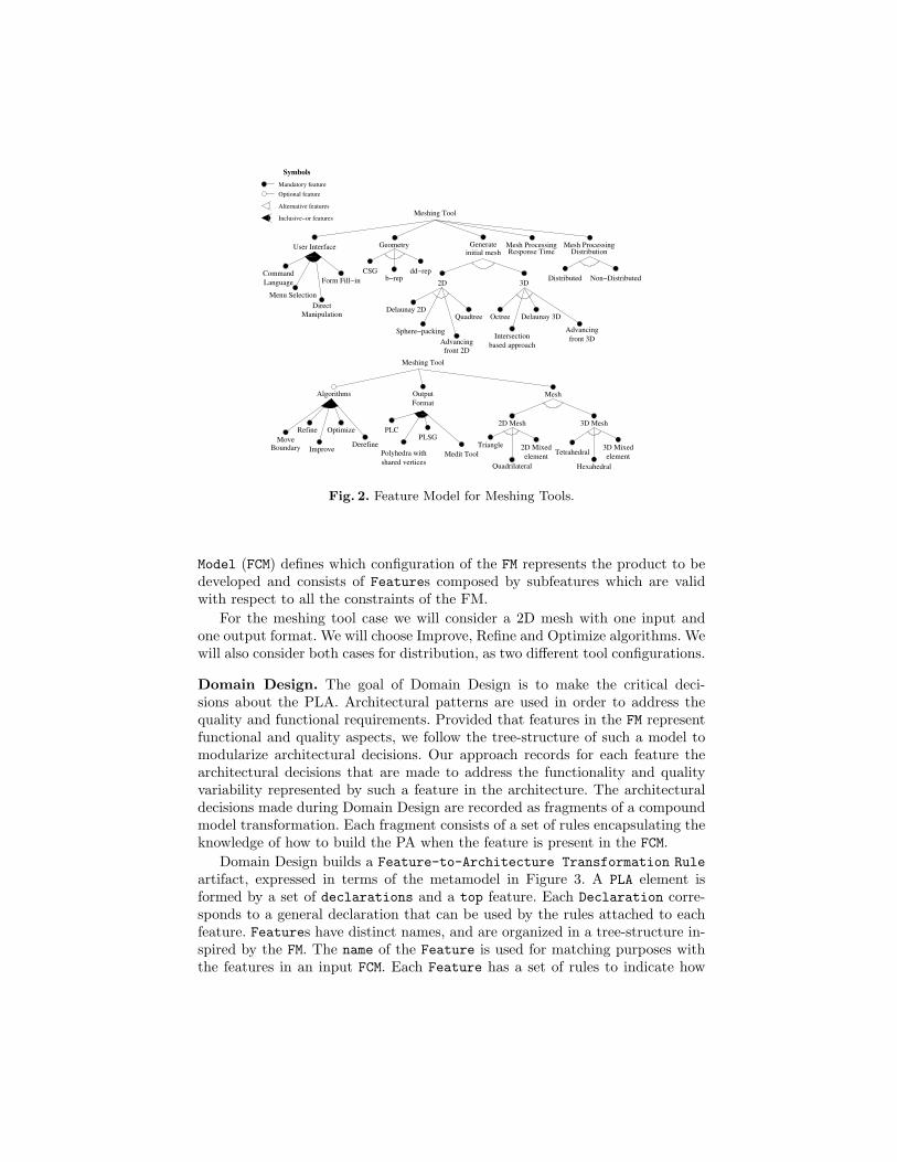
Figure 2 describes a FM including six functional areas involved in MeshingTools. The User Interface feature represents all possible user interfaces for aproduct. Geometry indicates different mechanisms to load into the tool a rep-resentation of the object to be modeled, in different input formats. Generateinitial mesh provides several algorithms for transforming an input geome-try to a Mesh. These algorithms generate either 2D or 3D meshes. The ini-tial mesh could need to be modified, both in quality and size of its elements;here we can use different Algorithms. Finally, the mesh can be saved in differ-ent Output Formats. We also included two quality attribute requirements: MeshProcessing Response Time and Mesh Processing Distribution. The formeris mandatory because all products must satisfy a specified mesh processing re-sponse time, and the latter implies a mandatory choice between Distributedand Non-Distributed, i.e. a variability at the quality level. We use the Feature-Plugin to define this Feature Model and we developed a text-to-model trans-formation which transforms the XML file produced by the FeaturePlugin to thecorresponding model of the metamodel in Figure 1.
Product Analysis. The goal of Product Analysis is the selection of the desiredfeatures for a particular product. These features are selected from those providedby the SPL, considering variability constraints. Thus, a Feature Configuration
User Interface
Manipulation
Direct
Geometry
CSGb−rep
dd−rep
initial meshGenerate
Octree
Advancing
front 3DIntersection
based approachAdvancing
front 2D
2D
Quadtree
Sphere−packing
Delaunay 2D
3D
Delaunay 3D
Mesh ProcessingResponse Time
Distributed Non−Distributed
Mesh ProcessingDistribution
Meshing Tool
Language Form Fill−inCommand
Menu Selection
Mandatory feature
Optional feature
Inclusive−or features
Alternative features
Symbols
Medit Toolshared vertices
Polyhedra with
PLSGPLC
Output
Format
DerefineMove
Boundary
Algorithms
Refine
Improve
Optimize
Triangle
Quadrilateral
2D Mesh
2D Mixed
element
Hexahedral
3D Mesh
Tetrahedralelement
3D Mixed
Mesh
Meshing Tool
Fig. 2. Feature Model for Meshing Tools.
Model (FCM) defines which configuration of the FM represents the product to bedeveloped and consists of Features composed by subfeatures which are validwith respect to all the constraints of the FM.
For the meshing tool case we will consider a 2D mesh with one input andone output format. We will choose Improve, Refine and Optimize algorithms. Wewill also consider both cases for distribution, as two different tool configurations.
Domain Design. The goal of Domain Design is to make the critical deci-sions about the PLA. Architectural patterns are used in order to address thequality and functional requirements. Provided that features in the FM representfunctional and quality aspects, we follow the tree-structure of such a model tomodularize architectural decisions. Our approach records for each feature thearchitectural decisions that are made to address the functionality and qualityvariability represented by such a feature in the architecture. The architecturaldecisions made during Domain Design are recorded as fragments of a compoundmodel transformation. Each fragment consists of a set of rules encapsulating theknowledge of how to build the PA when the feature is present in the FCM.
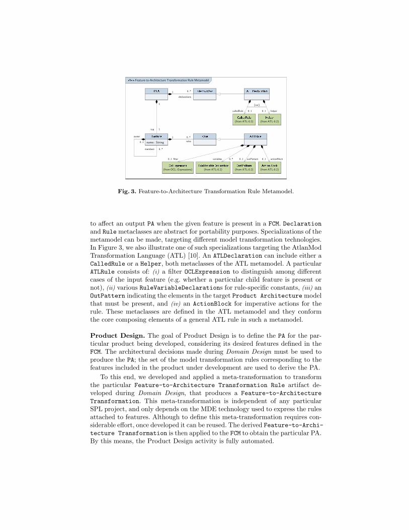
Domain Design builds a Feature-to-Architecture Transformation Ruleartifact, expressed in terms of the metamodel in Figure 3. A PLA element isformed by a set of declarations and a top feature. Each Declaration corre-sponds to a general declaration that can be used by the rules attached to eachfeature. Features have distinct names, and are organized in a tree-structure in-spired by the FM. The name of the Feature is used for matching purposes withthe features in an input FCM. Each Feature has a set of rules to indicate how
name : String
0..*1
rules
Feature-to-Architecture Transformation Rule Metamodel
(from ATL-0.2)
1
1
top
0..1
0..*
owner
members
0..*1
declarations
(from ATL-0.2) (from ATL-0.2)
(from ATL-0.2) (from ATL-0.2)
helper0..10..1calledRule
{xor}
0..*variables outPattern0..1 actionBlock0..1
(from OCL::Expressions)
0..1 filter
Fig. 3. Feature-to-Architecture Transformation Rule Metamodel.
to affect an output PA when the given feature is present in a FCM. Declarationand Rule metaclasses are abstract for portability purposes. Specializations of themetamodel can be made, targeting different model transformation technologies.In Figure 3, we also illustrate one of such specializations targeting the AtlanModTransformation Language (ATL) [10]. An ATLDeclaration can include either aCalledRule or a Helper, both metaclasses of the ATL metamodel. A particularATLRule consists of: (i) a filter OCLExpression to distinguish among differentcases of the input feature (e.g. whether a particular child feature is present ornot), (ii) various RuleVariableDeclarations for rule-specific constants, (iii) anOutPattern indicating the elements in the target Product Architecture modelthat must be present, and (iv) an ActionBlock for imperative actions for therule. These metaclasses are defined in the ATL metamodel and they conformthe core composing elements of a general ATL rule in such a metamodel.
Product Design. The goal of Product Design is to define the PA for the par-ticular product being developed, considering its desired features defined in theFCM. The architectural decisions made during Domain Design must be used toproduce the PA; the set of the model transformation rules corresponding to thefeatures included in the product under development are used to derive the PA.
To this end, we developed and applied a meta-transformation to transformthe particular Feature-to-Architecture Transformation Rule artifact de-veloped during Domain Design, that produces a Feature-to-ArchitectureTransformation. This meta-transformation is independent of any particularSPL project, and only depends on the MDE technology used to express the rulesattached to features. Although to define this meta-transformation requires con-siderable effort, once developed it can be reused. The derived Feature-to-Archi-tecture Transformation is then applied to the FCM to obtain the particular PA.By this means, the Product Design activity is fully automated.
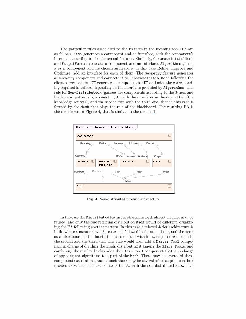
The particular rules associated to the features in the meshing tool FCM areas follows. Mesh generates a component and an interface, with the component’sinternals according to the chosen subfeatures. Similarly, GenerateInitialMeshand OutputFormat generate a component and an interface. Algorithms gener-ates a component and its chosen subfeature, in this case Refine, Improve andOptimize, add an interface for each of them. The Geometry feature generatesa Geometry component and connects it to GenerateInitialMesh following theclient-server pattern. UI generates a component for UI and adds the correspond-ing required interfaces depending on the interfaces provided by Algorithms. Therule for Non-Distributed organizes the components according to the 3-tiers andblackboard patterns by connecting UI with the interfaces in the second tier (theknowledge sources), and the second tier with the third one, that in this case isformed by the Mesh that plays the role of the blackboard. The resulting PA isthe one shown in Figure 4, that is similar to the one in [1].
IGeometry
IGenerate
IGeometry
IGenerate IMesh
IRefine IImprove IOptimize IOutput
IMeshIMesh
IMesh
IRefine IImprove IOutputIOptimize
Fig. 4. Non-distributed product architecture.
In the case the Distributed feature is chosen instead, almost all rules may bereused, and only the one referring distribution itself would be different, organiz-ing the PA following another pattern. In this case a relaxed 4-tier architecture isbuilt, where a master-slave [3] pattern is followed in the second tier, and the Meshas a blackboard in the fourth tier is connected with knowledge sources in both,the second and the third tier. The rule would then add a Master Tool compo-nent in charge of dividing the mesh, distributing it among the Slave Tools, andcombining the results. It also adds the Slave Tool component that is in chargeof applying the algorithms to a part of the Mesh. There may be several of thesecomponents at runtime, and as such there may be several of these processes in aprocess view. The rule also connects the UI with the non-distributed knowledge
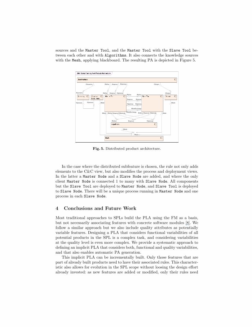
sources and the Master Tool, and the Master Tool with the Slave Tool be-tween each other and with Algorithms. It also connects the knowledge sourceswith the Mesh, applying blackboard. The resulting PA is depicted in Figure 5.
IGeometry
IGenerate
IGeometry
IGenerate IMesh
IRefine IImprove IOptimize
IOutput
IMesh
IMesh
IMesh
IRefine IImprove IOutputIOptimize
IImprove
IOptimize
IRefine
IOptimize
IImprove
IRefineIRefine IImprove IOptimize
IRefine IImprove IOptimize IRefine IImprove IOptimize
IMeshExchange
IMeshExchangeIMesh IMesh
Fig. 5. Distributed product architecture.
In the case where the distributed subfeature is chosen, the rule not only addselements to the C&C view, but also modifies the process and deployment views.In the latter a Master Node and a Slave Node are added, and where the onlyclient Master Node is connected 1 to many with Slave Node. All componentsbut the Slave Tool are deployed to Master Node, and Slave Tool is deployedto Slave Node. There will be a unique process running in Master Node and oneprocess in each Slave Node.
4 Conclusions and Future Work
Most traditional approaches to SPLs build the PLA using the FM as a basis,but not necessarily associating features with concrete software modules [8]. Wefollow a similar approach but we also include quality attributes as potentiallyvariable features. Designing a PLA that considers functional variabilities of allpotential products in the SPL is a complex task, and considering variabilitiesat the quality level is even more complex. We provide a systematic approach todefining an implicit PLA that considers both, functional and quality variabilities,and that also enables automatic PA generation.
This implicit PLA can be incrementally built. Only those features that arepart of already built products need to have their associated rules. This character-istic also allows for evolution in the SPL scope without loosing the design effortalready invested: as new features are added or modified, only their rules need
to be added or updated, respectively. However, in certain cases, these changesmay need to review the rules affecting other features, but the divide-and-conquerstrategy used for the design phase, makes this task easier. In all cases, the ar-chitectural knowledge associated to each feature can be more easily reused.
One of the drawbacks of our approach is that the implicit PLA cannot beassessed with traditional methods. Therefore, we can only asses particular PAs,and this may be risky and costly.
We are currently extending our approach so that it covers the whole SPLdevelopment process, i.e., including also domain and product implementation.For this purpose we are also applying MDE techniques. We are also using anenriched domain model, that includes not only the feature model but also goalsand scenarios, as the basis for the rules that generate the implicit PLA.
References
1. M. C. Bastarrica, N. Hitschfeld-Kahler, and P. O. Rossel. Product Line Architec-ture for a Family of Meshing Tools. In 9th International Conference on SoftwareReuse (ICSR 2006), LNCS 4039, pages 403–406. Springer, 2006.
2. D. S. Batory, M. Azanza, and J. Saraiva. The objects and arrows of computationaldesign. In 11th International Conference on Model Driven Engineering Languagesand Systems, MoDELS 2008, volume 5301 of LNCS, pages 1–20. Springer, 2008.
3. F. Buschmann, R. Meunier, H. Rohnert, P. Sommerlad, and M. Stal. Pattern-Oriented Software Architecture. A System of Patterns. John Wiley & Sons, 1996.
4. E. Cirilo, U. Kulesza, and C. J. P. de Lucena. A Product Derivation Tool Basedon Model-Driven Techniques and Annotations. Journal of Universal ComputerScience, 14(8):1344–1367, 2008.
5. P. Clements and L. Northrop. Software Product Lines: Practices and Patterns.SEI Series in Software Engineering. Addison-Wesley, 2001.
6. F. Contreras. Adapting a 3D Meshing Tool to a New Architecture. Master’s thesis,Computer Science Department, Universidad de Chile, 2007. (In Spanish).
7. K. Czarnecki, M. Antkiewicz, C. H. P. Kim, S. Lau, and K. Pietroszek. Model-Driven Software Product Lines. In R. Johnson and R. P. Gabriel, editors, OOPSLACompanion, pages 126–127. ACM Press, Oct. 2005.
8. K. Czarnecki, S. Helsen, and U. W. Eisenecker. Staged Configuration Using Fea-ture Models. In Third International Software Product Lines Conference SoftwareProduct Lines (SPLC 2004), volume 3154 of LNCS, pages 266–283, 2004.
9. M. T. Jones and P. E. Plassmann. Parallel algorithms for adaptive mesh refinement.SIAM Journal on Scientific Computing, 18:686–708, 1997.
10. F. Jouault and I. Kurtev. Transforming Models with ATL. In MoDELS SatelliteEvents, pages 128–138, 2005.
11. K. C. Kang, S. G. Cohen, J. A. Hess, W. E. Novak, and A. S. Peterson.Feature-Oriented Domain Analysis (FODA). Feasibility Study. Technical ReportCMU/SEI-90-TR-21, Software Engineering Institute, Nov. 1990.
12. J. Kim, S. Park, and V. Sugumaran. DRAMA: A framework for domain require-ments analysis and modeling architectures in software product lines. Journal ofSystems and Software, 81(1):37–55, jan 2008.
13. M. Matinlassi. Quality-Driven Software Architecture Model Transformation. InFifth Working IEEE / IFIP Conference on Software Architecture (WICSA 2005),pages 199–200, 2005.
14. E. Niemela and A. Immonen. Capturing quality requirements of product familyarchitecture. Inf. and Software Technology, 49(11-12):1107–1120, Nov. 2007.
15. D. Perovich, M. C. Bastarrica, and C. Rojas. Model-Driven Approach to Soft-ware Architecture Design. In Proc. of the 4th Workshop on SHaring ARchitecturalKnowledge, SHARK’2009, pages 1–8, Vancouver, Canada, May 2009.
16. D. Perovich, P. O. Rossel, and M. C. Bastarrica. Feature Model to Product Archi-tectures: Applying MDE to Software Product Lines. In Joint Working IEEE/IFIPConference on Software Architecture 2009 & European Conference on SoftwareArchitecture 2009. IEEE CS Press, September 2009.
17. M. C. Rivara, C. Calderon, A. Fedorov, and N. Chrisochoides. Parallel decou-pled terminal-edge bisection method for 3d mesh generation. Engineering withComputers, 22(2):111–119, 2006.
18. R. N. Taylor, N. Medvidovic, and E. M. Dashofy. Software Architecture. Founda-tions, Theory, and Practice. John Wiley and Sons, Inc., 2009.
19. J. White and D. C. Schmidt. Model-Driven Product-Line Architectures for MobileDevices. In In Proceedings of the 17th Annual Conference of the InternationalFederation of Automatic Control, Seoul, Korea, July 2008.
20. J. White, D. C. Schmidt, E. Wuchner, and A. Nechypurenko. Automating Product-Line Variant Selection for Mobile Devices. In Proceedings of the 11th InternationalSoftware Product Line Conference (SPLC 2007), pages 129–140, 2007.