mastering console - spl audio
TRANSCRIPT
Manual
DMCMastering Console
DMCVersion 1.1 – 03/ 2018 2Package Contents 2Product Registration 2
Introduction 3The centerpiece of your mastering studio 3
Technical Aspects 4120 Volt Technology 4120 Volt Technology - Diagrams 5
Installation 6Voltage Selection 6First Steps 6
Cabling: Rear Side 7XLR inputs and outputs 7Ground Lift switch to avoid ground loops 7Inputs (1-4) 10Sources (1-4) 10Insert Send 10Insert Return 10Recording Out 1 / Recording Out 2 10Speakers (Speaker A - D) 11Sub 11Phonitor / HP Out 11Metering Outputs 11GPI 11Multi-Channel Monitoring with the MC 16 12L/R from MC 16 12LFE from MC 16 12L/R to MC 16 12Pairing DMC and MC 16 13
Content
Content
Control Elements 14Inputs (1-4) 16L Off and R Off 16L Phase and R Phase 16Input Trim L / Input Trim R 16Input Trim -0+ Switch 16Recording Gain 16Recording Gain On 17Mono 17Insert 17Insert Return Trim L / Insert Return Trim R 17Insert Return Trim -0+ Switch 17Sources (1-4) 17Source 17Interval Auto Bypass (Insert/Off/Source) 18Speaker /Lautsprecher (Speakers A - D) 18Sub 18Phonitor / HP Out 18GPI (General Purpose Interface) 19Monitoring Level 19Monitoring - Dim -20 19Monitoring Level Offset +-10dB (variable) 19Monitoring - Mono 20Monitoring - Mute 20Monitoring - L Solo and R Solo 20Monitoring - L Phase and R Phase 20
Signal-Flow 21Recording Path 21Monitorng Path 21
Specifications� 22Measurements 22
Security Advices 23Notes on Environmental Protection 24
Contact 25
2
Version 1.1 – 03 / 2018
Developer: Bastian Neu
This manual includes a description of the product but no guarantee as for specific charac-teristics or successful results.
Unless stated otherwise, everything herein corresponds to the technical status at the time of delivery of the product and user manual by SPL electronics GmbH.
The design and circuitry are under continuous development and improvement.
Technical specifications are subject to change.
Package Contents
DMC Mastering Console
Power cord
Manual
The DMC Mastering Console is available in different colors.
Black: Modell 1690
Red: Modell 1694
Do consider keeping the original packaging. It can come in very useful whenever you need to transport your gear. If there is ever the need to send it in for repair, the original packag-ing guarantees a safe shipment.
Product Registration
Register your device to get useful information concerning the product. On the front page of this manual you will find a QR code, which includes the link to the registration form and automatically fills in the serial number and product name into the form. Alternatively you can also call up the online form with your internet browser via the following link:
https://spl.audio/register
3
Introduction
The centerpiece of your mastering studio
The new DMC Mastering Console – modell 1690/1694 is engineered from the ground-up making it not only more flexible with better specs than SPL’s previous console, but also more ergonomic and sized to fit in all types of studio furniture.
The 3RU console has 4 stereo inputs and 4 stereo sources, with 2 stereo recording out-puts, as well as 3 stereo and 2 mono speaker outputs that can be expanded with the new MC16 controller.
The new DMC console operates on the same unequaled 120V DC audio rail like each of the other SPL Mastering Series processors. The new DMC console is priced at half of its predecessor, and yet offers more features and improved audio performance.
Mastering engineer Michael Romanowski is using a new DMC console at his “Coast Mastering” studio with great results:
“The new DMC is the heart of my mastering system.”
“I like how much headroom the audio has ... I can count on what I’m hearing to be accurate.
“The most important things for me about the DMC are its transparency, its flexibility in gain structure, and its monitoring capabilities. And with emerging markets for immersive audio, its ability to expand the channel count is a necessity. Those are the biggest rea-sons that I choose to use the DMC.”
The DMC Mastering Console was designed, developed and manufactured in Germany.
4
Technical Aspects
120 Volt TechnologySPL‘s goal was to push analog signal processing to the limits. That‘s why we combined the best possible components with a high-grade optimized circuit design.
We have been using the in-house developed 120-volt technology - the highest-ever oper-ating voltage used for audio applications - in all our products from the Mastering series for years. Some of the most highly respected Mastering studios today revolve around SPL consoles and signal processors from our Mastering series (Bob Ludwigs Gateway Mastering & DVD in the USA, Simon Heyworth‘s Super Audio Mastering in the UK, Galaxy Studios in Belgium, and the legendary Wisseloord in the Netherlands, for instance).
The 120-volt technology is based on op-amps developed internally by SPL‘s co-founder and Chief Developer Wolfgang Neumann. The DMC Mastering Console features the most advanced generation of these op-amps. They boast with even better tech specs thanks to the thermal behavior optimization they underwent under the hands of Bastian Neu.
Ultimately, the supply voltage is key for the overall dynamic response of a processor. Voltage is to an electrical circuit what cylinder capacity is to an internal combustion engine:
You can‘t replace cylinder capacity with anything else, except more cylinder capacity.
5
Technical Aspects
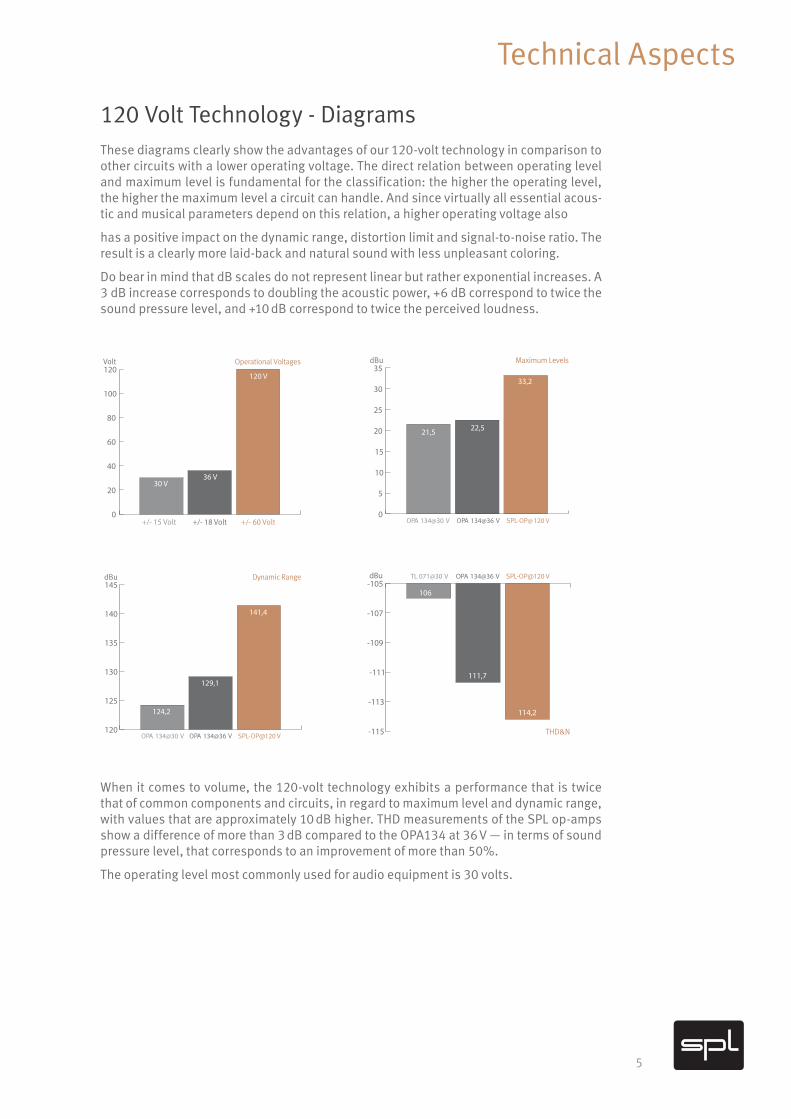
120 Volt Technology - Diagrams These diagrams clearly show the advantages of our 120-volt technology in comparison to other circuits with a lower operating voltage. The direct relation between operating level and maximum level is fundamental for the classification: the higher the operating level, the higher the maximum level a circuit can handle. And since virtually all essential acous-tic and musical parameters depend on this relation, a higher operating voltage also
has a positive impact on the dynamic range, distortion limit and signal-to-noise ratio. The result is a clearly more laid-back and natural sound with less unpleasant coloring.
Do bear in mind that dB scales do not represent linear but rather exponential increases. A 3 dB increase corresponds to doubling the acoustic power, +6 dB correspond to twice the sound pressure level, and +10 dB correspond to twice the perceived loudness.
When it comes to volume, the 120-volt technology exhibits a performance that is twice that of common components and circuits, in regard to maximum level and dynamic range, with values that are approximately 10 dB higher. THD measurements of the SPL op-amps show a difference of more than 3 dB compared to the OPA134 at 36 V — in terms of sound pressure level, that corresponds to an improvement of more than 50%.
The operating level most commonly used for audio equipment is 30 volts.
120
125
130
135
140
145dBu Dynamic Range
OPA 134@30 V OPA 134@36 V SPL-OP@120V
124,2
129,1
141,4
0
5
10
15
20
25
30
35dBu
OPA 134@30 V OPA 134@36 V SPL-OP@120V
21,5 22,5
33,2
Maximum Levels
0
20
40
60
80
100
120Volt
+/- 15 Volt +/- 18 Volt +/- 60 Volt
30 V36 V
120 V
Operational Voltages
-115
-113
-111
-109
-107
-105dBu TL 071@30 V OPA 134@36 V SPL-OP@120V
106
111,7
114,2
THD&N
6
Installation
Voltage SelectionBefore connecting the DMC Mastering Console to the mains, make sure that the voltage selection corresponds to the values of your local power grid (230 or 115 volts). Inside the power connec- tor, to the right, next to the on/off switch, there is an opening that displays the voltage selected. If the voltage indicated does not correspond to the one required, change it by following this procedure:
Open the power connector lid with a small screwdriver (use the tiny slots on the right hand side). Use the screwdriver to lever the red fuse holder from above until you can grab it. Take the fuse holder out and replace the fuse with one corresponding to the local power grid specifications. You can find the adequate values on the rear of the unit or on page 16 of this user‘s manual. Turn the fuse holder around 180 degrees and place it back again. When you close the lid again, you should see the correct voltage displayed in the opening.
On the product site on our website (http://dmc.spl.audio) you will find a video concerning the topic
“Changing the mains voltage”. If you ever have to exchange a fuse, we recommend the video “Exchange defective fuses”.
First Steps Before turning on the DMC Mastering Console you must first connect the included 3-pin power cord to the 3-pin IEC socket. The transformer, power cord and IEC socket all comply to the VDE, UL and CSA regulations.
The DMC Mastering Console should not be installed in close proximity to equipment that emits magnetic fields or emanates heat. Avoid exposure to heat, moisture, dust, and vibrations. Do not install the DMC close to any power amps or digital processors. Instead, install it in a fully “analog rack” where any interferences can be avoided (Word Clock, SMPTE, MIDI etc.).
The unit should be powered off before connecting or disconnecting any cables or equip-ment to it.
Use the On/Off switch on the rear panel to turn the unit on or off. The illuminated red LED in the middle of the front panel indicates the unit‘s operating status. The On/Off switch was placed on the rear panel to avoid any emissions due to voltage-carrying conductors running across the unit and affecting sound. When powering on or off, there‘s no need to observe a specific sequence regarding the connected devices. However, like with any audio signal chain, power amplifiers should always be powered on last and powered off first. The DMC can be powered on and off with the use of a circuit breaker, as long as the total load does not exceed the rating of the latter.
After switching on the DMC, all buttons light up top down. Afterwards the start configu-ration is loaded. When starting the unit for the first time, the following buttons are acti-vated: Input 1, Source, Speaker A and Mute. If you, for example, want to monitor the sig-nal of Input 1 with Speaker A, you now only have to push the “Mute” button and thereby deactivate it.
7
Cabling: Rear Side
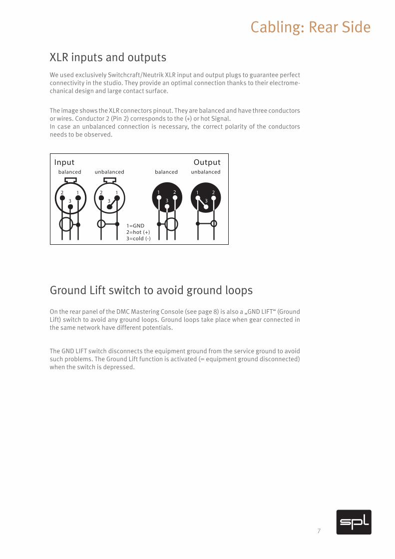
XLR inputs and outputsWe used exclusively Switchcraft/Neutrik XLR input and output plugs to guarantee perfect connectivity in the studio. They provide an optimal connection thanks to their electrome-chanical design and large contact surface.
The image shows the XLR connectors pinout. They are balanced and have three conductorsor wires. Conductor 2 (Pin 2) corresponds to the (+) or hot Signal.In case an unbalanced connection is necessary, the correct polarity of the conductors needs to be observed.
Ground Lift switch to avoid ground loops
On the rear panel of the DMC Mastering Console (see page 8) is also a „GND LIFT“ (Ground Lift) switch to avoid any ground loops. Ground loops take place when gear connected in the same network have different potentials.
The GND LIFT switch disconnects the equipment ground from the service ground to avoid such problems. The Ground Lift function is activated (= equipment ground disconnected) when the switch is depressed.
Input Outputbalanced unbalanced balanced unbalanced
1=GND2=hot (+)3=cold (-)
12
3
12
3
1 2
3
1 2
3
8
Cabling: Rear Side
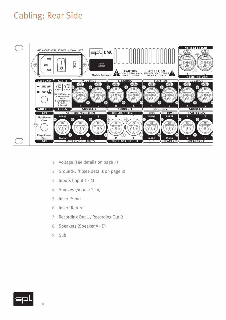
1 Voltage (see details on page 7)
2 Ground-Lift (see details on page 8)
3 Inputs (Input 1 - 4)
4 Sources (Source 1 - 4)
5 Insert Send
6 Insert Return
7 Recording Out 1 / Recording Out 2
8 Speakers (Speaker A - D)
9 Sub
~115 V AC/~230 V AC; 50 Hz/60 Hz; P max. 100 W
VOLTAGE Selection:1. Remove Fuse
Holder2. Exchange Fuses
3. Flip Over4. Reinstall
DMC
SerialNumber
RISK OF ELECTRIC SHOCKD O N OT O P E N
C AUT IONRISQUE DE CHOC ÉLECTRIQUE
N E PA S O U V R I R
AT T ENT ION
Made in Germany
LR
LR
INPUT 4
INPUT 4
LR
LR LR LR
LRPHONITOR/HP OUT
PHONITOR/HP OUT
LR
LR
LR
LR LR
LR LR
LR
LR
LR
LR
INPUT 1 INPUT 2 INPUT 3
INPUT 1 INPUT 2 INPUT 3
RECORDING OUT 2
RECORDING OUT 2
INSERT RETURN INSERT SEND
INSERT RETURN
SUB/MONO
SUB/MONO
LFE fr. MC16
LFE fr. MC16
SUB/MONO
SUB/MONO
GPI
GPI
GND LIFT
INSERT SENDLR LR
LRLRL/R from MC16 L/R to MC16
L/R from MC16 L/R to MC16
RECORDING OUT 1
RECORDING OUT 1METERING OUTPUTS
METERING OUTPUTS
LRMono
LR
Tip–Sleeve:Close
Ring–Sleeve:Open
SUB/MONO GND LIFT
Mono
AUDIOFEEDSTO &FROMMC16
GND LIFT
GND
FUSES
SUB/MONO FUSES
115V: T 2 A
L 250V
230V: T 1 A
L 250V
Mono
Mono
Mono
MonoSUB SPEAKER D
LR
LRSPEAKERS C
SPEAKERS C
LR
LRSOURCE 1
SOURCE 1LR
LRSOURCE 2
SOURCE 2LR
LRSOURCE 3
SOURCE 3LR
LRSOURCE 4
SOURCE 4
LR
LRSPEAKERS B
SPEAKERS BLR
LRSPEAKERS A
SPEAKERS ASUB SPEAKER D
230
9
Cabling: Rear Side
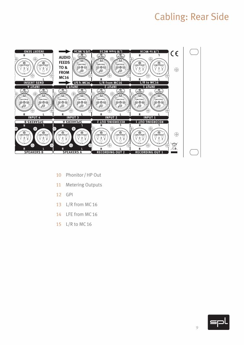
10 Phonitor / HP Out
11 Metering Outputs
12 GPI
13 L/R from MC 16
14 LFE from MC 16
15 L/R to MC 16
~115 V AC/~230 V AC; 50 Hz/60 Hz; P max. 100 W
VOLTAGE Selection:1. Remove Fuse
Holder2. Exchange Fuses
3. Flip Over4. Reinstall
DMC
SerialNumber
RISK OF ELECTRIC SHOCKD O N OT O P E N
C AUT IONRISQUE DE CHOC ÉLECTRIQUE
N E PA S O U V R I R
AT T ENT ION
Made in Germany
LR
LR
INPUT 4
INPUT 4
LR
LR LR LR
LRPHONITOR/HP OUT
PHONITOR/HP OUT
LR
LR
LR
LR LR
LR LR
LR
LR
LR
LR
INPUT 1 INPUT 2 INPUT 3
INPUT 1 INPUT 2 INPUT 3
RECORDING OUT 2
RECORDING OUT 2
INSERT RETURN INSERT SEND
INSERT RETURN
SUB/MONO
SUB/MONO
LFE fr. MC16
LFE fr. MC16
SUB/MONO
SUB/MONO
GPI
GPI
GND LIFT
INSERT SENDLR LR
LRLRL/R from MC16 L/R to MC16
L/R from MC16 L/R to MC16
RECORDING OUT 1
RECORDING OUT 1METERING OUTPUTS
METERING OUTPUTS
LRMono
LR
Tip–Sleeve:Close
Ring–Sleeve:Open
SUB/MONO GND LIFT
Mono
AUDIOFEEDSTO &FROMMC16
GND LIFT
GND
FUSES
SUB/MONO FUSES
115V: T 2 A
L 250V
230V: T 1 A
L 250V
Mono
Mono
Mono
MonoSUB SPEAKER D
LR
LRSPEAKERS C
SPEAKERS C
LR
LRSOURCE 1
SOURCE 1LR
LRSOURCE 2
SOURCE 2LR
LRSOURCE 3
SOURCE 3LR
LRSOURCE 4
SOURCE 4
LR
LRSPEAKERS B
SPEAKERS BLR
LRSPEAKERS A
SPEAKERS ASUB SPEAKER D
230
10
Rear Side: Connections
Inputs (1-4)The DMC offers four balanced stereo input pairs of the category “Inputs”. These are female XLR plugs. All sources, which are routed through the Insert or rather should be recorded through the Recording Output, should be connected to these inputs.
Sources (1-4)Furthermore the DMC offers four stereo input pairs of the category “Sources”. You should connect all monitoring related sources to these inputs, which for instance could be a player with reference material or of course the final monitoring path of the mastering DAW.
Insert SendThe Insert Send offers two balanced, female XLR plugs. This ensures an optimum match-ing to other mastering equipment. If the Insert is activated with the Insert button on the front of the DMC, the signal of the chosen input is at these output pairs. This signal can now be passed to other external mastering processors.
Insert ReturnThe Insert Return offers two balanced, male XLR plugs. A signal which is sent through the Insert Send can be returned to the DMC Mastering Console via the Insert Return after it has been externally processed. If level adjustments are necessary, you can adjust them with the Insert Return Trim L/R control on the front of the DMC.
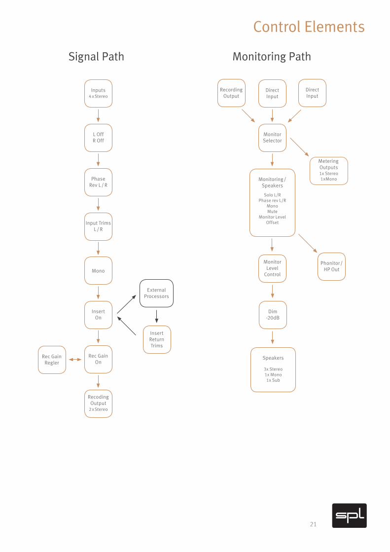
Recording Out 1 / Recording Out 2The DMC Mastering Console offers two stereo recording outputs (Recording Out 1 and Recording Out 2). Both output pairs are male XLR plugs, with individual output stages and contain the same output signal. This way the signal you wish to record can be sent to two different recording devices. The chosen signal is always at the chosen input of the two Recording Outs. Of course the Insert is always first in the signal flow (before the Recording Outs), so that the processed signal at the Insert can be recorded (see page 21). Furthermore the level of the output signal at the Recording Out can be controlled via the switchable, Recording Gain control on the front of the DMC.

11
Rear Side: Connections
Speakers (Speaker A - D)The DMC offers four different loudspeaker outputs. Three stereo output pairs and a mono output. All four outputs are balanced and provide male XLR connection jacks. Speakers A and C are perfectly suited for connecting different stereo loudspeakers. You can (for example) connect a mono speaker to Speaker D. With the Speaker buttons on the front of the DMC you can activate an output simultaneously at a time. The level of the output sig-nal can be controlled via the big Monitoring Level pot on the front of the DMC.
SubIt is possible to connect a subwoofer to the Sub output. You can run this output in addi-tion to the selected speaker (Speaker A to D). The level can also be controlled with the big Monitoring Level pot. Sub is a mono and balanced output and provides a male XLR jack.
Phonitor / HP OutBeside the loudspeaker outputs, the DMC offers an extra output for an headphone ampli-fier, e.g. a device of the SPL Phonitor series. This stereo output is balanced and imple-mented as two male XLR jacks.
Metering OutputsTo connect external metering tools to the DMC, the device provides two metering outputs on the rear of the DMC. Both are balanced and implemented as two male XLR jacks. One of the metering outputs is a stereo output (L/R), the other is a mono output (Mono). The sig-nal which is at the Metering Outputs is always the signal which is sent to the Monitoring section. Thus Recording Output, Sources or Direct Input (see page 21).
GPIIn addition to that, the DMC Mastering Console also provides a GPI output. GPI stands for General Purpose Interface. It is possible to operate with voltages up to 24V with this TRS jack plug. The jack plug features the following allocations:
Tip sleeve: Closed
Ring sleeve: Open
This provides the possibility to e.g. run a Talkback or a Red Light.
12
Rear Side: Connections
Multichannel Monitoring with the MC 16You can pair the DMC with the SPL MC 16 (Multichannel Mastering Monitor Controller) for surround and immersive audio applications. This way, Dolby Atmos® or Auro 3D® projects can be realized. The MC 16 is world’s first analog 16 channel monitoring con-troller. Mastering studios often use the L/R speakers and the subwoofer for stereo and multichannel monitoring. The combination of DMC and MC 16 makes replugging of the speakers redundant and allows their application in all fields.
L/R from MC 16The stereo input L/R from MC 16 (balanced, female XLR) serves to feed the L and R signal of the MC 16 into the DMC for stereo mastering applications. Through this opportunity to pair the DMC and MC 16, loudspeakers L and R of the stereo mastering configuration can also be used in surround applications with the MC 16.
LFE from MC 16The mono input LFE from MC 16 (balanced, female XLR) serves to feed the LFE signal of the MC 16 into the DMC for stereo mastering applications. Thereby it is possible to use the subwoofer, which is connected to the Sub output in surround mode, in combination with the MC 16 as LFE loudspeaker.
L/R to MC 16The stereo output L/R to MC 16 (balanced, male XLR) sends the L and R signal of the DMC to the MC 16.
The image on the following page shows a suggestion for the pairing of DMC and MC 16.
Find further information about the MC 16 on the product website: mc16.spl.audio
13
Rear Side: Connections
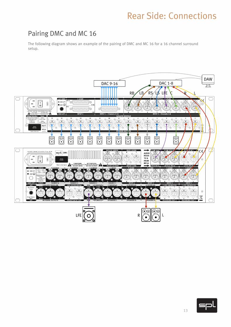
Pairing DMC and MC 16The following diagram shows an example of the pairing of DMC and MC 16 for a 16 channel surround setup.
14
Control Elements
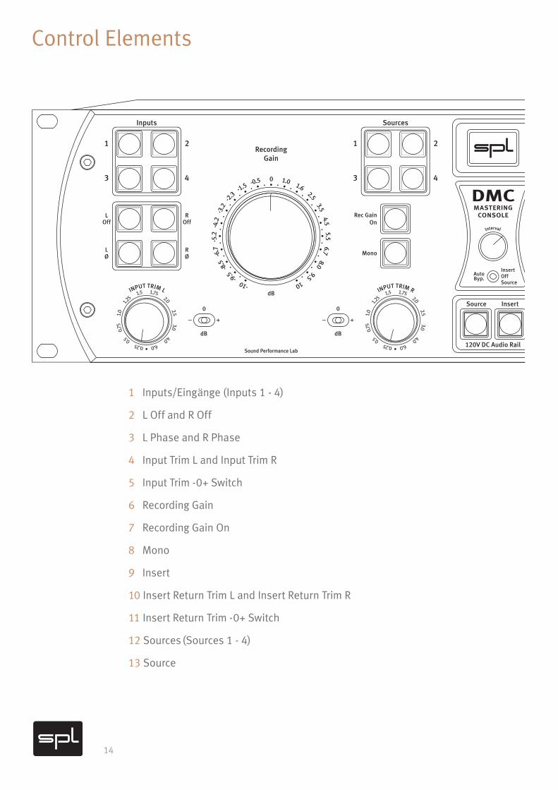
1 Inputs/Eingänge (Inputs 1 - 4)
2 L Off and R Off
3 L Phase and R Phase
4 Input Trim L and Input Trim R
5 Input Trim -0+ Switch
6 Recording Gain
7 Recording Gain On
8 Mono
9 Insert
10 Insert Return Trim L and Insert Return Trim R
11 Insert Return Trim -0+ Switch
12 Sources (Sources 1 - 4)
13 Source
120V DC Audio Rail
DMCmastering
console
OffInsert
Source
AutoByp.
InsertSource
Interval
-10 -9.5 -
8.5
-6.
7 -
5.2
-4.
2 -
3.2
-2.3 -
1.5 -0.5 0 1.0 1.6 2.5 3.5 4.5 5.5 6.7 8.0 9.5 10
-10
0
10
0.25 0.5
0
.75
1.
0
1.25
1.5 1.75 2.0 2.5 3.0 4.0 6.0 •
INPUT TRIM L
0.25 0.5
0
.75
1.
0
1.25
1.5 1.75 2.0 2.5 3.0 4.0 6.0 •
INPUT TRIM R
Sound Performance Lab Model 1690
+–
0
dB dB
dB
+–
0
dB
+–
0
dBdB
+–
0
dB
0.25 0.5
0
.75
1.
0
1.25
1.5 1.75 2.0 2.5 3.0 4.0 6.0 •
IN
SERT RETURN TRIM
L
0.25 0.5
0
.75
1.
0
1.25
1.5 1.75 2.0 2.5 3.0 4.0 6.0 •
IN
SERT RETURN TRIM R
LOff
LØ
ROff
RØ
LSolo
LØ
RSolo
RØ
Mono
Dim-20
Mute
Mono
A
C
B
Inputs Sources Speakers GPI Monitoring
D
PhonitorHP Out
Rec GainOn
Sub
ABastianNeu
Design-80 -55
-46
-4
1
-37
-3
4
-32
-29
-27 -25 -24 -22 -20 -18 -16 -14 -11 -8.0 -5.0 -1.5 0
RecordingGain
MonitoringLevel
1 2
3 4
1 2
3 4
15
Control Elements
120V DC Audio Rail
DMCmastering
console
OffInsert
Source
AutoByp.
InsertSource
Interval
-10 -9.5 -
8.5
-6.
7 -
5.2
-4.
2 -
3.2
-2.3 -
1.5 -0.5 0 1.0 1.6 2.5 3.5 4.5 5.5 6.7 8.0 9.5 10
-10
0
10
0.25 0.5
0
.75
1.
0
1.25
1.5 1.75 2.0 2.5 3.0 4.0 6.0 •
INPUT TRIM L
0.25 0.5
0
.75
1.
0
1.25
1.5 1.75 2.0 2.5 3.0 4.0 6.0 •
INPUT TRIM R
Sound Performance Lab Model 1690
+–
0
dB dB
dB
+–
0
dB
+–
0
dBdB
+–
0
dB
0.25 0.5
0
.75
1.
0
1.25
1.5 1.75 2.0 2.5 3.0 4.0 6.0 •
IN
SERT RETURN TRIM
L 0.25
0.5
0.75
1.0
1
.25
1.5 1.75 2.0 2.5 3.0 4.0 6.0 •
IN
SERT RETURN TRIM R
LOff
LØ
ROff
RØ
LSolo
LØ
RSolo
RØ
Mono
Dim-20
Mute
Mono
A
C
B
Inputs Sources Speakers GPI Monitoring
D
PhonitorHP Out
Rec GainOn
Sub
ABastianNeu
Design-80 -55
-46
-4
1
-37
-3
4
-32
-29
-27 -25 -24 -22 -20 -18 -16 -14 -11 -8.0 -5.0 -1.5 0
RecordingGain
MonitoringLevel
1 2
3 4
1 2
3 4
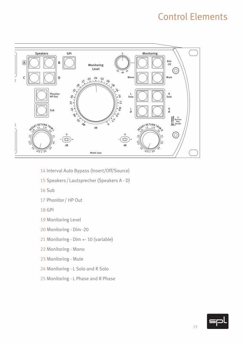
14 Interval Auto Bypass (Insert/Off/Source)
15 Speakers / Lautsprecher (Speakers A - D)
16 Sub
17 Phonitor / HP Out
18 GPI
19 Monitoring Level
20 Monitoring - Dim -20
21 Monitoring - Dim +- 10 (variable)
22 Monitoring - Mono
23 Monitoring - Mute
24 Monitoring - L Solo and R Solo
25 Monitoring - L Phase and R Phase
16
Control Elements
Inputs (1-4)With the four buttons of the Inputs section, you can select between the four different stereo inputs of the category inputs. This selected source can be routed with the Insert and recorded with the Recording Output. Only one button can be activated in this section. If another button is pushed, this button is activated. A multiple selection is not possible. The current selection is visualized by the button lighting up. If the button is pushed a sec-ond time, the Direct Input Monitoring is activated. This mode is indicated by an blinking Input button. In this mode, all functions processing the input signal are not led on the monitoring bus but stay on the recording bus.
L Off and R OffBy using the L Off and R off buttons, the input signal at the input section, depending on the selection, can be muted. L Off deactivates the left input channel, R Off the right input channel.
L Phase and R PhaseWith the L Phase and R Phase buttons, you can invert the phase of the input signal at the input section, depending on the selection, by 180°. L Phase inverts the signal on the left input channel, R Phase inverts the signal on the right channel.
Input Trim L / Input Trim RWith Input Trim L and Input Trim R you can increase or attenuate the input signal in the input section up to 6dB. If the switch (5) is in the center position (0 dB) the respective Input Trim is not influencing the signal flow.
Input Trim -0+ SwitchThis switch determines if the level at the respective Input Trim is attenuated (-) or increased (+) or (in the center position = 0 dB) stays unmodified when passing the Trim section.
Recording GainThe output level at the Recording Out 1 and Recording Out 2 can be increase or attenuated up to 10 dB by using the Recording Gain potentiometer. If you turn the control to the left, the level is attenuated. If you turn the control to the right, the level is increased. If the con-trol is in the center position “0” the level stays unmodified. In the standard configuration, the Recording Gain control is not in the signal path but has to be activated with the Gain On button.
17
Control Elements
Recording Gain OnIf the Recording Gain button is activated, the Recording Gain control is in the signal path.
MonoBy using the Mono button, the input signal can be switched from mono to stereo. If the button is activated, the mono signal is also at the Insert and Recording Out.
InsertWith the Insert button you can activate the Insert to loop external hardware. When the Insert button is activated, the signal is sent by the Insert Send and returned to the DMC by the Insert Return.
Insert Return Trim L / Insert Return Trim R With the buttons Input Return Trim L and Input Return Trim R you can increase or attenuate the Returns signal in the input section up to 6dB. If the switch (11) is in the center position (0 dB) the respective Input Return Trim is not influencing the signal flow.
Insert Return Trim -0+ SwitchThis switch determines if the level at the respective Insert Trim is attenuated (-) or increased (+) or (in the center position = 0 dB) stays unmodified when passing the Insert Return Trim section.
Sources (1-4)With the four buttons of the Sources section, you can select between the four differ-ent stereo inputs of the category Sources. This selected source can only be monitored with the monitor section of the DMC. Only one button can be activated in this section. If another button is pushed, this button is activated. A multiple selection is not possible. The current selection is visualized by the button lighting up. The signal CAN‘T be played with the Insert or the Recording Outputs.
SourceWith the button Source you can toggle between the inputs of the Source and Input sec-tion. Thanks to this it is possible to (for example) toggle between an input signal pro-cessed�through�the�Insert�and�a�final�Master�of�the�DAW�by�pushing�a�button.
18
Control Elements
Interval Auto Bypass (Insert/Off/Source)The DMC Mastering Console provides an Auto-Bypass switch with three possible set-tings. In the center position “Off” the Auto-Bypass is deactivated. In position “Insert” the Insert is activated and deactivated within a selected time frame, chosen with the Interval control. To be able to make an objective judgment of the processed material, it is best not to have to be toggling between the original and processed signals by yourself, but rather have it done automatically. Plus, the fact that you do not have to move from the sweet spot and can concentrate better on the music to optimally assess the processing is a huge advan- tage. The Interval control determines the time that needs to elapse before the compressor toggles between the processed and unprocessed signals. Hard left is the shortest setting. To increase the interval, turn the knob clockwise.
If the Bypass switch is in position “Source”, the device toggles between the Input and the Source signal. This allows you to compare the recorded signal (e.g. Input 1) to the DAW Return or a reference (e.g. Source 1).
Speaker (Speakers A - D)With the four buttons of the Speaker section, you can switch between the four different outputs of the category Speaker, in most cases a different pair of loudspeakers. Outputs A to C are stereo outputs, output D is a mono output. You can only select one pair of loudspeakers at the same time. A multiple selection is not possible.
SubWith the Sub switch you can add a Sub signal (subwoofer) in addition to the pair of speak-ers you selected in the speaker section. The Sub outputs a mono signal, which is unaf-fected frequency-wise.
This is why you have to connect a subwoofer with integrated bass management.
The subwoofer can be paired with a certain pair of speakers. Therefore you have to push the selected Speaker button (e.g. Speaker A) and the Sub button at the same time until the LEDs of the buttons start to blink. If you push both buttons at the same time again, you can reset this function.
Phonitor / HP OutThe Phonitor/HP Out delivers the same signal as the Speaker outputs A to C, but the sig-nal is intended for a headphone amplifier like the SPL Phonitor 2. This also allows you to optimally work with headphones.
To automatically deactivate when the Phonitor / HP Out is activated, you have to push the Phonitor / HP Out button until it starts to blink. If this mode is activated, the Phonitor / HP Out button and the Speaker button you selected before alternate in lighting up. To deactivate this mode, you have to push the Phonitor / HP Out button again until it stops blinking.
19
Control Elements
GPI (General Purpose Interface)The GPI button is a helpful feature. It can (for example) be used to run a red light or an electric door-opener. The GPI button is isolated and it is possible to operate with voltages up to 24V with it.GPI supports button and switch modes. To switch between these two modes, push the GPI and the Mute button at the same time until the GPI button blinks.
Monitoring LevelWith this potentiometer, you can control the level on the monitoring level, which basically means the level of the speakers. Thanks to the red LED on the control, you can always see your current setting, even in dark studio surroundings. Important: this control does not have any influence on the recording path!
Monitoring - Dim -20This Dim Switch attenuates the monitoring level in the monitoring section by -20dB.
Monitoring Level Offset +-10dB (variable)Especially when it comes to mastering it is important to compare various sound material at the same level. Because a lot of times loud signals are perceived as better sounding, it is hard to make objective monitoring decisions. If you want to compare the mastered sig-nal with the original signal, you got the possibility to continuously adjust the Monitoring Level Offset (with activated Source button) by attenuating or increasing it up to 10 dB - and thereby perfectly adjust the level to the original source.
The Monitoring Level Offset function can be paired by pushing the following buttons at at a specified interval.
Inputs 1 to 4
Insert
Source
Push the combination of buttons you like to pair at the same time until both buttons start to blink. Now both buttons are paired and the Monitoring Level Offset is automatically activated when you select the respective source. To reset this, you only have to push both buttons again until they blink.
20
Control Elements
L + R
√2Side S = Mid M =
L - R
√2
Monitoring - MonoThe Mono switch represents the sum of the stereo monitoring channel. The Mono signal is present on both channels. The Mono switch allows you to test the mono compatibility of a mix. This Mono switch only occurs in the monitoring section and does not affect the Recording Outs or the Insert!
Monitoring - MuteWith the Mute switch all monitoring outputs are turned off, without you having to change the level setting at the monitoring level control. This Mute switch only occurs in the mon-itoring section and does not affect the Recording Outs or the Insert!
Monitoring - L Solo and R SoloBy using the buttons L Solo and R Solo, you can monitor the respective selected side of the stereo signal in the monitoring section. The signal only occurs on the side on which it would also occur on stereo playback.
Monitoring - L Phase and R PhaseWith the L Phase and R Phase buttons, you can invert the phase of the signal of the moni-toring section, depending on the selection, by 180°. L Phase inverts the signal on the left input channel, R Phase inverts the signal on the right channel.
MS-Monitoring
Through the combination with the Mono function of the monitoring section, you can also monitor the S signal. Therefore you only have to activate the Mono function and invert the phase (R Phase) on one side of the stereo signal. MS signals are formed through summing (M) and substraction (S) of the left and right channels
On the product website we provide a Screenshow video manual:
https://dmc.spl.audio
21
Control Elements
Signal Path
Inputs4 x Stereo
Direct Input
Direct Input
Phonitor /HP Out
RecordingOutput
Mono
ExternalProcessors
MeteringOutputs1x Stereo1xMonoPhase
Rev L / RMonitoring /
Speakers
Solo L/RPhase rev L/R
MonoMute
Monitor Level Offset
Speakers
3x Stereo1x Mono1x Sub
Rec GainRegler
Rec GainOn
L OffR Off
MonitorSelector
MonitorLevel
Control
Dim-20dB
InsertOn
InsertReturnTrims
Input TrimsL / R
RecodingOutput
2 x Stereo
Monitoring Path
22
Specifications
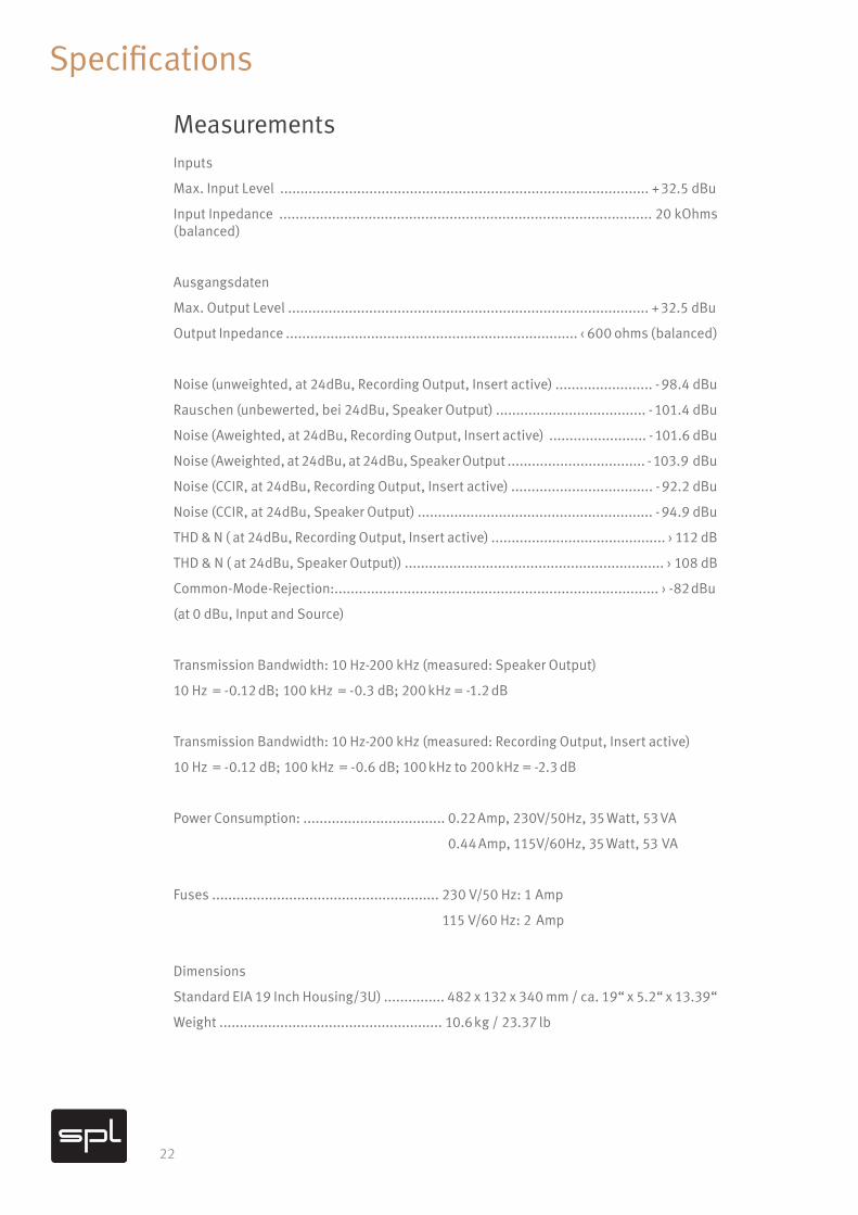
MeasurementsInputs
Max. Input Level ........................................................................................... + 32.5 dBu
Input Inpedance ............................................................................................ 20 kOhms (balanced)
Ausgangsdaten
Max. Output Level ......................................................................................... + 32.5 dBu
Output Inpedance ........................................................................ ‹ 600 ohms (balanced)
Noise (unweighted, at 24dBu, Recording Output, Insert active) ........................ - 98.4 dBu
Rauschen (unbewerted, bei 24dBu, Speaker Output) ..................................... - 101.4 dBu
Noise (Aweighted, at 24dBu, Recording Output, Insert active) ........................ - 101.6 dBu
Noise (Aweighted, at 24dBu, at 24dBu, Speaker Output .................................. - 103.9 dBu
Noise (CCIR, at 24dBu, Recording Output, Insert active) ................................... - 92.2 dBu
Noise (CCIR, at 24dBu, Speaker Output) .......................................................... - 94.9 dBu
THD & N ( at 24dBu, Recording Output, Insert active) ........................................... › 112 dB
THD & N ( at 24dBu, Speaker Output)) ................................................................ › 108 dB
Common-Mode-Rejection:................................................................................ › -82 dBu
(at 0 dBu, Input and Source)
Transmission Bandwidth: 10 Hz-200 kHz (measured: Speaker Output)
10 Hz = -0.12 dB; 100 kHz = -0.3 dB; 200 kHz = -1.2 dB
Transmission Bandwidth: 10 Hz-200 kHz (measured: Recording Output, Insert active)
10 Hz = -0.12 dB; 100 kHz = -0.6 dB; 100 kHz to 200 kHz = -2.3 dB
Power Consumption: ................................... 0.22 Amp, 230V/50Hz, 35 Watt, 53 VA
0.44 Amp, 115V/60Hz, 35 Watt, 53 VA
Fuses ........................................................ 230 V/50 Hz: 1 Amp
115 V/60 Hz: 2 Amp
Dimensions
Standard EIA 19 Inch Housing/3U) ............... 482 x 132 x 340 mm / ca. 19“ x 5.2“ x 13.39“
Weight ....................................................... 10.6 kg / 23.37 lb
23
Security Advices
Connections
Only use the connections as described. Other connections can lead to health risks and damage the equipment.
Water and humidity
Do not use this device anywhere near water (for example in a bath room, a damp cel-lar, near swimming pools, or similar environments). Otherwise your are dealing with an extremely high risk of fatal electrical shocks!
Insertion of objects or fluids
Be careful to not insert any object into any of the chassis openings. You can otherwise easily come into contact with dangerous voltage or cause a damaging short circuit. Never allow any fluids to be spilled or sprayed on the device. Such actions can lead to dangrous electrical shocks or fire!
Ventilation
The vent openings on the unit are meant to avoid the DMC from overheating. You should never cover nor block these openings.
Power Supply
Power the unit exclusively with the voltage rating specified on the unit. In case of doubt, contact your local dealer or electric provider. Disconnect the unit from the electric power grid if you are not going to use it for a long period of time. Unplug the power chord from the mains to cut power supply to the unit. Always make sure that the mains plug is easily accessible.
Opening the unit
Simply put: DON‘T, if you are not a certified SPL technician or engineer. Really: Do not open the device housing, as there is great risk you will damage the device, or – even after being disconnected – you may receive a dangerous electrical shock!
Cord protection
Make sure that your power and audio signal cords are arranged to avoid being stepped on or any kind of crimping and damage related to such event. Do not allow any equipment or furniture to crimp the cords. Power connection overloads: Avoid any kind of overload in connections to wall sockets, extension or splitter power cords, or signal inputs. Always keep manufacturer warnings and instructions in mind. Overloads create fire hazards and risk of dangerous shocks!
Lightning
Before thunderstorms or other severe weather, disconnect the device from wall power; do not do this during a storm in order to avoid life threatening lightning strikes. Similarly, before any severe weather, disconnect all the power connections of other devices and antenna and phone/network cables which may be interconnected so that no lightning damage or overload results from such secondary connections.
24
Security Advices
Controls and switches
Operate the controls and switches only as described in the manual. Incorrect adjustments outside safe parameters can lead to damage and unnecessary repair costs. Never use the switches or level controls to effect excessive or extreme changes.
Repairs
Unplug the unit from all power and signal connections and immediately contact a quali-fied technician when you think repairs are needed – or when moisture or foreign objects may accidentally have reached inside the housing, or in cases when the device may have fallen and shows any sign of having been damaged. This also applies to any situation in which the unit has not been subjected to any of these unusual circumstances but still is not functioning normally or its performance is substantially altered. In cases of damage to the power supply and cord, first consider turning off the main circuit breaker before unplugging the power cord.
Replacement/substitute parts
Be sure that any service technician uses original replacement parts or those with identical specifications as the originals. Incorrectly substituted parts can lead to fire, electrical shock or other dangers, including further equipment damage. Safety inspection: Be sure always to ask a service technician to conduct a thorough safety check and ensure that the state of the repaired device is in all respects up to factory standards.
Cleaning
Do not use any solvents, as these can damage the chassis finish. Use a clean, dry cloth (if necessary, with an acid-free cleaning oil). Disconnect the device from your power source before cleaning
Notes on Environmental Protection At the end of its operating life, this product must not be disposed of with regular house-hold waste but must be returned to a collection point for the recycling of electrical and electronic equipment. The wheelie bin symbol on the product, user‘s manual and pack-aging indicates that. The materials can be reused in accordance with their markings. Through reuse, recycling of raw materials, or other forms of recycling of old products, you are making an important contribution to the protection of our environment. Your local administrative office can advise you of the responsible waste disposal point.
WEEE Registration: 973 349 88.
25
Contact
SPL electronics GmbH
Sohlweg 80
41372 Niederkrüchten
Fon +49 (0) 21 63 98 34 0
Fax +49 (0) 21 63 98 34 20
E-Mail: [email protected]
Follow us on our Blog, Youtube, Twitter, Instagram and Facebook:
Website & Blog: spl.audio
Facebook: facebook.spl.audio
Instagram: instagram.spl.audio
Twitter: twitter.spl.audio
Videos: youtube.spl.audio
© 2018 SPL electronics GmbH
This document is the property of SPL and may not be copied or reproduced in any manner, in part or fully, without prior authorization by SPL. Sound Performance Lab (SPL) con-tinuously strives to improve its products and reserves the right to modify the product described in this manual at any time without prior notice. SPL and the SPL Logo are regis-tered trademarks of SPL electronics GmbH. All company names and product names in this manual are the trademarks or registered trademarks of their respective companies.
Declaration of CE Conformity
The construction of this unit is in compliance with the standards and regulations of the European Community.
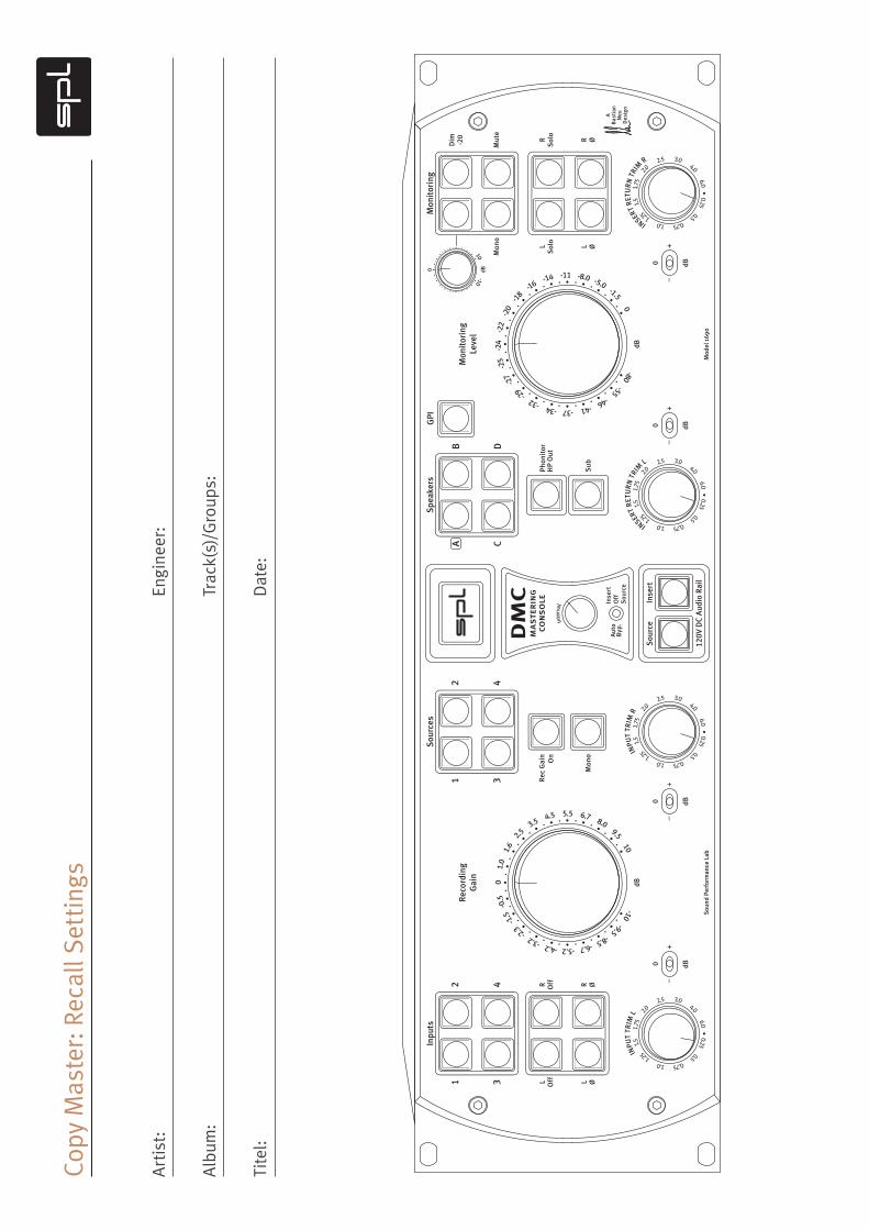
Copy
Mas
ter:
Rec
all S
ettin
gs
Art
ist:
Alb
um:
Tite
l:
Engi
neer
:
Trac
k(s)
/Gro
ups:
Dat
e:
120V
DC
Aud
io R
ail
DM
Cm
aste
rin
gco
nso
le Off
Inse
rt
Sou
rce
Auto
Byp
.
Inse
rtS
ourc
eInterval
-10 -9.5 -8.5 -6.7 -5.2 -4.2 -3.2 -2
.3 -1.
5 -
0.5
0
1.0
1
.6
2.5 3.5 4.5 5.5 6.7 8.0 9.5 10
-10
0
10
0.25 0.5 0.75 1.0 1.25
1
.5
1.
75
2.0
2.5 3.0 4.0 6.0 •
INPU
T TR
IM L
0.25 0.5 0.75 1.0 1.25
1
.5
1.
75
2.0
2.5 3.0 4.0 6.0 •
INPU
T TR
IM R
Sou
nd P
erfo
rman
ce L
abM
odel
169
0
+–
0
dBdB
dB
+–
0 dB
+–
0 dBdB
+–
0 dB
0.25 0.5 0.75 1.0 1.25
1
.5
1.
75
2.0
2.5 3.0 4.0 6.0 •
IN
SERT
RET
UR
N T
RIM
L
0.25 0.5 0.75 1.0 1.25
1
.5
1.
75
2.0
2.5 3.0 4.0 6.0 •
IN
SERT
RET
UR
N T
RIM
R
L Off L Ø
R Off R Ø
LS
olo
L Ø
RS
olo
R Ø
Mon
o
Dim -20
Mut
e
Mon
o
A C
B
Inpu
tsS
ourc
esS
peak
ers
GPI
Mon
itor
ing
D
Phon
itor
HP
Out
Rec
Gai
nO
n
Sub
ABas
tian
Neu
Des
ign
-80 -55 -46 -41 -37 -34 -32 -
29 -2
7
-25
-2
4
-22
-20
-1
8 -16 -1
4 -11 -8.0 -5.0 -1.5 0
Reco
rdin
gG
ain
Mon
itor
ing
Leve
l
12
34
12
34