relativistic interaction of laser pulses with plasmas
TRANSCRIPT
Reviews of Plasma Physics
Edited by V. D. Shafranov
Volume
KLUWER ACADEMIC/CONSULTANTS BUREAU NEW YORK • BOSTON • DORDRECHT • LONDON • MOSCOW

X Contents
RELATIVISTIC INTERACTION OF LASER PULSES WITH PLASMAS
S. V. Bulanov, F. Califano, G. I. Dudnikova, T. Zh. Esirkepov, I. N. Inovenkov,
F. F. Kamenets , Т. V. Liseikina, M. Lontano, K. Mima, N . M. Naumova, K. Nishihara,
F, Pegoraro, H. Ruhl, A. S. Sakharov, Y. Sentoku, V. A. Vshivkov,
V. V. Zhakhovskii
Introduction 227 1. Reiativistically strong electromagnetic waves in
underdense plasmas . . . . 237 1.1. Basic equations 237 1.2. Longitudinal reiativistically strong waves
in cold plasmas 239 1.3. Transverse reiativistically strong
electromagnetic waves 241 1.4. Stimulated Raman scattering 243 1.5. Self-modulation of laser pulses 245 1.6. Relativistic filamentation and self-focusing 247
2. Acceleration of charged particles and photons . . 249 2.1. Langmuir wave excitation 249 2.2. Charged particle acceleration by the "wake
field" . 254 2.3. Injection of charged particles into the
acceleration phase 255 2.4. Transverse wake-wave breaking 257 2.5. Upshifting of the electromagnetic wave
frequency during the interaction with nonlinear plasma waves . 262
Contents xi
3 Filamentation of the laser light and magnetic interaction of filaments of electromagnetic radiation . . 265 3.1. Generation of quasi-static magnetic field .........266 3.2. Merging of the filaments 266 3.3. Electron vortices 267 3.4. Hole boring and ion acceleration by a
petawatt laser pulse in underdense plasmas 273
4. Relativistic solitons 280 4.1. Envelope and sub-cycle circularly
polarized solitons 280 4.2. Relativistic subcycle solitons in the
2D case 283 4.3. 2D and 3D PIC simulations of soliton
generation 284 4.4. Influence of plasma inhomogeneity . . . . . . 288 4.5. Mechanism of soliton generation . . . . . . . . . . 291
5. Interaction of an ultrashort, relativistically strong, laser pulse with an overdense plasma 291 5.1. Oblique incidence on a non-uniform
plasma 292 5.2. Small amplitude electromagnetic waves in
non-uniform plasmas 293 5.3. Non-linear plasma dynamics near a sharp
boundary 294 5.4. Plasma resonance 296 5.5. "Vacuum heating" of the electrons ........ 298 5.6. Ion acceleration during "vacuum heating"
of electrons 299 5.7. Channel boring and soliton generation
during the propagation of a laser pulse in an inhomogeneous plasma 300
6. Nonlinear interaction of laser pulses with a foil . ........ 305 6.1. Relativistic foil transparency and pulse
shaping 308

xii Contents
6.2. Induced backward focusing of the light reflected at a mirror deformed by the radiation 310
6.3. Change of the wave frequency and polarization . 3 1 1
6.4. The oscillating mirror model for high harmonic generation . . . . .. . . . . . . . . . . 315
6.5. Ion acceleration during the interaction of a laser pulse with a slab of overdense plasma 316
7. Coulomb explosion of a cluster irradiated by a high intensity laser pulse 320 7.1. Expansion of the non-neutral ion cloud ........ . 321 7.2. Results of 2D and 3D PIC computer
simulations of the Coulomb explosion of small clusters ................ 324
8. Conclusions 326 References 327
RELATIVISTIC INTERACTION OF LASER PULSES WITH PLASMAS
S. V. Bulanov, F. Califano, G. I. Dudnikova, T. Zh. Esirkepov, I. N. Inovenkov,
F. F. Karnenets, T. V. Liseikina, M. Lontano, K. Mirna, N. M. Naurnova, K. Nishihara,
F. Pegoraro, H. Ruhl, A. S. Sakharov, Y. Sentoku, V. A. Vshivkov,
V. V. Zhakhovskii
Introd uction
Over the last few years we have witnessed extremely rapid progress in laser technology. The laser intensity I has increased by two orders of magnitude every couple of years and has now reached a value of I ~ 1021 W cm-2 in the radiation emitted by petawatt lasers [1]. The electric field of these pulses is of the order of 1012 V cm-1 , significantly exceeding the interatomic field. Such a large electric field fully ionizes the matter with which it interacts and can force the electrons in the plasma to oscillate with relativistic energy. In these regimes the specific features of the nonlinear dynamics of collision less plasmas and their interaction with electromagnetic waves become very important and attractive for theoretical studies.
In the relativistic range of amplitudes of laser radiation, when its intensity is above 1018 W cm-2 , the ratio VE/C becomes close to one in the case of laser light with wavelength IJ.lm. Here VE is the quiver oscillation velocity of electrons in the laser field. In particular this means that the magnetic part of the
227
V. D. Shafranov (ed.), Reviews of Plasma Physics
© Kluwer Academic/Plenum Publishers, New York 2001
228 S. V. Bulanov et al
Lorentz force ev x B / c becomes as important as the electric part e;E. Relativistic effects modify the nonlinear processes that are known in the limit of moderate radiation amplitudes and make it possible for essentially new nonlinear phenomena to occur.
Problems of the interaction of relativistically strong laser radiation with plasmas which are of increasing interest find various broad applications in the development of new concepts of compact laser-based accelerators of charged particles [2], powerful ultra-fast X-ray sources (see [3]) and controlled nuclear fusion in the framework of the Fast Ignition Concept [4]. They are also connected with problems of propagation of relativistically strong electromagnetic waves in space plasmas and with the mechanisms of acceleration of cosmic rays [5]. Particle acceleration by an ultra-intense laser pulse interacting with a plasma also has practical applications to laser induced nuclear reactions [6], ion injection into conventional accelerators, hadrontherapy in medicine [7] and, for extreme accelerations, to the testing of Unruh radiation [8]. When a petawatt laser pulse interacts with matter, conditions can be produced that were imagined to occur only in astrophysical objects. This opens the way for experimental plasma astrophysics to study the properties of matter under these extreme conditions [9].
One of the most attractive applications of ultra-short superintense laser pulses is connected with the development of new methods of accelerating charged particles. It seems that presently operating accelerators of charged particles have approached their maximum reasonable size. The main restriction on the accelerator size is imposed by the critical value of the electric field strength, of order Ecr ~ 106 V cm-t . If this value is exceeded an electric discharge forms on the chamber walls. These difficulties were evident as far back as the fifties when V. I. Veksler, G. I. Budker and Ya. B. Fainberg proposed the use of collective electric fields excited in a plasma (collective methods of acceleration) to accelerate charged particles (see [10]). The generation of high energy particles, both electrons and ions, when strong electromagnetic radiation interacts with a plasma is a well known basic
Relativistic Interaction of Laser Pulses With Plasmas 229
phenomenon [11]. However it is necessary to find the plasma and radiation parameters that optimize this process.
Among the wide variety of methods for generating a regular electric field in plasmas with strong laser radiation, the most attractive at the present time is the scheme [2, 12] of the laser wake field accelerator (LWFA). In this method a strong Langmuir wave is excited in the plasma and the charged particles are accelerated by the electric field of this wave. The advantages of Langmuir waves for charged particle acceleration, emphasized in Ref. [12], are related to the fact that the electric field in the wave is longitudinal and that its frequency wpe does not depend on the wave vector. This means that the group velocity of a Langmuir wave in a cold plasma, 8wpe /8k, is equal to zero, i.e., the wave stays in the plasma for a long time at the place where it is generated and can be used for charged particle acceleration. A plasma wave with wavenumber kp = c/ wpe has a relativistic phase velocity, and the charged particles at resonance can be accelerated up to ultra-relativistic energies.
Another fascinating suggestion for using ultra short laser pulses is related to a scheme which aims at achieving fusion conditions with a reduced laser pulse drive energy [4]. In the standard scheme of inertial confinement fusion (ICF) a pellet containing high pressure deuterium-tritium (DT) fuel is made to achieve a large isoentropic compression by ensuring a high degree of symmetrical irradiation of the driving nanosecond laser pulse. A significant amount of laser energy is needed in order to create at the center of the target with converging shock waves a hot spark with the required high temperature. Then a burn wave propagates through the fuel via alpha particle heating. The amount of additional energy needed in order to reach high gain depends on the degree of spherical convergence, which can be spoiled by the development of a Rayleigh-Taylor instability. On the contrary, in the fast ignition scheme it is suggested that a multi-terawatt laser pulse drills a channel towards the center in a precompressed target. Then, a picosecond petawatt pulse accelerates electrons up to multi-MeV energy values. The relativistic
230 S. V. Bulanov et al
electrons heat a small portion of the fuel before it can disassemble. A number of fundamental questions must be addressed in this scheme, such as the hole drilling and the transport of the laser pulse energy, the acceleration of fast particles and their interaction with a dense plasma.
The laser radiation is characterized by its incidence angle on the plasma, () and by its polarization, which can be circular, elliptic or linear. In the case of linear polarization, for oblique incidence one distinguishes s- and p-polarized waves. We consider a laser pulse of length lp, with electric field amplitude Eo, and carrier frequency Woo In describing the laser pulse interaction with plasmas, it is convenient to use dimensionless units in order to characterize the plasma density and the laser pulse amplitude.
The plasma density can be described by a dimensionless parameter defined as the ratio of the density n to the critical density ncr. In a plasma with density equal to the critical density, the carrier frequency of the laser radiation Wo is equal to the Langmuir frequency wpe = (47rne2/me)1/2, i.e., wo/wpe = (ncr /n)1/2 = 1. When wo/wpe > 1 the plasma is described as "underdense." Such a plasma is transparent to the laser radiation. The group velocity of the electromagnetic wave is close to the speed of light. A plasma where WO/wpe < 1 is described as "overdense." The electromagnetic radiation cannot penetrate deeply into an overdense plasma. It penetrates into the plasma as far as the evanescence length, which is of the order of de = c/wpe , where de is the collisionless skin depth. However, for relativistic intensities, the collisionless skin depth changes (the refractive index changes) and an overdense plasma can become transparent.
When the dimensionless ratio
eEo (1)
is much smaller than unity, the quiver velocity, VE = eEo/mewO, is small compared with the speed of light in vacuum, C (and the

Relativistic Interaction of Laser Pulses With Plasmas 231
quiver radius rE = eEo/mew5 is much shorter than the wavelength of the laser radiation, >. = 27rc/wo) and we can neglect relativistic effects and use classical mechanics in order to describe the interaction of the laser light with charged particles. In the opposite limit, when ao » 1, we must describe the laser-matter interaction in the framework of the relativistic theory.
First of all the relativistic effects qualitatively modify the charged particle dynamics in the field of the electromagnetic wave. From the exact solution of the equations of motion of a charged particle in a planar electromagnetic wave [13] it follows that the transverse component of the generalized momentum is constant,
e P.l - -A.l(x - ct) = constant, (2)
c and the energy and the longitudinal component of the momentum are related as
2 ( 2 4 2 2 2 2) 1/2 ( ) meC 'Y - Pllc = mec + P.l C + Pllc - Pllc = constant. 3
In the reference frame, where the charged particle was at rest before the interaction with the laser pulse, the particle kinetic energy K = m ec2 ("( - 1) and momentum p are given by the expressions (see Ref. [14])
K = ~meC2Ia.l(x - ct)1 2 ,
P.l = meca.l(x - ct), Pli = ~meC la.l(x - ct)1 2 (4)
Here a.l(x - ct) = eA.l(x - ct)/mec2. We see that for la.ll > 2 the particle acquires a relativistic energy and the longitudinal component of its momentum is larger than the transverse component.
We shall call the laser radiation with ao » 1 superintense or relativistically strong. The dimensionless amplitude of the electromagnetic wave (1) can also be expressed, via the radiation intensity I and the wavelength >., as:
[ 2]~ ao = (I/1.35 X 1018 W cm-2) (>'/lJlm)
232
0
S. V. Bulanov et al
a
t = 60.0 20 15 10 5
0 10 20 30
~o
o
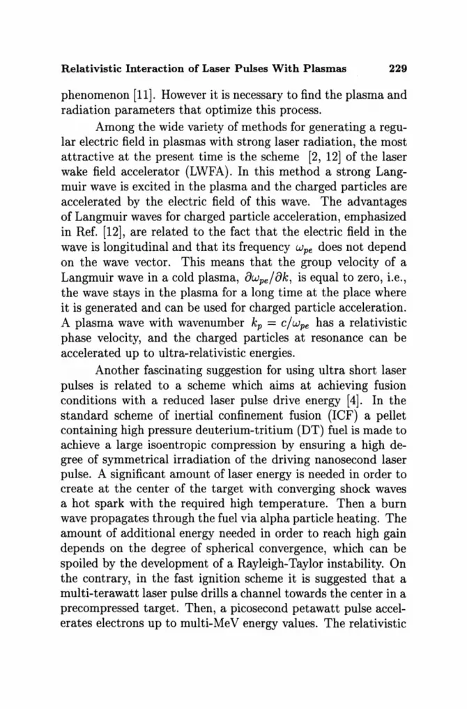
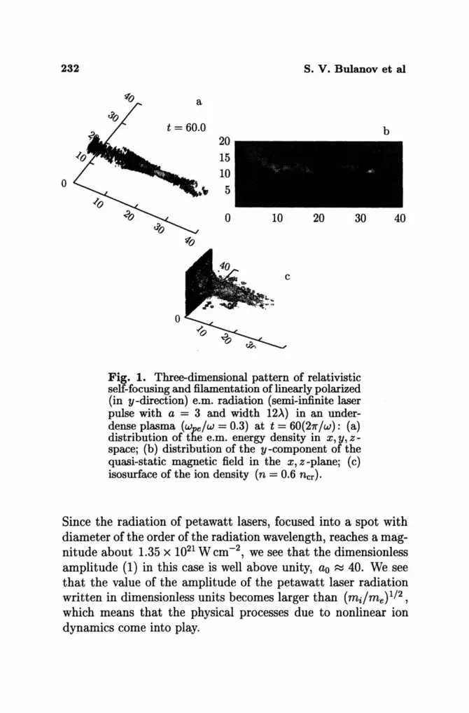
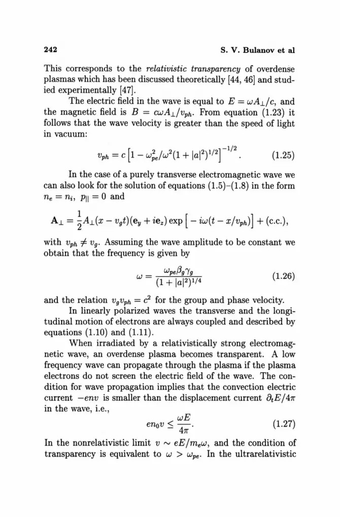
Fig. 1. Three-dimensional pattern of relativistic self-focusing and filament at ion of linearly polarized (in y-direction) e.m. radiation (semi-infinite laser pulse with a = 3 and width 12>.) in an underdense plasma (w e/w = 0.3) at t = 60{21r/w): (a) distribution of the e.m. energy density in x, y, zspace; (b) distribution of the y -component of the quasi-static magnetic field in the x, z-plane; (c) isosurface of the ion density (n = 0.6 ncr).
b
40
Since the radiation of petawatt lasers, focused into a spot with diameter of the order of the radiation wavelength, reaches a magnitude about 1.35 x 10²¹ W cm -2, we see that the dimensionless amplitude (1) in this case is well above unity, ao ~ 40. We see that the value of the amplitude of the petawatt laser radiation written in dimensionless units becomes larger than (mdme)1/2, which means that the physical processes due to nonlinear ion dynamics come into play.
Relativistic Interaction of Laser Pulses With Plasmas 233
Probably the most impressive nonlinear phenomenon in an underdense plasma is the self-focusing of laser radiation. Selffocusing, discovered by G. A. Askar'yan in 1962 [15], appears due to the nonlinear change of the refractive index of the medium in the region where a high intensity electromagnetic wave propagates. In the multi-terawatt or petawatt laser pulse-plasma interaction self-focusing appears due to the relativistic increase in the electron mass and to the plasma density redistribution under the action of the ponderomotive force (see Fig. 1). The threshold (critical) power for relativistic self-focusing is [16, 17, 18]
Pc ~ 2m;c5w~/e2w;e ~ 17(wo/wpe )2 GW. (5)
When the laser power far exceeds the critical power, the laser beam may split into separate filaments.
In Figure 1 we present the results of 3D PIC simulations of laser beam propagation in an underdense plasma. The selffocusing of the linearly polarized pulse is anisotropic in the plane perpendicular to the pulse propagation according to the direction of the light polarization.
Superintense laser radiation in a plasma is subject to a host of instabilities. The fastest is the stimulated Raman scattering (SRS) instability [19, 20], which develops on the electron time-scale. Stimulated forward Raman scattering (SFRS) leads to self-modulation of the laser pulse with a modulation length of the order of 27r /kp = 27rc/wpe [21-26]. Self-modulation of the laser pulse is of great importance for the LWFA, where the laser pulse excites a longitudinal electric field, which in turn accelerates electrons up to high energies [2, 27-29].
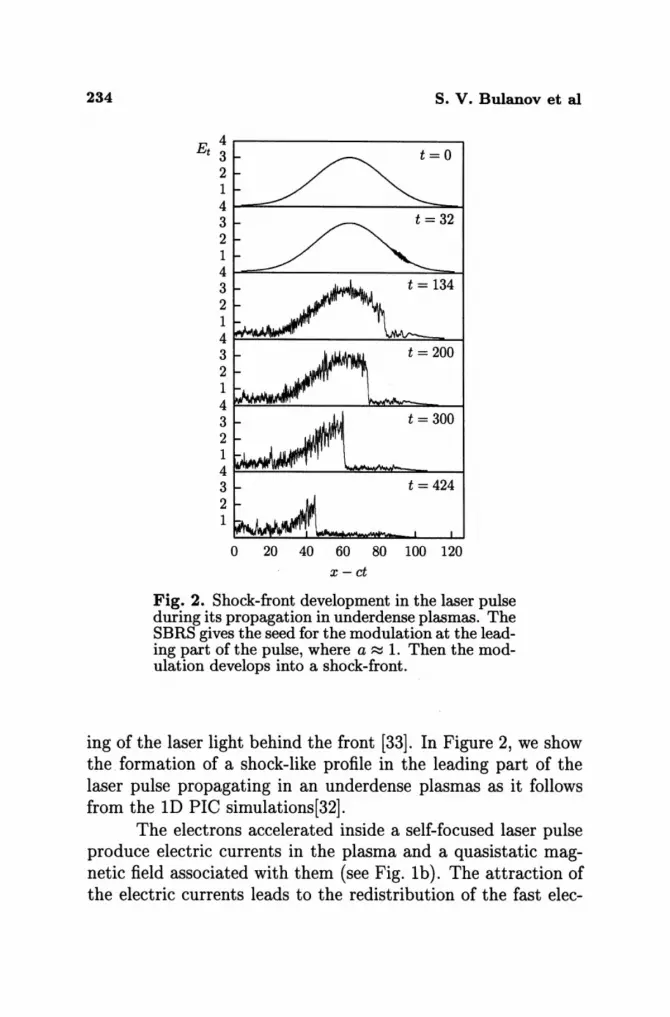
For ultrashort superintense laser pulses, the stimulated backward Raman scattering (SBRS) instability is the first to develop. SBRS leads to the erosion of the amplitude profile at the leading edge of the pulse and to the formation of a steep laser front similar to a shock in a time of the order of w;/(wO/Wpe )2. Such a shock front generates a wake field, which accelerates the electrons in the plasma, thus leading [32, 24] to fast depletion of the laser-pulse energy, tdep rv (wO/Wpe?Tp, and to induced focus-
234 s. v. Bulanov et al
4.----------------, Et 3 t=O
2 1 4t--=---------.;:===--I 3 2 1 41-""'=---------.;:=-; 3 2 1 4~~~------~~=-~ 3 2 1 4~~~----~~~--~ 3 2
1 L.loII.iilMlUlIM/l' 4~~~~--~~~----~
3 2 1
o 20 40 60 80 100 120 x-ct
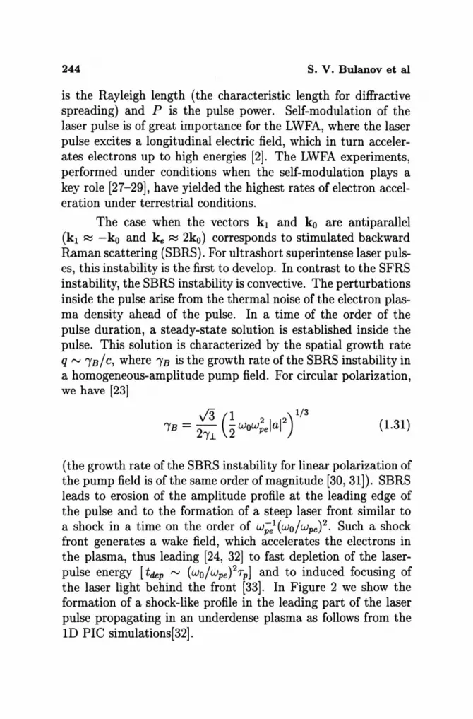
Fig. 2. Shock-front development in the laser pulse during its propagation in underdense plasmas. The SBRS gives the seed for the modulation at the leading part of the pulse, where a ~ 1. Then the modulation develops into a shock-front.
ing of the laser light behind the front [33]. In Figure 2, we show the. formation of a shock-like profile in the leading part of the laser pulse propagating in an underdense plasmas as it follows from the ID PIC simulations[32].
The electrons accelerated inside a self-focused laser pulse produce electric currents in the plasma and a quasistatic magnetic field associated with them (see Fig. Ib). The attraction of the electric currents leads to the redistribution of the fast elec-

Relativistic Interaction of Laser Pulses With Plasmas 235
trons. This in turn changes the refractive index because, due to the relativistic increase of the electron mass, the effective plasma frequency is smallest in the regions with the highest concentration of fast electrons. This process causes high intensity laser radiation to interact magnetically in plasmas, makes the laser light filaments merge and provides a mechanism for transporting the laser energy over long distances [34].
As a consequence of the equation
V x B = - 47ren v, c
(6)
in a plasma dominated by the electron dynamics the quasistatic magnetic field is associated with electron fluid vortices. In this case the vorticity is V x v = c~B /47ren. Both the electrostatic wake fields and the magnetic field vortices stay in the plasma much longer than the laser pulse because of their very low propagation velocity. On the other hand, sharply focused bunches of ultrarelativistic electrons, accelerated during the breaking of the wakewave, can generate a strong magnetic field which propagates together with the bunch and which is due to the magnetic component of the Lienard-Wiechert potential of the electron bunch [35].
In an overdense plasma with WO/wpe < lone can never neglect the plasma inhomogeneity. The laser radiation penetrates the plasma to just over the evanescence length which is of the order of the collision less skin depth. When the plasma has a sharp boundary the laser plasma interaction takes place at the plasmavacuum interface. At a sharp plasma-vacuum interface the laser radiation can easily extract the electrons from the plasma and accelerate them towards the vacuum region. This process, known as "vacuum heating of the electrons" [36], provides an effective mechanism of anomalous absorption of the laser light. At a steep plasma-vacuum interface the laser radiation radiates harmonics due to the so called "oscillating mirror" mechanism or due to the nonlinear motion of the electrons in the narrow region near the plasma boundary [37].

236 S. V. Bulanov et al
When the plasma has a smooth density distribution, the Langmuir frequency is a function of the coordinates wpe(r), and the processes that occur in the vicinity of the critical surface, in the region of the plasma resonance where Wo = wpe(r), playa key role [20]. In the plasma resonance region the electromagnetic wave resonantly excites an electric field with a very high amplitude, localized in a narrow region where the laser radiation is absorbed and fast particles are generated [11].
The interaction of laser pulses with overdense plasmas is of great importance for the development of high intensity Xray sources and controlled nuclear fusion. The ponderomotive pressure causes a plasma density redistribution in the transverse direction that changes the refractive index and allows the laser pulse to penetrate into an overdense plasma. This is the basic idea of the hole boring and of the laser energy transport in the fast ignition concept ICF [4].
Recently a new type of target for laser-matter interaction has appeared which consists of a gas made up of clusters that are relatively small pieces of a solid material. Very efficient absorption of the laser energy interacting with the clusters and the formation of very high temperature underdense plasmas have been demonstrated in Refs. [39-41]. Such high temperature plasmas make table top fusion experiments possible [40].
The complexity of the laser-plasma interaction due to the high dimensionality of the problem, to the lack of symmetry and to the importance of nonlinear and kinetic effects prevents analytical methods from providing a detailed description. On the other hand, powerful methods for investigating the laser-plasma interaction have become available through the advent of modern supercomputers and the developments of applied mathematics [43]. In the case of ultra-short relativistically strong laser pulses, simulations with 3D Particle In Cell codes provide a unique opportunity to adequately describe the nonlinear dynamics of laser plasmas, including nonlinear wave breaking, the acceleration of charged particles up to high energy and the generation of coherent nonlinear structures such as relativistic solitons and vortices.
Relativistic Interaction of Laser Pulses With Plasmas 237
1. Relativistically strong electromagnetic waves in underdense plasmas
Constant amplitude solutions of the equations for linear electromagnetic and Langmuir waves can be written in the form of waves propagating with constant velocity: u(x, t) = Ut cos[kx(k2c2 + w;e)1/2t] and u(x, t) = Ul cos(kx - wpet). In both cases the frequency and the velocity of propagation do not depend on the wave amplitude. This is a property of linear, small amplitude, waves. In the case of finite amplitude waves the frequency depends on the wave amplitude. In the theory of the interaction of high-intensity laser radiation with plasmas the seminal paper by Akhiezer and Polovin [44] played a key role for many years. In this paper the exact solution to the problem of the propagation of a relativistically strong electromagnetic wave in a collisionless plasma was found.
1.1. Basic equations
We now turn to the study of finite amplitude waves in a cold collisionless plasma [44]. Assuming also that the ions are at rest, we consider the model of an unbounded cold collisionless plasma, described by Maxwell's equations and by the hydrodynamic equations of an electron fluid in a fixed ion background with ion density no (x) :
1 1 47rene ( e) ~A - -ottA - -'Vot<P - P + -A = 0, c2 c mec2"( c
1 ne = ni(x) + -4 ~<P,
7re
OtP = 'V (e<p - meC2"() + ~ (p + ~A) x ('Vxp) .
(1.1)
(1.2)
(1.3)
The continuity equation is implied by equations (1.1) and (1.2). These equations are written in the Coulomb gauge:
'V·A = o. (1.4)
238 s. v. Bulanov et al
Here P is the canonical electron momentum, P = p-eA/c, and
the relativistic Lorentz factor is , = [1+(P+eA/c)2 /(mec2) f/2. Let us consider the case where all the variables that char
acterize the fields and the plasma are independent of y and z, so that 8y = 8z = O. This implies Ax = 0 and P y = Pz = O. We can rewrite equations (1.1)-(1.3) in components as
8xt cp - 47renePII/meCf = 0, (1.5)
8xxA1.. - 8tt A1.. - (47re2ne/mec2,)A1.. = 0, (1.6)
ne = ni(x) + 8xx'P/47re, (1.7)
8tPil + 8x (ecp - me~,) = 0, (1.8)
[ ]1/2
where, = 1 + (eA1../mee)2 + (PIi/meC)2 . The subscripts II and 1.. denote the components of the vectors along and perpendicular to the x -axis.
Assuming that the ion density is homogeneous and that the wave propagates with constant velocity Vph, we look for solutions that depend on the variable X = x - Vpht. We obtain for the electron density
(1.9)
and
0, (1.10)
O. (1.11)
Here and below /3ph = Vph/C, and 'ph = (1 - /3;h)-1/2, a prime denotes differentiation with respect to variable X.

Relativistic Interaction of Laser Pulses With Plasmas 239
1.2. Longitudinal relativistically strong waves in cold plasmas
Assuming the transverse components of electron momentum to be zero which implies A..l = 0, we obtain from equation (1.10):
(1.12)
where 1m = [1 + (Pm/meC)2f/2 = 1/(1 - f3~)1/2 is an integration constant, and 13m is the maximum value of the electron velocity in the longitudinal wave normalized on c: -13m ~ 13 = PII/mec, ~ 13m. Integrating equation (1.12) we obtain
V2f3Ph W;e X = J,m - I - 2f3ph [F (\l1,~) - (fm + l)E (\l1, ~)] , (1.13)
where F (\l1,~) and E (\l1,~) are incomplete elliptic integrals of the first and second kind, while
and ~ = _'m __ ( _1)1/2 1m + 1
are their argument and modulus, respectively. In a relativistically strong Langmuir wave the electric field depends on the coordinate X through the relationship
(1.14)
We see that the maximum electric field is at the point where PII(X) = O.
The expression for I given by equation (1.13) is periodic in X. For the wave frequency we get
1 [ ]-1 W = 27rWpe K (~) - (fm + l)E (~) , (1.15)
where K (~) and E (~) are complete elliptic integrals of the first and second kind. We see that the wave frequency does not

240 s. v. Bulanov et al
depend on the phase velocity of the wave. This means that the wave is not dispersive. One can obtain simple formulae for the frequency in two limiting cases: small and large amplitudes of the wave. In the first case when Pm « 1, the frequency is
(1.16)
which corresponds to the nonlinear shift of the frequency. In the second limiting case when "1m » 1 the frequency is equal to
(1.17)
Rewriting this expression in terms of the maximum value of the electron momentum, Pm = meC ("I! - 1) 1/2, we obtain that the period of the wave is T = 21f /W = 4(Pm/2meC)I/2 w;/. A finite amplitude longitudinal wave is not harmonic and its spectrum contains all odd and even harmonics of the Langmuir frequency.
The expression given by equation (1.9) becomes singular when the maximum velocity of the electrons in the wave becomes equal to the wave phase velocity, i.e., when "I = "Iph = (1 - f3~h)-1/2. This corresponds to so called wave breaking [44]. Close to the wave-breaking limit when, cf3m --+ Vph the maximum of the electron density tends to infinity while the width of the density spike tends to zero. For cf3m = Vph, from equations (1.9) and (1.13) we obtain that the electron density in the spike tends to infinity as
1/3 ( )-2/3 n(X)/no = 2 "1m 3wpeX / cf3m + ... (1.18)
as X --+ O. We see that the characteristic cusp like pattern P ex: X 2/ 3 appears in the phase plane (see also [45]):
(1.19)
However, integrating the electron density (1.18) in the neighborhood of the singularity we find that the total number of particles in the density spike is finite.
Relativistic Interaction of Laser Pulses With Plasmas 241
The wave breaking imposes a constraint on the maximum value of the electric field in the wave,
which is the Akhiezer-Polovin limiting electric field.
1.3. Transverse relativistically strong electromagnetic waves
(1.20)
For a purely transverse electromagnetic wave, from equation (1.11) with PII = 0 we find that the wave is circularly polarized and the amplitude of the vector potential A.l,
is constant and the frequency is
(1.21)
where (1.22)
In x, t-coordinates this corresponds to the dispersion equation for the frequency and wavenumber
2 2 _ k2 2 Wpe
W - C + (1 + laI2)1/2' (1.23)
The dispersion equation (1.23) can be rewritten in the form [ ]1/2
k = w2(1 + laI2)1/2 - W;e /c(l + laI2)1/4. We see that an elec-tromagnetic wave can propagate in an overdense plasma, where W ~ wpe , provided
(1.24)
242 s. v. Bulanov et al
This corresponds to the relativistic transparency of overdense plasmas which has been discussed theoretically [44, 46] and studied experimentally [47].
The electric field in the wave is equal to E = wAJ../ c, and the magnetic field is B = CWAJ../Vph' From equation (1.23) it follows that the wave velocity is greater than the speed of light in vacuum:
(1.25)
In the case of a purely transverse electromagnetic wave we can also look for the solution of equations (1.5)-(1.8) in the form ne = ni, PII = 0 and
AJ.. = ~AJ..(x - vgt)(ey + iez ) exp [ - iw(t - X/Vph)] + (c.c.),
with Vph =1= vg. Assuming the wave amplitude to be constant we obtain that the frequency is given by
wpe!3g"(g
w = (1 + la12)1/4 (1.26)
and the relation VgVph = c2 for the group and phase velocity. In linearly polarized waves the transverse and the longi
tudinal motion of electrons are always coupled and described by equations (1.10) and (1.11).
When irradiated by a relativistically strong electromagnetic wave, an overdense plasma becomes transparent. A low frequency wave can propagate through the plasma if the plasma electrons do not screen the electric field of the wave. The condition for wave propagation implies that the convection electric current -env is smaller than the displacement current atE / 47r in the wave, i.e.,
wE enov ~ 47r' (1.27)
In the nonrelativistic limit v '" eE / mew, and the condition of transparency is equivalent to w > wpe' In the ultrarelativistic
Relativistic Interaction of Laser Pulses With Plasmas 243
limit v ~ c, and we can write that the plasma becomes transparent if
(1.28)
1.4. Stimulated Raman scattering
The fastest instability which leads to the erosion of the laser pulse is the stimulated Raman scattering (SRS) instability [19, 20], which develops on the electron time-scale. In SRS, an electromagnetic pump wave (wo, ko) is scattered by a plasma wave (we, k e,), which in turn is excited by the beating of the pump and the scattered (WI, k l ) waves. Thus, there is a feedback loop, which results in the onset of the instability. The frequencies and wavenumbers of the waves involved satisfy the conditions:
(1.29)
The case when the vectors ki and ko are nearly parallel (k1 ~ ko and ke ~ kp = wpe/c « ko) corresponds to stimulated forward Raman scattering (SFRS). This involves the self-modulation of the laser pulse with modulation length of the order of 2rr/kp = 2rrc/wpe [21-26]. For direct forward scattering, the characteristic rise time of the SFRS-induced modulation of a superintense circularly polarized laser pulse is of the order of tm rv l/Tp"Y~ [23, 24], where Tp is the pulse duration,
w;elal "YF =
V8 wo"Yl (1.30)
is the growth rate of the SFRS instability in a homogeneousamplitude pump field (we have assumed Tp"YF < 1), and "Y.l = (1 + laI2)1/2 is the relativistic factor of plasma electrons oscillating in the pump field. SRS at small angles (0 rv l/kprp « 1 with rp being the laser spot size) also involves modulation of the spot-size and develops in a time of the order of tm rv
(lR/ c) (Pc/ P)-1/2 X (WpeTp)-1/2 [21, 25, 26], where lR = kor;/2
244 S. V. Bulanov et al
is the Rayleigh length (the characteristic length for diffractive spreading) and P is the pulse power. Self-modulation of the laser pulse is of great importance for the LWFA, where the laser pulse excites a longitudinal electric field, which in turn accelerates electrons up to high energies [2]. The LWFA experiments, performed. under conditions when the self-modulation plays a key role [27-29], have yielded the highest rates of electron acceleration under terrestrial conditions.
The case when the vectors kl and ko are antiparallel (k1 ~ -ko and ke ~ 2ko) corresponds to stimulated backward Raman scattering (SBRS). For ultrashort superintense laser pulses, this instability is the first to develop. In contrast to the SFRS instability, the SBRS instability is convective. The perturbations inside the pulse arise from the thermal noise of the electron plasma density ahead of the pulse. In a time of the order of the pulse duration, a steady-state solution is established inside the pulse. This solution is characterized by the spatial growth rate q t"V "IB / c, where "IB is the growth rate of the SBRS instability in a homogeneous-amplitude pump field. For circular polarization, we have [23]
(1.31)
(the growth rate of the SBRS instability for linear polarization of the pump field is of the same order of magnitude [30, 31]). SBRS leads to erosion of the amplitude profile at the leading edge of the pulse and to the formation of a steep laser front similar to a shock in a time on the order of w;e1{wO/wpe )2. Such a shock front generates a wake field, which accelerates the electrons in the plasma, thus leading [24, 32] to fast depletion of the laserpulse energy [tdep t"V (wO/Wpe )2Tp] and to induced focusing of the laser light behind the front [33]. In Figure 2 we show the formation of a shock-like profile in the leading part of the laser pulse propagating in an underdense plasma as follows from the 1D PIC simulations[32].
Relativistic Interaction of Laser Pulses With Plasmas 245
1.5. Self-modulation of laser pulses
As was noted above, self-modulation of the laser pulse corresponds to direct-forward or near-forward Raman scattering, which, depending on the plasma and laser pulse parameters, is accompanied by a longitudinal [23, 24, 26] or transverse [25, 26] redistribution of the laser energy. The self-modulation of a weakly relativistic (Ial « 1), fairly wide (kprp ~ 1) pulse can be described by the set of equations for the complex amplitude of the laser field and for the perturbation of the electron density [26] that follows from equations (1.1)-(1.3):
(1.33)
where X = x - Vgt with Vg = c2ko/wo the pulse group velocity (vg ~ c). The mechanism for the modulation instability is as follows. An initial perturbation of the electron density with longitudinal wavenumber close to kp (such a seed electron density wave can be excited, e.g., by a sharp leading edge of the pulse [48, 49] ) results in the redistribution of the laser field energy and causes a modulation of the pulse amplitude with the same longitudinal wavenumber. In turn, this modulation enhances the electron density perturbation. In fact, the self-modulation is mainly related to the change in the refractive index of the plasma caused by the perturbations of the electron density (the first term in brackets on the right-hand side of (1.32)), whereas the relativistic change in the electron mass (the second term in brackets on the right-hand side of (1.32)) is of relatively minor importance. For sufficiently long pulses, the self-modulation can develop in a time shorter than the diffractive spreading time even for P« Pc.
Different regimes of the self-modulation instability are related to whichever, among the terms after 2iwoaA~/at in the
246 S. V. Bulanov et al
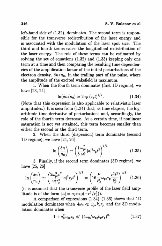
left-hand side of (1.32), dominates. The second term is responsible for the transverse redistribution of the laser energy and is associated with the modulation of the laser spot size. The third and fourth terms cause the longitudinal redistribution of the laser energy. The role of these terms can be estimated by solving the set of equations (1.32) and (1.33) keeping only one term at a time and then comparing the resulting time dependencies of the amplification factor of the initial perturbations of the electron density, 8n/no, in the trailing part of the pulse, where the amplitude of the excited wakefield is maximum.
1. When the fourth term dominates (first 1D regime), we have [23, 24]
(1.34)
(Note that this expression is also applicable to relativistic laser amplitudes.) It is seen from (1.34) that, as time elapses, the logarithmic time derivative of perturbations and, accordingly, the role of the fourth term decrease. At a certain time, if nonlinear saturation is not yet attained, this term becomes smaller than either the second or the third term.
2. When the third (dispersion) term dominates (second 1D regime), we have [24, 26]
In (8n) ~ (~W;e lal2~ t2) 1/3 no 8 wg p
(1.35)
3. Finally, if the second term dominates (3D regime), we have [25, 26]
(8) (2 3 2 )1/3 (P r?t2 ) 1/3 In n: ~ :;;; lal2Tpt2 = 16 Pc WpeTp l~ (1.36)
(it is assumed that the transverse profile of the laser field amplitude is of the form lal = ao exp( -r2 /r~)).
A comparison of expressions (1.34)-(1.36) shows that 1D modulation dominates when 4wo « wpekpr p and the 3D modulation dominates when
1 + a~wpeTp « (4wo/wpekprp)2. (1.37)

Relativistic Interaction of Laser Pulses With Plasmas 247
If the inequalities
1 « (4wo/wpekprp)2 « a6WpeTp (1.38)
are satisfied, the instability occurs in two stages: the instability starts as a 1D modulation (1.34) and, in the second stage, the modulation of the laser spot size dominates. In this case, the transition from 1D to 3D regime corresponds to In(c5n/no) ~ a~wpeTp(4wo/wpekprp)-2 » 1; i.e., the initial perturbation amplitude must be very small for such a transition to take place before the nonlinear saturation (c5n/no f'V 1) occurs. It also follows from (1.34)-(1.36) that, if (16P / Pc)WpeTp » 1, the modulation always develops in a time shorter than the diffractive spreading time lR/C.
These estimates show that the parameters of the experiments on the electron acceleration with ultaintense laser pulses [27-29] formally correspond to the first 1D regime of selfmodulation (1.34). In this case, however, the propagation of the laser pulse should also be affected by the formation of a shocklike front due to the finiteness of the pulse (see Fig. 2).
1.6. Relativistic filamentation and self-focusing
It has been shown [16] that, in a weakly relativistic regime (a~ « 1), a plane electromagnetic wave is subject to the socalled relativistic filamentation instability. The mechanism for this instability, which manifests itself in the splitting of the electromagnetic wave into narrow beams (filaments), is related to the relativistic increase in the mass of plasma electrons oscillating in the high-power laser field and to the corresponding increase in the plasma refractive index. If the wave amplitude is initially slightly modulated in the transverse direction, then the modulation of the refractive index causes the wave fronts to curve. This results in a redistribution of the electromagnetic field energy in the transverse direction so that the modulation amplitude increases, i.e., an instability develops. The filament at ion instability can be described in terms of the reduced equation for the
248 s. v. Bulanov et al
wave amplitude [51]
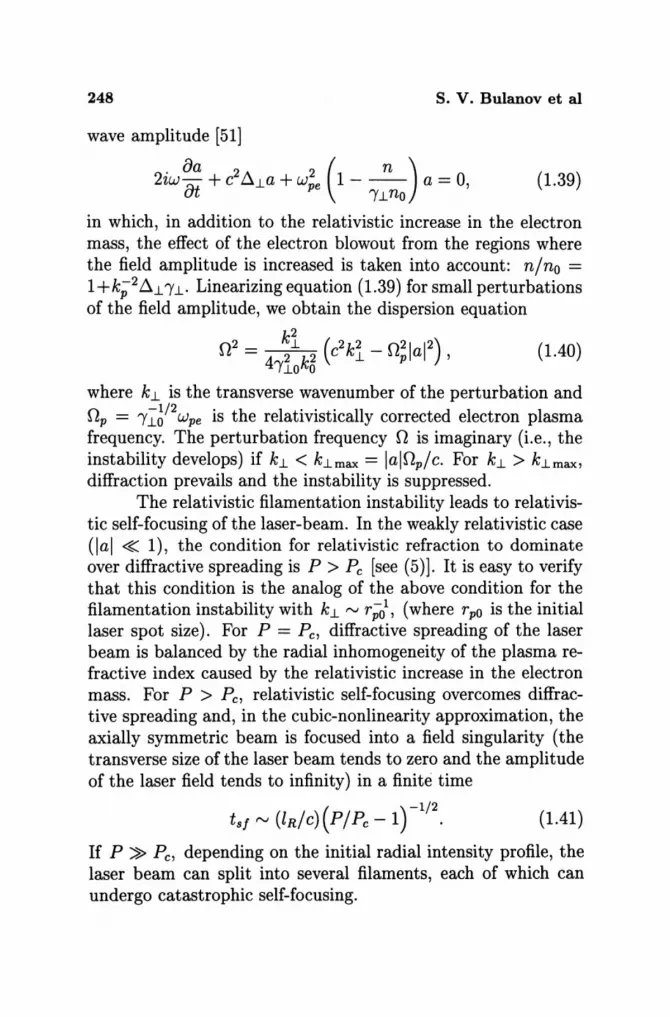
. 8a 2 2 ( n) 2zw£l + c ~~a + Wpe 1 - -- a = 0, ut I'~no
(1.39)
in which, in addition to the relativistic increase in the electron mass, the effect of the electron blowout from the regions where the field amplitude is increased is taken into account: nino = 1 +k;2 ~~ I'~. Linearizing equation (1.39) for small perturbations of the field amplitude, we obtain the dispersion equation
0 2 = kl (c2 k2 _ 021a12) (1.40) 41'1ok5 ~ p ,
where k~ is the transverse wavenumber of the perturbation and Op = 1'1:6/2 Wpe is the relativistically corrected electron plasma frequency. The perturbation frequency 0 is imaginary (i.e., the instability develops) if k~ < k~max = lalOplc. For k~ > k~max, diffraction prevails and the instability is suppressed.
The relativistic filamentation instability leads to relativistic self-focusing of the laser-beam. In the weakly relativistic case (Ial ~ 1), the condition for relativistic refraction to dominate over diffractive spreading is P > Pc [see (5)]. It is easy to verify that this condition is the analog of the above condition for the filamentation instability with k~ '" r;l, (where rpo is the initial laser spot size). For P = Pc, diffractive spreading of the laser beam is balanced by the radial inhomogeneity of the plasma refractive index caused by the relativistic increase in the electron mass. For P > Pc, relativistic self-focusing overcomes diffractive spreading and, in the cubic-nonlinearity approximation, the axially symmetric beam is focused into a field singularity (the transverse size of the laser beam tends to zero and the amplitude of the laser field tends to infinity) in a finite time
( )-1/2
tsf'" (lRlc) PIPe-1 . (1.41)
If P ~ Pc, depending on the initial radial intensity profile, the laser beam can split into several filaments, each of which can undergo catastrophic self-focusing.
Relativistic Interaction of Laser Pulses With Plasmas 249
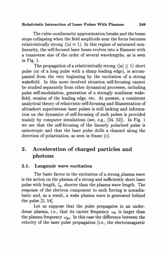
The cubic-nonlinearity approximation breaks and the beam stops collapsing when the field amplitude near the focus becomes relativistically strong (Ial ~ 1). In this regime of saturated nonlinearity, the self-focused laser beam evolves into a filament with a transverse size of the order of several wavelengths, as is seen in Fig. l.
The propagation of a relativistically strong (Ial 2: 1) short pulse (or of a long pulse with a sharp leading edge), is accompanied from the very beginning by the excitation of a strong wakefield. In this more involved situation self-focusing cannot be studied separately from other dynamical processes, including pulse self-modulation, generation of a strongly nonlinear wakefield, erosion of the leading edge, etc. At present, a consistent analytical theory of relativistic self-focusing and filamentation of ultrashort superintense laser pulses is still lacking and information on the dynamics of self-focusing of such pulses is provided mainly by computer simulations (see, e.g., [34, 52]). In Fig. 1 we see that the self-focusing of the linearly polarized pulse is anisotropic and that the laser pulse drills a channel along the direction of polarization, as seen in frame (c).
2. Acceleration of charged particles and photons
2.1. Langmuir wave excitation
The basic factor in the excitation of a strong plasma wave is the action on the plasma of a strong and sufficiently short laser pulse with length, lp, shorter than the plasma wave length. The response of the electron component to such forcing is nonadiabatic and, as a result, a wake plasma wave is generated behind the pulse [2, 54].
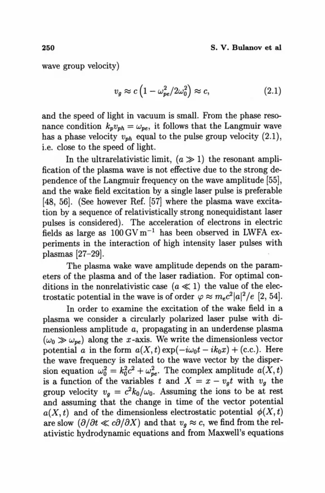
Let us suppose that the pulse propagates in an underdense plasma, i.e., that its carrier frequency Wo is larger than the plasma frequency wpe' In this case the difference between the velocity of the laser pulse propagation (i.e., the electromagnetic
250 S. V. Bulanov et al
wave group velocity)
(2.1)
and the speed of light in vacuum is small. From the phase resonance condition kpVph = wpe, it follows that the Langmuir wave has a phase velocity Vph equal to the pulse group velocity (2.1), i.e. close to the speed of light.
In the ultrarelativistic limit, (a ~ 1) the resonant amplification of the plasma wave is not effective due to the strong dependence of the Langmuir frequency on the wave amplitude [55], and the wake field excitation by a single laser pulse is preferable [48, 56]. (See however Ref. [57] where the plasma wave excitation by a sequence of relativistically strong nonequidistant laser pulses is considered). The acceleration of electrons in electric fields as large as 100 GV m- I has been observed in LWFA experiments in the interaction of high intensity laser pulses with plasmas [27-29].
The plasma wake wave amplitude depends on the parameters of the plasma and of the laser radiation. For optimal conditions in the nonrelativistic case (a «: 1) the value of the electrostatic potential in the wave is of order cp ::::::; mec2 lal 2/e [2,54].
In order to examine the excitation of the wake field in a plasma we consider a circularly polarized laser pulse with dimensionless amplitude a, propagating in an underdense plasma (wo ~ wpe ) along the x-axis. We write the dimensionless vector potential a in the form a(X, t) exp( -iwot - ikox) + (c.c.). Here the wave frequency is related to the wave vector by the dispersion equation w~ = k~c2 + w;e. The complex amplitude a(X, t) is a function of the variables t and X = x - Vgt with Vg the group velocity Vg = c2ko/wo. Assuming the ions to be at rest and assuming that the change in time of the vector potential a(X, t) and of the dimensionless electrostatic potential ¢>(X, t) are slow (a/ {)t «: ca / ax) and that Vg ::::::; c, we find from the relativistic hydrodynamic equations and from Maxwell's equations

Relativistic Interaction of Laser Pulses With Plasmas 251
(1.1)-(1.3) a system of coupled equations [48, 49]:
(2.2)
824> = k~ [1 + 1 a 12 - 1 8X2 2 (1 + 4>)2 1,
(2.3)
where kp = wpelvg. Here the vector potential a is normalized to mewocl e and the electrostatic potential 4> is normalized to m ec2 Ie. If a = 0, equation (2.3) describes free Langmuir oscillations in the limit Vph = c considered above [see equation (1.12)]. In a weakly relativistic limit equations (2.2)-(2.3) reduce to equations (1.32)-(1.33) in the case V 1.. = O.
If the laser pulse is assumed to be given as a square-pulse profile with amplitude ao (lal 2 = a~ at L < X < 0, and lal2 = 0 at X < L, X > 0), the analytical solution of equation (2.3) in the region occupied by the pulse can be expressed in terms of elliptic functions [48, 56]
kpX = -2 V1+ a5 E {arCSin [ (~ ~: ~rl ' (1+ ~5)1/2 }
2 (A. a~ - 4»1/2 + 'f' --'1'-+-4>- (2.4)
By matching this solution with the solution for the free plasma wave, we obtain that the typical value of the electrostatic potential in the plasma wave is [48, 56]
(2.5)
The optimal pulse length is L = 2(1 + a~)1/2 E [ao(1 + a~)-1/2] . The corresponding "wake field" has a wavelength equal to A = 23/2Iaolk;1, and the maximum electric field is
(2.6)

252 S. V. Bulanov et al
We emphasize that the electric field in the wake behind the laser pulse can be even higher in the case of a breaking Langmuir wave [59]. The maximum electron energy in the wake wave can be written using the first integral of equation (2.3) and is given by
(2.7)
Here the constant of integration is chosen such that there is no wake wave before the laser pulse. We see that the potential inside the laser pulse varies between zero and mec2a~/e. Behind the laser pulse, for an optimal pulse length, the electrostatic potential also scales as a~.
In the course of the wake wave excitation the laser pulse loses its energy. The typical time of laser pulse depletion is of the order of [32]: tnl ~ w;}(w/wpe)2ao1. This process is accompanied by a downshift of the laser radiation carrier frequency. This follows from the conservation of the first integral of equation (2.2)
f dX [la l2 - i Vg (a* aa - a aa*)] = f dX laI2~. (2.8) Wo ax ax Wo
Here the vector potential is supposed to be of the form a = lal exp [i'!9(X, t)] , and the local frequency is
a a'!9 W = at [wot - '!9(x - Vgt, t) ] ~ Wo - Vg ax' (2.9)
Integral (2.8) implies the conservation of the photon number in the electromagnetic pulse which is proportional to IEI2/w. Since the laser pulse loses its energy, the value of IEI2 decreases. This leads to a decrease of the carrier frequency of the laser radiation.
It is crucial to find the maximum value of the longitudinal electric field since its magnitude determines the acceleration rate of charged particles. Constraint (1.20) implies that a stationary Langmuir wave cannot have an electric field larger than
Relativistic Interaction of Laser Pulses With Plasmas 253
the critical value. (When Te > mc2''f;h2 it is necessary to take into account the effects of the finite value of the plasma electron temperature [58].) However it is possible to obtain electric fields in a plasma with substantially larger amplitudes (1.20). In a nonstationary, breaking plasma wave the amplitude of the electric field can be as large as
(2.10)
and effective acceleration of charged particles in such a field has been shown in numerical simulations[59] and in experiment [60].
In the case of a laser pulse with amplitude a > (mdme)1/2, which corresponds to the petawatt power range, ions can no longer be considered to remain at rest. The modifications of the "wake field" generated by a sufficiently short laser pulse with a ~ (mdme)1/2 propagating in an underdense plasma (see for comparison equations (1.10) and (2.3)) are given by
{'Y;h (1 + 1»2 - [1 + a2(X)J) 1/2
'Y;h/3ph (J1 - 1» (2.11)
where J1 = mdme. We assume that the (circularly polarized) laser pulse is known and use normalized variables. In the case of immobile ions the electrostatic potential is bound to -1 < 1> < a~ with am being the maximum value of the laser pulse amplitude [48]. On the contrary, from equation (2.11) we see that the effect of the ion motion restricts the potential 1> between the two bounds (in these estimates we assume /3g --+ 1)
-1 < 1> < min{J1,a~}. (2.12)
From equation (2.11) we can also find that behind a short laser pulse with length 1 = 21/2 lam (the optimal length for the excitation of a relativistically strong "wake field" [48]) the wavelength

254 s. V. Bulanov et al
>'w of the wake wave and the maximum value of the electric field Ew and of the potential ¢w scale as
>'w = 23/2am, Ew = am/21/2, ¢w = a~, (2.13)
for 1 < am < J-ll/2, and as
>'w = 21/2J-l/am, Ew = am/21/2, ¢w = J-l, (2.14)
for am > J-ll/2. For am > J-ll/2 the "wake field" wavelength decreases with increasing laser pulse amplitude while the value of the electrostatic potential does not change.
2.2. Charged particle acceleration by the "wake field"
To be effectively accelerated, a charged particle must be in the proper phase with the wake plasma wave. In a plasma with uniform density the phase velocity of the wave does not change along the path of propagation while the particle velocity increases in the acceleration process. This leads to breaking of the wave-particle resonance conditions and limits the particle energy. In inhomogeneous plasmas the group velocity and the amplitude of the electromagnetic wave packet depend on the coordinates so that the phase velocity and the amplitude of the plasma wake wave vary. With the appropriate choice of plasma density profile it is possible to increase the acceleration length significantly.
The equations of electron motion in the electric field of a one dimensional wake plasma wave can be written in the form [61 ]
d (7jJ) _ 1 [( 2 2 2)1/2 ] W~e - -- - - m c + p - p - --, dx wpe cp e 2w2c
(2.15)
d ( )1/2 dx m;c4 + p2C2 = -eE, (2.16)
where x is the particle coordinate and
7jJ = wpe(t - to) = wpe (t - jX dx' /VPh) (2.17)
Relativistic Interaction of Laser Pulses With Plasmas 255
is the wave phase, to is the time at which the laser pulse reaches the point x, p is the particle momentum, and E is the "wake field."
The electric field E depends on the coordinate x and on the phase 'I/J. As follows from equations (2.15) and (2.16), in a homogeneous plasma an ultrarelativistic particle in a moderately strong plasma wave acquires an energy of the order of
~c ~ eElace ,
where lace is the acceleration length [2],
C 2c 2 2c W ( )2
lace ~ ~ -"(ph = - -Wpe (C - Vph) Wpe Wpe Wpe
(2.18)
(2.19)
This length is (W /Wpe) 2 times larger than the plasma wave length. We note that this result has been obtained in the limit of a small amplitude wakefield. In the case of the relativistically strong "wake field" given by (2.4) the acceleration length is lace ~ (2c/wpe)"(;ha. The maximum energy of accelerated particles is limited by the constraint imposed due to the plasma wave breaking (1.20): cmax = 4meC2"(;h [62].
In an inhomogeneous plasma with a density that depends on the coordinate as ne(x) = no(L/x)2/3 j L ~ (c/3wpe) (W/Wpe)2, a laser pulse with moderate amplitude, a < 1, and length lp excites a wake plasma wave with electric field E(x, t) = -w;e(x) x (melp a2 / 4e) cos 'I/J. In this wave the acceleration length becomes formally infinite and the particle energy growth is unlimited [61]
( )2 1/3
c(x) ~ mec2 ~e (~) (2.20)
2.3. Injection of charged particles into the acceleration phase
The production of accelerated electron beams with a low energy spread requires very precise injection of extremely short electron bunches in the appropriate phase of the "wake field."
256 s. v. Bulanov et al
Since the typical length of the wake-field plasma wave is of the order of 27r C / wpe ~ 10-100 Ji m the length of the inj ected electron bunch must be shorter than 2 - 20 Jim. An optical method for injecting electrons in the accelerating phase of the "wake field" proposed in Ref. [65] uses two laser pulses: the first pulse (the driver) generates the wake field, while the second intersects the wake some distance behind the driver pulse. The ponderomotive force rv Va2 of the second pulse can accelerate a portion of the electrons so that they become trapped. A scheme of optical injection with three laser pulses, one high-intensity driver and two counter-propagating injecting laser pulses with moderate intensities, has been proposed in Ref. [66]. In this scheme the colliding laser pulses excite a slow phase velocity beat wave that injects electrons into the accelerating phase of the fast wake wave. This scheme requires accurate synchronization. Instead one can use the "wake field" breaking of the wake wave of a single laser pulse for the electron injection so as to overcome any synchronization problem [67].
As we have discussed above, the Langmuir wave break occurs when the quiver velocity VE of the electrons becomes equal to the phase velocity of the wave. In a plasma with inhomogeneous density, the Langmuir wave wavenumber depends on time through the well known relationship [63, 64] Otk = -oxw. The resulting growth in time of the wavenumber results in the break of the wave even when the initial wave amplitude is below the wave break threshold. In this case the wave break occurs in such a way that only a relatively small part of the wave is involved. We can use this property to perform a gentle injection of electrons into the acceleration phase.
As a result of the break [the wave structure is described by expression (1.19)] fast electrons from the wave crest are trapped by the wave and are pre-accelerated into the region where the phase velocity increases and the "wake field" has a regular and steady structure. In this way we obtain a gentle injection of electrons into the acceleration phase in the wake far from the breaking region.
Relativistic Interaction of Laser Pulses With Plasmas 257
The breaking leads to local decay of the wake wave. Its energy is transported away by the fast electrons. From the energy balance we estimate the fast electron density in the breaking region to be equal to
(2.21)
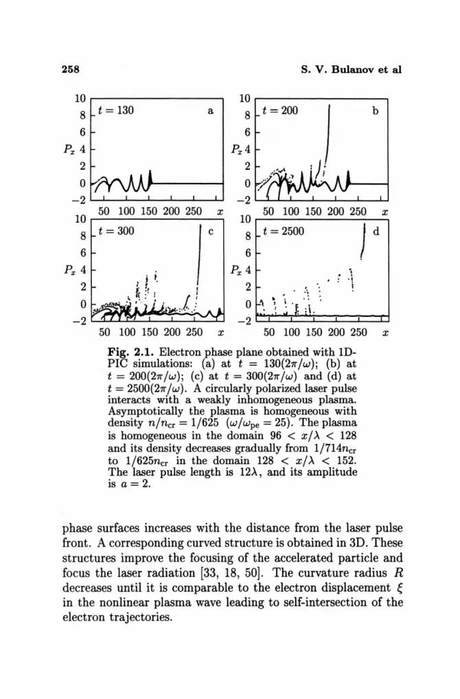
The results of ID PIC simulations of the electron injection due to wake wave breaking are presented in Fig. 2.1. We see that due to wake wave breaking a portion of the electrons is injected into the acceleration phase and further accelerated up to the energy which corresponds to the expression given by equation (2.18). In the vacuum-plasma interface we see the formation of wake breaking towards the vacuum region discussed in Ref. [68]. This process is similar to the "electron vacuum heating" discussed in Ref. [36]. At wt/27r = 130 (frame a) we see the formation of the cusp structures that characterize the wave break described by equation (1.19). At wt/27r = 200 (frame b), during the wave break, particles are injected into the accelerating phase of the wake field. Further acceleration is seen for wt/27r = 300 (frame c), and wt/27r = 2500 (frame d). At time wt/27r = 2500 the maximum energy of the fast particles is approximately 330mc2• The most energetic particles have been accelerated in the first period of the wake-wave behind the laser pulse.
A very important feature of this injection regime is that it provides conditions where the resonant wave-particle interaction in the region of homogeneous plasma forms electron bunches that are well localized both along the x-coordinate and in energy space as is seen in Fig. 2.2.
2.4. Transverse wake-wave breaking
A different form of wave break can occur in 2D and in 3D configurations in the wake of a relativistically strong, wide laser pulse or of a pulse propagating inside a plasma channel. The 2D "wake field" in a plasma has a specific "horse-shoe" [33, 18] (or "D-shape") structure where the curvature of the constant
258 s. V. Bulanov et al
10r-----------------~ 10 8 t = 130 a 8 t = 200 b
6
Px 4
2
6
Px 4
2
o ' 0 -2~~~--~~--~~u -2~~~--~~--~~u
10
8
6
Px 4
2
0
-2
50 100 150 200 250 x 10 50 100 150 200 250 x
t = 300
r I
8 t = 2500
6
Px 4
2
o
) d
i . . j i
50 100 150 200 250 x 50 100 150 200 250 x
Fig. 2.1. Electron phase plane obtained with 1DPIC simulations: (a) at t = 130(271-jw); (b) at t = 200(27r/w); (c) at t = 300{27r/w) and (d) at t = 2500(27r/w). A circularly polarized laser pulse interacts with a weakly inhomogeneous plasma. Asymptotically the plasma is homogeneous with density n/ncr = 1/625 (w/wpe = 25). The plasma is homogeneous in the domain 96 < x / >.. < 128 and its density decreases gradually from 1/714ncr to 1/625ncr in the domain 128 < x/>.. < 152. The laser pulse length is 12>.., and its amplitude is a = 2.
phase surfaces increases with the distance from the laser pulse front. A corresponding curved structure is obtained in 3D. These structures improve the focusing of the accelerated particle and focus the laser radiation [33, 18, 50]. The curvature radius R decreases until it is comparable to the electron displacement ~ in the nonlinear plasma wave leading to self-intersection of the electron trajectories.

Relativistic Interaction of Laser Pulses With Plasmas 259
>. ..., ..... 00 ~ CD
Q
6 0.4 a b 5
0.3 4 >. ..., ..... 3 ~ 0.2
CD
2 Q
0.1 1 o 0 L....L-'--__ oL.-__ '----' ....
2510 2515 2520 2525 2530 200 x
250 Energy
Fig. 2.2. Density inside the bunch of accelerated electrons at t = 2500{27r/w): (a) versus particle position x, and (b) versus particle energy Pxc.
300
We consider a "wake field" plasma wave excited by a laser pulse of finite width S. The resonance condition gives wpe/k = Vph. The transverse inhomogeneity of wpe is caused by the inhomogeneity of the plasma density, if the laser pulse is guided in a plasma channel, and by the relativistic dependence of Op ~ Op(O) = 7rWpe/2a(O) on the plasma wave amplitude, which is determined by the pulse transverse shape. The plasma wave frequency can be approximated in the vicinity of the axis by the parabolic form Op (y) ~ Op (0) + ~Op (y / S) 2 . Here ~wpe is the difference between the plasma frequency outside and inside the channel or is given by ~Op ~ Op(O) if the "wake field" is excited by an ultra high intensity pulse with a » 1 and the pulse transverse profile is approximated as a(y) = a(O)(1-y2/S2). As a consequence of these inhomogeneities the plasma wake wavelength Ap = 27r / kl depends on y. From the expression of the constant phase curves, 'I/J(x, y) = wpe(y) (t - X/Vph) = constant, it follows that their curvature 1/ R increases linearly with the distance I from the laser pulse,
~ _ 2wpe1 R Op(O)S2'
(2.22)

260 s. v. Bulanov et al
where 1 = '!f;vph/np(O). Thus we can write the constant phase curves as
(2.23)
The real position of the constant phase curves in a nonlinear plasma wave is shifted from the curves given above by the oscillation amplitude ~. Thus, when R becomes of the order of the electron displacement ~, the wake plasma wave starts to break[70]. From these considerations, the distance between the laser pulse and the first place of breaking can be estimated as np(O)82 /(2~np~), and the number ofregular wake wave periods as
0,282 Np ~ ---,P!:.....--
47rc~np~m (2.24)
The exact form and spatial dependence of the displacement ~ in a 2D (or 3D) configuration will depend on the specific laser-plasma regime under consideration. Nevertheless, a number of important features about the geometry of the phase surfaces near the axis at wave break can be understood by taking, for simplicity, the displacement to be perpendicular to the phase surfaces (in the 2D case the parabolic curves Xo - yU2Ry = constant, while in the 3D case the paraboloid surfaces Xo -YU2Ry - zU2Rz = constant) derived in the linear approximation, and writing the new surface, r = ro + ~(ro), as
x = ~ (~ + ;!J H(yo,zo) [1+ (~)'+ (;YF"(2.25) y YO{1+ ~(y;;,zo) [1+ (~)\ (;Yf} (2.26)
Z = Zo {1+ ~(Y~,zo) [1+ (~)' + (;yfl (2.27)
Here Ry and Rz are the curvature radii in the y - and z - directions.

Relativistic Interaction of Laser Pulses With Plasmas 261
z
.r
z b
Fig. 2.3. Surface of constant phase in the 3D case for (a) R ~ e and e = const; (b) e =1= constant with c5 = 4.
If we neglect the dependence of the displacement e{yo, zo) on the coordinate Yo, Zo along the wave front, equations (2.25)(2.27) define a so-called surface parallel to a paraboloid. The singularity that is formed for min {Ry, Rz } :::; em corresponds to the self-intersection of the electron trajectories. This is shown in Fig. 2.3a. In a more realistic analysis the amplitude of the displacement is not constant and in the most likely conditions it has its maximum on the axis. We describe this dependence with the Lorentzian form:
(2.28)
The singularity that is formed for R :::; em is shown in Fig. 2.3b.

262 s. v. Bulanov et al
In order to clarify the structure of the singularities we consider the 2D case where Rz -+ 00 and Sz -+ 00. Then the constant phase surface has a parabolic form that corresponds to our 2D computer simulations discussed below. If ~ is independent of the coordinate Yo, we obtain a singularity where the dependence of x on y is of the form y ~ IxI3/ 4 . For R < ~m a multivalued structure appears which is known as the "swallowtail" [69] in catastrophe theory. Near the breaking threshold, the value of the displacement on the axis is close to that of the curvature radius, ~(O)/ R -1 = £ « 1, and the size of the swallowtail is of order £2 along x and £3/2 along y. The typical portion of the affected wave measured in terms of Yo is £1/2.
2.5. Upshifting of the electromagnetic wave frequency during the interaction with nonlinear plasma waves
When the laser pulse propagates in the plasma, its carrier frequency changes. When an ultra short laser pulse interacts with a finite amplitude plasma wave its frequency can either increase or decrease depending on the phase of the interaction. The increase of the pulse frequency has received considerable attention [71, 33, 72, 73]. The frequency increase of the laser pulse comoving with wake wave is known as the photon acceleration.
2.5.1. Photon accelerator
In order to write the equations for the motion of a probe wave packet we refer to the dispersion equation for the frequency and the wavenumber of an electromagnetic wave, w2 = k2c2 + n~(X), with X = X-vpht where Vph = c!3ph is the phase velocity of the wake wave and the dependence of wpe on Vph is due to the fact that the wake wave (it is assumed to be given) modulates the local value of the Langmuir frequency. In the geometrical optics approximation, the wave packet motion is described in
Relativistic Interaction of Laser Pulses With Plasmas 263
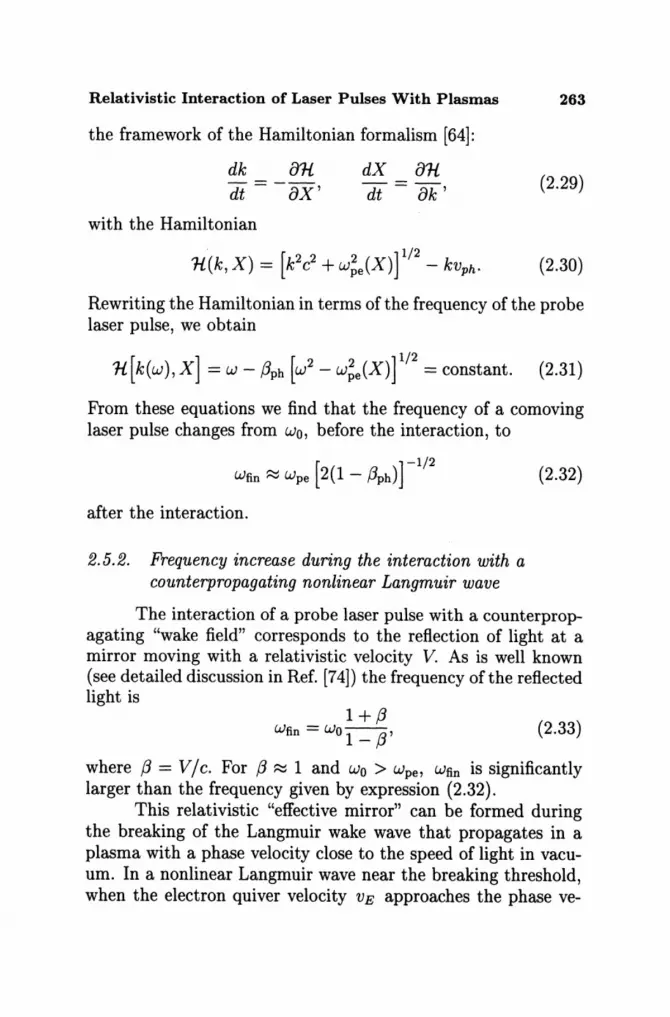
the framework of the Hamiltonian formalism [64]:
dX 81l dt - 8k' (2.29)
with the Hamiltonian
. [ 2 2 2 ] 1/2 ll(k, X) = k c + Wpe(X) - kVph. (2.30)
Rewriting the Hamiltonian in terms of the frequency of the probe laser pulse, we obtain
1l[k(w),X] = W - /3ph [w2 - w~e(X)r/2 = constant. (2.31)
From these equations we find that the frequency of a comoving laser pulse changes from wo, before the interaction, to
[ ]-1/2
Wfin ~ Wpe 2(1 - !3ph)
after the interaction.
2.5.2. Frequency increase during the interaction with a counterpropagating nonlinear Langmuir wave
(2.32)
The interaction of a probe laser pulse with a counterpropagating "wake field" corresponds to the reflection of light at a mirror moving with a relativistic velocity V. As is well known (see detailed discussion in Ref. [74]) the frequency of the reflected light is
1+!3 Wfin = Wo 1 _ !3' (2.33)
where /3 = V / c. For !3 ~ 1 and Wo > wpe , Wfin is significantly larger than the frequency given by expression (2.32).
This relativistic "effective mirror" can be formed during the breaking of the Langmuir wake wave that propagates in a plasma with a phase velocity close to the speed of light in vacuum. In a nonlinear Langmuir wave near the breaking threshold, when the electron quiver velocity VB approaches the phase ve-

264 S. V. Bulanov et al
locity of the wave, the dependence of the electron density on the coordinate X = x - vpht is given by (1.18). The distribution of the electron density (1.18) corresponds to an integrable singularity [Le., r~g· n(X)dX =1= 00]. However, it breaks the geometrical optics approximation and leads to the reflection of a portion of the laser pulse in the backward direction and to the increase of the frequency of the reflected pulse.
In order to calculate the reflected radiation, we consider the interaction of an electromagnetic wave with the spike of electron density formed in a breaking Langmuir wave (1.18). The electromagnetic wave, given by the z-component of the vector potential Az(x, y, t), is described by the wave equation
47re2 8tt Az - c2 (8xxAz + 8yy Az) + -- n(x - vpht) Az = 0, (2.34)
me'Y
where the electron Lorentz factor 'Y near the maximum of the density n(X) is equal to 'Yph.
In the reference frame moving with the phase velocity of the Langmuir wave we write the vector potential in the form
Az = [Ao exp( -ik~x') + AR(x')] exp [ - i(w't' - k~y') ], (2.35)
where Ao and AR correspond to the incident and reflected waves, and x', t' and k', w' are the coordinates and time and the wave vector and frequency in the boosted frame.
From equation (2.34) we obtain for the reflected wave
d2 AR 2A 9 [A A ('k' ')] (36) dX,2 - q R = - (X')2/3 R + oexp -z xx, 2.
where q2 = k5y - (w' /C)2 and 9 = (2/9)1/3 k;/3 'Y~'3. Assuming w » wpe , which is equivalent to kp/kx ~ 1,
and considering the first term in the brackets in the right hand side of equation (2.36) to be much smaller than the second term, we find the reflected wave:
i 4/ 3g (2) ., AR = q(q + k~)1/3 f "3 Ao exp(zqx ), (2.37)
where f(x) is the gamma function.
Relativistic Interaction of Laser Pulses With Plasmas 265
Performing the inverse Lorentz transformation, we obtain that in the case of normal incidence (ky = 0) the frequency of the reflected wave is equal to WR = wo(l + (3ph)/(l - (3ph), in agreement with the expression for the frequency change after a reflection at a relativistic countermoving mirror (2.33). The wave amplitude (the electric field) is increased by the factor 2 (k~'Yph/k;)2/3 r(2/3)/91/ 3 . The length of the reflected pulse is 4'Y;h times shorter than the length of the incident pulse. This opens a way for the generation of very short laser pulses.
If the Langmuir wave is generated by a laser pulse with carrier frequency W > wo, the ratio of the intensity of the reflected and incident wave is fR/ fo ~ (wwpe/W5)4/3.
3. Filamentation of the laser light and magnetic interaction of filaments of electromagnetic radiation
An external magnetic field affects the propagation of electromagnetic waves in media. However, in the relativistic range of amplitudes of the laser radiation the magnetic field produced by the laser beam itself changes the pattern of the beam interaction with the plasma. In Ref. [34] the importance of the long-range magnetic interaction was stressed for the first time and shown to lead to the merging of the long self-focusing channels produced by the pulse filamentation. In Ref. [34] this phenomenon was called "magnetic interaction of self focused channels." Regarding the magnetic interaction of self-focused channels we observe that the merging of the self-focusing channels and the associated self generated magnetic field were already seen in the 2D PIC simulations presented in Ref. [82]. The physical mechanism of the merging due to the attraction of the electric currents inside the filaments, and the subsequent change of the refractive index due to relativistic electron redistribution, was formulated in Ref. [34]. This mechanism was later called "magnetic lensing" or "electron pinching" and discussed in many papers including Refs. [83-85].
266 S. V. Bulanov et al
3.1. Generation of quasi-static magnetic field
The problem of the production of superstrong quasi-static magnetic fields in a laser plasma has been studied extensively over many years. These magnetic fields are observed in laser produced plasmas [86, 87] and can affect the thermal conductivity and the long time range plasma dynamiCs [88]. Several mechanisms of magnetic field generation are discussed in the literature, including baroclinic effects [89, 90], anisotropic electron pressure [91], spatial nonuniformity or time variation of the ponderomotive force [92] inverse Faraday effect in a circularly polarized pulse [93, 94], nonlinear processes in plasma waves [95] and the effect of the current produced by the electrons accelerated inside the self-focusing channels of the electromagnetic radiation [34]. In the latter case plasma quasineutrality requires that the fast-electron current be canceled by a cold electron current of opposite sign. These oppositely directed currents repel each other. This repulsion and the increase in the magnetic field value are the manifestation of the current filamentation instability [96]. Due to symmetry of the laser pulses, the quasi-static magnetic field reverses its sign at the laser beam axis. As a result it can focus charged particles, e.g., fast particles in a Laser Particle Accelerator [2, 97]. In addition, in the Fast Ignitor concept of ICF [4], the quasi-static magnetic field is expected to collimate superthermal electrons and to provide the energy transfer from the relatively low plasma density region where these electrons are produced by the laser pulse to the overdense plasma in the high-density core where they ignite the fuel [97].
3.2. Merging of the filaments
The results of the 3D PIC simulations shown in Fig. 1 show that the separate filaments, which are formed when a sufficiently wide laser beam splits, attract each other and eventually merge into a well defined channel, as demonstrated in the 2D case in Ref. [34]. The self-generated magnetic field is shown in frame (b). We see its structure corresponding to the electric cur-

Relativistic Interaction of Laser Pulses With Plasmas 267
rent inside the filaments in the rear part and inside the channel. Due to the repulsion of oppositely directed currents, the return current that shields the magnetic field flows in a much wider region. This makes the magnetic interaction long-range. Acting on the electric current of a neighboring channel, the magnetic field changes the relativistic electron distribution and this affects the refractive index and finally the direction of propagation of the channel.
In order to estimate the strength of the magnetic field, we note that the velocity of the current-carrying electrons is limited by the speed of light c and write the channel radius as [34] R = a1/ 2de, where de = c/wpe . We obtain
(3.1)
which is of order 104 -105T for typical values of the parameters. In order to test the hypothesis of the magnetic interaction,
in Refs. [34] the propagation of a beam in a plasma embedded in a magnetic field perpendicular to the beam was simulated. A deflection of the beam, consistent with the relative orientation of the external magnetic field and the electron current in the channel, was shown. The magnetic interaction mainly affects the leading part of the pulse.
3.3. Electron vortices
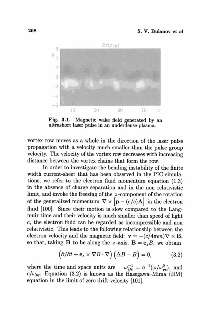
A laser pulse of finite length and width and very high intensity, propagating in underdense plasmas is subject to relativistic self-focusing and can propagate in the shape of a short, narrow "bullet" [18]. Such a laser pulse produces a quasistatic magnetic field wake in an initially unmagnetized plasma and the corresponding electron fluid motion takes the form of a vortex row [98, 99]. The vortex row is shown in Fig. 3.1. Near the laser pulse this vortex row is symmetrical, but it is unstable against bending and is transformed into an antisymmetric configuration. The distance between the vortices is comparable to, or in their final stage even larger than, the collisionless skin depth. The
268 S. V. Bulanov et al
6 Bz(x, y)
y <1
2
0
-2
-1
-6 10 50 60 70 3'
Fig. 3.1. Magnetic wake field generated by an ultrashort laser pulse in an underdense plasma.
vortex row moves as a whole in the direction of the laser pulse propagation with a velocity much smaller than the pulse group velocity. The velocity of the vortex row decreases with increasing distance between the vortex chains that form the row.
In order to investigate the bending instability of the finite width current-sheet that has been observed in the PIC simulations, we refer to the electron fluid momentum equation (1.3) in the absence of charge separation and in the non relativistic limit, and invoke the freezing of the z-component of the rotation of the generalized momentum V x [p - (e/c)A] in the electron fluid [100]. Since their motion is slow compared to the Langmuir time and their velocity is much smaller than speed of light c, the electron fluid can be regarded as incompressible and non relativistic. This leads to the following relationship between the electron velocity and the magnetic field: v = -(c/47ren)V x B, so that, taking B to be along the z-axis, B = ezB, we obtain
(B/Ot + ez x VB· V) (tJ.B - B) = 0, (3.2)
where the time and space units are WB; = a-I (W/W;e) , and c/wpe • Equation (3.2) is known as the Hasegawa-Mirna (HM) equation in the limit of zero drift velocity [101].
Relativistic Interaction of Laser Pulses With Plasmas 269
As is well known (see [102, 103]) equation (3.2) has a discrete vortex solution for which the generalized vorticity is localized at the points r = rj:
n = D.B - B = L:fjJ[r - rj(t)]. (3.3) j
Here fj are constants and r = (x, y). Then we have [104]
B=L:Bj, Bj[r,rj(t)] =-(fj /27r)Ko[lr-rj(t)I]. (3.4) j
Here and below Kn(~) are modified Bessel functions. The curves r j ( t) are determined by the characteristics
rj = ez x \7 . L: Bk [ rj(t), rk(t) ] k:/=j
of equation (3.2). From these expressions the equation of motion of the vortices follows
. 1 Yj - Yk . 1 '" Xj - Xk Xj = -- L: fk K1(rjk), Yj = -2 L.J fk K1(rjk),
27r k=f:j r jk 7r k:j:j r jk (3.5)
where rjk = Irj - rkl = [(Xj - Xk)2 + (Yj - Yk)2]1/2. We will assume that all vortices have the same absolute amplitude and take jrjl = l.
The vortex configuration seen in Fig. 3.1 corresponds to a double chain of vortices with opposite signs. In Euler hydrodynamics a symmetric double chain is unstable while an antisymmetric chain is stable for a specific set of values of the parameters. The problem of the stability of the vortex chain in the framework of the Hasegawa-Mirna equation was solved in Refs. [98,99]. In a double chain the oppositely polarized point vortices have coordinates and amplitudes equal to
xJ = js + Ut, yJ = q/2, -00 < j < +00, fj = -1,
for the upper chain, and
xg = (k + O")s + Ut, Y2 = -q/2, -00 < k < +00, fk = 1,
270 S. V. Bulanov et al
for the lower chain, respectively. The distance between neighboring vortices in a chain is s, the distance between the chains in the y -direction is q, and the lower chain is shifted along the x-direction by as: a = 0 and a = 1/2 correspond to the symmetrical and to the antisymmetric configurations respectively. Here
(3.6)
is the global velocity of the double chain in the x-direction. When s « 1 and q « 1 we recover known results valid for Euler hydrodynamics [105]: U = (1/2s) coth(1l'q/s) for a = 0 and U = (1/2s) tanh(1l'q/s) for a = 1/2. Far from the vortex row the magnetic field and the electron fluid velocity tend to zero exponentially. For q < 1 this configuration corresponds to an electron current sheet with thickness q surrounded by two opposite current sheets with thickness of order one, and is similar to the configuration observed behind the laser pulse. From equations (3.5) we can obtain, to the first order in perturbation amplitude, the linearized equation of motion of the vortices. Looking for solutions of the form
x exp['Yt + i(jcp)] ,
X' exp['Yt + i(kcp)] ,
Yj = Y eXP['Yt+i(jcp)], (3.7)
y~=Y'exp['Yt+i(kcp)], (3.8)
for the perturbations of the coordinates of vortices from the upper and the lower chain, respectively, we find the dispersion relation which gives the relationship between the real and imaginary parts of 'Y and cp :
Relativistic Interaction of Laser Pulses With Plasmas 271
+ f: [K1~~) - q2K2~~k)l [1 + ,cos [(k + a)cpJ] } k=O Pk Pk
X {f: [(Sk~a)2K2(p~)_ K1~k)l [1-,cos[(k+a)cpJ] k=O Pk Pk
+ t. [K~~i) - K,(Pi)] [1 - cos(jl")j r ' (3.9)
where, = ±1 depends on the parity of the perturbation. The symmetrical, a = 0, vortex row is always unstable. In the limit s « q « 1 and q « 27rs/cp « 1, we recover Rayleigh's result for the growth rate
Reb) = cp U (qcp) 1/2 S-3/2 = K, U (K,q) 1/2 (3.10)
of the bending instability of a finite width, fluid stream [105]. When the perturbation wavelength is larger than one and q (q < 1 < 27r S / cp), we can estimate the instability growth rate as
Reb) ~ K,2 U (K,q)1/2. (3.11)
If the distance between neighboring vortices is larger than one, S > 1, the growth rate is exponentially small. In the case of the antisymmetric vortex row with a = 1/2 we expect the perturbations to have more complicated behavior than the symmetrical configuration. As noted in Lamb's monograph [105], in standard hydrodynamics the antisymmetric von Karman's vortex row is stable for q/ S ~ 0.281. In the hydrodynamic case a point vortex is described by (fj /27r) In Ir - rj(t)1 instead of the expression (3.4) which involves the Bessel function Ko(lr - rj(t)I). By direct inspection of equation (3.9) we see that for large distances between neighboring vortices the antisymmetric vortex row is stable when
(3.12)
The dependence of the growth rate on cp and s is shown in Fig. 3.2 for the antisymmetric vortex row described in the framework of standard hydrodynamics, (a), and in the framework of the Hasegawa-Mirna equation, (b).

272
0.6
O. 1 1';,,'iI'J,.hWIJI
0.2 o
0.6 0.4 0.2 o ~~~1»mZ;Z
s. V. Bulanov et al
Fig. 3.2. Dependence of the growth rate on cp and s for the antisymmetric vortex row described in the framework of standard hydrodynamics, (a) and in the framework of the Hasegawa-Mima equation, (b).
We note here that we have investigated the stability problem in the linear approximation. As is well known, the stability of Hamiltonian systems in the linear approximation is always marginal because asymptotic stability cannot be reached. In other words, the condition Re{ w} = 0 indicates that a more detailed analysis of the vortex behavior is necessary, since nonlinear or dissipative effects may drive an instability. A nonlinear analysis of the stability of antisymmetric vortex rows was performed in Ref. [99] for the parameters in the domain of the linear stability given by expression (3.12). It was shown that the anti-
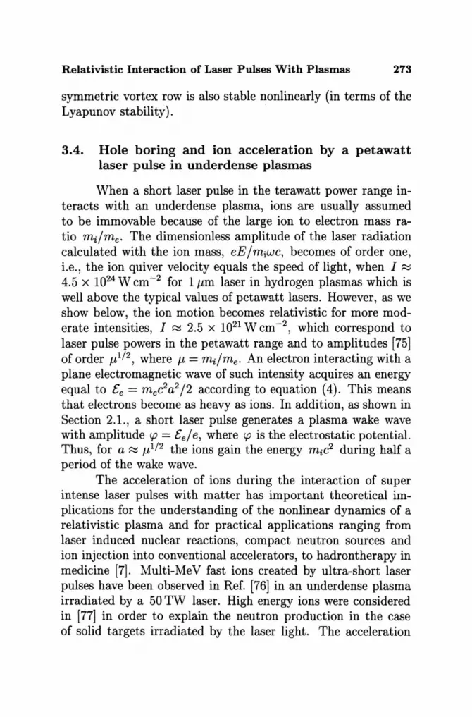
Relativistic Interaction of Laser Pulses With Plasmas 213
symmetric vortex row is also stable nonlinearly (in terms of the Lyapunov stability).
3.4. Hole boring and ion acceleration by a petawatt laser pulse in under dense plasmas
When a short laser pulse in the terawatt power range interacts with an underdense plasma, ions are usually assumed to be immovable because of the large ion to electron mass ratio mi/me. The dimensionless amplitude of the laser radiation calculated with the ion mass, eE / mjWC, becomes of order one, i.e., the ion quiver velocity equals the speed of light, when I ~ 4.5 X 1024 W cm-2 for 1 J.Lm laser in hydrogen plasmas which is well above the typical values of petawatt lasers. However, as we show below, the ion motion becomes relativistic for more moderate intensities, I ~ 2.5 X 10²¹ W cm -2, which correspond to laser pulse powers in the petawatt range and to amplitudes [75] of order J.L1/2, where J.L = mdme. An electron interacting with a plane electromagnetic wave of such intensity acquires an energy equal to Ee = mec2a2 /2 according to equation (4). This means that electrons become as heavy as ions. In addition, as shown in Section 2.1., a short laser pulse generates a plasma wake wave with amplitude <p = Eel e, where <p is the electrostatic potential. Thus, for a ~ J.L1/2 the ions gain the energy mic2 during half a period of the wake wave.
The acceleration of ions during the interaction of super intense laser pulses with matter has important theoretical implications for the understanding of the nonlinear dynamics of a relativistic plasma and for practical applications ranging from laser induced nuclear reactions, compact neutron sources and ion injection into conventional accelerators, to hadrontherapy in medicine [7]. Multi-MeV fast ions created by ultra-short laser pulses have been observed in Ref. [76] in an underdense plasma irradiated by a 50 TW laser. High energy ions were considered in [77] in order to explain the neutron production in the case of solid targets irradiated by the laser light. The acceleration
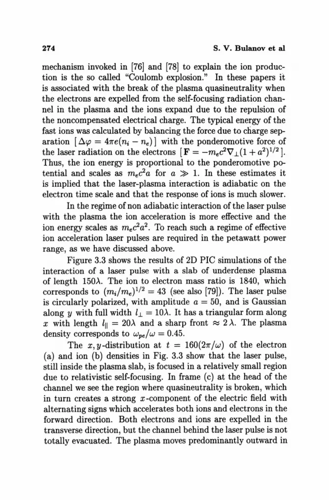
274 S. V. Bulanov et al
mechanism invoked in [76] and [78] to explain the ion production is the so called "Coulomb explosion." In these papers it is associated with the break of the plasma quasineutrality when the electrons are expelled from the self-focusing radiation channel in the plasma and the ions expand due to the repulsion of the noncompensated electrical charge. The typical energy of the fast ions was calculated by balancing the force due to charge separation [/l.cp = 41re(ni - ne )] with the ponderomotive force of the laser radiation on the electrons [F = -meeVJ..(l + a2)1/2]. Thus, the ion energy is proportional to the ponderomotive potential and scales as m ec2a for a » 1. In these estimates it is implied that the laser-plasma interaction is adiabatic on the electron time scale and that the response of ions is much slower.
In the regime of non adiabatic interaction of the laser pulse with the plasma the ion acceleration is more effective and the ion energy scales as mec2a2 • To reach such a regime of effective ion acceleration laser pulses are required in the petawatt power range, as we have discussed above.
Figure 3.3 shows the results of 2D PIC simulations of the interaction of a laser pulse with a slab of underdense plasma of length 150A. The ion to electron mass ratio is 1840, which corresponds to (mdme)1/2 = 43 (see also [79]). The laser pulse is circularly polarized, with amplitude a = 50, and is Gaussian along y with full width h = lOA. It has a triangular form along x with length III = 20A and a sharp front ~ 2 A. The plasma density corresponds to wpe/w = 0.45.
The x, y-distribution at t = 160(21r /w) of the electron (a) and ion (b) densities in Fig. 3.3 show that the laser pulse, still inside the plasma slab, is focused in a relatively small region due to relativistic self-focusing. In frame (c) at the head of the channel we see the region where quasineutrality is broken, which in turn creates a strong x-component of the electric field with alternating signs which accelerates both ions and electrons in the forward direction. Both electrons and ions are expelled in the transverse direction, but the channel behind the laser pulse is not totally evacuated. The plasma moves predominantly outward in
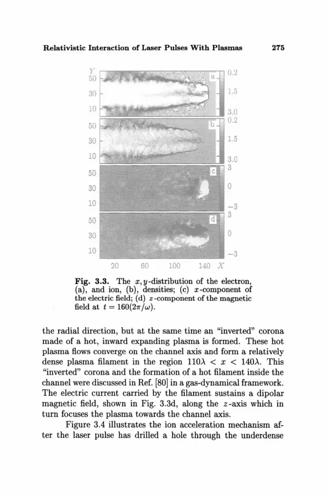
Relativistic Interaction of Laser Pulses With Plasmas 275
y 0.2 50
30 1.5
10 3.0
50 0.2
30 1.5
10 3.0
50 3
30 0
10 - 3
50 . 3
30 0
10 -3 20 60 100 140 X
Fig. 3.3. The x, y-distribution of the electron, (a), and ion, (b), densities; (c) x-component of the electric field; (d) z-component ofthe magnetic field at t = 160(21l"jw).
the radial direction, but at the same time an "inverted" corona made of a hot, inward expanding plasma is formed. These hot plasma f:l.ows converge on the channel axis and form a relatively dense plasma filament in the region 110), < x < 140),. This "inverted" corona and the formation of a hot filament inside the channel were discussed in Ref. [80] in a gas-dynamical framework. The electric current carried by the filament sustains a dipolar magnetic field, shown in Fig. 3.3d, along the z -axis which in turn focuses the plasma towards the channel axis.
Figure 3.4 illustrates the ion acceleration mechanism after the laser pulse has drilled a hole through the underdense
276
F.rl TTl('
2000
1000
o f---___ -.
o. F.r/Me
0.1
50 }'
30
10
130
b
170
S. V. Bulanov et al
a
c O.
PJ.·IMc 0.4
210 \'"
Fig. 3.4. (a) Phase planes (Pxe, x) of electrons; phase planes Pxi, x and (Pxi, y) of ions, (b) and (c), respectively; and (d) the x, y -distribution ofthe zcomponent of the magnetic field at t = 220(2n"/w) in the vicinity of the channel end.
plasma slab. The electron cloud expands into the vacuum region in the forward direction and, as seen in the phase planes in Fig. 3.4a, b, the electron energy decreases (nevertheless it is well above m ec2a2/2 because of the increase of the laser amplitude due to self-focusing) while ions are accelerated up to relativistic energies. The ion phase plane (Px, y) in Fig. 3.4c shows that the ion motion is well collimated. This collimation can be explained by the pinching in the self-generated magnetic field which changes polarity at the ion jet axis as seen in Fig. 3.4d in the region 165 < x < 180 near the laser pulse axis.
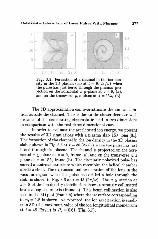
Relativistic Interaction of Laser Pulses With Plasmas 277
y
15
10
5
5
a Z b
15
10
.5
10 Hi 20 25 X 5 10 15 Y
Fig. 3.5. Formation of a channel in the ion density in the 3D plasma slab at t = 30(211,/w) when the pulse has just bored through the plasma: projection on the horizontal x, y-plane at z = 0, (a), and on the transverse y, z-plane at x = 15)" (b).
3.3
2.1
0.9
0.1
The 2D approximation can overestimate the ion acceleration outside the channel. This is due to the slower decrease with distance of the accelerating electrostatic field in two dimensions in comparison with the real three dimensional case.
In order to evaluate the accelerated ion energy, we present the results of 3D simulations with a plasma slab 15>' long [81]. The formation of the channel in the ion density in the 3D plasma slab is shown in Fig. 3.5 at t = 30 (27r I w) when the pulse has just bored through the plasma. The channel is projected on the horizontal x, y plane at z = 0, frame (a), and on the transverse y, z plane at x = 15>', frame (b). The circularly polarized pulse has carved a staircase structure which resembles the helical chamber inside a shell. The expansion and acceleration of the ions in the vacuum region, when the pulse has drilled a hole through the slab, is shown in Fig. 3.6 at t = 48 (27r /w). The x, y section at z = 0 of the ion density distribution shows a strongly collimated beam along the x axis (frame a). This beam collimation is also seen in the 3D plot (frame b) where the isosurface corresponding to ni = 1.8 is shown. As expected, the ion acceleration is smaller in 3D (the maximum value of the ion longitudinal momentum at t = 48 (27r/w) is Px = 0.61 (Fig. 3.7).
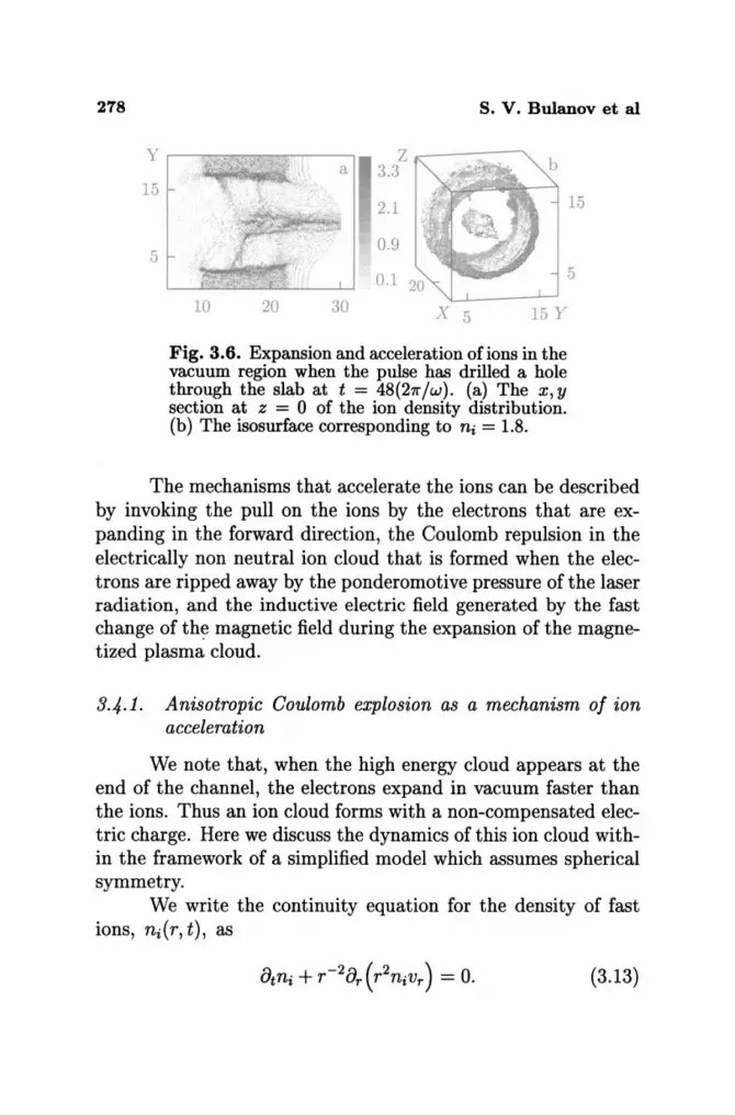
278 S. V. Bulanov et al
Y.-~~~~~---. Z
15
5
a 3.3
2.1 ~-....i
0.9
10 20 30 X 5 15 Y
Fig. 3.6. Expansion and acceleration of ions in the vacuum region when the pulse has drilled a hole through the slab at t = 48(21f"/w). (a) The x, y section at z = 0 of the ion density distribution. (b) The isosurface corresponding to ni = 1.8.
15
5
The mechanisms that accelerate the ions can be described by invoking the pull on the ions by the electrons that are expanding in the forward direction, the Coulomb repulsion in the electrically non neutral ion cloud that is formed when the electrons are ripped away by the ponderomotive pressure of the laser radiation, and the inductive electric field generated by the fast change of th~ magnetic field during the expansion of the magnetized plasma cloud.
3.4.1. Anisotropic Coulomb explosion as a mechanism of ion acceleration
We note that, when the high energy cloud appears at the end of the channel, the electrons expand in vacuum faster than the ions. Thus an ion cloud forms with a non-compensated electric charge. Here we discuss the dynamics of this ion cloud within the framework of a simplified model which assumes spherical symmetry.
We write the continuity equation for the density of fast ions, ni(r, t), as
(3.13)
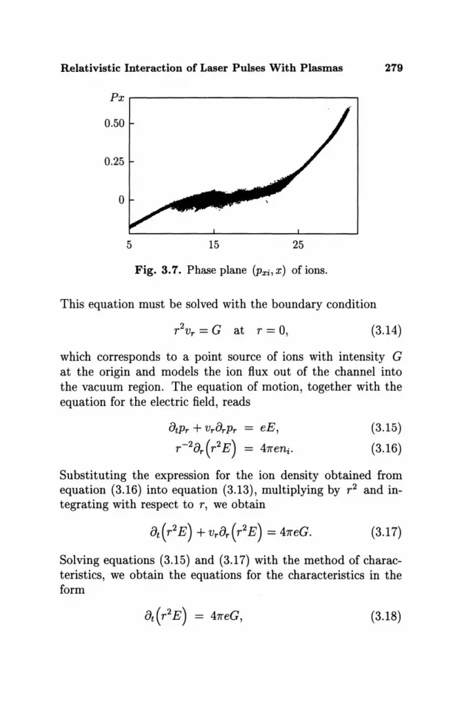
Relativistic Interaction of Laser Pulses With Plasmas 279
Px.-------------------------------,
0.50
0.25
o
5 15 25
Fig. 3.7. Phase plane (Pxi,X) of ions.
This equation must be solved with the boundary condition
(3.14)
which corresponds to a point source of ions with intensity G at the origin and models the ion flux out of the channel into the vacuum region. The equation of motion, together with the equation for the electric field, reads
8tPr + vr8rPr
r-28r (r2 E) (3.15)
(3.16)
Substituting the expression for the ion density obtained from equation (3.16) into equation (3.13), multiplying by r2 and integrating with respect to r, we obtain
(3.17)
Solving equations (3.15) and (3.17) with the method of characteristics, we obtain the equations for the characteristics in the form
(3.18)
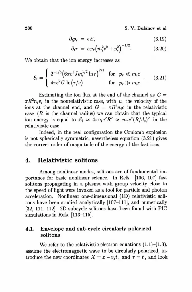
280 S. V. Bulanov et al
eE,
( 2 2 2)-1/2 CPr mic + Pr .
We obtain that the ion energy increases as
Ci = { 2-1/ 3 (67fe2 JmV2 ln r) 2/3 for Pr« miC
47fe2G In(r/c) for Pr ~ mic
(3.19)
(3.20)
(3.21)
Estimating the ion flux at the end of the channel as G = 7f R2nivi in the nonrelativistic case, with Vi the velocity of the ions at the channel end, and G = 7f R2nic in the relativistic case (R is the channel radius) we can obtain that the typical ion energy is equal to Ci ~ 47fnie2 R2 ~ m ec2(R/de)2 in the relativistic case.
Indeed, in the real configuration the Coulomb explosion is not spherically symmetric, nevertheless equation (3.21) gives the correct order of magnitude of the energy of the fast ions.
4. Relativistic solitons
Among nonlinear modes, solitons are of fundamental importance for basic nonlinear science. In Refs. [106, 107] fast solitons propagating in a plasma with group velocity close to the speed of light were invoked as a tool for particle and photon acceleration. Nonlinear one-dimensional (lD) relativistic solitons have been studied analytically [107-111], and numerically [32, 111, 112]. 2D sub cycle solitons have been found with PIC simulations in Refs. [113-115].
4.1. Envelope and sub-cycle circularly polarized solitons
We refer to the relativistic electron equations (1.1)-(1.3), assume the electromagnetic wave to be circularly polarized, introduce the new coordinates X = x - vst, and T = t, and look
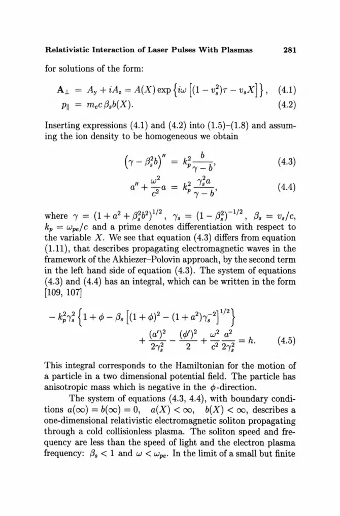
Relativistic Interaction of Laser Pulses With Plasmas 281
for solutions of the form:
A.l
PII
Ay + iAz = A(X) exp{iw [(1- V;)T - VsX]} ,
mec f3sb(X).
(4.1)
(4.2)
Inserting expressions (4.1) and (4.2) into (1.5)-(1.8) and assuming the ion density to be homogeneous we obtain
( 'Y - f3;b)" 2 b (4.3) kp--b, 'Y-
w2 2
a" +-a k2 'Ys a (4.4) c2 p b' 'Y-
where 'Y = (1 + a2 + f3;b2) 1/2 , 'Ys = (1 - f3;r 1/ 2 , f3s = Vs/C, kp = Wpe / C and a prime denotes differentiation with respect to the variable X. We see that equation (4.3) differs from equation (1.11), that describes propagating electromagnetic waves in the framework of the Akhiezer-Polovin approach, by the second term in the left hand side of equation (4.3). The system of equations (4.3) and (4.4) has an integral, which can be written in the form [109, 107]
- k;'Y; { 1 + 4> - f3s [(1 + 4»2 - (1 + a2h;2f/2} (a')2 (4)')2 w2 a2
+ 22 - -2- + 222 = h. (4.5) 'Ys C 'Ys
This integral corresponds to the Hamiltonian for the motion of a particle in a two dimensional potential field. The particle has anisotropic mass which is negative in the 4>-direction.
The system of equations (4.3, 4.4), with boundary conditions a(oo) = b(oo) = 0, a(X) < 00, b(X) < 00, describes a one-dimensional relativistic electromagnetic soliton propagating through a cold collision less plasma. The soliton speed and frequency are less than the speed of light and the electron plasma frequency: f3s < 1 and W < wpe. In the limit of a small but finite

282 s. V. Bulanov et a1
amplitude, the soliton solution is described by the well known hyperbolic secant expression [109, 107]:
[1 - (w/wpe'Ys)2f/2 exp {iw [(1 - (3:)7 - vsX/c2)]}
a = 2 cosh {k;X [1 _ (W/Wpe'Y,)'t'} (4.6)
with frequency W ~ wpe'Ys(l - a~/8), where am is the soliton amplitude. This solution corresponds to an isolated envelope soliton.
Another exact solution can be found in the limit of a soliton with zero propagation velocity. In the case {3s = 0, b vanishes and the system of equations (4.3, 4.4) reduces to
aU +k; [c:)' -1+ ~;Y'l a = O. (4.7)
With the help of the substitution a = sinh u, 'Y = coshu, this equation can be cast into the form
u" = k; sinh u [1 - (w /Wpe) 2 cosh u] (4.8)
which has an integral
~(U')2 - k; [(coshu -1) - (w/wpe)2sinh2u] = h. (4.9)
For h = 0 we obtain a soliton solution of the form [111] (see also Ref. [116], where relativistic self-focusing is discussed):
2 (w;e - w2f/2 cosh [(x/c) (w;e - W2)1/2] exp(iw7)
a(X, 7) = [ 1/2] cosh 2 (X / c) (wie - w2) + w2 - wie
(4.10) The relationship between the soliton amplitude am, which is equal to am = a(O, 0), and the soliton frequency W is given by
( 2 2)1/2_2 am = 2wpe Wpe - W w. (4.11)
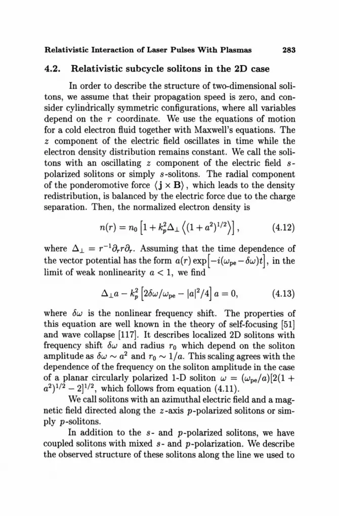
Relativistic Interaction of Laser Pulses With Plasmas 283
4.2. Relativistic sub cycle solitons in the 2D case
In order to describe the structure of two-dimensional solitons, we assume that their propagation speed is zero, and consider cylindrically symmetric configurations, where all variables depend on the r coordinate. We use the equations of motion for a cold electron fluid together with Maxwell's equations. The z component of the electric field oscillates in time while the electron density distribution remains constant. We call the solitons with an oscillating z component of the electric field spolarized solitons or simply s-solitons. The radial component of the ponderomotive force (j x B) , which leads to the density redistribution, is balanced by the electric force due to the charge separation. Then, the normalized electron density is
(4.12)
where ~l. = r-18r r8r . Assuming that the time dependence of the vector potential has the form a(r) exp[ -i(wpe - c5w)t], in the limit of weak nonlinearity a < 1, we find
(4.13)
where c5w is the nonlinear frequency shift. The properties of this equation are well known in the theory of self-focusing [51] and wave collapse [117]. It describes localized 2D solitons with frequency shift c5w and radius ro which depend on the soliton amplitude as c5w rv a2 and ro rv l/a. This scaling agrees with the dependence of the frequency on the soliton amplitude in the case of a planar circularly polarized 1-D soliton w = (wpe /a)[2(1 + a2 ) 1/2 - 2]1/2, which follows from equation (4.11).
We call solitons with an azimuthal electric field and a magnetic field directed along the z-axis p-polarized solitons or simply p-solitons.
In addition to the s- and p-polarized solitons, we have coupled solitons with mixed s- and p-polarization. We describe the observed structure of these solitons along the line we used to

284 s. v. Bulanov et al
obtain equation (4.13) and assume that their propagation speed is zero. The dependence of the vector potential on time and on coordinates has the form a( r 1., <p) exp [ -i (wpe - 6w)t], where 6w is the nonlinear frequency shift. In the limit a < 1 of weak nonlinearity we find
~a,.-k;[2~: -~(Ia,.I'+la'I')l a,. 0, (4.14)
(~- :,)a,-k; [2~: -~(la'I'+la,I')la, = 0, (4.15)
for the z- and <p-components of the vector potential, that corresponds to s- and p-modes respectively. We look for solutions where acp = a(r) depends only on r while az is of the form
(4.16)
with Cs a small proportionality constant Cs « 1. Neglecting laz l2 compared with lacpl2 in equations (4.14) and (4.15), we obtain the same equation for the amplitude a(r)
(4.17)
As discussed above, equation (4.17) describes localized 2D solitons, their width ro and frequency shift 6w depending on the soliton amplitude.
In the three dimensional case the analog of the s -solitons (p-solitons) are the TE-solitons (TM-solitons). The mixed TETM mode corresponds to a toroidal soliton with orthogonal magnetic and electric field lines wound on the surface of a torus.
4.3. 2D and 3D PIC simulations of soliton generation
The study of relativistic solitons with the help of 2D PIC simulations has shown that they are formed during the laser pulse plasma interaction [113-115]. The typical regime of soliton

Relativistic Interaction of Laser Pulses With Plasmas 285
10 y
-10
10
- 10
o
a
• II • ..
50 100 X
Fig. 4.1. Solitons in the x, y plane behind a pulse with amplitude a = 3, width 5>', and length 10>' in a plasma with n/ncr = 0.2025 at wt/21f = 120 (21f/w). (a) Distribution of the square root of the e.m. energy density in the x,y-plane. (b) electron density marking the solitons.
generation is shown in Fig. 4.1, where the results of 2D PIC simulations are presented. The dimensionless amplitude of the laser radiation is a = 3. The laser pulse has a Gaussian form both in the x and y directions, with full width h = 5), and length til = 12>', and is linearly s-polarized with its incident electric field along the z -axis. The ions are assumed to be fixed. The plasma density is no = 0.2025ncr '
The distribution of the square root of the electromagnetic energy density, W(x, y) = (E2 + B 2 )/81f, in the x, y plane at t = 120(27rlw) is shown in Fig. 4.1a. In the region 80 < xl). < 100 we see that the form of the pulse has changed due to self-focusing and energy depletion. Behind the pulse about ten spots of high electromagnetic energy density are seen, which we identify as solitons. Their propagation velocity is much smaller than the group velocity of the laser light, as shown by the solitary wave which remains at x ~ 14>., y ~ 1), for about 135
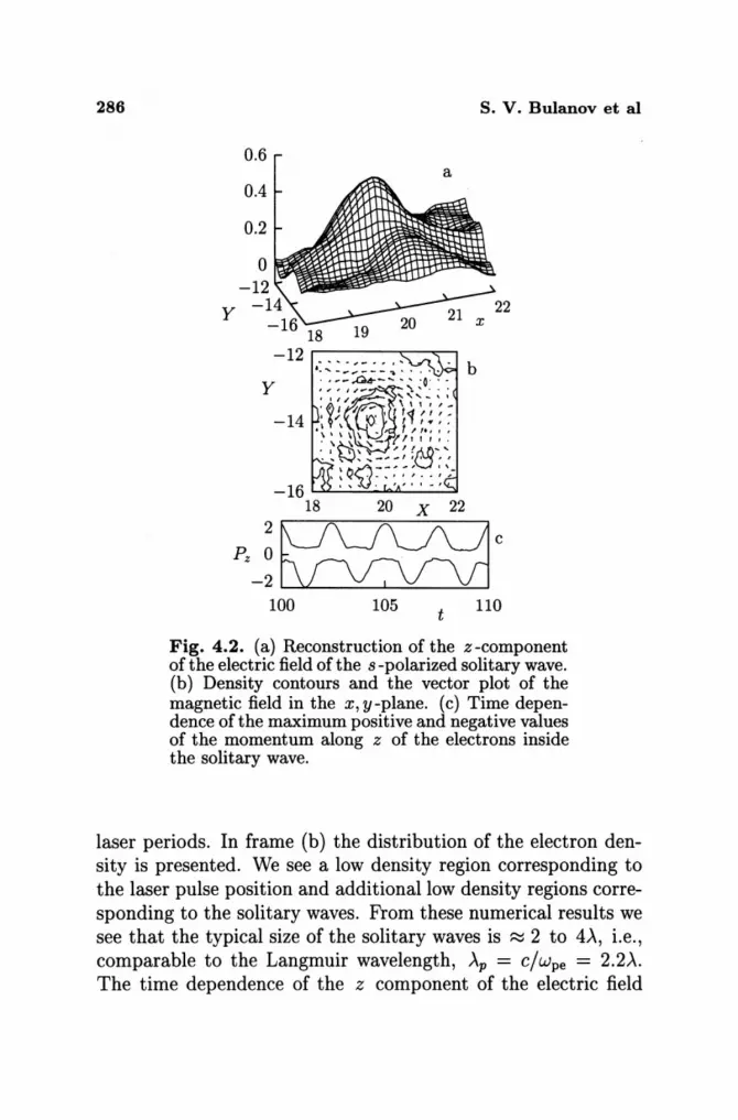
286 S. V. Bulanov et al
0.6 a
0.4
0.2
0 -12
Y -14
-16 18 19 -12
b Y
-14
-16 1.....>oL,...;",,;.....::..-.""'-A-_--=
18 20 X 22
100 105 t 110
Fig. 4.2. (a) Reconstruction of the z-component ofthe electric field of the s-polarized solitary wave. (b) Density contours and the vector plot of the magnetic field in the x, y-plane. (c) Time dependence of the maximum positive and negative values of the momentum along z of the electrons inside the solitary wave.
laser periods. In frame (b) the distribution of the electron density is presented. We see a low density region corresponding to the laser pulse position and additional low density regions corresponding to the solitary waves. From these numerical results we see that the typical size of the solitary waves is ~ 2 to 4>', i.e., comparable to the Langmuir wavelength, >'p = c/wpe = 2.2>'. The time dependence of the z component of the electric field

Relativistic Interaction of Laser Pulses With Plasmas 287
inside the solitary waves shows oscillations with a period ~ 3 to 4 times the laser pulse period which is longer than the period of the Langmuir wave 27r /wpe ' In Figure 4.2 the reconstruction of the z component of the electric field of the s-polarized solitary wave of Fig. 4.1a at x ~ 20,X, y ~ -14,X is shown in frame (a) at t = 106(27r/w). In frame (b) we see the corresponding density contours and the vector plot of the magnetic field in the x, y-plane at t = 105. In frame (c) the time dependence of the maximum positive and negative values of the momentum along z of the electrons inside the solitary wave is shown.
lEI
BI
Xe
20 -10
t = IVi o Fig. 4.3. 3-D soliton behind the laser pulse. Surfaces of constant value of the electric field (lEI = 0.2), (a), of the magnetic field (IBI = 0.2), (b), and of the electron density (n = 0.16 ncr), (c).
In Figure 4.3 we present the results of 3D PIC simulations. The laser pulse amplitude is a = 2.1, its width is i1. = 7\ its length is ill = 2,X, and it is circularly polarized. The ions are
288 s. v. Bulanov et al
assumed to be fixed. The plasma density is no = 0.16ncr . In Figure 4.3a, we show the surfaces of constant absolute value of the electric field (lEI = 0.2), in frame (b) those of the magnetic field (IBI = 0.2), and in frame (c) those of the electron density (n = 0.16ncr ). A soliton, with amplitude ~ 0.7, is localized near the pulse axis at x = 15A. It has a toroidal form and oscillates with a frequency below the Langmuir frequency.
4.4. Influence of plasma inhomogeneity
In a non-uniform plasma the propagation of a wave is strongly affected by the inhomogeneity of the medium. In a non-uniform dispersive medium a wave packet moves according to the geometric optics equations (2.29 ), where the Hamiltonian is the wave frequency l£(Xi, ki ) = w. From these equations we find that the wave packet acceleration is equal to
(4.18)
For an electromagnetic wave in a plasma we have
[ 2 2 2 ] 1/2 1£ (Xi , ki ) = k C + Wpe = W. (4.19)
In the case of the plasma density distribution given by n =
no [1 + xl Lx + y2 12L~] we obtain
(4.20)
The acceleration of the wave packet is directed towards the low density side and oscillates in the transverse direction. As a result, the soliton will move to the plasma vacuum interface, where it will radiate away its energy in the form of low frequency electromagnetic waves, in the process of non-adiabatic interaction with the plasma boundary.
In the case where a laser pulse propagates in a plasma inhomogeneous in the transverse direction, the soliton propagates

Relativistic Interaction of Laser Pulses With Plasmas 289
50 Y 40
30 20 10 o
50 y 40
30 20 10 o
50 Y -to
30 20 10
Ez Bz ne
O~~~~U=~~~~~~~L-~~~
01020304050 01020304050 01020304050 T T x
Fig. 4.4. (a) z-component of the electric field in the x, y plane during the interaction of a circularly polarized laser beam with a plasma inhomogeneous in the y -direction direction. (b) Quasi-static magnetic field. (c) Electron density.
a
b
c
in the direction perpendicular to the laser beam and abandons the region behind the laser pulse, where the wake field and electron vortices are localized. As a result, the soliton is less perturbed by nonlinear plasma waves, vortices and fast particles. Figure 4.4 shows the 2D PIC simulation of the interaction of a circularly polarized pulse with an underdense plasma. The incident laser pulse propagates along the x -direction. The pulse dimensionless amplitude in the vacuum region is a = 3, its width is l1.. = 16A and its length l" = 4A. The plasma density varies from n = 0 at the plasma vacuum interface at y = 0
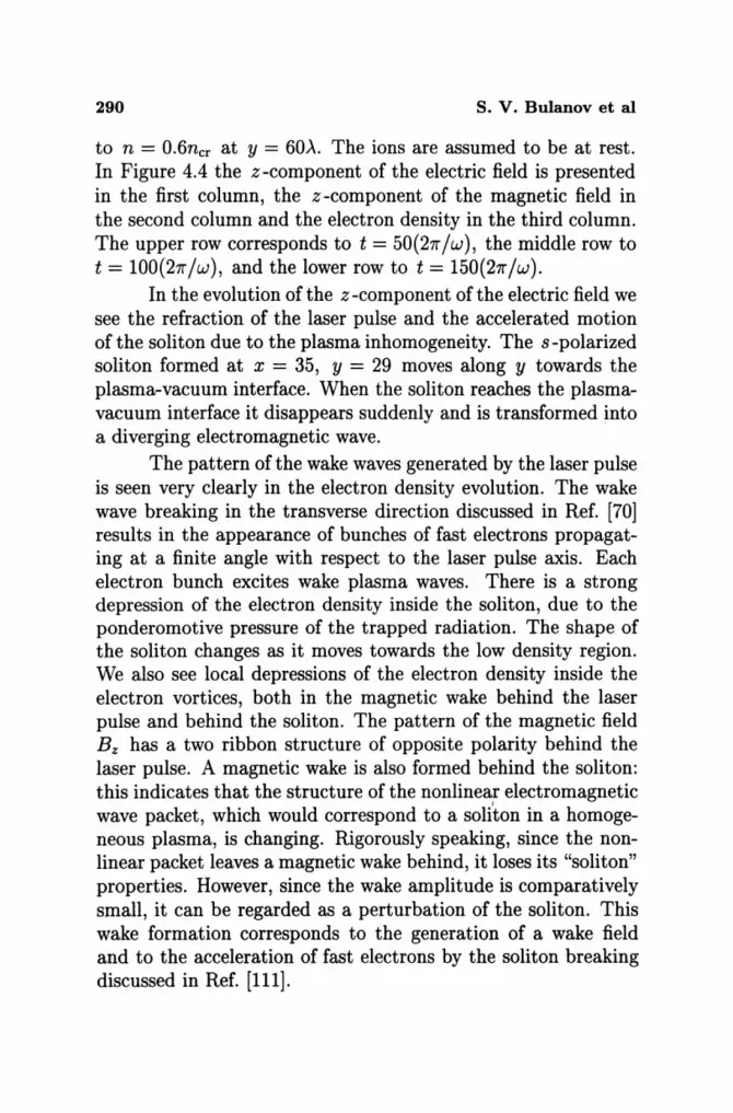
290 S. V. Bulanov et al
to n = 0.6ncr at y = 60A. The ions are assumed to be at rest. In Figure 4.4 the z-component of the electric field is presented in the first column, the z -component of the magnetic field in the second column and the electron density in the third column. The upper row corresponds to t = 50 (27r / W ), the middle row to t = 100(27r/w), and the lower row to t = 150(27r/w).
In the evolution of the z -component of the electric field we see the refraction of the laser pulse and the accelerated motion of the soliton due to the plasma inhomogeneity. The s-polarized soliton formed at x = 35, y = 29 moves along y towards the plasma-vacuum interface. When the soliton reaches the plasmavacuum interface it disappears suddenly and is transformed into a diverging electromagnetic wave.
The pattern of the wake waves generated by the laser pulse is seen very clearly in the electron density evolution. The wake wave breaking in the transverse direction discussed in Ref. [70] results in the appearance of bunches of fast electrons propagating at a finite angle with respect to the laser pulse axis. Each electron bunch excites wake plasma waves. There is a strong depression of the electron density inside the soliton, due to the ponderomotive pressure of the trapped radiation. The shape of the soliton changes as it moves towards the low density region. We also see local depressions of the electron density inside the electron vortices, both in the magnetic wake behind the laser pulse and behind the soliton. The pattern of the magnetic field Bz has a two ribbon structure of opposite polarity behind the laser pulse. A magnetic wake is also formed behind the soliton: this indicates that the structure of the nonlinear electromagnetic wave packet, which would correspond to a soliton in a homogeneous plasma, is changing. Rigorously speaking, since the nonlinear packet leaves a magnetic wake behind, it loses its "soliton" properties. However, since the wake amplitude is comparatively small, it can be regarded as a perturbation of the soliton. This wake formation corresponds to the generation of a wake field and to the acceleration of fast electrons by the soliton breaking discussed in Ref. [111].
Relativistic Interaction of Laser Pulses With Plasmas 291
4.5. Mechanism of soliton generation
The physical mechanism that produces these solitons is different from the standard process where the nonlinear steepening of the wave is counterbalanced by the effect of dispersion, and is based on the frequency decrease of the laser pulse discussed above (see Section 2.1.) and Refs. [114, 115]). Interacting with the underdense plasma the laser pulse loses its energy as it generates electrostatic and magnetostatic wake fields behind it. The frequency of these fields is much lower than the carrier frequency of the laser pulse and the laser-plasma interaction is adiabatic. In this case the number of quanta of the electromagnetic field is adiabatically conserved. Because of this constraint, the decrease of the radiation energy must be accompanied by a decrease of the carrier frequency. On the other hand the group velocity of the laser pulse decreases as the carrier frequency is decreased and the pulse group velocity tends to zero at W --+ wpe. The pulse depletion length calculated for wide laser pulse is equal to ldepl :::::; lp(W/wpe )2 [32]. We can show that a narrow laser beam decays after propagating over the length:::::; alp(w/wpe )2. Thus the depleted portions of the pulse, e.g. inside the lateral filaments, lag behind and convert their energy into soliton energy with almost zero group velocity.
5. Interaction of an ultrashort, relativistically strong, laser pulse with an overdense plasma
The interaction of laser light with an overdense plasma is of great importance for the problems of ICF both in the framework of the direct and of the indirect drive scheme as well as in the case of the fast ignition concept. Laser interaction with solid targets is usually accompanied by high harmonic generation, the formation of jets of fast ions and electrons as well as the emission of gamma-rays [118, 119].

292 S. V. Bulanov et al
As already noted in the Introduction, one can never neglect the plasma inhomogeneity in an overdense plasma. At a sharp plasma-vacuum interface the laser radiation can easily extract the electrons from the plasma and accelerate them towards the vacuum region. This process, known as "vacuum heating of the electrons" [36], provides an effective mechanism of anomalous absorption of the laser light. When the plasma has a smooth density distribution, the Langmuir frequency is a function of the coordinates wpe(r). At a steep plasma-vacuum interface the laser radiation radiates harmonics due to the so called "oscillating mirror" mechanism or due to the nonlinear motion of the electrons in the narrow region near the plasma boundary [37]. In the latter case the processes that occur in the vicinity of the critical surface, in the region of the plasma resonance where W = wpe(r), playa key role [38].
5.1. Oblique incidence on a non-uniform plasma
Let us consider an electromagnetic wave with carrier frequency W, wave vector k and dimensionless amplitude a. The wave is obliquely incident on a plasma (located in the region x > 0 ) and forms an angle () with respect to the normal to the plasma surface. In the vacuum region (x < 0) the frequency wand wave vector k are connected through the dispersion equation w2 = c2 (k; + k;), where kx = k cos (), ky = k sin (). Following [120], we perform a Lorentz transformation to the reference frame K' moving in the y direction with velocity Vboost. In the K' frame, the frequency w' and the components of the wave vector k' are
W' = I'v(w - kyV), k~ = kx, k~ = I'v(ky - wV/c) , (5.1)
where f3v = Vboost! c and I'v = (1 - f3v t 1/ 2 . When Vboost = kyc2 / W = c sin (), the y -component k~ of the wave vector is equal to zero. Thus, in the boosted frame, the electromagnetic wave propagates only in the x-direction, and the problem under consideration is reduced to that of the normal incidence of the
Relativistic Interaction of Laser Pulses With Plasmas 293
wave on a the plasma, where both ions and electrons move with velocity -V along the y-direction.
In the K' frame, the frequency is w' = w cos 0 and the wave vector has only one non-zero component: k' = (k~, 0, 0), with k~ = k cos O. The unperturbed plasma density n' in the K' frame is n' = nl'v = n/ cos 0, where the relativistic factor I' depends on f3v = sin 0 as follows: I'v = 1/ cos O. Electrons and ions move in this frame with velocity - Vboost. In the K' frame all quantities are taken to depend on the time t' and the coordinate x = x' only.
5.2. Small amplitude electromagnetic waves in nonuniform plasmas
By linearizing the cold plasma fluid equations together with Maxwell's equations, we obtain in the K' frame [37]
{ d 1 d W,2 W2} - + P (H' - f3v E') - 0 dx t'(w', x) dx C2t'(w', x) z x - , (5.2)
(E~ - f3vH~) = - '( ~ ) (H~ - f3vE~), E W,X
(5.3)
for p-polarized waves, and
d2E' W,2 - w2 z PE' 0 -d2+ 2 z=,
X C (5.4)
for s-polarized waves. Here the dielectric constant t'(w', x) is equal to t'(w', x) = 1- [wp (x)/w'j2(l- f3~). In the vacuum region, where E' = 1, E~ = O. From equations (5.2)-(5.4) we see that the reflection point of the electromagnetic waves occurs where W,2 = w~ and that, in the case of p-polarized waves, the plasma resonance point occurs where E'(W', xp ) = 0 [Le., where w,2 = w~(1 - f3~ )].
In the vicinity of the resonance point x = xr , where E'(W', x) ~ (x - xr)/L, H~ - f3vE~ has a logarithmic term (see Ref. [121])
294 S. V. Bulanov et al
H' - f3 E' '"'" H {I f3fw'2(X - Xr)2 I [f3fw'2(X - Xr)2]} z V x '"'" m + 4c2 (1 _ f3f) n 4c2 (1 - f3f) ,
(5.5) and, from equation(5.3), it follows that the value of
E' - f3 H' '"'" Lf3vHm x v z'"'" , X -Xr
(5.6)
becomes infinite for x -+ Xr. Here the constant Hm is of order Ho/'Yv if the wave-length is of the order of the scale of the plasma non-uniformity and, in general, can be found by matching equation (5.5) to the solution of equation (5.2) far from the resonant region.
5.3. Non-linear plasma dynamics near a sharp boundary
In order to obtain analytical estimates of the physical processes that are involved, we adopt a simplified one-fluid, cold electron model and compare its results with those of the computer simulation. Instead of the Eulerian coordinates x, t' we use the Lagrangian variables Xo and T, where x = Xo +~(xo, T), Vx = a~/fh, and ~(xo, T) is the displacement of the elementary volume of the electron fluid from the initial position Xo.
As is well known, the solution of Poisson's equations for the longitudinal electric field E~ is
e(XQ,r)
E~ = 47re I n~(xo + s) ds, o
(5.7)
where n~(x) = n'(x, 0) is the ion density distribution which, in the present case, is assumed to be given.
If we consider a linear density profile n~ = n~rx/ L, where the scale-length L of the plasma non-uniformity is chosen such
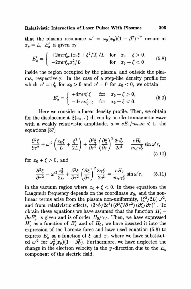
Relativistic Interaction of Laser Pulses With Plasmas 295
that the plasma resonance w' = wp(xp)(l - 132)1/2 occurs at xp = L, E~ is given by
I _ { +27ren~r (xo~ + e/2) /L for Xo + ~ > 0, Ex - I 2/L c c - 27rencrxO lor Xo + '" < 0
(5.8)
inside the region occupied by the plasma, and outside the plasma, respectively. In the case of a step-like density profile for which n' = n~ for Xo > 0 and n' = 0 for Xo < 0, we obtain
E = I {+47ren~~ x -47ren~xo
for Xo + ~ > 0, for Xo + ~ < O.
(5.9)
Here we consider a linear density profile. Then, we obtain for the displacement ~(xo, T) driven by an electromagnetic wave with a weakly relativistic amplitude, a = eEo/mewc < 1, the equations [37]
02~ 12 (xo~ f.-) 02~ (O~)2 3')'~ _ eHo . I ~ 2 + W L + 2L + ~ 2 . ~ 2 2 - 2 smw T, uT uT uT C me')'v
(5.10) for Xo + ~ > 0, and
02f. 12 X~ 02f. (Of.)2 3')'~ _ eHo . I ~ 2 - W -L + ~ 2 -;:) -2 2 - --2 sm W T, uT 2 uT uT C me')'v
(5.11)
in the vacuum region where Xo + f. < O. In these equations the Langmuir frequency depends on the coordinate Xo, and the nonlinear terms arise from the plasma non-uniformity, (e/2L)w /2 , and from relativistic effects, (3')'~/2c2) (02f./OT2) (Of./OT)2. To obtain these equations we have assumed that the function H~f3vE~ is given and is of order Ho/')'v. Then, we have expressed H~ as a function of E~ and of Ho, we have inserted it into the expression of the Lorentz force and have used equation (5.8) to express E~ as a function of ~ and Xo where we have substituted W /2 for w~(xp)(l - f3~). Furthermore, we have neglected the change in the electron velocity in the y-direction due to the Ey component of the electric field.

296 S. V. Bulanov et al
5.4. Plasma resonance
For rEI L « 1, that is for ~/ L « 1, the plasma resonance occurs near the point where W'2 = w; (1 - {32) [see equations (5.5), (5.6)]. In this region strong Langmuir oscillations are excited, leading to a large amplification of the x-component of the electric field E~, up to values for which saturation effects become important [38, 122]. These effects can be characterized in terms of a dimensionless parameter S, small compared to unity. The maximum value of the amplitude of the electric field is approximately E:nax ~ Ho/ S, and the width of the region, where the strong electric field E~ is localized, is given by Llx ~ SL while the characteristic time of the resonance saturation equals Llt' ~ l/w'S.
In the case of an ultra-short laser pulse, the main mechanisms of resonance saturation are the relativistic detuning of the oscillations, the self-intersection of the electron trajectories and the finite duration of the laser pulse. At the initial stage of the growth, when the amplitude of the electric field is still small, we can neglect the non-linear terms on the left hand side of equation (5.10). Then, we find for the displacement ~(xo, T) as a function of Xo, T,
rEL {WI sin [wpe(XO)T] . ,} ~(xo, T) ~ - - sm(w T) ,
Xo - L wp (5.12)
where wpe(xo) is a function of the Lagrangian coordinate Xo: wpe(xo) = w'(XO/L)I/2, rE = eHo/me'Y~w'2 = eHo/mew;e(xr). At the resonant point Xo = Xr = L, where wpe(xo) = w', the amplitude of the oscillation displacement grows linearly with time as ~(Xp,T) ~ -(rE/2)wITCOSW'T, while the resonance width decreases with time as l/T. At time t' ~ 2/W'rJl/2, the amplitude of the oscillations becomes equal to the resonance width Llx ~ L(rE/L)I/2, the Jacobian 18x/8xol vanishes and the electron trajectories start to self-intersect. The maximum oscillation amplitude is of order ~max ~ Llx ~ (rEL)I/2, and the dimensionless parameter S is equal to S N = (r E / L ) 1/2 .
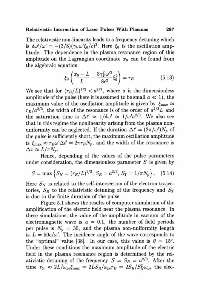
Relativistic Interaction of Laser Pulses With Plasmas 297
The relativistic non-linearity leads to a frequency detuning which is ow'/w' = -(3/8) (-yvw'eo/c)2. Here eo is the oscillation amplitude. The dependence in the plasma resonance region of this amplitude on the Lagrangian coordinate Xo can be found from the algebraic equation
C (xo - L _ 31'~W'2 C2) _ ,>0 L 8c2 '>0 - rEo (5.13)
We see that for (rE/L)1/2 < a2/3 , where a is the dimensionless amplitude of the pulse (here it is assumed to be small a « 1), the maximum value of the oscillation amplitude is given by emax ~ rE/a2/3 , the width of the resonance is of the order of a2/3L and the saturation time is IJ..t' ~ 1/ ow' ~ 1/ w' a2/3 • We also see that in this regime the nonlinearity arising from the plasma nonuniformity can be neglected. If the duration IJ..t' = (27r / w')Np of the pulse is sufficiently short, the maximum oscillation amplitude is emax ~ rEw' IJ..t' = 27rrENp , and the width of the resonance is IJ..x ~ L/7r Np •
Hence, depending of the values of the pulse parameters under consideration, the dimensionless parameter S is given by
S=max{SN= (rE/L)1/2, SR=a2/3 , ST=l/7rNp }. (5.14)
Here SN is related to the self-intersection of the electron trajectories, SR to the relativistic detuning of the frequency and ST is due to the finite duration of the pulse.
Figure 5.1 shows the results of computer simulation of the amplification of the electric field near the plasma resonance. In these simulations, the value of the amplitude in vacuum of the electromagnetic wave is a = 0.1, the number of field periods per pulse is Np = 30, and the plasma non-uniformity length is L = 50c/w'. The incidence angle of the wave corresponds to the "optimal" value [38]. In our case, this value is () = 15°. Under these conditions the maximum amplitude of the electric field in the plasma resonance region is determined by the relativistic detuning of the frequency S = SR = a2/3 . After the time Tbr ~ 2L/wpeemax = 2LSR/wperE = 2SR/Sivwpe the elec-
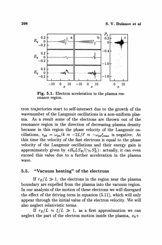
298 s. v. Bulanov et al
Px .-----..., 0.2 ' c o _ -.;o.J1l J:
o 10 x x x
Fig. 5.1. Electron acceleration in the plasma resonance region.
tron trajectories start to self-intersect due to the growth of the wavenumber of the Langmuir oscillations in a non-uniform plasma. As a result some of the electrons are thrown out of the resonance region in the direction of decreasing plasma density because in this region the phase velocity of the Langmuir oscillations, Vph = wpelk ~ -2Llt' ~ -wpe~max is negative. At this time the velocity of the fast electrons is equal to the phase velocity of the Langmuir oscillations and their energy gain is approximately given by eHoLS RI bvS'iv): actually, it can even exceed this value due to a further acceleration in the plasma wave.
5.5. "Vacuum heating" of the electrons
If rEI L » 1, the electrons in the region near the plasma boundary are expelled from the plasma into the vacuum region. In our analysis of the motion of these electrons we will disregard the effect of the driving term in equation (5.11), which will only appear through the initial value of the electron velocity. We will also neglect relativistic terms.
If rEI L ~ ~I L » 1, as a first approximation we can neglect the part of the electron motion inside the plasma, xo+
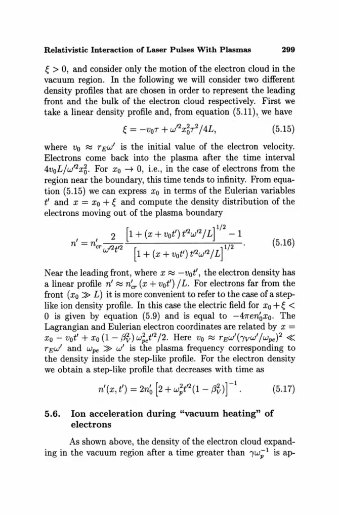
Relativistic Interaction of Laser Pulses With Plasmas 299
~ > 0, and consider only the motion of the electron cloud in the vacuum region. In the following we will consider two different density profiles that are chosen in order to represent the leading front and the bulk of the electron cloud respectively. First we take a linear density profile and, from equation (5.11),_ we have
(5.15)
where Vo ~ TEW' is the initial value of the electron velocity. Electrons come back into the plasma after the time interval 4voL/w'2X~. For Xo ---+ 0, i.e., in the case of electrons from the region near the boundary, this time tends to infinity. From equation (5.15) we can express Xo in terms of the Eulerian variables t' and x = Xo + ~ and compute the density distribution of the electrons moving out of the plasma boundary
[ ]1/2
, , 2 1 + (x + vot') t'2W,2 / L - 1 n = nCT ,2t,2 1/2 (5.16)
W [1+ (x + vot')t'2W'2/L]
Near the leading front, where x ~ -vot', the electron density has a linear profile n' ~ n~T (x + vot') / L. For electrons far from the front (xo » L) it is more convenient to refer to the case of a steplike ion density profile. In this case the electric field for Xo + ~ < ° is given by equation (5.9) and is equal to -47ren~xo. The Lagrangian and Eulerian electron coordinates are related by x = Xo - vot' + Xo (1- f3~)w;et'2/2. Here Vo ~ TEW'bvw'/Wpe)2 « T EW' and wpe » w' is the plasma frequency corresponding to the density inside the step-like profile. For the electron density we obtain a step-like profile that decreases with time as
(5.17)
5.6. Ion acceleration during "vacuum heating" of electrons
As shown above, the density of the electron cloud expanding in the vacuum region after a time greater than "/W;1 is ap-

300 S. V. Bulanov et al
proximately constant behind the leading front and its value decreases as t,-2. From equation (5.9) we find that the electric field in the cloud is given by
E ' , x + vot' x ~ - 87reno (1 _ (32)W~t'2' (5.18)
This field decelerates electrons and accelerates positively charged ions. Their equation of motion can be written as
d2x = _2Zame x + vot' dt,2 ma t,2 (5.19)
where ma is their mass and Zae their charge. This equation gives
(5.20)
where the constants Al and A2 are determined by the initial conditions and CYI,2 are given by
(5.21)
Since the ratio Zame/ma is positive, the ions, which start behind the leading front of the electron cloud which expands with velocity -Vo, are accelerated by the electric field given byequation (5.18), but never pass the electrons. Their energy gain can reach values of up to the order of ma'Yvv5/2.
5.7. Channel boring and soliton generation during the propagation of a laser pulse in an inhomogeneous plasma
In the 2D and 3D cases, in addition to the processes discussed above, the instability of the laser pulse results in pulse filamentation, merging of the filaments and hosing of the light beams. The transverse size of the self focusing channel in the near-critical plasma becomes of the order of the laser wavelength. This process is accompanied by the acceleration of fast particles
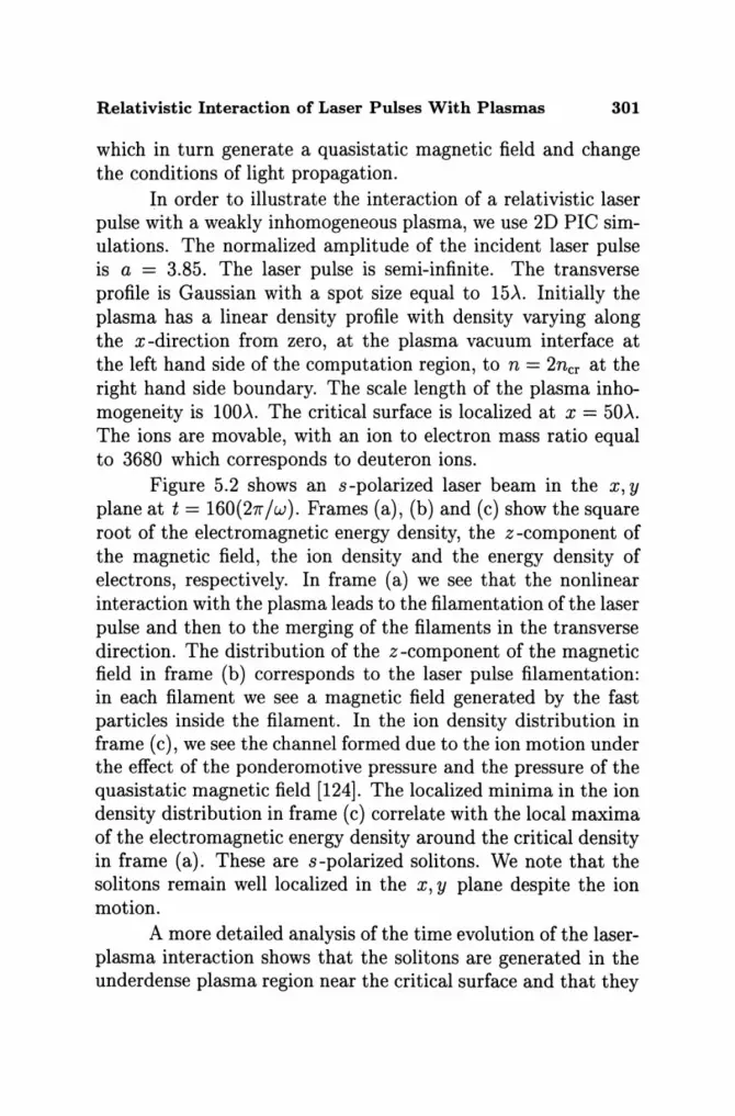
Relativistic Interaction of Laser Pulses With Plasmas 301
which in turn generate a quasistatic magnetic field and change the conditions of light propagation.
In order to illustrate the interaction of a relativistic laser pulse with a weakly inhomogeneous plasma, we use 2D PIC simulations. The normalized amplitude of the incident laser pulse is a = 3.85. The laser pulse is semi-infinite. The transverse profile is Gaussian with a spot size equal to 15),. Initially the plasma has a linear density profile with density varying along the x-direction from zero, at the plasma vacuum interface at the left hand side of the computation region, to n = 2ncr at the right hand side boundary. The scale length of the plasma inhomogeneity is 100),. The critical surface is localized at x = 50),. The ions are movable, with an ion to electron mass ratio equal to 3680 which corresponds to deuteron ions.
Figure 5.2 shows an s-polarized laser beam in the x, y plane at t = 160(27r/w). Frames (a), (b) and (c) show the square root of the electromagnetic energy density, the z-component of the magnetic field, the ion density and the energy density of electrons, respectively. In frame (a) we see that the nonlinear interaction with the plasma leads to the filament at ion of the laser pulse and then to the merging of the filaments in the transverse direction. The distribution of the z -component of the magnetic field in frame (b) corresponds to the laser pulse filamentation: in each filament we see a magnetic field generated by the fast particles inside the filament. In the ion density distribution in frame (c), we see the channel formed due to the ion motion under the effect of the ponderomotive pressure and the pressure of the quasistatic magnetic field [124]. The localized minima in the ion density distribution in frame (c) correlate with the local maxima of the electromagnetic energy density around the critical density in frame (a). These are s-polarized solitons. We note that the solitons remain well localized in the x, y plane despite the ion motion.
A more detailed analysis of the time evolution of the laserplasma interaction shows that the solitons are generated in the underdense plasma region near the critical surface and that they
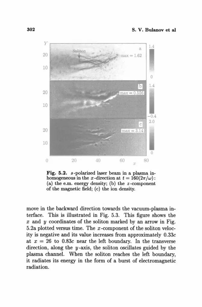
302 s. v. Bulanov et al
yo:------------~---___,
20
10
o
20
10
20
10
o x
Fig. 5.2. s-polarized laser beam in a plasma inhomogeneous in the x-direction at t = 160(211" /w): (a) the e.m. energy density; (b) the z-component of the magnetic field; (c) the ion density.
move in the backward direction towards the vacuum-plasma interface. This is illustrated in Fig. 5.3. This figure shows the x and y coordinates of the soliton marked by an arrow in Fig. 5.2a plotted versus time. The x-component of the soliton velocity is negative and its value increases from approximately O.33c at x = 26 to O.83c near the left boundary. In the transverse direction, along the y-axis, the soliton oscillates guided by the plasma channel. When the soliton reaches the left boundary, it radiates its energy in the form of a burst of electromagnetic radiation.
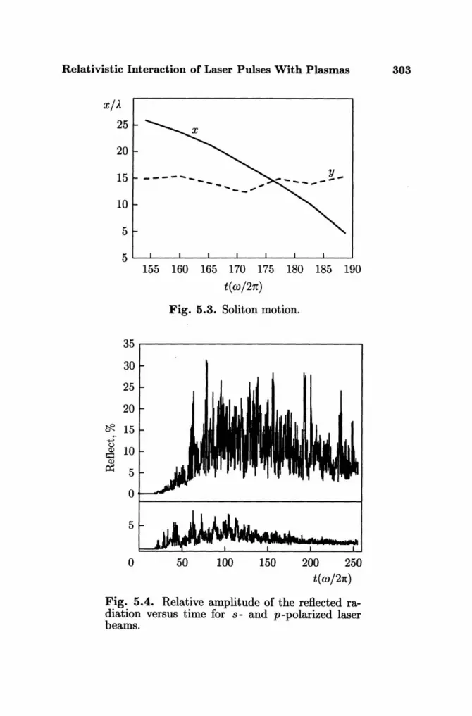
Relativistic Interaction of Laser Pulses With Plasmas 303
x/)..
25
20
15
10
5
---- ..... - ..... -- .. -_ ...
155 160 165 170 175 180 185 190
t( w /2rc)
Fig. 5.3. Soliton motion.
35~--------------------------~
30
25
20
~ 15
JIO 5
O~ __________________________ ~
5
o 50 100 150 200 250 t(w/2rc)
Fig. 5.4. Relative amplitude of the reflected radiation versus time for s- and p-polarized laser beams.
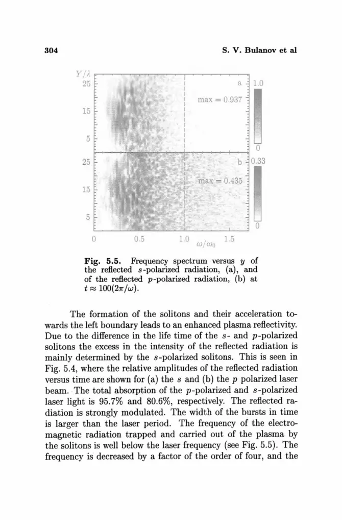
304
Yj}. 25
15
5
25
15
5
0 0.5
S. V. Bulanov et al
a 1.0
max = 0.937
1.0 j 1.5 W Wo
o b 0.33
o
Fig. 5.5. Frequency spectrum versus y of the reflected s-polarized radiation, (a), and of the reflected p-polarized radiation, (b) at t ~ lOO(27rjw).
The formation of the solitons and their acceleration towards the left boundary leads to an enhanced plasma reflectivity. Due to the difference in the life time of the s- and p-polarized solitons the excess in the intensity of the reflected radiation is mainly determined by the s-polarized solitons. This is seen in Fig. 5.4, where the relative amplitudes of the reflected radiation versus time are shown for (a) the sand (b) the p polarized laser beam . . The total absorption of the p-polarized and s-polarized laser light is 95.7% and 80.6%, respectively. The reflected radiation is strongly modulated. The width of the bursts in time is larger than the laser period. The frequency of the electromagnetic radiation trapped and carried out of the plasma by the solitons is well below the laser frequency (see Fig. 5.5). The frequency is decreased by a factor of the order of four, and the
Relativistic Interaction of Laser Pulses With Plasmas 305
reflected radiation is modulated in the transverse direction. We note that the frequency decrease of the reflected laser radiation has been observed in experiments [125].
6. Nonlinear interaction of laser pulses with a foil
A high-power laser pulse interacting with a very thin foil, modeled as a thin slab of overdense plasma, exhibits features that are not encountered either in underdense or in overdense plasmas [126] and offers special experimental conditions for investigating the basic properties of the laser-plasma interaction (some of these features were discussed in Ref. [127], see also Refs. [128] and [50]). This problem has been the subject of experimental and computer studies [129, 130]. These novel features become important when the foil thickness is shorter than, or of the order of, both the laser wavelength and the plasma collisionless skin depth.
Here we investigate how this interaction can be exploited in order to change the shape of the laser pulse [126]. Shaping a laser pulse provides a method for exciting regular wake fields in a plasma leading to effective acceleration of charged particles. The present method is based on the relativistic dependence of the electron mass on the quiver energy. The leading and the rear parts of the pulse are reflected by the foil, which is relativistically transparent for the central part of the pulse where the intensity is higher. This process cuts out the outer part of the laser pulse and produces a sharp leading (and rear) edge, as is needed in order to generate a good quality wake field. The conditions for the foil to be transparent depend on the polarization and incidence angle of the pulse.
To study the interaction of relativistically intense electromagnetic radiation with a thin foil in the 1D case we reduce the problem to the solution of the Cauchy problem for the wave equation with a nonlinear source, i.e., finally, to a system of ordinary differential equations for the electric field inside the foil. This

306 s. v. Bulanov et al
approach is valid for an arbitrary incidence angle of the laser pulse, since, as discussed above, a Lorentz transformation to a reference frame moving along the foil can be used to reduce the problem of oblique incidence to that of normal incidence [120]. In the moving frame all variables are assumed to depend only on time and on the coordinate perpendicular to the foil.
Here we apply this analytical model to study the relativistic transparency of the foil and to investigate how the form of the laser pulse changes depending on the foil thickness, on the plasma density inside the foil and on the amplitude of the pulse. Within this model the foil transparency is found to depend on the relative magnitude of the pulse dimensionless amplitude a and of the dimensionless foil parameter to
(6.1)
besides the pulse incidence angle and polarization. Here I is the foil width, wpe is the Langmuir frequency inside the foil plasma and de = c/wp the corresponding collision less electron skin depth. A thin foil is characterized by the inequalities I :::; de < )..
In the analytical model the foil is assumed to be infinitely thin and the wave equation in dimensionless units for the dimensionless vector potential a is written in the form
(6.2)
where a prime denotes, in the case of oblique incidence, quantities measured in the moving frame. The term on the right hand side of equation (6.2) describes the electric current of the 1D electric charge and the delta function, o(x), models its sharp localization at x = O. The dimensionless rationalized electric current j' (a') is a nonlinear functional of the vector potential a'(O, t') at the charge position x = O. Using Green's functional method the dimensionless electric field E'(x, t') and the mag-
Relativistic Interaction of Laser Pulses With Plasmas 307
netic field B'(x, t') on the two sides of the foil can be written as
E'(x, t')
B'(x, t')
E~(x,t') - ~j'[a'(o,r)], (6.3)
B~(x,t') + ~Sign(x)e~ xj'[a'(O,r)]. (6.4)
Here E'o(x, t') and B~(x, t') are the electric and magnetic field of the incident pulse, ex is the unit vector along x and a'(O, r) is the vector potential at the foil at the retarded time r = t' - lxI/c. The vector potential at the foil satisfies the ordinary differential equation [61, 126]
il'(O,t') - ~j'[a'(O,r)] = ~(O,t'), (6.5)
which is equivalent to equation (6.3) at x = O. We see that this equation does not have high order derivatives with respect to time, contrary to the case of a point three-dimensional charge, where the equations of motion with the radiation force have unphysical "self accelerated solutions" (see discussion in Refs. [13, 131, 132]).
Further we consider the case when the plasma slab position is fixed at x = O. Equation (6.5) with x(t') = 0 plays the role of a nonlinear boundary condition for the electromagnetic waves at x = o.
As we discussed above, the wave frequency and wavevector in the moving frame are related to those in the laboratory frame and to the incidence angle 00 by w' = w cos 00 , k' = k~ex = k cos Ooex, with k _ (k;+k;)1/2 and ky/kx = tan 00 . The e.m. fields are given by E' = Eo cos Ooez , B' = Eo cos Ooey for an s-polarized wave (with Eo replaced by Bo for a p-polarized wave) where Eo (Bo) is the z-component of the electric (magnetic) field of the wave in the laboratory frame, and the plasma density in the foil is given by n' = n/ cos 00.
The dependence of j' on a' follows from the model that we adopt in order to describe the foil. We assume that the ions do not move under the action of the electromagnetic wave
30~ s. V. Bulanov et al
and take the electrons to be collisionless. Since we disregard charge separation effects, electrons are allowed to move in the x, y plane only and their density is taken to be constant. Using the conservation of the y, z components of the canonical electron momentum in the moving frame, we find that the electric current j' takes the form
j'(a') = -2fo(1 + tan8~f/2 c5(x)
{ a' - ey tan 80 • } X 1/2 + sm80 ey . (6.6)
[1 + (a' - ey tan 80)2]
The factor (1 + tan 85)1/2 that multiplies the dimensionless parameter f is due to the transformation of the plasma density to the moving reference frame. This expression can be used to obtain an approximate form of the transmitted and reflected fields through the foil, of the harmonic generation, including the generation of a quasi-steady DC current in the case of oblique incidence, and of the polarization change due to the relativistic nonlinearities.
6.1. Relativistic foil transparency and pulse shaping
Equation (6.6) indicates that the transmission through the foil depends on the pulse amplitude, polarization and incidence angle and on the dimensionless parameter fOe In the simple case of normal incidence, 80 = 0, of a circularly polarized pulse, ao(x, t) = ao(t) exp[i(x - t)], we can solve equations (6.5 , 6.6) by looking for solutions of the form a'(O, t) = a(t) exp( -it), where we represent the two dimensional vector a(t) as a complex valued function ay + iaz = A(t) exp[iw(t)], with amplitude A(t) and phase w(t). If we assume that A, ao and Ware slowly varying functions of time and neglect the time derivatives, we find
1 {[ 2 2 2 2] 1/2 2 2 }1/2 A = y'2 4ao + (1 + fO - ao) - (1 + fO - ao) ,(6.7)
Relativistic Interaction of Laser Pulses With Plasmas 309
and W = W(Eo, ao) = - arccos (A/ao). (6.8)
We obtain the amplitude and the shape of the transmitted and of the reflected pulse. We find that the condition for the foil to be transparent to the electromagnetic radiation in the limit of moderate intensity ao « 1 is EO « 1. This can be rewritten as
(6.9)
which differs from the transparency condition for uniform plasmas by the factor (l/2de ). For relativistically strong waves with ao » 1, a foil with EO » 1 is transparent if ao » EO. This condition can be written as
w » (w;l/2cao), (6.10)
while a uniform plasma is transparent to relativistically strong radiation if [44, 46] w > wp/a~/2 [see equation (1.28)].
Let us now consider a laser pulse with amplitude varying along x. The amplitude is zero at the beginning of the pulse, increases up to its maximum value am and then decreases to zero. If am > EO the portion of the pulse where a < EO is reflected by the foil, while the portion with a > EO propagates through the foil. The model for the foil response used above can also be used to study the dependence of the pulse transmission on its incidence angle and polarization. However this model is based on a number of approximations and their validity must be checked in the framework of a more detailed description such as particle in cell (PIC) simulations. In Figure 6.1 we present the results of 3D PIC simulations of a laser-foil interaction [126]. A circularly polarized pulse, of initial width l.J.. = 10)" is shown before (left column), during (central column) and after (right column) its interaction with the foil. Row (a) gives the x, Y dependence of the pulse e.m. energy density and shows that the pulse loses its outer part, where the amplitude is smaller than EO,
due to its interaction with the foil. This "peeling" of the pulse provides an example of the nonlinear relativistic transparency of

310
15 .lJ 0
t = 20
s. v. Bulanov et al
t = 10 t = 60
a --15 r---------~I----------_1~----------~ o
IT' 10 o ~~~ __ ~~l~~~ __ _L~L~ __ ~ __ ~~
-25 0 2.5 -25 0 25 -25 0 2.) :1' .r .r
Fig. 6.1. Results of 2D3V PIC simulations of the laser-foil interaction. The foil is located at x = 30>'. (a) Distribution of the e.m. energy density as a function of x and y. (b) Distribution of the e.m. energy density along the x axis at y = O.
the plasma foil. As a result of this peeling a pulse with a sharp edge is formed as shown in row (b). The energy absorbed by the particles in the foil is only a few percent of the total pulse energy. The pulse curves the foil and makes it concave. The modification of the foil shape (row c) acts as a concave mirror and focuses the reflected radiation into a narrow beam with a width much smaller than that of the incident pulse (d).
6.2. Induced backward focusing of the light reflected at a mirror deformed by the radiation
In Figure 6.1 we see strong focusing of the reflected radiation in the backward direction to a very small spot, as found in Ref. [126]. The transverse size of the reflected beam is close to one wavelength. This backward focusing of the electromagnetic radiation is a nonlinear effect that appears due to deformation of the critical surface under the light pressure. We shall call this phenomenon backward self-focusing of the light reflected by a mirror deformed by the radiation. This nonlinear effect appears due to deformation of the surface of the critical density under the light pressure.
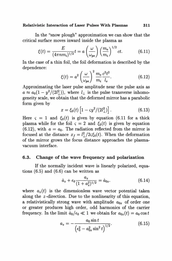
Relativistic Interaction of Laser Pulses With Plasmas 311
In the "snow plough" approximation we can show that the critical surface moves inward inside the plasma as
E ( W ) (me)1/2 ~(t) = (4 Y/2 t =a - . -. ct. 7rnmt wpe m t
(6.11)
In the case of a thin foil, the foil deformation is described by the dependence:
(6.12)
Approximating the laser pulse amplitude near the pulse axis as a :=:::: ao (1 - y2/ (21'i.) ), where 11.. is the pulse transverse inhomogeneity scale, we obtain that the deformed mirror has a parabolic form given by
(6.13)
Here <; = 1 and ~o(t) is given by equation (6.11 for a thick plasma while for the foil <; = 2 and ~o(t) is given by equation (6.12), with a = ao. The radiation reflected from the mirror is focused at the distance xf = li/2<;~0(t). When the deformation of the mirror grows the focus distance approaches the plasmavacuum interface.
6.3. Change of the wave frequency and polarization
If the normally incident wave is linearly polarized, equations (6.5) and (6.6) can be written as
(6.14)
where az(t) is the dimensionless wave vector potential taken along the z -direction. Due to the nonlinearity of this equation, a relativistically strong wave with amplitude aoz of order one or greater produces high order, odd harmonics of the carrier frequency. In the limit 0,0/ EO « 1 we obtain for aoz (t) = ao cos t
az = - 1/2'
(E~ - a~z sin2 t) ao sin t
(6.15)
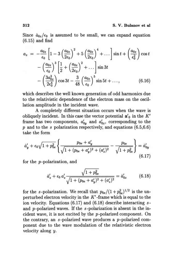
312 s. v. Bulanov et al
Since aoz/EO is assumed to be small, we can expand equation (6.15) and find
aOz [ (aoz )2 (aoz )4 J. (aoz) az = - - 1 - 3 - + 5 - + . .. sm t + -2 cos t EO 2Eo 2Eo EO
- (:~z r [~+ (~::r + ... J sin3t
_ (3a~z) cos 3t _ 43 (aoz) 5 sin 5t + ... , (6.16) 2Eo 8 EO
which describes the well known generation of odd harmonics due to the relativistic dependence of the electron mass on the oscillation amplitude in the incident wave.
A completely different situation occurs when the wave is obliquely incident. In this case the vector potential a' 0 in the K' frame has two components, a~y and a~z' corresponding to the P and to the s polarization respectively, and equations (6.5,6.6) take the form
., + VI + 2 { POe + a~ _ POe } _ ., ay EO POe - aOy VI + (POe + a~)2 + (a~y VI + P~e (6.17)
for the p-polarization, and
., , VI + P~e ., az + EO az = aoz vI + (POe + a~)2 + (a~J2
(6.18)
for the s-polarization. We recall that Poe/(1 + p~e)1/2 is the unperturbed electron velocity in the K' -frame which is equal to the ion velocity. Equations (6.17) and (6.18) describe interacting sand p-polarized waves. If the s-polarization is absent in the incident wave, it is not excited by the p-polarized component. On the contrary, an s-polarized wave produces a p-polarized component due to the wave modulation of the relativistic electron velocity along y.

Relativistic Interaction of Laser Pulses With Plasmas 313
The nonlinear interaction of these components generates both odd and even harmonics. The generation of odd and even harmonics depending on the laser light polarization has been obtained in PIC simulations [37] and [133]. In addition a zero frequency (DC) electric current and a quasistatic magnetic field are produced by s -polarized waves.
It is convenient to adopt a simplified description of the harmonic generation in which Eo/a~ is large.
First we assume the incident wave to be s-polarized, i.e., a~y = O. In the limit EO/ a~ > 1 we can neglect the time derivatives on the left hand side of equations (6.17), (6.18) and obtain for the z-component
1 ·1 (2 ./2 )-1/2 az = aoz EO - aoz . (6.19)
For the y-component we obtain
1 [( 2)1/2] [( 2 ./2)-1/2 ] ay = -POe 1 - 1 + a z = POe EO EO - aOz - 1 . (6.20)
We recover the result that the frequency and the polarization of the wave are changed. The transmitted and the reflected radiation contain both polarizations, the s-polarization is composed of odd harmonics and the P -polarization of even harmonics, including the zero frequency response which describes the generation of a quasistatic magnetic field. The fact that odd and even harmonics appear in the s- and p-polarized components of the reflected light was observed in the computer simulations presented in Ref. [37]. In the laboratory frame, the dependence of the odd harmonic amplitudes on the amplitude of the incident wave is given by equations (6.19), after expressing the time tf and the amplitude a~z in the K' -frame in terms of the time t and the amplitude of the electric field Eoz in the K -frame. We see that the efficiency of the harmonic generation depends on the incidence angle in the laboratory reference frame through the relationship -a~z = Ebz = Eoz cos ()o. Similarly the amplitudes of the even harmonics can be found by expanding (6.20)
(6.21)
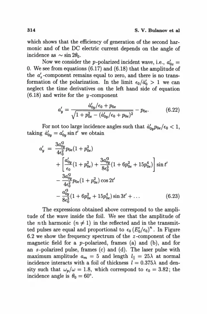
314 s. v. Bulanov et al
which shows that the efficiency of generation of the second harmonic and of the DC electric current depends on the angle of incidence as rv sin 2(}0.
Now we consider the p-polarized incident wave, i.e., a~z = O. We see from equations (6.17) and (6.18) that the amplitude of the a~ -component remains equal to zero, and there is no transformation of the polarization. In the limit to/a~ > 1 we can neglect the time derivatives on the left hand side of equation (6.18) and write for the y-component
a~y/to + POe a~ = . / 2 (' / - POe·
V 1 + POe - aoy to + POe)2 (6.22)
For not too large incidence angles such that a~yPoe/to < 1, taking a~y = a~y sin t' we obtain
a' y
3 '2 aOy 2 -4 2 POe(1 + POe)
to
[ a~y ( 2) 3a~t 2 4 1 ' + - 1 + POe + -8 3 (1 + 6POe + 15poe) sint to to
3 '2 aOy ( 2 ) , - -4 2 POe 1 + POe cos2t to
'3
- 8ao~ (1 + 6P~e + 15P6e) sin 3t' + . . . (6.23) to
The expressions obtained above correspond to the amplitude of the wave inside the foil. We see that the amplitude of the nth harmonic (n i= 1) in the reflected and in the transmi tted pulses are equal and proportional to to (Eb/tot. In Figure 6.2 we show the frequency spectrum of the z-component of the magnetic field for a p-polarized, frames (a) and (b), and for an s-polarized pulse, frames (c) and (d). The laser pulse with maximum amplitude am = 5 and length III = 25A at normal incidence interacts with a foil of thickness l = 0.375A and density such that wp/w = 1.8, which correspond to to = 3.82; the incidence angle is (}o = 60°.
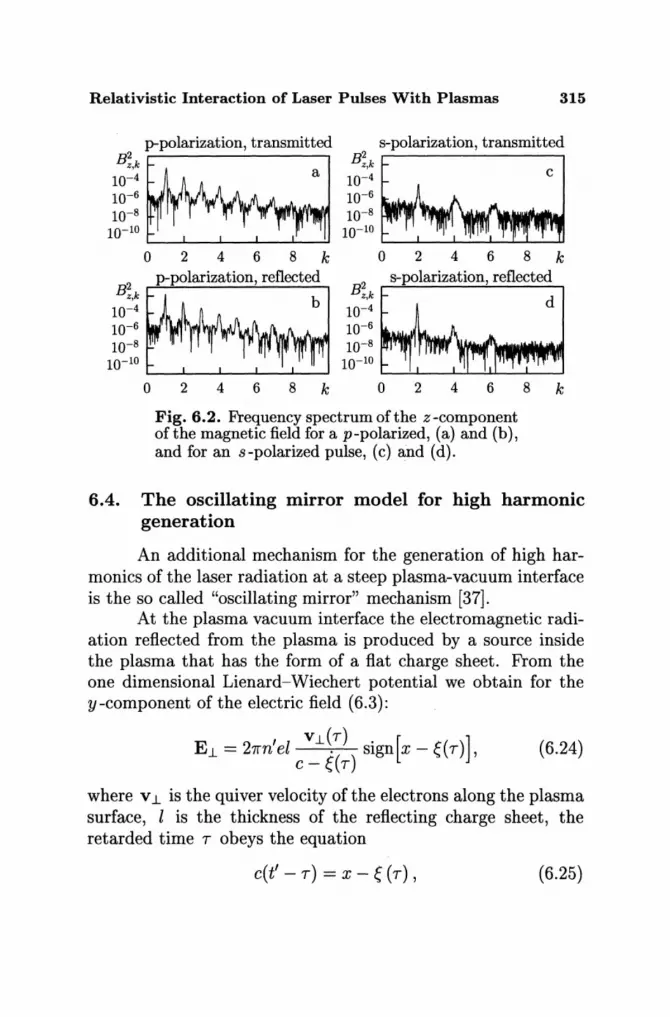
Relativistic Interaction of Laser Pulses With Plasmas 315
B;,k p-~pOlarization, transmitted B;,k s~_pOlarization, transmitted
10-4 a 10-4 c 10-6 10-6
10-8 10-8
10-10 10-10
02468 k 02468 k
B2 ~~ B2 ~s_pOlarization, reflected~ z,k b z,k d
10-4 10-4
10-6 10-6
1~~~: 1~~~:" 02468 k 02468 k
Fig. 6.2. Frequency spectrum of the z -component ofthe magnetic field for a p-polarized, (a) and (b), and for an s-polarized pulse, (c) and (d).
6.4. The oscillating mirror model for high harmonic generation
An additional mechanism for the generation of high harmonics of the laser radiation at a steep plasma-vacuum interface is the so called "oscillating mirror" mechanism [37].
At the plasma vacuum interface the electromagnetic radiation reflected from the plasma is produced by a source inside the plasma that has the form of a flat charge sheet. From the one dimensional Lienard-Wiechert potential we obtain for the y-component of the electric field (6.3):
E 1- = 27rn' el v 1- \7) sign [x - e ( 7) ] , c - ~(7)
(6.24)
where v 1- is the quiver velocity of the electrons along the plasma surface, l is the thickness of the reflecting charge sheet, the retarded time 7 obeys the equation
c(t' - 7) = X - e (7), (6.25)

316 S. V. Bulanov et al
and ~ ( T) is the displacement of the electrons in the normal to the plasma surface direction. By expanding ~(T) and the denominator of equation (6.24) into a series of the ratio ~ 1 c we see that the radiation contains all harmonics of the wave frequency w. The ratio between the amplitudes of the nth and (n + 1) th harmonics is of the order of ~ 1 c.
6.5. Ion acceleration during the interaction of a laser pulse with a slab of overdense plasma
In this section we discuss the ion acceleration by an ultra relativistic laser pulse interacting with a slab of overdense plasma. The 2D PIC simulations were performed for the case of a pre-deformed plasma slab (a thin foil). A foil of thickness 2--\ in the central part is deformed in the form of a parabola. The parabola is given (for x < 6--\) by the formula x = 4--\ + O.32(y - 7.5--\)21--\ and the curve is 2--\ thick. The maximum plasma density is n = 30ncr and the plasma consists of protons (ion mass mi = 1840m) and electrons.
As noted before, effective ion acceleration requires laser pulses in the petawatt power range. In order to show this we consider a plasma slab of width is and assume that it is irradiated by a laser beam with amplitude a and radius il.. » is at the focus. The electrons interacting with the laser light are displaced from their initial position and, if their energy ce = m ec2a2/2 is large enough, they can overcome the attractive electric field due to charge separation. For the electrons to be blown off, the pulse amplitude must be such that ce > CCoulomb, with CCoulomb ~ 27re2nish the Coulomb energy, i.e., a > (lshld~)1/2 . Here de = clwpe is the collisionless skin depth. Due to the Coulomb repulsion the ions start to expand and gain an energy of the order of CCoulomb. Assuming ce ~ CCoulomb, the ion energy gain in this Coulomb explosion can be rewritten as Ci ~ mic2(melmi)a2 which is of the order of the ion rest mass when a ~ (mdme)1/2.

Relativistic Interaction of Laser Pulses With Plasmas 317
In 2D PIC simulations an ultra intense p-polarized laser pulse is initiated at the left hand side boundary. The pulse has a Gaussian profile both in the longitudinal and in the transverse direction. The pulse length and spot size (its width) are 5.5'\ and 5'\, respectively. The normalized vector potential of the incident pulse is equal to a = 89, and is larger than (mdme)1/2 ~ 43. For a IJ1m laser, the intensity corresponds to 1.6 x 10²² W cm-2
and the pulse length to 18 fs. For the chosen parameters of the laser pulse and plasma,
the dimensionless parameter Eo = w;els/2wc [see (6.1)] is equal to 180. The normalized laser amplitude a = 89 is smaller than EO. In this case, according to Ref. [126] the foil is not transparent to the laser radiation and only a relatively small portion of the radiation can be transmitted through the foil.
The interaction of the laser pulse with the deformed foil is shown in Fig. 6.3: frames (a) and (c) correspond to t = 9(27r/w), and frames (b) and (d) correspond to t = 15(27r/w). Frames (a) and (b) show the distribution of the electromagnetic energy density and frames (c) and (d) show the x-component ofthe electric field in the x, y-plane. Since the target is initially deformed, the laser pulse is incident obliquely in the regions outside the center. The electric charge separation leads to the generation of a strong electrostatic field, as shown in Figs. 6.3b, d. The foil deformation leads to enhanced absorption of the laser light [135]. The fractions of the reflected and transmitted laser energy are respectively equal to 16.26% and 12.26%. The absorption of the laser pulse is accompanied by an effective particle acceleration. In Figure 6.4 the phase plane of electrons with energy above 1.5 MeV is shown in frame (a) at t = 15(27r/w). The electrons with maximum energy up to 200 MeV are accelerated in the forward direction twice per laser period due to the v x B force [136] and the energetic electrons are accelerated in the backward direction once per laser period as observed in Ref. [137]. The phase plane of the fast ions is shown in Fig. 6.4b: the ions are accelerated both in the backward and in the forward direction, but the forward ion acceleration is predominant. The maximum momentum reached

318
14 max = 1.25 y/;. 12
10
8
6
4
2
14 y/ i. 12
10
8
6
4
2
max = 0.486
c9
-~ ,.
o 2 4 6
S. v. Bulanov et al
b
Fig. 6.3. Electromagnetic energy density normalized to its peak value inside the pulse, (a) and (b), and Ex -component of the electric field normalized to the laser field Eyo, (c) and (d). Frames (a) and (c) correspond to t = 9(27r/w), (b) and (d) to t = 15(27r/w). Contour levels vary from 0.1 to 1.2 with 0.1 interval.
by the ions is Px/mic f',.J 1, which corresponds to the GeV energy range. Also in this case the acceleration mechanism must be attributed to the Coulomb explosion which gives a final ion energy of the order of CCoulomb ~ 27re2nlsR = 27r2mec2(wpe/w)2(lsR/ Jl.2).
For the parameters of the simulations CCoulomb ~ mic2 i.e., approximately 1 GeV.
Besides being accelerated, the ions are also well collimated in the forward direction. In Figure 6.5 we show the energy density of electrons (a), ions (b) in the x, y-plane and the zcomponent of the magnetic field (c) at t = 15(27r /w) together

Relativistic Interaction of Laser Pulses With Plasmas 319
600 Px/me
400
200
0
-200
1.5 Px/me
1.0
0.5
0
-0.5 0 2 4 6
a
b
8 10 12 x
Fig. 6.4. Phase plane of electrons (Pxe, x) with energy above 1.5 MeV, (a), and of ions at t = 15{27r/w) , (b).
with a plot of the quasistatic magnetic field and of the ion energy density at x = 4.65-\ versus y at t = 12(27r/w) (d). The ions moving in the forward direction form a single jet-shaped filament. Inside this filament the electric charge neutrality is broken. However, the repulsion in the transverse direction due the electric force is partially balanced by the magnetic force. We see in Figs. 6.5c, d the change of the sign of the magnetic field at the axis corresponds to the electric current carried by fast ions. The pinching does not confine the ions in the longitudinal direction: they expand and gain energy. The quasistatic magnetic field is approximately 300 MG (10 times smaller than the magnetic field in the laser pulse) and the transverse size of the ion jet is equal to 0.2-\. At t = 18(27r /w) the ion density in the
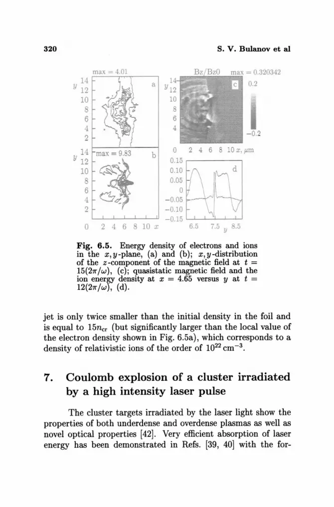
320
14 Y 12
10 8 6 4 2
14 Y 12
10 8 6 4 2
max = 4.01
max = 9.83 b
o 2 4 6 8 10 x
s. V. Bulanov et al
0 2 4 6 8 10 X,P.ffi
0.15 0.10 0.05
0 - 0.05 -0.10 -0.15
Fig. 6.5. Energy density of electrons and ions in the x, y-plane, (a) and (b); x, y-distribution of the z -component of the magnetic field at t = 15{27r/w), (c); quasistatic magnetic field and the ion enersY density at x = 4.65 versus y at t = 12(27r/w), (d).
jet is only twice smaller than the initial density in the foil and is equal to 15ncr (but significantly larger than the local value of the electron density shown in Fig. 6.5a), which corresponds to a density of relativistic ions of the order of 1022 cm-3 •
7. Coulomb explosion of a cluster irradiated by a high intensity laser pulse
The cluster targets irradiated by the laser light show the properties of both underdense and overdense plasmas as well as novel optical properties [42]. Very efficient absorption of laser energy has been demonstrated in Refs. [39, 40] with the for-
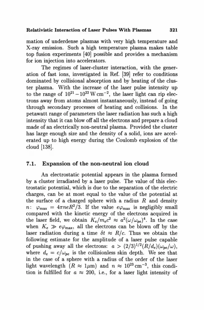
Relativistic Interaction of Laser Pulses With Plasmas 321
mation of underdense plasmas with very high temperature and X-ray emission. Such a high temperature plasma makes table top fusion experiments [40] possible and provides a mechanism for ion injection into accelerators.
The regimes of laser-cluster interaction, with the generation of fast ions, investigated in Ref. [39] refer to conditions dominated by collisional absorption and by heating of the cluster plasma. With the increase of the laser pulse intensity up to the range of 1021 _1022 W cm-2 , the laser light can rip electrons away from atoms almost instantaneously, instead of going through secondary processes of heating and collisions. In the petawatt range of parameters the laser radiation has such a high intensity that it can blow off all the electrons and prepare a cloud made of an electrically non-neutral plasma. Provided the cluster has large enough size and the density of a solid, ions are accelerated up to high energy during the Coulomb explosion of the cloud [138].
7.1. Expansion of the non-neutral ion cloud
An electrostatic potential appears in the plasma formed by a cluster irradiated by a laser pulse. The value of this electrostatic potential, which is due to the separation of the electric charges, can be at most equal to the value of the potential at the surface of a charged sphere with a radius R and density n: CPmax = 47rneR2 /3. If the value ecpmax is negligibly small compared with the kinetic energy of the electrons acquired in the laser field, we obtain Ke/mec2 ~ a2(w/wpe )4. In the case when Ke » ecpmax, all the electrons can be blown off by the laser radiation during a time 6t ~ R/c. Thus we obtain the following estimate for the amplitude of a laser pulse capable of pushing away all the electrons: a > (2/3)1/2(R/de)(wpe /W), where de = c/ wpe is the collisionless skin depth. We see that in the case of a sphere with a radius of the order of the laser light wavelength (R ~ 1J.lm) and n ~ 1023 cm-3 , this condition is fulfilled for a ~ 200, i.e., for a laser light intensity of

322 s. V. Bulanov et al
the order of 1024 W cm -2. For more moderate intensities of the laser pulse, ~ 2 x 10²¹ W cm -2, the quiver radius of electrons inside the cluster is smaller than R. The quiver radius is about rE = eE/mw;e = dea(w/wpe). In this case only a small portion of the electrons leave the cluster during one period of the laser radiation: ani ~ (rE/ R)ni. It takes a time of the order of t1 = 27r(R/rE)w-1 to blow off all the electrons.
We can identify two stages in the cluster expansion. During the first stage, which lasts a time t1, the cloud expands gradually. Then it explodes with a timescale of explosion approximately given by t2 = w;/. Fast ions acquire their energy during this second stage.
Now we consider the motion of the ion component under the Coulomb repulsion in this second phase. Assuming the ions to be cold and to move radially, we obtain the energy integral Ki + II = constant, where the ion kinetic energy is
(7.1)
and the potential energy is
(J(ro) (J(ro) -""':"":'''''''':'''--,-- --ro + ~(ro, t) ro
(7.2)
ro is the ion position at the beginning of the second phase, ~(ro, t) is the ion displacement at time t and
(7.3)
During the expansion of the cloud the ion kinetic energy increases, for ~ -+ 00, up to the value 47re2(J(ro)/ro which depends on the initial position of the ion inside the cloud. Assuming a homogeneous distribution of the ion density inside the cloud, ni, and calculating (J(ro) = nirgj3, we obtain that an ion acquires a final energy Ki = 47rnie2rU3, ro:::; R2, which is limited by
(7.4)

Relativistic Interaction of Laser Pulses With Plasmas 323
Here R2 = J (2/3)R3nie2 AI amec2 is the cloud radius at the beginning of the second stage of the cluster expansion. Here R2 is estimated as the value of the cloud radius for which the Coulomb force on the electrons becomes smaller than the electric force due to the laser light.
Since the ion energy is proportional to r5 we can calculate the ion energy spectrum df I dKi which, due to the flux continuity in phase space, is proportional to dro/dKi. We obtain
(7.5)
When the ion energy is smaller than M c2 , we can use a nonrelativistic description of the Coulomb explosion. In this approximation we write the following system of equations of motion
(7.6)
where Wpi = (47rnie2/mi)1/2 is the ion plasma frequency. Integrating equation (7.6) with the initial conditions ~(O) = 0, E(O) = 0 yields
~ In [2~ + ro + 2v1~2 + ro~ 1 + vie + ro~ = 13. Wpit. (7.7) 2 ~ ~ y~
When the displacement is small, ~ «ro (t« 21/2w;/), ions move with constant acceleration ~(ro, t) ~ rOw;it2/6, while, for
t -t 00, we have ~(ro, t) ~ ro (2/3)1/2 Wpit. In the latter case ions move with constant velocity, which corresponds to the kinetic energy given by equation (7.2). The typical time of the ion cloud expansion is of the order of w;/. Thus we can neglect the deformation of the ion cloud during laser pulse interaction with the electron component (it lasts about Ric) if Rwpdc < 1.

324 S. V. Bulanov et al
a
12~--~~~~~~~~--~
o 2 10 ,II
t = 2tl.OO
b
12~~~-J--~~-L---L--~
o 2 10 lJ
Fig. 7.1. Distribution of the electrons ripped off by the laser light at t = 11.7, (a), and the ion cloud at t = 28, (b).
7.2. Results of 2D and 3D PIC computer simulations of the Coulomb explosion of small clusters
In order to illustrate both the electron and the ion dynamics when a small cluster is irradiated by laser light we performed 2D PIC simulations. The initial radius of the cluster is equal to O.IA, the plasma density n = 100ner, and the ion to electron mass ratio md me = 2000. The laser pulse is circularly polarized with amplitude a = 5. Figure 7.la shows the distribution of the electrons ripped off by the laser light at t = 11 X 27r fWQ. This
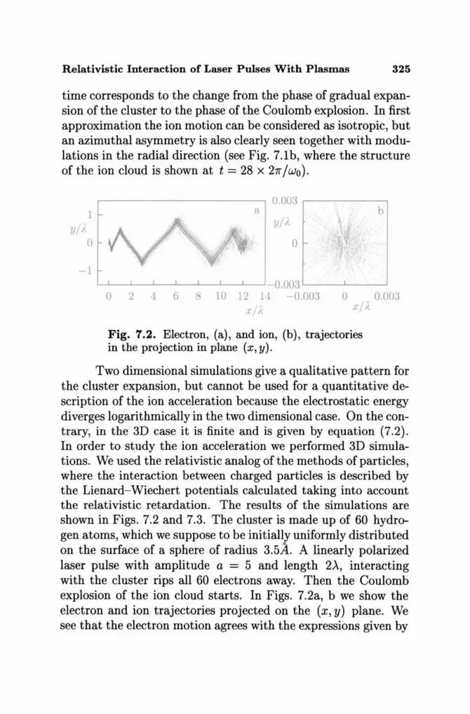
Relativistic Interaction of Laser Pulses With Plasmas 325
time corresponds to the change from the phase of gradual expansion of the cluster to the phase of the Coulomb explosion. In first approximation the ion motion can be considered as isotropic, but an azimuthal asymmetry is also clearly seen together with modulations in the radial direction (see Fig. 7.1b, where the structure of the ion cloud is shown at t = 28 X 2rr / wo) .
1 yl i.
o
-1
.---------------, 0.003 ,....---------, a b
yl)·
o
L........I..-....L..----'--.1....---'--'-----'----'-O .003 '-------'------' o 2 6 10 12 11 -0.003 o 0.003
. rl I J,/ I .
Fig. 7.2. Electron, (a), and ion, (b), trajectories in the projection in plane (x, y).
Two dimensional simulations give a qualitative pattern for the cluster expansion, but cannot be used for a quantitative description of the ion acceleration because the electrostatic energy diverges logarithmically in the two dimensional case. On the contrary, in the 3D case it is finite and is given by equation (7.2). In order to study the ion acceleration we performed 3D simulations. We used the relativistic analog of the methods of particles, where the interaction between charged particles is described by the Lienard-Wiechert potentials calculated taking into account the relativistic retardation. The results of the simulations are shown in Figs. 7.2 and 7.3. The cluster is made up of 60 hydrogen atoms, which we suppose to be initially uniformly distributed on the surface of a sphere of radius 3.5.4.. A linearly polarized laser pulse with amplitude a = 5 and length 2,A, interacting with the cluster rips all 60 electrons away. Then the Coulomb explosion of the ion cloud starts. In Figs. 7.2a, b we show the electron and ion trajectories projected on the (x, y) plane. We see that the electron motion agrees with the expressions given by

326 s. v. Bulanov et al
15.---------------------~
K/mc?
10
5
o 4 8 12
1" = 2T
16 20 T/t
Fig. 7.3. Time dependence of the electron kinetic energy.
equations (4), and that the ion cloud expands almost spherically symmetrically. In Fig. 7.3 we present the time dependence ofthe electron energy. At the beginning, in agreement with equation ( 4), the electron energy increases with time while the electrons remain inside the laser pulse. Then it decreases to zero when the laser pulse moves ahead of the electrons.
8. Conclusions
In this review we have discussed the nonlinear relativistic dynamics of plasmas interacting with high intensity laser pulses and have presented the different physical phenomena starting from lower amplitude regimes in underdense plasmas, where only the electrons are relativistic, and then moving towards higher pulse intensities in the petawatt power regime, where ions too become relativistic. We have then considered overdense plasmas, where the plasma inhomogeneity plays a fundamental role, and
Relativistic Interaction of Laser Pulses With Plasmas 327
targets with intermediate physical characteristics such as thin foils and clusters.
In all these cases we have stressed the important interplay between the investigation of basic physics features, such as the formation of coherent soli tonic nonlinear structures, and the applications that these new phenomena can open in an interdisciplinary context (for example in high energy astrophysics) and for practical use (from energy production to medicine).
An additional point is the fundamental role that numerical simulations play in the analysis of these "extreme" regimes which are outside the reach of most analytical developments because of their high dimensionality and because of their full nonlinear dynamics. Simulations here are not only used for validating analytical models, but also play the more vital role of an investigative tool for discovering new phenomena. Obviously this simulation analysis must be accompanied by the development of an appropriate terminology, in order to describe the numerical results, and must be guided by an a priori understanding of the relevant range of parameters and their scaling. Both the terminology and the parameter estimates can only be obtained from a physical understanding based on the extrapolation of simplified, lower dimensionality models.
Acknowledgements
We are pleased to acknowledge the use of the Origin SGI 2000 supercomputer at Scuola Normale Superiore, Pisa, Italy, and of the Cray T3E at Cineca, Bologna, Italy, under the INFM Parallel Computing Initiative.
REFERENCES
1. G. A. Mourou, C. P. J. Barty, and M. D. Perry, Phys. Today 51, 22 (1998)
2. T. Tajima and J. Dawson, Phys. Rev. Lett., 43, 262 (1979)

328 s. v. Bulanov et al
3. D. Giulietti and L. A. Gizzi, Rivista del Nuovo Cimento, 21, 10 (1998)
4. M. Tabak, J. Hammer, M. E. Glinsky, et. al., Phys. Plasmas, 1, 1626 (1994)
5. V. S. Berezinsky, S. V. Bulanov, V. A. Dogiel, V. L. Ginzburg, and V. S. Ptuskin, Astrophysics of Cosmic Rays, North Holland, Amsterdam, (1990)
6. V. Yu. Bychenkov, V. T. Tikhonchuk, and S. V. Tolokonnikov, JETP, 88, 1137 (1999)
7. G. Arduini, R. Cambria, C. Canzi, et al., Medical Phys., 23, 939 (1996)
8. P. Chen and T. Tajima, Phys. Rev. Lett., 83, 256 (1999)
9. J. Kane, D. Arnett, B. A. Remington, et al., Phys. Plasmas, 6, 2065 (1999); D. R. Farley, K. G. Estabrook, S. G. Glendinning, et al., Phys. Rev. Lett. 83, 1982 (1999)
10. Ya. B. Fainberg, Sov. J. Plasma Phys., 13, 607 (1987); Plasma Phys. Rep., 26, (2000)
11. S. V. Bulanov, L. M. Kovrizhnykh, and A. S. Sakharov, Phys. Reports, 186, 1 (1990)
12. J. M. Dawson, Plasma Phys. Contr. Fusion, 34, 2039 (1992)
13. L. D. Landau and E. M. Lifshits, Field Theory, Pergamon, Reading (1971)
14. H. M. Lai, Phys. Fluids, 23, 2373 (1980); B. Rau, T. Tajima, and H. Hojo, Phys. Rev. Lett., 78, 3310 (1997)
15. G. A. Askar'yan, Sov. Phys. JETP, 15, 8 (1962); Sov. Phys. Usp. 16, 680 (1973)
16. A. G. Litvak, Sov. Phys. JETP 30, 344 (1969); C. Max, J. Arons, and A. B. Langdon, Phys. Rev. Lett., 33, 209 (1974); G. Schmidt and W. Horton, Comm. Plasma Phys. Contr. Fusion, 9, 85 (1985)
17. A. B. Borisov, A. V. Borovskii, O. B. Shiryaev, et al., Phys. Rev. A, 45, 5830 (1992); X. L. Chen and R. N. Sudan, Phys. Rev. Lett., 70, 2082 (1993)
18. S. V. Bulanov, F. Pegoraro, and A. M. Pukhov, Phys. Rev. Lett., 74, 710 (1995)
19. N. E. Andreev, Sov. Phys. JETP, 32, 1141 (1971)
Relativistic Interaction of Laser Pulses With Plasmas 329
20. W. L. Kruer, The Physics of Laser Plasma Interactions, AddisonWesley, New York (1988)
21. T. M. Antonsen and P. Mora, Phys. Rev. Lett., 69, 2204 (1992)
22. N. E. Andreev, L. M. Gorbunov, and V. I. Kirsanov, et al., JETP Lett., 55, 571 (1992)
23. A. S. Sakharov and V.I. Kirsanov, Phys. Rev. E, 49,3274 (1994)
24. W. B. Mori, C. D. Decker, D. E. Hinkel, and T. Katsouleas, Phys. Rev. Lett., 72, 1482 (1994); C. D. Decker, W. B. Mori, T. Katsouleas, and D. E. Hinkel, Phys. Plasmas, 3, 1360 (1996)
25. E. Esarey, J. Krall, and P. Sprangle, Phys. Rev. Lett., 72, 2887 (1994)
26. N. E. Andreev, L. M. Gorbunov, V. I. Kirsanov, et al., Plasma Phys. Rep., 22, 379 (1996)
27. K. Nakajima, D. Fisher, T. Kawakubo, et al., Phys. Rev. Lett., 74, 4428 (1995)
28. A. Modena, Z. Najimudin, A. E. Dangor, et al., Nature, 337, 606 (1995)
29. D. Umstadter, S.-Y. Chen, A. Maksimchuk, et al., Science, 273, 472 (1996)
30. P. Sprangle and E. Esarey, Phys. Rev. Lett., 67, 2021 (1991); E. Esarey and P. Sprangle, Phys. Rev. A 45, 5872 (1992)
31. A. S. Sakharov and V. I. Kirsanov, Phys. Fluids, 4, 3382 (1997) 32. S. V. Bulanov, I. N. Inovenkov, V. I. Kirsanov, et al., Phys.
Fluids B, 4, 1935 (1992); S. V. Bulanov, I. N. Inovenkov, V. I. Kirsanov, et. al., Physica Scripta, 47, 209 (1993)
33. S. V. Bulanov and A. S. Sakharov, JETP Lett., 54, 203 (1991)
34. G. A. Askar'yan, S. V. Bulanov, F. Pegoraro, and A. M. Pukhov, JETP Lett., 60, 251 (1994); Plasma Phys. Rep., 21, 985 (1995); Comm. Plasma Phys. Contr. Fusion, 17, 35 (1995)
35. T. V. Liseikina, F. Califano, V. A. Vshivkov, et al., Phys. Rev. E, 60, 5991 (1999)
36. V. F. D'yachenko and V. S. Imshennik, Sov. J. Plasma Phys., 5, 413 (1979); F. BruneI, Phys. Rev. Lett., 59, 52 (1987); Phys. Fluids, 31, 2714 (1988); P. Gibbon and A. R. Bell, Phys. Rev. Lett., 68, 1535 (1992); P. Gibbon, Phys. Rev. Lett., 73, 664 (1994)

330 s. v. Bulanov et al
37. S. V. Bulanov, N. M. Naumova, and F. Pegoraro, Phys. Plasmas, 1,745 (1994); S. V. Bulanov, T. Zh. Esirkepov, N. M. Naumova, and F. Pegoraro, Phys. Scr. T, 63, 258 (1996)
38. V. L. Ginzburg, Propagation of Electromagnetic Waves in Plasmas, Pergamon Press, New York, (1964)
39. T. Ditmire, T. Donnelly, A. M. Rubenchik, et aI., Phys. Rev. A, 53, 3379 (1996); M. Lezius, S. Dobosz, D. Normand, and M. Schmidt, Phys. Rev. Lett., 80, 261 (1998)
40. T. Ditmire, J. Zweiback, V. P. Yanovsky, et aI., Nature, 398, 489 (1999)
41. S. Dobosz, M. Schmidt, M. Pedrix, et aI., JETP Lett., 68, 454 (1998)
42. T. Tajima, Y. Kishimoto, and M. C. Downer, Phys. Plasmas, 6, 3759 (1999)
43. J. M. Dawson, A. T. Lin, in: Basic Plasma Physics (edited by M. N. Rosenbluth and R. Z. Sagdeev), Vol. 2, North-Holland, Amsterdam, (1984) p. 555.
44. A. I. Akhiezer and R. V. Polovin, Sov. Phys. JETP, 30, 915 (1956)
45. M. B. Isichenko and V. V. Yan'kov, Sov. J. Plasma Phys., 12, 98 (1986)
46. P. Kaw and J. Dawson, Phys. Fluids, 13, 472 (1970)
47. J. Fuchs, J. C. Adam, F. Amiranoff, et aI., Phys. Rev. Lett., 80, 2326 (1997)
48. S. V. Bulanov, V. I. Kirsanov, and A. S. Sakharov, JETP Lett., 50, 176 (1989)
49. S. V. Bulanov, V. I. Kirsanov, and A. S. Sakharov, Sov. J. Plasma Phys., 16, 543 (1990)
50. S. V. Bulanov, T. Zh. Esirkepov, N. M. Naumova, et aI., IEEE Trans. Plasma Sci., 24, 393 (1996)
51. G.-Z. Sun, E. Ott, Y. C. Lee, and P. Guzdar, Phys. Fluids, 30, 526 (1987)
52. K.-C. Tzeng, W. B. Mori, and C. D. Decker, Phys. Rev. Lett., 76, 3332 (1996); K.-C. Tzeng and W. B. Mori, Phys. Rev. Lett., 81, 104 (1998); P. Chessa and P. Mora, Phys. Plasmas,S, 3451 (1998)
Relativistic Interaction of Laser Pulses With Plasmas 331
53. C. D. Decker, W. B. Mori, K.-C. Tzeng, and T. Katsouleas, Phys. Plasmas, 3, 2047 (1996)
54. L. M. Gorbunov and V. 1. Kirsanov, Sov. Phys. JETP, 66, 290 (1987)
55. M. Rosenbluth and C. S. Lui, Phys. Rev. Lett., 29, 701 (1972)
56. V. 1. Berezhiani and 1. G. Murusidze, Phys. Lett. A, 148, 338 (1990)
57. S. Dalla and M. Lontano, Phys. Rev. E, 49, R1819 (1994)
58. T. Katsouleas and W. B. Mori, Phys. Rev. Lett .. 61, 90 (1988)
59. S. V. Bulanov, V. 1. Kirsanov, and A. S. Sakharov, JETP Lett., 53, 540 (1991)
60. D. Gordon, K. C. Tseng, C. E. Clayton et al., Phys. Rev. Lett., 80, 2133 (1998)
61. S. V. Bulanov, V. A. Vshivkov, G. 1. Dudnikova, et al., Plasma Phys. Rep., 23, 660 (1997)
62. E. Esarey and M. Pilloif, Phys. Plasmas, 2, 1432 (1995)
63. B. B. Kadomtsev, Cooperative Effects in Plasmas [in Russian], Nauka, Moscow (1976); English translation: Consultants Bureau, New York (2000)
64. G. B. Whitham, Linear and Nonlinear Waves, Willey, New York (1974)
65. D. Umstadter, J. M. Kim, and E. Dodd, Phys. Rev. Lett., 76, 2073 (1996)
66. E. Esarey, R. F. Hubbard, and W. P. Leemans, et al., Phys. Rev. Lett., 79, 2682 (1997)
67. S. V. Bulanov, N. M. Naumova, F. Pegoraro, and J.-1. Sakai, Phys. Rev. E, 58, 5257 (1998)
68. S. V. Bulanov, 1. N. Inovenkov, V. 1. Kirsanov, et al., Sov. J. Plasma Phys., 16, 444 (1990)
69. V. I. Arnold, The Theory of Singularities and its Applications, Scuoia Normale Superiore, Pisa (1991)
70. S. V. Bulanov, F. Pegoraro, A. M. Pukhov, and A. S. Sakharov, Phys. Rev. Lett., 78, 4205 (1997)
71. S. C. Wilks, J. M. Dawson, W. B. Mori, et al., Phys. Rev. Lett., 74, 4428 (1989); E. Esarey, A. Ting, and P. Sprangle, Phys.
332 s. v. Bulanov et al
Rev. A, 42, 3226 (1990); R. Bingham, J. T. Mendonca, and J. M. Dawson, Phys. Rev. Lett., 78, 247 (1997)
72. S. V. Bulanov, I. N. Inovenkov, V. I. Kirsanov, et al., Kratkie Soobshcheniya po Fiz., 6, 9 (1991); S. V. Bulanov, V. I. KirsanoY, F. Pegoraro, and A. S. Sakharov, Laser Phys., 3, 1078 (1993)
73. A. A. Solodov, P. Mora, and P. Chessa, Phys. Plasmas, 6, 503 (1999)
74. W. Pauli, Theory of Relativity, Dover, New York (1981)
75. S. V. Bulanov, F. Califano, G. I. Dudnikova, et al., Plasma Phys. Rep., 25, 701 (1999)
76. K. Krushelnik, E. L. Clark, Z. Najmudin, et al., Phys. Rev. Lett., 82, 2095 (1999)
77. P. Norreys, A. P. Fews, F. N. Beg, et al., Plasma Phys. Contr. Fusion, 40, 175 (1998); L. Disdier, J.-P. Coronnet, G. MaIka, and J.-L. Miguel, Phys. Rev. Lett., 82, 1454 (1999)
78. G. S. Sarkisov, V. Yu. Bychenkov, V. N. Novikov, et al., Phys. Rev. E, 59, 7042 (1999)
79. T. Zh. Esirkepov, Y. Sentoku, F. Califano, et al., JETP Lett., 70, 82 (1999); S. V. Bulanov, T. Zh. Esirkepov, F. Califano, et al., JETP Lett., 71, 407 (2000)
80. G. A. Askar'yan, S. V. Bulanov, and I. V. Sokolov, Plasma Phys. Rep., 25, 549 (1999)
81. F. Pegoraro, S. V. Bulanov, F. Califano, et al., IEEE Trans. Plasma Sci., 28, (2000)
82. D. W. Forslund, J. M. Kindel, W. B. Mori, et al., Phys. Rev. Lett., 54, 558 (1985)
83. A. M. Pukhov and J. Meyer-ter-Vehn, Phys. Rev. Lett., 76, 3975 (1996)
84. M. Borghesi, A. J. Mackinnon, R. Gaillard, et al., Phys. Rev. Lett., 80, 5137 (1998); A. M. Pukhov and J. Meyer-ter-Vehn, Phys. Rev. Lett., 79, 2686 (1997)
85. H. Ruhl, Y. Sentoku, K. Mirna, et al., Phys. Rev. Lett., 82, 743 (1999)
86. V. V. Korobkin and R. V. Serov, JETP Lett., 4, 70 (1962)
Relativistic Interaction of Laser Pulses With Plasmas 333
87. G. A. Askar'yan, M. S. Rabinovich, A. D. Smirnova, and v. B. Studenov, JETP Lett., 5, 93 (1967)
88. A. R. Bell, Phys. Plasmas, 1, 1643 (1994)
89. J. Stamper, K. Papadopoulos, R. N. Sudan, et al., Phys. Rev. Lett., 26, 1012 (1971)
90. P. K. Shukla, N. N. Rao, M. Y. Yu, and N. L. Tsintsadze, Phys. Rep., 138, 1 (1986)
91. V. Yu. Bychenkov, V. P. SHin, and V. T. Tikhonchuk, Sov. Phys. JETP, 71, 79 (1990)
92. R. N. Sudan, Phys. Rev. Lett., 70, 3075 (1993)
93. A. D. Steiger and C. H. Woods, Phys. Rev. A, 5, 1467 (1971); L. M. Gorbunov and R. R. Ramazashvili, JETP, 87, 461 (1998)
94. V. I. Berezhiani, S. M. Mahajan, and N. L. Shatashvili, Phys. Rev. E, 55, 995 (1997)
95. L. Gorbunov, P. Mora, and T. M. Antonsen, Phys. Rev. Lett., 76, 2495 (1996); Phys. Plasmas, 4, 4358 (1997)
96. E. W. Weibel, Phys. Rev. Lett., 2, 83 (1959); F. Pegoraro, S. V. Bulanov, F. Califano, and M. Lontano, Phys. Scr. T, 63, 262 (1996); F. Califano, F. Pegoraro, S. V. Bulanov, and A. Mangeney, Phys. Rev. E, 57, 7048 (1998); F. Califano, R. Prandi, F. Pegoraro, and S. V. Bulanov, Phys. Rev. E, 58, 7837 (1998); Y. Kazimura, F. Califano, J.-I. Sakai, et al., J. Phys. Soc. Jpn., 67, 1079 (1998); Y. Kazimura , J.-I. Sakai, and S. V. Bulanov, J. Phys. Soc. Jpn., 68, 3271 (1999)
97. R. Bingham, Nature, 368, 496 (1994)
98. S. V. Bulanov, T. Zh. Esirkepov, M. Lontano, et al., Phys. Rev. Lett., 76, 3562 (1996)
99. S. V. Bulanov, T. Zh. Esirkepov, M. Lontano, and F. Pegoraro, Plasma Phys. Rep., 23, 660 (1997)
100. A. S. Kingsep, K. V. Chukbar, and V. V. Yan'kov, in: Reviews of Plasma Physics (edited by B. B. Kadomtsev), Vol. 16, Consultants Bureau, New York (1989)
101. A. Hasegawa and K. Mirna, Phys. Rev. Lett., 39, 205 (1977); Phys. Fluids, 21, 87 (1978)
102. G. Matsuoka and K. Nosaki, Phys. Fluids B, 4, 551 (1992)
103. W. Horton and A. Hasegawa, Chaos, 4, 227 (1994)

334 s. v. Bulanov et al
104. A. A. Abrikosov, Sov. Phys. JETP, 5, 1174 (1957)
105. H. Lamb, Hydrodynamics, Cambridge University Press, Cambridge, 1932)
106. K. Mirna, T. Ohsuga, H. Takabe, et al., Phys. Rev. Lett., 57, 1421 (1986)
107. P. K. Kaw, A. Sen, and T. Katsouleas, Phys. Rev. Lett., 68, 3172 (1992)
108. N. L. Tsintsadze and D. D. Tskhakaya, JETP, 45, 252 (1977)
109. V. A. Kozlov, A. G. Litvak, and E. V. Suvorov, Sov. Phys. JETP, 76, 148 (1979)
110. R. N. Sudan, Ya. S. Dimant, and O. B. Shiryaev, Phys. Plasmas, 4, 1489 (1997)
111. T. Zh. Esirkepov, F. F. Kamenets, S. V. Bulanov, and N. M. Naumova, JETP Lett., 68, 36, (1998)
112. S. V. Bulanov, T. Zh. Esirkepov, F. F. Kamenets, and N. M. Naumova, Plasma Phys. Rep., 21, 600 (1995)
113. S. V. Bulanov, T. Zh. Esirkepov, N. M. Naumova, et al., Phys. Rev. Lett., 82, 3440 (1999)
114. S. V. Bulanov, F. Califano, T. Zh. Esirkepov, et al., J. Plasma Fusion Res., 75, 506 (1999)
115. Y. Sentoku, T. Zh. Esirkepov, K. Mirna, et al., Phys. Rev. Lett., 83, 3434 (1999)
116. T. Kurki-Suonio, P.J. Morrison, and T. Tajima, Phys. Rev. A, 40, 3230 (1982)
117. V. E. Zakharov, Sov. Phys. JETP, 35, 908 (1972); E. A. KuznetSOY, A. M. Rubenchik, and V. E. Zakharov, Phys. Rep., 142, 105 (1986); E. A. Kuznetsov, Chaos, 6, 381 (1996); V. Petviashvili and O. Pokhotelov, Solitary Waves in Plasmas and Atmosphere, Gordon and Breach, Philadelphia (1992)
118. J. D. Kmetec, C. L. Gordon, and J. J. Macklin, et al., Phys. Rev. Lett., 68, 1527 (1992)
119. D. F. Price, R. M. More, R. S. Walling, et al., Phys. Rev. Lett., 75, 252 (1995)
120. A. Bourdier, Phys. Fluids, 26, 1804 (1983)
121. L. D. Landau, L. M. Lifshitz, and L. P. Pitaevskii, Electrodynamics of Continuous Media, Pergamon Press, New York (1984)

Relativistic Interaction of Laser Pulses With Plasmas 335
122. S. V. Bulanov and L. M. Kovrizhnykh, Sov. J. Plasma Phys., 2, 58 (1976); S. V. Bulanov, L. M. Kovrizhnykh, and A. S. Sakharov, Sov. Phys. JETP, 45, 49 (1977)
123. P. Koch and J. Albritton, Phys. Rev. Lett., 32, 1420 (1974); J. Albritton and P. Koch, Phys. Fluids, 18, 1136 (1975)
124. A. V. Gordeev and T. V. Losseva, JETP Letters, 70, 669 (1999)
125. C. A. Coverdale, C. B. Darrow, C. D. Decker, et al., Plasma Phys. Rep., 22, 685 (1996)
126. V. A. Vshivkov, N. M. Naumova, F. Pegoraro, and S. V. Bu-lanov, Phys. Plasmas 5, 2752 (1998)
127. J. Denavit, Phys. Rev. Lett., 69, 3052 (1992)
128. G. A. Aska'ryan and N. M. Tarasova, JETP Lett., 18, 8 (1973)
129. D. Giulietti, L. A. Ghizzi, A. Giulietti, et al., Phys. Rev. Lett., 79, 3194 (1997)
130. S. Miyamoto, S. Kato, K. Mirna, et al., J. Plasma Fusion Res., 73, 343 (1997)
131. V. L. Ginzburg, Theoretical Physics and Astrophysics, Pergamon, New York (1979)
132. A. O. Barut, Electrodynamics and Classical Theory of Fields and Particles, Dover, New York (1980)
133. R. Lichters, J. Meyer-ter-Vehn, and A. M. Pukhov, Phys. Plasmas, 3, 3425 (1996)
134. G. A. Askar'yan, M. G. Korolev, and L. L. Yakushkin, JETP Lett., 57, 167 (1993)
135. H. Ruhl, Y. Sentoku, K. Mirna, et al., Phys. Rev. Lett., 82, 743 (1999)
136. Y. Sentoku, K. Mirna, T. Taguchi, et al., Phys. Plasmas, 5, 4366 (1998)
137. Y. Sentoku, H. Ruhl, K. Mirna, et al., Phys. Plasmas, 6, 2855 (1999)
138. I. Last, I. Schek, and J. Jortner, J. Chem. Phys., 107, 6685 (1997)