magnetic island evolution in hot ion plasmas
TRANSCRIPT

Magnetic island evolution in hot ion plasmasA. Ishizawa, F. L. Waelbroeck, R. Fitzpatrick, W. Horton, and N. Nakajima Citation: Phys. Plasmas 19, 072312 (2012); doi: 10.1063/1.4739291 View online: http://dx.doi.org/10.1063/1.4739291 View Table of Contents: http://pop.aip.org/resource/1/PHPAEN/v19/i7 Published by the American Institute of Physics. Related ArticlesNonlinear dissipation of circularly polarized Alfvén waves due to the beam-induced obliquely propagating waves Phys. Plasmas 19, 082317 (2012) Electron magneto-hydrodynamic waves bounded by magnetic bubble Phys. Plasmas 19, 082118 (2012) Verification and validation of linear gyrokinetic simulation of Alfvén eigenmodes in the DIII-D tokamak Phys. Plasmas 19, 082511 (2012) Non-local gyrokinetic model of linear ion-temperature-gradient modes Phys. Plasmas 19, 082307 (2012) Resonant wave-particle interactions modified by intrinsic Alfvénic turbulence Phys. Plasmas 19, 082902 (2012) Additional information on Phys. PlasmasJournal Homepage: http://pop.aip.org/ Journal Information: http://pop.aip.org/about/about_the_journal Top downloads: http://pop.aip.org/features/most_downloaded Information for Authors: http://pop.aip.org/authors
Downloaded 09 Sep 2012 to 133.75.110.124. Redistribution subject to AIP license or copyright; see http://pop.aip.org/about/rights_and_permissions
Magnetic island evolution in hot ion plasmas
A. Ishizawa,1,a) F. L. Waelbroeck,2 R. Fitzpatrick,2 W. Horton,2 and N. Nakajima1
1National Institute for Fusion Science, Toki 509-5292, Japan2Institute for Fusion Studies, University of Texas at Austin, Austin, Texas 78712, USA
(Received 24 February 2012; accepted 9 July 2012; published online 24 July 2012)
Effects of finite ion temperature on magnetic island evolution are studied by means of numerical
simulations of a reduced set of two-fluid equations which include ion as well as electron
diamagnetism in slab geometry. The polarization current is found to be almost an order of
magnitude larger in hot than in cold ion plasmas, due to the strong shear of ion velocity around
the separatrix of the magnetic islands. As a function of the island width, the propagation speed
decreases from the electron drift velocity (for islands thinner than the Larmor radius) to values
close to the guiding-center velocity (for islands of order 10 times the Larmor radius). In the latter
regime, the polarization current is destabilizing (i.e., it drives magnetic island growth). This is in
contrast to cold ion plasmas, where the polarization current is generally found to have a healing
effect on freely propagating magnetic island. VC 2012 American Institute of Physics.
[http://dx.doi.org/10.1063/1.4739291]
I. INTRODUCTION
A. Motivation
The formation of magnetic islands degrades heat and
particle confinement, limits achievable plasma beta, and can
lead to plasma disruptions in high performance tokamak dis-
charges (for a review, see Ref. 1). Magnetic islands may be
caused by tearing modes, which are driven by gradients in the
profile of the current density.2 The most unstable tearing
modes have long-wavelengths, and typically give rise to a
small number of coherent magnetic island chains. In high-
beta discharges, however, magnetic islands appear even when
the linear theory of tearing modes predicts stability. Such
islands are believed to result from a nonlinear instability,
called the neoclassical tearing mode (NTM), that is driven by
the local reduction of the bootstrap current in large islands.3,4
As a result of the threat that NTM present to the per-
formance of ITER, fusion scientists have devoted intense
efforts to the development of systems for their avoidance5,6
and suppression.7–9 Avoidance schemes focus on either elim-
inating or reducing the size of the magnetohydrodynamic
(MHD) events, such as sawtooth crashes or edge-localized
modes (ELM), that may create seed islands for the NTM.
Suppression systems, by contrast, generally rely on RF
waves to reverse the loss of current through a combination of
heating10 and current drive.11 For both methods, knowledge
of the critical island size for NTM growth is necessary for
designing a system that will meet the needs of ITER and, in
particular, for estimating the required RF power.12
Experiments have shown that although NTM normally
require an initial seed island created during an MHD event,
they also frequently grow without an observable triggering
event.13,14 A likely explanation is the formation of seed islands
by turbulence. The first mechanism to be proposed for this
invoked direct excitation by turbulent fluctuations.15 A second
possibility is that turbulence can induce growth indirectly by
braking the island rotation, thereby producing a destabilizing
polarization current.16,17 More recently, two of us have dem-
onstrated a third mechanism whereby ion temperature-
gradient turbulence can robustly give rise to magnetic islands
of size several times the ion Larmor radius, which may be suf-
ficient to initiate NTM growth.18 These islands are created by
a process of merging, through inverse cascade, of the much
smaller-scale magnetic islands that are formed as a by-product
of ion temperature gradient driven (ITG) turbulence in finite-
beta plasma. The possible existence of additional phenomena
related to the interaction of turbulence and magnetic islands,19
and the relative importance of the three proposed mechanisms
are the subject of ongoing research.
In order to evaluate the importance of these effects for
NTM control systems, it is necessary to understand better the
conditions under which such islands are generated and sus-
tained. In particular, it is necessary to know the properties of
magnetic islands in the absence of turbulence but with finite
ion temperature. Only with this knowledge can the effects of
the turbulent fluctuations be quantified and understood. In
particular, the size of the ITG-driven islands will depend on
the balance between the rate of healing of the longest wave-
length island chain and the rate of flux coalescence caused
by the merging of short-scale islands. Likewise, the effect of
an island chain’s propagation on its width informs the effects
of turbulent braking and zonal flow generation. Furthermore,
the modification of the background profiles resulting from
the presence of the island will control the intensity as well
as the character of the turbulence.20–22 A good understanding
of the properties of islands in quiescent plasmas is thus an in-
dispensable basis for understanding and predicting the evolu-
tion of islands in turbulent plasma.
B. Role of propagation in island evolution
The growth and healing of magnetic islands is governed
by the generalized Rutherford equationa)Electronic mail: [email protected].
1070-664X/2012/19(7)/072312/13/$30.00 VC 2012 American Institute of Physics19, 072312-1
PHYSICS OF PLASMAS 19, 072312 (2012)
Downloaded 09 Sep 2012 to 133.75.110.124. Redistribution subject to AIP license or copyright; see http://pop.aip.org/about/rights_and_permissions
0:823
gdW
dt¼ D0 þ DPS þ Dbs þ DRF þ Dpol;
where W is the island width, g is the resistivity, and the terms
on the right hand side represent the contributions from the
following phenomena: the effect of the global current profile
(D0), the Pfirsch-Schluter current (DPS), the bootstrap current
(Dbs), the current driven by radio-frequency waves such as
the ECCD (DRF), and the polarization current (Dpol). Except
for the polarization current (last term), the form of these con-
tributions and, in particular, their dependence on the island
width W is known.3 In this paper, we focus on this last term.
Together with the bootstrap current, the polarization current
is thought to play an important role in island evolution. In
particular, it is a strong candidate to explain the nonlinear
threshold against the NTM, when such a threshold is
observed. It may also be responsible for the initiation of the
NTM in the cases when no threshold is observed.
The polarization current is caused by the acceleration of
ions flowing around the magnetic island.23 Understanding
electron and ion flows around the island are thus important.
Two cases must be distinguished according to whether the
island chain is freely propagating or is interacting with exter-
nal structures.24 Examples of external structures include
resistive walls, error fields, and resonant magnetic perturba-
tions. The currents in such external structures exert a force
on the islands, creating a momentum sink in and around the
island. This results in global changes in the velocity profile.
In the case of free propagation, by contrast, the modification
of the plasma rotation profile caused by the presence of the
island is localized to the close vicinity of the island. In the
present paper, we will examine the general case in Sec. III,
before specializing to the case of free propagation in Sec. IV.
Early investigations of the evolution of island propaga-
tion in the presence of finite ion and electron drifts used hy-
pothetical profiles for the electrostatic potential.23,25,26 In a
series of papers, Fitzpatrick and collaborators subsequently
showed how to solve the momentum transport equation in
the island in order to determine the profiles and the propa-
gation velocity self-consistently, considering consecutively
the effects of ion viscosity,27 electron viscosity,28 external
forces,29 Reynolds stresses,30 and emission of drift-
acoustic waves.31
A central consideration when evaluating the velocity
profile is the degree of flattening of the density profile. The
flattening, which is due to sound wave propagation, occurs
when the sound wave frequency becomes comparable to or
greater than the drift frequency.32 This corresponds to island
widths W � qsLs=Ln, where Ls and Ln are the shear and den-
sity gradient lengths, respectively,32 and qs ¼ cs=xci is the
ion-sound Larmor radius. Here cs ¼ffiffiffiffiffiffiffiffiffiffiffiffiTe=mi
pand xci ¼
eB0=mi are the sound speed and the cyclotron frequency,
respectively. Note that in the absence of curvature drifts, the
electron and ion fluid velocities consist of the E� B velocity
VE and the diamagnetic velocities V�i and V�e. As a result of
the local reduction of the diamagnetic velocity caused by the
flattening, the diamagnetic velocities vary rapidly (i.e., over
a scale short compared to the island width) across the separa-
trix of a large magnetic island.28–30
In the subsonic regime (cs � V�, or equivalently
W � qsLs=Ln), where the profiles are completely flattened,
analytic estimates of the polarization contribution take the
form29
DpolðVÞ ¼L2
s
V2A
1:4ðV0 � VEÞðV0 � ViÞ
ðW=4Þ3
"
� 0:4ðV0 � ðVE þ ViÞ=2ÞV01
ðW=4Þ2þ 0:5
V012
ðW=4Þ
#; (1)
where V01 is the asymptotic velocity gradient (proportional
to the external force acting on the island), V0 is the island
propagation velocity, VE is the electric drift velocity, Vi ¼V�i þ VE is the ion perpendicular velocity, and VA is the
Alfven velocity. This analytic result shows that the polariza-
tion current is a quadratic function of the island velocity as
well as the external force. It also shows the importance of fi-
nite ion temperature, as well as the need for determining the
island propagation velocity in order to evaluate the effect of
polarization currents on island evolution. In the presence of
both ion and electron viscosity (respectively, li and le), the
propagation velocity in this regime is
V0 ¼liVi þ leVe
li þ le
: (2)
That is, the competition between electron and ion viscosity
governs the propagation velocity. In particular, when the ion
dominates the electron viscosity, the island propagates at the
background (i.e., unperturbed) ion drift velocity.
An important implication of Eqs. (1) and (2) is that for
freely propagating islands in the subsonic regime, the polariza-
tion current vanishes for le � li. Since external forces are
small for small islands (V0 � VE=L, where L� W measures
the plasma size), the stabilization threshold for NTM depends
on sonic effects, i.e., on departures from Eq. (1). One source
of such departures is the generation of zonal flows by the
Reynolds stress, which causes Dpol to peak in the sonic regime
(kkcs � kyV�).36 Since the Reynolds stress vanishes when the
electric field vanishes, the theory of Refs. 30 and 37 predicts
that in the sonic regime the island propagates between the
guiding center and the background (unperturbed) ion velocity.
For large islands (W � 40qs), this is in agreement with experi-
mental observations33 and with numerical results.30,34
For intermediate-size islands (W=qs � 5� 10) compara-
ble to the observed “seed” islands for NTM, however, the
propagation frequency and the polarization current are still
poorly understood. Analytically, such islands fall between the
hypersonic and sonic regimes of Ref. 37. The transition
between these two regimes has only been investigated numeri-
cally in the limit of cold ions.36 In the transitional range corre-
sponding to intermediate island widths, there is a need for an
improved understanding of competition between (i) viscous
momentum transport, (ii) Reynolds stress, (iii) the radiative
forces, and (iv) partial density and temperature flattening. In
the present paper, we reexamine the problem of island propa-
gation with finite ion drifts in order to shed light on the rela-
tive importance of these various effects. We do this by
072312-2 Ishizawa et al. Phys. Plasmas 19, 072312 (2012)
Downloaded 09 Sep 2012 to 133.75.110.124. Redistribution subject to AIP license or copyright; see http://pop.aip.org/about/rights_and_permissions
numerically solving a reduced two-fluid model including both
electron and ion diamagnetic effects.35 In order to better
understand the balance of forces that determines the island
growth and decay as well as its propagation velocity, we
restrict the simulations to the electrostatic limit in which both
the propagation velocity and island size are fixed.16,36 This
makes it possible to chart the plasma response systematically.
We note that electromagnetic simulations, in which the island
is allowed to evolve “self-consistently” according to the dy-
namical equations, are limited by the fidelity of the model
for the other types of currents entering into the generalized
Rutherford equation, such as the bootstrap current, RF-driven
currents, etc. Rather than chronicling the evolution of islands
for a particular model, our goal here is to determine the func-
tional dependence of DpolðW;V0Þ.The paper is organized as follows. In Sec. II, we
describe the reduced two-fluid equation and the electrostatic
formulation. In particular, we describe the specification of
the island propagation in terms of the boundary conditions
and explain how we evaluate the drag force and the polariza-
tion current term. We next present the simulation results for
dragged magnetic island in Sec. III. In Sec. IV, we examine
the special case of freely propagating magnetic island. Last,
we summarize our results in Sec. V.
II. MODEL EQUATIONS AND NUMERICAL SETTINGS
A. Formulation
We consider a two-dimensional slab plasma which is
uniform along an ambient magnetic field. The model used
here is a reduced set of two-fluid equations.18,35 The model
consists a set of equations that describes temporal evolutions
of the electrostatic potential U, the density n, the parallel ion
velocity vk, and the ion temperature Ti. In keeping with our
electrostatic approach, we neglect the rate of growth of the
island in the electron parallel momentum equation (Ohm’s
law). This is justified for tearing modes with poloidal mode
number m 6¼ 1 for which the growth is much slower than the
relaxation of the profiles in the magnetic island. In this con-
text, Ohm’s law serves to determine the parallel component
of current density J.
The equations are
@$2?U@t¼� ½U;$2
?U�=q� þ b½w; J�=q�þ si$? ½$?U; pi�=q� þ l$4
?ðUþ sipiÞ;(3)
@n
@t¼ �½U; n�=q� þ b½w; J�=q� þ b½w; vk�=q� þ ln$
2?n; (4)
@vk@t¼ �½U; vk�=q� þ bð1þ siÞ½w; n�=q� þ bsi½w; Ti�=q�
þ lv$2?vk; (5)
gJ ¼ �b½w;U�=q� þ b½w; n�=q�; (6)
@Ti
@t¼� ½U; Ti�=q� þ ðC� 1Þb½w; vk�=q�� siðC� 1ÞjLTi þ lT$2
?Ti; (7)
where f ¼ feq þ q�~f , w ¼ weq þ q�~w, U ¼ ð~/ þ ~/bÞq�,n ¼ neq þ q�~n, vk ¼ q�~vk, p ¼ peq þ q�~p, Ti ¼ Tieq þ q� ~Ti,
~p ¼ ~pi þ ~pe, ~pi ¼ ~n þ ~Ti, ~pe ¼ ~n, q� ¼ qs=Lx, jL ¼ffiffiffiffiffiffi8Ti0
p
qj$keqj, Ln ¼ 1=q�. The equations include not only electron
diamagnetic effects in the Ohm’s law Eq. (6), but also ion
diamagnetic effects in the vorticity equation Eq. (3), where
the electron and ion diamagnetic velocities are Vde ¼�ez � $n and Vdi ¼ siez � $pi, respectively. Velocities are
normalized by the equilibrium part of electron diamagnetic
velocity V�e ¼ 1=Ln in figures. Cartesian coordinates (x, y, z)
are adopted. The normalizations are ðtcs=Ln; x=qs; y=qs; eU=Te0; w=bB0qs; n=n0; vk=cs; Ti=Te0Þ ! ðt; x; y;U;w; n; vk; TiÞ.Here, the density gradient scale length Ln is taken as the sys-
tem size, si ¼ Ti=Te is the ratio of ion and electron tempera-
tures, b ¼ 4pn0Te0=B20 is the electron beta, l; g; ln; lv, and
lT are the viscosity, the resistivity, diffusion coefficients of
the density, the parallel ion velocity, and ion temperature,
respectively. The operator ½f ; g� denotes the Poisson bracket,
½f ; g� ¼ ez $?f � $?g, where the perpendicular compo-
nents of a partial differential operator is represented as
$? ¼ ex@x þ ey@y.
We assume a uniform equilibrium current density and
use the constant-w approximation. Accordingly we represent
the magnetic flux by
w ¼ weqðxÞ þ q�W cos ky1y;
where w0eq ¼ �x=ðbLsÞ; ky1 ¼ kyðk ¼ 1Þ ¼ 2p=Ly and the
size of the magnetic island is fixed, i.e., W is constant. The
width of island is given by W ¼ffiffiffiffiffiffiffiffiffiffiffiffiffiffiffiffiffiffiffiffiffiffiffiffiffi16Wq�bLs=�
p. The density
and temperature gradients are n0eq ¼ �1=Ln and T0ieq ¼�1=LT . In order to avoid ion temperature gradient instabil-
ities, the temperature gradient is set to be zero, gi ¼Ln=LT ¼ 0 in this paper.
We introduce a background E � B flow by imposing a
potential difference across the simulation region. From
VE ¼ ez � $U, it is easy to see that this potential difference
is proportional to the total flux of plasma C ¼Ð
VEy dxthrough the simulation region. We parametrize the flux by
the corresponding unperturbed velocity ub ¼ @~/b=@x, where~/b ¼ ubx is the background electrostatic potential. A result
of the choice of constant-flux boundary conditions is that
any braking of the plasma in the neighborhood of the island
must be accompanied by an increase in the velocity away
from the island. We also require $2U ¼ 0 at the boundary,
corresponding to a free-slip boundary (i.e., no diffusive mo-
mentum flow through the boundary). This last choice is
mainly a matter of numerical convenience. In most confine-
ment devices, there is a large diffusive momentum flux
through the boundary. The momentum flows near the island,
however, are independent of the nature of the momentum
source or sink at large distances, so that the local properties
of the island are the same for a continuously distributed mo-
mentum source or for a remote momentum sink such as a
limiter or divertor.
We briefly describe the code used in this work. This
code applies a finite-difference method in the radial direction
x and a Fourier decomposition with poloidal mode number k
072312-3 Ishizawa et al. Phys. Plasmas 19, 072312 (2012)
Downloaded 09 Sep 2012 to 133.75.110.124. Redistribution subject to AIP license or copyright; see http://pop.aip.org/about/rights_and_permissions
in the poloidal direction y. It evaluates the nonlinear terms
with a pseudo spectral method.35 The time-advance uses the
fourth-order Runge-Kutta method with the time step width
Dt ¼ 1� 10�4. All the simulations shown in this paper use
Nx ¼ 128 grid-points for the radial direction and Ny ¼ 40
poloidal modes. The domain of the numerical simulations is
x ¼ ½0; Lx� and y ¼ ½0; Ly�, where Ly ¼ 4Lx and Lx ¼ Ln. The
scale lengths of magnetic shear and density gradient are
Ls=� ¼ 120 and Ln ¼ 1=q� ¼ 40, respectively. The default
parameters are g=b ¼ 0:1; b ¼ 0:01; l ¼ ln ¼ lv ¼ lT
¼ 0:1.
B. Force balance and polarization current term
Here, we describe the balance of forces acting on the
islands, and the polarization current term in the Rutherford
equation. The poloidal component of the momentum conser-
vation equation, averaged over the entire simulation volume,
is
d�vy
dt¼ Fy þHy; (8)
where vy ¼ @xU is the poloidal velocity,
�vy ¼ðLx
0
dx
Lx
ðLy
0
dy
Lyvy;
is the volume-averaged poloidal velocity,
Fy ¼ �bq�
ðLx
0
dx
Lx
ðLy
0
dy
Ly
~J@y~w;
is the electromagnetic force acting in y direction, and Hy is
the external force responsible for the E � B flow, ub. In a
linear experiment the external force could be imposed ei-
ther by biasing or by an axial (along ez) pressure gradient,
while in a toroidal experiment it could correspond to neutral
beam injection (NBI). Note that we have used the free-slip
boundary condition to eliminate the viscous force from
Eq. (8).
In steady state, the force acting on the magnetic island is
Hy ¼ �Fy. Since the island is thin compared to the sim-
ulation box, most of the momentum is injected outside
the island and viscously transported into the island region.
We remark that the figures in Sec. III show Fy ¼FyLxLy=ð2pbÞ ¼ Fy=ðbq2
�p=2Þ as a function of the velocity
normalized by the electron drift velocity u ¼ ub=V�e.
Since the interaction forces between a magnetic island
and external structures is generally small in a nominally axi-
symmetric device, the average plasma velocity in islands
propagating freely, defined by
FyðufreeÞ ¼ 0;
is of particular interest. The dependence of ufree on the other
parameters is the subject of Sec. IV. Note that the propaga-
tion velocity of the island in a frame where the background
plasma is at rest is equal and opposite to the plasma velocity
away from the island in the rest frame of the island. For suffi-
ciently large simulation domains, the background velocity is
close to the average velocity, so that Visland=V�e ¼ �u.
The effect of the polarization current on the island evo-
lution is measured by the parameter Dpol, here given by
Dpol ¼ �1
bW
ðLx
0
dx
Lx
ðLy
0
dy
Ly
~Jcos ky1y:
In Sec. III, we will investigate the dependence of this param-
eter on the injected momentum (parametrized by u) and on
the island width.
III. FORCED ISLAND PROPAGATION
In order to clarify the effects of finite ion temperature,
we consider three cases. The first is referred to as the
“incompressible” case because it neglects parallel velocity,
which accounts for the leading-order term in $ v ’ $kvk.For this case, we solve Eqs. (3), (4), (6), and (7). Except for
the evolution of the ion temperature, this case is analogous
to the simulations in Ref. 17. The second is referred to as the
“cold ion” case. This case neglects ion temperature, si ¼ 0,
i.e., it neglects the ion diamagnetic term in the vorticity
equation and the ion pressure in the parallel velocity equa-
tion and solves Eqs. (3)–(6), which are the same as those
used in the simulations in Ref. 36. The third and last case,
corresponding to a hot ion plasma, solves Eqs. (3)–(7) with
si ¼ 1. This last case differs from the simulations of Ref. 34
and from the simulations of Ref. 30 having negligible elec-
tron viscosity in two ways. First, it includes the evolution of
the ion temperature, and second, it neglects the inductive
electric field.
A. Incompressible plasma
First, we consider incompressible plasma by neglecting
the parallel velocity. Figure 1 shows that Fy and the polariza-
tion current Dpol vanish together at u ¼ ufree ¼ �1. This cor-
responds to an island that is co-propagating with the
electrons, so that U ¼ n ¼ �x=Ln, which leads to parallel
force-balance for the electrons, $kðU� nÞ ¼ 0. The current
density thus vanishes (J¼ 0), since the applied E� B flow
totally cancels out the equilibrium electron diamagnetic
flow, resulting in Fy ¼ 0 and Dpol ¼ 0.17
The force Fy is proportional to ufree � u, with a propor-
tionality constant that increases with the island width. The
curves of Dpol, by contrast, resemble parabolas, consistent
with Eq. (1). In addition to their common zero at u¼�1,
the curves have a second root for DpolðuÞ ¼ 0 at u > �1.
For W ¼ 6:9qs, however, the curve of Dpol differs signifi-
cantly from the others. In particular, the first root of Dpol ¼0 at u¼�1 appears to be a double root, while another root
lies at some �1 < u < 0. Since Dpol > 0 for large velocities
(u� 1), we expect that yet another root exists at larger val-
ues of u. The structure of the Dpol curve for this value of the
island width may be related to the oscillation due to drift
waves observed in Ref. 17, although here the force curve is
much smoother due to the higher values of viscosity and dif-
fusivity in our simulations. When the width of the simula-
tion box is smaller and closer to the island width, however,
072312-4 Ishizawa et al. Phys. Plasmas 19, 072312 (2012)
Downloaded 09 Sep 2012 to 133.75.110.124. Redistribution subject to AIP license or copyright; see http://pop.aip.org/about/rights_and_permissions
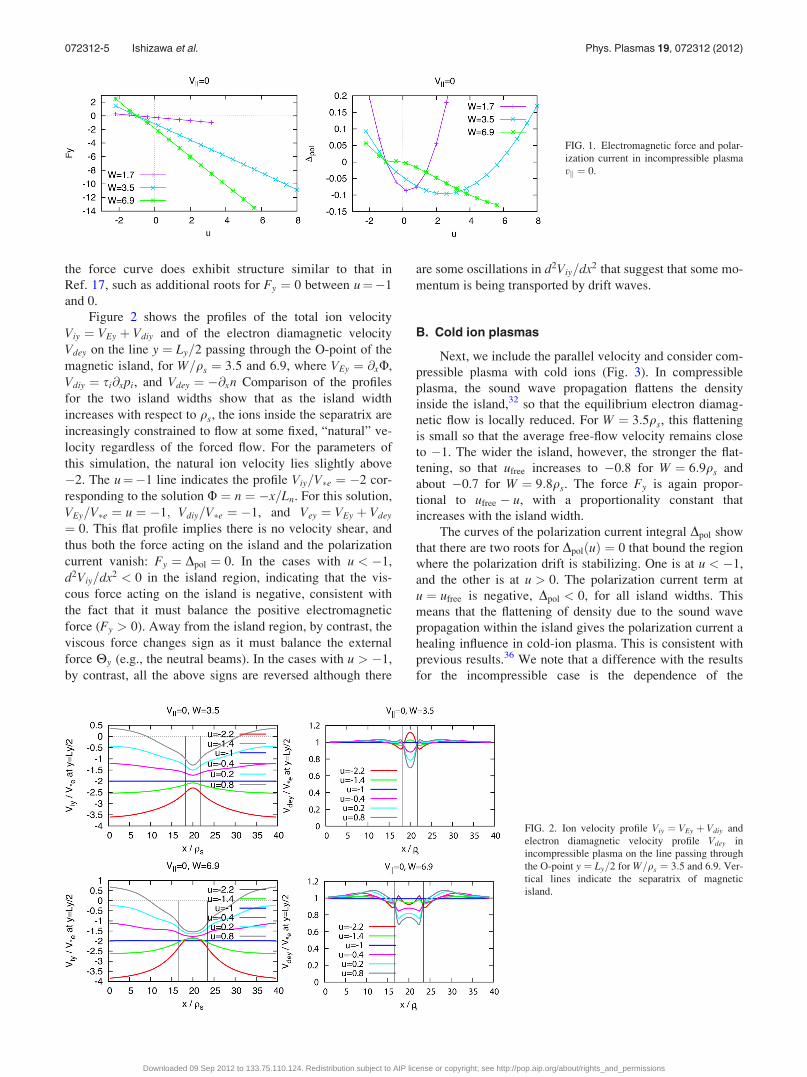
the force curve does exhibit structure similar to that in
Ref. 17, such as additional roots for Fy ¼ 0 between u¼�1
and 0.
Figure 2 shows the profiles of the total ion velocity
Viy ¼ VEy þ Vdiy and of the electron diamagnetic velocity
Vdey on the line y ¼ Ly=2 passing through the O-point of the
magnetic island, for W=qs ¼ 3:5 and 6.9, where VEy ¼ @xU,
Vdiy ¼ si@xpi, and Vdey ¼ �@xn Comparison of the profiles
for the two island widths show that as the island width
increases with respect to qs, the ions inside the separatrix are
increasingly constrained to flow at some fixed, “natural” ve-
locity regardless of the forced flow. For the parameters of
this simulation, the natural ion velocity lies slightly above
�2. The u¼�1 line indicates the profile Viy=V�e ¼ �2 cor-
responding to the solution U ¼ n ¼ �x=Ln. For this solution,
VEy=V�e ¼ u ¼ �1; Vdiy=V�e ¼ �1, and Vey ¼ VEy þ Vdey
¼ 0. This flat profile implies there is no velocity shear, and
thus both the force acting on the island and the polarization
current vanish: Fy ¼ Dpol ¼ 0. In the cases with u < �1,
d2Viy=dx2 < 0 in the island region, indicating that the vis-
cous force acting on the island is negative, consistent with
the fact that it must balance the positive electromagnetic
force (Fy > 0). Away from the island region, by contrast, the
viscous force changes sign as it must balance the external
force Hy (e.g., the neutral beams). In the cases with u > �1,
by contrast, all the above signs are reversed although there
are some oscillations in d2Viy=dx2 that suggest that some mo-
mentum is being transported by drift waves.
B. Cold ion plasmas
Next, we include the parallel velocity and consider com-
pressible plasma with cold ions (Fig. 3). In compressible
plasma, the sound wave propagation flattens the density
inside the island,32 so that the equilibrium electron diamag-
netic flow is locally reduced. For W ¼ 3:5qs, this flattening
is small so that the average free-flow velocity remains close
to �1. The wider the island, however, the stronger the flat-
tening, so that ufree increases to �0.8 for W ¼ 6:9qs and
about �0.7 for W ¼ 9:8qs. The force Fy is again propor-
tional to ufree � u, with a proportionality constant that
increases with the island width.
The curves of the polarization current integral Dpol show
that there are two roots for DpolðuÞ ¼ 0 that bound the region
where the polarization drift is stabilizing. One is at u < �1,
and the other is at u > 0. The polarization current term at
u ¼ ufree is negative, Dpol < 0, for all island widths. This
means that the flattening of density due to the sound wave
propagation within the island gives the polarization current a
healing influence in cold-ion plasma. This is consistent with
previous results.36 We note that a difference with the results
for the incompressible case is the dependence of the
FIG. 1. Electromagnetic force and polar-
ization current in incompressible plasma
vk ¼ 0.
FIG. 2. Ion velocity profile Viy ¼ VEy þ Vdiy and
electron diamagnetic velocity profile Vdey in
incompressible plasma on the line passing through
the O-point y ¼ Ly=2 for W=qs ¼ 3:5 and 6.9. Ver-
tical lines indicate the separatrix of magnetic
island.
072312-5 Ishizawa et al. Phys. Plasmas 19, 072312 (2012)
Downloaded 09 Sep 2012 to 133.75.110.124. Redistribution subject to AIP license or copyright; see http://pop.aip.org/about/rights_and_permissions

polarization current on the island width W. While in the
incompressible case Dpol increases with W, in the compressi-
ble case, it decreases with W.
Figure 4 shows the total ion velocity and the electron
diamagnetic velocity profiles on the line y ¼ Ly=2 passing
through the O-point of the magnetic island for W=qs ¼ 3:5,
6.9, and 9.8. Note that for Ti ¼ 0; Viy ¼ VEy. As the island
width increases, the ion velocity inside the separatrix seems
increasingly drawn to zero, regardless of the amplitude of
the forced flow and despite the incomplete flattening. The
plasma near the separatrix, however, is impelled in the ion
direction regardless of the direction of flow outside the sepa-
ratrix. For u¼ 0.8, for example, the ion velocity at the sepa-
ratrix is near Viy ¼ �0:5 for W=qs ¼ 9:8. For large island
width, the density gradient nearly vanishes at the O-point but
rises rapidly towards the separatrix. Note that the curvature
of the velocity profile away from the island is proportional to
Fy, since far from the separatrix the Maxwell and Reynolds
stresses become negligible and the viscous force must bal-
ance the momentum source. The profile corresponding to
free propagation can therefore be identified as that for which
the curvature (second derivative) of the velocity profile van-
ishes far from the separatrix. For this profile, the average ve-
locity u ¼ ufree is approximately equal to the asymptotic
velocity at large distances, partly because of the small size of
the island compared to the averaging domain, and partly
because of the mildness of the variation of the velocity in the
island region for free islands.
C. Hot ion plasmas
We next consider the complete model given by Eqs.
(3)–(7), including the effects of hot ions as well as both par-
allel flow and ion diamagnetism (si ¼ 1).
FIG. 3. Electromagnetic force and polar-
ization current in cold ion plasma Ti ¼ 0.
FIG. 4. Ion velocity profile Viy ¼ VEy and electron
diamagnetic velocity profile Vdey in cold ion
plasma on the line passing through the O-point y ¼Ly=2 for W=qs ¼ 3:5, 6.9, and 9.8. Vertical lines
indicate the separatrix.
072312-6 Ishizawa et al. Phys. Plasmas 19, 072312 (2012)
Downloaded 09 Sep 2012 to 133.75.110.124. Redistribution subject to AIP license or copyright; see http://pop.aip.org/about/rights_and_permissions
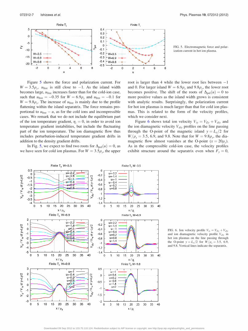
Figure 5 shows the force and polarization current. For
W ¼ 3:5qs; ufree is still close to �1. As the island width
becomes large, ufree increases faster than for the cold-ion case,
such that ufree ¼ �0:35 for W ¼ 6:9qs and ufree ¼ �0:1 for
W ¼ 9:8qs. The increase of ufree is mainly due to the profile
flattening within the island separatrix. The force remains pro-
portional to ufree � u, as for the cold ions and incompressible
cases. We remark that we do not include the equilibrium part
of the ion temperature gradient, gi ¼ 0, in order to avoid ion
temperature gradient instabilities, but include the fluctuating
part of the ion temperature. The ion diamagnetic flow thus
includes perturbation-induced temperature gradient drifts in
addition to the density gradient drifts.
In Fig. 5, we expect to find two roots for DpolðuÞ ¼ 0, as
we have seen for cold ion plasmas. For W ¼ 3:5qs, the upper
root is larger than 4 while the lower root lies between �1
and 0. For larger island W ¼ 6:9qs and 9:8qs, the lower root
becomes positive. The shift of the roots of DpolðuÞ ¼ 0 to
more positive values as the island width grows is consistent
with analytic results. Surprisingly, the polarization current
for hot ion plasmas is much larger than that for cold ion plas-
mas. This is related to the form of the velocity profiles,
which we consider next.
Figure 6 shows total ion velocity Viy ¼ VEy þ Vdiy and
the ion diamagnetic velocity Vdiy profiles on the line passing
through the O-point of the magnetic island y ¼ Ly=2 for
W=qs ¼ 3:5, 6.9, and 9.8. Note that for W ¼ 9:8qs, the dia-
magnetic flow almost vanishes at the O-point (x ¼ 20qs).
As in the compressible cold-ion case, the velocity profiles
exhibit structure around the separatrix even when Fy ¼ 0,
FIG. 5. Electromagnetic force and polar-
ization current in hot ion plasma.
FIG. 6. Ion velocity profile Viy ¼ VEy þ Vdiy
and ion diamagnetic velocity profile Vdiy in
hot ion plasmas on the line passing through
the O-point y ¼ Ly=2 for W=qs ¼ 3:5, 6.9,
and 9.8. Vertical lines indicate the separatrix.
072312-7 Ishizawa et al. Phys. Plasmas 19, 072312 (2012)
Downloaded 09 Sep 2012 to 133.75.110.124. Redistribution subject to AIP license or copyright; see http://pop.aip.org/about/rights_and_permissions
reflecting local momentum transport within the island region
that could be due to either the Reynolds stress or to the emis-
sion and reabsorption drift-acoustic waves. The velocity gra-
dients around the separatrix are larger than in the cold ion
case, accounting for the large DpolðuÞ shown in Fig. 5. The
tendency of the plasma near the separatrix to rotate in the ion
drift direction is also stronger than for cold ions.
D. A model of Dpol
We may summarize the results of the present section in
terms of the following model suggested by our numerical
results as well as the analytic result in Eq. (1):
Dpol ¼ AðWÞðu� u�ðWÞÞðu� uþðWÞÞ; (9)
where A(W) is a coefficient and uþ and u� describe the
bounds of the stabilizing region. Note that u plays a role anal-
ogous to that of V01 in Eq. (1). Analogues to u6 may be com-
puted in terms of Vi and Ve from Eq. (1), but the differences
in the boundary conditions used here disallow any quantita-
tive comparison. Table I shows Cpol; uþ, and u� for the cold
and hot ion plasmas. In the case of cold ions, the following
model describes the variation of the parameter A(W):
AðWÞ ¼ Cpol
WðW2 þW2c Þ;
where Cpol ¼ 1:5 and the critical island width Wc is about
7qs. This model is qualitatively consistent with analytic
results in the limits of large as well as small islands. For hot
ions, on the other hand, A(W) increases with W so that the
dependence of Dpol differs qualitatively from the cold-ion
result.
IV. NATURAL ISLAND PROPAGATION
In this section, we focus our attention on the important
special case of free propagation, where the external force
acting on the magnetic island vanishes. In particular, we
examine the dependence of the polarization integral on the
island width. We identify the average flows ufree correspond-
ing to free rotation by interpolation from the curves FyðuÞ in
Figs. 1, 3, and 5. Recall that, as noted in Sec. II B, for freelypropagating islands, the average velocity ufree is, to a good
approximation, equal to the asymptotic electric drift velocity
away from the island, which is itself equal and opposite to
the normalized island propagation velocity, Visland=V�e.
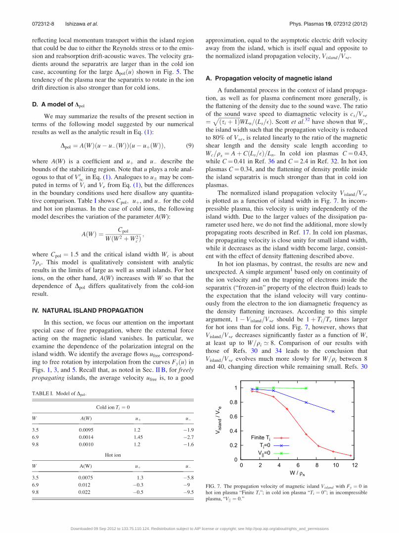
A. Propagation velocity of magnetic island
A fundamental process in the context of island propaga-
tion, as well as for plasma confinement more generally, is
the flattening of the density due to the sound wave. The ratio
of the sound wave speed to diamagnetic velocity is cs=V�e¼
ffiffiffiffiffiffiffiffiffiffiffiffiffiffiffiffiðsi þ 1Þ
pWLn=ðLs=�Þ. Scott et al.32 have shown that Wc,
the island width such that the propagation velocity is reduced
to 80% of V�e, is related linearly to the ratio of the magnetic
shear length and the density scale length according to
Wc=qs ¼ Aþ CðLs=�Þ=Ln. In cold ion plasmas C¼ 0.43,
while C¼ 0.41 in Ref. 36 and C¼ 2.4 in Ref. 32. In hot ion
plasmas C¼ 0.34, and the flattening of density profile inside
the island separatrix is much stronger than that in cold ion
plasmas.
The normalized island propagation velocity Visland=V�eis plotted as a function of island width in Fig. 7. In incom-
pressible plasma, this velocity is unity independently of the
island width. Due to the larger values of the dissipation pa-
rameter used here, we do not find the additional, more slowly
propagating roots described in Ref. 17. In cold ion plasmas,
the propagating velocity is close unity for small island width,
while it decreases as the island width become large, consist-
ent with the effect of density flattening described above.
In hot ion plasmas, by contrast, the results are new and
unexpected. A simple argument1 based only on continuity of
the ion velocity and on the trapping of electrons inside the
separatrix (“frozen-in” property of the electron fluid) leads to
the expectation that the island velocity will vary continu-
ously from the electron to the ion diamagnetic frequency as
the density flattening increases. According to this simple
argument, 1� Visland=V�e should be 1þ Ti=Te times larger
for hot ions than for cold ions. Fig. 7, however, shows that
Visland=V�e decreases significantly faster as a function of W,
at least up to W=qi ’ 8. Comparison of our results with
those of Refs. 30 and 34 leads to the conclusion that
Visland=V�e evolves much more slowly for W=qi between 8
and 40, changing direction while remaining small. Refs. 30
TABLE I. Model of Dpol.
Cold ion Ti ¼ 0
W A(W) uþ u�
3.5 0.0095 1.2 �1.9
6.9 0.0014 1.45 �2.7
9.8 0.0010 1.2 �1.6
Hot ion
W A(W) uþ u�
3.5 0.0075 1.3 �5.8
6.9 0.012 �0.3 �9
9.8 0.022 �0.5 �9.5FIG. 7. The propagation velocity of magnetic island Visland with Fy ¼ 0 in
hot ion plasma “Finite Ti”; in cold ion plasma “Ti ¼ 0”; in incompressible
plasma, “Vk ¼ 0.”
072312-8 Ishizawa et al. Phys. Plasmas 19, 072312 (2012)
Downloaded 09 Sep 2012 to 133.75.110.124. Redistribution subject to AIP license or copyright; see http://pop.aip.org/about/rights_and_permissions

and 37 account for the large-island results in terms of the
Reynolds stress. Unfortunately, the calculation of the effects
of the Reynolds stress assumes that the density profile is
fully flattened everywhere within the separatrix, a condition
that is violated for the more moderately sized islands in our
simulations. Thus, our simulations bridge the gap between
the thin-island “hypersonic” and the large-island “sonic”
regimes described in Ref. 37.
B. Polarization current
We next examine the stability parameter Dpol, the contri-
bution of the polarization current to island evolution, for
freely propagating islands. We evaluate the value of
DpolðufreeÞ by interpolation from the results in Figs. 1, 3, and
5. Figure 8 shows Dpol as a function of the island width Wfor hot ion plasmas, cold ion plasmas, and incompressible
plasmas.
We first describe the incompressible and cold ion cases,
where our results are consistent with previous studies. In
incompressible plasma, the polarization term vanishes
because the island propagation velocity is the electron dia-
magnetic velocity. In cold ion plasmas, by contrast, Dpol is
negative, i.e., the polarization term is stabilizing, as shown
in Ref. 36. The stabilizing effect peaks near the sound reso-
nance, at W � qsLs=Ln � 3qs.
We now turn to the case of islands in a quiescent plasma
with hot ions. Aside from the large size of Dpol already noted
in Sec. III C, the results reveal a new surprise: The sign of
Dpol changes with the island width, and thus the polarization
current is destabilizing for W > 5qs. Hence, the polarization
current can drive tearing mode growth even in the absence of
bootstrap current, provided that a sufficiently large “seed
island” is present.
The circumstances leading to the reversal of the role of
the polarization current for large islands are illustrated by
Fig. 9 showing the roots u6 of Dpolðu6Þ ¼ 0 in addition to
ufree. This figure shows that with increasing W, the domain
where Dpol is stabilizing shifts towards the ion direction
faster than the propagation velocity, so that the line of ufree
crosses that of uþ around W ¼ 5qs, coincident with the mar-
ginal point Dpol ¼ 0 in Fig. 8. Note that for W > 6qs, the
lower bound of the stable domain, u�, is obtained by extrap-
olation of the results shown in Fig. 5.
The strength of the destabilizing effect depends on
plasma resistivity and viscosity. We briefly describe the de-
pendence on them for W ¼ 6:9qs. When we halve the resis-
tivity, the Dpol become about 2.5 times larger, on the other
hand, when we halve the viscosity, the Dpol become 1/3 times
smaller approximately. When we halve both of the resistivity
and viscosity, the Dpol become 3 times larger.
C. Velocity profiles
Some insight into the physics of island propagation in
inhomogeneous plasma can be gained by examining the
streamlines for electrons and ions. Figure 10(a) shows elec-
tron flow streamlines, which are the equi-contours of the
electron stream function, U� n, in hot ion plasmas for
W=qs ¼ 6:9. The electron flow pattern is close to the mag-
netic surfaces, and the electron fluid is well tied to magnetic
field lines. Figures 10(b) and 10(c) show ion stream lines,
which are the equi-contours of the ion stream function Uþpi in hot ion plasmas for W=qs ¼ 6:9 and 9.8, respectively.
The stream lines deviate from the magnetic surfaces because
of drifts and viscosity. When the island width is much larger
than the Larmor radius, the stream lines are close to the mag-
netic surfaces and the ion fluid is trapped inside the separa-
trix. This is the result of the “magnetization” of the ion flow
with respect to the perturbed field. For W=qs ¼ 9:8, a pair of
small convection cells appears around the O-point, indicating
the presence of a standing drift-acoustic wave.
Figure 11 shows the electron flow velocity profiles on
the line passing through the O-point of two magnetic islands
in hot ion plasmas with W=qs ¼ 3:5 and 6.9. Within the
island separatrix, the velocity is very small as the electron
fluid is trapped within the separatrix. Outside the separatrix,
by contrast, the velocity is finite and pointed in the electron
diamagnetic direction. There is thus strong shear in the elec-
tron flow velocity at the separatrix. The electron flow is
enhanced just outside the separatrix (indicated by the vertical
lines) on either side of the O-point because the density pro-
file is steepened there. The electron velocity profiles in cold
and hot ion plasmas are similar.
FIG. 8. The polarization current term Dpol for magnetic island propagating
with its natural velocity Visland in compressible plasma with hot ions, “Finite
Ti”; in compressible plasma with cold ions, “Ti ¼ 0”; in incompressible
plasma, “Vk ¼ 0.”
FIG. 9. The root ufree of FyðufreeÞ ¼ 0 and the roots u of DpolðuÞ ¼ 0 in Fig.
5 as a function of island width W in hot ion plasmas.
072312-9 Ishizawa et al. Phys. Plasmas 19, 072312 (2012)
Downloaded 09 Sep 2012 to 133.75.110.124. Redistribution subject to AIP license or copyright; see http://pop.aip.org/about/rights_and_permissions

Figure 12 shows (a) the total ion velocity profiles
Viy ¼ VEy þ Vdiy, (b) the E � B electric drift velocity profiles
VEy, and the contributions of (c) the density gradients VdNy ¼@xn and (d) the temperature gradients VdTy ¼ @xTi to the ion
diamagnetic drift Vdiy ¼ VdNy þ VdTy on the line passing
through the O-point of the magnetic island for W=qs ¼ 3:5,
6.9, and 9.8. The total ion velocity is always negative and
directed toward the negative y direction, which is the ion dia-
magnetic direction, except for W¼ 9.8 around the O-point at
x ¼ 20qs (this is a consequence of the convection cells noted
above). For W=qs ¼ 3:5, 6.9, the amplitude of total ion ve-
locity is finite both inside and outside the separatrix, because
the ion viscosity is much larger than the electron viscosity.
The total ion velocity profile has a “W” shape, because the
density is flattened within the separatrix as shown in the
density-gradient profile, Fig. 12(c), while it is steepened just
outside the separatrix. The total ion velocity profile is similar
to the reverse of the total electron velocity profile because of
opposite electron and ion diamagnetic directions. The profile
of the total ion velocity is much smoother than that of the
electron velocity because of the larger ion viscosity. The
peak of the “W” shape becomes large when the island width
is large because of the broadening of the flattening of the
density profile. When the width is large enough, we have
convection cells within the separatrix for W=qs ¼ 9:8.
The profiles in Fig. 12 provide more detailed perspective
on the question of why Dpol in hot ion plasma is much larger
than that in cold ion plasma. The polarization current is
caused by E � B and ion-diamagnetic convection in the vor-
ticity equation (3), and thus both the total ion velocity shear
and the E � B velocity shear contribute. In Figs. 12(a) and
12(b), the total ion velocity and E � B velocity profiles of
hot ion plasmas are strongly sheared around the separatrix
which is indicated by the vertical lines, while in cold ion
plasmas (Figs. 12(e) and 12(f)), these profiles exhibit little
shear. We remark that total ion velocity is the same as the
E � B velocity in cold ion plasmas, Viy ¼ VEy. The strong
velocity shear is supported by the Maxwell stress as shown
in Fig. 13. The figure shows the profile of each term in the
vorticity equation on the line passing through the O-point of
the magnetic island y ¼ Ly=2 for W=qs ¼ 6:9. The viscosity
term, that suppress the shear, is large around the separatrix.
The Maxwell stress term is large and counteracts the sup-
pression of flow shear by viscosity term, while the Reynolds
stress and ion diamagnetic stress terms are small. Thus, the
large viscosity term due to the strong velocity shear balances
with the Maxwell stress term.
D. Current density profiles
Figure 14 shows a color map of the perturbed part of
the current density for W=qs ¼ 3:5 and 6.9. The bold line in
the figure shows the magnetic island separatrix. Note that the
asymmetry of the current with respect to the y direction is
caused by the viscous force on the island, which induces a
parallel current proportional to sinðky1yÞ. This current does
FIG. 10. (a) Electron stream lines with
W=qs ¼ 6:9; (b) and (c) ion stream lines
with W=qs ¼ 6:9 and 9.8 for finite Ti
plasma.
FIG. 11. Electron velocity profile on the
line passing through the O-point y ¼ Ly=2
for finite Ti plasma with Fy ¼ 0 and
W=qs ¼ 3:5 and 6.9. Vertical lines indi-
cate the separatrix of magnetic island.
072312-10 Ishizawa et al. Phys. Plasmas 19, 072312 (2012)
Downloaded 09 Sep 2012 to 133.75.110.124. Redistribution subject to AIP license or copyright; see http://pop.aip.org/about/rights_and_permissions
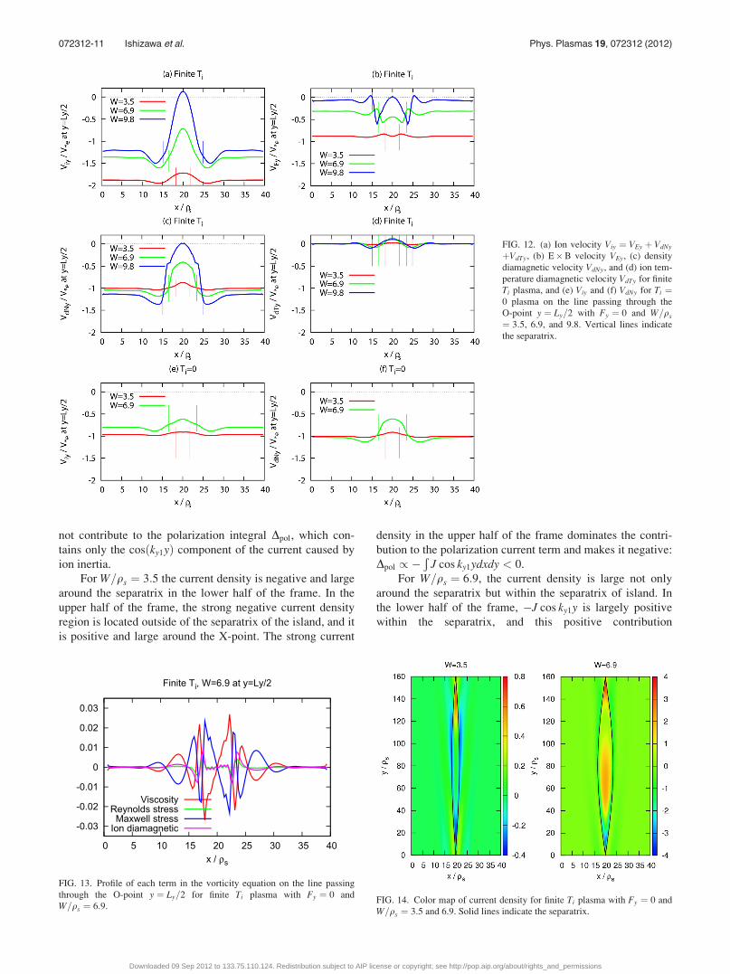
not contribute to the polarization integral Dpol, which con-
tains only the cosðky1yÞ component of the current caused by
ion inertia.
For W=qs ¼ 3:5 the current density is negative and large
around the separatrix in the lower half of the frame. In the
upper half of the frame, the strong negative current density
region is located outside of the separatrix of the island, and it
is positive and large around the X-point. The strong current
density in the upper half of the frame dominates the contri-
bution to the polarization current term and makes it negative:
Dpol / �Ð
J cos ky1ydxdy < 0.
For W=qs ¼ 6:9, the current density is large not only
around the separatrix but within the separatrix of island. In
the lower half of the frame, �J cos ky1y is largely positive
within the separatrix, and this positive contribution
FIG. 13. Profile of each term in the vorticity equation on the line passing
through the O-point y ¼ Ly=2 for finite Ti plasma with Fy ¼ 0 and
W=qs ¼ 6:9.FIG. 14. Color map of current density for finite Ti plasma with Fy ¼ 0 and
W=qs ¼ 3:5 and 6.9. Solid lines indicate the separatrix.
FIG. 12. (a) Ion velocity Viy ¼ VEy þ VdNy
þVdTy, (b) E�B velocity VEy, (c) density
diamagnetic velocity VdNy, and (d) ion tem-
perature diamagnetic velocity VdTy for finite
Ti plasma, and (e) Viy and (f) VdNy for Ti ¼0 plasma on the line passing through the
O-point y ¼ Ly=2 with Fy ¼ 0 and W=qs
¼ 3:5, 6.9, and 9.8. Vertical lines indicate
the separatrix.
072312-11 Ishizawa et al. Phys. Plasmas 19, 072312 (2012)
Downloaded 09 Sep 2012 to 133.75.110.124. Redistribution subject to AIP license or copyright; see http://pop.aip.org/about/rights_and_permissions

dominates the polarization current integral and leads to
Dpol / �Ð
J cos ky1ydxdy > 0.
V. SUMMARY
We have carried out numerical simulations of a reduced
set of two-fluid equations including both electron and ion
diamagnetic effects as well as ion temperature evolution,
and presented effects of finite ion temperature on the propa-
gation velocity of magnetic island and on the polarization
current.
We find that the magnetic island propagates toward the
electron diamagnetic direction for island of widths up to 10
times the Larmor radius. As the width of a magnetic island
in a hot-ion plasma increases, its propagation velocity slows
down much faster than in a cold-ion plasma. In hot-ion
plasma, the propagation velocity of large islands is small
compared to the diamagnetic velocities.
We also find that when the island width is larger than
5qs, the polarization current Dpol becomes destabilizing in
hot ion plasmas. The critical width Wc 5qs is determined
by the change in island propagation velocity with the island
width. The destabilization is the strongest when the island
width is about 10qs. This destabilizing effect of Dpol in finite
ion temperature is important because the threshold of NTM
excitation is several times of ion Larmor radius.4 The desta-
bilization is in contrast with the stabilizing effect of the
polarization current for thinner islands and in cold ion plas-
mas. Lastly, we find that the polarization current in hot ion
plasma is about ten times larger than that in cold ion plas-
mas. Such large polarization current in hot ion plasma is
produced by strong velocity shear around the separatrix of
the magnetic island. The velocity shear is driven by the
Maxwell stress, while it is balanced primarily by the viscous
stress.
ACKNOWLEDGMENTS
The work is supported by Joint Institute for Fusion
Theory exchange program, by the Japanese Ministry of Edu-
cation, Culture, Sports, Science and Technology, Grant No.
23561003, and by the U.S. DOE under Grant No. DE-FG02-
04ER-54742. One of the authors A.I. would like to thank
Professor R. Horiuchi and Professor H. Sugama for their
support.
1F. L. Waelbroeck, “Theory and observations of magnetic islands,” Nucl.
Fusion 49(10), 104025 (2009).2P. H. Rutherford, “Nonlinear growth of the tearing mode,” Phys. Fluids
16(11), 1903 (1973).3R. J. La Haye, “Neoclassical tearing modes and their control,” Phys. Plas-
mas 13(5), 055501 (2006).4R. J. La Haye and O. Sauter, “Threshold for metastable tearing modes in
DIII-D,” Nucl. Fusion 38(7), 987–999 (1998).5R. J. Buttery, R. Akers, E. Arends, N. J. Conway, G. F. Counsell, G. Cun-
ningham, C. G. Gimblett, M. Gryaznevich, R. J. Hastie, M. J. Hole,
I. Lehane, R. Martin, A. Patel, T. Pinfold, O. Sauter, D. Taylor, G. Turri,
M. Valovic, M. J. Walsh, H. R. Wilson, and the MAST Team, “Stability at
high performance in the MAST spherical tokamak,” Nucl. Fusion 44(9),
1027–1035 (2004).6I. T. Chapman, V. G. Igochine, J. P. Graves, S. D. Pinches, A. Gude,
I. Jenkins, M. Maraschek, G. Tardini, the ASDEX Upgrade Team, and
JET EFDA Contributors, “Sawtooth control and the interaction of ener-
getic particles,” Nucl. Fusion 49(3), 035006 (2009).7H. Zohm, “Stabilization of neoclassical tearing modes by electron cyclo-
tron current drive,” Phys. Plasmas 4(9), 3433–3435 (1997).8G. Gantenbein, H. Zohm, G. Giruzzi, S. Gunter, F. Leuterer, M. Mara-
schek, J. Meskat, Q. Yu, ASDEX Upgrade Team, and ECRH-Group
(AUG), “Complete suppression of neoclassical tearing modes with current
drive at the electron-cyclotron-resonance frequency in ASDEX upgrade
tokamak,” Phys. Rev. Lett. 85(6), 1242–1245 (2000).9A. Isayama, Y. Kamada, T. Ozeki, S. Ide, T. Fujita, T. Oikawa, T. Suzuki,
Y. Neyatani, N. Isei, K. Hamamatsu, Y. Ikeda, K. Takahashi, K. Kajiwara,
and JT-60 Team, “Long sustainment of quasi-steady-state high bp h mode
discharges in JT-60U,” Nucl. Fusion 41(6), 761–768 (2001).10E. Westerhof, A. Lazaros, E. Farshi, M. R. de Baar, M. F. M. de Bock,
I. G. J. Classen, R. J. E. Jaspers, G. M. D. Hogeweij, H. R. Koslowski,
A. Kramer-Flecken, Y. Liang, N. J. Lopes Cardozo, and O. Zimmermann,
“Tearing mode stabilization by electron cyclotron resonance heating dem-
onstrated in the TEXTOR tokamak and the implication for ITER,” Nucl.
Fusion 47(2), 85–90 (2007).11C. C. Hegna and J. D. Callen, “On the stabilization of neoclassical magne-
tohydrodynamic tearing modes using localized current drive or heating,”
Phys. Plasmas 4(8), 2940–2946 (1997).12L. Urso, H. Zohm, A. Isayama, M. Maraschek, E. Poli, ASDEX Upgrade
Team, and JT-60 Team, “ASDEX upgrade—JT-60U comparison and
ECRH power requirements for NTM stabilization in ITER,” Nucl. Fusion
50(2), 025010 (2010).13A. Gude, S. Gunter, S. Sesnic, and ASDEX Upgrade Team, “Seed island
of neoclassical tearing modes at ASDEX upgrade,” Nucl. Fusion 39(1),
127–131 (1999).14E. D. Fredrickson, “Observation of spontaneous neoclassical tearing mod-
es,” Phys. Plasmas 9(2), 548–559 (2002).15S.-I. Itoh, K. Itoh, and M. Yagi, “Turbulence trigger for neoclassical tear-
ing modes in tokamaks,” Plasma Phys. Controlled Fusion 46(1), 123–143
(2004).16F. Militello, F. L. Waelbroeck, R. Fitzpatrick, and W. Horton, “Interaction
between turbulence and a nonlinear tearing mode in the low beta regime,”
Phys. Plasmas 15(5), 050701 (2008).17F. L. Waelbroeck, F. Militello, R. Fitzpatrick, and W. Horton, “Effect of
electrostatic turbulence on magnetic islands,” Plasma Phys. Controlled
Fusion 51(1), 015015 (2009).18A. Ishizawa and N. Nakajima, “Turbulence driven magnetic reconnection
causing long-wavelength magnetic islands,” Phys. Plasmas 17(7), 072308
(2010).19M. Muraglia, O. Agullo, S. Benkadda, M. Yagi, X. Garbet, and A. Sen,
“Generation and amplification of magnetic islands by drift interchange
turbulence,” Phys. Rev. Lett. 107, 095003 (2011).20H. R. Wilson and J. W. Connor, “The influence of magnetic islands on
drift mode stability in magnetized plasma,” Plasma Phys. Controlled
Fusion 51(11), 115007 (2009).21A. Ishizawa and P. H. Diamond, “Ion-temperature gradient modes affected
by helical magnetic field of magnetic islands,” Phys. Plasmas 17(7),
074503 (2010).22Z. X. Wang, J. Q. Li, Y. Kishimoto, and J. Q. Dong, “Magnetic-island-
induced ion temperature gradient mode,” Phys. Plasmas 16(6), 060703
(2009).23A. I. Smolyakov, “Nonlinear evolution of tearing modes in inhomogene-
ous plasmas,” Plasma Phys. Controlled Fusion 35, 657 (1993).24R. Fitzpatrick, “Interaction of tearing modes with external structures in
cylindrical geometry,” Nucl. Fusion 33, 1049–1084 (1993).25F. L. Waelbroeck, J. W. Connor, and H. R. Wilson, “Finite larmor-
radius theory of magnetic island evolution,” Phys. Rev. Lett. 87, 215003
(2001).26E. Poli, A. Bergmann, A. G. Peeters, L. C. Appel, and S. D.
Pinches, “Kinetic calculation of the polarization current in the pres-
ence of a neoclassical tearing mode,” Nucl. Fusion 45(5), 384–390
(2005).27F. L. Waelbroeck and R. Fitzpatrick, “Rotation and locking of magnetic
islands,” Phys. Rev. Lett. 78, 1703–1706 (1997).28R. Fitzpatrick and F. L. Waelbroeck, “Two-fluid magnetic island
dynamics in slab geometry. I. Isolated islands,” Phys. Plasmas 12(2),
022307 (2005).29R. Fitzpatrick and F. L. Waelbroeck, “Two-fluid magnetic island dynamics
in slab geometry. II. Islands interacting with resistive walls or resonant
magnetic perturbations,” Phys. Plasmas 12(2), 022308 (2005).
072312-12 Ishizawa et al. Phys. Plasmas 19, 072312 (2012)
Downloaded 09 Sep 2012 to 133.75.110.124. Redistribution subject to AIP license or copyright; see http://pop.aip.org/about/rights_and_permissions
30R. Fitzpatrick, P. Watson, and F. L. Waelbroeck, “Two-fluid magnetic
island dynamics in slab geometry: Determination of the island phase
velocity,” Phys. Plasmas 12(8), 082510 (2005).31R. Fitzpatrick and F. L. Waelbroeck, “Effect of drift-acoustic waves on
magnetic island stability in slab geometry,” Phys. Plasmas 12(12), 122511
(2005).32B. D. Scott, A. B. Hassam, and J. F. Drake, “Nonlinear evolution of drift-
tearing modes,” Phys. Fluids 28(1), 275 (1985).33R. J. La Haye, C. C. Petty, E. J. Strait, F. L. Waelbroeck, and H. R. Wil-
son, “Propagation of magnetic islands in the er ¼ 0 frame of co-injected
neutral beam driven discharges in the DIII-D tokamak,” Phys. Plasmas
10(9), 3644–3648 (2003).
34K. Uzawa, A. Ishizawa, and N. Nakajima, “Propagation of magnetic
island due to self-induced zonal flow,” Phys. Plasmas 17(4), 042508
(2010).35A. Ishizawa and N. Nakajima, “Excitation of macromagnetohydrodynamic
mode due to multiscale interaction in a quasi-steady equilibrium formed
by a balance between microturbulence and zonal flow,” Phys. Plasmas
14(4), 040702 (2007).36R. Fitzpatrick, F. L. Waelbroeck, and F. Militello, “The influence of the
ion polarization current on magnetic island stability in a tokamak plasma,”
Phys. Plasmas 13(12), 122507 (2006).37R. Fitzpatrick and F. L. Waelbroeck, “Drift-tearing magnetic islands in
tokamak plasmas,” Phys. Plasmas 15(1), 012502 (2008).
072312-13 Ishizawa et al. Phys. Plasmas 19, 072312 (2012)
Downloaded 09 Sep 2012 to 133.75.110.124. Redistribution subject to AIP license or copyright; see http://pop.aip.org/about/rights_and_permissions