reinforcement of polymeric latexes by in situ polymerization
TRANSCRIPT
RE
SE
AR
CH
AR
TIC
LE
Copyright © 2009 American Scientific PublishersAll rights reservedPrinted in the United States of America
Journal ofNanoscience and Nanotechnology
Vol. 9, 1–7, 2009
Reinforcement of Polymeric Latexes byIn Situ Polymerization
Andres F. Vargas1�2�∗, Witold Brostow2, Haley E. Hagg Lobland2,Betty L. López1, and Oscar Olea-Mejia2�3
1Grupo Ciencia de los Materiales, Instituto de Química, Universidad de Antioquia,Calle 62, 52 59 Medellín, Antioquia, Colombia
2Laboratory of Advanced Polymers and Optimized Materials (LAPOM), Department of Materials Science and Engineering,University of North Texas, 1150 Union Circle # 305310, Denton, TX 76203-5017, USA
3Laboratorio de Investigación y Desarrollo de Materiales Avanzados (LIDMA), Facultad de Química,Universidad Autónoma del Estado de México, Km. 12 de la carretera Toluca-Atlacomulco, San Cayetano 50200, Mexico
Two silicas with different particle sizes have been synthesized by the Stöber method. The parti-cles have been functionalized with methacryloyl groups. In situ emulsion polymerization of butylacrylate and methyl methacrylate in the presence of functionalized silica particles was performed.The ratio of butyl acrylate to methyl methacrylate was varied in order to optimize the compositionfor improvement of tribological and thermophysical properties. The silica particles morphology andfunctionalization have been determined respectively by scanning electronic microscopy and infraredspectroscopy. The composites were characterized also by thermogravimetric analysis, differentialscanning calorimetry, microscratch testing and static light scattering. The latex reinforced with thesmallest functionalized silica exhibits higher thermal stability than the non reinforced latex, alongwith lower penetration depth and higher residual depth in progressive load scratch testing. Thus,the resistance to penetration is increased while viscoelastic healing is hampered by silica particles.
Keywords: Emulsion Polymerization, Silica Particles, Hybrid Latexes, Scratch Resistance.
1. INTRODUCTION
Polymeric nanocomposites show unusual properties—often related to the important role of interfacial forcesand to chemistry of surface molecular layers as thesize of the dispersed phase decreases and its surfacearea increases. Thus, better mechanical,1–3 electrical,4
thermal5–7 or tribological8–10 properties can be obtained bymodifying polymers with inorganic nanoparticles.
In the field of coatings it is important to reduce the useof organic solvents in the formulations or replace them bywaterborne coatings; this suggests improvement3 of prop-erties of polymeric latexes used in the coatings. Nanopar-ticles have been used to improve several properties ofpolymers, for instance to increase the Young modulusand yield stress of poly(ethyl acrylate) latex encapsulat-ing functionalized silica particles.1 Modified nanoparticlesof TiO2 were introduced into a polyacrylate resin; filmsobtained from the modified resins exhibit an increase ofhardness and also a reduction in water adsorption and
∗Author to whom correspondence should be addressed.
permeability.11 A paint containing silica nanoparticles inan acrylic latex obtained by emulsion polymerization has abetter flame resistance than a similar paint without silica.12
There are several ways to prepare polymer nanocompos-ites such as blending, solvent mixing, in situ polymeriza-tion, etc. A disadvantage of blending is the large amountof energy needed to achieve a homogeneous phase. On theother hand, an advantage of in situ polymerization is thenumber of parameters of the polymer and the filler that canbe controlled simultaneously to optimize the properties ofthe final material.
Polymeric latexes have been modified with inorganicparticles by means of miniemulsion,13 emulsion14 poly-merization among others; emulsion polymerization is themost frequently used. Thus nanocomposites with differ-ent morphologies such as core–shell13 raspberry-like,15
daisy-shape16 were obtained. The structures are depen-dent on the surface and the size of the inorganic parti-cles and also on matrix–filler interactions. The interactionscan be varied by using surfactants,17 or functionalizationagents.5�13 As discussed by Kopczynska and Ehrenstein18
J. Nanosci. Nanotechnol. 2009, Vol. 9, No. xx 1533-4880/2009/9/001/007 doi:10.1166/jnn.2009.1329 1
RE
SE
AR
CH
AR
TIC
LE
Reinforcement of Polymeric Latexes by In Situ Polymerization Vargas et al.
interface energies are decisive for properties of multiphasematerials.
In this work, two nanosilicas with different particlesize have been functionalized with methacryloyl groupsand used to reinforce butyl acrylate/methyl methacrylatecopolymers by in situ emulsion polymerization. Our goalwas to study the effect of copolymer composition, silicaparticles incorporation as well as silica particle size onthe thermal and tribological properties of the synthesizedlatexes. A pertinent review shows that much remains to bedone to improve polymer tribology,19 and we are advanc-ing our knowledge through this work.
2. EXPERIMENTAL DETAILS
2.1. Materials
Tetraethoxysilane (TEOS) and butyl acrylate (BA) werepurchased from Fluka. Ammonium hydroxide (28–30%in water), ethanol, methanol, ammonium persulfate,sodium dodecyl sulphate, methacryloylpropyltrimethoxisi-lane (MPS) and methyl methacrylate (MMA) were pur-chased from Sigma-Aldrich. All of them were reagentgrade and used without further purification.
2.2. Silica Particle Synthesis and Functionalization
Two silica particles of different size were synthesizedaccording to the well known procedure of Stöber.20
Ethanol, ammonium hydroxide and water were introducedin a three neck round flask equipped with a refrigeratingsystem. Then the mixture was stirred at 300 rpm to homog-enize at room temperature. After that TEOS was addedinto the solution and the reaction proceeded for 4 hoursunder stirring. The reagents ratio was varied to obtain twodifferent silica particles sizes.
An alcoholic suspension of silica was centrifugated at7000 rpm or 8000 rpm, depending of the particles size, andwashed with deionizated water several times to remove theammonium hydroxide and ethanol. After that the particleswere washed once more with ethanol and allowed to dryovernight at room temperature.
Functionalization of silica particles was achieved as fol-lows. First the silica powder was crushed, then water andmethanol were added to the powder, and then the suspen-sion was ultrasonicated for 1 hour to re-disperse the par-ticles. In a two neck round flask the silica dispersion wasmixed with metacryloylpropyltrimethoxisilane (MPS) in amolar ratio of 1:10 and a few drops of ammonium hydrox-ide were added. After that, it was left to react for 4 hat 70 �C.21
2.3. Polymerization
Emulsion copolymerization of BA and MMA was carriedout by using seeded semibatch emulsion polymerization
in a reactor equipped with a condenser, mechanical stirrer,addition funnel, nitrogen inlet and outlet. First, the initia-tor was dissolved in a part of water and the rest of waterwas charged into the reactor. The monomers were mixedin a separate beaker. Then the surfactant and a part of themonomer mixture were added to the reactor. The otherportion of the monomer mixture was poured into the addi-tion funnel. The addition of the monomer was performedin two steps. First, the initiator solution was added, thena half of the monomer was added dropwise for 30 min-utes through a funnel and allowed to react for 30 minutes.Then the second half of the monomer was poured dropwisefor 30 min, and the reaction lasted for another 30 min. Thetotal time of the polymerization reaction was two hourssince the addition of the initiator.
The same procedure described above was followed forthe synthesis of the reinforced latex, except that the func-tionalized silica was pre-emulsified with the monomerand the surfactant. The silica concentration used was 4%weight nominal respect to monomers.
2.4. Scanning Electron Microscopy (SEM)
A FEI dual beam FESEM/FIB microscope, where FIBmeans focused ion beam, was used to analyze the mor-phology of the silica particles. The samples were dispersedin ethanol, and then a few drops were poured into theSEM holder and allowed to dry. Finally the samples wereput in a high vacuum chamber and a high voltage wasapplied to coat the sample with a thin layer of metallicgold.
In order to see the nanoparticles inside the compos-ites the combination of the techniques SEM-FIB was per-formed. This method has recently been successfully usedby our group in low density polyethylene with aluminumparticles added.22
2.5. Fourier Transform InfraredAnalysis (FTIR)
IR spectra were obtained in a Perkin-Elmer Spectrum Onemachine. KBr pellets were prepared with functionalizedand non-functionalized silica particles. For the polymericlatex, a dilution of 1:10 was made, and a film was formedby evaporation of the emulsion on a ZnSe disc.
2.6. Thermogravimetrical Analysis (TGA)
Thermogravimetric analysis was performed in a TA Instru-ments Q500 equipment. Films were obtained from thelatex through evaporation. The thermal stability of thefilms was evaluated heating from room temperature to800 �C at 20 �C/min in nitrogen atmosphere at the flowrate of 100 mL ·min−1.
2 J. Nanosci. Nanotechnol. 9, 1–7, 2009
RE
SE
AR
CH
AR
TIC
LE
Vargas et al. Reinforcement of Polymeric Latexes by In Situ Polymerization
2.7. Differential Scanning Calorimetry (DSC)
TA Instruments Q100 was used to determine glass tran-sition Tg temperatures. Thermal history was erased at theheating rate of 30 �C/min to 200 �C, the sample cooled to−80 �C, and then heated at 20 �C/min to 200 �C.
2.8. Progressive Load Scratch Test
CSEM microscratch tester was used. First films weredeposited on polycarbonate substrates and then analyzed inprogressive mode using a 200 �m conical diamond inden-ter. Instantaneous penetration depth Rp and residual depthRh values in the scratch grooves after viscoelastic recoverywere recorded.
2.9. Particle Size
The particle size analysis was carried out from the SEMimages using the open source software ImageJ®. In addi-tion, the emulsions were tested using light scattering in aMicrotac S3000 particle size analyzer. The emulsions wereput directly in the sampler and then analyzed.
2.10. Haze
The haze of the samples was measured in a Colorquest IIspherical spectrophotometer. Films were obtained afterevaporation of the emulsion over polycarbonate substratesand then the samples were analyzed.
3. CHARACTERISTICS OFSILICA PARTICLES
Two kinds of silica particles with different sizes were syn-thesized by changing ammonium hydroxide concentrationwhile maintaining constant TEOS and water concentrationusing the well known Stöber method.20 The molar ratioswere: for silica S1 NH4OH 0.3/TEOS 0.2/Water 6.8; andfor silica S2 NH4OH 0.4/TEOS 0.2/Water 6.8.
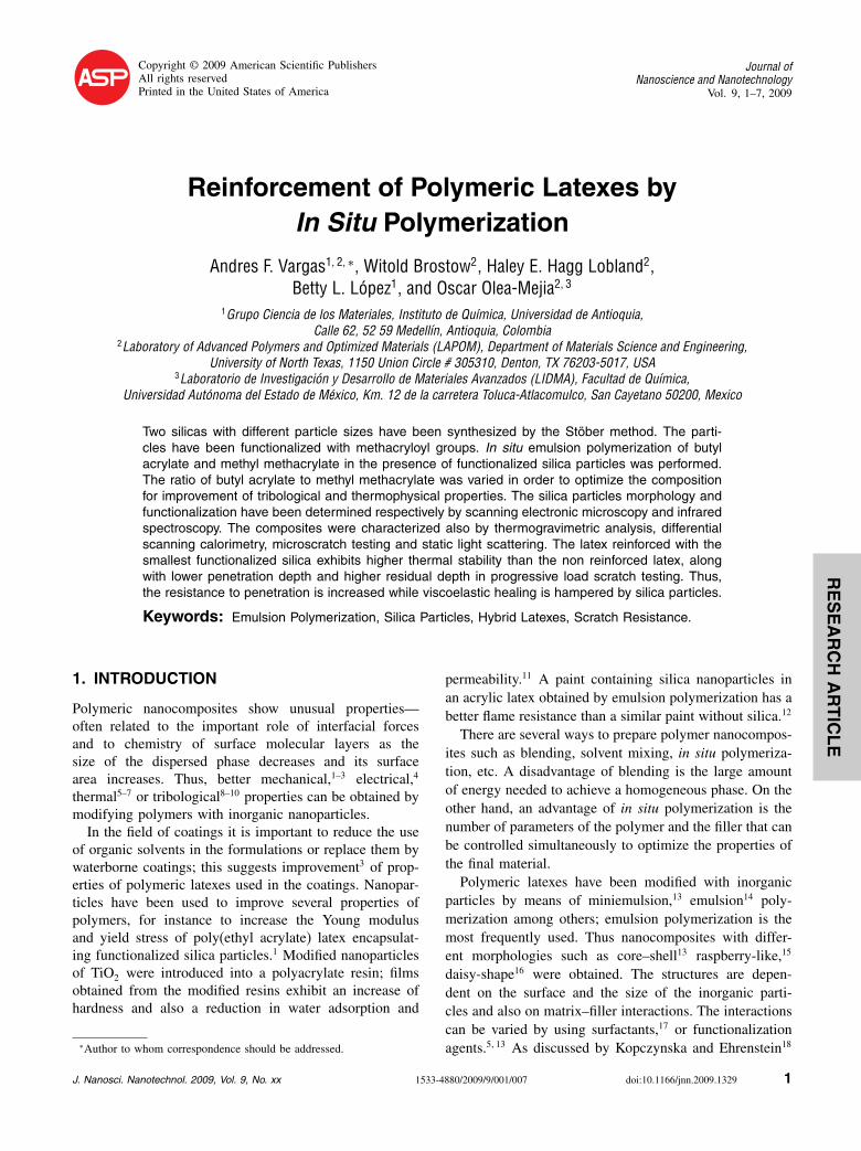
Figure 1 shows the SEM micrographs for S1 and S2silica samples. It can be observed that the particles havespherical shape, smooth surface and the particle size isquite uniform. Moreover, no coalescence is observed eitherin the S1 or S2 samples.
S1 silica sample presents an average size of 291±38 nmand S2 silica sample 350±33 nm. This indicates that theparticles size can be controlled by changing the synthesisparameters.
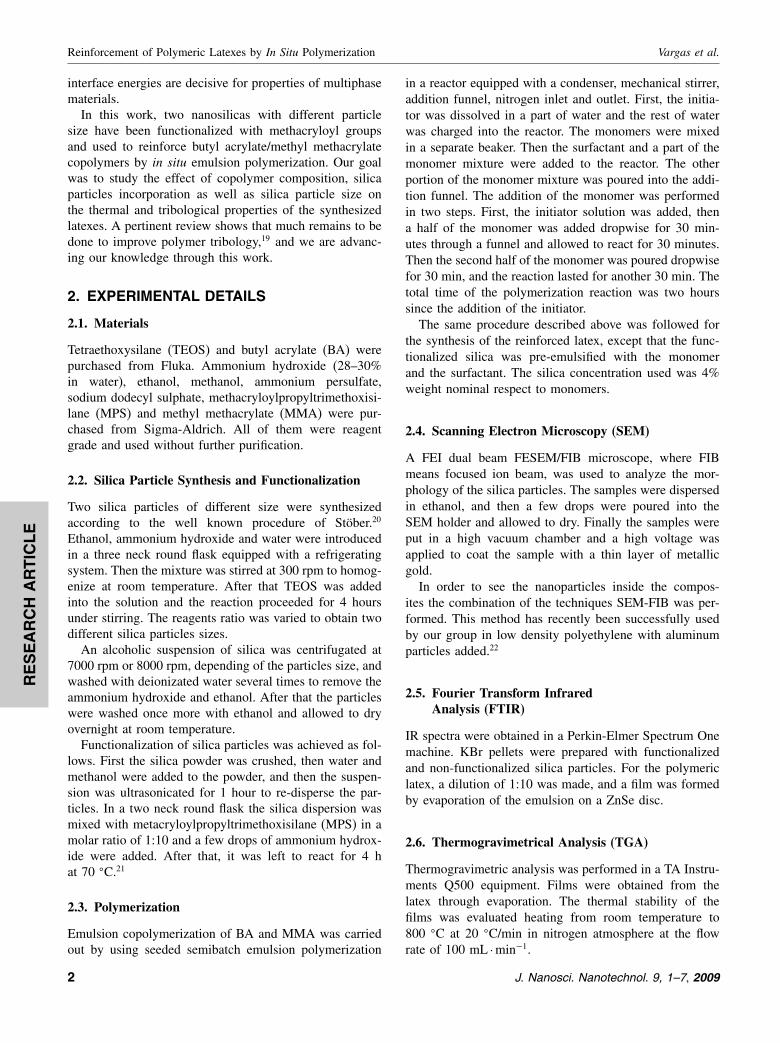
Figure 2 shows the infrared spectra for the silica par-ticles. A band at 1100 cm−1 corresponds to Si–O–Si andat 945 cm−1 to Si–OH groups. A small band at 1720 cm−1
observed for the functionalized silica can be attributed tocarbonyl groups of the MPS methacryloyl moiety. Thepresence of this band indicates that functionalization wassuccessfully achieved.
(a)
(b)
Fig. 1. SEM of silica particles S1 (a) and S2 (b).
4. COPOLYMERS
In order to obtain copolymers with different glass transi-tions, three copolymers were synthesized by varying theproportions of BA/MMA in the following weight ratios:50:50, 60:40 and 70:30.
5001000150020002500300035004000
Tra
nsm
itanc
e /a
u
Wavenumber /cm–1
3450
1720
1100
945
(a)
(b)
Fig. 2. FTIR spectra of non-functionalized (a) and functionalized(b) silica.
J. Nanosci. Nanotechnol. 9, 1–7, 2009 3
RE
SE
AR
CH
AR
TIC
LE
Reinforcement of Polymeric Latexes by In Situ Polymerization Vargas et al.
Tra
nsm
itanc
e /a
u
Wavenumber /cm–1
5001000150020002500300035004000
2960
1456
1735
1245
1165
1100
(b)
(a)
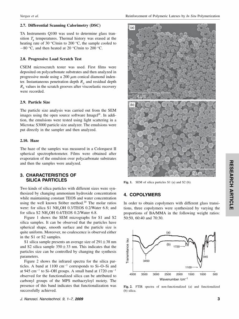
Fig. 3. IR spectrum for (a) 60BA/40MMA and (b) 60BA/40MMA/S1.
By following the conversion of 60BA/40MMA overtime, an optimized time of reaction of 120 minutes wasobtained. This time was used for all the reactions.
4.1. Latex Without Silica
All polymeric latexes without silica gave stable emulsions,still unchanged after 6 months. Figure 3(a) there is a typ-ical IR spectrum for 60BA/40MMA latex. The spectrumshows vibrations at 2960 cm−1 (stretching saturated C–H),1456 cm−1 and 1385 cm−1 (symmetrical and asymmet-rical extension –CH3, –CH2–) 1735 cm−1, 1245 cm−1,1165 cm−1 (carbonyl C O, ester –C–O–), all characteris-tic of polyacrylate. No signal for double bonds is observed,indicating complete polymerization.
4.2. Latex with Functionalized Silica
Latexes synthesized with functionalized silica were alsostable after 6 months. Figure 3(b) shows a typical IR spec-trum obtained for the 60BA/40MMA/S1 hybrid polymer.The spectrum shows the same bands seen for the latexwithout silica. However, in the present case there is asmall shoulder around 1100 cm−1, which is assigned tothe Si–O–Si extension of the silica. This is an indica-tion that the silica was successfully incorporated into thepolymer.
(a)
(b)
(c)
(d)
(e)
(f)
(g)
(h)
(i)
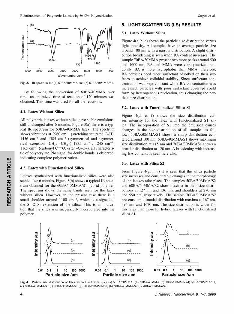
Fig. 4. Particle size distribution of latex without and with silica (a) 50BA/50MMA, (b) 60BA/40MMA (c) 70BA/30MMA (d) 50BA/50MMA/S1,(e) 60BA/40MMA/S1 (f) 70BA/30MMA/S1 (g) 50BA/50MMA/S2, (h) 60BA/40MMA/S2 (i) 70BA/30MMA/S2.
5. LIGHT SCATTERING (LS) RESULTS
5.1. Latex Without Silica
Figure 4(a, b, c) shows the particle size distribution versuslight intensity. All samples have an average particle sizearound 100 nm with a narrow distribution. A slight distri-bution broadening is seen when BA content increases. Thesample 70BA/30MMA present two more peaks around 500and 1600 nm. BA and MMA were copolymerized ran-domly. BA is more hydrophobic than MMA; therefore,BA particles need more surfactant adsorbed on their sur-faces to achieve colloidal stability. Since surfactant con-centration was kept constant while BA concentration wasincreased, particles with poor surfactant coverage couldform by heterogeneous nucleation, thus changing the par-ticle size distribution.
5.2. Latex with Functionalized Silica S1
Figure 4(d, e, f) shows the size distribution ver-sus intensity for the latex with functionalized S1 sil-ica. The incorporation of S1 into the emulsion causeschanges in the size distribution of all samples as fol-low: 50BA/50MMA/S1 shows a sharp distribution cen-tered around 100 nm, 60BA/40MMA/S1 shows maximumsize distribution at 115 nm and 70BA/30MMAS1 shows abroader distribution at 120 nm. A broadening with increas-ing BA contents is seen here also.
5.3. Latex with Silica S2
From Figure 4(g, h, i) it is seen that the silica particlesize increases and considerable changes in the morphologyof the latexes take place. The samples 50BA/50MMA/S2and 60BA/40MMA/S2 show maxima in their size distri-butions at 127 nm and 136 nm, and shoulders at 270 nmand 550 nm, respectively. The sample 70BA/30MMA/S2presents a multimodal distribution with maxima at 167 nm,395 nm and 1670 nm. The size distribution is wider forthis latex than those for hybrid latexes with functionalizedsilica S1.
4 J. Nanosci. Nanotechnol. 9, 1–7, 2009
RE
SE
AR
CH
AR
TIC
LE
Vargas et al. Reinforcement of Polymeric Latexes by In Situ Polymerization
Changes in morphology with addition of functionalizedsilica can be explained by absorption of surfactant. Thefunctionalized silicas (S1 and S2) have hydrophobic char-acter, which allows them to absorb surfactant during thepolymerization. Consequently some surfactant is not avail-able to stabilize the monomer droplets. As a result, somemonomer droplets may increase in size, reducing theirsurface/volume ratio. This in turn changes the progress ofemulsion polymerization and as a final result the size dis-tribution can vary for the latexes with silica.
6. MORPHOLOGY AND PHYSICALPROPERTIES
Figure 5 shows a SEM micrograph of a 50BA/50MMA/S1film after the FIB milling. After removal by FIB of somelayers of the polymer, the particles underneath can be seen.We note that functionalized silica particles are well dis-persed in polymer matrix.
For coating industry properties of resins such as highhardness and also flexibility are essential. Therefore, syn-thesized emulsions were air-dried at 80 �C, and filmsprepared by deposition of small quantities of latex onglass plates. From the macroscopic appearance of thefilms it could be seen that the 50BA/50MMA sample wasthe hardest, retaining its transparency. 60BA/40MMA wassofter than the former and again also transparent. Finally70BA/30MMA was the softest while sticky. All sam-ples show good adhesion to glass. While 50BA/50MMAexhibits high hardness, other samples adhere to glasssubstrate better. Harder materials exhibit less viscoelasticrecovery, see Section 9 below.
7. THERMOPHYSICAL PROPERTIES
7.1. Thermogravimetric Analysis (TGA)
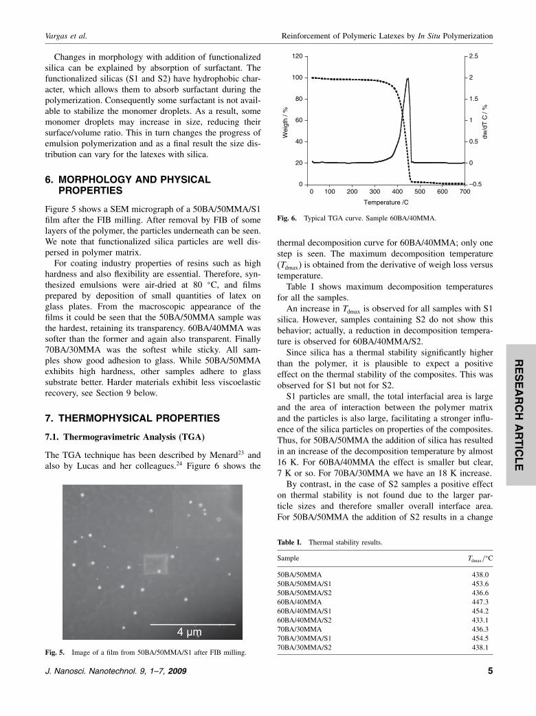
The TGA technique has been described by Menard23 andalso by Lucas and her colleagues.24 Figure 6 shows the
Fig. 5. Image of a film from 50BA/50MMA/S1 after FIB milling.
0
20
40
60
80
100
120
–0.5
0
0.5
1
1.5
2
2.5
0 100 200 300 400 500 600 700
Wei
gth
/%
dw/d
T C
/%
Temperature /C
Fig. 6. Typical TGA curve. Sample 60BA/40MMA.
thermal decomposition curve for 60BA/40MMA; only onestep is seen. The maximum decomposition temperature(Tdmax) is obtained from the derivative of weigh loss versustemperature.
Table I shows maximum decomposition temperaturesfor all the samples.
An increase in Tdmax is observed for all samples with S1silica. However, samples containing S2 do not show thisbehavior; actually, a reduction in decomposition tempera-ture is observed for 60BA/40MMA/S2.
Since silica has a thermal stability significantly higherthan the polymer, it is plausible to expect a positiveeffect on the thermal stability of the composites. This wasobserved for S1 but not for S2.
S1 particles are small, the total interfacial area is largeand the area of interaction between the polymer matrixand the particles is also large, facilitating a stronger influ-ence of the silica particles on properties of the composites.Thus, for 50BA/50MMA the addition of silica has resultedin an increase of the decomposition temperature by almost16 K. For 60BA/40MMA the effect is smaller but clear,7 K or so. For 70BA/30MMA we have an 18 K increase.
By contrast, in the case of S2 samples a positive effecton thermal stability is not found due to the larger par-ticle sizes and therefore smaller overall interface area.For 50BA/50MMA the addition of S2 results in a change
Table I. Thermal stability results.
Sample Tdmax/�C
50BA/50MMA 438�050BA/50MMA/S1 453�650BA/50MMA/S2 436�660BA/40MMA 447�360BA/40MMA/S1 454�260BA/40MMA/S2 433�170BA/30MMA 436�370BA/30MMA/S1 454�570BA/30MMA/S2 438�1
J. Nanosci. Nanotechnol. 9, 1–7, 2009 5
RE
SE
AR
CH
AR
TIC
LE
Reinforcement of Polymeric Latexes by In Situ Polymerization Vargas et al.
Table II. Glass transition of polymeric films.
Sample Tg/� C
50BA/50MMA 17�650BA/50MMA/S1 26�250BA/50MMA/S2 8�060BA/40MMA −7�060BA/40MMA/S1 −1�260BA/40MMA/S2 −6�870BA/30MMA −10�870BA/30MMA/S1 −18�170BA/30MMA/S2 −19�8
Table III. Haze results for latexes with S1.
Haze
50BA/50MMA 13�460BA/40MMA 20�270BA/30MMA 17�150BA/50MMA/S1 26�460BA/40MMA/S1 23�670BA/30MMA/S1 23�8
of Tdmax of ≈1 K, downwards for that matter. For60BA/40MMA there is a decrease of Tdmax by 13 K, appar-ently an effect of interruption of cohesion of the polymermatrix structure by the additive. For 70BA/30MMA wehave an increase of Tdmax by 2 K.
7.2. Differential Scanning Calorimetry (DSC)
DSC was used to locate glass transition temperatures Tg.This technique has also been described by Menard23 andby Lucas and coworkers.24 The importance of Tg has beendiscussed before.25 A so-called midpoint method was used,namely the temperature at which a line connecting theextrapolated baselines below and above the glass transitionregion intersects with the DSC curve was taken as the Tg.Only one Tg is observed in each of the samples; presum-ably random copolymers are obtained. Table II lists theresults.
50BA/50MMA/S1 and 60BA/40MMA/S1 show each anincrease in Tg value with respect to the same sample with-out silica. We infer that the polymer chains mobility is
0 4 8 120
50
100
150
200
250
300
Rp
/µm
Force /N
(a)
(b)
0 1 2 30
50
100
150
200
250
300
350
Force /N
(c)
(d)
0 0.2 0.4 0.6 0.8 10
50
100
150
200
250
Force /N
(e)
(f)
Rp
/µm
Rp
/µm
Fig. 7. Penetration depth versus applied force for all samples: (a) 50BA/50MMA/S1 (b) 50BA/50MMA (c) 60BA/40MMA/S1 (d) 60BA/40MMA(e) 70BA/30MMA/S1 and (f) 70BA/30MMA.
restricted due to the interaction between silica and poly-mer chains-through covalent bonds or interactions betweenchains attached to the silica and surrounding chains. Onthe other hand, 50BA/50MMA/S2 shows a lower Tg valuethan the sample without silica. The particle diameter hasan important role in silica particles interactions with poly-meric chains; as above when discussing thermal stability,lower surface area and interruptions in the matrix struc-ture are important. The 70BA/30MMA sample shows areduction in Tg with both silica particles size (S1, S2).Apparently, when BA content is less than 60 wt%, themain factor that affects the Tg is the silica particle size;at higher BA contents the Tg is affected mainly by theamount of BA.
Due to the better thermal properties obtained with sil-ica S1, these samples were subjected to the remainingtests.
8. TRANSPARENCY
Haze is a measure of lack of transparency caused bylight scattering—including scattering by particles of thedispersed phase. For potential optical applications it isimportant to measure the haze. Our films were depositedon polycarbonate substrates. Haze results for uncoatedpolycarbonate (highly transparent) were used a reference.Table III lists the haze results.
As more and more particles are incorporated into poly-meric matrices, an increase in haze occurs as expected.This agrees with the results obtained by LS and FIB.
9. SCRATCH RESISTANCE
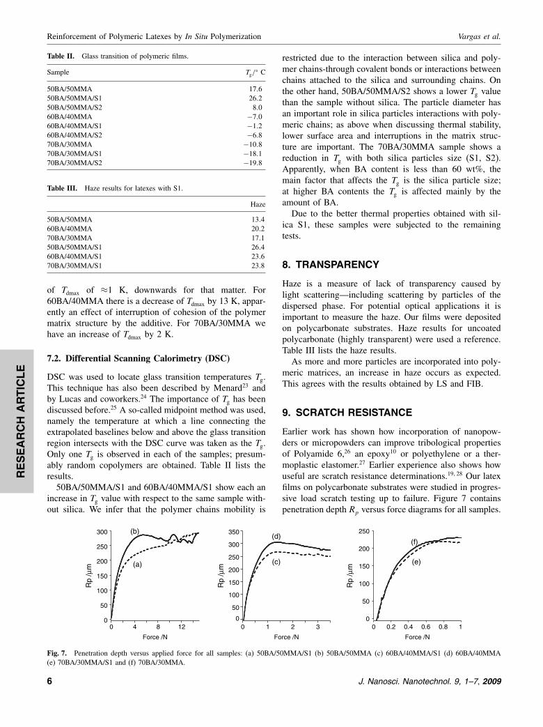
Earlier work has shown how incorporation of nanopow-ders or micropowders can improve tribological propertiesof Polyamide 6,26 an epoxy10 or polyethylene or a ther-moplastic elastomer.27 Earlier experience also shows howuseful are scratch resistance determinations.19�28 Our latexfilms on polycarbonate substrates were studied in progres-sive load scratch testing up to failure. Figure 7 containspenetration depth Rp versus force diagrams for all samples.
6 J. Nanosci. Nanotechnol. 9, 1–7, 2009
RE
SE
AR
CH
AR
TIC
LE
Vargas et al. Reinforcement of Polymeric Latexes by In Situ Polymerization
1 2 3 4 50
20
40
60
80
100
φ /µ
m
φ /µ
m
φ /µ
m
Force /N
(a)
(b)
1 1.2 1.450
60
70
80
90
100
110
Force /N
(c)
(d)
0.5 0.6 0.7 0.850
60
70
80
90
100
110
Force /N
(e)
(f)
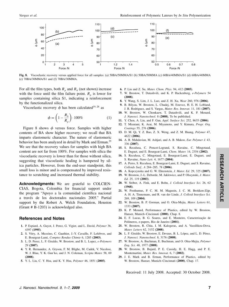
Fig. 8. Viscoelastic recovery versus applied force for all samples: (a) 50BA/50MMA/S1 (b) 50BA/50MMA (c) 60BA/40MMA/S1 (d) 60BA/40MMA(e) 70BA/30MMA/S1 and (f) 70BA/30MMA.
For all the film types, both Rp and Rh (not shown) increasewith the force until the film failure point. Rp is lower forsamples containing silica S1, indicating a reinforcementby the functionalized silica.
Viscoelastic recovery has been calculated19�28 as
=(
1− Rh
Rp
)·100% (1)
Figure 8 shows versus force. Samples with highercontents of BA show higher recovery; we recall that BAimparts elastomeric character. The nature of elastomericbehavior has been analyzed in detail by Mark and Erman.29
We see that the recovery values for samples with high BAcontent are not far from 100%. For samples with silica theviscoelastic recovery is lower than for those without silica,suggesting that viscoelastic healing is hampered by sil-ica particles. However, from the end-user standpoint, thissmall loss is minor and is compensated by improved resis-tance to scratching and increased thermal stability.
Acknowledgments: We are grateful to COLCIEN-CIAS, Bogota, Colombia for financial support underthe program “Apoyo a la comunidad científica nacionala través de los doctorados nacionales 2005.” Partialsupport by the Robert A. Welch Foundation, Houston(Grant # B-1203) is acknowledged also.
References and Notes
1. P. Espiard, A. Guyot, J. Perez, G. Vigier, and L. David, Polymer 36,4397 (1995).
2. S. Vitry, A. Mezzino, C. Gauthier, J.-Y. Cavaille, F. Lefebvre, andE. Bourgeat-Lami, Comptes Rendus Chimie 6, 1285 (2003).
3. L. D. Perez, L. F. Giraldo, W. Brostow, and B. L. Lopez, e-Polymers29 (2007).
4. Y. R. Hernandez, A. Gryson, F. M. Blighe, M. Cadek, V. Nicolosi,W. J. Blau, Y. K. Gun’ko, and J. N. Coleman, Scripta Mater. 58, 69(2008).
5. Y. L. Liu, C. Y. Hsu, and K. Y. Hsu, Polymer 46, 1851 (2005).
6. P. Liu and Z. Su, Mater. Chem. Phys. 94, 412 (2005).7. W. Brostow, T. Datashvili, and K. P. Hackenberg, e-Polymers 54
(2008).8. Y. Wang, S. Lim, J. L. Luo, and Z. H. Xu, Wear 260, 976 (2006).9. B. Bilyeu, W. Brostow, L. Chudej, M. Estevez, H. E. H. Lobland,
J. R. Rodriguez, and S. Vargas, Mater. Res. Innovat. 11, 181 (2007).10. W. Brostow, W. Chonkaew, T. Datashvili, and K. P. Menard,
J. Nanosci. Nanotechnol. 8 (2008), To be published.11. Y. Chen, A. Lin, and F. Gan, Appl. Surface Sci. 252, 8635 (2006).12. T. Mizutani, K. Arai, M. Miyamoto, and Y. Kimura, Progr. Org.
Coatings 55, 276 (2006).13. D. M. Qi, Y. Z. Bao, Z. X. Weng, and Z. M. Huang, Polymer 47,
4622 (2006).14. A. R. Mahdavian, M. Ashjari, and A. B. Makoo, Eur. Polymer J. 43,
336 (2007).15. S. Reculusa, C. Poncet-Legrand, S. Ravaine, C. Mingotaud,
E. Duguet, and E. Bourgeat-Lami, Chem. Mater. 14, 2354 (2002).16. S. Reculusa, C. Mingotaud, E. Bourgeat-Lami, E. Duguet, and
S. Ravaine, Nano Lett. 4, 1677 (2004).17. A. Perro, S. Reculusa, E. Bourgeat-Lami, E. Duguet, and S. Ravaine,
Colloids Surf., A 284–285, 78 (2006).18. A. Kopczynska and G. W. Ehrenstein, J. Mater. Ed. 29, 325 (2007).19. W. Brostow, J.-L. Deborde, M. Jaklewicz, and P. Olszynski, J. Mater.
Ed. 25, 119 (2003).20. W. Stöber, A. Fink, and E. Bohn, J. Colloid Interface Sci. 26, 62
(1968).21. W. Posthumus, P. C. M. M. Magusin, J. C. M. Brokken-Zijp,
A. H. A. Tinnemans, and R. van der Linde, J. Colloid Interface Sci.269, 109 (2004).
22. W. Brostow, B. P. Gorman, and O. Olea-Mejia, Mater. Letters 61,1333 (2007).
23. K. P. Menard, Performance of Plastics, edited by W. Brostow,Hanser, Munich–Cincinnati (2000), Chap. 8.
24. E. F. Lucas, B. G. Soares, and E. Monteiro, Caracterização dePolímeros, e-papers, Rio de Janeiro (2001).
25. W. Brostow, R. Chiu, I. M. Kalogeras, and A. Vassilikou-Dova,Mater. Letters 62, 3152 (2008).
26. L. F. Giraldo, W. Brostow, E. Devaux, B. L. López, and L. D. Pérez,J. Nanosci. Nanotechnol. 8, 3176 (2008).
27. W. Brostow, A. Buchman, E. Buchman, and O. Olea-Mejia, PolymerEng. Sci. 48, 1977 (2008).
28. W. Brostow, B. Bujard, P. E. Cassidy, H. E. Hagg, and P. E.Montemartini, Mater. Res. lnnovat. 6, 7 (2002).
29. J. E. Mark and B. Erman, Performance of Plastics, edited byW. Brostow, Hanser, Munich–Cincinnati (2000), Chap. 17.
Received: 11 July 2008. Accepted: 30 October 2008.
J. Nanosci. Nanotechnol. 9, 1–7, 2009 7