reducing artifacts impact on ivus automatic segmentation via inpainting
TRANSCRIPT
REDUCING ARTIFACTS IMPACT ON IVUS AUTOMATICSEGMENTATION VIA INPAINTING
Hugo Manterolaa,b, Lucas Lo Vercioa,b and Mariana del Fresnoa,c
aPLADEMA, Universidad Nacional del Centro, Tandil, Argentina, http://www.pladema.net
bConsejo Nacional de Investigaciones Científicas y Técnicas (CONICET)
cComisión de Investigaciones Científicas de la Prov. de Buenos Aires (CIC-PBA)
Keywords: Arterial wall, Inpainting, IVUS, Segmentation.
Abstract. In this work we present a novel approach that uses digital inpainting to preprocess intravas-cular ultrasound (IVUS) images to reduce the impact of undesired features. Then, we automaticallysegment the arterial wall with active contour models. IVUS is a catheter-based medical imaging tech-nique that produces cross-sectional images of blood vessels. Segmentation of vessel wall is particularlyuseful to study many coronary artery diseases, such atherosclerosis. Being IVUS a good technology toanalyse the anatomy of the arterial wall, the modality may present several artifacts, such as shadowsor catheter ring-down, that may difficult further processing. To deal with these artifacts, in this paperwe consider an exemplar-oriented inpainting algorithm that replaces the corrupted information by usingthe unaltered neighbourhood. To determine the impact of this preprocessing step, segmentation resultsover inpainted and non-inpainted IVUS are presented. The images are compared with manually outlinedcontours, showing that the inpainting method promotes continuity of the arterial wall and improves thesegmentation performance.
1 INTRODUCTION
Intravascular ultrasound (IVUS) is a medical imaging technique for vascular diagnosis. It isbased in a catheterism with an ultrasound transducer which captures axial images of the vessels.The capture is performed during the mechanical pullback of the transducer at a very slow con-stant speed (between 0.5mm to 1mm per second). IVUS technology provides high resolutionimages with speckle noise, typical of ultrasound images (Abbott and Thurstone, 1979; Loizouand Pattichis, 2008).
IVUS is a study that allows studying the three layers of the arterial wall. Unlike angiography,it provides not only information about the lumen but also about the tissues of the arterial walland atherosclerotic plaque. Regarding this, IVUS is a good complementary study to angiog-raphy. The first arterial tunica, known as intima, is in contact with the arterial lumen, wherethe blood flows. It is composed by elastic fibers which have high echogenicity. The secondlayer or media tunica, envelops the intima. It is constituted by muscular cells, and it has lowerechogenicity than the intima. Finally, the adventitia is composed by connective tissue and elas-tic fibers, and it is more echogenic than the intima and media.
Since the 1990s, intima - media thickness (IMT) has been the standard measure to evaluatethe progression of atherosclerotic cardiovascular disease. In order to automatically computethis indicator it is necessary to have a robust segmentation algorithm of the vessel wall. IVUSprovide valuable anatomical information in that sense. However, due to the high noise level ofthe ultrasound images and the presence of artifacts, the vessel wall segmentation is not a trivialtask and overcoming the artifacts becomes a challenge (Molinari et al., 2010). In particular, thesegmentation complexity in IVUS images is given by echographic reflexions, probe artifactsand atherosclerotic plaque (Balocco et al., 2014). Consequently, the detection and processingof such artifacts allow the segmentation algorithm to avoid inaccurate edge detection due topartial occlusion of the vessels.
In this context, we present a method to preprocess IVUS images that aims to reduce theimpact of artifacts in further vessel wall segmentation. The method is called inpainting andconsists in modify and fill corrupted or missing data with existing information in the image.Two different sources of IVUS images provided by Balocco et al. (2014) are used. On the onehand, a set was acquired using Boston Scientific iLab IVUS equipped with a 40 MHz catheterAtlantis SR (Set A). On the other hand, a set was acquired using Volcano Corporation Si5equipped with a 20 MHz Eagle Eye monorail catheter (Set B). Section 2 presents the commonobstacles that affects automatic or semi automatic layers segmentation. Section 3 shows theinpainting method. Furthermore, a media-adventitia segmentation technique is presented inSection 4 which is used in Section 5 to show the positive effects of inpainting method for vesselwall segmentation. Finally, in Section 6, we analyse the obtained results and present some finalremarks about the viability of the method.
2 OBSTACLES IN IVUS SEGMENTATION
Besides speckle noise, vascular ultrasound images are often degraded by different kind ofartifacts which affect image quality. These artifacts are generated by several sources such as thecatheter itself or other endoluminal devices (stents), plaques, defects in the acquisition systemor in the operator manipulation, among others. All this negative effects are frequently found,sometimes combined, in the IVUS images and make the processing a difficult task. In addi-tion, bifurcations and side vessels may interfere the automatic segmentation. In this sectionwe describe the most frequent difficulties when segmenting lumen-intima and media-adventitia
(a) (b)
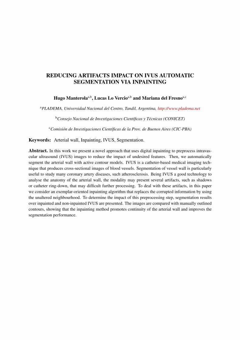
Figure 1: Shadow artifact - marked in solid yellow line (a) Boston Scientific Imaging (b) Volcano CorporationImaging
interfaces.
2.1 Shadow artifact
Shadows in this images are produced when the ultrasound beam can not penetrate an object.As the information behind the occlusion can not be retrieved, the ultrasound system displays ablack region. As a consequence a shadow effect is observed in the image. Even when this effectcan help detecting structures or foreign bodies (e.g. stones in a gallbladder), when it comes tovessel layers segmentation it interferes with the detection of the interfaces between them.
There are different causes of this artifact in the IVUS images. For example, in the case ofrotational transducers, there are certain positions where the guidewire of the device obstructsthe beam signal, resulting in misleading dark regions. This situation is called guidewire artifact(Katouzian et al., 2012). Vessel structures can produce shadows as well. For instance, a plaquewith a calcium build-up also produces a shadow due to its high echogenicity. Because of themost of the signal is reflected, the calcification appears as a highly bright region with a muchdarker region next to it (Taki et al., 2008). The Figure 1 presents examples of shadow artifacts.
2.2 Side vessel
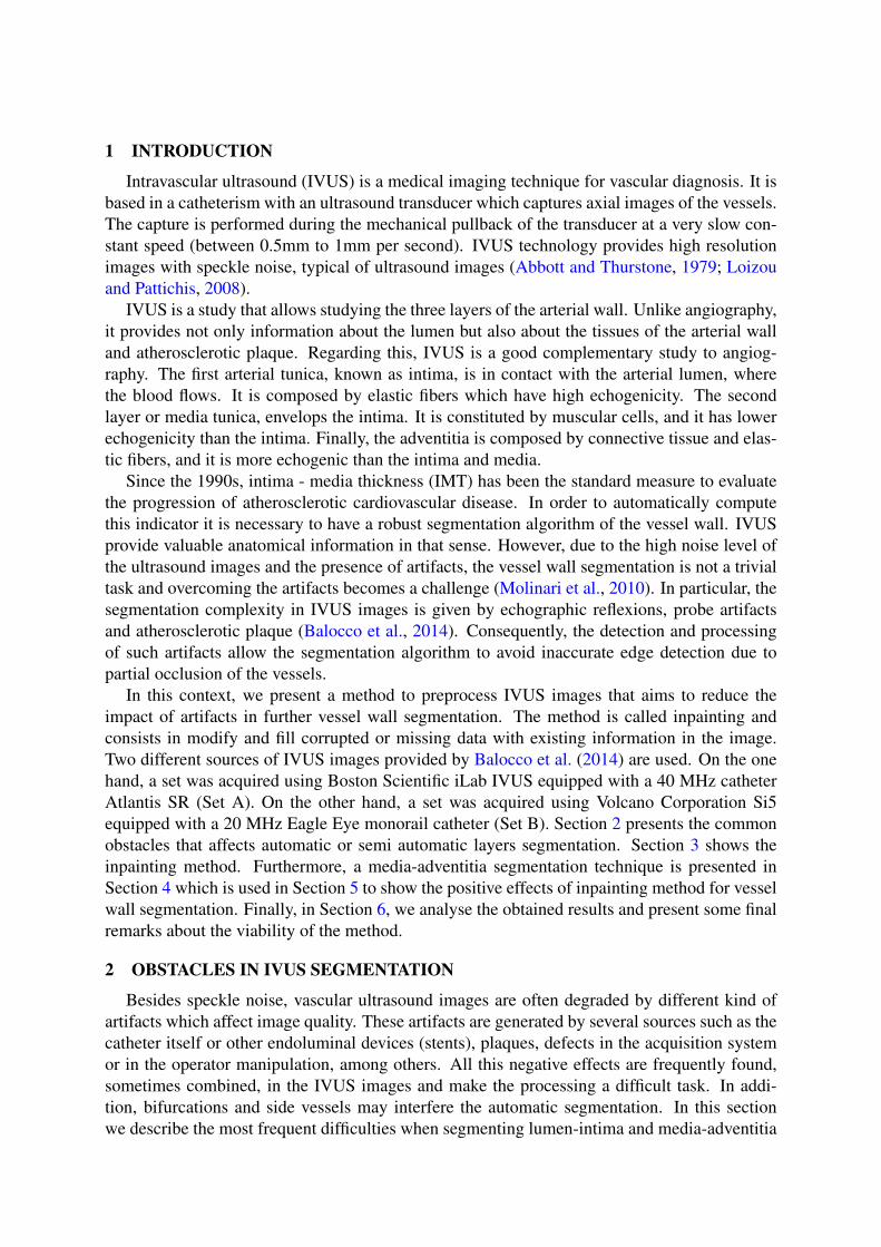
In some regions the ultrasound beam penetrates beyond the tissues of the wall that surroundthe catheter and traces of the adjacent vessels are found. The most discernible of this traces isthe lumen which is shown as a low intensity region due to its low echogenicity (Figure 2). Thisdark region that appears where high intensities are expected (corresponding to the adventitia) isa challenge to segmentation algorithms.
2.3 White dots
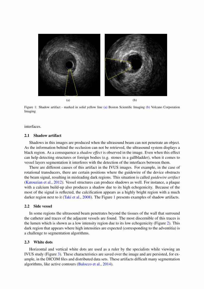
Horizontal and vertical white dots are used as a ruler by the specialists while viewing anIVUS study (Figure 3). These characteristics are saved over the image and are persisted, for ex-ample, in the DICOM files and distributed data sets. These artifacts difficult many segmentationalgorithms, like active contours (Balocco et al., 2014).
(a) (b)
Figure 2: Side Vessel - marked in solid yellow line (a) Boston Scientific Imaging (b) Volcano Corporation Imaging
Figure 3: White dots artifact
(a) Boston Scientific (b) Volcano Corporation
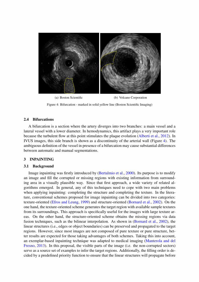
Figure 4: Bifurcation - marked in solid yellow line (Boston Scientific Imaging)
2.4 Bifurcations
A bifurcation is a section where the artery diverges into two branches: a main vessel and alateral vessel with a lower diameter. In hemodynamics, this artifact plays a very important rolebecause the turbulent flow at this point stimulates the plaque evolution (Alberti et al., 2012). InIVUS images, this side branch is shown as a discontinuity of the arterial wall (Figure 4). Theambiguous definition of the vessel in presence of a bifurcation may cause substantial differencesbetween automatic and manual segmentations.
3 INPAINTING
3.1 Background
Image inpainting was firstly introduced by (Bertalmio et al., 2000). Its purpose is to modifyan image and fill the corrupted or missing regions with existing information from surround-ing area in a visually plausible way. Since that first approach, a wide variety of related al-gorithms emerged. In general, any of this techniques need to cope with two main problemswhen applying inpainting: completing the structure and completing the texture. In the litera-ture, conventional schemes proposed for image inpainting can be divided into two categories:texture-oriented (Efros and Leung, 1999) and structure-oriented (Bornard et al., 2002). On theone hand, the texture-oriented scheme generates the target region with available sample texturesfrom its surroundings. This approach is specifically useful for the images with large texture ar-eas. On the other hand, the structure-oriented scheme obtains the missing regions via datafusion techniques, such as the bilinear interpolation. As shown in (Bornard et al., 2002), thelinear structures (i.e., edges or object boundaries) can be preserved and propagated to the targetregions. However, since most images are not composed of pure texture or pure structure, bet-ter results are expected for those taking advantages of both schemes. Taking this into account,an exemplar-based inpainting technique was adapted to medical imaging (Manterola and delFresno, 2013). In this proposal, the visible parts of the image (i.e. the non-corrupted sectors)serve as a source set of examples to infer the target regions. Additionally, the filling order is de-cided by a predefined priority function to ensure that the linear structures will propagate before
texture filling to preserve the connectivity of objects boundaries. Therefore, it is more likelythat these structures are preserved and, at the same time, the texture is correctly replicated.
3.2 The algorithm
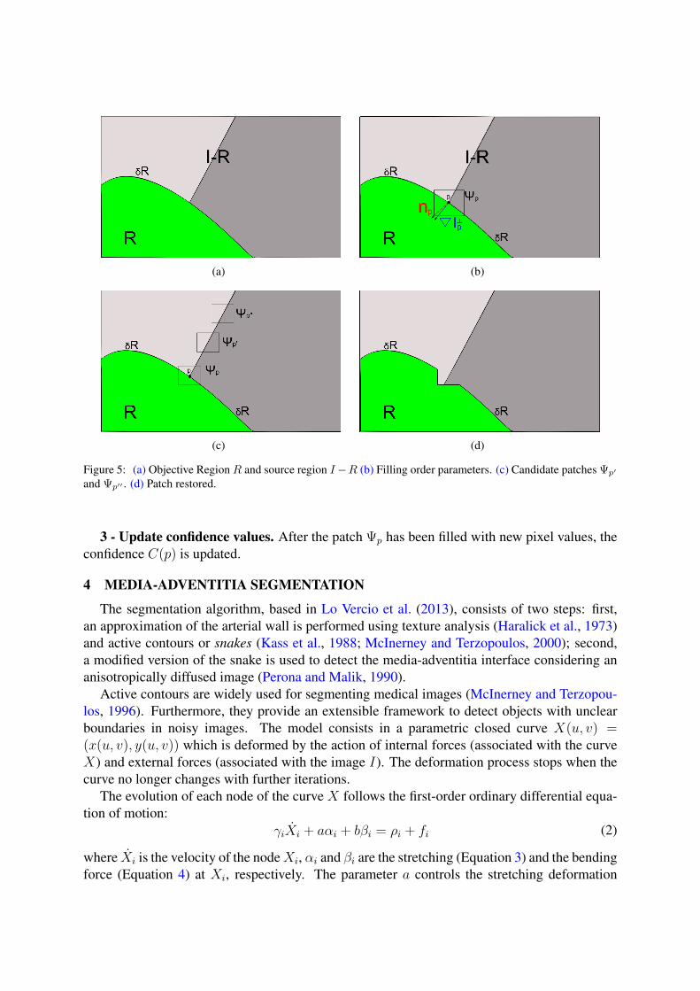
The core of the algorithm is a isophote-driven process. As showed in Figure 5(a), R is thetarget region to be filled and δR is its contour. It is expected that this boundary evolves inwardas the algorithm proceeds. This is the reason it is called the "fill front". Furthermore, I − R,that remains fixed throughout all the execution, is the source region from which the candidatespatches are taken. Let us focus on a single iteration to show how the different componentsinteract and how the exemplar-based synthesis is addressed. Assume that the square Ψp centeredin the point p, in Figure 5(b) is to be replaced. The exemplar that best matches the missing patchis taken from the source region, chosen amongst the candidates Ψq and Ψq′ , as they lie on thecontinuation of the same image edge (see Figure 5(c)). The strategy to pick this best candidatewill be explained later (for further details, see (Manterola and del Fresno, 2013)). Once thisprocess is finished, the chosen patch Ψq is copied over Ψp (see Figure 5(d)) and the algorithmcontinues until R is empty.
Let us now analyse in a general way the region filling algorithm. The only parameter thatneeds to be provided by the user is the region R to be replaced. From this region is straightfor-ward to deduce the source region I − R. Once all this is determined, the algorithm proceedsautomatically.
Each pixel of the image has two associated values: the confidence which reflects how surewe are about the pixel value and its correspondent colour which is empty if it is still unfilled.Moreover, each patch along the frontier δR has a priority value that is updated in every iterationand determines the patch which is the best candidate to be filled. Afterward, the algorithmiterates over three steps until every pixel has been filled:
1 - Compute exemplar priorities. The priority value assigned to each patch in δR deter-mines which one is going to be filled. The patches with the highest priorities are those who areon the continuation of strong edges or that are surrounded by pixels with high confidence values.For a patch Ψp centered at the point p ∈ δR, a priority Pr(p) is defined as P (r) = C(p) ∗ S(p)where C(p) is the confidence term and S(p) is the strength term. As can be observed in Figure5(b), the confidence and the strength can be defined as:
C(p) =
∑q∈Ψp∩(I−R) C(q)
|(∇Ip)⊥, S(p) =
∣∣∇I⊥p ∣∣ · np
α, (1)
where |Ψp| is the area of Ψp, α is a normalization factor, np is a unit vector orthogonal to thefront δR in the point p and ⊥ denotes the orthogonal operator. The priority P (p) is computedfor every border patch, with distinct patches for each pixel on the boundary of the target region.During initialization, the function C(p) is set to C(p) = 0∀p ∈ R, and C(p) = 1∀p ∈ I − R .The confidence term C(p) may be thought of as a measure of the amount of reliable informationsurrounding the pixel p.
2 - Propagate texture and structure information. Once all priorities on the δR have beencomputed, the patch Ψp with highest priority is found. It is then filled with the patch having theleast sum of squared differences. Having found the source exemplar Ψq, the value of each pixelof Ψp is copied from its corresponding position inside Ψq. This achieve the propagation of bothstructure and texture information from the source I − R to the target region R, one patch periteration.
(a) (b)
(c) (d)
Figure 5: (a) Objective Region R and source region I−R (b) Filling order parameters. (c) Candidate patches Ψp′
and Ψp′′ . (d) Patch restored.
3 - Update confidence values. After the patch Ψp has been filled with new pixel values, theconfidence C(p) is updated.
4 MEDIA-ADVENTITIA SEGMENTATION
The segmentation algorithm, based in Lo Vercio et al. (2013), consists of two steps: first,an approximation of the arterial wall is performed using texture analysis (Haralick et al., 1973)and active contours or snakes (Kass et al., 1988; McInerney and Terzopoulos, 2000); second,a modified version of the snake is used to detect the media-adventitia interface considering ananisotropically diffused image (Perona and Malik, 1990).
Active contours are widely used for segmenting medical images (McInerney and Terzopou-los, 1996). Furthermore, they provide an extensible framework to detect objects with unclearboundaries in noisy images. The model consists in a parametric closed curve X(u, v) =(x(u, v), y(u, v)) which is deformed by the action of internal forces (associated with the curveX) and external forces (associated with the image I). The deformation process stops when thecurve no longer changes with further iterations.
The evolution of each node of the curve X follows the first-order ordinary differential equa-tion of motion:
γiXi + aαi + bβi = ρi + fi (2)
where Xi is the velocity of the nodeXi, αi and βi are the stretching (Equation 3) and the bendingforce (Equation 4) at Xi, respectively. The parameter a controls the stretching deformation
while b controls the bending deformation,
αi = (Xi −Xi−1) + (Xi −Xi+1) (3)
βi = (αi − αi−1) + (αi − αi+1). (4)
The external forces are the inflation ρi and the edge attraction fi. ρi is a binary functionwhich determines if the curve goes forward or backward in the normal direction ni. fi is a forceassociated with the gradient (edges) of the image I . The parameters q and p control the impactof the external forces in the curve evolution.
The Euler method is applied to Equation 2 to update the positions of the node Xi from timet to t+ ∆t according to
X t+∆ti = X t
i −∆t
γ(aαt
i + bβti − qρti − pf t
i ). (5)
The Equation 5 iteratively proceeds until the displacement of every node does not exceeds agiven error tolerance. The method ensures convergence when the initial contour is placed closeenough to the object boundary.
Active contours present a challenge when applied to IVUS segmentation because of the highnoise that obstructs the evolution of a curve from the catheter to media-adventitia interface. Toovercome this issue, a two-step segmentation is proposed: first, a contour close to the arterialwall is obtained. Second, the media-adventitia segmentation is performed.
4.1 Initial approximation
The lumen has lower intensities than media and adventitia, but it suffers from speckle noise.This effect is visible as bright and dark spots (Loizou and Pattichis, 2008). A texture-based filteris performed to reduce the impact of the noise in the external forces of the curve. This filteruses grey level co-occurrence matrices (GLCM). The GLCM contains the probability of co-occurrence of two grey intensities in a particular or multiple directions (Haralick et al., 1973).In the present work, a GLCM is computed over a square region of radius r centred in the pixelI(x, y). Being N the possible grey-tone in the image (typically 256), each pixel of the image istransformed into:
I∗(x, y) =N−1∑i=0
(N−1∑j=0
(i2 + j2)P (i, j)) (6)
where P (i, j) is the probability of occurrence of the intensities i and j in the selected directionsobtained from the GLCM.
Then, a region-growing is performed using the textured image I∗. The method incorporatesto the region R the pixels with lower I∗(x, y) than a tolerance T starting from an initial set ofpoints, known as seeds. In this case, the seeds are automatically placed around the circumfer-ence of the catheter to avoid the interference of the ring-down artifact (Katouzian et al., 2012)and the sections where the catheter is touching the arterial wall (Balocco et al., 2014). Theregion-growing can stop near intima if it has a high contrast with the lumen, or can stop nearadventitia if intima and media present low contrast with each other.
The snake method is used to obtain a smoothed border of R. As in the previous seed placing,the initial curve is a circumference placed around the catheter. The external forces of the snake
are defined as
ρi ={ ni if Xi ∈ R−ni if Xi 6∈ R
(7)
fi = ∇I∗i . (8)
4.2 Final segmentation
Computed a curve close to the arterial wall, a precise segmentation of media-adventitia in-terface can be performed. The original image I is filtered using anisotropic diffusion whichhomogenizes noisy regions and enhance its contours (Perona and Malik, 1990). In this step, thediffused image I ′ guides the external forces.
On the one hand, as the adventitia presents higher intensities than the media and lumen,positive gradient in the outgoing radial direction is expected. On the other hand, low or nega-tive gradient values arise beyond the adventitia because the signal maintains high values or isattenuated by the distance from the transducer. Therefore, the inflation force ρ is defined as
ρi = Fini (9)
where F = ∇I ′. To generate a more precise segmentation of the media-adventitia interface, thecurve is adjusted to the maximum gradient change. Therefore, the external force f is given by
f = ∇F. (10)
5 RESULTS
The segmentation algorithm presented in Section 4 was used for segmenting IVUS imagesbefore and after application of inpainting in the presented obstacles. The tests were performedusing two sets of IVUS images from different commercial instrumental commonly used in clin-ical practice. The obstacles and reference segmentations were marked by trained observers.
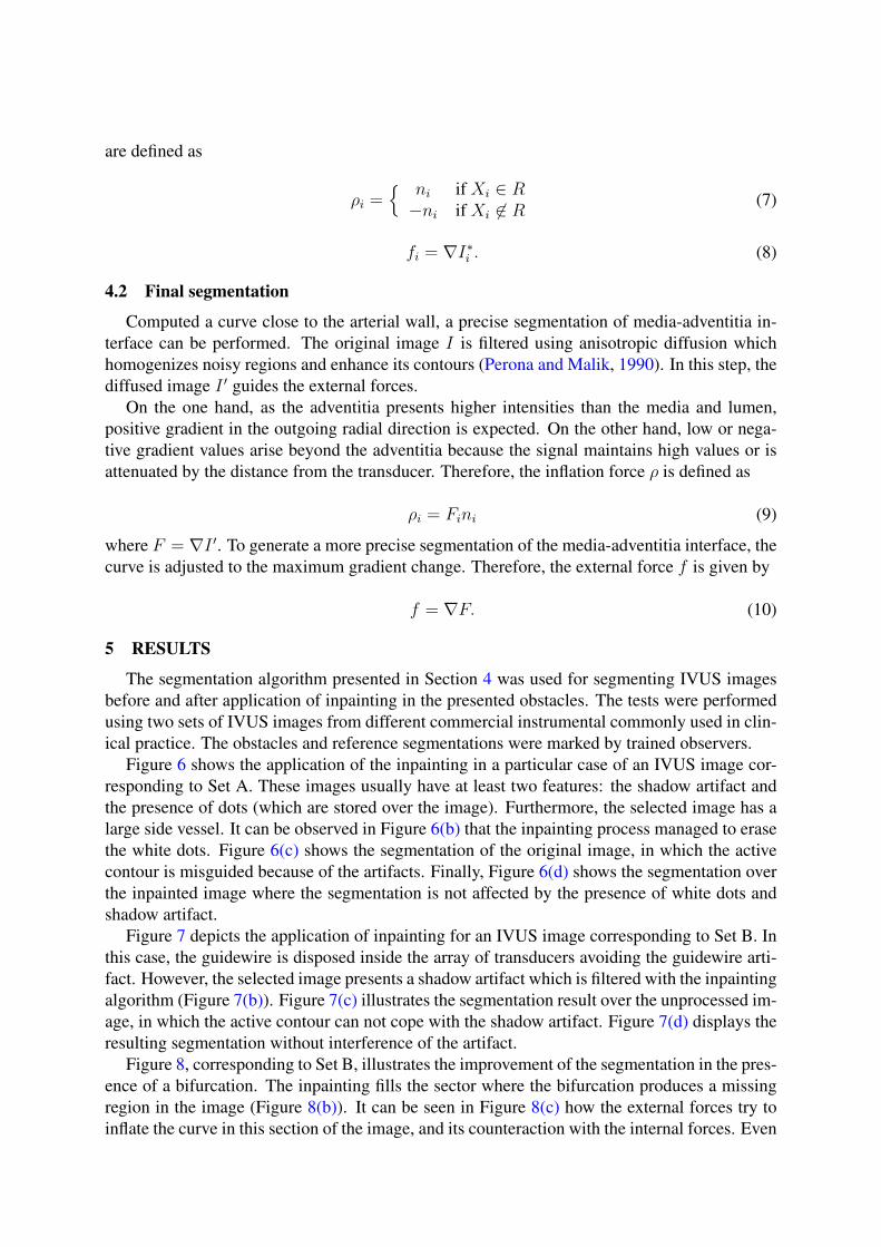
Figure 6 shows the application of the inpainting in a particular case of an IVUS image cor-responding to Set A. These images usually have at least two features: the shadow artifact andthe presence of dots (which are stored over the image). Furthermore, the selected image has alarge side vessel. It can be observed in Figure 6(b) that the inpainting process managed to erasethe white dots. Figure 6(c) shows the segmentation of the original image, in which the activecontour is misguided because of the artifacts. Finally, Figure 6(d) shows the segmentation overthe inpainted image where the segmentation is not affected by the presence of white dots andshadow artifact.
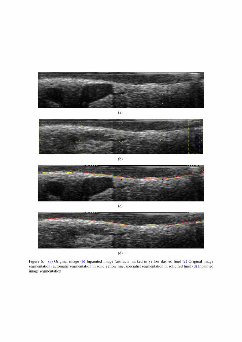
Figure 7 depicts the application of inpainting for an IVUS image corresponding to Set B. Inthis case, the guidewire is disposed inside the array of transducers avoiding the guidewire arti-fact. However, the selected image presents a shadow artifact which is filtered with the inpaintingalgorithm (Figure 7(b)). Figure 7(c) illustrates the segmentation result over the unprocessed im-age, in which the active contour can not cope with the shadow artifact. Figure 7(d) displays theresulting segmentation without interference of the artifact.
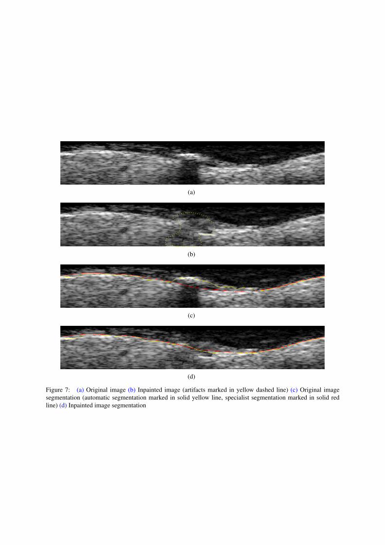
Figure 8, corresponding to Set B, illustrates the improvement of the segmentation in the pres-ence of a bifurcation. The inpainting fills the sector where the bifurcation produces a missingregion in the image (Figure 8(b)). It can be seen in Figure 8(c) how the external forces try toinflate the curve in this section of the image, and its counteraction with the internal forces. Even
(a)
(b)
(c)
(d)
Figure 6: (a) Original image (b) Inpainted image (artifacts marked in yellow dashed line) (c) Original imagesegmentation (automatic segmentation in solid yellow line, specialist segmentation in solid red line) (d) Inpaintedimage segmentation
(a)
(b)
(c)
(d)
Figure 7: (a) Original image (b) Inpainted image (artifacts marked in yellow dashed line) (c) Original imagesegmentation (automatic segmentation marked in solid yellow line, specialist segmentation marked in solid redline) (d) Inpainted image segmentation
(a)
(b)
(c)
(d)
Figure 8: (a) Original image (b) Inpainted image (artifacts marked in yellow dashed line) (c) Original imagesegmentation (automatic segmentation marked in solid yellow line, specialist segmentation marked in solid redline) (d) Inpainted image segmentation
when the improvement in the segmentation result is not considerable in this case, Figure 8(d)shows a smoother transition, produced by the the inpainting process. The filled area stops theevolution of the active contour.
6 DISCUSSION AND CONCLUSIONS
An inpainting method for IVUS segmentation improvement has been presented. The methodhave been applied in the region where IVUS artifacts are presented. Finally, the resulting imagehas been tested using a particular segmentation algorithm.
In the field of photography or cinema, it is sufficient that the result of the inpainting procedurebe visually plausible whereas in medical imaging this is not enough. Considering that it isdifficult to know with certainty what really was the corrupted or missing region, there is alimitation concerning the application of this technique, especially when the resulting image isused for diagnosis. In this work, as there is not a specific medical validation, the result of thisrestoration was used for improving segmentation and simulation.
The inpainting method proved to be effective erasing white dots, replacing them not arbitrar-ily as in Balocco et al. (2014). In our case, the inpainting process searches for the best patch that
ensures continuity of the corresponding object boundaries without losing texture information.The method also showed a good performance removing undesired shadows. In any case thereis a smooth continuation of the boundaries and a coherent texture filling. Finally, the inpaintingperforms well to fill with a coherent texture the region marked as side vessel.
It was shown that white dots and shadows interfere with the evolution of a snake-basedmethod as described by Balocco et al. (2014). The removal of white dots and shadow artifacthad a positive effect for the segmentation algorithm applied.
Another issue to analyse is the performance of the active contours when bifurcations occur.In these situations, the external forces compete with the internal forces to decide whether toincorporate or not the sector as part of the artery. However, when applying the inpaintingmethod in the bifurcation, the segmentation becomes more similar to the ground truth.
7 ACKNOWLEDGEMENTS
The present work has been partially funded by the National Agency for Science and Tech-nology Promotion (ANPCyT, within the project PICT 2010-1287).
REFERENCES
Abbott J. and Thurstone F. Acoustic speckle: Theory and experimental analysis. UltrasonicImaging, 1(4):303–324, 1979.
Alberti M., Balocco S., Gatta C., Ciompi F., Pujol O., Silva J., Carrillo X., and Radeva P.Automatic bifurcation detection in coronary ivus sequences. Biomedical Engineering, IEEETransactions on, 59(4):1022–1031, 2012. ISSN 0018-9294.
Balocco S., Gatta C., Ciompi F., Wahle A., Radeva P., Carlier S., Unal G., Sanidas E., MauriJ., Carillo X., Kovarnik T., Wang C.W., Chen H.C., Exarchos T.P., Fotiadis D.I., DestrempesF., Cloutier G., Pujol O., Alberti M., Mendizabal-Ruiz E.G., Rivera M., Aksoy T., DowneR.W., and Kakadiaris I.A. Standardized evaluation methodology and reference database forevaluating ivus image segmentation. Computerized Medical Imaging and Graphics, 38(2):70– 90, 2014. ISSN 0895-6111.
Bertalmio M., Sapiro G., Caselles V., and Ballester C. Image inpainting. Proceedings of the27th Annual Conference on Computer Graphics and Interactive Techniques, pages 417–424,2000.
Bornard R., Lecan E., Laborelli L., and Chenot J.H. Missing data correction in still images andimage sequences. Proceedings of the Tenth ACM International Conference on Multimedia,pages 355–361, 2002.
Efros A. and Leung T. Texture synthesis by non-parametric sampling. Proceedings of IEEEInternational Conference on Computer Vision, 2:1033–1038, 1999.
Haralick R., Shanmugam K., and Dinstein I. Textural features for image classification. Systems,Man and Cybernetics, IEEE Transactions on, (6):610–621, 1973.
Kass M., Witkin A., and Terzopoulos D. Snakes: Active contour models. International Journalof Computer Vision, 1(4):321–331, 1988. ISSN 0920-5691.
Katouzian A., Angelini E., Carlier S., Suri J., Navab N., and Laine A. A state-of-the-art reviewon segmentation algorithms in intravascular ultrasound (ivus) images. Information Technol-ogy in Biomedicine, IEEE Transactions on, 16(5):823–834, 2012. ISSN 1089-7771. doi:10.1109/TITB.2012.2189408.
Lo Vercio L., del Fresno M., and Vénere M. Segmentación automática de imágenes ivus basada
en indicadores de textura y modelos deformables. Mecánica Computacional, XXXII:3823 –3834, 2013. ISSN 1666-6070.
Loizou C. and Pattichis C. Despeckle Filtering Algorithms and Software for Ultrasound Imag-ing. Morgan and Claypool, 2008. ISBN 9781598296211.
Manterola H. and del Fresno M. Inpainting digital aplicado a la reconstrucción de imágenes deultrasonido. Mecánica Computacional, XXXII(2):3835–3848, 2013. ISSN 1666-6070.
McInerney T. and Terzopoulos D. Deformable models in medical image analysis: a survey.Medical image analysis, 1(2):91–108, 1996.
McInerney T. and Terzopoulos D. T-snakes: Topology adaptive snakes. Medical Image Analy-sis, 4(2):73 – 91, 2000. ISSN 1361-8415.
Molinari F., Zeng G., and Suri J. A state of the art review on intima-media thickness (imt)measurement and wall segmentation techniques for carotid ultrasound. Computer methodsand programs in biomedicine, 100(3):201–221, 2010.
Perona P. and Malik J. Scale-space and edge detection using anisotropic diffusion. PatternAnalysis and Machine Intelligence, IEEE Transactions on, 12(7):629–639, 1990. ISSN 0162-8828. doi:10.1109/34.56205.
Taki A., Najafi Z., Roodaki A., Setarehdan S., Zoroofi R., Konig A., and Navab N. Automaticsegmentation of calcified plaques and vessel borders in ivus images. International Journalof Computer Assisted Radiology and Surgery, 3(3-4):347–354, 2008. ISSN 1861-6410. doi:10.1007/s11548-008-0235-4.