recticin - prggram plan - nrc.gov
TRANSCRIPT
rr ~
WNF-'..2 PRESERVICE IN5I":rECTICiN
PRGGRAM PLANPRO~CEDURES
Volume 3
~ ~
COPY 'r'O.
r
~rr
Ir
WRshlngtoB PjjblliL''PjjjPjgi'.$'UPPlj 'S~st@"."i
"</ihla'nd,""Wabii'ng'ip™rj'SS3S2 '
~
Bnoa aeoeaoO890aoa~0~~09>@gal AODGY 030G
~V
I
Ik
1
hIIi
lt' ~
Date 1/8/79
Revision '
MNP-2 PSI PROGRAM PLAN
NOT USED
(Purposely left blank)

p,"%phdI
,(
'0
Da te 1/8/79
Revi sion 0
'I'JNP-2 PSI PROGRAM PLAiN
NOT USED
(Purposely left blank)

Date 1/8/79
Revision 0
IJNP-2 PSI PROGRAM PLAN
NOT USED
(Purposely left blank)

Date 1/8/79
Revision 0
MNP-2 PSI PROGRAt1 PLAN
NOT USED
(Purposely left blank)
;.". -<f:, 4' 308<'
l ~ Di's
O'V. i 'AO.i:0 ': <
0 t)0 j ~1'O'<\
0c]C,
";c7
9lff i 0 P.C,""."!~
~IONG"6 if',e ~q:c. ~
7t 9 fllJ l I I p 9 > y 4~ 1
L~ ~~ Q leairV g~l'."
1~6 - i li.
y, q 4.g~w~g
r r.s
! (
Lambert ~ MacQ ill~ Thomas, Inc.Testing ~ Engineering ~ SeNlce ~ Training
771 East Brokaw RoadSan Jose,ca. 95112
408-297-8766
. \
PROC. UTP'.-,'40l'AGE
1F 0 L LOW I NG'P AG Eii 2
r
REVISION 0,
DATE 12/.23'/80';; ';
~ '
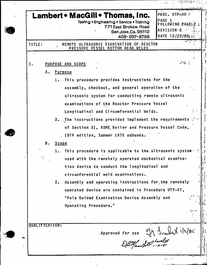
TITLE: REMOTE ULTRASONIC EXAMINATION OF REACTORPRESSURE VESSEL BOTTOM HEAD WELDS
PURPOSE AND SCOPE
A. ~Pur ose
1. This procedure provides instructions for the
assembly, checkout, and general operation of the
ultrasonic system for conducting remote ultrasonic
examinations of the Reactor Pressure Vessel
Longitudinal and Circumferential Welds.
2. The instructions provided implement the requirements ':"
of Section XI, ASME Boiler and Pressure Vessel Code,
1974 edition, Summer 1975 addenda.
B. ~Soo e
1. This procedure is applicable to the ultrasonic system
used with the remotely operated mechanical examina-
tion device to conduct the longitudinal and
circumferential weld examinations.
2. Assembly and operating instructions for. the remotely
operated device are contained in Procedure UTP-47,
"Pole Guided Examination Device Assembly and
Operating Procedure."
s
s
Iv
~ ~
~ )s 1
e s
8g
l.
ULI I I
Approved for use e h ~ SL
Egg~ ..;I
'.*I
" Lwmbert ~ MacG ill~ Thomas, Inc.'rv 'W« Testing ~ Engineering ~ Service ~ Training
771 East Brokaw RoadSan Jose,Ca. 95112
'~ "«,S i< I 408-297-8766
PROC. UTP-40
PAGE 2FOLI.OWING PAGE 3
REVISION 0
DATE 12/23/80
B..3. Instructions for the assembly and operation of the
+" 2) "a)'emote automatic ultrasonic data recording system are
contained in Procedure UTP-42, "Remote Automatic
Ultrasonic Data Recording."
4. Volumetric examinations shall be performed using
ultrasonic angle and straight beam techniques, as
fol 1 ows:
a) Base metal through which sound will pass shall
r eceiv'e a 0'ongitudinal beam examination to
detect reflectors which may interfere with the
angle beam examinatfons;
b) All welds and one-half t of the base metal beyond
each edge of the weld shall receive a 45'nd60'ngle
beam exaninatfon, and a 0'traight beam
examination;
c) Other angles may be used where wall thfckness oro . nfl )). og ))
~ «>on:. r )
«raoq evt ". )-
geometric configuration impedes effective use of45'nd 60'ngle beam examinatfon.
d) The extent of straight and angle beam scanning fs
defined in the Scan Plan sections appropriate to
the specific area to be examined.
(b9vo
Lambert ~ MacG ill~ Thomas, inc.Testing ~ Engineering ~ Service ~ Training
771 East Brokaw RoadSan Jose,ca. 95112
408-297-8766
PROCyg+TF-4PAGEFOLLOWING PAGE 4
REVISION 0
DATE 12/23/30
II. REFERENCES
A. A licable Code Editions
1. This procedure complies with the requirements of theS
1974 edition of ASME Boiler and Pressure Vessel Code,
Section XI, Summer 1975 addend'a.
B. Su lemental References
1. SNT-TC-1A (June 1975), "Recommended Practice for the
Establishment of Personnel gualification and Certifi-I
!cation Programs."
. 2. LMT, Inc. Procedure qA-6, "gualification and Certifi-cation of NDE Personnel."
3. LMT, Inc. Operating and equality Assurance Manual,
Revision 12, approved for the WNP-2 Pt.eservice
Inspection by WPPSS.
I I I. DEFINITIONS
Beam Direction:
Controller:
Orientation of ultrasonic beam rela-
tive to vessel axis, independent ofI
scan direction. I
Electronic device controlling mech,'-
Index Movement:
(Increment)
anical system motor direction and/
speed. May indicate relative posi
tion via multi-digit readout.
Module movement (distance moved)
between scans.
or
148 a 'L ea
C
3F'l I )~(.; j.Y.O.'c'.' .
"
Testing ~ Engineering ~ Service ~ Training771 East Brokaw Road
San Jose,Ca. 95112408-297-8766
.: '...Lambert ~ MacQill~ Thomas, Inc. PROC. UTP-40PAGE 4FOLLOWING PAGE 5
REVISION 0
DATE 12/23/80
~w' li+a w~rtri
1
io 2 f &v~
Scan Direction:<~ dc. Her'.~-
n5 Ua 'ir
,, X-axi s:
„.,„„„„„,Y;axis:
t'r~) 9 9~19 3G~ ~.''
I I I. Modul e, Search Uni t: Search unit cluster including shoes,
wedges, holding framework, couplant
supply manifold.
Motion of search unit module relativeto vessel axis, independent of beam
direction.Circumferential axis of head.
Meridional axis of head.
Calibration block thickness .
Weld thickness.
i" !.' '> l'$Q»'V.
RESPONSIBILITY
"o
B.~-a
o.'heTechnical Manager, LMT, Inc. is responsible for the
generation and control of this procedure and shall so
indicate by a dated signature on the procedure cover
sheet:.
The responsible Level III Field Supervisor, LMT, or his
designated Level III alternate, LMT, shall qualify the
procedure for a particular examination.
oi 1
n
nor ~t
:V. PROCEDURE UALIF ICATION
,This procedure shall be qualified for specific examinations,
,„, ipersonnel, and equipment by performing and documenting a suc-
cessful calibration.
Lambert ~ IacQ ill~ Thomas, Inc.TesNng ~ Engineering ~ Senrice ~ Training
771 East Brokaw RoadSan Jose,Ca. 95112
408-297-8766
I
P ROC;.--,4TP -'40
PAGE 5FOLLOWING 'PAGE 6
REVISION G
DATf~/2.3/80
YI. PERSONNEL RE UIREMENTS
A. Examiners using this procedure shall have levels of
qualifications as per the Procedure gualification.8. Personnel operating the Pole Guided Device'device sh)
be qualified on the equi pment and so -certified by an
authorized LMT Level III examiner.aA
1. For each shift of operation, the examination team
shall consist of at least the following personne~l:
a) Coordinator/supervisor: Coordinate efforts ofT
individual team members and efforts of the exami-
nation team with the owner and appropriate oz-I
site crafts. „V>lI
b) Consol e operator: Operate contr oil'ers, record
necessary data for completion of scan data
sheets. Conduct and verify functional checks of
mechanical system.
c) Observer: Stationed at device location to ob-
serve operation of device, warn of pendingI
obstruction, malfunction, etc. i
d) Ultrasonic operator: Perform examination clg
bration, enter appropriate informati"on on's'hart
recordings, verify proper operation o)
ultrasonic system. Certified to at least
Level,II Ultrasonic.
rip
««o«e«««
'
4
'L'ambert ~ MacQ ill~ Thomas, Inc.Testing
~ Engineering ~ Service ~ Troining771 East Brokaw Road
San Jose,Ca. 95112408-297-8766
PROC. UTP-40
PAGE 6FOLLOWING PAGE 7
REVISION 0
DATE 12/23/80
V5. ~ B. 2. Team personnel may perform the above dut1es on a
rotat1onal basis, provided adequate cross trainingand cert1fication levels are existent.
VI I>„- E UIPMENT AND MATERIALS
, A. S stem Descri ti on
1. The Ultrasonic and Data Acquisition System cons1sts
of three (3) Nortec NDT-131D ul trascopes, a digital-to-analog converter, and an eight (8) channel d1rect
wr 1ting strip chart recorder.
2. The ultrascopes have been modified for rack mounting
and remote "slave" display of each instruments'RTpresentation.
3. The BCD data output from the mechanical system con-
trollers is converted to analog form by the digital-to-analog converter and 1nput to the strip chart
recorder.
4. The eight channel strip chart recorder provides a
permanent record of range and amplitude data of re-
ceived ultrasonic signals (channels 1-6) and the X
and Y axis location of the device during each scan
(channels 7 and 8).B. Instrumentation Re u1rements
1. The NDT-1310 ultrascopes shall meet, the following
performance criteria:
Lambert ~ MacG ill~ Thomas, Inc.Testing
~ Engineering ~ Service ~ Training771 East Brokaw Road
San Jose,Ca. 95112408-297-8766
PROC. U/P-40PAGE 7
FOLLOWING PiAGE 8
REVISION 0;DATE 12/23/80
V I I. B. 1. a ) Vertical 11near1ty (screen height) w1thin a5%iof
full screen, for at least 80% of the total scjeen
he1ght. I
b) Ampl itude control accurate over its usefulr r'ange
to a20% of the nominal amplitude ratio.2. The NDT-1310 ultrascopes shall have their internal
a11gnment and calibration verified w1thin 90 dayst,
M I
prior to use.
a) Records of internal alignment and calibrationi
verif1cation shall be availab'le at the jobsitefor WPPSS audit.
3. The digital-to-analog converter shall meet the fol-lowing performance criteria:a) Repeat SwR I controller readout (last four dig'1ts)
0000 through 9999, a0 counts.
b) Analog voltage output proportional to BCD inputr
at the rate of 100 counts/volt, a0.01 v and 1000
counts/vol t, a0.01 v, sw1tch sel ectabl e.
4. The direct writ1ng analog str1p chart recorder shall
meet the following performance criter1a:
a) Frequency response at 40 mm - dc to 60 Hz, al
division.b) Frequency response at 10 div1sions amplitude - dc
to 125 Hz, x1 division.
- Lambert ~ MacG ill~ Thomas, Inc.Testing ~ Engineering ~ Senesce ~ Training
771 East Brokaw RoadSan Jose,Ca. 95112
408-297-8766
PROC'TP-40PAGE 8FOLLOWING PAGE 9
REVISION 0
DATE 12/23/80
VII... B.. 4. c) Non linearity may not exceed 0.35% of full scale.
5. The strip chart recorder shall have its internalalignment and calibration verified within 180 days
prior to use.
a) Records of internal alignment and calibrationverification shall be available at the jobsitefor WPPSS audit.
aiba
C. Search Unit and Wed e Re uirements
1. Search unit essential properties shall be certifiedby the manufacturer, including bandwidth, damping,
'enterfrequency within 10% of nominal, and relativegain.
a) A record of search unit properties shall be
available at the )obsite for WPPSS audit.2. Wedges shall yield refracted angles of 45', w2', and
60', x3', to be acceptable for use.
a) Refracted angles shall be determined in the cali-bration block daily, prior to use, as instructed
Procedure in UTP-14.
b)'ther angles may be used for evaluation and shall
be within a3'f the nominal wedge angle.
3. The results of examinations performed with angle beam
search units which meet the above requirements are
acceptable provided the search unit beam angle on
subsequent checking is within x3'f,nominal.
Lambert ~ MacQill~ Thomas, Inc.Testinp ~ En pineerlnp ~ Senrice ~ Traininp
771 East Brokaw RoadSan Jose,Ca. 95112
408- 297-8766
PROC. UTP-40
PAGE 9FOLLOWING PAGE
10'EVISION
0'ATE12/23/80
VI I. C. 3. Should this tolerance not be met on subsequent'check-
inq, determination of the need for r e-examination
shall be made and the basis for the decision docu-
mented.
4. Search units shall be 0.75 inch diameter with a
central frequency of 2.25 MHz, a10%.
a) Search units of other sizes and/or frequenciesa
may be used for evaluation and/or inunusual'ircumstances.
Such use shall be documented by
an approved Field Change to this procedure in
accordance with the requirements of LMT Procedure
QA-5.
D. ~Cnu 1 ant
1. Couplant used to conduct examinations governed by0
thi s procedure shall be "reactor grade" deioni zed
water.
2. Wetting .agents such as Kodak "Photo-flo"
to improve coupling efficiency.'I
E. Calibration Blocks
1. Calibration blocks shall be of the form
sions of Figures la) through 1 d).
may be added
and dimep
2. Select the appropriate calibration block for a
specific longitudinal or circumferential weld
examination according to Table 1.
~ t ~ifi g v'~
fi 'i g- ' ~
Testing ~ Engineering ~ Service ~ Training771East Brokaw Road .
San Jose;Ca. 9511240B -297- B766
'ambert ~ MacG ill~ Thomas, Inc. PROC. UTP-40
PAGE 10FOLLOWING PAGE 11
REVISION 0
DATE 12/23/80
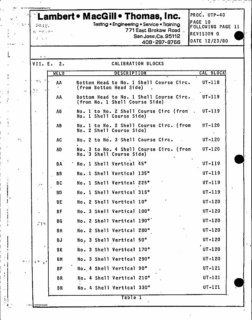
V I I ~ E ~ 2 ~
WELD
AA
AA
AB
AB
CALIBRATION BLOCKS
DESCRIPTION
Bottom Head to No. 1 Shell Course Circ.(from Bottom Head Side)
Bottom Head to No. 1 Shell Course Circ.(from No. 1 Shell Course Side)
No. 1 to No. 2 Shell Course Circ (fromNo. 1 Shell Course Side)
No. 1 to No. 2 Shell Course Circ. (fromNo. 2 Shell Course Side)
CAL BL CK
UT-118
C
UT-119
UT-119
UT-120
AC
AD
No. 2 to No. 3 Shell
No. 3 to No. 4 ShellNo. 3 Shell Course Si
Course Circ.
Course Circ. (fromde)
UT-120
UT-120
rC
BH No. 2 Shell Vertical
BJ No. 3 Shell Vertical
280O
50'K
No. 3 Shell Vertical170'M
No. 3 Shell Vertfcal 290
BP No. 4 Shell Vertical90'R
No. 4 Shell Vertical
BN No. 4 Shell Vertical
210
330o
Tab e 1
BA 'o. 1 Shell Vertical45'B
No. 1 Shell Vertical135'C
No. 1 Shell Vertical225'Q
No. 1 Shell Vertical315'E
No. 2 Shell Vertical10'F
No. 3 Shell Vertical100'G
No. 2 Shell Vertical
190'T-119UT-119
UT-119
UT-119
UT-120
UT-120
UT-120
UT-120
UT-120
UT-120
UT-120
UT»121
UT-121
UT-121
Lambert ~ MacG ill~ Thomas, Inc.Testing ~ Engineering ~ Service ~ Training
771 East Brokaw RoadSan Jose,Ca. 95112
408-297-8766
PROC. UTP-40
PAGE 11FOLLOWING PAGE 12
REVISION 0
DATE 12/23/80
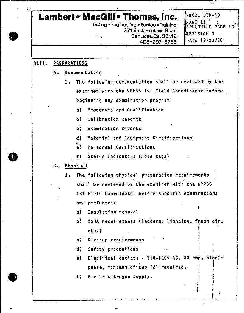
V I I I. P RE P ARATI ON S
A. Documentati on
1. The following documentation shall be r evfewed by the
examiner with the MPPSS ISI Field Coord1nator before
begfnn1ng any examination program:
a) Procedure and gualfffcatfon
b) Calibration Reports
c) Examination Reports
d) material and Equipment Certfffcatfons
e) Personnel Cert1fications
f) Status Indicators (Hold tags)
8. ~Ph s $ cat
1. The following physical preparat1on requirements
shall be rev1ewed by the examiner with the WPPSS
ISI Field Coordinator before specific exam1natfonsI
are performed:
a) Insulation removal
b) OSHA r equirements ( ladders, lighting, fresh a1r,
etc.)c)'leanup requirements.
d) Safety precautions
e) Electrical outlets - 110-120v AC, 30
phase, minimum of two (2) requfred.
f) Air or nitrogen supply.
amp,k
single
Lambert ~ MacQ ill~ Thomas, Inc.Testing ~ Engineering ~ Service ~ Training
771 East Brokaw RoadSan Jose,Ca. 95112
408" 297-8766
PROC. UTP-40
PAGE 12FOLLOWING PAGE 13
REVISION 0
D ATE l 2 /2 3/80
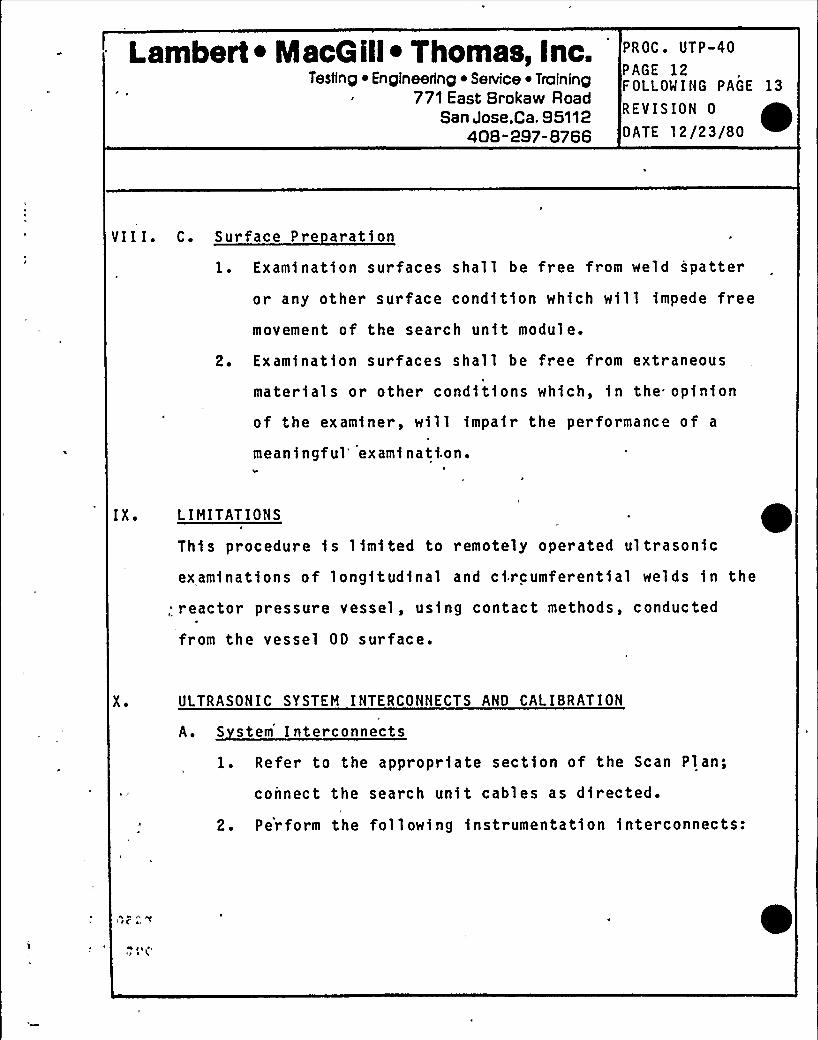
VIII. C. Surface Pre aration
1. Exam1nat1on surfaces shall be free from weld spatter
or any other surface condition which w111 1mpede free
movement of the search unit module.
2. Exam1nation surfaces shall be free from extraneous
mater1al s or other conditions wh1ch, in the opinion
of the examiner, will impair the performance of a
meaning ful'xami nati.on.
I X. L IMITATIONS
Th1s procedure is limited to remotely operated ultrasonic
exam1nations of longftud1nal and circumferential welds 1n the
; reactor pressure vessel, us1ng contact methods, conducted
from the vessel OD surface.
X ~ ULTRASONIC SYSTEM INTERCONNECTS AND CAl ISRATION
A. S stem Interconnects
1. Refer to the appropriate section of the Scan Plan;
connect the search unit cables as directed.
2. Perform the following instrumentat1on interconnects:
Lambert ~ MacQ ill~ Thomas, Inc.Testing ~ Engineering ~ SeNice ~ Troining
771 East Brokaw RoadSan Jose;Ca, 95112
408-297-8766
PROC. UTP-40
PAGE 13FOLLOWING PAGE 14
REVISION 0
D ATE l 2/2 3/8 0
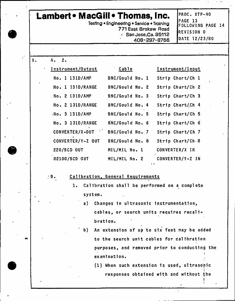
X ~ A. 2.
Instrument Out ut
No. 1 131D/AMP
Cabl e Instrument In ut
BNC/Gould No. 1 Strip Chart/Ch 1
No. 1 l31D/RANGE BNC/Gould No. 2 Strip Chart/Ch 2
No. 2 131D/AMP BNC/Gould No. 3 Strip Chart/Ch 3
No. 2 131D/RANGE BNC/Gould No. 4 Strip Chart/Ch 4
No. 3 131D/AMP
No. 3 131D/RANGE
CON VER TE R/X -OUT
CONVERTER/Y-Z OUT
BNC/Gould No. 5 Strip Chart/Ch 5
BNC/Gould No. 6 Strip Chart/Ch 6
BNC/Gould No. 7 Strip Chart/Ch 7
BNC/Gould No. 8 Strip Chart/Ch*8
220/BCD OUT
82100/BCD OUT
MIL/MIL No. 1
MIL/MIL No. 2
CONVERTER/X IN
CONVERTER/Y-Z IN
',B ~ Cal ibratf on General Re uirements
1. Calibration shall be performed on a complete
system.
a) Changes fn ultrasonic fnstrumentation,
cables, or search units requires recalf-bration.
b) An extension of up to sfx feet may be added
to the search unit cables for calibrationpurposes, and
examination.
(1) When such
responses
removed prior to conducting ther
extension fs used, ultrasonicV
obtained with and without the
Lambert ~ MacG ill~ Thomas, Inc.Testing ~ Engineering ~ Service ~ Training
771 East Brokaw RoadSan Jose,ca. 95112
408-297-8766
PROC. UTP-40
PAGE 14FOLLOWING PAGE 15
REVISION 0
DATE 12/23/80
X ~ B. 1. b) (1) extension shall be compared during the firstcalibration and so noted on the "Report, of
Ul t ra so ni c Ca l 1 b r a t1o n. "
c) A change in qualified personnel or record1ng „
instrumentat1on shall require calibration verifi-cation.
d) Instrument vertical linearity and amplitude
control verif1cations need not be made with the
search unit used forexamination.')
Calibrat1on checks shall be performed before and
after each examination and at intervals not to
exceed 12 hours.
2. Ver ify instrument vert1cal linearity as follows:
a) Position an angle beam search un1t on the cal1-
br ation block to obtain echoes from the T/2 and
-3T/4 holes in a 2:1 ampl1tude rat1o.
b) Adjust the ampl itude control to position the
larger indication at 100% of calibrated scale and
note the amplitude of the smaller on the calibra-
tion form as estimated to the nearest 1% of
screen height.
c) Vary the amplitude control so that the response
of the larger signal is successively lowered in
10% increments to 10'5 of full.cal1brated scale.
At each 1ncremental setting note the response of
both indicat1ons.
I
Lambert ~ MacG ill~ Thomas, inc.Testing ~ Engineering ~ SeNice ~ Training
771 East Brokaw RoadSan Jose,Ca. 95112
408-297-8766
PROC. UTP-40
PAGE 15FOLLOWING PAGE 16
REVISION 0
OATE 12/23/80
X. B. 2. d) Acceptable instrument al ignment 1 s veri fied when
the ratio of the two responses remains two-to-one
over the range of amplitude adjustment within 5%
of calibrated full scale.
Veri fy the ampl 1 t ud e control ace uracy a s fol l ows:
a) Position an angle beam search unit on the cal1-
bration block to obtain a peaked echo from the
T/2'ole at 80% of full cal1brated scale.
b) Adjust the amplitude control to decrease the gain
by 6 dB and 12 dB. Note the echo amplitude a'
each setting. Estimate the amplitude to 1% of
full calibrated scale.
c) Adjust the ampl1tude control to position the T/2
response to 20% of full calibrated scale.
Then adjust the amplitude control to 1ncrease the
gain 12 dB. Record the response as estimated to
1% of full calibrated scale.
d) Adjust the ampl1tude control to position the T/2
response to 40% of full calibrated scale. Then
adjust the amplitude control to increase the gain
6 dB. Note the response as estimated to 1% of
full scale.
Lambert ~ NlacQ ill~ Thomas, Inc.Testing ~ Engineering ~ Service ~ Troining
771 East Brokaw RoadSan Jose,Ca. 95112
408-297-8766
PROC. UTP-40PAGE 16F OLLOMING PAGE 17
REVISION 0
DATE 12/23/80
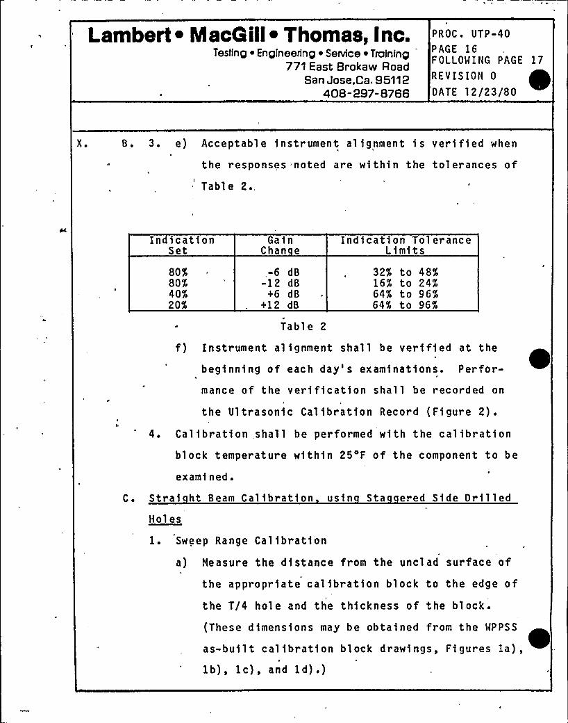
X. B. 3. e) Acceptable 1nstrument alignment is verified when
the responses noted are within the tolerances of
Table 2.,
In icat1onSet
80%80%40$20%
GainChan e
-6 dB-12 dB
+6 dB+12 dB
Tabl e 2
Indfcat1on ToleranceLimits
32% to 48%16% to 24%64% to 96%64% to 96%
f) Instrument alignment shall be verified at the
beginning of each day's examinations. Perfor-
mance of the veri f1cation shall be recorded onJ
the Ultrasonic Cal1bration Record (Figure 2).
4. Calibration shall be performed with the calibrat1on
block temperature within 25'F of the component to be
examined.
C. Strai ht Beam Calibration us1n Sta ered S1de Dr11led
Holes
1. Sweep Range Cal ibration
a) Measure the distance from the unclad surface of
the appropriate calibration block to the edge of
the T/4 hole and the thickness of the block.
(These dlmenslons may be obtained from the WPPSS
as-built callbratlon block drawings, Figures la),1b), 1c), and 1d) .)
Lambert ~ MacG ill~ Thomas, Inc.Teslinp ~ Enpineerinp ~ Senrice ~ Tfaininp
771 East Brokaw Road. San Jose,Ca. 95112
408-297-8766
PROC. UTP-40
PAGE 17FOLLOWING PAGE 18
REVISION 0
DATE 12/23/80
X. C. 1. b) Position the search unit on the calibration block
to obtain a s1gnal from the T/4 hole.
c) Adjust the delay control to set the left edge of
the signal to the number of divisions equivalent
to the distance to the T/4 hole measured in a).
d) Position the search unit on the calibration block
to obtain a first back surface reflection.e) Adjust the range control to set the left edge of
the first back reflection to the number of divi-sions equivalent to the thickness of the block
measured in a).
f) Repeat steps b), c), d), and e) until the s1gnal
from the T/4 hole and the f1rst back reflect1on
appears at the number of sweep d1v1sions equiva-
lent to the distances obtained in a).
g) At this sweep range calibration each major div1-
sion of sweep represents one 1nch of metal path.
2. Sensit1vity Cal1bration
a) Position the 0'earch unit for max1mum response
from the SDH in the appropriate calibration block
exhibiting the largest amplitude. See the WNP-2
Progr am Plan and Figures la), lb), 1c), and 1d)
for block selection.
Lambert ~ MacG ill~ Thomas, Inc.Testinp ~ En pineerinp ~ Service ~ Tralninp
771 East Brokaw RoadSan Jose,Ca. 95112
408-297-8766
PROC. UTP-40PAGE 18FOLLOWING PAGE 19
REVISION 0
DATE 12/23/80
X. C. 2. b) Adjust the amplitude. control to set the response
ampl 1 t ud e to 80% o f F SH.
c) Mark the location of the ampl ftude peak on the
CRT screen.
Without further sensitivity adjustment, obtain
and mark on .the CRT screen the amplitude peak of
the rema1ning staggered side dr11led holes.
e) Connect the ampl1tude peak marks with a smooth
curve,'x'tended to cover the examination thick-ness.
(1) Th(s $ s the Pr(mary Reference Response (PRR) ~or Distance Ampl1tude Correction (DAC)
Curve.
(2) The PRR shall terminate when the s1gnal-to-
no1se rat1o becomes less than four.
f) Position the search unit for maximum response
fr om a conven1ent reflector in a reference stand-
ard (Rompas, IIW, etc.). Mark the position on
the CRT screen.
g) Transcr1be the PRR curve po1nts and the positionof the reflector from the reference standard to
a
the Report of Ultrasonic Calibration form, Figure
2, and-complete all pertinent data.
Lambert ~ MacG ill~ Thomas, Inc.Testing
~ Engineering ~ Service ~ Training771 East Brokaw Road
San Jose.Ca, 95112408-297-8766
PROC. UTP-40
PAGE 19FOLLOWING PAGE 20
REVISION 0
DATE 12/23/80
X ~ D. An le Beam Calibration usin In-line Side 'Drilled Holes
1. Sweep Range Calibration
a) Position the angle beam search unit for maximum
amplitude response from the T/4 SDH in the appro-
priate calibration block.
b) Adjust the, DELAY control to set the left edge of
the T/4 SDH signal to 2.0 sweep divisions.
c) Position the angle beam search unit for maximum1
amplitude response from the 3T/4 SDH.lr
d) Adjust the RANGE control to set the left edge of
the 3T/4 SDH signal. to 6.0'sweep divisions.
e) Repeat steps a) through d), in sequence, as
required, until the T/4 and 3T/4 SDH signals
appear at 2.0 and 6.0 sweep divisions.2. Sensitivity Calibration
a) Position the angle beam search unit on the CLAD
SIDE of the block; determine the amplitude dif-ference in dB between the 3T/4 and 5T/4 SDH
responses. Record this number for use in step
X.D.2.f) (1).b) Position the angle beam search unit on the UNCLAD
SIDE for maximum response from the SDH exhibiting
the largest amplitude.
c) Adjust the amplitude control to set the responsek
amplitude to 80'5 of, FSH.
Lambert ~ MacGill ~ Thomas, Inc.Testing ~ Engineering Service ~ Training
771 East Brokaw RoadSan Jose,Ca. 95112
408 -297-8766
PROC. UTP-40PAGE 20FOLLOWING PAGE 21
REVISION 0
DATE 12/23/80
X. D. 2. d) Mark the locat1on of the amplitude peak on the
CRT screen.
e) W1thout further sensitivity adjustment, obta1n
and mark on the CRT screen the amplitude peak ofthe remaining SDH, except the 5T/4 position.
f) To obtain the amplitude of the 5T/4'DH, positionthe angle beam search un1t for max1mum response
amplitude from the 3T/4 SDH.
(1) Decrease the sensitivity control by the dB
value obtained in a-)'above.
(2) Mark ~ this ampl etude peak at 10;0 sweep divi- ~s1ons.
(3) Return the amplitude control to the value of
2.c) above.
g) Connect the amplitude peak marks with a smooth
curve.
(1) This 1s the Pr1mary Reference Response (PRR)
or D1stance Amplitude Correction (DAC)
Cur ve.
(2) The PRR curve shall terminate when the
signal-to-noise ratio becomes less than
four.
Lambert ~ MacGill~ Thomas, Inc.Tesfing ~ Engineering ~ Service ~ Training
771 East Brokaw RoadSan Jose,Ca. 95112
408-297-8766
PROC. UTP-40
PAGE 21FOLLOWING PAGE '22
REVISION 0
DATE 12/23/80
X. D. 2. h) Position the search unit. for maximum response
from a convenient reflector in a reference stand-
ard (Rompas, I IW, etc.). Mark the amplitude peak
on the CRT screen.
i) Position the search unit for maximum amplitude
response from the far (clad) side square notch.
)) Mark the square notch amplitude peak on the CRT
screen.
(1) The square notch signal fs to be considered
when evaluating planar reflectors perpendic-
ular to the examination surface, at or near
the far surface.
k) Transcribe the PRR curve points and the position,
of the reflector from the reference standard to
the Report of Calibration form, Figure 2, and
complete all pertinent data.
E. Beam S read Determination
Perform beam spread determinations according to Procedure
UTP-14.
F. Df ital Calibrations
1. Strafght (0') Beam
a) Measure the distance from the block surface to
the near edge of the T/4 SDH. (This information
may be obtained from the WPPSS as-built UT cali-bration block drawings.)
Lambert ~ MacG ill~ Thomas,Inc.'esting
~ Engineering Service ~ Training, 771 East Brokaw Road
San Jose,Ca. 95112408-297-8766
PROC. UTP-40PAGE" 22FOLLOWING PAGE 23
REVISION 0
DATE 12/23/80
X. F. 1. b), Measure the block thickness.
c) Depress 1st, 20, SINGLE, SOUNDPATH pushbuttons.
d) Position the '0 search unf t for maximum response
amplitude from the T/4 hole.
e) Depress and hold the D-1 pushbutton; adjust the
D-1 control such that the range gate triggers on
the T/4 SDH signal.
f) Adjust the ZERO control to set the digital read-
out to the distance value obtained in a) above.
g) Position the 0'earch unit for maximum response
amplitude from the far surface of the block.
h) Adjust the D-1 control such that the RANGE gate
triggers on the back surface signal (the farsurface of the block).
i) Adjust the CAL control to set the digital readout
to the block thickness.
j) Repeat steps d) through i), as required, untilthe digital readout is correct for each metal
path a0.01 inch.
2. Angle Beam
a) Determine refracted beam angle (0) according to
Procedure UTP-14.
Lambert ~ MacG ill~ Thomas, Inc.Testing ~ Engineering ~ Senrice ~ Training
771 East Brokaw RoadSan Jose,Ca. 95112
408-297-8766
PROC. UTP-40
PAGE 23FOLLOWING PAGE 24
REVISION 0
DATE 12/23/80
X. F. '. b) Measure the distance (depth) of the T/4 SDH from
the block surface to the hole centerline. (This
in$ormation may be obtained from the WPPSS as-
built UT calibration block drawings.)
c) Measure the block thickness. (This information
may be obtained from the WPPSS as-built UT cali-bration block drawings.)
d) Adjust the OFFSET control to set the "step" in
the baseline to sweep division "0".
e) Circulate the metal path to the T/4 SDH and the
far notch as follows:
Metal path ~cos
f) Depress 1st, 20, SINGLE, SOUNDPATH, and 45 or 60
pushbuttons, as appropriate.
g) Position the angle beam search unit for maximum
response amplitude from the T/4 SDH.
h) Adjust the D-1 control such that the RANGE gate
triggers on the T/4 SDH.
i) Adjust the ZERO control to set the digital'read-out to the calculated metal path value of e)
above.
j) Position the angle beam search unit to obtain
maximum response amplitude from the far notch.
Lambert I MacQ ill~ Thomas, Inc.Testing ~ Engineering ~ Se~ice ~ Training
771 East Brokaw RoadSan Jose,ca. 95112
408-297-8766
PROC ~ UTP-40
PAGE 24FOLLOWING PAGE 25
REVISION 0
DATE 12/23/80 .
X ~ F. 2. k) Adjust the D-1 control such that the RANGE gate
triggers on the notch signal.
1) Adjust the CAL control,to set the digital readout
to the calculated metal path of e) above.
m) Repeat steps g) through 1) until the digitalreadout is correct for each metal path, a0.01
inch.
G. Stri Chart Recorder Calibration
Calibrate each strip chart recorder channel to the appro-
priate 131D and digital-to-analog converter output ac-
cording to Procedure UTP-42.
XI. PERFORMANCE
:„A ~ Calibration Verification1. Calibration shall be performed using the, responses of
the basic calibration block at the beginning of each
day's examination, with any change in test personnel,
and at intervals not to'exceed 12 hours.
2. Calibration checks shall be performed using the re-
sponses of either the basic calibration block or the
reference standard before and after each examination,
or at intervals not to exceed four (4) hours.
3. Response within 2 d8 and 5% of the original amplitude
and sweep range values respectively shall be con-
sidered proof of calibration. An unacceptable
Lambert ~ MacG ill~ Thomas, Inc.Testing ~ Engineering ~ Service ~ Training
771 East Brokaw RoadSan Jose,Ca. 95112
408-297-8766
PROC. UTP-40
PAGE 25FOLLOMING PAGE 26
REVISION 0
GATE 12/23/80
A ~ 3 ~ calibration check shall. be cause for full examination
of the test system to determfne the reason for the
calibration change. Typical causes for calibration
change are ambient temperature effects on search
units and electronics, control settings inadvertently
changed, and loss of couplant between the search unit
and wedge. If, in the judgment of the examiner, the
cause of the calibration change has been corrected or
may be compensated for by a change in control(
settings, calibration may be restored using the
calibration check response. Any examination that has
been performed in a noncalibrated condition shall be
repeated.
4 ~ Record the time(s) at which verification is performed
on the 'Calibration Report form.
B. ~(
1. Scanning sensitivity shall be two (2) times that of
the Primary Reference Response.
2. Penetration of straight beam energy shall be verffied
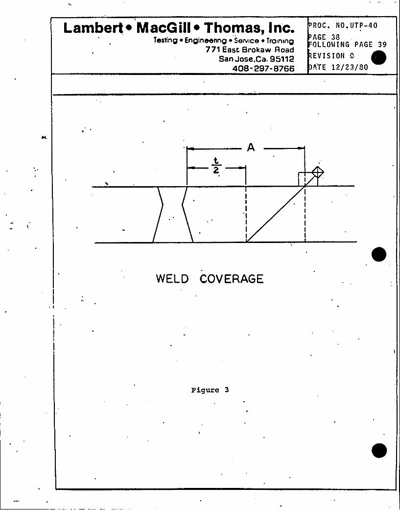
by a back surface echo.C.~C((pp((('P(1. The weld and adjacent base metal for at least t/2 on
I(
both sides of the weld shall be scanned with acalf-'rated
straight (0 ) beam, from an accessible
surface.
Lambert ~ MacQ ill~ Thomas, Inc.Testing ~ Engineering ~ SeNice ~ Training
771 East Brokaw RoadSan Jose,Ca. 95112
408-297-8766
PROC. UTP-40PAGE 26FOLLOWING PAGE 27
REVISION 0
DATE 12/23/80
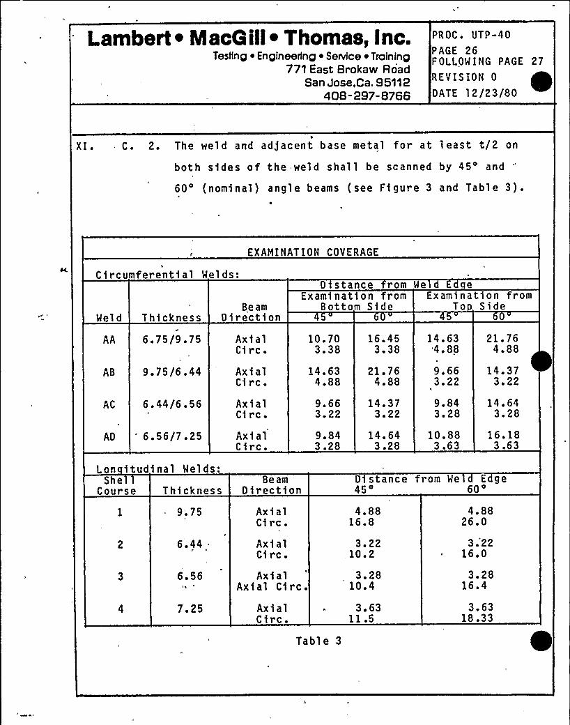
XI. C. 2. The weld and adjacent base metal for at 1 east t/2 on
both sides of the weld shall be scanned by 45'nd60 (nominal) angle beams (see Figure 3 and Table 3).
ircumferential WeldC s:
EXAMINATION COVERAGE
0 stance rom We E e
Weld Thickness
AA 6.75/9.75
9.75/6.44
AC 6 '4/6 '6AD
'~ 56/7.25
Lon itudinal Welds:
BeamDirection
AxialCirc.
Ax i alCirc.AxialCi rc ~
AxialCirc.
10.703.38
14.634.88
9.663.22
9.843.28
16.453.38
21 '64.88
14.373.22
14.643.28
Examination fr omBottom Side
14.63'4. 88
9.663 '29.843.28
10.883.63
21. 764.88
14.373 '2
14.643.28
16.183.63
Examination fromTo Side
SheCourse Thickness
9.75
6.44 .
6.56
7.25
BeamDirection
Ax i alCirc.AxialCi rc.Axial
Axial Circ ~
AxialCirc.
Table 3
Distance45
4.8816.8
3.22.10 '
3.2810.4
3.6311.5
rom We Edge60
4.8826.0
3.'2216.0
3 '816.4
3.6318.33
Lambert ~ MacQ ill~ Thomas, Inc.Testing ~ Engineering ~ SeNlce ~ Training
771 East Brokaw RoadSan Jose,Ca. 95112
40B -297-8766
PROC. UTP-40
PAGE 27FOLLOWING PAGE 28
REVISION 0
DATE 12/23/80
XI. C. 3. The material through which angle beams pass shall be
scanned with a straight beam maintaining a 50% to 80%
FSH back reflection amplitude, where practicable..
4. Index movement between scans shall not exceed 75% of
the search unit dimension measured perpendicular to
the scan direction.D. Scannin Directions
The angle beams shall be directed perpendicular to the
weld in two directions, and in two directions parallel to
the weld (CW, CCW).
E. ~SS d
1. Scan speed shall not exceed four (4) inches per" sec-
ond.
2. Scan speed shall be as specified in Procedure UTP-47.
F. Limita'tions
Physical and/or other limitations, obstructions, etc.,preventing full compliance with XI.C. above shall be
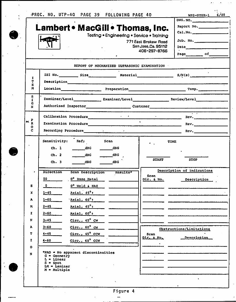
recorded on the Exam)nation Report form (Figure 4).XI I ~ EVALUATION
A. Recordable Indications
1. Any, non-geometric fndication wfth an amplftude\
20% or greater of the Primary Reference Response
level shall be recorded.
Lambert ~ MacGill~ Thomas, Inc.Testing ~ Engineering ~ Service ~ Training
771 East Brokaw RoadSan Jose,Ca. 95112
408-297-8766
PROC. UTP-40
PAGE 28FOLLOWING PAGE 29REVISION 0
DATE 12/23/80
XI I. A: 1. a) Geometric reflectors greater than 50% of DAC
shall be identified and noted on the examination
report and strip chart recording.
2. Clad interface and back wall reflections shall not be
recorded unless, fn the opinion of the examiner, an
l'nusualcondition is 'observed.
3. The extent and location of laminar reflectors found
by straight beam scanning (XI.C.3) which may inter-fere with angle beam examination shall be recorded.
4. Any planar indication exceeding the amplitude of the
calibration planar notch shall be recorded.
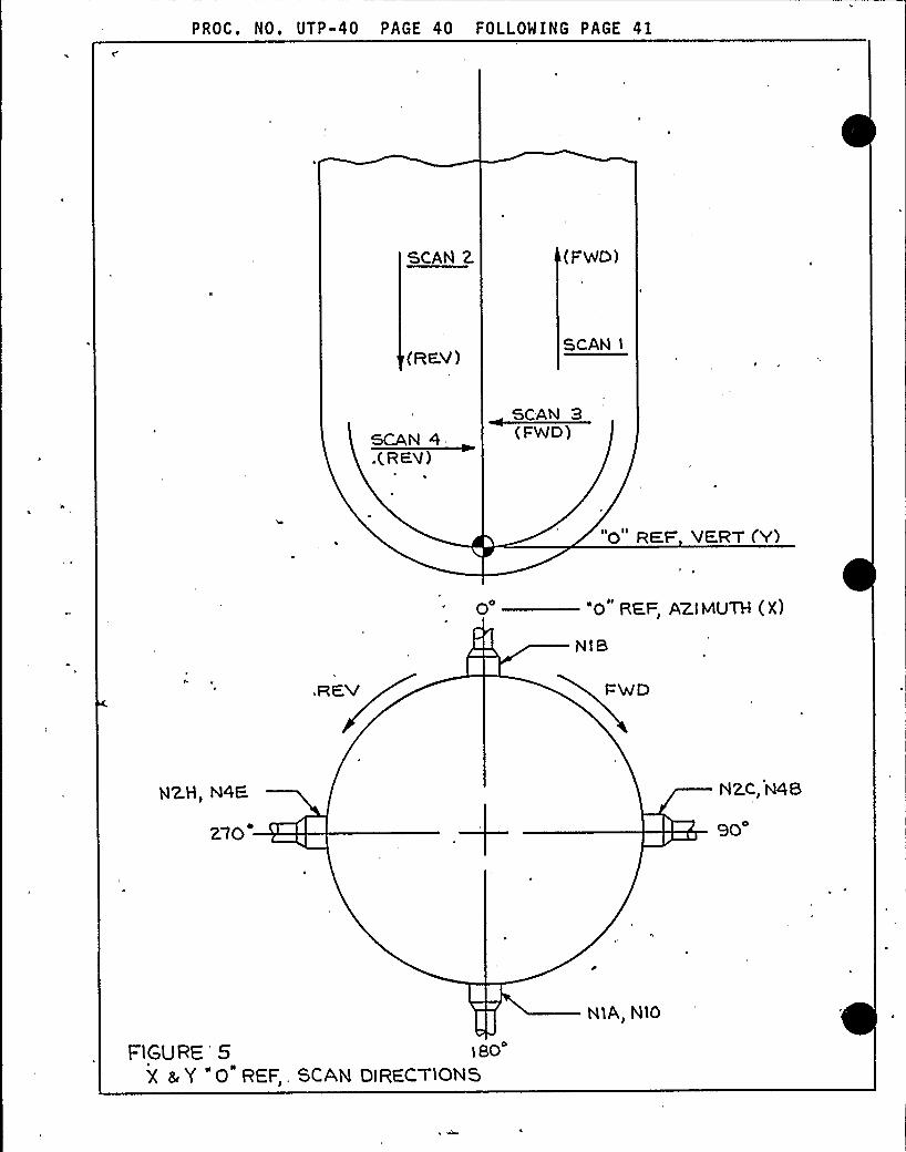
8 ~ Indic'ation recording is based on the scheme of reference
points shown in Figure 5.
1. Depth data shall be obtained from successive scans
perpendicular to the fndication with a minimum 25%
effective transducer width overlap, and data taken
between the 20% DAC points.
2. Length data shall be taken between 20% DAC points.
3. Record the following data for each scan perpendicular
to the indication:
a) Maximum amplitude, with assocfated metal path,
search unit position and sweep location.
Lambert ~ MacQ ill~ Thomas, Inc.Testing ~ Engineering ~ SeNice ~ Training
771 East Brokaw RoadSan Jose,Ca. 95112
408-297-8766
PROC. UTP-40
PAGE 29FOLLOWING PAGE 30
REVISION 0
DATE 12/23/80
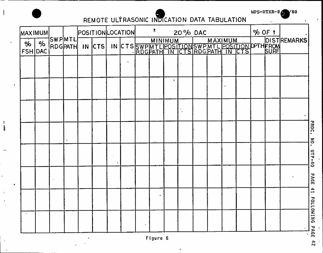
XI I. B. 3. b) Twenty percent of DAC points, with associated
metal path, search unit posftfon, and sweep
1 ocatf ons.
4. Enter the above data on the "Remote Ultrason1c Indf-
cat1on Data Tabulation" form, Figure 6.
C. Evaluation Criteria1. Any indication exceeding 20'5 of the Primary Reference
D1stance Amplitude Curve shall be evaluated by the
examiner to determine the extent, size, location and
shape of the reflector. These parameters shall be
included on the "Notification of Reportable Indica-
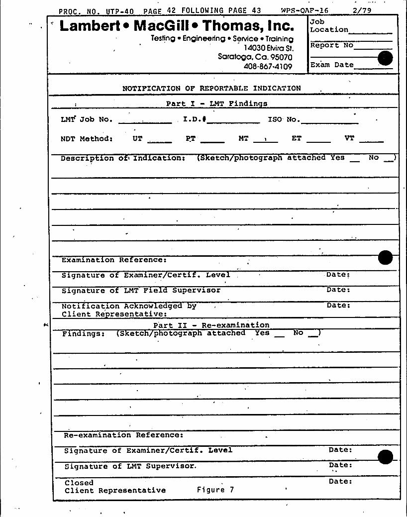
t1on" form, Figure 7, and on the "Ultrasonic Indica-
.tion Data Tabulat1on" form, Figure 6.
;.D. Acce tance Criter1a
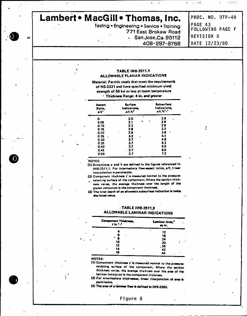
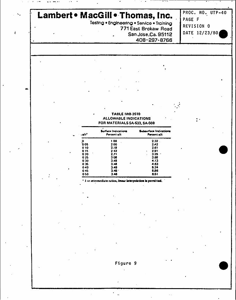
l. Acceptance criteria conta1ned in paragraph 3410 and
3510 of ASME Section XI, 1974 edition, addenda
through Summer 1975, are summarfzed 1n the tables
drawn 1n Figures 8 and 9.
XIII. RECORDS
A. A Report of Mechan1zed Ultrasonic Examination form shall
be prepared for each 1tem examined, and each examination
report shall be related to the appropriate Report of
Ultrasonic Calibration. Typical forms are attached in
Figures 2 and 4.
Lambert ~ MacG ill~ Thomas, inc.Testing Engineering ~ SeNice ~ Troining
771 East Brokaw RoadSan Jose,Ca. 95112
408-297-8766
PROC. UTP-40
PAGE 30FOLLOWING PAGE 31
REVISION 0
DATE 12/23/80
XIII. B. Oscillograph chart records shall be made of allexaminations.
1. Chart records shall include pre and post test cal1-
bration checks made at the same scanning speed as the
examination.
2. Location and pert1nent information shall be writtenon each chart.
a) Pert1nent information includes, but 1s not 11mi-
ted to, 1tem, date, and start and compl,etion
times.
C. Recordin Convent1ons
1. Ultrasonic sCans and the location of fndfcat1ons
shall be recorded according to the convent1ons es-
tablfshed 1n F1gure 5.
D. Other types of recording. devices, such as event or alarm
monitoring may be used to aid the examiner where feas-
fble.XIV. REVIEW
A. Exam1nat1on reports shall be subject to review by an
assfgned LMT Level III examiner for conformity to the
requirements of, this procedure.
1. Following the final LNT review, the reports will be
transm1tted to the WPPSS ISI Field Coordinator forreview by WPPSS and the Authorized Nuclear Inspector.
Lambert ~ MacQ ill~ Thomas, inc.Testing ~ Engineering ~ Senrice ~ Training
771 East Brokaw RoadSan Jose,Ca. 95112
408-297-8766
PROC. UTP-40
PAGE 31FOLLOWING PAGE 32
REVISION 0
DATE 12/23/80
XV. DOCUMENTATION STORAGE AND DISTRIBUTION
A. Original examination documentation shall become the
property of WPPSS upon sign-off by the ISI Field Coordfn-
ator.. Addi tfonal reports which may include examination
documentation as reference material shall be generated
from copies.
B. Ffeld storage facilities shall provide a safe storage
area and access to files shall be limited to the LMT
Field Supervisor, his.designated representatives, WPPSS
representatives, and the Authorfzed Nuclear Inspector.
Lambert ~ MacG ill~ Thomas, Inc.Testing ~ Engineering ~ Senrice ~ Training
771 East Brokaw RoadSan Jose,Ca. 95112
E 40B -297-8766
PROC. NO. UTP-40
PAGE 32FOLLO'lING PAGE 33
REVISION 0
OATE 12/23/80 ~
CONTACT SURFACE
~ 5
-d- I
I II I
6. 75
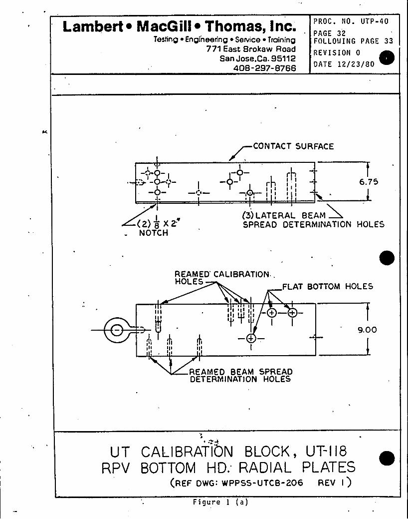
(Z) ~8XZ'OTCH
(S) LATERAL BEAMEDSPREAD DETERMINATION HOLES
REAMED CALIBRATION,HOLES
FLAT BOTTOM HOI ES
I
+I
I I9.00
REAMED BEAM SPREADDETERMINATION HOLES
UT CALIBRATION BLOCK, UT-I l8RPV BOTTOM HD. RADIAL PLATES
(REF DWG: WPPSS-UTCB-206 REV I )Figure 1 (a)
Lambert ~ MacQill ~ Thomas, Inc.Testing ~ Engineering ~ Senrice ~ Training
771 East Brokaw RoadSan Jose,Ca. 95112
408-297-8766
PROC. NO. UTP-40
PAGE 33FOLLOWING PAGE 34
REVISION 0
DATE 12/23/80
O~ryI I-0- t4
~ I
I—0—I—0—
I
III II
I
I'
I
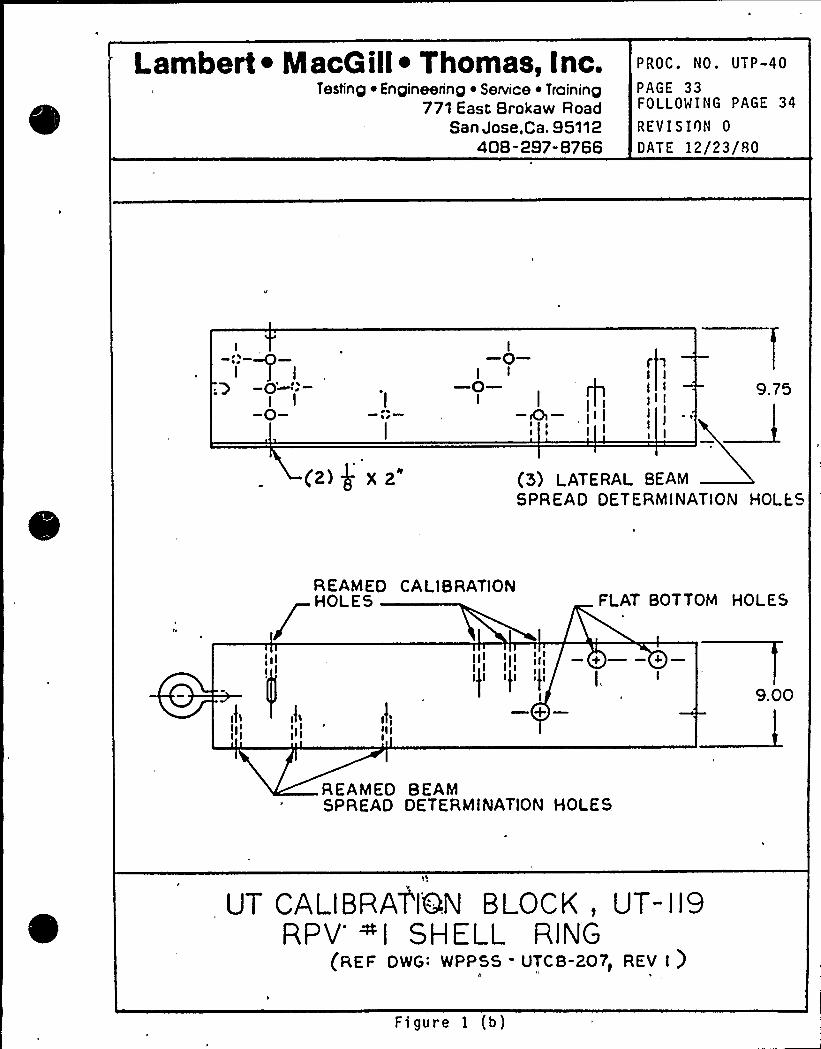
(z)$ xz" (5) LATERAL BEAMSPREAD DETERMINATION HOLKS
SEAMED CA LIB RATIONHOLES FLAT BOTTOM HOLES
I;urI
II
9.00
REAMED BEAMSPREAD DETERMINATION HOLES
UT CALIBRAT'IQN BLOCK, UT-119RPV'l SHELL RING
(REF DWG: WPPSS - UTCB-207) REV I )8 1
Figure 1 (b)
Lambert ~ Macaill ~ Thomas, Inc.Testing ~ Engineering ~ Service ~ Training
771 East Brokaw RoadSan Jose,Ca. 95112
408-297-8766
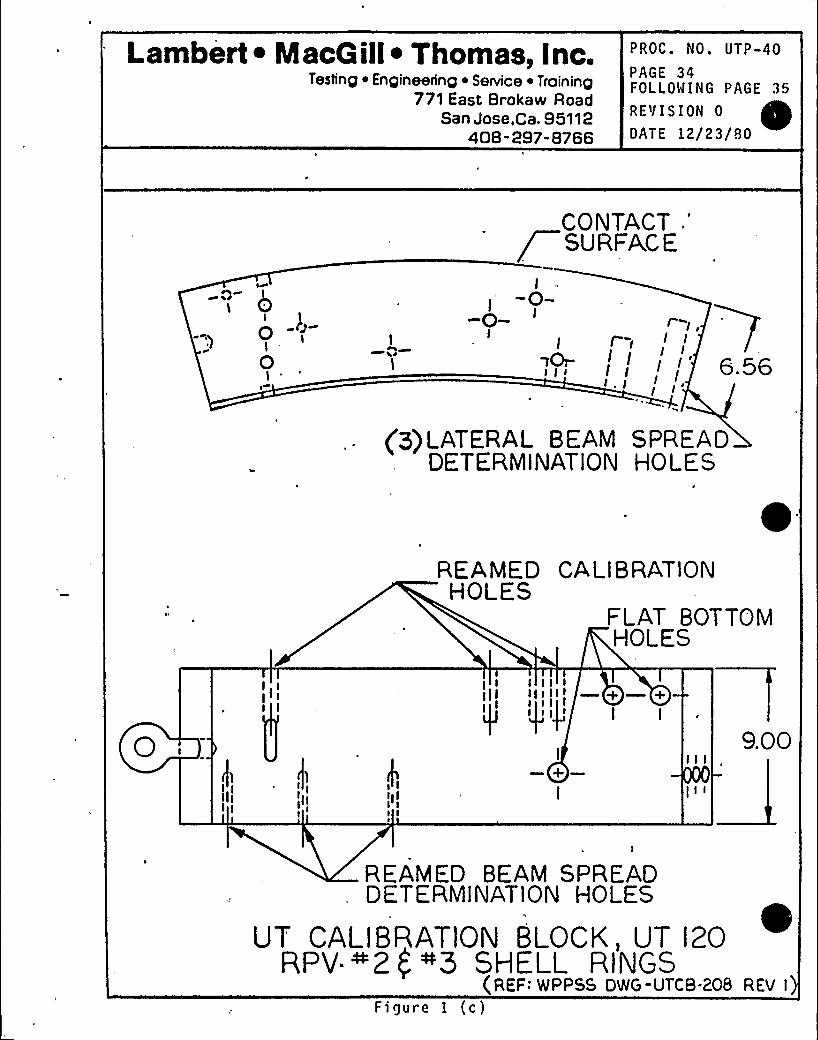
PROC. NO. UTP-40
PAGE 34FOLLOWING PAGE 35
RE'I I S ION 0
DATE 12/23/80
CONTACT .'
SuRPACE
iI'--0- I
I II I10I-
I I I' 56t II
'p)LATERALBEAM SPREADDETERMINATION HOLFS
REAMED CALI8 RATIONHOLES
FLAT BOTTOMHOLES
I IIII I III
I I
I
+I
9.00
REAMED BEAM SPREADDETERMINATION HOLES
UT CALIBRATION BLOCK, UT 120RPV ~2( ~5 SHELL RINGS
(REF: WPPSS DWG-UTCB-208 REV I)Figure 1 (c)
Lambert ~ IacG ill~ Thomas, Inc.Testing ~ EngineeIInp ~ SeNice ~ Trolning
771 East 8rokaw RoadSan Jose,Ca. 95112
408-297-8766
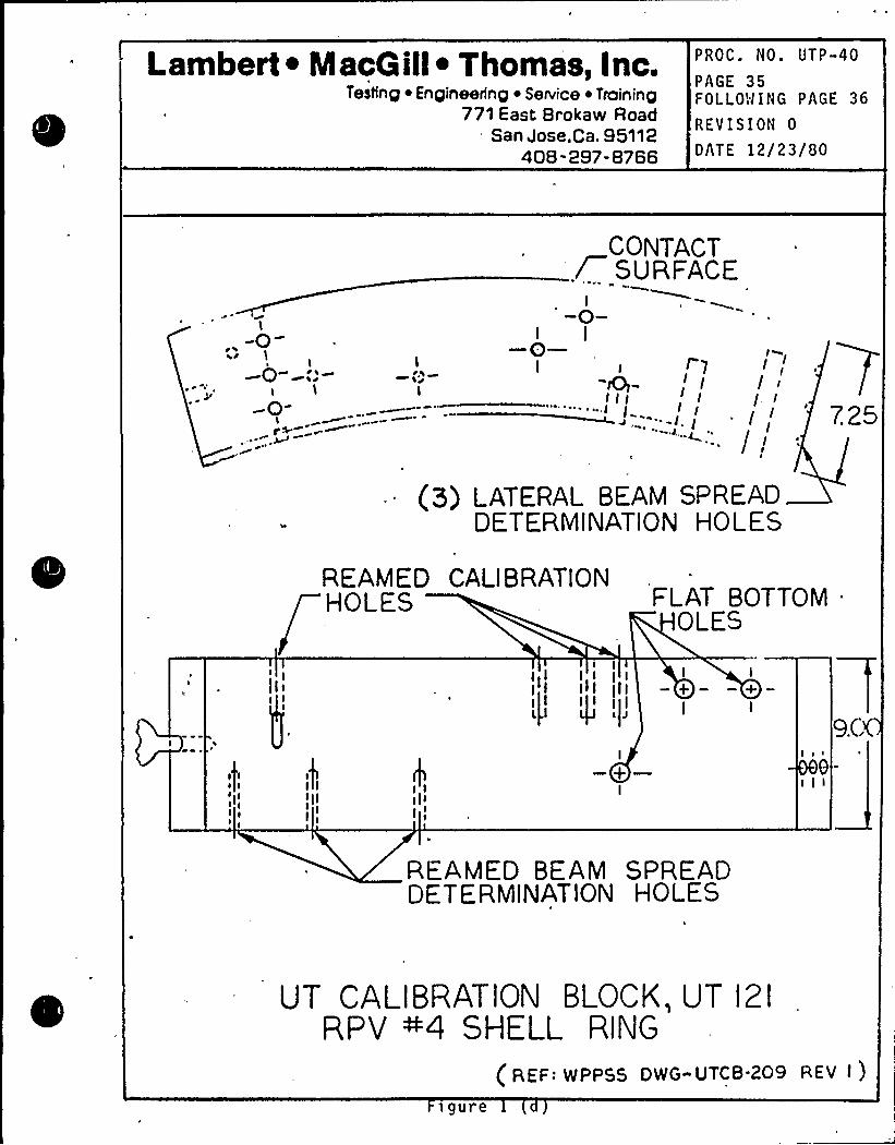
PROC. NO. UTP-40
PAGE 35FOLLO!lING PAGE 36
REVISION 0
OATE 12/23/80
I
,. -0I
I
~ W
I t 7
II II I I--l. (
CONTACT/ SURFACE
-0-I—0—I
Iw(I/I I
I
/ I
7.25C I
(5) LATERAL BEAM SPREADDETERMINATION HOLES
REAMED CALI8 RATIONHOLES
OLES
III II I il II I I
I I
+ — —+I I
tII
I
I
—+—I
REAMED BEAM SPREADDET ERMINATION HOLES
UT CALIBRATION BLOCK, UT 121
RPV ~4 SHELL RING
(REF: WPPSS DWG-UTCB 209 REV I )
figure
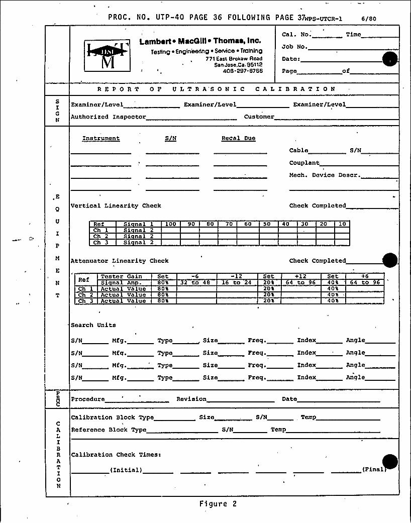
PROC. NO. UTP-40 PAGE 36 FOLLOWING PAGE 37wps-UTcR-1 6/80
Lambert ~ MacQlll~ Thomaa, inc.Testing H Engineering H SeNlce ~ Training
77'l East Bralfaw RoadSan Jose.Ca. 95118
M 406 897-6766
Cal. No.
Job No.
Date:
Page of
REPORT OF ULTRA'SONIC CALIBRATIONSIGN
Examiner/Level
Authorised Inspector
Examiner/Level
Customer
Examiner/Level
Instrument ~SN Recal Due
Cable S/N
Couplantz
Mech. Device Descr.
,EVertical Linearity Check Check Completed
RefCh 1Ch 2Ch 3
Si nal 1 100Si nal 2Si nal 2Si nal 2
90 80 70 60 50 40 30 20 10
Attenuator Linearity Check Check Completed
NRef Tester Gain
Sx na AmSet
0%
-6to
-126 to
Set0%
+12to
Set0% 4 to
Ch 1 Actual ValueC 2 Actua Va ueCh 3 Actua Value
80%0%0$
20$
20%
40%40t40%
Search Units
S/N Hfg . Type Size greg. Index Angle
S/N Mfg.
S/H Hfg.
S/N Mfg.
Type Size
Sire
Sire
Freq.
Freq.
Index
Index
Angle
Angle
PProcedure Revision Date
cALIBRATI0N
Calibration Block Type
Reference Block Type
Calibration Check Times:
(Initial)
Sire
S/N
S/N
Temp
(Final
Figure 2
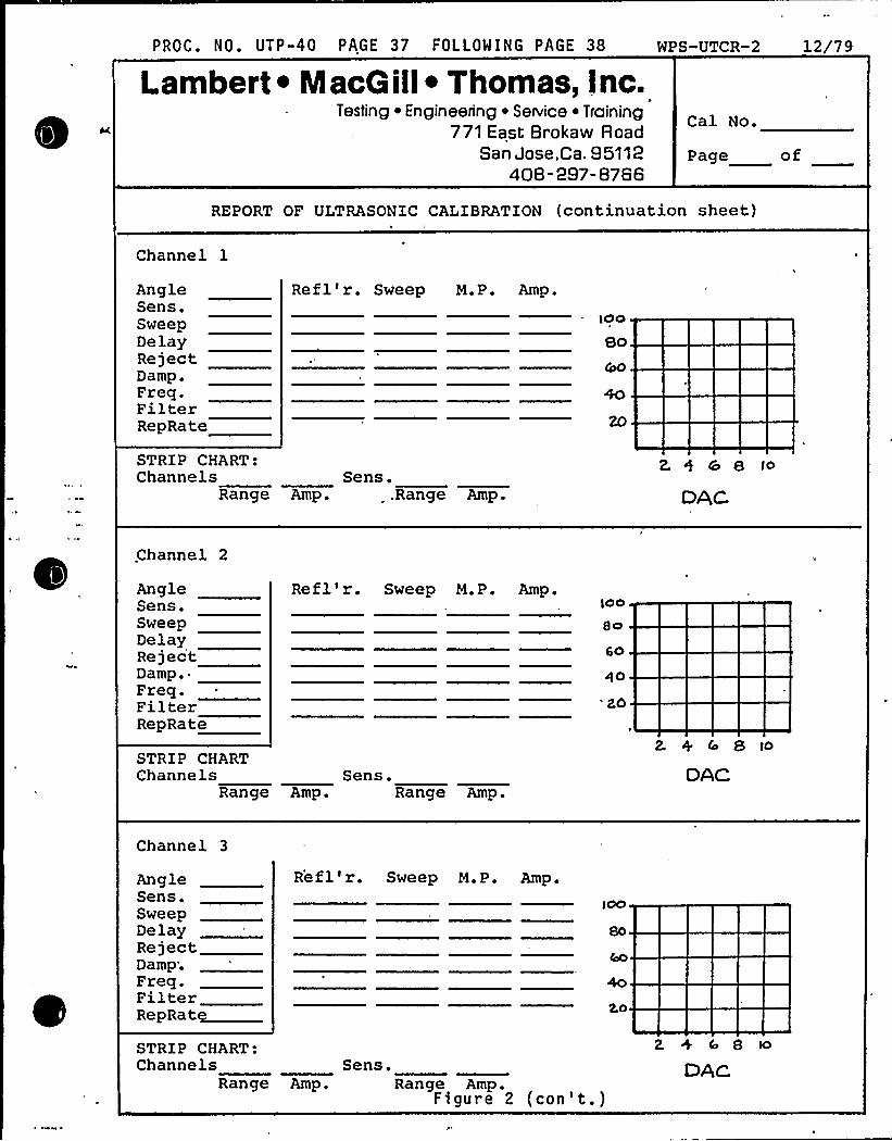
PROC. NO. UTP-40 PAGE 37 FOLLOWING PAGE 38
Lambert ~ NlacQ ill~ Thomas, Inc.D
Testing ~ Engineenng ~ Sennce ~ Troining771 East Brokaw Road
San Jose,Ca. 95112408-297-8766
WPS-UTCR-2 12/79
Cal No.
Page of
REPORT OF ULTRASONIC CALIBRATION (continuation sheet)
Channel 1
AngleSens.SweepDelayRejectDamp.Freq.FilterRepRate
Refl'r. Sweep M.P. Amp.
STRIP CHART:Channels Sans.
Range Amp. .Range Amp.
2. 5 & B l>
DAC
.Channel 2
AngleSens.SweepDelayRejectDamp.Freq.FilterRepRate
Refl'r. Sweep M.P. Amp.100
so
Qo
'20
2. + 4 8 ioSTRIP CHARTChannels Sens.
Range Amp. Range Amp.DAC
Channel 3
AngleSens.SweepDelayRejectDamp;Freq.FilterRepRatg
Refl'r. Sweep M.P. Amp.
2,0
STRI P CHART:Channels Sans.
Range Amp. Range Amp.Figure 2 (con't.)
2 + io 8
DAc
Lambert ~ MacG ill~ Thomas, Inc.Testing ~ Engineenng ~ Seance ~ Training
771 East Brokaw RoadSan Jose.Ca. 95112
408- 297- 8766
ROC. NO.UTP-40
AGE 38DLLOWING PAGE 39
EVISION 0
ATE 12/23/80
A
2
II
I'IIII
WELD COVERAGE
Figure 3
PROC. NO. UTP-40 PAGE 39 FOLLOMING PAGE 40
Lambert ~ MacG ille Thomas, Inc.Testing ~ Engfneertng ~ SeNtt-e ~ Trolnlng
771 East Brokaw RoadSan Jose,Ca. 95118
408-297-8766
WPS-UTXR-l 6/80DWG ~ NO
Report No.
Cal.No.
Job. No.
Date
Bags Gd
REPORT OF MECHANIZED ULTRASONIC EXAMINATION
ITEH
ISI No,
Description
Location
Size Material
Preparation
S/N ts)
Tempg
SIGN
Examiner/Level
Authorized Inspector
Examiner/Level
Customer
Review/Level
PKR0C
Calibration Procedure
Examination Procedure
Recording Procedure
Rev.
Rev.
Rev.
Sensitivityc Reft
Ch. lCh. 2
Ch. 3
dBG
dBG
dBG
Scan
dBG
dBG
dBG,START
TIME
STOP
D rect on
00
0
l 45
l 60
2-45
2-60
3-45
3-60
4-45
4"60
Scan Descript on
0 Base Metal
Oo Weld a HAZ
Axial 45
'Axial 60 t
Axial 45 t
Axial, 60 t
Circ., 45 CW
Circ. 60 CW
Circ. 45 CCW
Circ. 60 CCW
Resu ts Descri tion of IndicationsScan
Dir. t No. Descri tion
Obstructions/LimitationsScan
BtN B No
*NAD BB No apparent discontinuitiesG BB GeometryL BB LinearS BB SpotLM BB LaminarH BB Multiple
Figure 4
PROC. NO. UTP-40 PAGE 40 FOLLOWING PAGE 41
SCAN 2 (FWD)
(Re.v)SCAN 1
.(RKU)e
SCAN 3(FWD)
0 REF YE.R'T CY)
0
NfB
,RE'V 1='W D
2lO
N2C, N4B
90
FlGURE 5 |80X 8 Y "0 REF,, SCAN DIRFCTlONS
NlA, N10
NPS-UTXR-8 80
REMOTE ULTRASONIC IN CATION DATA TABULATION
MAXIMUM
FSH DAC
SWPRDG
MTLATH IN CTS IN CTS
POS IT ION LOCATION
SWPM AXIMUM
MTLA IN CTS
SWP,.MT LRDG'PATH IN
ZO~/o OAC
MINIMUMH
DI STR
RF
%0F t s
REMARKS
CD
CD
llCDIICD
Figure 6m
PROC. NO. UTP-40 PAGE 42 FOLLOWING PAGE 43 MPS-OAF-16 2/79
Lambert ~ MacG ill~ Thomas, Inc.TestIng ~ Engineering ~ Service ~ Training
14030 Eivira St.Saratoga. Ca. 95070
408-867-4109
JobLocation
Report No
Exam Date
LMf Job No.
NOTIFICATION OF REPORTABLE INDICATION
Part I - LMT Findin s
ISO'o.
NDT Methods UT PT MT i ET
Descr p on o i In cat one etc p otograp attac e es No
Exam nat on Re erence:
S gnature o Exam ner Cert . Leve
Signature o LNT P e Supervisor
Notification Ac now e ge yClient Re resentative:
Part II - Re-examinationFin ings: S etc p otograp attac e Yes No
-Date:
Date:
Date:
Re-examination Re ference:
Signature of Examiner/Certif. Level
Signature of LNT Supervisor„
Date:
Date:
ClosedClient Representative Figure 7
Date:
Lambe)I ~ Macaill ~ Thomas, Inc.Testing» Engineering ~ Service ~ Training
771 East Brokaw RoadSan Jose.Ca. 95112
408-297-8766
PROC. NO. UTP-40
PAGE 43FOLLOWING PAGE F
REVISION 0
DATE 12/23/80
TABLE IWB 3511.1ALLOWABLEPLANAR INDICATIONS
Mater)al: Ferritic stee)s that meet the requirementsof NB.2331 and have specified minimum yieldstrength of SO ksi or less at room temperature
'hickness Range: 4 in. and greater
AspectItstlo,mls'urf sc»
Indies tion»,rn.tks
Subsurf sc»Indicstions,~tC.Xs ~
'.
0.050.100 150.200250.300350.400.450.50
2.0 2.02.1
" 2.52.3 292.0 3.22.9 3.03.2 4.13.7 4.03.7 $ .23.7 5S31 0S3.7 72
NOTES:I1) Oimsnsions ~ snd t ere defined in the figures refer~ in
IWB 3511.1. For intermedwte liber~ rstios, rR, lineerInterpol ~ tion is permissibt ~ .
I2) Component thrcknsa r is ms»cured norm»i to the pressure.
retsimng surfsce of the component. Whee the section thick.n«s vwi«, the evwsse thrcknsss over tlw 4nsth of tlwplsnsr indrcstion 4 the component thrckness.
I31 The to tel depth of en allow»bi~ subsurf sc» Indketlon le tvrkethe Ihted vekw.
TABLE IWB 3511.3ALLOWABLELAMINARINDICATIONS
Component Th)eknese,r In.' srt In.
00
10121410
12'lb
30,3042
NOTES:(1) component thkkness r ls meesured nonnsl to the pressure.
retslning surfsce of ttw component. Where the sectionthickness vsriss, the svwsoe thrckn«s over the sree of tlwlsminsr indrcstion ls the component thickness.
I2) For Intwmed4te thkkns«es, linear interpolstlon of wee lspermissible.
I3) Tlwere» of ~ I»miner flaw ls defined In IW54350.
Figure 8
Lambert ~ Macoill ~ Thomas, inc.Testing o Engineering ~ SeNice ~ Training
771 East Srokaw RoadSan Jose,ca. 95112
408-297-8766
PROC. NO. UTP-40
PAGE F
REVISION 0
DATE 12/23/80
TABLE IWB 3510ALLOWABLEINDICATIONS
FOR MATERIALSSA-533, SA S08
Surf sco Ind icatioea 8uhaurf ceo tndicationa.4/v'al caht 0/t portent a/t
00050100 150 200 25030035040045050
1 882,002.182422,713083,483,483.483.48"3.48
2.32,2.422.812.913.2S3.884.134.835.248888et
' ur totcrmcdiata ratiot, Iittoar irttarpoiatiott Ia parrttlt tad.
Figure 9
Date 1/8/79
Revision 0
MHP-2 PSI PROGRAM PLAN
HOT USED
(Purposely left blank)
Ie
Testing ~ Engineering ~ Seaice ~ Troinin g771 East Brokaw Roe 3
San Jose.Ca. 951'.2408-297-876S
WNP»2 PROCEDURE COVER SHEET AND QUALIFICATXON RECG'.=
Procedure No. ~>~ Revision No.
Procedure Title R l TRp A )(ANj AT Oig fry' AQ R
LMT, Inc. QA Revie>v and Approval NQuali= .;: rance Officer)
Client Approval ms~ 5gz xi~~
Au&o.=ized Nuclear Ense .c. ar *ppnrvM
Specific Qualification Record
Component Examiners Date

a
0
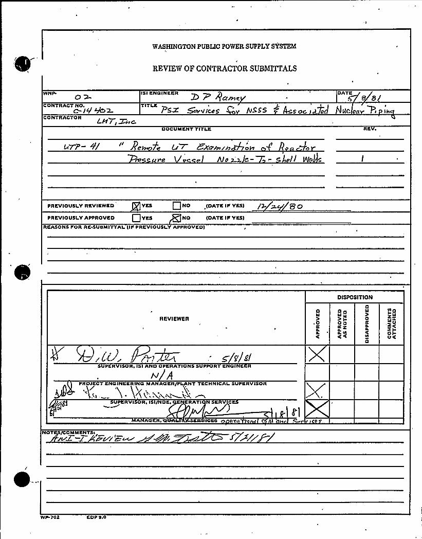
WASHINGTONPUBLIC POWER SUPPLY SYSTEM
REVIEW OF CONTRACTOR SUBMITTALS
WNP
CONTRACT NO+c-iVMwCONTRACTOR LH/ /Xhc
ISI ENGINEER Z)DATKf- +arne ii e a/
TITLE I IP5~ ~V/Cog 'S S S WS OC, eJ )IC g Pc
DOCUMENTTITLE RK
u~- +/' e 7< u~ EX~r rr oI 0
mO~~- .- Pl( e
PREVIOUSLY RKVIKWKD YKS NO (DATK IIc YES) /Q p. 'P Q
PREVIOUSLY APPROVED 0 YES NO IDATKIP YKS)
REASONS I'OR RKNUSMITTALIIS PRKVIOUSLYAPPROVKD)
DISPOSITION
REVIEWERD
).04cC
DDWW
OOC KCL $
DW
0CC
CL
K
D
CCC OI W5x~OXt-VC
g zjdSUPERVISOR, ISI AND OPKRATIONS SUPPORT KNGIN
pPROJECT ENGINEERING MA AGER/PLANT TECHNICALSUPERVISOR
R I Rc I /NDKc RATI K C
A AGERe
NOT /COMMENTScXur'w~
~-
WP 702 EDP leO

h
r
'ambert ~ MacGill~ Thomas, Inc.Testing ~ Engineering Setvice ~ Training
771 East Brokaw RoadSan Jose,Ca, 95112
408-297-8766
PROC ~ UTP-41
PAGE 1
FOLLOWING PAGE 2
REVISION IDATE 2/12/81
TITLE: REHOTE ULTRASONIC EXAHINATION OF REACTORPRESSURE VESSEL NOZZLE-TO-SHELL WELDS
PURPOSE AND SCOPE
A. ~Pur ose
1. This procedure provides instructions for the
assembly, checkout, and gene'r'al operation of the
ultrasonic-system for conducting remote ultrasonic
examinations of the Reactor Pressure Vessel Nozzle-
to-Shell welds.
2. The instructions provided implement the requirementslr 1
of Section XI, ASHE Boiler and Pressure Vessel Code,
1974 edition, Summer 1975 addenda.
B. ~Sco e'. This procedure is applicable to the ultrasonic system
used with the remotely operated mechanical examina-
tion device to conduct the nozzle-to-shell weld
examinations.
2. Assembly and operating instructions for the remotely
operated device are contained in Procedure UTP-44,
"Nozzle-to-Shell Device Assembly and Operating
Piocedure."
g UAL IF I CAT ION:
Approved for use
'ambert ~ MacQ ill~ Thomas, Inc.Testing ~ Engineering ~ Senrice ~ Training
771 East Brokaw RoadSan Jose,Ca. 95112
406-297-8766
PROC. UTP-.41
PAGE 2FOLLOWING PAGE 3
REVISION 1
DATE 2/12/81
B. 3. Instructions for the assembly and operation of the
remote automatic .ultrasonic data recording system are
contained in Procedure UTP-42, "Remote System
Automatic Ultr;asonfc Data Recording."
4 ~ Volumetric examinations shall be performed using
ultrasonic angle and straight beam techniques, as
fol 1 ows:
a) Base metal through which sound will pass shall
receive a 0'ongitudinal beam examination to
detect reflectors which may interfere with the
angle beam examfnations;
b) All welds and one-hal f t of the base metal on the
vessel side of the weld shall receive a 45'nd60'ngle beam exanination, and a 0'traightbeam examination;
c) Other angles may be used where wall thickness or
geometric configuration impedes effective use of
45 and 60'ngle beam examination.
d) The extent of straight and angle beam scanning is
defined in the Scan Plan sections appropriate to
the'specific area to be examin'ed.
'ambert ~ MacQ ill~ Thomas, Inc.Testing ~ Engineering ~ Service ~ Training
771 East Brokaw RoadSan Jose,Ca. 95112
408-297-8766
PROC. UTP-41
PAGE 3FOLLOWI NG, PAGE 4
REVISION 1
DATE 2/12/81
II. REFERENCES
A.' licable Code Editions
1. This procedure complies with the requirements of the
1974 edition of ASHE Boiler and Pressure Vessel Code,
Section XI, Summer 1975 addenda.
B. Su lemental References
1. SNT-TC-1A (June 1975), "Recommended Practice for the
Establishment of Personnel Qualification and Cert)fi-cation Programs."
I
2. LHT, Inc. Procedure QA-6, "Qualification and Certifi-cation'f NDE Personnel."
3 ~ LHT, Inc. Operating and Quality Assurance Hanual,
Revision 12, approved for the WNP-2 Preservice
Inspection by: WPPSS.
I I I. DEFINITIONS
Beam Direction:
Controller:
Index Hovement:
(Increment)
Orientation of ultrasonic beam rela-
tive to vessel axis,,independent of
scan direction.Electronic device controlling mech-
W
anical system motor direction and/or
speed. Hay indicate relative posi-
tion via multi-digit readout.
'odule movement (distance moved)
between scans.
'ambert ~ MacGill~ Thomas, Inc.Testlnp ~ En pineerinp ~ Service ~ Tralnlnp
771 East Brokaw RoadSan Jose,Ca. 95112
40B-297-8766
PROC ~ UTP-41
PAGE 4FOLLOWING PAGE 5
REVISION 1
DATE 2/12/81
III. Module, Search Unit:
Scan Direction:
Search unit cluster including shoes,
wedges, holding framework, couplant
supply manifold.
Motion of. search unit module relativeto vessel axis, independent of beam
direction.X-axis:
Y-axis:
Z-axis:
Circumferential axis of head.
Longitudinal axis of nozzle (radialto vessel) ~
Radial axis of nozzle.
Calibration block thickness.
Weld thickness.
IV;. RESPONSIBILITY
A. The Technical Manager, LMT, Inc. is responsible for the
generation and control of this procedure and shall so
indicate by a dated signature on the procedure cover
sheet.
B. The responsible Level III Field Supervisor, LMT, or his
designated Level III alternate, LMT, shall qualify the
procedure for a particular examination.
V ~ PROCEDURE UAL IF ICATION
This procedure shall be qualifie'd. for specific examinations,
personnel, and equipment by performing'nd documenting a suc-
cessful calibration.
'ambert ~ MacQill~ Thomas, inc.Testing ~ Engineering ~ Seniice Troining
771 East Brokaw RoadSan Jose,Ca. 95112
408-297-8766
PROC.. UTP-41
PAGE 5FOLLOWING PAGE 6
REVISION 1
.DATE 2/12/81
VI ~ PERSONNEL RE U IREHENTS
A. Examiners using this .procedure .shall have levels of
qualifications as per the Procedure Qualfffcatfon.
B. Personnel operating the nozzle-to-shell examination
device shall'e qualified on the equipment and so
certified by an authorized LMT Level III examiner.
1 ~ for each shift of operation, the examination team
shall consist of at least the following personnel:
a) Coordinator/s'upervfsor: Coordinate efforts of
individual team membe'rs and efforts of the examf-
nation team with the owner and appr'oprfate on-
site crafts.b) Console operator: Operrte controllers, record
necessary data for completion of scan data
sheets. Conduct and verify functional checks of
mechanical system.a
c) Observer: Stationed at devfce location to ob-
serve operation of devfce, warn of pending
obstruction, malfunction, etc.
d) Ultrasonic operator: Perform examination cal{-bration, enter appropriate fnformatfon on stripchart recordings, verify proper operation of
ultrasonic system. Certified,to at least
Level II Ultrasonic.
'ambert ~ MacGiil~ Thomas, Inc.Testinp ~ Enplneerlnp ~ SeNlce ~ Tralnlnp
771 East Brokaw RoadSan Jose,Ca. 95112
408-297-8766
PROC ~ UTP-41PAGE 6FOLLOWING PAGE 7
REVISION 1
DATE 2/12/81
VI ~ B. 2. Team personnel may perform the above'uties on a
rotational basis, pr ovided adequate cross trainingand certification levels are existent.
VI I. E UIPMENT AND MATERIALS
A. S stem Descri tion1. The Ultrasonic and Data Acquisition System consists
of three (3) Nortec NDT-131D ultrascopes, a digital-to-analog converter, and an eight (8) channel directwriting strip chart recorder.
2. The ultrascopes have been modified for rack mounting
and remote "slave"'isplay of each instruments'RTpresentation.
3. The BCD data output from the mechanical system con-
trollers is converted to analog form by the digital-to-analog converter and input to the strip chart
recorder.C
4. The eight channel strip chart recorder provides a
permanent record of range and amplitude data of re-
ceived ultrasonic signals (channels 1-6) and the X
and Z axis location of the. device during each scan
(channels 7 and 8).BE Instrumentation Re uirements
1. ,The NDT-131D ultrascopes sha'll meet the followingv
~ performance criteria:
Lambert~ MacGill~ Thomas, Inc.Testing ~ Engineering ~ Se~ice ~ Training
771 East Brokaw RoadSan Jose,Ca. 95112
408-297-8766
PROC. UTP-41
PAGE 7FOLLOWING PAGE 8
REVISION 1
DATE 2/12/81
VI I. B. 1. a) Vertical linearity (screen height) within a5X of
full screen, for at 1 east 807 of the total screen
hefght.
b) Amplitude control accurate over fts useful range
to a20% of the nominal amplitude ratio.2. The NDT-131D ultrascopes shall have their internal
'lignmentand calibration verified within 90 days
prior to use.
a) Records of internal alfgnment and calibration1
'verfffcatfon shall be available at the jobsitefor WPPSS audi t.
3. The digital-to-analog converter shall meet the fol-lowing performance crfteria:a) Repeat SwRI controller readout (last four digits)
0000 through 9999, a0 counts.
b) Analog voltage output proportional to BCD input
at the rate of 100 counts/volt, a0.01 v and 1000
counts/volt, +0.01 v', switch selectable.
4 ~ The direct writing analog strip chart recorder shal,l\
meet the followfng performance criteria:a) Frequency response at 40 mm - dc to 60 Hz, xl
divisi'on.
b) Frequency response at 10 divisions amplitude - dc
to 125 Hz, a1 division.
Lambert ~ MacGill~ Thomas, Inc.Testing ~ Engineering ~ Senile ~ Training
771 East Brokaw RoadSan Jose,Ca. 95112
408" 297-8766
PROC. UTP-41PAGE 8FOLLOWING PAGE 9
REVISION 1
DATE 2/12/81
V ~ B. 4. c) Non 1 fnearity may not exceed 0.35% of full scale.
5. The strip chart recorder shall have its internalalignment and calibration verified withfn 180 days
prf or to use.
a) Records of. internal alignment and calibratfonverification shall be available at the jobsitefor WPPSS audit.
C. Search Unit and Wed e Re ufrements
1. Search unit essential properties shall be certifiedby the manufacturer including bandwidth, damping,
center frequency within 10% of nominal, and relativegain.
a) A record of search unft properties shall be
available at the jobsite for WPPSS audit.2. Wedges shall yield refracted angles of 45', x2', and
60', +3', to be acceptable for use.
a) Refracted angles shall be determined in the cali-
brationn
block daily, prior to use, as instructedProcedure in UTP-14, "Beam Spread and Refracted
Angle Determination."
b) Other angles may be used for evaluation and
shall be within a3'f the nominal wedge angle.
3. The results of examinations performed with angle beam
search unfts which meet the above requirements are
acceptable provided the search unit beam angle on
subsequent checking fs within x3'f nominal.
Lambert~ MacQill ~ Thomas, Inc.Testing ~ Engineering ~ Senrice ~ Training
771 East Brokaw RoadSan Jose,Ca. 95112
408-297-8766
PROC. UTP-41
PAGE 9FOLLOWING PAGE 10
REVISION 1
DATE 2/12/81
VI I. C. 3. Shoul d thf s tol erance not be met on subsequent check-
ing, determinat1on of the need for re-examination
shall be made and the basis for the decision docu-
mented.
4. Search units shall be 0.75 1nch diameter with a
central frequency of 2.25 NHz, a10%.
a) Search units of other sizes and/or frequencies
may be used for evaluation and/or in unusual
circumstances. Such use shall be documented by
an approved Field=Change to this procedure in
accordance with the.requfrements of LNT Procedure
QA-5.
D. ~Cou 1 ant
1. Couplant used to conduct exam1nations governed by
th1s procedure shall be "reactor grade" deionized
water.
2. Wett1ng agents such as Kodak "Photo-flo" may be added
to the couplant,water to afd fn coupling efficiency .
E. .Calibration Blocks
1. -Calibration blocks shall be of the form and dimen-
sions of Ffgures la), 1b) or'c).2. Select the appropriate calibration block for a
specifi'c nozzle-to-shell weld examination according
to the following:
Lambert ~ MacQillI Thomas, inc.Testing ~ Engineering ~ Senrice ~ Troinfng
771 East Brokaw RoadSan Jose,Ca. 95112
408-297-8766
PROC. UTP-41
PAGE 10FOLLOW I NG PAGE 11
REVISION 1
OATE 2/12/81
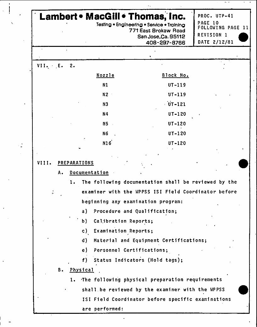
VI I ~ - E ~ 2 ~
Nozzle
N2 "
N3
N4
N5
N6
N16
Block No.
UT-119
UT-119
UT-121
UT-120
UT-120
UT-120
UT-120
VI I I. PREPARATIONS
A. Document at i on
1. The following documentation shall be reviewed by the
examiner with the WPPSS ISI Field Coordinator before
beginning any examination program:
a) Procedure and guali fication;b) Cal„,ibration Reports;
c) Examination Reports;
d) Haterial and Equipment Certifications;e) Personnel Certifications;
f) Status Indicators (Hold tags);H
B. ~Ph steal
1. -The following physical preparation requirements
shall be reviewed by the examiner with the WPPSS
ISI Field Coordinator before specific examinations
are performed:
Lambert ~ MacG ill~ Thomas, Inc.Testing ~ Engineering ~ Service ~ Training
771 East Brokaw RoadSan Jose,ca. 95112
408-297-8766
PROC'TP-41PAGE 11FOLLOWING PAGE 12
REVISION 1
DATE 2/12/81
VI I. B. 1. a) Insulation removal;
b) OSHA requirements (1 adders, lighting, fresh air,etc.);
c) Cleanup requirements;
d) Safety precautions;
e) Electrical outlets - 110-120v AC, 30 amp, single
phase, minimum of two (2) required;
f) Air or nitrogen supply .
C ~ Surface Pre aration
1. Examination surfaces shall be free from weld spatter
or any other surface condition which will impede free
movement of the search unit modul e.
2. Examination surfaces shall be free from extraneous
materials or other conditions which, in the opinion
of the examiner, will impair the performance of a
meaning f ul exami nat i on.
IX ~ LIMITATIONS
This procedure is limited to remotely operated ultrasonic
examinations of nozzl e-to-shell welds in the reactor pressure
vessel, using contact methods, conducted from the vessel OD
surface.
Lambert ~ MacG ill~ Thomas, Inc.Testing ~ Engineering ~ Service ~ Training
771 East Brokaw RoadSan Jose,Ca. 95112
408-297-8766
PROC ~ UTP-41
PAGE 12FOLLOWING PAGE 13
REVISION 1
DATE 2/12/81
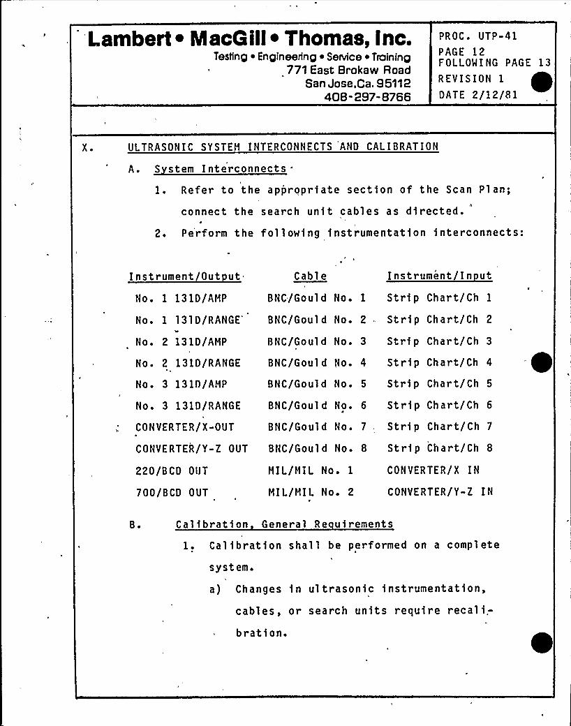
X ~ ULTRASONIC SYSTEH INTERCONNECTS AND CALIBRATION
A. S stem Interconnects"
1. Refer to the appropriate section of the Scan Plan;
connect the search unit cables as directed.
2. Perform the following instrumentation interconnects:
Instrument Out ut Cable Instrument In ut
No. 1 131D/AMP
No. 1 131D/RANGEI
No. 2 131D/AHP
BNC/Gould No. 1 Strip Chart/Ch 1
BNC/Gould No. 2 Strip Chart/Ch 2
BNC/Gould No. 3 Strip Chart/Ch 3
No. 2 131D/RANGE BNC/Gould No. 4 Strip Chart/Ch 4
No. 3 131D/AHP
No. 3 131D/RANGE
CONVERTER/X-OUT
BNC/Gould No ~ 5 Strip Chart/Ch 5
BNC/Gould No. 6 Strip Chart/Ch 6
BNC/Gould No. 7 Strip Chart/Ch 7
CONVERTER/Y-Z OUT BNC/Gould No. 8 Strip Chart/Ch 8
220/BCD OUT
700/BCD OUT
MIL/HIL No. 1
MIL/MIL No. 2
CONVERTER/X IN
CONVERTER/Y-Z IN
B ~ Calibr ation General Re uirements
1. Calibration shall be performed on a complete
system.
a) Changes in ultrasonic instrumentation,
cables, or search units require recali.-
bration.
'ambert ~ MacG ill~ Thomas, Inc.Testing ~ Engineering ~ SeNice ~ Training
771 East Brokaw RoadSan Jose,Ca, 95112
408-297-8766
PROC. UTP-41
PAGE 13FOLLOWING PAGE 14
REVISION 1
D ATE 2/1 2/81
X ~ B. 1. b) An extension of up to six feet may be added to
the search unit cables for calibration purposes,
and removed prior to conducting the examination.
(1) When such extension is used, ultrasonic
responses obtained with and wfthout the ex-
tension shall be compared during the firstcalibration and so noted on the "Report of
Ultrasonic Calibration."
c) A'hange in qualified personnel or recording
instrumentation shall require calibrationverification.
J
d) Instrument vertical linearity and amplitude
control verifications need not be made with
the search unit used for examination.
'e) Calibration checks shall be performed before
and after each examination and at intervals
not to exceed 12 hours.
2. Verify instrument vertical linearity as follows:
a) Position an angle beam search unit on the
calibration block to obtain echoes from the
T/2 and 3T/4 holes in a 2: 1 amplitude ratio.b) Adjust the amplitude control to position the
larger indication at 100$ of calfbrated s'cale
Lambert ~ Mace ill~ Thomas, Inc.Testing ~ Engineering ~ SeNlce ~ Troinlng
771 East Srokaw RoadSan Jose,Ca, 95112
408-297-8766 „,
PROC ~ UTP-41'AGE14
FOLLOWING PAGE 15
REVISION 1
DATE 2/12/81
X ~ B. 2. b) and note the ampl itude of the smaller on the
calibration form as estimated to the nearest 1%
of calibrated screen height.
c) Vary the amplitude control so that the response
of the larger signal is successively lowered in
10% increments to,10% of full calibrated scale.
At each incremental setting note the response of
both fndfcations.
d) Acceptable instrument alignment fs verified when
the ratio of the two responses remains two-to-one
over the range of amplitude.adjustment within S%%d
of calibrated full scale.
3. Verify the amplitude control accuracy as follows:
a) Position an angle beam search unit on the basic
cal'ibratfon block to obtain a peaked echo from
the T/2 hole at 80'$ of full calibrated scale.
b) Adjust the amplitude control to decrease the gain
by 6 dB and 12 dB. Note the echo amplitude at
each setting. Estimate the amplitude to 1% of
full calibrated scale.
c) Adjust the amplftude control to position the T/2
response to 20% of full calibrated scale. Then
adjust the amplitude control to increase the gain
12 dB. Record the response as estimated to 1% o
full calibrated seal'e.
Lambert ~ MacG ill~ Thomas, Inc.Testing ~ Engineering ~ Sennce ~ Training
771 East Brokaw RoadSan Jose,Ca. 95112
408-297-8766
PROC. UTP-41
PAGE 15FOLLOWING PAGE 16
REVISION 1
DATE 2/12/81
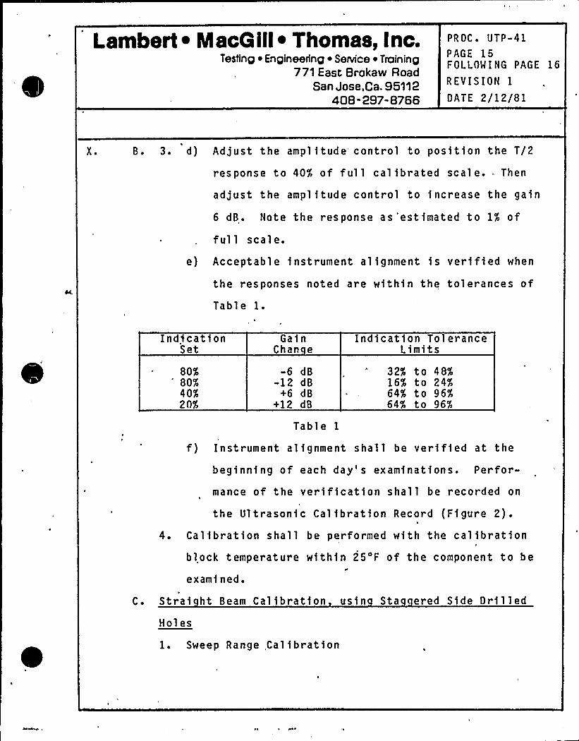
X ~ B. 3. d) Adjust the amplitude control to position the T/2
response to 40% of full calibrated scale. Then
adjust the amplitude control to increase the gain
6 dB. Note the response as'estimated to 1% of
full scale.
e) Acceptable instrument alignment is verified when
the responses noted are within the tolerances of
Tabl e l.
IndicationSet
80%80%40$20%
GainChan e
-6 dB-12 dB
+6 dB+12 dB
Table 1
Indication ToleranceLimits
32% to 48%16% to 24%64% to 96%64% to 96%
f) Instrument alignment shall be verified at the
beginning of each day's examinations. Perfor-
mance of the verification shall be recorded on
the Ultrasonic Calibration Record (Figure 2).4. Calibration shall be performed with the calibration
block temperature within 25'F of the component to be
examined.
C. Strai ht Beam Calibration usin Sta ered Side DrilledH01es
1. Sweep Range Calibration
'ambert ~ MacGill~ Thomas, Inc.Testing ~ En gineenng ~ Senrice ~ Training
771 fast Brokaw RoadSan Jose,CB. 95112 .
408" 297-8766
PROC. UTP-41
PAGE 16FOLLOWING PAGE 17
REVISION. 1
DATE 2/12/81
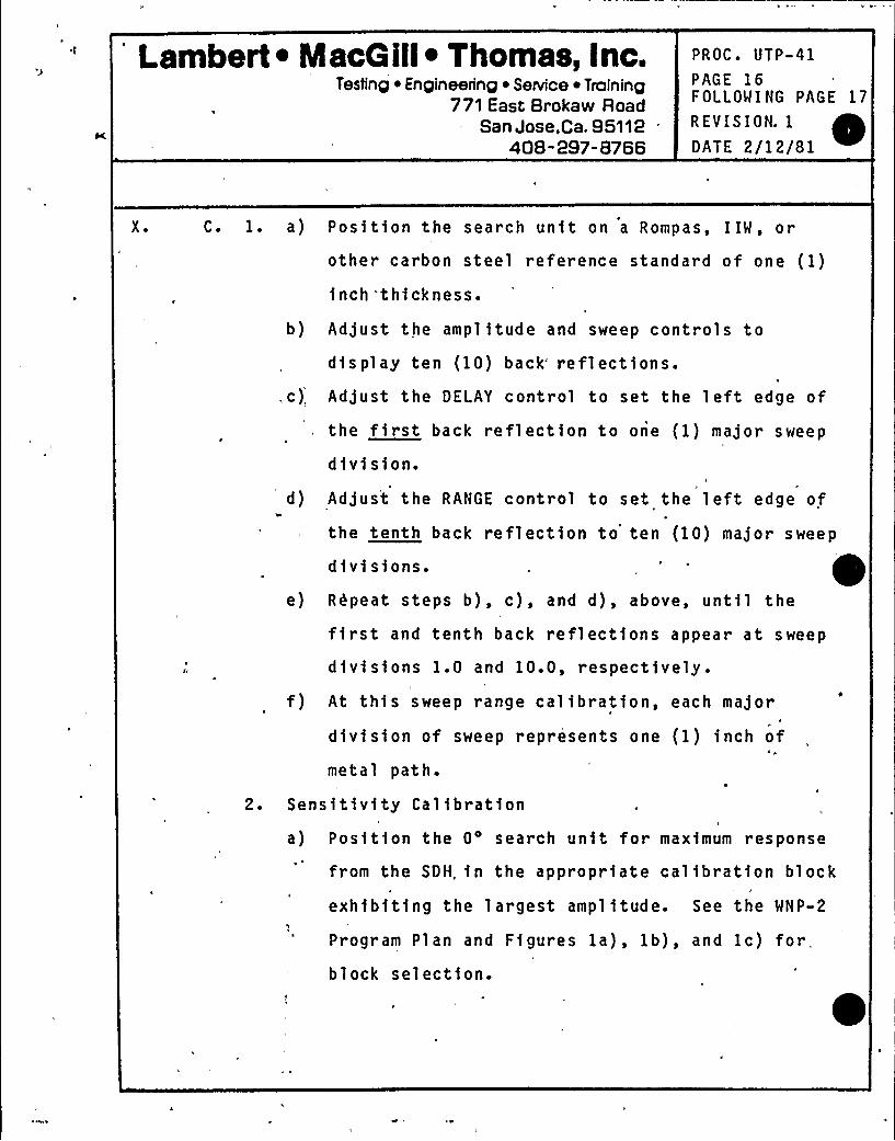
X ~ C. l. a) Position the search unit on a Rompas, IIW, or
other carbon steel reference standard of one (1)
inch'thickness.
b) Adjust the amplitude and sweep controls to
display ten (10) back" reflections.,c) Adjust the DELAY control to set the left edge of
the first back reflection to one (1) major sweep
division.d) Adjust the RANGE control to set the left edge of
the tenth back reflection to ten (10) major sweep
divisions.
e) Repeat steps b), c), and d), above, until the
first and tenth back reflections appear at sweep
divisions 1.0 and 10.0, respectively.
f) At this sweep range calibration, each major
division of sweep represents one (1) inch of
metal path.
2. Sensitivity Calfbration
a) Position the 0'earch unit for maximum response
from the SDH, fn the appropriate calibration block
exhibiting the largest amplitude. See the WNP-2
Program Plan and Figures la), lb), and lc) forblock selection.
Lambert ~ MaoQ ill~ Thomas, Inc.Teston p ~ Enpineerinp ~ SeNlce ~ Trctninp
771 East Brokaw RoadSan Jose,Ca. 95112
408-297-8766
PROC ~ UTP-41
PAGE 17FOLLOWING PAGE 18
REVISION 1
DATE 2/12/81
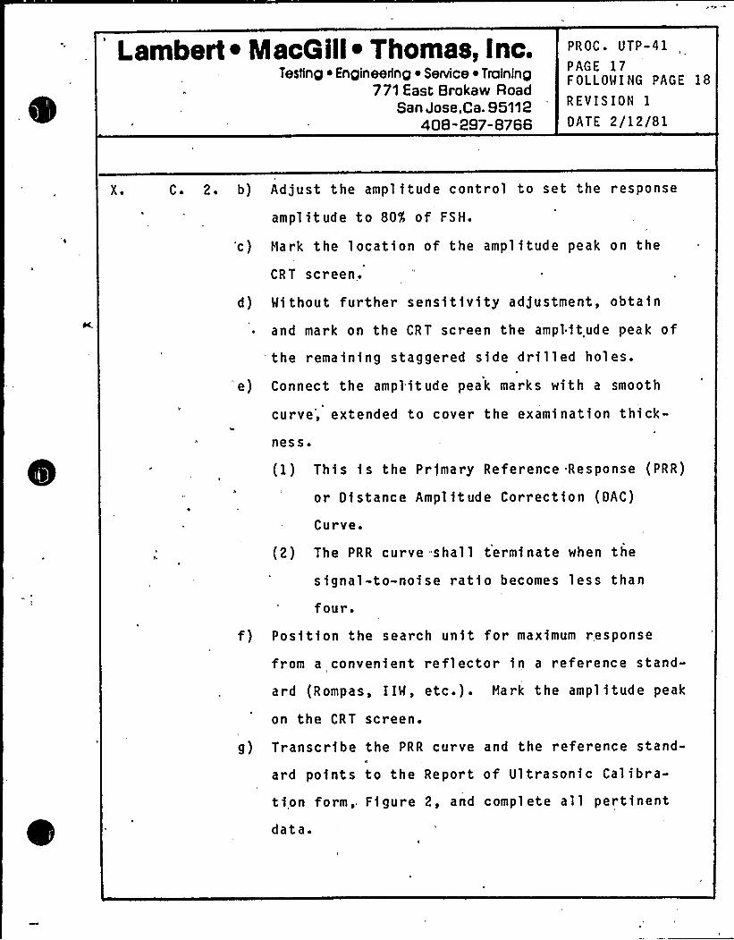
X. C. 2. b) Adjust the amplitude control to set the response
amplitude to 80'Ir of FSH.
'c) Mark the location of the amplitude peak on the
CRT screen.
d) Without further sensitivity adjustment, obtain
and mark on the CRT screen the amplitude peak of
the remaining staggered side drilled holes.
'e) Connect the amplitude peak marks with a smooth
curve', extended to cover the examination thick-ness.
(1) This is the Primary Reference Response (PRR)
or Distance Amplitude Correction (DAC)
Curve.
(2) The PRR curve shall terminate when the
signal-to-noise ratio becomes less than
four.
f) Position the search unit for maximum r esponse
from a convenient reflector in a reference stand-
ard (Rompas, IIW, etc.). Mark the amplitude peak
on the CRT screen.
g) Transcribe the PRR curve and the reference stand-
ard points to the Report of Ultrasonic Calibra-
tion form, Figure 2, and complete all pertinent
data.
Lambert ~ MacG ill~ Thomas; Inc.Testing ~ Enpineerfnp ~ Service ~ Training
771 East Brokaw RoadSan Jose,Ca. 95112
408-297-8766
PROC. UTP-41PAGE 18FOLLOWING PAGE 19
REVISION 1
DATE 2/12/81
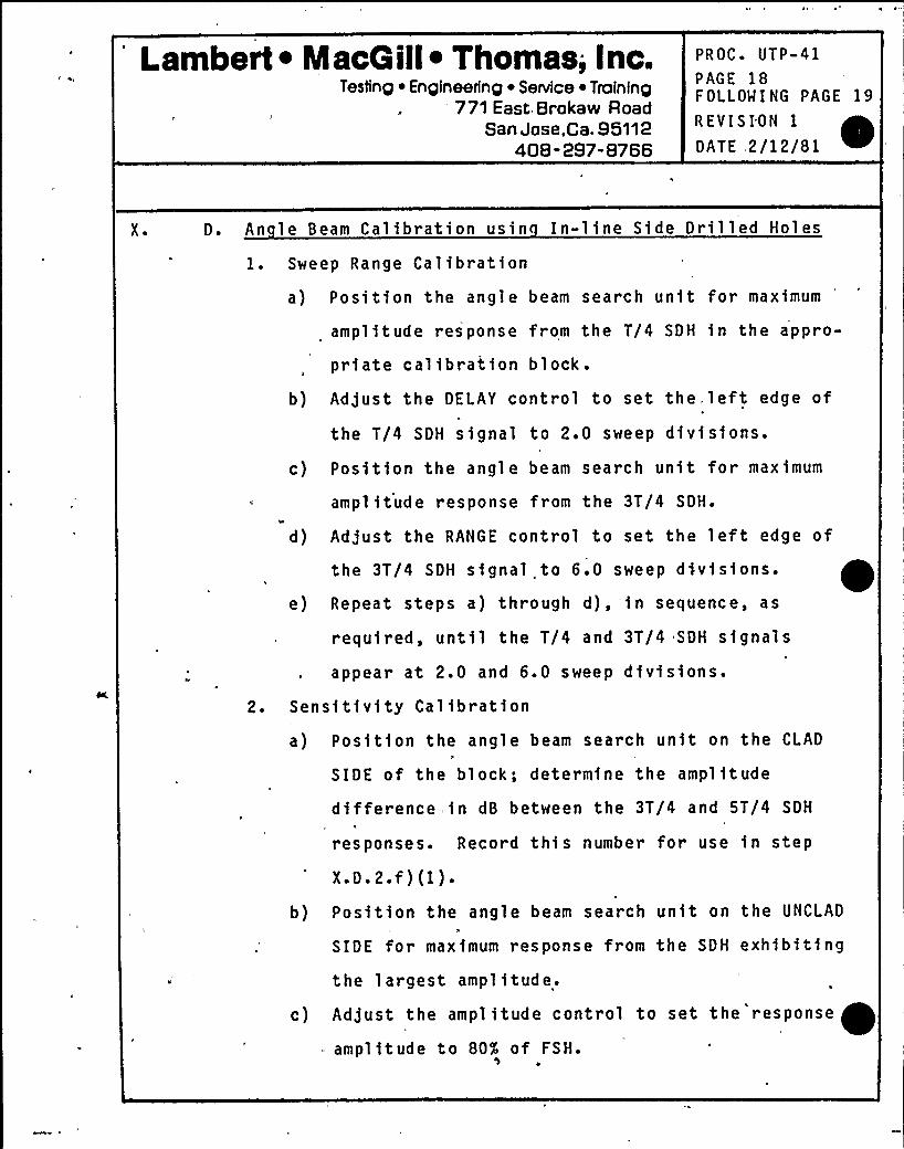
X ~ D. An le Beam Calibration usin In-line Side Drilled Holes
1. Sweep Range Calibration
a) Position the angle beam search unit for maximum
amplitude response from the T/4 SDH in the appro-
priate calibration blocke
b) Adjust the DELAY control to set the, left edge of
the T/4 SDH signal to 2.0 sweep divisions.
c) Position the angle beam search unit for maximum
amplitude response from the 3T/4 SDH.
d) Adjust the RANGE control to set the left edge of
the 3T/4 SDH signal to 6.0 sweep dfvfsfons.
e) Repeat steps a) through d),'in sequence, as
required, until the T/4 and 3T/4 SDK signals
appear at 2.0 and 6.0 sweep divisions.2. Sensftfvfty Calfbration
a) Position the angle beam search unft on the CLAD
SIDE of the block; determine the amplftude
difference in dB between the 3T/4 and 5T/4 SDH
responses. Record this number for use in step
X. D ~ 2. f ) (1) ~
b) Position the angle beam search unit on the UNCLAD
SIDE for maxfmum response from the SDH exhibiting
the largest amplitude.
c) Adjust the amplitude control to set the response ~amplitude to 80% of FSH.
Lambert ~ MacG ill~ Thomas, inc.Testing ~ Engineering ~ Service ~ Training
771 East Brokaw RoadSan Jose,Ca. 95112
408-297-8766
PROC. UTP-41
PAGE 19FOLLOWING PAGE 20
REVISION 1
DATE 2/12/81
X ~ D. 2. d) Hark the location of the amplitude peak on the
CRT screen.
e) Without further sensitivity adjustment, obtafn
and mark'n the CRT screen the amplitude peak of
the remaining SDH, except the 5T/4 position.
f) To obtain the amplitude of the ST/4 SDH, positionthe'ngle'eam search unit for maximum response
amplitude from the 3T/4 SDH.
(1) Decrease the sensitivity control by the dB
value obtained in a) above.
(2) Hark this amplitude peak at 10.0 sweep divi-sions.
(3) Return the amplitude control to the value of
2.c) above.
g) Connect the amplitude peak marks with a smooth
curve.
(1) This fs the Primary Reference Response (PRR)
or Distance Amplitude Correctfon (DAC),
Curve.
(2) The PRR curve shall terminate when the
signal-to-noise ratio becomes less than
four ~
Lambert ~ MacQ ill~ Thomas, Inc.Testing ~ Engineering ~ Service iTraininp
771 East Brokaw RoadSan Jose,Ca. 95112
408-297-8766
PROC. UTP-41
PAGE 20FOLLOWING PAGE 21
REVISION 1
DATE 2/12/81
X ~ D. 2. h) Position the search unit for maximum ampl itude r-esponse from a convenient reflector in a refer-e'nce standard (Rompas, IIW, etc.). Hark the
amplitude peak on the CRT screen.
i) Position the search unit for maximum amplitude
response from the far (clad) side square notch.
j) Hark the square. notch amplitude peak on the CRT
screen.
(1) The square notch signal is to be considered
when evaluating planar reflectors perpendic-
ular to the examination surface, at or near
the far surface.
k) Transcribe the PRR curve and the reference stand-
ard points to the Report of Calibration form,
Figure 2, and complete all pertinent data.
E. Beam S read Determination
Perform beam spread determinations according to Procedure
UTP-14.
F. Di ital Calibrations
1. Straight (0 ) Beam
a) Measure the distance from the block surface to
the near edge of the T/4 SDH. (This information
may'be obtained from the WPPSS as-built UT cali-bration b1ock dran1ngs UTC8-207, 208 and 209.) ~
Lambert ~ MacQ ill~ Thomas, Inc.Testing ~ Engineering ~ Service ~ Trofnfng
771 East Brokaw Road-San Jose,Ca. 95112
408-297-8766
PROC. UTP-41
PAGE 21FOLLOWING PAGE 22
REVISION 1
DATE 2/12/81
X ~ F. 1. b) Measure the block thickness. (This,infor'mation
may be obtained from the above calibration block
drawf ngs. )
c)
d)
e)
Depress 1st, 20, SINGLE, SOUNDPATH pushbuttons.
Position the 0'earch unit for maximumre'sponse''I
'I
amplitude from the T/4 hole.
Adjust the D-l control such that the RANGE gate
triggers on the T/4 SDH signal.
2 ~
f) Adjust the ZERO control to set the digital read-
out to the distance value obtained fn a) above.
g) Position the 0'earch unft for maximum response
ampl ftude from the far surface of the block.
h) Adjust the D-1 control such that the RANGE gate
triggers on the back surface signal (the farsurface of the block).
i) Adjust the CAL control to set the digital readout
to the block thickness.
j) Repeat steps d) through f), as required, untilthe digital readout is correct for each, metal
path a0.01 inch.
Angle Beam
a) Determine refracted beam angle (Q) according to
Procedure UTP-14.
Lambert.I MacG ill~ Thomas, Inc.Testing ~ Engineering ~ Service ~ Training
771 East Brokaw RoadSan Jose,Ca. 95112
408-297-8766
PROC ~ UTP-41
PAGE 22FOLLOWING PAGE 23
REVISION 1
DATE 2/12/81
X ~ F. 2. b) Heasure the distance (depth) of the T/4 SDH from
the block surface to the hole centerline. (Th1s
information may be obta1ned from the WPPSS as-
bu1lt UT calibration block drawfngs.)'5
c) Heasure the block th1ckness. (Thi s 1 nformat1on
may be obtained from the WPPSS as-built UT cali-bration,block drawings.)
d) Adjust the OFFSET control to set the "step" fn
the baseline to sweep dfvfs1on "0".
e) Calculate the metal path to the T/4 SDH and the
far notch as follows:
Meta1 Path = P—11
f) Depress 1st, 20, SINGLE, SOUNDPATH, and 45 or 60
pushbuttons, as approprfate.
g) Posit1on the angle beam search unit for maximum
response ampl ftude from the T/4 SDH.
h) Adjust the D-1 control such that the RANGE gate
triggers on the T/4 SDH.
i,} Adjust the ZERO control to set the digital read-
out to the calculated metal path value of e)
above.
j) Posft1on the angle beam search unit to obta1n
maximum response amplitude from the far notch.
Lambert ~ MacG ill~ Thomas, Inc.Testing ~ Engineering ~ Service ~ Training
771 East Brokaw RoadSan Jose,Ca. 95112
408-297-8766
PROC. UTP-41PAGE 23FOLLOWING PAGE 24
REVISION 1
DATE 2/12/81
X ~ F. 2. k) Adjust the D-1 control such that the RANGE gate
triggers on the notch signal.
1) Adjust the CAL.,control to set the digital readout
to the calculated metal path of e) above.
m) Repeat steps g) through 1) until the digitalreadout is correct for each metal path, +0.01
inch.
G. Stri Chart Recorder Calibration
Calibrate each strip chart recorder channel to the appro-
priate 131D and digital-to-analog converter output ac-
cording to Procedure UTP-42.
XI. PERFORMANCE
A. Calibration Verification1. Calibration shall be performed using the responses of
the basic calibration block at the beginning of each
day's examination, with any change in test personnel,
and at intervals not to exceed 12 hours.
2. Calibration checks shall be performed using the re-
sponses of either the basic calibration block or the
reference standard before and after each examination,
or at intervals not to exceed four (4) hours;
3. Response within 2 dB and 5% of the original amplitude
and sweep range values respectively shall 0'e con-
s1dered proof of calibration. An unacceptable
Lambert ~ MacG ill~ Thomas, inc.Testing ~ Eng|neerfng ~ Senrice ~ Training
771 East Brokaw RoadSan Jose,Ca. 95112
408-297-8766
PROC ~ UTP-41
PAGE 24FOLLOWING PAGE 25
REVISION 1
DATE 2/12/81
A. 3. calibration check shall be cause for full examination
of, the test system to determine the reason for the
cal fbration change. Typical causes for calibrationchange are ambient temperature effects on search
units and electronics, control settings fnadvertentlychanged, and loss of couplant between the search unitand wedge. If, in the judgment of the examiner, the
cause. of the calibration change has been corrected or
may be compensated for by a change in control
settings, calibration may be restored using the
calibration check response. Any examination that ha
been performed fn a noncal'fbrated condition shall be
repeated.
4. Record the time(s) at which verfficatfon is performed
on the. Calfbratfon Report form.
B. ~E
1. Scanning sensitfvity shall be two (2) tfmes that of
the Prfmary Reference Response.
2. Penetration of straight beam energy shall be verifiedby a back surface echo.
1. The weld and adjacent base metal for at least t/2 on
both sides of the weld shall be scanned with a calf-
1brated straight (0') beam, from an accessfble
surface..
Lambert ~ MacG ill~ Thomas, inc.Testing ~ Engineering ~ Senrice ~ Trafning
771 East Brokaw RoadSan Jose,Ca. 95112
408-297-8766
PROC. UTP-41
PAGE 25FOLLOWING PAGE 26
REVISION 1
DATE 2/12/81
X,I ~ C ~ 2 ~ The weld and adjacent base metal for at least t/2 on
the vessel side of the weld shall be scanned by 45'
and 60'nominal) angle beams.
3. The material through which angle beams pass shall be
scanned with a straight beam mafntainfng a 50% to 80%
FSH back reflection amplitude, where practfcable.4.'ndex movement between scans shall not exceed 75% of
the search unit dimension measured perpendicular to
the scan direction.D. Scannin Directions
The angle beams shall be directed perpendicular to the
weld from the vessel shell, and in two directions paral-
lel to the weld (CW, CCW).
E., Scan S eed
1. Scan speed shall not exceed four (4) inches per sec-
onde
2. Scan speed shall be as specfffed in Procedure UTP-44.
F. Limitatfons
XI I ~
Physical and/or other limitations, obstructfons, etc.,preventing full complfance with XI.C. above shall be
documented on the examination report.EVALUATION
A. Recordable Indications
1. Any non-geometric indication 'with an 'amplitude
20% or greater of the Primary Reference Response
level shall be recorded.
I.ambert ~ MacG ill~ Thomas, Inc.Testing ~ Engineering ~ Service ~ Training
771 East Brokaw RoadSan Jose.Ca. 95112
408-297-8766
PROC ~ UTP-41
PAGE 26FOLLOWING PAGE 27
REVISION 1
DATE 2/12/81
XI I. A. 1. a) Geometric reflectors greater than 50% of DAC
shall be fdentified and noted on the examinationID
report and strip chart recording.
2. Clad interface and back wall reflections. shall not be
recorded unless, in the opinion of the examiner, anI
unusual condition fs observed.
3. The extent and location of laminar reflectors found
by straight beam scanning (XI.C.3) which may inter-fere with angle'eam examination-shall be recorded.
4. Any planar indication exceeding the amplitude of the
cal fbratfon planar not'ch shall be recorded.
8 ~ Indfcatfon recording fs based on the scheme of reference
points shown fn Figure 3.
1. Depth data shall be obtained from successive scans
perpendicular to the indication with a minimum 25%
effective transducer width overlap, and data taken
between the 20% DAC pofnts.
2. Length data shall be taken between 20% DAC points.
3. Record the following data for each scan perpendicular
to the'indication:
a) Maximum amplitude, with associated metal path,
search unit position and sweep location.
Lambert ~ MacGill~ Thomas, inc.Testing ~ Engineering ~ SeNice ~ Training
771 East Brokaw RoadSan Jose,Ca. 95112
„'08-297-8766
PROC. UTP-41
PAGE 27FOLLOW I NG PAGE 28
REVISION IDATE 2/12/81
XII. B. 3. b) Fifty percent of DAC points, with associated
metal path, search unit posft1on, and sweep
locations.
4. Enter the above data on the "Remote Ultrason1c Indf-
cation Data Tabulation" form, Figure 4.
C. Evaluation Crfter1a
l. Any indication exceeding 20% of the Primary Reference
Distance Amplitude Curve shall be evaluated by the
examiner to determine the extent, size, location and
shape of the reflector. These parameters shall be
included on the "Notification of Reportable Indica-
tion" form, Figure 5, and on the "Ultrasonic Indica-
tion Data Tabulat1on" form, Figure 4.
D. Acce tance Criterial. Acceptance crfter1a contained fn paragraph 3512 of
ASt)E Sect1on XI, 1974 edition, addenda through Summer
1975, are summarized 1n the tables drawn in Figures 6
and 8.
XIII. RECORDS
A. A Report of Mechanized Ultrasonic Examfnatfon form shall
be prepared for each ftem examined, and each examination
report shall be related to the appropriate Report of
Ultrasonic Calibration. Typical forms are attached ine
Figures 2 and 8.
Lambert ~ MacG illI Thomas, Inc.Testing ~ Engineering Senrice ~ Training
771 East Brokaw RoadSan Jose,Ca. 95112
408-297-8766
PROC'TP-41PAGE 28FOLLOWING PAGE 29
REVISION 1
DATE 2/12/81
XIII. 8 ~ Oscillograph chart records shall be made of allexaminations.
1. Chart records shall include pre and post test cali-bration checks made at the same scanning speed as the
examination.
2. L'ocation and other pertinent information shall be
written on each chart.
a) Pertinent information fncludes, but is not limi-ted to, item, date, and start and completion
times.
C. Recordin Conventions
1. Ultrasonic scans and the location of indications
XIV~
shall be recorded accordfng to the conventions es-
tablished in Figure 3.
D. 'ther types of recording devices,-such as event or alarm
monitoring may be used to aid the examiner where feas-
ible.REVIEW
A. Examination reports shall be subject to review by an
assigned LHT Level III examfner for conformfty to the
requirements of this procedure.
1 ~ Following the final LNT review, the reports will be
transmitted to the WPPSS ISI Field Coordfnator forreview by WPPSS and the Authorized Nuclear Inspector
Lambert ~ MacG ill~ Thomas, inc.Testing ~ Engineering ~ SeNice ~ Training
771 East Brokaw RoadSan Jose.Ca. 95112
'08-297-8766
PROC. UTP-41
PAGE 29FOLLOWING PAGE 30
REVISION 1
DATE 2/12/81
"XV.. DOCUMENTATION STORAGE AND DISTRIBUTION
A. Original examination documentation shall become the
property of WPPSS upon sign-off by the ISI Field Coordin-
ator. Additional reports which may include examination
documentation as reference material shall be gener ated
from copies.
B. Field storage facilities shall provide a safe storage
area and access to files shall be limited to the LMT
Field Supervisor, his designated representatives, WPPSSl
representatives, and the Authorized Nuclear Inspector.
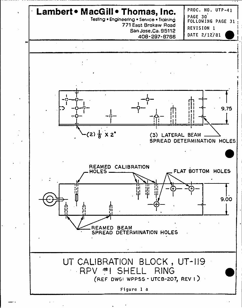
Lambert ~ Maca ill~ Thomas, I nc.Testing ~ Engineering ~ Senesce ~ Troininp
771 East Brokaw RoadSan Jose,Ca. 95112
408-297-8766
PROC. NO. UTP-41
PAGE 30fOLLOWING PAGE 31,REVISION 1
ATE 2 12 81I
I-0- - spy —I I I
t
I'I
I
I I II
1
(2) $ X2'3) LATERAL BEAMSPREAD DETERMINATION HOLES
BEAMED CALIB RATIONHOLES FLAT BOTTOM HOLES
9.00
REAPED BEAMSPREAD DETERMINATION HOLES
UT CALIBRATION BLOCK, UT-II9RPV ~I SHELL RING
(REF DWG: WPPSS - UTCB-207, REV 1)
figure 1 a
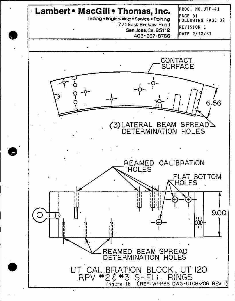
Lambert ~ Naca ill~ Thomas, Inc.Testing ~ Engineering ~ Service ~ Training
, 771 East Brokaw RoadSan Jose,ca. 95112
408-297-8766
PROC. NO. UTP-41
PAGE 31FOLLOWING PAGE 32
REVISION 1
DATE 2/12/81
CONTACT/ SURFACE
I
0I
l0-~Q l
Ir II- I I
I II'II
6. 56
(3)LATERAL BEAM SPREADDETERMINATION HO LES
RE A MED CA L I B RATIONHOLES
FLAT BOTTOMHOLES
I IIII I II I
I,
9.00
REAMED BEAM SPREADDETERMINATION HOLES
UT CALIBRATION BLOCK, UT I20RPV ~2 ( "3 SHELL RINGS
Figure 1b (REF: VJPPSS DWG-UTCB-208 REV I
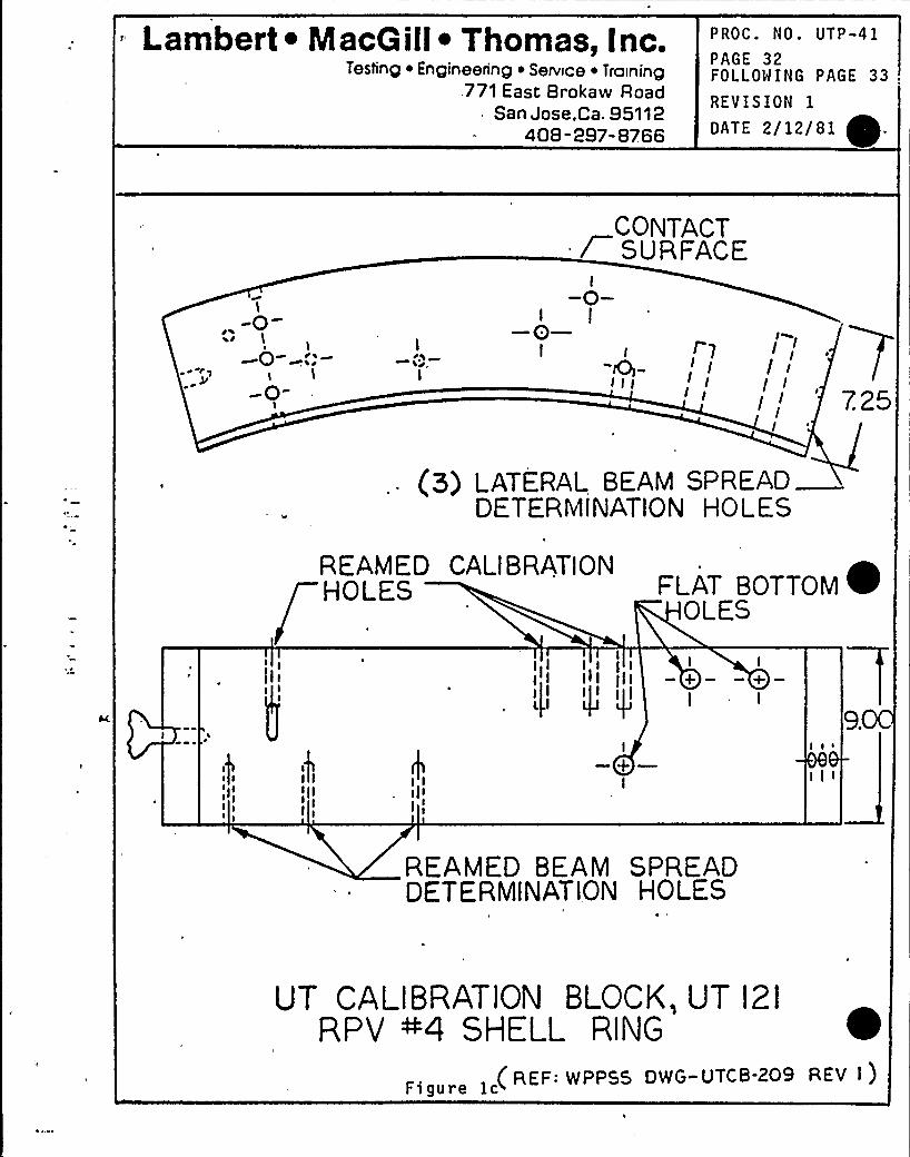
'ambert ~ Maco ill~ Thomas, Inc.Testing ~ Engineering ~ Service ~ Training
771 East 8rokaw RoadSan Jose,Ca. 95112
408-297-8766
P ROC. NO. UTP -41PAGE 32FOLLOWING PAGE 33
REYISION 1
DATE 2/12/81
CONTACT/ SURFACE
I
I
-0-l—0—
I I 7I
r I I I
illI I/
7.25r ~
(P) LATERAL BEAM SPREADDE.TERMINATION HOLES
REAMED CALIBRATION ~HOLES FLAT BOTTOMOLES
II I
II I Ii I il I
I
9.
BEAMED BEAM SPREADDETERMINATION HOLES
UT CALIBRATION BLOCK, UT I21RPV ~4 SHELL RING
( REF: WPPBB DWG-UTCB-209 REV I )Figure 1c
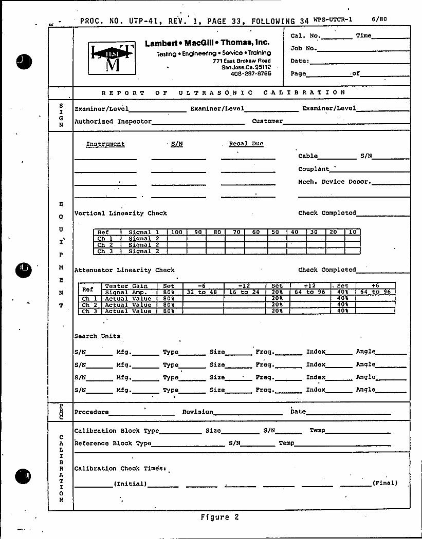
PROC. No. UTP-4C, REV.', PAGE 33, FOLLPgrNG 34»S-UTcR-1
Lambert ~ Nacaill ~ Thomas, inc.Testing ~ Engineedng ~ Sevice ~ Twining
771 East Brokaw RoadSan Jose.Ca. 95112
408 297-8766
Cal. No.
Job No.
Date:
Page .of
REPORT OF ULTRASONICCALIBRATION8IGN
Examiner/Level
Authorized Inspector
Examiner/Level
Customer
Examiner/Level
Instrument S/N Recal Due
Cable
Couplant'/N
Mech. Device Descr.
E
Vertical Linearity Check Check Completed
RefCh 1Ch 2Ch 3
Si nal 1 100Si nal 2Si nal 2Si nal 2
90 80 70 60 50 40 30 20 10
Attenuator Linearity Check Check Completed
NRef Tester Gain
S na AmSet
0% to toSet
0%+12to
, Set40% to
Ch 1 Actual Value 80% 20% 40%Ch 2 Actua Va ue 0% 0% 40%Ch 3 Actua Value 80% 20% 40%
Search Units
6/N Mfg. Type
S/N Mfg. Type
Nfg. Type
/ 8N Nfg. Type
Size
Size
Size
Size
Freq.
Freq.
Freq.
Zndex Angle
Angle
Zndex Angle
Index Angle
PProcedure Revision Date
CALIBRATI0
Calibration Block Type
Reference Block Type
Calibration Check Timist
(Initial)
Size
S/N
S/N
Temp
Temp
(Final)
Figure 2
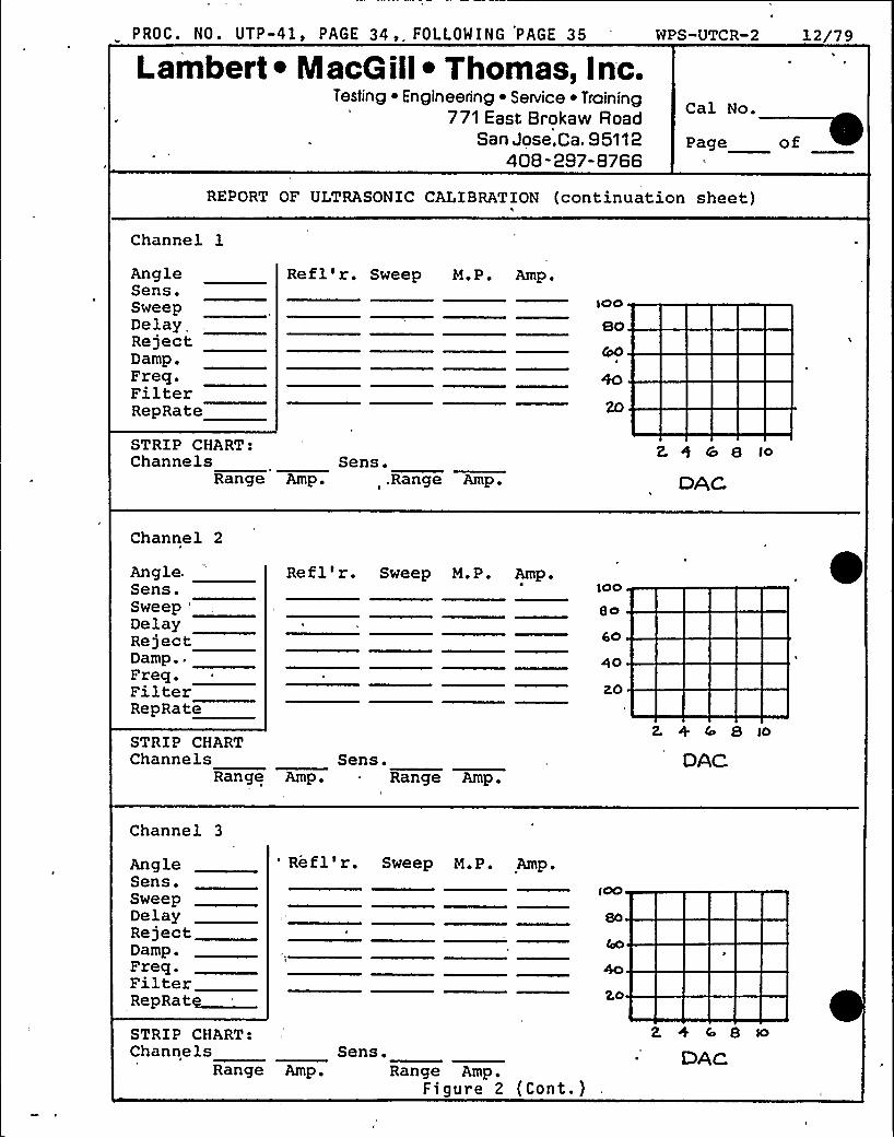
PROC. NO. UTP-41, PAGE 34,. FOLLOWING PAGE 35
Lambert ~ Naca ill~ Thomas, Inc.Testing ~ Engineering ~ Service ~ Training
771 East Brokaw RoadSan Jose,Ca. 95112
408-297-8766
WPS-UTCR-2 12/79
Cal No.
Page of
REPORT OF ULTRASONIC CALIBRATION (continuation sheet)h
Channel lAngleSens.SweepDelayRejectDamp.Freq.FilterRepRate
Refl'r. Sweep M.P. Amp.
ro
STRIP CHART:Channels Sans.
Range Amp. .Range Amp.
2. g cc 8 to
DAC
Channel 2
Angle.Sens.Sweep
'elay
RejectDamp..Freq.FilterRepRate
Refl'r. Sweep M.P. Amp.$OO
8O
rso
4p
20
2. + r 8 roSTRI P CHARTChannels Sens.
Range Amp. Range Amp.DAC
Channel 3
AngleSens.SweepDelayRejectDamp.Freq.FilterRepRatg
'efl'r. 'Sweep M.P. Amp.
2.0
STRI P CHART:Channels Sens.
Range Amp. Range Amp.Figure 2 (Cont.)
~ DAc
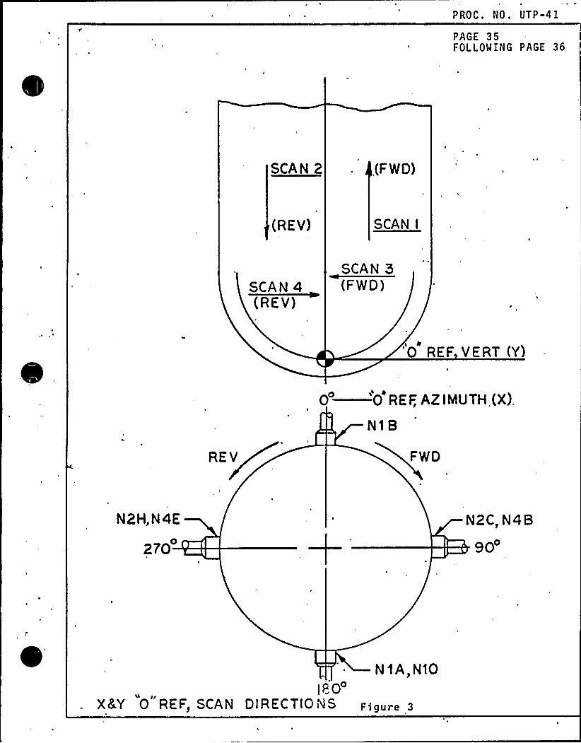
PROC. NO. UTP-41
PAGE 35FOLLOWING PAGE 36
SCAN 2 (F WO)
(REV) SCAN I
SCAN 4(REV)
SCAN
'R E F V E RT (Yl
REV
0—O REF, AZIMUTH(X).
N18
FWD
N2H,N4E
270
N2C, N4B
90
N 1A, N103
00I
X4Y 0 REF> SCAN DIRECTIO i JS f)gUpe 3
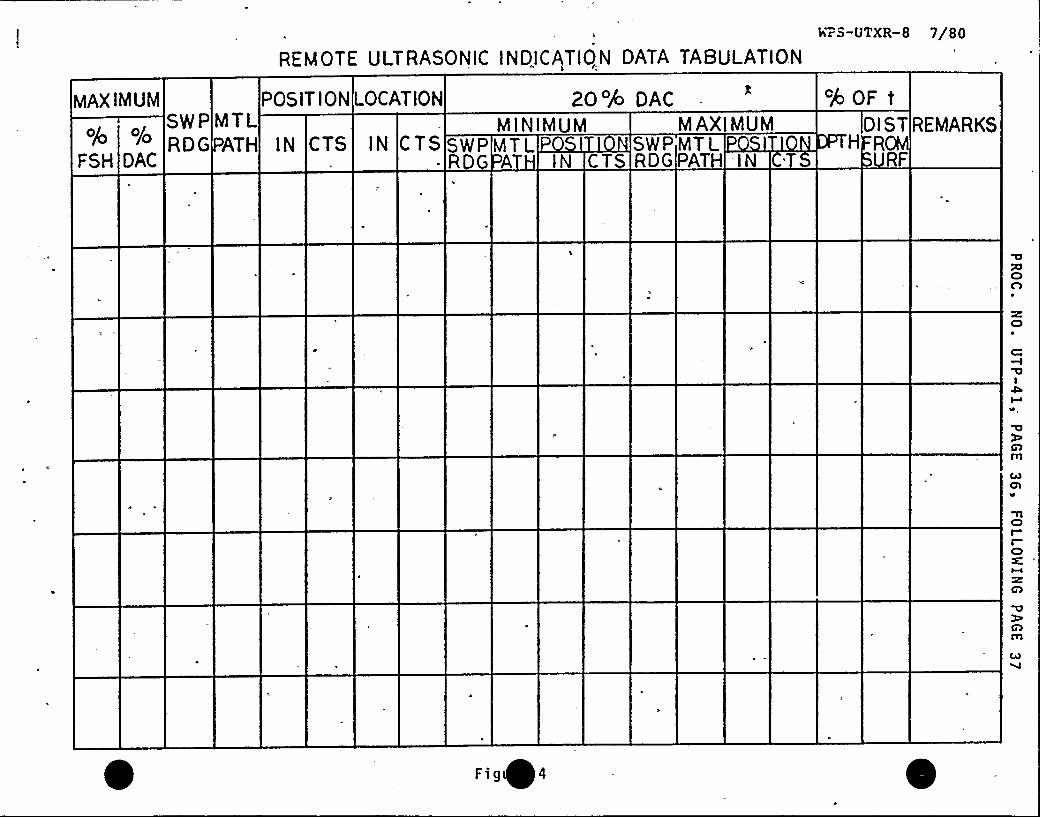
REMOTE ULTRASONIC INDICATION DATA TABuLATiONhr5-UTXR 8 7/80
MAXIMUM
o/
FSH
SWP'~'OGDAC
POSIT ION LOCATIONMTLATH IN CTS IN CTS
MAXIMUMSWP MTLR A IN
SWP MTLCT RDG PATH IN
ZO% OAC
M I NIMUMH ROM
RF
cPOF tDl ST REMARKS
oXICDn
CD
rlCDI
CD
Fig 4
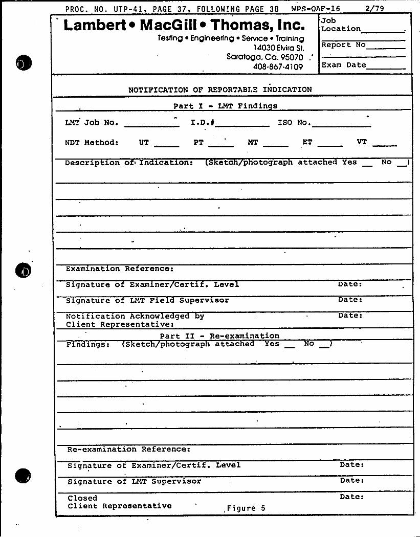
PROC. NO. UTP-41 PAGE 37, FOLLOWING PAGE 38 NPS-OAF-16 2 79
Lambert ~ Maca ill~ Thomas, Inc.Testing ~ Engineering ~ Service ~ Training
14030 Elvira St.Saratoga. Ca. 95070
.'08.867-4109
JobLocation
Report No
Exam Date
NOTIFICATION OF REPORTABLE INDICATION
Part I - LMT Findin s
LNT Job No.
NDT Methods UT
~I I AD.N
PT MT
ISO No.
ET
Descrxp son o i In @cat on< etc p otograp attac e Yes No
Examxnat on Re erence:
S gnature o Exam ner Cert' Leve
Signature o LNT F e Supervisor
Notxfxcatzon Ac now e ge yClient Re resentative:
Part II - Re-examinationFan xngs: S etc p otograp attac e es o
Da te!ate:
Date:
Re-examination Reference:
Signature of Examiner/Certif. Level
Signature of LMT Supervisor
Date:
Date:
ClosedClient Representative Figure 5
Date:
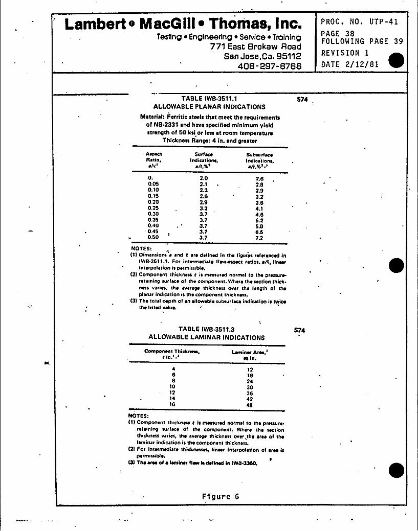
'ambert e MacQill~ Thomas, Inc.Testing ~ Engineering ~ Service ~ Troinfng
771 East Srokaw RoadSan Jose,Ca. S5112
408-287-8766
PROC. NO. UTP -41PAGE 38FOLLOWING PAGE 39
REVISION 1
DATE 2/12/81
TABLE IWB 3511.1ALLOWABLEPLANAR INDICATIONS
Material: Ferritic steels that meet the requirementsof NB.2331 and have specified minimum yieldstrength of 50 ksi or ress at room tem perature
Thidcness Range: 4 in. and greater
S74
AspectRatio,~
Iv'urfaceIndicatioils,rh,%s
SubsurfaceIndications,rh;Xs"
0.0.050.100.150,200.250.300.350.40
',450.50
2.02.12.32.62.93.23.73.73.73.73.7
2.62828323.64.14.66.2686.57.2
NOTES;I1) Oimansions r and Q are defined in the figures referenced in
IWS 35'l1.1. For intermediate flaw~t ratios, rA, linearinterpol ~ tion is permissible.
I2) Component thickness r is measured normal to the pressure-rataininy surface of the component. Where the section thick.ness varies, the average thickness over the length of theplanar indication is the component thickness.
'l3l The total depth of an allowabl ~ subsurface indication ls twicethe fisted value.
TABLE IWB.3511.3ALLOWABLELAMINARINDICATIONS
S74
Component Thick~,t in.' i Laminar
Area,'it
in.
466
'IO
121416
12'IS24303642
NOTES:I1I Component thickness t Is measured normal to the pressure.
retaininy surface of the component. Where the sectionthickness varies, the averaye thickness over, the area of thelaminar indication is the component thickness.
I2) For intermediat ~ thicknesses, linear interpolation of area Ispermissible.
I31 The area of a lamksar f1~ la defkted in IWS4350.
Figure 6
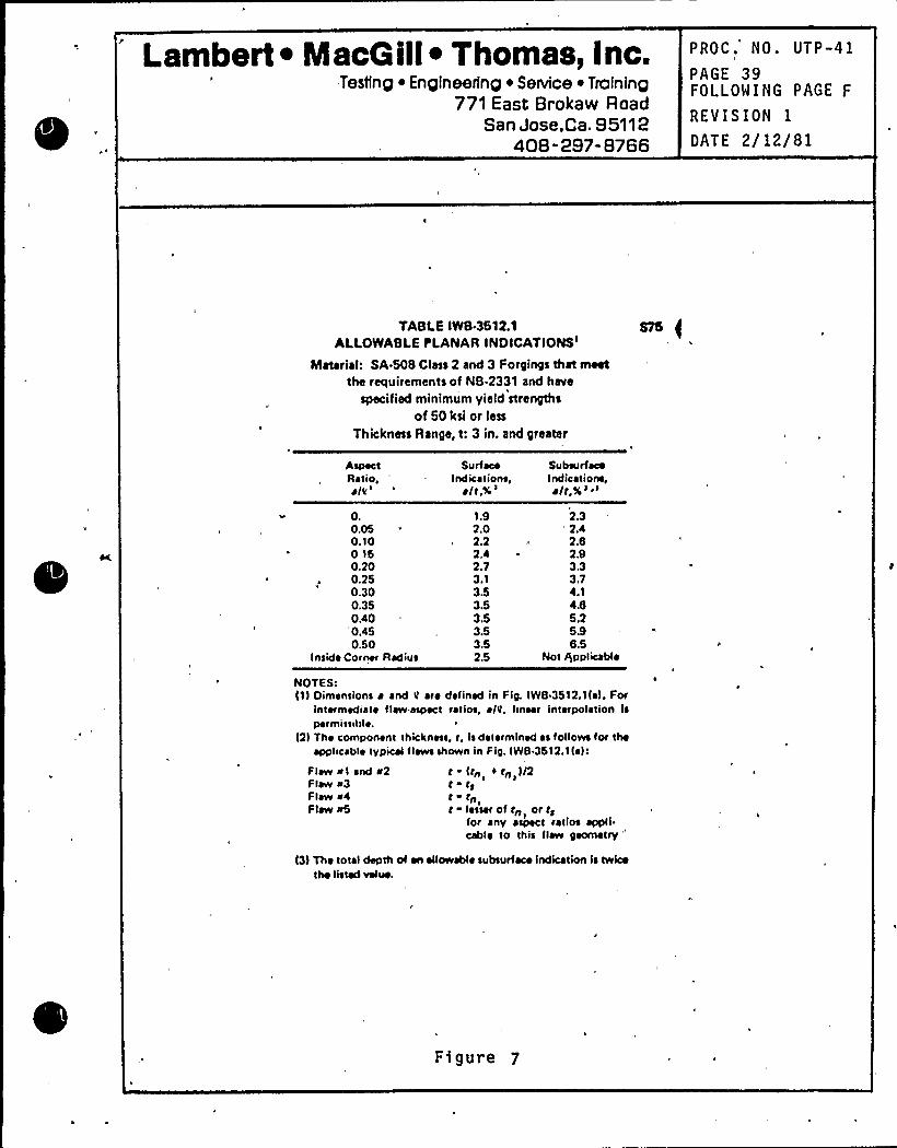
Lambert ~ MacQ ill~ Thomas, Inc..Testing ~ Engineering ~ Senice ~ Training
771 East Brokaw RoadSan Jose,Ca. 95112
408-297-8766
PROC. NO. UTP-41
PAGE 39FOLLOWING PAGE F
REVISION 1
DATE 2/12/81
TABLE IW8-3512.1ALLoyyABLEPLANAR INOICATIONSI
Materia): SA 508 Class 2 and 3 Forgings that meetthe requirements of NB 2331 and httve
specified minimum yield strengthsof 50 ksi or less
Thickness Range, t: 3 in. and greater
AspectRatio,~
Iv'.
0.050.100160.200.250.300.350.40'0.450.50
Inside Corner Radius
SurfaceIndlca I lone
alt.%'.9
2.02.22.42.73.13.53.53.53.53.52.5
SubsurfaceIndicetione,alt,ts'
'.3
'42.B2.93.33.74.14.B5.25.9B.5
Not gpplicabl ~
NOTES:l1) Dimensions a and y are defined in Fig. IWB 3512.1la). For
intermediate tlaw aspect ratios, alit. hnear int«polation lspermissihl ~ .
l2) The component thickness, t, Is delermined es follows lor the~pplicabl ~ typical flaws shown in F ie. IWB 3612.1la):
Flaw «I and «2Flaw «3Flaw «4Flaw «5
t ~ I trr trr, ) IZt tgt ~ trr Ir ~ less«of rrr or rg
1
for any aspect ratios appli.cabl ~ to this flaw geometry"
l3) The total depth of an ailowabl ~ subsurface indication is twicethe Iwted velue.
Figure 7
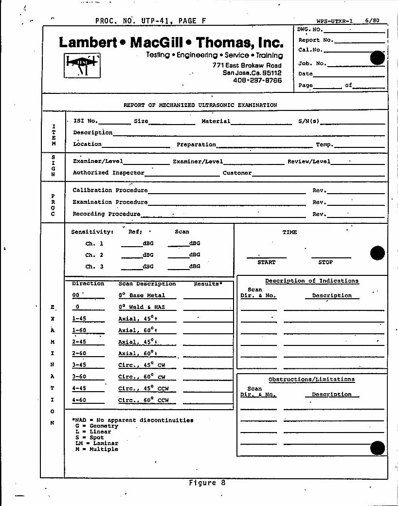
PROC. NO. UTP-41, PAGE F WPS-UTXR-1 6/80
Lambert 4 MacGill~ Thomas, Inc.Testing ~ Englneerlng ~ Service ~ Trolnlng
771 Esst 8rakaw RoadSen Jose,CB. 95112
408-297-8786
DWG ~ NO.
Report No.
Cal.No.
Job. No.
Date
Page of
REPORT OP MECHANIZED ULTRASONIC EXAMINATION
IT
M
ISI No.
Description
Location
Size Material
Preparation
S/N (s)
Temp.
SIGN
Examiner/Level
Authorized Inspector
Examiner/Level
Customer
Review/Level
PR0
C'alibration Procedure
Examination Procedure
Recording Procedure
Rev
Revr
Rev ~
Sensitivity: Ref r Scan
Ch. 1
Ch. 2
Chr 3START STOP
0
D rect on
00
1-45
1-60II
2-45
2-60
3 45
3-60t
4-45
4-60
Scan Descr pt on
0 Base Metal
04 Weld a HAZ
Axial 45 tAxial 60 t
Axial 45 t
Axial 60
Circ., 45 CW
Circ. 60 CW
Circ. 45 CCW
Circ. 60 CCW
Resu tsScan
Dir. a No. Descri tion
Obstructions/LimitationsScan
Dir r No Descr~iorr
Descri tion of Indications
N«NAD ~ No apparent discontinuities
G ~ GeometryL ~ LinearS ~ SpotLM LaminarM ~ Multiple
Figure 8
Da te 1/8/79
Revi sion 0
NAP-2 PSI PROGRAH PLAN
NOT USE D
( 4(Purposely left blank)
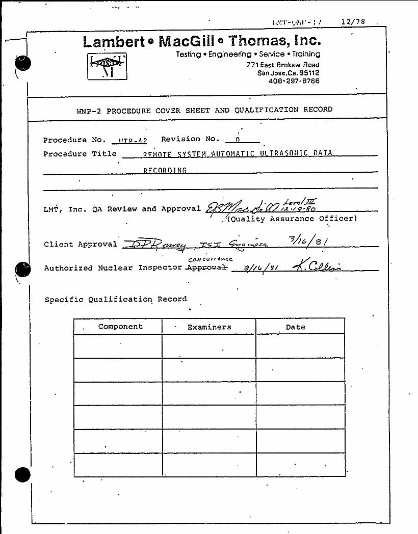
Lambert + MacGiil ~ Thomas, inc.Testing ~ Engineering ~ Service ~ Training
771 East Srokaw RoadSan Jose,Ca. 95112
408-297-8766
WNP-2 PROCEDURE COVER SHEET AND QUALIFICATION RECORD
Procedure No. ~~ Revision No.
Procedure Title 'l t TR A 0tl DATA
LHT, Inc. QA Review and ApprovalZ ~/M
lA /, (Quality Assurance Officer)
Client Approval
~~ Cu s r deere
Authorized Nuclear Inspector ~~ova3.- g gg yy
>As sy
Specific Qualification Record
Component Examiners Date
WASHINGTON PUBLIC POWER SUPPLY SYSTEM
REVIEW OF CONTRACTOR SUBiIIITTALS
ISI ENGINKKR~ P~ 4. AC
QATK)~- X'I/-QOONTRACT NOeC-/+VOi
CONTRACTOR 4H Zp c.
TITLEP'S~ 5 I S 7 QS45 0 PSC'2'II C/eO
QQCUMKNTTITLE REV.
ow fi 'c
PREVIOUSLY REVIEWED
PRKVIOUSLYAPPROVED
ONO (DATKIPYES) ~c, 5 1980 u)PC,H 2=PI 39)
Q YES g NO (DATE IP YKS)
REASONS POR RK.SUBMITTAL(IP PRKVIQUSLYAPPROVED)
DISPOSITION
REVIEWERQ
~ 9C
E
OOW W
OOC g0, Vlg E
OW
9IL
0C
Q
Vl QgWXEU~EOlUE
r /Z- ZY'oSUPERVI/OR, ISI ANQ OPERATIONS SUPPORT ENGI
'I. IAO.~~i~IA. n k~ ~N~
PROJE~CKNGINEKRING MANAGER/PLANTTECHNICAI PERV OA/l6//e/
UIERVI EN RAT SKR IC
MA ACERB'UALITYSERVICES
NOTES/COMMENTS>c'o ~c ~Wmw~c w
WP 702 KQP 9.0

Lambert ~ MacQillI Thomas, lnc.Testing ~ Engineering ~ Service ~ Training
771 East Brokaw RoadSan Jose,Ca. 95112
408-297-8766
PROC. UTP-42
PAGE 1
FOLLOWING PAGE 2
REVISION 0
DATE 12/19/80
TITLE: REMOTE SYSTEM AUTOMATIC ULTRASONIC DATA RECORDING
PURPOSE AND SCOP'E
This procedure provides direction for automatic recording of
test data generated'n remote ultrasonic examinations per-
formed under other LMT, Inc. procedures.
REFERENCES
A. A licable Code Editions
Automatic data recording is not directly covered by any
ASME Code.
B. A licable Code Cases
None.
C. Su lemental References
1. Manufacturer's Manual, Nortec 131D.
2. Applicable LMT Remote, Mechanized Equipment and
Remote Ultrasonic Test Procedures.
3. LMT Operating and Quality Assurance Manual, Revision
12, approved for the WHP-2 Preservice Inspection by
WPPSS.
QUAL IF I CAT ION:I
Approved for use
Lambert 6 MacG ill~ Thomas, Inc:.Testing ~ Engineering ~ Service ~ Troining
771 East Brokaw RoadSan Jose,ca. 95112
408- 297-8766
PROC. UTP-42
PAGE 2F OLLOMING PAGE 3
REVISION 0
DATE 12/19/80„
I I I. DEFINITIONS
System: Combination of remotely operated
examination device, ultrasonic and
data acquisition instrumentati on,
including search units and wedges.
I V., RESPONSIBILITY
A. The Technical Manager, LNT, Inc., is responsible for the
generation and control of this procedure and shall so
indicate by a dated signatur e on the procedure cover
sheet.
B. The responsible Level III Field Supervisor, LHT, shall
qualify the procedure for a particular examination. Mhen
the Field Supervisor is not Level III in the discipline,
both his signature and that of a qualified LHT Level IIIare required.
V. PROCEDURE UALIFICATION
This procedure shall be qualified in conjunction with the
first remote examination system procedures. Such qualifica-
tion shall be acceptable for use with all remote examination
system procedures.C
Lambert ~ MacG illI Yhomas, lnc.Testing ~ Engineering ~ Service ~ Training
771 East Brokaw RoadSan Jose,Ca. 95112
408-297- 8766
PROC. UTP-42
PAGEFOLLOWING PAGE 4
REVISION 0
DATE 12/19/80
V I. PERSONNEL RE UIREMENTS*
A. Examiners using this procedure shall have levels of
qualification, as specified by the approved procedure
qualification, and associated approved calibration
records.
B. Personnel shall be qual1f1ed and cert1fied according to
the require'ments of ASME Sections V and XI, SNT-TC-1A,
and LHT Procedure gA-6, "gualification and Certification
of NDE Personnel."
VI I ~ E UIPHENT AND MATERIAL RE UIREMENTS
A Nortec 131D, or equivalent instrumentation, modified to
provide analog metal path and echo ampl itude vol tage
outputs.
B. Digital-to-analog converter.
C. Gould 2800 eight-channel strip chart recorder, or equiva-
lent, using chart materials as recommended by the manu-
facturer.D. Equipment shall meet the calibrat1on requirements as
stated in the examination procedure.
VI I I. PREPARATION
A. Documentation
Documentation requirements shall be as stated in the
examination procedure.
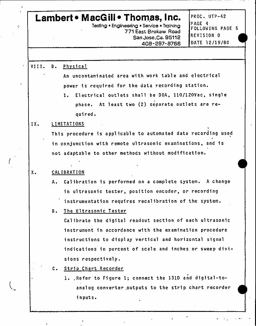
Lambert o MacGill ~ Thomas, Inc.Testing ~ Engineering ~ Service ~ Training
771 East Brokaw RoadSan Jose,Ca. 95112
408- 297-8766
PROC. UTP-42
PAGE 4FOLLOW ING PAGE 5
REVISION 0
DATE 12/19/80
VII I. B. ~Ph sical
An uncontaminated area with work table and electrical
I X.
power is required for the data recording station.
l. El ectrical outlets shal l be 30A, 110/120Vac, single
phase. At least two (2) separate outlets are re-
quired.
L I NI TAT I ONS
This procedure is applicable to automated data recording used
in conjunction with remote ultrasonic examinations, and i s
not adaptable to other methods without modification.
X. CALIBRATION
A. Calibration is performed on a complete system. A change
in ul trasonic tester, position encoder, or recording
instrumentation requ'ires recalibration of the system.
B. The Ultrasonic Tester
Calibrate the digital readout section of each ultrasonic
instrument in accordance with the examination procedure
instructions to display vertical and horizontal signal
indications in percent of scale and inches or sweep divi-si ons respecti vely.
C. Stri Chart RecorderI
1.,Refer to Figure 1; connect the 131D and digital-to-analog converter. outputs to the strip chart recorder
inputs.
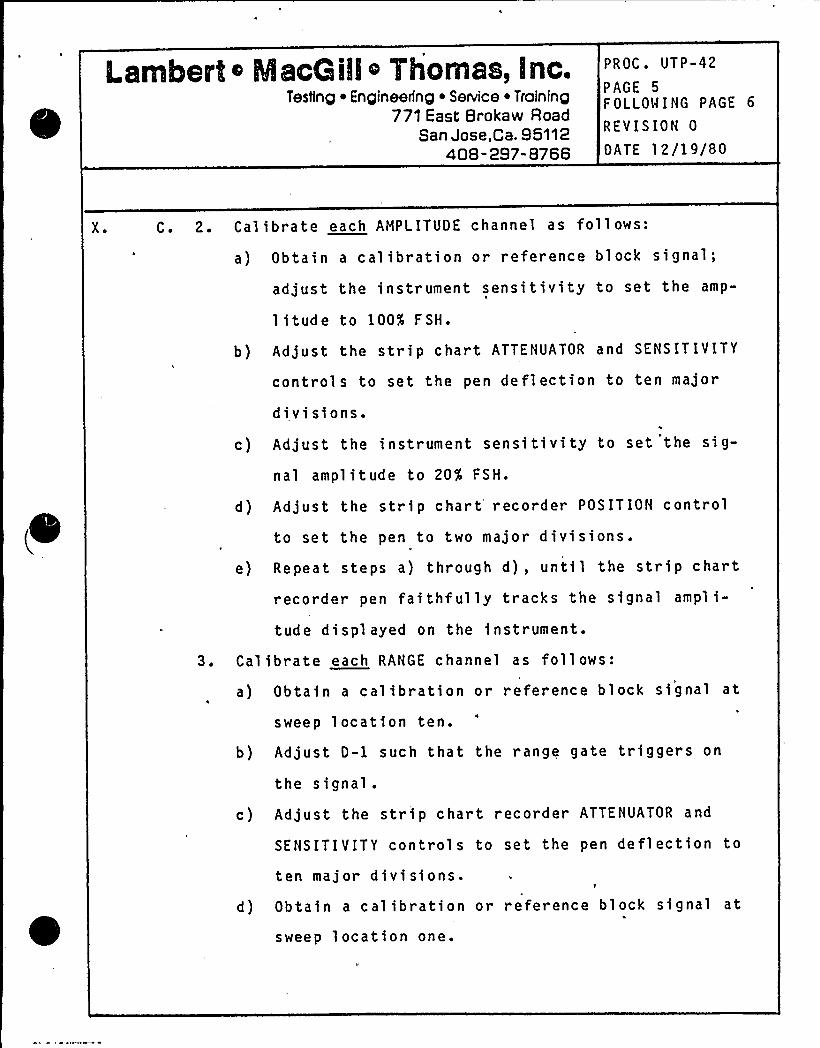
Lambert o Ms@Gill o Thomas, inc.Testing ~ Engineering ~ Service ~ Training
771 East Broka w RoadSan Jose,Ca. 95112
408- 297-8766
PROC. UTP-42
PAGE 5FOLLOWING PAGE 6
REVISION 0
DATE 12/19/80
X. C. 2. Calibrate each AMPLITUDE channel as follows:
a) Obtain a calibration or reference block signal;
adjust the instrument sensitivity to set the amp-
1 itude to 100% FSH.
b) Adjust the strip chart ATTENUATOR and SENSITIVITY
controls to set the pen deflection to ten major
divisions.
c) Adjust the instrument sensitivity to set the sig-
nal amplitude to 20% FSH.
d) Adjust the strip chart'ecorder POSITION control
to set the pen to two major divisions.
e) Repeat steps a) through d), until the strip chart
recorder pen faithfully tracks the signal ampli-
tude displayed on the instrument.
3. Calibrate each RANGE channel as follows:
a) Obtain a calibration or reference block signal at
sweep location ten.
b) Adjust D-l such that the range gate triggers on
the signal.
c) Adjust the strip chart recorder ATTENUATOR and
SENSITIVITY controls to set the pen deflection to
ten major divisions.
d) Obtain a calibration or reference block signal at
sweep location one.
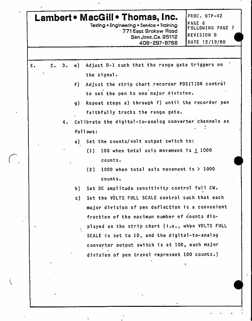
Lambert ~ MacG ill~ Thomas, inc.Testing ~ Engineering ~ Service ~ Training
771 East Brokaw RoadSan Jose,Ca. S5112
408-297-8766
PROC. UTP-42
PAGE 6FOLLOWING PAGE 7
REVISION 0
DATE 12/19/80
X. C. 3. e) Adjust D-1 such that the range gate triggers on
the signal.
f) Adjust the strip chart recorder POSITION control
to set the pen to one major division.
g) Repeat steps a) through f) until the recorder pen
faithfully tracks the range gate.
4. Calibrate the digital-to-analog converter channels asV
fol l ows:
a) Set the counts/volt output switch to:
(1) 100 when total axis movement is < 1000
counts.
(2 ) 1000 when total axis movement is > 1000
counts.
b) Set DC amplitude sensitivity control full CW ~
c) Set the VOLTS FULL SCALE control such that each
major division of pen defle'ction is a convenient
fraction of the maximum number of counts di s-
played on the strip chart (i.e., when VOLTS FULL
SCALE is set to 10, and the digital-to-analog
converter output switch is at 100, each major
division of pen travel represent 100 counts.)
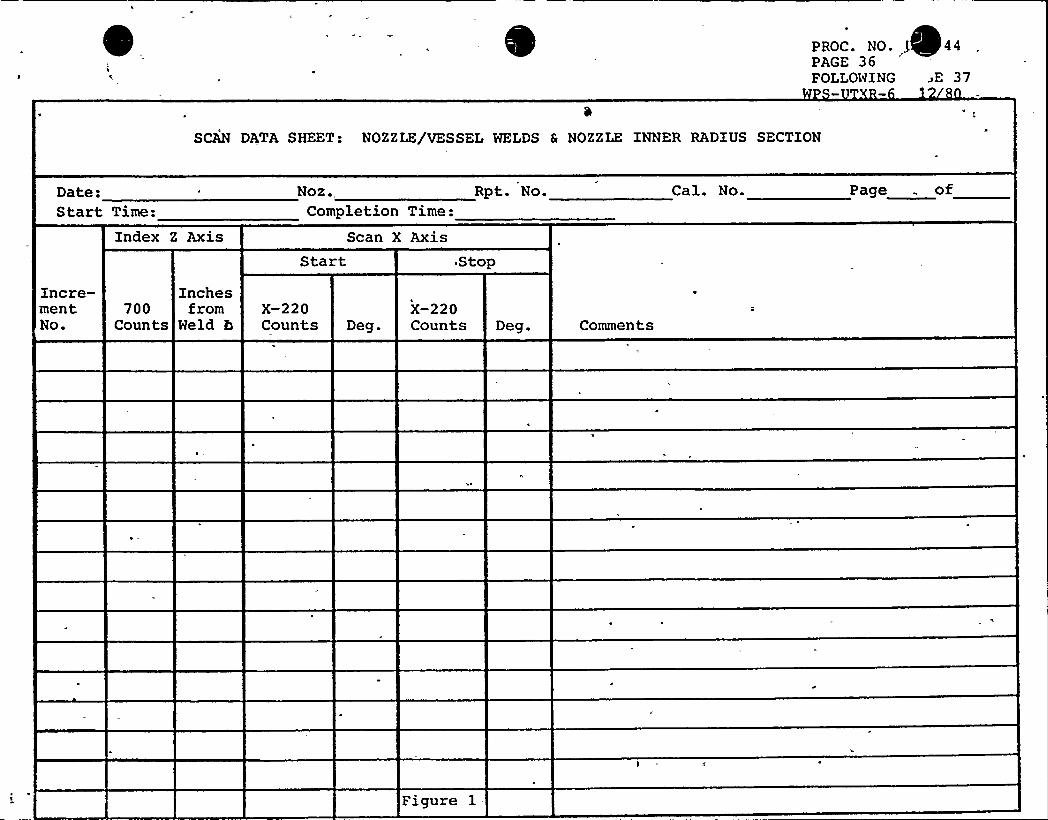
PROC. NO- f 44PAGE 36FOLLOWING ~E 37
SCAN DATA SHEET: NOZZLE/VESSEL WELDS 6 NOZZLE INNER RADIUS SECTION
Date:Start Time:
Index Z Axis
Noz ..Completion Time:
Scan X AxisStart
Rpt. No.
Stop
Cal. No. Page . of
Incre-mentNo.
Inches700 from
Counts Held bX-220Counts Deg.
X-220Counts Deg. Comments
Figure 1
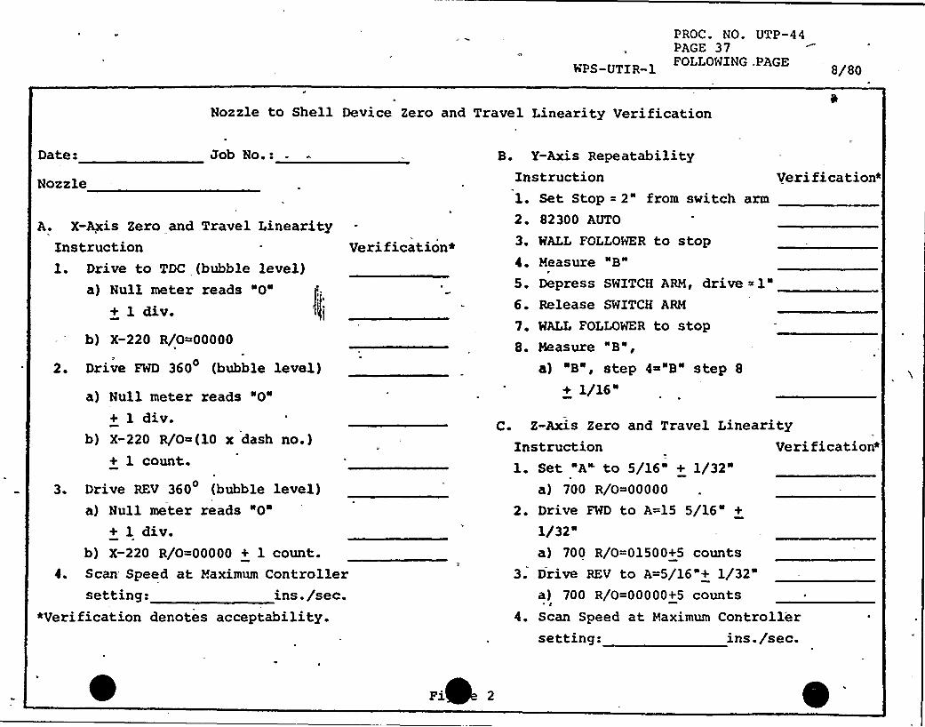
PROC. NO. UTP-44PAGE 37FOLLOWING .PAGE 8/80
Nozzle to Shell Device Zero and Travel Linearity Verification
Date:
Nozzle
Job No.: B. Y-Axis RepeatabilityInstruction Verification~
A. X-Axis Zero and Travel LinearityInstruction Verification*1. Drive to TDC (bubble level)
a) Null meter reads "0"+ 1 div.
I
b) X-220 R/0=00000
2. Drive FWD 360 (bubble level)
a) Null meter reads "0"
+ 1 div.b) X-220 R/0~(10 x dash no.)
+ 1 count.
3. Drive REV 360 (bubble level)a) Null meter reads "0'
1 div.b) X-220 R/0=00000 + 1 count.
4. Scan Speed at Maximum Controllersetting: ins./sec.
*Verification denotes acceptability.
1. Set Stop = 2" from switch arm
2. 82300 AUTO
3 ~ MALL FOLLOWER to stop4. Measure "B"
5. Depress SWITCH ARM, drive ~1"
6. Release SWITCH ARM
7. MALL FOLLOWER to stop8. Measure "B",
a) B", step 4 "B" step 8
+ 1/16"
C. Z-Axis Zero and Travel LinearityInstruction Verification~1. Set A to 5/16" + 1/32"
a) 700 R/0 00000
2. Drive FWD to A=15 5/16" +
1/32"a) 700 R/0=01500+5 counts
3. Drive REV to A=5/16"+ 1/32"a) 700 R/0=00000+5 counts
4. Scan Speed at Maximum Controllersetting: ins. /sec.
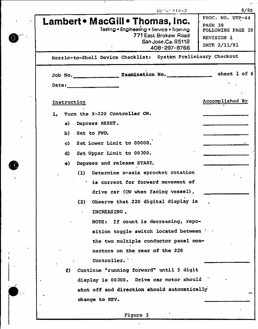
W!'-'~'r!'-?
Lambert ~ IacG ill~ Thomas, I nc.Testing ~ Engineering ~ Serwce ~ Training
771 East Brokaw RoadSan Jose,Ca. 95112
408-297-8766
8/80PROC. NO. UTP-44
PAGE 38FOLLOWING PAGE 39
REVISION 1
DATE 2/11/81
Nozzle-to-Shell Device Checklists System Preliminary Checkout
Job No.
Dates
Examination No. sheet 1 of 6
Instruction Accom lished B
1, Turn the X-220 Controller ON.
a) Depress RESET.
b) Set to FWD.
c) Set Lower Limit to 00000.
d) Set Upper Limit to 00300.
e) Depress and release START.
(1) Determine x-axis sprocket rotationis correct for forward movement of
drive car (CW when facing vessel),I
(2) Observe that.220 digital display is
INCREAS ING ~
NOTE! If count is decreasing, repo-
sition toggle switch located between
the two multiple conductor panel con-
nectors on the rear of the 220
Controller.
f) Continue "running foxward" until 5 digitdisplay is 00300. Drive car motor should
shut off and direction should automatically
change to REV.
Figure 3
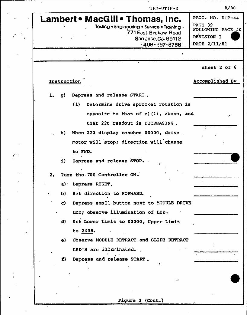
Nl".:-U'I'l l'-2
Lambert ~ MacG ill~ Thomas, I nc.Testing ~ Engineering ~ Sennce ~ Training
771 East Brokaw RoadSan Jose,Ca. 95112
408- 297-8766
8/80
PROC. NO. UTP-44
PAGE 39FOLLOWING PAGE 40
REVISION 1
DATE 2/11/81
sheet 2 of 6
Instruction Accom lished B
l. g) Depress and release START .
(1) Determine drive sprocket rotation isopposite to that of e) (1), above, and
that 220 readout is DECREASING .
h) When 220 display reaches 00000, drive
motor will stop; direction will change
to FWD.'I
i) Depress and release STOP.
2. Turn the 700 Controller ON.
a) Depress RESET.
b) Set direction to FORWARD.
c) Depress small button next to MODULE DRIVE
LED; observe illumination of LED.
d) Set Lower Limit to 00000, Upper Limitto,2438.
e) Observe MODULE RETRACT and SLIDE RETRACT
LED'S are illuminated.
f) Depress and release START .
Figure 3 (Cont.)
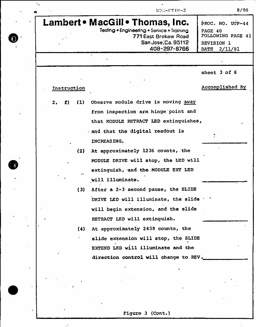
Lambert ~ MacGill ~ Thomas, Inc.Testing ~ Engineering ~ Service ~ Troinrng
771 East Brokaw RoadSan Jose,'Ca. 95112
408-a97-8766
8/80
PROC. NO. UTP-44
PAGE 40FOLLOWING PAGE 41
REVISION 1DATE 2/ll/81
sheet 3 of 6
Instruction Accom lished B
2. f) (1) Observe module drive is moving ~awa
from inspection arm hinge point and
that MODULE RETRACT LED ext.inguishesg,
~ and that the digital readout is
INCREAS ING.
(2) At approximately 1236 counts, . the
MODULE DRIVE will stop, the LED willextinguish, and the MODULE EXT LED
will illuminate.
(3) After a 2-3 second pause, the SLIDE
DRIVE LED will illuminate, the slide'illbegin extension, and the slide
RETRACT LED will extinguish.
(4) At approximately 2438 counts, the
slide extension will stop, the SLIDE
EXTEND LED will illuminate and the
direction control vill change to REV.
Figure 3 (Cont. )
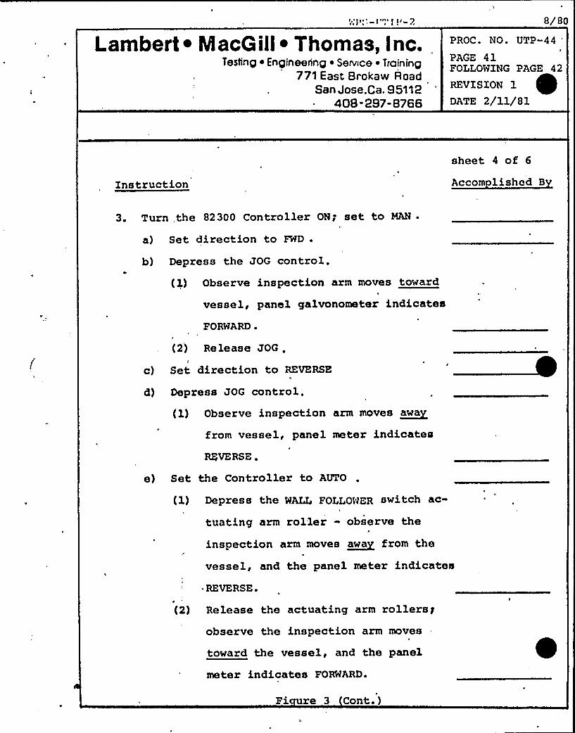
sm ~
Lambert ~ MacG ill~ Thomas, I nc.Testing ~ Engineering ~ Serwce ~ Training
771 East Brokaw RoadSan Jose,Ca. 95112
408-297-8766
8/80
PROC. NO. UTP-44
PAGE 41FOLLOWING PAGE 42
REVISION 1
DATE 2/11/81
Instruction
sheet 4 of 6
Accom lished B
3. Turn, the 82300 Controller ON; set to MAN ~
a) Set direction to FWD .
b) Depress the JOG control.
{1) Observe inspection arm moves toward
vessel, panel galvonometer indicates
FORWARD ~
(2} Release JOG .5
c) Set direction to REVERSEa
d) Depress JOG control.(l) Observe inspection arm moves ~awa
from vessel, panel meter indicates
REVERSE ~
e) Set the Controller to AUTO
(1) Depress the WALL FOLLOWER switch ac-
tuating arm roller - observe the
inspection arm moves ~awa from the
vessel, and the panel meter indicates~ REVERSE.
(2) Release the actuating arm rollersgobserve the inspection arm moves
toward the vessel, and the panel
meter indicates FORWARD.
Fi re 3 Cont. )
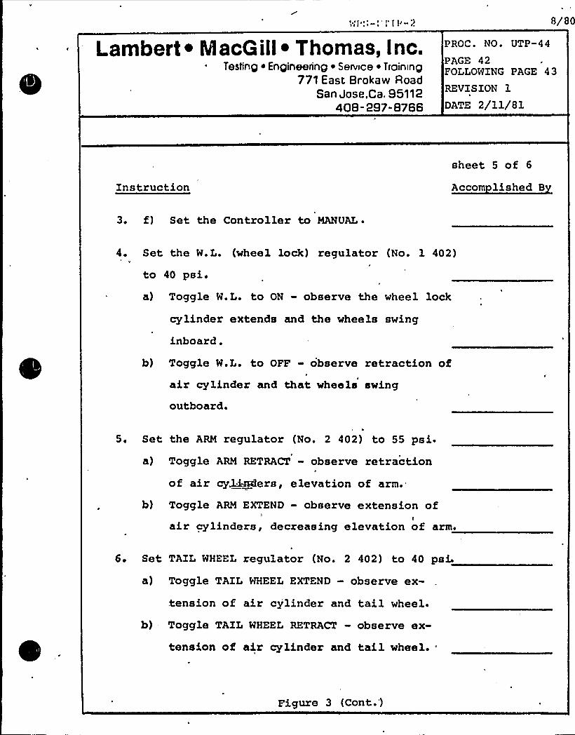
Lambert ~ IacG ill~ Thomas, Inc.Testing ~ Engineering ~ Service ~ Training
771 East Brokaw RoadSan Jose,Ca. 95112
40B -297-8766
PROC. NO. UTP-44
8/80
PAGE 42FOLLOWING PAGE 43
REVISION 1
DATE 2/11/81
Instructionsheet 5 of 6
Accom lished B
3 ~ f) Set the Controller to MANUAL~
4 ~ Set the W.L. (wheel lack) regulator (No. 1 402)
to 40 psi.a) Toggle W.L. to ON - observe the wheel lock
cylinder extends and the wheels swing
inboard.
b) Toggle W.L. to OFF - observe retraction ofair cylinder and that wheels swing
outboard.
5. Set the ARM regulator (No. 2 402) to 55 psi.a) Toggle ARM RETRACT - observe retraction
of air cd:~ers, elevation of arm.
b) Toggle ARM EXTEND - observe extension ofIair cylinders, decreasing elevation of arm.
6. Set TAIL WHEEL regulator (No. 2 402) to 40 psi
a) Toggle TAIL WHEEL EXTEND - observe ex-
tension of air cy'linder and tail wheel.
b) Toggle TAIL WHEEL RETRACT - observe ex-
tension of air cylinder and tail wheel.-
Figure 3 (Cont.)
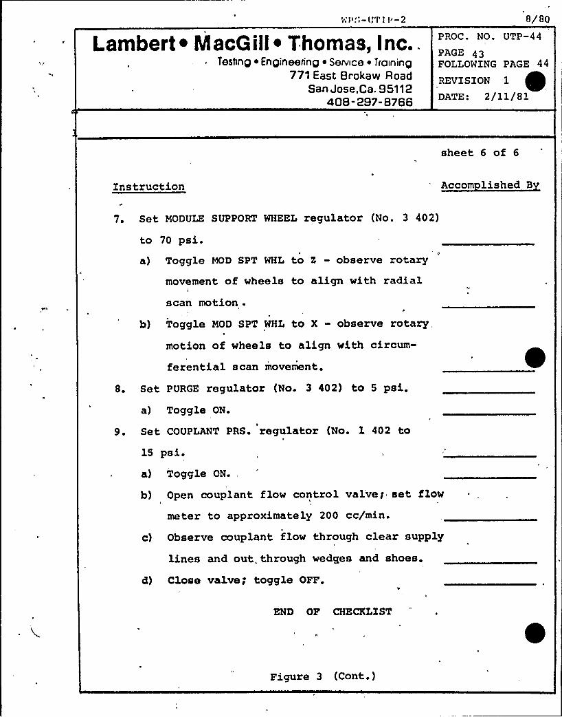
Lambert ~ Maco ill~ Thomas, Inc..~
Teshnp ~ Enpineerinp ~ Service ~ Troininp771 East Brokaw Road
San Jose.Ca. 95112408- 297-8766
8/80PROC. NO. UTP-44
PAGE 43FOLLOWING PAGE 44
REVISION 1
DATE: 2/11/81
sheet 6 of 6
Instruction Accom lished B
7. Set MODULE SUPPORT WHEEL regulator (No. 3 402)
to 70 psi.a) Toggle MOD SPT WHL to 5 - observe rotary
b)
movement of wheels to align with radialscan motion .
P
Toggle MOD SPT WHL to X - observe rotary
motion of wheels to align with circum-
ferential scan movement.
8. Set PURGE regulator (No. 3 402) to 5 psi.
a) Toggle ON.
9. Set COUPLANT PRS. regulator (No. 1 402 to
15 psi.a) Toggle ON.,
b) Open couplant flow control valveg set flow
meter to approximately 200 cc/min.
c) Observe couplant flow through clear supply
lines and out. through wedges and shoes.
d) Close valve; toggle OFF.
END OF CHECKLIST
Figure 3 (Cont.)
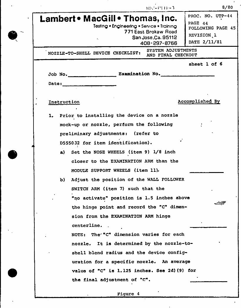
< >,',-r "l li -'3
Lambert ~ Macoill ~ Thomas, Inc.Testing ~ Engineering ~ Service ~ Training
771 East Brokaw RoadSan Jose,Ca. 95112
408-297-8766
8/80
PROC. NO. UTP-44'I
PAGE 44FOLLOWING PAGE 45
REVISION 1
DATE 2/11/81
NOZZLE-TO-SHELL DEVICE CHECKLIST:
Job No. Examination No.
sheet 1 oi 6
Datei
Instruction, Accom lished B
1. Prior to installing the device on a nozzle
mock-up or nozzle, perform the following
preliminary ad)ustments: (refer to
D555032 for item identification) .
a) Set the NOSE WHEELS (item 9) 1/8 inch
closer to the EXAMINATION ARM than the
MODULE SUPPORT WHEELS (item 11).
b) Ad5ust the position of the WALL FOLLOWER
SWITCH ARM (item 7) such that the
"no activate" position is 1.5 inches above
the hinge point and record the "C" dimen-
sion from the EXAMINATION ARM hinge
centerline.NOTE: The" "C" dimension varies for each
nozzle. It is determined by the nozzle-to-
shell blend radius and the device config-
uration for a specific nozzle. An average
value of "C" is 1.125 inches. See 2d) (9) i'or
the final ad)ustment of "C".
Figure 4
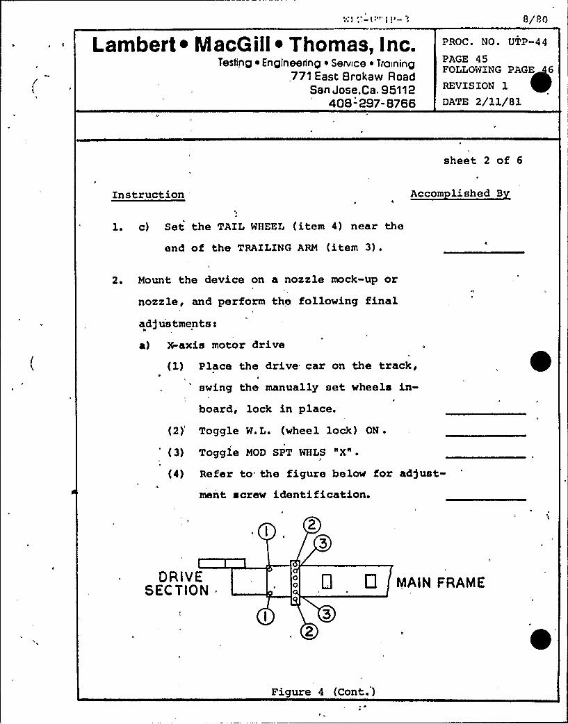
Lambert ~ IacG ill~ Thomas, Inc.Testing ~ Engineering ~ Sennce ~ TraIning
771 East 6 roka w R oadSan Jose.Ca. 95112
408" 297- 8766
8/80
PROC. NO. UTP-44
PAGE 45FOLLOWING PAGE 6
REVISION 1
DATE 2/11/81
sheet 2 of 6
Instruction 'ccom lished B
1. c) Set the TAIL WHEEL (item 4) near the
end of the TRAILING ARM (item 3) .
2 ~ Mount the device on a nozzle mock-up or
nozzle, and perform the following finaladjustments~
,t
a) X-axis motor drive
(1) Place the drive car on the track,swing the manually set wheels in-
I
board, lock in place.
(2) Toggle W. L. (wheel lock) ON .
(3) Toggle MOD SPT WHLS "X".
(4) Refer to. the figure below for ad)ust-
ment screw identification.
DRlVESEC TION 0 0 MAIN FRAME
Figure 4 (Cont. )
3«'3".:- «J'3' 3>- '3
Lambert ~ Macoill ~ Thomas, Inc.Testing ~ Engineering ~ Service ~ Training
771 East Broka w RoadSan Jose,Ca. 95112
408- 297-8766
UTP-44
8/80
PAGE 46FOLLOWING PAGE 47
REVISION 1
DATE 2/al/8l
Instruction
sheet 3 of 6
Accom lished B
2. a) (5) Loosen set screws 1,2, a 3.
(6) Hold the drive section down, in
contact with the track chain. Drivel
the car slowly in either direction g
tighten screws 2 until the drive
section no longer moves up and
down as the drive sprocket teeth
engage the chain.
b) Boss Wheel Bracket Ad)ustment
(1) Drive the device to the nozzle TDC
(null meter reads "0").
(2) Set the 82300 Controller to the MAN
STOP mode, with the WALL FOLLOWERI
DRIVE retracted such that the WALL
FOLLOWER SWITCH ARM does not contact
the vessel.
(3) The NOSE WHEEL end of the EXANINA-1«
TION ARM should lightly contact the
vessel wall.
Figure 4 (Cont.')
i~ i 1<i
Lambert ~ IacG ill~ Thomas, Inc.Testing ~ Engineering ~ Service ~ Training
771 East Brokaw RoadSan Jose,Ca. 95112
408-297-8766
8/80
PROC. NO. UTP-44
PAGE 47FOLLOWING PAGE 8
REVISION 1DATE 2/11/81
sheet 4 of 6
Instruction Accom lished B
2 ~ b) (4) Reset (zero) the 220 readout
(5), Adjust the BOSS WHEEL BRACKET as
required to set the WALL FOLLOWER
DRIVE ASS'Y parallel to the nozzle
boss.
(6) Record the final distance between
the nozzle boss and the bottom of the
WALL FOLLOWER DRIVE ASSEMBLY~
c) Tail Wheel Ad)ustment
(1) Position the TAIL WHEEL on the TRAIL-
ING ARM as indicated in the appropriate
drawing (D5570-011 through 015).
(2) Ad)ust the height of the TAIL WHEEL
such that it contacts the pipe, withinI
its working range (~ 1 inch) at allpoints around the track.
(3) Set the TAIL WHEEL regulatorto 40 psi.
d) Wall Follower
(1) Drive the device to nozzle TDC
(X 220 R/0 Q 00000).
Fig.ure 4 (Cont.')
\'r ''-ll'r r i'- 3
Lambert ~ MacG ill~ Thomas, Inc.Testing ~ Engineering ~ Service ~ Training
771 East Brokaw RoadSan Jose,Ca. 95112
408-297-8766
8/80
PROC. NO. UTP-44
PAGE 48FOLLOWING PAGE F
REVISION 1
DATE 2/11/81
sheet 5 of 6
Instruction Accom lished B
2 ~ d) (2) Toggle ARM FXTg reduce regulator
setting to approximately 10 psi.
(3) Toggle MOD SPT WHLS "Z" r set 70p
Controller to MODULE DRIVE, REV.
(i) Depress and hold JOG'rive module to
set "A" to 5/16 inch + 1/32 inch
(Drawing 55032) g release JOG .
(5) Set the 82300 Controller to AUTO,
activating the WALL FOLLOWER DRIVE.
The WALL FOLLOWER SWITCH ARM willcontact the vessel wall and shut offthe WALL FOLLOWER DRIVE.
(6) Set the 700 Controller to MODULE
DRIVE, FWD. Depress JOG; drive the
MODULE SUPPORT WHEELS to the tangent
point between the nozzle blend radius
and vessel wall.(7) Ad)ust the WALL FOLLOWER SWITCH ARM
such that the module is firmly seatedI
on the vessel surface, with approximately
4 inch gap between the MODULE SUPPORT
WHEELS and the vessel surface.
Fi re 4 (Cant.)
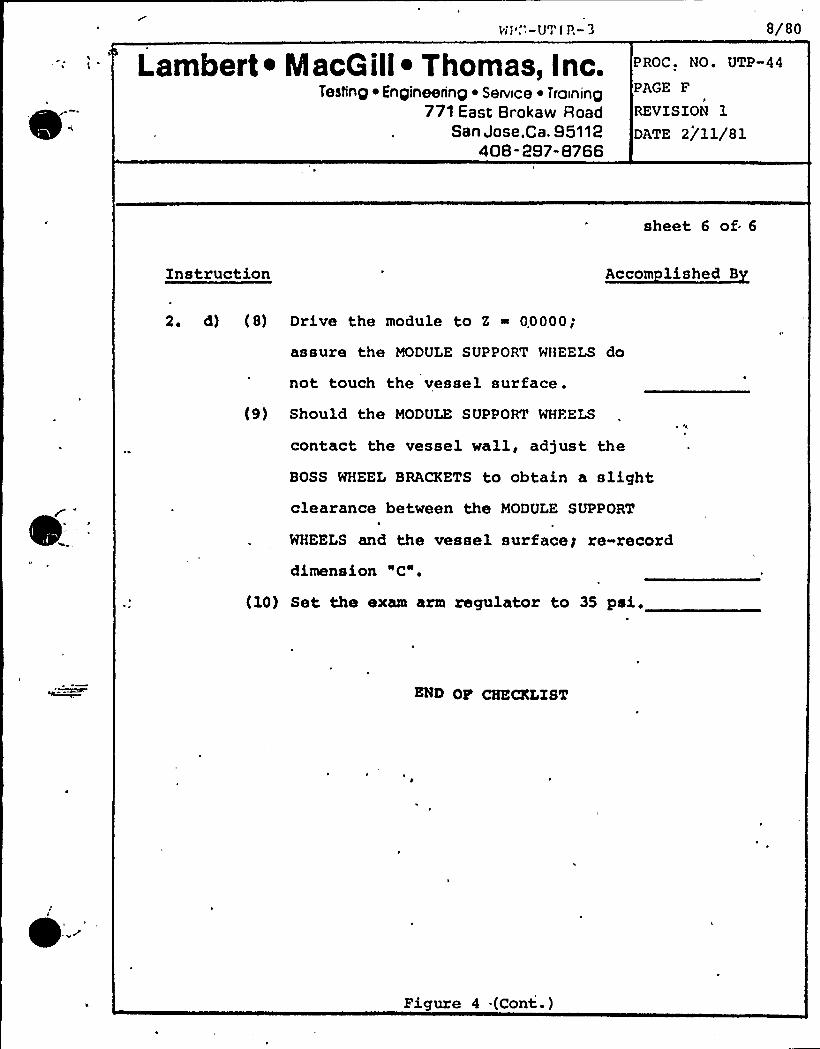
wi'."-U"r'IR- 3
Lambert ~ IacG ill~ Thomas, Inc.Testing ~ Engineering ~ Serwce ~ Training
771 East Brokaw RoadSan Jose,Ca. 95112
408- 297-8766
8/80
PROC. NO. UTP-44
PAGE F
REVISION 1
DATE 2/11/81
sheet 6 of 6
Instruction Accom lished B
2. d) (8) Drive the module to Z ~ 00000;
assure the MODULE SUPPORT WHEELS do
not touch the vessel surface .
(9) Should the MODULE SUPPORT WHFELS
contact the vessel wall, adjust the
BOSS WHEEL BRACKETS to obtain a slightclearance between the MODULE SUPPORT
WHEELS and the vessel surfaceg re-record
dimension "C".
(10) Set the exam arm regulator to 35 pai.
END OP CHECKLIST
Figure 4 .(Cont.)


Da te 1/8179
Revision 0
MNP-2 PSI PROGRAM PLAN
NOT USED
(Purposely left blank)
Lambert ~ MacQ illI Thomas, Inc.Testing ~ Engineering ~ Service ~ Training
771 East Brokaw RoadSan Jose,Ca. 95112
408- 297-8766
PROC. UTP-42
PAGE 7
FOLl.OWING PAGE 8
REVISION 0
GATE 12/19/80
X. C. 4. d) With the appropriate controller readout at zero
(or the readout representing the start position),adjust the POSITION control to set the pen to
zero.
e) Orive the device along one axis to a count value
representing full chart pen travel.f) Adjust the SENSITIVITY contr ol {as required) to
set the pen to ten (10) major divisions.
g) Orive the device (along the same axis) to the
start posi tion, d) .
h) Adjust the POSITION control to set the pen to "0"
division.i) Repeat steps e), f), g), and h) until the pen
fa i thful ly tracks the di s pl ay value.
XI. PERFORMANCE
A. Chart records shall contain written notes fully identi-fying the record as directed in the examination proce-
dure ~
B. Calibration checks shall be recorded on each chart as
directed by the examination procedure.
~ ~
~ ~
~ ~
l I
l I
W0 0 0
~ ~
~ s
~ ~ ~ ~ ~ I ~ ~ ~
~ ~ ~ ~ ~
~ ~ ~ I ~ ~
~ ~ ~
~ ~ ~ ~ ~ ~
~ ~
l I ~ ~ I
~ ~ ~ ~ ~ ~ ~ ~ ~ ~ ~
~ ~ ~ ~ ~ ~ ~ ~
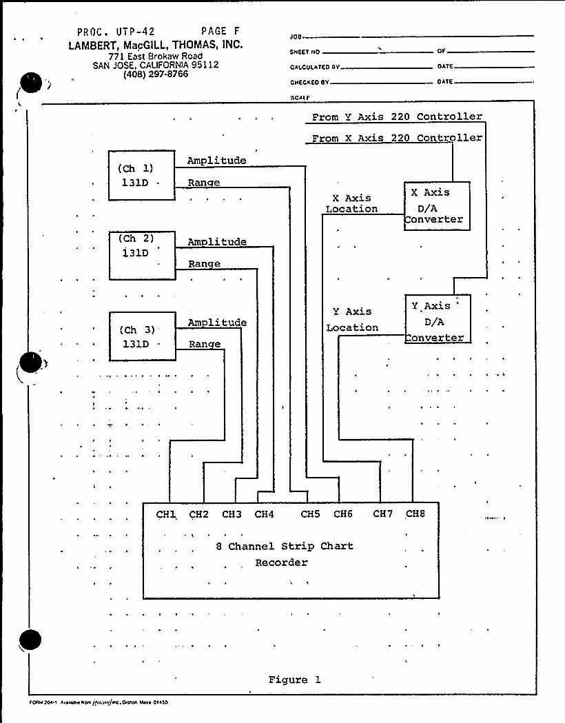
~ ~
(
PROC. UTP-42 PAGE F
LAMBERT, MacGllL, THOMAS, INC.771 fast Brokaw Road
SAN JOSE., CALIFORNIA95112(408) 297-8766
JOB
SHEET NO
CALCULATFDBY
CHECKED BY
SCALF
OF
DATE
DATE
(Ch 1)131D .
Amplitude
Ran e
From Y Axis 220 Controller
From X Axis 220 Controller
(Ch 2)131D
Am litudeRan e
X AxisLocation
X AxisD/A
onverter
(Ch 3)131D
Am litudeRan e
Y AxisLocation
Y AxisD/A
onverter
, ~
4 I
CH1 CH2 CH3 CH4 CH5 CH6 CH7 CHS
8 Channel Strip ChartRecorder
I'DOOO TOO I Aeo~ Oom jhloo>ojuc. &alon. Mooo. 01OSO
Figure 1

Date l /8/79Revi sion 0
)JNP-2 PSI PROGRAM< PLAN
( g
NOT USED
(Purposely left blank)
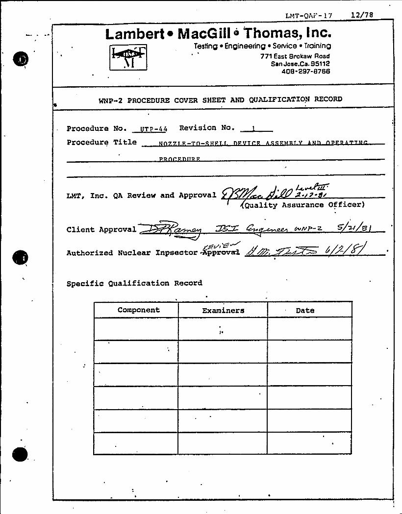
Lambert ~ MacGill o 'Thomas, Inc.Testing ~ Engineering i Service ~ Training
771 East Brokaw RoadSan Jose,Ca. 95112
408-297-8766
WNP-2 PROCEDURE COVER SHEET AND QUALIFICATION RECORDI
Procedure Na. ~qp-gg Revision No.
Procedure Title
LMT, Inc. QA Review and Approval Ae ePe /Quality Assurance Officer)
Client Approval yvtvP -2. 5 2/ g
Authorized Nuclear Inpsector '
Specific Qualification Record
Component Examiners Date

I'l
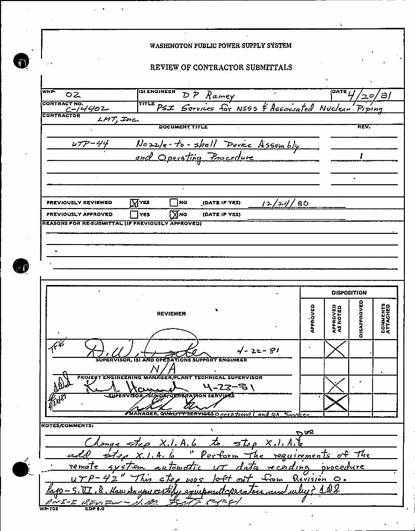
WASHINGTONPUBLIC POWER SUPPLY SYSTEM
REVIEW OF CONTRACTOR SUBMITTALS
WNP ~p I5 I KNOINEERZ p ffcL/nQ
DATK
CONTRACT NO+-I')c'O2 TITLE \ i iP~~ W~ry(~S POV h/555 0 ACPac-IcZ7el ~ +<R-CONTRACTOR SPIT WC..
DOCUMENT, TITLE RK ~
50 WJc. - 7 0 - sic I( Merce f4'jQpg
Wmc c~t'Pe
PREVIOUSLY RKVIKWKD ' YKS NO (DATE IF YKS)
PRKVIOUSI.YAPPROVED Q YES gfNO IDATKIF YKS)
REASONS FOR RKWUBMITTAL(IF PREVIOUSLY APPROVED)
/x w-'0
DISPOSITION
REVIEWERO
~ 0
cL~C
OOW c0)IOOcc: Z
~g0
0hl
0C
O
SUPERVISOR, ISI A D OP ATIONS SUPPOR KNO N
w APROJK T ENOINKERINO MAN CiKR/PLANT TKCHNICAI SUPERVISOR
A AGER,
NOTES/COMMENTS'PE
~fe
./. A. CII r'r x.j, A,
rc' JsRa+ W~ce re"w7'cv/5 oH G ~
WP'701 EDP $ .0

'I
ll
'I
'
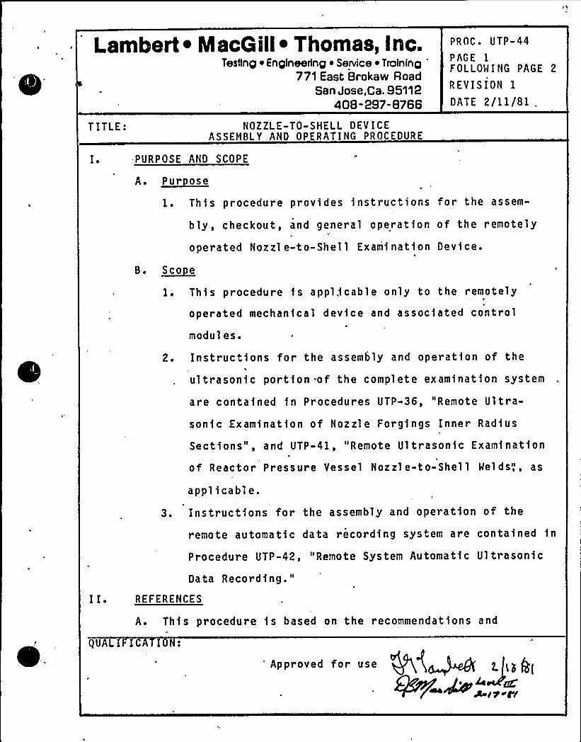
Lambert ~ IacG ill~ Thomas, Inc.Testlnp ~ En pineetfnp ~ Service ~ Tralninp
771 East Brokaw RoadSan Jose,Ca. 95112
408-297-8766
PROC ~ UTP-44
PAGE 1
FOLLOWING PAGE 2
REVISION 1
DATE 2/11/81 .
TITLE:
Ie
NOZZLE-TO-SHELL DEVICEASSEMBLY AND OPERATING PROCEDURE
PURPOSE AND SCOPE
A. ~Pur ose
1 ~ This procedure provides instructions for the assem-
bly, checkout, and general operation of the remotely
operated Nozzle-to-Shell Examination Device.
B. ~Sco e
1 ~ This procedure is appl,fcable only to the remotely\
operated mechanical device and associated control
modules.
2. Instructions for the assembly and operation of the
ultrasonic portion of the complete examination system
are contafned fn Procedures UTP-36, "Remote Ultra-
sonic .Examination of Nozzle Forgfngs Inner Radius
Sections", and UTP-41, "Remote Ultrasonic Examination
of Reactor Pressure Vessel Nozzle-to-Shell Welds",, as
applicable.
3. Instructions for the assembly and operation of the
remote automatic data recording system are contained fn
Procedure UTP-42, "Remote System Automatic Ultrasonic
Data Recording."
REFERENCES
A. This procedure fs based on the recommendations and
QUAL I
'ppr oved for use
Ce
A it"C'(
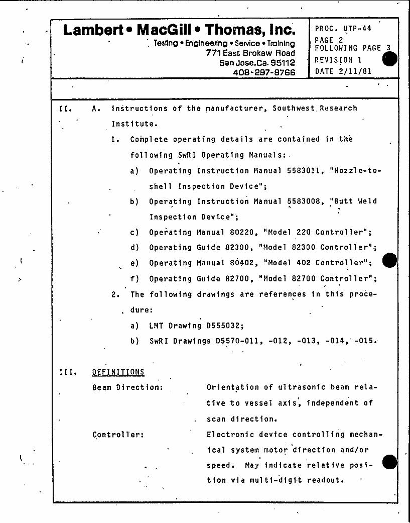
Lambert ~ IacG ill~ Thomas, Inc.'. Testing ~ En'gineerlng ~ Senrice ~ Training
771 East Brokaw RoadSan Jose,Ca. 95112
408" 297-8766
PROC. UTP-44
PAGE 2FOLLOWING PAGE 3
REVISION 1
DATE 2/11/81
A. instructions of the manufacturer, Southwest, Research
Institute.1. Complete operating details are contained in the
following SwRI Operating Manuals:I
a) Operating Instruction Hanual 5583011, "Nozzl e-to-
shell Inspection Device";
b) Operating Instruction Manual 5583008, "Butt Weld
Inspection Devi.ce";
c) Opeiatfng Manual 80220, "Model 220 Controller";
d) Operating Guide 82300, "Model 82300 Controller",;
e) Operating Manual 80402, "iaodel 402 Controller";
f) Operating Guide 82700, "Model 82700 Controller";
2. The followfng drawings are references in this proce-
dure:
a) LHT Drawfng 0555032;
b) SwRI Drawings D5570-011, -012, -013, -014,'-015.
I I I e DEFINITIONS
Seam Direction:
Contr ol 1'er:
Orientation of ultrasonic beam rel a-
tive to vessel axis, independent of
scan direction.Electronic device controlling meehan«
ical system motor direction and/or
speed ~ May indicate relative posf-
tfon vfa multi-digit readout.
Lambert ~ MacG ill~ Thomas, Inc.Tesiinp ~ Engineerinp ~ Service ~ Training
771 East Brokaw RoadSan Jose,Ca. 95112
408-297-8766
PROC. UTP-44
PAGE 3FOLLOW I NG PAGE 4
REVISION 1
DATE 2/11/81
III. Index Movement:
(Increment)
Module, Search Un1t:
Scan Direction:
Hodul e movement (di stanc e moved)
between scans.
Search unit cluster inc 1 ud1ng shoes,
wedges, hold1ng framework, coupl ant
supply manifold.
Motion of search unit module relative
to nozzle axis, independent of beam
direction.X-axis:
Y-axis:
Z-axi s:
Circumferential axis of vessel.
Longitud1nal axis of nozzle (radial-to-vessel).Radial axis of nozzle.
IV ~ RESPONSIBILITY
A. The Technical Manager, LMT, Inc. 1s responsible for the
generation and control of this procedure and shall so
1ndicate by a dated signature on the procedure cover
sheet.
B. The responsible Level III Field Supervisor, LHT, or his
designated Level III alternate, LHT, shall qualify the
procedure for a particular examination.
Lambert ~ MIacG ill~ Thomas, Inc.Testing ~ Engineering ~ Service ~ Troining
771 East Brokaw RoadSan Jose,Ca. 95112
408-297-8766
PROC ~ UTP-44
PAGE 4FOLLOWING PAGE 5
REVISION 1
DATE 2/11/81
V ~ PROCEDURE UALIF ICATION
This procedure shall be qual ff1ed by performing and docu-
menting successful checkout and position verification an'dK
repeatabf1 fty as instructed in X.D. below.
VI ~ PERSONNEL RE UIREHENTS
A. Examiners us1ng this procedure shall have levels of qual-
fffcat1ons as per the Procedure Qualiffcat1on.
B. Personnel: operating the nozzl e-to-shell examination
devtce sha11 be qua1$ fSed on the equt pment ~and s
certified y an authorized LHT Level III examiner.
1. For each sh1ft of operation, the.exam'fnation team
.shall'onsist of at least the following personnel:
a) Coordinator/superv1sor: Coordinate efforts ofindividual team members and efforts of the exam1-
nation team wfth the owner and appropriate on-
sf te crafts.b) Console operator: Operate controllers, record
necessary data for completion of scan data
sheets. Conduct and verify functfonal checks of
mechanical. system.
c) Observer: Stationed at dev1ce locat1on to ob-
serve operation of device, warn of pending ~
obstruction, malfunction, etc.
Lambert ~ MacG ill~ Thomas, Inc.Testing Engineering ~ Service ~ Training
771 East Brokaw RoadSan Jose,Ca. 95112
408-297-8766
PROC'TP-44PAGE 5FOLLOQING PAGE 6
REVISION 1
DATE 2/11/81
VI ~ B. 1. d) Ul trasonfc operator: Perform examination cal f-bration, enter appropriate information on stripchart recordings, veri fy proper operation. of.
ultrasonic system. Certified to at least
Level II Ultrasonic.
2. Team personnel may perfor'm the above duties on a
rotatf-onal basis, provided adequate cross trainingand certification levels are existent.
VI I. E UIPMENT AND MATERIALS
A. S stem Descri tfon
1 ~, The mechanical 'system has been desfgned to remotely
scan nozzle.-to-vessel welds and nozzle inner radius
sections.A
2. The device operates from tracks'hich encircle the
"necked-down" portion of the nozzl e forging. The„
drive car (pipe bug) mounts on the track, providing
circumferential movement around the nozzle. The
ins ection arm assembl , attached to the pipe bug bym
an adapter arm, positions the search unf t module
radially on the vessel wall, and provides a wall
following motion of the arm assembly, which has been
des'igned to ensure a constant radial location of the
search unit module.
Lambert ~ MacG ill~ Thomas, Inc.Testing ~ Engineering ~ SeNice ~ Training
771 East Brokaw RoadSan Jose,Ca. 95112
408 -297-8766
PROC. UTP-44
PAGE 6FOLLOWING PAGE 7
REVISION 1
DATE 2/11/81
VI I. A. 2. The 82300 Controller governs the wall following mo-
tion of the inspection arm.assembly. A switch and
actuator assembly mounted at the hinge point of the
inspection arm/linear drive Junction contacts the
vessel wall. As the device progresses around the
nozzl e forging, the switch actuator arm position
changes, causing the inspection arm assembly to move
as required to maintain approximate parallelism be-
tween the arm and vessel wall.
The 82300 Controller may be set to either AUTO or
HANUAL to control the wall following function. When
in the AUTO mode, the position of the switch arm
determines the direction the arm assembly will move.
In the HANUAL mode, the proximity switch assembly isI
disabled and the wall following motions are control-
led by the JOG control - a front panel galvanometerE
indicates direction of travel in both AUTO and HANUAL
modes.
r
The 82700 Controller governs radial movement of the
search unit array along the vessel wall. Radial
position is indicated on a five digit display,
Lambert ~ MacG ill~ Thomas, Inc.Testing ~ Engineering ~ Service ~ TraIning
771East Brokaw Road "
. San Jose,Ca. 95112408-297-8766
PROC. UTP-44
PAGE 7FOLLOWING PAGE 8
REVISION IOATE 2/11/81
VI I ~ A. 2. mounted on the controller front panel. Upper and
lower limit switches are set to control the extent of
search unit movement, wfth1n the physfcal 1 fmits of
the inspection arm assembly.
The 220 Controller regulates rotational speed and
d 1rect1on and, via a five d1gft d1splay, 1ndfcates
circumferential location of the device along'he
nozzle track. Upper and lower limit control switches
may be set to allow complete, 360', rotation around
the nozzle,=or lim1ted movement between selectable
lfmits. Air and/or n1trogen supply and couplant
water flow rates are regulated by the 402 Control-
ler.
VII I. PREPARATION
— A. Documentation
1. The following prelfmfnary documentat1on requirements
,shall be rev1ewed by the examiner wfth the WPPSS IS I
Field Coordinator before beginning any examination
program:,
a) Procedure and gualiffcatfonb) Calibration Reports
c) Examination Reports
d) Haterfa1 and Equipment Certfffcatfons
Lambert ~ MacG ill~ Thomas, Inc.Testing Engineering ~ Se~ice ~ Training
771 East Brokaw RoadSan Jose.Ca. 95112
408 -297-8766
PROC. UTP-44
PAGE 8FOLLOWING PAGE 9
R EV I S ION 1
DATE 2/11/81
X. A. 1. e) Personnel Certfffcatfons
f) Status Indfcators (Hold tags)
B. ~Ph s $ ca 1
1. The following physical preparation requirements
shall be reviewed by the examiner with the WPPSS
ISI Field Coordinator before specific examinations
are performed:
a) Insulation removal;
b) OSHA requirements (ladders, lighting, fresh afr,scaffolding, etc.);
c) Cleanup requirements;
d) Safety precautions (other work fn area, etc.);e) Electrical outlets - 110-120v AC, 30 amp, single
phase, minimum of two (2) required;
f) Af r or nitrogen supply.
C. Surface Pre aratfon
1 ~ Examination surfaces shall be free from weld spatter
or any other surface condition which will impede free
movement of the search unit array.
2. Examination surfaces shall be free from extraneous
materials or other conditions which, fn the opinion
of the examiner, will impair the performance of a
~ meaningful examination.
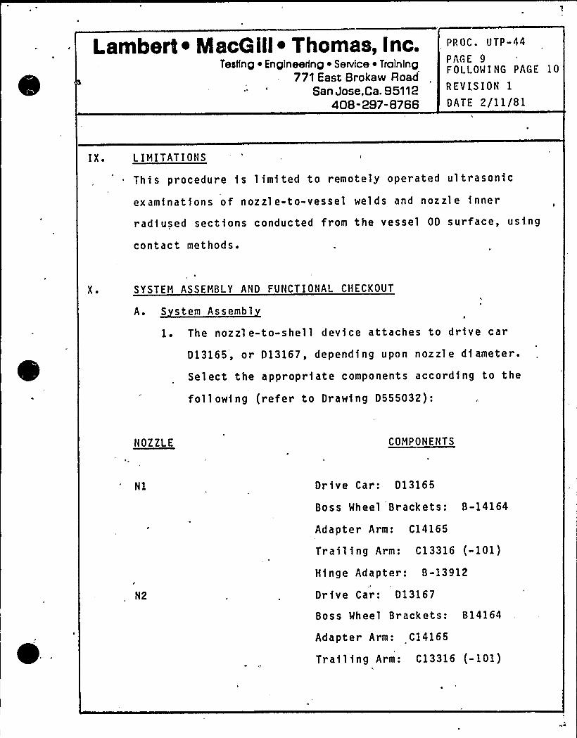
Lambert ~ MscG ill~ Thomas, Inc.Testing ~ Engineering ~ Service ~ Training
771 East Brokaw RoadSan Jose,Ca. 95112
408-297-8766
PROC. UTP-44
PAGE 9FOLLOWING PAGE 10
REVI.SION 1
DATE 2/11/81
IX ' IMITATIONS
This procedure is limited to remotely operated ultrasonic
examinations of nozzle-to-vessel welds and nozzle inner
radiused sections conducted from the vessel OD surface, usi.ng
contact methods.
X ~ SYSTEM ASSEMBLY AND FUNCTIONAL CHECKOUT
A. S stem Assembl
1. The nozzle-to-shell device attaches to drive car
D13165, or D13167, depending upon nozzle diameter.
Select the appropriate components according to the
following (refer to Drawing D555032):
NOZZLE COMPONENTS
N1
/
N2
Dr ive Car: D13165
Boss Wheel Brackets: B-14164
Adapter Arm: C14165
Trailing Arm: C13316 (-101)
Hinge Adapter: B-13912
Drive Car: D13167
Boss Wheel Brackets: B14164
Adapter Arm: C14165
Trail ing Arm: C13316 (-101)
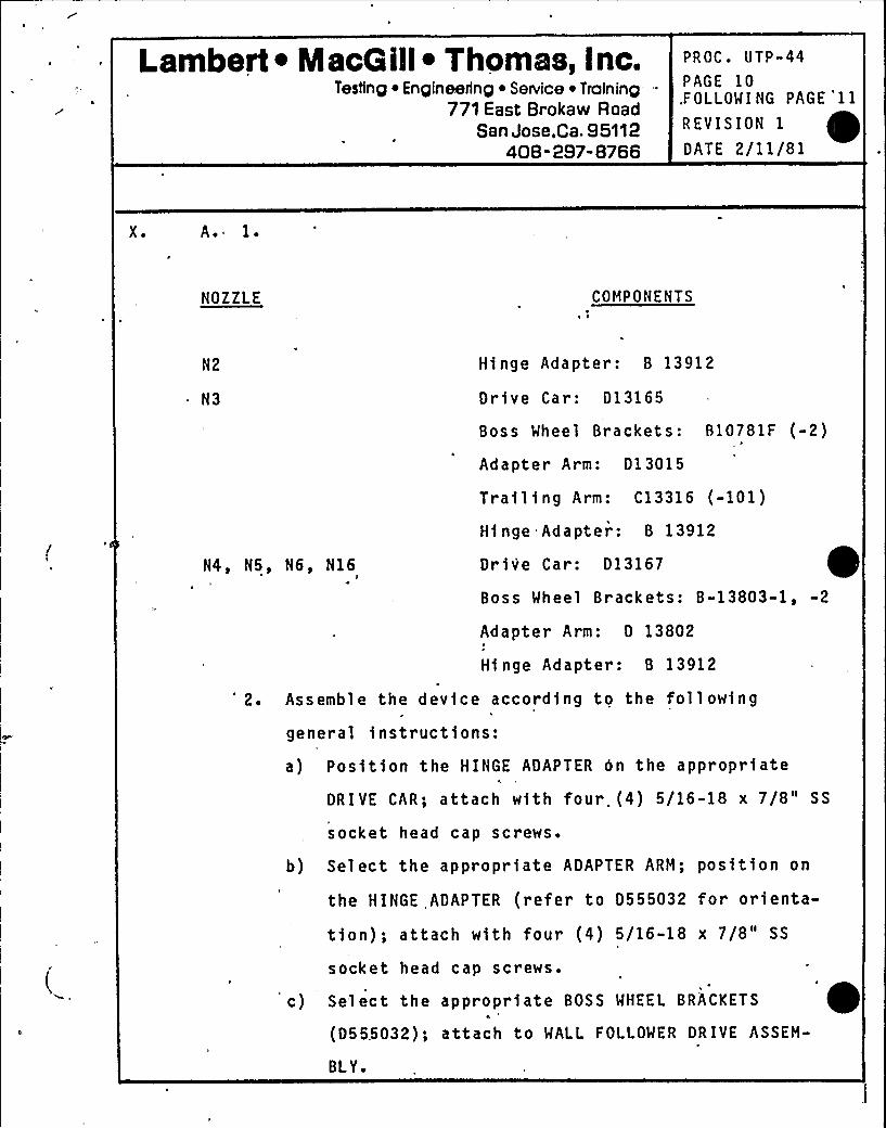
Lambert ~ NlacG ill~ Thomas, Inc.Testing i Engineerinp ~ SeNice ~ Training
771 East Brokaw RoadSan Jose,Ca. 95112
408-297-8766
PROC. 0TP-44PAGE 10FOLLOWING PAGE 11
REVISION 1
DATE 2/11/81
X ~ A. 1 ~
NOZZLE COMPONENTS
N3
N4, N5, N6, N16
Hinge Adapter: 8 13912
Drive Car: D13165
Boss Wheel Brackets: 810781F (-2)
Adapter Ar m: D13015
Trailing Arm: C13316 (-101)
Hinge Adapter: 8 13912
Drive Car: D13167
Boss Wheel Brackets: B-13803-1, -2
Adapter Arm: D 13802
Hinge Adapter: B 13912
2. Assemble the device according to the following
general instructions:
a) Position the HINGE ADAPTER 0n the appropriateh
DRIVE CAR; attach with four. (4) 5/16-18 x 7/8" SS
socket head cap screws.
b) Select the appropriate ADAPTER ARM; position on
the HINGE ADAPTER (refer to D555032 for orienta-
tion); attach with four (4) 5/16-18 x 7/8" SS
socket head cap screws.
c) Select the appropriate BOSS WHEEL BRACKETS ~(D555032); attach to MALL FOLLOWER DRIVE ASSEM-
BLY.
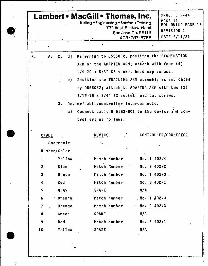
Lambert ~ MacGill~ Thomas, Inc.Testlnp iEnpineerinp ~ Service ~ Tralninp
771 East Brokaw RoadSan Jose,Ca. 95112
408-297-8766
PROC. UTP-44PAGE 11FOLLOWING PAGE 12
REVISION 1
DATE 2/11/81
X ~ A. 2 ~ d) Referring to D555032, position the EXAMINATION
ARM on the ADAPTER ARH; attach with four (4)
1/4-20 x 5/8" SS socket head cap screws.
e) Position the TRAILING ARM assembly as indicated
by D555032; attach to ADAPTER ARM with two (2)
5/16-18 x 3/4" SS socket head cap screws.
3. Device/cable/controller interconnects.I
a) Connect cable D 5583-801 to the device a'nd con-
trollers as follows:
CABLE
Pneumatic
Number/Color
1 Yellow
2 Blue
3 Green
4 Red
5 Gray
6 'range7 , Orange
8 Green
9 Red
10 Yellow
DEVICE
Match Number
Hatch Number
Hatch Number
Match Number
SPARE
Match Number
Match Number
SPARE
Hatch Number
SPARE
CONTROLLER CONNECTOR
No. 1 402/4
No. 2 402/2
No. 1 402/3
No. 3 402/1
N/A
, No. 1 402/3
No. 2 402/3
N/A
No. 2 402/1
N/A
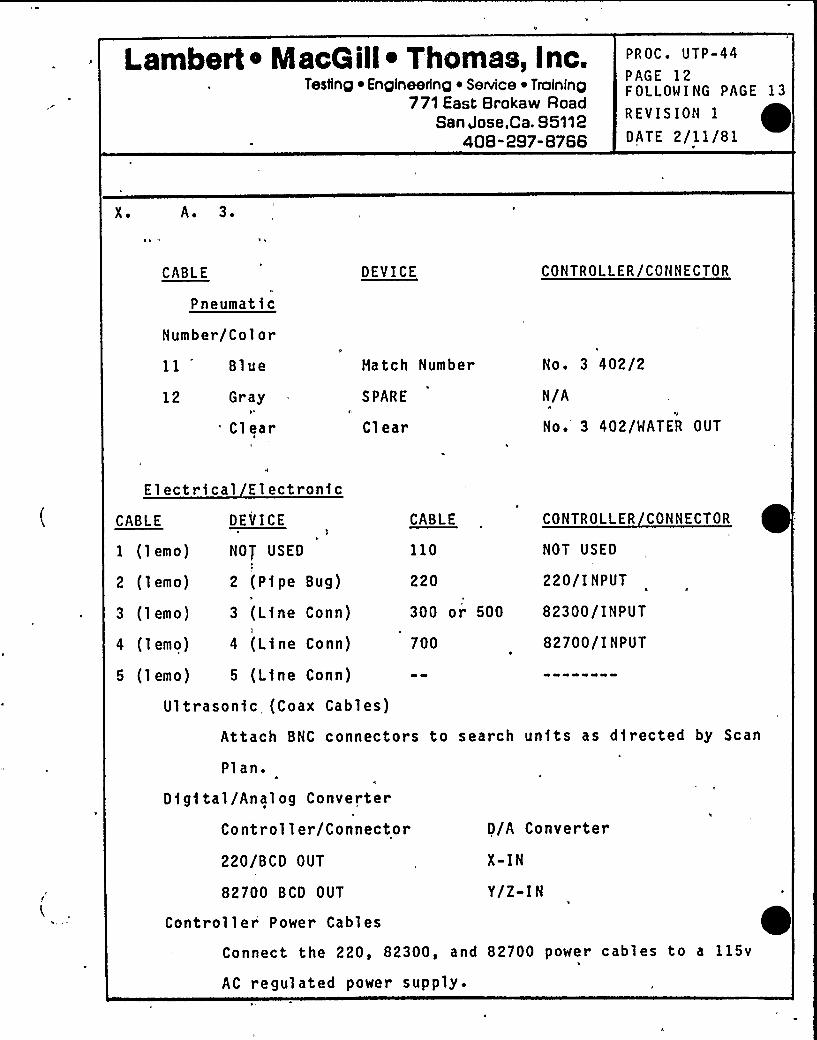
Lambert ~ MacGill ~ Thomas, Inc.Testing ~ Engineedng ~ Service ~ Training
771 East Brokaw RoadSan Jose,Ca. 95112
408-297-8766
PROC. UTP-44PAGE 12FOLLOWING PAGE 13
REVISION 1
DATE 2/11/81
X ~ A. 3 ~
CABLE
Pneumatic
Number/Color
11 Blue
12 GrayI*
Cl ear
DEVICE
Hatch Number
SPARE
Clear
CONTROLLER/CONNECTOR
No. 3 402/2
N/A
No. 3 402/MATER OUT
Electrical Electronic
CABLE
1 (lemo)
2 (lemo)
3 (lemo)
4 (lemo)
DEVICE
NOT USED
2 (Pipe Bug)
3 (Line Conn)
4 (Line Conn)
CABLE
110
220
300 or 500
CONTROLLER CONNECTOR
NOT USED
220/INPUT
82300/INPUT
700 82700/INPUT
5 (lemo) 5 (Line Conn)
Ultrasonic, (Coax Cables)
Attach BNC connectors to search units as directed by Scan
Plan.
Digital/Analog Converter
Controller/Connector
220/BCD OUT
82700 BCD OUT
Controller Power Cables
D/A Converter
X-IN
Y/Z-IN
Connect the 220, 82300, and 82700 power cables to a 115v
AC regulated power supply.
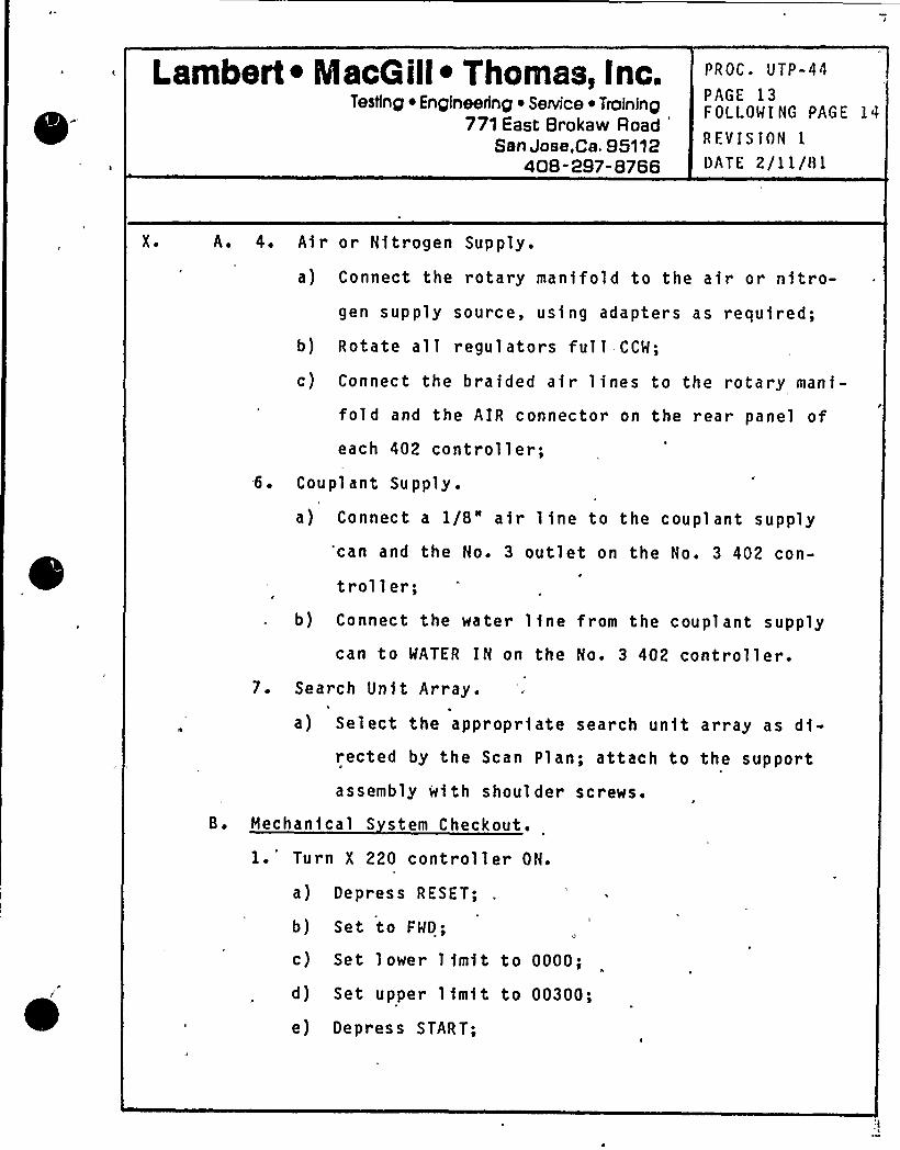
Lambert ~ MacGill ~ Thomas, Inc.Testing ~ Engineering ~ Service ~ Troining
771 East Brokaw RoadSan Jose,Ca. 95112
408-2S7-8766
PROC ~ UTP-44
PAGE 13FOLLOWING PAGE 14
R EV I S ION IDATE 2/1 1/Bl
X ~ A. 4. Air or Nitrogen Supply.
a) Connect the rotary manifold to the air or nitro-gen supply source, using adapters as required;
b) Rotate a11 regu1ators ful1 CCW;
c) Connect the braided air lines to the rotary mani-
fold and the AIR connector on the rear panel ofeach 402 controller;
6. Coupl ant Supply.
a) Connect a 1/8" air line to the coupl ant supply'can and the No. 3 outlet on the No. 3 402 con-
troller;b) Connect the water line from the couplant supply
can to WATER IN on the No. 3 402 contro11er.
7. Search Unit Arrays1
a) Select the appropriate search unit array as di-rected by the Scan Plan; attach to the support
assembly with shoulder screws.
B. Mechanical S stem Checkout.
1.'urn X 220 controller ON.
a) Depress RESET;
b) Set to FWD;
c) Set lower limit to 0000;
d) Set upper limit to 00300;
e) Depress START;
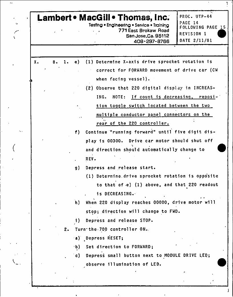
Lambert ~ MacQ ill~ Thomas, Inc;Testing ~ Engineering ~ SeNice ~ Training
771 East Brokaw RoadSan Jose,Ca. 95112
408-297-8766
PROC. UTP-44PAGE 14FOLLOWING PAGE 15
REVISION 1
DATE 2/11/81
X ~ 8 ~ 1 ~
2 ~
e) (1) Determine X-axis drive sprocket rotation iscorrect for FORWARD movement of drive car (CW
when facing vessel).
(2) Observe that 220 digital display in INCREAS-
ING. NOTE: If count is decreasin re osi-
tion to le switch located between the two
multi le conductor anel connectors on the
rear of the 220 controller.f) Contfnue '"running forward" until five digit dfs-
play is 00300. Drive car motor should shut offand direction should automatically change to
REV ~
g) Depress and,release start.(1) Determine. drive sprocket rotation is oppo'site
to that of e) (1) above, and that 220 readout
is DECREASING.e ~
h) When 220 display reaches 00000, drive motor willstop; direction will change to FWD.
i ) Depress and release STOP.II
Turn the 700 controller ON.,
a) Depress RESET;
b) Set direction to FORWARD;
c) Depress small button next to NODULE DRIVE LED;
observe illumination of LED.
Lambert ~ MacG ill~ Thomas, Inc.Testinp ~ Enpineerinp ~ Service ~ Traininp
771 East Brokaw RoadSan Jose,Ca. 95112
408-297-,8766
PROC. UTP-44
PAGE 15FOLLOWING PAGE 16
-REVISION 1
DATE 2/11/81
X ~ 8 ~ 2. d) Set lower limit to 00000, upper limit to 2438.
e) Observe MODULE RETRACT and SLIDE RETRACT LED's
are illuminated.
f) Depress and rel'ease START.
(1) Observe module drive is moving ~awa from
'nspection arm'inge point, that MODULE
RETRACT LED estinguishes, and that the digi-tal'readout is INCREASING.
(2) At approximately 1236 counts, the MODULE
DRIVE will stop, the LED will- extinguish, and
the MODULE EXT LED will illuminate.C
(3) After a 2-3 second pause, the SLIDE DRIVE LED
will illuminate, the slide will begin exten«
sion, and the SLIDE RETRACT LED will extin-
guish.
(4) At approximately 2438 counts. —.the slide
extension will stop, the SLIDE EXTEND LED
will illuminate and the direction control
will change to REV.
3. Turn the 82300 controller ON; set to MAN.
a) Set direction to FWD.
b) Depress the, JOG control-.
(1) Observe inspection arm moves toward vessel
and panel galvonometer indicates FORWARD.
I.ambert ~ MacG ill~ Thon@a, Inc.Testlnp ~ Enpineerinp ~ Service ~ Tralninp
771 East Brokaw RoadSan Jose, Ca. 95112
408-297-8766
PROC. UTP-44
PAGE 16FOLLOWI NG PAGE 17
REVIS IOI'I 1
DATE 2/11/81
X ~ B. 3. b) (2) Release JOG.
c) Set direction to PEVERSE.
d) Depress JOG control.
(1) Observe inspection arm moves ~awa from vessel
and panel meter indicates REVERSE.
e) Set the controll er to AUTO.0
(1) Depress the wall follower switch actuating
arm roller; observe the inspection arm moves
~awa from the vessel and the panel meter in-dicates REVERSE.
(2) Release the actuating arm rollers; observe
the inspection arm moves toward the vessel
and .the panel meter indicates FORWARD.
f) Set the controller to MANUAL.
4. Set the W.L.'wheel lock) regulator (No. 1 402) to 40
ps i ~
a) Toggle W.L. to ON; obser ve the wheel 1 ock aircylinder extends and the wheels swing inboard.
b) Toggle W.L. to OFF; observe retraction of aircylinder and that wheels swing outboard.
5. Set the ARM regulator (No. 2 402) to 55 psi.
a) Toggle ARM RETRACT; observe retraction of aircylinders and elevation of arm.
Lambert ~ IacG ill~ Thomas, Inc.Tesiing Engineering ~ SeNice ~ Training
771'East Brokaw RoadSan Jose,Ca. 95112
408-297-8766
PROC ~ UTP-44
PAGE 17FOLLOWING PAGE 18
REVISION 1
DATE 2/11/81
X ~ B. 5. b) Toggle ARM EXTEND observe extension of air'cylinders and decreasing elevation of arm.
6. Set TAIL WHEEL regulator (No. 2 402) to 40 psi.
a) Toggle TAIL WHEEL EXTEND; observe extension of
air cylinder and TAIL WHEEL.,
7... Set MODULE SUPPORT WHEEL regulator (No. 3 402) to 70
psi.
a) Toggle MOD SPT WHL to Z,; observe. rotary movement
of wheels to align with radial scan motion.
b) Toggle MOD SPT WHL to X; observe rotary motion of
wheels to align with circumferential scan move-
ment.
8. Set PURGE regulator (No. 3 402) to 5 psi.
a) Toggle ON.
9. Set COUPLANT PRS. regulator (No. 1 402) to 15 psi.
a) Toggle ON.
b) Open couplant flow control valve;'set flow meter
to approximately 200 cc/mfn.h
c) Observe coupl ant fl ow through clear supply lines
and out through wedges and shoes.
d) Cl ose valve; toggle OFF.

l
«I
J
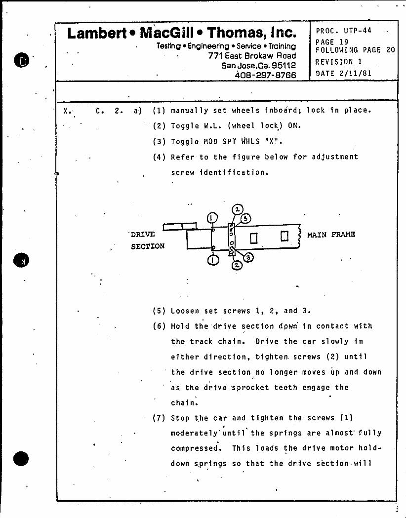
Lambert ~ Maca ill~ Thomas, Inc.Testing Enpineerinp ~ SeNice ~ Traininp
77)East Brokaw RoadSan Jose,Ca. 95112
408-297-8766
PROC. UTP-44
PAGE 19FOLLOWING PAGE 20
REVISION 1
DATE 2/11/81
X ~ C. 2. a) (1) manual ly set wheel s inboard; lock in pl ace.
'2) Togg1 e W.L. (wheel 1 ock) ON.
(3) Toggle M00 SPT WHLS "X".
(4) Refer to the figure below for adjustment
screw identification.
'RIVESECTION
a 0 ~NF~
(5) Loosen set screws 1, 2, and 3.
(6) Hold the'drive section dpwn in contact with
the track chain. Drive the car slowly in
either direction, tighten screws (2) until'he drive section no longer moves up and down
as the drive sprocket teeth engage theIlt
chain.
(7) Stop the car and tighten the screws (1)
moderately'ntil the springs are almost ful lycompressed. This loads the drive motor hold-
down springs so that the drive section will
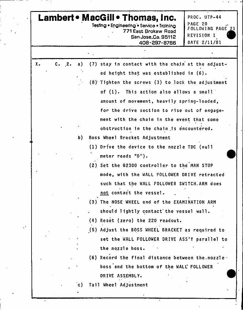
Lambert ~ MacGill~ Thomas, Inc.Testing ~ Engineering
'~ Service ~ Training771 East Brokaw -Road
San Jose,Ca, 95112408-297-8766
PROC'TP-44PAGE 20FOLLOW I NG PAGE 21
REVISION 1
DATE 2/11/81
X ~ C. 2. a) (7) stay fn contact with the chain at the adjust-ed height that was established in (6).
(8)'ighten the screws (3) to,l ock the ad jus tment
of (1). This action also allows -a small
amount of movement, heavily spring-loaded,
for the drive section to rise out of engage-
ment with the chain fn the event that some
obstruction fn the chain .fs encountered.
b) Boss Wheel Bracket Adjustment
(1) Drive the device to the nozzl e TDC (nullmeter reads "0").
(2) Set the 82300 controller to the MAN STOP
mode, with the WALL FOLLOWER DRIVE retractedsuch that the WALL FOLLOWER SWITCH.ARM does
not contact the vessel.
(3) The NOSE WHEEL end of the EXAMINATION ARM
should lightly contact'he vessel wall.
(4) Reset (zero) the 220 readout.
(5) Adjust the BOSS WHEEL BRACKET as required to
set the WALL FOLLOWER DRIVE ASS'Y parallel to
the nozzle boss.
(6) Record the final distance between the. nozzle =
boss and the bottom of the WALL'OLLOWER
DR IVE ASSEMBL Y.
c) Tail Wheel Adjustment
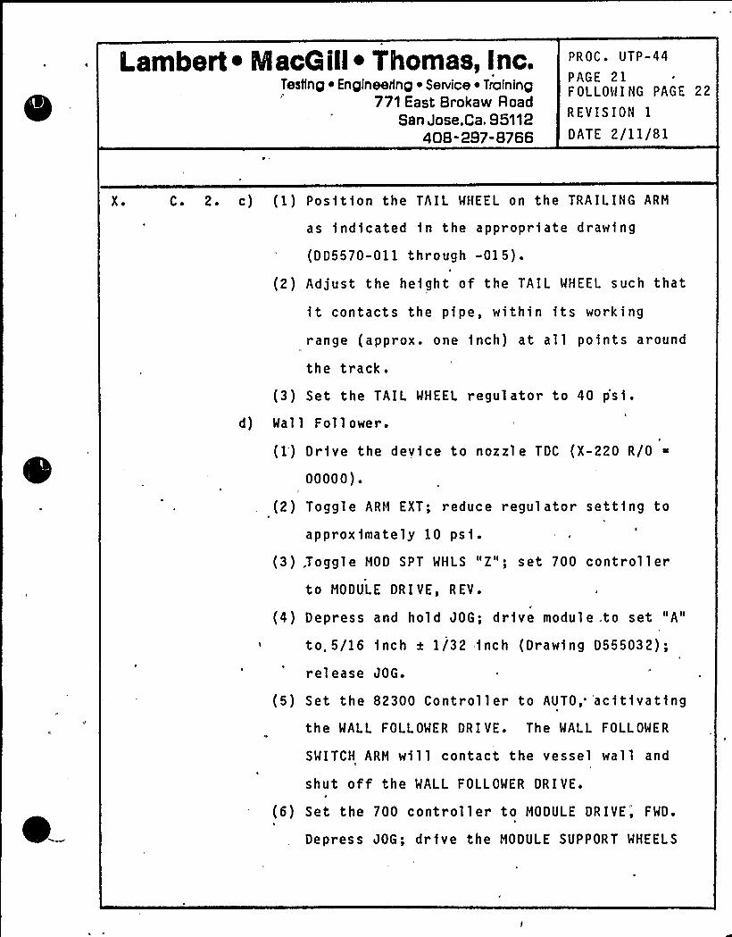
Lambert ~ IacG ill~ Thomas, Inc.Testing Engineering ~ Service ~ Training
771 East Brokaw RoadSan Jose,Ca. 95112
408-297-8766
PROC. UTP-44
PAGE 21FOLLOWING PAGE 22
REVISION 1
DATE 2/11/81
X ~ C. 2. c) (1) Position the TAIL WHEEL on the TRAILING ARM
as fndfcated fn the approprfate drawing
(DD5570-011 through -015).
(2) Adjust the height of the TAIL WHEEL such that
it contacts the pipe, within its working
range (approx. one inch) at all points around
the track.
(3) Set the TAIL WHEEL regulator to 40 p'sf.
d) Wall Follower.
(1') Drive the device to nozzle TDC (X-220 R/0
00000).
(2) Toggle ARM EXT; reduce regulator setting to
approximately 10 psf.
(3),Toggle MOD SPT WHLS "2"; set 700 controllerto MODULE DRIVE, REV.
(4) Depress and hold JOG; drive module .to set "A"
to„5/16 inch x 1/32 inch (Drawing D555032);
release JOG.
(5) Set the 82300 Controller to AUTO,"'acitfvatfng
the WALL FOLLOWER DRIVE. The WALL FOLLOWER
SWITCH ARM will contact the vessel wall and
shut off the WALL FOLLOWER DRIVE.\
(6) Set the 700 controller to MODULE DRIVE', FWD.
Depress JOG; drive the MODULE SUPPORT WHEELS
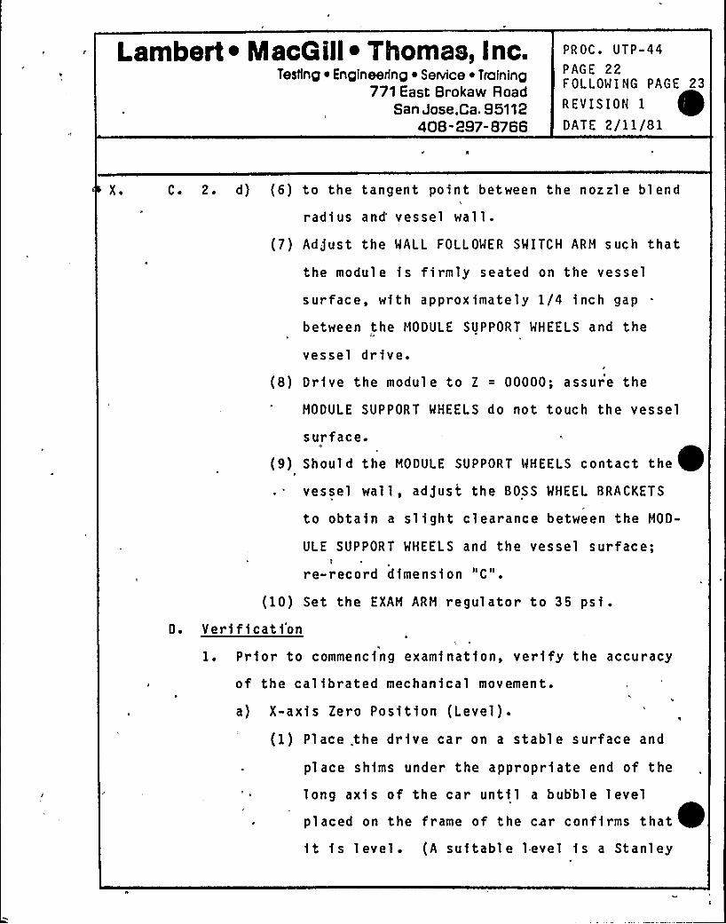
Lambert ~ MacG ill~ Thomas, Inc.Testing Engineering ~ SeNice ~ Training
771 East Brokaw RoadSan Jose,Ca. 95112
408-297-8766
PROC. UTP-44
PAGE 22FOLLOWING PAGE 23
REVISION 1
DATE 2/11/81
X ~ C. 2. d) (6) to the tangent point between the nozzl e bl end
radius and vessel wall.
(7) Adjust the MALL FOLLOWER SWITCH ARM such that
the module is firmly seated on the vessel
surface, with approximately 1/4 inch gap
between the MODULE SUPPORT WHEELS and the
vessel drive.
(8) Drive the module to Z = 00000; assure the
MODULE SUPPORT WHEELS do not touch the vessel
surface.u
(9) Should the HOOULE SUPPORT WHEELS contact the ~vessel wall, adjust the BOSS WHEEL BRACKETS
to obtain a slight clearance between the MOD-
ULE SUPPORT MHEELS and the vessel surface;
re-record dimension "C".
(10) Set the EXAM ARM regulator to 35 psi.D. Veri fi cat i'on
1. Prior to commencfng examinatfon, ver ify the accur acy
of the cal fbrated mechanical movement.
a) X-axis Zero Position (Level).
(1) Place. the drive car on a stable surface and
place shfms under the appropriate end of the
long axis of the car until a bubble level
placed on the frame of the car conffrms thatit is level. (A suitable l.evel fs a Stanley
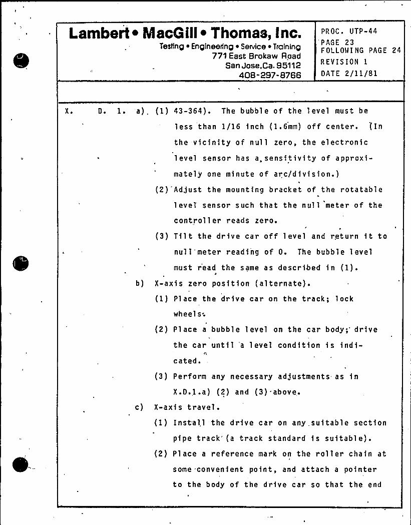
Lambert ~ MacGill~ Thomas, Inc.Testing ~ Engineering ~ Service ~ Training
771 East Brokaw RoadSan Jose,Ca. 95112
408" 297-8766
PROC. UTP-44
PAGE 23FOLLOW I NG PAGE 24
REVISION 1
DATE 2/11/81
X ~ D. 1. a). (1) 43-364). The bubble of the level must be
less than 1/16 inch (1.6mm) off center. (In
the vicinity of nul 1 zero, the electronic
level sensor has a,sensitivity of approxi-
mately one minute of arc/division.)I
(2)'Adjust the mounting bracket of the rotatable
1 evel'ensor such that the null meter of the
controller reads zero.
(3) Tilt the drive car off .level and return ft to
null meter reading of 0. The bubble level
must read the same as described fn (1).b) X-axis zero position (alternate).
F
(1) Place the drfve car on the track; lock
wheels;
(2) Place a bubble level on the car body drive
the car until 'a level condftfon is indi-cated.-
(3) Perform any necessary adjustments as in
X.D.,l.a) (2) and (3) above,.
c) X-axis travel.(1) Install the drive car on any suitable section
pipe track'(a track standard fs suitable).(2) Place a reference mark on the roller chain at
some convenient point, and attach a pointerto the body of the drive car so that the end
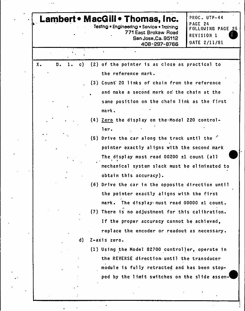
Lambert ~ NlacGill ~ Thomas, Inc.Testing ~ Engineering ~'enrice ~ Training
771 East Brokaw RoadSan Jose,Ca. 95112
408" 297-8766
PROC. UTP-44PAGE 24FOLLOWING PAGE 25
REVISION IDATE 2/11/81
X ~ D. 1. c) (2) of the po1nter 1s as close as practical to
the reference mark.
(3) Count'0 links of chain fr om the reference
and make a second mark on'he cha1n at the
same pos1tion on the cha1n,link as the firstmark.
(4) Zero the display on the.Model 220 control-ler.
(5) Dr1ve the car along the track until the
po1nter exactly aligns w1th the second 'mark
The dtsplay must read 00200 el count (all ~I a
mechanical system slack must be eliminated to
obtain, this accuracy).
(6) Drive the car in the oppos1te d1rection untilthe pointer exactly aligns w1th the firstmark. The display must read 00000 al count.
fi
(7) There 1s no adjustment for this calibration.If the proper accuracy cannot be achieved,
replace the encoder or readout as necessary.
d) Z-ax'1s zero.
(1) Using the Model 82700 controller, operate inthe REVERSE direction until the transducer
module is fully retracted and has been stop-
ped by the 11mit switches on the s11de assem-
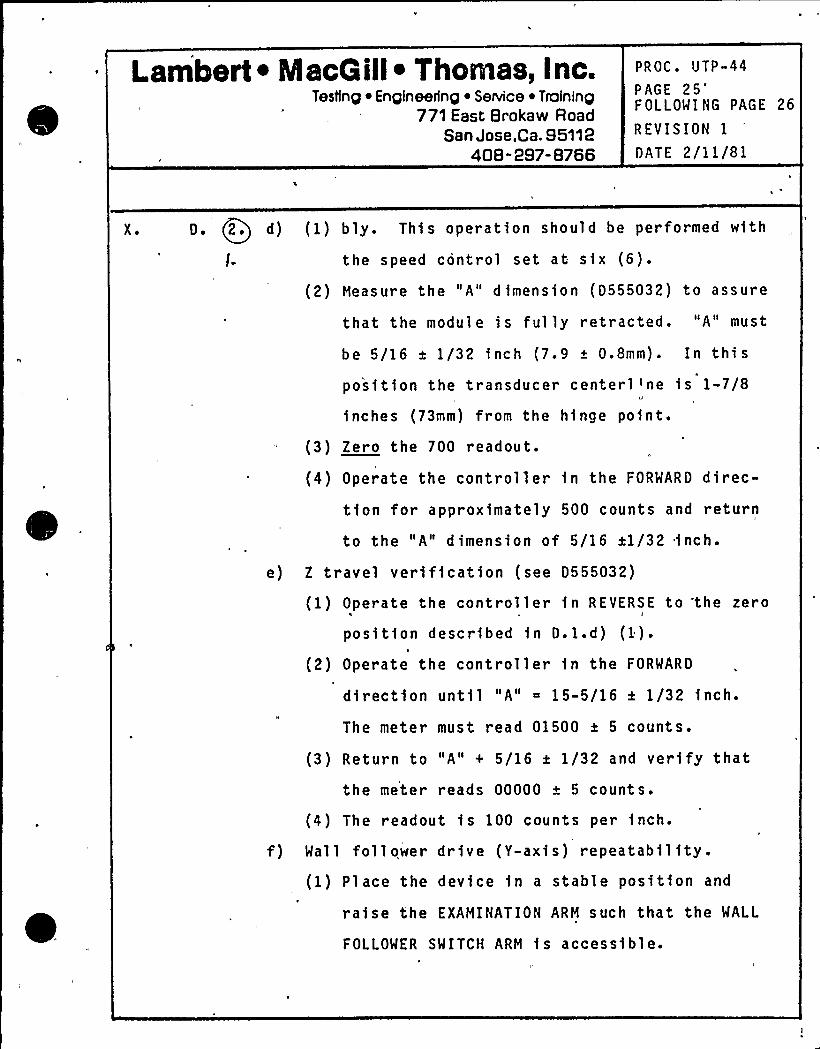
Lambert ~ MacG ill~ Thomas, Inc.Testing ~ Engineering ~ Senrice ~ Training
771 East Brokaw RoadSan Jose,Ca. 95112
408-297-8766
PROC. UTP-44
PAGE 25"FOLLOWING PAGE 26
REVISION 1
DATE 2/11/81
X ~ 0 ~ Q2. d) (1) b)y. Thi s operation shoo1d be performed with
l- the speed control set at six (6).
(2) Heasure the "A" dimension (0555032) to assure
that the module is fully retracted. "A" must
be 5/16 a 1/32 inch (7e9 a 0.8mm). In thisposition the transducer centerl)ne is 1-7/8
inches (73mm) from the hinge point.
(3) Zero the 700 readout.
(4) Operate the controller in the FORWARD direc-
tion for approximately 500 counts and return
to the "A" dimension of 5/16 +1/32 inch.
e) Z travel verification (see D555032)
(1) Operate the controller in REVERSE to 'the zeros
position described in D. l.d) (1) ~
(2) Operate the controller in the FORWARD
direction until "A" 15-5/16 a 1/32 inch.
The meter must read 01500 a 5 counts.
(3) Return to "A" + 5/16 a 1/32 and verify that
the meter reads 00000 a 5 counts.
(4) The readout fs 100 counts per inch.
f) Wall follower drive (Y-axis) repeatability .
(1) Place the device in a stable position and
raise the EXAHINATION ARH such that the WALL
FOLLOWER SWITCH ARH is accessible.
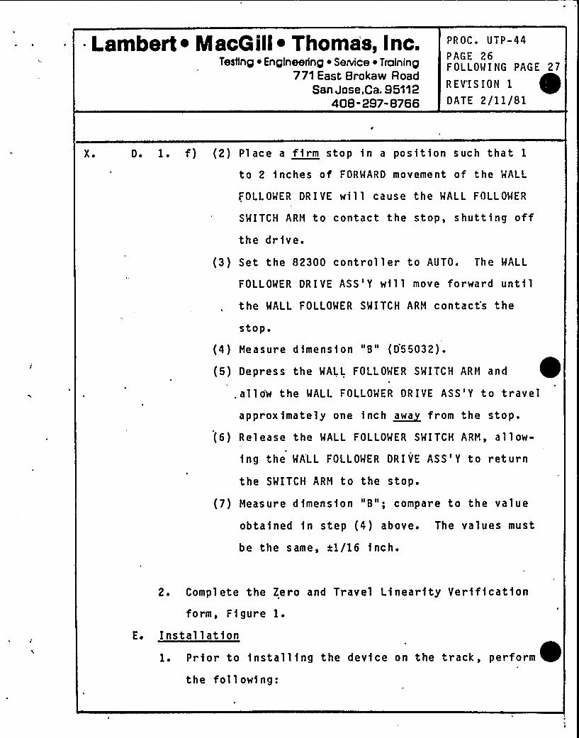
Lambert ~ IacG ill~ Thomas, Inc.Testing ~ Engineering ~ Service ~ Training
771 East Brokaw RoadSan Jose,Ca. 95112
408-297-8766
PROC. UTP-44
PAGE 26FOLLOWING PAGE 27
R EV'I S ION 1
DATE 2/11/81
X ~ D. 1. f) (2) Place a firm stop in a position such that 1
to 2 inches of FORWARD movement of the WALL
FOLLOWER DRIVE will cause the MALL FOLLOWER
SWITCH ARM to contact the stop, shutting offthe drive.
(3) Set the 82300 controller to AUTO. The WALL
FOLLOWER DRIVE ASS'Y will move forward untilthe WALL FOLLOWER SWITCH ARM contact's the
stop
(4) Measure dimension "B" (D55032).
(5) Depress the WALL FOLLOWER SWITCH ARM aad ~.allow the WALL FOLLOWER DRIVE ASS'Y to travel
approximately one inch ~awa from the stop.
(6) Release the WALL FOLLOWER SMITCH ARM, allow-
ing the MALL FOLLOWER DRIVE ASS'Y to return
the SWITCH ARM to the stop.
(7) Measure dimension "B"; compare to the value
obtained in step (4) above. The values must
be the same, al/16 inc h.
2. Complete the Zero and Travel Linearity Verificationform, Fi gure 1.
E. I nstal 1 at i on
1. Prior to installing the device on the track, perform
the following:
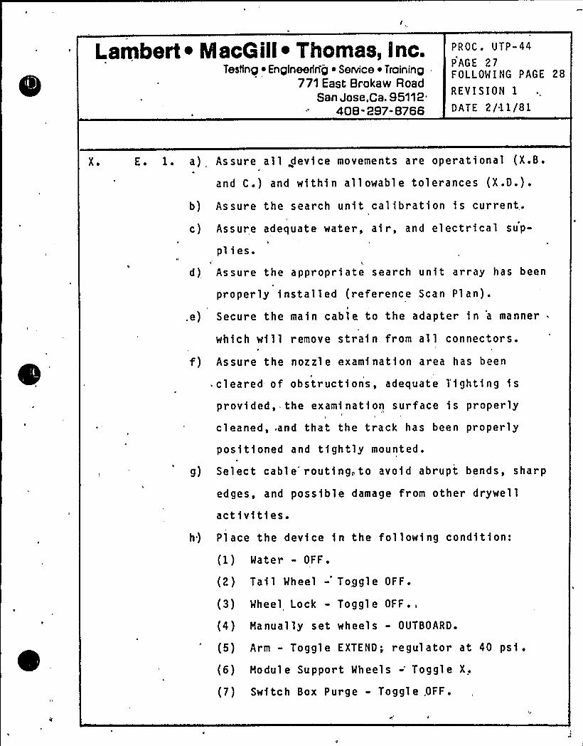
Lambert ~ NlacQ ill~ Thomas, Inc.Testing ~ Engineertng ~ Setvice ~ Training
771 East Brokaw RoadSan Jose,Ca. 95112.
408 -297-8766
PROC. UTP-44
PAGE 27FOLLOWING PAGE 28
REVISION 1
DATE 2/11/81
X ~ E. 1. a) Assure all device movements are operational (X.B.
and C.) and with1n allowable tolerances (X.D.).
b) Assure the search unit calibration is current.'I
c) Assure adequate water, air, and electrical sup-
plies.I.
d) Assure the appropriate search unit array has been
properly installed (reference Scan Plan).
.e) Secure the ma1n cable to the adapter in 'a manner
which will remove stra1n from all connectors.
f) Assure the nozzle examinat1on area has been
cleared of obstruct1ons, adequate l'ighting is
provided, the exami nat1on surface 1s properly
cleaned, and that the track has been properly
positioned and t1ghtly mounted.
g) Select cable'outing,to avoid abrupt bends, sharp
edges, and poss1ble damage from other drywell
act1vi ti es.
h) Place the device in the following cond1t1on:
(1) Water - OFF.
(2) Tail Wheel - Toggle OFF.
(3) Wheel Lock - Toggle OFF.,
(4) Manually set wheels - OUTBOARD.
(5) Arm - Toggle EXTEND; regulator at 40 psi.
(6) Module Support Wheels -'oggle X,
(7) Sw1tch Box Purge - Toggle .OFF.
l.ambert ~ MacQ ill~ Thomas, Inc.Testing ~ Enqlneering ~ SeNice ~ Trafninp
771 East Brokaw RoadSan Jose,Ca, 95112
408-297-8766
PROC. UTP-44PAGE 28roLLOWING PAGE 2O
REVISION IDATE 2/11/81
X ~ E. I ~ h) (8) 82300 - MANUAL, STOP.
(9) X-220 - STOP.
(10) 700 - STOP.
2. Move to examination area.
a) Exercise extreme care to revent dama e to both
the device and the cable durin the .move.4
Ensure suff1cient excess cable (approximately 15
feet) 1s readily available in the exam1n'at1on
ar ea.1
3. Prepare for dev1ce fnstallat1on.
a) Set EXAMINATION ARM regulator to 0 psi; toggle
EXTENDS
'b) Concurrently locate the device on the track and
carefully insert the EXAMINATION ARM 1nto the
space between the vessel surface and the
insulation.c) Swing the manually set wheels 1nboard; lock 1n
place w1th the thumb screws.
„,d) Toggle W.L. ON.
e) Set ARM regulator to 35 ps1.
f) Toggle ARM EXTEND.
g) Check the f1nal adjustments of X.C.2; refine as
neces s a ry.
l.ambart ~ MacG ill~ Thomas, lnc.Testing ~ Engineeting ~ Service ~ Training
771 East Brokaw RoadSan Jose,Ca. 95112
408" 297-8766
PROC. UTP-44
PAGE 29FOLLOWING PAGE 30
REVISION 1
DATE 2/11/81
X. E. 3. g) NOTE: The final adjustments may require "refin-ing" on each nozzle due to minor variations in
nozzl e dimensions.
4. Prel imi,nary scan.
a) Perform the preliminary scan to determine scan-
ning 1 imits which may be imposed on any specific
nozzle by variation in clearance due to penetra-
tions, insulation, thermocoupl e pads, et'c.
b) Set the system to the following conditions:
(1) Toggle W.L. ON.
(2) Toggle TAIL WHEEL EXT.
(3) Toggle EXAMINATION ARM EXT.
(4) Toggle COUPLANT OFF; valve CLOSED.
(5) Toggle MODULE SUPPORT WHEELS Z.
(6) Toggle WALL FOLLOWER SWITCH box purge ON.
(7) 82300 Controller » MANUAL STOP.I
(8) 220 Controll er - STOP.
(9) 700 Controller - STOP, MANUAL DRIVE.
c) Station an observer at the device, communicating
with the console operator vi'a a comm set.,
d) Set 700 to REVERSE: depress START.
(1) Module will drive to 00000, stop.
e) Set the 82300 controller to AUTO.
f) Toggle MODULE SUPPORT WHEELS to X.
Lambert ~ MacQill~ Thomas, Inc.Testing ~ Engineering ~ Service ~ Training
771 East Brokaw RoadSan Jose,ca. 95112
408-297-8766
PROC. UTP-44PAGE 30FOLLOWING PAGE 31
REVISION 1
D'AT E 2/1 1/8 1
X ~ E. 4. g) JOG the device to nozzle TDC; reset the 220 con-
troller; set lower limit to 00000.
h) Set the 220 controller to FORWARD; depress JOG,
driving the device ~s'lowi 360'hf1e the observer
checks for:(1) MODULE contact;
(2) TAIL WHEEL contact;
(3) Smooth, regular pr'ogression of the device
around the nozzle;
(4) NOSE WHEEL contact with the vessel wall;(5) Accurate WALL FOLLOWER function;
(6) Note and record all obstructfons and inter-ferences.
i), When the device reaches nozzle TDC (null meter
indicates "0") release the JOG oontrol. Note the
R2g-„readout; add 20 counts and set value as upper
lfmft.j) Set 220 Controller to REV, STOP.
k) Toggle MODULE SUPPORT WHEELS Z.
1) Set the 700 Controller to'ODULE. DRIVE, FWD.
m) Refer to the. Scan Plan; determine the maximum
Z-axfs extension required and set as upper
Lambert ~ MacGill~ Thomas, Inc.Testing ~ Engineering ~ Service ~ Troining
771 East Brokaw RoadSan Jose,Ca. 95112
408-297-8766
PROC. UTP-44
PAGE 31FOLLOWING PAGE 32
REVISION 1
DATE 2/11/81
X ~ E. 4. n) Depress and release START;. drive the modul e to
the upper limit.o) Toggle MODULE SUPPORT WHEELS X.
p) Slowly drive the device CCW to X = 00000 while
the observer checks for the same conditions item-
ized fn X.E.4.h), above.
q) Note and record all obstructfons and fnterfer-E
~ ences.
r) When the devi ce returns to X 00000, veri fy the
null meter equals "0", then drive the MODULE REV
to Z 00000.
s) Arrange the cable such that minimal attention is
required by routing along the pipe and attaching
with a rope, strap, etc., leaving sufficientslack for a complete circumferential scan,
avoiding sharp bends or kinks, sharp edges,
projections, etc.
XI ~ PERFORMANCE
A. Pre aration for Scannfn
1. Refer to the appropriate section of the Scan Plan;
determine the correct search unit module.
2. Refer to Procedure UTP-41'or nozzle-to-vessel welds,
or Procedure UTP-36 for nozzle inner radius examfna-
tions ~ Assure that the ultrasonic system has been
calibrated fn accordance with the procedure requfre-
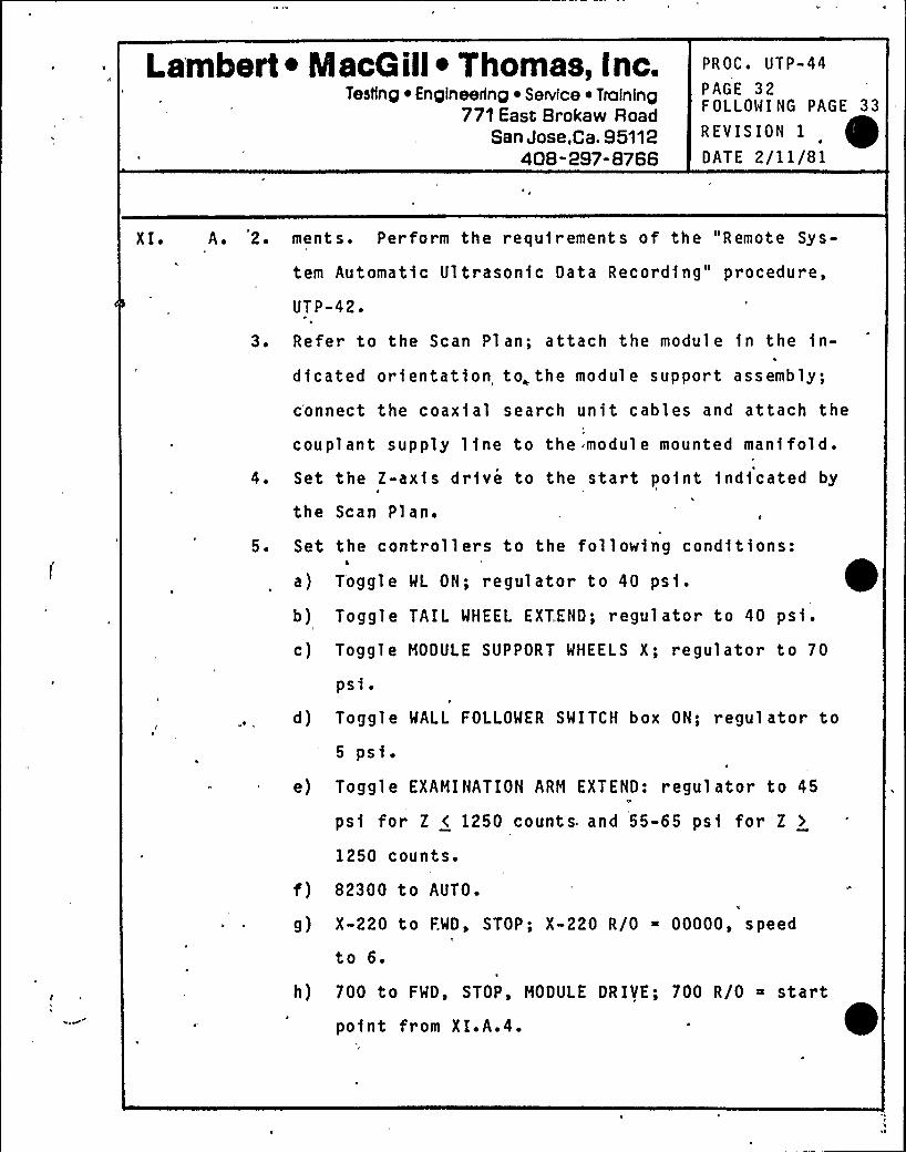
Lambert ~ MacG ill~ Thomas, Inc.Testing ~ En pineerlnp ~ SeNlce ~ Tralnlnp
771 East Brokaw RoadSan Jose,Ca. 95112
408-297-8766
PROC'TP-44PAGE 32FOLLOWING PAGE 33
REVISION 1
DATE 2/11/81
XI. A. 2. ments. Perform the requirements of the "Remote Sys-
tern Automatic Ultrasonic Data Recording" procedure,
3 ~
5 ~
UTP-42 ~
Refer to the Scan Plan; attach the module in the in-
dicated orientation to, the module support assembly;
connect the coaxial search unit cables and attach the
couplant supply line to the module mounted manifold.
Set the Z-axis drive to the start point indicated by
the Scan Plan.
Set the controllers to the following conditions:
a) Toggle WL ON; regulator to 40 psi.
b) Toggle TAIL WHEEL EXTEND; regulator to 40 psf.
c) Toggle MODULE SUPPORT WHEELS X; regulator to 70
psi.d) Toggle WALL FOLLOWER SWITCH box ON; regulator to
5 psi.
e) Toggle EXAMINATION ARM EXTEND: regulator to 45
psi for Z < 1250 counts. and 55-65 psi for Z >
1250 counts.
f) 82300 to AUTO.h
g) X-220 to FWD, STOP; X-220 R/0 00000, speedf
to 6.
h) 700 to FWD, STOP, MODULE DRIVE; 700 R/0 startpoint from X I.A.4.
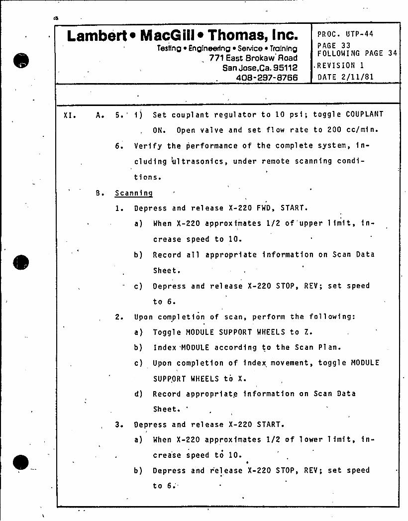
Lambert ~ iViacG ill~ Thomas, Inc.Testing ~ Engineering ~ Service ~ Training
,771East Brokaw Road
San Jose,ca. S5112408-297-8766
PROC. UTP-44
PAGE 33FOLLOWING PAGE 34
REVISION 1
DATE 2/11/81
XI ~ A. 5. ') Set coupl ant regulator to 10 psi; toggle COUPLANT
ON. Open valve and set flow rate to 200 cc/min.
6. Verify the performance of the complete system, in-
cluding ultrasonics, under remote scanning condi-
tions.B. ~Scannin
1. Depress and release X-220 FWD, START.
a) When X-220 approximates 1/2 of 'upper limit, in-
crease speed to 10.
b) Record all appropriate information on Scan Data
Sheet.
c) Depress and release X-220 STOP, REV; set speed
to 6.
2. Upon completion of scan, perform the following:
a) Toggle MODULE SUPPORT WHEELS to Z.
b) Index MODULE according to the Scan Plan.
c) Upon completion of index movement, toggle MODULE
SUPPORT WHEELS to X.i
d) Record appropriate information on Scan Data
Sheet.a
3. Depress and release X-220 START.
a) When X-220 approximates 1/2 of lower limit, in-crease speed to 10.
b) Depress and r'elease X-220 STOP, REV; set speed
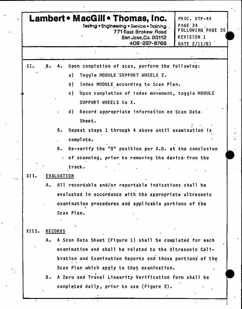
Lambert ~ MacGill Thomas, Inc.Testing ~ Engineering ~ Service ~ Training,
771 East Brokaw RoadSan Jose,Ca. 95112
408-297-8766
PROC. UTP-44
PAGE 34FOLLOWING PAGE 35
REVISION 1
DATE" 2/11/81
XI ~
XI I ~
,B. 4. Upon completion of scan, perform the following:
a) Toggle NODULE 'SUPPORT WHEELS Z.
b) Index MODULE according to Scan Plan ~
c) Upon completion of index movement, toggle MODULE
SUPPORT WHEELS to X.
d) Record appropriate information on Scan Data
Sheet.
5. Repeat steps 1 through 4 above until examination iscompl'ete.
1
6. Re-verify the "0" position per X.D. at the conclusion
of scanning, prior to removing the device. from the
track.EVALUATION
A. All recordable and/or reportable indications shall be
evaluated in accordance with the appropriate ultrasonicexamination procedures and appl icable portions of the
Scan Pl an.
XI I I ~ RECORDS
A. A Scan Data Sheet (Figure 1) shall be completed for eachC
examination and shall be related to the Ultrasonic Cali-bration and Examination Reports and those portions of the
Scan Plan which apply to that, examination.
B. A Zero, and Travel Linearity Verification form shall be
completed daily, prior to use (Figure 2).
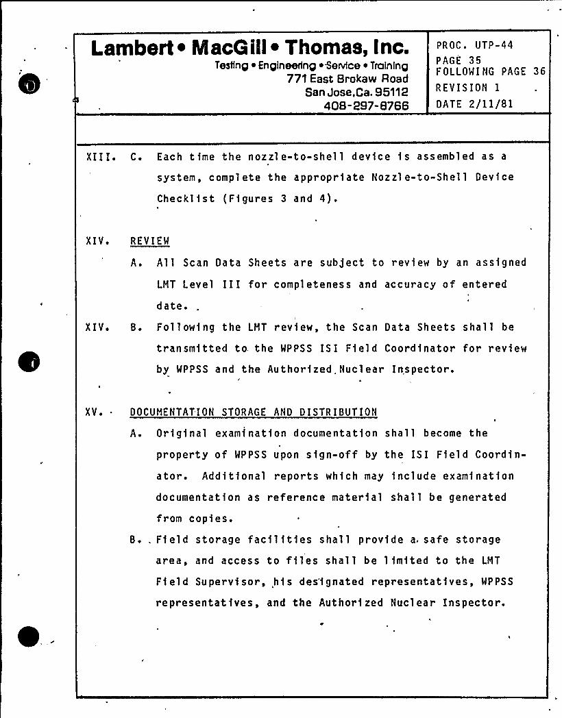
l.ambert ~ MacG ill~ Thomas, Inc.Testing Engineering Service ~ Training
771 East Brokaw RoadSan Jose,Ca. 95112
408-297-8766
PROC. UTP-44
PAGE 35FOLLOWING PAGE 36
REVISION IDATE 2/11/81
XIII. C. Each time the nozzle-to-shell device is assembled as a
system, complete the appropr1ate Nozzl e-to-Shell Dev1ce
Check11st (Figures 3 and 4).
XIV~ REVIEW
A. All Scan Data Sheets are subject to review by an assigned
LHT Level III for completeness and accuracy of entered
date.
XIV. B. Following the LHT review, the Scan Data Sheets shall be
transm1tted to. the WPPSS IS I Field Coordinator for review
by WPPSS and the Authorized.Nuclear Inspector.
XV.. DOCUHENTATION STORAGE AND DISTRIBUTION
A. Or1g1nal examfnation documentation shall become the
property of WPPSS upon sign-off by the ISI Field Coordin-
ator. Additional reports whfch may include examination
documentation as reference materfal shall be generated
fr om cop1es.
B.. Ffeld storage fac11ftfes shall provide a, safe storage
area, and access to files shall be 1 fmfted to the LHT
Field Super v1sor, his des'fgnated representatives, WPPSS
representatives, and the Author) zed Nucl ear Inspector.

1
'I
Date 1/8/79
Revision 0
>NP-2 PSI PROGRAM PLAN
NOT USE D
(Purposely left blank)

Date l /8/79Revi sion 0
lJNP-2 PSI PROGRAM PLAN
NOT USED
(Purposely 1 e ft bl ank)
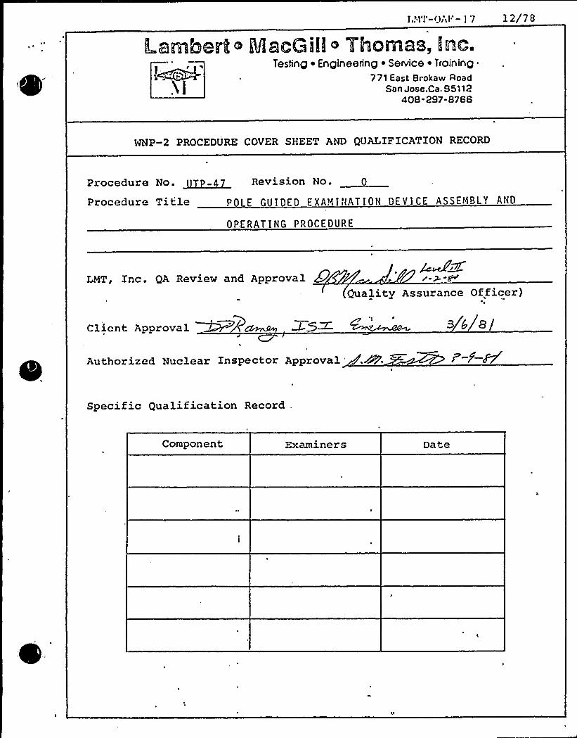
ILamberh o MacGill ~ Ylhomas, Iinc.Testing ~ Engineering ~ Service ~ Training
771 East Brokaw RoadSan Jose.Ca. 85112
408 297-8766
WNP-2 PROCEDURE COVER SHEET AND QUALXFXCATXON RECORD
Procedure No. ~~ Revision No. O
Procedure Title P E GUI ED EXAMINATION DEVICE ASSEMBLY AND
OPERATING PROCEDURE
LMT, Xnc. QA Review and ApprovalQuality Assurance Officer)
Client Approval ~ ~Y
Authorized Nuclear Xnspector Approval
Specific Qualification Record
Component Examiners Date

0
J
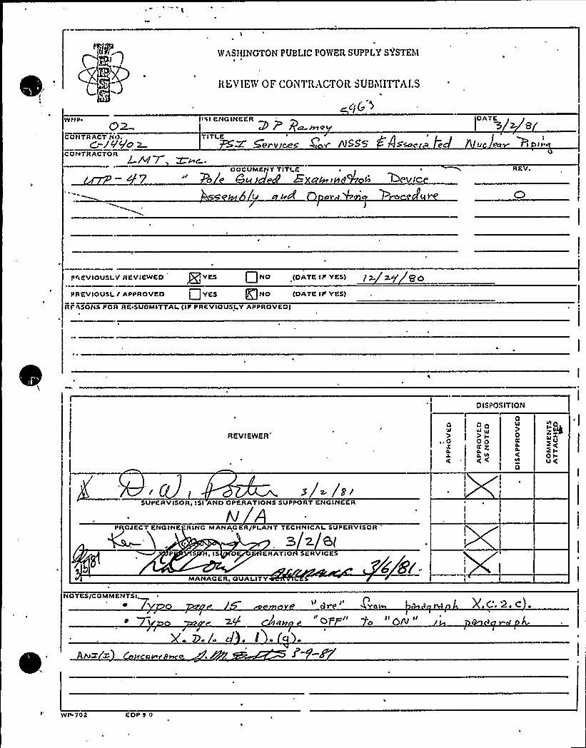
WASIIINGTONPUBLIC POWER SUPPLY SYSTE51
CONTRACT NO.C-JVgo m
ItEVIEW OF COB'I'I<ACTOR SUBhIITTAI.S
c(('ISI ENGINEER
~~QTITLE /I
5ery/Ceg Ov" /VSS5 AS~0 e
DATE
)I/
CONTRACTORL.&17 ~~c..
0g/DOCUMENT TITLE
b 5PV/C
PREVIOUSLY REVIEWED Jg YES P NO (DATE 4P YES) 1 ~
PRKVIOUSL f APPROVED LjYES @NO (DATE IP YKS)
RPhSONS POR RE.SUBMITTAI (IP PREVIOUSLY APPROVEO)
0ISPOSITION
REVIEWER'.0 00ul gg
OO+Z
]
0Io
0C
0
~o
OIOC
s /z~SUPERVISOR, ISI AND OPERATIONS SUPPORT ENGINEER
/VP OJECT ENGINE RING MANAG RIPLANT TECHNICAI SUPERVISOR
3 z 6(P 8, IS ERATIO SERVICE
MA AGER, QUALITY
NOTES/COMMENTS(II gr Ii
I cp II Ilg~llC.2. c .
WP. VOa EDP9 0

e
Lambert ~ MacG ill~ Thomas, Inc.Testing ~ Engineering ~ Service ~ Training
771 East Brokaw RoadSan Jose,ca. 95112
408-297-8766
PROC. UTP-47
PAGE IFOLLOWING PAGE 2
REVISION 0
DATE 12/19/80
TITLE: POLE GUIDED EXAMINATION DEVICEASSEMBLY AND OPERATING PROCEDURE
PURPOSE AND SCOPE
A. ~Por ose
1. This procedure provides instructions for the assem-
bly, checkout, and-general operation of the remotely
operated Pole Guided Examination Device.
B. ~Sco eC
I
1. This procedure is applicable-to the remotely operated
mechanical device and associated control modules.
2. Instructions for the assem6ly and operation of the
ultrasonic portion of the complete examination system
are contained in Procedure UTP-40, "Remote Ultrasonic
Examination of Reactor Vessel Circumferential and
Longitudinal Butt Welds."
3. Instructions for the assembly and operation of thee
remote automatic ul trasonic data recording system are
contained in Procedure UTP-42, "Remote System Automatic
Ultrasonic Data Recording."
II. REFERENCES
A. This procedure is based on the recommendations and
instructions. of the manufacturer, Southwest Research
Institute. i
gUAL'IF ICAT ION: ')4GgPP~~,, g,
Lambert ~ IacG ill~ Thomas, Inc.Tesling ~ Engineering ~ Service ~ Training
771 East Brokaw RoadSan Jose,Ca. 95112
408-297-8766
,PROC. UTP-47
PAGE 2FOLLOWING PAGE 3
REVISION 0
DATE 12/19/80
A.1. Complete operating details ar e contained in the
fol 1 owing SwR I Opera ting Ma nu'al s:
a) Operating Manual 80110, "Model 110 Controll.er"
b) Operating Manual 80220, "Model 220 Controller"
c) Operating Manual 80402, "Model 402 Controller"
d) Operating Manual 82100, "Model 82100 Controller"
e) Operating Manual 5583006; "Pole Guided Inspection
Device"
2. The following drawings are referenced in thisprocedure:
a) SwRI Drawing D-10094
b) SwRI Drawing D-10490
c) SwRI Drawing C-13577
d) SwRI Drawing D-10520
I I I. DEFINITIONS
8eam Direction:
Controller:
Orientation of ultrasonic beam rela-tive to vessel axis, independent of
scan direction.Electronic device controllingmechanical system motor directionand/or speed. May indicate relativeposition via multi-digit readout.
Lambert ~ IacG ill~ Thomas, Inc.Testing ~ En pineerinp ~ Service ~ Traininp
771 East Brokaw RoadSan Jose,Ca. 95112
408-297-8766
PROC ~ UTP-47
PAGE 3FOLLOWING PAGE 4
REV IS ION 0
DATE 12/19/80
III. Index Movement:~ 1
(Increment)
Module, Search Unit:
Scan Direction:
Module movement (distance moved)
between scans.
Search unit cluster including shoes,
wedges, holding framework, couplant
supply manifold.
Motion of search unit module relativeto vessel axis, independent of br am
direction.X-axis:
Y-axi s:
Circumferential axis of vessel.
Longitudinal axis of vessel.
Calibration block thickness.
Weld thickness.
I V. RESPONSIBILITY
A. The Technical Manager, LMT, Inc. is responsible for the
generation and control of this procedure and shall so
indicate by a dated signature on the procedure cover
~ sheet.
B. The r esponsible Level III Field Supervisor, LMT, or his
designated Level III alternate, LMT, shall qualify the
procedure for a parti cul ar examination.
Lambert ~ NlacG ill~ Thomas, Inc.Testing ~ Engineering ~ Service ~ Training
771 East Brokaw RoadSan Jose,Ca, 95112
408-297-8766
PROC. UTP-47
PAGE 4FOLLOWING PAGE 5
REVISION 0
DATE 12/19/80
V. PROCEDURE UALIF ICATION
This procedure shall be qualified by performing and docu-
menting successful checkout and position verification and
repeatability as:instructed in X.D. below.
V I. PERSONNEL RE UIREMENTSI I
A. Examiners usi.ng this procedure sball have l evels of qual-
ifications as per -the Procedure gualification.~ ~
B. Personnel operating .the pole guided examination device
shall be qualified on the equipment and so certified by
an authorized LMT Level III examiner.
1. For each shift of operation,"the examination team
shall consist of at least the following personnel
a) Coordinator/supervisor: Coordinate efforts of
individual team members and efforts of the exami-
nation team with the owner and appropriate on-
site crafts.b) Console operator: Operate controllers, record
t
necessary data for completion of scan data
sheets. Conduct and verify functional checks of
mechanical system.
c.) Observer: Stationed at device location to ob-
serve operation of device, warn of pending
obstruction, malfunction, etc.
Lambert ~ MacG ill~ Thomas, Inc.Testing ~ Engineering ~ Service ~ Training
771 East Brokaw RoadSan Jose,Ca. S5112
408-2S7-8766
PROC. UTP-47
PAGE 5FOLLOWING PAGE 6
REVISION 0
DATE 12/19/80
V I. B. 1. — d) Ultrason1c operator: Perform examination cali-bration, enter appropr1ate information on stripchart record1ngs, veri fy proper operation of
ultrasonic system. Certified to at least
Level I I Ul trasonic.I
2. Team personnel may perform the above duties on a'
rotational basis, prov1ded adequate cross'trainingand certification levels are existent.
VI I. E UIPMENT AND MATERIALS
A. S stem Descri tion
1. The p'ol e guided device has been designed to remotely
scan reactor pressure vessel long1tud1nal and c1rcum-
ferential welds.
2. Vertical device movement is along permanently 1nstal-
led Pole Tracks which have been pl aced at known
elevations and azimuth locat1ons around the vessel.
3. Hor izontal search unit movement is accomplished by
means of.,a transverse arm, which may be extended up
to 21.69 1nches either side of the dev1ce centerline.
4. Search units are mounted in a modular configuration
on an assembly which may be remotely rotated up to
300'. The remote rotation feature allows for chang-
1ng the direction of the ultrasonic beam relative to
the vessel long axis, without removing the search
r
Lambert ~ IacG ill~ Thomls, Inc.Testing ~ Engineering ~ Service ~ Training
771 East Brokaw RoadSan Jose,Ca. 95112
408-297-8766
PROC. UTP-47
PAGE 6FOLLOWING PAGE 7
REVISION 0
OATE 12/19/80
VI I. A. 4. unit module from the device.
5. Vertical and circumferential (X- and Y- axis) move-
ments are governed by the Model 220 Controllers.
Front panel controls regulate scan speed, directionand limits. Module location, relative to a known
ZERO reference, is indi'cater by a digital display.6. The transverse arm is mounted to the vertical ax,is
drive car in a manner allowing the arm assembly to be
extended outward, toward the vessel, or retracted
back to the drive car.
motion describes an arc.
The extending/retracting
When the transverse arm is
extended, the search unit modul e location, relativeto the drive car reference switch, changes. A "sine
pot", attached to the transverse arm hinge point,"reads" the degree of transverse arm movement, and i s
input to the 82100 controller. The 82100 has two (2)
digital displays. The first is a three digit display
of the sine pot input. The second (five digit)displ ay is the algebraic sum of the Y-axis 220
display and the sine pot input.
7. Search unit module rotation is regulated by the Model
. 110 controller. Front panel controls govern rota-
tional speed and direction. Module orientation is
indicated by a front panel digital display.
Lambert ~ MacG ill~ Thomas, Inc.Testing ~ Engineering ~ Service ~ Training
771 East Brokaw RoadSan Jose,Ca. 95112
408-297-8766
PROC. UTP-47
PAGE 7
FOLLOW I NG PAGE 8
REVISION 0
DATE 12/19/80
VI I. A. 8. Model 402 Controllers regul ate coupl ant fl ow,
couplant supply pressurization, transverse arm
extension/retraction, and drive car wheel lock
functions.
VIII. PREPARATIONS
A. Documentation
1. The following preliminary documentation requirements
shall be reviewed by the examiner with the WPPSS ISI
Field Coordinator before beginning any examination
program:
a) Procedure and gualificationb) Calibration Reports
c) Examination Reports
d) Material and Equipment Cert)fications
e) Personnel Certificationsf) Status Indicators (Hold tags)
B. ~Ph sical
1. The following physical preparation requirements
shall be reviewed by the examiner with the WPPSS
ISI Field Coordinator before specific'examinations
are performed:
a) Insul.ation removal
b) OSHA requirements (ladders, lighting, fresh air,scaffolding, etc.)
Lambert ~ MacG ill~ Thomas, Inc.Testing ~ Engineering ~ SeNice ~ Training
771 East Brokaw RoadSan Jose,Ca. 95112
408- 297-8766
PROC. UTP-47
PAGE 8FOLLOWING PAGE 9
REVISION 0
DATE 12/19/80
VI I I. B. 1. c) Cleanup requirements
d) Safety precautions (other work in area, etc.)
e) Electrical ou'tlets - 110-120v AC, 30 amp, singl e
phase, minimum of two (2) required..
f) Air o', nitrogen supply.1
P
C. Surface Pre aration l
1. Examination surfaces shall be free from weld spatterh
or any other surface condition which will impede free
movement o f the search uni t modul e.
2. Examination surfaces shall be free from extraneous
materials or other conditions which, in the opinion
of the examiner,„ will impair the performance of a.
meaningful examination.
IX ' I HI TATI ONS
Thi s procedure i s l imi ted to remotely operated ul trasonic
examinations of longitudinal and circumferential welds of the
reactor vessel conducted from the vessel OD surface, using
contact methods.
X ~ SYSTEM ASSEMBLY AND FUNCTIONAL CHECKOUT
A. S stem Assmebl
1. Device Cable Controller interconnects
a) Using cable 82041, interconnect the device and ~control 1 ers as follows:
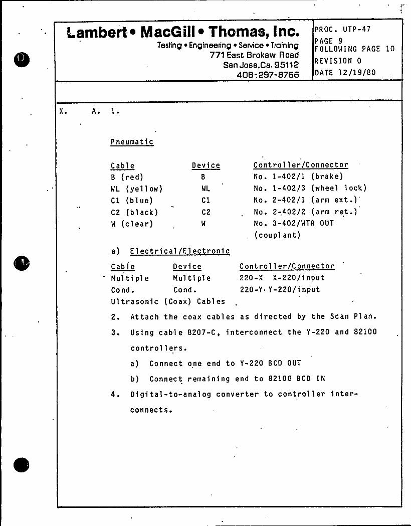
Lambert ~ MacG ill~ Thomas, Inc.Testing ~ Engineering ~ Service ~ Training
771 East Brokaw RoadSan Jose,Ca. 95112
408-. 297-8766
PROC. UTP-47
PAGE 9FOLLOWING PAGE 10
REVISION 0
DATE 12/19/80
X ~ AD 1.
Pneumatic
CableB (red)WL (yellow)Cl (blue)C2 (black)W (clear)
DeviceB
WL
Cl
C2
W
Controller/ConnectorNo. 1-402/1 (brake)No. 1-402/3 (wheel lock)No. 2-402/1 (arm
ext.)'o.
2-.402/2 (arm ret.)No. 3-402/WTR OUT
(couplant)
a) Electrical Electronic
Cable DeviceHul ti pl e Hul ti pl e
Cond. Cond.Ultrasonic (Coax) Cables
Controller/Connector220-X X-220/input220-Y Y-220/input
2. Attach the coax cables as directed by the Scan Plan.
3. Using cable 8207-C, interconnect the Y-220 and 82100
controllers.a) Connect one end to Y-220 BCD OUT
b) Connect remaining end to 82100 BCD IN
4. Digital-to-analog converter to controller inter-connects.
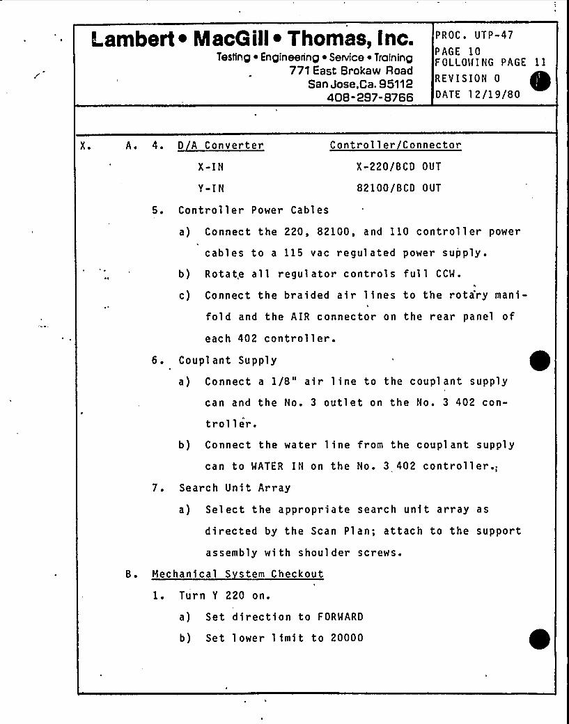
Lambert ~ NlacG ill~ Thomas, Inc.Testing ~ Engineering ~ Senrice ~ Training
771 East Brokaw RoadSan Jose,Ca. 95112
408-297-8766
PROC. UTP-47
PAGE 10FOLLOWING PAGE 11
REVISION 0
DATE 12/19/80
X. A. 4. D A Converter
X-IN
Y-IN
5. Controller Power Cables
Controller/Connector
X-220/BCD OUT
82100/BCD OUT
a) Connect the 220, 82100, and 110 controller power
cables to a 115 vac regulated power supply.
b) Rotate all regulator controls full CCW.4
c) Connect the braided air lines to the rota'ry mani-
fold and the AIR connector on the rear panel of
each 402 controller.6. Couplant Supply
a) Connect a 1/8" air line to the couplant supply
can and the No. 3 outlet on the No. 3 402 con-
troller.b) Connect the water line from the couplant supply
can to WATER IN on the No. 3 402 controller.;7. Search Unit Array
a) Select the appropriate search unit array as
directed by the Scan Plan; attach to the support
assembly with shoulder screws.
B. Mechanical S stem Checkout
1. Tur n Y 220 on.
a) Set direction to FORWARD
b) Set lower limit to 20000
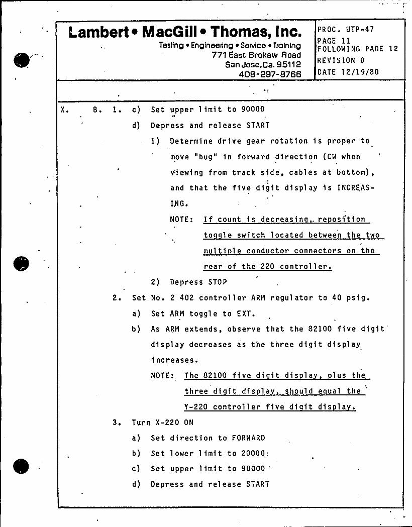
Lambert ~ MacQ ill~ Thomas, Inc.Testing ~ Engineering ~ Se Nice ~ Traininp
771 East Brokaw RoadSan Jose,Ca. 95112
408-297-8766
PROC. UTP-47
PAGE 11FOLLOWING PAGE 12
REVISION 0
DATE 12/19/80
X. B. 1 ~ c) Set upper limit to 90000H W
d) Depress and release START
1) Determine drive gear rotation is proper to
move "bug" in forward direction (CW when
viewing from track side, cables at bottom),
and that the five digit display is INCREAS-
I5 G.
NOTE: If count is decreasin . re ositionto le switch located between the two
multi le conductor connectors on the
rear of the 220 controller .
2) Depress STOP
2. Set No. 2 402 controller ARM regulator to 40 psig.
a) Set ARM toggle to EXT.
b) As ARM extends, observe that the 82100 five digitdisplay decreases as the three digit display
increases.
NOTE: The 82100 five di it dis la lus the
three di it dis la should e ual the
Y-220 controller five di it dis la
3. Turn X-220 ON
a) Set direction to FORWARD
b) Set lower limit to 20000;
c) Set upper limit to 90000 "
d) .Depress and release START
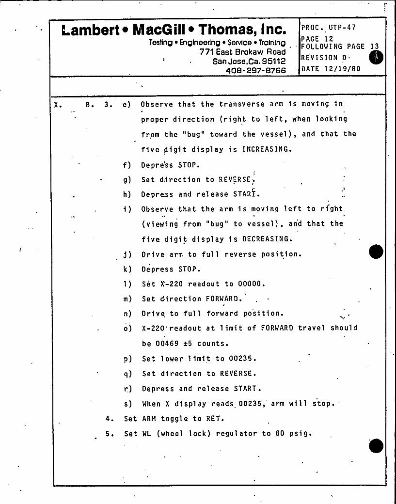
Lambert ~ MacQill~ Thomas, Inc.Testing ~ Engineering ~ Service ~ Training
771 East Brokaw RoadSan Jose,Ca. 95112
408" 297- 8766
PROC. UTP«47
PAGE 12FOLLOWING PAGE 13
REVISION 0 ~
DATE 12/19/80
X ~ B. 3. e) Observe that the transverse arm is moving inP
proper direction (right to left, when looking
from the "bug" toward the vessel), and that the
five digit display is INCREASING.
f) Depre'ss STOP.
g) Set diirection to REVERSE.
h) Depress and release START ~
i) Observe that the arm is moving left to right(viewing from "bug" to vessel), and that the
fi ve di gi t di s pl ay i s DECREASING.
j) Drive arm to full reverse position.
k) Depress STOP.
1) Set X'-220 readout to 00000.
m) Set direction FORWARD.
n) Drive to full forward position.
o) X-220'readout at limit of FORWARD travel should
be 00469 x5 counts.
p) Set lower limit to 00235.
q) Set direction to REVERSE.
r) Depress and release START.
s) When X display reads 00235, arm will stop..4. Set ARM toggle to RET.
5. Set WL (wheel lock) regulator to 80 psig.
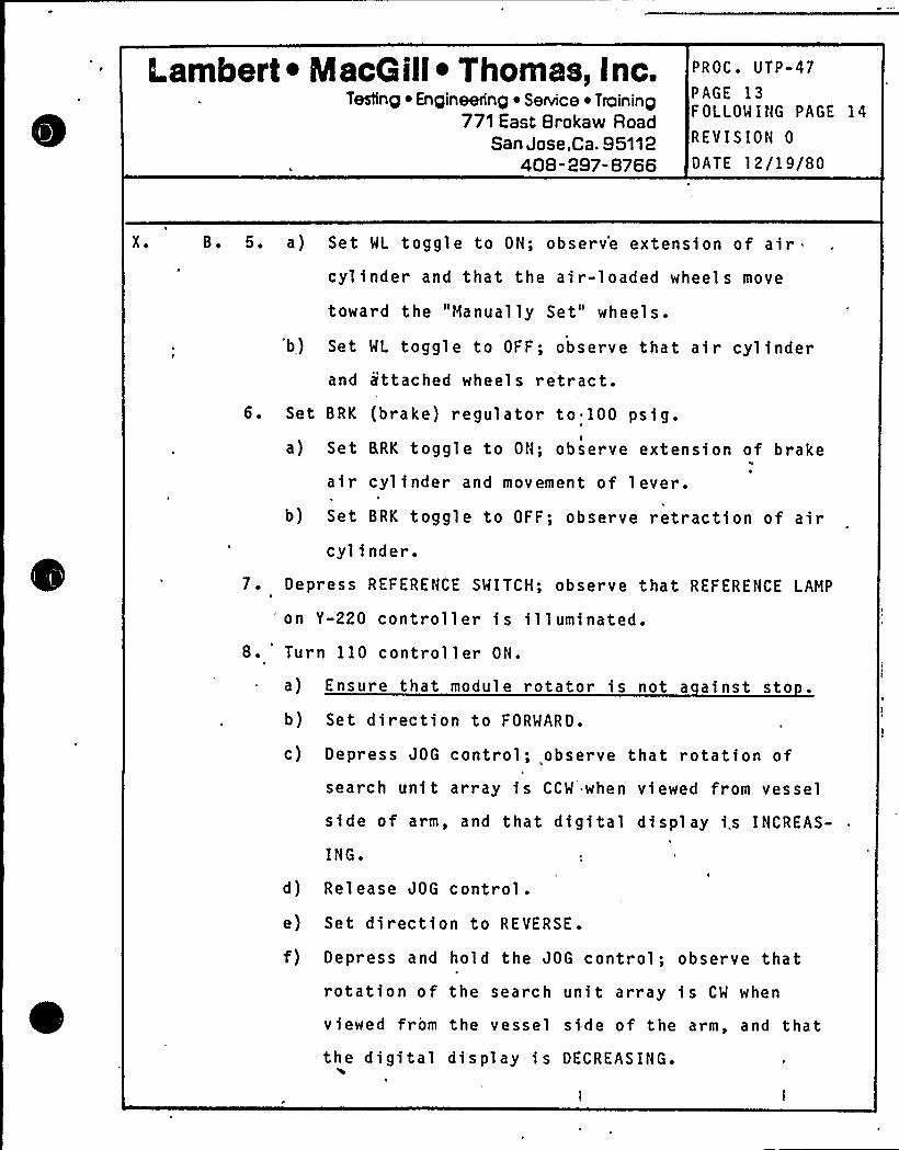
Lambert ~ IacQ ill~ Thomas, Inc.Testing ~ Engineering ~ Service ~ Training
771 East Brokaw RoadSan Jose,Ca. 95112
408-297-8766
PROC. UTP-47
PAGE 13FOLLOWING PAGE 14
REVISION 0
DATE 12/19/80
X. B. 5. a) Set WL toggle to ON; observ*e extension of aircylinder and that the air-loaded wheel s move
toward the "Manually Set" wheels.
'b) Set WL toggle to OFF; observe that air cyl inder
and ittached wheels retract.6. Set BRK (brake) regulator to 100 psig.
,I
a) Set BRK toggle to ON; observe extension of brake
a i r cyl i nder'nd movement of 1 ever.
b) Set BRK toggle to OFF; observe retraction of aircylinder.
7. Depress REFERENCE SWITCH; observe that REFERENCE LAMP
'n Y-220 controller is illuminated.8. Turn 110 controller ON.
a) Ensure that module rotator is not a ainst sto
b) Set direction to FORWARD.
c) Depress JOG control; observe that rotation of
search unit array is CCW when viewed from vessel
side of arm, and that digital display is INCREAS-
ING.
d) Release JOG control.e) Set direction to RFVERSE .
f) Depress and hold the JOG control; observe thatrotation of the search unit array is CW when
viewed from the vessel side of the arm, and thatthe digital display is DECREASING.
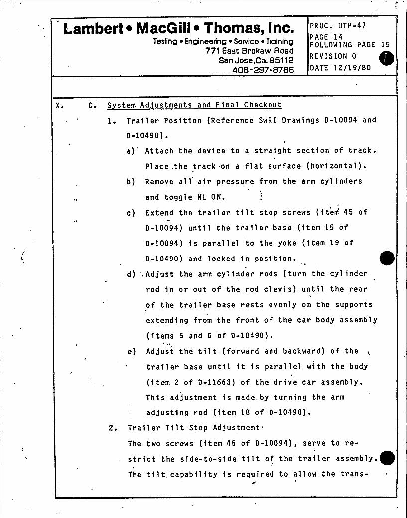
Lambert ~ MacG ill~ Thomas, Inc.Testing ~ Engineering ~ Service ~ Training
771 East Brokaw RoadSan Jose,Ca. 95112
408-297-8766
PROC. UTP-47
PAGE 14FOLLOWING PAGE 15
REVISION 0
DATE 12/19/80
X. C. S stem Ad ustments and Final Checkout
1. Trailer Position (Reference SwRI Drawings 0-10094 and
0-10490).
a) Attach the device to a straight section of track.Place'he track on a flat surface (horizontal).
b) Remove all air pressure from the arm cylinders
and toggle WL ON.
c) Extend the trailer tilt stop screws (item 45 of
0-10094) until the trailer base (item 15 of
D-10094) is parallel to the yoke (item 19 of
0-10490) and locked in position.
d) ',Adjust the arm cylinder rods (turn the cylinder
rod in or out of the rod clevis) until the rear
of the trailer base rests evenly on the supports
extending from the front of the car body assembly
(items 5 and 6 of D-10490).~ a
e) Adjust the tilt (forward and backward) of the
trailer base until it is parallel with the body
(item 2 of D-11663) of the drive car assembly .
This adjustment is made, by turning the arm
adjusting rod (item 18 of D-10490).
2. Trailer Tilt Stop Adjustment
The two screws (item 45 of D-10094), serve to re-
strict the side-to-side tilt of the trailer assembly.
The tilt capability is required to allow the trans-
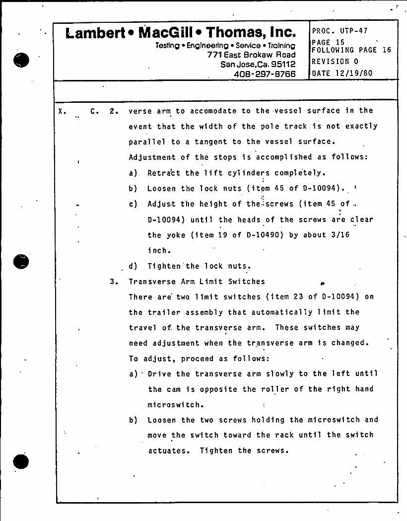
Lambert ~ MacG ill~ Thomas, Inc.Testing ~ Engineering ~ Service ~ Training
771 East Brokaw RoadSan Jose,Ca. 95112
408-297-8766
PROC. UTP-47
PAGE 15FOLLOW ING PAGE 16
REVISION 0
DATE 12/19/80
X. C. 2. verse arm to accomodate to the vessel surface in the
event that the width of the pole track is not exactly
parallel to a tangent to the vessel surface.
Adjustment of the stops is accomplished as follows:
a) Retra'ct the lift cylinders completely.
b) Loosen the lock nuts (item 45 of D-10094).
c) Adjust the height of the:screws (item 45 of ..
D-10094) until the heads of the screws are clear
the yoke (item 19 of D-10490) by about 3/16
inch.
d) Ti ghten 'he lock nuts.
3. Transverse Arm Limit Switches
There are two limit switches (item 23 of D-10094) on
the trailer assembly that automatically limit the
travel of. the transverse arm. These switches may
need adjustment when the transverse arm is changed.
To adjust, proceed as follows:
a) Drive the transverse arm slowly to the left untilthe cam is opposite the roller of the right hand
mi eros wi tc h.
b) Loosen the two screws holding the microswitch and
move the switch toward the rack until the swi tch
actuates. Ti ghten the scr ews.
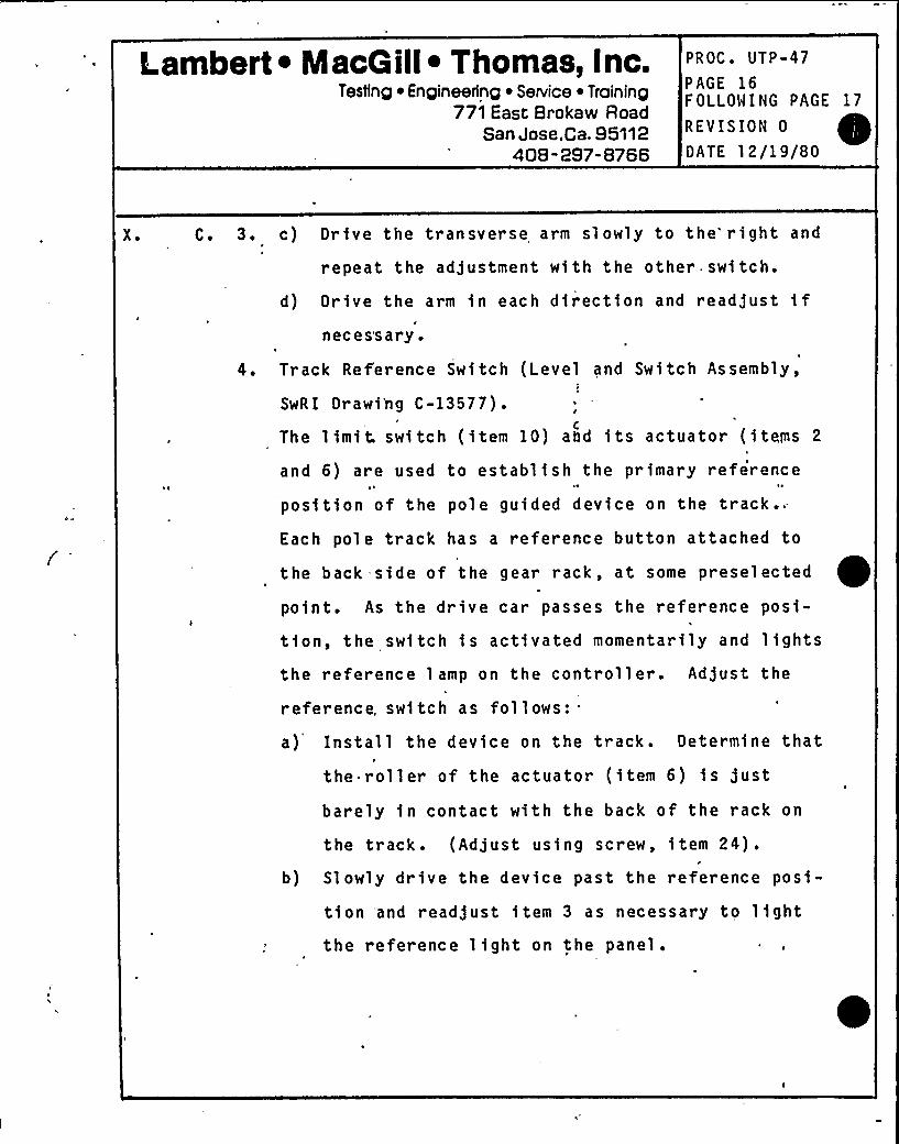
Lambert ~ MacG ill~ Thomas, Inc.Testing ~ Engineering ~ Service ~ Training
771 East Brokaw RoadSan Jose,Ca. 95112
408-297-8766
PROC. UTP-47
PAGE 16FOLLOWING PAGE 17
REVISION 0
DATE 12/19/80
X ~ C. 3. c) Drive the transverse arm slowly to the'right and
repeat the adjustment with the other. switch.
d) Drive the arm in each direction and readjust ifnecessary.
4. Track Reference Switch (Level and Switch Assembly,
SwRI Drawi'ng C-13577).C
The limit. switch (item 10) abd its actuator (items 2
and 6) are used to establish the primary reference
position of the pole guided device on thetrack.'ach
pole track has a reference button attached to
the back side of the gear rack, at some preselected
point. As the drive car passes the reference posi-
tion, the switch is activated momentarily and lightsthe reference lamp on the controller. Adjust the
reference, switch as follows:
a) Install the device on the track. Determine that
the roller of the actuator (item 6) is justbarely in contact with the back of the rack on
the track. (Adjust using screw, item 24).
b) Slowly drive the device past the reference posi-
tion 'and readjust item 3 as necessary to lightthe reference light on the panel.
Lambert ~ MacGill ~ Thomas, Inc.Testing Engineering ~ Service ~ Training
771 East Brokaw RoadSan Jose,Ca. 95112
408-297-8766
PROC. UTP-47
PAGE 17FOLLOWING PAGE 18
REVISION 0
DATE 12/19/80
X. C. 4. c) Drive the device past the reference position in
the other direction. The light should light in
both directions as the reference position ispassed and not be lighted at other locations.
d) If there is insufficient" adjustment in item 3,
adjust item 18 until item 3 is within its range.
NOTE: The distance from.'.the reference SWITCH
osition to the centerline of the trans-
ducer modules on the transverse arm is
a roximatel 255 counts with the trailerfull retracted.
5. Search Unit Module Offset (along track)
The positional readout of the pole device (along the
track) is relative to the track reference. With the
search unit support'(tra'iler) fully retracted, the
position of the module is a fixed and known number ofr
counts away from the reference switch. However, thisis not a useful operating condition. The search
units must be extended to contact the examination
surface. As the search units are extended to the
surface, due to the mechanical configuration of the
device, the distance between,Ithe modul e and the
reference switch and drive assembly becomes less~.
The difference in position is a sine function of. the
amount of. extension necessary to reach the surface.
LalllbeF'I ~ MSCG III~ Tllom88, InC.Testing ~ Engineering ~ SeNice ~ Training
771 East Brokaw RoadSan Jose,ca. 95112
408-297-8766
PROC. UTP-47
PAGE 18F OLLOMI NG PAGE 19
REVISION 0
DATE 12/19/80
X. C. 5. Thi s condition 1 s easily seen on SwRI Draw1ng
D-10520. .A sine potentiometer and Model 82100
Controller are used to compensate for this change in
posttion of the search unit.. The 82100 controllermon1tors the rotation of the sine potentiometer,
subtracts an appropr1ate number of counts from the
~ posttion .displayed on the Model 220 Controller,,and
displays the corrected -position on the five dig1t
display as well as the "OFFSET" on the 3-1/2 digitdisplay.
Adjustment of the potentiometer (item 6 of D-10490)
1s critical and should be accomplished in the follow-
ing manner after the sine pot has been replaced. No
'adjustment should be required in normal operation.
a) Remove the sine pot connector from the back of
the 82100 controller and short pins B and K of
the controller receptacle.
b) Remove the plastic front cover from the 3-1/2
d,igit analogic panel meter and turn the ZERO
adjustment screw until the offset meter reads
000. The ZERO adjust screw is located between
Lambert ~ MacGill~ Thomas, Inc.Testing ~ Engineering ~ Sefvlce ~ Training
771 East Brokaw RoadSan Jose,Ca. 95112
408- 297- 8766
PROC. UTP-47
PAGE 19FOLLOWING PAGE 20
REVISION 0
DATE 12/19/80
C. 5. b) the second and third NIXIE tubes from the right.It is the left hand adjustment. DO NOT ADJUST
THE SCREW ON THE RIGHT ~
c) Remove the short between pins B and K and re-
conne'ct the sine pot cable connector.
d) With the cover (item 14 of D-10490) removed and
the trailer in the full down position, loosen the
set screw which holds the gear (item 59) on the
1/4 inch shaft (item 57).
e) Rotate the gear (item 59) and sine pot shaft
until the offset meter reads 000 'and lightlytighten the set screw.
f) Raise'he trailer to its maximum height. The
offset meter should increase smoothly and stop at
approximately 76.
(1) If the readout does not stop near 76 or does
-not increase smoothly, the pot has been set
at the wrong ZERO.
(2) 'Lower the trailer back to the mechanical
zero position and loosen the set screw'n
item 59.
(3) Slowly rotate the gear and sign pot shaft
(about 90'otation of the pot) until the
meter again reads 000. Lightly tighten the
set screw.
Lambert ~ IacG ill~ Thomas, Inc.Testing ~ Engineering ~ SeNice ~ Training
771 East Brokaw RoadSan Jose,Ca. 95112
408-297- 8766
PROC. UTP-47
PAGE 20FOLLOWING PAGE 21
REVISION 0
DATE 12/19/80
X ~ C. 5. f) (4) Repeat 5.f).g) Lower the trailer to the mechanical zero position
and loosen the set screw on item 59..
h) Slowly rotate the gear and pot shaft until the
meter'eads +004 and tighten the set screw .
i) Adjust the zero screw on the meter untilthe'eadqut
is 000.
j) Replace the meter cover and the sine pot 'cover
(item 14).
k) Select a convenient horizontal reference point on
the trailer assembly and on the drive car.
Measure and record the horizontal distance be-
tween these two points.
1) Raise the trailer assembly'o that the horizontal
distance between these two reference points is
reduced by 4.36 inches.
m) Adjust the range of the offset meter so that the
meter reads 76. (The adjustment screw is located
in the middle of the rear end of the chassis of
the Model 82100 Controller.)
n) Check the reading at the following positions:
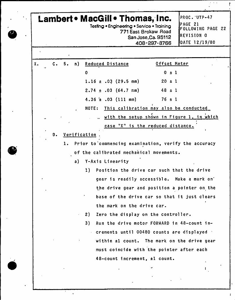
Lambert ~ IacG ill~ Thomas, Inc.Testing ~ Engineering ~ Service ~ Training
771 East Brokaw RoadSan Jose,Ca, 95112
408- 297- 8766
PROC. 'UTP-.47
PAGE 21FOLLOWING PAGE 22
REVISION 0
DATE 12/19/80
X. C. 5. n) Reduced Distance Offset Meter
0 0 *11.16 a .03 (29.5 mm) 20*12.74 a .03 (64.7 mm) 48al4.36 'x .03 (111 mm) 76 a 1
I
NOTE: This calibration ma also be conducted
with the setuC I
shown in Fi ure 1 in hich
D. Verificationcase "X" is the reduced distance.
1. Prior to"commencing examination, verify the accuracy
of the calibrated mechanical movements.
a) Y-Axis I inearity1) Position the drive car such that the drive
gear is readily accessible. Make a markon'he
drive gear and position a pointer on the
base of the drive car so that it just clears
the mark on the drive car.
2) Zero the display on the controller.3) Run the drive motor FORWARD in 48-count in-
crements until 00480 counts are displayed
within xl count. The mark on the drive gear
must coincide with the pointer after each
48-count increment, al count.
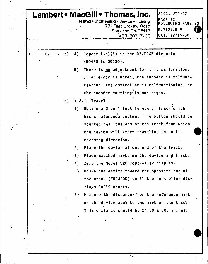
Lambert ~ MacGill ~ Thomas, Inc.Testing ~ Engineering ~ Senrice ~ Training
771 East Brokaw Road.San Jose,Ca. 95112
408-297-8766
PROC. UTP-47
PAGE 22FOLLOWING PAGE 23
REVISION 0
DATE 12/19/80
X. D. 1. a) 4) Repeat l.a) (3) in the REVERSE direction(00480 to 00000).
5) There is no adjustment for this calibration.If an error is noted, the encoder is malfunc-
t'ioning, the controller is malfunctioning, or
the encoder coupling is not tight.b) Y-Axi.s Travel
1) Obtain a 3 to 4 foot length of track which'
has a reference button. The button should be
mounted near the end of the track from which
the device will start traveling in an in-
creasing direction.2) Place the device at one end of the track.
3) Place matched marks on the device and track.
4) Zero the Model 220 Controller display.
5) Drive the device toward the opposite end of
the track (FORWARD) until the controller dis-
plays 00419 counts.
6) Measure the distance from the reference mark
,on the device, back. to the mark on the track.
This distance should be 24.00 t .06 inches.
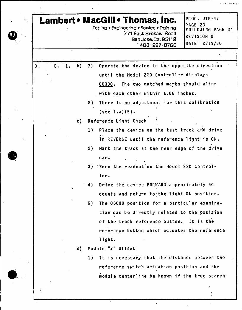
Lambert ~ NlacGill ~ Thomas, Inc.Testing ~ Engineering ~ Service ~ Training
771 East Brokaw RoadSan Jose,Ca. 95112
408-297-8766
PROC. UTP-47PAGE 23FOLLOWING PAGE 24
REVISION 0
DATE 12/19/80
X ~ D. 1. b) 7) Operate the device in the opposite direction
until the Model 220 Controller displays
00000. The two matched marks should align
with each other within a.06 inches.
8) There is no adjustment for this calibration
(see 1 .a) (5).
c) Reference Light Check
1) Pl ace the device on the test track arid drive
in REVERSE until the reference light is ON.
2) Mark the track at the rear edge of the drive
car.
3) 'Zero the readout on the Model 220 control-
ler.4) Drive the device FORWARD approximately 50
counts and return to=the light ON position.
5) The 00000 position for a particular examina-
tion can be directly related to the position
of the track reference button. It is the
reference button which actuates the reference
light.d) Modul,e ",Y" Offset
1) It is necessary that, the distance between the
reference switch, actuation position and the
modul e centerline be known if the true search
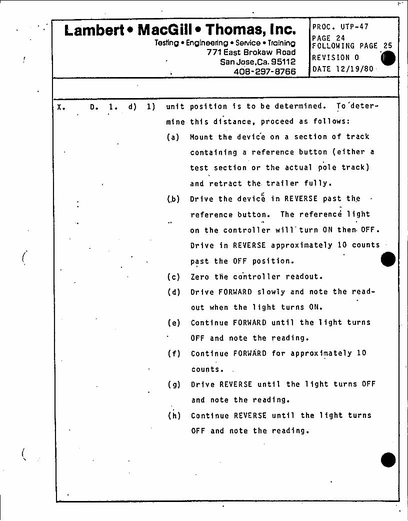
Lambert ~ MacG ill~ Thomas, Inc.Testing ~ Engineering ~ Service ~ Training
771 East Brokaw RoadSan Jose,Ca. 95112
408-297-8766
PROC. UTP-47
PAGE 24FOLLOW ING PAGE 25
REVISION 0
DATE 12/19/80
X ~ D. 1. d) 1) un i tmine
post tion i s to be determined. To 'deter-
thi s di stance, proceed as follows:
(a) Mount the device on a section of track
containing a reference button (either a
test section or the actual pole track)
(.b)
(c)
(d)
and retract the, trailer fully.Drive the device in REVERSE past the
reference button. The reference lighton the controller will'turn ON then OFF.
Drive in REVERSE approximately 10 counts
past the OFF position.Zero the controller readout.
Drive FORWARD sl owly and note the read-
out when the light turns ON.
(e) Continue FORWARD until the light turns
OF'F and note the reading.
(f) Continue FORWARD for approximately 10
counts.
(g) Drive REVERSE until the light turns OFF
and note the reading.
(h) Continue REVERSE until the light turns
OFF and note the reading.
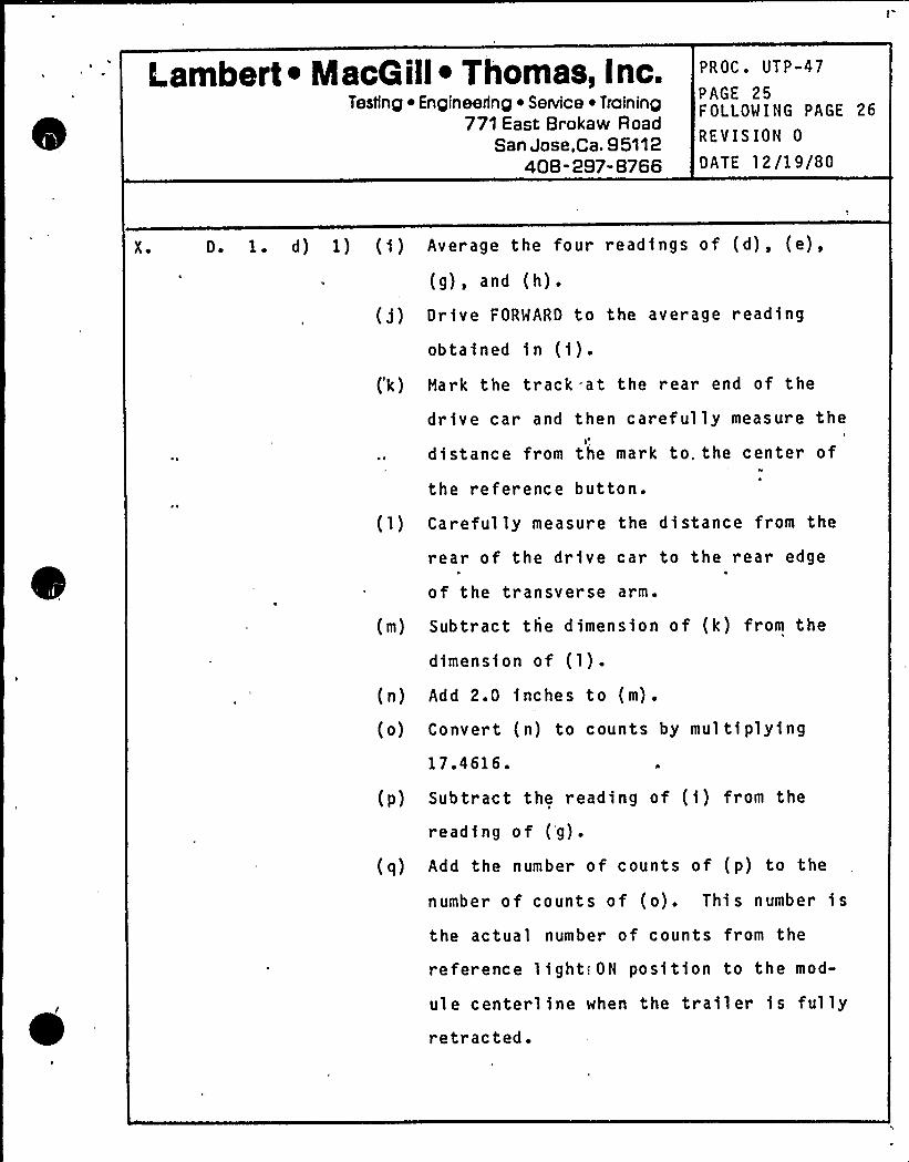
Lambert ~ MacG ill~ Thomas, Inc.Testing ~ Engineering ~ Service ~ Training
771 East Brokaw RoadSan Jose,Ca. 95112
40B -297- 8766
PROC. UTP-47
PAGE 25FOLLOWING PAGE 26
REVISION 0
DATE 12/19/80
X. D. 1. d) 1) (i) Average the four readings of (d), (e),
(g), and (h).
(j) Drive FORWARD to the average reading
obtained in (i).(k) Hark the track at the rear end of the
drive car and then car efully measure the
distance from the mark to. the center of
the reference button.
( 1) Carefully measure the distance from the
rear of the drive car to the rear edge
of the transverse arm.
(m) Subtract the dimension of (k) from the
(n)
(o)
dimension of (1).Add 2.0 inches to (m).
Convert (n) to counts by multiplying17.4616.
(p) Subtract the reading of (i) from the
reading of (g).
(q) Add the number of counts of (p) to the
number of counts of (o). This number is
the actual number of counts from the
reference light!ON position to the mod-
ule centerline when the trailer is fullyretracted.
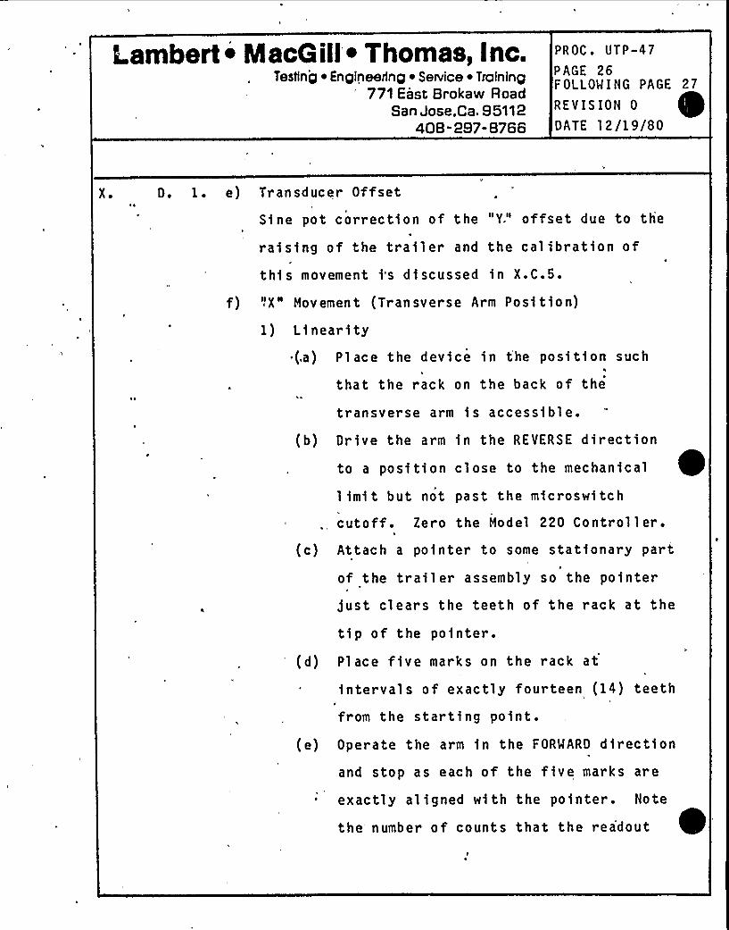
Lambert~ MacGill ~ Thomas, Inc.Testing ~ Engineering ~ Service ~ Training
771 East Brokaw RoadSan Jose,Ca. 95112
408-297-8766
PROC. UTP-47
PAGE 26FOLLOWING PAGE 27
REVISION 0
DATE 12/19/80
X ~ D. 1. e) Transducer Offset
Sine pot correction of the "Y." offset due to theP
raising of the trailer and the calibration of
this movement i's discussed in X.C.5.
f) "X" Movement (Transverse Arm Position)
1) Linearity.(a) Place the device in the position such
4
that the rack on the back of the
transverse arm is accessibl e.
(b) Drive the arm in the REVERSE direction
to a position close to the mechanical
limit but not past the microswitch
cutoff. Zero the Model 220 Control 1 er.
(c) Attach a pointer to some stationary part
of the trail er assembly so the pointer
just clears the teeth of the rack at the
tip of the pointer.
(d) Place five marks on the rack at
intervals of exactly fourteen (14) teethN
from the starting point.
(e) Operate the arm in the FORWARD directionand stop as each of the five marks are
exactly aligned with the pointer. Note
the number of counts that the rea'dout
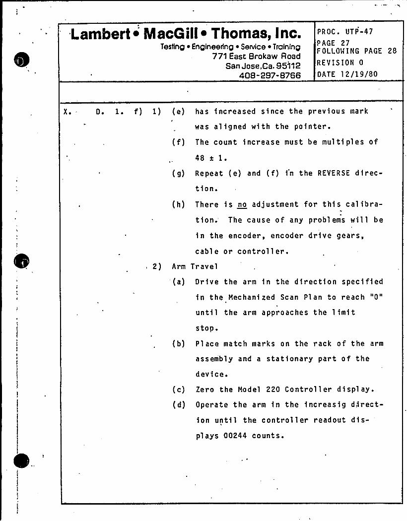
Lambert» MacGill ~ Thomas, Inc.Testing ~ Engineering ~ Service ~ Training
771 East Brokaw RoadSan Jose,Ca. 95112
408-297-8766
PROC. UTP-47
PAGE 27FOLLOWING PAGE 28
REVISION 0
DATE 12/19/80
X. D. 1. f) 1) (e) has increased since the previous mark
was aligned with the pointer.
(f) The count increase must be multi ples of
48 a 1.
(g) Repeat (e) and (f) in the REVERSE direc-
tion.
(h) There is no adjustment for this calibra-tion.'he cause of any problems will be
in the encoder, encoder drive gears,
cable or controller.2) Arm Travel
(a) Drive the arm in the direction specified
in the Mechanized Scan Plan to reach "0"
until the arm approaches the limitstop0
(b) Place match marks on the rack of the arm
assembly and a stationary part of the
(c)
(d)
device.
Zero the Model 220 Controller displ ay.
Operate the arm in the increasig direct-ion until the controller readout dis-
plays 00244 counts.
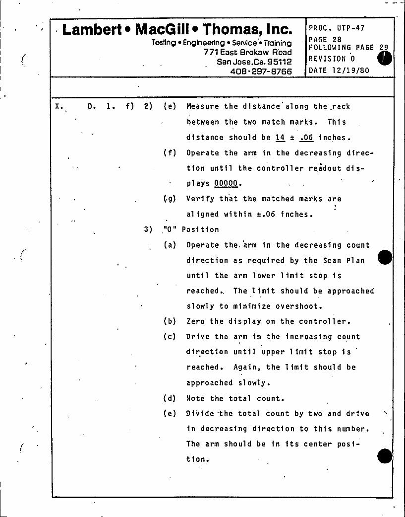
Lambert ~ IacG ill~ Thomas, Inc.Testinp ~ Enpineerinp ~ Service ~ Traininp
771 East Brokaw RoadSan Jose,Ca. 95112
408-297-8766
PROC. UTP-47
PAGE 28FOLLOWING PAGE 29
REVISION 0
DATE 12/19/80
X. D. 1. f) 2) (e) Measure the distance along the rack
between the two match marks. This
distance should be I4 a .06 inches.
(f) Operate the arm in the decreasing direc-
tion until the controller readout dis-plays 00000.
(g) Veri fy that the matched marks are
aligned within a.06 inches.
3),"0" Position
(a)
(b)
(c)
(d)
(e)
Operate the. arm in the decreasing count
direction as required by the Scan Plan
until the arm lower limit stop isreached .. The 1 imi t sho ul d be approac hed
slowly to minimize overshoot.
Zero the display on the controller.Drive the arm in the increasing count
direction until upper limit stop is'eached.Again, the 1 imi t shoul d be
approached slowly.
Note the total count.
Divide the total count by two and drive
in decreasing direction to this number.
The arm should be in its center posi-
tion.
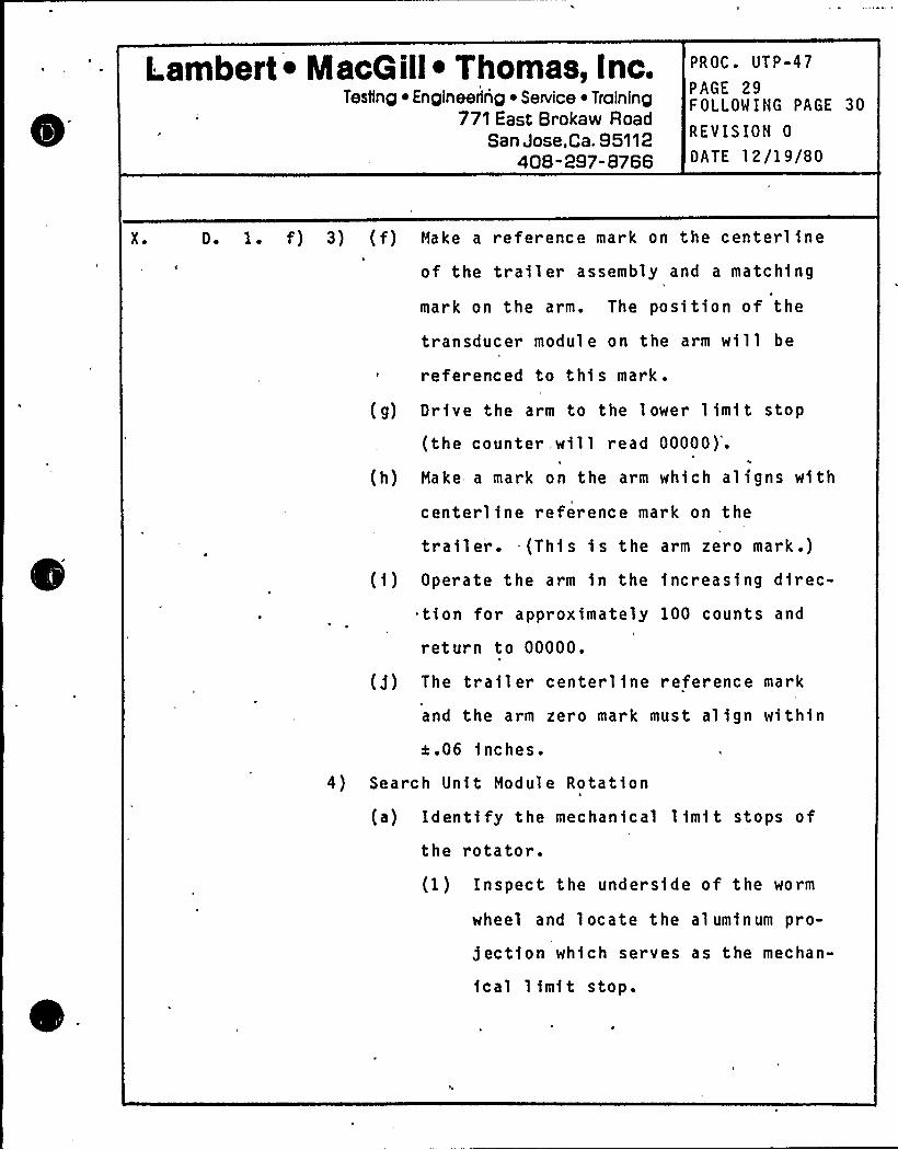
Lambert ~ MacG ill~ Thomas, Inc.Testing ~ Engineering ~ Service ~ Training
771 East Brokaw RoadSan Jose,Ca. 95112
408-297-8766
PROC. UTP-47
PAGE 29FOLLOW ING PAGE 30
REVISION 0
DATE 12/19/80
X ~ D. 1. f) 3) (f) Hake a reference mark on the centerl1ne
of the tra1ler assembly and a matching
mark on the arm. The position of the
transducer module on the arm will be
referenced to this mark.
(g) Drive the arm to the lower 11m1t stop
(the counter will read 00000)".V
(h) Make a mark on the arm which aligns with
centerline reference mark on the
trailer. -(Th1s is the arm zero mark.)
(1) Operate the arm in the increasing d1rec-
tion for approximately 100 counts and
return to 00000.
(g) The trailer centerline reference mark
and the arm zero mark must alfgn within
e.06 inches.
4) Search Unit Module Rotat1on
(a) Identify the mechanical lfm1t stops of
the rotator.(I) Inspect the underside of the worm
wheel and locate the aluminum pro-
jectionn
which serves as the mechan-
ical 1 1mit stop.
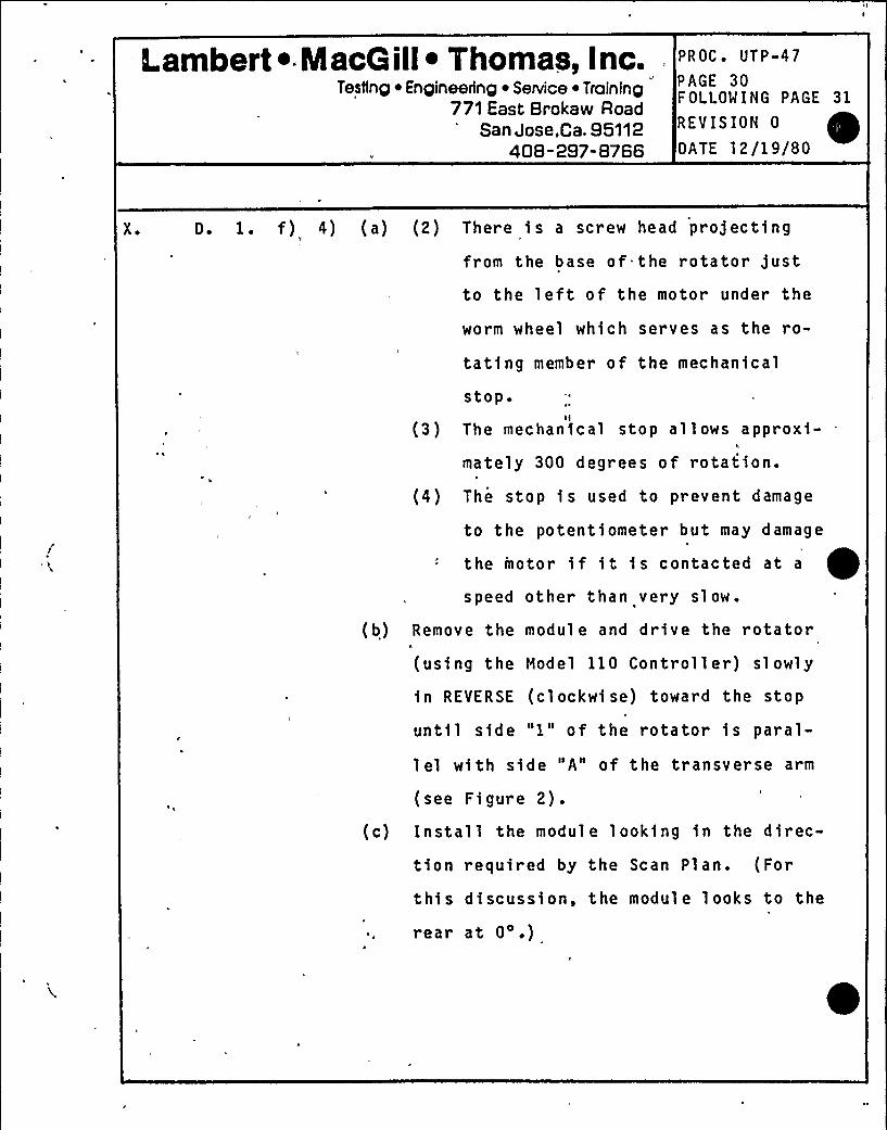
Lambert ~ . MacG ill~ Thomas, Inc.Testing ~ Engineering ~ SeNice ~ Training
771 East Brokaw RoadSan Jose,Ca. 95112
408-297-8766
PROC. UTP-47
PAGE 30FOLLOWING PAGE 31
REVISION 0
OATE 12/19/80
X. D. 1. f) 4) (a) (2) There is a screw head projecting
from the base of. the rotator justto the left of the motor under the
worm wheel which serves as the ro-
tating member of the mechanical
stop
(3) The mechanical stop allows approxi-
mately 300 degrees of rotation.
(4) The stop is used to prevent damage
to the potentiometer but may damage1
the motor i f i t i s contacted at a
speed other than very sl ow.
(b) Remove the modul e and dr ive the rotator
(using the Model 110 Controll er) sl owly
in REVERSE (cl ockwi se) toward the stop
until side "I" of the rotator is paral-
1 el with side "A" of the transverse arm
(see Figure 2).(c) Install the module looking in the direc-
tion required by the Scan Plan. (For
this discussion, the module looks to the
rear at 0'.)
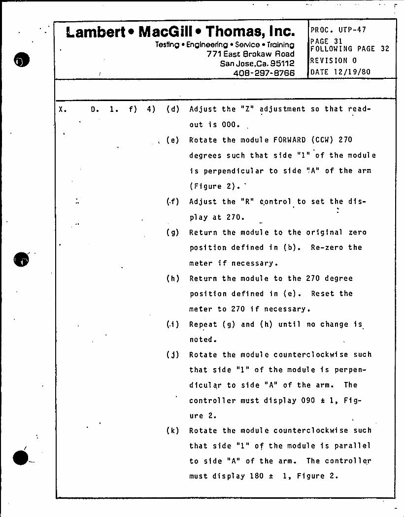
Lambert ~ MacG ill~ Thomas, Inc.Testing ~ Engineering ~ SeNice ~ Training
771 East Brokaw RoadSan Jose,Ca. 95112
408-297-8766
PROC. UTP-47
PAGE 31FOLLOWING PAGE 32
REVISION 0
DATE 12/19/80
X. D. 1. f) 4) (d) Adjust the "Z" adjustment so that r'ead-
out i s 000.
, (e)
(g)
R'otate the modul e FORWARD (CCW) 270
degrees such that side "1" of the modul e
is perpendicular to side '!A" of the arm
(Figure 2).'djustthe "R" Control to set the dis-
play at 270.
Return the module to the original zero
position defined in (b). Re'-zero the
meter if necessary.
(h) Return the module to the 270 degree
position -defined in (e) . Reset the
meter to 270 if necessary .
(.i) Repeat (g) and (h) until no change fs
noted.
(j) Rotate the module counterclockwise such
that side "1" of the module is perpen-
dicular to side "A" of the arm. The
controller must display 090 x 1, Fig-
ure 2.
(k) Rotate the module counterclockwise such
that side "1" of the module is parallelto side "A" of the arm. The controllermust display 180 a 1, Figure 2.
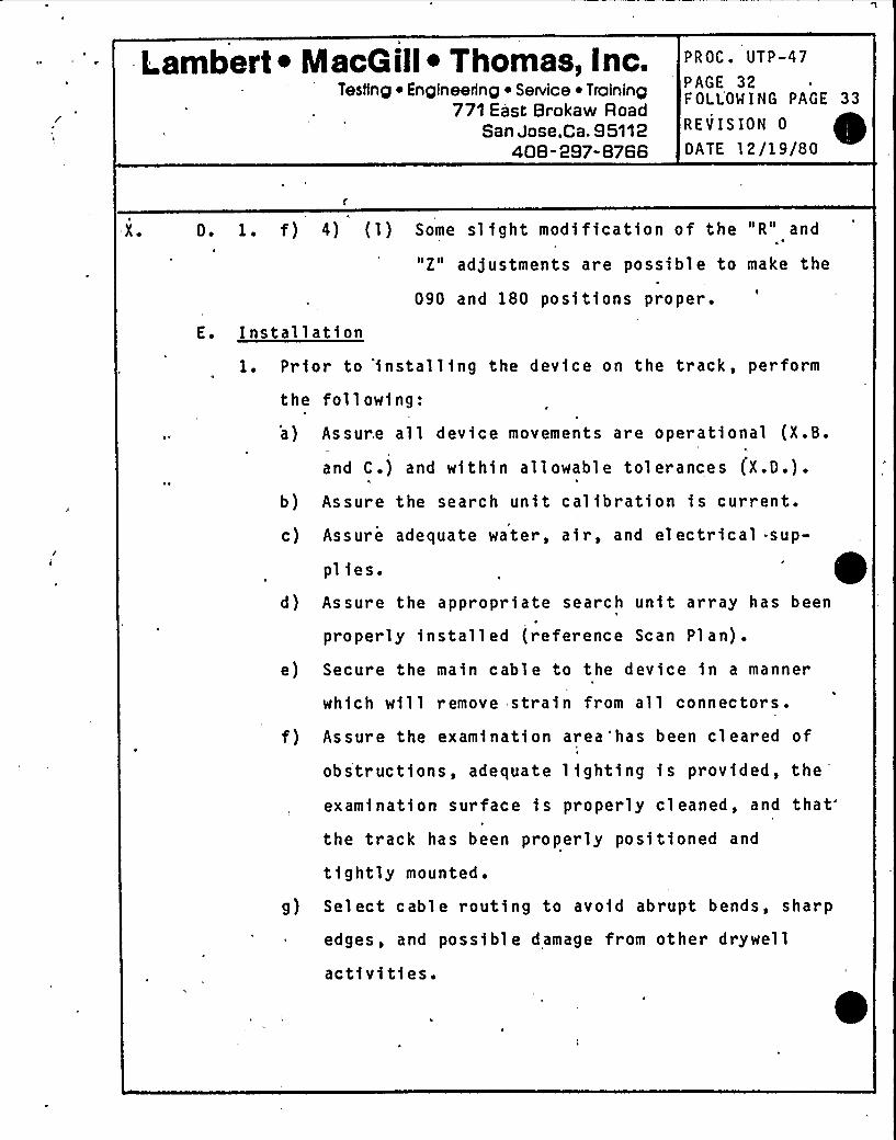
Lambert ~ NlacG ill~ Thomas, Inc.Testing ~ Engineering ~ Service ~ Training
771 East Brokaw RoadSan Jose,Ca. 95112
408-297-8766
PROC ~ UTP-47'AGE 32
F OLLOM I NG PAGE 33
REVISION 0
DATE 12/19/80
X ~ D. 1. f) 4) (1) Some sl fght modification of the "R" and
"Z" adjustments are possible to make the
090 and 180 positions proper.
E. Installation1. Prior to 'installing the device on the track, perform
the following:
a) Assure all device movements are operational (X.B.E
and C.) and within allowable tolerances (X.D.).
b) Assure the search unit calibration is current.
c) Assure adequate water, air, and electrical sup-
plies.d) Assure the appropriate search unit array has been
properly installed (reference Scan Plan).
e) Secure the main cable to the device in a manner
which will remove strain from all connectors.
f) Assur e the examination area'has been cleared of
obstructfons, adequate lighting is provided, the
examinatfon surface fs properly cleaned, andthat'he
track has been properly positioned and
tightly mounted.
g) Select cable routing to avoid abrupt bends, sharp
edges, and possible damage from other drywell
activities.
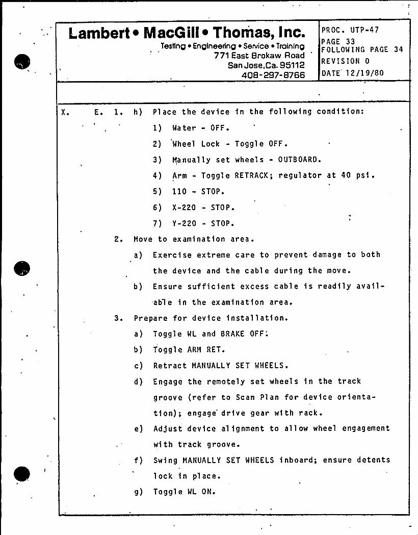
Lambert ~ MacGill~ Thomas, Inc.Testing ~ Engineering ~ Service ~ Training
771 East Brokaw RoadSan Jose,Ca. 95112
408-297-8766
PROC ~ UTP-47
PAGE 33FOLLOW I NG PAGE 34
REVISION 0
DATE 12/19/80
X. E. 1. h) Place the device in the following condition:
1) Water - OFF.
2) Wheel Lock - Toggle OFF.
3) Manually set wheels - OUTBOARD.
4) Arm - Toggle RETRACK; regulator at 40 psi.
5) 110 - STOP.
6) X-220 - STOPS
7) Y-220 - STOP.
2. Move to examination area.
a) Exercise extreme care to prevent damage to bothf
the device and the cable during the move.
b) Ensure sufficient excess cable is readily avail-
able in the examination area.
3. Prepare for device install ation.
a) Toggl e WL and BRAKE OFF;
b) Toggle ARM RET.
c) Retract MANUALLY SET WHEELS.
d) Engage the remotely set wheels in the track
groove (refer to Scan Plan for device orienta-
tion); engage'rive gear with rack.
e) Ad)ust device alignment to allow wheel engagement
with track groove.
f) Swing MANUALLY SET WHEELS inboard; ensure detents
lock in pl ace.
g) Toggle WL ON.
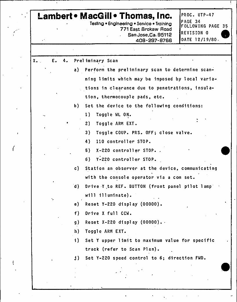
Lambert ~ NlacG ill~ Thomas, Inc.Testing ~ Engineering ~ Service ~ Training
771 East Brokaw RoadSan Jose,Ca. 95112
408-297-8766
PROC. UTP-47
PAGE 34FOLLOWING PAGE 35
REVISION 0
OATE 12/19/80.
X. E. 4. Prel iminary Scan
a) Perform the preliminary scan to determine scan-
ning limits which may be imposed by local varia-
tions in clearance due to penetrations, fnsul a-
tion, thermocouple pads, etc.
b) Set the device to the following conditions:
1) Toggle WL ON.
2) Toggle ARM EXT.
3) Toggle COUP. PRS. OFF; close valve.
4) 110 controller STOP.
5) X-220 controller STOP.
6) Y-220 controller .,STOP.
c) Station an observer at the device, communicating
with the console operator vfa a corn set.
d) Drive -Y .to REF. BUTTON (front panel pilotlamp'ill
illuminate).e) Reset Y-220 display (00000).
f) Orive X full CCW.
g) Reset X-220 display (00000).
h) Toggle ARM EXT.
i) Set Y upper limit to maximum value for specifictrack (refer to Scan Plan).
)) Set Y-220 speed control to 6; dfrectfon FWO.
0
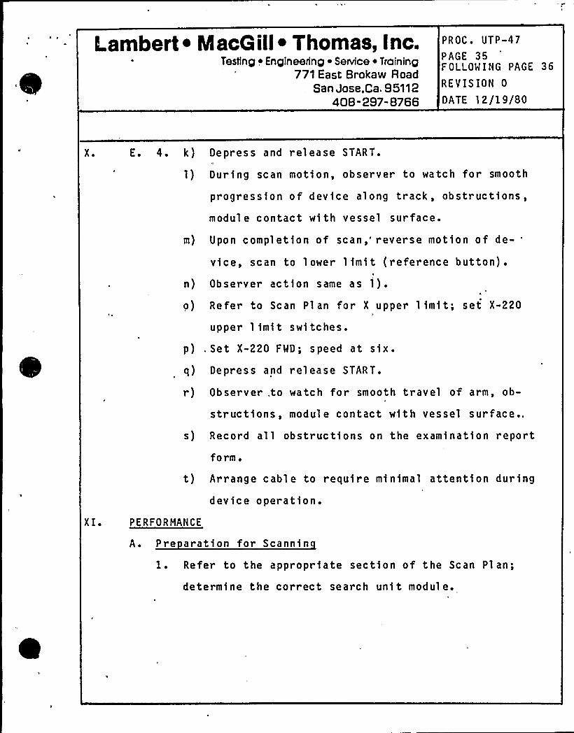
Lambert ~ IacG ill~ Thomas, Inc.Testing ~ Engineering ~ Service ~ Training
771 East Brokaw Road. San Jose,Ca,95112
408-297-8766
PROC. UTP-47
PAGE 35FOLLOWING PAGE 36
REVISION 0
DATE 12/19/80
X ~ E. 4. k) Depress and release START.
1) During scan motion, observer to watch for smooth
progression of device along track, obstructions,
module contact with vessel surface.
m) Upon completion of scan,'everse motion of de-'ice,scan to lower limit (reference button).
n) Observer action same as i).I,
o) Refer to Scan Plan for X upper limit; set X-220
upper limit switches.
p) .Set X-220 FWD; speed at six.
q) Depr ess and release START.
r) Observer.to watch for smooth travel of arm, ob-
structions, module contact with vessel surface..
s) Record all obstructions on the examination report
form.
t) Arrange cable to require minimal attention during
device operation.
X I. PERFORMANCE
A. Pre aration for Scannin
1. Refer to the appropriate section of the Scan Plan;
determine the correct search unit module.
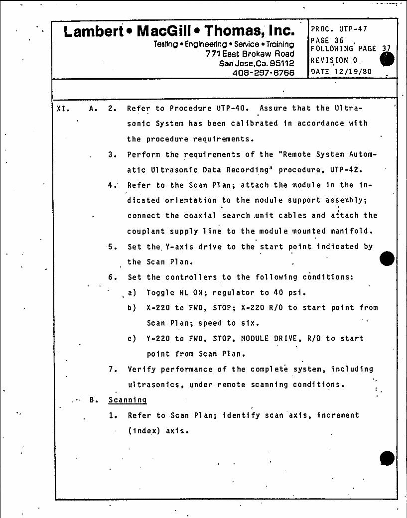
Lambert ~ MacG ill~ Thomas, Inc.Testing ~ Engineering ~ Service ~ Training
771 East Brokaw RoadSan Jose,Ca. 95112
408-297-8766
PROC. UTP-47
PAGE 36FOLLOWING PAGE 37
REVISION 0,DATE 12/19/80
XI. A. 2. Refer to Procedure UTP-40. Assure that the Ul tra-II
son1c System has been cal1brated 1n accordance wf th
the procedure requ1rements.
3. Perform the requirements of the "Remote System Autom-
atic Ultrasonic Data Recordfng" procedure, UTP-42.
4.'efer to the Scan Plan; attach the module 1n the fn-
dfcated orientation to the module support assembly;4
connect the coaxial search,un1t cables and attach the
coupl ant supply line to the modul e mounted mani fold.H
5. Set the, Y-axis drfve to the start point 1ndfcated by
the Scan Plan.
6. Set the controllers to the followfng cond1tfons:
a) Toggle WL ON; regulator to 40 psf.
b) X-220 to FWD, STOP; X-220 R/0 to start point from
Scan Plan; speed to six.c) Y-220 to FWD, STOP, MODULE DRIVE, R/0 to start
point from Scan Plan.
7. Verify performance of the complete system, including
ultrasonics, under remote scanning conditions.t
B. ~Sc anne n
1. Refer to .Scan Plan; fdentf fy scan axis, increment
(1 ndex) axi s.
Lambert ~ MacG ill~ Thomas,'nc.Testing ~ Engineering ~ Se Nice ~ Training
771 East Brokaw RoadSan Jose,Ca. 95112
408-297-8766
PROC. UTP-47
PAGE 37FOLLOWING PAGE 38
REVISION 0
DATE 12/19/80
XI ~ B. 2. Verify module is positioned according to- Scan Pl an
start points.
3. Verify X and Y controllers upper and lower limits are
set according to Scan'lan.
4. Toggle COUP. PRS. ON; regulator to 15 psi; open'alve
and set flow to 200 cc/min.
5. Depress and release appropriate axis-controller
START.
6. Upon completion of scan, depress and release STOP,
REV, and index module according to Scan Plan.
7. Enter all appropriate iriformation on Scan Data
Sheet.
8. Repeat steps 5, 6, and 7 until examination is com-
piete.9. Upon completion of scanning and prior to removing the
device from the track, re-verify the X and Y axis "0"
positions.
XI I ~ EVALUATION
A. All recordable and/or repor table indications shall be
evaluated in accordance with the appropriate ultrasonic
examination procedures and appl icable portions of theP
Scan Plan.
Lambert' acG ill~ Thomas, Inc.Testing» Engineering ~ Service ~ Training
771 East Brokaw RoadSan Jose,Ca. 95112
408-297-8766
PROC. UTP-47
PAGE 38FOLLOWING PAGE 39
REVISION 0'ATE12/19/80
XI I I. RECORDS
A. A ScantOata Sheet (Figure 3) shall be completed for each
examination and shall be related to the Ultrasonic Cali-
bration and Examfnatfon reports and those portions of the
Scan Plan which apply to that examination.
B. A "Pole Guided Device Zero and Travel Linea'rity Verifica-,tfon" form shall be completed daily, prior to commencing
examination (Figure 4).C. Each time the pole guided examination device fs assembled
as a system, complete the checklists (Figures 5 and 6).
XIV. REVIEW
A. All Scan Data Sheets are subject to review by an assigned
LMT Level II I for completeness and accuracy of entered
data.
B. Following the LMT review, the Scan Data Sheets shall be
transmitted to the WPPSS ISI Field Coordinator for review
by WPPSS and the Authorized Nuclear Inspector.
XIV. DOCUMENTATION STORAGE ANO DISTRIBUTION
A. Original examination documentation shall become the prop-
erty of WPPSS upon sign-off by the ISI Ffeld Coordinator.
Additional reports which may include examination documen-
0
Lambert ~ MacG ill~ Thomas, Inc.Testing.
~ Engineering ~ Service ~ Training771 East Brokaw Road
San Jose,Ca, 95112408" 297-8766
PROC. UTP-47
PAGE 39FOLLOWING PAGE 40
REVISION 0
DATE 12/19/80
XIV.. A. tation as reference material shall be generated from
copies.
B. Field storage facilities shall provide a safe storage
area, and access.to files shall be limited to the LMT
Field Supervisor, his designated representatives, WPPSS
representative and the Authorized Nuclear Inspector.
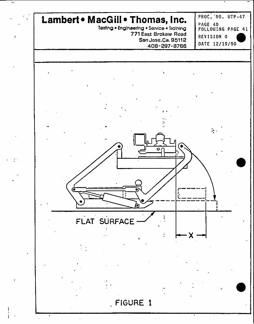
t.ambert ~ Maca ill~ Thomas, Inc.Testing ~ Engineering ~ Service ~ Training
771 East Brokaw RoadSan Jose,Ca. 95112
408-297-8766
PROC.'NO. UTP-47
PAGE 40FOLLOWING PAGE 41
REVISION 0
DATE 12/19/80
II
FLAT SURFACE
FIGURE 1
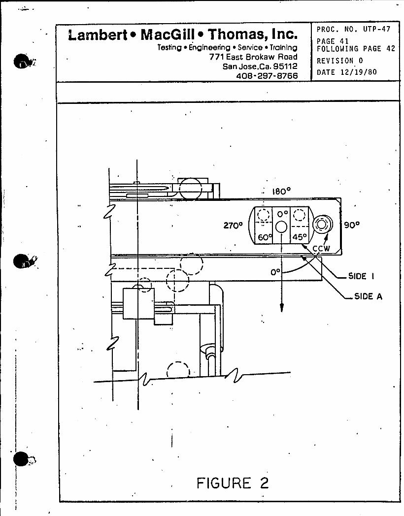
Lambert ~ MacGill ~ Thomas, Inc.Testing Engineering ~ Service ~ Training
771 East Brokaw RoadSan Jose,ca. 95112
408- 297-8766
PROC. NO. UTP-47
PAGE 41FOLLOWING PAGE 42
REVISION 0
OAT E 12/19/80
180
70opO
450
fels
CCW
90o
pOSIDE I
SIDE A
( l.
FIGURE 2
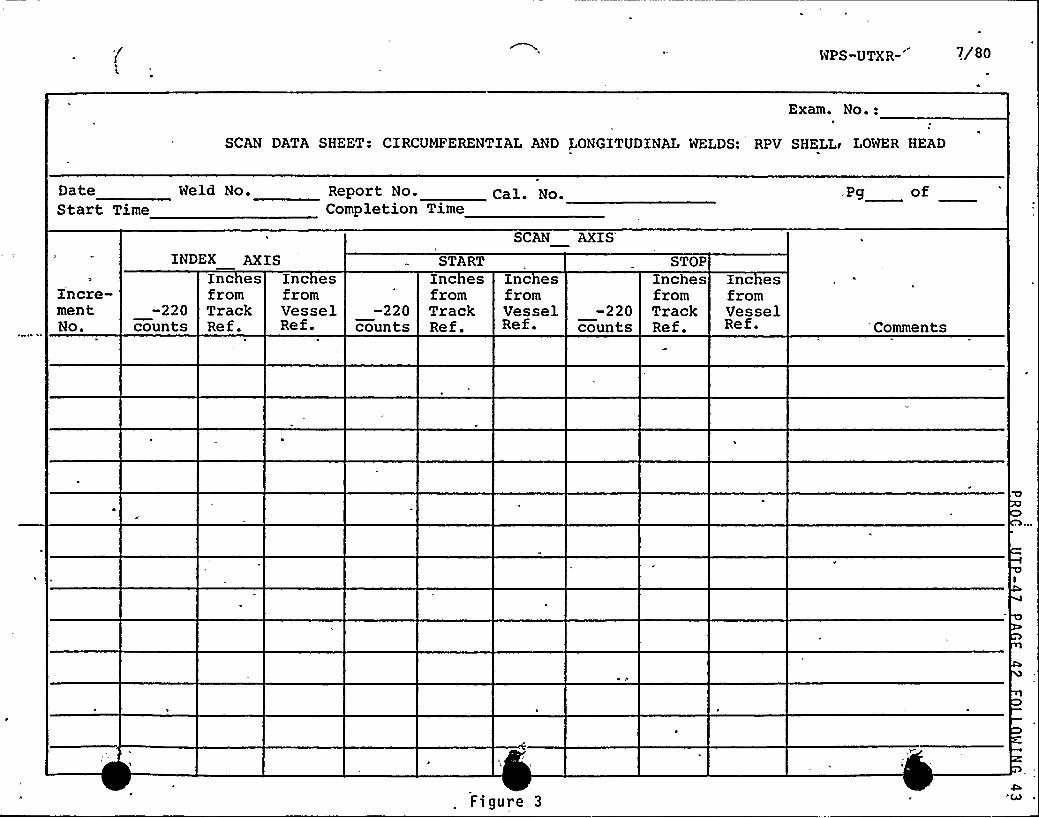
WPS-UTXR- 7/80
Exam. No.:
SCAN DATA SHEET CIRCUMFERENTIAL AND LONGITUDINAL WELDS: RPV SHELLe LOWER HEAD
DateStart Time
Weld No. Report No.Completion Time
Cal. No.
SCANAXIS'g of
I'ncre-mentNo.
INDEX AXISInc esfromTrackRef.
-'220counts
Inc esfromVesselRef.
-220counts
STARTInc esfromTrackRef.
Inc esfromVesselRef.
-220counts
STOPInchesfromTrackRef.
Inc esfromVesselRef. Comments
Figure 3
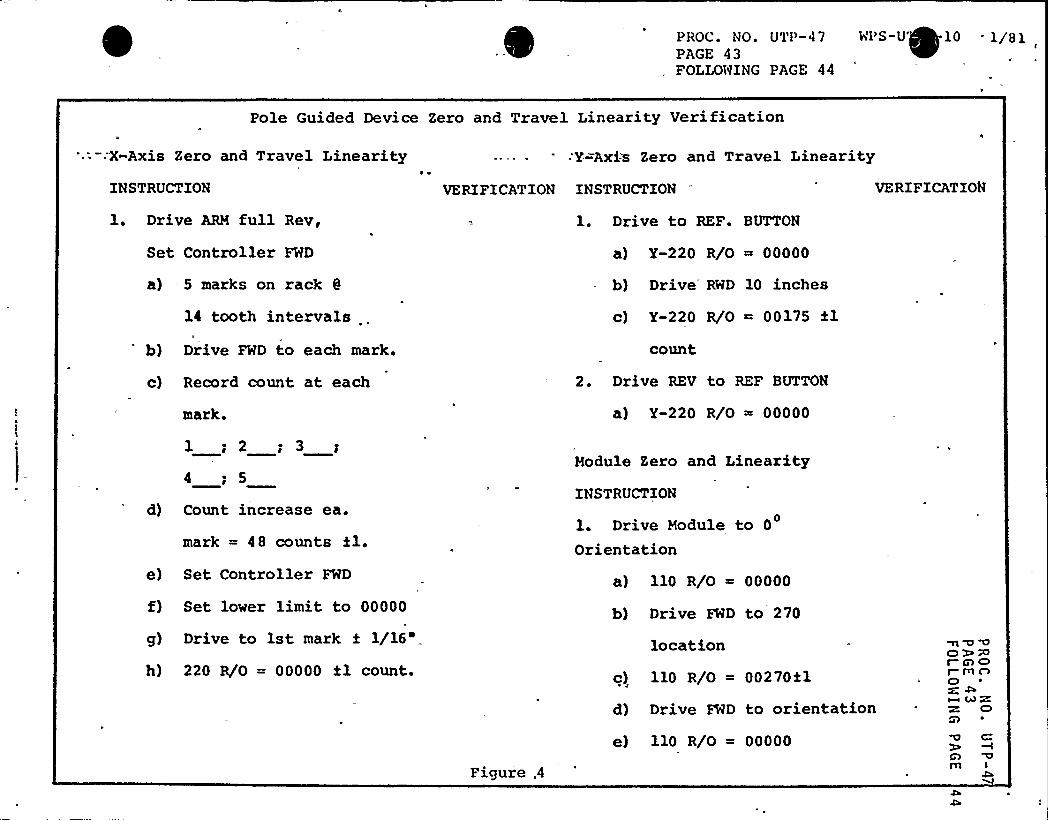
PROC. NO. UTP-4 7 WPS-U~ 1 0 1/8 1PAGE 43FOLLOWING PAGE 44
Pole Guided Device Zero and Travel Linearity Verification
'.: —:X-AxisZero and Travel Linearity -Y=Axis Zero and Travel LinearityINSTRUCTION
1. Drive ARM full Rev,
Set Controller FWD
a) — 5 marks on rack 0
14 tooth intervals
b) Drive FWD to each mark.
c) Record count at each
mark.
1; 2; 3 g
4 g 5
d) Count increase ea.
mark = 48 counts il.e) Set Controller FWD
f) Set lover limit to 00000
g) Drive to 1st mark f1/16')
220 R/0 = 00000 fl count.
VERIFICATION INSTRUCTION
1. Drive to REF. BUTTON
a) Y-220 R/0 00000
b) Drive RWD 10 inches
c) Y-220 R/0 ~ 00175 flcount
2. Drive REV to REF BUTTON
a) Y-220 R/0 = 00000
Module Zero and LinearityINSTRUCTION
1. Drive Module to 0
Orientation
a) 110 R/0 ~ 00000
b) Drive FWD to 270
location
c) 110 R/0 = 00270%1
d) Drive FWD to orientation
VERIFICATION
m O OOPNI C)OI- rl OO~-c 4)RZ O
Figure .4
e) 110 R/O = 00000
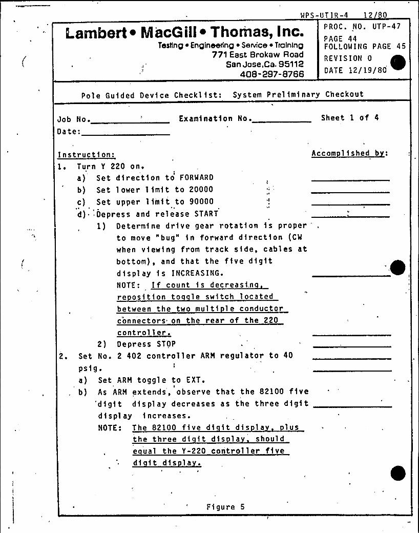
WPS-UT IR-4 12
Lambert ~ MacGill~ Thomas, Inc.Testing Englneehng ~ SeNice ~ Training
771 East Brokaw RoadSan Jose,Ca. 95112
408-297-8766
P ROC. NO. UTP-47
PAGE 44FOLLOWING PAGE 45
REVISION 0
DATE 12/19/80 ~Pole Guided Dev1ce Checkl fst: System Prelfm1nary Checkout
Job No.
Date:Examination No. Sheet 1 of 4
Instruction:1. Turn Y 220 on.
a) Set dfr ect1on to FORWARD
b) Set lower l 1mft to 20000 I
c) Set upper limit to 90000 ~ I
~ ~
d) Depress and release START
~1) Determine dr1ve gear rotation fs proper
to move "bug" fn forward direct1on (CM
when v1ewing from track side, cables atbottom), and that the five digitdisplay fs INCREASING.
NOTE: If count fs decreasi.nre osition to le switch locatedbetween the two mult1 le conductorconnectors on the rear of the 220
controller.2) Depress STOP
2. Set No. 2 402 controller ARM regulator to 40
psfgea) Set ARM toggle to EXT.
b) As ARM extends', observe that the 82100 five'digit display decreases as the three digitdisplay 1ncreases.NOTE: The 82100 five df 1t df s l a lus
the three dt it d1s la shoulde ual the Y-220 controller fivedf ft d1s la
Accom lished b
Figure 5
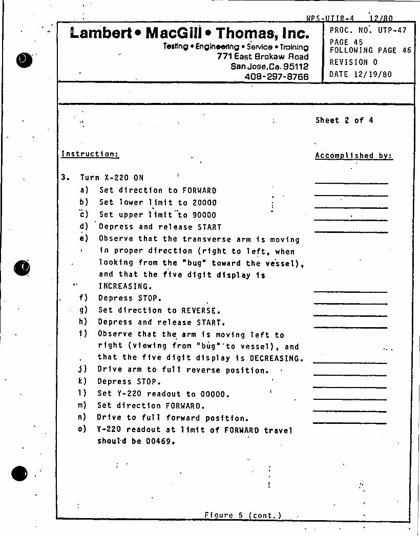
Lambert ~ Macoill ~ Thomas, Inc.Testing ~ Enqlneerlnq ~ Seniice ~ Trolninp
771 East Brokavv RoadSan Jose,Ca. 95112
408-297-8766
PROC. NO. UTP-47
PAGE 45FOLLOWING PAGE 46
REVISION 0
DATE 12/19/80
Sheet 2 of 4
I nstr uctf on: Accom 11shed b
3 ~ Tura)
b)
c)d)e)
f)g)h)f)
>)k)1)m)
n)
o)
n X-220 ON
Set dfrect1on to FORWARD
Set lower 1 fmit to 20000Set upper 1 fmf t to 90000Depress and release START
Observe that the transverse arm fs movingfn proper dfrectfon (right to left, whenlooking from the "bug" toward the vessel),and that the five digit display fsI NCREAS ING.Depress STOP.
Set direction to REVERSE.
Depress and release START.Observe that the arm fs movfng left tor1ght (viewing from "bug"'to vessel), andthat the f 1 ve d 1 gf t d1s pl ay 1s DECREASING.Drive arm to full reverse posft1on.Depress STOP.
Set Y-220 readout to 00000.Set direction FORWARD.
Drive to full forward posftfon.Y-220 readout at limit of FORWARD travelshoul=d be 00469.
Fi ure 5 cont. )
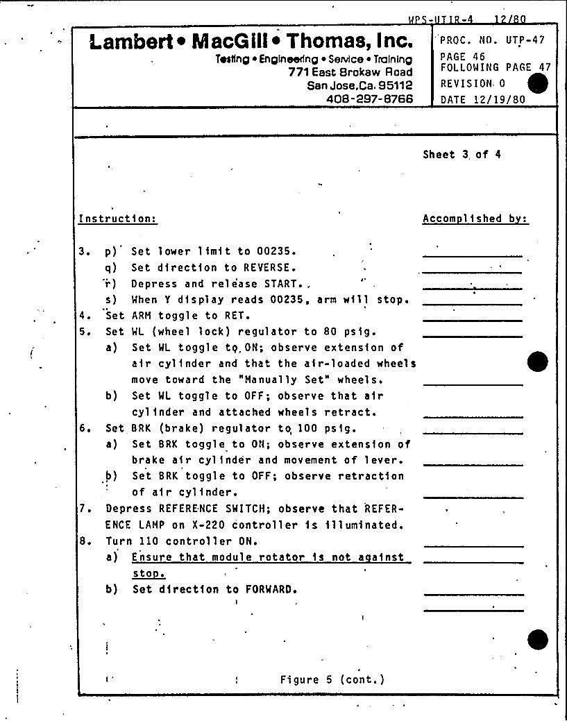
Lambert ~ MacGill ~ Thomas, Inc.Testfng iEngineering ~ Service ~ Troining
771 East Brokaw RoadSan Jose,Ca. 95112
408-297-8766
PROC. NO. UTP-47
PAGE 46FOLLOWING PAGE 47
REVISION 0
DATE 12/19/80
Sheet 3, of 4
Instruction: Accom lished b
3. p) Set l ower, 1 imi t to 00235.
q) Set direction to REVERSE.'i) Depress and release START..s) When Y display reads 00235, arm will stop.
4. Set ARM toggle to RET.
5. Set WL (wheel lock) regulator to 80 psig.a) Set WL toggle tq. ON; observe extension of
air cylinder and that the air-loaded wheelsmove toward the "Manually Set" wheels.
b) Set WL toggle to OFF; observe that aircylinder and attached wheels retract.
6. Set BRK (brake) regulator to, 100 psig.a) Set BRK toggle to ON; observe extension of
brake air cylinder and movement of lever.b) Set BRK toggle to OFF; observe retraction
of air cylinder.7. Depress REFERENCE SWITCH; observe that REFER-
ENCE LAMP on X-220 controller is illuminated.8. Turn 110 controller ON.
r
a) Ensure that module rotator is not a ainst~St 0 ~
b) Set direction to FORWARD.I
E
Figure 5 (cont.)
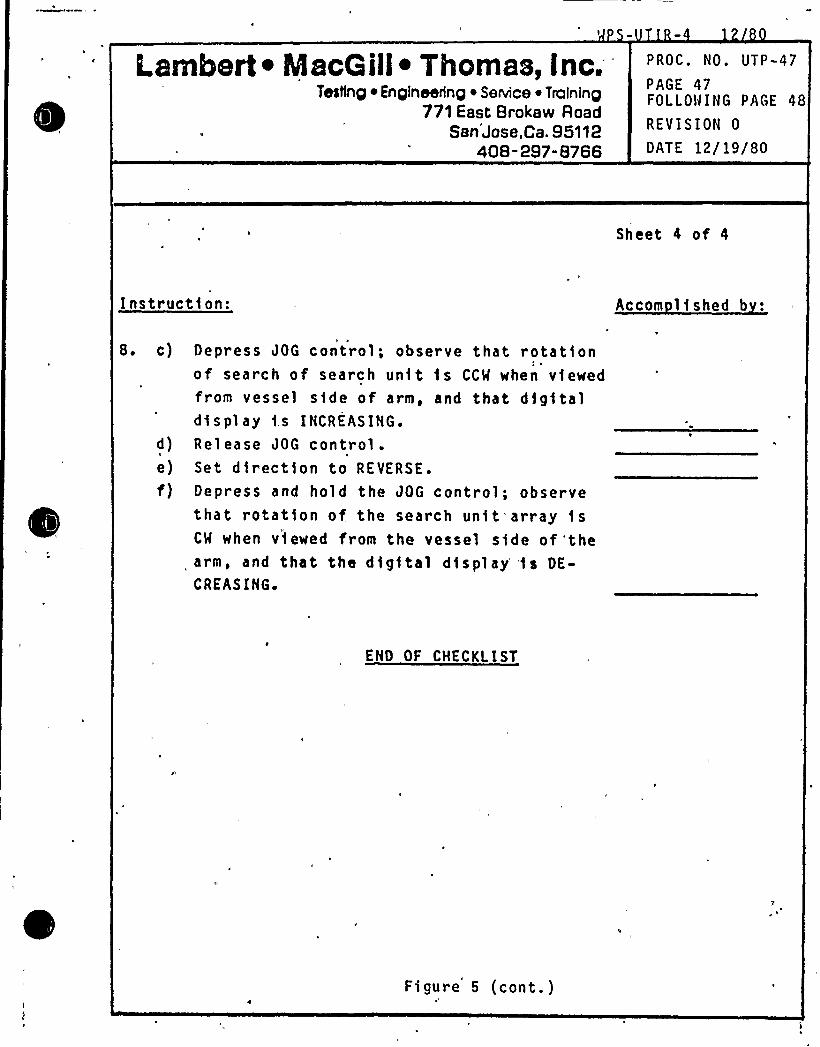
Lambert ~ Maco ill~ Thomas, Inc.Testing ~ Enplneerinp ~ Senrice ~ Troininp
771 East Brokaw RoadSan Jose,Ca. 95112
408-297" 8766
PROC. NO. UTP-47
PAGE 47FOLLOWING PAGE 48
REVISION 0
DATE 12/19/80
Sheet 4 of 4
Instruct1on: Accom lished b :
8. c)
d)e)f)
Jl, ~
Depress JOG control; observe that rotationof search of search unit is CCM when viewedfrom vessel side of arm, and that digitald1spl ay 1.s INCREASING.
Release JOG control.Set direction to REVERSE.
Depress and hold the JOG control; observethat rotat1on of, the search un1t array 1sCM when v1ewed from the vessel side of 'thearm, and that the dig1tal display''is DE-CREASING ~
END OF CHECKLIST
Figure 5 (cont.)
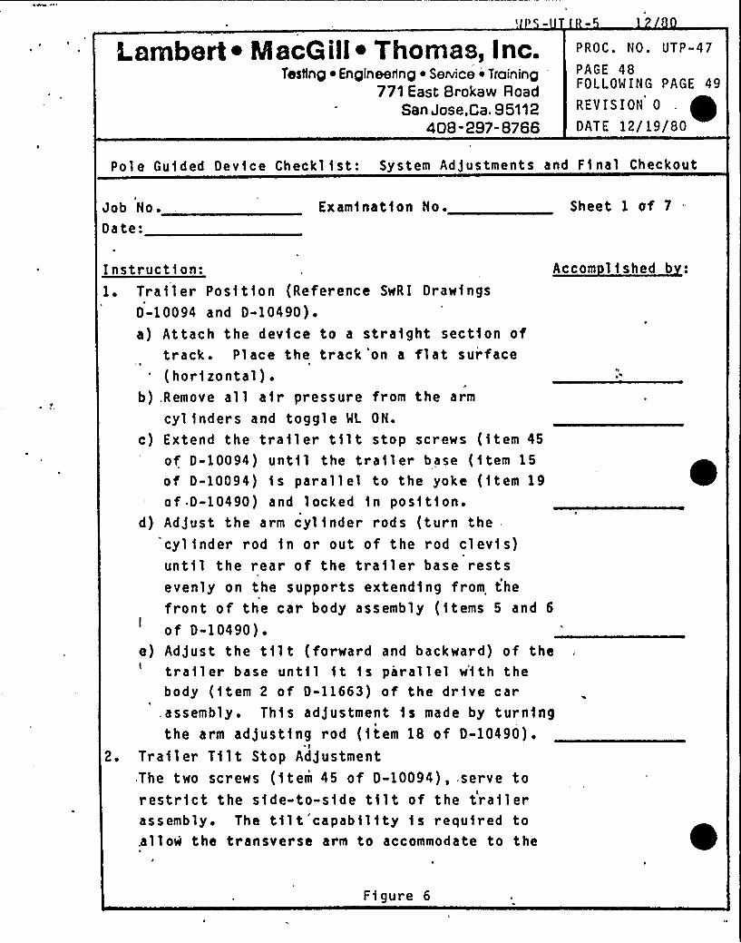
Lambert ~ MScG III~ Tllom88, Inc.Testing Engineering ~ Service ~ Training
771 East Brokaw RoadSan Jose,Ca. 95112
408 -297-8766
PROC. NO. UTP-47
PAGE 48FOLLOWING PAGE 49
REVISION 0
DATE 12/19/80
Pole Gu1ded Dev1ce Checkl 1st: System Adjustments and F1nal Checkout
Job No.Date:
Examination No. Sheet 1 of 7
Accom 11shed bInstruction:1. Trailer Position (Reference SwRI Drawings
D-10094 and D-10490).a) Attach the device to a straight sect1on of
track. Pl'ace the track 'on a flat surface(horizontal).
b) Remove all a1r pressure from the arm
cylinders and toggle WL ON.
c) Extend the trailer tilt stop screws (item 45
of D-10094) until the trailer base (item 15
of D-10094) is parallel to the yoke (item 19
of D-10490) and locked in pos1tion.d) Adjust the arm cylinder rods (turn the
'cyl1nder rod 1n or out of the rod clevis)unt11 the rear of the trailer base restsevenly on the supports extend1ng from thefront of the car body assembly (items 5 and 6
I of D-10490) ~
e) Adjust the tilt (forward and backward) of thetrailer base until 1t 1s parallel w1th thebody (item 2 of 0-11663) of the dr1ve car
.assembly. This adjustment is made by turn1ngthe arm adjust1ng rod (item 18 of D-10490).
2. Trailer Tilt Stop AdjustmentThe two screws (1tem 45 of D-10094), .serve torestrict the side-to-side tilt of the trailerassembly. The tilt capability 1s required to.allow the transverse arm to accommodate to the
Figure 6
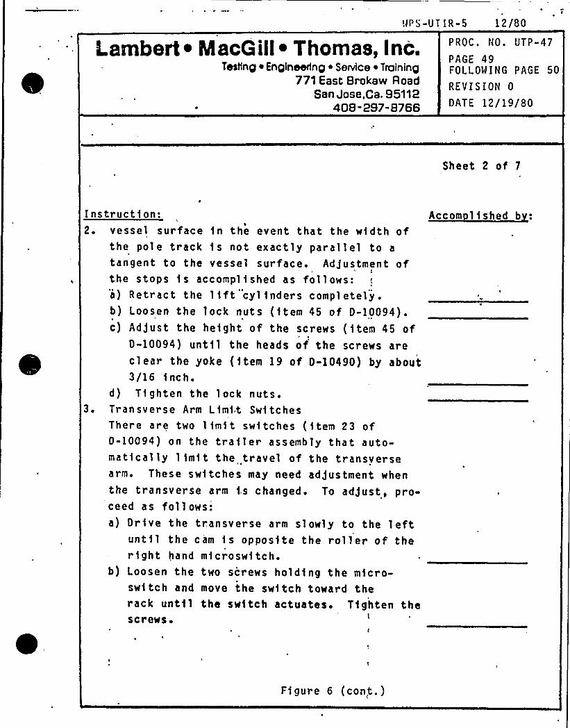
WPS-UT IR-5 12/80
Lambert ~ Macoill ~ Thomas, Inc.TeNng ~ Engineering ~ Service ~ Training
771 East Brokaw RoadSan Jose,Ca. 95112
408-297"B766
PROC. NO. UTP-47
PAGE 49FOLLOWING PAGE 50
REVISION 0
DATE 12/19/80
Sheet 2 of 7
Instruction:2. vessel surface 1n the event that the w1dth of
the pole track is not exactly parallel to a
tangent to the vessel surface. Adjustment ofthe stops is accompl1shed as follows:a) Retract the 11ft cylinders completely .
b) Loosen the lock nuts (item 45 of D-10094).c) Adjust the height of the screws ( 1tem 45 of
D-10094) unt11 the heads of the screws areclear the yoke (item 19 of D-10490) by about3/16 1 nc h.
d) T1ghten the lock nuts.3. Transverse Arm Lim1t Switches
There are two lim1t switches ( 1tem 23 of0-10094) on the trailer assembly Chat auto-mat1cally limit the travel of the transversearm. These sw1tches may need adjustment whenthe Cransverse arm i.s changed. To adjust, pro-ceed as follows:a) Drive the transverse arm slowly to the left
until the cam fs opposite the roller of ther1ght hand microswitch.
b) Loosen the two screws holding the micro-switch and move the sw1tch toward therack until the switch actuates. Tighten thescrews'
Accom Iished b :
Figure 6 {con,t.)

Lambert ~ MacG ill~ Thomaa, Inc.Tesling ~ Engineering ~ Service ~ Traininp
& 771 East Brokaw RoadSan Jose,Ca. 95112
408-297-8766
PROC. NO. UTP-47
PAGE 50FOLLOWING PAGE 51
REVISION 0
DATE 12/19/80
Sheet 3 of 7
Instruction:3. c) Drive the transverse arm slowly to the right
and repeat the ad)ustment with the othersw1tch.
d) Dr1ve the arm in each direct1on and,j ead$ ust1 f necessary.
4. Track Reference Switch (Level and Switch Assem-
bly, SwR I Dra~ing C-13577) .The 1 im1t sw1tch (item 10) and its actuator(items 2 and 6) are used to establish the pri-mary reference position of the pble gu1deddevice on the track. Each pole track has a
re'ference button attached to the back side ofthe gear rack, at some preselected po1nt. As
the drive car passes the'reference pos1tion,the sw1tch 1s act1vated momentar1ly and'ightsthe reference lamp on the controller. Ad)ustthe reference sw1tch as follows:a) Install the device on the track. Determ1ne
that the roller of the actuator (item 6) isfust barely in contact with the back of therack on the track. (Adjust using screw,item 24).
b) Slowly drive the device past the referenceposit1on and readjust 1tem 3 as necessary tolight the reference l1ght on the panel.
. ~
Accom lished b
Figure 6 (cont.)
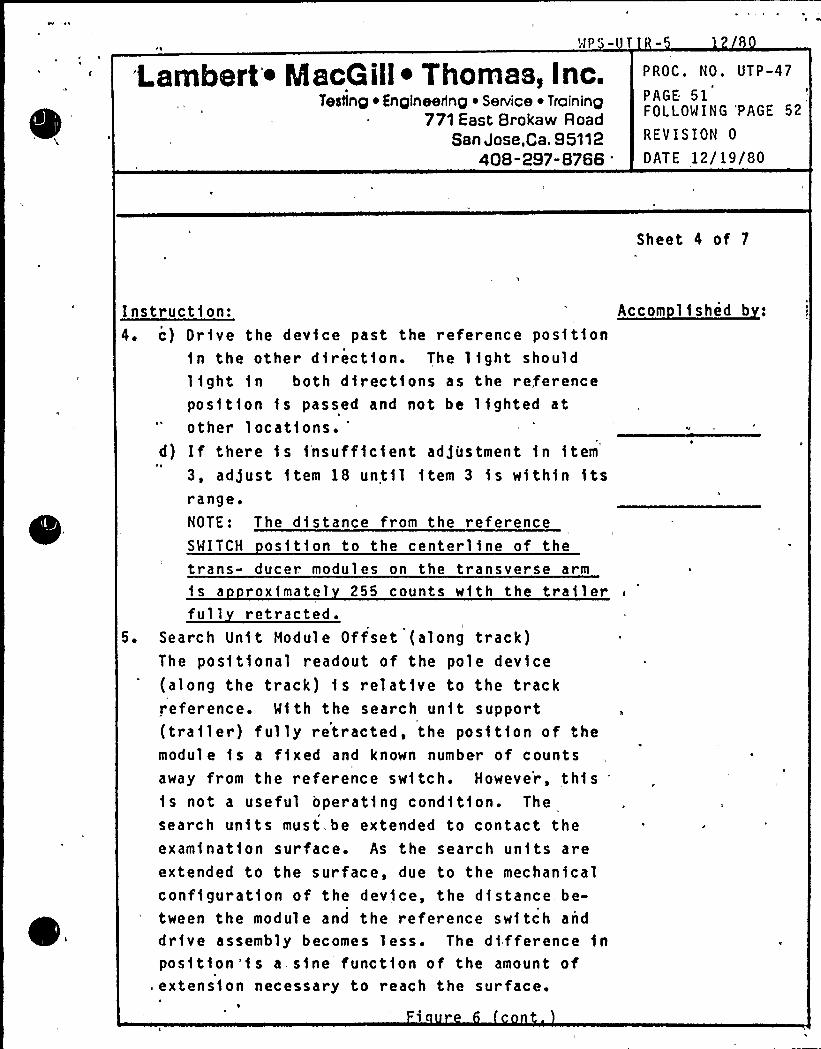
iambert ~ IacG ill~ Thomas, I nc.Testing iEngineering ~ Service ~ Training
771 East Brokaw RoadSan Jose.Ca. 95112
408-297-8766
'ROC. NO. UTP-47
PAGE 51FOLLOWING 'PAGE 52
REVISION 0
DATE 12/19/80
Sheet 4 of 7
Instruction:4. c) Dr1ve the device past the reference position
1n the other direction. The light shouldlight in both directions as the referenceposf t1on is passed and not be lighted atother locat1ons. "
d) If there 1s insufficient ad)ustment 1n 1tem
3, ad]ust item 18 until item 3 1s w1thin itsrange.NOTE: The distance from the referenceSMITCH os1t1on to the center11ne of thetrans- ducer modules on the transverse arm1s a roximatel 255 counts with the trailerfull retracted.
5. Search Un1t Module Offset (along track)The pos1tional readout of the pole device(along the track) is relative to the trackreference. With the search unit, support(trailer) fully retracted, the position of themodule is a f1xed and known number of countsaway from the reference switch. However, this1s not a useful operat1ng cond1t1on. The
search units must, be extended to contact theexamination surface. As the search un1ts areextended to the surface, due to the mechanicalconf1gurat1on of the dev1ce, the distance be-tween the module and the reference switch anddrive assembly becomes less. The d1fference 1n
pos1tion'is a.sine function of the amount of.extens1on necessary to reach the surface.
Accom lished b :
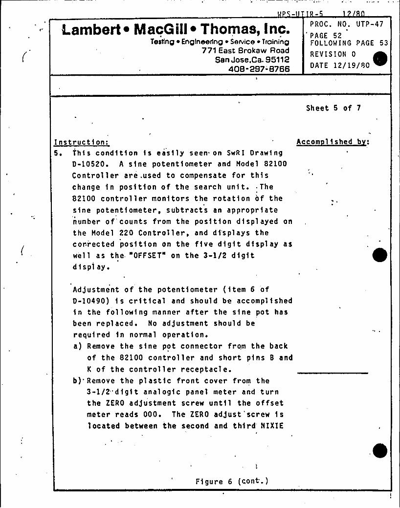
k.ambert ~ MacG ill~ Thomas, I nc.Testing ~ Enqlneerlnp ~ Service ~ Troininp
771 East Brokaw RoadSan Jose,Ca. 95112
408-297-'8766
PROC. NO. UTP-47
PAGE 52FOLLOWING PAGE 53
REVISION 0
DATE 12/19/80 ~
Sheet 5 of 7
Instruct)on:5. This cond)t1on is easily seen on SwR I Draw1ng
D-10520. A s1ne potentiometer and Model 82100
Controller are .used to compensate for thischange in position of the search unit. The
82100 controller monitors the rotation of thesine potent1ometer, subtracts an appropriatenumber of'counts from the pos1tion d1splayed on
the Model 220 Controller, and d1'splays thecori ected posit1on on the f1ve digit d1splay as
well as the "OFFSET" on the 3-1/2 digitdi spl ay.
Accom lished b
Adjustment of the potent1ometer (item 6 ofD-10490) 1s critical and should be accomplishedin the follow1ng manner after the s1ne pot hasbeen repl aced. No adjustment should be
required in normal oper ation.a) Remove the sine pot connector from the back
of the 82100 controller and short p1ns B and
K of the controller receptacle.b)'emove the plastic front cover from the
3-1/2"digit analogic panel meter and turnthe ZERO adjustment screw until the offsetmeter reads 000. The ZERO adjust'screw islocated between the second and third'IXIE
Figur e 6 (cont'-)
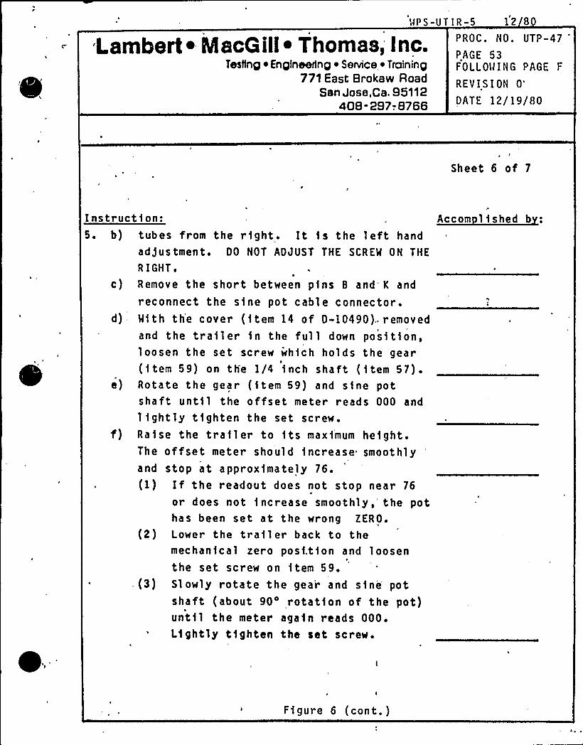
WPS-UT IR-5 12 8
Lambert ~ MacG ill~ Thomas, Inc.Testing ~ Engineering ~ Senrice ~ Training
771 East Brokaw RoadSan Jose,Ca. 95112
40B -297-. 8766
PROC. NO. UTP-47'AGE
53FOLLOWING PAGE F
REVISION 0"
DATE 12/19/80
Sheet 6 of 7
Instruction:5. b) tubes from the right. It is the left hand
ad)ustment. DO NOT ADJUST THE SCREW ON THE
R IGHT o
c) Remove the short between pins 8 and' and
reconnect the sine pot cable connector.d) With the cover (item 14 of D-10490). removed
and the trailer 1n the full down pos1tion,loosen the set screw wh1ch holds the gear(1tem 59) on the I/4 inch shaft (1tem 57).
e) Rotate the gear (item 59) and sine potshaft unt11 the offset meter reads 000 and
lightly tighten the set screw.f) Raise the trailer to 1ts maximum height.
The offset meter should increase smoothlyand stop at approximately 76.(1) If the readout does not stop near 76
or does not increase smoothly,'he pothas been set at the wrong ZERO.
(2) Lower the trailer back to themechanical zero posi.tion and loosenthe set screw on item 59.
-(3) Slowly rotate the gear and sine potshaft (about 90'otation of the pot)unt11 the meter again reads 000.Lightly tighten the set screw.
Accom lished b :
Fi gure 6 (cont. )
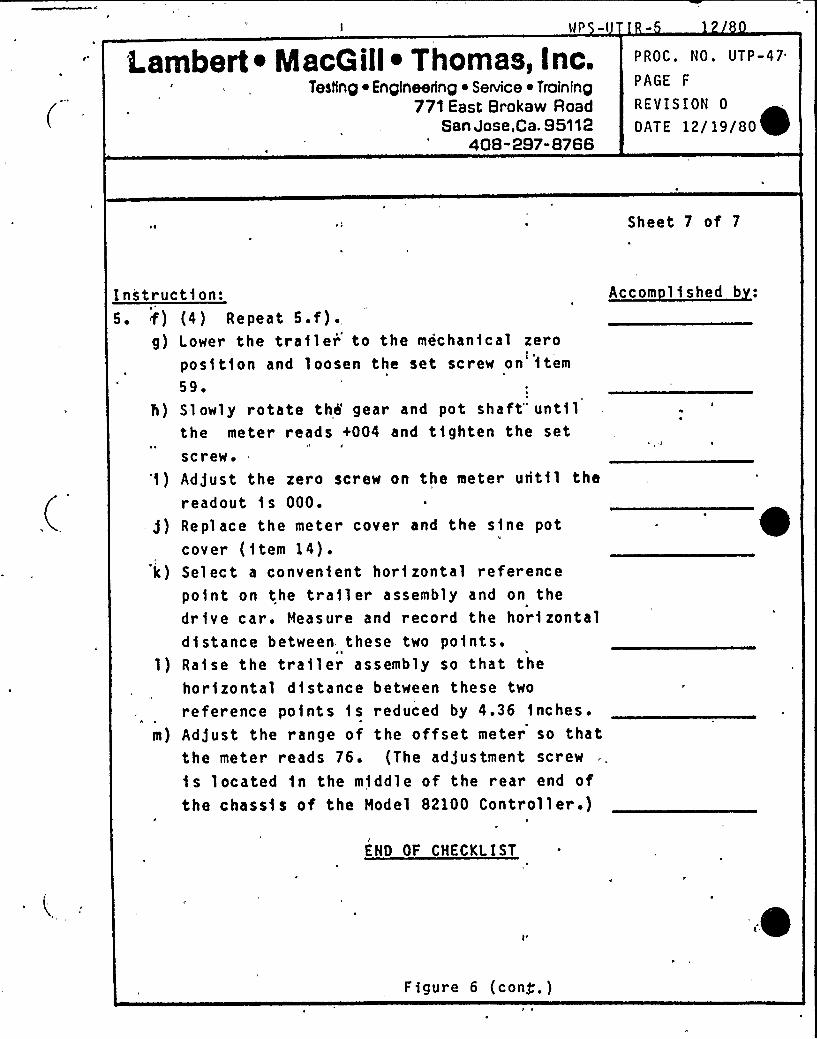
Lambert ~ MacG ill~ Thomas, Inc.Testlnp ~ Enplneednp ~ Service ~ Traininp
771 East Brokaw RoadSan Jose.Ca. 95112
408-297-8766
PROC. NO. UTP-47
PAGE F
REVISION 0
OAT E 12/19/80
Sheet 7 of 7
Instrucg)g)
m)
ti on:
(4) Repeat 5.f).Lower the trailer to the mechanical zeroposition and loosen the set screw on'tem59
'lowly rotate thh gear and pot shaft" untilthe meter reads +004 and tighten the setscrew.Ad)ust the zero screw on the meter until thereadout 1s 000.Replace the meter cover and the sine potcover (item 14).Select a convenient horizontal referencepo1nt on the trailer assembly and on thedr1ve car. Measure and record the horizontaldistance between. these two po1nts.Ra1se the trailer assembly so that thehorizontal distance between these two
reference points 1 s reduced by 4.36 1nches.Ad)ust the range of the offset meter so thatthe meter reads 76. (The ad)ustment screw
1s located 1n the m1ddle of the r ear end ofthe chass1s of the Model 82100 Controller .)
Accom lished b
ENO OF CHECKLIST
'0Figure 6 (cong. )
Date l/8/79Revision 0
MNP-2 PSI PROGRAM PLAN
NOT USED
(Purposely left blank)
Da te I /8/79Revi sion 0
MNP-2 PSI PROGRAM PLAN
NOT USED
(Purposely left blank)

'0
Date 1/8/79
Revision 0
MNP-2 PSI PROGRAM PLAN
NOT USED
(Purposely 1 e ft bl ank)
Date 1/18/85Revision 3'
11.0 —ULTRASONIC CALIBRATION STANDARDS
This section of the WNP-2 PSI Program Plan provides a description of the
design and identifies the applicability of each ultrasonic calibrationblock which will be used to complete the ultrasonic examinations identifiedin this Program Plan. This section is divided into two subsections. Sub-
section 11.1 presents the UT calibration blocks which will be used in
completing examinations of the RPV, including top and bottom heads, nozzle-
to-shell welds and inner radii, and nozzle safe end weld examinations.
Subsection 11.2 presents those calibration blocks which will be used in
completing examinations of the piping systems. The RPV safe-end UT blocks
were designed and fabricated by the NSSS supplier, as were the vessel
blocks, with the exception of the calibration blocks for the feedwater
nozzle inner radius and flange-to-shell weld. The feedwater nozzle block
is an actual BWR feedwater nozzle with attached shell plate material. This
mock-up, including the notches which simulate flaws, was designed and fab-
ricated by the Supply System. The flange-to-shell weld block is an actual
BWR fl'ange with attached shell plate material. This block was designed and
fabricated by the Supply System. The balance of the piping weld blocks
were designed and fabricated by the Supply System as detailed in 11.2.
11-1
Revision 0
11.1 VESSEL STANDARDS
The design drawings on the following pages illustrate the ultrasoniccalibration blocks which will be used to perform ultrasonic examinations
of the RPV, including top and bottom heads, the nozzle-to-she1.1 welds
and inner radii, and the nozzle safe end welds. Table 11-1 lists those
UT blocks, including the block identification number which will be
used exclusively whenever referencing the calibration block on data
sheets or other records, and the corresponding design drawing number.
The block identification number is the same number referenced from theProgram Plan and Schedule Tables and the Weld and Component Identifi-cation Diagrams found in Section 8.0, "WELD ID DIAGRAMS".
11-2
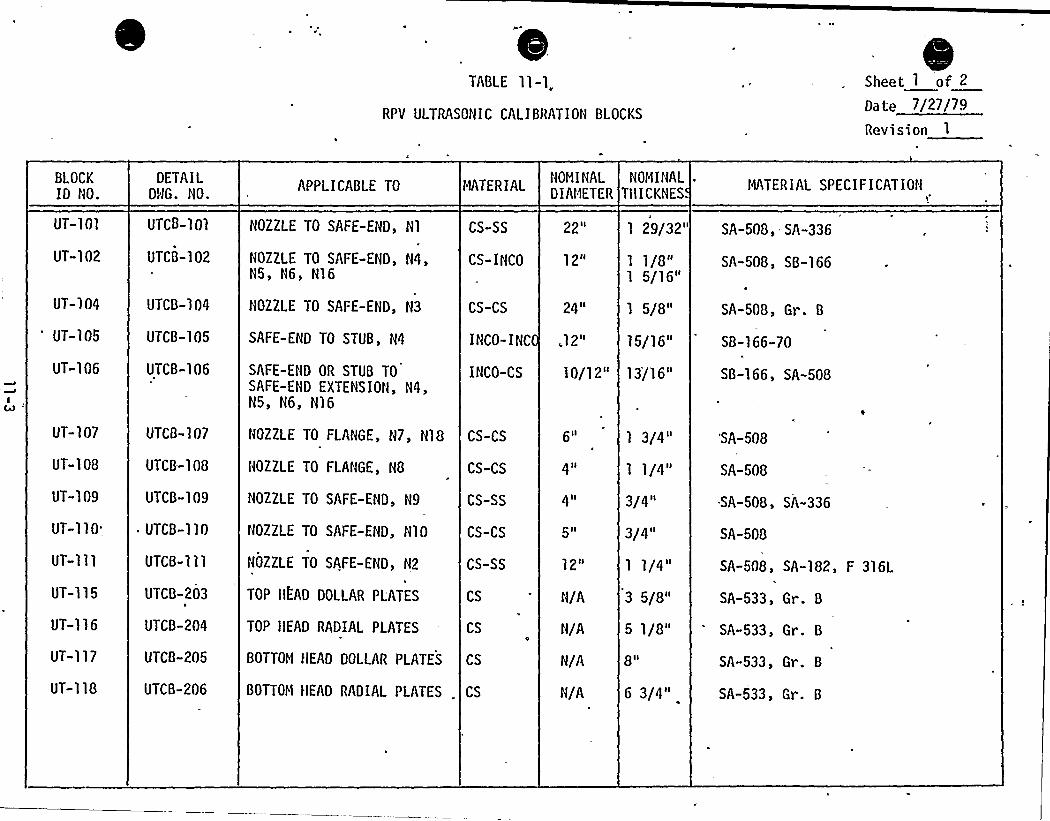
TABLE ll-l„RPV ULTRASONIC CALIBRATION BLOCKS
Sheet I of 2
Da te 7/27/79
Revision
BLOCKID NO.
UT-101
UT-102
DETAILDlJG. NO.
UTCB-101
UTCB-102
APPLICABLE TO
NOZZLE TO SAFE-EHD, Hl
NOZZLE TO SAFE-END, N4,N5, N6, N16
MATERIAL
CS-SS
CS-INCO
NOVINALDIAMETER
22 II
12"
NOMINALTllICKNES
1 29/32"
1 1/8"1 5/16"
MATERIAL SPECIFICATION1
SA-508, SA-336
SA-508, SB-166
UT-104
UT-105
uT-106
uTcB-104
UTCB-105
UTCB-106
NOZZLE TO SAFE-END, H3
SAFE-END TO STUB, N4
SAFE-END OR STUB TOSAFE-END EXTENSION, N4,N5, N6, N16
CS-CS 24 II
INCO-CS 10/12"
IHCO-IHC „12"
1 5/8"
15/16"
13/16"
SA-508, Gr. B
SB-166-70
SB-166, SA-508
UT-107
uT-108
UT-109
UT-110'T-111
UT-115
UT-116
UT-117
UT-118
UTCB-107
UTCB-'l08
UTCB-109
~ UTCB-110
UTCH-ill
UTCB-203
UTCB-204
UTCB-205
UTCB-206
HOZZLE TO FLANGE, N8
NOZZLE TO SAFE-EHD, N9
NOZZLE TO SAFE-EHD, H10
NOZZLE TO SAFE-EHD H2
TOP HEAD DOLLAR PL'ATES
TOP HEAD RADIAL PLATES
BOTTOM HEAD DOLLAR PLATES
CS-CS
CS-SS
CS-CS
CS-SS
CS
CS
CS
BOTTOt1 HEAD RADIAL PLATES . CS
NOZZLE TO FLANGE, H7, H18 CS-CS 6 II
4II
4II
5 ll
1 2ll
N/A
1 3/4"
1 1/4"
3/4 II
3/4 II
1 1/4"
3 5/8"
5 1/8"
8 II
6 3/4"
'SA-508
SA-508
SA-508, SA-336
SA-508
SA-508, SA-182, F 316L
SA-533, Gr. B
SA-533, Gr. B
SA-533, Gr. B
SA-533, Gr. B
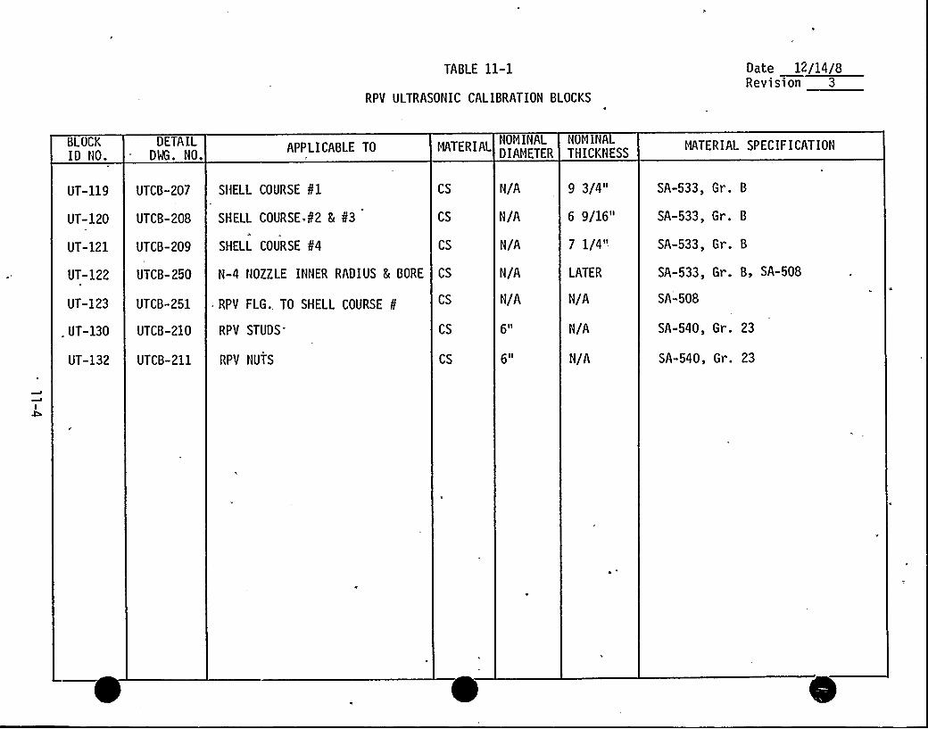
TABLE 11-1
RPV ULTRASONIC CALIBRATION BLOCKS
Date 12/14/8Revision 3
BLOCKID NO.
DETAILDMG. NO.
APPLICABLE TO MATERIALNOMINALDIAMETER
NOMINALTHICKNESS
MATERIAL SPECIFICATION
UT-119 UTCB-207 SHELL COURSE ¹1
UT-120 UTCB-208
UT-121 UTCB-209
SHELL COURSE ¹2 5 ¹3
SHELL COURSE ¹4
UT-122 UTCB-250 N-4 NOZZLE INNER RADIUS 5 BORE
UT-123 UTCB-251 - RPV FLG.. TO SHELL COURSE ¹
. UT-130 UTCB-210 RPV STUDS
UT-132 UTCB-211 RPV NUTS
CS
CS
CS
CS
CS
CS
N/A
N/A
N/A
6"
9 3/4"
6 9/16"
7 1/4"
LATER
N/A
N/A
SA-533, Gr. B
SA-533, Gr. B
SA-533, Gr. B
SA-533, Gr. B, SA-508
SA-508
SA-540, Gr. 23
SA-540, Gr. 23
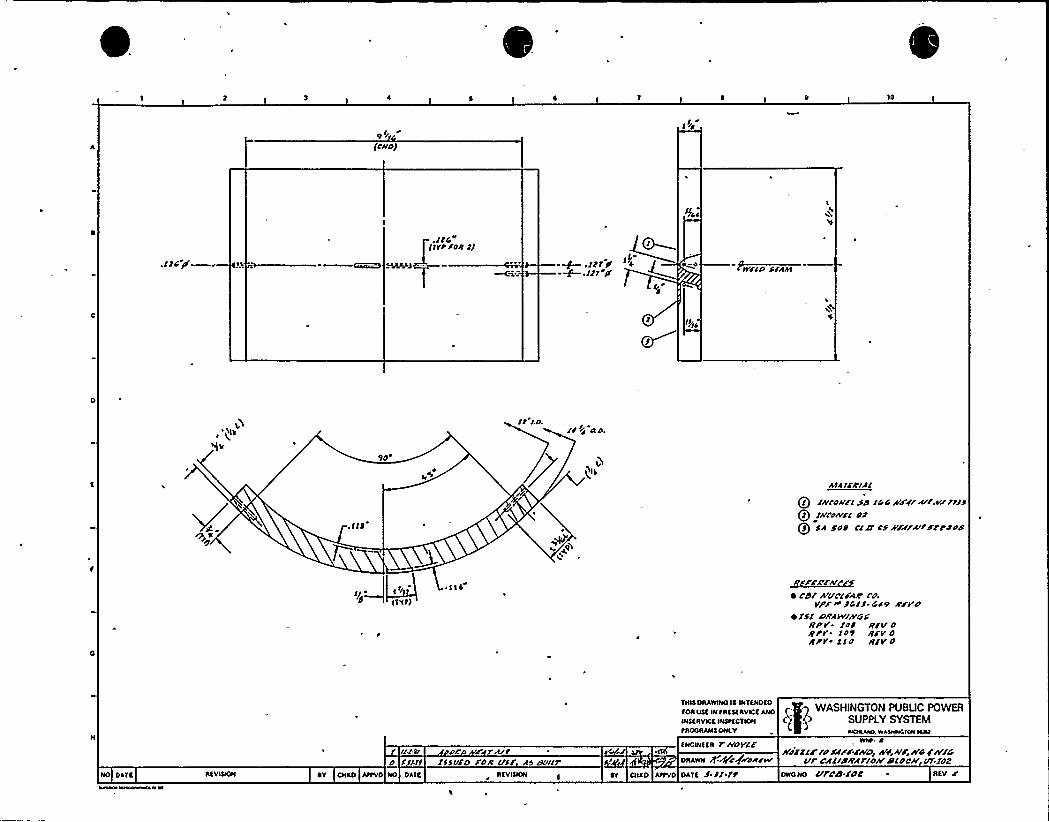
lo
1/g1r
(lRDJ
.12C P
. llG(1PP FOR 2J
C5'.121 11 +-~./21P'llDSFRAE
ll /.O.ll+~ ao.
9o
htR 1fRillQ/ ielo//rc so 1/ G Neer srr~r relyQ2 zwro/vs'2Qj sw soo Cia csssars/lsrrool/
E f/0
EENP)
~ EE4~FFA~FA/~ c8/ rr/rclFA// c'o.
VPF N'G/f Cs9 A'FPD~ 2$1 PifAWIW'S
//P'f /OS RFV Oerr. CO9 RFVORP'F 21O R/V O
PONCHO™)NPAEEERV~~AND E I WASHINGTON PUBLIC POWERENEEAvEOE wstECENNE C~ P SUPPLY SYSTEMPAOGRANEONEV NCIAAAO,WA5HNCTON NNA
illPI Doo dsr R/lO f /11 2SSuFD FOR /FFF WO 8uur
ENGNCKER T//OYlfDRAWN )f.+rgmRFW
s/s221F ra urFzpo ws R/r, /vc i/v/cill CAL//PILAF/olV'/2loC//lr/fdZNO DATE AEVNNNE ~V ONKO AttVO NO DAEE AEVINON
1 Dt ONTO APPVO DREE 5'll'19 ONG NO G/Fdic F02 AEV C'
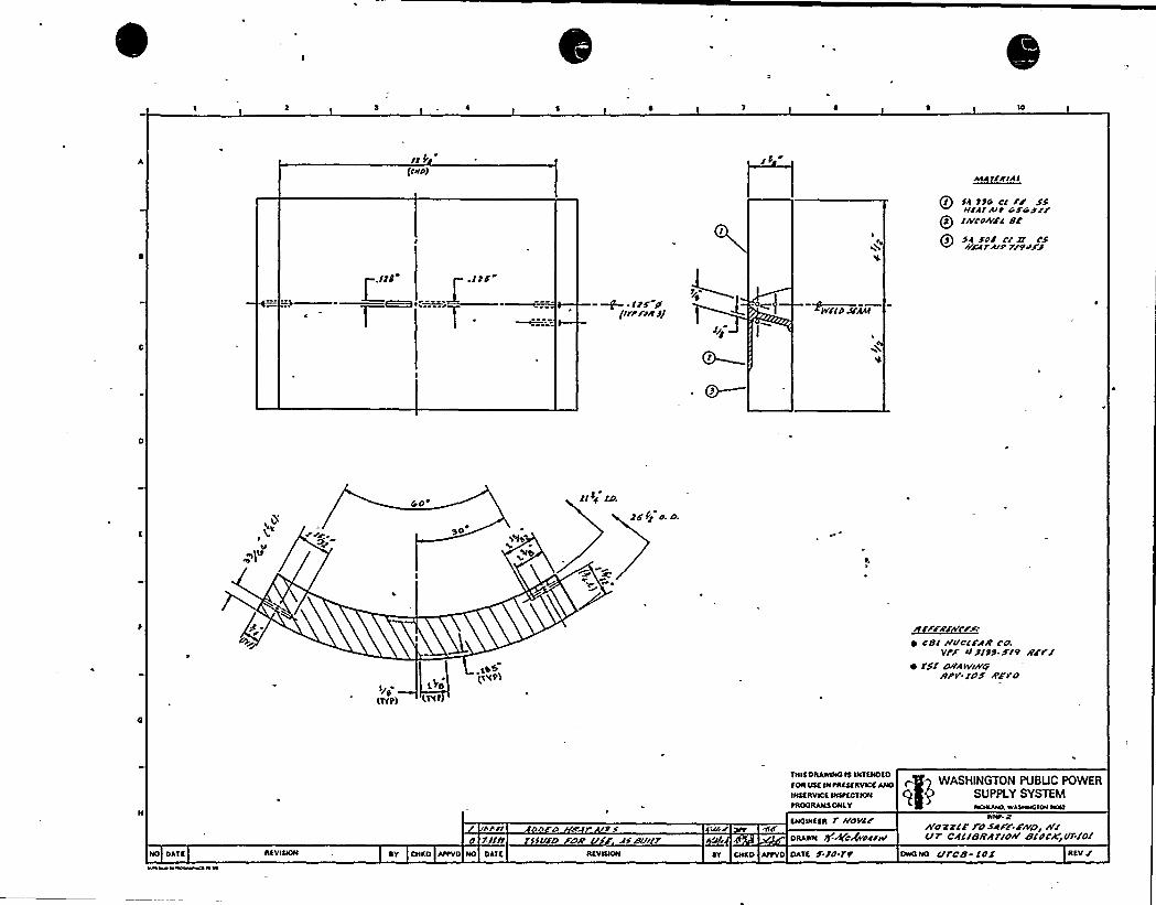
if%(DYAD
AIAf/+IAI
s4 ff4 dl Fr $$If' Alt 4 $4 ///PR /ncd~rc or
Qs sa rdi rr lf//WTAITt/grjg
~WildAfAAI
GO
DO
lsd ED.
2r fg d. d.
p'IP)L TO
gyp> LVIf
~ fof llfITCfrAlfC'o.Vtr Itf Pl J$ r/O Rrt/
~ 15/ duMIV/P'gAfw'/ur zrro
APT/ DD D 4'till/ /SSuSO ZuAf Ar8tlllt
NIN g4'azrlr toslFr.r~D, /t/fitCAll/SRAt/W'/dCKjf/t/O/
ENOINEER l r/dYC/Wd'RAOOI Q~dgVPZT
W'OR
INE INTREEERVIOE ANO ( gq WASHINGTON PUBUC POWERINEERYIOE INITECINNI QP'UPPLY SYSTEM~RODRANE ONLY NDAAlvO.WASlaeOION NNI
NO DATE RIVIQON RY CNAD AftVD NO DAIf. REVIIION OY DNRO AtfVD DATE r ld tp DAO NO f/tdg id/ REV /

r,
V
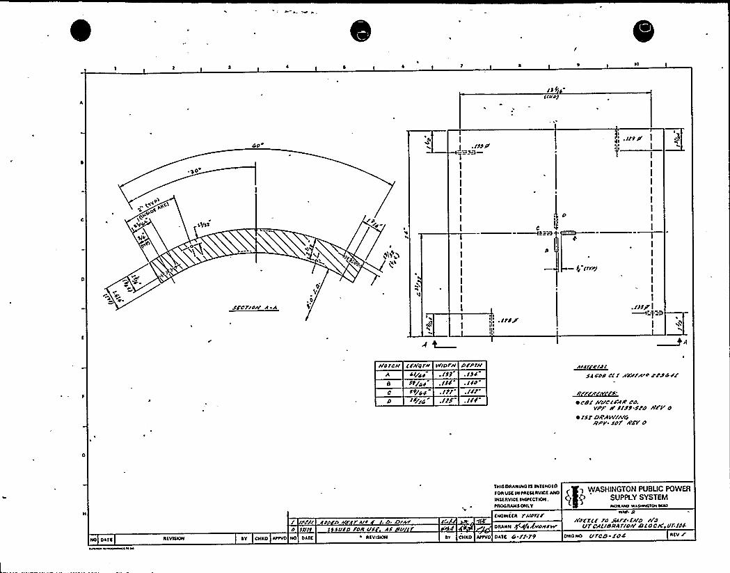
IO
/J9(rr/4/
3JCWOS
NYIP'
go
33/3'3
Go'.//t /t
I
I
I
I
I
I
I
I
I
I
4'
4~
SFCF/W' R
P
,0
hAS
J/ /rtPJ
I I //firI 1 h
//41C// lr//t/1// SV/DI'/r
./JsJt/yg /J J
./J/
PFPF//./JJ./Sd.///
JJ FOP Cl / XFAFR/'4 j'PS G 4/
~t~~f~ crt/ R/I/c/FR/t cu
vpr /F J/JJ fro //rv o~ /5/ DF/JI W//L/G/1'-rur ZFI O
sm~lNnsurvaa~ P g WASHINGTON PUBUC POWER
NIsaavlcs INstacvrNI, g q> SUPPLY SYSTEMtNOONANSONLY NOAAAO WA5HSASVON NNA
/ P/// JJ D F A/4 /. D. /3iD I//It If5 DID FOR UJ RJ V
SNQINS III 1'//CtlrONANN g+iVADR4W
narra FD XVV FA/n alaI/7'//BRAt/D/F ltlnCK>Vf/C/-
NO DAIS II(VISION ov cNro AttvD No DAIf. IISVISION OV CNro AttVD DAIS G // 79 DIDO NO I/FC/3 /DII ASVI

II
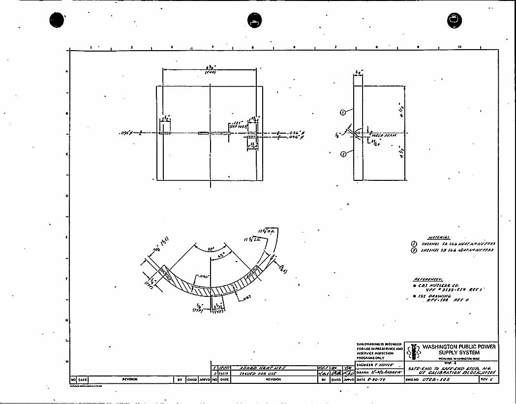
'IO
frv0
oR/ O94 St~. 094 P'vrsd srAstrr/4S I
9O
.090
I/ ~0
(rrpg
rsss au
«SZ Ea
/pAIJIIRIAI
Qr Is/rss/rr sd I0 4 //rr/Ar'tA/prsrQr IA'crau sd /44 ~urw~riru
strrrstrAIust~ cBI At'E/crFAc co.
VPF 0 Jr J J ~ r/9 lrrVI~ rfI DIIAwlp+
/rPV /dr Ir/V d
I IN SDMD s/&rtt l/rr0 S art rlsllrd /OAT I/sr
TAIS DAAWINGtS INTENDED
fOAOSE IN tAESEAVICE ANO
WSE AVLCE INStECT IONtAOGAALISONLY
ENGwEEA v//ov/rDAAWN h.+cANugrw
WASHINGTON PUBUC POWERSUPPLY SYSTEMNDAANRWASHWGION ICNI
SAFF Fi/D '/d S/I/'F.FLOYD SfVi9, IVsEUI @AC'/ddA fldAICTC OCC)b'f'/dF
NO DATE AEVISKW JY CNKD AttVD NO DATE AEVISION EY CNKD AttVD DATE F to r9 DWG NO UrCB SOB'EY r

4
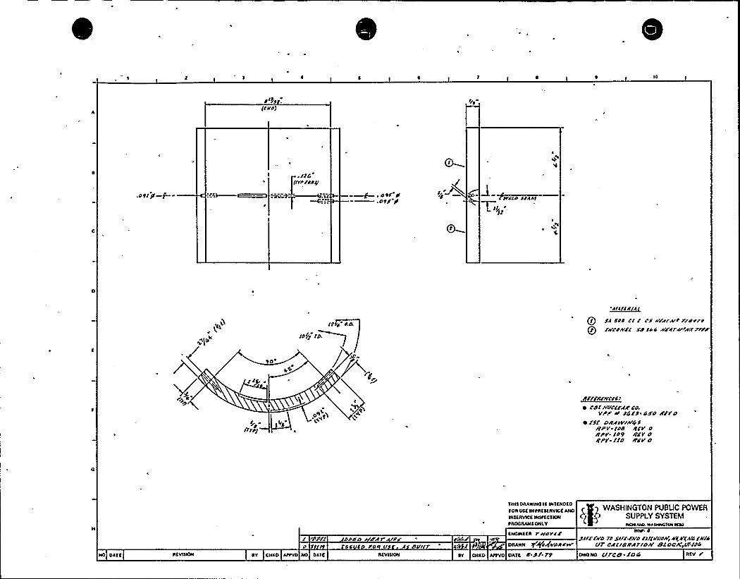
4 it/
.Dtljl~Gfjg
Itg RA SW Cta CI I CS Wu/4 t XrdrrtOl A'cDA'cI SD /4 4 /vciru+ws Frrp
SO
I/y-
~ Cd/ h OCWC CdVPP't FCIS 44'D 8'FVO
~ lsl o/I/tv//v$f/rPV-Ide RIS DBpv. ID9 /rcv o/IPV. IIO ~CV O
NO DATE REVISNN
/ 'PPF/
~V CHXO Attvo NO DATE
DDDD D'47O'DJ'S
FDR Cl
REVISION
THIS DRAWINOIS INTENOEO
TOR OSE IN tRESERVICE ANOINSERVICE INStECTIONtROC RANS ONLY
ENGINEER r'BDVIC
DRAWN I9A(A(h'DRCW
IW DHSO AttVO DATE O'8/ 79
WASHINGTON PUBLIC POWERSUPPLY SYSTEMNOAAlvD.WASNWGIONWNS
SIFFFN'D rd SIFAA'D /IIII/BN~49kgA4/I//4Ell'RI/B/r/Ir/or/ BIDC'//Idd
REV rDWO NO I/FCB /04

0
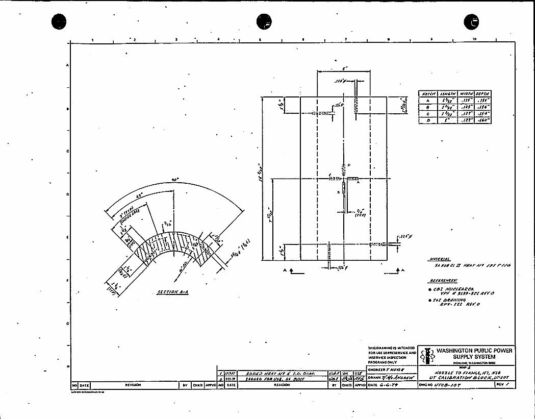
10
TTLLM %el
O',Of"1
tSIX
I
I
I
I
I
I
I
I
I I IIN
I B S
I
I
I
I
I
I
I
I
I
rI
,I
I
I
I
I
I
I
I
I ~
I
AI
I
I
IIIA
IITTII
I
I
I~tAAI
ROTC5I IIAICIW W'/DIN DIPTII
.ISO-
,LI'IEf flFDS CC 2 PEAT@'T /P/PIPED
RCFFRCAIClft
ffCTISA' $ ~ l'BI IVI/CCFARNvpr o'rfx-rrrRFro
~ I'5l DRAw/A'4RPT Il/ RFIr 0
/ A<TI DDJ'D HIATAIDF l.D DIrAT0 55I It ICAVCD /OR I/5 Df IT
TAIS DAAWINOIS INTENOEO
TOA VSC IN tAESEAVICE ANDINSfAVICC WStfC SION
tAOOAANSONLY
ENOWEEAT&DYCC'id
DRAWN Tf+agWORFNT
WASHINGTON PUBUC POWERSUPPLY SYSTEMWLIAAAO,WANANOIONWNI
WNt.gA'OZZCF 70 FIAAI<E,II'7, NIS
Elf CAIIBRATIor/SIDCK,o/'f07DWQNO ITTC'B r0 TNO DATE ACVIQON AY CACO AttVD NO DATE AEVIQON AT CNCD AItVO DATE 4 4 ?t AfV I'

0
,n
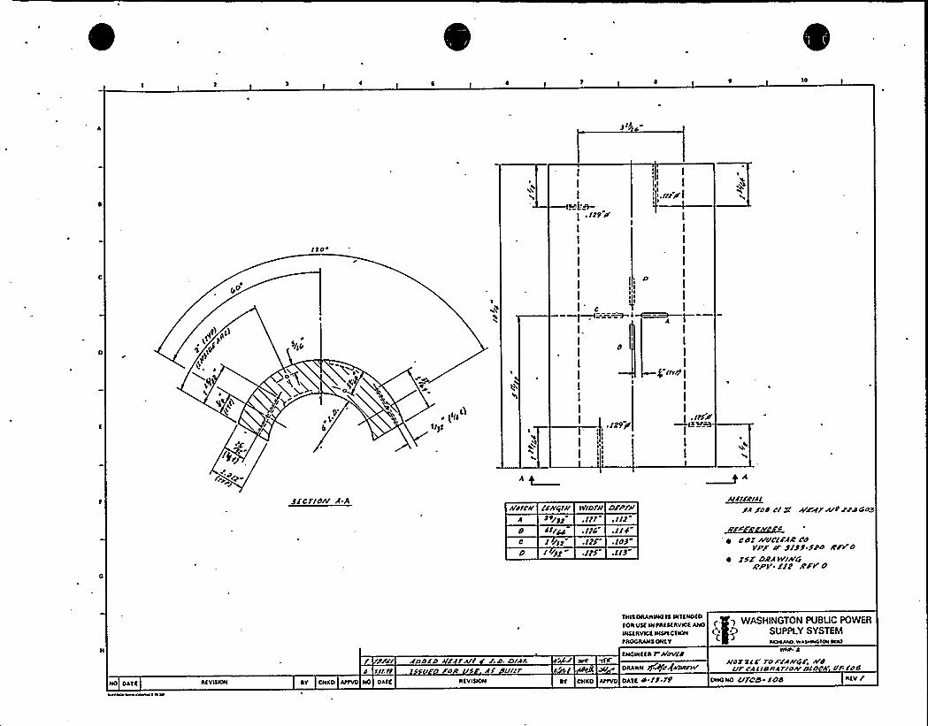
10
3 Sjl
yo
I
I
I
I
I
I
II
I I~ I
II I
I I,'I,/IldslI
I
I
I
I
Ie
4~~I—-—X
I
I
I
I
$ /ssh I
I
I
I./r/IV
I
I
I
I
I,I
I
I
I
I
I
I
f ./293/
) I
I I
I f I
3jcrldrv A.Aud/CI/ /Ervrtru wroru
3 tr'32 /gr«/
DFPIu./IP
~f/ «xl End c/ 3/ pzgr lrtppd coo
.//S"
./rs. /D3 ~ cd/ rvrlc/Fll.'d
VPF 0" j/33-SPD ddt'0~ Efl'A'lIV/A/at
aPV. «2 st'Ft'
P'Pdr ADDED /IA/ll/ I.D. lord/l/ Vr/
THIS DRAIIWOIt WTINOtoFOR Vtt IN tRtSt RVICS ANO
INSIRVICt INSttCT ION
tROCRANS ONLV
SNOWISR I ASCIsrderDRANN +~C QADR/Nr
WASHINGTON PUBUC POWERSUPPLY SYSTEMNORAAO, WA50sNGION NRI
IINt.4
uN 3/S ro P/er/sf, D dVl'Cltrostll/DAsEI/DC'k VBECB
NO OATS
hAOIAWECWW' 8 N
RtVNION SV CNKO AtIVD NO DATt RSVIQON Rv CNSO AttVO OATS d /3 rf OIIO NO /Ifd/3- ECID Rtv /

/
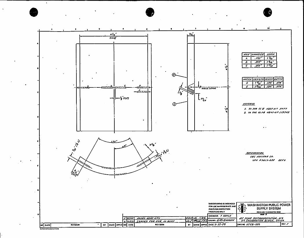
IO
(CIIOJ
IIOIF DIAAIF/FR
O9S
DFP/JI
l Q/C
1 9/O
(ee
IvrlD S/Aht
IYO/CII lrlvg/IIWID/II D/P/IID I » .IF@ .D/j
1 /1C .1)4 .O/C
NM//Billse sor crsr ww/R/r sorrSR ))C Cr FB AFAR/4'r//SSB2
)O
OO3 S/O
CDr IvurrwaR co.VPW RIS>rS CSr I9/Vo
WASHINGTON PUBUC POWERSUPPLY SYSTEM
0RODRAll0 ONEV WOKAIO WLAWWDICNNNI
NO DATf RfVIQON DV CNKD AIPVD NO DATC RTVIQON
rl ro III/O Rl)ll SSVFD /DR rrsF )S DVI//
fNOINffR l IFO Yl/DRAWN Jf&fCQADRF/r
DT DNKO Allvo oATf 9'12 79 owoND Vl'CB~ SD9 RfV F
VlfPVIIIP IA'S/RuIIrFN/AfIOk',4'9V/ CRllBRl/IOI/81OC4, J /IO9

N
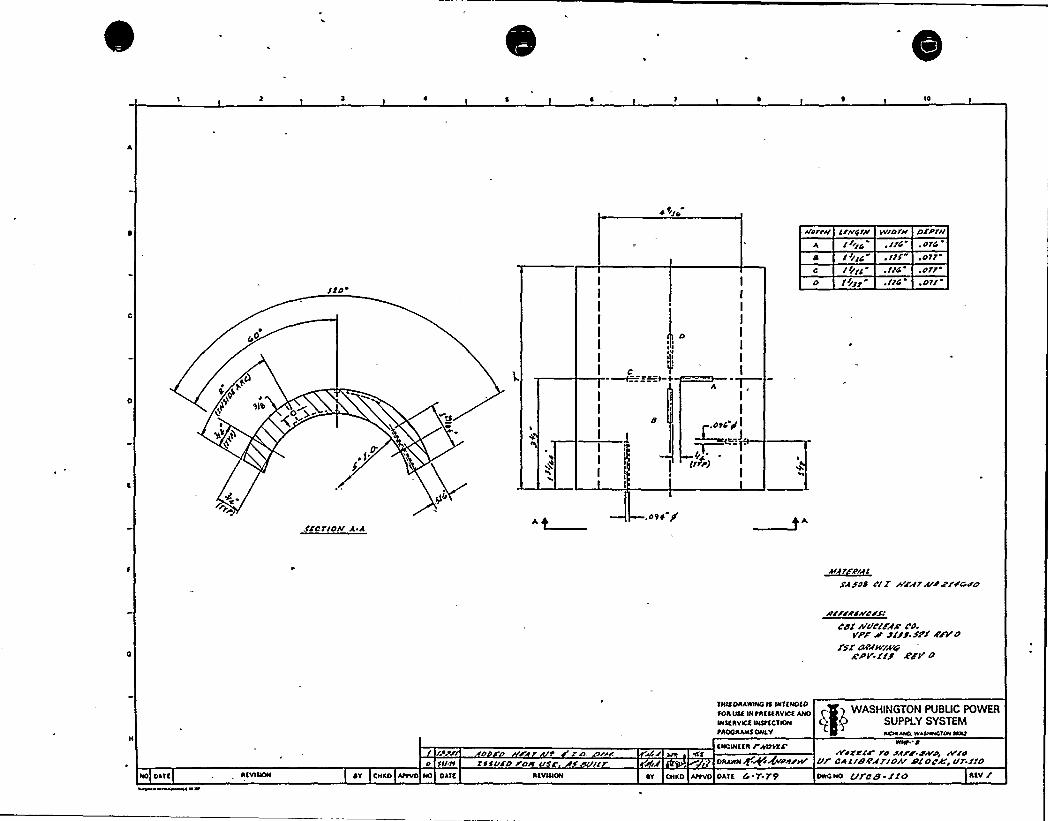
10
+ )IG
ICO)
I/rrc trr wloIrr or/ lrr, IIG . OIG
Ir/IC .IIS .PtlII/Ig .I/G .pllI//II ~ IIC .Oll
'tlCI
IE
,'I 3
D I
I
I
I
I
I
(IP)l
S'!CTIOI/ A A
~AI If~A'I ISWSOS /II Wrzr lt//rrt)C/a
/Il/rt/rrp/SCdl //IIC(EAA'p.
Vrtr pt uSS.Sir SsVOSKI''I/IV/A4:
IIFVIIS'VO
NO OATE AEVIQON
0 ttltt~Y CNEO AttVO NO OATC
D F W /o. rif.rtttrrp Fprt u
AEVIIION
TNIE OAAWNIQIE IN'IENOEO
fOA OEE IN tAEECAVICE ANO
WEE AVICE INSta CT ION
tROOAAALTONLY
ENowaaAF)tates'ar
OAAWN+~i~z/WAT oNrn Attvo oATa G ~ 'F-T9 OWONO I/See-IIO Aav /
WASKlNGTON PUBUC POWERSUPPLY SYSTEMWOAA))O. WktwWAIANAANt
WIN"A
)VP//IJ IP Birr P))VP) )AlloIII CAIISAI'/OA'IIOL)k)III'IO

0J
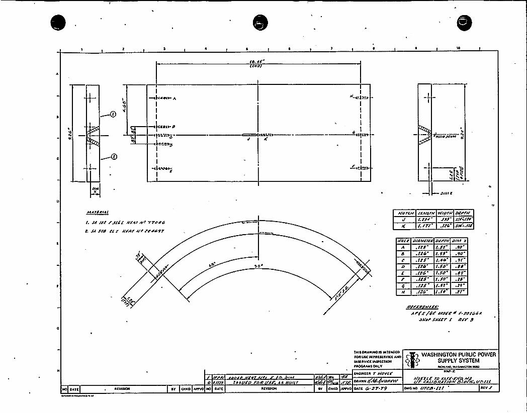
10
IP.PS'itd
0I
I0
I
-«4 Ptt- gI
I
I
Jl
V"="~c
I
I
I
4.I
H
I
I
I
I
I
I
I
I
I
I
I0
~WI/OSIAAt
dlklX
AtA YSAIAI
I. IIIII' Jttt KIAIA/I 77odr/
t. SA Jdd CI I IIF/ArA/IZC'od9r
AldrCII IIAI/IIIIwdorII DII/rIIJ /.Z/I JJJ .I/A//I
!. I7/ ./ZC .Idd ~ ./dl
SO',9'0I
HdlC DIAAYIIjg PSPW. /zr t. bl
a .IZG t.bb.Izr /.po. 114 I.bd"
E ./14 I.gd. Itb 1. 1d. /Zb'. bt
H ./14 1.1'f
Plkt I.9d9d
. 91
.b9
.Zb
.19
.ZI
~////////'rt'rllar odors A' zd/4@A
dHIrsurrr 1 art/ I
Qff 1N fRff1Rvlof Af01 f I WASHINGTON PU BUG POWERSUPPLY SYSTEM
tROORANf ONLY IIPCHlANO.WA5WNCYONNN2
NO DA'1f~Std /~ C4%II
DY CNRD AttVD NO DAlf RfVlQON
d ttldt ISSVED Fdff Sr AS IIVICr
fNOINffR r AIdVIrDRAWN .IIPt A/D&lff/
DY DNAD Attvo oAtf Q.ZT.T9
WNt. C
Irdzzlr ro sArr.cA'D A/zIIrc'lll8II/Irloh'ISIS'Kur IIIRfvIowoND urea-tt/

i
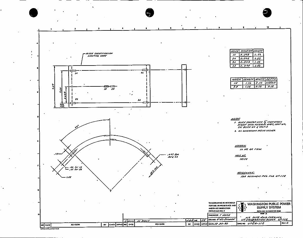
10
r>rocF /r>rf/frfrcf//r>vsrf/fr/A/G/rrrr/'orrfr>rff/off'f
O O99eA o. o9eBf O. O95
o. O9e
rrAd/Fr,$ 9
/. XG
r. FG
/A
I
I
I
I
I tl
f/OfC// r'ArgW»9f>f// OArP rzr.rG o./G or//or/
ew r./G o.rG o.re
A/O/FF:
r 8(o/f'FAK>//ato >>or// ro WigA'rrfFFFSffr>IP >>rrrrrfrfrrrrlJlo/pFcp /rfffA/fpcfr rlrocf A/o 0'I'w/AzA/r o>SI(A/frof/offC/A//A/CUFF
. G 97 jO9Sf+ Of
fArrff/lr>rfrSf /oe G4 FJ/&~
A/rfrA/frrrxo
fG rrr /fEE force
/.OZ
Kj$>EF oorvf>FA/fHAG Fos r/fr/4
l/ 5 BV
END>NEED fPo>rr'FWNt. 2
A/e SfFF-FA/s FOA'G/A/sErfcJ(lstt//rroffBlock' rreDKAWN +A/i'+BIO>to>>r
IOKI>IEINtaaaaAVIOEANO E.T) WASHINGTON PUBUC POWER
tAOOIIAMEONLY ~. Wsuwe>0W W>>I
IIEV>DON ~Y CNKO At>VO NO OA1E IIEVN>ON OY CNKD AttVD OATElc.&O Oo Dwo No vfcB rrz IIav O

IW
I
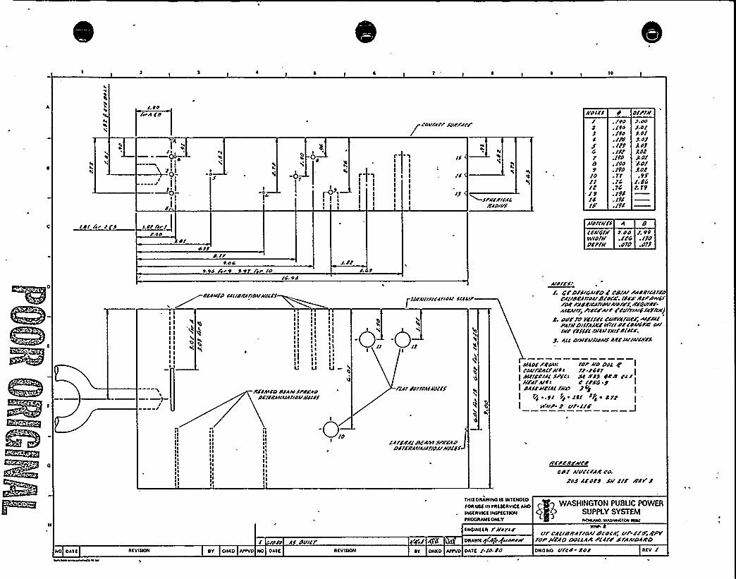
10
4
L'
4s
a
I.OO
fwAfd
Ils
II'101
I ~
s ~ I-—0-rl'
4cI
Is
I"01
IOO
I
I I sI ~l I
'IIIIIIIIII
IS
'9
~
~sr/If/IIOAI/AD/VS
col//Are surrca/uolcs
JO
C1e9
IO
Ir-19IClr
. /to, lto. Itd. Ifd. 119~ Ilf'Itd
. Ito
. Idd~ TT.TC.TC. I9C. ITP.IPC
IIIPfkS.Ns.ols. DIj.OI
J. OrSOISo/gde.
99'.dl
T. T9
I.OI fir I S I.tr//r/1. OO
PIcss
P. /1ROC
Ardflkfc A 8lfAIdfA/ s.do 1.99sv/ofd .Ifc .Ilddfrfll .dfd .oTJ
t. O fit Rt t ld/c tc
I II IIE
II11 4I I EII IIII II I
//IAA/iocclrdrfcfrrdsrrrocrs
s', l II I sssI ~ llSl ~
I
I 11I ~ Issss ss
ss
I I I II'IdrlAICDdsAAISrrcdo
DCIIAAIIAIAI/OAI//Olrs
IsI I
sII IIIIEI II II II s
O
rIDCAIII/IIAIIOAISIACIf'A
41
'E
I'
II
/llfrplfpAtrrdlfs
Arp/rs/I. 4rDfsrc/IFD F cd/A/ Podrtrccrrr/
CllldRAfflpcrrscpQ'. Irrrdrrdeff'e
radrfrcArros/A/prus /frdvl//r.A/rA//S/ prrcrAIP Fcurlrcrgsturm)
e. c ur ro vrssrc cudvcrusu. Arr/AIPAfrrDISIAAerIs/IlldfCPAICFA-'A//kfVfllrl/kAAI1///Idlpce.
All DIAICAISIPAISArlr/AI/AICkrS
AllofArose rdr ko Dpc ~ ICPAlfeACIAIOI 11 PCOT
II A/I/re/Ac specs st rss ded cc/uFArA/ts C /rSC y
I ddfrAIFIAIrkrdI
I /o . tl /p ~ IS/ PSo ~ e frI Isrkp- z ur.llr J
~Isl~ lIlll~ II ~llIII,sllIlIlI
slIsll~ IIIIIlllslsIsIlIIIsI
III ~I ~
IsI~
lsIIIIlIIIsI ~lsII
IAfrnzdr~svr.u lDffr/IAIIA/A/rdcrrrdcfs+
Cdf AIVCICArlC/A
Zds Afdrs Sk'rr lfr J
I ~ PPP A 8V/Cr
ENSS OISAWSNO SS WSENOEO
SOR ESSE IN tRESERVSCE ANOWSEISVICE INStECSIONtROCRANS ONLY
ENCINEER rkore//ORAWN ghP+~rstpsv
WASHINGTON PUBUC POWERSUPPLY SYSTEMSOsSASso. WASWs010SS ISSSI
vfcdclcs/TAT/PA/rscocrf, ur-few /Tpvfop /frdo DoccAIE plcfr/ drAAIDArccs
NO OASE REVISION bY CNKO AttVO NO OAIE REVISION SY CNKO AttVO OAEE I /d.rd owo No vfcd ed p REV I

s ACo '~ . ~i" ~ ~ ~
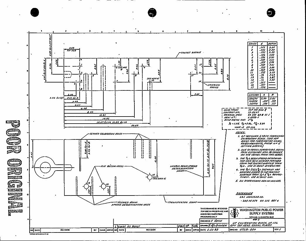
10
~I
~r AID
L I-Wo- r2
r~ IS l-—0-0- Sf t I
I8'
~ IsI
II
'4I
s C IIIIII/If
I
s
I
Oe
I-0
/If/A/cur//
IDAIIACIIIIRFACS
I, IlSSL
I" Iss0
hsfh
h/P///2/CAIRADIVS
/IOIFf/
4
Gle9
/o/I/2/4IG/l
. 2/l
. )S/. tfl. I/C. /)G./)t./tf./ft. )ft. /S2. /)t. lC. lC. lG.tf/~tff./54
DIP/I/J. DfJ.D4). OSAop)A7QDD299'.D/)OD344J. o)t. C)).4 l/.)F
I.SC frrlfl. LSO
A Sr /rr)ASS
~LS/
AID/fr/Sf/fi+'fkr 2. OD 2. O/f9/Df// .//F .//9D/Pfr/ ./Od ./f/
Is~ I~ ~~ ~~ ~~ s
Isssss
G. SB
s IS I
. /o// SI
/j. DIIADYlrrr'4I/.D9 Airro
SR 69
d/AAI/DCAIIBRA/IDAISOIff
I II ~III IIsIlI I~ I~
I~ II,S
IIIII IllI II II IIIIILI
IIIIII1
LA
FIA/ SDIIDAI //DISS
~ IssII
l2 'sI
~ Issss
ssss
~ III
I) I IIsII
s h IsII
-0I4/All'VI///
//F/IA/SD ASAASSPSSA D Drfrsrv/IAIAFIOI///jiff
~ ~
~ ss ~s ~~ ~
IAffRAISFAAISPRFADPS/4 Rkf/A/A/IDAI Os
f /AAD/FAD/II. IDP kp SAD C I
I cDA/IRAI/A'<I ft./44fAu/CRul ffsc/ fAft) GRS cl /
I kÃÃfA/PI fDfo).j IDAISAISIAIrrrrr SOB Ijji/fr rtidrG, I/4 ~ )44
WA/P Is u/ /IG J~Ar r
!. QF Dff/GAISDF CP/Isr FABRI/A//PCAIIPIIAIIOA/slfcr.IfjrAfrPIVdfFOR FASRICAFIBAIArjfffr/rsc/ulrrsrvlsrvff, rrrcrArig'curr/A/4s~nrr/
2. DVFfo frf5/ICVFVAfurjf.AIFFAIPAfk'ISIAAICFSIVIIISf/OArfrSRDAIfrrrVS/SF/ FAIAAIfk/rf
s/OGC'AF
4 4 PSAAISPRFAD Off/FAIIAIA.flAVkolf(4jrfID/A/SD/ARA'AsFRDAI fk/FCLSfrfACFFVSFACFf/IAAII/4 a. ulrAlSvrlfCIAISArfrjAA
4. VSS Ift/(ltj(f2 (I4JIIDISIA/ISADIAfSDCIDSSRrof/IFCDAI/Rc/supFACF FA/AA/fjl4'4 I SslPSC-f/frcv. uffAfdu/frp/Al.
F. AllDIAIIA/5IAvsARFIAIIAIjrrsf,
/ISFSA'SAICS
cBI Aru'c/FAR co.~ 2ofASOt) fl/IIG rldY4
fOR IISfHI0RfSf RVICfANO C~ WASHINGTON PUBLIC POWERSUPPLY SYSTEM
tROCRANS ONLY LCLAALS0. W*ISSSLAIASS aaAI
NO OATf RfVINOM RY CHKO AIIVO NO OAIE
A Bu/RfVISIOM
fNONISSR V /(OVIS
ORAWN ~ CguORSflr
IY CHIO AIIVO OATS f.//-idVfCACISRAfroA/SIDCICi uf./IG
//PV loP kFAD f(AD/A/PCAVSS
ONONO Vfcs-ZS4

'\
AP
h I
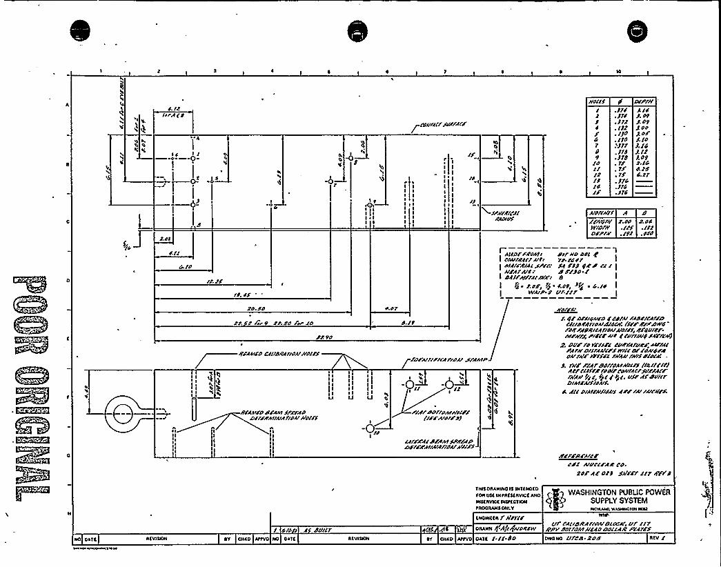
IIO//I DIP///4. llIirflo
~ 2-—' o-
F'.tl
-0
I 9
I llI ~ I
!:
rIIIIIIIIIIIIII
If'III 14IIIII I
III
~ cnA/ffCfSv//AC/
XW/A/CS/AMOlvf
h0
I
4
47
/OIIl2/2/4Ij
.Jrl:Jrf.J/2. /12. IJO~ /1O1f11. 11B~ JTB. 1$
.114
./14
A/4J. O9J. O9g OOgoFJ. /OJ./4J. /2J. O92./44./f4. 21
Alnfcffrf A/l/sOru I.oo D.ooW/DID .I/F .//IDFPrl/
I ASIDFF/IOAtr dll'foOnl g 1I coAIIRAcrAlt. rr. rcor[ Atfr/RIAl/Pre SA FfJ Ifdd llI III/ffAICI SS/jo 1I SAIFA/rfflaN/ aI P4 ~ C.o/t PI '.$ 9~ 8z ~ 4./O I
IVA/P 2 Vl'-Ilr
2O. Fn rtor
4
~ III
IIl)III
I fir9 Cr.f'O Fm IO
ss 9n
RFAAIIDCAIISRAf/OAI /In//S
I II IIIIII
IM
Ir/1 t/IDs/flr/SPA/ADDSI/RAIIAIAflnAIAln/rf
~ IIIIIIIIII
I II
I I III IlIJ IJ
'0
S./9
-0„'0/2P/fIdnffoAIIIII/I
(/FrA/O//O)I
If/IAAIdrfAtSPA/lDD/f//At/A/Arlnuffs//S4
I, TS
0
/D/A/fr//CArlou SffhtP
1. RF DCIIOAIFDF cd/A/ Ffdcllff/DCA/IS/A/IOAISIOCI//I//R/PDN/4/o/I/ASRICAf/nuA/of/f~SFlVIF//tr/lrr/,rr/I/us C cuff/Alps/FrcsJ
z. Dv/ro rru/I cu/rfruR/u/ff/PA/ffDll/A<c/str//Isr coA/4/dnslrNF eff/I 1AIAIIFAIISSIOC/
J. rff///fr'dpf/pAIAInlrf/l411/ICJ4' clof/R'roo//cnA/rfI'rsv/rfcFfAIAA/PI I +/I/ 4$'I'f/AfdvlllDIAf/AISIOAII
it A/ID/A/FAISICAIS AFFIuIAICR/S
R/r/s/A/c/Cd/ Alul'CFAA'O.
2OF AF OCJ Sill'Fl'lrfr/F's
roost INtRtstRvict AHo T I1 WASHINGTON PUBUC POWERSUPPLY SYSTEM
tROORANS ONI.Y NCHlklsO, WASHWSTOH NHI
NO OATt RTVISION
4/n I A dullr~Y CHKO AttVO NO OATC RTVIQON
tNOWSSR r l/orl/ORANN -APQ~ORITV
RT CHKO AttVO OATt l.// BO
ill CAIISRAFIOAISIOC'WeVfi/1RPI/ dorforfffFADDollARPlff/sOWONO VlCS.ROS

P e ~ I g j,/I+\II P I '
3 'I xg.'j
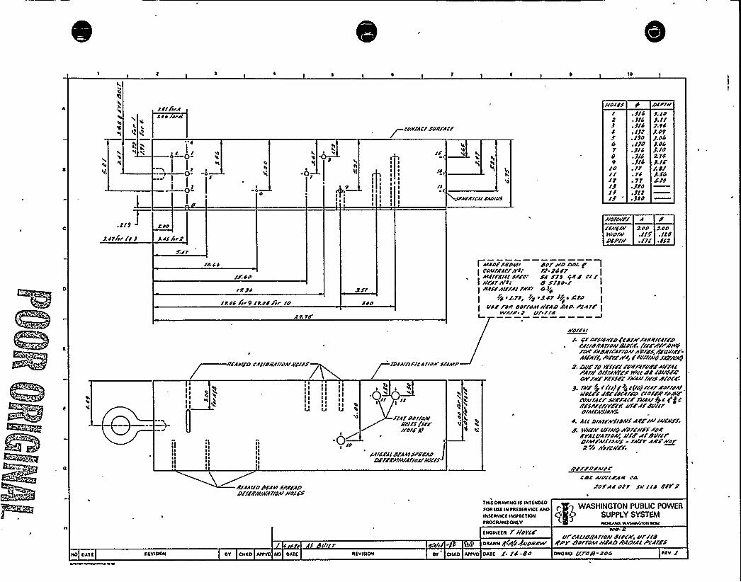
IO
EI
Jltf AA SS srd
4—0-
0I,0-
Rh
'E
-01
P
p corrtfcf svR/Acr
+sp~rEIIAIFAD/of
uOI/S
J
G78
loI/IdIJIf/5
~ 3/4~ 3/4. 3/4. IJZ,. IJO. /JD~ 3/4. J/4:314,ft. tS. 77. J/O. JII.JPO
SNPIEJ. IOJ. IlJ. OPJ.O4J. 84J. Io/A PoJ. If'.
8/J.SG
l.uo
l.i/fir/
Arotcrrrf A//A/dlr 2 uo 2oow/Drlr . /15 ./IdDfrf// .IT/ .Ifd
/SISS
/r su
tASS hr 9 /Aud /ir ID fuo
I A/AD/FRDAI/ dor IID Doc gI
CDAIIAACIA'll f/ 24fr IAlffrflflSP/c. FA FJP PEP I'I/I 4/rftA ll 8 fifo /I /PffrAtr/f/rr/A." 44+ I
Pjc I/.ff/ I/2 sT Or //fr ~ FPDI/sr /DE Doffoul //FAD AAIAPIA/F III/A/P 8 ut I/8
R ~iII R RII R RL
:IIII ~IIIIIII ~
IlI ~
I ~IIIII
I I'II I I I
II III I I I I III II
~ ~ II RIj Iu IJ
'n
0„/IA/puttoAI
Niff /urA'ofrJJ
/f/fr/Idf A+ISPA'FADDr//RAP/A/AIIDAII/rfrfA
/vofrsr/ 86 Drfrdlv/D(cd/At/Ad/clef/FD
~ lfllPRAIIDAIPIDCR///FR/<DIAT/FArfdRIIA/IDA/AT/4Y,RFRDIFF-Atrr/ffrPrrrrrVlr C /Vt//AIDSFF/CFIJ
2. DVF/D fr/fr/CVAf/VFFAtrffIPlfA/DIS/fkE'Ff IV/IIdr /AE/prZTAVEVrffrl'A/AVN/$d/DCR
J. fs/6 fl/'(llew5 Jrulp'oJ/IfrrluttrftI/o/Fff/trluCA/FD CIDFFR/uSVFcour/Acr svRFAcr rrrfurft6 ErjcRFSPFC/rrFrV utrftdurlrDIAIIA/SIIRf.
S. AllDlkIFA/SIONS AS'/ IAIIAICIIFS
d w/lrAruf/A/8 Nore/IFS FDRFVAluA/ID%,'lfFffdu//rDIAIFA/fruAIS- /A/rrARF+~o2 Fr AffCAllf.
R/AA/IDdffSt SPA/ADDft/RIIIIIVA/IDAIk>lff
I r f I/I
TNLS ORARINQ IS LNTENOEO
TOR IISE IN tAESEAVISE ANOINSTIRROE INStEC SION
tROQAANS ONLY
ENQINEER t NOyCF
oAARN /3 rttrgwDIIATI/
CD/ AIVCSFAR l'8roSAE oft SR lld RFI J
WASHINGTON PUBLIC POWEASUPPLY SYSTEMNOAAAO.W ANNA IOI NRT
uf'CllrdRAIIDAIPIDCZ> lllII8IJPV Bor/DAAA/FACTIIACIIAI6'ffff
AEVINON SV ONEO NO OATE AEVISION SV'NAO AttVO OATE 1. /C-88 ONQNO ulDB ADG AEV /

I,
J
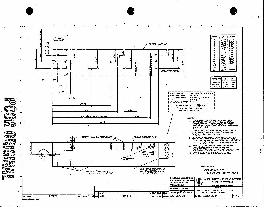
IO
S. /lerA
I0
VlI IIOd
couffcf sorffrr
I/.I I I
lbI II I
IJ,esp/IIRICA/ Cfog.
I.
3/J
4r89
/dIRIC
.Jrd
. 3rd. Jrd. Irr. //Z:/lr~ 311. 318. 318. 14. 14.?4.JdZ~ Jlo. Jll
uocls IS DFP/uJ. I3J. I3J. /8gooJ.ddJ.oo3. /3J Il8/3xoJÃSZ
/19
S. 94
AIO/C//IIcrud I//IV/D/uDFPI/I
r. oo z.oo.115 .Ild. Jog . SJI
4. 9/
I4 SC
JJ.JS
lwdS
I Avfo/ /r/NII s/IRooo cr4 AIA/rr/AcCOAIIRAC/A/os rl-r4 S r IAcfllRIACSPFD SA Sll dfd CC Iulf/A/l: A ooPJ Idf/3 All/At///K'.rr . I
pIIrp,cd/ /poS,9/I Jp<or,l/VSF FOR o// SIIIICRfuf/ I
II/AIP 8 CIP. //9I
Rr JI r9 f1.3C for !D
4O. 98
Iqr IIFAA1FO CAC/BRA//df/Ifd/FS
~ II ~
I II ~
~O
I II ~I II IU
%94
/DFAICIFICA/ldA/SIAAIP
tl I llI?A/eo//d.afA/d//SI/SFF
m
V
OC
uof/S///r c /5/4AlrDFFBIAIFA/FIFA/rDdftleRAlldA/clot/. /ir/II/PDIII<role'f8gi'cA/ldA/AldfF4'F/DIII/tu/>8;g PIFFF uI.J
8. Dur fo rrfsrc CIIRffruhr Alr/Ac pffuDlsffucrs 8/cl BF coAA/re dA/furI/sl/c fuaA/ru/5 c//ocr
3. /AIFFIA/ed/fdAlwol/5/Id /II/JAR/(DCA//D Clds/Z 7 I /A// /dA//AC/'VFFACFf/IAAIPc c, 38c f Js c. clf/Afe/Ilcf D/AI./A/F SC 4 ///iCf///ACBFAAISPA/ADDrf/DAIIAIA/lduAIOIF/I/4CA/A'D$CIG/Iftrdf/F/uflP. Vf/'/Bull/DIA/.
ACC d/AICAIS/oAICA/CF /AlluCII/S.
F/A91FD e/AA1$//FADDff/ICAIIAIAflfAIM(/5
If/FRACBFAAISPRFAD~/FA',IIIAIA/IduAft/5
(//F A/dfF43
Il/FFRrurrcd r uuc//AR cd
go/AF d?3 su II9'FV3
p'gq WASHINGTON PUBLIC POWERwsasvIoa wsoccvsw gm9 SUPPLY SYSTEM94OONNls ONav J NCI\PAD. WASNWGIONNNI
asowaas rl/ore/osssN -/9/c uoo/w'f cfI/deaf 7/ou stocKj ul /ll
ACPr oII Sll/CC RIAIGNO Dkla savlooN DY CNKD /Ivvo NO DAIa savlsIDN Dv csxo 499vo oscc /./C.dd owoso c/fce- +or sav I

~, . y> p1 of~P(l$ a
'4
*„, (g
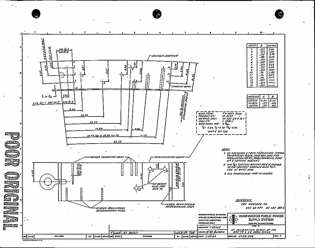
10
h Sgt
i p-I
iig
Pt
I 4p
gg
It I
Ig gI gI
gI
Caf/re/'AA/AF
I (/if
I I ~
IgIg I/
I II g
II/Ir//IIIIFIIVII/
IIOIISI
S474
ldI/ltIJ/4IS
.JIJ
.JIJ
. JI/
./Jd
. /19
.119~ SIJ.«J. J/4~ 74.74.74.919.519.J/9
olpfuJ OO4dtJ. Ot
J. OlJd/J.OJJ. OJSO/I.Jt/A 47S./7
S.OI
9 44 /t I 444 ft/2 440~5
~ 4O
IO. 44
/7. 59
~Y
~b
'4
I Afid/ FROA/I +9 Sul/I R/AlpI /olr/RA/f8 t: rr.cdlf
lIAIFAIAIJP/c/ sA FJJ Ge d c// II uFArul/ c «o/.rI OASFAIFIAIIkey" G tdd
/.Gt, IIA iAJd >k~ F.O4 I
WAIP 2 /If./Pd I
AIOICRFS 4IFAIGI// t. OO 2. OdW/Df// .I/7 .ItdOSPji/ .IJO .4/S
/4.97 or /4.54 fFIO 4. 79
~ I
IIIlIlIII
ll"~ I~ I~ IIIIII
R/AAIFD CAIIOAAIIAIIudll/
I I~ II I
IQIIIIIIIIgg
RFAAIFDSFAAISF//FADDFf/RAIIAIAfldMIIIOIFS
I II II II II II I
-0„
/DFAIIIPIIAIIFAIS/AAIP
0;
ItlfedffFA/I/O/FI//FCA/dlif')
+IAIFPAIeFAAA SF//FADDFIFPIIIA'Af/OAISFIFS
~dtiI GF DFFIGAIFD F cefuFAi RI/Afso rusrFD
CAIIORAf/dig elOIA'./SFFA'FFDIVG.FOe/AORICAf/44/AIdfFS IIFROIRFAIFAI/S,P/FcFA/I/ Cufflu4 szslc//.j
2. r~r/4 I /Id/I/ere/ffdAIIfdlrfsc/essereru/fcdAlrACrSuer'/FRIAAI IF4 4.USF AI'Su/IfDIAS '
A/4 OIAIFAISIOA//ARF/A//A/Cga
~EFEAV~ Ece/ A/uc/FAR co.
2OS AF OFJ S// ltd R'/7 J
toA QSE INNtREEERYIcfAERI <- q WASHINGTON PU BUG POWER
IN SERVICE INStfCS ION SUPPLY SYSTEMtROOAANS ONLY SKIAAAO.WASNWGIONNRI
ENOINffR r/IOYSF
SU/I ORARN S/hP+uuRFSIIuf CAIISIIAIIOAIelOCA', ur /Fd/IPIlrd 4 e) SIIFIC RIAIiSS
NO CASE RfVISION RY CACAO AttVO NO CASE AEVISION RY CNKO AttVO OASE / /S Sd owo No Ufcf/.Roe REV I

~ ~14 ~J"
g ~
~ ~
c}
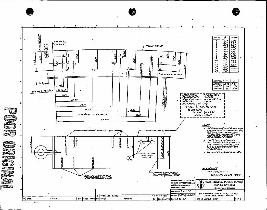
9/ /orAGpfsrd
~ 14 I
9
0 e
9I
r'ouffcfSo/ffrf'
'II I
II II (I
I
II isprr/Rural r/fDlus
ffOC/S/34
47d9
IOI/IJ/4/S
. 314. JI4. J12.//d.//9~ IJO. 3/J.311.311
. 1S. 3/I. 3/2. 3/2
CIIPII/J. 045 04J. 032 pt2.9d2.99J. 04J. OSJ. 042.nd394SJS
977f4rl 349/™ 3,49 /or3
/I 40
IX/9/9. 34
PO 72'Forp 20.44/hr/O
do.no
r.ar
gh
AIO/CIIFS 4 BI/Alrlffff. 99 I.pdW/Dfff ./// ./JdDraff .I/2 .4'OS
I htf0/FROhl/ I/4SI/rllRINF/ ICoff/RAC/N/I r/.2447
Ih141/'Rill SPEC/ FA HJ 4rRB Cl/I /IFAfh'4/ 4'STJI Bhs/hf/ldl ff/FI fIF4 I
IIC i/JG, rl i312, JP4~6/dDrh ROI/S I
/4 I /.1/tI/hIP. 2 C////I
ilIIIIIIII
R/fhI/O /All/Rf/IOf/ffdl/S
I II II II II II I
IIIIIIIIIIIIII
RFAAIED SEAh/'SPR/ADD/IFRi8'IN4riff/ffdlds
IIIIIII IIIII
I II
I
I Il I
I OI
'4
-0„
ID/frr/Flrfrrdfl Srfh/
Flf/ dorrorttRoc/s /lr/lror/ p)
'L
«
'L''If/ref/
d/ffrsre/40Drr/RAIIN4lrdfrffd//S
hror/s/g/D/SIQAdD /ldNFfdc'/CffFDCrier/D C4/rddfll/SIIISIO/r./laRFF. Diffft/+Ifdelldfl/A/A/Old/r /f/DVI8FAkh/Sj PIF/fNo 4 cufflfrfserum
g SII/IIFC(u//g>C/II/Fffrsorroh/I/or EF 4'loscerofffFCohrlfrfSVRFAr6 AfhIl/g /r~ C R/SPSCrri'6(V CISFAS S /CI CS/h!
J AllDlhr/f/SIOAISARFIAIIAICKFS.
~e~h/c/cdI Aluc/FAR css
20/4/o/3 sfflel gF/3
7NIS DRAWINOIS WTSNDSDsoR us« w RRasIRvlcs ANO q g WASHINGTON PUBLIC POWERwssRvlca wstcct«w
Q P SUPPLY SYSTEMtROORAN4 ONLV Aio«AIVO„WL5HWCIOR ICOSI
cs 4 As BullsNcwaaR f //0YCE
DRAwN rfjcrfRIDII/Our CACISRAr/OIIIBCOCK« Crr /2/
RPI/ RO Sff//C /CIAIGNO DAIS REVIQON SV CN«O AIIVO NO DAIS RSVIQON sv cR«o Istvo OASS X./5'-dd OWONO C//Cd. 209 Afv I

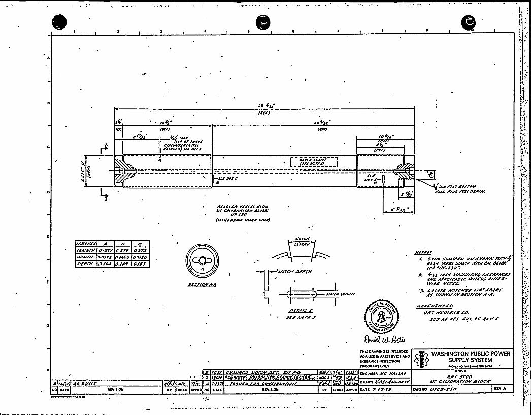
ss
A
5>i
e/5 (oj/I5 /gf
/IO OEOK(Irror Irrdrr
CIAIIIIIIfrdjwnfc/lolcdrslsirDffr
sir O$ 1l'I
(Arrl
oo Enc(dll/
f dlolrrroar~ (/lrsVO11/JL I
ld I>jo ~
dg i
5/'o'ID/rfX
CwC'g
DIA 6'f1 dnffdsII/rnjf, P/W XCO'I OFPfhr.
s
arhcfoR vfrrrc sr/idVfCfllddfrrdsV
din/4'/1lno(AEAerA/Too/ spf/fr@rue)
o-Sf5 4575AV/sOfr/
DFPrr/d OOOS
4/dd 4/ddDodtd4/Fr
A/drr//FSIFA/6f//
cd$6rfjdr/AA
Arnrrr/CFIrrrrH
Ardri// jsFPfI/s
+ + Aro/le IV/Pl/V
arrajj rsFF ArorFa
~ofrdrSfVD SfNPFD OA/S/S/sdhrk /Vlf/reff/rr//SfFFC Sffn/P IV/f1/Cfl
dldDC'/d
~ur. t5d .
5, //sg INC// A/fr////V/Arg fdl/RAp'CCSfRF hpptjrfda llvass ordFR-lV/5F sVd/dl7.
.y. AorffF /vdrr//Fs rzo xpMrrfS Sj/OH/A/ /AfSrrlllA R-R.
~zwzsr~azs:cdr n ucraR rd.
d'd XfF oFS SA'r SF RFVt
WASHINGTON PUBLIC POWERSUPPLY SYSTEM
1ROOIIAIIEONLY SOSLASSO. WAASSOSOIOSS IOOI
d. SB /lf 5 5 5/1o f.
os s ss sit gs
5 VCD A OR COAss Vdljdrr
c 1/ l Ar Fz uorrA/AIFr. rare EIIODIEEII IVC /IAllh5DAAonl +A('1geerlrlv
IIlotE
Rpv sfudUf cf5jdRfrjohrdl orred
NO DATE
~vw eaewastsnIIEVIEIOII ~Y ONED AIIVD IIO DATE IIEVIEION AtfVD DATE f. t2'fd DIION Ufrd-Cto IIEV 3
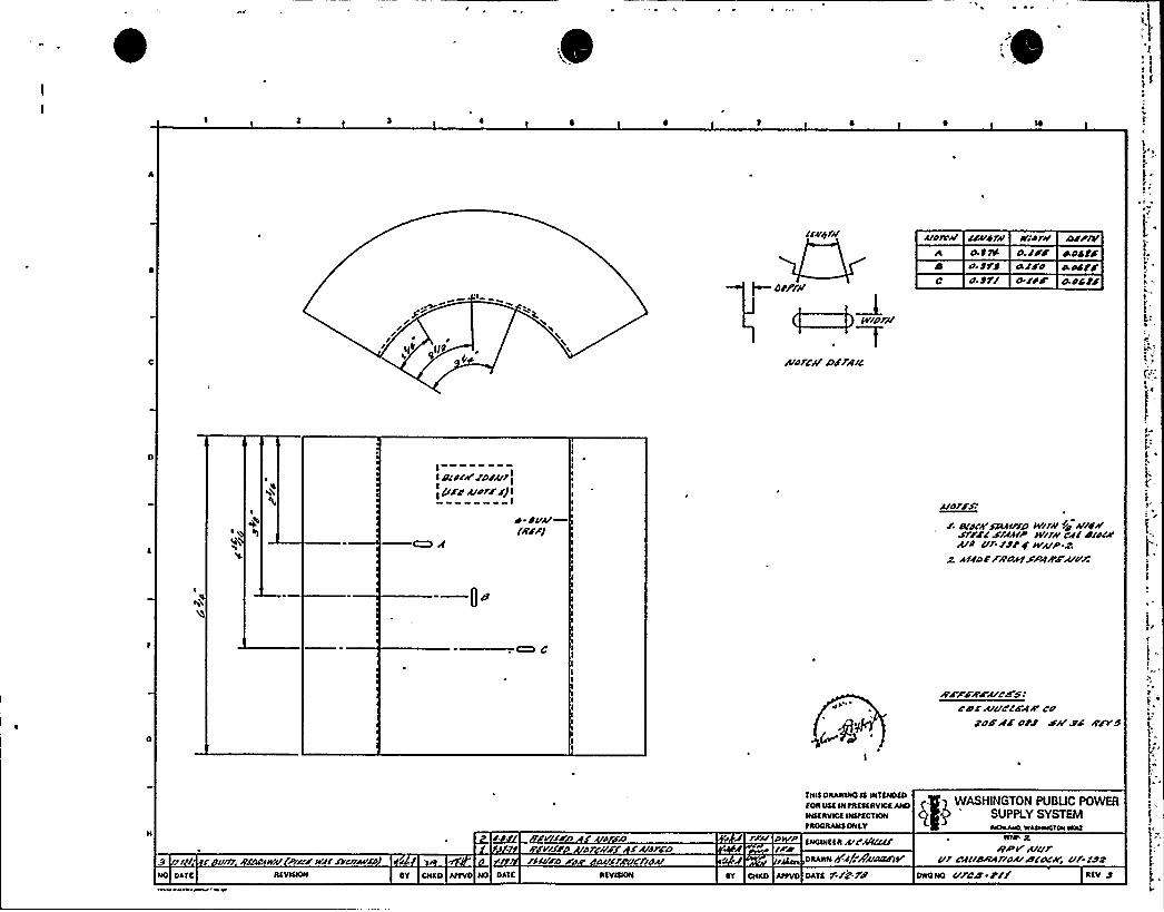
//i III (jf
A'4'$///
~ OFF///
Tt//or//'
rE/O/C/i rDFF/T/C
uo/c// uekrw R//dr//4f TYS O./rdO. frf 4FFOo ff/ 4/1$
A1FP/A
kokfd
4ocfF
It d/d/i/FDFu/T
>4cFC udrF F) l
I
FS/A/NFF/
d/orFF/
r. O/d///au/r//t W/r// //o ///gd/F/FFC F/rtd/P W/rdr CF/ d/dCFrL/d Ur.//rC WuP-Z
2 PrfDF /r//OdfFP4/rdrt//r/F
F/FFSSFaCd S/CdtC rE/UMBRA CO
ZOSrdF OFF SW JIS eVa
/ in /Dwivd/ err t/dr /Idr/d//sc
FV/dV/Xfn dr rVF rtXA!drFD
/ /d///rn rp DrVSrZuCfipu
/ J r/r//
THIS ORANINO IS WTENDEDTOR OSE NI tAESEAVICEAIEIWSEAVICE INStECTKWtAOOAANSONLY
D SNOWIER A/C//E//rt//rrDAANN//'d/rA~CuuN/
q WASHINGTON PUBUC POWEASUPPLY SYSTEMNOAAAO WklaasSION NNI
IINt *ZPV u//r
Ur Crtl/O/trt//Ort/ /f/OCA/r U/'22NO OATS AEVIQOW RY ONED AttVD NO DATE REVISNW AY CNKD AttVO DATE //f'.tP Dwo No Urcd p// REV J
Date 1/8/79Revision 0
11.2 PIPING SYSTEM STANDARDS
The design drawings on the following pages illustrate the ultrasoniccalibration blocks which will be used to perform ultrasonic examina-
tions of the nuclear Class 1 and 2 piping systems., Table 11-2 liststhose UT blocks, including the block identification number which willbe used exclusively whenever referencing the calibration block on
data sheets or other records, and,the corresponding design drawing
number. The block identification number is the same number referenced
from the Program Plan and Schedule Tables and the Weld and Component
Identification Diagrams found in Section 8.0, "WELD ID DIAGRAMS".
The following notes apply to Table 11-2:
NOTE 1: This block is for use on 20" RHR(2)-4S which is of materialspecification SA-312 rather than SA-358. This is acceptable
based on the acoustic similarity of the two materials.
NOTE 2: For these piping systems, the UT calibration block is foruse on the schedule 100 elbows only.
NOTE 3: This block is for use on 12" RHR(1)-4S which is of materialspecification SA-312 rather than SA-358. This is acceptable
based on the acoustic similarity of the two materials.
NOTE 4: See detail for special 5" thermal sleeve on RFW-101-1 inSection 8.0, "WELD ID DIAGRAMS".
NOTE 5: See detail for flued head fitting on MS-101-3. This block isintended for use along with pipe block UT-3.
11-5
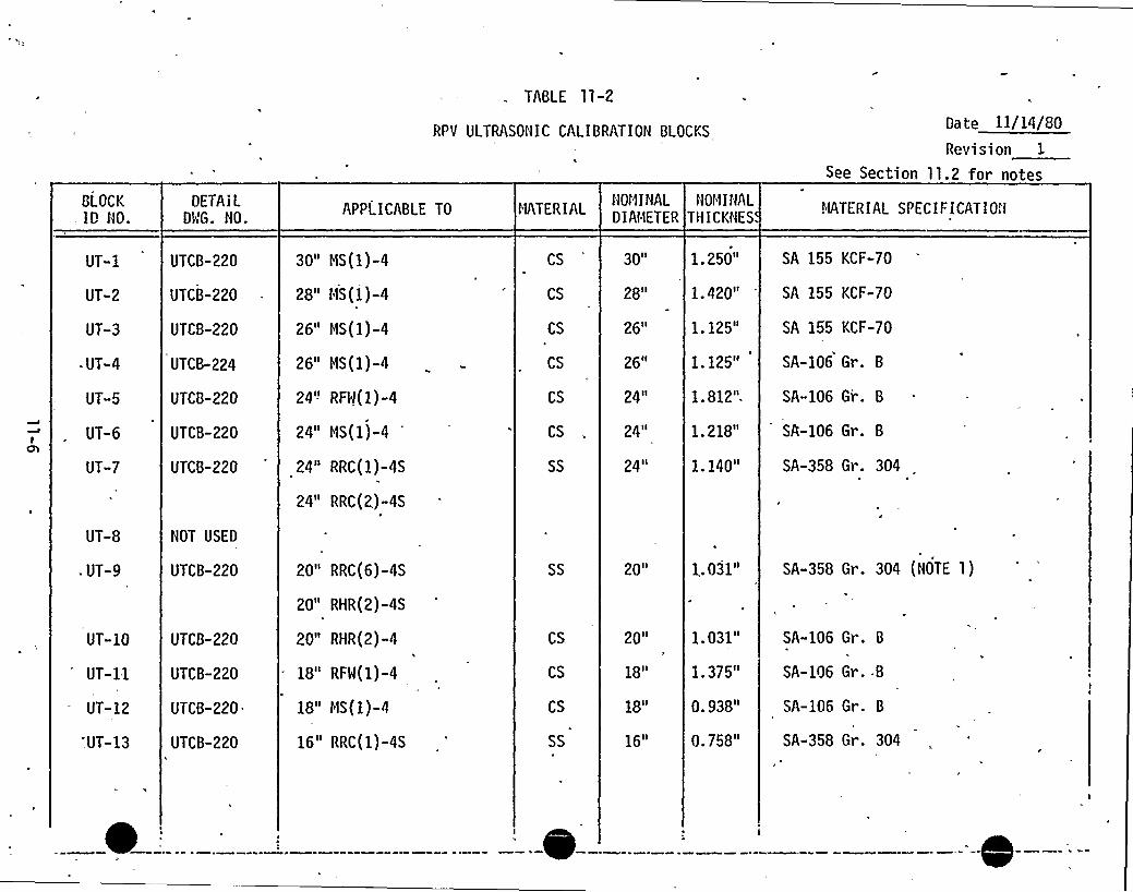
TABLE 11-2
RPV ULTRASONIC CALIBRATION BLOCKSDate 11/14/80
Revision 1
See Section 11.2 for notes
BLOCKID NO.
UT-1
UT-2
UT-3
~ UT-4
UT-5
UT-6
UT-7
UT-8
. UT-9
UT-10
UT-11
UT-12
'.UT-13
DETAILDMG. NO.
UTCB-220
UTCB-220
UTCB-220
UTCB-224
UTCB-220
UTCB-220
UTCB-220
NOT USED
UTCB-220
UTCH-220
UTCB-220
UTCB-220
UTCB-220
APPLICABLE TO
30" HS(1)-4
28" HS(l)-4
26" HS{1)-4
26" HS(1)-4
24'-'FW(1)-4
24" HS(1)-4
24" RRC(l)-4S
24" RRC(2)-4S
20" RRC{6)-4S
20" RHR(2)-4S
20" RHR(2)-4
18" RFW(l)-4
18" HS(l)-4
16" RRC(1)-4S
HATERIAL
CS
CS
CS
CS
CS
CS
SS
SS
CS
CS
CS
SS
NOHINALDIAHETER
3 0II
28 II
26"
26lf
24 II
24 II
24"
20 <t
20n
18"
18"
16"
NOMINALTHICKNES
1.250"
1.420"
1.125"
1.125"
1.812".
1.218"
1.140"
1. 031"
1. 031"
l. 375"
0. 938"
0.758"
HATERIAL SPECIFICATION
SA 155 KCF-70
SA 155 KCF-70
SA 155 KCF-70
SA-106 Gr. B
SA-106 Gr. B
SR-106 Gr. B
SA-358 Gr. 304
SA-358 Gr. 304 (NOTE 1)
SA-106 Gr. B
SA-106 Gr..B
SA-106 Gr. B
SA-358 Gr. 304
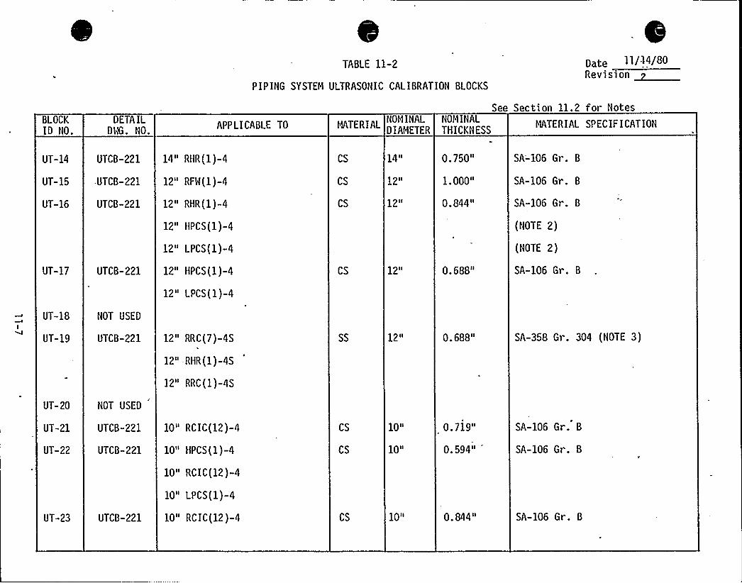
TABLE 11-2
PIPING SYSTEM ULTRASONIC CALIBRATION BLOCKS
pete 11/14/80Revision ~
See Section 11.2 for NotesBLOCKID NO.
DETA ILDWG. NO.
APPLICABLE TO MATERIALNOMINALDIAMETER
NOMINALTHICKNESS
11ATERIAL SPECIFICATION
UT-14
UT-15
UT-16
UT-17
UT-18
UT-19
UT-20
UT-21
UT-22
UT-23
UTCB-221
-UTCB-221
UTCB-221
UTCB-221
NOT USED
UTCB-221
NOT USED
UTCB-221
UTCB-221
UTCB-221
14" RHR(1)-4
12" RFW(l)-4
12" RHR(1)-4
12" HPCS(1)-4
12" LPCS(1)-4
12" HPCS(1)-4
12" LPCS(1)-4
12" RRC(7)-4S
12" -RHR(1) -4S
12" RRC(l)-4S
10" RCIC(12)-4
10" HPCS(l)-4
10" RCIC(12)-4
10" LPCS(1)-4
10" RCIC(12)-4
CS
CS
CS
CS
SS
CS
CS
CS
14"
12"
12"
12 II
12sl
10"
10"
10"
0.750"
1.000"
0.844"
0.688"
0.688"
0.719"
0.594"
0.844"
SA-106 Gr. 8
SA-106 Gr. 8
SA-106 Gr. 8
(NOTE 2)
(NOTE 2)
SA-106 Gr. 8
SA-358 Gr. 304 (NOTE 3)
SA-106 Gr. 8
SA-106 Gr. 8
SA-106 Gr. 8
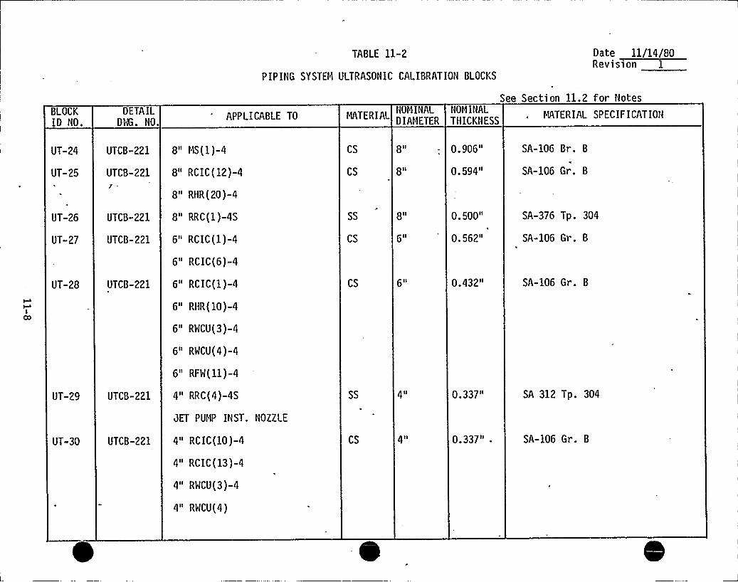
TABLE 11-2
PIPING SYSTEM ULTRASONIC CALIBRATION BLOCKS
Date ll/14/80Revision 1
See Section 11.2 for NotesBLOCKID NO.
DETAILDWG. NO.
APPLICABLE TO MATERIALNOMINALDIAMETER
NOMINALTHICKNESS
MATERIAL SPECIF ICATION
UT-24
UT-25
UT-26
UT-27
UT-28
UT-29
UT-30
UTCB-221
UTCB-2211
UTCH-221
UTCB-221
UTCB-221
UTCB-221
UTCB-221
8" MS(1)-4
8" RCIC(12)-4
8" RHR(20)-4
8" RRC(1)-4S
6" RCIC(1)-4
6" RCIC(6)-4
6" RCIC(1)-4
6" RHR(10)-4
6" RWCU(3)-4
6" RWCU(4)-4
6" RFW(11)-4
4" RRC(4)-4S
JET PUMP INST. NOZZLE
4" RCIC(10)-4
4" RCIC(13)-4
4" RWCU(3)-4
4" RWCU(4)
CS
CS
SS
CS
CS
SS
CS
8 II
8 I I
8 II
6 II
4 II
4 II
0 906
0.594"
0. 500"
0.562"
0.432"
0.337"
0.337"-
SA-106 Br. B
SA-106 Gr. B
SA-376,Tp. 304
SA-106 Gr. B
SA-106 Gr. B
SA 312 Tp. 304
SA-106 Gr. B
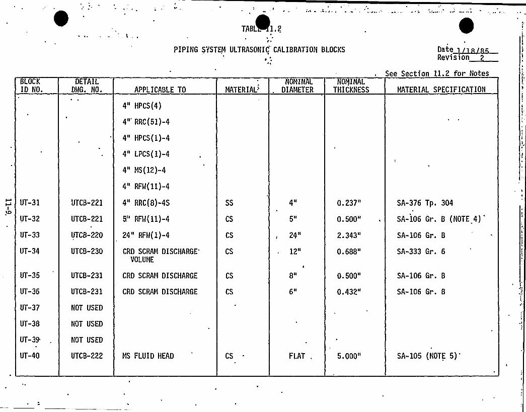
t~\
TABL 1.2s
r ~
PIPING SYSTEM ULTRASONIC CALIBRATIOH BLOCKS DRevision~See Section 11.2 for Notes
BLOCKID NO.
DETAILDWG. NO. APPLICABLE TO
4" HPCS(4)
MATERIAL'MIHAL
DIAMETERHOQIHAL
THICKNESS MATERIAL SPECIFICATION
UT-31
UT-32
UT-33
UT-34
UT-35
UT-36
UT-37
UT-38
UT-39.
UT-40
4" RRC(51)-4
4" HPCS(1)-4
4" LPCS(1)-4
4" MS(12)-4
4" RFW(11)-4
UTCB-221 4" RRC{8)-4S
UTCB-221 B." RFW(11)-4
UTCB-220
UTCB-230
UTCB-231
24" RFW(l)-4
CRD SCRAMDISCHARGE'OLUME
CRD SCRAM DISCHARGE
UTCB-231 CRD SCRQ1 DISCHARGE
HOT USED
NOT USED
NOT USED
UTCB-222 MS FLUID HEAD
SS
CS
CS
CS
CS
CS
4 II
5tl
24 II
12"
8 II
6ll
FLAT .
0.237"
0.500"
2.343"
0.688"
0.500"
0.432"
5.000"
SA-376 Tp. 304
SA-106 Gr. 8 (NOTE 4)
SA-106 Gr. 8
SA-333 Gr. 6
SA-106 Gr. 8
SA-106 Gr. 8
SA-105 (NOTE 5)'
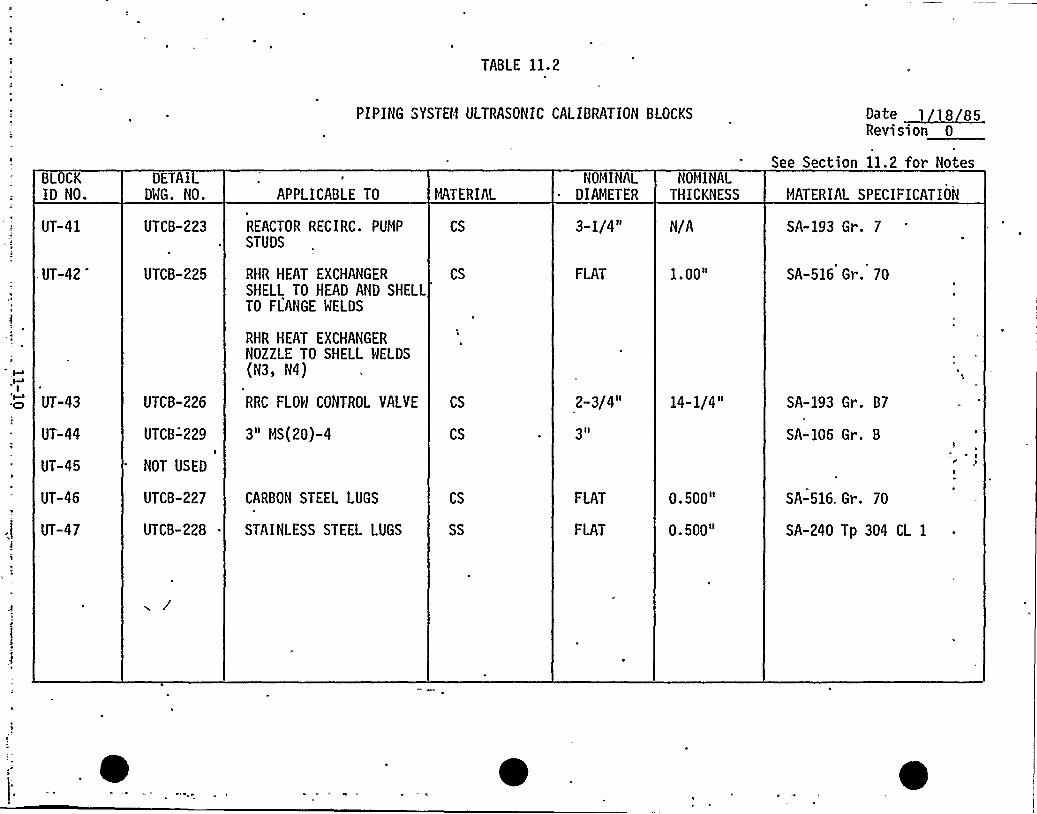
TABLE 11.2
PIPING SYSTEM ULTRASONIC CALIBRATION BLOCKS Date 1 18 85Revision 0
BLOCKID NO.
UT-41
. UT-.42
DETAILDWG. NO.
UTCB-223
UTCB-225
APPLICABLE TO
REACTOR RECIRC. PUMP
STUDS
RHR HEAT EXCHANGER
SHELL TO HEAD AND SHELLTO FLANGE FIELDS
RHR HEAT EXCHANGERNOZZLE TO SHELL MELDS
(N3, N4)
MATERIAL
CS
CS
NOMINALDIAMETER
3-1/4"
FLAT
NOMINALTHICKNESS
N/A
1.00"
See Section 11.2 for Notes
MATERIAL SPECIFICATION
SA-193 Gr. 7
SA-516 Gr. 70
UT-44
UT-45
UT-46
UT-47
UTCB-226
UTCB-'229I
NOT USED
UTCB-227
UTCB-228
RRC FLOW CONTROL VALVE
3" MS(20)-4
CARBON STEEL LUGS
STAINLESS STEEL LUGS
CS
CS
CS
SS
2-3/4"
3Il
FLAT
FLAT
14-1/4"
0.500"
0.500"
SA-193 Gr. B7
SA-106 Gr. B
SA-516, Gr. 70
SA-240 Tp 304 CL 1
Cr p
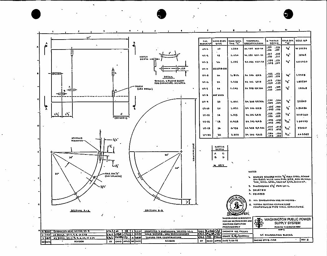
I S
Ul ~ 'L IO
L
Ul
CkL NONI 'PltCDLDCKN'I 411.1.
HDIAWALLINV. AL
S.1% 0
'l, lI 0
I~ It'I
MATERIATECttllfIC~ IIDN
Sk 1SC V.LF '10
Sk IS'1 KCI 10
DA155 KCf:10
W NDICNDCOIN
.ITS . Itt~ lll .II0
.III .Itf
.110 .I I I~ 109 .SIS.108 .109
NOLO DlkAg
I/O
NCLI NS
V/1025%
ISSDb
MOIOCAO
A ~ HOICN(CC ~ DCTNLS
OCT AILtt'P'ICAL 4'PLLCIS CllltfSOR CURVATURE. Slt NOICC
Ul 5
Ut SO
Ut 1 tk
Ul 4 Nlf DOID
ul ~ A Sll UICDSSS
1, DLL
l.i'l~
I ~ LIIO
Sk LDD CAD
SL 'IOC EAR O
Sk SSB QRSOl
.152,15'I
.155 ~ ISO
,11 1 ~ 1'SO
.110 .115
~ IfI . 109.I I 0 . Io9
IIS
1.2908
LDDTSO
19008
A
~to'IIALCtlIINIIUD
(511 ROIS Sj
Ul I
Ul~ 10
Uf llUl \1
Ul ~ SS
to
t0
I~ ODL
'L.OSS
I. ST5
O.'I 52
0 l5$
Dk 'CDS PAR20%.
Sk SOI RILB
SL IOC EAILD
SL 'LOC, CARD
CA %50 +ROOD
Sk. LDC GARB
.IOC .IOC
.109 IOC
. 105 019
. 099 o ITEA
.SSS .LIO
.IIC F 115
.095 .095,092 .092
.OTIC .015
.OTT .018
.144 ~ IDC
.195 .152
I/O
I/5
5$ 2
+IC.
25890
L BCSCO
N IOIGO
L 001'15
51000
A4 5549
n
4
02
LIOICNDCOI
A C
ES P
KC f
SO NDLC. DLL8'PIPIPLACES'I
NOICDI
BLOCKS SfAMtCPVIIIN /S NIAN SICEI. DIAOAP0th CNDC WIIN NOMO\tC 411C I CN OII WALLlNK, MAIL5t44 > N\LtISC g Ckk DLOCK Nl.
DIMCNDIONCIAS fOR UI'l.PCLCICPOCI.C1CP
D~N
,U WPO
0L
ALL 01LACNSAON'4 AILCIN INCNE4OOOICII BOTTOM CURVAIURQCONF ORNAS ffPIPC V/ALLCURVAIURC.
TNISDRAWINGIS INTENOEO
FOFIUSE IN tRESERVICE ANO
INSERVICE INSPECTION
tROGRANS ONLY
WASRINGTON PUBUC POWERSUPPLY SYSTEMOATS AAO WANAAOIOSWNI
IS UI CDCCitt\D NCAI Nl COIL 51IIIII O UI I O'I"I 'I
BILL(I UI-I 0 9 F 10 ll LtNO I RIVIQON DY CNEO JFYVO NG DATE REVUION DY CNEO APPVD DATE'I LD'IC
AD UI 1% 'I I ltl ED 'CCI '2 I 'IN SN 'D'llf11 UI .AI. SNOWIER Olt, NLLLLCI Ot II IAS'LC '4'SVIOID NOLC DttlllCNLUCID 1
0 Il LS'UCO IDD CDUDIILQC1101l DRAWN I(;QC.AaDRCwU'I CALIDRLIIDNBkDCKD
OWG NG UICTO t'tO REV 5

0
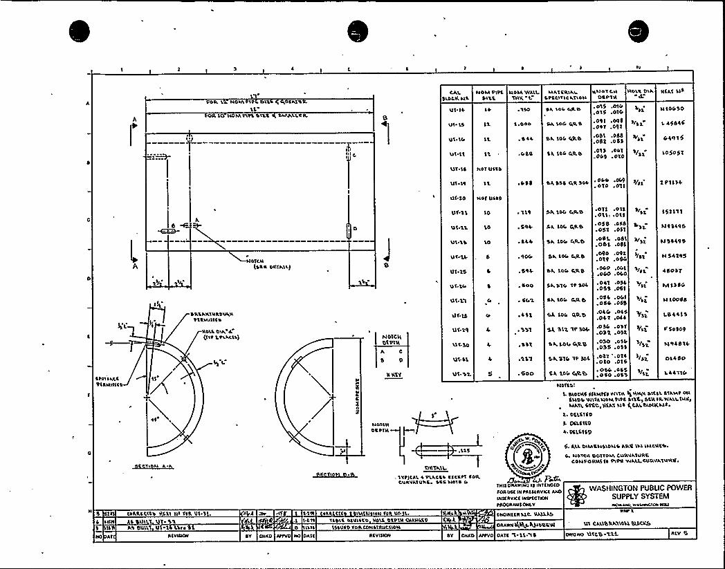
N»
ROLL LL NOM 196 flILQ CIRCAIQIL
LLR LCD MOMtttS CIRC 'hlrtALLQR.
CALSLDLK41
Ut 15
Ut IC»
U'I Ll
40M tttCSI%%.
4DIAWALIIIK L.
L,ODD
, O44
. 015 .DIG
.015 .01G
.O91 .O95
.091 .091
.oSL .obb
.o82 .o53
.01$ .001
.OGS,O'10
Sk 1DC SILT!
QA, LOG tARD
Sk 104 rARTI
SL 'LOC CARD
MATCQ.lkl 44OI C IISTCCITICktlou D@t'I'4
IIDULO'Ik
/32
Rfkt 43
4 too So
L 4584'5
04915
105051
'UT 15 NOT U1TD
UI.LQ
Ut 20 NOT UCCD
CA SSS C»R 304 ' t/.olo .olL 2 L»IL34
~ t01 1 kCCDLCMIttCD
»
2/
DRLAKIRRDUARVCR%RISC
RD'LC D'll, 4(et t 2tkkLIS)
L2 I.
NDICN(S'CQ DQIML)
N
1L
C
0g
NOTCIC
BIDING
A C
8 0
uateuDCQTR
Ut.'LL
'Ut.l'L
UI.IS
UI 24
Ut 25
Ut I.IA
Ut 'Ll
U6SO
Ut-SL
Ut.>2.
10
10
'LO
~ l19
, $94
544
,%00
»4\2
.600
SA LDG C»ILf1
Sk lot» CARD
Sk 10r» TAILT»
Sk LDI» CARD
Sk 1DC» CIRS
Sk'DlC» It304
Sk 104 CIR 9»
CL LDC» RR.B
SL SL2 'It 304
'Sk LOL» tutLB
SA SIC» It 304
SL LOC» OIILTD
.olf .otf.011» .013
.o58 .055051 .051
.051..08'L.OBL .OSL
.090 .092
.019 .oSG
~ 060 .OC»L
,OGO .040.041 .054~ OSS .061
.054 .OGL
.054 .058
.04G .045
.042 .044
~036 .O'Sl.032 .032.OSO OSC»
055 .033
.021 ~ O'14.020 .016~ OSC» .OSS050 .06'3
3/Si
/31
/SL
/si
IA2
152'111
LL93498
SI33495
N 542%5
4505'T
M LSSG
4 Loodd
1.8 44L 3
5 5o 309
1494814
OLASO
L44IIG
401 CSI
L SLDCK9 jfkutftW'I'IH SC RVAR StLCL Stktkt OuSMDC VIWluDIutltCSILC) SCRILVIALLIRKILAAILstcc, Ilckt 44 b,cLLDIDLKLIT
l. DLLSTCD
3. PCLCILD
4 DCLSSCP
QILSIION~
CIRRT.CtCS LLI NI fIR 'Ut 1
C»RIMI
. IVt)CAL4 QLAC'CC TCCCtf fOR.O'URVktulIC, SIC uvt Q C»
~ W. A~
tcevutfO'/. P~TNICDQAWI IfINICNDCD
ANoff INtACCCRVICC ANDWSCQVICC INCICCTION
tADORANTONLV
'5. LLL D'IIARustouc LIAR IDI lucQLI»~
C 44IC4 Dot'tDIACURVAIURScouf ORML 1 ~ tltQ wkkLcu'RvkluRIC
WASHINGTON PUBLIC POWERSUPPLY SYSTEMNOVA»»V WAIHWCICWNul
ONUS
NO A'I
6 UI ~-32AS BULLS U 1 LLrv
QCVUNN QY CHAD AttVO I»0 DAIC RCVICION OY CHAD Attfo DATC 'I 'L'1 lS
0 l m W DIII IR CC I lout ut 1. IL fNOINCCNLLC. RLLLLC1 I t tt IADLC QIVICCD QDLX Dt'tIR CQLRr»CD
0 lkll 1SSUID fDQ CONSIRllC'tlou DRAWNLtLLSLLIISISILQVC UI CLLIBRLIIDSCBLSCKS
owaNO Utc,B '2'CL RCV 6
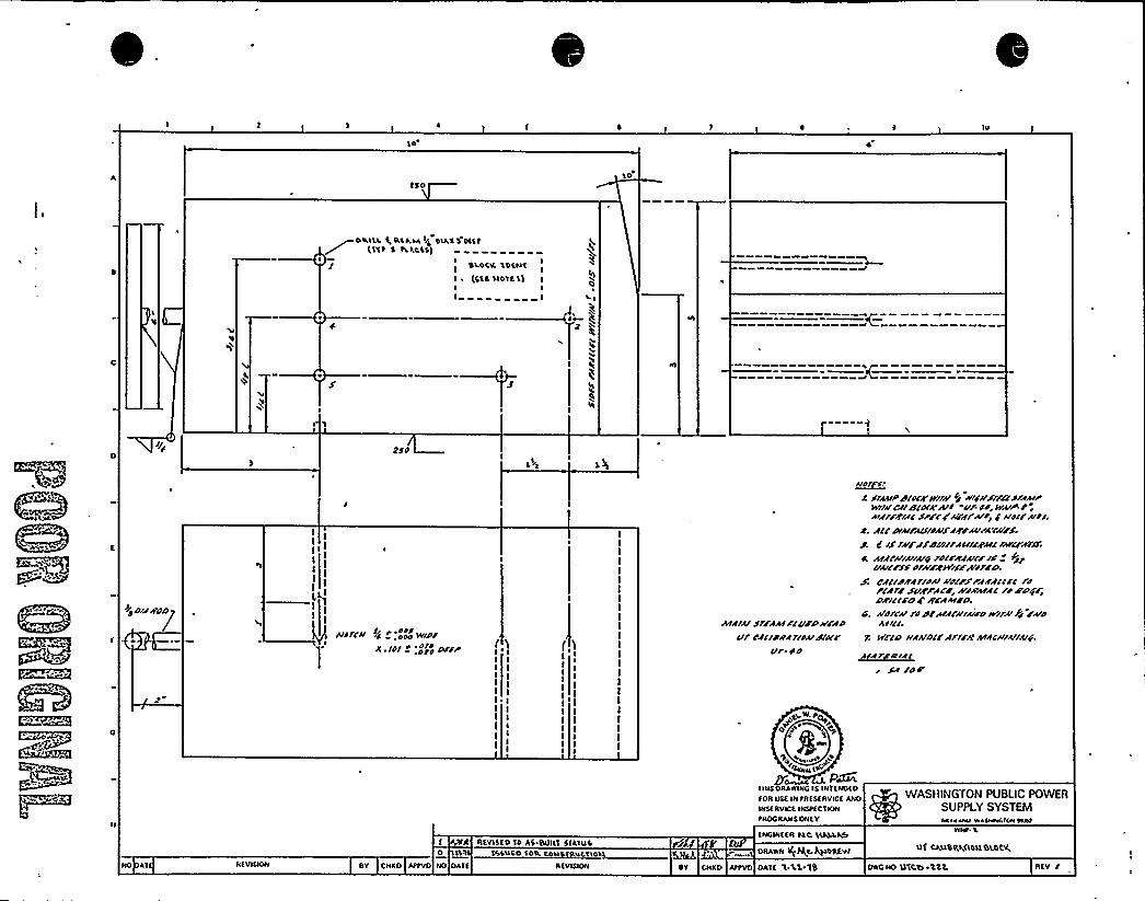
10
150
DRILL Q ILSLTA14 DIRK5 DfftE11t 5 hkCN)
ISLOCR 1OENT I
(SEC IE Off5)I II I Li
t
IS 2$d
+p DIARDDg
I
II
I
I I
I
lgI
II
Ard/CII FC d 'odd Vddd,dd/
/f rd/ d:ddrddd Dr/F
AAAIA//IRAN/FCVF/r//FADvr'dcrdilArlddl
d'/ACi'r
dd
~A/dl S.
C diAAIFldrdCR/fr/A/ dd iiiddidrfctAIAA+WIIICR /Crdrr/AI/ -Vfdd, WAIF-R,AIR/FR/Ac $1/i CrrfgfIvdr $ lid//'Ard/.
a ACC AAIFACridAIFARFIAIFArA/F.J. 8 /jI/IFJfFlddrfACIICRAICrdrrFN30;
a. A/AC/I/A//A/yrdrrRAAIIF/du+Wd dl/IFRWIFFAIdfFn.
AC CdlrcRArrddrrrdIFFrfRACIFC rdFCAIF SVRFACFi hVRA/AC fd FDg/iDRICCFD E RFAAIFD.
C. Ad/CA/ fdDCAIACRIA/ddWI/A fg FAd4IICC,
7. NFCD IIAAIDCCAf/CRAdACIIIAIIAI+.
FA rdd
IIIISFRAWINGiS INTENDEDION USE INtiifsfRVICfAM>NisfRVICE INltfC 1 KNItROGIIANS ONLY
WASRING fON PUBLIC POWERSUPPLY SYSTEMOkla klw H LNIWOIOVWAI
NO Af NEVI@ON ST CHKO AttVD NO OAff REVISION
REVISED 10 AS Bllilf51AIUC0 tll f5\USO 1OIL CON UCT IOTA
ENGINEER IAC DEOSLIULftDRA'IVN lff+C ~DRAW
ST CNKD AttVD OAEE 'E.LS 1B
WNt- L
Qf CASIBQ.VlsllBLOC+
DWQ NO 11ECW B'S C REV /

h
If Ali. P"'.~~ f f h I I
k
,'v
"I
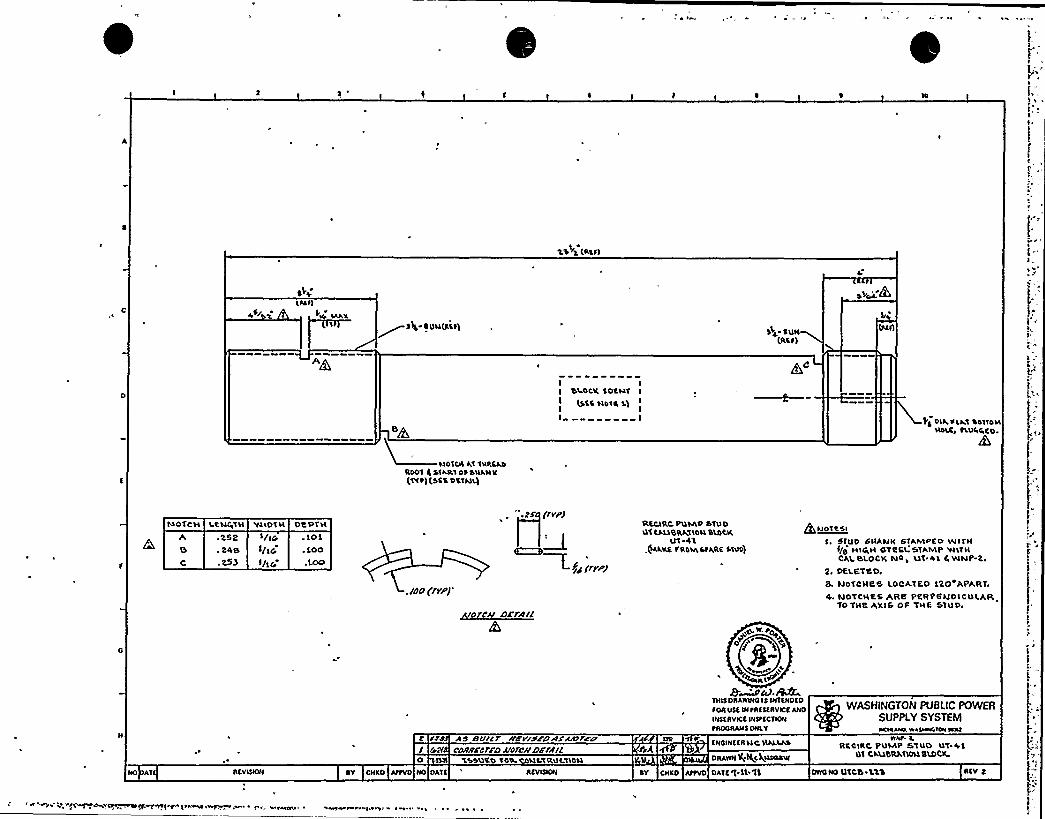
10
1 ~%% ~5 (ASTI
C ACE Y
S(g
~ ST4 ~ UH(AttISUH
(Rtt)
IIIASII
LHDTLR kl TN'RSADRDDT 4 S'IART 0% SWANK(Ttt)(SSA DtTNL)
I IbLOC'll. SDEHT I
I(sts Hatt s)
III
PS DIA, 4 LAt 44TTDMHOLA> tLUR+CD.
A0C
~ ESe. 44B.E53
NOTCH LCHQTH
I/IGI/IGI/IG
.105
. 5OO
.Loo
wlDTH De PTH
./00 ('/rpJ'
rvy)
~ g~ /rry/
W'A DE/A/I
R%CLRC PUMP STUDUt CNABRILTIDILbLOCK
UT 45+IS TAO',StRRC ITLIDj
QuDTCSIf. STUD SHANK STAAAPCO Wl1'N
«/4 HIGH STEEL 5TAIVIP VIITHCELLBLOCK Na, LIT.af 4WNP-Z..
Z. DELETED,S. NOTCHe5 LOCATED SZO Ale.RT.4 NOTCHES Alfe PERPESIDICULATL
TO TNE AXIS OF THa STUD.
NO AT ASVISION
O ILIINO DATIAY CNKO AttVD
AS BSIAtr A'Et/Sr/tAr'AAtlCPcawrcrro uorrr/arra//
%+&NO TOO LISTRLILTIOHRtVIQON
a).RAETRIS DI4LWINOIS INTINDIOSOR USS IN tAIStAVICfANO
INStRVICS INStfC'IIONtROGRANS ONLY
fNOINftRltCHNAAS
DRAWN I(;+LQHSARW
AY CNKD AttVD DATt'( Tl 11 DWO NO UTCb.'L'tb RIV 4
WASHINGTON PUBLIC POWERSUPPLY SYSTEMWCNLANO WASMNCICNINNI
WNtRtCIRC PUMP STU'D LIT +5
QT CI LlbRRTLDLLSLDCIL
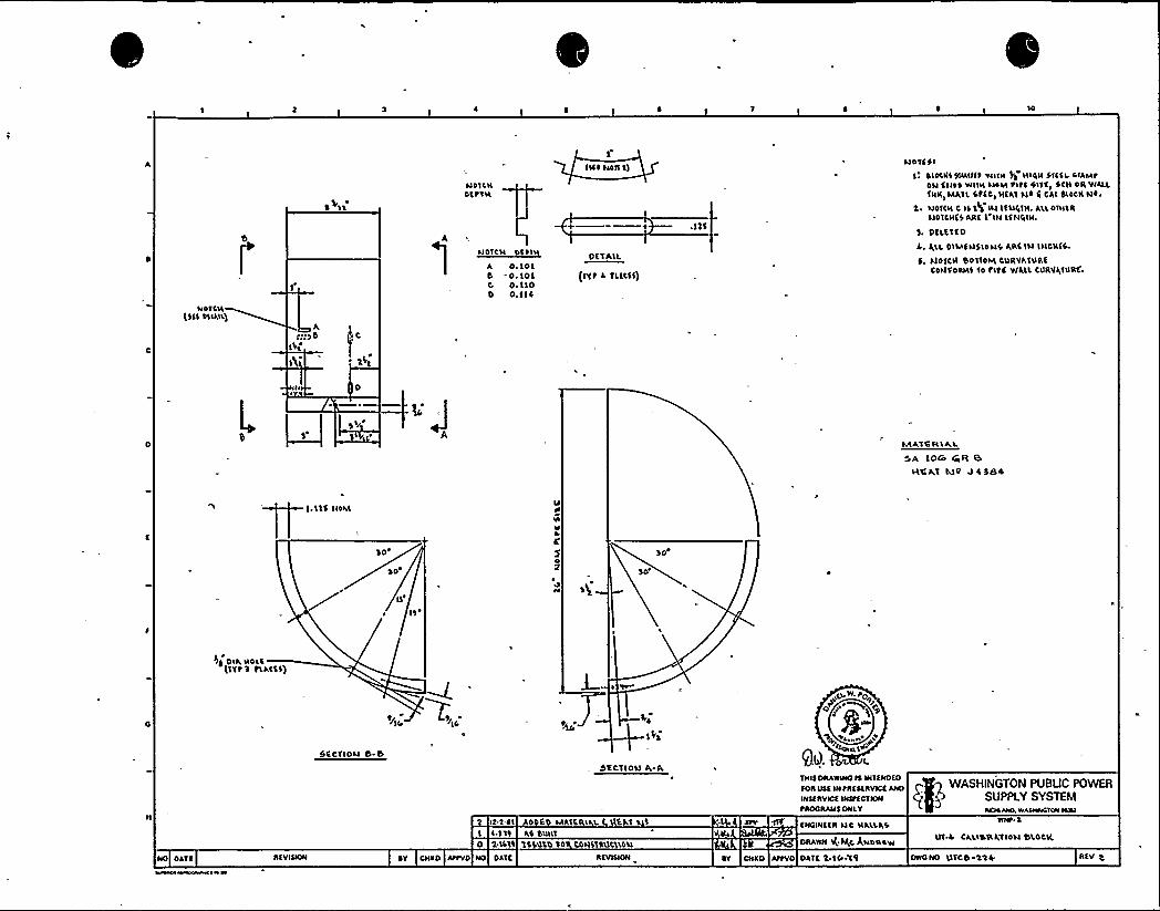
10
NOCCN(511 OLIAIL)
>2>sb C
''I
NO'ICNOfPCN
A 0. IOL0 -0.1010 0. I I0D O. II4
I>lfNOI> I)
OftAIL
(IVt 4 fLLCI5)
NOtfSI
olocKSso»tft w»» 51 NIRN $>>f>, CLAMPON ENOS WILN NON P>tl OIlf> SCN OR WALL5NK>OAAILStfC> >IfA1 NO ( CAI blOCK NO.
NO'ICN C 1$ 'I gILI lfl>4'IN.ALLO>NIRL>0 ICN(S ARI I'INLfN4>i>.
3. OILE'>f0
A. J,LL 0»AE NSIONS ARE IN INCRES.
b. SIOICN B0110NL CURYAIURECO>ffOAM5 50 t>tf WALL CUILVQIURC'
gv)MA,t0 IC IAL
OA IO& CNR BLltl>Lf IU0 0 4 384
1.11$ l>OM
So'O
I>
N
If
1
llIS
sg
Ii 0>A NOL\(ftt3 tLACE5)
IO IS
5ECf>ON B B
bECt>ON IC A
>22.0> 0 E MAIER> 1. EAt 1
I I 11l AS bl>>lt0 l IC>IS 15$>LLD 10 CONSIRUCLLO>L
4 ~ ~ ENO>NIIR NC NA'LLASN
oaAwN >I;SRC A»c >AcwUI 0 CAL>BICAYIONBLOCK
foRULEINtRICCRY>cfANO I 5q WASHINGTON PUBUC POWERSUPPLY SYSTEM
PAOORAMS ONLY NOCAA>C WACW>VC>0» >ON>
NO OAff RfV>l>ON ~Y CHAD A>tVD NO DAIE RfV>NON OY cNCO Attvo oAIE a.lc'w>1 0»0 NO UtC0 SS + REV g

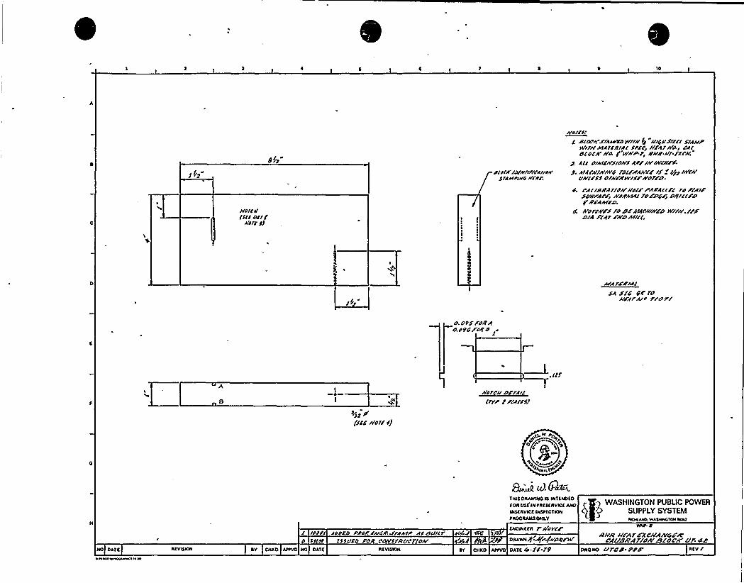
10
8//p"
JV'Alit/Ifflmr/
Ntrf SJ
ortrrr/AY+/lirefr/A'lf
Atr/A'4 iV/A:
~err>:g dcoc/rF/4ffoct wl//St "/rryrrsltl/sr~frp
N/rr// Atfrrrt/4/ SPFC~ //Ark/At CflslocA'A A F Nrf/P.Pi Rrr/l /t/./lrt/
g fa orffNj/AVlNFF /A/INk'(f;j. frfrr//Arrfro Joltd4//CF /S t //tt lrrrt/
lrt/trss ol//Fwrrrse worert.
S. CAl/d/rl7/of/'//dlF Pwrlelrr ro P/4/FSf/EXAFp NFW/ rOFPGFr OtrrllFDp /tFNkttrt.frorr//FS ro dF hDEC//NFtt N/rr//./FFo/4 F 'er a%At lttrr(.
v~rzZr~l$4 Etc Ete ro//Ftrut 7/ort
o. op> Foe4o.otG/rte 8 f
'if'ffsg A'O/F i)
//frcAI orrflltrap F rrwrrsf
t~mINtAEuoveE~ C g WASHINGTON PUBLIC POWERDIEEAVICE INItECEION g + SUPPLY SYSTEMtNOCIIANEONLY IICMANO WAINWCIONNNI
/ /PHl fDPCD Plterf/G/'.JrfktP 4/ SVR7 AiJ ECIE
o E ctt lsfvco Fort corrsrRl/crrof/
ENOINEEN r/ttyCeODAWNggrgao gFN/ R!/R t/F4 7 FXCt/4/I/rtFR
rgusA'4sto4/tszoc'A ttr. 4eNO DA'IE IIEVIQON DY CNKO AttVD NO DATE IIEVIQON ONED Attvo DAEE G.SC./9 DWCND l/7cd epS'IEV l

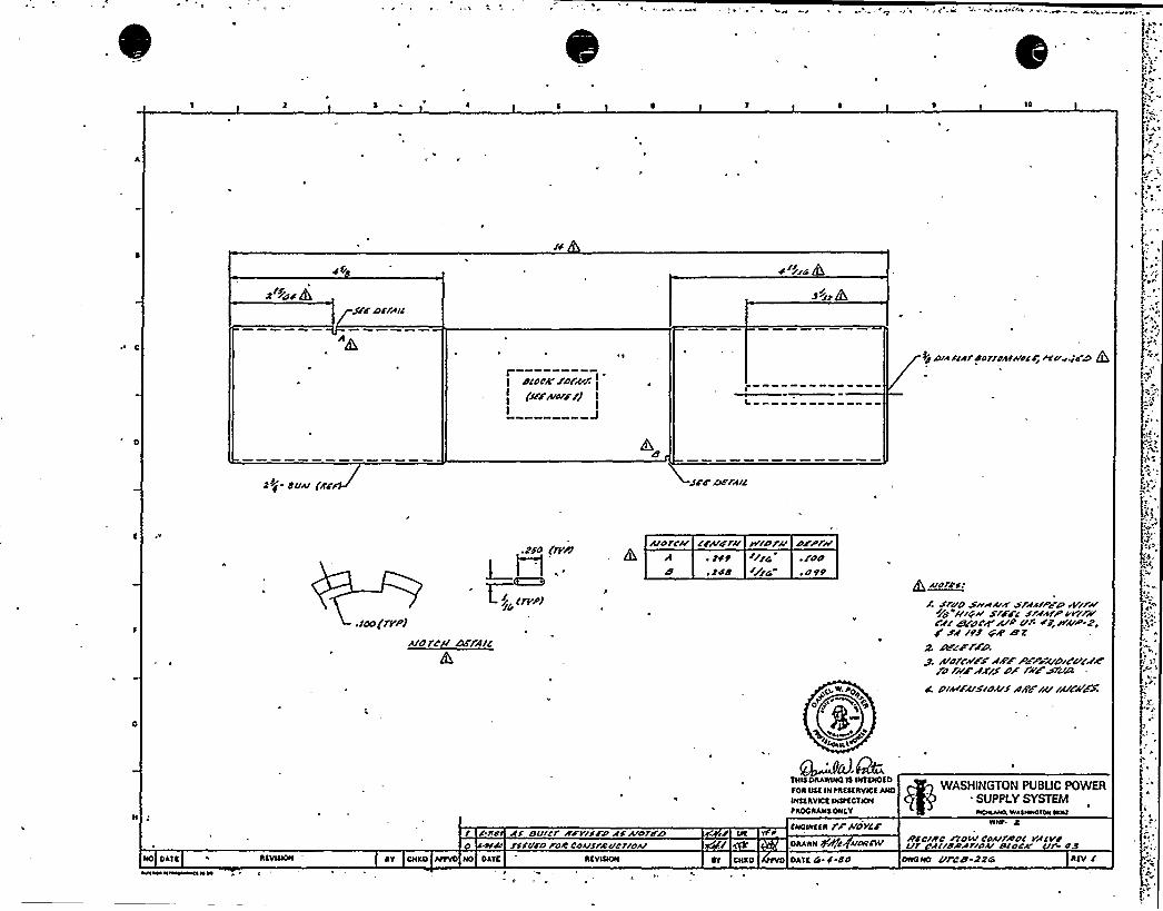
10
4
2'i~iChSFc toe/A/c
d'~//dry
>//Ck
r"——--"-didCR
SAN/'uf
murzrJ
/d plA «Ardorr/AC/I/crAYu«os ttL1
dVA/ (A'g sr+ ns rA/c
.CC/CI(r'V+1
~Pl .
$> crppJ
AICITCII dtttt FAIC
ArdrcA/ «A/arrl wrctr/I crpf//IE ~ 2fEt //ry,retdCE 2dd /F/G ~ 0A'/L/,Ald roc/
r s/Aid SHAAIICS/i(A/PCP eE//FA/<yg /IIII/srffC s/4AIPvf/F/fC4( RE/CIRCA R/+ C/I-'9, /tAIP-Z,g $4 /dd QA' Z
g 4/r/fi'PFX4ffPFPrkSIIC I//4/d'dlfffffISC/F +/ 4fVA
NO DAY E REVIDION
/ C.fd Aj BVICf IIFYIJFCIAS A/Oft/Atd/ rSSCIC'D /OR COAIS/RIldrldA/
EY CKEO AofVO NO DATE EY CKED
O. oO
Imu1
~d.GhYKeORARONO e anENOEOFOR OEE 1N OREEERVICE ANO
INEERVtCE IN5ftCYIONIROC RANE OKEY
ENCNtEBI rF 8'CtYCF
ORI,WN /+I A/OECNI
DAlE Ci C dd
IE dIAIFAISIIIAIS4ffyu rA/CAFX
WASHINGTON PUBUC POWERSUPPLY SYSTEMNOAAIAt.WANtWOION OAT
/ICCIRC F/OW COAINOC IACVIIVf ACISAtAfrdA/Atro''OWONO CIFCCC 22/A
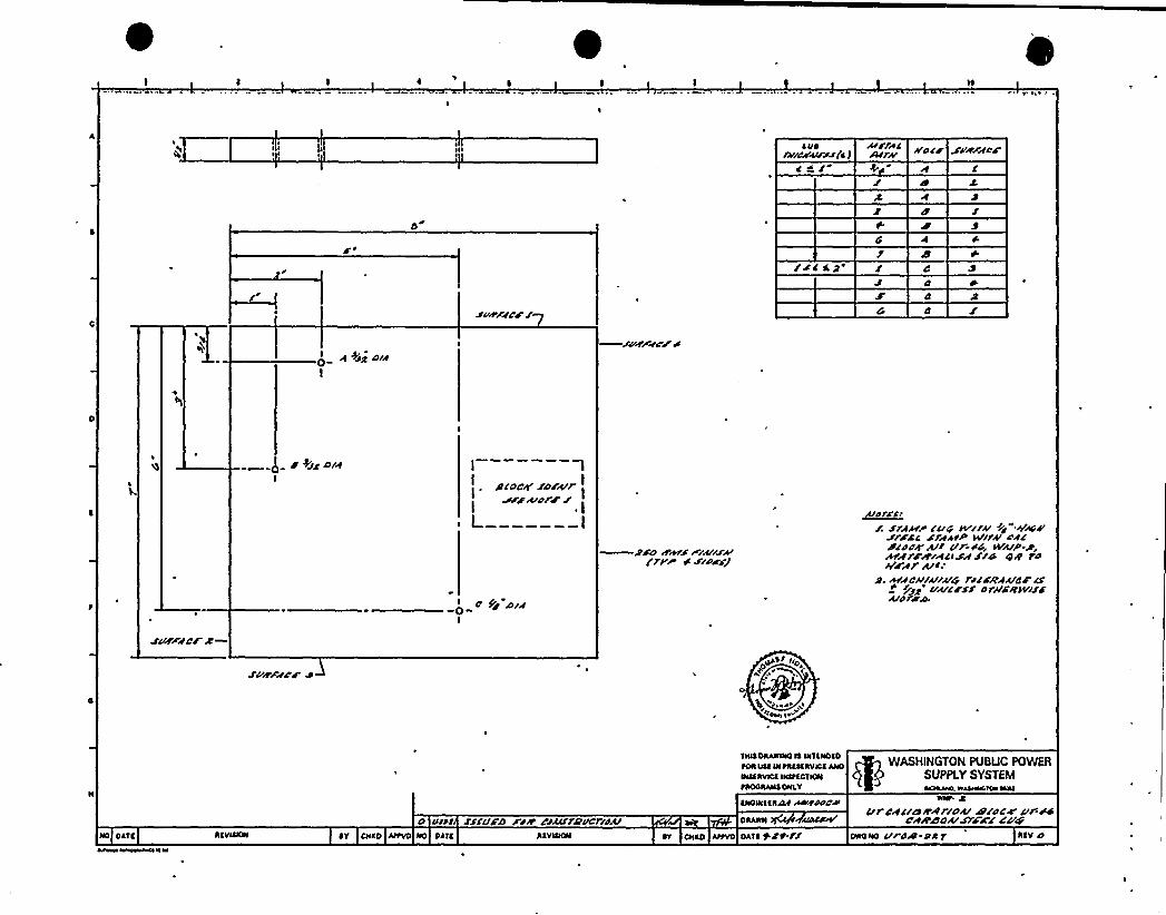
'
W
A CIDrvlcNA>rss(c J
WOCF SVRFaCF
b
$ 4
/SC S
2'Viflf
CF r
A +ig 4/sI
J'VEFWCF S
g 44icOla I lAICOCW raWrA/A/d/FJ
PIPI
$$4 8&SS/A//Fk'flP'C FlPCS)
~dlrr. $rx>lrre wlrAI Cr" Acc<V
SrFSA SfAASP Wlrk'ACASCF All Vr S4g WlClP PqAAfFRACCISA$/4 IIIR fdkdA1 A/lr%AC>llAlafp relFRAArcF Cc
VACF$$ 4 N'SRkVI$$AlpreAN
SVFraCr Z—
SVRFVd'F JO>S> «D
CD.i~ '<
WASHINGTON PUBUC POWERSUPPLY SYSTEM
>IOOAANIOHLV WOE«4. WAIWWAICWICNI
4 IA»s fffvFa xiR csurrevcflsArANDVIIIN&4 SDCVPCCAI
UrCRclc>Rllrfo&N/SCF fit.S4CAR84AISfFAfCgg
NO DA'lC
Ms% WWWdaOI W W
DAVI>IN DV DICED At>VD NO DAI( INVNION DNAD A>IVD DATDjftff DNONO V dR PC 7 DIV 4
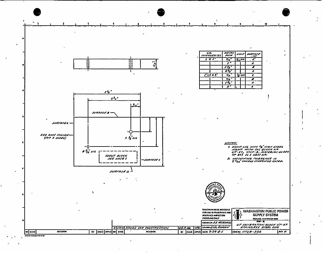
11
I St/g ~
Jicdlp+ ~
Fcd'u/Ff
dF's
SCII'Ffd/C
Dd ghlJF/f//Sk'rvriSums/
-0If fg wl
-0P i'd d/f f
Lrorur /ococ//
sFF udrc' —SvirFfFF c
c/dry c/c. srfer cup air// ud ///ywsrssc
af>P/P AT//rf/ CfC Ctc ddt'/4c/r d 7/ WA/P d ) Nrsg/fC gNlp Sod cc c uFfrut/
g AfN/k'/ud ocsA'CAID'J'Fg ~zqz u~au ~rara/I ///F>iree
SCIL'Ffds'4
AS I NO
+Oaa 14'
in/ usI/dd /os rouFr//udf/d/I/
TINS DIIAWWOIS WTtkotDIOIIINS W tttttiVCSANOWSSIWICS W&tCTNN~AOOIIANSDNAV
SNOWS ta CIfAtVfCNI
DSANN C ddt�/V
WASHlNGTON PUBUC POWERSUPPLY SYSTEMICIAAMkNAMSOIONNW
ur Ffc/war/dectcdcwc/F-drsr/I/uc s'is soFC curNO OA'Il
~AWW%0$WKI% W
StVNNN ~V CHAD AIIVD NO OATS At VIOON ~T cNSD AIIvo OATS t-dd.d.c owoND c/rd& Ass SSV CI

k
,I
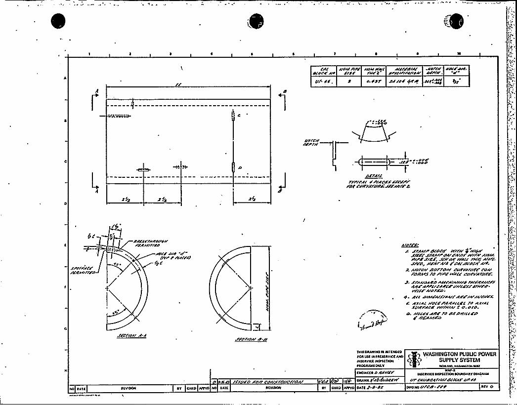
chic r/or//wrw ACLNIw~c mv/Fgw .AAI/c// ///ter/rrt.scnog Artt s/sr r///'c sr rcrrrrw//fax/ uuw'. dU/ SC. o.of/ JJ/Od +t'4 .CCC/~C
rr.rrSD 0
SF/r/// ~
t ~ ./Ed . op pr
~lA/Crerrr~c we~ods
rzrFr/'O//Fair//C///r/AFFrttO/F2
SrC/FUFF/S+tt////jo
0<g ~
(/t'/Td/F/)
dt/Frt4/r/ttOCrtfArwzgAr//F/t ttlI//OO/FS/
/. >/>~/pcfcoow rtr/w g mr~8/SF@'frrrt/POuFrt/DS'trr/rlr rt/CTT/Pr/td $/4'Fr FFVCLlt /TSCC //Ir~A/~Cwe, PZ~re~ C/ra/we//~>.
2 tlat/4'h'OI/Crrt/ CVrtN/Crtl'F COrf/SO//Af /O P PF rrVACC Qr'PVA/VdF.
J. S/rt C//AttgD &Ftl/ru/Arg////+AC/CFS8/TFdrrcrcv~c'dvucdss a/// w.
uo/dD.4. rt/C D/e/uPWF WF/e/urWZXr. WX/WC //OCFW~CCdC /O rtX/rlC
SVdFACd /rtr////ru r 0 OCP
4i, //OCt/S rt//F /O Crd'D///CC ZDS'/dd/T rt/dxt
ABC//OX/ A tl
/Ss rp po /'c'//cpu
TNLTDRANWOIS WTTIRITOSOR INfIN thTSTRVICf ANDWSTRVICfWltfCTNWtROCRANS ONLY
fNOWTTh OWaist'RANN
Sc//r Arms/i/
q WASHINGTON PUBLIC POWERSUPPLY SYSTEMAtOAANO.WANtttCIOttNRI
YINt.SWTTRVICf WltfCTRWSOVNDARYWACRAN
Vl' rrr//r//rf//Ott/C/Cr/C/A/Cr/ tr/t
NO OATS
r ~ a»RLVITION SY ONED AttVD NO OATf RTVISNW SY ONED AttVD DATf2 S SZ DWONO u/C Z-Zrr RTV 0
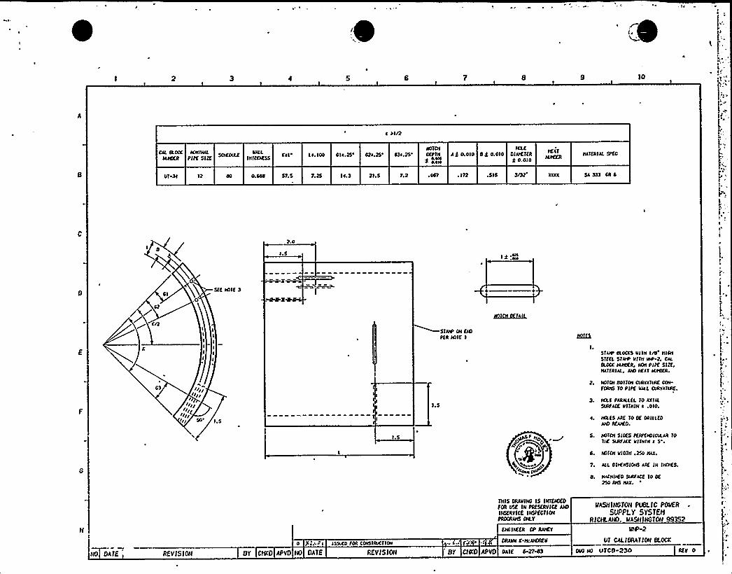
IO
I Sin
IKIIIHAL ~ VAILPIPE SI?E THICKIESS
Le.100 4IA.25e 42A.25'3t.25'OTCHDEPTH Aj O.OIO SA 0.010IAE
OIAtfTER
R 0.010HATERIAL SIC
ttT SI 12 57.5 IA.S 21 ~ 5 7,2 . I72 .5 I6
2.0
I.S) g .AAA
41Stf NOIt 3 + +
KnIIIII
I
tttlIlgn
Igt
I.S
I.S
STAte CN ttttPtR N)TE I
I.S
tto) iW
STAtP OLOCKS VITtt I/O'ICHSTEEL STAtP VTTH VtP-2. CuSOCK IAtttfR, NOH PIPE SIZE,HATTRIAL~ AIO HEAT AAttfR.
2. NOTCH OO ITCH CLIIVATARE COtt
FCRHS 10 PIPE VAIL OAIVATLIIE
3. tA.E PARuLEL TO AXIALSLIIFACE VITHIN A .010.
tAtS ARE '10 Of ORILLEOANT REAtttO.
S. NOTCH SIDES PEAPttOICALAR 10Ttf SLRfACK Vllvttt t S'.
6. NOICH VIOTH .250 HAX.
7. ALL OIIHHSIOttS ARE IH INCtfS
O. ItACttttf0 StttfACf 10 Of250 RHS HAX.
0 lttOKt ISSttEO fOR CCttSTRVCTIOH .et. f
THIS CRAVINS IS TNTEIEEDFOR IISE IN PRESERV ICE AIOINSERVICE IN5PECTIONPROCRAHS OILT
ENC ITEER CP RNCV
CRAHH L ttcAIOEH
IIASHIHGTOH PUBLIC POVER
SUPPLY SYSTBIRICIkAHD. IIASHIHGTOH 99352
IOS'-2
UT CALIBRATION BLOCK
NO DATE REVISIOH BY CHED APVD IIO DATE REVISIOH BY CHED APVD OAlf 6-27-03 CHO IAI LITC8 230 REV 0
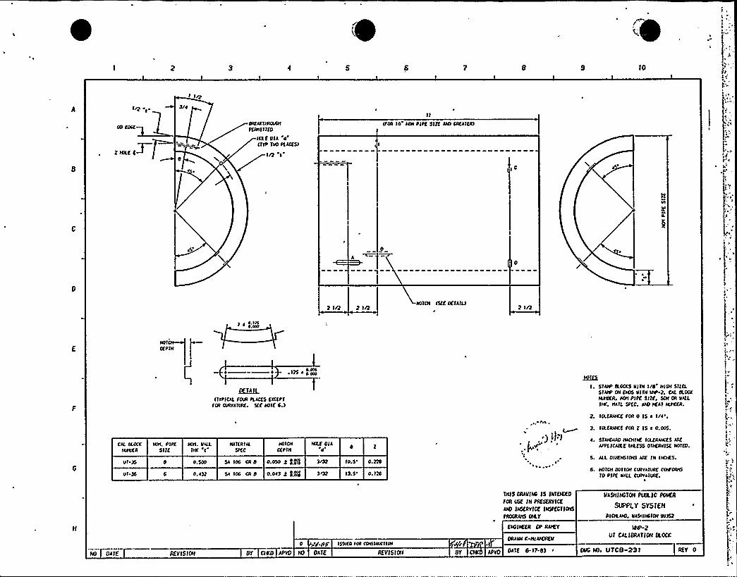
TO
I»
I tn
T W»C C~Q0
< ~
OtfAKftFKAtONPERtt1 Iffo
IKLE OIA dIffo TIO FLACESI
In I
IFOR lo ION PIPE Sllf uO CofATERI
IC
2ln 2 In NOTCH ISEE DETAILI2 In
DEPTH
+ + 125 A4 FOA
~AI'fft'ICALFOIAI PLACES EXCEPT
FOR ORVATIME. Sff IOTE 6.l
BHEXI. STAN'OCKS V1 ftl I/4'I@I STEEL
SIAtP ON EIOS VlfH VNP 2, CAL ROCKt4tOER. ION PIPE Sllf, SCH OR VILLTIAC, NATL 5PEC, AIO IEAI MIOER.
CAL ROCKMlfÃR
Ill.35
01-36
ISN. PIPESill
IKH. VAILTHK I
0. A32
ttATERIALSPEC
HofOIDEPTH
5A Io6 OR4 o.olo 4 kgSA 106 CR 4 O.OA3 g g.'gj
MlfOIAd
IO.S'.22813.5'. 126
2. 'IRERANCE FOR 8 IS a I/O'.
3. IRERAHCE FOR l IS a 0.005.
STAFOAFO HACNItf TOLERANCES AAE
APPLICARE IAAESS OTIERVISE NOIEO.
S. ALL DltfHSIONS AAE IH INCTES.
6. HO'ICN 401 ION CIKIVAII/AE COIFCFVtS
10 PIPE VALL CINVATIAIE.
»
AA
ND DA IE REVISIGN Bl'ITED APVD IO DATE REVISIOII
O Zg./IF; ISTAKO SOA CttdttKCTlot
BY
THIS CRAVIHC IS INTENIED
FDR IISE IH PRESERV ICE
uo INMRYIcf INspfCTTOIIS
PROCRANS CITY
EIOIIEER OP ROD
DRAVN K HouOREV
DATE 6-17-43 ~
NASNINGTCN PLBL)C POVER
SUPPLY SYSTEH
RICILAIO. VASNIMifOH43352
IOEt-2
VT CALIBRATTON ROCK
DMS IOt UTCB-23T REV 0
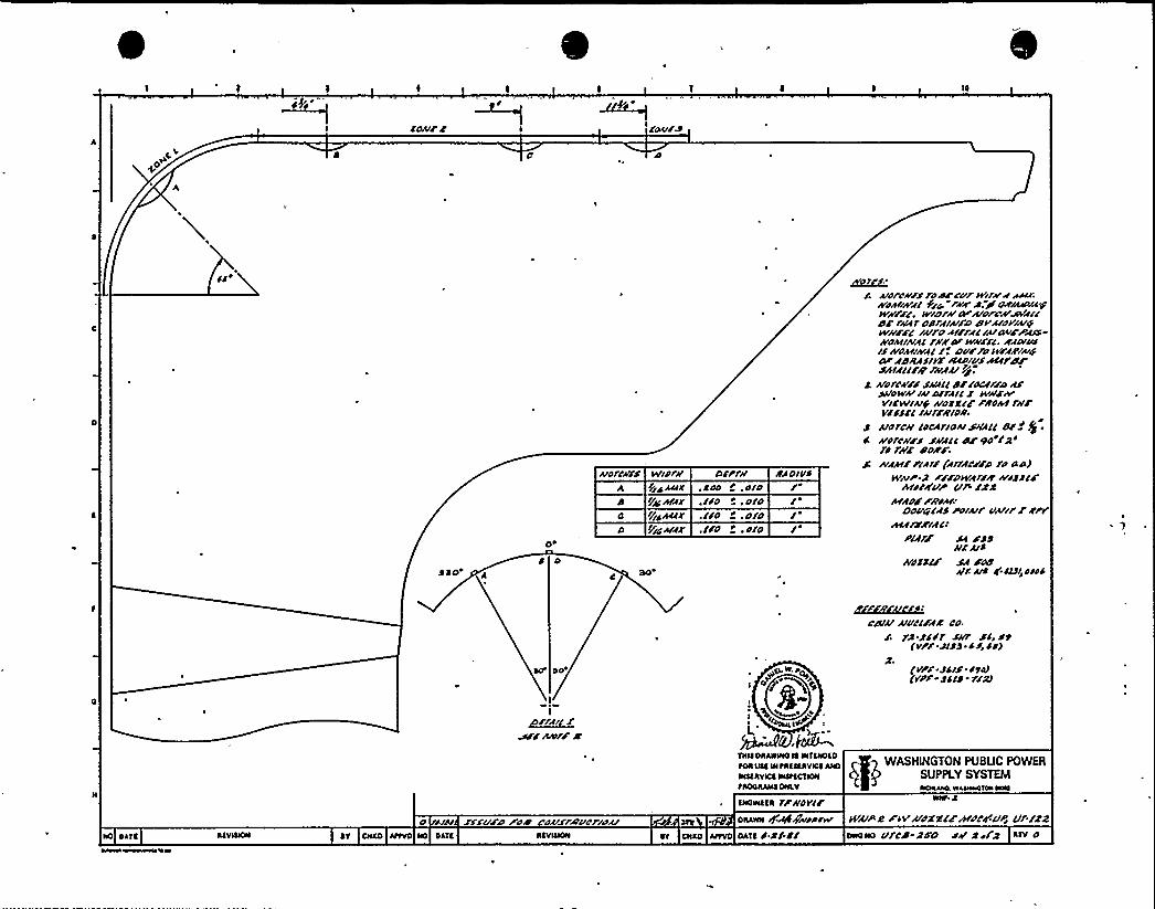
ICOIIF >
~C~O
SJO A
udrc//s
c
WldlifDIC ACIA
Ili/hrh/IrfidAC/<
PIC
Afil'Sdd
+ .did./Fd +, d/O.lid +,O/O.l/O r .d/O
SA DIIIS
/ ~
/ Afore'/SFOO/Cur IrifhrihACHKdhffrV/C fit r/A S. IS dO/AIAarhT/wwrrz. +roru cveorohrw~/cI//fhchr osraIAI/o c/ +oaredwii//c ihlro hr/roc iu/wry/s-Kdh/IAIACrh A'0 kVKFFC, /ACV/I/l/Kdh/IKAC/. DV/rd/V/i/IAIDOCar i/II/ASIA'CCPIVSraCCPCCIse~u/Ir r~~ii rfs.
1 kdfCA/S SKACC /I//d//f/rdAS/HIOIVAIIAId/fAIC/ WPJ'hrVICWIAlfKd/XCjFl/dht
fu/'ll/lczur/Ir/dl/.s udrcu cdchrlohisilhcc ca/'$.II Afdldu/S SAIACC cv aId'/a'd
rK/ /ldw:S: Afih/FPlhf/(INC//P fd Oa)
WAIP'rT PF/OIVraf/ir rV/1JC Jh/dch'up un /xs
II/hdj'I/dhffDDVigCAS Pdluf ClhlirINP
hcirÃslfclPlir/ Sa Sdgu/udI/dSS/j SA /dc
ACS ud a'/Csi did/
II~rr
mr IIidf//C
n II/i /saul poAI ohi/rhlucriohf
d'fKEZGI(CA(f:rcalu Aluccjic co.
/ fA'SC/7 SIIf S/r St(VPF i/St ~ dsr dd)
g.(VPF S/IS Ital(vpr- s/cs - r/s/
WASHINGTON PUBLIC POWERSUPPLY SYSTEM
tAOOHAHa OHAY HCHLAIKLWAHreHICHHHI
aHoIHaaa rrildr//OHAHH g~g~ddsw kfAIPC AVAI/XNjhrdcd'VP, C/FIZZ
HO 01Ta ~T CINO AtfVO HO OATa HT OHao AItvo oATa S S/.// oHoHo ci/'cit Q/D SAI sr/Q Aav o
4
I'a
~ w c
A1
.pV
l ]
4, ~ .~o ~
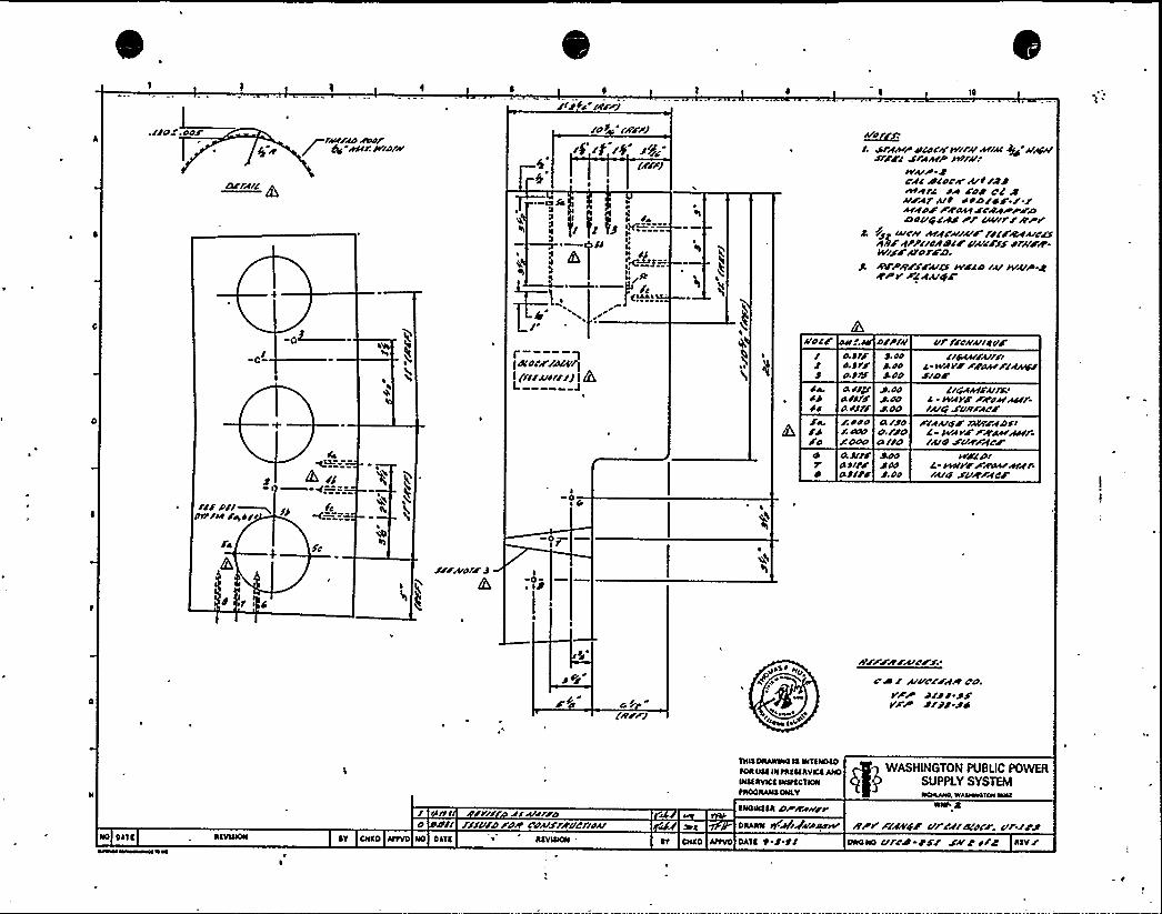
i/iJs /fry10
err~re'
I A4/47 /OAT$g «CJC/ W/O/S«
/d J /err/
I I ~
~-sa /A~
$ll Cgl 0 I $ gs A /e
/ P YS '~==--~ /A
"~~>.- ~
il li—J«s.
/. srfwrcr/ocr/wry m4/ J/s Assfs/JT/F/ S/«Ck/P /+/N"
WuP JCf/ 4/oc< u//J J~~ra s~ roJ C/ Su/AfAr~ S/D/S J / /egOF FFSsSCt SrfarrFDDOV/c/fS rr /rurr/rrrr
J /Jp Iucrr «ctfc«s«ruF f/SFso«luce/
rcpt/
HPP/rcfDSF vk/F// srr/F//-+rFFS/'OtFD
J, IOFPRFSFu/J WFSD ru /SruP jFrpr Fcfuyr
-«I— r--—-qJA'ocF/Jscr
~
I (rr/Alar//fI 4L
4s
Vo/C
/a,/J/o
a JT/o IT/a Jr/
o/prlrJ. JoJ. JoJ co
a //p'.oo4 SJT/ J. OOaS/f/ J.Od/ SOO CI //CS/ IAAr CS.//d/ddd 4I//da Jlr/a Jl/r jooa J/t/ J. oo
ur rrcrruladr//~ruhr
A-WfTF Fracr F/fisc//SIDF
/I/cfrrr/ul/'wfYF Frrssrssrfruse Sdr/F«ICF
F/auSF /ACTFfD/sC Wee'Fgac/«Acr/ruifsurfcF
ASFSPIA rscrvtFfcccr«c/f rlu«J svEFfcF
///e/r~pSTrct /~A/c /J fcOO
Isf Ig
/rruolF J I0
« IJ
J V/
(//FF/
«I>$ ~ ha
\ «««sc««s I\+
FFFF«CFk'N.'ss
/ uvccrfIv des.
I Fr JCJ/-JJIIFP J/J J.JS
WASHlNGTON PUSUC POWEASUPPLY SYSTEM
tAOOAANCONLY 1«cs««s«0. Is«awcsc«s NRI
NO DASC ACVICNN ~V CACO ANVD
/ lrc s'I// fsuslro0 /r I//V/DFdrr CNS/FIVC/IOu
NO DASC ACVIAION .
CNOWCCI DP/e«rrrDAANN 44if~ardw
CV ONTO AtSVO DATA ' / t/FIPII F/rJ4'Sf
Vf'/fr�/ICSCF.
Vf./rJDWONO Cl/C/I t// SF/ s/C
Date 12/14/81
Revision 1
12.0--MANAGEMENT PLAN
12.1 INTRODUCTION
This management plan describes the interfaces bet een the variouspersons involved in performance of the PSI examina ions. These
interfaces are described for the Supply System,Becht 1 constructionmanagement and PSI Contractor (Lambert-MacGill-Thomas [LMT)] per-sonnel, The LMT Management Plan, QA-26, which describes the LMT
site and home office organization, and the Supply System/LMT
interfaces, is incorporated herein by reference, with the actualdocument located at the end of this section.
This management plan is divided into sections based on activitiesas follows:
12.2
12.3
12.4
12.5
12.6
12.7
Site OrganizationPlanning and Scheduling
PSI Program Plan Revisions
Field Support Services
Reporting and Disposition of IndicationsTechnical Surveillance
Each of the above listed sections consists of a description of the
responsibilities and interfaces for that activity, and a corre-sponding organization chart to illustrate the lines of responsibi-lity and flow of information.
12-1
~24 2
Revision 2
12.2 Site Or anization
The LMT site organization is 'described in the LNT Management Plan,
Section X, Page 5. This organization is applicable to the volu-
metric and surface examinations.
Visual examinations of piping and component supports will be con-
ducted in conjunction with the Test and Startup Program as described
in Section 9.0, "Visual Program". The Supply System ISI Engineer
will work with the Test and Startup personnel to ensure that the
personnel involved in these examinations are properly trained and
the procedures and records generated satisfy the preservice
inspection requirements of ASNE Section XI, Subsection IWF from the
Summer 1978 Addenda insofaras practacal.
Visual examinations for evidence of leakage during hydrostatictests will be conducted as part of. the ASME Section III hydro-
static test program as allowed by Section XI.
Visual examinations of Class 1 pump, Valve bodies, and the RPV
interior will be or have been completed and documented by. Supply
System personnel.
The WPPSS ISI Engineer is responsible for the overall completion
of the Preservice Inspections as designated in Engineering Divi-sion Procedure EDP-9.3, "Conduct of Preservice Inspections" (see
Section 10.0, "Procedures). The Supply System ISI Field Coordi-
nator is, in turn, responsible for the implementation of the PSI
Program Plan, ice., for coordinating the field examination acti-vities. The Supply System ISI Field Coordinator provides day-to-
day technical direction to LNT. The LMT Site Supervisor, in turn,directs the activities of his examination teams and the data
control personnel, Bechtel Construction Management is responsible
for the scheduling of day-to-day work and for getting any needed
support services from the other crafts.
12-2
Date 11/14/80
Revision . 2
WNP-2 PSI PROGRAM PLAN
NOT USED
(Purposely left blank)
12-3
~4/8Revi sion 2
12.3 Pl annin and Schedul in
The planning and scheduling of the PSI examinations will be
conducted as follows. The organization of personnel involved inplanning and scheduling is illustrated on Figure 12.3-1 below.
Their primary source of scheduling information is the Supply
System ISI Fi'eld Coordinator. The Bechtel Construction Management
Field Coordinator receives input from the Supply System ProjectEngineer, Bechtel Planning and Scheduling, the Supply System ISI
Engineering, and Supply System ISI Field Coordinator. Weekly
scheduling meetings, with greater or less frequencies as needed,
will be the primary source of input to the ISI. Field Coordinator,
LMT Field Supervisor, and Bechtel Construction Management FieldCoordinator.
The Supply System has developed a computerized ISI Data Management
System which will ensure the completion of all examinations com-
mitted to in this Program Plan, This software will allow trackingof progress and aid in scheduling the remaining examinations
through to completion. The system is such that all committed
examinations are entered into the data bases as open items. The
data records for each examinations are then entered as they are
performed, closing out the individual examinations commitments one
at a time. Surveys of the data base can be quickly run to deter-mine remaining examinations as often as needed to assist in
planning and scheduling.
12-4
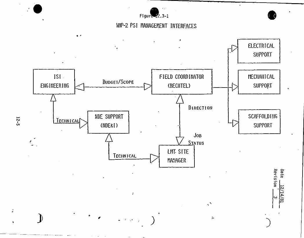
0Fulgur .3-1
RIP-2 PS I HIIIAGEHENT INTERFACES
ELECTRICAL
SUPPORT
ISI
EHG I tlEER IIIG8UDGET/SCOPE
FIELD CCORDINnTOR
(BI CIITL=L)
t1ECIIAflI CAL
SUVPOPT
TECNN1 CANDE SUPPORT
(HDEal)
TEC)1N1CAL
Joo
S TUS
LtlT- SITE
."I"IEGER
01AECT1 ON
SCAFFOI.D I llG
SUPPORT
Date 11/14/80Revi si on 1
PSI'Pro ram Plan Revisions
WPPSS ISI Engineering is responsible for the maintenance of the PSI
Program Plan, and will make changes to the plan as authorized inEngineering Division Procedure EDP-9.2, "Preparation of PSI Plan".The primary source of 'notification of need for Program Plan revisionis the WPPSS ISI Field Coordinator, who in turn receives input fromWPPSS Project Engineering, or the LMT Field Supervisor. Alternativeexaminati on techniques or methods may al so be proposed by the ISIField Coordinator. The responsible ISI Engineer will verify needfor any Program Plan change and coordinate the actual change withthe ISI Field Coordinator. Any unexaminable areas discovered in theabove process will be documented in the PSI Final Report by the ISIEngineer with appropriate justification which will constitute thebasis for request for relief from code requirements as required bythe NRC. Figure 12.4-1 illustrates the above described interfaces.
12-6
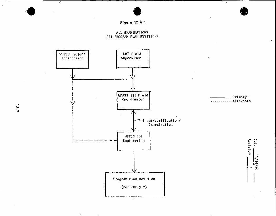
Figure 12.It-l
ALL EXAMINATIONSPSI PROGRAM PLAN REVISIONS
'WPPSS ProjectEngineering
LMT FieldSupervisor
l
I
I
VI
1
I
I
I
I
I
I
WPPSS ISI fieldCoordina tor
~Input/Veri fIcation/Coordination
WPPSS ISIEngineering
Primary .
——------ Alternate
OlD Ol( rt
Q
0D
COC)
Program Plan Revision
(Per EDP-9.2)
Date 12 14 81
Revision 2
12.5 Field Su ort Services
The Bechtel Construction Management organization (BCM) is respon-
sible for arranging field support services through the individualfield contractors as shown on Figure 12.5-1. The primary source
of requests for support services comes from the LMT Field
Supervisor/Foreman. As an alternative, the LMT Field Supervisor
may notify, the Supply System ISI Field Coordinator.
Field support services include such things as scaffolding,electric power hookup, water, compressed air or nitrogen, ladders,
support or insulation removal, cosmetic grinding, etc.
12-8
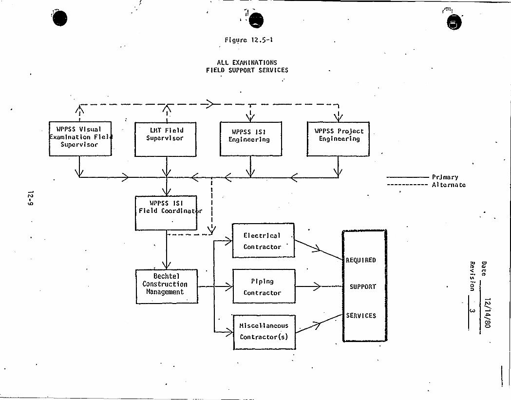
'Figurc 12.5-1
ALL EXAHIIIATIONSFIELD SUPPORT SERVICES
WPPSS Visual.xamination Fiel
Supervisor
LHT Fl eldSupervisor
WPPSS ISIEnglneerlng
WPPSS ProjectEngineering
Pr.imary----------- Alternate
WPPSS ISIField Coordlnat
I
r II
I
ElectricalCon tractor
BechtelConstruction
Management
P I pingCon tractor
REQUIRED
SUPPORT
XI C7S Glrt
8lh
oD
Hiscel.laneous
Contractor(s)
SERVICESCOCD
Date: ll/14/80Revision: 2
12.6 Re ortin and Dis osition of Indications
The LNT Field Supervisor is responsible for reporting all indications to
the Supply System I S I Field Coordinator in accordance with hi s
respective NDE procedures, and/or the contract with the Supply System.
The Field Coordinator will then verify the existence and status
(reportable/not reportable) of the indication,. and report the indication
to the Supply System ISI Engineer as required. The Field Coordinator
will notify ISI Engineering of any significant non-geometric indication
such that ISI Engineering will have the opportunity to witness the
verification of the existence and status of the indication. The Supply
System ISI Field Coordinator will keep a continuous written inventory of
reportable indications, and will forward copies of the inventory sheets
to the ISI Engineer on a weekly basis during the conduct of Preservice
Inspections.
Any reported indication which cannot be routinely dispositioned by the
Supply System ISI Engineering or the ISI Field Coodinator, will be
presented by the ISI Engineer to the Supply System Evaluation'eview
Team for action. Disposition of all indications reported to the
Evaluation Review Team will be documented on Evaluation Review Team
Reports per EDP-9-3, "Conduct of Preservice Examinations".
NOTE: A portion of the preservice examinations of piping systems willbe performed prior to final release of those systems by the
installation contractor to the owner. During that time period,
unacceptable surface conditions which are likely to be easilyremoved by cosmetic grinding will not be subject to Evaluation
Review Team scrutiny.
The ISI Field Coordinator will resolve unacceptable surface indications
detected by liquid penetrant, magnetic particle, or visual examination
methods by giving Construction Management a detailed description of the
unacceptable condition. Construction Management transmits this
12-10
-Date: 11/14/80
Revision: 0
information to the appropriate installation contractor who wi 11 repairor rework the component or weld as necessary. If it is deemed
appropriate to do so, a non-conformance report (NCR) will be initiatedby Construction Management using their established HCR system.
12-10a
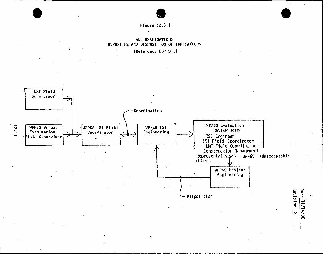
Fi gure 12.6-1
ALL EXANINAT I ONS
REPORT I NG AND D I S POS I T I ON OF I ND I CAT I ONS
(ReFerence EDP-9.3)
LMT FieldSupervisor
Coordina t ion
WPPSS VisualExamination
.ield Supervisor
WPPSS ISI FieldCoordinator
WPPSS ISIEngineering
WPPSS EvaluationReview Team
ISI EngineerISI Field Coord1nator
LNT Field CoordinatorConstruction Management
Representativ WP-651 ~UnacceptableOthers
WPPSS ProjectEngineering
DispositionO
St0
Date: l2/l4/80Revisi on: 2
12.7 Technical Surveillance
The Supply System ISI Engineering is responsible for technicalsurveillance of the overall PSI examination effort to ensure compli ancewith the requirements of the PSI Program Plan. Technical surveillanceof the volumetric and surface NDE activities on a day-to-day basis willbe accomplished by the ISI Field Coordinator with the aid of a TechnicalSurveillance Team as required depending on the number of examinationteams present on-site and other such factors. The TechnicalSurveill,ance Team will be under the direction of the Field Coordinator,and may consist of personnel from either the ISI Engineering orGeneration Services organizations. Figure 12.7-1 illustrates the aboveinterfaces for volumetric and surface examinations performed by LHT.
The Technical Surveillance Personnel will complete Daily Log Sheets todocument their surveillance. Figure 12.7-3 is a typical Daily LogSheet. The Log sheets will be returned to the Field Coordinator, whowill maintain them in a chronological file on a system basis. The FieldCoordinator is responsible for assuring that any follow-up action notedon the log sheets is taken, and will confirm that action by signing and
dating the log sheet.
Figures 12.7-1 'also illustrates the technical surveillanceperformed by the HPPSS Authorized Nuclear Inspector.
l2-12
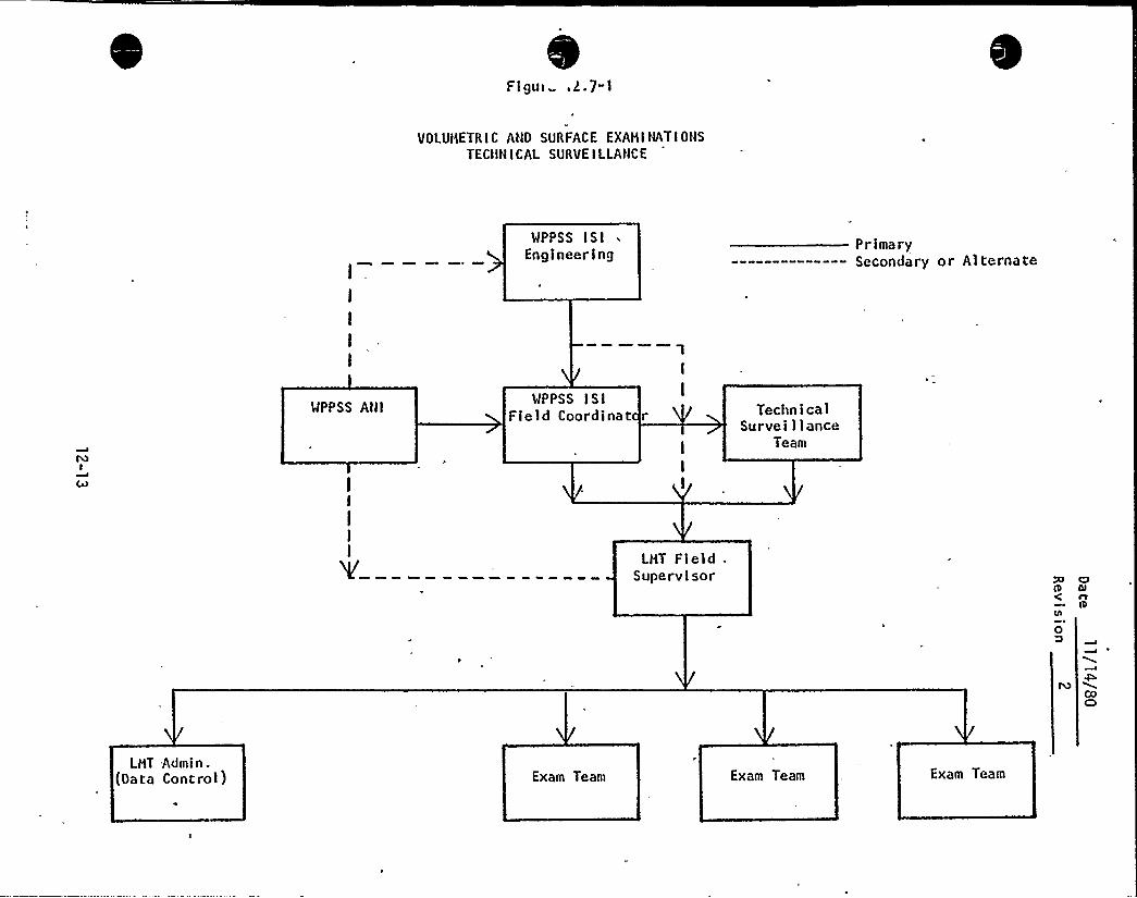
Flgui .2.7-1
VOLUMETRIC AND SURFACE EXAMINATIONSTECIIN ICAL SURVEILLANCE
WPPSS ISIEngineering
P r ima ry----—-—----- Secondary or Alternate
WPPSS AHIWPPSS ISI
Field Coordinat r TechnicalSurveillance
Team
LMT fieldSupervisor O
0 Qrt0
COC)
LMT Admin.(Data Control) Exam Team Exam Team Exam Team

Date 12/14 81
Revision
NOT USED
(Purposely Left Blank)
12-14
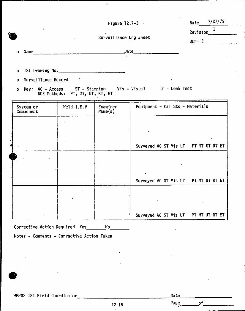
o Name
Figure 12.7-3
Surveillance Log Sheet
Date
Date 7/27/79
IRevision
NNP- 2
o ISI Drawing No.
o Surveillance Record
o Key: AC - Access ST - Stamping Vis - VisualNDE Methods: PT, MT, UT, RT, ET
LT - Leak T'est
System orComponent
Meld I.D.A'xaminerName(s)
Equipment - Cal Std - Materials
Surveyed AC ST Vis LT PT MT UT RT ET
Surveyed AC ST Vis LT PT MT UT RT ET
Surveyed AC ST Vis LT PT MT UT RT ET
Corrective Action Required Yes No
Notes - Comments - Corrective Action Taken
HPPSS ISI Field Coordinator
12-15
Date
Page of

i
fi
I * I ~
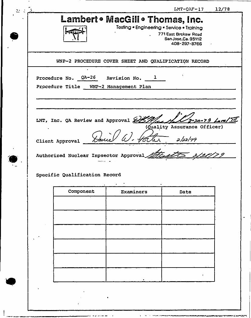
LNT-QAF-17 12/78
ILambert~ MacGIII Tlhornas, Inc.Mi" Tesfing ~ Engineering ~ Service ~ Training
771 East Brokaw RoadSan Jose.Ca. 95112
408-297-8766
WNP-2 PROCEDURE COVER SHEET AND QUALIFICATION RECORD
Procedure No. QA 2< Revision No.
Procedure Title WNP-2 Mana ement Plan
LMT, Inc. QA Review and Approval{ uality Assurance Officer)
Client Approval ~/~z/~Z
Authorized Nuclear Inpsector Approval
Specific Qualification Record
Component Examiners Date
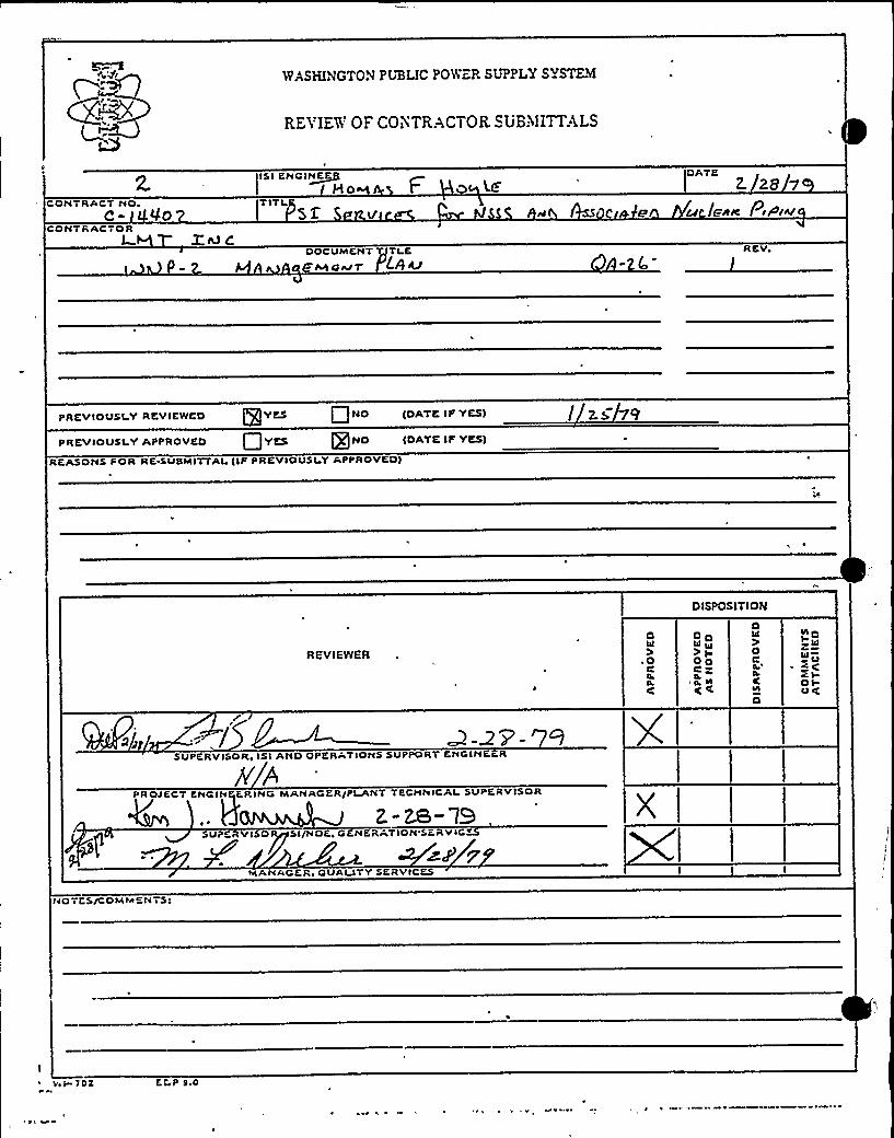
WASHINGTON PIiBLIC PO)Vc.R SIJPPLY SYSTEM
REVIEW OF CONTRACTOR SUB,"IIITTALS
CONTRACT NQc- VoCONTRACTOR
ZR) C
IS I ENGINEHow tTITI
52 v
DOCUMENT TI E
P MO AJ 7 LQ IL/
DATE28 7
e u eR~ P.P.V
RCV
PREVIOUSI Y REVIEWED @YES Q NO {DATE!F YES)
PREVIOUSLY APPROVED @YES @NO IDATKIF YES)
REASONS FOR RK SUSMITTALIIF PREVIOUSLY APPROVED)
DISPOSITION
REVIEWER
4
OC
(
ODhl I0
OQC»
((
0iC)DC
(IA
O
NDI2I0»U~C (OlU(
SUPERVISOR, ISI AND OPERATIONS SUPPORT CNGINEER
jY ~PROJECT CNGINfjK.RING MANAGER/PLANTTKCHNICAI SUPERVISOR
~~ ~z-M" l3
SUPCRV ISO Sl/NOC, GCNKRATIQN'SCRVIC~
MANAGCRe QUAI ITY SKRV ICKS
NOTE SIC QM
MENTS'o
I 70K COP 9.0
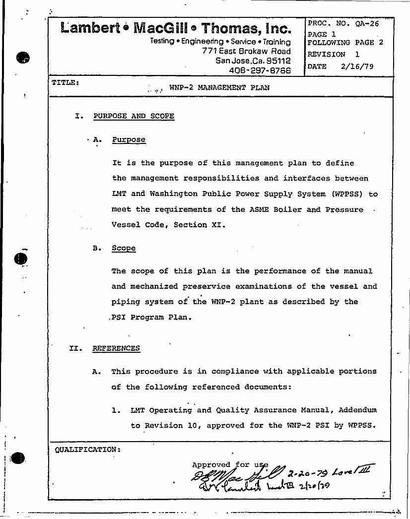
Lambel'lt o Msea illl 7lhomas, Inc.Testing ~ Engineering ~ Service ~ Training
771 East Brokaw RoadSan Jose,Ca. 95112
408-297-8766
PROC. NO. QA-26PAGE 1FOLLOWING PAGE 2
REVISION 1
DATE 2/16/79
TITLE:WNP-2 MANAGEMENT PLAN
I. PURPOSE AND SCOPE
A. ~Pur oee
It is the purpose of this management plan to definethe management responsibilities and interfaces between
LMT and Washington Public Power Supply System (WPPSS) tomeet the requirements of the ASME Boiler and Pressure
Vessel Code, Section XX.
B. ~Bco e
The scope of this plan is the performance of the manual
and mechanized preservice examinations of the vessel and
piping system of the WNP-2 plant as described by the
.PSI Program Plan.
XI~ REFERENCES
A. This procedure is in compliance with applicable portions
of the following referenced documents:
1. LMT Operating and Quality Assurance Manual, Addendum
to Revision 10, approved for the NNP-2 PSI by WPPSS.
QUALIFICATION:
Approved for u
~W >(in(We
Lambel'to Macoillo Thomas, lnc.Testing ~ Engineering ~ Service ~ Training
771 East Brokaw RoadSan Jose,ca. S5112
408-297-8766
PROC. NO. QA-26
PAGE 2FOLLOWING PAGE 3
REVISION 1
DATE 2 /16/79
II. A. 2. WNP-2 PSI Program Plan
3. ASME .Boiler and Pressure Vessel Code, Section XI,
1974 edition, addenda through Summer 1975.
IIX. DEFINXTIONS
None
XV. RESPONSIBILITY
The Technical Manager, LMT, Inc., is responsible for the
generation and control of this procedure and shall so
indicate by a dated signature on the procedure cover sheet.
V. PROCEDURE QUALIFICATION
The management plan shall be considered qualified upon
acceptance by WPPSS.
VI. PERSONNEL REQUIREMENTS
The management plan sets forth the organizational responsi-
bilities and interfaces for LMT. It shall be observed by
all LMT personnel.
Lsrtrmbetrt o MacQilllI TiIcinas, Inc.Testing ~ Engineering i Service ~ Training
771 East Brokaw RoadSan Jose,Ca. 95112
408-297-8766
PROC. NO. QA-26
PAGE 3FOLLOWING PAGE 4
REVISION 1
DATE 2/16/79
VIX. EQUIPMENT REQUIREMENTS
There shall be appropriate office space, and equipment and
storage space for the implementation of this procedure.
A. Office space shall be located in a trailer or similarfacility in or adjacent to plant buildings and shall be
provided with desks, chairs and 'outside and plant tele- .
phone system connections.
B. A wire-enclosed secure area adjacent to the office space
shall be provided for the storage of equipment and
materials to be used in the examinations.
VIII'REPARATION
A. Documentation
The following documentation shall be submitted to WPPSS
for review and approval before beginning examinations:
l. NDE Procedures
2. LMT Forms
3. LMT QA Manual (controlled copies upon approval by
WPPSS)
4. LMT Weld Marking Procedure
5. LMT Document Control Procedure
Lambert o MacG illo Yhomas, Inc.Testing ~ Engineering ~ Service ~ Training
771 East Brokaw RoadSan Jose, Ca. 95112
408-297-8766
PROC. NO. QA-26
PAGE 4FOLLOWING PAGE 5
REVISION 1
DATE 2/16/79
VIII. B. Ph sical Pre aration
The following physical preparation requirements shall be
reviewed by WPPSS before beginning examinations:
l. OSHA requirements
2. Material preparation
3. Services
IX. LIMITATIONS
This management plan has been prepared for the PSI of the
WNP-2 plant of WPPSS and is not necessarily applicable to
other situations.
X. LMT ORGANIZATION
A. Internal LMT Or anization
See Figure l.
B. LMT Site Or anization
1. See Figure 2.
2. It is the intention of this plan that the position
of LMT Field Superviso'r be occupied by a Company
Testing ~ Engineering ~ Service ~ Training771 East Brokaw Road
San Jose,Ca. 95112408-297-8766
PROC. NO. QA-26
PAGE 5FOLLOWING PAGE 6
REVISION
DATE 2/l6/7 9
X. B. 2. Officer, particularly at points in the job where
levels of effort may be changing and during the
performance of the mechanized examinations.
a) During periods of low and stable job effortduring the manual examination, requiring no more
than two ultrasonic teams, plus helpers, the
Field Supervisor, with the concurrence of the
WPPSS ISI Field Coordinator, may leave the siteafter designating an LMT acting supervisor.
XI. INTERFACES
A. LMT/WPPSS Preservice Inspection interfaces will be as
shown in Figure 3.
B. Transmittals will be addressed to Mr. A. D. Kohler and
will consist of two copies, with attachments, forMr. Kohler and four copies, with attachments, forMr. T. F. Hoyle.
l. LMT letters shall be. identified according to the
following, scheme:
a) LMWP-2-78 (year)-XXX (sequence number, beginning
Lambert o Macallll o Thomas, Inc.Testing ~ Engineering ~ Service ~ Training
771 East Srokaw RoadSan Jose.Ca. 95112
408-297-8766
PROC. NO. QA-26
pAGE 6FOLLOWING PAGE 7
REVISION
DATE 2/1 6/7 9
XI. B. 2. WPPSS letters will be identified WPLM-2-78 (year)
XZZ (sequence number, beginning with -001).
C.. LMT's billing will be submitted to Mr. A. D. Kohler and.
marked for attention to Mr. R. L. Winters/M. E. Reed.
1. Billing will include LMT invoices and backup docu-
mentation such as Purchase Orders, Expense Accounts,
etc.
2. Each billing will include WPPSS "Contractor's Request
for Payment" forms (Pigures 4 and 5).
XII. CONTROLS
A. Quality Assurance shall be according to that revision of
the controlled LMT Operating and Quality Assurance
Manual approved by WPPSS.
B. Personnel policy shall be controlled according to the
LMT Company Policy (Attachment 1).
XIII. „ RECORDS
Job related documentation will be maintained at the site
in a satellite job file organized according to LMT procedure
QA-28, "Document Control for the WNP-2 Preservice Inspection."
Lsmbel't o MscGilllo 7hornss, Irlc.Testing ~ Engineering ~ Service ~ Training
771 East 8rokaw RoadSan Jose.Ca. 95112
408-297-8768
PROC. NO. QA-26
PAGE 7.FOLLOWING PAGE 8
REVISION 1
DATE 2/16/79
XZV. REVIEW
l. The WPPSS ISZ Field Coordinator and the Authorized Nuclear
Inspector shall have full access to examination data.
2. The LMT Site Supervisor will prepare a weekly report of
job activities as directed by WPPSS, which shall include
as a minimum:
a) Manhours expended
b) Manhours estimated
c) Examinations completed
d) Examinations remaining
e) Schedule analysis
f) Summary of indications
g) Accessibility problems
XV. STORAGE AND DISTRIBUTION
A. Field storage facilities shall provide a safe storage
area. Access to the files shall be limited to the LMT
Field Supervisor, his designated representatives, the
WPPSS ISZ Field Coordinator, and the Authorized Nuclear
Inspector.
B. Examination documentation shall become the property of
WPPSS upon sign-off by the WPPSS ZSI Field Coordinator.
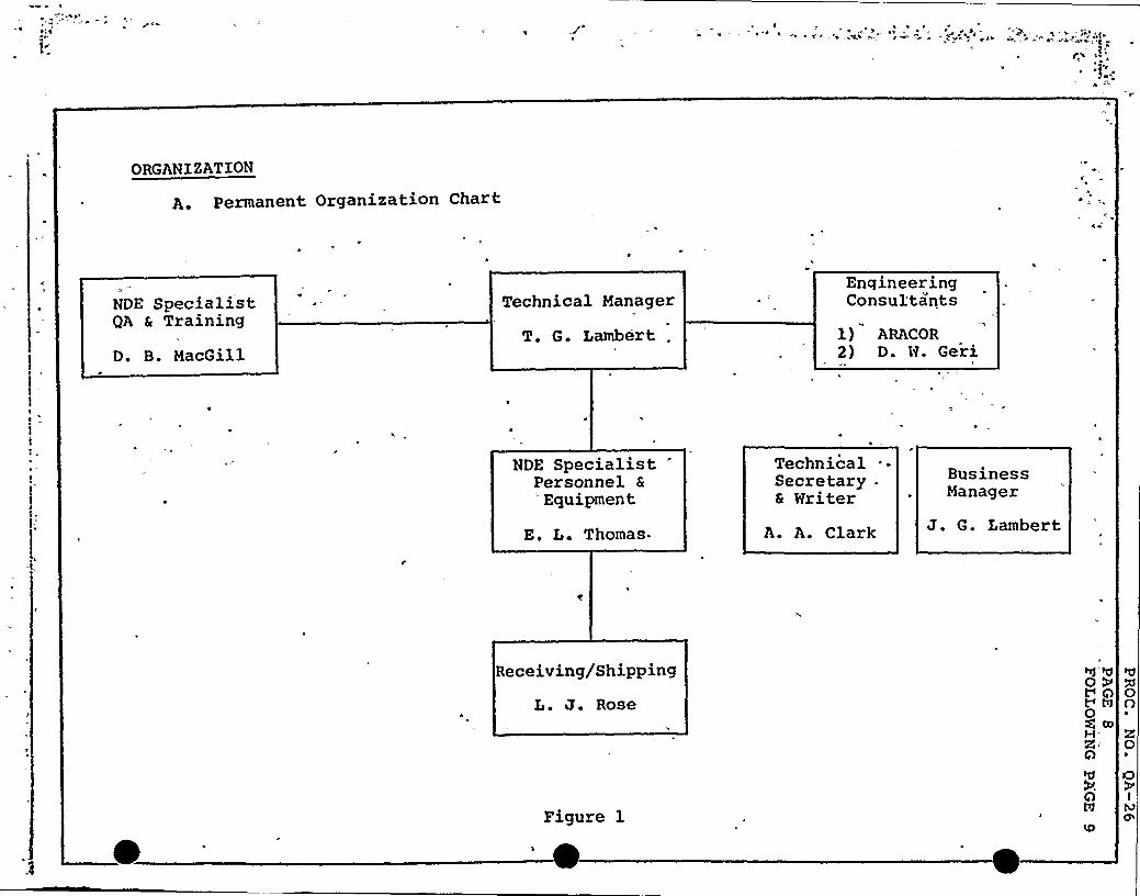
ylI
ql — a~ ~
r .!:.C
~ 4
A
ORGANIZATION
A. Permanent Organization Chart
NDE SpecialistQA & Training
D. B. MacGill
Technical Manager
T. G. Lambert .
h
EngineeringConsultants
1) ARACOR2) D. W. Geri
NDE SpecialistPersonnel &
Equipment
E. L. Thomas.
TechnicalSecretary .
& Writer
A. A. Clark
BustinessManager
J. G. Lambert
Receiving/Shipping
L. J. Rose
Figure l
OP0 A0g mH.
A
A
A0O
0
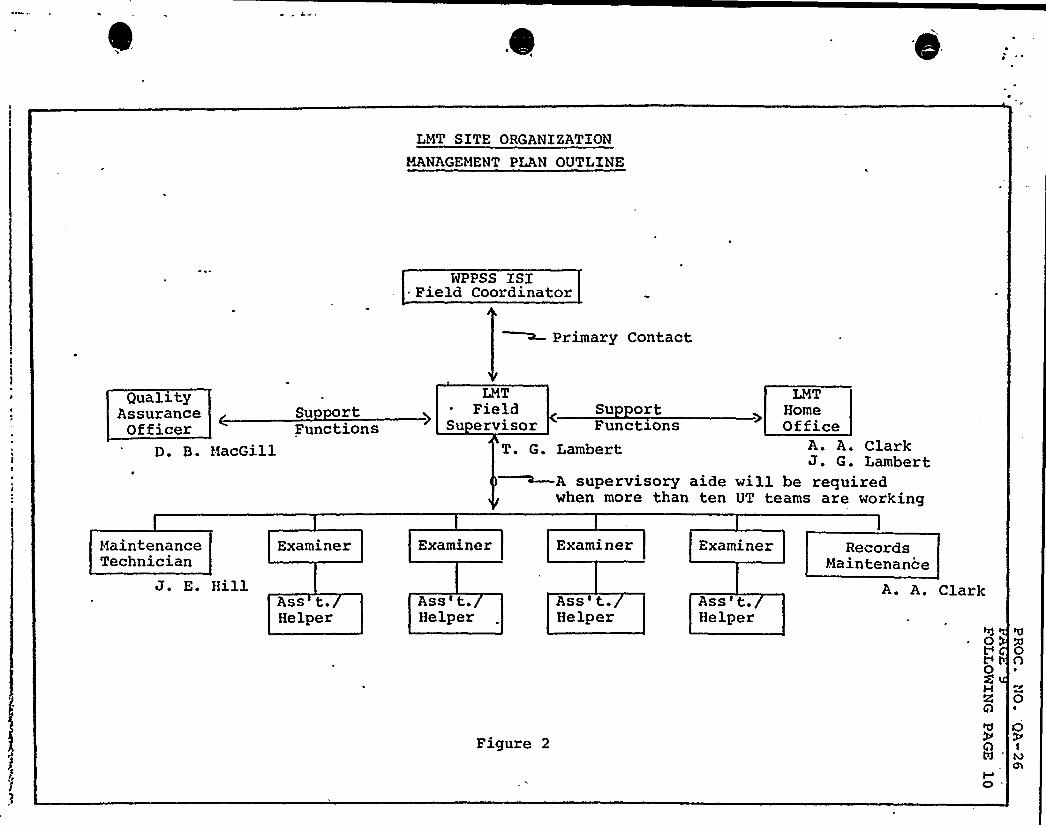
LMT SITE ORGANIZATION
MANAGEMENT PLAN OUTLINE
NPPSS ISI- Field Coordinator~ Primary Contact
QualityAssuranceOfficer
Su rtFunctions
LMT~ FieldSu ervisor
Su ortFunctions
LMTHomeOffice
D. B. MacGill T. G. Lambert~A supervisory aidewhen more than ten
A. A. ClarkJ. G. Lambert
will be requiredUT teams are working
MaintenanceTechnician
J. E. Hill
Examiner
Ass t.Helper
Examiner
Ass'.Helper
Examiner
Ass'Helper
Figure 2
Examiner
Ass't.Helper
RecordsMaintenance
A. A. Clark
hf0Vh0M
A
A
'd
0A
0
OIM
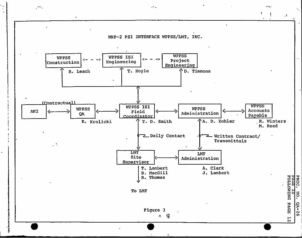
WNP-2 PSI INTERFACE WPPSS/LMTP INC.
WPPSSConstruction
rR. Leach
WPPSS ISIEngineering
T. Hoyle
WPPSSProject
En ineerinD. Timmons
ontractuANI C
WPPSSQA
R. Krolicki
WPPSS ISIField
T. D. Smooth A. D. Kohler R. WintersM. Reed
WPPSS
) AccountsAdministration Payable
~Daily Contact Written Contract/Transmittals
LMTSite
Su ervisorT. LambertD. MacGillB. Thomas
To LMT
LMTAdministration
A. ClarkJ. Lambert
0C0H
Figure 3
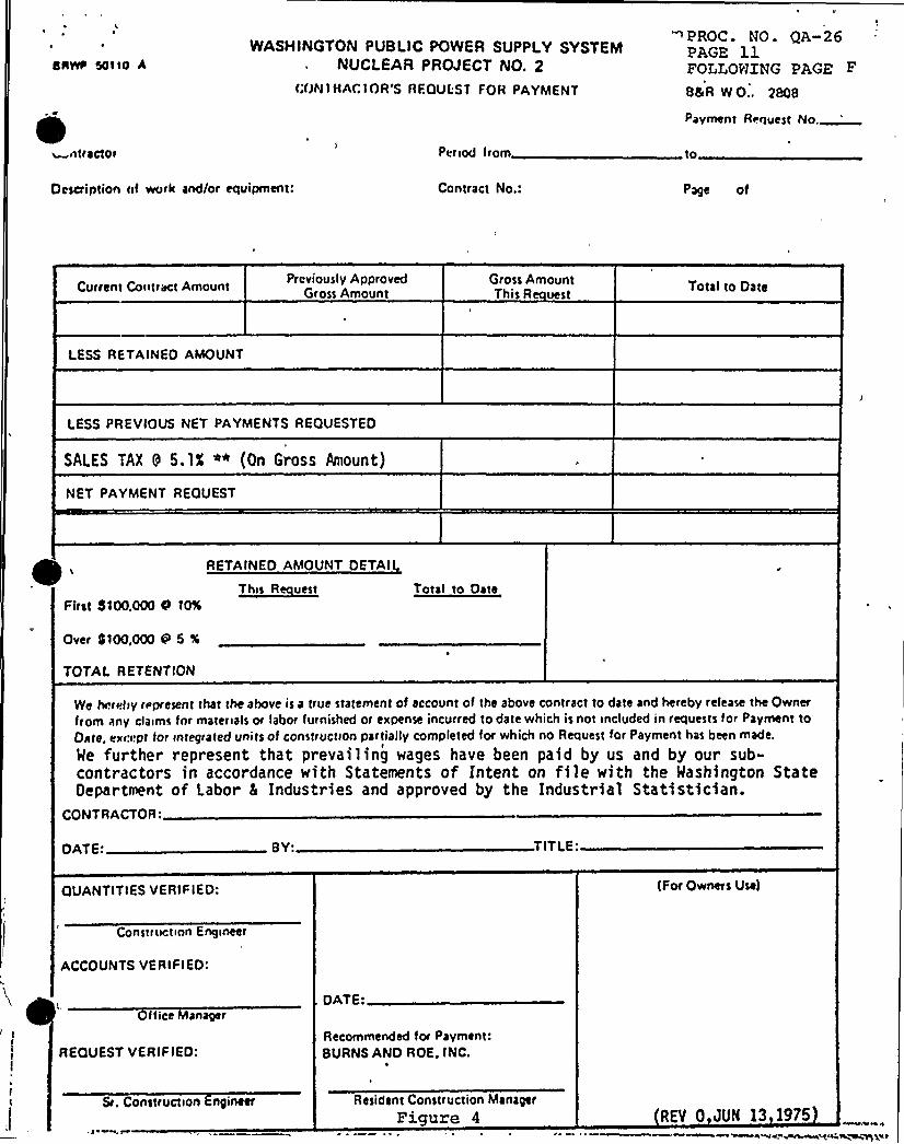
estsvp sotto *WASHINGTON PUBLIC POWER SUPPLY SYSTEM
NUCLEAR PRCVECT NO, 2CONIHACIOR'S RFQUEST FOR PAYMENT
PROC. NO. QA-26PAGE 11FOLLOWING PAGE F
8&R WO.. 2808
~ntracto<
Description nf work and/or equipment:
Period from
Contract No.:
Pavl<ient Request No.
to
Page of
Current Coiitract Amount Previously ApprovedGross Amount
Gross AmountThis R vest
Total to Date
LESS RETAINED AMOUNT
LESS PRFVIOUS NET PAYMENTS REQUESTED
SALES TAX 9 5.1X ** (On Gross Amount)
NET PAYMENT REQUEST
RETAINED AMOUNT DETAI
T~hn R vestFirst St00,000 Cs t0%
Total to Date
Over IItoo,ooo tii 5 %,
TOTAL RETENTION
We hn<vfiy represent that the above is a true statement of account of the above contract to date and hereby release the Owner
from any claims Ior materials or labor furnished or expense incurred to date which is not included in requests for Payment toD<ite, ex«: ipt Ior integrated units of construction partially completed for which no Request for Payment has been made.
Me further represent that prevailing wages have been paid by us and by our sub-contractors in accordance with Statements of Intent on file with the Washington StateDepartment of Labor 5 Industries and approved by the Industrial Statistician.
CONTRACTOR:DATE'Y:TITLE'UANTITIES
VERIF IED: (For Owners Use)
Construction Engineer
ACCOUNTS VERIFIED:
I tice anager
REQUEST VERIFIEO:l
I
DATE:
Recominended for Payment:BURNS AND ROE. INC.
Sr. Construction ngineer Resident Construction Manager
Figure 4 REV 0 JUN 13 1975
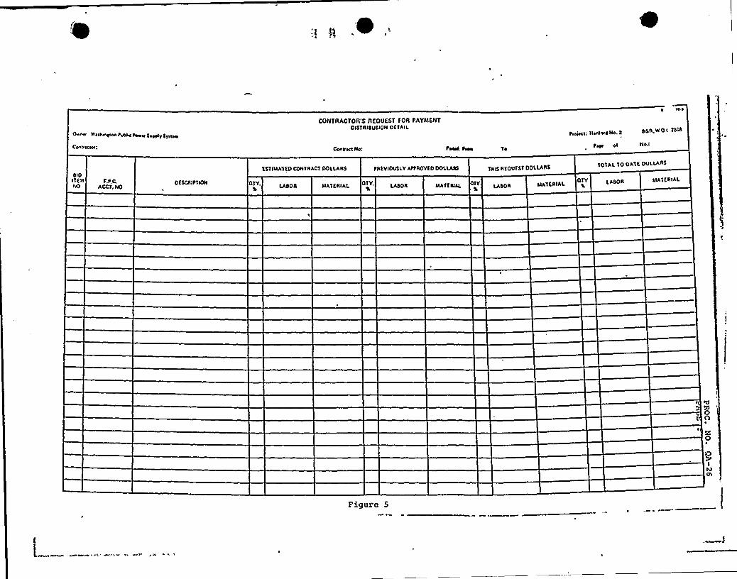
~ ~ Q
Iggg~g~~~~8Ãg~m~I~~i~~a~~+1~@RIimm~~~r~~a~~aa~~~
~~ a~ E~~~~a~~R~~a~~
~~~a~ x~~aa~~~ a~ s~a~~ a~~ 8~~I»r~~a~~a~~~a~~~~a~~a~~aa~~a~~a~~a~~aa»
~~~a~~a~~ Ia~ a~~i~~I ~a ~I~~~~a~~a ~
~~~a~~a
~~~a~ ~a~~a~~~~ a~ E~ ~r~~a~~a~~a~~~~~~a~~a~~~a~~
'~~a~~a~a~~a~~a~ I~~
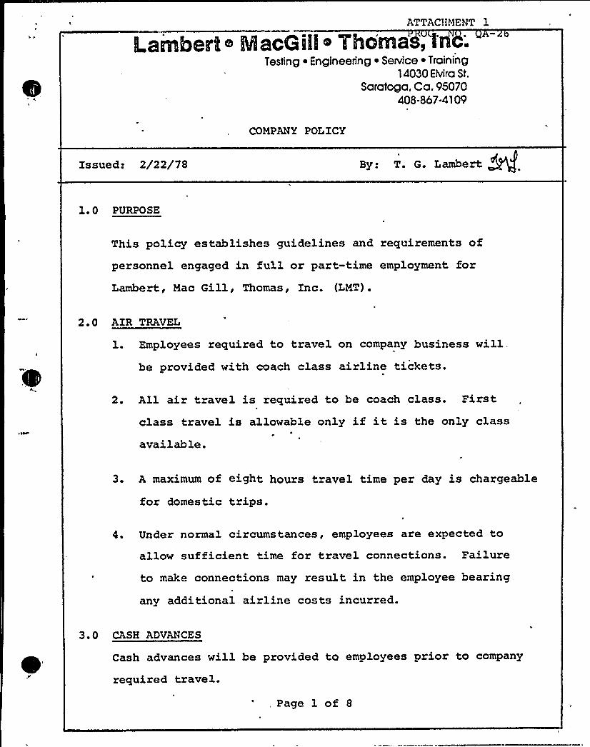
ATTAC!iMENT 1
ILambemt 6 MacGili o Yhc'ma,Testing ~ Engineering ~ Service ~ Training
14030 Elvira St.
Saratoga. Ca. 95070408-867-4109
COMPANY POLZCY
Zssued: 2/22/78 By: T. G. Lambert.
1. 0 PURPOSE
This policy establishes guidelines and requirements ofpersonnel engaged in full or part-time employment forLambert, Mac Gill, Thomas, Znc. (LMT).
2 ' AZR TRAVEL
l. Employees required to travel on company business will,be provided with coach class airline tickets.
2. All air travel is required to be coach class. Firstclass travel is allowable only if it is the only class
available.
3. A maximum of eight hours travel time per day is chargeable
for domestic trips.
4. Under normal circumstances, employees are expected to
allow suf ficient time for travel connections. Failure
to make connections may result in the employee bearing
any additional airline costs incurred.
3.0 CASH ADVANCES
Cash advances will be provided to employees prior to company
required travel.
Page- 1 of 8
l amberto MacGill o 7homas, Inc.Testing ~ Engineering ~ Service ~ Training
14030 Elvira St.
Saratoga. Ca. 95070408-867-4109
LMT may not be held responsible for loss or theft of monies
advanced to an employee.
4.0 TZME CARDS
1. Time cards are to be submitted on a weekly basis (see
sample attached) .
2. For time keeping purposes, time shall be submitted from
Monday through Saturday of each week.
3. For employees working on field assignment, all time
cards must have the approval of the responsible LMT
Field Supervisor.
5. 0 EXPENSE ACCOUNTS
l. Expense accounts shall be submitted upon completion of
a job or assigned task. Zn the event of job is of longer
duration than one week, expense accounts shall be sub-
mitted on a weekly basis, in conjunction with time cards.
2. Complete receipts must accompany all expense accounts
including airline tickets, gasoline, job supplies, enter-
tainment, motel, phone, and laundry.
3. Zn the event an employee incurs any entertainment expense,
receipts must. accompany the expense account for each
occasion. Receipts shall reflect what expense covered,
where expense was incurred, names of attendees, and the
amount of'expense. Zf entertainment expense includes
Page 2 of 8
lLarnberto MacGiW ~ rhorYlss Inc.Testing ~ Engineering i Service ~ Training
14030 Elvira St.
Saratoga, Ca. 95070408-867-4109
employee meals employee shall note difference in the
total day's meal expense.
4. For field assignments, all expense accounts must have the
signed approval of the responsible LMT Field Supervisor.
6 0 TRAVEL EXPENSES
A. Meals
1. Maximum allowable charges for meals shall be $ 18.00
per day (on overnight trips, where employee is unable
to return home) .
2. Meals shall not be reimbursable when employees can
return home at night without inconvenience.
B. ~Lod in
1. Lodging in most cases will be prearranged by LMT
management.
2. Accomodations in excess of $ 20.00 per day must have
prior approval of LMT management.
3. Lodging expenses shall be limited to room, telephone
expense, and laundry (when applicable) .
1. Telephone charges to employee ' home will be reimbursed
equivalent to one three-minute station-to-station
Page 3 of 8
lLsrnbert o MacGilt o Thorrias, Inc.Testing ~ Engineering ~ Service ~ Training
14030 Elvira St.Saratoga. Ca. 95070
408-867-4109
operator assisted call per day. Evidence of expense must
accompany expense account.
2. All company calls to the LMT Cupertino office shallbe collect (include charge number when applicable).
D. L~auad
1. Laundry charges shall not be paid by LMT for tripsless than four days duration.
2. For trips in excess of four days duration, a $ 10.00
maximum laundry charge per week will be reimbursed
by LMT.
E. Automobiles
1. A .15C per mile rate shall be paid by LMT for business
trips in personal cars, when company vehicles are not
available and on prior approval by LMT management.
2. In the event an employee elects to drive a personal
car to a job site rather than fly, reimbursement willbe made on the basis of airfare or mileage, whichever
is less. Travel time will be paid on the basis oftotal air travel time required.
3. A valid driver's license shall be required for any
employee operating a company vehicle. LMT is not
responsible for moving violations an employee receives
while operating a company vehicle.Page 4 of 8
ILamberIl o MaeGilll Thomas, Inc.Testing ~ Engineering ~ Service ~ Training
14030 Elvira St.
Saratoga. Ca. 95070408-867-4109
4. Company vehicles are not to be loaned to anyone other
than employees of LNT, Inc.
5. For field assignments, rental cars will in most cases
be prearranged by LNT management.
6. LNT employees are instructed to decline insurance on
all rental car agreements. In the event 'an employee
elects to retain additional insurance, it shall be at
the employee's expense.
7. 0 PAY PERIODS
l, Payroll checks will be issued on the last working day ofeach month.
2. Time cards and expense accounts covering each )ob are
required prior to paycheck issuance.
3. All hours worked will be submitted on a w~eekl basis by
the LNT Field Supervisor. It is the responsibility ofthe individual employee to submit time cards and expense
accounts to the Supervisor for submission to the Business
Manager.
4. When a field assignment prevents submittal of expense
accounts and time cards to the home office by the last
working day of the month, the responsible Field Supervisor
shall "call-in" time and expenses to the Business Manager.
Page 5 of 8
ILambert ~ MacGilio 7hornas, Ilnc.Testing ~ Engineering ~ SeNice ~ Training
14030 EMro St.
Saratoga, Ca. 95070408-867<109
Such call-in shall-be made in sufficient time that payrollchecks may be issued.
8. 0 VZS ZON EXAMINATIONS
Reimbursement for industrial vision examinations will be made
by LMT via expense account up to $ 15.00 maximum.
9.0 GENERAL
Employees may be held responsible for loss or damage to
equipment or tools borrowed from a client.
10 ' TERMINATZONS
Any employee. reporting for work under the influence of alcohol
or drugs shall be cause for either suspension without pay forthat day or termination, at the discretion of LMT management.
Employees terminated in the field by LMT will be returned to
their home base to LMT expense. Employees who terminate
without LMT authorization will be required to pay their own
travel and living expenses from the time of termination.
11 ~ 0 EXCEPTIONS
Any exceptions to the foregoing guidelines and requirements
shall be written or verbal approval of the LMT Technical
Manager.
Page 6 of 8
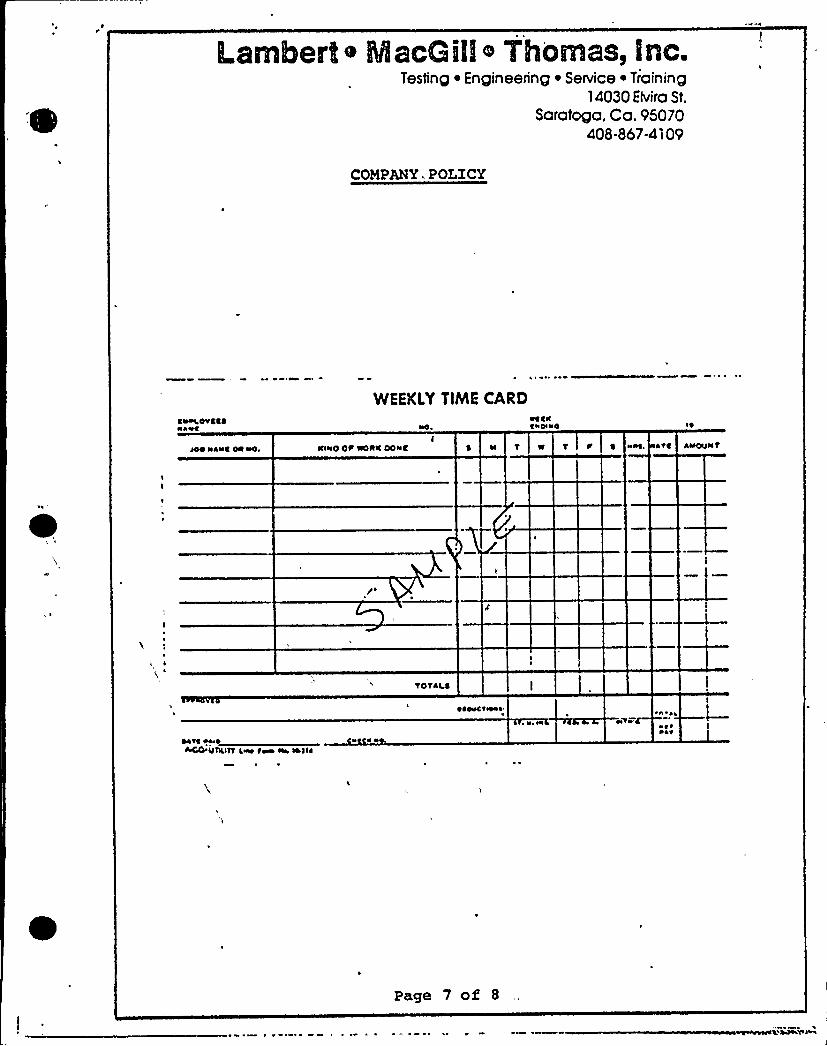
Lamberto MscGillo Thomas, inc.Testing ~ Engineering ~ Service ~ Training
14030 Bvira St.
Saratoga. Ca. 95070408-867-4109
COMPANY. POLICY
t+NOa'IEINAVC
WEEKLY TlhhE CARD%ttrskolr4
100 roast 00 sso sossO Op %0rss OOssC aa T r art Aasevssv
TOTill
was t4ooACO usaasn a~ s» sa sasss
~I ~ 0
~s aasc a ~a ~ Q ~ +a
saapa'
Page 7 of 8
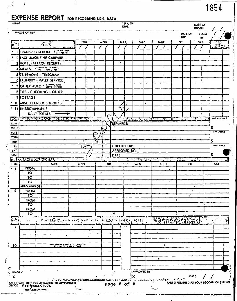
EXPENSE REPORT FOR RECORDING I.R.S. DATANAME TERR. OR
DEPT.
1854
DATE OFREPORT
IRPOSE OF TRIP DATE OF FROMTRNs TO
~ 7
IO
SUN
MON.
TUES.
WED.
THU{'I.SAT
TOT ~ l
j a
40 a' ~
TRANSPORTATION ( Att ttctu~t )
TAXI~ LIMOUSINE.CARFARE
HOTEL (ATTACH RECEIPT)(tteSOHAS VSt OATSY)
TELEPHONE - TELEGRAM
LAUNDRY - VALET SERVICE~*tSTHTS IOllS
OTHER AUTO 'tevrt tttalt5
TIPS ~ CHECKING - OTHER
POSTAGE
MISCELLANEOUS 4 GIFTS
ENTERTAINMENT
DallY TOTAlS~ ~ ~ ~ T ~ ~ ~
MOH. TUES.
EMARKS:
CHECKED BY:
APPROVED BY:
DATE:
WED. THUR. F RI. SAT
~aal atavaeTT t
ttt ASOYI
ITTtttttMII'IIM
F ROMTOTO
SUH. MOH. TUE WED, THUR FRI SAI
I. 2
AUTO MILEAGE
FROM
TO
FROMTO
FROMTO
~ ~ ~ e y
S(j'l al'l, ~ +J'I etl ~a ~ ~ l ~ ~ 'lit '„ag, r .l IYI.~ ~ ~ ~ I 'e 'lI ''5 } ~ %II
'r(]>TreT ~ I ~ ~
gv >':iLI!
WT,Ijr,,Vs'y~ ~ e ~ I ~
~ ~ I
IO ASTSC SHOW HAAat, COST, STTTSOSSt All lrt
Ta
SIGNED(
X~ a» l ~ a'
PART I WITH RFCEIP'TS ATTACHED TO APPROPRIATEOFFICE Redify rttt~ 95974
~SS1 MC SSD ttTST ASS
APPROVED IT
'I'
X~ ~ Y 4P «hga ~
I / YDATE
PESC(e 8 CIf 8'ART2 RETAINED AS TOUR RECORD Of EXPENSE
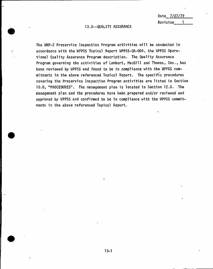
13.0--QUALITY ASSURANCE
Date 7/27/79
Revision 1
The WNP-2 Preservice Inspection Program activities will be conducted inaccordance with the WPPSS Topical Report WPPSS-QA-004, the WPPSS Opera-
tional Quality Assurance Program description. The Quality Assurance
Program governing the activities of Lambert, MacGill and Thomas, Inc., has
been reviewed by WPPSS and found to be in compliance with the WPPSS com-
mitments in the above referenced Topical Report. The specific procedures
covering the Preservice Inspection Program activities are listed in Section
10.0, "PROCEDURES". The management plan is located in Section 12.0. The
management plan and the procedures have been prepared and/or reviewed and
approved by WPPSS and confirmed to be in compliance with the WPPSS commit-
ments in the above referenced Topical Report.
13-1

0
11/14/80
Revision 1
14. 0-- EXAMINATION E(U IPMENT
The remote ultrasonic examination equipment to be used in completing the pre-service examinations of the reactor pressure vessel consists primarily of:I) permanently installed pole and bottom head tracks and temporary nozzletracks; and 2) the remote examination system. This section is divided intothose two categories accordingly.
14.1 RPY POLE BOTTOM HEAD AND NOZZLE TRACKS.
The Supply System has installed permanent pole and bottom head tracks atMNP-2. Those tracks are mounted on the metallic reflective insulationin the annulus between the RPV and the sacrificial shield wall on theskirt insulation beneath the RPV (located on the skirt inside surface),respectively. Drawings showing details of the track designs and loca-tions are included in Appendix 14A to this section. Generally, theremote examination devices described in 14.2 below are loaded onto thepole tracks through sacrificial shield nozzle penetrations using tempo-
rary track extensions or through the skirt openings in the shield walland RPV skirt for the bottom head tracks. The lower pole tracks in theskirt area are loaded from the skirt annulus area after removing theinsulation at the bottom of the annulus. Hinged swing-out sacrificialshield doors provide access through the nozzle penetrations.
The RPV nozzle scanning tracks are removable roller chain tracks withleaf spring tensioners between the pipes and nozzles and the trackitself. -The tracks are designed to be quickly installed and removed tominimize residence time in a radiation environment during inserviceinspections. Nozzle track removal is r'equired during plant service toallow clearance for closure of the sacrificial shield doors. The
nozzle-to-shell welds, nozzle inner radii, and nozzle safe end and
extension welds are all accessible to the nozzle examination devicesusing these tracks. A procedure for ensuring repeatability of locationof these tracks on subsequent installation is included in the mechanized
equipment procedures in Section 10.0, "PROCEDURES".
14-1
Date 11/14/80.
Revision
14.2 REMOTE EXAMINATION SYSTEM
The Remote Examination System consists of a Data Acquisition system
coupled to various remotely operated examination devices. The examina-
tion system is described in Appendix 14B of this section. The Appendixcontains 'a system description, device and controller functional descrip-tions and device assembly drawings. - Following is a list of components
which make.up this system.
a. RPV Longitudinal and Circumferential Pole Guided Inspection Device
b. Nozzle-to-Vessel/Inner Radius Weld Inspection Device
c. Nozzle Butt Weld Inspection Device
d. Lower Head Inspection Device
e., Control Equipment
f. Digital-to-Analog Converter
I
g. Eight Channel Strip Chart Recorder
h. Multiple Trace Oscilloscope
i. TV Camera, Recorder and Monitor
14-2
, Date 1181~79
Revision O
APPENDIX 14A
RPV POLE AND NOZZLE INSPECTION TRACKS
o DESIGN DETAILS
~ LOCATIONS
14A-1
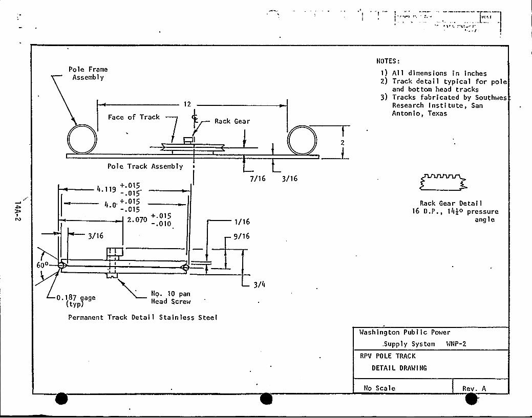
Pole FrameAssembly
Face of Track
12
Rack Gear
I
NOTES:
1) All dimensions in inches2) Track detail typical for pole
and bottom head tracks3) Tracks fabricated by Southwes
Research Institute, SanAntonio, Texas
4»9+ 0'~-.015
, 0 0+.015-.015
2. 070 -.010
3/16
7/16 3/16
1/16
9/16
Rack Gear Detail16 D.P., 14$ o pressure
angle
60'.187gage
(typ)No. 10 panHead Screw
3/4
Permanent Track Detai 1 Stainless Steel
Washington Public Power
.Supply System WNP-2
RPV POLE TRACK
DETAIL DRAWING
No Scale Rev. A
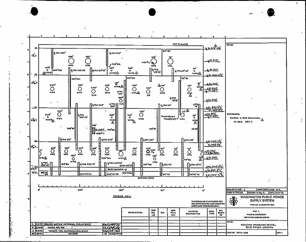
AE
lotVLkuf»'E NOTES:
4 'D
I
II qTRK dao'
IIII
4400 SSO bN
QHSLA
0 0
110 BI»I
ILTRK141.'SO ILTRK114 SO
I
+IRKLlo'
IIIi~210 BTL
'L100
HL4$+Ldo0
HLLcg'L'10 BK
Hdt 41NSB
ILTRKLLL30
010'lRK+1130'
HTL~$0 bl
~KL315
ILoil
~MKY.4'SD
0Hdt
Ll0
H4E
$40»
ulb
QOu»$40
HLO 'Lll»
LOCP
'L50
0+4000 N4b
NeILTRK
BL LS
l0
0~aM~c5KY
~EL 558
-MC
F»gT
SLS
~40'0
SI LSD
(TRKLld ls
PLTRK 145 +'%Klbb
0ul'1C
NIO
1'SS
o0ll'L'14
+TRKSI»
4$
'TSHtdRARV
'cakcKIITP)~ udl.
PLIRE
10'
Hill
IL55L.DF4RL 4~54< 4
RffERENCE Sl
BURNS Q R0$ DRAWluf»IVl 440 RKV '1
SBIf IWI
1SS
~EL C 1 1'SO dfS
MRPP 1
ll'l
QTRK SSS QTRK 11$ I'LTRK LSS QTRK4$ ~V.L5W~LLL$3$ ++
BTIdlt4
abdr-
4$ 0
0NLK
ulb+
ALLSL
SSLLSL IOb
ao»
0 0 0NSTSNLS S» N1K
usbSls'bD QTRK RSLLsl
'SL<SL'Dk
1'LO
0N'Lt
11$ 'bC
1'SO
0N'll
glRKLSLE51SLTRKSSS Sf
SKIRT TOIQEKL$
I 111 Ol.lit 1\LSSLX
110
g HktNLD HS»
0N'Sk
1'15 Bb
bollCIA KEko
N'LC Nlb
/ARKSL
$1 00
30 ~»
0 0 0N1k
44 bk
T~'EL
533''LTRK
SE.S'I~%a BLC.4. v~LL5'clio 4
~aL5351 5 SL
Llo 1$0 80 0 DUALITY CLASS: 1 ASME CODE CLASS: H A
OIITCI05 VlfW
THIS DRAWNCIS INTfNDED FORUSE N PRE Sf RV ICE AND INSERVICEINEPTCTNN tROCRAMS ONLY.
INCR:DIORTLR DRAWN:K.SALQ DATE:114-1$
WASHINGTON PUBUC POWERSUPPLY SYSTEM~»C»»»NO. W»Q»»CTON MNI
l. SIT If IEEISED L14%$LI IITTERTSIP» PETS AC BLRLT
IMS =LSSQES "TCR TF»I
tltINC SYSTEMNOMCIAIN)
NOMWALLTNE
MAISRIALSPEC IF ICATION
MATLTYPE
CALSLDCR
NO
TITLEl
WNP. 1WELD 4 COMPONENT
IDENT IF ICATIONDIAGRAM
RE klIOR PRCStsuRC VK3$T»LPOLI 'TRACK LOCATION
I TLTL sdbuf o toa. IucoRsdkllou ouiv4 fVISION 4Y C AttV DWO NO: RP'I 'LO'3 REV 1
L" '„,ii
j+>
c C'
'C
t
p 4PCh
gt
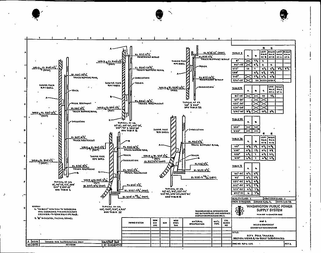
I I 5
WCLO CL SOS~TO(TLCP)
wcLD LCL54DIIDL~Rtf)
cl. 511 OVAICCDTPLAINTSTRAP
CL SC C:-LOU.
llM'LD'L TAC)fltlSCLS$ L
EL STL.LL RcfItl.Sl ' . \L
VRLAKSLItt411ILTRAt
1 ILALK
1LSLI Iso
94LS'SD
LtfTtOLEAT ~
Ci. 4C i.
CS Ci
RLCLCLT
~DLCAT O
'Ltfl ILLCLLT
PILLS 'POLO
Al A AT A
Pi
INSIDE TACSfit V OLLELL
A
$4~~~ 'IlbD+V
IRACKSCIVPORT RLNII
CILAIL
'LNSLOC fACCRPV SCSLL
INSO'LA1MN
TPLACK
WCI.O 'SL 54%~$ 4(ICCQ
CLSTL'ah.I%At
LNSDLklLDLI
'LL5
lkiLSIl
S'L
41
.'SO'ly
4 CVO
IN \LOLLACES)
LITTVO'LtAlA
10
RL4CLIPOLI~,I A
VIRID LL SSL MIDI
(RES)
TRACL( RKSIRAINT
tLSSC" ++i WELD~EL55%.5 $
1~KM~KIRI~— „,A
TRACK KCCTRAINV lltLCALAT Al.)IO ( SSOSCC 'lADLCITL
111. 50LIA.SO
LD'L )0
1~ALETTI
LOVA
QLCSLATL)ll
EL SL1'4TRACK(Tltslc AILIT
WSLO~ C'L SLO ~'1
IIPILALAl ALifLC, Cr.54',LLLLSO'ItTL SO R LDLASLE
Stt TASL'i IL
'lPALL(SLLtfORT TLPLSL
INLLD'IPISSRPV SRSLL
lNLLILAlI0Ll
tL O'LLLL
CRACK SGVP401 LLLLMLL
210'S1
0'ASLS It
LSS'25~CVS
'LIPT RllaLCIPOLI 't011Als ATO
4 4VL
WELD~EL6LO'-~tRtf =-
'QILLDE fACK,
RPV SILKS
EL SSS -aV.'TRACK TCCCTRAINT
El A~
CRACK V~L~O\2 \LLf~L~RCS jt)ISOLATION cLS<AK (Rc)I
CL SSI. AA'TTLAAKCLKSTRAILIT
~OCLS
SLS-SL'sl
ottf 5+)L(llcfl
. S'l'5
'll\LtII
W.'-SL)2'
Yi 4)A
TTtLLALAT ALSISL LSIIILLISO
'EL5 ( 114 ~LS'tc
TASLC 1
VICL~DCL52S~4~F)st/ Dk Rc)I LL LL
cL sts s~ (Reft
RL sts'- 5 )s (Rt f1
1VPICAL Al AL~' '12)f«SLL'I'$1 SL
1'll, 511152 SLCCC TAOLCX
152''L2$ te,SL
Lit 'SL
)22 5'L
OLIALITYCLASSL I ASM E CODE CLASS:
KNGRL 0 POT(ICE DRAWNL NIP A DA'TE 11L1'i
NOTS\IAS DLLL$1 MLNOl'M liSLTADUSNNLLN CLEARANCE SORIAtCLILNlltDCRAWLCR 144IA).SAC KOSLPO$E,
t + INDLCATIL~fACLN4VCSSt L
IVPLLALAv ALAD ~ LLS )115 I RSLL
Scc IADLR IR TMLS DRAWINGIS INTtNDKD fORu)t INtR(ttRVCEANOINSKRYCEINSttCTION tROGRAMS ONLY.
WASHINGTON PUBLIC POWERSUPPLY SYSTEM~ICE kML W ASM'OLL PLLLI
A )ILTS 1)SOLD TER LNfORMATLLLNONLYNO DATE )Y C AttV
tltWOSY)ltMNOMDIAIINI
NOMWALLTNK
MATERIALSt(CI fCATION
MAILTYtE
CAL)(ocr
ND
WNt-1WILD~ COMPONENT
NIKNTIIICATION DIAGRAM
TITLKI
RP V POLE 1RACKSSCCTLOLLVI%VISg AD OLLILLICL%ATVkLC1S
DWO NO: 'RPV 1OA REVA
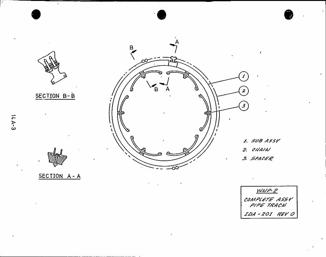
E
B 7
SECTION B- B
SECTION A - A
p<g< 11/14/80
Revision
APPENDIX 148
REMOTE EXAMINATION SYSTEM
SYSTEM DESCRIPTION
EXAMINATION DEVICE FUNCTIONAL DESCRIPTIONS
CONTROLLER FUNCTIONAL DESCRIPTIONS
EXAMINATION DEVICE PERFO NCE SPECIFICATIONS
ASSEMBLY DRAWINGS
14 B-1
Date ll/14/80R
REMOTE EXAMINATION SYSTEM DESCRIPTION
The inspection of the WNP-2 Reactor Pressure Vessel is remotely performed
using a series of Southwest Research Institute devices. The vessel longitudi-nal and girth weld seams are examined by a device called a "Pole Bug" which
travels between the vessel and the insulation on permanently mounted verticaltracks. The attachment welds and inner radius zones of the larger nozzles are
examined by a radially scanning nozzle to shell weld examination device and
the safe ends are examined using a,butt weld inspection device. Both of these
travel on tracks mounted circumferentially on the safe end or pipe. Finally,the bottom head welds are examined using a device which travels around a track
'\
inside the vessel support skirt. All remote devices were designed and manu-,
'acturedby Southwest Reseach Institute (SWRI)
Each of these devices include an ultrasonic transducermodule, motors, and the
electrical encoders which convert the motion of the device into electricalsignals. The motion signals are transmitted to controllers which displayposition and provide control functions.
The device controllers contain the circuitry necessary to position the trans-ducers to perform the required examinations, and to display the transducer
position. The transducers themselves are driven by a maximum of three ultra-sonic testers, one per transducer.
These instruments perform the'xamination, display examination data, and pro-vide analog voltage outputs for recording on an eight channel strip chartrecorder. The analog voltage outputs from the controller via digital toanalog converters represent the two co-ordinates of the device's position.Signal range and amplitude data output are recorded for each ultrasonic tester(up to three tester's may be operated simultaneously for each scan, each exam-
ining at a different angle).
The examination instrumentation and control functions are divided into two
categories; device operation and examination performance. The instrumentationnecessary for each function is mounted in a separate console designed to be
14 B-2
Date 11/14/80
Revision 0
monitored by a technician performing a single function. The device control-lers are mounted in a Desk Console (Figure 1) and the ultrasonic testers and
associated instrumentation are mounted in a standing console rack (Figure 2).
The performance of the separate functions is improved by providing. crossover
information between technicians. That is, providing the examiner at the testconsole with position readout, and the device operator with examination read-
out. This is done by displaying the position data on a slave panel in the
Tester Console, and by a multiple trace oscilloscope display and closed cir-cuit TV System with monitor at the device operators desk. A cassette TV
recorder provides a permanent record of the examination.
0 I SCUSS ION
MECHANICAL SYSTEM CONTROL INSTRUMENTATION
Block diagrams of the remote device control systems are shown in Figure 3.
The actual number of SWRI System Controllers in use at any given time depends
on the examination being performed. All controllers will be physically in
place throughout the entire examination program, however. The selection ofcontrollers for each examination is shown in Table 1.
In addition to the controls and readouts, the TV monitor showing ultrasonictest data wi 11 be located at the operator's desk. This display gives theDevice Operator confirmation that his system is performing as required, and
that the recording system is functional.
TESTING INSTRUMENTATION
The ultrasonic test instruments are mounted in a standing console rack. There
are three Nortec NOT 1310 portable ultrasonic testers connected to operate insynchronization. Each tester provides two analog voltage outputs, one ofwhich is proportional to the amplitude of the largest indication in the
displayed gated sweep; the other is proportional to the metal path distance to
14 B-3
Date ll/l4/80Revision . 0
the leading edge of the first indication which has amplitude exceeding a
preset threshold level. By this selection of parameter s, complex waveforms
are most consistently recorded for evaluation.
Each tester displays data conventionally on a individual CRT, and the analogoutputs are routed to a Brush eight-channel oscillograph recorder. The .
recorder provides continuous monitoring of the amplitude and range outputs ofeach tester, using six of the available eight channels for this purpose.
The remaining two channels of the Brush recorder are reserved for analog volt-ages representing the position co-ordinates of the transducer module. Each
SWRI device is located by 'a two-dimensional digital encoder readout. The
readout may be proportional to X-Y position coordinates, as in the examinationof a plate repair area, or the readout may indicate R-0 position co-ordinatesduring the examination of a .nozzles-to-vessel weld. In either case the outputof the encoder is digital pulse.
The encoder output and display represent Binary Coded Decimal information.The Brush recorder can only accomnodate analog inputs. Conversion of theBinary Coded Decimal output of the SWRI controllers to analog voltage is thefunction of the LMT Digital to Analog Converter, Model 1 (DAC 1). This unitallows conversion of the three most-significant or the three least-significantdigits to analog voltage, in this way providing an expandable scale for pre-cise recording of flaw locations. The DAC 1 also repeats, visually the digitaloutputs of the SWRI controllers on LED readouts on the front panel.
The remaining test instrumentation panel component is a Tektronix 5110 Oscil-loscope with a 5B12N dual time base, and two 5A18N dual amplifie~s. So
equipped, this scope displays four signals simutaneously on two separate timebases. The 45 and 60 shear wave and the 0 longitudinal wave traceswill be displayed on a time base proportional to the longitudinal wave velo-city of „ultrasound.
14 B-4
Date 11/14/80
Revision
VIDEO RECORDING INSTRUMENTATION
Essential readouts are closely grouped on the test instrumentation console so
that the data can be recorded on video tape for a permanent visual record ofthe test.
The video recording system consists of an RCA TC1005 Black and White closed-circuit TV camera, an RCA TC1210 monitor and a Sony V02610 3/4" Video Cassette
Tape Recorder.
The camera is mounted in a fixed position in front of the test equipment 'cabi-net and is focused on the oscilloscope and digital position displays. The
camera is activited by the main power switch of the test equipment console.
14 B-5
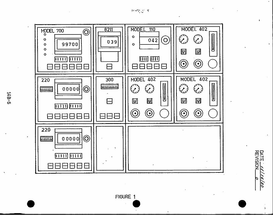
HODEI 700
99700
8211
039
MODEL 110
042 Qo
MODEL 402
889 ill
~II I I I ~illI I
eeeeee~ll I I [llill
eeeee 0o 0o 0220
ooooo
300 MODEL 402 MODEL 402
Qr Qr
~ll I I I ~II I I:I
eeeeee OoOo 0 Oo Oo 0220
Rig ooooo Qo
~II I I I ~II I I I
eeeeee
FIGURE 1
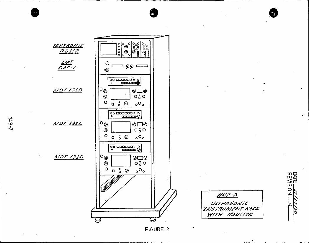
p 0 0o Qppp Qooo '0
Qoa
0
Qo
0 0tl
00 OOODOO o 0o IZDXXGXI0
Qo Qo~QoQo OooO a
0 0 0 0
00 OOQOOOo 04 mxzzau o
OQ OOC300
00 OOO
o 0 oOo
00 DQCIOQQo 0azazxza Qo
Oao Qo{ J00 000
0 00 o o
FIGURE 2
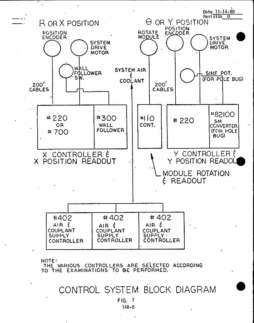
~ Q ~
~ ~
0 ~~ ~
~ ~~ ~
ols I
~ ~
~ 0
~ 0 0 ~ e
o 0 ~ Q
~ ~
~ 0 ~ 0
0 0 ~ li~~ ~ ~
~ ~ ~ ~ ) ~
~ ~ ~ '0 g ~ ~
- J ~~ 0
~ ~ ~ ~ ~ ~ 0 ~
~ ~ ~ ~ ~ ~
~ ~ ~ ~ 0 ~ 0
~ ~ ~ 0 I S ~ J j~ ~ ~ ~
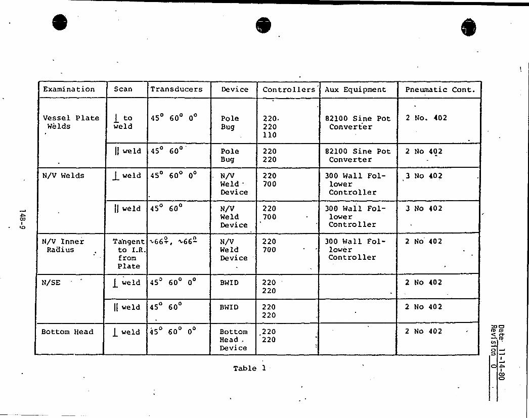
Examination Scan Transducers Device Controllers Aux Equipment Pneumatic Cont.
Vessel PlateWelds
J toweld
45 60 0 PoleBug
220.220110
82100 Sine PotConverter
2 No. 402
N/V Helds
N/V InnerRadi us
ll weld 45 60
weld 45 60 0
tl weld 45 60
Tangent >66~, <66-0 n
to I.R.fromPlate
PoleBug
N/VMeldDevice
N/VMeldDevice
N/VMeldDevice
220220
220700
220700
220700
82100 Sine PotConverter
300 Wall Fol-lowerController
300 Hall Fol-lowe rController
300 Wall Fol-lowerController
2 No 402
3 No 402
3 No 402
2 No 402
N/SE
Bottom Head
weld 45 60 0
II weld 45 60
g weld 45 60 0
BHID
BHID
BottomHead .
Devi ce
220220
220220
220220
2 No 402
2 No 402
2 No 402XlDLD Ql( c+0lA
O
Table 1-I
ICOCD
pete ll/14/80Revision O
EXAMINATION DEVICE FUNCTIONAL DESCRIPTIONS
14 B-10
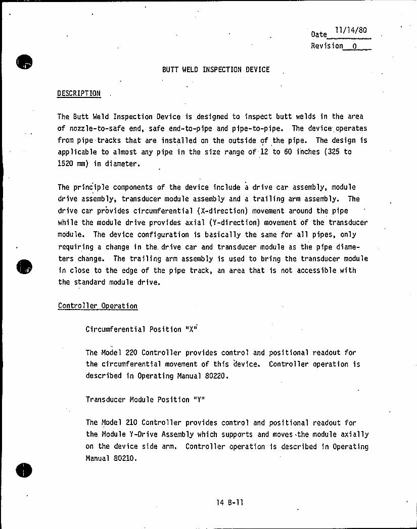
0 t 11/14/80
Revision 0
BUTT WELD INSPECTION DEVICE
DESCRIPTION
The Butt Weld Inspection Device is designed to inspect butt welds in the area
of nozzle-to-safe end, safe end-to-pipe and pipe-to-pipe. The device operates
from pipe tracks that are installed on the outside of the pipe. The design isapplicable to almost any pipe in the size range of-12 to 60 i'nches (325 to1520 om) in diameter.
The principle components of the device include a drive car assembly, module
drive assembly; transducer module assembly and a trailing arm assembly. The
drive car provides circumferential (X-direction) movement around the pipewhile the module drive provides axial (Y-direction) movement of the transducermodule. The device configuration is basically the same for all pipes, only
requiring a change in the, drive car and transducer module as the pipe diame-
ters change. The trailing arm assembly is used to bring the transducer module
in close to the edge of the pipe track, an area that is not accessible withthe standard module drive.
Controller 0 eration
Circumferential Position "X"
The Model 220 Controller provides control and positional readout forthe circumferential movement of this device. Controller operation isdescribed in Operating Manual 80220.
Transducer Module Position "Y"
The Model 210 Controller provides control and positional readout forthe Module Y-Drive Assembly which supports and moves the module axiallyon the device side arm. Controller operation is described in OperatingManual 80210.
14 B-ll
Date 11/14/80
Revision 0
Air Pressure and Water
Two Model 402 Controllers provide control of the air and water for thisdevice.
(a) The first Model 402 Controller provides air control for thedrive car WHEEL LOCK and the TRANSDUCER MODULE load cylinders.
(b) The second Model 402 Controller provides air to pressurize thewater supply container and control of the water to the Trans-,
ducer Module assembly.
(c) Controller operation is described in Operating Manual 80402.
14 B-12
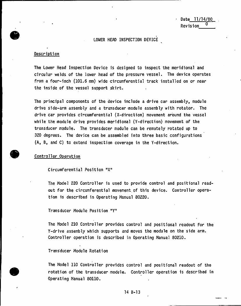
D ~11 14 8
Revision
LOWER HEAD INSPECTION DEYICE
Descri tion
The Lower Head Inspection Device is designed to inspect the meridional and
circular welds of the lower head of the pressure vessel. The device operatesfrom a four-inch (101.6 mn) wide circumferential track installed on or near
the inside of the vessel support skirt.
The principal components of the device include a drive car assembly, module
drive side-arm assembly and a transducer module assembly with rotator. The
drive car provides circumferential (X-direction) movement around the vessel
while the module drive provides meridional (Y-direction) movement of thetransducer module. The transducer module can be remotely rotated up to320 degrees. The device can be assembled into three basic configurations
(A, B, and C) to extend inspection coverage in the Y-direction.
Controller 0 eration
Circumferential Position "X"
The Model 220 Controller is used to provide control and positional read-
out for the circumferential movement of this device. Controller opera-
tion is described in Operating Manual 80220.
Transducer Module Position "Y"
The Model 210 Controller provides control and positional readout for theY-drive assembly which supports and moves the module on the side arm.
Controller operation is described in Operating Manual 80210.
Trans'ducer Module Rotation
The Model 110 Controller provides control and positional readout of the
rotation of the transducer module. Controller operation is described inOperating Manual 80110.
Revision~
Air Pressure and Water
Two Model 402 Controllers provide control of the air and water for thisdevice.
(a) The first Model 402 Controller provides air control for the drive
car WHEEL LOCK and the Y-DRIVE SIDE ARM cylinder.
(b) The second Model 402 Controller provides air control for the TRANS-
DUCER MODULE load cylinder, air to pressurize the water supply con-
tainer, and control of the water to the transducer Module Assembly.
(c) Controller operation is described in Operating Manual 80402.
14 B-14
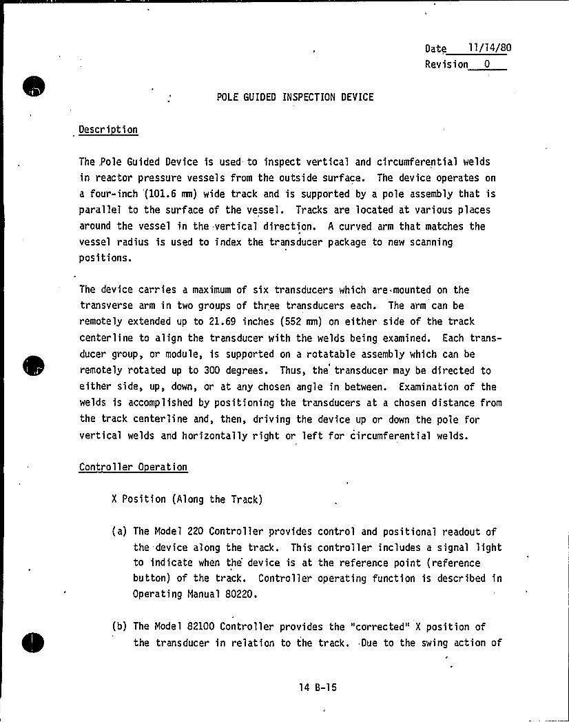
Date 11/14/80
Revision 0
POLE GUIDED INSPECTION DEVICE
Descri tion
The .Pole Guided Device is used to inspect vertical and circumferential welds
in reactor pressure vessels from the outside surface. The device operates on
a four-inch '(101.6 mn) wide track and is supported by a pole assembly that isparallel to the surface of the vessel. Tracks are located at various placesaround the vessel in the vertical direction. A curved arm that matches thevessel radius is used to index the transducer package to new scanning
positions.
The device carries a maximum of six transducers which are mounted on thetransverse arm in two groups of three transducers each. The arm can be
remotely extended up to 21.69 inches (552 mn) on either side of the trackcenterline to align the transducer with the welds being examined. Each trans-ducer group, or module, is supported on a rotatable assembly which can be
remotely rotated up to 300 degrees. Thus, the transducer may be directed toeither side, up, down, or at any chosen angle in between. Examination of thewelds is accomplished by positioning the transducers at a chosen distance from
the track centerline and, then, driving the device up or down the pole forvertical welds and horizontally right or left for circumferential welds.
Controller 0 eration
X Position (Along the Track)
(a) The Model 220 Controller provides control and positional readout ofthe device along the track. This controller includes a signal lightto indicate when the'evice is at the reference point (referencebutton) of the track. Controller operating function is described inOperating Manual 80220.
(b) The Model 82100 Controller provides the "corrected" X position ofthe tr ansducer in relation to the track. Due to the swing action of
14 B-15
pate 11/14/80
Revision
the arms that support the trailer and transducer assemblies, theactual transducer position changes as a function of the distancebetween the pole track and the vessel surface. The "corrected"position is the true distance "along the track" of the transducerand the track reference point. Controller operating function isdescribed in Operating Manual 82100.
Y Position (Perpendicular to the Track)
The Model 210 Controller provides control and positional readout of the
transverse arm which supports and moves the transducers in the "Y"
direction. Controller operating function is described in OperatingManual 80210.
Transducer Nodule Rotation
The Model 110 Controller provides control and positional readout of therotation of the transducer module. There are two identical transducermodules located at each end of the transverse arm. Only one module can
be operated at one time. Operational function of the Model 110 Control-ler is described in Operating Manual 80110.
Air and Water Control
(a) The first Model 402 Controller provides control of the WHEEL LOCK
and BRAKE on the drive car.
(b) The second Model 402 Controller provides control of the ARM on thetrailer assembly and WATER for the transducer.
(c) Operational function of .the Model 402 Controller is described inOperating Manual 80402.
14 B-16
Date ll/14/80Revision 0
Transducer i4lodule C-10680
This module includes three transducer/shoe assemblies providing 'a scan
capability of 0 longitudinal beam and 45 and 60 shear beams.
The module is supported on a rotatable assembly and can be remotely
rotated through 300 degrees (see C-12408). The transducer has a
3/4-inch (19.05 mm) diameter crystal and operates at 2.25 8Hz.
14 8-17
Date ll/14/80Revision 0
NOZZLE-TO-SHELL/NOZZLE INNER RADIUS'NSPECTION DEVICE.
Descri tion
The nozzle-to-shell inspection dev'ice has been designed to inspect the nozzle-
to-shell welds of nozzles in the size range of 10 to 42 inches (254 to 1100
mm) in diameter. The inspection device assembly consists of the Inspection
Arm (12100) and the Drive Car (13165 or 13167) as primary components. The
Inspection Arm is the same for all nozzles. Drive Car 13167 is used for noz-
zles from 10 to 20 inches (254 to 508 mm) in diameter and Dr,ive Car 13165 is
used for nozzles from 20„ to 42 inches (508 to 1100 mn) in diameter.
The device operates from pipe tracks that are installed on the necked-down
portion of the nozzle forging. - The Drive Car provides circumferential move-
ment (X direction) around the track and the Inspection Arm Assembly provides
both radial movement of the transducer (Y direction) and a wall followingfeature which assures a constant radial position.
Due to the differences in nozzle shapes, a specific configuration of the pri-mary components must be designed for each type of nozzle, although the basic
function and operation of the'rimary components is the same for allconfigurations.
Controller 0 eration
Circumferential Position "X"
The Model 220 Controller is used to provide control and positional read-
out for the circumferential movement of this device.. Controller opera-
tion is described in Operating Manual 80220.
The nozzle inner radius function of the nozzle-to-shell device is accom-
plished by changing the transducer module assembly.
14 B-18
11/14/80
Revision
Transducer Module Position "Y"
The Model 700 Controller provides control and positional readout for the
Transducer Module movement on the INSPECTION ARM ASSEMBLY of the
device. This provides a movement and readout capability which is radialwith respect to the nozzle centerline. Due to the mechanical configura-tion of the device, the position of the inspection arm is influenced by
the pipe track position and the configuration of the nozzle. If the
device adjustment is maintained according to the configuration drawings,
module position will be repeatable. Controller operation is described
in Operating Manual 82700.
Wall Follower
The Model 300 Controller provides control of the WALL FOLLOWER DRIVE
ASSEMBLY. Wall sensor switches mounted on the HINGE ARM ASSEMBLY con-
tact the pressure vessel causing the Controller to move the wall fol-lower dr ive assembly as necessary so that the arm assembly remains
approximately parallel to the vessel wall. Controller operation is
described in Operating Manual 82300.
Air Pressure and Water
Three Model 402 Controllers provide control of the air and water forthis device.
( a) The first Model 402 Controller provides control for the TAIL WHEEL
and the Drive Car WHEEL LOCK.
(b) The second Model 402 Controller provides control for the INSPECTION
ARM ASSEMBLY tilt cylinders and the MODULE WHEEL cylinder.
14 B-19
Date 1 1/14/80
Revision 0
(c) The third Nodel 402 Controller provides air to purge the wall sensor
switch case, air to pressurize the water supply container and con-
trol of the water to the Transducer Nodule Assembly.
(d) Controller operation is described in Operating Nanual 80402.
14 B-20
Date 11/14/80
Revision 0
CONTROLLER FUNCTIONAL DESCRIPTIONS
14 B-21
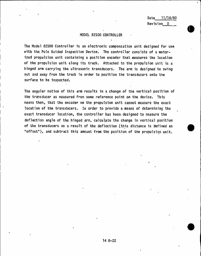
Date ll/14/80Revision 0
MODEL 82100 CONTROLLER
The Model 82100 Controller is an electronic compensation unit designed for use
with the Pole Guided Inspection Device. The controller consists of a motor-ized propulsion unit containing a position encoder that measures the locationof the propulsion unit along its track. Attached to the propulsion unit is a
hinged arm carrying the ultrasonic transducers. The arm is designed to swingout and away from the track in order to position the transducers onto thesurface to be inspected.
The angular motion of this arm results in a change of the vertical position ofthe transducer as measured from some reference point on the device. Thismeans then, that the encoder on the propulsion unit cannot measure the exactlocation of the transducers. In order to provide a means of determining theexact transducer location, the controller has been designed to measure thedeflection angle of the hinged arm, calculate the change in vertical positionof the transducers as a result of the deflection (this distance is defined as
"offset"), and subtract this amount from the position of the propulsion unit.
14 B-22
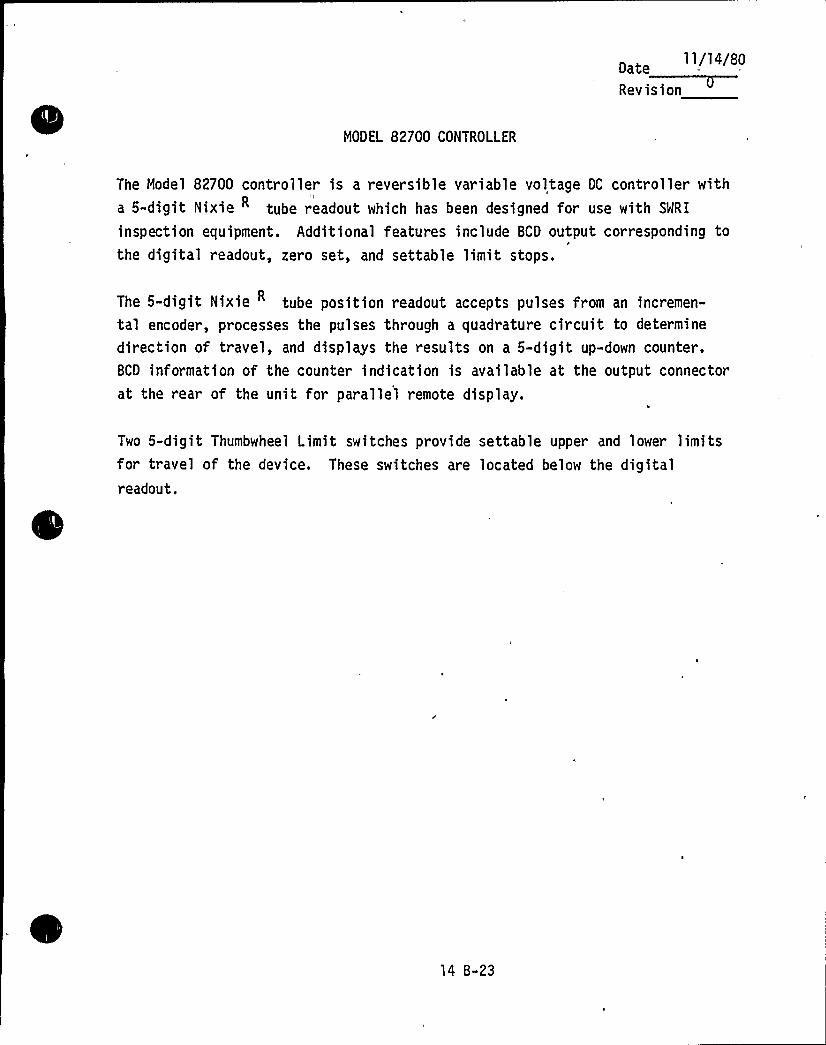
ll/14/80Date
MODEL 82700 CONTROLLER
The Model 82700 controller is a reversible variable voltage DC controller witha 5-digit Nixie tube readout which has been designed for use with SMRI
inspection equipment. Additional features include BCD output corresponding tothe digital readout, zero set, and settable limit stops.
The 5-digit Nixie tube position readout accepts pulses from an incremen-
tal encoder, processes the pulses through a quadrature circuit to determine
direction of travel, and displays the results on a 5-digit up-down counter.BCD information of the counter indication is available at the output connector
at the rear of the unit for parallel remote display.
Two 5-digit Thumbwheel Limit switches provide settable upper and lower limitsfor travel of the device. These switches are located below the digitalreadout.
14 8-23
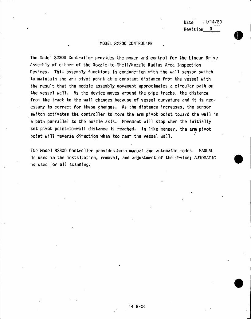
Date ll/14/80Revision 0
MODEL 82300 CONTROLLER
The Model 82300 Controller provides the power and control for the Linear DriveAssembly of either of the Nozzle-to-Shell/Nozzle Radius Area InspectionDevices. This assembly functions in conjunction with the wall sensor switchto maintain the arm pivot point at a constant distance from the vessel withthe result that the module assembly movement approximates a circular path on
the vessel wall. As the device moves around the pipe tracks,- the distancefrom the track to the wall changes because of vessel curvature and it is nec-
essary to correct for these changes. As the distance increases, the sensor
switch activates the controller to move the arm pivot point toward the wall ina path par rallel to the nozzle axis. Movement will stop when the initiallyset pivot point-to-wall distance is reached. In like manner, the arm pivotpoint will reverse direction when too near the vessel wall.
The Model 82300 Controller provides. both manual and automatic modes. MANUAL
is used in the installation, removal, and adjustment of the device; AUTOMATIC
is used for all scanning.
14 B-24
Il ~11. I 81
Revision~
MODEL 220 CONTROLLER
v
The Model 220 Controller is a reversible variable voltage DC controller with a
5-digit Nixie tube readout which has been designed for use with SWRI
inspection equipment. Additional features include level indication, positionlight, BCD output corresponding to the digital readout, zero set, counterreversal, and settable limit stops.
The 5-digit X-positive Nixie ~ tube readout accepts pulses from an incre-mental encoder, processes the pulses-through a quadrature circuit to determine
direction of travel, and displays the result on the 5-digit up-down counter.BCD information of the counter indication is available at the output plug atthe rear of the unit for parallel remote display.
A level indicator is provided to operate in conjunction with a 7606 Fredericks-level sensor to provide a primary level indication. The indicator is a
100-0-100 zero center micrometer. Full scale is approximately one degree.
The meter is located at the upper left corner of the front panel.
Two 5-digit thumbwheel limit switches provide settable upper and lower limitsfor travel of the device. These switches are located below the digital readout
A position REFERENCE light is provided at the middle left side of the frontpanel. This light operates in conjunction with a position reference switchattached to the scanning device.
14 B-25
Date 11/14/80
Revision
MODEL 110 CONTROLLER
The Mod'el 110 Controller is a reversible variable-voltage DC controller with a
3-1/2 digit Nixie tube readout which has been designed for use with SwRI=
inspection equipment. Additional features include BCD output corresponding tothe digital readout, zero set, counter reversal and settable limit stops.
The 3-1/2 digit X-positive Nixie tube readout accepts analog information from
a potentiometer, performs an analog-to-digital conversion, and displays the
result on the 3-1/2 digit up-down counter. BCD information of the counter
indication is available at the output plug at the rear of the unit forparallel remote display.
*
Two 4-digit thumbwheel limit switches provide settable upper and lower limitsfor travel of the device. These switches are located below the digitalreadout.
14 B-26
Date 11/14/80
Revision
MODEL 402 CONTROLLER
The Model 402 Controller is a dual, regulated, filtered pneumatic supply incombination with a single, flow-regulated fluid supply which has been designed
for use with SwRI inspection equipment. Each pneumatic system includes a
regulated pressure gauge, 4-way valve suitable for operation of double-actingcylinders and a bezel locking regulator. The fluid system includes a needle
valve for flow regulation and a flow meter for easy repeatability of flowsetting.
14 B-27
,.
D t 11/14/80
EXAMINATION DEVICE PERFORMANCE SPECIFICATIONS
14 B-28
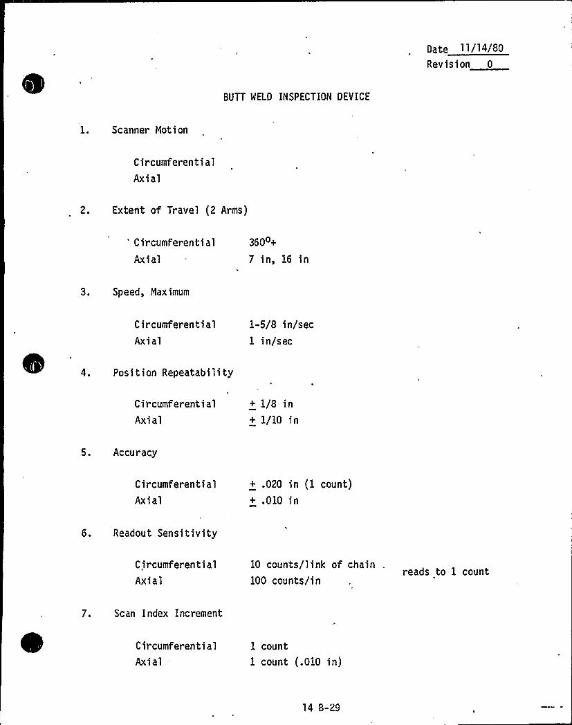
Date 11/14/80
Revision 0
BUTT MELD INSPECTION DEVICE
1. Scanner Motion
C ircumferent i a 1
Axial
2. Extent of Travel (2 Arms)
'ircumferentialAxial
360o+
7 in,16 in
3. Speed, Maximum
CircumferentialAxial
1-5/8 in/sec1 in/sec
4. Position Repeatability
CircumferentialAxial
+ 1/8 in+ 1/10 in
5. Accuracy
CircumferentialAxial
+ .020 in (1 count)+ .010 in
6. Readout Sensitivity
C ircumferen tia 1
Axial10 counts/link of chain
100 counts/inreads to 1 count
7. Scan Index Increment
CircumferentialAxial
1 count
1 count (.010 in)
14 B-29
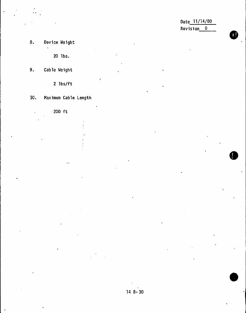
Date 11/14/BD
Revision 0
8. Device Weight
20 lbs.
9. — Cable Weight
2 lbs/ft
10. Maximum Cable Length
200 ft
I
14 B-30
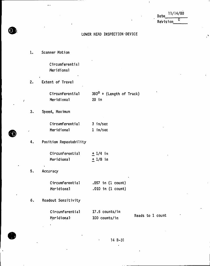
ll/14/80Date
LOWER HEAD INSPECTION 'DEVICE
1. Scanner Motion
CircumferentialMeridional
2. Extent of Travel
CircumferentialMeridional
360 + (Length of Track)20 in
3. Speed, Maximum
C ir cumfer enti alMeridional
3 in/sec1 in/sec
4. Position Repeatability
CircumferentialMeridional
+ 1/4 in+ 1/8 in
5. Accuracy
CircumferentialMeridional
.057 in (1 count)
.010 in (1 count)
6. Readout Sensitivity
CircumferentialMeridional-
17.5 counts/in100 counts/in Reads to 1 count
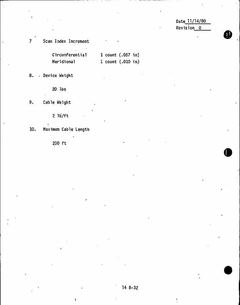
Date ll/14/80Revision 0
7 Scan Index Increment
Cir cumferenti alMeridional
I count (.057 in)1 count (.010 in)
8. Device Weight
20 lbs
9. Cable Weight
2 lb/ft
10, Maximum Cable Length
200 ft
14 B-32
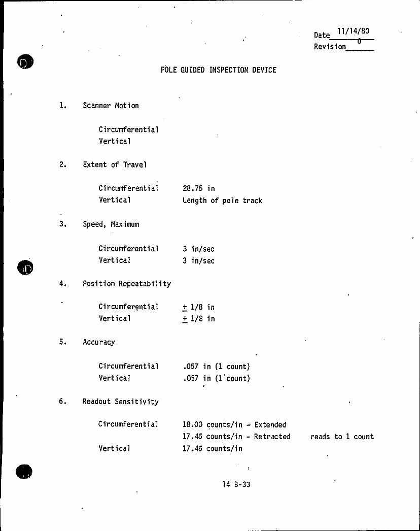
0 t 11/14/80
POLE GUIDED INSPECTION DEVICE
1. Scanner Motion
CircumferentialVertical
2. Extent of Travel
CircumferentialVertical
28.75 inLength of pole track
3. Speed, Maximum
CircumferentialVertical
3 in/sec3 in/sec
4. Position Repeatability
CircumferentialVertical
+ 1/8 in+ 1/8 in
5. Accuracy
CircumferentialVertic'al
.057 in (1 count)
.057 in (1 count)
6. Readout Sensitivity
Circumferential
Vertical
18.00 counts/in - Extended
17.46 counts/in - Retracted
17.46 counts/inreads to 1 count
14 B-33
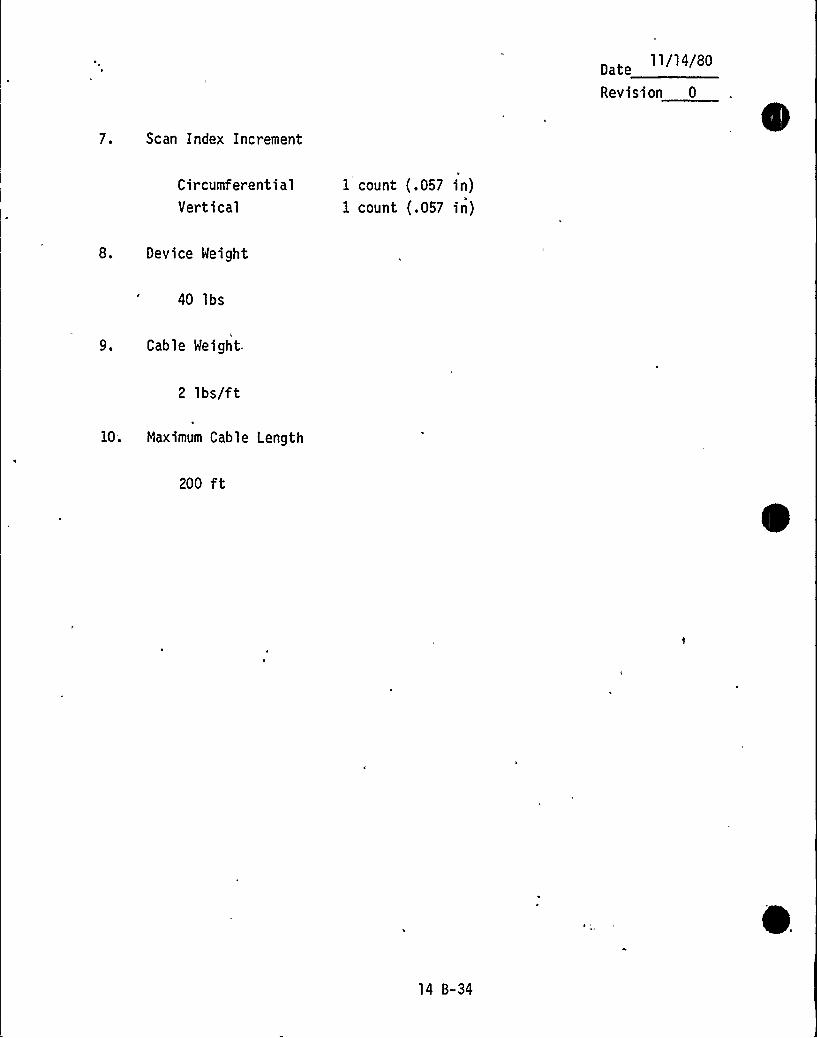
11/14/80Date
Revision 0
7. Scan Index Increment
CircumferentialVertical
I count (.057 in)1 count (.057 in)
8. Device Weight
40 lbs
9. Cable Weight.
2 lbs/ft
10. Maximum Cable Length
200 ft
14 B-34
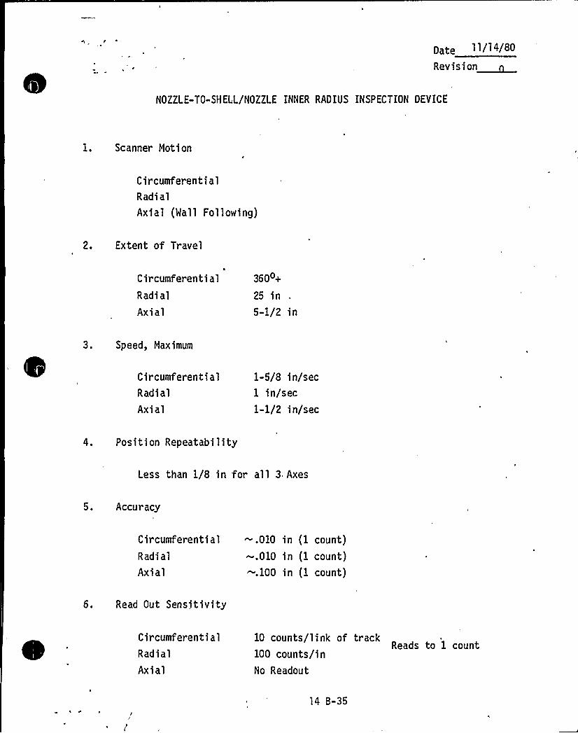
pate 11/14/80
Revision~
NOZZLE-TO-SHELL/NOZZLE INNER RAOIUS INSPECTION OEVICE
1. Scanner Motion
CircumferentialRadi alAxial (Mall Following)
2. Extent of Travel
CircumferentialRadial
Axial
360o+
25 in5-1/2 in
3. Speed, Maximum
CircumferentialRadi al
Axial
1-5/8 in/sec1 in/sec1-1/2 in/sec
4. Position Repeatability
Less than 1/8 in for all 3 Axes
5. Accuracy
Circumferential -,010 in (1. count)
Radi al -.010 in (1 count)Axial -.100 in (1 count)
6. Read Out Sensitivity
CircumferentialRadial
Axial
10 counts/link of trackReads to 1 count
100 counts/inNo Readout
14 B-35
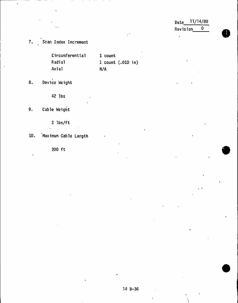
pate ll/14/80Revision
7. Scan Index Increment
C ir cumferent i alRadi al
Axial
1 count
1 count (.010 in)N/A
8. Device Weight
42 lbs
9. Cable Weight
2 lbs/ft
10. Maximum Cable Length
200 ft
14'-36
p~~e 11/14/80
Revision
ASSEMBLY ORAWINGS
14 B-37

I
I/
-
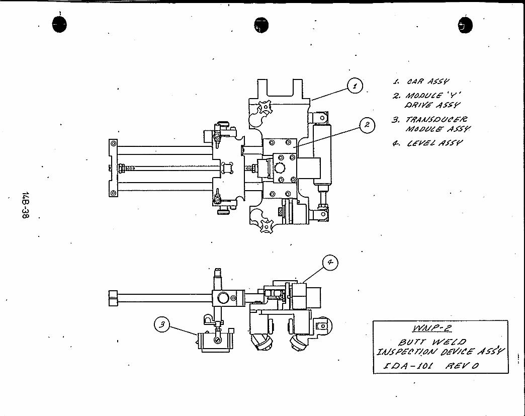
0o
0
c'. dAA'/Xp8/HAD'ZF YD+iVHAXXf
S. ~bern/nue~&M~u~CW AXED
0
O.
0 ~VYif/P-
guar WZZ47y~~~~zzrzM ~EVrc'H ><A
X'OA —le 8'8 P'0

rr
4
Wii"
r
h~ '
rf
l ~P
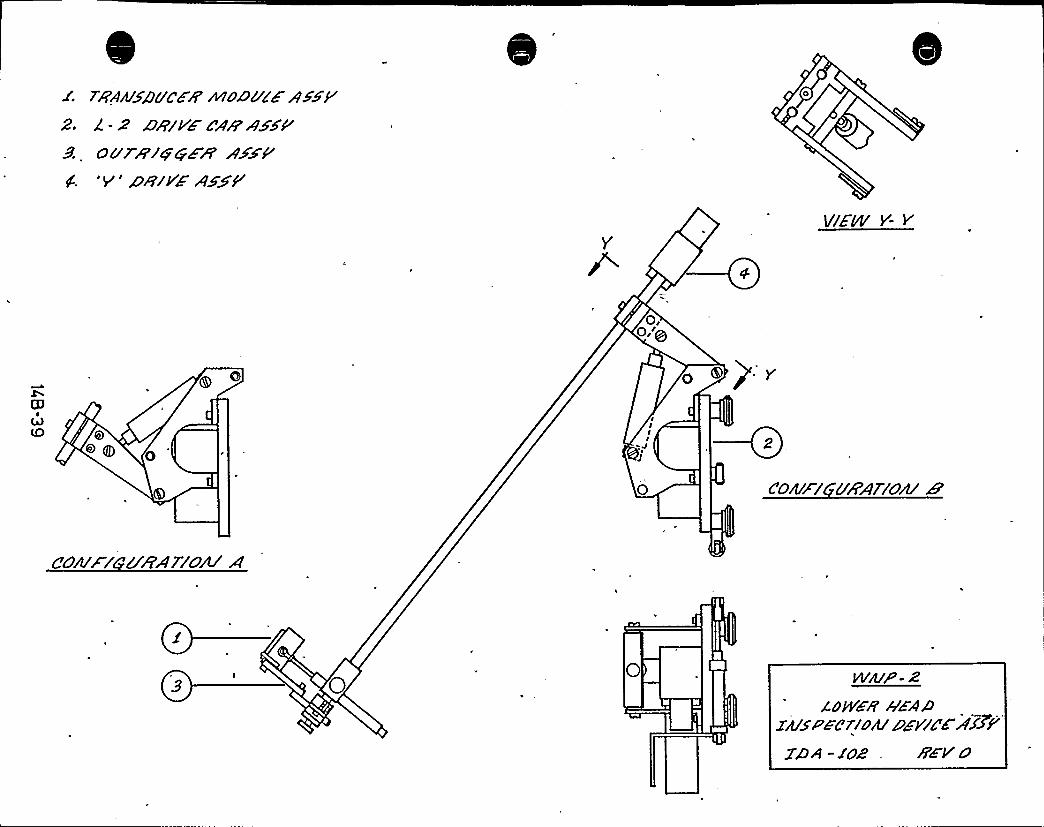
TAArt/SSPC&8'o&bCEAXSF'-z
a+rvr ex'sseourergqea
aszP'v'aiV>
<xzP
Y1//ZS'- Y
0,0,'@
cN4)(D
IIII
J
o
C'04F/ 6'SPAT/OW
S'o~rz
uzArzou a
WA/P- Z
zowie NaAazws~~errow ++vugg ice2g)A -XOZ . 8Z'VO
r~ '
r
K
Ip V I
R
~ Ilr g
~ ~
~t „
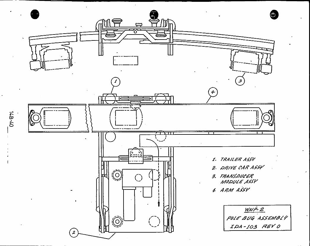
C:::::3C
CO
l
(r a3
I
L
Qo''lC.
I)
-~lI',)I
--(IIIII
78'A/lHA'5gFz. ~wive CAR'AXE<
s ~w~uX~uexRbNpg& /DAN
4 A'Em 4XXP
/ L
t y
zoz~wuw2@A - j'gy REVO
lI d
i V
1
p
I" T
I
"~
*
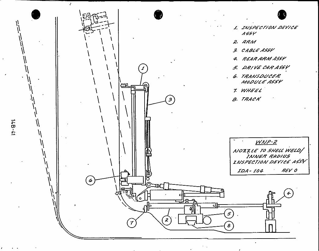
Y'
JAf5Pd 4V/Ok Dd VlC"8AKSY
9''gcF4'HAAXF'
K 4arVd 4VwAsXPd. z8awxoc de%
Azau~wAKWP'
NAZZZ
1ÃA4'8'YkP-Z
>OZZc'F N Sh'E/8 %EL'6/
ZAJSPED/OAf SF V/CF AKSV
ISA- f04 8'
,p 4
o
5

~ ~%> I ir~
'I
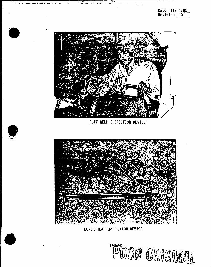
Da te 11/14/BORevision 0
'/6
BUTT WELD INSPECTION DEVICE
LOWER HEAT INSPECTION DEVICE

i'(", v
I
(a
k
iE
1
k
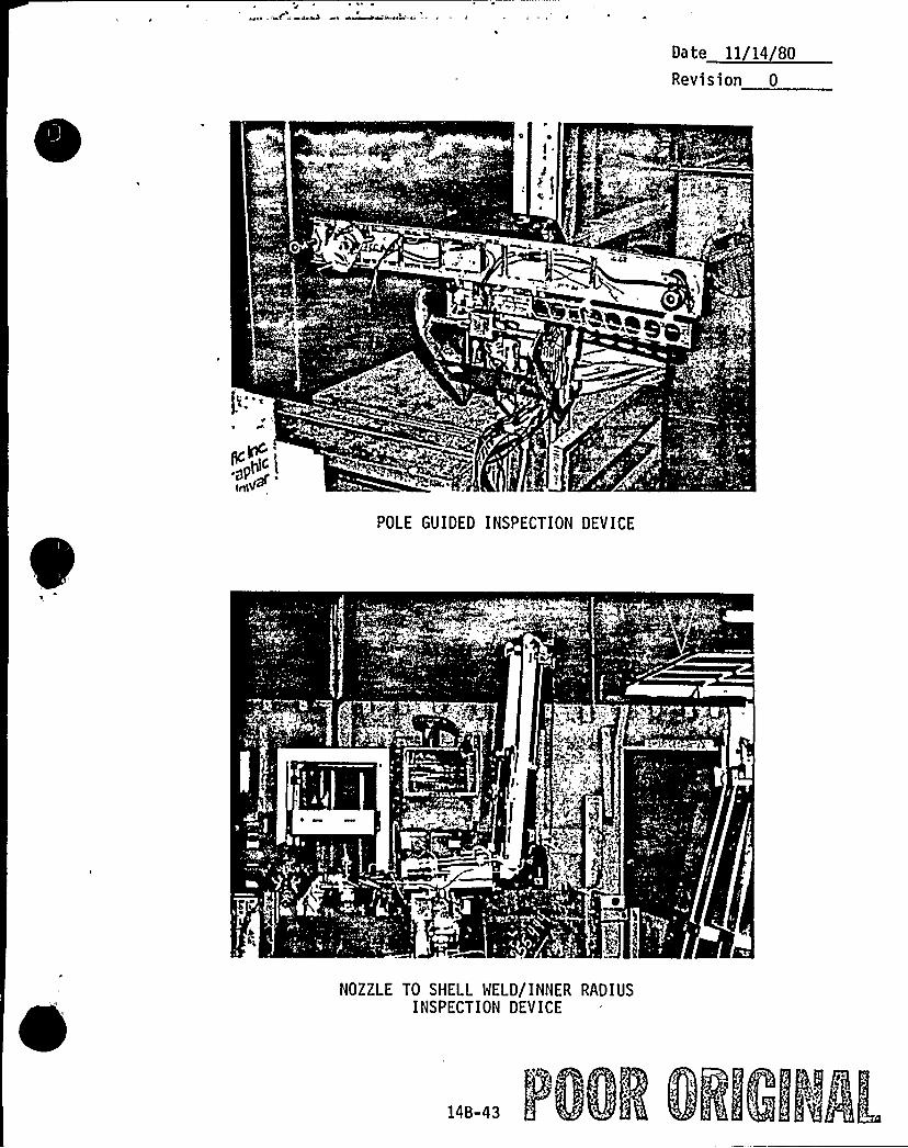
Date ll/14/80Revision 0
0 ~
p+p~
POLE GUIDED INSPECTION DEVICE
C <f
C
NOZZLE TO SHELL WELD/INNER RADIUSINSPECTION DEVICE
14B-43

4 f R g
I
'
fit J V
ad
Revision
11/14/80
15.0-,-PSI REPORT SUBMITTAL
Following the completion of the WNP-2 Preservice Inspection, a Preservice
Inspection Report will be prepared by the Supply System and fil,ed with the
enforcement and regulatory authorities having jurisdiction at the plant
site. The report will satisfy the reporting requirements of the reference
ASME Section XI Code, Article IWA-6000, "RECORDS AND REPORTS".
The WNP-2 Preservice Inspection Report will include, but not be limited to,the following information:
l. Abstract, including form NIS-1.
2. Authorized Inspector approval.
3. Summary of examinations and results, including disposition of signi-ficant indications.
4. Procedures used during the PSI effort.
5. Equipment, personnel, and material certifications.
6. Report supplement itemizing the examinations performed, procedures
used, data sheet references, and results of each examination. This
supplement will consist of the following:
a. For piping systems involving volumetric and surface examinations,
including the RPV and appurtenances, the supplement will include
weld and component identification diagrams which reflect as-
built, as-examined conditions, and non-destructive examination
summary tables which list the examination results for each exam-
'nation item.
b. For piping systems involving only visual examinations, the supple-
ment will include the ISI boundary diagrams which reflect as-built, as-examined conditions, and a summary of examinationresults for each system.
15-1
~ ~ - r.,14 8
Revision 0
The format for the non-destructive examination summary tables is shown
on the following pages, including sample completed tables with typicalentries.
At the time of issuance of this document,, the filing of the PSI finalreport is anticipated to occur in September 1981 amendment.
~ 5h,
15-2
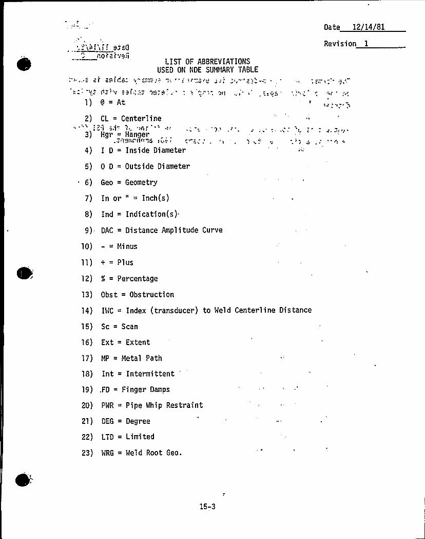
no'r z'r ve,lLIST OF ABBREVIATIONS
USED ON NDE SUMMARY TABLE
Date 12/14/81
Revi sion 1
v L4
2)
8 = At
CL = Centerline
4)
0 D = Outside Diameter
3) Hgr = Hanger.i'lemr1 1~'"ss i ii; '
D = Inside Diameter
'
~ 6)
8)
Geo = Geometry
In or " = Inch(s)
Ind = Indication(s)
9) DAC = Distance Amplitude Curve
1O)
14)
18)
19)
2O)
2i)
22)
23)
- = Minus
+ = Plus
X = Percentage
Obst = Obstruction
IWC = Index (transducer) to Weld Centerline
Sc = Scan
Ext = Extent
MP = Metal Path
Int = Intermittent
FD = Finger Damps
PWR = Pipe Whip Restraint
DEG = Degree
LTD = Limited
WRG = Weld Root Geo.
Distance
15-3
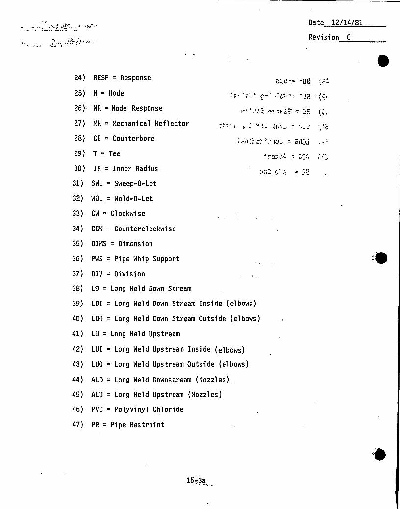
I ~ ~ ~
~PK/P f g "gg
Date 12/14/81
Revision 0
24)
25)
RESP = Response
N = Node
26) NR = Node Response
27)
28)
2g)
3O)
31)
32)
33)
34)
35)
36)
37)
38)
3g)
4O)
41)
42)
43)
44)
45)
46)
47)
MR = Mechanical Reflector
CB = Counterbore
T = Tee
IR = Inner Radius~ n»
SWL = Sweep-0-Let
WOL = Weld-0-Let
CW = Clockwise
CCW = Counterclockwise
DIMS = Dimension
PWS = Pipe Whip Support
DIV = Division
LD = Long Weld Down Stream
LDI = Long Weld Down Stream Inside (elbows)
LDO = Long Weld Down Stream Outside (elbows)
LU = Long Weld Upstream
LUI = Long Held Upstream Inside (elbows)
LUO = Long Weld Upstream Outside (elbows)
ALD = Long Weld Downstream (Nozzles)
ALU = Long Weld Upstream (Nozzles)
PVC = Polyvinyl Chloride
PR = Pipe Restraint
= G)4i
15-..3a
»:afv&liDate 12/14/81
Revi sion 0
48) BDY = Body
49) BLT = Bolting (valve)
50) BD = Flange Bolting
51) LOC = Leak Off Connection
52) LONG = Longitudinal
53) ACC = Accept
54) SE = Safe End
>»'
I yrr
'„,
>~ y
I ~
/ ~
I r ~I
y h j ~ ~ '!
~ h
Ih>r I ~ r ~~ ~ 'r yI'rr
'y> I( ~
~ ~
,>C CCC
r>
~ I
15-'36'

~PI
„\
1 j, 0
y1
Ip
I
<',IF'I
0-
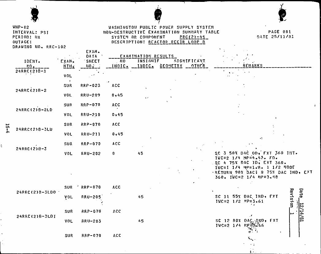
MNP-02INTERVAL: PS1PER100: NAOUTAGE:DRA'MING NO ~ RRC-102
WASHINGTOW PUI3LIC POPE ff S(IPPLY SYST.. )
hlOtl-DESTRUCT IVE EX A!flNATION SUHt'fARY TABLESYSTE'0 ifR COffPONFNT PRC(2) -4SOESCR IPT ION'. REACTOR RECIR LOAP 8
PAGE 001!)ATE 25/ll/81
I DfNT ~
t.'O ~
24RRC(2)B-1
E$ AH ~
t~i TH~
EXAH ~
DATA"SHEET
hlO ~
EXAHINATIOf'f RESL!LTSN 0 I N S I C N I F S I G h! IF I C'.9 T
IfFDIC INOTC GEf)'fETRY ATfL R REHARKS
24RRC(2)B-2
J
SUR PRP-023 ACC
24RRC(2)B-2LD
VOL RRU-209
SUR RRP-070
VOL RRU-210
0e45
ACC
Oe45
24RRC(2)B-3LU
24RRC(2)B-3
SUR RRP-070
VOL RRU-211
SUR RRP-070
ACC
Oe45
ACC
VOL fcRU-202 0 45 SC 3 50K DAC
DDT�
. F'XT $ 60 IhlT ~
It!C-"2 1/4 HP=4 ~ 43 ~ FD ~
. SC 4 75K OAC IOe EXT 360 ~
I WC=1 1/4 !ifP=1 '8 ~ 1 1/2 NODERETURN 904 DAC e 9 75~ DAC INDe EXT360 'LfC=P. 1/4 NP=3 F 88
24RRC(2)B«3LDO
24RRC(2)B-3LOI
SUR 'RP-070 ACC
VOI RRU-205
SUR RRP-070 ACC
VOL RRU-203
SC ll 557 DAC INDe fXTIMC=2 1 /2 ~P=3 ~ 61
SC 12 80K OAC.-...I'D e f XTI M C= 2 1 /4 fiP +," 66
ZI O!D QlC c+Wo Qcji
O M
00
SUP, RR P-070 ACC
I»gati
{e ge i ~ gt Ilie
re
(e( ~ ~
I i III
6 ~ ~ (
r ~ ) ~ -';{".as { . n~ i'h
~r 4 re /1{ef~ » f)(A,, i 'P i P(1i {i
>$ ({("""~(; = i('~
1bgi',g i~ e
~
~ 'ril".: '1(» 7. 'i'' '(.j1g{{
~ i ke
"C .(i.;(',
!U({ ~ .i")i .
(,( .V1 'g(; - ME
e
e
( r.r~riq~r, ~
.- ~ j\''{("('11'»'{'. ~ -'){ r
''»f(i
r
V
,<c '~v
~i ~
' 83 Dhs{s~rgb7 = '."'
/ e
{'(i&4~:,"{i h{ &a /{10„{Sq. & tb'u{i~l
g ~ =+p{ (C» ~" ~ '»(Sr. ~ a ~
"(ygqc pig,
gr. ~g t"
rg) p{eV r P,(r
'„'t VAU08F~Q opr
:r (.{tgPai>usga."d'"
..ci'AADu( " '{99{{Ljo.(P(, <g 1r ) + JP/
(i'{~l f&SA&e){",tie-:{. { oo'.»,",'(;,
e '"0 -'oA f»j-'{{a.~~'wHac<'- .-: '..
'y'{ops".6'0
g i (ggp gl( p L'CjM
Q4„':id@{>r',( =;..;; Z) {{O'i
'{e{m{'(';a){",
(:,a;vi0'cQ
~..8'- {f:..1h'0 " ..r
eI
4 / &OG(e» 'Cr({'.„-': O'SV3 = J '=
tC ".P>F"SX3 = (» e
oo Fzs'rl KitKx3 ". +."',)..
>(35"
l»ek 6 ( >r.//~1
~ '
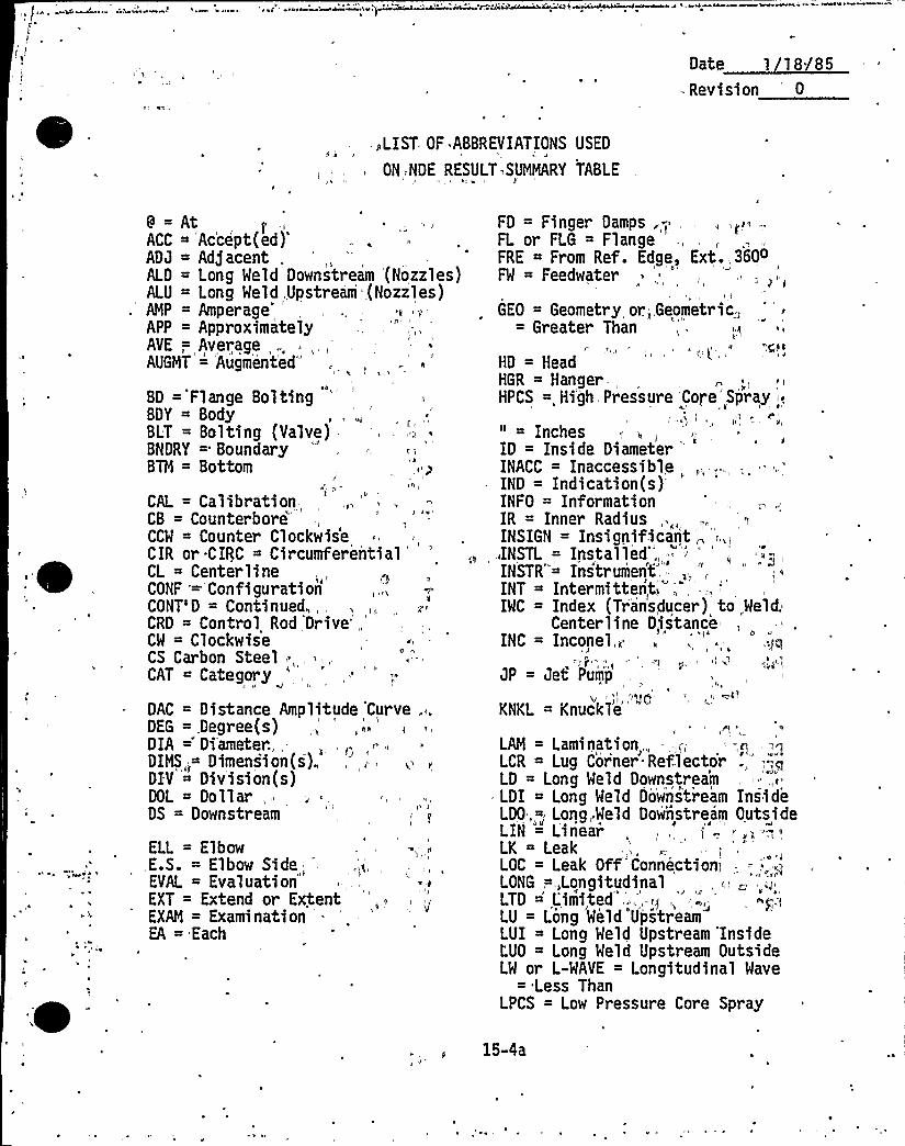
0 t ~11 /85= Rev~sion 0
>LIST OF. ABBREVIATIONS USED
ON, NDE RESULT SUMMARY TABLE
9 = AtACC ~
Ac'cept(ed)'DJ
= Adjacent,ALD = Long Meld Downstream (Nozzles)ALU = Long Meld,Upstream (Nozzles)AMP = Amperage'APP = ApproximatelyAVE -; Average „.. .,,,,AUGHT =
Augment'ed'D
='Flange BoltingBDY = BodyBLT = Bolting (Valve),BNDRY = BoundaryBTN = Bottom
/
CAL = Calibration-,CB = CounterboreCCW = Counter ClockwiseCIR or.CIRC = Circumferential
'L
= CenterlineCONF '='ConfigurationCONT'D = Continued,,CRD = Control Rod 'Drive'„'W
= ClockwiseCS Carbon Steel ...CAT = Category
DAC = Distance Amplitude 'Curve . „
DEG =,Degree(s)DIA =" Diameter...-DIHS„= Dimensi on(s),DIV = Division(s)DOL = Dollar,,DS = Downstream
ELL = ElbowE.S. = Elbow Side
„'VAL= EvaluationEXT = Extend or ExtentEXN = Examination '.EA = Each
FD = Finger Damps .; .,FL or FLG = Flange ',FRE = From Ref. Edge, Ext. 360oFW = Feedwater
I
GEO = Geometry or.„,Geometric,= Greater Than
HD = HeadHGR Hanger.,HPCS =„Hi'gh Pressure Core Spray <
" = InchesID = Inside Diameter
'NACC= InaccessibleIND = Indication(s)INFO = InformationIR = Inner Radius,.„„,INSIGN = Insigpificant „;.,iINSTL =
Installed'NSTR'
Instrument',INT = Intermitten,t>,
'MC= Index (Transducer) to,Meld.Centerline Distance
INC = Inconel,~ „, ' '>j~I
JP = Jet Pum'p,,-
KNKL = Knuckle
LAN = Lamination,„- —,~.,:-,p,LCR = Lug Cor'ner Reflector .,";=,~LD = Long Weld DownstreamLDI = Long Meld Oo'wns'tream InsideLDO „;-, Long,,Weld Dow'nstream OutsideLIN = L'i'nearLK = LeakLOC = Leak Off'ConnectionjLONG,=,,LongitudinalLTD ',Limi,ted „.,-~~,,™.;...LU = Long Weld UpstreamLUI ~ Long Meld Upstream'InsideL'UO = Long Meld Upstream OutsideLW or L-MAVE = Longitudinal Wave
= Less ThanLPCS = Low Pressure Core Spray
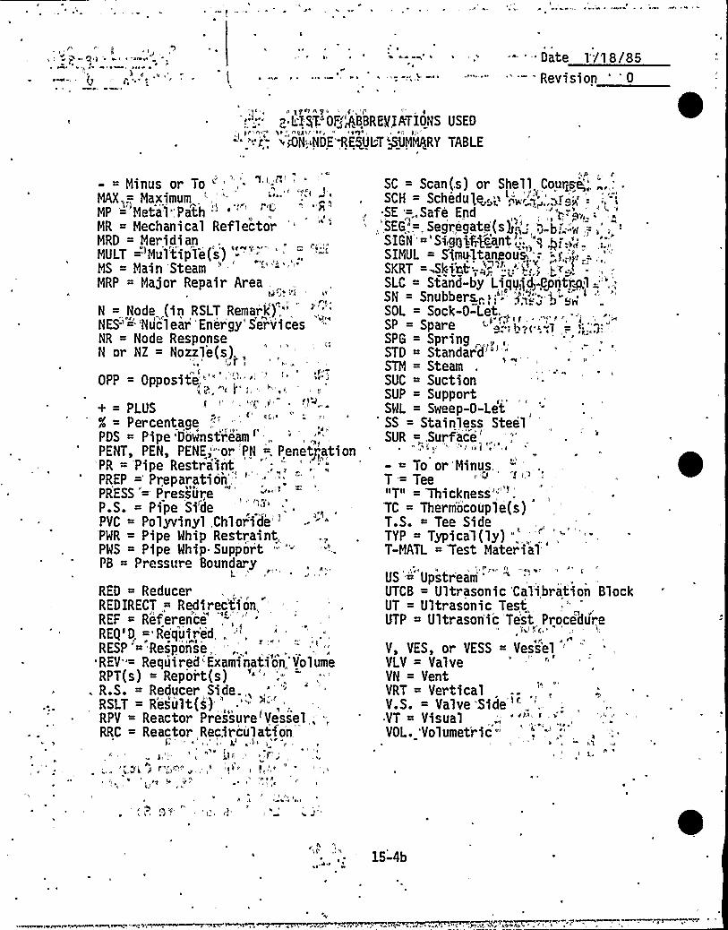
'4 4
~ 4 4 44
'L '4W I ~ .- '- Date 1'/'18/85Revision ' 0
I
p LI)TIOF„'"ABBREVIATIONS USED
w 4N ~NDE'RESULT MMMARY TABLE
4C=
- = Minus or To " ',"- " ',;", '
MAX ;—,
MaximumMP = Metal",Path " '
'R
= Mechanical ReflectorMRD = MeridianMULT ='Mul'tip'le(s') '-'"'.MS = Main SteamMRP = Major Repair Area .
N = Node (in RSLTRemark',"'ES-'"Nucl
ear 'ner'gy" Servi cesNR = Node ResponseN or NZ = Nozzle(s) „
I
OPP = Opposite,'-'"
+ = PLUSX = Percentage
,'-'DS
= Pipe'Downstream'ENT,
PEN, PENE,'-'or PN =, Penety~ationPR = Pipe RestraintPREP = Preparation'' "
PRESS "= PressureP.S. = Pipe'i'dePVC = Polyvinyl Chl or ide'PWR = Pipe Whip Restraint,PWS = Pipe Whip Supp'or't " '"PB = Pressure Boundary
RED = ReducerREDIRECT,=, Redirec'ti on,REF = Reference',-'.„„"REg'D ="Re'quir'ed, . -",RESP = Response,REV"= Required-Examinati'on,'VolumeRPT(s) = Report(s)
. R.S. = Reducer, SideRSLT = R'esult(s4') ',RPV = Reactor Pressure'Vessel „-,.RRC = Reactor Recirculation
f
~ gg g4 f 4f 44444
I'I
4 I
SC = Scan(,s) or Shell, Course;,'. „.„'SCH = Schedule', -„'> „',>re.,: .'-,'-"i
SE =,„Safe End„',SEG, .=, Segr,egate(s g „',', b;"'„.:;> .= „', -:
SIGN 'Si,ggkf7gaytl,", '"qp,".,"„',.;,'IMUL
= S'imu1tanyous, =.;~.:„';'=,-,'KRT=-Skirt='" ': '<';,"; .j~:.-
SLC = Stand-by Liqg~ig<yntrl ='",'N
= Snubbers, 1;"'>"„., g"'>'„'SOL = Sock-O-Let.SP = Spare <" "."-,!,",<'-,'1 =': '--SPG = Spr ingSTD =
Standard'"',"„'TM
= SteamSUC = SuctionSUP = SupportSWL = Sweep-0-Let-SS = Stainless SteelSUR =..Surf'ace'.
4
- = To or'Minus,, -', .
T= Tee"T" = Thickness'-TC = Therm'ocouple(s)T.S. = Tee SideTYP = Typical(ly) "
T-MATL = Test Material
US'='pstream ""'TCB= Ultrasonic 'Calibration Block
UT = Ultrasonic Test,UTP = Ultrason'i'c 'Te'st Procedure
kid <'c,4
V, VES, or VESS = Vessel '-
VLV = ValveVN = VentVRT = VerticalV.S. Valve 'Side "-
~ VT Visual,VOL. 'Volumet'ric-
44
15-4b
'('.' iO'
=5"or 3 f V41I
Il ~I/ 5
Revision 0
4 L'Isl 0Ã'AMEVIATI50NS USED
l'ON"NDE "RCSOLW -'SUMlNKY TABLE
5
'W MP+~C3 r ~ I'C, r l tr
MCG = Weld Crown Geo?f't==r:2WD = WeldWOL = Meld-0-Let ') 9>f"~-'""!92 — -:"MPG = Meld Prep; EeomdtF). = "'< '--MRG = Weld Root'ctmometFjr, = -'-'
MRR.=. Weld Radius Reft&br,=''C
= Ke%F4dMri-'"-f- '~<»bn==2 =>-'!'CL
= Weld Centerline"-".-"'"'„'2 " »~09J-iJ-~x~ = JO2
XDUCER = Transduceroftr'",r' ".tq,'.
I&) giltJ +2, 755
.I@922 = ''.2~ 5»
+r'J-0 (99wr -" .!r ri
t 9912 229 nf5 '
2'U!tiff
1C 'T =-99T =
»9qgw fr( rl kl
(2) 9f aUC-cm;9lt9b P 99'
'gf i ryQrq'/r = 1 l'6."te)Srr't9 "&I = t,'riM-.
'-'O ? Ul'
555 5
\ ~
'%"~ 2 I t i»'9~A «,'aqua,'$ !~'j5
«araH J2n !t":. -'c ' t9»? V 145 %go«r
~ "t
9+f
2ol-9'„5Ffr,33
f9 r
"a'!ac<w'rC:qi'" = 'J~-O('S-29«" -- ' "'"-"'t 8" rN ".
„'nii"42-.: '<r I =-:l".r5!5 gi god g Q ~ pe
~ v5 c 9 ~
r..'.r" grrrQ = P
9t:",O,'F„, I!t'.,pro~ = '.
rr Z".'2a,~ aHtI 9O: ', = .":
v"s",OU2 qi.".W eo !t = . W t
~s9'f+!.U - V„rlI 3F«di t63 ", f»r'25" r r 0 "- OCTA
f297 ar-.",OZ ",:lU = Tt.". a9oo~~ 0,".9T ~f.tc29",'4 --:Tl,
f9229'i = r.2=",™o, 3/ Y
9VIGY -" l. Jl- AYfsoii"9Y
9bi2 9vfal. SU2fV "- l V
3 i™+9rttUfC .:0.
9.>ft9 to+98tp53Q 1
r'r)
251', l 2'1 " lr'll.. 5~~ < ~+'1 ftrrE.X» "..:1....3
~ v~2 l9rU'P = r
f'tcC9Y 9«L~~~ 0 "~ ..5~ l
'oUF t vo lfDo lo ~ 3H "-
5'5-4c
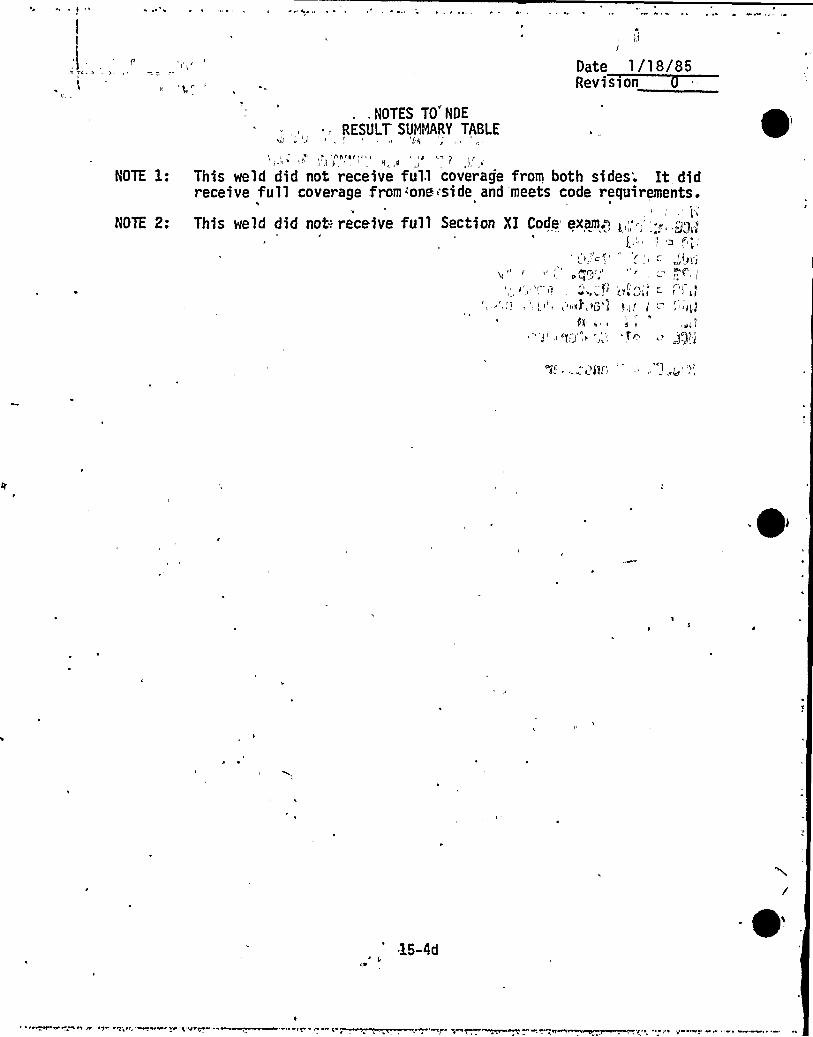
l
Date 1/18/85R i II
.NOTES TO NDE
RESULT SUMiORY TABLE
... Ih((
This weld did not receive ful.l coverage from both sides'. It didreceive full coverage from:one side and meets code requirements.
This weld did not-: receive full Section XI Code exam.q ~,„".'<,.~g,,
. «'Af"
k5-4d