recommendation 3 - dansk energi
TRANSCRIPT

Recommendation 3
Technical terms and conditions etc. for arc-
suppression coils for 10-60 kV system voltage
5th edition, 2022
Danish Energy
Vodroffsvej 59
1900 Frederiksberg C
Tel.: +45 35 300 400
E-mail: [email protected]
www.danskenergi.dk
© Danish Energy 2021
CONTENTS
1. SCOPE
2. GENERAL REQUIREMENTS
3. PRINCIPAL ELECTRICAL DATA
3.1. Rated frequency
3.2. Rated voltage
3.3. Rated current
3.4. Regulation range
3.5. Tolerances
3.6. Load time
3.7. Insulation level
4. CONSTRUCTIONAL DETAILS
4.1. Regulation equipment
4.1.1. Arc-suppression coils for stepless regulation
4.1.2. Arc-suppression coils for stepped regulation
4.2. Cooling equipment
4.3. Bushings
4.4. Main tank
4.5. Protection against corrosion
4.6. Box for auxiliary equipment, control conductors etc.
4.7. Protective earth connection
5. ACCESSORIES
5.1. Oil conservator
5.2. Gas relay etc.
5.3. Dehydrating breather
5.4. Valves
5.5. Secondary winding, instrument transformers etc.
5.6 Wattful component amplifier (resistor)
5.7. Transport arrangements etc.
5.8. Oil
5.9. Marking
6. TESTING
6.1. Routine tests
6.2. Type tests
6.3 Special testing
7. DATA TO BE PROVIDED IN INVITATION TO TENDER
8. DATA TO BE PROVIDED IN TENDERS SUBMITTED
ANNEX 1: SURFACE TREATMENT
ANNEX 2: SPS CLASSES

3
1. SCOPE
This recommendation applies to oil-immersed arc-suppression coils with normal accessories
for use in 10-15-20 kV and 50-60 kV networks.
The arc-suppression coil must be designed for outdoor and indoor installation at air
temperatures in the range -25 ... +40°C. Furthermore, the monthly average temperature must
not exceed 30°C, and the annual average temperature must not exceed 20°C.
The recommendation is published in Danish and English. In case of discrepancy
between the two versions the Danish version shall prevail.
2. GENERAL REQUIREMENTS
The arc-suppression coil must comply with applicable Danish legislation.
The arc-suppression coil must be made in accordance with DS/EN 60076-6. The general
requirements and test requirements in relevant standard issued by CENELEC, CEN and IEC
standards at the time of the invitation to tender must be fulfilled.
It is the responsibility of the user of this recommendation to ensure that the current version and
any applicable amendments to legislation, regulations and standards are used when preparing
invitations to tender. Information about the applicable version of a standard and any
addendums is available from Danish Standards, CENELEC or IEC.
The terminology used in this recommendation is in accordance with the definitions given in the
above mentioned standards.
3. ELECTRICAL MAIN DATA
3.1. Rated frequency 50 Hz
3.2. Rated voltage Nominal system
voltage [kV]
Rated voltage of
arc-suppression coil
[kV]
10 11 √3⁄
15 16 √3⁄
20 22 √3⁄
50 52 √3⁄
60 66 √3⁄
3.3. Rated current The rated current according to the following tables must be stated in invitations to tender.
Rated currents refer to the maximum current settings.
Nominal
system voltage
[kV]
Rated current
[A]
10 16 25 31,5 40 50 63 80 100 125 160 200 250 300 400
15 11 17 22 27 34 43 54 68 87 108 135 173 217
20 12,5 16 20 25 31,5 40 50 63 80 100 125 160 200 300
Nominal
system voltage
[kV]
Rated current
[A]
10
15
20 400 500
Nominal
system voltage
Rated current
[A]

4
[kV]
50 21 27 33 42 53 67 83 105 133 167 210 300
60 17 21 26 33 42 52 66 83 105 131 165 210 300
3.4. Regulation
range
Arc-suppression coils are categorised as follows according to the regulation method:
3.4.1. Arc-suppression coils for continuously regulation (adjustable air gap)
Unless otherwise agreed, the regulation range must be:
Nominal system voltage
[kV]
Regulation range
10-15-20 1:5 to 1:12,5
50-60 1:12,5
3.4.2. Arc-suppression coils for stepwise regulation
These must have the following regulation ranges and tappings, unless otherwise specified in
the invitation to tender:
Rated current < 50 A: current tappings at 40-50-63-80 and 100% of the rated current.
Rated current ≥ 50 A: Current tappings must be placed so that the difference in current between
two consecutive tappings does not exceed 10 A or 20% of the smaller of the two current values.
The lowest current tapping must be 40% of the rated current of the arc-suppression coil.
With the recommended regulation ranges, more tappings may be required to meet the step
and touch voltage requirements in the Executive Order on safety for the realisation of electrical
installations [in Danish: Bekendtgørelse om sikkerhed for udførelse af elektriske anlæg] and
DS/EN 50522.
3.5. Tolerances The purchaser reserves the right to reject the arc-suppression coil if the difference between
the agreed and measured current value, see section 6.1.2, is greater than ±5% at the maximum
current setting or ±10% in one or more of the other positions, see 6.1.2.
3.6. Load time 3.6.1. 10-20 kV arc-suppression coils must be dimensioned to carry the rated current
continuously. The maximum temperature rise for the winding is 80 K.
3.6.2. 50-60 kV arc-suppression coils must be dimensioned to carry the rated current for two
hours. The maximum temperature rise for the winding is 100 K.
3.7. Insulation level
Rated voltage
[kV]
Rated withstand voltage at the network
connection terminal
Rated withstand
voltage at the earth
terminal
Alternating voltage
[kV]
Impulse
≤ 1,2/50 µs
[kV]
Alternating voltage
[kV]
11 √3⁄ 28 75 28
16 √3⁄ 38 95 38
22 √3⁄ 50 125 50
52 √3⁄ 95 250 28
66 √3⁄ 95 250 28

5

6
4. CONSTRUCTION
4.1. Regulation
equipment
4.1.1. Arc-suppression coils with continuously regulation
The arc-suppression coil must be designed for regulation during operation and made for
mechanical and electrical local control as well as for electrical remote control. The electrical
control – local as well as remote – must be blocked during mechanical control. In the case
of local control, it must be possible to operate the arc-suppression coil from the ground.
The arc-suppression coil must be prepared for connection of a control unit for automatic
regulation of the arc-suppression coil during operation. If such equipment is to be included
in tenders, this must be indicated in the invitation to tender with the requirements
concerning the equipment.
The current setting of the arc-suppression coil must appear on an indicator which is
mechanically connected to the iron core. It must be possible to read the indicator at a safe
distance from live parts.
The regulating motor must be a three-phase short circuit motor protected by a motor
protection device. The motor, control circuits and associated auxiliary equipment must be
made for 230/400 V AC (but DC for signal contacts). The arc-suppression coil must be
equipped with a limit switch and must not be damaged if an electrical limit switch fails. The
motor etc. must have a class IP 55 enclosure and be dimensioned for a lifetime of at least
10 years in intermittent operation.
4.1.2. Arc-suppression coils with stepwise regulation
Switching between the tappings described in 3.4.2. must take place while the arc-
suppression coil is in the de-energised state with a tap-changer built into the main tank.
The tap-changer must be easy to operate by means of a handle placed outside the arc-
suppression coil tank.
The step positions of the tap-changer must be clearly marked with the numbers 1, 2, 3, ...
etc. The number 1 indicates the lowest coil current.
If more steps than usual are required, see section 3.4.2, two tap-changer may be used if
necessary.
The relationship between the position of the tap-changer and the current setting of the arc-
suppression coil must be indicated on the rating plate.
4.2. Cooling equipment The cooling system of the arc-suppression coil must be made for natural oil and air
circulation (ONAN).
4.3. Bushings 4.3.1. 50-60 kV nominal network voltage
The invitation to tender must indicate whether open type bushings or plug-in type bushings
are to be used.
4.3.1.1 Open type
Bushings must be dimensioned for rated current of the arc-suppression coil. and must be
made and tested as prescribed in DS/EN 60137.
The invitation to tender must indicate whether the outer insulator of the bushing must be
made of porcelain or a polymer material. The invitation to tender must indicate whether the
inner insulation must be of the type RIP (resin impregnated paper) or RIS (resin
impregnated synthetic).

7
In the case of porcelain insulators, brown-glazed porcelain dimensioned for full vacuum
(100 Pa) must be used.
The insulators must be suitable for use in an environment corresponding to SPS class d or
e, see DS/IEC TS 60815-1. Annex 2 contains examples of typical environments
corresponding to SPS class d and e. The requested SPS class must be indicated in the
invitation to tender.
The minimum creepage distance for the insulators must be as follows regardless of the
material:
Highest voltage for
winding [kV]
Minimum creepage distance [mm]
SPS class d SPS class e
72,5 1812 2248
The insulator connected to the earth terminal bushing must have the same creepage
distance as a network connection terminal for 10 kV rated network voltage, see section
4.3.2.1.
Connection pins must be of silvered copper and have a minimum diameter of 30 mm and
a free length of at least 80 mm.
The internal connection of the windings to the insulators must be secured to prevent nuts
loosening.
4.3.1.2 Plug-in type bushings
Plug-in type bushings must be dimensioned for an overload of at least 150% with reference
to the rated power of the transformer and must be realised and tested as prescribed in
DS/EN 50673.
It must be possible to inspect and replace the bushings without the need to raise the cover
of the transformer.
The bushings must be placed and marked as shown in annex 1. The marking must use
raised letters on the transformer cover at each of the bushings. The distance between the
bushings must adhere to the minimum values shown in the annex.
4.3.2 10-15-20 kV nominal network voltage
The invitation to tender must indicate whether outdoor type bushings or plug-in type
bushings are to be used.
4.3.2.1 Outdoor type
Bushings must be dimensioned for rated current of the arc-suppression coil and mustmust
be made and tested as prescribed in DS/EN 50180-1.
The insulators must be suitable for use in an environment corresponding to SPS class d or
e, see DS/IEC TS 60815-1. Annex 2 contains examples of typical environments
corresponding to SPS class d and e. The requested SPS class is indicated in the invitation
to tender.
The minimum creepage distance for the insulators must be as follows regardless of the
material:

8
Highest voltage for winding
[kV]
Minimum creepage distance [mm]
SPS class d SPS class e
12 300 372
17,5 437 543
24 600 744
Insulators connected to the earth terminal bushing must have the same creepage distance
as an insulator for a network connection terminal bushing.
Dimensions of connecting bolts and nuts etc. are indicated in the invitation to tender.
Connection flanges must be included in the delivery and be of silvered copper or
a material with similar electrical and mechanical properties. Bolts and nuts must
be of stainless steel.
The internal connection of the windings to the insulators must be secured to prevent nuts
loosening.
4.3.2.2 Plug-in type bushings
Plug-in type bushings must be dimensioned for rated current of the arc-suppression coil
and must be made and tested in accordance with DS/EN 50180-1.
4.3.3 Marking of bushings
The network connection bushing must be marked A and the earth bushing must be marked
B. The marking must be weatherproof and oil resistant.
4.4. Main tank 4.4.1. The main tank (including cooling elements if any), gaskets etc. must be dimensioned
so that they are able to withstand without permanent deformation oil filling and also an
internal overpressure corresponding to an oil column of the same height as the internal
height of the tank. The arc-suppression coil must hereby remain oil-tight.
In the case of 50-60 kV arc-suppression coils, the main tank, cooling elements if any,
gaskets etc. must be able to withstand a vacuum of 100 Pa without permanent deformation.
4.4.2. The main tank, conservator and cooling elements must be designed to prevent air
pockets forming.
4.4.3. Cooling ribs made of corrugated sheet metal must be braced to each other at the top
and bottom if the ribs are more than 100 mm deep.
4.4.4. The main tank must have two connecting points for earth conductors, one on each
side of the tank. The connection point must be either an M12 earthing screw, length 35
mm, with two nuts, or a clamp connection for 95 mm2 cable. The screws etc. must be made
of stainless steel.
4.5. Protection against
corrosion
All items including screws, nuts and other fastenings, valves, terminals, terminal blocks etc.
must be dimensioned for a lifetime of at least 20 years in an environment corresponding to
corrosion class 3, high aggressiveness, industrial and coastal areas. For 10-20 kV arc-
suppression coils for indoor installation, however, corrosion class 1 may be specified in the
invitation to tender. Surface treatment etc. is realised in accordance with annex 1.
9
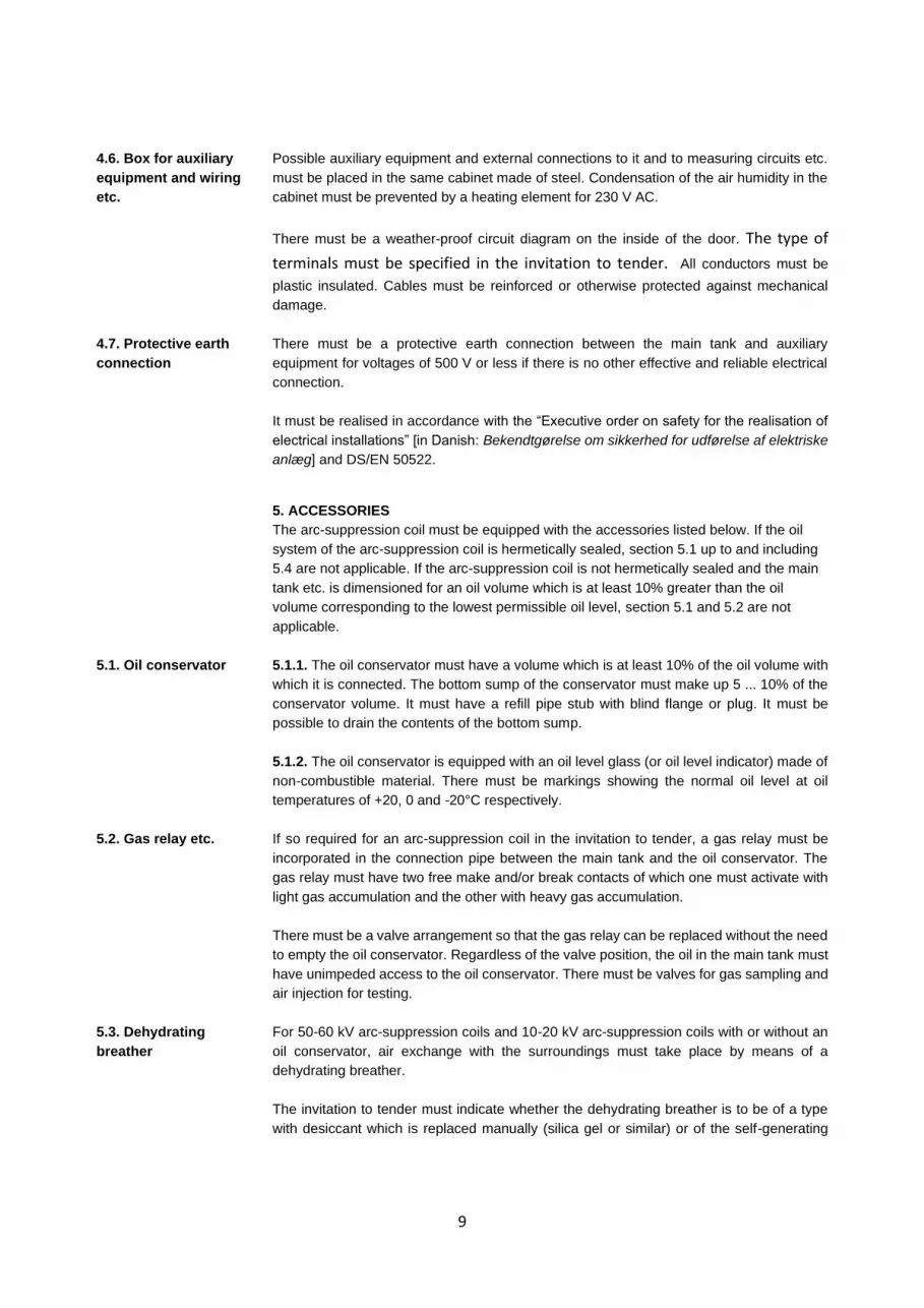
4.6. Box for auxiliary
equipment and wiring
etc.
Possible auxiliary equipment and external connections to it and to measuring circuits etc.
must be placed in the same cabinet made of steel. Condensation of the air humidity in the
cabinet must be prevented by a heating element for 230 V AC.
There must be a weather-proof circuit diagram on the inside of the door. The type of
terminals must be specified in the invitation to tender. All conductors must be
plastic insulated. Cables must be reinforced or otherwise protected against mechanical
damage.
4.7. Protective earth
connection
There must be a protective earth connection between the main tank and auxiliary
equipment for voltages of 500 V or less if there is no other effective and reliable electrical
connection.
It must be realised in accordance with the “Executive order on safety for the realisation of
electrical installations” [in Danish: Bekendtgørelse om sikkerhed for udførelse af elektriske
anlæg] and DS/EN 50522.
5. ACCESSORIES
The arc-suppression coil must be equipped with the accessories listed below. If the oil
system of the arc-suppression coil is hermetically sealed, section 5.1 up to and including
5.4 are not applicable. If the arc-suppression coil is not hermetically sealed and the main
tank etc. is dimensioned for an oil volume which is at least 10% greater than the oil
volume corresponding to the lowest permissible oil level, section 5.1 and 5.2 are not
applicable.
5.1. Oil conservator 5.1.1. The oil conservator must have a volume which is at least 10% of the oil volume with
which it is connected. The bottom sump of the conservator must make up 5 ... 10% of the
conservator volume. It must have a refill pipe stub with blind flange or plug. It must be
possible to drain the contents of the bottom sump.
5.1.2. The oil conservator is equipped with an oil level glass (or oil level indicator) made of
non-combustible material. There must be markings showing the normal oil level at oil
temperatures of +20, 0 and -20°C respectively.
5.2. Gas relay etc. If so required for an arc-suppression coil in the invitation to tender, a gas relay must be
incorporated in the connection pipe between the main tank and the oil conservator. The
gas relay must have two free make and/or break contacts of which one must activate with
light gas accumulation and the other with heavy gas accumulation.
There must be a valve arrangement so that the gas relay can be replaced without the need
to empty the oil conservator. Regardless of the valve position, the oil in the main tank must
have unimpeded access to the oil conservator. There must be valves for gas sampling and
air injection for testing.
5.3. Dehydrating
breather
For 50-60 kV arc-suppression coils and 10-20 kV arc-suppression coils with or without an
oil conservator, air exchange with the surroundings must take place by means of a
dehydrating breather.
The invitation to tender must indicate whether the dehydrating breather is to be of a type
with desiccant which is replaced manually (silica gel or similar) or of the self-generating

10
type. Regardless of the choice of type, the requirements for realisation and testing for the
respective type in DS/EN 60076-22-7 must be met.
The dehydrating breather must be placed approximately 1 m above the bottom of the
transformer tank and the dehydrating breather must have an oil lock to reduce the
exchange of air.
If silica gel is used in a dehydrating breather of the type with desiccant which is replaced
manually, the dehydrating breather must also be equipped with a window so that the colour
of the desiccant at the top and at the bottom of the dehydrating breather can be checked.
5.4. Valves 5.4.1. 10-20 kV arc-suppression coils must have an oil drain point on the side of the main
tank and as low as possible. If indicated in the invitation to tender, draining must take place
through a valve.
5.4.2. In 50-60 kV arc-suppression coils, at two diagonally opposite corners of the main
tank there must be two valves for filling, draining and recirculation. One valve is installed at
the bottom of the main tank such that the bottom layer will also be included in oil circulation.
The other valve is at the top of the tank. Alternatively, it may be placed at the bottom, but
in that case it must be connected to the top of the tank by means of a rise pipe, and the
rating plates of the valves must clearly state which one is for the top oil. The valves must
be terminated with a DIN 2533 flange with a bore of 40 or 80 mm2.
5.4.3. One valve must be provided for oil test sampling. The valve must be placed at a
height of about 10 cm above the bottom of the main tank.
5.4.4. All valves must be equipped with an oil-tight closing cap or blind flange and, if there
is more than one valve, with a rating plate describing their use.
5.5. Secondary winding,
instrument
transformers etc.
5.5.1. Unless otherwise specified in the invitation to tender, a 10-20 kV arc-suppression coil
must have a secondary winding intended to be connected to a resistor for increasing the
resistive component of the earth fault current.
The rated voltage of the secondary winding must be 500 V with a tolerance of ±10%, to be
met for all arc-suppression coil settings. For arc-suppression coils with stepwise regulation,
see section 3.4.2., the winding is switched together with the primary winding.
The rated power of the secondary winding and the maximum operating time at full load
should be indicated in the invitation to tender. If nothing else is indicated, at least 100 kW
and an operating time of 90 seconds must be selected.
The temperature of the secondary winding must not exceed the value in DS/EN 60076-5
table III for the temperature of transformer windings after short circuit.
5.5.2. If so requested in the invitation to tender, a current transformer must be incorporated
with a rated performance of 15 VA in class 1 with extended current range to 120%. Of the
IEC standardised rated currents for current transformers, the rated current for current
transformers which is closest to (and less than) the rated current of the arc- suppression
coil must be selected as the primary rated current. The secondary rated current must be 5
A.
5.5.3. If so requested in the invitation to tender, a voltage transformer is incorporated with
the secondary rated voltage specified herein (100 V or 110 V). The rated performance must
be 100 VA in class 3P, unless otherwise agreed.

11
Alternatively, in arc-suppression coils with an adjustable air gap, a measurement winding
is used. In this case, a transformation ratio tolerance of ± 15% is allowed, which must be
met for all arc-suppression coil settings. The angle error must correspond to class 3P.
5.5.4. Terminals for instrument transformers and the secondary winding must be clearly
marked. The markings must be weatherproof and oil resistant.
5.5.5. Possible signal contacts must be available for DC, see the invitation to tender.
5.6. Resistor The resistor for increasing the resistive component of the earth fault current must be able
to be connected to the secondary winding of the arc-suppression coil as described in
section 5.5.1. The resistor must be made and tested in accordance with annex G to DS/EN
60076-6.
The resistor must be air-insulated, unless otherwise indicated in the invitation to tender.
The invitation to tender must indicate whether the resistor is to be installed indoors or
outdoors.
The resistor must have a rated voltage of 500 V and a rated power which must be specified
in the invitation to tender (typical values are around 60 and 100 kW) and must be
dimensioned for a minimum 30-second connection time, after which disconnection and
cooling may be necessary. The cooling time must be indicated in the tender.
The resistor must have the degree of protection IP23.
The resistor must be protected by a thermal relay.
5.7 Transport
arrangements etc.
5.7.1. The invitation to tender must indicate whether 10-15-20 kV arc-suppression coils are
to be fitted with transport rollers.
5.7.2. 50-60 kV arc-suppression coils must be fitted with transport rollers or flanged wheels
according to the customer’s specifications. In the case of flanged wheels, the track gauge
must be 1435 mm (internal measurement), see DS/EN 60076-22-7. 4 sets of lock wedges
must be supplied for securing to rails.
5.7.3. The frame of 50-60 kV arc-suppression coils must be equipped with the towing lugs
necessary for transport.
5.7.4. For 50-60 kV arc-suppression coils, the main tank must be equipped with clearly
marked reinforcements or lifting flanges for placing of jacks.
5.7.5. 50-60 kV arc-suppression coils must have loops or hooks for lifting of both the
complete oil-filled arc-suppression coil and the core with cover.
5.8. Oil Unless otherwise specified in the invitation to tender, the oil must be mineral oil and must
meet the requirements of DS/EN 60296 for transformer oil type A or type B.
The invitation to tender must indicate whether the transformer oil is to be inhibited.
To minimise the risk of copper sulphides forming in the oil, the oil must be tested as “non-
corrosive” in tests prescribed in DS/EN 62535.

12
5.9. Marking The arc-suppression coil must have a visible and unambiguous rating plate of a
weatherproof and oil-resistant type with the information specified in DS/EN 60076-6.
− Type of reactor (arc-suppression coil)
− Outdoor and/or indoor use
− Reference to EN 60076-6
− Manufacturer
− Serial no.
− Year of manufacture
− Insulation levels
− Rated frequency
− Rated voltage
− Rated no-load voltage for secondary winding (if applicable)
− Maximum continuous voltage
− Rated current and duration
− Type of regulation
− Type of cooling
− Temperature rise for the top oil and average temperature rise of winding at rated
current and duration
− Total weight
− Transport weight
− Weight of empty oil tank
− Weight of insulation oil
− Type of insulation oil and possible inhibitor
− Connection diagram for tappings including current transformers, if any
− Type of tap changer (in the case of stepped regulation)
− Table or graph indicating the regulation range in ampere or as a percentage
relative to rated current.
In addition, the weight of the core with winding and cover must appear.
6. TESTS
Before a delivery is approved, the routine and type tests described in DS/EN 60076-6 with
the following additions must have been carried out with a satisfactory result.
Protocols with the results of all routine tests must be submitted to the purchaser in duplicate
no later than the time of invoicing.
6.1. Routine tests 6.1.1. Measurement of winding resistance. In the case of arc-suppression coils with
stepwise regulating, see section 3.4.2, the resistance of the primary winding must be
measured in all positions.
6.1.2. Measurement of current throughout the regulation range. For continuously regulated
arc-suppression coils, measurements must be carried out at the outer positions and at a
sufficient number of points to verify the mechanical indication described in 4.1.1.
The measurement must be carried out as far as possible at the rated voltage and
frequency. If this is not feasible, the measurement must be carried out at the highest
possible voltage.
6.1.3. Measurement of voltage ratio between the primary and the secondary winding and
measurement winding respectively. For arc-suppression coils with stepwise regulation,

13
measurements must be carried out at all related tappings of the primary and secondary
winding. For continuously regulated arc-suppressions coils, at least the outer positions
must be measured.
6.1.4. Testing with overvoltage from separate voltage source. The size of the test voltage
is shown in the table in section 3.7. In the case of arc-suppression coils with uniform
insulation, the voltages in column 2 are used. In the case of graduated insulation, column
4 is used.
6.1.5. Testing with induced overvoltage. The arc-suppression coil is set to the minimum
current regardless of regulation method. However, in the case of arc-suppression coils with
stepwise regulation, it may be indicated in the invitation to tender that the test is to be
carried out at the maximum current setting.
The voltage between the terminals must be twice the rated voltage. In the case of arc-
suppression coils with graduated insulation, the bushing for the network connection must
simultaneously be tested with the voltage in column 2 of the table in section 3.7.
If a test with induced overvoltage is not feasible, it must be replaced with an impulse voltage
test as described in section 6.2.1, and this must be communicated to the purchaser in the
tender. For an arc-suppression coil with stepwise regulation, this alternative test is carried
out at both the maximum and minimum current setting.
6.1.6. Auxiliary and measurement windings must be tested with 2 kV to earth, 50 Hz, for
one minute.
6.1.7. Functional testing of regulation equipment, if any.
6.2. Type tests 6.2.1. Impulse voltage test with the test voltage in column 3 of the table in 3.7. The rise
time must not exceed 1.2 μs and the half time must be 50 μs. In the case of arc-
suppression coils with tappings, the test must be carried out with the arc-suppression coil
set to the minimum current.
6.2.2. Temperature rise test. The test must be carried out at the setting which produces
the highest losses.
6.2.3. Measurement of current at the rated voltage.
6.3 Special testing Special tests in accordance with DS/EN 60076-6 may additionally be specified in the
invitation to tender.
− Measurement of losses
− Measurement of magnetic characteristics up to and including 1.1 times the rated
voltage
− Measurement of sound level
− Endurance test of the regulation mechanism
− Demonstration of ability of the arc-suppression coil to withstand the dynamic
effects of the rated current.

14
7. DATA TO BE PROVIDED IN INVITATION TO TENDER
The following data and information must be provided in the invitation to tender:
• Rated voltage, see section 3.2.
• Rated current, see section 3.3.
• Whether regulation of the arc-suppression coil is to take place off-line or on-line.
• Possible requirements concerning the regulation range or step distances, see
section 3.4.
• In the case of off-line regulation, it must be indicated whether continuous
regulation is preferred.
• In the case of on-line regulation, it must be indicated whether a control unit for
automatic regulation, potentiometer, transmitter/instrument to indicate the
position etc. are to be included in the delivery, see section 4.1.1.
• DC voltage for signal contacts etc.
• Whether a current transformer is to be incorporated.
• Whether a voltage transformer/measurement winding is to be incorporated.
Requirements concerning rated voltages (and possibly rated power if there is no
need for 100 VA).
• Whether a 500 V secondary winding, see section 5.5.1 is to be omitted (10-20
kV) or included (50-60 kV).
• Rated power and operating time at full load.
• Whether the arc-suppression coil is to have a built-in or external neutral point
resistor. Rated voltage, rated power, connection time, whether it is to be air-
insulated or oil-immersed, and IP class, see section 5.6.
• Requirements concerning protection against corrosion and, if applicable, colour
of top coat, see section 4.5.
• Requirements concerning transformer oil, for example whether it is to be of type
A or B and whether it is to be inhibited, see section 5.8.
• Requirements concerning valves, see section 5.4.1.
• Whether a gas relay etc. is to be included in the delivery, see section 5.2.
• Whether a hermetically sealed tank or a non-hermetically sealed tank with or
without oil conservator is preferred.
• Whether the lid is to be bolted to the tank.
• Requirements concerning the dimensions of the arc-suppression coil.
• Whether the arc-suppression coil is to be equipped with transport arrangements
and if so, which ones, see section 5.7.
• If applicable, requirements concerning terminals: measurement bushings, short
circuit links, connectors, heaters.
• For arc-suppression coils with stepwise regulation, whether testing with induced
overvoltage, see 6.1.5., is to be carried out at the maximum current setting.
• Which spare parts must be included in the delivery.
• Earliest and latest delivery time.
• Place of delivery and approach to the site.
• If applicable, the terms of delivery, which unless otherwise specified is to be
carriage paid to place of delivery (lncoterms 2020).
• Deadline for submission of tender and respectively final dimension drawings,
circuit diagrams, maintenance instructions etc.
• Whether information is to be provided about a price increase for impulse voltage
testing (special test) as described in 6.2.1 (not applicable in the case of arc-
suppression coils for 10-20 kV networks).
• Possible requirements concerning warranty period, insurance and deposits.

15
Details of the commercial terms and conditions should also be provided.
8. DATA TO BE PROVIDED IN TENDERS SUBMITTED
Information about the following must be provided in the tenders submitted:
• Price for complete arc-suppression coil carriage paid to place of delivery.
• Price of spare parts and their warranty period.
• Price increase for impulse voltage testing (special test) if the purchaser has requested
this information.
• Possible price adjustments.
• Information about customs duties, exchange rates and VAT.
• Terms of payment.
• Data for bushings (creepage distances, insulation level, rated current, manufacturer,
type and type test).
• Oil type and, if applicable, inhibitor, in which case data for the base oil.
• Information about surface treatment.
• 500 V secondary winding: rated power and maximum operating time at full load.
• Resistor for increase of the resistive component of the earth fault current: rated voltage,
rated power, connection time and cooling time.
• Information about built-in current transformers, if any.
• Information about the sound power level see DS/EN 60076-10 at maximum induction
if measurements are carried out.
• Total weight of the arc-suppression coil.
• Weight of core with winding(s) and cover, required crane height to remove it.
• Weight of oil.
• Maximum transport weight.
• Dimension drawings, circuit diagrams, descriptions etc. which are necessary for
assessing the construction of the arc-suppression coil, including possible electrical
control equipment and regulation equipment, installed neutral point resistor etc.
• Delivery time.
• Warranty period.
In addition, the manufacturer must confirm that the arc-suppression coil meets the requirements
stated in the terms and conditions of the invitation to tender. Possible departures from the
requirements must be specified in detail.

16
ANNEX 1: RESISTANCE TO CORROSION
Note: Updating corrosion protection requirements are under consideration.
1. Efforts must be made to obtain a lifetime of 20 years or more.
2. An environmental pollution corresponding to heavy pollution (pollution level
III (heavy), see EN 60071-2) must be assumed.
3. All construction parts must be well drained. Profile and plate edges must be
rounded off, r2 mm or equal to half the metal thickness. Welding beads
and protruding surface defects must be completely removed.
All welds must be fully welded and all welding cinder must be removed prior
surface treatment. After welding with coated electrodes, the construction
must be carefully washed off with water if the subsequent cleaning is blast-
cleaning.
4. Outside surface treatment.
Supplier may choose between following system procedures:
4.1 Paint.
The pre-treatment must be sand blast-cleaning, minimum purity degree Sa 2
1/2 according to ISO 8501-1.
The surface treatment must be carried out as follows:
Basic treatment: two-component zinc-rich epoxy or metallisation with zinc
min. 50 m
Intermediate paint: two-component epoxy min. 140 m
or vinyl or chlorinated rubber min.
160 m
Paint finish: on epoxy two-component polyurethane or vinyl/acrylic enamel
min. 30
m
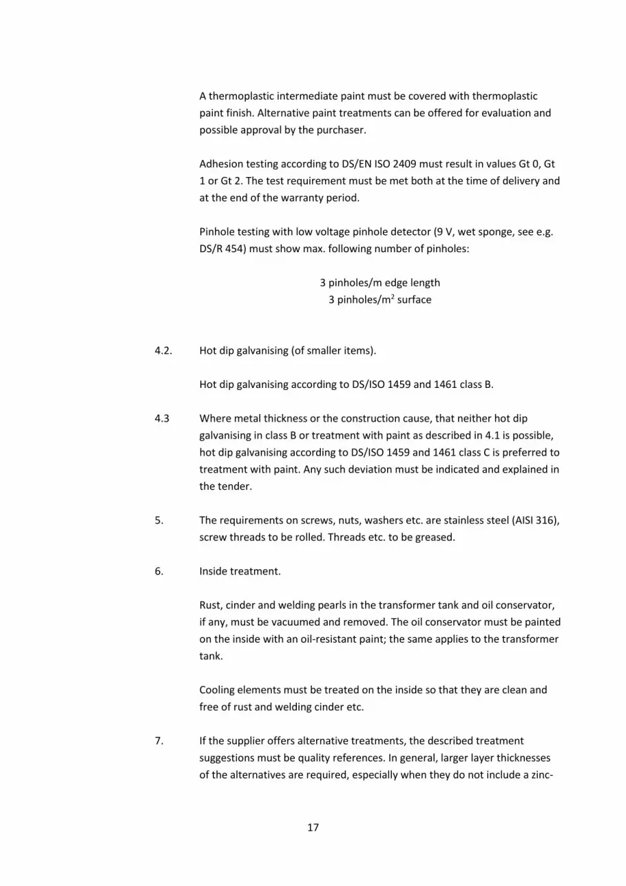
17
A thermoplastic intermediate paint must be covered with thermoplastic
paint finish. Alternative paint treatments can be offered for evaluation and
possible approval by the purchaser.
Adhesion testing according to DS/EN ISO 2409 must result in values Gt 0, Gt
1 or Gt 2. The test requirement must be met both at the time of delivery and
at the end of the warranty period.
Pinhole testing with low voltage pinhole detector (9 V, wet sponge, see e.g.
DS/R 454) must show max. following number of pinholes:
3 pinholes/m edge length
3 pinholes/m2 surface
4.2. Hot dip galvanising (of smaller items).
Hot dip galvanising according to DS/ISO 1459 and 1461 class B.
4.3 Where metal thickness or the construction cause, that neither hot dip
galvanising in class B or treatment with paint as described in 4.1 is possible,
hot dip galvanising according to DS/ISO 1459 and 1461 class C is preferred to
treatment with paint. Any such deviation must be indicated and explained in
the tender.
5. The requirements on screws, nuts, washers etc. are stainless steel (AISI 316),
screw threads to be rolled. Threads etc. to be greased.
6. Inside treatment.
Rust, cinder and welding pearls in the transformer tank and oil conservator,
if any, must be vacuumed and removed. The oil conservator must be painted
on the inside with an oil-resistant paint; the same applies to the transformer
tank.
Cooling elements must be treated on the inside so that they are clean and
free of rust and welding cinder etc.
7. If the supplier offers alternative treatments, the described treatment
suggestions must be quality references. In general, larger layer thicknesses
of the alternatives are required, especially when they do not include a zinc-

18
rich basic treatment, Requirements to pinhole occurrence and adhesion
remain unchanged.

19
ANNEX 2: SITE POLLUTION SEVERIATY CLASS (SPS class)
SPS class e − Within 3 km of a coast
− Within 1 km of a pollution source
− With a greater distance from a coast than 3 km, but dense fog (or drizzle) often
occurs after a long (several weeks or months) dry pollution accumulation season
SPS class d − Within the same distance of a coast as SPS class e, but directly subjected to sea-
spray or dense saline fog.
− Directly subjected to contaminants with high conductivity, or cement type dust with
high density, and with frequent wetting by dense fog or drizzle.