recent advances battlefield acoustic sensors
TRANSCRIPT
1
Recent Applications of the Role of Acoustic Sensors
In the Modern Battlefield
Abstract. The focus of this survey paper is to update the advances in the use of acoustic sensors
in the contemporary battlefield since 2005. The template for this investigation is a
comprehensive paper presented on this subject by Kaushik, Nance, and Ahuja at the 26th
AIAA
Aeroacoustics Conferernce in Monterey, California. [1]. Recent engineering advances in
nanotechnology, digital signal processing, cybernetics, wireless communications and long-range
weapons manufacturing have compelled the armed forces towards more coordinated battlespace
operations which deploy autonomous and manned systems equipped with acoustic sensors. This
unified battlespace suffused with sensory technology requires an implementation strategy where
command decisions are made in real time. Indeed the modern battlefield is a mechanized and
digitized environment of rapid information processing and deeply-penetrating surveillance with
increased weapons accuracy and target designations. Updates to the improved acoustic sensory-
based capabilities of military equipment and systems for ground, aerial, and naval combat that
improve battlespace survival will be the central investigation theme , as well as cutting-edge
research that has the potential for advancing the acoustic technology used in future conflict
scenarios.
I. Battlefield Acoustic Sensing Capabilities
A. The Newest Battlespace Scenario
The newly configured digital battlefield of the 21st century will be triumphed with the strategic
implementation of intelligence, surveillance and reconnaissance (ISR) that results in importunate
target identification and hostile threat neutralization. The concept operations (CONOPS) may be
to annihilate or contain an armed menace that threatens national interests or the resources of a
friendly ally with a zero casualty edict. A forward operating base (FOB) is set up in the most
clandestine nearby terrain to gather tactical reconnaissance. Geographical features, roadways,
and building structures are assessed with real-time streaming from visual and acoustics data from
robotic crawlers and Unmanned Aerial Vehicles (UAVs) sent out in solo formations or swarms.
The signal data gathered by these electronic warriors will be relayed back to the FOB for
evaluation and correlation. Attached sensors transmit acoustic, seismic, and visual signatures of
each of the vehicles in the mobilized push of the enemy which allow for classification and threat
capabilities. The computational assessment of visual information provides rough estimates of the
size and locations of ground troops, enemy command centers and mobility. Visual, chemical, and
acoustical signatures of artillery mounds are estimated by the FOB with decisions on red zoning
the area. The online data is shared with larger continental United States (CONUS) command

2
posts with the option of the FOB to maintain continuous sensors input in determining the most
appropriate countermeasures.
Meanwhile additional air support is coordinated, automated combat systems and air cavalry units
keep vigilance of ground vehicle movements and inimical troop formations as they develop the
most effective counter force assault plans. Updated GPS, weather, and geographical and the
outlay of building architecture continue to be processed digitally from satellite communications
between CONUS and the FOB. The mission succeeds with zero casualties due to the analyses of
data from multiple sensors arrays, large-scale tracking and target localizations, accurate
communications transmissions, remote control and guidance of robotic scouts and UAVs, and
the rapid inserting of a domineering force response.
B. Recent Advances in Acoustic Sensor Devices on the Battlefield
The modern manufacturing of new laser devices, optics and miniaturization of electronic devices
with innovative composites materials have created a new wave of acoustics sensor technology
that has reshaped the logistics for force penetration and conquest on the modern battlefield. Once
more these new acoustic sensor devices will be discussed according to ground-based, aerial, and
naval battlefield applications. Those acoustic sensors applications which are dramatically
changing how the soldier has improved survivability on the battlefield are discussed mostly.
1. The Newest Ground - based Battlefield Applications
In the past five years, new improvements in wireless sensor networks, WSNs, and their strategic
deployment in an active battlespace have allowed for more advantageous utilization of acoustic
sensors technologies for rapid interventions against unfriendly forces. Some pertinent
applications enabled by WSNs including nonlinear trajectories of enemy artillery fire, and data
mining algorithms to discover temporal movement of moving objects were proposed by Khedr
and Osamy [2]. Battlefield surveillance is accomplished by distributing sensor nodes using
remotely-controlled robotics (to include UAVs) or low-flying aircraft. WSNs, while enabling
essential communications in diverse battlespace topographies, are constrained by processing
capacity, signaling quality, and battery power limitations. Various geometries of WSNs have
been configured to perform specific analyses during ground-based warfare. Authors Simon and
Ledeczi [3] proposed that sensor nodes be aligned only to collect data processed by a base station
loaded with computational resources. This approach was limited by WSN bandwidth and the
likely drain on battery power for sustained periods of data processing. Other researchers such as
Guha and Sirer [4] propounded the strengths of a system called Sextant that uses Belzier curves,
and a distributed algorithm to resolves systems constraints. The Sextant framework provides
probability distributions for event locations, as well as non-convex area estimates for node
locations for higher level applications. Too often in practical cases, e.g., in non-line-of-sight,
NLOS, areas, sensors may have cooperative and consistent errors. Vakulya and Simon [5] have
proposed an adaptive consistency-function based solution to compensate for these errors. ( G.
Vakulya and G. Simon, “Fast Adaptive Acoustic Localization for Sensor Networks,” IEEE
Transactions on Instrumentation and Measurement, vol. 60, no. 5, pp. 1820-1829, May 2011.)
Some more recent authors have obtained cleaner results using simplified acoustic localization

3
using [6] linear arrays (Simplified acoustic localization by linear arrays for wireless sensor
networks, S Astapov, JS Preden… - Digital Signal Processing 2013); another mathematical
technique with reasonable robustness for moving vehicles in the battlespce can be found in the
paper [7] by Astapov and Riid, ( S. Astapov, A. Riid, “A hierarchical algorithm for moving
vehicle identification based on acoustic noise analysis,” 19th International Conference Mixed
Design of Integrated Circuits and Systems (MIXDES 2012), pp. 467-472, 24-26 May 2012).
Other WSNs configurations can be based on target tracking algorithm called MCTA using
tracking contour based on vehicular kinematics, or a scheme based on the difference of signal
arrival times called inter-node time difference-of-arrival, ITDOA. In mobile target tracking,
WSNs nodes must act in a coordinated and synchronized manner for its optimal operation. For
the sake of investigating their effectiveness in the battlespace, WSNs are usually assumed to
have the following features:
(a) All sensors have the same traits.
(b) Sensors are distributed arbitrarily in the terrain of interest.
(c) All sensors possess the capacity to about any moving object in their sensing range.
(d) Time synchronization. To summarize, classification of moving targets, especially ground vehicles based on acoustic
signals using WSNs continues to be a paramount concern for battlefield surveillance, border
monitoring, and traffic control. In particular, different signal processing techniques have been
developed for the classification of ground moving vehicles in a WSN zone. The emergence of
WSNs was due in part to advances in the technologies of Micro-electro-mechanical systems,
MEMS, microprocessors, wireless communication and power supply. Detection, classification,
and tracking are the main signal processing functions of a WSN. Even though WSN is a cost
efficient technology, it is constrained by limited energy, limited bandwidth, and limited
computational power. Nonetheless the signal processing techniques and collaborations schemes
used for ground vehicle identification and target locations in WSNs based on acoustic signals are
vital to success in the modern battlespace.
Specific transforms or techniques are used to select and generate the features that represent the
characteristic of the source signal in the feature extraction of an acoustic signature from sensor
data in an WSN . The set of features is called a feature vector generated in the time, frequency,
or time/frequency domain. The two most frequent used algorithms for this process are Fast
Fourier Transform, FFT and Power Spectral Density, PSD. Other numerical methods that can be
employed for ground vehicle classifications include Hidden Markov Modeling [8], or Wavelet
Packet Algorithms [9]. A more recent technique for the classification of ground moving vehicle
in the battlespace has been the diligent efforts of researchers Wu and Mendel [10], (Wu, H.,
Mendel, J.M.: Classification of Battlefield Ground Vehicles Using Acoustic Features and Fuzzy
Logic Rule-Based Classifiers. IEEE Transactions on Fuzzy Systems 15, 56–72 (2007)). Their ground
vehicle schematics note that the acoustic emissions of ground vehicles is simplified to periodic
components and noise. The former deals with the periodic motions in the engine and the latter deals
with the propulsion process in the engine and all interactions between the vehicle and the terrain.
Because these traits are different for different vehicles, it justifies the use of acoustic emissions for
classifying vehicle types in the battle zone. The authors distinguish between nine different kinds of

4
vehicles (see Table below, [figure 1]) that are classified into four categories---heavy-tracked, heavy-
wheeled, light-traced, and light-wheeled based on their acoustic emissions. The analysis and
classification of battleground ground vehicles is done using the strange mathematics of fuzzy logic
rule-based classifiers (FLRBC).
Figure 1. Labeled Battle Ground Vehicles
A lightweight, elegant sensor tool, the Acoustic Vector Sensor (AVS) were invented (by Hans-Elias
deBree) and introduced in 2002, tested and became fully operational [11] around 2010 in battlefield
applications. It is comprised of three Microflown sensors (introduced 1994) and a co-located
pressure microphone. With the AVS, acoustic signatures of battlespace sources can be used to detect,
localize and track hostile units. The advantages of the AVS compared to traditional sound pressure
sensor arrays is that it offers more numerical manipulations, increased acoustic bandwidths, reduced
system size since it relies on MeMs technology, low data transmission between nodes, and brevity of
assembly. These traits allow the AVS to be more practically configured in a battle zone to determine
the localization of mortars, artillery, gunshots from snipers, ground vehicles and aircraft. According
to an analysis done [12] by de Bree and Druyvesleyn, (An acoustic vector sensor based method to
measure the bearing, elevation and range of a single dominant source as well as the ground
impedance , Euronoise, 2009), multiple n-spaced AVS can find 4n2 uncorrelated sources in 3-D
space; even more, current research has shown that 8n2 sources can be found if they are broad
banded. The AVS are accoutered with an MFSC-4 which is a 4 channel signal conditioner with
powering, pre-amplification, and amplitude/phase correction capabilities. Signal processing is
required in order to convert the real time acoustic data to a relevant format and relate the relevant
data to a timestamp and location.
First, the signal is examined for relevant signatures (triggering). This can be in the time domain
(e.g. gunshots), the time-frequency domain (e.g. Doppler of a passing propeller driven aircraft)
or even in its time-frequency- DOA representation (e.g. tracking an aircraft using measurement

5
data which is interrupted by gunfire). When such a signal is detected, it is determined if the
signal is within preset limits (classification). If the signal is classified, models are applied to
generate an appropriate output. When linked, these outputs are combined to improve the
classification precision and the localization accuracy.
The picture below shows an example from a time-frequency-level-DOA representation of
the output of a single AVS of an airplane flyover at a military shooting range in the presence of
gunshots and a nearby diesel engine [13]. The time is shown on the x-axis, the frequency is on
the y-axis, the level is represented with the brightness of the color and the color represents the
DOA as indicated in the legend (right).
Figure 2 (Time
Frequency Level Direction Of Arrival)
Given that the AVS is a MeMs based device, research has continued since 2006 to produce a
MeMs based acoustic sensor system [14], (D. W. Greve, I. J. Oppenheim, W. Wu, and A. P.
Wright, Development of a MEMS Acoustic Emission Sensor System, SPIE Smart
Structures/NDE Joint Conf., 2007.) The 2006 MEMS AE device reported by Greve et.al. re
features four resonant sensors, with frequencies between 100 kHz and 500 kHz, on a chip that is
5 mm square. A typical sensor on the device demonstrates a first mode response that is relatively
close to the ideal of a spring-plate system in pure translation, with a frequency that is well
separated from that of the second mode. A typical sensor on the device exhibits higher Q than
sensors on the 2004 device, partly because of a change from a square layout to a triangular layout
of etch holes. Each MEMS device occupies only one-quarter of a die site, so that the yield from a
regular batch in the PolyMUMPS process is 60 devices rather than 15. The new device is
mounted in a pin grid array ceramic package with a geometry permitting superior acoustic
coupling to a structural substrate and a more compact four-channel system, with a 25 mm x 25
mm footprint. A related MEMS sensor design is sensitive to in-plane motion, featuring a spring-
mass mechanism vibrating in the plane of the MEMS device, and creating the signal by the
change in capacitance between stationary and moving fingers. A 3-D MEMS sensor system is
currently being fabricated, collocating two in-plane sensors and one out-of-plane sensor at the
mm scale. The 2006 MEMS device has been mounted in a ceramic pin grid array package, only
6
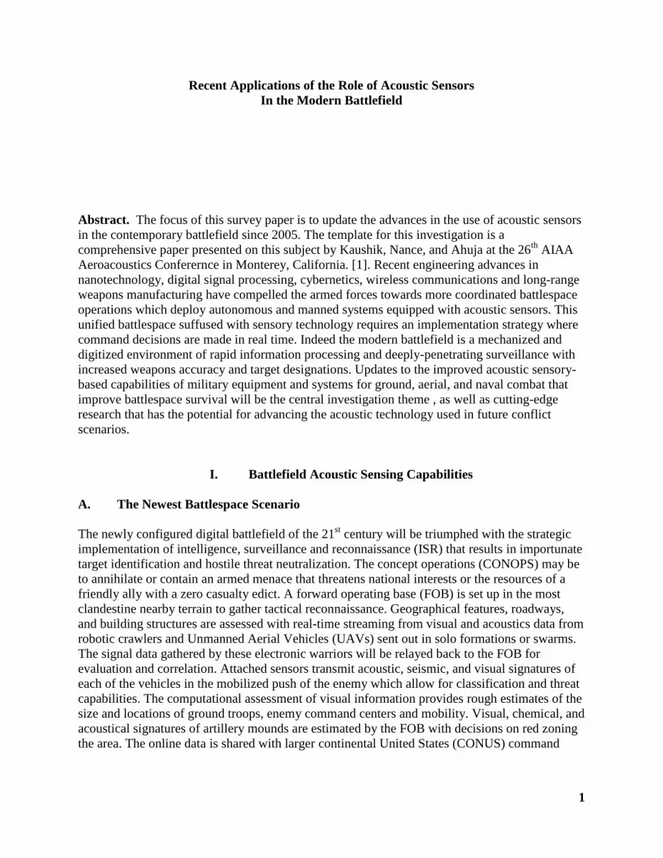
25-mm square, which is shown in Figure 4a during characterization measurements. The package
geometry features a flat bottom, which is well-suited for acoustic coupling to a structural
substrate, and the pin geometry permits direct electrical connection to a custom PC board
containing the four amplifier circuits. A resulting sensor system exploiting both of those
advantages is shown in Figure 4b, where the system is mounted on a steel plate with its
housing/shielding removed. The four-channel system is contained in a 25 mm x 25 mm x 15 mm
volume.
Figure 4a: MEMs device in ceramic grid array
Often the operation of acoustic sensor systems in the battlespace require human management that
runs the risks of putting their operating crew into dire harm especially in environment strafed by
munitions payloads. Modern day conflicts in places like Afghanistan, Syria and Ukraine, Iraq,
etc. are showing that the urban zone has become a hotbed for guerilla style warfare. An
additional operational need is increasingly the protection of vital military sites or buildings. For
these reasons, unattended acoustic and seismic sensors are playing a major role in the detecton of
encroaching enemy soldiers. Newer detection algorithms are being merged with proven weapons
firing algorithms that have created a new class of acoustic sensing devices to construct a
defensive battlefield acoustic early warning system. The defense contractor SenTech (located in
Cambridge, MA) has developed a low-cost, compact size, easily deployable unattended sensor
[15] for covertly detecting, identifying, locating and tracking ground vehicles and dismounted
personnel. An autonomous geo-location capability (global positioning system [GPS] and
compass) was incorporated into the sensors to autonomously record their location, so that they
could be easily emplaced without adding to the soldier’s burden (see diagram below) . The
sensors and signal processing methods addressed several essential functions, including target
localization using a small conformal microphone array, seismic detection and localization using
a three-axis geophone; and target tracking and identification using an embedded digital signal
processor and neural networks trained with the spectral features of the target emissions.

7
Figure 3: Unattended Ground Sensor System.
SenTech teamed with General Dynamics to develop the Intelligent Munitions System, a
networked target-tracking and fire-control system [16]. The companies also partnered on the
Massively Deployed Unattended Ground Sensor System[17]. Both of these systems used the
main processor of SenTech’s sensor. For Harris RF Communications, the company developed a
new dual mode imager (infrared [IR] and visual) and licensed the design of its acoustic-seismic
sensor.[18] The imaging sensor ombines IR and visual cameras and built-in image processing
capabilities in a compact militarized package. The Acoustic Warning System was a joint
development project with Lockheed Martin’s Infrared and Imaging Systems[19]. It gained high
marks for accuracy during government-sponsored tests at the United States Marine Corps Camp
Pendleton Military Operations.
Since a vital aim of early acoustic sensors detection in the battlespace is force protection, the L-3
Communications Company has geared the ground troop with the new Battlefield Anti-Intrusion
System (BAIS) . The new Battlefield Anti-Intrusion System (BAIS) [20], aka
AN/PRS-9A, is an upgrade to the U.S. Army’s AN/PRS-9 BAIS type standard Unattended
Ground Sensor (UGS) System. The new AN/PRS-9A provides improved early warning intrusion
detection and threat classification of vehicles and personnel. The system (see picture below)
supports small Tactical Units up to company level forward operating base security by Mounted
and Dismounted Units to establish defensive positions and by Military Police Units for security
of personnel and assets. The AN/PRS-9A comprises one Hand Held Monitor/Transmitter
(HHM/T) and a set of three Seismic/Acoustic Sensors, known as Sensor/Transceivers (S/T). The
upgraded system provides two-way RF communication to allow local and remote wireless
programming. Remote programming can be performed while the sensors are deployed. Each S/T
can be configured as a standalone sensor, a radio repeater or a combined sensor/repeater. The
radio repeater capability eliminates the need for a separate, standalone repeater unit, and allows
users to overcome radio line-of-sight obstacles, extending the RF range for longer-range

8
communications and remote programming capability. The basic set of three Seismic/Acoustic
S/Ts retain the ability to accept Infrared or Magnetic Detection sensors to provide additional
information such as target count and direction of travel. The system is small, weighs less than 10
lbs. and is easily transported by a single warfighter in ALICE or MOLLE mission equipment
packs.
Figure 4: Battlefield Anti-Intrusion System
The individual soldier is maturing also to carry other sensor payloads like advanced sniper
detection devices. 01dB-Metravib’s product in this category, the LATE Acoustic Localization
System, is used in Afghanistan. The company’s PILAR Mkil gunshot detection device, is a
situation awareness system for the automatic detection and localization of small-and medium-
calibre gunshots, rocket-propelled grenade, mortar, and anti-tank missile firing. The Picatinny
rail-compatible device weighs less than 350g and displays the exact position of a gunshot in grid
coordinates and in real-time allowing to pinpoint the threat. Its detection range is quoted at 1,500
meters. The system can be coupled with a remotely controlled weapon station (RWS), offering a
real-time slew-to-cue capability and/or computation of target positions from any detected shot
after tactical move.
Microflown Technologies developed a dismounted soldier gunshot localization device that is
named Acoustic Vector Sensor (AVS) [21]. It is in the form of a small metal tube measuring
pencil size. A first variant of the system is already in use with the Dutch Army in Afghanistan as
a counter-rocket, artillery and mortar warning sensor. A future version is shown by the company
to be adapted to mini-UAVs. A rifle-mounted version will be offered also. With a target weight
of 150g, it would allow the infantryman to bring to bear his weapon in the direction of the fire
source in short order.
Another battlefield advancement since the invention of the AVS has been the Acoustic Multi-
Mission Sensor (AMMS) is a revolutionary acoustical detection system (see picture below),
capable of detecting and localizing Rockets, Artillery and Mortars (RAM) and Small Arms Fire
(SAF) in a single, compact system [22]. The system uses Acoustic Vector Sensors (AVS), which
simultaneously measure the amplitude and direction of sound events, rather than just sensing
pressure, such as a standard microphone. Due to this, a single sensor the size of a pencil eraser
can detect, classify, and determine the direction of arrival (DOA) of acoustical events of interest.

9
Figure 5: Acoustic Multi-Mission Sensor
Qioptiq’s POINTER, a weapon cueing system, draws information from a network of observers,
sensors and shooters and intuitively delivers the potential target information directly into the
user’s view via a display indicating the target for visual identification and reaction. The mapping
interface at the base station location means the target information can be easily assimilated by C2
staff dramatically reducing response times [23]. POINTER can be linked to almost any target
location system for proactive planning and response or shot detection system to provide real
target information to weapon operators and improve force protection. Using information
provided by C4ISTAR assets, shot detection systems or a simple map, POINTER sends target
location information directly to the Head Up Display mounted on the weapon station. This
system also enables multiple weapon systems to be cued onto the same or several different
targets silently allocation priority as and when required.
Rafael’s solution [24] in this category is the SPOTLIKE Mk2 small arms finding detection
system. It represents an EO system designed for the precise location of small arms fire sources.
The system detects multiple small arms/sniper fire sources simultaneously, day and night, at long
ranges and with high precision and detection probabilities.
Raytheon’s BBN Technologies, developed the BOOMERANG WARRIOR-X wearable shooter
detection system [25]. This new device weights 900g and encompasses two sensor pads that are
installed on the soldier’s shoulders. The system includes also a display providing range and
azimuth of the hostile shooter. The performance of the device is quoted at over 95% for
incoming supersonic projectiles. The system warms the soldier of an incoming shot either
through a built-in speaker or an ear-piece and it provides the data of the shooting position even if
the soldier is on the move, as it automatically compensates for the motion and updates the threat
location.
A rifle-mounted shooter detection device has been developed by the Sonar Systems Division of
Ultra Electronics. Named Rifle Mounted Gunfire Locator (RMGL) [26], its concept is based in
principle on sonar technology. The sensor unit has the dimension of a golf ball and incorporates
a three-axis inertial tracker that compensates for the soldier’s movement. The device detects and
localizes the source of incoming high-velocity rounds. The gunfire locator sensor employs
frequency domain signal processing on characteristic acoustic signals to determine the range,
direction and elevation to the source of hostile gunfire. An advanced algorithm isolates the fire
position in the complex battlefield environment and minimizes false alarms. Target data is
intuitively displayed on a screen. The process culminates with the display and rifle pointing
directly at the target. Ultra Electronics will further reduce the weight of the overall system from

10
the current 450 grams. The system is undergoing currently in-theater operational assessment with
British and US troops. Several international customers have shown also interest in this
innovative system.
Among other acoustic sensing upgrades to the battlefield soldier’s equipment with vital ISR
application is a high-tech helmet called a headgear system (HGS). Essential to the modern
soldier’s helmet is a HUD (Heads Up Display) whose micro-electronics enhances situational
awareness and provides critical combat data. The HGS incorporates a neurocap sensor suite to
monitor brain activity, as well as multi-band, multi-mode radio frequency communications for
C4 data processing. The microelectronics/optics suite integrated into the Headgear system
provides unaided thermal, visual, light-amplified, acoustic, NBC detection with LADAR and
radar sensor fusion. Sensor emitters on the headgear will assist in navigation, determination of
target locations, target designation, combat ID, amplification devices, and movement detection
sensors. Indeed the Headgear system will be a synergism [27] of laser rangefinder,
chemical/biological sensors, and radar sensors providing a 360-degree detection of nuclear,
biological, chemical (NBC) aersol and vapor clouds up to 2 km. A combination of these sensors
will feed also a weather decision system. A typical sensor array on the helmet (see futuristic
display below) could consist of the following:
1. Laser Rangefinder/Designator, LADAR 2. Secondary Infrared Illumination 3. Network Assist for GPS (RF Ranging Signal) that helps Soldiers determine the origin of
the GPS signal, the time sequence, strength of the signal 4. Radar (to detect movement) 5. Hyper-spectral image processing and display Laser and Environmentally Hardened
Sensors will provide sensor selection through nanometer range via digital signal processing
Laser (detection of unfriendly queries and reception of friendly Combat ID) Thermal Acoustic Light Amplification (Image Intensification) Unaided Vision
In addition, the sensors on the helmet will incorporate geo spatial registration and weapon targeting features that assist in navigation, sniper detection, biometric facial recognition, and target detection:
1. Head Tracker 2. Eye Tracker 3. Geo-location Devices (inertial, MEMS gyros, and non-magnetic digital compass) 4. Biometric facial recognition algorithms will allow face and feature localization even
within a complex background Segmentation of multiple faces to isolate individuals Ability to collect, analyze, then decide/act on biometric data matches

11
Figure 6: Future Soldier Battle Dress----Head Gear System (per http://www.pinterest.com/pin/328833210263701086/)
Even though the HGS will equip the Future Soldier with greater situational awareness on the
new high-tech battlefield, robotic and unmanned sensors will play a greater role in their
entrenchment against hostile forces while providing greater protection from tactical threats posed
by tunnels, caves and underground canopies. The effectiveness of these sensors [28] will be a
function of critical C3 links and deployment logistics. In the early 2000’s the Army deployed an
unmanned ground system with acoustic and seismic sensors called the Terrain Commander from
Textron Corporation (see diagrammed below)

12
Figure 7: The Terrain Commander
This UGS was replaced by the mine-seeking and tank demolishing Advanced and M-93 WAM
Hornet UGS in the mid-2000s and later. Once deployed, the WAM uprights itself (see picture
below) and autonomously searches for a target vehicle. WAM uses acoustic and seismic sensors
to locate, identify and track armored targets. When a firing solution is satisfied, the WAM
launches a sublet in a trajectory over the target. The sublet uses a passive infrared sensor to
detect the target and fires an Explosively Formed Penetrator (EFP) at the vulnerable area. In
addition, the WAM has a command destruct capability for easy battlefield cleanup.
Figure 8:M-93 Hornet (Air Deliverable Sensor)
Subsequent to the deployment of the E-93 Hornet, especially for mine fields in Iraq and
Afghanistan by special forces, the Army is testing the AN/GSR-9/10. Unattended Ground
Sensors (UGS) are a central element in the U.S. Army Brigade Combat Team modernization
effort. Part of the FCS Spin-Out program are two UGS systems developed by Textron Systems -
the AN/GSR-9 Tactical-UGS and AN/GSR-10 Urban-UGS sensors, (also known as the Urban

13
Military Operations in Urban Terrain Advanced Sensor System – UTASS).
Figure 9: AN/GSR-9 Tactical unattended Ground Sensor
Another useful UGs for combat soldiers in the modern battlespace is the XM1216, Small
Umanned Ground Vehicle (SUGV). The XM1216 is a lightweight, man portable Small
Unmanned Ground Vehicle (SUGV) manufactured by iRobot. The SUGV can be used in
military operations conducted in urban environments, tunnels, culverts and caves.
The SUGV is deployed for Early Infantry Brigade Combat Team (IBCT) fielding. It is currently
being evaluated (see picture below) by the Army Evaluation Task Force (AETF). The XM1216
SUGVs were successfully deployed in operation by the 3rd Brigade, 1st Armoured Division.
Figure 10: XM1216 Small Unattended Ground Vehicle
Since 2010, another UGS that utilizes an algorithm to detect human footsteps and moving
vehicles is the Applied Research Associates (ARA) upgraded early warning system called the E-
UGS. These E-UGS (Expendable Unattended Ground Sensors) are low-cost “consumable”
seismic sensors that are quickly emplaced in dead spots, on a perimeter, at frequent IED sites or
on “goat trails” to provide early warning from miles away.

14
Figure 10: Expandable Unattended Ground System
ARA’s military grade E-UGS, which deliver intrusion alerts over long distances are now
available for commercial and border security applications. E-UGS can operate as a standalone
system or as a key element of our Integrated Base Defense (IBDSS) site security software
solution. ARA has delivered [32] more than 40,000 E-UGS sensors, which are in use by U.S.
forces around the world. It is the low-cost consumable unattended ground sensor on the
battlefield today, The most recent UGS has been developed by the Israelis called TREASURES. Elbit Systems’
TREASURES (Tactical Reconnaissance and Surveillance Enhanced System) is a comprehensive
system [33] of unattended ground sensors (UGS) that enables detection, tracking and
identification of human and vehicular targets.
Using advanced algorithms and unique communications protocols, the system offers a high
probability of detection (PD) and low false alarm rates (FAR).
Other UGS which are products of Israeli innovation for border control and perimeter protection
include:. SAND, which is designed for real-time target tracking (see picture below) using an
array of seismic UGS, and TALOS™ Unattended Ground Radar, which is designed for
continuous operation using solar energy.
The UGS systems easily integrate with existing UGS and are compatible with any C4I system.
TREASURES detects, classifies and tracks human and vehicular targets, in real time, on any
terrain and in all weather conditions. The system uses a broad network of in-house developed
sensor clusters, with intelligent dedicated communication, breakthrough sensing technologies
and data analysis capabilities. Since all the sensors are developed in house at Elbit Systems, their
connectivity in one communication network maximizes the performance of each sensor.
SAND - Seismic All-terrain Networked Detectors which are designed for real time [34], Beyond-
Line-Of-Sight (BLOS) human and vehicular targets detection, for years of continuous operation.

15
SAND
Figure 11: Smart All-Terrain Networked Detectors
OCEAN - Seismic acoustic multi-detector for detection and classification of humans and
vehicles, as well as vehicle direction estimation [35].
OCEAN
Figure 12: Seismic Acoustic Multi Detector
TALOS - Low-cost Unattended Ground Radar for human and vehicular tracking [36]. It contains
a patented low-energy design, featuring integrated solar panels for continuous operation, without
the need for additional infrastructure.
TALOS
Figure 13: Unattended Ground Radar

16
MTR Miniature Tactical Radar for human and vehicular detection and tracking, [37] featuring a
small form factor and ground level covert operation. MTR has high target separation capability
and solar panels for recharging the inner battery providing continuous power.
Figure 14: MTR, Miniature Tactical Radar
MID Miniature Imaging Detector hybrid day and thermal imagers [38] with advanced VMD
capabilities, transmits automatically day and thermal images correlated to target track, through
the UHF narrowband network.
Figure 15: Miniature Imaging Detector
Chameleon 2 - Day and thermal video covert sensor [39], with inner pan capabilities for wide
area and high resolution coverage, with no external moving parts, using wide band
communication for video transmission.
Chameleon-2
Figure 16, Day and Thermal Video Convert Sensor

17
The science behind the Chameleon-2 is discussed in a paper [40] by Miyata, Konno, and others
explaining how natural observations lead to its development. Included with the TREASURES
unattended sensors suite are the following units:
Communications Unit - The unit has three system uses: facilitating the connection of 3rd party
detectors to the network, act as an f1/f1 relay for sensor field extension, and serving as a
communication hub connected to the control station.
Backhaul Communications Unit - A field deployed f1/f2 relay for communication range
extension, offering 60-days of continuous operation based on an integral battery.
The above sensor systems are designed to give the military infantry personal protection while
engaging in a battle theater possible having dramatic weapons exchanges. In such a theater, the
possibility of injuries should factor into force strategies where optimally troops sustain minimal
injuries. One system designed by the Army after sustaining many bone-related blasts and
casualties especially in Eastern Europe and the Middle East conflicts is the IBESS (Integrated
Blast Effects Sensor Suite). The IBESS was designed to endure the hard explosions in these hot
fire conflict zones while collecting invaluable data on brain trauma induced by crashes, rollovers
and sudden detonations. In a Proceedings of the 2013 8th
Conference on System of Systems
paper [41], the authors Mulkey, Liu and Medda describe the system architecture of the IBESS
and its operative component interactions between vehicle, soldier and seat1 (see article). The
soldier component has pressure ports and an accelerometer to record body blast kinetics. The
vehicle system records data from sensors to get blast data on its hull and seat much like the data
collected in car crash testing facilities for major auto manufacturers. The following figures are
taken from this paper:
“The Vehicle System records blast induced acceleration and rollover events at the hull and the seats, and also houses
the main communication systems and interfaces. The Data Collection System is an existing U.S. Army computer
already present on the vehicle, and is connected to IBESS through common interfaces. Finally, the System Database,
which resides on US Army operated servers, houses the data collected with IBESS. A picture of the Soldier System
is shown in Figure 17, while an overall picture of the complete IBESS system prior to installation is shown in Figure
18. In Figure 19 are highlighted three important IBESS subsystems and their interactions, the Vehicle, the Soldier
and the Seat (or VIA) Systems, while Figure 20 shows a high level block definition diagram of the IBESS
subsystems.”
The Vehicle System records blast induced acceleration and rollover events at the hull and the
seats, and also houses the main communication systems and interfaces. The Data Collection
System is an existing U.S. Army computer already present on the vehicle, and is connected to
IBESS through common interfaces. Finally, the System Database, which resides on US Army
operated servers, houses the data collected with IBESS. A picture of the Soldier System is shown
in Figure 17, while an overall picture of the complete IBESS system prior to installation is
shown in Figure 18. In Figure 19 are highlighted three important IBESS subsystems and their
1 Mulkey, N.; Liu, B.; Medda, A. System of Systems Engineering (SoSE), 2013 8th International Conference on, 2-6
June 2013

18
interactions, the Vehicle, the Soldier and the Seat (or VIA) Systems, while Figure 20 shows a high
level block definition diagram of the IBESS subsystems.
Figure 17. The Soldier Subsystem, one of several subsystems within the overall IBESS SoS.
Figure 18. IBESS vehicle system components laid out on tabletop prior to field installation

19
Figure 19. Block diagram showing functional interconnections between three major IBESS
subsystems: Vehicle, Soldier, and Seat (or VIA) subsystems.
Figure 20. IBESS high level block definition diagram.
In protecting the warfighter, Lockheed Martin has develop sensing devices especially to increase
situational awareness on the battlefield. The Self-Powered Adhoc Networks or SPAN are ultra-
low powered, remote unattended ground sensing surveillance system. SPAN is a cheap,
imperceptible micro-sensing and reporting system made to detect and relay situational

20
awareness. It combines microelectronics, distributed signal processing and wireless mesh
networking into a single surveillance system for force protection (see image below).
Figure 21: Self Powered Ad hoc Networks
SPAN may also be used for border security and control. The new engineering concept for these sensing
devices is to make them low cost manufactured and expendable. Future innovations of such sensors will
be to provide images of targets as well as location. (per Bob Lisowski VP of Secure Space and Sensor
Systems at L-3 Communications Systems – East). L – 3 is set to deliver the Army BAIS (Battlefield Anti-
Intrusion System) [43] and the Marine Corps’ Tactical Remote Sensor System soon . These magnetic and
infrared sensors that detect personnel, wheeled and traced vehicles can be hooked to seismic sensors to
determine more accurately direction of travel.
Millennium Sensors are producing an Android capability to upload information. In addition, Textron
Defense Systems wants to put their UGS in air vehicles.
Lockheed Martin is prototyping from its Advanced Technology Laboratories the Samarai family of
vehicles inspired by maple seeds. These biomimetic devices use a high-speed image sensor coupled with
optical flow algorithms to drive vertical motion parameters. The MEMS accelerometer will derive vertical
pitch, rool and vertical motion with a magnetometer to derive rotation [45]. (see figure that follows)
Figure 22: Lockheed’s 4 inch SAMARAI
Interestingly enough, Northrop Grumman has developed a PGM, precision guided munition, which has an
external acoustic probe as a fin [46], or just an acoustic vector array Microflown sensor in the nose cone.
(picture below)

21
Figure 23. PGM, Precision Guided Missile
Finally, Ducommun Miltec has developed the RMSA (Reduced Manning Situational Manning) Suite that
provide wide area persistent surveillance. (see photo)
Figure 24: RMSA, Reduced Manning Situational Awareness Suite
Before moving to air sensing system, it should be pointed out that the battlefield presence of
acoustic sensors has brought about the need for sensor networks. A consistency-function-based
algorithm has been considered due to real world issues of non-line-of-sight reverberant areas that
produce cooperative and consistent errors in them. A solution to these basic problems have led to
stochastic initialization, acoustic signal detection algorithms, Cramer-Rao bounds, and acoustic
localization. Acoustic localization has applications that include passive sonar, noise source localization,

22
test and analysis, speaker-tracking, camera steering, diarization in teleconferencing, Whereas single-step
methods require transmission of fully raw data to a central processor, a two-step method proves more
reliable since the first step of processing data can be done locally. At the second (fusion) step,
reduced processing creates faster estimation. In a sensor networking scenario, the two step
approach reduces the inter-sensor communication requirements. Its only disadvantage is
probable lost of information due to data compression. Redundant measurements provided by
redundant sensors however minimize this deficiency in the two step approach. If no outliers are
present, then the TOA/TDOA based localization problems can be solved sung the Cramer-Rao
lower bound estimation.
2. Air-based Applications
Acoustic sensor devices are propagating with the advent of new air vehicles in the battlezone.
UAV’s or unmanned air vehicles can apply directional acoustic sensors using sound pressure
microphones. The disadvantage of this approach is that the UAV has to have considerable size
and weight. However the Microflown vector array sensor eliminates this problem. The acoustic
sensor in an air vehicle has these primary purposes: (a) situational awareness (b) miss distance
indication (c) gunshot localization and sniper detection (d) collision alert (f) unmanned
navigation (g) VTOL: (h) permiter defense (i) helicopter blind landing or white out landing in
unknown terrain (j) health & usage monitoring (HUMS) vibration sensors (accelerometers).
Another innovation for airborne sensors with battlespace utility is Smart Dust. Smart Dust as a
concept originated out of a research project by the United States Defense Advanced Research
Projects Agency (DARPA) and the Research And Development Corporation (RAND) in the
early 1990s. We use the military anecdote above because it was these military research groups
that first conceptualized Smart Dust but the practical application of the technology can be
applied to almost any industry. Dust in the fields monitoring the crops. Dust in the factories
monitoring the output of machines. Dust in your body monitoring your entire state of well being.
Dust in the forests tracking animal migration patterns, wind and humidity.
The entire world could be quantified with this type of ubiquitous sensor technology. But how
does it really work?
Smart Dust is made of “motes” which are tiny sensors that can perform a variety of functions.
They are made of “microeletromechanical systems” known as MEMS. Gartner’s Hype Cycle for
Emerging Technology describes the functionality of these motes:
A single smart dust mote typically contains a semiconductor laser diode and MEMS beam-
steering mirror for active optical transmission; a MEMS corner cube retro reflector for passive
optical transmission; an optical receiver, signal processing and control circuitry; and a power
source based on thick-film batteries and solar cells.
23
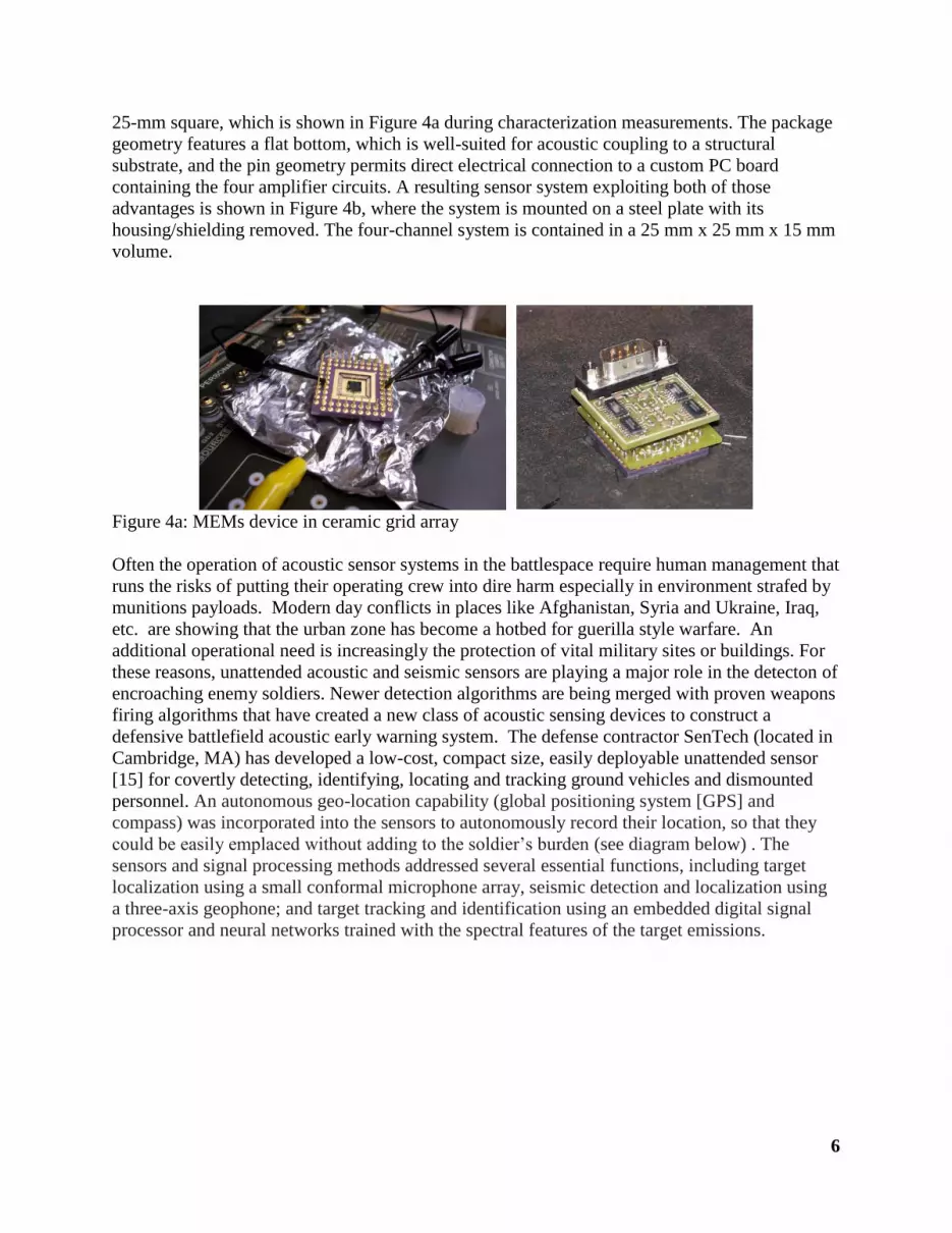
Smart Dust is made capable by these MEMS as well as advances in digital circuitry and wireless
communication. The advances in digital circuitry are what enable the motes to become so small
while still having the ability to have a battery [48], a nominal amount of RAM and a wireless
transmitter, likely powered by RFID (but perhaps Bluetooth). (see picture below)
Figure 25: Smart Dust
Another flying sensing device or equipped sensing machine will be robotic or actual insects
equipped with flying sensing technologies. A giant flower beetle with implanted electrodes and
a radio receiver on its back can be wirelessly controlled, according to research presented this
week. Scientists at the University of California developed a tiny rig that receives control signals
from a nearby computer. Electrical signals delivered via the electrodes command the insect to
take off, turn left or right, or hover in midflight. The research, funded by the Defense Advanced
Research Projects Agency (DARPA), could one day be used for surveillance purposes or for
search-and-rescue missions.
Beetles and other flying insects are masters of flight control, integrating sensory feedback from
the visual system and other senses to navigate and maintain stable flight, all the while using little
energy. Rather than trying to re-create these systems from scratch, Michel Maharbiz and his
colleagues aim to take advantage of the beetle’s natural abilities by melding insect and machine
[49]. His group has previously created cyborg beetles, including ones that have been implanted
with electronic components as pupae. But the current research, presented at the IEEE MEMS in
Italy, is the first demonstration of a wireless beetle system.

24
Figure 26: Cyborg Beetle
With the proliferation of Unmanned Air Systems (UAS), much concern has arisen in the aviation
community to equip these UAS with Sense And Avoid (SAA) capability. Unpiloted military
drones and commercial UAVs are predicted to increase in coming years and possibly disastrous
mid-air collisions with other air vehicles (such as commercial airliners), or skyscrapers must be
avoided. The requirement for avoiding collisions between aircraft, or between aircraft and
objects, applies equally to manned and unmanned aviation. Therefore, appropriate steps must be
taken to cater for the absence of a pilot within the aircraft. For UAS flights, the methods used to
prevent collisions depend on whether the aircraft is being flown within or beyond the 'Line of
Sight' of its pilot. Visual Line of Sight is termed as being the maximum distance that the flight
crew is able to maintain separation and collision avoidance, under the prevailing atmospheric
conditions, with the unaided eye (other than corrective lenses). For flights within Line of Sight,
the pilot is required to employ the See-and-Avoid principle through continued observation of the
aircraft, and the airspace around it, with respect to other aircraft and objects. Within the UK,
Visual Line of Sight operations are normally accepted out to a maximum distance of 500 m
horizontally, and 400 ft vertically, from the pilot.

25
As indicated above, it may be necessary to operate an unmanned aircraft within segregated
airspace if the pilot wishes to fly it beyond unaided visual line of sight.
Unmanned aircraft with a mass of more than 7 kg (excluding fuel) must not be flown within
controlled airspace, restricted airspace or an Aerodrome Traffic Zone (ATZ) unless permission
has been obtained from the relevant ATC unit. More information about contacting ATC can be
obtained from the Aeronautical Information Service (AIS).
One emerging sensor technology utilizes acoustic sounds to provide a passive sense and avoid
system..SARA’s Passive Acoustic Non-cooperative Collision-Alert System (PANCAS) utilizes
Low Cost Scout UAV Acoustic System (LOSAS) technology (an array of four lightweight
acoustic probes and a custom-designed digital-signal processor. The acoustic probes employ
proprietary windscreen technology and mounts that remove the effects of wind noise and
platform vibration [50]. The system’s digital-signal processor board (3x5 inches) filters
acoustics, detects, locates, and tracks targets, and generates clearance maneuver commands for
automated collision avoidance. Interfacing with the UAV flight control system, it gathers GPS
location and aircraft attitude data to estimate the location of targets. The system sends data
directly to the operator’s ground station through the existing UAV data downlink. The LOSAS
system weighs approximately 250g and consumes about 7 watts of 6 -volt DC power. PANCAS
offers several advantages over the optical and radar based collision alert systems.
One of the most ambitious civilian efforts under way to develop an integrated system for UAVs
is the Mid-Air Collision Avoidance System (MIDCAS), which [51] is being developed by five
European countries — Sweden, Germany, France, Italy and Spain — and 11 industrial partners.
The four-year, $65 million project is expected by 2014 to deliver an automated sense-and-avoid
system that will not depend on transponders. While it is being designed to integrate (Automatic
Dependent Surveillance-Broadcast) ADS-B, MIDCAS also includes two visible-band electro-
optical cameras and one infrared camera for aircraft to use in identifying other aircraft. In
addition, the team's developers are designing image-processing algorithms, processing units and
integration with on-board avionics.
General Atomics Aeronautical Systems, Inc. (GA-ASI), a leading manufacturer of Remotely
Piloted Aircraft (RPA), tactical reconnaissance radars [52], and electro-optic surveillance
systems, has announced the completion of the first of several planned flight tests of a Sense and
Avoid (SAA) architecture and Self Separation functionality. This marked the first time the
system hadfunctioned as a true “system of systems” to detect every class of aircraft equipage and
paves the way for a Due Regard capability.
The purpose of the test was to integrate and synchronize BAE Systems’ AD/DPX-7
Identification Friend or Foe (IFF) transponder with Automatic Dependent Surveillance Broadcast
(ADS-B) IN, GA-ASI’s air-to-air radar, called Due Regard Radar (DRR), and Honeywell’s

26
Traffic Alert Collision Avoidance System (TCAS) TPA-100 to detect and track cooperative and
non-cooperative aircraft. The prototype DRR tracked multiple targets of opportunity, in addition
to participating aircraft, throughout 40-plus scripted encounters, including some aircraft not
tracked by Air Traffic Control. Sensor data collected by these systems during the flight test will
be used by the FAA and industry participants to develop and further refine their algorithms,
which will in turn lead to a proof-of-concept SAA system including Collision Avoidance
3. Sea-based Applications
The battlefield of the future will undoubtedly include the oceans territories---specifically
navigation of weapons and vessels underwater, in the littoral zones and upon the ocean surface.
The Navy in conjunction with many manufacturers is building a faster class of warships
accoutered with the latest sensors technologies for rapid surveillance, information and
reconnaissance processing.
Figure 27: Long Range Acoustic Device
LRAD – is a long-range hailing and warning, directed acoustic device designed to communicate
with authority and exceptionally high intelligibility in a 15-30 degree beam. LRAD can issue a
verbal challenge with instructions in excess of 500 meters and has the capability of following up
with a warning tone to influence behavior or determine intent [53]. The "hailing and warning"
application for commercial shipping is similar to the successful LRAD deployments by the U.S.
Navy on patrol craft in and around the port of Basra, Iraq to communicate with vessels in
shipping lanes and around oil terminals, where the device was reported to be effective even at a
distance of 1,000 meters. LRAD was originally conceived to support the protection and
exclusion zones around U.S. Navy warships. The challenge of interdicting small boats
approaching commercial maritime assets is quite similar. LRAD's warning tones command
attention at ranges in excess of 500 meters while its directional and highly intelligible voice
instructions can unquestionably be heard. LRAD's ability to positively communicate with
authority on land or at sea is proving highly effective in creating safe situations out of uncertain
ones.

27
Figure 28: LRAD mounted on a commercial vehicle
LRADs and its scale-down Medium Range Acoustic Device (MRAD)
(shown above), are currently deployed with the coast guard, U.S.
Marine Corps, U.S. Army, and U.S. Navy in Operation Iraqi Freedom
in and around Fallujah, Mosul, and the port of Basra. Most recently,
over $600,000 worth of products were procured for the Army's 3rd
Armored Cavalry Regiment. Recent deliveries were made to the 44th
Engineering Battalion, deployed in central Iraq and the 3rd Infantry
Division will be utilizing LRADs in Iraq for crowd control, area denial
Figure 29: LRAD mouinted on a Jeep
and clearing buildings. The smaller MRAD is optimized for land and vehicle-based operations. It can be
employed from armored vehicles, for urban warfare, shorter-range checkpoints and security. A larger,
more powerful Extended Range Acoustic Device (ERAD), can also be used to supports very long distance
communications for the critical infrastructure, including border security.
An opposite approach to boisterous intervention in the sea current is a proven geometric layered
coating just recently demonstrated by Duke researchers. Using a few perforated sheets of plastic
and extensive computation, Duke University engineers have demonstrated the world’s first three-
dimensional acoustic cloak.
Figure 30: 3D Cloaking Acoustic Shielding

28
The new device reroutes sound waves to create the impression that both the cloak and anything
beneath it are not there.
The acoustic cloaking device works in three dimensions, no matter which direction the sound is
coming from or where the observer is located, and holds potential for future applications such as
sonar avoidance and architectural acoustics.
The study appears online in Nature Materials.
“The particular trick we’re performing is hiding an object from sound waves,” said “By placing
this cloak around an object, the sound waves behave like there is nothing more than a flat surface
in their path.”
To achieve this trick, Duke University professor of electrical and [54] computer
engineering Steven Cummer and his colleagues used metamaterials — the combination of
natural materials in repeating patterns — to achieve unnatural properties. The device looks like
several plastic plates with a repeating pattern of holes poked through them stacked on top of one
another to form a sort of pyramid.
To give the illusion that it isn’t there, the cloak must alter the waves’ trajectory to match what
they would look like had they had reflected off a flat surface. Because the sound is not reaching
the surface beneath, it is traveling a shorter distance and its speed must be slowed to compensate.
To test the cloaking device, researchers covered a small sphere with the cloak and “pinged” it
with short bursts of sound from various angles. Using a microphone, they mapped how the
waves responded and produced videos of them traveling through the air.
Cummer and his team then compared the videos to those created with both an unobstructed flat
surface and an uncloaked sphere blocking the way. The results clearly show that the cloaking
device makes it appear as though the sound waves reflected off an empty surface.
Another acoustics system for assisting with antisubmarine warfare is the U.S. Navy's sonobuoy
system. Sonobuoys are dropped into the ocean (from either an aircraft or ship) to record
underwater sounds. These instruments [55] include a hydrophone and a radio transmitter to send
sound signals back to the aircraft or ship. The U.S. Navy uses these instruments to listen for
enemy submarines. They can be dropped by airplanes into the water from altitudes as high as
30,000 feet. The sonobuoys are approximately three feet long and 5 inches in diameter. Passive
acoustic sonobuoys detect acoustic signals generated by submarines and provide information on
their location. The exact location of a target can be determined by deploying a pattern of
sonobuoys. Sonobuoys may also be used to record marine mammal calls and listen for
earthquake activity.
An example of a passive acoustic sonobuoy is the Navy's Directional Frequency Analysis and
Recording DIFAR} device. This sonobuoy deploys four directional hydrophones and one
omnidirectional hydrophone at depths up to 1000 feet. It detects acoustic energy from 5 to 2,400

29
Hz. It can operate for up to eight hours. The Navy has also provided these sonobuoys for
research to track whale populations and monitor underwater volcanic activity.
Figure 31:Sonobuoy being loaded into aircraft.
Another passive acoustic sonobuoy is the Navy's LOFAR buoy system. This is used primarily for
intelligence gathering. It deploys an omnidirectional hydrophone and can detect acoustic energy
from 5 Hz to 40 kHz. This buoy can work at depths up to 400 feet and stay in the water for up to
eight hours. It provides data on ambient noise levels. It has also been used during research for
fishery and marine mammal projects. There are two types of active acoustic sonobuoys. One is
used for searching and one is used for the final fixing of a target submarine position. The
searches are accomplished by sending out an acoustic signal over large areas.
Figure 32: LOFAR sonobuoy
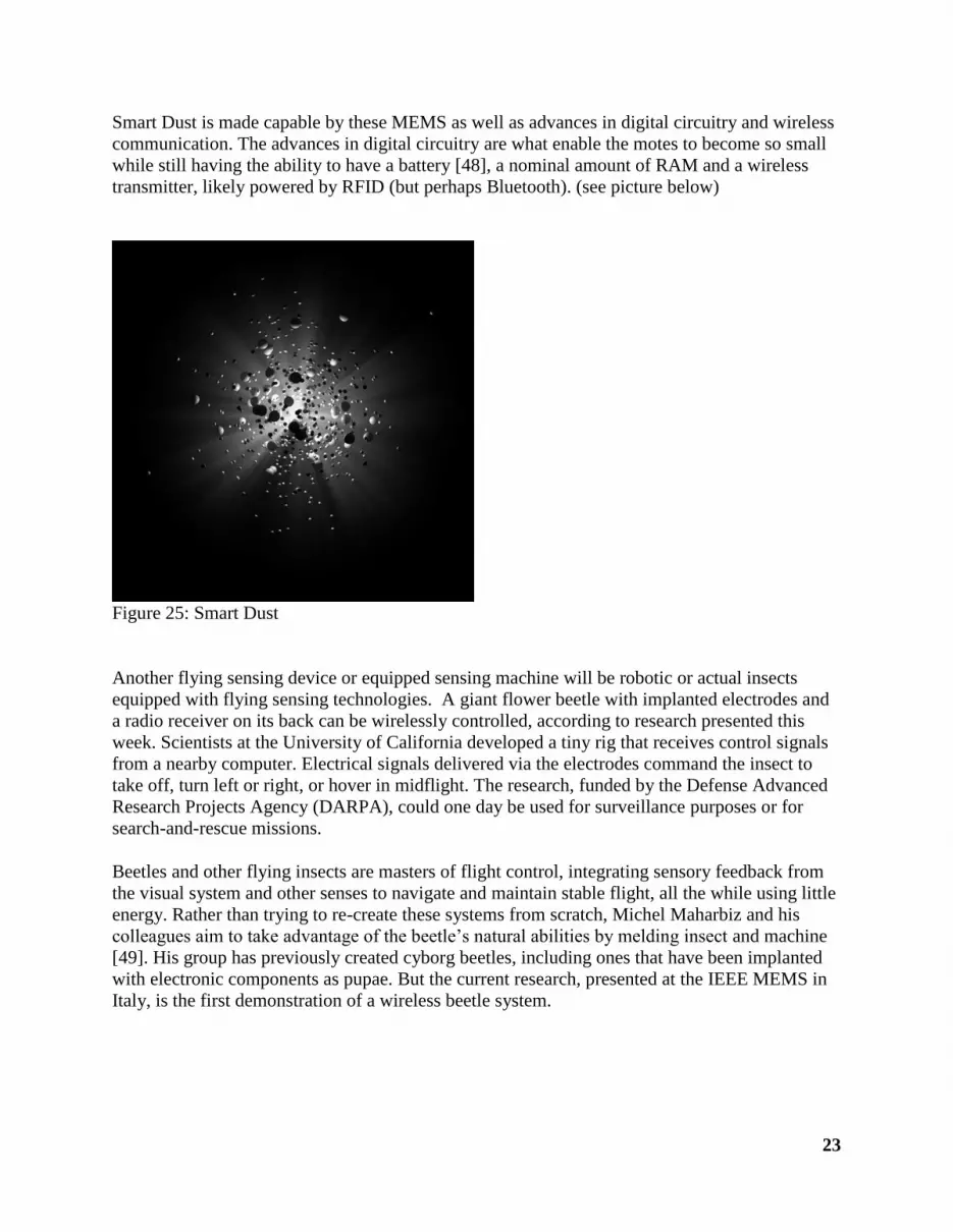
Another maritime acoustic device used for mines countermeasures (MCM), as well as other
naval environment functions, is the UUV (unmanned underwater vehicle) called REMUS . The
acronym means Remote Environmental Monitoring Unit System. The UUV navigates
underwater with an advanced inertial navigation system coupled to an acoustic device that can be
programmed [57] with an initial set of waypoints and travel speeds. Once it finds its target, (see
figure below) it can autonomously adapt its measurement protocol via a second computer that
30
constantly monitors the data stream, including salinity, temperature, oxygen, nitrate, and
flourescence -- an indicator of the presence of phytoplankton.
Figure 33: REMUS (Remote Environmental Monitoring Unit System)
REMUS 600 provides a detailed maritime survey and mine detection and classification
capability in the 30m to 200m depth range. Although the vehicle can operate down to 600m. It is
fitted with a range of sensors and runs on re-chargeable batteries. Obviously acoustic packages
placed in the nose cone of the REMUS are for facilitating detection, assessment, and
characterization of underwater munitions, especially mines. The REMUS [58] contains a
suite of sensors including a magnetic sensor, a Laser Scalar Gradiometer (LSG).
The REMUS system carries a dual frequency, 900/1800 kHz side scan sonar.
The REMUS system provides high resolution acoustic images of proud objects.,
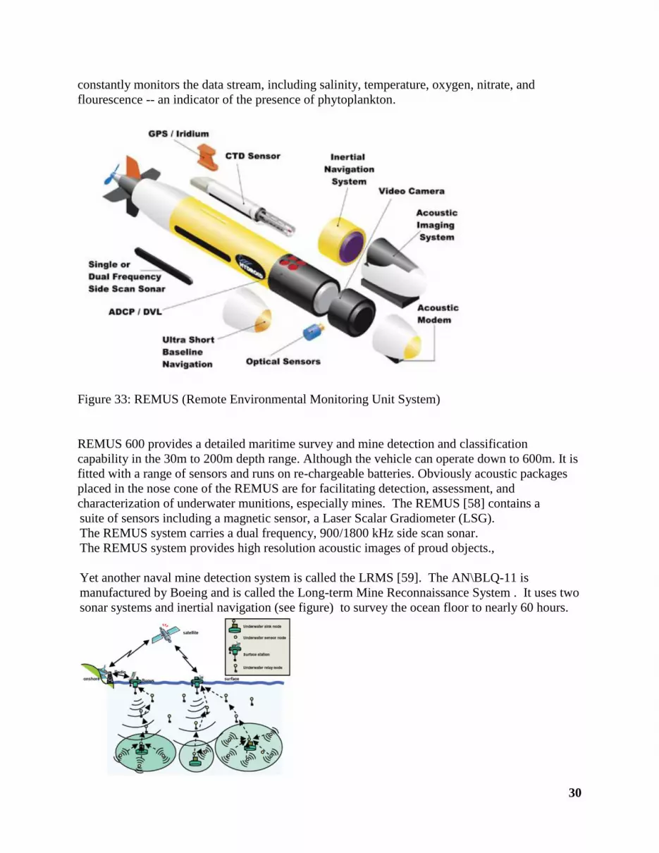
Yet another naval mine detection system is called the LRMS [59]. The AN\BLQ-11 is
manufactured by Boeing and is called the Long-term Mine Reconnaissance System . It uses two
sonar systems and inertial navigation (see figure) to survey the ocean floor to nearly 60 hours.

31
Its hull is designed to withstand torpedo and surface strikes.
Figure 34: Long-term Mine Reconnaissance System
As far back as 1990 concepts labs were developing acoustic sensors for unmanned underwater
vehicles. In fact, [60] Gary Bane of Rockwell International diagrammed where such sensors
would go in underwater naval drones. A current model for underwater acoustic sensor networks
is detailed in a paper by Wen-Yu and Jing-Biao who discuss the configurations of static nodes
and mobile ones on UUV’s [61]. Their paper provide an informative illustration of the acoustic
sensors networking for naval drones (see below). .
Figure 35: Underwater Acoustic Sensor Networks
Finally, another UUV of note in the class of MCM is the multipurpose SeaOtter MKII. This
SeaOtter AUV is specially designed for various military and commercial purposes. Approaching
in the favorable flatfish design. The SeaOtter is an autonomous vehicle [62] for underwater
survey, mapping, imaging, inspections and measurements with high reliability and safety. The
exceptional hydrodynamic form and twin hull with sectional modularity allows the integration
and operation of various sensor systems, propulsions, energy packages and navigations. The
length and width can be changed by using special interface connectors.
Integrated vehicle guidance, internal system analysis and optimised AUV core assures effective
and riskless missions, even under extreme conditions. It provides positioning and navigations of
outstanding accuracy, even for extended operations and relocalisation. The SeaOtter system is
versatile and can be operated from ships, piers or platforms. K. Siantidis and Ursula Hölscher-
Höbing discuss the automatic detection and classification software processing of unmanned
naval drones in a 2009 research paper.

32
Figure 36: The SeaOtter