rebar cutter instructions & parts lists dc series
TRANSCRIPT
Cutter_Instructions_2020B Page | 1 September, 2020
SERVICE NOTEHave your power tool serviced by a qualified repair person using only identical replacement parts. This will ensure that the safety of the power tool is maintained. For a Service Repair Center nearest you please call (800) 992-3833 or go visit us online:
www.bnproducts.com
IMPORTANT: READ THESE INSTRUCTIONS CAREFULLY BEFORE ATTEMPTING TO USE YOUR TOOL
Rebar Cutter Instructions & Parts ListsDC SERIES PORTABLE REBAR CUTTERS
• DC-32WH • DC-25X • DC-20WH • DC-16W • DC-16LZ
3450 Sabin Brown Road • Wickenburg, Arizona 85390(800) 992-3833 • (928) 684-2813 • [email protected]
Cutter_Instructions_2020B Page | 2 September, 2020
MAINTAIN CUTTER WITH CARE
Inspect cutter before each application. Faulty or loose cutter blocks could result is personal injury. Keep handle dry, clean and free from oil and/or grease. Keep housing and piston free of dirt and iron filings. Check that no screws or bolts are loose or miss-ing. Follow instructions for maintenance. Inspect switch, cord, plug and any extension cable at regular intervals. It is a good idea to inspect the housing for any cracks before operating.
DO NOT EXCEED MAXIMUM CUTTING PRESSURE BY ADDING TO OR MODIFYING THE HYDRAULIC PUMP.
BLEEDING YOUR PORTABLE REBAR CUTTER
You may have to bleed the hydraulics on your cutter if the tool runs unusually slow or doesn’t have the pressure to cut normally. Do not run tool with low or no oil. For best results please follow these directions:
1. If piston is still moving, run the tool for 2 minutes to warm the oil inside. If the piston is not moving, add oil before warming up for 2 minutes.
2. When the oil is warm, run the piston out just before it re-turns and stop.
3. Remove the oil plug and top it off with oil.4. Make a seal with your thumb over the oil plug opening.5. Run the tool so that it makes a complete cycle.6. When the piston is completely retracted in the open posi-
tion, gently roll your thumb to let the unwanted air escape.7. Repeat step #5 and #6 at least three times.8. Add oil only when the piston is at least halfway out. 9. If you have to add additional oil, repeat #5 and #6.10. Replace the oil plug and tighten it.11. Make three or four cuts with rebar. The machine should now
be working properly. Make sure that you observe exactly at what point the rebar is actually breaking.
12. Pinch a piece of rebar stopping just before it actually breaks.13. Remove the oil plug again and top off the reserve one more
time.14. Replace the oil plug and tighten15. The operation is now complete.
We recommend the following; 20-weight Non-Detergent Hy-draulic Oils for use with our tools (anti-foam anti-abrasion): Tel-lus 68 (Shell), Rando HD 68 (Texaco) or Chevron AW 68 (Chev-ron). Hydraulic oil can also be ordered in quart containers from your Diamond Tool Distributor.
OPERATING INSTRUCTIONS
CAUTION: Indicates hazard that could result in minor personal injury and/or product damage. CARE: Indicates hazard that will result in product damage.
GENERAL SAFETY PRECAUTIONS
Use rebar cutters on maximum Grade 60 steel reinforcing bars only. These tools are not to be used in cutting other kinds of metal or materials. Do not cut ungraded rebar.
IMPORTANT:
Do not attempt to cut rebar by locking the off/on switch to the on position. This locking procedure is to be used only to warm the tool in cold climates or used with our hands free electrical box and foot operated switch. This is a safety issue and may cause damage to your rebar cutter. Always pull the on/off switch by hand for each individual cut. A foot operated switch and spe-cial electrical box are available if you want to use these cutters as production tools. Contact your local distributor or BN Products
RESTRICT USE TO DESIGNATED MATERIALS
There is always a chance that the cut end may shoot out, espe-cially if less than 30cm (1 foot) in length. Exceeding designated material specifications greatly increases this risk and will also damage the tool. Do not attempt to cut rebars harder, thicker or thinner than specified.
USE EYE PROTECTION
Wear safety goggles, safety glasses with side shields or a face shield when using cutter.
PROVIDE SAFETY BARRIERS
Erect safety screens to protect coworkers from possible flying ends. Place a safety screen under the rebar when working in high places.
EXERCISE PROPER CONTROL
Hold cutter firmly and maintain proper footing and balance. Do not overreach. When working in a high place, secure cutter to scaffolding with a safety rope. Check that power cord is not fouled and keep cord away from sharp edges and heat. Check that all adjusting wrenches have been removed before using cut-ter.
GUARD AGAINST ELECTRIC SHOCK
To avoid possible shock, do not handle cutter with wet hands or use cutter in the rain or damp places. Be aware of all power lines, electric circuits and other hazards that may be contacted, especially those that are below the surface or otherwise hid-den from view. Never attempt to pick the tool up by use of the electric cord.
UNPLUG TOOL
Disconnect cutter from outlet when not in use and before cleaning, adjusting or servicing. Do not disconnect plug from outlet by pulling the cord. Always check that the switch lock is OFF before plugging in.
Cutter_Instructions_2020B Page | 3 September, 2020
PRE-USE CHECKS
1. Check oil level. (See Maintenance)2. Check condition of cutter blocks and tightness of cutter
block bolts. (See Maintenance) - CHECK FOR CRACKS IN HOUSING CAUTION: Using loose or cracked cutter blocks may result in injury to operator as well as damage to the tool.
3. Check that the power source is appropriate to the cutter. CARE: If voltage is too high, the motor will burn out. If voltage is too low, insufficient power will be generated. Never use DC current.
4. Check that power supply is properly grounded. CAUTION: Failure to ground power supply may result in electric shock to operator (DC-16LZ, DC-16W and DC-32WH have double-insulated motors and do not require grounding.)
5. Check that cord is undamaged and that plug is not loose. CAUTION: Cut or abraded covering could result in a short and Electric shock to operator.
6. If an extensions cable is to be used, make sure that it is undamaged and that it is the proper wire gauge thickness for the length. See table below.
7. Before plugging in the tool, make sure that the switch lock is OFF. CAUTION: If switch lock is ON, cutter will start as soon as it is plugged in. To disengage lock, pull trigger-switch and press lock-button, which will pop out.
Length 110/115 50/60 HzCable Size (AWG)
Up to 15mm (50 ft.) 14
Up to 30mm (100 ft.) 12
Up to 45mm (150 ft.) 10
WARM-UP
In cold weather you should warm up the tool unit for 30-60 sec-onds so that the hydraulic oil reaches the proper viscosity. Pull trigger-switch to extend piston and release when it has reached its full stroke. Repeat 15-20 times.
STOPPER BOLT ADJUSTMENT
THE STOPPER BOLT IS PROBABLY THE MOST IMPORTANT PART OF YOUR PORTABLE CUTTER.
The adjustable stopper functions to maintain the rebar in the correct position during cutting and must be properly set for each size of rebar before use.
1. Screw in stopper to provide sufficient clearance for rebar.2. Insert rebar fully into U-shaped support. Make sure that
rebar is resting on the base of the support.
3. Keeping rebar at right angles (90 degrees) to front cutter block, screw out stopper until it is just touching the rebar. Once set, the stopper needs no further adjustment while cutting rebar of the same diameter, but must be reset for a different size rebar. CAUTION: Failure to correctly set the stopper bolt will result in excessive wear of cutter blocks and may cause cut end to fly out. This will also lead to piston and cylin-der damage.
CUTTING
1. Insert rebar between stopper and front cutter block, mak-ing sure that it is properly seated in U-shaped support.
2. Pull trigger-switch and keep depressed while piston ad-vances and rebar is cut. (If switch is released at an interme-diate point, piston will stop.)
3. When cut is completed, release switch. Piston retracts automatically (Note that switch cannot be reactivated until piston has fully retracted.)
POINTS OF ATTENTION
1. 1. Be especially careful when cutting off short lengths (30cm/12” or less) as the cut end tends to fly out. CAUTION: Flying ends are a hazard to all personnel in the vicinity. Erect safety screens.
2. Do not cover air vents or operate the tool on dirt – use a plywood base under the rebar cutter to keep armature and fan clean CARE: If the vents are covered, the motor will overheat and may burn out.
3. If hydraulic oil exceeds 70 degrees C (158 degrees F) in temperature, power will drop. Allow unit to cool before resuming operation. (Be particularly careful in summer, when the aluminum pump case heats up quicker.)
4. If a drop in power is observed and motor is unusually hot, check carbon-brushes. (See maintenance)
5. If piston should ever fail to retract completely, push rear cutter block backwards to manually retract piston or check under piston to remove any debris keeping the piston from retracting. CAUTION: Use a rebar or flat metal bar for this pur-pose. Never push cutter block with any part of the hand, even if gloved.
NOTE: Rebar cutters manufactured in after 2007 have a safety release valve for retracting the piston if it doesn’t return to the start position. This is usually caused by cut-ting improperly seated rebar that becomes jammed between the cutting blocks. On these newer models simply rotate the Allen set screw a quarter turn to retract the piston. On the DC-20WH, see parts breakdown part #64 for location of this release valve. Once piston has been retracted, pull trigger-switch long enough to partially advance piston. Unplug unit. Check piston and housing for accumulated dirt and iron filings that may be
Cutter_Instructions_2020B Page | 4 September, 2020
jamming the piston. (See Maintenance) If, after cleaning, piston still does not automatically retract when fully extended, the piston itself may be damaged. Return the unit to an authorized repair center or BN Products for repair.
MAINTENANCE ON CUTTER BLOCKS
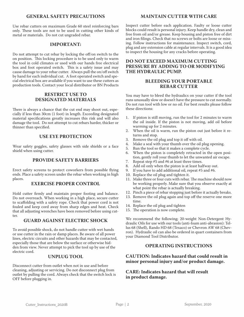
Before using, always check that the two bolts on each cutter block are properly tightened. Using a loose block will result in damage to block and housing. Also check condition of cutter blocks. If either cutting edge is dull or chipped, remove retain-ing bolts and rotate both blocks so that two new edges come into use. Replace and tighten bolts. (Each block has four cutting edges.) When all four cutting edges have been used or if either block is cracked or otherwise damaged, replace both blocks.
CAUTION: A loose or cracked block may result in injury to operator.
CLEANING
Clean your tool every day, preferably immediately after use.
CAUTION: Wear gloves to protect hands from metal splin-ters.
Do not use an air gun: blasting with air can cause metal filings and/or dust to get into eyes and respiratory system.
Disconnect the unit. Wipe or brush away all dirt and metal filings. Pay particular attention to the lower half of the piston, where dirt is more easily accumulated.
NEVER USE YOUR CUTTER TO CUT REBAR IN WET CONCRETE.
OIL-LEVEL CHECK
As the cutters are hydraulically operated, the oil-level must be checked at frequent intervals, preferably every day. Failure to maintain the oil at the proper level results in a drop in pressure and loss of cutting power.
CAUTION: Hydraulic oil is highly flammable. Keep away from sparks and naked flame. Do not smoke.
CAUTION: Hydraulic oil may cause inflammation of the eyes and skin. If ingested, it will cause diarrhea and vomit-ing. In case of eye contact, rinse in clean water for at least 15 minutes and consult a physician. In case of skin contact, wash thoroughly with soap and water. In case of ingestion, consult a physician immediately. Do not induce vomiting.
1. Oil should be warm but not hot. Warm up unit if cold.2. Adjust stopper and make three or four cuts, noting exactly
at what point the rebar is actually breaking.3. Pinch a short piece of rebar, stopping just before it breaks
off. Unplug unit from power source.4. With partially severed rebar in place, oil-plug should be
straight up. (If unit is hot, allow cooling down.)5. Remove oil-plug and seal-washer (packing).
CAUTION: Never remove oil-plug when unit is hot or oil will spurt out.
6. Check that oil is level with bottom of plug hole (i.e. that pump case if full to the brim). If oil level is too low, top up with 20-weight hydraulic oil with anti-foam and anti-abra-sion properties (ISO viscosity grade VG46, e.g. Shell oil Tellus 68, Mobil oil DTE-25 or Esso Uni power SQ46).
7. After topping off, extract air from system. Gently tilt cutter lengthwise and return it to a level position. Top off again and tilt in the opposite direction. Repeat this process until all air has been extracted. CARE: Cutter cannot function properly if oil contains air bubbles.
8. Replace seal washer (packing) and oil plug. Connect cutter to power source and completely sever rebar.
OIL-CHANGE
The hydraulic oil should be changed at least once a year, sooner if it appears dirty.NOTE: Hydraulic oil should be warm before draining
1. Unplug unit from power source. Remove oil-plug and pack-ing. Turn cutter over and drain oil into a suitable recepta-cle. When oil ceases to drain out, tilt unit to rear so that oil trapped in the piston housing can run out. When housing is empty, tilt unit in the opposite direction to empty the resi-due in the pump case.
2. With drain-hole uppermost, slowly fill the unit with fresh oil. Replace plug and lightly tighten. Connect unit to power source and advance piston two or three times. Unplug unit and remove oil-plug. Top off oil-level and replace plug.
3. Finally, follow procedure for oil-level check. (Steps 2-8)
NOTE: Dispose of hydraulic oil in accordance with local regula-tions. Do not pour into the sea, a river, a lake or drains.
BOLT TIGHTNESS
Once a week, or after every 500 cuts, check the tightness of all bolts; especially those bolts securing the housing to the cylinder. Loose bolts will result in a loss of power. Make sure that the bolts holding both cutter blocks are also tight
CARBON BRUSHES
Inspect the two carbon brushes at least once every two months. (Nominal brush life is 200 hours).
Cutter_Instructions_2020B Page | 5 September, 2020
CARE: Worn brushes will result in power loss, cause the motor to run hot and irreparably damage the armature.1. Disconnect unit.2. Unscrew both brush caps and pull out carbon brushes.3. Replace brushes if less than 6mm or1/4” in length.
OVERHAUL
Return the unit to an authorized agent for overhaul at least once every two years, sooner if subjected to heavy use. Call (800) 992-3833
GENERAL SAFETY RULES
WARNING: Read all instructions. Failure to follow all instruc-tions listed below may result in electric shock, fire and/or seri-ous injury. The term “power tool” in all of the warnings listed below refers to your mains-operated (corded) power tool or battery-operated (cordless) power tool.
WORK AREA SAFETY
Keep work area clean and well lit. Cluttered or dark areas invite accidents.
Do not operate power tools in explosive atmospheres, such as in the presence of flammable liquids, gases or dust. Power tools create sparks which may ignite the dust or fumes.
Keep children and bystanders away while operating a power tool. Distractions can cause you to lose control.
ELECTRICAL SAFETY
Power tool plugs must match the outlet. Never modify the plug in any way. Do not use any adapter plugs with earthed (grounded) power tools. Unmodified plugs and matching out-lets will reduce risk of electric shock. Avoid body contact with earthed or grounded surfaces such as pipes, radiators, ranges and refrigerators. There is an increased risk of electric shock if your body is earthed or grounded.
Do not expose power tools to rain or wet conditions. Water entering a power tool will increase the risk of electric shock.
Do not abuse the cord. Never use the cord for carrying, pull-ing or unplugging the power tool. Keep cord away from heat, oil sharp edges or moving parts. Damaged or entangled cords increase the risk of electric shock.
When operating a power tool outdoors, use an extension cord suitable to outdoor use. Use a cord suitable for outdoor use reduces the risk of electric shock.
PERSONAL SAFETY
Stay alert, watch what you are doing and use common sense when operating a power tool. Do not use a power tool while you are tired or under the influence of drugs, alcohol or medi-cation. A moment of inattention while operating power tools may result in serious personal injury.
Use safety equipment. Always wear eye protection. Safety equipment such as dust mask, non-skid safety shoes, hard hat, or hearing protection used for appropriate conditions will reduce personal injuries.
Avoid accidental starting. Ensure the switch is in the off-posi-tion before plugging in. Carrying power tools with your finger on the switch or plugging in power tools that have the switch on invites accidents.
Remove any adjusting key or wrench before turning the power tool on. A wrench or a key left attached to a rotating part of the power tool may result in personal injury.
Do not overreach. Keep proper footing and balance at all times. This enables better control of the power tool in unex-pected situations.Dress properly. Do not wear loose clothing or jewelry. Keep your hair, clothing and gloves away from mov-ing parts. Loose clothes, jewelry or long hair can be caught in moving parts.
If devices are provided for the connection of dust extraction and collection facilities, ensure these are connected and prop-erly used. Use of these devices can reduce dust-related hazards.
POWER TOOL USE AND CARE
Do not force the power tool. Use the correct power tool for your application. The correct power tool will do the job better and safer at the rate for which it was designed.Do not use the power tool if the switch does not turn it on and off. Any power tool that cannot be controlled with the switch is dangerous and must be repaired.
Disconnect the plug from the power source and/or the bat-tery pack from the power tool before making any adjustments, changing accessories, or storing power tools. Such preventa-tive safety measures reduce the risk of starting the power tool accidentally.
Store idle power tools out of the reach of children and do not allow persons unfamiliar with the power tools or these instruc-tions to operate the power tool. Power tools are dangerous in the hands of untrained users.
Maintain power tools. Check for misalignment or binding or moving parts, breakage of parts and any other condition that may affect the power tools operation. If damaged, have the power tool repaired before use. Many accidents are caused by poorly maintained power tools.
Keep cutting tools sharp and clean. Properly maintained cut-ting tools with sharp cutting edges are less likely to bind and are easier to control.
Use the power tool, accessories and tool bits etc., in accordance with these instructions and in the manner intended for the particular type of power tool, taking into account the working conditions and the work to be performed. Use of the power tool for operations different from those intended could result in a hazardous situation.
Cutter_Instructions_2020B Page | 6 September, 2020
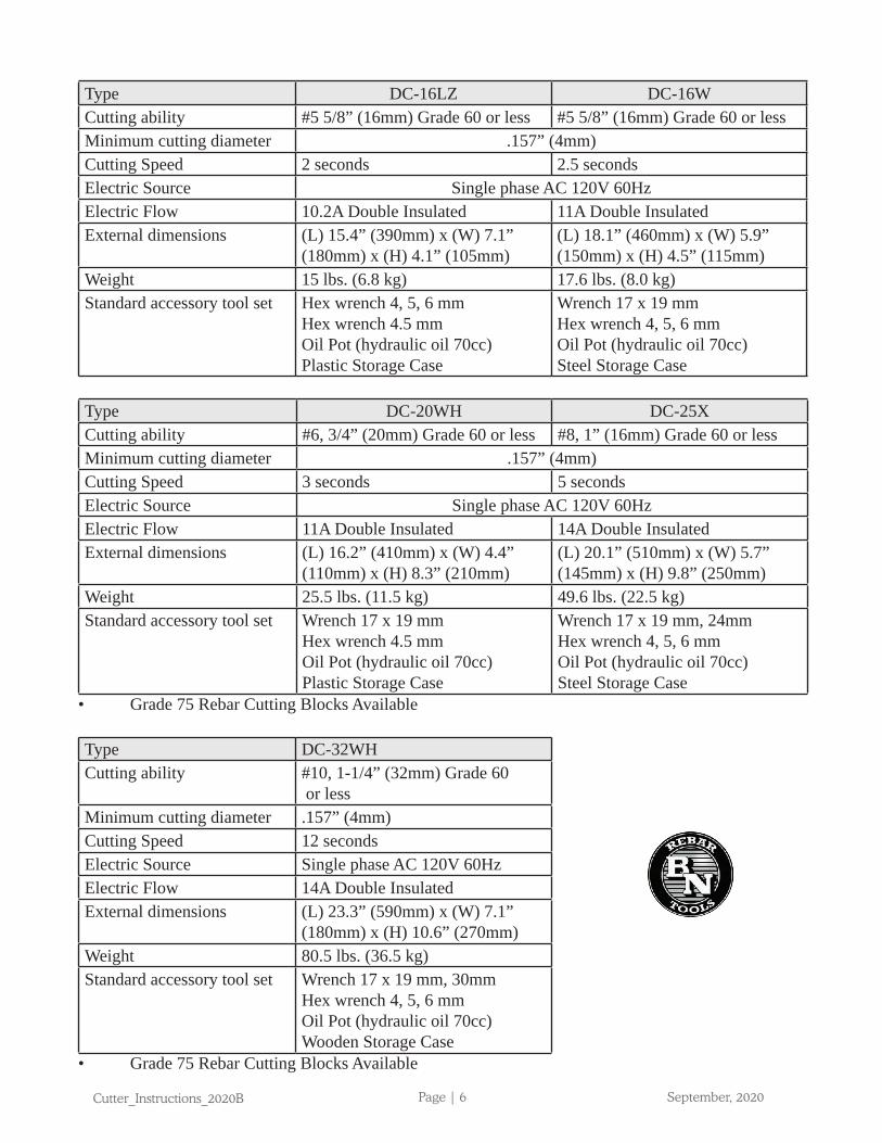
Type DC-16LZ DC-16WCutting ability #5 5/8” (16mm) Grade 60 or less #5 5/8” (16mm) Grade 60 or lessMinimum cutting diameter .157” (4mm)Cutting Speed 2 seconds 2.5 secondsElectric Source Single phase AC 120V 60HzElectric Flow 10.2A Double Insulated 11A Double InsulatedExternal dimensions (L) 15.4” (390mm) x (W) 7.1”
(180mm) x (H) 4.1” (105mm)(L) 18.1” (460mm) x (W) 5.9” (150mm) x (H) 4.5” (115mm)
Weight 15 lbs. (6.8 kg) 17.6 lbs. (8.0 kg)Standard accessory tool set Hex wrench 4, 5, 6 mm
Hex wrench 4.5 mmOil Pot (hydraulic oil 70cc)Plastic Storage Case
Wrench 17 x 19 mmHex wrench 4, 5, 6 mmOil Pot (hydraulic oil 70cc)Steel Storage Case
Type DC-20WH DC-25XCutting ability #6, 3/4” (20mm) Grade 60 or less #8, 1” (16mm) Grade 60 or lessMinimum cutting diameter .157” (4mm)Cutting Speed 3 seconds 5 secondsElectric Source Single phase AC 120V 60HzElectric Flow 11A Double Insulated 14A Double InsulatedExternal dimensions (L) 16.2” (410mm) x (W) 4.4”
(110mm) x (H) 8.3” (210mm)(L) 20.1” (510mm) x (W) 5.7” (145mm) x (H) 9.8” (250mm)
Weight 25.5 lbs. (11.5 kg) 49.6 lbs. (22.5 kg)Standard accessory tool set Wrench 17 x 19 mm
Hex wrench 4.5 mmOil Pot (hydraulic oil 70cc)Plastic Storage Case
Wrench 17 x 19 mm, 24mmHex wrench 4, 5, 6 mmOil Pot (hydraulic oil 70cc)Steel Storage Case
• Grade 75 Rebar Cutting Blocks Available
Type DC-32WHCutting ability #10, 1-1/4” (32mm) Grade 60
or lessMinimum cutting diameter .157” (4mm)Cutting Speed 12 secondsElectric Source Single phase AC 120V 60HzElectric Flow 14A Double InsulatedExternal dimensions (L) 23.3” (590mm) x (W) 7.1”
(180mm) x (H) 10.6” (270mm)Weight 80.5 lbs. (36.5 kg)Standard accessory tool set Wrench 17 x 19 mm, 30mm
Hex wrench 4, 5, 6 mmOil Pot (hydraulic oil 70cc)Wooden Storage Case
• Grade 75 Rebar Cutting Blocks Available
Cutter_Instructions_2020B Page | 7 September, 2020
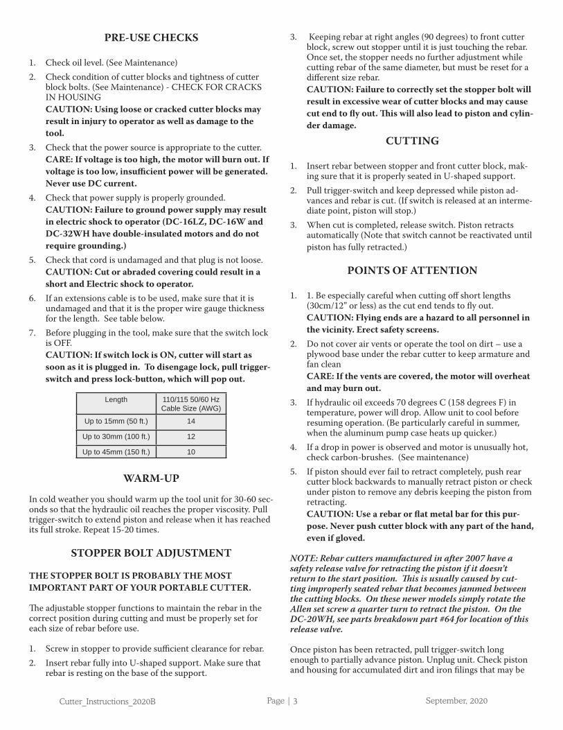
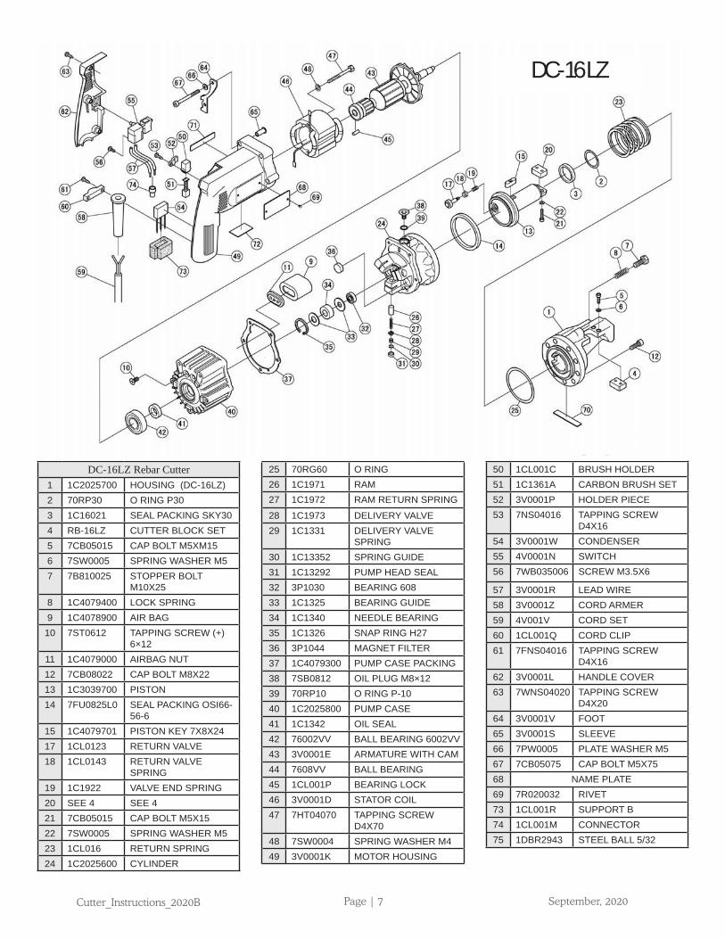
DC-16LZ Rebar Cutter1 1C2025700 HOUSING (DC-16LZ)2 70RP30 O RING P303 1C16021 SEAL PACKING SKY304 RB-16LZ CUTTER BLOCK SET5 7CB05015 CAP BOLT M5XM156 7SW0005 SPRING WASHER M57 7B810025 STOPPER BOLT
M10X258 1C4079400 LOCK SPRING9 1C4078900 AIR BAG10 7ST0612 TAPPING SCREW (+)
6×1211 1C4079000 AIRBAG NUT12 7CB08022 CAP BOLT M8X2213 1C3039700 PISTON14 7FU0825L0 SEAL PACKING OSI66-
56-615 1C4079701 PISTON KEY 7X8X2417 1CL0123 RETURN VALVE18 1CL0143 RETURN VALVE
SPRING19 1C1922 VALVE END SPRING20 SEE 4 SEE 421 7CB05015 CAP BOLT M5X1522 7SW0005 SPRING WASHER M523 1CL016 RETURN SPRING24 1C2025600 CYLINDER
25 70RG60 O RING26 1C1971 RAM27 1C1972 RAM RETURN SPRING28 1C1973 DELIVERY VALVE29 1C1331 DELIVERY VALVE
SPRING30 1C13352 SPRING GUIDE31 1C13292 PUMP HEAD SEAL32 3P1030 BEARING 60833 1C1325 BEARING GUIDE34 1C1340 NEEDLE BEARING35 1C1326 SNAP RING H2736 3P1044 MAGNET FILTER37 1C4079300 PUMP CASE PACKING38 7SB0812 OIL PLUG M8×1239 70RP10 O RING P-1040 1C2025800 PUMP CASE41 1C1342 OIL SEAL42 76002VV BALL BEARING 6002VV43 3V0001E ARMATURE WITH CAM44 7608VV BALL BEARING45 1CL001P BEARING LOCK46 3V0001D STATOR COIL47 7HT04070 TAPPING SCREW
D4X7048 7SW0004 SPRING WASHER M449 3V0001K MOTOR HOUSING
50 1CL001C BRUSH HOLDER51 1C1361A CARBON BRUSH SET52 3V0001P HOLDER PIECE53 7NS04016 TAPPING SCREW
D4X1654 3V0001W CONDENSER55 4V0001N SWITCH56 7WB035006 SCREW M3.5X6
57 3V0001R LEAD WIRE58 3V0001Z CORD ARMER59 4V001V CORD SET60 1CL001Q CORD CLIP61 7FNS04016 TAPPING SCREW
D4X1662 3V0001L HANDLE COVER63 7WNS04020 TAPPING SCREW
D4X2064 3V0001V FOOT65 3V0001S SLEEVE66 7PW0005 PLATE WASHER M567 7CB05075 CAP BOLT M5X7568 NAME PLATE69 7R020032 RIVET73 1CL001R SUPPORT B74 1CL001M CONNECTOR75 1DBR2943 STEEL BALL 5/32
DC-16LZ
Cutter_Instructions_2020B Page | 8 September, 2020
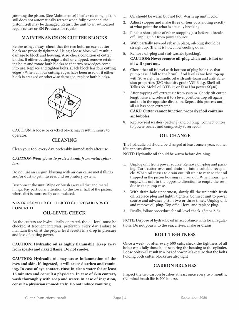
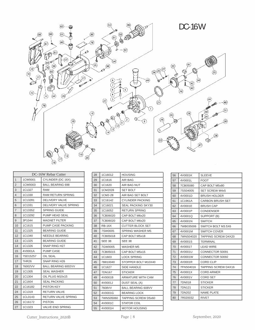
DC-16W Rebar Cutter1 1CW0001 CYLINDER (DC 16X)
2 1CW0003 BALL BEARING 698
3 1C1327 RAM
4 1C1330 RAM RETURN SPRING
5 1C13281 DELIVERY VALVE
6 1C1331 DELIVERY VALVE SPRING
7 1C13352 SPRING GUIDE
8 1C13292 PUMP HEAD SEAL
9 3P1044 MAGNET FILTER
10 1C1615 PUMP CASE PACKING
11 1C1325 BEARING GUIDE
12 1C1340 NEEDLE BEARING
13 1C1325 BEARING GUIDE
14 1C1326 SNAP RING H27
15 4V0001A PUMP CASE
16 7SD15257 OIL SEAL
17 7HR26 SNAP RING H26
18 76002VV BALL BEARING 6002VV
19 1C1305 SEAL WASHER
20 1C1304 OIL PLUG M10x15
21 1C1604 SEAL PACKING
22 1C16182 PISTON KEY
24 1C1319 RETURN VALVE
25 1CL0143 RETURN VALVE SPRING
26 1C16172 PISTON
27 1C1323 VALVE END SPRING
28 1C16012 HOUSING
29 1C1616 AIR BAG
30 1C1620 AIR BAG NUT
31 1CM2028 SET BOLT
32 1CM2-28 AIR BAG SET BOLT
33 1C16142 CYLINDER PACKING
34 1C16021 SEAL PACKING SKY30
35 1C16052 RETURN SPRING
36 7CB06020 CAP BOLT M6x20
37 7CB06020 CAP BOLT M6x20
38 RB-16X CUTTER BLOCK SET
39 7SW0005 SPRING WASHER M5
40 7CB05018 CAP BOLT M5x18
41 SEE 38 SEE 38
42 7GW0005 WASHER M5
43 7CB05015 CAP BOLT M5x15
44 1C1603 LOCK SPRING
45 7B810040 STOPPER BOLT M10X40
46 1C1627 SIDE HANDLE
47 7DN167 STICKER
49 4V0001B ARMATURE WITH CAM
50 4V0001J DUST SEAL (A)
51 7608VV BALL BEARING 608VV
52 4V0001G BEARING LOCK
53 7WNS05060 TAPPING SCREW D5x60
54 4V0001C STATOR COIL
55 4V0001H MOTOR HOUSING
56 4V0001K SLEEVE
57 4V0001L FOOT
58 7CB05080 CAP BOLT M5x80
59 7SS04005 SET SCREW M4x5
60 4V0001D BRUSH HOLDER
61 1C1961A CARBON BRUSH SET
62 4V0001E BRUSH CAP
63 4V0001P CONDENSER
64 4V0001Q SUPPORT (B)
65 4V0001N SWITCH
66 7WB035006 SWITCH BOLT M3.5X6
67 4V0001M SWITCH COVER
68 7WNS04020 TAPPING SCREW D4X20
69 4V0001S TERMINAL
70 4V0001T LEAD WIRE
71 4V0001U CONNECTOR 50091
72 4V0001W CONNECTOR 50092
73 4V0001R CORD CLIP
74 7FNS04016 TAPPING SCREW D4X16
75 4V0001X CORD ARMER
76 4V0001V CORD SET
77 7DN018 STICKER
78 7DN121 STICKER
79 7DN202 NAME PLATE
80 7R020032 RIVET
DC-16W
Cutter_Instructions_2020B Page | 9 September, 2020
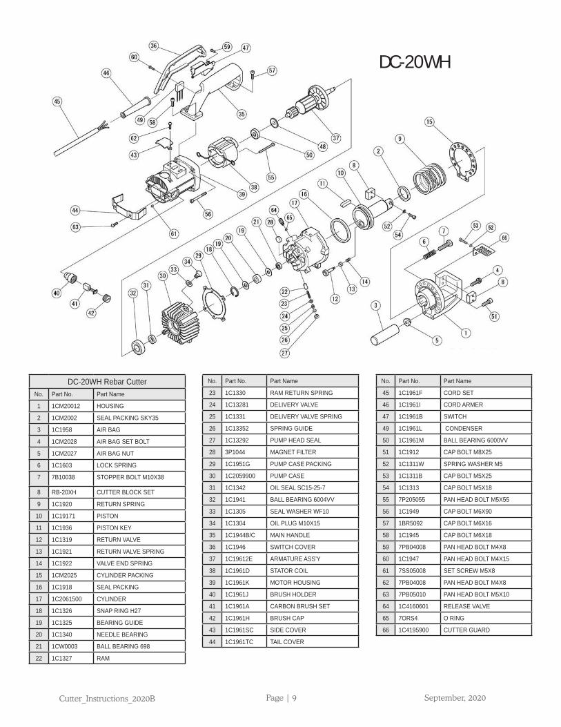
DC-20WH Rebar CutterNo. Part No. Part Name
1 1CM20012 HOUSING
2 1CM2002 SEAL PACKING SKY35
3 1C1958 AIR BAG
4 1CM2028 AIR BAG SET BOLT
5 1CM2027 AIR BAG NUT
6 1C1603 LOCK SPRING
7 7B10038 STOPPER BOLT M10X38
8 RB-20XH CUTTER BLOCK SET
9 1C1920 RETURN SPRING
10 1C19171 PISTON
11 1C1936 PISTON KEY
12 1C1319 RETURN VALVE
13 1C1921 RETURN VALVE SPRING
14 1C1922 VALVE END SPRING
15 1CM2025 CYLINDER PACKING
16 1C1918 SEAL PACKING
17 1C2061500 CYLINDER
18 1C1326 SNAP RING H27
19 1C1325 BEARING GUIDE
20 1C1340 NEEDLE BEARING
21 1CW0003 BALL BEARING 698
22 1C1327 RAM
No. Part No. Part Name
23 1C1330 RAM RETURN SPRING
24 1C13281 DELIVERY VALVE
25 1C1331 DELIVERY VALVE SPRING
26 1C13352 SPRING GUIDE
27 1C13292 PUMP HEAD SEAL
28 3P1044 MAGNET FILTER
29 1C1951G PUMP CASE PACKING
30 1C2059900 PUMP CASE
31 1C1342 OIL SEAL SC15-25-7
32 1C1941 BALL BEARING 6004VV
33 1C1305 SEAL WASHER WF10
34 1C1304 OIL PLUG M10X15
35 1C1944B/C MAIN HANDLE
36 1C1946 SWITCH COVER
37 1C19612E ARMATURE ASS’Y
38 1C1961D STATOR COIL
39 1C1961K MOTOR HOUSING
40 1C1961J BRUSH HOLDER
41 1C1961A CARBON BRUSH SET
42 1C1961H BRUSH CAP
43 1C1961SC SIDE COVER
44 1C1961TC TAIL COVER
No. Part No. Part Name
45 1C1961F CORD SET
46 1C1961I CORD ARMER
47 1C1961B SWITCH
49 1C1961L CONDENSER
50 1C1961M BALL BEARING 6000VV
51 1C1912 CAP BOLT M8X25
52 1C1311W SPRING WASHER M5
53 1C1311B CAP BOLT M5X25
54 1C1313 CAP BOLT M5X18
55 7P205055 PAN HEAD BOLT M5X55
56 1C1949 CAP BOLT M6X90
57 1BR5092 CAP BOLT M6X16
58 1C1945 CAP BOLT M6X18
59 7PB04008 PAN HEAD BOLT M4X8
60 1C1947 PAN HEAD BOLT M4X15
61 7SS05008 SET SCREW M5X8
62 7PB04008 PAN HEAD BOLT M4X8
63 7PB05010 PAN HEAD BOLT M5X10
64 1C4160601 RELEASE VALVE
65 7ORS4 O RING
66 1C4195900 CUTTER GUARD
DC-20WH
Cutter_Instructions_2020B Page | 10 September, 2020
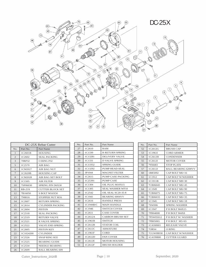
DC-25X Rebar CutterNo. Part No. Part Name
1 1C2601B HOUSING
2 1C2602 SEAL PACKING
3 70RP32 O RING P32
5 1C2570 AIR BAG
6 1CM2027 AIR BAG NUT
7 1C2620B HOUSING CAP
8 1CM2028 AIR BAG SET BOLT
9 1C1505 AIR FILTER
10 7SP06030 SPRING PIN D6X30
11 RB-25X CUTTER BLOCK SET
12 7B16050 S BOLT M16X50
13 7N8016 STOPPER NUT M16
14 1C2607 RETURN SPRING
15 1C2614 CYLINDER PACKING
16 1C2604 PISTON
17 1C2518 SEAL PACKING
18 1C2519 RETURN VALVE
19 1C2521 R VALVE SPRING
20 1C2522 VALVE END SPRING
21 1C2605 PISTON KEY
22 1C1024200 CYLINDER
23 1C2526 SNAP RING H35
24 1C2525 BEARING GUIDE
25 1C2534 NEEDLE BEARING
26 1C2609 BALL BEARING 609
No. Part No. Part Name
27 1C2610 RAM
28 1C1330 R RETURN SPRING
29 1C13281 DELIVERY VALVE
30 1C1331 D VALVE SPRING
31 1C13352 SPRING GUIDE
32 1C13292 PUMP HEAD SEAL
33 3P1044 MAGNET FILTER
34 1C2615 PUMP CASE PACKING
35 1C25391 PUMP CASE
36 1C1304 OIL PLUG M10X15
37 1C1305 SEAL WASHER WF10
38 1C2542 OIL SEAL SC20-35-8
39 1C1941 BEARING 6004VV
40 1C2616 HANDLE PRESS
41 1C1944B/C MAIN HANDLE
42 1C1946 SWITCH COVER
43 1C2611 CASE COVER
44 1C2612A CARBON BRUSH SET
45 1C1961B SWITCH
46 1C2612B STATOR COIL
47 1C2612C ARMATURE
48 1C1961F CORD
49 1C2612D FAN COVER
50 1C2612E MOTOR HOUSING
51 1C2612F BRUSH HOLDER
No. Part No. Part Name
52 1C2612G BRUSH CAP
53 1C1961I CORD ARMER
54 1C2612H CONDENSER
55 1C2612I MOTOR COVER
56 7956683 STOP PLATE
57 1C2612J BALL BEARING 6200VV
60 1BR5092 CAP BOLT M6×16
61 1C1912 CAP BOLT W/WASHER
62 1C1911B CAP BOLT M8×30
63 7CB06045 CAP BOLT M6×45
64 1C1949 CAP BOLT M6×90
65 7CB06075 CAP BOLT M6×75
66 7CB06035 CAP BOLT M6×35
67 1C1945 CAP BOLT M6×18
68 7SW006 SPRING WASHER
69 1C1947 P H BOLT M4X15
70 7PB04008 P H BOLT M4X8
71 7PSW05012 P H BOLT W/ WASHER
72 7PB05065 P H BOLT M5×65
73 1C4160601 RELEASE VALVE
74 7ORS4 O RING
75 7CGW08030 CAP BOLT W/WASHER
76 1C4199800 CUTTER GUARD
DC-25X
Cutter_Instructions_2020B Page | 11 September, 2020
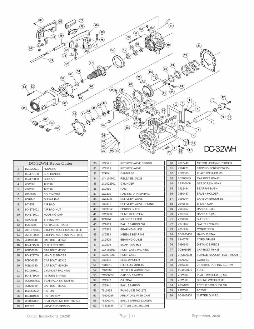
DC-32WH Rebar Cutter1 1C1022601 HOUSING
2 1C4172100 SUB HANDLE
3 1C4172000 COLLAR
4 7PW008 1C2607
5 7SW008 1C2607
6 7B08020 BOLT M8X20
7 7ORP40 O RING P40
8 1C3258 AIR BAG
9 1C4171401 AIR BAG NUT
10 1C4171601 HOUSING CAP
11 7SP06036 SPRING PIN
12 1CM2028 AIR BAG SET BOLT
13 7B11T20060 STOPPER BOLT M20X60 (11T)
14 7N11T0020 STOPPER NUT M20-P2.5 (11T)
15 7CB08040 CAP BOLT M8X40
16 1C4171500 CUTTER BLOCK
17 7CB08030 CAP BOLT M8X30
18 1C4171700 HANDLE SPACER
19 7CB06025 CAP BOLT M6X25
20 7CB10030 CAP BOLT M10X30
21 1C3093601 CYLINDER PACKING
22 1C4171900 RETURN SPRING
23 7CU0567KO SEAL PACKING USH-45
24 7CB08030 CAP BOLT M8X30
25 1C2056502 PISTON
26 1C4184900 PISTON KEY
28 7FU1078LO SEAL PACKING OS1100-85-9
29 1C2522 VALVE END SPRING
30 1C2521 RETURN VALVE SPRING
31 1C2519 RETURN VALVE
33 7ORS4 O RING S4
34 1C4160601 RELEASE VALVE
35 1C1022901 CYLINDER
36 1C2610 RAM
37 1C1330 RAM RETURN SPRING
38 1C13281 DELIVERY VALVE
39 1C1331 DELIVERY VALVE SPRING
40 1C13352 SPRING GUIDE
41 1C13292 PUMP HEAD SEAL
42 3P1044 MAGNET FILTER
43 1C2609 BALL BEARING 609
44 1C2525 BEARING GUIDE
45 1C2534 NEEDLE BEARING
46 1C2525 BEARING GUIDE
47 1C2526 SNAP RING H35
48 1C4165800 PUMP CASE PACKING
49 1C1021301 PUMP CASE
50 1C1305 SEAL WASHER
51 7B10015 OIL PLUG M10X15
52 7GW006 TEETHED WASHER M6
53 7CB06055 CAP BOLT M6X55
54 1C2542 OIL SEAL
55 1C1941 BALL BEARING
56 7312435 FAN GUIDE 7001975
57 7360406F ARMATURE WITH CAM
58 762002RU BALL BEARING 62002RU
59 7340358F STATOR COIL 7001691
60 7312449 MOTOR HOUSING 7001303
61 7984271 TAPPING SCREW D5X75
62 7SW005 PLATE WASHER M5
63 7CB05045 CAP BOLT M5X45
64 7SS05008 SET SCREW M5X8
65 7312434 BEARING BUSH
66 7980487 BRUSH HOLDER
67 7999044 CARBON BRUSH SET
68 7940540 BRUSH CAP
69 7981867 HANDLE B (L)
70 7981866 HANDLE A (R )
71 7990082 SUPPORT
72 7971162 SWITCH 7992891
73 7001934 CONDENSER
74 1C4160400 HANDLE STAY
75 7940778 CORD ARMER
76 7990940 DISTANCE PIECE
77 7CB06035 CAP BOLT M6X35
78 7FCB06025 FLANGE SOCKET BOLT M6X25
79 7930053 CORD SET
80 7956636 7NT04025 TAPPING SCREW
81 1C4156001 TUBE
82 7PW006 PLATE WASHER (S) M6
83 7SW005 SPRING WASHER M5
84 7GW008 TEETHED WASHER M8
85 7SW008 1C2607
86 1C4103800 CUTTER GUARD
DC-32WH

Cutter_Instructions_2020B Page | 12 September, 2020
BN PRODUCTS_USA,LLC.3450 Sabin Brown Road • Wickenburg, Arizona 85390(800) 992-3833 • (928) 684-2813 • [email protected]
www.bnproducts.com