range instrumentation handbook - dtic
TRANSCRIPT
SUPERSEDES ETR-TR-71-5 DATED SEPTEMBER 1971 (A?
THE UNITED STATES AIR FORGE
EASTERN TEST RANGE
1 JULY 1976
RANGE INSTRUMENTATION
HANDBOOK
D D C
V) SEP 3 1976
EEtnns B
PATRICK AIR FORCE BASE, FLORIDA
r\ » - - • — -
■.T A
I»" :ase; . . ; . !
FOREWORD
The purpose of the Air Force Eastert Test Range (AFETR) Instrumentation Handbook is to provide detailed descriptions of the instrumentation and related equipment for use by Range personnel and Range Users. It complements the AFETR Capa- bilities Handbook which provides an assessment of the support capabilities of the Eastern Test Range (ETR). These two handbooks should be used together to provide a complete depiction of the ETR.
This handbook will be updated periodically to reflect changes that continually occur. Current data on specific areas of interest will be provided upon request.
FOR THE COMMANDER
HOWARD L. PECKHAM, JR., Coionel, USAF Director of Range Operations
tmnu\m.
IT
«Kites« & musm a
a
•BTWIlWM»MU«un CMS
A MM *-_*—__!__»«__-__»• «_ ^^^^^
«1» W?^5IWW -»™ ■■■=:
SECURITY CLASSIFICATION OF THIS PAGE (Wien Dalf Bn!»r«<0
I
*
\
REPORT DOCUMENTATION PAGE BESOM; HUMBEH
AFETR UMBf« •+•
-TR-76-T& / / 12. GOVT ACCESSION NO
READ INSTRUCTIONS BEFORE COMPLETING FORM
3. RECIPIENT'S CATALOG NUMBER
4. TITLE (and Sublitf«)
The United States Air Force Eastern Test Range JY Range Instrumentation Handbook« J
7. AUTHOR^
Bruce E /Conel Capt., USAF
PERFORMING ORGANIZATION NAME AMD ADDRESS Plans and Requirements Division Directorate ot Range Operations (DOX) Hq., Air Force Eastern Test Range %/ Patrick Air Force Base. Florida 32925
II. CONTROLLING OFFICE NAME ANO ADDRESS Plans and Requirements Division Directorate of Range Operations (DOX) Hq., Air Force Eastern Test Range Patrick Mr Eflice Ba<^, Elooda 32225
I«. MONITORING AGENCY NAME "« ADDRESS?» älüiymi.
Not applicable
«c«)
It. DISTRIBUTION STATEMENT (ot M» Resort)
E*ORT « PERIOD COVEREO
Final TBtityl 8. PERFORM.^ WE itPBI f BOT!
■ . CONTRACT OR GRANT HUMBERT«)
10. PROGRAM ELEMENT. PROJECT. TASK AREA a WORK UNIT NUMBERS
nrr>.-r »*-r.
1 JuljU|76 iibUttiK 5i wxm
173
1 IS. SECURITY CLASS, (ot thl« «port)
Unclassified IS«. DECLASSIFICATION/DOWNGRAOING
SCHEDULE _ ,. , Not applicable
Approved for public release; distribution unlimited.
17. DISTRIBUTION STATEMENT (ot th« ihmoct mntotoä In Block 10, It «ttotmt turn Roport)
It. SUPPLEMENTARY NOTES
It. KEY WORDS rConOmra on »••##•• «*#• iraaceaaar» and laWlfr *r Mec« nwa*ar)
Test Rante. Radar, Telemetry. Optics, Communications, Command/Control, Range Safety, Range Tracking Ships, Missile Testing, Impact Location Systems, Data Handling/Processing
w\U BSTRACT (Ctmtlm>m en raver ae »14» It neceeeenr aW Itfwtftfr «F «•«* mm»»*)
The Air Fores Eastern Test Range (AFETR) extends from ttie eastern United States mainland through the south Atlantic Ocean area eastward into the Indian Ocean. It includes all stations, sites, ocean areas, and air space necessary to conduct missile and apace vehicle test and development.
This hand book describes the major instrumentation systems now operating, or being installed, on the ETR. The equipment and operation of each system is discussed briefly, and its location and accuracies given.
00,: '\Tn 1*73 EDITION OF 1 NOV tS IS OBSOLETE
SEC OilOZÖ
UNITY CLASSIFICATION OF THIS PAGE fWta« Dm» gMare« i
AFETR-TR-76-04
Range Instrumentation Handbook
1 July 1976
United States Air Force Eastern Test Range
Patrick Air Force Base, Florida
o
TABLE OF CONTENTS 1 INTRODUCTION 1- 1
1.1 1.2 1.3 1.4 1.5 1.6 1.7 1.8
Metric Measurement Capabilities Telemetry Capabilities .... Signature Capabilities .... Command/Control Photographic Services .... Meteorological Services .... Laboratory Services Facilities
1- 1- 1- 1- 1- 1- 1- 1-
I L
r
2 DATA ACQUISITION
2.1 Radar
2.1.1 2.1.2 2.1.3 2.1.4 2.1.5 2.1.6
On-Axis Radars AN/FPS-16 Radar Integrated Instrumentation Radar AN/FPS-16V Radar Mod II Radar ' . . . AN/SPS-35 Radar
2.2 Telemetry . . . .
2.2.1 introduction
2.2.1.1 Antennas and Rf Distribution Systems 2.2.1.2 Receive and Record 2.2.1.3 Separation and Display 2.2.1.4 Real-Time Telemetry Transmission . .
2.2.2 Telemetry Receiver/Reeorder Group (TRKl-12)
2.2.2.1 Receiver 2.2.2.2 Recorder 2.2.2 3 Telemetry Receiver/2-MHz Recorder
2.2 4 2.2 5 2.2 6
7 -» -> 8 2.2 9 2.2 10 2.2 II 2.2 12
DigitaMo-Analofc Converter, Models 2119 and ";
Data Processing (Computer Formatter) . . . 20
2.2.12.1 All Data Selection . . . 2.2.12.2 Patch Program Selection . 2.2.12.3 Computer Format Converter 2.2.12.4 IBM Format Recorders . .
2- 1
2- 1
2- 1 2- 7 2- 9 2-13 2-14 2-16
2-17
2-17
2-17 2-17 2-17 2-17
2-23
2-23 2-23
2.2.3 Tape Playback Srbsystem TDM-1 2-24 Tape Copy Subsystem TMM-7 Post-Detection Tape Copy Station (MPDL) TDM Decommutators Type I and I! . TDM Decommutator Type II! Fixed Discriminator System, Model 210 ... , Tunable Frequency Discriminator System Analog-to-Digital Converter, Model 2239 2-26
2-24 2-24 2-25 2-26 2-26 2-26
2-27 2-27
2-27 2-28 2-28
ui
«M
* <r
CONTENTS
2.2.13 Range Time Decoder 2-28
2.2.13.1 Tape Start and Stop Time Selection Controls 2-28 2.2.13.2 Identification Control 2-28 2.2.13.3 Computer Tarn Time Placement 2-29 2.2.13.4 Additional Capability 2-29 2.2.13.5 Range Time Input 2-29
2.2.14 Data Corrector System 2-2^ 2.2.15 Oscillographic Recorders 2-29 2.2.16 Pen Recorders . 2-29 2.2.17 Digital Bar-Graph, Model 2321 .... 2-30 2.2.18 Digital Display 2-30
2.2.18.1 Multistylus Event Recorder 2-30 2.2.18.2 Digital Printer 2-30 2.2.18.3 Nixie Readouts 2-30 2.2.18.4 Analog Meter 2-30
2.2.19 Real-Time Telemetry Data System 2-30 2.2.20 USNS Redstone Telemetry' 2-33
2.2.20.1 Antenna Subsystem 2-33 2.2.20.2 Receiver Subsystem 2-33 2.2.20.3 Recording Subsystem 2-33 2.2.20.4 Data Separation and Decommutation System 2-33 2.2.20.5 Signal Programmer and Conditioner 2-34
2.2.21 ARIS Telemetry 2-34
'..3 Optics 2-51
2.3.1 Metric Optics 2-51
2.3.1.1 Cinetheodolltes 2-S3 2.3.1.2 Balletic 2-56 2.3.1.3 Rib'xH» Frame (CZR) Camera 2-58 2.3.1.4 Laser Ranger 2-59
2.3.2 Engineering Sequential and Documentary Optics 2-60
2.3.2.1 IFLOT (Intermediate-Focal Length Tracker) 2-60 13.2.2 MOTS (Mobile Optical Tracking System) 2-62 2.3.2.3 ROTI (Recording Optical Tracking Instrument) . 2-64 2.3.2.4 IGOR (Intercept Ground Optical Recorder) 2-66 2.3.2.5 RML/ITEK 48-inch Telescope (Meteor II) 2-67 2.3.2.6 Engineering Sequential and Documentary Photography Cameras . 2-68
2.3.3 Laser Illumination 2-69 2.3.4 Opto-Radiometric 2-69
2.3.4.1 ARIS (USNS Arnold & USNS Vandenberg) ......... 2-70 2.3.4.2 RIS (USNS Redstone) # 2-72 2.3.4.3 Ascension Island 2-72
iv
«M*g"V*.-'
Wfy^^^^V^^^"-W^v''a^ip''''"''' ■■■'«^J!f?«T<fp?T:'v«^pw^^-'- -^^^■\r^^.^f^^~~r- ■ i -
CONTENTS
2.4 Impact Location Systems 2-73
2.4.1 Missile Impact Location System 2-73
2.4.1.1 Location 2-74 2.4.1.2 Accuracy 2-74 2.4.1.3 Data Handling 2-74
2.4.2 Sonobuoy Impact Location System 2-74
2.4.2.1 Location 2-76 2.4.2.2 Accuracy 2-76 2.4.2.3 Operations 2-76
2.5 Meteorology 2-77
2.5.1 Surface Instrumentation 2-77
2.5.1.1 AN/FPS-77 Storm Detection Meteorological Radar Set 2-77 2.5.1.2 Launch Pad Lightning Warning System (LPLWS) 2-78 2.5.1.3 Weather Information Network Display System (WINDS) .... 2-78
2.5.2 Upper Air Instrumentation 2-78
2.5.2.1 AN/GMD-4 (Rawin Set) 2-78 2.5.2.2 Omega NAVAID Sounding System 2-79 2.5.2.3 High Resolution Wind Measurement Balloon (Jimsphere) .... 2-79 2.5.2.4 LOK! Meteorological Rocket System 2-79 2.5.2.5 Super LOKI Meteorological Rocket System 2-79
2.5.3 Data Processing 2-79 2.5.4 Satellite Imagery Acquisition and Processing . 2-79
2.5.4.1 APT Satellite Tracking S»atior 2-80 2.5.4.2 Defense Meteorological Satellit« frogram (DMSP) 2-80
2.5.5 STAFFMET Library 2-80
SUPPORT SYSTEMS 3-1
3.1 Communications 3-1
3.1.1 Interstation Communications 3-1
3.1.1.1 undersea Cable 3-1 1.1.2 Hign Frequency Radio (HF) 3-1 1.1.3 Uhf/Vhf Radio 3-6 1.1.4 Satellite Communications 3-6 1.1.5 Microwave System 3-7 1.1.6 Teletype 3-7 1.1.7 Voice Communications 3-7
#* 3.1.2 Range Communications Control Center 3-7 3.1.3 Oosed-Curuit Television CCCTV) 3-9
^^"—"■"^"^^"("■"■■■•S^""P^™"*«"P"",«ff^"^P"«""i"»»™p"
F „ , „..,— .-■■«„■.i, .lil.W.1 IT '-I —""••••""
CONTENTS
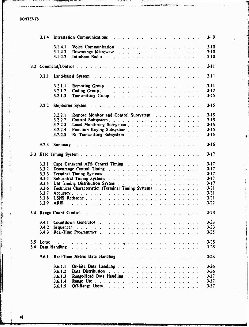
3.1.4 Intrastation Communications 3-9
3.1.4.1 Voice Communication 3-10 3.1.4.2 Downrange Microwave 3-10 3.1.4.3 Intrabase Radio 3-10
3.2 Command/Control 3-11
3.2.1 Land-based System 3-11
t 3.2.1.1 Remoting Group 3-11 3.2.1.2 Coding Group 3-12
j 3.2.1.3 Transmitting Group 3-35
i 3.2.2 Shipborne System 3-15 i
3,2.2.1 Remote Monitor and Control Subsystem 3-15 3.2.2.7 Control Subsystem 3-15 3.2.2.3 Loca* Monitoring Subsystem 3-15
: 3.2.2.4 Function Keying Subsystem 3-15 3.2.2.5 Rf Transmitting Subsystem 3-15
3.2.3 Summary 3-16
3.3 ETR Timing System 3-17
\ 3.3.1 Cape Canaveral AFS Central Timing 3-17 3.3.2 Downrange Central Timing 3-17 3.3.3 Terminal Timing Systems 3-17 3.3.4 Subcentral Timing Systems 3-17 3.3.5 Uhf Timing Distribution System 3-17 3.3.6 Technical Characteristic? (Terminal Timing System) 3-21 3.3.7 Accuracy , 3-21 3.3.8 USNS Redstone 3-21 3.3.9 AR1S 3-22
j 3.4 Range Count Control 3-23
3.4.1 Countdown Generator 3-23 3.4.2 Sequencer 3-23 3.4.3 Real-Time Programmer 3-25
3.5 Lorac 3-2S 3.6 Data Handling 3-28
3.6.1 Re^l-Time Metric Data Handling 3-28
3.6.1.1 On-Site Data Handling . 3-26 3.6.1.2 Data Distribution 3-36 3.6.1.3 Range-Head Data Handling 3-37 3.6.1.4 Range Use . . 3-37 3.6.1.5 Off-Range Users 3-37
VI

CONTENTS
if
'i
i
'.I
t.'
t c
3.6.2 Data Processing and Analysis 3-37
3.6.2.1 Metric Data 3-39 3.6.2.2 Telemetry Data , 3-40 3.6.2.3 Signature Data 3-40 3.6.2.4 Other Data Processing 3-40
3.6.3 Redstone Data Handling 3-40 3.6.4 ARIS Data Handling 3-41
RANGE SAFETY 4-1
4.1 RSDS 4-1
4.1.1 CDC-3600 & 3100 Computer 4-1 4.1.2 RTCS/RSDS Interface Buffer 4-4 4.1.3 Varian 620/M07 Computer 4-4 4.1.4 1DIIOM II Display Generator 4-4 4.1.5 Cathode-Ray Tube Displays (CRT) 4-4 4.1.6 Range Safety Console 4-4
4.2 Auxiliary Capabilities 4-4
4.2.1 Command/Control 4-4 4.2.2 Command/Control Panel 4-5 4.2.3 RICS Panel 4-5 4.2.4 Timing and Firing Control Panel 4-5
4.3 Vertical Wire Skysctean (VWS) 4-- 5 4.4 Range Safety Closed Circuit TV 4- S 4.5 Plotting Board Display System 4-5 4.6 Data Display 4-5
4.6.1 Radar Data 4-5 4.6.2 Telemetry Data 4-6 4.6.3 Launch Area Surveillance 4-6
SHIPS 5-1
S.I Range Instrumentation Ship (RIS) ÜSNS Redstone. T-AGM-20 5-1
5.1.1 Operations Control Center (OCCi 5-1 5.1.2 Tracking Radar System 5-4 5.1.3 Telemetry System 5-4 5.1.4 Ship Position and Attitude Measurement System (SPAMS) 5-4 S.i.S Command Destruct System 5-4 5.1.6 Central Data Processing System 5-5 5.1.7 Timing System S- 5 5.1.8 Acquisition/Stabilization Network 5-5 5.1.9 Meteorological System 5-5 5.1.10 Communications System . 5-5 5.1.11 Miscellaneous Equipment 5-6
jam mam Vtt mm

CONTENTS
5.2 Advanced Range Instrumentation Ships (AR1S) USNS Arnold, T-AGM-9 and ÜSNS Vandenberg, T-AGM-10 5-6
5.2.1 Operations Control Center (OCC) 5-6 5.2.2 Radar 5-9 5.2.3 Telemetry 5-9 5.2.4 Optics 5-9 5.2.5 Navigation/Stabilization 5-9 5.2.6 Data Handling 5-10 5.2.7 Timing 5-10 5.2.8 Meteorology 5-10 5.2.9 Communications 5-10
AIRCRAFT 6-1
6.1 Advanced Range Instrumentation Aircraft (ARIA) 6-1
6.1.1 Special Projects Instrumentation 6-3 6.1.2 Range Instrumentation Checkout 6-4
6.2 Terminal Radiation Program Aircraft (TRAP) 6-5
vui
w
I
k
ILLUSTRATIONS
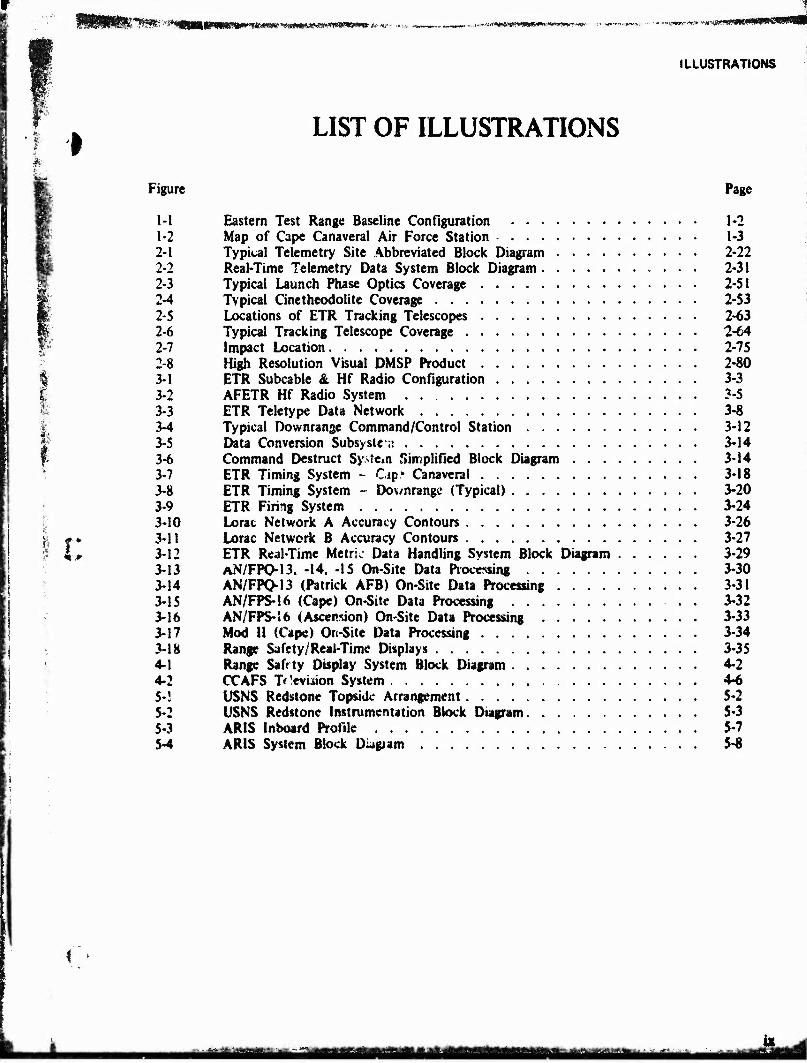
LIST OF ILLUSTRATIONS
Figure Page
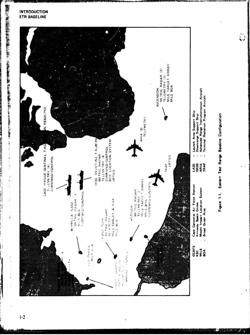
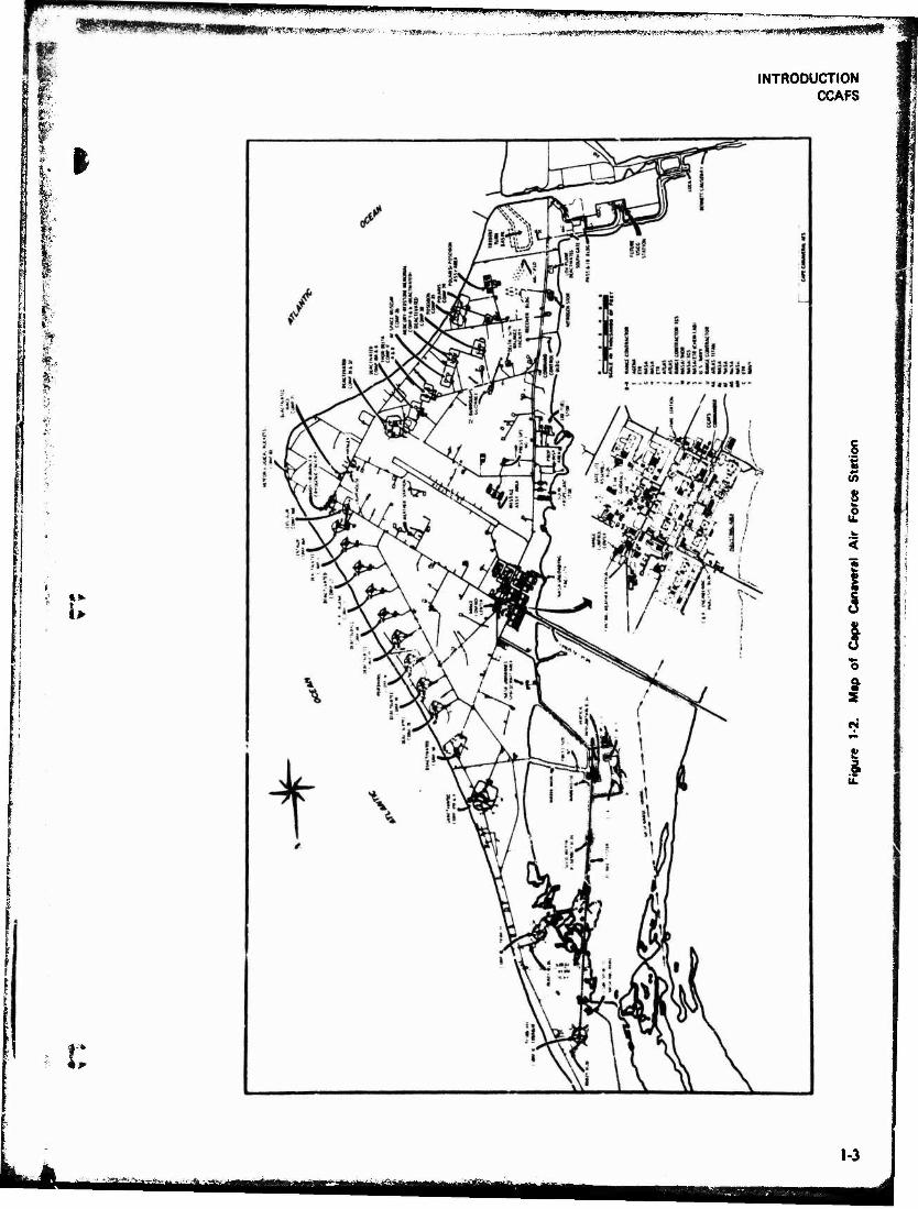
1-1 Eastern Test Range Baseline Configuration 1-2 1-2 Map of Cape Canaveral Air Force Station 1-3 2-1 Typical Telemetry Site Abbreviated Block Diagram 2-22 2-2 Real-Time Telemetry Data System Block Diagram 2-31 2-3 Typical Launch Phase Optics Coverage 2-51 2-4 Typical Cinetheodolite Coverage 2-53 2-5 Locations of ETR Tracking Telescopes 2-63 2-6 Typical Tracking Telescope Coverage 2-64 2-7 Impact Location 2-75 2-8 High Resolution Visual DMSP Product 2-80
I 3-1 ETR Subcable & Hf Radio Configuration 3-3 I 3-2 AFETR Hf Radio System 3-5 ■ 3-3 ETR Teletype Data Network 3-8 |- 3-4 Typical Downrange Command/Control Station 3-12
3-5 Data Conversion Subsystem 3-14 3-6 Command Destruct Sy>t«,n Simplified Block Diagram 3-14 3-7 ETR Timing System - Cap* Canaveral 3-18 3-8 ETR Timing System - Dov/nrangc (Typical) 3-20 3-9 ETR Firing System 3-24 3-10 Lorac Network A Accuracy Contours 3-26
#* 3-11 Lorac Network B Accuracy Contours 3-27 i, 3-12 ETR Real-Time Metric Data Handling System Block Diagram 3-29
3-13 AN/FPO-13. -14. -15 On-Site Data Processing 3-30 3-14 AN/FPO-13 (Patrick AFB) On-Site Data Processing 3-31 3-15 AN/FPS-16 (Cape) On-Site Data Processing 3-32 3-16 AN/FPS-16 (Ascension) On-Site Data Processing 3-33 3-17 Mod II (Cape) On-Site Data Processing 3-34 3-18 Range Safety/Real-Time Displays 3-35 4-1 Range Safrty Display System Block Diagram 4-2 4-2 CCAFS T<!evbion System 4-6 5-! USNS Redstone Topside Arrangement 5-2 5-2 USNS Redstone Instrumentation Block Diagram 5-3 5-3 ARIS Inboard Profile 5-7 5-4 ARIS System Block Diagiam 5-8
mmma^mummmmmmmmmmmmmmamm^^^^jm is
^luWWKWiiffMliMMMMHWMihWitll.U.*
PHOTOS
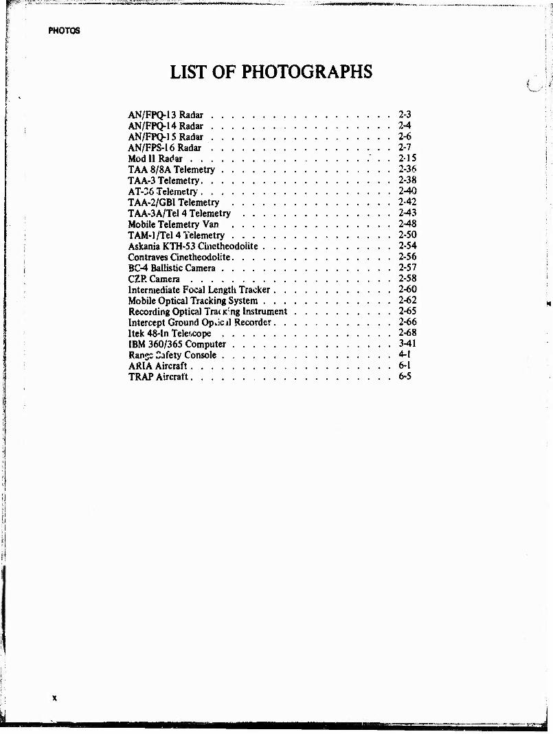
LIST OF PHOTOGRAPHS
AN/FPQ-13Radar 2-3 AN/FPQ-14 Radar 2-4 AN/FPQ-15Radar . 2-6 AN/FPS-16Radar 2-7 Mod II Radar . 2-15 TAA 8/8A Telemetry 2-36 TAA-3 Telemetry 2-38 AT-26 Telemetry. . , 2-40 TAA-2/GBI Telemetry 2-42 TAA-3A/Tel 4 Telemetry 2-43 Mobile Telemetry Van 2-48 TAM-1/Tel 4 Telemetry 2-50 Askania KTH-53 Cinctheodoiite 2-54 Contraves Cinetheodolite 2-56 BC-4 Ballistic Camera 2-57 CZR Camera 2-58 Intermediate Focal Length Tracker 2-60 Mobile Optical Tracking System 2-62 Recording Optical Tra< K ng Instrument 2-65 Intercept Ground Opöcd Recorder 2-66 Itek 48-In Telescope 2-68 IBM 360/365 Computer 3-41 Ransc Safety Console 4-1 ARIA Aircraft 6-1 TRAP Aircraft 6-5

TABLES
I LIST OF TABLES
i r
Table Page
i
2-1 2-2 2-3 2-4 2-5 2-6 2-7 2-8 2-9 2-10
11 12 13 14 15
2-16 2-17 2-\ 8 2-19 2-20 2-21 2-22 2-23 2-24 2-25 2-26 2-27 2-28 2-29 2-30 2-3! 2-32 3-1 3-2 3-3 3-4 3-5 3-6 5-1 61 6-2 6-3 6-4
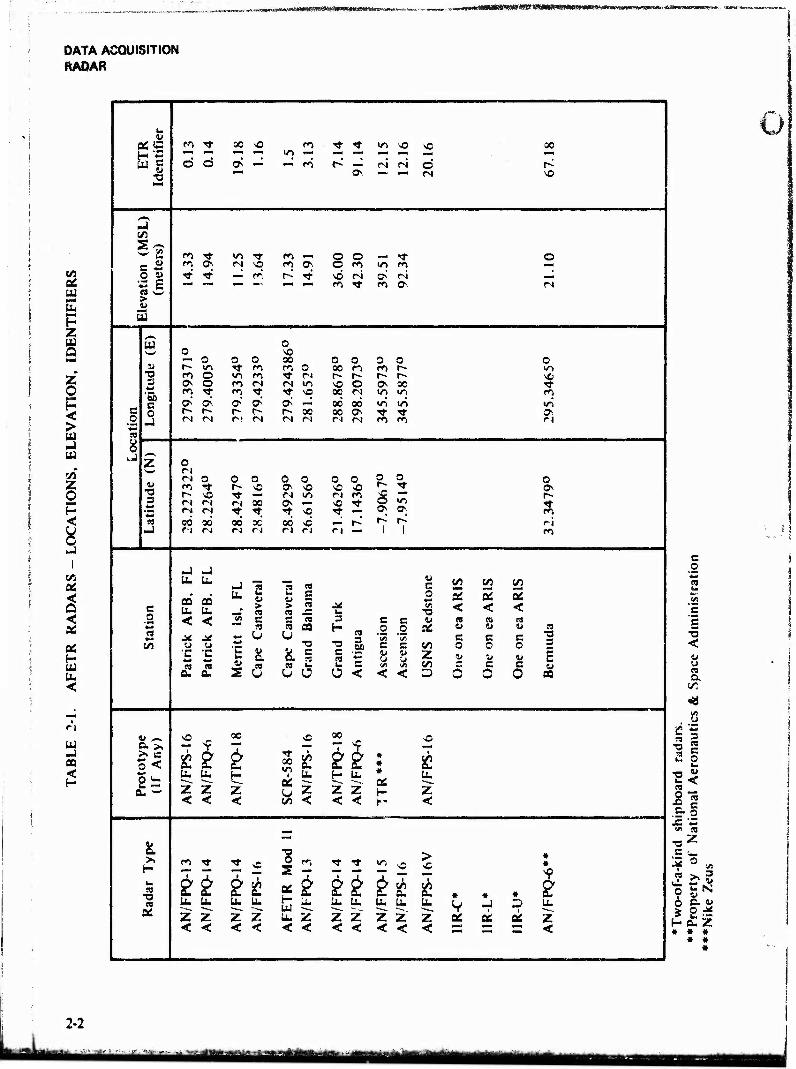
AFETR Radars - Locations, Elevation, ic.ntifiers 2-2 AN/FPQ-13 Radar Technical Characteristics 2-3 AN/FPQ-14 Radar Technical Characteristics 2-4 AN/FPQ-15 Radar Technical Characteristics 2-6 AN/FPS-16 Radar Technical Characteristics 2-8 IIR-C Radar Technical Characteristics 2-10 IIR-L Radar Tecm.'cal Characteristics 2-11 HR-U Radar Technical Characteristics 2-12 AN/FPS-16V Radar Technical Characteristics 2-14 Mod II Radar Technical Characteristics 2-15 AN/SPS-35 Radar Technical Characteristics 2-16 Major Telemetry Equipment 2-18 AFETR Telemetry Frequency Coverage by Station 2-35 TAA-8/Grand Turk Telemetry Technical Characteristics 2-37 TAA-8A/Antigua Telemetry Technical Characteristics 2-37 «AA-3/Ascension Telemetry Technical Characteristics 2-39 AT-36/Pretoria Telemetry Technical Characteristics 2-41 TAA-2/Grand Bahama Telemetry Technical Characteristics 2-42 TAA-3A/Tel 4 Telemetry Technical Characteristics 2-43 TAA-3A/Grand Bahama Telemetry Technical Characteristics 2-44 TAA-3A/Antigua Telemetry Technical Characteristics 2-45 TAA-3A/Ascension Telemetry Technical Characteristics 2-46 4-Ft Broadbeam Antenna/Ascension Telemetry Technical Characteristics . . 2-47 3-Ft Broadbeam Antenna/Ascension Telemetry Technical Characteristics . . 2-47 Broadbeam Antenna/Tel 4 Telemetry Technical Characteristics 2-48 Mobile Telemetry Van, Parabolic Antenna, Technical Characteristics , . . 2-49 Mobile Telemetry Van, Crossed-Dipole Antenna, Technical Characteristics . 2-49 TAM-1/Tel 4 Telemetry Technical Characteristics , 2-50 ETR Metric Optical Instrumentation Summary 2-52 ETR Tracking Mounts and Telescope Summary 2-61 Film Cameras for RML/Itek 48-Inch Telescope 2-69 Optical Instrumentation Parameters 2-71 AFETR Communications & Data Transmission Capability 3-2 ETR Vhf/Uhf and Microwave Communication Equipment , . 3-6 Communications Control 3-9 Command/Control Technical Characteristics 3-13 Command/Control Station Locations and Capabilities 3-16 Lorac Equipment 3-28 Range Instrumentation Ships Characte istics 5-11 ARIA and TRAP Nominal Flight Performance Data 6-2 ARIA and TRAP Navigation Capabilities. . 6-3 ARIA Signal Transmission Capability 6-4 ARIA Signal Reception Capability 6-4
XI
■•:^:i^^^^M4^^J^:.,^MM!äM iBg mm mm m

REFERENCE
*^s*WS»»»fla*>>w»:.»
LIST OF REFERENCES
^F£77? Capabilities Handbook, February 1975
AFETR Communications System Handbook, July 1972
ARIS Orientation Manual, June 1971, Pan American World Airways, Inc. and RCA Service Co.
Orientation Manual - USNS Redstone, April 1972, Pan American World Airways, Inc.
AFETRP 105-1, Meteorological Handbook, 1 July 1973
IRIG Document 106-73, Telemetry Standards (Revised November 1975)
IRIG Document 104-70, IRIG Standard Time Formats, August 1970
Pan Am Specification A-600106, Rev B, Timing Terminal Signals
AFETR Geodetic Coordinates Manual 1975, RCA Service Co.
AFETR Quarterly Accuracy Report, RCA Service Co. Technical Analysis
xu
IM&^M ..... :.■-,*!».-»***: ~«~~ ,i- !>.,' ^ ''^^MM^kM^^tB
fsiwwwiiisswisiiitiw^^
ABBREVIATIONS
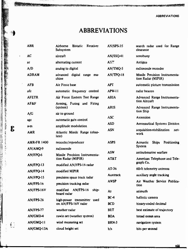
I ABBREVIATIONS
llpuv'; ABR Airborne Bistatic Receiver AN/SPS-35 search radar used for Range
Subsystem clearance
m AC aircraft AN/SSQ-41 sonobuoy
1 ac alternating current A?%T Antigua
A/D analog to digital AN/TMQ-5 radiosonde recorder
1 ADRAM advanced digital range ma- AN/TPO>18 Missile Precision Instrumenta-
■ if: chine tion Radar (MIPIR)
1 AFB Air Force base APT automatic picture transmission
Bo afc automatic frequency control APW-11 radar beacon
1 1: AFETR Air Force Eastern Test Range ARIA Advanced Range Instrumenta- tion Aircraft ' 1 AF&F Arming, Fusing and Firing
f IT (system) ARIS Advanced Range Instrumenta- s* tion Ship
A/G air to ground * < ASC Ascension ; \ age automatic gam control
ASD Aeronautical Systems Division
'I!1' K a-m amplitude modulation
ASN acquisition-stabilization net- ; 1 AMR Atlantic Missile Range (obso- work i : lete)
1* AMR-FR 1400 recorder/reproducer ASPS Acoustic Ships Positioning
.1 • j |- AN/AMQ-9
AN/FPQ-6
radiosonde
Missile Precision Instrumenta- ASW
System
antisubmarine warfare
tion Radar (M1PIR) AT&T American Telephone and Tele-
i i AN/FPQ-13 modified AN/FPS-16 radar graph Co.
AN/FPQ-14 modified MIPIR AT-36
Auxtrack
60-ft telemetry antenna
auxiliary angle tracking AN/FPQ-15 precision space track radar
AWSP Air Weather Service Publica- t AN/FPS-16 precision tracking radar tion
AN/FPS-16V modified AN/FPS-16 ship- board radar
Az
BC-4
azimuth
ballistic camera AN/FPS-26 high-power transmitter used
on AN/FPS-16V radar BCD binary-coded decimal
AN/FPS-77 weather radar BET best estimate of trajectory
AN/GMLM rawin set (weather system) BOA broad ocean area
> - ■ % ■
AN/GMQ-11 wind measuring set BRN-3 navigation system
AN/GMQ-13A cloud height set b/s bits per second
I"-"W-" JUJL
ABBREVIATIONS
BW
CCAFS
CCC
CCFF
CCTV
CDC-3100
CDC-3600
CDCE
CDP
CDPS
CDS
CEC
CFAR
CL
cm
COMM
CRDSB
CRT
CSE
CSM
cw
CZR
D/A
DAC
DARTS
DAT
dB
bandwidth
Cape Canaveral Air Force Station
Central Control Console
Cape Canaveral Forecast Facil- ity
closed-circuit television
RTCS computer
RTCS computer
Central Data Conversion Equipment
Central Data Processing
Central Data Processing Sys- tem
Command Destruct System
Consolidated Electrodynamics Corp
constant false alarm rate
common language
centimeter
communications
central retransmission decom- mutator and storage
cathode-ray tube
circular standard error
central switch matrix
continuous wave
a type of ribbon-frame camera
digital to analog
digital to analog converter
Digitized Automatic Radar Tracking System
designate, track
decibels
acquisition, and
dBm
dc
DCC
DMSP
deg
DEMUX
DME
DMSP
DOD
DP
DPE
DPDE
DPN-66
DPS
DRS
DRSB
DRSS
DSOC
DSSB
EC-135
E,F,G
• • • E,F,G
El
EPABX
ESCO
ETR
FCA
FEDAC
decibels referenced to 1 milli- watt
direct current
Designate Control Console
data conversion interface and switching equipment
degree(s)
demultiplex
distance measuring equipment
Defense Meteorological Satel- lite Program
Department of Defense
distribution programmer
data processing equipment
digital playback and digitizing equipment
radar beacon
Data Processing Subsystem
Digital Range Safety (System)
digital recording system buffer
Downrange Support Ship
DRSS Safety Officer Console
data selector and storage buf- fer
ARIA airframe
Earth-centered rectangular co- ordinates
E,F,G rates
elevation
electronic private automatic branch exchange
manufacturer
Eastern Test Range
frequency control and analysis
forward error detection and correction
xiv
0»<#,^'»*3*^^
ABBREVIATIONS
H
I i
F&G Felton & Gixlleume IP
fm frequency modulation •_ /
f/s frame per second m/s in
ft/s feet per second IR
FSK frequency shift keying I RIG
FSO Flight Safety Officer IRV GBI Grand Bahama Island IT&T GBR timing standard (Rugby,
England) K GDOP geometric dilution of precision
GEOS-C geodetic satellite k
GET ground elapsed time K-19B
GHz gigahertz kb/s
GMT Greenwich Mean Time kHz
GTK Grand Turk KSC
hf high frequency (3-30 MHz) kVA
HF/SSB high frequency /single sideband kW
HOR horizontal kyd
IBM 360/65 postflight data processor LASS
IBM 7094 post flight data processor LCP
ICBM
ID
intercontinental ballistic mis- sile
identification
LCU
If
LHC i-f intermediate frequency
1/min IFLOT intermediate focal length opti-
cal telescope Lorac
IGOR intercept ground optical re- corder
Loran-C
LPLWS
IIR integrated instrumentation ra- dar (AR1S) LSB
UR-C
HR-L
5400-5900 MHz integrated in- strumentation radar
12704290 MHz integrated in- strumentation radar
mA
max
MCC
IIR-U 435.39 MHz integrated instru- mentation radar
mf
impact point, position impact prediction
inch per second
infrared
Inter-Range Instrumentation Group
interrange vector
International Telephone and Telegraph Co.
Kelvin (degrees absolute) (de- gree symbol understood)
kilo (thousand)
ballistic camera
thousand bits per second
thousand hertz
Kennedy Space Center
thousand volt-amperes
kilowatts
1,000 yards
Launch Area Support Ship
left circular polarization
landing craft-utility
low frequency (30-300 kHz)
left-hand circular polarization
lines per minute
long-range accuracy (system)
long-range navigation (system)
Launch Pad Lightning Warning System
least significant bit
miUiampere
maximum
Master Control Console
medium frequency (300-3000 kHz)
xv
Pi^iüWPW«^5Pi«ii^
ABBREVIATIONS
mfc
MHz
MFID
MILA
MILS
min
MIPIR
MITTS
|: MM
'*'■ MOD II fr I i MOIS
V
MOTS
4 f MPDL
mrad
MRD
MRS
MSC
MSC
MSL
ms
M-32
MTU
MUSTRAC
MW
NA
NASA
manual frequency control
megahertz
main frame identification
Merritt Island (obsolete)
Missile Impact Location Sys- tem
minimum, minute
Missile Precision Instrumen- tation Radar
Mobile IGOR Tracking Tele- scope System
millimeter
small tracking radar (modified SCR-584)
Missile Operations Intercom System
Mobile Optical Tracking Sys- tem
maintenance program designa- tion letter
milliradian
Mechanized Range Documen- tation
Mechanized Range Scheduling
Military Sealift Command
Master Systems Console
mean sea level
millisecond
Mincom intermediate band re- corder
magnetic tape unit
multiple target steerable te- lemetry tracker
megawatt
not applicable
National Aeronautics and Space Administration
NAV
NBA
ND
NDHIS
nmi
navigation
timing standard (Balboa, Panama)
neutral density
Navigation Data Handling Interface System
nautical mile
u
NOAA National Oceanic and Atmos- pheric Administration
NORAD North American Air Defense Command
NRZ nonreturn to zero
NRZ-L, -M, -S nonreturn to zero -level, mark, space
OCC Operations Control Center
OT&E operational test and evaluation
P-3 Orion Navy ASW aircraft
PA pubUc address (system)
PACM pulse-amplitude code modula- tion
PAM pulse-amplitude modulation
PB program block
PCM pulse-code modulation
PDM • pulse-duration modulation
PDS Projection Display System
PEC Program Entry <*»nd Control
pH measure of acidity
pin phase modulation
POPS Precision Optical Pedestal System
pot>D post detection
PPI plan position indicator
p/s pulses per second
PRE Pretoria
pre-D predetection
XVI
P^jpggyppBT w..JW*™>^%mWfm>^^*¥*i'MW'l'*'mr '**"'•' ■"~W^y.^^w.-.^vr^^^y^.^. ^^^J^^OT^^
^^*W*M*jaBffiF^¥t*!^^
ABBREVIATIONS
I' 1
PRF
PSK
RA
pulse-repetition frequency
phase shift keying
range amplitude
SAMSO
SAMTEC
Space and Missile Systems Or- ganization
Space and Missile Test and Evaluation Center
Sri/-,
rad
RAMLAS
radians
RML laser SCR-584 basis for the Mod II Radar
MK1 RC-5, RC-5A- fixed metric camera systems SFID subframe identification |§§ RCC Range Control Center SGLS Space Ground Link Subsystem
B> RCE Receiving Control Equipment shf super high frequency (3-30 GHz)
Ships Inertial Navigation System I
RCP
RCS
right circular polarization
radar cross section SINS
rcvr
R&D
receiver
research and development SIM Ships Instrumentation Man-
ager ft", II.1: i
RDAU radar data analysis unit SIT silicon intensified tube
rf
RICS
radio frequency
Range Instrumentation Con- trol System
SMILS
S/N
Sonobuoy Missile Impact Lo- cation System
signal-to-noise (ratio) if
I» RIS Range Instrumentation Ship sofar sound fixing and ranging
r RML Range Measurements Labora- tory
SPAC signal programmer and condi- tioner
r/min
rms
revolution per minute
root mean square
SPAMS Ships Position and Attitude Measurement System
ROSE meteorological balloon SRN-9 navigation system
ROTI Recording Optical Tracking Instrument
SS/FM
SSBAM
single sideband/frequency modulation
single sideband amplitude RP retransmission programmer modulation
RSDS Range Safety Display System SSPO Strategic Systems Project Of-
RSO Range Safety Officer fice (Navy)
STAFFMET staff meteorologist RTCS Real-Time Computer System
starute a parachute type device RTI range time intensity
STC Standard Telephone & Cable RTTD3 Real-Time Telemetry Data
System T-0 time of launch
RV reentry vehicle TAA-2 85-ft telemetry antenna
RZ return to zero TAA-3 30-ft telemetry antenna
s second TAA-3A 33-ft telemetry antenna
XVM
||>MH» - - -
IRMMwiiwittgiii
^^^^^r^^w^^^w^'^^^wp^^^'
ABBREVIATIONS
TAA-8/8A
TAA-9
TACAN
TACSAT
TAER
T-AGM 9
T-AGM 10
T-AGM 20
TAM-1
TASS
TDM
TDMTDS
Tel 4
TKDC-1
TKM-1
TLM
TMM-7
TOM
TOPS
TOY
TRAP
TRKI-12
TTR
TTY
TV
TVOC
TWT
uhf
80-ft telemetry antenna
17-ft telemetry antenna (Red- stone)
Tactical Air Navigation (Sys- tem)
Tactical Communications Sat- ellite
time, azimuth, elevation, range
USNS Arnold
USNS Vandenberg
USNS Redstone
broadbeam telemetry antenna
terminal area support ship
time division multiplex
Time Division Multiplexer Timing Distribution System
ETR Central Telemetry Facil- ity
Manually Programmed Time Division Multiplex (system)
telemetry remote signal re- corder subsystem
telemetry
telemetry tape copy subsys- tem
Technical Operations Manager (ARIS)
Transistorized Operations Phone System
time of year
Terminal Radiation Program (aircraft)
telemetry receiver/recorder group
target tracking radar
teletype
television
Television Operations Center
traveling-wave tube
ultra high frequency (300-3000 MHz)
USB
USN
USNS
UTC
UV
Vac
Vdc
Vert
vhf
vlf
VOR/ILS
VWS
W
WECO
WINDS
w/min
w/s
wwv WWVH
WWVL
XDS
xmtr
X
XY
XY BIdg
XYZ • • • XYZ
yd
@
M
MF
MS
Unified S-band
US Navy
US Naval Ship
Universal Time Coordinated
ultraviolet
volts, alternating current
volts, direct current
vertical
very high frequency (30-300 (MHz)
very low frequency (3-30 kHz)
Navigation System
Vertical Wire Skyscreen
watts
Western Electric Co.
Weather Information Network and Display System
words per minute
words per second
Timing Standard Station
Timing Standard Station (Hawaii)
Timing Standard Station (Boulder, Colorado)
Xerox Data Systems
transmitter
power/( optical)
two orthogonal axes
ETR Communications Center
three orthogonal axes
XYZ rates
yard(s)
About
micro
microfarad
microsecond
xvni.
?*w«^^ _; -...,- <>■„* .^^i:-^/■r'W.^^E*t'■'''^s.:»'i^;^.'a^^-',^f
INTRODUCTION METRIC
n SECTION 1
INTRODUCTION
i i
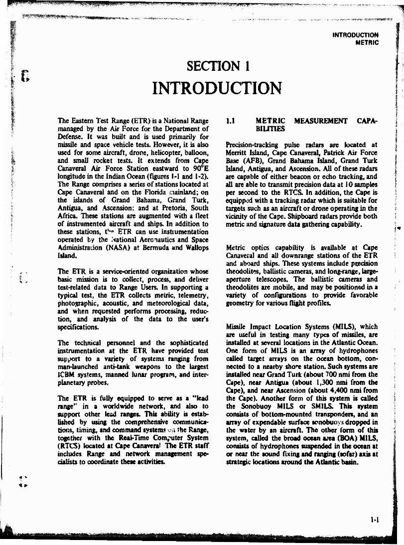
The Eastern Test Range (ETR) is a National Range managed by the Air Force for the Department of Defense. It was built and is used primarily for missile and space vehicle tests. However, it is also used for some aircraft, drone, helicopter, balloon, and small rocket tests. It extends from Cape Canaveral Air Force Station eastward to 90°E longitude in the Indian Ocean (figures 1-1 and 1-2). The Range comprises a series of stations located at Cape Canaveral and on the Florida mainland; on the islands of Grand Bahama, Grand Turk, Antigua, and Ascension; and at Pretoria, South Africa. These stations are augmented with a fleet of instrumented aircraft and ships. In addition to these stations, tV ETR can use instrumentation operated by the National Aeronautics and Space Administration (NASA) at Bermuda and Wallops Island.
The ETR is a service-oriented organization whose basic mission is to collect, process, and deliver test-related data to Range Users. In supporting a typical test, the ETR collects metric, telemetry, photographic, acoustic, and meteorological data, and when requested performs processing, reduc- tion, and analysis of the data to the user's specifications.
The technical personnel and the sophisticated instrumentation at the ETR have provided test support to a variety of systems ranging from man-launched anti-tank weapons to the largest ICBM systems, manned lunar program, and inter- planetary probes.
The ETR is fully equipped to serve as a "lead range" in a worldwide network, and also to support other lead ranges. This ability is estab- lished by using the comprehensive communica- tions, timing, and command systems •--» the Range, together with the Real-Time Computer System (RTCS) located at Cape Canaveral The ETR staff includes Range and network management spe- cialists to coordinate these activities.
1.1 METRIC MEASUREMENT CAPA- BILITIES
Precision-tracking pulse radars are located at Merritt Island, Cape Canaveral, Patrick Air Force Base (AFB), Grand Bahama Island, Grand Turk Island, Antigua, and Ascension. All of these radars are capable of either beacon or echo tracking, and all are able to transmit precision data at 10 samples per second to the RTCS. In addition, the Cape is equipped with a tracking radar which is suitable for targets such as an aircraft or drone operating in the vicinity of the Cape. Shipboard radars provide both metric and signature data gathering capability.
Metric optics capability is available at Cape Canaveral and all downrange stations of the ETR and aboard ships. These systems include precision theodolites, ballistic cameras, and long-range, large- aperture telescopes. The ballistic cameras and theodolites are mobile, and may be positioned in a variety of configurations to provide favorable geometry for various flight profiles.
Missile Impact Location Systems (MILS), which are useful in testing many types of missiles, are installed at several locations in the Atlantic Ocean. One form of MILS is an array of hydrophones called target arrays on the ocean bottom, con- nected to a nearby shore station. Such systems are installed near Grand Turk (about 700 nmi from the Cape), near Antigua (about 1,300 nmi from the Cape), and near Ascension (about 4,400 nmi from the Cape). Another form of tins system is called the Sonobuoy MILS or SMILS. This system consists of bottom-mounted transponders, and an array of expendable surface tpnobuoys dropped in the water by an aircraft. Hie other form of this system, called the broad ocean a,ta (BOA) MILS, consists of hydrophones suspended in the ocean at or near the sound Axing and ranging (sofar) axis at strategic locations around the Atlantic basin.
1-1
mmmwum j&p^m*>m0*!*mw&itö#<t*M**s?*m ■. *',;
m INTRODUCTION ETR BASELINE
•■%*>
c o
I c o o a> c
c is
g
1-2
INTRODUCTION CCAFS
I
I *■■■"
s
• *►
1-3
i. ' unnni.1! i ii in iP PPW. *j;") «iiwitShipjHPWJi n impwi! "ii.
«•Kz**mx®*®fr- : ■^B«e^i«rt»ww;r^^>'-''w
INTRODUCTION MISC
1.2 TELEMETRY CAPABILITIES
r
The ETR telemetry capability consists of a large central station at the Cape and several fixed stations downrange. In addition, the fleet of Advanced Range Instrumentation Aircraft (ARIA) and the USNS Redstone, and Advanced Range Instrumentation Ships (ARIS) may be positioned in areas not covered by fixed stations, from which they can collect, record, and relay telemetry data. Tracking stations are located at the Cape, Grand Bahama, Grand Turk, Antigua, Ascension, and Pretoria, and are equipped with one or more large-aperture antennas, multiple receivers, and real-time retransmission equipment. Other an- tennas having lower gains are installed at some stations. Current equipment provides reception of frequencies in the range of 100 to 4000 MHz (depending on the location).
1.3 SIGNATURE CAPABILITIES
The signature capabilities on the ETR are divided into two categories: radar cross-section and opto- radiometric. Radar cross-section data can be obtained at Ascension and on-board the Advanced Range Instrumentation Ships (ARIS). Opto- radiometric data are collected primarily on the ARIS. Signature data can be made available at any ETR station if required.
1.4 COMMAND/CONTROL
The ETR Command/Control System provides the ability to transmit user commands to missiles and spacecraft and to permit arm-and-destruct com- mands by Range Safety. Transmitters are located at Cape Canaveral, Grand Bahama, and Antigua and on-board the USNS Redstone.
1.5 PHOTOGRAPHIC SERVICES
The ETR is staffed and equipped to collect engineering sequential and documentary photo- graphic data in essentially all areas of the Range. This capability, together with the metric op ics systems, is cemptemented by a photo process«»
facility that can provide finished data to users quickly and by a complete set of photographic data reduction devices.
1.6 METEOROLOGICAL SERVICES
The ETR is equipped to collect, process, and deliver meteorological data from a full spectrum of instruments throughout the Range. Coverage is provided from the surface to approximately 300,000-ft altitude at various stations and on ships. Climatological data for the ETR is contained in the ETR Meteorological Handbook, and additional data may be obtained from the Staff Meteor- ologist.
1.7 LABORATORY SERVICES
The ETR operates a number of laboratories whose services are provided to Range Users. Using standards traceable to the National Bureau of Standards, these laboratories calibrate instruments for the Range and for Range Users. Calibration capability exists in the fields of ac/dc voltage and current, resistance, capacitance, inductance, fre- quency, and radio frequency (if) and nuclear radiation.
Services and standards are also provided in the fields of dimensional measurement, temperature, humidity, vacuum/pressure, mass, weight, force, flow, optics, light, acoustics, vibration, time, torque rate, volume, specific gravity, hardness, leak detection, combustible gas detection, oxygen analysis, hydrogen and halogen detection, pH measurement, and spectrophotometry.
1.8 FACILITIES
A substantial amount of missile assembly, hangar, and administrative floor space and other facilities are available in the launch area for Range Users. These facilities are accessible by land, sea, and air. Water accessibility is gamed from the ocean by way of Port Canaveral and by way of the Intercoastal Waterway. Air access to the launch area is gained by a runway on the Cape, which can accommodate any aircraft now in use.
M
?*m^~^^^m*^mßmm<y*mm*».m*,M irtrqtTiW:»y"W«|<HffSW«Wj>WWMW
DATA ACQUISITION RADAR
SECTION 2
DATA ACQUISITION
2.1 RADAR
I ... 1 I 0
Precision-tracking pulse radars are located at Cape Canaveral Air Force Station, Merritt Island, Patrick AFB, Grand Bahama, Grand Turk, Antigua, Ascension, and on board the three Range Instru- mentation Ships. All of these radars are capable of either beacon or echo (skin) tracking, and all can transmit precision data at 10 samples per second to the RTCS. In addition, the Cape is equipped with a 2700 to 2900-MHz tracking radar which is suitable for a target such as an aircraft or drone operating in the vicinity of the Cape. Shipboard radars provide both metric and signature data gathering capability.
When required, the NASA-owned AN/FPQ-6 radars at Bermuda Island and at Wallops Island, Virginia, support AFETR tests.
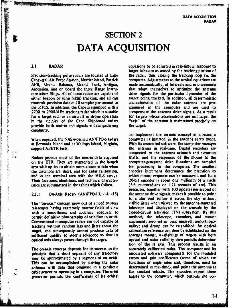
Radars provide most of the metric dflta acquired on the ETR. They are augmented in the launch area with optics to obtain more accurate data when the distances are short, and for radar calibration, and in the terminal area with the MILS arrays Their locations, identifiers, and technical character- istics are summarized in the tables which follow.
2.1.1 On-Axk Radars (AN/FPQ-13. -14, -IS)
The "on-axis" concept grew out of a need to steer telescopes having extremely narrow fields of view with a smoothness and accuracy adequate to permit definitive photography of satellites in orbit. Conventional monopulse radars are not capable of tracking without random lags and jitter about the target, and consequently cannot produce data of sufficient quality to steer a telescope so that its optical axis always passes through the target.
The on-axis concept depends for its success on the principle that a short segment of any trajectory may be approximated by a segment of m orbit. This can be accomplished by driving the radar antenna with data that originate in a synthetic orbit generator operating in a computer. The orbit generator permits the coefficients of its orbital
equations to be adjusted in real-time in response to target behavior as sensed by the tracking portion of the radar, thus closing the tracking loop via the computer. Adjustments to the orbital equation? are made automatically, at intervals and in increments that adapt themselves to optimize the antenna drive signals for the particular dynamics of the target being tracked. In addition, all deterministic characteristics of the radar antenna are pro- grammed in the computer and are used to compensate the antenna drive signals. As a result for targets whose accelerations are not large, the "axis" of the antenna is maintained precisely on the target.
To implement the on-axis concept at a radar, a computer is inserted in the antenna servo loops. With its associated software, the computer manages the antenna in real-time. Digital encoders are connected to the antenna azimuth and elevation shafts, and the responses of the mount to the computer-generated drive functions are sampled for processing in the computer. The smallest encoder increment determines the precision to which mount response can be measured, and foi a 20-bit encoder is about one millionth of a circle (5.6 microradians or 1.24 seconds of arc). This precision, together with 100 updates per second of the antenna drive signals, makes it possible to point to a itu and follow it across the sky without visible jitter when viewed by the antenna-mounted telescope and displayed on the console by the closed-circuit television (TV) subsystem. By this method, the telescope, encoders, and mount alignment; zero set or bias; miskvel; nonorthogo- nality; and droop can be established. An optical calibration reference can then be established on the antenna mount Availability of targets with both optical and radar visibility then permits determina- tion of the rf axis. This process results in an accurately calibrated radar. The computer and its associated software compensate for the modeled errors and gain coefficients (some of which are functions of angle rates and, therefore, must be determined in real-time), and point the antenna at the tracked vehicle. The encoders report these angles to the computer, which outputs the cor*
2-1
rommwn&mifMWmil^JQ .„,ww, l^mmmmsm^mmMmmmsmmmmmmm^mmmmmmvmm
DATA ACQUISITION ftADAR
VI OS w E P z w Q
z o
> W
U3
z o p <
V5 öS
< OS
OS H u u. <
so
k. « es« ro «fr ao so ro it 't *r> so SO 00 S—* -5 «— •*■ *-* »>M
""! """ *-**"" «—« »—e »—t P—t
w S d 6 o< •—' — rö t* —i ri r4 d K ■— 0^ — — (N sO
-—s -4 Cfl S~ w jg ro rf >/-> «T ro — o o — t O
1 C -w ro Os <N so ro CTv O ro iO ro *m
O u «fr «fr — ro r-' ■* so rj o\ ri _J '5 2 ~« •—t *—» —-. ro «t ro ON rj «9 w > V
W
/_^ iü o •*mS o — o O o so
oo O O 0 o o M r- m «fr ro ro O 00 ro ro r- wo
TJ ro O in ro ■<* rM r~ r- r*- r~ sO 3 os o ro <N r< m SO O Os 00 ■<r 'IV fO «fr ro «fr rf so 00 <N W> IO ro
a ON o*' ON Ov — oo oo </ in IT) c o f- t- r- r- r- oo 00 Os ^J" ^ o^ .2 +■* es
8
rN rs r> fM r-i (N fN (N ro ro <N
.J Z o r< n o 0 o O O o o 2» 2> 0 4» ro 'if r~ s0 O"! v0 sC SO ^ * Os r- so «fr «—* r->) m ri ro XT r- 3 «N fN CM oo Os — ■<t
4M* fN C-J «fr «fr Tf VO ^f _ o> s< ro
« oo oö oö oc ad so _; r-' «7 «7 ri -J n rj rj <N n ri ri — II ro
-J -J u. ü.
-J 13 13 g c £ £2 «5
C cd so U. 4) >
w S > 2 0 #■■§
-3
5 <
Öl <
äs < o < < "35 c C «8 ,3 C C 4» 8J to ja
*■» MM w « CQ H _ o o et 4» s> u 7}
es M M *■* U U -3 V5 t/5 C c s 3 V} u o l "O ^ So c c in O o O & V c C .5* u y Z 1» 4» 0> E 4> n» «s t- w C yi S t/3 d c c i>
Cka ßa 2 Ü U Ü ü < < < _3 0 O O 03
4» <-. sC _ oc vC X vO
o < £ § i "? S: b^ «rf U-> Un H HU.» tu 8- a. —
**»»» —»--. o> ~~ —- —- 0- z z Z R < Z Z j- z
< < < < < F <
r^i <*f «fr so ^ro s - "* t «^ ^
> sC
• • u «9
"O es
££ 5 i « i ^ Si t * # * 2 u. u. u. u. r- u. u. u, u. u. u. V •J -5 u. 0£ ixi —«. i 1
z z z z u. z z z z z z as as as z < < < < < < < < < < < ■■ "™" «a» <:
u
c o
"c 'I < 41 U <s a
u Sä ♦-*
rä 3 •b 2 2 o
.5- o £ — (/! -3
"3 *-
u C 41
> O J- r-a.Z • « *
*
2-2
tfjkü-- ^■-^ -'■^•■■yJüSiiaaUi müi i-ttM-i-«Miiiti
^.^i»%fii«KW»*™^^^fi^iSaftBB»9aWW«:' >■ ^^w;^*^"«'«*««»»^'^^1"«***«»»?^^
DATA ACQUISITION RADAR
¥
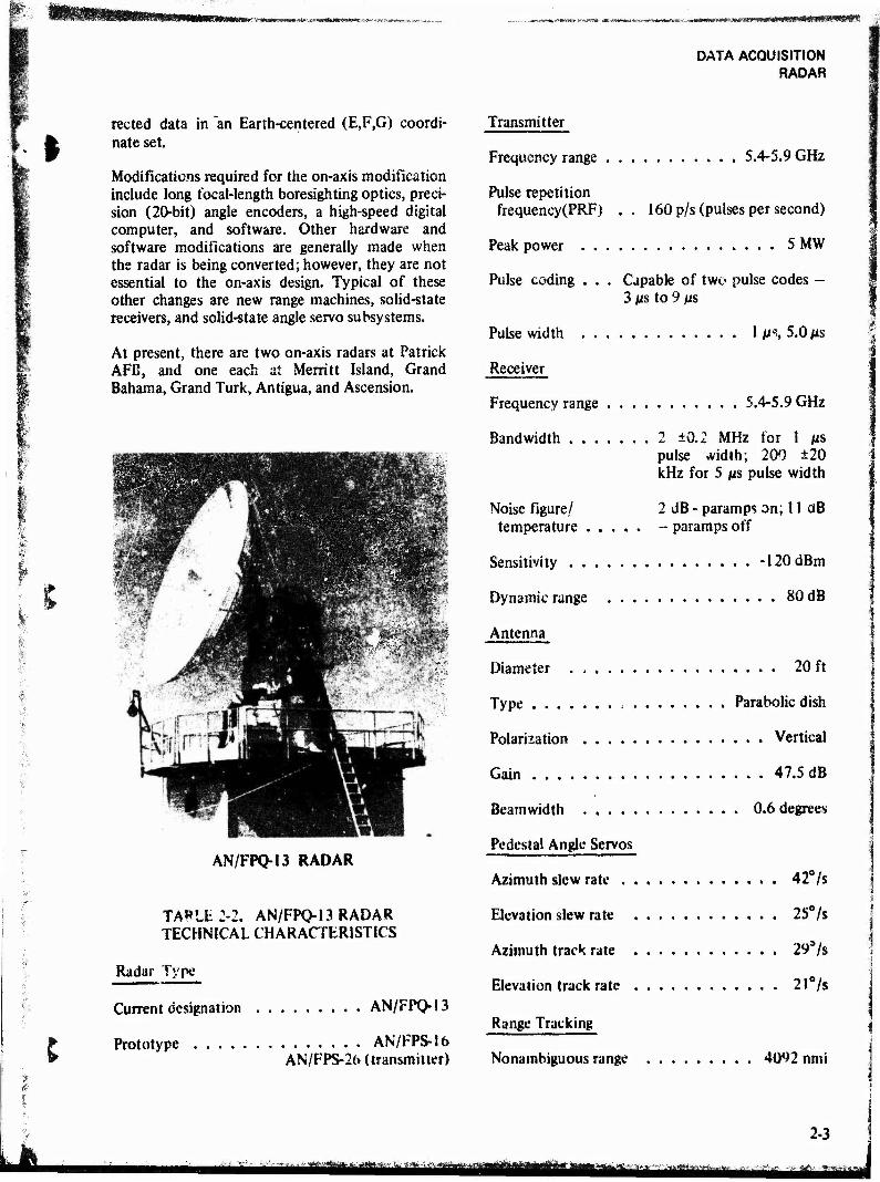
rected data in "an Earth-centered (E,F,G) coordi- nate set.
Modifications required for the on-axis modification include long focal-length boresighting optics, preci- sion (20-bit) angle encoders, a high-speed digital computer, and software. Other hardware and software modifications are generally made when the radar is being converted; however, they are not essential to the on-axis design. Typical of these other changes are new range machines, solid-state receivers, and solid-state angle servo subsystems.
At present, there are two on-axis radars at Patrick AFB, and one each at Merritt Island, Grand Bahama, Grand Turk, Antigua, and Ascension.
; —I
jp" ■ WF Warn
I
AN/FPQ-13 RADAR
TA»LE2-2. AN/FPQ-13 RADAR TECHNICAL CHARACTERISTICS
Radar Type
Current designation AN/FPQ-13
Prototype AN/FPS-16 AN/FPS-26 (transmitter)
Transmitter
Frequency range 5.4-5.9 GHz
Pulse repetition frequency(PRF) . . 160 p/s (pulses per second)
Peak power 5 MW
Pulse coding . . . Capable of two pulse codes - 3 /is to 9 JUS
Pulse width 1 M% 5.0 fxs
Receiver
Frequency range 5.4-5.9 GHz
Bandwidth 2 ±0.2 MHz for 1 /is pulse vvidth; 200 ±20 kHz for 5 ps pulse width
Noise figure/ 2 dB - paramps on; 11 aB temperature - paramps off
Sensitivity -120dBm
Dynamic range 80 dB
Antenna
Diameter 20 ft
Type Parabolic dish
Polarisation Vertical
Gain 47.5 dB
Beamwidth 0.6 degrees
Pedestal Angle Servos
Azimuth slew rate 42°/s
Elevation slew rate 2S°/s
Azimuth track rate 29*/s
Elevation track rate 21°/s
Range Tracking
Nonambiguous range 4092 nmi
2-3
^•i4*^^!ir'.j hi^Mtffflaiüaa mmA
DATA ACQUISITION RADAR
Slew rate 82kyd/s
Acceleration 20kyd/s2
Tracking rate 20kyd/s
Accuracy
Specific See AFETR Accuracy Bulletin for official values.
Acquisition Aids
Range and angle search patterns are computer controlled. Processor and constant false alarm rate (CFAR) circuits are provided for target identifica- tion.
Data Inputs
Data Characteristics
Input data: 1-speed synchro data for azi- muth and elevation; IRV (Interrange Vector) NORAD (North American Air Defense
Command) Message; X,Y,Z low density data; look angles.
Output data: 2-speed synchro data for azi- muth and elevation E,F,G,T !0-p/s data or TAER (time, azimuth, elevation, and range) 10-p/sdata X,Y,Z low density data Teletype (TTY) 100 w/min
B3 format 38-character format IRV
The system also has a 2400-b/s data link for radar designation.
TABLE 2-3. AN/FPQ-14 RADAR TECHNICAL CHARACTERISTICS
Radar Type
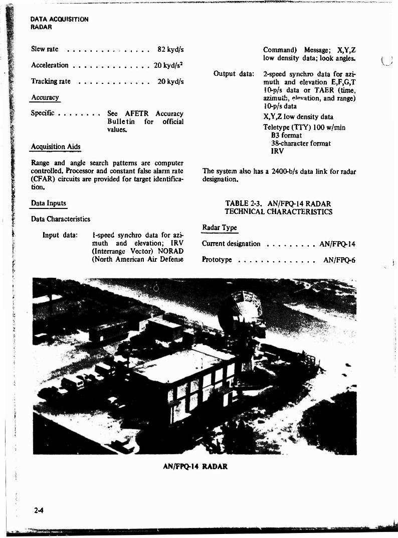
Current designation AN/FPQ-14
Prototype AN/FPQ-6
AN/FPQ-14 RADAR
2-4
■HÜ

I Transmitter
Frequency range 5400-5900 MHz
Frequency stability . Less than 100 kHz/hr drift
Fine tuning Plus or minus 20 MHz
PRF 160,640p/s
Peak power 2.8 MW
Average power (max) 4.8 kW
Power programming range 25 dB
Pulse coding Code A and B( 1-3 pulses)
Pulse width 0.25, 1.0, 2.5, and 5.0 /as
Receiver
Frequency range 5400-5900 MHz
Frequency stability . . . Skin: 1 kHz relative to transmitter Beacon: 300 kHz/24 hr in manual frequency con- trol (MFC)
Bandwidth 4 MHz (1 p$), 400 kHz (2.5 MS), 200 kHz (5 »s)
Noise figure/ 150 K (cooled paramp) temperature (above 10° elevation)
Dynamic range 70 dB
Antenna
Diameter 29 ft
Type Parabolic
Polarization .... Vertical, Unear, and circular
Gain 53 dB
Beamwidth 0.3hn
Mount Elevation over azimuth
Feed Cassegrainian
DATA ACQUISITION RADAR
Pedestal Angle Servos
Azimuth slew rate 500 mrad/s
Elevation slew rate 500 mrad/s
Azimuth track rate 350 mrad/s
Elevation track rate 350 mrad/s
Azimuth acceleration 350 mrad/s2
Elevation acceleration 350 mrad/s2
Range Tracking
Nonambiguous range 32,000 nmi
Slew rate 160kyd/s
Acceleration 600yd/s/s
Tracking rate 20kyd/s
Precision
Range 23 bits (least significant bit (LSB) = 0.97 yd)
Angles 20 bit (LSB = 0.006 mrad)
Accuracy
Specific Refer to AFETR Accu- racy Bulletin
Data Inputs
Synchro
Azimuth 1:1,60 Hz
Elevation 1:1,60 Hz
Digital 2400 b/s, E.F.G, E.F.G T
Other l00w/minTTY,E,F,G,E,F,G,T
2-5
*^^^»i*iM^mmiatmmmäämmsmmmmmtmiA»^m, ■«MM»« Mama Jg-uj-nfr''.
mmmmmm. ips*spiiii^ifp^
DATA ACQUISITION RADAR
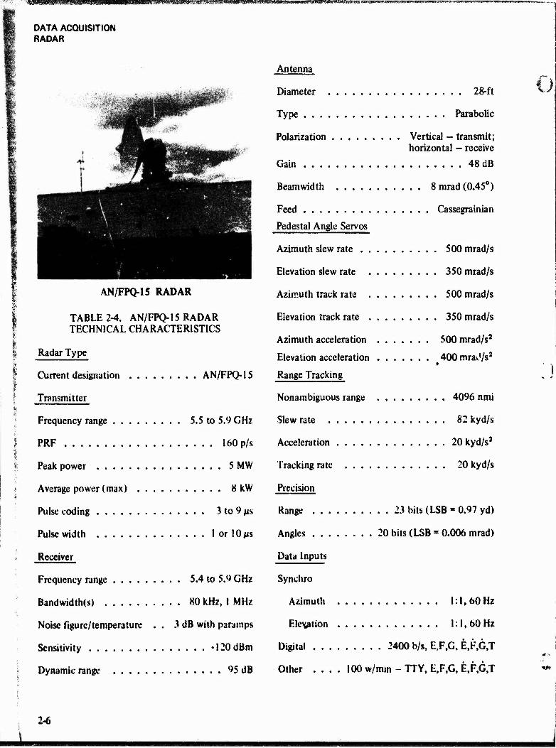
AN/FPQ-15 RADAR
TABLE 2-4. AN/FPQ-15 RADAR TECHNICAL CHARACTERISTICS
Radar Type
Current designation AN/FPQ-15
Transmitter
Frequency range 5.5 to 5.9 GHz
PRF 160 p/s
Peak power 5 MW
Average power (max) 8 kW
Pulse coding 3 to 9 #s
Pulse width 1 or 10/as
Receiver
Frequency range 5.4 to 5.9 GHz
Bandwidth(s) 80 kHz, I MHz
Noise figure/temperature . . 3 dB with paramps
Sensitivity -120 dBm
Dynamic range 95 dB
Antenna
Diameter 28-ft
Type Parabolic
Polarization Vertical - transmit; horizontal - receive
Gain 48 dB
Beamwidth 8mrad(0.45°)
Feed Cassegrainian
Pedestal Angle Servos
Azimuth slew rate 500 mrad/s
Elevation slew rate 350 mrad/s
Azimuth track rate 500 mrad/s
Elevation track rate 350 mrad/s
Azimuth acceleration 500 mrad/s2
Elevation acceleration 400 mrav'/s2
Range Tracking
Nonambiguous range 4096 nmi
Slew rate 82 kyd/s
Acceleration 20 kyd/s2
Tracking rate 20 kyd/s
Precision
Range 23 bits (LSB » 0.97 yd)
Angles 20 bits (LSB ■ 0.006 mrad)
Data Inputs
Synchro
Azimuth 1:1,60 Hz
Elevation 1:1, 60 Hz
Digital 2400 b/s, E,F,G, E.F.G.T
Other .... IO0vv/min~TTY,E,F,G,E,F,GJ
2-3
v* ^sft^sawr.ÄJTOPr "T ;"-^:sw-iiTfwwW3UiaSiWWsp!!WOT "^W? ■;=f ^w^^gs:^'.^^
DATA ACQUISITION RADAR
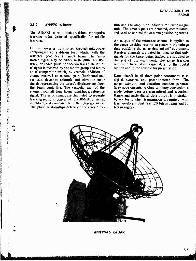
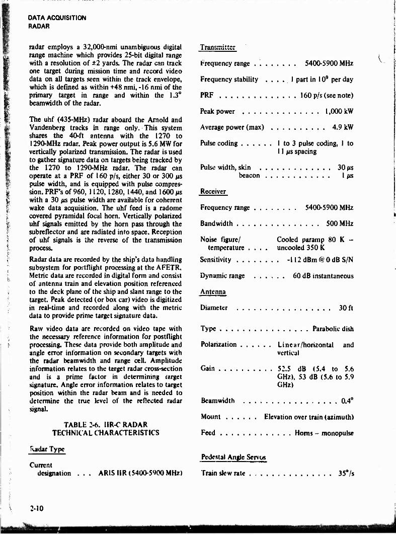
2.1.2 AN/FPS-16 Radar
The AN/FPS-16 is a high-precision, monopulse tracking radar designed specifically for missile tracking.
Output power is transmitted through microwave components to a 4-horn feed which, with the reflector, produces a narrow beam. The trans- mitted signal may be either single pulse, for skin track, or coded pulse, for beacon track. The return rf signal is received by the 4-horn group and fed to an rf comparator which, by vectorial addition of energy received at selected pairs (horizontal and vertical), develops azimuth and elevation error signals representing the target's displacement from the beam centerline. The vectorial sum of the energy from all four horns furnishes a reference signal. The error signals are channeled to separate tracking sections, converted to a 30-MHz i-f signal, amplified, and compared with the reference signal. The phase relationships determine the error direc-
tion and the amplitude indicates the error magni- tude. The error signals are detected, commutated, and used to control the antenna positioning servos.
An output of the reference channel is applied to the range tracking section to generate the voltage that positions the range data takeoff equipment. Receiver channels are gated in range so that only signals for the target being tracked are supplied to iJie rest of the equipment. The range tracking section delivers slant range data to the digital section and to the console for presentation.
Data takeoff in all three polar coordinates is in digital, synchro, and potentiometer form. The range, azimuth, and elevation encoders generate Gray code outputs. A Gray-to-binary conversion is made before data are transmitted and recorded. Range and angle digital data output is in straight binary form, when transmission is required, with least significant digit first (20 bits in range and 17 bits in angles).
4*.
AN/FPS-16 RADAR
2-7

DATA ACQUiSiTiON RADAR
TABLE 2-5. AN/FPS-16 RADAR TECHNICAL CHARACTERISTICS
Radar Type
Current designation AN/FPS-16
Transmitter
Frequency range 5480-5825 MHz
PRF 71, 80, 142, 160, 285, 320, 341, 366, 640 p/s
Peak power 1 MW
Average power (max) 640 W
Power programming range 30 dB
Pulse coding Capable of 3 pulse codes
Pulse width 0.25,0.5, 1.0 MS
Receiver
Frequency range 5450-5825 MHz
Bandwidth(s) 1.8 MHz or 8.0 MHz
Noise figure/temperature 4 dB
Sensitivity -107 dBm at 2 MHz; -101 dBm at 8 MHz
Dynamic range 80 dB with age (auto- matic gain control)
Antenna
Diameter 12 ft
Type Parabolic reflector
Polarization Cape FPS-16: linear/ vertical; Ascension FPS-16: circular
Gain 44 dB
Beamwidth 1.2°
Mount Elevation over azimuth
Feed .... 4-hom monopulse, Newtonian focus
Pedestal Angle Servos
Azimuth slew rate 45°/s
Elevation slew rate 24°/s
Azimuth track rate 42°/s
Elevation track rate 22.5°/s
Azimuth acceleration 31°/s/s
Elevation acceleration 31°/s/s
Range tracking
Acceleration 2,000 yd/s/s
Tracking rate 12,000 yd/s
Precision
Range 20 bits; LSB = 1 yd
Angles 17 is; LSB = 0.0488 mrad
Accuracy
Nominal
Range (beacon) 25 ft
Azimuth (beacon) 0.2 mrad
Elevation (beacon) 0.2 mrad
Specific See AFETR Accuracy Bulletin
Acquisition
1. ±3000-yd range sweep
2. Angle sector scans
3. Angle circular scans
Data Inputs
Synchro
Range 60 Hz; 1:1
Azimuth . 1:1
Elevation 1:1
2-8

'•g^m&tmsm-11 «■ !. v^ww^ä«»»«»**»^^
DATA ACQUISITION RADAR
i Data Outputs
H
r
1. Analog X,Y,Z, in which ±140 V dc = 106 yd
2. Digital time, azimuth, elevation, and range (TAER); 10 samples per second; transmitted over a unique data trans- mitter to the Cape Real-time Computer for general purpose use.
Power Requirements
120/2"° V, 60 Hz, 4-wire grounded neutral, 150 kVA (75 kVA for radar, 75 kVA for air conditioning)
2.1.3 Integrated Instrumentation Radar (IIR)
The AR1S IIR is an integrated radar system composed of (1) two independent tracking radars, one at 5400 to 5900-MHz, the other at 1270 to 1290-MHz which provide tracking and target signature (cross-section) data and (2) a slaved uhf radar which provides signature data only. In the 5400 to 5900-MHz band, signature data are collected on two polarizations, along with cross- polarizarion data, while target tracking is carried out by the vertically polarized channel. In the 1270 to 1290-MHz band, a horizontally polarized channel is used for both tracking and signature data.
The antenna for the 5400 to 5900-MHz system is a 30-ft diameter parabolic reflector having both horizontal and vertical polarization capabilities. A hyperbolic subreflector is used in a Casscgrainian configuration; it is reflective to horizontally polar- ized signals but transparent to vertically polarized signals. The vertical feed is located a', the focal point and transmits through the Cassegrainian subreflcctor. The 5400 to 5900-MHz tracking radar employs a vertically polarized monopulse feed located at the parabola focal point for developing uigJe tracking information on skin or beacon targets. Its antenna includes an auxiliary 4-ft dish for side lobe blanking. The tracker can provide precise skin track of targets when the target signal-to-noise ratio is 12 dB or greater and provide early acquisition, long-range track on beacon targets. Digital range units provide unambiguous data up to 32,000 nautical miles with a range resolution of ±2 yards.
The range data supplied to the computer is a 25-bit binary word. Deck angle data is derived from 19-bit digital shaft encoders which are mounted on the elevation and train axes of the mount
The 5400 to 5900-MHz radar can track a skin or beacon return from a primary target and provide relative range and angle data on additional targets by means of postflight data reduction techniques. The secondary target must be within the track cell of the radar, i.e., within ±0.2° in angle and ±32,000 yards in range of the primary target. In addition, the secondary target must be separated in range from the primary target by at least 100 yards. Target slant range resolution of 100 yards is accomplished through pulse compression. A skin pulse of 30 MS is compressed to less than 1 fts in the receivers before angle error and signature data are extracted.
The 5400 to 5900-MHz radar can acquire a target by using designate data supplied by the !270 to 1290-MHz radar, telemetry tracker, star tracker, MK-51 director, or intermediate focal length telescope (IFLOT); by the computer using the theoretical orbital elements; or by local radar console operation of handwheels. The computer is the primary source of designate and acquisition data. A scan pattern is superimposed upon the designate point to enhance the probability of acquisition. Early target acquisition is enhanced by the simultaneous beacon interrogation mode (se- lectable), allowing interrogation pulses from both the horizontal and vertical channels at the same time. A video double threshold detector provides a 99.9 percent probability of detection of targets having a signal-to-noise ratio of 10 dB or greater.
In addition to target tracking, the 5400 to 5900-MHz radar provides target illumination for cross-section data. Horizontally and vertically polarized energy at a peak power of I MW is transmitted by interlaced pulses. Each polarization uses a PRF or IbO p/s. Both normal and cross-polarized returns are received and recorded.
The 1270 to 1290-MHz antenna on each ship is a 40-ft diameter parabolic dish with a Cassegraintan feed for horizontally polarized transmission and reception. It operates as an independent tracking radar providing both metric and signature data. The radar tracks in the skin mode only. Peak power output is 8 MW, PRF 160 p/s, and the puke width is 30 MS compressed to 0.6 its at 4 dB. The
2-9
DATA ACQUISITION RADAR
£ I
radar employs a 32,000-nmi unambiguous digital range machine which provides 25-bit digital range with a resolution of ±2 yards. The radar can track one target during mission time and record video data on all targets seen within the track envelope, which is defined as within +48 nmi, -16 nmi of the primary target in range and within the 1.3° beamwidth of the radar.
The uhf (435-MHz) radar aboard the Arnold and Vandenberg tracks in range only. This system shares the 40-ft antenna with the 1270 to 1290-MHz radar. Peak power output is 5.6 MW for vertically polarized transmission. The radar is used to gather signature data on targets being tracked by the 1270 to 1290-MHz radar. The radar can operate at a PRF of 160 p/s, either 30 or 300 ps pulse width, and is equipped with pulse compres- sion. PRF's of 960, 1120, 1280, 1440, and 1600 ps with a 30 ps pulse width are available for coherent wake data acquisition. The uhf feed is a radome covered pyramidal focal horn. Vertically polarized uhf signals emitted by the horn pass through the subreflector and are radiated into space. Reception of uhf signals is the reverse of the transmission process.
Radar data are recorded by the ship's data handling subsystem for poitflight processing at the AFETR. Metric data are recorded in digital form and consist of antenna train and elevation position referenced to the deck plane of the ship and slant range to the target. Peak detected (or box car) video is digitized in real-time and recorded along with the metric data to provide prime target signature data.
Raw video data are recorded on video tape with the necessary reference information for postfiight processing. These data provide both amplitude and angle error information on secondary targets with the radar beamwidth and range cell. Amplitude information relates to the target radar cross-section and is a prime factor in determining target signature. Angle error information relates to target position within the radar team and is needed to determine the true level of the reflected radar signal.
TABLE 2-6. IIR-C RADAR TECHNICAL CHARACTERISTICS
JiadarType
l nuisiTai & icr
Frequency range . . 5400-5900 MHz
Frequency stability .... 1 part in 109 per day
PRF 160 p/s (see note)
Peak power 1,000 kW
Average power (max) 4.9 kW
Pulse coding 1 to 3 pulse coding, 1 to 11 ps spacing
Pulse width, skin 30 ps beacon 1 ps
Receiver
Frequency range 5400-5900 MHz
Bandwidth 500 MHz
Noise figure/ Cooled paramp 80 K - temperature .... uncooled 350 K
Sensitivity -112dBm@0dB S/N
Dynamic range 60 dB instantaneous
Antenna
Diameter 30 ft
Type Parabolic dish
Polarization Linear/horizontal and vertical
Gain 52.5 dB (5.4 to 5.6 GHz), 53 dB (5.6 to 5.9 GHz)
Beamwidth 0.4*
Mount Elevation over train (azimuth)
Feed Homs - monopulse
Current designation AR!SUR(5400-S<»00MHz)
Pedestal Angle Servos
Train slew rate . . . . 35°/s
2-10

mm
%
Elevation slew rate 26°/s
Train track rate 35°/s
Elevation track rate 26°/s
Acceleration 28°/s/s
Range Tracking
Nonambiguous range 32,335 nmi
Slew rate 200,000 yd/s
Acceleration 5,000 yd/s/s
Tracking rate 20,000 yd/s
Precision
Range 25 bits(LSB= 2 yd)
0.001° (derived from synchro) 19 bits (LSB = 0.012 mrad)
Accuracy
Specific See AFETR Accuracy Bulletin
Acquisition Aids
Angle scans
Auxiliary range tracker
Video digital detector
Computer designate
Slave bus
Data Outputs
Digital m and el ~\ Analog az and el > 10 p/s Digital range J
Radar crosKcction (RCS) on tracked target, pulse by pulse
Radar video tape
Relative range & RCS
DATA ACQUISITION RADAR
On-off axis targets in the radar beam/look interval
All the above data are both horizontally and vertically polarized.
Cross polarization signals are also recorded.
Range time intensity (RTI) and range amplitude (RA) from video tape.
NOTE
Dual transmitters; each operates at 160-p/s PRF, one transmitting horizontally polarized energy, the other transmitting vertically polarized energy; transmissions are interlaced.
TABLE 2-7. UR-L RADAR TECHNICAL CHARACTERISTICS
Radar Type
Current designation . . ARIS (Advanced Range Instrumentation Ship) IIR( 1280 MHz)
Transmitter
Frequency range . 1270-1290 MHz
Frequency stability .... 1 part in 1010 per day
Fine tuning ±10 MHz about 1280 MHz
PRF 160 p/s (nominal)
Peak power 10 MW
Average power (max I 48 kW
Pulse width 30 jis
Receiver
Frequency range 1270-1290 MHz
Bandwidth 5 MHz
Noise figure/temperature 1.5 dB
Sensitivity 60 dB instantaneous
Dynamic range .... 120 dB with attenuation
■■-.-at, LlijfSgfeMaSfe^ --4£3ft*«sa** jj^g^^jggggggggj

IBm'^lllW'^^^'rwf^^'^^m.^mtimmimm^-mn^M^mmi
DATA ACQUISITION RADAR
Antenna
Diameter 40 ft
Type Parabolic dish
Polarization linear/horizontal
Gain 41 dB
Beam width 1.2°
Mount Elevation over train
Feed Horn/Cassegrainian
Pedestal Angle Servos
Train slew rate 35°/s
Elevation slew rate 26°/s
Train track rate 3S°/s
Elevation track rate 26°/s
Train acceleration 28°/s1
Elevation acceleration 28*/sJ
Range Tracking
Nonambtguous range 4,000 nmi
Slewrate 200,000yd/s
Acceleration 1,500 yd/s
Tucking rate . 20,000yd/s
Precision
Range 22bits(LSB* 1.953 yd)
Ancles 19 bits (LSB- 0.012 mrad)
Accuracy
Auxiliary range tracker
Video digital detector
Computer designate
Slaved bus
Data Outputs
Horizontal polarized tracked target azimuth, eleva- tion, and range.
RCS
2-inch video tape nontracked target relative azi- muth, elevation, and range and RCS from video tape playback RA and RTI film from video playback.
TABLE 2-8. HR-U RADAR TECHNICAL CHARACTERISTICS
Radar Type
Current designation AR1S UR (435.39 MHz)
Transmitter
Frequency 435.39 MHz
Frequency stability ... I part in 101 e per day
Fine tuning None
PRF 160, 960, 1120, 1280, 1440,andl600p/s
Peak power 5.6 MW
Average power (max) 274 kW
Pube widths 30 or 300 ja
Receiver
Specific Set AFETR Accuracy Bulletin
Acquisition Aids
Angle Scam
Frequency 435.39 MHz
Bandwidth S MHz (3 dB)
Sensitivity See Note 1
2-12
^■^;^«!i»w»iw»ws*««^^
I
9fr
P
1
f * 4>
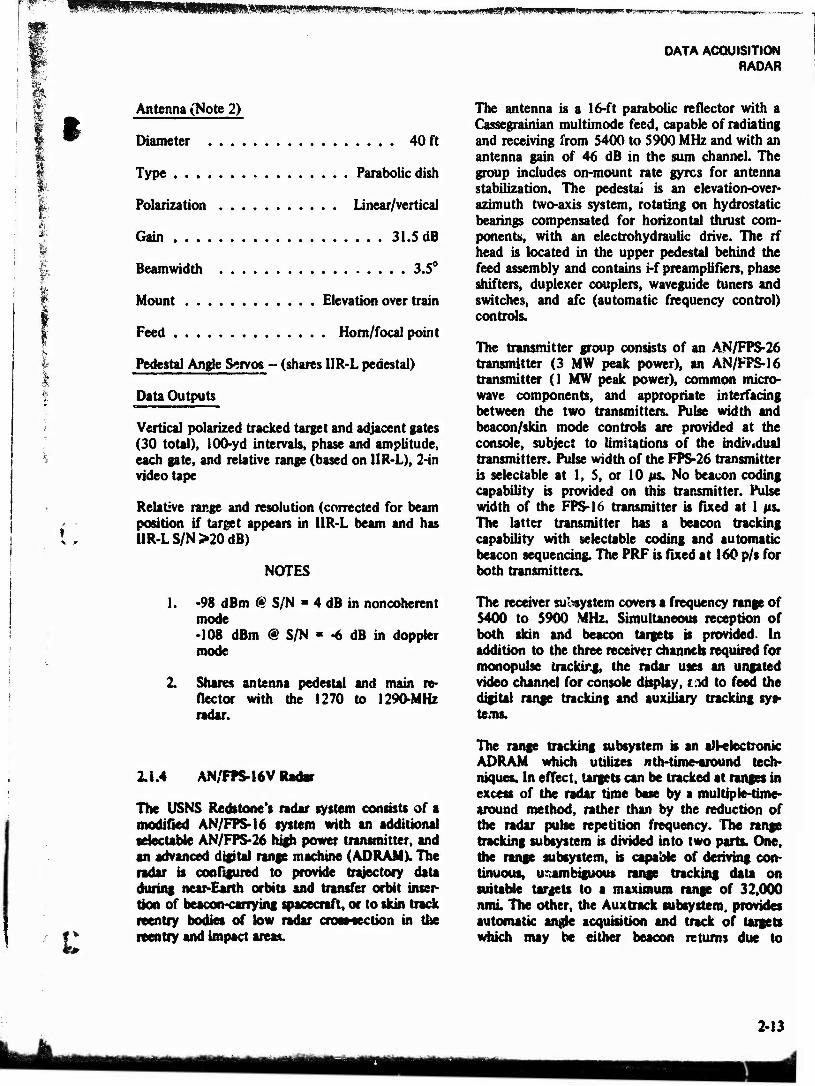
Antenna (Note 2)
Diameter 40 ft
Type Parabolic dish
Polarization linear/vertical
Gain 31.5 dB
Beamwidth 3.5°
Mount Elevation over train
Feed Horn/focal point
Pedestal Angle Servos - (shares IIR-L pedestal)
Data Outputs
Vertical polarized tracked target and adjacent gates (30 total), lOO-yd intervals, phase and amplitude, each gate, and relative range (based on HR-L), 2-in videotape
Relative range and resolution (corrected for beam position if target appears in IIR-L beam and has IIR-L S/N>20 dB)
NOTES
1. -98 dBm « S/N » 4 dB in noncoherent mode •108 dBm @ S/N « -6 dB in doppler mode
2. Shares antenna pedestal and main re- flector with the 1270 to 1290-MHz radar.
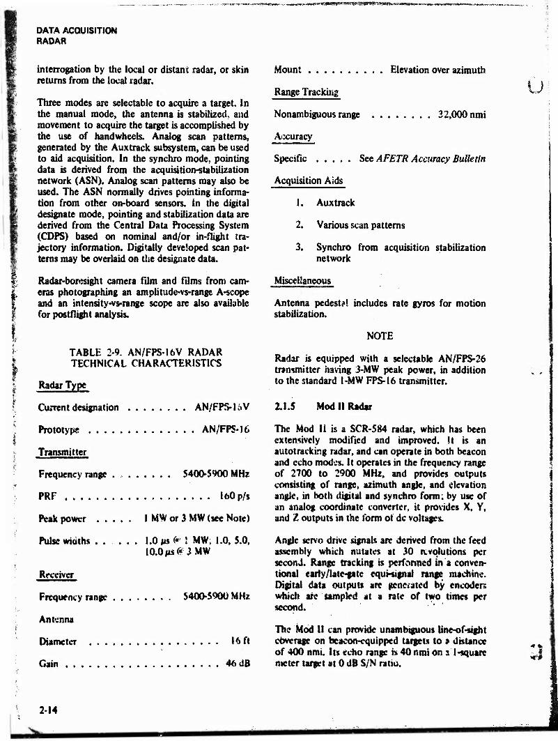
2.1.4 AN/FPS-16V Radar
The USNS Redstone's radar system consists of a modified AN/FPS-16 system with an additional selectable AN/FPS-26 high power transmitter, and an advanced digital range machine (AD RAM K The radar is configured to provide trajectory data during near-Earth orbits and transfer orbit inser- tion of beacon-carrying spacecraft, or to skin track reentry bodies of low radar cross-section in the reentry and impact areas.
DATA ACQUISITION RADAR
The antenna is a 16-ft parabolic reflector with a Cassegrainian multimode feed, capable of radiating and receiving from S400 to 5900 MHz and with an antenna gain of 46 dB in the sum channel. The group includes on-rnount rate gyres for antenna stabilization. The pedestal is an elevation-over- azimuth two-axis system, rotating on hydrostatic bearings compensated for horizontal thrust com- ponents, with an electrohydraulic drive. The rf head is located in the upper pedestal behind the feed assembly and contains i-f preamplifiers, phase shifters, duplexer couplers, waveguide tuners and switches, and afc (automatic frequency control) controls.
The transmitter group consists of an AN/FPS-26 transmitter (3 MW peak power), an AN/FPS-16 transmitter (1 MW peak power), common micro- wave components, and appropriate interfacing between the two transmitters. Pulse width and beacon/skin mode controls are provided at the console, subject to limitations of the individual transmitter?. Pulse width of the FPS-26 transmitter is selectable at 1, 5, or 10 us. No beacon coding capability is provided on mis transmitter. Pulse width of the FPS-16 transmitter is fixed at 1 us. The latter transmitter has a beacon tracking capability with selectable coding and automatic beacon sequencing. The PRF is fixed at 160 p/s for both transmitters.
The receiver subsystem covers a frequency range of 5400 to 5900 MHz. Simultaneous reception of both skin and beacon targets is provided. In addition to the three receiver channels required for monopulse tracking, the radar uses an ungated video channel for console display, tad to feed the digital range tracking and auxiliary tracking sys- tems.
The range tracking subsystem is an all-electronic ADRAM which utilizes nth-time-around tech- niques. In effect, targets can be tracked at ranges in excess of the radar time base by a multiple-time- around method, rather than by the reduction of the radar pulse repetition frequency. The range tracking subsystem is divided into two parts. One, tiie range subsystem, is capable of deriving con- tinuous, unambiguous range tracking data on suitable targets to a maximum range of 32,000 nmi The other, the Aux track subsystem, provides automatic angle acquisition and track of targets which may be either beacon returns due to
2-13
DATA ACQUISITION RADAR
*-w«^«*SW!SS!^rS!PC^
interrogation by the local or distant radar, or skin returns from the local radar.
Three modes are selectable to acquire a target. In the manual mode, the antenna is stabilized, and movement to acquire the target is accomplished by the use of handwheeis. Analog scan patterns, generated by the Auxtrack subsystem, can be used to aid acquisition. In the synchro mode, pointing data is derived from the acquisition-stabilization network (ASN). Analog scan patterns may also be used. The ASN normally drives pointing informa- tion from other on-board sensors. In the digital designate mode, pointing and stabilization data are derived from the Central Data Processing System (CDPS) based on nominal and/or in-flight tra- jectory information. Digitally developed scan pat- terns may be overlaid on use designate data.
Radar-boresight camera film and films from cam- eras photographing an amphtude-vs-range A-scope and an intensity-vs-range scope are also available for post flight analysis.
TABLE 2-9. AN/FPS-16V RADAR TECHNICAL CHARACTERISTICS
Radar Type
Current designation AN/FP&l&V
Prototyps AN/FPS-16
Transmitter
5400-5900 MHz
I60p/s
Frequency range . ,
PRF
Peak power 1 MW or 3 MW (see Note)
Pulse widths ... I .OM« ^5 MW; 1.0,5.0, 10.0MS«?3 MW
Receiver
Frequency range $400-5900 MH*
Antenna
Diameter 16 ft
Gain 46 dB
Mount Elevation over azimuth
Range Tracking
Nonambiguous range 32,000 nmi
Atxuracy
Specific See AFETR Accuracy Bulletin
Acquisition Aids
1. Auxtrack
2. Various scan patterns
3. Synchro from acquisition stabilization network
Miscellaneous
Antenna pedest?! includes rate gyros for motion stabilization.
NOTE
Radar is equipped with a selectable AN/FPS-26 transmitter having 3-MW peak power, in addition to the standard 1-MW FPS-16 transmitter.
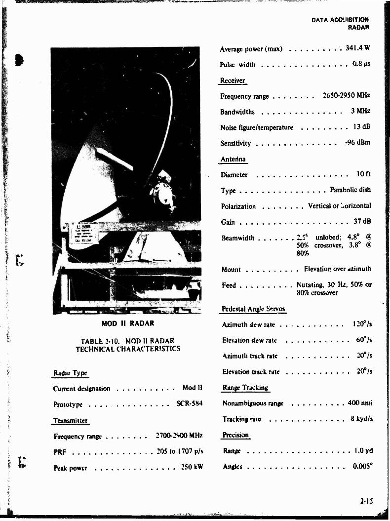
11.5 Mod U Radar
The Mod II is a SCR-584 radar, which has been extensively modified and improved. It is an autotracking radar, and can operate in both beacon and echo modes. It operates in the frequency range of 2700 to 2900 MHz, and provides outputs consisting of range, azimuth angle, and elevation angle, in both digital and synchro form; by use of an analog coordinate converter, it provides X, V, and Z outputs in the form of dc voltages.
Angle servo drive Signals are derived from the feed assembly which nutates at 30 revolutions per second. Range tracking is performed in a conven- tional eariy/late-pte equi-signal range machine. Digital data outputs are generated by encoders which are sampled at a rate of two times per second.
The Mod II can provide unambiguous Une-of-sight coverage on beacon-equipped targets to $ distance of 400 nmi. Its echo range is 40 nmi on a 1-square nteter target at 0 dB S/N ratio.
2-14
mmm
&mm^mmmMmmmmrß**^m>*'-'
MOD 1! RADAR
TABLE 2-10. MOD »RADAR TECHNICAL CHARACTERISTICS
Radar Type
Current designation Mod II
i*
Prototype . . .
Transmitter
Frequency range
Peak power . •
.... SCR-S84
2?00-2<*00 MHz
. 205tol707p/$
• • » * * *3U KW
DATA ACQUISITION RADAR
Average power (max) . 341.4 W
Pulse width 0.8 us
Receiver
Frequency range 2650-2950 MKz
Bandwidths 3 MHz
Noise figure/temperature 13 dB
Sensitivity -96dBm
Antenna
Diameter 10 ft
Type Parabolic dish
Polarization Vertical or horizontal
Gain . 37 do
Beamwidth 2.56 unlobed; 4.8° @ 50% crossover, 3.8° @ 80%
Mount Elevation over azimuth
Feed Nutating, 30 Hz, 50% or 80% crossover
Pedestal Angle Servos
Azimuth slew rate 120°/s
Elevation slew rate 6Cf/$
Azimuth track rate 20s/s
Elevation track rate . 20°/$
Range Tracking
Nonambiguous range 400 nmi
Tracking rate 8 kyd/s
Precision
Range 1.0 yd
2-1S
DATA ACQUISITION RADAR
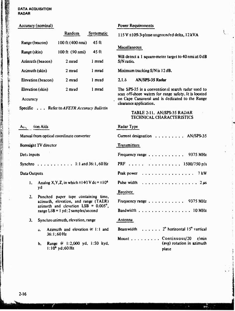
Accuracy (nominal)
Random Systematic
Range (beacon) 100ft(400nmi) 45 ft
Range (skin) 100 ft (90nmi) 45 ft
Azimuth (beacon) 2 mrad 1 mrad
Azimuth (skin) 2mrad 1 mrad
Elevation (beacon) 2 mrad 1 mrad
Elevation (skin) 2 mrad 1 mrad
Accuracy
Specific . . . Refer to AFETR Accuracy Bulletin
Act, tion Aids
Manual from optical coordinate converter
Boresight TV director
Data inputs
Synchro 1:1 and36:l,60Hz
Data Outputs
1. Analog X,Y,Z, in which ± 140 V dc = ± 106
yd
2. Punched paper tape containing time, azimuth, elevation, and range (TAER) azimuth and elevation LSB = 0.005°, range LSB — 1 yd; 2 samples/second
3. Synchro azimuth, elevation, range
a. Azimuth and elevation C«M: I and 36:1; 60 Hz
b. Range 0 1:2,000 yd, 1:50 kyd, l:IO»yd;60Hz
Power Requirements
115 V ± 10% 3-phase ungrounded delta, 12 kVA
Miscellaneous
Will detect a 1 square-meter target to 40 nmi at 0 dB S/N ratio.
Minimum tracking S/N is 12 dB.
2J.6 AN/SPS-35 Radar
The SPS-35 is a conventional search radar used to scan off-shore waters for range safety. It is located on Cape Canaveral and is dedicated to the Range clearance application.
TABLE 2-11. AN/SPS-35 RADAR TECHNICAL CHARACTERISTICS
Radar Type
Current designation AN/SPS-35
Transmitters
Frequency range 9375 MHz
PRF 1500/750 p/s
Peak power 7 kW
Pulse width 2 (is
Receiver
Frequency range . 9375 MHz
Bandwidth 10 MHz
Antenna
Beamwidth 2° horizontal 15° vertical
Mount Continuous/20 r/min (avg) rotation in azimuth plane
2-16

'^mmme^mm^^m:mßmmmmmm»mmmmm»mm^ •W«s«a*«sw*r..*»*<WHK»,
r>
DATA ACQUISITION TELEMETRY
i 2.2
2.2.1
TELEMET3Y
Introduction
t
The LTR land telemetry facilities include the central telemetry station (Tel 4) located on Menitt Island, four essentially similar downrange stations, and a semiactive station at Pretoria, South Africa. These land-based faculties are augmented by the USNS Redstone, which is especially equipped to serve as a support ship for US Navy underwater launched missiles, the two ARIS, and the eight ARIA aircraft.
Table 2-12 is a tabulation of major equipment by location. Figure 2-1 is an abbreviated block diagram of a typical telemetry receiving station. One or more groups of the equipment represented by the blocks are installed at each station. In addition, the central telemetry station at Merritt Island has capabilities for acquisition, storage, processing, preparation of computer-formatted magnetic tapes, tape copying, tape playback, and interface for video retransmission. Four separate display areas are equipped with direct-write pen recorders, oscillograph recorders, and digital dis- plays for the convenience of Range Users. Com- puter-ready magnetic tapes may be formatted in real-time or from recorded data tapes. Facilities are provided to produce duplicate predetection or video magnetic tapes. Interconnection of the data handling system is largely accomplished by re- motely controlled switches rather than through the use of manual patch panels. In addition to switch closures, the Control, Status Display, and Patching System provides equipment status signals and remote operation of the station data recorders.
2.2.1.1 Antennas and Rf Distribution Systems
Autotracking antenna subsystems are distributed as shown in table 2-12. The 80-ft-diametcr TAA-8's, installed in 196S, are the newest of the antenna systems on the Range. The TAA-8,1AA-3, and the USNS Redstone antennas are equipped with 2200 to 2300-MHz feeds and parametric amplifiers. The others have a broader frequency capability. The Range Modernization Program provides a Xerox Data Systems i'XDS) 530 computer for acquisition,
antenna management, test, and calibration for the TAA-3, TAA-8, TAA-8A, and TAA-2 antenna subsystems. New parametric amplifiers and multi- couplers have been added to the TAA-2, TAA-3, TAA-8A, and the Tel 4 TAA-3A, which give them the capability to collect either 2200 to 2300-MHz data or down-converted data.
2.2.1.2 Receive and Record
All of the telemetry stations are equipped with one or more TR.KI-12 receive and record groups. Each has 12 receivers; two 7-track, V4-in, 1.5-MHz bandwidth tape recorders (some 14-track, 1-in models are available at Tel 4); and associated display units, combiners, converters, amplifiers, and test equipment. Thirty dual-channel receivers and eight 14-track, 1-in, 2.0-MHz tape recorders are available to increase the system capability for receiving and recording 2200 to 2300-MHz data.
2.2.1.3 Separation and Display
Decommutation equipment for pulse code modula- tion (PCM), pulse amplitude modulation (PAM), and pulse duration modulation (PDM) signals is installed at all of the stations. Three types of decommutators are available: Type I, which can process a PCM, PAM, or PDM IRIG (Inter-Range Instrumentation Group) standard bit stream; Type II, which can process only PCM bit streams, but which has greater PCM versatility than the Type I; and Type III, which can handle only PAM and PDM signals. Frequency modulation (fm) dis- criminators, digital-to-analog (D/A) and analog-to- digital (A/D) converters, and formatters are avail- able for processing this type of modulated signal for presentation on the analog and digital displays and for computer processing. Displays are con- ventional pen and oscillograph paper recorders, digital and meter readouts, and cathode-ray tube displays.
2.2.1.4 Real-Time Telemetry Transmission
The ETR is* equipped with a real-time data selection and reformatting system that outputs selected words at a lower bit rate to accommodate communications channel bandwidth limitations.
2-17
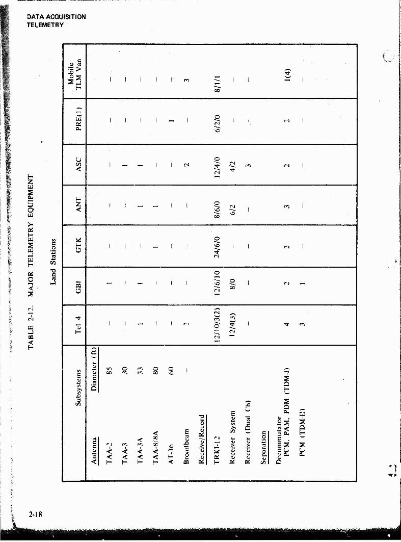
DATA ACQUISITION TELEMETRY
*» H
1 Z s 5
; a $■•'
w 1
> Or •i 05 . P« H % W <A
¥'■■:'
2 W -J
c .2 4-» CO
f U)
öS c 1 i.
O .3 •<
9 s I
tu -J
<
£J CJ (B
*£> >-*\ •O T>-
IS 1 ... i , i—4 *■-• 1 ' 1 1 r m _ ' 1 —i i
f- 00
^-s f—H
1 | 1 1 I o 1- 1 fN i
OS (N a. ^O
u o us 1 •— _. 1 l ra ^t <N
C"> CM i < c-i ^
H Z 1 1 _« —■ I 1 O
cj ro i <
oo ^0 1
^ © H 1 | 1 i I vo j j ra i a ^
(N
o '—'
3 o
1 1 i 1 -2" o oo
1 CJ
*^ <N ^^
■* <-<■> f>
~ 1 i — ! i ri o 5 1 •* fj
H <-^l
(N
^ ■i-' <— *—■
u
E <u 1/-I O *■*** o o j —* 1) c
oo cs m 80 s0
S C/i
.ra a >. «O t </> £ 3
■VI
E a»
JC s a a. _
u 0
15 3
• s
< C 0£ > '5
■yj 6 c 3 0« a b
3 c c 11
n i
< <
t
< <
<
< <
oc < <
1 I—
as
X)
ö
n i
1» > 3J
'5
o
u CS
E . ES s
k < H H H H < SO tc t- OS CC C/5 a
■>*■#
2-18
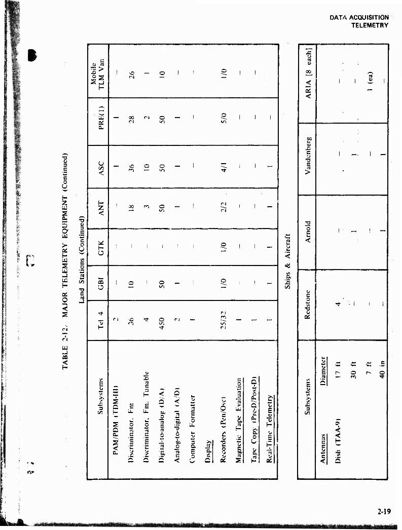
DATA ACQUISITION TELEMETRY
m
I
•a 4) 3 C
S o u
s a S a, 5 a üä
>• oi H W S w -J
H
OS o —> < s
ÜJ
CQ <
"O « 3 .5 c o U
c/5
■a c es
►V
C <u es
-Is
a.
Z <
H
as Ü
u
3 5/5
5
s a.
< a.
00 C-l
O O
^C o r<1 —
O
O in
O —
o IT) in
JO n c
< < d
c _ — —
o
c
0 2? -5 6 2 — Ü
f3
"51 <-s rs <-\
c <
3 C. E ,o
c n a.
"S o
5 Q
_3
>
0 a. Q
>> u
ÜJ i E 1* a. 41 c 1« ^3 t-
►— .*. a •J
u 0 JI «M*
1» O H-
51 fc -i n 3 ^
2s H aj
t3
5«
o C3 W
00
< 5 <
to
1 1 3 i
60 1- « C CJ
*o c >
I _. I -
0 C u <
1 ' - I —
It C 0 5/5
•a tu
02
-* '- i 1 i
E u «I >.
JO 3
1/3
it It E sa,
5
•.f. S3 c c 11
c < D
ish
(TA
A-9
)
!7
ft
30
ft
7 f
t
40
in
MTmmiiM -ejämammwamtmä «ASK da« SB
2-19

DATA ACQUISITION TELEMETRY
•9 <U 3 C
§
I 2 3 a U)
>• a: H u 2 w
a: O < 2
<s
W
GO
•o t> s e
XJ
§
as o
00
<
8?
c
c at >
o E <
& 2 «a
w e c *■* <« •o u
E e Ml
I 3
W
-S w es
r- .5
<N
w e c ^ 2 oo •g ^
00 *
<N — CJ
w
c^ «N 00 O — — </1
c
t <
E o
■a o c
5
c/5
X
o
V > 8
0&
t > '8
c <N O
as G s.
3 E E o
o b.
$ S2 o c r^ ** X *» w
r-_) r-i ec 3 > > «Mt M t. u. \- c c 2 2 Ot E
w e, (°> a a 2 •c E E i- H w
Q u. u. <
IS
o u 0£
c o
E c 5
u E
I
2-20

DATA ACQUISITION TELEMETRY
0
*
i
3
a 1
e o
S
e «>
1 e
•T
V
i ft
e "T
i 1
— (N
M
3-
1 s
i i s
1 * I 1 3 •g 2
1 o t:
«alls
I £ >>
B Si
1 «n
at
g t
1
i * l x s
mm
«? r»
X
c •T
I S <**
I
e T
•s s
s I ■
I
2
e •2* 3 ft 32
sis
00
li in iiiaiTifiriitiitfrtrtMiiii^iirfliMlriiiitii-itii ■aunty» mmmt 2-21
irmriMMiiiin [
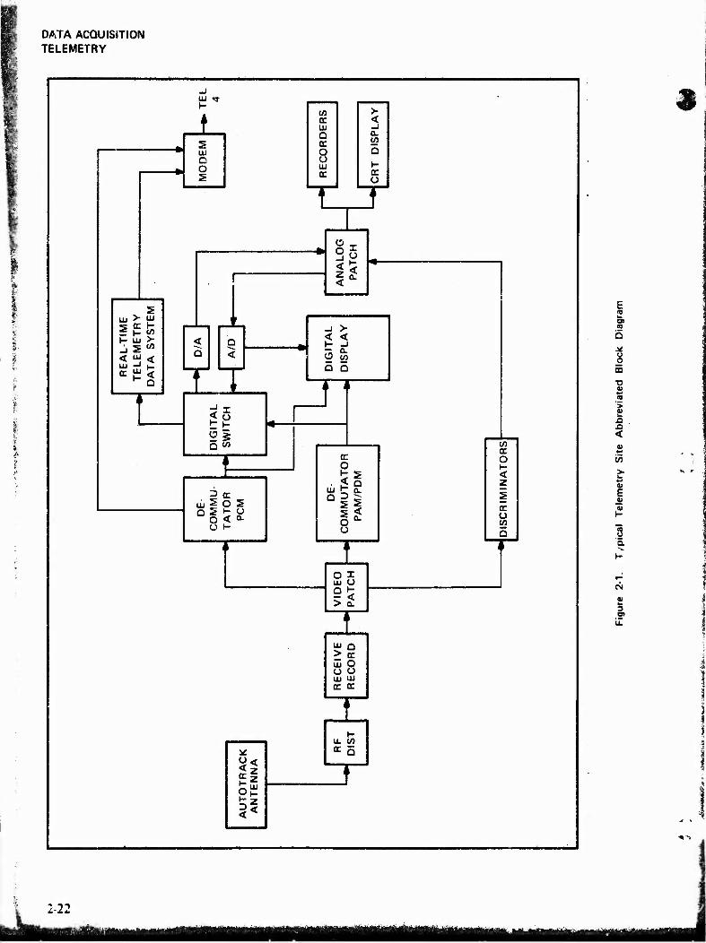
DATA ACQUISITION TELEMETRY
s LU D O 5
(A > DC < UJ _J o a.
o o O UJ K- cc cc
o
I
in > 5 w
^ D I Q <
T uj 2 o
o < o t-
Ü
< < K -I
a 5
n cc O
I o°- o
O I UJ U
i< > QL
UJ a
UJ O o o UJ UJ cc cc
t- U. C/5 cc 5
V) cc o < z
o
u o
CO
■o 0)
<
V) > w *-> 41 E 01 I-
8 5.
*•■ ' 4
3
-22
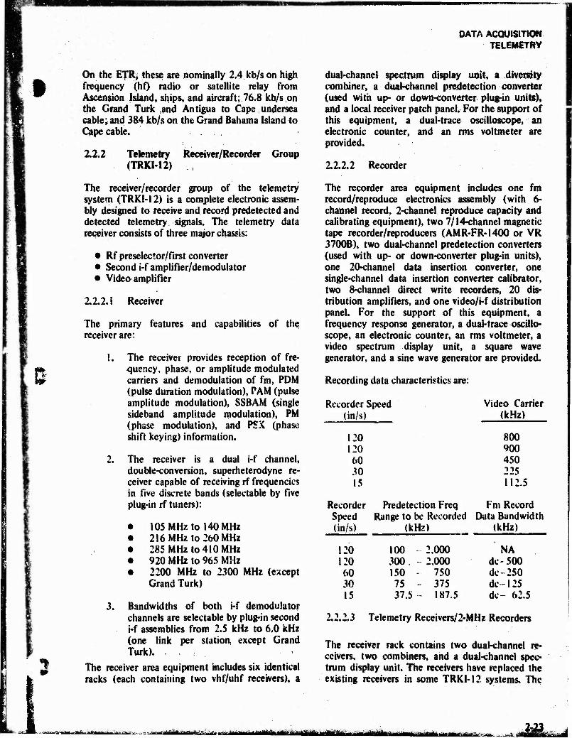
mam
DATA ACQUISITION TELEMETRY
On the ETRj thes$ are nominally 2.4 kb/s on high frequency (hO radio or satellite relay from Ascension Island, ships, and aircraft; 76.8 kb/s on the Grand Turk and Antigua to Cape undersea cable; and 384 kb/s on the Grand Bahama Island to Cape cable.
2.2.2 Telemetry (TRKI-12)
Receiver/Recorder Group
The receiver/recorder group of the telemetry system (TRKI-12) is a complete electronic assem- bly designed to receive and record predetected and detected telemetry signals. The telemetry data receiver consists of three major chassis:
• Rf preselector/first converter • Second i-f amplifier/demodulator • Video amplifier
2.2.2.1 Receiver
The primary features and capabilities of the, receiver are:
!. The receiver provides reception of fre- quency, phase, or amplitude modulated carriers and demodulation of fm, PDM (pulse duration modulation), PAM (pulse amplitude modulation), SSBAM (single sideband amplitude modulation), PM (phase modulation), and PSX (phase shift keying) information.
2. The receiver is a dual i-f channel, double-conversion, superheterodyne re- ceiver capable of receiving rf frequencies in five discrete bands (selectable by five plug-in rf tuners):
105 MHz to 140 MHz 216 MHz to 260 MHz 285 MHz to 410 MHz 920 MHz to 965 MHz 2200 MHz to 2300 MHz (except Grand Turk)
3. Bandwidths of both i-f demodulator channels are selectable by plug-in second i-f assemblies from 2.5 kHz to 6.0 kHz (one link per station, except Grand Turk).
The receiver area equipment includes six identical racks (each containing two vhf/uhf receivers), a
dual-channel spectrum display unit, a diversity combiner, a dual-channel predetection converter (used with up- or down-converter plug-in unite), and a local receiver patch panel. For the support of this equipment, a dual-trace oscilloscope, an electronic counter, and an rms voltmeter are provided.
2.2.2.2 Recorder
The recorder area equipment includes one fm record/reproduce electronics assembly (with 6- channel record, 2-channel reproduce capacity and calibrating equipment), two 7/14-channel magnetic tape recorder/reproducers (AMR-FR-1400 or VR 3700B), two dual-channel predetection converters (used with up- or down-converter plug-in units), one 20-channel data insertion converter, one single-channel data insertion converter calibrator, two 8-channel direct write recorders, 20 dis- tribution amplifiers, and one video/i-f distribution panel. For the support of this equipment, a frequency response generator, a dual-trace oscillo- scope, an electronic counter, an rms voltmeter, a video spectrum display unit, a square wave generator, and a sine wave generator are provided.
Recording data characteristics are:
Recorder Speed Video Carrier (in/s) (kHz)
120 800 120 900 60 450 30 225 15 112.5
Recorder Predetection Freq Fm Record Speed Range to be Recorded Data Bandwidth (in/s) (kHz) (kHz)
120 100 2.000 NA 120 300. 2.000 dc-500 60 150 750 dc 250 30 75 - 375 dc 125 15 37.5- 187.5 dc- 62.5
2.2.2.3 Telemetry Receivers/2-MHz Recorders
The receiver rack contains two dual-channel re- ceivers, two combiners, and a dual-channel spec- trum display unit. The receivers have replaced the existing receivers in some TRKI-12 systems. The
«tit!■"----■•-'■■ -- j tHUfHUiUiilWl ijtf^-A»-^ MiritriiMMh li BMBf
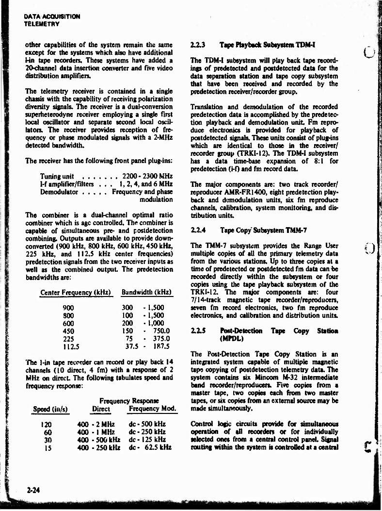
DATA ACQUISITION TELEMETRY
other capabilities of the system remain the same except for the systems which also have additional Hn tape recorders. These systems have added a 20-channel data insertion converter and five video distribution amplifiers.
The telemetry receiver is contained in a single chassis with the capability of receiving polarization diversity signals. The receiver is a dual-conversion superheterodyne receiver employing a single first local oscillator and separate second local oscil- lators. The receiver provides reception of fre- quency or phase modulated signals with a 2-MHz detected bandwidth.
The receiver has the following front panel plug-ins:
Tuning unit 2200 -2300 MHz 1-f amplifier/filters . . . 1,2,4, and 6 MHz Demodulator Frequency and phase
modulation
The combiner is a dual-channel optimal ratio combiner which is age controlled. The combiner is capable of simultaneous pre- and postdetection combining. Outputs are available to provide down- converted (900 kHz, 800 kHz, 600 kHz, 4S0 kHz, 225 kHz, and 112.5 kHz center frequencies) predetection signals from the two receiver inputs as well as the combined output The predetection band widths are:
Center Frequency (kHz) Bandwidth (kHz)
900 300 •1,500 800 100 •1,500 600 200 1,000 450 150 • 750.0 225 75 • 375.0 112.5 37.5 • ■ 187.5
The 1-in tape recorder can record or play back 14 channels (10 direct, 4 fm) with a response of 2 MHz on direct The following tabulates speed and frequency response:
Frequency Response Speed (in/s) Direct Frequency Mod.
120 400 -2 MHz dc-500 kHz 60 400 -1 MHz dc-250 kHz 30 400-500 kHz dc-125 kHz 15 400 -250 kHz dc- 615kHz
2.2.3 Tape Playback Subsystem TDM-I
The TDM4 subsystem will play back tape record- ings of predetected and postdetected data for the data separation station and tape copy subsystem that have been received and recorded by the predetection receiver/recorder group.
Translation and demodulation of the recorded predetection data is accomplished by the predetec- tion playback and demodulation unit Fm repro- duce electronics is provided for playback of postdetected signals. These units consist of plug-ins which are identical to those in the receiver/ recorder group (TRKI-12), The TDM-I subsystem has a data time-base expansion of 8:1 for predetection (t-f) and fm record data.
The major components are: two track recorder/ reproducer AMR-FRI400, eight predetection play- back and demodulation units, six fm reproduce channels, calibration, system monitoring, and dis- tribution units.
2.2.4 Tape Copy Subsystem TMM-7
The TMM-7 subsystem provides the Range User multiple copies of all the primary telemetry data from the various stations. Up to three copies at a time of predetected or postdetected fm data can be recorded directly within the subsystem or four copies using the tape playback subsystem of the TRKI-12. The major components are: four 7/14-track magnetic tape recorder/reproducers, seven fm record electronics, two fm reproduce electronics, and calibration and distribution units.
2.2.5 Post-Detection Tape Copy Station (MPDL)
The Post-Detection Tape Copy Station is an integrated system capable of multiple magnetic tape copying of postdetection telemetry data. The system contains six Mincom M-32 intermediate band recorder/reproducers. Five copies from a master tape, two copies each from two master tapes, or six copies from an external source may be made simultaneously.
Control logic circuits provide for simultaneous operation of all recorders or for individually selected ones from a central control panel Signal routing within the system is controlled at a central
U
:)
£
2-24
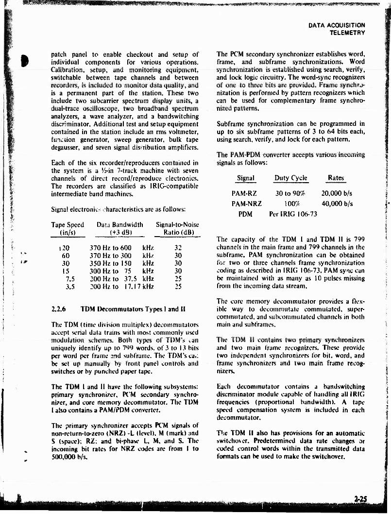
sivff^mm^^fs^^^^^-w^mmmmtmmm^m^^^s^ni^m^^iim^w^
DATA ACQUISITION TELEMETRY
IS*
patch panel to enable checkout and setup of individual components for various operations. Calibration, setup, and monitoring equipment, switchable between tape channels and between recorders, is included to monitor data quality, and is a permanent part of the station. These two include two subcarrier spectrum display units, a dual-trace oscilloscope, two broadband spectrum analyzers, a wave analyzer, and a bandswitching discriminator. Additional test and setup equipment contained in the station include an rms voltmeter, function generator, sweep generator, bulk tape degausser, and seven signal distribution amplifiers.
Each of the six recorder/reproducers contained in the system is a V>-in 7-track machine with seven channels of direct record/reproduce electronics. The recorders are classified as lRlG-compatible intermediate band machines.
Signal electronic characteristics are as follows:
Tape Speed Data Bandwidth Signal-to-Noise (in/s) (+3 dB) Ratio (dB)
i20 370 Hz to 600 kHz 32 60 370 Hz to 300 kHz 30 30 350 Hz to 150 kHz 30 15 300 Hz to 75 kHz 30 7.5 200 Hz to 37.5 kHz 25 3.5 200 Hz to 17.17 kHz 25
2.2.6 TDM Decommutator* Types I and II
The TDM (time division multiplex) decomnuitators accept serial data trains with most commonly used modulation schemes. Both types of TDM's >>an uniquely identify up to 799 words, of 3 to 13 bits per word per frame 2nd subframe. The TDM's ca.. be set up manually by front panel controls and switches or by punched paper tape.
The TDM I and II have the following subsystems: primary synchronizer, PCM secondary synchro- nizer, and core memory decommutator. The TDM I also contains a PAM/PDM converter.
The primary synchronizer accepts PCM signals of non-return-to-zero (NRZ) -I (level). M (mark) and S (space); R2; and bi-phase L, M, and S. The incoming bit rates for NRZ codes are from I to 500,000 b/s.
The PCM secondary synchronizer establishes word, frame, and subframe synchronizaiions. Word synchronization is established using search, verify, and lock logic circuitry. The word-sync recognizers of one to three bits are provided. Frame synchro- nization is performed by pattern recognizers which can be used for complementary frame synchro- nized patterns.
Subframe synchronization can be programmed in up to six subframe patterns of 3 to 64 bits each, using search, verify, and lock for each pattern.
The PAM-PDM converter accepts various incoming signals as follows:
Signal
PAM-RZ PAM-NRZ
PDM
Duty Cycle
30 to 90% 100%
PerlRIG 106-73
Rates
20,000 b/s 40,000 b/s
The capacity of the TDM I and TDM II is 799 channels in the main frame and 799 channels in the subframe. PAM synchronization can be obtained for two or three channels frame synchronization coding as described in IRIG 106-73. PAM sync can be maintained with as many as 10 pulses missing from the incoming data stream.
The core memory decommutator provides a flex- ible way to decommutatc commuiated, super- commutated, and subcoiumutated channels in both main and subframes.
The TDM II contains two primary synchronizers and two main frame recognizers. These provide two independent synchronizers for bit, word, and frame synchronizers and two main frame recog- nizers.
Each decommutator contains a bandswitching discriminator module capable of handling all IRIG frequencies (proportional bandwidth). A tape speed compensation system is included in each decommutator.
The TDM II also has provisions for an automatic switchover. Predetermined data rate changes ar coded control words within the transmitted data formats can be used to make the switchover.
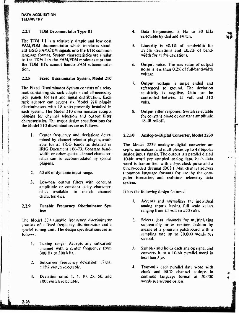
SPlSSISSff'WgOTI^'lTO
DATA ACQUISITION TELEMETRY
2.2.7 TDM Decommutator Type III
The TDM III is a relatively simple and low cost PAM/PDM decommutator which translates stand- ard IRIG PAM/PDM signals into the ETR common language format. System characteristics are similar to the TDM I in the PAM/PDM modes except that the TDM Ill's cannot handle PAM subcommuta- tion.
2.2.8 Fixed Discriminator System, Model 210
The Fixed Discriminator System consists of a relay rack containing six rack adapters and all necessary jack panels for test and signal distribution. Each rack adapter can accept six Model 210 plug-in discriminators with 18 units presently installed in each system. The Model 210 discriminator accepts plug-ins for channel selection and output filter characteristics. The major design specifications for the Model 210 discriminators are as follows:
4. Data frequencies: 3 Hz to 30 kHz selectable by dial and switch.
5. Linearity is ±0.1% of bandwidth for ±7.5% deviations and ±0.2% of band- width for ±15% deviations.
6. Output noise: The rms value of output noise is less than 0.2% of full-band »vidth voltage.
7. Output voltage is single ended and referenced to ground. The deviation sensitivity is negative. Gain can be controlled between ±1 volt and ±10 volts.
8. Output filter response: Switch selectable for constant phase or constant amplitude 18-dBrolloff.
I
1. Center frequency and deviation; deter- mined by channel selector plug-in; avail- able for all IRIG bands as detailed in IRIG Document 106-73. Constant band- width or other special channel character- istics can be accommodated by special plug-ins.
2. 60 dB of dynamic input range.
3. Low-pass output filters with constant amplitude or constant delay chaneter- istics available to match channel characteristics.
2.2.9 Tunable Frequency Discriminator Sys- tem
The Model 22l> tunable frequency discriminator consists of a fixed frequency discriminator and a special tuning unit. The design specifications are as follows:
1. Tuning range. Accepts any subcarrier channel with a center frequency from 300 Hz to 300 kHz.
2. Subcarrier frequency deviation: ±7'/i9«, t\$';i switch wrlectable.
3. Deviation ratio: I. 5. 10. 25. 50. and 100; switch selectable.
2.2.10 Analogto-Digital Converter, Model 2239
The Model 2239 analog-to-digital converter ac- cepts, normalizes, and multiplexes up to 48 bipolar analog input signals. The output is a parallel digital 10-bit word per sampled analog data. Each data word is transmitted with a 5-f/s clock pulse and a binary-coded decimal (BCD) 7-bit channel add'ess (common language format) for use by the com- puter formatter, and real-time telemetry data system.
it has the following design features:
1. Accepts and normalizes the individual analog inputs having full scale values ranging from ±1 volt to ±20 volts.
2. Selects data channels for multiplexing sequentially or m random fashion by means of a program patchboard with a sampling rate up to 20,000 words per second.
3. Samples and holds each analog signal and converts it to a 10-bit parallel word in less than 3 ps.
4. Transmits each parallel data word with clock and BCD channel address in common language format at 20,(WJ0 words per second or less.
#
2-26
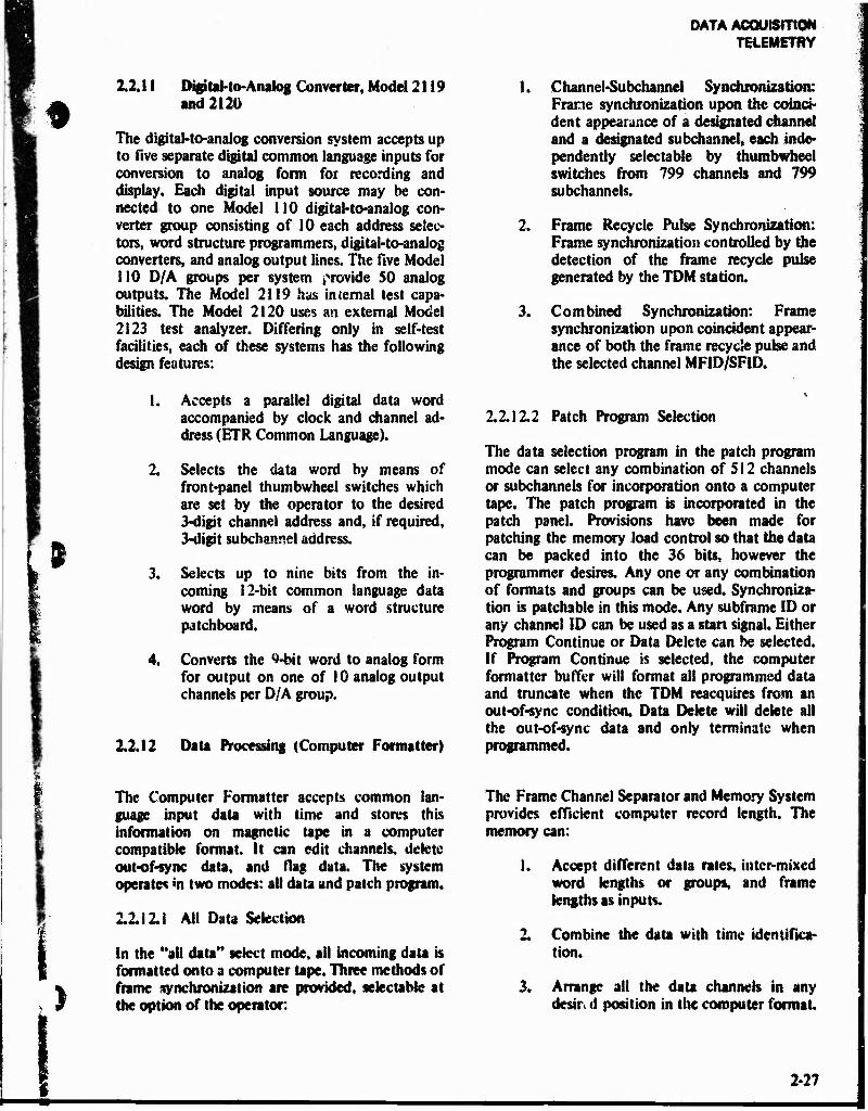
DATA ACQUISITION TELEMETRY
w
i
12.11 DigüaMo-Analog Converter, Model 2! 19 and 2120
The digital-to-analog conversion system accepts up to five separate digital common language inputs for conversion to analog form for recording and display. Each digital input source may be con- nected to one Model 110 digital-to-analog con- verter group consisting of 10 each address selec- tors, word structure programmers, digital-to-analog converters, and analog output lines. The five Model 110 D/A groups per system provide SO analog outputs. The Model 2119 has internal test capa- bilities. The Model 2120 uses an external Model 2123 test analyzer. Differing only in self-test facilities, each of these systems has the following design features:
1. Accepts a parallel digital data word accompanied by clock and channel ad- dress (ETR Common Language).
2. Selects the data word by means of front-pane! thumbwheel switches which are set by the operator to the desired 3-digit channel address and, if required, 3-digit subchannel address.
3. Selects up to nine bits from the in- coming 12-bit common language data word by means of a word structure patchboard.
4. Converts the 9-bit word to analog form for output on one of 10 analog output channels per D/A group.
2.2.12 Data Processing (Computer Formatter)
1. Channel-Subchannel Synchronization: Frame synchronization upon the coinci- dent appearance of a designated channel and a designated subchannel, each inde- pendently selectable by thumbwheel switches from 799 channels and 799 subchannels.
2. Frame Recycle Pulse Synchronization: Frame synchronization controlled by the detection of the frame recycle pulse generated by the TDM station.
3. Combined Synchronization: Frame synchronization upon coincident appear- ance of both the frame recycle pulse and the selected channel MFID/SF1D.
2.2.12.2 Patch Program Selection
The data selection program in the patch program mode can select any combination of 512 channels or subchannels for incorporation onto a computer tape. The patch program is incorporated in the patch panel. Provisions have been made for patching the memory load control so that the data can be packed into the 36 bits, however the programmer desires. Any one or any combination of formats and groups can be used. Synchroniza- tion is patchable in this mode. Any subframe ID or any channel ID can be used as a start signal. Either Program Continue or Data Delete can be selected. If Program Continue is selected, the computer formatter buffer will format all programmed data and truncate when the TDM reacquires from an out-of-sync condition. Data Delete will delete all the out-of-sync data and only terminate when programmed.
>
The Computer Formatter accepts common lan- guage input data with time and stores this information on magnetic tape in a computer compatible format. It can edit channels, delete out-of-sync data, and flag data. The system opera»« in two modes: all data and patch program.
2.2.12.1 All Data Selection
In the "all data" select mode, all incoming data is formatted onto a computer tape. Three methods of frame synchronization are provided, selectable at the option of the operator:
The Frame Channel Separator and Memory System provides efficient computer record length. The memory can:
1. Accept different data rates, inter-mixed word lengths or groups, and frame lengths as inputs.
2. Combine the data with time identifica- tion.
3. Arrange all the data channels in any desire d position in the computer format
2-27
mm
DATA ACQUISITION TELEMETRY
The Fiame Channel Separator has a random frame selection capability from the major cycle start identification of one to 10 frames containing known subchannels. The separator also can select every frame, second frame, fourth frame, eighth frame, or 16th frame for computer processing.
The multiple frame formatted per tape record provides a continuous recording of two or more frames of formatted data before a record gap. The number of frames formatted can be selected by thumbwheel switches:
FRAME SYNC RECOGNITION WORD SYNC RECOGNITION SUB-FRAME SYNC RECOGNITION WORD PER FRAME RESTART
2.2.12.3 Computer Format Converter
The computer format converter provides a com- patible selected-format for the computer tapes. The converter can program data entry tapes at 200 and 556 bits/inch packing densities. The parity check is patchable to provide for all modes. The parity check and the parity bit insertion is included for both lateral and longitudinal positions on the tape. A parity check is made on the output tape during preparation of the recording.
The tape format generation for computer entry includes ail requirements for the maximum effi- ciency in computer entry including tape gaps, stop marks, and/or file marks and data control marks.
l"he system can formst nine 3f-bit computer words of different data word composition and two 36-bit computer words of different time word composi- tion. Variable input words from 4 to 64 bits can be integrated into the nine computer words.
2.2.12.4 IBM Format Recorders
Two magnetic tape recorders, ft-in 7-track, are provided for recording IBM format tapes. The tecorders provide packing densities of 200 and 556 bits/inch. The recording speeds and the recorder stop and start times are chosen for maximum time efficiency and continuous operation in the produc- tion of a computer tape. Tlw recorders operate in five modes:
Continuous recording Parallel recording
Tape copying Single recorder operation Overlap recording
The recorders operate alternately to provide continuous recording of data. AL required com- mand signals are provided for this operation. A selectable number of overlap records is available. In the tape copying mode, tie data on one tape is copied onto the second tape of the formatter.
2.2.13 Range Time Decoder
The range time decoder provides time words for correlation of the data on the computer tape to within 1 ms. In addition, the decoder may be used for time search of the input tape and visual time display. The decoder supplies decimal readout in days, hours, minutes, seconds, and milliseconds from the 100/1,000 p/s range time code generator. A time control delays the seconds time changeover f*?m ±50 ms to 1-ms increments.
The decoded range time is recorded on the computer tape, in one or more computer words, in any position in the record. The decoded range time is recorded at a recurrent rate to provide accurate time correlation of the data on the computer tape to within I ms for forward and reverse time. The time readout can be correlated with any word in the data record recorded on the computer tape.
The time decoder provides a new decoded time word st the detection of the leading edge of the range time markers.
2,2.13.1 Tape Start and Stop Time Selection Controls
The Selection Control is provided for the pre- selection of recording time interval referenced to recorded range time for the processing of a computer tape. The time selection switches for determining the recording time interval are com- patible with the time display. Six sets of switches are provided for selecting the automatic starting time of the recording interval for bom forward and reverse time recording. An end-of-fik is provided alter each time period selected.
o
2.2.13.2 Identification Control
Two methods are provided to enter identification data onto the computer tape. The first is a series of C
JJL
DATA ACQUISITION TELEMETRY
I
thumbwheel switches arranged in groups as fol- lows: identifying data - 6 characters, run number • 4 characters, reel number • 2 characters» recording location - 2 characters, primary recording device - 2 characters, secondary recording device - 2 charac- ters, and special identification - 6 characters. The second method is a paper tape entry in which ait of the above identification data plus complete identi- fication can be provided. ID entry on tape does not preclude the recording of data records only.
2.2.13.3 Computer Tape Time Placement
The time word reference for the computer tape can be integrated into the computer tape format in any denied position to provide complete time correla- tion of tiie data with all possible conditions of frame stripping.
2.2.13.4 Additional Capability
The range unit addition to the ETR Range Time provides the capability of handling 1R1G 104-70 formats A and B. The BCD format is used.
2.2.13.5 Range Time Input
Patch facilities are provided for receiving various time codes from four inpui lutes. The range time input impedance is 10,000 ohms. The input voltage is 5 volts peak-to-peak.
2.2.14 Data Collector System
>
The Data Corrector System performs real-time operations on telemetry data. Depending upon the particular program (software) used, either on-line or off-line digital operations may be performed by the data corrector. Primary on-line operations consist of receiving real-time telemetry data (com- mon language format), editing and correcting this data, and producing outputs for the display and mission control Data and other ii«'®rmation may also be recorded on magnetic tap? ku' postmission analysis. Off line, the data corretior may be used to perform many general purpose computer func- tions: assemble and cheek out its own programs, generate programs for other stored program te- lemetry equipment such as the TDM 1 and TDM II, check and dump computer formatter tapes, etc
Communications with other telemetry equipment in carried out in real-time through its common
(CL) interface. The heart of the Data
Corrector System is a small-scale solid-state general purpose digital computer (Beckman Model 420) having an 18-bit word length and a memory capacity of 16,384 words. There are two standard input/output channels and a third high-speed input channel (DME) which use the direct memory access feature of the computer. Peripheral devices include a card reader, a line printer, a high speed code converter, and a magnetic tape unit
2.2.15 Oscillograph* Recorders
The primary osciUographic recorders used on the Range are Honeywell 1612's. These machines make permanent recordings for distribution to the Range User. They have the following specifications:
1. Provide 17 data and a timing channel on one paper strip.
2. Have frequency response from dc to 5 kHz (with special high frequency galva- nometers: dc to 13 kHz).
3. Provide IS chart speeds from 0.1 uv's to 160in/i.
4. Provide quick identification of traces by interruption of galvanometer tight beams.
2.2.16 Pest Recorders
The Brush Mk 200 recorders on the Range have essentially the same configuration. The design derails are as follows:
1. Provide eight chani/sts of low fmquency data recording phis timing,
2. Provide separate timing inputs to be displayed on riant side, left side, or both sides through ^»»arate marker amplifiers.
3. Provide chart speeds from 0.002 tn/s to 8 in/sin 12 steps.
4. Provide provisions to remotely control the recorder if required,
5. Provide an internally generated 0.1% reference voltage to the 25 pens for calibration.
2-29
DATA ACQUISITION TELEMETRY
I
6. Handle data amplitudes from ±1 volt to ±20 volts.
2.2.17 Digital Bar-Graph, Model 2321
The digital bar-graph display provides an analog display of up to 40 channels stripped from the common language signal. The design features are as follows:
1. Converts variable-length digital data to a form suitable for bar-graph display.
2. Accepts telemetry data and channel addresses in ETR common language for word rates to 100 kHz from one of eight switch-selected sources.
3. Selects channels to be displayed by thumbwheel switch indicating channel and subchannel.
4. Normalizes inputs to provide full scale bar heights regardless of input word length.
5. Adjusts frame length to display either 10, 20, 30, or 40 channels starting from either channel 1,11, 21, or 31.
22.18 Digital Display
The digital display unit accepts common language inputs and distributes the data to such displays as 7-digit Nixies, analog meters, event meters, multi- stylus event recorders, and digital printers. The Nixies and analog meters display transient signals, and the event recorders and printers provide a permanent record of data.
A programming selector (patchboard) will select the channels to be displayed or recorded. A digital printer prints binary or binary-coded decimal. A multistylus recorder provides an alternate means for displaying binary data. Alphanumeric readout devices have lamp visual displays for decimal digital data. Special alarm meters, with adjustable toler- ance, monitor digital data.
2.2.18.1 Multistylus Event Recorder
A self-contained ISO-channel event recording in- strument in lufactured by Brush Instruments. The recording units accept on-off type data signals
which are recorded on permanent chart paper. One channel is used as a timing channel for accurate event riming information. The technical character- istics are:
Number of styli: 150
•
Response:
Chart speeds:
Up to 1.25 ms at maxi- mum chart speed.
5, 10, 20, 50, 100, and 200 mm/s and 0.05, 0.1, 0.2, 0.5, 1 and 2 mm/s.
2.2.18.2 Digital Printer
This printer is a Hewlett-Packard 526-A with 11 columns utilizing standard code wheels. The display unit includes a binary-to-BCD converter to print either octal or decimal.
2.2.J.8.3 Nixie Readouts
Ten banks of 7-digit in-line displays which are single channel selectable.
2.2.18.4 Analog Me ter
Ten meters with 10-volt full scale range. Separate DAC units with 9-bit binary resolution are in- cluded. Separate dividers for external inputs of 30 volts are included (the included DAC's provide levels to 10 volts maximum, unipolar). Adjustable alarm limits (both high and low) on each meter energize a latching error indicator. The error light acts on an input below low limit (only), above high limit (only), or out of either limit.
2.2.19 Real-Time Telemetry Data System
The Real-Time Telemetry Data System (RTTDS) was developed so that remotely and locally acquired telemetry data could be delivered to users in real-time. To accomplish this, the RTTDS performs the following major functions:
1. Selects data from multiple asynchronous telemetry down links.
2. Formats the mixed data channels for uprange retransmission.
3. Decommutates the received downrange data mix at the central telemetry facil- ity.
u
I
2-30
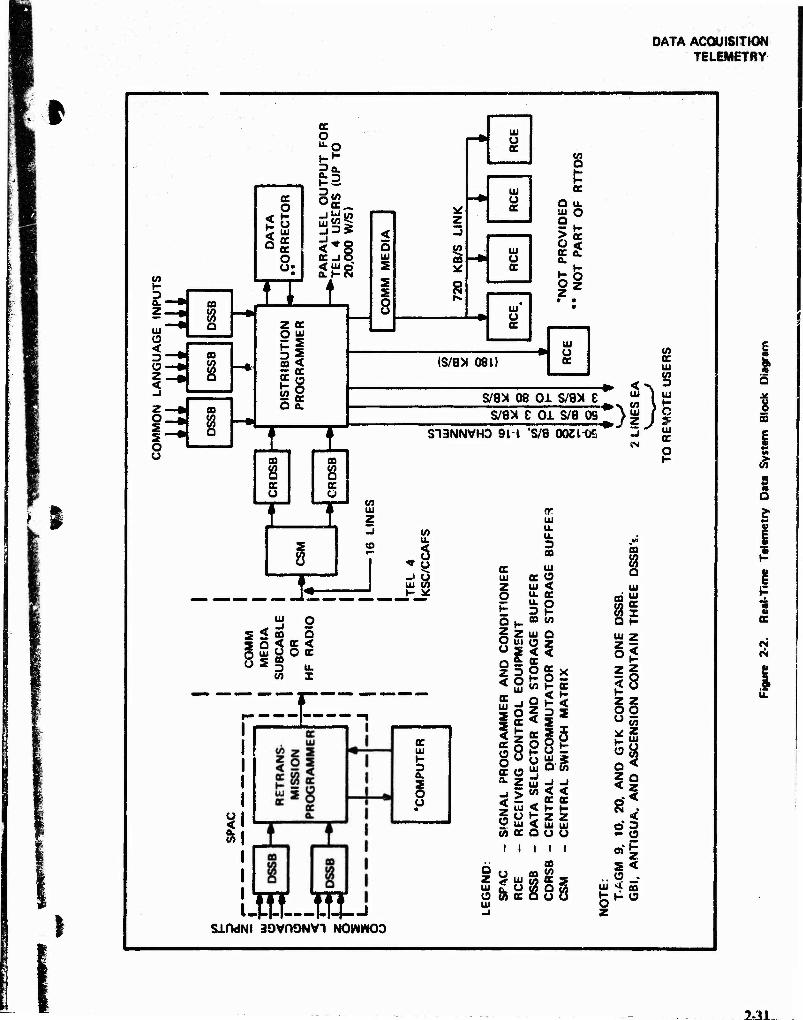
DATA ACQUISITION TELEMETRY
t-
a.' Z.
Ui' a < D"
z, <
z- o. s S' o o
ee e o ui CC OC o
CO
a
CO
1 CO
8
n
cc o u-O
?Q. £2 °£
<*§ cc-io CLh-i
1 z cc O ui
3i
O a.
I CO
8 e u
I
I
ui u OC
u cc
8 1=
UI o cc
UI o cc
D UI Q
> o cc
O z
cc < a.
z
(s/ax 081) ui u cc
s/ax 08 oi s/ax e s/ax e oi s/a os
S13NNVH0 911 'S/8 00Zl"0fi
ui I UI
^ A ui / C WS J * ^ ~j "' UI
cc
CO
8 X
I s 8
UI z
«J
f " UJ &,
u. <
UI U>
2 2 ui o
< oo 5 o < cc < UJ U O CC
o u. X
zig^r;
l
»I
c UI
3 a.
o
-roust SifWNI 39VH9NV1 NOWWO0
09
a UI
IS
o< z o o
z
& UI
s z
Q <
li
s< o .
£ a
ft
s E
I
I s
cc
I CM
£
2=31

0ATA ACQUISITION TELEMETRY
5^-
3
4. Selects locally acquired data to combine with remote site data.
5. Provides several output data formats at various word rates and channel groupings for transmission to various users.
A simplified block diagram of the system, depict- ing the flow of data, is shown in figure 2-2. The data inputs to the system are from multiple digital common-language (CL) sources consisting typically of TDM Type I, II, and 111 decommutators and A/D conversion systems. A remote site subsystem is called a signal programmer and conditioner (SPAC), Each SPAC consists of two major types of equipment: a data selector and storage buffer (DSSB) and a retransmission programmer (RP). The nuiriber of DSSB's per each SPAC can vary from one to six. Figure 2-2 identifies the number of DSSB's installed with each SPAC A DSSB has three CL inputs and can simultaneously accept and store data in memory, in parallel form, at asynchronous input rates up to a combined total of 100,000 w/s. In addition, it can select and store a time word with each data word selected. Data word length can be from 4 to 12 bits per word.
A DSSB contains a 4098-word by 26-bit magnetic core memory where program instructions and data are stored. The RP, which is more complex than a DSSB, selects data from each DSSB memory, the programmable patch panel, and a computer and merges this data into one output serial bit stream, the format of which is under program control. The output bit rate capability is from 25 b/s up to 400 kb/s. The output serial bit stream is routed into communications interface equipment (modem) where it is converted into a form suitable for transmission over a submarine cable or high frequency radio, whichever is applicable. The maximum bit rates from the downrange sites are: Grand Bahama - 384 kb/s; Antigua and Grand Turk - 76.8 kb/s; all others • 2.4 kb/s. The RP can handle words of mixed length (4 to 12 bits). It also has truncation capability for words over four bits long. The RP magnetic core memory system holds 4,096 words of 30 bits each and contains the program instructions.
The SPAC contains a program entry and control (PEC) panel which provides manual access to the RP and DSSB memories. Programs can be manually read into any of the memories and the contents of any memory location can be read out and
displayed on the PEC panel Programs are normally entered in the memories via paper tape from a tape reader which is part of the PEC. The DSSB's and RP can store two programs and change from one to the other by merely actuating a switch. Also new programs can be read into the system while it is operating without interference to the operating program.
The Central Site equipment consists of a central switch matrix (CSM), two central retransmission decommutator and storage buffers (CRDSB), a distribution programmer (DP), a central control console (CCC), and three DSSB's. Receiving con- trol equipment (RCE) is located at users' interfaces at KSC and CCAFS.
The serial bit streams from downrange are routed to the CRDSB's via the CSM. The CRDSB's, under program control, decommutate the data and store it in known locations in their 4096-word by 32-bit magnetic core memories. The maximum serial input rate to a CRDSB is 200 kb/s. The DP, under program control, selects data from the DSSB's and the CRDSB's and combines this data into one or more of several output formats and rates described below:
1. A high rate parallel output (up to 20,000 w/s) for display within Tel 4.
2. A high rate serial output (up to 720 kb/s) with either BCD or binary ID's for users at KSC and CCAFS. This link contains the same data as I above.
3. A serial output link to the Real-Time Computer System with a maximum rate of 180 kb/s. RCE's are provided to the users of this output and 2 above. The RCE is essentially a serial-to-parallel converter.
4. A serial output which can be interfaced with a Bell 301-B or similar modem. The rate is variable from 3 kb/s to 80 kb/s with a fixed stop at 40.8 kb/s. This link is for transmitting data to remote user locations.
5. Two serial output links (their data content can be different) for remote i sv-rs as in 4 above. The rates are from i r b/s to 3 kb/s. These links can be
2-32
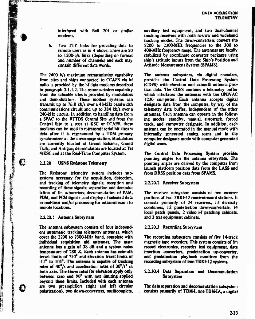
IT-: i DATA ACQUISITION TELEMETRY
t
€ n
ft
-*
i i
o
interfaced with Bell 201 or similar modems.
6. Two TTY links for providing data to remote users as in 4 above. These are SO to 1200-b/s links (depending on format and number of channels) and each may contain different data words.
The 2400 b/s maximum retransmission capability from sites and ships connected to CCAFS via hf radio is provided by the hf data modems described in paragraph 3.1.1.2. The retransmission capability from the subcable sites is provided by modulators and demodulators. These modem systems can transmit up to 76.8 kb/s over a 48-kHz bandwidth communications circuit and up to 384 kb/s over a 240-kHz circuit. In addition to handing data from a SPAC to the RTTDS Central Site and from the Central Site to a user at KSC or CCAFS, these modems can be used to retransmit serial bit stream data after it is regenerated by a TDM primary synchronizer at the downrange station. Modulators are currently located at Grand Bahama, Grand Turk, and Antigua; demodulators are located at Tel 4/KSC and at the Real-Time Computer System.
2.2.20 USNS Redstone Telemetry
The Redstone telemetry system includes sub- systems necessary for the acquisition, detection, and tracking of telemetry signals; reception and recording of these signals; separation and demodu- lation of fm subcarriers; decommutatiou of PAM, PDM, and PCM signals; and display of selected data in real-time and/or processing for retransmissio i to remote locations.
2.2.20.1 Antenna Subsystem
The antenna subsystem consists of four independ- ent automatic tracking telemetry antennas, which cover the 2200 to 2300-MHz band, complete with individual acquisition aid antennas. The main antenna has a gain of 38 dB and a system noise temperature of 280 K. Each antenna has azimuth travel limits of 750° and elevation travel limits of -11° to 105**. The antenna is capable of tracking rates of 40°/s and acceleration rates of 30°/s3 in both axes. The above rates for elevation apply only betweeii zero and 90* with rate limiting applied beyond these limits. Included with each antenna are two preamplifiers (right and left circular polarization), two down-converters, multicouplere,
auxiliary test equipment, and two dual-channel tracking receivers with both narrow and wideband tracking modes. The down-converters convert the 2200 to 2300-MHz frequencies to the 300 to 400-MHz frequency range. The antennas are locally stabilized by coordinate converter packages using ship's attitude inputs from the Ship's Position and Attitude Measurement System (SPAMS).
The antenna subsystem, via digital encoders, provides the Central Data Processing System (CDPS) with elevation and azimuth antenna posi- tion data. The CDPS contains a telemetry buffer which interfaces the antennas with the UNIVAC 1230 computer. Each antenna accepts digital designate data from the computer, by way of the telemetry data buffer, independent of the other antennas. Each antenna can operate in the follow- ing modes: standby, manual, autotrack, forced track, and computer designate. In addition, each antenna can be operated in the manual mode with internally generated analog scans and in the computer designate mode with computer generated digital scans.
The Central Data Processing System provides pointing angles for the antenna subsystem. The pointing angles are derived, by the computer from launch platform position data from the LASS and from DRSS position data from SPAMS.
2.2.20.2 Receiver Subsystem
The receiver subsystem consists of two receiver portions of two TRK1-12 receive/record stations. It consists primarily of 24 receivers, 12 diversity combiners, 12 predetection down-converter», 14 local patch panels, 2 video i-f patching cabinets, and 2 test equipment cabinets.
2.2.20.3 Recording Subsystem
The recording subsystem consists of five 14-track magnetic tape recorders. This system consists of fm record electronics, recorder test equipment, data insertion converters, predetection up-converter, and predetection playback monitors from the recording subsystem of two TRKH 2 systems.
2.2.20.4 Data Separation and DecommutatJon Subsystem
The data separation and decommutation subsystem consists primarily of TDM-I, one TDM-I A, a digital
Li 2-33
DATA ACQUISITION TELEMETRY
bar-graph, 12 fixed frequency discriminators, 18 tunable discriminators, four oscillographs, seven pen recorders, one data insertion converter, A/D converters, D/A converters, a signal programmer and conditioner (SPAC), and associated test equip- ment
In the data separation and documentation sub- system, standard I RIG, PAM, PCM, and POM commutatcd data are decommutated by the TDM-I and IA. Outputs from this subsystem are patched to the pen recorders.
2.2.20.5 Signal Programmer and Conditioner (SPAC)
Data to be retransmitted in real or near-real time are processed through the SPAC after demulti- plexing in the TDM-IA. This syst im conditions and reformats the data into parai<d data streams for retransmission over the high-speed hf data link to remote stations. Data modems and retransmission facilities are part of the communications system. Data may be shifted out of the SPAC at rates up to 2400 b/s. Telemetry data recorded in video form on magnetic tape recorders may be retransmitted to aircraft or close-range bases through a vhf retransmission system.
2.2.21 ARIS Telemetry
The ARIS telemetry subsystem serves a dual purpose: (1) as an automatic tracker it provides angular data that can be put on the master designate bus to assist the radars in acquiring a target, and (2) as a data collecting and recording system it provides telemetry data in the standard telemetry bands within the frequency range of 216 to 2800 MHz. The ARIS also carry special telemetry equipment to collect data within the 60 to 4000-MHz band.
The telemetry tracking antenna employs a dual- element log periodic broadband feed system for frequencies from 215-2800 MHz (19 dB-38 dB gain, respectively). One element receives right circular polarized (RCP) signals and the other receives left circular polarization (LCP). The conical scan rate of 600 r/min produces a 10-Hz error signal for auto track. The system can track on either RCP, LCP, or in a combined mode, using a 30-ft parabolic dish mounted on an antenna mount identical to the radar mounts. The antenna mount can be slaved to the designate bus controlled by
the master selected in the Operations Control Center (OCC), or can control this bus, if selected as master.
The TRKI-12 system is used for receiving and recording telemetry data. The TRKI-12 system consists of 12 telemetry data receivers, six spec- trum display units, six diversity combiners, six predetection converters, two predetection play- back monitors, two FR-1400 magnetic tape re- corders, two direct-write recorders, one data insertion converter, one fm record/reproduce elec- tronic unit, and necessary test equipment and patching facilities.
Each telemetry data receiver provides reception of fm, pm, and a-m carriers and demodulation of fm, PDM, PAM, PCM, PACM, and pm. Separation and display equipment consists of a Time Division Multiplex Type II (TDM-II) station and TDM-II test unit, fm fixed discriminators, tunable discrimi- nators, D/A converters, A/D converters, digital bar-graph display, oscillographic recorders, and direct-write recorders.
The TDM-II derives primary and secondary synchronization from video signals for the recon- struction of the various modulated carriers using the basic PCM technique. The system will decom- mutate PCM at rates up to 1,000,000 b/s. A PAM/PDM to PCM converter in the system converts a PAM or PDM wavetrain to PCM for decommutation of this type data.
The 18 fm fixed discriminators are Data Control System Model GFD-2 subcarrier discriminators with the necessary plug-ins for the discrimination of I RIG channels 1-18 and A-E The five fm tunable discriminators are EMR Model 229 units that can be tuned to any desired frequency between 300 Hz and 300 kHz; frequency deviation of ±7.5% or ±15% can be selected. A Monitor Systems Model 2119 D/A converter (50 channels) converts parallel digital outputs from the TDM-II to analog form for recording and display, and a Monitor Systems Model 2239 A/D converter (48 channels) digitizes discriminator outputs for re- mote transmission and computer use.
A Monitor Systems Model 2321 digital bar-graph (40 channels) converts parallel digital outputs from the TDM4I and displays up to 40 channels of digital telemetry data in the form of vertical bars, each representing a data word. Four Minneapolis
o
-I I'
Q
JL2L

DATA ACQUISITION TELEMETRY
Honeywell Model 1612 recorders (18 channels « each) are used for recording up to 54 channels of ™ analog data at rates up to 5 kHz. Four Brush
Instrument Mark 200 recorders (8 channels each) are used for recording up to 32 total channels of analog data at rates up to 58 Hz.
The Real-Time Retransmission System consists of a SPAC, a part of the Real-Time Telemetry Data System, and the High Speed Data Modem. The SPAC accepts up to three links of telemetry data from units such as the TDM-II and A/D converter for storage and selection, or selected data from the 1206 computer for retransmission in near real-time at a rate up to 2400 b/s. (This rate is determined by the High Speed Data Modem and the hf link since the SPAC can accept up to 100,000 data words per second.)
A special telemetry system enables frequency coverage over a range from 60 MHz to 4,000 MHz. The system consists of: (1) super high frequency (shf) autotrack system, (2) reentry vehicle (RV) receiving antenna system, (3) ground-look antenna
system, (4) control console, and (5) magnetic tape recorder system.
A 40-in shf autotrack antenna dish is mounted on top of the 30-ft telemetry antenna. The traveling wave tube (TWT) preamp, filter, and 20-dB coupler are in a weathertight enclosure which is also on top of the 30-ft dish. The R-35 receiver is mounted in the rf enclosure on the back of the 30-ft dish. Although the receiver can tune from 2 to 4 GHz, the system will operate only between 2.665 GHz and 2.955 GHz because of the bandpass filter in front of the preamp.
The RV receiving antenna system consists of five antennas (including the primary 30-ft telemetry dish), six preamplifiers, five postamplifiers, and 12 receivers. The 5-antenna complex covers the frequency band of 60 MHz to 4 GHz. The six preamplifiers cover the same frequency band in five overlapping steps. The postamplifiers provide frequency coverage from 90 MHz to 4 GHz in five overlapping steps. The receivers cover the 60 MHz to 4 GHz band in four steps with a minimum of
O TABLE 2-13. AFETR TELEMETRY FREQUENCY COVERAGE BY STATION
0
Frequency Range (MHz)
Location
Launch Area
Mobile TLM Van GBI GTK ANT ASC PRE Redstone ARIS (2) ARIA (8)
130-140 X X X X** X X
225-260 X X X X X X
285-315 X X X X
370-410 X X X X X X(400)
920-965 X X X X X
2200-2300 X X X X X X X X X X
704000 X*
1435-1535 X X
'Special capability for ARIS only. ••Pretoria. S.A.. station is inactive.
2-35

DATA ACQUISITION TELEMETRY
two receivers for each step. In addition, the system contains the necessary multiplexers, multicouplers, demodulators, and converters for video and pre- detection display and recording.
The ground-look antenna system consists of two separate systems, one mounted on the portside of the ship and the other mounted on the starboard side. They are individually controlled from the control console. The combined system consists of four antennas, five preamplifiers, and eight re- ceivers. The antennas cover the band of 60 MHz to 4 GHz in two steps. The preamplifiers cover this band in five overlapping steps, while the receivers cover the band in three overlapping steps. There is a minimum of one receiver for each band, and the
system contains the necessary multiplexers, multi- couplers, demodulators, and converters for video and predetection display and recording.
The control console contains the necessary test, control and display equipment for operating the special telemetry system. In addition, it houses the receivers and pcstamplifiers that are a part of the RV and ground-look antenna systems.
The tape recorder system consists of four CEC, VR-3600 1-in tape recorders with 14 tracks each, and two CEC, VR-3600 Vxm recorders with seven tracks each. Recording capabilities are from 400 Hz to 1.5 MHz on all tracks for either video or predetection recording.
' ' ... *
TAA-8/8A TELEMETRY
2-36

SEsg
DATA ACQUISITION TELEMETRY
%Br
o
p<
4» O W
fio I«
1 1 8
1 2 N
5 3
S § •a I Eti
-i _ 3 X
«a
M
6 a
5
K
s E
O -5. Ö O — v>
'S H
a 18 * o R **
-8
- 8
N X X *
8 5 2* <s O
^ 1 1 | s i 2 © — **> «« d
•B
2 a
.3 «1
1 o
5 I ? £
i •t I
I I S 8 H H
1
!
1
§ r Ü.
5
E
I e a
& 3 »* .St
1; h
1 ! e
§
•> us e C
«
1
0
§0*
8
■8
!
o
j* S
u o a 2 w «s a 3.8
e *^ a
I
g. .5
- «5
s § e <
8 1 1 1 8 1
CO 1 I 1 5 5
I
U.
B.-S a
ill
as
1 I 6 m
2-37

DATA ACQUISITION TELEMETRY
TAA-3 TELEMETRY

DATA ACQUISITION TEUSMETRY
Q
TABLE 2-16 TAA-3/ASCENSION TELEMETRY TECHNICAL CHARACTERISTICS
Antenna Paraboloid
Size 30-ft diameter
Feed Apex, offset circular cavity, conical scan
Scan rate 10 Hz
Pedestal Elevation over azimuth
Pointing error ±0.1° static plus tO.059 perdeg/scumu- lathe
p. ■ ""',
Tracking velocity 15*/s max. (both axes)
Tracking acceleration 7°/s/s max. (both axes)
Polarization Right and left circular (simultaneous and selectable)
Frequency band (MHz) •2200-2300 •*785 to 865
Antenna gain (nominal) (reference at preamp input . and like polarization) 42.5 dB 29.5 dB
Antenna beamwidth (nominal) 1.0° 3.0°
Receiving system noise figure (nomi- nal) (reference at preamp input and like polarization) 1.5 dB 3.2 dB
System noise temperature (nominal) (antenna plus receiving system referenced at preamp input) 240 K 475 K
System sensitivity; S ■ N (nominal) (based on receiver M bandwidth of 500 kHz) -118 dBm -115 dBm
* Also down-converted outputs available at 300 to 400 MHz. ** Autotrack capability not available; receive only.
■
O
i
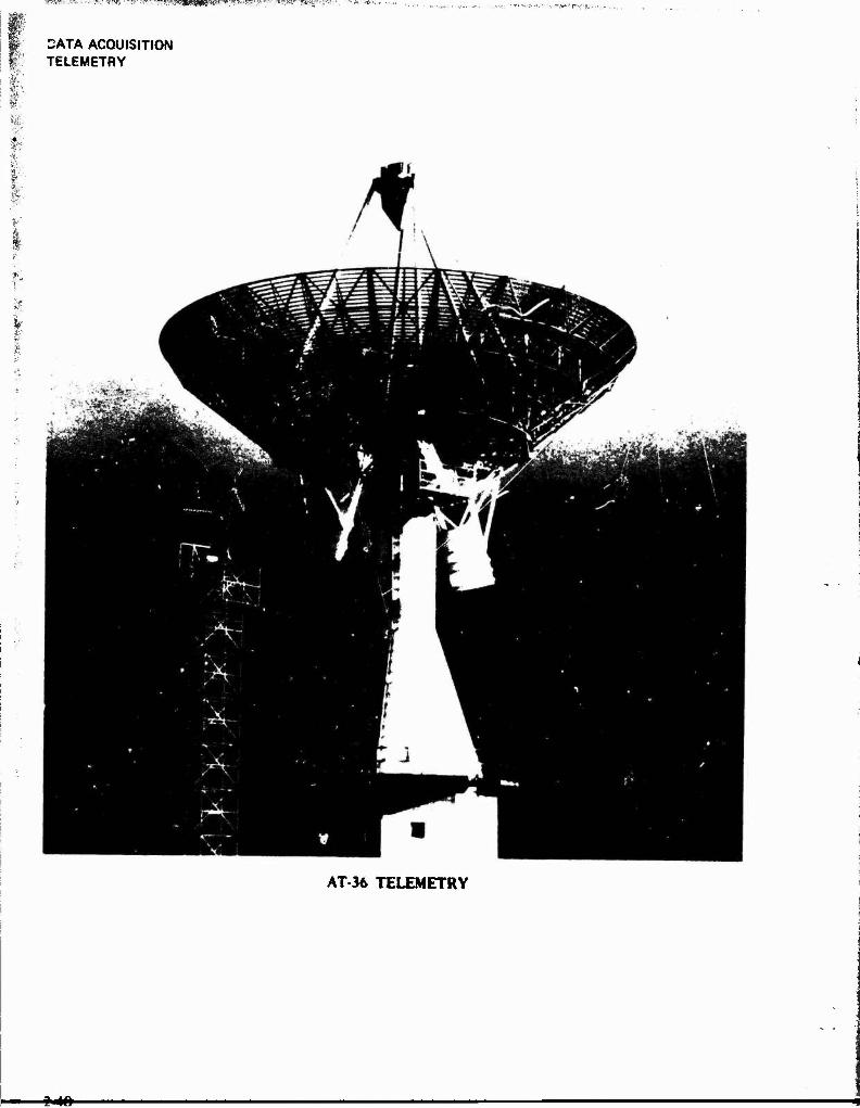
5W3SÜHRW
DATA ACQUISITION TELEMETRY
AT-36 TELEMETRY
-2-46-

DATA ACQUISITION TELEMETilY
6 TABLE 2-17
AT-36/PRETORlA TELEMETRY TECHNICAL CHARACTERISTICS
( <
Antenna Paraboloid
Size
Feed
60-ft diameter
Apex, auai rag penoutc conical spirals, conical scan
Scannte 10 Hz
Pedestal Etevatjon over azimuth
Pointing error *0.1- static plus dynamic of 0.02* per deg/s
Tracking velocity IO*/s both axes (20*/s at zenith)
Tracking acceleration 7*/s/s both axes
Polarization Right and left circular (simultaneous and selectable)
Frequency band 2200 to 2300 MHz (down-converted to 300400 MHz)
Antenna gain (reference at preamp input) 44 dB (nominal)
Antenna beam width 0.5* (nominal)
Receiving system noise figure (reference at preamp input) 1.5 dB (nominal)
System noise temperature (antenna phis receiving system referenced at preamp Input) 350 K (nominal)
System sensitivity; S ■ N (bated on receiver i-f bandwidth of 500 kHz) •116 dBm (nominal)
o
JdL

DATA ACQUISITION TELEMETRY
Srf E 6 o flQ
"O 0 r; T3
o in
oa
o sf-''
* • n sd ro
•
^KS^ Mt- TR>- n SO ^ E
oa •u p'v 'Syfl Bf »A o •o o 00
t3 O Cß**-":' l^^l ^Wfi««i$ ,» CM <5 o> m Jüü» '^^^BS^HPP^^^^^^ «' rj ri n ro ■* a <N
^^^^^H^H
"T
i ED Ü E «"> «n T3 0 aa oa 00 — T3 O
o •a * r<% ri u-> o» r\
■BP ^B «
T
E 6 o
CO "3 0 OS
^ CO ■a
r- — T3 in
* f i iAi 30 r\
• ~
iA fm
'EL a« 6 o Si "3 0
CQ T3
'*i 3 rt C" C3> *— w. "C ri , , w • t o »ri 30
n C * —. .— ?3
1
er
o SO 3 ^ '-* £ CD 00
-J * c
oa *J _ * * ± ■* m "O 0 *n T3 -5 0 3
•j \» « el * 5 t-
"5 J2 • • • • d
in »•<■,
t* • 3 o mm JL\ "* # i
CM N V C o O .=
M* „_ a» i*™ x -c •-> g
v _ y ■3 E 2 _ a .2 -3 5 ~ "3 ■-
X _ x s 2 'T "-* vJ
Si
> 0
£ '"" id <Lm
0 /
'"I «*", fin * d
00
O
rs m ~ O — cz o c ~ S_ X < _ *- —v. X
V "3 I :i
«H> ~ 'J c
X ~
"?5 1 £ S 7.
? •
z
1 .s C JE *
i 0
^" *i 2 -i M 1 c
1? i w -1 I i I i V
0 3? 1"* «m
I
^ 4M
IB
V — S v
t» V {- •* ■"= o
"2 X
i 1
5 A
'5 2 S 1 s
i E 0
c
1 rj
1*
— 3J 3 -5 i»
V
V c c
Mi g *» trf »" Esc i Q
t: v v E 5 £ "3 M
V V ^i ?» f) —• w w C
5rf w
c - 3 r * » u. • < «/: —
*■■* ■*• < < ac 'J-. ■J-, # *
■4-W-

DATA ACQUISITION TELEMETRY
I
C/5
H
5
u < a: < X u
< u z X u H
> OS h> UJ
2
•M H
,J
<
< <
»
*2 61 V
73
"3 ? s
■J ~> - _ _ Ä "~ ~- — Ji ■■* ^ *X ~ t* r-
."" 0 X " i-■ - ' — "4
: 3 §
y £•
"2 5
•J Mi
V ?. n
y '- £
= 2 £ ~ - i > V 5 ■-* '-> rs /. T : s * •:
a. r^ ~
"~ "5
i? * 0
H J| I? x = 0 1 !? _ E
3 i-.f ! § s ^ — $ ! f 1 « v — e S ^5 1 8 I i w *•» V t» % _) c £. »
2 §8 *•* S T jt z < £ *£
y; —
■> r: «r
'-r
1 03 73
00 73
^ E DO o o 0 o T3 -1
rr, Tt >C N£> o rr o
1
1 •1
03 CG T3 Ü
E CO - i >/"i o TJ O o -a 1
— q O r) n oo 't 0~ T 1
ea 00 ^ P
X — T3 q
•a P o o
CO *
* r I r~" u-i c- r i 3
# _- .; * i i r«
s
O o 20 0 q
S3 -3 ■ji
C SQ '
u-, q X -3 ri
1 * *
r 1 ir] in X 1 * ~
O o aa ■3 O
r 1
S3 •a q
E CO 73
* ^ r i irl X ri 1 * •« «
■ 1
^ 1 •/", I/'. S3 CO
T3 a; SO 1 T3 C f*5 ir, iri 73 I
r^, „^ "* r? rn * » ""
/Wl
B
2 2 f 1 r+i
35 as ■a X
03 -3 in
1
! <* I r I i.
^i ■■^
"i ■^^ <*s
iS
5 73 X 2 J
4: § 1 « ■«-
c ~ T i
»j *~ 1 .5 " ^ o " 2 « _ 1
M3
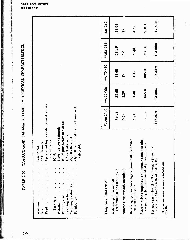
DATA ACQUISITION TELEMETRY
u E DC
2
<
OS H W 2 w U) H
< S <
< CO
Q Z <
O <
i
<
o t
w OS <
J2
'5.
y "c o o
o "C y a
i- (311 y C <U _
S E 9 ° -2 -a o -a '
X) «* x
-T5 "> 3" ft. fi <
00 y
JS -a 3 u
1 & N C9
0» W) 3 O t) c es
"5 E
o
i
fS
*n
m OQ 1/1 X) « 00 ro O TJ <N <N r» W> * *
3 r- * *
O
s * *
*
O 00
tMJ « •a o
«r> <N a —
E a 03 o •o o C-l <?\ ~
OQ TJ
o 03 TJ
E * CO m •o 00 <N 00 ^-
CO •a o CO
TJ 00
E fid TJ
03 TJ
CO
o 03 -a
00
E 03 TJ
O o o Ö
3 y
y ,0 C N ~ ox?
o ü — US
0
c/s y X - CS >t»
X5 « 3 O *3
o x>
0 T o~ O v~> +1 —
u jO
" -"a 8 o •- r- OS
c o
>* a —• <u
•- o w O O o c *» y v > «
cs c c
C N g < (A U.
C O
u _ BO 00 M '5
sa.s-s.ss C/3 -3 o 2 2 o
O. Du H H O.
IS!
X s TS C BJ
y c u 3 cr a u.
I 3 a •- .E E
— r, ° •3 & =
•— eo je E « *-
BJ c . ay c m y C ,y
5 y
E
JS « c c V
+-* c <
y y c y
y s-
ta c E o c
3 00 C
I© £l y e •*-* •— >. fc M g 0Q «S
.£ a > a "y *- 8-
0Ä
(A 3
nj 3 c a c c y —
c S- « £ ^»s y
g a •«M +rf
E n
O ■g e y
c y
25 a E y
c o
■a
CTJ X» ^
1^ d >n c t^^ w o Zx: ii 5
.ts Si >» - in .—i
° c C .3 > E 'S y y ^-» y t/l u >>
C
s u E y ♦-«
>. £2
244
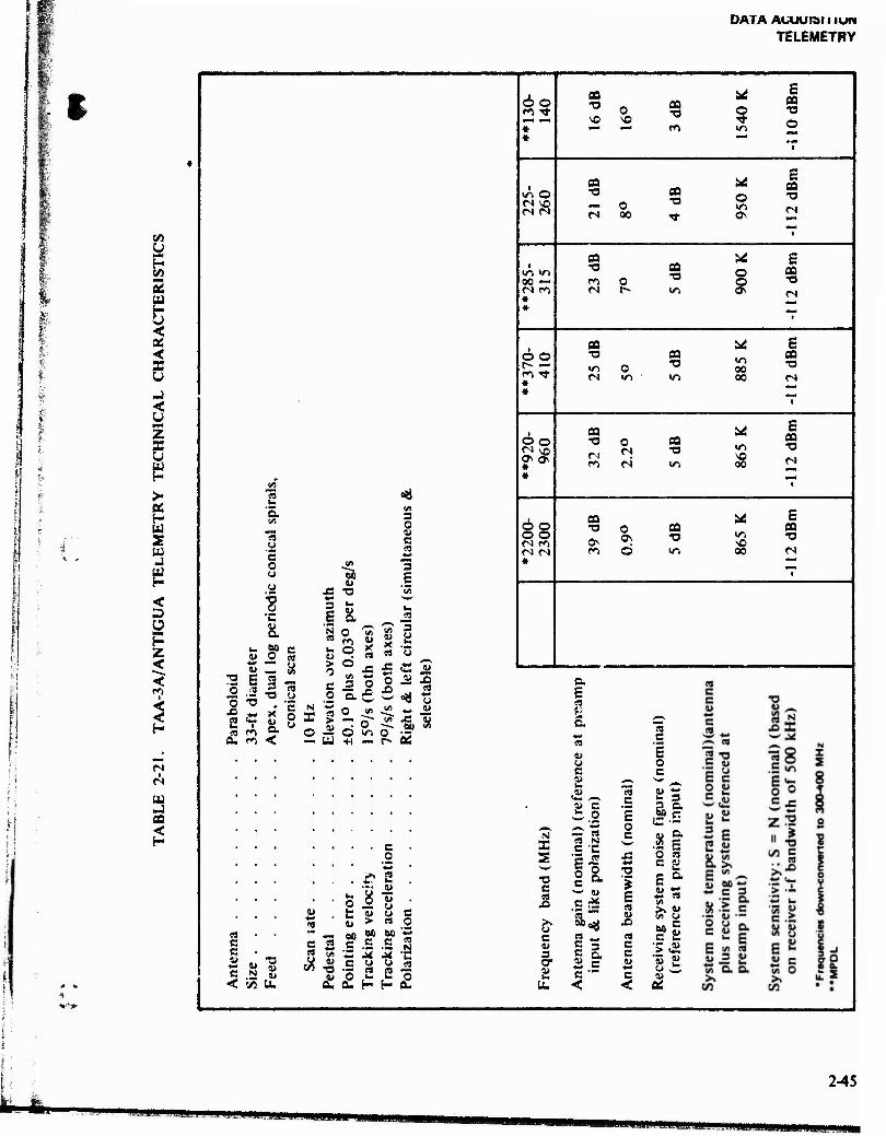
DATA AUUUIÖIIIUW
TELEMETRY
1 I
CO U
k 2 w
<
<
-J <: u Ml z s >- as H u 2 w -1
< D Ü H Z <
i
1
i
Hi J
<
'a 3 O u
CO c 'c ** o 5Ä 3 o
j=
~0Ö w E
*3> :3 0
"C
*■»
3 E ■2
a oo 0 c
'3 u. 1»
0 m q
'l/l u X 03
X 03
3
O "o 2
4M w E "5
"3 3
•a "3 o
> 0 c 0
ö 3
X! 0
X> o
& l
eft
ctab
le)
i
X* '5 o o N X 03 >
1>
o ob *
01 i*) o Ö in o" IM
a. <n < U ■H — r~ Di
62
io O <N SO
00 —
*
6o r- —
do «N so o\ os #
gs *
flO
SO o SO
oa o E
ca •o
so
— o C") 00
as T3 o
E
O o o
E PÖ
oa •o
o oa •o
E
oa -o o oa
T3
00 •o 00 CJ
»—< t
Mi £ IT) "O SO 00 rs
oa
Os O ON
CO
in sO oo
E oa "O C4
c .2
si fc w
a E 08
a
o c
s E o c
5 §> N X s
— OS 03 N C •
3 5 8 2 e JS 5
03 C C
c N «5 < irt U.
- _ oo »o eo « c 2 c .5 .S M ft 'v ■£ M M '£
i» o .»- .»« P a. o. H H a-
"O c 03
JO
>. o c V 3 O" 4» k.
C
■Sä
03 „
i = £ e c "" <
a 'S
X! 4M»
5 E 03 01
X) 03 C C w c <
i- 3 - a 00 r; C •-
a s E O cs C P
*j 03
00 g c c
V
■& MHM4MMBH«!!M!li!^^ HKMMM
2-45
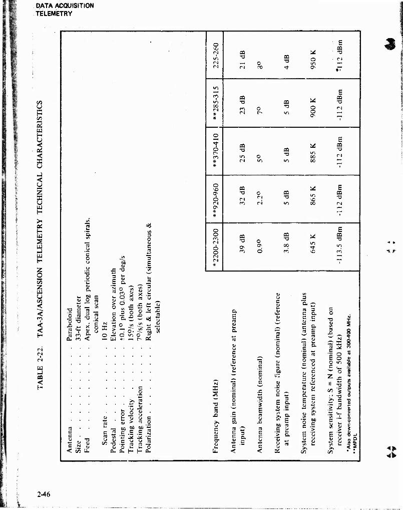
DATA ACQUISITION TELEMETRY
CO
U H co cd w H U < OS < as u _i < u MM)
z E U w H
>< OS H w S
w H
Z o z UJ y GO
<
co i
<
H
CM CM
w CO <
C5 U
'S o o
TJ o
1»
60 o
60
x: -o
£ a
3 E o « o ;3 « <» I- I S3 ro a. m
S3 3
TJ
x' 4> a <
co H o Ö
!/) 3 O 4> c si *-»
"5 E
re
03 (J
O VO c-i ■
CM
co i
in 00 CM * *
r- co * *
O NO ON
I o CM
* *
O O 00 CM
6 o CM CM *
o a *- N m O R = > -
-c fj <= Ü o
JO
o ü -o jD «3
O -^ O wi — UJ +1 —
ca TJ
o CO
CQ TJ
■ h ca
S4 TJ
o C4 in .— ON
CO TJ
CM O r-
ca TJ O
o CN
CQ TJ
in (N
O in
ca •a
00 00
ca TJ O c^ n oo CM
CQ -a m
vD oo
CQ -a 0 ON ON
m o
ca •a oo oo
m NC
c o
>. *
o o t « Z >
S3 C c a* «- a» «, c N 5 < co U.
c 2 c M M » «
™ c/s "3 J* M -C
CO -Q •- S3 si o .>- .*- o
S3
D
N X S
•a c S3
JO
C 4* 3 O" 4>
a E S3 W
a
4) u c K
<S u
S3 c
o c
S3 60 S3 "~-
5 3 s &
Qu Cu 1- (- Qu
S3 C
0 c
JS
•S '5 S3 1)
X) S3 C c <u c <
u c 1»
S3 c
E o c
3
o c
E o> c
ao S3
.£ K .> a 'S «
«5 3
S3 C
3 a .£ a E S3 1»
S3
O TD C "j
K C
C « 2 j*
3 a 4» o. <- = c
o c
OS CO
CQ TJ
E ca TJ
CQ TJ
CM
E CQ TJ
in
CO
TJ I S
S3 JO 8
M T «H X 8
S3 V, CO C ^-
'la o CO
b o V o m Si c '.»_
o I Z JS 4-* II TJ 3
CO TJ 3
>> 4-* i 4> *- 3
I/)
01) r" **~ c ^ a» > > u F a* CJ 4» o a* 4*
4> «
CO
2-46
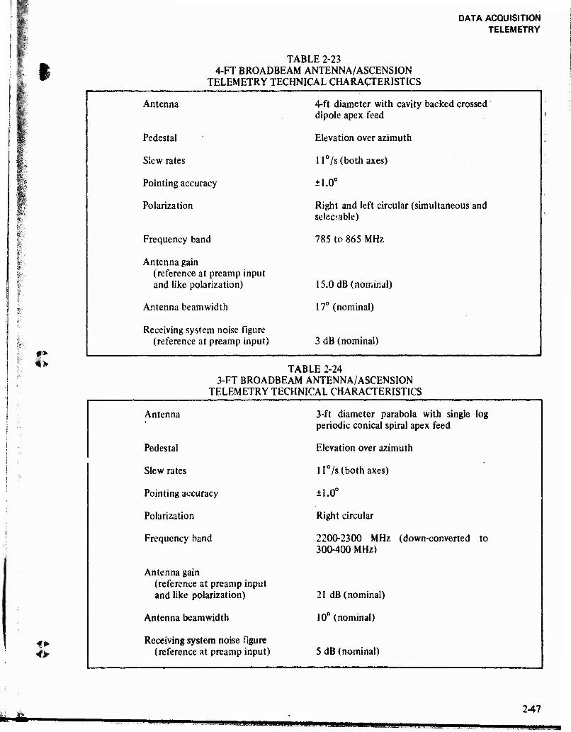
DATA ACQUISITION TELEMETRY
9
#*■
4s»
TABLE 2-23 4-FT BROADBEAM ANTENNA/ASCENSION
TELEMETRY TECHNICAL CHARACTERISTICS
Antenna 4-ft diameter with cavity backed crossed dipole apex feed
Pedestal Elevation over azimuth
Slew rates ll°/s (both axes)
Pointing accuracy ±1.0°
Polarization Right and left circular (simultaneous and selectable)
Frequency band 785 to 865 MHz
Antenna gain (reference at preamp input and like polarization) 15.0 dB (nominal)
Antenna beamwidth 17° (nominal)
Receiving system noise figure (reference at preamp input) 3 dB (nominal)
TABLE 2-24 3-FT BROADBEAM ANTENNA/ASCENSION
TELEMETRY TECHNICAL CHARACTERISTICS
Antenna 3-ft diameter parabola with single log periodic conical spiral apex feed
Pedestal Elevation over azimuth
Slew rates ll°/s (both axes)
Pointing accuracy ±1.0°
Polarization Right circular
Frequency band 2200-2300 MHz (down-converted to 300-400 MHz)
Antenna gain (reference at preamp input and like polarization) 21 dB (nominal)
Antenna beamwidth 10° (nominal)
Receiving system noise figure (reference at preamp input) 5 dB (nominal)
•KHk mMHMMHM MHBMP
2-47
MMHIWi
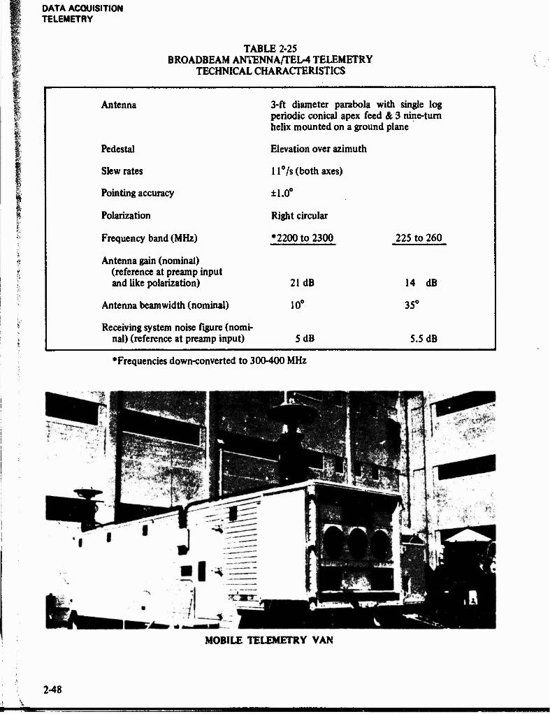
DATA ACQUISITION TELEMETRY
TABLE 2-25 BROADBEAM ANTENNA/TEL-4 TELEMETRY
TECHNICAL CHARACTERISTICS
Antenna 3-ft diameter parabola with single log periodic conical apex feed & 3 nine-turn helix mounted on a ground plane
Pedestal Elevation over azimuth
Slew rates ll°/s (both axes)
Pointing accuracy ±1.0°
Polarization Right circular
Frequency band (MHz) *2200 to 2300 225 to 260
Antenna gain (nominal) (reference at preamp input and like polarization) 21 dB 14 dB
Antenna beamwidth (nominal) 10° 35°
Receiving system noise figure (nomi- nal) (reference at preamp input) 5 dB 5.5 dB
"Frequencies down-converted to 300-400 MHz
MOBILE TELEMETRY VAN
2-48
•——■

DATA ACQUISITION TELEMETRY
jy^
TABLE 2-26 MOBILE TELEMETRY VAN, PARABOLIC ANTENNA,
TECHNICAL CHARACTERISTICS
I
Antenna 3-ft diameter parabola backed crossed-dipole apex
with cavity- feed
Pedestal Elevation over, izimuth
Slew rates
Pointing accuracy
Elevation - Azimuth -
3°/s 7°/s
±1°
Polarization Right and left circular (simultaneous and selectable)
Frequency band (MHz) ♦2200-2300 •1435-1535
Antenna gain (nominal) (reference at preamp input and like polarization) 20.5 dB 17 dB
Antenna beamwidth (nominal) 11° 16°
Receiving system noise figure (nomi- nal) (reference at preamp input) 4 dB 4 dB
■Frequencies down-converted to 300-400 MHz.
TABLE 2-27 MOBILE TELEMETRY VAN, CROSSED-DIPOLE ANTENNA,
TECHNICAL CHARACTERISTICS
O-
Antenna Omni, crossed-dipole overground plane
Pedestal Fixed
Polarization Right and left circular (selectable)
Frequency band •2200-2300 •1435-1535
Antenna gain (nominal) (reference at preamp input and like polarization)
3 dB at zenith
-5 dB at +10° el
3 dB at zenith
•5 dB at 10° el
Antenna beamwidth (azimuth) Omnidirections Omnidirectional
Receiving system noise figure (nomi- nal) (reference at preamp input) 4 dB 4 dB
'Frequencies down-converted to 300-400 MHz.
2-49

!«%.;
DATA ACQUISITION TELEMETRY
u p c/3
5 w H u < OS < X u mi < y z X u w H >- OÄ H tu S u mi Hi H
-j Ui
Z
ao
W
SO <
<i2 « 03
:-.:-:a.:r^Sfc^PI#! ' ■■:■;: .._ ___ W: ''' 1 ^■'^H r^ ,T o »ri (N rM
V—•t ro rö "« aBfe' 'IBS
■ •#';:'^i(i|aii^™K*.s«i«| !■ *' a HH IT) O CQ
" ^IJ "'■ *iH M- 3 Hal ri so T3 O
S3
. - A McM Mm
HMK Sft£? ' BB * *
r^ T3
CO 03 H ' >sf & ̂ -- Vv.-'^^K vy-:*d^^^tfäPKvj^..*iÄ .H.H Vl »o u-i •a o ■w ;~.
"", " " :'"*;$4 / oo — r 4 m M
iri
\%s *
.' ". ^ i
6 o 03 T3
33 "O
'*?"-■'■' i?t ' '". ^ _ *|Pj ir i ri o u-i
- ;. pi» ÄiU* .^N p -^ 1 * #
fO vö
ää ; • i-' y © O
CQ T3
03 T3
T s'il fHP^IBlfl
•; J" fl BC O o- rs 0 »n
'-»' H S •. . * * ■"■ CO oo
ts!
X t/1
73 2 o 0 O c 1 CQ u X w T: in m ts 03
Is 3 Ü Tj- IT) rj
O
rn T3
in * #
3 w Tf 'Ü ■^ >w
c C <- 2 © O O
n ri
03
g of
eque
ON 3 ■= X §
"3 0 ri ro
03
in c ,*- r; «^ ';»
# 'j
«5 t. '3> .O
'3 ^£ »*—
«-• °*—> o f?s » 0 w> ° r' 4= •j a ~ ■= eg
r* ro O 3 ~" >> s
_ 3 x o — "5 c no- < X II s SJ —
c 3.2
3 5
I s
C N a
c 8 '■J 'C «J *-• t: "5 J2
k- 3 8 ■ 3 3 C w o 3 6b c M * j* 0 5 ■*™
N !l C
.3 0 5 i
3S |«a 4M* C V >. w "3 t_ c
0
'i "3 £J «a* 'I c V 2 = 3 3 Z c. i 5 - « ■^ r" 73 >i 5J 1
§ ü a ' * » 5 >,
2 2 = 3 3 ^ * c S -
n 3 is
3 i" £
c
C 3 *J lo
» a. it2
< 3- (/i a. — u. < < OS • » *
^»V
2-50
^W-"
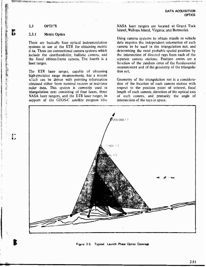
%ä$g^$$v*j^#^j>m?. ^■^iMS»fc*»«»i. .^.,;,.^^,.-;..-'-?&*??*m
I ■■
f
2.3 orars
2.3.1 Metric Optics
There are basically four optical instrumentation systems in use at the ETR for obtaining metric d ita. Three are conventional camera systems which include the cine theodolite, ballistic camera, and the fixed ribbon-frame camera. The fourth is a laser ranger.
The ETR laser ranger, capable of obtaining high-precision range measurements, has a mount which can be driven with pointing information obtained either from nominal vectors or real-time radar data. This system is currently used in triangulation nets consisting of four lasers, three NASA laser rangers, and the ETR laser ranger, in support of the GEOS-C satellite program (the
DATA ACQUISITION OPTICS
NASA laser rangers are located at Grand Turk Island; Wallops Island, Virginia; and Bermuda).
Using camera systems to obtain missile or vehicle data requires the independent orientation of each camera to be used in the triangulation net, and determining the most probable spatial position by the intersection of directed rays from each of the separate camera stations. Position errors are a function of the random error of the fundamental measurement and of the geometry of the triangula- tion net.
Geometry of the triangulation net is a considera- tion of the location of each camera station with respect to the position point of interest, focal length of each camera, direction of the optical axis of each camera, and primarily the angle of intersection of the rays in space.
Figure 2-3. Typical Launch Phase Optics Coverage
*■* 2-51
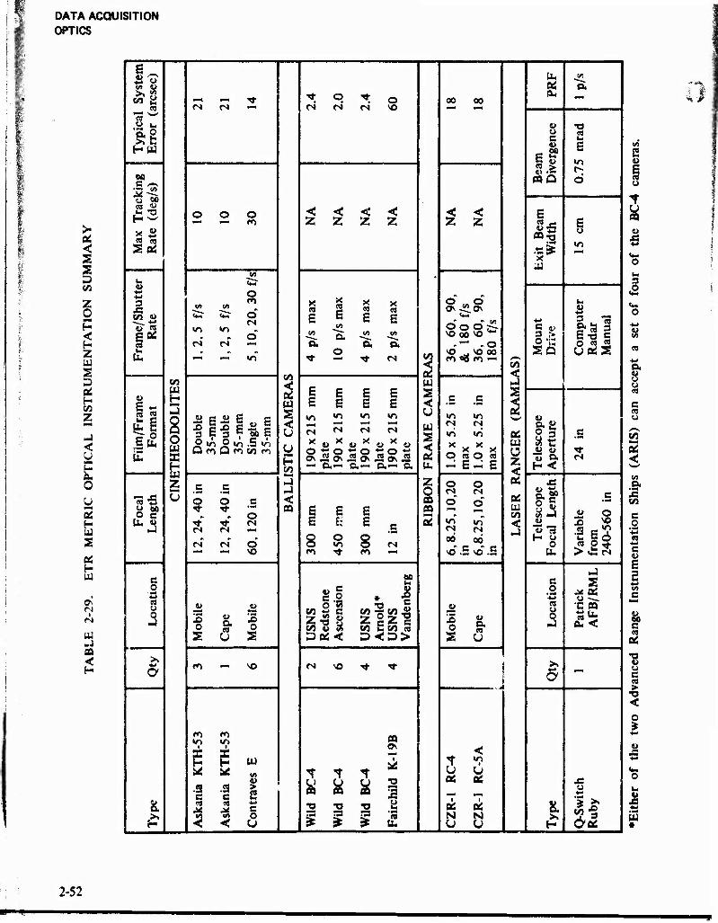
DATA ACQUISITION OPTICS
Pi <
3 P c«
Z o < H 2 W S D OS* H CO
5 <
y 5
s oü H ui
0>
ill
s tu on
05
"a CO £ r4 _ "T ■<t o t o 03 00
a*
ical
r
(a
<N n <N <s <N VO •—4 fm4
fi •a T
yp
Err
o o at i c E
£ Ö Sä «Q 6 i
Max
Tra
cki
Rat
e (d
eg/s
O o o < < < < < < s *—< «—» O Z Z 2 Z z z 1« BD-r)
.«at W
E o
1—H
BJ
«fc?
Shu
tt
te en
55" CM
O
1 E 2 « E E
o\ -ZLo\ w 4-*
W
E * «n «o
o in
—. O, »9 in sgs^
Mou
n D
rive
E •o S u
n n _ o
O. 0. co
Ü w
VO ^ VO 00 O « « uoüS tu •■" *-■ «n ■«■ — ■* <N
CO <
co w
8 O « X
CO
5
E E E E s
/Fra
m«
orm
at
u 3 3 9 3
| « E
215
m
215
m
215
m
21
5m
< u w s <
5.25
ir
5.25
ir
2 02
a g 8 3 c
Eu, tu
o Q ^5 rn Q
io .5 K-»
p CO
90 x
la
te
90 x
fl> <D tt> 1.
0 x
max
1.
0 x
max
U] O z < of
*3 Q, *"*** Qu •"* O.—■> O.— Oi u- H <
c c ►4 z o o o C
• OT4 *a -c u o o c < CO o o OS o S? 8* •«■ TT
o ca S E E CO u
CO äi l> o U.JJ
o
E h
2 ° E .5 5 CM
05
6,8
.25
in
6,
8.25
in
< !S 13 0
3 S ■a |S
""" — VO co -* r*» — u- > C *s
NJ c 61)
u e s 0
c .2 * 1 .2 is si u
5 1) 4» o R
z gz^ co q co «3
4> cs •C 03 15 0
u a es
!3
o SNS
edst
se
en
13 m ,3 0. < 3 U 5 5ttl< S u
: fO - VO <N NO "<r ■* >>
5 -
<■*> fn PQ
1
i z ■ 2
«n Wl
is S w <
t "?
.3 c
-S3 c 1
OS US o
91 es c tj *o «o a Qä oi a
Q-S
w
Rub
y
3 < o u
rs ."3 ät u.
N N
* i
tn «1
u
5
8 es
O. 8 o W
c ea u
CO *—* 02 <
m .& CO
c o
c
4» 60 c ca
Oi
"8 o c es >
< o
V
«
2-52
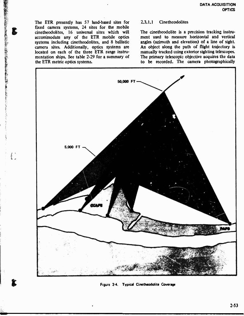
DATA ACQUISITION OPTICS
%
The ETR presently has 57 land-based sites for fixed camera systems, 24 sites for the mobile cinetheodolites, 16 universal sites which will accommodate any of the ETR mobile optics systems including cinetheodolites, and 8 ballistic camera sites. Additionally, optics systems are located on each of the three ETR range instru- mentation ships. See table 2-29 for a summary of the ETR metric optics systems.
2.3.1.1 Cinetheodolites
The cinetheodolite is a precision tracking instru- ment used to measure horizontal and vertical angles (azimuth and elevation) of a line of sight. An object along the path of flight trajectory is manually tracked using exterior sighting telescopes. The primary telescopic objective acquires the data to be recorded. The camera photographically
Figure 2-4. Typical Cinethtodolitt Coverage
2-53
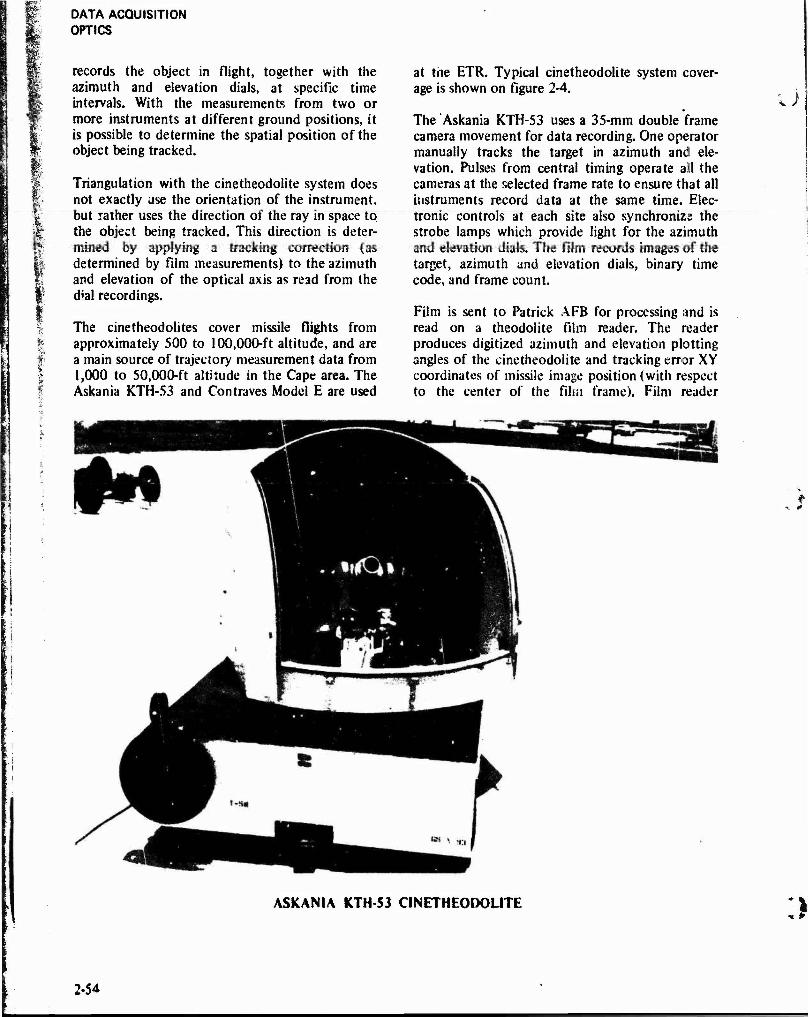
DATA ACQUISITION OPTICS
if
records the object in flight, together with the azimuth and elevation dials, at specific time intervals. With the measurements from two or more instruments at different ground positions, it is possible to determine the spatial position of the object being tracked.
Triangulation with the cinetheodolite system does not exactly use the orientation of the instrument, but rather uses the direction of the ray in space to the object being tracked. This direction is deter- mined by applying a tracking correction (as determined by film measurements) to the azimuth and elevation of the optical axis as read from the dial recordings.
The cinetheodolites cover missile flights from approximately 500 to 100,000-ft altitude, and are a main source of trajectory measurement data from 1,000 to 50,000-ft altitude in the Cape area. The Askania KTH-53 and Contraves Model E are used
at the ETR. Typical cinetheodolite system cover- age is shown on figure 2-4.
The Askania KTH-53 uses a 35-mm double frame camera movement for data recording. One operator manually tracks the target in azimuth and ele- vation. Pulses from central timing operate all the cameras at the selected frame rate to ensure that all instruments record data at the same time. Elec- tronic controls at each site also synchronize the strobe lamps which provide light for the azimuth and elevation dials. The film records images of the target, azimuth and elevation dials, binary time code, and frame count.
Film is sent to Patrick AFB for processing and is read on a theodolite film reader. The reader produces digitized azimuth and elevation plotting angles of the cinetheodolite and tracking error XY coordinates of missile image position (with respect to the center of the filin frame). Film reader
ASKANIA KTH-53 CINETHEODOLITE
2-54
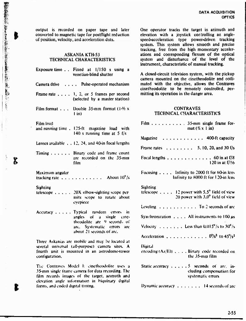
DATA ACQUISITION OPTICS
4**
output is recorded on paper tape and later converted to magnetic tape for postflight reduction of position, velocity, and acceleration data.
ASKAN1A KTH-53 TECHNICAL CHARACTERISTICS
Exposure time
Camera drive
Frame rate . .
Film format . .
Fixed at 1/150 s using a venetian-blind shutter
. . Pulse-operated mechanism
1, 2, or 5 frames per second (selected by a master station)
Double 35-mm format (l-'/i x I in)
Film load and running time . 125-ft magazine load with
140 s running time at 5 f/s
Lenses available ..12, 24, and 40-in focal lengths
Timing Binary code and frame count are recorded on the 35-mm film
Maximum angular tracking rate About 10°/s
Sighting telescope ..... 20X elbow-sighting scope per
mils scope to rotate about eyepiece
Accuracy Typical random errors in angles of a single cine- theodolite are l> second > of arc. Systematic errors are about 21 seconds of arc.
Three Askanias are mobile and may be located at several universal (alä-purposel camera sites. A fourth unit is mounted in an astrodome-tower configuration.
The Contraves Model K cinetheodolite uses a 35-mm single frame camera for data recording. The film records images of the target, azimuth and elevation angle information in biquinary digital forms, and coded digital timing.
One operator tracks the target in azimuth and elevation with a joystick controlling an angle- speed-acceleration type power-driven tracking system. This system allows smooth and precise tracking, free from the high momentary acceler- ations and corresponding flexure of the optical system and disturbance of the level of the instrument, characteristic of manual tracking.
A closed-circuit television system, with the pickup camera mounted on the cinetheodolite and c-olli- mated with the objective, allows the Contraves cinetheodolite to be remotely controlled, per- mitting its operation in the danger area.
CONTRAVES TECHNICAL CHARACTERISTICS
Film 35-mm single frame for- mat (% x 1 in)
Magazine 400-ft capacity
Frame rates 5, 10, 20, and 30 f/s
Focal lengths 60 in at f/8 l20inatf/!6
Focusing .... Infinity to 2000 ft for 60-in lens Infinity to 8000 ft for 1 20-in lens
Sighting telescope .... 12 power with 5.5° field of view
20 power with 3.0° field of view
Leveling To 2 seconds of arc
Synchronization .... All instruments to 100 //s
Velocity Less than 0.01 S°/s to 30°h
Acceleration 0°/s2 to 45°/s2
Digital encoding <A//FD
Static accuracy
Binary code recorded on the 35-mm film
5 seconds of arc, in- cluding compensation for systematic errors
Dynamic accuracy 14 seconds of arc
■W" 2-55
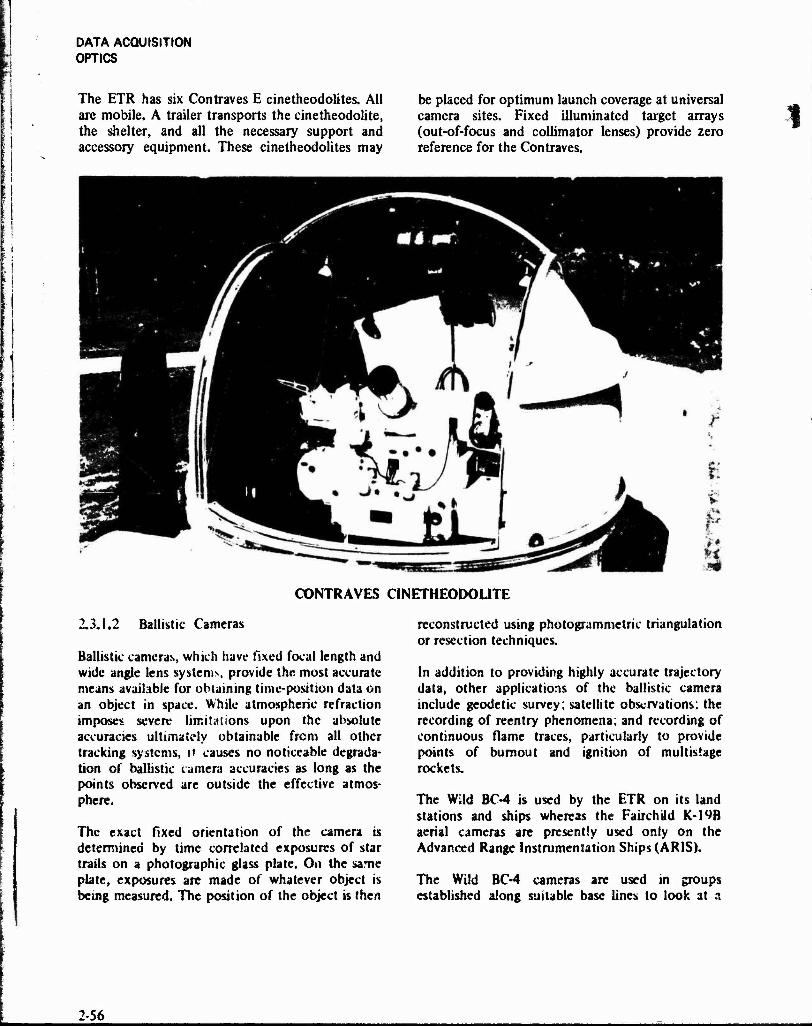
DATA ACQUISITION OPTICS
The ETR has six Contraves E cinetheodolites. All are mobile. A trailer transports the cine theodolite, the shelter, and all the necessary support and accessory equipment. These cinetheodolites may
be placed for optimum launch coverage at universal camera sites. Fixed illuminated target arrays (out-of-focus and collimator lenses) provide zero reference for the Contraves.
CONTRAVES CINETHEODOLITE
2.3.1.2 Ballistic Cameras
Ballistic cameras, which have fixed focal length and wide angle lens systems, provide the most accurate means available for obtaining time-position data on an object in space. While atmospheric refraction imposes severe limitations upon the absolute accuracies ultimately obtainable from all other tracking systems, it causes no noticeable degrada- tion of ballistic camera accuracies as long as the points observed are outside the effective atmos- phere.
The exact fixed orientation of the camera is determined by time correlated exposures of star trails on a photographic glass plate. On the same plate, exposures are made of whatever object is being measured. The position of the object is then
reconstructed using photogrammetric triangulation or resection techniques.
In addition to providing highly accurate trajectory data, other applications of the ballistic camera include geodetic survey; satellite observations; the recording of reentry phenomena; and recording of continuous flame traces, particularly to provide points of bumout and ignition of multistage rockets.
The Wild BC-4 is used by the ETR on its land stations and ships whereas the Fairchild K-19B aerial cameras are presently used only on the Advanced Range Instrumentation Ships (ARIS).
The Wild BC-4 cameras are used in groups established along suitable base lines to look at a
2-56

§
DATA ACQUISITION OPTICS
W
«■
I
common point of interest. The BC-4 has a 2-axis mount for support and presetting to the desired orientation (the exact orientation is determined from star images). A camera shutter programmer drives the capping shutter through the desired sequences of exposures for the star trail and data point recording. Each shutter operation time is recorded so the star position can be referenced by sidereal time to its right ascension and declination position and so image points may be correlated from camera to camera.
BC-4 TECHNICAL CHARACTERISTICS
Film Plate
Eastman 103-F glass plate
Thickness . . 6-mm, flat to 6 wavelengths of sodium light
Size 190x210 mm with 180x80 mm usable image area
Speed 100 ASA
Resolution 60-70 lines/mm
Lens
Focal length (mm) 300 450
Angular field (deg) 33 22
Aperture (mm) 117 117
F-stop 2.6 2.6
Accuracy
Angular errors of triangulation average 2.4 arsec for the 300-mm camera and 2.0 for the 450-mm camera.
The current distribution of BC-4 cameras is tabulated on table 2-29; however, a number of surveyed sites are available throughout she eastern U.S. and the ETR. New sites can be eM Jbushed with tittle facilities work.
The Advanced Range Instrumentation Ship (ARIS) USNS Vandenberg has an array of four fixed Fairchild K-19B cameras. The array consists of two ballistic cameras and two ballistic spectrographs. These instruments are modified K-19B aerial cameras. The lens iris of each instrument is automatically controlled during a mission to provide alternating exposures of 1/2 second at f/4 and 1/2 second at f/16. This sequential event is recorded on time-referenced paper charts. The normal iris control sequence can be manually interrupted during a mission to allow time correla- tion with photographic images. One camera and one spectrograph are focused for and operated with Kodak 1-N infrared emulsion, while the other camera and spectrograph utilize Kodak 103-F visible emulsion. The ballistic spectrographs use a 300 lines/mm transmission grating.
Normally, ballistic camera plates are used for overall event documentation, object identification, target malfunction identification, etc., and as an aid to interpreting the spectrograph plates. Ballistic cameras are also used to record metric data on objects outside the radar beams. The ballistic spectrographs are the sole source of spectral data on nontracked objects.
BC-4 BALLISTIC CAMERA
2-57
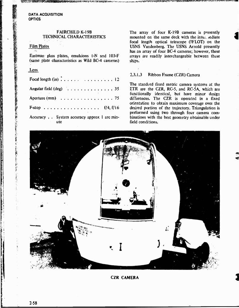
igMP&*8!*fä!fKmRRltimi*vn*>»i' , .^mmmmam0^mmmm»0»^mmmmmmmifmmmm^mmmmyi.
DATA ACOUISITION OPTICS
FAJRCHILDK-19B TECHNICAL CHARACTERISTICS
Film Plates
Eastman glass plates, emulsions 1-N and 103-F (same plate characteristics as Wild BC-4 cameras)
Lens
Focal length (in) * 12
Angular field (deg) 35
Aperture (mm) 75
F-stop f/4, f/16
Accuracy . . System accuracy approx 1 arc min- ute
The array of four K-19B cameras is presently mounted on the same deck with the intt*. iediate focal length optical telescope (JFLOT) on the USNS Vandenberg. The USNS Arnold presently has an array of four BC-4 cameras; however, these arrays are readily interchangeable between these ships.
2.3.1.3 Ribbon Frame (CZR) Camera
The standard fixed metric camera systems at the ETR are the CZR, RC-5, and RC-5A, which are functionally identical, but have minor design differences. The CZR is operated in a fixed orientation to obtain maximum coverage over the desired portion of the trajectory. Triangulation is performed using two through four camera com- binations with the best geometry obtainable under field conditions.
CZR CAMERA
2-58
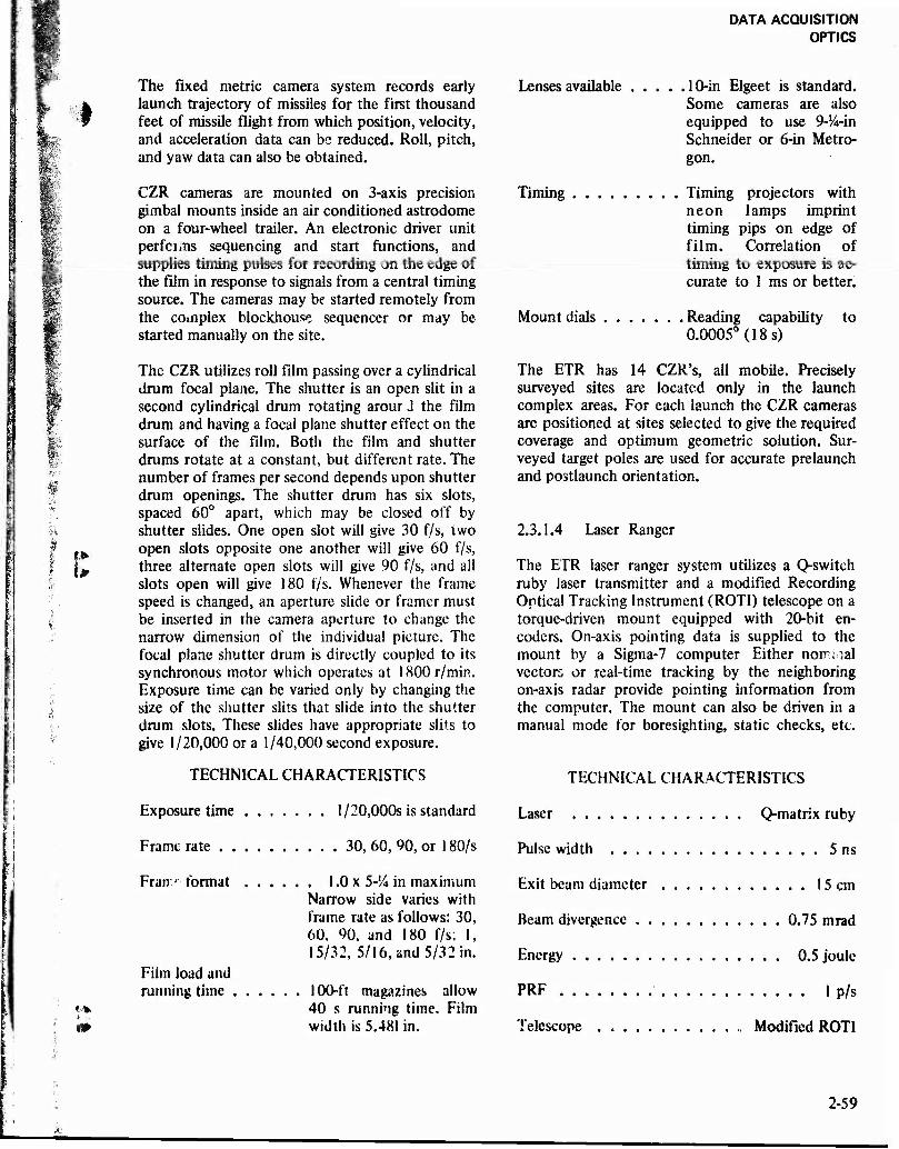
DATA ACQUISITION OPTICS
I
! I>
?i
The fixed metric camera system records early launch trajectory of missiles for the first thousand feet of missile flight from which position, velocity, and acceleration data can be reduced. Roll, pitch, and yaw data can also be obtained.
CZR cameras are mounted on 3-axis precision gimbal mounts inside an air conditioned astrodome on a four-wheel trailer. An electronic driver unit pcrfcims sequencing and start functions, and supplies timing pulses for recording on the edge of the film in response to signals from a central timing source. The cameras may be started remotely from the complex blockhouse sequencer or may be started manually on the site.
The CZR utilizes roll film passing over a cylindrical drum focal plane. The shutter is an open slit in a second cylindrical drum rotating arour J the film drum and having a focal plane shutter effect on the surface of the film. Both the film and shutter drums rotate at a constant, but different rate. The number of frames per second depends upon shutter drum openings. The shutter drum has six slots, spaced 60° apart, which may be closed off by shutter slides. One open slot will give 30 f/s, two open slots opposite one another will give 60 f/s, three alternate open slots will give 90 f/s, and all slots open will give 180 f/s. Whenever the frame speed is changed, an aperture slide or framer must be inserted in the camera aperture to change the narrow dimension of the individual picture. The focal plane shutter drum is directly coupled to its synchronous motor which operates at 1800 r/min. Exposure time can be varied only by changing the size of the shutter slits that slide into the shutter drum slots. These slides have appropriate slits to give 1/20,000 or a 1/40,000 second exposure.
TECHNICAL CHARACTERISTICS
Exposure time 1/20,000s is standard
Frame rate 30, 60, 90, or 180/s
Fran' format 1.0 x 5-14 in maximum Narrow side varies with frame rate as follows: 30, 60, 90, and 180 f/s; 1, 15/32, 5/16, and 5/32 in.
Film load and running time 100-ft magazines allow
40 s running time. Film width is 5.481 in.
Lenses available
Timing
.10-in Elgeet is standard. Some cameras are also equipped to use 9-^-in Schneider or 6-in Metro- gon.
Timing projectors with neon lamps imprint timing pips on edge of film. Correlation of timing to exposure is ac- curate to 1 ms or better.
Mount dials , Reading capability 0.0005° (18 s)
to
The ETR has 14 CZR's, all mobile. Precisely surveyed sites are located only in the launch complex areas. For each launch the CZR cameras are positioned at sites selected to give the required coverage and optimum geometric solution. Sur- veyed target poles are used for accurate prelaunch and postlaunch orientation.
2.3.1.4 Laser Ranger
The ETR laser ranger system utilizes a Q-switch ruby laser transmitter and a modified Recording Optical Tracking Instrument (ROTI) telescope on a torque-driven mount equipped with 20-bit en- coders. On-axis pointing data is supplied to the mount by a Sigma-7 computer Either nomnal vectors or real-time tracking by the neighboring on-axis radar provide pointing information from the computer. The mount can also be driven in a manual mode for boresighting, static checks, etc.
TECHNICAL CHARACTERISTICS
Laser Q-matrix ruby
Pulse width 5 ns
Exit beam diameter 15 cm
Beam divergence 0.75 mrad
Energy 0.5 joule
PRF 1 p/s
Telescope . Modified ROTI
2-59
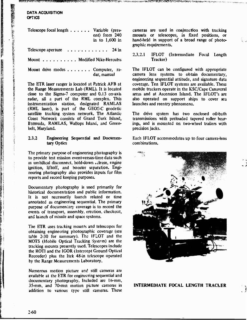
1 -K T •" *?- *"B » we , * ■*■ ■" »-S - ' <*- * v - * 'T A KI < -\ ,-«,;,
DATA ACQUISITION OPTICS
Telescope focal length Variable (pres- ent) from 240 in to 1,600 in
Telescope aperture 24 in
Mount Modified Nike-Hercules
Mount drive modes Computer, ra- dar, manual
The ETR laser ranger is located at Patrick AFB at the Range Measurements Lab (RML). It is located close to the Sigma-7 computer and 0.13 on-axis radar, all a part of the RML complex. This instrumentation station, designated RAMLAS (RML laser), is part of the GEOS-C geodetic satellite tracking system network. The Atlantic Coast Network consists of Grand Turk Island, Bermuda, RAMLAS, Wallops Island, and Green- belt, Maryland.
2.3.2 Engineering Sequential and Documen- tary Optics
The primary purpose of engineering photography is to provide test mission event-versus-time data such as umbilical disconnect, hold-down »olease, engine ignition, liftoff, and booster separation. Engi- neering photography also provides inputs for film reports and record keeping purposes.
Documentary photography is used primarily for historical documentation and public information. It is not necessarily launch related or time annotated as engineering sequential. The primary purpose of documeniary coverage is to record the events of transport, assembly, erection, checkout, and launch of missile and space systems.
The ETR uses tracking mounts and telescopes for obtaining engineering photographic coverage (see table 2-30 for summary). The IFLOT and the MOTS (Mobile Optical Tracking System) are the tracking mounts presently used. Telescopes include the ROTI and the IGOR (Intercept Ground Optical Recorder) plus the Itck 48-in telescope operated by the Range Measurements Laboratory.
Numerous motion picture and still cameras are available at the ETR for engineering sequential and documentary photography. Included are 16-mm, 35-mm, and 70-mm motion picture cameras in addition to various type still cameras. These
are used in conjunction with tracking telescopes, in fixed positions, or
cameras mounts or telescopes, in fixed positions, or hand-held in support of a broad range of photo- graphic requirements,
2.3.2.1 IFLOT (Intermediate Focal Length Tracker)
The IFLOT can be configured with appropriate camera lens systems to obtain documentary, engineering sequential attitude, and signature data coverage. Ten IFLOT systems are available. These mobile trackers operate in the KSC/Cape Canaveral areas and at Ascension Island. The IFLOT's are also operated on support ships to cover sea launches and reentry phenomena.
The drive system has two enclosed oil-bath transmissions with preloaded tapered roller bear- ings, and is mounted on two-wheel trailers with precision jacks.
Each IFLOT accommodates up to four camera-lens combinations.
r *^lJ&s\
INTERMEDIATE FOCAL LENGTH TRACKER
1-60
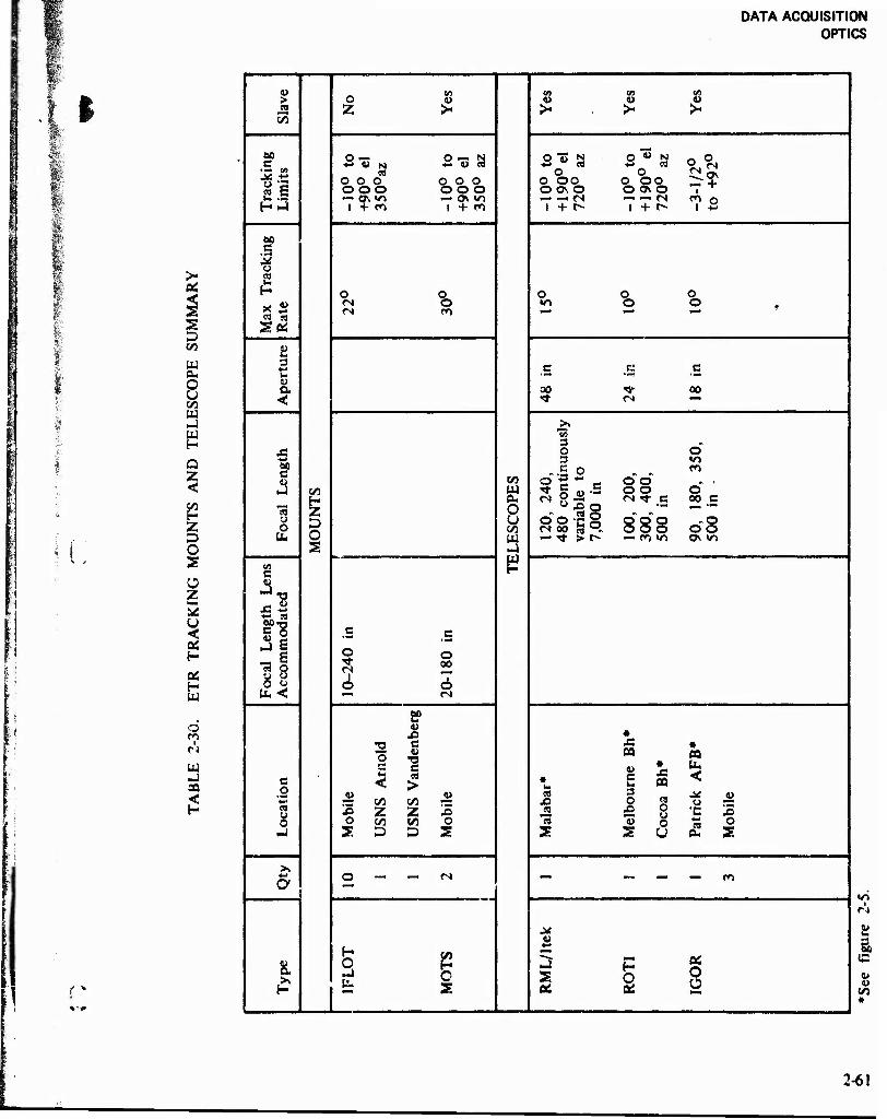
DATA ACQUISITION OPTICS
•■ l
05 < a
CO
W
& U CO w -I
G-
Q Z <
z D O s o z
OS H W
o
OQ
o en «0 CO 1» > o 4» « J» 4) .2 Z >• >« > >- 55
_ 60 o — O —< N o "«3 5J O *> N
^^ C +■* 4> N Ü 4> ea +-> " ea +■» ea •1 OJ
° 3 ea c
CD O O O o o o o
O OO O
O OO o o o ooo O ON o O 0\ o
r1"1 "t — cr. «o «-* 0\ «n •-' —*«N <-H <—1 CN| <*> o H .4 i + o 1 + f*l i + r» 1 + t» 1 "
bo .5 .* u SO
£ o o o o o
ea ea
n o in o o <N ro *■* *" r~i r
Stf w hi 3
4-» C M c c •*■* • f*
u a SO ■"*■ 00 < <* <S "■"
>. Hi 3 ^
J3 O o ■*-» 3 «n 60 c -.S o „ ro a> CO 3 c~ c
^ 8 -3 cf o ^ ,
J CO w o o O
g Ok M "* s 00 c "« O u Si o
oo-Sg «oo 3°.
»■N *^H
0 D O CO 888 08
lb 2 — T* > r- — CO w> c> «o
69 c B U -"■o fi2 ■f. w
,3 E c c
tmmt
^ 6 73 0 o o
00
^^ 6 s bu< fN
£? 4>
X5 • T3 C Jti «
c
O C I- <
■a c « >
u • u es
CQ
« * £ « 3
CQ
< *«* rs to CO •O 2 9 <■> ra « 8 •e z Z s 2. JO 0 •C JS
O tfl co o 13 -j 2 D D S S 2 O
>» ■4-» o —
~ <N
" "" — m
8. S o
^? 1 06
8
3 M
« 10
2-61
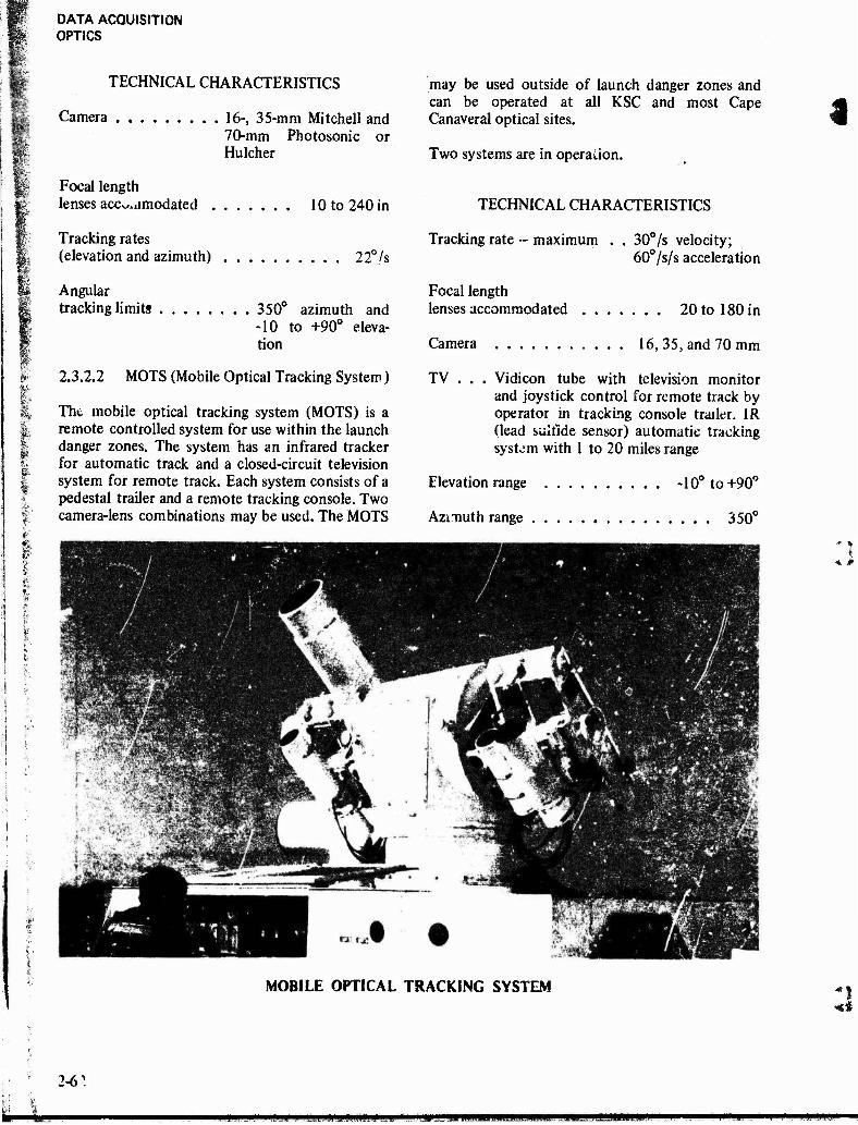
DATA ACQUISITION OPTICS
TECHNICAL CHARACTERISTICS
Camera 16-, 35-mm Mitchell and 70-mm Photosonic or Hulcher
Focal length lenses accommodated 10 to 240 in
Tracking rates (elevation and azimuth) 22°/s
Angular tracking limits 350° azimuth and
-10 to +90° eleva- tion
2.3.2.2 MOTS (Mobile Optical Tracking System)
The mobile optical tracking system (MOTS) is a remote controlled system for use within the launch danger zones. The system has an infrared tracker for automatic track and a closed-circuit television system for remote track. Each system consists of a pedestal trailer and a remote tracking console. Two camera-lens combinations may be used. The MOTS
may be used outside of launch danger zones and can be operated at all KSC and most Cape Canaveral optical sites.
Two systems are in operation.
TECHNICAL CHARACTERISTICS
Tracking rate - maximum . . 30°/s velocity; 60°/s/s acceleration
Focal length lenses accommodated 20 to 180 in
Camera 16, 35, and 70 mm
TV . . . Vidicon tube with television monitor and joystick control for remote track by operator in tracking console trailer. 1R (lead sulfide sensor) automatic tracking system with 1 to 20 miles range
Elevation range -10° to+90°
Azmuth range 350°
MOBILE OPTICAL TRACKING SYSTEM
2-6^
■SHHP «KnMHmHHMMKMMni MPJLL mmm
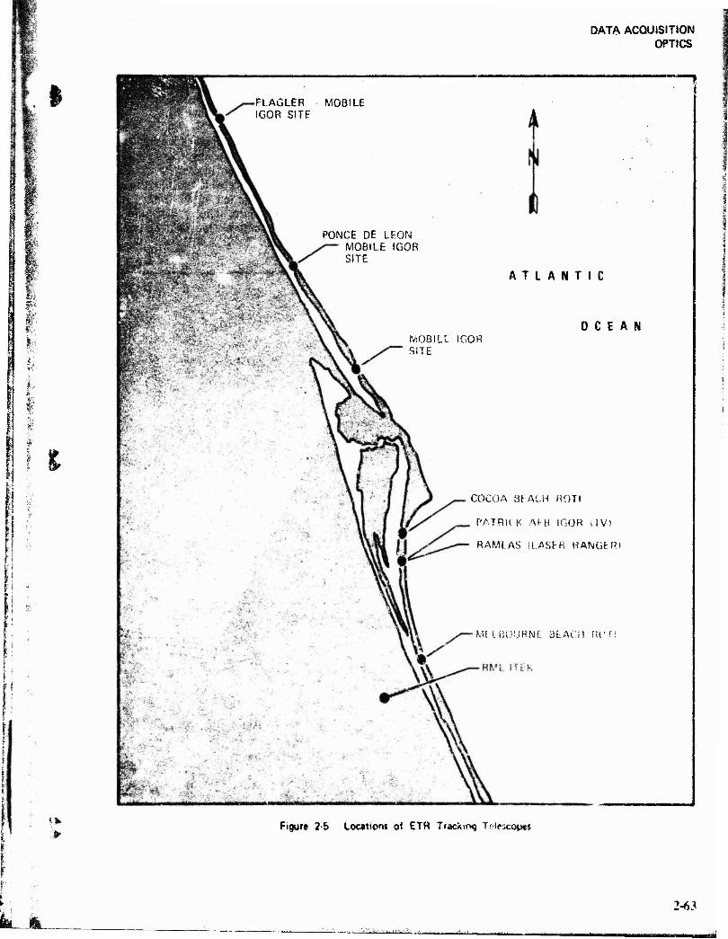
DATA ACQUISITION OPTICS
I
9
>
-FLAÜLER IGOR SITE
MOBILE
PONCE DE LEON MOBILE IGOR SITE
ATLANTIC
iVsOBILC IGOR SITE
OCEAN
COCOA SFACH ROTI
PATRICK M-Ü IGOR (TV)
RAMLAS (LASER RANGER)
Mt IBOURNt 3EACH Rr
Figure 2-5 Locations of ETR Tracking Telescopes
JL 2-63
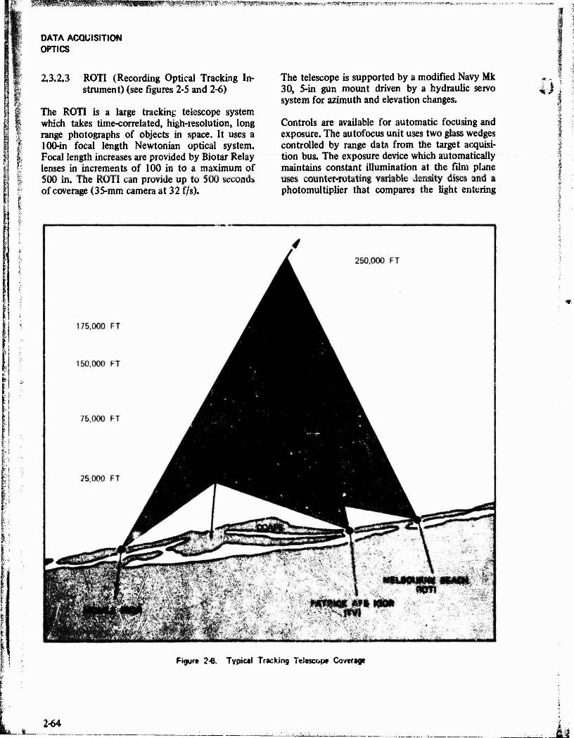
i "-„ »If-lV *M v-f , ,,.*». V »v« "•
DATA ACQUISITION OPTICS
1
2.3.2.3 ROTI (Recording Optical Tracking In- strument) (see figures 2-5 and 2-6)
The ROTI is a large tracking telescope system which takes time-correlated, high-resolution, long range photographs of objects in space. It uses a 100-in focal length Newtonian optical system. Focal length increases are provided by Biotar Relay lenses in increments of 100 in to a maximum of 500 in. The ROTI can provide up to 500 seconds of coverage (35-mm camera at 32 f/s).
The telescope is supported by a modified Navy Mk 30, 5-in gun mount driven by a hydraulic servo system for azimuth and elevation changes.
Controls are available for automatic focusing and exposure. The autofocus unit uses two glass wedges controlled by range data from the target acquisi- tion bus. The exposure device which automatically maintains constant illumination at the film plane uses counter-rotating variable density discs and a photomultiplier that compares the light entering
J
Figure 2-6. Typical Tracking Totacope Cawsrap
2-64
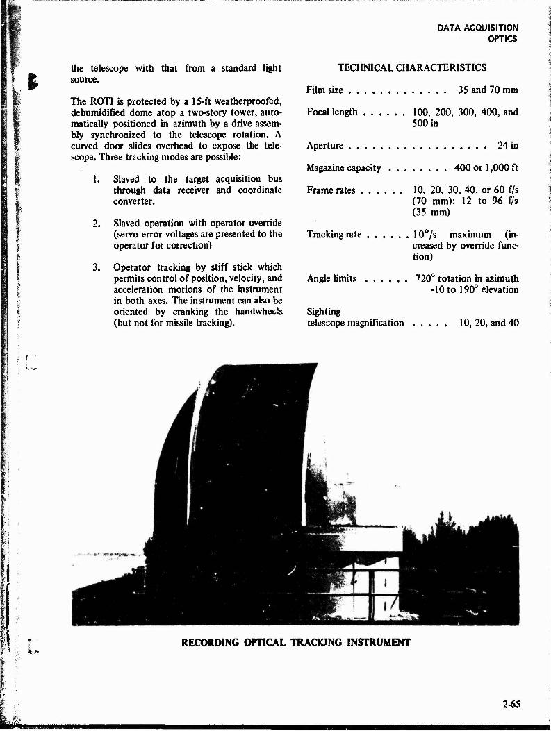
I the telescope with that from a standard light source.
The ROTI is protected by a 15-ft weatherproofed, dehumidified dome atop a two-story tower, auto- matically positioned in azimuth by a drive assem- bly synchronized to the telescope rotation. A curved door slides overhead to expose the tele- scope. Three tracking modes are possible:
1. Slaved to the target acquisition bus through data receiver and coordinate converter.
2. Slaved operation with operator override (servo error voltages are presented to the operator for correction)
3. Operator tracking by stiff stick which permits control of position, velocity, and acceleration motions of the instrument in both axes. The instrument can also be oriented by cranking the handwheels (but not for missile tracking).
DATA ACQUISITION OPTICS
TECHNICAL CHARACTERISTICS
Film size 35 and 70 mm
Focal length 100, 200, 300, 400, and 500 in
Aperture 24 in
Magazine capacity 400 or 1,000 ft
Frame rates 10, 20, 30, 40, or 60 f/s (70 mm); 12 to 96 f/s (35 mm)
Tracking rate 10°/s maximum (in- creased by override func- tion)
Angle limits 720° rotation in azimuth -10 to 190° elevation
Sighting telescope magnification 10, 20, and 40
RECORDING OPTICAL TRACKING INSTRUMENT
2-65
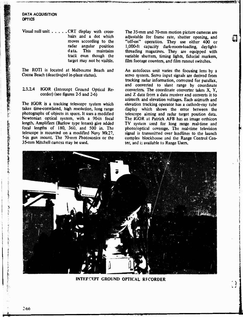
DATA ACQUISITION OPTICS
Visual null unit CRT display with cross- hairs and a dot which moves according to the radar angular position data. This maintains track even though the target may not be visible.
The ROTI is located at Melbourne Beach Cocoa Beach (deactiva/ed in-place status).
and
2.3.2.4 IGOR (Intercept Ground Optical Re- corder) (see figures 2-5 and 2-6)
The IGOR is a tracking telescope system which takes time-correlated, high resolution, long range photographs of objects in space. It uses a modified Newtonian optical system, with a 90-in focal length. Amplifiers (Barlow type lenses) give added focal lengths of 180, 360, and 500 in. The telescope is mounted on a modified Navy Mk27, 5-in gun mount. The 70-mm Photosonics or the 35-mm Mitchell camera may be used.
The 35-mm and 70-mm motion picture cameras are adjustable for frame rate, shutter opening, and "off-on" operation. They use either 400 or 1,000-ft capacity dark-room-loading, daylight- threading magazines. They are equipped with variable shutters, timing lights, fiducial markers, film footage counters, and film runout switches.
An autofocus unit varies the focusing lens by a servo system. Servo input signals are derived from tracking radar information, corrected for parallax, and converted to slant range by coordinate converters. The coordinate converter takes X, Y, and Z data from a data receiver and converts it to azimuth and elevation voltages. Each azimuth and elevation tracking operator has a cathode-ray tube display which shows the error between the telescope aiming and radar target position data. The IGOR at Patrick AFB has an image orthicon TV system used for long range real-time and photo/optical coverage. The real-time television signal is transmitted over landlines to the launch complex blockhouse and the Range Control Cen- ter, and is available to Range Users.
INTERCEPT GROUND OPTICAL RFCORDER *)
2-66

»«««MNIKIIMIMMMfllMEMM^
DATA ACQUISITION OPTICS
TECHNICAL CHARACTERISTICS
I
ft.
Camera BX-7 TV, 70-mm Photosonics or 35-mm Mitchell
Frame rates .... 10, 15, 30, 45 or 60 f/s (70-mm); 80 to 96 f/s (35-mm)
Aperture 18 in
Magazine capacity 40 or 1,000 ft
Tracking rate . . . 10°/s maximum
Angle limits .... Continuous azimuth, -3Vi to +92° elevation (tower) 190° azimuth, -3V2 to +92° eleva- tion (mobile)
Sighting telescope magnification 20 or 35
P
A fixed IGOR in an astrodome is located on a tower at Patrick AFB. Three mobile units (called Mobile IGOR Tracking Telescope System, MITTS) are available. These may be towed to operating sites or transported by C-l 24 aircraft.
2.3.2.5 RML/ltek 48-lnch Telescope (Meteor II)
The RML/ltek tek scope is equipped with an f/2.5 solid CerVit paraboloidal primary mirror. A 5- element Wynne type corrector gives a 35-mm diameter coma-free flat field at the f/2.5 prime focus. This focal position can be used with a 35-mm camera specially modified to use high resolution thin base film. A set of reimaging lenses, supported on an additional spider, can be added in train with the prime focus to give an f/5.0 35-mm format film plane. A second attachable support spider holds a 40-mm SIT TV camera which permits a full field of view format at the f/2.5 focal plane. The limiting brightness equivalent value for this system, when operated in a cine mode, is löth to 17th magnitude. Provisions are incorporated in both the f/2.5 and f/5.0 systems for the use of narrow bandpass fitters.
\ remotely controlled reflex mirror can be rotated into position to direct the optical axis through a periscope-relay lens system to a right-angle cube on
top of the telescope which directs the optical axis back parallel to the primary mirror axis. The relay lens system is designed so that the incoming light is brought to focus at an equivalent f/10 plane.
On the telescope top surface is mounted a table which can be positioned at various points along the f/10 optical axis with a servo torque-motor-driven lead screw. An attached digital encoder provides a readout of table position with a precision which ensures table positioning to a least count smaller than the depth-of-focus tolerance of f/10. During mission operation the table is continuously posi- tioned as a function of range to target by the computer to maintain accurate focus.
The translating table carries a reimaging lens with provisions for varying the back conjugate distance to adjust from f/10 to f/15. A double, 5-position filter wheel contains both long wave, sharp-cut spectral filters and a graded series of neutral density filters for contrast and exposure control.
Video imaging cameras mounted on this table can be either standard or infrared vidicon cameras, S-25 photo surface image-orthicon camera, or extended red S-20, 25-mm or 40-mm SIT cameras, The orthicon cameras and the 40-mm SIT cameras have various options of scan and of field rates.
The telescope is carried on an elevation-over- azimuth mount equipped with torque motors and 21-bit shaft angle encoders. A TV boresight telescope provides for star calibration of mount characteristics. The mount can be driven to keep the telescope pointed at a moving space target to within 1 to 2 arc seconds.
In addition to the imagery, insertion can be made on each TV frame of the last digit of the year, day of year, time of day to 1/10 second, effective focal length, azimuth to 1/10 degree, elevation to 1/10 degree, range, and offset of the f/10 focal plane from infinity. The data is updated 10 times a second.
The telescope is housed in a 36-ft diameter aluminum dome and is supported on a 42-ft tower. The mount is on a central pier which is isolated from the rest of the structure supporting the two floors and the rotating dome. The dome is air-conditioned to control humidity.
2-67
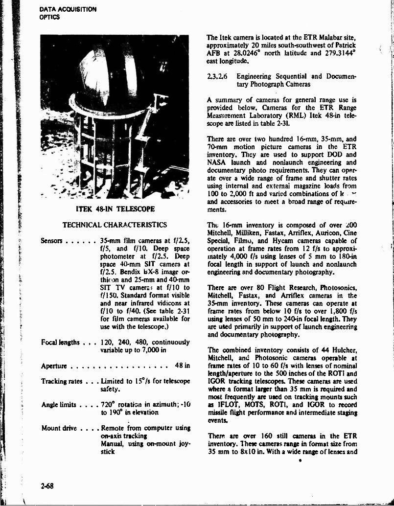
DATA ACQUISITION OPTICS
ITEK 48-IN TELESCOPE
The Itek camera is located at the ETR Malabar site, approximately 20 miles south-southwest of Patrick AFB at 28.0246° north latitude and 279.3144° east longitude.
2.3.2.6 Engineering Sequential and Documen- tary Photograph Cameras
A summary of cameras for general range use is provided below. Cameras for the ETR Range Measurement Laboratory (RML) Itek 48-in tele- scope are listed in table 2-31.
There are over two hundred 16-mm, 35-mtn, and 70-mm motion picture cameras in the ETR inventory. They are used to support DOD and NASA launch and nonlaunch engineering and documentary photo requirements. They can oper- ate over a wide range of frame and shutter rates using internal and external magazine loads from 100 to 2,000 ft and varied combinations of k " and accessories to meet a broad range of require- ments.
f
TECHNICAL CHARACTERISTICS
Sensors 35-mm film cameras at f/2.5, f/S, and f/10. Deep space photometer at f/2.5. Deep space 40-mm SIT camera at f/2.5. Bendix bX-8 image or- thicon and 25-mm and 40>mm SIT TV earners.* at f/10 to f/150. Standard format visible and near infrared vidicons at f/10 to f/40. (See table 2-31 for film cameras available for use with the telescope.)
Focal lengths ... 120, 240, 480, continuously variable up to 7,000 in
Aperture 48 in
Tracking rates . . . Limited to 15°/s for telescope safety.
Angle limits .... 720° rotation in azimuth; -10 to 190° in elevation
Mount drive .... Remote from computer using on-axis tracking Manual, using on-mount joy- stick
Tht 16-mm inventory is composed of over 200 Mitchell., MiUiken, Fastax, Arriflex, Auricon, Cine Special, Filmo, and Hycam cameras capable of operation at frame rates from 12 f/s to approxi- mately 4,000 f/s using lenses of 5 mm to 180-in focal length in support of launch and nonlaunch engineering and documentary photography.
There are over 80 Flight Research, Photosonics, Mitchell, Fastax, and Arriflex cameras in the 35-mm inventory. These cameras can operate at frame rates from below 10 f/s to over 1,800 f/s using lenses of 50 mm to 240-in focal length. They are used primarily in support of launch engineering and documentary photography.
The combined inventory consists of 44 Hulchcr, Mitchell, and Photosonic cameras operable at frame rates of 10 to 60 f/s with lenses of nominal length/aperture to the 500 inches of the ROTi and IGOR tracking telescopes. These cameras are used where a format larger than 35 mm is required and most frequently are used on tracking mounts such as IFLOT, MOTS, ROTI, and IGOR to record missile flight performance and intermediate staging events.
There are over 160 still cameras in the ETR inventory. Ihese cameras range in format size from 35 mm to 8x 10 in. With a wide range of lenses and
2-68

DATA ACQUISITION OPTICS
'» I TABLE 2-31.
FILM CAMERAS FOR RML/ITEK 48-INCH TELESCOPE
Camera Format Focal
Position Mode Rate Film
Capacity Timing
Provisions Exposure Control
Flight Research Model 207
(Note 1)
22 mm diameter
f/2.5 and f/5
Pulse 4/s 200 to 1000 ft
Alphanumeric on frame to milliseconds
Fixed shutter, Filters, spec- tral and ND
Pentax
(Note 2)
24x36 mm
f/10 Manual NA 36 exp. None Variable Shutter
Mitchell Reflex Sound Record- ing
(Note 3)
16 mm f/10 Cine 24/s 400-ft and 100-ft magazines
On Magnetic Strip
Fixed shutter, filters
Pentax 24 x36 mm
f/2.5 and f/5
Pulse None Variable Shutter
NOTES SYNCHRONIZING PROVISIONS
1. Pickup on shutter, timed from computer clock. 2. None 3. None-data inform, on video from vidicon camera
used at reflex viewing position,
accessories they are used in fixed positions or hand-held to support launch and nonlaunch photo requirements.
2.3.3 Laser Illumination
A laser illumination facility is operated by the ETR at the Range Measurements Laboratory complex at Malabar, Florida. One transmitter system (Meteor I) is available which provides target illumination for photography coverage by the RML/ltek 48-in tracking telescope (see paragraph 2.3.2.S).
The Meteor 1 transmitter telescope is mounted on a modified Nike-Ajax pedestal. The laser beam is reflected upward through the azimuth axis of the mount and horizontally into a 20-in aperture lens assembly. Beam divergence is variable from 0.12 mrad to 17 mrad; the laser firing rate is nominally 30 per minute. It is triggered locally by the XDS Sigma 7 computer.
A 120-inch focal length Questar/TV boresight syOem Is coaUgned with the transmitter telescope, the azimuth and elevation axes being equipped with 20-bit digital encoders to provide angular output data.
2.3.4 Opto-Radiometric
Opto-radiometric equipment is used by the ETR to determine certain electromagnetic radiation charac- teristics of missile flights and to measure atmos- pheric attenuation. The radiation measurements can be divided into three categories: (1) radiomet- ric, total energy in a relative wide spectral interval, (2) spectral total energy in a very narrow spectral interval, and (3) spatial, radiometric, or spectral energy as a function of position within the field of view. Additionally, dimensional and shape data become important when resolved images are present.
Some typical types of provided are as follows:
opto-radiometric data
• Effective fireball, nosecone, and decoy tem- perature
• Energy distribution of an explosive fire bail • Radiant intensity • Spectral emission • Ablation rates • Thermal buildup and decay rates • Absolute spectral transmission of the Earth's
atmosphere
1 2-69
DATA ACQUISITION OPTICS
The most extensive ETR opto-radiometric capa- bilities exist on the two Advanced Range Instru- mentation Ships (AR1S): USNS Arnold and USNS Vandenberg. Four subsystems exist on each ARIS for obtaining opto-radiometric data. These are boresight cameras installed on radar and telemetry tracking antenna mounts, an instrumented IFLOT (see paragraph 2.3.2.1), the ballistic cameras array (see paragraph 2.3.1.2) of four fixed cameras, and the Precision Optical Pedestal System (POPS). Photographic instruments installed in these sub- systems provide a means of acquiring optical signature data in the 0.28 to 0.9-micron spectral region. Except for the fixed wide-field ballistic plate cameras, ARIS optical instruments are used in a tracking mode and record optical images.
The USNS Redstone is equipped with two ballistic plate cameras and an IFLOT instrumented with four motion picture cameras for obtaining spectral diagnostic, temperature, and scintillation data during reentry.
Signature data is also obtained at Ascension with two Fairchild T-l I aerial mapping cameras and an IFLOT tracker with six motion picture cameras. The Ascension installation also includes six BC-4 ballistic camera systems.
Ballistic camera arrays on the ARIS are discussed in paragraph 2.3.1.2. Their optical parameters are included in table 2-32 for convenience. One set of instruments, presently on the USNS Arnold, consists of four BC-4 cameras with 12-in Aero Ektar lenses. The second set of instruments, now on the USNS Vandenberg, consists of four K-19 cameras with 300-mm Aero Ektar lenses. Each array consists of two ballistic cameras and two ballistic spectrographs.
The POPS provides ARIS with reentry data capacity for cold body image photography, day- light cinespectrograph measurements, and high- speed radiometry measurements.
A modi ied Nike mount is used to support the optica1 sensors. It is suitable for supporting approximately 1,000 pounds of equipment and has the capability of accurate designation/slaving to the shipboard tracking radars or computers. The slaved optics instrumentation is located amidships on the bridge deck. The POPS mount can be slaved to either of the primary radar tracking systems. The slaved optics system has the following fea- tures:
Above decks:
13.4.1 ARIS (USNS Arnold & USNS Vanden- berg)
Boresight cameras installed on the radar and telemetry tracking antenna mounts provide pri- mary sources of radiometric data. These are standard 35-mm Mitchell cameras with Zoomar f/8 40-in focal length lenses. Table 2-32 lists the frame rate, exposure time, emulsion, filter, and spectral response typical for day or night operation.
The ARIS IFLOT is a one-man, manual tracking mount located in front of the star tracker. Target acquisition is accomplished with an open gunsight and the visual null indicator. The IFLOT also provides two-speed synchro designate data to the ship acquisition system.
IFLOT instrumentation and associated optical parameters are given in table 2-32. These instru- ments include high resolution spatial, surveillance, ultraviolet (UV) cinespectrograph. and infrared (IRl cinespectrograph cameras.
and Parabam astrodome, 12-ft diameter Nike pedestal, modified bearings servo drive 180-in, f/10 Pcrkin-Elmer Lens. 70-mm Photosonics 10A camera Cinespectrograph Barnes 18-138. with 150-in. f/10 lens Pair of cineradiometers. Photosonics IP, 20-in. f/5 lens Surveillance camera Mitchell 35-mm, 90-f/s with 10-in f/5.6 Schneider Symmar lens TV monitor/alignment camera with a 40-in Telestar lens
Below decks:
Operations control console, dual rack Camera control units/test and calibration control Data handling rack for ships computer interface Interconnecting cabling MirateITVMonitor.TVI7R 3
2-70
PW MH neu

DATA ACQUISITION OPTICS
I
CO
Z <
z o
Z w Z
as u. i/s Z
-1 <
E o (-1
X J— yj
Z 3E Ul P'S
1" r» r» «»* r» m^ier- r— r» r» r» in 0} en OS 0)C0 oo
1 | o
i o
1 ooö d 1*11
O O O o
1 1 1 1 o
1 0 0
1 1 0 00
1 1 > eo « 00 m m so es kO « m * llllflV« in * un «r CM * * mnun
oo o o o o o o o o o o o 0 0 0000
111 K Hi UJ
-1 lA< (9 in < *z IAIA Uftg
CO -C3 . m < m < •— ^» •• ^
Ul z o
i~ O
Ul Ul zz _ 0 0
u. <* z zz
Z P o — X > o
3 X SI a m «» K ecee Jgm in m o ae ac u. u.
i ■" «>; CO u. MMjJ ><5><5 s «O CA ?o?o -"CM X Ul X X OL CM * es* es ▼— X X •-'-•"•-
_ -~P —- H ""■ K —>H Ul >I £x ► l >X K 2 Ö <o < (9 <S
PO
SU
T
IME
<S
) Si MO (SO
O O O O NSNS
eg o p o * * es o 0 0
X =:«» «58! 5Ct^ «» C 8» < < J*«I ^ ^ ■H <)■■ *— ^- •— *- ^ w ^ •" p> v* *•*■ z z £0
i 2 S > < Ul uj
u.
c Ul
i o S s
ce Ul S <
O en
in m o 0 0 9C or <
< < z z
u ü <
X (9
«o <* (0 ce
•". **} Ö d 0 "-
uu
1 S3 S ul >X 35 X X X o X X X X x 2 0 X X U. u.>
oo. HI K
s o p a -1
u. m «M
"; ««! ft in
« 0 in — 0 to r>
*™ X ifl- fcO u.
o z u.
m as as O — O ~
o CO r— in
2 5 s. X^X 0
a ae a «2 «•
_lx
§ s O tR kO e^i o
o o rsi eo
CM IM CM
X X > > Ul Ul O O v» ac ac EC SE ac H k—
z < < < < «t OE yj
3 3 OS .'ee.ee 2 X S 2 2 10 «5°< 0 < 0 < o o o 2 2 ä z ijee»- eti- se >- o o o 3 3 o g < <w v: wxwy Nl iM M Crt Irt 2 2 < ui < IM < Ui
z as j © o<
*- »- „ 0 i_ ui
5 5: X
2 3
So a. —
EC ■— 5 * «J 5"" 5
a «™fc »*. *■» Ul X O *" O as 3 * ac ee ►- Ul
o
fr~ —i ►- _l SE _J —J oc£ o«~ ee ui g
u « ° («SB ,«,
en
«Ul - X
*£ o z
X -1 a ui
Ul*f
OX
O —i SB Ul
>5 ui*
" XX
?x
"z Set v>< ~ LU CO —
X
0 T -1 0 — ca _ X n
ac £
eo .1
AC «A
— s
*Z
Ulfi M 52
(A XI 2o it
öStf >§o
cSlui O f» Q
ae • • z
u 0 ee _iu»
< So • • 5S
-I z
ui o
Si Si £g z a Ul -I a o z z «GOB > <
O o< a»
3 « -j ■n*
O X c« Ul ee
0 ee ft
«Ml
< <
(A Ul OO <
io O
M — ua O Z Ss ~ fi e4
•71
WBPBHHHHHB»!
"py^ <t ßp- if s"^ B. «■ is
i
!
HnMMmiii
DATA ACQUISITION OPTICS
The primary optical system is a high resolution cinetelescope with a focal length of 180 in and f/10 aperture. Automatic exposure and focus controls operate in conjunction with a modified 70-mm Photosonics 10A camera. This optical equipment is mounted on an upgraded Nike pedestal. Pedestal slaving precision is estimated between 10 and 20 seconds of arc. Dynamic angular performance has been demonstrated in elevation at 910 mrad/s, 1200 mrad/s/s; azimuth 910 mrad/s, 1100 mrad/s/s. It is estimated that cold body image photography at sea may be possible with one and one-half seconds of arc resolution.
% High-resolution spectrographic measurements are made with a Barnes 18-138 Czerny-Turner Cine- spectrograph. The lens for this system is a 150-in, f/10. Spectral response is 0.39 to 0.62 micron. This instrument is capable of daylight cinespearoscopy.
The cineradiometers operate at 100 f/s. One camera covers the IR spectrum of 0.S to 0.9 micron. The second covers the visible spectrum from 0.4 to 0.7 micron. Reentry object tumble, scintillation, ablation, and materials identification are aided hy analysis of these data.
13.4.2 RIS (USNS Redstone)
The USNS Redstone ballistic came as are Wild BG4 (see paragraph 2.3.1.2) cameras with rotating disc-type shutters. The cameras are mounted in yoke-type pedestals which permit positioning the camera in azimuth and elevation. They are posi- tioned side by side to optimize data coverage. One camera, configured with a 300 line/mm trans-
mission grating, is operated in an open shutter mode, and the second in a shutter-time-chopped mode.
The IFLOT tracking mount on the Redstone is configured with four motion picture cameras: one 70-mm Photosonics camera with a 20-in lens and a ISO-line/mm transmission grating, two 35-mm Mitchell cameras with a 504nm lens for engineering sequential data, and one 35-mm Mitchell camera with a 75-mm lens and a 300-line/mm transmission grating.
2.3.4.3 Ascension Island
Signature data is obtained at Ascension with two Fairchild T-ll aerial mapping cameras and an IFLOT tracker with six motion picture cameras.
The T-ll aerial mapping camera has a 6-in Metrogen lens, between-the-!ens type shutter, and interchangeable film magazines. It accepts film 9-54 in wide and up to 390 ft long.
The IFLOT tracking mount (see paragraph 2.3.2.1) is configured with six motion picture cameras: two 35-mm Mitchell cameras with bandpass filters for temperature and scintillation data, one 35-mm Mitchell camera with 150 line/mm transmission grating for spectral data, one 35-rr.m Mitchell camera for engineering sequential data, one 70-mm Photosonics camera with 300-line/mm transmission grating for spectral data, and one 70-mm Photo- sonic camera for engineering sequential data.
Ballistic cameras at Ascension are discussed in paragraph 2.3.1.2.
_8H__ 2-72
DATA ACQUISITION IMPACT LOCATION
#
2,4 IMPACT LOCATION SYSTEMS
f
Impact location systems are underwater sound detection -vstems used to obtain the geographic position of reentry vehicles or other missileborne objects upon impact into the sea. Systems operated on or by the ETR can be grouped in two basic types as a function of the technique used for data retrieval.
The first basic type is the ETR Missile Impact Location System (MILS) which uses a cable to relay sound signals detected by underwater hydro- phones to a nearby land station where the signals are recorded. The system is based on: (1) the production of sound generated by impact of an object(s) on the surface of the water, or by the underwater explosion of a bomb carried by a missile component, and (2) the detection of the sound and recording of its arrival time at a number of known hydrophone locations in the ocean. The location of the impact or bomb detonation point can be computed from a knowledge of the hydrophone positions, the velocity of propagation of sound in the ocean, and the arrival times of sound at the hydrophones.
The second type is the Sonobuoy Missile Impact Location System (SMILS) which retrieves its data in real-time by attendant aircraft via a radio link. This system consists of an ocean bottom acoustic transponder array plus an array of expendable surface hydrophones (sonobuoy) deployed for each test mission. Specially equipped aircraft sow the sonobuoy and receive/record impact data relayed from the sonobuoys. The transponder array in the impact area provides a geodetic reference.
2.4.1 Missile Impact Location System
The MILS used on the ETR consists of two types: the target array (also called pentagon or splash array) end the sofar (sound fixing and ranging) system (also called the broad ocean area (BOA) system). The target array provides high accuracy information in a limited target area, usually within a 10-nmi radius. The hydrophones are placed on the bottom in essentially a regular pentagon formation with a sixth hydrophone at the center, the target area being the water surface above the pentagon. The sound transient produced at the surface by an impacting reentry vehicle travels through the water to the hydrophones. The
computation for impact location is the conven- tional space hyperbolic solution in which the z term (altitude) is a constant equivalent to the depth of the water. The pentagon configuration ensures that for any point of impact within the target area, there will be at least four hydrophones with ranges less than the refraction limit so they will receive signals by a direct transmission path.
The BOA configuration is essentially a plane hyperbolic system taking advantage of the long range sound transmission in water (about 2,000 rmi) and the superior identification characteristics of the sofar channel. An inversion point (the sofar axis), or minimum velocity of sound, is formed at a depth of 3,000 to 4,000 ft by decreasing tem- perature and increasing pressure. At the depth of minimum velocity, attenuation of sound energy with distance is nearly linear rather than propor- tional to the square of the distance, and even comparatively low level sounds can be detected at great distances. The BOA hydrophones are placed as close as possible to the sofar axis. A sofar bomb with pressure-activated control is mounted in the reentry body and allowed to sink with it until the bomb detonates near the sofar channel.
The accuracy of the system depends on the geometrical relationship of the impact pejtion to the hydrophone positions, signal timing, and on the velocity of sound propagation. There are many sound paths between the explosion point and the hydrophone positions, resulting in many sound arrivals at any one hydrophone from a single explosion. However, the sound path along the sofar axis, traveling in the plane of the system and at the lowest velocity, is the last arrival to a hydrophone and can be identified. Its time of arrival together with hydrophone position and values of "horizon- tal velocity" (measured by calibration) are the inputs for computing the impact location. Data from at least three hydrophones is needed for a solution.
The geodetic accuracy of the BOA has been improved at specific midrangc impact areas by calibration (measurement of acoustic propagation velocity) near the time of the missile test. The calibration consists of a ship releasing a few sofar bombs while the ship's location is being deter- mined by the Acoustic Ship Positioning System (ASPS). Three or four transponders, placed in each impact area, are interrogated by a pulse from the ship, and reply at individual frequencies. The
2-73
DATA ACQUISITION IMPACT LOCATION
MM
geodetic position of the transponders is surveyed by the most accurate method available, e.g., BRN-3 or SRN-9 navigation systems.
Impact location (geodetic and relative) of multiple reentry vehicles is provided in the BOA by varying the amount of explosive earned in the sofar bomb. An approximate 5 dB difference in the peak signal level is observed when the charge weight is doubled. For instance, the charge weights recom- mended for midrange was are 1,2, and 4 pounds for three reentry vehicles.
2.4.1.1 Location
Figure 2-7 shows the general location of the active ETR MILS/MILS sites. Precise coordinates are presented in the AFETR Geodetic Coordinates Manual.
SMILS Arrays (The acoustic ship positioning transponders located on the bottom)
Bottom Array
C2A C9C C11A C12 C15W CI5E C16
2.4.1.2 Accuracy
Distance Downrange (nmi)
550 1,900 2,500 3,000 1,500 1,550 4,700
Accuracies of the MILS systems are classified Confidential. They may be obtained from AFETR/Systems Analysis Office.
Target Arrays (hydrophones positioned on bottom) 2.4.1.3 Data Handling
Grand Turk (85 miles northeast of, at a depth of 3 miles, 24-nmi di- ameter)
Antigua (150 nmi northeast of. at a depth of 3 miles. 5-nmi diam- eter)
Ascension (20 miles west-southwest of, at a depth of 2 diameter)
miles, 12-nmi
BOA Arrays (BOA hydrophones positioned at or near the sofar axis)
Barbados
Bermuda
Eleuthera
Antigua
Grand Turk
Puerto Rico
Ascension
Cape Hatteras
The hydrophone outputs of the arrays are recorded simultaneously on strip charts with timing annota- tion and on magnetic tape with timing and operator voice annotation. The strip chart and magnetic tape recordings are then forwarded to Patrick AFB for postlaunch data processing.
Arrival times are obtained manually at each site from the strip chart recordings, and quick-look information from all sites can be relayed by way of radio or telephone to the mainland for immediate use. Recorded signals collected from arrays at Grand Turk and Antigua are transmitted from those stations to the mainland by way of undersea cable circuits, and signals from the array at Ascension are transmitted by hf radio circuits to permit rapid delivery of results to Range Users.
2.4.2 Sonobuoy Impact Location System
The SMILS (Sonobuoy Missile Impact Location System), us*d to determine the impact location of missile reentry bodies, consists of four basic elements: (1) an ocean bottom acoustic trans- ponder array, (2) specially equipped P-3 Orion aircraft, (3) modified Navy ASW sonobuoys. and (4) an ocean surface duct.
The transponder arrays in the impact area consist of 10 deep ocean transponders which serve as a geodetic reference point for the sonobuoys. These
2-74
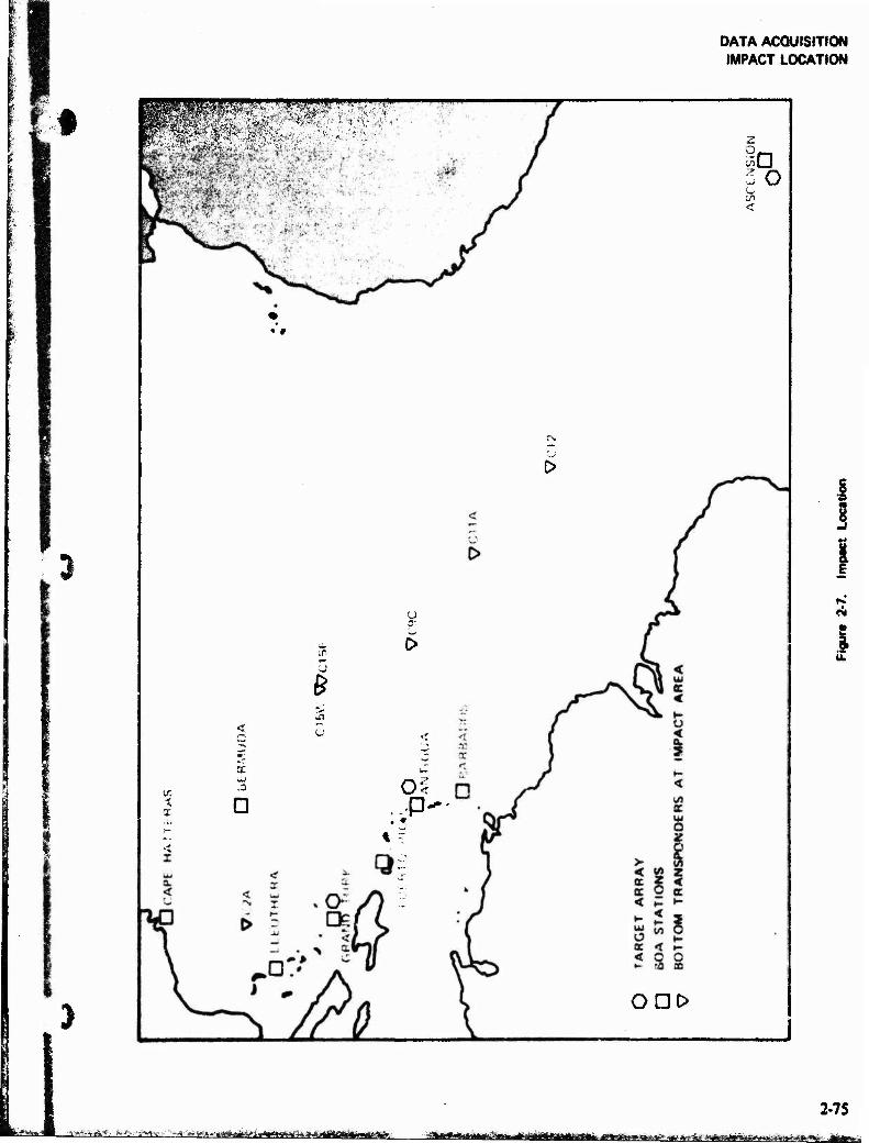
DATA ACQUISITION IMPACT LOCATION
3
•»
&
■x x G
a--
o-<
z
sG 30 <
ODE>
2-75 ■'A*' j^fr-^vt:;~% ^»A-i^aftafei^tii^i^g^wäaji fr,»hiä«^«is^^fcrf#jafc;»rtti3^

'-^wSFH
DATA ACQUISITION IMPACT LOCATION
transponders are energized by a 16-kHz interro- gator signal and respond each on a different frequency at '/j-kHz intervals from 7.5 to 12 kHz. Each transponder array is located geodetically by the Navy Satellite System.
Two Navy P-3 Orion Lockheed Electra ASW (antisubmarine warfare) aircraft assigned to Air Test and Evaluation Squadron One (VX-1), Pautuxet River NAS, Md, have been modified to accommodate the SMILS. These modifications provide: (1) the capability to receive and record additional sonobuoys (24 and 32, respectively), (2) a timing system, and (3) a monitoring and quick-look recording capability.
The modified ASW sonobuoy is an expendable item designed to be dropped from an aircraft into the sea where it detects underwater sounds, and by means of a self-contained transmitter relays this infoimation to the aircraft. There are 31 trans- mitter frequency channels between 162.25 kHz to 173.50 kHz. The sonobuoys have been modified to increase the active life by installing additional batteries, and the circuitry has been changed to increase the frequency response in order to receive the ASPS transponders interrogator and reply signals. In addition, some of the sonobuoys have been modified to incorporate a low frequency (2.5 kHz) pinger. An interrogator sonobuoy is deployed by a ship or aircraft in the center of the transponder array. This device is essentially an AN/SSQ-41 sonobuoy modified to transmit a 16-kHz signal, and to receive the 7.5 to 12-kHz transponder response signal.
The wind-mixed surface layer of the ocean creates an isothermal duct or waveguide through which sound reliably propagates for many miles. Splash signals have been received through this surface duct at ranges up to 20 miles. The depth of the o<x»r, duct is determined by means of a bathythermo- graph sonobuoy dropped from the SMILS aircraft. The depth together with the planned reentry body
impact footprint are used to determine sonobuoy pattern to be employed.
the
A typical sonobuoy pattern for a single aim-point footprint consists of four rings about 3 nmi apart with a total outside diameter of about 20 nmi. Thirty sonobuoys including an interrogator sono- buoy are deployed during each mission.
The transponders which arc energized by the 16-kHz interrogator signals serve to locate the 2.5-kHz pinger sonobuoys relative to the trans- ponders. The signals from these pinger sonobuoys propagate through the surface duct and are received by the sonobuoys. The splash position relative to the sonobuoys as well as the time at which splash occurred can then be determined.
2.4.2.1 Location
SMILS is presently used exclusively to support the fleet ballistic missile programs. Impact area co- ordinates are classified. Descriptions and locations are available from AFETR/Systems Analysis Office.
2.4.2.2 Accuracy
Accuracies of the SMILS system are classified. They muy be obtained from the Navy Stratefie Systems Project Office (SSPO), Washington. fi.C.
2.4.2.3 Operations
The USNS Strategic Systems Project Office (SSPO) is responsible for the overall operation and funding of SMILS. The Navy provides the P-3 aircraft support and various other services (through the Palisades Geophysical Institute, Bermuda) such as sonobuoy acquisition/modification, mission plan- ning/support, and data analysis/reduction.
The AFETR provides the transponder arrays (by acquisition, installation, and survey of trans- ponders) on a reimbursable basis.
-76
^^^F^W^'*" '
DATA ACQUISITION METEOROLOGY
2.5 METEOROLOGY K
%
An integrated meteorological system is used to obtain surface and upper-air weather data at several points along the Range in support of Range Users. Satellite data is also received and interpreted in real-time from most meteorological satellites pass- ing over the Range. The following functions are performed by the ETR Meteorological Section:
i. Meteorological data is collected with standard meteorological equipment whenever possible at the following loca- tions: Cape Canaveral AFS (CCAFS), Patrick AFB, Grand Turk, Antigua, and Ascension. Automatic weather stations are used at Grand Bahama and during the night at Grand Turk.
2. Specialized meteorological and micro- meteorological support are provided to the Kennedy Space Center (KSC).
3. Meteorological forecasts are made for all operations at CCAFS, for NASA un- manned programs, and for DOD opera- tions at KSC.
4. Ugper atmospheric data is collected by balloon and rocket-borne instruments. Standard rawin soundings are conducted by the Runge ships and by CCAFS, Grand Turk, Antigua, and Ascension. Rocketsondes are fired at CCAFS, Antigua, and Ascension.
5. The Weather Information Network Dis- play System (WINDS) at CCAFS and KSC is operated and maintained for the purpose of monitoring and predicting low level diffusion characteristics.
6. Assistance, as required, and coordination with Space Flight Meteorology Group is provided on all meteorological forecasts in support of NASA manned program operations and other joint missions.
7. Weather warnings are provided to CCAFS and KSC.
8. Satellite data received directly by the Cape Canaveral Forecast Facility (CCFF) or that received by a downrange station
and relayed real-time to the CCFF is interpreted.
The following paragraphs briefly describe the major equipment items; a more detailed explana- tion of instrumentation and capabilities can be obtained from AFETRP 105-1, Weather ~ Meteor- ological Handbook.
2.5.1 Surface Instrumentation
Surface weather observations are taken on a 24-hour basis at CCAFS using standard meteoro- logical observation practices. Instrumentation used for observations is simile r to that used at most Air Force bases and includes the following items:
Mecurial Barometer ML-2-H Barograph ML-3-D Psychrometer ML-224/24 Hygrothermograph Wind Measuring Set AN/GMQ-11 Cloud Height Set AN/GMQ-13A Ceiling Light Projector ML-121
Descriptions and specifications of this equipment may be found in Air Weather Service Publication (AWSPi 105-3. The more specialized surface equipment is described in the following paragraphs.
2.5.1.1 AN/FPS-77 Storm Detection Meteoro- logical Radar Set
The AN/FPS-77 radar, located at CCAFS, provides displays of the horizontal and vertical cross- sections and intensity measurements of precipita- tion areas within a 120-nmi radius. Antenna controls permit continuous scan, manual position- ing, and elevation sector scan capability.
Radar scope photography is available using either of two methods. Polaroid pictures may be taken of any of the regular console scopes. The second system incorporates a 35-mm recording camera mounted on a remote PPt radarscope whkh includes a video integrator and processor for contoured intensity presentations. Photos are taken automatically wiih Urn system, providing a sequence of radar scope presentations and an excellent data base for analysis of weather situa- tions.
The radar detectable data from the FPS-77 is digitized and processed by a CDC 3100 computer
2-77 ~m+j '_*w
DATA ACQUISITION METEOROLOGY
(Digitized Automatic Radar Tracking System, DARTS) producing an analyzed teletype printout for storm track following and p-ediction extrapola- tion throughout the enure 2i.O nmi range of the radar. This system greatly aids tin weather warning function by decreasing the impact warning circle of storms and work centers from 5 miles to 3 miles, thereby reducing the downtime on gantries due to severe storm activity.
2.5.1.2 Launch Pad Lightning Warning System (LPLWS)
The Launch Pad Lightning Warning System (LPLWS) provides the duty forecaster at CCFF the capability of detecting and monitoring lightning from eight locations - seven major launch com- plexes and the Port Canaveral Navy complex. The system consists of eight electrostatic field sensors or mills, a CDC (Control Data Corporation) 3100 computer for data acquisition and analysis, and a teletype to print out for the forecaster, an analysis of lightning potential and lightning occurrence. Each field mill's output is continuously recorded by strip chart recorders and simultaneously ana- lyzed by the computer. The computer translates the field strength data into meteorological terms for the forecaster and provides the following information for each of the eight sites:
1. Knowledge of highly charged clouds where lightning is eminent.
2. When thunder can be heard by an observer (approximately 4 miles to 10 miles from a site).
3. When lightning is occurring at ,* site (within 3 miles).
4. The intensity of an electrical storm occurring at a site.
2.5.1.3 Weather information Network Display System (WINDS).
The WIND System consists of: (I) 16 stationary towers that range in height from 54 to 500 ft. (2) wind, temperature, and dew point sensors attached to the towers at various heights. (3) a CDC 3100 computer that receives and processes the sensor measurements, and (4) a 4-terminal teletype circuit that prints out the processed data. The towers are
located throughout Cape Canaveral and Merritt Island. The displayed data, available in 30, 15, or 5-minute readouts, consist of numerical values for the variables: wind direction and speed, wind gusts, «emperature, dew point, lapse rate (i.e., "Delta T" - temperature change with height), two distances for toxic concentrations (one for concentrations of 25 parts of toxic per one million parts of air and another for 5 parts of toxic per one million parts of air), and standard deviations of the wind direction.
2.5.2 Upper Air Instrumentation
15.2.1 AN/GMD-4(RawinSet)
The AN/GMD-4 rawin set is a 1680-MHz radio direction finder used for automatic tracking of a balloon or rocket-borne instrumentation package. During tracking, the transmitter generates a 400 to 406-MHz cw carrier modulated at 81.94 kHz. This is a ranging signal which is transmitted to the radiosonde set. A pulsed 1680-MHz signal carrying the 81.94-kHz fm modulation is .eturned by the radiosonde set and sent to the receiving system. This system demodulates the rf signal to separate position data, range data, and meteorological data. The position da** are sent to the antenna positioning system for precise antenna control and for data relay to a recorder. The range data (ranging subcarrier) are send to the ranging system for measurement of slant range. The pulsed meteorological data are sent from the receiving system to the data processor. Instrument slant range, altitude, and elevation and azimuth angles versus time aw recorded on punched tape at sampling rates of I, 2, 5. or 10 times a minute. Temperature and humidity versus time are pre- sented sequentially in graphic form on the radio- sonde recorder AN/TMQ-5 and also punched on paper tape with the instrument position data.
The AN/AMQ-9 radiosonde is a balloon-burne transponder type, designed for u.4? with the AN/GMD-4 ground equipment, which uses a clock- driven commutator to switch between reference frequency, humidity data, and temperature data.
The mcteorologicaS data processor automatically provides digital meteorological and position data on punched paper tape. These data represent:
1. Azimuth and elevation tracking angles, and slant range from the AN/GMD-4 to
2-78
• - - ■"TüFBr»
DATA ACQUISITION METEOROLOGY
*•
I :
I
L
the balloon- or rocket-borne radiosonde set.
2. Temperature and humidity data being transmitted from the radiosonde cor- rected for reference frequency drive.
3, Elapsed time.
Station identification, prelaunch calibration data, etc., may be entered manually. The data, acquired in real-time, are presented on teletype coded, punched paper tape.
2.5.2.2 Omega NAVAID Sounding System
The Omega NAVAID sounding system, Buekers Models WO-2 and WO-2Ds, is installed aboard the USNS Redstone and USNS Arnold. This rawin- scndc sounding system may be employed on land or sea and does not require a tracking ?ntcnna or stabilized platform for the determination of upper air winds. Using a standard 403-MHz fm meteoro- logical radiosonde modified for the retransmission of track information, it accurately determines wind speeds to 1 to 2 meters jpct record. System accuracy is independent of the distance from the balloon launch site and is constant over the entire flight period. Thermodynamic data are acquired using conventional radiosonde observation tech- niques. This equipment is scheduled to be installed on the USNS Vandcnberg in FY-76 and on Grand Turk in FY-77.
2.5.2.3 High Resolution Wind Measurement Bal- loon Uimspherc)
These measurement! are obtained by use of a rigid radar reflective balloon tracked by a Range radut. In contrast to standard sounding balloons, this balloon is aerodynamically stable and retains a constant volume. Wind speed, direction, and shear from the surface to 60.000 ft arc computed from the radar tracking data.
2.5.2.4 tOKl Meteorological Rocket System
The solid propellant LOKi rocket lifts an 8-pound dtl assembly to approximately 210.000 ft. The motor burns for 1.9 s (approximately 4.000 ft) at which time the dart and motor separate and the dart amis to apogee. The launcher consists of a rail assembly mounted on a pedestal.
The dartsonde is carried aloft by the LOKI rocket. After separation from the rocket, it coasts to a 210,000-ft apogee, at which time the &-pound instrument is deployed and descends on a starute. As the dartsonde descends, temperature measure- ments are transmitted to a GMD receiver. The starute is tracked by radar to determine wind speed and direction.
2.5.2.5 Super LOKI System
Meteorological Rocket
The solid propellant super LOKI rocket is 4 inches in diameter compared to the 3 inch diameter LOKI motor. This higher performance motor enables altitude capabilities up to 300,000 ft depending on the system configuration. There are four separate configurations of the super LOKI:
PWN-10A Transponder PWN-I0A Mod-I Stable Booster Transponder PWN-11A Stable Booster PWN-12A Robin
2,5.3 Data
A CDC-3100 data processing system on the ETR provides accurate reduction of upper air meteoro- logical data. Rawinsonde, meteorological rocket, and upper-air wind data aw some of the data reduced by the system. A printed copy and a perforated tape are made of the incoming data. The output data provides tabular printout of altitude, pressure, temperature, and other meteoro- logical parameters. Tabular printouts, card output leeks, and magnetic tapes are provided to Range Users to evaluate test performance.
2,5.4 Satellite Imagery Acquisition and Proc-
Satellitc data is received and processed by the CCFF on a daily o««s from NO A A (National Oceanic and Atmospheric Administration) and DMSP (Defense Meteorological Satellite Program) satellites. This data provides a wide area, bird's-eye view of the weather patterns and greatly add« to the conventional data where available or provides a sok source of data over isolated locations along the Range. These photos are used as observing, forecasting, and briefing tools by the forecaster to enable the dec «ton-makers to receive the best meteorological information with regard to their program!»). Using the available visible and infrared
2-79
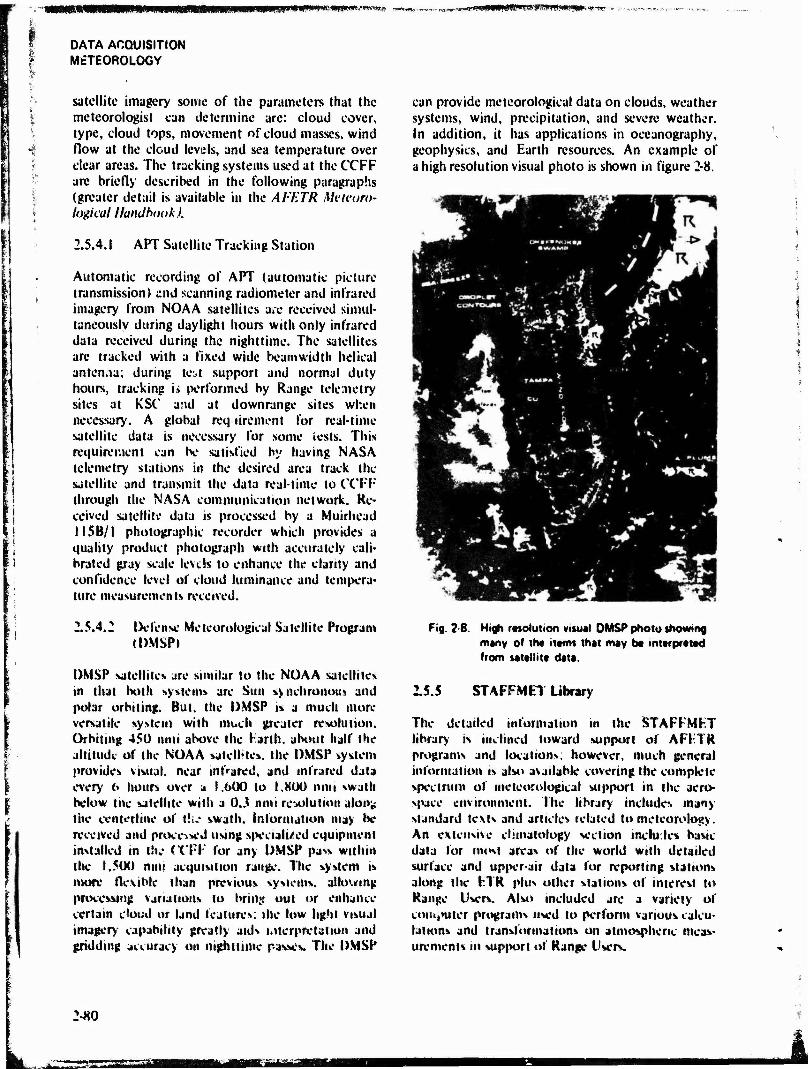
mmmmm SWW8« iMjüHIB?! Jl,ta***B*iB& -m*«f*Bi(t., ■,
DATA ACQUISITION METEOROLOGY
satellite imagery some of the parameters that the meteorologist can determine are: cloud cover, type, cloud tops, movement of cloud masses, wind flow at the cloud levels, and sea temperature over clear areas. The tracking systems used at the CCFF are briefly described in the following paragraphs (greater detail is available in the AFETR Meteoro- logical Handbook).
2.5.4.1 APT Satellite Tracking Station
Automatic recording of APT (automatic picture transmission) and scanning radiometer and infrared imagery from NOAA satellites are received simul- taneously during daylight hours with only infrared data received during the nighttime. The satellites arc tracked with a fixed wide beam width helical antenna; during test support and normal duty hours, tracking i» performed by Range telemetry sites at KSC' and at downrange sites when necessary. A global requirement for real-time satellite data is necessary for some iests. This requirement can be satisfied by having NASA telemetry stations in the desired area track the satellite and transmit the data real-time to CCFF through the NASA communication network. Re- ceived satellite data is processed by a Muirhead 11 SB/1 photographic recorder which provides a quality product photograph with accurately cali- brated gray scale levels to enhance live clarity and confidence level of cloud luminance and tempera- ture measurements received,
2.5.4.2 Defense Meteorological Satellite Program (DMSP)
DMSP satellite» are similar to the NOAA satellites in that both systems are Sun synchronous and polar orbiting. But, the DMSP is a much more versatile system with much greater resolution. Orbiting 450 unit above the Earth, about half the attitude of the NOAA satellites, the DMSP system provides visual, near infrared, and infrared data every 6 hours over a I.6ÜÜ to I.SOU mm swath below the satellite with a ÖJ nmi resolution alonjs the centerline of t!;.- swath. Information may be received and processed using specialized equipment installed in th„- CCFF for any DMSP pass wtlhiti the 1,500 mm acquisition range. The system is more flexible than previous systems, allowing processing variations to bring out or enhance certain cloud or land features; the low light visual imagery capability greatly aids interpretation and gridding accuracy on nighttime passes. The DMSP
can provide meteorological data on clouds, weather systems, wind, precipitation, and severe weather. In addition, it has applications in oceanography, geophysics, and Earth resources. An example of a high resolution visual photo is shown in figure 2-8.
Fig, 2-8. High resolution visual DMSP photo showing many of the items that may be interpreted from satellite data.
15.5 STAFFMET library
The detailed information in the STAFFMET library is inclined toward support of AFFTR programs and locations; however, much general information is also available covering the complete spectrum of meteorological support in the aero- space environment. The library includes many standard texts and articles related to meteorology. An extensive climatology section ineiu.ics basic data for most areas of the world with detailed surface and upper-air data for reporting stations along the ETR plus other stations of interest to Range Users. Also included are a variety of computer programs used to perform various calcu- lations and transformations on atmospheric meas- urements in support of Range Users.
1-80
mum msmm
SUPPORT SYSTEMS COMMUNICATIONS
it: > ;
u
SECTION 3
SUPPORT SYSTEMS
3.1 COMMUNICATIONS
The Air Force Eastern Test Range (AFETR) operates point-to-point, air-to-ground, ship-to- shore, and intrastation communications using undersea cable, uhf, vhf, and hf radio, satellite, microwave, standard and wideband wire distribu- tion, closed-circuit television, and automatic and manual telephones. These systems are used for voice or teletype transmission of operational and administrative traffic, transmission and reception of test data, and for transmission of launch vehicle commands (see table 3-1). Additional details can be obtained from the AFETR Communications Hand- book.
3.1.1
3.1.1.1 Undersea Cable
Coaxial undersea cables hate been a most impor- tant part of AFETR communications sines 1954. The original cable« with iand-btied repeafcsr ampli- fiers at 60 to 70-nmt intervals, was installed by Western Electric (WECOj in 1954. The cable presently is serviceable only between Grand Bahama and Beuthera. The bandwidth (ISO kite) was multiplexed to provide 12 fun duplex chan- nels, or if desired. 12 voice channels downrange and 9 voice phis one 45-kHz data channel uprange.
In 1963, the WECO cable between Grand Turk and Ramey AFB, Puerto Rico, was replaced by the Felton A GixUeume (FAG) cable. At the same time the service was extended to Antigua Air Station. The FAG cable has submerged repeaters at 17.5-ttmi intervals with a land repeater station at Ramey AFB. Gruup modulators and demodulators break the 240-kHz supt* group into five full dupkx 48-kH« group». A third underwater cable system was placed in service in 1967 by Standard Telephone attd Cabk (STO. This system links Grand Bahama and Grand Turk with underwater repeaters spaced approximately 29.7 nmi apart. The capacity of this action is also 240 kHz each direction. In order to accommodate the demand for transmission of wideband telemetry data from
Grand Bahama to CCAFJ, the capacity of the STC cable between these two points was expanded and repeaters spaced 9.7 nmi apart. The capacity of this section of the cable is 1080-kHz, each direc- tion; cable equipment is placed to provide four 240-kHz super groups, two super groups uprange only, and two super groups bo*h uprange and downrange. One of the two-way super groups is instrumented to provide five 48-group channels, three 12-channel 4-kHz full duplex circuits, and two 48-kHz data transmission channels.
One of the uprange 48-kHz data channels, when not needed for data transmission, is used with a downrange 48-kHz channel to establish 12 full duplex voice circuits between CCAFS and Antigua Air Station.
Figure 3-1 shows the existing operating stations and their respective subcable channel and high frequency radio circuit capability.
3.1.1 ? High Frequency Radio (HF)
High frequency, single sideband (HF/SSB) radio is used to span long distances and provide two-way point-to-point, ship-to-sbore. and air-to-ground communications. Each radio link is capable of voice, teletype, or digital data transmission.
Point-to-point radio links between major stations primarily use the 45-kW transmitters and antennas. The tri-nested rhombic antennas are cut to specific
number of 12-MHz frequencies are assigned: however, most hf frequencies are 6 MHz. Two-way point-to-point major rf links art Mainland-Antigua. Mainland-Ascension. Antigua-Ascension, and Ascension-Mane Island, but other combinations are
iii n IWI—* la pCfullU
Additionally hf radio is used on the mainland. Grand Bahama. Eteuthera, Grand Turk, Antigua.
i The equipment
H
'— - "—n'fiimiitiiri i - inn ^miMii-iiiffiMiiii ii iBttimnmnii i mmu i aafaa. i, mmmnmmm/aäm^&am
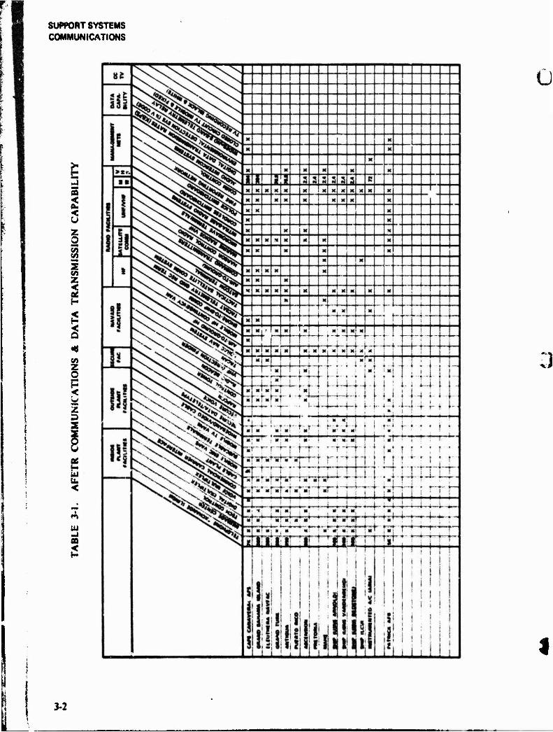
SUPPORT SYSTEMS COMMUNICATIONS
oa
< Ü z o g 5 c/i Z
<
Z o p <
2 3 3 3t
u
<
CD <
3-2
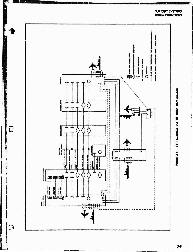
SUPPORT SYSTEMS COMMUNICATIONS
H
I i
0
i
?
K H IU
S 1
34

SUPPORT SYSTEMS COMMUNICATIONS
is similar to that used for point-to-point service but used at lower power levels.
The mainland hf transmitter site is located at Malabar» Florida. The site has five 205J-1A Collins 45-kW transmitters for use with rhombic and log periodic antennas; ten 240C-1 Collins 10-kW trans- mitters for use with rhombic, log periodic, and discone antennas; five 204F-1 Collins 2.5-kW transmitters used with log periodic, discone, doublet, and caged discone antennas; four KWT-6 Collins 500-W transceivers used with log periodic, discone, doublet, caged discone, and whip an- tennas; and two KWM-2 Collins 100-W transceivers used with whip antennas.
The mainland receiver site, located at CCAFS, has four 5151, sixteen 651 F-l, one 50E6, seven 50E6D, and six SX-116 receivers. The receivers are used in combination with the following receiver site anten- nas: one H log periodic (fixed), one V log periodic (fixed), two 237A1 log periodic (rotat- able), three 237B1 log periodic (rotatable), two discone, and two tri-nested rhombics.
Distribution of the remaining hf radio equipment is as follows:
HF TRANSMITTERS
45 kW lOkW 2.5 kW UW
Antigua 7 4 3 -
Ascension 13 7 2 -
Mahe 2 6- -
500 W 350 W 100 w
RCC-CCAFS 1 I
GB1 & Cays ■> *• -
Grand Turk _ "» -
Antigua - ~
Ascension - -
Mahe _ -
Eleuthera 2 «=
HF RECEIVERS
51S1 50E6 651F1 R390
RCC-CCAFS - 1 - -
Antigua 3 10 12 3
Ascension 2 17 20 2
GBI - - - 4
Grand Turk - - - 2
Eleuthera 1 - - 2
Mahe 2 2 8
The mainland hf antenna receiver site is located on CCAFS. There are: 16 Collins 651F1, four Collins 51S1, one Collins 50E6, four Collins 50E6D, three Collins 50E6DF, and six Hallicrafter SX-116 hf receivers. The hf receiver antennas consist of two tri-nested rhombics, five log periodics (fixed and rotatable), and two discone antennas for day and night reception.
The HF/SSB radios on board the aircraft (ARIA/TRAP) consist of three AN/ARC-58 trans- ceivers and use a retractable trailing wire antenna.
The USNS Arnold hf radio complement consists of two Collins 204C-1 10-kW, and two Collins 204F-1 2.5-kW linear amplifiers in combination with four each 310 F-6E exciters using three whip and on? long periodic CA-3038 antennas, four ISB 50E7 receivers, one R-390 receiver, one ISB 50E6D receiver, one SP-600 receiver, and five 65IF-1URG receivers using six whip antennas.
The USNS Vandenberg hf radio complement consists of two Collins 204C-1 10-kW and two Collins 204F-1 2.5-kW linear amplifiers in com- bination with four 310F6E exciters using three whips and one log periodic CA-3038 antennas, one R-390 receiver, two 50E7 receivers, six 65IF-1URG receivers, and seven whip antennas.
The USNS Redstone hf radio complement consists of six TMC TSTEI0K (10-kW hf transmitters), seven TMC DDRR 506 hf receivers, two log periodic antennas, three uhf antennas, six AX-568 hf transmitters, one monopoie antenna with four
3-4
if rVm f.T mriiBniiniY i1 iff Miff i furl jMhüAa^^iaMBaM
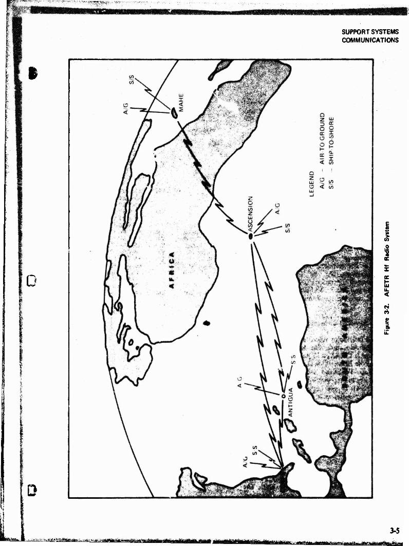
SUPPORT SYSTEMS COMMUNICATIONS
i
%**>
0
o
c H iu u. <
8 i.
t f.Jy.^-»-«ilWMia>a,.^8<.;Ai? mHimtmmum 3-5
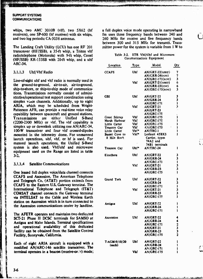
*™>**■ jiwpip.a^wwiWP^Wi? *"nf »-■' ■*"*■»?-'■ ' »■* * ^ * * t* ^;
SUPPORT SYSTEMS COMMUNICATIONS
whips, two AMC 301 OB (vlO, two 5X62 (hf receivers), one SP-600 (hf receiver) with six whips, and two log periodic CA-3038 antennas.
The Landing Craft Utility (LCU) has one RF 201 transceiver (HF/SSB), a 35-ft whip, a Triton vhf radiotelephone (Motorola) with 9-ft whip, Conel (HF/SSB) KR-I53SB with 20-ft whip, and a uhf ARC-34.
3.1.1.3 Uhf/Vhf Radio
Line-of-sight uhf and vhf radio is normally used in the ground-to-ground, air-to-air, air-to-ground, ship-to-shore, or ship-to-ship mode of communica- tions. Transmissions normally consist of admini- strative/operational test support coordination using simplex voice channels. Additionally, up to eight ARIA, which may be scheduled from Wright- Patterson AFB, can provide a real-time voice relay capability between spacecraft and ground stations. Transmissions are either Unified S-Band (2200-2300 MHz) or vhf. The vhf capability is simplex up or downlink utilizing one AN/ARC-34, 100-W transceiver and four vhf crossed-dipoles mounted in the telemetry dome. For unmanned launch operations, uhf, vhf, or hf is used. For manned launch operations, the Unified S-Band system is also used. Vhf/uhf and microwave equipment used on the Range are listed in table 3-2.
3.1.1.4 Satellite Communications
One leased full duplex voice/data channel connects CCAFS and Ascension. The American Telephone and Telegraph Co. (AT&T) portion extends from CCAFS to the Eastern U.S. Gateway terminal. The International Telephone and Telegraph (1T&T) COMSAT channel connects the Gateway terminal via INTELSAT to the Cable and Wireless Earth station on Ascension which is in turn connected to the Ascension communications center by landline.
The AFETR operates and maintains two dedicated SCT-21 Phase II DCSC terminals for SAMSO at Antigua and Mahe Islands. Terminal specifications and operational availability of this dedicated facility can be obtained from the Satellite Control Facility, Sunnyvale, California.
Each of eight ARIA aircraft is equipped with a modified AN/ARC-146 satellite transceiver. The terminal operates in a beacon (receive-or^v) mode;
a full duplex voice mode operating in narrowband fm uses three frequency bands between 240 and 260 MHz for receive and five frequency bands between 300 and 315 MHz for transmit. Trans- mitter power for the system is variable from 1 W to
Table 3-2. ETR Vhf/Uhf and Microwave Communications Equipment
Location Type Model Qty
CCAFS Uhf AN/GRT-22(xmtr) 7 AN/GRR-24(rcvr) 7 AN/GRC-171(xcvr) 3
Vhf AN/GRT-21 (xmtr) 6 AN/GRR-23(rcvr) 6 AN/GRC-175(xcvr) 3
GBI Uhf AN/GRT-22 3 AN/GRR-24 3 AN/GRC-171 1
Vhf AN/GRT-21 AN/GRT-23 AN/GRC-175
3
Great Stirrup Vhf AN/GRC-175 1 Marsh Harbour Vhf AN/GRC-175 1 Little Carter Vhf AN/GRC-175 1 Treasure Cay Vhf AN/GRC-175 1 Little Carter Vhf* AN/TRC-1 ! Basset Cove to Vhf* Lenkurt 45BX3 1
8 Mile Rock Carrier, types 74A2 and 74B1 terminals
Treasure Cay Uhf* AN/TRC-24 1
Eleuthera Uhf AN/GRT-22 3 AN/GRR-24 3 AN/GRC-171 1
Vhf AN/GRT-21 3 AN/GRR-23 3 AN/GRC-175 1
Grand Turk Uhf AN/GRT-22 3 AN/GRR-24 3 AN/GRC-171 1
Vhf AN/GRT-21 3 AN/GRR-23 3 AN/GRC-175 1
Antigua Uhf AN/GRT-22 1 AN/GRR-24 1 AN/GRC-171 1
Ascension Uhf AN/GRT-22 4 AN/GRR-24 4 AN/GRC-171 2 AN/GRT-21 3 AN/GRR-23 3 AN/GRC-175 2
T-AGM-9/10/20 Uhf AN/GRT-22 I (each) AN/GRR-24 1
AN/GRC-171 1 VM AN/GRC-175 1
3-6
<*i****»*m»** «z&mm^i**M&0'*~*:** Btat^j&Ätj*^.

■*™^mwmmm
SUPPORT SYSTEMS COMMUNICATIONS
•
war
> t r
I kW. The antenna subsystem consists of three ant nas, a dummy load, a diplexer, an rf sampler, an antenna select panel, and two coaxial relays. The diplexer permits simultaneous transmission and reception using a common antenna. Three antennas give the operator a choice of antenna pattern and polarization.
Each ARIS has an AN/ARC-146 satellite terminal with the identical parameters as the ARIA dis- cussed above. The exception is the antenna subsystem. The ARIS has two bow-mounted steerable (azimuth only) high gain, broadbeam antennas. Each antenna covers 180° from the bow to the stern. The port-mounted antenna covers the port side and the starboard-mounted antenna covers the starboard side of the ship.
3.1.1.5 Microwave System
One microwave link is used on the mainland to connect CCAFS (XY Bldg) and the Malabar transmitter site with a 24-channel breakout at the Patrick AFB Communications Center. This link uses a Collins MW-503 with a Collins MX-106 multiplexer to provide 108 two-way full duplex voice channels.
3.1.1.6 Teletype
The teletype network interconnecting AFETR stations for handling record traffic is shown in figure 3-3. Teletype circuits are multiplexed on 3-kHz voice channels of the undersea cable and hf radios. Message traffic is received and routed in both DD form 173 and JANAP 128 formats. Pro- vision is made for handling both classified and unclassified traffic. Typical equipment used in- cludes: AN/FGC-69,AF/FGC-97,II 333/UG12TD. II 47D/UG. AF/FGC-%. AN/UGC-32. AN/FGC-58. AN/UGC-32. and U-70A/UG. Dedicated, confer- ence, and shared-use circuits are available depend- ing on the type of service required as well as the quantity and precedence of traffic.
3.1.1.7 Voice Communications
The AFETR's administrative telephone system can handle all official calls. Limited secure voice systems are available for official use by authorized personnel.
Direct-dial circuits connect Patrick AFB and CCAFS with downrange subcabie stations. Manual
patch through the CCAFS/Malabar hf transmitter connects the ships, aircraft, and other stations which are not on the undersea cable.
Three intercommunications systems extend throughout the mainland and downrange instru- mentation and operational control sites. They are the Green Phone, Missile Operation Intercom System (MOIS), and Transistorized Operations Phone System (TOPS).
The Green Phone system is a direct line ringdown system which provides rapid communication for instrumentation supervisors to their operating personnel and to other supervisors. Each supervisor has one or more 10/12-line key panels at his operating position. A call is made by depressing one or more key switches in the top position. Subscribers call simply by lifting the handset. Key panels have visual and audible signaling. Since the system can be battery operated it is not affected by commercial power failures.
MOIS/TOPS are intercom systems which permit selection of a net or nets rather than individual stations. All related operating positions, such as those for telemetry are customarily assigned to the same net. Rotary selector switcnes on the end instruments are used to select the desired net. MOIS/TOPS maintain usable transmission level with headset operation under severe loading. Access to any net may be limited to certain operators who have previously selected the net.
TOPS is a completely transistorized network system which operates in either a 2 or 4-wire mode with a capability of selecting from 2 to 20 channels with up to 2S0 subscribers per channel. A variety of end instruments are available for use in indoor or outdoor weather. An explosion-proof end instrument is available for hazardous arras.
3.1.2 Range Communications Control Centers
Operations control of ETR communications is exercised at communications control centers at each major station. These centers allocate, moni- tor, and maintain transmission quality on all on- and off-base circuits and technical operations nets for their station. Equipment and capabilities are limited to manual and semiautomatic operation. See table 3-3.
3-7
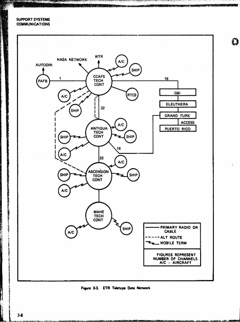
mMifMOm®?- A w„ > i- -/*
SUPPORT SYSTEMS COMMUNICATIONS
NASA NETWORK AUTODIN
PRIMARY RADIO OR CABLE
ALT ROUTE
hi MOBILE TERM
FIGURES REPRESENT NUMBER OF CHANNELS
A/C - AIRCRAFT
Figur« 3-3. ETR Teletype Data Network
3-8 -. —f.:-* ■._--> — ^ . ■ 111»! Mil " ..■■-■■•■■ — --—>*-* liiHWT n-nnTim.nl. n r.nm^-1, ■ .■■„M>»«r> ehA^ii
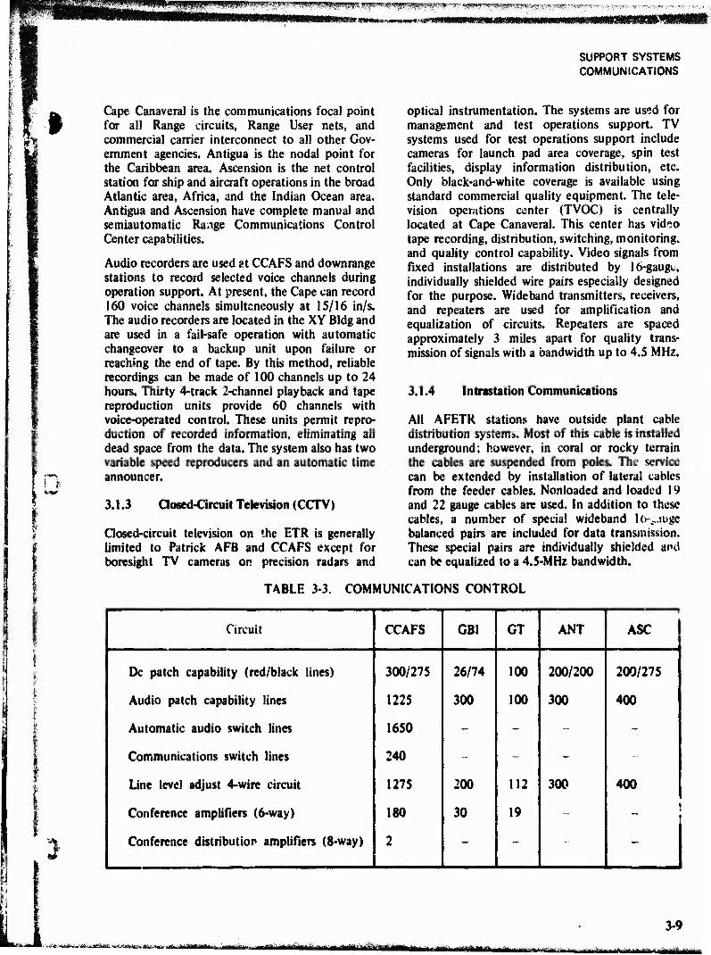
§ Cape Canaveral is the communications focal point for all Range circuits, Range User nets, and commercial carrier interconnect to all other Gov- ernment agencies. Antigua is the nodal point for the Caribbean area. Ascension is the net control station for ship and aircraft operations in the broad Atlantic area, Africa, and the Indian Ocean area. Antigua and Ascension have complete manual and semiautomatic Range Communications Control Center capabilities.
Audio recorders are used at CCAFS and downrange stations to record selected voice channels during operation support. At present, the Cape can record 160 voice channels simultaneously at 15/16 in/s. The audio recorders are located in the XY Bldg and are used in a fail-safe operation with automatic changeover to a backup unit upon failure or reaching the end of tape. By this method, reliable recordings can be made of 100 channels up to 24 hours. Thirty 4-track 2-channel playback and tape reproduction units provide 60 channels with voice-operated control. These units permit repro- duction of recorded information, eliminating all dead space from the data. The system also has two variable speed reproducers and an automatic time announcer.
3.1.3 Closed-Circuit Television (CCTV)
Closed-circuit television on the ETR is generally limited to Patrick AFB and CCAFS except for boresight TV cameras on precision radars and
SUPPORT SYSTEMS COMMUNICATIONS
optical instrumentation. The systems are used for management and test operations support. TV systems used for test operations support include cameras for launch pad area coverage, spin test facilities, display information distribution, etc. Only black-and-white coverage is available using standard commercial quality equipment. The tele- vision operations center (TVOC) is centrally located at Cape Canaveral. This center has video tape recording, distribution, switching, monitoring, and quality control capability. Video signals from fixed installations are distributed by 16-gaugc, individually shielded wire pairs especially designed for the purpose. Wideband transmitters, receivers, and repeaters are used for amplification and equalization of circuits. Repeaters are spaced approximately 3 miles apart for quality trans- mission of signals with a bandwidth up to 4.5 MHz.
3.1.4 Intrastation Communications
All AFETR stations have outside plant cable distribution systems. Most of this cable is installed underground; however, in coral or rocky terrain the cables are suspended from poles. The service can be extended by installation of lateral cables from the feeder cables. Nonloaded and loaded 19 and 22 puge cables are used. In addition to these cables, a number of special wideband lo>auge balanced pairs are included for data transmission. These special pairs are individually shielded and can be equalized to a 4.5-MHz bandwidth.
T4BLE 3-3. COMMUNICATIONS CONTROL
% «*
Circuit CCAFS GBI GT ANT ASC
Dc patch capability (red/black lines) 300/275 26/74 100 200/200 200/275
Audio patch capability lines 1225 300 100 300 400
Automatic audio switch lines 1650 - - - -
Communications switch lines 240 - - - -
Line level adjust 4-wire circuit 1275 200 112 300 400
Conference amplifiers (6-way) 180 30 19 - i
Conference distribution amplifiers (8-way) 2 - - -
3-9 ;- .,^.a>.~-.-, fefe^a^-aga—ttfäffilBliii „.,-..-... —ggjjyu^njg >...„,- ^itf ■'tf^TfiiHlliiiil I, **,***.■ mfiMam,*M.i, aaMfcujafcaaaa ja»aM«i«iaaa»üJMB«Mi
^^m^mm^sm
SUPPORT SYSTEMS COMMUNICATIONS
3.1.4.1 Voice Communica tion
All intrastation administrative and operational voice communication are conducted by local telephone and interphone systems using the same end instruments previously described.
Additionally each mainland and downrange station has a public address/aural warning system used for local area personnel paging, dissemination of test support and countdown information, and emer- gency warning and instructions.
3.1.4.2 Downrange Microwave
A Lenkurt microwave system using a 45BX3 carrier and type 74A2 and 74B1 terminals is installed between Basset Cove and Eight Mile Rock, Grand Bahama Island.
Antigua Air Station utilizes a microwave system between the main base and the transmitter site at Paruim Point. The system uses four Lenkurt 74B1 microwave receive/transmit units with two Lenkurt
46A2 channel multiplexers to provide 24-channel duplex service.
Mahe Island utilizes a 24-channel ATRAX system between the. transmitter and receiver sites and between the technical site and receivers.
3.1.4.3 Intrabase Radio
Each station maintains a two-way base station for administrative and emergency voice communica- tions. The base station uses a 6,0-W Motorola type C536KB-1100B narrowband fm transceiver which normally connects the base communications cen- ter, fire and security headquarters, runway control tower, and base powerhouse. Mobile units are usually installed in ambulances and in vehicles operated by the USAF Base Commander, Range Contractor Base Operations Manager, and fire and security. These units are usually mobile two-way Motorola Model U43HHT-543HHT with 25 W power.
Additionally, Range and Range User personnel use two-way simplex hand-held walkie-talkies for spe- cialized voice communications.
i 3-10
ja&Mumstmt. HÜ mndtM»mmtum,iL wKtmmm,,. I'II Miiirriiifiiiilliriiiiiiiiiaii
„,vw,...
«-*■"■'"■-: W!i!«i'.S »E** ^y&^V:
SUPPORT SYSTEMS COMMAND/CONTROL
3.2 COMMAND/CONTROL
«#
i
The ETR Command/Control System consists of a network of radio transmitters at Cape Canaveral Air Force Station, Grand Bahama, Antigua, and onboard the USNS Redstone, The land-based sites are linked to the CCAFS Range Safety Officer (RSO) console located in the Range Control Center for center point control operation, and are used by Range Safety Officers to transmit arm-and-destruct commands to missiles and spacecraft. Range User application of the system includes transmission of commands such as command safe, engine cutoff, and retrofire, and transmission of tones for vehicle control.
For northerly launch azimuths the NASA Bermuda and Wallops Island stations are used by Range Safety when additional coverage is needed. The Bermuda station is a prime support station for NASA manned launches, but is considered backup for DOD launches also.
The Command Destruct System on the USNS Redstone provides the capability for mobile com- mand transmitters. This system primarily supports the USN Fleet Ballistic Missile Programs in conjunction with the Launch Area Support Ship (LASS) from which the request for flight termina- tion is made.
Each of the ETR transmitter sites, the USNS Redstone, and NASA's Bermuda station have two high-power (10-kW) transmitters, while the Wallops Island transmitter is limited to 600 watts. The ETR Cape site can also transmit low power (600 W) signals for use in the launch area.
3.2.1 Land-Based System
Commands are initiated by the RSO, or the flight controller in the case of Range Users, by closing a switch. The switch closure from the console is converted to a MIL STD 188 compatible serial output by dual-redundant encoders installed in the Range Control Center. This output will be routed via the Range Instrumentation Control System (RiCS) to the remote command transmitting sites at CCAFS, Grand Bahama, and Antigua. A command decoder and verifier decode the com- mand from the serial data and, as appropriate for the mission, keys the audio from the tone encoder or the digital Range Safety encoder. The encoder output frequency modulates the carrier and the
composite signal is radiated to the vehicle (only one station radiates at a time to avoid mutual interference). At the same time, the output of the transmitter is detected before reaching the trans- mitting antenna and applied to a receiver/decoder, the output which is recorded on a strip chart and also transmitted back to the RSO (or flight controller) via the remote control group to show the command has been transmitted.
The vehicle receives the rf signal, detects the coded command, and passes it to the decoder. The decoder output is a relay closure which activates the destruct mechanism (or causes some other desired action such as fuel cutoff). Telemetry may or may not report on vehicle response to com- mands but generally does report received signal strength. The rf signal is a frequency-modulated carrier (406-450 MHz) and the carrier deviation is selectable from ±30 to ±300 kHz. The modulating signal is supplied by audiotone coders.
The ground equipment can be divided into three groups: remoting, coding, and transmitting. Re- dundancy is used within each group to obtain high reliability. The interconnection of these three groups is always the same although the amount of equipment varies from station to station. A typical downrange system is shown in figure 3-4.
3.2.1.1 Remoting Group
A means of directly controlling the command/ contrul encoders and transmitters at Cape Canaveral, Grand Bahama, and Antigua from the Range Control Center at Cape Canaveral is pro- vided by the RICS and local remoting links. The latter consists of frequency shift key (FSK) tone equipment which transfers closures from the RICS terminals or the local RSO console at a given station to the remote transmitter site. Thus, any station can be selected either manually or auto- matically by a station sequencer.
The RICS is a digital supervisory control and communications system for rapid message ex- change between CCAFS and downrange stations via the undersea cable.
The data conversion subsystem (see figure 3-5) sends Range User commands from Cape Canaveral to the command/control stations. Basically, the subsystem remotely controls 17 relays by fre- quency division multiplexing 17 tones onto a
3-11 - .:.»,«■ aaMSaagiggfeaasifel *■»<*■>
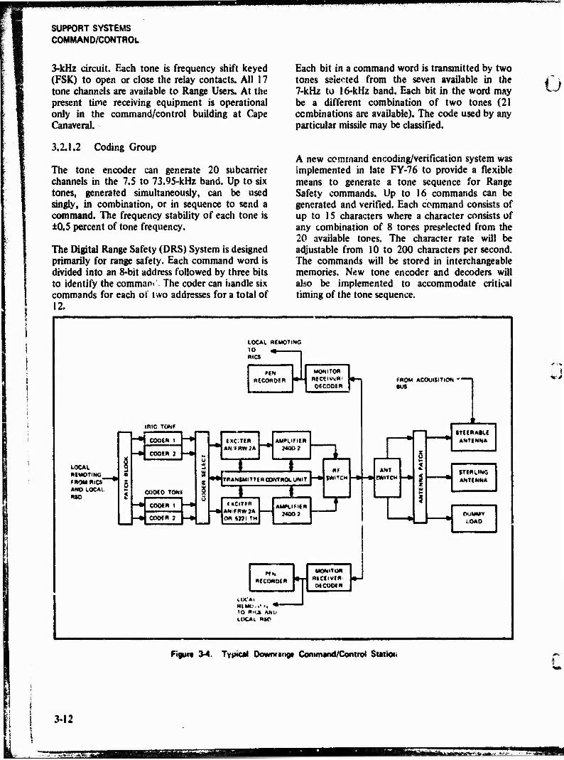
SUPPORT SYSTEMS COMMAND/CONTROL
3-kHz circuit. Each tone is frequency shift keyed (FSK) to open or close the reiay contacts. All 17 tone channels are available to Range Users. At the present time receiving equipment is operational only in the command/control building at Cape Canaveral.
Each bit in a command word is transmitted by two tones selected from the seven available in the 7-kHz to 16-kHz band. Each bit in the word may be a different combination of two tones (21 combinations are available). The code used by any particular missile may be classified.
Ü
3.2.1.2 Coding Group
The tone encoder can generate 20 subcarrier channels in the 7.5 to 73.95-kHz band. Up to six tones, generated simultaneously, can be used singly, in combination, or in sequence to send a command. The frequency stability of each tone is ±0.5 percent of tone frequency.
The Digital Range Safety (DRS) System is designed primarily for range safety. Each command word is divided into an 8-bit address followed by three bits to identify the comman» The coder can handle six commands for each o! two addresses for a total of 12.
A new command encoding/verification system was implemented in late FY-76 to provide a flexible means to generate a tone sequence for Range Safety commands. Up to 16 commands can be generated and verified. Each command consists of up to 15 characters where a character consists of any combination of 8 tores preselected from the 20 available tones. The character rate will be adjustable from 10 to 200 characters per second. The commands will be stored in interchangeable memories. New tone encoder and decoders will also be implemented to accommodate critical timing of the tone sequence.
LOCAL RfMOTING
RICS
PIN RECORDER
MONITOR RICEIVWR'
DECODER
tfilO TONF
LOCAL RIMGTING » ROM RICS™ AND LOCAL RIO
CODER 1
CODER i
CODED TONE
CODER 1
CODER 1
EXCTIR AN/FRW7A
AMPLIFIER
TRANSMITTER CONTROL UNIT
TZ 1 (MCiTER
AN/FRWJA m ms TM
AMPLIFIER JMOJ
RE SWITCH
RECORDER
lUCAi R(MO, .•-j • 10 RiCS AM.' LOCAL «SO
D1 MONITOR
RECEIVER MCOOER
BUS
ANT SWITCH
3UISITIC4 4 —
STEERABLE ANTENNA
STERLING ANTENNA
DUMMY LOAD
"1 !
Figure 3-4. Typical Dowmange Command/Control Stattet im,-
I
3-12
SSE^j rihmffMffl
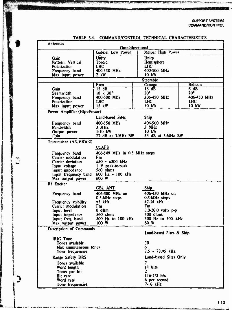
pwipwpspppp? «TPSSH^^cWKppv
SUPPORT SYSTEMS COMMAND/CONTROL
TABLE 3-4 k COMMAND/CONTROL TECHNICAL CHARACTERISTICS Antennas
Omnidirectional
Gain Pattern, Vertical Polarization Frequency band Max input power
Gabriel Low Power Melpar High P^wer Unity Toroid LHC 400-550 MHz 2 kW
Unity Hemisphere LHC 400-500 MHz 10 kW
Steerable
Gain Beamwidth Frequency band Polarization Max input power
Esco Canoga Helicon 15 dB 18 x 30° 400-500 MHz LHC 15 kW
18 dl 20° 306450 MHz LHC 10 kW
6 dB 70° 406-^50 MHz LHC 10 kW
Power Amplifier (Hi& t-Power) Land-based Sites Ship
Frequency band 400-550 MHz 406-500 MHz Bandwidth 3 MHz 3 MHz Output power 1-10 kW 10 kW ^iin 27 dB at 3-MHz BW 33 d3 at 3-MHz BW
Transmitter (AN/FRW-2)
Frequency band Carrier modulation Carrier deviation input voltage Input impedance Input frequency band Max output power
CCAFS 406-549 MHz in 0 5 MHz steps Fm ±30 - ±300 kHz 1 V peak-to-peak 560 ohms 600 Hz - 100 kHz 600 W
Rf Exciter
Frequency band
Frequency stability Carrier modulation Input level Input impedance Input freq. band Max output power
GBI. ANT Ship 406-500 MHz on 406450 MHz on 0.5-MHz steps 0.5-MHz steps ±5 kHz ±2.14 kHz Fm Fm 0 dBm 2.0-20.0 volts p-p $60 ohms 500 ohms 300 Hz to 100 kHz 300 Hz to 100 kHz 100 W 80 W
Description of Command
IRIG Tone Tones available Max simultaneous tc Tone frequencies
Range Safety DRS Tones available Word length Tones per bit Bit rate Word rate Tone frequencies
Land-based Sites & Ship
20 mes 6
7.S - 73.95 kHz Land-based Sites Only 7 11 bits 2 116-2/3 b/s 6 per second 7-16 kHz
3-13 jiUHUibUU^r^^ i^dfejsaaftriiattäaÄdi
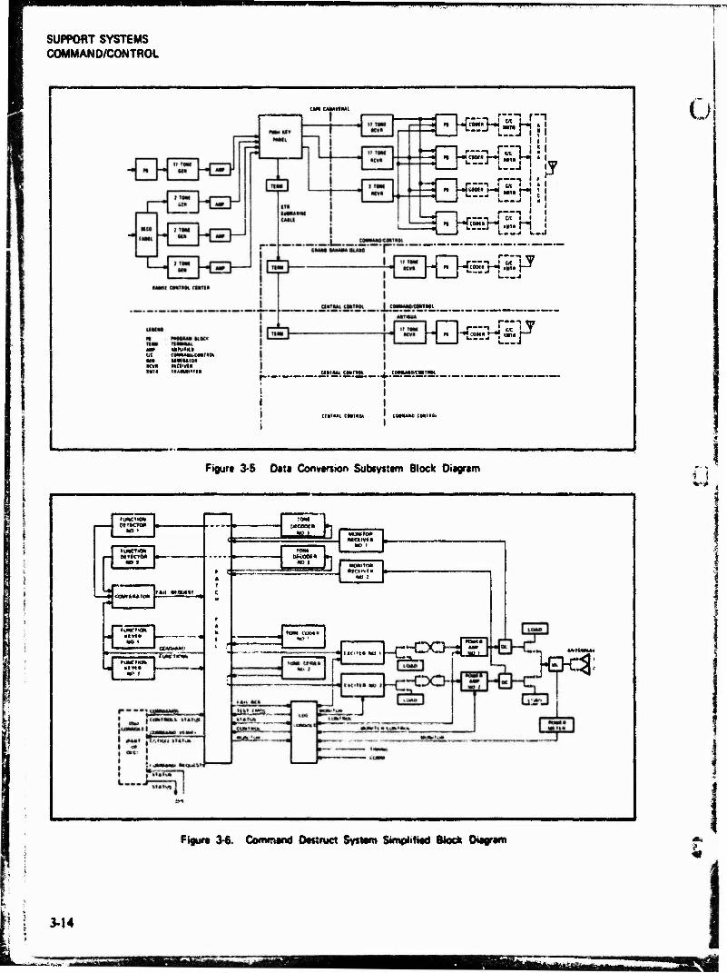
SUPPORT SYSTEMS COMMAND/CONTROL
UK CMMVf HAI
Uta*« ft cenMHbCM»«, IfMftAfOft KCBtVlS TftAMMiTTIH
-i i at I .! w« t-»l i J
■n
-J « |-J}ÖM«J-« iina (—*
cMiiMtawim
"• M '■«*£'
cwui MMMK j
WUt CMlftSt [QMAftfi CMiafe
Figure 3-5 Data Conversion Subsystem Block Diagram
•weft«*
e»«j QgrtCfG«
rE ä28»***ie»» l*U_t«äyi«I
10M Btceet*
SB i
WBS5KJ
• 1 _._f"v~>_- 'S"
-EHr$:
Figure 34. Command Destruct System Simplified Bleck Dtagram «s
3-14
f<pfpp«wf^^ UBS
/*?'•.
SUPPORT SYSTEMS COMMAND/CONTROL
i t
3.2.1.3 Transmitting Group
The AN/FRW-2 transmitter, currently used at the CCAFS command control site, is crystal controlled and provides up to 600 watts of rf power. Rf power of up to 10 kW (practical limit of 8 kW) is provided by 240D-2 power amplifiers which are driven by the AN/FRW-2's. At Grand Bahama and Antigua the FRW-2's have been replaced by solid-state exciters having an output up to 100 watts. Dual, tow-power solid-state exciters are also scheduled to replace the AN/FRW-2's at the Cspe in FY-77.
3.2.2 Shipborne System
The USNS Redstone Command Destruct System (CDS) is designed to permit positive flight termina- tion of errant sea-launched missiles. Arm-and* destruct command functions (coded audio tones) are frequency modulated onto a 10-kW rf carrier and transmitted at the request of the LASS Flight Safety Officer (FSO). The carrier frequency is selectable in 0.5-MHz steps from 406 to 450 MHz.
The Command Destruct System is divided into five subsystems: (I) remote monitor and control subsystem that provides shipboard function activa- tion, monitoring, and distribution; {2) a control subsystem that provides status indications, control functions, and interface connections with system components and other shipboard systems; (3) a local monitoring subsystem that provides demodu- lated signals for verification of command function transmission; (4) a function keying subsystem for sequencing and activating the proper tone com- binations; and (5) transmitting subsystem that performs the modulation, rf power generation, and radiation of cnc.gy into space. Figure 3-6 depicts the command destruct system in block diagram form.
3.2.2.1 Remote Monitor and Control Subsystem
The remote monitor and control subsystem is the primar> interface for controlling and monitoring the Command Destruct System during normal operation.
The FSO has the option of operating in either manual or automatic mode, in the automatic mode, the link signal« from the Central Data Processing System are sent from the FSO console to the Command Destruct System equipment with
no FSO intervention. In the manual mode, the link signals are terminated at the FSO console, and Command Destruct System equipment is operated from the FSO console or at the CDS console.
3.2.2.2 Control Subsystem
The control subsystem consists of five bays and the Command Destruct System Console that provides all necessary control functions to operate, monitor, and test the entire system. It also provides an interface with other CDS equipment and with other ship systems.
3.2.2.3 Local Monitoring Subsystem
The local monitoring subsystem is used to verify and record the transmitted functions and the rf carrier level. Events such as transmitted Range Safety Center command functions, transmitted tones, equipment status, system status, and se- lected mode indications are selectable for inputs to the recorder.
3.2.2.4 Function Keying Subsystem
The function keying subsystem provides a capa- bility for assigning preestabUshed codes to the four arm-and-destruct function combinations. Any com- bination of three tones, from a total of 10 tones, can be selected and assigned to each of four missiles.
3.2.2.5 Rf Transmitting Subsystem
The rf transmitting subsystem is a dual/redundant transmitter group, consisting of a tone coder, an fm exciter, a power amplifier, and an rf switching antenna and dummy load assembly.
The exciters provide a nominal 15 watts drive power to the 10-kW power amplifier«. The exciter output is frequency modulated with audio tone« from a tone coder and has a frequency in the 406 to 45Q MH? range. The power amplifiers provide 10 kW of rf power to the rf switching and dummy load assembly which transfers the power output to one of two antennas or to dummy loads.
Rf is »dialed by hroadbeam helical antennas. Dual antennas are provided, and each is mounted on eievation-over-aximuth pedestals. Direction*! con- trol is accomplished with elevation and azimuth manual control* on the pedestals. The antenna can
";a"—**--^i«iar,'tiMfiwi-iif>rtalifdiHi in if 11"» I in irtilMiiWMi IM« I Hi mat mti-iiiMr-nTiTi TUMUML J immii

SUPPORT SYSTEMS COMMAND/CONTROL
«•El
be positioned from +10° to +80° in elevation and ±90* in azimuth.
3.2.3 Summary
Location and capabilities of each command/ control station are given in table 3-5. Each
downrange station and the USNS Redstone has one complete high power dual redundant transmitting system. The Cape has three complete dual re- dundant systems: one high power, one low power emergency backup, and one low power system for local pad support.
TABLE 3-5. COMMAND/CONTROL STATION LOCATIONS AND CAPABILITIES
Station Max Power
Available Coders
AN/FRW-2 Exciter Antenna IRIG Tone DRS Remoting
Cape Canaveral 600 W X X X X Two Canoga (NASA)
10 kW X X X X One Melpar Hi-power omni
One Gabriel Lo-power omni
Grand Bahama 10 kW X X X X Two ESCO
Antigua 10 kW X X X X One ESCO
One TEMEC Dish
USNS Redstone 10 kW X X Two Hi-power Helicon
Beimuda (NASA) 10 kW X X X Two Canoga
Wallops Is (NASA) 600 W X X X Two Canop
KEY: IRIG ■ Intensnge Instrumentation Group
DRS ■ Digital Range Safety System
3-16 s
-ii in .im' 11 ifrMfbmMitmullZlit&m'i» -' ^m(fifrAiftrnvMäir,~**g^^^MMtiM

mmmme-^a >»' ■ i1 UMMMMMNMI
SUPPORT SYSTEMS TIMING
I 3.3 THE ETR TIMING SYSTEM
C
t i
i
3.3.1 Cape Canaveral AFS Central Timing
The time signal generators used at the ETR are synchronized to Universal Time Coordinated (UTC) with the aid of the East Coast Loran C Chain, operated by the U.S. Coast Guard, and closely synchronized to the U.S. Naval Observatory and radio station WWV operated by the National Bureau of Standards.
The time signal generators located in the Range Control Center produce 24 different time codes (presence-absence, pulse width, and pulse posi- tion), with frame rates ranging from 1 f/hr to 10 f/s and element rates ranging from I p/m to 1,000 p/s. Time words are coded straight binary seconds time-of-day, modified binary hours-minutcs- seconds and 10th seconds time-of-day, binary- coded decimal days-hours-minutes-seconds and 10th seconds time-of-year, and combinations thereof. In addition. 28 pulse repetition rates are produced, ranging from 1 p/hr to 100,000 p/s. All outputs of the time signal generators are fed to a patch panel where plug-in modular distribution amplifiers have input and output signal termina- tions. Through system patching the following output configurations are possible:
1. High Level Signals. Forty-two channels of high-level timing signals are available to Range User equipment near the Range Control Center, the generating point. Thirty-six channels of dry contact relay closures are also available.
2. Low Level Signals. Sixty-four channels of low-level signals, distributed over the Cape by the communications system, are sent out as low-level spikes to be shaped and amplified by timing terminal units. Fourteen channels of amplitude-modu- lated sine wave signals suitable for com- munication line transmission are also available.
3.3.2 Dowttrange Central Timing
All downrange stations contain dual time-signal generators and a signal comparator. The signal generators at Grand Bahama. Grand Turk, and Antigua Central Timing are identical to those at CCAFS. The signal generators are synchronized to
the DOD master clock via WWV and Loran-C with periodic verification by portable cesium clocks.
3.3.3 Terminal Timing Systems
A timing terminal unit consists of a power supply and chassis that accepts modular subassemblies. Five types of plug-in modules are available: (I) code shapers (to develop high-level coded time signals), (2) pulse shapers (to produce high-level pulses synchronized with range time) (3) neon drivers (for high-level signals for neon lamps), (4) sine wave drivers (to produce amplitude-modulated sine waves whose frequency is derived from the repetition rate and the amplitude modulation from the coded time), and (5) tone detectors (which produce high-level signals or relay closures from an amplitude-modulated sine wave). The outputs of the timing terminal units are used for data clocking, neon light timing for metric camera operation, and timing records on magnetic tape and oszi'lograph charts.
The overall accuracy of the timing signals is deteriorated by transmission delays, the delay of the timing terminal unit, and the response time of the customer instruments. When correlation accu- racy better than I millisecond is needed, these delays can be measured and incorporated in the data reduction process.
3.3.4 Subcentral Timing Systems
Subcentral Timing Systems at satellite instrumenta- tion sites on the Florida mainland (I) accept and det?c< a signal from the central timing system; (2) generate pulse rates, coded timing signals, and position identifiers: and (3) provide standard signals to instrumentation equipment and timing terminal units.
The transmission delays are periodically measured and compensated for so that the subcentral sites are within S jis of synchronization with the central liming system.
3J.S Uhf Timing Distribution System
A Time Division Multiplexed Timing Distribution System (TDMTDS) is in operation at Cape Canaveral
At Central Timing, an encoder time multiplexer early signals from the generators and distributes
taaa ■'■^j" dä*aeaa "^r ia i Ataai«B»lt.»i ^jjgfe, 3-17
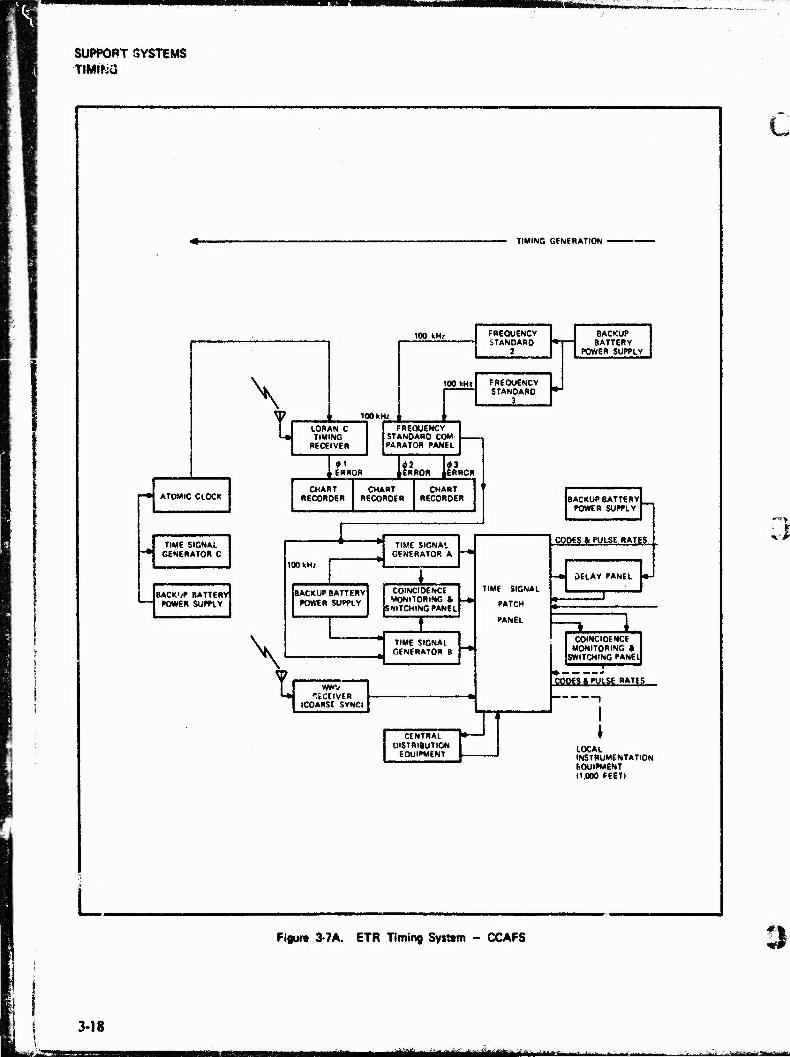
SUPPORT SYSTEMS TtMifcÜ
TIMING GENERATION
100 kHl
\
ATOMIC CLOCK
TIME SIGNAL GENERATOR C
BACKUP BATTER' TOWER SUPPLY 3
ti 100 km
LORAN C TIMING
RECEIVER
FREQUENCY STANDARD
2
100 kHi FREQUENCY STANDARO
3
BACKUP BATTERY
TOWER SUPPLY
FREQUENCY STANDARD COM- PARATOR PANEL
#1 j_ERROR
CHART RECORDER
ERROR
CHART RECORDER
*3 ERRCR
CHART RECORDER
\
BACKUP BATTERY POWER SUPPLY
100 kH»
TIME SIGNAL GENERATOR A
(BACKUP BATTERY I POWER SUPPLY
COINCIDENCE MONITORING a
SWITCHING PANEL
TIME SIGNAL J GENERATOR B
\
wwv RECEIVER
(COARSE SYNCI
TIME SIGNAL
PATCH
PANEL
CODES & PULSE RATES
DELAY PANEL
CENTRAL DISTRIBUTION
EQUIPMENT
Jl
COINCIDENCE MONITORING *
SWITCHING PANE* I
WfffS ft "WSE BAT^
LOCAL INSTRUMENTATION EQUIPMENT 11.000 FEET)
3-18
Figure 3-7A. ETR Timing System - CCAFS
atataa Mkk »-fi*aBte^. .:-. ...■».» :->»»,;m^i«t»
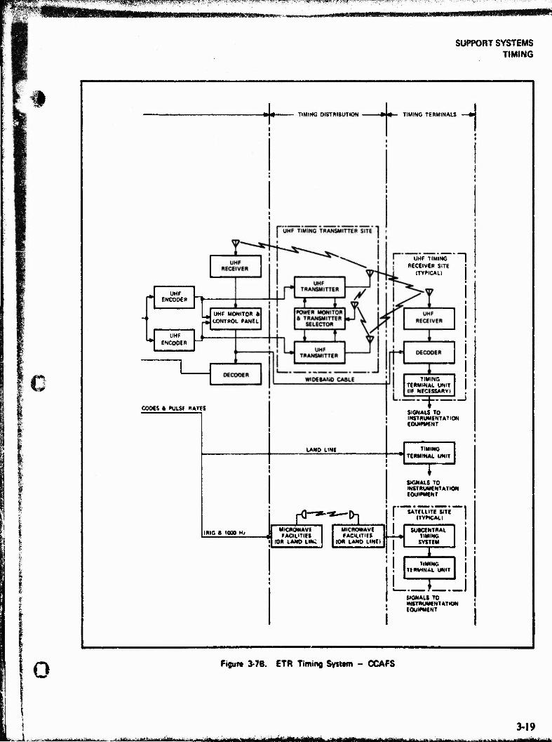
■* '--w^tf »1. f•" iv v
SUPPORT SYSTEMS TIMING
-*!*■ TIMING DISTRIBUTION • •— TIMING TERMINALS H
-. UHF *■ ENCODER
UHF ENCODER
_. UHF MONITOR It CONTROL PANEL
l£
UHF TIMING RECEIVER SITE
(TYPICAL)
COOES i PULSE RATES
TIMING TERMINAL UNIT (IF NECESSARYI
LAND LINE
r=p= SIGNALS TO INSTRUMENTATION EQUIPMENT
TIMING TERMINAL UNIT
SIGNALS TO INSTRUMENTATION EQUIPMENT
IRIG B 1906 Hj
fQr*~*~~ 0] I" SATELLITE SITE " (TYPICAL I
MICROWAVE <B FACILITIES
(OR LAND LINC
MICROWAVE FACILITIES
10* LAW LINE I
SUKfMTRAL TIMING SYSTEM
TIMING TERMINAL UNIT
Tzr_i SIGNALS TO INSTRUMENTATION EQUIPMENT
o Figure 3-7B. ETR Timing System - CCAFS
i-Jr. ■ ■ I ■ ill i - i ; --Hftf-i , ^-iV .T.li-lri-|t"---— li Hi I I III llllll«-|lllllir II It Ij^MllUMjlirlWiiaai >l HtlrtiMlimillll ■ ill II Hill
3-19

mm MMmt. fi;7«A:W':iJ",W'ö^i''äS»"!!^^ij^S UP——
SUPPORT SYSTEMS TIMING
ll
#4
I
5*5
(t
iff Hi
Is
s C «s ii s a*
•i « e §
§1 I *
c -&a * s
II »
It
r-* Sol
J.
il 1~T
»/*" ^
I ,iil ii
M -i Is IT
l! Ii
.-♦«■* 3li!
Sit 813
/
5"
§§ ^3"
••mm -J3S
ago
*****
8i!|l« of; fSI
lillp y. _ •„> * * *
1 <M g < * U *•
a >
& c a
E
1
K H Ui
£ & il
3-20
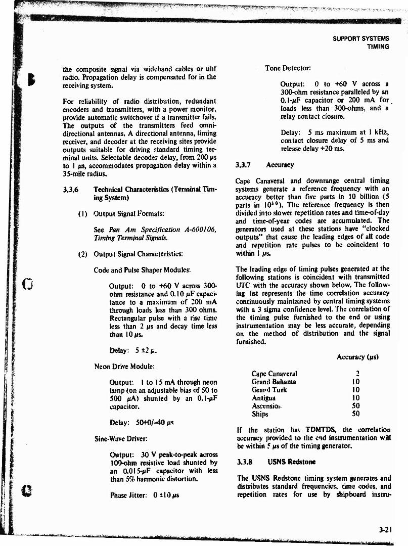
HW^Ü^^^^^^^^:: ^.Si.TfW-.T r-w -, „ -.»^,^„^^5^,^,,.
m
SUPPORT SYSTEMS TIMING
p
0 J
Q
the composite signal via wideband cables or uhf radio. Propagation delay is compensated for in the receiving system.
For reliability of radio distribution, redundant encoders and transmitters, with a power monitor, provide automatic switchover if a transmitter fails. The outputs of the transmitters feed omni- directional antennas. A directional antenna, timing receiver, and decoder at the receiving sites provide outputs suitable for driving standard timing ter- minal units. Selectable decoder delay, from 200 p$ to 1 its, accommodates propagation delay within a 35-mile radius.
3.3.6 Technical Characteristics (Terminal Tim- ing System)
(1) Output Signal Formats:
See Pan Am Specification A-600106, Timing Terminal Signals,
(2) Output Signal Characteristics:
Code and Pulse Shaper Modules:
Output: 0 to +60 V across 300- ohm resistance and 0.10 fiF capaci- tance to a maximum cf 200 mA through loads less than 300 ohms. Rectangular pulse with a rise time less than 2 fi$ and decay time less than 10 «is.
Delay: 5 ±2 M-
Neon Drive Module:
Output: 1 to 15 mA through neon lamp (on an adjustable bias of SO to 500 pA) shunted by an 0.1-MF capacitor.
Delay: 50+0/-40 M*
Sine-Wave Driver:
Output: 30 V peak-to-peak across tOO-ohm resistive load shunted by an 0.01 5-MF capacitor with less than 5% harmonic distortion.
Phase Jitter: OilOjis
Tone Detector:
Output: 0 to +60 V across a 300-ohm resistance paralleled by an 0.1-MF capacitor or 200 mA for loads less than 300-ohms, and a relay contact closure.
Delay: 5 ms maximum at 1 kHz, contact closure delay of 5 ms and release delay +20 ms.
3.3.7 Accuracy
Cape Canaveral and downrange central timing systems generate a reference frequency with an accuracy better than five parts in 10 billion (5 parts in 1010). The reference frequency is then divided into slower repetition rates and time-of-day and time-of-year codes are accumulated. The generators used at these stations have "clocked outputs" that cause the leading edges of all code and repetition rate pulses to be coincident to within 1 MS.
The leading edge of timing pulses generated at the following stations is coincident with transmitted UTC with the accuracy shown below. The follow- ing list represents the time correlation accuracy continuously maintained by central timing systems with a 3 sigma confidence level. The correlation of the timing pulse furnished to the end or using instrumentation may be less accurate, depending on the method of distribution and the signal furnished.
Accuracy (MS)
Cape Canaveral Grand Bahama 10 Grand Turk 10 Antigua 10 Ascensioi. 50 Ships 50
If the station has TDMTDS, the correlation accuracy provided to the end instrumentation will be within 5 MS of the timing generator.
3.3.8 USNS Redstone
The USNS Redstone timing system generates and distributes standard frequencies, time codes, and repetition rates for use by shipboard instru-
«^ü&äiyyjatfÄÄÄ i tin HU iiMBiw'" ifrmt.iwnfntiniiiiiMtitu tttfc:
3-21
»a«* "wmajij
SUPPORT SYSTEMS TIMING
mentation. The timing equipment is located in the communications and timing center room. Timing system leading particulars are as follows:
1. System outputs - 5 MHz, 1 MHz, and 100 kHz; pulses - 2 p/s, 400 p/s, 2 p/m, and 10 p/m; and time signals - BCD time-of-year to 0.1 s, serial binary time-of-year to 0.1 s time codes I RIG A-H, Central Data Processing (CDP) code (for TOY indicators); sinusoidal signals; square waves correlated to a 1 p/s on-time signal; and square waves delayed with respect to the 1 p/s on-time signal by selectable amounts; all based on rubidium standard.
2. Cesium beam frequency standard "clock" - Hewlett-Packard Model 5061 in system; off-line, as master clock for reference and synchronization. Cumula- tive time offset of 0.4 ßs per day.
3. Rubidium frequency standard - long- term stability ±1x10"*' per month
3.3.9
(maximum limit of drift rate), short- term stability of 5x10"*2 per second.
ARIS
|
Dual crystal oscillators provide the timing base for time code generators which feed monitoring and distribution equipment to produce 23 digital codes, 39 mixed codes, 39 pulse rates, and 7 sine waves in the standard, approved 1R1G format. Through reception of standard hf broadcast and the use of an on-board cesium beam frequency standard and Loran-C equipment, timing synchro- nization to UTC is maintained.
Digital time codes are used by the ship computer and for recording on pen recorders, oscillographs, and camera film. Mixed codes, such as a 1-kHz sine wave modulated with a digital code, are used for recording on magnetic tape. Pulse repetition rates are provided for mixing with time codes to interpolate between code pulses and for use as driving pulses for instrumentation equipment. Sine waves provide reference frequencies.
3
i 3-22
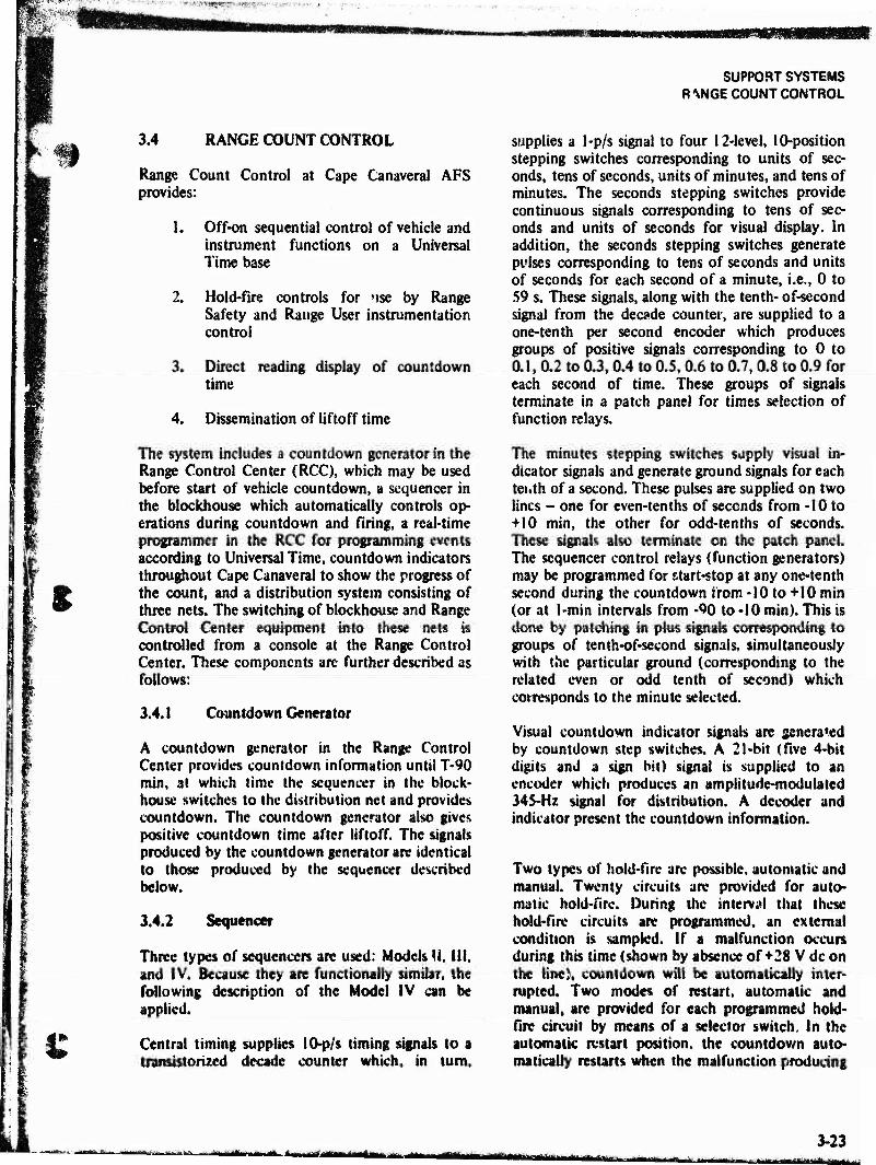
^$i.rfi^-
SUPPORT SYSTEMS R *\NGE COUNT CONTROL
3.4 RANGE COUNT CONTROL
m
Range Count Control at Cape Canaveral AFS provides:
1. Off-on sequential control of vehicle and instrument functions on a Universal Time base
2. Hold-fire controls for Mse by Range Safety and Range User instrumentation control
3. Direct reading display of countdown time
4. Dissemination of liftoff time
The system includes a countdown generator in the Range Control Center (RCC), which may be used before start of vehicle countdown, a sequencer in the blockhouse which automatically controls op- erations during countdown and firing, a real-time programmer in the RCC for programming events according to Universal Time, countdown indicators throughout Cape Canaveral to show the progress of the count, and a distribution system consisting of three nets. The switching of blockhouse and Range Control Center equipment into these nets is controlled from a console at the Range Control Center. These components are further described as follows:
3.4.1 Countdown Generator
A countdown generator in the Range Control Center provides countdown information until T-90 min, at which time the sequencer in the block- house switches to the distribution net and provides countdown. The countdown generator also gives positive countdown time after liftoff. The signals produced by the countdown generator are identical to those produced by the sequencer described below.
3.4.2 Sequencer
Three types of sequencers are used: Models U. Ill, and IV. Because they are functionally similar, the following description of the Model IV can be applied.
Central timing supplies 10-p/s timing signals to a transistorized decade counter which, in turn,
supplies a 1-p/s signal to four 12-level, 10-position stepping switches corresponding to units of sec- onds, tens of seconds, units of minutes, and tens of minutes. The seconds stepping switches provide continuous signals corresponding to tens of sec- onds and units of seconds for visual display. In addition, the seconds stepping switches generate pulses corresponding to tens of seconds and units of seconds for each second of a minute, i.e., 0 to 59 s. These signals, along with the tenth- of-second signal from the decade counter, are supplied to a one-tenth per second encoder which produces groups of positive signals corresponding to 0 to 0.1, 0.2 to 0.3,0.4 to 0.5,0.6 to 0.7,0.8 to 0.9 for each second of time. These groups of signals terminate in a patch panel for times selection of function relays.
The minutes stepping switches supply visual in- dicator signals and generate ground signals for each teiith of a second. These pulses are supplied on two lines - one for even-tenths of seconds from -10 to +10 min, the other for odd-tenths of seconds. These signals also terminate on the patch panel. The sequencer control relays (function generators) may be programmed for start-stop at any one-tenth second during the countdown from -10 to +10 min (or at l-min intervals from -90 to -10 min). This is done by patching in plus signals corresponding to groups of tenth-of-second signals, simultaneously with the particular ground (corresponding to the related even or odd tenth of second) which corresponds to the minute selected.
Visual countdown indicator signals are generated by countdown step switches. A 21-bit (five 4-bit digits and a sign bit) signal is supplied to an encoder which produces an amplitude-modulated 345-Hz signal for distribution. A decoder and indicator present the countdown information.
Two types of hold-fire are possible, automatic and manual. Twenty circuits are provided for auto- matic hold-fire. During the interval that these hold-fire circuits are programmed, an external condition is sampled. If a malfunction occurs during this time (shown by absence of +28 V dc on the line), countdown will be automatically inter- rupted. Two modes of restart, automatic and manual, are provided for each programmed hold- fire circuit by means of a selector switch. In the automatic restart position, the countdown auto- matically restarts when the malfunction producing
-•*•■'»-■ IM lift »Mm »innKUMiini amSniiiiM -mu
3-23 ■ ■Vn«iir<Mii
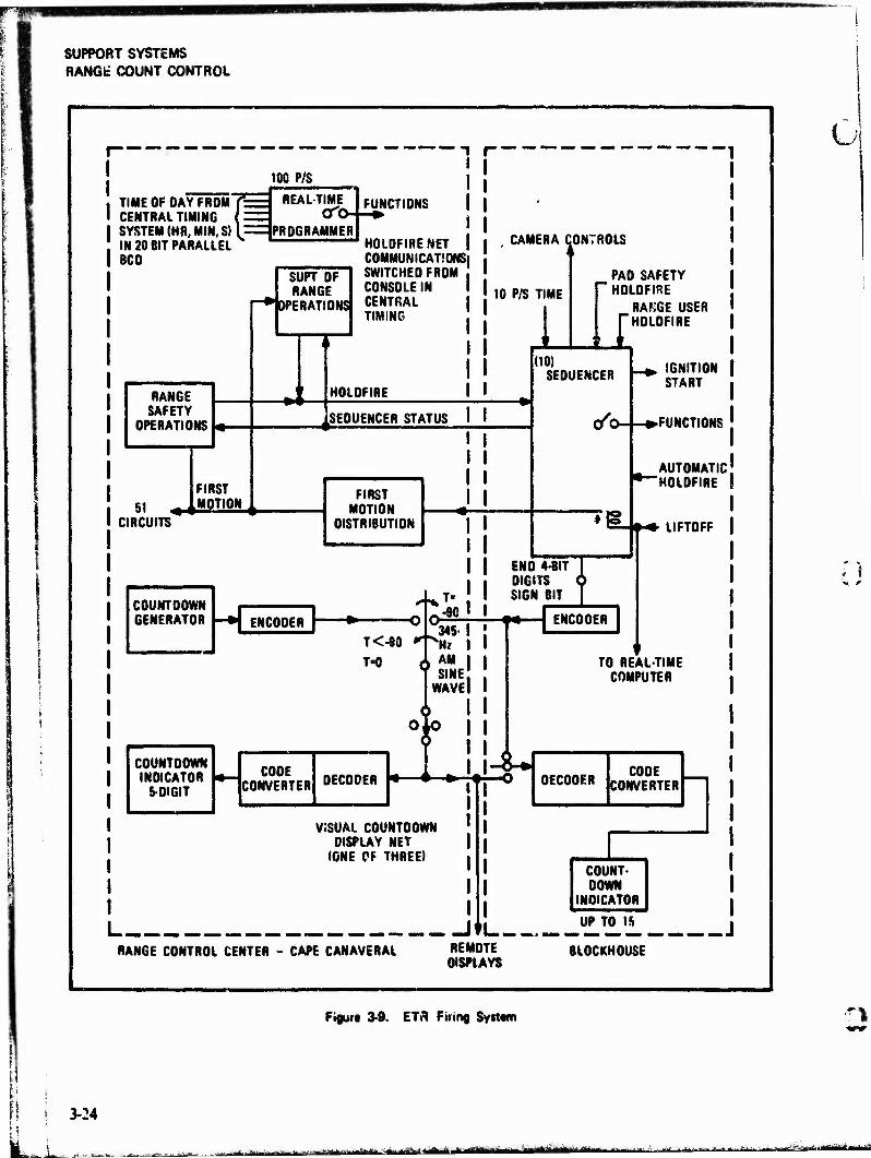
SUPPORT SYSTEMS RANG* COUNT CONTROL
—
100 P/S
TIME OF DAY FROM CENTRAL TIMING SYSTEM (HR, MIN, S) IN 20 BIT PARALLEL BCD
■ REAL-TIME
PROGRAMMER
RANGE SAFETY
OPERATIONS
51 FIRST MOTION
SUPT OF RANGE
f-* OPERATIONS
1i -»4
FUNCTIONS
HOLOFIRENET COMMUNICATIONS; SWITCHED FROM CONSOLE IN CENTRAL TIMING
HOLOFIRE
SEQUENCER STATUS
CIRCUITS
FIRST MOTION
DISTRIBUTION
COUNTDOWN GENERATOR ENCODER
T<-80
T-0
.-90
AM SINE
WAVE
COUNTDOWN INDICATOR
5-DIGIT
COOE CONVERTER DECODER X
VSSUAL COUNTDOWN DISPLAY NET
(ONE OF THREE)
I I
RANGE CONTROL CENTER - CAPE CANAVERAL
i )*L-
REMOTE DISPLAYS
CAMERA CONTROLS
10 P/S TIME PAO SAFETY HOLOFIRE
I RAfiGE USER HOLOFIRE
(10) SEQUENCER
END 4-BIT DIGITS SIGN BIT
••- I
ENCODER
IGNITION START
»FUNCTIONS
AUTOMATIC 'HOLOFIRE
LIFTOFF
TO REALTIME COMPUTER
DECODER COOE
CONVERTER
COUNT- DOWN
INDICATOR
UP TO IS
BLOCKHOUSE
UP TO IS a
Pfeift 3-9. ETR Firing System
3-24
..^■^..F-. -.&a& y^^^ä^^-^S^ ■ifffc i fljftftrflrli - ■~*^.^^*^*^*^:*&^S,^,^^4&'Ji
AB ""SJ^säSSW*
SUPPORT SYSTEMS LORAC
1,
O
LL_
the hold-fire has been cleared. In the manual restart position, the countdown must be restarted manually when the malfunction has been cleared. Automatic hold-fire override is also provided for each circuit.
The countdown may be manually interrupted by hold-fire switches on the Range Safety, Range Operations, Pad Safety, and Range User consoles.
3.4.3 Real-Time Programmer
By use of the Range Hold-fire Net Distribution System, a precise start pulse is sent from the "*al-time programmer located in the RCC to the sequencer in the blockhouse. The sequence count- down will then reach T-Oat the predicted Universal Time for T-0 in order that launch program window requirements may be met.
REALTIME PROGRAMMER TECHNICAL CHARACTERISTICS
Input .... Second, minute, and hour of day in 20-bit parallel BCD format plus 100 p/s repetition rate.
Function control circuits Ten may be programmed
throughout the day in 10 ms increments.
Encoder
Input . . Current pulses of 300 mA peak at 28 V for 20 ms at 1 s intervals.
Operation times . 140 ms read-in, 120 ms readout
Output , .Amplitude-modulated 345-Hz sine wave
Decoder
Input Variable, depending on line length
Operation times . . 70 ms read-in, 930 ms readout
3.S LORAC
Lorac (Long Range Accuracy) is a radio- positioning system operating in the 1.7 to 2.5-MHz portion of the radio spectrum. Lorac provides position information for ships and submarines engaged in launch, tracking, and recovery opera-
tions. It also provides a standard of comparison for calibration of a ship's inertial navigation systems and associated equipment. The two Lorac net- works installed at the ETR provide coverage from Cape Canaveral to Eleuthera.
A Lorac network consists of three base stations and one reference station. The three base stations are arranged in a triad (one center and two end stations) to provide coverage in the area of interest. The reference station is usually located in the vicinity of the center base station.
The three base stations operate in the continuous wave mode and generate a family of hyperbolas used to provide position information. The refer- ence station operates in the amplitude-modulated mode and provides the reference signal apinst which the phase measurements are made.
Each Lorac network requires two carrier fre- quencies: one for the reference station and one for the base stations. While each base station operates on a different frequency from the other two, the difference is so slight the frequencies can be considered the same. The center base station operates at frequency f while the end base stations operate at T + 135 Hz and F - 315 Hz, respectively. The end base station, operating at f + 135 Hz, is identified as the Green Station while the other is called the Red Station. The reference station receiver receives the three base station signals and produces two heterodyne beat notes, 135 and 315 Hz, in its output. These signals are applied as modulation to the reference transmitter and transmitted at another carrier frequency.
The Lorac mobile receiver operating aboard ship contains two receivers which pick up the signals radiated from the base and reference stations. The output* of these two receivers are filtered to provide four separate audio tones. Phase measure- ments are made on the 135-Hz pair and the 31 S4iz pair continuously. The phase meters then display the position of the ship in hyperbolic coordinates. These readings are transferred to a navigation chart containing a hyperbolic ovetiay to determine the ship's position. Alternately, the position can be recorded for later reduction and convenor» to any other desired coordinate system. Any number of mobile receivers can use the Lorac network simultaneously since the receivers operate in a completely passive mode.
mtmmmAmmMM iirfiiiWllritriMiiMfilfi'ifllli MM 3-25
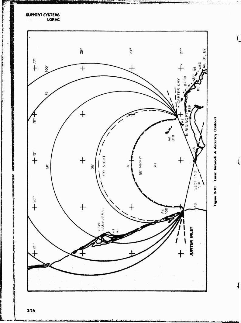
SUPPORT SYSTEMS LORAC
l
i
2
i d
i
3-26
arirf tt.«-^*. w., ■ ■ - --te-■■■ ^if irtmriMrithiiTi #fjg-ftr ättmm -m ■ *g*nriBi ii^ibäaäi« afa ü'iiiiMii*! >iliimMiii|-lliiiiil'"-^trilriJiii

^^^■^r^fw^^'w^'- ^'^^■^m^.v^^^W^^^mjfWW^'
SUPPORT SYSTEMS LORAC
©
-... ,... ^afafc, .afc^--.--^^^'ajM^May^/-.«.^-t.»»-«iatat_-a^ .ij^ia*
3-27
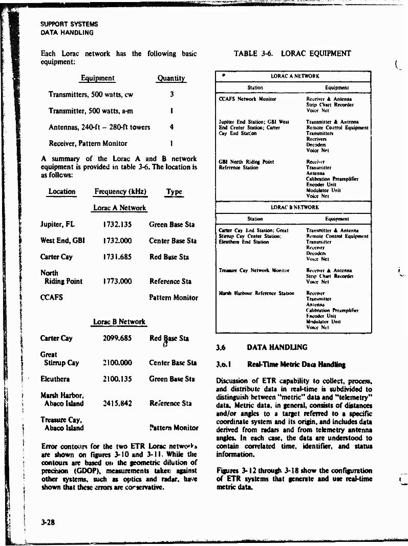
SUPPORT SYSTEMS DATA HANDLING
III
Each Lorac network has the following basic equipment:
Equipment Quantity
Transmitters, 500 watts, cw 3
Transmitter, 500 watts, a-m 1
Antennas, 240-ft - 280-ft towers 4
Receiver, Pattern Monitor I
A summary of the Lorac A and B network equipment is provided in table 3-6. The location is as follows:
TABLE 3-6. LORAC EQUIPMENT
Location Frequency (kHz) Type
Jupiter, FL
West End, GBI
Carter Cay
North Riding Point
CCAFS
Carter Cay
Lorac A Network
1732.135 Green Base Sta
1732.000
1731.685
1773.000
Center Base Sta
Red Base Sta
Reference Sta
Pattern Monitor
Lorac B Network
2099.685 Red Base Sta
Great Stirrup Cay 2100.000 Center Base Sta
Eteu there 2100.135 Green Base Sta
Marsh Harbor. Abaco Island 241 S.842 Reference Sta
Treasure Cay, Abaco Island Pattern Monitor
Error contour* for the two ETR Lorac netwe*** are shown on figures 3-10 and 3-11, While the contours are based on the geometric dilution of precision (GDOP), measurements taker? against other systems, such as optics and radar, have shown that these errors are corservathfe.
• LORAC A NETWORK
Station Equipment
CCAFS Network Monitor Receiver & Antenna Strip Chart Recorder Voice Net
Jupiter End Station; GBI West End Center Station; Carter Cay End Station
Transmitter & Antenna Remote Control Equipment Transmitters Receivers Decoders Voice Net
GBI North Riding Point Reference Station
Receiver Transmitter Antenna Calibration Preamplifier Encoder Unit Modulator Unit Voice Net
LORAC B NETWORK
Station Equipment
Carter Cay End Station; Great Stirrup Cay Center Station; Eieutnera End Station
Transmitter 4 Antenna Remote Control Equipment Transmitter Receiver Decoders Voice Net
Treasure Cay Network Monitor Receiver It Antenna Strip Cnart Recorder Voice Net
Mink Hareour Reference Station Receiver Traimnitter Antenna Cabbraiiea Preamplifier Encoder Unit Modulator Unit Voice Net
3.6 DATA HANDLING
3.0.1 Real-Time Metric Da« Handling
Discussion of ETR capability to collect, process, and distribute data in real-time is subdivided to distinguish between "metric" data and "telemetry" data. Metric data, in general, consists of distances and/or angles to a target referred to a specific coordinate system and its origin, and includes data derived from radar» and from telemetry antenna angles. In each case, the data are understood to contain correlated time, identifier, and status information.
Figures 3-12 through 3-18 show the configuration of ETR systems that generate and use real-time metric data.
3-28
UM "" aMtt

SUPPORT SYSTEMS DATA HANDLING
Ü
| w
o
J
l| Pl I«
23:
« 5 II
1 =
*3 0
I I
* §
U i! if H
C=3
r TJ
r——<I
®Z14«=J.-.L=~J
"Ü" M
-sr* IlS _.-_-.-__._ ©6©
-'--•'^■-hviMrff y i j rinriiiniiiiiminirirrrimi■■ in^ii«^iinri
3-29 jgifr<aalttaftiB^a£iiajafcjya*a
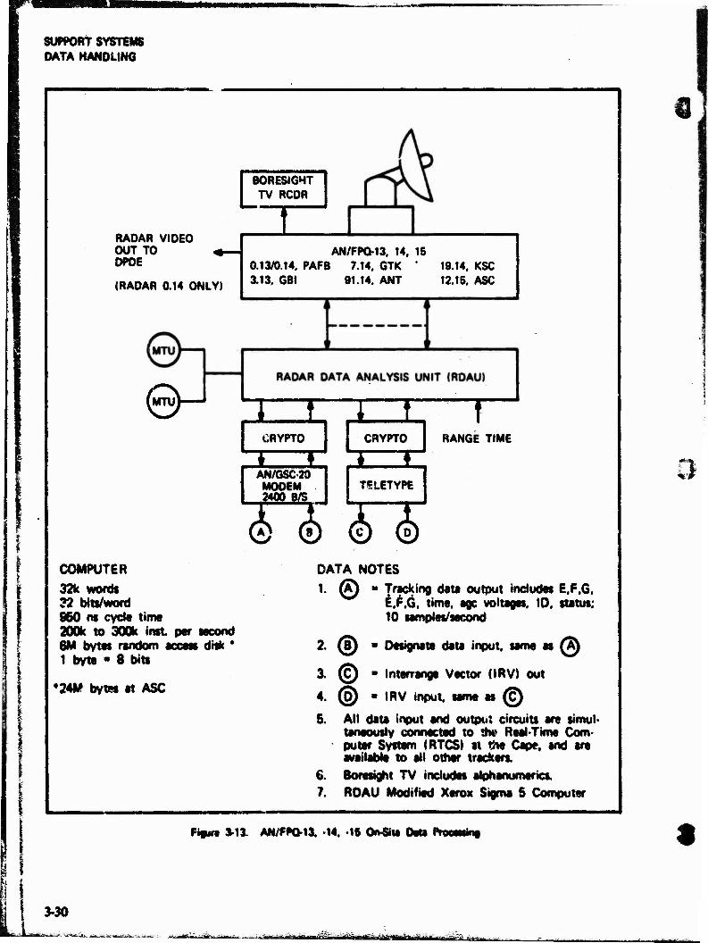
SUPPORT SYSTEMS DATA HANDLING
RADAR VIDEO OUT TO 4- DPDE
(RADAR 0.14 ONLY)
UlTuV—
BORESIGHT TV RCDR
1 AN/FPQ-13. 14, 15
0.13/0.14. PAFB 7.14. QTK * 19.14. KSC 3.13, GBI 91.14. ANT 12.15. ASC
1 t CRYPTO
* ♦
L_I CRYPTO
T RANGE TIME
AN/6SC20 MODEM JSSLgSJ
TELETYPE
0©0© COMPUTER
32k words 32 bits/word 950 m cycle time 200k to 300k inst per second 6M bytes random access disk * 1 byte ■ 8 bits
*24M bytes at ASC
DATA NOTES
1. (A) ■ Tracking data output includes E.F.G, i.F.G, time, age voltages, ID. status; 10 samples/second
2. (!) ■ Designate data input, same as @
3. (c) • Interrangt Vector (IRV) out
4. ® « IRV input, same es (c)
5. All data input and output circuits are simul- taneously connected to the Real Time Com- puter System (RTCS) at the Cape, and «re available to all other trackers.
6. Borostght TV includes alphanumeric*,
7. RDAU Modified Xerox Sigma S Computer
Pigura »13. AN/PPQ-13. -14. -15 On-Si* DM Pracmini
3-30
"-*--« "»ffipirwäfliil ^S.-Muwjdüt«. riimrti niii^iiii i .i....

SUPPORT SYSTEMS DATA HANDLING
f
B0RESI6HT TV RCDR
! ♦ AN/FPQ-13
RADAR 0.13. PATRICK
t- *
vS/ . XEROX DATA SYSTEMS SIGMA 7 COMPUTER
LJ. CRYPTO
1 f
T RANGE TIME
AN/GSC-20 MODEM 2400 8/S
d> d) COMPUTER
32k word« 32 bits/word SSO ns cycle time 200k to 300k inst per second 6M bytes random access disk 1 byte - 8 bits
DATA NOTES
1. (A) ■ Tracking date output includes E.F.G, ^ E.F.G, time, age voltage. ID, status;
10 samples/second
2. (5) * Designate Data Input, same as (A)
3. !nttrrange vectors IIRVJ may be entered or extracted manually.
4. Bowight TV includes alphanumerks.
C Figure 3-14. AN/FPQ-1S (PAFB) OftSh« Data Kvtmk*
sääkäm IÜMÜB an
3-31
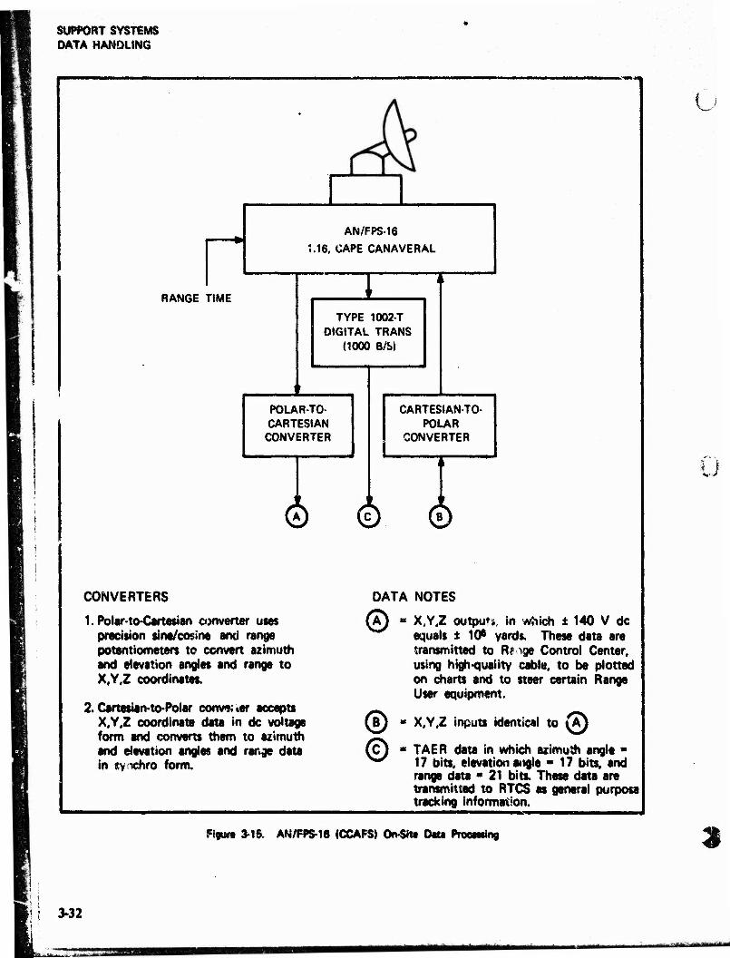
SUPPORT SYSTEMS DATA HANDLING
--■»■«•
AN/FPS-16
M6. CAPE CANAVERAL
RANGE TIME
TYPE 1002-T DIGITAL TRANS
(1000 B/S)
POLAR-TO- CARTESIAN CONVERTER
CARTESIANTO- POLAR
CONVERTER
© ©
CONVERTERS
1. Polar to-Cartesian converter uses precision sine/cosine and range potentiometers to convert azimuth and elevation angles and range to X,Y,Z coordinates,
2.Certesian-to-Polar commaer accepts X.Y.Z coordinate data in dc voltage form and converts them to azimuth and elevation angles and range data in synchro form.
DATA NOTES
© X,Y,Z output, in which ± 140 V dc equals ± 10* yards. These data are transmitted to Rf ige Control Center, using high-quality cable, to be plotted on charts and to steer certain Range User equipment.
u
i I
(ß) « X,Y,Z inputs identical to (A) 1 © TAER data in which azimuth angle ■
17 bits, elevation angle ■ 17 bits, and range data • 21 bits. These data are transmitted to RTCS as general purpose tracking information.
Ffgun 3-16. AN/FPS-16 (CCAFSJ On^itt Data Practising 2
3-32
^m
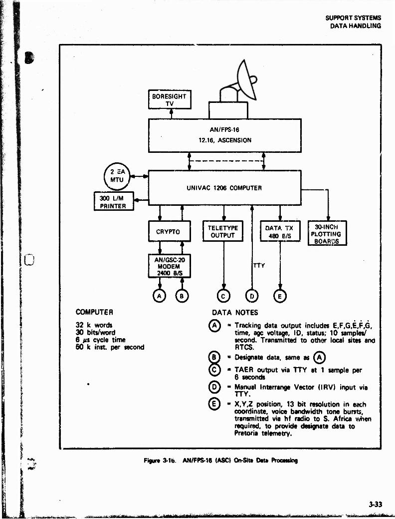
SUPPORT SYSTEMS DATA HANDLING
t
So
i
300 L/M PRINTER
(™)~
COMPUTER
32 k words 30 bits/word 6 MS cycle time 50 k inst per second
BORESIGHT TV
AN/FPS-16
12.16, ASCENSION
E 3 UNIVAC 1206 COMPUTER
mrn CRYPTO
m TELETYPE OUTPUT
AN/GSC-20 MODEM 2400 B/S
0 ©
DATA TX 480 B/S
TTY
30-INCH PLOTTING
BOARDS
© © © DATA NOTES
0 » Tracking data output includes E,F,G,E,F,G, time, age voltage, 10, status; 10 samples/ second. Transmitted to other local sites and RTCS.
* Designate data, same as (M
■ TAER output via TTY at 1 sample per 6 seconds
■ Manual Interrange Vector (IRV) input via TTY.
« X.Y.Z position, 13 bit resolution in each coordinate, voice bandwidth tone bursts, transmitted via hf radio to S. Africa when required, to provide designate data to Pretoria telemetry.
Pieurt 3-16. AN/FPS-16 (ASCJ On-SIt» DM Promising
~r '.fim lir» HteEfc. f Yi agaaaj^aaaiajaaüiia» aaaai nth , IMllliillli iTIIillllHiUHillill^triiMlllHWl'JMin! iiwiiilii -f-—fflüeaaüg|j^a«iflgai —"
3-33 ililiini-iiüi I
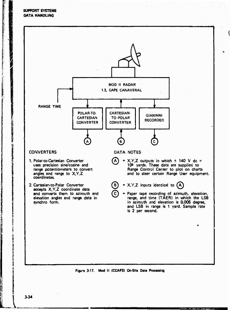
SUPPORT SYSTEMS DATA HANDLING
MOD II RADAR 1.3, CAPE CANAVERAL
RANGE TIME
POLAR-TO- CARTESIAN CONVERTER
I CARTESIAN- TO- POLAR
CONVERTER
GIANINNI RECORDER
© © © CONVERTERS DATA NOTES
1. Polar-to-Cartesian Converter uses precision sine/cosine and range potentiometers to convert angles and range to X,Y,Z coordinates.
2. Cartesian-to-Polar Converter accepts X,Y,Z coordinate data and converts them to azimuth and elevation angles and range data in synchro form.
®- X,Y,Z outputs in which ± 140 V dc = 106 yards. These data are supplied to Range Control Center to plot on charts and to steer certain Range User equipment.
@ = X,Y,Z inputs identical to (A) 8
© Paper tape recording of azimuth, elevation, range, and time (TAER) in which the LSB in azimuth and elevation is 0.005 degree, and LSB in range is 1 yard. Sample rate is 2 per second.
Figur« 3-17. Mod II (CCAFS) On-SSta Data Practising
3-34
SSEuSS s

3SS
SUPPORT SYSTEMS DATA HANDLING
AFETR
fW,GE CONTROL CENTER
RSDS 21-INCH CRT DISPLAYS
FOR IMPACT PREDICTION AND PRESENT POSITION, W/LIMIT LINES, MAPS, ALPHANUMERIC DATA
30 X 30-INCH VERTICAL PLOTTING BOARDS
FOR IMPACT PREDICTION, PRESENT POSITION, AIRCRAFT TRACK,
ETC. (DUAL X.Y PLOT)
F1^ AXIS ROTATION. SCALE FACTOR,
ORIGIN TRANSLATION, DATA DISTRIBUTION
2 EACH PLOTTING BOARDS
FOR AIRCRAFT VECTORING
STRIP-CHART RECORDERS
(GEN. PURPOSE)
f S
REALTIME COMPUTER SYSTEM
2 EACH CDC3600 AND 3 EACH CDC-3100
* WHEN THE RSDS BECOMES OPERATIONAL. THE SET OF PLOTTING BOARDS MAY BE DEACTIVATED.
Figur« 3-18. Rangt Safety/Real-Time Displays
h»e3fiBiSäi£msSg28Kte»i^jjg£S8£ijBs£SiB rfUH«M
3-35

■»>•" ■ --^wiwe»^»
SUPPORT SYSTEMS DATA HANDLING
3.6.1.1 On-Site Data Handling
Distance to a target of interest is derived from a range machine in each radar that tracks the target Azimuth and elevation angles are derived from digital encoders driven by radar and telemetry antennas. Related data, such as automatic gain control (age) data and timing angles, are derived from appropriate transducers and, together with range and angles, delivered to an on-site computer for processing and formatting to fulfill Range and Range User requirements.
At a typical ETR radar site, data are extracted from the radar at a rate of 160 and 100 samples per second. These data are simultaneously recorded on magnetic tape with correlated timing, and are processed by an on-site digital computer. In one of the processing operations, correction factors are applied to the raw data to remove, to the extent possible, systematic errors such as antenna mislevel and encoder biases. In another operation, the range and azimuth and elevation angles are converted to Earth-centered rectangular coordinates (E,F,G) and their rates (E,F,G), having usual resolutions of 1 meter and 1 meter per second (either of four scHes may be programmed and identified). In a third operation, identifiers, scale codes, status signals, and sync signals are generated and added to each sample of data. Finally, the composite samples are formatted as required and readied for transmission at a 10 samples/second rate.
At a typical telemetry site, similar operations are performed with important exceptions. ETR telem- eters do not measure range, making it necessary to "dub1" in a range to be used with the antenna azii „uth and elevation angles in order to derive E,F,G data. This "dubbed" range may be a nominal value inserted manually, or generated using a real or hypothetical trajectory or orbit. In either event, E,i',G data so generated are intended to serve as aids in Erecting other ETR antennas or sensors to the target
Metric data derived at an ETR radar or telemeter can be formatted to satisfy any user requirement. The format chosen for internal Range use such as impact prediction and designation consists of eight 30-bit words per sample, with 10 samples per second, giving a data rate of 2400 b/s. This set of data can be transmitted to off-Range Users, when requested, using standard 3-kHz voice channels.
Another set of data can be generated at certain sites, which is suitable for transmission in a teletype format. This set is referred to as an "Interrange Vector" (IRV)S and is generated at a rate of one sample per 6 s. Each sample consists of a discrete point and the velocity ard rime associated with the point, expressed in u. format containing E,F,G, E,F,G,T;
3.6.1.2 Data Distribution
The ETR network provides for real-time distri- bution of data from any source to any and all other locations on or off the Range. The distri- bution network characteristics and capabilities are summarized below.
Several vehicles tracked by KTR equipmen. ' ave trajectories that are classified. This makes it necessary to use encryption devices to "secure" tna data links. Range Users may, therefore, be assured of complete confidentiality of trajectory or orbit data collected and transmitted over the ETR network. These data can be transmitted off-Range to any user who is equipped to receive encrypted data in the ETR format. In general, ETR circuits use the KG-13 type crypto equipment. Each crypto set is equipped with remote control units.
Real-time metric data are transmitted by various landline modems at a rate of 2400 b/s. When required, AN/USC-12 hf radio modems are used on radio circuits, together with forward error detec- tion and correction (FEDAC) equipment, to transmit data at an effective rate of 1200 b/s. Teletype-like formats aie generated by Range computers which can be programmed to produce any of the standard speeds and formats. These formats can be transmitted over conventional circuits to desired locations.
The "standard" link for real-time metric data transmission at ETR is the nominal 3-kHz channel. These links include landlines, microwave links, undersea cable, and satellite relays. A typical data circuit may use all of these links between its terminals. Data circuits are equalized both for amplitude and for differential delay, making them highly reliable in terms of bit error rate. Data circuit; extend both uprange and downrange, and are accessible at Cape Canaveral to off-Range Users. Circuits are available in sufficient numbers to accommodate any reasonable requirement
3-36
■jjBaeawfc^aa^Ji; ^^fea^*-*^ «^ ^ mäamti -^*,.,^.^^iirr^M^^ aaa Vinr in TI aa ■■ ■ iMHIllMlHtlllli«
Ml MM m
SUPPORT SYSTEMS DATA HANDLING
J
Ww'
«* t »
3.6.1.3 Range-Head Data Handling
The ETR range-head is located at Cape Canaveral, and comprises the Range Control Center (RCC), the Real-Time Computer System (RTCS), and the Communications Central Office (referred to as the XY Building). Datu from all ETR instruments are transmitted to the range-head, at which they are received, processed, and distributed to a worldwide network.
The key element of the ETR real-time data handling system is the RTCS, which consists of two CDC-3600 and two CDC-3100 computers. The two CDC-3600 computers are used principally for the range safety task of instantaneous impact prediction. Other major tasks include orbit compu- tations, target designation message generation, and present-position plotting computations. In addi- tion, they compute toxic gas plume diffusion and debris fallout contours, and perform a variety of support computations incidental to missile testing.
An additional CDC-3100 computer is dedicated to real-time weather computations and is interfaced to the AN/FPS-77 wither radar and to the WINDS system. Each of the other two CDC-3100 machines is connected to one of the CDC-3600 computers, and both perform part of the real-time computations during a launch. At other times, they are used as general purpose processors.
One typical aspect of the versatility of the RTCS complex is portrayed in figure 3-12.
During a typical operation, the RTCS is the hub of the ETR data gathering network, and provides position and impact displays to the Range Safety Officer, and computes and dispatches designation messages to a worldwide network of land-based, shipboard, and airborne sensors.
Real-time operation of ETR instrumentation is focused at the RCC located at Cape Canaveral. At this location, all aspects of ETR participation in an operation are managed by a team of controllers. This team includes the Range Safety Officer who is responsible for ensuring that powered flight of a missUe or rocket does not threaten the safety of Ufe and property. Other controllers allocate instru- ments, aircraft, and ships to cover various segments of the flight.
Control is exercised by a combination of methods including voice transmissions, automated function control, and preprogrammed contingency criteria. Commands and directions are transmitted by way of a worldwide communications network.
The ETR is fully equipped tt. serve as a "lead range" to establish and direct large-scale instrumen- tation networks during missions that require networking outside the ETR boundaries.
The XY Building is the terminal for all communica- tions associated with ETR data handling. This facility is located adjacent to the RTCS and RCC, and provides termination, distribution, and test capabilities for all internal and external ETR circuits.
3.6.1.4 Range Use
Real-time data are used for three primary purposes. First, they form the basis for computing predicted impact point and for plotting present position displays. Second, they are used as designation messages to enable other instruments to find and track the same target. Third, they are transmitted in several formats to Range User faculties such as blockhouse and hangar displays.
3.6.1.5 Off-Range Users
When requested, real-time metric data are for- matted, scaled, and transmitted to off-Range User facilities such as Goddard Space Flight Center, Houston Manned Spacecraft Center, and Jet Propulsion Laboratory during manned and un- manned space operations.
In another special application, radar track data are received from SAMTEC (Space and Missile Test and Evaluation Center) while they track a meteoro- logical balloon (ROSE). The RTCS performs a standard computation on the data to derive wind velocity/altitude profiles, wind shear forces, etc, and transmits the results back to SAMTEC Many similar tasks can be performed by the ETR whenever requested.
3.6.2 Data Processing & Analysis
In general, raw data are received on magnetic tape in digital or analog form, on film of various types,
MfteMtf 3-37
mmämtfämsMmam
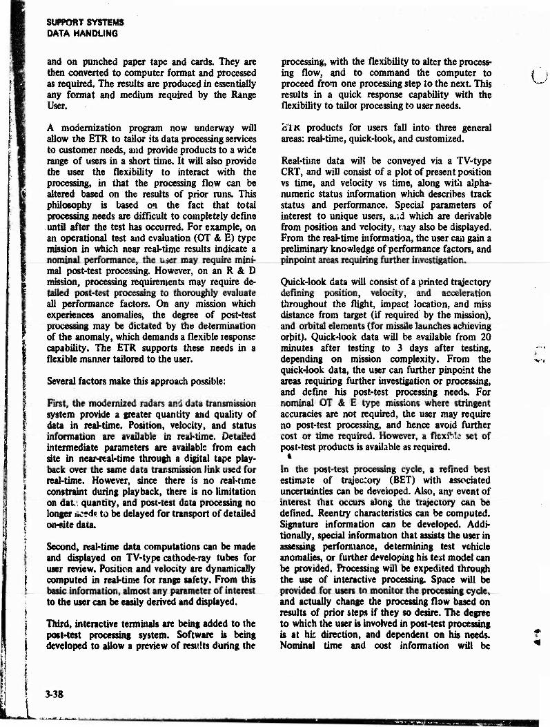
SUPPORT SYSTEMS DATA HANDLING
and on punched paper tape and cards. They are then converted to computer format and processed as required. The results are produced in essentially any format and medium required by the Range User.
A modernization program now underway will allow the ETR to tailor its data processing services to customer needs, and provide products to a wide range of users in a short time. It will also provide the user the flexibility to interact with the processing, in that the processing flow can be altered based on the results of prior runs. This philosophy is based on the fact that total processing needs are difficult to completely define until after the test has occurred. For example, on an operational test and evaluation (OT & E) type mission in which near real-time results indicate a nominal performance, the user may require mini- mal post-test processing. However, on an R & D mission, processing requirements may require de- tailed post-test processing to thoroughly evaluate all performance factors. On any mission which experiences anomalies, the degree of post-test processing may be dictated by the determination of the anomaly, which demands a flexible response capability. The ETR supports these needs in a flexible manner tailored to the user.
Several factors make this approach possible:
First, the modernized radars and data transmission system provide a greater quantity and quality of data in real-time. Position, velocity, and status information are available in real-time. Detailed intermediate parameters are available from each site in near-real-time through a digital tape play- back over the same data transmission link used for real-time. However, since there is no real-time constraint during playback, there is no limitation on dafc', quantity, and post-test data processing no longer liced«, to be delayed for transport of detailed on-site data.
Second, real-time data computations can be made and displayed on TV-type cathode-ray tubes for user review. Position and velocity are dynamically computed in real-time for range safety. From this basic information, almost any parameter of interest to the user can be easily derived and displayed.
Third, interactive terminals are being added to the post-test processing system. Software is being developed to allow a preview of results during the
processing, with the flexibility to alter the process- ing flow, and to command the computer to proceed from one processing step to the next. This results in a quick response capability with the flexibility to tailor processing to user needs.
H'lK products for users fall into three general areas: real-time, quick-look, and customized.
Real-time data will be conveyed via a TV-type CRT, and will consist of a plot of present position vs time, and velocity vs time, along with alpha- numeric status information which describes track status and performance. Special parameters of interest to unique users, a.;d which are derivable from position and velocity, nay also be displayed. From the real-time information, the user can gain a preliminary knowledge of performance factors, and pinpoint areas requiring further investigation.
Quick-look data will consist of a printed trajectory defining position, velocity, and acceleration throughout the flight, impact location, and miss distance from target (if required by the mission), and orbital elements (for missile launches achieving orbit). Quick-look data will be available from 20 minutes after testing to 3 days after testing, depending on mission complexity. From the quick-look data, the user can further pinpoint the areas requiring further investigation or processing, and define his post-test processing needs. For nominal OT & E type missions where stringent accuracies are not required, the user may require no post-test processing, and hence avoid further cost or time required. However, a flexible set of post-test products is available as required.
4
In the post-test processing cycle, a refined best estimate of trajectory (BET) with associated uncertainties can be developed. Also, any event of interest that occurs along the trajectory can be defined. Reentry characteristics can be computed. Signature information can be developed. Addi- tionally, special information that assists the user in assessing performance, determining test vehicle anomalies, or further developing his test model can be provided. Processing wUl be expedited through the use of interactive processing. Space will be provided for users to monitor the processing cycle, and actually change the processing flow based on results of prior steps if they so desire. The degree to which the user is involved in post-test processing is at hie direction, and dependent on his needs. Nominal time and cost information will be
i 3-38
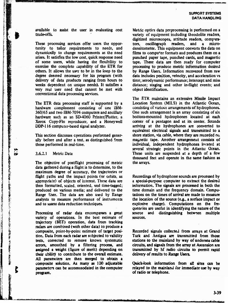
mmmmm mmmmmimm
SUPPORT SYSTEMS DATA HANDLING
I
f f
I
available to assist the user in evaluating cost tradeoffs.
These processing services offer users the oppor- tunity to tailor requirements to needs, and dynamically to change requirements as the need arises. It satisfies the low cost, quick response need of some users, while having the flexibility to exercise the complete capability of the ETR for others. It allows the user to be in the loop to the degree deemed necessary for his program (with delivery of data products ranging from hours to weeks dependent on unique needs). It satisfies a very real user need that cannot be met with conventional data processing services.
The ETR data processing staff is supported by a hardware complement consisting of one iBM- 360/65 and two IBM-7094 computers and ancillary hardware such as an SD-4060 Printer/Plotter, a Xerox Copy-Flo reproducer, and a Honeywell DDP-116 computer-based signal analyzer.
This section discusses operations performed gener- ally before and after a test, as distinguished from those performed in real-time.
3.6.2.1 Metric Data
The objective of postflight processing of metric data pthered during a flight is to determine, to the maximum degree of accuracy, the trajectories or flight paths and the impact points (or orbits, as appropriate) of objects of interest. These data are then formatted, scaled, oriented, and time-tagged; produced on various media; and delivered to the Range User. The data are also used by Range analysts to measure performance of instruments and to assess data reduction techniques.
Processing of radar data encompasses a great variety of operations. In the best estimate of trajectory (BET) operation, data from tracking radars are combined (with other data) to produce a composite, point-by-point estimate of target posi- tion. Data from each radar are subjected to validity tests, corrected to remove known systematic errors, smoothed by a filtering process, and assigned a weight (figure of merit) depending on their ability to contribute to the overall estimate. All parameters are then merged to obtain a composite solution. As many as 100 adjustable parameters can be accommodated in the computer program.
Metric optics data preprocessing is performed on a variety of equipment including theodolite readers, digitized microscopes, attitude readers, compara- tors, oscillograph readers, and a micro- densitometer. This equipment converts the data on films to compu*er formats and produces them on a punched paper tape, punched cards, and magnetic tape. These data are then ready for computer processing to produce metric information desired by Range Users. Information recovered from raw data includes position, velocity, and acceleration vs time; aerodynamic performance; intercept and miss distance; staging and other in-flight events; and object identification.
The ETR maintains an extensive Missile Impact Location System (MILS) in the Atlantic Ocean, consisting of various arrangements of hydrophones. One such arrangement is an array consisting of six bottom-mounted hydrophones located at each corner of a pentagon and at its center. Sounds arriving at the hydrophones are converted to equivalent electrical signals and transmitted to a shore station, via cable, where they are recorded m, magnetic tape. Another arrangement consists of individual, independent hydrophones located at several strategic points in the Atlantic Ocean. These units are suspended at a depth of a few thousand feet and operate in the same fashion as the arrays.
Recordinp of hydrophone sounds are processed by a special-purpose computer to extract the desired information. The signals are processed in both the time domain and the frequency domain. Compu- tations on the times of arrival are made to measure the location of the source (e.g., a surface impact or explosive charge). Computations on the fre- quencies are useful in identifying the nature of the source and distinguishing between multiple sources.
Recorded signals collected from arrays at Grand Turk and Antigua are transmitted from those stations to the mainland by way of undersea cable circuits, and signals from the array at Ascension are transmitted by hf radio circuits to permit rapid delivery of results to Range Users.
Quick-look information from all sites can be relayed to the mainland for immediate use by way of radio or telephone.
3-39 , >^a..i aama,,.,...-,...■ t ^-•^tmtmMi urn rfl'MIIMTM1,»T>l ttSttt

SUPPORT SYSTEMS DATA HANDLING
3.6.2.2 Telemetry Data
The ETR is equipped to perform all kinds of operations on telemetry data for Range Users. Data received on magnetic tapes are separated, identi- fied, and formatted for subsequent processing. Processing operations such as conversion to engi- neering units and formatting for plots, graphs, tables, and charts arc then performed on the data processing computers. Finished computations may be produced on any of several media for delivery to Range Users.
An important feature of this capability is the iarge capacity and high speed with which data may be processed and delivered to a user.
3.6.2.3 Signature Data
"Signature" data refers to the kinds of data gathered by radars, optics, and radiometric sensors that characterize and aid in the identification of devices »entering the atmosphere and objects in space. With regard to the ETR data processing capability, signature data refers to the information collected by the two ARIS ships and processed at ETR.
Data are received from the ships on magnetic tapes containing digital, analog, and video recordings and on films. A preprocessing system, called the data playback and digitizing equipment (DPDE), con- verts the video data into a format suitable for computer processing. Data from film and other media are similarly converted and, together with the converted video and metric data, are processed by the data reduction computers. Results of these processes include number and relative positions of multiple space or reentry objects, shapes and sizes of objects, radar cross-sec :10ns, heat and light emissions, ballistic coefficients, accelerations, and other information useful in determining the nature and purpose of the objects.
3.6.2.4 Other Data Processing
The ETR has developed the capability, procedures, and programs to perform a number of special toks that involve the use of computers. For example, Mechanized Range Scheduling (MRS) is a tech- nique that makes use of teleprocessing to schedule Range activities. It includes a data base containing all ETR instrumentation, and enables accurate and immediate determination of Range availability. It
. !so identifies all resource conflicts and assists users in determining what compromises, if any, can be made in support configuration.
Another example of special-purpose data process- ing is the Mechanized Range Documentation (MRD) system. The data processing computers are used to produce Operations Directives (detailed directions to instrumentation operators). Inter- active processing techniques are applied to enable the most rapid possible response by instrumenta- tion to changes in test support requirements. This gives the ETR a high degree of flexibility with respect to Range User needs.
Both the MRS and MRD techniques are specialized applications of general-purpose information storage and retrieval systems, and are able to accommodate new test programs quickly.
Special meteorological sounding formats are avail- able to meet Range User needs. Meteorological sounding data is obtained from rocketsondes, rawinsondes, jimspher?s, etc; computer processed into the format desired; and delivered to users.
3.6.3 Redstone Data Handling
The Central Data Processing System (CDPS) consists of a Univac 1230 digital computer, associated peripheral equipment, and buffers which interface the computer with instrumentation com- plex equipment.
The Univac 123C (modified CP-642B) general purpose computer provides a random access mem- ory for 32,608 30-bit words, 16 input and 16 output channels of 30-bit words, and cycle times of 2 MS and 1 JIS with memory overlap. The peripheral equipment includes: one 2-deck and one 4-deck Univac 1240 magnetic tape unit; a Univac 1232A input-output console; a Teletype Model 28 Teletypewriter Set (ASR) with Univac 1259 adapter; a Data Products 4120, 600-une/min high-speed printer; raw data recorder; and interface buffers to instrumentation equipment
The Central Data Processing System receives shir's position and attitude data, timing system signals, antenna pedestal flexure data, control signals, target acquisition information, and real-time track- ii.g data. It processes the received information to provide data for antenna pointing, ship's position and attitude, trajectory data recording and display.
3-40
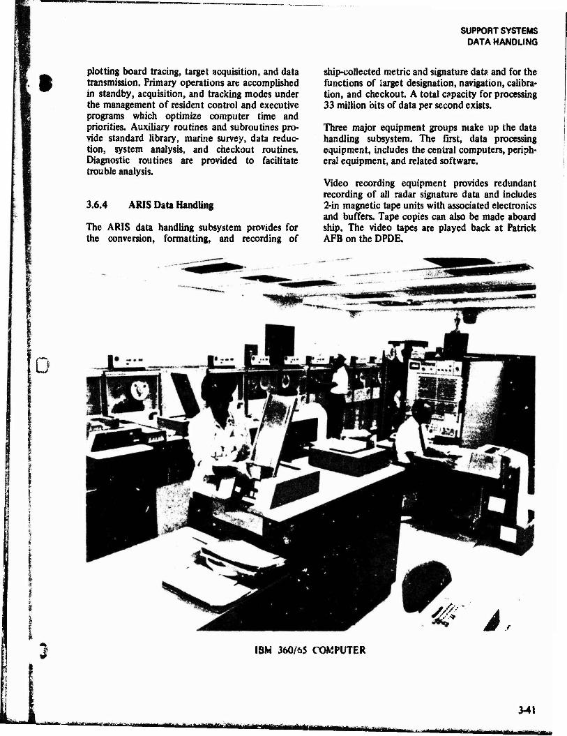
SUPPORT SYSTEMS DATA HANDLING
plotting board tracing, target acquisition, and data transmission. Primary operations are accomplished in standby, acquisition, and tracking modes under the management of resident control and executive programs which optimize computer time and priorities. Auxiliary routines and subroutines pro- vide standard library, marine survey, data reduc- tion, system analysis, and checkout routines. Diagnostic routines are provided to facilitate trouble analysis.
3.6.4 ARIS Data Handling
The ARIS data handling subsystem provides for the conversion, formatting, and recording of
ship-collected metric and signature data and for the functions of target designation, navigation, calibra- tion, and checkout. A total capacity for processing 33 million bits of data per second exists.
Three major equipment groups make up the data handling subsystem. The first, data processing equipment, includes the central computers, periph- eral equipment, and related software.
Video recording equipment provides redundant recording of all radar signature data and includes 2-in magnetic tape units with associated electronics and buffers. Tape copies can also be made aboard ship. The video tapes are played back at Patrick AFB on the DPDE.
0
&• ä
3 IBM 360/65 COMPUTER
3-41 TO.?i» iniiKm • *'~•^***^*~atiti'ni fwiinr'MiBi'iin iwinniium um ■!■ Miiiii min "■ - i'ilTil»lilitl«i1illlIIIIIM' III! iiillilM li til llii'lur

SUPPORT SYSTEMS DATA HANDLING
Data conversion equipment serves an interface for the processing and recording function by providing two-way conversions between digital and analog data, formatting digital data for recording and computer entry, routing data between subsystems for the tracking radars, and recording all prime target metric and signature data with SINS attitude and other reference data.
The allocation of major equipment for the two ships is shown below.
Equipment
Computers Video Recorders Data Conversion
USNS Arnold USNS Vandenberg«
1206, 642-B, 1230 4 units CDCE, NDHIS, DRSB, DCISE
1206 and 1230 4 units CDCE, DCISE
* Future plans call for upgrading this ship to the same configuration as the USNS Arnold.
CDCE - Central Data Conversion Equipment NDHIS - Navigation Data Handling Interface
System DRSB Digital Recording System Buffer DCISE Data Conversion interface and Switch-
ing Equipment *
The computers perform their functions in the systems by the following major programs:
1. Navigation (NAV). Used before and after a launch to determine ship's posi- tion and heading. It uses SINS, sonar, and star tracker data.
2. Designate, acquisition, and track (DAT). Used during launch or orbital support to designate tracking sensors onto target, collection of mission data and impact prediction. During DAT, a limited part of the NAV program provides continuity of the navigation routine.
3. Data transcription. Used after the mis- sion to transcribe mission data from the I-in magnetic RDR tape to IBM 7094 format on Yt-in magnetic tape (Vanden- berg only).
4. Checkout. Used to check out the computers and associated data process- ing equipment (DPE) peripheral equip- ment, and the major subsystem inter- face.
5. Combined mount misalignment data col- lection and navigation calibration. Used to determine system misalignments.
6. Quick Look. Used after the mission to obtain cross information on the mission and calibration data.

w"wwmwiiM»w. ii>mm«&sm:'Mg>f^m^miFmm^mtimmmimsi&.^^^gi^^^^^^
RANGE SAFETY
SECTION 4
RANGE SAFETY
I
The purpose of the Range Safety System is to ensure an operating environment that permits the maximum flexibility in the achievement of test objectives while reducing the risk to personnel, property, and the test vehicle to an acceptable level.
The Rtnge Safety System provides the Range Safety Officer (RSO) the capability for monitoring missile, space launch vehicle, aircraft, drone, and special testing (e.g., helicopter, balloon, small rocket, etc) conducted on the AFETR.
In particular the system is comprised of the following:
Range Safety Display System Vertical Wire Sky screen Range Safety Closed-Circuit TV Plotting Board Display System Data Display
All safety information is channeled to one or bosh of the two Range Safety areas in the Range Control Center. The two areas arc functionally similar but vastly different in equipment. One area is the new Range Safety Display System (RSDS) and the other area is the plotting board/console area which was previously the prime system and is now being replaced by the RSDS. Both areas contain displays and instrumentation/capability necessary to provide safety for all testing con- ducted on the AFETR.
4.1 RSDS
The primary system used by the RSO ü the RSDS. It consists of a console with four direct-write eathoderay tubes (CRT's) whose displays arc real-time selectable by either of the two RSO's (figure 4-1), Major components of the system arc:
• CDC-3600 Computer System (2> • CDC-3100 Computer System (2) • 1D110M Display System (2) • Cathode-Ray Tubes (4) • Console with Auxiliary Capabilities
RANGE SAFETY CONSOLE
4.1.1 CDC-3600 & 3100 Computers
Real-time raw data from radar and telemetry systems are inputted directly into the memories of both the 3600 and 3100 computers in the Real-Time Computer System (RTCS). This data is processed by the RTCS and graphical data such as impact prediction (IP), present position, debris footprint, velocity vs time, and various alpha- numeric data (e.*., plus count, designation of tracking instrument and mode, and altitude and velocity of target) are outputted to the RSDS buffers which are in turn read out by the Varian computer and displayed on the CRT's. AH back- ground information such as geographic maps and destruct lines are pretest loaded into the Varian memories. During the test, four separate CRT displays arc selectable by the RSO. Normal sequences follow a preprogrammed routine but can be altered by switch selection from keyboards on the RSO console.
Under normal system operation the prime 3600 computer outputs to the RSDS throt jh buffers I and 2. The standby 3600 computer generates the debris footprint data and passes ?t to the prime 3600. Varian A reads data from buffer I and Varian B reads buffer 2. Both buffers contain identical data, which consists of all current updates generated by the 3600's.
4-1
liüBiJogi m m ifiiiliit -J*lnMiii>'--ri rift» mtmtm liiUfciiil

RANGE SAFETY
0.13- 0.14-
1.16- 19.14 ■
3.13. 7.14.
91.14 .
12.15-
•WTR DSN
'BOA.
•WLPS IS. • *CIF TEL.
•TEL 4 .
TIMING. ••MOO II,
Z m
i t» E tu > m o tu ff
< o
Ul ü < u. GE Ul »- z
3600A COMPUTER
3600B COMPUTER
3600
OUTPUT
SUB-
SYSTfcM
RTCS/ RSOS
BUFFER 1
ANALOG TO P.B. (16) 2400 B/S AGO (2) 480 B/S AGO (2) DISCRETES (96) 2000 B/S TO GSFC (2)
TO RCC/ RSDS BUFFER
RTCS/ RSOS
BUFFER 2
u. ff Ul
Z
i
fCRT^^ IB3 .>*"*
RTCS/ RSOS
BUFFER 3
3100A COMPUTER
►
31008 COMPUTER 3100
OUTPUT SUB-
SYSTEM sw —
TO RCC/ RSDS BUFt-'ER
.«FROM lOIIOM II DISPLAY
■«GEN
TO RCC/ RSDS BUFFER
DISCRETE BIT
RECEIVER
ANALOG TO »P.B. (24)
2400 B/S ACO »tu
480 B/S ACO »(II
DISCRETES
FROM RCC ■«DISCRETE
BIT XMTR
Fipirt 4-1A Ranft Safety Dispfey Sytttm Block Otap*n
»Ml IM. ,
4-2
i •ffcigffVi f-f^'m, lrfB,ar"wflfffrrr~- MÜSüat rilililiiniriil Üüfa
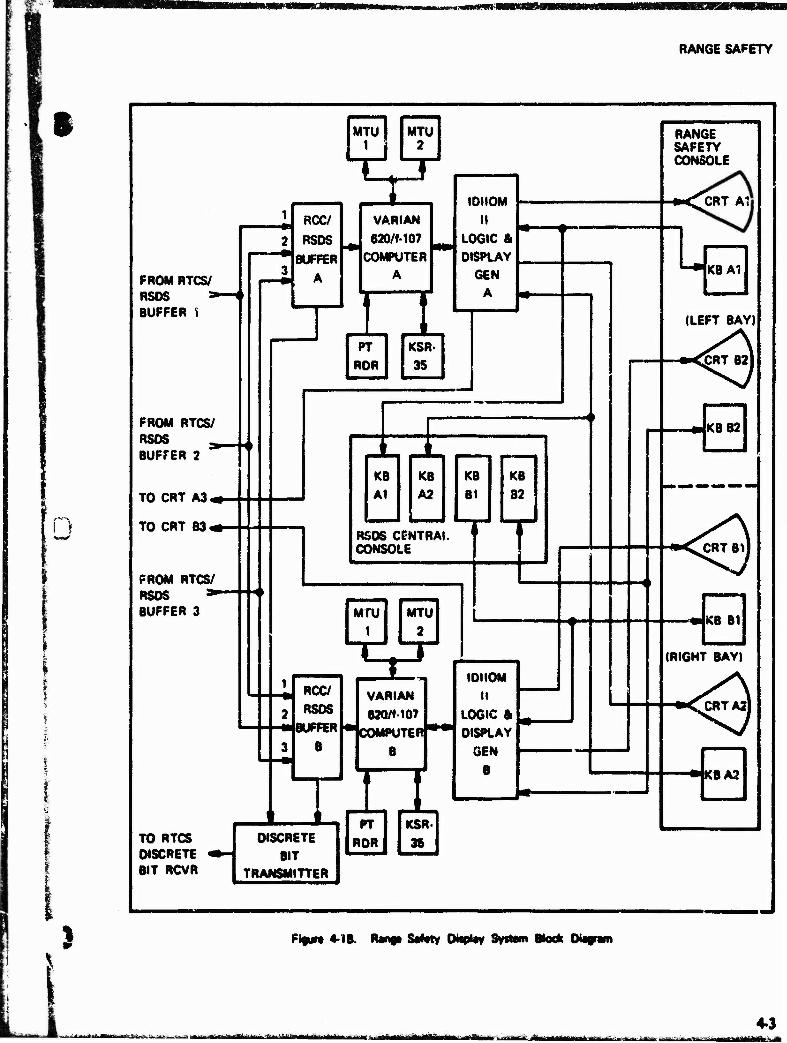
RANGE SAFETY
I
FROM RTCS/ RSDS * BUFFER t
FROM RTCS/ RSDS BUFFER 2
TO CRT A3«.
TO CRT B3 «•-
FROM RTCS/ RSOS BUFFER 3
TO RTCS DISCRETE BIT RCVR
I MTU I MTU
RCC/
RSDS
BUFFER
A
I VARfAN
620/M07 COMPUTER
A n IDIIOM
II LOGIC & DISPLAY
GEN A
PT
ROR
KSR.
35
•-
s KB At
KB
A2
KB
B1
KB
82
RSOS CENTRAL CONSOLE
MfU I
ROC/
RSOS
B
T
MTU
2
B
VARIAN 02O/MO7
•icOMPUTERf**! DISPLAY
TX1
IDIIOM II
LOGIC ft
GEN B
DISCRETE
BIT
TRANSMITTER
PT
ROR
KSR.
38
RANGE SAFETY CONSOLE
HMLCRT At'
KB Al
(LEFT BAY)
-«-<CRT B2)
KBB2
■••^jRTBH
KB B1
(RIGHT BAY)
<XRTA21
«KB A3
Flgiirt 4-18. Renp S#tty Oisptay SyitMn Block Diagram
-w - -*- -■■--.-.-. ^- ... a.-—,.., nk—,- . -^-——^——^fcy jiajiji tfiiiim ii 11 ami i iii iiti Iwt iiw m\\i n.tm* fftltf.ilftlüii
4-3 ■'■'■-" n-r--i-'frir»1iiTi-M-üruniriläiiiitlllli"i nil
RANGE SAFETY
If the prime 3600 computer fails, the standby 3600 takes over, including outputting to both buffers 1 and 2; however, when this happens, debris footprint data capability is lost. The 3100 computer (A or B) outputs to the Varian com- puters through buffer 3. Data from the 3100 computer will be processed and displayed on the CRT's only if both 3600's fail. Data displayed will be theoretical impact point (IP), vertical plane present position, and selected alphanumerics. De- tails of these computers are covered in paragraph 3.6.1.3.
4.1.2 RTCS/RSDS Interface Buffer
The RTCS/RSDS interface buffer consists of three identical buffers. Each has a two-channel Input th"t is CDC-3600 and 3100 compatible, a 512 twe've-bit word memory, and an output to both V'Man computers. Buffers 1 and 2 are associated wiv'i 3600A and B with cross-over connection c?vability. Normally each buffer is associated with or Varian computer; however, a cross-over con- ne.uon capability exists such that both Varian < ./mputers continue to receive all updated data even though one buffer has failed.
4.1.3 Varian 620/M07 Computer
Each display system contains a Varian 620/M07 computer. This computer has a 32 k, 16-bit word core memory with a cycle time of 750 nano- seconds. Standard features are direct memory access, real-time clock, power failure/restart, and priority interrupt. Optional features installed are: priority memory access for the IDIIOM, and automatic loader for rapid recovery. Peripheral equipment includes a 150-character-per-seeond pa- per tape reader, KSR-35 keyboard printer, and two magnetic tape units (MTU's) with controller. The MTU*s are 7-track 556/800 b/in, 45-in/s units, vacuum buffered, and with read-after-write capa- bility. One MTU is used in real-time for recording data received from the RTCS, while the other MTU contains an autoload tape for fast recovery. Data recorded on previous launches can be played back and an entire test simulated without the necessity of scheduling the RTCS.
4.1.4 IDIIOM II Display Generator
The display generator provides control and se- quencing of the images on the CRT. Built-in circuits provide for the generation rf vectors,
circles, and 126 alphanumeric characters. Also provided is the ability to blink, dot, dot-dash, and provide solid line images on the display CRT's. The display generator is a special purpose computer with its own machine language sharing the 32,000 word memory of the Vaiian 620/f-107 computer.
4.1.5 Cathode-Ray Tube Displays (CRT)
The RSO console contains two RSO operating positions. Each position contains two 21-in CRT's (one from each display subsystem) and a 16-switch function keyboard for each CRT. With this configuration each RSO has control over the information desired to be observed via the function keyboard associated with that particular CRT.
4.1.6 Range Safety Console
Two identical operating positions are included in the console. Each position contains a CRT display and a function keyboard from each of the two independent display systems. Adjacent to each of the display bays is a communications console with a 10-channel network, 20 direct-line circuits, administrative telephone, and controls for the Range Safety TV display selection. The center bay of the console contains indicators and controls for common use by the two RSO's. Included are indicators for three countdown nets, two 5-inch TV monitors with channel select controls, a Z-time indicator, two interval timers, two RSO hold-fire switches, command function switches (arm, de- struct, and special function), command transmitter control switches, and command antenna indicators.
4.2 AUXILIARY CAPABILITIES
4.2.1 Command/Control (Details are provided in paragraph 3.2.)
The command/control system provides the means for the RSO to terminate launch vehicle flight or initiate special functions for the Range User. When tracking information is received indicating that further flight should not be permitted, the RSO closes a switch on his console. This closure is sensed by the Range Instrumentation Control System (RICS) and relayed to each command/control station. At a preselected station, a signal which performs the required function is then transmitted to the vehicle.
RANGE SAFETY
§ 4.2.2 f ^mmand/Control Panel
On-off switches and indicators are provided for the primary and backup Cape command/control trans- mitters. Lights indicate transmitter failure and automatic switchover to the standby transmitters.
The arm/fuel cutoff and destruct/propellant disper- sion switches are recessed and protected by hinged metal covers. Red light indicators illuminate flashing (arm) or steady (destruct) when the command functions are sent.
A special function switch provides required selected control signals through the command transmitters.
4.2.3 RICS Panel
This panel contains on-off controls and indicators for all command/control transmitters. Green ready lights show when the transmitters are controlled by the Range Instrumentation Control System and a white light indicates which transmitter is active. Normally the transmitters are turned on and off at programmed times by a timer started by the first motion indicator.
Antenna status lights are provided for each command station to display antenna elevation with respect to vehicle position (red, less than 1°; amber, l°-3°; green, greater than 3°).
4.2.4 Timing and Firing Control Panel
The timing functions include a visual display of automatic (manual backup) first motion elapsed time, Range countdown/plus count, a manual interval timer, and a timer activated by first motion indicating when flight termination action wai sent.
A red "hold-fire" pushbutton switch/indicator provides the RSO with hold-Are capability.
A green "proceed" indicator illuminates when a hold is not in effect
perpendicular to the flight azimuth and approxi- mately 1 mile from the launch site. VWS are presently mounted on top of three Range Safety TV vans. The operator sights along the plane of the wires and gives a verbal account to the primary RSO of the vehicle's behavior throughout its vertical flight.
4.4 RANGE TV
SAFETY CLOSED-CIRCUIT
4.3 VERTICAL WIRE SKYSCREEN
Two 5-in TV monitors are located in the RSO console to provide real-time program and flight line displays of the launch vehicle to the RSO from prelaunch countdown throughout loss of optical coverage. One van-mounted TV camera is positioned perpendicular to the expected flight line trajectory for program display; the other van-mounted camera is positioned behind the launch vehicle and is pointed parallel to the intended flight path. Each van transmits the observed picture to the TV operations control center via microwave transmitters. The picture is then relayed by hardwire to the RSO console TV monitors (see figure 4-2).
4.5 PLOTTING BOARD DISPLAY SYSTEM (Backup system to the RSDS)
The plotting board display system comprises six 30 x 30-in, two-dimensional plotting boards located in front of a separate but fully equipped RSO console in the Range Safety area of the Range Control Center adjacent to the RSDS. Each board has two plotting pens plus two timing pens so that two different track loci can be displayed simultaneously. A tracking source indicator located above each plot board indicates both the tracking source and the type track (beacon or skin) being plotted by that board. Tracking data is presented on the plotting boards as vehicle present position and vacuum (theoretic?)) impact prediction displays. (Methods for selecting and presenting this data are discussed in paragraph 3.6.1.)
4.6 DATA DISPLAY (Additional informa- tion can be obtained from AFETR/ Missile Flight Analysis, Patrick AFB, FL 3292S.)
The vertical wire skyscreen (VWS) consists ot two vertical parallel wires, 12 inches apart, held in a 12 x 60 in adjustable frame. The wires are optically aligned (to avoid parallax) from a selected site pedestal through the launch site. The VWS site for each test is selected as close as possible to a point
4.6.1 Radar Data
Radar data are displayed in X-Y and X-Z coordinates and represent the time correlated present position of the vehicle in flight. RTCS processed data, also
4-5 ii iii iiirrMiiltriiiifBiiliiiiiliiii lüaüä&ügf iMiiTiiiiliii ,.^^~i**M~*
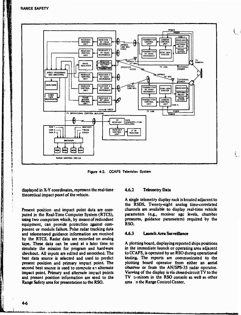
RANGE SAFETY
RECEIVEH CONTROL
UNIT
DECEIVER 1 RF HEAD
1_J I n .VIDEO PROCESSING
AND SWITCHING
VIDEO TAPE U
RECORDERS
CAM 1 CAM 2 CAM 3 111
RECEIVER CONTROL
UNIT
WAVE ANALYSER
RECEIVER CONTROL
UNIT
RECEIVER CONTROL
UNIT
TRANS- MITTER
CONTROL UNIT
TV OPERATIONAL CONTROL BUILDING
*
ill WEATHER TIMING OTHER
SSfifi
RF RECEIVER
PAFB ADMINISTRATION BUILDING
RECEIVER CONTROL
UNIT
27 IN MONITOR
RANGE CONTROL CENTER
Figure 4-2. CCAFS Television System
displayed in X-Y coordinates, represent the real-time theoretical impact point of the vehicle.
Present position and impact point data are com- puted in the Real-Time Computer System (RTCS), using two computers which, by means of redundant equipment, can provide protection against com- ponent or module failure. Pulse radar tracking data and telemetered guidance information are received by the RTCS. Radar data are recorded on analog tape. These data can be used at a later time to simulate the mission for program and hardware checkout. AH inputs are edited and smoothed. The best data source is selected and used to predict present position and primary impact point. The second best source is used to compute an alternate impact point. Primary and alternate impact points and present position information are send to the Range Safety area for presentation to the RSO.
4.6.2 Telemetry Data
A single telemetry display rack is located adjacent to the RSDS. Twenty-eight analog time-correlated channels are available to display real-time vehicle parameters (e.g., receiver age levels, chamber pressures, guidance parameters) required by the RSO.
4.6.3 Launch Area Surveillance
A plotting board, displaying reported ships positions in the immediate launch or operating area adjacent to CCAFS, is operated by an RSO during operational testing. The reports are communicated to the plotting board operator from either an aerial observer or from the AN/SPS-35 radar operator. Viewing of the display is via closed-circuit TV to the TV Ts* mi tors in the RSO console as well as other area n the Range Control Center.
4-6 ■*&.. .^jüaüii H.^-mi^.-...i^.-
imtäm ■■ -- iTriV

SHIPS REDSTONE
i SECTION 5
SHIPS
• 1
The AFETR operates three instrumentation ships to provide data coverage in areas outside the limits of land stations. One of these ships, the USNS Redstone, operates primarily in the Atlantic in support of the Navy's Fleet Ballistic Missile Program. The other two, the USNS General H. H. Arnold and the USNS General Hoyt S. Vandenberg, presently provide support in the Pacific. Detailed character- istics of each are given in the following paragraphs and under the appropriate instrumentation category in previous paragraphs.
5.1 RANGE INSTRUMENTATION SHIP (WS), USNS REDSTONE, T-AGM-20
The Range Instrumentation Ship, USNS Redstone (T-AGM-20) is configured to collect metric and telemetry data in remote areas. Additionally, equipment is available to provide ship's position and attitude, timing, data handling, communications, surface and upper-air meteorological data, and command/control which allows independent opera- tion in the broad ocean areas of the Eastern Test Range.
The Redstone currently supports three basic types of missions:
(1) Functioning as the Downranf; Support Ship (DRSS), it supports ubmarine- launched ballistic missiles in the immedi- ate postlaunch phase. In this role the ship support in conjunction with the Launch Area Support Ship (LASS), USNS Range Sentinel, and collects telemetry data from a ripple launch of up to four vehicles while located 100 to 150 mUes from the launch point. When operating in the DRSS role, the Redstone can command the destruc- tion of missiles which deviate from preplanned flight corridors.
(2) It provides terminal area ship support (TASS) for ballistic missile firings on the AFETR. In this mission it provides metric trajectory data, collects telemetry data from the reentry bodies, collects terminal
area meteorological data, and calibrates the Missile Impact Location Systems (MILS) on the Range.
(3) The ship also provides support during the insertion and on-orbit phases of space- craft operations. In this role it collects both metric and telemetric data and retransmits the information in real-time back to range control centers for further application.
Data gathered by the Redstone are normally shipped to Patrick AFB for processing, reduction, and distribution. Support activities (test planning, engineering, operational control, and logistic sup- port) are also based at Patrick AFB.
The basic configuration of the Redstone is shown in figure 5-1.
The Redstone instrumentation complex is divided into 10 distinct but integrated systems as shown in figure 5*2. Each system is briefly described below. More detailed system descriptions can be found in sections 2 and 3.
5.1.1 Operations Control Center (OCC)
The OCC is the centralized control and monitor facility which provides integrated operations both aboard the ship and between ship and other stations. There are four major equipment items in this area: the Master Systems Console (MSC), the Designate Control Console (DCC), the DRSS Safety Officer Console (DSOC), and the recording and display equipment.
The MSC provides the displays, controls, and communications necessary to integrate and direct the functions of the instrumentation complex and to coordinate with other participating stations.
The DCC contains the status indicators, communi- cations, and controls needed for selection of the master source on the synchro master acquisition
*—rii-rii iHi-amrai »ii liniiaifi(niAiiii-fii'^h«toTi
5-1
-*-—"--*- "YT in r liniiiiniMii
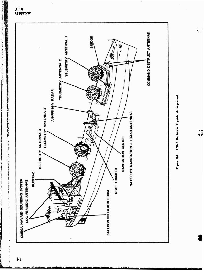
SHIPS REDSTONE
L
c « E
I a» 8
(A Z (A 3
4 s
i
5-2
uJaauaeaaaaüaiMiailBftatBt^fe iIliiililiiiiliWiiilii^iiiTIi
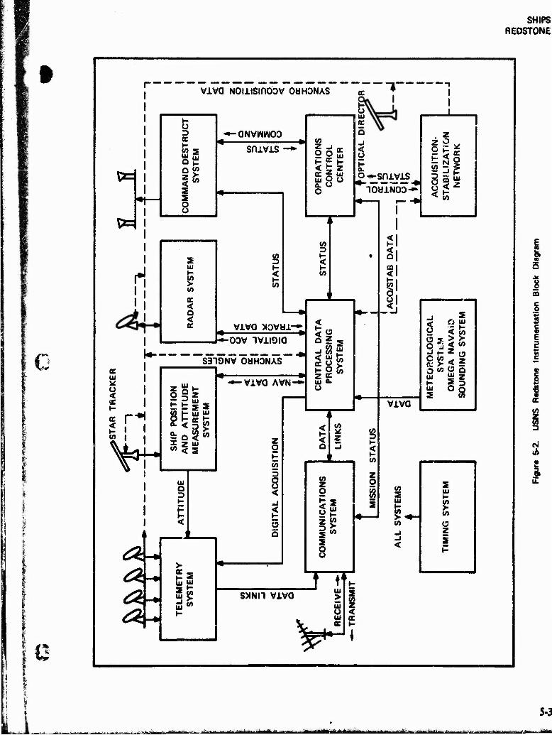
SHIPS REDSTONE
i
1 %mr
II
I i ii
viva NOiiismoDv OUHONAS
3
I- tA S UJ S Q I-
s s 8
-»-aNvwwoo snivis
s UJ I-
< a < e
tA
t- < tA
viva xovui-r /r*-oov iviioia
k- ,__--___-- S319NV OUHDNAS
§Z -*-VlVO AVN-
tu jff
2?
Z O
E 55 5
<
5 a
«5 z o
< ec UJ a. O
is z z
O ü o
UJ
o^-^sniyis 10U1NOD-*'
<
Q 2 5
SO te * y > z oc UJ Q- u
tA
z
tA z o
JE tA
s 8
SXNH viva
, z
§3* o < *
Q| mi <l i-i
S <■>
viva
< o
s a uj
_ < tö
^ »- z o O W -• 2 O tA O O UJ »y» Ui
i§ 8
tA z
tA
i i 5
1 5 § I 2
1
uS
I 9 tA
o z I
i
V^ 5-3
i-Srf:. *. JtK.B.Isi£H;' ■■-■-»•"iiiliii n'mi* m *nii-jniHWni'ii>'«iiii 'ilirrift HthiirrBttiritel a^ä**fe&aiiEB ^--•■': I —!:;
SHIPS REDSTONE
bus, and for selection of the radar designate source when the radar is in the digital slave mode.
The DSOC controls range safety command destruct functions on the ship. The console furnishes comma.* and control status and data displays, and contains necessary operational and communica- tions controls.
The 120-channel event recorder displays and records selected events from the radar and telem- etry systems. Two dual-arm 30-in x 30-in vertical plotting boards display target position and pre- dicted impact points in cartesian coordinates.
5.1.2 Tracking Radar System
The Redstone's precision tracking radar is an AN/FPS-16 type modified for shipboard use by the addition of on-mount rate gyros and a hydrostatic bearing compensated for horizontal thrust compo- nents. This radar is capable of high accuracy stabilized tracking of high-speed targets using target-borne beacons and is also capable of skin tracking.
To meet Range needs for an improved skin tracking capability, m alternate transmitter, AN/ FPS-26 type, is selectable for use in the radar system. Both transmitters use the same antenna and waveguide and the desired transmitter output is routed by a waveguide switch. Further details are provided in paragraph 2.1.4.
5.1.3 Telemetry System
The Redstone telemetry system can detect, track, receive, record, separate, and decommutate telem- etry data. Processed data may be recorded, displayed, or retransmitted in real-time or post- mission.
The system includes four completely independent 17-ft diameter autotracking antennas, each en- closed in a protective radome. The antennas provide 38 dB gain over the 2200 to 2300-MHz frequency range.
The receive and record subsystems include 24 data receivers, five 14-track magnetic tape recorders, and the necessary ancillary equipment to allow
receipt and recording of both pre- and post- detection telemetry signals.
The data separation and display subsystem includes two time division multiplex (TDM) stations, tunable and fixed discriminators, and several types of display units.
The retransmission subsystem consists of a signal processor and conditioner (SPAC) to process and output digital data to the communications system and video retransmission equipment for retrans- mitting recorded telemetry video data over vhf links to aircraft for quick-look data.
Further details are provided in paragraph 2.2.20.
5.1.4 Ship Position and Attitude Measurement System (SPAMS)
The SPAMS provides continuous and accurate data of ship attitude (roll and pitch relative to the local vertical, and heading relative to north), velocity (inertial components north, east, and vertical), and position (latitude and longitude). The system is comprised of a number of individual subsystems and equipment integrated to provide data for stabilization of shipboard antenna systems and for conversion of angle information from deck- referenced coordinates to Earth-referenced co- ordinates. The system also provides for ship's velocity measurement, and for monitoring the flexure angles between the bedplate caused by the nonrigidity of the ship.
5.1.5 Command Destruct System (CDS)
The CDS provides the Redstone with the capability of commanding the destruction of missiles in flight. This destruct capability is used only when the ship is operating as the DRSS and in conjunction with the LASS.
Upon receipt of a destruct request from the LASS, the onboard DRSS Safety Officer (DSO) initiates proper commands to the CDS to generate and transmit coded arm and destruct signals to the missile. The CDS is a redundant 10-kW uhf system with a capability for automatic or manual switch- over to on-line standby equipment upon failure detection. Further details are provided in para- graph 3.2.2.
ÜÜHUHÜ mm k-Ä,

wmimmmm
SHIPS REDSTONE
i
i
5 W-
5.1.6 Central Data Processing System (CDPS)
The CDPS receives ship's position and attitude data, timing signals, control and status signals, radar antenna pedestal flexure data, target acquisi- tion information, and real-time radar tracking data. It processes the received information to provide data for antenna pointing, ship's position and attitude, trajectory data recording and display, plotting board tracking, target acquisition, com- mand and control functions, status display, and real-time transmission.
The CDPS consists of a Univac 1230 digital computer with associated peripheral equipment and buffers which interface the computer with instrumentation complex equipment. The Univac 1230 (modified CP-642B) is a medium scale, general purpose computer with a random access memory of 32,608 thirty-bit words, 16 input and 16 output channels for information transfer, and cycle times of 2 JJS. Peripheral equipment includes one 2-deck and one 4-deck magnetic tape unit, input-output console, teletypewriter unit, high- speed printer, raw data recorder, and interface buffers to instrumentation equipment Further details are provided in paragraph 3.6.3.
5.1.7 Timing System
The timing system generates and distributes the standard frequencies, time codes, and repetition rates required for precise synchronization, calibra- tion, and titüe identification of instrumentation complex functions and data.
The system is similar to other standard Range timing installations but incorporates certain design features to improve accuracy and reliability. Frequency and time generation are redundant with (1) manual on-line selection and (2) electronic, transient-free failure alarms and switchovers. Re- chargeable emergency batteries and electronic power switchover circuits permit operation of essential system functions for up to 8 hours without loss of synchronization in the event of primary power failure. Features include a rubidium-vapor primary frequency standard, corre- lated crystal secondary frequency standard, cesium beam frequency standard as master clock, provi- sion for both vlf and WWV radio broadcast synchronization, compensation for the ship's radial
velocity during synchronization, and integral patch panel for output distribution. See paragraph 3.3.9.
5.1.8 Acquisition/Stabilization Network (ASN)
The ASN provides target synchro acquisition and antenna stabilization signals required to inter- connect, position, and stabilize certain tracking and remotely controlled directional antennas on the ship. The system may be controlled centrally from the OCC or locally at individual system consoles. The prime synchro designation source may be either the CDPS computer, radar antenna, optical director, or any of the telemetry antennas. Antennas using synchro data may then be slaved to the selected prime designation source for acquisi- tion purposes. The star tracker may also be slaved to the prime designation source.
When lock-on is accomplished and automatic tracking begins, on-track signals are transmitted to the pertinent consoles via the on-track. subnetwork. The designate controller in the OCC receives the on-track data from the designate sources and assigns the master antenna for the synchro master acquisition bus.
The system has an optical acquisition aid and four principal subnetworks: ship's heading, on-track, stabilization, and acquisition.
5.1.9 Meteorological System
The Redstone, like other AFETR stations, collects and records weather data to determine its effect on a given mission and to predict weather conditions for future scheduling and planning. Both surface weather data (wind speed and direction, pressures, etc) and high altitude data are collected. See paragraph 2.5.
5.1.10 Communications System
The communications system includes radio trans- mitters and receivers for long and short-haul communications in the hf, vhf, and uhf bands. Also included in the radio subsystem are a crypto- graphic facility, teletype, and high-speed digital data link faculties. An interphone subsystem provides for inter- and intraship voice traffic during operational support. A dial telephone subsystem is used for administrative support and an entertatn-
»a tiiühaä. j w ■ "■—JM »ttMH liiniTiiirar iimir'—iMiarini in i j^mammmm^ikmMtm
5-5
SHIPS ARIS
ment subsystem receives and distributes television and radio broadcasts to personnel spaces on the ship. See paragraph 3.1.
5.1.11 Miscellaneous Equipment
Cine and ballistic cameras can be installed to acquire optical documentary, engineering, spatial, and radiometric data to support Range Users.
Acoustic velocimeter, bathythermograph, and T-0 recorders are used to determine the velocity of sound at varying depths and record event times for underwater sound signals.
A transponder (beacon) and radio homing devices are installed to provide navigation assistance to Range aircraft participating in mission support.
MUSTRAC is a multiple target steerable telemetry tracking system which has been placed aboard the Redstone for engineering evaluation. The multiple beam system can simultaneously search, acquire, and track up to four independent sources located within a 50° cone. The system uses a pedestal positioner for locating the array face in such a manner that the 50° cone of coverage can be optimally used. The technique employed is not electronic steering but one of selection of the various beams formed by a beam-forming network (lenses). The selection commands are generated in a small general-purpose computer which generates a scan for the search mode, performs acquisition functions, and processes the tracking error signals. The MUSTRAC antenna has an aperture of 7 ft and uses transistorized preamplifiers in the re- ceiving subsystem.
5,2 ADVANCED RANGE INSTRUMENTA- TION SHIPS (ARIS), USNS ARNOLD, T-AGM-9, and USNS VANDENBERG, T-AGM-10
The USNS General H. H. Arnold and the USNS General Hoyt S. Vandenberg are the two Advanced Range Instrumentation Ships (ARIS) which are designed to gather precision data on missile reentry bodies and penetration aids; each ship carries multiple high performance radars, broadband te- lemetry, and radiometric and optical instrumen- tation. Additional equipment for navigation/ stabilization, meteorology, data handling, timing, control, communications, and marine support allows independent operation in remote areas of
both the Eastern Test Range and the Western Test Range. ^
Both ships are converted C-4 cargo class ships which were formerly used as troop ships. Figure 5-3 shows the ARIS inboard profile. The primary mission of the ship instrumentation is to gather scientific measurement data associated with the midcourse and reentry phases of ballistic missile flight. These data can be divided into two principal regions: those which pertain to exoatmospheric flight and those which are endoatmospheric Of specific interest are those target properties and characteristics such as size, shape, mass, and precision motion which produce certain distinct signatures or modulations on a radar signal.
In addition to the primary purpose of the ARIS system as a tool for gathering data on missile reentry bodies, the ships constitute a flexible expansion of the missile test ranges beyond the coverage capabilities of land-based instrumenta- tion.
ARIS instrumentation is divided into nine major subsystems as shown in figure 5-4. Each subsystem and its capability is briefly described below. More detailed system descriptions can be found in "* sections 2 and 3.
5.2.1 Operations Control Center (OCC)
The OCC is the centralized control facility which provides integrated operations both aboard ship and between the ship and other stations. There are two major equipment items in this area: the master control console (MCC) and the designate control console (DCC).
The MCC displays ship's heading, speed, and position from the navigation subsystem; instrumen- tation status from all subsystems; and radar boresight television. The master countdown clock and two intercom stations are also provided.
The DCC provides status displays for all systems which can be elected as MASTER on the acquisition buses, including radar antenna, telem- etry, computer, star tracker, and the IFLOT. Switches are provided to allow selection of the desired MASTER system. The on-track or off-track condition of the radars and telemetry is displayed. * A countdown clock and communications panel are ^ also provided.
5-6
aa^teaittiäSli mm

.vi><m.^>a*f>wmsmmm mmummmmm
SHIPS ARIS
I WS*
■MUBÜML 5-7
i riilniTiii um i ifcin luili imrwifi iitiMUmilii ■■*"*"■**"' •^iiüt irr-fc i r imnliifiMiiiMnitiimi «ifflrittiTinii - «TiiiftTi i tmayrt—MfläMaai
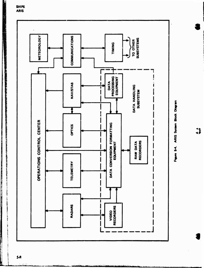
SHIPS ANS
S-*
-«as-»..,, mail aaH '■■■^"-'-*i-^iHiiiaiairwilMiiif uniim
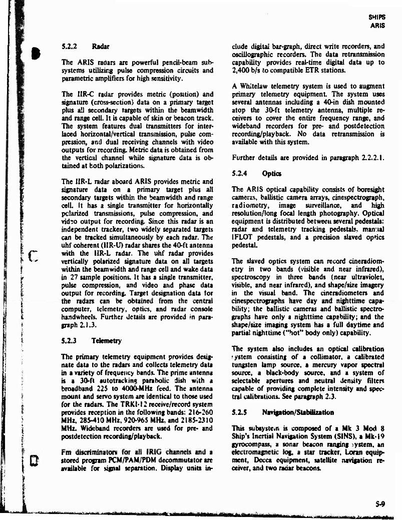
c
D
5.2.2 Radar
The ARIS radars are powerful pencil-beam sub- systems utilizing pulse compression circuits and parametric amplifiers for high sensitivity.
The IIR-C radar provides metric (position) and signature (cross-section) data on a primary target plus ail secondary targets within the beamwidth and range cell. It is capable of skin or beacon track. The system features dual transmitters for inter- laced horizontal/vertical transmission, pulse com- pression, and dual receiving channels with video outputs for recording. Metric data is obtained from the vertical channel while signature data is ob- tained at both polarizations.
The 1IR-L radar aboard ARIS provides metric and signature data on a primary target plus all secondary targets within the beamwidth and range cell. It has a single transmitter for horizontally polarized transmissions, pulse compression, and vid?o output for recording. Since this radar is an independent tracker, two widely separated targets can be tracked simultaneously by each radar. The uhf coherent (1IR-U) radar shares the 40-ft antenna with the 1IR-L radar. The uhf radar provides vertically polarized signature data on all targets within the beamwidth and range cell and wake data in 27 sample positions. It has a single transmitter, pulse compression, and video and phase data output for recording. Target designation data for the radars can be obtained from the central computer, telemetry, optics, and radar console handwheels. Further details are provided in para- graph 2.1.3.
5.2.3 Telemetry
The primary telemetry equipment provides desig- nate data to the radars and collects telemetry data in a variety of frequency bands. The prime antenna is a 30-ft auto tracking parabolic dish with a broadband 225 to 4000-MHz feed. The antenna mount and servo system are identical to those used for the radars. The TRKI-12 receive/record system provides reception in the following bands: 216*260 MHz, 285-410 MHz, 920-965 MHz, and 2185-2310 MHz. Wideband recorders are used for pre- and postdetection recording/playback.
Fro discriminators for all IR1G channels and a stored program PCM/PAM/PDM decommutator are available for signal separation. Display units in-
SHIPS ARIS
elude digital bar-graph, direct write recorders, and oscillographic recorders. The data retransmission capability provides real-time digital data up to 2,400 b/s to compatible ETR stations.
A Whitelaw telemetry system is used to augment primary telemetry equipment. The system uses several antennas including a 40-in dish mounted atop the 30-ft telemetry antenna, multiple re- ceivers to cover the entire frequency range, and wideband recorders for pre- and postdetection recording/playback. No data retransmission is available with this system.
Further details are provided in paragraph 2.2.2.1.
52.4 Optics
The ARIS optical capability consists of boresight cameras, ballistic camera arrays, cinespectrograph, radiometry, image surveillance, and high resolution/long focal length photography. Optical equipment is distributed between several pedestals: radar and telemetry tracking pedestals, manual IFLOT pedestals, and a precision slaved optics pedestal.
The slaved optics system can record cineradiom- etry in two bands (visible and near infrared), spectroscopy in three bands (near ultraviolet, visible, and near infrared), and shape/size imagery in the visual band. The cineradiometers and cinespectrographs have day and nighttime capa- bility; the ballistic cameras and ballistic spectro- gntphs have only a nighttime capability; and the shape/size imaging system has a full daytime and partial nighttime ("hot" body only) capability.
The system also includes an optical calibration system consisting of a coUimator, a calibrated tungsten lamp source, a mercury vapor spectral source, a black-body source, and a system of selectable apertures and neutral density filters capable of providing complete intensity and spec- tral calibrations. See paragraph 2.3.
5.15 .Navipuon'Stabilualion
This subsystem is composed of a Mk 3 Mod 8 Ship's Inertia! Navigation System (SINS), a Mk-19 gyrocompass, a sonar beacon ranging system, an electromagnetic log, a star tracker, Loran equip- ment, Dccca equipment, satellite navigation re* ceiver, and two radar beacons.
S-9 ■-■,,j-t-,j. „-„^fi^, 111« n i i*ii mi »ii «Seme» iwmii.ua «ü» i»mi <uiii»ainftn
SHIPS ARIS
The 1206 computer uses inputs from the above equipment to derive ship's position and heading and for tracking system orientation.
SINS outputs are latitude, longitude, roll, pitch, and heading Attitude data are used to remove ship's motion from the computer designate data and to provide a reference for transformation of radar deck elevation and bearing to a stable local vertical coordinate system.
For precision navigating, the SINS is used as a means of interpolating ship's position and heading between star tracker, satellite position, or sonar fixes. Prior to support of a mission in a broad ocean area, a pattern of two or three sonar beacons may be sown. Geodetic locations of the beacons are established by obtaining ship position fixes using the star tracker or satellite navigation receiver while simultaneously recording slant ranges to the sonar beacons. Two radar beacons are included in the navigation subsystem: AN/APN-69 and AN/ DPN-66. These beacons are aircraft/ship navigation aids.
5.2.6 Data Handling
The data handling subsystem provides a capability for processing 33 million bits pe* second. The data handling subsystem also provides:
1. Conversion, formatting, and recording of metric and signature data.
Computer support for target designation, navigation, calibration, and checkout.
Three major equipment groups make up the data handling subsystem.
1. The first, data processing equipment, includes the central computers, periph- eral equipment, and related software.
2. Vidto recording equipment provides re- dundan. recording of ail radar signature data and includes 2-in magnetic tape units with associated electronic* and buffers. Tape copies can also be made aboard ship.
3. Data conversion equipment serves an interface for the processing and record« tag function by providing two-way con-
versions between digital analog data for recording and computer entry, routing data between subsystems for the track- ing radars, and recording all prime target metric and signature data with SINS attitude and other reference data.
IIR-C radar data on the Vandenberg are recorded on 1-in tape and then transcribed to Mt-in tape in IBM format. The Arnold's IIR-C radar data are recorded directly in IBM format on Mt-in tape. IIR-L radar data, on both ships, are recorded on !4-in tape directly in IBM format. See paragraph 3.6.4,
5.2.7 Timing
The timing subsystem provides accurate time and/or reference signals to all subsystems to permit correlation of independent events both :nternal and external to the ship. The cesium standard is stable to within 1 part in 10" per day and maintains time correlation between the ?hip and Cape Canaveral to within ±0.5 ms at distances up to 10,000 miles. Receiver/comparators in the system provide for synchronization of the ship's timing system with WWV, WWVH (Hawaii), NBA (Balboa, Panama), GBR (Rugby, England), or WWVL < Boulder, Colorado). The system is capable of providing an output of 23 digital codes, 39 pulse rates, 39 mixed codes, and 7 sine waves in standard 1R1G format.
See paragraph 3.3.(0.
5.2.8 Meteorology
Surface and high altitude meteorological data »re fathered by both ARIS ships to furnish accurate and timely weather information needed to sched- ule tests and analyze missile performance data. All meteorological data arc transmitted to Patrick AFB via teletype.
See paragraph 2.5.
5.2.9 Communications
The communications subsystem provides for inter- nal and external transmission and reception "tf voice, teletype, and data. Internal voice communi- cations include a direct-dial Electronic Private Automatic Branch Exchange (EPABX) system with
5-10 rirriirihtiin'niiü* mmgmaam watfiüiia-MniHrirTr' —m i t;mt*t*tv'
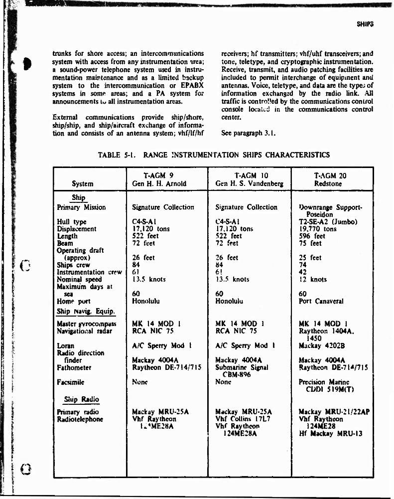
NKWM
SHIPS
trunks for shore access; an intercommunications system with access from any instrumentation irea; a sound-power telephone system used in instru- mentation maintenance and as a limited backup system to the intercommunication or EPABX systems in some areas; and a PA system for announcements u all instrumentation areas.
External communications provide ship/shore, ship/ship, and ship/aircraft exchange of informa- tion and consists of an antenna system; vhf/lf/hf
receivers; hf transmitters; vhf/uhf transceivers; and tone, teletype, and cryptographic instrumentation. Receive, transmit, and audio patching facilities are included to permit interchange of equipment and antennas. Voice, teletype, and data are the types of information exchanged by the radio link. All traffic is contro'Jed by the communications control console located in the communications control center.
See paragraph 3.1.
TABLE 5-1. RANGE INSTRUMENTATION SHIPS CHARACTERISTICS
' { *
i n
T-AGM 9 T-AGM 10 T-AGM 20 System Gen H. H. Arnold Gen H. S. Vandenberg Redstone
Ship Primary Mission Signature Collection Signature Collection Downrange Support-
Poseidon Hull type C4-S-AI C4-S-A1 T2-SE-A2 (Jumbo) Displacement 17,120 tons 17.120 torn 19,770 tons Length 522 feet 522 feet 596 feet Beam 72 feet 72 feet 75 feet Operating draft
(approx) 26 feet 26 feet 25 feet Ships crew 84 84 74 Instrumentation crew 6! 6! 42 Nominal speed 13.5 knots !3.5 knots 12 knots Maximum days at
sea 60 60 60 Homr port Honolulu Honolulu Port Canaveral Ship Navig. Equip.
MK 14 MOD 1 MK 14 MOD 1 MK 14 MOD 1 Master gyrocompass Naviptio^al radar RCA NIC 75 RCA NIC 75 Raytheon I404A.
1450 Loran A/C Spcrry Mod 1 A/C Sperry Mod I Mackay 4202B Radio direction
finder Mackay 4Q04A Mackay 4004A Mackay 4004A Fathometer Raytheon DE-714/71S Submarine Signal
CBM'8% Raytheon DE-7M/7JS
Facsimile None None Precision Marine CDDI 5I9M(T)
Ship Radio
Primary radio Mackay MRU-25A Mackay MRU-25A Mackay MRU-21/22AP Radiotelephone Vhf Raytheon Vhf Collins I7L7 Vhf Raytheon
I**ME28A Vhf Raytheon 124ME28 I24ME28A Hf Mackay MRU-13
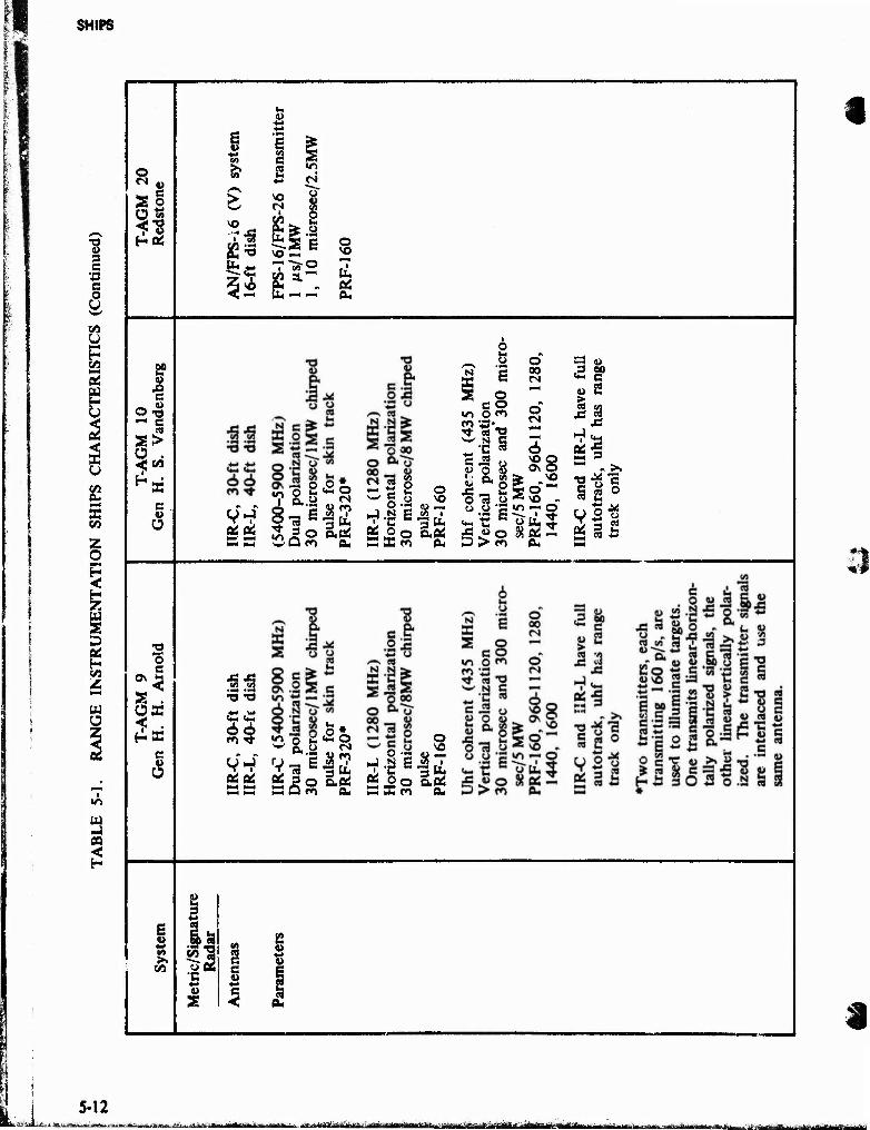
fe™ SHIPS
1 1 Ö 3
::■- | c fj" •ö "■■,■ c f o & B %.
CO o t—<
t H !;• CO M a! w
a* £ to Z o H < H W 2 D of fe 2
-J j»
8 2 o
Htt,
E? JO c
-g ^ •
e w Ü
o e
5s
c 3
6 2 M
•v-a
5s
It 4) +■> ♦J
6 £ CO •«
e3 •" +3 <N
£ « CS B5
«^ 2 ft«;* .a VO «-<
o VO
"T ~a-° «j aLw u. ft, * . cd bu- — ft«
a -1 £ •? j3o o.ft« wUm ft«
w C o i 'C
PÖ o 6 M o o.
o
8*7
2 2 c 2 «o o o ■* es "O c
SJ
R a& o 73 .a
o 00
o
i—i OS to ft«
vo Q Ov ©
* «^ «* \o - «/•> •— o
ft.
5 « "*- c g> 2 (8 u
*^ «a OS'S " .>. M .* "3 c ° S
66
«JOS eg 3 M M mm D
o #
as^s o
aft« a«
£ o0 aft. M 3a Cl CU
c 4»
i
a
5-12 frjssfiaAfcfei '": - ■! ■ a ■ r r. .nil-! iwm--.nlfftf!hi., i.ii-rt'., r-n.. £-'< ViViti f ■ i«-iiiThrr - -JItfi frifc
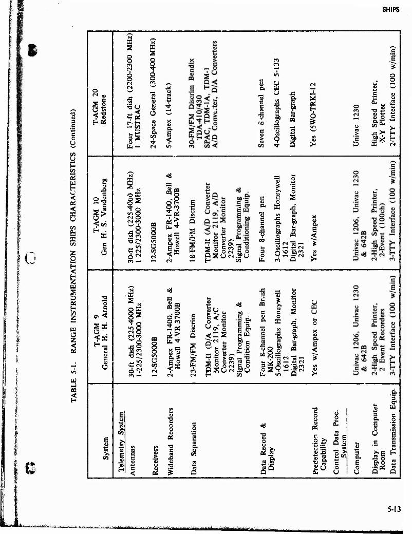
SHIPS
g
I c
C
CO Ü H CO
2
flu < a CJ CO 0. 5 CO
Z O
§ H Z
a D as H CO Z
W Ü z
UJ
CO <
%
o
a s
2? s ■g
s
> 3
c u Ü
o
ON
S Ü
2
o o <n n
i o o ts w
3 •So
-5 2 a o b-
K a o o ^r 8
■a u c u Ü
ft CO
I ■«•
M o
(U &
ro r> r-<
«O
c u (S ft w o JÜ
c c cd ft a» as
& CO
CO O
S3 *—I <A c o 43 ^»-' > u to
9 s «1
as a N
X a
o o o to «rt o <N o
^o
6^ ro —>
<*
CO O -o
2« 8
as 8 o
"5 CO I
ft * c o
— «N 00
T1 *3 te Os -J "2 _ o O<N co pau<N.spu H co
*-M It O
y 3= C >> o
c c a 1> o ft K 43 ,«, ft <0 e c ft ja
o es s
y co <; oo fa CN 3 n
* 3 O 9 '§> 05
b m u >
■s = a> *S
438 8
«^ O <Z CN CO
i Ki i
cog ..o
O ro 2«
«1 "5 ft* S3
-. — <s
gü fa 00
c PQ
c c
••* c 0 a
a üoT§ •g-& 5 3
E <T tdU
!l Ox *3
ft "53
o
ft S Q
a b
w b "
c c to
43 V 8
ft «
O
u s CO
ft
i—i Z, u y*«*v oo
PSUN
— "3 2 c c o •SPU CO
3 O b
« >-
c -w^
s * o o
t-i «-^ « •«-^ -M c « "C o
o b
m xi *J <u (N
4> O e
> c ig
h S
p X
-Y
PI
>- H
D S (M
F u 'S 4M o C >. o 0
CO u +-•
s 1>
(A
02 S C9 ft
CO E g c
c CO
43 ä
u u w (4 V ■•-1 u TJ ■♦-•
H c <
u oi ^ c3
o
Öä JS ft w ST
<s
•o l-l
o o
0«
6
l& « E Q «
W 43 (A
OÄ o 3
■SB1 C ft E
&u a 0 u
3 ft
I
^E ft 5 s
ft 3
W e o
E US
e
Q
5-13
»ÄaiÄiÖBlÄiäyiijta«ÄiBMfi^^ -'""-•
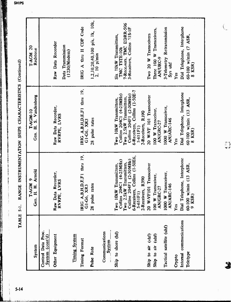
SHIPS
w
CO <
o
S3 •^ co
2?
c
~ *° O C
>
3. CO
c CO O
o
-I
c
3
E V +■» en >. to
M O
CO r—•<
•a o U P-,
CO c Q U "ft
O O co
o CO g B
0,40
,100
p/
min
« £ «a 2 ca fi © X •*-» ca Q H O <
o"2 1
öS
w tN Ü "™1
3° H-4
--"
VO o
■ Uu
K Oi OS
1
4> n t~ +-* a <n
g M u .£
§ O s 0
■ HU h«
rfc B S2 w <0
o H >
<3 O o o
X s F
co <D
as t-~ co
S2 o CO
co g 'S
CO > CO o s
CD O CO C ca
c 2 H
c ca
co
=S 05
s o
X! oi to <:
o CN
O
o\
2oi 4>
Is co S c«
tu c e o "i x 6 P. "^
2 to 2« "33 H
ca O 00 so
Ö •H o o 4>
OS
ca Q
oi
to oi
a a. oi > oi
Ov
ta Q co
5x
2u
c« 1)
4> CO
3 a ao CN
'N „^g <- »S2Kg 4> > ÖS £2 ' CO
nsm
itt
(4-2
5 an
smit
(2
-30
llins
(
O
CJ (« C
2 H
i-T
.6 Ca n ha r— O *o «
kW T
i 20
4C
kW T
20
4F
ers, C
Oi
e o
rii
1- 2^
O «> *! en g —* .S M .5 "w
in
> "S >
o 2 o 2 °£ in oi 8<
H H so rs fN
c o r>
.0 Oi . &
I) CO <
> c CO
u o niS
4) e ^-«
22 o E ft u
13 f- o co
o < S 3 2^s Ö 00
•—1 >- Q vo
T3 to
O Oi oi > ea
£> Q 0U oi
*> ca 0i
Oi
ON
5 ja *->
tu w" Q'CO
«X CQ
< so'
2u
en CO
■*-•
2
"5 ft 00 cs
N N
S i2 CO S
*^ i/-i
E en
o CO
£ i ■
c S«^ C 2
w
o
UHfc,
s ̂ ^ o
»! vi CA c CN c
iS3 o o O o # u ,# () H H
8^
2 o ca u Q w
•S 6
6"
c
E .9* *3 cr w i- a>
JS
E 4) en CQ >. c
CO n 0 CO
M U- ca C
E .5 p
oi
F £
en e 0 *-* 3 E
4» e in 3 >. E CO
E o U
c si
o XI en
ft CO
C C X! X > 3
ca ca en
*■* ** 3 .5- A o JS S « to co H
en C .2 ca u 'E 3 E E o u
o. 1 I- ** c ^
U JS H 3
5-14
in i t uniMHiri—t^—MtM«^
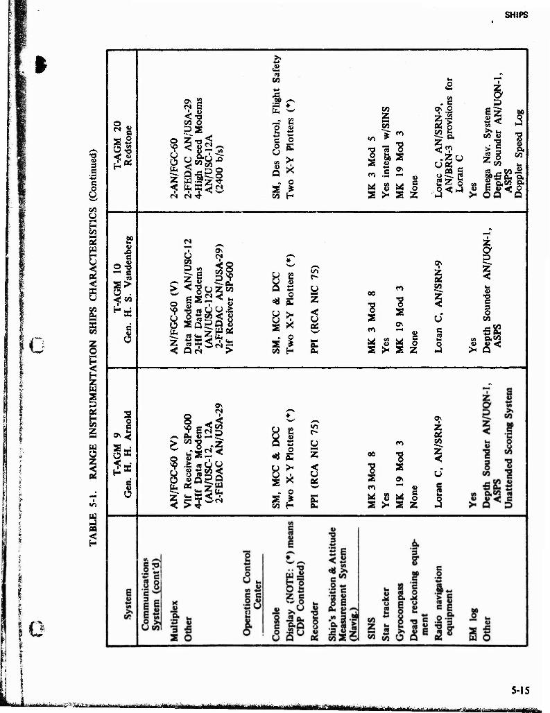
SHIPS
I
u 3
I C o B CO U fr-« H CO >-* 05
s CO
I Z w
02 H SO z IHNI
Ü z
m aa
8| <? 'S < s
s? ■S c > CO
S
6
o
c 3
ON
< (/) P
o z !* <
b <
5 <: fe 0> <N
so
e O S
Mco
o
b z <
i Z | «•8 as
SQ
IS a?
n
äs §2 uzS
Po8 ä
8 -I o
8 b Z <
Uli Ja ^ b
(l> <« w
CO
+■»
■a a * b "W
•■* B o w a r. o o u b
»1 >r Q K
„ o 3S > CO H
o S CO
CO Z co
'S o
>■ s z
<* s o
•33
8 5 z .Zu
2Z %
■ z a D
Sz s*< j£« I« CO »
■ c
§ CO
60
,3 'S CO
« g O.CO o.
>• OQ Q
> Z
Q»
52
o S
o
z
8 0k
Z OS
m CO 00
"8 OS
s «a
s 4> e o Z
c 2
J3
I D Z
w
'S §
CO
a, co
8 S co
i2 w
o S >•
o
U z
Si
&
00
CO
"8 "8
M S M o s >- s z
z OS co
5-15 afefcaä^igicii^^a 5 . ^*^^^>a*afaä^^ , ,-, ,. , . . ^„.^^^ag^,
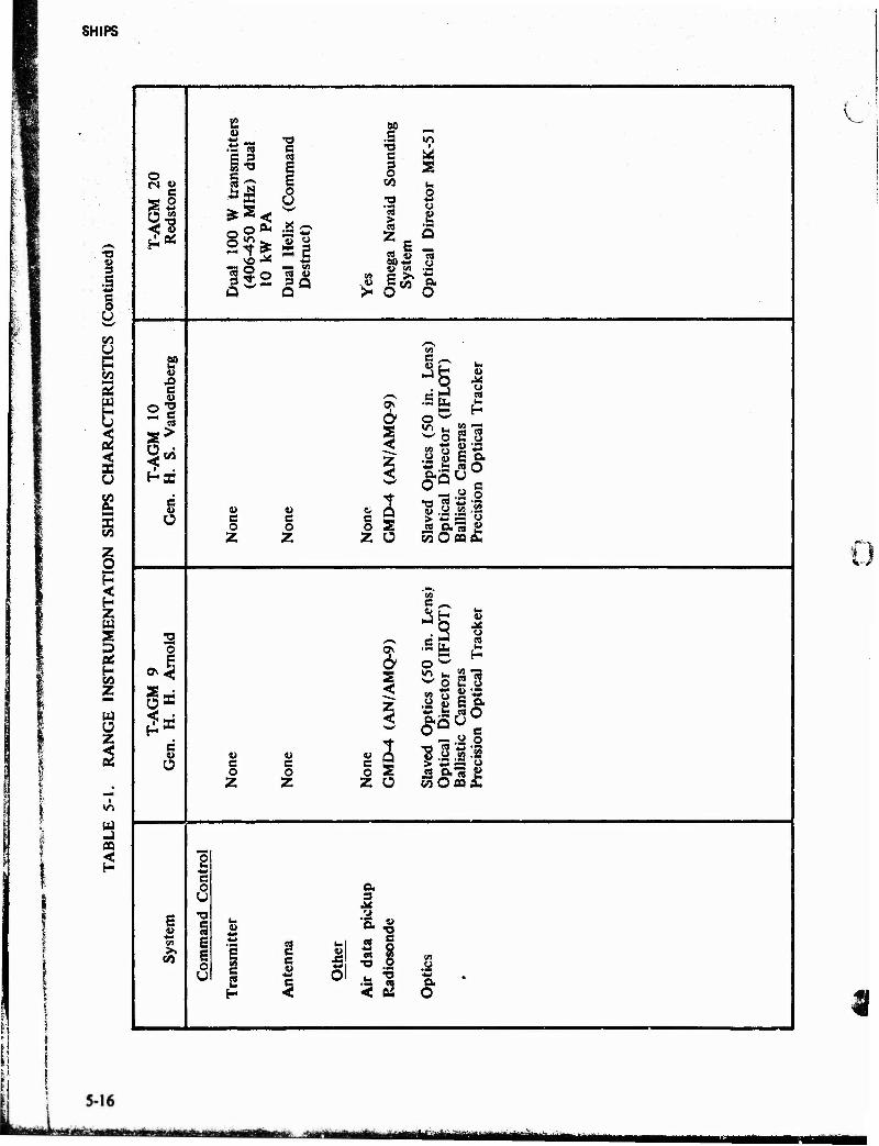
SHIPS
o
e g a
§2'
'S « E £ o u
""> «^ "öS o
rt «-• «a 9 f-> «a ü — <n «8 V I»
so .s *T) •g l
o 3 «1 i->
o x> <-» o BJ <i>
•Ja Q
u Ü 5. w efl 60*- O U vi
i& oOT O
V
s? u e u •a e >
«5
C w Ü
4> u C c O 0 Z Z
«5 c J2 H «
in.
IFL
Tra
c
a o w
£S2S
z
Opt
ics
Dir
ect
Cam
e n
Opt
i
c 2 ved
tica
l lis
tic
cisi
o
O ^ J2 0""3 2 Z Ü W O ao a-
1
e
8> c u Ü
u V c c o o Z Z
« c o Z
< z <
2 s o
c^ c
J3 H «3 3 is
.Sg 2
523 <« o £ *• *- .s- « o AS« O e
"8 .§ .a 3
o in
W
» <
05
e a
E E 6
V
M C c (A u
*J* a O 1
UHU MiiMüi
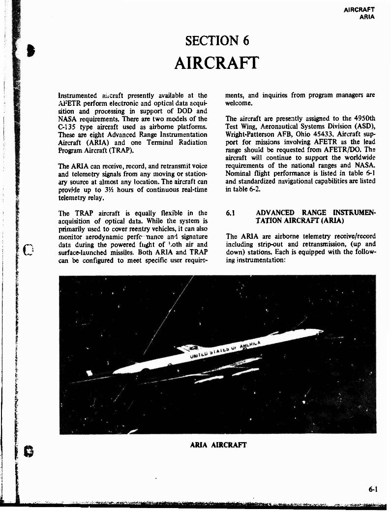
AIRCRAFT ARIA
SECTION 6
AIRCRAFT
Instrumented aucraft presently available at the AFETR perform electronic and optical data acqui- sition and processing in support of DOD and NASA requirements. There are two models of the C-135 type aircraft used as airborne platforms. These are eight Advanced Range Instrumentation Aircraft (ARIA) and one Terminal Radiation Program Aircraft (TRAP).
The ARIA can receive, record, and retransmit voice and telemetry signals from any moving or station- ary source at almost any location. The aircraft can provide up to 3Vz hours of continuous real-time telemetry relay.
The TRAP aircraft is equally flexible in the acquisition of optical data. While the system is primarily used to cover reentry vehicles, it can also monitor aerodynamic perfc nance and signature data during the powered flight of ',oth air and surface-launched missiles. Both ARIA and TRAP can be configured to meet specific user require-
ments, and inquiries from program managers are welcome.
The aircraft are presently assigned to the 4950th Test Wing, Aeronautical Systems Division (ASD), Wright-Patterson AFB, Ohio 45433. Aircraft sup- port for missions involving AFETR as the lead range should be requested from AFETR/DO. The aircraft will continue to support the worldwide requirements of the national ranges and NASA. Nominal flight performance is listed in table 6-1 and standardized navigational capabilities are listed in table 6-2.
6.1 ADVANCED RANGE INSTRUMEN- TATION AIRCRAFT (ARIA)
The ARIA are airborne telemetry receive/record including strip-out and retransmission, (up and down) stations. Each is equipped with the follow- ing instrumentation:
0 ARIA AIRCRAFT
6-1
LÄÄ|*Ää^^fe ̂ ^^f^f^g^^ mm ̂ ^g^^^-^^KJ. - . ■ f^'^rttHS&ü^^jfjjfäföi ■ 'iä '^^Mmäjmj^Mt
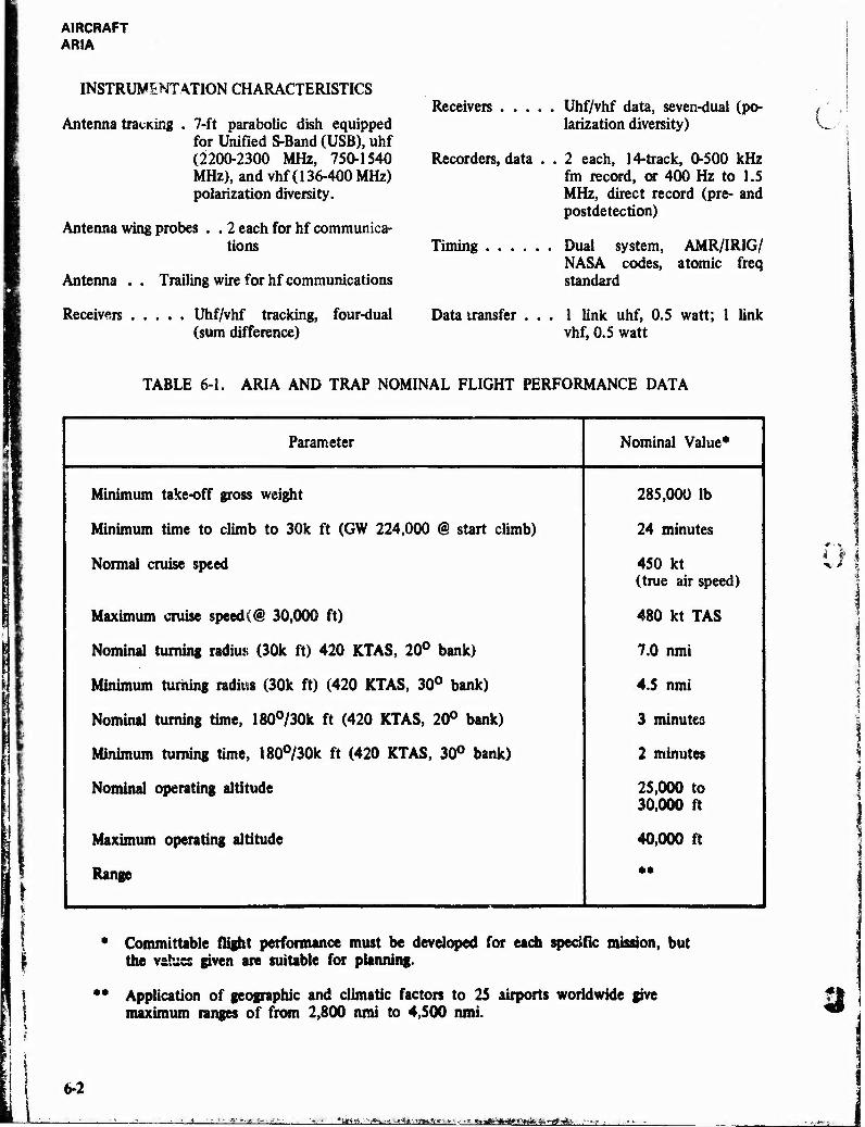
AIRCRAFT ARIA
INSTRUMENTATION CHARACTERISTICS
Antenna touting . 7-ft parabolic dish equipped for Unified S-Band (USB), uhf (2200-2300 MHz, 750-1540 MHz), and vhf (136-400 MHz) polarization diversity.
Antenna wing probes . . 2 each for hf communica- tions
Antenna . . Trailing wire for hf communications
Receivers Uhf/vhf tracking, four-dual (sum difference)
Receivers Uhf/vhf data, seven-dual (po- larization diversity)
Recorders, data . . 2 each, 14-track, 0-500 kHz fm record, or 400 Hz to 1.5 MHz, direct record (pre- and postdetection)
Timing
Data transfer .
Dual system, AMR/IRIG/ NASA codes, atomic freq standard
1 link uhf, 0.5 watt; 1 link vhf, 0.5 watt
TABLE 6-1. ARIA AND TRAP NOMINAL FLIGHT PERFORMANCE DATA
Parameter Nominal Value*
Minimum take-off gross weight
Minimum time to climb to 30k ft (GW 224,000 @ start climb)
Normal cruise speed
Maximum cruise speed(@ 30,000 ft)
Nominal turning radius (30k ft) 420 KTAS, 20° bank)
Minimum turning radius (30k ft) (420 KTAS, 30° bank)
Nominal turning time, 180°/30k ft (420 KTAS, 20° bank)
Minimum turning time, 180°/30k ft (420 KTAS, 30° bank)
Nominal operating altitude
Maximum operating altitude
Range
285,000 lb
24 minutes
450 kt (true air speed)
480 kt TAS
7.0 nmi
4.5 nmi
3 minutes
2 minutes
25,000 to 30,000 ft
40,000 ft
* Committable flight performance must be developed for each specific mission, but the values given are suitable for planning.
** Application of geographic and climatic factors to 25 airports worldwide give maximum ranges of from 2,800 nmi to 4,500 nmi.
6-2
',-«■> *. w._- iaa —. - •**i**>*mtx*ii~m<ii*.
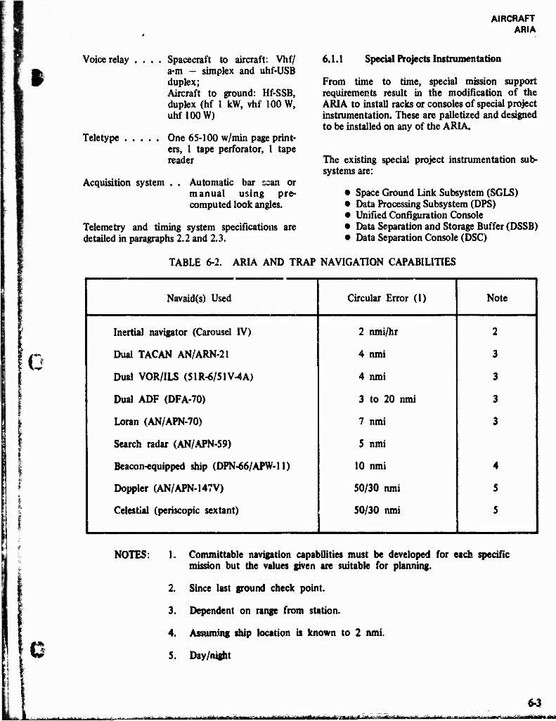
AIRCRAFT ARIA
i Voice relay .
u
Teletype
Spacecraft to aircraft: Vhf/ a-m - simplex and uhf-USB duplex; Aircraft to ground: Hf-SSB, duplex (hf 1 kW, vhf 100 W, uhf100 W)
One 65-100 w/min page print- ers, 1 tape perforator, 1 tape reader
Acquisition system . . Automatic bar ssan or manual using pre- computed look angles.
Telemetry and timing system specifications are detailed in paragraphs 2.2 and 2.3.
6.1.1 Special Projects Instrumentation
From time to time, special mission support requirements result in the modification of the ARIA to install racks or consoles of special project instrumentation. These are palletized and designed to be installed on any of the ARIA.
The existing special project instrumentation sub- systems are:
• Space Ground Link Subsystem (SGLS) • Data Processing Subsystem (DPS) • Unified Configuration Console • Data Separation and Storage Buffer (DSSB) • Data Separation Console (DSC)
TABLE 6-2. ARIA AND TRAP NAVIGATION CAPABILITIES
Navaid(s) Used Circular Error (1) Note
Inertia! navigator (Carousel IV) 2 nmi/hr 2
Dual TACAN AN/ARN-21 4 nmi 3
Dual VOR/ILS (51R-6/51V4A) 4 nmi 3
Dual ADF (DFA-70) 3 to 20 nmi 3
Loran (AN/APN-70) 7 nmi 3
Search radar (AN/APN-59) 5 nmi
Beacon-equipped ship (DPN-66/APW-11) 10 nmi 4
Doppier (AN/APN-147V) 50/30 nmi 5
Celestial (periscopic sextant) 50/30 nmi 5
NOTES: Committable navigation capabilities must be developed for each specific mission but the values given are suitable for planning.
Since last ground check point.
Dependent on range from station.
Assuming ship location is known to 2 nmi.
Day/night
1 ^tä^ttjiia^fflifoiaiäafciiai^^ ü'^
6-3 ft« vf ii in toawa i *-iftfÜTfiiiifiiitiffirirfr i
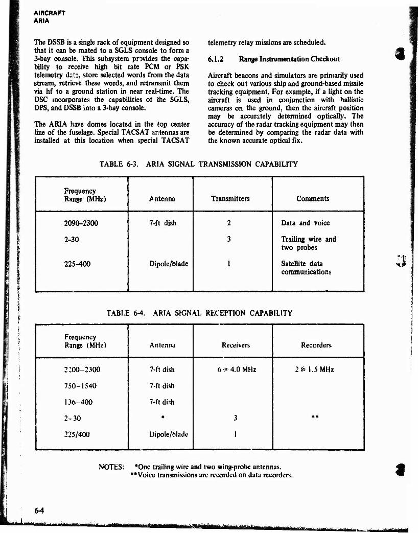
AIRCRAFT ARIA
The DSSB is a single rack of equipment designed so that it can be mated to a SGLS console to form a 3-bay console. This subsystem provides the capa- bility to receive high bit rate PCM or PSK telemetry dats, store selected words from the data stream, retrieve these words, and retransmit them via hi to a ground station in near real-time. The DSC incorporates the capabilities ot the SGLS, DPS, and DSSB into a 3-bay console.
The ARIA have domes located in the top center line of the fuselage. Special TACSAT antennas are installed at this location when special TACSAT
telemetry relay missions are scheduled.
6.1.2 Range Instrumentation Checkout
Aircraft beacons and simulators are primarily used to check out various ship and ground-based missile tracking equipment. For example, if a light on the aircraft is used in conjunction with ballistic cameras on the ground, then the aircraft position may be accurately determined optically. The accuracy of the radar tracking equipment may then be determined by comparing the radar data with the known accurate optical fix.
'%
TABLE 6-3. ARIA SIGNAL TRANSMISSION CAPABILITY
Frequency Range (MHz) Antenna Transmitters Comments
2090-2300
2-30
225-400
7-ft dish
Dipole/blade
2
3
1
Data and voice
Trailing wire and two probes
Satellite data communications
;
;i
TABLE 6-4. ARIA SIGNAL RECEPTION CAPABILITY
Frequency Range (MHz) Antenna Receivers Recorders
2Ü00-2300 7-ft dish 6 »'* 4.0 MHz 2 C« 1.5 MHz
750-1540 7-ft dish
136-400 7-ft dish
2-30 * 3 • *
225/400 Dipole/blade !
NOTES: *One trailing wire and two wing-probe antennas. »»Voice transmissions are recorded on data recorders.
64
- -'lmwunirMiiiTriiriiiiiii i j.i., iMiffimta mmm *&?. äMüÜ «IlifiMiiiiiiTiMi
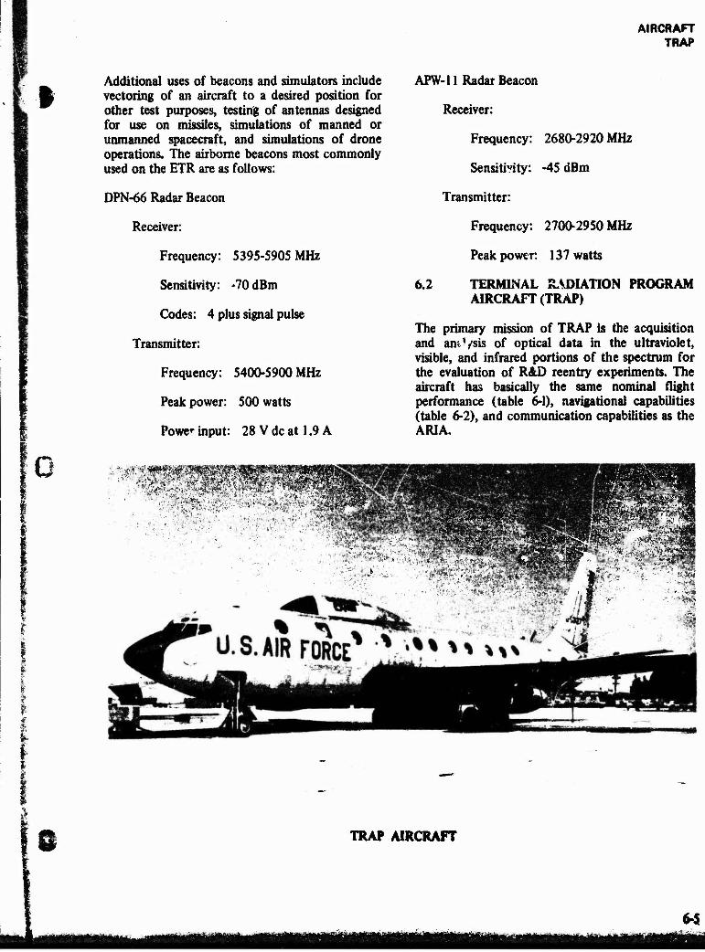
AIRCRAFT TRAP
Additional uses of beacons and simulators include K vectoring of an aircraft to a desired position for
other test purposes, testing of antennas designed for use on missiles, simulations of manned or unmanned spacecraft, and simulations of drone operations. The airborne beacons most commonly used on the ETR are as follows:
DPN-66 Radar Beacon
Receiver:
Frequency: 5395-5905 MHz
Sensitivity: -70dBm
Codes: 4 plus signal pulse
Transmitter:
Frequency: 5400-5900 MHz
Peak power: 500 watts
Power input: 28 V dc at 1.9 A
APW-11 Radar Beacon
Receiver:
Frequency: 2680-2920 MHz
Sensitivity: -45 dBm
Transmitter:
Frequency: 2700-2950 MHz
Peak power: 137 watts
6.2 TERMINAL RADIATION PROGRAM AIRCRAFT (TRAP)
The primary mission of TRAP is the acquisition and amVsis of optical data in the ultraviolet, visible, and infrared portions of the spectrum for the evaluation of R&D reentry experiments. The aircraft has basically the same nominal flight performance (table 6-1), navigational capabilities (table 6-2), and communication capabilities as the ARIA,
•'-!
- , > —v ■ » „ *- - - • " -',-.■"■-.-■ fa- ».
■ ' f
^rr^i rv-~«Wj[
1
ft TRAP AIRCRAFT
6-5
AIRCRAFT TRAP
Special instrumentation tracking systems are mounted on both fixed and gimbal pedestals which use remote acquisition sights for manual and automatic tracking. These systems are:
• Dual-Channel Photometer • High Resolution Camera System • Framing Spectral Ballistics • Cinespectrographs © Metric Ballistic Camera Subsystems • High Speed and Wide Angle Cines • Master Tracking System • Timing and Recording Systems
The operation, maintenance, and upgrading of TRAP instrumentation plus the processing and analysis of TRAP data is provided to Space and Missiles Systems Organization (SAMSO) by AVCO Everett Research Laboratory, Inc (AERL), Everett, Massachusetts. Details of the systems and opera- tional mission support availability can be obtained from:
SAMSO/RSTFS P.O. Box 92960 Worldway Postal Center Los Angeles, California 90009 Autovon: 833-2870
*m, \
©■©
V-"^'—J-irrliffill»t>i^g*-- aiägBÜ I'Tnit-Wrm»iM