rajkot municipal corporation
TRANSCRIPT

Bidders’ stamp & initials
1
RAJKOT MUNICIPAL CORPORATION Water Works [Projects]
e-Tender No.: RMC/WW/508-OD-MSPL/Mosi-schl- Sojitra /2021-3[RE-TENDER]
VOLUME-I
INVITATION TO BID, INSTRUCTIONS TO BIDDERS,
Year: 2021-22 :: Milestone dates of e-Tendering ::
1. Downloading of e-Tender documents Dt. 11-2-2022 to Dt. 03-03-2022 up to 17.00 Hrs.
2. Pre-bid Meeting
On Dt. 22-02-2022 at 11.00 Hrs. At office of Addl. City Engineer WW dept. CZ-RMC. All Queries will be accepted on or before pre-bid meeting (e-mail ID [email protected] )
3. Online submission of e-Tender Dt. 04-03-2022 up to 18.00 Hrs.
4. Physical submission of EMD, Tender fee, Documents required for pre-qualification and other necessary documents.
Dt. 05-03-2022 up to 18.00 Hrs
5. Verification of submitted documents (EMD, Tender fee, Documents required for pre- qualification and other Necessary documents.)
Dt. 07-03-2022 AT 11.30 Hours onwards
6. Opening of online Primary Bid (Technical Bid) Dt. 05-03-2022 at 11.30 Hrs. onwards
7. Opening of online Commercial Bid (Price Bid) for technically qualified bidders only.
Dt. 10-03-2022 at 11.30 Hrs. onwards (If possible)
8. Bid Validity 180 Days
Tender Documents For
Bid Documents for Design, Build & trial run with working survey for Providing, Supplying, Lowering, Laying, Jointing, Testing and Commissioning 3LPE COATED MILD STEEL PIPELINE - 508 mm DIA. (OD) – (6.3 mm thick & 1300 m – all confirmingto relevant BIS or other standards) from MODI SCHOOL TO SOJITRA HEADWORKWITH ALL ALLIED CIVIL WORKS. [Third Attempt]
Addl. City Engineer [CZ] Water Works (Projects) Rajkot Municipal Corporation, Central Zone Dr. Ambedakar Bhavan, Dhebarbhai Road Rajkot-360 001. Tel.: +91 97 145 03709 E-mail: [email protected]

Bidders’ stamp & initials
2
CONTENTS OF THE TENDER / BID DOCUMENT
Table of Contents
CONTENTS OF THE VOLUME- I ..................................................................................................................... 5
PART-I .............................................................................................................................................................
1. Invitation To Bid ................................................................................................................................... 5
2. Instructions to Bidders ......................................................................................................................... 5
ABBREVIATIONS ........................................................................................................................................... 6
SECTION - I .................................................................................................................................................... 7
PART 1. INVITATION TO BID ...................................................................................................................... 7
1. MANDATORY SUBMISSION ...................................................................................................................... 9
2. THE PRE-QUALIFICATION REQUIREMENT IS AS UNDER: ......................................................................... 9
i. Financial Criteria .................................................................................................................................... 9
ii. Experience Criteria .............................................................................................................................. 10
iii. Physical Criteria .................................................................................................................................. 11
A. MS Pipeline: (As per revised GWSSB 274th Board meeting held on 29.02.20)………………………………….11
PART 2. INSTRUCTIONS TO BIDDERS ......................................................................................................... 13
A. General ............................................................................................................................................... 14
1. INVITATION TO E-TENDER ................................................................................................................... 14
2. SOURCE OF FUNDS .............................................................................................................................. 17
3. ELIGIBLE BIDDERS ................................................................................................................................ 17
4. ELIGIBLE MATERIALS, EQUIPMENTS & SERVICES ................................................................................ 18
5. QUALIFICATION OF THE BIDDER ......................................................................................................... 18
6. ONE BID PER BIDDER ........................................................................................................................... 19
7. COST OF BIDDING................................................................................................................................ 19
8. EXAMINATION BY BIDDERS & SITE VISIT ............................................................................................. 19
9. CONTENT OF BIDDING DOCUMENTS .................................................................................................. 20
10. CLARIFICATION OF BIDDING DOCUMENT ......................................................................................... 20
11. AMENDMENTS OF BIDDING DOCUMENTS ....................................................................................... 20
B. PREPARATION OF BIDS .......................................................................................................................... 21
12. LANGUAGE OF BID ............................................................................................................................ 21
13. DOCUMENTS COMPRISING THE BID ................................................................................................. 21
14. BID FORM & PRICE SCHEDULES ........................................................................................................ 22
15. BID PRICES ......................................................................................................................................... 22
16. BID CURRENCIES................................................................................................................................ 22
17. BID VALIDITY .............................................................................................................................................. 22

Bidders’ stamp & initials
3
18. BID SECURITY [EMD] ......................................................................................................................... 23
19. ALTERNATIVE PROPOSALS BY BIDDERS & PAYMENT TERMS............................................................ 25
20. PRE-BID MEETING ............................................................................................................................. 25
21. FORMAT AND SIGNING OF BID ......................................................................................................... 25
C. SUBMISSION OF BIDS ............................................................................................................................ 29
22. ONLINE PRIMARY BID AND ONLINE PRICE BID ................................................................................. 29
23. DEADLINE FOR SUBMISSION OF BIDS ............................................................................................... 30
24. LATE SUBMISSION OF REQUIRED DOCUMENTS (PHYSICALLY) ......................................................... 31
25. OPENING OF PRIMARY BID AND PHYSICALLY SUBMITTED DOCUMENTS FOR PRE-QUALIFICATION 31
26. PROCESS TO BE CONFIDENTIAL ........................................................................................................ 31
27. PRELIMINARY EXAMINATION OF TECHNICAL PROPOSAL ................................................................. 31
28. EVALUATION & COMPARISION OF TECHNICAL PROPOSAL .............................................................. 31
29. CLARIFICATION OF TECHNICAL PROPOSALS AND CONTACTING THE EMPLOYER ............................ 31
30. OPENING OF ONLINE COMMERCIAL BID (PRICE PROPOSALS) .......................................................... 32
D. OPENING AND EVALUATION OF PRICE PROPOSALS ............................................................................. 33
31. OPENING OF ONLINE PRICE PROPOSALS (COMMERCIAL BIDS) ........................................................ 33
32. PROCESS TO BE CONFIDENTIAL ........................................................................................................ 33
33. CLARIFICATION OF PRICE PROPOSALS AND CONTACTING THE EMPLOYER ..................................... 33
34. PRELIMINARY EXAMINATION OF PRICE PROPOSALS AND DETERMINATION OF RESPONSIVENESS 33
35. EVALUATION AND COMPARISION OF PRICE PROPOSAL................................................................... 33
36. DOMESTIC PREFERENCE: NOT APPLICABLE ...................................................................................... 35
E. AWARD OF CONTRACT ........................................................................................................................... 36
37. AWARD .............................................................................................................................................. 36
38. EMPLOYER’S RIGHT TO ACCEPT ANY BID OR TO REJECT ANY OR ALL BIDS ...................................... 36
39. NOTIFICATION OF AWARD ................................................................................................................ 36
40. SIGNING OF CONTRACT AGREEMENT ............................................................................................... 36
41. PERFORMANCE SECURITY ................................................................................................................. 36
42. CORRUPT OR FRAUDULENT PRACTICES ............................................................................................ 37
APPENDIX Part-1 .................................................................................................................................... 40
APPENDIX – A .......................................................................................................................................... 43
APPENDIX – B ............................................................................................................................................. .
APPENDIX – C ............................................................................................................................................. .
APPENDIX – D .......................................................................................................................................... 44
APPENDIX – E1 ............................................................................................................................................
APPENDIX – F .......................................................................................................................................... 45
Bidders’ stamp & initials
4
APPENDIX – G .......................................................................................................................................... 46
APPENDIX – G1 ........................................................................................................................................ 47
APPENDIX – I ........................................................................................................................................... 48
APPENDIX – J ........................................................................................................................................... 49
APPENDIX – K .......................................................................................................................................... 50
APPENDIX – L........................................................................................................................................... 51
APPENDIX – L-1 ....................................................................................................................................... 52
APPENDIX PART - 2 ................................................................................................................................. 53
Annexure A ..................................................................................................................................................
Application Form (1) ............................................................................................................................... 55
Application Form (1A) ............................................................................................................................. 57
MOU for MS pipe .................................................................................................................................... 59
SCHEDULE 2 ............................................................................................................................................ 60
SCHEDULE 3 ............................................................................................................................................ 61
SCHEDULE 4 ............................................................................................................................................ 62
Schedule 5 - Liquidated Damages ........................................................................................................... 63

Bidders’ stamp & initials
5
CONTENTS OF THE VOLUMES
Section I Description
I 1 Invitation To Bid
2 Instructions to Bidders
Section II Description
I 1 General Conditions of Contract
Section III Description
I 1 Submission to be made on Award of Contract

Bidders’ stamp & initials
6
ABBREVIATIONS
Statement showing the details of abbreviations.
Full Form Abbreviation
Atal Mission for Rejuvenation and Urban Transformation AMRUT
Municipal Commissioner MC
The Executive Engineer, Water Works (Project) E. E (WW)
The Deputy Executive Engineer, Water Works (Project) Dy. E. E (WW)
Rajkot Municipal Corporation RMC
Dispute Adjudication Board DAB
Operation and Maintenance O&M
Net Present Value NPV
Engineering Procurement and Construction EPC
Paschim Gujarat Vij Company Limited PGVCL
Critical Path Method CPM
Reinforced Cement Concrete RCC
Kilometer KM
Mild Steel MS
Bureau of Indian Standard BIS
Central Public Health & Environmental Engineering Organization CPHEEO
American Society of Civil Engineers ASCE
American Petroleum Industries API
Million Liter per Day MLD
High Yield Strength Deformed bar HYSD
Corrosion Residence Steel CRS
Ordinary Portland Cement OPC
American Standard for Testing of Material ASTM
Flux Compensated Magnetic Amplifier FCMA
Cost Insurance and fright CIF
Free On Board FOB
Ex – Works EXW
Water Treatment Plant WTP
Sewage Treatment Plant STP
Turbidity Tu
Total Suspended Solids / Suspended Solids TSS / SS
Free Chlorine FRC

Bidders’ stamp & initials
7
SECTION - I
PART 1. INVITATION TO BID

Bidders’ stamp & initials
8
RAJKOT MUNICIPAL CORPORATION
Water Works (Project)
INVITATION FORBIDS / TENDER
e- Tender Notice e-Tender No.: RMC/WW/508-OD-MSPL/Mosi-schl- Sojitra /2022-1
Tenders are invited by Rajkot Municipal Corporation, Water Works (Project)Department,
Dr. Ambedkar Bhavan, Central Zone, Dhebarbhai Road, Rajkot-360001, from the experienced
contractors registered in ‘B’ Class / Equivalent Class in GWSSB / State Government/ Central
Government for following works, under Rajkot Municipal Corporation Water Works Project.
Sr. No.
Name of work
a) Estimated Cost b) Amount of EMD c)e-Tender fee d)Time limit for completion of work
1.
Bid Documents for Design, Build & trial run with working survey for Providing, Supplying, Lowering, Laying, Jointing, Testing and Commissioning 3LPE COATED MILD STEEL PIPELINE - 508 mm DIA. (OD) – (6.3 mm thick & 1300 m – all confirming to relevant BIS or other standards) from MODI SCHOOL TO WITH ALL ALLIED CIVIL WORKS. (Third Attempt)
a) Rs. 1,50,00,000/- b) Rs. 1,50,000/- c) Rs. 4,500/-
d)9 month [inclusive monsoon period] + 1 month trial run period.
:: Milestone dates of e-Tendering ::
2. Downloading of e-Tender documents Dt. 11-2-2022 to Dt. 03-03-2022 up to 17.00 Hrs.
3. Pre-bid Meeting
On Dt. 22-02-2022 at 11.00 Hrs. At office of Addl. City Engineer WW dept. CZ-RMC. All Queries will be accepted on or before pre-bid meeting (e-mail ID [email protected] )
4. Online submission of e-Tender Dt. 04-03-2022 up to 18.00 Hrs.
5.
Physical submission of EMD, Tender fee, Documents
required for pre-qualification and other necessary
documents.
Dt. 05-03-2022 up to 18.00 Hrs
6.
Verification of submitted documents (EMD, Tender
fee, Documents required for pre- qualification and
other Necessary documents.)
Dt. 07-03-2022 AT 11.30 Hours onwards
7. Opening of online Primary Bid (Technical Bid) Dt. 05-03-2022 at 11.30 Hrs. onwards
8. Opening of online Commercial Bid (Price Bid) for
technically qualified bidders only. Dt. 10-03-2022 at 11.30 Hrs. onwards (If possible)
9. Bid Validity 180 Days

Bidders’ stamp & initials
9
b) Mandatory Submission
All bidders must submit the tender fee and Bid Security (EMD) as above either directly deposited in ICICI BANK –
JAYHIND PRESS BR.- RAJKOT. BANK Account No.015305010638 (Rajkot Municipal Corporation) IFSC Code
ICIC0000153 or submit at the below-mentioned address along with physical submission of bid documents in
form of Demand draft in favor of "Rajkot Municipal Corporation", Rajkot, from any Nationalized Bank or
Scheduled Bank (except Co-Operative Bank) in India. Bid Security (EMD). Also, Address proof of registered office
and ID proof shall have to be submitted along with physical submission of required documents.
Office of the Addl. City Engineer, Water Works (Project),
Rajkot Municipal Corporation, Central Zone,
Water Works Department, Dr. Ambedkar Bhavan, Dhebarbhai Road,
Rajkot - 360 001.
c) The pre-qualification requirement is as under:
i. Financial Criteria:
a) The bidder shall have the financial capability and having an average annual turnover of the last seven
years, ending 31st March of the previous financial year (i.e. 2020-21), should not be less than 50% of the
estimated tender cost. Bidder to enclose reports on its financial standing, such as profit and loss
statements and auditor’s reports, for the last seven financial years.
b) Working capital (to be demonstrated by the bidder in form of a confirmed credit line from reputed
Nationalized Bank with the bidder's audited financial statement taking into account current
commitment) must not be less than 25% of the estimated tender cost.
c) Bidder shall have a Solvency Certificate must require a minimum Rs.35.00 lacs. Certified banker’s
statement not older than 6 months shall be attached.
d) The contractor shall have registration with State / Central Government or State Water Supply Boards of
the ‘B’ Class / Equivalent Class. Supporting attested documents to be submitted in hard copy. Available Bid
Capacity-ABC must be more than the estimated tender cost.
Note:
1. Available Bid Capacity(ABC) will be derived by the following method.
ABC is calculated as ABC=2*A*N-B
Where,
A = Maximum value of works executed in any one year during the last Seven years
(updated to present price level by applying enhancement factor) taking into account
the completed as well as works in progress.
N = Number of years prescribed for completion of the works for which tenders are invited.
B = Value (present price level by applying enhancement factor) of existing commitments
and on-going works to be completed during that next N year (period of completion of
the works for which the tenders are invited.)

Bidders’ stamp & initials
10
2. In financial criteria, enhancement factor at the rate of 10% per year will be applicable to arrive at enhanced financial amount at current financial year.
Financial Year Turnover/ Cost of Executed
work/O&M
Effective cost of executed work
at previous completed financial
year’s price
level
2020-2021 A 1.00 x A
2019-2020 B 1.10 x B
2018-2019 C 1.21 x C
2017-2018 D 1.33 x D
2016-2017 E 1.46 x E
2015-2016 F 1.61 x F
2014-2015 G 1.77 x G
ii. Experience Criteria:
The bidder should possess the following minimum experience:
Bidder shall have experience of having completed (including successful trial run & commissioning) at least
one work of MS or DI PIPE LINE PROJECT of 40% of the tendered amount in last 7 years from the
month of invitation of this tender.
or
Two works of MS or DI PIPE LINE PROJECT of 30% of the tendered amount in last 7 years from the
month of invitation of this tender.
In above “Work of Similar Nature” means an experience of design, detailed engineering, procuring,
construction, testing, commissioning work of completed project as per above mentioned tendered
amount of raising main (Pressure) pipeline carrying any type of fluid like sewer, water, oil etc. whose
projects cost inclusive of MS / DI pipeline work in any Municipal Body / Urban Local Body / Development
Authority / State Government Body or undertaking / any department or undertaking of Government of
India.
In addition to that experience will be required also for minimum diameter & pipeline length within the
last seven financial years in any Municipal Body / Urban Local Body / Development Authority / State
Government Body or undertaking / any department or undertaking of Government of India as per physical
criteria shown below.
Note: The Bidder who has no experience as well as a specialty in such type of bulk pipeline works, as required in this tender; such
bidder’s tender will be rejected out rightly.

Bidders’ stamp & initials
11
iii. Physical Criteria:
A. MS Pipeline:
Procure, Lowering, Laying, Jointing, Testing, and Commissioning of minimum length (as under) of MS
pipeline in any single project during last seven (7) financial years i.e. from 2014-2015 to 2020-21. And up
to one month before the last date of submission of the bid. If the pipeline work has been completed along
with successful hydro testing, such works shall also be considered for evaluation based on the facts and
circumstances as certified by the client.
If the bidder satisfies the above criteria but the bidder is not a manufacturer of the pipeline the bidder should have to produce the
memorandum of understanding (MOU) from the current government mfg license holder, reputed and capable manufacturer (As
per prescribed brand mentioned in this tender) from whom the bidders intend to procure the pipeline. For such physical criteria,
the manufacture shall be of Indian origin and the pipe shall have an ISI mark. Only MSPIPE supplied by any prospective bidder will
not be considered for procurement purposes.
Type of Pipeline Min. Diameter [OD/ID] (In mm)[40%]
Min. Length (In Km)[25%]
MS Pipeline ≥ 219 mm ≥ 325 RMT
a) For experience criteria and physical criteria attested Copy of the original certificates [Form -3 (a)] with
outward no & date of concerned govt. dept., in support of the above requirements shall be enclosed in
hard copy for verification, certified by the respective employer or his authorized representative, not
below the rank of an Executive Engineer or equivalent. Original Certificates of the same must be needed
to produce for verification on demand by RMC, failing which, will result in rejection of the tender.
b) For the purpose of bid evaluation, if the RMC’s representatives feel necessary to visit a specific or all such
Mfg. plants as mentioned above by the bidder, the bidder shall have to make necessary arrangements for
the same. The cost of such visits shall be borne by the bidder.
c) Joint Venture will not be permitted for this tender.
d) The experience of Sub-Contractor / back to back works shall not be considered.
3. The bidder should not have been Black Listed, suspended, terminated, backed out,
debarred & delisted by any Municipal Body / Urban Local Body / Development Authority / any State
Government Body or undertaking / any department or undertaking of Government of India, since
inception of the firm / Company. Such a case will be rejected out rightly. A Declaration in this regard on
Rs.300/- Stamp Paper Duly Notarized shall have to be submitted as per Annexure-III, along with the
tender documents. Submission of the bid document without such Notarized declaration will be rejected
out rightly.

Bidders’ stamp & initials
12
4. The bidder should provide accurate information on any litigation history or arbitration resulting from
contracts completed or under execution by him or by his firm over the last ten years. This should also
include such cases, which are in process / progress. A consistent litigation history or arbitration for
awarded work in past / current against OR by the bidder may result in failure of the bid. In case the bidder
has not provided such information and has come to the notice of the authority, the tender will be rejected
at what so ever stage and in such case all the losses that will arise out of this issue will be recovered from
the tenderer / bidder and he will not have any defense for the same.
5. Client has reserved the right (i) to change, alter or to waive quantity as mentioned in the tender’s price
bid, any technical or commercial terms, condition and qualification (ii) to reject all the bids or any bid in
part or full without assigning any reason whatsoever (iii) for making changes / relaxation in eligibility
criteria at any time in the interest of the public. The bidder shall have no cause of action or claim against
the Rajkot Municipal Corporation or its Officers / Employee’s successor or assignee for rejection of his
tender/bid.
6. After opening of Technical Bid, the procedure for the pre-qualification shall be adopted and the Price Bid
of only successful qualified bidder shall be opened for final evaluation of the contract. The decision of
Municipal Commissioner regarding the pre-qualification shall be final and binding to all the bidders.
7. The Tender of those bidder(s) who fail to submit the required documents physically within the stipulated
date and time will be treated as non-responsive and their Price Bid will not be opened.
8. Conditional Tenders will be out rightly rejected.
9. Right to accept / reject any or all e-Tender(s) without assigning any reasons is hereby reserved.
Addi. City Engineer Rajkot Municipal Corporation

Bidders’ stamp & initials
13
SECTION – I
PART 2. INSTRUCTIONS TO BIDDERS

Bidders’ stamp & initials
14
A. General
1. INVITATION TO E-TENDER
The Rajkot Municipal Corporation hereinafter referred as the Corporation will receive e-Tenders for the work of as per the specifications and schedule of prices in the e- Tender document. The e-Tenders shall be opened online as specified in the e-Tender notice in the presence of interested Bidders or their representatives. The Corporation reserves the right to reject the lowest or any other or all e-Tenders or part of it which in the opinion of the Corporation does not appear to be in its best interest, and the Bidder shall have no cause of action or claim against the Corporation or its officers, employees, successors or assignees for rejection of his e-Tender.
SCOPE OF BID: The Rajkot Municipal Corporation (hereinafter referred to as “the Employer”) wishes to receive bids for, the Name of Work: - Bid Documents for Design, Build & trial run with working survey for Providing, Supplying, Lowering, Laying, Jointing, Testing and Commissioning 3LPE COATED MILD STEEL PIPELINE - 508 mm DIA. (OD) – (6.3 mm thick & 1300 m – all confirming to relevant BIS or other standards) from MODI SCHOOL TO SOJITRA HEADWORK WITH ALL ALLIED CIVIL WORKS.
[a] Below image is showing location of proposed pipe line alignment with section : [ This is indicative sketch only]

Bidders’ stamp & initials
15
DETAILS OF PROPOSED PROJECT WORKS
CIVIL WORK – Bid Documents for Design, Build & trial run with working survey for Providing, Supplying, Lowering, Laying, Jointing, Testing and Commissioning 3LPE COATED MILD STEEL PIPELINE - 508 mm DIA. (OD) – (6.3 mm thick & 1300 m – all confirming to relevant BIS or other standards) from MODI SCHOOL TO SOJITRA HEADWORK WITH ALL ALLIED CIVIL WORKS.
CONNECTIONS:
[A] At 150 feet ring road Modi school:
Existing 600 mm M.S. MAIN TRANSMISSION from Raiyadhar to 150 feet headwork will be connected with proposed 500 mm MS line at 150 feet ring road Modi school with 500 mm size butterfly valve with expansion bellows, in the 3.5 mt x 3.2 mt [2 nos. of separate] RCC valve chamber with top cover of 10 mm thick MS plate of required size for valve chamber with required all civil works, fittings & appurtenances as applicable all necessary requirement – all connections work shall be executed as per pre-approval & directed by engineer in-charge.
[B] Connection at SOJITRA HEADWORKS SUMP: Proposed 500mm M.S. MAIN TRANSMISSION MAINLINE from Modi School to Sojitra Headworks Sump chamber with connection will be included of providing, Lowering, Laying, Jointing, Testing and Commissioning of the [a] 500 mm dia. butterfly valve with expansion bellows, in the a 3.5 mt x 3.2 mt separate RCC valve chamber with top cover of RCC Precast slabs & cover in pieces of required for valve chamber with required all civil works, fittings & appurtenances as applicable all necessary requirement all connections work shall be executed as per pre-approval & directed by engineer in-charge.
[C] Flow meter Connection at SOJITRA HEADWORKS SUMP: Proposed 500mm M.S. MAIN TRANSMISSION MAINLINE from Modi School to Sojitra Headworks Sump chamber with connection will be included of providing, Lowering, Laying, Jointing, Testing and Commissioning of the [a] 500 mm dia. Flow meter with expansion bellows, in the a 3.5 mt x 3.2 mt separate RCC valve chamber with top cover of RCC Precast slabs & cover in pieces of required for valve chamber with required all civil works, fittings & appurtenances as applicable all necessary requirement all connections work shall be executed as per pre-approval & directed by engineer in-charge.
[D] In this project,
[a] Providing, Lowering, Laying, Jointing, Testing and Commissioning of the Necessary nos. of the
Temper proof air valves [ Maximum 500 meter interval] + 200 mm dia sluice valve, in whole pipeline segment as total length shown in project with 40 cm x 40 cm x 3.2 mt height of M15 grade R.C.C. stand post as shown in tender drawing or as directed by engineer in charge with approval in written with necessary hydraulic design. [b] Providing, Lowering, Laying, Jointing, Testing and Commissioning of the Necessary nos. of the Scour valves of size mentioned in tender specification with M.S. special required for it, , in whole pipeline segment as total length shown in project, with 2.0 mt x 2.0 mt separate RCC valve chamber with top cover of RCC Precast slabs & cover in pieces of required with required all civil works, fittings & appurtenances as applicable all necessary requirement. [c] Providing, Lowering, Laying, Jointing, Testing and Commissioning of the Necessary nos. of the Butterfly valves mentioned as per tender with expansion bellows, , in whole pipeline total length as total length shown in project with 3.5 mt x 3.2 mt separate RCC valve chamber with top cover of RCC Precast slabs & cover in pieces of required with required all civil works, fittings &

Bidders’ stamp & initials
16
appurtenances as applicable all necessary requirement. Location will be decided by RMC engineer in charge with approval in written with hydraulic design. [d] Providing, Lowering, Laying, Jointing, Testing and Commissioning of the Necessary nos. of the zero velocity valves mentioned as per tender with expansion bellows, among, in whole pipeline total length as total length shown in project with necessary size of zero velocity RCC valve chamber with top cover of RCC Precast slabs & cover in pieces of required with required all civil works, fittings & appurtenances as applicable all necessary requirement. Location will be decided by RMC’s engineer in charge with approval in written with hydraulic design proposed by agency’s hydraulic engineer. [e] Providing, Lowering, Laying, Jointing, Testing and Commissioning of the Necessary nos. of the air cushion valves mentioned as per tender with expansion bellows, among, in whole pipeline total length as total length shown in project with necessary size of RCC valve chamber with top cover of RCC Precast slabs & cover in pieces of required with required all civil works, fittings & appurtenances as applicable all necessary requirement. Location will be decided by RMC’s engineer in charge with approval in written with hydraulic design proposed by agency’s hydraulic engineer. [f] All existing services i.e. existing all types of pipe lines i.e. [1] MS pipes , [2] DI pipe line , [3] RCC pipeline i.e. all existing water supply lines of any sizes, existing all type of the drainage lines of any sizes , all petroleum/gas lines , internet lines, cable line, phone connections lines or all type of existing service line not mentioned here – will be altered, changed, repaired , shifted by agency of this tender work, that work will be considered as part of tender and no extra payment will be provided for them. Further if any existing service line may be damaged during execution work it will be repaired, restored immediately by agency of this tender work, that work will be considered as part of tender and no extra payment will be provided for them. [g] RMC shall have reserved right to increase or decrease quantity of all items mentioned in proposed estimate of this tender at any time of undergoing works and prospective agency shall have to execute all such works without any objection. [h] Agency shall have to carry out separate survey in longitudinal alignment of work in whole pipeline total length shown in project with all important details of surrounding locations throughout alignment of proposed work. Agency shall have to carry out the trial pit as required throughout alignment of proposed work. Agency shall have to submit and get approval of the accurate hydraulic design considering level difference considering highest level and the lowest level in proposed alignment to make the most safer hydraulic design to avoid accidental power failure surge, water hammer, air pressure develops inside pipeline by providing zero velocity valve and air cushion valve of required size at required location considering whole 8 km length for Hydraulic design. [i] Agency must start work simultaneously on two different spot with 2 different execution team for this tender work. [j] RMC will be supplied water with existing pipe line during whole project duration, so agency will be executed their scope of work in separate alignment from existing pipe line. The alignment shown in this tender is just indicative. So Agency will be submitting details of final alignment plan for approval within 10 days of agreement. No extra payment will be given in case of major change in alignment to agency. [k] Agency shall have to depute well experienced in MS pipeline work of same diameter of MS pipeline as QUALITY ASSURANCE ENGINEER SAPARATLY. It is his duty to check consistent inspection for quality work especially in sand bedding thickness, sand bedding material, in removal of all stones from proposed pipeline trench and very important work that he shall have to carry out consistently is to check each weld joint of each pipe laid. He shall be only allowed skilled, qualified welder on side to weld the pipes. He shall have to checked the consistently and
Bidders’ stamp & initials
17
report about quality of weld rod use in the welding works. He must be other then site manager or main supervisor. His duty is to continuously check thickness for sand bad cushion before laying 1016 mm MS new line. He must check weld quality regularly during whole project execution work with testing more number of weld samples as required as per relevant BIS. The client will be deducted penalty if average or poor quality work performs by the agency or PMC supervision. [l] All the drawing and data mentioned in tender are indicative only to just guide the bidder. All bidders shall have to study precisely all necessary design engineering details related with this project for sound and durable work of this project. [n] Pipeline Crossing Works: RMC will be responsible to get all statutory permissions and
clearances from the concerned central/ state or local statutory authorities. However, the
contractor shall have to manage the day-to-day co-ordination and follow up activities based
on these clearances on site. RMC shall provide required help and assistance for such day-to-
day activities.
The contractor must complete the pipeline crossing works of other authorities, within 3
months from the date of receiving the permission from concerned Authority. The contractor
is required to plan and frame his project execution schedule accordingly.
1.1 Project Area and Coverage:
The lifespan of the proposed pipeline must be minimum 30 years and all type of valves must be
15 years. The defect liability period will be three years after successful completion of one month
trial run period.
1.2 The successful bidder will be expected to complete the works within nine (9) months (inclusive
monsoon period) and excluding one (1) month successful trial run period and working period will
be started from the date of issue of Work Order.
1.3 Trial run period shall be one months before the date of issue of completion certificate during
which all expense incurred (except raw water and power) shall be borne by successful bidder.
1.4 On completion of trial run and three years defect liability period will be started.
2. SOURCE OF FUNDS, METHOD OF THE RATE QUOTING FOR TENDER & ACTUAL PAYMENT :
2.1 Rajkot Municipal Corporation has sufficient finance for the implementation of the above work.
Preliminary employer shall have to spent fund from “SWARNIM JAYANTI MUKHYA MANTRI
SHAHERI VIKAS YOJNA” budget head. But employer reserve right to change finance source from
suitable government Scheme also if it suitable.
2.2 In Price Schedule bidder must quote his percentage above/below for total tender cost. However
the payment for the work done by the Contractor will be based on the actual site measurement
of each item mentioned in Price Bid, at various stages of the work, in accordance with the
condition at clause GC- 36, 81 & 84 (measurement of work in progress).
3. ELIGIBLE BIDDERS:
3.1 This invitation to the bid is open to all the bidders.

Bidders’ stamp & initials
18
3.2 Bidders shall provide such evidence of their continued eligibility satisfactory to the employer as
the employer shall reasonably request.
3.3 Bidders shall not be under a declaration of ineligibility for corrupt or fraudulent practices in
accordance with sub-clause 42.
3.4 A Bidder shall not have a conflict of interest. All bidders found to be in conflict of interest shall be
disqualified. A Bidder may be considered to have a conflict of interest with one or more parties in
this bidding process if they;
(a) have controlling shareholders in common; or
(b) receive or have received any direct or indirect subsidy from any of them; or
(c) have the same legal representative for purpose of this Bid; or
(d) have a relationship with each other, directly or through common third parties, that puts
them in a position to have access to information about or influence on the Bid of
another Bidder, or influence the decisions of the Employer regarding this bidding
process; or
(e) Participated as a consultant in the preparation of technical specifications of the goods
and related services that are the subject of the Bid.
4. ELIGIBLE MATERIALS, EQUIPMENTS & SERVICES:
4.1 The materials, equipment, and services to be supplied under the Contract shall have their origin
in eligible source countries as defined in Sub-Clause 4.3 below and all expenditures made under
the Contract will be limited to such materials, equipment, and services. At the Employer's
request, bidders may be required to provide evidence of the origin of materials, equipment, and
services.
4.2 For purposes of Sub-Clause 4.1 above, “services" means the works and all project-related
services including design services.
4.3 For purposes of Sub-C1ause 4.1 above, “origin" means the place where the materials and
equipment are mined, grown, produced, or manufactured, and from which the services are
provided. Materials and equipment are produced when, through manufacturing, processing, or
substantial or major assembling of components, a commercial recognized product results that
are substantially different in basic characteristics or purpose or utility from its components.
5. QUALIFICATION OF THE BIDDER:
A. Bidders shall abide by the laws of the Union of India and Gujarat State and legal jurisdiction will be of the place where the works are located.
B. The Bidder shall furnish a written statement of financial and technical parameters with details and documents along with his e-Tender which contains namely as below:
i. The Bidder’s experience in the fields relevant to this contract. ii. The Bidder’s financial capacity/resources and standing over at least 7 (Seven)
years.
iii. The Bidder’s present commitments (Jobs on hand). iv. The Bidder’s capability and qualifications of himself and his regular staff etc. v. Plants and Machinery available with the Bidder for the work e-Tendered.
C. The Bidder shall furnish original documents on the date mentioned in the tender notice.

Bidders’ stamp & initials
19
The bid for those bidders will be treated as non-responsive who failing to produce original documents on the specified date.
Note: Joint Venture will not be permitted for bidding of this tender.
6. ONE BID PER BIDDER
6.1 Each bidder shall submit only one bid either by itself. A bidder who submits or participates in more than one bid will cause all those bids to be rejected.
7. COST OF BIDDING:
7.1 The bidder shall bear all costs associated with the preparation and submission of its bid and the
Employer will in no case be responsible or liable for those costs. 8. EXAMINATION BY BIDDERS & SITE VISIT:
8.1 The bidder is advised to visit and examine the Site of Works (Alignment of proposed pipeline as shown in attached document) and its surroundings and obtain for itself on its own responsibility all information that may be necessary for preparing the bid and entering into a contract for the design-build and completion of the Works. Each Bidder shall (a) examine the Contract Documents, (b) visit the site and determine local conditions which may affect the work including the prevailing wages and other pertinent cost factors, (c) familiarize, himself with all central, state and local laws, ordinance, rules regulations and codes affecting the material supply including the cost of permits and licenses required for the work and (d) correlate his observations, investigations, and determinations with the requirements of the e-TENDER Documents, site & subsoil investigation. The costs of visiting the Site shall be at the bidder's own expense.
8.1.1 The e-Tender is invited on ……...% rate and contractor shall have to quote his price on % bases above or below in the price bid schedule. The works shall have to be completed in all respect as stated in the e-Tender document to the satisfaction of the Corporation.
8.1.2 The following comprises in Contract Documents at a price of as mentioned in tender notice.
e-TENDER Document: Part-I
1. Notice inviting Bidders. 2. Instructions to the Bidder.
3. Formats
4. General conditions of contract
Part-II
Technical specifications
Part-III
a. Bid Form of Price Proposal b. Price Schedule-A (with Price)
b. Price Schedule-B (with Price)
c. Price Schedule-C (Payment Break-up)
8.1.3 Copy of the E-TENDER Document should be completed, checked in a responsible manner, digitally signed, and submitted. Security Bond shall be submitted in person by the stipulated date, which shall form the e-Tender.
The e-Tender is required to complete with all the pages in which entries are required to be made by the Bidder are contained in the e-Tender documents and the Bidder shall not take out or add to or amend the text of any of the documents except in so far as may be necessary to comply with any addenda issued pursuant to Clause IT.17 hereof.

Bidders’ stamp & initials
20
8.2 The bidder and any of its personnel or agents will be granted permission by the Employer to
enter upon its premises and lands for the purpose of such inspection, but only upon the express
condition that the bidder, its personnel and agents, will release and indemnify the Employer and
its personnel and agents from and against all liability in respect thereof and will be responsible
for death or personal injury, loss of or damage to property and any other loss, damage, costs and
expenses Incurred as a result of the inspection.
8.3 The Employer may conduct a site visit concurrently with the pre-bid meeting referred to in clause
19.
B. BIDDING DOCUMENTS
9. CONTENT OF BIDDING DOCUMENTS
9.1 The e-Tender documents and drawings shall comprehensively be referred to as e- TENDER document. The several sections form in the document are the essential parts of the contract and a requirement occurring in one shall be as binding as though occurring in all, they are to be taken as mutually, explanatory and describe and provide for complete works.
9.2 The details of works, bidding procedure, contract terms and technical requirements are prescribed in
the bidding documents. The Bidding Documents include the following volumes, together with any
Amendments/Addenda/circulars/all government rules & regulations there to which may be issued in
accordance with Clause-10. 9.3 The bidder is expected to examine carefully the contents of the Bidding documents. Failure to comply
with the requirements of bid submission will be at the bidder's own risk. Pursuant to Clause-26, bids, which are not substantially responsive to the requirements of the bidding documents, will be rejected.
10. CLARIFICATION OF BIDDING DOCUMENT:
10.1 A prospective bidder requiring any clarification of the bidding documents may notify the Employer in
writing or by E-mail/Fax (hereinafter the term "E-mail/Fax" is deemed to include electronic transmissions
such as facsimile, cable, mail and, telex) at the Employer’s address indicated in the Invitation for Bids. The
Employer will respond to any request for clarification, which it receives earlier than pre-bid meeting day.
Copies of the Employer's response, including a description of the inquiry, will be forwarded to all
purchasers of the bidding documents on the n-procure website before 48 hours of the last date & time of
Online submission of e-Tender.
11. AMENDMENTS OF BIDDING DOCUMENTS:
11.1 At any time, before the deadline for submission of bids, the Employer may, for any reason, whether at
its own initiative or in response to a clarification requested by a prospective bidder modify the bidding
documents by issuing addenda.
11.2 Any amendment thus issued shall be part of the bidding documents according to Sub-Clause-8.1, and
shall be communicated in writing or by e-mail/fax or addenda shall be uploaded on the n-procure
website for all purchasers of the bidding documents. Prospective bidders shall acknowledge receipt of
each addendum by fax to the Employer.

Bidders’ stamp & initials
21
11.3 To afford prospective bidders reasonable time in which to take an addendum into account in preparing
their bids, the Employer may extend the deadline for submission of bids, under Clause-22.
B. PREPARATION OF BIDS
Bidders are required to note the following while preparing the e-Tender Documents: A. e-Tender shall be submitted on the e-Tender form bound here in English. All statements shall be properly filled in. Numbers shall be stated both in words and in figures where so indicated. B. All entries or prices and arithmetic shall be checked before submission of the e-Tender. If there is discrepancy between the rates quoted in figures and in words, the rates expressed in words shall be considered as binding. C. Each e-Tender shall be accompanied by the prescribed e-Tender security bond and other required documents and drawings. All witnesses and sureties shall be persons of status and probity and their full names, occupations and addresses shall be stated below their signature.
D. Variation to the contract documents requested by the Bidder may be affixed and duly signed and stamped. Such variations may be approved or refused by the Corporation and is not obliged to give reason for his decisions.
12. LANGUAGE OF BID:
The bid, and all correspondence and documents, related to the bid, exchanged between the bidder and
the Employer shall be written in the English/Gujarati language. Supporting documents and printed
literature furnished by the bidder may be in another language provided they are accompanied by an
accurate translation of the relevant passages in the English language, in which case, for purposes of
interpretation of the bid the English translation shall prevail.
13. DOCUMENTS COMPRISING THE BID:
13.1 In Technical Proposal, the required documents submitted physically by the bidder for pre-
qualification, shall contain the following: (i) Bid Form for Technical Proposal and Appendix to Technical Proposal; (ii) Power of Attorney; (iii) Information on Qualification; (iv) Confirmation of Eligibility; (v) Schedule of Major items of Constructional equipment/Backhoe Loader/Hydra/Welding
equipment’s/Testing lab-equipment’s; (vi) Schedule of Sub contractors (vii) Schedule of compliance with the bidding documents (viii) If the bidder satisfies the above criteria but the bidder is not a manufacturer of the
pipeline the bidder should have to produce the memorandum of understanding (MOU). Also other material required to be completed and submitted by bidders in accordance with these instructions to bidders
(ix) DD towards Tender Fee (x) DD towards Earnest Money Deposit (xi) Hydraulic design for MS pipe – related to its sizing, layout, alignments, RL/LS etc. (xii) And all other information applicable and asked for in the bid forms and schedules
furnished in the bidding document Volume I, II, & III (xiii) A set of Tender Documents Volume-I, II, III and Volume-IV including drawings and
documents in hard copy and addendum/corrigendum, if any, duly signed and stamped, completed in all respects shall be submitted with Technical Bid.

Bidders’ stamp & initials
22
13.2 The online price proposal details to be submitted as per following;
SCHEDULE - A - GRAND SUMMARY SCHEDULE - B - BREAK-UP OF COST FOR CONSTRUCTION PHASE SCHEDULE B1 (I) - CIVIL WORKS (Pipeline) SCHEDULE – C MILE STONE TIME SCHEDULE FOR HYRAULIC DESIGN, SURVEY &
RELEVENT DRAWINGS WORKS FOR PIPELINE AND CHAMBER ETC.. 14. BID FORM & PRICE SCHEDULES:
The Bidder shall complete the Bid Forms and schedules furnished in the bidding documents in the manner and detail indicated therein, following the requirements of Clauses 14 and 15. Bidder shall present all the information which sought for in the e-Tender document in form of various schedules if given. e-Tenders may not be considered if left blank or the schedules are not properly filled in.
15. BID PRICES:
15.1 Unless specified otherwise in Employer's Requirements, Bidders shall quote for the entire
facilities on a "single responsibility" basis such that the total bid price covers all the Contractor's
obligations mentioned in or to be reasonably inferred from the bidding documents in respect of
the design, manufacture, including procurement delivery, lowering, and laying, Jointing, testing
and commissioning, construction, installation and completion of the facilities. This includes all
requirements under the Contractor's responsibilities for testing, pre-commissioning and
commissioning of the facilities and, where so required by the bidding documents, the acquisition
of all permits, approvals and licenses, etc. such other items and services as may be specified in
the bidding documents, all in accordance with the requirements of the Conditions of Contract.
15.2 Bidders shall give a breakdown of the prices, in the manner and detail called for in the schedules
of prices.
15.3 In the Schedules, Bidders shall give the required details and a breakdown of their prices,
including all taxes, duties, levies and charges payable in the Employer's country.
16. BID CURRENCIES:
16.1 Prices shall be quoted in the following currencies:
(a) The prices shall be quoted in Indian currency only.
17. BID VALIDITY:
17.1 Bids shall remain valid for a period of 180 days after the date of opening of Price proposals (Online Price Bid) and that the Bidder shall not be allowed to withdraw or modify the e-Tender offer on his own during the validity period. The Bidder will not be allowed to make any modifications or additions in the terms and conditions on his own e-Tender. If this is done then the owner shall, without prejudice to any other right or remedy, be at liberty to reject the e-Tender and forfeit the earnest money deposit in full.
17.2 In exceptional circumstances, before the expiry of the original bid validity period, the Employer
may request that the bidders extend the period of validity for a specified additional period. The

Bidders’ stamp & initials
23
request and the responses thereto shall be made in writing or by e-mail. A bidder may refuse the
request without forfeiting its bid security. A bidder agreeing to the request will not be required
or permitted to modify its bid, but will be required to extend the validity of its bid security for the
period of the extension, and in compliance with Clause 17 in all respects.
18. BID SECURITY [EMD]:
18.1 The bidder shall furnish, as part of its bid with the Technical proposal, a bid
Security in the amount as prescribed 1% estimated tender amount as mentioned
in the tender document.
18.2 The bid security [EMD] shall be directly deposited in ICICI BANK – JAYHIND PRESS BR.- RAJKOT.
BANK Account No.015305010638 (Rajkot Municipal Corporation) IFSC Code ICIC0000153 or
submit at the below mentioned address along with physical submission of bid documents in form
of Demand draft in favour of "Rajkot Municipal Corporation", Rajkot, from any Nationalized Bank
or Scheduled Bank (except Co-Operative Bank) in India. The Tender Bond, shall be valid for a
period of not less than hundred and Eighty (180) days from the date the e-Tenders are
opened beyond the original validity period for the bid, and beyond any period of extension
subsequently requested. And shall comply with the requirements for Bond as
stipulated in the General conditions of contract. The Tender guarantee bond will be held by
the owner as a guarantee that the Bidder, if awarded the contract, will enter into the
contract agreement in good faith and furnish the required bonds. Any e-Tender not
accompanied by a Tender guarantee in the form of earnest money deposited for the sum
stipulated in the e-Tender Document will be summarily rejected.
18.3 Any bid not accompanied by an acceptable bid security shall be rejected by the Employer as non-
responsive.
18.4 The bid securities of unsuccessful bidders will be returned as promptly as possible, after an
award has been finalized / the expiration of the period of bid validity.
18.5 The bid security of the successful bidder will be returned when the bidder has signed the
Contract Agreement and furnished the required performance security.
18.6 The Earnest Money Deposit (Tender Guarantee) will be forfeited in the event, the successful Bidder fails to accept the contract and fails to submit the “Performance Guarantee Bonds to the Owner as stipulated in this e-Tender documents within ten days. (10) days after receipt of notice of award of contract.
18.A WITHDRAWAL OF TENDERS
If, during the tender validity period, the Bidder withdraws his Tender, Tender security (Earnest Money) shall be forfeited and Bidder will be debarred for next three years to quote in R.M.C.
18.B INTERPRETATIONS OF e-TENDER DOCUMENTS
Bidders shall carefully examine the e-TENDER Document and fully inform themselves as to all the conditions and matters which may in any way affect the work or the cost thereof, If a Bidder finds discrepancies, or omission from the specifications or other documents or should be in doubt as to
Bidders’ stamp & initials
24
their meaning, he should at once address query to the ADDL CITY Engineer, R.M.C. The result of interpretation of the e-TENDER will be issued as addendum.
18.C ERRORS AND DISCREPANCIES IN e-TENDERS
In case of conflict between the figures and words in the rates the rate expressed in words shall prevail and apply in such cases.
18.D MODIFICATION OF DOCUMENTS
Modification of specifications and extension of the closing date of the e-Tender, if required will be made by an addendum. Each addendum will be made available online to all Bidders. These shall form a part of e-Tender. The Bidder shall not add to or amend the text of any of the documents except in so far as may be necessary to comply with any addendum.
ADDEND Addenda form part of the Contract Documents, and full consideration shall be given to all Addenda in the preparation of e-Tender. Bidders shall verify the number of Addenda issued, if any and acknowledge the receipt of all Addenda in the e-TENDER
Failure to so acknowledge may cause the e-Tender to be rejected. A. the Owner may issue Addenda to advise Bidders of changed requirements. Such addenda may
modify previously issued Addenda. B. No addendum maybe issued after the time stated in the notice inviting e-Tenders.
18.E TAX AND DUTIES ON MATERIALS
All charge on account of excise duties, terminal tax, sales tax, work contract tax, G S T , Vat and all other type of tax, duties, charges, levy, penalty e t c . On all in this tender work from any source shall be borne b y the work awarded agency. No (P) or ‘C’ or ‘D’ form shall be supplied.
18.F EVALUATION OF E-TENDERS
While comparing e-Tenders, the Rajkot Municipal Corporation shall consider factors like price offer is workable with the market price, efficiency and reliability of construction method proposed, compliance with the specifications, relative quality, Work done in past with Rajkot Municipal Corporation or other Government Organizations, litigation issues etc. Evaluation criteria specifically mentioned in the specification will also be taken into consideration in the evaluation of e- Tenders.
18.G TIME REQUIRED FOR COMPLETION
The completion period mentioned in this schedule is to be reckoned from the date of notice to proceed. Total completion period is as mentioned in tender notice from the date of issue of notice to proceed and contractor should adhere to this completion time.
18.H POLICY FOR TENDER UNDER CONSIDERATION
TENDER shall be termed to be under consideration from the opening of the e - Tender until such time any official announcement or award is made.
While e-Tenders are under consideration, Bidders and their representative or other interested parties are advised to refrain from contacting by any means any corporation’s personnel or representatives on matters related to the e-Tenders under study. The Corporation’s representatives if necessary will obtain clarification on e- Tenders by requesting such information from any or all the Bidders, either in writing or through personal contact, as may be necessary. The Bidder will not be permitted to change the substance of his/her e-Tender after e-Tenders have been opened. This includes any post Tender price revision. Non-compliance with his provision shall make the Tender liable for rejection.

Bidders’ stamp & initials
25
18.I PRICES AND PAYMENTS
The Bidder must understand clearly that the prices quoted are for the total works or the part of the total works quoted for and include all costs due to materials, labour, equipment, supervision, other services, royalties, taxes etc. and to include all extra to cover the cost. No claim for additional payment beyond the prices quoted will be entertained and the Bidder will not be entitled subsequently to make any claim on any ground. Prices quoted by the bidder should firm and fixed.
19. ALTERNATIVE PROPOSALS BY BIDDERS & PAYMENT TERMS:
The terms of payment are defined in the General Conditions of Contract and Technical specifications. The Corporation shall not under any circumstances relax these terms of payment and will not consider any alternative payment terms. Bidders should therefore in their own interest note this provision to avoid rejection of their e-Tenders.
20. PRE-BID MEETING:
20.1 The bidder shall submit pre-bid queries addressed/e-mailed to Addl. City Engineer, Water Works
(Projects), Rajkot Municipal Corporation through e-mail (in editable soft copy format) at
[email protected] also the bidder shall submit pre-bid queries at the time of the pre-bid
meeting as prescribed in the tender notice. The queries that shall be received after the pre-bid
meeting shall not be entertained. RMC shall clarify/reply to the relevant queries of bidder received within stipulated time limit the
online only at www.rmc.nprocure.com website at least 48 hours before the last date of
submission of on-line bid.
20.2 The purpose of the pre-bid meeting will be to clarify issues and to answer questions on any
matter that may be raised at the pre-bid meeting stage.
20.3 Regarding clarification to the Bidding document, refer to clause 9.1
20.4 Minutes of the meeting, including the text of the questions raised and the responses, were given,
will be uploaded online on e-tender website "www.rmc.nprocure.com" as early as possible. Any
modification of the bidding documents listed in Sub-Clause 8.1, which may become necessary as
a result of the pre-bid meeting shall be made by the Employer exclusively through the issue of an
Addendum according to Clause-10 and not through the minutes of the pre-bid meeting.
20.5 Non-attendance at the pre-bid meeting will not be a cause for disqualification of a bidder.
21. FORMAT AND SIGNING OF BID:
21.1 The bidder shall prepare one original hard copy of the technical proposal, clearly marking
"Physical submission of TECHNICAL PROPOSAL" duly superscripted with the name of the work.
21.2 The copy of the Technical Bid (i.e. Physical submission) shall be typed or written in indelible ink
(in the case of copies, Photostats are also, acceptable and shall be signed by a person or persons
duly authorized to sign on behalf of the bidder, under Sub-Clauses 5.1 (a), as the case may be. All
pages of the bid where entries or amendments have been made shall be initialed by the person
or persons signing the bid.
21.3 The bid shall contain no alterations, omissions, or additions, except those to comply with
instructions issued by the Employer, or as necessary to correct errors made by the bidder, in
which case such corrections shall be initialed by the person or persons signing the bid.

Bidders’ stamp & initials
26
21.4 The bidder shall furnish information in “Form of Price Proposal” stipulated in “Price Bid”, Volume
III, along with required documents during physical submission, on commission or gratuities, if
any, paid or to be paid relating to this Bid, and to execute the contract as given in “Form of
Contract Agreement”, Volume II, if the bidder is awarded the contract. . However, bidders shall
note that prices shall be quoted Online only and no reference of the same shall be made in hard
copy submission failing which the bid shall be rejected outright.
21.5 If the Tender is made by an individual it shall be signed with his full name above his current
address. If the Tender is made by a proprietary firm, it shall be signed by the proprietor above
his name and the name of his firm with his current address.
If the e-Tender is made by a firm in partnership, it shall be signed by all the partners of the firm above their full names and current address, or by a partner holding the power of attorney for the firm, in which case a certified copy of the power of attorney shall accompany the e-TENDER. A certified copy of the partnership deed, current addresses of all the partners of the firm shall also accompany the e-Tender.
If the e-Tender is made by a limited company or a limited corporation, it shall be signed by a duly authorized person holding the power of attorney, shall accompany the e-Tender. Such limited company or corporation may be required to furnish satisfactory evidence of its existence before the contract is awarded.
If the e-TENDER is made by a group of firms, the sponsoring firm shall submit complete information pertaining to each firms in the group and state along with the bid as to which of the firms shall have the responsibility for e-Tendering and for completion of the contract documents and furnish evidence admissible in law in respect of the authority to such firms on behalf of the group of firms for e-Tendering and for completion of contract documents. The full information and satisfactory evidence pertaining to the participation of each member of the group of firms in the e-Tender shall be furnished along with the e-Tender.
All witnesses and sureties shall be persons of status and probity and their full names, occupations and addresses shall be stared below their signatures. All the signatures in the e-Tender document shall be dated.
21.A DISQUALIFICATION A e-Tender shall be disqualified and will not be taken for consideration if,
(a) The Tender fee and Tender Earnest Money Deposit is not deposited in full and in the manner as specified in this tender O R
(b) The e-Tender is in a language other than English or does not contain its English Translation in case of other language adopted for e-Tender preparation. OR
(c) The e-Tender documents are not signed by an authorized person as specified in this tender OR (d) The general performance data for qualification is not submitted fully as specified in this tender OR
(e) Bidder does not agree to payment terms defined as specified in this tender OR
(f) Online/ physically information filled or submitted are Incomplete / inappropriate / Wrong.
A e-Tender may further be disqualified if,
(a) Price variation is proposed by the Bidder on any principle other than those provided in the e-TENDER Documents.
(b) Completion schedule offered is not consistent with the completion schedule defined and specified in e-Tender document.
(c) The validity of e-Tender bond is less than that mentioned as specified in this tender. (d) Any of the page or pages of e-Tender is/are removed or replaced. (e) Any conditional tender.

Bidders’ stamp & initials
27
21.B PERFORMANCE GUARANTEE (SECURITY DEPOSIT)
Within ten days from the date of issue of the letter accepting his Tender, the successful Bidder shall
furnish a performance guarantee (Security deposit) for the amount of 5% of the contract price to
the office of the Engineer In-Charge for execution of the Contract documents. If he fails to furnish the
Security Deposit for performance or to execute the Contract for the work offered to him, his EMD
shall be forfeited and the Bidder may be disqualified from tendering for further works.
A fixed deposit receipt / Bank Guarantee of any Schedule Bank or Nationalized Bank (except
Co- operative Bank) duly endorsed in favour of the Rajkot Municipal Corporation, Further
amount equivalent to 5% shall be deducted from the running bill as retention money.
The performance guarantee shall be delivered to the Corporation within ten (10) days of the notice of award and at least three (3) days before the contract agreement is signed unless otherwise specified by the Engineer-in-charge. Alternatively, the contractor may at his option deposit an amount of 2.5% of the value of the contract price within ten days and the balance 2.5% to be recovered in installments through deduction @ the rate of 10% from the running account bills.
On due performance and successful completion of the contract in all respects, THE PERFORMANCE GUARANTEE (SECURITY DEPOSIT) 5% WILL BE RELEASED TO THE CONTRACTOR, WITHOUT ANY
INTEREST, after 30 days from the date of successful completion of the DEFECT
LIABILITY PERIOD IS OVER. The bidder shall have to provide the Security Deposit for minimum validity period of the 46 months from date of agreement. However if any delay happened in execution work of the project, the bidder must be extended Security Deposit up to completion period of DLP + 30 days, as per Engg.-In-Charge instruction.
21.B.1 Overall Physical Progress of work :
a) The schedule of completion of the work shall be as under:-
Time Percentage of MODE OF DEDUCTION AT
work (Physical) EACH MILE STONE
25% 15% DEPOSIT
35% 25% DEPOSIT
50% 40% DEPOSIT
60% 50% DEPOSIT
75% 75% DEPOSIT
100% 100% LD Deduction
However if the contractor fails to meet any of the milestone both in time (e.g. 25 % for first
milestone) and corresponding Physical progress (e.g. 15 % for first milestone) as mentioned
above, amount to be retained at the rate of 0.1 percentage of that milestone value per day till
said designated part (s) is completed. In case, if the contractor executes and meet the

Bidders’ stamp & initials
28
subsequent milestone criteria, then the earlier retained amount shall be released. However,
such retention / release for the slippage of subsequent / other milestones shall be applicable in
the similar manner.
However, if the contractor meets any of the next milestones of physical completion of work
within the corresponding time limit as per the table above, the amount kept as deposit as per
para (b) above, shall be returned to the contractor after completing that milestone.
If the contractor does not compete the entire work under the scope on the date of
Completion, (i.e. 100% of the physical progress at the end of 100% of the time of completion),
Liquidated damages at the rate of 0.1% of contract value per day of delay shall be recovered
from the contractor. In such case, the amount retained as deposit shall be converted into
liquidated damages.
In case the time limit for completing the work is extended under any circumstances by RMC
the milestone for completing the works will get changed according to the table as specified in
Clause (a) above. Subsequently in event of any amount deposited as per Clause (b) above shall
be released to the contractor. But in case, the work is not completed within the extended time
limit and no further time extension to be granted, the liquidated damages shall be payable as
0.1% of the total contract value per day subjected to the maximum amount of 10% of the total
contract value.
The aggregate maximum of liquidated damages payable under this clause shall not exceed 0.1 percentage of contract value per day and shall be subject to the maximum amount of ten percentage of estimated amount put to tender or contract value whichever is higher
21.C STAMP DUTY The successful bidder shall have to enter into an agreement on a Non-Judicial stamp paper as per Stamp Duty Act as per the form of the agreement approved by the Corporation. The cost of stamp paper and adhesive stamps shall have to be borne by the contractor.
21.D BRAND NAMES Specific reference in the specifications to any material by manufacturer’s name, or catalogue shall be constructed as establishing a standard or quality and performance and not as limiting competition.
21.E NON TRANSFERABLE
E-TENDER documents are not transferable.
21.F COST OF e-Tendering
The owner will not defray expense incurred by Bidders in e - Tendering.
21.G CHANGE IN QUANTITY
The Corporation reserves the right to waive any information in any e-Tender and also to vary the quantities of items or group as specified in the scheduled of prices as may be necessary.
21.H EXCESS QUANTITY
In case of work required to execute total quantity more than 10% that of mentioned in the Schedule B, the decision of Municipal Commissioner regarding payment of excess work, will be final and binding to the contractor.

Bidders’ stamp & initials
29
21.I RIGHTS RESERVED
The owner reserves the right to reject any or all e-Tenders, to waive any informality or irregularity in any e-Tender without assigning any reason. The owner further reserves the right to withhold issuance of the notice to proceed, even after execution of the contract agreement. No payment will be made to the successful Bidder on account of such withholding. The owner is not obliged to give reasons for any such action.
21.J ADDITIONAL RIGHTS RESERVED
The Commissioner, Rajkot Municipal Corporation, reserves right to reduce the scope of work & split the e-Tender on two or more parts without assigning any reason even after the awards of contract.
21.K MOBILIZATION ADVANCE
No mobilization advance or advance in any form will be given.
21.L CONDITIONAL e-Tenders
The scope of work is clearly mentioned in the e-Tender documents. The contractor shall have to carry out the work in accordance with the details specifications. No condition will be accepted. The conditional e-Tender will liable to be rejected.
21.M PF CODE:
The contractors who are liable to be registered under EPF Act, 1950 must possess EPF code at the time of filling of tender. The agency should follow all the rules and regulations of ESI Act as per prevailing norms.
21.N LABOUR LICENSE:
The contractors who are liable to be registered under Contract Labour Act, 1970 must possess Labour License at the time of filling of tender. The agency should follow all the rules and regulations of ESI Act as per prevailing norms.
21.P CESS & REGISTRATION:
For the welfare of labour working under construction Industry, the agency shall have to take the registration with competent authority as per Circular No.CWA/2004/841/M-3 dated 30-01-2006 of Government of Gujarat. Rajkot Municipal Corporation will deduct prevailing CESS of the value of work and will deposit the same in Government.
21.Q ESI REGISTRATION:
The contractors who are liable to be registered under ESI Act must possess ESI registration number at the time of filling of tender. The agency should follow all the rules and regulations of ESI Act as per prevailing norms.
C. SUBMISSION OF BIDS
22 ONLINE PRIMARY BID AND ONLINE PRICE BID:
22.1 The bidder shall have to provide Tender fee and EMD details online in Primary Stage whereas the
rates are to be quoted online only in the given online Commercial Stage. Rate quoted in any
other format will not be accepted.
22.2 The bidder shall during the physical submission of documents, have to submit Demand Draft for
Tender fee and DD for EMD along with all necessary documents required for pre-qualification
and as asked in the tender documents.

Bidders’ stamp & initials
30
The physical submission of required documents is to be submitted at the below given address
within the stipulated date and time mentioned in Tender Notice. The submission of required
documents can be submitted either in person or by Speed Post.
Office of the Addl. City Engineer (Water Works Projects) Rajkot Municipal Corporation, Water Works Department,
Central Zone, Room No.6, (S.F.), Dr. Ambedkar Bhavan, Dhebarbhai Road, Rajkot - 360001.
Bear the following identification:
e-Tender No.: RMC/WW/508-OD-MSPL/Mosi-schl- Sojitra /2021-3
Name of work:
Bid Documents for Design, Build & trial run with working survey for Providing, Supplying, Lowering, Laying, Jointing, Testing and Commissioning 3LPE COATED MILD STEEL PIPELINE - 508 mm DIA. (OD) – (6.3 mm thick & 1300 m – all confirming to relevant BIS or other standards) from MODI SCHOOL TO SOJITRA HEADWORK WITH ALL ALLIED CIVIL WORKS.
22.3 In addition to the identification required in Sub-Clause 21.2, the envelope shall indicate the name
and address of the bidder to enable the physical submission made to be returned, unopened
incase it is declared "late" pursuant to Clause 23.
22.4 If the envelope is not sealed and marked as above, the Employer will assume no responsibility for
the misplacement of physically submitted documents.
The time limit for receipt of e-Tender shall strictly apply in all cases. The Bidders should therefore ensure that their e-Tender is received by the competent authority The Rajkot Municipal Corporation at before expiry of the time limit. No delay on account of any cause for receipt of e-Tender may be entertained.
The e-Tender must contain the name address of residence / place of business of the person or persons submitting the e-Tender and must be digitally signed.
e-TENDER by partnership firm must be furnished with the full names and addresses of all partners and be signed by one of the members of the partnership or by a legally authorized representative holding power of attorney followed by signature and designation of the person of person signing.
e-TENDER by Corporations/Companies must be signed with the legal name of the Corporation/Companies by the president/or by the secretary or other person or persons legally authorized to bind the Corporation/Company in the matter.
23. DEADLINE FOR SUBMISSION OF BIDS:
23.1 The bidder shall have to provide Tender fee and EMD details online in the Primary Stage whereas
the rates are to be quoted online only in the given online Commercial Stage within the
prescribed date and time as mentioned in the Tender Notice.
Physical submission of all required documents must be received by the Employer at the address
specified above not later than the prescribed date and time as mentioned in the Tender Notice.

Bidders’ stamp & initials
31
The submission of required documents can be submitted either in personal [submission in
personal will be eligible only if bidder submit the document’s cover with Water Works
department inward number and date from the departmental staff of RMC in working days &
hrs.] or by Speed Post.
23.2 The Employer may, at its discretion, extend the deadline for submission of bids by issuing an
addendum in accordance with Clause 10, in which case all rights and obligations of the Employer
and the bidders previously subject to the original deadline will thereafter be subject to the
deadline as extended.
24. LATE SUBMISSION OF REQUIRED DOCUMENTS (PHYSICALLY):
24.1 Any physical submission received by the Employer after the deadline for submission prescribed
in Clause 22 will be rejected and returned unopened to the bidder.
25. OPENING OF PRIMARY BID AND PHYSICALLY SUBMITTED DOCUMENTS FOR PRE-QUALIFICATION:
25.1 The Employer will open the Primary Bid and physically submitted documents for Pre-qualification
at the office of the Addl. City Engineer (Water Works projects), Rajkot Municipal Corporation,
Central Zone, Dr. Ambedkar Bhavan, Dhebarbhai Road, Rajkot-360001.
25.2 After opening of Primary Bid and Physically submitted documents for Pre-qualification, the
procedure for the pre-qualification shall be adopted and the Commercial Bid of only successful
qualified bidder shall be opened for final evaluation of the contract. The decision of Municipal
Commissioner regarding the pre-qualification shall be final and binding to all the bidders.
26. PROCESS TO BE CONFIDENTIAL:
Information relating to the examination, clarification, evaluation and comparison of bids and
recommendations for the award of a contract shall not be disclosed to bidders or any other persons not
officially concerned with such process. Any effort by a bidder to influence the Employer's processing of
bids or award decisions may result in the rejection of the bidder's bid.
27 PRELIMINARY EXAMINATION OF TECHNICAL PROPOSAL:
The Employer will examine the bids to determine whether they are complete, whether the documents
have been properly signed, whether-the required security is included, and whether the bids are generally
in order. Any bids found to be non-responsive for any reason or not meeting the minimum levels of the
performance or other criteria specified in the bidding documents will be rejected by the Employer and not
included for further consideration.
28. EVALUATION & COMPARISION OF TECHNICAL PROPOSAL
The Employer will carry out a detailed evaluation of the bids in order to determine whether the technical
aspects are substantially responsive to the requirements set forth in the bidding documents. In order to
reach such a determination, the employer will examine the information supplied by the bidders and other
requirements in the bidding documents, taking into account the factors mentioned in clause 5.3, on a pass
or fail basis.
29. CLARIFICATION OF TECHNICAL PROPOSALS AND CONTACTING THE EMPLOYER:
28.1 The Employer may conduct clarification meetings with each or any Bidder to discuss any matters,
technical or otherwise, 'where the Employer requires amendments or changes to be made to the
Technical Proposal.

Bidders’ stamp & initials
32
28.2 The envelope containing the physical submission of required necessary documents shall be
addressed and bear the name of Contract and Bid Reference Number as specified in Sub-Clause
21.2.
28.3 Any effort by the bidder to influence the employer in the Employer’s evaluation of technical
proposals, bid comparison, or the Employer’s decisions on acceptance or rejection of bids may
result in the rejection of the bidder’s bid.
30. OPENING OF ONLINE COMMERCIAL BID (PRICE PROPOSALS):
At the end of the evaluation of the technical proposals and after receiving approval from the competent
authority, the Employer will open an online Commercial Bid (Price Bid) for pre-qualified bidders only.
In the evaluation of technical proposals, the decision of Municipal Commissioner, Rajkot Municipal
Corporation shall be final and binding to all the bidders. Rajkot Municipal Corporation will not entertain
any dispute in this regard.

Bidders’ stamp & initials
33
D. OPENING AND EVALUATION OF PRICE PROPOSALS
31. OPENING OF ONLINE PRICE PROPOSALS (COMMERCIAL BIDS):
The Employer will open the ONLINE price proposals of prequalified bidders who submitted substantially
responsive technical proposals.
32. PROCESS TO BE CONFIDENTIAL
Information relating to the examination, clarification, evaluation, and comparison of bids and
recommendation for the award of a contract shall not be disclosed to bidders or any other persons not
officially concerned with such process until the award to the successful bidder has been announced. Any
effort by a bidder to influence the Employer's, processing of bids or award decisions may result in the
rejection of the bidder's bid at any stage of the bidding process.
33. CLARIFICATION OF PRICE PROPOSALS AND CONTACTING THE EMPLOYER:
33.1 To assist in the examination, evaluation, and comparison of price proposals, the Employer may,
at its discretion, ask any bidder for clarification of its bid. The request for clarification and the
response shall be in writing or by EMAIL/cable, but no change in the price or substance of the bid
shall be sought, offered or permitted except as required to confirm the correction of arithmetic
errors discovered by the Employer in the evaluation of the bids.
33.2 Subject to Sub-clause 32.1, no bidder shall contact the employer on any matter relating to its bid
from the time of opening of price proposals to the time the contract is awarded. If the bidder
wishes to bring additional information to the notice of the Employer, it should do so in writing.
33.3 Any effort by the bidder to influence the Employer in the Employer’s evaluation of price
proposals, bid comparison or contract award decisions may result in the rejection of the bidder’s
bid.
34. PRELIMINARY EXAMINATION OF PRICE PROPOSALS AND DETERMINATION OF RESPONSIVENESS:
34.1 The Employer will examine the bids to determine whether they are complete, whether the
documents have been properly signed, whether the required security is included, whether the
bids are substantially responsive to the requirements of the bidding documents; and whether the
bids provide any clarification and/or substantiation that the Employer may require pursuant to
Clause 32.
34.2 A substantially responsive bid conforms to all the terms, conditions and requirements of the
bidding documents, without material deviation or reservation, and includes the amendments
and changes, if any, requested by the Employer during the evaluation of the bidder's technical
proposal.
34.3 If a price proposal is not substantially responsive, it will be rejected by the Employer, and may
not subsequently be made responsive by correction or withdrawal of the nonconforming
deviation or reservation.
35. EVALUATION AND COMPARISION OF PRICE PROPOSAL:
35.1 The Employer will evaluate and compare only the bids determined to be substantially responsive
in accordance with Clause 33.
35.2 Evaluation will be done on the total bid price inclusive of all taxes and duties.

Bidders’ stamp & initials
34
35.3 The Employer's evaluation of a bid will take into account, the bid prices indicated in the Schedule
of Prices.
35.4 The following evaluation methods will be followed:
(a) The statement showing the value and details of completed works, existing commitments and
ongoing works as well as the stipulated period of completion remaining for each of the work listed
should be countersigned by the officer not below the rank of an Engineer-In-Charge.
(b) The certificate for past performance should be as per prescribed Appendix – H
(c) The Bidders are required to upload latest client’s certificates Appendix –H (or in any format with
yearly breakup) obtained from the concerned authorities/ employers towards proof of their having
executed contracts satisfactorily along with their bids. The quantities involved should be certified
by the top executive of the firm in the prescribed Appendix – H (or in any format with yearly
breakup) of Volume-I.
(d) Physical and Financial Performance of Any Work Not Supported By Client Certificate in Appendix –
H or In Any Form Will Not Be Considered For Qualification.
(e) The applicant Bidder must provide by uploading evidence of having adequate experience. The bid
should include supporting certificate or report relating to physical, financial, technical and other
capability of Bidder in their original language along with certified translation of relevant portion of
the certificate/ report in English. The Bidder should furnish the information about financial
capability in Rupees only.
(f) Depending upon the actual bid capacity assessed and other qualifying requirements, the applicant
will be qualified for the work.
(g) The bidder is required to submit the declaration of his financial liabilities, work on hand/completed
projects on Rs.300/- Non Judicial stamp paper. In case of false statement/ declaration the bidder
shall be liable for penal action. Further, the details furnished in the relevant form as per tender
should be in line to the declaration by the bidder.
The criteria mentioned above at shall be evaluated based on the details submitted with the
documents. Such bidder shall have to submit the details in the prescribed Performa which are
applicable to them. Bidders should read the note under each Form/Annexure carefully and
submit the details accordingly.
Table for final bid evaluation only
SR NO
WORK AMOUNT
A Bid Documents for Design, Build & trial run with working survey for Providing, Supplying, Lowering, Laying, Jointing, Testing and Commissioning 3LPE COATED MILD STEEL PIPELINE - 508 mm DIA. (OD) – (6.3 mm thick & 1300 m – all confirming to relevant BIS or other standards) from MODI SCHOOL TO SOJITRA HEADWORK WITH ALL ALLIED CIVIL WORKS. e-Tender No.: RMC/WW/508-OD-MSPL/Mosi-schl- Sojitra /2021-3
TOTAL BID VALUE FOR PRICE EVALUATION…..A

Bidders’ stamp & initials
35
(A) Work, services, facilities etc., to be provided by the Employer:
Where bids include for the undertaking of work or the provision of services or facilities by the
Employer in excess of the provisions allowed for in the bidding documents, the Employer
shall assess the costs of such additional work, services and/or facilities during the duration of
the contract. Such costs shall be added to the bid price for evaluation; and
35.5 (a) any adjustments in price that result from the above procedures shall be added, for purposes of
comparative evaluation only, to arrive at an "Evaluated Bid Price." Bid prices quoted by Bidders
shall remain unaltered.
(b) The Employer reserves the right to accept or reject any variation or deviation. Variations,
deviations, and other factors which are in excess of the requirements of the bidding
documents or otherwise result in the accrual of unsolicited benefits to the Employer shall not
be taken into account in bid evaluation.
(c) The estimated effect of the price adjustment provisions of the Conditions of Particular
Application, applied over the period of execution of the Contract, shall not be taken into
account in bid evaluation.
(d) If the bid of the technically qualified bidder is substantially below the Employer's estimate for
the contract, the Employer may require the bidder to produce detailed price analyses to
demonstrate the internal consistency of those prices. After evaluation of the price analysis,
the Employer may require that the amount of the performance security set forth in Clause 41
be increased at the expense of the successful bidder to a level sufficient to protect the
Employer against financial loss in the event of default of the successful bidder under the
Contract. However, if employer feels that with substantially lower quotation, the desired
quality of work is not possible, than it is at the discretion and right of employer to reject or to
consider such price offer. Under such circumstances, the second lowest bidder shall be called
for negotiation.
36 DOMESTIC PREFERENCE: NOT APPLICABLE

Bidders’ stamp & initials
36
E. AWARD OF CONTRACT 37 AWARD:
Subject to Clause 38, the Employer will award the Contract to the bidder whose bid has been determined
to be substantially responsive to the bidding documents and who has offered the Lowest Evaluated Bid
Price, provided that such bidder has been determined to be (i) eligible in accordance with the provisions
of Clause 3; and (ii) qualified in accordance with the provisions of Clause 5.
38 EMPLOYER’S RIGHT TO ACCEPT ANY BID OR TO REJECT ANY OR ALL BIDS:
Notwithstanding Clause 40, the Employer reserves the right to accept or reject any bid, and to annul the
bidding process and reject all bids, at any time prior to award of Contract, without thereby incurring any
liability to the affected bidder or bidders or any obligation to inform the affected bidder or bidders of the
grounds for the Employer's action.
39. NOTIFICATION OF AWARD:
39.1.1 Prior to expiration of the period of bid validity prescribed by the Employer, the Employer will
notify the successful bidder by fax, confirmed by registered letter, that its bid has been
accepted. This letter {hereinafter and in the Conditions of Contract called the “Letter of
Intent") shall name the sum which the Employer will pay the Contractor in consideration of
the execution, completion and maintenance of the Works by the Contractor as prescribed by
the Contract (hereinafter and in the Conditions of Contract called “the Contract Price”).
39.1.2 The notification of award will constitute the formation of the Contract.
39.1.3 Upon the furnishing by the successful bidder of a performance security, the Employer will
promptly notify the other bidders that their bids have been unsuccessful and issue “Notice
to proceed to successful bidder.”
40 SIGNING OF CONTRACT AGREEMENT:
40.1 At the same time that he notifies the successful bidder that his/her bid has been accepted, the Employer will send the bidder the letter of acceptance and inform him/her to enter into a Contract Agreement with Rajkot Municipal Corporation, incorporating all agreements between the parties. The successful bidder shall have to enter into an agreement on a non-judicial stamp paper of Rs.300/- as per the form of the agreement approved by the Corporation. The cost of stamp paper and adhesive stamp shall be borne by the contractor.
40.2 Within 10 (Ten) days of receipt of the letter of acceptance, the successful bidder shall sign the
Contract Agreement and return it to the Employer.
41 PERFORMANCE SECURITY:
41.1 Within 10 (Ten) days of receipt of the notification of award from the Employer, the successful
bidder shall furnish to the Employer performance security in an amount of 10 (TEN) percent of
the Contract Price in accordance with Clause 4.2 of Particular Conditions of Contract. The form of
performance security provided in Volume III of the bidding documents shall be used.
41.2 Failure of the successful bidder to comply with the requirements of Clauses 40 or 41.1 shall
constitute sufficient grounds for the annulment of the award and forfeiture of the bid security.

Bidders’ stamp & initials
37
42 CORRUPT OR FRAUDULENT PRACTICES:
42.1 The RMC requires that bidders/ suppliers/ contractors, observe the highest standard of ethics
during the procurement and execution of such contracts. In pursuance of this policy:
(a) Defines for the purposes of this provision, the terms set forth below as follows:
(i) ”corrupt practices” means behavior on the part of officials in the public or private
sectors by which they improperly and unlawfully enrich themselves and/or those close
to them, or induce others to do so, by misusing the position in which they are placed,
and it includes the offering, giving, receiving, or soliciting of anything of value to
influence the action of any such official in the procurement process or in contract
execution; and
(ii) “Fraudulent practice” means a misrepresentation of facts in order to influence a
procurement process or the execution of a contract to the detriment of the Borrower,
and includes collusive practice among bidders (prior to or after bid submission) designed
to establish bid prices at artificial non-competitive levels and to deprive the borrower of
the benefits of free and open competition;
(b) Will reject a proposal for award if it determines that the bidder recommended for
award has engaged in corrupt or fraudulent practices in competing for the contract in
question;
(c) will declare a firm ineligible, either indefinitely or for a stated period of time, to be
awarded
If at any time determines that the firm has engaged in corrupt and fraudulent practices
in competing for, or in executing the contract.
42.2 Furthermore, bidders shall be aware of the provision stated Sub-Clause 15.6 of the Conditions of
Particular Application, Vol. 1 Section II - Part 2.

Bidders’ stamp & initials
38
SPECIAL CONDITIONS:
1. The contractor shall have to provide his own latest level instrument [total station/ theodolite etc.] for this work / Contractor shall have to arrange all kind of survey work at his own cost inclusive in this tender as & when require and as per instruction of engineer in charge.
2. Work is required to be carried out in residential area where all the services like water supply, sullage water pipeline, gas pipeline, telephone / electric cable are existing. Under the circumstances, prior to starting the work agency shall have to excavate the trenches manually for up to minimum 1.00 mt. depth. During the course of execution, all the services shall have to be maintained by the agency and any damage to any services or property, the agency shall have to get it repair at their cost.
3. For excavation of trench, use of JCB machine will not be permitted directly on the top surface of the road. After excavation up to minimum 1.00 mt. depth from road surface or existing ground level, same shall have to be carried out manually or by using Breaker and after locating underground services like; water supply pipeline, gas pipeline, water connection lines, pipe gutters, telephone cables, electric cables etc., and thereafter upon taking the prior approval of the Engineer-In-Charge, the excavation can be carried out by using JCB machine.
4. Rajkot Municipal Corporation shall recommend to the competent authority to give Controlled Blasting License to the contractor for carrying out excavation in hard rock. In case of blasting license not permissible from the competent authority in some places then excavation is to be done by using wedges and hammers, chiseling, breakers, pneumatic tools, etc. Also in case where blasting license is permitted but even then if there is no possibility of carrying out the blasting for whatsoever reason, the excavation is to be done by using Wedges and hammers, chiseling, breakers, pneumatic tools etc. No extra payment shall be made for excavation to be carried out in any of the above mentioned both the situations.
5. Excavation in soft rock and hard rock shall have to be carried out only by Chiseling, Breaker (pneumatic tools) etc., as far as possible. If excavation is not possible in terms of above and if excavation is required to be carried out with the help of blasting then the same shall have to be carried out only after taking prior approval and necessary license by agency for blasting from the competent authority.
6. In case of excavation not possible manually or by chiseling in certain place(s) as well as if blasting is also not possible due to various reasons i.e. to avoid damage to nearby water pipeline, pipe gutter, telephone cables / Duct, Raw houses / week buildings / narrow street etc., then the excavation by blasting will not be permitted. Under these circumstances, excavation shall have to be carried out only by Breaker (pneumatic tools) as per the instructions of the Engineer-In-Charge. No extra payment will be made for such type of excavation done by using Breaker. The rate for excavation shall be paid as per the rate of related item mentioned in Schedule-B.
7. The safety of the trenches is the prime important factor. Along the trenches on both the side, a hump of excavated stuff of minimum height 3 to 5 ft shall have to be provided till the work is got completed. However, where there is no defined road, in such area, the fencing/ lighting etc., requires to be provided as per safety clause. Sign Board shall have to be provided at required locations, so that there will not be any fatal accident.
8. The quantity of various items mentioned in the schedule-B is liable to increase or decrease up to any extent. Under the circumstances, the contractor shall have to carry out the work accordingly without any rate escalation. Rajkot Municipal Corporation will not entertain any dispute in this regard.
9. In excavation, the decision regarding classification of strata shall rest with the Engineer-In-Charge and his decision in this regards shall be final and binding to the Contractor.

Bidders’ stamp & initials
39
10. The rates are inclusive of dewatering, if required.
11. In case of any ambiguity found in technical specifications / drawings etc, the decision of Addl.City Engineer - RMC shall be final and binding to the contractor.
12. In the plate thickness of the MS Pipe no negative tolerance is permitted.
13. All the materials i.e. pipes, valves etc., shall have to be got inspected through Third Party Inspecting Agency / RMC officials .
14. Clear cover on pipe will be minimum 1.2 mt.
15. The quantity of various items which need to be executed but if such items is not mentioned in the
Schedule-B of this tender then such items will be executed & paid , as per tender premium
percentage above or below quoted by agency in the tender, on basis of the rate & specification
mentioned in the GWSSB current SOR / RMC SOR
16. Al the drawings / sketches & levels etc. shown in this tender are indicative only. The bidder shall have to
carry out all type of necessary survey / all necessary investigation as & when require to submit /
execute serge analysis & hydraulic design for this tender.
17. Horizontal Boring for Crossing works:
For horizontal boring works, the casing pipe’s diameter and thickness are mentioned already mentioned
in the tender. But If it will change in future by the approval authority like - Railway Authority / Highway
Authority / Ruda etc. then in such situation, agency shall have to be executed work according to approval
of approval authority .
In such cases, casing pipe’s diameter and thickness will be considered as per details given GWSSB latest
SOR / as per table no 5 of the BIS 3589-2001 [or its latest revision] / as per all other relevant standards, -
which will be more safer and as decided by the engineer in charge.
1) For above mentioned situation, casing pipe’s rate for other then size mentioned in tender will be paid , as
per tender premium percentage above or below quoted by agency in the tender, on basis of the rate
mentioned in the GWSSB current SOR / RMC SOR for casing pipe’s diameter, thickness and all other
relevant works.
2) For above mentioned situation, for all crossing works in this project, each crossing length will be
considered 45 meter per job. But if actual crossing length will increase/decrease, then the rate per
meter/kg for additional length or for reduced length will be added or deducted as per actual executed
length of crossing work for billing purpose.
18. After completion of trial run period, 3% or 300 meter [which ever is lower] excess quantity of the only, 12
meter / FULL LENGTH, 1016 mm dia. MS Pipe in company condition will be accepted by the RMC from
contractor. The Contractor shall have to transport said quantity of pipe to RMC premises as per
instruction of Engineer in charge before final bill process.

Bidders’ stamp & initials
40
APPENDICES
Part-1

Bidders’ stamp & initials
41
Information /Derails to be submitted by the the Bidders In the Performa mentioned under Statement below. Documents submitted herewith as
supporting documents shall be duly attested and certified true copy.
STATEMENT NO-1
(Fresh Declaration on Non-Judicial Stamp Paper of 100/-duly Notarized)
DECLARATION
I / We hereby declared that I/We am/are not partner(s) blacklisted/terminated/debarred or
connected with firm blacklisted/terminated/debarred/delisted in any states, CPWD/MES/Railway or any
Government or Semi-Government. Also , that no police complaint is lodged against the person /firm.
At present, I/we am/ are registered as approved contractor (s), firms in -----------State
,CPWD/MES/Railways.
We, the partners/owners of this firm, hereby give an undertaking that we are jointly and severally
responsible to meet all the liabilities ever and above the business of this firm and make good the above
financial loss sustained by the Rajkot Municipal Corporation as a result of out abandoning the works
entrusted to us.
Date:- Seal and Signature of the Bidder

Bidders’ stamp & initials
42
STATEMENTNO-2
APPLICABILITY OF PROVIDENT FUND AND MISCELLANEOUS PROVISIONS ACT 1952 Successful bidder i.e. the agency whose tender is accepted by the RMC shall have to comply the necessary formalities under the employees provident fund and Miscellaneous Provisions Act, 1952 as Contributory Provident Fund Scheme is applicable to labourers engaged in construction activity and shall have to submit proofs regarding deduction of provident fund and other dues and depositing the same with government department under the act and the scheme regularly on monthly basis failing which no running / final bill payment will be made by the RMC to the contractor in any circumstances.
A certificate to the above effect has to be given by the contractor as under.
Declaration Of Depositing Provident Fund contribution This to certify that we have deducted the employees’ P.F. and deposited the same along with employer’s contribution towards provident fund on labour charges / wages paid by us to the labourers engaged for the work of ---------------------------------------------------------------------------------with Provident Fund Authority under our Provident Fund Code No. ------------------------ We produce herewith the copies of the challans for the provident fund deduction and contribution deposited as mentioned above. Date: Seal and Signature of the Bidder

Bidders’ stamp & initials
43
APPENDIX – A
FINANCIAL INFORMATION
1. Annual turnover for last financial seven years
Financial year 2014-15 2015-16 2016-17 2017-18 2018-19 2019-20 2020-21
Average of last 7
years
Turnover Rs. In Lacs
2. Working Capital
Working Capital As on date:- Rs.
Note:- The bidder shall have to submit the copies of Audited Report of last seven Financial Years. The
bidder shall also have to submit the Certificate regarding Turnover and Working Capital from
the registered Charted Accountant

44
APPENDIX – B
EXPERIENCE OF EPC / TURNKEY PROJECT EXECUTION OF WORK OF SIMILAR NATURE INCLUDING PIPELINE WORK COMPLETED SUCCESSFULLY AS A
CONTRACTOR DURING LAST 7 (SEVEN) YEARS OF VALUE AS SPECIFIED UNDER EXPERIENCE CRITERIA FOR QUALIFICATION OF THE BIDDER (“Work of Similar Nature” means experience of design, detailed engineering, procuring, construction, testing, commissioning of any Water Supply Project including Pipeline work in any Municipal Body / Urban Local Body / Development Authority / State Government Body or undertaking / any department or undertaking of Government of India and out of
these at least one plant shall be in successful operation for minimum one year.)
Sr.No
Name of the Project Pipeline dia.& Type
Name of Client with address and contact number
Cost of the Project (Rs. in lacs)
Brief Details of components (with type
and nature of the process design)
Date of Work Awarded
Date of Work Completed
Delay in Months from the Scheduled date of Completion
Whether Project Under Litigation (Yes/No) & reasons thereof
A certificate from client for satisfactory completion of the work and successful performance of the system shall be attached as per Performa Signature of Contractor

45
APPENDIX – C
INFORMATION ON BID CAPACITY
WORK FOR WHICH BIDS HAVE BEEN SUBMITTED AND WORKS WHICH ARE YET TO BE COMPLETED AS ON
THE DATE OF THIS BID (EXISTING COMMITMENTS AND ON-GOING WORKS)
Description of Work
Place and state
Contract No. & Date
Name and Address of the Employer
Value of Contract Rs. in
Lacs
Stipulated Date of
completion
Value of work remaining to be completed
Rs. in Lacs
Anticipated date of
completion.
1 2 3 4 5 6 7 8
Signature of Bidder

Bidders’ stamp & initials
46
APPENDIX – D
Key Technical personnel & Project Manager Competence and qualification
(Experience in Year)
Team Name of person Qualification Experience in Years (In
Required status)
Project Manager
Civil Engineer
Mechanical Engineer
Laboratory Technician
Note: Please give required details in curriculum vitae (Appendix G1) for each team members
Signature & Stamp of Contractor

Bidders’ stamp & initials
47
APPENDIX – D1
Key Technical Personnel & Project Manager Competence and qualification
CURRICULUM VITAE
Sr.No Details
1. Name
2. Age
3. Qualifications
4. Experience in Project Related field.
5. Other experience
6. Employment Record.
Sr. No. Period
From To
Organization Status
Note: The contractor’s project Team should consist of persons in the following disciplines.
Treatment process;
Other civil engineering works;
Mechanical engineering;
Signature & Stamp of Contractor

Bidders’ stamp & initials
48
APPENDIX – E
DETAILS OF STORE, OFFICE & EQUIPMENT OWNED BY THE CONTRACTOR
Name of Plants / Equipments
Make of Plants / Equipments
Details of the RTO registration
Cost of Plants / Equipment
Location where the Plants / Equipment
located
Signature & Stamp of Contractor

Bidders’ stamp & initials
49
APPENDIX – F
Bidder’s Available Credit in Bank
Name of the Bank : (with address, phone and Fax Nos.)
Sr.No.
(1)
Year
(2)
Working Capital limit (Rs. In Lacs) Interest rate charged
by Bank.
(5)
Sanctioned
(3)
Drawn.
(4)
1 2014-2015
2 2015-2016
3 2016-2017
4 2017-2018
5 2018-2019
6 2019-2020
7 2020-2021
Details of fund base as well as non-fund based credit available with bank should be furnished
Note: The latest credit facilities available from banks with certified copies to be submitted.
Signature & Stamp of Contractor

Bidders’ stamp & initials
50
APPENDIX – G
Available Bid Capacity
(TO BE SUBMITTED WITH FOLLOWING CALCULATION) Note :
1. Available Bid Capacity-ABC will be finding out by the following method.
ABC is calculated as ABC=2*A*N-B Where, A= Maximum value of works executed in any one year during the last seven years (updated to present price level by applying
enhancement factor) taking into account the completed as well as works in progress.
N= Number of years prescribed for completion of the works for which tenders are invited.
B= Value (present price level by applying enhancement factor) of existing commitments and on-going works to be completed
during that next N year(period of completion of the works for which the tenders are invited.)
Signature & Stamp of Contractor

Bidders’ stamp & initials
51
APPENDIX – H
Name of Office:-
Date:
CERTIFICATE FOR EXPERIENCE OF WORK
This is to Certify that M/s______________________________________ was awarded the work of
_________(Agreement / contract No. & Year ____). As individual / in a Joint Venture with
_________________________________ other details of the work are as under.
1(a) Name of Agency (Joint Venture-If applicable)
1(b) -Office address. -Name of state -Telegraphic address -Telephone number with STD code -Fax number. -E-mail address.
2) Percentage of share of the agency as per Joint Venture agreement (If applicable)
3) Tendered amount Rs. in Lac.
4) Actual cost of work completed, including price escalation
5) Time Limit in months
6) (A) Actual date of starting. (B) Stipulated date of completion
7) Actual / expected date of completion
8) Whether any fine imposed for not carrying the work as per stipulated time Schedule? (If Yes please give details)
9) Execution of pipe line work, type of pipe, diameter in mm & length in kms
10) Execution of Elevated storage with capacity and ground storage with capacity in million liters
11) Execution of pumping machinery in KW ( excluding standby)
12 Execution of treatment plant, type and capacity in MLD
13 Execution of intake arrangement, head regulators and other similar structures, capacity in MLD.
Note : 1 The agency has carried out the work timely/ late and satisfactorily/ unsatisfactorily. 2 Details of quantities of main items of similar nature of work shall be given in the respective column. SIGNATURE OF ENGINEER-IN-CHARGE
NAME AND SEAL OF ENGINEER-IN-CHARGE
DATE:
PLACE:

Bidders’ stamp & initials
52
APPENDIX – H-1
Form 3A
WORK WISE DETAILS OF WORK COMPLETED/ IN PROGRESS BY THE CONTRACTOR
PART - 1
1. Name of Contractor :
(If J.V Consortium, mention financial
stake of Each partner)
2. Name of Work :
3. Name of Division in which the work Executed :
4. Work Order No. and Date :
5. Estimated Cost of Work Put to Tender :
6. Tendered Amount :
(As per contract agreement)
7. Date of starting of the work :
8. Amount of the work done till date/Gross amount of final bill :
9. Stipulated Date of completion of the work :
(As per contract agreement)
10. Actual Date of Completion of Work :
(as per contract agreement)
11. Did the contractor go for arbitration for this work :
Signature of Contractor

Bidders’ stamp & initials
53
PART - 2
12. State whether details as above given by the contractor correct, if not as to what is the correct information. :
13. State whether the contractor has executed the work
in progress satisfactory as per specification or not. If not then provide the correct position of the work
14. Date of time limit Extension, If Available :
15. Details of Quantity Executed : (As per Annexure A)
16. Quality of Work executed :
(Very Good/Good/Satisfactory/poor)
17. Any other remarks :
Note : Certified that the details given in part-I & Part-II have been verified and found correct.
Outward No.
Date :
Executive Engineer

Bidders’ stamp & initials
54
For Form 3A
Details of Qty. Executed for the work
Sr. No. Description Unit Quantity
1
2
3
4
5
6
7
Outward No.
Date :
Executive Engineer

Bidders’ stamp & initials
55
Application Form (1)
General Information All individual firms and each partner of a consortium applying for qualification are requested to complete the information in this form. Nationality information to be provided for all owners or applicants who are partnerships or individually-owned firms. Where the Applicant proposes to use named subcontractors for critical components of the works, or for work contents in excess of 10 percent of the value of the whole works the following information should also be supplied for the specialist subcontractor(s).
1. Name of Firm
2. Head office address
3. Telephone Contact
4. Fax Telex
5. Place of incorporation/registration Year of incorporation/ registration
Nationality of owners
Name Nationality
1.
2.
3.
4.
5.
Signature & Stamp of Contractor

Bidders’ stamp & initials
56
Name of Bidders officers / Persons to be contacted
Name. Address Phone Nos. Fax.
Signature & Stamp of Contractor

Bidders’ stamp & initials
57
Application Form (1A)
Structure and Organization
The applicant is an individual a proprietary firm a firm in partnership a Limited Company or Corporation a group of firms/consortium (if Yes, give completion information in respect of each partner)
Attach the Organization Chart showing the structure of the organization including the names of the Directors and position of officers
Number of years of experience :
as a Prime Contractor (contractor shouldering major responsibility in own country
other countries (specify country)
in a consortium in own country
other countries (Specify country)
as a sub-contractor (specify main contractor) in own country
other countries (Specify country)
a. Name and address of any associates the applicant has in India (in case the applicant happens to be from foreign country) who are knowledgeable in the procedures of customs, immigration, taxes and other information necessary to do the work.
For how many years has your organization been in business of similar work under its present name? What were your fields when your organization was established? Whether any new fields were added in your organization? And if so, when?
b. Were you ever required to suspend construction for a period of more than six months continuously after you started? If so, give the name of project and give reasons therefore.
c. Have you ever left the work awarded to you incomplete? If so, give name of project and reasons for not completing work.
7. In which fields of civil engineering construction do you claim specialization and interest?
8. Give details of your experience in mechanized cement

Bidders’ stamp & initials
58
concrete and in modern concrete technology for manufacture and quality control.
9. Give details of your experience in using heavy earth moving equipment and quality control in compaction of soils.
10. Details of experience in Design, build, operate and maintain Water Treatment Plant along-with capacity, technology used
Signature & Stamp of Contractor

Bidders’ stamp & initials
59
MOU for MS pipe
“Assured Pipe Supply Declaration” (MOU with Manufacturer of M.S Pipe)
In the interest of timely completion of the Project, after discussions and getting assurance from the manufacturer of M.S pipe, the following schedule for M.S Pipe supply is proposed in order to meet the milestones and desire target of the Projects.
Name of the Pipe Supply
Firm
Location of
Manufacturing
Unit
Size of Pipe
Quantity
(In MT)
Assured date
of delivery at
site (zero date
starts from
date of work
order)
Diameter
(In mm)
(FID)
Length
(In Km)
Total number of days for supply of pipe shall be 60 days from the date of work order. We hereby declare that the supply of pipes for the Project will be ensured by us (within 60 days) as per the above-mentioned schedule. We are aware, that, in case the above schedule is not met with by us, we shall be liable for paying the Liquidated damages as prescribed in the tender documents for non-fulfillment of assured supply of pipes.
Authorized Signatory of the Contractor Authorized Signatory of the Manufacturer

Bidders’ stamp & initials
60
SCHEDULE 2
Performance Guarantees
This Schedule may contain certain minimum performance that the Contractor must guarantee in terms of maximum
permissible parameters of treated Water to be supplied onwards to distribution network, quantity of Water to be
treated, quality of the Water etc. as prescribed in the tender document elsewhere and reviewed by RMC.

Bidders’ stamp & initials
61
SCHEDULE 3
REPORTS
MONTHLY REPORT
The monthly report shall include but not be limited to:
Pipeline Supply , Lowering, Laying qty. register/drawing etc.
UT/RT Welding reports
Concrete pour card,
All type of required registers.
Physical and financial report during end of the month

Bidders’ stamp & initials
62
SCHEDULE 4
Insurances
Insurance against Injury to Persons and Damage to Property
The Contractor shall insure against each liability for any loss, damage, death or bodily injury, which may occur to any
physical property or to any person, which may arise out of the Contractor's performance of his obligations under these
Conditions during the defect liability period
This insurance shall be with maximum three numbers of occurrences till the full amount of the tender cost.
Insurance for mechanical, electrical & automation of the package is compulsory whereas that of all Transmission Main,
Storage and other Civil work shall be optional.
Insurance for Contractor's Personnel
The Contractor shall effect and maintain insurance against liability for arising from injury, sickness, disease or death of
any person employed by the Contractor or any other of the Contractor's Personnel.
Contractor shall have to take insurance policy and intimate to RMC along with the evidence within time limit. In case of
noncompliance entire responsibility shall be rest with the agency and required amount shall be recovered from any
due amount of the Contractor. RMC can recover penalty amount from the agency for not taking the insurance.
Though the penalty amount is recovered, responsibilities of the agency for taking insurance shall be continued and will
not be escaped from this responsibility.
The Employer shall also be indemnified under the policy of insurance, except that this insurance may exclude losses
and claims to the extent that they arise from any act or neglect of the Employer or of the Employer's Personnel.
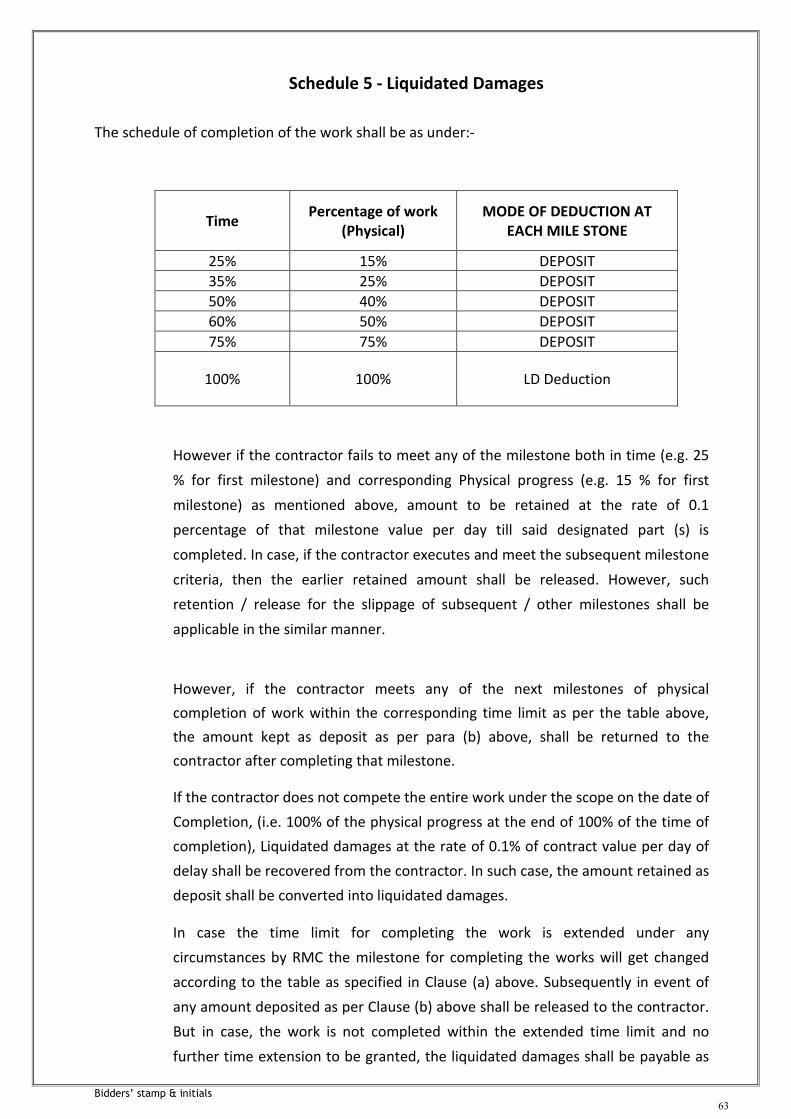
Bidders’ stamp & initials
63
Schedule 5 - Liquidated Damages
The schedule of completion of the work shall be as under:-
Time Percentage of work
(Physical) MODE OF DEDUCTION AT
EACH MILE STONE
25% 15% DEPOSIT
35% 25% DEPOSIT
50% 40% DEPOSIT
60% 50% DEPOSIT
75% 75% DEPOSIT
100% 100% LD Deduction
However if the contractor fails to meet any of the milestone both in time (e.g. 25
% for first milestone) and corresponding Physical progress (e.g. 15 % for first
milestone) as mentioned above, amount to be retained at the rate of 0.1
percentage of that milestone value per day till said designated part (s) is
completed. In case, if the contractor executes and meet the subsequent milestone
criteria, then the earlier retained amount shall be released. However, such
retention / release for the slippage of subsequent / other milestones shall be
applicable in the similar manner.
However, if the contractor meets any of the next milestones of physical
completion of work within the corresponding time limit as per the table above,
the amount kept as deposit as per para (b) above, shall be returned to the
contractor after completing that milestone.
If the contractor does not compete the entire work under the scope on the date of
Completion, (i.e. 100% of the physical progress at the end of 100% of the time of
completion), Liquidated damages at the rate of 0.1% of contract value per day of
delay shall be recovered from the contractor. In such case, the amount retained as
deposit shall be converted into liquidated damages.
In case the time limit for completing the work is extended under any
circumstances by RMC the milestone for completing the works will get changed
according to the table as specified in Clause (a) above. Subsequently in event of
any amount deposited as per Clause (b) above shall be released to the contractor.
But in case, the work is not completed within the extended time limit and no
further time extension to be granted, the liquidated damages shall be payable as

Bidders’ stamp & initials
64
0.1% of the total contract value per day subjected to the maximum amount of
10% of the total contract value.
The aggregate maximum of liquidated damages payable under this clause shall not exceed 0.1 percentage of contract value per day and shall be subject to the maximum amount of ten percentage of estimated amount put to tender or contract value whichever is higher

Bidders’ stamp & initials
65
SECTION 2
GENERAL CONDITIONS OF CONTRACT

Bidders’ stamp & initials
66
:: TABLE OF CONTESTS ::
No. Description
GC-1 Definitions and Interpretations
GC-2 Location of site and accessibility
GC-3 Scope of work
GC-4 Ruling language
GC-5 Interpretation of Contract Document
GC-6 Contractor to understand himself fully
GC-7 Errors in submissions
GC-8 Sufficiency of Tender
GC-9 Discrepancies
GC-10 Performance Guarantee (Security Deposit)
GC-11 Inspection of work
GC-12 Defect Liability
GC-13 Power of Engineer-In-Charge to give further instructions.
GC-14 Programme
GC-15 Sub-letting of work
GC-16 Sub-Contracts for temporary works, etc.
GC-17 Time for completion
GC-18 Extension of time
GC-19 Contract Agreement
GC-20 Liquidated damages
GC-21 Forfeiture of Security Deposit
GC-22 Action of Forfeiture of Security Deposit
GC-23 No compensation for alteration in or restriction in work
GC-24 In the event of death of contractor
GC-25 Members of the owner not individually liable
GC-26 Owner not bound by personal representations
GC-27 Contractor's office at site
GC-28 Contractor's subordinate staff and their conduct
GC-29 Termination of sub-contract by owner
GC-30 Power of entry
GC-31 Contractor's responsibility with the other Contractor and Agencies.
GC-32 Other Agencies at site
GC-33 Notices
GC-34 Rights of various interests
GC-35 Price adjustments
GC-36 Terms of Payment
GC-37 Retention Money
GC-38 Payments due from the Contractor

Bidders’ stamp & initials
67
:: TABLE OF CONTESTS ::
No. Description
GC-39 Contingent Fee
GC-40 Breach of Contract by Contractor
GC-41 Default of Contractor
GC-42 Bankruptcy
GC-43 Ownership
GC-44 Declaration against waiver
GC-45 Laws governing the contract
GC-46 Over payment and under payment
GC-47 Settlement of disputes
GC-48 Disputes of differences to be referred to
GC-49 DELETED
GC-50 Termination of the Contract
GC-51 Special risks
GC-52 Change in Constitution
GC-53 Sub-contractual relations
GC-54 Patents and Royalties
GC-55 Lien
GC-56 Execution of work
GC-57 Work in monsoon
GC-58 Work on Sundays and Holidays
GC-59 General Conditions for construction work
GC-60 Drawings to be supplied by the Owner
GC-61 Drawings to be supplied by the Contractor
GC-62 Setting outwork
GC-63 Responsibilities of Contractor for correctness of work
GC-64 Materials to be supplied by the Owner
GC-65 Conditions of issue of materials by the Owner
GC-66 Materials procured with assistance of the Owner
GC-67 Materials obtained from dismantling
GC-68 Article of value of treasure found during construction
GC-69 Discrepancies between instructions
GC-70 Alternations in specifications and designs and extra work.
GC-71 Action when no specifications are issued
GC-72 Abnormal rates
GC-73 Assistance to Engineer-In-Charge
GC-74 Tests for quality of work
GC-75 Action and compensation in case of bad workmanship

Bidders’ stamp & initials
68
:: TABLE OF CONTESTS ::
No. Description
GC-76 Suspension work
GC-77 Owner may do part of the work
GC-78 Possession prior to completion
GC-79 Completion Certificate
GC-80 Schedule of Rates
GC-81 Procedure for measurement of work in progress
GC-82 Running account payments to be regarded as advances
GC-83 Notice for claim for additional payment
GC-84 Payment of Contractor's Bill
GC-85 Final Bill
GC-86 Receipt for payment
GC-87 Completion Certificate
GC-88 Taxes, Duties, Octroi etc.
GC-89 Insurance
GC-90 Damage to Property
GC-91 Contractor to Indemnify Owner
GC-92 Implementation of Apprentice Act 1954
GC-93 Health and Sanitary arrangements for workers
GC-94 Safety Code
GC-95 Accidents

Bidders’ stamp & initials
69
GC-01 DEFINITIONS AND INTERPRETATIONS :
1.0 In the contract (as hereinafter defined) the following words and expressions shall, unless
repugnant to the subject or context thereof, have the following means as signed to them.
1.1 The "Owner / Corporation" shall mean Rajkot Municipal Corporation and shall include its
Municipal Commissioner or other Officers authorized by the Corporation and also include
owner's successors and assignees.
1.2 The "Contractor" shall mean the person or the persons, firm or Company whose tender has
been accepted by the Owner and includes the Contractors legal representative, his
successors and permitted assigned.
1.3 Deleted.
1.4 The "Engineer-In-Charge" shall mean the person designated as such by the owner from time
to time and shall include those who are expressly authorized by the Corporation to act for
and on its behalf for all functions pertaining to the operation of this contract.
1.5 Engineer-In-Charge's Representative shall mean any resident Engineer or Assistant to the
Engineer-In-Charge appointed from time to time by the owner to perform duties set forth in
the Tender Document whose authority shall be notified in writing to the Contractor by the
Engineer-In-Charge.
1.6 "Tender" – the offer or proposal of the Tenderer submitted in the prescribed form setting
for the prices for the work to be performed, and the details thereof.
1.7 "Contract Price" shall mean total money payable to the Contractor under the contract.
1.8 "Addenda" shall mean the written or graphic notices issued prior to submission of tender
which modify or interpret the contract documents.
1.9 "Contract Time" – the time specified for the completion of work.
1.10 "Contract" shall mean agreement between the parties for the execution of works including
therein all contract documents.
1.11 "Contract Document" shall mean collectively the tender documents, designs, drawings,
specifications, agreed variations, if any and such other documents constituting the tender
and acceptance thereof.
1.12 "The Sub-Contractor" shall mean any person, firm or company (other than the Contractor)
to whom any part of the work has been entrusted by the Contractor with the written
consent of the Engineer-In-Charge and the legal representative successors and permitted
assignee of such person, firm or company.
1.13 The "Specifications" shall mean all directions, the various Technical Specifications,
provisions and requirements attached to the contract which pertains to the method and
manner of performing the work, to the quantities and qualities of the work and the
materials to be furnished under the contract for the work and any order(s) or instruction(s)
there under. It shall also mean the latest Indian Standard Institute Specification relative to

Bidders’ stamp & initials
70
the particular work or part thereof, so far as they are not contrary to the Tender
specifications and in absence of any other Country applied in Indian as a matter of standard
engineering practice and approved in writing by the Engineer-In-Charge with or without
modification.
1.14 The "Drawings" shall include maps, plans, tracings, or prints thereof with any modification
approved in writing by the Engineer-In-Charge and as such other drawings as may, from
time to time, be furnished or approved in writing by the Engineer-In-Charge in connection
with the work.
1.15 The "Work" shall mean the works to be executed in accordance with the contract or the
part thereof as the case may be and shall include extra, additional, altered or substituted
works as required for the purpose of the contract. It shall mean the totality of the work by
expression or implication envisaged in the contract and shall include all materials,
equipment and labour required for or relative or incidental to or in connection with the
commencement, performance and completion of any work and / or incorporation in the
work.
1.16 The "Permanent Work" shall mean works which will be incorporated in and form part of the
work to be handed over to the owner by the Contractor on completion of the contract.
1.17 The "Temporary Work" shall mean all temporary works of every kind required in or about
the execution, completion and maintenance of the work.
1.18 "Site" shall mean the land and other places, on, under, in or through which the permanent
works are to be carried out and any other lands or places provided by the Corporation for
the purpose of the contract together with any other places designated in the contract as
forming part of the site.
1.19 The "Construction Equipment" shall mean all appliances / equipment of whatever nature
required in or for execution, completion or maintenance of works or temporary works (as
herein before defined) but does not include materials or other things intended to form or
forming part of the permanent work.
1.20 "Notice in writing or written Notice" shall mean a notice written, typed or in printed form
delivered personally or sent by Registered Post to the last known private or business
address or Registered Office of the Contractor or on Email or SMS on the Mobile of the
contractor and shall be deemed to have been received in the ordinary course of post it
would have been delivered.
1.21 The "Alteration / variation order" shall mean an order given in writing by the Engineer-In-
Charge to effect additions or deletions from or alterations in the work.
1.22 "Final Test Certificate" shall mean the final test certificate issued by the owner within the
provisions of the contract.
1.23 The "Completion Certificate" shall mean the certificate to be issued by the Engineer-In-
Charge when the work has been completed and tested to his satisfaction.

Bidders’ stamp & initials
71
1.24 The "Final Certificate" shall mean the final certificate issued by the Engineer-In-Charge after
the period of defects liability is over and the work is finally accepted by the owner.
1.25 "Defects Liability Period" shall mean the specified period between the issue of Completion
Certificate and the issue of final certificate during which the Contractor is responsible for
rectifying all defects that may appear in the works.
1.26 "Approved" shall mean approved in writing including subsequent confirmation in writing of
previous verbal approval and "Approval" means approved in writing including as aforesaid.
1.27 "Letter of Acceptance" shall mean an intimation by a letter to tenderer that his tender has
been accepted in accordance with the provisions contained therein.
1.28 "Order" and "Instructions" shall respectively mean any written order or instruction given by
the Engineer-In-Charge within the scope of his powers in terms of the contract.
1.29 "Running Account Bill" shall mean a bill for the payment of "On Account" money to the
Contractor during the progress of work on the basis of work done and the supply of non-
perishable materials to be incorporated in the work.
1.30 "Security Deposit" shall mean the deposit to be held by the owner as security for the due
performance of the contractual obligations.
1.31 The "Appointing Authority" for the purpose of Arbitration shall be the Municipal
Commissioner, Rajkot Municipal Corporation.
1.32. "Retention Money" shall mean the money retained from R.A.Bills for the due completion of
the "LET WORS".
1.33 Unless otherwise specifically stated, the masculine gender shall include the feminine and
neuter genders and vice-versa and the singular shall include the plural and vice-versa.
GC-02 LOCATION OF SITE AND ACCESSIBILITY :
The work is to be carried out at location mentioned in Tender notice. Non-availability of
access roads etc. shall in no case be the cause to condone delay in the execution of the
work and no claim or extra compensation will be paid. The work is to be carried out outside
the city area.
GC-03 SCOPE OF WORK :
The scope of work is defined broadly in the special conditions of contract and specifications.
The Contractor shall provide all necessary materials, equipment and labor etc. for the
execution and maintenance of the work. All material that go with the work shall be
approved by the Engineer-In-Charge prior to procurement and use.
Power Supply :
The Contractor shall make his own arrangement for power supply during installation.

Bidders’ stamp & initials
72
Land for Contractor's Field Office, Godown Etc.:
Owner will not be in a position to provide land required for Contractor's field office,
godown, etc. The Contractor shall have to make his own arrangement for the same.
GC-04 RULING LANGUAGE :
The language according to which the contract shall be construed and interpreted shall be
English. All entries in the contract document and all correspondence between the
contractor and the Corporation or the Engineer-In-Charge shall be in English. All
dimensions for the materials shall be given in metric units only.
GC-05 INTERPRETATION OF CONTRACT DOCUMENT :
1. The provision of the General Conditions of Contract and Special Conditions of Contract shall
prevail over those of any other documents of the contract unless specifically provided
otherwise, should have there be any discrepancy, inconsistency, error or omission in the
several documents forming the contract, the matter may be referred to the Engineer-In-
Charge for his instructions and decision. The Engineer-In-Charge's decision in such case
shall be final and binding to the Contractor.
2. Works shown upon the drawings but not described in the specifications or described in the
specifications without showing on the drawings shall be taken as described in the
specifications and shown on the drawings.
3. The headings and the marginal notes to the clause of these General Conditions of Contract
or to the specifications or to any other part of tender documents are solely for the purpose
of giving a concise indication and not a summary of contents thereof. They shall never be
deemed to be part thereof or be used in the interpretation or construction of the contract.
4. Unless otherwise states specifically, in this contract documents the singular shall include
the plural and vice-versa wherever the context so requires. Works imparting persons shall
include relevant Corporations / Body of individual / firm of partnership.
5. Notwithstanding the sub-division of the documents into separate section and volumes
every part of each shall be supplementary to and complementary of every other part and
shall be read with and into the context so far as it may be practicable to do so.
6. Where any portion of the General Conditions of Contract is repugnant to or at variance with
any provisions of the Special Conditions of Contract, then, unless a different intention
appears, the provisions of the special conditions of contract shall be deemed to over ride
the provisions of General Conditions of Contract to the extent of each repugnancy of
variance.
7. The materials, design, and workmanship shall satisfy the relevant ISS, and codes referred to.
If additional requirements are shown in the specifications, the same shall be satisfied over
and above ISS and other codes.
8. If the specifications mention that the Contractor shall perform certain work or provide
certain facilities, it shall mean that the Contractor shall do so at his own cost.

Bidders’ stamp & initials
73
9. Contractor to Collect His Own Information -
The details given in the tender are arranged making necessary investigations for framing an
estimate. However, when the work is being executed, changes in soil conditions are likely
to be met with in view of the formation of soil, strata in Rajkot District. It is, therefore,
desirable that the Contractor makes his own investigations or additional investigations as
may be required for correctly assessing the cost of different items of work and submit his
tender accordingly. Any change in description or quantity of an item shall not vitiate the
contract or release the Contractor from executing the work comprised in the contract
according to the drawings and specifications at the tendered rates.
He is deemed to have known the scope, nature and magnitude of the work and the
requirements of materials and labor involved and as to whatever work he has to complete
in accordance with the contract. The Contractor is expected to visit the site and
surroundings to satisfy himself as to the nature of all existing structures, if any, and also as
to the nature and the conditions of railways, roads, bridges and culverts, means of
transport and communications whether by land, air or water and as to possible
interruptions thereto and the access and gross from the site, to have examined and
satisfied himself as to the sites for obtaining sand, stones, bricks and other materials, the
site for disposal of surplus materials, the available accommodation and make such enquiries
as may be necessary for executing and completing the work, to have local enquiries as to
the sub-soil, subsoil water and variation thereof, storms, prevailing winds, climatic
conditions and all other similar matters, effecting work. He is expected to be familiar with
his liability for payment of Government taxes, customs and excise duty, GST, octroi and
other charges etc. in contract with the execution of this contract.
GC-06 CONTRACTOR TO UNDERSTAND HIMSELF FULLY :
The Contractor by tendering shall be deemed to have satisfied himself, as to all
considerations and circumstances affecting the tender price, as to the possibility of
executing the works as shown and described in the contract and to have fixed his prices
according to his own view on these matters and to have understood that no additional
allowances except as otherwise expressly provided, will afterwards be made beyond the
contract price. The Contractor shall be responsible for any misunderstanding or incorrect
information, however, obtained.
GC-07 ERRORS IN SUBMISSIONS :
The Contractor shall be responsible for any errors or omissions in the particulars supplied
by him, whether such particulars have been approved by the Engineer-In-Charge or not.
GC-08 SUFFICIENCY OF TENDER :
The Contractor shall be deemed to have satisfied himself before tendering as to the
correctness of the tender rates which rates shall, except as otherwise provides for, cover all
the Contractor's liabilities and obligations set forth or implied in the contract for the proper
execution of the work for compliance with requirements of Article GC-19 thereof.

Bidders’ stamp & initials
74
GC-09 DISCREPANCIES :
The drawings and specifications are to be considered as mutually explanatory of each other,
detailed drawings being followed in preference to small-scale drawings and figured
dimensions in preference to scale and special conditions in preference to General
Conditions. The special directions or dimensions given in the specifications shall supersede
all else. Should any discrepancies however, appear or should any misunderstanding arise
as to the meaning and intent of the said specifications or drawings, or as to the dimensions
or the quality of the materials or the due and proper execution of the works, or as to the
measurement or quality and valuation of the work executed under this contract or as extra
there upon, the same shall be explained by the Engineer-In-Charge and his explanation shall
be subject to the final decision of the Municipal Corporation in case reference be made to
it, be binding upon the Contractor and the Contractor shall execute the work according to
such explanation and without addition or to deduction from the contract price and shall
also do all such works and things necessary for the proper completion of the works as
implied by the drawings and specifications, even though such works and things are not
specially shown and described in the said specifications. In cases where no particular
specifications are given for any article to be used under the contract, the relevant
specifications of the Indian Standard Institution shall apply.
GC-10 PERFORMANCE GUARANTEE (SECURITY DEPOSIT) :
1. A sum of 5% of the accepted value of the tender shall be deposited by the tenderer
(hereinafter called the contractor when tender is accepted) as security deposit with the
owner for the faithful performance, completion and maintenance of the works in
accordance with the contract documents and to the satisfaction of the Engineer-In-Charge
and assuring the payment of all obligations arising from the execution of the contract. This
shall be deposited in one of the forms mentioned below:
a. By a Demand Draft on the Rajkot Branch of any Nationalised Bank or Scheduled Bank
[except co-operative bank] in favour of the "RAJKOT MUNICIPAL CORPORATION", Rajkot.
.
b. A Fixed Deposit Receipt of a Schedule Bank duly endorsed in favour of the "RAJKOT
MUNICIPAL CORPORATION", Rajkot.
c. The Contractor may pay 2.5% of the value of works as initial security deposit and the
balance 2.5% shall be recovered in installments through deductions at the rate of 10 (ten)
percent of the value of each Running Account Bill till the total security execution exceeds
the accepted value of tender because of allotment of further work, further recoveries
towards security deposit shall be effected at 10% of the R A Bills to make up the five
percent security deposit of the revised value of contract. Alternatively, the Contractor may
at his option deposit the full amount of 5 percent of security deposit within ten days of
receipt by him of the notification accepting the tender in the form as aforesaid.
1. If the Contractor, sub-contractor or their employees shall break, deface or destroy any property
belonging to the owner or other agency during the execution of the contract, the same shall be
made good by the contractor at his own expense and in default thereof, the Engineer-In-Charge
may cause the same to be made good by other agencies and recover expense from the Contractor
(for which the certificate of the Engineer-In-Charge shall be final). These expenses can be recovered

Bidders’ stamp & initials
75
from the security deposit if recovery from other sources is not possible. The amount as reduced in
security deposit will be made good by deduction from the next R A Bill of the Contractor.
GC-11 INSPECTION OF WORK :
1. The Engineer-In-Charge shall have full power and authority to inspect the work at any time
wherever in progress either on the site or at the Contractor's or any other manufacturer's
workshop or factories wherever situated and the Contractor shall afford to Engineer-In-
Charge every facility and assistance to carry out such inspection, Contractor or his
authorized representative shall, at all time during the usual working hours and all times
when so notified, remain present to receive orders and instructions.
Orders given to Contractor's representative shall be considered to have the same force as if
they had been given to the Contractor himself. Contractor shall give not less than ten (10)
days notice in writing to the Engineer-In-Charge before covering up or otherwise placing
beyond reach of inspection and measurement any work in order that the same may be
inspected and measured. In the event of breach of the above, the same shall be uncovered
at Contractor's expenses for carrying out such inspection or measurement.
2. The material shall be dispatched from Contractor's store on site of work before obtaining
approval in writing of the Engineer-In-Charge. Contractor shall provide at all times during
the progress of work and maintenance period of proper means of access with ladders,
gangways, etc. and make necessary arrangement as directed for inspection or
measurement of work by Engineer-In-Charge.
GC-12 DEFECT LIABILITY :
1. Contractor shall guarantee the work for a period of 36 months from the date of issue of
Completion Certificate. Any damage or defect that may arise or that may remain
undiscovered at the time of issue of Completion Certificate connected in any way with the
equipment or materials supplied by him or in the workmanship shall be rectified or replaced
by Contractor at his own expense as desired by Engineer-In-Charge or in default Engineer-
In-Charge may cause the same to be made good by other agency and deduct expenses of
which the certificate of Engineer-In-Charge shall be final from any sums that may then or
any time thereafter become due to Contractor or from his security deposit or the proceeds
of sale thereof or of a sufficient portion thereof.
2. From the commencement to completion of work Contractor shall take full responsibility for
the care of the work including all temporary works and in case any damages, occur from any
cause whatsoever he shall at his own cost, repair and make good the same so that on
completion, work shall be in good order and in conformity, in every respect, with the
requirements of contract and as per the instructions of the Engineer-In-Charge.
3. If at any time before the work is taken over, the Engineer-In-Charge -
a) Decide that any work done or materials used by the Contractor are defective or not in
accordance with the contract or that work or any portion thereof is defective or do not fulfill
the requirements of contract (all such materials being herein after called defects in this clause)
he shall, as soon as reasonably practicably, give notice to Contractor in writing of the said defect
specifying particulars of the same then Contractor shall at his own expense and with all speed
make good the defects so specified.

Bidders’ stamp & initials
76
b) In case Contractor fails to do so, owner may take, at the cost of the Contractor, such stops
as may in all circumstances be responsible to make good such defects. The expenditure so
incurred by owner will be recovered from the amount due to Contractor. The decision of
Engineer-In-Charge with regard to the amount to be recovered from Contractor will be final
and binding on the Contractor.
GC-13 POWER OF ENGINEER-IN-CHARGE TO GIVE FURTHER INSTRUCTIONS :
The Engineer-In-Charge shall have the power and authority from time to time and at all
times to give further instructions and directions as may appear to him necessary or proper
for the guidance of the Contractor and the works and efficient execution of the works
according to the terms of the specifications, and the Contractor shall receive, execute, obey
and be bound by the same, according to the true intent and meaning thereof, as fully and
effectively as though the same had accompanied or had been mentioned or referred to in
the specifications. No work which radically changes the original nature of the contract shall
be ordered by the Engineer-In-Charge and in the event of any deviation being ordered,
which in the opinion of the Contractor changes the original nature of the contract, he shall
nevertheless carry it out and any disagreement as to the nature of the work and the rate to
be paid to thereof shall be resolved.
The time of completion of works shall, in the event of any deviations being ordered
resulting in additional cost or reduction in cost over the contract sum, be extended or
reduced reasonably by the Engineer-In-Charge. The Engineer-In-Charge's decision in the
case shall be final and binding.
GC-14 PROGRAMME :
The time allowed for execution of works shall be the essence of the contract. The contract
period shall commence from the date of notice of intimation to proceed. The tenderer at
the time of submitting his tender shall indicate in the construction schedule his programme
of execution of work commencement with the total time specified. The Contractor shall
provide the Engineer-In-Charge a detailed programme of time schedule for execution of the
works in accordance with the specifications and the completion date. The entire
programme to be finalized by the Contractor, has to conform to the execution period
mentioned along with the Bill of Quantities in the tender documents. The Engineer-In-
Charge upon scrutiny of such submitted programme by Contractor, shall examine suitability
of it to the requirement of contract and suggest modifications, if found necessary.
GC-15 SUB-LETTING OF WORK :
No part of the contract nor any share of interest thereon shall in any manner or degree be
transferred, assigned or sublet by the Contractor directly or indirectly to any person, firm or
Corporation whosoever except as provided for in the succeeding sub-clause, without the
consent in writing of the owner.
GC-16 SUB-CONTRACTS FOR TEMPORARY WORKS ETC. :
The owner may give written consent to sub-contractors for execution of any part of the
works at the site, being entered upon the contractor provided each individual contract is
submitted to the Engineer-In-Charge before being entered into and is approved by him. List
of sub-contractors to be supplied.

Bidders’ stamp & initials
77
Not-withstanding any subletting with such approval as aforesaid and notwithstanding the
Engineer-In-Charge shall have received of any sub-contractors, the Contractor shall be and
shall remain solely responsible for the quality and proper and expeditious execution of the
works and the performance of all the conditions of contract in all respects as if such
subletting or subcontracting had not taken place and as if such works had been done
directly by the Contractor.
GC-17 TIME FOR COMPLETION :
1. The work covered under this contract shall be commenced from the date the Contractor is
served with a notice to proceed with the work and shall be completed before the date as
mentioned in the time schedule of work. The time is the essence of the contract and unless
the same is extended as mentioned in Clause GC-18 "Extension of Time", the Contractor
shall pay liquidated damages for the delay.
2. The general time schedule for construction is given in the tender document. Contractor
shall prepare a detailed weekly or monthly construction programme in consultation with
the Engineer-In-Charge soon after the agreement and the work shall be strictly executed
accordingly.
The time for construction includes, the time required for testing, rectifications, if any,
retesting and completion of the work in all respects to the entire satisfaction of the
Engineer-In-Charge except the items which are not coming in the way to commission the
project.
GC-18 EXTENSION OF TIME :
Time shall be considered as the essence of the contract. If, however, the failure of the
Contractor to complete the work as per the stipulated dates referred to above arises from
delays on the part of Corporation in supplying the materials or equipment, it has
undertaken to supply under the contract or from delays on the quantity of work to be done
under the contract, or force majeure an appropriate extension of time will be given by the
Corporation. The Contractor shall request for such extension within one month of the
cause of such delay and in any case before expiry of the contract period.
GC-19 CONTRACT AGREEMENT :
The successful bidder shall enter into and execute the contract agreement within 10 (ten)
days of the notice of award, in the form shown in tender documents with such
modifications as may be necessary in the opinion of the Corporation. It shall be incumbent
on the Contractor to pay the stamp duty and the legal charges for the preparation of the
contract agreement.
GC-20 LIQUIDATED DAMAGES :
If the Contractor fails to complete the work or designated part thereof within the stipulated
completion date for the work or for the part, he shall pay liquidated damages at half a
percent of contract value for each week of delay subject to maximum of 10% of the
contract value or as decided by Municipal Commissioner.
The Contractor shall complete one-sixth quantum of work within one fourth period, four-
tenth quantum of work within one-half period and eight-tenth quantum of work within

Bidders’ stamp & initials
78
three-fourth period, failing which, the Contractor shall be liable to pay liquidated damages
an amount as specified above, or as decided by Municipal Commissioner.
The amount of liquidated damages shall, however, be subjected to a maximum of 10
percent of the contract value.
GC-21 FORFEITURE OF SECURITY DEPOSIT :
Whenever any claim against the Contractor for the payment of a sum of money out of or
under the contract arises, the Corporation shall be entitled to recover such sum by
appropriating in part or whole, the security deposit of the Contractor. In case the security
deposit is insufficient, the balance recoverable shall be deducted from any sum then due or
which at any time thereafter may become due to the Contractor. The Contractor shall pay
to the owner on demand any balance remaining due.
GC-22 ACTION OF FORFEITURE OF SECURITY DEPOSIT :
In any case in which under any Clause or Clauses of the contract, the Contractor shall
committed a breach of any of the terms contained in this contract, the owner shall have
power to adopt any of the following courses as he may deem best suited to his interest.
a) To rescind the contract (of which recession notice in writing to the contractor under the
hand of the owner shall be conclusive evidence) in which case the security deposit of the
Contractor shall stand forfeited and be absolutely at the disposal of the owner.
b) To employ labour and to supply materials to carry out the balance work debiting Contractor
with the cost of labour employed and the cost of materials supplied for which a certificate
of the Engineer-In-Charge shall be final and conclusive against the Contractor and 10% of
costs on above to cover all departmental charges and crediting him with the value of work
done at the same rates as if it has been carried out by the Contractor under the terms of his
contract. The certificate of Engineer-In-Charge as to the value of the work done shall be
final and conclusive against the Contractor.
c) To measure up the work of the contractor and to take such part thereof as shall be
unexecuted out of his hand and give it to another Contractor to complete, the same. in this
case the excess expenditure incurred than what would have been paid to the original
Contractor, if the whole work had been executed by him, shall be borne and paid by the
original Contractor and shall be deducted from any money due to him by the owner under
the contract or otherwise and for the excess expenditure, the certificate of the Engineer-In-
Charge shall be final and conclusive.
In the event any of the above courses being adopted by the owner, the Contractor shall
have no claims for compensation for any loss sustained by him by reason of his having
purchased or procured any materials or entered into any agreements or made any advance
on account of or with a view to the execution of the work or the performance of the
contract.
In purchase the Contractor shall not be entitled to recover or be paid any sum for any work
actually performed under this contract unless the Engineer-In-Charge will certify in writing
the performance of such work and the value payable in respect thereof and he shall only be
entitled to be paid the value so certified.

Bidders’ stamp & initials
79
In the event of the owner putting in force the powers as stated in a, b, c, above vested in
him under the proceeding clause, he may, if he so desires, take possession of all or any tools
and plant, materials and stores in or upon the works or the site thereof belonging to the
Contractor, or procured by him and intended to be used for the execution of the work or
any part thereof paying or allowing for the same in account at the contract rates to be
certified by the Engineer-In-Charge. The Engineer-In-Charge may give notice in writing to
the Contractor or his representative requiring him to remove such tools, plant, materials or
stores from the premises within the time specified in the notice and in the event of the
Contractor failing to comply with any such notice, the Engineer-In-Charge may remove
them at the Contractor's expenses or sell them by auction or private sale on account of the
Contractor and his risks in all respects without any further notice as to the date, time or
place of the sale and the certificate of Engineer-In-Charge as to the expense of any such
removal and the amount of the proceeds and the expenses of any such sale shall be final
and conclusive against the Contractor.
GC-23 COMPENSATION FOR ALTERATION IN OR RESTRICTION IN WORK :
If at any time from the commencement of the work, the owner shall for any reasons
whatsoever not require the whole work or part thereof as specified in the tender to be
carried out, the Engineer-In-Charge shall give notice in writing of the fact to the Contractor,
who shall have no claim to any payment or compensation whatsoever on account of any
profit or advantage which he might have derived from the execution of the work in full but
which he did not derive in consequence of full amount of the work not having been carried
out. He also shall not have any claim for compensation by reasons of any alterations having
been made in original specifications, drawings, designs and instructions which shall involve
any curtailment of the work as originally contemplated.
When the Contractor is a partnership firm, the prior approval in writing of the owner shall
be obtained before any change is made in the Constitution of the firm. Where the
Contractor is an individual or a Hindu Undivided Family or business concern, such approval
as aforesaid shall, likewise be obtained before Contractor enters into an agreement with
other parties where under, the reconstituted firm would have the right to carry out the
work hereby undertaken by the Contractor. In either case, if prior approval as aforesaid is
not obtained, the contract shall be deemed to have been allotted contravention of
subletting clause hereof and the same action may be taken and the same consequence shall
ensure as provided in the subletting clause.
GC-24 IN THE EVENT OF DEATH OF THE CONTRACTOR :
Without prejudice to any of the rights or remedies under the contract, if the Contractor
dies, the owner shall have the option of terminating the contract without compensation to
the Contractor.
GC-25 MEMBERS OF THE OWNER NOT INDIVIDUALLY LIABLE :
No official or employee of the owner shall in any way be personally bound or liable for the
acts or obligation of the owner under the contract, or answerable for any default or
omission in the observance or performance of any acts, matters or things, which are herein,
contained.

Bidders’ stamp & initials
80
GC-26 OWNER NOT BOUND BY PERSONAL REPRESENTATIONS :
The Contractor shall not be entitled to any increase on the schedule of rates or any other
rights or claims whatsoever by reason of representation, promise or guarantees given or
alleged to have been given to him by any person.
GC-27 CONTRACTOR'S OFFICE AT SITE :
The Contractor shall provide and maintain an office at the site for the accommodation of his
agent and staff and such office shall remain open at all reasonable hours to receive
information, notices or other communications.
GC-28 CONTRACTOR'S SUBORDINATE STAFF AND THEIR CONDUCT :
1. The Contractor on award of the work shall name and depute a qualified Engineer having
experience of carrying out work of similar nature, whom equipments, materials, if any, shall
be issued and instructions for work given. The Contractor shall also provide to the
satisfaction of Engineer-In-Charge sufficient and qualified staff, competent sub-agents,
foreman and loading hands including those specially qualified by previous experience to
supervise the type of works comprised in the contract in such manner as will ensure work of
the best quality and expeditious working. If, in the opinion of the Engineer-In-Charge
additional properly qualified supervision staff is considered necessary, it shall be employed
by the Contractor, without additional charge on account thereof. The Contractor shall
ensure to the satisfaction of the Engineer-In-Charge that sub-contractors, if any, shall
provide competent and efficient supervision over the work entrusted to them.
2. If and whenever any of the Contractor's or sub-contractor's agents, sub-agents, assistants,
foreman or other employees shall, in the opinion of the Engineer-In-Charge, be guilty of any
misconduct or be incompetent or insufficiently qualified or negligent in the performance of
their duties or that in the opinion of the owner or Engineer-In-Charge, it is undesirable for
administrative or any other reason for person or persons to be employed in the works, the
Contractor if so directed by the Engineer-In-Charge, shall at once remove such person or
persons from employment thereon. Any person or persons so removed shall not again be
re-employed in connection with the works without the written permission of the Engineer-
In-Charge. Any person, so removed from the works shall be immediately replaced at the
expense of the Contractor by a qualified and competent substitute. Should the Contractor
be required to repatriate any person removed from the works he shall do so after approval
of Engineer-In-Charge and shall bear all costs in connection therewith.
3. The Contractor shall be responsible for the proper behavior of all the staff, foreman,
workmen and others and shall exercise proper control over them and in particular and
without prejudice to the said generality, the Contractor shall be bound to prohibit and
prevent any employee from trespassing or acting in any way detrimental or prejudicial to
the interest of the community or of the properties or occupiers of land and properties in
the neighborhood and in the event of such employees so trespassing, the Contractor shall
be responsible therefore and relieve the owner of all consequent claims, actions for
damages or injury or any other ground whatsoever. The decision of the Engineer-In-Charge
upon any matter arising under this claim shall be final.
4. If and when required by the owner, the Contractor's personnel entering upon the owner's
premises shall be properly identified by badges of a type acceptable to the owner which
must be worn at all times on owner's premises.

Bidders’ stamp & initials
81
GC-29 TERMINATION OF SUB-CONTRACT BY OWNER :
If any sub-contractor engaged upon the works at the site execute any work which in the
opinion of Engineer-In-Charge is not accordance with the contract documents, the owner
may by written notice to the Contractor request him to terminate such sub-contract and
the Contractor upon the receipt of such notice shall terminate such sub-contracts and the
latter shall forthwith leave the works, failing which, the owner shall have the right to
remove such sub-contractors from the site.
No action taken by the owner under the above clause shall relieve the Contractor of his
liabilities under the contract or give rise to any right to compensation, extension of time or
otherwise.
GC-30 POWER OF ENTRY :
If the Contractor shall not commence the work in the manner previously described in the
contract documents or if he shall at any time, in the opinion of Engineer-In-Charge –
i) Fail to carry out works in conformity with the contract documents, or
ii) Fail to carry out the works in accordance with the time schedule, or
iii) Substantially suspend work or the works for a period of seven days without authority from
Engineer-In-Charge, or
iv) Fail to carry out and execute the work to the satisfaction of the Engineer-In-Charge, or
v) Fail to supply sufficient or suitable construction plant, temporary works, labour, materials
or things, or
vi) Commit breach of any other provisions of the contract on his part to be performed or
observed or persists in any of the above mentioned breaches of the contract for seven days
after notice in writing shall have been given to the Contractor by the Engineer-In-Charge
requiring such breach to be remedied, or
vii) Abandon the work, or
viii) During the continuance of the contract becomes bankrupt, make any arrangement or
compromise with his creditors, or permit any execution to be levied or go into liquidation
whether compulsory or voluntary not being merely a voluntary liquidation for the purpose
of amalgamation or reconstruction then in any such case.
The owner shall have the power to enter upon the works and take possession thereof and
of the materials, temporary works, constructional plant and stores therein and to revoke
the Contractor's license to use the same and to complete the works by his agents, other
Contractor or workmen, to relate the same upon any terms to such other person firm or
Corporation as the owner in his absolute discretion may think proper to employ, and for the
purpose aforesaid to use or authorize the use of any materials, temporary works,
constructional plant, and stores as aforesaid with making payments or allowance to the
Contractor for the said materials other than such as may be certified in writing by the
Engineer-In-Charge to be reasonable and without making any payment or allowance to the
Contractor for the use of said temporary works, constructional plant and stock or being
liable for loss or damage thereto. If the owner shall be reason of his taking possession of
the works or of the work being got completed by other Contractor incurred excess
expenditure be deducted from any money which may be due for the work done by the
Contractor under the contract and not paid for. Any deficiency shall forthwith be made
good and paid to the owner by the Contractor and the owner shall have power to sell in

Bidders’ stamp & initials
82
such manner and for such price as he may think fit all or any of the constructional plant,
materials etc., consist constructed by or belonging to and to recoup and retain the said
deficiency or any part thereof out of the proceeds of the sale.
GC-31 CONTRACTOR'S RESPONSIBILITY WITH THE OTHER CONTRACTOR AND AGENCIES :
Without repugnance to any other conditions, it shall be the responsibility of the Contractor
executing the work, to work in close co-operation and co-ordination with other Contractors
or their authorized representatives and the Contractor will put a joint scheme with the
concurrence of other contractors or their authorized representatives showing the
arrangements for carrying his portion of the work to the Engineer-In-Charge and get the
approval. The Engineer-In-Charge before approving the joint scheme will call the parties
concerned and modify the scheme if required. No claim will be entertained on account of
the above. The Contractor shall conform in all respects with the provisions of any statutory
regulations, ordinances or bylaws of any local or duly constituted authorities or public
bodies which may be applicable from time to time to works or any temporary works. The
Contractor s shall keep the owner indemnified against all penalties and liabilities of every
kind arising out of non-adherence to such statutes, ordinance, laws, rules, regulations etc.
GC-32 OTHER AGENCIES AT SITE :
The Contractor shall have to execute the work in such place and condition where other
agencies will also be engaged for other works, such as site grading, filling and leveling,
electrical and mechanical engineering works etc. No claim shall be entertained for works
being executed in the above circumstances.
GC-33 NOTICES :
Any notice under this contract may be served on the Contractor or his duly authorized
representative at the job site or may be served by Registered Post direct to the official
address of the Contractor. Proof of issue of any such notice could be conclusive of the
Contractor having been duly informed of all contents therein.
GC-34 RIGHTS OF VARIOUS INTERESTS :
The owner reserves the right to distribute the work between more than one Contractor.
Contractor shall co-operate and afford reasonable opportunity to other Contractor’s for
access to the works, for the carriage and storage of materials and execution of their works.
Whenever the work being done by department of the owner or by other Contractor
employed by the owner is contingent upon work covered by this contract, the respective
rights of the various interests shall be determined by the Engineer-In-Charge to secure the
completion of various portions of the work in general harmony.
GC-35 PRICE ADJUSTMENTS :
No adjustment in price shall be allowed and no price escalation will be allowed.
GC-36 TERMS OF PAYMENT :
The payment of bills shall be made progressively according to the rules and practices
followed by the Corporation. The progressive payment unless otherwise provided in the
contract agreement or subsequently agreed to by the parties shall be made generally
monthly on submission of a bill by the Contractor in prescribed form of an amount
according to the value of the work performed less the price of materials supplied by owner
aggregate of previous progressive payments and as required by Clause GC-37 (Retention of

Bidders’ stamp & initials
83
Money) herein. All such progressive payments shall be regarded as payments by way of
advance against final payment. Payment for the work done by the Contractor will be based
on the measurement at various stages of the work, in accordance with the condition at
clause GC-81 (measurement of work in progress).
GC-37 RETENTION MONEY :
i) Pursuance to clause GC-36 (Terms of Payment) any on at money due to the Contractor for
work done, Corporation will hold as Retention money five (5) percent of the value of work.
The retention money will not normally be due for payment until the completion of the
entire work and till such period the work has been finally accepted by the Corporation and a
completion certificate issued by the Corporation in pursuant to Clause-79 (Completion
Certificate).
ii) Over and above this, Ten (10) percent of value of water retaining items will be with hold
against hydraulic test of the structure. The said amount shall be released after giving the
satisfactory hydraulic test. This amount will be deducted as per payment schedule.
GC-38 PAYMENTS DUE FROM THE CONTRACTOR :
All costs, damages or expenses, for which under the contract, Contractor is liable to the
Corporation, may be deducted by the Corporation from any money due or becoming due to
the Contractor under the contract or from any other contract with the Corporation or may
be recovered by action at law or otherwise from the Contractor.
GC-39 CONTINGENT FEE :
i) The Contractor warrants that he has not employed a person to solicit or secure the contract
upon any agreement for a commission, percentage, and brokerage contingent fee. Breach
of this warranty shall give the Corporation the right to cancel the contract or to take any
drastic measure as the Corporation may deem fit. The warranty does not apply to
commissions payable by the Contractor to establish commercial or selling agent for the
purpose of securing business.
ii) No officer, employer or agent of the Corporation shall be admitted to any share or part of
this contract or to any benefit that may rise there from.
GC-40 BREACH OF CONTRACT BY CONTRACTOR :
If the Contractor fails to perform the work under the contract with due diligence or shall
refuse or neglect to comply with instructions given to him in writing by the Engineer-In-
Charge in accordance with the contract, or shall contravene the provisions of the contract,
the Corporation may give notice in writing to the Contractor to make good such failure,
neglect, or contravention. Should the Contractor fail to comply with such written notice
within 14 (fourteen) days of receipt, it shall be lawful for the Corporation, without prejudice
to any other rights the Corporation may have under the contract, to terminate the contract
for all or part of the works, and make any other arrangements it shall deem necessary to
complete the work outstanding under the contract at the time of termination. In this event,
the performance Bond shall immediately become due and payable to the Corporation. The
value of the work done on the date of termination and not paid for shall be kept as deposit
for adjustment of excess expenditure incurred in getting the remaining work completed and
the Corporation shall have free use of any works which the Contractor may have at the site
at the time of termination of the contract.

Bidders’ stamp & initials
84
GC-41 DEFAULT OF CONTRACTOR :
i) The Corporation may upon written notice of default to the Contractor terminate the
contract circumstances detailed as under :
a) If in the opinion of the Corporation, the Contractor fails to make completion of works within
the time specified in the completion schedule or within the period for which extension has
been granted by the Corporation to the Contractor.
b) If in the opinion of the Corporation, the Contractor fails to comply with any of the other
provisions of this contract.
ii) In the event, the Corporation terminates the contract in whole or in part as provided in
Article GC-50 (Termination of the Contract) the Corporation reserves the right to purchase
upon such terms and in such manner as it may be deem appropriate, plant similar to one
which is not supplied by the Contractor and the Contractor will be liable to the Corporation
for any additional costs for such similar plant and / or for liquidated damages for delay until
such time as may be required for the final completion of works.
iii) If this contract is terminated as provided in this paragraph GC-30 (Power of Entry) (1) the
Corporation in addition to any other rights provided in this clause, may require the
Contractor to transfer title and deliver to the Corporation.
a) Any completed works
b) Such partially completed information and contract rights as the Contractor has specifically
produced or acquired for the performance of the contract so terminated.
iv) In the event, the Corporation does not terminate the contract as provided in the paragraph
GC-50 (Termination of Contract) the Contractor shall continue performance of the contract,
in which case, he shall be liable to the Corporation for liquidated damages for delay until
the works are completed and accepted.
GC-42 BANKRUPTCY :
If the Contractor shall become bankrupt or insolvent or has a receiving order made against
him, or compound with his creditors, or being the Corporation commence to be wound up
not being a member voluntary winding up for the purpose of amalgamation or
reconstruction, or carry on its business under a receiver for the benefit of his creditors or
any of them, the Corporation shall be at liberty to either (a) terminate the contract
forthwith by giving notice in writing to the Contractor or to the receiver or liquidator or to
any person or Organization in whom the contract may become vested and to act in the
manner provided in Article GC-41 (Default of Contractor) as thought the last mentioned
notice had been the notice referred to in such article or (b) to give such receiver, liquidator
or other persons in whom the contract may become vested the option of carrying out the
contract subject to his providing a satisfactory guarantee for the due and faithful,
performance of the contract up to an amount to be agreed. In the event that the
Corporation terminates the contract in accordance with this article, the performance bond
shall immediately become due and payable on demand to Corporation.

Bidders’ stamp & initials
85
GC-43 OWNERSHIP :
Works hand over pursuant to the contract shall become the property of the Corporation
from whichever is the earlier of the following times, namely;
a) When the works are completed pursuant to the contract.
b) When the contractor has been paid any sum to which he may become entitled in respect
thereof pursuant to Clause GC-36 (Terms of Payment).
GC-44 DECLARATION AGAINST WAIVER :
The condonation by the Corporation of any breach or breaches by the Contractor or an
authorized sub-contractor of any of the stipulations and conditions contained in the
contract, shall in no way prejudice or affect or be construed as a waiver of the Corporation's
rights, powers and remedies under the contract in respect of any breach or breaches.
GC-45 LAWS GOVERNING THE CONTRACT :
This contract shall be construed according to and subject to the laws of India and the State
of Gujarat and under the jurisdiction of the Courts of Gujarat at Rajkot.
GC-46 OVER PAYMENT AND UNDER PAYMENT :
Whenever any claim for the payment of a sum to the Corporation arises out of or under this
contract against the Contractor, the same may be deducted by the Corporation from any
sum then due or which at any time thereafter may become due to the Contractor under this
contract and failing that under any other contract with the Corporation (which may be
available with the Corporation), or from his retention money or he shall pay the claim on
demand. The Corporation reserves the right to carry out post payment audit and technical
examinations of the final bill including all supporting vouchers, abstracts etc. The
Corporation further reserves the right to enforce recovery of any payment when detected,
notwithstanding the fact that the amount of the final bill may be included by one of the
parties as an item of dispute before an Arbitrator, appointed under Article GC-49
(Arbitration) of this contract and notwithstanding the fact that the amount of the final bill
figures in the arbitration award. If as a result of such audit and technical examinations any
over payment is discovered in respect of any work done by the Contractor or alleged to
have been done by him under the contract, it shall be recovered by the Corporation from
the Contractor as prescribed above. If any under payment is discovered by the Corporation,
the amount due to the Contractor under this contract may be adjusted against any amount
then due or which may at any time thereafter become due before payment is made to the
Contractor.
GC-47 SETTLEMENT OF DISPUTES :
Except as otherwise specifically provided in the contract, all disputes concerning questions
of fact arising under the contract shall be decided by the Engineer-In-Charge subject to a
written appeal by the Contractor to the Engineer-In-Charge and those decisions shall be
final and binding on the parties hereto. Any disputes or differences including those
considered as such by only one of the parties arising out of or in connection with this
contract shall be to the extent possible settled amicably between the parties. If amicable
settlement cannot be reached then all disputed issues shall be settled as provided in Article
GC-48 (Disputes or differences to be referred to) and Article No. GC-49 (Arbitration).

Bidders’ stamp & initials
86
GC-48 DISPUTES OF DIFFERENCES TO BE REFERRED TO :
If at any time, any question, disputes or differences of any kind whatsoever shall arise
between the Engineer-In-Charge and the contractor upon or in relation to or in connection
with this contract either party may forthwith give to the other, notice in writing of the
existence of such question, dispute or difference as to any decision, opinion, instruction,
direction, certificate or evaluation of the Engineer-In-Charge. The question, dispute or
differences shall be settled by the Municipal Commissioner, Rajkot Municipal Corporation,
who shall state his decision in writing and give notice of same to the Engineer-In-Charge and
to the Contractor. Such decision shall be final and binding upon both parties. The contract
and work on contract if not already breached or abandoned shall proceed normally unless
and until the same shall be revised (or uphold) by any arbitration proceedings as hereinafter
provided. Such decisions shall be final and binding on the Engineer-In-Charge and the
Contractor unless the Contractor shall require the matter to be referred to an Arbitration
panel as hereinafter provided.
GC-49 ARBITRATION :
In case of any dispute arising during the course of execution, the matter should be referred
to Municipal Commissioner who will be sole Arbitrator whose decisions will be final and
binding to the Contractor.
GC-50 TERMINATION OF THE CONTRACT :
i) If the Contractor finds it impracticable to continue operation owing to force majeure
reasons or for any reasons beyond his control and/or the Corporation find it impossible to
continue operation, then prompt notification in writing shall be given by the party affected
to the other.
ii) If the delay or difficulties so caused cannot be expected to cease or become unavoidable or
if operations cannot be resumed within two (2) months then either party shall have the
right to terminate the contract upon ten (10) days written notice to the other. In the event
of such termination of the contract, payment to the Contractor will be made as follows :
a) The Contractor shall be paid for all works approved by the Engineer-In-Charge and for any
other legitimate expenses due to him.
b) If the Corporation terminates the contract owing to Force Majeure or due to any cause
beyond its control, the Contractor shall additionally be paid for any work done during the
said two (2) months period including any financial commitment made for the proper
performance of the contract and which are not reasonably defrayed by payments under (a)
above.
c) The Corporation shall also release all bonds and guarantees at its disposal except in cases
where the total amount of payment made to the Contractor exceeds the final amount due
to him in which case the Contractor shall refund the excess amount within thirty (30) days
after the termination and the Corporation thereafter shall release all bonds and guarantees.
Should the Contractor fail to refund the amounts received in excess within the said period
such amounts shall be deducted from the bonds or guarantees provided.
iii) On termination of the contract for any cause the Contractor shall see the orderly
suspension and termination of operations, with due consideration to the interests of the

Bidders’ stamp & initials
87
Corporation with respect to completion safeguarding of storing materials procured for the
performance of the contract and the salvage and resale thereof.
GC-51 SPECIAL RISKS :
If during the contract, there shall be an outbreak of war (whether war is declared or not),
major epidemic, earthquake or similar occurrence in any part of the world beyond the
control of either party to the contract which financially or otherwise materially affects the
execution of the contract, the Contractor shall unless and until, the contract is terminated
under the provisions of this article use his best endeavors to complete the execution of the
contract, provided always that the Corporation shall be entitled at any item after the onset
of such special risks, to terminate the contract by giving written notice to the contractor
and upon such notice being given this contract shall terminate but without prejudice to the
rights of either party in respect of any antecedent breach thereof.
The Contractor shall not be liable for payment of compensation for delay or for failure to
perform the contract for reasons of Force Majeure such as acts of public enemy, acts of
Government, fires, floods, cyclones, epidemics, quarantine restrictions, lockouts, strikes,
freight embargoes and provided that the Contractor shall within 10 (ten) days from the
beginning of such delay notify the Engineer-In-Charge in writing, of the cause of delay, the
Corporation shall verify the facts and grant such extension as the facts justify.
GC-52 CHANGE IN CONSTITUTION :
Where the Contractor is a partnership firm, the prior approval in writing of the owner shall
be obtained before any change is made in the constitution of the firm. Where the
Contractor is an individual or undivided family business concern such approval as aforesaid
shall likewise be obtained before the Contractor enters into any partnership agreement
where under the partnership firm would have the right to carry out the works hereby
undertaken by the Contractor. If prior approval as aforesaid is not obtained, the contract
shall be deemed to have been assigned in contravention of contract.
GC-53 SUB-CONTRACTUAL RELATIONS :
All works performed for the contract by a sub-contractor shall be pursuant to an
appropriate agreement between the Contractor and the sub-contractor, which shall contain
provision to –
a) Protect and preserve the rights of the Corporation and the Engineer-In-Charge with respect
to the works to be performed under the sub-contracting party will not prejudice such rights.
b) Require that such work be performed in accordance with the requirements of contract
documents.
c) Require under such contract to which the contractor is a party, the submission to the
Contractor of application for payment and claims for additional costs, extension of time,
damages for delay or otherwise with respect to the sub-contracted portions of the work in
sufficient time, that the Contractor may apply for payment comply in accordance with the
contract documents for like claims by the Contractor upon the Corporation.
d) Waive all rights the contracting parties may have against one another for damages caused
by fire or other perils covered by the property insurance except such rights as they may
have to the proceeds of such insurance held by the Corporation as trustee and,
e) Obligate each sub-contractor specifically to consent to the provisions of this Article.

Bidders’ stamp & initials
88
GC-54 PATENTS AND ROYALTIES :
1. Contractor, if licensed under any patent covering equipment, machinery, materials or
composition of matter to be used or supplied or methods and process to be practiced or
employed in the performance of this contract agrees to pay all royalties and license fees,
which may be due with respect thereto. If any equipment, machinery, materials,
composition matters, to be used or supplied or methods practiced or employed in the
performance of this contract, is covered by a patent under which Contractor is not licensed,
then the Contractor before supplying / using the equipment, machinery, materials,
compositions, methods of process shall obtain such license and pay such royalties and
license fees as may be necessary for performance of this contract. In the event Contractor
fails to pay such royalty or to obtain any such license, any suit for infringement of such
patents which is brought against the Contractor or the owner as a result of such failure will
be defended by the Contractor at his own expenses and the Contractor will pay any
damages and costs awarded in such suit. The Contractor shall promptly notify the owner if
the Contractor has acquired knowledge of any plant under which a suit for infringement
could be reasonably brought because of the use by the owner of any equipment machinery,
materials, process methods to be supplied in hereunder. Contractor agrees to and does
hereby grant to owner together with the right to extend the same to any of the subsidiaries
of the owner an irrevocable royalty fee license to use in any Country, any invention made
by the Contractor or his employees in or as a result of the performance of work under
contract.
2. With respect to any sub-contract entered into by Contractor pursuant to the provisions of
the relevant clause hereof, the Contractor shall obtain from the sub-contractor an
understanding to provide the owner with the same patent protection that contracts is
required to provide under the provisions of the clause.
3. The Contractor shall indemnify and save harmless the owner from any loss on account of
claims against owner for the contributory infringement of patent rights arising out of and
based upon the claim that the use by the Corporation of the process included in the design
prepared by the Contractor and used in the operation of the plant infringes on any patent
rights.
GC-55 LIEN :
If, at any time, there should be evidence of any lien or claim for which owner might have
become liable and which is chargeable to the Contractor, the owner shall have the right to
retain out of any payment then due or thereafter to become due an amount sufficient to
completely indemnify the owner against such lien or claim or if such lien or claim be valid
the owner may pay and discharge the same and deduct the amount as paid from any
money which may be due or become due and payable to the Contractor. If any lien or
claims remaining unsettled after all payments are made, the Contractor shall refund or pay
to the owner all money that the latter may be compelled to pay in discharging such lien or
claim including all costs and reasonable expenses.
GC-56 EXECUTION OF WORK :
The whole work shall be carried out in strict conformity with the provisions of the contract
document, detailed drawings, specifications and the instructions of the Engineer-In-Charge
from time to time. The Contractor shall ensure that the whole work is executed in the most

Bidders’ stamp & initials
89
substantial, and proper manner with best workmanship using materials of best quality in
strict accordance with the specifications to the entire satisfaction of the Engineer-In-Charge.
GC-57 WORK IN MONSOON :
When the work continues in monsoon, the Contractor shall maintain minimum labour force
required for the work and plan and execute the construction and erection work according
to the prescribed schedule. No extra rate will be considered for such work in monsoon.
During monsoon and entire construction period, the Contractor shall keep the site free
from water at his own cost.
GC-58 WORK ON SUNDAYS AND HOLIDAYS :
No work except curing shall be carried out on Sunday and holidays. However, if the
exigencies of the work need continuation of work on Sundays and Holidays, written
permission of the Engineer-In-Charge shall be obtained in advance.
GC-59 GENERAL CONDITIONS FOR CONSTRUCTION WORK :
Working hours shall be eight every day. The over time work in two shifts could be carried
out with the written permission of the Engineer-In-Charge but no compensation shall be
paid for the same. The rate quoted shall include this. The Contractor shall plan his work in
such a way that his labourers do not remain idle. The owner will not be responsible for idle
labour of the Contractor. The Contractor shall submit to the owner progress report every
week. The details and Performa of the report will be as per mutual agreement.
GC-60 DRAWINGS TO BE SUPPLIED BY THE OWNER :
The drawings attached with the tender documents shall be for general guidance of the
Contractor to enable him to visualize the type of work contemplated and scope of work
involved. Detail working drawings according to which the work is to be done shall be
prepared by the Contractor for executing the work.
GC-61 DRAWINGS TO BE SUPPLIED BY THE CONTRACTOR:
Where drawings, data are to be furnished by the Contractor they shall be as enumerated in
special conditions of contract and shall be furnished within the specified time. Where
approval of drawings has been specified it shall be Contractor's responsibility to have these
drawings got approved before any work is taken up with regard to the same. Any changes
becoming necessary in those drawings during the execution of the work shall have to be
carried out by the Contractor at no extra cost. All final drawings shall bear the certification
stamp as indicated below duly signed by both the Contractor and Engineer-In-Charge.
Certified true for………………………………………………………………………….Project Agreement
No………………………………………………………………………………..
Signed …………………………………………………………….
Contractor Engineer-In-Charge
Drawings will be approved within three (3 weeks of the receipt of the same by the Engineer-In-Charge.

Bidders’ stamp & initials
90
GC-62 SETTING OUT WORK :
The Contractor shall set out the work on the site handed over by the Engineer-In-Charge
and shall be responsible for the correctness of the same. The work shall be carried out to
the entire satisfaction of Engineer-In-Charge. The approval thereof or partaking by
Engineer-In-Charge or setting out work shall not relieve Contractor of any of his
responsibilities. The Contractor shall provide at his own cost all necessary level posts,
pegs, bamboos, flags, ranging rods, strings and other materials and labourers required for
proper setting out of the work. The Contractor shall provide fix and be responsible for the
maintenance of all stakes, templates, level markets, profiles and similar other things and
shall take all necessary precautions to prevent their removal or disturbance and shall be
responsible for the consequences for such removal or disturbance. The Contractor shall
also be responsible for the maintenance of all existing survey marks, boundary marks, and
distance marks and centerline marks either existing or face lines or cross lines shall be
marked by small masonry pillars. Each pillar shall have distance mark at the center for
setting up the theodolite. The work shall not be started unless the setting out is choked
and approved by Engineer-In-Charge in writing but such approval shall not relieve the
Contractor of his responsibilities about the correctness of setting out. The Contractor shall
provide all materials, labor and other facilities necessary for checking at his own cost.
Pillars bearing geodetic marks on site shall be protected by the Contractor. On
completion of the work, the Contractor shall submit the geodetic documents according to
which the work has been carried out.
GC-63 RESPONSIBILITIES OF CONTRACTOR FOR CORRECTNESS OF THE WORK :
The Contractor shall be entirely and exclusively responsible for the correctness of every part
of the work and shall rectify completely any errors therein at his own cost when so
instructed by Engineer-In-Charge. If any error has crept in the work due to non-observance
of this clause, the Contractor will be responsible for the error and bear the cost of
corrective work.
1. Materials to be supplied by the Contractor:
Contractor shall procure and provide all the material required for the execution and
maintenance of work including M S rods; all tools, tackles, construction plant and
equipment except, the materials to be supplied by the owner detailed in the contract
documents. Owner shall make recommendations for procurement of materials to the
respective authorities if desired by the Contractor but assumes no responsibility of any
nature. Owner shall insist for procurement of materials with ISI marks supplied by
reputed firms of the DGS & D list.
2. If however, the Engineer-In-Charge feels that the work is likely to be delayed due to
Contractor's inability to procure materials, the Engineer-In-Charge shall have the right to
procure materials, from the market and the Contractor will accept these materials at the
rates decided by Engineer-In-Charge.
GC-64 MATERIALS TO BE SUPPLIED BY THE OWNER :
1. If the contract provided certain materials or stores to be supplied by the owner, such
materials and stores transported by the Contractor at his cost from owner's stores or
Railway Station. The cost from Contractor for the value of materials supplied by the owner
will be recovered from the R.A. Bill on the basis of actual consumption of materials in the

Bidders’ stamp & initials
91
work covered and for which R A Bill has been prepared. After completion of the work, the
Contractor has to account for the full quantity of materials supplied to him.
2. The value of store materials supplied by owner to the Contractor shall be charged at rates
shown in the contract document and in case any other material not listed in the schedule of
materials is supplied by the owner, the same shall be charged at cost price including carting
and other expenses incurred in procuring the same. All materials so supplied shall remain
the property of the owner and shall not be removed from the site on any account. Any
material remaining unused at the time of completion of work or termination of contracts
shall be returned to owner's store or any other place as directed by the Engineer-In-Charge
in perfectly good condition at Contractor's cost. When materials are supplied free of cost
for use in work and surplus and unaccounted balance thereof are not returned to the
owner, recovery in respect of such balance will be effected at double the applicable issue
rate of the material or the market rates whichever is higher.
GC-65 CONDITIONS OF ISSUE OF MATERIALS BY THE OWNER:
The materials specified to be issued by the owner to the Contractor shall be issued by the
owner at his store and all expenses for it carting site shall be borne by the Contractor will be
issued during working hours and as per rules of owner from time to time.
Contractor shall bear all expenses for storage and safe custody at site of materials issued to
him before use in work.
Material shall be issued by the owner in standard / non-standard sizes as obtained from
manufacturer.
Contractor shall construct suitable godowns at site for storing the materials to protect the
same from damage due to rain, dampness, fire, theft etc.
The Contractor should take the delivery of the materials issued by the owner after satisfying
himself that they are in good condition. Once the materials are issued, it will be the
responsibility of the Contractor to keep them in good condition and in safe custody. If the
materials get damaged or if they are stolen, it shall be the responsibility of the Contractor
to replace them at his cost according to the instructions of the Engineer-In-Charge.
For delay in supply or for non-supply of materials to be supplied by the owner, on account
of natural calamities, act of enemies, other difficulties beyond the control of the owner, the
owner carries no responsibilities. In no case the Contractor shall be entitled to claim any
compensation for loss suffered by him on this account.
None of the materials issued to the contractor, shall be used by the Contractor for
manufacturing items which can be obtained from the manufacturer's. The materials issued
by the owner shall be used for the work only and no other purpose.
Contractor shall be required to execute indemnity bond in the prescribed form for the safe
custody and account of materials issued by the owner.
Contractor shall furnish sufficiently in advance a statement of his requirements of
quantities of materials to be supplied by the owner and the time when the same will be

Bidders’ stamp & initials
92
required for the work, so as to enable Engineer-In-Charge to make arrangements to procure
and supply the materials.
A daily account of materials issued by the owner shall be maintained by the contractor
showing receipt, consumption and balance on hand in the form laid down by Engineer-In-
Charge with all connected paper and shall be always available for inspection in the site
office.
Contractor shall see that only the required quantities of materials are got issued and no
more. The Contractor shall be responsible to return the surplus materials at owner's store
at his own cost.
GC-66 MATERIALS PROCURED WITH ASSISTANCE OF THE OWNER :
Notwithstanding anything contained to the contrary in any of the clauses of this contract,
where any materials for the execution of the contract are procured with the assistance of
the owner either by issue from owner's stock or purchase made under orders or permits or
licenses issued materials as trustees for owner, and use such materials not disposed them
off without the permission of owner and unserviceable materials that may be left with him
after completion of the contract or at its termination for any reason whatsoever on his
being paid or credited such price as Engineer-In-Charge shall determine having due regard
to the conditions of the materials. The price allowed to Contractor shall not exceed the
amount charged to him excluding the storage of breach of the aforesaid condition, the
Contractor shall in terms of license or permits and/or for criminal breach of trust be liable
to compensate owner at double the rate or any higher rates. In the event of these
materials at that time having higher rate or not being available in the market than any other
rate to be determined by the Engineer-In-Charge at his decision shall be final and
conclusive.
GC-67 MATERIALS OBTAINED FROM DISMANTLING :
If the Contractor, in the course of execution of work, is called upon to dismantle any part of
work for reasons other than on account of bad or imperfect work, the materials obtained
from dismantling will be property of the owner and will be disposed off as per instructions
of Engineer-In-Charge in the best interest of the owner.
GC-68 ARTICLE OF VALUE OF TREASURE FOUND DURING CONSTRUCTION:
All gold, silver and other minerals of any description and all precious stones, coins,
treasures, relics, antiques and other similar things which shall be found in, under or upon
site shall be the property of the owner and the Contractor shall properly preserve the same
to the satisfaction of the Engineer-In-Charge and shall hand over the same to the owner.
GC-69 DISCREPANCIES BETWEEN INSTRUCTIONS:
If there is any discrepancy between various stipulations of the contract documents or
instructions to the Contractor or his authorized representative or if any doubt arises as to
the meaning of such stipulation or instructions, the Contractor shall immediately refer in
writing to the Engineer-In-Charge and shall hand over the same to the owner.
GC-70 ALTERATIONS IN SPECIFICATIONS & DESIGNS & EXTRA WORK :
The Architect / Engineer-In-Charge shall have power to make any alterations in, omission
from, addition to substitution for, the schedule of rates, the original specifications,

Bidders’ stamp & initials
93
drawings, designs and instructions that may appear to him to be necessary or advisable
during the progress of work and the Contractor shall be bound to carry out such altered /
extra / new items of work in accordance with any instructions which may be given to him in
writing signed by Engineer-In-Charge and such alteration omissions, additions or
substitutions, shall not invalidate contract and any altered, additional or substituted work
shall be carried out by the Contractor on the same conditions of contract. The time of
completion may be extended by Architect as may be considered just and reasonable by
him. The rates for such additional, altered or substitute work shall be worked out as under:
a) If the rates for additional, altered or substitutes work are specified in the contract for work,
the Contractor is bound to carry out such work at the same rates as specified in the
contract.
b) If the rates for additional, altered or substituted work are not specifically provided in the
contract for the work, the rates will be derived from the rates of similar items of work in the
contract work. The opinion of Engineer-In-Charge as to whether the rates can be
reasonably so derived the items of contract will be final and binding to the Contractors.
c) If the rates of altered, additional or substitute work cannot be determined as specified in (a)
or (b) above, the rate shall be paid as per S.O.R. of GWSSB.
d) If the rates of altered, additional or substitute work cannot be determined as specified in (a)
or (b) or (c) above, the Contractor shall within seven days of the receipt of order to carry
out the work inform the Architect / Engineer-In-Charge of the rate which he intends to
charge for such work supported by rate analysis and the Architect / Engineer-In-Charge will
determine the rate on the basis of prevailing market rates of materials, labour cost at
schedule of labour plus 15% there on as Contractor's supervision overheads and profit. The
opinion of Architect / Engineer-In-Charge as to the market rates of materials and the
quantity of labour involved per unit of measurement will be final and binding on Contractor.
But under no circumstances, the Contractor suspends work or the plea of non settlement of
items falling under this clause.
GC-71 ACTION WHEN NO SPECIFICATIONS ARE ISSUED :
In case of any class of work for which no specifications is supplied by the owner in the
tender documents, such work shall be carried out in accordance with relevant latest ISS and
if ISS do not cover the same, the work shall be carried out as per General Technical
Specification for building work; and if not covered in then it is to be with standard
Engineering Practice subject to the approval of Engineer-In-Charge.
GC-72 ABNORMAL RATES :
Contractor is expected to quote rate for each item after careful analysis of cost involved for
the performance of the completed item considering all specifications and conditions of
contract.
GC-73 ASSISTANCE TO ENGINEER-IN-CHARGE:
Contractor shall make available to Engineer-In-Charge free of cost all necessary instruments
and assistance in checking of any work made by the Contractor setting out for taking
measurement of work etc.

Bidders’ stamp & initials
94
GC-74 TESTS FOR QUALITY OF WORK :
1. The Contractor shall be required to give satisfactory hydraulic test where required and shall
rectify the defects, if any, free of cost. The necessary waterpower, labor etc., required for
the hydraulic test shall also be arranged by the Contractor at his own cost.
2. All workmanship shall be of the best kind described in the contract documents and in
accordance with the instructions of Engineer-In-Charge and shall be subjected from time to
time to such tests at Contractor's cost as the Engineer-In-Charge may direct at the place of
manufacture of fabrication or on the site or at any such place. Contractor shall provide
assistance, instruments, labor and materials as are normally required for examining,
measuring and testing of any work of workmanship as may be selected and required by
Engineer-In-Charge.
3. All tests necessary in connection with the execution of work as decided by Engineer-In-
Charge shall be carried out at an approved laboratory at Contractor's cost.
4. Contractor shall furnish the Engineer-In-Charge for approval when requested or if required
by the specification, adequate samples of all materials and finished goods to be used in
work sufficiently in advance to permit tests and examination thereof. All materials
furnished and finished goods applied in work shall be exactly as per the approved samples.
GC-75 ACTION AND COMPENSATION IN CASE OF BAD WORKMANSHIP :
If it shall appear to the Engineer-In-Charge that any work has been executed with materials
of inferior description, or quality or are unsound or with unsound, imperfect or unskilled
workmanship or otherwise not in accordance with the contract, the Contractor shall, on
demand in writing from Engineer-In-Charge or his authorized representative specifying the
work, materials or articles complained of, notwithstanding that the same may have been
inadvertently passed, certified and paid for, forthwith rectify or remove and reconstruct the
work, so specified. In the event of failure to do so within a period to be specified by the
Engineer-In-Charge in his aforesaid demand, Contractor shall be liable to pay compensation
at the rate of half a percent of the estimated cost of work for every work limited to a
maximum of ten (10%) percent of the value of work while his failure to do so continues and
in the case of any such failure, the Engineer-In-Charge may on expiry of the notice period
rectify and remove and re-execute the work or remove and replace with others at the risk
and cost of the Contractor. The decision of the Engineer-In-Charge as to any question
arising under this clause shall be final and conclusive.
GC-76 SUSPENSION WORK :
Contractor shall, if ordered in writing by Engineer-In-Charge or his representative
temporarily suspended the work or any part thereof for such time (not exceeding one
month) as ordered and shall not after receiving such written notice proceed with the work
until he shall have received a written order to proceed therewith. The Contractor shall not
be entitled to claim compensation for any loss or damage sustained by him by reason of
temporary suspension of work as aforesaid. An extension of time for completion of work
will be granted to the Contractor corresponding to the delay caused by such suspension of
work if he applies for the same provided the suspension was not consequent upon any
default or failure on the part of the Contractor.

Bidders’ stamp & initials
95
GC-77 OWNER MAY DO PART OF THE WORK :
When the Contractor fails to comply with any instructions given in accordance with the
provisions of this contract, the owner has the right to carry out such parts of work as the
owner may designate whether by purchasing materials and engaging labour or by the
agency of another Contractor. In such case the owner shall deduct from the amount which
otherwise might become due to Contractor, the cost of such work and materials with then
(10) percent added to cover all departmental charges and should the total amount thereof
exceed the amount due to contract, Contractor shall pay the difference to owner.
GC-78 POSSESSION PRIOR TO COMPLETION :
The Engineer-In-Charge shall have the right to take possession of or to use any completed
or partly completed work or part of work. Such possession or use shall not be deemed to
be an acceptance of any work completed in accordance with the contact. If such prior
possession or use by Engineer-In-Charge delays the process of work, equitable adjustment
in the time of completion will be made and the contract shall be deemed to be modified
accordingly.
GC-79 COMPLETION CERTIFICATE :
As soon as the work has been completed in accordance with contact (except in minor
respects that do not affect their use for the purpose for which they are intended and except
for maintenance thereof) as per General Conditions of Contract the Engineer-In-Charge
shall issue a certificate (hereinafter called completion certificate) in which shall certify the
date on which work has been completed and has passed the said tests and owner shall be
deemed to have taken over work on the date so certified. If work has been divided in
various groups in contract, owner shall be entitled to take over any group or groups before
the other or others and there upon the Engineer-In-Charge will issue a completion
certificate, which will, however, be for such group or groups so taken over.
In order that Contractor could get a completion certificate, he shall make good will all speed
any defect arising from the defective materials supplied by Contractor of workmanship or
any act or omission of Contractor that may have been discovered or developed after the
work or groups of works has been taken over. The period allowed for carrying out such
work will be normally, one month. If any defect be not remedied within the time specified,
owner may proceed to do work at Contractor's (Agency, or Firm) risk and expenses and
deduct from the final bill such amount as may be decided by owner. If by reason of any
default on the part of the Contractor, a completion certificate has not been issued in
respect of every portion of work within one month after the date fixed by contract for
completion of work, owner shall be at liberty to use work or any portion thereof in respect
of which a completion certificate has been issued, provided that work or the portion
thereof so used as aforesaid shall be afforded reasonable opportunity for completion of
that work or the portion thereof so used as aforesaid shall be afforded reasonable
opportunity for completion of that work for the issue of completion certificate.
GC-80 SCHEDULE OF RATES :
1. The rates quoted by the Contractor shall remain firm till the completion of the work and
shall not be subject to escalation. Schedule of rates shall be deemed to include and cover
all costs, expenses and liabilities of every description and risks or every kind to be taken in
executing, completing and handing over the work to owner by Contractor. The contractor
shall be deemed to have known the nature, scope, magnitude and the extent of work and
materials required though contract documents may not fully and precisely furnish them. He

Bidders’ stamp & initials
96
shall make such provision in the Schedule of Rates as he may consider necessary to cover
the cost of such items of work and materials as may be reasonable and necessary to
complete the work. The opinion of Engineer-In-Charge as to the item of work which are
necessary and reasonable for completion of the work shall be final and binding on
Contractor although the same may be not shown on drawings or described specifically in
contract documents.
2. The Schedule of Rates shall be deemed to include and cover the cost of all constructional
plant, temporary work, materials, labour and all other matters in connection with each item
in Schedule of Rates and the execution of work or any portion thereof finished complete in
every respect and maintained as shown or described in the contract document or as may be
ordered in writing during the continuance of the contract.
3. The Schedule of Rates shall be deemed to include and cover the cost of all royalties and fees
for the articles and processes, protected by letters patent or otherwise incorporated in or
used in connection with work, also all royalties, rents and other payments in connection
with obtaining material of whatsoever kind for work and shall include an indemnity to
owner which Contractor hereby gives against all action, proceedings, claims, damages, costs
and expenses arising from the incorporation in or use on the works of any such articles,
processes or materials. Octroi or other Municipal or local Board charges if levied on
material, equipment or machineries to be brought to site for use on work shall be borne by
the Contractor.
4. No exemption or reduction of custom duties, excise duties, sales tax or any other taxes or
charges of the Central or State Government or of any Local Body whatsoever will be
granted or obtained and all such expenses shall be deemed to have been included in and
covered by Schedule of Rates. Contractor shall also obtain and pay for all permits or other
privileges necessary to complete the work.
5. The Schedule of Rates shall be deemed to include and cover risk on account of delay and
interference with Contractor's conduct of work which may occur from any cause including
orders of owner in the exercise of his powers and on account of extension of time granted
due to various reasons.
6. For work under unit rate basis, no alteration will be allowed in the Schedule of Rates by
reasons of work or any part of them being modified, altered, extended, diminished or
omitted.
GC-81 PROCEDURE FOR MEASUREMENT OF WORK IN PROGRESS:
1. All measurements shall be in metric system. All the work in progress will be jointly
measured by the representative of Engineer-In-Charge and Contractor's authorized agent.
Such measurements will be got recorded in the Measurement Book by the Engineer-In-
Charge or his authorized representative and signed by the Contractor or his authorized
agent in token of acceptance. If the Contractor or his authorized agent fails to be present
whenever required by the Engineer-In-Charge for taking measures for every reasons
whatsoever, the measurement will be taken by the Engineer-In-Charge or his authorized
representative notwithstanding the absence of Contractor and these measurements will be
deemed to be correct and binding on the Contractor.

Bidders’ stamp & initials
97
2. Contractor will submit a bill in approved Performa in quadruplicate to the Engineer-In-
Charge of the work giving abstract and detailed measurements of various items executed
during a month as mutually agreed. The Engineer-In-Charge shall verify the bill and the
claim, as far as admissible, adjusted if possible, within 10 days of presentation of the bills.
GC-82 RUNNING ACCOUNT PAYMENTS TO BE REGARDED AS ADVANCES :
1. All running account payments shall be regarded as payments by way of advance against the
final payment only and not as payment for work actually done and completed and shall not
preclude the requiring of bad, unsound and imperfect or unskilled work to be removed and
taken away and reconstructed or rejected or to be considered as an admission of the due
performance of contract or any part thereof.
2. Five (5) percent of the gross R.A. Bill amount shall be retained from each bill as retention
amount and the same will be paid with the final bill.
GC-83 NOTICE FOR CLAIM FOR ADDITIONAL PAYMENT :
If the Contractor considers that he is entitled to extra payment or compensation or any
claim whatsoever in respect of work, he shall forthwith give notice in writing to the
Engineer-In-Charge about his extra payment and / or compensation. Such notice shall be
given to the Engineer-In-Charge within ten (10) days from the happening of any event upon
which Contractor basis such claims and such notice shall contain full particulars of the
nature of such claim with full details and amount claimed. Failure on the part of the
Contractor to put forward any claim with the necessary particulars as above, within the
time above specified shall be an absolute waiver thereof. No omission by owner to reject
any such claim and no delay in dealing therewith shall waiver by owner or any rights in
respect thereof.
GC-84 PAYMENT OF CONTRACTOR'S BILL :
1. The price to be paid by the owner to Contractor for the work to be done and for the
performance of all the obligations undertaken by the Contractor under contract shall be
based on the contract price and payment to be made accordingly for the work actually
executed and approved by the Engineer-In-Charge.
2. No payment shall be made for work costing less than Rs.10,000/- till the work is completed
and a certificate of completion given. But in case of work estimated to cost more than
Rs.10,000/-. Contractor on submitting the bill thereof will be entitled to receive a monthly
payment proportionate to the part thereof, approved and passed by Engineer-In-Charge,
whose certificate of such approval and passing of the sum so payable shall be final and
conclusive against contractor. This payment shall be made after necessary deductions as
stipulated elsewhere in the contract documents for materials, security deposit etc. The
payment shall be released to the Contractor within fifteen (15) days of submission of the bill
duly pre-occupied on proper revenue stamp. Payment due to Contractor shall be made by
the owner by crossed Account Payee Cheque in Indian currency forwarding the same to the
registered office of the Contractor. Owner shall not be responsible if the cheque is mislaid
of misappropriated by unauthorized persons.

Bidders’ stamp & initials
98
GC-85 FINAL BILL :
The final bill shall be submitted by Contractor within one (1) month of the date of physical
completion of work, otherwise the Engineer-In-Charge's certificate of the measurement and
of total amount payable for work shall be final and binding on all parties.
GC-86 RECEIPT FOR PAYMENT :
Receipt for payment made on account of work when executed by a firm must be signed by
a person holding Power of Attorney in this respect on behalf of Contractor except when
described in the tender as a limited company in which case the receipt must be signed in
the name of the Company by one of its principal officers or by some person having
authority to give effectual receipt for the Company.
GC-87 COMPLETION CERTIFICATE :
1. When the Contractor fulfils his obligation as per terms of contract, he shall be eligible to
apply for Completion Certificate. Contractor may apply for separate Completion Certificate
in respect of each such portion of work by submitting the completion documents along with
such application for Completion Certificate.
The Engineer-In-Charge shall normally issue to Contractor the Completion Certificate within
one (1) month after receiving an application thereof from Contractor after verifying, from
the completion documents and satisfying himself that work has been completed in
accordance with and as set out in the construction and erection drawings and the contract
documents. Contractor after obtaining the Completion Certificate is eligible to present the
final bill for work executed by him under the terms of contract.
2. Within one month of completion of work in all respects Contractor shall be furnished with a
certificate by the Engineer-In-Charge of such completion but no certificate shall be given
nor shall work be deemed to have been executed until all (i) scaffolding, surplus materials
and rubbish is cleaned off site completely, (ii) until work shall have been measured by the
Engineer-In-Charge whose measurement shall be binding and conclusive and, (iii) until all
the temporary works, labour and staff colonies etc. constructed are removed and the work
site cleaned to the satisfaction of the Engineer-In-Charge. If Contractor shall fail to comply
with the requirements as aforesaid or before date fixed for the completion of work, the
Engineer-In-Charge may at the expense of Contractor remove such scaffolding, surplus
materials and rubbish and dispose off the same as he thinks fit.
3. The following documents will form the completion documents:-
a) Technical documents according to which the work has been carried out.
b) Three sets of construction drawings showing therein the modifications and corrections
made during the course of execution signed by the Engineer-In-Charge.
c) Completion Certificate for "Embedded" or "Covered" up work.
d) Certificate of final levels as set out for various works.
e) Certificate of test performed for various work.
f) Material appropriation statement for the materials issued by owner for work and list of
surplus materials returned to owner's store duly supported by necessary documents.

Bidders’ stamp & initials
99
4. Upon expiry of the period of defect liability and subject to Engineer-In-Charge being
satisfied that work has been duly maintained by Contractor during the defect liability period
of fixed originally or as extended subsequently and that Contractor has in all respects made
up any subsidence and performed all his obligations under contract, the Engineer-In-Charge
(without prejudice to the rights of owner in any way) give final certificate to that effect.
The Contractor shall not be considered to have fulfilled the whole of his obligation until
final certificate shall have been given by the Engineer-In-Charge.
5. Final Certificate only evidence of completion:
Except the final certificate, no other certificate of payment against a certificate or on
general account shall be taken to be an admission by owner of the due performance of
contract or any part thereof of occupancy or validity or any claim by the Contractor.
GC-88 TAXES, DUTIES, OCTROI ETC. :
1. Contractor agrees to and does hereby accept full and exclusive liability for the payment of
any and all taxes including GST(CGST & SGST), Duties and all other applicable taxes etc.,
now or hereinafter imposed, increased or modified from time to time in respect of work
and materials and all contributions and taxes for unemployment, compensation, insurance
and old age pension or annuities now or hereinafter imposed by the Central or State
Government authorities with respect to or covered by the wages, salaries or other
compensation paid to the persons employed by Contractor.
2. Contractor shall be responsible for compliance with all obligations and restrictions imposed
by the labour law or any other law affecting employer-employee relationship.
3. Contractor further agrees to comply and to secure the compliance of all sub contractors
with applicable Central, State, Municipal and local laws and regulations and requirement.
Contractor also agrees to defend, indemnify the hold harmless the owner from any liability
or penalty which may be imposed by Central, State or local authority by reasons of any
violation by Contractor or sub Contractor of such laws, regulations or requirements and also
from all claims, suits or proceedings that may be brought against owner arising under,
growing out of or by reasons or work provided for by this Contract by third parties or by
Central or State Government authority or any administrative Sub-Division thereof.
.
4. The Contractor shall pay all taxes like GST (State and central), income tax or any other tax
which are in force time to time. Employer may not be any way hold responsible for any such
taxes. However Employer can ask to produce the tax payment on the request from detail
concern departments of Govt. or Employer.
5. The rates to be quoted by contractor must be inclusive of all taxes prevailing on due date of
submission.
However any subsequent changes in the tax structure by government after due date of bid
submission will be compensated (±) on availability or submission of actual documentation.
Contractor has to intimate Engineer In charge regarding changes occurred in the tax
structure after bid submission. If contractor fails to provide such information and if any

Bidders’ stamp & initials
100
financial obligation may arise due to change in tax structure, same will be recovered from
contractor.
The contractor shall apply fair means of stock maintenance and shall adopt accounting
standards as may be prescribed under GST. For arriving at the difference in procurement
prices due to introduction of GST, it will be open for the Government to ask for original
invoices, LR, weigh bridge slips, payment details and such other documents as may be
required for the purpose.
If there is reduction in overall tax burden then proportional benefit of that shall be passed
on to the Government.
GC-89 INSURANCE :
Contractor shall at his own expenses carry and maintain the reputable Insurance Companies
to the satisfaction of owner as follows :
1. Contractor agrees to and uses hereby accept full and exclusive liability for compliance with
all obligations imposed by the Employer's State Insurance Act, 1948 and Contractor further
agrees to defend, indemnify and hold owner hardness from any liability or penalty which
may be imposed by the Central or State Government or local authority by reasons of any
assorted violation by Contractor or Sub-Contractor or the Employees State Insurance Act,
1948 and also from all claims, suits or proceedings that may be brought against owner
arising under, growing out of or by reasons of the work provided for by this contract
whether brought by employees of Contractor by third parties or by Central or State
Government authority or any administrative Sub-division thereof.
Contractor agrees to fill in with the Employees State Insurance Corporation, the declaration
form and all forms which may be required in respect of Contractor's or sub-Contractor's
employees whose aggregate remuneration is Rs.400/- p.m. or less and who are employed in
work provided for or those covered by ESI from time to time under the agreement. The
Contractor shall deduct and secure the agreement of the sub-Contractor to deduct the
employees contribution as per the first schedule of the Employees State Insurance Act from
wages. Contractor shall remit and secure the agreement of sub-contractor to remit to the
State Bank of Indian Employees State Insurance Accounts, the employee's contribution as
required by the Act. Contractor agrees to maintain all cards and records as required under
the Act in respect of employees and payments and Contractor shall secure the agreements
of the sub contractors to maintain in such records, any expenses incurred for the
contributions, making contributions or maintaining records shall be to Contractors or sub-
contractors own account. owner shall retain such sum as may be necessary from the
contract value until Contractor shall furnish satisfactory proof that all contribution as
required by the Employees State Insurance Act, 1948 have been paid.
The contractor will responsible to cover insurance as per below mentioned details: a) The works, together with all type of the materials and plants/ whole site area of project
for to the full replacement cost (Term “Cost” in this context shall include profit) b) The contractor equipments and other things brought onto the site by the contractor,
for a sum sufficient to provide for their replacement at site. c) The insurance detailed above shall be in the joint names of the contractor and the
employer at the contractor’s cost and shall cover the employer and the contractor against all loss or damages such as,

Bidders’ stamp & initials
101
i) Death or injury to any person, or ii) Loss of or damage to any property (other than the works) which may arise out of in
consequent up to defect liability period and the remedying of any defects therein, and against all claims proceedings, costs, charges, and expenses whatsoever in respect thereof or in relation thereto.
iii) Damage to property which is the unavoidable result of the execution and completion of the works or remedying of any defects therein, in accordance with the contract and
iv) Death of or injury to persons or loss of or damage to the property resulting from any act or neglect the contractor ,his agent, servant or other contractor not being employed by the Contractor or in respect of any claims proceedings, damages, cost, charges and expenses in respect thereof or in relation , where the injury or damages to contractor/employer’s servant or agents, such part of said injury or damages from whatsoever cause arising from the start of date of work to the completion of successful defect liability period as per the scope of work. The employer shall not liable for or in respect of any damages or compensation payable to any workman or other person in the employment of the contractor or any subcontractor, other than death or injury resulting from any act or default of the employer, his agent or servants.
Any amount not insured or not recovered from the insurer shall be borne by the contractor in accordance with their responsibilities for all losses and claims that mentioned here or not mentioned as per all relevant law of Government of India. Agency shall have to take insurance policy and intimate to RMC along with the evidence within time limit. In case of noncompliance entire responsibility shall be rest with the agency. RMC can recover penalty amount from the agency for not taking the insurance. Though the penalty amount is recovered, responsibilities of the agency for taking insurance shall be continued and will not be escaped from this responsibility.
2. Workman's compensation and employees liability insurance: Insurance shall be effected
for all Contractors employees engaged in the performance of this contract. If any part of
work is sublet, Contractor shall require the sub-Contractor to provide workman's
compensation and employer's liability insurance, which may be required by owner.
3. Other Insurance required under law of regulations or by owner Contractor shall also carry
and maintain any and all other insurance which may be required under any law or
regulation from time to time. He shall also carry and maintain any other insurance, which
may be required by owner.
GC-90 DAMAGE TO PROPERTY :
1. Contractor shall be responsible for making good to the satisfaction of owner any loss of and
any damage to all structures and properties belonging to owner or being executed or
procured or being procured by owner or of other agencies within the premises of all work
of owner, if such loss or damage is due to fault and / or the negligence of willful act or
omission of Contractor, his employees, agent, representatives or sub-Contractor s.
2. Contractor shall indemnify and keep owner harmless of all claims for damage to properties
other than property arising under by reasons of this agreement, such claims result from the
fault and / or negligence or willful act or omission of Contractor, his employees, agents
representative or sub-contractor.

Bidders’ stamp & initials
102
GC-91 CONTRACTOR TO INDEMNIFY OWNER :
1. The Contractor shall indemnify and keep indemnified the owner and every member, officer
and employee of owner from and against all actions, claims, demands and liabilities
whatsoever under the in respect of the breach of any of the above clauses and / or against
any claim, action or demand by any workman / employee of the Contractor or any sub-
contractor under any laws, rules or regulations having force of laws, including but not
limited to claims against the owner under the workman compensation Act, 1923, the
Employee's Provident Funds Act, 1952 and / or the contract labour (Abolition and
Regulations) Act, 1970.
2. PAYMENTS OF CLAIMS AND DAMAGES : If owner has to pay any money in respect of such
claims or demands aforesaid, the amount so paid and the cost incurred by the owner shall
be charged to and paid by Contractor without any dispute not withstanding the same may
have been paid without the consent or authority of the Contractor.
3. In every case in which by virtue of any provision applicable in the workman's Compensation
Act, 1923 or any other Act, owner be obliged to pay compensation to workmen employed
by Contractor the amount of compensation so paid, and without prejudice to the rights of
owner under Section-(12) Sub-section-(2) of the said Act, owner shall be at liberty to
recover such amount from any surplus due to on to become due to the Contractor or from
the security deposit. Owner will not be bound to contest any claim made under Section-
(12) Sub-section-(2) of the said act except on written request of Contractor and giving full
security for all costs consequent upon the contesting of such claim.
The Contractor shall protect adjoining sites against structural, decorative and other
damages that could be cased to adjoining premises by the execution of these works and
make good at his cost, any such damage, so caused.
GC-92 IMPLEMENTATION OF APPRENTICE ACT 1954 :
Contractor shall comply with the provisions of the apprentice Act 1954 and the orders
issued there under from time to time. If he fails to do so, it will be a breach of contract.
GC-93 HEALTH AND SANITARY ARRANGEMENTS FOR WORKERS:
Contractor shall comply with all the rules and regulations of the local Sanitary Authorities or
as framed by owner from time to time for the protection of health and provide sanitary
arrangements of all labour directly or indirectly employed on the work of this contract.
GC-94 SAFETY CODE :
General :
Contractor shall adhere to safe construction practice and guard against hazardous and
unsafe working conditions and shall comply with owner's rules as set forth herein.
1.0 First Aid and Industrial Injuries :
1.1 Contractor shall maintain First-Aid facilities for its employees and those of his sub-
contractors.
1.2 Contractor shall make outside arrangements for ambulance service and for the treatment
of industrial injuries. Name of those providing these services shall be furnished to Engineer-
In-Charge prior to start of construction, and their telephone numbers shall be prominently
posted in Contractor's field office.

Bidders’ stamp & initials
103
1.3 All injuries shall be reported promptly to Engineer-In-Charge and a copy of Contractor's
report covering each personal injury requiring the attention of a physician shall be
furnished to owner.
2.0 General Rules:
2.1 Carrying and striking, matches, lighters inside the project area and smoking within the job
site is strictly prohibited. Violators of smoking rules shall be discharged immediately.
Within the operation area, no hot work shall be permitted, without valid gas, safety, fire
permits. The Contractor shall also be held liable and responsible for all lapses of his sub-
Contractor s / employees in this regard.
3.0 Contractor's Barricades :
3.1 Contractor shall erect and maintain barricades without any extra cost, required in
connection with his operation to guard or protect during the entire phase of the operation
of this contract for -
i) Excavation
ii) Hoisting areas
iii) Areas adjudged hazardous by Contractor's OR Owner's inspectors.
iv) Owner's existing property liable to be damaged by Contractor's operations, in the
opinion of Engineer-In-Charge / Site Engineer.
3.2 Contractor's employees and those of his sub-contractors shall become acquainted with
owner's barricading practices and shall respect the provisions thereof.
3.3 Barricades and hazardous areas adjacent to but not located in normal routes of travel shall
be marked by red lantern at night.
4.0 Scaffolding :
4.1 Suitable scaffolding shall be provided for workman for all works that cannot safely be done
from ladders.
When a ladder is used, an extra labour shall be engaged for holding the ladder and if the
ladder is used for carrying materials as well suitable footholds and handholds shall be
provided on the ladder and the same shall be given an inclination not steeper that 1 in 4 (1
horizontal and 4 vertical).
4.2 Scaffolding or staging, more than 3.6 M. (12') above the ground or floor, swing or
suspended from an overhead support or erected with stationary support shall have a guard
rail properly attached, bolted, braced and otherwise fixed at least 1.0 M (3') high above the
floor or platform or scaffolding or staging and extending along the entire length of the
outside ends thereof with only such openings as may be necessary for the delivery of
materials. Such scaffolding or staging shall be so fastened as to prevent it from swaying
from the building or structure.
4.3 Working platforms, gangways, and stairways should be so constructed that they should not
sag unduly or inadequately and if the height of the platform or the gangway of the stairway
is more than 3.6 (12') above ground level or floor level, they should be closely boarded,
should have adequate width and should be suitably fastened as described in 4.2 above.

Bidders’ stamp & initials
104
4.4 Every opening in the floor of a building or in a working platform be provided with suitable
means to prevent the fail of persons or materials by providing suitable fencing or railing
whose minimum height shall be 1.0 M (3'.0").
4.5 Safe means of access shall be provided to all working platforms and other working places.
Every ladder shall be securely fixed. No portable single ladder shall be over 9.0 M. (30') in
length while the width between the side rails in rung ladder shall in no case be less than 30
cms (12 inches) for ladder up to and including 3.0 M. (10'), in longer ladders this width
would be increased at least 6 mm (1/4") for each addition 30 c.m. (1.0) of length. Uniform
step spacing shall not exceed 30 cms. (12"). Adequate precaution shall be taken to prevent
danger from electrical equipment. No materials on any of the side of work shall be so
stacked or placed as to cause danger or inconvenience to any person or public. The
Contractor shall also provide all necessary all necessary fencing and lights to protect the
workers and staff from accidents, and shall be bound to bear the expenses of defense of
every suit action or other proceedings at law that may be brought by any persons for injury
sustained owning to neglect of the above precautions and to pay damages and costs which
may be awarded in any such suit or action or proceedings to any such person, or which,
may be with the consent of the Contractor be paid to compromise any claim by any such
person.
5.0 Excavation:
5.1 All trenches 1.2 M (4') or more in depth, shall at all time be supplied with at least one
ladder.
5.2 Ladder shall be extended bottom of the trench to at least 3" above the surface of the
ground. The side of the trench which are 1.5 M (5') or more in depth shall be stopped back
to give suitable slope, or securely held by timber bracing, so as to avoid the danger of sides
to collapse. The excavated materials shall not be placed within 1.5 M (5') of the trench of
half of the trench depth whichever is more. Cutting shall be done from top to bottom.
Under no circumstances, undermining or under cutting be done.
6.0 Demolition:
6.1 Before any demolition work is commenced and also during the progress of the work all
roads and open area adjacent to the work site shall either be closed or suitably protected.
6.2 No electric cable or apparatus which is liable to be a source of danger shall remain
electricity charged.
6.3 All practical steps shall be taken to prevent danger to persons employed from risk of fire or
explosion of flooding. No floor or other part of the building shall be so over loaded with
debris or materials as to render it unsafe.
7.0 Safety Equipment:
7.1 All necessary personal safety equipment as considered necessary by the Engineer-In-Charge
should be made available for the use of persons employed on the site and maintained in a
condition suitable for immediate use, and the Contractor should take adequate steps to
ensure proper use of equipment by those concerned.

Bidders’ stamp & initials
105
7.2 Workers employed on mixing asphaltic materials, cement and line mortars shall be provided
with protective footwear and protective gloves.
8.0 Risky Place:
8.1 When the work is done near any place where there is a risk of drowning, all necessary
safety equipment shall be provided and kept ready for use and all necessary steps taken for
prompt rescue of any person in danger and adequate provision should be made for prompt
first-aid treatment of all injuries likely to be sustained during the course of the work.
9.0 Hoisting Equipment:
9.1 Use of hoisting machines and tackles including their attachments, and storage and supports
shall conform to the following standards or conditions.
9.2 These shall be of good mechanical construction, sound material and adequate strength and
free from patent defect and shall be kept in good condition and in good working order.
9.3 Every rope used in hoisting or lowering materials or as a means of suspension shall be of
durable quality and adequate strength and free from patent defects.
9.4 Every crane driver or hoisting appliance operator shall be properly qualified and no person
under the age of 21 years should be in-charge of any hoisting machine including any
scaffolding.
9.5 In case of every hoisting machine and of every chain ring hook, shackle, swivel and pulley
block used in hoisting or lowering or as means of suspension, the safe working load shall be
ascertained by adequate means. Every hoisting machine and all gear referred to above
shall be plainly marked with the safe working load and the conditions under which it is
applicable shall be clearly indicated. No part of any machine or any gear referred to above
in this paragraph shall be loaded beyond the safe working load except for the purpose of
testing.
9.6 In case of departmental machine, the safe work load shall be notified by the Engineer-In-
Charge, as regards Contractor s machine, the Contractor shall, notify, the safety working
load of the machine to the Engineer-In-Charge. Whenever the Contractor brings any
machinery to site of work he should get it verified by the Engineer-In-Charge concerned.
10.0 Electrical Equipment:
Motors, gears, transmission, electric wiring and other dangerous parts of hoisting
appliances shall be provided with efficient safeguards, hoisting appliances should be
provided with such means when will reduce to the minimum the risk of accidental descent
of the load, adequate precautions shall be taken to reduce to the minimum the risk of any
part or a suspended load becoming accidentally displaced. When workers are employed on
electrical installations, which are already energized, insulating mats, wearing apparel such
as gloves, and booths as may be necessary shall be provided. The workers shall not wear
any rings, watches and carry keys or other materials, which are good conductors of
electricity.

Bidders’ stamp & initials
106
11.0 Maintenance of Safety Devices:
All scaffolds, ladders and other safety devices as mentioned or described herein shall be
maintained in sound condition and no scaffold, ladder or equipment shall be altered or
removed while it is in use. Adequate washing facilities should be provided at or near place
of work.
12.0 Display of Safety Instructions:
The safety provisions should be brought to the notice of all concerned by display on a
Notice Board at a prominent place at the work spot. The persons responsible for
compliance of the safety code shall be named therein by the Contractor.
13.0 Enforcement of Safety Regulations:
To ensure effective enforcement of the rules and regulations relating to safety precautions,
the arrangement made by the Contractor shall be open to inspection by the Welfare
Officer, Engineer-In-Charge or Safety Engineer of the owner or their representatives.
14.0 No Exemption:
14.1 Notwithstanding the above clause 1.0 to 13.0 there is nothing to exempt the Contractor
from the operations of any other Act or Rules in force in the Republic of India.
14.2 In addition to the above, the Contractor shall abide by the safety code provisions as per
C.P.W.D. safety code framed from time to time.
GC-95 ACCIDENTS :
It shall be Contractor's responsibility to protect against accidents on the works. He shall
indemnify the owner against any claim for damage or for injury to person or property
resulting from, and in the course of work and also under the provisions of the workman's
compensation Act. On the occurrence of an accident arising out of the works which results
in death or which is so serious as to be likely to result in death, the Contractor shall within
twenty-four hours of such accident, report in writing to the Engineer-In-Charge, the facts
stating clearly and in sufficient details the circumstances of such accident and the
subsequent action. All other accidents on the works involving injuries to person or damage
to property other than that of the Contractor shall be promptly reported to the Engineer-In-
Charge, stating clearly and in sufficient details the facts and circumstances of the accidents
and the action taken. In all cases, the Contractor shall indemnity the owner against all loss
or damage resulting directly or indirectly from the Contractor's failure to report in the
manner aforesaid. This includes penalties or fines, if any, payable by the owner as a
consequence of failure to give notice under the Workman's Compensation Act, or failure to
conform to the provisions of the said act in regard to such accidents.
Bidders’ stamp & initials
107
In the event of an accident in respect of which compensation may become payable under
the Workman's Compensation Act VIII of 1923 including all modification thereof, the
Engineer-In-Charge may retain out of money due and payable to the Contractor such sum of
sums of money as may in the opinion of Engineer-In-Charge be sufficient to meet such
liability. On receipt of award from the Labour Commissioner in regard to quantum of
compensation, the difference in amount will be adjusted.
Asst. Engineer Dy. Exe. Engineer ADDL.CITY ENGINEER
Rajkot Municipal Corporation Rajkot Municipal Corporation Rajkot Municipal Corporation

Bidders’ stamp & initials
108
SECTION 3
SUBMISSION TO BE MADE ON AWARD OF CONTRACT

Bidders’ stamp & initials
109
SUBMISSIONS TO BE MADE ON AWARD OF CONTRACT
1.0 SUBMISSION, REVIEW AND APPROVAL
1.1 Submission and Review
1.1.1 The Contractor shall submit the following designs and drawings for review and approval generally in
the sequence given:
The scope also includes geotechnical survey of Alignment to derive soil bearing capacity, strata classification and details of water table etc. However, bidders to note that all tender drawings and data are indicative for bidder’s guidance only and RMC shall not be held responsible for the correctness of same and bidder shall be responsible to obtain all required data on their own prior to bidding.
The Contractor shall submit the following designs and drawings for review and approval generally in
the sequence given:
DRAWINGS, DOCUMENTS, CERTIFICATE, MANUALS
Submission and review of Engineering Documents
The Contractor shall submit the following designs and drawings for review and approval of the Addl. City Engineer/ Consultant generally as given below list and other necessary documents :
(a) Hydraulic design, Alignment survey out put etc.
(b) Provide surge analysis & hydraulic design with location of zero velocity valve air cushion valve etc.
(c) Designs and drawings for mechanical equipment valve etc, expansion below.
(d) GAD & Structure design of RCC Channel
(e) GAD & Structure design of RCC Chamber
(f) GAD & Structure design of Thrust block & Encasing
(g) GAD of Air valve riser
(h) Welder qualification test.
(i) Methods of Welding
(j) QAP of Pipeline
(k) QAP of all items of price bid incl Valve
1.1.2 After review, the Employer will convey comments which the Contractor shall incorporate by
modifying designs and drawings accordingly.
(a) Manufacturer’s data-sheets, catalogues, leaflets, brochures, drawings for bought-out items.
(b) General arrangement drawings for all units of works.
(c) Structural design calculations and drawings for unit of work.
(d) Any other drawing, document mentioned elsewhere in this tender specification.

Bidders’ stamp & initials
110
1.1.3 In no case will design calculations/drawings be considered complete or acceptable, if
(a) They are not approved and duly signed by collaborator, if applicable.
(b) They are not thoroughly checked and duly signed in the appropriate places by Contractor
and Sub Contractor (if any) and the authorized designers / consultants of the contractors.
(c) Detailed design calculations are not accompanied by supporting engineering drawings or
appropriate sketches.
(d) Design calculations are incomplete or not fulfilling the design requirements or are shabbily
done or are without adequate reference, or other necessary back-up data.
(e) Any comments previously made are not incorporated on revised drawings/calculations.
1.1.4 Such unaccepted drawings / designs as described above shall be summarily rejected and the
Contractor will be informed. The Contractor shall arrange to re-submit the same duly checked,
revised and signed. No claim from the Contractor for extension of time or for extra cost on this
account will be entertained under any circumstances.
1.1.5 The review of civil engineering design calculations and drawings shall be carried out only in
respect of correctness of centre-to-centre distances, elevations, important / typical details,
orientation and sizes of important members, general design principles and approach, adherence to
requirements of the relevant IS or other statutory codes, compliance with the Technical
Specifications, general or specific notes and with the requirements of good engineering practice and
whether the details shown on drawings conform to design calculations. Check for any interference
and taking remedial action is the responsibility of the Contractor.
1.1.6 No check will be specifically carried out by the Employer to verify arithmetical / numerical accuracy
of the calculations, which shall remain entirely the Contractor’s responsibility, irrespective of any
approval that may have been accorded thereto by the Employer.
1.1.7 All values / dimensions / elevations, etc. without supporting back-up data adopted/
assumed by the Contractor in his calculations / drawings shall be taken by the Employer to be
correct unless they are specified.
2.0 LITERATURE, MANUALS AND CERTIFICATES
2.1 Where certificates are required by the specifications or relevant Reference standard, the original
and one copy of each such certificate shall be provided by the Contractor.
2.2 Manufacturer’s and supplier’s test certificates shall be submitted as soon as the tests have
been completed and in any case not less than seven calendar days prior to the time that the
materials represented by such certificate are needed for incorporation into the Works.
2.3 Certificates of test carried out during the construction or on completion of parts of the Works shall
be submitted within 7 days of the completion of the test.

Bidders’ stamp & initials
111
CONTENTS
SR. NO. PARTICULARS Page No.
1.0 DRAWINGS, DOCUMENTS, CERTIFICATES, MANUALS
1.1 SUBMISSION AND REVIEW OF ENGINEERING DOCUMENTS
1.2 FORM OF DRAWINGS
1.3 PROGRAMME OF SUBMISSION
1.4 APPROVAL OF DESIGNS AND DRAWINGS
1.5 CERTIFICATES

Bidders’ stamp & initials
112
DRAWINGS, DOCUMENTS, CERTIFICATE, MANUALS
1.1 Submission and review of Engineering Documents
1.1.1 The Contractor shall submit the following designs and drawings for review and approval of the
Addl.City Engineer/ Consultant generally in the sequence given :
(a) General layout plan.
(b) Designs and drawings for all electrical, instrumentation and mechanical equipment.
(c) General arrangement drawings for all units of works.
(d) Structural design, calculations and drawings for all units of work.
(e) Architectural drawings for all buildings and landscaping inside said plot surrounding entire
Head works plant (This shall be prepared and duly signed by registered Architect /
Engineer).
1.1.2 After review, Addl.City Engineer/Consultant will convey comments which the Contractor shall
incorporate by modifying designs and drawings accordingly.
1.1.3 In no case will design calculations/drawings be considered complete or acceptable, if
(a) They are not approved and duly signed by collaborator, if applicable.
(b) They are not thoroughly checked and duly signed in the appropriate places by Contractor
and Sub Contractor (if any).
(c) Design calculations are not accompanied by supporting engineering drawings or
appropriate sketches.
(d) Design calculations are incomplete or not fulfilling the design requirements or are shabbily
done or are without adequate reference, or other necessary back-up data.
(e) Any comments previously made are not incorporated on revised drawings/calculations.
1.1.4 Such unaccepted drawings / designs as described above shall be summarily rejected and
Contractor will be informed. Contractor shall arrange to re-submit the same duly checked, revised
and signed. No claim from Contractor for extension of time or for extra cost on this account will be
entertained under any circumstances.
1.1.5 The review of civil design calculations and drawings shall be carried out only in respect of
correctness of center-to-centre distances, elevations, important / typical details, orientation and
sizes of important members, general design principles and approach, adherence to
requirements of the relevant IS or other statutory codes, compliance with the Technical
Specifications, general or specific notes and with the requirements of good engineering
practice and whether the details shown on drawings conform to design calculations. Check for any
interference and taking remedial action is the responsibility of the Contractor.
1.1.6 No check will be specifically carried out by the Consultant / Addl.City Engineer to verify arithmetical
/ numerical accuracy of the calculations, which shall remain entirely the Contractor’s responsibility,
irrespective of any approval that may have been accorded thereto by the Consultant / Addl.City
Engineer.

Bidders’ stamp & initials
113
1.1.7 All values / dimensions / elevations, etc. without supporting back-up data adopted / assumed
by the Contractor in his calculations / drawings shall be taken by the Consultant / Department
to be correct unless they are specified.
1.2 Form of Drawings
1.2.1 All drawings submitted for approval shall be ISO standard size sheets, prepared on
computer AutoCAD. Every drawing shall have a title block in the bottom right
corner showing:
Employer : Addl.City Engineer
Rajkot Municipal Corporation
Contract No. : Tender NO. As mentioned in tender notice
Consultant :
Contractor :
Project : Name of work - As mentioned in tender notice
Drawing Title :
Drawing Number :
Revision Number :
Date :
1.2.2 Each drawing shall bear the signature of the Project Manager on behalf of the Contractor to the
effect that the drawing (whether his own or from any other source) has been checked by the
Contractor before submission to the Addl.City Engineer / Consultant.
1.2.3 Each revision shall be properly recorded to show the number, date, specific description of
revision/s carried out, and signature of the Project Manager in the revision block. The Contractor
shall be responsible for incorporating all the comments issued by the Addl.City Engineer in the
subsequent revision.
1.3 Programme of Submission
1.3.1 The Contractor shall furnish a programme for submitting all designs, drawings, and documents
to Addl.City Engineer / Consultant within three weeks of award of Contract for pre-construction
review. The program shall make reasonable provision for re-submission of unapproved designs,
drawings and documents and for the time needed to review and transmit such designs,
drawings and documents. No designs, drawings and documents will be accepted for review
until the programme for submission has been approved by Addl.City Engineer.
1.3.2 The Contractor shall provide four copies of all submissions for review / approval. Two copies
will be returned to the Contractor with comments / approval.
1.3.3 The review period of pre-construction documents shall be as per conditions of contract Part-I
Clause 5.2.
1.3.4 After approval, the Contractor shall submit to Addl.City Engineer one tracing, computerised
drawing soft copy and five copies of all approved drawings with the date of approval marked.

Bidders’ stamp & initials
114
11..44 Approval of Designs and Drawings
1.4.1 Approval from PMC appointed for this project and Addl.City Engineer to the Contractor’s design
or drawings shall not relieve the Contractor of any of his contractual obligations or liabilities
under the Contract or his responsibilities for correctness of dimensions, materials of
construction, weights, quantities, design details, assembly fits, performance particulars and
conformity of the suppliers with the Indian statutory laws as may be applicable, nor does it limit
the Addl.City Engineer’s rights under the Contract.
1.4.2 Should it be found at any time after approval has been given by Addl.City Engineer that any
designs, drawings or documents submitted by the Contractor are not consistent with any
design, drawings or documents submitted or approved previously or deviate from any major
aspect of the Contract Document, then such alternations or additions as may be deemed
necessary by the Addl.City Engineer shall be made therein by the Contractor and the works
carried out accordingly.
1.4.3 No revision shall be made by the Contractor after a design, drawing or document is “approved”
by the Addl.City Engineer. In case the Contractor desires to incorporate any minor amendments
in an “approved” drawing, he shall re-submit the same for formal approval. Contractor shall not
make any revision in design/drawings, which is not related to the comments conveyed by
Addl.City Engineer.
1.4.4 The approval of all the design will be given within 7 days. The Employer will accept the same
within maximum 10 days for review with maximum one set of revisions.
11..55 Certificates
1.5.1 Where certificates are required by the Specification or relevant Reference standard, the original
and one copy of each such certificate shall be provided by the Contractor.
1.5.2 Manufacturer’s and supplier’s test certificates shall be submitted as soon as the tests have been
completed and in any case not less than seven calendar days prior to the time that the
materials represented by such certificate are needed for incorporation into the Works.
1.5.3 Certificates of test carried out during the construction or on completion of parts of the Works
Shall be submitted within 2 days of the completion of the test.

Bidders’ stamp & initials 1
RAJKOT MUNICIPAL CORPORATION Water Works [Projects]
e-Tender No.: RMC/WW/508-OD-MSPL/Mosi-schl- Sojitra /2022-1[Third Attempt]
VOLUME-II
Technical Specifications & Data Sheet
Year : 2021-22
:: Milestone dates of e-Tendering ::
1. Downloading of e‐Tender documents Dt. 11-2-2022 to Dt. 03-03-2022 up to 17.00 Hrs.
2. Pre‐bid Meeting
On Dt. 22-02-2022 at 11.00 Hrs. At office of Addl. City Engineer WW dept. CZ-RMC. All Queries will be accepted on or before pre-bid meeting (e-mail ID [email protected] )
3. Online submission of e‐Tender Dt. 04-03-2022 up to 18.00 Hrs.
4. Physical submission of EMD, Tender fee, Documents required for pre‐qualification and other necessary documents.
Dt. 05-03-2022 up to 18.00 Hrs
5. Verification of submitted documents (EMD, Tender fee, Documents required for pre‐ qualification and other Necessary documents.)
Dt. 07-03-2022 AT 11.30 Hours onwards
6. Opening of online Primary Bid (Technical Bid) Dt. 05-03-2022 at 11.30 Hrs. onwards
7. Opening of online Commercial Bid (Price Bid) for technically qualified bidders only.
Dt. 10-03-2022 at 11.30 Hrs. onwards (If possible)
8. Bid Validity 180 Days
Tender Documents For
Bid Documents for Design, Build & trial run with working survey for Providing, Supplying, Lowering, Laying, Jointing, Testing and Commissioning 3LPE COATED MILD STEEL PIPELINE -508 mm DIA. (OD) – (6.3 mm thick & 1300 m – all confirming to relevant BIS or other standards) from MODI SCHOOL TO SOJITRA HEADWORK WITH ALL ALLIED CIVIL WORKS. [Third Attempt]
Addl. City Engineer [CZ] Water Works (Projects) Rajkot Municipal Corporation, Central Zone Dr. Ambedakar Bhavan, Dhebarbhai Road Rajkot-360 001. Tel.: +91 97 145 03709 E-mail: [email protected]

Bidders’ stamp & initials 2
Contents
SECTION: 1 GENERAL AND MATERIAL 5 SECTION: 2 SURVEY & GEOTECHNICAL INVESTIGATION FOR DESIGN ........................................... 17
SECTION: 3 CONCRETE ................................................................................................................... 28
SECTION: 4 BUILDING ITEMS ......................................................................................................... 53
SECTION: 5 STRUCTURAL STEEL WORK .......................................................................................... 97
SECTION: 6 WATER SUPPLY AND SANITARY WORKS ................................................................... 111
SECTION: 7 EARTHWORK ............................................................................................................. 127
SECTION: 8 ITEMWISE SPECIFICATIONS ....................................................................................... 137
SECTION: 9 DATA SHEET ............................................................................................................... 215

Bidders’ stamp & initials 3
SPECIFICATIONS
SECTION: 1 GENERAL AND MATERIAL

Bidders’ stamp & initials 4
THIS PAGE IS LEFT INTENTIONALLY BLANK
Bidders’ stamp & initials 5
SECTION: 1
GENERAL AND MATERIAL GENERAL
1.0 Employer’s Drawings: 1.1. The drawings listed in the Tender document are the Employer’s conceptual drawings and are
to be got approved prior to start of the works with actual site conditions & level in
consultation with Engineer in charge.
2.0 Drawing Sheet Format: 2.1. All drawings provided by the Contractor shall be on standard size sheets, prepared on
computer with AutoCAD and shall show the following particulars in a title block located in the
lower right hand corner, in addition to the name of Contractor and equipment manufacturer,
date, scale, drawing number, revision number (R0 for drawings submitted initially, R1, R2, etc.
for drawings submitted subsequently) and title.
· City Engineer/Deputy Executive Engineer, Water works branch., Rajkot Municipal Corporation
Project name: -
Bid Documents for Design, Build & trial run with working survey for Providing, Supplying, Lowering, Laying, Jointing, Testing and Commissioning 3LPE COATED MILD STEEL PIPELINE - 508 mm DIA. (OD) – (6.3 mm thick & 1300 m – all confirming to relevant BIS or other standards) from MODI SCHOOL TO SOJITRA HEADWORK WITH ALL ALLIED CIVIL WORKS.
A blank space of 90 mm x 100 mm shall be provided for the Engineer’s approval stamp and provision shall be made for details of revisions to be recorded.
2.2. All drawings submitted by the Tenderer/Contractor shall use the English language and SI units.
All drawings shall be clearly and fully cross‐referenced to the other drawings as relevant.
3.0 Tender / Contract Drawings: 3.1. Drawings submitted by the Tenderer shall show all the essential items of the Plant offered
together with sufficient details to enable the general arrangement of the Plant to be
determined. 3.2. The drawings and documents to be provided by the Tenderer / Contractor shall be as per the
schedules of price but shall not be limited to those listed: 4.0 Submissions and Approval of Drawings: 4.1. The following shall be the procedure for submission and approval of drawings: 4.1.1. The Contractor shall submit 4 copies of the drawings to the Employer. All the drawings are to be
signed by the Contractor or his authorized representatives
4.1.2. The Engineer’s Representative will review the drawings and, if found fit for approval, the Employer will return 2 copies to the Contractor duly approved.
4.1.3. In case the drawings/documents are not fit for approval but worth for review, the Engineer’s
Representative will mark the comments on the drawings and return 2 copies to the Contractor.
In such case, the Contractor shall resubmit the revised drawings within two weeks as per sub‐
clause 4.1.1 above and the same shall be repeated till the drawings are finally approved as per
sub‐clause 4.1.2 above.

Bidders’ stamp & initials 6
4.1.4. If the submitted drawings/documents are not worth for review, the Contractor will be informed accordingly.
4.1.5. On receipt of the approved drawings as per sub‐clause 4.1.2 above, the Contractor shall submit floppy and documents to the employer.
4.1.6. After tests on completion, the Contractor shall submit, within 15 days of the conclusion of the
tests, soft copy of the “As Built Drawings” to the Employer. 4.1.7 When the drawings are received by the Engineer’s Representative after revision by the
Contractor, he will only review the revision made and hence the Contractor shall carefully
identify all the revised details / dimensions and also describe the revisions in the revision
block.
4.1.8 No drawings, with corrections made after taking the prints, will be accepted.
4.1.9 Approval of drawings by the Engineer shall not relieve the Contractor of his responsibility in terms of the Contract. The agency shall have to fulfill all works as directed by Addl.City Engineer in case of approved drawing defer from required actual site work.
4.1.10 Agency shall have to submit necessary hydraulic design, and drawing showing proposed
alignment with all necessary data related to this tender within 15 days from agreement. The agency shall have to get approval of drawing within 20 days of agreement.
5.0 Delivery, Unloading and Storing at Site: 5.1. The Contractor shall be responsible for checking all materials delivered to Site and shall keep
the Engineer’s Representative fully informed of the state of deliveries. The Contractor shall
carry out, at his cost, all instructions of Engineer or his Representative for proper unloading,
preservation, maintenance, storage and security of materials delivered to Site until he fulfills
all his obligations under the Contract.
5.2. The Contractor shall erect and maintain on the Site any temporary storage facility as required and approved by the Engineer.
5.3. Multiple handling and movement of materials during storage and retrieval shall be avoided. 6.0 Spare Parts: deleted

Bidders’ stamp & initials 7
MATERIALS AND WORKMANSHIP: 1.0 Introduction: 1.1 This part of the Specification sets out the general standards of materials to be supplied and the
workmanship required to be ensured by the Contractor. All component parts of the Works
shall, unless otherwise specified, comply with the provisions of employer’s requirement or be
subject to the approval of the Employer.
Particular attention shall be paid to a neat, orderly and well‐arranged installation carried out in a methodical competent manner.
2.0 Reference Specifications and Standards: 2.1 Where reference is made in the Specification to a British Standard Specification (hereinafter
abbreviated to `B.S’) issued by the British Standards Institution of 2, Park street, London W.I.,
or to an Indian Standard Specification (I.S.) issued by the Bureau of Indian Standards, (earlier
known as Indian Standard Institution), Manak Bhavan, 9 Bahadur shah Zafar Marg, New Delhi
110 002, or American Society for Testing and materials (ASTM) issued by ASTM 1916 Race
Street, Philadelphia, P.A., 19103, U.S.A. or American national Standards Institute (ANSI) issued
by ANSI 1430, Broadway, New York, N.Y., 10018, U.S.A. or Japanese Industrial Standards (JIS)
issued by Japanese Standards Association, 4‐1‐24, Alaska, Minato‐Ku, Tokyo 107, Japan or to
any other equivalent Standard it shall be to the latest revision of that Standard on the Tender
opening date.
2.2 The Contractor may propose at no extra cost to the Employer, the use of any relevant authoritative internationally recognized Reference Standard.
2.3 All details, materials and utensils supplied and workmanship performed shall comply with the
specified Standards. If Tenderer offers equipment to other Standards, the equipment/material
should be equal or superior to those specified and full details of the difference shall be
supplied.
2.4 In the event of conflict between this Specification and the Codes for equipment, provisions of
this Specification shall govern. Certain specifications issued by national or other widely
recognized bodies are referred to in this Specification. In referring to the Standard
Specifications the following abbreviations are used:
IS: Indian Standard
ANSI: American National Standards Institute
API: American Petroleum Institute
ASME: American Society of Mechanical Engineers
ASTM: American Society of Testing and Materials
AWS: American Welding Society
AWWA: American Water Works Association
ISO: International Organization for Standardization
DIN: Deutsches Institute fur Normung
BS: British Standard
IEC: International Electro technical Commission
IEE: Institution of Electrical Engineers
IEEE: Institute of Electrical and Electronic Engineers
NEMA: National Electrical Manufacturers Association
AGMA: American Gear Manufacturer’s Association

Bidders’ stamp & initials 8
3.0 Materials – General:
3.1 All materials incorporated in the Works shall be the most suitable for the duty concerned and
shall be new and of reputed make/approved quality, free from imperfections and selected for
long life and minimum maintenance. Non‐destructive tests, if called for in the Specification,
shall be carried out. All submerged moving parts of the Plant, or shafts and spindles or faces
etc. in contact with them shall be of corrosion resistant materials. All parts in direct contact
with various chemicals, shall be completely resistant to corrosion, or abrasion by these
chemicals, and shall maintain their properties without aging due to the passages of time,
exposure to light or any other cause.
4.0 Workmanship – General:
4.1 Workmanship and general finish shall be of first‐class quality and in accordance with best
workshop practice.
4.2 All similar items of the Plant and their component parts shall be completely interchangeable.
Spare parts shall be manufactured from the same materials as the originals and shall fit all
similar items.
4.3 All parts, which can be worn or damaged by dust, shall be totally enclosed in dust proof
housings. All materials incorporated in the Works shall be the most suitable for the duty
concerned, free from imperfections and selected for long life and minimum maintenance. All
necessary accessories required for satisfactory and safe operation of the Plant shall be
supplied by the Contractor unless it is specifically excluded from his scope. Suitable provision
by means of eyebolts or other means are to be provided to facilitate handling of all items that
are too heavy or bulky for lifting and carrying by two men.
5.0 Welding:
5.1 Welding shall comply with the latest revision of the BS 5135 Code.
5.2 Welders shall be qualified in accordance with the requirement of the appropriate section of
BS 4871. The Engineer shall have the right to call for further qualification from time to time
from any welder who in the opinion of the Engineer does not produce weld in accordance with
the qualification. Each welder shall be assigned a number and letter. Each welding elements
shall clearly be identified as to its welder marking the welder’s Code adjacent to the welds. A
record chart shall be maintained for each welder showing the procedures, for which he has
qualified, the date of such qualification, the type of defects produced and their frequency. The
Engineer shall disqualify the welder whose Work requires a disproportionate amount of
repairs. All procedures where required shall be qualified as per BS EN 283‐3.
5.3 Inspection and quality of surveillance shall not be limited to the examination of finished welds.
The techniques employed shall be based on methods which are known to produce good
results and which have been verified at Site by actual demonstration.

Bidders’ stamp & initials 9
5.4 Haphazard striking of the electrodes for establishing an arc shall not be permitted. The arc shall
be struck either on the joint or on a starting tag. The starting tag shall be of the same material
or a material compatible with the base metal being welded. In case of any inadvertent strike
on place other than the welding, the area affected shall be ground flushed and examined by
liquid penetration method.
5.5 Generally, a stringer bead technique shall be used with a slight oscillation of necessary to avoid
slag and to minimize the number of beads needed to fill exceed 3 times the wire diameter.
Vertical welds shall be made in upward direction. For all pipes above 300 mm dia., welding
shall be done whenever possible, by 2 welders working simultaneously along both sides of
the pipe.
5.6 The root pass shall have less than 1.5 mm internal reinforcement. Defects like icicles, burn
through and excessive “such back”, etc. shall be cause for rejection of welds.
5.7 Final welds shall be suitable for appropriate fabrication of the non‐destructive examination of
the weld. If grinding is necessary, the weld shall be blended into the parent metal without
gouging or thinning of the parent metal in any way. Uneven and excessive grinding may be a
cause for rejection. Fillet weld shall preferably be convex and free from undercutting and
overlap at the toe of weld. Convexity and concavity shall not exceed 1.5 mm. The leg lengths
shall not exceed the specified size by more than 1.5 mm.
5.8 All attachments such as lugs, brackets and other non‐pressure parts shall also be done by
qualified welders in accordance with the design details and materials specifications.
Temporary attachments shall be removed in a manner that will not damage the parent metal.
Areas of temporary attachments shall be dressed smooth and examined by ultrasonic or liquid
penetration methods.
5.9 All tack welds shall be made using qualified procedure and welders, the number of sizes of tack
welds shall be kept as small as to consist of adequate strength and joint alignments. All tack
welds shall be examined visually for defects and if found defective shall be completely
removed. As welding proceeds, tack welds shall be either removed completely or shall be
properly prepared by grinding or filling their starting ends so that they may be satisfactorily
incorporated in the welds. Unacceptable defects shall be removed by grinding machine or
chipping or gouge. Flame gouging may be permitted provided gouged surfaces are ground at
least by 1.0 mm below the deepest indentation.
5.10 All weld repairs shall be carried out using the approved welding procedures and welders. Re‐
welded areas shall be re‐examined by the methods specified for the original welds and the
Engineer’s Representative shall duly qualify repair procedures.
6.0 Pre-heating and Post-Heating Treatment:
6.1 Pre‐heating and post heating treatment shall conform to the relevant application Codes. Pre‐
heating not exceeding 121 deg. C for all carbon steel construction above 25 mm thickness
would be mandatory. Such pre‐heating would be maintained during flame cutting, flame or arc
gouging, welding and repairs and may be done by gas heating by gas torches/gas rings with
neutral flame. The temperature shall be checked by temperature indicating crayons. However,
such pre‐heating will not be necessary for welds less than 6 mm size. In large diameter pipe

Bidders’ stamp & initials 10
fabricated out of plate materials, production control test plates in accordance with the BS
4870‐part 1 Table 6 to represent 30% of the long seams and each welder’s performance would
be mandatory.
7.0 Electrodes:
7.1 All electrodes shall be stored in their original sealed containers under dry conditions.
Electrodes shall remain identified until consumed. All electrodes shall be dried before use.
Drying ovens shall be provided in Work areas for drying purposes. Electrodes withdrawn from
oven shall be promptly used and excess unused electrodes shall be promptly returned to oven.
8.0 Examination/NDT/Radiography
8.1 The various stages of examination and types shall be as stipulated in the respective fabrication
Codes. Radiographic examination shall be carried out as per provisions of BS 2600 or BS 2910;
Ultrasonic tests where called for shall be carried out as per provisions of BS 3926; magnetic
particle tests shall be carried out as per BS 6072. Liquid penetration tests shall be carried out
as per BS 6443.
9.0 Stainless Steel Welding:
9.1 All welding consumable such as electrodes, filler weirs, argon gas for shielding and purging
shall be of high quality and the proposed brand shall be furnished for approval of the Engineer.
Weld deposits shall have similar or higher physical properties and similar chemical composition
to the members joined.
9.2 All electrodes shall be purchased in sealed containers only and stored in their packing intact.
The packets opened shall be consumed as early as possible. The electrodes removed from the
containers shall be kept in holding ovens at temperatures recommended by electrode
manufacturer. Special care shall be taken in avoiding mixing of electrodes in the oven. The
electrodes and filling wires shall be free from rust, oil, grease, earth and other foreign matter.
9.3 Argon gas with purity 99.5% shall be used for shielding and purging. The purity of gas shall be
certified by the gas manufacturers.
9.4 Non‐destructive examination of the welds shall be carried out to ensure quality of weld.
9.5 The electric current for welding shall be direct current, straight polarity (electrode negative).
The welding current shall be kept minimum possible to ensure minimum heat affected zone in
the parent material. Other side of the weld joint shall be periodically flushed with argon gas.
10.0 Castings:
10.1 Cast iron shall be of standard grey close‐grained quality. The structure of the castings shall be
homogeneous and free from non‐metallic inclusions and other injurious defects. All surfaces of
castings, which are not machined, shall be smooth and shall be carefully fettled to remove all
foundry irregularities.
10.2 Minor defects in depth not exceeding 12.5 percent of total metal thickness and which will not
ultimately affect the strength and serviceability of the casting may be repaired by approved
welding techniques. The Engineer shall be notified of large defects and no repair welding of

Bidders’ stamp & initials 11
such defects shall be carried out without prior approval of the Engineer. If the removal of
metal for repair should reduce the stress resisting cross section of the casting by more than 25
percent, or to such an extent that the computed stress in the remaining metal exceeds the
allowable stress by more than 25 percent, then casting shall be rejected. Test coupons cast
simultaneously with the main castings shall be identified to check physical, chemical analysis of
casting. Major defects on casting are not acceptable. Castings repaired by welding for minor
defects shall be stress‐relieved after such welding. Non‐destructive tests as directed by the
Engineer will be required for any casting containing defects whose extent cannot otherwise be
judged, or to determine where repair welds have been properly made.
11.0 Forging:
11.1 All major stress‐bearing forging shall be made to a Standard Specification. Forging shall be
subjected to magnetic particle testing or dye penetration test at the areas of fillets and change
in section. The testing shall be conducted after rough machining (10 microns). Any defect,
which will not machine out during the final machining, will be gouged out fully, inspected by
dye penetration or magnetic particle inspection to ensure that the defect is fully removed and
repaired using an approved repair procedure. Any indication, which proves to penetrate
deeper than 2.5% of the finished thickness of the component, shall be reported to the
Engineer giving the details like location, length, width and depth. For the magnetic particle
inspection, the choice of wet or dry particles shall be at the Contractor’s discretion.
11.2 All forging shall be demagnetized after test and shall be heat‐treated for the relief of residual
stresses.
12.0 Design Life:
12.1 The Works as a whole shall be new, of sound workmanship, robustly designed for a long
reliable operating life and shall be capable of 24 hours per day continuous operation for
prolonged period in the climatic and working conditions prevailing at the Site, and with the
minimum of maintenance. Particular attention shall be given to temperature changes, the
stability of paint finish for high temperatures, the rating of engines, electrical machinery,
thermal overload services, cooling systems and the choice of lubricants for possible high and
prolonged operating temperatures. The Contractor shall be called upon to demonstrate this
for any component part either by service records, or evidence of similar equipment already
installed elsewhere or relevant type tests. Routine maintenance and repair shall as far as
possible not requires the services of highly skilled personnel.
12.2 & 13 DELETED
14.0 Nuts, Bolts, Studs and Washers:
14.1 Nuts, bolts, studs and washers for incorporation in the Plant shall conform to the requirements
of the appropriate standard. Nuts and bolts shall be of the best quality of specified grade,
machined on the shank and under the head and nut.
14.2 Fitted bolts shall be a light driving fit in the reamed holes they occupy, shall have the screwed
portion of such a diameter that it will not be damaged in driving and shall be marked in a
conspicuous position to ensure correct assembly at Site.

Bidders’ stamp & initials 12
14.3 Washers, locking devices and anti‐vibration arrangements shall be provided where necessary
Jointing hardware for the entire Plant shall be provided with sufficient spares to cater for site
losses.
14.4 Where bolts pass through structural members taper washers shall be fitted, where necessary,
to ensure that no bending stress is caused in the bolt. Where there is a risk of corrosion, bolts,
nuts and studs shall be designed so that the maximum stress does not exceed half the yield
stress of the material under any conditions. All bolts, nuts and washers that are subject to
frequent adjustment or removal in the course of maintenance and repair shall be made of
nickel‐bearing stainless steel.
14.5 The Contractor shall supply all holding down, alignment and leveling bolts complete with
anchorages, nuts, washers and packing required to attach the Plant to its foundations, and all
bed plates, frames and other structural parts necessary to spread the loads transmitted by the
Plant to concrete foundations without exceeding the design stresses.
15.0 Allowances for Wastage:
15.1 The Contractor shall supply reasonable excess quantities to cover wastage of those
consumable, which will be normally subject to waste during erection, commissioning and
setting to Work.
16.0 Painting – General:
16.1 The Contractor shall be responsible for the cleaning, preparation for painting, and priming or
otherwise protecting, as specified, all parts of the Plant at the place of manufacture prior to
packing.
16.2 Parts may be cleaned but surface defects may not be filled in before testing at the
manufacturer’s works. Parts subject to hydraulic test shall be tested before any surface
treatment. After test, all surfaces shall be thoroughly cleaned and dried out, if necessary by
washing with an approved de‐watering fluid prior to surface treatment. Except where the
specification provides to the contrary all painting materials shall be applied in strict accordance
with the paint manufacturer’s instructions.
16.3 All protective coatings shall be suitable for use in warm humid climates. All primers, under
coats and finishes shall be applied by brush or airless spray, except where otherwise specified.
Consecutive coats shall be in distinct but appropriate shades. All paints shall be supplied from
the store to the painters, ready for application, and addition of thinners or any other material
shall be prohibited.
17.0 Painting at Place of Manufacture:
17.1 Steel and cast‐iron parts shall be sand blasted to near white cleaning before painting. Edges,
sharp covers etc. shall be ground to a curve before sand blasting. A primer coat of a zinc rich
epoxy resin‐based coating with at least 75 microns’ dry film thickness is to be provided. In
addition, the parts are to be provided with adequate number of coats of coal tar epoxy
polyamine coating to a dry film thickness of 175 microns including primer coating.

Bidders’ stamp & initials 13
18.0 Painting at Site:
18.1 Immediately on arrival at the site, all items of Plant shall be examined for damage to the paint
coat applied at the manufacturer’s works, and any damaged portions shall be cleaned down to
the bare metal, all rust removed, and the paint coat made good with similar paint.
18.2 After erection, such items, which are not finish painted, shall be done so and, items that have
been finish painted at the manufacturer’s works shall be touched up for any damaged
paintwork. For finish painting, two coats of synthetic enamel conforming to IS: 2932 shall be
applied. Dry film thickness of each coat shall be at least 25 microns.
18.3 The dry paint film thickness shall be measured by Electrometer or other instruments approved
by the Employer. In order to obtain the dry film thickness specified the Contractor should
ensure that the coverage rate given by the paint manufacturer would enable this thickness to
be obtained. Strength of adhesion shall be measured with an adhesion tester and this value
shall not be less than 10 kg/cm2. Painted fabricated steel work which is to be stored prior to
erection shall be kept clear of the ground and shall be laid out or stacked in an orderly manner
that will ensure that no water or dirt can accumulate on the surface. Suitable packing shall be
laid between the stacked materials. Where cover is provided, it shall be ventilated.
19.0 Galvanizing:
19.1 Wherever galvanizing has been specified the hot dip process shall be used. The galvanized
coating shall be of uniform thickness. Weight of zinc coatings for various
applications shall not be less than those indicated below:
a) Fabricated steel :
Thickness less than 2 mm but not less than 1.2 mm ‐ 340 gms/sq.m
Thickness 2 mm and above ‐ 460 gms/sq.m
b) Fasteners
Up to nominal size M10 ‐ 270 gms/sq.m
Over M10 ‐ 300 gms/sq.m
19.2 Galvanizing shall be carried out after all drilling; punching, cutting, bending and welding
operations have been carried out. Burrs shall be removed before galvanizing. Any Site
modification of galvanized parts should be covered well by zinc rich primer and aluminum
paint.
20.0 Support for Pipe work & Valves:
20.1. All necessary supports, saddles, sling, fixing bolts & foundation bolts shall be supplied to
support the pipe work. Valve and other facilities mounted in the pipe work shall be supported
independent of the pipes to which they connect.

Bidders’ stamp & initials 14
INSPECTION AND TESTING AT MANUFACTURER’S PREMISES
1.0 Inspection and Tests:
1.1 Valve:
1.1.1 During testing there shall be no visible evidence of structural damage to any of the valve
component.
1.1.2 Motorized valves shall be tested with their actuators, with a differential head equivalent to
their maximum working pressure, to prove that the actuators are capable of opening and
closing the valves under maximum unbalanced head condition within the specified opening or
closing period.
1.1.3 The following test shall be carried out for sluice valves:
a) Seat leakage test at rated pressure
b) Hydrostatic test at 1.5 times the rated pressure
c) Valve operation
1.1.4 The following test shall be carried out for non‐return valves:
a) Seat leakage test at rated pressure
b) Body hydrostatic test at 1.5 times rated pressure
c) Operation
1.2 Pipe work:
1.2.1 Testing of pipes and fitting shall be carried out in accordance with relevant Indian Standard and
internationally approved standard. Pipes, fittings and expansion bellows shall be
hydrostatically tested for 1.5 times the rated pressure.
1.3. E.O.T. Crane:
1.3.1 The cranes shall be completely assembled in the Contractor’s or subcontractor’s Works and
shall be subjected to the tests as specified in IS 807/IS 3177 or relevant internationally
approved standard. The Contractor shall provide the test weights.
1.4 Equipment for testing:
Equipment required for testing CC cubes and testing of steel bars are installed at main H/W
site.

Bidders’ stamp & initials 15
THIS PAGE IS LEFT INTENTIONALLY BLANK

Bidders’ stamp & initials 16
SPECIFICATIONS
SECTION:2 SURVEY & GEOTECHNICAL INVESTIGATION FOR DESIGN

Bidders’ stamp & initials 17
THIS PAGE IS LEFT INTENTIONALLY BLANK

Bidders’ stamp & initials 18
1. Specifications for Minimum Investigations required for Project:
1. Survey and Soil Exploration:
To plan out and obtain pre‐approval and subsequently carry out Topographic and level Survey,
preparing cross sections, Longitudinal sections, Soil exploration to obtain foundation design
data at various locations for all the components listed in preamble on previous page, complete
all as per general pre‐approved plan and as per detailed description and specifications and
including submitting survey, soil exploration and analysis reports in six copies along with two
soft copies and getting the same approved by the engineer in charge.
Work consists of providing all equipment, materials, labour etc. to carry out survey, to provide
permanent markers of various points for later use, to create permanent bench mark of
approved design and approved location on the site, to carry out soil exploration to obtain
information for foundation design as well as collecting data to determine various design
parameters, to collect all data, prepare interim and final reports for submission and approval
of the Engineer in‐charge, all as per detailed description, specifications and as directed by the
Engineer in‐charge. This may call for revised serge design & hydraulic design, in case location
of headwork/ sub headwork/ village level sump etc. changes. However, minimum pipe size (as
given in Schedules and drawings) shall be adhered to. In certain cases, due to revised location
of tail end point sump, level may be higher or frictional losses may increase. This will demand
pipe size of higher diameter and contractor shall carry out hydraulic design to suit specific
section subject. In case level of such sump reduces or location reduces the length ultimately
resulting into permission of lower size, size given in schedule & drawing shall be provided and
on no account, it shall be reduced.
It must be clearly understood that the data furnished with the tender and suggested
procedure for survey and soil exploration are purely for general guidance of the bidders for
selecting the best design criteria. The contractor is expected to carry out additional work if it
becomes necessary in the process of selecting appropriate criteria. In any case responsibility of
assuring the guaranteed water supply will fully rests with him.
Work Description:
Work under this item involves survey, soil exploration and investigation as described below.
Survey maps and all interim as well as final reports of soil investigation, other tests as well as
the reporting of final tests shall be submitted in six paper copies as well as two soft copies and
these will form part of a permanent record of the project for use during construction,
operation, and maintenance stages as well as for future use. All below mentioned work shall
be all inclusive and will be carried out as per detailed specifications and as directed by the
Engineer in‐charge.
Survey and soil investigation shall be completed within 15 days. In case after delay the
department will get completed the work from other agency at the risk and cost of the
contractor which shall be binding to the contractor.

Bidders’ stamp & initials 19
2. Survey work shall consist of the following:
A. To carry out Block level survey based on GTS benchmark, prepare longitudinal section along
alignment of all types of pipeline and prepare contour survey of the allotted plot of land and the
river bed of the width of 100m – 50m on either side ‐ of the suggested center line of the
alignment, and prepare contour maps to a scale of 1:500 or larger. Survey in the river may be
carried out with help of sounding technique or long metallic rod inserted in water from the boat.
All the levels/ distance may be measured with help of total station or DGPS.
B. Selecting most appropriate location (on the basis of survey) to determine various geotechnical
parameters for carrying out design of various components shall be responsibility of the
contractors and it shall be carried out by laboratory approved by GOG acceptable to RMC.
C. Above survey shall be carried out in stages as and when required, using the latest equipment like
TOTAL STATION or DGPS with high accuracy. In case dumpy level/ auto level is used, then fly
back as well as closing error must be performed without which survey will be considered as NOT
completed. All levels will be based on GTS, and the work shall include transferring level from a
reliable established GTS benchmark in the vicinity of the site of work and establishing a
permanent bench mark on site at a suitable location as per approved design and location. Above
survey will be carried out jointly with the representative of the owner, as per his convenience
during day time.
D. Detailed Longitudinal Section for each pipe shall be prepared and HGL marked on it for approval
of RMC. After marking of such data only, execution of pipeline shall be permitted.
E. Detailed contour plan of the headwork/ sub headwork etc. prepared with interval of 0.2 m so as
to determine position of various units.
Soil exploration work as necessary throughout alignment of pipeline.
A. 150 mm bores or more diameters (Minimum one no per unit/ structure) will be made to collect
information for the foundation / hydraulic design of the pipeline / intake well, approach bridge
supports, underground sump, Pump House, other structures. Minimum depth of bores from the
existing level at the location of proposed sump 12 m depth, and pump house 6 m depth, or more
as per requirement of structural design. Disturbed and undisturbed soil samples will be
collected, and grain size analysis by dry sieving/Wet analysis, determination of liquid/plastic limit
and other necessary tests like C value, N value, Ø value and important parameters to carry out
structural design and facilitate execution of structures shall be carried out. All levels including
ground level of the bore point, levels of various strata and water levels etc. will be noted in
reference to GTS.
(A) Specification for drilling, investigation, furnishing details of bore logs, laboratory testing and
reporting:
1. The investigation bores shall be made by percussion method and not by rotary method. No
bentonite slurry or drilling mud shall be used. The bores shall be cased when it is to be done in
sandy and silty strata.

Bidders’ stamp & initials 20
2. The quantity of boring mentioned in work description is approximate and likely to vary
materially if investigating alternative location of Infiltration Well becomes necessary. Any change
in the quantity of boring work shall not entitle the contractor for any claim or compensation. His
rates shall be deemed to cover such an eventuality.
3. The disturbed samples shall be collected at every 1.5 Mt. Depth or at the points where the strata
changes whichever is less.
4. The samples so collected shall be preserved in systematic manner in core boxes, when the bore
is in progress. After the bore is completed, each of the samples shall be packed in two separate
poly thin bags with contents of approx. 0.5 Kg and properly numbered giving other details so as
to identify the position to which the samples represent. All other details such as the bores Sr.
Nos., the depth from which the samples are taken etc. should be clearly given with the samples.
5. Out of the two sets of samples collected for every bore one set of samples with all requisite
details shall be sent to the laboratory for testing and the second set of samples together with
requisite details shall be supplied to the clients in their office for record. The casing pipes shall be
removed after above compliance and with the approval of the Engineer in‐charge. The recovered
samples shall be tested in the laboratory for grain size analysis and Atterberg’s limits to identify
the samples in accordance with the provision in IS.1498, 1971. The testing of samples shall have
to be done at the recognized laboratory approved by the engineer‐in charge.
6. The drilling shall be terminated at approx. 2.0 Mts. below the impervious (e.g. clay) strata, when
bores are being made primarily to find the level of impervious strata. And if the samples
collected indicate the soil being predominantly clayey further drilling shall be discontinued. In
sandy strata including sand with gravels and small size boulders, Bores shall be extended at least
up to 15 Mts. below bed level or low water level whichever is lower, however if required by
Client /Consultants, the bores may have to be carried further.
7. Where bores are required to be done in water channel in river/ nallah bed, necessary
island/islands shall be prepared in sand or sand filled gunny bags. The cost of which shall be
covered within the rates quoted.
8. The rates quoted shall be inclusive for drilling in all kinds of strata including boulders, soft or
hard rock.
9. For every bore water level encountered shall be recorded together with variation in water level
if during the period of boring.
10. All levels shall be with reference to the GTS Bench Hark. For this purpose, a pucca GTS Bench
mark shall be established in the region of proposed survey and investigation area.
11. The readings are to be recorded and observations are to be submitted with the reports in the
format as per prosoma 1 and 2 shown below. The Contractor shall prepare bore charts for each
and every bore in the approved manner and Performa as required by Client.
12. The disturbed samples are to be analyzed as per relevant clause of I.S. 2720 Part I to IV.

Bidders’ stamp & initials 21
13. The water samples of water pumped out during pump test shall be collected and analyzed
covering requirements of I.S. 10500 to establish its portability and the results of the chemical
and other tests submitted in the format shown in Performa 3.
14. A Technical report covering the observations and tests is to be submitted to the client with the
contractor’s recommendations for selecting the most suitable site for the Radial well which
could give the desired yield. The site for location of the pumping test shall be finalized in
consultation with the clients before the work of pumping test including necessary boring work
for the same is taken up.
(B) Specification for preparing and submitting the full technical report:
The survey work shall be carried out with proper accuracy and permanent Bench Marks shall
be established at points which are approved by the Engineer in‐charge. Also, sufficient number
of permanent identification marks shall be established on the bank to enable establishment of
base lines and the survey map to be included in the report shall contain sufficient details with
respect to these permanent marks to enable the contractor to relocate the soil investigation
bores as well as pump well and piezometric bores positions.
Based on the soil investigation carried out, a contour map of the area investigated showing the
soil strata shall be prepared and included in the technical report.
The soil investigation work shall be carried out as per specifications and information will be
recorded in the format given in attached Performa 1 and 2.
The short chemical analysis of water samples shall be carried out as per I.S. 10500 and results
reported in format given in attached Performa 3.
7. The Performa included in the tender are only for guidance and by no means are they to be
considered as the only ones required for reporting the investigation. Additional information
which is considered necessary shall be collected and recorded systematically in proper format
to arrive at the relevant conclusions.
8. Using these parameters discharge shall be calculated for different water levels of the river, and
the report shall make definite recommendations as regards to the number of radials, their
levels, and their lengths required to obtain the desired yield.

Bidders’ stamp & initials 22
PERFORMA 1
Bore hole no. Date of start Date of comp. GTS value Revision no.
Me
tho
d
Cas
ing
Bo
re d
ia in
cm
Co
re r
eco
very
De
pth
in m
Th. O
f la
yer
in
m
Soil
Vis
ual
soil
de
scri
pti
on
Penetration test N-Value
Un
dis
turb
ed
sam
ple
Dis
turb
ed
sam
ple
Re
mar
ks

Bidders’ stamp & initials 23
PERFORMA 2
Bore Date of Date of Termination depth Revision no. hole no. start comp.
Depth of Grain size analysis sample
% Gravel % sand Hydrometer LL% PL% PI%
% Silt % Clay
PERFORMA 3: CHEMICAL ANALYSIS OF WATER
Date of Source collection
Date of arrival Location Village: at lab
Lab ref. no.
Sr. Characteristics Permissible value as per IS 10500 no.
Desirable Relaxation in absence Analytical value of alternate source
1 Color
2 Odor
3 Turbidity
4 Dissolved solids
5 pH
6 Total hardness as CaCO3
7 Calcium
8 Magnesium
9 Chloride
10 Sulphate
11 Nitrate
12 Fluoride
13 Manganese
Signature:
Date:

Bidders’ stamp & initials 24
SPECIFICATIONS
SECTION:3 CONCRETE
Bidders’ stamp & initials 25
THIS PAGE IS LEFT INTENTIONALLY BLANK

Bidders’ stamp & initials 26
SECTION ‐3:
CONCRETE
1.0 Applicable Codes with latest revisions.
2.0 Materials
1) IS.269 Specification for 33 grade ordinary Portland cement. 2) IS.455 Specification for Portland slag cement. 3) IS.1489 Specification for Portland‐ Pozzolana cement (Part 1&2).
4) IS:8112 Specification for 43 grade ordinary Portland cement.
5) IS:12269 Specification for 53 grade ordinary Portland cement.
6) IS:12330 Specification for sulphate resisting Portland cement.
7) IS:383 Specification for coarse and fine aggregates from natural sources for concrete.
8) IS:432 Specification for mild steel and medium (tensile steel bars and hard‐drawn steel) wires for
concrete reinforcement. (Part 1 and 2)
9) IS:1786 Specification for high strength deformed steel bars and wires for Concrete
reinforcement.
10) IS:1566 Specification for hard‐drawn steel wire fabric for concrete Reinforcement.
11) IS:9103 Specification for admixtures for concrete.
12) IS:2645 Specification for integral cement water‐ proofing compounds.
13) IS:4990 Specification for plywood for concrete shuttering work.
2.0 Material Testing:
IS.4031 Methods of physical tests for hydraulic cement (Parts 1 to 15)
IS:4032 Method chemical analysis of hydraulic cement.
3) IS:650 Specification for standard sand for testing of cement.
4) IS:2430 Methods for sampling of aggregates for concrete.
5) IS: 2386 Methods of test for aggregates for concrete (Parts 1 to 8)
6) IS:3025 Methods of sampling and test (physical and chemical) for water used in industry.
7) IS:6925 Methods of test for determination of water‐soluble chlorides in Concrete admixtures.

Bidders’ stamp & initials 27
2.1 Material Storage:
1) IS:4082 Recommendations on stacking and storing of construction Materials at site.
2.1.4 Concrete Mix Design:
1) IS:10262 Recommended guidelines for concrete mix design.
2) SP:23 (S&T) Handbook on Concrete Mixes
2.1.5 Concrete Testing:
1) IS.1199 Method of sampling and analysis of concrete.
2) IS:516 Method of test for strength of concrete.
3) IS:9013 Method of making, curing and determining compressive strength of accelerated cured
concrete test specimens.
4) IS:8142 Method of test for determining setting time of concrete by Penetration resistance.
5) IS:9284 Method of test for abrasion resistance of concrete.
6) IS:2770 Methods of testing bond in reinforced concrete.
2.1.6 Equipment:
1) IS:1791 Specification for batch type concrete mixers.
2) IS:2438 Specification for roller pan mixer.
3) IS:4925 Specification for concrete batching and mixing plant.
4) IS:5892 Specification for concrete transit mixer and agitator.
5) IS:7242 Specification for concrete spreaders.
6) IS:2505 General Requirements for concrete vibrators: Immersion type.
7) IS:2506 General Requirements for screed board concrete vibrators.
8) IS:2514 Specification for concrete vibrating tables.
9) IS:3366 Specification for pan vibrators.
10) IS:4656 Specification for form vibrators for concrete.
11) IS:11993 Code of practice for use of screed board concrete vibrators.
12) IS:7251 Specification for concrete finishers.

Bidders’ stamp & initials 28
13) IS:2722 Specification for portable swing weigh batchers for concrete (Single and double bucket
type).
14) IS:2750 Specification for steel scaffoldings.
2.1.7 Codes of Practice:
1) IS:456 Code of practice for plain and reinforced concrete.
2) IS:457 Code of practice for general construction of plain and reinforced
Concrete for dams and other massive structures.
3) IS:3370 Code of practice for concrete structure for storage of liquids (Part 1 to 4)
4) IS:3935 Code of practice for composite construction.
5) IS:2204 Code of practice for construction of reinforced concrete shell roof
6) IS:2210 Criteria for the design of reinforced concrete shell structures and Folded Plates.
7) IS:2502 Code of practice for bending and fixing of bars for concrete Reinforcement.
8) IS:5525 Recommendation for detailing of reinforcement in reinforced Concrete works.
9) IS:2751 Code of practice for welding of mild steel plain and deformed bars used for reinforced
concrete construction.
10) IS:9417 Specification for welding cold worked bars for reinforced concrete construction.
11) IS:3558 Code of practice for use of immersion vibrators for consolidating concrete.
12) IS:3414 Code of practice for design and installation of joints in buildings.
13) IS:4326 Code of practice for earthquake resistant design and construction of building.
14) IS:4014 Code of practice for steel tubular scaffolding (Parts 1 & 2)
15) IS:2571 Code of practice for laying in situ cement concrete flooring.
16) IS:7861 Code of practice for extreme weather concreting: Part 1 Recommended practice for hot
weather concreting.
2.1.8 Construction Safety:
1) IS: 3696 Safety code for scaffolds and ladders.
2) IS:7969 Safety code for handling and storage of building materials.
3) IS:8989 Safety code for erection of concrete framed structures.

Bidders’ stamp & initials 29
2.2 General:
The Engineer in charge shall have the right at all times to inspect all operations including the
sources of materials, procurement, layout and storage of materials, the concrete batching and
mixing equipment and the quality control system. Such an inspection shall be arranged and the
Engineer in charge’s approval obtained, prior to starting of concrete work. This shall however,
not relieve the Contractor from any of his responsibilities. All materials which do not conform
to the Specifications shall be rejected.
Materials should be selected so that they can satisfy the design requirements of strength,
serviceability, safety, durability and finish with due regards to the functional requirements and
the environmental conditions to which the structure will be subjected. Materials complying
with codes/standards shall generally be used. Other materials may be used after approval of
the Engineer in charge and after establishing their performance suitability based on previous
data, experience or tests.
2.3 Materials:
2.3.1 Cement:
Unless otherwise called for by the Engineer in charge, cement shall be ordinary Portland
cement conforming to IS: 269, IS: 8112 or IS: 12269. However, in any case, cement grade
shall not be lower than 53 grades.
Only one type of cement shall be used in a particular unit. The source of supply, type or brand
of cement within the same structure or portion thereof shall not be changed without approval
from the Engineer in charge.
Only fresh Cement shall be taken in use. Cement which is not used within 30 days from its date
of manufacture shall be tested at a laboratory approved by the Engineer in charge and until
the results of such tests are found satisfactory, it shall not be used in any work.
2.3.2 Aggregates (General):
Aggregates shall consist of naturally occurring stones (crushed or uncrushed), gravel and sand.
They shall be chemically inert, strong, hard, clean, durable against weathering, of limited
porosity, free from dust/silt/ organic impurities/deleterious materials and conform to IS:383.
Aggregates such as slag, crushed over burnt bricks, bloated clay ash, sintered fly ash and tiles
shall not be used.
Aggregates shall be washed and screened before use where necessary or if directed by the
Engineer in charge.
Aggregates containing reactive materials shall be used only after tests conclusively prove that
there will be no adverse effect on strength, durability and finish, including long term effects,
on the concrete.
The fineness modulus of sand shall neither be less than 2.2 nor more than 3.2.

Bidders’ stamp & initials 30
The maximum size of coarse aggregate shall be as stated on the drawings but in no case
greater than 1/4 of the minimum thickness of the member.
Plums 160 mm and above of a reasonable size may be used in mass concrete where directed.
Plums shall not constitute more than 20% by volume of the concrete.
2.3.3 Water:
Water to be used for both mixing and curing shall conform to IS:456. Potable water is generally
satisfactory. Water containing any excess of acid, alkali, sugar or salt shall not be used.
2.3.4 Reinforcement:
All reinforcement steel shall be relevant I.S. for all RCC structure with CRS ‐ Fe‐500 conforming
to IS‐1786.
All reinforcement shall be clean, free from pitting, oil, grease, paint, loose mill scales, rust, dirt,
dust, or any other substance that will destroy or reduce bond.
All Grade of reinforcement steel shall be as per Price bid & Data‐sheet.
2.3.5 Admixtures:
Accelerating, retarding, water‐reducing and air entraining admixtures shall conform to IS: 9103
and integral water proofing admixtures to IS: 2645.
Admixtures may be used in concrete as per manufacturer's instructions only with the approval
of the Engineer in charge. An admixture's suitability and effectiveness shall be verified by trial
mixes with the other materials used in the works. If two or more admixtures are to be used
simultaneously in the same concrete mix, their interaction shall be checked and trial mixes
done to ensure their compatibility. There should also be no increase in risk of corrosion of the
reinforcement or other embedment.
Calcium chloride shall not be used for accelerating set of the cement for any concrete
containing reinforcement or embedded steel parts.
Wastage:
Wastage allowance for cement and steel shall be considered in the item rate and no extra
payment shall be paid to the Contractor on any account.
2.4 Samples and Tests:
All materials used for the works shall be tested before use.
Manufacturer's test certificate shall be furnished for each batch of cement/steel and when
directed by the Engineer in charge samples shall also be got tested by the Contractor in a
laboratory approved by the Engineer in charge at no extra cost. Engineer in charge may
appoint separate third‐party inspection for the material testing to ensure the quality of the
work. The Contractor shall replace the defective material as an outcome of these tests.
Sampling and testing shall be as per IS:2386 under the supervision of the Engineer in charge.
Water to be used shall be tested to comply with requirements of IS:456.
The Contractor shall furnish manufacturer's test certificates and technical literature for the
admixture proposed to be used. If directed, the admixture shall be got tested at an approved
laboratory at no extra cost.

Bidders’ stamp & initials 31
2.5 Storing of Materials:
All materials shall be stored in a manner so as to prevent its deterioration and contamination
which would preclude its use in the works. Requirements of IS:4082 shall be complied with.
The Contractor will have to make his own arrangements for the storage of adequate quantity
of cement. If such cement is not stored properly and has deteriorated, the material shall be
rejected. Cement bags shall be stored in dry weatherproof shed with a raised floor, well away
from the outer walls and insulated from the floor to avoid moisture from ground. Not more
than 15 bags shall be stacked in any tier. Storage arrangement shall be approved by the
Engineer in charge. Storage under tarpaulins shall not be permitted. Each consignment of
cement shall be stored separately and consumed in its order of receipt.
Each size of coarse and fine aggregates shall be stacked separately and shall be protected from
leaves and contamination with foreign material. The stacks shall be on hard, clean, free
draining bases, draining away from the concrete mixing area.
The Contractor shall make his own arrangements for storing water at site in tanks to prevent
contamination.
The reinforcement shall be stacked on top of timber sleepers to avoid contact with
ground/water. Each type and size shall be stacked separately.
2.6 Concrete:
2.6.1 General:
Concrete grade shall be as designated on drawings. In concrete grade M15, M20 etc. the
number represents the specified characteristic compressive strength of 150X150X150 mm
cube at 28 days, expressed in N/mm2 as per IS:456. Concrete in the works shall be "DESIGN
MIX CONCRETE" or "NOMINAL MIX CONCRETE". All concrete works of grade M5, M7.5 and
M10 shall be NOMINAL MIX CONCRETE whereas all other grades, M15 and above, shall be
DESIGN MIX CONCRETE. Concrete grade shall not be lower than M‐25 for building and M‐30
for water retaining structures
2.6.2 Design Mix Concrete:
(a) Mix Design & Testing:
For Design Mix Concrete, the mix shall be designed according to IS:10262 and SP:23 to provide
the grade of concrete having the required workability and characteristic strength not less than
appropriate values given in IS:456. The design mix shall be cohesive and does not segregate
and should result in a dense and durable concrete and also capable of giving the finish as
specified. For liquid retaining structures, the mix shall also result in water tight concrete. The
Contractor shall exercise great care while designing the concrete mix and executing the works
to achieve the desired result.
The minimum cement content for Design Mix Concrete shall be as per Appendix‐A of IS:456 or
as given below, whichever is higher.

Bidders’ stamp & initials 32
Grade of Concrete Minimum Cement Content in Kg/m
3 of
Concrete
M15 290
M20 360
M25 380
M30 410
M 35 425
The minimum cement content stipulated above shall be adopted irrespective of whether the
Contractor achieves the desired strength with less quantity of cement. The CONTRACTOR's
quoted rates for concrete shall provide for the above eventuality and nothing extra shall be
paid to the CONTRACTOR on this account. Even in the case where the quantity of cement
required is higher than that specified above to achieve desired strength based on an approved
mix design, nothing extra shall become payable to the CONTACTOR.
It shall be the Contractor's sole responsibility to carry out the mix designs at his own cost. He
shall furnish to the EMPLOYER at least 30 days before concreting operations, a statement of
proportions proposed to be used for the various concrete mixes and the strength results
obtained. The strength requirements of the concrete mixes ascertained on 150 mm cubes as
per IS:516 shall comply with the requirements of IS:456.
Grade of
Concrete
Minimum Compressive Strength
N/sq.mm at 7 days
Specified Characteristic Compressive
Strength N/sq.mm at 28 days
M 15 10.0 15.0
M 20 13.5 20.0
M 25 17.0 25.0
M 30 20.0 30.0
M 35 23.5 35.0
M 40 27.0 40.0
A range of slumps which shall generally be used for various types of construction unless
otherwise instructed by the Engineer in charge is given below:
Reinforced foundation walls and
Plain footings, caissons and
Slabs, Beams and reinforced walls
Pump & miscellaneous Equipment
Foundations
Building columns
Pavements
Heavy mass construction
Slump in millimetersStructure/Member
50 25
50 25
50 25
100 25
75 25
75 25
100 25
Maximum Minimum

Bidders’ stamp & initials 33
(b) Batching & Mixing of Concrete:
Proportions of aggregates and cement, as decided by the concrete mix design, shall be by
weight. These proportions shall be maintained during subsequent concrete batching by means
of weigh batchers capable of controlling the weights within one percent of the desired value.
Amount of water added shall be such as to produce dense concrete of required consistency,
specified strength and satisfactory workability and shall be so adjusted to account for moisture
content in the aggregates. Water‐ cement ratio specified for use by the Engineer in charge
shall be maintained. Each time when the work stops, the mixer shall be cleaned out, and while
recommencing, the first batch shall have 10% additional cement to allow for sticking in the
drum.
Arrangement should be made by the Contractor to have the cubes tested in an approved
laboratory or in field with prior consent of the Engineer in charge. Sampling and testing of
strength and workability of concrete shall be as per IS:1199, IS:516 and IS:456, IS 3370.
2.6.3 Nominal Mix Concrete;
(a) Mix Design & Testing:
Mix design and preliminary tests are not necessary for Nominal Mix Concrete.
However, works tests shall be carried out as per IS:456. Proportions for Nominal Mix Concrete
and Water Cement Ratio may be adopted as per Table 3 of IS:456. However, it will be the
Contractor's sole responsibility to adopt appropriate nominal mix proportions to yield the
specified strength.
(b) Batching & Mixing of Concrete:
Based on the adopted nominal mixes, aggregates shall be measured by volume. However,
cement shall be by weight only.
2.7 Formwork:
Formwork shall be all inclusive and shall consist of shoring, bracings, sides of footings, walls,
beams and columns, bottom of slabs etc. including ties, anchors, hangers, inserts, false work,
wedges etc.
The design and engineering of the formwork as well as its construction shall be the
responsibility of the Contractor. Contractor shall have to submit formwork design as per
relevant BIS.
The drawings and calculations for the design of the formwork shall be submitted to the
Engineer in charge for approval.
Formwork shall be designed to fulfill the following requirements:
(a) Sufficiently rigid and tight to prevent loss of grout/ slurry or mortar from the concrete at all
stages and appropriate to the methods of placing and compacting.

Bidders’ stamp & initials 34
(b) Made of suitable materials.
(c) Capable of providing concrete of the correct shape and surface finish within the specified
tolerance limits.
(d) Capable of withstanding without deflection the worst combination of self‐weight,
reinforcement and concrete weight, all loads and dynamic effects arising from construction
and compacting activities, earthquake, wind and weather forces.
(e) Capable of easy striking out without shock, disturbance or damage to the concrete.
(f) Soffit forms capable of imparting a camber if required.
(g) Soffit forms and supports capable of being left in position if required.
(h) Capable of being cleaned and/or coated if necessary immediately prior to casting the concrete;
design temporary openings where necessary for these purposes and to facilitate the
preparation of construction joints.
The formwork may be of timber, plywood, steel, plastic or concrete depending upon the type
of finish specified. Sliding forms and slip form may be used with the approval of the Engineer in
charge. Timber for formwork shall be well seasoned, free from sap, shakes, loose knots, worm
holes, warps and other surface defects. Joints between formwork and between formwork and
structures shall be sufficiently tight to prevent loss of slurry from concrete, using seals if
necessary.
The faces of formwork coming in contact with concrete shall be cleaned and two coats of
approved mould oil applied before fixing reinforcement. All rubbish, particularly chippings,
shavings, sawdust, wire pieces dust etc. shall be removed from the interior of the forms before
the concrete is placed. Where directed, cleaning of forms shall be done by blasting with a jet of
compressed air at no extra cost.
Forms intended for reuse shall be treated with care. Forms that have deteriorated shall not be
used. Before reuse, all forms shall be thoroughly scraped, cleaned, nails removed, holes
suitably plugged, joints repaired and warped lumber replaced to the satisfaction of the
Engineer in charge. The Contractor shall equip himself with enough shuttering to allow for
wastage so as to complete the job in time.
Permanent formwork shall be checked for its durability and compatibility with adjoining
concrete before it is used in the structure. It shall be properly anchored to the concrete.
Wire ties passing through beams, columns and walls shall not be allowed. In their place bolts
passing through sleeves shall be used. Formwork spacers left in situ shall not impair the
desired appearance or durability of the structure by causing spilling, rust staining or allowing
the passage of moisture.
For liquid retaining structures, sleeves shall not be provided for through bolts nor shall through
bolts be removed if provided. The bolts, in the latter case, shall be cut at 25 mm depth from

Bidders’ stamp & initials 35
the surface and the hole made good by cement mortar of the same proportion as the concrete
just after striking the formwork.
Where specified all corners and angles exposed in the finished structure shall have chamfers or
fillets of 20 mm x 20 mm size.
Forms for substructure may be omitted when, in the opinion of the Engineer in charge, the
open excavation is firm enough (in hard non‐porous soils) to act as a form. Such excavations
shall be larger, as approved by the Engineer in charge, than that required as per drawing to
compensate for irregularities in excavation.
The Contractor shall provide adequate props carried down to a firm bearing without
overloading any of the structures.
The shuttering for beams and slabs shall be so erected that the side shuttering of beams can
be removed without disturbing the bottom shuttering. If the shuttering for a column is erected
for the full height of the column, one side shall be built up in sections as placing of concrete
proceeds or windows left for placing concrete from the side to limit the drop of concrete to
1.0m or as approved by the Engineer in charge. The Contractor shall temporarily and securely
fix items to be casted (embedment / inserts) in a manner that will not hinder the striking of
forms or permit loss of grout.
Formwork showing excessive distortion, during any stage of construction, shall be repositioned
and strengthened. Placed concrete affected by faulty formwork, shall be entirely removed and
formwork corrected prior to placement of new concrete at Contractor's cost.
The striking time for formwork shall be determined based on the following requirements:
(a) Development of adequate concrete strength;
(b) Permissible deflection at time of striking form work;
(c) Curing procedure employed ‐ its efficiency and effectiveness;
(d) Subsequent surface treatment to be done;
(e) Prevention of thermal cracking at re‐entrant angles;
(f) Ambient temperatures; and
(g) Aggressiveness of the environment (unless immediate adequate steps are taken to prevent
damage to the concrete).
Under normal circumstances (generally where temperatures are above 20oC) forms may be
struck after expiry of the time period given in IS:456 unless approved otherwise by the
Engineer in charge. For Portland Pozzolana/slag cement the stripping time shall be suitably
modified as approved by the Engineer in charge. It is the Contractor's responsibility to ensure
that forms are not struck until the concrete has developed sufficient strength to support itself,
does not undergo excessive deformation and resist surface damage and any stresses arising
during the construction period.

Bidders’ stamp & initials 36
2.8 Reinforcement Workmanship;
Reinforcing bars supplied bent or in coils shall be straightened cold without damage. No bending
shall be done when ambient temperature is below 5°C. Local warming may be permitted if steel
is kept below 10° C. All bars shall be accurately cut and bent gradually and according to the sizes
and shapes shown on the drawings/ schedules or as directed by Engineer in charge. Re‐bending
or straightening incorrectly bent bars shall not be done without the approval of the Engineer in
charge.
Reinforcement shall be accurately fixed and maintained firmly in the correct position by the use
of blocks, spacers, chairs, binding wire etc. to prevent displacement during placing and
compaction of concrete. The tied in place reinforcement shall be approved by the Engineer in
charge prior to concrete placement. Spacers shall be of such materials and designs as will be
durable, not lead to corrosion of the reinforcement and not cause spilling of the concrete cover.
Binding wire shall be 16‐gauge soft annealed wires. Ends of the binding wire shall be bent away
from the concrete surface and in no case encroach into the concrete cover.
Substitution of reinforcement, laps/splices not shown on drawing shall be subject to Engineer
in charge’s approval.
2.9 Tolerances:
Tolerance for formwork and concrete dimensions shall be as per IS:456 unless specified
otherwise.
Tolerances specified for horizontal or vertical building lines or footings shall not be construed
to permit encroachment beyond the legal boundaries.
The formwork shall be designed and constructed to the shapes, lines and dimensions shown
on the drawings within the tolerances given below:
(a) Deviation from specified dimensions
of cross section of columns and beams ‐ 6 mm+ 12 mm
(b)
Deviations from dimensions of footings
(Tolerances apply to concrete dimensions
only, not to positioning of
vertical reinforcing steel or dowels
1) Dimension in plan ‐ 12 mm+ 50 mm
2) Eccentricity
0.02 times the width of the
footing in the direction of
deviation but not more than 50
mm.
3) Thickness ± 0.05 times the specified
thickness

Bidders’ stamp & initials 37
2.10 Preparation Prior to Concrete Placement:
Before concrete is actually placed in position, the inside of the formwork shall be cleaned and
mould oil applied, inserts and reinforcement shall be correctly positioned and securely held,
necessary openings, pockets, etc. provided.
All arrangements‐formwork, equipment and proposed procedure, shall be approved by the
Engineer in charge. Contractor shall maintain separate Pour Card for each pour as per the
format enclosed.
2.11 Transporting, Placing and Compacting Concrete:
Concrete shall be transported from the mixing plant to the formwork with minimum time lapse
by methods that shall maintain the required workability and will prevent segregation, loss of
any ingredients or ingress of foreign matter or water.
In all cases concrete shall be deposited as nearly as practicable directly in its final position. To
avoid segregation, concrete shall not be re handled or caused to flow. For locations where,
direct placement is not possible and in narrow forms the Contractor shall provide suitable
drops and "Elephant Trunks". Concrete shall not be dropped from a height of more than 1.0m.
Concrete shall not be placed in flowing water. Under water, concrete shall be placed in
position by tremie or by pipeline from the mixer and shall never be allowed to fall freely
through the water.
While placing concrete the Contractor shall proceed as specified below and also ensure the
following:
(a) Continuously between construction joints and pre‐determined abutments.
(b) Without disturbance to forms or reinforcement.
(c) Without disturbance to pipes, ducts, fixings and the like to be cast in; ensure that such items
are securely fixed. Ensure that concrete cannot enter open ends of pipes and conduits etc.
(d) Without dropping in a manner that could cause segregation or shock.
(e) In deep pours only when the concrete and formwork designed for this purpose and by using
suitable chutes or pipes.
(f) Do not place if the workability is such that full compaction cannot be achieved.
(g) Without disturbing the unsupported sides of excavations; prevent contamination of concrete
with earth. Provide sheeting if necessary. In supported excavations, withdraw the linings
progressively as concrete is placed.
(h) If placed directly onto hardcore or any other porous material, dampen the surface to reduce
loss of water from the concrete.

Bidders’ stamp & initials 38
(i) Ensure that there is no damage or displacement to sheet membranes.
(j) Record the time and location of placing structural concrete.
Concrete shall normally be compacted in its final position within thirty minutes of leaving the
mixer. Concrete shall be compacted during placing with approved vibrating equipment without
causing segregation until it forms a solid mass free from voids thoroughly worked around
reinforcement and embedded fixtures and into all corners of the formwork. Immersion
vibrators shall be inserted vertically at points not more than 450 mm apart and withdrawn
slowly till air bubbles cease to come to the surface, leaving no voids. When placing concrete in
layers advancing horizontally, care shall be taken to ensure adequate vibration, blending and
melding of the concrete between successive layers. Vibrators shall not be allowed to come in
contact with reinforcement, formwork and finished surfaces after start of initial set. Over‐
vibration shall be avoided.
Concrete may be conveyed and placed by mechanically operated equipment after getting the
complete procedure approved by the Engineer in charge. The slump shall be held to the
minimum necessary for conveying concrete by this method. When concrete is to be pumped,
the concrete mix shall be specially designed to suit pumping. Care shall be taken to avoid
stoppages in work once pumping has started.
Except when placing with slip forms, each placement of concrete in multiple lift work shall be
allowed to set for at least 24 hours after the final set of concrete before the start of
subsequent placement. Placing shall stop when concrete reaches the top of the opening in
walls or bottom surface of slab, in slab and beam construction, and it shall be resumed before
concrete takes initial set but not until it has had time to settle as approved by the Engineer in
charge. Concrete shall be protected against damage until final acceptance.
2.12 Mass Concrete Works:
Sequence of pouring for mass concrete works shall be as approved by the Engineer in charge.
The Contractor shall exercise great care to prevent shrinkage cracks and shall monitor the
temperature of the placed concrete if directed.
2.13 Curing:
Curing and protection shall start immediately after the compaction of the concrete to protect
it from:
(a) Premature drying out, particularly by solar radiation and wind;
(b) Leaching out by rain and flowing water;
(c) Rapid cooling during the first few days after placing;
(d) High internal thermal gradients;
(e) Low temperature or frost;

Bidders’ stamp & initials 39
(f) Vibration and impact which may disrupt the concrete and interfere with its bond to the
reinforcement.
All concrete, unless approved otherwise by the Engineer in charge, shall be cured by use of
continuous sprays or ponded water or continuously saturated coverings of sacking, canvas or
other absorbent material for the period of complete hydration with a minimum of 7 days. The
quality of curing water shall be the same as that used for mixing.
Where a curing membrane is approved to be used by the Engineer in charge, the same shall be
of a non‐wax base and shall not impair the concrete finish in any manner. The curing
compound to be used shall be approved by the EMPLOYER before use and shall be applied
with spraying equipment capable of a smooth, even textured coat.
Curing may also be done by covering the surface with an impermeable material such as
polyethylene, which shall be well sealed and fastened.
2.14 Construction Joints and Keys:
Construction joints will be as shown in the drawing or as approved by the EMPLOYER. Concrete
shall be placed without interruption until completion of work between construction joints. If
stopping of concreting becomes unavoidable anywhere, a properly formed construction joint
shall be made with the approval of the Engineer in charge.
Dowels for concrete work, not likely to be taken up in the near future, shall be coated with
cement slurry and encased in lean concrete as indicated on the drawings or as approved by the
Engineer in charge.
Before resuming concreting on a surface which has hardened all laitance and loose stone shall
be thoroughly removed by wire brushing/hacking and surface washed with high pressure
water jet and treated with thin layer of cement slurry for vertical joints and horizontal layers.
When concreting is to be resumed on a surface which has not fully hardened, all laitance shall
be removed by wire brushing, the surface wetted, free water removed and a coat of cement
slurry applied. On this, a layer of concrete not exceeding 150 thickness shall be placed and well
rammed against the old work. Thereafter work shall proceed in the normal way.
2.15 Foundation Bedding:
All earth surfaces upon which or against which concrete is to be placed, shall be well
compacted and free from standing water, mud or debris. Soft or spongy areas shall be cleaned
out and back filled with either soil‐cement mixture, lean concrete or clean sand compacted as
approved by the Engineer in charge. The surfaces of absorptive soils shall be moistened.
Concrete shall not be deposited on large sloping rock surfaces. The rock shall be cut to form
rough steps or benches by picking, barring or wedging. The rock surface shall be kept wet for 2
to 4 hours before concreting.

Bidders’ stamp & initials 40
2.16 Finishes:
2.16.1 General:
The formwork for concrete works shall be such as to give the finish as specified. The
Contractor shall make good any unavoidable defects as approved consistent with the type of
concrete and finish as specified. Defects due to bad workmanship (e.g. damaged or misaligned
forms, defective or poorly compacted concrete) will not be accepted. The Contractor shall
construct the formwork using the correct materials and to meet the requirements of the
design and to produce finished concrete to required dimensions, plumbs, planes and finishes.
Surface Finish Type F1:
The main requirement is that of dense, well‐compacted concrete. No treatment is required
except repair of defective areas, filling all form tie holes and cleaning up of loose or adhering
debris. For surfaces below grade, which will receive waterproofing treatment, the concrete
shall be free of surface irregularities, which would interfere with proper and effective
application of waterproofing material specified for use.
Surface Finish Type F2:
The appearance shall be that of a smooth dense, well‐compacted concrete showing the slight
marks of well fitted shuttering joints. The Contractor shall make good any blemishes.
Surface Finish Type F3:
This finish shall give an appearance of smooth, dense, well‐compacted concrete with no
shutter marks, stain free and with no discoloration, blemishes, arises, air holes etc. Only lined
or coated plywood with very tight joints shall be used to achieve this finish. The panel size shall
be uniform and as large as practicable. Any minor blemishes that might occur shall be made
good by the Contractor.
Integral Cement Finish on Concrete Floor:
In all cases where integral cement finish on a concrete floor has been specified, the top layer
of concrete shall be screened off to proper level and tamped with tamper having conical
projections so that the aggregate shall be forced below the surface. The surface shall be
finished with a wooden float and a trowel with pressure. The finish shall be continued till the
concrete reaches its initial set. No cement or cement mortar finish shall be provided on the
surface. Where specified, a floor hardener as approved by the Engineer‐In‐Charge shall be
supplied and used as recommended by the manufacturer.
The formwork for concrete works shall be such as to give the finish as specified. The
Contractor shall make good any unavoidable defects as approved consistent with the type of
concrete and finish specified; defects due to bad workmanship (e.g. damaged or misaligned
forms, defective or poorly compacted concrete) will not be accepted. The Contractor shall
construct the formwork using the correct materials and to meet the requirements of the
design and to produce finished concrete to required dimensions, plumbs, planes and finishes.

Bidders’ stamp & initials 41
2.17 Repair and Replacement of Unsatisfactory Concrete:
Immediately after the shuttering is removed, all the defective areas such as honey‐combed
surfaces, rough patches, holes left by form bolts etc. shall be inspected by the Engineer in
charge who may permit patching of the defective areas or reject the concrete work.
All through holes for shuttering shall be filled for full depth and neatly plugged flush with
surface.
Rejected concrete shall be removed and replaced by the Contractor at no additional cost to
the Employer.
For patching of defective areas all loose materials shall be removed and the surface shall be
prepared as approved by the Engineer in charge.
Bonding between hardened and fresh concrete shall be done either by placing cement mortar
or by applying epoxy. The decision of the Engineer in charge as to the method of repairs to be
adopted shall be final and binding on the Contractor. The surface shall be saturated with water
for 24 hours before patching is done with 1:5 cement sand mortar. The use of epoxy for
bonding fresh concrete shall be carried out as approved by the Engineer in charge.
2.18 Vacuum Dewatering of Slabs:
Where specified floor slabs, either grade or suspended, shall be finished by vacuum
dewatering including all operations such as poker vibration, surface vibration, vacuum
processing, floating and toweling as per equipment manufacturers recommendation. The
equipment to be used shall be subject to the Engineer in charge's approval.
2.19 Hot Weather Requirements:
Concreting during hot weather shall be carried out as per IS:7861 (Part I).
Adequate provisions shall be made to lower concrete temperatures which shall not exceed 40º
C at the time of placement of fresh concrete.
Where directed by the Engineer in charge, the Contractor shall spray non‐wax based curing
compound on unformed concrete surfaces at no extra costs.
Cold Weather Requirements.
Concreting during cold weather shall be carried out as per IS: 7861 (Part II).
The ambient temperature during placement and up to final set shall not fall below 5º C.
Approved antifreeze/accelerating additives shall be used where directed.
For major and large‐scale concreting works the temperature of concrete at times of mixing and
placing, the thermal conductivity of the formwork and its insulation and stripping period shall
be closely monitored.

Bidders’ stamp & initials 42
2.20 Liquid Retaining Structures:
The Contractor shall take special care for concrete for liquid retaining structures, underground
structures and those others specifically called for to guarantee the finish and water tightness.
The minimum level of surface finish for liquid retaining structures shall be as defined
elsewhere. All such structures shall be hydro‐tested.
The Contractor shall make all arrangements for hydro‐testing of structure, all arrangements for
testing such as temporary bulk heads, pressure gauges, pumps, pipe lines etc.
The Contractor shall also make all temporary arrangements that may have to be made to
ensure stability of the structures during construction.
Any leakage that may occur during the hydro‐test or subsequently during the defects liability
period or the period for which the structure is guaranteed shall be effectively stopped either
by cement/epoxy pressure grouting, guiniting or such other methods as may be approved by
the Engineer in charge. All such rectification shall be done by the Contractor to the entire
satisfaction of the Engineer in charge at no extra cost.
2.21 Testing Concrete Structures for Leakage:
Hydro‐static test for water tightness shall be done at full storage level or soffit of cover slab, as
may be directed by the Engineer in charge, as described below:
In case of structures whose external faces are exposed, such as elevated tanks, the
requirements of the test shall be deemed to be satisfied if the external faces show no sign of
leakage or sweating and remain completely dry during the period of observation of seven days
after allowing a seven‐day period for absorption after filling with water.
In the case of structures whose external faces are buried and are not accessible for inspection,
such as underground tanks, the structures shall be filled with water and after the expiry of
seven days after the filling; the level of the surface of the water shall be recorded. The level of
water shall be recorded again at subsequent intervals of 24 hrs. Over a period of seven days.
Backfilling shall be withheld till the tanks are tested. The total drop in surface level over a
period for seven days shall be taken as an indication of the water tightness of the structure.
The Engineer in charge shall decide on the actual permissible nature of this drop in the surface
level, considering whether the structures are open or closed and the corresponding effect it
has on evaporation losses. Unless specified otherwise, a structure whose top is covered shall
be deemed to be water tight if the total drop in the surface level over a period of seven days
does not exceed 40 mm.
Each compartment/segment of the structure shall be tested individually and then all together.
For structures such as pipes, tunnels etc. the hydrostatic test shall be carried out by filling with
water, after curing as specified, and subjecting to the specified test pressure for specified
period. If during this period the loss of water does not exceed the equivalent of the specified
rate, the structure shall be considered to have successfully passed the test.

Bidders’ stamp & initials 43
2.22 Optional Tests:
If the Employer feels that the materials i.e. cement, sand, coarse aggregates, reinforcement
and water are not in accordance with the Specifications or if specified concrete strengths are
not obtained, he may order tests to be carried out on these materials in laboratory, to be
approved by the Engineer in charge, as per relevant IS Codes. Contractor shall have to pay for
these tests.
In the event of any work being suspected of faulty material or workmanship requiring its
removal or if the works cubes do not give the stipulated strengths, the Engineer in charge
reserves the right to order the Contractor to take out cores and conduct tests on them or do
ultrasonic testing or load testing of structure, etc. The Engineer in charge also reserves the
right to ask the Contractor to dismantle and re‐do such unacceptable work, at no cost to the
Engineer in charge. Alternately Engineer in charge also reserves the right to ask the
CONTRACTOR to dismantle and re‐do such unacceptable work at the cost of CONTRACTOR.
2.23 Grouting:
2.23.1 Standard Grout:
Grout shall be provided as specified on the drawings.
The proportion of Standard Grout shall be such as to produce a flow able mixture consistent
with minimum water content and shrinkage. Surfaces to be grouted shall be thoroughly
roughened and cleaned. All structural steel elements to be grouted shall be cleaned of oil,
grease, dirt etc. The use of hot, strong caustic solution for this purpose will be permitted. Prior
to grouting, the hardened concrete shall be saturated with water and just before grouting,
water in all pockets shall be removed. Grouting once started shall be done quickly and
continuously. Variation in grout mixes and procedures shall be permitted if approved by the
Engineer in charge. The grout proportions shall be limited as follows:
Use Grout Thickness Mix Proportions
Water
Cement Ratio
(max)
1. Fluid mix Under 25mm One‐part Portland Cement
to one‐part sand 0.44
b) General mix 25mm and over but
less than 50mm
One‐part Portland Cement
to 2 parts of sand 0.53
c) Stiff mix 50mm and over One‐part Portland Cement
to 3 parts of sand 0.53

Bidders’ stamp & initials 44
2.23.2 Non-Shrink Grout:
Non‐shrink grout where required shall be provided in strict accordance with the
manufacturer's instructions / specifications on the drawing.
Inspection:
All materials, workmanship and finished construction shall be subject to continuous inspection
and approval of Engineer in charge. Materials rejected by Engineer in charge shall be expressly
removed from site and shall be replaced by Contractor immediately.
Clean-Up:
Upon the completion of concrete work, all forms, equipment, construction tools, protective
coverings and any debris, scraps of wood, etc. resulting from the work shall be removed and
the premises left clean.
Acceptance Criteria:
Any concrete work shall satisfy the requirements given below individually and collectively for it
to be acceptable.
a) Properties of constituent materials;
b) Characteristic compressive strength;
c) Specified mix proportions;
d) Minimum cement content;
e) Maximum free‐water/cement ratio;
f) Workability;
g) Temperature of fresh concrete;
h) Density of fully compacted concrete;
i) Cover to embedded steel;
j) Curing;
k) Tolerances in dimensions;
l) Tolerances in levels;
m) Durability;

Bidders’ stamp & initials 45
n) Surface finishes;
o) Special requirements such as;
i) Water tightness
ii) Resistance to aggressive chemicals
iii) Resistance to freezing and thawing
iv) Very high strength
v) Improved fire resistance
vi) Wear resistance
vii) Resistance to early thermal cracking
The Engineer in charge's decision as to the acceptability or otherwise of any concrete work
shall be final and binding on the Contractor. For work not accepted, the Engineer in charge
may review and decide whether remedial measures are feasible so as to render the work
acceptable. The Engineer in charge shall in that case direct the Contractor to undertake and
execute the remedial measures. These shall be expeditiously and effectively implemented by
the Contractor. Nothing extra shall become payable to the Contractor by the Employerfor
executing the remedial measures.
2.24 Water stops:
2.24.1 Material:
The material for the PVC water stops shall be a plastic compound with the basic resin of
polyvinyl chloride and additional resins, plasticizers, inhibitors, which satisfies the performance
characteristics specified below as per IS:12200. Testing shall be in accordance with IS:8543.
a) Tensile strength : 3.6 N/mm2 minimum
c) Ultimate elongation : 300 % minimum
d) Tear resistance : 4.9 N/mm2 minimum
e) Stiffness in flexure : 2.46 N/mm2 minimum
f) Accelerated extraction
g) Tensile strength : 10.50 N/mm2 minimum
h) Ultimate elongation : 250% minimum
i) Effect of Alkali : 7 days
j) Weight increase : 0.10% maximum
k) Weight decrease : 0.10% maximum
l) Hardness change : ± 5 points
m) Effect of Alkali : 28 days
n) Weight increase : 0.40% maximum
o) Weight decrease : 0.30% maximum
p) Dimension change : ±1%
PVC water stops shall be either of the bar type, serrated with center bulb and end grips for use
within the concrete elements or of the surface (kicker) type for external use.

Bidders’ stamp & initials 46
PVC water stops shall be of approved manufacture. Samples and the test certificate shall be
got approved by the Engineer in charge before procurement for incorporation in the works.
Alternatively, G.I. sheet of 18 gage (1.3mm) thick and 200mm wide can be used by the
contractor as construction joints.
Alternatively, contractors can use G.I sheet 200mm wide and 18 gauge thick as constructions
joints.
2.24.2 Workmanship:
Water stops shall be cleaned before placing them in position. Oil or grease shall be removed
thoroughly using water and suitable detergents. Water stops shall be procured in long lengths
as manufactured to avoid joints as far as possible. Standard L or T type of intersection pieces
shall be procured for use depending on their requirement. Any non‐standard junctions shall
be made by cutting the pieces to profile for jointing. Lapping of water stops shall not be
permitted. All jointing shall be of fusion welded type as per manufacturer’s instructions.
Water stops shall be placed at the correct location/level and suitably supported at intervals
with the reinforcement to ensure that it does not deviate from its intended position during
concreting and vibrating. Care shall also be taken to ensure that no honey‐combing occurs
because of the serrations/end grips, by placing concrete with smaller size aggregates in this
region. Projecting portions of the water stops embedded in concrete shall be thoroughly
cleaned of all mortar/ concrete coating before resuming further concreting operations. The
projecting water stop shall also be suitably supported at intervals with the reinforcement to
maintain its intended position during concreting so as to ensure that it does not bend leading
to formation of pockets. In addition, smaller size aggregates shall be used for concreting in this
region also.
2.25 Preformed Fillers and Joint Sealing Compound:
2.25.1Materials:
Preformed filler for expansion/isolation joints shall be non‐extruding and resilient type of
bitumen impregnated fibers conforming to IS:1838 (Part I).
Bitumen coat to concrete/masonry surfaces for fixing the preformed bitumen filler strip shall
conform to IS:702. Bitumen primer shall conform to IS:3384.
Sealing compound for filling the joints above the preformed bitumen filler shall conform to
Grade 'A' as per IS:1834.
2.25.2 Workmanship:
The thickness of the preformed bitumen filler shall be 25mm for expansion joints and 50mm
for isolation joints around foundation supporting rotatory equipment's. Contractor shall
procure the strips of the desired thickness and width in lengths as manufactured. Assembly of
small pieces/thicknesses of strips to make up the specified size shall not be permitted.
The concrete/masonry surface shall be cleaned free from dust and any loose particles. When
the surface is dry, one coat of industrial blown type bitumen of grade 85/25 conforming to
IS:702 shall be applied hot by brushing at the rate of 1.20 kg/m2. When the bitumen is still hot
the preformed bitumen filler shall be pressed and held in position till it completely adheres.

Bidders’ stamp & initials 47
The surface of the filler against which further concreting/masonry work is to be done shall
similarly be applied with one coat of hot bitumen at the rate of 1.20 kg/m2.
Sealing compound shall be heated to a pouring consistency for enabling it to run molten in a
uniform manner into the joint. Before pouring the sealing compound, the vertical faces of the
concrete joint shall be applied hot with a coat of bitumen primer conforming to IS: 3384 in
order to improve the adhesive quality of the sealing compound.
Expansion joints between beams/slabs shall be provided with 100mm wide x 4mm thick
mild steel plate at the soffit of RCC beams/slabs to support and prevent the preformed
joint filler from dislodging. This plate shall be welded to an edge angle of ISA 50 x 50 x
6mm provided at the bottom corner, adjacent to the expansion joint of one of the
beams/slabs, by intermittent fillet welding. Steel surfaces shall be provided with 2 coats of
red oxide zinc chrome primer and 3 coats of synthetic enamel paint finish.

Bidders’ stamp & initials 48
CONCRETE POUR CARD
POUR NO.: DATE:
DRG. NO.: STRUCTURE:
CONCRETE GRADE/QUANTITY/: MAX. AGGREGATE SIZE /
SLUMP: START / COMPLETION TIME:
SL.NO ITEM Remarks If
Any
1 BEFORE CONCRETING
CENTRELINES CHECKED
YES/NO
2
FORMWORK AND STAGING CHECKED FOR ACCURACY, STRENGTH & FINISH
YES/NO
3 REINFORCEMENT CHECKED
YES/NO
4 COVER TO REINFORCEMENT CHECKED
YES/NO
5 VERIFIEDTEST CERTIFICATE FOR CEMENT/STEEL
YES/NO
6 ADEQUACY OF MATERIALS / EQUIPMENT FOR POUR
YES/NO
7
EMBEDDED PARTS (LOCATION & PLUMB) CHECKED
CIVIL YES/NO MECH. YES/NO
ELEC. YES/NO
8 SOFFIT(S) & POUR TOP(T) LEVELS CHECKED BEFORE (B) & AFTER (A) FORM REMOVAL
S(B)
T(B)
S(A)
T(A)
9
CONSTRUCTION JOINTS LOCATION & TYPE
EXPANSION JOINTS – LOCATION AND TYPE
10 CEMENT CONSUMPTION IN KGS.
10A REINFORCEMENT CONSUMPTION DIAWISE IN KGS
11 NUMBER OF CUBES AND IDENTIFICATION MARKS
12 TEST CUBE RESULTS (7 DAYS / 28 DAYS)
13 CONCRETE CONDITION ON FORM REMOVAL
V.GOOD/GOOD/FAIR/POOR
Contractor's Representative Engineer‐ in‐charge's Representative

Bidders’ stamp & initials 49
NOTES:
1. EACH POUR TO HAVE SEPARATE CARDS, IN TRIPLICATE ONE EACH FOR CLIENT, CONTRACTOR &
SITE OFFICE.
a) UNDER REMARKS, INDICATE DEVIATIONS FROM DWGS. & SPECIFICATIONS, CONGESTION IN
REINFORCEMENT IF ANY, UNUSUAL OCCURRENCES SUCH AS FAILURE OF EQUIPMENTS,
SINKING OF SUPPORTS / PROPS. HEAVY RAINS AFFECTING CONCRETING, POOR COMPACTION,
IMPROPER CURING, OTHER DEFICIENCIES, OBSERVATIONS ETC.

Bidders’ stamp & initials 50
SPECIFICATIONS
SECTION -4 BUILDING ITEMS

Bidders’ stamp & initials 51
THIS PAGE IS LEFT INTENTIONALLY BLANK

Bidders’ stamp & initials 52
SECTION - 4:
BUILDING ITEMS.
Applicable Codes and Specifications
The following codes and standards are included in this section, as part of these specifications. However, respective IS codes for the works not mentioned here shall also be applicable for those particular items of work.
IS:110 ‐ Ready mixed paint, brushing, gray filler, for Enamels for use over primers
IS:269 ‐ Specification for 33 grade ordinary Portland cement
IS:280 ‐ Specification for mild steel wire for general Engineering purposes
IS:287 ‐ Recommendations for maximum permissible Moisture content of timber used for different
purposes
IS:383 ‐ Specif. for coarse &fine aggregates from natural sources for concrete
IS:412 ‐ Expanded metal steel sheets for general purposes
IS:419 ‐ Specification for putty for use on window frames
IS:428 ‐ Distemper, oil emulsion, color as required
IS:459 ‐ Specification for unreinforced corrugated and semi‐corrugated asbestos cement sheets
IS:702 ‐ Specification for industrial bitumen
IS:710 ‐ Specification for marine plywood
IS:712 ‐ Specification for building limes
IS:730 ‐ Specification for hook bolts for corrugated sheet Roofing
IS:733 ‐ Wrought aluminum and aluminum alloys, bars, Rods and sections for general engineering
purposes
IS:777 ‐ Specification for glazed earthenware tiles
IS:1003 ‐ Specification for timber paneled and glazed shutters (Parts 1 & 2)
IS:1038 ‐ Specification for steel doors, windows and ventilators
IS:1077 ‐ Specification for common burnt clay building bricks
IS:1081 ‐ Code of practice for fixing and glazing of metal (steel &aluminum) doors,
windows and ventilators.
IS:1124 ‐ Method of test for determination of water absorption, apparent specific
gravity and porosity of natural building stones
IS:1237 ‐ Specification for cement concrete flooring tiles
IS:1322 ‐ Bitumen felts for water proofing and damp proofing
IS:1346 ‐ Code of practice for water proofing of roofs with bitumen felts
IS:1361 ‐ Specification for steel windows for industrial buildings
IS:1443 ‐ Code of practice for laying and finishing of cement concrete flooring tiles
IS:1477 ‐ Code of practice for painting of ferrous metals in buildings (Parts 1 & 2)
IS:1542 ‐ Specification for sand for plaster
IS:1580‐ Specification for bituminous compounds for water‐proofing and caulking purposes
IS:1597‐ Code of practice for construction of stone masonry: Part 1 Rubble stone masonry
IS:1661 ‐ Code of practice for application of cement and cement‐lime plaster finishes
IS:1834 ‐ Specification for hot applied sealing compound for joint in concrete
IS:1838‐ Specification for preformed fillers for expansion joint in concrete Pavements and structures
(none extruding and resilient type): Part 1 Bitumen impregnated fiber.
IS:1948 ‐ Specification for aluminum doors, windows and ventilators
IS:1949 ‐ Specification for aluminum windows for industrial buildings
IS:2074 ‐ Ready mixed paint, air drying, red oxide‐ zinc chrome, priming
IS:2114 ‐ Code of practice for laying in‐situ terrazzo floor finish
IS:2116 ‐ Specification for sand for masonry mortars

Bidders’ stamp & initials 53
IS:2185 ‐ Specification for concrete masonry units (Parts 1,2& 3)
IS:2202 ‐ Specification for wooden flush door shutters (Solid core type): Parts 1&2
IS:2212 ‐ Code of practice for brickwork
IS:2250 ‐ Code of practice for preparation and use of masonry mortars
IS:2338 ‐ Code of practice for finishing of wood and wood‐based materials (Parts 1 & 2)
IS: 2395‐ Code of practice for painting concrete, masonry and plaster surfaces (Parts 1 & 2)
IS:2402 ‐ Code of practice for external rendered finishes
IS:2571 ‐ Code of practice for laying in‐situ cement concrete flooring
IS:2572 ‐ Code of practice for construction of hollow concrete block masonry
IS:2645 ‐ Specification of integral cement waterproofing compounds
IS:2690 ‐ Specification for burnt clay flat terracing tiles: Part 1 Machine made
IS:2691 ‐ Specification for burnt clay facing bricks
IS:2750 ‐ Specification for steel scaffoldings
IS:2835 ‐ Flat transparent sheet glass
IS:2932 ‐ Specification for enamel, synthetic, exterior type (a) undercoating,(b) finishing
IS:3007‐ Code of practice for laying of asbestos cement sheets ‐ corrugated and
(Part 1 & 2) semi‐corrugated sheets
IS:3067 ‐ Code of practice of general design details and preparatory work for
Damp‐proofing and water‐ proofing of buildings
IS:3068‐ Specification for broken brick (burnt clay) coarse aggregates for use in Lime concrete.
IS:3384 ‐ Specification for bitumen primer for use in water‐proofing and damp‐proofing
IS:3462 ‐ Specification for unbaked flexible PVC flooring
IS:3495 ‐ Method of test for burnt clay building bricks: Part 1 to 4
IS:3536 ‐ Specification for ready mixed paint, brushing, and wood primer, pink
IS:3696 ‐ Safety code of scaffolds and ladders (Parts 1 & 2)
IS:4020 ‐ Methods of test for wooden flush door: Type test
IS:4021 ‐ Specification for timber door, window and ventilator frames
IS:4351 ‐ Specification for steel door frames
IS:4443 ‐ Code of practice for use of resin type chemical resistant mortars
IS:4457 ‐ Specification for ceramic unglazed vitreous acid resisting tile
IS:4631 ‐ Code of practice for laying epoxy resin floor toppings
IS:4832 ‐ Specification for chemical resistant mortars (Part II)
IS:4860 ‐ Specification for acid resistant bricks
IS:4948 ‐ Specification for welded steel wire fabric for general use
IS:5318 ‐ Code of practice for laying of flexible PVC sheet and tile flooring
IS:5410 ‐ Cement paint, color as required
IS:5411 ‐ Specification for plastic emulsion paint (Parts 1 & 2)
IS:5437 ‐ Wired and figured glass
IS:5491 ‐ Code of practice for laying of in‐situ granolithic concrete floor topping
IS:6042 ‐ Code of practice for construction of light weight concrete block masonry
IS:6248 ‐ Specification for metal rolling shutters and rolling grilles
IS:7193 ‐ Specification for glass fiber base coal tar pitch and bitumen felts
IS:7452 ‐ Specification for hot rolled steel sections for doors, windows and Ventilators
IS:8042 ‐ Specification for white Portland cement
IS:9197‐ Specification for epoxy resin, hardeners and epoxy resin composites for floor topping
IS:9862 Specification for ready mixed paint, brushing, bituminous, black, lead‐free, acid, alkali, water
and chlorine resisting
IS:12200‐ Code of practice for provision of water stops at transverse contraction
joints in masonry and concrete dams

Bidders’ stamp & initials 54
Brickwork:
Materials: Bricks used in the works shall conform to the requirements laid down in IS: 1077. The class of the
bricks shall be as specifically indicated in the respective items of work.
The nominal size of the modular brick shall be 200 mm x 100 mm x 100 mm with the permissible
tolerances over the actual size of 190mm x90 mm x 90 mm as per IS: 1077. The nominal thickness of
one brick and half brick walls using modular bricks shall be considered as 200 mm and 100 mm
respectively. In the event of use of traditional bricks of nominal size 230 mmx115mmx75mm with
tolerance up to 3 mm in each dimension, one brick and half brick walls shall be considered as 230
mm and 115 mm respectively.
Bricks shall be sound, hard, and homogenous in texture, well burnt in kiln without being vitrified,
hand/machine mounded, deep red, cherry or copper colored, of regular shape and size & shall have
sharp and square edges with smooth rectangular faces. The bricks shall be free from pores, cracks,
flaws and nodules of free lime. Hand moulded bricks shall be moulded with a frog and those made by
extrusion process may not be provided with a frog. Bricks shall give a clear ringing sound when struck
and shall have a minimum crushing strength of 3N/sq.mm unless otherwise specified in the Items of
work prepared by the Contractor.
The average water absorption shall not be more than 20 percent by weight up to class 12.5 and 15
percent by weight for higher classes. Bricks which do not conform to this requirement shall be
rejected. Over or under burnt bricks are not acceptable for use in the works. Sample bricks shall be
submitted to the RMC for approval and bricks supplied shall conform to approved samples. If
demanded by RMC, brick samples shall be got tested as per IS: 3495 by Contractor. Bricks rejected by
RMC shall be removed from the site of works within 24 hours.
Mortar for brick masonry shall consist of cement and sand and shall be prepared as per IS: 2250. Mix
shall be in the proportion of 1:5 for brickwork of thickness one brick or above and 1:4 for brickwork
of thickness half brick or below, unless otherwise specified in the respective items of work prepared
by the Contractor. Sand for masonry mortar shall conform to IS:218. The sand shall be free from clay,
shale, loam, alkali and organic matter and shall be of sound, hard, clean and durable particles. Sand
shall be approved by RMC. If so directed by the RMC, sand shall be screened and washed till it
satisfies the limits of deleterious materials.
For preparing cement mortar, the ingredients shall first be mixed thoroughly in dry condition. Water
shall then be added and mixing continued to give a uniform mix of required consistency. Mixing shall
be done thoroughly in a mechanical mixer, unless hand mixing is specifically permitted by the RMC.
The mortar thus mixed shall be used as soon as possible, preferably within 30 minutes from the time
water is added to cement. In case, the mortar has stiffened due to evaporation of water, this may be
re‐tempered by adding water as required to restore consistency, but this will be permitted only up to
30 minutes from the time of initial mixing of water to cement. Any mortar which is partially set shall
be rejected and shall be removed from the site. Droppings of mortar shall not be re‐used under any
circumstances. The Contractor shall arrange for test on mortar samples if so directed by the RMC.

Bidders’ stamp & initials 55
Workmanship:
Workmanship of brick work shall conform to IS: 2212. All bricks shall be thoroughly soaked in clean
water for at least one hour immediately before being laid. The cement mortar for brick masonry
work shall be as specified in the respective item of work prepared by the Contractor. Brick work
200mm/230mm thick and over shall be laid in English Bond unless otherwise specified.
100mm/115mm thick brickwork shall be laid with stretchers. For laying bricks, a layer of mortar shall
be spread over the full width of suitable length of the lower course. Each brick shall be slightly
pressed into the mortar and shoved into final position so as to embed the brick fully in mortar. Only
full‐size bricks shall be used for the works and cut bricks utilized only as closers to make up required
wall length or for bonding. Bricks shall be laid with frogs on top.
All brickwork shall be plumb, square and true to dimensions shown. Vertical joints in alternate
courses shall come directly one over the other and be in line. Horizontal courses shall be leveled. The
thickness of brick courses shall be kept uniform. In case of one brick thick or half brick thick wall, at
least one face should be kept smooth and plane, even if the other is slightly rough due to variation in
size of bricks. For walls of thickness greater than one brick both faces shall be kept smooth and plane.
All interconnected brickwork shall be carried out at nearly one level so that there is uniform
distribution of pressure on the supporting structure and no portion of the work shall be left more
than one course lower than the adjacent work. Where this is not possible, the work shall be raked
back according to bond (and not saw toothed) at an angle not exceeding 45 deg. But in no case the
level difference between adjoining walls shall exceed one meter. Brickwork shall not be raised more
than one meter per day.
Bricks shall be so laid that all joints are well filled with mortar. The thickness of joints shall not be less
than 6 mm and not more than 10 mm. The face joints shall be raked to a minimum depth of
10mm/15mm by raking tools during the progress of work when the mortar is still green, so as to
provide a proper key for the plastering/ pointing respectively to be done later. When plastering or
pointing is not required to be done, the joints shall be uniform in thickness and be struck flush and
finished at the time of laying. The face of brickwork shall be cleaned daily and all mortar droppings
removed. The surface of each course shall be thoroughly cleaned of all dirt before another course is
laid on top. During inclement weather conditions, newly built brick masonry works shall be protected
by tarpaulin or other suitable covering to prevent mortar being washed away by rain.
Brickwork shall be kept constantly moist on all the faces for at least seven days after 24 hrs of laying.
The arrangement for curing shall be got approved from the E.I.C.
Double scaffolding having two sets of vertical supports shall be provided to facilitate execution of the
masonry works. The scaffolding shall be designed adequately considering all the dead, live and
possible impact loads to ensure safety of the workmen, in accordance with the requirements
stipulated in IS:2750 and IS:3696
(Part I). Scaffolding shall be properly maintained during the entire period of construction. Single
scaffolding shall not be used on important works and will be permitted only in certain cases as
decided by the RMC. Where single scaffolding is adopted, only minimum number of holes, by
omitting a header shall be left in the masonry for supporting horizontal scaffolding poles. All holes in
the masonry shall be carefully made good before plastering/pointing.

Bidders’ stamp & initials 56
In the event of usage of traditional bricks of size 230 mm x115mm x75mm, the courses at the top of
the plinth and sills as well as at the top of the wall just below the roof/floor slabs and at the top of
the parapet shall be laid with bricks on edge. All brickwork shall be built tightly against columns, floor
slabs or other structural members.
To overcome the possibility of development of cracks in the brick masonry following measures shall
be adopted. For resting RCC slabs, the bearing surface of masonry wall shall be finished on top with
12 mm thick cement mortar 1:3 and provided with 2 layers of Kraft paper Grade 1 as per IS:1397 or 2
layers of 50‐micron thick polyethylene sheets.
RCC/ steel beams resting on masonry wall shall be provided with reinforced concrete bed blocks of
50 mm thickness, projecting 50mm on either side of the beam, duly finished on top with 2 layers of
Kraft paper Grade 1 as per IS:1397 or 2 layers of 50‐micron thick polyethylene sheets.
Steel wire fabric shall be provided at the junction of brick masonry and concrete before taking up
plastering work. Bricks for partition walls shall be stacked adjacent to the structural member to pre‐
deflect the structural member before the wall is taken up for execution. Further, the top most course
of half or full brick walls abutting against either a de‐shuttered slab or beam shall be built only after
any proposed masonry wall above the structural member is executed to cater for the deflection of
the structural element.
Reinforced cement concrete transoms and mullions of dimensions as indicated in the construction
Drawings to be prepared by the Contractor are generally required to be provided in the half brick
partition walls.
Where the drawings prepared by the Contractor indicate that structural steel sections are to be
encased in brickwork, the brickwork masonry shall be built closely against the steel section, ensuring
a minimum of 20mm thick cement‐sand mortar 1:4 over all the steel surfaces. Steel sections partly
embedded in brickwork shall be provided with bituminous protective coating to the surfaces at the
point of entry into the brick masonry.
Facing bricks of the type specified conforming to IS: 2691 shall be laid in the positions indicated on
the Drawings prepared by the Contractor and all facing brickwork shall be well bonded to the backing
bricks/RCC surfaces. The level of execution of the facing brickwork shall at any time be lower by at
least 600 mm below the level of the backing brickwork. Facing bricks shall be laid over 10 mm thick
backing of cement mortar. The mortar mix, thickness of joint and the type of pointing to be carried
out shall be as specified in the item of works prepared by the Contractor. The pattern of laying the
bricks shall be as specifically indicated in the Drawings prepared by the Contractor. For facing
brickwork, double scaffolding shall
be used. Faced works shall be kept clean and free from damage, discoloration etc., at all times.
Uncoursed Random Rubble Masonry, in Foundation, Plinth and Superstructure.
Materials:
Stones for the works shall be of the specified variety, which are hard, durable, fine grained and
uniform in color (for superstructure work) free from veins, flaws and other defects. Quality and work
shall conform to the requirements specified in IS: 1597 (Part‐I). The percentage of water absorption
shall not exceed 5 percent as per test conducted in accordance with IS: 1124. The Contractor shall
Bidders’ stamp & initials 57
supply sample stones to the RMC for approval. Stones shall be laid with its grains horizontal so that
the load transmitted is always perpendicular to the natural bed.
Cement‐sand mortar for stone masonry works shall be in the proportion of 1:6.
Materials and preparation of mortar shall be as specified in clause 7.2.1.
Workmanship:
For All Works below ground level the masonry shall be random rubble uncoursed with ordinary
quarry dressed stones for the hearting and selected quarry dressed stones for the facing.
For all works above ground level and in superstructure the masonry shall be random rubble
uncoursed, well bonded, faced with hammer dressed stones with squared quoins at corners. The
bushings on the face shall not be more than 40 mm on an exposed face and on the face to be
plastered it shall not project by more than 12 mm nor shall it have depressions more than 10 mm
from the average wall surface.
Face stones shall extend back sufficiently and bond well with the masonry. The depth of stone from
the face of the wall inwards shall not be less than the height or breadth at the face. The length of the
stone shall not exceed three times the height and the breadth on base shall not be greater than
three‐fourths the thickness of wall nor less than 150 mm. The height of stone may be up to a
maximum of 300 mm. Face stones or hearting stones shall not be less than 150 mm in any direction.
Chips and spalls shall be used wherever necessary to avoid thick mortar joints and to ensure that no
hollow spaces are left in the masonry. The use of chips and spalls in the hearting shall not exceed 20
percent of the quantity of stone masonry. Spalls and chips shall not be used on the face of the wall
and below hearting stones to bring them to the level of face stones.
The maximum thickness of joints shall not exceed 20 mm. All joints shall be completely filled with
mortar. When plastering or pointing is not required to be done, the joints shall be struck flush and
finished as the work proceeds. Otherwise, the joints shall be raked to a minimum depth of 20 mm by
a raking tool during the progress of the work while the mortar is still green.
Through or bond stones shall be provided in walls up to 600 mm thick and in case of walls above 600
mm thickness, a set of two or more bond stones overlapping each other by at least 150 mm shall be
provided in a line from face to back. In case of highly absorbent types of stones (porous lime stone
and sand stone, etc.) the bond stone shall extend about two‐thirds into the wall and a set of two or
more bond stones overlapping each other by at least 150 mm shall be provided. Each bond stone or a
set of bond stones shall be provided for every 0.5 sq.m of wall surface.
All stones shall be sufficiently wetted before laying to prevent absorption of water from the mortar.
All connected walls in a structure shall be normally raised uniformly and regularly. However, if any
part of the masonry is required to be left behind, the wall shall be raked back (and not saw toothed)
at an angle not exceeding 45deg. Masonry work shall not be raised by more than one meter per day.
Green work shall be protected from rain by suitable covering. Masonry work shall be kept constantly
moist on all the faces for a minimum period of seven days for proper curing of the joints.
Type of scaffolding to be used shall be as specified in clause 7.2.2.

Bidders’ stamp & initials 58
Coursed Rubble Masonry (First Sort) for Superstructure:
Materials:
The Material specification for the work shall be as per clause 7.3.1.
Workmanship:
All Courses shall be laid truly horizontal and shall be of the same height in any course. The height of
course shall not be less than 150 mm and not more than 300 mm. The width of stone shall not be less
than its height.
Face stones shall tail into the work for not less than their height and at least 1/3rd
the number of
stones shall tail into the work for a length not less than twice their height but not more than three‐
fourths the thickness of the wall whichever is smaller. These should be laid as headers and stretchers
alternately to break joints by at least 75 mm.
The face stones shall be squared on all joints and beds; the bed joints being hammer or chisel
dressed true and square for at least 80 mm back from the face and the side joints for at least 40 mm.
The face of the stone shall be hammer dressed so that the bushing shall not be more than 40 mm on
an exposed face and 10 mm on a face to be plastered. No portion of the dressed surface shall show a
depth of gap more than 6
mm from a straight edge placed on it. The remaining unexposed portion of the stone shall not
project beyond the surface of bed and side joints.
No spalls or pinning shall be allowed on the face. All bed joints shall be horizontal and side joints shall
be vertical and no joints shall be more than 10 mm in thickness. When plastering or pointing is not
required to be done, the joints shall be struck flush and finished as the work proceeds. Otherwise,
the joints shall be raked to a minimum depth of 20 mm by a raking tool, during the progress of the
work while the mortar is still green.
Hearting shall consist of flat bedded stones carefully laid on their proper beds and solidly bedded in
mortar. The use of chips shall be restricted to the filling of interstices between the adjacent stones in
hearting and these shall not exceed 10 percent of the quantity of the stone masonry. Care shall be
taken so that no hollow spaces are left anywhere in the masonry.
The requirement regarding through or bond stones shall be as specified in clause 7.3.2 with the
further stipulation that these shall be provided at 1.5 m to 1.8m apart clear in every course but
staggered at alternate courses.
The quoins which shall be of the same height as the course, in which they occur, shall not be less
than 450 mm in any direction. Quoin stones shall be laid as stretchers and headers alternately. They
shall be laid square on their beds, which shall be rough chisel dressed to a depth of at least 100 mm
from the face. These stones shall have a minimum uniform chisel draft of 25mm width at four edges,
all the edges being in the same plane.
Type of scaffolding to be used shall be as per Clause 7.2.2. Requirements of execution of the work
and curing shall be as stipulated in clause 7.3.2.

Bidders’ stamp & initials 59
Concrete Block Masonry:
Materials
Masonry units of hollow and solid concrete blocks shall conform to the requirements of IS: 2185 (Part
I). Masonry units of hollow and solid light‐weight concrete blocks shall conform to the requirements
of IS: 2185 (Part 3). Masonry units of autoclaved cellular concrete blocks shall conform to the
requirements of IS:2185 (Part 3). The height of the concrete masonry units shall not exceed either its
length or six times its width.
The nominal dimensions of concrete block shall be as under.
Length 400, 500 or 600 mm
Height 100 or 200 mm
Width 100 to 300 mm in 50 mm increments
Half blocks shall be in lengths of 200, 250 or 300mm to correspond to the full‐length blocks. Actual
dimensions shall be 10mm short of the nominal dimensions.
The maximum variation in the length of the units shall not be more than ±5 mm and maximum
variation in height or width of the units shall not be more than ± 3mm.
Concrete blocks shall be either hollow blocks with open or closed cavities or solid blocks. Concrete
blocks shall be sound, free of cracks, chipping or other defects which impair the strength or
performance of the construction. Surface texture shall as specify. The faces of the units shall be flat
and rectangular, opposite faces shall be parallel and all arises shall be square.
The bedding surfaces shall be at right angles to the faces of the block.
The concrete mix for the hollow and solid concrete blocks/light weight concrete blocks shall not be
richer than one part of cement to six parts of combined aggregates by volume. Concrete blocks shall
be of approved manufacture, which satisfy the limitations in the values of water absorption, drying
shrinkage and moisture movement, as specified for the type of block as per relevant IS code.
Contractor shall furnish the test certificates and also supply the samples for the approval of RMC.
Workmanship:
The type of the concrete block, thickness and grade based on the compressive strength for use in
load bearing and/or non‐load bearing walls shall be as specified. The minimum nominal thickness of
non‐load bearing internal walls shall be 100mm. The minimum nominal thickness of external panel
walls in framed construction shall be 200 mm.
The workmanship shall generally conform to the requirements of IS:2572 for concrete block
masonry, IS:6042 for light weight concrete block masonry and IS:6041 for autoclaved cellular
concrete block masonry works.
From considerations of durability, generally concrete block masonry shall be used in superstructure
works above the damp‐proof course level.

Bidders’ stamp & initials 60
Concrete blocks shall be embedded with a mortar which is relatively weaker than the mix of the
blocks in order to avoid the formation of cracks. Cement mortar of proportion 1:6 shall be used for
the works. Preparation of mortar shall be as specified in clause 7.2.1.
The thickness of both horizontal and vertical joints shall be 10mm. The first course shall be laid with
greater care, ensuring that it is properly aligned, leveled and plumb since this will facilitate in laying
succeeding courses to obtain a straight and truly vertical wall. For the horizontal (bedding) joint,
mortar shall be spread over the entire top surface of the block including front and rear shells as well
as the webs to a uniform layer of 10mm. For vertical joints, the mortar shall be applied on the vertical
edges of the front and rear shells of the blocks. The mortar may be applied either to the unit already
placed on the wall or on the edges of the succeeding unit when it is standing vertically and then
placing it horizontally, well pressed against the previously laid unit to produce a compacted vertical
joint. In case of two cell blocks with slight depression on the vertical sides these shall also be filled up
with mortar to secure greater lateral rigidity. To assure satisfactory bond, mortar shall not be spread
too far ahead of actual laying of the block as the mortar will stiffen and lose its plasticity Mortar while
hardening shrinks slightly and thus pulls away from the edges of the block. The mortar shall be
pressed against the units with a jointing tool after it has stiffened to effect intimate contact between
the mortar and the unit to obtain a weather tight joint. The mortar shall be raked to a depth of
10mm as each course is laid to ensure good bond for the plaster.
Dimensional stability of hollow concrete blocks is greatly affected by variations of moisture content
in the units. Only well dried blocks should be used for the construction. Blocks with moisture content
more than 25% of maximum water absorption permissible shall not be used. The blocks should not
be wetted before or during laying in the walls. Blocks should be laid dry except slightly moistening
their surfaces on which mortar is to be applied to obviate absorption of water from the mortar.
As per the design requirements and to effectively control cracks in the masonry, RCC bound
beams/studs, joint reinforcement shall be provided at suitable locations. Joint reinforcement shall be
fabricated either from mild steel wires conforming to IS:280 or welded wire fabric/high strength
deformed basis.
For jambs of doors, windows and openings, should concrete blocks shall be provided. If hollow units
are used, the hollows shall be filled with concrete of mix 1:3:6. Hold fasts of doors/windows should
be arranged so that they occur at block course level.
At intersection of walls, the courses shall be laid up at the same time with a true masonry bond
between at least 50% of the concrete blocks. The sequence for construction of partition walls and
treatment at the top of load bearing walls for the RCC slab shall be as detailed under clause 7.2 for
the brick work. Curing of the mortar joints shall be carried out for at least 7 days. The walls should
only be lightly moistened and shall not be allowed to become excessively wet. Double scaffolding as
per clause 7.2.2 shall be adopted for execution of block masonry work. Cutting of the units shall be
restricted to a minimum. All horizontal and vertical dimensions shall be in respectively, adopting
modular co‐ordination for walls, opening locations for doors, windows etc.
Concrete blocks shall be stored at site suitably to avoid any contact with moisture from the ground
and covered to protect against wetting.

Bidders’ stamp & initials 61
Damp - Proof Course:
Materials and Workmanship:
Where Specified, all the walls in a building shall be provided with damp‐proof course cover at plinth
to prevent water from rising up the wall. The damp‐proof course shall run without a break
throughout the length of the wall, even under the door or other openings. Damp‐proof course shall
consist of 50 mm thick cement concrete of 1:2:4 nominal mix with approved water‐proofing
compound admixture conforming to IS: 2645 in proportion as directed by the manufacturer.
Concrete shall be with 10 mm downgraded coarse aggregates.
The surface of brick work/stone masonry work shall be leveled and prepared before laying the
cement concrete. Side shuttering shall be properly fixed to ensure that slurry does not leak through
and is also not disturbed during compaction. The upper and side surface shall be made rough to
afford key to the masonry above and to the plaster.
Damp‐proof course shall be cured properly for at least seven days after which it shall be allowed to
dry for taking up further work.
Miscellaneous Inserts, Bolts etc.
All the miscellaneous inserts such as bolts, pipes, plate embedment etc., shall be accurately installed
in the building works at the correct location and levels, all as detailed in the construction Drawings to
be prepared by the Contractor. Contractor shall prepare and use templates for this purpose, if so
directed by the RMC. In the event, of any of the inserts are improperly installed, Contractor shall
make necessary arrangements to remove and reinstall at the correct locations/levels, all as directed
by the RMC.
Wood Work for Doors, Windows, Ventilators & Partitions
Materials
Timber to be used shall be first class Teak wood as per IS:4021. Timber shall be of the best quality
and well seasoned by a suitable process before being planed to the required sizes. The maximum
permissible moisture content shall be from 10 to 16 percent for timber 50mm and above in thickness
and 8 to 14 percent of timber less than 50mm in thickness for different regions of the country as
stipulated in IS:287. Timber shall be close grained, of uniform color and free from decay, fungal
growth, boxed heart, pitch pockets or streaks on the exposed edges, borer holes, splits and cracks.
Flush door shutters of the solid core type with plywood face panels shall conform to IS:2202 (Part 1)
and with particle board/hard board face panels shall conform to IS:2202 (Part 2).
Transparent sheet glass shall conform to the requirements of IS:2835. Wired and figured glass shall be
as per IS:5437.
Builder’s hardware for fittings and fixtures shall be of the best quality from approved manufacturers.

Bidders’ stamp & initials 62
Workmanship:
The workmanship and finish of wood work in doors, windows, ventilators and partitions shall be of a
very high order. Contractor shall ensure that work is executed in a professional manner by skilled
carpenters for good appearance, efficient and smooth operation of the shutters.
All works shall be executed as per the detailed Drawings prepared by the Contractor and/or as
directed by the RMC.
All members of the door, window, and ventilator shall be straight without any warp or bow and shall
have smooth well‐planned faces. The right angle shall be checked from the inside surfaces of the
respective members of the frame. Frames shall have mortise and tenon joints which shall be treated
with an approved adhesive and provided with metal or wood pins. The vertical members of the door
frame shall project 50 mm below the finished floor level. The finished dimension of frames shall be
rebated on the solid for keying with the plaster and for receiving the shutters. The depth of rebate
for housing the shutter shall be 15 mm. The size of the frames shall be as specified in the respective
items of work prepared by the Contractor. The workmanship shall generally conform to the
requirements specified in IS:4021.
The face of the frames abutting the masonry or concrete shall be provided with a coat of coal tar.
Three hold fasts using 25 mm x 6 mm mild steel flats 225 mm long with split ends shall be fixed on
each side of door and window frames, one at the center and the other two at 300 mm from the top
and bottom of the frame. For window and ventilator frames less than 1 m in height, two hold fasts on
each side shall be fixed at quarter points.
Timber paneled shutters for doors, windows and ventilators shall be constructed in the form of
framework of stiles and rails with panel insertion. The panels shall be fixed by either providing
grooves in the stiles and rails or by beading. Glazing bars shall be as detailed in the Drawings
prepared by the Contractor. The stiles and rails shall be joined by mortise and tenon joints at right
angles. All members of the shutter shall be straight without any warp or bow and shall have smooth,
well planed faces at right angles to each other. The right angle for the shutter shall be checked by
measuring the diagonals and the difference shall not be more than 3 mm. Timber panels made
from more than one piece shall be jointed with a continuous tongued and grooved joint, glued
together and reinforced with metal dowels. The
workmanship shall generally conform to the requirements specified in IS: 1003 (Parts 1 & 2). The
thickness of the shutter, width/thickness of the stiles/rails/panel type shall be as specified. Marine
plywood panels conforming to IS:710 shall be used for doors where specified.
Details of the wooden flush door shutters, solid core type with specific requirement of the thickness,
core, face panels, viewing glazed panel, Venetian louver opening, teak wood lapping etc. shall be as
specified. Panels of shutter shall be of marine plywood conforming to IS:710. Flush door shutters
shall be from reputed manufacturers and Contractor shall submit test results as per IS:4020, if so
desired by the RMC.
Glazing of door, window, ventilator and partitions shall be with either flat transparent sheet glass,
wired or figured glass. Transparent sheet glass shall be of 'B' quality as per IS: 2835.The thickness and
type of glazing to be provided shall be as specified.

Bidders’ stamp & initials 63
The material of the fittings and fixtures either of chromium plated steel, cast brass, copper oxidized
or anodized aluminum shall be as specified. The number, size and type of the fittings and fixtures
shall be as specified.
Woodwork shall not be provided with the finishes of painting/varnishing etc. unless it has been
approved by the RMC. The type of finish and the number of coats shall be as stipulated in the
respective items of work prepared by the Contractor. Preparation of the wood surfaces and
application of the finishes shall be in accordance with clause 7.32.
Wooden hand railing and architraves shall be of the size and shape with the fixing arrangement as
indicated in the Drawings prepared by the Contractor.
The framework of the partitions with mullions and transoms shall be with the sections of dimensions
as specified. Panels of double/single glazing/plywood shall be fixed as per details specified. Partitions
shall be fixed rigidly between the floor and structural columns/beams including provision of
necessary shims for wedging etc. Finished work shall be of rigid construction, erected truly plumb to
the lines and levels, at locations as per the construction Drawings prepared by the Contractor.
Any carpentry work which shows defects due to inadequate seasoning of the timber or bad
workmanship shall be removed and replaced by Contractor with work as per Specifications.
Steel Doors, Windows and Ventilators:
Materials:
Hot rolled steel sections for the fabrication of steel doors, windows and ventilators shall conform to
IS: 7452, which are suitable for, single glazing.
Pressed steel door frames for steel flush doors shall be out of 1.25mm thick mild steel sheets of
profiles as per IS: 4351.
Transparent sheet glass shall conform to the requirements of IS: 2835. Wired and
figured glass shall be as per IS: 5437.
Builder’s hardware of fittings and fixtures shall be of the best quality from the approved
manufacturers.
Workmanship:
All steel doors, windows and ventilators shall be of the type as specified in the respective items of
work prepared by the Contractor and of sizes as indicated in the Drawings prepared by the
Contractor prepared by the Contractor. Steel doors, windows and ventilators shall conform to the
requirements as stipulated in IS: 1038. Steel windows shall conform to IS: 1361, if so specified.
Doors, windows and ventilators shall be of an approved manufacture. Fabrication of the unit shall be
with rolled section, cut to correct lengths and metered. Corners shall be welded to form a solid fused
welded joint conforming to the requirements of IS: 1038. Tolerance in overall dimensions shall be
within ±1.5mm. The frames and shutters shall be free from wrap or buckle and shall be square and
truly plain. All welds shall be dressed flush on exposed and contact surfaces. Punching of holes, slots
and other provisions to install fittings and fixtures later shall be made at the correct locations as per

Bidders’ stamp & initials 64
the requirements. Samples of the units shall be got approved by the RMC before further
manufacture/purchase by the Contractor.
Type and details of shutters, hinges, glazing bar requirement, couplings, locking arrangement, fittings
and fixtures shall be as described in the respective items of work and / or as shown in the Drawings
prepared by the Contractor for single or composite units.
For windows with fly proof mesh as per the item of work prepared by the Contractor, rotor operator
arrangement, for the operation of the glazed shutters from the inside shall be provided.
Pressed steel door frames shall be provided with fixing lugs at each jamb, hinges, lock‐strike plate,
mortar guards, angle threshold, shock‐absorbers of rubber or similar material as per the
requirements of IS: 4351. Pressed steel doorframes shall be fixed as `built‐in’ as the masonry work
proceeds. After placing it plumb at the specified location, masonry walls shall be built up solid on
either side or each course grouted with mortar to ensure solid contact with the doorframe, without
leaving any voids. Temporary struts across the width shall be fixed, during erection to prevent
bow/sag of the frame. Door shutters of flush welded construction shall be 45 mm thick, fabricated
with two outer skills of 1.25mm thick steel sheets, 1mm thick steel sheet stiffeners and steel
channels on all four edges. Double shutters shall have meeting stile edge beveled or rebated.
Provision of glazed viewing panel, louvers shall be made as per the items of works and/or Drawings
prepared by the Contractor. Shutters shall be suitably reinforced for lock and other surface hardware
and to prevent sagging/twisting. Single sheet steel door shutters shall be fabricated out of 1.25mm
thick steel sheets, mild steel angles and stiffeners as per the Drawings prepared by the Contractor.
Doors, windows and ventilators shall be fixed into the prepared openings. They shall not be ‘built‐in’
as the masonry work proceeds, to avoid distortion and damage of the units. The dimensions of the
masonry opening shall have 10mm clearance around the overall dimensions of the frame for this
purpose. Any support of scaffolding members on the frames/glazing bars is prohibited.
Glazing of the units shall be either with flat transparent glass or wired / figured glass of the thickness
as specified in the items of works prepared by the Contractor. All glass panels shall have properly
squared corner and straight edges. Glazing shall be provided on the outside of the frames.
Fixing of the glazing shall be either with spring glazing clips and putty conforming to IS:419 or with
metal beads. Pre‐formed PVC or rubber gaskets shall be provided for fixing the beads with the
concealed screws. The type of fixing the glazing shall be as indicated in the items of work and/or in
Drawings prepared by the Contractor.
Steel doors, windows and ventilators shall be provided with finish of either painting as specified or
shall be hot dip galvanized with thickness of the zinc coating as stipulated all as described in the
respective items of works prepared by the Contractor.
The material of the Builders hardware of fittings and fixtures of chromium plated steel, cast brass,
brass copper oxidized or anodized aluminum shall be as specified in the items of works prepared by
the Contractor. The number, size and type of fittings and fixtures shall be as in the Drawings /items of
works prepared by the Contractor.
Installation of the units with fixing lugs, screws, mastic caulking compound at the specified locations
shall generally conform to the requirements of IS:1081. Necessary holes etc required for fixing shall
be made by the Contractor and made good after installation. Workmanship expected is of a high
order for efficient and smooth operation of the units.

Bidders’ stamp & initials 65
Aluminum Doors, Windows, Ventilators & Partitions:
Materials:
Aluminum alloy used in the manufacture of extruded sections for the fabrication of doors, windows,
ventilators shall conform to designation HE9‐WP of IS:733.
Transparent sheet glass shall conform to the requirements of IS:2835. Wired and figured glass shall
be as per IS:5437.
Builder's hardware of fittings & fixtures shall be of the best quality from approved manufacturers.
Workmanship:
All aluminum doors, windows, ventilators and partitions shall be of the type and size as specified. The
doors, windows, ventilators shall conform to the requirements of IS:1948. Aluminum windows shall
conform to IS:1949, if so specified.
All aluminum units shall be supplied with anodized finish. The minimum anodic film thickness shall be
0.015 mm. Doors, windows and ventilators shall be of an approved manufacture. Fabrication of the
units shall be with the extruded sections, cut to correct lengths, mitered and welded at the corners to
a true right angle conforming to the requirements of IS:1948. Tolerance in overall dimensions shall be
within ± 1.5mm. The frames and shutters shall be free from warp or buckle and shall be square and
truly plane. Punching of holes, slots and other provisions to install fittings or fixtures later shall be
made at the correct locations, as per the requirements. Aluminum swing type doors, aluminum
sliding windows, partitions shall be as specified.
IS:1948 and IS:1949 referred to incorporates the sizes, shapes, thicknesses and weight per running
meter of extruded sections for the various components of the units. However, new sizes, shapes,
thicknesses with modifications to suit snap‐fit glazing clips etc. are being continuously being added by
various leading manufacturers of extruded sections, which are available in the market. As such, the
sections of the various components of the unit proposed by the Contractor will be reviewed by the
RMC and will be accepted only if they are equal to or marginally more than that given in the codes/as
specified.
The framework of the partitions with mullions and transom shall be with anodized aluminum box
sections. Anodized aluminum box sections shall be in‐filled with timber of class 3 (silver oak or any
other equivalent) as per IS:4021. Panels of double/single glazing/plywood shall be fixed as per details
indicated in the Drawings to be prepared by the Contractor. Partitions shall be fixed rigidly between
the floor and the structural columns/beams including provision of necessary shims for wedging etc.
Finished work shall be of rigid construction, erected truly plumb to the lines and levels, at locations
as per the construction Drawings to be prepared by the Contractor.
Specific provisions as stipulated for steel doors, windows, ventilators under clause 7.9.2 shall also be
applicable for this item work. Glazing beads shall be of the snap‐fit type suitable for the thickness of
glazing proposed as indicated in the items of works prepared by the Contractor. A layer of clear
transparent lacquer shall be applied on aluminum sections to protect them from damage during
installation. This lacquer coating shall be removed after the installation is completed.

Bidders’ stamp & initials 66
Steel Rolling Shutters:
Materials and Workmanship:
Rolling shutters shall be of an approved manufacture, conforming to the requirements specified in
IS:6248.
The type of rolling shutter shall be self coiling type (manual) for clear areas up to 12 m2, gear
operated type (mechanical) for clear areas up to 35 m2 and electrically operated type for areas up to
50 sq.m. Mechanical type of rolling shutters shall be suitable for operation from both inside and
outside with the crank handle or chain gear operating mechanism duly considering the size of
wall/column. Electrical type of rolling shutter shall also be provided with a facility for emergency
mechanical operation.
Rolling shutters shall be supplied duly considering the type, specified clear width/height of the
opening and the location of fixing as indicated in the Drawings prepared by the Contractor. Shutters
shall be built up of interlocking laths 75 mm width between rolling centers formed from cold rolled
steel strips. The thickness of the steel strip shall not be less than 0.90 mm for shutters up to 3.50m
width and not less than 1.20 mm for shutters above 3.50 m width. Each lath section shall be
continuous single piece without any welded joint. The guide channels out of mild steel sheets of
thickness not less than 3.15 mm shall be of either rolled, pressed or built up construction. The
channel shall be of size as stipulated in IS:6248 for various clear widths of the shutters.
Hood covers shall be of mild steel sheets not less than 0.90 mm thick and of approved shape. Rolling
shutters shall be provided with a central hasp and staple safety device in addition to one pair of lever
locks and sliding locks at the ends.
All component parts of the steel rolling shutter (excepting springs and insides of guide channels) shall
be provided with one coat of zinc chrome primer conformity to IS:2074 at the shop before supply.
These surfaces shall be given an additional coat of primer after erection at the site along with the
number of coats and type of finish paint as specified in the respective items of works prepared by the
Contractor. Painting shall be carried out as per clause 7.33.
In case of galvanized rolling shutter, the lath sections, guides, lock plate, bracket plates, suspension
shaft and the hood cover shall be hot dip galvanized with a zinc coating containing not less than 97.5
percent pure zinc. The weight of the zinc coating shall be at least 610gms/m2.
Guide channels shall be installed truly plumb at the specified location. Bracket plate shall be rigidly
fixed with necessary bolts and holdfasts. Workmanship of erection shall ensure strength and rigidity
of rolling shutter for trouble free and smooth operation.
Rubble Sub-Base:
Materials:
Stones used for rubble packing under floors on grade, foundations etc., shall be clean, hard, durable
rock free from veins, flaws, laminations, weathering and other defects. Stones shall generally
conform to the requirements stipulated in IS: 1597 (Part I).

Bidders’ stamp & initials 67
Stones shall be as regular as can be obtained from quarries. Stones shall be of height equal to the
thickness of the packing proposed with a tolerance of 10 mm. Stones shall not have a base area less
than 250 sq cm nor more than 500 sq.cm, and the smallest dimension of any stone shall not be less
than half the largest dimension. The quality and size of stones shall be subject to the approval of the
RMC.
Workmanship:
Stones shall be hand packed carefully and laid with their largest base downwards resting flat on the
prepared sub‐grade and with their height equal to the thickness of the packing. Stones shall be laid
breaking joints and in close contact with each other. All interstices between the stones shall be
wedged‐in by small stones of suitable size, well driven in by crow bars and hammers to ensure tight
packing and complete filling‐in of the interstices. The wedging shall be carried out simultaneously
with the placing in position of rubble packing and shall not lag behind. After this, any interstices
between the smaller wedged stones shall be unfilled with clean hard sand by brooming so as to fill
the joints completely.
The laid rubble packing shall be sprinkled with water and compacted by using suitable rammers.
Base Concrete:
The thickness and grade of concrete and reinforcement shall be as specified in items of works
prepared by the contractor.
Before placing the blinding concrete, the sub‐base of rubble packing shall be properly wetted and
rammed. Concrete for the base shall then be deposited between the forms, thoroughly tamped and
the surface finished level with the top edges of the forms. Two or three hours after the concrete has
been laid in position, the surface shall be roughened using steel wire brush to remove any scum or
laitance and swept clean so that the coarse aggregates are exposed. The surface of the base concrete
shall be left rough to provide adequate bond for the floor finish to be provided later.
Terrazzo and Plain Cement Tiling Work:
Materials:
Terrazzo tiles and cement tiles shall generally conform in all respects to standards stipulated in
IS:1237. Tiles shall be of the best quality manufactured adopting hydraulic pressure of not less than
14N/mm2.
The type, quality, size, thickness color etc, of the tiles for flooring/dado/skirting shall be as specified.
The aggregates for terrazzo topping shall consist of marble chips which are hard, sound and dense.
Cement to be used shall be either ordinary Portland cement or white cement with or without
coloring pigment. The binder mix shall be with 3 parts of cement to 1 part of marble powder by
weight. The proportion of cement shall be inclusive of any pigments. For every one part of cement‐
marble powder binder mix, the proportion of aggregates shall be 1.75 parts by volume, if the chips
are between 1mm to 6mm and 1.50 parts by volume if the chips are between 6mm to 25mm.
The minimum thickness of wearing layer of terrazzo tiles shall be 5mm for tiles with chips of size
varying from 1mm up to 6mm or from 1mm up to 12mm. This shall be 6mm for tiles with chips
varying from 1mm up to 25mm. The minimum thickness of wearing layer of cement/colored cement

Bidders’ stamp & initials 68
tiles shall be 5mm. This shall be 6mm for heavy duty tiles. Pigment used in the wearing layer shall not
exceed 10 percent of the weight of cement used in the mix.
Workmanship
Laying and finishing of tiles shall conform to the requirements of workmanship stipulated in IS:1443.
Tiling work shall be commenced only after the door and window frames are fixed and plastering of
the walls/ ceiling is completed. Wall plastering shall not be carried out up to about 50 mm above the
level of proposed skirting/dado.
The base concrete shall be finished to a reasonably plane surface about 40 to 45mm below the level
of finished floor. Before the tiling work is taken up, the base concrete or structural slab shall be
cleaned of all loose materials, mortar droppings, dirt, laitance etc. using steel wire brush and well
wetted without allowing any water pools on the surface. A layer of 25mm average thickness of
cement mortar consisting of one part of cement to 6 parts of sand shall be provided as bedding for
the tiles
over the base concrete. The thickness of bedding mortar shall not be less than 10mm at any place.
The quantity of water to be added for the mortar shall be just adequate to obtain the workability for
laying. Sand for the mortar shall conform to IS:2116 and shall have minimum fineness modulus of
1.5. The surface shall be left rough to provide a good bond for the tiles. The bedding shall be allowed
to harden for a day before laying of the tiles. Neat cement slurry using 4.4 kg of cement per m2of
floor area shall be spread over the hardened mortar bedding over such an area at a time as would
accommodate about 20 tiles. Tiles shall be fixed in this slurry one after the other, each tile being
gently tapped with a wooden mallet till it is properly bedded and in level with the adjoining tiles. The
joints shall be in straight lines and shall normally be 1.5mm wide. On completion of laying of the tiles
in a room, all the joints shall be cleaned and washed fairly deep with a stiff broom/wire brush to a
minimum depth of 5mm. The day after the tiles have been laid, the joints shall be filled with cement
grout of the same shade as the color of the matrix of the tile. For this purpose, white cement or grey
cement with or without pigments shall be used. The flooring should be kept moist and left
undisturbed for 7 days for the bedding/joints to set properly. Heavy traffic shall not be allowed on
the floor for at least 14 days after fixing of the tiles.
About a week after laying the tiles, each and every tile shall be lightly tapped with a small wooden
mallet to find out if it gives a hollow sound; if it does, such tiles along with any other cracked or
broken tiles shall be removed and replaced with new tiles to proper line and level. The same
procedure shall be followed again after grinding the tiles and all damaged tiles replaced, properly
jointed and finished to match. For the purpose of ensuring that such replaced tiles match with those
laid earlier, it is necessary that the Contractor shall procure sufficient quantity of extra tiles to meet
this contingency.
Wherever a full tile cannot be provided, tiles shall be cut to size and fixed. Floor tiles adjoining the
wall shall go about 10mm under the plaster, skirting or dado.
Tile skirting and dado work shall be executed only after laying tiles on the floor. For dado and skirting
work, the vertical wall surface shall be thoroughly cleaned and wetted. Thereafter it shall be evenly
and uniformly covered with 10mm thick backing of 1:4 cement sand mortar. For this work the tiles as
obtained from the factory shall be of the size required and practically full polished. The back of each

Bidders’ stamp & initials 69
tile to be fixed shall be covered with a thin layer of neat cement paste and the tile shall then be
gently tapped against the wall with a wooden mallet. Fixing shall be done from the bottom of the
wall upwards. The joints shall be in straight lines and shall normally be 1.5mm wide. Any difference in
the thickness of the tiles shall be evened out in the backing mortar or cement paste so that the tile
faces are in conformity & truly plumb. Tiles for use at the corners shall be suitably cut with beveled
edges to obtain a neat and true joint. After the work has set, hand polishing with carbonado stones
shall be done so that the surface matches with the floor finish.
Wall plastering of the strip left out above the level of skirting/dado shall be taken up after the tiles
are fixed.
Chequered terrazzo tiles for flooring and for stair treads shall be delivered to site after the first
machine grinding.
Machine grinding and polishing shall be commenced only after a lapse of 14 days of laying. The
sequence and three numbers of machine grinding operations, usage of the type of carborundum
stones, filling up of pin holes, watering etc. shall be carried out all as specified in IS:1443.
Tiles shall be laid to the levels specified. Where large areas are to be tiled the level of the central
portion shall be kept 10mm higher than that at the walls to overcome optical illusion of a depression
in the central portion. Localized deviation of ±3mm in any 3m length is acceptable in a nominally flat
floor.
In-Situ Terrazzo Work:
Materials:
The requirements of marble aggregates for terrazzo topping shall be as per clause 7.14.1.
Cement shall first be mixed with the marble powder in dry state. The mix thus obtained shall be
mixed with the aggregates in the specified proportions. Care shall be taken not to get the materials
into a heap which results in the coarsest chips falling to the edges and cement working to the centre
at the bottom. Materials shall be kept, as far as possible, in an even layer during mixing. After the
materials have been thoroughly mixed in the dry state, water shall be added, just adequate to obtain
plastic consistency for the desired workability for laying. The mix shall be used in the works within 30
minutes of the addition of water to the cement.
Workmanship:
The thickness, type, quality, size and color of chips etc. for the in‐situ terrazzo finish for
flooring/dado/ skirting shall be as specified in the respective items of works prepared by the
Contractor. Laying and finishing of in‐situ work shall conform to the requirements of workmanship
stipulated in IS: 2114.
In‐situ terrazzo finish shall be laid over hardened concrete base. The finish layer consists of an under
layer and terrazzo topping. The under layer shall be of cement concrete of mix 1:2:4 using 10mm
downgraded coarse aggregates. The combined thickness of under layer and topping shall not be less
than 30 mm for flooring and 20mm for dado/skirting work.
Bidders’ stamp & initials 70
The minimum thickness of topping shall be 6mm if chips used are between 1mm to 4mm, 9mm if
chips are between 4mm to 7mm and 12mm if chips are between 7mm to 10mm. If chips larger than
10mm size are used, the minimum thickness shall be one and one third the maximum size of chips.
Both the under layer and later the topping shall be divided into panels not exceeding 2 m2for laying
so as to reduce the possibility of development of cracks. The longer dimension of any panel shall not
exceed 2m. Dividing strips shall be used to separate the panels. When the dividing strips are not
provided, the bays shall be laid alternately, allowing an interval of at least 24 hours between laying
adjacent bays.
Dividing strips shall be either of aluminum, brass or other material as indicated in the items of works
prepared by the Contractor. Aluminum strips should have a protective coating of bitumen. The
thickness of the strips shall not be less than 1.5mm and width not less than 25mm for flooring work.
Concrete base shall be finished to a reasonably plane surface to a level below the finished floor
elevation equal to the specified thickness of terrazzo finish. Before spreading the under layer, the
base concrete surface shall be cleaned of all loose materials, mortar droppings, dirt, laitance etc. and
well wetted without allowing any water pools on the surface. Dividing strips or screed strips, if
dividing strips are not provided shall be fixed on the base and leveled to the correct height to suit the
thickness of the finish. Just before spreading the under layer the surface shall be smeared with
cement slurry at 2.75 Kg/m2. Over this slurry, the under layer shall be spread and leveled with a
screening board. The top surface shall be left rough to provide a good bond for the terrazzo topping.
Terrazzo topping shall be laid while the under layer is still plastic and normally between 18 to 24
hours after the under layer is laid. Cement slurry of the same color as the topping shall be brushed on
the surface immediately before laying is commenced. The terrazzo mix shall be laid to a uniform
thickness and compacted thoroughly by tamping and with a minimum of toweling. Straight edge and
steel floats shall be used to bring the surface true to the required level in such a manner that the
maximum amount of marble chips come up and spread uniformly all over the surface.
The surface shall be left dry for air‐curing for a period of 12 to 18 hours. Thereafter it shall be cured
by allowing water to stand in pools for a period of not less than 4 days.
Machine grinding and polishing shall be commenced only after a lapse of 7 days from the time of
completion of laying. The sequence and four numbers of machine grinding operations, usage of the
type of carborundum stones, filling up of pinholes, wet curing, watering etc shall be carried out all as
specified in IS: 2114.
Shahabad / Tandur/ Kota Stone Slab work:
Materials:
The slabs shall be of approved selected quality, hard, sound, dense and homogenous in texture, free
from cracks, decay, weathering and flaws. The percentage of water absorption shall not exceed 5
percent as per test conducted in accordance with IS: 1124.
The slabs shall be hand or machine cut to the required thickness. Tolerance in thickness for
dimensions of tile more than 100mm shall be ±5mm. This shall be ±2mm on dimensions less than
100mm. Slabs shall be supplied to the specified size with machine cut edges or fine chisel dressed to
the full depth. All angles and edges of the slabs shall be true and square, free from any chipping

Bidders’ stamp & initials 71
giving a plane surface. Slabs shall have the top surface machine polished (first grinding) before being
brought to site. The slabs shall be washed clean before laying.
Workmanship:
The type, size, thickness and color/shade etc. of the slabs for flooring/dado/skirting shall be as
specified in the respective items of works prepared by the Contractor.
Preparation of the concrete base, laying and curing shall be as per clause 7.14.2.
Dado / skirting work shall be as per clause 7.14.2. The thickness of the slabs for dado/skirting work
shall not be more than 25mm. Slabs shall be so placed that the back surface is at a distance of 12mm.
If necessary, slabs shall be held in position temporarily by suitable method. After checking for
verticality, the gap shall be filled and packed with cement sand mortar of proportion 1:3. After the
mortar has acquired sufficient strength, the temporary arrangement holding the slab shall be
removed.
Grinding and polishing shall be as per clause 7.14.2 except that first grinding with coarse grade
carborundum shall not be done and cement slurry with or without pigment shall not applied before
polishing.
Carborundum Tile Finish:
Materials:
Carborundum tiles shall generally conform in all respects to the standards stipulated in IS:1237 for
heavy duty tiles. Tiles shall be of the best quality manufactured adopting hydraulic pressure of not
less than 14 N/mm2.
The topping shall be uniform and of thickness not less than 6mm. The quantity of Carborundum grit
shall be not less than 1.35 kg/sq.m used with cement with or without pigment. The Carborundum grit
shall pass through 1.18mm mesh and shall be retained on 0.60 mm mesh.
Workmanship:
Requirements as detailed for terrazzo/cement tile finish under clause 7.14.2 shall be applicable for
Carborundum tile flooring.
Glazed Tile Finish:
Materials:
Glazed earthenware tiles shall conform to the requirements of IS: 777. Tiles shall be of the best
quality from an approved manufacturer. The tiles shall be flat, true to shape and free from flaws such
as crazing, blisters, pinholes, specks or welts. Edges and underside of the tiles shall be free from glaze
and shall have ribs or indentations for a better anchorage with the bedding mortar. Dimensional
tolerances shall be as specified in IS: 777.

Bidders’ stamp & initials 72
Workmanship:
The total thickness of glazed tile finish including the bedding mortar shall be 20 mm in
flooring/dado/skirting. The minimum thickness of bedding mortar shall be 12mm for flooring and
10mm for dado/skirting work.
The bedding mortar shall consist of 1 part of cement to 3 parts of sand mixed with just sufficient
water to obtain proper consistency for laying. Sand for the mortar shall conform to IS: 2116 and shall
have minimum fineness modulus of 1.5.
Tiles shall be soaked in water for about 10 minutes just before laying. Where full size tiles cannot be
fixed, tiles shall be cut to the required size using special cutting device and the edges rubbed smooth
to ensure straight and true joints.
Colored tiles with or without designs shall be uniform and shall be preferably procured from the
same batch of manufacture to avoid any differences in the shade.
Tiles for the flooring shall be laid over hardened concrete base. The surface of the concrete base shall
be cleaned of all loose materials, mortar droppings etc well wetted without allowing any water pools
on the surface. The bedding mortar shall then be laid evenly over the surface, tamped to the desired
level and allowed to harden for a day. The top surface shall be left rough to provide a good bond for
the tiles. For skirting and dado work, the backing mortar shall be roughened using a wire brush.
Neat cement slurry using 3.3 kg cement per m2of floor area shall be spread over the hardened
mortar bed over such an area as would accommodate about 20 tiles. Tiles shall be fixed in this slurry
one after the other, each tile being gently tapped with a wooden mallet till it is properly bedded and
in level with the adjoining tiles. For skirting and dado work, the back of the tiles shall be smeared
with cement slurry for setting on the backing mortar. Fixing of tiles shall be done from the bottom of
the wall upwards. The joints shall be in perfect straight lines and as thin as possible but shall not be
more than 1mm wide. The surface shall be checked frequently to ensure correct level/required slope.
Floor tiles near the walls shall enter skirting/dado to a minimum depth of 10mm. Tiles shall not
sound hollow when tapped. All the joints shall be cleaned of grey cement with wire brush to a depth
of at least 3mm and all dust, loose mortar etc. shall be removed. White cement with or without
pigment shall then be used for flush pointing the joints. Curing shall then be carried out for a
minimum period of 7 days for the bedding and joints to set properly. The surface shall then be
cleaned using a suitable detergent, fully washed and wiped dry.
Specials consisting of coves, internal and external angles, cornices, beads and their corner pieces
shall be of thickness not less than the tiles with which they are used.
In-Situ Cement Concrete Floor Topping:
Materials:
The mix proportion for the in‐situ concrete floor topping shall be 1:2.5:3.5 (one‐part cement: two and
half parts sand: three and half parts coarse aggregates) by volume unless otherwise specified.
The aggregates shall conform for the requirements of IS:383.

Bidders’ stamp & initials 73
Coarse aggregates shall have high hardness surface texture and shall consist of crushed rock of
granite, basalt, trap or quartzite. The aggregate crushing valve shall not exceed 30 percent. The
grading of the aggregates of size 12.5mm and below shall be as per IS:2571.
Grading of the sand shall be within the limits indicated in IS:2571.
Workmanship:
The thickness of the floor topping shall be as specified in the items of work prepared by the
Contractor. The minimum thickness of the floor topping shall be 25mm.
Preparation of base concrete/structural slab before laying the topping shall be as per clause 7.13. The
surface shall be rough to provide adequate bond for the topping.
Mixing of concrete shall be done thoroughly in a mechanical mixer unless hand mixing is specifically
permitted by the RMC. The concrete shall be as stiff as possible and the amount of water added shall
be the minimum necessary to give just sufficient plasticity for laying and compacting. The mix shall be
used in the work within 30 minutes of the addition of water for its preparation.
Floor finish shall be laid in suitable panels to reduce the risk of cracking. No dimension of a panel
shall exceed 2 meters and the length of a panel shall not exceed one and a half times its breadth.
Topping shall be laid in alternate panels, the intermediate panels being cast after a gap of at least
one day. Construction joints shall be plain vertical butt joints.
Screed strips shall be fixed dividing the area into suitable panels. Immediately before depositing the
concrete topping, neat cement slurry at 2.75 kg/m2of area shall be thoroughly brushed into the
prepared surface. Topping shall then be laid, very thoroughly tamped, struck off level and floated
with wooden float. The surface shall then be tested with a straight edge and mason's spirit level to
detect any inequalities and these shall be made good immediately.
Finishing of the surface by Trowelling shall be spread over a period of one to six hours depending
upon the temperature and atmospheric conditions. The surface shall be trowelled 3 times at intervals
so as to produce a smooth uniform and hard surface. Immediately after laying, the first Trowelling
just sufficient to give a level surface shall be carried out avoiding excessive Trowelling at this stage.
The surface shall be re‐ trowelled after sometime to close any pores and to scrap off excess water or
laitance, which shall not be trowelled back into the topping. Final Trowelling shall be done well
before the concrete has become too hard but at a time when considerable pressure is required to
make any impression on the surface. Sprinkling of dry cement or cement‐sand mixture for absorbing
moisture shall not be permitted.
Immediately after the surface is finished, it shall be protected suitably from rapid drying due to wind/
sunlight. After the surface has hardened sufficiently to prevent any damage to it, the topping shall be
kept continuously moist for a minimum period of 10 days.
It is preferable to lay the topping on hardened base concrete, as against being laid monolithically
with a lesser thickness, since proper levels and slopes with close surface tolerances is achievable in
practice, owing to its greater thickness. Further, as this would be laid after all other building
operations are over, there will be no risk of any damages or discolorations to the floor finish which
are difficult to repair satisfactorily.

Bidders’ stamp & initials 74
In-Situ Granolithic Concrete Floor Topping:
Materials and Workmanship:
The Requirements of materials and workmanship shall be all as per clause 7.19 for in‐situ cement
concrete floor topping except that the mix proportion of the concrete shall be 1:1:2 (cement: sand:
coarse aggregates) by volume.
The minimum thickness of granolithic floor topping on hardened concrete base shall be 40mm.
Floor Hardener Topping:
Materials & Workmanship:
Floor Hardener topping shall be provided either as integrally finished over the structural slab/grade
slab or lay monolithically with the concrete/granolithic floor finish on top of hardened concrete base.
Floor hardener of the metallic or non‐metallic type suitable for the performance of normal /
medium/ heavy duty function of the floor, the quantum of ingredients and the thickness of topping
shall be as specified in the respective items of work prepared by the Contractor. For monolithic
application with the floor finish/slab the thickness of the layer shall be 15mm. The topping shall be
laid within 2 to 3 hours after concrete is laid when it is still plastic but stiffened enough for the
workmen to tread over it by placing planks. The surface of the concrete layer shall be kept rough for
providing adequate bond for the topping. Laitance shall be removed before placing the topping. The
topping shall be screened and thoroughly compacted to the finished level. Trowelling to a smooth
finish shall be carried out as per clause 7.19.2. After the surface has hardened sufficiently, it shall be
kept continuously moist for at least 10 days. The procedure for mixing the floor hardener topping
shall be as per manufacturer's instructions.
Surface shall be prevented from any damages due to subsequent building operations by covering
with 75 mm thick layer of sand.
PVC Sheet/Tile Flooring:
Materials:
PVC floor covering shall be of either unbaked homogeneous flexible type in the form of sheets/tiles
conforming to IS:3462 or homogeneous PVC asbestos tiles conforming to IS:3461. Surface of the
sheets/tiles shall be free from any physical defects such as pores, blisters, cracks etc. which affects
the appearance and serviceability. Tiles/ sheets shall meet with the tolerance limits in dimensions
specified in the IS. Contractor shall submit the test certificates, if so desired by the RMC.
Each tile/sheet shall be legibly and indelibly marked with the name of the manufacturer or his trade
mark, IS certificate mark, and batch number.
The adhesive to be used for laying the PVC flooring shall be rubber based and of the make as
recommended and approved by the manufacturer of PVC sheets/tiles.
The type, size, colour, plain or mottled and the pattern shall be as specified in the respective items of
work prepared by the Contractor.

Bidders’ stamp & initials 75
Workmanship:
PVC Floor covering shall be provided over an under bed of cement concrete floor finish over the base
concrete or structural slab. It is essential that the sub‐floor and the under bed are perfectly dry
before laying the PVC flooring. This shall be ensured by methods of testing as stipulated in Appendix‐
A of IS:5318.
The surface of the under bed shall have trowelled finish without any irregularities, which creates
poor adhesion. Surface shall be free of oil or grease and thoroughly cleaned of all dust, dirt and
wiped with a dry cloth.
PVC sheets/tiles shall be brought to the temperature of the area in which they are to be laid by
stacking in a suitable manner within or near the laying area for a period of about 24 hours. Where
air‐conditioning is installed, the flooring shall not be laid on the under bed until the A/C units have
been in operation for at least 7 days. During this period, the temperature range shall be between
20deg.C and 30deg.C and this shall be maintained during the laying operations and also for 48 hours
thereafter.
Layout of the PVC flooring shall be marked with guidelines on the under bed and PVC tiles/sheets
shall be first laid for trial, without using the adhesive, according to the layout.
The adhesive shall be applied by using a notched trowel to the surface of the under bed and to the
backside of PVC sheets/tiles. When the adhesive has set sufficiently for laying, it will be tacky to the
touch, which generally takes about 30 minutes. The time period need be carefully monitored since a
longer interval will affect the adhesive properties. Adhesive shall be uniformly spread over only as
much surface area at one time which can be covered with PVC flooring within the stipulated time.
PVC sheet shall be carefully taken and placed in position from one end onwards slowly so that the air
will be completely squeezed out between the sheet and the background surface and no air pockets
are formed. It shall then be pressed with a suitable roller to develop proper contact. The next sheet
shall be laid edge to edge with the sheet already laid, so that there is minimum gap between joints.
The alignment shall be checked after each row of sheet is completed and trimmed if considered
necessary.
Tiles shall be laid in the same manner as sheets and preferably, commencing from the center of the
area. Tiles should be lowered in position and pressed firmly on to the adhesive with minimum gap
between the joints. Tiles shall not be slide on the surface. Tiles shall be rolled with a light wooden
roller of about 5kg to ensure full contact with the underlay. Work should be constantly checked to
ensure that all four edges of adjacent tiles meet accurately.
Any excess adhesive which may squeeze up between sheets/tiles shall be wiped off immediately with
a wet cloth. Suitable solvents shall be used to remove hardened adhesive.
A minimum period of 24 hours shall be given after laying for the development of proper bond of the
adhesive. When the flooring is thus completed, it shall be cleaned with a wet cloth soaked in warm
soap solution.
Metallic edge strips shall be used to protect the edges of PVC sheets/tiles which are exposed as in
doorways/ stair treads.

Bidders’ stamp & initials 76
Hot sealing of joints between adjacent PVC sheet flooring to prevent creeping of water through the
joints shall be carried out, using special equipment as per manufacturer's instructions.
Acid Resisting Brick/Tiling Work:
Materials:
The ceramic unglazed vitreous acid resisting tiles shall conform to the requirements of IS:4457. Acid
resistant bricks shall conform to the requirements of IS:4860.
The finished tile/brick when fractured shall appear fine grained in texture, dense and homogeneous.
Tile/brick shall be sound, true to shape, flat, free from flaws and any manufacturing defects affecting
their utility. Tolerance in dimensions shall be within the limits specified in the respective IS.
The tiles/bricks shall be bedded and jointed using chemical resistant mortar of the resin type
conforming to IS:4832 (Part II). Method of usage shall generally be as per the requirements of
IS:4443.
Workmanship:
The resin shall have viscosity for readily mixing with the filler by manual methods.
The filler shall have graded particles which permit joint thickness of 1.5 mm.
The base concrete surface shall be free from dirt and thoroughly dried. The surface shall be applied
with a coat of bitumen primer conforming to IS:3384. The primed surface shall then be applied with a
uniform coat of bitumen conforming to IS:1580. Tiles or bricks shall be laid directly without the
application of bitumen, if epoxy or polyester resin is used for the mortar. Just adequate quantity of
mortar which can be applied within the pot life as specified by the manufacturer shall be prepared at
one time for bedding and jointing. Rigid PVC/Stainless steel/chromium plated tools shall be used for
mixing and laying. For laying the floor 6 to 8 mm thick mortar shall be spread on the back of the
tile/brick. Two adjacent sides of the tile/brick shall be smeared with 4 to 6 mm thick mortar.
Tile/brick shall be pressed into the bed and pushed against the floor and with the adjacent tile/ brick,
until the joint in each case is 2 to 3 mm thick. Excess mortar shall then be trimmed off and allowed to
harden fully. Similar procedure shall be adopted for the work on walls by pressing the tile/brick
against the prepared wall surfaces and only one course shall be laid at a time until the initial setting
period.
The mortar joints shall be cured for a minimum period of 72 hours with 20 to 25% hydrochloric acid
or 30 to 40% sulphuric acid. After acid curing, the joints shall be washed with water and allowed to
thoroughly dry. The joints shall then be filled with mortar to make them smooth and plane. Acid
curing is not required to be carried out if epoxy or polyester resin is used for the mortar.
Resin mortars are normally self curing. The area tiled shall not be put to use before 48 hours in case
epoxy, polyester and furan type of resin is used for the mortar. If phenolic or cashew nut shell liquid
resin is used for the mortar, the area tiled shall not be put to use for 7 to 28 days respectively,
without heat treatment. This period shall be 2 to 6 days respectively, if heat treatment is given with
infrared lamp.

Bidders’ stamp & initials 77
Epoxy Lining Work:
Materials:
The epoxy resin and hardener formulation for laying of joint less lining work in floors and walls of
concrete tanks/trenches etc shall be as per the requirements of IS:9197.
The epoxy composition shall have the chemical resistance to withstand the following conditions of
exposure:
Hydrochloric acid up to 30% concentration
Sodium hydroxide up to 50% concentration
Liquid temperature up to 60deg.C
Ultraviolet radiation
Alternate wetting and drying
Sand shall conform to grading zone III or IV of IS:383.
The hardener shall be of the liquid type such as Aliphatic Amine or an Aliphatic/Aromatic Amine
Adduct for the epoxy resin. The hardener shall react with epoxy resin at normal ambient
temperature.
Contractor shall furnish test certificates for satisfying the requirements of the epoxy formulation if so
directed by the RMC.
Workmanship:
The minimum thickness of epoxy lining shall be 4 mm. It is essential that the concrete elements are
adequately designed to ensure that water is excluded to permeate to the surface, over which the
epoxy lining is proposed. The epoxy lining shall be of the trowel type to facilitate execution of the
required thickness for satisfactory performance.
The concrete surfaces over which epoxy lining is to be provided shall be thoroughly cleaned of oil or
grease by suitable solvents, wire brushed to remove any dirt/dust and laitance. The surfaces shall
then be washed with dilute hydrochloric acid and rinsed thoroughly with plenty of water or dilute
ammonia solution. The surfaces shall then be allowed to dry. It is essential to ensure that the
surfaces are perfectly dry before the commencement of epoxy application. Just adequate quantity of
epoxy resin which can be applied within the pot life as specified by the manufacturer shall be
prepared at one time for laying and jointing. Rigid PVC/stainless steel/chromium plated tools shall be
used for laying. Trowelling shall be carried out to obtain uniformly the specified thickness of lining.
Lining shall be allowed to set without disturbance for a minimum period of 24 hours. The facility shall
be put to use only after a minimum period of 7 days of laying of the lining.
Water-Proofing:
General:
The work shall include waterproofing for the building roofs, terraces, toilets, floor slabs, walls,
planters, chajjas, sills and any other areas and at any other locations and situations as directed by the
Employers Representative.

Bidders’ stamp & initials 78
The waterproofing treatment shall be carried out on top of lime concrete (brick bat coba) laid to
slope on roof surfaces. The brick bat‐coba shall be covered as specified below.
The work shall be carried out by an experienced specialist Sub‐Contractor who shall be appointed
only after prior approval of the RMC.
Modified Bituminous Membrane:
Modified Bituminous Membrane shall be “SUPER THERMOLAY” 4 mm thick weighing 4 Kg/sq.m,
manufactured using APP Polymer modified bitumen with a central core of non‐woven polyester
reinforcement (200 gms/sqm) and with top and bottom layers of thermo fusible film (top layer could
also be sand finished) made by STP Limited in collaboration with Bitumen Company Limited.
“PLYFLEX” of Bitumen Company Limited, Saudi Arabia supplied by STP Limited shall also be
acceptable or other equivalent specification.
Waterproofing of Roofs with Lime Concrete:
Materials:
Broken brick coarse aggregates prepared from well/over burnt bricks shall be well graded having a
maximum size of 25mm and shall generally conform to IS:3068.
Lime shall be class C lime (fat lime) or factory‐made hydrated lime conforming to IS:712.
Workmanship:
Lime concrete shall be prepared by thoroughly mixing the brick aggregates inclusive of brick dust
obtained during breaking with the slaked lime in the proportions of 2 1/2 (two and a half) parts of
brick aggregates to 1 part of slaked lime by volume. Water shall be added just adequate to obtain the
desired workability for laying. Washing soap and alum shall be dissolved in the water to be used. The
quantity of these materials required per cum of lime concrete shall be 12kg of washing soap and 4kg
of alum. Brick aggregates shall be soaked thoroughly in water for a period of not less than six hours
before use in the concrete mix. Lime concrete shall be used in the works within 24 hours after
mixing.
The roof surface over which the water‐proof treatment is to be carried out shall be cleaned of all
foreign matter by wire brushing, dusting and made thoroughly dry. Preparation of surfaces shall be
as stipulated in IS:3067.
The slope of the finished waterproofing treatment shall be not less than 1 in 60 for efficient drainage.
This shall be achieved either wholly in the lime concrete layer.
The average thickness of lime concrete, slope and the finish on top of machine‐made burnt clay flat
terracing tiles conforming to IS:2690 (part I) shall be as specified in the items of work to be prepared
by the Contractor. Cement concrete flooring tiles
in lieu of clay terracing tiles shall be provided if so specified in the items of work prepared by the
Contractor, duly considering the traffic the terrace will be subjected to.
The minimum compacted thickness of lime concrete layer shall be 75mm and average thickness shall
not be less than 100mm. In case, the thickness is more than 100mm, it shall be laid in layers not

Bidders’ stamp & initials 79
exceeding 100mm to 125mm. Laying of lime concrete shall be commenced from a corner of the roof
and proceeded diagonally towards center and other sides duly considering the slopes specified for
effectively draining the rain‐water towards the downtake points. Lime concrete fillet for a minimum
height of 150mm shall be provided all along the junction of the roof surface with the brick masonry
wall/parapet/column projections. These shall then be finished on top with provision of clay terracing
tiles/cement concrete tiles.
After the lime concrete is laid it shall be initially rammed with a rammer weighing not more than 2 Kg
and the finish brought to the required evenness and slope. Alternatively, bamboo strips may be used
for the initial ramming. Further consolidation shall be done using wooden THAPIES with rounded
edges. The beating will normally have to be carried on for at least seven days until the THAPI makes
no impression on the surface and rebounds readily from it when struck. Special care shall be taken to
properly compact the lime concrete at its junction with parapet walls or column projections. During
compaction by hand‐beating, the surface shall be sprinkled liberally with lime water (1 part of lime
putty and 3 to 4 parts of water) and a small proportion of sugar solution for obtaining improved
water‐proofing quality of the lime concrete. On completion of beating, the mortar that comes on the
top shall be smoothened with a trowel or float, if necessary, with the addition of sugar solution and
lime putty. The sugar solution may be prepared in any one of the following ways as directed by the
RMC.
a) By mixing about 3 Kg of Jaggery and 1.5 Kg of BAEL fruit to 100 liters of water.
b) By mixing about 600 gm of KADUKAI (the dry nuts shall be broken to small pieces and allowed to
soak in water), 200 gm of jaggery and 40 liters of water for 10 sq.m of work. This solution shall be
brewed for about 12 to 24 hours and the resulting
liquor decanted and used for the work.
The lime concrete after compaction shall be cured for a minimum period of seven days or until it
hardens by covering with a thin layer of straw or hessian which shall be kept wet continuously.
Machine made flat terracing tiles shall be of the size and thickness as specified. Tiles shall be soaked
in water for at least one hour before laying. Bedding for the tiles shall be 12mm thick in cement
mortar 1:3. Tiles shall be laid, open jointed with 4 to 6 mm wide joints, flat on the mortar and lightly
pressed and set to plane surface true to slope, using a trowel and wooden straight edge. They shall
be laid with their longitudinal lines of joints truly parallel and generally at right angles to the direction
of run‐off gradient. Transverse joints in alternate rows shall come directly in line with each other.
Transverse joints in adjacent courses shall break joints by at least 50 mm. The joints shall be
completely filled and flush pointed with cement mortar 1:2 mixed with water proofing compound as
per manufacturer's instructions. Curing shall be carried out for a minimum period of seven days.
Finishing on top with cement concrete tiles or in‐situ cement concrete floor topping shall be carried
out in similar fashion as described for clay tiles in above paragraph. Tiles to be used shall be supplied
after the first machine grinding of the surface.
Waterproofing of Roofs/Terraces etc.:
(A) Water proofing of Horizontal Surfaces:
The waterproofing shall be applied as follows:
A coat of Blown Bitumen 85/25 shall be applied at the rate of 1.45 kg/sq.km

Bidders’ stamp & initials 80
A roll of Modified Bituminous Membrane shall be unrolled over the primed surface and completely
bonded to the substrate by pressing down evenly for the full width of the roll using a wooden roller.
Torching shall be done, where recommended by the manufacturer and where directed by the RMC,
as the unrolling progresses.
The side overlaps shall be minimum 100 mm whereas the end overlaps shall be minimum 150 mm;
both shall be bonded and sealed by flame torching. Care shall be taken that the membrane is lapped
with the treatment along the vertical surface and roof gutter treatment for at least 500 mm. The
membrane shall be properly overlapped/terminated at all openings, rainwater down takes etc. to
ensure that such junctions do not become sources of leakage.
Top of membrane finally shall be painted with antiglouse reflective paint.
(B) Waterproofing of Vertical Surfaces at Roof Level and Gutters: The Water proofing shall be
applied as described in (a) above.
Modified Bituminous membrane shall be unrolled and bonded to the substrate after applying a coat
of bitumen and by pressing down evenly for the full width of the roll. Light torching shall be done to
ensure complete bonding.
The membrane shall be overlapped with treatment for the horizontal surface by at least 500 mm.
The membrane shall be taken up to a pre‐cut chase anchored and sealed.
Khurras and Rainwater down Pipes:
Down pipes shall be isolated from RCC work with 6 mm polyethylene foam fixed with adhesive
(Araldite) and sealed with silicone sealant prior to laying membrane. A water proofing flashing
composed of one layer of Hessian based self finished felt Type 3 Grade 1 and two layers of aluminum
foil of 0.075 mm thickness shall be provided. This flashing shall be carried into the down take pipes
for at least 150 mm and sealed with hot bitumen. The Contractor shall closely coordinate the work
with the agency providing and fixing the rainwater down take pipes.
Testing:
The treated area (flat and horizontal only) shall be tested by allowed water to stand on the treated
areas to a depth of 150 mm for a minimum period of 72 hours.
The treated area (flat and horizontal) shall have continuous slope towards the rainwater outlets and
no water shall pond anywhere on the surface.
Cement Plastering Work:
Materials:
The proportions of the cement mortar for plastering shall be 1:3 (one part of cement to three parts
of sand). Cement and sand shall be mixed thoroughly in dry condition and then just enough water
added to obtain a workable consistency. The quality of water and cement shall be as per relevant IS

Bidders’ stamp & initials 81
standards. The quality and grading of sand for plastering shall conform to IS:1542. The mixing shall be
done thoroughly in a mechanical mixer unless hand mixing is specifically permitted by the RMC. If so
desired by the RMC sand shall be screened and washed to meet the Specifications. The mortar thus
mixed shall be used as soon as possible preferably within 30 minutes from the time water is added to
cement. In case the mortar has stiffened due to evaporation of water this may be re‐ tempered by
adding water as required to restore consistency but this will be permitted only up to 30 minutes from
the time of initial mixing of water to cement. Any mortar which is partially set shall be rejected and
removed forthwith from the site. Droppings of plaster shall not be re‐used under any circumstances.
Workmanship:
Preparation of surfaces and application of plaster finishes shall generally conform to the
requirements specified in IS:1661 and IS:2402.
Plastering operations shall not be commenced until installation of all fittings and fixtures such as
door/window panels, pipes, conduits etc. are completed.
All joints in masonry shall be raked as the work proceeds to a depth of 10mm/20mm for brick/stone
masonry respectively with a tool made for the purpose when the mortar is still green. The masonry
surface to be rendered shall be washed with clean water to remove all dirt, loose materials, etc.,
Concrete surfaces to be rendered shall be roughened suitably by hacking or bush hammering for
proper adhesion of plaster and the surface shall be evenly wetted to provide the correct suction. The
masonry surfaces should not be too wet but only damp at the time of plastering. The dampness shall
be uniform to get uniform bond between the plaster and the masonry surface.
Interior plain faced plaster ‐ This plaster shall be laid in a single coat of 13mm thickness. The mortar
shall be dashed against the prepared surface with a trowel. The dashing of the coat shall be done
using a strong whipping motion at right angles to the face of the wall or it may be applied with a
plaster machine. The coat shall be trowelled hard and tight forcing it to surface depressions to obtain
a permanent bond and finished to smooth surface. Interior plaster shall be carried out on jambs,
lintel and sill faces etc. as shown in the drawing and as directed by the RMC.
Plain Faced Ceiling plaster ‐ This plaster shall be applied in a single coat of 6mm thickness.
Application of mortar shall be as stipulated in above paragraph.
Exterior plain faced plaster ‐ This plaster shall be applied in 2 coats. The first coat or the rendering
coat shall be approximately 14mm thick. The rendering coat shall be applied as stipulated above
except finishing it to a true and even surface and then lightly roughened by cross scratch lines to
provide bond for the finishing coat. The rendering coat shall be cured for at least two days and then
allowed to dry. The second coat or finishing coat shall be 6 mm thick. Before application of the
second coat, the rendering coat shall be evenly damped. The second coat shall be applied from top to
bottom in one operation without joints and shall be finished leaving an even and uniform surface.
The mortar proportions for the coats shall be as specified
in the respective item of work. The finished plastering work shall be cured for at least 7 days.
Interior plain faced plaster 20mm thick if specified for uneven faces of brick walls or for
random/coursed rubble masonry walls shall be executed in 2 coats similar to the procedure
stipulated in above paragraph.

Bidders’ stamp & initials 82
Exterior Sand Faced Plaster‐ This plaster shall be applied in 2 coats. The first coat shall be
approximately 14mm thick and the second coat shall be 6mm thick. These coats shall be applied as
stipulated above. However, only approved quality white sand shall be used for the second coat and
for the finishing work. Sand for the finishing work shall be coarse and of even size and shall be
dashed against the surface and sponged. The mortar proportions for the first and second coats shall
be as specified in the respective items of work.
Wherever more than 20mm thick plaster has been specified, which is intended for purposes of
providing beading, bands, etc. this work shall be carried out in two or three coats as directed by the
RMC duly satisfying the requirements of curing each coat (rendering/floating) for a minimum period
of 2 days and curing the finished work for at least 7 days.
In the case of pebble faced finish plaster, pebbles of approved size and quality shall be dashed
against the final coat while it is still green to obtain as far as possible a uniform pattern all as directed
by the RMC.
Where specified in the Drawings to be prepared by the Contractor prepared by the Contractor,
rectangular grooves of the dimensions indicated shall be provided in external plaster by means of
timber battens when the plaster is still in green condition. Battens shall be carefully removed after
the initial set of plaster and the broken edges and corners made good. All grooves shall be uniform in
width and depth and shall be true to the lines and levels as per the Drawings to be prepared by the
Contractor prepared by the Contractor.
Curing of plaster shall be started as soon as the applied plaster has hardened sufficiently so as not to
be damaged when watered. Curing shall be done by continuously applying water in a fine spray and
shall be carried out for at least 7 days.
For waterproofing plaster, the Contractor shall provide the water‐proofing admixture as specified in
manufacturer’s instruction while preparing the cement mortar.
For external plaster, the plastering operations shall be commenced from the top floor and carried
downwards. For internal plaster, the plastering operations for the walls shall commence at the top
and carried downwards. Plastering shall be carried out to the full length of the wall or to natural
breaking points like doors/windows etc. Ceiling plaster shall be completed first before commencing
wall plastering.
Double scaffolding to be used shall be as specified in clause 7.2.2.
The finished plaster surface shall not show any deviation more than 4mm when checked with a
straight edge of 2m length placed against the surface.
To overcome the possibility of development of cracks in the plastering work following measures shall
be adopted.
Plastering work shall be deferred as much as possible so that fairly complete drying shrinkage in
concrete and masonry works takes place.
Steel wire fabric shall be provided at the junction of brick masonry and concrete to overcome
reasonably the differential drying shrinkage/thermal movement.

Bidders’ stamp & initials 83
Ceiling plaster shall be done, with a trowel cut at its junction with wall plaster. Similarly trowel cut
shall be adopted between adjacent surfaces where discontinuity of the background exists.
Cement Pointing:
Material:
The cement mortar for pointing shall be in the proportion of 1:3 (one part of cement to three parts of
fine sand). Sand shall conform to IS: 1542 and shall be free from clay, shale, loam, alkali and organic
matter and shall be of sound, hard, clean and durable particles. Sand shall be approved by RMC and if
so directed it shall be washed/screened to meet specification requirements.
Workmanship:
Where pointing of joints in masonry work is specified, the joints shall be raked at least 15mm/20mm
deep in brick/stone masonry respectively as the work proceeds when the mortar is still green.
Any dust/dirt in the raked joints shall be brushed out clean and the joints shall be washed with water.
The joints shall be damp at the time of pointing. Mortar shall be filled into joints and well pressed
with special steel trowels. The joints shall not be disturbed after it has once begun to set. The joints
of the pointed work shall be neat. The lines shall be regular and uniform in breadth and the joints
shall be raised, flat, sunk or 'V' as may be specified in the respective items of work. No false joints
shall be allowed.
The work shall be kept moist for at least 7 days after the pointing is completed. Whenever colored
pointing has to be done, the coloring pigment of the color required shall be added to cement in such
proportions as recommended by the manufacturer and as approved by the RMC.
Water-Proofing Admixtures;
Water‐proofing admixture shall conform to the requirements of IS:2645 and shall be of approved
manufacture. The admixture shall not contain calcium chloride. The quantity of the admixture to be
used for the works and method of mixing etc. shall be as per manufacturer's instructions and as
directed by the RMC.
Painting of Concrete, Masonry & Plastered Surfaces:
Materials:
Oil bound distemper shall conform to IS:428. The primer shall be alkali resistant primer of the same
manufacture as that of the distemper.
Cement paint shall conform to IS:5410. The primer shall be a thinned coat of cement paint. Lead free
acid, alkali and chlorine resisting paint shall conform to IS:9862.
Color wash shall be made by addition of a suitable quantity of mineral pigment, not affected by lime,
to the prepared white wash to obtain the shade/tint as approved by the RMC.
All the materials shall be of the best quality from an approved manufacturer. Contractor shall obtain
prior approval of the RMC for the brand of manufacture and the color/shade. All materials shall be
brought to the site of works in sealed containers.

Bidders’ stamp & initials 84
Workmanship:
Contractor shall obtain the approval of the RMC regarding the readiness of the surfaces to receive
the specified finish, before commencing the work on painting. Painting of new surfaces shall be
deferred as much as possible to allow for thorough drying of the sub‐ strata.
The surfaces to be treated shall be prepared by thoroughly brushing them free from dirt, mortar
droppings and any loose foreign materials. Surfaces shall be free from oil, grease and efflorescence.
Efflorescence shall be removed only by dry brushing of the growth. Cracks shall be filled with
Gypsum. Workmanship of painting shall generally conform to IS:2395. Surfaces of doors, windows
etc. shall be protected suitably to prevent paint finishes from splashing on them.
White Wash:
The prepared surfaces shall be wetted and the finish applied by brushing. The operation for each coat
shall consist of a stroke of the brush first given horizontally from the right and the other from the left
and similarly, the subsequent stroke from bottom upwards and the other from top downwards,
before the first coat dries. Each coat shall be allowed to dry before the next coat is applied. Minimum
of 2 coats shall be applied unless otherwise specified. The dry surface shall present a uniform finish
without any brush marks.
Color Wash:
Color wash shall be applied in the same way as for white wash. A minimum of 2 coats shall be applied
unless otherwise specified. The surface shall present a smooth and uniform finish without any
streaks. The finished dry surface shall not show any signs of peeling/powdery and come off readily on
the hand when rubbed.
Cement Paint:
The prepared surfaces shall be wetted to control surface suction and to provide moisture to aid in
proper curing of the paint. Cement paint shall be applied with a brush with stiff bristles. The primer
coat shall be a thinned coat of cement paint. The quantity of thinner shall be as per manufacturer's
instructions. The coats shall be vigorously scrubbed to work the paint into any voids for providing a
continuous paint film free from pinholes for effective water proofing in addition to decoration.
Cement paint shall be brushed in uniform thickness and the covering capacity for two coats on
plastered surfaces shall be 3 to 4 kg/m2. A minimum of 2 coats of the same color shall be applied. At
least 24 hours shall be left after the first coat to become sufficiently hard before the second coat is
applied. The painted surfaces shall be thoroughly cured by sprinkling with water using a fog spray at
least 2 to 3 times a day. Curing shall commence after about 12 hours when the paint hardens. Curing
shall be continued for at least 2 days after the application of final coat. The operations for brushing
each coat shall be as detailed above.
Oil bound Distemper:
The prepared surfaces shall be dry and provided with one coat of alkali resistant primer by brushing.
The surface shall be finished uniformly without leaving any brush marks and allowed to dry for at
least 48 hours. A minimum of two coats of oil bound

Bidders’ stamp & initials 85
distemper shall be applied, unless otherwise specified. The first coat shall be of a lighter tint. At least
24 hours shall be left after the first coat to become completely dry before the application of the
second coat. Broad, stiff, double bristled distemper brushes shall be used for the work. The
operations for brushing each coat shall be as detailed above.
Acid, Alkali Resisting Paint:
A minimum of 2 coats of acid/alkali resisting paint shall be applied over the prepared dry surfaces by
brushing. Primer coat shall be as per manufacturer's instructions.
Plastic Emulsion Paint:
The prepared surface shall be dry and provided with one coat of primer which shall be a thinned coat
of emulsion paint. The quantity of thinner shall be as per manufacturer's instructions. The paint shall
be laid on evenly and smoothly by means of crossing and laying off. The crossing and laying off
consists of covering the area with paint, brushing the surface hard for the first time over and then
brushing alternately in opposite directions two or three times and then finally brushing lightly in a
direction at right angles. In this process, no brush marks shall be left after the laying off is finished.
The full process of crossing and laying off constitutes one coat. The next coat shall be applied only
after the first coat has dried and sufficiently become hard which normally takes about 2 to 3 hours. A
minimum of 2 finishing coats of the same color shall be applied unless otherwise specified. Paint may
also be applied using rollers. The surface on finishing shall present a flat velvety smooth finish and
uniform in shade without any patches.
Acrylic Emulsion Paint:
Acrylic emulsion paint shall be applied in the same way as for plastic emulsion paint. A minimum of 2
finishing coats over one coat of primer shall be provided unless otherwise specified.
Painting & Polishing of Wood Work:
Materials:
· Wood primer shall conform to IS:3536.
· Filler shall conform to IS:110.
· Varnish shall conform to IS:337.
· French polish shall conform to IS:348.
· Synthetic enamel paint shall conform to IS:2932.
All the materials shall be of the best quality from an approved manufacturer. Contractor shall obtain
prior approval of the RMC for the brand of manufacture and the color/shade. All materials shall be
brought to the site of works in sealed containers.

Bidders’ stamp & initials 86
Workmanship:
The type of finish to be provided for woodwork of painting or polishing, the number of coats, etc.
shall be as specified in the respective items of work to be prepared by the Contractor. Primer and
finish paint shall be compatible with each other to avoid cracking and wrinkling. Primer and finish
paint shall be from the same manufacturer. Painting shall be either by brushing or spraying.
Contractor shall procure the appropriate quality of paint for this purpose as recommended by the
manufacturer.
The workmanship shall generally conform to the requirements of IS:2338 (Part I). All the wood
surfaces to be painted shall be thoroughly dry and free from any foreign matter. Surfaces shall be
smoothened with abrasive paper using it across the grains and dusted off. Wood primer coat shall
then be applied uniformly by brushing. The number of primer coats shall be as specified in the item
of work to be prepared by the Contractor. Any slight irregularities of the surface shall then be made‐
up by applying an optimum coat of filler conforming to IS:110 and rubbed down with an abrasive
paper for obtaining a smooth surface for the undercoat of synthetic enamel paint conforming to
IS:2932. Paint shall be applied by brushing evenly and smoothly by means of crossing and laying off in
the direction of the grain of wood. After drying, the coat shall be carefully rubbed down using very
fine grade of sand paper and wiped clean before the next coat is applied. At least 24 hours shall
elapse between the applications of successive coats. Each coat shall vary slightly in shade and this
shall be got approved by the RMC. The number of coats of paint to be applied shall be as specified in
the item of work to be prepared by the Contractor. All the wood surfaces to be provided with clear
finishes shall be thoroughly dry and free from any foreign matter. Surfaces shall be smoothened with
abrasive paper using it in the direction of the grains and dusted off. Any slight irregularities of the
surface shall be made up by applying an optimum coat of transparent liquid filler and rubbed down
with an abrasive paper for obtaining a smooth surface. All dust and dirt shall be thoroughly removed.
Over this prepared surface, varnish conforming to IS:337 shall be applied by brushing. Varnish should
not be retouched once it has begun to set. Staining if required shall be provided as directed by the
RMC. When two coats of varnish are specified, the first coat should be a hard‐drying undercoat or
flatting varnish which shall be allowed to dry hard before applying the finishing coat. The number of
coats to be applied shall be as specified. For works where clear finish of French polish is specified the
prepared surfaces of wood shall be applied with the polish using a pad of woolen cloth covered by a
fine cloth. The pad shall be moistened with polish and rubbed hard on the surface in a series of
overlapping circles to give an even finish over the entire area. The surface shall be allowed to dry
before applying the next coat. Finishing shall be carried out using a fresh clean cloth over the pad,
slight dampening with methylated spirit and rubbing lightly and quickly in circular motions. The
finished surface shall have a uniform texture and high gloss. The number of coats to be applied shall
be as specified.
Painting of Steel Work:
Materials:
· Red‐oxide – zinc chrome primer shall conform to IS:2074.
· Synthetic enamel paint shall conform to IS: 2932.
· Aluminum paint shall conform to IS:2339.

Bidders’ stamp & initials 87
All the materials shall be of the best quality from an approved manufacturer. Contractor shall obtain
prior approval of the RMC for the brand of manufacture and the color/shade. All the materials shall
be brought to the site in sealed containers.
Workmanship:
Painting work shall be carried out only on thoroughly dry surfaces. Painting shall be applied either by
brushing or by spraying. Contractor shall procure the appropriate quality of paint for this purpose as
recommended by the manufacturer. The workmanship shall generally conform to the requirement of
IS:1477 (Part 2).
The type of paint, number of costs etc. shall be as specified in the respective items of work. Primer
and finish paint shall be compatible with each other to avoid cracking and wrinkling. Primer and
finish paint shall be from the same manufacturer. All the surfaces shall be thoroughly cleaned of oil,
grease, dirt, rust and scale. The methods to be adopted using solvents, wire brushing, power tool
cleaning etc., shall be as per IS:1477 (Part – I) and as indicated in the item of work. It is essential to
ensure that immediately after preparation of the surfaces; the first coat of red oxide‐zinc chrome
primer shall be applied by brushing and working it well to ensure a continuous film without holidays.
After the first coat becomes hard dry, a second coat of primer shall be applied by brushing to obtain
a film free from `holidays. After the second coat of primer is hard dry, the entire surface shall be wet
rubbed cutting down to a smooth uniform surface. When the surface becomes dry, the undercoat of
synthetic enamel paint of optimum thickness shall be applied by brushing with minimum of brush
marks. The coat shall be allowed to hard‐dry. The under coat shall then be wet rubbed cutting down
to a smooth finish, taking adequate care to ensure that at no place the undercoat is completely
removed. The surface shall then be allowed to dry. The first finishing coat of paint shall be applied by
brushing and allowed to hard‐dry. The gloss from the entire surface shall then be gently removed and
the surface dusted off. The second finishing coat shall then be applied by brushing. At least 24 hours
shall elapse between the applications of successive coats. Each coat shall vary slightly in shade and
this shall be got approved by the RMC.
Flashing:
Materials:
Anodized Aluminum sheets shall be 1.00mm thick with anodic film thickness of 0.025 mm.
Galvanized mild steel sheets shall be 1.00mm thick with zinc coating of 800 gms/sq.m.
Bitumen felt shall be either Hessian base self finished bitumen felt Type‐3 Grade I conforming to
IS:1322 or glass fiber base self finished felt Type‐2 Grade 1 conforming to IS:7193.
Workmanship:
The type of the flashing and method of fixing shall be as specified.
Flashing shall be of the correct shape and size as indicated in the construction Drawings to be
prepared by the Contractor and they shall be properly fixed to ensure their effectiveness.
Flashing shall be of long lengths so as to provide minimum number of joints. The minimum overlap at
joints shall be 100mm.

Bidders’ stamp & initials 88
Fixing of the flashing shall be either by bolting with bitumen washers or by tucking into the groove 75
mm wide x 65 mm deep in masonry/concrete along with cement mortar 1:4 filleting as indicated in
the Drawings to be prepared by the Contractor. Curing of the mortar shall be carried out for a
minimum period of 4 days.
Bitumen felt flashing of the type as specified shall be provided with 2 coats of bituminous paint at the
rate of 0.10 liter/m2after the installation.
Thermal Insulation for Ceiling
Thermal insulation shall be “Thermocole” TF type or similar approved or Resin bonded fiber glass
boards.
Fixing:
“Thermocole” Boards:
Soffit of R.C.Slab shall be thoroughly cleaned with wire brush and 85/25 industrial grade hot bitumen
conforming to IS:702 shall be applied uniformly over the surface at the rate of 1.5 Kg/m2.
Thermocole boards (T.F. variety) of 50mm thickness shall be stuck by means of the same grade of hot
bitumen. The boards shall be further secured with screws, washers and plugs. The joints of the
boards shall be sealed with bitumen.
Fiber Glass Boards:
Timber pegs 50mm x 50mm x 50mm shall be fixed to the slab at 600mm centers with 6mm x 65mm
long wood screws. 20‐gauge G.I. lacing wire shall be tied to the pegs.`Crown’ 200 fiberglass boards
50mm thick shall be stuck to the pegs with CPRX compound or any other suitable adhesive and be
held in position by the 20‐gauge G.I. lacing wires. The insulation boards shall be covered with 20mm
– 24‐gauge hexagonal G.I. chicken wire mesh, nailed to the timber pegs and 30‐gauge aluminum
sheets shall be fixed over the chicken wire mesh with 50mm overlap and secured to the timer pegs
by screws. If the insulation is specified to rest on top of the false ceiling, it shall be properly installed
and anchored to the framework. In case additional battens are required for proper installation,
Contractor shall include its cost in the rate for insulation.
Plaster of Paris Board for False Ceiling:
Materials:
Plaster of Paris Boards:
· The plaster of Paris boards to be used in the false ceiling shall be of an approved manufacture or
manufactured at site by methods and materials approved by RMC.
· The plaster of Paris shall be of the calcium‐sulphate hemi‐hydrate variety and shall contain not less
than 35 percent Sulphur trioxide and other requirements as per IS:2547 (Part I) However, its fineness
shall be such that the residue, after drying, and sieving on I.S. sieve designation 3.35mm for 5
minutes shall not be more than 1 percent by weight. Initial setting time shall not be less than 13
minutes. The average compressive strength of plaster determined by testing 5 cm cubes 24 hours

Bidders’ stamp & initials 89
after removal from moulds and drying in an oven at 40 Deg. C till the weight of the cubes is constant,
shall not be less than 84 Kg per sq.cm.
· The plaster of Paris boards reinforced with hessian cloth or coir shall be prepared in suitable sizes
as shown on the drawings or as directed by RMC. Wooden forms of height equal to the thickness of
boards shall be placed on truly level and smooth surface such as a glass sheet. The edges of the
boards shall be truly square. The glass sheet or surface on which form is kept and the form sides shall
be given a thin coat of non‐staining oil to facilitate the easy removal of the board. Plaster of Paris
shall be evenly spread into the form up to about half the depth and hessian cloth or coir shall be
pressed over the plaster of Paris layer. The weight of hessian cloth or coir in the board shall be 250
gm per sq.m. The ends of the hessian/coir reinforcement shall be turned over at all edges to form a
double layer for a width of 50mm. The hessian cloth shall be of an open web texture so as to allow
the plaster below and above to intermix with each other and form an integral board. The form shall
then be filled with plaster of Paris which shall be uniform pressed and then wire cut to an even and
smooth surface. The board shall then be allowed to set initially for an hour or so and then removed
from the form and allowed to dry and harden for about a week. The board after drying and
hardening shall give a ringing sound when struck. The boards shall be true and exact to shape and
size and the exposed face shall be truly plane and smooth.
· The size of boards shall generally be 600mm x 600 mm x 12 mm thick. Boards shall be kept dry in
transit and stored flat in a clean dry place and shall not be exposed to moisture. The boards shall
always be carried on edges.
Timber Frame Work:
Timber for frame work of false ceiling grid and hangers shall be of good quality and well seasoned. It
shall have uniform color, reasonably straight and close grains and shall be free from knots, cracks and
sapwood. It shall be treated with approved anti‐termite preservative as directed by the RMC.
Extreme care shall be taken so that the preservative treatment does not stain the ceiling boards. In
case metal hangers are used, these shall be M.S. flats or bars, having two coats of red oxide zinc
chromate paint primer, as shown on drawings or as approved by RMC.
Metal Framework:
The metal frame work may be made of sections of light metal, such as anodized aluminum, mild steel
or as shown on the drawings. The shape of cross‐section shall be such as to facilitate proper
suspension and proper fixing of the ceiling boards covering them and shall be structurally sound and
rigid.
Construction:
· Contractor shall ensure that the frame to support the ceiling is designed for structural strength and
the sizes, weight and strength of ceiling boards to be fixed and other loads due to live load, air‐
conditioning ducts, grills, electrical wiring and lighting fixtures, thermal insulation, etc. as shown on
the drawings. Contractor shall also submit a detailed drawing to show the grid work, sizes of grid
members, method of suspension, position of openings for air‐conditioning and lighting, access doors,
etc.

Bidders’ stamp & initials 90
· Structural design of timber member for the frame shall be in accordance with IS: 883, and metal
sections shall be of appropriate size and thickness and shall be of approved manufacture, all as
approved by RMC.
· The false ceiling grid work shall be carried out as per the approved drawings or as directed by RMC.
In case of timber grid work, the grid work shall consist of teak wood runners of minimum size 60mm
deep x 40mm wide along one direction at 1.2m centre to centre and secondary runners of size 50mm
deep x 40 mm wide at 60mm centre to centre perpendicular to the main runners.
· The timber grid work shall be suspended with the help of wooden hangers or metal hangers at
1.2m centre to centre in both the directions. Wooden hangers shall be adopted for flat R.C. roof slab
structures whereas metal hangers for flat R.C. roof or structural steel floors / tresses. Metal hangers
shall be fabricated from mild steel / galvanized flats of 35mm x 6mm size or bars of 10mm dia.
Threaded at the lower end and anchored securely in the roof concrete or welded to inserts provided
on the underside of slabs, beams etc. All M.S. hangers shall be given two coats of red oxide zinc
chromate paint primer. In case the roof work is of A.C. sheeting supported on purlins and trusses,
hangers shall be suspended from roof steel work. The arrangement of metal hangers shall be such
that the level of false ceiling can be adjusted during fixing of the ceiling frame work. The ceiling frame
work shall be secured to hangers by means of washers and nuts. The ends of main runners shall
preferably be embedded into the masonry work.
· The metal frame work when it is anodized aluminum false ceiling grid system shall consist of
aluminum main member of special T‐Profile of 38mm x 38mm x 1.5mm
thick, interlocking with each other to form frames of various sizes, 600mm x 600 mm or as shown on
the drawing. The main members shall be suspended from the roof structures by means of steel
hangers as described for timber frame work and supported at the walls by means of anodized
aluminum wall angles.
· In the case of timber frame work, all the edges of the plaster of Paris board shall be fixed to frame
members by means of counter sunk and rust less screws of 2.74 mm size, 40mm long at a spacing of
100mm to 150 mm c/c and 12mm from the edge of the board. Holes for screws shall be drilled and
screws slightly countersunk into the boards. The boards shall be fixed to wooden framework with a
joint clearance of about 3mm. The joints shall always be in perfect line and plane.
· In case of aluminum grid system, boards shall be just placed into the frames formed by the main `T’
members and the cross members fitted with the clips for locking boards. Contractor shall take utmost
care so as not to force the boards in position and a slight gap shall be provided so as not to make a
tight joint. The boards shall be cut with a saw, if required, to any shape and size.
· As the work of false ceiling may be inter‐connected with the work of air‐conditioning ducts and
lighting, Contractor shall fully co‐operate with the other agencies entrusted with the above work,
who may be working simultaneously. Contractor shall provide necessary openings in the false ceiling
work for air‐conditioning, lighting and other fixtures. Additional framing, if required, for the above
opening shall also be provided at no extra cost to Employer. Removable or hinged type inspection or
access trap doors shall be provided at locations specified by RMC.

Bidders’ stamp & initials 91
Finishing:
It is essential that false ceiling work should be firm and in perfect line and level and all boards free
from distortion, bulge, and other defects. All defective boards and other material shall be removed
from site immediately and replaced, and ceiling restored to original finish to the satisfaction of RMC.
The workmanship shall be of highest order and all joinery work for timber work shall be in the best
workmanship manner. The joints for aluminum frame work shall be of inter‐locking type so that
when the cross member is in place, it cannot be lifted out. The countersunk heads of screws and all
joints shall be filled with plaster of Paris and finished smooth. After filling the joints, a thick skin of
the finishing material shall be spread about 50mm wide on either side of the joint and on to it shall
be trowelled dry a reinforcing scrim cloth about 10mm wide. If metal scrim is used, a stiffer plaster
will be necessary to enable the Troweling the scrim down to the board.
Fire Stopping:
In case of fire protective ceilings, fire resisting barriers at suitable intervals shall be provided. These
shall completely close the gap between the false ceiling and soffit of the structural slab. The material
of the barrier shall be as indicated by RMC (Reference may be made to the British Standards
Institutions CP 290: Code of Practice for suspended ceiling and lining of dry construction using metal
fixing system, `for guidance).
False or Cavity Floor; Frame
Work:
The false floor shall consist of a framework of suitable structural member designed to carry the loads
specified. This frame work shall be supported on suitably designed stools placed at 600mm centre to
centre in both directions. The stools shall consist of a mild steel base plate with a mild steel stud
having adjustable lock nut and coupling at the centre and another mild steel plate at top serving as a
prop head.
The above framework shall be suitably designed to accommodate 35mm thick, 600mm square
panels. The base plate shall be fixed to the reinforced concrete floor with an approved adhesive
compound or with 4 Nos. 6mm dia. Anchor fasteners. Bedding of 1:2 or richer cement sand mortar
shall be provided locally under the base plates of stools to provide a level surface.
The prop head shall be provided with mild steel lugs welded on top and each placed perpendicular to
the other for proper positioning and supporting the main and cross members. The stools shall be
capable of adjustment to accommodate concrete floor level irregularities up to plus or minus 15mm.
The framing members shall be completely removable and shall remain in position without screwing
or bolting to the prop heads. All steel framework including steel stools shall be given a coat of zinc
chromate primer and two coats of enamel paint of approved color and shade. Floor Panels:
The floor panels shall be made of 600mm x 600mm x 35 mm thick medium density unvinegared/
non‐prelaminated teak wood particle boards having a density of not more than 800 kg/cu.m bonded
with boiling water proof phenol formaldehyde synthetic resin and shall be of fire resistant, termite
resistant and moisture proof quality, generally conforming to IS:3087‐specification for wood particle
boards (Medium Density) for general purposes.
The thermal conductivity of the boards shall not exceed 0.12 kCal/hr./sq.m/deg./C/m. The panel size
given above may be suitably modified near electrical panel/equipment and also to suit room
dimensions with panel size not more than 600mm under any circumstances. Exposed 2mm thick vinyl

Bidders’ stamp & initials 92
edging shall be provided on all edges of individual panels. Each panel shall be given a coat or primer
and two coats of approved fire‐resistant paint from underside. The particle boards shall be faced with
600mm x 600 mm x 2mm thick approved make flooring tiles conforming to IS:3462 – “Specification
for unbaked flexible PVC flooring” and of approved color and shade. The completed panel shall be
completely removable and shall remain in position without screwing or bolting to the on the inner
side with stickers for easy identification and reassembly whenever required. Suitable backing
material shall be provided on the underside of the particle board to prevent warping and / or to cater
to specified loading. Suitable removable covers shall be provided to serve as outlets for the cables.
Imposed Loading:
The finished floor shall be capable of supporting uniformly distributed loads of 500 to 1000 Kg. per
m2of floor area as specified in data sheet. A point load of 450 Kg on 600 sq.mm on any part of the
panel or a line load of 725 Kg on 100mm strip across the panel length shall not result in a deflection
greater than 2.5mm.
Finish:
The finished floor shall be true to lines and levels and present a neat flush surface.
Vendor Drawing:
Vendor shall prepare and submit a layout drawing for false floor giving all details including supporting
system for approval. If so called for, vendor shall also submit his calculations for the supporting
system with all relevant data assumed, to the RMC for his approval. Work shall be carried out on
approved drawings only.
Fire Proof Doors:
Material and Workmanship:
The design of fire proof doors and the materials to be used in their fabrication have to be such that
they shall be capable of providing the effective barrier to the spread of fire. The materials, fabrication
and erection of fire proof doors shall confirm to IS:3614 (Part – I). The fire proof doors shall be
obtained from an approved manufacturer. Specific approval for such purchase shall be obtained
beforehand. Sample approval shall also be obtained from testing authority as per the standard IS:
3614 (Part – 2) for the specified degree of fire rating in hours. All fire proof doors shall have specified
sizes and confirm to the description in the respective items of work.
Fire proof door shutters shall be of zinc coated weldable steel (confirming to BS:6687) or stainless
steel (conforming to IS:304) sheet (18G minimum) fixed in a frame work of rolled channel. The
shutter shall consist of an insulating material like mineral wool in required thickness to satisfy the
specified fire rating. Normally the thickness of door shutter shall not be less than 35mm for two‐hour
fire rating and 46
mm for four‐hour fire rating. The shutter with the required insulating material shall be mounted on
angle iron frame or the special made frame from zinc coated (16G minimum) weldable steel sheet.
The shutter shall be fixed to frame by means of suitable hinges and shall have a three‐way latching
system. All the doors shall be provided with a coat of primer and one coat of synthetic enamel paint
to attain the specified fire rating. All other accessories like hinges, door lock, hold fasts, etc. shall be
provided as approved by TAC (Tariff Advisory Committee). All these accessories shall be compatible
with the material used for door and shutter.

Bidders’ stamp & initials 93
SPECIFICATIONS
SECTION – 5 STRUCTURAL STEEL WORK

Bidders’ stamp & initials 94
THIS PAGE IS LEFT INTENTIONALLY BLA

Bidders’ stamp & initials 95
SECTION - 5:
STRUCTURAL STEEL WORK
Applicable Codes and Specifications: The supply, fabrication, erection and painting of structural steel works shall comply with the following specifications, standards and codes unless otherwise specified herein. All standards, specifications and codes of practices referred to herein shall be the latest editions including all applicable official amendments and revisions.
IS: 808 Dimensions for Hot Rolled Steel sections
IS: 814 Covered Electrodes for Manual Metal Arc Welding of Carbon and Carbon Manganese Steel
IS: 800 Code of Practice for General Construction in Steel
IS: 801 Code of Practice for Use of Cold Formed Light Gauge Steel Structural Members in General Building Construction
IS: 806 Code of Practice for Use of Steel Tubes in General Building Construction
IS: 7205 Safety Code for Erection of Structural Steel Work
IS: 7215 Tolerances for Fabrication of Steel Structures
IS: 4000 High Strength Bolts in Steel Structure – Code of Practice
AISC Specifications for Design, Fabrication and Erection of Buildings
IS: 1161 Steel Tubes for structural purposes
IS:10 IS:102
Ready Mixed paint, Brushing, Red Lead, Non‐setting, Priming.
IS:110 Ready Mixed paint, brushing, grey filler for enamels for use over primers.
IS:117 Ready Mixed paint, Brushing, Finishing, and Exterior Semigloss for general purposes, to Indian Standard colors.
IS:158 Ready Mixed paint, Brushing, Bituminous, Black, Lead free, Acid, Alkali and heat resisting.
IS:159 Ready Mixed paint, Brushing, Acid resisting for protection against acid fumes, color as required.
IS:341 Black Japan, Types A, B and C
IS:2339 Aluminum paint for general purposes, in Dual container
IS:2932 Specification for enamel, synthetic, exterior, type 1, (a) Undercoating, (b) finishing
IS:2933 Specification for enamel, exterior, type 2, (a) Undercoating, (b) finishing.
IS:5905 Sprayed aluminum and zinc coatings on Iron and Steel.
IS:6005 Code of practice for phosphating of Iron and Steel.
IS:9862 Specification for ready mixed paint, brushing, bituminous, black, lead free, acid, alkali, water & chlorine resisting.
IS:13183 Aluminum paint, Heat resistant.
SIS‐05‐5900 (Swedish Standard)
IS: 1239
Mild steel tubes, tubulars and other Wrought steel fittings
Part 1 – Mild steel tubes
Part 2 – Mild steel tubulars and other wrought steel pipe fittings
IS: 1363 (Parts 1 to 3)
Hexagon Head Bolts, Screws and Nuts of product Grade C (Size range M5 to M64)

Bidders’ stamp & initials 96
IS: 1367 (All parts)
Technical Supply Conditions for Threaded Fasteners
IS: 1852 Rolling and Cutting Tolerances for Hot Rolled Steel Products
IS: 1977 Structural Steel (Ordinary Quality)
IS: 2062 Steel for General Structural Purposes
IS: 2074 Ready Mixed Paint, Air drying, Red Oxide Zinc Chrome and Priming
IS: 3502 Steel Chequered Plate
IS: 3757 High Strength Structural Bolts
IS: 5369 General Requirements for Plain Washers and Lock Washers
IS: 5372 Taper Washers for Channels
IS: 5374 Taper Washer for 1 Beams
IS: 6610 Heavy Washers for Steel Structures
IS: 8500 Structural Steel‐micro alloyed (medium and high strength qualities)
IS: 803 Code of practice for design, fabrication and erection of vertical mild steel cylindrical welded storage tanks
IS: 816 Code of Practice for use of Metal Arc Welding for General construction in Mild Steel
IS: 822 Code of Procedure for Inspection of Welds
IS: 1182 Recommended Practice for Radiographic examination of Fusion – Welded Butt Joints in Steel Plates
IS: 1200 Method of Measurement in Building Civil Works
IS: 1477 Code of Practice for Painting of (Parts 1&2) Ferrous Metals in Buildings
IS: 2595 Code of Practice for Radiographic Testing
IS: 3658 Code of Practice for Liquid Penetrate Flaw Detection
IS: 5334 Code of Practice for Magnetic Particle Flaw Detection of Welds
IS: 9595 Recommendations for Metal Arc Welding of Carbon and Carbon Manganese Steel Steel Materials: Steel materials shall comply with the referred to in Sub-Clause 4.1. All materials used shall be new, unused and free from defects. Steel conforming to IS: 1977 shall be used only for the following:
Fe310‐0 For general purposes such as door/window frames, grills, steel gates, handrails, fence posts, tee bars and other non‐structural use.
(St 32‐0)
Fe410‐0 For structures not subjected to dynamic loading other than wind loads such
(St 42‐0) as: Platform roofs, foot over bridges, building, factory sheds etc.
Fe510‐0 Grade steel shall not be used
(St 42‐0)
a) If welding is to be employed for fabrication b) If site is in severe earthquake zone c) If plastic theory of design is used
Drawings prepared by the VENDOR/CONTRACTOR:
The VENDOR/CONTRACTOR shall prepare all fabrication and erection drawings for the entire work.
All the drawings for the entire work shall be prepared in metric units. The drawings shall preferably
be of one standard size and the details shown there in shall be clear and legible.

Bidders’ stamp & initials 97
All fabrication drawings shall be submitted to the Engineer‐In‐Charge for approval.
No fabrication drawings will be accepted for Engineer In charge’s approval unless checked and
approved by the VENDOR/Contractor’s qualified structural engineer and accompanied by an erection
plan showing the location of all pieces detailed. The VENDOR/CONTRACTOR shall ensure that
connections are detailed to obtain ease in erection of structures and in making field connections.
Fabrication shall be started by the VENDOR/CONTRACTOR only after Engineer In charge’s approval of
fabrication drawings. Approval by the Engineer‐In‐Charge of any of the drawings shall not relieve the
VENDOR/CONTRACTOR from the responsibility for correctness of engineering and design of
connections, workmanship, fit of parts, details, material, errors or omissions or any and all work
shown thereon. The Engineer In charge’s approval shall constitute approval of the size of members,
dimensions and general arrangement but shall not constitute approval of the connections between
members and other details.
The drawings prepared by the VENDOR/CONTRACTOR and all subsequent revisions etc. shall
be at the cost of the VENDOR/CONTRACTOR for which no separate payment will be made.
Fabrication:
General:
All workmanship and finish shall be of the best quality and shall conform to the best‐approved method
of fabrication. All materials shall be finished straight and shall be machined/ground smooth true and
square where so specified. All holes and edges shall be free of burrs. Shearing and chipping shall be
neatly and accurately done and all portions of work exposed to view shall be neatly finished. Unless
otherwise approved by the Engineer‐In‐Charge, reference may be made to relevant IS codes for
providing standard fabrication tolerance. Material at the shops shall be kept clean and protected from
weather.
Connections:
Shop/field connections shall be as per approved fabrication drawings. In case of bolted connections,
taper washers or flat washers or spring washers shall be used with bolts as necessary. In case of high
strength friction grip bolts, hardened washers to be used under the nuts or the bolt heads whichever
are turned to tighten the bolts. The length of the bolt shall be such that at least one thread of the bolt
projects beyond the nut, except in case of high strength friction grip bolts where this projection shall be
at least three times the pitch of the thread.
In all cases where bearing is critical, the unthreaded portion of bolt shall bear on the members
assembled. A washer of adequate thickness may be provided to exclude the threads from the bearing
thickness, if a longer grip bolt has to be used for this purpose.
All connections and splices shall be designed for full strength of members or loads. Column splices shall
be designed for the full tensile strength of the minimum cross section at the splice.
All bolts, nuts, washers, electrodes, screws etc., shall be supplied/brought to site 10% in excess of the
requirement in each category and size. Rates shall cover the cost of this extra quantity.
All members likely to collect rainwater shall have drain holes provided.

Bidders’ stamp & initials 98
Straightening:
All materials shall be straight and, if necessary, before being worked shall be straightened and/or
flattened by pressure and shall be free from twists. Heating or forging shall not be resorted to without
the prior approval of the Engineer‐In‐Charge in writing.
Rolling and Forming:
Plates, channels, R.S.J. etc., for circular bins, bunkers, hoppers, gantry girders, etc., shall be accurately
laid off and rolled or formed to required profile/shape as called for on the drawings. Adjacent sections
shall be match‐marked to facilitate accurate assembly, welding and erection in the field.
High Strength Friction Grip Bolting:
Inspection after tightening of bolts shall be carried out as stipulated in the appropriate standards
depending upon the method of tightening and the type of bolt used.
Welding:
Welding procedure shall be submitted to the Engineer‐In‐Charge for approval. Welding shall be
entrusted to qualified and experienced welders who shall be tested periodically and graded as per IS
817, IS: 7310 (Part 1) and IS: 7318 (Part 1).
While fabricating plated beams and built up members, all shop splices in each component part shall be
made before such component part is welded to other parts of the members. Wherever weld
reinforcement interferes with proper fit‐up between components to be assembled off welding, these
welds shall be ground flush prior to assembly.
Approval of the welding procedure by the Engineer‐In‐Charge shall not relieve the Contractor of his
responsibility for correct and sound welding without undue distortion in the finished structure.
No welding shall be done when the surface of the members is wet nor during periods of high wind.
Each layer of a multiple layer weld except root and surfaces runs may be moderately penned with light
blows from a blunt tool. Care shall be exercised to prevent scaling or flaking of weld and base metal
from overweening.
No welding shall be done on base metal at a temperature below –50 C. Base metal shall be preheated to
the temperature as per relevant IS codes.
Electrodes other than low‐hydrogen electrodes shall not be permitted for thickness of 32 mm and
above.
All welds shall be inspected for flaws by any of the methods described under Sub-clause 4.6.3. The
choice of the method adopted shall be agreed with the Engineer‐In‐Charge.
The correction of defective welds shall be carried out in a manner approved by the Engineer‐In‐Charge
without damaging the parent metal. When a crack in the weld is removed, magnetic particle inspection
or any other equally positive means approved by the Engineer‐In‐Charge shall be used to ensure that
the whole of the crack and material up to 25

Bidders’ stamp & initials 99
mm beyond each end of the crack has been removed. The cost of all such tests and operations
incidental to correction shall be borne by the Contractor.
Tolerances:
The dimensional and weight tolerances for rolled shapes shall be in accordance with ARE: 1852 for
indigenous steel and equivalent applicable codes for imported steel. The tolerances for fabrication of
structural steel shall be as per ARE: 7215.
Cutting, punching, drilling, welding and fabrication tolerances shall be generally as per relevant IS codes.
End Milling:
Where compression joints are specified to be designed for bearing, the bearing surfaces shall be milled
true and square to ensure proper bearing and alignment.
Inspection:
General:
The Contractor shall give due notice to the Engineer‐In‐Charge in advance of the works being made
ready for inspection. All rejected material shall be promptly removed from the shop and replaced with
new material for the Engineer In charge’s inspection. The fact that certain material has been accepted at
the Contractor’s shop shall not invalidate final rejection at site by the Engineer‐In‐Charge if it fails to
conform to the requirements of these specifications, to be in proper condition or has fabrication
inaccuracies which prevent proper assembly nor shall it invalidate any claim which the Employer may
make because of defective or unsatisfactory materials and/or workmanship.
No materials shall be painted or dispatched to site without inspection and approval by the ENGINEER
INCHARGE unless such inspection is waived in writing by the ENGINEER‐IN‐CHARGE.
The Contractor shall provide all the testing and inspection services and facilities for shop work except
where otherwise specified.
For fabrication work carried out in the field the same standard of supervision and quality control shall
be maintained as in shop fabricated work. Inspection and testing shall be conducted in a manner
satisfactory to the Engineer‐In‐Charge.
Inspection and tests on structural steel members shall be as set forth below.
Material Testing:
If mill test reports are not available for any steel materials the same shall be tested by the Contractor to
the Employer’s Representative’s satisfaction to demonstrate conformity with the relevant specification.

Bidders’ stamp & initials 100
Tests on Welds:
(a) Magnetic Particle Test:
Where welds are examined by magnetic particle testing, such testing shall be carried out in accordance
with relevant IS codes. If heat treatment is performed, the completed weld shall be examined after the
heat treatment. All defects shall be repaired and retested. Magnetic particle tests shall be carried out
using alternating current. Direct current may be used with the permission of the Engineer‐In‐Charge.
(b) Liquid Penetrate Inspection:
In the case of welds examined by Liquid Penetrate Inspection, such tests shall be carried out in
accordance with relevant IS Code. All defects shown shall be repaired and rechecked.
(c) Radiographic Inspection:
All full‐strength butt welds shall be radio graphed in accordance with the recommended practice for
radiographic testing as per relevant IS code.
Dimensions, Workmanship & Cleanliness:
Members shall be inspected at all stages of fabrication and assembly to verify that dimensions,
tolerances, alignment, surface finish and painting are in accordance with the requirements shown in the
Contractor’s approved fabrication drawings.
Test Failure:
In the event of failure of any member to satisfy inspection or test requirement, the Contractor shall
notify the Engineer‐In‐Charge. The Contractor must obtain permission from the Engineer‐In‐Charge
before any repair `is undertaken. The quality control procedures to be followed to ensure satisfactory
repair shall be subject to approval by the Engineer‐In‐Charge.
The Engineer‐In‐Charge has the right to specify additional testing as he deems necessary, and the
additional cost of such testing shall be borne by the Employer, only in case of successful testing.
The Contractor shall maintain records of all inspection and testing which shall be made available to the
Engineer‐In‐Charge.
Shop Matching:
For structures like bunkers, tanks, etc. Shop assembly is essential. For other steel work, such as columns
along with the tie beams/bracings may have to be shop assembled to ensure satisfactory fabrication,
obtaining of adequate bearing areas etc., if so desired by the Engineer‐In‐Charge. All these shop
assemblies shall be carried out by the Contractor.
Drilling Holes for other works:
As a part of this Contract, holes in members required for installing equipment or steel furnished by
other manufacturers or other contractors shall be drilled by the VENDOR/CONTRACTOR at no extra cost
of the EMPLOYER. The information for such extra holes will be supplied by the EMPLOYER/ENGINEER‐
IN‐CHARGE.

Bidders’ stamp & initials 101
Marking of Members:
After checking and inspection, all members shall be marked for identification during erection. This mark
shall correspond to distinguishing marks on approved erection drawings and shall be legibly painted and
stamped on it. The erection mark shall be stamped with a metal dye with figures at least 20 mm high
and to such optimum depth as to be clearly visible.
All erection marks shall be on the outer surface of all sections and near one end, but clear of bolt holes.
The marking shall be so stamped that they are easily discernible when sorting out members. The
stamped marking shall be encircled boldly by a distinguishable paint to facilitate easy location.
Erection marks on like pieces shall be in identical locations. Members having lengths of 7.0 m or more
shall have the erection mark at both ends.
Errors:
Any error in shop fabrication which prevents proper assembling and fitting up of parts in the field by
moderate use of drift pins or moderate amount of reaming will be classified by the Engineer‐In‐Charge
as defective workmanship. Where the Engineer‐In‐Charge rejects such material or defective
workmanship, the same shall be replaced by materials and workmanship conforming to the
Specifications by the Contractor, at no cost to the Employer.
Painting of Steel Work:
All fabricated steel material, except those galvanized shall receive protective paint coating as specified
in specification, which is described below.
Materials:
Red‐oxide – zinc chrome primer shall conform to IS: 2074.
Synthetic enamel paint shall conform to IS: 2932.
Aluminum paint shall conform to IS: 2339.
All the materials shall be of the best quality from an approved manufacturer. Contractor shall obtain
prior approval of the Engineer‐In‐Charge for the brand of manufacture and the color/shade. All the
materials shall be brought to the site in sealed containers.
Workmanship:
Painting work shall be carried out only on thoroughly dry surfaces. Painting shall be applied either by
brushing or by spraying. Contractor shall procure the appropriate quality of paint for this purpose as
recommended by the manufacturer. The workmanship shall generally conform to the requirement of IS:
1477 (Part 2).
The type of paint, number of costs etc. shall be as specified in the respective items of work. Primer and
finish paint shall be compatible with each other to avoid cracking and wrinkling. Primer and finish paint
shall be from the same manufacturer. All the surfaces shall be thoroughly cleaned of oil, grease, dirt,
rust and scale. The methods to be adopted using solvents, wire brushing, power tool cleaning etc., shall
be as per IS: 1477 (Part – I) and as indicated in the item of work. It is essential to ensure that

Bidders’ stamp & initials 102
immediately after preparation of the surfaces; the first coat of red oxide‐zinc chrome primer shall be
applied by brushing and working it well to ensure a continuous film without holidays. After the first coat
becomes hard dry, a second coat of primer shall be applied by brushing to obtain a film free from
`holidays.
After the second coat of primer is hard dry, the entire surface shall be wet rubbed cutting down to a
smooth uniform surface. When the surface becomes dry, the undercoat of synthetic enamel paint of
optimum thickness shall be applied by brushing with minimum of brush marks. The coat shall be
allowed to hard dry. The under coat shall then be wet rubbed cutting down to a smooth finish, taking
adequate care to ensure that at no place the undercoat is completely removed. The surface shall then
be allowed to dry.
The first finishing coat of paint shall be applied by brushing and allowed to hard dry. The gloss from the
entire surface shall then be gently removed and the surface dusted off. The second finishing coat shall
then be applied by brushing.
At least 24 hours shall elapse between the applications of successive coats. Each coat shall vary slightly
in shade and this shall be got approved by the Engineer‐In‐Charge.
Acceptance of Steel, its Handling & Storage:
The Contractor shall carefully check the steel to be erected at the time of acceptance. Any fabrication
defects observed should be brought to the notice of the Engineer‐In‐Charge.
No dragging of steel shall be permitted. All steel shall be stored 300mm above ground on suitable
packing to avoid damage. It shall be stored in the order required for erection, with erection marks
visible. All storage areas shall be prepared and maintained by the Contractor. Steel shall not be stored in
the vicinity of areas where excavation or grading will be done and, if so stored temporarily, this shall be
removed by the Contractor well
before such excavation and/or grading commences to a safe distance to avoid burial under debris.
Scratched or abraded steel shall be given a coat of primer in accordance with the Specifications for
protection after unloading and handling prior to erection. All milled and machined surfaces shall be
properly protected from rust/corrosion by suit able coating and also from damage.
Anchor Bolts & Foundations:
The Contractor shall carefully check the location and layout of anchor bolts embedded in foundations
constructed, to ensure that the structures can be properly erected as shown on the drawings. Any
discrepancy in the anchor bolts/foundation shall be reported to the Engineer‐In‐Charge.
Leveling of column bases to the required elevation may be done either by providing shims or three nuts
on the upper threaded portion of the anchor bolt. All shim stock required for keeping the specified
thickness of grout and in connection with erection of structures on foundations, crane brackets or at
any other locations shall be of good M.S. plates and shall be supplied by the Contractor at his cost.
A certain amount of cleaning of foundations and preparing the area is considered normal and shall be
carried out by the Contractor at no extra cost. Here beams bear in pockets or on walls; bearing plates
shall be set and leveled as part of the work. All grouting under column base plates or beam bearing
plates will be carried out by the Contractor.
Bidders’ stamp & initials 103
Assembly & connections:
Field connections may be affected by riveting, bolting, welding or by use of high strength friction grip
bolts as shown on the design and erection drawings.
All field connection work shall be carried as per the drawings. All bolts, nuts, washers, rivets, electrodes
required for field connections shall be supplied by the Contractor free of cost. All assembling shall be
carried on a level platform. Drifts shall be used only for drawing the work to proper position and must
not be used to such an extent as to damage the holes. Size of drifts larger than the normal diameter of
hole shall not be used. Any damaged holes or burrs must be rectified to the satisfaction of the Engineer‐
In‐Charge.
Corrections of minor misfits and reasonable amount of reaming and cutting of excess stock from rivets
shall be considered as a part of erection. Any error in the shop, which prevents proper fit on a moderate
amount of reaming and slight chipping or cutting, shall be immediately reported to the Engineer‐In‐
Charge.
Erection:
All structural steel shall be erected as shown on the drawings prepared by the Contractor. Proper size
steel cable slings, etc., shall be used for hoisting. Guys shall not be anchored to existing structures,
foundations, etc., unless so permitted by the Engineer‐In‐Charge in writing. Care shall be taken to see
that ropes in use are always in good condition.
Steel columns in the basement, if any, are to be lowered and erected carefully with the help of a crane
and/or derrick without damaging the basement walls or floor.
Structural steel frames shall be erected plumb and true. Frames shall be lifted at points such
that they are not liable to buckle and deform. Trusses shall be lifted only at node points. In the case of
trusses, roof girders, all of the purlins and wind bracing shall be placed simultaneously and the columns
shall be erected truly plumb on screed bars over the pedestals. All steel columns and beams shall be
checked for plumb and level individually before and after connections are made. Temporary bracings shall
be introduced wherever necessary to take care of all loads to which the structure may be subjected,
including erection equipment and the operation thereof. Such bracings shall be left in place as long as
may be required for safety and stability.
Chequered plates shall be fixed to supporting members by tack welding or by countersunk bolts as
shown/specified in relevant drawings and/or as approved by the Engineer‐In‐Charge. The edges shall
be made smooth and no burrs or jagged ends shall be left. While splicing, care should be taken so that
there is continuity in pattern between the two portions. Care should also be taken to avoid distortion
of the plate while welding. The erection of chequered plates shall include:
a) Welding of stiffening angles/vertical stiffening ribs
b) Cutting to size and making holes to required shape wherever necessary to allow service piping
and/or cables to pass through
c) Splicing as shown in relevant drawings
d) Smoothening of edges
e) Fixing of chequered plates by tack welding or by countersunk bolts

Bidders’ stamp & initials 104
f) Providing lifting hooks for ease of lifting.
As erection progresses, the work shall be securely bolted to take care of all dead load, wind, seismic
and erection stresses. No riveting or welding or final bolting shall be done until the structure has been
properly aligned and approved by the Engineer‐In‐Charge. No cutting, heating or enlarging of the holes
shall be carried out without the prior written approval of the Engineer‐In‐Charge. The Contractor shall
furnish test certificates.
Inspection:
The Engineer‐In‐Charge shall have free access to all parts of the job during erection and all erection
shall be subjected to his approval. In case of faulty erection, all dismantling and re‐erecting required
will be at the Contractor’s cost. No paint shall be applied to rivet heads or field welds or bolts until
these have been approved by the Engineer‐In‐Charge.
Tolerances:
General:
Tolerances mentioned below shall be achieved after the entire structure or part thereof is in line, level
and plumb.
Columns: Deviation of column axes at foundation top level with respect to true axes: (a) In longitudinal direction ±5 mm (b) In lateral direction ±5 mm Deviation in the level of bearing surface of columns at foundation top with respect to true
level±5mm. Out of plumb ness (verticality) of column axis from true vertical axis, as measured at
column top: (a) For columns up to and including 15 meters ±1/1000 of column height in mm

Bidders’ stamp & initials 105
or ±15 mm whichever is less
(b) For columns exceeding ±1/1000 of column height in mm
or ±20 mm whichever is less
Deviation in straightness in longitudinal transverse ±1/1000 of column height in mm
planes of column at any height or ±10 mm whichever is less
Point along the height
Difference in erected position of adjacent Pairs of ±10 mm
columns along length or across width of building prior to
connecting trusses/beams with respect to true distance Width of building prior to connecting trusses/beams with ±10 mm
respect to true distance Deviation in any bearing or seating level with respect to ±5 mm
true level Deviation in differences in bearing level of a member on ±10 mm
adjacent pair of columns both across and along the
building
Trusses and Beams:
Shift at the center of span of top chord member with ±1/250 of height of truss in mm
respect to the vertical plane passing through the center or ±15 mm whichever is less
of bottom chord.
Lateral shift of top chord of truss at the center of span ±1/1500 of height of truss in mm
from the vertical plane passing through the center of or ±15 mm whichever is less
supports of the truss Lateral shift in location of truss from its true vertical ±10 mm
position
Lateral shift in location of purlin true position ±5 mm
Deviation in difference of bearing levels of trusses or 1. ±20 mm for trusses
beams from 2. For beams: the true
difference
Depth < 1800mm: ±6mm
Depth > 1800mm: ±10mm
Deviation in sag in chords and diagonals of truss between 1/1500 of length in mm or 10mm
node points whichever is smaller
Deviation in sweep of trusses, beams etc. horizontal plan 1/1000 of span in mm subject to
a maximum of 10 mm
Crane Girders & Rails
Shift in the center line of crane rail respect to center line ±5 mm
of web of with crane girder Shift in plan of alignment of crane rail with respect to ±1 mm
true axis of crane rail at any point Difference in alignment of crane rail in plan measured ±1 mm
between any two points 2 meters apart Deviation in crane track with respect to true gauge
For track gauges up to and Including 15 meters ±5 mm
For track gauges more than 15 meters ± [5 + 0.25 (S‐15)] where S in
meters are true gauge Deviation in the crane real level at any point from true ±1/1200 of the gauge distance
level or±10mm whichever is less Difference in the crane rail actual levels between any ±2 mm
two points 2 meters apart along the rail length Difference in levels between crane track Rails at
(a) Supports of crane girders ±15 mm
(b) Mid span of crane girders ± 20 mm
Relative shift of crane rail surfaces at a joint in plane 2 mm and elevation surfaces for smooth transition Relative shift in the location of crane stops (end buffer 1/1000 of track gauge subject to

Bidders’ stamp & initials 106
along the crane tracks with track gauge S maximum of 20 mm S in
Painting: After steel has been erected, all bare and abraded spots, rivet heads, field welds, bolt heads and nuts shall be spot painted with primer. Before paint is applied, the surface shall be dry and free from dust, dirt, scale and grease. All surfaces inaccessible after erection shall receive two coats of the approved paint before erection.
Clean up of Work site:
During erection, the Contractor shall at all times keep the working and storage areas used by him free from accumulation of waste materials or rubbish. Before completion of erection, he shall remove or dispose of in a satisfactory manner all temporary structures, waste and debris and leave the premises in a condition satisfactory to the Engineer‐In‐Charge.

Bidders’ stamp & initials
107
SPECIFICATIONS
SECTION -6 WATER SUPPLY WORKS

Bidders’ stamp & initials
108
THIS PAGE IS LEFT INTENTIONALLY BLANK

Bidders’ stamp & initials 109
SECTION -6:
WATER SUPPLY AND SANITARY WORKS Applicable Codes: The following standards and codes are made a part of this Employer’s Requirement. All standards, codes of
practice referred to herein shall be the latest editions including all official amendments and revisions.
IS: 210 : Specification for grey iron castings
IS: 269 : Specification for ordinary and low heat Portland cement
IS: 383 : Specification for coarse and fine aggregates from natural sources for concrete
IS: 432 : Specification for mild steel and medium tensile steel bars and hard drawn steel wire for
concrete reinforcement
IS: 456 : Code of Practice for plain and reinforced concrete
IS: 458 : Concrete Pipes (with and without reinforcement).
IS: 516 : Methods of tests for strength of concrete
IS: 554 :Dimensions for pipe threads where pressure tight joints are required on the threads.
IS: 651 : Salt glazed stoneware pipes and fittings.
IS: 774 : Flushing Cisterns for water closets and urinals (valueless siphonic type)
IS: 775 : Cast iron brackets and supports for wash basins and sinks.
IS: 781 : Sand‐cast brass screw‐down bib taps and stop taps for water services.
IS: 783 : Code of practice for lying of concrete pipes.
IS: 1068 : Electroplated coatings of nickel and chromium of iron and steel.
IS: 1077 : Specification for common burnt clay building bricks
IS: 1786 : Specification for high strength deformed steel bars and wires for concrete reinforcement
IS: 1239 : Mild steel tubes (Part I) and mild steel tubular and other wrought steel pipe fittings (Part II)
IS: 1536 : Centrifugally cast (spun) iron pressure pipes for water, gas and sewage.
IS: 1626 : Asbestos cement building pipes, gutters and fittings (spigot and socket types).
IS: 1703 : Copper Alloy float valves (horizontal plunger type) for water supply purposes.
IS: 1726 : Cast iron manhole covers and frames.
IS: 1729 : Sand cast iron spigot and socket soil, waste and ventilating pipes, fittings and accessories.
IS: 1742 : Code of practice for buildings drainage
IS: 2116 : Specification for sand for masonry mortars
IS: 2212 : Code of practice for brickwork
IS: 2250 : Code of practice for preparation and use of masonry mortars
IS: 2326 : Automatic flushing cisterns for urinals
IS: 2470 : Code of practice for design and construction of septic tanks (Parts I & II)
IS: 2556 : Vitreous sanitary appliances (Part I to Part XV)
IS: 2963 : Specification for copper alloy waste fittings for wash basins and sinks
IS: 3006 : Specification for chemically resistant glazed stoneware pipes and fittings
IS: 3311 : Waste plug and its accessories for sinks and wash basins
IS: 5455 : Specification for cast iron steps for manholes
IS: 4127 : Code of Practice for laying of glazed stoneware pipes
IS: 3495 : Methods of tests of burnt clay building bricks
IS: 4111 : Code of practice for ancillary structures in sewerage system manholes
IS: 5382 : Specification for rubber sealing rings for gas mains, water mains and sewers
IS: 5329 : Code of practice for sanitary pipe work above ground for buildings
IS: 5434 : Non‐ferrous alloy bottle traps for marine use
Sanitary Installation:

Bidders’ stamp & initials 110
The work shall be carried out complying in all respects with any specific requirements of the local body in
whose jurisdiction the work is situated, and as approved by the Employer’s Representative.
Any damage caused to the building, or to installations therein, either due to negligence on the part of the
Contractor, or due to actual requirements of the work, shall be made good and the building or the
installation shall be restored to its original condition by the Contractor.
All sanitary and plumbing work shall be carried out by licensed plumbers.
All sanitary appliances including sanitary fittings, fixtures, and toilet requisites shall be of size, and design as
approved by the Employer’s Representative. All white glazed porcelain fixtures, such as wash basin, sink drain
board, water closet pan, urinal, `P' trap etc. shall have hard durable white glazed finish. They shall be free from
cracks and other glazing defects. No chipped porcelain fixtures shall be used. Joints between iron and
earthenware pipes shall be made perfectly air and water tight by caulking with neat cement mortar.
A) Indian Type Water Closet:
This shall be the long pan pattern with separate footrests made of white glazed earthenware; white glazed
vitreous china or of white glazed fire clay. The general requirements shall conform to IS:2556 (Parts III and X).
Each pan shall have an integral flushing rim of suitable type. It shall also have an inlet or supply horn for
connecting the flush type. The flushing rim and inlet shall be of the self draining type. It shall have a weep
hole at the flushing inlet to the pan. The flushing inlet shall be in the front, unless otherwise approved by the
Employer’s Representative. The inside of the bottom of pan shall have sufficient slope from the front
towards the outlet and the surface shall be uniform and smooth enable easy and quick disposal while
flushing. The exterior surface shall be unglazed and sufficiently rough or grooved at right angles to the axis of
the outlet. Pans shall be provided with a trap `P' or `S' type with a minimum 50 mm water seal and 50 mm
dia. vent horn. Pan shall be laid at the correct location and level over a bed of lime concrete using brick
aggregates (1‐part lime mortar to 2 parts brick bats with lime mortar to 2 parts of sand) or cement‐sand
admixture as specified in the drawings.
B) European Type Water Closet:
Water closets shall be either of white glazed earthenware, white grazed vitreous china or white glazed fire
clay as specified and shall be of "Symphonic Wash down type" conforming to IS.2556 (Part VIII). The closets
shall be of one‐piece construction with approved plastic/Bakelite seat and cover. Each water closet shall have
4 fixing holes having a minimum diameter of 6.5 mm for fixing to floor and shall have an integral flushing rim
of suitable type. It shall also have an inlet of supply horn for connecting the flush pipe. The flushing rim and
inlet shall be of the self‐draining type. The water closet shall have a weep hole at the flushing inlet. Each
water closet shall have an integral trap with either "S" or "P" outlet with at least 50 mm water seal. The
water closets shall have an ant siphonage 50 mm dia. vent horn on the outlet side of the trap. The inside of
water closets and traps shall be uniform and smooth in order to ensure in efficient flush. The serrated part of
the outlet shall not be glazed externally. The water closet when sealed at the bottom of the trap in line with
the back plate shall be capable of holding not less than 10 liters of water between the normal water level and
the highest possible water level of the water closet installed.
Urinals:
Urinals shall be of the bowl pattern, either flat back or angle back type lipped in front. They shall be of white
glazed earthenware, white glazed vitreous china or white glazed fire clay, and of size as specified conforming
to IS:2556 (Part VI). The urinals shall be of one‐piece construction. Each urinal shall be provided with not less

Bidders’ stamp & initials 111
than two fixings holes of a minimum dia. of 6.5 mm on each side. Each urinal shall have an integral flushing
box rim of suitable type and inlet or supply horn for connecting the flush pipe. The flushing rim and inlet shall
be of the self‐draining type. It shall have a weep hole at the flushing inlet of the urinal. At the bottom of the
urinal, an outlet horn for connecting to an outlet pipe shall be provided. The exterior of the outlet horn shall
not be glazed and the surface shall be provided with grooves at right angles to the axis of the outlet to
facilitate fixing to the uniform and smooth throughout to ensure efficient flushing. The bottom of pan shall
have sufficient slope from the front, towards the outlet such that there is efficient draining of the urinal. The
waste fittings shall be chromium plated.
Wash Basins: Wash basins shall be of white glazed earthenware, white glazed vitreous china or white glazed fire clay as approved by the Employer’s Representative and conforming to IS.2556
Type Size
Flat Back 630 x 450 mm
Flat Back 550 x 400 mm
(a) Wash basins shall be of one‐piece construction, including a combined overflow. All internal angles shall be designed so as to facilitate cleaning. Each shall have a rim sloping inside towards the bowl on all sides except skirting at the back. Basins shall be provided with single or double tap holes as approved. The tap holes shall be square. A suitable tap hole button shall be supplied if one tap hole is not required in installation. Each basin shall have a circular waste hole to which the interior of basin shall drain. The waste hole shall be either rebated or beveled internally with diameter of 65 mm at top and a depth of 10 mm to suit a waste plug having 64 mm diameter. Each basin shall be provided with non‐ferrous 32 mm waste fittings. Stud slots to receive the brackets on the underside of the wash basins shall be suitable for a bracket with stud not exceeding 13 mm diameter, 5 mm high and 305 mm from the back of basin to the center of the stud. The stud slots shall be of depth sufficient to take 5 mm stud. Every basin shall have an integral soap holder recess or recesses which shall fully drain into the bowl. The position of the chain stay‐hole shall not be lower than the overflow slot. A
slot type of overflow having an area of not less than 5 cm2. shall be provided and shall be so
designed as to facilitate cleaning of the overflow. The Employer’s Requirements for waste plug, chain and stay shall be the same as given for sinks.
(b) All the waste fittings shall be chromium plated. Bottle trap shall conform to IS. 5434. The chromium
plating shall be of service grade No. 2 conforming to IS.1068.
Sinks:
(a) The sinks shall be of white glazed earthenware, white glazed vitreous china or white glazed fire clay as approved by the Employer’s Representative conforming to IS.2556 (Part V) and shall be of the following sizes:
450 x 300 x 150 mm 600 x 450 x 200 mm
(b) They shall be of one‐piece construction, including a combined overflow. The floor of the sink shall gently slope towards the outlet. The outlet shall in all cases be suitable for waste fittings having flange of 64 mm diameter and the waste hole shall have a minimum diameter of 65 mm at the bottom to suit the waste fittings. The waste hole shall be either rebated or beveled having a depth of 10 mm. Each sink shall be provided with a non‐ferrous 40 mm dia. waste fitting. The sink shall have overflow of the weir type and the inverts shall be 30 mm below the top edge. Each sink shall be provided with a waste plug, of suitable dia. chain and stay. The plug shall be of rubber or other equally suitable material and shall be water tight when fitted. Plug chains shall be of brass wire chromium plated. It shall have an overall length from the collar to the stay of not less than 300 mm. There shall be a triangular or D shackle at each end, one of which shall be brazed to the plug and the

Bidders’ stamp & initials 112
other securely fixed to the stay. The 150 mm long shank of the waste shall be threaded conforming to the requirements of IS: 2556 for sinks only. The waste fittings and plug fittings shall be chromium plated. The chromium plating shall be of service grade No.2 conforming to IS: 1068.
Flushing Cisterns: The flushing cisterns shall be automatic or manually operated high level or low level, as approved by
the Employer’s Representative. For water closets and urinals high level cistern is intended to operate
with minimum height of 125 cm and a low‐level cistern a maximum height of 30 cm between the top
of the pan and the underside of the cistern. They shall be of cast iron, glazed earthenware, or pressed
steel complying iron, glazed requirement of IS: 774. Automatic flushing cistern for urinals shall
conform to IS: 2326.
Cast Iron Soil Waste and Vent Pipes and Fittings: All cast iron pipes and fittings shall be of uniform thickness with strong and deep sockets, free from
flaws, air holes, cracks, sand holes and other defects and conform to IS: 1536. The diameter approved
shall be internal diameter of pipe. The pipes and fittings shall be true to shape, smooth and
cylindrical and shall ring clearly when struck over with a light hand hammer. All pipes and fittings
shall be properly cleaned of all foreign material before being fixed.
All plug bends of drainage pipes shall be provided with inspection and cleaning caps, covers, which
shall be fixed with nuts and screws. Pipes shall be fixed to the wall by W.I. or M.S. holder bat clamps,
unless projecting ears with fixing holes are provided at socket end of pipe. The pipes shall be
installed, truly vertical or to the lines and slopes as indicated. The clamps shall be fixed to the walls
by embedding their hooks in cement concrete blocks (1:2:4) 10 cm x 10 cm making necessary holes in
the walls at proper places. All holes and breakages shall be made good. The clamps shall be kept 25
mm clear of the finished face of the walls to facilitate cleaning and painting of pipes.
The annular space between the socket and spigot shall be filled with a gasket of hemp or spun yarn
soaked in neat cement slurry. The joint shall then be filled with stiff cement mortar 1:2 (1 cement: 2
fine sand) well pressed with caulking tool and finished smooth on top at an angle of 45°. The joint
shall be kept wet for not less than 7 days by tying a piece of gunny bag kept moist. Joints shall be
perfectly air tight as well as water tight.
C.I. pipes and fittings which are exposed shall be first cleaned and then painted with a coat of red
lead primer. Two coats of zinc paint with white base and mixed with pigment of required color to get
the approved shade shall be given over the base primer coat.
The thickness of fittings and their socket and spigot dimensions shall conform to the thickness and dimensions approved for the corresponding sizes of straight pipes.
The connection between the main pipe and branch pipes shall be made by using branches and bends with access for cleaning. Floor traps shall be provided with 25 mm dia. puff pipe where the length of the waste is more than 1800 mm or the floor trap is connected to a waste stack through bends.
All cast iron pipes and fittings including joints shall be tested by a smoke test to the satisfaction of the
Employer’s Representative and left in working condition after completion. The smoke test shall be
carried out as stated under:
Smoke shall be pumped into the pipe at the lowest and from a smoke machine which consists of a
bellow and a burner. The material usually burnt is greasy cotton waste which gives out a clear
pungent smoke which is easily detectable by sight as well as by smell if there is a leak at any point of
the pipeline. Water test and air test shall be conducted as stipulated in IS: 5329.

Bidders’ stamp & initials 113
Galvanized Mild Steel (G.I.) Pipe:
The pipes shall be galvanized mild steel welded pipes and seamless screwed and sockets tubes
conforming to the requirements of IS: 1239, for medium grade. They shall be of the diameter
(nominal bore) approved. The sockets shall be designated by the respective nominal bores of the
pipes for which they are intended. The pipes and sockets shall be finished neatly, well galvanized on
both inner and outer surfaces, and shall be free from cracks, surface flaws, laminations and other
defects. All screws, threads shall be clean and well cut. The ends shall be cut cleanly and square with
the axis of the tube.
All screwed tubes and sockets shall have pipe threads conforming to the requirements of IS.554.
Screwed tubes shall have taper threads while the sockets shall have parallel threads.
The fittings shall be of malleable cast iron or mild steel tubes complying with all the appropriate
requirements as approved for pipes. The fittings shall be designated by the respective nominal bores
of the pipes for which they are intended. The fittings shall have screw threads at the ends conforming
to the requirements of IS: 554. Female threads on fittings shall be parallel and male threads (except
on running nipples and collars of unions) shall be tapered.
The pipes and fittings shall be inspected at site before use to ascertain that they conform to the
specification. The defective pipes shall be rejected. Where the pipes have to be cut or rethreaded,
the ends shall be carefully filled out so that no obstruction to bore is offered. The ends of the pipes
shall then be threaded conforming to the requirements of IS.554 with pipe dies and taps carefully in
such a manner as will not result in slackness of joints when the two pieces are screwed together. The
taps and dies shall be used only for straightening bent and damaged screw threads and shall not be
used for turning of the threads so as the make them slack, water tight joint. The screw‐ thread of
pipes and fittings shall be protected from damage until they are fitted. The pipes shall be cleaned and
cleared of all foreign matter before being laid. In jointing the pipes, the inside of the socket and the
screwed end of the pipes shall be oiled and rubbed over with white lead and a few turns of spun yarn
wrapped around the screwed end of the pipe. The end shall then be screwed in the socket, tee, etc.,
with the pipe wrench. Care should be taken that all pipes and fittings are properly jointed so as to
make the joints completely water tight and pipes are kept at all times free from dust and dirt during
fixing. Burrs from the joint shall be removed after screwing. After laying, the open ends of the pipes
shall be temporarily plugged to prevent access of soil or any other foreign matter. Any threads
exposed after jointing shall be painted or in the case of underground piping thickly coated with
approved anticorrosive paint to prevent corrosion.
For internal work the galvanized iron pipes and fittings shall run on the surface of the walls or ceiling
(not in chase) unless otherwise specified. The fixing shall be done by means of standard pattern
holder bat clamps, keeping the pipes about 1.5 cm clear of the wall. Pipes and fittings shall be fixed
truly vertical/horizontal. When it is found necessary to conceal the pipes, chasing may be adopted or
pipes fixed in the ducts of recesses etc. provided there is sufficient space to work on the pipes with
the usual tools. The pipes shall not ordinarily be buried in walls or solid floors. Where unavoidable,
pipes may be buried for short distances provided adequate protection is given against damage, but
the joints in pipes shall not be buried. M.S. pipe sleeve shall be fixed at a place where a pipe is
passing through a wall or floor for reception of the pipe and to allow freedom for
expansion/contraction and other movements/maintenance. In case the pipe is embedded in walls or
floors it should be painted with anti‐corrosive bitumastic paint of approved quality. The pipe should
not come in contract with lime mortar or lime concrete as the pipe is affected by lime. Under the
floors the pipes shall be laid in layer of sand filling or as approved by the Employer’s Representative.

Bidders’ stamp & initials 114
G.I. pipes with socket and spigot ends shall be provided with lead caulked joints wherever specified and the joints shall conform to the requirements of IS.3114.
The work of excavation and backfilling shall be done true to line and gradient in accordance with General Employer’s Requirements for earthworks in trenches for pipes laid underground.
The pipes shall be laid on a layer of 10.0 cm sand and filled up to 15 cm above the pipes. A sand
cushion of 15cm on either side of the pipe shall also be provided. The remaining portion of the trench
shall then be filled with excavated earth. The surplus earth shall be got rid of as directed. When
excavation is done in rock the bottom shall be cut deep enough to permit the pipes to be laid on a
cushion of sand 75 mm minimum. The pipes and fittings after they are laid and jointed shall be subjected to hydrostatic pressure test as
approved by the Employer’s Representative and shall satisfactorily pass the test. Pipe line system
shall be tested in sections as the work proceeds, keeping the joints exposed for inspection. Pipes shall
be slowly and carefully charged with water allowing all air to escape. All draw off taps shall then be
closed and water pressure gradually raised to test pressure. Care shall be taken to ensure that
pressure gauge is accurate and preferably should have been recalibrated before the test. Pump used
having been stopped; the section of the pipeline shall maintain the test pressure for at least half an
hour. Any joints or pipes found leaking shall be removed and replaced by the Contractor.
The G.I. pipe line shall be cut to the required length at the position where the meter and stop cock
are required to be fixed. The ends of the pipes shall be threaded. The meter and stop cock shall be
fixed in position by means of connecting pipe, G.I. nuts, sockets, etc. The stop cock shall be fixed near
the inlet of the water meter. The paper disc inserted in the ripples of the meter shall be removed and
meter installed exactly horizontally or vertically and with the arrow cast on the body of the meter
pointing in the direction of flow. Care shall be taken that the factory seal of the meter is not
disturbed. Whenever the meter is to be fixed to a newly fitted pipe line, the pipe line will have to be
completely washed before fixing the meter. For this purpose, a connecting piece of pipe equal to the
length of the meter is to be fixed on the new pipe line. The water shall be allowed to flow completely
to wash the pipe line and then the meter installed as described above by replacing the connecting
piece. Stoneware pipes and fittings: All pipes with spigot and socket ends shall conform to IS: 651/3006 and shall be of grade `A'. These
shall be sound, free from visible defects such as fine cracks or hair cracks. The glaze of the pipes shall
be free from crazing. The pipes shall give a sharp clear note when struck with a light hammer.
The following information shall be clearly marked on each pipe and fitting:
(a) Internal diameter; (b) Grade; (c) Date of manufacture; (d) Name of manufacturer or his registered trade‐mark or both.
All pipes and fittings shall have ISI mark.
Jointing of GSW pipes and fittings shall be done as per the requirements of the following Employer’s
Requirements and the relevant IS. After jointing, extraneous material if any shall be removed from
the inside of the pipes and fittings and the newly made joints shall be thoroughly cured. In case,
rubber sealing rings are used for jointing, these shall conform to IS: 5382.

Bidders’ stamp & initials 115
Spigot and Socket Joint (Cement Joint):
The spigot of each pipe shall be slipped home well into the socket of the pipe previously laid and
adjusted in the correct position. In each joint, spun yarn soaked in neat cement slurry or tarred
gasket shall be passed around the joint and inserted in it by means of a caulking tool. More skeins of
yarn or gasket shall be added if necessary and shall be well caulked. Yarn or gasket so rammed shall
not occupy more than one‐ fourth of the depth or socket. Cement mortar (1:1) shall be slightly
moistened and carefully inserted by hand into the remaining space of the joint after caulking of yarn
or gasket. The mortar shall than be caulked into the joint with a caulking tool. More cement mortar
shall be added until the space of joint has been completely filled with tightly caulked mortar. The
joint shall then be finished of neatly outside the socket at an angle of 45 degrees. The cement mortar
joints shall be cured at least for seven days before testing.
The approximate quantity of cement required for each joint for certain common sizes of pipes are give below for guidance:
Nominal diameter of pipe (mm) Cement (kg)
150 1.5
200 2.0
250 2.5
300 3.25
350 4.5
400 5.5
450 6.5 Spigot and Socket Joint (Bituminous Joint): The general requirements for this type of joint shall be as specified in 5.12.1 the material for jointing
shall consist of composition of asphalt and sand in the ratio of 1:7. Asphalt and sand shall be boiled
together and filled into the socket in a molten state with the aid of special moulds.
Spigot and Socket Joint (Rubber Ring Joint): The pipe with the rubber ring accurately positioned on the spigot shall be pushed well home into the
socket of the previously laid pipe by means of uniformly applied pressure with the aid of a jack or similar appliance. The rubber rings conforming to IS: 5382 shall be used, and the manufacturer's instructions shall be deemed to form a part of this Employer’s Requirements. The rubber rings shall be lubricated before making the joint and the lubricant shall be soft soap water or an approved lubricant supplied by the manufacturer.
Cleaning of Pipes: As soon as a stretch of GSW pipes has been laid complete from manhole to manhole or for a length
as approved by the Employer’s Representative, the Contractor shall run through the pipes both backward and forward a double disc or solid or closed cylinder 50 mm less in diameter than the internal diameter of pipes. The open end of an incomplete stretch of pipeline shall be securely closed as approved by the Employer’s Representative to prevent entry of mud or silt etc. If as a result of the removal of any obstruction the Employer’s Representative considers that damages may have been caused to the pipe lines, he shall be entitled to order the length to be tested immediately. Should such test prove unsatisfactory the Contractor shall repair the pipeline and carry out such further tests as are required by the Employer’s Representative.
It shall also be ascertained by the Contractor that each length from manhole to manhole or the
length as approved by the Employer’s Representative is absolutely clear and without any obstruction by means of visual examination of the interior of the pipeline suitably illuminated by projected sunlight or otherwise.

Bidders’ stamp & initials 116
After laying and jointing of GSW pipes is completed the pipe line shall be tested as per the following Employer’s Requirements and as approved by the Employer’s Representative. All equipment for testing at work site shall be supplied and erected by the Contractor. Water for testing of pipeline shall be arranged by him. Damage during testing shall be the Contractor's responsibility and shall be rectified by him to the full satisfaction of the Employer’s Representative. Water used for test shall be removed from pipes and not released to the excavated trenches. After the joints have thoroughly set and have been checked by the Employer’s Representative and before backfilling the trenches, the entire section of the sewer or storm water drain shall be proved by the Contractor to be water tight. Before commencing the hydraulic test, the pipelines shall be filled with water and maintained full for 24 hours by adding water, if necessary, under a head of 0.6 m of water. The test shall be carried out by suitably plugging the low end of the drain and the ends of connections, if any, and filling the system with water. A knuckle bend shall be temporarily jointed at the top end and a sufficient length of vertical pipe jointed to it so as to provide the required test head; or the top end may be plugged with a connection to a hose ending in a funnel which could be raised or lowered till the required head is obtained and fixed suitably for observation. The pipeline shall be subjected to a test pressure of at least 2.5 m head of water at the highest point of the section under test. The tolerance of two liters per centimeter of diameter per kilometer may be allowed during a period of 10 minutes. Any leakage including excessive sweating which causes a drop in the test water level will be visible and the defective part of the work should be removed and made good. If any damage is caused to the pipeline during the execution of work or while cleaning/testing the pipeline as specified. The Contractor shall be held responsible for the same and shall replace the damaged pipeline and re‐test the same to the full satisfaction of the Employer’s Representative.
Water for testing of pipeline shall be arranged by the Contractor.
Stop Cock and Bib Cock: A bibcock (bib tap) is a draw off tap with a horizontal inlet and free outlet and stopcock (stop tap) is a
valve with a suitable means of connections for insertion in a pipe line for controlling or stopping the flow. They shall be of specified size and shall be of the screw down type. The closing device should work by means of a disc carrying a renewable non‐metallic washer, which shuts against water pressure on a seating at right angles to the axis of the threaded spindle which operates it. The handle shall be either crutch or butterfly type securely fixed to the spindle. The cocks shall open in anti‐clockwise direction. When the bib cocks and stop cocks are required to be chromium plated, the chromium plating shall be of service Grade No. 2 conforming to IS.1068. in finish and appearance, the plated articles shall be free from plating defects such as blisters, pits, roughness and shall not be stained or discolored.
These fittings shall be of brass heavy class; chromium plated (C.P) and of approved manufacture and
pattern with screwed of flanged ends as specified. The fittings shall in all respects comply with the
requirements of IS.781. The standard size of brass fittings shall be designated by the nominal bore of
the pipe to which the fittings are attached. A sample of each kind of fitting shall be approved by the
Employer’s Representative and all supplies made according to the approved samples. All cast fittings shall be sound and free from laps, blow holes and fittings, both internal and external
surfaces shall be clean, smooth and free from sand etc. Burning, plugging stopping or patching of the
casting shall not be permitted. The bodies, bonnets, spindles and other parts shall be truly machined
and when assembled the parts shall be axial, parallel and cylindrical with surfaces smoothly finished.
The area of the waterway of the fittings shall not be less than the area of the nominal bore.
The fittings shall be fully examined and cleared of all foreign matter before being fixed. The fittings
shall be fitted in the pipe line in a workman like manner. The joints between fittings and pipes shall
be made leak‐ proof. The joints and fittings shall be leak proof when subjected to a pressure test
approved by the Employer’s Representative and the defective fittings and joints shall be replaced or
redone.

Bidders’ stamp & initials 117
Soak Pit: Soak pit shall be constructed at the location specified by the Employer’s Representative. Earthwork
excavation shall be carried out to the exact dimensions. Brick masonry lining with open joints shall be constructed in the pit up to 150 mm below the outlet pipeline. Brick masonry in cement mortar 1:6 shall be constructed above this level up to ground. Well burnt brick aggregates of nominal size 40 mm to 80 mm and coarse sand shall be filled within the chamber. Construction of pit lining and filling of the brick ballast shall progress simultaneously.
Manholes: Location: Manholes shall be constructed at places approved by the Employer’s Representative.
Excavation: Excavation, shoring, dewatering etc. for the pits of manholes, laying of pipes and fittings/specials
shall be done in accordance with Employer’s Requirements described elsewhere in the document.
Bed Concrete:
The bed concrete for manholes shall be done in accordance with Employer’s Requirements described elsewhere in the document.
Bricks: Bricks to be used for construction of manholes shall conform to the relevant Indian Standards. They
shall be sound, hard, and homogeneous in texture, well burnt in kiln without being vitrified, table
moulded, deep red, cherry or copper colored, of regular shape and size and shall have sharp and
square and parallel faces. The bricks shall be free from pores, chips, flaws or humps of any kind.
Bricks containing ungrounded particles and/or which absorb water more than 1/6th of their weight
when soaked in water for twenty‐four hours shall be rejected. Over burnt or under burnt bricks shall
be liable to rejection. The bricks shall give a clear ringing sound when struck and shall have a
minimum crushing strength of 50 kg/sq.cm. Unless otherwise noted in drawings. The class and
quality requirements of bricks shall be as laid down in IS: 1077.
The size of the brick shall be 23.0 x 11.5 x 7.5 cm. unless otherwise specified; but tolerance up to 3
mm in each direction shall be permitted. Only full‐size brick shall be used for masonry work. Brick
bats shall be used only with the permission of Employer’s Representative to make up required wall
length or for bonding. Sample bricks shall be submitted to the Employer’s Representative for
approval and bricks supplied shall conform to approved samples. If required by the Employer’s
Representative, brick sample shall be tested as per IS: 3495 by Contractor. Bricks rejected by the
Employer’s Representative shall be removed from the Site within 24 hours. Cement Mortar: Mortar for brick masonry shall be prepared as per IS: 2250. Manholes shall be constructed in brick
masonry with cement mortar (1:2) unless otherwise specified. Gauge boxes for sand shall be of such
dimensions that one bag containing 50 kg. of cement forms one unit. The sand shall be free from
clay, shale, loam, alkali and organic matter and shall be of sound, hard, clean and durable particles.
Sand shall be as approved by the Employer’s Representative. If required by the Employer’s
Representative Sand shall be thoroughly washed till it is free of any contamination.
For preparing cement mortar, the ingredients shall first be mixed thoroughly in dry conditions. Water
shall then be added and mixing continued to give a uniform mix of required consistency. Cement
mortar shall be used within 25 minutes of mixing. Mortar left unused in the specified period shall be
rejected.

Bidders’ stamp & initials 118
The Contractor shall arrange for tests on mortar samples if so required by Employer’s Representative. Retendering of mortar shall not be permitted.
Brick Masonry: All bricks shall be thoroughly soaked in clean water for at least one hour immediately before being
laid. The cement mortar for brick masonry work of manholes shall be in the proportion specified in
5.15.5. Brick work 230 mm thick and over shall be laid in English Bond unless otherwise specified. 115
mm thick brick work shall be laid with stretchers. For laying bricks, a layer of mortar shall be spread
over the full width of suitable length of the lower course. Each brick shall be pressed into the mortar
and shoved into final position so as to embed the brick fully in mortar. Bricks shall be laid with frogs
uppermost.
All brickwork shall be plumb and square unless otherwise shown on drawing and true to dimensions
shown. Vertical joints in alternate courses shall come directly one over the other and be in line.
Horizontal courses shall be leveled. The thickness of brick courses shall be kept uniform. For walls of
thickness greater than 230 mm both faces shall be kept in vertical planes unless otherwise specified.
All interconnected brickwork shall be carried out at nearly one level (so that there is uniform
distribution of pressure on the supporting structure) and no portion of the work shall be left more
than one course lower than the adjacent work. Where this is not possible, the work shall be raked
back according to bond (and not saw toothed) at an angle not exceeding 45 degrees. But in no case
the level difference between adjoining walls shall exceed 1.25 M. Workmanship shall conform to IS:
2212.
Brick shall be so laid that all joints are well filled with mortar. The thickness of joints shall not be less
than 6 mm and not more than 10 mm. The face joints shall be raked to a minimum depth of 12 mm
by raking tools daily during the progress of work when the mortar is still green, so as to provide a
proper key for the plastering to be done. When plastering is not required to be done, the joints shall
be uniform in thickness and be struck flush and finished at the time of laying. The face of brickwork
shall be cleaned daily and all mortar droppings removed. The surface of each course shall be
thoroughly cleaned of all dirt before another course is laid on top. If mortar in the lower courses has
begun to set, the joints shall be raked out to a depth of 12 mm before another course is laid. Cement Plaster: All joints in masonry shall be raked to a depth of 12 mm with hooked tool made for the purpose
when the mortar is still green and in any case within 48 hours of its laying. The surface to be
rendered shall be washed with fresh clean water free from all dirt, loose material, grease etc. and
thoroughly wetted for 6 hours before plastering work is commenced. Concrete surfaces to be
rendered will however be kept dry. The wall should not be too wet but only damp at the time of
plastering. The damping shall be uniform to get uniform bond between the plaster and the wall.
The proportion of the cement mortar shall be as approved on relevant drawings. Cement shall be
mixed thoroughly in dry condition and then just enough water added to obtain a workable
consistency. The quality of water, sand and cement shall be as per relevant I.S. The mortar thus
mixed shall be used immediately and in no case shall the mortar be allowed to remain for more than
25 minutes after mixing with water.
Curing of plaster shall be started as soon as the applied plaster has hardened enough so as not to be
damaged. Curing shall be done by continuously applying water in a fine spray and shall be carried out
for at least 7 days.
Plastering shall be done on both faces of brick masonry in cement mortar (1:2) and 20 mm thick unless otherwise specified.

Bidders’ stamp & initials 119
Plastering work shall be carried out in two layers, the first layer being 14 mm thick and the second
layer being 6 mm thick. The first layer shall be dashed against the prepared surface with a trowel to
obtain an even surface. The second layer shall then be applied and finished leaving an even and
uniform surface, trowel finished unless otherwise approved by the Employer’s Representative.
Cement Concrete Channel: The channel for the manhole shall be constructed in cement concrete of M15 grade. Both sides of the
channel shall be taken up to the level of the crown of the outgoing sewer. They shall be benched up
in concrete and rendered in cement mortar (1:1) of 20 mm thickness and formed to a slope of 1 in 12
towards the channel.
Pipe Entering or Leaving Manhole: Whenever a pipe enters or leaves a manhole, bricks on edge must be cut to a proper form and laid
around the upper end of the pipe so as to form an arch. All around the pipes, there shall be a joint of
cement mortar (1:2) 13 mm thick between it and the bricks.
Cast Iron Steps:
Cast iron steps shall be as per IS: 5455. The steps shall be of grey cast iron of grade 15 as per IS: 210.
The steps shall be clean, well cast and they shall be free from air and sand holes, cold shuts and
warping. The portion of the step which projects from the wall of the manhole shall have a raised
chequered design to provide an adequate non‐slip grip. C.I. steps shall weigh not less than 4.5 kg
each and shall be of 150 mm x 375 mm overall dimensions. These steps shall be coated with a black
bituminous composition. The coating shall be smooth and tenacious. It shall not flow when exposed
to a temperature of 63 degrees C and shall not be brittle as to chip off at temperature of 0‐degree C.
Where the depth of invert of manhole exceeds 800 mm, cast iron steps of approved pattern shall be
fixed in the brick work at the interval of 300 mm vertically and staggered at 380 mm horizontally
centre to centre. In case of pipe diameter greater than 600 mm, box type C.I. steps weighing 19 kg
each shall be provided at 300 mm vertically in channel of manhole.
Frame and Covers: Frame and covers for manholes shall be of required type and dimensions as per the relevant
drawings prepared by the Contractor. Following information shall be clearly marked on each cover. i. Year of manufacture, ii. Identification mark of the Employer: PROJECT DIRECTOR AND CHIEF ENGINEER. iii. Arrow showing direction of flow. (a) Cast Iron Frame and Cover: The cast iron frame and cover shall be of grey cast iron as per IS: 1726. The general requirements for
casting and coating of CI frame and cover shall be as specified for CI steps in Clause 5.15.10. The
covers shall have a raised chequered design to provide an adequate non‐slip grip. The rise of the
chequered shall not be less than 4 mm. The locking device for the cover shall be provided as
approved by the Employer’s Representative. The CI covers for the load test shall be selected at one
for every lot of fifty or part thereof for each type and size manufactured and as approved by the
Employer’s Representative. The frame shall be fixed in cement concrete of M15 grade all round and
finished with neat cement. The manhole frame shall have 560 mm diameter clear opening and shall
weigh not less than 208 kg. Including cover. In case of rectangular CI frame and cover of 900 mm x
600 mm clear opening, the total weight shall not be less than 275 kg. In case of scraper manhole, the
frame shall have clear opening of 1200 mm x 900 mm and shall weigh not less than 900 kg including

Bidders’ stamp & initials 120
cover. The manhole cover and frame shall be painted with three coats of anti‐corrosive paint after
fixing in position. (b) Fiber Reinforced Concrete Frame and Cover: Fiber reinforced concrete frame and cover shall be capable of withstanding load of 35 tones. The
frame shall be fixed in cement concrete of M15 grade all around and finished with neat cement. The fiber reinforced frame shall have clear opening of 560 mm diameter and weighing 102 kg. The cover shall have a minimum thickness of 100 mm and weighing 78 kg. The fiber shall constitute 1% of the weight of the concrete in the form of 50 mm to 100 mm long high tensile steel wires. For the cover, MS sheet lapping of 18 gauge shall be provided to avoid damage to the edges. Similarly, for frame, MS angle/flat shall be provided along the edge. Both MS sheet and angle shall be painted with black bituminous paint. The cover should have suitable lifting arrangement. The fiber reinforced frame and cover shall be manufactured as approved.
(c) Reinforced Cement Concrete Frame and Cover: Reinforced cement concrete frame and cover for manholes shall be of required dimensions and
shape as shown on the drawing prepared by the Contractor. The frame and cover shall be cast in
cement concrete of M25 grade. Minimum cover to the reinforcement shall be 40 mm. The edges of
frame and covers shall be provided with mild steel angles to avoid damages to the corners. These
angles shall be painted with black bituminous paint. The covers should have suitable lifting
arrangement.
Drop Manhole:
When a sewer connects a main sewer, and where the difference in level between water line (peak
flow levels) of main line and the invert level of branch lines is more than 600 mm or a drop of more
than 600 mm is required to be given in the same sewer line and it is uneconomical or impractical to
arrange the connection within 600 mm, a drop connection shall be provided for which a manhole
shall be constructed as per relevant drawing, incorporating a vertical drop pipe from the higher
sewer to the lower one. This pipe shall be provided outside the shaft and encased in concrete. A
continuation of the branch sewer should be built through the shaft wall to form a rodding and
inspection eye, which should be provided with a half blank flange. The diameter of the back drop
should be at least as large as that of the incoming pipe. The drop pipe should terminate at its lower
end with a plain or duck‐foot bend turned so as to discharge its flow at 45 degrees or less to the
direction of the flow in the main sewer. The pipe unless of cast iron should be surrounded with 150
mm thick concrete. In the case of sewers over 450 mm in diameter the drop‐in level may be accomplished by one of the
following approved methods: (a) A cascade; (b) A ramp; (c) By drops in previous manholes. RCC Manhole: M25 grade of concrete used for construction of RCC manhole shall have minimum cement content of
360 kg/cum of concrete. Minimum cover to the reinforcement shall be 50 mm. Vent Shafts:
(a) General: Vent shafts shall be erected at such places as approved by the Employer’s Representative.

Bidders’ stamp & initials 121
(b) Mild Steel Vent Shaft: Mild steel vent shaft shall be of 150 mm diameter and 12.17 m height from ground level with C.I.
ornamental cap. This shall be fixed firmly and encased in cement concrete of M15 grade as shown on
relevant drawing with necessary mild steel bolts, plates etc. for foundation. The vent shaft shall be
painted with one coat of silver paint over one coat of red lead oxide paint. The vent shaft shall be
connected to manhole by 150 mm diameter glazed stoneware pipe encased by M10 concrete of 150
mm thickness all around as approved by the Employer’s Representative. (c) RCC Vent Shaft: Reinforced cement concrete vent shaft shall be of M25 grade concrete, 200 mm diameter at bottom
and tapered to 100 mm diameter at top (both inside clear openings) and 6 m height from ground
level. The vent shaft shall be embedded in concrete of M10 grade and anchored by 2 nos. of 16 mm
diameter and 600 mm long MS bars. The vent shaft shall be connected to manhole as specified in (b)
above through a brick masonry flue chamber.
Miscellaneous: If any damage is caused to the other services such as water supply pipeline, sewer, cable, etc. during
the construction of manholes and erection of vent shafts, the Contractor shall be held responsible for the same and shall replace the damaged services to the full satisfaction of the Employer’s Representative.

Bidders’ stamp & initials
122
THIS PAGE IS LEFT INTENTIONALLY BLANK

Bidders’ stamp & initials
123
SPECIFICATIONS
SECTION -7 EARTHWORK

Bidders’ stamp & initials
124
THIS PAGE IS LEFT INTENTIONALLY BLANK

125
SECTION -7:
EARTHWORK Applicable Codes
The following Indian Standard Codes, unless otherwise specified herein, shall be applicable. In all cases, the latest revision of the codes shall be referred to.
IS 3764 ‐ 1992 Excavation work ‐ Code of Safety.
IS 2720 Methods of test for soils:
(Part‐1) ‐ 1983 Part 1 Preparation of dry soil samples for various tests.
(Part‐2) ‐ 1986 Part 2 Determination of Water Content.
(0Part‐4) ‐ 1985 Part 4 Grain size analysis.
(Part‐5) ‐ 1985 Part 5 Determination of liquid and plastic limit.
(Part‐7) Part 7 Determination of water content ‐ dry density relation using light compaction.
(Part‐9) Part 9 Determination of dry density ‐ moisture by constant weight of soil method.
(Part‐14) – 1983 Part 14 Determination of density index (relative density) of cohesion less soils.
(Part‐22) – 1978 Part 22 Determination of organic matter.
(Part‐26) – 1987 Part 26 Determination of pH Value.
(Part‐27) – 1987 Part 27 Determination of total soluble sulphates.
(Part‐28) – 1974 Part 28 Determination of dry density of soils in place by the sand replacement method.
(Part‐33) – 1971 Part 33 Determination of the density in place by the ring and water replacement method.
(Part‐34) – 1972 Part 34 Determination of density of soil in place by rubber balloon method.
(Part‐38) – 1976 Part 38 Compaction control test (Hilf Method ).
General: The Contractor shall furnish all tools, plant, instruments, qualified supervisory personnel, labour, materials, any temporary works, consumables, any and everything necessary, whether or not such items are specifically stated herein for completion of the work in accordance with the Employer’s Requirements. The Contractor shall survey the site before excavation and set out all lines and establish levels for various works such as grading, basement, foundations, plinth filling, roads, drains, cable trenches, pipelines etc. Such survey shall be carried out by taking accurate cross sections of the area perpendicular to established reference/grid lines at 8m intervals or nearer, if necessary, based on ground profile and thereafter properly recorded. The excavation shall be carried out to correct lines and levels. This shall also include, where required, proper shoring to maintain excavations and also the furnishing, erecting and maintaining of substantial barricades around excavated areas and warning lamps at night. Excavated material shall be dumped in regular heaps, bunds, riprap with regular slopes within the lead specified and leveling the same so as to provide natural drainage. Rock/soil &murrum excavated shall be stacked properly as approved by the Employer’s Representative. As a rule, all softer material shall be laid along the center of heaps, the harder and more weather resisting materials forming the casing

126
on the sides and the top. Rock shall be stacked separately. Top soil shall be stock piled separately for later re‐use.
Clearing: The area to be excavated / filled shall be cleared of fences, trees, plants, logs, stumps, bush, vegetation, rubbish, slush, etc. and other objectionable matter. If any roots or stumps of trees are encountered during excavation, they shall also be removed. The material so removed shall be disposed off as approved by the Employer’s Representative. Where earth fill is intended, the area shall be stripped of all loose/ soft patches, top soil containing objectionable matter/ materials before fill commences.
Excavation: All excavation work shall be carried out by mechanical equipment unless, in the opinion of Employer’s Representative, the work involved requires it to be carried out by manual methods.
Excavation for permanent work shall be taken out to such widths, lengths, depths and profiles as are shown on the drawings provided by the Contractor or such other lines and grades as may be agreed with the Employer’s Representative. Rough excavation shall be carried out to a depth of 150mm above the final level. The balance shall be excavated with special care.
Soft pockets shall be removed below the final level and extra excavation filled up with lean concrete as approved by the Employer’s Representative. The final excavation should be carried out just prior to laying the blinding course.
To facilitate the permanent works the Contractor may excavate, and also backfill later, outside the lines shown on the drawings provided by the Contractor as agreed with the Employer’s Representative. Should any excavation be taken below the specified elevations, the Contractor shall fill it up with concrete of the same class as in the foundation resting thereon, up to the required elevation at no cost to the Employer. All excavations shall be to the minimum dimensions required for safety and ease of working. Prior approval of the Employer’s Representative shall be obtained by the Contractor in each individual case, for the method proposed for the excavation, including dimensions, side slopes, dewatering, disposal, etc. This approval shall not in any way relieve the Contractor of his responsibility for any consequent loss or damage. The excavation must be carried out in the most expeditious and efficient manner. Side slopes shall be as steep as will stand safely for the actual soil conditions encountered. Every precaution shall be taken to prevent slips. Should slips occur, the slipped material shall be removed and the slope dressed to a modified stable slope. Rock: General: ‘Rock’ means a natural aggregate of mineral crystals, which for its excavation would normally require the use of heavy pneumatic/hydraulic breaker and/or cutting equipment or explosives. The term shall exclude any material that can be removed by ordinary excavating machinery and which in any
individual mass has a volume not exceeding 1m3 or 0.25m
3 where the net width of excavation is less
than 2 m. Ordinary excavating machinery means a hydraulic back hoe with rated output of 50 kW or less.
Before classification of material as rock the Contractor shall demonstrate to the satisfaction of the Employer’s Representative his inability to excavate it without resort to heavy percussion tools complete with rock bits, hydraulic wedges or blasting. Excavation by the use of explosive will not normally be permitted except for pipeline.
Material shall not be classified as rock unless the Employer’s Representative has agreed to such classification on the basis of such a demonstration before its excavation. Excavations where rock has

127
been encountered and classified as such shall not be backfilled before examination of the excavated faces by the Employer’s Representative to enable the extent of the rock excavation to be determined.
Excavation by the Use of Explosives Unless otherwise stated herein, I.S. Specification “IS: 4081: Safety Code for Blasting and related Drilling
Operations” shall be followed. As far as possible all blasting shall be completed prior to
commencement of construction. At all stages of excavation, precautions shall be taken to preserve the
rock below and beyond the lines specified for the excavation, in the soundest possible condition. The
quantity and strength of explosives used shall be such as will neither damage nor crack the rock
outside the limits of excavation. All precautions, as directed by Employer’s Representative, shall be
taken during the blasting operations and care shall be taken that no damage is caused to adjoining
buildings or structures as a result of blasting operations. In case of damage to permanent or temporary
structures, Contractor shall repair the same to the satisfaction of Employer’s Representative at his
cost. As excavation approaches its final lines and levels, the depth of the charge holes and number of
explosives used shall be progressively and suitably reduced.
The contractor shall obtain a valid Blasting License from the authorities concerned. No explosive shall
be brought near the work in excess of quantity required for a particular amount of firing to be done;
and surplus left after filling the holes shall be removed to the magazine. The magazine shall be built as
far possible from the area to be blasted. Employer’s Representative’s prior approval shall be taken for
the location proposed for the magazine.
In no case shall blasting be allowed closer than 30 meters to any structure or to locations where concrete has just been placed. In the latter case the concrete must be at least 7 days old.
For blasting operations, the following points shall be observed.
i) Contractor shall employ a competent and experienced supervisor and licensed blaster in‐charge
of each set of operation, who shall be held personally responsible to ensure that all safety regulations
are carried out. ii) Before any blasting is carried out, Contractor shall intimate Employer’s representative and
obtain his approval in writing for resorting to such operations. He shall intimate the hours of firing
charges, the nature of explosive to be used and the precautions taken for ensuring safety. iii) Contractor shall ensure that all workmen and the personnel at site are excluded from an area within 200 m radius from the firing point, at least 15 minutes before firing time by sounding warning whistle. The area shall also be given a warning by sounding a distinguishing whistle. iv) The blasting of rock near any existing buildings, equipment or any other property shall
be done under cover and Contractor has to make all such necessary muffling arrangements. Covering
may preferably be done by MS plates with adequate dead weight over them. Blasting shall be done
with small charges only and where directed by Employer’s Representative; a trench shall have to be
cut by chiseling prior to the blasting operation, separating the area under blasting from the existing
structures. v) The firing shall be supervised by a Supervisor and not more than 6 (six) holes at a time
shall be set off successively. If the blasts do not tally with the number fired, the misfired holes shall be
carefully located after half an hour and when located, shall be exploded by drilling a fresh hole along
the misfired hole (but not nearer than 600 mm from it) and by exploding a new charge. vi) A wooden tamping rod with a flat end shall be used to push cartridges home and
metal rod or hammer shall not be permitted. The charges shall be placed firmly into place and not

128
rammed or pounded. After a hole is filled to the required depth, the balance of the hole shall be filled
with stemming, which may consist of sand or stone dust or similar inert material. vii) Contractor shall preferably detonate the explosives electrically. viii) The explosives shall be exploded by means of a primer, which shall be fired by
detonating a fuse instantaneous detonator (F.I.D) or other approved cables. The detonators with F.I.D.
shall be connected by special nippers. ix) In dry weather and normal dry excavation, ordinary low explosive gunpowder may be
used. In damp rock, high explosive like gelatin with detonator and fuse wire may be used. Underwater
or for excavation in rock with substantial accumulated seepage electric detonation shall be used. x) Holes for charging explosives shall be drilled with pneumatic drills, the drilling pattern being so
planned that rock pieces after blasting will be suitable for handling without secondary blasting. xi) When excavation has almost reached the desired level, hand trimming shall have to be done for dressing the surface to the desired level. Any rock excavation beyond an over break limit of 75 mm shall be filled up as instructed by Employer’s
Representative, with concrete of strength not less than M10. Stopping in rock excavation shall be done
by hand trimming. xii) Contractor shall be responsible for any accident to workmen, public or Employer’s property
due to blasting operations. Contractor shall also be responsible for strict observance of rules, laid by
Inspector of explosives, or any other Authority duly constituted under the State and / or Union
Government as applicable at the place of excavation.
Stripping Loose Rock: All loose boulders, detached rocks partially and other loose material which might move therewith not directly in the excavation but so close to the area to be excavated as to be liable, in the opinion of Employer’s Representative, to fall or otherwise endanger the workmen, equipment, or the work shall be stripped off and removed from the area of the excavation. The method used shall be such as not to render unstable or unsafe the portion, which was originally sound and safe.
Any material not requiring removal in order to complete the permanent works, but which, in the opinion of Employer’s Representative, is likely to become loose or unstable later, shall also be promptly and satisfactorily removed.
Classification of Strata:
The decision regarding, classification of strata shall rest with the Engineer in charge and his decision shall be final and binding to the contractor.
All the materials encountered in the excavation shall be classified as under: ‐
ORDINARY SOIL AND SOFT MURRUM: These will include all materials of an earthy or sandy nature, which can be easily ploughed or small shingle, and gravel, which can be easily removed.
HARD MURRUM: This shall include all kinds of disintegrated rock or shale or inundated clay which can be removed with a shovel without difficulty and which do not require blasting.

129
SOFT ROCK: This shall include all materials which is rock or hard conglomerate, all decomposed and whether rock, highly fissured rock old masonry and also soft rock boulders bigger than 1/2 cubic meter and other varieties of rock. Which do not require blasting and which can be removed with the pie crowbars wedges and hammer.
HARD ROCK: This shall include rocks, occurring in masses, which could best be removed by chiseling or by blasting.
Fill, Backfilling and Site Grading:
General: All fill material shall be subject to the Employer’s Representative’s approval. If any material is rejected by Employer’s Representative, the Contractor shall remove the same forthwith from the site. Surplus fill material shall be deposited/disposed off as directed by Employer’s Representative after the fill work is completed. No earth fill shall commence until surface water discharges and streams have been properly intercepted or otherwise dealt with to the approval of the Employer’s Representative.
Material: To the extent available, selected surplus spoil from excavations shall be used as backfill. Backfill material shall be free from lumps, organic or other foreign material. All lumps of earth shall be broken or removed. Where excavated material is mostly rock, the boulders shall be broken into pieces not larger than 150 mm size, mixed with properly graded fine material consisting of murrum or earth to fill the voids and the mixture used for filling. If fill material is required to be imported, the Contractor shall decide to bring such material from outside borrow pits. The material and source shall be subject to the prior approval of the Employer’s Representative. The approved borrow pit areas shall be cleared of all bushes, roots of trees, plants, rubbish, etc. Topsoil containing foreign material shall be removed. The materials so removed shall be disposed of as directed by Employer’s Representative. The Contractor shall provide the necessary access roads to borrow areas and maintain the same if such roads do not exist.
Filling in pits and trenches around foundations of structures, walls, etc. As soon as the work in foundations has been accepted and measured, the spaces around the foundations, structures, pits, trenches, etc., shall be cleared of all debris, and filled with earth in layers not exceeding 15 cm, each layer being watered, rammed and properly consolidated, before the succeeding one is laid. Each layer shall be consolidated to the satisfaction of Employer’s Representative. Earth shall be ramming with approved mechanical compaction machines. Usually no manual compaction shall be allowed unless the Employer’s Representative is satisfied that in some cases manual compaction by tampers cannot be avoided. The final backfill surface shall be trimmed and leveled to a proper profile to the approval of the Employer’s Representative.
Plinth Filling: Plinth filling shall be carried out with approved material as described hereinbefore in layers not exceeding 15cm, watered and compacted with mechanical compaction machines. The Employer’s Representative may, however, permit manual compaction by hand tampers where he is satisfied that mechanical compaction is not possible. The finished level of the filling shall be trimmed to the level/slope specified.

130
The thickness of each unconsolidated fill layer can in this case be up to a maximum of 300mm. The Contractor will determine the thickness of the layers in which fill has to be consolidated depending on the fill material and equipment used and the approval of the Employer’s Representative obtained prior to commencing filling. The compacted surface shall be properly shaped, trimmed and consolidated to an even and uniform gradient. All soft spots shall be excavated, then filled and consolidated.
Sand Filling in Plinth and Other Places: Where backfilling is required to be carried out with local sand it shall be clean, medium grained and free from impurities. The filled‐in‐sand shall be kept flooded with water for 24 hours to ensure maximum consolidation. The surface of the consolidated sand shall be dressed to required level or slope. Construction of floors or other structures on sand fill shall not be started until the Employer’s Representative has inspected and approved the fill.
Filling in Trenches: Filling in trenches for pipes and drains shall be commenced as soon as the joints of pipe and drains have been tested and passed. The backfilling material shall be properly consolidated taking due care so that no damage is caused to the pipes.
Where the trenches are excavated in soil, the filling from the bottom of the trench to the level of the center line of the pipe shall be done by hand compaction with selected approved earth in layers not exceeding 8 cm; backfilling above the level of the center line of the pipes shall be done with selected earth by hand compaction, or other approved means in layers not exceeding 15 cm.
In case of excavation of trenches in rock, the filling up to a level 30 cm above the top of the pipe shall be done with fine materials such as earth, murrum, etc. The filling up to the level of the centerline of the pipe shall be done by hand compaction in layers not exceeding 8 cm whereas the filling above the centerline of the pipe shall be done by hand compaction or approved means in layers not exceeding 15 cm. The filling from a level 30 cm above the top of the pipe to the top of the trench shall be done by hand or other approved mechanical methods with broken rock filling of size not exceeding 15 cm mixed with fine material as available to fill up the voids. Filling of the trenches shall be carried out simultaneously on both sides of the pipe to avoid unequal pressure on the pipe.
General Site Grading: Site grading shall be carried out as indicated in the drawings and as approved by the Employer’s Representative. Excavation shall be carried out as specified in the Employer’s Requirements. Filling and compaction shall be carried out as specified under Clause 2.7 and elsewhere unless otherwise indicated below.
If no compaction is called for, the fill may be deposited to the full height in one operation and leveled. If the fill has to be compacted, it shall be placed in layers not exceeding 225 mm and leveled uniformly and compacted as indicated in Clause 2.7 before the next layer is deposited.
To ensure that the fill has been compacted as specified, field and laboratory tests shall be carried out by the Contractor.
Field compaction tests shall be carried out in each layer of filling until the fill to the entire height has been completed. This shall hold good for embankments as well. The fill will be considered as incomplete if the desired compaction has not been obtained.

131
The Contractor shall protect the earth fill from being washed away by rain or damaged in any other way, the Contractor shall remove the affected material and make good.
If so specified, the rock as obtained from excavation may be used for filling and leveling to indicate grades without further breaking. In such an event, filling shall be done in layers not exceeding 50 cms approximately. After rock filling to the approximate level, indicated above has been carried out, the void in the rocks shall be filled with finer materials such as earth, broken stone, etc. and the area flooded so that the finer materials fill up the voids. Care shall be taken to ensure that the finer fill material does not get washed out. Over the layer so filled, a 100 mm thick mixed layer of broken material and earth shall be laid and consolidation carried out by a 12‐ton roller. No less than twelve passes of the roller shall be accepted before subsequent similar operations are taken up.
Fill Density: The compaction, under the plant road area and building plinths shall comply with minimum 95% compaction by Standard Proctor at moisture content differing not more than 4% from the optimum moisture content. The Contractor shall demonstrate adequately by field and laboratory tests that the specified density has been obtained. In other areas the soil should be backfilled and compacted suitably as specified by the Engineer.
Timber Shoring: Close timbering shall be done by completely covering the sides of the trenches and pits generally with short, upright members called 'polling boards'. These shall be of minimum 25 cm x 4 cm sections or as approved by the Employer’s Representative. The boards shall generally be placed in position vertically side by side without any gap on each side of the excavation and shall be secured by horizontal walling of strong wood at maximum 1.2 meter spacing, strutted with bullies or as approved by the Employer’s Representative. The length of the bully struts shall depend on the width of the trench or pit. If the soil is very soft and loose, the boards shall be placed horizontally against each side of the excavation and supported by vertical walling, which in turn shall be suitably strutted. The lowest boards supporting the sides shall be taken into the ground and no portion of the vertical side of the trench or pit shall remain exposed, so as to render the earth liable to slip out.
Timber shoring shall be 'close' or 'open' type, depending on the nature of soil and the depth of pit or trench. The type of timbering shall be as approved by the Employer’s Representative. It shall be the responsibility of the Contractor to take all necessary steps to prevent the sides of excavations, trenches, pits, etc. from collapsing.
Timber shoring may also be required to keep the sides of excavations vertical to ensure safety of adjoining structures or to limit the slope of excavations, or due to space restrictions or for other reasons. Such shoring shall be carried out, except in an emergency, only under instructions from the Employer’s Representative.
The withdrawal of the timber shall be done carefully to prevent the collapse of the pit or trench. It shall be started at one end and proceeded with, systematically to the other end. Concrete or masonry shall not be damaged during the removal of the timber. In the case of open timbering, the entire surface of the side of trench or pit is not required to be covered. The vertical boards of minimum 25 cm x 4 cm sections shall be spaced sufficiently apart to leave unsupported strips of maximum 50 cm average width. The detailed arrangement, sizes of the timber and the spacing shall be subject to the approval of the Employer’s Representative. In all other respects, the Employer’s Requirements for close timbering shall apply to open timbering.
In case of large pits and open excavations, where shoring is required for securing safety of adjoining structures or for any other reasons and where the planking across sides of excavations/pits cannot be

132
strutted against, suitable inclined struts supported on the excavated bed shall be provided. The load from such struts shall be suitably distributed on the bed to ensure no yielding of the strut.
Dewatering: The Contractor shall ensure that the excavation and the structures are free from water during construction and shall take all necessary precautions and measures to exclude ground/rain water so as to enable the works to be carried out in reasonably dry conditions in accordance with the construction planning. Sumps made for dewatering must be kept clear of the excavations/trenches required for further work. The method of pumping shall be approved by Employer’s Representative, but in any case, the pumping arrangement shall be such that there shall be no movement of subsoil or blowing in due to differential head of water during pumping. Pumping arrangements shall be adequate to ensure no delays in construction. The dewatering shall be continued for at least (7) seven days after the last pour of the concrete. The Contractor shall, however, ensure that no damage to the structure results on stopping of dewatering.
The Contractor shall study the sub‐soil conditions carefully and shall conduct any tests necessary at the site with the approval of the Employer’s Representative to test the permeability and drainage conditions of the sub‐soil for excavation, concreting etc., below ground level.
The scheme for dewatering and disposal of water shall be approved by the Employer’s Representative. The Contractor shall suitably divert the water obtained from dewatering from such areas of site where a buildup of water in the opinion of the Employer’s Representative obstructs the progress of the work, leads to unsanitary conditions by stagnation, retards the speed of construction and is detrimental to the safety of men, materials, structures and equipment.
When there is a continuous inflow of water and the quantum of water to be handled is considered in the opinion of Employer’s Representative, to be large, a well point system‐ single stage or multistage, shall be adopted. The Contractor shall submit to the Employer’s Representative, details of his well point system including the stages, the spacing, number and diameter of well points, headers etc., and the number, capacity and location of pumps for approval.
Rain Water Drainage: Grading in the vicinity of excavation shall be such as to exclude rain/ surface water draining into excavated areas. Excavation shall be kept clean of rain and such water as the Contractor may be using for his work by suitably pumping out the same. The scheme for pumping and discharge of such water shall be approved by the Employer’s Representative.

133
SPECIFICATIONS
SECTION 8 : ITEM WISE SPECIFICATIONS

134
THIS PAGE IS LEFT INTENTIONALLY BLANK

135
SECTION -8:
ITEMWISE SPECIFICATIONS
Item No. 1 :
Manufacture, Supply & Delivery of Submerged Arc Welded (Above 400mm) M.S. Pipe having beveled ends plate or coil conforming to IS‐3589‐2001 or its latest revision/ amendment for 6.3 mm thickness and 508 mm outer diameter at RMC/GWIL store or site anywhere in Gujarat State including all taxes, insurance, transportation, freight charges, octroi, inspection charges, loading, unloading conveyance to Departmental stores/Contractor's own stack yard, stacking, stack yard to site transportation charges etc. all complete. I/S Solvent free Liquid Epoxy Lining (406 micron) as per AWWA C210 + O/S 3 LPE as per DIN 30670 Coated with all type of specials, tees, bends, & Flange M. S. Pipe MS PIPE SPECIFICATION Applicable Codes & Specifications The following specifications, standards and codes are made a part of the specification. All standards, tentative specifications, specifications, codes of practice referred to herein shall be the latest editions including all applicable official amendments and revisions. In case of discrepancy between this specification and those referred to herein, this specification shall govern.: IS: 2062 Steel for general structural purposes. IS : 808 Dimensions for hot rolled steel beam, column, channel and angle sections. IS : 814 Covered Electrodes for manual Metal Arc Welding of carbon and C‐Mn steel. BS EN 499: Welding Consumables. Covered Electrodes for Manual Metal Arc Welding of Non Alloy and Fine Grain Steel. Classification AWS: A‐5.17: Specification for Mild Steel Covered Arc Welding Electrodes. IS : 3613: Acceptance Tests for Wire Flux combinations for Submerged – Arc Welding. AWS:A‐5.17: Specification for Bare Mild Steel Electrodes and Fluxes for Submerged Arc Welding IS: 1367: Technical Supply Conditions for Threaded Fasteners (Parts 1 to 3). IS: 2016: Plain Washers. IS: 2074: Ready Mixed Paint, Red Oxide Zinc Chrome and Priming. IS: 102 Ready Mixed Paint, Brushing, Red Lead, no setting, Priming. IS: 1786 High Strength Deformed Steel Bars and Wires for Concrete Reinforcement IS : 432 Specification for Mild Steel & (Part‐I) Medium Tensile bars and hard drawn steel wire for concrete reinforcement : mild Steel & Medium tensile steel bars. IS.432 Specification for mild steel & (Part‐II) Medium Tensile steel bars and hard drawn steel wires for concrete reinforcement : Hard drawn steel wire IS : 269 Specification for Ordinary and Low heat Portland cement IS : 8041 Specification for Rapid hardening Portland Cement IS : 383 Specification for coarse and fine aggregate from natural source for concrete IS :12330 Specification for Sulphate Resisting Portland Cement IS : 456 Code of practice for plain and reinforced concrete IS : 800 Code of practice for General Construction in Steel. IS : 816 Code of practice for use of Metal Arc Welding for General Construction in mild steel. IS : 4353 Submerged Arc Welding of Mild Steel & Low Alloy Steels – Materials Recommendations.

136
IS: 817 Code of practice for Training and Testing of Metal Arc Welders. IS: 1182 Recommended practice for Radiographic examination of Fusion – Welded Butt Joints in steel plants IS: 2595 Code of Practice for Radiographic Testing. IS: 3658 Code of Practice for Liquid Penetrate Flaw Detection IS: 5334 Code of practice for Magnetic Particle Flaw Detection of welds. ASTM E 94 Guide for Radiographic Testing ASTM E 709 Guides for Magnetic Particle Examination. ASTM E 165 Test Method for Liquid Penetrate Examination. IS: 3600 Methods of Testing Fusion Welded Joints and weld metal in steel (Parts 1 to 9) IS: 4853 Recommended Practice for Radiographic Inspection of Fusion Welded Butt Joints in Steel Pipes. IS: 1239 Seamless or Electrically welded steel pipes for Water Gas and Sewage (Up to 166.5 mm Outside Diameter) IS: 3589 Seamless or Electrically welded steel pipes for Water Gas and Sewage (168.3 to 2540 Outside Diameter) IS: 6631 Steel pipes for Hydraulic Purposes IS: 7343 Code of practice for ultrasonic Testing of Ferrous Welded Pipes and Tubular Products IS: 2598 Safety Code for Industrial Radiographic Practice IS: 5822 Code of Practice for Laying of Electrically Welded steel pipes for water supply IS: 1608 Mechanical testing of Metals. IS: 9595 Metal Arc welding of Carbon and Carbon‐Manganese Steels. IS: 2825 Code of unfired Pressure Vessels IS: 5504 Code for Spiral Welded PIPES(457mm to 3250mm Outside Diameter) IS: 10748 Requirements for Wieldable Hot Rolled Carbon Steel Strip in Coils. IS: 10234 Recommendation for radiography for general pipeline welding. API‐1104 Welding of pipeline & related facilities ASME Section V Non Destructive Examination 1.0 MATERIALS Steel Coils ‐ The raw material of H.R. steel Coils used for pipes, fittings, specials and stiffeners shall
be conforming to IS: 10748 grade III and shall bear ISI mark. The HR Coils older than 6 months from date of its manufacturing shall not be allowed to manufacture pipes.
Welding Consumables ‐ such as electrodes, filler rods and wires shall conform to IS:814, IS: 3613, IS: 6419 and IS: 7280 and shall be of RMC approved make.
Before fabrication of pipes and specials/fittings is commenced, the copies of the mill sheets and the manufacturer's test certificates for Coils and other materials required for the fabrication shall be submitted by the Contractor to the Engineer for his approval.
When requested by the Engineer, the Contractor shall supply free of charge to the Employer, for testing suitable samples of the materials to be used/used in the Works. The cost of such tests shall be borne by the Contractor and shall be included in his item rates.
2.0 INSPECTION All works and material under specification will be rigidly inspected during all phases of
manufacture and testing and such inspection shall not relieve the Contractor of his responsibility to furnish materials and performed work in accordance with this specification.
The Contractor shall notify the Engineer, in advance of the production of materials and fabrication thereof, in order that the Employer may arrange for mill and shop inspection.
The Engineer may reject any or all materials or works that do not meet with any of the requirements of this specification. The Contractor shall rectify or replace such rejected material/performed work at his own cost, to the satisfaction of the Engineer.
The Engineer shall have free access to those parts of all plants or any other premises and sites that are concerned with the furnishing of materials or the performance of work under this specification.

137
The Contractor shall furnish to the Employer's inspector reasonable facilities and space without charge for inspection, testing and obtaining of any information he desires in respect of the character of material used and the progress and manner of the work.
The Contractor shall supply free of cost required specimen of materials for testing by the Owner at any time during the progress of work and shall bear the cost of all such tests or retests to the satisfaction of Engineer.
The Contractor shall provide 2 (two) sets of accurate `Go' and `No Go' ring gauges to measure the diameter of pipes specials and fitting for the use of the Engineer at no extra cost.
3.0 FABRICATION OF PIPE
GENERAL All pipes and specials shall be manufactured as per IS: 1239 part 1/ IS: 3589 and IS: 5504 out of
new mild steel HR Coils (IS: 10748 grade‐III) (as mentioned above) which shall be free from any cracks, surface flaws, laminations, excessive fittings or any other defects. The pipes shall be truly cylindrical, and straight in axis. The ends shall be accurately cut and prepared for field welding. The external circumference of the pipe pieces which are to be fixed adjacent to flange adapter with fixed outer diameter shall not deviate from theoretical one by more than 1 mm. To obtain this accuracy the pipe shall be rolled several times, if necessary, as pipe pieces should be truly cylindrical. The external longitudinal welding of this pipe shall be ground smooth flush with surface to the satisfaction of the Engineer, for a length of 200 mm. No extra cost shall be charged by the Contractor for this grinding work. However, the pipe shall be manufactured as per tender specification.
Minor repair by welding or otherwise shall be permitted at the discretion of the Engineer, but such repairs shall be done only after obtaining the previous permission of the Engineer. Any pipe or part thereof which develops injurious defects during shop welding or other operations shall be rejected.
Permissible Stress : The permissible stress in the pipe shell shall be related to yield stress of pipe material making due allowance for weld efficiency of the joint.
working stress for combined bending and direct tensile stress shall not exceed 60% of yield stress of the material making due allowance for efficiency of welded joint (as per IWWA M‐1).
Working stress for combined bending and direct compressive stress shall not exceed 50% of yield stress making due allowance for weld efficiency (as per IWWA M‐1).
It is also necessary to check the shell thickness for adequate factor of safety against failure by buckling (as per IWWA M‐11).
For field welded joint, efficiency factor of 80% is generally adopted, while for shop welding joint 90% efficiency is allowed (as per IS 5822 ).
FABRICATION
The Contractor shall get the fabrication work done in a duly valid licensed factory of his own or that of an approved nominated sub‐contractor. This factory meant for fabrication of pipes, specials etc. shall also be involved with testing etc., machining as well as painting. For completing the work under the present contract within the contract period, the factory shall be equipped with adequate number of various equipment and plant such as :
I. Plate bending machines for rolling of pipe drums II. Automatic welding machines (suitable for circumferential welding)
III. Hydraulic Testing Machines IV. Travelling gantry or crane of capacity 10 Tones or above. V. Mobile cranes for loading/unloading of Coils, pipes etc. 15 tones capacity each
VI. Lathe for machining of the flanges rings, Coils etc. VII. Equipment for sand blasting and applying paint by spray gun.
VIII. Equipment for cold pressing of Coils up to 25 mm thick to the required curvature (specials, plug Coils etc.)
IX. Bending machine of adequate capacity for manufacturing ring girders and other necessary equipment.

138
The factory shall have adequate area, and shall also have stacking yard for the stacking of Coils, structural, fabricated pipes etc. and the scrap.
The Bidder may establish pipe fabrication factory within the project site for minimizing the transportation of pipes after fabrication to bring the pipes to the trench where pipes are to be laid. Contractor shall furnish with his bid the details of the factory where he intends to get the fabrication done, such as its location within the project site and the equipment, plant and other facilities available in the factory for the manufacture of M.S. Pipes and special required under this contract. This shall be as per the MOU executed with the pipe manufacturer.
CUTTING OF COILS or FROM COIL ROLLED AS PER REQUIRED SIZES
The Coils shall be indented in such length as to have minimum wastage and so as to make the pipe as far as possible.
Before cutting, all the edges of the Coils shall be cleaned by brushing/grinding on both the sides. After the Coils are cut, the edges shall be made smooth and even by polishing with an electrical or
pneumatic grinder to remove all inequalities. Care shall be taken to see that the cut edges of the plate are perfectly straight. Jigs to be used for this purpose shall depend upon the types of cutting machine used. The Coils cut to the required shape shall be checked for correctness before they are rolled into pipe drums. If any corrections are required, the Contractor shall do the same by re‐cutting, if necessary. ROLLING OF COILS
The Coils prepared as mentioned above are cut to the exact size shall be put into a rolling machine to form a pipe of the required diameter as under :
The Contractor shall adjust the rolling machine so as to give a uniform curvature to the pipe throughout its circumference.
The curvature obtained shall be checked by the Contractor's foreman during the process of rolling and if proper curvature is not obtained at any place including the ends, the rolling operation shall be repeated at this stage.
Heating of Coils to obtain the desired curvature shall not be permitted.
WELDING All components of a standard shell, either straight or bent etc. shall be welded, wherever possible
by use of automatic arc welding machine by Submerged Arc Welding Process with alternating current. Generally hand welding shall not be permitted except specific cases, where it is absolutely necessary. This should be done in consent with client’s representative. Hand welding shall also not be permitted except for sealing runs and such other minor works at the discretion of the Engineer‐in‐charge. The strength of the joint shall be at least equal to that of the parent material.
The Contractor shall use electrodes of RMC/GWIL approved make and size, the size depending on the thickness of coil and the type of joint. It shall also be used with standard current and arc voltage required for the machine in use with such modifications as may be found necessary after experimental welding. For this purpose, samples of welded joints shall be prepared and tested in the presence of the Engineer. The values once determined shall be maintained throughout the work and if any modifications are to be made, a written permission of the Engineer shall be obtained. In the case of thin sheets, electric arc welding may not give satisfactory results and gas welding shall be resorted to. Gas welding shall be subject to the same specifications and tests as those for electric welds. Welding should be carried out inside as well as outside.
All the shop and field joints shall be welded, all welding shall conform to the requirements of IS 9595 and IS 4353.
All circumferential joints shall be double welded butt joints. Field joints shall be from outside, with a sealing weld from inside. End preparation for such welding shall conform to IS: 2825.
All circumferential welds involving Coils of unequal thickness shall be so kept that the inside surfaces of Coils match to provide stream lined joints without alteration in the internal diameter. As far as practicable, welding of dissimilar thickness of shells shall be carried out in the shops.
The welding shall be of the best workmanship free from flaws, burns, etc. and the Contractor shall provide for his own electrodes and equipment, ovens to keep the electrodes at the desired

139
temperatures and dry. In order to maintain a good standard in welding, welders shall be tested by the Contractor with prior intimation to the client before they are entrusted with the job. Qualification standard for welding procedures, welders and welding operation shall conform to the requirements of IS: 7307 and IS: 7310 (latest). Periodical tests as regards their efficiency shall also be taken at intervals of about 6 months and those found inefficient shall be removed from the job. Only those who pass the test shall be posted on the job. If an incompetent welder has already welded some pipes, all welding done by him previously shall be fully checked by X‐ray in addition to the regular X‐ray inspections. The defects if any shall be set right to the satisfaction of the Engineer. All such check tests and rectification of defects shall be entirely at the cost of the Contractor. No pipes or steel sections shall be erected unless the work of the welder concerned has been proved to be satisfactory. Specially selected welders shall do site welds.
A record shall be maintained showing the names of welders and operators who have worked on each individual joint. Hand‐welding shall preferably be carried out by a pair of welders (parallel welding putting two welders at a time both will be working in diametrically opposite side of the curvature. Welding shall be divided into 4 quadrants shall be welded simultaneously, so that by observing proper sequence, distortion can be avoided. A joint entrusted to a particular individual or a pair shall be as far as possible, completed by them in all respects, including sealing run. No helper or other unauthorized person shall be permitted to do any welding whatsoever. In case of infringement of above, the persons shall be punished as directed by the Engineer.
The welded joint after welding should not become brittle or sensitive to blows and there should be no loss of toughness due to welding or heat treatment. The material after welding and heat treatment is to be tougher than the base metal and is to retain its original ductility. No allowance will be made for thinning of weld and the weld should in no point be less than the nominal thickness of plate.
Upon receipt of the order and prior to the start of fabrication, the Contractor shall submit to the Engineer for his approval the ``welding procedure'' he intends to use in the shop work. Similarly, prior to the start of the field welding, procedure for the field welding must be submitted to the Engineer for his approval. Manual welding shall be adopted only when machine welding is not possible.
4.0 ULTRASONIC & RADIOGRAPHIC TEST OF WELDED JOINTS
MANUFACTURED IN SITE FACTORY/WORKSHOP For the mild steel pipes manufactured in site factory/workshop, fabricated from mild steel Coils,
100 % of weld length of each pipe shall be subjected to Ultrasonic Test either on line or off line. (As per API 5L or ASME SECTION V or API 1104 )
For the mild steel pipes manufactured in site Factory/Workshop fabricated from mild steel coils, 15% of weld length of each pipe shall be subjected to Radiography Test by Digital Image/ X‐Ray Film Method. (As per API 5L or ASME SECTION V or API 1104 )
The weld ripples or weld surface irregularities, on both inside and outside shall be removed by any suitable mechanical process to a degree such that resulting radiographic contact due to any remaining irregularities cannot mark or be confused with that of objectionable defect. The radiograph shall be made in strict accordance with the latest requirements and as per the latest and most efficient technique either with X‐ray or gamma ray equipment.
The photographs are to be marked in such a way that the corresponding portion of the welded seam can be readily identified. All radiographs will be reviewed by the Engineer to identify the defect and determine those which must be removed. Defects that are not acceptable shall be removed by chipping, machining or flame gouging to sound metal and the resulting cavities shall be welded. After rectification, the joint is to be radio graphed again to prove the quality of the repair. The Engineer based on the latest standards prescribed by Indian Standard specification will judge the radiographs as acceptable or unacceptable.
All X‐ ray shall be made with equipment and by personnel furnished by the Contractor. Films shall be developed within 24 hours of exposure and be readily accessible at all times for inspection by the Engineer. The Contractor shall provide for the use of the Engineer suitable X‐ray viewing equipment. X‐ray films shall be properly maintained by the Contractor and shall be handed over to the department on completion of the Contract. All films shall be identified by the No. and chart prepared indicating location of the joint each X‐ray photo represents. In the event of additional

140
radiographic inspections required of any work associated with the pipe erection, the Radiographer at the discretion of the Engineer shall perform such inspection.
5.0 RADIOGRAPHIC INSPECTION
GENERAL The Engineer shall assure himself that the welding procedure employed in the construction of
pipes has been qualified. The Contractor shall submit evidence to the Engineer that the requirements have been met. The Contractor shall certify that the welding of pipes has been done only by qualified welders and welding operators and the Engineer shall ensure himself that only qualified welders and welding operators have been used.
The Contractor shall make available to the Engineer a certified copy of the records of the qualification tests of each welder and welding operator. The Engineer shall have the right at any time to call for and witness tests of welding procedure or of the ability of any welder and welding operator.
RADIOGRAPHIC INSPECTION OF WELDED JOINTS
All welded joints to be radiographed shall be examined in accordance with IS : 2595‐ Code of Practice for Radiographic Testing IS : 4853 : Recommended Practice for Radiographic Inspection of Fusion Welded Butt joints in Steel Pipes. IS : 1182 : Recommended Practice for Radiographic Examination of Fusion Welded Butt‐ Joints in steel Coils.
The reinforcement on each side of all butt welded joints shall not exceed 1.5 mm. A complete set
of radiographs and records as described in IS: 2595 for each job shall be retained by the Contractor and kept on file for a period of at least five years.
Radiographers performing radiograph shall be qualified in accordance with SNT‐TC‐1A. Supplements and Appendices ``Recommended Practice for Non‐destructive Testing Personnel Qualification and Certification'' published by the American Society for Non‐destructive Testing as applicable for the technique and methods used.
Final acceptance of radiographs shall be based on the ability to see the prescribed pentameter image and the specified hole.
The acceptance criteria for radiography of the joint shall be as per API 5L or as per API ‐1104 standard.
6.0 TOLERANCE The shell in the completed work shall be substantially round. The difference between maximum
and minimum inside diameters at any cross section shall not exceed 1% of the nominal diameter of the cross section under consideration subject to a maximum of 10 mm.
Machined parts shall be within the limits specified by IS 3589. Straight pipes shall have their faces perpendicular to the axis of the section with a maximum
deviation of 2 mm on either side of the plane. Pipe ends shall be bevelled as per IS: 3589. The pipes shall be supplied in length of 10.5 meters to 12.5 meters.
For the Pipe thickness, no negative tolerances are acceptable. All dimensions of pipe like Outside Diameter, thickness, out of roundness, length, straightness,
bevel angle, weld bead height shall be as per IS 3589. 7.0 SHOP TESTING After fabrication, but before application of protective coatings all pipes and specials shall be
subjected to a shop hydraulic test (100%). Standard lengths of pipes shall be directly subjected to test and non‐standard pipe and elbows can be tested as standard pipe before being cut to size.
Each pipe shall be filled with water and the pressure slowly and uniformly increased until the required test pressure is reached.
The pipe to be tested shall be given a serial no. which shall be painted on its inside together with details such as pipe No. Shell thickness, diameter, length etc. as directed. It shall be entered in the register to be maintained by the Contractor.

141
Prior to testing, the pipe shall be inspected thoroughly and all the apparent defects in welding such as jumps, porosity etc. shall be repaired by gouge and re‐welding.
The hydraulic test shall be carried out under cover at the fabrication shop, in the presence of and to the satisfaction of the Engineer or the inspection agency appointed by the Employer.
For indicating the pressure inside the pipe an accurate pressure gauge of approved make duly tested and calibrated for the accuracy of readings shall be mounted on one of the closures which close the pipe ends.
The pressures shall be applied gradually by approved means and shall be maintained for a period of 5 Second. The pipe shall be hammered throughout its length with sharp blows, by means of a 1 kg. hand hammer.
The pipe shall withstand the test without showing any sign of weakness, leakage, oozing or sweating. If any leak or sweating is observed in the welded joints, the same shall be repaired by gouging and re‐welding after dewatering the pipe. The repaired pipe shall be re‐tested to conform to the specified pressure.
If any leak or sweating is observed in pipe shell the pipe under test shall be rejected temporarily. The Contractor shall stack such rejected pipes separately in his yard. The Engineer shall inspect the same and after taking cuts if necessary, shall determine the nature of repairs to be carried out thereon and shall then decide as to how and where they shall be used. No payment shall be made for handling or carrying out repairs, but, payment for the fabrication and hydraulic testing of the pipe shall be released only after acceptance of the pipe with necessary repairs and subsequent testing etc. are carried out by the Contractor to the satisfaction of the Engineer. The Engineer shall be supplied with two copies of the results of all the tests carried out.
The Mechanical Tests for Pipe material at Manufacturers work shall be carried as per approved Quality Assurance Plan (QAP) and tests shall be as per IS:1239/ IS:3589/IS:5504.
8.0 TESTING OF SITE WELDED JOINTS The welded joints at site shall be tested for Tensile test and Bend test in accordance with
procedure laid down in as per the latest edition of IS 3600 “code of procedure for testing of fusion welded joints and weld metals in steel”.
Test pieces shall be taken by the contractors from the welded joints at the position on fabricated pipes pointed out by the Engineer in‐charge.
The sample so taken shall then be cut to the exact shape and dimensions and machined as described below and handed over to the Engineer‐in‐charge for testing. All the work up to and including machining and arranging for test shall be done by the contractors.
9.0 SUBMISSION OF DAILY PROGRESS REPORT The Contractor shall submit to the Engineer a daily progress report in the proforma approved by
the Engineer, wherein all the details of the work carried out in the factory shall be fully recorded. Similarly, works done in the various units in the factory shall be separately mentioned. The Contractor shall maintain a register of all the finished materials giving dates of carrying out important operations such as testing, transport, etc. The register shall be presented at least once a week to the Engineer who shall initial the entries after verification.
10.0 MARKING The component parts of the pipes shall be carefully marked for identification in the field. The
marking shall be on the side which will be the inside of the pipe after bending. The marking operation shall be conducted with full size rulers. Only blunt nose punches should be
used. The Coils used for fabrication of pipes shall be laid out in such a way that when the shells are
completed one set of original identification markings for the material will be plainly visible. In case these markings are unavoidably cut out, they shall be accurately transferred by the Contractor to a location where these markings will be visible on the completed work.
After the hydraulic tests on the specials and other items, the number of the shell in the line as it will be erected and the direction of flow shall be stamped in a prominent manner on each piece.

142
A register shall be maintained in suitable Performa giving the following information for each shell tested:
I. Serial No. II. Shell No.
III. Date of test IV. Thickness and specification of steel V. Weight of shell tested
VI. Maximum test pressure VII. Details of test performance
VIII. Details of radiographic examination of welds IX. Name of Engineer's representative witnessing tests X. Name of Welder’s
A copy of these details shall be furnished to the owner free of cost. No separate payment will be made for these markings and the rates for the items concerned shall
be deemed to include the cost of such markings. 11.0 EXTERNAL COATING: 3-LAYER POLYETHYLENE (3LPE)
SCOPE This Specification defines the minimum requirements for the application of three‐layer
polyethylene coating to the external surface of steel pipes and internal surface of steel pipes with solvent free liquid epoxy lining for water transmission pipe line.
For the factory applied coating the system shall comprise of a layer of fusion bonded epoxy (FBE), overlaid with adhesive with an outer layer for high density polyethylene (HDPE) and internally lined with an air less spray applied solvent free epoxy. CODES AND STANDARDS
This latest edition of the following codes and standards shall establish the minimum standards for the work :
ANSI/AWWA C213 Standard for Fusion‐bonded Epoxy Coating for the Interior and Exterior of Steel Water Pipelines.
ASTM D149 Standard test method for dielectric breakdown voltage and dielectric strength of solid electrical insulating materials at commercial power frequencies.
ASTM D257 Test methods for dc resistance or conductance of insulating materials.
ASTM D570 Standard test method for water absorption of plastics
ASTM D638 Standard test method for tensile properties of plastics
ASTM D746 Standard test method for brittleness temperature of plastics and elastomers by impact.
ASTM D790 Standard test method for flexural properties of unreinforced and reinforced plastics and electrical insulating materials.
ASTM D1238 Standard test method for melt flow rates of thermoplastics by extrusion plastometer.
ASTM D1505 Standard test method for Density of plastics by the Density Gradient Technique.
ASTM D1525 Standard test method for Vicat softening temperature of plastics.
ASTM D1531 Standard test methods for relative permittivity (dielectric constant) and dissipation factor by fluid displacement procedures.
ASTM D1603 Standard test method for carbon black in define plastics
ASTM D1928 Standard practice for preparation of compression‐molded polyethylene test sheets and test specimens.
ASTM D2240 Standard test method for rubber property – durometer hardness.
ASTM D3417 Standard test method for enthalpies of fusion and Crystallization of polymers by differential scanning calorimetry (dsc)
ASTM D4703 Standard test practice for compression Molding Thermoplastic Materials

143
into Test Specimen, Plaques or Sheets.
ASTM F372 Standard test method for water vapor transmission rate of flexible barrier materials using an infrared detection technique.
AWWA C 200‐97 Steel water pipe line
ASTM G8 Standard test method for Cathodic Dis‐bonding of pipeline Coatings.
CAN/CSA Z 245:1 Internal fusion bond epoxy coating / lining of steel pipes.
DIN 30670 Polyethylene Coatings of Steel pipes and Fittings – Requirements and Testing.
DIN EN ISO 9001 2000
Quality management systems – Requirements
DIN EN ISO 8501‐1
Preparation of steel substrates before application of paints and related products – Visual assessment of surface cleanliness – Part 1: Rust grades and preparation grades of uncoated steel substrates and of steel substrates after overall removal of previous coatings.
DIN EN ISO 8502‐2 Preparation of steel substrates before application of paints and related products – Tests for the assessment of surface cleanliness – Part 2 : Laboratory determination of chloride on cleaned surfaces.
DIN EN ISO 8502‐3
Preparation of steel substrates before application of paints and related products – Tests for the assessment of surface cleanliness–Part 3 : Assessment of dust on steel surfaces prepared for painting (pressure‐sensitive tape method)
DIN EN ISO 8502‐4 Preparation of steel substrates before application of paints and related products – Tests for the assessment of surface cleanliness Part 4 : Guidance on the estimation of the probability of condensation prior to paint application
DIN EN ISO 8502‐9 Preparation of steel substrates before application of paints and related products – Tests for the assessment of surface cleanliness Part 9 : Field method for the conductometric determination of water‐soluble salts
DIN EN ISO 8503‐1
Preparation of steel substrates before application of paints and related products – Surface roughness characteristics of blast‐ cleaned steel substrates – Part 1 : Specifications and definitions for ISO surface profile comparators for the assessment of abrasive blast cleaned surfaces.
DIN EN ISO 8503‐2
Preparation of steel substrates before application of paints and related products – Surface roughness characteristics of blast‐ cleaned steel substrates – Part 2 : Method for the grading of surface profile of abrasive blast‐cleaned steel – comparator procedure.
ISO 8502‐5
Preparation of steel substrates before application of paints and related products – Tests for the assessment of surface cleanliness – Part 5 : Measurement of chloride on steel surfaces prepared for painting (ion detection tube method)
NACE RP0490 Holiday Detection of Fusion‐Bonded Epoxy External Pipeline Coatings of 250 to 760 µm (10 to 30 mils)
NACE RP‐01‐75 Recommended practice : control of Internal corrosion in steel pipe lines and Piping system.
SIS 05‐5900
Preparation of steel substrates before application of paints and related products – visual assessment of surface cleanliness – PT 1 : grades and preparation grades of uncoated steel substrates and of steel substrates after overall removal of previous.
GENERAL Environmental Conditions
The environmental conditions operating conditions, product data, etc. under which the pipes shall operates and defined in Documents. Scope of Work, Project Design Data and Site Conditions and Specification for Pipeline construction.

144
Definitions The terms “Contractor”, “Pipe Supplier”, “Pipe Coating Contractor”, “Engineer”, etc. used in this
specification shall have the meanings defined in the General and Special Conditions of Contract.
Abbreviations ANSI American National Standards Institute API American Petroleum Institute ASME American Society of Mechanical Engineers ASTM American Society for Testing and Materials DIN German Standards Institute ISO International Organization for Standardization NACE National Association of Corrosion Engineers NPS Nominal Pipe Size MPI Magnetic Particle Inspection UT Ultrasonic Testing SIS Swiss standard AWWA American Water Works Association.
Conflicting Requirements, Exceptions
The Pipe Coating Contractor shall notify the Engineer of any conflict between this specification, the codes and standards and any other specifications included as part of the contract documents related with line pipes and coating.
Any exceptions to this specification and referenced documentation shall be raised by the Pipe Coating Contractor and approved by the Engineer in writing.
TECHNICAL REQUIREMENTS HANDLING OF COATING MATERIALS : General :
Materials shall be brought from the RMC approved vendor list only and shall be handled and stored in accordance with the material manufacture’s recommendations, which shall be available for review by the Engineer at the Pipe Coating Contractor’s premises. Materials shall be stored in temperature controlled environment until required for use.
Coating materials shall be segregated by type and batch during storage and handling. Materials from damaged containers shall be rejected unless otherwise agreed with the Engineer.
As a minimum, all packages of the coating materials shall be marked with the following data: a) Name of manufacturer b) Complete material identification – trade name, chemical name and c) style of product details d) Batch number e) Date of manufacture f) Place of manufacture g) Shelf life/expiry date (if appropriate) h) Health and safety, and environmental instructions i) Hazard Warnings j) Storage instructions k) Quantity l) Manufacturing Standard
Any material not labelled with the above information shall not be used

145
Abrasive Grit
The abrasive shall be steel grit, also in combination with steel shot of the required grade to achieve the specified surface profile. The use of sand is not permitted.
Blasting abrasives shall be kept dry, clean and free from contamination. When recovered metallic grit systems are used, a stabilized working mix of blast cleaning material shall be established. This mix shall be maintained throughout the entire course of the production, by frequent small additions from fresh or cleaned stock at a rate sufficient to refurnish consumption. Blasting and other dust producing areas shall be kept separate from coating application areas. The surface cleaning shall be degree of cleanliness as per SA 21/2 & ISO 8502‐3.
FBE Powder
The FBE powder selected shall be suitable for use at the design temperatures in the proposed environment and be suitable for a three layer polyethylene coating system. The FBE shall be endorsed by the Pipe Coating contractor of the adhesive and Polyethylene as being compatible with these products under the specified service conditions.
Each batch of FBE shall be accompanied by a certificate stating the following tests have been carried out on every batch and results are in accordance with the coating material manufacturer’s product specifications;
Gel Time
Cure Time
Moisture content
Thermal analysis
Adhesive The adhesive selected shall be completely suitable for use at the design temperatures in the
proposed environment and be suitable for a three layer polyethylene coating system. Each batch of adhesive shall be accompanied by a certificate stating the following tests have been
carried out on every batch and results are in accordance with the coating material manufacturer’s product specifications:
Melt flow rate
Vicat softening point
Specific gravity
Polyethylene The polyethylene selected shall be or high density and shall be completely suitable for use at the
design temperatures in the described environment. The polyethylene shall be suitable for a three‐layer polyethylene can be stabilized against UV‐rays before or after granulating the material.
Each polyethylene batch shall be accompanied by a certificate stating the following tests have been carried out on every batch and results are in accordance with the coating material manufacturer’s product specification:
Melt flow rate
Specific gravity
Moisture content
Vicat softening point
oxidation induction time 12.0 PROPERTOES OF EPOXY POWDER, ADHESIVE & POLYETHELENE MANUFACTURER shall choose such a brand of epoxy powder and adhesive that will achieve the
functional requirement and properties of coating system as specified and shall submit a compatibility certificate in this regard from the manufacturer of materials. In absence of such certificate, compatibility test shall be conducted by the contractor by contractor at his own cost. In addition, the Manufacturer shall also furnish Infra‐red Scan for each batch of epoxy powder. The coating materials Supplier shall issue test certificates as per EN 10204 for each batch of materials supplied to MANUFACTURER and the same shall be submitted to PURCHASER for

146
approval prior to their use. Epoxy powder properties shall be as per CSA Z245.20.98 (latest revision). The color of epoxy powder shall be either green or dark red or any other color approved by COMPANY except grey color. Epoxy Powder shall have shall have the following properties.
SR.NO PROPERTIES UNIT REQUIREMENTS TEST METHOD
A Gel Time Second 24.0 seconds min CSA‐Z245
B Density g/L 1410 min CSA‐Z245
C Particle Size Distribution CSA‐Z245
D Moisture Content % Max 0.6 CSA‐Z245
E Thermal Analysis Degree C CSA‐Z245
F Infrared Scan CSA‐Z245
G Cure Time Second Max. 120 sec. CSA‐Z245
Adhesive shall have shall have the following properties.
Sr. No. Properties Unit Requirement Test Method
a. Adhesion ‐‐ As per raw material
manufacturer recommendation. ‐‐
b. Melt Flow Rate (1900C / 2.16 kg)
g/10 Minutes
Minimum 1.0 g/10 min. ASTM D 1238 or DIN 53735
c. Specific Gravity + 250C ‐ 0.926 minimum ASTM D 792
d. Vicat Softening Point 0C 100 0C minimum ASTM D 1525
Properties of Polyethylene Compound
Sr. No. Properties Unit Requirements Test Method
a. Tensile Strength @ + 25 0C N/mm2 17 min ASTM D638
b. Melt Flow Rate (1900C / 2.16 kg)
g/10 minutes 0.25 ASTM D 1238 or DIN 53735
c. Specific Gravity + 250C ‐ 0.926 min. (MDPE), 0.941 min.(HDPE)
ASTM D 792
d. Hardness @ + 250C Shore D 50 min. ASTM D 2240
e. Water Absorptions, 24 hours @ + 25 0C
% 0.05 mz. ASTM D 570
f. Volume Resistivity @ + 25 0C
Ohm‐cm 1015 min. ASTM D 257
g. Dielectric Volt/sec rise @ + 250C
Volts/mm 30,000 min. ASTM D 149
h. Vicat Softening Point 0C 110 min. ASTM D 1525
i. Elongation % 600 min. ASTM D 638
j. Oxidative Induction Time in Oxygen at 2200C, Aluminum pan, no screen
Minutes 10 min. ASTM D 3895
k.
Environmental Stress Crack Resistance (ESCR) (for F50) ‐ Medium Density , Condition "C" ‐ High Density, Condition "B"
Hours 300 300
ASTM D 1693
l. Carbon Black Content % 2 min. ASTM D 1603
In addition to vendor’s certificate, the MANFUCTURER shall draw samples from each batch of
epoxy, adhesive and polyethylene in the presence of PURCHASER and the test for the following

147
properties at the coating yard at least one week prior to its use, to establish compliance with the Manufacturer’s test certificates.
(A) Epoxy Powder: Gel Time, Cure Time, Moisture content, Thermal Characteristics (Tg1, Tg2, ∆H)
(B) Adhesive: Specific gravity, Melt Flow Rate, Vicat Softening Point (C) Polyethylene: Melt Flow Rat, Specific Gravity, Vicat Softening Point, Moisture content,
Oxidative Induction Time. In Case of the failure of any of the above tests in a batch, that batch of material shall be tested for
all other tests required including the tests which failed. If all tests pass, the batch shall be accepted for coating. If any of the tests fail, entire batch of material shall be rejected and shall not be used for the coating.
MANFUCATURER shall ensure that all coating materials are properly stored in accordance with the Manufacturer’s recommendation at all times, to prevent damage and deterioration in quality prior to use.Properties of coating System :
Sr. No.
Properties Unit Requirement Test Method
a.
Bond Strength (using Type 2 Test assembly i.e. Dynamometer) ‐@ 20+ /‐ 50C ‐ @ 65 +/‐ 50C
Kg/cm
8.0 min 50 min
DIN 30670
b. Impact Strength (Mon. of 30 impacts on body along the length. No breakdown allowed when tested at 25 Kv)
Joules per mm of coating thickness
7 min DIN 30670
c. Indentation Hardness ‐ @ 23 +/‐ 20C ‐ @ 70 +/‐ 20C
mm
0.2 max 0.3 max
DIN 30670
d. Elongation at Failure % 300 min DIN 30670
e. Coating Resistivity (*) Ohm‐m2 10
8 min. DIN 30670
f. Heat Ageing (*) ‐ Melt Flow rate shall not
deviate by more than 35% of original value Melt flow rate
shall not deviate by
more than 35% of original
value.
DIN 30670
g. Light Ageing (*) ‐ DIN 30670
h. Cathodic Disbondment ‐ @ + 650C after 30 days ‐@ + 650C after 48 hrs
Minimum radius of disbondment
(**)
15 max 7 max
ASTM G42
i. Degree of Cure of Epoxy ‐ Percentage Cure, ∆H ‐ ∆Tg
% 0C
95
+3/‐2
CSA Z 245.20 – 98 (***)
(*) Test carried out in an independent laboratory of national / international recognition of
PE top coat is also acceptable. (**) Disbondment shall be equivalent circle radius of total unsealed area as per ASTM G 42. (***) Temperature to which the test specimens are to be heated during cyclic heating shall
however be as per the recommendations of epoxy powder manufacturer.

148
Acceptance of Pipe Materials Identification and Tracking
Upon receipt at the coating factory, the Pipe Coating Contractor shall record the following pipe information:
The unique pipe identification number, measured length, and measured weight (both to be found stenciled in paint on one end or the pipe).
This data shall be used as a basis for monitoring pipe from the time of receipt until the delivery of coated pipe.
The Pipe Coating Contractor shall identify (or maintain identification of) every coated item, by using a weatherproof mark on the inside of the pipe and on the outside of the coated item. The pipe identification shall be the unique pipe identification number (the number required by the applicable pipes specification). The pipe coating contractor may use additional tracking numbers at his discretion but these shall relate simply to the unique pipe number in the QC documentation.
Pipe tracking shall be carried out in accordance with approved procedures.
Preliminary Inspection The Pipe Coating Contractor shall carry out visual inspection of all pipes. The Pipe Coating Contractor shall record all external damage on pipes against the unique item
serial number. This damage shall be brought to the attention of the Engineer and the Pipe shall not be coated without prior release by Engineer.
Bevel protectors at each end of every pipe joint shall not be removed unless showing signs of damage or if removal is required to facilitate surface preparation, or they would be damaged by coating operations. If the protectors are removed the conditions of the bevel shall be recorded against the pipe serial number and any damage shall be brought to the attention of the Engineer.
Damage to Pipe and Pipe Ends and Repair
No repair work shall proceed until a written procedure has been prepared by the Pipe Coating Contractor and approved by the Engineer.
Minor damage to pipe and pipe ends/bevels, identified either at time of receipt or after abrasive blasting shall be repaired by grinding. The number of such damages shall be not more than 3 per pipe. Repair by grinding on the pipe or pipe ends/ bevels outside diameter shall not reduce the wall thickness to less than the minimum requirements of the line pipe specification, when measured using ultrasonic thickness measurement equipment.
All other damage to pipe ends/bevels shall be advised to the Engineer for review. Subject to Engineer’s approval, these defects may be repaired by removal of damaged pipe material and re‐beveling. No welding on the pipe surface shall be allowed.
Pipe identification numbers shall be preserved during repair. Any reduction in pipe lengths shall be recorded in the relevant forms and files.
Prior to Coating Application Stages
The principle stages of pipe coating shall be as follows: • Solvent cleaning followed by steam or hot bath cleaning (if required) • Abrasive blasting • Application of fusion bond epoxy (FBE) layer • Application of adhesive layer • Application of polyethylene layer
Cleaning Prior to Abrasive Blasting
All surface contaminants such as oil, grease, tar, salt, or other contaminants on the pipe shall be removed by solvent cleaning followed by steam or hot bath cleaning, in accordance with a procedure approved by the Engineer.

149
Following the steam or hot bath cleaning the pipe shall be tested for salt and chloride contamination in accordance with the requirements of DIN EN ISO 8502‐2, ISO 8502‐5 or DIN EN ISO 8502‐9.
The removal of hydrocarbon contamination shall be confirmed by a water spray test, where a fine spray is applied to the surface and uniform wetting confirms the removal. This check shall be performed before and after blasting, as a pre‐qualification test and as a minimum, once per 100 items during production, or when necessary.
Items found to be contaminated shall be cleaned as above and re‐blasted if testing after blasting establishes that salt, chloride or hydrocarbon contamination is still present. The remainder of the batch concerned shall all be checked individually.
All water used for rinsing or cleaning purposes shall be potable with less than 200 ppm total dissolved solids and 50 ppm chlorides.
Abrasive Blasting
Blasting and other dust producing areas shall be separate from coating application areas. After cleaning and prior to abrasive blasting the pipe lengths shall be free from moisture, dust,
and grease and free from other foreign materials. Abrasive and dust, which entered the inside of the pipe during blasting operation, shall be
removed by suitable means. Weld joints, sharp‐edge projections; weld spatter and slag etc. shall be dressed prior to blast
cleaning. Using dry blasting techniques only, the exterior surface of the pipe joints shall be abrasively
cleaned to remove all mill scale, and other impurities from the surface. No blast cleaning shall take place when the prevailing relative humidity is higher than 85 percent
unless pipe is preheated to at least 3º C above the dew point. Twice per shift, samples of the abrasives mixture shall be removed from the hopper and checked
for hydrocarbon contamination. The sample shall be placed in a beaker to which de‐ionized water is added. The beaker shall then be sealed and shaken vigorously. Once the grit has settled the surface of the water shall be examined for signs of hydrocarbon contamination. If any signs are found all the abrasive in the hopper shall be rejected and not re‐used.
Additionally, abrasive materials shall be checked at least once per shift to ensure that only uncontaminated angular grit with an acceptable size distribution is used.
As a minimum the following shall be carried out. • Correct abrasive size distribution shall be carried out by sieve analysis. • Placing a sample of abrasive on a clean, dry sheet of absorbent paper to determine water
contamination. The surface of the pipes shall be blasted until a finish of Grade 2.5 to DIN EN ISO 8501‐1 is
attained. The surface profile shall be between 50 to 75 microns, measured in accordance with DIN EN ISO 8503‐2. Profile measurements shall be made with a Keane Tator Profile Comparator, Testex Press –O‐Film or other Engineer approved method suitable for the abrasive being used.
Following abrasive blasting, the surface shall not be contaminated with dirt, dust, metal particles, hydrocarbons, water, chlorides, sulphates or any other foreign matter, which would be detrimental to the coating.
Prior to the coating application, the exterior surface shall be thoroughly inspected under adequate lighting. Any damage such as surface imperfections, slivers, scabs, burrs, gouges, or sharp edged defects, shall be repaired in accordance with this specification. Pipes that have damage repaired by grinding and have ground areas greater than 50 mm diameter shall be re‐blasted to meet the requirements. After grinding or mechanical repairs the wall thickness shall be ultrasonically examined and compared with the minimum requirements of the applicable code / standard.
Any dust or loose residue that has accumulated during blasting and/ or grinding operations shall be removed by the use of clean compressed air or by vacuum extraction. Alternative methods for removing dust and lint shall require approval of the Engineer.
The elapsed time between the start of blasting and the heating of pipe shall be indicated in the application procedure submitted by the Pipe Coating Contractor and shall be reflected on his plant scheme.

150
The total elapsed time between the start of blasting of any pipe and the heating of that pipe to the specified temperature shall not exceed the following time‐humidity table:
PERCENT RELATIVE ELAPSED TIME (HOURS) HUMIDITY 85 0.5 80 1.0 70 2.0 60 2.0 Any pipe surface not processed within the above time‐humidity table shall be completely re‐
cleaned and re‐blasted before coating. The maximum time limit between blasting and coating for humidity below 60% shall be 4 hours.
Note : The Method of Blasting will be finalized at the time of execution based on site condition. 13.0 COATING APPLICATION
General The application of the coating shall be in accordance with the material manufacturer
recommendations and the procedure outlined below. The Pipe Coating Contractor shall perform coating procedure qualification testing (PQT) prior to
commencing production or on his own risk at the start of production in accordance with this specification.
Prior to start‐up of the coating process the powder application and recovery systems shall be thoroughly cleaned to remove any powder other than that is use, minimum once per day and the collected powder shall be disposed off.
FBE Layer
The FBE shall be applied to a minimum thickness of 200 microns. The pipe shall be uniformly preheated in accordance with the FBE manufacturer’s instructions.
This temperature shall have been confirmed during PQT. The surface temperature shall not exceed 260 deg C in accordance with AWWA C213.
Pipe temperature shall be checked periodically using pyrometer. The pyrometer shall be checked for error not less than every four hours against a calibrated temperature measuring instrument.
The coating shall be applied by electrostatic spray with the pipe at earth potential and the epoxy powder charged to high potential.
The use of reclaimed FBE powder is only permitted if the reclaimed powder is screened to remove foreign or deleterious material before being reintroduced into the powder application system.
The clean reclaimed powder up to a maximum of 20% shall be introduced back into the fresh virgin material by means of proportional weight.
During application, the beveled ends and pipe bore shall be protected against mechanical damage and from contamination with coating material.
Adhesive Layer
The adhesive shall be applied to a thickness of 200 microns. The adhesive layer shall be applied before gel time of the FBE has expired. Application of the
adhesive shall not be permitted after the FBE has fully cured. The Pipe Coating Contractor shall establish to the satisfaction of the Engineer that the adhesive is applied within gel time window of the FBE and at the temperature recommended by the adhesive manufacturer. The Pipe Coating Contractor shall state the proposed minimum and maximum time interval between FBE and adhesive applications at the proposed pre‐heat temperature.

151
Polyethylene Layer/Cutback The polyethylene layer shall be applied to a minimum thickness as per DIN 30670 over the pipe
body and to a minimum of 90% body thickness over the production welds.
Nominal Size
Minimum Thickness in mm
Normal (n) Increased (v)
≤ DN 100 1.8 2.5
> DN 100 to ≤ DN 250 2.0 2.7
> DN 250 to < DN 500 2.2 2.9
≥ DN 500 to < DN 800 2.5 3.2
≥ DN 800 3.0 3.7
A polyethylene layer cutback of 150 mm (+10/‐10mm) shall be provided at pipe ends. The polyethylene shall be applied over the adhesive within the time limits established during pre‐
production testing. The coating shall be cooled to below 60 deg C before handling. The ends of the coating shall be chamfered and beveled to 30 to 45 deg Immediately after the coating is fully cured, pipe identification marks shall be re‐applied o the
coated pipe using a method approved by Engineer. 14.0 INSPECTION, TESTING AND CERTIFICATION
GENERAL In order to demonstrate that the manufacturer’s proposed coating procedure is capable of
meeting the specification, the Pipe Coating Contractor shall undertake coating procedure qualification testing (PQT) prior to commencing production, or at his own risk at the start of production. The pipe coating Contractor shall also be required to test the finished coating during production to demonstrate continued compliance with this specification. Details of all inspections and testing shall be fully documented in accordance with this section.
All states of the surface preparation, coating and testing shall be subject to 100% inspection by the Pipe Coating Contractor. The Engineer shall be informed at least two weeks prior to the start of surface preparation to allow scheduling of inspection supervision work.
Coating Procedure Qualification Testing (PQT)
Prior to commencing or at the start of full production five pipe joints of each diameter coated with FBE only, five pipe joints of each diameter with the full coating system amd one pipe partially coated with epoxy and adhesive shall be selected for PQT. All coating shall be in accordance with the coating procedure specifications and shall be witnessed by the Engineer or its representative.
The produced pipes will not be released until the successful results of the PQT can be provided. In case of long‐term tests the PQT report shall be updated once the results can be provided. Any failure in meeting the specified acceptance criteria for the PQT will result in rejection of the coated pipes. Engineer shall approve any remedial action, repairs or re‐use.
The test methods for all tests required for PQT on the FBE and the complete coating system shall be performed in the same manner as the production tests described in this specification.
Pipes selected for PQT testing shall pass all the criteria containing before production commences. Any change in the coating material or coating procedure shall require re‐qualification. If any of the tests fails to meet the minimum acceptance criteria defined in this specification, then
the pre‐qualification pies shall be rejected. Further pipes may be prepared and coated using revised procedures and further tests performed. Once acceptable results are obtained and approved by Engineer, the Pipe Coating Contractor’s quality plan and procedures shall be revised, and submitted to the Engineer for approval. All items coated using the rejected procedures shall be striped and recoated to the revised procedures.

152
PQT Inspection and Test Summary
Inspection and testing summary for procedure qualification test (PQT) for three layer coating system for each pipe diameter:
Sr No property Acceptable Values Frequency of tests
1 On arrival
Visual inspection No defect and damage Each pipe
Oil contamination No oil contamination Each pipe
2 After abrasive blasting
Degree of cleanliness SA 2.5 Each pipe
Surface roughness profile 50 – 75 µm Each pipe
Chloride test 2 mg/cm2 Each pipe
Dust contamination Maximum rating 3 Each pipe
Quality of abrasive mix No hydrocarbon Twice per day
3 FBE and Adhesive
FBE Layer thickness Min 200 micron Once in party coated
Adhesive layer thickness Min 200 micron Once in partly coated
Holiday test No holiday Each pipe
‘X’ cut adhesion test Any disbondment shall be ignored
Each pipe
4 3LPE Coating
Coating thickness Min. 3 mm on body and 2.7 mm on weld
Each pipe
Visual inspection Free from any scratches and pin holes having uniform
color finish
Each pipe
Holiday inspection No holiday Each pipe
Impact strength No holiday on impact area Each pipe
Elongation Min 300 % 2 nos per pipe
Cathodic disbondment As specified 2 nos per pipe
Indentation hardness Maximum 0.2mm at 23±5°C &
Maximum 0.3mm at 70±2°C
2 nos per pipe
Peel test at both end
>100 N/cm minimum at 23±5°C >50 N/cm
minimum at 50±5°C
2 nos per pipe
PRODUCTION TESTING
Production testing shall be performed at the frequency shown below: Sr No property Acceptable Values Frequency of tests
1 On arrival
Visual inspection No defect and damage Each pipe
Oil contamination No oil contamination 1 in 50 pipes
2 After abrasive blasting

153
Degree of cleanliness SA 2.5 Each pipe
Surface roughness profile 50 – 75 µm 1 in 20 pipes
Chloride test 2 mg/cm2 Each pipe
Dust contamination Maximum rating 3 1 in 20 pipes
Quality of abrasive mix No hydrocarbon Twice per day
3 FBE and Adhesive
FBE Layer thickness Min 200 micron Twice per shift
Adhesive layer thickness Min 200 micron Twice per shift
Holiday test No holiday Twice per shift
‘X’ cut adhesion test Any disbondment shall be ignored
Twice per shift
4 3LPE Coating
Coating thickness Min. 3 mm on body and 2.7 mm on weld
Each pipe
Visual inspection Free from any scratches and pin holes having uniform
color finish
Each pipe
Holiday inspection No holiday Each pipe
Impact strength No holiday on impact area Each pipe
Elongation Min 300 % 2 nos per pipe
Cathodic disbondment As specified 1 pipe last pipe and 1 in 500 pipes
Indentation hardness Maximum 0.2mm at 23±5°C &
Maximum 0.3mm at 70±2°C
Twice per day
Peel test at both end >100 N/cm minimum at 23±5°C >50 N/cm
minimum at 50±5°C
1 in 25 pipes at both end
The frequency of tests shown in the table above will be for normal production operations. This
frequency of tests is subject to change at the discretion of the Engineer as a result of change of materials or consistent poor production performance.
HOLIDAY DETECTION FBE Layer:
The FBE coating shall be 100 % holiday tested with a pulse type DC holiday detector equipped with audible signaling device. The test shall be carried out in accordance with NACE RP0490 or equivalent.
FINAL COATING:
Each fully coated pipe shall be inspected for holidays over 100 percent of its coated surface using a high voltage DC detector.
The detector shall be a type, which maintains complete contact with the coating. It may be either constant or pulsed voltage type. If constant voltage type, holiday detection shall be carried out on a dry coating. The operating voltage between electrode and pipe shall be checked at least twice per working shift, and shall be maintained at 10 kilovolt/mm of coating thickness.
The Pipe Coating Contractor shall demonstrate to the Engineer that the setting of the detector is satisfactory for detecting pinhole defects. This setting shall be checked once every two hours. The

154
correct travel speed shall be determined by consistent detection of an artificial pinhole made in a good coating sample but shall not exceed 300 mm/s.
All holidays and other detects shall be marked for subsequent repair and re‐testing. On retesting, no holidays shall be permitted in the final coating.
The number of holidays for each pipe length shall be recorded. Coated pipe having holidays in excess of 1 per 1 square meter shall be stripped and re‐coated.
If there is an excess occurrence of holidays on successive pipes, the Pipe Coating Contractor shall immediately stop the coating operation to determine the cause and remedy it.
15.0 ADHESION (PEEL) TEST
FBE Layer: With a sharp narrow bladed knife, two incisions (approximately 13 mm long) shall be made, in the
form of an X. through to the metal substrate. At the intersection of the X. an attempt shall be made to force the lining from the steel substrate with the knife point. The point of the knife shall be inserted horizontally i,e., the flat of the blade under the lining at the point of intersection of the X such that the blade point is on the metal surface. Using a levering action, the flat point shall be forced away from the steel in an attempt to pry off the coating. Refusal of the lining to disbond from the substrate shall be recorded as a pass. A pass shall also be recorded where the lining fails cohesively. Partial or complete adhesive failure between the lining and the substrate shall be recorded as a failure. Disbondment at the point of the intersection is common due to the action of marking the 'X' cut. Therefore for 1 mm away from the tip of the intersection any disbandment shall be ignored. Final Coating:
The adhesion for the complete coating shall be determined in accordance with the requirements for bond strength in DIN 30670. The relevant test temperature and acceptance criteria for these tests shall be as specified. Automatic chart recording equipment shall be used and the average peeling force shall be recorded.
The failure mode shall be recorded. The failure should occur at the adhesive/polyethylene interface or adhesive/FBE interface or cohesively in the polyethylene layer. If failure should occur at the FBE/steel interface this will be considered a total failure of the system.
Impact Test
A sample or coated pipe shall be impact tested in accordance with the procedures and acceptance criteria of DIN 30670.
Resistance to Indentation Test (Indentation Hardness)
Once per shift (and when the FBE or polyethylene batch is changed), the indentation hardness of two coated samples shall be measured (at 23○C ± 5○C and 70○C ± 2○C) in accordance with DIN 30670
Indentation depth shall not exceed 0.2mm at 23○C ± 5○C or 0.3mm at 70○C ± 2○C.
Percentage Elongation at Failure This test shall be conducted in accordance with DIN 30670 on each of the full system pre‐
qualification pipes, but at least the coating of three pipes shall be tested for elongation at failure, from which five test pieces shall be taken. The percentage elongation at failure shall be at least 300% ‐ on each of the full system pre‐qualification pipes, 2 samples per pipe to the requirements of DIN 30670.
Other DIN 30670 Tests
The Pipe Coating Contractor shall demonstrate, for the same system to be applied for this order, attainment of DIN 30670 requirements for Coating Resistivity, to Thermal Ageing and Light Ageing as required by DIN 30670.

155
CATHODIC DISBONDMENT TEST Cathodic Disbondment testing shell be conducted: As a pre‐qualification test ‐ 48 hours duration at 65 +/‐ 2○C as a pre‐qualification test ‐ 28 days
duration at 23 +/‐ 2○C As a production test ‐ 48 hours duration, at the frequency of one test per 50D coated pipes at 65
+/‐ 2○C The test requirements shall be in accordance with ASTM G 8. The final unsealed diameter (including the initial holiday diameter of 6.35 mm) shall not exceed
15 mm. This shall apply to both, the 28 day test at 23 +/‐ 2○C and the 2 days test at 65 +/‐ 2○C. The Pipe Coating Contractor may propose alternative Cathodic disbondment test standards
provided the essential requirements of this specification are retained. Any such alternatives shall be submitted to the Engineer for review and approval.
Every 24 hours the applied voltage and current flow shall be recorded. Any drift from the specified voltage setting shall be corrected.
COATING REPAIRS The Pipe Coating Contractor shall submit detailed coating repair procedures for approval by
Engineer. These shall include procedures for repair or 'pin‐hole', 'small area' and 'large area' defects. The minimum and maximum areas for which each type of repair is applicable shall be stated taking into consideration the below mentioned requirements.
The maximum number of coating defects allowable, before a joint of pipe shall be classed as rejected and recoated, shall not exceed 1 per 1 square meter (exclusive of damage caused by testing).
Repair areas of sizes < 5 mm2
Pinhole damage shall be repaired by cleaning with an emery cloth followed by application of a two (2) pack epoxy repay repair kit or an approved hot melt mastic smoothed flush with the polyethylene surface. If the mastic is used, it shall be spread with the aid of a hot air or a propane torch.
Repair areas of sizes > 5 mm2 up to < 250 mm2
The area shall be cleaned with solvent and abraided with an emery cloth to ensure that the surrounding polyethylene is well bonded, the surface shall be roughened for a distance of at least 25 mm beyond the damage area. Approved hot melt mastic shall be applied to the damage area and smoothed flush. The mastic and surrounding area shall be warmed with hot air or propane torch until the surrounding polyethylene has as slight sheen. An approved polyethylene patch material shall be applied overlapping the damage but not overlapping the pre‐abraided areas. Torch heat and smoothing pressure shall be applied to fuse the patch and ensure that no blisters are formed. Repair areas of sizes 250 mm2 up to 625 mm2
Heat shrink‐wrapping pipe sleeves shall be used for repair according to the following procedure: Thoroughly clean the area to be coated Bevel the extremities of the mill‐coating with a rasp Pre‐heat the area to be coated to a
temperature of approximately 700C. Install the sleeve over the area to be coated Warm the shrink sleeve to a temperature above 150OC with a propane torch or a warm‐air ring.
Repair areas of sizes exceeding 625 mm2 No single defect shall exceed an area or 625 mm2. Pipes with a coating defect exceeding 625
mm2 shall be cause for rejection and shall be subsequently rejections and recoated. All rejections shall be recorded.
Repairs shall provide a finished coating equal in effectiveness to that of the parent coating. The limit of the repair area shall be revised.
Each repaired area shall be holiday inspected in accordance as specified.

156
The Pipe Coating Contractor shall submit coating stripping procedure for pipes rejected for coating quality. The rejected coating may be stripped by heating in an oven. Under these circumstances, the temperature of the pipe joint shall not be allowed to rise above 400 0C.
16.0 HANDLING, TRANSPORT AND STORAGE The Manufacture shall be responsible for any damage occurring to the pipes from unloading to
reloading on the relevant transportation means. The Manufacturer shall consequently: inspect the bare pipes upon delivery to check that they have suffered no previous damage, take all necessary precautionary measures to prevent any deterioration during the following
operations: - handling, - transfer tot storage yards. - storage, - loading of pipes for shipment.
All repairs and inspections shall be at the Manufacturer's expense.
Handling The pipes shall be handled without causing damage to the pipe bevels and coating. Direct contact steel or hamp slings or with any material whose shape or nature may deteriorate
the pipe coating shall be strictly prohibited. Polyamide slings or hooks fitted with thermoplastic protection may be used.
Use of electromagnetic device is recommended.
Transfer to Storage Yard During transport of pies to the storage yard of the Manufacturer, the latter shall take all their
required measures to avoid pipe and coating damage.
Storage Yard of the Manufacturer Stockpiling of coated pipes shall be made so as to avoid any deterioration of coating. Coated
pipes, when non concrete weight coated, shall be protected against ultraviolet rays action in particular.
Pipe Loading for Shipment
When loading the coated pipes for shipment, the Manufacturer shall take all necessary measures to avoid the deterioration of pipes and coating during handling and transport.
End Caps
If the bare pipes have been delivered to the Manufacturer with end caps, these end caps or new ones) should be fitted again on the pipe ends after coating if required in the CONTRACT. REPAIR OF COATING
MANUFACTURER shall submit to PURCHASER, its methods and materials proposed to be sued for executing a coating repair and shall receive approval from PURCHASER prior to use. In open storage the repair materials must be able to withstand a temperature of at least (+) 800C without impairing its serviceability and properties. MANUFACTURER shall furnish manufacturer's test certificates for the repair materials clearly establishing the compliance of the repair materials with the applicable coating requirements indicated in this specification.
All repair material will be of Class C.70 as specified in the relevant DIN Standard. All pipe coating plan, shall have sound external with no holiday or porosity on 100% of the
surface. Defects, repairs and acceptability criteria shall be as follows: Pipes showing porosities or very small damage not picked up during holiday test and having a
surface less than 0.5 cm2 or linear damage (cut) of less than 3 mm shall be repaired by stick using material of same quality.

157
Damages caused to coating by handling such as scratches, cuts, dents, gouges, not picked up during holiday test, having a total reduced thickness on damaged portion not less than 2 mm and an area not exceeding 20cm2 shall be rebuild as per approved method and without exposing to bare metal.
Defects of size exceeding the above and mentioned area of or holidays of width less than 300 mm shall be repaired as per approved method by exposing the bare metal surface.
Defect exceeding the above and in number not exceeding 2 per pipe and their length not exceeding 500 mm shall be repaired as per approved method.
Pipes with bigger damage shall be stripped and recoated. In case of coating defect close to coating cut back, MANUFACUTRER shall remove the coating
throughout the entire circumference of the pipe down to the steel surface and increase the coating cut back length. Now, if the coating cut back exceeds by 30 mm than the specified cut back length, then the coating shall be repaired as per approved method thereby making up the coating cut back length as per specification.
In case the defect exceeds 70 mm from the original coating cut back length, the entire coating shall be removed and the pipe shall be recycled through the entire coating procedure.
Irrespective of type of repair, the maximum number of repair of coating shall be as follows: Holiday repair of size ≤ 100 cm2 attributable to process of coating application shall be maximum
one number per pipe. In addition to the above, defects to be repaired as per approved method shall be maximum 2
(two) per pipe. Defects exceeding the above limits shall cause pipe coating rejection, stripping and recoating. The
above is exclusive of the repairs warranted due to testing as this specification. All repairs carried out to the coating for whatever reason shall be to the account to
MANUFACTURER. Cosmetic damages occurring in the polyethylene layer only need not be repaired by exposing up
to steel surface, as deemed fit by the PURCHASER. In any case the MANUFACTURER shall establish his material, methods and procedure of repair that result in an acceptable quality of product by testing and shall receive approval from PURCHASER prior to use.
Testing of repairs shall be in the same form as testing coating. All repairs shall result in a coating thickness no less than the parent coating thickness.
MANUFACURTRER shall test repairs to coating as and when required as and when required by PURCHASER.
REPAIR MATERIAL
HTPL‐80, PERP 80 PERP FILLER, S 1239 Epoxy or Canusa GTS‐80, CRP 80 Mastic Filler, S/E/liquid epoxy and then should be followed by or equivalent material to be qualified by the material manufacturer and approved by Purchaser.
Any combination of epoxy, adhesive and polyethylene shall be tested and certified by an internationally recognized agency.
In case the MANGUACTURER proposed coating material other than above e mentioned combination of epoxy, adhesive and polyethylene, coating procedure and qualification need to be carried out by an internationally recognized agency by the coating material Manufacturer.
All materials to be used shall be supplied in sealed, damage free containers and shall be suitable marked with the following minimum information: a) Name of the Manufacturer b) Type of Materials c) Batch Number d) Place and Date of Manufacture e) Shelf Life/Expiry Date (if Applicable) f) Quantity
All materials noted to be without above identification shall be deemed suspect and shall be
rejected by PURCHASER. Such materials shall not be used for coating and shall be removed from site and replaced by MANUFACTURER at his expense.

158
17.0 INTERNAL COATING: SOLVENT FREE FOOD GRADE EPOXY LININGS GENERAL
All steel pipes and fittings outside the pumping station shall be internally lined with a spray applied solvent free epoxy approved for contact with potable water under the United Kingdom Water Regulations Advisory Scheme authorized for use under Regulation 31 (4)(a) of the water supply (Water Quality) Regulations 2000 for contact with potable water. The applicable specifications for the coating system shall be in accordance with BS 6920/NACE RP‐01‐75/AWWA C210‐97/CAN‐CSA Z 245:21 or clients specifications.
Internal coating system
The internal food grade solvent free epoxy coating system of chemically cured resin(epoxy) & hardener(curing agent) mixed in the ratio as recommended by the manufacturer and applied to a dry film thickness of minimum 406 micron. Physical properties of internal coating material as follows.
Sr No Property Requirement Test method
1 Long term contact with potable water Long term contact with potable water. No effects
for human consumption as certified by NSF
NSF/ANSI 61
2 Thickness 406 micron min. SSPC‐PA‐2
3 Dielectric strength 450 V/mil ASTM D149
4 Hardness shore D 85 min. ASTM D2240
5 Adhesion to steel 800 psi min. ASTM D4541
6 Tabor abrasion 1560 cycles/min ASTM D4060
7 Compressive strength 70 Mpa ASTM C109
Coating Application General
All internal epoxy lining work for main pipeline shall be done in coating plant using two component airless plural spray machine. For internals of bends, short section of pipes, tees, fittings etc., internal epoxy will be manually spray applied either in the coating plant or in the field using suitable two component airless plural spray machine. Internal field joint coating shall be spray/ brush applied. The internal epoxy lining shall be applied only on blasted steel surface.
Pipe Preparation Internal surface of the pipe shall be free from mud, mill scale, mill lacquer, wax, oil, grease or any other foreign material. Before blast cleaning, surfaces shall be inspected and pre‐cleaned according to SSPC‐SP 1 to remove oil, grease and loosely adhering deposits. Visible oil and grease spots shall be removed using a solvent. Only solvents that do not leave a residue shall be used. Preheating to remove oil, grease, and mill scale may be used provided that all pipes is preheated in a uniform manner to avoid distortion. After drying and removing all loosely adhering foreign materials, the pipe surface shall be cleaned by blasting with grit or steel shots to achieve a surface preparation at least equal to SA 2.5 that specified in BS 7079/ISO 8501‐1:2007. The blast anchor pattern or profile depth shall be 2 mils to 3 mils (50 μm to 75 μm) measured in accordance with ASTM D‐4417 and/or ISO 8503‐4. For consistent surface finish, a stabilized working mix shall be maintained in abrasive recycling blasting machines by frequent small additions of new grit, shot infrequent large additions shall be avoided. The abrasive working mix, abrasive recycling blasting machines shall be maintained clean of contaminants by continuous effective operation of blasting machine scalping and air‐wash separators. The cleaned interior pipe surface shall be inspected for adequate surface preparation. Surface imperfections such as slivers, scabs, burrs, weld spatter and gouges shall be removed by hand filing or grinding if necessary to prevent holidays. Blast‐cleaned pipe surfaces shall be protected from conditions of high humidity, rainfall or surface moisture. No pipe shall be allowed to flash rust before coating. To ensure a dry pipe

159
surface at the time of liquid epoxy application, the minimum steel substrate temperature shall be 10°C and at least 3°C above the dew point.
Coating Application A. Main Pipe Line
Application temperature The temperature of the mixed coating material and of the pipe at the time of application shall be not lower than 10°C. Preheating of the coating material by using in line heaters to heat the coating material may be used to facilitate the application. Heating shall conform to the recommendations of the epoxy coating manufacturer. b. Application of epoxy The epoxy shall be applied directly to the abrasive roughened steel surface pipe using a hot plural component airless spray equipment with all necessary ancillary equipment like spraying boom etc, in accordance with the epoxy coating manufacturer‘s recommendations. Pipe will be rotated at a suitable speed and the boom of the spray machine carrying the spray gun will travel inside the pipe at a predetermined speed to ensure that thickness of minimum 406 microns is achieved in one single spray application. Alternatively, fixed boom & spray machine with moving pipe with predetermined speed to achieve minimum thickness of 406 micron in a single spray is also accepted. c. Curing After application of epoxy, curing of the epoxy shall be natural air convection. Typical dry time of the epoxy at ambient temperature of 25 ‐ 40°C shall be between one hour to three hours. Shore D hardness of the epoxy after 10 hours shall be > 65. d. Internal coating cutback Internal coating cutback on either side of the pipe shall be 150 mm.
MATERIALS & WORKMANSHIP
The coating system shall be factory lined and the lining shall be suitable for application in an environment with black bulb temperature up to 85 deg C. Coating materials shall be of RMC approved make only.
All steel pipes shall be lined at the factory. Pipes welded on site shall be lined on site to the same standards as for pipes.
Detailed proposals of the lining method, materials and apparatus to be used for both factory and site application shall be submitted to and approved by the Engineer before work starts. Storage and application shall be accordance with recommendations of the coating manufacturer, but as a minimum:
A visual examination of the surface to be coated shall be carried out and any slivers or similar deposits removed.
Prior to blasting all oil and grease shall be removed from the surface to be coated. Preparation of steel surfaces for both factory and site application shall be to a minimum of Sa 2.5
accordance with BS 7079/ ISO 8501‐1:2007 specifications /or as per client specifications and roughness should be 50‐75 micron.
The surface to be coated shall be dry, clean and free from foreign material and coating shall take place before any surface rusting and at least within 4 hours of blasting.
Surface preparation and coating shall not be carried out when the relative humidity exceeds 85% or when the surface to be coated is less than 3 deg C above the dew point.
The coating shall have a minimum DFT (Dry Film Thickness) of 406 microns. Coatings shall be used within the pot life specified by the manufacturer.
Pipe linings shall be inspected on site, and damaged, defective or otherwise unsatisfactory linings
may be condemned. All defective areas shall be made good to the satisfaction of the Engineer. Inspection and testing shall be detailed in the contractors Quality Plan and as a minimum
undertaken to the following frequencies: Visual Inspection of blasted profile on every pipe to be coated. Visual inspection of finished coating on every pipe. Measurement of coating thickness at four points on each pipe. Each completed pipe shall be subjected to holiday detection tests which shall be carried out to the
satisfaction of the Engineer. The applied voltage shall be those appropriate to the coating under test as recommended by the coating material manufacturer.
Peel Test as per Manufacturers standard specification shall also carried out.

160
PRESERVATION, MARKING AND SHIPPING PRESERVATION Preservation
Cutback of minimum 150 mm +/‐ 10mm shall be provided over both ends of pipes on internal coating . The bare ends of each pipe shall be painted outside with a removable vanish as temporary corrosion protection during transportation.
Spiders and/or Bevel protectors of a type to be approved by the Engineer shall protect the bare ends of each pipe. Spiders shall be welded with pipes in such a way that inside coating do not get burnt.
Marking
In addition to the marking required by API 5L, the specification MO1 "Steel Pipes for Mainlines and other applicable project specifications, the Pipe Coating Contractor's unique coating number shall be marked to the internal surface or the pipe with synthetic resin paint.
Further marking details like color coding etc. shall be agreed upon with the Engineer. The marking shall have at least a distance or 150 mm to the pipe end.
Shipping Shipping and Loading preparation shall be in accordance with API Specification 5L or otherwise
stated in the contract documents. The Pipe Coating Contractor shall submit detailed loading, stacking‐ and shipping procedures for
approval by the Engineer. 18.0 DOCUMENTATION
Pre-Production Documentation The Pipe Coating Contractor shall submit the following documents to the Engineer for approval
prior to commencing production: The manufacturer’s trade name and data sheets for all proposed coating Materials. This includes
cleaning and abrasive blasting consumables. Procedure for identifying or maintaining the identification of each coated item. Handling procedure. Stacking procedure. Materials control and traceability procedure for the batches of coating materials. Materials storage procedure (pipe and coating materials) Procedure for steel surface preparation including materials, cleaning. inspection, verification of
cleanliness and surface profile. Coating application procedures, including fusion bonded epoxy (FBE). Adhesive and polyethylene
layers. The results of the batch tests for batches to be used for pre‐qualification tests. Details of testing methods including instrument types and copies or current calibration
certificates. Details of inspection methods for bare and coated pipe. Full test results from the coating Procedure Qualification Test (PQT). Repair procedure and results or tests on demonstration of repairs. Project specific Quality Plan.
Work shall not commence until these procedures have been reviewed and approved by the
Engineer. The selection of proposed coating materials shall be subject to Engineer's approval.
Production Records A daily log containing the following data shall be maintained and be available for inspection by the
Engineer during and/or after production. Data shall be recorded against the pipe unique identification number.
a) Bare pipe inspection data b) Ambient temperature (every 4 hours) c) Humidity (every 4 hours)

161
d) Coating progress (no. of items coated. including item serial numbers) e} Blast pipe surface amplitude
e) Tests for cleanliness of blast surface f) Tests for cleanliness or blast medium g) Film thickness measurements h) Average, maximum and minimum coating thickness during each shift i) Details of any coating defects recorded and defect density on respective pipe lengths j) Details of any coating repairs k) The unique identification number of all items that are stripped for recoating l) Pipe coating test results
This log shall be available to the Engineer throughout all coating operations
Release Documentation The Pipe Supplier and/or Pipe Coating Contractor shall submit to the Engineer the following
documentation in hard copy and softcopy (format to be agreed upon with the Engineer) with each batch of pipes released:
a) Mill certificates for line pipe b) Production listing for each batch c) Unique pipe identification numbers d) Unique coating identification number (if different) e) Pipe length f) Length of the coated portion of each pipe and total coated lengths of all pipes. g) Reductions in lengths due to use in tests, damage or repairs, recorded against pipe
unique identification number h) Date or coating i) Batch numbers of coating materials used
This shall be followed within two weeks by the following:
a) Manufacturer's certificates for each batch of coating materials b) Certification/calibration certificates for all testing and coating equipment c) Inspection and test records, results, and other documentation of all materials and
coating tests All reports shall be signed by the Pipe Coating Contractor to signify compliance with the
requirements of this specification. 19.0 TRANSPORTING OF PIPES, SPECIALS etc. All pipes and specials fabricated in the site factory / workshop and temporarily stacked in the
Contractor's yard shall be transported to the site of laying after cleaning them internally etc. The loading in the factory shall be carried out by means of either a crane, gantry or shear legs, so as not to cause any damage to the finished material. Similarly, while unloading and stacking, great care shall be taken to ensure that the material is not damaged or dented. The contrivances to be used for unloading will be different in different situations and in each case the one approved by the Engineer shall be adopted. The material stacked at site shall be jointly inspected by the Engineer and the Contractor and defect or damage noticed shall be repaired to the satisfaction of the Engineer before payment is admitted.
Props of approved designs for maintaining circularity having M.S. Angle/Pipe at both ends to avoid metal to metal contact shall be fixed to the pipes during transit to avoid undue sagging and consequent distortion. After the pipes are carefully stacked, props should be retained till pipes are joined in trenches and then props are re‐used for subsequent similar operations. The stacking ground, both in the Contractor's yard and at the site of laying shall be selected in such a way as not to get waterlogged during monsoon. If this cannot be done, the pipes shall be supported on sleepers to avoid contact with wet earth and subsequent rusting. In order to prevent sagging during transit, savings of steel Coils can be utilized by cutting to the required length and tacking the same to the pipe ends, in place of props, if approved by the Engineer.
As explained in earlier paragraphs, materials such as pipes, tapers, etc. may be transported to the site of laying as soon as the material is finished in all respects with the permission of the Engineer

162
to avoid congestion in the Contractor's yard. However, materials such as expansion joints, composite bends, `T' branches and other complicated materials shall be stacked in the Contractor's yard until they are required for laying in the field. In view of this, the work of fabrication of such materials shall be properly synchronized as far as possible with the laying operations.
Fabricated materials such as specials, appurtenances, bolts, nuts, distance pipes, flanges, saddles, collars bypass arrangements etc. shall be transported to the site of laying from the fabrication shop according to the needs of the laying operations only. In regards access roads, the Contractor shall note that access road may lead up to some points on the alignment the Contractor shall have to make his own arrangement for connecting approaches to transport the pipes cross country to the actual site of laying at his own cost. Whatever may be the mode of transport he uses it shall be incumbent on the Contractor to carry and stack the pipes and specials along the alignment as close as possible to the site of laying.
20.0 PROCEDURE FOR RECEIVING STEEL PIPES
General To ensure that the work of erecting pipes is not held up at any stage and place, the Contractor
shall maintain an adequate stock of standard specials, flange rings, plug Coils, manhole covers, etc. and short length of smaller diameter pipelines, etc. at site in his field stores, in consultation with the Engineer. Wherever possible, the Contractor shall arrange one full month's requirement of pipes, specials, etc. stacked along the alignment.
Stacking of Pipes, etc. and Inspection
The Contractor shall keep in each section a responsible representative to take delivery of the pipes, specials and appurtenances, etc. transported from the fabricating stockyard or received from any other work site to the site of laying and to stack along the route on timber skids. Padding shall be provided between coated pipes and timber skids to avoid damage to the coating. Suitable gaps in the pipes stacked shall be left at intervals to permit access from one side to the other. The pipes, specials, appurtenances so received on site shall be jointly inspected and defects recorded, if any, such as protrusions, grooves, dents, notches, damage to the internal coating etc. shall be pointed out immediately to the Engineer at the site and in the acknowledgement challans. Such defects shall be rectified or repaired to the satisfaction of the Engineer entirely at the Contractor's risk and cost.
Handling of Pipes, Special Appurtenances etc.
It is essential to avoid damage to the pipes, fittings and specials, etc. or their coatings at all stages during handling. The pipes and specials shall be handled in such a manner as not to distort their circularity or cause any damage to their surface treatment. Pipes shall not be thrown down from the trucks nor shall they be dragged or rolled along hard surfaces. Slings of canvas or equally non‐abrasive materials of suitable width of special attachment shaped to fit the pipe ends shall be used to lift and lower coated pipes to prevent damage to the coating.
Great care shall be taken in handling the pipe right from the first operation of manufacture until they are laid and jointed. The Contractor will provide temporary props as described earlier in order to prevent any sagging of the pipes while they are stacked in their yard and while transporting to the site of delivery, i.e. laying. The props shall be retained until the pipes are laid and welded. If at any time these props are found to be dislodged or disturbed, the Contractor shall immediately reinstate them in such a way that the true shape of the pipe shell or specials is maintained to the satisfaction of the Engineer. No defective or damaged pipe or special shall be allowed to be used in the work without rectification to the satisfaction of the Engineer. Any damage to the coating shall be repaired by the Contractor at his own cost to the satisfaction of the Engineer.

163
Dents Whenever any dent, i.e. a significant alteration of the curvature of the pipe shell is noticed, the
depth of the dent shall be measured between the lowest point of the dent and the pipe shell curvature line. All dents exceeding 2 percent of the outer diameter of the pipe shall be removed by cutting out a cylindrical portion of the pipe and replacing the same by an undamaged piece of the pipe. The Engineer may permit insert patching if the diameter of the patch is less than 25 percent of the nominal diameter of the pipe. Repairs by hammering with or without heating shall not be permitted. Any damage to the coating shall also be carefully examined and rectified.
Mode Of Measurement And Payment
Measurement shall be paid on basis as per relevant dia. of the item in schedule ‘B’ of the tender. Item No. 2 : Providing and supplying ISI mark cast Iron D/F Butterfly Valves PN 1.6 with Bypass arrangement 150mm with valve arrangement of following class and diameter including all taxes, insurance, transportation, freight charges, octroi, inspection charges, lowering, laying, Installation charges, loading, unloading, conveyance to departmental stores/Contractor's own stack yard, stacking, stack yard to site transfer etc. complete, including nut bolts and giving satisfactory hydraulic testing, etc. complete Manually Operated Butterfly Valve:
General This specification covers the design, engineering, manufacturer, transportation to site, installing,
testing double flanged and wafer type of metal seated, dual eccentricity cast iron manually operated butterfly valves.
Valves covered under this specification are manually operated. Fabricated valve will not be considered.
Design Criteria
Butterfly valve shall be as per IS 13095 (ISI Marked). Valves shall be double flanged type and the face shall be parallel to each other and flange face
should be at right angles to the valve centerline. The valve stem, thrust washers, screws, nuts and all other components exposed to the water shall
be of a corrosion resistant grade of stainless steel and free from sharp projections. The valve seat shall be of integrally cast or renewable design. When the valve is fully closed, the
seal shall seat firmly so as to prevent leakage. The seat surfaces shall be machined smooth to provide a long life for the seal. All fasteners shall be set flush so as to offer the least resistance possible to the flow through the valve.
Valve shall be suitable for throttling purpose. All valve, spindles and hand wheels shall be positioned to give good access for operational personnel.
All hand wheels shall be arranged to turn in a clockwise direction to close the valve, the direction of rotation for opening and closing being indicated on the hand wheels. Service Applications
Valves shall be suitable for one or more of the following applications. Tight Shut off‐ A valve having no visible leakage on the disc in closed position under test conditions.
Regulating a valve intended for regulating purpose and which may have a Clearance between the disc and the body in close position. Nominal Pressures
Valve shall be designated by nominal pressure PN – 1.6 at ambient temperature respectively. Body Ends Double Flanged Body Ends
The dimensions of flanged body ends and drillings shall be in accordance with the IS 1538 (latest). Flanges as per any other specific requirements of the Owner may also be given “As Agreed”

164
between the manufacturer and the Owner. Flanges shall be at right angles to the axis of the bore and concentric with the bore. Flanges shall be drilled unless otherwise specified and bolt holes shall be off centers. Face to Face Dimension
Face to face dimensions of double flanged types of valve shall be as per design standard. Bodies
Bodies end ports shall be circular and the numerical valves of the diameter shall be as close as possible to the valve of DN. Disc and shafts
The disc and shaft shall be designed to withstand the maximum pressure differential across the valve in either direction of flow. The shaft may be of one piece design attached to the disc. Any means of attachment between the shaft and the disc shall be such as to preclude components becoming loose in service. Seating and linings
Non‐integral seating, and lining where used, and their means of attachment shall be such as to preclude their becoming loose in service. Bearings
The bearings shall be suitable for the maximum loads imposed by the shaft during testing and in service. b. For valves DN 350 and above, a bearing shall be provided to take the axial thrust; spring retaining clips shall not be used as thrust bearing. Suitable sealing shall be provided for the shaft where it passes outside the pressure containing encloser. Operation
Electrically and Manually Operated a. All valves shall be electrically (pump house valve) and manually operated (rising main valves) and capable of operate at a differential pressure across the disc as marked on the valve. Testing
All valves shall hydrostatically tested by the manufacturer before dispatch. The pressure shall be obtained without any significant hydraulic shock. Testing shall be carried on before application of paint. There shall be no air entrapped within the part of the valves subjected to test pressure. Test pressure as per IS 13095. Performance Test
Each valve complete with operator shall be shop operated at least three (3) times from fully closed to fully open conditions and reverse, hold at intermediate positions under no flow condition, to prove the workability of the assembly. Body Test
Completely assembled valve shall be tested as follows: The valve disc shall be in slightly open position and pressure equivalent to 1.5 (15 Kg/Cm2) times
the maximum permissible working pressure shall be applied with water. Seat Test
The seating surface of the valve shall be cleaned unless a surface treatment forms an integral part of the design or the use of a temporary surface treatment has been agreed between the manufacture and the Owner to avoid the possibility of damage under the condition of the test.
Each valve shall be shop tested for leaks in close position. The test shall be conducted with the body flanges in a horizontal position. Pressure shall be applied to the upstream end of the valve, the downstream being open to atmosphere. The duration of test shall be as per Table above. There shall be no indication of leakage the valve disc during test and valves shall be drop tight.

165
Seat test shall be carried out in both the direction of valve. The seat pressure applied on upstream side shall be equivalent to 1.6 (16 Kg/Cm2) times the maximum permissible working pressure at 20˚C and shall be applied with water. Disc Strength Test
The test shall be conducted with the body flanges in horizontal position. The test pressure shall be 1.5 times the maximum permissible pressure at 20˚C With disc in closed position, hydro test pressure shall be applied to the lower face of the disc for duration as per above table. There shall be no damage to the valve disc nor shall any part of valve or disc be permanently deformed by the test. The purpose of this test is to provide evidence of the adequacy and structural integrity of disc and body. Positive material Identification (PMI Test)
PMI test shall be checked at random for Stainless steel parts. Test Certificates
When specified by Owner, the manufacturer shall issue a test certificate confirming that the valves have been tested in accordance with this standard and stating the actual pressures and medium used in the test. Marking
Marking shall be cast integral on the body or on a plate securely attached to the body for ‘DN’ size, ‘PN’ rating, Heat Number and Serial number. Painting
Each valve shall be drained, cleaned, prepared and suitable protected with 2 coats of red oxide and then black bituminous paint for minimum of 150 micron DFT on surfaces before dispatch.
Mode Of Measurement And Payment
Measurement shall be paid on basis as per relevant dia. of the item in schedule ‘B’ of the tender. Item No. 3 : Supply, Installation, testing & commissioning of flange ends expansion bellow PN 1.6 as per EJMA standards with companion flanges, accessories erection hardware, necessary mounting supports etc complete of overall length of minimum 450 mm, designed for 15 mm axial compression and 5 mm axial extension with tie roads etc. of following MOC & pressure ratings. Metallic Expansion Bellow: General Design, fabrication, testing and installation of metallic expansion bellows with necessary
hardware have to be provided at delivery side of each pump. Expansion joint shall be a metallic flexible connector fabricated of plies of metal corrugation to provide stress relief in piping systems due to thermal, mechanical and other moments and movements. It provides flexibility and concurrent movements.
Expansion bellows shall be designed as per the details furnished in the data sheet and shall be in accordance with the EJMA standard. All expansion bellows shall be free from dirt, moisture, grease, oil, etc. and all reports for hydrostatic test shall be furnished. The bellows shall be metallic corrugated design and shall have double flange. The material for Bellows shall be SS 304.
In order to avoid pipe buckling, guide collars must be provided regularly along the pipe length. A guide collar must also be provided on either side of the SS Expansion Joint. Maximum service life depends on careful and correct installation. Transport Expansion Joints to area of installation in packed condition. Flange face of companion flanges in pipeline should be smooth and without any sharp edges.
For large size of Expansion Joints installed in horizontal ducts, lifting lugs welded to flanges should be used to hoist joint in position. Joints should only be fitted after all work on the pipeline and flanges have been complete and anchors and supports have been established. This is to avoid any

166
accidental damage due to welding splatter or sharp objects and to ensure that the joints are not overstressed. The bolts on the flanges must be tightened evenly. Uneven tightening may lead to hazardous leakage. Faulty fitting may lead to failure of the expansion joints. Operating Principal
Expansion Joints are flexible, reinforced bellows which are used in piping systems to meet the following major needs.
To protect piping by absorbing any difference in dimension due to temperature variation or line movement. It shall be protect equipment such as supports & anchors, pumps & valves etc., other equipment.
It shall be useful for simple connection of misaligned pipes. Movement Accommodation. Expansion and contraction, as well as rapid movements (dynamic stresses), are absorbed multidirectional and often simultaneous deflections. Tests and Inspection
Bellows shall be tested as per the relevant Standards with latest revisions. Bellows shall be offered for visual inspection and dimensional checks. The hydrostatic and water tightness testing of one of each size shall be witnessed. Compression and expansion test shall be offered for one no. for each size and to be witnessed.
Positive material Identification (PMI Test)
PMI test shall be checked at random for Stainless steel parts. Test Certificates
When specified by Owner, the manufacturer shall issue a test certificate confirming that the valves have been tested in accordance with this standard and stating the actual pressures and medium used in the test. Marking
Marking shall be cast integral on the body or on a plate securely attached to the body for ‘DN’ size, ‘PN’ rating, Heat Number and Serial number. Painting
Each valve shall be drained, cleaned, prepared and suitable protected with 2 coats of red oxide and then black bituminous paint for minimum of 150 micron DFT on surfaces before dispatch.
Mode Of Measurement And Payment
Measurement shall be paid on basis as per relevant dia. of the item in schedule ‘B’ of the tender.Item No. 4 : Providing & supplying ISI mark Cast Iron D.F. Scour valves PN 1.6 as per IS:14846 (Latest Edition) including all taxes, insurance, transportation, freight charges, octroi, inspection charges, loading, unloading, conveyance to Departmental stores/Contractor's own stack yard, stacking, stack yard to site transportation charges, etc. complete, including supply, installation and joint of drain pipe main for pipeline to river/Nala. Manually Operated Sluice valve/Scour Valve:
Design Features Sluice valve/Scour Valve shall conform to IS 14846 (ISI Marked). Except pump house, these valves
are to be installed in valve chamber. All valves of pump house and rising mains shall be non‐rising stem type.
The valves shall be free from sharp projections, which are likely to catch and hold stringy materials. Valves shall close with clockwise rotation of the hand wheel. The direction of closing and opening shall be marked on the hand wheel.

167
Necessary joining materials viz. bolts, nuts, washers, packing etc. shall be provided by the contractor at his cost. The valves shall be fixed so as to have axis perfectly horizontal. If required the contractor shall also carry out drilling of holes of appropriate diameter in flanges in required numbers. A hand wheel shall be provided for emergency operation. The hand wheel drive shall be mechanically independent.
The valve design shall take care of the pressure drop across the valve disc in case of partial opening of the valve and shall take care of the erosion and cavitation effect on the body and disc during such operation. Valve(s) subjected to back pressure shall have the valve seat, disc and the operator suitably designed to ensure trouble‐free operation. The shaft diameter shall take into consideration, the maximum torque required for the valve operation, the maximum differential pressure across the valve disc when the valve is closed and the shock load due to accidental closure of the valve disc. The disc shall be designed for maximum differential pressure across the valve as well as the shock load due to accidental closure of the valve. Disc design shall offer minimum head loss. Disc shall also offer minimum resistance to flow Disc shape shall be contoured.
Valve seats shall be of a design that permits removal and replacement at site and shall be securely clamped on the body or disc of the valve. Seat material shall be suitable for the operating conditions and handling fluid and may be suitably reinforced, if required. The seat design shall permit easy removal for replacement purposes without the need for removing the valve from the line. No deposited or welded seat rings permitted. The valve bearings shall be of 'self‐lubricated' type and shall not have any harmful effect due to handling fluid. Adjustable thrust bearing(s) shall be provided to hold the valve disc securely in the center of the valve seat. Each Sluice Valve shall be provided with a hand wheel for manual operation. For the Valves located at inaccessible position, it shall be provided with extension spindle and floor stand or hand lever / round chain to facilitate manual operation. Hydrostatic Test
Each valve body shall be subjected to hydrostatic test (Body and Seat) as per IS 14846. For valves subjected to back pressure condition, leakage test shall be carried out on both sides of the disc. Performance Test
Each valve complete with operator shall be shop operated at least three (3) times from fully closed to fully open conditions and reverse, hold at intermediate positions under no flow condition, to prove the workability of the assembly. Positive material Identification (PMI Test)
PMI test shall be checked at random for Stainless steel parts. Test Certificates
When specified by Owner, the manufacturer shall issue a test certificate confirming that the valves have been tested in accordance with this standard and stating the actual pressures and medium used in the test. Marking
Marking shall be cast integral on the body or on a plate securely attached to the body for ‘DN’ size, ‘PN’ rating, Heat Number and Serial number. Painting
Each valve shall be drained, cleaned, prepared and suitable protected with 2 coats of red oxide and then black bituminous paint for minimum of 150 micron DFT on surfaces before dispatch.

168
Mode Of Measurement And Payment Measurement shall be paid on basis as per relevant dia. of the item in schedule ‘B’ of the tender.
Item No. 5 : Providing & supplying and delivery and Water Hammer Control Devices for use on various pumping main of following class and diameter including all taxes, insurance, transportation, freight charges, octroi, inspection charges, loading, unloading, conveyance to Departmental stores/Contractor's own stack yard, stacking, stack yard to site transportation charges, etc. complete. Zero Velocity Valve:
General The valve has an outer fabricated casing ('Main Body') in which a 'Central Rod' is held by struts. A
'Stationary Central Dome' creates an annular streamlined passage for smooth flow of water. Closing Disc is mounted on 'Central Rod'. Disc is held in closed position by a number of ‘Stainless
Steel Springs' (as per AISI 304). Two 'Anti Rotation Guides' are provided on the edge of ‘Central Disc' with minimum resistance to flow.
'Anti Rotation Guide' is cladded with Stainless Steel Strip (as per AISI304) and 'Guide Fork' with brass liners. A 'Bypass' with a 'Valve' connects upstream and downstream sides of valve. A 'Man Hole' is provided on 'Outlet' cone of main body, for maintenance and replacement of spring (if required) without removing the valve from line.
The 'Outer Shell', 'Dome' & 'Disc' are fabricated out of M.S. plates as per IS 2062. A stainless steel sleeve (as per AISI 304) is fitted on 'Central Shaft' and moves in brass bush in ‘Disc’ for free movement.
The bypass arrangement shall be provided at side of Main Body with Bypass valve arrangement. Testing
All valves shall hydrostatically tested by the manufacturer before dispatch. The pressure shall be obtained without any significant hydraulic shock. Testing shall be carried on before application of paint. There shall be no air entrapped within the part of the valves subjected to test pressure. Positive material Identification (PMI Test)
PMI test shall be checked at random for Stainless steel parts. Test Certificates
When specified by Owner, the manufacturer shall issue a test certificate confirming that the valves have been tested in accordance with this standard and stating the actual pressures and medium used in the test. Marking
Marking shall be cast integral on the body or on a plate securely attached to the body for ‘DN’ size, ‘PN’ rating, Heat Number and Serial number. Painting
Each valve shall be drained, cleaned, prepared and suitable protected with 2 coats of red oxide and then black bituminous paint for minimum of 250 micron DFT on surfaces before dispatch.

169
Mode Of Measurement And Payment Measurement shall be paid on basis as per relevant dia. of the item in schedule ‘B’ of the tender. Item No. 6 : Providing and supplying Cast Iron Temper proof Air valves PN 1.6 as per AWWA C512 with SS 304 float gun metal nozzle of approved make and quality of following class and diameter including all taxes, insurance, transportation, freight charges, octroi, inspection charges, loading, unloading, conveyance to Departmental stores/Contractor's own stack yard, stacking, stack yard to site transportation charges, etc. complete. Tamper proof air valve:
General Tamper proof air valve confirming to AWWA C 512, having outlet for admission and release of
bulk volume of air during emptying and filling of the pipeline. The ball sealed orifice shall always remain open while air is exhausting and is immediately closed when Water rises in the chamber, lifts the ball and seals the orifice.
It shall also ensure that there are no recesses or pockets, sheltering, escaping air for the large orifice (low pressure) ball to drop into when the valve open. Turbulent air at the time of filling of pipe shall not circulate in such cavities and cause the ball to blown into when the valve is open.
Turbulent air at the time of filling of pipe shall not circulate in such cavities and cause the ball to blown into the discharging air streams, blowing the valve shut prematurely. The cone angle of the lower pressure chamber shall be such that even at the critical velocity of all air escape at 300 m/sec.
The total impact force on the ball is less than the suction force on the angular area between the ball and the cone. The design of the valve should be such as to allow maximum free air discharge at various pressure differentials.
The low pressure cover shall be massive and designed to withstand full operating thrust in working Conditions. The seat ring shall be held securely in place under the low pressure cover by a joint support ring to prevent it from sagging when the ball is not sealing the orifice. Testing
All valves shall hydrostatically tested by the manufacturer before dispatch. The pressure shall be obtained without any significant hydraulic shock. Testing shall be carried on before application of paint. There shall be no air entrapped within the part of the valves subjected to test pressure. Test pressure as per AWWA C512 or API 598. Positive material Identification (PMI Test)
PMI test shall be checked at random for Stainless steel parts. Test Certificates
When specified by Owner, the manufacturer shall issue a test certificate confirming that the valves have been tested in accordance with this standard and stating the actual pressures and medium used in the test. Marking
Marking shall be cast integral on the body or on a plate securely attached to the body for ‘DN’ size, ‘PN’ rating, Heat Number and Serial number. Painting
Each valve shall be drained, cleaned, prepared and suitable protected with 2 coats of red oxide and then black bituminous paint for minimum of 150 micron DFT on surfaces before dispatch.

170
Mode Of Measurement And Payment Measurement shall be paid on number basis as per relevant dia. of the item in schedule ‘B’ of the tender.Item No. 7 : Providing, supplying and delivery of Air cushion Control Devices CLASS 15 for use on various pumping main of following class and diameter including all taxes, insurance, transportation, freight charges, octroi, inspection charges, loading, unloading, conveyance to Departmental stores/Contractor's own stack yard, stacking, stack yard to site transportation charges etc. complete. Air Cushion Valve:
General
The valve consists of a 'Main Body' and 'Top Housing'. On the side of main body, two 'Air Inlet Valves' loaded with a light spring are fitted. The 'Inlet' is protected by a cover.
The 'Top Housing' has an opening for air escape. A spring loaded 'Poppet' with a brass seat and Neoprene 'Sealing Ring' covers the top of the opening. The spring pressure on the valve is adjustable by a screw (S.S. as per AISI‐304).
The 'Housing' has a tapered outlet, the opening of which is adjustable by a tapered plug and Screw (S.S. as per AISI‐ 304). The outlet is protected by a cover. On its lower side a cage holding a ball float is fitted. 'Main Body', 'Top Flange', are fabricated from M.S. (as per I.S.2062/I.S.1239). The 'Top Housing' is made from high grade cast iron.
Main body, float ball and air inlet flange are hydraulically pressure tested. Stems of valves are in stainless steel (as per AISI‐304), and work in 'Brass Bushes'. Sealing rings are of good quality rubber and seats are of brass
Thickness of all flanges will be as per I.S. Thickness of pipes Strength of steel pipes is verified to check effect of positive and negative pressures during transients due to power failure and surge protection devices shall be provided to avoid any damage to the pipeline integrity, shape and structure. Testing
All valves shall hydrostatically tested by the manufacturer before dispatch. The pressure shall be obtained without any significant hydraulic shock. Testing shall be carried on before application of paint. There shall be no air entrapped within the part of the valves subjected to test pressure. Positive material Identification (PMI Test)
PMI test shall be checked at random for Stainless steel parts. Test Certificates
When specified by Owner, the manufacturer shall issue a test certificate confirming that the valves have been tested in accordance with this standard and stating the actual pressures and medium used in the test. Marking
Marking shall be cast integral on the body or on a plate securely attached to the body for ‘DN’ size, ‘PN’ rating, Heat Number and Serial number. Painting
Each valve shall be drained, cleaned, prepared and suitable protected with 2 coats of red oxide and then black bituminous paint for minimum of 250 micron DFT on surfaces before dispatch. Mode Of Measurement And Payment
Measurement shall be paid on number basis as per relevant dia. of the item in schedule ‘B’ of the tender.

171
Item No. 8 : Excavation for pipe line trenches for water supply , sewerage line, manhole, etc. all with shoring and strutting if required as per required gradient and line including safety provisions using site rails and stacking excavated stuff including up to all required lead cleaning the site etc. complete for all lift in all sorts of soil and soft murrum, hard murrum, boulders incl. macadam road, Soft Rock and/or masonry in CM or LM or Lime Concrete, hard rock and/ or in C.C. 1:2:4 or with blasting and chiseling or by chiseling only etc. including all complete.
Excavation General
The excavation for trenches will generally, refer to open excavation for trenches in wet/dry conditions for pipe laying work.
Clearing Of Sites The site on which the pipelines are to be laid and shown on plan and the area required for setting
out and other operations shall be cleared and all obstruction loose stones and materials, rubbish of all kinds, stumps, brushwood as trees shall be removed as directed the roots shall be entirely grubbed up.
The products of the clearing to restocked in such a place and in such a manner, as directed by the engineer in charge.
In jungle clearings, all trees not specially marked for preservation, bamboo’s jungle wood and brushwood shall be cut down their roots grubbed up. All wood and materials from the clearing shall be the property of the Board shall be arranged as directed by the Board Engineer or his authorized agent, the material pronounced as useful by the Engineer will be conveyed and properly stacked as directed within the specified limit. Unless materials will be burnt or otherwise disposed off as directed.
All holes or hollows whether originally existing or produced by digging up roots, shall be carefully filled up with earth, well earth, well rammed leveled off, as may be directed.
Setting Out The center lines of all pipe trenches etc. shall be given by the Engineer‐in‐charge and it will be the
responsibility of the contractor to install substantial reference marks, bench marks, etc. and maintain then as long as required true to line, level curve and slopes. The contractor shall assure full responsibility for alignment, and dimension of trench.
The labor materials etc. required for setting out and establishing benchmarks and other reference marks shall be arranged by the contractor at his own cost.
Excavation The excavation should be a minimum width 1.50 m (0.50 m clearance on both sides of the pipe)
and minimum depth 1.80 m and top cover from pipe should be 1.00 m (minimum) including dewatering.
Item shall also include the providing and fixing of rock shield protection(in rock portion only) The excavation incl. Bailing out of water for the pipe trenches shall also incl. Removal of all materials
of whatever nature and whether wet or dry condition necessary for laying of pipelines exactly in accordance with alignment, levels grades and curves shown on the plans or as directed by the Engineer‐in‐charge. Trenches shall be excavated to the exact width and depth according to the size of pipe and the sides shall be left vertical as far as possible or according to the angle of repose of various soils. Unless there is a specific extra provision in the contract for shoring and strutting or for cutting side slopes the contractor shall at his own cost do the necessary shoring and strutting or cutting of slopes to a safe of repose or both approved by the Engineer‐in‐charge. As per Site condition if Extra width or depth require then prior permission of concern chief engineer is require. The contractor shall notify the Engineer before starting excavation to enable him to take cross sectional levels for purpose of measurements before the ground is disturbed. The bottom of the

172
trenches shall be leveled both longitudinally and transversely or slopped as directed by the Engineer. The contractor shall at his own cost to remove such portions of boulders or rocks, as are rectified to make the bottom of the trench level. No filling shall be allowed to bring the trench to level. If by contractor’s mistake excavation is made deeper than shown on the plans and if ordered by the Engineer the extra depth shall have to be made with selected excavated stuff only with watering, remedying etc. as directed, by the Engineer and at the cost of the contractor. Other hard excavation shall be cleared of all sorts and loose materials and cut to firm surface, either level, stepped as directed by the Engineer. The Engineer may order such charges in the dimensions and alignment of pipe trench as may be deemed necessary to secure satisfactory cover over pipeline. The contractor shall, at his own expense, make provision for bailing out of draining water and the trenches shall be kept free of water, during laying work.
After each excavation is completed, the contractor shall notify the Engineer to that effect and no laying of pipeline will be allowed to laid until Engineer has approved the depth and dimensions of trenches level and measurements.
Shoring And Strutting: Shoring & strutting and dewatering if required shall have to be carried out by the contractor, for
which any extra charge will not be paid During excavation if water connections, sewage connections, telephone lines khalkuva (soak pits) etc. are damaged by the contractor, the same shall have to be restored by the contractor without any extra payment.
Protection The trenches shall be strongly fenced and red light signal shall be kept at night and arrangement of
watchman to prevent accidents should be done, sufficient care protective measure shall be taken to see that the excavation shall not affect or damage the adjoining structure. The contractor shall be entirely responsible for any injury to life and damage to the properties etc. Necessary protection work such as guide ropes, crossing places, barricades, caution boards etc. shall be provided by the contractor.
The excavation in all sorts of soil, hard murram, soft rock or hard rock or any type of soil shall have to be carried out up to the required depth by the agency, no extra payment shall be given for soft/ hard rock.
Disposal Of Excavated Stuff No excavated stuff from trench are to be placed even temporarily nearer than 1.5 meter or greater
distance up to 90 meter or as prescribed by the Engineer from the outer edge of trench. All excavated material will be the property of the board. The rate of excavated includes sorting out of useful materials and stacking then separately as directed within specified lead. The excavated stuff suitable and useful for refilling or for other use shall be stacked at convenient places. The materials not useful in any wet shall be disposal off as directed by the Engineer from the outer edge of trench.
The site should be cleared off on completion of work.
Additional Requirements At the joints of pipes, the trench shall be excavated to an additional depth of 15 cm. and width of 30
cm. And length of 15 cm. beyond the edge of collar on both the sides or as directed. The rate include for such extra excavation made at the joints. The trenches shall be excavated perfectly in straight line. The bottom of the trench shall be kept as per invert level or as directed. To maintain the proper slop the usual method of site rails and boning rods shall be adopted. The contractor shall have to provide and fix and maintain sight rails and boning rod without any extra cost.
If the contractor fails or makes delay to give hydraulic test of the pipe line laid in any of the section, without any genuine reason, he shall be responsible to get any part of the length trenches refill in such case i.e. before tasting for safety of pedestrian and/or vehicular traffic as found necessary by the engineer‐in‐charge without any extra cost. If found necessary any directed by the Engineer‐in‐

173
charge. The contractor shall have to excavate the refilled trenches, during hydraulic test without any extra cost.
At all road crossings, trenches shall be excavated only for half width of the road and pipe shall be laid. The other half shall be excavated only after back filling over the laid pipeline is done so as to make it suitable for the traffic. The contractor shall provide direction when the pipeline is to be laid along the road as required and shall maintain the diversion or any part of it, without any extra cost. At all road crossings, the pipe shall be laid below the crest of read.
The contractor shall break the road surface by excavation chiseling to the exact width and length as shown on the drawing or as directed by the Engineer‐in‐charge.
The excavated stuff shall be deposited in uniform layers to avoid mixing with other kind of materials at non‐objectionable place or as directed by the Engineer‐in‐charge.
Measurements And Payment As per Price bid or Payment Schedule. This item of excavation shall include unless and otherwise mentioned.
a) Clearing of site.
b) Setting out work including all materials and labour.
c) Providing and subsequently removing, shoring and strutting outing slopes etc.
d) Excavation and removal and staking of all excavated stuff as directed.
e) Necessary protection including labour materials equipment etc. to ensure safety and protection against risk or accident.
f) Providing facilities for inspection and damage to property if caused during progress of work.
g) Compensation for injury to life and damage to property if caused during progress of work.
h) Restoring of water supply connections, sewer connections, telephone lines, khalkuva soapiest etc. if damaged by contractor without extra payment.
i) Dewatering of excavated pit trench during the progress of work.
j) Clearing the site on completion of works directed by the Engineer.
Additionally Refer Section 7 Earthwork for detail technical Specification
Item No. 9 : Providing bedding incl. ramming, watering, levelling, consolidating etc. complete as per standard and instruction of engineer in charge with As above with requied quality Sand brought from outside including all lead & Lift inclusive all taxes and charges etc. comp. Minimum thickness shall be 200 MM
Sand Bedding: The minimum 600 mm in width both the side, sand bedding shall be provided from outer side of
pipe. The sand bedding of minimum 200 mm thickness and level shall be provided below pipe, prior to
laying the pipe in trenches. It shall be compacted with a light hand rammer. Any reduction in thickness due to compaction shall be made up by adding sand during ramming. For the purpose of the bedding under this item only screened fine sand of grain size not larger than 2mm shall be used. The sand shall be clean, uncoated and free form clay lumps, injurious amounts of dust, soft particles, organic matter, loam or other deleterious substances.
If the sand supplied is unclean it shall be washed. In no case shall sand containing more than 3.5 % by dry volume or 5% by wet volume of clay, loam or silt be accepted. Tests specified for determining silt in sand and organic impurities as described in IS:383 shall apply. Sieved and washed sand shall be stored on the works in such a manner as to prevent intrusion of any foreign matter, including coarser particles of sand or any clay or metal or chips. Tests as indicated above shall be performed if called for by the Engineer at the expense of the Contractor.
During the work of providing sand bedding and laying the pipeline over it, loose material from the sides or edges of the trench shall be prevented from falling inside the trench, by providing shoring
174
and taking other measures. Also where necessary, trench shall be kept dry by pumping out seepage water continuously.
MODE OF PAYMENT Payment shall be made for cubic meter of selected excavated bedding carried out satisfactory. Item No. 10 :
Lowering, laying, jointing & welding in position to correct line & level M.S. Pipe with outer side 3 LPE coating & inside solvent free liquid epoxy lining on pedestal or chairs upon prepared formation or prepared bedding in trenches the rates include conveyance from store to site of work loading, unloading, field joint coating heat shrink sleeve shall be as per EN 12068 & 3 mm thick, incl. jointing hydro testing etc. Complete. [ IN WHOLE TENDER AMENDMENT IS PROVIDED HERE THAT FOR 508 MM DIA MS PIPE ONLY OUTSIDE WELDING SHALL BE NEEDED TO PERFORM ONLY. NO INSIDE WELDING IS POSSIBLE. SO AGENCY SHALL NEED TO DESIGN OUTSIDE WELD WORK ACCRDING TO THIS CLASUE TO MAINTAIN STRENGTH OF WELD. ]
Lowering, Laying & Jointing Of Pipeline
General The pipe shall be lowered into the trenches by removing only one or two struts at a time. It shall be
seen that no part of the shoring is disturbed or damaged and, if necessary, additional temporary struts may be fixed during the lowering operations. It shall also be necessary to see that the outside coating of pipe is not damaged in anyway during the lowering and assembling
After the pipe is lowered into the trench, it shall be laid in correct line and level by using the leveling instruments, sight rails, theodolite, etc. Care shall be taken to see that the longitudinal joints of two consecutive pipes at each circumferential joints are staggered by 90°. While assembling the pipes, the ends shall have to be brought close enough to leave a uniform gap not exceeding 4mm. If necessary, a marginal cut may be taken to ensure a close fit of the pipe faces. For this purpose, only experienced cutters who can make uniform and straight cuts, shall be permitted to cut the faces of the pipes. No extra payment shall be made for such marginal cutting. There shall be no lateral displacement between the pipe faces to be joined. If necessary, spiders from inside and tightening rings from outside shall be used to bring the two ends in perfect contact and alignment. It may also be necessary to use jacks for this purpose. In no case shall hammering or longitudinal slitting be permitted. When the pipe is properly assembled and checked for correct line and level, it shall be firmly supported on wooden beams and wedges and tack welded. Some portion of the trench may be refilled at this stage so as to prevent the pipeline from losing its alignment. The tack welded circumferential joints shall then be welded fully. Only experienced welders, who shall be tested from time to time shall be permitted to carry out the welding work.
On completion of the pipe jointing and external protection, the trench shall be cleaned of outside coating rebound. The welding shall be filled and compacted in 150mm layers with the bedding material. Backfilling shall be carried out as detailed here under. Precautions against Floatation
When the pipeline laid underground or above ground in a long narrow cutting gets submerged in water collected in the trench of cutting it is subjected to an uplift pressure due to buoyancy and is likely to float if completely or partly empty. In the design of pipelines, provision is to be made to safeguard against floatation providing sufficient overburden or by providing sufficient dead weight by means of blocks, etc. Factor of safety for calculations for check against floating shall be taken as 1.2.
In the case of works extending over one or more monsoon seasons, however, special care and precautions are necessary during the progress of work on this account. The Contractor shall close down pipe laying operations well in time for the monsoon. The work of providing blocks, refilling the earth to the required level, compacting the same, etc. shall always be done as soon as the pipeline in the cutting has been laid.

175
The Contractor shall see that the water shall not be allowed to accumulate in open trenches. Where work is in an incomplete stage, precautionary work, such as blank‐flanging in the open ends of the pipeline and filling the pipeline with water etc. shall be taken up as directed by the Engineer.
Such works shall be to the Contractor's account and no separate payment shall be made for the same. The Contractor's rate for pipe laying shall be deemed to include such precautionary measures against floatation.
Protection of the pipeline against floatation during the Contract Period shall be the responsibility of the Contractor. Should any section of the pipeline float due to his negligence, etc. the entire cost of laying it again to the correct line and level shall be to his account.
CLEANING, DISINFECTIONING AND COMMISSIONING OF THE PIPELINE
Upon completion of a newly laid main, the main shall be disinfected as directed by the Engineer. The main shall be flushed prior to disinfection except when the tablet method is used. After initial
flushing, the hypochlorite solution shall be applied to the water main with mechanically or electrically powered chemical feed pump designed for feeding chlorine solutions. For small applications, the solution may be fed with a hand pump.
In the case of main of large diameter, water from the existing distribution system or other approved source of supply shall be made to flow at a constant measured rate into the newly laid pipe line. The water shall receive a dose of chlorine also fed at a constant measured rate. The two rates shall be proportioned so that the concentration in the water entering the pipeline is maintained at no less than 300 mg/l. The chlorine shall be applied continuously and for a sufficient period to develop a solid column of 'Slug' of chlorinated water that will as it passes along the line expose all interior surfaces to a concentration of at least 300 mg/l. for at least 3 hours. As the chlorinated water flows past tees and crosses related valves and hydrants shall be operated so as to disinfect the appurtenances.
In the case of newly laid mains in which scrupulous cleanliness has been exercised the tablet method can be adopted and in this method, the initial flushing is dispensed with. The calcium hypochlorite tablets are placed in each section of pipe and also in hydrants, hydrant branches and other appurtenances. The tablets shall be attached by an adhesive and must be at the top of the main. The main shall then be filled with water and the water shall remain in the pipe for at least 24 hours.
After the applicable retention period, the heavily chlorinated water shall be flushed from the main until the chlorine concentration in the water leaving the mains is not higher than that generally prevailing in the system or less than 1 mg/l.
After final flushing and before the water main is placed in service, a sample or samples of water shall be collected from the end of the line and tested for bacteriological quality and shall show the absence of coliform organisms. If the initial disinfection fails to produce satisfactory samples, disinfection shall be repeated until satisfactory, samples are obtained before the main is placed in service.
The Contractor is expected to carry out the disinfection work as a part of laying the pipes and his rates for laying the pipes should include the disinfection and other connected works till the main is placed in service, unless otherwise specified in the schedule.
Unless specified otherwise, the pipeline shall be buried with minimum cover at top, directed by Engineer‐in‐charge. No material shall be erected unless it has been previously passed by the Engineer.
Inspection and Test plan for Laying of Pipeline shall be approved before start of Laying work. Pipe shall be protected from outside with rock shield mesh/soft murrum/Sand wherever
required/as directed by Engineer‐In ‐Charge. In such cases, the depth of soft murrum/sand shall be 300mm above top of pipe.
Erection of fabricated shells shall be carried out by the Contractor who shall equip himself, at his cost, with all necessary tools, machinery, labour etc. required for the purpose. Field Welded Joints
Before Start of Laying of Pipeline, WPS/PQR/WPQ shall be approved as per ASME SECTION X Latest edition for welding of Pipeline.

176
Welding Except for routine welding of joints, no other work shall be done in the absence of Contractor's
engineer, either during the day time or at night. Chipping shall not be kept in arrears for more than 15 joints. Field Welded Joint UT/RT Test:
For Field welded joints, 100% of each welded joint shall be examined by Ultrasonic Test. The ultrasonic test shall be conducted as (As per API 5L or ASME SECTION V or API 1104 ). The person who conducts the test shall have certificate of ASNT Level‐2 as per SNT‐TC‐1A for Ultrasonic testing and 15% (Or as required by Engineer‐in‐charge) weld length of each welded joint shall be examined by Radiography Test (As per API 5L or ASME SECTION V or API 1104 )
In case of failure of any of the joint during RT, the contractor is to carry out radiography of thrice the number of field joints which includes 1 Repair and 2 Penalty shots.
Subsequent to RT of thrice the number of field joints, if anyone of the joint fails the contractor has to carry out RT of all field welded joints i.e. 100 % basis. All these testing’s shall be carried out by the contractor at his own risk and cost.
The weld ripples or weld surface irregularities, on both inside and outside shall be removed by any suitable mechanical process to a degree such that resulting radiographic contact due to any remaining irregularities cannot mark or be confused with that of objectionable defect. The radiograph shall be made in strict accordance with the latest requirements and as per the latest and most efficient technique either with X‐ray or gamma ray equipment.
The photographs are to be marked in such a way that the corresponding portion of the welded seam can be readily identified. All radiographs will be reviewed by the Engineer to identify the defect and determine those which must be removed. Defects that are not acceptable shall be removed by chipping, machining or flame gouging to sound metal and the resulting cavities shall be welded. After rectification, the joint is to be radio graphed again to prove the quality of the repair. The Engineer based on the latest standards prescribed by Indian Standard specification will judge the radiographs as acceptable or unacceptable.
All X‐ ray shall be made with equipment and by personnel furnished by the Contractor. Films shall be developed within 24 hours of exposure and be readily accessible at all times for inspection by the Engineer. The Contractor shall provide for the use of the Engineer suitable X‐ray viewing equipment. X‐ray films shall be properly maintained by the Contractor and shall be handed over to the department on completion of the Contract. All films shall be identified by the No. and chart prepared indicating location of the joint each X‐ray photo represents. In the event of additional radiographic inspections required of any work associated with the pipe erection, the Radiographer at the discretion of the Engineer shall perform such inspection. Radiographic Inspection General
The Engineer shall assure himself that the welding procedure employed in the construction of pipes has been qualified. The Contractor shall submit evidence to the Engineer that the requirements have been met. The Contractor shall certify that the welding of pipes has been done only by qualified welders and welding operators and the Engineer shall ensure himself that only qualified welders and welding operators have been used.
The Contractor shall make available to the Engineer a certified copy of the records of the qualification tests of each welder and welding operator. The Engineer shall have the right at any time to call for and witness tests of welding procedure or of the ability of any welder and welding operator. Radiographic Inspection of welded joints
All welded joints to be radiographed shall be examined in accordance with IS : 2595‐ Code of Practice for Radiographic Testing
IS : 4853 Recommended Practice for Radiographic Inspection of Fusion Welded Butt joints in Steel Pipes.

177
IS :1182 Recommended Practice for Radiographic Examination of Fusion Welded Butt‐Joints in steel Coils.
The reinforcement on each side of all butt welded joints shall not exceed 1.5 mm. A complete set of radiographs and records as described in IS: 2595 for each job shall be retained by the Contractor and kept on file for a period of at least five years.
Radiographers performing radiograph shall be qualified in accordance with SNT‐TC‐1A. Supplements and Appendices ``Recommended Practice for Non‐destructive Testing Personnel Qualification and Certification'' published by the American Society for Non‐destructive Testing as applicable for the technique and methods used.
Final acceptance of radiographs shall be based on the ability to see the prescribed pentameter image and the specified hole.
The acceptance criteria for radiography of the joint shall be as per API 5L or as per API ‐1104 standard. Testing of Site Welded Joints
The welded joints at site shall be tested for Tensile test and Bend test in accordance with procedure laid down in as per the latest edition of IS 3600 “code of procedure for testing of fusion welded joints and weld metals in steel”.
Test pieces shall be taken by the contractors from the welded joints at the position on fabricated pipes pointed out by the Engineer in‐charge.
The sample so taken shall then be cut to the exact shape and dimensions and machined as described below and handed over to the Engineer‐in‐charge for testing. All the work up to and including machining and arranging for test shall be done by the contractors. Field Destruction Test
Contractor shall perform destruction test of any section of MS Pipeline which Engineer selects at every 5 KM pipeline laid and shall submit its result to him. The testing shall be done in the NABL approved laboratory in the presence of representative of the employer.
Temperature
The components of the pipeline such as base Coils, top Coils and pedestals have been so designed that the centres of the Coils and pedestals shall coincide at the Mean Temperature (30o).
For this reason, all works such as fixing flanges, base plate etc. in true alignment and in correct position and tack welding pipes shall be done at the mean temperature.
For ascertaining the temperature, the Contractor shall provide mercury cups and fix them to the pipe shell from outside and shall also provide thermometers of the required type and range. No extra payment shall be made for this. Saddle supports
Unless otherwise specified pipeline shall be underground. However at unavoidable reaches it shall be on R.C.C. saddles spaced at about 6 m center to center. The material and construction of R.C.C./Steel structures such as saddles, anchor blocks, crossings etc. associated with the work of pipe line shall conform with the relevant I.S. codes, good engineering practice and as directed by the Engineer. The pipes to be laid on saddle supports shall be erected at mean temperature. Saddle supports shall either be sliding type or fixed type. For both the types of supports a 10mm thick double plate shall be welded to the part circumference of the pipeline that will make contact with the saddle and another similar plate shall also be embedded in the concrete saddle with necessary arrangement to facilitate welding it to the double plate welded to the pipe, in case of fixed support. In case of sliding support, the pipe shall be allowed to slide freely over the plate embedded in the saddle. Alternatively to achieve fixity, the pipe shall be anchored by providing suitable anchor block. The rate for laying the pipe on saddle support shall include for laying, aligning, tack welding, provision of rigging screws with screw eyes etc., complete.
In addition to above, the pipe shall be held in position on saddles with two numbers 50mm x 8mm thick holding down traps fixed to the saddles with holding down bolts and nuts.

178
Erection of Shells
The erection shall be true to position, lines and grade of the trench prepared or as modified by the Engineer. The Contractor shall provide at his cost necessary saddles, pads, spider etc., all necessary instruments and other materials and labour required for proper erection of shells in position and for the Engineer in checking the correctness of the erection.
Alignment of sections at edges to be butt welded shall be such that the maximum offset is not greater than the values given below:
Thickness ‘t’ (mm) Offset in longitudinal joints (mm) Offset in Girth joints
(mm)
Up to 12 0.25 t 0.25 t
12 to 20 3 mm 0.25 t
20 to 40 3 mm 5 mm
40 to 50 3 mm 1/8 t
Over 50 Lesser of 0.0625 t or 10
mm Lesser of 0.125 t or 20
mm
The best of welders as selected from their work in the Contractor's workshop shall be selected for in‐situ welding of the shells. The relevant provision under welding such as qualification standard for welding procedures, tests on welder's work and removal of defects etc., shall also apply to in‐situ welding. General Sequence of Operations
Before commencing the work of pipe laying, the Contractor shall study the L‐section of the pipeline for the section concerned. He shall also study the details of laying i.e. underground or aboveground. The underground pipeline shall be laid on sand cushioning/ bedding as shown on the drawing. The difference in depth due to uneven excavations shall be made up by sand cushioning.
Pipe laying shall generally start from the fixity points on either side, the expansion joints if required for pipeline aboveground being provided last. Fixing points are at all anchor blocks. Where such blocks are not required for long lengths, fixity shall be achieved by fixing the pipeline to the special type of R.C.C. or steel saddles as specified. The distance between successive fixity points shall not exceed 300 m.
Thrust and Anchor blocks shall be constructed before commencing the pipe laying work in any section. The construction of the blocks shall be carried out in 3 stages: in the first stage the lower part up to 150 mm below the invert of the pipeline including concrete chairs to support it shall be constructed; in the second stage the pipeline on this part of the block shall be laid; and lastly, the remaining block around and over the pipeline shall be constructed.
The fixity saddles and ordinary saddles if the pipeline is aboveground shall be cast‐at least 3 weeks before the pipeline is laid on them. After all saddles between successive fixity points have been cast, a line plan showing the actual position thereof shall be prepared, after taking levels and measuring distances. In case of any errors in casting the pedestals, corrections shall be applied. The pipe laying work shall then start from the fixity points and shall proceed towards the expansion joints. The method of jointing the pipes and erecting them on previously cast R.C.C. saddles shall be determined by the Contractor depending upon the type of plant equipment and personnel available with them.
The pipe strakes shall be assembled in position on the saddles either by the cranes, portable gantries, shear legs or any other equipment approved by the Engineer. Normally, not more than two pipes shall be aligned, tacked and kept in position on temporary supports. The Contractor shall not proceed with further work, until the circumferential joints of these pipes are fully welded. During assembly, the pipeline shall be supported on wooden sleepers and wedges, with the free end of the pipeline held in position by slings to avoid deflection due to temperature variations during the day. In general, the assembly of pipe strakes and one run of welding shall be done during the day time

179
while full welding including the external gouging and sealing runs shall be done after 5 p.m. or so. The Contractor shall maintain the continuity of the work by adding two more pipes on the second day in a similar manner, after full welding of the previous joints is completed during the night. While this new work is being done, the Contractor shall proceed with the work of providing permanent supports for the pipeline assembled and welded previously. Fixing Expansion Joint
The work of laying pipeline at above the ground, laying starts from the fixity points and proceeds towards the expansion joints. It shall be continued until the gap between the pipe ends is less than the lengths of the expansion joint plus pipe strake length. At this stage, the exact gap between the pipe ends shall be measured at mean temperature of that locality. Let it be `X'. Similarly, the exact length of the pipe strake and the expansion joint bought at site shall be measured at the same temperature let these be `Y' and `Z' respectively. Normally, the length of the expansion joint (`Z') is standard.
Case when `Y' plus `Z' is more than `X' or equal to `X' (i.e. fixing of expansion joint without strip) At mean temperature the exact gap between pipes shall be measured. Free ends of pipes shall be
brought in a correct line and level; lateral movement, if any, shall be corrected. Then the gap between the free ends shall be made equal to the exact length of the expansion joint by cutting one of the pipe ends. Choice of the end to be cut must be made from the point of view of bringing the expansion joint to a central position.
The expansion joints are normally supplied without packing. The normal length of the expansion joint shall be reduced by about 100 mm by cutting the inside locks and inserting the inner strake by means of turn buckles. At mean temperature this expansion joint shall be inserted inside the gap (care being taken to keep the tapered portion on the down‐stream side), and both ends shall be tack welded to the pipe ends, after pulling the expansion joint. (Tacks of these two joints shall be of longer length, approximately 100 mm long).
Welding of these two joints of the expansion joints shall be started only after it is ascertained by taking observations that the expansion joint is functioning properly. The procedure to be followed for taking observations as specified .
(b) Case when `Y' plus `Z' is less than `X' (i.e. fixing of expansion joints with strap) The expansion joint shall be laid in locked position. Before laying the pipes adjacent to the expansion
joint, the exact gap between the pipes shall be calculated by taking measurements of the first pipe (upstream of the expansion joint), and the second pipe (downstream of the expansion joint) at Mean Temperature.
If the gap is less than 100 mm, the second pipe shall be cut to make the desired gap of at least 100 mm. If the gap is more than 200 mm, suitable distance piece of not less than 600 mm shall be inserted after cutting necessary length of the first pipe.
The second pipe shall then be laid in position. Then a strap of length equal to three times the gap length shall be welded to the pipe, overlapping the second pipe by the gap length. The other end of the strip shall be kept free.
At mean temperature the other end of the strap shall be tacked to the first pipe, after checking of the line and level. Simultaneously, all the locks of the expansion joint shall be removed and chipped off properly.
Welding of the joints between the strap and the first pipe shall be started only after observations are over and it is ascertained that the expansion joint is functioning properly. Observations
Before fixing the expansion joint, two mercury cups ‐ one on the left and the other on the right side ‐ shall be fixed on the pipe near the upstream side of the expansion joint.
Immediately after the expansion joint in case (a) above or the strap in case (b) above is tack welded, observations for total expansion or contraction shall be started and continued for 48 hours round the clock. Similarly, the central and end fixity pedestals shall be kept constantly under observation.
The expansion and contraction shall be measured by making a temporary marking on the inner strake (on the upstream side) and measuring the distance between this mark and the edge of the gland of the expansion joint.
The observations shall be recorded in the following Performa;

180
Reading No. Time Shell temp on upstream side
Shell temp on Downstream side
Atmospheric Temperature
Dist. between edge of gland and marking
1 2 3 4 5 6
In case the pipeline is laid in trenches as shown on the drawing, after welding and field testing, the trench shall be filled with selected material up to 300 mm above pipes. This backfill shall be provided in layers not more than 150 mm, with a density more than 70 to 80% of the standard proctor density. Samples shall be tested as directed by the Engineer. Remaining depth of trenches shall be filled with ground backfill material. Specials General
Specials, such as tees, Y‐pieces, bends (single or composite), tapers, etc. shall necessarily be in steel and shall be manufactured as per standards and tested and laid in the same manner as the pipes. Small branches, single piece bends, etc. may be fabricated at site, care being taken to ensure that the fabricated fittings have at least the same strength as the pipeline to which they are to be jointed. Bends
Bends shall be fabricated taking into account the vertical and horizontal angles for each case. The bends shall have welded joints and the upstream and downstream ends of each bend shall have
a straight piece of variable lengths as required. Bends shall be designed with deflection angle of maximum 10 deg. between segments. When the point of intersection of a horizontal angle coincides with that of a vertical angle, or when
these points can be made to coincide, a single combined or compound bend shall be used, designed to accommodate both the angles. The combined bend should have a pipe angle equal to the developed angle, arrived at from appropriate formula.
All joints in bends shall be thermally stress relieved as specified. Details of thrust collars anchor bolts, holding down straps, saddle Coils should be furnished together
with full specifications in Contractor's fabrication drawing. Manholes
Manholes of 750‐mm dia shall be provided at both the sides of butterfly valves and as directed by Engineer‐In‐Charge. Manholes in the pipeline shall be placed in suitable position in the top quadrant.
The Contractor shall fabricate different parts of manhole in conformity with relevant IS Specification, well‐established practices and as directed by the Engineer. Closing or Make up sections
Closing or make up sections shall be furnished at appropriate locations on the line to permit field adjustments in pipeline length to compensate for shrinkage in field welded joints, differences between actual and theoretical lengths and discrepancies in measurements. Heads
Test heads may be ellipsoidal, standard dished as per ASME code or hemispherical heads. They shall be welded in the shop and removed after the test. Allowance should be made in the length of the pipe section receiving the test head for the welding and removal of the head and preparation of the plate edges for the final weld after testing.
No separate payment will be made for such test heads. The rate quoted for the hydraulic test shall be deemed to cover the cost of such installations.

181
Walkways, Stairs, Ladders, Hand Rails etc.
Walkways, stairs, rungs, ladders, hand rails, etc. shall be provided as shown in the drawings and/or as directed by the Engineer. They shall conform to well established design and construction for each accessory concerned.
Flanges
Flanges shall be provided at the end of pipes or special where sluice valves, blank flanges, tapers, etc. have to be introduced. The flanges received from the manufacturers will have necessary bolt holes drilled. The Contractor shall assemble the flanges in the exact position by marginal cutting, if necessary, so as to get the desired position of the sluice valves, etc. either vertical or horizontal and shall then fully weld the flanges from both sides in such a way that no part of the welding protrudes beyond the face of the flanges. In case the welding protrudes beyond the flanges and if the Engineer orders that such protrusions shall be removed, the Contractor shall file or chip them off. If required and when ordered by the Engineer, the Contractor shall provide and weld gusset stiffeners, as directed on site. The drilling pattern shall be matching with the drilling pattern of flanges of valves. Blank Flanges
Blank flanges shall be provided at all ends left unattended for the temporary closure of work and also for commissioning a section of the pipeline or for testing the pipeline laid. For temporary closures, non‐pressure blank flanges consisting of mild steel Coils, tack welded at the pipe ends may be used. For pipes subjected to pressures, the blank flanges or domes suitably designed as per Engineer's requirements shall be provided. Stiffener Rings
The Contractor shall provide stiffener rings wherever required by design. The Contractor shall weld the same to the pipes with one circumferential run on each side.
All fillet welds shall have a throat thickness of not less than 0.7 times the width of welding. Field Joint Coating : Heat Shrink Sleeve (HSS) Scope
This specification establishes the minimum requirements of materials, equipment and Installation of field joint anti‐corrosion coating of buried onshore pipelines factory coated with three layer polyethylene coating, by heat shrink wraparound sleeves conforming to EN 12068.
“Cathodic Protection – External Organic Coatings for the Corrosion Protection of Buried or Immersed Steel Pipelines used in Conjunction with Cathodic Protection – Tapes and Shrinkable Materials” and the requirements of this specification. Unless modified/replaced by this specification, all the requirements of EN 12068 shall remain fully applicable and complied with.
This specification shall be read in conjunction with the conditions of all specifications and documents included in the Contract between Company and Contractor. Unless specified otherwise, all sections of this specification shall apply to all specifications referred in this specification.
After Sand blasting of Welded joint, Dust contamination test should be checked by Engineer/TPIA as 1 joint per 10 joints and after completion of Heat shrinkable sleeve of welded joint, Peel test should be done as 1 joint per 10 Joints.
Holiday Test done at field for pipe end and field joint coating shall be done as per instruction of Engineer‐in‐Charge.

182
Reference Documents
Reference has also been made to the latest edition (edition enforce at the time of issue of enquiry) of the following standards, codes and specifications:
a) ISO 8502‐3
Preparation of Steel Substrates before Application of Paints and Related Products – Part 3 – Assessment of Dust on Steel Surfaces Prepared for Painting (Pressure Sensitive Tape Method)
b) ISO 8503‐1 Part 1 Specification and definitions for ISO surface profile comparator for the assessment of abrasive blast cleaned surfaces
c) ISO 8503‐4 Part 4: Methods for calibration of ISO surface profile Comparator and for the determination of surface profile ‐ Stylus instrument procedure.
d) SIS 055900 Pictorial Surface Preparation Standard for Painting Steel Surfaces.
e) SSPC‐SP1 Steel Structure Painting Council
f) ASTM D149 Standard Test Method for Dielectric Breakdown Voltage & Dielectric Strength of Solid Electrical Insulating Materials at Commercial Power Frequencies
g) ASTM D257 Standard Test Methods for DC Resistance or conductance of Insulating Materials
h) ASTM D570 Standard Test Methods for Water Absorption of Plastics
In case of conflict between the requirements of this specification and that of above referred Documents, the requirements of this specification shall govern.
The CONTRACTOR shall be familiar with the requirements of these documents and shall make them readily available at the site to all personnel concerned with carrying out the works specified in this specification. Materials And Equipment
Field joint anti‐corrosion coating material shall be heat shrinkable wraparound sleeve suitable for a maximum operating temperature of (+) 60°C (max. T) and shall conform to designation EN 12068‐C‐HT‐60 UV. In addition, the field joint anti‐corrosion coating shall comply the requirements Heat shrinkable wraparound sleeves:
Heat shrinkable wraparound sleeve shall consist of radiation cross‐linked, thermally stabilized, ultraviolet resistant semi‐rigid polyolefin backing with a uniform thickness of high shear strength thermoplastic/co‐polymer hot melt adhesive. The joint coating system shall consist of a solvent free epoxy primer applied to the pipe surface prior to sleeve application. The backing shall be provided with suitable means (thermo‐chrome paint, dimple, or other means) to indicate the desired heat during shrinking in field is attained. The sleeve shall be supplied in pre‐cut sizes to suit the pipe diameter and the requirements of overlap.
The total thickness of heat shrinkable wraparound sleeve in the “As Applied” condition shall be as follows:
Pipe size (specified outside diameter)
Thickness (mm)
On Pipe Body On Weld Bead
Min Min.
<30” (762.0mm) 2.5 2.0
>32” (813.0mm) 3.3 3.0

183
The heat shrink wraparound sleeve shall have the required adhesive properties when applied on various commercial pipe‐coating materials. The pre‐heat and application temperatures required for the application of the shrink sleeve shall not cause loss of functional properties of the pipe coating.
Functional Requirements of Field Joint Coating Properties of the PE backing shall be as follows:
Sr. No. Properties Unit Requirement Test Method Std.
a. Tensile Strength @ +25°
C N/mm2 ≥15 ISO 527‐3
b. Ultimate Elongation @
+25° C % ≥400 ISO 527‐3
c. Dielectric withstand with
1000 Volts/Sec kV ≥30 ASTM D149
d. Water absorption @ +25°
C for 24 hours % ≤0.05 ISO 62
e. Electrical Volume
Resistivity @ +25° C Ohm‐cm ≥1015 ASTM D257
Functional Properties of Joint Coating System (As supplied) As applied field joint coating system shall comply the requirements of DIN EN 12068, corresponding
to designation EN 12068 – C HT 60 UV, except as modified below: Catholic Disbandment Resistance at Tmax i.e. 60°C shall be 10mm when tested as per Annexure K of
EN 12068. Test shall be carried out at (+) 60°C. Peel Strength shall be as follows:
Peel Strength Unit Requirement for Mech.
Resistance Test Method
Inner to Inner (+)
Outer to Inner
@23° C N/mm 1.5
Annex B of DIN EN 12068
@Tmax N/mm 0.3
Outer to Outer @23° C N/mm 1.5
@Tmax N/mm 0.3
To Pipe Surface @23° C N/mm 5.0 Annex C of DIN EN
12068 @Tmax N/mm 1.0
To Factory Coating @23° C N/mm 5.0
@Tmax N/mm 1.0
Contractor shall obtain prior approval from Employer regarding the Manufacturer of the joint coating material and the specific grade of the joint coating system. Complete technical details along with test certificates complying with the requirements and shall be submitted to Employer for this purpose. The Contractor shall furnish test certificates from an independent DIN recognized/approved laboratory for all the properties required for the specified EN designation of field joint coating and the requirements of this specification Cut back
Cut back length of the percolated pipes shall be 150mm ±10mm Field joint coating system shall be of suitable width considering an overlap to the factory coated
pipe coating by minimum 50 mm on each side 3LPE coated pipes.

184
Application Procedure General
The application procedure shall be in accordance with manufacturer’s instructions and the minimum requirements specified below whichever are the most stringent and shall be demonstrated to and approved by the Employer. Manufacturer’s expert shall supervise the application and shall be available at site upon request during qualification of application procedure and during construction at Contractor’s cost.
Operators for coating application shall be given necessary instructions and training before start of work, by the Contractor. To verify and qualify the application procedures, all coating applied during the qualification test, shall be removed for destructive testing as detailed subsequently in this specification. Contractor shall only utilize those operators who have been approved/pre‐ qualified by the field joint coating manufacturer.
Oil, grease and salt shall be removed from steel surface by wiping with rags soaked with suitable solvents such as naphtha or benzene. Kerosene shall not be used for this purpose. Solvent cleaning procedure according to SSPC‐SP1 shall be followed.
Each field joint shall be blast cleaned using a closed cycle blasting unit or an open expendable blasting equipment. With the first equipment type, steel or chilled shot and iron grit shall be used and Garnet material with the second one (in case the authority having jurisdiction have no objection, the contractor may adopt sand blasting instead of garnet material). During blast cleaning the pipe surface temperature shall be simultaneously more than 5oC and more than 3oC above ambient Dew Point, while the ambient Relative Humidity shall not be greater than 85%. Prior to surface cleaning the surfaces shall be completely dry. The surface shall be cleaned to a grade Sa 2½ in accordance with Swedish Standard SIS‐055900 with a roughness profile of 50‐70 microns. Surface roughness profile shall be measured using an approved profile comparator in accordance with ISO 8503‐1 and shall be calibrated prior to the start of the work in accordance with ISO 8503 or ISO 8503‐4. The blast cleanliness shall be checked on every joint and the roughness profile shall be checked 1 every 10 joints.
Dust, grit or foreign matter shall be removed from the cleaned surface by an industrial vacuum cleaner. The dust contamination allowed shall be of a rating max 2 as per ISO 8502‐3. The frequency of checking for dust contamination shall be 1 every 10 joints.
Blast cleaned field joint shall be coated with 2‐4 hours according to the conditions below: • Relative Humidity (RH) >80% ‐ 2 hours • Relative Humidity (RH) 70‐80% ‐ 3 hours • Relative Humidity (RH) <70% ‐ 4 hours
Pipes delayed beyond this point or pipes showing any visible rust stain, shall be blast cleaned again. The field joint surface shall be inspected immediately after blast cleaning and any feature of the
steel surface such as weld spatter, scabs, laminations or other imperfections considered injurious to the coating integrity, made visible during blast cleaning, shall be reported to the Company Representative and on permission from Company Representative, such defects shall be removed by filling or grinding. Pipes affected in this manner shall be then re‐blasted cleaned if the defective area is larger than 50mm in diameter.
The ends of existing pipe protective coating shall be inspected and chamfered. Unbounded portions of the coating shall be removed and then suitably trimmed. Portions where parent coating is removed shall be thoroughly cleaned as specified. The adjacent chamfered areas of the line pipe coating shall be cleaned and abraded, to expose a clean uniform fresh surface of uncontaminated factory applied coating.
All steel joint surfaces shall be thoroughly examined before the application of the coating in order to ensure the surfaces are free of oil, grease, rust, mud, earth or any other foreign matter. All these substances shall be removed before coating, to the procedures herein described.
Protection coating shall be applied on the joints immediately after the completion of cleaning operation.

185
Application Procedure for Heat Shrink Wraparound/Sleeves In addition to the requirements stated above, following shall be complied with:
The wraparound sleeve shall be of a size such that a minimum overlap of 50mm is ensured (after shrinking) on both sides of the yard applied corrosion coating of pipes.
In the cases where carrier pipe is installed by direct boring/jacking, the overlap on the mill coating for the leading edges of the joints shall be minimum 200mm. When this extra overlap is achieved by providing an additional patch of heat shrink tape/wraparound, it shall be applied in such a manner that the square edge of the patch on the joint coating is in the direction opposite to the direction of boring/jacking.
Before centring the wraparound sleeve, the bare steel surface shall be preheated either with a torch moved back and forth over the surface or by induction heating. The minimum pre‐heat temperature shall be as recommended by manufacturer and shall be checked by means of contact type temperature‐recording thermometer (Digital Pyrometer with flat probe type contact). Temperature indicating crayons shall not be used. Pre‐heat temperature shall be checked on every joint. Care shall be taken to ensure that the entire circumference of the pipe is heated evenly. Temperature measuring instruments shall be calibrated immediately before the start of the works and thereafter at intervals recommended by the manufacturer of the instrument.
Upon pre‐heating, the pipe surface shall be applied with two pack epoxy primer of wet film thickness 200 microns or as per manufacturer’s recommendation whichever is higher, to cover the exposed bare metal of the welded field joint and 10mm min. onto the adjacent pipe coating if recommended by the manufacturer. The wet film thickness of the primer shall be checked on every joint with a wet film thickness gauge prior to installation of sleeve. Thickness gauge shall be calibrated once per shift.
Immediately after application of epoxy primer, the wraparound sleeve shall be entirely wrapped around the pipe when the epoxy is still wet. Sleeve shall be positioned such that the closure patch is located to one side of the pipe in 10 or 2 O’clock position, with the edge of the undergoing layer facing upward and an overlap of min. 50mm. Gently heat by appropriate torch the backing and the adhesive of the closure and press it firmly into place.
A heat shrinking procedure shall be applied to shrink the sleeve in such a manner to start shrinkage of the sleeve beginning from the centre of the sleeve and heat circumferentially around the pipe. Continue heating from the centre towards one end of the sleeve until recovery is completed. In a similar manner, heat and shrink the remaining side. Shrinking has been completed when the adhesive begins to ooze at the sleeve edges all around the circumference.
The complete shrinking of the entire sleeves shall be obtained without undue heating of the existing pipe coating and providing due bonding between pipe, sleeve and pipe coating. The installed sleeve shall not be disturbed until the adhesive has solidified.
The joint coating application shall be done under supervision of the manufacturer’s personnel during the field trial demonstration and testing work. Presence of manufacturer’s representative is a mandatory requirement and bidders are required to furnish specific commitment to this. Minimum 50 (fifty) field joint coating to be carried out under supervision of the joint coating supplier’s representative. Application procedure and environment protection methodology demonstrated at the time of field trial shall be strictly followed during the entire work. Repairs
If a field joint is detected to be unacceptable after testing as per relevant QA section of this specification the Contractor shall, at his own cost:
Determine the cause of the faulty results of the field coating. Mobilize the expert of manufacturer, if required. Test to the complete satisfaction of Company, already completed field coatings. Stop the field coating works until remedial measures are taken against the causes of such faults, to
the entire satisfaction of the Company. Contractor shall replace all joint coating found or expected to be unacceptable as per relevant
section of this specification. Contractor shall, at his own cost, repair all areas where the coating has been removed for testing by
the Company.

186
After the coating work on welded joints and repairs to the coating have been completed the coating as a whole shall be tested with a spark‐tester before lowering or jacking the pipeline.
Employer shall be entitled to check the coating on buried pipelines or parts of pipelines with equipment such as the “Pearson Meter” and the resistance meter. If coating defects are established, the Contractor shall be responsible for excavation at such points, repairing the coating, spark testing and backfilling the excavations without extra charge. Documentation
Prior to procurement of coating materials, Contractor shall furnish the following information for qualification of the Manufacturer and material.
Complete information as per DIN EN 12068 along with descriptive technical catalogues. Test certificates and results of previously conducted tests, for all properties listed. Reference list of previous supplies, in last 5 years, of the similar material indicating the project
details such as diameter, quantity, operating temperature, year of supply, project name, contact person and feedback on performance.
Once the Employer’s approval has been given, any change in material or Manufacturer shall be notified to Employer, whose approval in writing of all changes shall be obtained before the materials are manufactured.
Prior to shipment of materials from the Manufacturer’s Works, Contractor shall furnish the following documents:
Test certificates/results as per Manufacturer’s Quality Control Procedure for each batch of material. Specific application instructions with pictorial illustrations. Specific storage and handling instructions. All documents shall be in English language only.
Specification For External Coating For Special Sections, Connections & Fittings Of Buried Steel Pipelines: General:
Special sections, miter bends, tees, connections, fittings in buried steel pipeline network shall be coated externally, with prefabricated polyolefin tape coating as per AWWA C 209‐00. The Contractor shall perform all work in accordance with these specifications and the latest pipeline coating practices, and shall complete the work in all respects to the full satisfaction of the Owner / Owner’s Representative. The entire coating operation starting from cleaning and surface preparation till coating shall be performed under the supervision of skilled personnel who are well conversant with the work. Pipes which have been cleaned and primed, or cleaned, primed and coated, without having been inspected and approved shall be rejected.
This specification is not intended to be all inclusive and the use of guidelines set forth here does not relieve the Contractor of his responsibility for the quality and performance of the applied coating system, and to supply coating material capable of performing its intended service. Referenced Standards:
The following standards (latest revision) referenced below are a part of this specification. In case of conflict between this specification and the referenced standards, this specification shall apply.
ANSI/AWWA C209 ‐ Standard for Cold Applied Tape Coatings for the Exterior of Special Sections, Connections, and Fittings for Steel Water Pipelines.
ANSI/AWWA C214 ‐ Standard for Tape Coating Systems for the Exterior of Steel Water Pipelines SSPC‐SP l ‐ Solvent Cleaning SSPC‐SP 6/NACE No. 3 ‐ Commercial Blast Cleaning
General:
The buried steel pipeline special sections shall be protected with hand or manual machine applied cold applied tape protective coating conforming to AWWA C209 ‐ 00 (Cold Applied Tape Coating Systems for Exterior of Steel Water Pipelines).

187
Protective coating shall consist of a coating system consisting of primer, inner ‐ layer tape and outer‐layer tape. Work or material that fails to conform to this standard may be rejected at any time before final acceptance Coating system
The pre‐fabricated polyolefin tape coating system shall consist of the following layers to provide an applied coating system thickness of 100 mils (2.5mm) on the exterior of the special sections of steel pipes.
A liquid adhesive layer. An inner‐layer tape for corrosion protection having thickness of 30mils and applied with 50%
overlap An outer‐layer tape for mechanical and UV protection having thickness of 20mils and applied with
50% overlap. Liquid Adhesive layer:
The liquid adhesive layer shall consist of a mixture of suitable rubber and synthetic compounds and solvent. The liquid adhesive layer shall be brush applied to the abrasive blasted prepared pipe surface before application of the inner‐layer tape. The function of the liquid adhesive is to provide a bonding medium between the pipe surface and the inner‐layer tape.
The liquid adhesive shall be supplied by the manufacturer that supplies the inner‐layer tape. The liquid adhesive shall not settle in the container forming a cake or sludge that cannot be easily mixed by hand or mechanical agitation and it shall have good machine‐application properties. Inner-layer tape:
The inner‐layer tape shall be a two‐layer tape consisting of a polyolefin backing layer with a laminated butyl‐ based adhesive layer. The inner tape shall be compatible with the liquid adhesive. The manufacturer shall certify that the backing material shall be polyolefin only, containing not more than 3.5 percent, by weight, of non‐ polyolefin material consisting of carbon black and antioxidants. The inner‐layer tape shall be applied after the liquid adhesive and before the outer‐layer tape.
The backing and adhesive shall be made from materials that provide high electrical resistivity, resistance to corrosive environments, low moisture absorption and permeability, and shall provide an effective bond to a primed steel surface. The inner‐layer tape shall be of material that will resist excessive mechanical damage during normal application operations and shall be sufficiently pliable for the intended use. The inner‐layer tape shall withstand, without tearing, the tensile force necessary to obtain a tightly wrapped inner coating free of voids. The inner‐ layer tape shall be supplied in roll form wound on hollow cores with a minimum inside diameter of 38mm.
The thickness of the inner tape shall be 30mils. To ensure a proper smooth coating by hand or by manual hand wrapping machine, the inner‐layer
tape shall be provided in standard widths of 4” or 6” as per manufacturer recommendations consistent with the pipe diameter. Outer-layer tape:
The outer‐layer tape shall be a two‐layer tape consisting of a polyolefin backing layer with a laminated butyl adhesive layer. The manufacturer shall certify that the backing material shall be polyolefin only containing not more than 3.5 percent, by weight, of non‐polyolefin material consisting of pigments, antioxidants and stabilizers. The outer layer shall be compatible with the inner‐layer tape The primary function of the outer tape layer is to provide mechanical protection to mechanical and outdoor weathering (UV) protection to the tape system, and secondarily, to contribute to the overall corrosion‐protection properties of the system. The outer‐ layer tape backing shall be compounded so that it will be resistant to outdoor weathering.
The outer‐layer should be of suitable quality for the local environment, as follows:
• Storage Temperature : 0 to 500C.
• Over‐ground Condition : 0 to 600C.
• Under‐ground Condition : 70C to 350C.
• Ultraviolet‐ray Protection : Required in outer layer.

188
Materials used in the outer‐layer tape shall have high electrical resistivity, low moisture absorption and permeability, and shall provide mechanical protection during handling and outdoor storage. The outer‐layer tape shall be sufficiently pliable for normal application operations by hand or by manual hand wrapping machine and shall form an effective bond to the inner‐ layer tape. The outer‐layer tape shall be supplied in roll form wound on hollow cores with a minimum inside diameter of 38mm The thickness of the outer‐layer tape shall be 20mils.
To ensure a proper smooth coating by hand or by manual hand wrapping machine, the outer‐layer tape shall be provided in standard widths of 4” or 6” as per manufacturer recommendations consistent with the pipe diameter. Coating-system Thickness:
The installed coating system thickness shall not be less than 100 mils (2.5mm) and shall comprise of the following.
liquid adhesive layer (50‐75 microns)
An inner‐layer tape (Nominal 30 mils i.e. 0.75mm) applied with 50% overlap
An outer‐layer tape (Nominal 20 mils i.e. 0.50mm) applied with 50% overlap
The properties of the tape & coating system shall conform to the following requirements. Table– I ‐ Physical Properties of Total System
Property Requirement
Minimum Maximum
Thickness 100 mil, nominal
95 mil 105 mil
Dielectric breakdown 400v/mil
Water‐vapor transmission, max.
0.25 perms ([1.44ng/(Pa.s.m2)]
Insulation resistance 500,000 mega ohms (min)
Adhesion to Primed Steel 20 ozf/inch
Coating Application General:
The coating application shall be a manual operation starting with properly abrasive blasted pipe surface.
Longitudinal & spiral welds of the pipe shall not exceed a height of 3/32 inch (2.4mm) above the pipe surface and shall be ground flush a full 18 inch (450mm) along the length of the pipe from both ends prior to the coating process.
Steps, which shall be performed consecutively, shall consist of (1) liquid adhesive application by brush; (2) application of the inner‐layer tape directly onto the prepared pipe surface with 50% overlap; and (3) application of the outer‐layer tape directly on top of inner‐layer tape with 50% overlap. Pipe preparation: Metal surface condition:
Bare pipe shall be free from mud, mill scale, mill lacquer, wax, coal tar, asphalt, oil, grease, or any other foreign material. Before blast cleaning, surfaces shall be inspected and pre‐cleaned according to SSPC‐SP 1 to remove oil, grease, and loosely adhering deposits. Visible oil and grease spots shall be removed using a solvent. Only solvents that do not leave a residue shall be used. Preheating to remove oil, grease, and mill scale may be used provided that all pipe is preheated in a uniform manner to avoid distortion.
After drying and removing all loosely adhering foreign materials, the pipe surface shall be cleaned by blasting with grit or sand to achieve a surface preparation at least equal to that specified in

189
SSPC:SP6/NACE3. The blast anchor pattern or profile depth shall be 1 mil to 3 mils (25 μm to 75 μm) measured in accordance with ASTM D‐4417.
The cleaned exterior pipe surface shall be in inspected for adequate surface preparation. Surface imperfections, such as slivers, scabs, burrs, weld spatter, and gouges, shall be removed by hand filing or grinding if necessary to prevent holidays.
Blast‐cleaned pipe surfaces shall be protected from conditions of high humidity, rainfall, or surface moisture.
No pipe shall be allowed to flash rust before coating. To ensure a dry pipe surface at the time of liquid adhesive application, the minimum steel substrate temperature shall be 21°C and at least 3°C above the dew point. Coating Application: Liquid adhesive application:
The liquid adhesive shall be applied in a uniform thin film at the coverage rate recommended by the manufacturer. The liquid adhesive shall be thoroughly and continuously mixed and agitated during application to prevent settling. The liquid adhesive shall be applied to the entire exterior surface of the pipe by brush to cover the entire exterior surface of the pipe.
The liquid adhesive coat shall be uniform and free from floods, runs, sags, drips, or bare spots. The liquid adhesive‐coated pipe surface shall be free of any foreign substances, such as sand, grease, oil, grit, rust particles, or dirt.
Before applying the inner‐layer tape, the liquid adhesive layer shall be allowed to touch dry in accordance with the manufacturer's recommendation.
Application of inner-layer tape:
The inner‐layer tape shall be applied directly onto the prepared pipe surface by manual tape coating machine.
When applied to spirally welded pipe, the direction of the tape spiral shall be generally parallel to the weld spiral. The minimum overlap shall not be less than 50%. When a new roll of tape is started, the ends shall be overlapped at least 150 mm measured circumferentially. Application of outer-layer tape:
The outer‐layer tape shall be applied over the inner‐layer tape using the same type of manual tape coating machine used to apply the inner layer tape. The overlap of the outer‐layer tape shall not coincide with the overlap of the inner‐layer tape. The minimum overlap shall not be less than 50%. When a new roll of tape is started, the ends shall be overlapped at least 150 mm measured circumferentially. Material acceptance
Acceptance of the proposed coating materials shall be approved by the Owner / Owner’s representative.
The tape manufacturer proposed by the Contractor should have supplied at least 30% quantity of tape required for this project and as per this specification in a single contract for pipe diameter ≥ 900mm in the last five years.
Work completing certificates from End User & coating applicator will be submitted by the Contractor while submitting credentials of the proposed tape manufacturer to the employer for approval. Coating repair in field:
All holidays visually or electrically discovered either at the coating plant or in the field shall be repaired by peeling back and removing the outer and inner layers from the damaged area. The exposed areas shall then be coated with liquid adhesive and either (1) a length of inner‐layer tapes shall be wrapped around the pipe to cover the defective area; or (2) a patch of inner‐ layer tape shall be applied directly to the defective area as specified by the Owner’s Representative. The minimum over‐lap at the damaged area shall be 100 mm all around. The repaired area shall be tested with a holiday detector as per specifications after the repair is completed. If holidays are not found, the

190
repaired area shall be covered with the outer‐layer tape with a minimum over‐lap of 100 mm beyond the inner‐tape patch. FIELD WELDED JOINT INTERNAL COATING: SOLVENT FREE FOOD GRADE EPOXY COATING
All steel pipes welded joints shall be internally lined with a spray applied solvent free epoxy approved for contact with potable water under the United Kingdom Water Regulations Advisory Scheme authorized for use under Regulation 31 (4)(a) of the water supply (Water Quality) Regulations 2000 for contact with potable water. The applicable specifications for the coating system shall be in accordance with BS 6920/NACE RP‐01‐75/AWWA C210‐97/CAN‐CSA Z 245:21 or clients specifications.
Internal coating system
The internal food grade solvent free epoxy coating system of chemically cured resin(epoxy) & hardener(curing agent) mixed in the ratio as recommended by the manufacturer and applied to a dry film thickness of minimum 406 micron.
Quality assurance Plan shall be submitted by agency for approval prior to Coating application started.
Physical properties of internal coating material as follows.
Sr No Property Requirement Test method
1 Long term contact with potable water Long term contact with potable water. No effects
for human consumption as certified by NSF
NSF/ANSI 61
2 Thickness 406 micron min. SSPC‐PA‐2
3 Dielectric strength 450 V/mil ASTM D149
4 Hardness shore D 85 min. ASTM D2240
5 Adhesion to steel 800 psi min. ASTM D4541
6 Tabor abrasion 1560 cycles/min ASTM D4060
7 Compressive strength 70 Mpa ASTM C109
General
All internal epoxy lining work for pipe welded joint shall be done at site using spray/ brush applied two component or by manual spray applied.
Pipe Preparation Internal surface of the pipe shall be free from mud, mill scale, mill lacquer, wax, oil, grease or any other foreign material.
The cleaned interior pipe joint surface shall be inspected for adequate surface preparation. Surface imperfections such as slivers, scabs, burrs, weld spatter and gouges shall be removed by
hand filing or grinding if necessary to prevent holidays. To ensure a dry pipe joint surface at the time of liquid epoxy application, the minimum steel
substrate temperature shall be 10°C and at least 3°C above the dew point.
Coating Application: Application temperature The temperature of the mixed coating material and of the pipe at the
time of application shall be not lower than 10°C. Application of epoxy shall be applied directly to the MS pipe welded joint using spray/ brush applied two component or by manual spray applied with all necessary ancillary equipment.
Curing After application of epoxy, curing of the epoxy shall be natural air convection. Typical dry time of the epoxy at ambient temperature of 25 ‐ 40°C shall be between one hour to three hours.

191
The coating shall have a minimum DFT (Dry Film Thickness) of 406 microns. As per instructions of Engineer in charge, the internal coating of Field joint test must be carried out at site.
Field Hydraulic Test After erection at site and after the concrete Thrust/anchor blocks have been constructed, the
pipeline shall be subjected to a 100% hydraulic test. The pressure test shall be conducted in as per IS‐5822.
The Pipeline after lying at site shall be subjected to 100% Hydro testing. The test pressure shall be 1.5 times working pressure or 6 kg/cm2 whichever is higher. The pressure shall be maintained for a period of 24 hours/as per mentioned in relevant IS. The length of pipe for hydro testing shall be generally 5 km as directed by Engineer‐In‐Charge.
During the test, the pipe shall be struck sharp blows with 1 Kg hammer. Water shall not spout, ooze
or sweat either through joints‐welded or bolted or the body of the pipe. If any leakage noticed shall be repaired by the Contractor, which shall include coating and repairing of the damaged portion. Repairs and replacements and further testing including the cost of the Coils and other raw materials shall be carried out by the Contractor at his own cost. If any leakages are observed during the defects liability period due to defective workmanship or material supplied by the Contractor, he shall repair the same to the entire satisfaction of the Employer, at his own cost.
Client shall assist the contractor in identifying the source & in obtaining permission for drawl of
water for field‐testing of pipe. The contractor shall pay for the water and carry the water to the test location at his cost. The cost of hydraulic testing of the installation by providing necessary testing equipment, pumping the water, creating and maintaining pressure, and the necessary bulk heads and their fixtures, and their subsequent removal and restoring the installation to working trim shall be included in the rate for laying and testing of the pipe. Progress in Laying
The tenderer shall submit along with the tender his detailed bar chart for manufacturing and laying of the pipeline. While preparing his bar chart, the tenderer shall plan his activities such that the laying of pipes shall closely follow the manufacturing schedule and no pipes shall remain stacked in factory or at site for a period more than two months.
It is mandatory that he shall submit an approach note on how he will carry out this Work within the contractual period and on the compatible resources in terms of construction equipment and other facilities that he shall utilize to complete the tendered Work. Connection of Pipeline
Contractor shell Carrey out connection work of new laid pipeline with existing pipeline at both end in such a way that there is no obstruct in flow . Generally connection shell be “Y” type manner so that water flow divert easily in new pipeline. Necessary protection like thrust block shell be cast at both end connection for preventing pipeline from damage. Contractor also repair outside gunniting of old pipeline after connecting with new one. DISTANCE INDICATORS AND MARKINGS
The Contractor shall supply and fix indicators on either side of major crossings along the buried pipe line. Indicators shall consist of 10 cm x 10 cm precast concrete posts 1.25 meter long, set 0.75 meter into the ground and painted white above ground level. The description shall be written in blue at one face of the precast post.
In case of the pipeline laid above ground details such as chain age, Invert levels of pipe, appurtenance number, pedestal / saddle number, culvert number, anchor / thrust block number etc., shall be suitably marked either on the pipeline or the supporting structure etc., in distinct color. The Bidder / Contractor shall include the cost of this in his rates for the other items.

192
Marking All field welded joints should be marked with KM No, Welder No, Joint No for identification with
Yellow paint.
Crossing: General Specifications (If Required) At public highways, or at such other crossings as are shown in the construction drawings issued by
the company the pipeline shall be installed in MS casing pipe conforming to the specifications given herein.
The casing pipes shall be installed in accordance with the details given in drawing and the casing, bushing and insulators, etc., shall be installed on the carrier pipe as detailed in drawings. Casing pipe size shall be as per approved drawing of sanctioning authority, Casing shall be installed with even bearing throughout its length and shall slope towards one end, as specified or desired by the engineer‐in‐charge. The ends of the casing shall be sealed to outside of carrier pipe in accordance with the details given in drawing.
Before installation, holes for installing vent pipes shall be cut and burrs if any shall be removed. The welding of both carrier pipe and casing pipe shall be done in accordance with the welding specifications, given herein. Before installing the casing pipe, it should be cleaned of all internal obstructions and during installation care should be taken to keep the inside clean.
The section of carrier pipe to be placed in any casing shall be closed at each end, hydrostatically tested preferably with dead weight tester for at least two hours. Only on successful completion of this test, shall the carried pipe section be inserted in the casing pipe. The installation of casing may open cut as circumstances may permit or require as directed by the engineer‐in‐charge.
The installation of casing in bended section of the carrier pipe shall be performed by meter bends of the casing pipe provided that the length of each meter cut out of casing pipe shall be such as to provide a clearance of at least 1‐1/2" between the inside of the casing pipe and the outside of the coated carrier pipe.
Excavation for casing installation shall be immediately backfilled at the completion of the work with suitable solid matter and packed thoroughly to prevent seepage of water into the excavation. Measurements And Payment
As per Price bid or Payment Schedule. Item No. 11 :- Lowering, Laying and jointing in position following C.I. / D.F. Butterfly Valves Valves including cost of all labour, jointing material, including nut bolts and giving satisfactory hydraulic testing, etc. complete.
AND
Item No. 12 :- Lowering, Laying and jointing in position following C.I/Ductile Iron D.F. Scour valve including cost of all labour, jointing material, including nut bolts and giving satisfactory hydraulic testing, etc. complete.
Lowering, Laying and Jointing of Valve (Butterfly & Scour valve)
Supply Of Material Cast iron double‐flanged sluice valve/butterfly valves with two tailpieces suitable to pipe shall be
supplied and carted by the contractor as per latest IS. The rate shall include loading, unloading and stacking at site.
The sluice valve/butterfly valves and tailpieces shall be examined before laying for cracks and other flows. They shall be undamaged in all respect.
The sluice valves/butterfly valves shall be operated before laying. All grits and foreign materials shall be removed from the inside of the valves before placing. All the four faces shall be thoroughly cleaned and coated with a thin layer of mineral grease.

193
The tightening of gland shall be checked with a pair of inside‐calipers. Clearance between the top of stuffing box and the underside of the gland shall be uniform all the sides.
Jointing Material The contractor shall provide all necessary jointing materials such as nuts bolts, rubber packing white
zinc jute lead wool, C.I. tailpiece etc. All tools and plant required for installation of sluice valve shall be provided by the contractor. All jointing materials shall be approved from the engineer‐in‐charge before use. The nut and bolts shall conform to specification of materials. The rubber packing shall conform all specifications as narrated in Specifications of materials.
Installation The sluice valve/butterfly valve shall be lowered in to the trench carefully, so that no part is
damaged during lowering operation. If necessary tailpieces shall be fitted with sluice valve first outside the trench and then lowered in to
the trench. The rubber packing shall be three ply and of approved thickness. The packing shall be of full
diameter of the flange with necessary holes and the sluice/butterfly valve bore. It shall be even at both the inner and outer edges.
The flange faces thoroughly greased. If flange faces are not free, the contractor shall use thin fibers of lead wool. After placing the packing, nuts and bolts shall be inserted and tightened to make the joint. The valve shall be tightly closed when being installed to prevent any foreign materials from getting
in between the working parts of the valve. Each flange bolt shall be tightened a little at a time taking care to tighten diametrically opposite
bolts alternatively. The sluice valve/butterfly valve shall be installed in such a way that its Spindle shall remain in truly
vertical position. The other end of tailpiece shall be fitted with pipes so that continuous lines can work. Extra excavation required for facility of lowering and fixing sluice valve shall not be paid for. Testing After installation of sluice valve/butterfly valve the same is tested to 1.5 times of its test pressure. The joints sluice valve/butterfly valve shall withstand the test pressure of pipelines. Defects noticed during test and operation of sluice valve shall be rectified by the contractor at his
own cost without any extra claim to the entire satisfaction of the Engineer‐in‐charge.
Measurements And Payment As per Price bid or Payment Schedule. Item No. 13 : Lowering, Laying and jointing in position Water hammer control devices including cost of all labour, jointing material, including nut bolts and giving satisfactory hydraulic testing, etc. complete.
Lowering, Laying and Jointing Zero Velocity Valve
Supply of Material MS Zero velocity valve with two tailpieces suitable to pipe shall be supplied and carted by the
contractor as per latest IS. The rate shall include loading, unloading and stacking at site. The Zero velocity valves and tailpieces shall be examined before laying for cracks and other flows.
They shall be undamaged in all respect. All grits and foreign materials shall be removed from the inside of the valves before placing. All the faces shall be thoroughly cleaned and coated with a thin layer of mineral grease.
The valve should be provided with 1 (One) no. of manhole of internal dia 450 mm (minimum) On exit cone to facilitate attending the valve. A suitable cover shall be provided on manhole.

194
Jointing Material The contractor shall provide all necessary jointing materials such as nuts bolts, gaskets and tailpiece
etc. All tools, fixtures and plant required for installation of Zero velocity valve shall be provided by the
contractor. All jointing materials shall be approved from the engineer‐in‐charge before use. The nut/bolts and washers shall conform to specification of materials. The rubber packing shall conform all specifications as narrated in Specifications of materials.
Installation The Zero velocity valve shall be lowered in to the trench carefully, so that no part is damaged during
lowering operation.
The barrel at inlet and outlet of the valve should suit the pipe diameter Before installation of valve check the flow direction embossed marked on Zero velocity valve body.
Install the valve as per direction of flow.
If necessary tailpieces shall be fitted with Zero velocity valve first outside the trench and then lowered in to the trench.
The rubber packing shall be three ply and of approved thickness. The packing shall be of full diameter of the flange with drilled as per flange of valve. It shall be even at both the inner and outer edges.
The flange faces thoroughly greased. After placing the packing, nuts/bolts and washer shall be inserted and tightened to make the joint. The valve shall be tightly closed when being installed to prevent any foreign materials from getting
in between the working parts of the valve. Each flange bolt shall be tightened a little at a time taking care to tighten diametrically opposite
bolts alternatively. The other end of tailpiece shall be fitted with pipes so that continuous lines can work. Extra excavation required for facility of lowering and fixing the valve shall not be paid for. After completely installation of Zero velocity valve, check that valve legs are completely on rest of
excavated trench.
Measurements And Payment As per Price bid or Payment Schedule. Item No. 14 : Lowering, laying and jointing in position following C.I D/F Air valves including cost of all labour, jointing material, including nut bolts and giving satisfactory hydraulic testing, etc. complete.
Air Valve Installation
The air valve shall be lowered in to the trench carefully, so that no part is damaged during lowering operation.
The rubber packing shall be three ply and of approved thickness. The packing shall be of full diameter of the flange with necessary holes and the air valve bore. It shall be even at both the inner and outer edges.
The flange faces thoroughly greased. If flange faces are not free, the contractor shall use thin fibers of lead wool. After placing the packing, nuts and bolts shall be inserted and tightened to make the joint. The valve shall be tightly closed when being installed to prevent any foreign materials from getting
in between the working parts of the valve. Each flange bolt shall be tightened a little at a time taking care to tighten diametrically opposite
bolts alternatively. Extra excavation required for facility of lowering and fixing air valve shall not be paid for.

195
MODE OF MEASUREMENT AND PAYMENT
Measurement shall be paid on number basis as per relevant dia. of the item in schedule ‘B’ of the tender. Item No. 15 : Providing and fixing in position air valve shaft including providing & fixing 100 mm dia. Internal 6.3 mm thick M.S. pipe shaft 3.20 M long over pipe 100 mm thick encasing of vertical shaft in RCC M‐20 as approved in type design together with providing and making temper proof air valve and fixing MS bad over pipe welding, coating as shown in approved drawing as per type design and as directed by engineer‐in‐charge for following diameters of pipeline.
Air valve Shaft
The work of Air valve riser shall be carried out as per the approved drawing and as per the instruction of Engineer in charge
The work shall be carried out as per the description of the Item The M.S pipe shall be up to 3.20 mtr Long and of diameter as per price‐bid. The 100 mm thick encasing around the vertical shaft shall be minimum in grade M‐20 or as per
approved drawings. Necessary reinforcement shall be placed in footing and column as per the instruction of Engineer in
Charge. CRS Fe‐500 grade steel shall be provided. Necessary flanges , Nut, bolts, Clamp all type jointing materials shall be provided and fixed by
agency Air valve shall be fixed by agency with jointing materials Item includes all type labours, excavation, refilling etc Item includes necessary cost of form work etc All the air shaft shall be painted as approved by Engineer in Charge and Air valve No shall be painted
with Radium Paint. Additionally this work shall be executed as Relevant Section 1 to 7 and as per Engineer in Charge
Direction
Air Cushion valve Shaft
The work of Air cushion valve riser shall be carried out as per the approved drawing and as per the instruction of Engineer in charge
The work shall be carried out as per the description of the Item The M.S pipe shall be up to 6.4 mtr Long and of diameter as per price‐bid. The 50 mm thick encasing around the vertical shaft shall be minimum in grade M‐20 or as per
approved drawings. Necessary reinforcement shall be placed in footing and column as per the instruction of Engineer in
Charge CRS Fe‐500 grade steel shall be provided. Necessary flanges , Nut, bolts, Clamp all type jointing materials shall be provided and fixed by
agency Air cushion valve shall be fixed by agency with jointing materials Item includes all type labours, excavation, refilling etc Item includes necessary cost of form work etc All the air cushion valve shaft shall be painted as approved by Engineer in Charge and Air cushion
valve Number shall be painted with Radium Paint. Additionally this work shall be executed as Relevant Section 1 to 7 and as per Engineer in Charge
Direction

196
MODE OF MEASUREMENT AND PAYMENT
Measurement shall be paid on number basis as per relevant dia. of the item in schedule ‘B’ of the tender. Item No. 16 : Lowering, Laying and jointing in position Air cushion valve devices including cost of all labour, jointing material, including nut bolts and giving satisfactory hydraulic testing, etc. complete. For Lowering, laying Refer specification of Item no. 13 & 14 of BOQ. Item No. 17 : Construction of RCC valve chambers of different sizes for different valve. The rates shall include construction of RCC valve chamber in M 20 concrete. Excavation, Foundation, foundation concrete 100 mm thick in CC 1:3:6, pedestal and vertical wall in CC M20 top cover of RCC Precast slabs & cover in pieces of required size with necessary nuts, bolts, locking arrangement, PVC encapsulated Rungs etc. complete as per drawings & specification and instruction of Engineer‐In‐Charge/Consultant.
RCC Valve Chamber
The contractor has to construct Valve Chambers for all types of Valves of minimum dimensions as per Price‐Bid.
The Contractor has to submit his own design and getting approved before starting the work. No additional payment shall be made for this.
The Valve chambers shall be RCC. The Minimum grade shall be as mentioned in the Price‐Bid. The base slab of valve chambers shall slope towards a sump pit from which water can be pumped to
keep the chamber dry. Precast Reinforced cement concrete top slab shall be casted in pieces for covering the chamber. The
size of the pieces of Precast top slab shall be such that a single person can easily open the chamber and go inside for inspection purpose.
The thickness of precast slab shall be 150 mm. Necessary keyholes shall be provided at appropriate place for operation of spindle of valve. All valve chamber Cover shall be painted with Radium Paint. Interior and Exterior side 20 mm thick finish plaster shall be done. Internal & External side oil paint shall be done as approve by Engineer in Charge. The minimum thickness of slab shall be 100mm and same shall be casted in C.C. of M20 grade. Necessary locking arrangement shall be provided. Chambers shall have opening & locking arrangements. The PVC encapsulated rungs shall be provided with all necessary fixtures of standard quality or as
approved by Engineer‐in‐charge. No additional payment shall be made for any fixtures use for PVC encapsulated rungs.

197
MODE OF MEASURMENT AND PAYMENT
Payment shall be made on the basis as per number of valve chamber constructed with all constructing materials, labour, curing finishing, etc. complete in all respect as per size and type of chamber in items of schedule B of the tender.
The measurement shall be for such number of valve chamber constructed.
Item No. 18 : Providing and casting in situ C.C. in grade M‐20 (proportions as per mix design or as per table9 of IS456 2000 in masses by weigh batching ) using granite, quartzite trap metal of size 6 mm to 20 mm for RCC work, including scaffolding centering, formwork, needle vibrated consolidation, curing complete up to 6 meter depth or height, including Supplying, cutting, bending, binding and placing in position steel as per plan and design and as per ISS 2502 and binding wire for all diameters. CRS Fe‐500 grade for all diameters for Thrust block
Thrust Block
RCC thrust blocks of adequate size and shape in required grade shall be provided on bend for anchorage as per design requirement to transmit the hydraulic thrust / force to the ground, spreading over a sufficient area, depending upon the type of soil met with.
Thrust blocks shall be provided for both horizontal and vertical bends wherever required in the pipeline to effectively transfer the hydrostatic thrust developed to the surrounding ground.
The Contractor has to submit his own design with steel reinforcement details and getting approved before executing the work.
The PCC shall be in M‐15 grade. The minimum 70kg/Cum. Steel shall be provided for thrust block.
Reinforcement
All reinforcement steel shall be CRS FE‐500 conforming to relevant I.S. for all RCC structure with
conforming to IS.
All reinforcement shall be clean, free from pitting, oil, grease, paint, loose mill scales, rust, dirt,
dust, or any other substance that will destroy or reduce bond.
All Grade of reinforcement steel shall be as per Price bid.
MODE OF MEASURMENT AND PAYMENT
The rate shall be paid per Cum as per item of Schedule 'B'. Item No. 19 : Providing and casting in situ C.C. in grade M‐15 (proportions as per mix design or as per table9 of IS456 2000 in masses by weigh batching ) using granite, quartzite trap metal of size 6 mm to 20 mm for RCC work, including scaffolding centering, formwork, needle vibrated consolidation, curing complete up to 6 meter depth or height, including Supplying, cutting, bending, binding and placing in position steel as per plan and design and as per ISS 2502 and binding wire for all diameters. CRS Fe‐500 grade for all diameters for Encasing
Encasing Pipeline
Encasing of pipeline with the reinforced concrete of desired grade as shall be done as per design requirement wherever adequate cover on pipeline is not available as per site condition.
Encasing of pipeline shall also be done for all the nallah crossing/River crossing/minor road crossings as per indicative drawing and to the design requirement and as directed by the Engineer In‐charge.
The Contractor has to submit his own design with steel reinforcement details and getting approved before executing the work.
198
The PCC shall be in M‐15 grade. The minimum 45kg/Cum. Steel shall be provided for pipe encasing.
Reinforcement
All reinforcement steel shall be CRS FE‐500 conforming to relevant I.S. for all RCC structure with
conforming to IS.
All reinforcement shall be clean, free from pitting, oil, grease, paint, loose mill scales, rust, dirt,
dust, or any other substance that will destroy or reduce bond.
All Grade of reinforcement steel shall be as per Price bid.
MODE OF MEASURMENT AND PAYMENT
The rate shall be paid per Cum as per item of Schedule 'B'.
Item No. 20 : Removal of Excavated Stuff and laying within RMC limit as directed by Engineer‐in‐Charge etc comp. After refilling the pipe / chamber trenches by the excavated stuff is 15cm thick layer, including ramming, watering and consolidating up to possible extent as specified in excavation & refilling item, the surplus stuff shall be disposed of as directed within the prescribed limits of Rajkot Municipal Corporations limits 20 km and as directed by the engineering in charge. After refilling surplus earth shall have to carted by the contractor with in RMC limit including loading transporting unloading spreading without any extra cost. MODE OF MEASUREMENT AND PAYMENT: The rate shall be per Cubic Meter of truck‐body bases Item No. 21 : FLOW METER :‐ Design, Supply, Installation, Testing & Commissioning of Electro‐magnetic flow meter. Design, Supply, Installation, Testing, Commissioning of Full Bore Electromagnetic flow meter with factory calibrated, Regular Power Operated, flanged connection, Flow sensor, Indicator, transmitter and totaliser with all accessories viz. surge arrestor, associated cables, cabinets, hardware, etc complete as per following specifications: Flow meter / Sensor: DC pulsed type, IP 68 Protection, Flanged process connection as per IS 1538 or equivalent standard, SS304/ Metallic Alloy Flow Tube, SS316/ SS 316 L/ Hastelloy Sensor, SS316/ Hastelloy Grounding Ring/ Inbuilt Grounding Electrode, Neoprene/ Polyurethane/ Hard Rubber/ Rilsan lining, SS304/ Die Cast Aluminum/ Carbon steel with Anticorrosive Paint Coil Housing with Junction Box, CS flanges. Flow Transmitter/ Converter ( Remote Field Mounted): Microprocessor based, Modular design, 2 line LCD for indication of actual flow rate, forward, reverse, sum totaliser display,±0.5% accuracy at 0.3 to 4 m/sec velocity, 4 to 20 mA with HART/Modbus output, one scalable pulse, one status out put,IP 67 protection, Die cast aluminum/ polycarbonate/ SS316 with Anticorrosive Paint/ PU finish with glass window enclosure, Inbuilt EEPROM and Data Logger, 20 meters cable length for sensor to transmitter communication etc along with wall mounted/ stand mounted cabinet. Hourly Basis Worldwide transmission of measured data and events via e‐mail and SMS by integrated GSM/GPRS modem, Reliable data storage facility through integrated SD card etc. along with wall mounted/ stand mounted cabinet .Full Bore Electromagnetic Flow Meter (Regular Power Operated (Regular Power Operated) Flow measuring system shall consist of flow sensor/ transducers, flow computer & flow transmitter, digital flow indicator & integrator and any other item required to complete the system. The flow sensor and Transmitter should be separated by a corrosion resistant material.

199
Flow sensors / transducers shall be rugged in construction and shall be suitable for continuous operation. Flow transducers shall have waterproof construction and shall be suitable for installation on underground /above ground pipelines. In line type/removal of flow sensors shall be possible when pipelines are pressurized and should be Leak‐proof at 1.5 times the working pressure at that location. To avoid the effects of disturbances in the velocity profile, a straight and uninterrupted run, upstream as well as downstream from the location of the flow sensor shall be provided, as required by the flow meter manufacturer. The exact location of flow transducers shall be finalized in consultation with Engineer‐in charge Representative. The flow transmitter shall be suitable for field mounting and shall accept input from the flow transducer. It shall process the input signal and provide 4‐20mA DC output proportional to flow rate. Flow transmitters shall have LCD display to indicate instantaneous flow rate. The flow range shall be adjustable. The flow meters shall be suitable for measuring flow at velocities of water from 0 to 4 m/sec. Flow measurement shall not be affected by physical properties of water viz., temperature, pressure, viscosity, density etc., within given limits. Contractor shall provide compensating electronic circuits, if required. Contractor shall construct a suitable concrete chamber for enclosing flow transducer to be mounted on underground pipelines. A concrete cabin shall be constructed above the chamber for housing the flow transmitter. A concrete cabin shall be constructed for housing. The flow transducer and the flow transmitter to be mounted on surface pipelines The flow transmitter shall be microprocessor based and shall have self‐diagnosis facility. Measurement of flow at site will be by full bore Electromagnetic type flow meter. Electromagnetic Flow Meter shall be installed on discharge header pipeline and tail end for flow measurement. Item No. 22 : Drilling of 900 mm Horizontal bore hole for wastewater main pipeline under the Railway/Road tracks in all strata with required length including fixing of M.S casing pipe of 800 mm size and 12 mm Thickness. Rate includes the cost of drilling of borehole, casing pipe & welding pushing etc complete but excluding the cost of wastewater main, valves and other items. Entire work should be as per Approved Drawing and as per instruction of railway/road authority for following diameter of bore hole.
In General following sequence shall be adopted in carrying out the job:
Pushing of the completed segments of the pipe shall be commenced as per the procedure described in above paras till the entire length of the pipe in the embankment is built up.
Permission for Highway & Canal crossing shall be procured by agency/department from competent authority of the concerned department. Necessary letter of recommendation shall be given by department.
At canal, public state highways, at such other crossings as are shown in the construction drawings issued by the company the pipeline shall be installed in MS casing of as recommended by canal / state highway authority casing pipes conforming to the specifications given herein.
The casing pipes / box shall be installed in accordance with the details given in drawing and the casing, bushing and insulators, etc., shall be installed on the carrier pipe as detailed in drawings. Casing pipe size shall be as per Engineer in charge instruction to facilitate the insertion of the later

200
without disturbing the casing pipe and to provide adequate drainage, Casing shall be installed with even bearing throughout its length and shall slope towards one end, as specified or desired by the engineer‐in‐charge. The ends of the casing shall be sealed to outside of carrier pipe in accordance with the details given in drawing.
Before installation, holes for installing vent pipes shall be cut and burrs if any shall be removed. The welding of both carrier pipe and casing pipe shall be done in accordance with the welding specifications, given herein. Before installing the casing pipe, it should be cleaned of all internal obstructions and during installation care should be taken to keep the inside clean
The section of carrier pipe to be placed in any casing shall be closed at each end, hydrostatically tested preferably with dead weight tester for at least two hours. Only on successful completion of this test, the carrier pipe shall be inserted in the casing pipe. The installation of casing may open cut as circumstances may permit or require as directed by the engineer‐in‐charge.
The installation of casing in bended section of the carrier pipe shall be performed by meter bends of the casing pipe provided that the length of each meter cut out of casing pipe shall be such as to provide a clearance of at least 1‐1/2" between the inside of the casing pipe and the outside of the coated carrier pipe.
Excavation for casing installation shall be immediately backfilled at the completion of the work with suitable solid matter and packed thoroughly to prevent seepage of water into the excavation.
ROAD, RAILWAY AND IRRIGATION CANAL CROSSINGS:
At road, canal and railway crossings the work shall be performed to the specifications of local authorities or such public bodies as may be in charge (S) of roads, railways and canals to be crossed.
In case, however the minimum requirements of the governing agencies are less than those set out in the drawing or the specifications given herein, then the requirements given in the drawings and the specifications given for encased line shall be followed.
Whereas the casing pipe in the case of encased line to be laid normal by boring, tunneling, engineer‐in‐charge may at his discretion permit open‐cuts to be made for the installation of casing provided, however, that the TENDERER shall procure the necessary permit / license for the same from competent authority. At locations wherein the open cut methods are permitted, the TENDERER shall pass the carrier pipe through the casing located in the trench after the approval of the engineer‐in‐charge in writing and care shall be exercised to avoid damage to pipe coating and wrapping during this operation. The TENDERER shall produce a certificate in writing from concerned authorities for its satisfactory restoration and payment therefore.
At all crossings the carrier pipe shall be laid straight without bends so that if necessary the pipe at a later date may be replaced without cutting the casing. The carrier pipe shall extend at least 2 meters beyond the end of casing pipe at either end.
At railway crossings the TENDERER shall eliminate unnecessary bending of pipe to conform to the contour of ground by gradually deepening the ditch at such approaches as directed by the engineer‐in‐charge. Where the installation of the casing has been made by open cut TENDERER shall install suitable temporary bridge work ensuring the safety of the traffic aids and safeguards for protection of the public safety, or he shall provide suitable diversions as desired by the engineer‐in‐charge.
At all railways pipeline crossings shall be bored with horizontal boring machine. The method of carrying out a cased crossing by boring for various crossings on this pipeline route shall be jointly inspected by the representative of the COMPANY and TENDERER for each category of work prior to commencement of actual work.

201
Pipeline under railway track and irrigation canal an applicable portion of the right‐of‐way shall be
encased in accordance with the specification. This item of work shall include, necessary clearing and grading required therefore, trenching to the depths and widths required, welding of casing and carrier pipes, testing, lowering in, installation of vent assembles, end seals, insulator and all other fittings that may be required, backfilling, clean up, complete restoration to the original condition and further strengthening and protective works as may be required. The work shall be carried out in accordance with the drawings and as directed by the engineer‐in‐charge. For various operations mentioned above, the specifications pertaining to these operations shall apply in addition to the specifications given herein.
The TENDERER shall be permitted to use William Sons type Neoprene seals in place of concrete end seals for the crossings. The item shall be procured by the TENDERER himself as per the provisions under the appropriate head of work in case TENDERER so desires. The representative of the COMPANY may also be associated to determine the quality of the material and its delivery schedule from the open market. However, the particular work defined under the proper head shall not be delayed on account of non‐availability of Neoprene end seals. In such case, concrete seals may be provided.
On both ends of pushing concrete supports are to be provided as per direction of engineer in‐charge. MODE OF PAYMENT:
The payment shall be made on actual running meter basis as shown in relevant schedule.
Item No. 23 : M.S. Special : Providing Plain and flanged ends M.S. Specials for jointing work etc. comp. Above 300 mm dia. 1.1 General Specials, such as tees, Y‐pieces, bends (single or composite), tapers, etc. shall necessarily be in steel and shall be manufactured from 6 to 10 mm thick steel plate as per standards and tested and laid in the same manner as the pipes. Small branches, single piece bends, etc. may be fabricated at site, care being taken to ensure that the fabricated fittings have at least the same strength as the pipeline to which they are to be jointed. 1.2 Bends
Bends shall be fabricated taking into account the vertical and horizontal angles for each case. The bends shall have welded joints and the upstream and downstream ends of each bend shall have a straight piece of variable lengths as required. Bends shall be designed with deflection angle of maximum 10 deg. between segments. When the point of intersection of a horizontal angle coincides with that of a vertical angle, or when these points can be made to coincide, a single combined or compound bend shall be used, designed to accommodate both the angles. The combined bend should have a pipe angle equal to the developed angle, arrived at from appropriate formula. All joints in bends shall be thermally stress relieved as specified. Details of thrust collars anchor bolts, holding down straps, saddle plates should be furnished together with full specifications in Contractor's fabrication drawing.
1.3 Flanges
Flanges shall be provided at the end of pipes or special where sluice valves, blank flanges, tapers, etc. have to be introduced. The flanges received from the manufacturers will have necessary bolt holes drilled. The Contractor shall assemble the flanges in the exact position by marginal cutting, if necessary, so as to get the desired position of the sluice valves, etc. either vertical or horizontal and shall then fully weld the flanges from both sides in such a way that no part of the welding protrudes beyond the face of the flanges. In case the welding protrudes beyond the flanges and if the Engineer orders that such

202
protrusions shall be removed, the Contractor shall file or chip them off. If required and when ordered by the Engineer, the Contractor shall provide and weld gusset stiffeners, as directed on site. The drilling pattern shall be matching with the drilling pattern of flanges of valves.
1.4 Blank Flanges Blank flanges shall be provided at all ends left unattended for the temporary closure of work and also for commissioning a section of the pipeline or for testing the pipeline laid. For temporary closures, non‐pressure blank flanges consisting of mild steel plates, tack welded at the pipe ends may be used. For pipes subjected to pressures, the blank flanges or domes suitably designed as per Engineer's requirements shall be provided.
1.5 Stiffener Rings The Contractor shall provide stiffener rings wherever required by design. The Contractor shall weld the same to the pipes with one circumferential run on each side. All fillet welds shall have a throat thickness of not less than 0.7 times the width of welding.
1.6 Field Hydraulic Test After erection at site and after the concrete anchor blocks have been constructed, the section of the pipeline shall be subjected to a hydraulic test as follows, to the test pressure as mentioned below:
1.6.1 The pressure test shall be conducted in as per IS‐ 5822‐1986.
1.6.2 During the test, the pipe shall be struck sharp blows with 1 Kg hammer. Water shall not spout, ooze or sweat either through joints‐welded or bolted or the body of the pipe. If any leakage noticed shall be repaired by the Contractor, which shall include coating and repairing of the damaged portion. Repairs and replacements and further testing including the cost of the plates and other raw materials shall be carried out by the Contractor at his own cost. If any leakages are observed during the defects liability period due to defective workmanship or material supplied by the Contractor, he shall repair the same to the entire satisfaction of the Employer, at his own cost. Wt. of pipe specials shall be carried out before guniting and shall be paid on weight per Kg bases.
1.7 Welding of MS Pipe Line / Specials & cutting of pipeline The item includes following operations: i) Carting of pipes from departmental store to site of work ii) Lowering and laying pipes and specials in trenches. iii) Welding of pipes and specials as per IS 5822: 1994 iv) Testing of welded joint as specified in the IS 5822: 1994 para 6.2. & tensile test for minimum one joint out of forty joints. V) Hydraulic testing of the pipes M.S. pipe/specials shall be lowered, laid and jointed by welding including preparation of ends wherever required, grinding as per relevant IS code of welding, testing etc. complete with hydraulic testing complete as per IS: 5822‐1994. 1.7.1 SPECIFICATIONS FOR WELDING: These specifications cover shop welding as well as site welding for requirement of M.S. pipe in particular length and M.S. specials. Following types of joints are considered for connecting the two pipes or pipe and specials. Fillet weld with swaging of one end of pipe OR But weld without swaging of one end of pipe. 1.7.2 WELDING UNDER RAIN AND STRONG WIND: If welding is to be done during rain or strong wind, suitable protection shall be provided for the parts to be welded and the welder. Pre‐heating of electrodes shall be done so as to remove any moisture. Where this is not practicable, no welding shall be done on piping under such conditions. All the types of bends, scour tees, air valve tees, tail pieces of valves and water meters etc. shall be fabricated as per standard practice from M.S. pipe to be supplied by Contractor. The contractor shall have to provide M.S. pipe pieces and 18 to 20 mm thick flanges of required diameter for branch of tees, reducers, enlargers, etc. and paid on m. basis in Item No.1 supply of M.S. pipe. Fillet or butt weld as may

203
be required shall do joint. Holes of appropriate dia shall be drilled in flanges of specials at appropriate spacing to facilitate jointing of sluice valves, water meter, air valves and other types of valves. The following does are applicable for welding: IS 814 code for covered electrode for metal Arc welding for mild steel. IS 815 CLASSIFICATION AND CODING OF COVERED ELECTRODES FOR METAL Arc WELDING OF MILD STEEL AND LOW ALLOY HIGH TENSILTE STEEL. IS 1663 Part – I/ Part – II regarding method of tensile testing of steel sheets and stripes. IS: 3600 codes of procedure for testing of fusion welding joints and weld metal in steel. 1.7.3 ELECTRODES : The contractor shall use preferably Advani Orelikon overcord S.S. Greecon (Blue) or other electrodes as approved by Engineer‐in‐Charge depending upon the thickness of the plate and type of joint. They shall use standard current and Arc Voltage required for the machine in use as per manufacturer’s directions. Welding electrode shall conform to test procedure of IS 814 and IS 815. The contractor shall submit manufacturer’s test Certificate for each batch of electrode use by him. Electrodes shall be stored unopened in original containers. Electrodes when used shall be free of rust, oil, grease and all other matter which could be harmful for the good quality of welding. 1.7.4 QUALIFICATION OF WELDERS : Only such welders who are experienced and whose workmanship is satisfactory shall be employed for the work. Welders will be individually tested for the welding skill before they are allowed to work. 1.7.5 WELDING PROCESS: All welds shall be made down – hand by manual or automatic shielded arc welding process. Welding shall be done so that there shall be thorough fusion and complete penetration. Sealing runs in the inside shall be done manually. The joints for seams and circular welding shall be square but as per standard practice as per of IS: 816 shall be accepted. 1.7.6 END PREPARATION : Ends to be welded will be preferably made by machining. However, preparation of ends may be made by flame cutting, provided all grooves and irregularities are ground off and all the oxidation is removed. 1.7.7 CLEANINIG : The ends to be welded shall be properly cleaned. All paint, oil, grease, rust and oxide as well as all earth, sand or any other material sticking which could be harmful to the welding should be removed. Ends shall be totally dry while welding. No dirt or debris will be permitted in the pipeline. Prior to alignment the inside of each joint shall be adequately scrapped by approved means to the satisfaction of the Engineer‐in‐charge. 1.7.8 ALIGNMENT AND SPACING : Pipes to be welded shall be aligned and fitted with external line up clamp and spaced in a suitable manner, so as to hold ends during welding at a distance to ensure full penetration. Root opening shall not be more than as specified. Internal off set shall not exceed 1.5 mm. The pipe piece to be butt‐welded shall be coupled by means of pipe couplers or by yokes or bridge “c” clamps. Owner’s inspector may check and approve the joint fit‐up and alignment prior to the commencement of welding. 1.7.9 WELDING TECHNIQUE : 1.7.9.1 FOR BUTT JOINTS : The maximum electrode size shall be 3.15 mm (10 SWG) and the electrode holder shall be connected, having due regard for the polarity requirement of the electrode approved for the use for pipe in horizontal position. Upward technique shall be used with the recommended values of current. The root pass of butt joints, regardless of the technique used, shall be such as to achieve full penetration. However, projection of weld metal in to the pipe bore shall not exceed more than 5 mm.

204
Root grooves and defective restart of the welding shall is care fully avoided. For pipes having dia greater then 500 mm all circumferential joints shall be welded on both sides i.e. outside and inside. At each interruption of welding and on completion of each run, craters, weld irregularities and slag shall be removed by grinding or chiseling. After the welding is started and until the joint has been completed displacements, shocks, vibration or stresses shall be avoided in order to prevent cracks or breaks in the weld. 1.7.9.2 FOR FILLET WELDS : The maximum electrode size shall be 4 mm (8 SWG). On completion of the root pass, any visual defect or irregularity shall be ground off to avoid defects or irregularities in the next pass. 1.7.9.3 JOINT COMPLETION : Electrode size of more than 8 SWG (4 mm) shall not be allowed for filling of the weld upward technique shall generally be used for pipe in horizontal and vertical position welding. At each interruption of welding and after each run of welding is completed, chipping and slag removal shall be done. When the welding is completed, butt joints shall have a cover pass. It shall be slightly convex and fuse into the surface of the base metal in such a manner as to have a gradual notch free finish and good fusion at the joint edges. Welds shall have a regular appearance and shall be free from defects. Welder number shall be stamped alongside each weld whenever required by the Engineer‐in‐Charge / consulting engineer. 1.7.9.4 WELDING EQUIPMENT, TOOLS AND SUPPLIES : All welding machines, line up clamps, beveling machines, cutting torches and other equipment, tools and supplies used in connection with the welding work shall be kept in good working condition so as to produce sound welds. The welding machines shall have adequate controls for obtaining current adjustment for all pipeline‐welding requirements. Ground clamps shall be of such design as to be dependable and should not deflect the pipe and with as large a contact area as is practicable. 1.7.9.5 PREPARATION OF PIPE FACE FOR WELDING : Before aligning, assembling and welding pipe faces shall be cleaned by scrapping by wire brushes or by any other method approved by Engineer‐in‐Charge. The correctness of shape and bevel edge will be checked with templates and required corrections carried out before welding. 1.7.10 WELDED JOINTS : As required in the welding work following points shall be observe. The contractor shall use the standard electrode depending on thickness of the plate and type of joints. They shall also use standard current and arc voltage required for the machine in use as per the direction of the Engineer‐in‐Charge. Welding electrodes shall confirm to IS 814 of Indian or equivalent foreign make of required quality approved by Engineer‐in‐Charge shall be used wherever possible. 1.7.11 GAS CUTTING : Gas cutting if required for preparing on site distance pieces, straps etc. and cutting out holes in the pipe line shall have to be carried out by the contractor at his own cost. After cutting the edges shall be made smooth and even by using electrical or pneumatic grinder so as to remove all inequalities. Care shall be taken to see that the shape of the material cut does not defect in any way at the time of cutting. 1.7.12 BLANK FLANGES : Blank flanges shall be provided at all ends left unattached for temporary closure of work and also for commissioning a section of pipeline for testing the line laid. For temporary closure non pressure blank flanges consisting of M.S. plate tack welded at the pipe ends may be used. The blank flanges or domes designed as per requirement shall be provided. Separate payment will not be made for the flanges or domes. 1.7.13 STRAPS :

205
Whenever pipe line is to be done from two faces and / or required to be done in broken stretches due to any difficulty met at site the final connection has to be done by introducing straps to cover the gap upto 30 cm length. Such straps shall be fabricated in field by cutting pipes splitting them longitudinally and tapping them over the ends connected in the form of collar. The collar shall be in two halves and shall have the inside diameter equal to the outside diameter of pipe to be connected. A minimum lap of 8 cm on either end of the pipe shall be kept and fillet welds shall be run for circumferential joint. The longitudinal joint of the collar shall be butt welded. The material for straps and labour for doing above work is included in the rate, and nothing extra shall be paid for material as well as labour. The joints shall be provided with Reinforced cement mortar coating outside and cement mortar lining inside. 1.8 HYDRAULIC TEST : The final high pressure test on the completed sections over ground or in the trench shall be performed before back filling. The testing shall be carried out in strict compliance with the testing procedure that shall be specified by the Engineer‐in‐Charge / consultant. The final hydrostatic pressure test on the pipeline shall be performed with water. All arrangement required for testing should be made by the contractor and after testing they shall be removed to the entire satisfaction of the Engineer‐in‐Charge. Water to be used for testing should be clean, arranged and supplied by the contractor. While the line is full, hydrostatic pressure shall be applied at 1.5 times the internal design pressure and maintained on the line without significant loss. The testing shall be at least for 24 hours. Failure of the line disclosed by loss of pressure shall be located and reported by the contractor. Cost of required repairs shall be borne by the contractor. Before taking delivery and commencement he should inspect the pipes and if any defect is noticed at the time of taking over he should bring it to the notice of the Engineer‐in‐Charge. 1.9 LINING AND PAINTING OF PIPES AND SPECIALS: In inside the pipes & Specials, an epoxy painting of thickness 150 micron confirming to drinking water standards and as per ANNEX‐B of IS 3589‐2001 ( specifications for internal epoxy paint lining will be applied ) and outside the surface to pipe‐Specials, heavy duty bituminous paint of three coat including primer shall be provided as prescribed in the relevant IS code of practice., 1.9.1 General The fabricated pipes and specials shall be painted externally with 2 shop coats and one filed coat of Heavy Duty Bitumen paint over a coat of Zinc Rich Epoxy Primer as specified hereunder. 1.9.2 Material Zinc rich epoxy primer and Heavy Duty bitumen paint ( Inertol 49 W or equivalent) conforming to the following specification shall be used for painting. Each lot of the paint supplied shall be accompanied by the certified copies of the results of the tests carried out by the manufacturer. If any sample of the paint and / or primer is not conforming to the specification, the entire consignment to which the sample may pertain shall be rejected. Only those primers and painting materials that have been approved by the Engineer/Owner in writing shall be used for this work. 1.9.3 Painting 1.9.3.1 General
a) Except with the permission of the ENGINEER, nothing but ready mixed paints of an approved make and brand shall be used. Thinning or heating of paints will not be permitted except with specific approval and in accordance with instructions. Any warming of paint shall be performed by means of a hot water bath and paint shall not be heated to temperature higher than 40 deg. C. All paint shall be in thoroughly mixed condition at the time of application. On completion of the work, the CONTRACTOR shall remove any oil stains or paint spots, leaving the structures and equipment in a clean and acceptable condition.
b) Paint shall be applied only to dry, freshly cleaned surfaces, free form dust, rust, scale, grease or other substances which might affect the adhesion or the durability of the coating. In no case shall paint be applied to surfaces that are not to be applied during rainy or misty weather, unless unavoidable, in which case the work shall have suitable and satisfactory protection and such protection shall be maintained until the paint has dried.

206
c) All paint shall be applied by skilled workmen in workmanship manner and the average coverage shall be equal to that recommended for first class work with the type of paint and on the kind of surface being painted. 1.9.3.2 Preparation of Surface of Painting
a) General
(i) All oil and grease shall be removed from surface to be painted by washing with a suitable solvent and by wiping with rags until completely clean. After removal of all oil and greases, surfaces of metal work required to be painted shall be cleaned by removing all rust, loose scale and dirt by sandblasting, grit blasting or other effective means. Surface which will be permanently or intermittently submerged or subjected to moisture from spray or excessive condensation shall be cleaned to clean metals by sand or grid blasting. After cleaning, all surfaces shall be maintained free from oil, greases, rust, dirt and other contamination’s until they have received the final coat of paint.
(ii) Surface of stainless steel and bronze and machined surfaces which are attached or adjacent to metal work that is being cleaned or painted shall be protected by adhesive tape or other suitable means during the cleaning and painting operations.
b) Sand Blasting
(i) The surface of the steel pipes and specials to be painted shall be thoroughly cleaned by sand or shot blast cleaning process to SA 2.5 finish, to remove all rust mill scale etc. oil and grease shall be removed by applying a suitable metal cleaning solution and wiping with clean rags. All foreign matter which can not be removed by blasting process shall be removed as directed by the Engineer/Owner.
(ii) Blasting should be done at a pressure of 5.62 Kg/sq.cm. (80 p.s.i.) at the compressor end and at 4.93 Kg/sq/cm. (70 p.s.i.) at nozzle end. This pressure should be maintained during the entire blasting operations. Improper jointing of hose pipes and resultant reduction in pressure at nozzle end shall be checked and avoided.
(iii)The blast cleaned surface shall be primed immediately after blasting is over. The sequence and the programme of blast cleaning and application of zinc rich epoxy primer shall be arranged in such a way that the blast cleaned surface shall not remain uncovered with zinc rich epoxy primer for more than 2 hours.
(iv) Any deviation from above shall require the approval of the Engineer/Employer.
c) Manual Cleaning Wherever manual cleaning is approved by the Engineer the internal surface of special shall be thoroughly cleaned by using scrapers and wire brushes to remove all rust, mill scale etc. to give a shining metallic (SA 2.5) surface. The surface so cleaned shall be washed with water and allowed to dry. A metal cleaning solution of approved make shall then be applied over it. After it is dry, the surface shall be again washed with water, scrapping wire brushes simultaneously. A copious use of water is necessary at this state to ensure that the metal cleaning solution is completely removed. The primer coat shall be applied immediately after the surface has become dry. 1.9.3.3 Shop Painting a) General
(i) Immediately after cleaning and inspection, and before removal from the shop,all metal work except machine finished surfaces, and surfaces of metals to be embedded in concrete, shall be given one coat of zinc rich epoxy primer followed by two coats of heavy duty Bitumen Paint as specified hereafter. Surface not accessible after assembly or erection shall be given a second shop coat of primer. Machine finished surface shall be effectively coated with white load to prevent rust.
(ii) No coating shall be applied closer than 100 mm from ends of pipes and specials and this coating shall be done after field welding. The exposed steel surfaces shall be protected by rust preventive applications which shall not interfere with the filed welding. b) Application of Primer
i) No primer shall be applied without prior approval of the Engineer/Owner. During rain or fog, shells of the pipes and specials shall be protected from weather by suitable housing.

207
ii) The proportion of mixing of base and hardener shall be as specified by the manufacturer by weight and volume. The mix of zinc rich epoxy primer shall be prepared at the work site/yard not earlier than 15 minutes before applying the same on pipe and specials surfaces.
iii) On coat of zinc rich primer shall be applied by spray giving a film thickness of approximately one mil.
iv) No thinner shall be added to the ready mix paint without previous approval of the Engineer/Owner, and the finishing coats on top of the
primer coat, shall only be applied after allowing the film to cure for at least 48 hours.
v) The priming coat shall be uniform in thickness and free from floods, runs, sags, drips, or bare sports. Any bare sports shall be recoated with an additional application of the primer. All runs, sags, floods or drips shall be removed or all such defects shall be remedied by repriming as per the instruction of the Engineer / Owner.
( c) Application of two shop coats of bitumen paint application of the paint under very strong sun or in the early morning in winter shall be avoided. After application of zinc rich epoxy primer, the surface should be cleaned by duster and inspected. If during inspection any potion is found rusting the same shall be removed by emery paper and coated with zinc rich epoxy primer. When complete section is checked as above, two coats of heavy duty bitumen paint shall be applied. When one coat is applied, the date of application of this coat should be written on either end of section. Before application the paint shall be properly stirred so as to get a good mix. The painting shall be done by cross brushing i.e. one coat shall be given vertically and another coat shall be given horizontally so as to get required thickness, a good looking surface and also to avoid sagging of paint. To distinguish the second coat from first coat, the tint of the second coat shall be changed slightly. Every successive coat of paint shall be given only after the lapse of 48 hours of painting the previous coat. Before applying the next coat, the surface shall be properly cleaned by duster. The paint shall be stirred every time before applying with brush. Each coat of Bitumen paint shall give a film thickness of 75 microns. 1.9.4 Field Painting The Contractor shall take proper care during loading / unloading and transport of the pipes and specials from the shop to the site of erection to preserve the shop paint in the best practicable condition. After erection of the pipeline on installation all rust sports, damaged areas and site welded portion of the pipeline shall be cleaned to metal and shall be painted with one coat of zinc rich epoxy primer and two coats of heavy duty bitumen paint. After lapse of 48 hours of application of repairing coats specified above a finish coat of heavy duty bitumen paint shall be applied to exterior surface to the entire pipeline, care being taken to clean the surface with duster prior to application of the said finish coat. 1.9.5 Inspection The entire procedure of applying the paint as specified will be rigidly inspected right from the cleaning stage to the application of final coat by the Engineer / Owner. If, at any time, it is found that the procedure of applying the paint is not as per the standards laid down, all such painting work done shall be rejected and shall be rectified by the Contractor at his own cost, as directly by the Engineer / Employer. 1.9.6 Paint thickness After completing 3 coats of heavy duty bitumen paint inspection of paint thickness will be done by the Engineer / Employer using Elcometer or other standard measuring devices. If the thickness is found to be less than specified the pipe shall be resurfaced to bring the same to the specified thickness as directed by the Engineer / Employer. All instruments and facilities for testing shall be provided by the Contractor. 1.9.7 Adhesion Tow parallel knife cuts about 100 mm long and 20 mm apart shall be made thorough the coating. If necessary, the test knife may be heated to make the cut. The painted surface between the tow cuts shall be lifted off the pipe with a stiff blade. If the paint film does not peel off more than the width of the cut, the bond shall be deemed to be satisfactory. Should the width of peel exceed the width of the cut, two

208
additional tests shall be made on the same pipe at two different locations. The painted surface shall be accepted if both the tests are satisfactory. If the results of either of these tests are unsatisfactory, the painting work shall be rejected. 1.9.8 Covering Capacity Covering capacity of paint shall be checked by taking into account the actual consumption of paint on site by dividing the area covered by paint by the quantity of paint actually consumed. The covering capacity shall be 8‐10 sq.m./litre per coat of Bitumen paint giving a film thickness of 3‐4 mills. 1.10 WELDING DEFECTIVE JOINT : The defective joints should be cleared up to root pass and re‐welded. Complete die penetration test for re‐welded joint shall be given. Providing temporary arrangements to keep the pipe clean and in position. Labour for cutting pipes by gas cutting any other method and laying and fixing the same. Carting surplus pipes, pieces, scrap etc. to stores at plant site, head work or sub head work sites. 1.11. THE PROTECTION OF OTHER WORKS & MISCELLANEOUS WORKS COVERED AS SCOPE OF WORK. Providing, transporting the pipes/ specials from the manufacturer/ factory to site, arranging pipes‐specials along alignment. Cost of all materials like steel, cement, aggregate, bolts, nuts, washers, white lead, grease, rubber‐packing etc. necessary for supply of specials, lowering, laying and jointing. Labour for laying pipes‐specials in trenches to correct alignment at required depth with tools including cutting of pipes and specials if required for laying the pipes, including connecting pipes to specials and appurtenances. Cost of scaffolding, tools and plants, ropes etc. Protection of existing works from damage and cost of repairs to the damages carried out to the existing structures, poles, sewer, pipe line, telephone/electricity cables, electric lines, gas pipe line, etc. Labour for making joints including welding with all materials for joints, tools as well as test for welds including testing of welded joint as per IS 5822: 1994 para 6.2 etc. including tensile test for at least one joint out of forty joints. Testing of pipes for leakage under water pressure, and flushing the pipes after testing. Water required for this hydraulic testing and construction work shall have to be arranged by the contractor at his own cost. METHOD OF MEASURMENT OF PIPES: The measurement of extra welding & gas cutting shall be recorded in running metres on weld length No payment shall be made for overlaps etc. 30% payment of this item shall be withheld for satisfactory hydraulic testing. Payment against untested pipe ‐ specials shall be made at 70% percent of the total tendered rate of supply and laying of pipes. Remaining payment shall be made on giving as per price bid.

209
THIS PAGE IS LEFT INTENTIONALLY BLANK

210
DATA SHEET
SECTION 9 : DATA SHEET
CIVIL & MECHANICAL WORKS.

211
PIPE SCHEDULE
Sr. No. Service From To
Pipe MOC
Pipe Size, mm
Signature of the Bidder &
Company Seal

212
SLUICE VALVES / SCOUR VALVES
Sr No Component PN‐ 1.6 (For Pipeline BOQ incl. Scour valve, Bypass &
Isolating SV for AV)
1 Body CI IS 210 FG260
2 Bonnet CI IS 210 FG260
3 Wedge CI IS 210 FG260
4 Gland CI IS 210 FG260
5 Stem SS 410
6 Body Ring/Wedge Ring IS 318 Gr LTB‐2
7 Gland Packing EPDM
8 Nut Bolts Carbon steel
9 Wedge Nut and Stem Nut IS 318 Gr LTB‐2
10 Hand Wheel CI IS 210 FG260
11 Flange End IS 1538
I/We are bound to supply the above Item of stated manufacture having rated capacity, material of construction and other requirements mentioned in the data sheet. _______________ Sign. of Contractor

213
BUTTERFLY VALVES
I/We are bound to supply the above Item of stated manufacture having rated capacity, material of construction and other requirements mentioned in the data sheet. _______________ Sign. of Contractor
Sr. No. Component PN‐1.6
1 Body CI IS 210 FG260
2 Disc CI IS 210 FG260
3 Shaft SS 410
4 Seat Ring SS 304
5 Seat EPDM
6 Disc pin SS 410
7 Nut Bolts Carbon Steel
8 Bush Stainless steel Backed PTFE
9 Flange End IS 1538
10 Bypass arrangement Required including bypass Sluice valve of relevant pressure rating and MOC & size as per price bid

214
TEMPER PROOF AIR VALVE
Sr No Component PN‐1.6
1 Body CI IS 210 FG260
2 Cover CI IS 210 FG260
3 Float SS 410
4 Seat EPDM
5 Float Guide SS 410
6 Orifice SS 410
7 Gasket EPDM
8 Nut Bolt Carbon steel
9 Flange End IS 1538
I/We are bound to supply the above Item of stated manufacture having rated capacity, material of construction and other requirements mentioned in the data sheet. _______________ Sign. of Contractor

215
EXPANSION BELLOWS
Sr No Component M.O.C.
1 Bellows SS 304
2 Internal Sleeve SS 304
3 Weld ends IS 2062 Gr. B
4 Lugs IS 2062 Gr. B
5 Limit Rods and Nuts CS ‐ IS 1367
6 Flange End IS 1538
I/We are bound to supply the above Item of stated manufacture having rated capacity, material of construction and other requirements mentioned in the data sheet. _______________ Sign. of Contractor

216
Zero Velocity Valve
Sr. No.Component M.O.C.
1 Shell MS
2 Disc MS
3 Shaft SS 304
4 Shaft Sleeve SS 304
5 Bush SS 410
6 Manhole MS
7 Internal Cone MS
8 Spring SS 304
9 By Pass As per IS 1239 / IS 3589 & size as per surge analysis / design
10 Anti‐Rotation Guide SS 304
11 Pressure gauge plugs Required
I/We are bound to supply the above Item of stated manufacture having rated capacity, material of construction and other requirements mentioned in the data sheet. _______________ Sign. of Contractor

217
Air Cushion Valve
Sr No Component M.O.C.
1 Body MS
2 Float SS 410
3 Stem SS 304
4 Spring SS 304
5 Plug MS
6 Adjustable Screw SS 304
7 Mounting Flange MS
8 Isolation Valve SS 304
9 Flange end IS 1538
I/We are bound to supply the above Item of stated manufacture having rated capacity, material of construction and other requirements mentioned in the data sheet. _______________ Sign. of Contractor

218
ELECTROMAGNETIC FLOW METER
Sr. No. Particulars Unit Requirement
1 Service Flow measurement on common discharge header
2 Line size As per site requirement
3 Range setting As per site requirement
4 Liquid Type Clear water / raw water
5 Type of solid Silt particles
6 Operating pressure As per price bid
7 Operating temperature 0o C to 50o C.
8 Overall accuracy of measurement ± 0.5 % of full scale
9 Quantity No. As per price bid
1 Type Full bore type Electromagnetic
2 No. of paths As per requirement
3 Measuring principle Magnetic Induction
4 Weather Protection Class IP 68 of IS : 13947 Part (I)
5 Measuring principle Magnetic Induction
6 Type Pulsed DC excitation
7 System Separate with cable output
8 Power supply 240 V AC, 50 Hz
9 End Connections Welded Flanges of Carbon Steel
10 Flange Rating & Material As per price bid
11 Electrode Measuring, reference and empty pipe electrodes with empty pipe detection & alarm facility
12 Electrode material SS 316 (Stainless steel) / Platinum / Tantalum
13 Meter tube SS 304 (Stainless steel)
14 Electrode type Round head electrodes (Bullet nose)
15 Lining material Neoprene / Polyurethane
16 Protection category IP 68 IS : 13947 Part (I)
17 Measuring accuracy ± 0.5% of measured value inclusive of linearity, repeatability, pressure effect and hysterics between 0.5 ‐ 4 m/s velocity
18 Coil Housing SS 304 with fully welded construction
19 Connection / Junction Box SS 304
20 Earthing Grounding rings in SS 316 (earthing electrodes not accepted)
21 Fluid conductivity > 5 m Siemens/cm

219
22 Marking Direction of flow with arrow, size, Sr. no. & make
1 Type Microprocessor based of modular design
2 Display language English
3 Ambient temperature ‐20 C to + 600 C
4 Display Minimum 2 line back lit LCD / LED for indication of actual flow rate, forward, reverse, sum totalizers
5 Outputs One current output (4 – 20 mA) One scaleable pulse output One Status output
6 Protection Category IP 65 IS: 13947
7 Enclosure Die Cast Aluminum with polyurethane finish with glass window
8 Programming Through key / keypad on front fascia /optical touch key
9 Power Supply 240 V AC, 50 Hz
10 Cable Gland ½” NPT (4 glands of double compression type)
11 Mounting Wall mounted
12 Interface RS 485, based on EIA R 422/485 standard, or HART
13 Power failure mode Provision of RAM / PROM to store parameter entered and measured flow data during power failure
14 Max. Separation Up to 200 meters between sensor & transmitter without any signal boosters
15 Terminals Shock – hazard protected push lock terminals
16 Error Identification 0/3.6/22 m Amp
17 Interchangeability Fully interchangeable with all sizes of flow sensors
18 Safety classification General purpose certification
1 Type Microprocessor based
2 Display Digital, seven segment back lit LCD / LED display
3 Flow Indicator Totalizes Internal 8 digit LCD Totalizes
4 Digit Height 14 mm or Higher
5 No. of Digits for
Flow indicator 5 Digits
Flow integrator 8 Digits
6 Zero and span adjustment Required
7 Manual Reset Facility for flow integrator Required (shall be key operated)
8 Engineering Units for

220
Flow rate indicator in M3 / Hr
Flow integrator in Ml
1 Prefabricated integral cables for connecting sensors and transmitter
Required minimum 10 meters in single length
2 Battery backup for integrator Required
I/We are bound to supply the above Item of stated manufacture having rated capacity, material of construction and other requirements mentioned in the data sheet. _______________ Sign. of Contractor

221
APPROVED VENDOR LIST FOR MECHANICAL EQUIPMENT
Sr. No. Item Description Approved Vendors
1 REINFORCEMENT STEEL CRS FE 500 SAIL / TATA /ESSAR
2 OPC 53 GRADE CEMENT AMBUJA/HATHI/ULTRATECH/SANGHI/
3 MS Plates and HR Coil TATA/ESSAR/WELSPUN/JINDAL/SAIL
4 MILD STEEL PIPE WELSPUN/JINDAL/RATNAMANI/ESSAR
5 Welding Electrodes
ESAB/D&H INDIA LIMITED/ADOR/GEE
6 Heat shrinkable Sleeve (HSS SEAL OF LIFE / RAY CHEM
7 Sluice Valves Kirloskar / IVI / Fouress Engg. / VAG
8. Butterfly Valves Kirloskar / IVI / Fouress Engg./ VAG
9. Kinetic TEMPER PROOF Air Valves Kirloskar / IVI / Fouress Engg. / VAG
10. Electro Magnetic Flow Meter ABB/ Endress and Hausher
Krohne Marshall / Siemens / Yokogawa/Aarohi embedded system/
Adept Fluidyne
11. Zero velocity valve and Air cushion valve
JASH Engineering / Flownix valves/VAG/IVI
12. Metallic Expansion Bellows Flexican/ Bellows & Hoses / Precise Engineers / Sur Industries / Athulya / B.D. Engineers / Dhruv / D. Wren / Stanfab
13. D.I./ C.I. / G.I. Pipes Jindal / Tata / Welspun / SAIL / Essar
14. Office Fourniture Godrej / Blind Men’s Association
15. Computer System / Laptop computer HP‐Compaq ,Dell ,IBM – Lenovo,ASUS
16. Printer (Inkjet/Laser Jet) HP, Canon, Samsung,Epson
The contractor shall distinctly understand that it will not be their prerogative to insist on a particular brand from the list, final selection will be done with the approval of Engineer in charge.

1
RAJKOT MUNICIPAL CORPORATION Water Works [Projects]
e-Tender No.: RMC/WW/508-OD-MSPL/Mosi-schl- Sojitra /2022-1 [Third Attempt]
VOLUME-III
PRICE BID
Year: 2021-22 :: Milestone dates of e-Tendering ::
1. Downloading of e-Tender documents Dt. 11-2-2022 to Dt. 03-03-2022 up to 17.00 Hrs.
2. Pre-bid Meeting
On Dt. 22-02-2022 at 11.00 Hrs. At office of Addl. City Engineer WW dept. CZ-RMC. All Queries will be accepted on or before pre-bid meeting (e-mail ID [email protected] )
3. Online submission of e-Tender Dt. 04-03-2022 up to 18.00 Hrs.
4. Physical submission of EMD, Tender fee, Documents required for pre-qualification and other necessary documents.
Dt. 05-03-2022 up to 18.00 Hrs
5. Verification of submitted documents (EMD, Tender fee, Documents required for pre- qualification and other Necessary documents.)
Dt. 07-03-2022 AT 11.30 Hours onwards
6. Opening of online Primary Bid (Technical Bid) Dt. 05-03-2022 at 11.30 Hrs. onwards
7. Opening of online Commercial Bid (Price Bid) for technically qualified bidders only.
Dt. 10-03-2022 at 11.30 Hrs. onwards (If possible)
8. Bid Validity 180 Days
Tender Documents For
Bid Documents for Design, Build & trial run with working survey for Providing, Supplying, Lowering, Laying, Jointing, Testing and Commissioning 3LPE COATED MILD STEEL PIPELINE - 508 mm DIA. (OD) – (6.3 mm thick & 1300 m – all confirming to relevant BIS or other standards) from MODI SCHOOL TO SOJITRA HEADWORK WITH ALL ALLIED CIVIL WORKS. [Third Attempt]
Addl. City Engineer [CZ] Water Works (Projects) Rajkot Municipal Corporation, Central Zone Dr. Ambedakar Bhavan, Dhebarbhai Road Rajkot-360 001. Tel.: +91 97 145 03709 E-mail: [email protected]

2
Sr. No. Particulars
1.0 Form of Price Proposal
2.0 Appendix to Price Proposal
3.0 Price Schedule – A
4.0 Price Schedule – B
5.0 Price Schedule – C

3
FORM OF PRICE PROPOSAL
Bidders are required to fill up all blank spaces in this Bid Form To: The Municipal Commissioner, Rajkot Municipal Corporation, Central Zone, Dr. Ambedakar Bhavan, Dhebarbhai Road, Rajkot-360 001 Gujarat, INDIA.
SUB : Bid Documents for Design, Build & trial run with working survey for Providing, Supplying,
Lowering, Laying, Jointing, Testing and Commissioning 3LPE COATED MILD STEEL PIPELINE - 508 mm DIA. (OD) – (6.3 mm thick & 1300 m – all confirming to relevant BIS or other standards) from MODI SCHOOL TO SOJITRA HEADWORK WITH ALL ALLIED CIVIL WORKS. (Third Attempt) e-Tender No.: RMC/WW/508-OD-MSPL/Mosi-schl- Sojitra /2022-1
With defect Liability period of entire water works facility for Three years (3) after satisfactory commissioning, trial run & acceptance of above entire pipeline works.
1. Having visited the site and examined the Bid Documents, Drawings, Conditions of Contract,
Specifications, Schedules, Annexures, Preamble to Price Schedules, Price Schedules etc. including Addenda/Amendments to the above, for the execution of the above Contract, we the undersigned offer to carry out as given in Conditions of Contract and in conformity with the Drawings, Conditions of Contract, Specifications, Preamble to Price Schedules, Price Schedules, Annexures, Bidding Documents, including Addenda Nos. (insert numbers)
For __________ % age (in figure) (in words) Below / Above than total tender cost in the Price Schedule.
1a. I / We agree that,
(a) if we fail to provide required facilities to the Employer's representative or any
other person/agency by the employer to perform on his behalf for carrying out the inspection and testing of materials and workmanship
or (b) if we incorporate into the Works, materials before they are tested and
approved by the Engineer’s representative or
(c) if we fail to complete project work according to the conditions/stipulations of the Contract,
for all such situation the Engineer in charge / employer will be at liberty to take any action including termination of Contract and impose at his absolute discretion any Penalties, and/or reject the work.
2. We undertake, if our Bid is accepted, to complete and deliver the Works in accordance with the Contract within the prescribed time limit period from the date of Work Order issued to us by Rajkot Municipal Corporation.
3. We agree to abide by this Bid for a period of 180 days from the date fixed for receiving the
same and it shall remain binding upon us and may be accepted at any time before the expiry of the period.

4
4 In the event of our Bid being accepted, we agree to enter into a formal Contract Agreement with you incorporating the conditions of Contract thereto annexed but until such agreement is prepared this Bid together with your written acceptance thereof shall constitute a binding Contract between us.
5. We agree, if our Bid is accepted, to furnish Performance Bond/Security in the forms and of
value specified in the Conditions of Contract of a sum equivalent to 5% of the Contract price for due performance of the Contract.
7. We have independently considered the amounts of liquidated damages shown in
Appendix to Bid and agree that they represent a fair estimate of the damages likely to be suffered by you in the event of the Work not being completed by us in time.
8. We understand that you are not bound to accept the lowest or any Bid you may receive. Dated this …………………………………… day of ………………………………. 2021.
…………………………………….. Signature
……………………………………….
Name of person
………………………………………. In the Capacity of
………………………………. Company Seal Name of Firm Witness Signature ………………………………………………………………………. Name ……………………………………………………………………………………………………………………………………………. Address ………………………………………………………………..……………………………………………………………………….

5
APPENDIX TO
PRICE PROPOSAL

6
APPENDIX TO PRICE PROPOSAL Conditions of Contract
Employer’s name and address The Municipal Commissioner, Rajkot Municipal Corporation, Central Zone, Dr. Ambedakar Bhavan, Dhebarbhai Road, Rajkot-360 001 Gujarat, INDIA.
Contractor’s name and address Phone No. Fax No. : E-mail : Whatsapp Number 7 Days Time for notice to commence
_______________________________________________________________________________________________________________________________________________________________________________________ __________________________________ __________________________________ __________________________________ ____________________________________
Name and address of the agency’s Representative/Engineer
To be nominated and list shall be provided by the agency at the time of Award of Contract
Time for Completion of construction of Works
12 months including monsoon period and + 1 months successful trial run and acceptance of plant.
Validity Period of Tender Offered 180 days from the last date of receiving of the Tender.
Defects liability period 36 months after commissioning and issue of certificate of Completion.
Period for O & M Contract
Language for communications
English / Gujarati
Electronic transmission systems
Confidential Details _______________________________________________________________________________________________________________
Currency of all payments Indian Rupees

7
Amount of full insurance for work
As per all relevant law for Total cost of work for total period of construction work as per work order + six month. That insurance shall be included construction cost + all type of unforeseen hazard/accident/natural disaster etc must be covered under insurance inclusive all humans’ life & medical insurance present on site during above mentioned period.
Amount of third party insurance As per all relevant law per occurrence, number of occurrences: Up to Defect Liability Period
Periods for submission of insurance
Up to contract period till completion of Defect Liability Period
Evidence of insurance
15 days from commencement date before starting of site execution
Number of members of Arbitral Tribunal
Members of Dispute Adjudication Board (if not agreed) to be nominated by
As per the Arbitration and Conciliation Act 1996, India along with its latest amendments.
Arbitration rules
Language of arbitration
English / Gujarati
Place of arbitration
Rajkot
Procedural Law Indian as governed by the Arbitration and Conciliation Act, 1996, India and its latest amendments.
Limit of Retention Money 10 % of the construction contract price. (5 % S.D. + 5 % to be recovered from bill)
Payments in Local Currencies In Indian Rupees
Time for access to the Site Within 15 days from the date of Letter of Work Order Acceptance / Letter of Intent
Amount of performance security 5% of contract price
Damages for delay 0.1 % per day with limit as 10 % of the

8
Construction Contract Price
Deductions of Labour Cess : 1 % of contract price for construction workers welfare fund from all R.A. Bills & final Bill.
Deductions of Income Tax : % as applicable of contract price from all R.A. Bills & final Bill.
Deductions of Material Testing Expenses.
: The material testing fee at the rate of 0.25 % shall be deducted from every running bill of the contractor.
Note on Schedules The bid is percentage rate bid for, Bid Documents for Design, Build & trial run with working survey for Providing, Supplying, Lowering, Laying, Jointing, Testing and Commissioning 3LPE COATED MILD STEEL PIPELINE - 508 mm DIA. (OD) – (6.3 mm thick & 1300 m – all confirming to relevant BIS or other standards) from MODI SCHOOL TO SOJITRA HEADWORK WITH ALL ALLIED CIVIL WORKS. e-Tender No.: RMC/WW/508-OD-MSPL/Mosi-schl- Sojitra /2021-3
1. The rates and prices shall be submitted for design, engineering, procurement,
construction, testing, commissioning Contract for Water Works Pipeline works including all other allied works as specified in tender. The rates and prices shall be submitted in
the formats given in the enclosed Price Schedules. Rates and prices received in any other formats will be rejected and the Bidder will be disqualified.
2. It will be entirely at the discretion of the Employer to accept or reject the bidder’s
proposal, without giving any reasons whatsoever.
3. In Price Schedule bidder must quote his percentage above/below for total tender cost in the schedule. Prices quoted in Schedule only will be considered for price
evaluation & shall form a part of the Contract Agreement. The rates and prices shall be submitted on-line only in the formats given in the on-line Price Schedules. Rates and prices received in any other formats will be rejected and the Bids will be disqualified. However the payment for the work done by the Contractor will be based on the actual site measurement of each item mentioned in Price Bid, at various stages of the work, in accordance with the condition at clause GC- 36, 81 & 84 (measurement of work in progress).
4. Only Price Schedule will be considered for financial evaluation of the bid with the successful bidder.
5. The bidder shall be deemed to have allowed in his price for provision,
maintenance and final removal of all temporary works of whatsoever nature required for construction including temporary bunds, diverting water, pumping, dewatering etc. for the proper execution of works. The rates shall also be deemed to include any works and setting out that may be required to be carried out for laying out of all the works involved.

9
6. Where there is a discrepancy between the unit rates and the amount entered, the latter shall govern.
7. The Price Schedules are to be read in conjunction with the Conditions of Contract,
the Specifications and other sections of these bid documents and these documents are to be taken as mutually explanatory of one another.
8. Prices quoted by the bidder shall be firm for the entire period of Contract without
any escalation.
9. The bidder shall interpret the data furnished and carry out any additional survey work, or investigation work required at his own cost.
10. The prices quoted shall include the cost of materials inclusive of all taxes, duties,
work contingencies, etc. Without any statutory variation as well as material utilized
for testing. Items not specifically listed in this Price Schedule B, but required to be executed for satisfactory working of the system as specified, will not be separately paid for by the Employer when executed and shall be deemed to be already covered by other items and rates listed in the price sheets and Lump sum prices quoted in Schedule A & B.
11. The prices quoted are firm & fix. RMC will not entertain any statutory variation as well as the price rise in the market, if any.
12. Inspection and Tests: The purchaser (client) or its representative shall have the right to
inspect and / or to test the Goods for confirm their conformity to the Contract. The special conditions of the contract and / or the Technical Specifications shall specify what inspections and tests the Purchaser requires and where they are to be conducted. If not specified or notwithstanding any mention, the contractor shall submit the inspection plan of all major bought-out items for approval with client specifying the stages of inspection as per manufacturer’s quality plan and shall arrange to carry out the inspection along with client or it’s representative at manufacturer’s works as per the approved plan. The Purchaser shall notify the Contractor in writing of the identifying of any representatives retained for these purposes. All the expenses viz. lodging & boarding, transportation, all facilities as required for this purpose shall be borne by the successful bidder for up to two persons of client / client’s representative (PMC/TPI).
13. Material Testing: Necessary material testing shall be carried out by contractor in
presence of RMC engineers at Govt. approved laboratory at his own cost as directed by Engineer-in-charge. The quality assurance must be consistently maintained by contractor during whole work. For this purpose Contractor must required appointing separate well experienced person in testing work as quality engineer during whole project work.
14. The bidder shall have to identify various risks involved in this work and shall
accordingly frame the methodology for constricting the same.
15. From each Running Account Bill, labour cess, Income Tax, Value Added Tax IVAT)
and other taxes prevailing from time to time will be deducted as per norms.

10
16. The contractor shall have to avail PF code as per the prevailing circular of Government for the employees on work. The required documents shall have to be submitted by the contractor to the competent authority.
17. The contractor shall have to get registered under ESI (Employer’s State
Insurance) Act and obtain ESI registration number if the number of workers are more than 9. Also, the agency shall have to give all the benefits to the workers as available under the ESI Act. The agency should follow all the rules and regulations of ESI Act as per prevailing norms.
18. During construction activity, proper care must be taken for labour safety and all
the provisions of the labour laws must be followed by the contractor.
19. Testing of the materials like Bricks, Sand, Aggregate, Reinforcement, structural steel, weld test, all type of factory test, site test etc. should have to be tested periodically as suggested by the engineer-in- charge at Government approved material testing laboratory and testing charges for the same has to be borne by contractor. The contractor shall have to carry out the sub-soil strata investigation at his own cost.
20. During the physical submission the bidder shall have to submit, Tender Fee, EMD,
Document required as prequalification criteria, Tender Volume (shall be unpriced and Rate to be quoted online only), Addendum, Corrigendum, Minutes of Pre-bid Meeting / Reply to bidder’s queries and all other necessary documents. All the documents shall be duly signed & stamped by bidder.
21. The bidder should acquaint himself with the site conditions including the access to
Worksite. The successful bidder shall have to make suitable access to worksites at his own cost. These accesses will be used by the other contractors working for RMC.
22. ALTERATIONS IN SPECIFICATIONS & DESIGNS & EXTRA WORK :
Rajkot Municipal Corporation in the interest of work has power to make any alterations in, omission from, addition to substitution for, the schedule of rates, the original specifications, drawings, designs and instructions that may appear to be necessary or advisable during the progress of work and the Contractor shall be bound to carry out such altered / extra / new items of work in accordance with any instructions which may be given to him by Engineer-In-Charge and such alteration omissions, additions or substitutions, shall not invalidate contract and any altered, additional or substituted work shall be carried out by the Contractor on the same conditions of contract. The rates for such additional, altered or substitute work shall be worked out as under :
a) If the rates for additional, altered or substitutes work are specified in the
contract for work, the Contractor is bound to carry out such work at the same rates as specified in the contract.
b) If the rates of altered, additional or substitute work cannot be determined as
specified in (a) above, the rate shall be paid as per S.O.R. of GWSSB or S.O.R. of RMC.
c) If the rates of altered, additional or substitute work cannot be determined as specified in (a) or (b) or (c) above, the Contractor shall within seven days of the receipt of order to carry out the work inform Engineer-In-Charge of the rate which he intends to charge for such work supported by rate analysis and the Engineer-In-Charge will determine the rate on the basis of prevailing market rates of materials, labour cost at schedule of labour plus 15% there on as Contractor's supervision overheads and profit. The opinion of Engineer-In-Charge as to the market rates of materials and the quantity of labour

11
involved per unit of measurement will be final and binding on Contractor.
d) But under no circumstances, the Contractor suspends work or the plea of non settlement of items falling under this clause.
23. Further, the whole work is to be carried out and executed as per the requirement and
instructions of engineer-in-charge to his satisfaction.
24. Bidder shall note that RMC shall appoint PMC/TPI agency for supervision of this work and fees pertaining to same shall be borne by RMC. Bidder must be followed all instruction directly given by PMC to bidder to improve quality of work.
25. Bidders are suggested to visit the site and ascertain his own assessment.
26. Project Vehicle: One brand new 7 seat vehicle of latest make with A.C. shall be provided to the employee of RMC for site supervision of the work. The cost of running, maintenance, fuel, driver salary, full insurance with sole responsibility etc. complete will be borne by the contractor. The vehicle shall be required in any area within Gujarat state including Rajkot City & RUDA limits. Vehicle shall be provided for testing of materials and office work purpose within anywhere in Gujarat state as per requirement decided by Addl. City Engineer – WW projects – RMC. The vehicle shall run throughout the construction contract period including trial run period and including Sundays & holidays. The vehicle must be handed over to RMC as soon as the work order is issued till the completion of the construction & commission of entire work. A penalty of Rs. 1,200/day shall be levied and deducted from RA Bill / Deposit of contractor for not providing vehicle as stipulated.
27. The contractor shall have to carry out the sub-soil strata investigation at his own cost.
28. This office Circular bearing No. RMC/C/329 dated 22-12-2012 and Order No. RMC/C/132 dated 10-06-2013 are uploaded in tender document. The bidders quoting their rates shall have to read, implement, and submit the same duly signed along with the documents to be submitted during physical submission.
29. In reference to the above Circular and Order cited above, the bidder’s firm who has quoted their rates for this work will be called in person for verification of original documents. The date and time for verification of original documents will be intimated to the bidders separately.
30. In case of any ambiguity found in specifications / drawings etc,. the decision of
engineer-in-charge shall be final and binding to the contractor.
31. Issue of Certificate for Completion of Works / Taking over Certificate: As soon as the successful completion of trial run period work, the Contractor shall give a notice of such completion to the Employer and on receipt of such notice, the Engineer-in-Charge/PMC shall inspect the work, and if he is satisfied that the work is completed & successful completion of trial run period is also completed in all respects then PMC/department will issue a certificate for completion of works / taking over certificate.

12
32. The bidder must provide site office his own cost as directed by engineer in charge. The bidder must find out his own land. If he wants to use the Government land / RMC’s land, he should apply for it and pay assessment for it. The office shall consist of the computer with I5 processor with 8 GB RAM – 256 SSD – 1TB HDD with 16” monitor, A3 size color laser printer, 24 x 7 - unlimited 50 MBPS high speed internet connection, and 2 nos. of office tables, mini 5 nos. of office chair, 10 nos. of heavy duty plastic chair , a full size Godrej cubobard with all other necessary furniture as directed by engineer in charge office furniture, storeroom, pantry and washing place separately for workers and for utensils. The bidder shall construct sufficient number of baths/toilets/urinals being provided with a separate Male and Female. Such facilities shall be conveniently accessible and shall be kept in clean and hygienic condition up to completion of trial run period by bidder.
33. During the physical submission the bidder shall have to submit EMD, Tender Fee, Documents
required for pre-qualification, Tender Volume I, II, III (Vol III shall be priced), Addendum, Corrigendum, Minutes of pre-bid meeting, Replies to bidder’s queries, and all other necessary documents. All the documents shall be duly signed & stamped by bidder.
34. The bidder has been carried out work for connection of pipeline at different
places/location or as per instruction of engineer-in-charge. No any extra payment will be made for such type of work.
35. The bidder has been carried out hydraulic design/structure design/drawings of all RCC
components as per requirement at his own cost.
36. The bidder has been carried out surge analysis & hydraulic design with location of zero velocity valve.
37. IN WHOLE TENDER AMENDMENT IS PROVIDED HERE THAT FOR 508 MM DIA MS PIPE ONLY OUTSIDE WELDING SHALL BE NEEDED TO PERFORM ONLY. NO INSIDE WELDING IS POSSIBLE. SO AGENCY SHALL NEED TO DESIGN OUTSIDE WELD WORK ACCRDING TO THIS CLASUE TO MAINTAIN STRENGTH OF WELD.
Signature of Contractor Add. City Engineer [CZ] (Water Project) Rajkot Municipal Corporation

13
Price Schedule - A : (Schedule of Prices)
GRAND SUMMARY
Rajkot Municipal Corporation
Name of Work :- Bid Documents for Design, Build & trial run with working survey for Providing, Supplying, Lowering, Laying, Jointing, Testing and Commissioning 3LPE COATED MILD STEEL PIPELINE - 508 mm DIA. (OD) – (6.3 mm thick & 1300 m – all confirming to relevant BIS or other standards) from MODI SCHOOL TO SOJITRA HEADWORK WITH ALL ALLIED CIVIL WORKS. e-Tender No.: RMC/WW/508-OD-MSPL/Mosi-schl- Sojitra /2021-3
With defect Liability period of entire water works facility for Three years(3) after satisfactory commissioning, trial run & acceptance of above entire pipeline works.
ABSTRACT
SCHEDULES OF PRICES
Sr.no. Description Total Price in Fig
1 Schedule:-For Pipeline 1,50,00,000.00
TOTAL 1,50,00,000.00
I/We agree to carry out the above work at ________% (To be Quoted online only) Equal / Above /
Below on the total tender amount shown in Schedule.
Signature of Contractor

14
Rajkot Municipal Corporation PRICE SCHEDULE –B
Name of Work :- Bid Documents for Design, Build & trial run with working survey for Providing, Supplying, Lowering, Laying, Jointing, Testing and Commissioning 3LPE COATED MILD STEEL PIPELINE - 508 mm DIA. (OD) – (6.3 mm thick & 1300 m – all confirming to relevant BIS or other standards) from MODI SCHOOL TO WITH ALL ALLIED CIVIL WORKS. e-Tender No.: RMC/WW/508-OD-MSPL/Modi-schl- Sojitra /2022-1 With defect Liability period of entire water works facility for Three years (3) after satisfactory commissioning, trial run & acceptance of above entire pipeline works.
Schedule:-B :-For Pipeline
Sr. Item Quantity Unit Rate Amount
1.1
Manufacture, Supply & Delivery of Electric Resistance Welded (Up to 400mm) & Submerged Arc Welded (Above 400mm) M.S. Pipe having beveled ends plate or coil conforming to IS‐3589‐2001 or its latest revision/ amendment for following thickness and diameter at RMC store or site anywhere in Gujarat State including all taxes, insurance, transportation, freight charges, octroi, inspection charges, loading, unloading conveyance to Departmental stores/Contractor's own stack yard, stacking, stack yard to site transportation charges etc. all complete. I/S Solvent free Liquid Epoxy Lining (406 micron) as per AWWA C210 + O/S 3 LPE as per DIN 30670 Coated M. S. Pipe. 508mm(OD) 6.3 mm thick
1300.00 Rmt. 7667.00 9,967,100.00
1.2 508mm(OD) 6.3 mm thick- MS Bare pipe 24.00 Rmt. 5817.00 139,608.00
2.1
Providing and supplying ISI mark Cast Iron D/F Butterfly Valves with By pass arrangement 150mm of following class and diameter including all taxes, insurance, transportation, freight charges, octroi, inspection charges, lowering, laying, Installation charges, loading, unloading, conveyance to departmental stores/Contractor's own stack yard, stacking, stack yard to site transfer etc. complete, including nut bolts and giving satisfactory hydraulic testing, etc. complete. 500 mm dia (Butterfly Valves IS 13095 with ISI mark PN 1.6)
2.00 No. 52100.00 104,200.00
3.1 Supply, Installation, testing & commissioning of flange ends expansion bellow as per EJMA
4.00 No. 21840.00 87,360.00

15
standards with companion flanges, accessories erection hardware, necessary mounting supports etc complete of overall length of minimum 450mm, designed for 15 mm axial compression and 5 mm axial extension with tie roads etc. of following MOC & pressure ratings. MOC: belows : SA 240 Gr. 304; Internal sleeve : SA 240 Gr. 304; Weldends: IS 2062 Gr. B; Flanges : IS 2062 Gr. B (Grilling as per IS 1538/IS 6392) & uni Roads & Nuts : CS ‐IS 1367. PN -1.6, Size - NB 500 mm (size) and 350 mm (width)
4.1
Providing & supplying ISI mark Cast Iron D.F. Scour valves as per IS:14846 (Latest Edition) including all taxes, insurance, transportation, freight charges, octroi, inspection charges, loading, unloading, conveyance to Departmental stores/Contractor's own stack yard, stacking, stack yard to site transportation charges, etc. complete. 300 mm dia Scour Valve & 1.6 PN with hand/wheel cap operated (PD type Short body)
1.00 No. 23460.00 23,460.00
5.1
Providing & supplying and delivery and Water Hammer Control Devices for use on various pumping main of following class and diameter including all taxes, insurance, transportation, freight charges, octroi, inspection charges, loading, unloading, conveyance to Departmental stores/Contractor's own stack yard, stacking, stack yard to site transportation charges, etc. complete. Zero velocity valves with by pass arrangement above 300 mm dia body with M.S. body (class -15) 500 mm
1.00 No. 163266.00 163,266.00
6.1
Providing and supplying Cast Iron Temper proof Air valves as per AWWA C512 with SS 304 float gun metal nozzle of approved make and quality of following class and diameter including all taxes, insurance, transportation, freight charges, octroi, inspection charges, loading, unloading, conveyance to Departmental stores/Contractor's own stack yard, stacking, stack yard to site transportation charges, etc. complete.100 mm dia. with isolating sluice valve PN-1.6
3.00 No. 21403.00 64,209.00
7.1
Providing, supplying and delivery of Air cushion Control Devices for use on various pumping main of following class and diameter including all taxes, insurance, transportation, freight charges, octroi, inspection charges, loading, unloading, conveyance to Departmental stores/Contractor's own stack yard, stacking, stack yard to site transportation charges etc. complete. 100 MM (Air cushion with cast iron Body, Class-15)
1.00 No. 78692.00 78,692.00
8.1
Excavation for pipe line trenches for water supply , sewerage line, manhole, etc. all with shoring and strutting if required as per required gradient and line including safety provisions
2090.00 Cum. 100.05 209,104.50

16
using site rails and stacking excavated stuff including up to all required lead cleaning the site etc. complete for all lift in all sorts of soil and soft murrum, hard murrum, boulders incl. macadam road, Soft Rock and/or masonry in CM or LM or Lime Concrete, hard rock and/ or in C.C. 1:2:4 or with blasting and chiseling or by chiseling only etc. including all complete. (with re‐filling of trench).508 mm dia (OD), 6.3 mm thick. (A)Up to 1.50 m Depth In all soil, soft murrum, Hard Murrum
8.2 in Soft rock and Hard Rock 900.00 Cum. 369.15 332,235.00
8.3 (B)1.5 m to 3.0 m Depth. in Soft rock and Hard Rock
1590.00 Cum. 393.30 625,347.00
9.1
Providing bedding incl. ramming, watering, levelling, consolidating etc. Complete as per standard and instruction of engineer in charge As above with required quality Sand brought from outside including all lead & Lift.508mm(OD) 6.3 mm thick 200mm mini thickness.
400.00 Cum. 348.00 139,200.00
10.1
Lowering, laying, jointing & welding in position to correct line & level M.S. Pipe with outer side 3 LPE coating & inside solvent free liquid epoxy lining on pedestal or chairs upon prepared formation or prepared bedding in trenches the rates include conveyance from store to site of work loading, unloading, heat shrink sleeve shall be as per EN 12068 & 3 mm thick, incl. jointing hydro testing etc. complete. 508mm(OD) 6.3 mm thick
1300.00 Rmt. 640.00 832,000.00
10.2 508mm(OD) 6.3 mm thick- MS Bare pipe 24.00 Rmt. 452.00 10,848.00
11.1
Lowering, Laying and jointing in position following C.I. / D.F. Butterfly Valves including cost of all labour, jointing material, including nut bolts and giving satisfactory hydraulic testing, etc. complete. 500 mm dia. (Butterfly Valves IS 13095 with ISI mark PN 1.6)
2.00 No. 3114.00 6,228.00
12.1
Lowering, Laying and jointing in position following C.I/Ductile Iron D.F. Scour valve including cost of all labour, jointing material, including nut bolts and giving satisfactory hydraulic testing, etc. complete. 300 mm dia Scour Valve & 1.6 PN with hand/wheel cap operated (PD type Short body)
1.00 No. 1223.00 1,223.00
13.1
Lowering, Laying and jointing in position Water hammer control devices including cost of all labour, jointing material, including nut bolts and giving satisfactory hydraulic testing, etc. complete. Zero velocity valves with by pass arrangement above 300 mm dia body with M.S. body (class -15) 500 mm
1.00 No. 3114.00 3,114.00
14.1 Lowering, laying and jointing in position following C.I. / D.I. D/F Air valves including cost of all labour, jointing material, including
3.00 No. 1034.00 3,102.00

17
nut bolts and giving satisfactory hydraulic testing, etc. complete. 100 mm dia. with isolating sluice valve PN-1.6
15.1
Errection of Air Valve Riser by installing new MS pipe 6mm thick 3.20 mtr. Length with necy. fittings such as flanges , nut bolts embedded in RCC M:15 with 10cm. Around pipe with necy. Steel etc. comp. Dia of Air Valve 100 mm & MS Pipe
3.00 No. 5756.00 17,268.00
16.1
Lowering, Laying and jointing in position Air cushion valve devices including cost of all labour, jointing material, including nut bolts and giving satisfactory hydraulic testing, etc. complete. 100 MM (Air cushion with cast iron Body,Class-15)
1.00 No. 470.00 470.00
17.1
Construction of RCC valve chambers of different sizes for different valve. The rates shall include construction of RCC valve chamber in M 20 concrete. Excavation, Foundation, foundation concrete 100 mm thick in CC 1:3:6, pedestal and vertical wall in CC M20 top cover of RCC Precast slabs & cover in pieces of required size with necessary nuts, bolts, locking arrangement, PVC encapsulated Rungs etc. complete as per drawings & specification and instruction of Engineer‐In‐Charge/Consultant. Size of 2.5 m X 2.20 m X 2.30 m deep for B/F valve & Zero Velocity Valve & Flow meter
5.00 No. 101053.00 505,265.00
17.2 Size of 1.0 m X 1.0 m X 2.30 m deep for Scour valve
1.00 No. 36353.00 36,353.00
18.1
Providing and casting in situ C.C. in grade M‐20 (proportions as per mix design or as per table9 of IS456 2000 in masses by weigh batching ) using granite, quartzite trap metal of size 6 mm to 20 mm for RCC work, including scaffolding centering, formwork, needle vibrated consolidation, curing complete up to 6 meter depth or height , including Supplying, cutting, bending, binding and placing in position steel as per plan and design and as per IS 2502 and binding wire for all diameters. CRS Fe‐500 grade for all diameters for Thrust block.
20.00 Cum. 11202.67 224,053.40
19.1
Providing and casting C.C. in grade M‐15 (proportions as per mix design or as per table9 of IS456 2000 in masses by weigh batching ) using granite, quartzite trap metal of size 6 mm to 20 mm for RCC work, including scaffolding centering, formwork, needle vibrated consolidation, curing complete up to 6 meter depth or height, including Supplying, cutting, bending, binding and placing in position steel as per plan and design and as per IS 2502 and binding wire for all diameters. CRS Fe‐500 grade for all diameters for Encasing
30.00 Cum. 8790.15 263,704.35
20.1
Removal Work : Removal of Excavated Stuff and laying within RMC limit 20 km and as directed by Engineer‐in‐Charge etc comp.
830.00 Cum. 122.00 101,260.00

18
21.1
FLOW METER :‐ Design, Supply, Installation, Testing & Commissioning of Electro‐magnetic flow meter ‐ Regular power operated. Design, Supply, Installation, Testing, Commissioning of Full Bore Electromagnetic flow meter with factory calibrated, Regular Power Operated, flanged connection, Flow sensor, Indicator, transmitter and totalizer with all accessories viz. surge arrestor, associated cables, cabinets, hardware’s, etc complete as per following specifications: Flow meter / Sensor: DC pulsed type, IP 68 Protection, Flanged process connection as per IS 1538 or equivalent standard, SS304/ Metallic Alloy Flow Tube, SS316/ SS 316 L/ Hastelloy Sensor, SS316/ Hastelloy Grounding Ring/ Inbuilt Grounding Electrode, Neoprene/ Polyurethane/ Hard Rubber/ Rilsan lining, SS304/ Die Cast Aluminum/ Carbon steel with Anticorrosive Paint Coil Housing with Junction Box, CS flanges. Flow Transmitter/ Converter ( Remote Field Mounted): Microprocessor based, Modular design, 2 line LCD for indication of actual flow rate, forward, reverse, sum totaliser display,±0.5% accuracy at 0.3 to 4 m/sec velocity, 4 to 20 mA with HART/Modbus output, one scalable pulse, one status output,IP 67 protection, Die cast aluminum/ polycarbonate/ SS316 with Anticorrosive Paint/ PU finish with glass window enclosure, Inbuilt EEPROM and Data Logger, 20 meters cable length for sensor to transmitter communication etc. along with wall mounted/ stand mounted cabinet. Hourly Basis Worldwide transmission of measured data and events via e‐mail and SMS by integrated GSM/GPRS modem, Reliable data storage facility through integrated SD card etc. along with wall mounted/ stand mounted cabinet. Full Bore Electromagnetic Flow Meter (Regular Power Operated). 500 mm PN 1.6
1.00 Nos. 341534.60 341534.60
22.1
Horizontal Bore hole :900 mm Drilling of Horizontal bore hole for water main pipeline under the Railway / Road tracks in all strata with required length including fixing of M.S. casing pipe of 800mm size and 12mm Thickness. Rate includes the cost of Drilling of bore hole , Casing pipe & welding pushing etc. complete but excluding the cost of water main, valves and other items. Entire work should be as per approved Drawing and as per instruction of Railway / Road authority for Following diameter of Bore hole. for MS pipe
30.00 Rmt. 18838.00 565140.00

19
23.1
M.S. Special : Providing Plain and flanged ends M.S. Specials for jointing work etc. comp. Above 300 mm dia.
1011.00 Kg. 90.00 90,990.00
TOTAL COST OF M.S PIPELINE= 1,49,36,334.85
Say Rs.= 1,50,00,000.00
Add. City Engineer [WW] Water Works Projects
Rajkot Municipal Corporation
I/We agree to carry out the above work at ________________% (To be Quoted
online only) Equal / Above / Below on the tendered rates shown in Schedule.
Signature of Contractor : Name Company’s Seal : Date:

20
PRICE SCHEDULE – C
BREAK UP OF PAYMENT SCHEDULE

21
SCHEDULE - C
PREAMBLE
1. The Schedule specifies the procedure for all such assessment of the items for Civil/ Pipeline works specified in Schedule B.
2. Each item of Schedule B has been divided into broad components. The Employer's Representative shall assess the value of each component as indicated in paragraph 6 herein below.
3. Percentages are indicated against each component of each item of Civil works specified in Schedule B, based on the Employer's best appreciation of the value of the component as related to the total costs of the concerned item as whole. A head titled (any other unforeseen work(s) / item(s)) is included in each breakdown of schedule and the tenderer shall at the time of tendering indicate any additional items which he considers necessary but cannot be covered by any of the heads indicated in the breakup.
4. The percentage breakup as indicated in the Schedule may differ from that corresponding to the tenderer’s scheme and design and he should take this into account while quoting his lump sum prices for the items specified in Schedule-B
5. The contractor shall, after approval of his detailed hydraulic as well as structural designs and drawings, furnish to the Employer's Representative an initial bill of quantities to all major items, to be reviewed and updated periodically with the Employer's Representative. This bill of quantities will be used for assessment of percentage progress of the component at any stage. By measurement jointly taken by the Employer's Representative and the Contractor, mutually agreed and entered in the measurement books in the form and by the method approved by the Employer's Representative, and signed jointly by both the parties
6. The payment on running bills & final bill will be regulated as per percentage shown in each item.
7. 5% amount of all running bills shall be recovered and kept as retention money and shall be released as per tender.
8. Percentage (%) of total cost means cost quoted in Schedule-B and finally approved by the employer.

22
SCHEDULE OF MILE STONE PAYMENT
C. MILE STONE PAYMENT BREAK-UP FOR CIVIL WORKS
Item Description of Items Percentage Payment to
be released
1 PIPELINE
a On receipt of materials at project site 60 % of Quoted rate
b On Excavation, Lowering, laying and Jointing 25 % of Quoted rate
c On Hydraulic testing 5 % of Quoted rate
d After completion of the successful trial run test period 10 % of Quoted rate
Note: (Maximum 650 METERS of unlaid pipe will be paid)
2 VALVES
a On receipt of materials on site 60 % of Quoted rate
b On erection 25 % of Quoted rate
c On Hydraulic testing 5 % of Quoted rate
d After completion of the successful trial run test period 10 % of Quoted rate
Signature of Contractor : Name
Addl. City Engineer [CZ] Water Works Projects
Company Seal Rajkot Municipal Corporation Date:

23

24

25

26

27

28
Annexure
RMC Commitment Contractor's Commitment
To maintain high ethical standards • To ensure transparency in transactions • To ensure to abide by the terms of agreement of
contract and to consider the views of parties objectively.
• To try to ensure timely payments for work done. • To ensure that no improper demand is made by
employees or by anyone on their behalf. • To provide maximum possible help to all
contractors/ vendors/suppliers and any other party working with us so that the contracted assignment is completed in time.
Not to bring pressure/recommendation from outside to influence decision.
To abide by general discipline to be maintained in our dealings.
To be prompt and reasonable in fulfilling the terms of agreement of contract and legal obligations.
To ensure high standards are set for quality of work or supplies at lowest possible cost.
Not to use any pressure, threat, intimidation or inducement of any kind of any of the employees.
To be true and honest in furnishing specification and information and make all efforts for completing the contracted assignment well in time.
Addl. City Engineer [CZ] Water Works Projects Rajkot Municipal Corporation
Signature of Contractor
Building ethical Partnership and working Together

29

30

31

32

33

34

35

36

37

38

39