municipal corporation of greater mumbai - portal
TRANSCRIPT
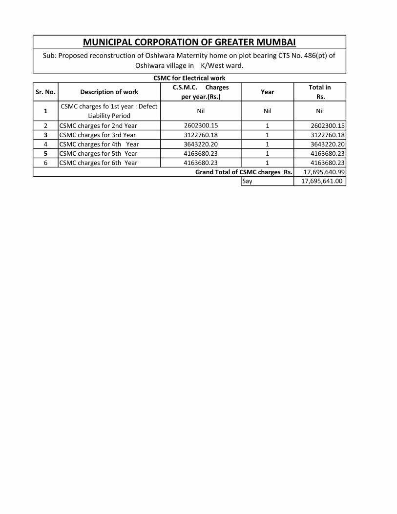
Sr. No. Description of workC.S.M.C. Charges
per year.(Rs.) Year
Total in Rs.
1CSMC charges fo 1st year : Defect
Liability PeriodNil Nil Nil
2 CSMC charges for 2nd Year 2602300.15 1 2602300.153 CSMC charges for 3rd Year 3122760.18 1 3122760.184 CSMC charges for 4th Year 3643220.20 1 3643220.205 CSMC charges for 5th Year 4163680.23 1 4163680.236 CSMC charges for 6th Year 4163680.23 1 4163680.23
17,695,640.99 Say 17,695,641.00
MUNICIPAL CORPORATION OF GREATER MUMBAISub: Proposed reconstruction of Oshiwara Maternity home on plot bearing CTS No. 486(pt) of
Oshiwara village in K/West ward.
CSMC for Electrical work
Grand Total of CSMC charges Rs.
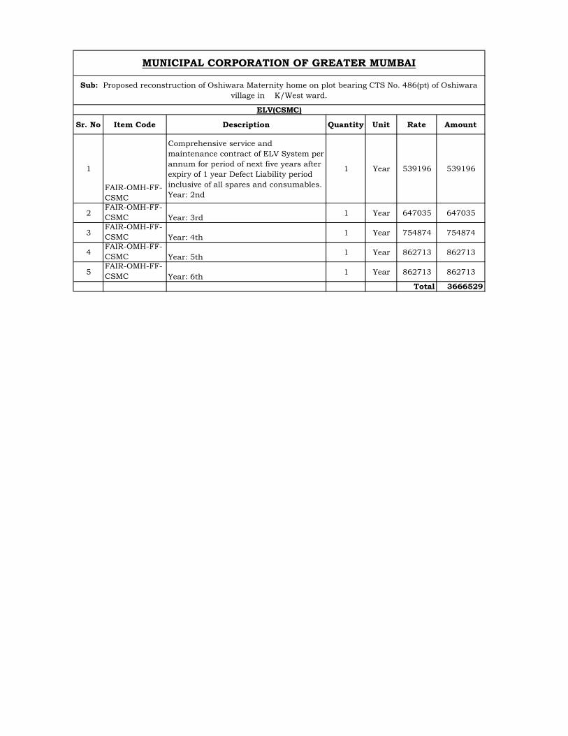
Sr. No Item Code Description Quantity Unit Rate Amount
1
FAIR-OMH-FF-CSMC
Comprehensive service andmaintenance contract of ELV System per annum for period of next five years after expiry of 1 year Defect Liability period inclusive of all spares and consumables. Year: 2nd
1 Year 539196 539196
2FAIR-OMH-FF-CSMC Year: 3rd
1 Year 647035 647035
3FAIR-OMH-FF-CSMC Year: 4th
1 Year 754874 754874
4FAIR-OMH-FF-CSMC Year: 5th
1 Year 862713 862713
5FAIR-OMH-FF-CSMC Year: 6th
1 Year 862713 862713
Total 3666529
MUNICIPAL CORPORATION OF GREATER MUMBAI
Sub: Proposed reconstruction of Oshiwara Maternity home on plot bearing CTS No. 486(pt) of Oshiwara village in K/West ward.
ELV(CSMC)
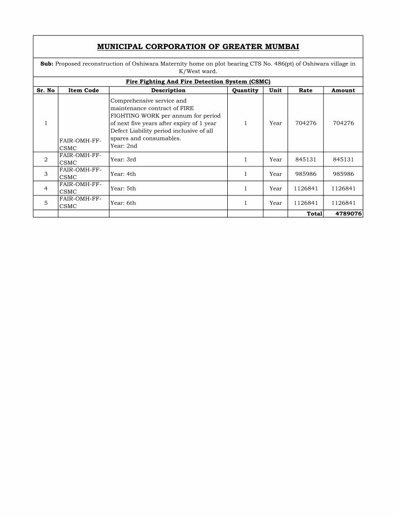
Sr. No Item Code Description Quantity Unit Rate Amount
1
FAIR-OMH-FF-CSMC
Comprehensive service andmaintenance contract of FIREFIGHTING WORK per annum for period of next five years after expiry of 1 year Defect Liability period inclusive of all spares and consumables. Year: 2nd
1 Year 704276 704276
2FAIR-OMH-FF-CSMC
Year: 3rd 1 Year 845131 845131
3FAIR-OMH-FF-CSMC
Year: 4th 1 Year 985986 985986
4FAIR-OMH-FF-CSMC
Year: 5th 1 Year 1126841 1126841
5FAIR-OMH-FF-CSMC
Year: 6th 1 Year 1126841 1126841
Total 4789076
MUNICIPAL CORPORATION OF GREATER MUMBAI
Sub: Proposed reconstruction of Oshiwara Maternity home on plot bearing CTS No. 486(pt) of Oshiwara village in K/West ward.
Fire Fighting And Fire Detection System (CSMC)
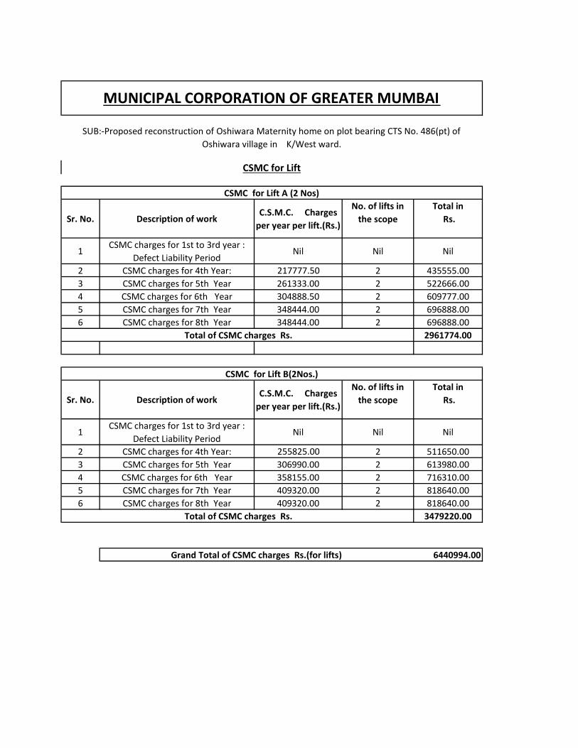
Sr. No. Description of workC.S.M.C. Charges
per year per lift.(Rs.)
No. of lifts in the scope
Total in Rs.
1CSMC charges for 1st to 3rd year :
Defect Liability PeriodNil Nil Nil
2 CSMC charges for 4th Year: 217777.50 2 435555.003 CSMC charges for 5th Year 261333.00 2 522666.004 CSMC charges for 6th Year 304888.50 2 609777.005 CSMC charges for 7th Year 348444.00 2 696888.006 CSMC charges for 8th Year 348444.00 2 696888.00
2961774.00
Sr. No. Description of workC.S.M.C. Charges
per year per lift.(Rs.)
No. of lifts in the scope
Total in Rs.
1CSMC charges for 1st to 3rd year :
Defect Liability PeriodNil Nil Nil
2 CSMC charges for 4th Year: 255825.00 2 511650.003 CSMC charges for 5th Year 306990.00 2 613980.004 CSMC charges for 6th Year 358155.00 2 716310.005 CSMC charges for 7th Year 409320.00 2 818640.006 CSMC charges for 8th Year 409320.00 2 818640.00
3479220.00
6440994.00
MUNICIPAL CORPORATION OF GREATER MUMBAI
SUB:-Proposed reconstruction of Oshiwara Maternity home on plot bearing CTS No. 486(pt) of Oshiwara village in K/West ward.
CSMC for Lift A (2 Nos)
Total of CSMC charges Rs.
CSMC for Lift
CSMC for Lift B(2Nos.)
Total of CSMC charges Rs.
Grand Total of CSMC charges Rs.(for lifts)
Sr. No Item Code Description Quantity Unit Rate Amount
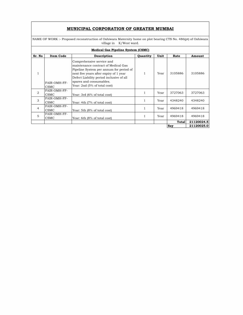
1
FAIR-OMH-FF-CSMC
Comprehensive service andmaintenance contract of Medical Gas Pipeline System per annum for period of next five years after expiry of 1 year Defect Liability period inclusive of all spares and consumables. Year: 2nd (5% of total cost)
1 Year 3105886 3105886
2FAIR-OMH-FF-CSMC Year: 3rd (6% of total cost)
1 Year 3727063 3727063
3FAIR-OMH-FF-CSMC Year: 4th (7% of total cost)
1 Year 4348240 4348240
4FAIR-OMH-FF-CSMC Year: 5th (8% of total cost)
1 Year 4969418 4969418
5FAIR-OMH-FF-CSMC Year: 6th (8% of total cost)
1 Year 4969418 4969418
Total 21120024.5Say 21120025.0
MUNICIPAL CORPORATION OF GREATER MUMBAI
NAME OF WORK :- Proposed reconstruction of Oshiwara Maternity home on plot bearing CTS No. 486(pt) of Oshiwara village in K/West ward.
Medical Gas Pipeline System (CSMC)
Sr. No Item Code Description Quantity Unit Rate Amount
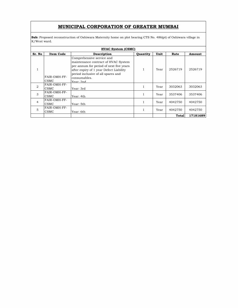
1
FAIR-OMH-FF-CSMC
Comprehensive service andmaintenance contract of HVAC System per annum for period of next five years after expiry of 1 year Defect Liability period inclusive of all spares and consumables. Year: 2nd
1 Year 2526719 2526719
2FAIR-OMH-FF-CSMC Year: 3rd
1 Year 3032063 3032063
3FAIR-OMH-FF-CSMC Year: 4th
1 Year 3537406 3537406
4FAIR-OMH-FF-CSMC Year: 5th
1 Year 4042750 4042750
5FAIR-OMH-FF-CSMC Year: 6th
1 Year 4042750 4042750
Total 17181689
MUNICIPAL CORPORATION OF GREATER MUMBAI
Sub: Proposed reconstruction of Oshiwara Maternity home on plot bearing CTS No. 486(pt) of Oshiwara village in K/West ward.
HVAC System (CSMC)
Sr. No Item Code DescriptionQuanti
tyUnit Rate Amount
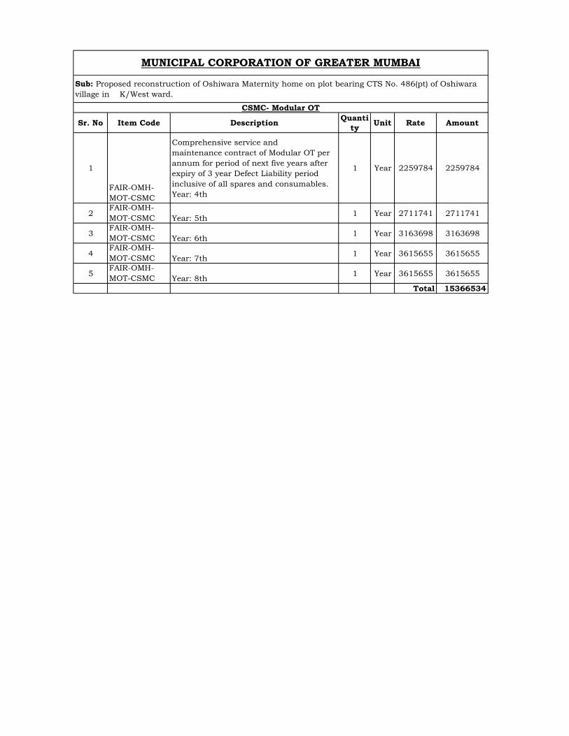
1
FAIR-OMH-MOT-CSMC
Comprehensive service andmaintenance contract of Modular OT per annum for period of next five years after expiry of 3 year Defect Liability period inclusive of all spares and consumables. Year: 4th
1 Year 2259784 2259784
2FAIR-OMH-MOT-CSMC Year: 5th
1 Year 2711741 2711741
3FAIR-OMH-MOT-CSMC Year: 6th
1 Year 3163698 3163698
4FAIR-OMH-MOT-CSMC Year: 7th
1 Year 3615655 3615655
5FAIR-OMH-MOT-CSMC Year: 8th
1 Year 3615655 3615655
Total 15366534
MUNICIPAL CORPORATION OF GREATER MUMBAI
Sub: Proposed reconstruction of Oshiwara Maternity home on plot bearing CTS No. 486(pt) of Oshiwara village in K/West ward.
CSMC- Modular OT
Sr. NoItem Code
DescriptionQuanti
tyUnit Rate Amount
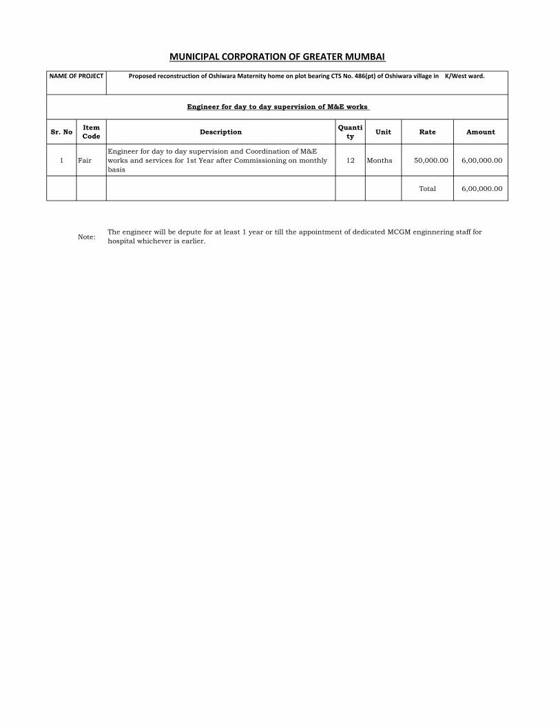
1 FairEngineer for day to day supervision and Coordination of M&E works and services for 1st Year after Commissioning on monthly basis
12 Months 50,000.00 6,00,000.00
Total 6,00,000.00
Note:The engineer will be depute for at least 1 year or till the appointment of dedicated MCGM enginnering staff for hospital whichever is earlier.
NAME OF PROJECT Proposed reconstruction of Oshiwara Maternity home on plot bearing CTS No. 486(pt) of Oshiwara village in K/West ward.
Engineer for day to day supervision of M&E works
MUNICIPAL CORPORATION OF GREATER MUMBAI
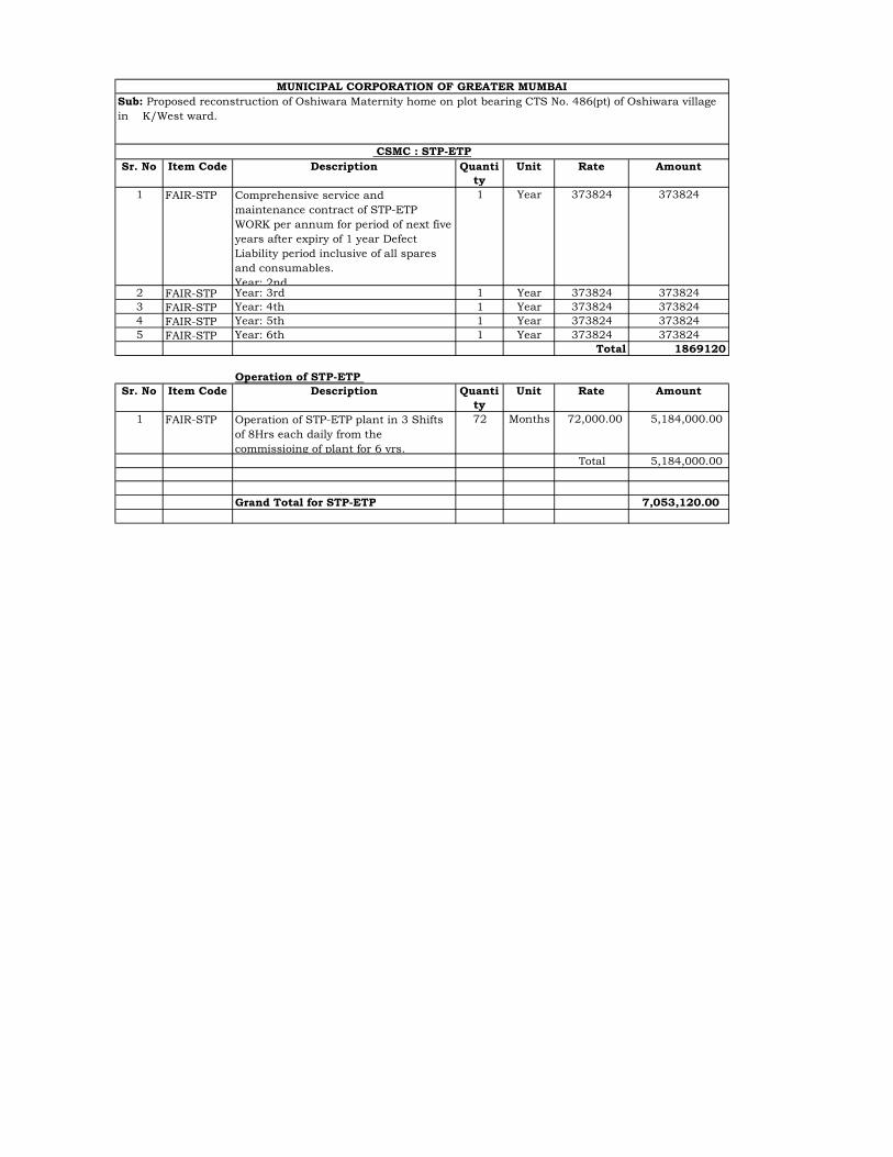
Sr. No Item Code Description Quantity
Unit Rate Amount
1 FAIR-STP Comprehensive service andmaintenance contract of STP-ETP WORK per annum for period of next five years after expiry of 1 year Defect Liability period inclusive of all spares and consumables. Year: 2nd
1 Year 373824 373824
2 FAIR-STP Year: 3rd 1 Year 373824 3738243 FAIR-STP Year: 4th 1 Year 373824 3738244 FAIR-STP Year: 5th 1 Year 373824 3738245 FAIR-STP Year: 6th 1 Year 373824 373824
Total 1869120
Operation of STP-ETP Sr. No Item Code Description Quanti
tyUnit Rate Amount
1 FAIR-STP Operation of STP-ETP plant in 3 Shifts of 8Hrs each daily from the commissioing of plant for 6 yrs.
72 Months 72,000.00 5,184,000.00
Total 5,184,000.00
Grand Total for STP-ETP 7,053,120.00
MUNICIPAL CORPORATION OF GREATER MUMBAISub: Proposed reconstruction of Oshiwara Maternity home on plot bearing CTS No. 486(pt) of Oshiwara village in K/West ward.
CSMC : STP-ETP
1
TECHANICAL SPECIFICATION FOR M&E WORK.
1. TECHANICAL SPECIFICATION FOR ELECTRICAL WORK
Majority items are taken from M&E USOR 2018 for which technical specifications may be obtained from M&E USOR Specifications 2018 from MCGM portal.
Unified Schedule of Rates - MyBMC - Welcome to BMC's Website (mcgm.gov.in)
Technical specifications for fair market rate item is as follows :-
Technical Specification For 415 Volts, Main Low Tension Panel And Power Control Centres And Distribution Boards 1.0 Scope :- This Specification covers the design, manufacture, testing and supplying at site all LT Distribution
Panels in all respect and to complete the installation in working condition 2.0 Applicable Standards :- All relevant Indian Standards shall be made applicable with latest amendments. Also any other specific
application is required, then the same shall be complied to. 3.0 440 Volts grade Warning Boards :- All the warning Boards shall be 440 Volts Red in color and made up of Aluminum sheet and having size
of 150 mm x 150 mm x 3 mm thick painted with self illuminated fluorescent “RED” Color paint shall be fixed at prominent places. These shall have minimum 2 languages inscribed on it, mainly Local Language, and English . The Warning Boards shall also have the usual Electrical Shock inscriptions as well as the small mark of Danger on it. These shall be fixed on The Main L.T Panel and All the Distribution Panels as per directions of Consultant.
1.1 General Specification of Equipment :- 1.2 The scope of work comprises of Designing, Obtaining Approval of the Consultants and Fabricating as
per approved Drawings, Testing at Works, Packing and Forwarding, Supplying, at Site, Checking at site, Touching Up all Damaged portions, and assessing the Electrical Contractor while commissioning of the Panels at site. Further Touching up of damaged powder coated painting shall be carried at site after the installation of all panels is completed by the contractor.
1.3 The Main L.T. Panel, Power Control Centers, distribution boards shall be metal clad, totally enclosed,
rigid, floor mounting, air-insulated, cubicle type for use on 415 volts, 3 phase 50 cycles system. 1.4 The equipment shall be designed for operation in high ambient temperature and high humidity
tropical atmospheric conditions. Means shall be provided to facilitate ease of inspection, cleaning and repairs in the installations where continuity of operation is of prime importance.
2
1.5 Standards :- The equipment shall be designed to conform to the following requirements and to the latest
amendments in the codes or relevant IEC applicable standards. a) IS 8623 - Part II of 1993 Factory Built Assemblies of switchgear and control gear.
b) IS 13947 - Part I General requirements for switchgears and control gear for voltages not exceeding
1000 Volts.
c) IS 13947 Part I - Degrees of protection provided by enclosures for low voltage switchgear and control-gear.
d) IS 11353 - Marking and arrangement of bus-bars. e) IEC 660947-1 – General specification for Low voltage Switchgears f) IEC 60947-2 – For ACB and MCCB g) IEC 60947-3 – For Switches (Isolators and SDF) h) IEC 60947-4 For Contactors and BMR i) IEC 60898 – For MCB 1.6 Individual equipments housed in the power control center shall conform to the following IS specifications : a) Air Circuit Breakers - IEC 647-2 and IS 13947-2 b) Molded Case Circuit Breakers - IEC 60947-2 and IS 13947-2. c) HRC Fuse-links - IS.9224 Part II d) Current Transformers- IS.2705 Part I, II & III of 1992. e) Voltage Transformers - IS.3156 Part I,II,III &IV of 1992. f) Relays - IS.3231 Part I, II, & III of 1987 g) Indicating Instruments - IS. 1248 Part I of 1993 h) Control Switches & Push Buttons - IS 13947 Part V Sec -1 i) AC Contractors - IS.13947 Part IV Sec - 4 2.0 Construction :- 2.1 The Main LT Panel, Power Control Centers, Distribution boards shall be :- a) of the metal enclosed, indoor, floor mounted, free standing type. b) be made up of the minimum 14 Gauge White CRCA Sheets vertical sections, which, when coupled
together shall form continuous front operated dead back type switchboards except for Main L.T Panel which shall have back access.
3
c) Provide dust and vermin proof design. All the Panels should be designed in such a manner that the in
Panel Temperature should not rise more than 30 degree Centigrade over an ambient of 45 degree Centigrade. The Vendors has to provide the temp sensors. If the temp of the cubicle increase more than 15 degree over an ambient the Exhaust Fan should be started and even after that the temp of the Bus Bars reaches to 85 degree the Alarm should be stared and should the command to the Main Breaker to Trip . All this provision has be done by the bidder without any extra cost. The Small Exhaust fans with the louvers should be provided for the Main Bus Bar chambers and all the cable alleys. All the fans should have the provision to start and stop by way of MCB. All the fans should be suitable for continuous duty. All panels cable alleys should have dust proof ventilators with the provision to mount impedance compensated fans
d) be readily extensible on both sides by the addition of vertical sections after removal of the end
covers or as otherwise as called for in the schedule of quantities. 2.2 The Main L.T Panel, Power Control Centers and Distribution Boards shall be constructed only of
materials capable of withstanding the mechanical, electrical and thermal stresses, as well as the effects of humidity, which are likely to be encountered in normal service.
2.3 Each vertical section shall comprise :- a) A front framed structure of rolled/folded sheet steel channel section, of minimum 14 Gauge
thickness, rigidly bolted together. This structure shall house the components contributing to the major weight of the equipment, such as Air circuit breaker, Molded Case Circuit Breakers, main horizontal bus-bars, vertical risers and other front mounted accessories.
2.3.2 The structure shall be mounted on a rigid base frame fabricated using Galvanized Iron channel of
minimum 100 mm height. The design shall ensure that weight of the components is adequately supported without deformation or loss of alignment during transit or during operation. The thick ness of the Galvinsing should be minimum 65 microns and it should be hot dipped.
a) A rear or front cable chamber housing shall be designed in such a manner that enough space is available
for clamping of the cable cores terminating the same on the terminals. The design shall ensure generous availability of space for case of installation and maintenance of cabling, and adequately safety for working in one vertical section without coming into accidental contact with live parts in an adjacent section.
b) Galvanised Powder Coated Sheets of 18 gauge shall be provided inside all the horizontal and vertical
Bus bar chamber and cable alleys. After the removal of the Bus Cover these painted sheets should be visible this is to be provided for ventilation purpose
and to avoid direct access to Bus Bars or live parts after the removal of the Bus-bar covers. The size of the holes shall be less than 12.5 mm in diameter. This sheets should also go under seven tank painting process and should be power coated Egg Shell white in color. This sheets shall be fixed using magnetic locks and the ball catch fixed to the Main body.
c) All the doors should be fitted with neoprene gaskets with fasteners designed to ensure proper
compression of gaskets. When covers are provided in place of doors, generous overlap shall be assured between sheet steel surfaces with closely spaced fasteners to preclude the entry of dust.
d) No Black sheets shall allowed. All sheets shall be white CRCA. If it is found at any stage that Black
sheets have been used, The panel shall be summarily rejected. 2.4 The height of the panel should not be more than 2100 mm. The total depth of the panel should be adequate
to cater for proper cabling space and should not be less then 1000 mm for ACB sections and 450 mm for
4
MCCB sections. The Minimum size of the Compartments for the various sizes of MCCBs/ACBs shall be as shown in the General Arrangement drawings . The Contractor may modify to suit the site conditions.
2.5 Doors and compartment partitions shall be fabricated using 14 Gauge thick sheet steel. Sheet steel
shrouds and partitions shall be of minimum 14 Gauge thickness. All sheet steel work forming the exterior of switch boards shall be smoothly finished, leveled and free from flaws. The corners should be rounded. All the Sheet steel forming the exterior of the switch board should be fabricated using 14 gauge White CRCA Sheets. The entire Panel shall be fabricated using 14 Gauge white CRCA Sheets only.
2.6 The apparatus and circuits in the Power Control Centers shall be so arranged as to facilitate their
operation and maintenance and at the same time to ensure the necessary degree of safety. 2.7 Apparatus forming part of the Power Control Centers shall have the following recommended minimum
clearances for un insulated or should be as per relevant IS Codes. a) Between Phases - 25 mm. b) Between Phases and Neutral - 25 mm. c) Between Phases and Earth - 25 mm. d) Between Neutral and Earth - 25 mm. When, for any reason, the above clearances are not available, suitable insulation shall be provided.
Clearances shall be maintained during normal service conditions. Creepage distances shall comply to those specified in relevant standards. 2.8 All insulating material used in the construction of the equipment shall be of non-hygroscopic material,
duly treated to withstand the effects of high humidity, high temperature tropical ambient service conditions. 2.9 Functional units such as circuit breakers and fuse switches shall be arranged in multi-tier formation. All
the Air Circuit Breakers shall housed in a single tier formations Only. Nothing shall be housed above and below the Bus- Coupler. The above and below compartments of the Bus-Coupler/Or shall be kept empty.
2.10 Metallic/insulated barriers shall be provided within vertical sections and between adjacent sections to
ensure prevention of accidental contact with : 2.10.1 Main bus-bars and vertical risers during operation, inspection or maintenance of functional units and
front mounted accessories. 2.11 All doors/covers providing access to live power equipments circuits shall be provided with tool
operated fasteners to prevent unauthorized access. 2.12 Provision shall be made for permanently earthing the frames and other metal parts of the switchgear by
two independent connections. 3.0 METAL TREATMENT AND FINISH :- 3.1 All steel work used in the construction of the switch board should have undergone a rigorous metal
treatment process as follows.
5
3.1.1 Effective Cleaning by hot alkaline degreasing solution followed by cold water rinsing to remove traces
of alkaline solution. 3.1.2 Pickling in dilute sulfuric acid to remove oxide seals and rust formation, if any, followed by cold water
rinsing to remove traces of acidic solution. 3.1.3 A recognized phosphating process to facilitate durable coating of the paint on the metal surface and also
to prevent the speared of rustling in the event of the paint film being mechanically damaged. This again, shall be followed by hot water rinsing to remove traces of phosphate solution.
3.1.4 Passivating in de-oxalite solution to retain and augment the effects of phosphating. 3.1.5 Drying with compressed air in a dust free atmosphere. 3.1.6 Two coats of granule finished Powder Coating of Siemens gray having shade No. RAL 7032 is to be
done from inside and outside of the panel on the phosphate panels on all exterior and interior side, by wet on wet process, with an interval of 2-3 minutes between coats. One coat involves 2 phases horizontally/ vertically over the entire surface on all exterior and interior side. In any case the thickness of the Paint
should not be less than 65 Microns. All the panels shall be Granule finished powder coated painted with
Siemens Gray having shade No RAL 7032 from Outside and Inside and dried up in oven. 4.0 BUS-BARS :- 4.1 The material of the Bus-Bars shall be Copper as per IEC-60105 & ISO-209-1,2. All the Bus Bars grade
should be 6101 throughout the length. All the Bus Bars should be tested as per relevant IS and latest IEC standard. The Bus Bar manufacture should submit the certificate from original supplier of Bus Bar for purity. The size of the Bus bars used should be indicated by the Bidder in his Bid and shall be subject to the Consultants approval. To arrive at the bus bar size, the calculations will be based on 700-800 Amps. Per sq. inch. The size of the bus bar thus arrived at shall be chosen to the nearest mm. The sizes of the b usbar shall be chosen in such a manner that the sizes of the terminals and the sizes of the are matches with each other.
4.2 The busbar shall be suitably braced with non-hygroscopic SMC supports. The Neutral as well as the
earth bar should also be cable of withstanding the stresses of electrical fault. Ridges shall be provided on the SMC supports to prevent tracking between adjacent .
4.3 Large clearances and creepage distances shall be provided on the system to minimized the
possibility of a fault. 4.4 High tensile bolts and spring washers shall be provided at all joints. 4.5 The cross section of the bus-bars and risers for various ratings shall have been decided on the basis of
temperature rise tests results carried out on some other Panels for the stated sections. 4.6 Connections from the main bus-bars to functional circuits shall be arranged and supported so as to
withstand without any damage or deformation the thermal and dynamic stresses due to short circuit currents.
4.7 Bus-bars shall be color coded for easy identification of individual phases and neutral. 4.8 All the busbar shall be provided with color coded heat sink sleeves through the full length. Intermittent
color bands are not acceptable . The Earth Bus bar shall be provided with green color heat shrink sleeve. The size of the Earth shall be same as the size of the neutral bus bar but in any case it should not be less
6
than 50 x 6 mm Tinned Cooper strip with Heat Shrinkable PVC Sleeve for Main L.T Panel and 25 x 6 mm Tinned Copper Strips for Small Panels.
5.0 AIR CIRCUIT BREAKERS :- 5.1 All Air Circuit breakers shall be Triple Pole with Neutral link or Four Pole as specified in the Bill of
material or in drawing. All the Breakers shall be air break, horizontal draw out type, designed to be maintained.
5.2 The breakers shall comply fully with IEC 947-2 Or IS 13947-2 and should have Thermal Magnetic base
trip unit and shall have ICs=ICu=ICw 5.3 A short circuit breaking capacity of not less than 65 KA RMS at 440 Volts 50 Hz AC. 5.4 A short circuit making capacity of 136 KA. 5.5 A short-time withstand circuit of 65 KA for 1 Second. 5.6 All the Circuit Breaker shall confirm to disconnection function and should have fault indication L.E.D 5.7 Air Circuit Breakers having rating 3200 Amps or Below shall have Maintenance free Electrical life of
minimum 6000 operations. 5.8 The circuit breakers shall be fitted with detachable arc chutes on each pole designed to permit rapid
dispersion, cooling and extinction of the arc. All the accessories shall be snap fitted in design and it should be possible to convert Manually operated Breaker into Electrically operated breaker at site without any major modification.
5.9 Arcing contacts shall be of hard wearing material of copper tungsten. 5.10 The operating mechanism shall be of robust design, with a minimum number of linkages to ensure
maximum reliability. Manually operated circuit breakers shall be provided with spring operated closing mechanism which are independent of speed of manual operation. Electrically operated breakers shall have a motor wound spring charged closing mechanism. Breaker operation shall be independent of the motor which shall be used solely for charging the closing spring.
5.11 The Breaker shall be Trip free type an should be provided with anti pumping function. 5.12 The Releases fitted on the Breaker shall confirm to the following
a) Long Time Current Setting and with adjustable Tripping Delay b) Over Load Signal (LED) c) Short Time Pick Up and Tripping Delay. d) Adjustable Instantaneous Pick up. e) Earth leakage or Earth Fault Pickup and Tripping Delay f) Earth leakage or Earth Fault Test Button g) Long Time rating Plug Screw h) Test Connector. i) Lamp + Battery test and indication Reset j) Indication of tripping Cause. k) High Resolution Screen l) Measurement Display m) Maintenance indicators (% Contact Wear Indication) n) Protection Settings (Over & Under Voltage, Over Under Frequency, Current in balance, Phase
Sequence, & Reverse Power)
7
o) Navigation buttons p) Hole for Setting lockout pin on cover q) Communication option r) Indication option via programmable contacts. s) Reverse Power Alarm t) Phase Sequence. u) Tripping History and Alarm History recorded in two separate history files and same should be
displayed on Screen.(for last 10 faults as stand alone breaker without communication) v) All the above parameters should be able to communicated with the PC with RS-485 port. w) It should be possible to change IDMT Charities (EIT/VI/DT/SIT &HF) for achieving the
discrimination with up stream HV Breaker or a Fuse
5.13 Circuit breakers shall be individually housed in sheet metal cradle fabricated using MS Zinc passivated sheets. The breaker along with its operating mechanism shall be mounted on a robust carriage moving on guide rollers within the cradle. Isolating contacts for both power and control circuits shall be of robust design and fully self-aligning. The assembly shall be designed to allow smooth and easy movement of the breaker within its cradle .
5.14 Operating Mechanism
The operating mechanism shall be of the Open/Closed/Open stored-energy type. The closing springs shall be able to be manually charged by operating the front lever
The circuit breaker shall be of trip free type and shall be provided with built in mechanical Anti Pumping device. Closing coil & other auxiliary devices shall be available in sufficient number for the purpose of indication, alarms, annuciations on switch boards as well as on respective remote control panel in control room & for the purpose of interlocking scheme shall be provided
There shall be four distinct & separate position of the circuit breakers on the cradle as – Service / Test / Isolated / Maintenance. The first three position shall be positive , achieved only through the racking motion of draw out mechanism & not by trail & error. There shall be indicator clearly showing the above 3 conditions
Circuit breaker shall be convertible from Manual to Electrical breaker at site.
5.15 The breaker shall have four distinct position within the cradle. 5.16 Service/Test/Isolate and Maintenance. The position shall be positive achieved through the racking handle
motion. Their shall be indicator showing the above mentioned four conditions and should be possible to interlock the breaker at each position.
5.17 All Air Circuit Breakers should have molded case design with Class II front facia. All Air Circuit Breakers
shall have indication of Mechanical wear of Contacts, enabling visible indication of Contact life.
5.18 Provision shall be available for the padlocking of the circuit breaker access flaps in any of three positions. 5.19 Automatically operated safety shutters shall be provided to screen the fixed isolating contacts when the
breaker is drawn out from the cassette.
8
5.20 Auxiliary switches directly operated by the breaker operating mechanism and having 4 NO and 4 NC contacts, shall be provided on each breaker. The auxiliary switch contacts shall have a minimum rated thermal current of 10 Amps.
5.21 All the Air Circuit Breakers shall confirm to EMC and shall be immune to harmonics to avoid the nuisance
tripping of the Breaker. Further all the Breaker shall be provided with RS 485 Communication port with facility to Operate the Breaker from Remote. The Vendor to provide the necessary software suitable to Profy Bus open Prtocol.
5.22 The trip unit fitted on the Breaker shall have Thermal memory to store Temperature rise data in case of the
respective faults. 5.23 All the Breakers shall have the facility of zone selectivity interlocking and their shall be indication of
percentage loading of current in each phase of the Circuit Breaker. All Air circuit Breaker shall comply with IEC – 60947-2 & all incoming Air Circuit breaker should be four pole, electrical draw out type capable of setting Neutral Protection to N or N/2 to ensure precise neutral Protection. Breaking Capacity of Breaker in Main LT Panel shall be Ics = Icu = 65 KA at 440V & Ics = Icu = Icw (for 3 Sec)
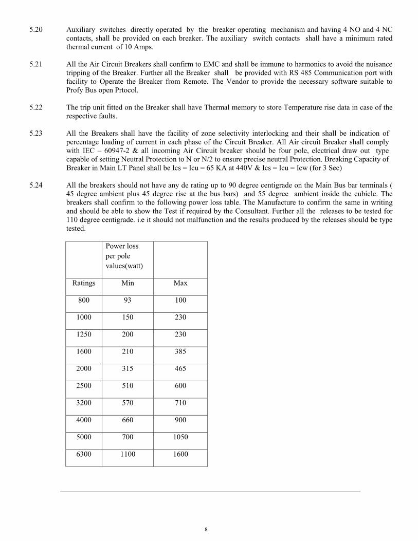
5.24 All the breakers should not have any de rating up to 90 degree centigrade on the Main Bus bar terminals (
45 degree ambient plus 45 degree rise at the bus bars) and 55 degree ambient inside the cubicle. The breakers shall confirm to the following power loss table. The Manufacture to confirm the same in writing and should be able to show the Test if required by the Consultant. Further all the releases to be tested for 110 degree centigrade. i.e it should not malfunction and the results produced by the releases should be type tested.
Power loss per pole values(watt)
Ratings Min Max
800 93 100
1000 150 230
1250 200 230
1600 210 385
2000 315 465
2500 510 600
3200 570 710
4000 660 900
5000 700 1050
6300 1100 1600
9
5.25 Protection and Measurement Function :
Protection Functions :
All shall have releases capable of sensing true RMS value of Current based on Digital Technology
All ACB shall confirm to EMC & shall be immune to harmonics to avoid Nuisance tripping
Protection unit shall offer following as standard in all breakers excluding bus couplers
- Long time protection with adjustable time delay. - Instantaneous or Short ckt protection with time delay. The short circuit setting (Isd) should necessarily be
the function of the set current(Ir) of the ACB. - Earth fault protection with settable absolute values& this protection will be only where specified in BOQ
or in Drawing
For all ACBs above 1250A, the maximum earth fault setting should not exceed 1250A
All the adjustments should be on line & the circuit breaker need not be switched off while adjusting the settings.
The control unit shall have thermal memory throughout the range to store temp rise data in case of repetitive Overloads or earthfault for protecting the cables & loads.
The Trip unit should also give the IDMTL long time protection, minimum & maximum voltage & frequency, voltage & current imbalance, phase sequence & reverse power protection.
Breaker shall have facility of Zone selective interlocking
Measurement Functions
Measurement function should be independent of protection functions & there shall be A power meter with graphical display & bar graph for showing the percentage loading in each phase built in the trip unit.
Communication Function
Main incoming breaker shall be equipped with communication output port & the circuit breaker shall be capable of communicating the following data via a bus:
Circuit-breaker status (open/closed, connected/disconnected/test, tripped on a fault, ready to close);
Control-unit settings;
Tripping causes;
The measurements processed by the control unit: current, voltage, frequency, power, power quality.
It shall be possible to remotely control the circuit breaker.
10
It shall be possible to remotely modify circuit-breaker settings:
Settings of the protection functions and the alarms.
Communications functions shall be independent of the control unit.
Main incoming breaker shall also have Event Logging facility for last ten faults, events storing & counting the no of operations & contact wear (electronic)
6.0 MOULDED CASE CIRCUIT BREAKER :-
All the MCCBS Shall be suitable for fault braking Capacity as mentioned in the Single line Diagrams but in any case should not be less than 65 KA. All the MCCBs shall be provided with variable Over Current, Short Circuit releases . The variable Earth fault release is optional. The same shall be provided if called for in the schedule of quantity. The MCCBS having rating 250 Amps and the above the releases shall be Thermo magnetic based only and the MCCBS of lower ratings the releases shall be Thermo magnetic type. All the MCCBS shall have ICs=100% of ICu. All the MCCBS shall conform to disconnection function as per IEC947-2 Section 7.1.2. All four pole MCCBS above 250 Amps shall have capability of setting Neutral to N or N/2. All accessories of MCCBS shall be snap fitted type . All MCCBS should have flexibility of Line Load reversibility. Manufacture should submit let through energy curves and discrimination charts and cascading table for the approval of the consultant prior to ordering the MCCBS. All the MCCBS should be designed in such a way that no live parts is accessible. All the MCCBS should comply to IEC 60947-2 and IS 13947-2. All the MCCBS should have three clear positions ON/OFF and TRIP. The Manufacturer to Provide direct or extended Rotary handle with door interlock facility for all the rating of the MCCBS. All the MCCBS should be suitable for total discrimination. The MCCBs having rating more than 250 Amps shall have communication option which should able to display the status of each breaker and its setting, Control the circuit breakers and display the faults. All MCCB's shall be double break the current limiting type enabling full use of current limitation. Operating mechanism shall be of the quick make quick break type, with the speed of operation independent of the operator, and mechanically trip free from the operating handle so as to revert the contacts from being held closed against short-circuit and overload conditions. The operating mechanism shall be constructed to operate all poles in a multi-pole breaker simultaneously during opening, closing and tripped conditions.
Protection Function
All Molded Case Circuit Breakers should have Microprocessor based releases capable of sensing true RMS values of Current based on digital Technology & should have Centralised variable short circuit & overload setting
Electronic trip units shall comply with appendix F of IEC60947-2 standard (measurement of rms current values, electromagnetic compatibility, etc.).
All electronic components shall withstand temperatures up to 125°C. ‘
Earth fault protection if required should be an integral part of the release & should be adjustable The control unit shall have thermal memory to store temp rise data in case of repetitive
Overloads or earth fault for protecting the cables & loads. The accessories like shunt trip, closing trip coils should be continuously rated to avoid the Burning due to sustained command.
The MCCBs should be with Class-2 front facia in order to avoid any live part exposure in case the front cover is opened for the accessory mounting. All the Molded Case Circuit Breakers should have load Monitor LED and Adjustable Magnetic Threshold above 200 Amps. All the MCCB,s Should have Trip Unit Interchangeability at site.
11
The MCCB shall be 3 pole / 4 pole as the need be. In case of 4 pole MCCB, the 4th pole shall be 100% rated.
The MCCB shall be available in fixed / draw-out version as the need be.
It shall be possible to fit accessories on the MCCB such as aux contact, trip indication contact, rotary handle, undervolt coil or shunt trip coil, etc. In case of rotary handle, the same shall have built-in door interlock, defeat & padlocking facility. The rotary handle shall be same as that for SDF or MPCB for better aesthetics.
The MCCB shall be manually operated or motor operated as the need be. It shall be possible to convert the MCCB from manually operated to motorised MCCB and vice-versa. Electrical All the MCCB shall be suitable for 690 V ac system voltage.
The MCCB shall be suitable for impulse withstand of 8 kV.
The MCCB shall have short circuit breaking capacity Icu of 18 or 40 or 70 kA rms. The MCCB breaking capacity shall have Icu = 100% of Ics for the entire range.
The MCCB shall have no de rating up to 50C service temperature. In case the MCCB needs de rating,
manufacturer shall declare the de rated current carrying capacity at 50C service temperature.
The MCCB shall be current limiting and shall have line-load interchangability without any loss of capacity.
The MCCBs above 100 A, shall have adjustable and properly calibrated overload and short circuit settings.
Trip Unit
The MCCBs up to 630 A shall be with thermo-magnetic trip unit. 800 A & above, the trip unit shall be microprocessor based. Static trip unit shall not be acceptable.
The trip unit shall be capable to accept any change in the setting on-line, without need to switch off the MCCB. The trip unit shall have overload and short circuit protection. It shall be possible to change the trip unit from thermo-magnetic to microprocessor based and vice-versa.
7.0 MINIATURE CIRCUIT BREAKERS (MCB)
All the Miniature Case Circuit Breakers shall comply fully with IEC 8828-1996 and should have uniform breaking capacity of 10 KA.
7.1 All the MCB shall comply with Isolation function. 7.2 “C” Curve MCBS shall be used for Lighting and other small loads and “D” Curve MCBS should be used
for Capacitors and UPS Loads. 7.3 All the accessories of the MCB should be Snap fit type in design.
12
7.4 The Power loss per pole of the MCB shall be less than as specified in relevant codes of IEC standards and
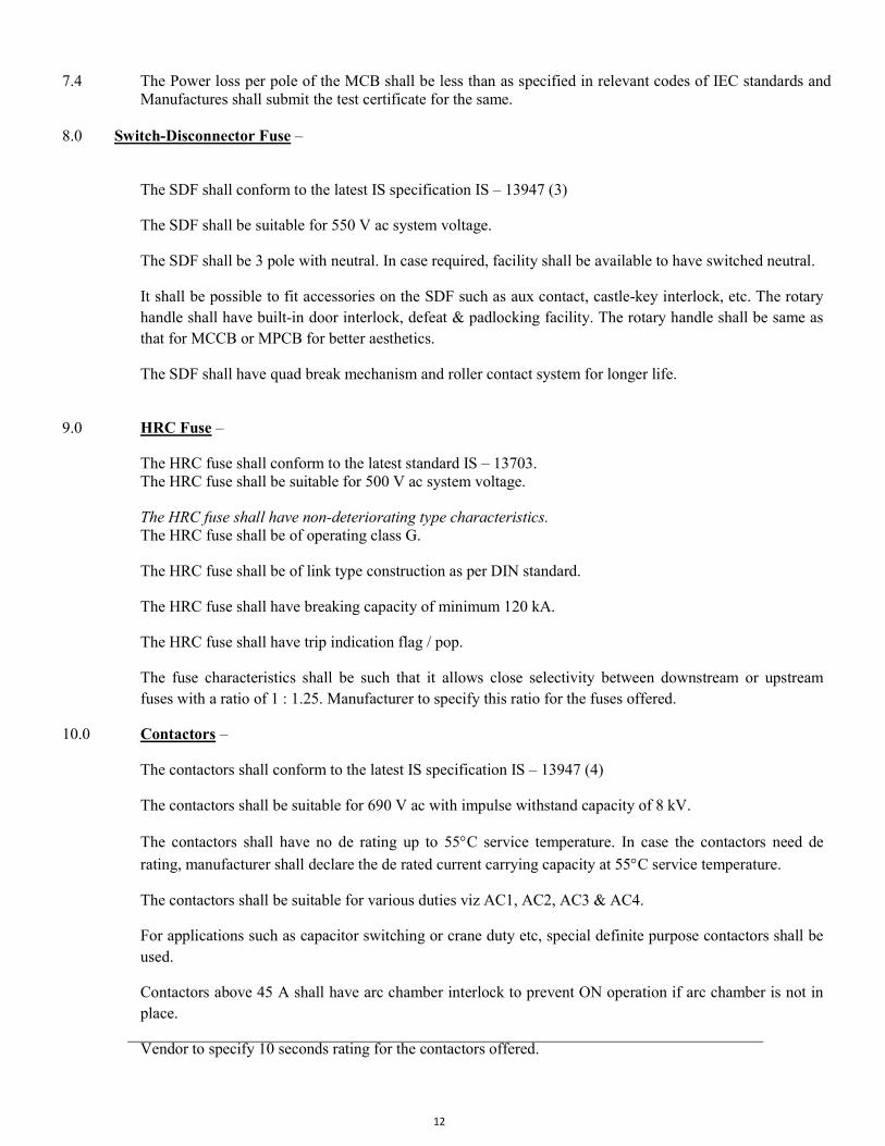
Manufactures shall submit the test certificate for the same. 8.0 Switch-Disconnector Fuse –
The SDF shall conform to the latest IS specification IS – 13947 (3)
The SDF shall be suitable for 550 V ac system voltage.
The SDF shall be 3 pole with neutral. In case required, facility shall be available to have switched neutral.
It shall be possible to fit accessories on the SDF such as aux contact, castle-key interlock, etc. The rotary handle shall have built-in door interlock, defeat & padlocking facility. The rotary handle shall be same as that for MCCB or MPCB for better aesthetics.
The SDF shall have quad break mechanism and roller contact system for longer life.
9.0 HRC Fuse –
The HRC fuse shall conform to the latest standard IS – 13703. The HRC fuse shall be suitable for 500 V ac system voltage.
The HRC fuse shall have non-deteriorating type characteristics. The HRC fuse shall be of operating class G.
The HRC fuse shall be of link type construction as per DIN standard.
The HRC fuse shall have breaking capacity of minimum 120 kA.
The HRC fuse shall have trip indication flag / pop.
The fuse characteristics shall be such that it allows close selectivity between downstream or upstream fuses with a ratio of 1 : 1.25. Manufacturer to specify this ratio for the fuses offered.
10.0 Contactors –
The contactors shall conform to the latest IS specification IS – 13947 (4)
The contactors shall be suitable for 690 V ac with impulse withstand capacity of 8 kV.
The contactors shall have no de rating up to 55C service temperature. In case the contactors need de
rating, manufacturer shall declare the de rated current carrying capacity at 55C service temperature.
The contactors shall be suitable for various duties viz AC1, AC2, AC3 & AC4.
For applications such as capacitor switching or crane duty etc, special definite purpose contactors shall be used.
Contactors above 45 A shall have arc chamber interlock to prevent ON operation if arc chamber is not in place.
Vendor to specify 10 seconds rating for the contactors offered.
13
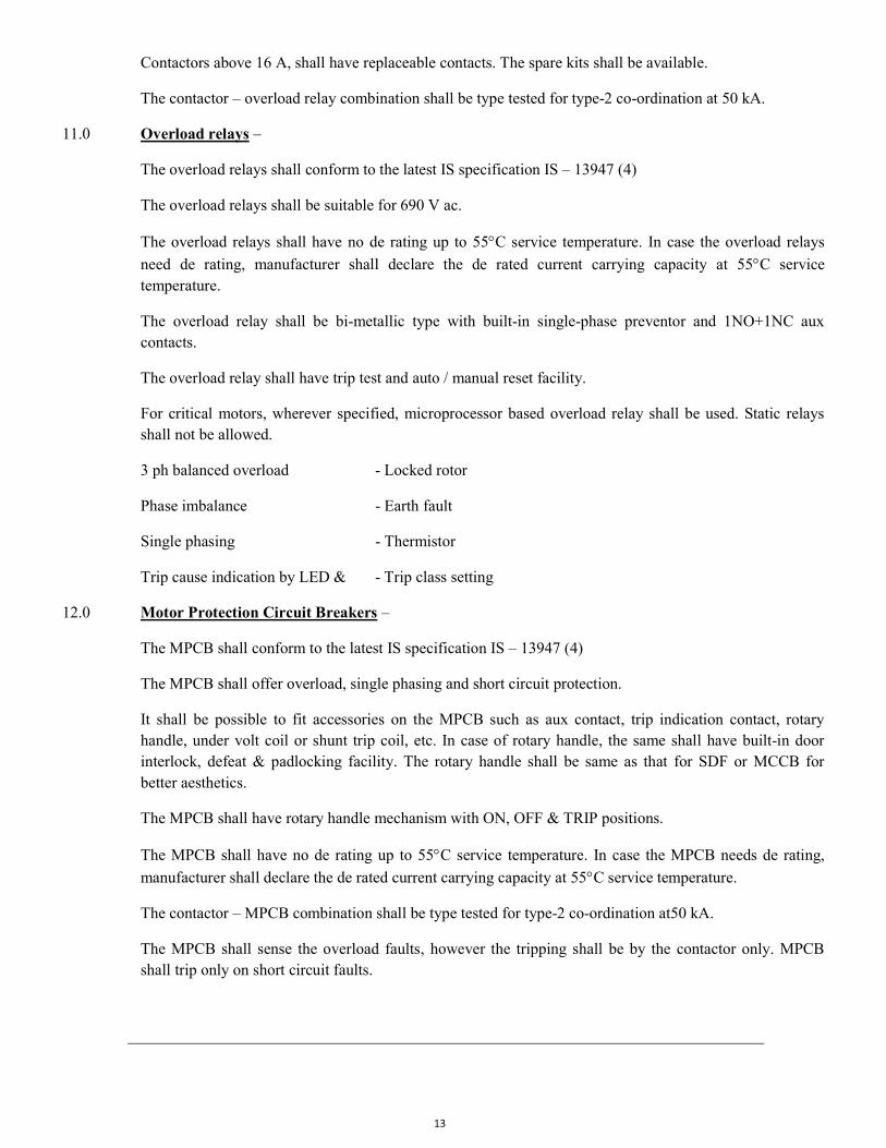
Contactors above 16 A, shall have replaceable contacts. The spare kits shall be available.
The contactor – overload relay combination shall be type tested for type-2 co-ordination at 50 kA.
11.0 Overload relays –
The overload relays shall conform to the latest IS specification IS – 13947 (4)
The overload relays shall be suitable for 690 V ac.
The overload relays shall have no de rating up to 55C service temperature. In case the overload relays
need de rating, manufacturer shall declare the de rated current carrying capacity at 55C service temperature.
The overload relay shall be bi-metallic type with built-in single-phase preventor and 1NO+1NC aux contacts.
The overload relay shall have trip test and auto / manual reset facility.
For critical motors, wherever specified, microprocessor based overload relay shall be used. Static relays shall not be allowed.
3 ph balanced overload - Locked rotor
Phase imbalance - Earth fault
Single phasing - Thermistor
Trip cause indication by LED & - Trip class setting
12.0 Motor Protection Circuit Breakers –
The MPCB shall conform to the latest IS specification IS – 13947 (4)
The MPCB shall offer overload, single phasing and short circuit protection.
It shall be possible to fit accessories on the MPCB such as aux contact, trip indication contact, rotary handle, under volt coil or shunt trip coil, etc. In case of rotary handle, the same shall have built-in door interlock, defeat & padlocking facility. The rotary handle shall be same as that for SDF or MCCB for better aesthetics.
The MPCB shall have rotary handle mechanism with ON, OFF & TRIP positions.
The MPCB shall have no de rating up to 55C service temperature. In case the MPCB needs de rating,
manufacturer shall declare the de rated current carrying capacity at 55C service temperature.
The contactor – MPCB combination shall be type tested for type-2 co-ordination at50 kA.
The MPCB shall sense the overload faults, however the tripping shall be by the contactor only. MPCB shall trip only on short circuit faults.
14
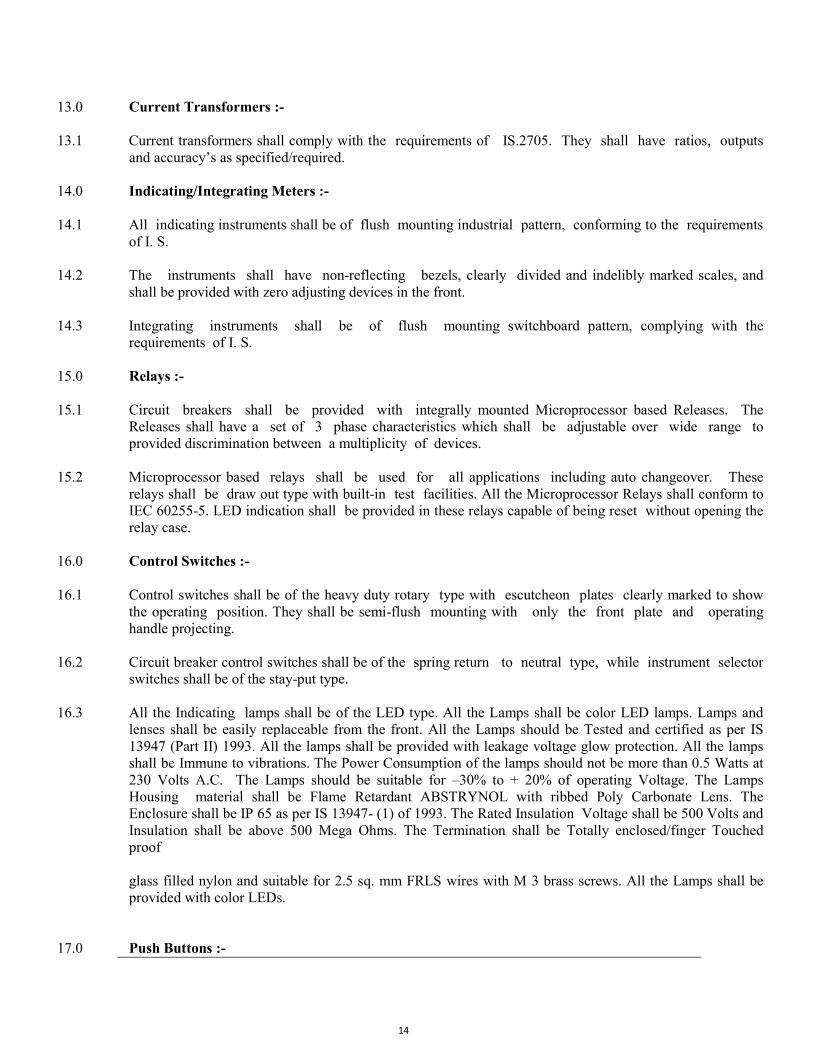
13.0 Current Transformers :- 13.1 Current transformers shall comply with the requirements of IS.2705. They shall have ratios, outputs
and accuracy’s as specified/required. 14.0 Indicating/Integrating Meters :- 14.1 All indicating instruments shall be of flush mounting industrial pattern, conforming to the requirements
of I. S. 14.2 The instruments shall have non-reflecting bezels, clearly divided and indelibly marked scales, and
shall be provided with zero adjusting devices in the front. 14.3 Integrating instruments shall be of flush mounting switchboard pattern, complying with the
requirements of I. S. 15.0 Relays :- 15.1 Circuit breakers shall be provided with integrally mounted Microprocessor based Releases. The
Releases shall have a set of 3 phase characteristics which shall be adjustable over wide range to provided discrimination between a multiplicity of devices.
15.2 Microprocessor based relays shall be used for all applications including auto changeover. These
relays shall be draw out type with built-in test facilities. All the Microprocessor Relays shall conform to IEC 60255-5. LED indication shall be provided in these relays capable of being reset without opening the relay case.
16.0 Control Switches :- 16.1 Control switches shall be of the heavy duty rotary type with escutcheon plates clearly marked to show
the operating position. They shall be semi-flush mounting with only the front plate and operating handle projecting.
16.2 Circuit breaker control switches shall be of the spring return to neutral type, while instrument selector
switches shall be of the stay-put type. 16.3 All the Indicating lamps shall be of the LED type. All the Lamps shall be color LED lamps. Lamps and
lenses shall be easily replaceable from the front. All the Lamps should be Tested and certified as per IS 13947 (Part II) 1993. All the lamps shall be provided with leakage voltage glow protection. All the lamps shall be Immune to vibrations. The Power Consumption of the lamps should not be more than 0.5 Watts at 230 Volts A.C. The Lamps should be suitable for –30% to + 20% of operating Voltage. The Lamps Housing material shall be Flame Retardant ABSTRYNOL with ribbed Poly Carbonate Lens. The Enclosure shall be IP 65 as per IS 13947- (1) of 1993. The Rated Insulation Voltage shall be 500 Volts and Insulation shall be above 500 Mega Ohms. The Termination shall be Totally enclosed/finger Touched proof glass filled nylon and suitable for 2.5 sq. mm FRLS wires with M 3 brass screws. All the Lamps shall be provided with color LEDs.
17.0 Push Buttons :-
15
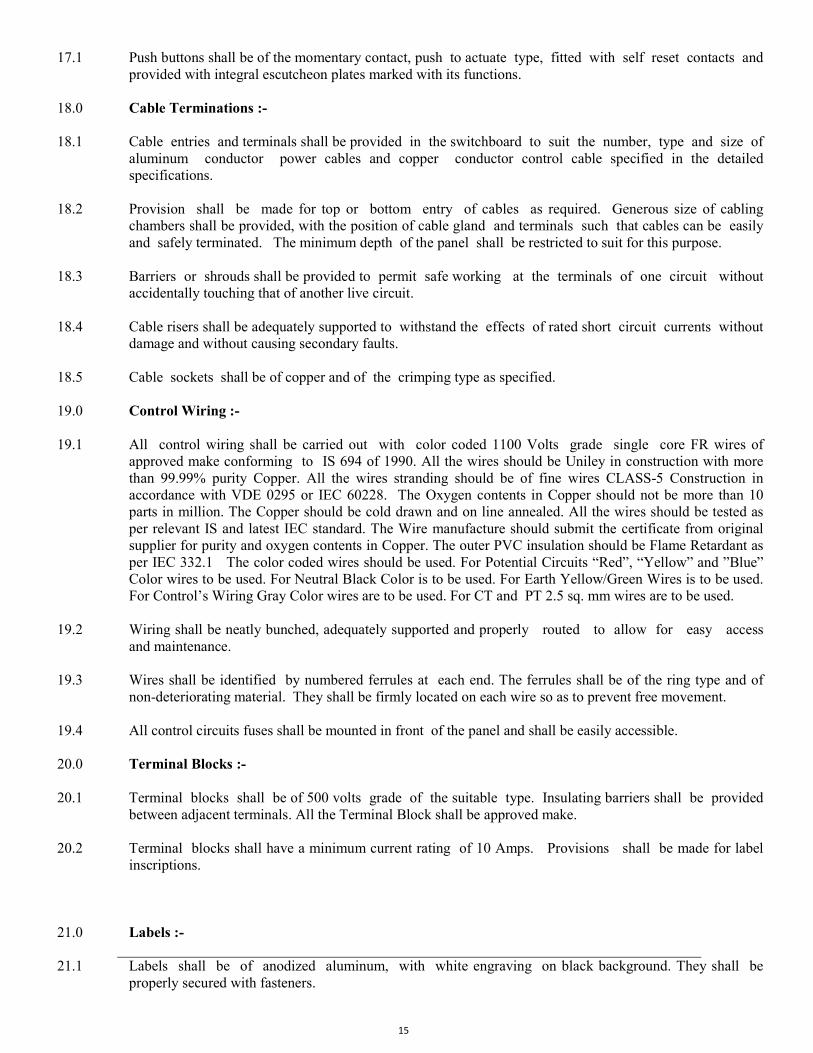
17.1 Push buttons shall be of the momentary contact, push to actuate type, fitted with self reset contacts and provided with integral escutcheon plates marked with its functions.
18.0 Cable Terminations :- 18.1 Cable entries and terminals shall be provided in the switchboard to suit the number, type and size of
aluminum conductor power cables and copper conductor control cable specified in the detailed specifications.
18.2 Provision shall be made for top or bottom entry of cables as required. Generous size of cabling
chambers shall be provided, with the position of cable gland and terminals such that cables can be easily and safely terminated. The minimum depth of the panel shall be restricted to suit for this purpose.
18.3 Barriers or shrouds shall be provided to permit safe working at the terminals of one circuit without
accidentally touching that of another live circuit. 18.4 Cable risers shall be adequately supported to withstand the effects of rated short circuit currents without
damage and without causing secondary faults. 18.5 Cable sockets shall be of copper and of the crimping type as specified. 19.0 Control Wiring :- 19.1 All control wiring shall be carried out with color coded 1100 Volts grade single core FR wires of
approved make conforming to IS 694 of 1990. All the wires should be Uniley in construction with more than 99.99% purity Copper. All the wires stranding should be of fine wires CLASS-5 Construction in accordance with VDE 0295 or IEC 60228. The Oxygen contents in Copper should not be more than 10 parts in million. The Copper should be cold drawn and on line annealed. All the wires should be tested as per relevant IS and latest IEC standard. The Wire manufacture should submit the certificate from original supplier for purity and oxygen contents in Copper. The outer PVC insulation should be Flame Retardant as per IEC 332.1 The color coded wires should be used. For Potential Circuits “Red”, “Yellow” and ”Blue” Color wires to be used. For Neutral Black Color is to be used. For Earth Yellow/Green Wires is to be used. For Control’s Wiring Gray Color wires are to be used. For CT and PT 2.5 sq. mm wires are to be used.
19.2 Wiring shall be neatly bunched, adequately supported and properly routed to allow for easy access
and maintenance. 19.3 Wires shall be identified by numbered ferrules at each end. The ferrules shall be of the ring type and of
non-deteriorating material. They shall be firmly located on each wire so as to prevent free movement. 19.4 All control circuits fuses shall be mounted in front of the panel and shall be easily accessible. 20.0 Terminal Blocks :- 20.1 Terminal blocks shall be of 500 volts grade of the suitable type. Insulating barriers shall be provided
between adjacent terminals. All the Terminal Block shall be approved make. 20.2 Terminal blocks shall have a minimum current rating of 10 Amps. Provisions shall be made for label
inscriptions. 21.0 Labels :- 21.1 Labels shall be of anodized aluminum, with white engraving on black background. They shall be
properly secured with fasteners.
16
22.0 Tests :- 22.1 The Following tests shall be conducted on all the Panels and Distribution Boards before the same are
dispatched to the site from the vendors place. All the Tests shall be carried out in accordance with relevant IS codes and in presence of the Representative of Owner/ Consultant .
22.2 Visual inspection of Panels and checking the bill of materials as per the approved drawings and Mechanical
ON/OFF operation of the components. 22.3 Checking of Protective Measures and electrical continuity of the protective circuits. 22.4 High Voltage Test by applying 2.5 kV, 1 minute for checking insulation of equipment and the Material
used and recording the leakage current . 23.5 Megger tests before and after High Voltage Test at Vendors Factory. 24.6 Heat Run Test On Main L.T Panel . 24.7 Primary Injection Test for Checking of all Meters and Relays. 24.8 Testing of all the Microprocessor Releases at vendors factory and at site before commissioning of the ACBs
and MCCBs. The Release should be tested by OEM only and necessary settings of releases to be done at site in consultation with Consultants.
24.9 Millie Volt Drop Test across the Bus-Bars Joints/ACB/MCCB/SFU/MCB and any other Equipment. 24.10 Testing of Barkers through Remote operation for ON/OFF and connectivity and operation of Barkers
Through the Software and RS 485 Port. 24.11 Physical verification of all components. 24.12 Any other tests as desired by Owner / Consultant. TECHNICAL SPECIFICATIONS FOR L. T. CAPACITORS 1.0 Scope : This specifications covers the design, manufacture, supplying and testing of Gas Filled L.T.
Capacitors required to be installed in L.T. Room of the sub-station for correction of the power factor. 2.0 Standards : All relevant Indian Standards shall be made applicable with latest amendments and in particularly IS
133340/41, IEC 831-1-1996, IEC 831-2-1995, EN 60831-2-1996, VDE 560-46:3/95, VDE 560-47:3/95 and any other specific application is required, then the same shall be complied to.
3.0 Specifications : 3.1 The capacitors are to be provided with Extruded Aluminum , Easy disposal, Non populating case
with IP 20 enclosure, indoor mounting. The containers shall be made up of Extruded Aluminum and should be heat-proof, dust-proof, indoor type and PCB environment .
3.2 The containers should be scratch and rust proof.
17
3.3 Terminal provided should be Double , Three way SIGUT terminal strip with protection against electric shock hazard. 9According to IP 20 /IP 54 to VDE 0106 part 100)
3.4 The capacitor should be able to handle in rush current up to 200 times the rated current and should be
corona free. 3.5 The raw materials should be Non PCB inert gas and polypropylene film should be provided as
dielectric. 3.6 The dielectric loss should be very low in the order of 0.25 Watts/KVAR or lower. 3.7 Each unit shall have over pressure tear off fuse, self healing technology, explosion proof construction,
touch proof terminals Eco friendly, non flammable. 3.8 The Capacitors shall be of the 3 Phase, Delta connected natural or forced cooled type with capacitance
tolerance 0f +5% . the capacitor should be able to perform up to humidity of 95% and discharge module resistor should be included.
3.9 The basic unit shall be of 5 KVAR to give 50 KVAR as basic step or any other step as specified in
the schedule of quantities. 3.10 The Capacitors banks shall be erected directly inside the panel on the mounting stands and with
complete treatment done to the stand. The stand shall be effectively doubled earthed to the earthing grid.
4.0 Discharge Resistance: 4.1 The Capacitors shall be provided with discharge resistors module so that residual voltage of the
capacitor shall be reduced to 50 Volts or less within one minute after the capacitor is disconnected from the source of supply.
5.0 Testing : 5.1 The Capacitor bank shall be subject to all routine and acceptance tests as specified in relevant
Indian Standards at the factory and the actual test results shall be furnished. 5.1.1 Residual voltage after switching of the capacitors shall be less than 50 Volts after one minute. 5.1.2 Insulation resistance shall be tested with a 1000 Volts megger between phases and phase to earth. 5.1.3 Each discharge resistors shall be tested for its working. 5.1.4 Loss angle test will be conducted and power losses will not exceed 025 Watts KVAR. 5.1.5 The value of discharge resistance shall be furnished at the time of testing.
Technical Specification: UPS System
1. Technical Specification: UPS System General:
The UPS system shall be housed in Epoxy powder-coated cabinet. The cabinet shall house the converter, inverter, charger, Static bypass switch, manual bypass switch, all control and
18
indications, displays etc. The Batteries shall be housed in Battery Rack of M.S angle frame powder coated with battery isolating breaker, which shall be as per site condition. The cabinets shall be high quality powder coated. The enclosure shall comply with IP20. The cabinet housing the UPS shall be self-standing type steel enclosure with lockable doors. The environmental conditions for operating temperatures shall be 0 to 48 degrees Centigrade with relative humidity of 95% non-condensing.
Voltage/ Frequency: The UPS shall be suitable for 3Phase input voltage 415Volts with variations of + 10% to -15%. The supply input frequency shall be 50Hz with variations of ± 6%. The output voltage shall be 230Volts, Variation 1% for single Phase & 380/400/415 for three phase, for 100% load & Line, & Input voltage variation. The frequency shall be maintained at 50Hz, 0.05Hz in free running mode.
Operation: The UPS shall be fully True On-Line double conversion system as follows:
a) Normal mode: The load shall be continuously supplied by the inverter at the rated KVA. The rectifier shall derive power from A.C. Input source & convert into D.C. Power. The D.C. Power will be converted to A.C. Power by the inverter for supplying it to the Load. Simultaneously the charger shall supply D.C. Power to charge the Batteries at controlled levels.
b) Emergency Mode: On failure of the A.C. Incoming Power Supply, the inverter shall be fed D.C. Power from the battery, which floats on the D.C. Bus. There shall be no switching or break in the output load supply. In the event of restoration of main power supply, the load will be taken over from the Batteries to the A.C. Source input without any break or switching. At the same time the battery charging will take place. The battery charging and load on the rectifier shall automatically restart with power walk-in gradually to take over the full load within 30 Seconds.
c) Bypass Mode: The load will be bypassed to the supply line in case of the following:
i) Inverter failure- Synchronous Mode: In case of inverter failure, the load shall be automatically bypassed to the mains within 3ms via Static Bypass Transfer switch without interruption in the power output. The Static Bypass switch shall be adequately rated at least 3 times the rated current of UPS, and shall be double- ended.
ii) Inverter failure- Asynchronous Mode: In case of inverter failure, the load shall be automatically bypassed to the mains in less than 10ms or better via static bypass transfer switch.
iii) Momentary overload: In case of momentary over load due to switching, which is beyond the overload capability of the Inverter, the load shall be bypassed to mains via static bypass switch. As soon as the momentary over load dies down and falls within the Inverter overload handling capacity, the load shall be re-Transferred to Inverter without break. This transfer and re- transfer shall be done automatically.
iv) Manual Bypass: A manually operated bypass switch shall be provided for UPS that will connect the load to mains by bypassing the rectifier charger, inverter and static transfer switch.
19
d) Transfer to Battery mode: The inverter shall derive power from battery in the following conditions:
i) Failure of Input Mains Supply. ii) Input Voltage out of Range. iii) Failure of any one Phase. iv) Input frequency out of Range.
In any event, if the UPS still functions on the mains supply for the above conditions, the output shall not vary from the output set limits. The UPS shall continuously track the main supply. An alarm, dual-tone shall indicate such conditions as listed above in i, ii, iii.
e) Rectifier cum Charger: The rectifier cum charger shall be fully-solid state microprocessor based, IGBT for converting the A.C. Input to D.C. output, as input to the inverter and also for battery charging. The rectifier cum charger shall be 3 Phase IGBT controlled 12 pulse thyristor bridge constant voltage / current limiting type with control circuitry. The charger shall contain power walk-in circuit that allows the unit to gradually walk-in power after application of Input Voltage. Power semi- conductors shall be protected with fast acting fuses so that failure of any component shall not cause cascading failures. The D.C. Filters shall be used to minimize ripple voltage within specified limits in the specification. In addition to supplying the power to the inverter the rectifier cum charger shall be capable of charging the Batteries. The charging current shall be controlled automatically for boost cum float charging as per recommendations of the battery manufactures. This will enhance the life of the batteries. It will continuously monitor the conditions of the batteries and give advance warning in case of failure of batteries to prevent system crash. The UPS shall contain power factor improvement circuits with active filter circuits. The input power factor shall not be less than 0.95 under full load & total input current harmonics less than 10% or achieved through active filters.
f) Inverter: The inverter shall convert the D.C. Power to A.C. Power and shall be fully solid- state type, microprocessor based control, IGBT Technology. The inverter shall be capable of supplying rated load continuously and shall also handle over loads as specified in the detailed specification sheet. The crest factor shall not less than 3:1. A status indicator and audible alarm shall indicate the overload conditions. The UPS shall transfer the load to bypass when overload capacity is exceeded, automatically and re-transfer it back when the load is within its rating. For large currents of longer durations the inverter shall have current limiting protection to prevent damage to components.
g) Dynamic response: The output voltage shall remain within ± 5% of the rated output voltage for 100
% load change (Step Input) and shall recover to 98% of normal voltage within 1Hz.
h) Display & Controls: The UPS shall be provided with microprocessor based status display unit (LCD) designed for convenient and reliable user-friendly operation. The display unit shall give a system power flow diagram, various parameters like Input/output Voltage, Input/output load, Input/output frequency, THD (Current) and battery condition & Back- up Time remaining as a part of monitoring & control with digital display.
i) Interfaced Port: An RJ45/RS-232 Port shall be provided for communication via digital telephone/modem for remote display of UPS Status information. The UPS monitoring shall be compatible with local
networks from any workstation.incorporated.
j) Battery Requirements: The batteries shall be lead acidseparate Rack with battery isolation breaker. full load at 0.9 power factor for each UPS.interconnections of batteries,specify the number of batteries,1.75 for a nominal cell voltage of 2.0 Volts for battery calculation at full load. Thebatteries shall be as specified
Technical Requirements
2. Technical Requirements: UPS
2.
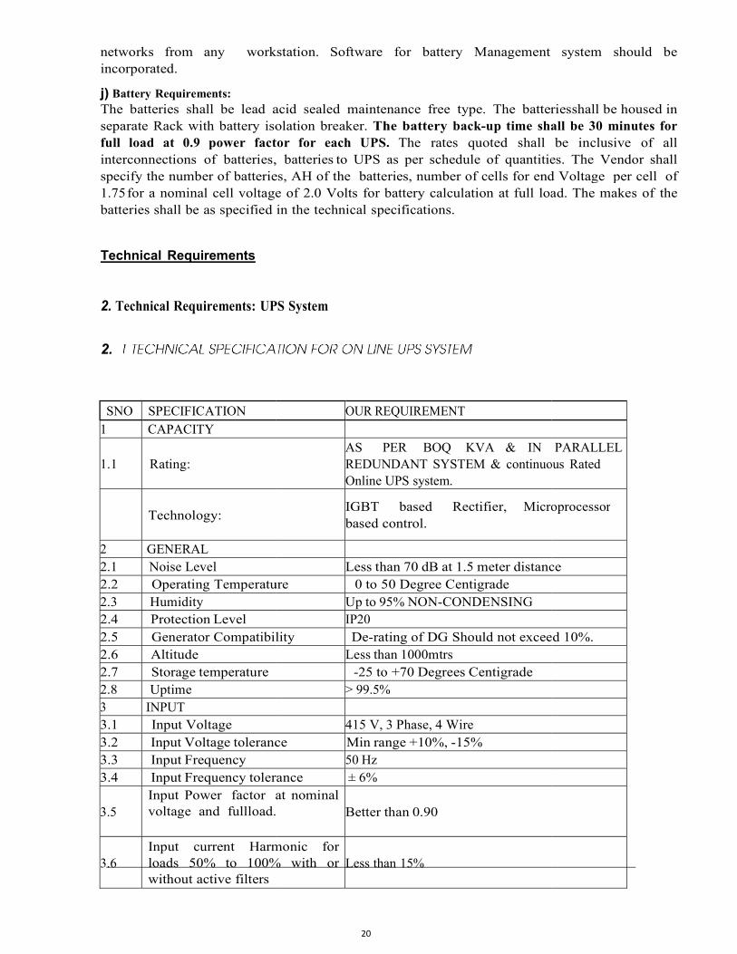
SNO SPECIFICATION 1 CAPACITY
1.1
Rating:
Technology:
2 GENERAL 2.1 Noise Level 2.2 Operating Temperature2.3 Humidity 2.4 Protection Level 2.5 Generator Compatibility2.6 Altitude 2.7 Storage temperature 2.8 Uptime 3 INPUT 3.1 Input Voltage 3.2 Input Voltage tolerance3.3 Input Frequency 3.4 Input Frequency tolerance
3.5
Input Power factor atvoltage and full load.
3.6
Input current Harmonicloads 50% to 100% with orwithout active filters
20
any workstation. Software for battery Management
acid sealed maintenance free type. The batteriesseparate Rack with battery isolation breaker. The battery back-up time shall be 30 full load at 0.9 power factor for each UPS. The rates quoted shall
batteries, batteries to UPS as per schedule of quantities. The Vendor shall batteries, AH of the batteries, number of cells for end Voltage per cell of
for a nominal cell voltage of 2.0 Volts for battery calculation at full load. The in the technical specifications.
UPS System
OUR REQUIREMENT
AS PER BOQ KVA & IN REDUNDANT SYSTEM & continuousOnline UPS system.
IGBT based Rectifier, Microprocessorbased control.
Less than 70 dB at 1.5 meter distanceTemperature 0 to 50 Degree Centigrade
Up to 95% NON-CONDENSING IP20
Compatibility De-rating of DG Should not exceedLess than 1000mtrs
-25 to +70 Degrees Centigrade > 99.5%
415 V, 3 Phase, 4 Wire tolerance Min range +10%, -15%
50 Hz tolerance ± 6%
at nominal load.
Better than 0.90
Harmonic for loads 50% to 100% with or
Less than 15%
system should be
batteries shall be housed in up time shall be 30 minutes for
be inclusive of all to UPS as per schedule of quantities. The Vendor shall
of cells for end Voltage per cell of for a nominal cell voltage of 2.0 Volts for battery calculation at full load. The makes of the
PARALLEL continuous Rated
Microprocessor
distance
Should not exceed 10%.
21
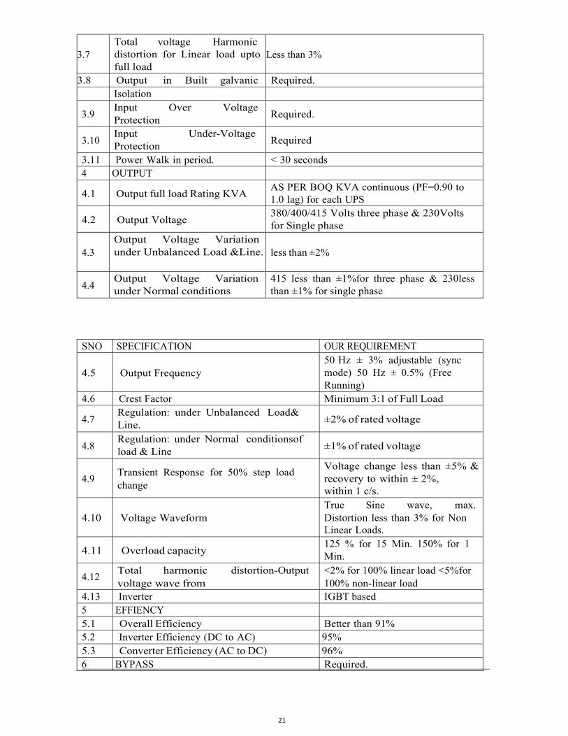
3.7
Total voltage Harmonic distortion for Linear load up to full load
Less than 3%
3.8 Output in Built galvanic Required. Isolation
3.9 Input Over Voltage Protection
Required.
3.10 Input Under-Voltage Protection
Required
3.11 Power Walk in period. < 30 seconds 4 OUTPUT
4.1 Output full load Rating KVA AS PER BOQ KVA continuous (PF=0.90 to 1.0 lag) for each UPS
4.2 Output Voltage 380/400/415 Volts three phase & 230 Volts for Single phase
4.3
Output Voltage Variation under Unbalanced Load & Line.
less than ±2%
4.4 Output Voltage Variation under Normal conditions
415 less than ±1%for three phase & 230 less than ±1% for single phase
SNO SPECIFICATION OUR REQUIREMENT
4.5
Output Frequency
50 Hz ± 3% adjustable (sync mode) 50 Hz ± 0.5% (Free Running)
4.6 Crest Factor Minimum 3:1 of Full Load
4.7 Regulation: under Unbalanced Load & Line.
±2% of rated voltage
4.8 Regulation: under Normal conditions of load & Line
±1% of rated voltage
4.9
Transient Response for 50% step load change
Voltage change less than ± 5% & recovery to within ± 2%, within 1 c/s.
4.10
Voltage Waveform
True Sine wave, max. Distortion less than 3% for Non Linear Loads.
4.11 Overload capacity 125 % for 15 Min. 150% for 1 Min.
4.12 Total harmonic distortion-Output voltage wave from
<2% for 100% linear load <5% for 100% non-linear load
4.13 Inverter IGBT based 5 EFFIENCY
5.1 Overall Efficiency Better than 91% 5.2 Inverter Efficiency (DC to AC) 95% 5.3 Converter Efficiency (AC to DC) 96% 6 BYPASS Required.
22
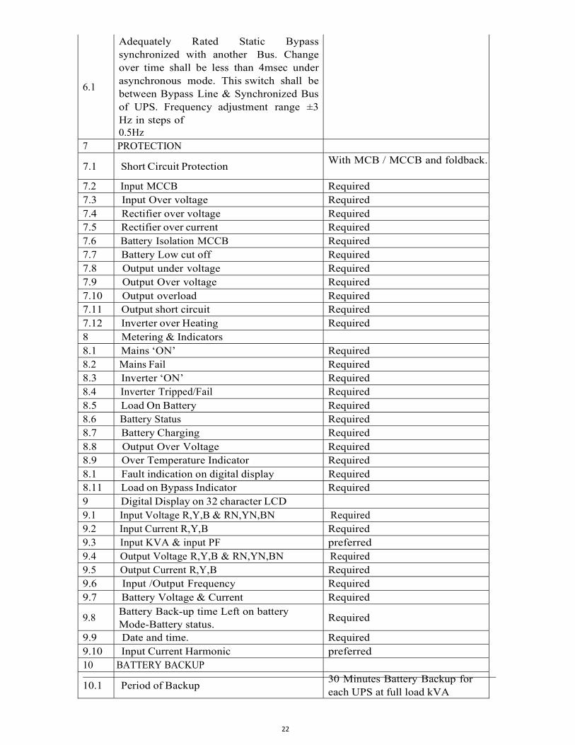
6.1
Adequately Rated Static Bypass synchronized with another Bus. Change over time shall be less than 4msec under asynchronous mode. This switch shall be between Bypass Line & Synchronized Bus of UPS. Frequency adjustment range ±3 Hz in steps of 0.5Hz
7 PROTECTION
7.1 Short Circuit Protection With MCB / MCCB and fold back.
7.2 Input MCCB Required 7.3 Input Over voltage Required 7.4 Rectifier over voltage Required 7.5 Rectifier over current Required 7.6 Battery Isolation MCCB Required 7.7 Battery Low cut off Required 7.8 Output under voltage Required 7.9 Output Over voltage Required 7.10 Output overload Required 7.11 Output short circuit Required 7.12 Inverter over Heating Required 8 Metering & Indicators
8.1 Mains ‘ON’ Required 8.2 Mains Fail Required 8.3 Inverter ‘ON’ Required 8.4 Inverter Tripped/Fail Required 8.5 Load On Battery Required 8.6 Battery Status Required 8.7 Battery Charging Required 8.8 Output Over Voltage Required 8.9 Over Temperature Indicator Required 8.1 Fault indication on digital display Required 8.11 Load on Bypass Indicator Required 9 Digital Display on 32 character LCD
9.1 Input Voltage R,Y,B & RN,YN,BN Required 9.2 Input Current R,Y,B Required 9.3 Input KVA & input PF preferred 9.4 Output Voltage R,Y,B & RN,YN,BN Required 9.5 Output Current R,Y,B Required 9.6 Input /Output Frequency Required 9.7 Battery Voltage & Current Required
9.8 Battery Back-up time Left on battery Mode-Battery status.
Required
9.9 Date and time. Required 9.10 Input Current Harmonic preferred 10 BATTERY BACKUP
10.1 Period of Backup 30 Minutes Battery Backup for each UPS at full load kVA
23
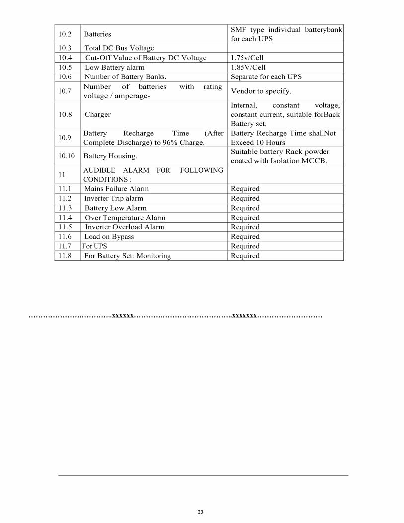
10.2 Batteries SMF type individual battery bank for each UPS
10.3 Total DC Bus Voltage
10.4 Cut-Off Value of Battery DC Voltage 1.75v/Cell 10.5 Low Battery alarm 1.85V/Cell 10.6 Number of Battery Banks. Separate for each UPS
10.7 Number of batteries with rating voltage / amperage-
Vendor to specify.
10.8
Charger
Internal, constant voltage, constant current, suitable for Back Battery set.
10.9 Battery Recharge Time (After Complete Discharge) to 96% Charge.
Battery Recharge Time shall Not Exceed 10 Hours
10.10 Battery Housing. Suitable battery Rack powder coated with Isolation MCCB.
11 AUDIBLE ALARM FOR FOLLOWING CONDITIONS :
11.1 Mains Failure Alarm Required 11.2 Inverter Trip alarm Required 11.3 Battery Low Alarm Required 11.4 Over Temperature Alarm Required 11.5 Inverter Overload Alarm Required 11.6 Load on Bypass Required 11.7 For UPS Required 11.8 For Battery Set: Monitoring Required
……………………………..xxxxxx…………………………………..xxxxxxx………………………
24
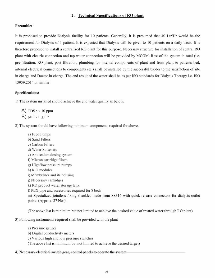
2. Technical Specifications of RO plant Preamble:
It is proposed to provide Dialysis facility for 10 patients. Generally, it is presumed that 40 Ltr/Hr would be the
requirement for Dialysis of 1 patient. It is expected that Dialysis will be given to 10 patients on a daily basis. It is
therefore proposed to install a centralized RO plant for this purpose. Necessary structure for installation of central RO
plant with electric connection and tap water connection will be provided by MCGM. Rest of the system in total (i.e.
pre-filtration, RO plant, post filtration, plumbing for internal components of plant and from plant to patients bed,
internal electrical connections to components etc.) shall be installed by the successful bidder to the satisfaction of site
in charge and Doctor in charge. The end result of the water shall be as per ISO standards for Dialysis Therapy i.e. ISO
13959:2014 or similar.
Specifications:
1) The system installed should achieve the end water quality as below.
A) TDS : < 10 ppm
B) pH : 7.0 + 0.5
2) The system should have following minimum components required for above.
a) Feed Pumps b) Sand Filters c) Carbon Filters d) Water Softeners e) Antiscalant dosing system f) Micron cartridge filters g) High/low pressure pumps h) R O modules i) Membranes and its housing j) Necessary cartridges k) RO product water storage tank l) PEX pipe and accessories required for 8 beds m) Specialized jointless fixing shackles made from SS316 with quick release connectors for dialysis outlet points (Approx. 27 Nos). (The above list is minimum but not limited to achieve the desired value of treated water through RO plant)
3) Following instruments required shall be provided with the plant
a) Pressure gauges b) Digital conductivity meters c) Various high and low pressure switches (The above list is minimum but not limited to achieve the desired target)
4) Necessary electrical switch gear, control panels to operate the system
25
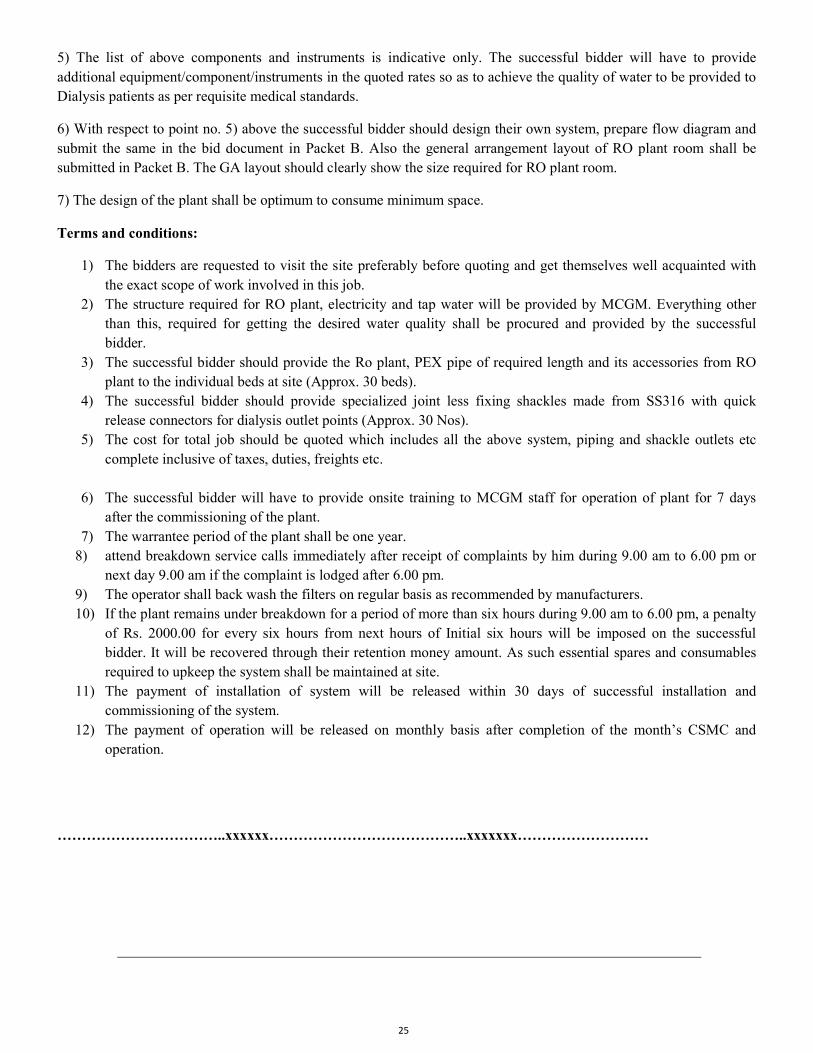
5) The list of above components and instruments is indicative only. The successful bidder will have to provide additional equipment/component/instruments in the quoted rates so as to achieve the quality of water to be provided to Dialysis patients as per requisite medical standards.
6) With respect to point no. 5) above the successful bidder should design their own system, prepare flow diagram and submit the same in the bid document in Packet B. Also the general arrangement layout of RO plant room shall be submitted in Packet B. The GA layout should clearly show the size required for RO plant room.
7) The design of the plant shall be optimum to consume minimum space.
Terms and conditions:
1) The bidders are requested to visit the site preferably before quoting and get themselves well acquainted with the exact scope of work involved in this job.
2) The structure required for RO plant, electricity and tap water will be provided by MCGM. Everything other than this, required for getting the desired water quality shall be procured and provided by the successful bidder.
3) The successful bidder should provide the Ro plant, PEX pipe of required length and its accessories from RO plant to the individual beds at site (Approx. 30 beds).
4) The successful bidder should provide specialized joint less fixing shackles made from SS316 with quick release connectors for dialysis outlet points (Approx. 30 Nos).
5) The cost for total job should be quoted which includes all the above system, piping and shackle outlets etc complete inclusive of taxes, duties, freights etc.
6) The successful bidder will have to provide onsite training to MCGM staff for operation of plant for 7 days after the commissioning of the plant.
7) The warrantee period of the plant shall be one year. 8) attend breakdown service calls immediately after receipt of complaints by him during 9.00 am to 6.00 pm or
next day 9.00 am if the complaint is lodged after 6.00 pm. 9) The operator shall back wash the filters on regular basis as recommended by manufacturers. 10) If the plant remains under breakdown for a period of more than six hours during 9.00 am to 6.00 pm, a penalty
of Rs. 2000.00 for every six hours from next hours of Initial six hours will be imposed on the successful bidder. It will be recovered through their retention money amount. As such essential spares and consumables required to upkeep the system shall be maintained at site.
11) The payment of installation of system will be released within 30 days of successful installation and commissioning of the system.
12) The payment of operation will be released on monthly basis after completion of the month’s CSMC and operation.
……………………………..xxxxxx…………………………………..xxxxxxx………………………
26
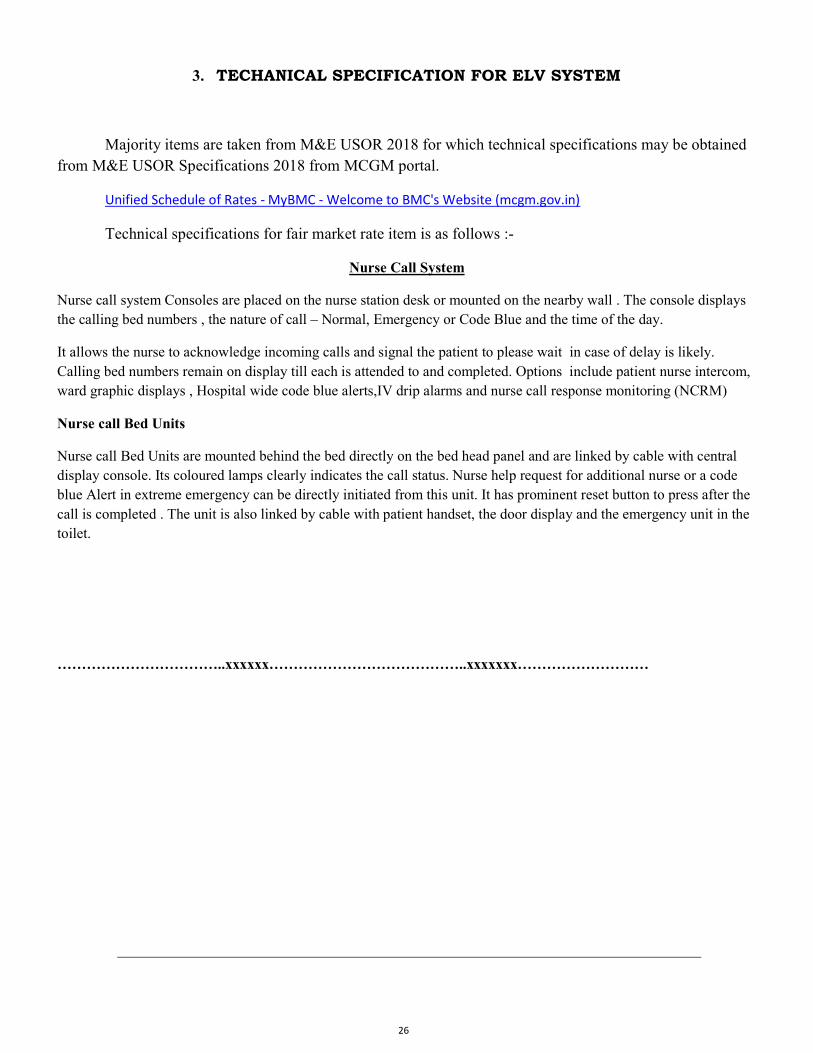
3. TECHANICAL SPECIFICATION FOR ELV SYSTEM
Majority items are taken from M&E USOR 2018 for which technical specifications may be obtained from M&E USOR Specifications 2018 from MCGM portal.
Unified Schedule of Rates - MyBMC - Welcome to BMC's Website (mcgm.gov.in)
Technical specifications for fair market rate item is as follows :-
Nurse Call System
Nurse call system Consoles are placed on the nurse station desk or mounted on the nearby wall . The console displays the calling bed numbers , the nature of call – Normal, Emergency or Code Blue and the time of the day.
It allows the nurse to acknowledge incoming calls and signal the patient to please wait in case of delay is likely. Calling bed numbers remain on display till each is attended to and completed. Options include patient nurse intercom, ward graphic displays , Hospital wide code blue alerts,IV drip alarms and nurse call response monitoring (NCRM)
Nurse call Bed Units
Nurse call Bed Units are mounted behind the bed directly on the bed head panel and are linked by cable with central display console. Its coloured lamps clearly indicates the call status. Nurse help request for additional nurse or a code blue Alert in extreme emergency can be directly initiated from this unit. It has prominent reset button to press after the call is completed . The unit is also linked by cable with patient handset, the door display and the emergency unit in the toilet.
……………………………..xxxxxx…………………………………..xxxxxxx………………………
27
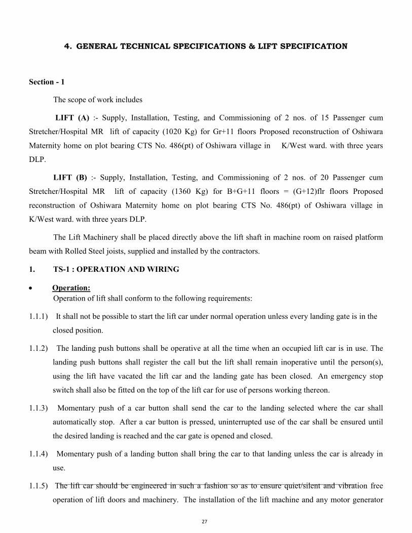
4. GENERAL TECHNICAL SPECIFICATIONS & LIFT SPECIFICATION
Section - 1
The scope of work includes
LIFT (A) :- Supply, Installation, Testing, and Commissioning of 2 nos. of 15 Passenger cum
Stretcher/Hospital MR lift of capacity (1020 Kg) for Gr+11 floors Proposed reconstruction of Oshiwara
Maternity home on plot bearing CTS No. 486(pt) of Oshiwara village in K/West ward. with three years
DLP.
LIFT (B) :- Supply, Installation, Testing, and Commissioning of 2 nos. of 20 Passenger cum
Stretcher/Hospital MR lift of capacity (1360 Kg) for B+G+11 floors = (G+12)flr floors Proposed
reconstruction of Oshiwara Maternity home on plot bearing CTS No. 486(pt) of Oshiwara village in
K/West ward. with three years DLP.
The Lift Machinery shall be placed directly above the lift shaft in machine room on raised platform
beam with Rolled Steel joists, supplied and installed by the contractors.
1. TS-1 : OPERATION AND WIRING
Operation: Operation of lift shall conform to the following requirements:
1.1.1) It shall not be possible to start the lift car under normal operation unless every landing gate is in the
closed position.
1.1.2) The landing push buttons shall be operative at all the time when an occupied lift car is in use. The
landing push buttons shall register the call but the lift shall remain inoperative until the person(s),
using the lift have vacated the lift car and the landing gate has been closed. An emergency stop
switch shall also be fitted on the top of the lift car for use of persons working thereon.
1.1.3) Momentary push of a car button shall send the car to the landing selected where the car shall
automatically stop. After a car button is pressed, uninterrupted use of the car shall be ensured until
the desired landing is reached and the car gate is opened and closed.
1.1.4) Momentary push of a landing button shall bring the car to that landing unless the car is already in
use.
1.1.5) The lift car should be engineered in such a fashion so as to ensure quiet/silent and vibration free
operation of lift doors and machinery. The installation of the lift machine and any motor generator
28
set shall free of noise and vibration by ensuring perfect axial alignment of rotating shafts, rigid
installation and providing rubber cushions.
1.1.6) The lifts in the scope of work shall operate on collective selective with ON/OFF switch.
1.1.7) Duplex lift Control System.
Electrical Wiring: 1.2.1) All electric supply lines and apparatus in connection with the lift installation shall be constructed,
installed, protected, worked and maintained in such a manner that there shall be no danger to persons
there from.
All metal casing of metal coverings containing or protecting any electric supply or appurtenances
shall be effectively earthed.
Suitable Caution Notice shall be affixed near every motor or other apparatus operating on 250 Volts
supply.
The copper armoured cables shall be fixed on wall / ceiling from Switch gear at Meter room through
the lift well to switch gear at distribution position in Machine room
1.2.2) It would be a responsibility of the contractor to arrange an electric supply from meter room to Lift
machine room, complete with electric cable, earthing wires, switch gear etc. In no case the work of
Erection, Testing and Commissioning shall be held up for want of electric supply from Corporation.
1.2.3) On carrying out complete wiring work, tenderer shall arrange to submit test report to Electric Supply
authorities and get the meter connected and keep the lift ready for Testing and inspection of P.W.D.
Inspector.
License:-
It is mandatory to obtain the licenses to install, operate and maintain the lifts from Lift Inspector
(P.W.D.) Government of Maharashtra, by paying necessary government license fee & charges.
Necessary documents, letters, drawings, as required by PWD authorities will be provided by MCGM.
PWD fee for seeking erection permission and license fee shall be borne by successful bidder. The
rates quoted shall be inclusive of this.
1.3 Submission of relevant details to lift Inspector:
The successful tenderer (hereinafter called the contractor) shall submit the necessary details in
prescribed format to the Lift Inspector (PWD Govt. of Maharashtra). The work will be deemed to be
complete only after mandatory requirement of getting PWD license is fulfilled.
Please refer complete details of electrical wiring works in the respective specifications onwards.
29
Section - 2 TECHNICAL SPECIFICATIONS FOR LIFT Lift (A)-
Rated capacity :- 15 Passenger/1020Kg
Floors :- G+11 flrs.
Location of Lift Machine:- MR
Rated speed :- 1.0mps VS
Doors type :- COPO/TOPO Doors with frame having clear opening of 900 mm wide x 2000 mm high made from SS 304 grade sheet of 1.5mm, thick in hairline finish for car and all landing doors with SS door architraves /frames
Lift( B)- Rated capacity :- 20 Passenger/1360Kg
Floors :- B+G+11 flrs.= (G+12) flr
Location of Lift Machine:- MR
Rated speed :- 1.0mps VS
Doors type :- COPO/TOPO Doors with frame having clear opening of 1100 mm wide x 2000 mm high made from SS 304 grade sheet of 1.5mm, thick in hairline finish for car and all landing doors with SS door architraves /frames
For Lift having entrance in 1.5mm thick SS 304 grade landing door [Two panel], this includes all
necessary accessories like LOP's with UP/DN buttons-arrows indicators, extension of guide rails, shaft wiring with trunking, travelling cables, main hoisting ropes/belts, & OSG rope landing doors with all accessories etc. necessary for the normal safe functioning of lift installation complete
Lift car enclosure made from SS 304 grade sheet of 1.5mm, thick with hairline finish with frame made from MS girders, bracing of adequate size with minimum safety factor of 5, with Toe Guard Apron, with necessary false ceiling with adequate LED lights, blower/fan for ventilation & SS chequered plate flooring, handrails, mirror, emergency light etc. The lift car shall be fitted with at least one similar Emergency light fitting complete with 1/2 no. of cabin type noiseless fan/s for adequate ventilation. Decision regarding approval of “Total Car interior design” will be taken by concerned site-engineer in-charge. His decision shall be final and binding upon the lift manufacturer/ Authorized Dealer.
The car shall be provided with an emergency stopping device and an alarm signal, both operated by a push button switch, which shall be clearly marked. The alarm shall be clearly audible in the lift well and nearby passages, in order to obtain assistance in case of break down or failure between the floors. The car may have stainless steel luminary flush panels and be provided with suitable/rounded corners. The material and/or finish of the car bodywork shall be durable to withstand frequent washing. The amplitude of vibration in the car cage shall not exceed 25 microns in running condition and 10 microns in standstill condition. A solid roof capable of supporting 150 Kg. shall be provided. Roof of car shall be fabricated in painted/powder coated M.S. framework while false ceiling shall be made in relevant selected S.S. finish panel. The car entrance shall be protected by a center opening sliding steel door or two speed telescopic
30
S.S. door as the case may be. Gate/door shall be hung on a steel track by ball bearing hangers and guided on a finished heavy section grooved sill on the car platform. The car gate/door shall be equipped with an electric contractor/suitable mechanical device, which shall prevent the movement of the car unless the gate/door is properly closed. The enclosure and door including their tracks shall withstand a thrust of 35 Kg. supplied normally at any point excepting vision panel without permanent deformation. The car platform shall be constructed of structural steel shapes securely fastened together and designed on the basis of contact load evenly distributed. The minimum factor of safety shall be 5 for steel. The car frame, which supports the car platform and enclosure shall be made of structural steel and it shall be equipped with suitable guides and safety devices mounted underneath the car platform.
COP with SS face plate having metallic push buttons with Braille Code & luminous indicator around button with FPI, scrolling UP/DN LED indicator & with/without attendant key switch, OWD with audio-visual alarm, VAS in Marathi, Hindi & English with intercom system with telephone instrument in Lift car, LMR & FCC/ground floor Car operating panel (COP) shall also have “key switch” to keep the car operation in „ON‟ or „OFF‟ mode, in addition to normal provision of „Attendant Key switch‟ & other necessary buttons. Display / position indicator inside the car, shall preferably be fitted above car doors or at suitable location which shall be easily viewable. The passenger cum hospital bed type stretcher lifts shall be provided with 150 mm wide aluminum kicking plates at three different heights and of not less than 5 mm thickness on all the three sides of the car and return posts so as not to damage the car body due to impact of foot or stretcher trolleys.
Clear Car size as per lift manufacturers standards to suit the MCGM’s requirement.
The entrance on the landings from the hoist way side shall be fitted with automatic, side/center opening two speed telescopic S.S. door, with a clear opening as required at each landing complete with top and bottom tracks, etc. or as per manufacturer’s standard. All landing doors shall be made in Stainless Steel with Hairline Finish. The landing entrances as well as car-door, shall have window of fireproof toughened transparent glass or similar transparent material, of approximately 200 mm X 300mm size, so that one can see inside the car from outside or vice-versa, for safety purpose or as per manufacturer’s standard. Every landing gate shall be fitted with electrical and mechanical interlocks, which shall comply with the appropriate requirements given below:- i) It shall not be possible to open the landing gate from the landing side until the lift car is within that particular landing zone. Provision shall be made for opening the gate in case of emergency by means of special key at terminal floors. The lift cannot be started or kept in motion unless all the landing gates are closed and locked. The electrical and mechanical parts of all locking devices shall be of substantial design and construction. The removal of any inspection cover or covers shall not affect the operation of a device. All locking devices shall be fixed securely to the enclosure by suitable means. iii) Each landing gate shall have both electrical & mechanical locking system. After closing the gate electrical contact should not be made unless and until the mechanical locking is done. The locking device for landing gates shall be so designed that the lock contact shall not be closed until the gate is closed. Any springs used in the locking device shall be in compression and properly supported. Contacts shall be solid type, pivoted or hinged and of sturdy construction. iv) The design shall be such that reasonable wear between working parts does not permit of interference with the operation of the lift by movement of the lock handles. v) The conduit / trunking carrying the conductors to the lock shall be securely fixed to the boxes and shall maintain electrical and
31
mechanical continuity. vi) The levers operating the mechanical parts of the locking device shall be protected from obstruction from the landing side of the lift enclosure. vii) The provision to prevent the opening of any landing gate when the car is passing that zone in response to a call from another landing shall be made for the lift.
LOP with SS face plate having recess/surface push button box for all landings with scrolling UP/DN LED indicator having metallic push buttons with Braille Code & luminous indicator around button with CPI, Lift car arrival & next travel direction audio-visual indication at all landings.
Contractor shall furnish and install Electric Door Operators for opening and closing the car door and the hoist way door as per manufacturer’s standard. The equipment shall consist of a machine on the elevator car, operating the car door when the car is stopping at a landing. The car door and hoist way door shall be mechanically connected and shall move simultaneously in opening and closing. The opening and closing of the car door and the hoist way door shall be power operated and shall be checked in opening and closing with an oil cushioning mechanism built into the gear unit. Each hoist way door shall be provided with an inter-lock, which shall prevent movement of the car away from the landing until the doors are locked in the closed position as defined in the I.S.I. codes. An electric interlock for the car door shall be provided which shall prevent car movement away from landing unless the door is in the closed position as defined in the ISI Codes. Necessary switches shall be provided in the elevator machine room to control the operation of the doors. The car door and the hoist way door shall open automatically when the car stops at a landing. The closing of the car door and the hoist way door must occur before the car can be started. Doors can be stopped and reversed during their closing motion, as soon as infrared curtain beam provided on either side of door is cut/activated, the door shall automatically close after predetermined time interval. Contractor shall furnish and install for the car and each landing sliding door, sheave type two point suspension hangers complete with tracks, Sheaves and rollers shall be of steel and shall include shielded ball bearing to retain grease lubrication. Adjustable ball bearings rollers shall be provided to take the upward thrust of the doors. Tracks shall be of suitable steel section with smooth surface, landing gates/doors including hangers and tracks shall withstand a thrust of 35 Kgs. applied normally at any point except vision panel without causing any damages.
Lift controller: Lift controller based on microprocessor/ PLC with VVVF Drive having closed loop control system, with IBMS compatible having necessary port, control panel duly wired with proper size & strength copper wire for power & control circuit, with provision for addition of floor/ control card & allied accessories control panel having enclosure of 1.5mm CRCA sheet with powder coating with IP54 Protection class. The control panel shall have microprocessor based control with operational card file containing logic board with microprocessor chip and erasable programmable chips to monitor and take over the commands of elevator for flexibility of program, better leveling, reduced waiting time, shorter travel time and easy maintenance. This shall also indicate detection of stuck hall button, over current protection, motor failure protection. There shall be a provision of segmented displays provided in the logic board, for quick identification of fault and restoration of normal operation. The control panel shall be compact, incorporate solid state electronic circuitry for efficient & smooth operations to monitor traffic control. The material used shall be of best quality. The switches, contactors and relays shall be compact and robust in construction and smooth in operation. Controller shall have variable speed arrangement with leveling accuracy of ± 3.00 mm.
32
The controller shall protect lift motor, automatically apply the brake if any of the safety devices fails to operate including power supply failures at any time. In the event of an earth fault with any door open, the lift shall not work. Neither operation of a spring or springs in tension nor the completion of another electric circuit shall depend upon to break the circuit to stop the lift at terminal landings. The interruption of the electrical circuit shall stop and/or shall prevent the movement of the car. Protection shall be provided in the controller to protect the lift equipment against phase reversal, low voltage, over voltage and phase failure. No control system shall be used, which depends on the completion or maintenance of an electrical circuit for the interruption of the power supply and application of the electric-mechanical brakes, when the lift cage reaches the terminal floors. The controller shall be provided with proper ventilating arrangement so as to avoid overheating and hence malfunction/damage to the controller. Enclosure shall be made of powder coated sheet steel with proper mounting arrangement. It should withstand adverse atmospheric conditions. Controller shall have provision of display to show the status of movement of lift car. Controller enclosure/body shall also have LED array lights with auto/manual switch, for maintenance in bad light, such that it shall neither disturb door closure/opening nor create hindrance while maintenance. Controller shall be as per manufacturer's standard
Fireman controller having fireman switch at fire Landing,
CCTV surveillance system comprises of 2nos minimum 2.0MP FHD IP based vandal proof Dome camera in lift car & in LMR/inside lift shaft top aimed on Lift machinery & controller with NVR kept in LMR/FCC with HDR data backup for 60 days with 18" FHD TV monitor, to be kept in FCC/LMR as directed by Engineer In Charge.
Lift Machine of Gearless PMSM of suitable kW with Traction pulley, OSG, electromagnetic brakes, entire assembly mounted on adequate size girders duly fixed on LMR floor/ shaft walls complete with main/diverter traction sheaves, suspension wire ropes/belts of adequate size & strength. The Gearless, Energy Efficient, electric hoist motor to be installed in lift machine room, shall have bearings specially built for heavy duty hoisting service. The motor shall be conforming to relevant I.S. or International Standards or as per manufacturer’s standard and shall be able to withstand all the routine as well as type tests, as specified in I.S. or relevant International Standards. It shall be also suitable for frequent reversals, high starting torque and low starting current with Class „F‟ insulation, Minimum permissible operations per hour shall not be less than 120. The motor shall be rated for 30 minutes continuous service with 115°C rise above ambient temperature. The motor noise shall not exceed 55 dB on No-Load. The motor vibration shall not exceed 0.45 mm/sec on No-Load. The motor shall be designed in such a way to withstand occasional over loading of one fourth of rated capacity. The motor shall have a good speed regulation under different conditions of loads. The windings shall be robust in design and adequately insulated for tropical climates and mechanically strengthened with double varnishing. The motor of lift machine or the worm shaft shall be arranged so as to provide hand winding facilities, with suitable marking for up and down direction of travel of the lift cage. Electric motor shall be of suitable duty, energy efficient and working on 3 ph. A.C. 50 c/s electric supply. The motor shall be installed using heavy duty channel of suitable size & using anti vibration rubber pads to damp vibration. The thickness of the rubber pad should be minimum 25 mm. The noise level in the machine room shall not exceed 60 dB at one meter distance from Machine.
Other mechanical parts such as 'T' section adequate size guide rails for car & counter weight with brackets fasteners, counter weight frame with necessary blocks, buffers with necessary support arrangement, MS pit ladder etc. erected with necessary steel work.
33
Minor civil work for alteration if any and erection of door frames and accessories, erection buffers, erection of lift machinery, adequate size core cuts if required & scaffolding for erecting guide rails fixing of girders for mounting lift machine etc. complete as per specification no. LFT.
Lift shaft available having clear size of 2180mm wide x 3070mm deep for Lift A & 2450mm wide x 3070mm deep for Lift B. Depth of the pit &height of overhead will be constructed as per manufacturers recommendations.
Full Collective control system.
Brakes: When metal to metal contacts are used on the controller switches, for opening the main circuits, or for stopping a lift machine, at least two independent direct current brakes shall be incorporated in the design, each one shall hold full load as per manufacturer's standard. The direct current brake shall be spring applied, electrically released and designed to provide smooth stops under variable loads. The brakes shall be unaffected by overloads or temperature and shall hold load securely and positively when lift stops. The brakes shall be highly wear resistant. No single earth fault, short circuit or counter electromotive force shall prevent the brake from being applied during normal operation.
Governor: Governor shall be placed where it cannot be struck by the lift car or counter – weight in the event of over-run as per manufacturer's standard Governor for car safety gears shall be adjusted to actuate the safety gear at not less than 115 percent of rated speed and the maximum Governor tripping speed shall be not more than 140% of rated speed. No Governor shall be required to operate the safety gear at less than 45 mm. per minute. Governor shall be marked with its tripping speed in terms of car speed in meters per minute and shall be provided with suitable casing. The motor control and brake control circuits shall be opened before or at the time the Governor trips. Governor ropes shall not be less than 6 mm. in dia. and shall be of traction steel and of suitable construction. The ropes shall run clear of the governor jaws during normal operation of the lift. Governor gears shall have self-lubricating bearings so as not to require frequent attention.
Emergency Safety Devices: The lift shall be provided with one or more car safety devices, attached to the lift car frame and preferably placed beneath the car as per manufacturer's standard. The safety devices shall be capable of stopping and sustaining the lift car with rated load in the car. The safety gears to be used shall be of the following types: a) Instantaneous type limited to speed not exceeding 60 Mtrs./min. b) Gradual wedge clamp (GWC) type with gradual increasing retarding force. c) Flexible guide clamp (FGC) type with constant retarding force. The lift shall be equipped with an over speed governor device, which shall operate to apply the safety gear in the event of the speed of the lift car in the descending direction exceeding a predetermined limit. The operation of the safety devices shall not cause the lift car platform to become out of level in excess of 3 cm. per meter measured in any direction. When the safety gear comes into operation, it shall automatically open the operating circuit but it shall be possible for a responsible person to release the safety gear after a thorough inspection of the equipment and taking of any necessary precaution by reversing the direction of the motion of the machine. The safety device shall be such that it can be released as soon as the lift car is raised. The safety gear shall operate to stop and sustain the lift car in the event of failure of the suspension ropes or in the event of the lift exceeding a predetermined maximum speed in the descending direction. Every safety gear shall operate
34
positively and mechanically independent of any springs/used in its construction. Keys of good quality shall key any levers or dogs operated by shafts to such shafts. The design of the safety gear shall provide for its application equally to both guides. Any additional rope used solely for the purpose of operating the safety gear shall be laid over independent pulleys, running on independent shafts. All bearings for drums and shafts in connection with the safety gears shall be of non-ferrous metals. No safety gear shall depend on actuation of an electric circuit for its operation. All safety gears shall be applied mechanically. The gripping surfaces of the car or counter weight safety gears shall not be used to guide the lift cage or counter weight but shall run free of the guides during normal operation of the lift (A rail or ratchet shall not be held to constitute a sufficient safety for lift traveling in a vertical or substantially vertical direction).
Automatic Rescue Device (A.R.D.): complete with necessary SMF VRLA batteries If the power fails during the normal operation of lift, ARD should immediately come in action and the lift must halt/stop/reach at nearby landing floor, smoothly with normal deceleration. The lift must reach to nearest landing floor within 60 seconds after main power failure. The automatic doors shall open for people to come out of car and the door must remain open till the main power supply is restored. The lift must not operate in any manner till the main power supply is restored. ARD should immediately come in action, even in case of occurrence of faults like phase reversal & phase imbalance, in addition to power failure. The Automatic Rescue Device (ARD) shall be such that minimum three rescue operations should be performed. ARD shall have provision to visually indicate status of battery charge/potential, etc. or as per manufacturer's standard. At least emergency light and one fan, inside car cabin, shall remain „ON‟ during ARD operation.
Infrared Light Curtain:- The lift doors shall be provided with a safety device in the form of infra red light curtains as per manufacturer's standard. This shall prevent the lift doors from closing, in case of any obstruction. The Infrared Light Curtain should have minimum 47 beams arranged in crisscross manner to a minimum height of 1600 mm. This infrared light curtain should have no effect of ambient light on its operation. Any faulty beam should be detected and fault indicators should turn on to inform the operator about the fault status. This light curtain should be housed / embedded in a mechanical safety edge to give double protection on door detection. In case of failure of infrared light curtain, this conventional mechanical edge safety should extend protection to humans while entering the lift.
Indicators and Signalling System:- Signalling system shall be of all bell type as per manufacturer's standard and the lift should be provided with: –
a) Manual reset light annunciator mounted flush in the car and connected to one heavily insulated type of call buttons at all landings including all wiring, bell transformers etc. The car annunciator box shall contain a single/double row of light indicators numbered to correspond to the various landings.
b) Luminous UP/DOWN indicators incorporated in push button face plates shall be provided at all landings.
c) Illuminating type hall position indicator on all landing to indicate the position of the car on the hoist way.
d) Illuminating type & audio announcement of car position indicator in the car. e) The signaling system shall work on main supply and during ARD operation as well. The wiring for
the same shall be independent of the lift wiring.
35
f) Digital Dot-Matrix scrolling / LED display at all floors except Ground floor & car. g) Infrared safety throughout the door height. h) Automatic Rescue Device. i) Alarm bell shall be operated on D.C. battery. j) Firemen switch on ground floor as per fire protection rules. k) Over load indicator - The lift shall be equipped with a system of over passenger over load safety.
In case the persons or overload exceeds the rated capacity of elevator, it will not start at all. The system shall be with audio and visual indication.
l) Floor-Numbers on the Car Operating Panel & Landing Operating Panel should also be present in “Braille” character/font of sufficiently large dimensions, suitable for blind people.
m) Hot-line communication between lift car and control center shall be provided along with necessary instruments, in case of lift breakdown.
n) Chime / gong producing sufficiently loud audio and visual light signal shall be provided at each landing when lift reaches any of the landing position, to indicate lift arrival at that landing.
o) The written visual indication of overload capacity at each landing in each car shall be displayed.
Ropes:- The hoist ropes shall be of traction steel of suitable size, construction and number to ensure proper and smoothest kind of hoisting service and satisfactory wearing qualities as per manufacturer's standard. The ropes shall be non-spinning type having safety factor not less than twelve. The tension in a suspension rope shall be related to the operating conditions as a whole e.g. rope speed, ratio of diameter of pulley, sheave, type of rope groove and intensity of service as well as to its breaking load. Every lift car or counterweight rope shall be in one length and free from joints. The car and counter weight ends of the suspension rope shall be fastened by spliced return loops, clipped returned loops or individual tapered babbited sockets. Loops shall not bear directly on their fixing, but shall be lined with proper thimble eyes or equal protection. In all cases, the fastening shall be capable of sustaining a load not less than 80 percent of the ultimate strength of the undisturbed rope. Means shall be provided to equalize the load on the individual suspension ropes. Tensioning devices for compensation ropes, governor ropes and the like shall be protected against damage due to falling objects. The minimum diameter of ropes for car and counterweight shall be not less than 8 mm. A substantial handhold shall be provided at a convenient height surrounding the guard but clear of the ropes. Suitable degreasing arrangement shall be provided in the machine room. The suspension ropes shall conform to I.S. 2365/1977/ I.S. 2366/2002 / I.S. 14665:1999-2000 Part-I to Part-5. Alternative STM (suspension traction media) than specified conventional ropes, if approved by PWD/Lift Inspectorate, shall be accepted.
Counter Weight:- Frame type counter weights made of cast iron shall be employed as per manufacturer's standard. The sections shall be secured by rods passing through holes in all sections, having lock nuts at each end, further secured by solid pins. Factor of safety of the threaded portion of the rods shall be not less than ten. The traction shall be such that no appreciable slip shall occur under normal conditions but that slip shall be free to take place up to the landing of either the car or the counter weight. The guide shoes of counterweight shall be fixed and adjusted so that play in the direction of the width of the counterweight does not exceed five mm. Adjustable guide shoes on counterweight shall be so designed that their correct adjustment shall be maintained independent of the tightness of bolts or set screws through slotted holes. Rod type counterweight shall be slotted for use with the steel guides in which case separate guide shoes need not be fitted.
36
The counterweight shall be equal to the weight of the complete car and approximately 40% of the contact load. The operation shall be smooth and economical. A substantial metal counterweight guard with steel frame work of required length shall be provided at the bottom of hoist way. Alternative arrangement for holding the counterweights in steel frame, if any, as approved by PWD/Lift Inspectorate, shall be accepted.
Guides:- Car guides and counterweight guides shall be of machine steel 'T' sections; guides shall be continuous throughout the entire length and shall be provided with adequate iron or steel brackets or equivalent fixing as per manufacturer's standard. It will be designed and spaced in such way that the guides shall not be deflected more than 5mm under normal operation. Guide brackets and shims, if any, shall be of steel and shall not be directly supported and fastened to the lift well enclosure walls unless such wall is of such construction and strengthened as to adequately withstand the thrust imposed on the guides under all conditions of the lift service. The fastenings shall be built in the walls by means of bond blocks or expansion bolts or through bolts with metal plates of such thickness and size as to adequately distribute the load on the wall. Guides shall be arranged to withstand the action of the safety gear when stopping a counter weight or fully loaded car. Guides shall be of such length that it shall not be possible for any of the car or counterweight shoes to run off the guides. Regular greasing and lubrication is to be done as required. Oil shall be applied evenly to the guide rails and the rate of feed shall be adjustable.
Buffers:- Spring type buffers shall be fitted below the lift cage as per manufacturer's standard. Buffers shall be placed symmetrically with respect to the center of gravity of the lift cage within a tolerance of 5 cm. and shall be so arranged that the lift cage in ordinary circumstances of the operation, cannot strike them. Counter weight shall be fitted with buffers, similar to those specified for lift cage and arranged symmetrically below the weight. Buffers in the pit shall be mounted on the steel channel/concrete blocks, which extend between both cars and counter weight guide rails provided by the contractor.
Limit Switches:- Lift shall be provided with upper and lower normal terminal limit switches to stop the car automatically within the limit of top of car clearance and bottom run (by over travel) from any speed attained in normal operation as per manufacturer's standard. Such limit switches shall not be independent of the operating device, ultimate or final limit switches and the buffers. Normal terminal limit switches shall be fitted in the lift car or in the lift well or in the motor room and such switches shall be brought into operation by the movement of the lift car. The switch and the spring buffers shall be so arranged that the switch shall open before the buffers are engaged. Ultimate or final limit switches shall not be mounted on the lift cage and shall be operated by the movement of the lift car in the lift well within the limits of normal travel. Ultimate or final limit switches shall not control the same switches on the controller as those are controlled by the terminal limit switches unless two or more separate and independent switches are provided, two of which shall be closed to complete the motor and brake circuit in each direction of travel, when the ultimate or final limit switches control the same switch or switches on the controller as the operating device or the terminal limit switches, they shall be connected in the control circuit on the opposite side of the line. Ultimate limit switches designed to open the main circuit of the motor may control the same switch or switches on the controller as those controlled by the terminal limit switches but when such ultimate limit switches are employed on direct current power supplies they shall be provided with additional contacts to control the brake circuits. All ultimate or final limit switches shall be of
37
enclosed type and shall be mounted properly. The movement of the lift car shall open the contact of all such switches positively and mechanically.
Connectivity to Building Management Services:- The Contractor shall provide potential-free connectivity and communication ports for all elevators to Building Management System. as per manufacturer's standard.
Data Storage and Retrieval:- Data from daily operations shall be stored in the control system and shall be retrievable (as per manufacturer’s standard). Data shall include all particulars of calls, mode of operation, door open/close, acceleration / deceleration, stops, status etc as per manufacturer's standard. The contractor shall specify in his offer the full capability of his system in this regard. It should be possible (for the manufacturer) from such retrieved data to prepare an up-dated traffic analysis at any time.
Fire Alarm Home Landing (Through BMS):- The contractor shall provide only potential free contacts as per manufacturer's standard and communication ports for fire alarm home landing through BMS .
Door Failure Operation :- As per manufacturer’s standard. When an obstruction prevents a door from opening, the controller shall attempt its removal by repeated opening and closing, failing which the car shall travel to the next floor.
Nudging Door Operation:- When the doors remain open for more than a predetermined period, a buzzer shall sound and the door shall close automatically. The door sensing device shall be rendered inoperative but the Door Open button and the safety shoe shall remain operative.
Self - Diagnostic Facility :-The Controller shall perform self - diagnostic tests and report the health of the system. The system shall take care of minor faults like door operation and motor overheating. A universal service tool shall be provided in each machine room to assist technicians in quick pin-pointing of mal-function.
Electrical Work:- The electrical work shall be carried out as per General & Technical Specifications specified in Unified SOR 2018, using FIRST CATEGORY material approved in unified schedule 2018 or as per manufacturer’s standard whichever is better.
The electrical work comprises of following works (Applicable to lift) :- Each landing in lift shaft and lift pit shall be provided with I) One Modular 5/15A - 5 pin socket with switch in G.I enclosure of suitable size. ii) One light point with switch & 20W CFL. A set complete with one 20 W CFL with protective grill with 3 meter long PVC 3 core flexible cord terminated in 3 pin top shall also be supplied for each lift, for maintenance staff. All the lights and outlet points shall be connected to a separate circuit independent of lift mains and control wiring. Lift contractor shall carry out the necessary wiring in the conduit / troughing / cabling/casing N caping from the lighting D.B. in lift machine room.
Switch gears at Service & distribution position:- (a) 63 Amp 440 V TPN switch fuse unit (one at service and one in each Machine room for every proposed lift at distribution position for all the proposed lifts.) as per manufacturer's standard– 2 Nos. for each lift . (b) 32 Amp, 250 V, MCB (one at service and one in each Machine room for every proposed lift at distribution position). – 2 Nos. for each lift . (c) 32 Amp DPMCB and 3 way 6 Amp SPMCB per way = 1 No each at distribution position in Machine room lighting for each lift – 1 No. for each lift.

38
E.L.C.B.s. :- (a) 32/40 Amp 2 Pole E.L.C.B. with 100 mA sensitivity and complete with interconnection and wiring, M.S. enclosure = 1 No. for each lift.. (b) 63 Amp & 4 Pole E.L.C.B. with 100 mA Sensitivity and complete with interconnection and wiring, M.S. enclosure = 1 No. for each lift.
M.S. Angle / Flat bar frame work:- Switchgear at service (in Meter room) and at distribution position (in Machine room) shall be fixed by using:- (a) 40 x 40 x 5 mm of M.S. Angle (b) Flat bar: 40 mm x 5 mm thick.
Cable:- Power supply cable and lighting cable from service point to machine room for the lift, through lift shaft, lift shaft wiring and machine room wiring with switchgears, fittings and fixtures as per manufacturer's standard . The copper armoured cables shall be fixed on wall / ceiling from Switchgear at Meter room through the lift well to switchgear at distribution position in Machine room of followings: – a) Power Cable – 4 C x 16 sq. mm copper or as per lift manufacturer’s standard. b) Lighting Cable – 2 C x 6 sq. mm. Copper.
Cable end terminations:- Providing cable end terminations at incoming and outgoing end of copper armoured power and lighting cables- a) 4 core x 16 sq. mm. or as required as per lift manufacturer‟s requirement for lift. b) 2 Core x 6 sq. mm.
Point Wiring :- a) Providing lighting wiring using copper cable of 2 core x 2.5 Sq.mm 1100 V grade with proper saddle support at 1 feet along the run of cable in lift pit and lift well for inspection and maintenance purpose. One light point and plug point of 5/6 Amp with S.P. Switch at lift pit and lift shaft top and midway shall be provided as per requirement as per manufacturer's standard. b) Point wiring in Casing-N-Caping with 1.5 Sq. mm copper conductor, 1100 V grade shall be provided in lift each Machine room for 1 no. of exhaust fan. The exhaust fans shall be enclosed in safety covers/wire mesh.
Fittings & Fixtures:- Following fittings and fixtures shall be provided: – i) Light points at each floor in lift well and in lift pit with CFL of 20W as per point wiring provided
at lift well, for every lift well. ii) One no. of bulkhead fitting outside every lift Machine room with point wiring. iii) One no. of Exhaust fan 380 mm sweep, 900 RPM, Single ph., 2350 CFM shall be provided for
each lift Machine room as per point wiring in each lift Machine room as per manufacturer's standard.
Meter Leads:- Providing 3, single core cu wires of 25 Sq. mm. size for phases and 1 single core wire of 10 Sq. mm for Neutral for 63 Amp switch fuse unit & 6 sq. mm cu wire for 32 A MCB, lead through PVC flexible pipe with proper fixing arrangement as per manufacturer's standard.
Earthing :- The terminal for the earthing of the frame of the motor, the winding machine, the frame of the control panel, the cases and covers of the tappet switch and similar electric appliances, which normally carry the main voltage shall be as per IS 732-1958 Indian Electricity Rules 1956 & Electric Supply Co.'s Regulations as applicable as per manufacturer's standard. The terminal for the earthing of metallic cases and covers of doors, interlocks, call and control switches, stop buttons, car switches, limit switches, junction boxes and similar electrical fittings which normally carry only the control current shall be at least equivalent to 5mm brass screw, such terminal being one specially provided for this purpose and the earth conductor shall be at least equivalent to 7/29 in copper conductor. The earthing conductor shall be secured
39
to the earthing terminal in accordance with the recommendations made in clause 7 of IS – 732 and also in conformity with Indian Electricity Rules 1956 as applicable. The exposed metal parts of electrical apparatus installed in a lift car shall be earthed through wire ropes or ramp supporting in car, but shall not be earthed by means of an earthing conductor in the trailing flexible cable. One side of the secondary wiring of the bell transformers and their cases shall be earthed. b) Separate earthing conforming to IS-3043 shall be provided at service for the lift and earth continuity conductors shall be provided as follows:- i) Earthing station/plate of size 600 mm x 600mm x 3.15 mm tinned copper shall be connected with 2
nos. of tinned copper flat bars of size 25x3 mm upto earth chamber. These copper flat bars are to be connected to tinned copper test link of size 32 mm x 6mm.
ii) Earthing from test link to hoist machine, its support assembly & switchgear shall be done with 2 nos. of 10 SWG copper conductors terminated by lugs with double earthing as per requirement. Note:-all electrical work shall be carried out as per Unified SOR 2013.
Civil Work :-The scope of civil work consists of following works :- i) Brick masonry wall works for & around landing doors if necessary, Chipping of walls, door openings, fascia plates architraves, making holes in the walls / slab. minor civil work in lift pit & shaft, complete with final finishing plaster, white wash, civil work in lift pit along with white glazed tiles on the wall and flooring, grouting etc. making lift openings as per required size for landing doors. ii) Contractor shall examine the maximum bending moment of the beam & structural stability of lift shaft / structure, Lift machine platform etc. and suggest the strengthening if required with detailed working. iii) A Firm, stable and sturdy scaffolding shall be erected in the hoist way for carrying out the lift work. iv) Barriers should be provided across all open entrances to avoid chance of accident. The minor civil work which is not included in the specifications but required for commencement of lift in all respect should be carried out by the Tenderer without any additional financial implications.
Testing :-Various tests and thorough inspection shall be carried out during manufacturing of the lift components to ensure that they comply with the standard practice. The following tests shall be carried out after lift installation and before it is put into normal service. The contractor shall provide the necessary test with calibrated instruments without any extra cost. 1) Test to determine the insulation resistance. 2) Test to determine that earthing of all the conduit switch casings and similar metal work is continuous. 3) Test to determine that the motor (including no load test), brake, control equipment and door locking
devices function correctly. 4) Tests to determine that the lift car shall raise and lower at rated load. 5) Test to determine that the lift car shall attain rated speed. 6) Tests to determine that the safety gear shall stop the lift car with rated load. 7) Testing the ARD device operation on power failure & overload audio-visual warning indicator. 8) Equipment noise levels inside the car 9) Performance of door control devices 10) Operations of emergency two-way communication device 11) Operations of firefighters' service 12) Operations of special security features and floor lock-off provisions 13) Operations of remote monitoring devices 14) Operations of emergency brake device
40
STEEL MATERIALS:- This specification comprises of supply, installation, testing and commissioning of steel material / structure / items required to provide for the lift, like sill support angles, fascia plates, hitch plates, steel ladder in the lift pit, M.S. trap door cover with frame, supporting beams in the lift machine room, R.S. Joist / beam / channel, M.S. chequred plate platform and other allied work in the lift shaft and lift pit. The structural steel framework in the lift shaft for supporting the lift machine shall be provided as per manufacturer’s design and suggestions. If necessary, M.S. Grill partition for lift machinery for safety purpose shall be provided. Complete M.S. structure shall be tested for its mechanical stability.
ARCHITRAVES / FACIAS ON EACH LANDING:- TECHNICAL SPECIFICATIONS M&E MUNICIPAL CORPORATION OF GREATER MUMBAI Page 338 Each landing shall be covered with architraves / fascias to have aesthetically good appearance. Architraves / fascias shall be provided in such manner that lift car gate clearance may not reduce and no disturbance will be caused for opening of car gate. The decision of Site Engineer shall be final for the above work.
Make of Lift:- As per MCGM’s circular no A.M.C./City/258/ dated 20/08/2021 following are the approved list of lift Manufacturer
1) M/s Jhonson lifts Pvt. Ltd 2) M/s Otis Elevator Company (India) Limited 3) M/s. Kone Elevator India (P) Ltd 4) Mis Escon Elevator Pvt. Ltd. 5) M/s. Eros Elevators & Escalators Pvt. Ltd. 6) M/s Schindler India Pvt. Ltd. 7) M/s. ThyssenKrupp Elevators India Pvt. Ltd. 8) Eskay Elevators (I) Pvt. Ltd 9) M/s Trio Elevators Co. (India) Ltd. 10) M/s. Omega Elevators
Section -3
TECHNICAL SPECIFICATIONS FOR SITC OF LIFTS
APPLICABLE STANDARDS
Unless otherwise specified elsewhere in this specification, the rating Performance and testing of equipment and accessories shall conform to the latest revisions of standards listed below. Bidder can obtain copies of Indian Standards Specifications from Bureau of Indian Standards, Manek Bhavan, Bahadur Shah Zafar Marg, New Delhi-110002 on payment of applicable charges.
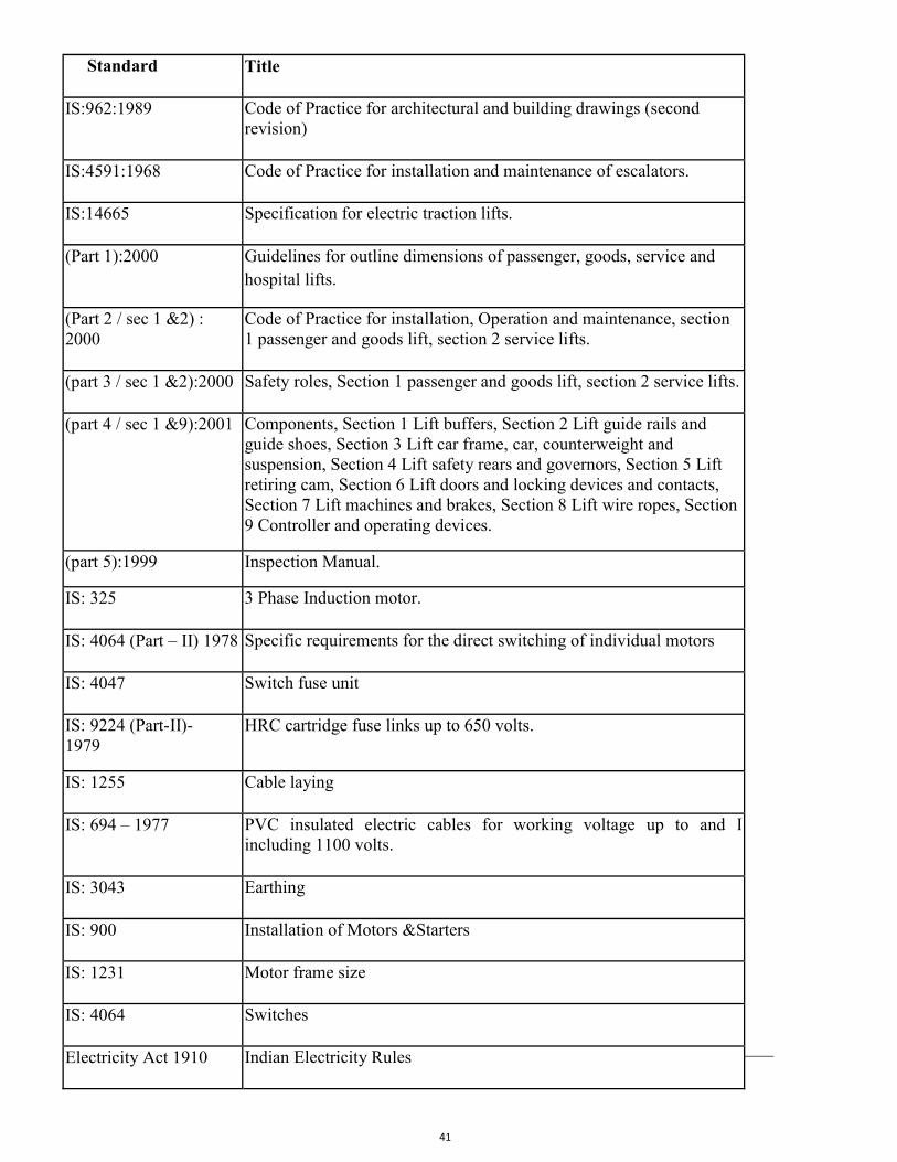
41
Standard Title
IS:962:1989 Code of Practice for architectural and building drawings (second revision)
IS:4591:1968 Code of Practice for installation and maintenance of escalators.
IS:14665 Specification for electric traction lifts.
(Part 1):2000 Guidelines for outline dimensions of passenger, goods, service and hospital lifts.
(Part 2 / sec 1 &2) : 2000
Code of Practice for installation, Operation and maintenance, section 1 passenger and goods lift, section 2 service lifts.
(part 3 / sec 1 &2):2000 Safety roles, Section 1 passenger and goods lift, section 2 service lifts.
(part 4 / sec 1 &9):2001 Components, Section 1 Lift buffers, Section 2 Lift guide rails and guide shoes, Section 3 Lift car frame, car, counterweight and suspension, Section 4 Lift safety rears and governors, Section 5 Lift retiring cam, Section 6 Lift doors and locking devices and contacts, Section 7 Lift machines and brakes, Section 8 Lift wire ropes, Section 9 Controller and operating devices.
(part 5):1999 Inspection Manual.
IS: 325 3 Phase Induction motor.
IS: 4064 (Part – II) 1978 Specific requirements for the direct switching of individual motors
IS: 4047 Switch fuse unit
IS: 9224 (Part-II)- 1979
HRC cartridge fuse links up to 650 volts.
IS: 1255 Cable laying
IS: 694 – 1977 PVC insulated electric cables for working voltage up to and I including 1100 volts.
IS: 3043 Earthing
IS: 900 Installation of Motors &Starters
IS: 1231 Motor frame size
IS: 4064 Switches
Electricity Act 1910 Indian Electricity Rules
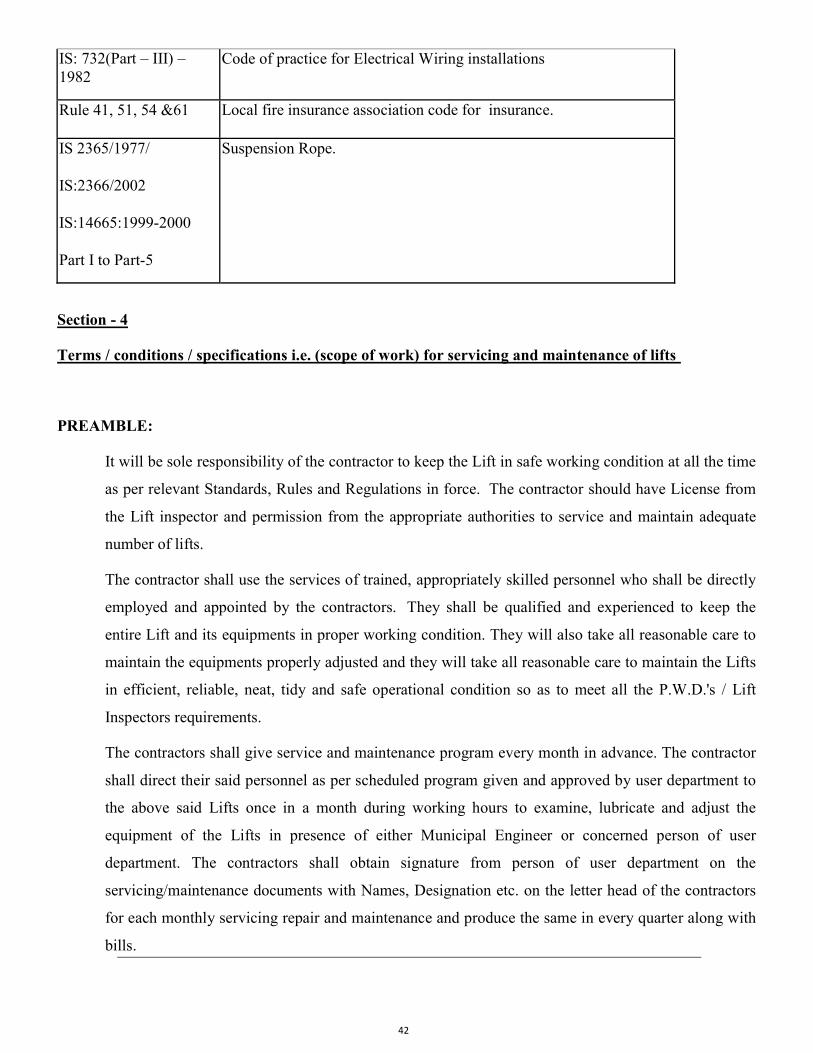
42
IS: 732(Part – III) – 1982
Code of practice for Electrical Wiring installations
Rule 41, 51, 54 &61 Local fire insurance association code for insurance.
IS 2365/1977/
IS:2366/2002
IS:14665:1999-2000
Part I to Part-5
Suspension Rope.
Section - 4
Terms / conditions / specifications i.e. (scope of work) for servicing and maintenance of lifts
PREAMBLE:
It will be sole responsibility of the contractor to keep the Lift in safe working condition at all the time
as per relevant Standards, Rules and Regulations in force. The contractor should have License from
the Lift inspector and permission from the appropriate authorities to service and maintain adequate
number of lifts.
The contractor shall use the services of trained, appropriately skilled personnel who shall be directly
employed and appointed by the contractors. They shall be qualified and experienced to keep the
entire Lift and its equipments in proper working condition. They will also take all reasonable care to
maintain the equipments properly adjusted and they will take all reasonable care to maintain the Lifts
in efficient, reliable, neat, tidy and safe operational condition so as to meet all the P.W.D.'s / Lift
Inspectors requirements.
The contractors shall give service and maintenance program every month in advance. The contractor
shall direct their said personnel as per scheduled program given and approved by user department to
the above said Lifts once in a month during working hours to examine, lubricate and adjust the
equipment of the Lifts in presence of either Municipal Engineer or concerned person of user
department. The contractors shall obtain signature from person of user department on the
servicing/maintenance documents with Names, Designation etc. on the letter head of the contractors
for each monthly servicing repair and maintenance and produce the same in every quarter along with
bills.
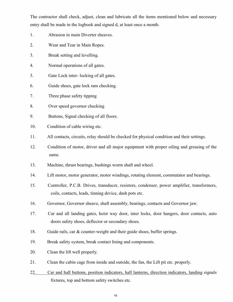
43
The contractor shall check, adjust, clean and lubricate all the items mentioned below and necessary
entry shall be made in the logbook and signed d, at least once a month.
1. Abrasion in main Diverter sheaves.
2. Wear and Tear in Main Ropes.
3. Break setting and levelling.
4. Normal operations of all gates.
5. Gate Lock inter- locking of all gates.
6. Guide shoes, gate lock ram checking.
7. Three phase safety tipping
8. Over speed governor checking
9. Buttons, Signal checking of all floors.
10. Condition of cable wiring etc.
11. All contacts, circuits, relay should be checked for physical condition and their settings.
12. Condition of motor, driver and all major equipment with proper oiling and greasing of the
same.
13. Machine, thrust bearings, bushings worm shaft and wheel.
14. Lift motor, motor generator, motor windings, rotating element, commutator and bearings.
15. Controller, P.C.B. Drives, transducer, resistors, condenser, power amplifier, transformers,
coils, contacts, leads, tinning device, dash pots etc.
16. Governor, Governor sheave, shaft assembly, bearings, contacts and Governor jaw.
17. Car and all landing gates, hoist way door, inter locks, door hangers, door contacts, auto
doors safety shoes, deflector or secondary shoes.
18. Guide rails, car & counter-weight and their guide shoes, buffer springs.
19. Break safety system, break contact lining and components.
20. Clean the lift well properly.
21. Clean the cabin cage from inside and outside, the fan, the Lift pit etc. properly.
22. Car and hall buttons, position indicators, hall lanterns, direction indicators, landing signals
fixtures, top and bottom safety switches etc.
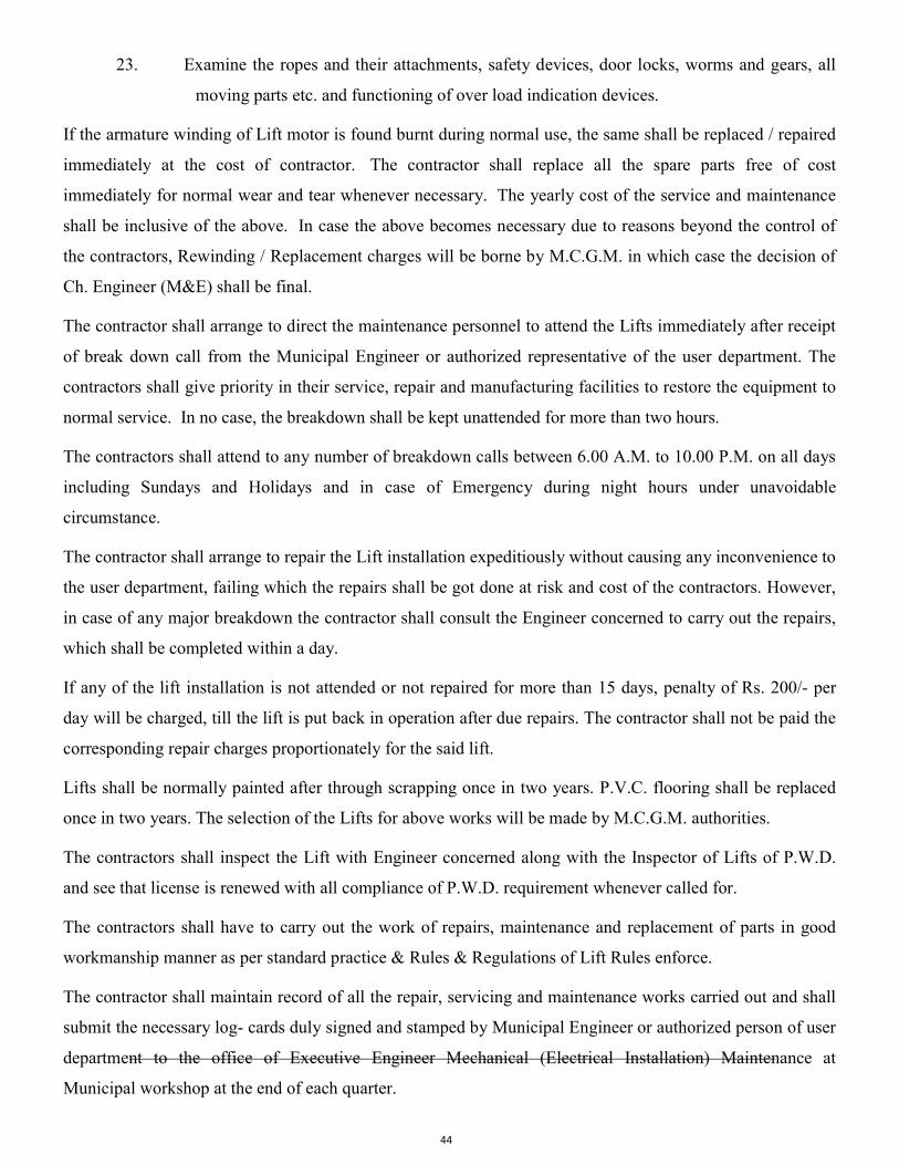
44
23. Examine the ropes and their attachments, safety devices, door locks, worms and gears, all
moving parts etc. and functioning of over load indication devices.
If the armature winding of Lift motor is found burnt during normal use, the same shall be replaced / repaired
immediately at the cost of contractor. The contractor shall replace all the spare parts free of cost
immediately for normal wear and tear whenever necessary. The yearly cost of the service and maintenance
shall be inclusive of the above. In case the above becomes necessary due to reasons beyond the control of
the contractors, Rewinding / Replacement charges will be borne by M.C.G.M. in which case the decision of
Ch. Engineer (M&E) shall be final.
The contractor shall arrange to direct the maintenance personnel to attend the Lifts immediately after receipt
of break down call from the Municipal Engineer or authorized representative of the user department. The
contractors shall give priority in their service, repair and manufacturing facilities to restore the equipment to
normal service. In no case, the breakdown shall be kept unattended for more than two hours.
The contractors shall attend to any number of breakdown calls between 6.00 A.M. to 10.00 P.M. on all days
including Sundays and Holidays and in case of Emergency during night hours under unavoidable
circumstance.
The contractor shall arrange to repair the Lift installation expeditiously without causing any inconvenience to
the user department, failing which the repairs shall be got done at risk and cost of the contractors. However,
in case of any major breakdown the contractor shall consult the Engineer concerned to carry out the repairs,
which shall be completed within a day.
If any of the lift installation is not attended or not repaired for more than 15 days, penalty of Rs. 200/- per
day will be charged, till the lift is put back in operation after due repairs. The contractor shall not be paid the
corresponding repair charges proportionately for the said lift.
Lifts shall be normally painted after through scrapping once in two years. P.V.C. flooring shall be replaced
once in two years. The selection of the Lifts for above works will be made by M.C.G.M. authorities.
The contractors shall inspect the Lift with Engineer concerned along with the Inspector of Lifts of P.W.D.
and see that license is renewed with all compliance of P.W.D. requirement whenever called for.
The contractors shall have to carry out the work of repairs, maintenance and replacement of parts in good
workmanship manner as per standard practice & Rules & Regulations of Lift Rules enforce.
The contractor shall maintain record of all the repair, servicing and maintenance works carried out and shall
submit the necessary log- cards duly signed and stamped by Municipal Engineer or authorized person of user
department to the office of Executive Engineer Mechanical (Electrical Installation) Maintenance at
Municipal workshop at the end of each quarter.
45
The contractor will furnish the program of servicing and maintenance of Lifts for the whole year with date
and timing etc. immediately on receipt of work order to the user department with a copy to Executive
Engineer Mechanical (Electrical Installation) Maintenance at Municipal workshop within a week. Any
changes in the above scheduled program shall be informed in Advance.
The contractors shall have to carry out any other work which is not included in the above terms and
conditions under the instructions from Municipal Engineer of Executive Engineer Mechanical (Electrical
Installation) Maintenance at Municipal workshop / Office with due approval of rates etc. for the satisfactory
working of Lifts.
Before quoting the rates the Tenderer shall inspect the Lift installations. No extra claim whatsoever will be
entertained later on during the contract period.
The contractor will replace all the parts (including indication lamps switches wire, cables, emergency lights
batteries etc.) whenever found necessary due to normal wear and tear at their cost.
Further, though the costs of replacement of the following items are not charged extra as the replacement of
the same is covered under comprehensive maintenance contract for the normal working of Lifts with usual
wear and tear, the contractor shall specifically quote the rates for the following which may become necessary
in unusual circumstances:-
i) Replacement of Ropes
ii) Repairs to collapsible gates of car.
iii) Repairs to collapsible gates of landings
iv) Car enclosure (removable panels) door panels, hung ceiling, light diffuser, handrails,
frames, sills etc.
v) Automatic Rescue Device.
vi) Audio Video overload warning indicator.
vii) Infrared Light Curtain.
viii) Repairs to cabin fans.
ix) Rewinding of motors.
x) Any other items.

46
The above rates will be applicable when repairs and replacement becomes necessary due to accidents,
leakage / seepage of water or such reasons which are beyond the control of contractor. The Engineer of
contract will decide the responsibility in such cases whose decision will be final.
The complete safety of human Life and the machinery and other parts of the lifts while carrying out the
service and maintenance of the Lift will be the responsibility of the contractor. Any damages caused to the
municipal property will be recovered from the bills.
The contract is terminable by either party, giving one calendar month's Notice in writing to his intention to
discontinue it.
In case of disputes Municipal Commissioner's decision will be final and binding to both parties.
The tenderer/ quotationer shall specifically state there past experience in maintaining such lifts and also
furnish the detailed List of Lifts maintained by them.
Attend the complaints free of cost whenever called by Corporation.
Whenever found necessary, the Contractor shall replace the spares and other parts of all the equipment’s
integrated to the lift operation, safety and statutory requirement free of cost.
The contractor shall check the performance of the lift after servicing by noting various operating parameters
such as temperature control, load, setting etc.
The contractor shall invariably clean the premises of lift car top, lift pit and lift shaft, after carrying out the
servicing work.
The contractor shall submit a preventive maintenance schedule for each lift and get it approved from the user
dept.
The contractor shall submit the copies of service reports (duly signed by the user dept.) to E.E. Mech.(E.I.)
Maint. every month.
The contractor shall have setup to receive & attend the complaints 24 hours a day. The break-down
complaint shall be attended within 2 hours from intimation.
The contractor / firm has to arrange a technically qualified liaison officer in respect of day to day servicing
and maintenance of lifts, who will keep regular contact with central office of Ex. Engr. Mech.(EI) Maint. and
attend to the defects informed to him immediately. He shall give feedback to MCGM after complying with
the rectification / repairs.
47
The contractor shall arrange for annual inspection of lifts by the lift inspector, PWD Govt. of Maharashtra during guarantee period and CSMC period. The inspection charges for the same shall be borne by contractors. PENALTY TERM Every breakdown or preventive maintenance call shall be backed by inspection report by the contractor. Failure to attend the call shall attract penalty of Rs. 500/- for 1st incidence, which shall be doubled for
subsequent failure. The maximum penalty shall be Rs. 2000/-
Due to non-availability of spares if the plants remain unrepaired for more than a week, prorate service
charges for the month shall be deducted from the quarterly bill.
TERMS OF PAYMENT FOR ANUAL SERVICE MAINTENANCE CONTRACT
Service during the quarter period shall be billed by the contractor at the end of quarter and on receipt of bill will be paid within thirty days as per M.C.G.M. procedure.
This contract is terminable by MCGM if the services rendered are unsatisfactory.
In case of dispute the Municipal Commissioner's decision will be final and binding on both the parties.
……………………………..xxxxxx…………………………………..xxxxxxx………………………
48
5. TECHANICAL SPECIFICATION FOR FIRE FIGHTING WORK
Majority items are taken from M&E USOR 2018 for which technical specifications may be obtained from M&E USOR Specifications 2018 from MCGM portal.
Unified Schedule of Rates - MyBMC - Welcome to BMC's Website (mcgm.gov.in)
Technical specifications for fair market rate item is as follows :-
General
The diesel pump set shall be suitable for automatic operation complete with necessary automatic starting gear, for starting on wet battery system and shall be complete with all accessories. Both engine and pump shall be assembled on a common base plate.
Drive
The pump shall be only direct driven by means of a flexible coupling. Coupling guard shall also be provided. The speed shall be 1500 RPM as specified.
Fire Pump
The fire pump shall be horizontally mounted centrifugal single/ multi stage, single/ multi outlet. It shall have a capacity to deliver as specified, and developing adequate head so as to ensure a minimum pressure of 3.5 Kg/Sq.cm at the highest and the farthest outlet. The pump shall be single/ multi stage as specified. The pump shall be capable of giving a discharge of not less than 150% of the rated discharge at a head of not less than 65% of the rated head. The shut off head shall be within 120% of the rated head.
The pump casing shall be of cast iron to grade FG 200 to IS 210 and parts like impeller, shaft sleeves, wearing-ring etc. shall be of non-corrosive metal like bronze/brass/gun metal. The shaft shall be stainless steel. Provision of mechanical seal shall also be made.
The pump casing shall be designed to withstand 1.5 times the working pressure.
Bearing of pump shall be effectively sealed to prevent loss of lubricant or entry of dust or water.
PUMP SETS ASSEMBLY
On the main fire sprinkler and hydrant headers near pump sets a 150 mm dia by-pass valve located in an accessible location shall be provided along with a rate of flow rota meter calibrated in 1 pm and able to read 200% of the rated pump capacity. The delivery shall be connected to the fire tank.
Each and every pump set assembly shall be provided with suction valve (only for positive suction head), discharge valve, non-return valve and 150 mm dia Bourdon type pressure gauge with isolation valve.
49
FLEXIBLE CONNECTORS
On all suction and delivery lines double flanged reinforced neoprene flexible pipe connectors shall be provided. Connectors should be suitable for maximum working pressure of each pipe line on which it is mounted and tested to a test pressure of 1:5 time the operating pressure. Length of the connector shall be as per manufacturer’s standard
8.0 OPEN DRENCHER SYSTEM 8.1 The scope of work shall cover supply, installation testing and commissioning of the
Drenchers system covering the following : 1) By Pass connection with valves from electric or diesel driven both main fire Pump
as shown in Diagram. 2) Sluice Valve, Drain Valves at bottom of riser. 3) Drenchers 4) Drencher piping
8.2 Standards The Drencher installation shall conform to and meet with the requirements set out by the following :
1) IS 1648 1961 Code of practice for fire Safety of buildings 2) Fire Insurance Association of India - Tariff Advisory Committee rules. 3) Local Fire Brigade and Fire Engineering Authorities.
8.3 Source of water The installation shall be connected to the existing Fire Hydrant pumps, with Sluice valve at riser bottom & 50 mm (2") drain valve fully open between sluice valve & 1st drenchers.
8.4 Valve: The controlling valves shall be located in accessible positions. The Positions of each valve & the drenchers it controls must be clearly indicated by a well-written signboard. Painted in post office red paint.
8.5 Drencher Head: 8.5.1 Drenchers shall be standard products from an established firm of repute and standard
and approved by an appropriate authority for fire fighting duty. 8.5.2 All Drenchers shall be brass castings polished chrome or white (polyester) unless stated
otherwise and rated for 12.0 Kg/sq. cm WG and factory tested for 34.0 Kg/sq. cm. Drenchers shall be walls or Curtain Drenchers type as specified and shown on drawings.
8.5.3 Spacing of Drencher heads: Drenchers shall be placed with maximum horizontal spacing of 2.5 meters C/C.
8.5.4 Piping All piping shall be mild steel medium duty as specified under "Piping for Fire Fighting". Necessary Valves & drain valves shall be provided as shown on drawings or as required to.
8.5.5 Operation: System shall be operated by the opening of main Sluice valve & closing of drain valve located at bottom of the riser.
8.5.6 Drainage: In open drencher system, the drain valve shall always be kept open except when the drenchers are in operation
8.5.7 Test Valve: A full way 50mm (2") dia. Valve and shall be provided below the controlling valves, so that the running pressure test can be carried out at any time.
9.0 Mode of Measurement 9.1 Sprinkler pump with mounting frame, vibration mounts excluding concrete foundation
shall be measured per unit.
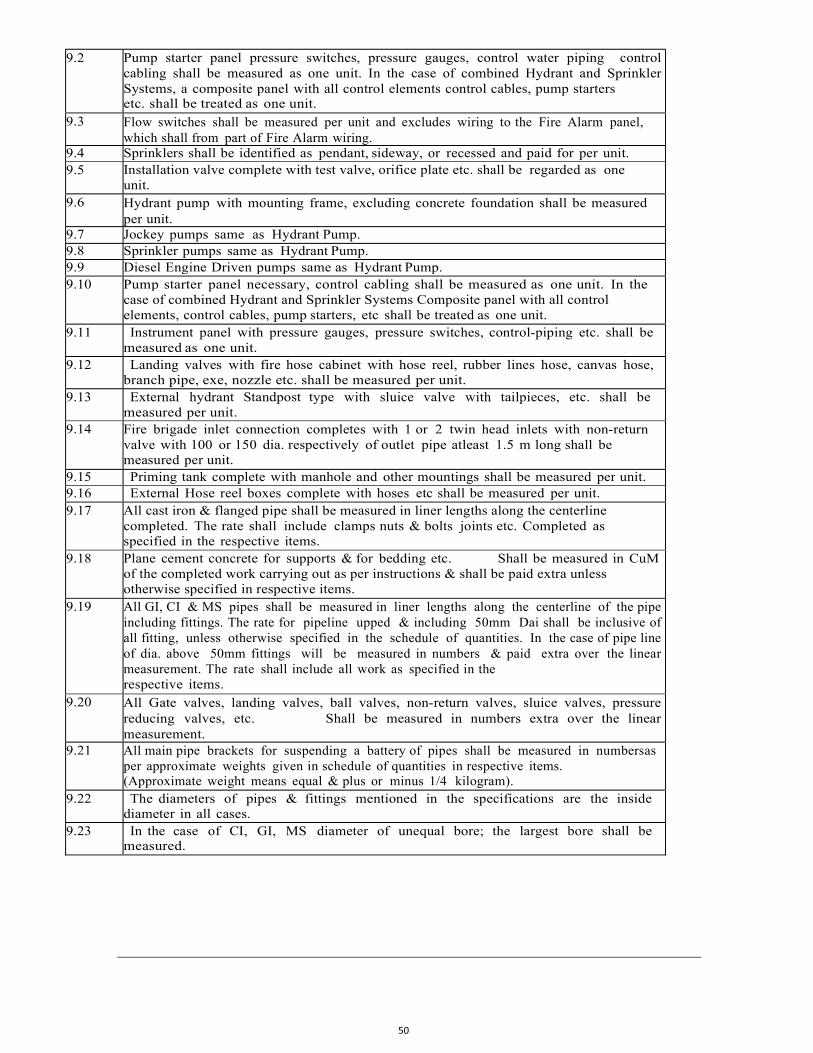
50
9.2 Pump starter panel pressure switches, pressure gauges, control water piping control cabling shall be measured as one unit. In the case of combined Hydrant and Sprinkler Systems, a composite panel with all control elements control cables, pump starters etc. shall be treated as one unit.
9.3 Flow switches shall be measured per unit and excludes wiring to the Fire Alarm panel, which shall from part of Fire Alarm wiring.
9.4 Sprinklers shall be identified as pendant, sideway, or recessed and paid for per unit. 9.5 Installation valve complete with test valve, orifice plate etc. shall be regarded as one
unit. 9.6 Hydrant pump with mounting frame, excluding concrete foundation shall be measured
per unit. 9.7 Jockey pumps same as Hydrant Pump. 9.8 Sprinkler pumps same as Hydrant Pump. 9.9 Diesel Engine Driven pumps same as Hydrant Pump. 9.10 Pump starter panel necessary, control cabling shall be measured as one unit. In the
case of combined Hydrant and Sprinkler Systems Composite panel with all control elements, control cables, pump starters, etc shall be treated as one unit.
9.11 Instrument panel with pressure gauges, pressure switches, control-piping etc. shall be measured as one unit.
9.12 Landing valves with fire hose cabinet with hose reel, rubber lines hose, canvas hose, branch pipe, exe, nozzle etc. shall be measured per unit.
9.13 External hydrant Standpost type with sluice valve with tailpieces, etc. shall be measured per unit.
9.14 Fire brigade inlet connection completes with 1 or 2 twin head inlets with non-return valve with 100 or 150 dia. respectively of outlet pipe atleast 1.5 m long shall be measured per unit.
9.15 Priming tank complete with manhole and other mountings shall be measured per unit. 9.16 External Hose reel boxes complete with hoses etc shall be measured per unit. 9.17 All cast iron & flanged pipe shall be measured in liner lengths along the centerline
completed. The rate shall include clamps nuts & bolts joints etc. Completed as specified in the respective items.
9.18 Plane cement concrete for supports & for bedding etc. Shall be measured in CuM of the completed work carrying out as per instructions & shall be paid extra unless otherwise specified in respective items.
9.19 All GI, CI & MS pipes shall be measured in liner lengths along the centerline of the pipe including fittings. The rate for pipeline upped & including 50mm Dai shall be inclusive of all fitting, unless otherwise specified in the schedule of quantities. In the case of pipe line of dia. above 50mm fittings will be measured in numbers & paid extra over the linear measurement. The rate shall include all work as specified in the respective items.
9.20 All Gate valves, landing valves, ball valves, non-return valves, sluice valves, pressure reducing valves, etc. Shall be measured in numbers extra over the linear measurement.
9.21 All main pipe brackets for suspending a battery of pipes shall be measured in numbers as per approximate weights given in schedule of quantities in respective items. (Approximate weight means equal & plus or minus 1/4 kilogram).
9.22 The diameters of pipes & fittings mentioned in the specifications are the inside diameter in all cases.
9.23 In the case of CI, GI, MS diameter of unequal bore; the largest bore shall be measured.
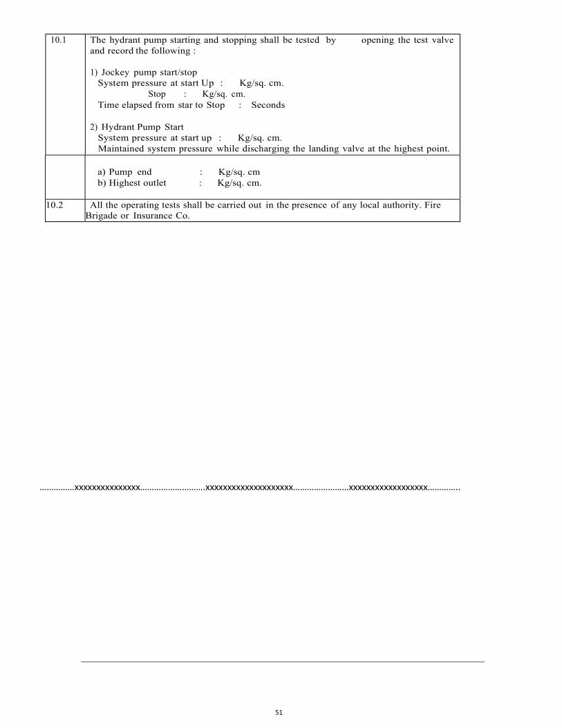
51
10.1 The hydrant pump starting and stopping shall be tested by opening the test valve and record the following :
1) Jockey pump start/stop
System pressure at start Up : Kg/sq. cm. Stop : Kg/sq. cm.
Time elapsed from star to Stop : Seconds
2) Hydrant Pump Start System pressure at start up : Kg/sq. cm. Maintained system pressure while discharging the landing valve at the highest point.
a) Pump end : Kg/sq. cm b) Highest outlet : Kg/sq. cm.
10.2 All the operating tests shall be carried out in the presence of any local authority. Fire Brigade or Insurance Co.
……………xxxxxxxxxxxxxxx……………………….xxxxxxxxxxxxxxxxxxxx……………………xxxxxxxxxxxxxxxxxx…………..
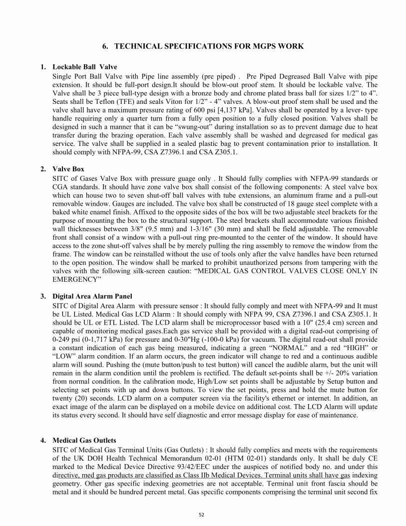
52
6. TECHNICAL SPECIFICATIONS FOR MGPS WORK 1. Lockable Ball Valve
Single Port Ball Valve with Pipe line assembly (pre piped) . Pre Piped Degreased Ball Valve with pipe extension. It should be full-port design.It should be blow-out proof stem. It should be lockable valve. The Valve shall be 3 piece ball-type design with a bronze body and chrome plated brass ball for sizes 1/2” to 4”. Seats shall be Teflon (TFE) and seals Viton for 1/2” - 4” valves. A blow-out proof stem shall be used and the valve shall have a maximum pressure rating of 600 psi [4,137 kPa]. Valves shall be operated by a lever- type handle requiring only a quarter turn from a fully open position to a fully closed position. Valves shall be designed in such a manner that it can be “swung-out” during installation so as to prevent damage due to heat transfer during the brazing operation. Each valve assembly shall be washed and degreased for medical gas service. The valve shall be supplied in a sealed plastic bag to prevent contamination prior to installation. It should comply with NFPA-99, CSA Z7396.1 and CSA Z305.1.
2. Valve Box SITC of Gases Valve Box with pressure guage only . It Should fully complies with NFPA-99 standards or CGA standards. It should have zone valve box shall consist of the following components: A steel valve box which can house two to seven shut-off ball valves with tube extensions, an aluminum frame and a pull-out removable window. Gauges are included. The valve box shall be constructed of 18 gauge steel complete with a baked white enamel finish. Affixed to the opposite sides of the box will be two adjustable steel brackets for the purpose of mounting the box to the structural support. The steel brackets shall accommodate various finished wall thicknesses between 3/8" (9.5 mm) and 1-3/16" (30 mm) and shall be field adjustable. The removable front shall consist of a window with a pull-out ring pre-mounted to the center of the window. It should have access to the zone shut-off valves shall be by merely pulling the ring assembly to remove the window from the frame. The window can be reinstalled without the use of tools only after the valve handles have been returned to the open position. The window shall be marked to prohibit unauthorized persons from tampering with the valves with the following silk-screen caution: “MEDICAL GAS CONTROL VALVES CLOSE ONLY IN EMERGENCY”
3. Digital Area Alarm Panel SITC of Digital Area Alarm with pressure sensor : It should fully comply and meet with NFPA-99 and It must be UL Listed. Medical Gas LCD Alarm : It should comply with NFPA 99, CSA Z7396.1 and CSA Z305.1. It should be UL or ETL Listed. The LCD alarm shall be microprocessor based with a 10" (25.4 cm) screen and capable of monitoring medical gases.Each gas service shall be provided with a digital read-out comprising of 0-249 psi (0-1,717 kPa) for pressure and 0-30"Hg (-100-0 kPa) for vacuum. The digital read-out shall provide a constant indication of each gas being measured, indicating a green “NORMAL” and a red “HIGH” or “LOW” alarm condition. If an alarm occurs, the green indicator will change to red and a continuous audible alarm will sound. Pushing the (mute button/push to test button) will cancel the audible alarm, but the unit will remain in the alarm condition until the problem is rectified. The default set-points shall be +/- 20% variation from normal condition. In the calibration mode, High/Low set points shall be adjustable by Setup button and selecting set points with up and down buttons. To view the set points, press and hold the mute button for twenty (20) seconds. LCD alarm on a computer screen via the facility's ethernet or internet. In addition, an exact image of the alarm can be displayed on a mobile device on additional cost. The LCD Alarm will update its status every second. It should have self diagnostic and error message display for ease of maintenance.
4. Medical Gas Outlets SITC of Medical Gas Terminal Units (Gas Outlets) : It should fully complies and meets with the requirements of the UK DOH Health Technical Memorandum 02-01 (HTM 02-01) standards only. It shall be duly CE marked to the Medical Device Directive 93/42/EEC under the auspices of notified body no. and under this directive, med gas products are classified as Class IIb Medical Devices. Terminal units shall have gas indexing geometry. Other gas specific indexing geometries are not acceptable. Terminal unit front fascia should be metal and it should be hundred percent metal. Gas specific components comprising the terminal unit second fix
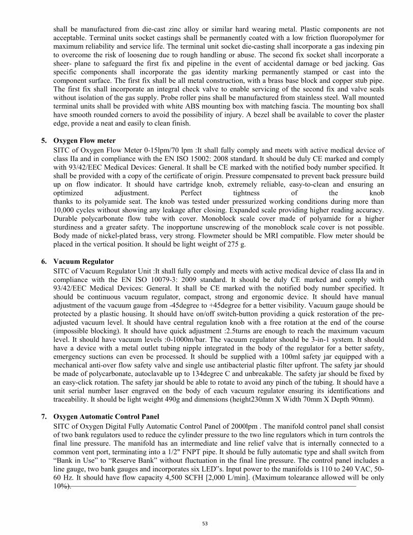
53
shall be manufactured from die-cast zinc alloy or similar hard wearing metal. Plastic components are not acceptable. Terminal units socket castings shall be permanently coated with a low friction fluoropolymer for maximum reliability and service life. The terminal unit socket die-casting shall incorporate a gas indexing pin to overcome the risk of loosening due to rough handling or abuse. The second fix socket shall incorporate a sheer- plane to safeguard the first fix and pipeline in the event of accidental damage or bed jacking. Gas specific components shall incorporate the gas identity marking permanently stamped or cast into the component surface. The first fix shall be all metal construction, with a brass base block and copper stub pipe. The first fix shall incorporate an integral check valve to enable servicing of the second fix and valve seals without isolation of the gas supply. Probe roller pins shall be manufactured from stainless steel. Wall mounted terminal units shall be provided with white ABS mounting box with matching fascia. The mounting box shall have smooth rounded corners to avoid the possibility of injury. A bezel shall be available to cover the plaster edge, provide a neat and easily to clean finish.
5. Oxygen Flow meter
SITC of Oxygen Flow Meter 0-15lpm/70 lpm :It shall fully comply and meets with active medical device of class IIa and in compliance with the EN ISO 15002: 2008 standard. It should be duly CE marked and comply with 93/42/EEC Medical Devices: General. It shall be CE marked with the notified body number specified. It shall be provided with a copy of the certificate of origin. Pressure compensated to prevent back pressure build up on flow indicator. It should have cartridge knob, extremely reliable, easy-to-clean and ensuring an optimized adjustment. Perfect tightness of the knob thanks to its polyamide seat. The knob was tested under pressurized working conditions during more than 10,000 cycles without showing any leakage after closing. Expanded scale providing higher reading accuracy. Durable polycarbonate flow tube with cover. Monoblock scale cover made of polyamide for a higher sturdiness and a greater safety. The inopportune unscrewing of the monoblock scale cover is not possible. Body made of nickel-plated brass, very strong. Flowmeter should be MRI compatible. Flow meter should be placed in the vertical position. It should be light weight of 275 g.
6. Vacuum Regulator
SITC of Vacuum Regulator Unit :It shall fully comply and meets with active medical device of class IIa and in compliance with the EN ISO 10079-3: 2009 standard. It should be duly CE marked and comply with 93/42/EEC Medical Devices: General. It shall be CE marked with the notified body number specified. It should be continuous vacuum regulator, compact, strong and ergonomic device. It should have manual adjustment of the vacuum gauge from -45degree to +45degree for a better visibility. Vacuum gauge should be protected by a plastic housing. It should have on/off switch-button providing a quick restoration of the pre-adjusted vacuum level. It should have central regulation knob with a free rotation at the end of the course (impossible blocking). It should have quick adjustment :2.5turns are enough to reach the maximum vacuum level. It should have vacuum levels :0-1000m/bar. The vacuum regulator should be 3-in-1 system. It should have a device with a metal outlet tubing nipple integrated in the body of the regulator for a better safety, emergency suctions can even be processed. It should be supplied with a 100ml safety jar equipped with a mechanical anti-over flow safety valve and single use antibacterial plastic filter upfront. The safety jar should be made of polycarbonate, autoclavable up to 134degree C and unbreakable. The safety jar should be fixed by an easy-click rotation. The safety jar should be able to rotate to avoid any pinch of the tubing. It should have a unit serial number laser engraved on the body of each vacuum regulator ensuring its identifications and traceability. It should be light weight 490g and dimensions (height230mm X Width 70mm X Depth 90mm).
7. Oxygen Automatic Control Panel
SITC of Oxygen Digital Fully Automatic Control Panel of 2000lpm . The manifold control panel shall consist of two bank regulators used to reduce the cylinder pressure to the two line regulators which in turn controls the final line pressure. The manifold has an intermediate and line relief valve that is internally connected to a common vent port, terminating into a 1/2" FNPT pipe. It should be fully automatic type and shall switch from “Bank in Use” to “Reserve Bank” without fluctuation in the final line pressure. The control panel includes a line gauge, two bank gauges and incorporates six LED‟s. Input power to the manifolds is 110 to 240 VAC, 50-60 Hz. It should have flow capacity 4,500 SCFH [2,000 L/min]. (Maximum tolearance allowed will be only 10%).
54
8. Vacuum Pump SITC of Vacuum Pump. : It should be oil lubricated vacuum pump, having each vacuum pump capacity of 3000lpm with IEC Motor rating of minimum 10 HP @ 50 Hz or above. Vacuum pump shall comprise of air cooled, oil lubricated vacuum pumps suitable for both continuous and frequent start / stop operation at inlet vacuum vessels between 525mm Hg and 700 mm Hg. The ultimate vacuum of pump shall be 0.1 mbar with gas ballast valve closed. The Vacuum Pump should be air cooled and oil lubricated vacuum pumps designed for use in the field of high quality vacuum. The pump should be having a 4 barriers system that avoids any oil leaks by doubling the 2 lip seals. The use of shaft lip seals Pump shall be lubricated by a fully re-circulated and filtered lubricant supply. Also Pump design should include a lubricant separation system integral to the pump exhaust box consisting of no less than four stages of internally installed lubricant and smoke eliminators through which the exhaust gas stream must pass. This system shall consist of bulk separation, lubricant mist elimination, smoke elimination, synthetic lubricant baffle, and shall be capable of removing 99.9 percent of all lubricant and smoke particles from the exhaust gas stream. The unit should have extremely low vibration. (Maximum tolearance allowed will be only 10%).
9. Vacuum Filter
SITC of Vacuum Filter (Bacteria Filter) of 100cfm to 105cfm – 3” Filter housing with drain flask.: It fully complies and meets with requirements of UK HTM medical standards. It should have BS 3928 sodium flame test certificate based on requirements of HTM standards.The bacteria filter should be designed for critical application involving removal of dry and wet dust, particulars, oil aerosol and water droplest, high efficiency glass fiber, fieece media from suction side of vacuum pump system. It should have efficiency of at least 99.995% when tested by sodium flame test and that should be according to BS 3928:1969. The Vacuum filtration efficiency should be in excess of 99.9999% as per HTM0201 & AS 2896 standards. The high efficiency medical grade filter element should have custom engineered filter media and deep pleat element technology provides minimal pressure loss and filtration efficiencies. It should have advanced filtration technology for Low pressure loss borosilicate glass microfiber-media and open cell reticulated foam pre-filtration layer captures particulates, bacteria and liquid aerosols reducing energy consumption and overall system costs. It should have corrosion protection Internal and external electrophoretic painting followed by a tough exterior polyester powder coating. It should have easily removable sterilisable drain flask and differential pressure monitor gauge. It should have push fit element design for quick and easy maintenance with unique push fit element design. It should have element end cap color black. It should have maximum temperature 60 degree centigrade (140 degree F). It should have element of E31140MV grade. It should have pipe size connection 1” = 105scfm and 180nm3/hr FAA. It should have pressure loss clean & dry = < 3kPa (30m/bar/0.44psig). It should have maximum working pressure 0.5barg(7psig. It should have manual drain valves and 250ml sterilisable glass drain flasks.(Maximum tolearance allowed will be only 10%).
10. Air Compressor
SITC of Oil Free Rotary Screw/Scroll Air Compressor : Oil free Rotary Screw/scroll air compressor.It should be 50Hz, 3 Phase, 440volts. 8 Bar, 116 Psig. 85cfm or more at 8 Bar. 22 Kw & 30 Hp. The 85cfm flow capacity for each compressor unit having suitable motor rating of Rotary Screw/scroll air cooled compressor. Compressors shall be oil free Rotary Screw/scroll compressors suitable for both continuous and frequent start/stop operation at a nominal outlet pressure of 800 kPa (8 bar). The air quality shall be 100% oil free, certified ISO8573-1. The compressor shall have a sound insulating enclosure. Air is drawn through air filter and should be compressed by the compressor element of each compressor module. Dependent on the model, the compressors have 3 or 4 electric motor driven compressor modules, enclosed in a sound insulating canopy. The front door panel houses the Graphic controller and the emergency stop button. An electric cabinet with the electric components is installed behind the front panel. (Maximum tolerance allowed will be only 15%). ISO Compressors shall conform to ISO 7396-1 standards. HTM Compressor shall comply with HTM02-01/HTM2022 standards and shall include an additional pressure sensor and temperature sensor, required for transmitting additional alarm conditions. An additional analogue ammeter and inter locking isolator shall also be included.
55
11. Air Dryer Unit SITC of 100cfm Heatless Air Dryer : 100cfm Heatless Air Dryer : It should have air dryer desiccant type with ½” end BSP connection. It should have pre filter and post filter. It should be designed for ISO:7183- 1986 (E) standards. It should have dryer quality class -ISO 8573-1 standards. It should be made of aluminum construction. It should have purge loss 15+/- 1%. The dryer control system shall incorporate a Purge Saver Energy Management system that freezes the regeneration of the desiccant once adequate dew point is reached in the inactive tower. Only when the dewpoint level in the active tower deteriorates to an unacceptable level will the intelligent controller switch towers. This shall be achieved by including an additional dew point sensor and associated software in the dryer controller to effectively manage the system as well as providing on screen measurements of purge savings. An alarm condition shall trigger on the dryer control panel if the dew point exceeds a -46 degree C atmospheric set point
12. Coarse coalescing filter
SITC of Coarse coalescing filter 1" of 100cfm to 105 scfm filter :It should have flow-optimized design for advanced filter head design for optimized flow performance. It should have flexible installation Modular design and accessible fixings enable simple close coupling assembly. It should comply with air quality standard ISO 8573-1: 2010. It should have profiled bowl design and push fit elements ensure quick and for reliable maintenance. It should have corrosion protection Internal and external electrophoretic paint finish followed by a tough exterior polyester powder coating. It should have color coded element end caps of red color for easy and accurate grade identification.It should have element of E30612 grade. It should have particle retention of up to 99.999%, and significantly reduced pressure loss. It should have pipe size connection 1” = 105scfm and 144nm3/hr. It should have particle removal 1 micron. It should have maximum particle size class 2 micron as per ISO 8573-1: 2010 . It should have maximum oil content 3 micron ISO 8573-1: 2010. It should have maximum oil carryover at 68degree F (20degree centigrade) = 0.3 ppm (0.3mg/m3). It should have pressure loss clean & dry = 0.8psi (55m/bar). (Maximum tolearance allowed will be only 15%).
13. Fine coalescing filter
SITC of Fine coalescing filter 1" of 100cfm to 105 scfm filter :It should have flow- optimized design for advanced filter head design for optimized flow performance. It should have flexible installation Modular design and accessible fixings enable simple close coupling assembly. It should comply with air quality standard ISO 8573-1: 2010. It should have profiled bowl design and push fit elements ensure quick and for reliable maintenance. It should have corrosion protection Internal and external electrophoretic paint finish followed by a tough exterior polyester powder coating. It should have color coded element end caps of blue color for easy and accurate grade identification.It should have element of E30612 grade. It should have particle retention of up to 99.999%, and significantly reduced pressure loss. It should have pipe size connection 1” = 105scfm and 144nm3/hr. It should have particle removal 0.01 micron. It should have maximum particle size class 1 micron as per ISO 8573-1: 2010 . It should have maximum oil content 1 micron ISO 8573-1: 2010. It should have maximum oil carryover at 68degree F (20degree centigrade) = 0.01ppm (0.01mg/m3). (Maximum tolearance allowed will be only 15%).
14. Activated Carbon Filter
SITC of Activated Carbon Filter 1" of 100cfm to 105 scfm Filter :It should have flow-optimized design for advanced filter head design for optimized flow performance. It should have flexible installation Modular design and accessible fixings enable simple close coupling assembly. It should comply with air quality standard ISO 8573-1: 2010. It should have profiled bowl design and push fit elements ensure quick and for reliable maintenance. It should have corrosion protection Internal and external electrophoretic paint finish followed by a tough exterior polyester powder coating. It should have color coded element end caps of black color for easy and accurate grade identification.It should have element of E30612 grade. It should have particle retention of up to 99.999%, and significantly reduced pressure loss. It should have pipe size connection 1” = 105scfm and 144nm3/hr. It should have particle removal 0.01 micron. It should have maximum particle size class 1 micron as per ISO 8573-1: 2010 . It should have maximum oil content 1 micron ISO 8573-1: 2010. It should have maximum oil carryover at 68degree F (20degree centigrade) = 0.003ppm (0.003mg/m3). (Maximum tolearance allowed will be only 15%).
56
15. Fine Dust Filter
SITC of Fine Dust Filter 1" of 100cfm to 105 scfm: It should have flow-optimized design for advanced filter head design for optimized flow performance. It should have flexible installation Modular design and accessible fixings enable simple close coupling assembly. It should comply with air quality standard ISO 8573-1: 2010. It should have profiled bowl design and push fit elements ensure quick and for reliable maintenance. It should have corrosion protection Internal and external electrophoretic paint finish followed by a tough exterior polyester powder coating. It should have color coded element blue color end caps for easy and accurate grade identification. It should have element of E30612 grade. It should have particle retention of up to 99.999%, and significantly reduced pressure loss. It should have pipe size connection 1” = 105scfm and 144nm3/hr. It should have particle removal 0.01 micron. (Maximum tolerance allowed will be only 15%).
16. Vacuum Receiver(s) - Vacuum receiver(s) shall be supplied with relevant test certificates and have a total volume of at least 100% of the plant output in 1 minute in terms of free air aspired at normal working pressure. Each vacuum receiver shall be hot dip galvanised inside and out.
17. SITC of Vacuum Filter: Vacuum Filter (Bacteria Filter) of 100cfm to 105cfm – 3” Filter housing with drain flask.: It fully complies and meets with requirements of UK HTM medical standards. It should have BS 3928 sodium flame test certificate based on requirements of HTM standards.The bacteria filter should be designed for critical application involving removal of dry and wet dust, particulars, oil aerosol and water droplest, high efficiency glass fiber, fieece media from suction side of vacuum pump system. It should have efficiency of at least 99.995% when tested by sodium flame test and that should be according to BS 3928:1969.
18. Air Receiver(s) - Vacuum receiver(s) shall be supplied with relevant test certificates and have a total volume of at least 50% of the plant output in 1 minute in terms of free air aspired at normal working pressure. Each vacuum receiver shall be hot dip galvanised inside and out. The Receivers Tank should be suitably designed with capacity of minimum 3X1750 litres at an operating pressure of 10.5 bar. The receivers should be present in duplex configuration to handle the designed load requirement. The vertical air receiver shall be vertically mounted and manufactured from heavy gauge fusion weld steel. The vertical air receiver shall be internally galvanised, double coat primer and epoxy coated white RAL 9010, fitted with automatic and manual drain valves and be protected by a pressure relief valve, fusible plug and include a pressure gauge.
19. Cryogenic vessels- a. Product: The liquid medical oxygen (LMO) supplied at site should be of IP grade. The LMO supplied
should comply with all relevant SMPV regulations and standards under the preview of the Indian Drugs and Cosmetic Act rules. They should also satisfy the IP 2007 specifications.
b. Storage Tank Specifications : The storage tank and the vaporizer coils should be designed as per the
ASME Sec.VIII Div.I latest Edition / EN 13458-2 Annexure-C/ AD2000 , MARKBLATTER 2004 Edition.
57
c. The cryogenic vessel will be of cylindrical shape with vaporiser and the pressure control system. It should be provided with the essential components to fill the liquid, to build up pressure, to relieve pressure, to withdraw product and to evacuate the vessel. All protective, safety and alarm provisions mandatory to Liquid Medical Oxygen plants should be supplied.
d. The requirement of the Cryogenic Vessel should be: • Configuration: Vertical • Inner vessel maximum
allowable working Pressure: 17 kg/cm2 or as per relevant Standard of system. • Inner vessel hydrostatic test pressure: Greater than 26 kg/ cm2 or as per relevant Standard of system. • Outer vessel material of construction: Carbon steel • Inner vessel material of construction: Stainless steel • Independent AV coil should be provided with each vessel.
e. Storage Tank Capacity: Vacuum insulated evaporator vessel should have adequate capacity The AV coil
should have adequate capacity to handle the gas flow requirements of the hospital.
f. Vaporizer Coil: • Maximum operating Pressure: 20 kg/cm2 • Design Pressure: 22 kg/cm2 • Pneumatic test
Pressure: Greater than 24 kg/cm2 • Inlet temperature: - 196 to +40°C. • Duty cycle: Continuous duty • Flow rate : 200 cubic metre/ hour.
The fence, foundation, lighting, signage, approach gate etc are to be designed and installed by the vendor. Safety: The vendor should ensure that all international safety norms and standards applicable as implemented and certified by the CCE.
Following are the mandatory provisions for vessel: • Vessel low liquid level alarm • Vessel low pressure alarm Pipeline low pressure alarm. • Twin regulator • Twin safety valve • Non return valve and 3 way diverter (bypass) valve • Automatic changeover to manifolds with control panel • Alarm on indicating manifold in use in case the vessel is not in use. • Alarm on low pressure back-up manifold cylinders
Statutory Requirements: All statutory requirements of the Chief Controller of Explosives of India and SMPV rules need to be followed; besides all regulations and guidelines put forward by the Govt. of India from time to time should be followed.
20. Copper Piping: Medical Grade Copper Tube/Pipes including all type of accessories Like,Tee, Elbow, Valves, etc. complete. The piped distribution system shall use copper pipes manufactured from phosphorous de-oxidized non-arsenical copper grade CW024A (Cu-DHP), manufactured to metric outside diameters and having mechanical properties in accordance or in either R250 (half hard) or R290 (hard). Degreasing of pipe shall be such that there is less than 20 mg/m2 (0.002mg/cm2) of hydrocarbons on the degreased surface when tested by the method specified Norms. all copper tube suppliers are to have Lloyds, BSI kite mark and certificate number.
58
21. Bed Head Panel
SITC of Double duct Bed Head Horizontal Wall Panel 600 mm. Separete duct for gas outet and seperate duct for electricals. (made up from Aluminum powder coated profiles) with double duct. Separate duct for electrical sockets and separate duct for gas outlet points. Each bed head panel should be pre piped and pre wired. It should have pre wired 4 nos. electrical sockets in separate duct ( 2 nos. 5 A sockets and 2 nos. 15 A sockets). Gas outlet points 2nos. pre piped to be fitted in the bed head panel. Gas outlet points cost not to be included in the bed head panel cost since it is separate line item. It should have provision for RJ45 connector and Nurse call system bedside switch with partition between LV and ELV system. IT should have Infusion pump mount pole with adapter for mounting at least two infusion pumps.
……………………………..xxxxxx…………………………………..xxxxxxx……………………
59
7. TECHANICAL SPECIFICATION FOR HVAC SYSTEM
Majority items are taken from M&E USOR 2018 for which technical specifications may be obtained
from M&E USOR Specifications 2018 from MCGM portal. Unified Schedule of Rates - MyBMC - Welcome to BMC's Website (mcgm.gov.in) Technical specifications for fair market rate item is as follows :-
1. AIR Handling Unit:-
Supply, installation, testing and commissioning of Sectionalised, DX/VRF COMPATIBLE Double Skin Air Handling Units with Thermal break profile & UVGI compatible constructed of extruded aluminum hollow sections framework, preplasticised GS Sheets of 22G (outside) / 22G (inside) with 40 mm thick injected PUF / 40 kg/cu.m + 5% density, consisting of fan section with Plug type Centrifugal Fan , & High Eff (IE-3) TEFC IP 55 motor , vibration isolators. Coil Section with 6R/4R-DX Coil, insulated sandwich type drain tray of SS (inside) / GI (outside). Internal surface shall be smooth and shall be cleanable without any projection. Fan outlet velocity not to exceed 1800 fpm. Coil face velocity not to exceed 500 fpm. AHU Coil shall be designed for 52 F ADP.The fan shall have low sound level exceeding not more than 40DBA at 3 metre distance. The Contractor shall confirm the copper pipe sizing from AHU supplier before doing the piping work for respective AHU's.AHU's shall be with 4-Pole Motor & Accoustically Insulated with 25 mm Thick open cell Nitrile rubber. All AHU's are of UVGI Lights compatible.Fan & Motor - AHU's are to be equipped with High Efficiency Plug Fans EC (Electronically Commutated) motor, energy optimized for operation without spiral housing for high efficiency and favourable acoustic behaviour. Fan & Controller are of same Make & Controller shall be with BMS Compatible with exisiting panel.
Filter - Each unit shall be provided with a factory assembled filter section containing Pre filter of MERV-8 & Fine filter of MERV-13 washable synthetic type air filters having GI frame. Filter media and frame shall be rust proof and corrosion resistant.The filter shall have minimum 90% & 97% efficiency with 3.0 to 10.0 microns & 0.3 to 1.0 microns.Filter bypass rating shall ensure F9 standard of EN 1886 European standard. Eurovent certified computerized selection for AHU shall be with filter selection. Unit shall be floor/ceiling mounted as per site requirement with sandwich type insulated SS drain tray, door limit switches, RA mixing box, prefilter section with filters 90% down 3.0 to 10.0 micron & Fine filter 97% down 0.3 to 1.0 micron, coil section coil connected to DX system, distributor, fan section with backward curved fans. AHU shall have a UV light fitted across the coil section. AHU shall be mounted on floor with vibration isolators. Unit shall be with factory fitted inlet/outlet aluminium aerofoil dampers. Price shall include all accessories required for healthy working.FA opening shall have filter and insect screen. The cost shall include BMS Compatible Starter & Control panel of 2mm thick CRCA sheet with OLP, SPP, ON/OFF push buttons with ON indications, A-M switch for remote operation, A-M Switch for switching to bypass starting instead of VFD starting, 3nos. NO-NC (non polarized) contacts for tripping on signal from fire dampers / fire alarm panel, remote status feedback. The AHU Panel shall be provisioned to house the AHU VFD and a standalone Controller & shall have a bypass arrangement for the AHU to run on normal starter incase of VFD failure. AHUs shall be controlled via VFD and Standalone Controller. The Canvas connection for AHU should be Fire Rated. Cabling: Power cabling of copper armoured cable from panel to motor with double compression gland & Copper armoured Control cabling with hookup to its controller. AHU shall be provided with test ports with plugs to facilitate testing & measuring of air quality before & after coil & after fan section. The unit
60
will be certified by Eurovent. AHU will be cerifited for mechanical performance like casing heat transfer coefficient class T3, Thermal bridging TB-2, mechanical strength D1 and casing tightness L1 according to EN 1886: 2007 standard. All AHU's are of UVGI Lights compatible.Note: All AHUs to operate with VFD, VFD package shall be supplied by AHU manufacturer.Bypass starter & Power/Control cabling from Starter to Motor shall be in HVAC Contractors Scope.Installation of AHU's shall mean Unloading, lifting-shifting, positioning, levelling & installation in place. All AHUs shall be delivered at site and Installed in place by skilled workmen of AHU supplier/Contractor.(NOTE : CONTRACTOR SHALL VERIFY STATIC PRESSURE FROM CONSTRUCTION DRAWINGS BEFORE ORDERING.) MAKE :- VTS, Advantek, System Air, Flaktwood
2. UVGI SYSTEM UVGI SYSTEM (DUCT MOUNTED) Supply, Installation, testing , commissioning of the AHU mount UVGI System for make cooling coils free form moulds, fungus which improves efficiency and indoor air quality . The System must be UL listed or equivalent for fire safety. The components of the system must be in strict conformity with the specifications and shall be including freight, Insurance etc. required. The Prices to include all interconnected wiring and safety controls between the UVGI systems.( The UVGI Equipment shall be listed to UL 1995, and certified for Smoke and Fire Safety to UL 2043.) MAKE :- Sanuvox, Alpha-UV, Magneto
3. AIR DISTRIBUTION, DUCTING, INSULATION & OTHER WORKS Supply, Installation , testing , commissioning of Heater Bank for RH Control ( 0.5 KW x 6 Nos should be operate in sequential as per RH % ( 1> 45% to 50% 2> 50% to 55% 3> 55% to 60%) MAKE :- Das Pass, Escorts, KEPL or equivalent Temperature & RH Duct/Room type sensor for signalling. MAKE :- Honeywell, Belimo , Omnicron SITC BMS Comptible Control Panel for Temperature & RH % control should be microprocessor based, having 2 display one in condition room and other at machine room. MAKE :- Honeywell, Belimo , Microview electronics DIGITAL type temparature indicator with thermostat for temperature MAKE : - Honeywell, Johnson, Siemens, Schneider
Supply Installation testing & Commissioning of ASPEN Make Drain Pumps, 12 L/h , Lift 2 m, with Discharge tube,safety switch & all Necessary accessories for Hi Wall Units . MAKE :- Aspen or Equivalent
Supplying, Fixing,testing and commissioning of UL555/UL 555s Listed fire dampers for Dynamic Rating in supply air duct/main branch and return air path as and where required of required sizes i/c control wiring,the damper shall be motorized and spring return so as to close the damper in the event of power failure automatically and open the same in case of power being restored. The spring return action shall be inbuilt mechanism and not externally mounted. The damper shall also be closed in the event of fire signal complete as required and as per specifications. MAKE :- Greenheck, System Air, Ruskin, KMC JerseyMAKE :- Honeywell, Belimo, Seimens, Schneider (For Actuators)
61
4. DX ODUs For AHU SITC of Inverter DX Outdoor Units complete with scroll based type compressors & referigerant gas, cooling mode, low noise condenser fans, GI coated condenser stands, microprocessor panel with sequential starting of condensing unit, coils, expansion valves, Cu cabling, single phase preventor, all vibration isolators, Cowl Piece with Flexible Connection, safeties etc.ODU to have specially factory coated treatment for heat & rust corrosion for panels, motor, electricals & heat exchanger etc. Air on condenser 45 Deg C ( Ref Drawing ). MCB/Control Panel & MS Stand for ODUs & Other accessories like Antivibration Pads shall be included in cost. MAKE : - Blue star, Voltas, Videocon, LG, Carrier, Godrej, Daikin
5. Sequential Controller PLC Cum Sequential Controller - Supply and installation of Programmable Logic controller including timer, Aux.Relays, contactor as required with auto/manual selector switch, push button, indicating lamp, etc. The controller should automatically start & stop the Air-conditioning unit and close outlet damper as per the required schedule.Dry Contact Module for connecting Enternal Sequential Controller with wall type Indoor units. The controller should give the sound alarm in case of failure of Air Conditioning unit accordingly include the necessary accessories. The controller shall automatically start the standby unit in case of failure of operating unit. The controller shall provide high temperature alarm in critical rooms . Provide Audible alarm with silencing switch to be installed at room entrance. PLC shall be BMS compatible & It shall be control the Sequence of 3 AC Units. (For UPS/IBMS/SERVER etc) MAKE : - Aircon Controls, Proton, TechnoAir Solution, Softhard Automation Pvt.Ltd., Selec Controls Pvt.Ltd. TYPE Centrifugal, in-line propeller fans and roof mounted units shall be of the type as indicated on Drawings and identified in Schedule of Quantities. CAPACITY The air-moving capacity of fans shall be as shown on Drawings and in Schedule of Quantities.
6. CENTRIFUGAL FAN Centrifugal fan shall be DWDI / SWSI Class I construction arrangement 3 (i.e. bearings on both the sides) for DWDI fans complete with access door, squirrel-cage induction motor, V-belt drive, belt guard and vibration isolators, direction of discharge / rotation, and motor position shall be as per the Approved-for-Construction shop drawings.
i. Housing shall be constructed of 14 gage sheet steel welded construction. It shall be rigidly reinforced and supported by structural angles. Split casing shall be provided on larger sizes of fans, however neoprene / asbestos packing should be provided throughout split joints to make it air-tight. 18 gauge galvanized wire mesh inlet guards of 5 cm sieves shall be provided on both inlets. Housing shall be provided with standard cleanoutdoor with handles and neoprene gasket. Rotation arrow shall be clearly marked on the housing.
ii. Fan Wheel shall be backward-curved non-over loading type. Fan wheel and housing shall be statically and dynamically balanced. For fans upto 450 mm dia, fan outlet velocity shall not exceed 550 meter/minute and maximum fan speed shall not exceed 1450 rpm. For fans above 450 mm dia, the outlet velocity be within 700 meter/minute and maximum fan speed shall not exceed 1000 RPM. High static pressure fan speed shall be as per manufacturer.
iii. Shaft shall be constructed of steel, turned, ground and polished. d. Bearings : shall be of the sleeve / ball-bearing type mounted directly on the fan housing. Bearings shall be designed especially for quiet operation and shall be of the self-aligning, oil / grease pack pillow block type.
iv. Motor : Fan motor shall be energy efficient and suitable for 415±10% volts, 50 cycles, 3 phase AC power supply, squirrel-cage, totally enclosed, fan- 113
7. HVAC WORK FOR M.T. AGARWAL HOSPITAL AT MULUND
62
cooled motor, provided with class F insulation, and of approved make. Motor name plate horsepower shall exceed brake horsepower by a minimum of 10%. Motor shall be designed specially for quiet operation and motor speed shall not exceed 1440 rpm. The fan and motor combination selected for the particular required performance shall be of the most efficient (smallest horse power), so that sound level is lowest. f. Drive to fan shall be provided through belt with adjustable motor sheave and a standard belt guard. Belts shall be of the oil-resistant type. g. Vibration Isolation : MS base shall be provided for both fan and motor, built as an integral part, and shall be mounted on a concrete foundation through resistoflex vibration isolators. The concrete foundation shall be atleast 15 cm above the finished floor level, or as shown in approved-forconstruction shop drawings.
8. AXIAL FLOW FAN Fan shall be complete with motor, motor mount, belt driven (or direct driven) and vibration isolation type, suspension arrangement as per approved for construction shop drawings.a. Casing : shall be constructed of heavy gage sheet steel. Fan casing,motor mount and straightening vane shall be of welded steel construction.Motor mounting plate shall be minimum 15 mm thick and machined to receive motor flange. An inspection door with handle and neoprene gasket shall be provided. Casing shall have flanged connection on both ends for ducted applications. Support brackets for ceiling suspension shall be welded to the casing for connection to hanger bolts. Straightening vanes shall be aerodynamically designed for maximum efficiency by converting velocity pressure to static pressure potential and minimizing turbulence. Casing shall be bonderized, primed and finish coated with enamel paint. b. Rotor : hub and blades shall be cast aluminium or cast steel construction. Blades shall be die-formed aerofoil shaped for maximum efficiency and shall vary in twist and width from hub to tip to effect equal air distribution along the blade length. Fan blades mounting on the hub shall be statically and dynamically balanced. Extended grease leads for external lubrication shall be provided. The fan pitch control may be manually readjusted at site upon installation, for obtaining actual air flow values, as specified and quoted. c. Motor: shall be energy efficient squirrel-cage, totally-enclosed, fan cooled, standard frame, constant speed, continuous duty, single winding, suitable for 415±10% volts, 50 cycles, 3 phase AC power supply, provided with class `F’ insulation. Motor shall be specially designed for quiet operation. The speed of the fans shall not exceed 1000 RPM for fans with impeller diameter above 450 mm, and 1440 RPM for fans with impeller diameter 450 mm and less.For lowest sound level, fan shall be selected for maximum efficiency or minimum horsepower. Motor conduit box shall be mounted on exterior of fan casing, and lead wires from the motor to the conduit box shall be protected from the air stream by enclosing in a flexible metal conduit. d. Drive : to fan shall be provided through belt drive with adjustable motor sheave and standard sheet steel belt guard with vented front for heat dissipation. Belts shall be of oil-resistant type. e. Vibration Isolation : The assembly of fan and motor shall be suspended from the slab by vibration isolation suspension of rubber-in.
9. PROPELLER FAN Propeller fan shall be direct-driven, three or four blade type, mounted on a steel mounting plate with orifice ring. a. Mounting Plate shall be of steel construction, square with streamlined venture inlet (reversed for supply
applications) coated with baked enamel paint. Mounting plate shall be of standard size, constructed of 12 to 16 gauge sheet steel depending upon the fan size. Orifice ring shall be correctly formed by spinning or stamping to provide easy passage of air without turbulence and to direct the air stream.
b. Fan Blades shall be constructed of aluminium or steel. Fan hub shall be of heavy welded steel construction with blades bolted to the hub. Fan blades and hub assembly shall be statically and dynamically balanced at the manufacturer’s works.
c. Shaft shall be of steel, accurately ground and shall be of ample size for the load transmitted and shall not pass through first critical speed thru the full range of specified fan speeds.
d. Motor shall be standard (easily replaceable) permanent split capacitor or shaded pole for small sizes, totally enclosed with prelubricated sleeve or ball bearings, designed for quiet operation with a maximum speed of 1000 rpm for fans 60 cm dia or larger and 1440 rpm for fans 45 cm dia and smaller. Motors for larger fans shall be
63
suitable for 415±6% volts, 50 cycles 3 phase power supply, and for smaller fans shall be suitable for 220 ± 6% volts, 50 cycles single phasepower supply. Motors shall be suitable for either horizontal or vertical service as indicated on Drawings and in Schedule of Quantities.
e. Accessories : The following accessories shall be provided with propeller fans : i. Wire guard on inlet side and birdscreen at the outlet. ii. Fixed or gravity louvers built into a steel frame at the outlet. iii. Regulator for controlling fan speed for single phase fan m
……………………………..xxxxxx…………………………………..xxxxxxx………………………
64
8. TECHANICAL SPECIFICATION FOR MODULAR O.T
Advanced Modular theatres (MOT):
Advanced Modular theatres (MOT) should be furnished on turnkey basis including Design, Engineering, fabrication, Installation, Integration, Testing & Commissioning of all items mentioned in the BOQ attached. It should be free-standing structure which allows easy repair, maintenance, integration & future expandability. The Operation Theatre must be warranted for a period of three years from all defects, and the constructor must be willing to offer an AMC for an addition period of 5 years.
The MOT shall comprise of free standing wall substructure, SS wall panelling system, SS ceiling system, conductive flooring with necessary levelling, laminar air flow system, SS Exhaust air Cabinet with bottom fluff strainers, Auto / manual doors having double glass window in door leaf with necessary operators, illumination peripheral lights, Operating Theatre lights, HD Cameras, Control Panel, X-Ray viewing screen, Writing board, scrub station.
The Modular OT wall system shall have certification for hygiene, noise protection, radiation protection & fire protection. The bidders shall provide Test Reports/certification.
a. The fire resistance for single panelled wall system including substructure work should confirm to Class A2, according to DIN 4102 (or equivalent BIS) required.
b. Power operated windows, doors should comply ZH 1/494 directives and to be certified by manufacturer.
c. Metal structure work should be in accordance to DIN 18360 (or equivalent BIS) to be certified by manufacturer/ installer.
A. Wall & Ceiling System :
1. Wall Sub-structure :
Itshould be made of galvanized steel having thickness not less than 1.5mm. This steel substructure will provide backing for prefabricated wall panels mounting and flush mounted equipment, display and control units, storage etc. The cavity between the inner and outer walls should be left with minimum obstructions for the possible addition of equipment at a later date and to enable services, pipes, conduits etc.,to be run within the cavity.
2. Wall Panel:
The Operation Theatre wall panels system shall be fabricated in factory and shall be made from ANSI 304 Stainless Steel of thickness (1.2 or more) backed by class 2A fire rated material such as gypsum boards. Wall panels must be mounted onto the sub-structure in such a manner so as to enable easy installation. The gap between panels should be sealed with silicon gasket or suitable sealant to make it a continuous surface. Liquid silicone should not be used for sealing. Once fixed, they have to provide complete hygienic and hermetic sealing. The inner surface of OT should have coating with antibacterial and anti-mycotic properties.
All wall-mounted equipment should be flush mounted. The wall panel design and construction should allow for the installation and support of all equipment and the provision of openings required for installations, without affecting rigidity and strength. There should not be any sharp edges and corners should be smoothened.

65
The individual wall panels should be made of single sheet without any joints. The individual wall panels should be attached to each other with suitable joining mechanism or an equivalent fastening system which will allow easy installation.
The prefabricated wall panels should be highly durable against mopping and steam cleaning. Colour scheme of OT should be coordinate with Architect. Resistance against common hospital cleaning and disinfection agents must be ensured.
In all the corners of the OTs, especially fabricated, one piece, angular SS wall panels shall be used both inside & outside the OTs. There shall not be any rubber seal / joint at any corner. Wall panels shall not have any horizontal joint, at any height from floor to false ceiling, except for installation modules i.e. control panel, X-ray, monitor, doors & cabinets etc.
Finished Floor to False Ceiling Height inside the OTs shall be minimum 3000 mm.
The wall system (panels and substructure) should be made of non flammable material. No dangerous concentrations of gases should be produced in an event of fire. It should confirm to Class A2, according to DIN 4102 (or equivalent BIS) required
3. Ceiling:
The ceiling system should also be made from Panels of ANSI 304 Stainless Steel of thickness (1.0mm or more) backed by class 2A fire rated material such as gypsum boards and be made of panels for easy installation and access for maintenance. It should be similarly prefabricated in the factory. It should have perfect sealing. The joints should be provided with a silicone sealing for a continuous optical closure and hermetical sealing. It should be stable and nonslip after adjustment. The material of construction should be with a thickness of 1.0 mm or more. All ceiling panels should have folded edges.
The ceiling system (panels and substructure) should be made of nonflammable material. No dangerous concentrations of gases should be produced in an event of fire. It should confirm to Class A2, according to DIN 4102 (or equivalent BIS) required
4. Imported Antimicrobial Paint with Primer for OT: All the sharp edges and corners should be smoothened to avoid bacteria contamination.The internal surfaces of the room walls and ceiling should be sprayed with anti- microbial paint, to a minimum dry film thickness of 300 microns. The coating should overlap the floor covering, ceiling system and doorframes by 25mm to provide a continuous sealed surface. The plastic coasting should be nonreflective.
The biological efficiency of the anti-bacterial painting finish shall provide for minimum of 10 years ability to prevent mildew, bacteria and blight. The paint shall also be resistant to other pathogens which are prevalent in the hospital area and listed below: Acinetobacter sp ,Aerobacter .Aerogenes, bacillus subtilis (vediger Bacillus sp), Enterobacter aerogenes, Escherichia Coli, Listeria Mozocytogenes, Pseudomonas Aeruginosa, Pseudomonas putida, Salmonella Typhimurium, Serratia Maercescens, Staphylococcus aureus. The Anti-Bacterial paint shall be resistant against abrasive and diluted acid and also alkalis which are in detergents etc.
5. Electro Static Dissipative/ Conductive Flooring (Imported):
a. Conductive Flooring: Providing and fixing 2mm thick, permanently static conductive, pressed homogeneous vinyl sheet flooring with carbon backing as necessary of total thickness 2.00 mm. The flooring shall include necessary copper backing for necessary grounding. The flooring shall be polyurethane reinforced, scratch
66
resistant, fire resistant, chemical resistant, slip resistant, resistant to fungal and bacterial growth with necessary coving of 100 mm.height. All floor joints shall be welded with compliant welding rods with adequate coving and a (skirting) level of 100mm shall be achieved on the wall.
b. Self-Levelling Subfloor: The entire floor shall be covered with selflevelling compound (of Make Ardex, Sika or equivalent) so as to achieve a levelled surface that will facilitate laying of the conductive flooring within necessary tolerances.
6. Recess mounted digital image viewing station designed for use in OT (Imported):
The device can operate in an independent mode by accessing radiological images from either USB storage device, or an optical disk; or in conjunction with PACS, RIS, HIS of Radiology department. Monitor of screen size 40 inches with anti-glare glass, and calibrated for viewing DICOM images. Unit equipped with easy to disinfect medical grade keyboard, touch pad, and optional USB mouse. Minimum requirements for integrated hardware Intel i7 processor, 4GB RAM, 500GB HD, professional graphic card, and Windows7 Pro operating system.
7. Surgeon Control Touch screen panel (Imported):
The surgeon Control panel should be able to incorporate all the services within the operating theatre. The panel shall be touch screen type for premium OT’s and shall be mounted on the theatre wall.
The panel shall be able to control the following services:
Digital type Time day clock with high brightness characters
Digital type Time Elapsed day clock with high brightness characters
General Lighting Control System (on/off/endo) Control for Operating Theatre Lights with intensity, on/ off function.
Control for laminar flow (on/ off/ intensity setting)
Control for OT table
Operating Theatre temperature indicator
Operating Theatre humidity indicator
Medical gases with High and Low gas pressure indicator for each gas service present in the operating theatre and will have an audible buzzer with mute facility.
Hands free Telephone system with memory HEPA filter status.
Control for temperature and AGSS
Music Control
The touch panel should be upgradable type
8. Ceiling Air Management System:
The Ceiling Air Management System shall comprise of the following:
67
a. Laminar Air Flow H14 HEPA System (Imported):
The ceiling filtration system should be designed to ensure unidirectional distribution of sterile air with differential flow velocities decreasing from centre to perimeter of the surgical theatre to ensure the cleanliness of all the area covered by the air flow. The ceiling system should be equipped with HEPA filters with different performances according to their position in the ceiling to achieve different flow velocities. The complete filtration ceiling system should be factory assembled its holding structure, Filter frames and top plenum should be made of ANSI 304 stainless steel. Filtration ceiling system should have HEPA filters, according to EN 1822. The filtration ceiling system should have flow equalizer to achieve uniform & constant air distribution over the whole surface it should also have connection for surgical lamp to be fitted in place of any filter.
The HEPA filters should have dust spot efficiency of 99.997% for 0.3 micron particles. Number of air changes should be such that Clean room classification can be maintained at Class 100, as per ISO 14644 System shall have CE mark as per MDD 93/42/EEC.
Air extraction modules of the laminar flow system having two openings each, should be placed at four corners of the OT. The material of construction of the front cladding panel should be same as that of wall panels, and for riser duct may be same as that of air ducting inside OT. The extraction module openings should have suitable grills with fine washable filter, for easy cleaning and prevent residue build-up in the extraction chamber.
9. X-Ray/ CT scan LED Viewing Box (Indian / Imported):
Two plate X-ray/CT view screens should be provided with electrical safety for high & low voltage system. It should be designed to provide flicker free luminance for the film viewing purpose. It should be installed flushed with the wall for hygiene and ease of cleaning.
10. Pressure Relief Dampers Stainless Steel:
Pressure relief dampers should be provided in each room to prevent contamination of air from clean and dirty areas. Suitably sized air pressure relief damper should be strategically placed, enabling differential room pressure to be maintained and ensured when doors are opened. Counter-weight balancing system should be provided in the PRD to maintain positive pressure inside the operation room.
Air pressure stabilizers should have unique capability of controlling differential pressure to close tolerance. The PRD should remain closed at pressure below the set pressure and should open fully at pressure only fractionally above the threshold pressure of 25 KPa. The body should be stainless steel grade 304 with stainless steel grill. Stainless Steel 304 Grade Plate should be used for body and with high grade SS 304 stainless steel for blades. Overall size of the P.R.D: 305 x 335mm or as per room size.
11. Storage Unit:
Size 2000mm x 1000mm x 230mm deep. The storage unit made from 1.5 mm of Stainless steel of SS304 grade. The doors shutter of the storage cabinet should house glass, and should be installed on the storage units with the help of fittings allowing an opening allowance of at least 160. The storage unit should be divided in 2 equal parts and each part should have individual doors with stopper system. Each part should be provided with glass racks as per user department, and should be adjustable type.
12. Writing Board (Indian / Imported): (List Board) Size: about 950mm x 650mm, flush mounted with wall panel .
68
13. Hermetically Sealed Door & Frames:
The doors of the theatres should maintain sterility and the correct air pressure in the room. All doors into and out should be of the sliding, 100% hermetically sealing type. These doors should be durable and with ease of control, and versatility for clean environments. Each door should have vision panels of a minimum size of 300mm X 300 mm. In case of 2 doors, each leaf should have vision panels of a minimum size of 300mm X 300 mm.
The doors should meet the following specifications:
The doorframe and the door panels should be made of high quality ANSI 304 Stainless Steel that can withstand high abrasion.
The door should seal on all four edges in the closed position & should be surface installed type. Doors should be wired to the current IEE regulations & BS7971 standard.
Motor should be DC 24V 70 W brush less DC Motor
Noise level of movement should not be more than 60 decibel.
Controller should be microprocessor based and be CE marked.
Power efficiency should be .95 (in AC 100V full load).
The track should be made up of single piece extruded aluminum.
Environment temperature should be -20°C to +55° C.
Starting time should be able to regulate from 0.5 second to 23 second &starting speed should be 600 mm per second.
Electrical safety codes for high & low voltage system.
Design should meet HTM 2020/2021 standards.
Nylon runner guides should be fixed to the door in such a way they do not obstruct trolley movement through the door.
The door controller should be sensing overload condition and in overload in case the door will automatically stop & reverse the direction of travel.
The controller should be capable of either being operated by elbow switches/foot switches, radar switch (touch less sensor).
All doors should be able to be operated easily manually in the event of failure of the power supply or the automation unit
Automation with 2 sensors - foot operation and hand sensors (magic switch).
Opening, closing and stay-open times should be programmable.
Electrical motor drive should offer various control types such as energy saving feature (partial opening adjustable for distance and time); automatic closing (full opening, adjustable for time); sluice function and permanent opening
69
Lead protection on view window is necessary.
14. Medical Grade Copper Tube /Piping:
All Copper Pipes must be duly Medical Grade, seamless, fully degreased and half hard (designated to R 250). It should confirm and meet with the latest BS EN13348:2008 standard or equivalent. Chemical composition as per CU. DHP to 1190-1 and CW024A to EN 1412 or equivalent. Maximum total carbon content 20mg/m2. Copper Pipes must have BS EN 13348:2008 and Kite mark or Llyod or equivalent stamped on it.
15. Electrical wiring, Conduits with fixtures inside the OT:
Wiring with Low leakage current wires of FRLS wires as per requirements including providing and fixing of conduits and boxes, etc. to complete the work in all respect.
16. Air Exhaust shaft / box:
Exhaust Air Cabinets (4 nos. in each OT): Especially designed Exhaust Air Cabinets (4 nos. in each OT) made of SS material, SS 304, same as used in wall system. Complete Cabinet should be a SS hollow box with a rectangular opening and Each of opening shall have fluff strainers (exhaust grills) for exhaust shall have openable access from the front for routine / periodic cleaning of accumulated bacteria (Fixed, non-openable exhaust grills shall not be used.
17. Peripheral Lights:
Peripheral lights should be integrated with the SS Ceiling/ Air Management System. The lights shall be have laminated safety glass cover with highly efficient reflectors to achieve glare free, flicker free, even lamination of 500 - 800 lux within the Operation Theatre. Body should be designed such as to achieve minimum IP 54 protection against dust and humidity. The Peripheral light should be LED Type, single colour with an addition facility for Endoscopy procedure.
18. Scrub Station (Indian/Imported): The scrub unit shall be made of one piece ANSI 304 Stainless Steel material and shall be of anti- splash design with minimum 1.0mm thickness. Each scrub station shall have four manual soap dispensers (two for each bay) and two taps Foot operated + (battery operated with individual/independent optical sensor. The taps shall have individual automatic mixer for hot & cold water through a temperature regulator/knob as a part of the tap.
19. Modular Operating Theatre Lights:
Ceiling suspended Double Dome LED Surgical Light (Imported): The Operating Theatre lights should be hung rigidly from the ceiling of the modular operation theatre. Each dome should have a multi-lens matrix for a shadow free, homogenous, pure white, natural light field with sterilisable handle. The light should be shaped such as not to obstruct the laminar air flow.
The ceiling mounted Double Dome LED OT lights shall have following features:
Illumination/ light head at 1m 160,000 lux
Bulb Type LED Illumination adjustment - 30 100%
Light Rotation 360 Color temperature 4500 K fixed +/- 300 K
Working range - 700 - 1400 mm
Color rendering index > 90
Power supply - 90 250 V AC
70
Service Life > 40,000 hrs
Power consumption - 60 - 110W
It should be a flat, aerodynamic, open design suitable for laminar air flow ceilings.
It should have a IR-free Illumination. Should have ENDO light function in OT light or Air Ceiling System.
20. Premium OT’s- Ceiling suspended Triple Dome LED Surgical Light with HD Camera (Imported):
The Operating Theatre lights should be hung rigidly from the ceiling of the modular operation theatre. Each dome should have a multi-lens matrix for a shadow free, homogenous, pure white, natural light field.
The ceiling mounted triple dome LED OT lights with HD Camera shall have following features:
Illuminaiton/ light head at 1m 160,000 lux
Bulb Type LED Illumination adjustment - 5 100% stepless
Light Rotation -360
Color temperature 4500 K +/- 300 K
Working range - 700 - 1400 mm
Color rendering index > 93
Power supply - 90 250 V AC Service Life > 40,000 hrs
Power consumption < 80 W-110W It should be a flat, aerodynamic, open design suitable for laminar air flow ceilings. It should have a IR-free Illumination. Should have ENDO light function in OT light or Air Ceiling System.
21. High Definition Camera (Imported): The OT lights and camera system should have CE certification.
The Camera should have full HD video Output and following specification: CCD Sensor CMOS Zoom 120 x motorized zoom (10 optical x 12 digital) Signal HD 1080i Effective Pixels - Approx. 2 million Aperture F1.8 F2.1 White Balance Auto/ Manual Focus System Yes (lockable) Antiflicker Integrated Freeze Integrated Contrast Enhancement Auto
Foot Control Yes Location of camera Integrated within OT light Monitor for HD Camera Picture Size > LCD Panel Active Matrix Resolution 1920 x 1200
22. Operation Theatre Control Panel Membrane Type (CE-Mark): The Product should be CE Certified make, manufactured as per standards in accordance with Medical Devices Directives 93/42/EEC. The Product should be factory tested, provision for pre dispatch Inspection necessary. The Operation Theatre Control Panel should be having following controls. Digital clock with battery Time Day Clock Time Elapse Day Clock Temperature measurement & display Humidity measurement & display OT light controls General light controls Hand free Telephone Medical Gases Alaram HEPA STATUS DIFFERENTIAL AIR PRESSURE GAUGE - DIGITAL OR ANALOG
71
The Surgeon control panel should meet electrical safety codes for high and low voltage system, wired to the current IEE regulations and The Operating room’s surgeon control panel should be designed to cope with changing technology and equipment in operating environments. Control panel should be user friendly and with ease of operating & maintaining purpose.
The panel should be configured to incorporate all the services that operation room staff requires and control.
The fascia should be membrane made with superior quality material, UV Resistance with sterilization feature as per Operating Room requirement.
The Control Panel should have Isolated "NO" "NC" FOR HVAC and OT lights
The interior part of the panel can be accessed two ways front part inside the operation theatre or rear part outside the room. The access from inside the room through tillable doors. When access is done from outsi service" corridor if provision is there.Should have been factory assembled and tested should be Inspected at factory before delivery and type tested in accordance with MDD and CE Certified.
23. Ceiling Suspended Pendants:
a. Ceiling Suspended Pendants Anaesthesia (Imported): Dual Arm of about 800 mm + 800 mm The 2 swivel arms, carrying the supply column, should have the maximum degree of rotary motion (3 x330degree)in the horizontal plane and should be able to hold a weight of upto 200kg The distribution column should be at least 1000mm in height. Minimum clearance from finished floor to bottom of pendant should be about 700 mm. Should have 2 platforms of about 500 x 450mm. The platforms should be adjustable along its vertical support and hence should be adaptable to the terminal units for which they are intended The following medical gas outlets should be provided on the back of the service head. It shall be CE marked. O2 2 Nos Nitrous Oxide 1 Nos Vacuum 2 Nos Medical Air 1 No AGSS -1 No All Gas Outlets should come fitted from the factory 12 electrical sockets should be provided on the service head (6 on each side), and should be compatible with the Indian plugs. Should have Data Port 2 Video Out/IN, Audio Out/In Socket The length of the drop tube from the extension arm should be suitable to the OT height The pendant should have a Pneumatic braking system or Electromagnetic type Main material used should be of high strength aluminum alloy or stainless steel, with a sealed design. Resistance against common hospital cleaning and disinfection agents must be ensured. It shall be CE marked.
Ceiling Suspended Pendants Surgeon (Imported): Dual Arm of about 800 mm + 800 mm The 2 swivel arms, carrying the supply column, should have the maximum degree of rotary motion (3 x330degree)in the horizontal plane and should be able to hold a weight of upto 150kg
The distribution column should be at least 1000mm in height. Minimum clearance from finished floor to bottom of pendant should be about 700 mm. Should have 2 platforms of about 500 x 450mm. The platforms should be adjustable along its vertical support and hence should be adaptable to the terminal units for which they are intended. The following medical gas outlets should be provided on the back of the service head. It shall be CE marked. O2 2 Nos Vacuum 2 Nos Compressed air supply 1 No Medical Air 1 No CO2 - 1 No All Gas Outlets should come fitted from the factory 12 electrical sockets should be provided on the service head (6 on each side), and should be compatible with the Indian plugs. Should have Data Port 2 Video Out/IN, Audio Out/In Socket The length of the drop tube from the extension arm should be suitable to the OT height
The pendant should have a Pneumatic braking system or Electromagnetic type Main material used should be of high strength aluminum alloy or stainless steel, with a sealed design, surface having antimicrobial and

72
antifungal coating. Resistance against common hospital cleaning and disinfection agents must be ensured. It shall be CE marked.
Ceiling Suspended Percussionist Pendants (Imported): Slim and light weight unit with spring arm. The spring arm of length 1000mm and service head of 700mm with the support head should be able to hold a weight of 15kg. Platform on the support head of size 500 x 350mm, should be adjustable along its vertical support. The following medical gas outlets should be provided on the back of the service head. It shall be CE marked. Oxygen 2 Nos. Medical Air 1 No
All Gas Outlets should come fitted from the factory 4 electrical sockets should be provided on the service head (6 on each side), and should be compatible with the Indian plugs. Data port 1 No It shall be CE marked.
24. Audio System (Indian / Imported): Audio system for Operating room to hear soothing music and radio channels. It should be able to play CDs, pen drive, hand held device.
Writing board should be made of ceramic having Magnetic properties and should be flushed to the wall of the operation room.
25. Degreasing: All pipes, fittings and valves shall be degreased, steam cleaned internally, dried, shot blasted and blown through with medical quality air and individually capped at both ends after passing a visual internal inspection.
26. Fittings: Fittings shall be wrought copper, brass or bronze conforming to BS: 864 parts 2 and suitable for a steam working pressure of 17 bar and especially made for brazed socket type of connections.
27. Area Valve Unit Module with single service valve box and area alarm fitted in module: It should fully comply with HTM 2022, HTM02-01and C11, or DIN standard or EN or NSPA or equivalent and must be duly CE marked with CE no. specified on it. It should be easy to operate and reliable.
28. AGSS hose kit with probe: It should fully meets and complies with BS 5684, BS 6832 and HTM 2022, HTM02-01, C11 standards and must be duly CE marked or equivalent.
29. Air Exhaust shaft / box
30. Exhaust Air Cabinets (4 nos. in each OT): Especially designed Exhaust Air Cabinets (4 nos. in each OT) made of SS material, SS 304, same as used in wall system. Complete Cabinet should be a SS hollow box with a rectangular opening and Each of opening shall have fluf fstrainers (exhaust grills) for exhaust shall have openable access from the front for routine / periodic cleaning of accumulated bacteria (Fixed, nonopenable exhaust grills shall not be used.
……………..xxxxxxxxxx…………………………….xxxxxxxxxxxxx……………………………….
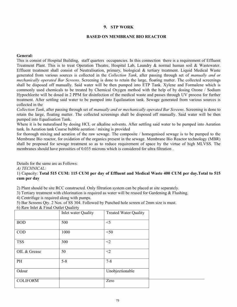
73
9. STP WORK
BASED ON MEMBRANE BIO REACTOR
General: This is consist of Hospital Building, staff quarters occupancies. In this connection there is a requirement of Effluent Treatment Plant. This is to treat Operation Theatre, Hospital Lab, Laundry & normal human soil & Wastewater. Effluent treatment shall consist of Neutralisation, primary, biological & tertiary treatment. Liquid Medical Waste generated from various sources is collected in the Collection Tank, after passing through set of manually and or mechanically operated Bar Screens. Screening is done to retain the large, floating matter. The collected screenings shall be disposed off manually. Said water will be then pumped into ETP Tank. Xylene and Formalene which is commonly used chemicals to be treated by Chemical Oxygen method with the help of by dosing Ozone / Sodium Hypochlorite will be dosed in 2 PPM for disinfection of the medical waste and passes through UV process for further treatment. After settling said water to be pumped into Equilasation tank. Sewage generated from various sources is collected in the Collection Tank, after passing through set of manually and or mechanically operated Bar Screens. Screening is done to retain the large, floating matter. The collected screenings shall be disposed off manually. Said water will be then pumped into Equalisation Tank. Where it is be nuturalised by dosing HCL or alkaline solvents. After settling said water to be pumped into Aeration tank. In Aeration tank Coarse bubble aeration / mixing is provided for thorough mixing and aeration of the raw sewage. The composite / homogenised sewage is to be pumped to the Membrane Bio reactor, for oxidation of the organics present in the sewage. Membrane Bio Reactor technology (MBR) shall be proposed for sewage treatment so as to reduce requirement of space by the virtue of high MLVSS. The membranes should have porosities of 0.035 microns which is considered for ultra filtration . Details for the same are as Follows: A) TECHNICAL: 1) Capacity: Total 515 CUM: 115 CUM per day of Effluent and Medical Waste 400 CUM per day.Total to 515 cum per day 2) Plant should be site RCC constructed. Only filtration system can be placed at site separately. 3) Tertiary treatment with chlorination is required as water will be reused for Gardening & Flushing. 4) Centrifuge is required along with pumps. 5) Bar Screens Qty. 2 Nos. of SS 304. Followed by Punched hole screen of 2mm size is must. 6) Raw Inlet & Final Outlet Qualirty Inlet water Quality Treated Water Quality
BOD 500 <5
COD 1000 <50
TSS 300 <2
OIL & Grease 50 <2
PH 5-8 7-8
Odour Unobjectionable
COLIFORM Zero
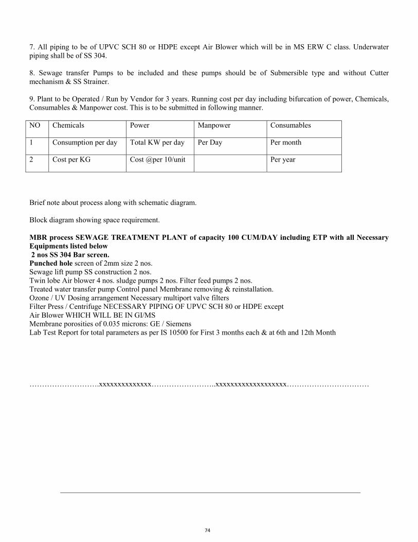
74
7. All piping to be of UPVC SCH 80 or HDPE except Air Blower which will be in MS ERW C class. Underwater piping shall be of SS 304. 8. Sewage transfer Pumps to be included and these pumps should be of Submersible type and without Cutter mechanism & SS Strainer. 9. Plant to be Operated / Run by Vendor for 3 years. Running cost per day including bifurcation of power, Chemicals, Consumables & Manpower cost. This is to be submitted in following manner. NO Chemicals Power Manpower Consumables
1 Consumption per day Total KW per day Per Day Per month
2 Cost per KG Cost @per 10/unit Per year
Brief note about process along with schematic diagram. Block diagram showing space requirement. MBR process SEWAGE TREATMENT PLANT of capacity 100 CUM/DAY including ETP with all Necessary Equipments listed below 2 nos SS 304 Bar screen. Punched hole screen of 2mm size 2 nos. Sewage lift pump SS construction 2 nos. Twin lobe Air blower 4 nos. sludge pumps 2 nos. Filter feed pumps 2 nos. Treated water transfer pump Control panel Membrane removing & reinstallation. Ozone / UV Dosing arrangement Necessary multiport valve filters Filter Press / Centrifuge NECESSARY PIPING OF UPVC SCH 80 or HDPE except Air Blower WHICH WILL BE IN GI/MS Membrane porosities of 0.035 microns: GE / Siemens Lab Test Report for total parameters as per IS 10500 for First 3 months each & at 6th and 12th Month
……………………….xxxxxxxxxxxxxx……………………..xxxxxxxxxxxxxxxxxxx……………………………
75
10. TECHNICAL SPECIFICATIONS FOR SOLAR PV
A. General:
1. Tenderer shall go through the specifications properly, visit the site and get acquainted with
quantum of work, site conditions & get cleared all the doubts and queries with MCGM
Engineers before uploading the tender. Further no any excuses shall be entertained.
2. Drawings attached herewith are for reference only and successful renderer shall get
approved the drawings before manufacturing.
3. Contractor or their representative shall bring all the tools, tackles & equipments required
for the work.
4. Contractor or their representative shall carry out the work with due care following safety of
man power & equipment.
5. After completion of successful installation of solar power plant, pre-commissioning checks
and final charging is to be carried out. It is Contractor's responsibility to consider all the
aspects required for successful charging of solar power plant. Any changes of whosoever
nature required for successful charging shall be carried out by successful Contractor at his
own cost to complete the work.
6. Successful Tenderer shall provide two sets of operational manuals & as built drawings of
the entire 20 KWp Solar Power Plant including electrical layouts & detailed drawings.
7. The test certificates for material compliance of the major components shall be submitted by
the Successful Tenderer.
D D O C U M E N T Page 96
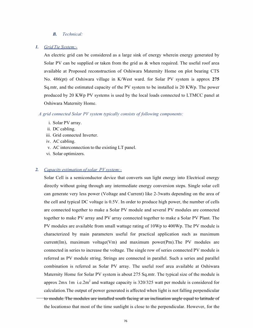
76
B. Technical:
1. Grid Tie System:-
An electric grid can be considered as a large sink of energy wherein energy generated by
Solar PV can be supplied or taken from the grid as & when required. The useful roof area
available at Proposed reconstruction of Oshiwara Maternity Home on plot bearing CTS
No. 486(pt) of Oshiwara village in K/West ward. for Solar PV system is approx 275
Sq.mtr, and the estimated capacity of the PV system to be installed is 20 KWp. The power
produced by 20 KWp PV systems is used by the local loads connected to LTMCC panel at
Oshiwara Maternity Home.
A grid connected Solar PV system typically consists of following components:
i. Solar PV array. ii. DC cabling.
iii. Grid connected Inverter. iv. AC cabling. v. AC interconnection to the existing LT panel.
vi. Solar optimizers.
2. Capacity estimation of solar PV system:-
Solar Cell is a semiconductor device that converts sun light energy into Electrical energy
directly without going through any intermediate energy conversion steps. Single solar cell
can generate very less power (Voltage and Current) like 2-3watts depending on the area of
the cell and typical DC voltage is 0.5V. In order to produce high power, the number of cells
are connected together to make a Solar PV module and several PV modules are connected
together to make PV array and PV array connected together to make a Solar PV Plant. The
PV modules are available from small wattage rating of 10Wp to 400Wp. The PV module is
characterized by main parameters useful for practical application such as maximum
current(Im), maximum voltage(Vm) and maximum power(Pm).The PV modules are
connected in series to increase the voltage. The single row of series connected PV module is
referred as PV module string. Strings are connected in parallel. Such a series and parallel
combination is referred as Solar PV array. The useful roof area available at Oshiwara
Maternity Home for Solar PV system is about 275 Sq.mtr. The typical size of the module is
approx 2m x 1m i.e.2m2 and wattage capacity is 320/325 watt per module is considered for
calculation. The output of power generated is affected when light is not falling perpendicular
to module. The modules are installed south facing at an inclination angle equal to latitude of
the location so that most of the time sunlight is close to the perpendicular. However, for the

77
estimation and capacity calculation purpose, total 63 P.V. modules can be easily
accommodate in the available area with considering sufficient area between the rows of the
Solar modules, sufficient area along the sides and area for DC-AC cabling work.
Energy Estimation calculation:-
Number of modules on the roof= 63
WATTAGE OF EACH MODULE=320WP
Total Wattage of the Plant=320 x63= 20,160Wp =( Approx 20 KWp)
3. Solar PV Module:-
Polycrystalline high power cells shall be used in Solar PV Module. To connect the Solar
Module Interconnection cable shall be provided. Photoelectric conversion efficiency of SPV
Module shall be greater than 16.5 %. Module shall have hot butyl rubber edge sealant for
module protection. The module shall be UL and CE approval. The module frame is made of
corrosion resistant material, which is electrolytically compatible with the structural material
used for mounting the module. Weather resistant module junction box shall be designed for
long life and outdoor operation environment. Solar PV modules from the following Tier 1
Indian Manufacturers i.e. Tata Waaree, and Vikram or equivalent tier –I Indian
manufacturers will be accepted. A minimum warranty of 10 years shall be given with
degradation of power generated not exceeding 10% over the entire 10 years period. In addition
to that, 25 years linear output warranty shall be offered. Manufacturers test certificates for solar
PV modules shall be submitted. Data sheet with details like Current/voltage/ module efficiency,
of the offered module shall be submitted. The solar PV Modules should be made in India with
service setup/office located in MMRDA zone.
PV modules considered are with minimum declared output of 320/325 Wp or more. Number of
Modules to be supplied shall be worked out accordingly. Total Stabilized output of the Solar PV
array for the Power Plants should not be less than 20 KW.
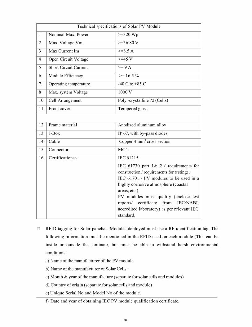
78
Technical specifications of Solar PV Module
1 Nominal Max. Power >=320 Wp
2 Max Voltage Vm >=36.80 V
3 Max Current Im >=8.5 A
4 Open Circuit Voltage >=45 V
5 Short Circuit Current >= 9 A
6. Module Efficiency >= 16.5 %
7. Operating temperature -40 C to +85 C
8 Max. system Voltage 1000 V
10 Cell Arrangement Poly -crystalline 72 (Cells)
11 Front cover Tempered glass
age
12 Frame material Anodized aluminum alloy
13 J-Box IP 67, with by-pass diodes
14 Cable Copper 4 mm2 cross section
15 Connector MC4
16 Certifications:- IEC 61215.
IEC 61730 part 1& 2 ( requirements for
construction / requirements for testing) , IEC 61701:- PV modules to be used in a highly corrosive atmosphere (coastal areas, etc.) PV modules must qualify (enclose test reports/ certificate from IEC/NABL accredited laboratory) as per relevant IEC standard.
RFID tagging for Solar panels: - Modules deployed must use a RF identification tag. The
following information must be mentioned in the RFID used on each module (This can be
inside or outside the laminate, but must be able to withstand harsh environmental
conditions.
a) Name of the manufacturer of the PV module
b) Name of the manufacturer of Solar Cells.
c) Month & year of the manufacture (separate for solar cells and modules)
d) Country of origin (separate for solar cells and module)
e) Unique Serial No and Model No of the module.
f) Date and year of obtaining IEC PV module qualification certificate.

79
g) Other relevant information on traceability of solar cells and module.
h) Name of the test lab issuing IEC certificate.
The successful tender shall arrange the RFID reader machine as per the instructions of
MCGM engineers for decoding the encrypted data.
The technical specifications of solar module are indicative however contractor shall select no of Modules as per design to fulfill the desired generation capacity of 20KW.
B I D D O C U M E N T Page 99
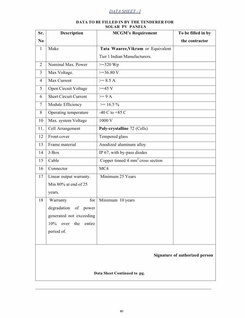
80
DATA SHEET - I
DATA TO BE FILLED IN BY THE TENDERER FOR SOLAR PV PANELS
Sr.
No
Description MCGM’s Requirement To be filled in by
the contractor
1 Make Tata Waaree,Vikram or Equivalent
Tier 1 Indian Manufacturers.
2 Nominal Max. Power >=320 Wp
3 Max Voltage. >=36.80 V
4 Max Current >= 8.5 A
5 Open Circuit Voltage >=45 V
6 Short Circuit Current >= 9 A
7 Module Efficiency >= 16.5 %
8 Operating temperature -40 C to +85 C
10 Max. system Voltage 1000 V
11. Cell Arrangement Poly-crystalline 72 (Cells)
12 Front cover Tempered glass
13 Frame material Anodized aluminum alloy
14 J-Box IP 67, with by-pass diodes
15 Cable Copper tinned 4 mm2 cross section
16 Connector MC4
17 Linear output warranty.
Min 80% at end of 25
years.
Minimum 25 Years
18 Warranty for
degradation of power
generated not exceeding
10% over the entire
period of.
Minimum 10 years
Signature of authorized person
Data Sheet Continued to pg.
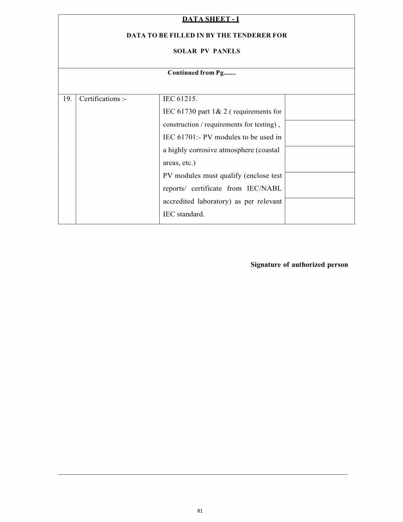
81
B I D D O C U M E N T DATA SHEET - I
DATA TO BE FILLED IN BY THE TENDERER FOR
SOLAR PV PANELS
Continued from Pg.......
19. Certifications :- IEC 61215.
IEC 61730 part 1& 2 ( requirements for
construction / requirements for testing) ,
IEC 61701:- PV modules to be used in
a highly corrosive atmosphere (coastal
areas, etc.)
PV modules must qualify (enclose test
reports/ certificate from IEC/NABL
accredited laboratory) as per relevant
IEC standard.
Signature of authorized person
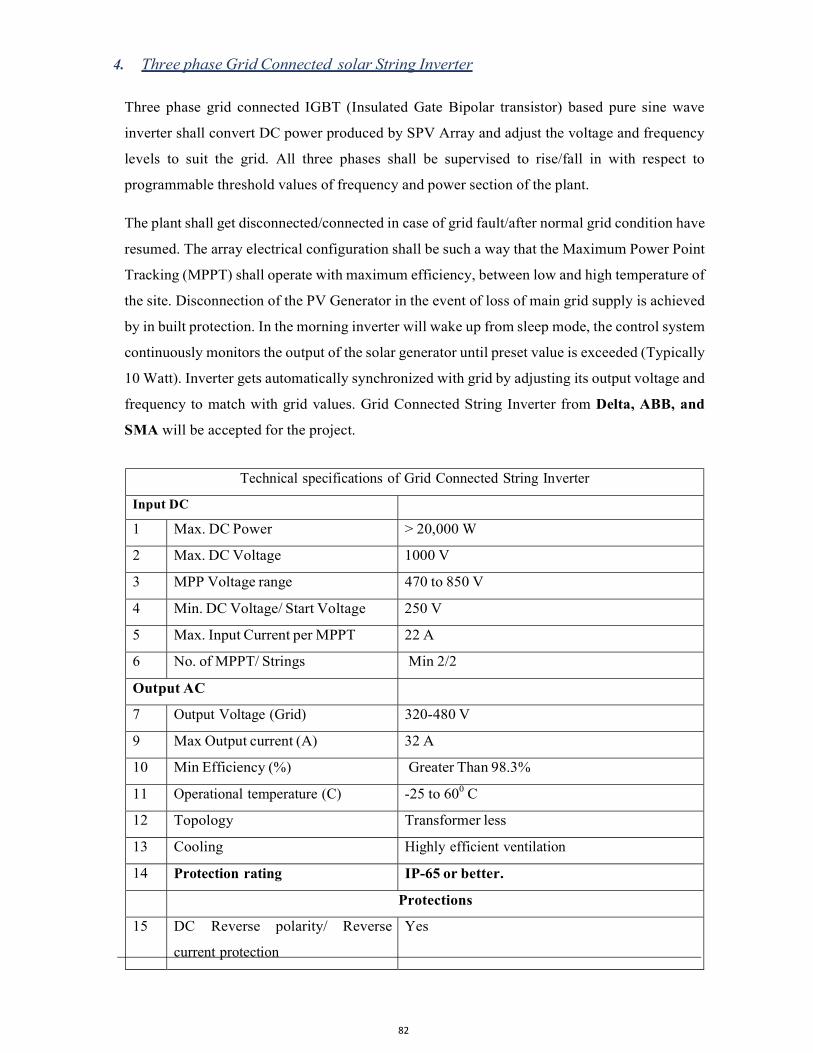
82
d f r f h h 4. Three phase Grid Connected solar String Inverter
Three phase grid connected IGBT (Insulated Gate Bipolar transistor) based pure sine wave
inverter shall convert DC power produced by SPV Array and adjust the voltage and frequency
levels to suit the grid. All three phases shall be supervised to rise/fall in with respect to
programmable threshold values of frequency and power section of the plant.
The plant shall get disconnected/connected in case of grid fault/after normal grid condition have
resumed. The array electrical configuration shall be such a way that the Maximum Power Point
Tracking (MPPT) shall operate with maximum efficiency, between low and high temperature of
the site. Disconnection of the PV Generator in the event of loss of main grid supply is achieved
by in built protection. In the morning inverter will wake up from sleep mode, the control system
continuously monitors the output of the solar generator until preset value is exceeded (Typically
10 Watt). Inverter gets automatically synchronized with grid by adjusting its output voltage and
frequency to match with grid values. Grid Connected String Inverter from Delta, ABB, and
SMA will be accepted for the project.
Technical specifications of Grid Connected String Inverter
Input DC
1 Max. DC Power > 20,000 W
2 Max. DC Voltage 1000 V
3 MPP Voltage range 470 to 850 V
4 Min. DC Voltage/ Start Voltage 250 V
5 Max. Input Current per MPPT 22 A
6 No. of MPPT/ Strings Min 2/2
Output AC
7 Output Voltage (Grid) 320-480 V
9 Max Output current (A) 32 A
10 Min Efficiency (%) Greater Than 98.3%
11 Operational temperature (C) -25 to 600 C
12 Topology Transformer less
13 Cooling Highly efficient ventilation
14 Protection rating IP-65 or better.
Protections
15 DC Reverse polarity/ Reverse
current protection
Yes
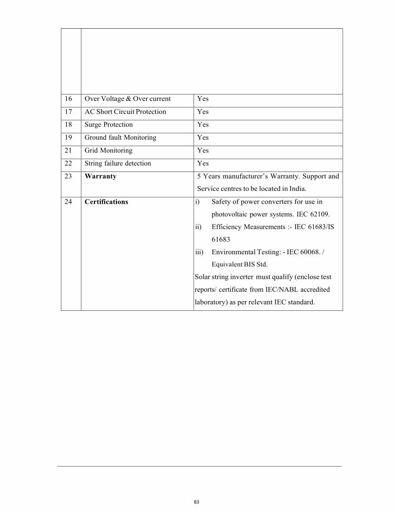
83
B I D D OC UM EN T Page 102
16 Over Voltage & Over current Yes
17 AC Short Circuit Protection Yes
18 Surge Protection Yes
19 Ground fault Monitoring Yes
21 Grid Monitoring Yes
22 String failure detection Yes
23 Warranty 5 Years manufacturer’s Warranty. Support and
Service centres to be located in India.
24 Certifications i) Safety of power converters for use in
photovoltaic power systems. IEC 62109.
ii) Efficiency Measurements :- IEC 61683/IS
61683
iii) Environmental Testing: - IEC 60068. /
Equivalent BIS Std.
Solar string inverter must qualify (enclose test
reports/ certificate from IEC/NABL accredited
laboratory) as per relevant IEC standard.
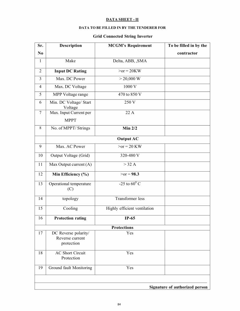
84
DATA SHEET - II
DATA TO BE FILLED IN BY THE TENDERER FOR
Grid Connected String Inverter
Sr.
No
Description MCGM’s Requirement To be filled in by the
contractor
1 Make Delta, ABB, ,SMA
2 Input DC Rating >or = 20KW
3 Max. DC Power > 20,000 W
4 Max. DC Voltage 1000 V
5 MPP Voltage range 470 to 850 V
6 Min. DC Voltage/ Start Voltage
250 V
7 Max. Input Current per
MPPT
22 A
8 No. of MPPT/ Strings Min 2/2
Output AC
9 Max. AC Power >or = 20 KW
10 Output Voltage (Grid) 320-480 V
11 Max Output current (A) > 32 A
12 Min Efficiency (%) >or = 98.3
13 Operational temperature (C)
-25 to 600 C
14 topology Transformer less
15 Cooling Highly efficient ventilation
16 Protection rating IP-65
Protections 17 DC Reverse polarity/
Reverse current protection
Yes
18 AC Short Circuit Protection
Yes
19 Ground fault Monitoring Yes
Signature of authorized person
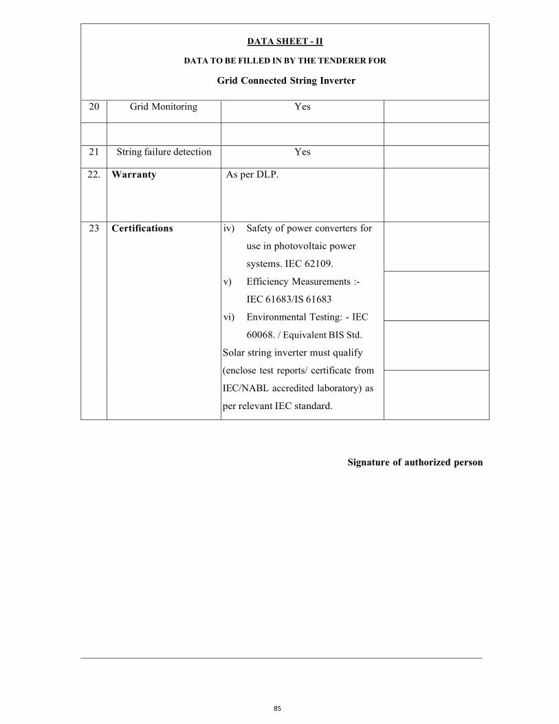
85
DATA SHEET - II
DATA TO BE FILLED IN BY THE TENDERER FOR
Grid Connected String Inverter
20 Grid Monitoring Yes
21 String failure detection Yes
22. Warranty As per DLP.
23 Certifications iv) Safety of power converters for
use in photovoltaic power
systems. IEC 62109.
v) Efficiency Measurements :-
IEC 61683/IS 61683
vi) Environmental Testing: - IEC
60068. / Equivalent BIS Std.
Solar string inverter must qualify
(enclose test reports/ certificate from
IEC/NABL accredited laboratory) as
per relevant IEC standard.
Signature of authorized person
105
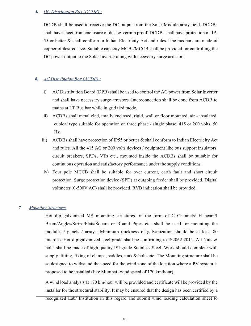
86
5. DC Distribution Box (DCDB) :
DCDB shall be used to receive the DC output from the Solar Module array field. DCDBs
shall have sheet from enclosure of dust & vermin proof. DCDBs shall have protection of IP-
55 or better & shall conform to Indian Electricity Act and rules. The bus bars are made of
copper of desired size. Suitable capacity MCBs/MCCB shall be provided for controlling the
DC power output to the Solar Inverter along with necessary surge arrestors.
6. AC Distribution Box (ACDB) :
i) AC Distribution Board (DPB) shall be used to control the AC power from Solar Inverter
and shall have necessary surge arrestors. Interconnection shall be done from ACDB to
mains at LT Bus bar while in grid tied mode.
ii) ACDBs shall metal clad, totally enclosed, rigid, wall or floor mounted, air - insulated,
cubical type suitable for operation on three phase / single phase, 415 or 200 volts, 50
Hz.
iii) ACDBs shall have protection of IP55 or better & shall conform to Indian Electricity Act
and rules. All the 415 AC or 200 volts devices / equipment like bus support insulators,
circuit breakers, SPDs, VTs etc., mounted inside the ACDBs shall be suitable for
continuous operation and satisfactory performance under the supply conditions.
iv) Four pole MCCB shall be suitable for over current, earth fault and short circuit
protection. Surge protection device (SPD) at outgoing feeder shall be provided. Digital
voltmeter (0-500V AC) shall be provided. RYB indication shall be provided.
7. Mounting Structures
Hot dip galvanized MS mounting structures- in the form of C Channels/ H beam/I
Beam/Angles/Strips/Flats/Square or Round Pipes etc. shall be used for mounting the
modules / panels / arrays. Minimum thickness of galvanization should be at least 80
microns. Hot dip galvanized steel grade shall be confirming to IS2062-2011. All Nuts &
bolts shall be made of high quality ISI grade Stainless Steel. Work should complete with
supply, fitting, fixing of clamps, saddles, nuts & bolts etc. The Mounting structure shall be
so designed to withstand the speed for the wind zone of the location where a PV system is
proposed to be installed (like Mumbai -wind speed of 170 km/hour).
A wind load analysis at 170 km/hour will be provided and certificate will be provided by the
installer for the structural stability. It may be ensured that the design has been certified by a
recognized Lab/ Institution in this regard and submit wind loading calculation sheet to
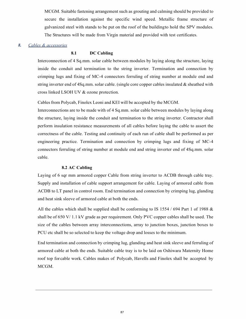
87
MCGM. Suitable fastening arrangement such as grouting and calming should be provided to
secure the installation against the specific wind speed. Metallic frame structure of
galvanized steel with stands to be put on the roof of the building to hold the SPV modules.
The Structures will be made from Virgin material and provided with test certificates.
8. Cables & accessories
8.1 DC Cabling
Interconnection of 4 Sq.mm. solar cable between modules by laying along the structure, laying
inside the conduit and termination to the string inverter. Termination and connection by
crimping lugs and fixing of MC-4 connectors ferruling of string number at module end and
string inverter end of 4Sq.mm. solar cable. (single core copper cables insulated & sheathed with
cross linked LSOH UV & ozone protection.
Cables from Polycab, Finolex Leoni and KEI will be accepted by the MCGM.
Interconnections are to be made with of 4 Sq.mm. solar cable between modules by laying along
the structure, laying inside the conduit and termination to the string inverter. Contractor shall
perform insulation resistance measurements of all cables before laying the cable to assert the
correctness of the cable. Testing and continuity of each run of cable shall be performed as per
engineering practice. Termination and connection by crimping lugs and fixing of MC-4
connectors ferruling of string number at module end and string inverter end of 4Sq.mm. solar
cable.
8.2 AC Cabling
Laying of 6 sqr mm armored copper Cable from string inverter to ACDB through cable tray.
Supply and installation of cable support arrangement for cable. Laying of armored cable from
ACDB to LT panel in control room. End termination and connection by crimping lug, glanding
and heat sink sleeve of armored cable at both the ends.
All the cables which shall be supplied shall be conforming to IS 1554 / 694 Part 1 of 1988 &
shall be of 650 V/ 1.1 kV grade as per requirement. Only PVC copper cables shall be used. The
size of the cables between array interconnections, array to junction boxes, junction boxes to
PCU etc shall be so selected to keep the voltage drop and losses to the minimum.
End termination and connection by crimping lug, glanding and heat sink sleeve and ferruling of
armored cable at both the ends. Suitable cable tray is to be laid on Oshiwara Maternity Home
roof top for cable work. Cables makes of Polycab, Havells and Finolex shall be accepted by
MCGM.
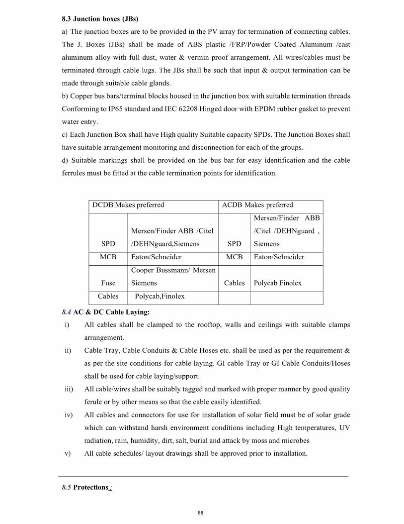
88
8.3 Junction boxes (JBs)
a) The junction boxes are to be provided in the PV array for termination of connecting cables.
The J. Boxes (JBs) shall be made of ABS plastic /FRP/Powder Coated Aluminum /cast
aluminum alloy with full dust, water & vermin proof arrangement. All wires/cables must be
terminated through cable lugs. The JBs shall be such that input & output termination can be
made through suitable cable glands.
b) Copper bus bars/terminal blocks housed in the junction box with suitable termination threads
Conforming to IP65 standard and IEC 62208 Hinged door with EPDM rubber gasket to prevent
water entry.
c) Each Junction Box shall have High quality Suitable capacity SPDs. The Junction Boxes shall
have suitable arrangement monitoring and disconnection for each of the groups.
d) Suitable markings shall be provided on the bus bar for easy identification and the cable
ferrules must be fitted at the cable termination points for identification.
DCDB Makes preferred ACDB Makes preferred
SPD
Mersen/Finder ABB /Citel
/DEHNguard,Siemens
SPD
Mersen/Finder ABB
/Citel /DEHNguard ,
Siemens
MCB Eaton/Schneider MCB Eaton/Schneider
Fuse
Cooper Bussmann/ Mersen
Siemens
Cables Polycab Finolex
Cables Polycab,Finolex
8.4 AC & DC Cable Laying:
i) All cables shall be clamped to the rooftop, walls and ceilings with suitable clamps
arrangement.
ii) Cable Tray, Cable Conduits & Cable Hoses etc. shall be used as per the requirement &
as per the site conditions for cable laying. GI cable Tray or GI Cable Conduits/Hoses
shall be used for cable laying/support.
iii) All cable/wires shall be suitably tagged and marked with proper manner by good quality
ferule or by other means so that the cable easily identified.
iv) All cables and connectors for use for installation of solar field must be of solar grade
which can withstand harsh environment conditions including High temperatures, UV
radiation, rain, humidity, dirt, salt, burial and attack by moss and microbes
v) All cable schedules/ layout drawings shall be approved prior to installation.
8.5 Protections :
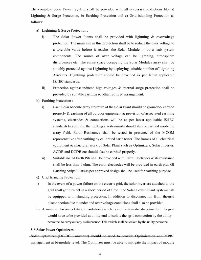
89
The complete Solar Power System shall be provided with all necessary protections like a)
Lightning & Surge Protection, b) Earthing Protection and c) Grid islanding Protection as
follows:
a) Lightning & Surge Protection :
i) The Solar Power Plants shall be provided with lightning & overvoltage
protection. The main aim in this protection shall be to reduce the over voltage to
a tolerable value before it reaches the Solar Module or other sub system
components. The source of over voltage can be lightning, atmosphere
disturbances etc. The entire space occupying the Solar Modules array shall be
suitably protected against Lightning by deploying suitable number of Lightning
Arrestors. Lightning protection should be provided as per latest applicable
IS/IEC standards.
ii) Protection against induced high-voltages & internal surge protection shall be
provided by suitable earthing & other required arrangement.
b) Earthing Protection :
i) Each Solar Module array structure of the Solar Plant should be grounded/ earthed
properly & earthing of all outdoor equipment & provision of associated earthing
systems, electrodes & connections will be as per latest applicable IS/IEC
standards In addition, the lighting arrester/masts should also be earthed inside the
array field. Earth Resistance shall be tested in presence of the MCGM
representative after earthing by calibrated earth tester. The frames of all electrical
equipment & structural work of Solar Plant such as Optimizers, Solar Inverter,
ACDB and DCDB etc should also be earthed properly.
ii) Suitable no. of Earth Pits shall be provided with Earth Electrodes & its resistance
shall be less than 1 ohm. The earth electrodes will be provided in earth pits. GI
Earthing Strips/ Flats as per approved design shall be used for earthing purpose.
c) Grid Islanding Protection:
i) In the event of a power failure on the electric grid, the solar inverters attached to the
grid shall get turn off in a short period of time. The Solar Power Plant system shall
be equipped with islanding protection. In addition to disconnection from the grid
disconnection due to under and over voltage conditions shall also be provided.
ii) A manual disconnect 4-pole isolation switch beside automatic disconnection to grid
would have to be provided at utility end to isolate the grid connection by the utility
personnel to carry out any maintenance. This switch shall be locked by the utility personnel.
8.6 Solar Power Optimizers
Solar Optimizer (DC/DC Converter) should be used to provide Optimization and MPPT
management at bi-module level. The Optimizer must be able to mitigate the impact of module
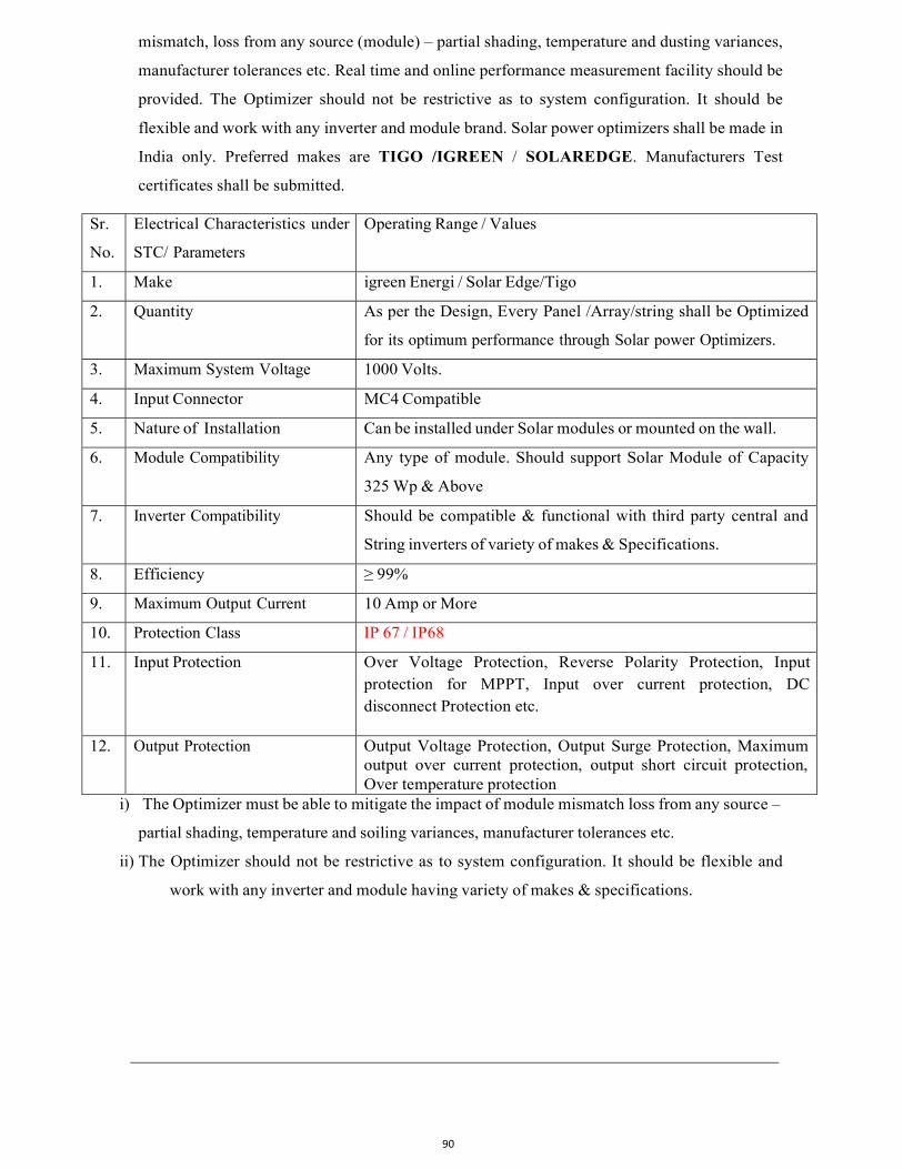
90
mismatch, loss from any source (module) – partial shading, temperature and dusting variances,
manufacturer tolerances etc. Real time and online performance measurement facility should be
provided. The Optimizer should not be restrictive as to system configuration. It should be
flexible and work with any inverter and module brand. Solar power optimizers shall be made in
India only. Preferred makes are TIGO /IGREEN / SOLAREDGE. Manufacturers Test
certificates shall be submitted.
Sr.
No.
Electrical Characteristics under
STC/ Parameters
Operating Range / Values
1. Make igreen Energi / Solar Edge/Tigo
2. Quantity As per the Design, Every Panel /Array/string shall be Optimized
for its optimum performance through Solar power Optimizers.
3. Maximum System Voltage 1000 Volts.
4. Input Connector MC4 Compatible
5. Nature of Installation Can be installed under Solar modules or mounted on the wall.
6. Module Compatibility Any type of module. Should support Solar Module of Capacity
325 Wp & Above
7. Inverter Compatibility Should be compatible & functional with third party central and
String inverters of variety of makes & Specifications.
8. Efficiency ≥ 99%
9. Maximum Output Current 10 Amp or More
10. Protection Class IP 67 / IP68
11. Input Protection Over Voltage Protection, Reverse Polarity Protection, Input protection for MPPT, Input over current protection, DC disconnect Protection etc.
12. Output Protection Output Voltage Protection, Output Surge Protection, Maximum output over current protection, output short circuit protection, Over temperature protection
i) The Optimizer must be able to mitigate the impact of module mismatch loss from any source –
partial shading, temperature and soiling variances, manufacturer tolerances etc.
ii) The Optimizer should not be restrictive as to system configuration. It should be flexible and
work with any inverter and module having variety of makes & specifications.Page 110
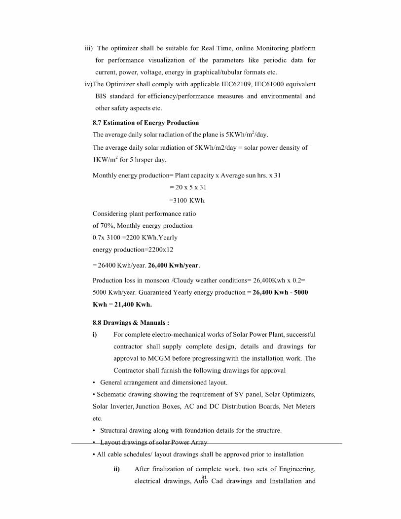
91
iii) The optimizer shall be suitable for Real Time, online Monitoring platform
for performance visualization of the parameters like periodic data for
current, power, voltage, energy in graphical/tubular formats etc.
iv) The Optimizer shall comply with applicable IEC62109, IEC61000 equivalent
BIS standard for efficiency/performance measures and environmental and
other safety aspects etc.
8.7 Estimation of Energy Production
The average daily solar radiation of the plane is 5KWh/m2/day.
The average daily solar radiation of 5KWh/m2/day = solar power density of
1KW/m2 for 5 hrs per day.
Monthly energy production= Plant capacity x Average sun hrs. x 31
= 20 x 5 x 31
=3100 KWh.
Considering plant performance ratio
of 70%, Monthly energy production=
0.7x 3100 =2200 KWh. Yearly
energy production=2200x12
= 26400 Kwh/year. 26,400 Kwh/year.
Production loss in monsoon /Cloudy weather conditions= 26,400Kwh x 0.2=
5000 Kwh/year. Guaranteed Yearly energy production = 26,400 Kwh - 5000
Kwh = 21,400 Kwh.
8.8 Drawings & Manuals :
i) For complete electro-mechanical works of Solar Power Plant, successful
contractor shall supply complete design, details and drawings for
approval to MCGM before progressing with the installation work. The
Contractor shall furnish the following drawings for approval
• General arrangement and dimensioned layout.
• Schematic drawing showing the requirement of SV panel, Solar Optimizers,
Solar Inverter, Junction Boxes, AC and DC Distribution Boards, Net Meters
etc.
• Structural drawing along with foundation details for the structure.
• Layout drawings of solar Power Array
• All cable schedules/ layout drawings shall be approved prior to installation
ii) After finalization of complete work, two sets of Engineering,
electrical drawings, Auto Cad drawings and Installation and
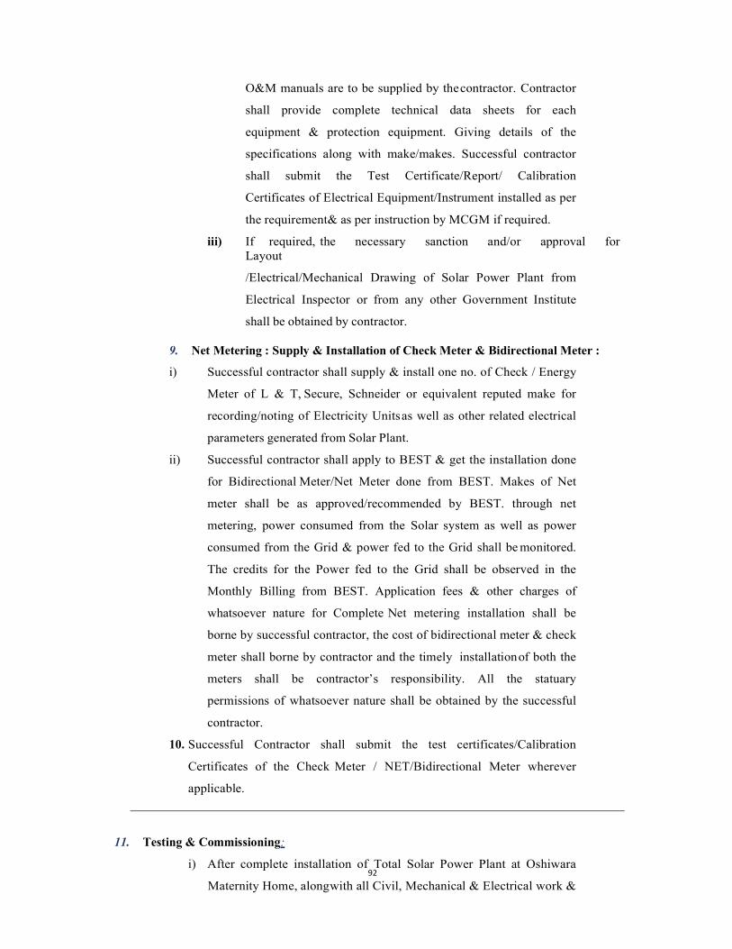
92
O&M manuals are to be supplied by the contractor. Contractor
shall provide complete technical data sheets for each
equipment & protection equipment. Giving details of the
specifications along with make/makes. Successful contractor
shall submit the Test Certificate/Report/ Calibration
Certificates of Electrical Equipment/Instrument installed as per
the requirement & as per instruction by MCGM if required.
iii) If required, the necessary sanction and/or approval for Layout
/Electrical/Mechanical Drawing of Solar Power Plant from
Electrical Inspector or from any other Government Institute
shall be obtained by contractor.
9. Net Metering : Supply & Installation of Check Meter & Bidirectional Meter :
i) Successful contractor shall supply & install one no. of Check / Energy
Meter of L & T, Secure, Schneider or equivalent reputed make for
recording/noting of Electricity Units as well as other related electrical
parameters generated from Solar Plant.
ii) Successful contractor shall apply to BEST & get the installation done
for Bidirectional Meter/Net Meter done from BEST. Makes of Net
meter shall be as approved/recommended by BEST. through net
metering, power consumed from the Solar system as well as power
consumed from the Grid & power fed to the Grid shall be monitored.
The credits for the Power fed to the Grid shall be observed in the
Monthly Billing from BEST. Application fees & other charges of
whatsoever nature for Complete Net metering installation shall be
borne by successful contractor, the cost of bidirectional meter & check
meter shall borne by contractor and the timely installation of both the
meters shall be contractor’s responsibility. All the statuary
permissions of whatsoever nature shall be obtained by the successful
contractor.
10. Successful Contractor shall submit the test certificates/Calibration
Certificates of the Check Meter / NET/Bidirectional Meter wherever
applicable.
11. Testing & Commissioning:
i) After complete installation of Total Solar Power Plant at Oshiwara
Maternity Home, along with all Civil, Mechanical & Electrical work &
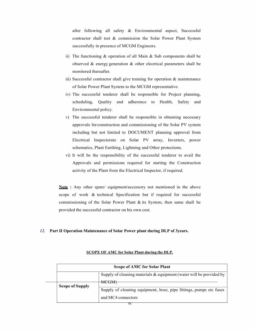
93
after following all safety & Environmental aspect, Successful
contractor shall test & commission the Solar Power Plant System
successfully in presence of MCGM Engineers.
ii) The functioning & operation of all Main & Sub components shall be
observed & energy generation & other electrical parameters shall be
monitored thereafter.
iii) Successful contractor shall give training for operation & maintenance
of Solar Power Plant System to the MCGM representative.
iv) The successful tenderer shall be responsible for Project planning,
scheduling, Quality and adherence to Health, Safety and
Environmental policy.
v) The successful tenderer shall be responsible in obtaining necessary
approvals for construction and commissioning of the Solar PV system
including but not limited to DOCUMENT planning approval from
Electrical Inspectorate on Solar PV array, Inverters, power
schematics, Plant Earthing, Lightning and Other protections.
vi) It will be the responsibility of the successful tenderer to avail the
Approvals and permissions required for starting the Construction
activity of the Plant from the Electrical Inspector, if required.
Note : Any other spare/ equipment/accessory not mentioned in the above
scope of work & technical Specification but if required for successful
commissioning of the Solar Power Plant & its System, then same shall be
provided the successful contractor on his own cost.
12. Part II Operation Maintenance of Solar Power plant during DLP of 3years.
SCOPE OF AMC for Solar Plant during the DLP.
Scope of AMC for Solar Plant
Scope of Supply
Supply of cleaning materials & equipment (water will be provided by
MCGM)
Supply of cleaning equipment, hose, pipe fittings, pumps etc fuses
and MC4 connectors
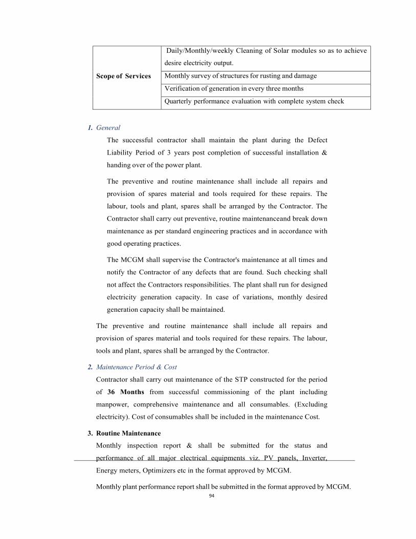
94
Scope of Services
Daily/Monthly/weekly Cleaning of Solar modules so as to achieve
desire electricity output.
Monthly survey of structures for rusting and damage
Verification of generation in every three months
Quarterly performance evaluation with complete system check
1. General
The successful contractor shall maintain the plant during the Defect
Liability Period of 3 years post completion of successful installation &
handing over of the power plant.
The preventive and routine maintenance shall include all repairs and
provision of spares material and tools required for these repairs. The
labour, tools and plant, spares shall be arranged by the Contractor. The
Contractor shall carry out preventive, routine maintenance and break down
maintenance as per standard engineering practices and in accordance with
good operating practices.
The MCGM shall supervise the Contractor's maintenance at all times and
notify the Contractor of any defects that are found. Such checking shall
not affect the Contractors responsibilities. The plant shall run for designed
electricity generation capacity. In case of variations, monthly desired
generation capacity shall be maintained.
The preventive and routine maintenance shall include all repairs and
provision of spares material and tools required for these repairs. The labour,
tools and plant, spares shall be arranged by the Contractor.
2. Maintenance Period & Cost
Contractor shall carry out maintenance of the STP constructed for the period
of 36 Months from successful commissioning of the plant including
manpower, comprehensive maintenance and all consumables. (Excluding
electricity). Cost of consumables shall be included in the maintenance Cost.
3. Routine Maintenance
Monthly inspection report & shall be submitted for the status and
performance of all major electrical equipments viz. PV panels, Inverter,
Energy meters, Optimizers etc in the format approved by MCGM.
Monthly plant performance report shall be submitted in the format approved by MCGM.
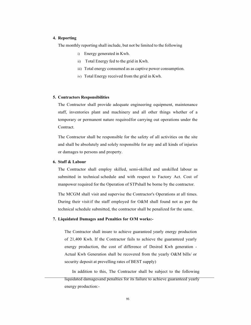
95
4. Reporting
The monthly reporting shall include, but not be limited to the following
i) Energy generated in Kwh.
ii) Total Energy fed to the grid in Kwh.
iii) Total energy consumed as as captive power consumption.
iv) Total Energy received from the grid in Kwh.
5. Contractors Responsibilities
The Contractor shall provide adequate engineering equipment, maintenance
staff, inventories plant and machinery and all other things whether of a
temporary or permanent nature required for carrying out operations under the
Contract.
The Contractor shall be responsible for the safety of all activities on the site
and shall be absolutely and solely responsible for any and all kinds of injuries
or damages to persons and property.
6. Staff & Labour
The Contractor shall employ skilled, semi-skilled and unskilled labour as
submitted in technical schedule and with respect to Factory Act. Cost of
manpower required for the Operation of STP shall be borne by the contractor.
The MCGM shall visit and supervise the Contractor's Operations at all times.
During their visit if the staff employed for O&M shall found not as per the
technical schedule submitted, the contractor shall be penalized for the same.
7. Liquidated Damages and Penalties for O/M works:-
The Contractor shall insure to achieve guaranteed yearly energy production
of 21,400 Kwh. If the Contractor fails to achieve the guaranteed yearly
energy production, the cost of difference of Desired Kwh generation -
Actual Kwh Generation shall be recovered from the yearly O&M bills/ or
security deposit at prevelling rates of BEST supply)
In addition to this, The Contractor shall be subject to the following
liquidated damages and penalties for its failure to achieve guaranteed yearly
energy production:-
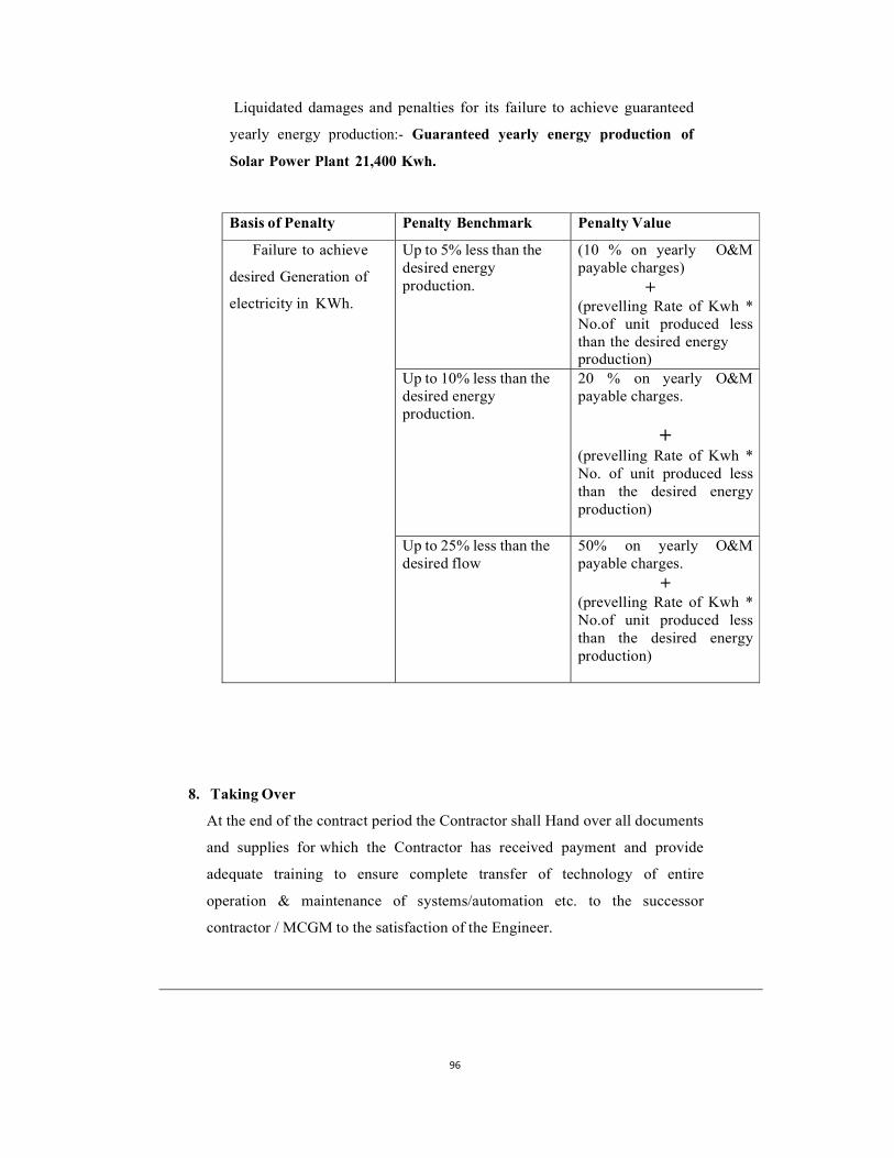
96
Liquidated damages and penalties for its failure to achieve guaranteed
yearly energy production:- Guaranteed yearly energy production of
Solar Power Plant 21,400 Kwh.
Basis of Penalty Penalty Benchmark Penalty Value
Failure to achieve
desired Generation of
electricity in KWh.
Up to 5% less than the desired energy production.
(10 % on yearly O&M payable charges)
+ (prevelling Rate of Kwh * No.of unit produced less than the desired energy production)
Up to 10% less than the desired energy production.
20 % on yearly O&M payable charges.
+ (prevelling Rate of Kwh * No. of unit produced less than the desired energy production)
Up to 25% less than the desired flow
50% on yearly O&M payable charges.
+ (prevelling Rate of Kwh * No.of unit produced less than the desired energy production)
8. Taking Over
At the end of the contract period the Contractor shall Hand over all documents
and supplies for which the Contractor has received payment and provide
adequate training to ensure complete transfer of technology of entire
operation & maintenance of systems/automation etc. to the successor
contractor / MCGM to the satisfaction of the Engineer.
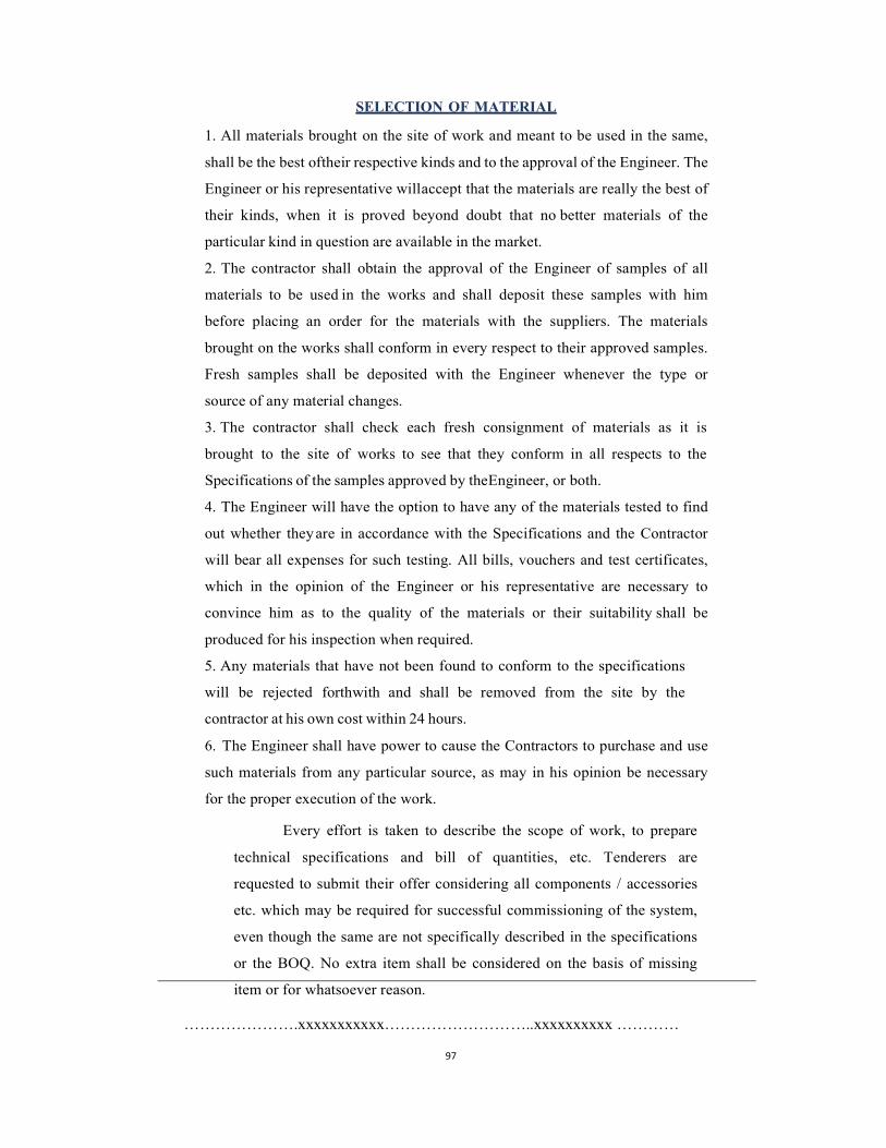
97
SELECTION OF MATERIAL
1. All materials brought on the site of work and meant to be used in the same,
shall be the best of their respective kinds and to the approval of the Engineer. The
Engineer or his representative will accept that the materials are really the best of
their kinds, when it is proved beyond doubt that no better materials of the
particular kind in question are available in the market.
2. The contractor shall obtain the approval of the Engineer of samples of all
materials to be used in the works and shall deposit these samples with him
before placing an order for the materials with the suppliers. The materials
brought on the works shall conform in every respect to their approved samples.
Fresh samples shall be deposited with the Engineer whenever the type or
source of any material changes.
3. The contractor shall check each fresh consignment of materials as it is
brought to the site of works to see that they conform in all respects to the
Specifications of the samples approved by the Engineer, or both.
4. The Engineer will have the option to have any of the materials tested to find
out whether they are in accordance with the Specifications and the Contractor
will bear all expenses for such testing. All bills, vouchers and test certificates,
which in the opinion of the Engineer or his representative are necessary to
convince him as to the quality of the materials or their suitability shall be
produced for his inspection when required.
5. Any materials that have not been found to conform to the specifications
will be rejected forthwith and shall be removed from the site by the
contractor at his own cost within 24 hours.
6. The Engineer shall have power to cause the Contractors to purchase and use
such materials from any particular source, as may in his opinion be necessary
for the proper execution of the work.
Every effort is taken to describe the scope of work, to prepare
technical specifications and bill of quantities, etc. Tenderers are
requested to submit their offer considering all components / accessories
etc. which may be required for successful commissioning of the system,
even though the same are not specifically described in the specifications
or the BOQ. No extra item shall be considered on the basis of missing
item or for whatsoever reason.
………………….xxxxxxxxxxx………………………..xxxxxxxxxx …………
98
11. Operators for 24x7 operation of Sewage treatment Plant:
Contractor shall appoint one operator per shift for 24x7 operation of Sewage
treatment Plant. The operator shall be of Wireman/Fitter/ITI grade with relevant
experience . The operator will report to Engineer in charge of Operation &
Maintenance of the Hospital. The operator shall operate & supervise the plant on
daily basis and carryout routine minor maintenance and coordinate with concern
STP CSMC personals deployed by contractor for any major preventive
maintenance and breakdown maintenance.
The duty time for the operational staff shall be as per the shift schedule decided
by the hospital authority and he shall be responsible for smooth working of the
plant. Any repairs / breakdown / rectification observed shall be coordinate with
CSMC persons to attend. He should maintain a log book for the day to day
operation activities of the plant and submit the same to Engineer deputed for
Hospital.
The contractor will furnish the information about the name & contact no’s, etc.
of Operator well in advance. The deployed staff shall have mobile phone &
number. If not, then contractor shall arrange to provide the same to them. The
contractors will issue the Identity Card to the staff. Any changes in the above
shall be informed in Advance.
The contractor shall appoint an operation staff immediately after the
commissioning of the STP failing which the penalty of Rs 500 per person per
day will be imposed till their appointment. Except as the MCGM may otherwise
agree, no changes shall be made in the Operator. If, for any reason beyond the
reasonable control of the Contractor, such as retirement, death, medical
incapacity, among others it becomes necessary to replace any of the Operator,
the Contractor shall provide as a replacement a person of equivalent or better
qualifications subject to prior approval from MCGM.
If for following reasons, the MCGM
1. finds that Operational staff has committed serious
misconduct or has been charged with having committed a
criminal action, or
2. has reasonable cause to be dissatisfied with the
performance of Operational staff,

99
then the Contractor shall, at the Client’s written request specifying the grounds
therefore, provide as a replacement of a staff with qualifications and experience
acceptable to the Client.
The removal and/or replacement under (a) & (b) above shall have no cost
implications on MCGM and the Contractor shall be solely responsible.
Note: - Replacement of operation staff for the first three instance, will be
permitted without imposition of any penalty. Any change thereafter, will attract a
penalty of Rs. 5000/- each per occurrence. However, the Contractor has to
replace with equivalent or better qualification and experience. The decision for
replacement shall be with the prior approval of the MCGM.
The Contractor shall submit attendance record of staff along with the monthly
bill. Daily attendance report and worksheet report of Engineer shall be submitted
to MCGM along with monthly bill. Absenteeism, if any, will not be tolerated and
salary to that effect will be deducted on pro-rata basis. Further, if it continues for
more than a week, penalty of Rs 1000/person per day will be imposed till the
resumption of duty or replacement of new staff with applicable penalty charges.
No bill will be certified without the attendance record of staff and work sheet for
the personnel.
Operation staff shall have one weekly off as per shift schedule finalized by the
MCGM Engineer. However, The Contractor shall ensure availability of the
operational staff as per shift schedule for all seven days in a week and shall make
arrangement for relieving staff.
The above requirement is minimum only, if required, the Contractor will arrange
extra workforce as and when required, so as to smoothly run the operation and
maintenance including preventive maintenance, repairs etc. and general
cleanliness of the installations.
Moreover, apart from the deployment of staff for operation of STP, contractor
has to maintain the following for smooth operation of the plant:
1. The Contractor shall provide an Operation and Maintenance Manual (O&M
Manual) to the MCGM.
2. The Contractor shall during the Operation Service Period, replenish the stock of
spares & consumables to maintain at all times an equivalent stock of spares &
consumables as required at the commencement of the Operation Service Period.

100
All spare parts used for the equipment in the maintenance of the system must be
from the manufacturer of the equipment or, if the equipment itself has been made
with parts from other manufacturers, the parts must be of the same make as used
in the equipment supplied and installed.
3. A Monthly Status Report (MSR) is required to report the main events that have
occurred and the significant aspects of the Works performance in the given
month. The Contractor shall provide such a report to the MCGM on a monthly
basis throughout the Operation Service Period.
4. The Contractor shall be responsible for all aspects of health and safety during the
Operation Service Period and shall comply with all national and regional
legislation and regulations.
With respect to health and safety, the Contractor shall:
a. implement safe working and reporting procedures and promote safety awareness
in every element of operation and maintenance;
b) ensure adequate regard to site safety including:
safe working procedures in all Works operation
and maintenance activities;
cleanliness and care of the facility;
reporting accidents and hazards;
safe practice in sewers, tanks, and all other
elements within the wastewater treatment facility;
1. During the Operation Service Period, the Contractor shall take total
responsibility for the operation and maintenance of the Works. As part of these
general obligations, the Contractor shall undertake the following tasks:
a. Carry out all flow measurement, sampling and laboratory analyses for the
Wastewater treatment and sludge treatment and disposal periodically throughout
the Operation Service Period.
b. Operate and maintain the Works and ensure that the Plant is able to operate at all
times to its maximum installed capacity. The Operation Service shall achieve the
101
performance criteria specified in these documents. The Contractor shall satisfy
all legal and environmental requirements for supply of water and disposal of
sludge and other waste products for each day of the Operation Service Period.
c. Utilize information gathered as a result of monitoring to determine what
Improvements can be made to optimize the operation of the treatment facility.
d. Transport all waste by-products and sludge arising at the Site . The Contractor
shall be responsible for identifying off site location/land and route(s) for
disposing all screenings, grit and sludge arising from the Works and for paying
all tipping & transportation charges and other associated costs including that for
location/land. The Contractor shall dispose of all hazardous materials in
accordance with existing laws and regulations. All permissions and consents
from respective authorities shall be obtained by the contractor.
e. Operate the Works in the most economic manner with respect to the
consumption of energy and other resources.
f. Maintain the Works such that they remain in a visually and aesthetically pleasing
condition at all times.
g. Monitor all changes in legislation, codes or standards and bring these to the
attention of the MCGM.
………………..XXXX……………………XXXX……………