radial drilling technique for improving well productivity in petrobel-egypt
TRANSCRIPT
Radial drilling technique for
improving well productivity in
petrobel-egypt
ABSTRACT
With growing global energy demand and depleting reserves,oil well stimulation has become more important. In all ofthese reservoirs, formation damage is a headache problemwhich needs to be treated. One of the proposed techniques isto bypass the damaged zone. Radial drilling can provide asolution with lowest costs than the others.
Radial drilling technique utilizes hydraulic energy tocreate several lateral holes in different directions andlevels with several lengths. These lateral holes are made bymilling the casing with small bit then by extending theseholes laterally using high pressure hydraulic jetting.
The current paper presents a very good analysis and anevaluation of the radial drilling techniques that have beenmade in one of the Egyptian oil field, and presentsscreening criteria about the optimum parameters forperforming these techniques. A number of pilot tests wasperformed and analyzed in Egypt in Belayim oil field. Radialdrilling performed only on three wells in Egypt; the resultsobtained from these wells are monitored and analyzed. Thereservoir depth varies from 2172 meter to 2481 meter. Thefirst well was laterally drilled with 50 m long by sevenlaterals and the angle between each two is 90 degrees. Thesecond well was laterally drilled with 50 and 90 m long by 6
1

laterals in two different levels. The third well wasradially drilled by 4 laterals of 50 m long.
From the production point of view, the first well wasimproved by more than 12.5% increase in production, and thesecond shows an improvement by about 47% increase. Thethird well shows an improvement by about 12.5 % but forshort period.
Several experiences have been learned and registered fromdrilling these 17 laterals which will help generally for thefuture radial drilling operational around the world.
Introduction
Increasing production and raising usable reserves from knownhorizon now a days has been a very good motivation fordevelopment of a new technologies. One of these newtechnologies is radial drilling technique.
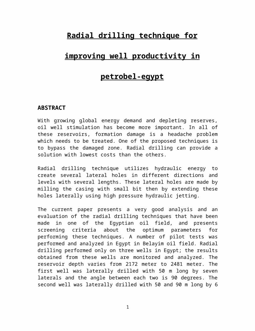
Radial drilling is a technique that can create severalsmall diameter drains from the well in a relatively shorttime, fast method to rehabilitate and optimize oil and gaswells, perforates 25-50 mm diameter holes in the casing,using high pressure fluid at selected depths, a hole ofabout 100 Mt long is created perpendicular to the motherwell as shown in figures 1&2.
2
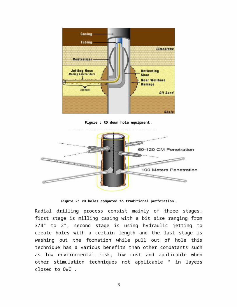
Figure : RD down hole equipment.
Figure 2: RD holes compared to traditional perforation.
Radial drilling process consist mainly of three stages,first stage is milling casing with a bit size ranging from3/4" to 2", second stage is using hydraulic jetting tocreate holes with a certain length and the last stage iswashing out the formation while pull out of hole thistechnique has a various benefits than other combatants suchas low environmental risk, low cost and applicable whenother stimulation techniques not applicable “ in layersclosed to OWC”.
3
This technique was applied first time in Egypt in 2010, themain objectives were to find an appropriate and/oralternative for conventional completion and stimulationtechnology.
Theoretically creating a small diameter holes with longdepth of penetration ( aims to or should achieve an inincrease in productivity index, increasing apparent paythickness, eliminating permeability barriers in thereservoir and increasing the recovery factor.
Radial Drilling Equipment and Process
A-Radial Drilling Surface Equipment.
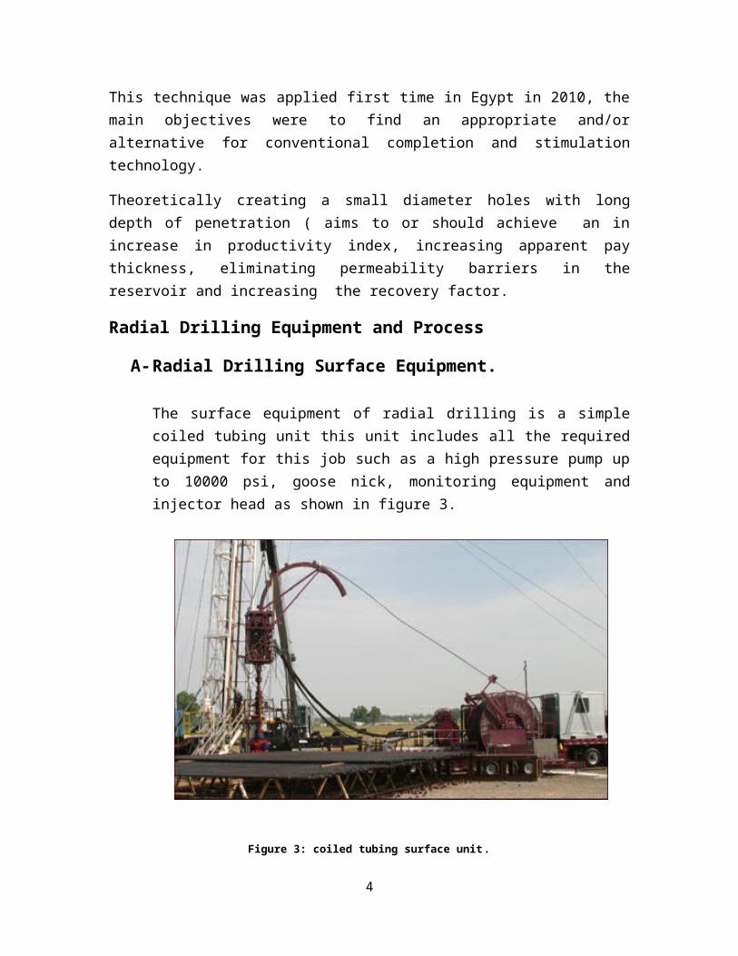
The surface equipment of radial drilling is a simplecoiled tubing unit this unit includes all the requiredequipment for this job such as a high pressure pump upto 10000 psi, goose nick, monitoring equipment andinjector head as shown in figure 3.
Figure 3: coiled tubing surface unit.
4
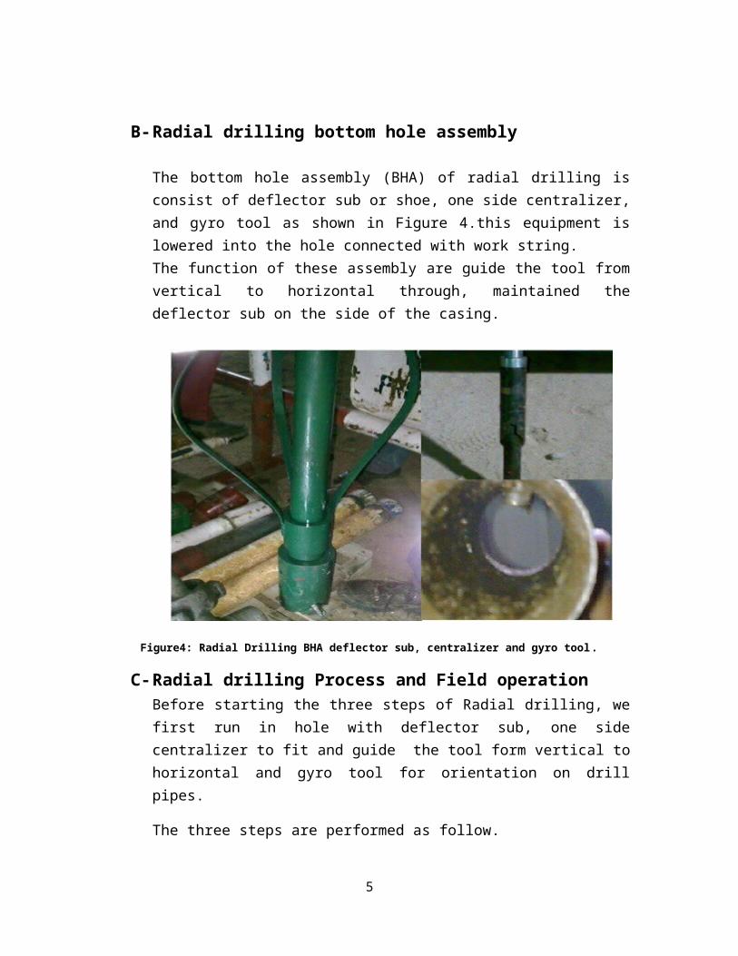
B-Radial drilling bottom hole assembly The bottom hole assembly (BHA) of radial drilling isconsist of deflector sub or shoe, one side centralizer,and gyro tool as shown in Figure 4.this equipment islowered into the hole connected with work string.The function of these assembly are guide the tool fromvertical to horizontal through, maintained thedeflector sub on the side of the casing.
Figure4: Radial Drilling BHA deflector sub, centralizer and gyro tool.
C-Radial drilling Process and Field operationBefore starting the three steps of Radial drilling, wefirst run in hole with deflector sub, one sidecentralizer to fit and guide the tool form vertical tohorizontal and gyro tool for orientation on drillpipes.
The three steps are performed as follow.
5

1- First step ( milling the casing ).Is consisting mainly of a milling bit with aspecific size the used size was 1 ¾" bit connectedwith flexible shaft both are rotated by conventionalmud motor connected to coiled tubing up to surfaceconnected to coiled tubing unit with its monitoringsystem. The milling bit is shown in Figure 5
2- Second step (jetting formation)Jetting the formation with nozzle has three openingoriented forward and three oriented from backwardconnected to a 0.5” hose. The jetting is performedwith a pressure greater than fracture pressure ofthe formation, the pressure range from 7000 psi to10000 psi. the jet nozzle is shown in Figure 6.
3- Third step ( washing out the formation)Washing out the formation accomplished by pulling outthe hose. While Pull out of hole we keep pumping throughthe operation.
Figure 5: Milling bit for Radial drilling .
6
Figure 6: jetting nozzle for Radial drilling .
Mechanism of penetration
Bruni.et.al, reported that four main penetration mechanismswere identified in RD operation; surface erosion, hydraulicfracturing, poroelastic tensile failure and cavitation. Asshown in Figure 7.
A-Surface erosionis the process where the rock fragments are removedfrom the surface of the rock due to the shear andcompression forces exerted on the rock surface due tojetting force.
B-Hydraulic fracturingthe same theory of hydraulic fracturing stimulation ,as the pressure increase at the stagnation pointdiffuses in to formation, the formation may fail or
7
crack if this pressure is higher than the stresses setby formation stresses .
C-Poroelastic tensile failurea rapid fluid pressure decrease at the rock surfacewill induce effective tensile stresses in the formationequal to the decrease. If this induced tension ishigher than the sum of the smallest effective stress inthe formation and the tensile strength, the rock willfail in tension. This induced tension occurs as thecompressibility of the rock grains and pore fluid isnot equal, and any deviation from equilibrium betweenthe rock grains and pore fluid has to be restored byfluid flowing through the pore space. This flow takestime due to the finite permeability of the rock, andgives rise to this transient poroelastic effect.However, for high permeability sandstones (1 Darcy) thetime scale is around 1 µs, which may be unrealisticallyfast. However, the time scales inversely with thepermeability and for chalk (1 md) or shale (1 mDarcy)this effect may be important
D-Cavitation
when the water accelerate to pass through comers of the
nozzle, the pressure may drop below the vapor
pressure. This may cause vapor bubbles to form. as the
flow moves into a larger area, the pressure recovers
to a certain degree. This increases the pressure above
the vapor pressure, causing the vapor bubbles to
collapse or implode. The shock waves may be extremely
high and cause additional erosion and tension effect.
8
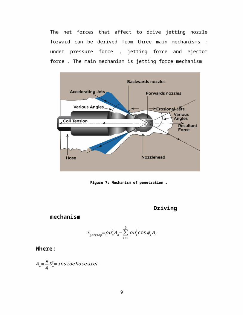
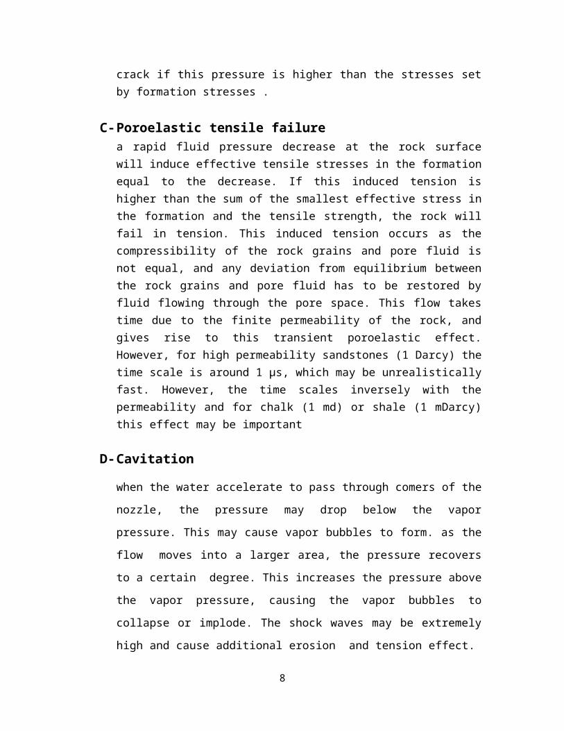
The net forces that affect to drive jetting nozzle
forward can be derived from three main mechanisms ;
under pressure force , jetting force and ejector
force . The main mechanism is jetting force mechanism
Figure 7: Mechanism of penetration .
Driving mechanism
Sjetting=ρuo2Ao−∑
i=1
6ρui
2cosφiAi
Where:
AO=π4Do2=insidehosearea
9
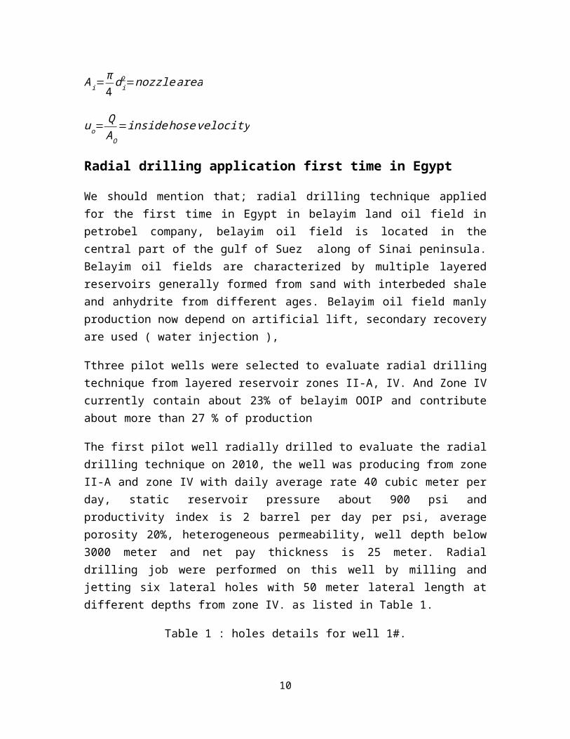
Ai=π4di2=nozzlearea
uo=QAO
=insidehosevelocity
Radial drilling application first time in Egypt
We should mention that; radial drilling technique appliedfor the first time in Egypt in belayim land oil field inpetrobel company, belayim oil field is located in thecentral part of the gulf of Suez along of Sinai peninsula.Belayim oil fields are characterized by multiple layeredreservoirs generally formed from sand with interbeded shaleand anhydrite from different ages. Belayim oil field manlyproduction now depend on artificial lift, secondary recoveryare used ( water injection ),
Tthree pilot wells were selected to evaluate radial drillingtechnique from layered reservoir zones II-A, IV. And Zone IVcurrently contain about 23% of belayim OOIP and contributeabout more than 27 % of production
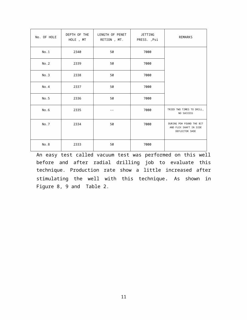
The first pilot well radially drilled to evaluate the radialdrilling technique on 2010, the well was producing from zoneII-A and zone IV with daily average rate 40 cubic meter perday, static reservoir pressure about 900 psi andproductivity index is 2 barrel per day per psi, averageporosity 20%, heterogeneous permeability, well depth below3000 meter and net pay thickness is 25 meter. Radialdrilling job were performed on this well by milling andjetting six lateral holes with 50 meter lateral length atdifferent depths from zone IV. as listed in Table 1.
Table 1 : holes details for well 1#.
10
REMARKSJETTINGPRESS. ,Psi
LENGTH OF PENETRETION , MT.
DEPTH OF THEHOLE , MTNo. OF HOLE
7000502340No.1
7000502339No.2
7000502338No.3
7000502337No.4
7000502336No.5
TRIED TWO TIMES TO DRILL,NO SUCCESS
7000--2335No.6
DURING POH FOUND THE BITAND FLEX SHAFT IN SIDE
DEFLECTOR SHOE
7000502334No.7
7000502333No.8
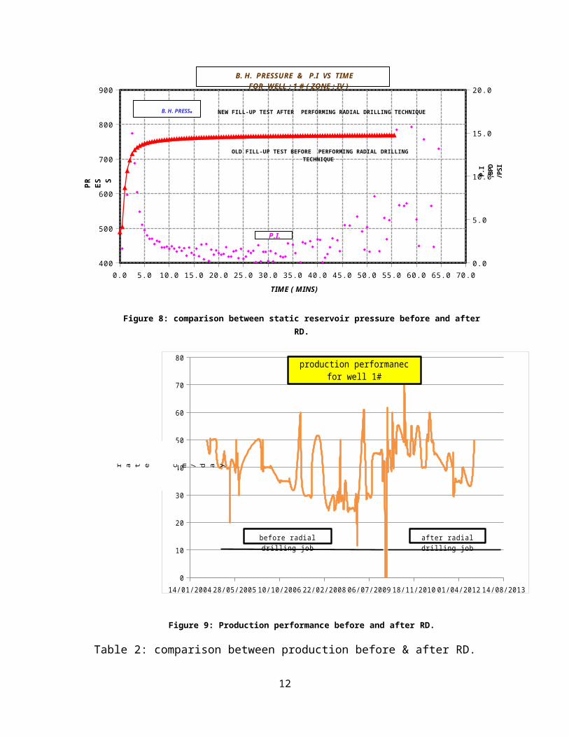
An easy test called vacuum test was performed on this wellbefore and after radial drilling job to evaluate thistechnique. Production rate show a little increased afterstimulating the well with this technique. As shown inFigure 8, 9 and Table 2.
11
0.0 5.0 10.0 15.0 20.0 25.0 30.0 35.0 40.0 45.0 50.0 55.0 60.0 65.0 70.0400
500
600
700
800
900
0.0
5.0
10.0
15.0
20.0
P.I.
B. H. PRESS.
B. H. PRESSURE & P.I VS TIME FOR WELL : 1 # ( ZONE : IV )
TIME ( MINS)
PR ES S
P.I
,BPD
/PSI
NEW FILL-UP TEST AFTER PERFORMING RADIAL DRILLING TECHNIQUE
OLD FILL-UP TEST BEFORE PERFORMING RADIAL DRILLING TECHNIQUE
Figure 8: comparison between static reservoir pressure before and afterRD.
14/01/2004 28/05/2005 10/10/2006 22/02/2008 06/07/2009 18/11/2010 01/04/2012 14/08/20130
10
20
30
40
50
60
70
80 production performanec for well 1#
after radial drilling job
before radial drilling job
r a t e c m / d a y
Figure 9: Production performance before and after RD.
Table 2: comparison between production before & after RD.
12
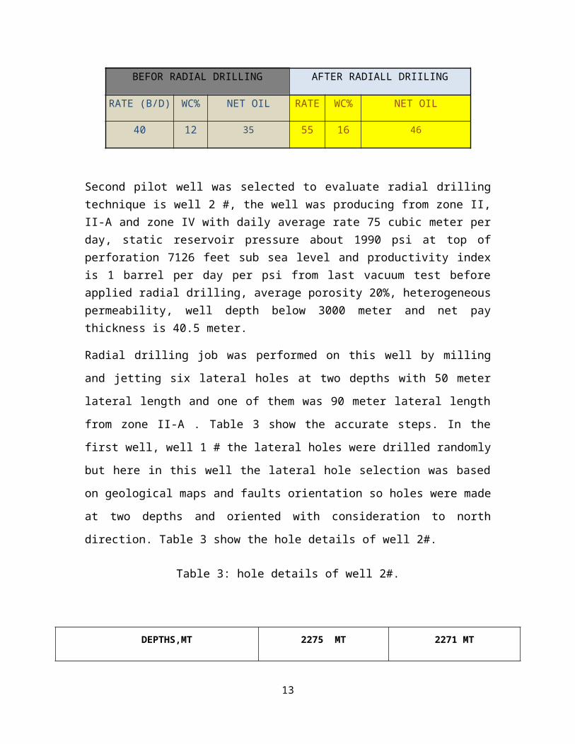
BEFOR RADIAL DRILLING AFTER RADIALL DRIILING
RATE (B/D) WC% NET OIL RATE WC% NET OIL
40 12 35 55 16 46
Second pilot well was selected to evaluate radial drillingtechnique is well 2 #, the well was producing from zone II,II-A and zone IV with daily average rate 75 cubic meter perday, static reservoir pressure about 1990 psi at top ofperforation 7126 feet sub sea level and productivity indexis 1 barrel per day per psi from last vacuum test beforeapplied radial drilling, average porosity 20%, heterogeneouspermeability, well depth below 3000 meter and net paythickness is 40.5 meter.
Radial drilling job was performed on this well by milling
and jetting six lateral holes at two depths with 50 meter
lateral length and one of them was 90 meter lateral length
from zone II-A . Table 3 show the accurate steps. In the
first well, well 1 # the lateral holes were drilled randomly
but here in this well the lateral hole selection was based
on geological maps and faults orientation so holes were made
at two depths and oriented with consideration to north
direction. Table 3 show the hole details of well 2#.
Table 3: hole details of well 2#.
DEPTHS,MT 2275 MT 2271 MT
13
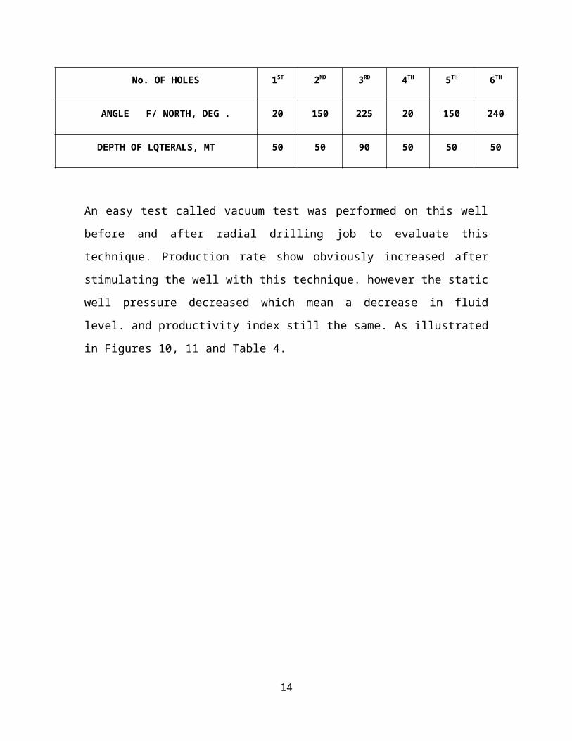
No. OF HOLES 1ST 2ND 3RD 4TH 5TH 6TH
ANGLE F/ NORTH, DEG . 20 150 225 20 150 240
DEPTH OF LQTERALS, MT 50 50 90 50 50 50
An easy test called vacuum test was performed on this well
before and after radial drilling job to evaluate this
technique. Production rate show obviously increased after
stimulating the well with this technique. however the static
well pressure decreased which mean a decrease in fluid
level. and productivity index still the same. As illustrated
in Figures 10, 11 and Table 4.
14

0.0 10.0 20.0 30.0 40.0 50.0 60.0 70.0 80.01200
1400
1600
1800
2000
0
2
4
6
8
10
12
B. H. PRESSURE & P.I VS TIME FOR WELL : 2 # ( ZONE : II , II-A ,
IV )
TIME ( MINS)
PRE
SS.
,PS i
P. I ,B PD / PS I
NEW FILL-UP TEST AFTER PERFORMING RADIAL DRILLING TECHNIQUE
OLD FILL-UP TEST BEFORE PERFORMING RADIAL DRILLING TECHNIQUE
OLD P.I BEFORE PERFORMING RADIAL DRILLING TECHNIQUE
new P.I BEFORE PERFORMING RADIAL DRILLING TECHNIQUE
Figure 10: comparison between fill up test before and after RD.
15
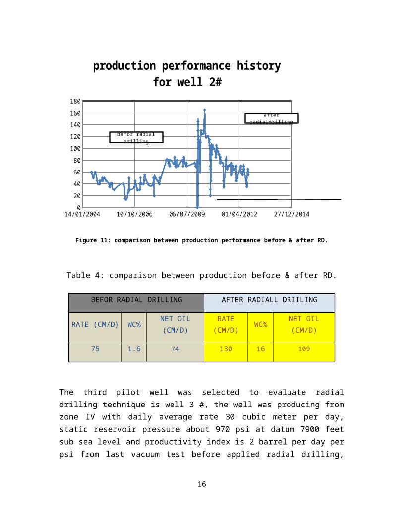
14/01/2004 10/10/2006 06/07/2009 01/04/2012 27/12/2014020406080100120140160180
production performance history for well 2#
befor radial drilling
after radialdrilling
Figure 11: comparison between production performance before & after RD.
Table 4: comparison between production before & after RD.
BEFOR RADIAL DRILLING AFTER RADIALL DRIILING
RATE (CM/D) WC% NET OIL(CM/D)
RATE(CM/D) WC% NET OIL
(CM/D)
75 1.6 74 130 16 109
The third pilot well was selected to evaluate radialdrilling technique is well 3 #, the well was producing fromzone IV with daily average rate 30 cubic meter per day,static reservoir pressure about 970 psi at datum 7900 feetsub sea level and productivity index is 2 barrel per day perpsi from last vacuum test before applied radial drilling,
16
average porosity 20%, heterogeneous permeability, well depthbelow 3000 meter and net pay thickness is 26.5 meter.
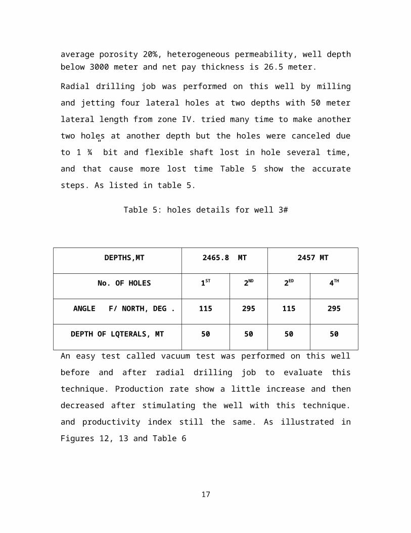
Radial drilling job was performed on this well by milling
and jetting four lateral holes at two depths with 50 meter
lateral length from zone IV. tried many time to make another
two holes at another depth but the holes were canceled due
to 1 ¾” bit and flexible shaft lost in hole several time,
and that cause more lost time Table 5 show the accurate
steps. As listed in table 5.
Table 5: holes details for well 3#
DEPTHS,MT 2465.8 MT 2457 MT
No. OF HOLES 1ST 2ND 2ED 4TH
ANGLE F/ NORTH, DEG . 115 295 115 295
DEPTH OF LQTERALS, MT 50 50 50 50
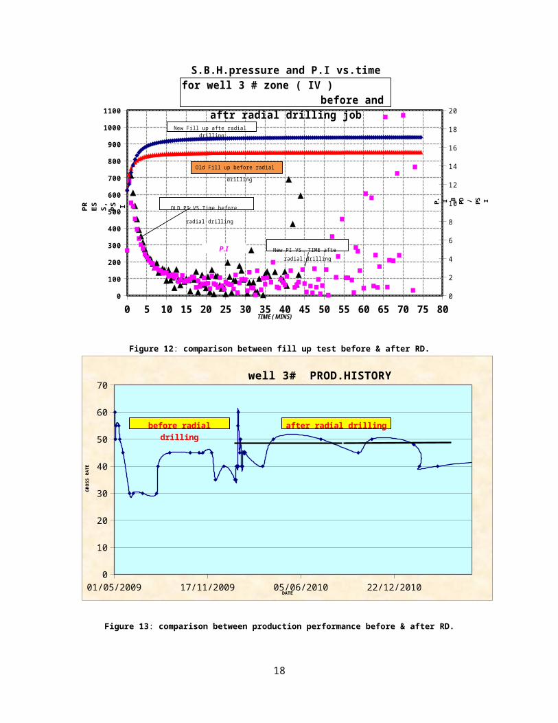
An easy test called vacuum test was performed on this well
before and after radial drilling job to evaluate this
technique. Production rate show a little increase and then
decreased after stimulating the well with this technique.
and productivity index still the same. As illustrated in
Figures 12, 13 and Table 6
17
0 5 10 15 20 25 30 35 40 45 50 55 60 65 70 75 800
100
200
300
400
500
600
700
800
900
1000
1100
0
2
4
6
8
10
12
14
16
18
20
P.I
TIME ( MINS)
PR ES S,
PS I P. I ,B PD / PS I
Old Fill up before radial
drilling
New Fill up afte radial drilling
S.B.H.pressure and P.I vs.time for well 3 # zone ( IV ) before and
aftr radial drilling job
OLD PI VS.Time before
radial drilling
New PI VS. TIME afte radial drilling
Figure 12: comparison between fill up test before & after RD.
01/05/2009 17/11/2009 05/06/2010 22/12/20100
10
20
30
40
50
60
70well 3# PROD.HISTORY
DATE
GROSS RATE
before radial drilling
after radial drilling
Figure 13: comparison between production performance before & after RD.
18
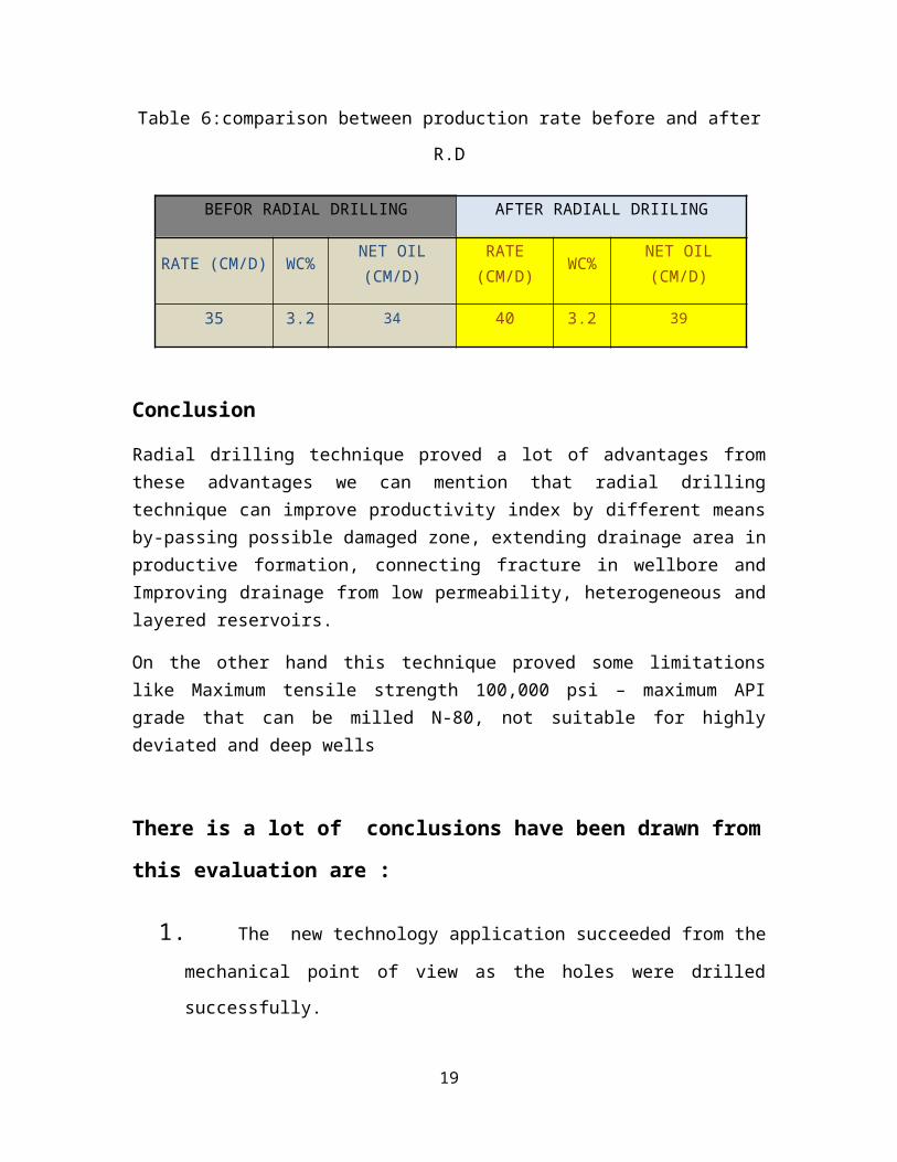
Table 6:comparison between production rate before and after
R.D
BEFOR RADIAL DRILLING AFTER RADIALL DRIILING
RATE (CM/D) WC% NET OIL(CM/D)
RATE(CM/D) WC% NET OIL
(CM/D)
35 3.2 34 40 3.2 39
Conclusion
Radial drilling technique proved a lot of advantages fromthese advantages we can mention that radial drillingtechnique can improve productivity index by different meansby-passing possible damaged zone, extending drainage area inproductive formation, connecting fracture in wellbore andImproving drainage from low permeability, heterogeneous andlayered reservoirs.
On the other hand this technique proved some limitationslike Maximum tensile strength 100,000 psi – maximum APIgrade that can be milled N-80, not suitable for highlydeviated and deep wells
There is a lot of conclusions have been drawn from
this evaluation are :
1. The new technology application succeeded from the
mechanical point of view as the holes were drilled
successfully.
19

2. Form the actual results as the length of lateral
hole increase the production rate increase.
3. The screening criteria about Radial Drilling must
be taken in consideration before the operation
specially depth & degree of consolidation.
4. It is preferable to pass through a consolidated
formation to avoid weak sandstone and fines migration
problems.
5. As the number of holes increase results show a
good results than those of less number of holes
6. The well 1# shows a good results as the net oil
production rate increased by 12.5%, for the well 2#
increased by 47 % and for well 3# increased by 12.5%
7. Radial drilling is a little bit easy to be apply
and less expensive compare to the other stimulation
techniques.
8. The real challenge is keeping the increase in
production is constant as long as possible after Radial
Drilling where it is noticed that most of the increase
not extended for long time.
References:
20

1. Bruni.m,biasotti.h,salamone.g., "radial drilling in argentia,".Petroleum engineering conference held in buenos aires argenina 2007.
2. Raul andres cirigliano,juan felipe,driliing and workoverrepsol ypf un bolivia,dept,”first experince in theapplication of radial perforation in deep wells”, Petroleumengineering conference held in buenos aires argenina 2007.
3. Bueset.p,Riiber.m and Eek.A., "Jet drillingcost eefectiv lateral drillingtechnology for enhanced oil recovery,". 2001.
4. Kolle, SPE/IADC 22000 Laboratory and Field Testing of anUltra-High-Pressure, Jet-Assisted Drilling System
5. Dickinson.w, Dickinson.R and Herrerra.H., “ slim holes multiple radial drilledwith coild tubing.”
6. Dickinson.W, Dystra.H and Nodlund.R., “ coild tubing radial placed by jet drillingfield results.”.
21