quick start installation guide - software house
TRANSCRIPT

apC/LQuick Start
Installation Guide
Version A2Document Part Number UM-201
May 2010
OVERVIEW The apC/L is an intelligent access control and alarm monitoring control panel which serves as a basic building block for C•CURE® security management systems. It is a two-door version of the apC/8X, making it an economical solution for smaller applications, such as parking garages, small office buildings, retail outlets and apartment complexes or for remote site monitoring.
Features:
Fast, stand-alone processing supporting 2 readers and 2 output relays
Distributed database processing for up to 20,000 cardholders
Support for magnetic stripe, Wiegand, and proximity card technologies
Card, keypad, or card and keypad access support
Reader-by-reader support for variable card formats, site codes, company codes, and card technologies
Class A, 2-wire supervised input capability with optional input modules
FLASH Memory
Dynamic memory allocation between card and events storage
Software-linked inputs and outputs for offline control
Communication between host and apC/L through direct connect or dialup mode
Battery backup option
Network Connectivity using a terminal server
UL Listed — 294/1076, CE Compliant
1

Overview
This guide describes quick start connection information for the apC/L, including:
How to connect power
Functions of switches, LEDs, and jumpers
How to connect to the host computer
How to connect readers to RM ports
How to connect I/8 and R/8 bus modules to RM ports
How to wire inputs and outputs
How to configure in the software
System Components The apC/L hardware components consist of:
apC/L circuit board
Enclosure
Optional transformer
Optional Battery and cable
TABLE 1. apC/L Components
Model Number Description
AS0101-003 apC/L, two Readers, 512K Memory, Flash, with Enclosure and Transformer (Battery not included)
AS0101-NPS apC/L, two Readers, 512K Memory, Flash, with Enclosure, no Transformer (Battery not included)
AS0101-003MB apC/L Circuit board Only, 512K Memory, Flash
FW-APCS Firmware Upgrade Kit for apC/L FlashNote: All firmware upgrades are upgrades to the current released firmware. To upgrade to any other firmware version, contact Technical Support.
AS0101-600 Battery and Cable for apC/L
AS0101-501 apC/L Transformer 18 VAC Wall Transformer
2

Overview
FIGURE 1. apC/L Cabinet
apC/L Basics The apC/L is housed in a 16 AWG metal wall-mounted cabinet which has tamper switches on the front and rear, and can be used in a wide variety of configurations. It has two reader ports, capable of handling a maximum of two readers and two relay outputs.
The apC/L’s two card readers can be wired in a bus or star configuration.
The panel’s static RAM memory consumes minimal power and has a capacity of 512K.
3

Overview
The apC/L can accommodate 38 outputs and 36 inputs as shown in Table 2.
The apC/L does not have any supervised inputs. You can, however, connect up to four I/8 input modules to an apC/L. Eight supervised inputs are available on each I/8 Module, as well as two supervised inputs per RM module, giving you a maximum of 36 supervised inputs.
You can also connect up to four R/8 output modules to an apC/L. Eight additional relays are available on each R/8 module.
Figure 2 illustrates the layout and highlights the components described in this guide.
Power and battery connections
Host port
Switches, LEDs, jumpers
Host port
RM ports (Readers, I/8s, R/8s)
Relay outputs
Cabinet tampers
Power fail input
TABLE 2. apC/L Outputs and Inputs
apC/L Outputs apC/L Inputs
apC/L Circuit Board 2 -
R/8 4 x 8 (32)
I/8 4 x 8 (32)
RM-4 or RM-4E 2 x 2 (4) 2 x 2 (4)
Total 38 36
4

Overview
Reader
apC/L Circuit Board Layout
FIGURE 2. apC/L Layout
Host Port
Tampers
Power FailInput
Relay Outputs
LEDs
Address Switch
Reset
Power
Ports
5

Mounting the apC/L
MOUNTING THEAPC/L
Before you begin the installation, make sure the installation location provides enough space and meets environmental requirements for the apC/L and the necessary electrical conduit.
Electrical Specifications
Mechanical Specifications
Environmental Specifications
TABLE 3. Electrical Specifications
Electrical Values
Wall Transformer - Input 120 VAC 60 Hz
Wall Transformer - Output 18 VAC at 3.3 Amp
Wall Transformer - Power Consumption
Less than 10 Watts typical
Auxiliary Hardware Relay Contacts rated at 30 VAC/DC1 Amp inductive, 2 Amps non-inductive
TABLE 4. Mechanical Specifications
Mechanical Values
Height 14.00 in (35.56 cm)
Width 8.00 in (20.32 cm)
Depth 3.24 in (8.26 cm)
Weight apC/L Unit 8.25 lbs. (3.71 kg.)
Weight apC/L Unit and Battery 12.0 lbs (5.40 kg.)
Housing 16 AWG metal wall mounted locking cabinet with tamper switches on door and rear.
TABLE 5. Environmental Specifications
Environmental Values
Operating 32° to 122° F (0° to 50° C)
Storage 9° to 185° F (-13° to 85° C)
Operating with Optional Battery 32° to 122° F (0° to 50° C)
6

Mounting the apC/L
Mounting the circuitboard
Figure 3 provides the dimensions for mounting the apC/L board and the distance between mounting holes.
FIGURE 3. apC/L Mounting Specifications
.200"
7.70
0”
5.100”
7.30
0”
Microprocessor
5.500”.200"
7

Mounting the apC/L
Mounting theenclosure
Figure 4 provides the dimensions for mounting the apC/L enclosure and the distance between mounting holes.
FIGURE 4. apC/L Enclosure Mounting Hole Layout
8

Mounting the apC/L
Connecting theExternal Transformer
The apC/L is shipped with an external transformer. The Class-2 transformer is connected to the apC/L with the supplied cable assembly. The transformer will only accept 120 VAC, 60 Hz. The cable assembly consists of two red wires and one green wire. Connect the red wires to the transformer connectors marked (AC). Connect the green wire to the middle connector marked (GND) then to P8 on the apC/L, which is marked with an ~ for AC and a ground symbol for the ground connection.
The output of the transformer is internally fused. Do not short the output of the transformer. Do not cut or remove the ground lug from the transformer.
The AC input is fused with a 5A, 5mm x 20mm fuse. Replace it only with a fuse of the same type and rating.
NOTE The transformer will be shipped separately in separate packaging.
FIGURE 5. Transformer Connection
9
Mounting the apC/L
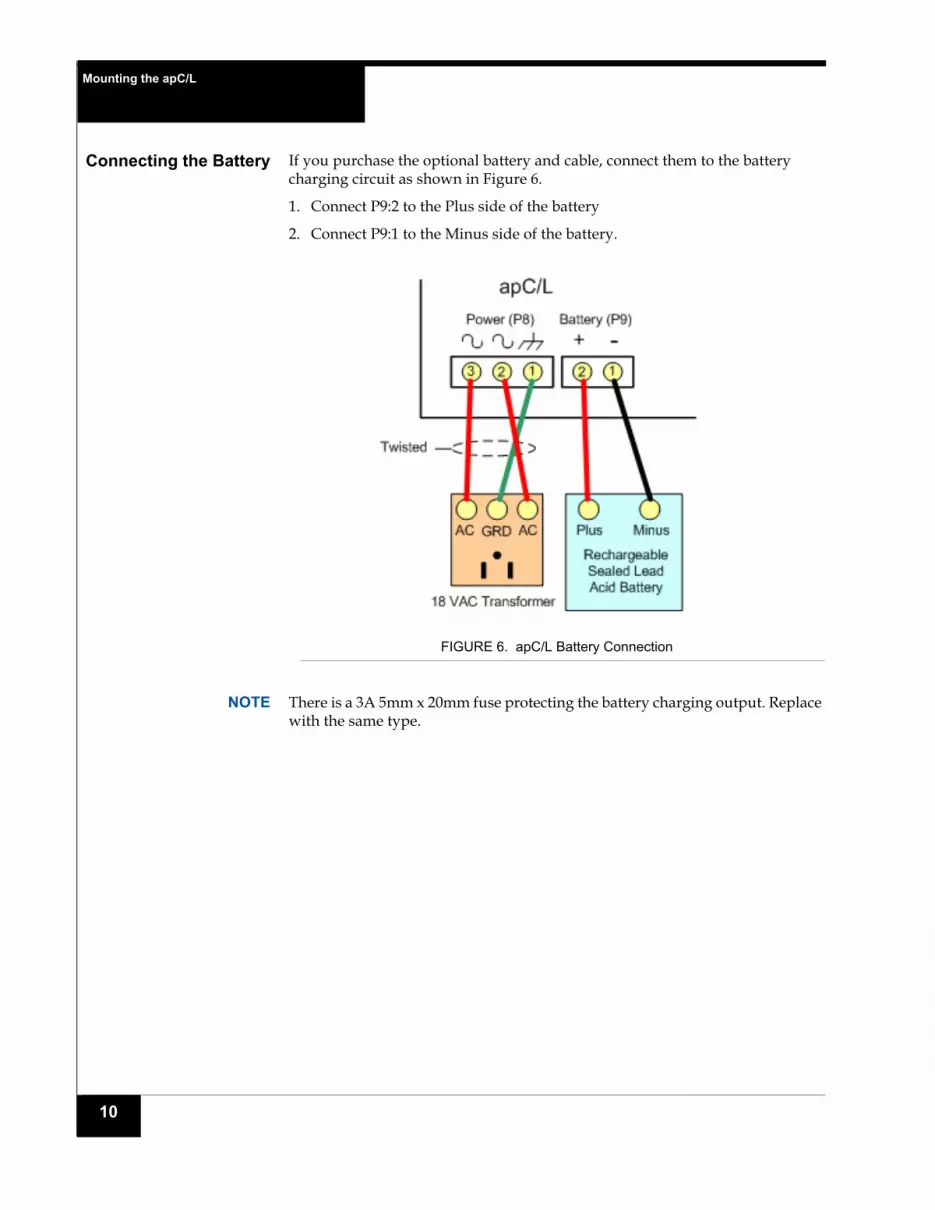
Connecting the Battery If you purchase the optional battery and cable, connect them to the battery charging circuit as shown in Figure 6.
1. Connect P9:2 to the Plus side of the battery
2. Connect P9:1 to the Minus side of the battery.
FIGURE 6. apC/L Battery Connection
NOTE There is a 3A 5mm x 20mm fuse protecting the battery charging output. Replace with the same type.
10

Connecting the apS Another way to power the apC/L is to use the apS™ power supply with built in battery backup.
1. Connect pins 3 and 4 of the apS to P9 as shown in Figure 7.
FIGURE 7. apS Connection
2. Connect the AC fail output of the apS to the P3 AC Fail input of the apC/L.
3. Connect the Low Battery output of the apS to any available input.
11

Setting Up the apC/L Panel
SETTING UP THEAPC/L PANEL
Setting up the apC/L panel involves setting the panel’s jumpers and DIP switches.
Figure 2 on page 5 shows the location of the apC/L switches and jumper location.
Setting the apC/LSwitches
SW1 Rotary Address Switch
Use rotary switch SW1 to indicate the apC/L’s unique address. You can set the SW1 rotary switch by using a screwdriver to turn the arrow to the number you want.
You also need to set SW3:8 to indicate whether the unit has a Low-Address (0 through 15) or Hi-Address (16 through 31).
SW2 Reset Button
Switch SW2 is a push button to reset the apC/L.
SW3 DIP Switch Package
The SW3 DIP switch package contains eight switches with two positions: ON (or closed) and OFF (or open). For most installations, all switches should be in the OFF position. (ON closed is to the right)
The apC/L reads the SW3:2 switch (dialup mode enabled) only when it is powered up with the SW3:1 switch set to ON. Changes to the SW3:2 switch setting do not take effect until the next power up with SW3:1 set to ON.
12

Setting Up the apC/L Panel
The following sections describe the switches and their functions..
Setting Switches SW1, SW2, SW3
Table 6 lists the features and settings for Switches SW1, SW2, and SW3.
NOTE Switch setting OFF is the factory default. If set to off, the switch is open.
Switch setting ON means the switch is closed.
TABLE 6. apC/L Rotary and DIP Switch Settings for SW1, SW2, SW3
Switch Setting System Feature
SW1 0 to F Address Switch (Rotary)
SW2 Push button
Push to reset the apC/L
SW3:1 ON Database cleared on power up and/or reset
OFFa
a. Default setting
Database not cleared on power up and/or reset
SW3:2 ON Dialup mode communication is enabled
OFFa Dialup mode communication is disabled
SW3:3 ON CTS is enabled (for 5-wire RS 232 applications)
OFFa CTS is disabled
SW3:4 ON Host parity none, 8 data bits, 1 stop bit
OFFa Host parity even, 8 data bits, 1 stop bit
SW3:5 ON Host baud rate (see Table 7 on page 15)
OFFa Host baud rate (see Table 7 on page 15)
SW3:6 ON Host baud rate (see Table 7 on page 15)
OFFa Host baud rate (see Table 7 on page 15)
SW3:7 ON Host baud rate (see Table 7 on page 15)
OFFa Host baud rate (see Table 7 on page 15)
SW3:8 ON apC/L unit number 16-31 in use
OFFa apC/L unit number 0 through 15 in use
13

Setting Up the apC/L Panel
SW3:1 - Clear Database
If SW3:1 is set ON, the database is cleared whenever the apC/L recovers from power loss or when the reset switch SW2 is pressed. This switch is used only during the initial database setup. For normal operation, set the switch OFF.
NOTE When you install a new apC/L or an apC/L that has been used somewhere else, power up with SW3:1 ON to clear the apC/L memory, then turn SW3:1 OFF.
SW3:2 - Dialup
Switch 2 enables apC/L dialup communication mode. Set Switch 2 ON to operate in dialup mode. Set it OFF to disable dialup communication.
SW3:3 - CTS
Enables Clear To Send (CTS) for 5-wire RS-232 when set to ON.
SW3:4 - Parity
Switch 4 sets the parity for communication with the computer or modem. Set it ON for no parity, OFF for even parity. Use even parity (OFF) with directly connected apC/Ls. For modem communications, including apC/L dialup mode, match the apC/L’s parity to the host’s parity.
With either the ON or OFF setting, the apC/L communicates 8-bit characters with one stop bit. Note that the apC/L and the host will not communicate if the host, the apC/L, and the modem parity settings are not the same.
SW3:5-7 - Baud Rate
Switches 3:5 through 3:7 set the baud rate at which the apC/L communicates to the host computer and selects the baud rate for X.25 communications. Refer to Table 7 for a list of baud rates.
Set the baud rate to the highest rate compatible with the host. If the devices are far apart or if communication errors result, lower the baud rate. All apC/Ls in a chain must run at the same rate. If you are using a modem, set these switches to match the modem’s baud rate.
SW3:8 - Low/High Address
Unit Low-Address or Unit Hi-Address.
When switch 8 is set OFF (Default), the SW1 unit switch addresses the apC/L as units 0 through 15.
When switch 8 is ON, the SW1 unit switch addresses the apC/L as units 16 through 31.
14

Setting Up the apC/L Panel
Baud Rate Settings
Table 7 lists baud rates and their corresponding switch settings.
The first five switch settings in the table select the baud rate for direct connect or dialup communication. The last three switch settings in the table select the baud rate for X.25 communication.
TABLE 7. Baud Rate Settings for RoHS Boards
Baud Rate SW3:5 SW3:6 SW3:7 Notes:
1200 ON OFF OFF Direct connect or dialup
2400 OFF ON OFF Direct connect or dialup
4800 ON ON OFF Direct connect or dialup
9600a
a. This setting is the default and is recommended.
OFF OFF OFF Default setting, recommended
19,200b
b. This setting is not supported.
OFF OFF ON Not supported
2400 x.25 ON OFF ON X.25 Communication
4800 x.25 OFF ON ON X.25 Communication
9600 x.25 ON ON ON X.25 Communication
15

Setting Up the apC/L Panel
Setting Tamper, Power, Reader Ports, and RS485 Chains
Table 8 lists the settings and functions for Switches S3, S4, and S5. It also lists the functions and settings for jumper W1.
S3:3 - Reader Port A/B Usage
When switch S3:3 is OFF, this switch indicates that both reader ports are being used. Terminate each reader as an end-of-line reader. There can also be I/8 and R/8 modules on either RM bus.
When switch S3:3 is ON, either reader Port A or reader Port B is in use. If you are using only the A or B reader port, set switch S3:3 ON and terminate the last device in the chain. You can have two readers plus four I/8s and four R/8s on the RM bus that is used. Use only one of the ports in this mode.
S4:1 Cabinet Tamper Override
Set switch S4:1 OFF for all UL applications. When S4:1 is OFF, the apC/L tamper is enabled.
TABLE 8. apC/L Switch Settings - S3, S4, S5 and W1
Switches/Jumper Setting System Features
S3:3 OFF Both reader Port A and Port B are in use
ONa Either reader Port A or Port B is in use
S4:1 ONa Disables Cabinet Tamper
OFF Enables Cabinet Tamper.
S4:2 OFF Normal system operation
S4:3 ONa
S4:2 ON Do not use this setting
S4:3 OFF
S4:4 ONa 512Kb x 8 SRAM (40Kb or 80Kb)
OFF 128Kb x 8 SRAM (10Kb or 20Kb)
S5:5 & S5:6 OFF Not the last RS485 unit in chain
ONa For Last unit in RS485 chain
W1 (Jumper) INa Disables External P3 PWR fail
OUT Enables External P3 PWR fail.
16

Setting Up the apC/L Panel
When S4:1 is ON, the switch overrides the wall and door tamper switches. Set S4:1 ON for diagnostic purposes only or when using the apC/L outside the apC/L cabinet.
S4:2 & S4:3 - System Operation
Set switch S4:3 ON for normal system operation. Set switch S4:2 ON to disable external power failure. The apC/L will not operate properly if S4:2 and S4:3 are not set correctly.
S4:4 - RAM Size
Switch 4:4 indicates the size of RAM installed on the apC/L. Leave this switch in the factory default position. Switch S4:4 ON indicates 512 KB SRAM installed.
S5:5 & S5:6 - Unit position in chain
Switches S5:5 and S5:6 indicate the position of the apC/L unit in an RS-485 chain. Set switches S5:5 and S5:6 OFF when the apC/L is not the last unit in the chain. Set switches S5:5 and S5:6 ON when the apC/L is the last unit in the RS-485 chain.
W1 - Power Fail Jumper
Jumper W1 activates the normal power fail operation while running with an internal battery backup.
Plugging IN Jumper W1 Disables the External P3 Power Fail connection (leave open).
Removing the W1 jumper Enables the Internal P3 power fail connection;
The normal operation of the power fail input is a short across P3, and opening P3 causes a power fail indication.
S1 and S5 - Host Port Communication Protocol
Switches S1 and S5 determine the type of transmission at the host port: RS-485 communications format or RS-232C format. Refer to Table 9 and Table 10 for communication protocol settings.
17

Communication Settings
COMMUNICATIONSETTINGS
Setting RS-485Communication
Switches
For RS-485 communication, set switches S1 and S5 as shown in Table 9.
Also indicate whether or not the RS485 unit is last in the chain by setting switches S5:5 and S5:6 to ON or Off as shown in Table 8.
TABLE 9. RS-485 Communication Setting - Switches S1 and S5
Switch Setting System Feature
S1:1 OFF apC/L communicates with host through RS-485 format
S1:2 ON
S1:3 OFF apC/L communicates with host through RS-485 format
S1:4 ON
S1:5 OFF apC/L communicates with host through RS-485 format
S1:6 ON
S1:7 OFF apC/L communicates with host through RS-485 format
S1:8 ON
S5:1 ON apC/L communicates with host through RS-485 format
S5:2 OFF
S5:3 OFF apC/L Communicates with host through RS-485 format
S5:4 ON
18

Communication Settings
Setting RS-232Communication
Switches
For RS-232 communication, set switches S1 and S5 as shown in Table 10.
TABLE 10. RS-232 Communication Settings - Switches S1 and S5
Switch Setting System Feature
S1:1 ON apC/L communicates with host through RS-232 format
S1:2 OFF
S1:3 ON apC/L communicates with host through RS-232 format
S1:4 OFF
S1:5 ON apC/L communicates with host through RS-232 format
S1:6 OFF
S1:7 ON apC/L communicates with host through RS-232 format
S1:8 OFF
S5:1 OFF apC/L communicates with host through RS-232 format
S5:2 ON
S5:3 ON apC/L Communicates with host through RS-232 format
S5:4 OFF
19

apC/L LEDs
APC/L LEDS The apC/L has several types of LEDs:
Communications LEDs that indicate when data is transmitted and received from the AUX port, host computer, or reader
LED bar that indicates various system status
LED on the apC/L’s cabinet door
Communications LEDs
The communications LEDs are located at the bottom of the apC/L panel (see Figure 8).
FIGURE 8. Communications LED and LED Bar
Table 11 lists the communications LEDs and their meaning.
Communications LEDs
LED Bar
TABLE 11. apC/L Communications LEDs
LED Indication
Aux port, LED 3 AUX port transmitting data when on (Tx)
Aux port, LED 5 AUX port receiving data when on (Rx)
Reader port, LED 1 Receiving data from reader bus when on (Rx)
Reader port, LED 2 Transmitting data to reader bus when on (Tx)
Host port, LED 6 Transmitting data to host when on (Tx)
Host port, LED 7 Receiving data from host when on (Rx)
20

apC/L LEDs
LED Bar
The LED Bar is located above the communications LEDs (see Figure 8).
Table 12 indicates the color of the LEDs in the bar, their state, and their meaning.
When Red3 and Yellow1 LEDs are both ON, the flash ROM is being updated; all other LEDs except the power LED are OFF.
TABLE 12. apC/L LED Bar - ON and OFF Settings
LED ON OFF Flashing
Red1 Reset/Fault Normal operation
Red2 Reader error; a configured reader or RM module is offline
Normal operation
Red3 Reserved for system use Normal operation
Yellow1 DTR enabled for dialup and modem on hook
DTR disabled DTR enabled for dialup and modem off hook. Direct connect will flash when apC/L transmits to host
Yellow2 DTR enabled but apC/L on hook with a modem that is not reappointing as if it is online
Normal operation
Yellow3 0.5 second flash when monitor point changes (online monitor point only)
Normal operation
Yellow4 Offline from host Normal operation
Message received from host
Green1 0.5 second flash while scanning monitor points
Hardware problem
Green2 1 second flash during normal operation (program heartbeat)
Hardware problem
Green3 Power on Power off
21

Setting the Panel Address
Status LED on the apC/L enclosure
The single LED on the apC/L cabinet door can display three different colors, each signifying various states of the apC/L.
SETTING THE PANELADDRESS
The SW1 switch on the apC/L is a 16-position rotary switch that determines the communication address for the panel when used with SW3:8, providing 32 addresses. SW3:8 must be set ON or OFF to correctly determine the apC/L addresses.
Each panel must have a unique address. Assign address numbers to the panels using any convenient sequence, such as the order in which the panels are wired to the host.
Use a screwdriver to turn the arrow on the switch to the desired address. The system reads the address switch setting after several seconds.
TABLE 13. apC/L Door LED
LED Color State
Red Reset Condition which is seen at initial power up or when you push the reset switch (SW2). If the LED cycles between yellow and red after power up, there is a problem with the unit.
Yellow The unit has successfully completed its power up sequence, but is not yet on line with the host computer, or it has been on line but lost communication with the host computer. (The color yellow is a combination of the internal green and red LEDs and may appear to be a dull red color.)
Green The unit is on line with the host.
22
Host Connection
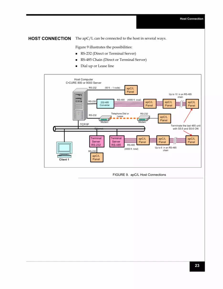
HOST CONNECTION The apC/L can be connected to the host in several ways.
Figure 9 illustrates the possibilities:
RS-232 (Direct or Terminal Server)
RS-485 Chain (Direct or Terminal Server)
Dial up or Lease line
FIGURE 9. apC/L Host Connections
23

Host Connection
Connecting the apC/Lto the Host
Use P10 to connect the apC/L to a host computer (see Figure 10). A single apC/L can connect to the host via RS-232 format. Multiple apC/Ls communicate via an RS-485 chain, but the apC/L chain must be connected to the host through an RS-232 to RS-485 converter.
FIGURE 10. RS-232 Three-wire Connection between apC/L and Host
NOTE You must set switches S1:1 through S1:8 and switches S5:1 through S5:4 on the apC/L to the communications protocol being used.
RS-232
For RS-232 transmission, follow these steps:
1. Use twisted, shielded 22 AWG (0.325 mm) Belden #9855 or equivalent.
The apC/L can be no further than 50 ft. (15 m) from the host, unless you extend this distance with a modem, line driver, or other communications device. Connect the apC/L directly to the host as shown in Table 14.
2. Connect the cable shield to the apC/L chassis ground.
NOTE Connect the shield to a proper ground only at one end.
TXRX
GND
TX
RX
GND
Host PC
RS-232
Twisted, shielded 22 AWG (.325 mm)Belden 9855Maximum 50 feet (15 meters) without modems or line drivers
apC/L Host Port P10
1
2
3
4
5
24

Host Connection
RS-485
Use RS-485 transmission to connect apC/L panels in a chain configuration. A chain of apCs can have a total length of 4,000 ft. (1,219 m). Host signals must be converted to an RS-485 by using an RS-232 to RS-485 converter.
In an apC/L chain configuration
1. Set S5:5 and S5:6 to ON on the last apC/L in the chain.
2. Connect the apC/Ls using twisted, shielded 24 AWG (0.288 mm) Belden #9842.
3. Tie the shield wires together where the two meet, but do not connect the shield at the apC/L.
4. Ground the shield wires at the RS-232/RS-485 converter.
If your converter does not have an available point to connect the shield to chassis ground, connect the shield at the chassis ground connection on the last apC/L only.
TABLE 14. apC/L Connection to Host PC
apC/L Pin apC/L Signal DB-25 Pin
DB-9 Pin Host Signal
P10-1 Data transmit (TX) 3 2 Data receive (RX)
P10-4 Data receive (RX) 2 3 Data transmit (TX)
P10-5 Ground (GND) 7 5 Ground (GND)
25

Connecting Reader Ports
CONNECTINGREADER PORTS
The apC/L reader ports can be employed in two ways:
S3:3 ON - Use either Port A or Port B (Built in termination in the apC/L)
S3:3 OFF - Use both Port A and Port B in a star configuration (No termination in the apC/L)
Figure 11 illustrates the S3:# ON case and Figure 12 illustrates the S3:3 OFF case.
FIGURE 11. S3:3 ON - Single Bus
FIGURE 12. S3:3 OFF - Star Busses
26

Connecting Relay Outputs
CONNECTINGRELAY OUTPUTS
Pins for apC/L relays are arranged in groups of three on the lower right side of the board.
The communications LEDs are located at the bottom of the apC/L panel (see Figure 13).
FIGURE 13. Communications LED and LED Bar
The pins are labeled COM (Common), NC (Normally Closed), NO (Normally Open). Use twisted, 18 AWG (0.902 mm) Belden #8461 or twisted 22 AWG (0.357 mm) Belden #8442 for wiring all relay outputs.
Do not use apC/L relays to switch AC main power, because this may exceed the ratings for the relay contacts. Use a secondary switching relay instead.
Maximum relay contact voltage is 30 VAC or DC.
When using an apC/L relay for controlling a DC door strike or for driving a secondary relay, you must install a diode (Motorola diode type #1N4933 or equivalent) across the strike to suppress noise.
When using a relay for controlling an AC door strike, you must install a MOV (World Products, Inc. part # SNR-D56K2 or equivalent) across the strike to suppress noise.
Figure 14 illustrates the diode and MOV installations for door strikes.
Relay Outputs
27

Connecting Relay Outputs
FIGURE 14. Door Strike Relays for the apC/L
NOTE Normally closed = fail-safe strike or magnetic lock.
Normally open = fail-secure strike.
DC door strike or
secondary relay
AC door strike or
secondary relay
AC Transformer
Local DC power(common)
(common)
(normally open)or
(normally closed)
+ -
(normally open)or
(normally closed)
apC/LP4 or P5
apC/LP4 or P5
Place diode as close to a strike or secondary relay as possible
Diode IN4933 or equivalent
MOV (World Products Inc. SNR-D56K2 or equivalent)
28

Connecting Relay Outputs
Inputs There are no inputs on the apC/L but up to 36 inputs are available on the I/8 and RM boards.
The wiring of supervised inputs is shown in the next two figures. Note that the resistor network is different for NO and NC switches.
Normally Open (NO) Wiring
Normally Closed (NC) Wiring
NOTE To comply with UL requirements, use shielded, minimum 22 AWG stranded, twisted pair cable for monitor points, DSMs, and REXs. Use Belden 9462 or equivalent.
29

Connecting Relay Outputs
C•CURE and Software House are registered trademarks of Tyco International Ltd. and its respective companies.
The trademarks, logos, and service marks displayed on this document are registered in the United States [or other countries]. Any misuse of the trademarks is strictly prohibited and Tyco International Ltd. will aggressively enforce its intellectual property rights to the fullest extent of the law, including pursuit of criminal prosecution wherever necessary. All trademarks not owned by Tyco International Ltd. are the property of their respective owners, and are used with permission or allowed under applicable laws.
Product offerings and specifications are subject to change without notice. Actual products may vary from photos. Not all products include all features. Availability varies by region; contact your sales representative.
apC/L Quick Start Installation GuideDocument Number: UM-201Revision: A2Release Date: May 2010
This manual is proprietary information of Software House. Unauthorized reproduction of any portion of this manual is prohibited. The material in this manual is for information purposes only. It is subject to change without notice. Software House assumes no responsibility for incorrect information this manual may contain.
Copyright ©2010 by Tyco International Ltd. and its respective companies.
All rights reserved.
30