pwm switching frequency signal injection sensorless
TRANSCRIPT
1576 IEEE TRANSACTIONS ON INDUSTRY APPLICATIONS, VOL. 48, NO. 5, SEPTEMBER/OCTOBER 2012
PWM Switching Frequency Signal InjectionSensorless Method in IPMSM
Sungmin Kim, Student Member, IEEE, Jung-Ik Ha, Member, IEEE, and Seung-Ki Sul, Fellow, IEEE
Abstract—The rotor position of an interior permanent-magnetsynchronous machine (IPMSM) can be estimated without a po-sition sensor by signal injection sensorless control at standstilland/or in very low speed rotating condition. In the signal injectionsensorless control, however, the fundamental control performanceis limited by the frequency of the injected signal, and no negli-gible acoustic noise is generated. If the frequency of the injectedvoltage signal would increase to pulsewidth modulation (PWM)switching frequency and if the switching frequency is near orabove audible range, the dynamics of the sensorless control canbe improved, and the acoustic noise can be remarkably reducedor totally eliminated. This paper describes how to extract therotor position information of IPMSM using the voltage signalinjection whose frequency is the same as the PWM switchingfrequency. Compared to the conventional heterodyning process,the proposed method is simple to implement and appropriate forPWM switching frequency signal injection. The high-frequencyvoltage signal can be injected in the stationary reference frameor in the estimated rotor reference frame. In this paper, the 5-and 16-kHz signal injections are proposed, implemented, andcompared. The experimental results confirm the effectiveness ofthe proposed method.
Index Terms—AC machine, motor drives, sensorless control,signal injection.
I. INTRODUCTION
IN THESE days, the popularity of interior permanent-magnetsynchronous machines (IPMSMs) has been increased in
many industrial drive systems [1]. The high power density, hightorque density, and high efficiency are attractive characteristicsof IPMSM for not only conventional drive applications but alsohigh-performance servo applications. Because an IPMSM is akind of synchronous machines, the rotor position information isessential for field-oriented control [2]. As the result, an encoderor resolver has been attached to the shaft of the rotor. Theseposition sensors invoke many problems: increasing system costand volume, signal noise issues, and reliability concerns. There-
Manuscript received October 12, 2011; revised March 28, 2012; acceptedApril 7, 2012. Date of publication August 13, 2012; date of current versionSeptember 14, 2012. Paper 2011-IDC-546.R1, presented at the 2011 IEEEEnergy Conversion Congress and Exposition, Phoenix, AZ, September 17–22,and approved for publication in the IEEE TRANSACTIONS ON INDUSTRY
APPLICATIONS by the Industrial Drives Committee of the IEEE IndustryApplications Society.
The authors are with the Seoul National University Power ElectronicsCenter (SPEC), Seoul National University, Seoul 151-744, Korea (e-mail:[email protected]; [email protected]; [email protected]).
Color versions of one or more of the figures in this paper are available onlineat http://ieeexplore.ieee.org.
Digital Object Identifier 10.1109/TIA.2012.2210175
fore, control techniques which are not dependent on the positionsensor have been developed for the last several decades.
In position sensorless control, there are two groups in thesensorless position estimation of IPMSM according to the po-sition estimation principle. One is based on back electromotiveforce (EMF), and the other uses the magnetic saliency of anIPMSM [3]. In the first group, to extract the rotor position infor-mation from the back EMF voltages, it uses voltage models andobservers in the synchronous or stationary frame and presentsgood performance in the middle- and high-speed operationsof IPMSM [4]–[6]. At standstill or very low rotating speed,however, because the voltage from the back EMF, which has theposition information, is proportional to the rotating speed, thesignal is too weak to be used as position information. In the sec-ond group, rotor position is estimated from the characteristicsof IPMSM: The spatial inductance distribution is determinedby the rotor position because of the saliency of the magneticpath [7]–[18]. To extract the spatial inductance variation, therelationship between current and voltage is employed. To ex-amine the current–voltage relationship, pulse width modulation(PWM) current ripple can be used [7]–[10]. By measuring thecurrent variation according to the voltage vector variation ina PWM period, inductance can be calculated directly [7]–[9]or estimated with a nonlinear estimator [10]. However, thesemethods require the modification of the PWM switching patternbecause the current variation in the conventional space vectorPWM (SVPWM) is too small to be used for the calculationof the inductance. Moreover, additional devices to measure thephase currents in arbitrary time should be designed in controlhardware, which might not be acceptable to many industryapplications. Similarly, the intended discontinuous voltage sig-nal injected method has been proposed [11]. In [11], a largevoltage signal is injected for a very short time interval, andthe current variation by the injected voltage signal is measured.From the measured current variation, the inductance and rotorposition can be estimated. However, with this method, therotor position information is discontinuously obtained, and therotor position estimation and the overall control performancecould be degraded.
Meanwhile, the continuous signal injection methods withoutPWM modification have been proposed, and the signal can beeasily augmented into the conventional current control loop[12]–[18]. The continuous voltage signals into the IPMSMcauses the current ripple, which reflects the rotor position. Fromthe corresponding current ripple, the rotor position informationcan be extracted with a properly designed observer and/ora state filter. For each signal injection sensorless method, a
0093-9994/$31.00 © 2012 IEEE
KIM et al.: PWM SWITCHING FREQUENCY SIGNAL INJECTION SENSORLESS METHOD IN IPMSM 1577
demodulation process should be incorporated to extract therotor position-related value from the current ripple. Thesesignal injection sensorless methods can be further classifiedinto two categories according to where the signal is injected:the rotating voltage signal injection in the stationary referenceframe [12], [18] and the pulsating voltage signal injection in theestimated rotor reference frame [13]–[17]. The rotating voltagesignal methods inject the continuous signal spatially regardlessof the rotor position, and the pulsating voltage signal methodsinject the signal continuously pulsating on the estimated rotorreference frame and/or the stationary reference frame. Thesesensorless methods have unique characteristics according to theinjected signal type. These characteristics of each sensorlessmethod affect the rotor position detection performance. Manyresearch results have been published regarding the relationshipsbetween sensorless methods and their performances [19], [20].
Even though each sensorless control method has uniquecharacteristics according to the injection signal type and thedemodulation process, in every sensorless method, the rotorposition is obtained from the current response caused by theinjected voltage signal. However, the measured currents containnot only current ripples by the intentionally injected voltagesignal but also the extra one by the fundamental current controland/or by nonidealities in machine and inverter. To improvethe position estimation accuracy, the only current ripple by thecorresponding injected voltage should be extracted from themeasured phase current.
Generally, the frequency of the injected voltage signal isdetermined between the current control bandwidth and thePWM switching frequency. As the frequency of the injectedsignal is getting higher, the dynamics of the sensorless controlcan be enhanced, and the interference between the injectedsignal and the fundamental components of the current controlcan be diminished. If the PWM switching frequency is near orabove the audible frequency range, the acoustic noise by theinjected signal can be remarkably reduced or totally eliminated.However, the synthesis of the injection voltage by PWM limitsthe injection frequency up to the PWM switching frequencyideally, and furthermore, the filter used in the demodulationprocess restricts the injection frequency.
In this paper, new sensorless methods for IPMSM drivesare proposed to improve the sensorless control performance.This study focuses on the highest frequency signal injectionto enhance the control bandwidth and reduce the acousticnoise simultaneously. By injecting the voltage signal whosefrequency is the same as the PWM switching frequency, whichis the theoretical maximum frequency in a drive system fedby a PWM inverter where the sampling of the current andupdating PWM is done twice in a PWM switching period, theinjected signal can be easily decoupled from the fundamentalfrequency, and the speed/torque control performance can beenhanced. Moreover, if the PWM switching frequency is nearthe audible range for most people, which is around 16 kHz,the acoustic noise due to the injected signal can be virtuallyeliminated, which may be a concern with the signal injection insome applications. The proposed signal injection methods arecompatible to the stationary reference frame or to the estimatedrotor reference frame.
II. BASIC PRINCIPLE OF HIGH-FREQUENCY VOLTAGE
SIGNAL INJECTION SENSORLESS METHOD
A. Rotating Voltage Signal Injection in the StationaryReference Frame
By exploiting the variation of the measured current, thespatial information related to the rotor position can be directlycalculated easily. The voltage equation of IPMSM in the sta-tionary d-/q-axis reference frame with currents and flux can bedescribed as [
vsdsvsqs
]= Rs
[isdsisqs
]+
d
dt
[λsds
λsqs
](1)
where [vsds, vsqs]
T, [isds, isqs]
T, and [λsds, λ
sqs]
T are the vectors ofthe stator voltage, current, and flux linkage in the stationaryd-/q-axis reference frame, respectively. Physically, the fluxlinkages in the stationary reference frame in (1), [λs
ds, λsqs]
T,are function of the stator currents and the flux linkage of therotor permanent magnet. Those flux linkages can be derived as[
λsds
λsqs
]= LS
[isdsisqs
]+ λf
[cos θrsin θr
](2)
where the inductance matrix, LS, is represented in terms of thed-/q-axis inductances, Lds and Lqs, in the synchronous rotorreference frame and the rotor position, θr, as (3) and (4) and λf
is the permanent-magnet flux linkage
LS =
[ΣL+ΔL cos 2θr ΔL sin 2θr
ΔL sin 2θr ΣL−ΔL cos 2θr
](3)
ΣL =Lds + Lqs
2ΔL =
Lds − Lqs
2. (4)
Then, (1) can be represented in terms of motor parametersand the stator currents as[vsdsvsqs
]= Rs
[isdsisqs
]+ LS
d
dt
[isdsisqs
]
+2ΔLωr
[− sin 2θr cos 2θrcos 2θr sin 2θr
][isdsisqs
]+ ωrλf
[− sin θrcos θr
](5)
where ωr is the synchronous speed. Because of the saliencyof IPMSM, the inductance matrix, LS, in (3) has the spatialinformation of the rotor position. From the inductance saliency,the rotor position can be obtained. Under the assumption thatthe high-frequency voltage signal is injected into the IPMSMand the rotating speed is almost zero, the voltage drop of thestator resistance and the back EMF voltages can be ignored.Therefore, the high-frequency impedance model of IPMSM canbe simply expressed as[
vsdshvsqsh
]= LS
d
dt
[isdshisqsh
](6)
where [vsdsh, vsqsh]
T and [isdsh, isqsh]
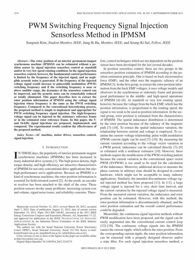
T are the injected high-frequency voltage vector and the corresponding current vectorin the stationary reference frame, respectively. The spatial in-ductance variation in Fig. 1 shows the possibility to estimate the
1578 IEEE TRANSACTIONS ON INDUSTRY APPLICATIONS, VOL. 48, NO. 5, SEPTEMBER/OCTOBER 2012
Fig. 1. Inductance variation according to the rotor position at 5 kHz.
rotor position from the inductance model in (6). According tothe injected voltage signal, the current response can be derivedfrom (6) as [
isdshisqsh
]=
∫L−1S
[vsdshvsqsh
]dt. (7)
If the voltage signal in (8) is injected to the stationaryreference frame, the locus of the voltage vector would be acircle
vsdqsh = Vinj
[− sinωht
cosωht
](8)
where Vinj and ωh are the amplitude and frequency of theinjection signal, respectively. According to this rotating voltagesignal, the corresponding current response can be derived from(7) as[isdshisqsh
]=
Vinj
ΣL2 −ΔL2
[ΣLωh
cosωht+ΔL
2ωr−ωhcos(2θr−ωht)
ΣLωh
sinωht+ΔL
2ωr−ωhsin(2θr−ωht)
].
(9)
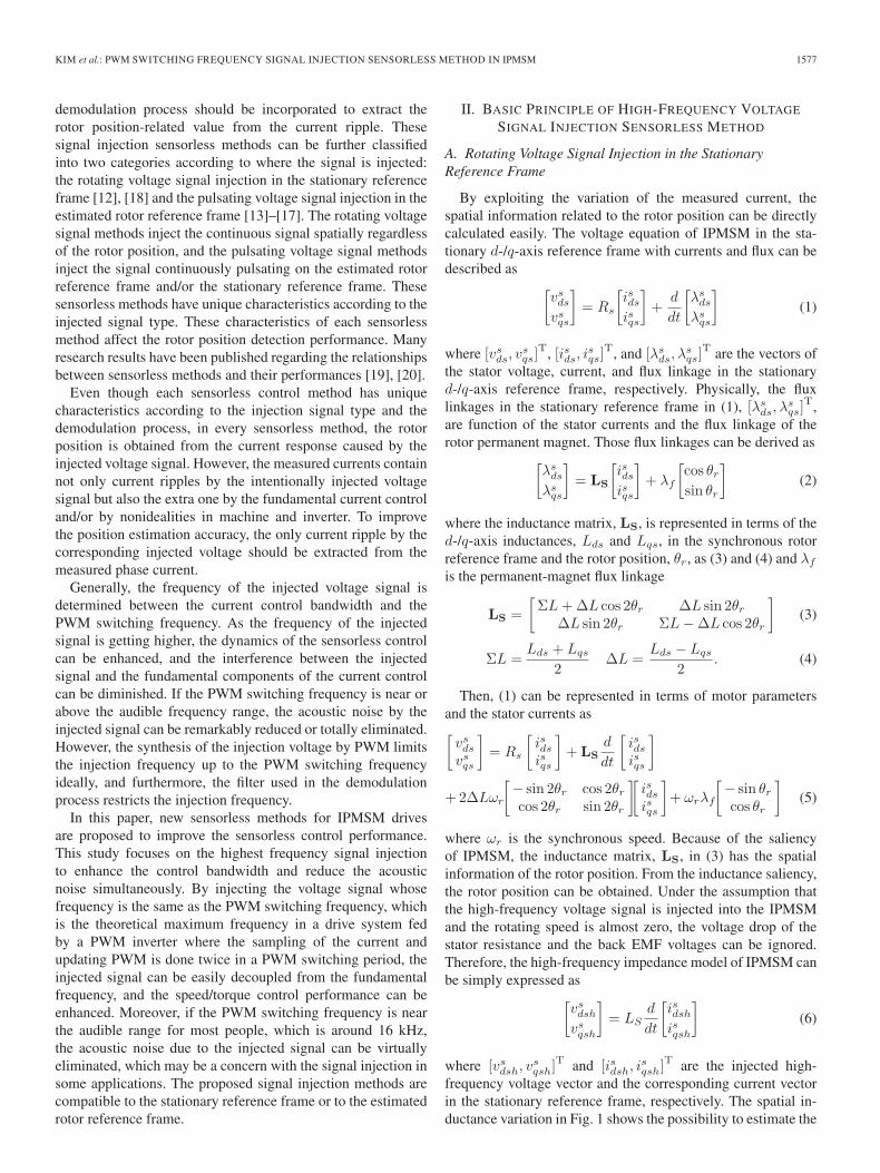
From the current response, (9), the rotor position informationcan be extracted through a kind of signal processing called asthe demodulation process. In [12], the heterodyning demodu-lation process has been proposed as shown in Fig. 2. In thisdemodulation process, the current responses in (9) are multi-plied with a sinusoidal function whose frequency is identical tothe injection frequency. After low-pass filtering, the final resultof the demodulation process, ef , in Fig. 2 can be derived as thefollowing:
εf ≈ −Vinj
ΣL2 −ΔL2
ΔL
ωh2(θr − θ̂r) (10)
where the signal injection frequency, ωh, is assumed to be largeenough compared to the rotating speed, ωr, (ωh � ωr) and therotor position error between the real position and the estimatedposition is reasonably small. The result of the process, ef , canbe used as a corrective error input to the Luenberger styleobserver or state filter as shown in Fig. 2 [13]. In this paper,some new sensorless control methods are proposed. Thesemethods are focused on the realization to extract the positionerror with switching frequency signal injection. Therefore, theLuenberger style observer or state filter in Fig. 2 should be also
Fig. 2. Block diagram of the heterodyning demodulation process in therotating voltage vector injection method in the stationary reference frame.
accompanied by the proposed methods. By driving ef to zero,the observer or state filter enforces the estimated rotor positionto follow the actual rotor position.
B. Pulsating Voltage Signal Injection in the Estimated RotorReference Frame
As the rotor position information is derived from the in-ductance matrix in the stationary reference frame, the rotorposition-related information can be also extracted from thecurrent–voltage relationship in the estimated rotor referenceframe. The voltage equation in the rotor reference frame canbe described as[vrdsvrqs
]= Rs
[irdsirqs
]+
[Lds 00 Lqs
]d
dt
[irdsirqs
]
+ ωr
[0 −Lqs
Lds 0
] [irdsirqs
]+ ωrλf
[01
](11)
where [vrds, vrqs]
T and [irds, irqs]
T are the vectors of the statorvoltage and current in the rotor reference frame, respectively.Supposing that the high-frequency voltage signal is injectedinto the IPMSM, the high-frequency impedance model in therotor reference frame can be simply described as[
vrdshvrqsh
]=
[Lds 00 Lqs
]d
dt
[irdshirqsh
](12)
where [vrdsh, vrqsh]
T and [irdsh, irqsh]
T are the vector of theinjection frequency voltage component and current componentin the rotor reference frame, respectively. According to theinjection voltage signal, the current response can be derivedfrom (12) as
[irdshirqsh
]=
∫ [Lds 00 Lqs
]−1 [vrdshvrqsh
]dt. (13)
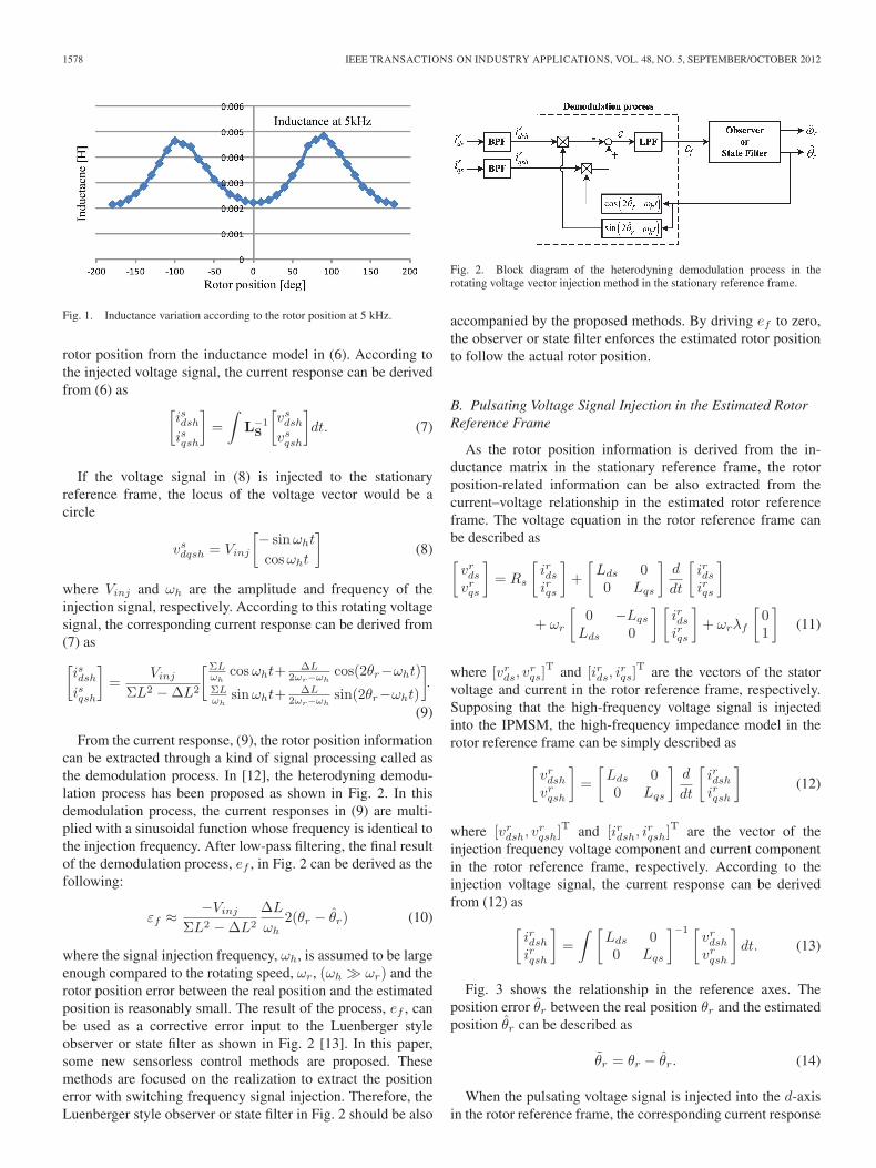
Fig. 3 shows the relationship in the reference axes. Theposition error θ̃r between the real position θr and the estimatedposition θ̂r can be described as
θ̃r = θr − θ̂r. (14)
When the pulsating voltage signal is injected into the d-axisin the rotor reference frame, the corresponding current response
KIM et al.: PWM SWITCHING FREQUENCY SIGNAL INJECTION SENSORLESS METHOD IN IPMSM 1579
Fig. 3. Relationship between reference axes. (Black) Stationary referenceframe, (blue) real rotor reference frame, and (red) estimated rotor referenceframe.
leads to estimate the rotor position. The pulsating voltage signalin the rotor reference frame can be described as[
vrdshvrqsh
]= Vinj
[cosωht
0
]. (15)
Then, the corresponding current response can be derived as (16)from (13) [
irdshirqsh
]=
Vinj
Ldsωh
[sinωht
0
]. (16)
If the saturation effect is neglected and the pulsating voltagesignal is injected into the exact d-axis rotor reference frame, theq-axis current ripple due to the injected voltage does not happen[20]. However, because the real rotor position is not available,the injected voltage signal actually differs from the one injectedat the real d-axis, (15). The injection voltage in the estimatedrotor reference frame can be rewritten with consideration of theestimated rotor position error as
V r̂dqsh = Vinj
[cosωht
0
]. (17)
Considering the position error, the actual injection voltagesignal into the real rotor reference frame can be described as
V rdqsh = T (θ̃r)V
r̂dqsh = Vinj
[cos θ̃r cosωht
− sin θ̃r cosωht
](18)
where T (θ̃r) stands for the transformation from the estimatedrotor reference frame to the real rotor reference frame. Then, thecorresponding current response in the estimated rotor referenceframe can be deduced as[
ir̂dshir̂qsh
]=T (θ̃r)
−1
[irdshirqsh
]
=Vinj
ωh
⎡⎣(
cos2 θ̃rLds
+ sin2 θ̃rLqs
)sinωht
12
(−ΔL
LdsLqs
)sin 2θ̃r sinωht
⎤⎦ . (19)
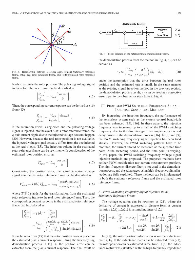
It can be seen from (19) that the rotor position error is placed inthe estimated q-axis current response. Using the heterodyningdemodulation process in Fig. 4, the position error can beextracted from the q-axis current response. The final result of
Fig. 4. Block diagram of the heterodyning demodulation process.
the demodulation process from the method in Fig. 4, ef , can bederived as
εf ≈ 1
2
Vinj
ωh
(−ΔL
LdsLqs
)(θr − θ̂r) (20)
under the assumption that the error between the real rotorposition and the estimated one is small. In the same manneras the rotating signal injection method in the previous section,the demodulation process result, ef , can be used as a correctiveerror input to the observer or state filter in Fig. 4.
III. PROPOSED PWM SWITCHING FREQUENCY SIGNAL
INJECTION SENSORLESS METHODS
By increasing the injection frequency, the performance ofthe sensorless system such as the system control bandwidthhas been enhanced [15], [16]. In these papers, the injectionfrequency was increased up to a half of the PWM switchingfrequency due to the discrete-type filter implementation anddelay issues in the demodulation process [16]. In [8] and [9],the PWM switching frequency signal injection has been triedalready. However, the PWM switching patterns have to bemodified, the current should be measured at the specified timepoint in the switching period, and the time point is varying.In this paper, the PWM switching frequency voltage signalinjection methods are proposed. The proposed methods haveneither PWM modification nor current measurement problem.The high-frequency discrete filter is not used in the demodula-tion process, and the advantages using high-frequency signal in-jection are fully exploited. These methods can be implementedin both the stationary reference frame and the estimated rotorreference frame.
A. PWM Switching Frequency Signal Injection in theStationary Reference Frame
The voltage equation can be rewritten as (21), where thederivative of current is expressed in discrete form as currentvariation (Δisds,Δisqs) in a sampling interval ΔT[vsdsvsqs
]= Rs
[isdsisqs
]+ ωrλf
[− sin θrcos θr
]+ LS
1
ΔT
[ΔisdsΔisqs
]
+2ΔLωr
[− sin 2θr cos 2θrcos 2θr sin 2θr
] [isdsisqs
]. (21)
In (21), the rotor position information is on the inductancematrix, LS. If the inductance matrix can be extracted from (21),the rotor position can be estimated in real time. In [8], the induc-tance matrix was calculated with the high-frequency impedance
1580 IEEE TRANSACTIONS ON INDUSTRY APPLICATIONS, VOL. 48, NO. 5, SEPTEMBER/OCTOBER 2012
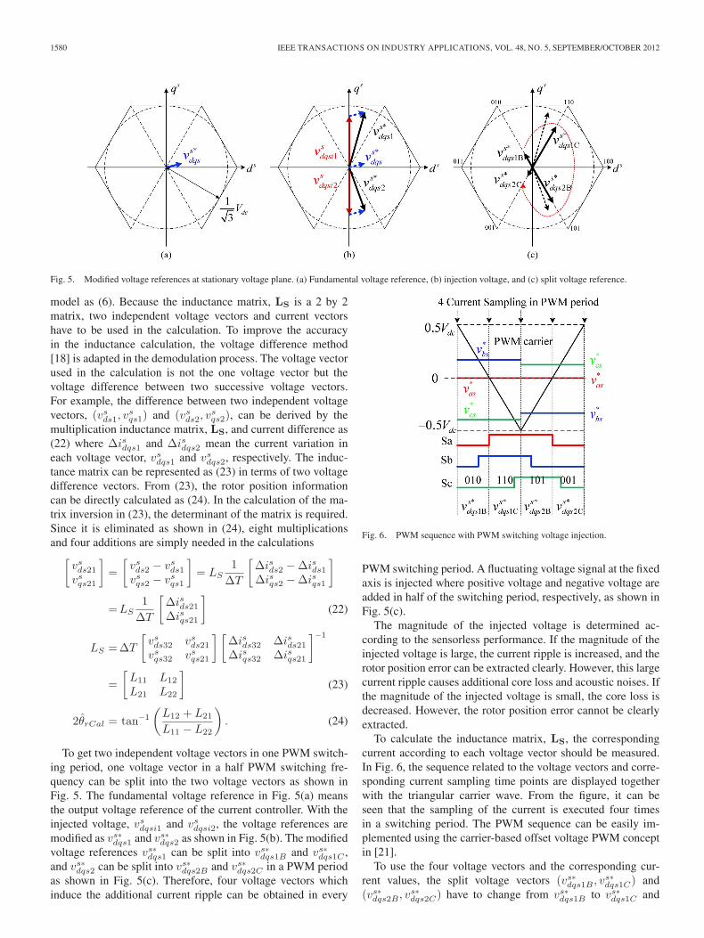
Fig. 5. Modified voltage references at stationary voltage plane. (a) Fundamental voltage reference, (b) injection voltage, and (c) split voltage reference.
model as (6). Because the inductance matrix, LS is a 2 by 2matrix, two independent voltage vectors and current vectorshave to be used in the calculation. To improve the accuracyin the inductance calculation, the voltage difference method[18] is adapted in the demodulation process. The voltage vectorused in the calculation is not the one voltage vector but thevoltage difference between two successive voltage vectors.For example, the difference between two independent voltagevectors, (vsds1, v
sqs1) and (vsds2, v
sqs2), can be derived by the
multiplication inductance matrix, LS, and current difference as(22) where Δisdqs1 and Δisdqs2 mean the current variation ineach voltage vector, vsdqs1 and vsdqs2, respectively. The induc-tance matrix can be represented as (23) in terms of two voltagedifference vectors. From (23), the rotor position informationcan be directly calculated as (24). In the calculation of the ma-trix inversion in (23), the determinant of the matrix is required.Since it is eliminated as shown in (24), eight multiplicationsand four additions are simply needed in the calculations[
vsds21vsqs21
]=
[vsds2 − vsds1vsqs2 − vsqs1
]= LS
1
ΔT
[Δisds2 −Δisds1Δisqs2 −Δisqs1
]
=LS1
ΔT
[Δisds21Δisqs21
](22)
LS =ΔT
[vsds32 vsds21vsqs32 vsqs21
] [Δisds32 Δisds21Δisqs32 Δisqs21
]−1
=
[L11 L12
L21 L22
](23)
2θ̂rCal = tan−1
(L12 + L21
L11 − L22
). (24)
To get two independent voltage vectors in one PWM switch-ing period, one voltage vector in a half PWM switching fre-quency can be split into the two voltage vectors as shown inFig. 5. The fundamental voltage reference in Fig. 5(a) meansthe output voltage reference of the current controller. With theinjected voltage, vsdqsi1 and vsdqsi2, the voltage references aremodified as vs∗dqs1 and vs∗dqs2 as shown in Fig. 5(b). The modifiedvoltage references vs∗dqs1 can be split into vs∗dqs1B and vs∗dqs1C ,and vs∗dqs2 can be split into vs∗dqs2B and vs∗dqs2C in a PWM periodas shown in Fig. 5(c). Therefore, four voltage vectors whichinduce the additional current ripple can be obtained in every
Fig. 6. PWM sequence with PWM switching voltage injection.
PWM switching period. A fluctuating voltage signal at the fixedaxis is injected where positive voltage and negative voltage areadded in half of the switching period, respectively, as shown inFig. 5(c).
The magnitude of the injected voltage is determined ac-cording to the sensorless performance. If the magnitude of theinjected voltage is large, the current ripple is increased, and therotor position error can be extracted clearly. However, this largecurrent ripple causes additional core loss and acoustic noises. Ifthe magnitude of the injected voltage is small, the core loss isdecreased. However, the rotor position error cannot be clearlyextracted.
To calculate the inductance matrix, LS, the correspondingcurrent according to each voltage vector should be measured.In Fig. 6, the sequence related to the voltage vectors and corre-sponding current sampling time points are displayed togetherwith the triangular carrier wave. From the figure, it can beseen that the sampling of the current is executed four timesin a switching period. The PWM sequence can be easily im-plemented using the carrier-based offset voltage PWM conceptin [21].
To use the four voltage vectors and the corresponding cur-rent values, the split voltage vectors (vs∗dqs1B , v
s∗dqs1C) and
(vs∗dqs2B , vs∗dqs2C) have to change from vs∗dqs1B to vs∗dqs1C and
KIM et al.: PWM SWITCHING FREQUENCY SIGNAL INJECTION SENSORLESS METHOD IN IPMSM 1581
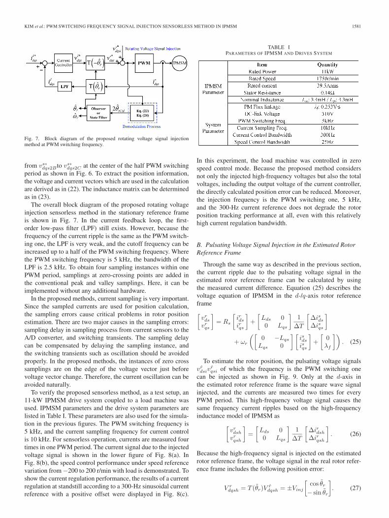
Fig. 7. Block diagram of the proposed rotating voltage signal injectionmethod at PWM switching frequency.
from vs∗dqs2Bto vs∗dqs2C at the center of the half PWM switchingperiod as shown in Fig. 6. To extract the position information,the voltage and current vectors which are used in the calculationare derived as in (22). The inductance matrix can be determinedas in (23).
The overall block diagram of the proposed rotating voltageinjection sensorless method in the stationary reference frameis shown in Fig. 7. In the current feedback loop, the first-order low-pass filter (LPF) still exists. However, because thefrequency of the current ripple is the same as the PWM switch-ing one, the LPF is very weak, and the cutoff frequency can beincreased up to a half of the PWM switching frequency. Wherethe PWM switching frequency is 5 kHz, the bandwidth of theLPF is 2.5 kHz. To obtain four sampling instances within onePWM period, samplings at zero-crossing points are added inthe conventional peak and valley samplings. Here, it can beimplemented without any additional hardware.
In the proposed methods, current sampling is very important.Since the sampled currents are used for position calculation,the sampling errors cause critical problems in rotor positionestimation. There are two major causes in the sampling errors:sampling delay in sampling process from current sensors to theA/D converter, and switching transients. The sampling delaycan be compensated by delaying the sampling instance, andthe switching transients such as oscillation should be avoidedproperly. In the proposed methods, the instances of zero crosssamplings are on the edge of the voltage vector just beforevoltage vector change. Therefore, the current oscillation can beavoided naturally.
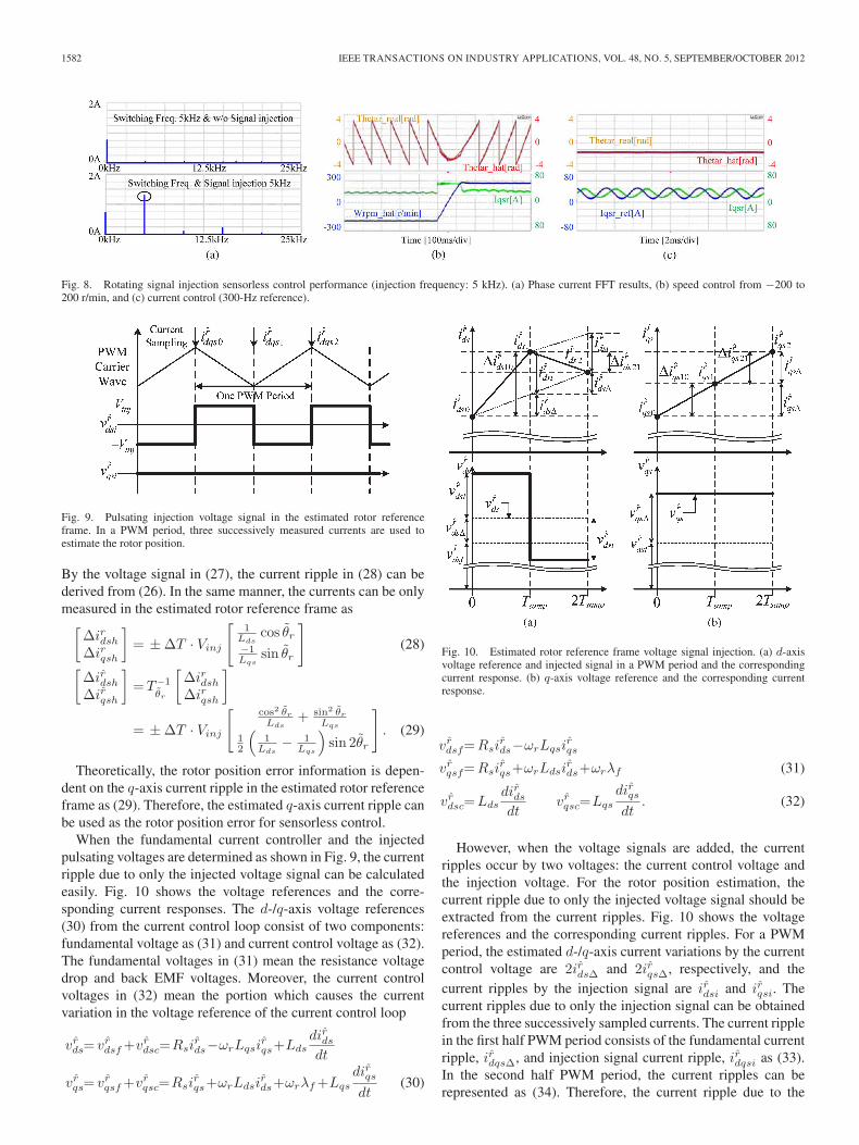
To verify the proposed sensorless method, as a test setup, an11-kW IPMSM drive system coupled to a load machine wasused. IPMSM parameters and the drive system parameters arelisted in Table I. These parameters are also used for the simula-tion in the previous figures. The PWM switching frequency is5 kHz, and the current sampling frequency for current controlis 10 kHz. For sensorless operation, currents are measured fourtimes in one PWM period. The current signal due to the injectedvoltage signal is shown in the lower figure of Fig. 8(a). InFig. 8(b), the speed control performance under speed referencevariation from −200 to 200 r/min with load is demonstrated. Toshow the current regulation performance, the results of a currentregulation at standstill according to a 300-Hz sinusoidal currentreference with a positive offset were displayed in Fig. 8(c).
TABLE IPARAMETERS OF IPMSM AND DRIVES SYSTEM
In this experiment, the load machine was controlled in zerospeed control mode. Because the proposed method considersnot only the injected high-frequency voltages but also the totalvoltages, including the output voltage of the current controller,the directly calculated position error can be reduced. Moreover,the injection frequency is the PWM switching one, 5 kHz,and the 300-Hz current reference does not degrade the rotorposition tracking performance at all, even with this relativelyhigh current regulation bandwidth.
B. Pulsating Voltage Signal Injection in the Estimated RotorReference Frame
Through the same way as described in the previous section,the current ripple due to the pulsating voltage signal in theestimated rotor reference frame can be calculated by usingthe measured current difference. Equation (25) describes thevoltage equation of IPMSM in the d-/q-axis rotor referenceframe[vrdsvrqs
]= Rs
[irdsirqs
]+
[Lds 00 Lqs
]1
ΔT
[ΔisdsΔisqs
]
+ ωr
([0 −Lqs
Lqs 0
] [isdsisqs
]+
[0λf
]). (25)
To estimate the rotor position, the pulsating voltage signalsvr̂dsiv
r̂qsi of which the frequency is the PWM switching one
can be injected as shown in Fig. 9. Only at the d-axis inthe estimated rotor reference frame is the square wave signalinjected, and the currents are measured two times for everyPWM period. This high-frequency voltage signal causes thesame frequency current ripples based on the high-frequencyinductance model of IPMSM as[
vrdshvrqsh
]=
[Lds 00 Lqs
]1
ΔT
[ΔirdshΔirqsh
]. (26)
Because the high-frequency signal is injected on the estimatedrotor reference frame, the voltage signal in the real rotor refer-ence frame includes the following position error:
V rdqsh = T (θ̃r)V
r̂dqsh = ±Vinj
[cos θ̃r− sin θ̃r
]. (27)
1582 IEEE TRANSACTIONS ON INDUSTRY APPLICATIONS, VOL. 48, NO. 5, SEPTEMBER/OCTOBER 2012
Fig. 8. Rotating signal injection sensorless control performance (injection frequency: 5 kHz). (a) Phase current FFT results, (b) speed control from −200 to200 r/min, and (c) current control (300-Hz reference).
Fig. 9. Pulsating injection voltage signal in the estimated rotor referenceframe. In a PWM period, three successively measured currents are used toestimate the rotor position.
By the voltage signal in (27), the current ripple in (28) can bederived from (26). In the same manner, the currents can be onlymeasured in the estimated rotor reference frame as[
ΔirdshΔirqsh
]= ±ΔT · Vinj
[1
Ldscos θ̃r
−1Lqs
sin θ̃r
](28)[
Δir̂dshΔir̂qsh
]=T−1
θ̃r
[ΔirdshΔirqsh
]
= ±ΔT · Vinj
[cos2 θ̃rLds
+ sin2 θ̃rLqs
12
(1
Lds− 1
Lqs
)sin 2θ̃r
]. (29)
Theoretically, the rotor position error information is depen-dent on the q-axis current ripple in the estimated rotor referenceframe as (29). Therefore, the estimated q-axis current ripple canbe used as the rotor position error for sensorless control.
When the fundamental current controller and the injectedpulsating voltages are determined as shown in Fig. 9, the currentripple due to only the injected voltage signal can be calculatedeasily. Fig. 10 shows the voltage references and the corre-sponding current responses. The d-/q-axis voltage references(30) from the current control loop consist of two components:fundamental voltage as (31) and current control voltage as (32).The fundamental voltages in (31) mean the resistance voltagedrop and back EMF voltages. Moreover, the current controlvoltages in (32) mean the portion which causes the currentvariation in the voltage reference of the current control loop
vr̂ds= vr̂dsf+vr̂dsc=Rsir̂ds−ωrLqsi
r̂qs+Lds
dir̂dsdt
vr̂qs= vr̂qsf+vr̂qsc=Rsir̂qs+ωrLdsi
r̂ds+ωrλf+Lqs
dir̂qsdt
(30)
Fig. 10. Estimated rotor reference frame voltage signal injection. (a) d-axisvoltage reference and injected signal in a PWM period and the correspondingcurrent response. (b) q-axis voltage reference and the corresponding currentresponse.
vr̂dsf=Rsir̂ds−ωrLqsi
r̂qs
vr̂qsf=Rsir̂qs+ωrLdsi
r̂ds+ωrλf (31)
vr̂dsc=Ldsdir̂dsdt
vr̂qsc=Lqs
dir̂qsdt
. (32)
However, when the voltage signals are added, the currentripples occur by two voltages: the current control voltage andthe injection voltage. For the rotor position estimation, thecurrent ripple due to only the injected voltage signal should beextracted from the current ripples. Fig. 10 shows the voltagereferences and the corresponding current ripples. For a PWMperiod, the estimated d-/q-axis current variations by the currentcontrol voltage are 2ir̂dsΔ and 2ir̂qsΔ, respectively, and thecurrent ripples by the injection signal are ir̂dsi and ir̂qsi. Thecurrent ripples due to only the injection signal can be obtainedfrom the three successively sampled currents. The current ripplein the first half PWM period consists of the fundamental currentripple, ir̂dqsΔ, and injection signal current ripple, ir̂dqsi as (33).In the second half PWM period, the current ripples can berepresented as (34). Therefore, the current ripple due to the
KIM et al.: PWM SWITCHING FREQUENCY SIGNAL INJECTION SENSORLESS METHOD IN IPMSM 1583
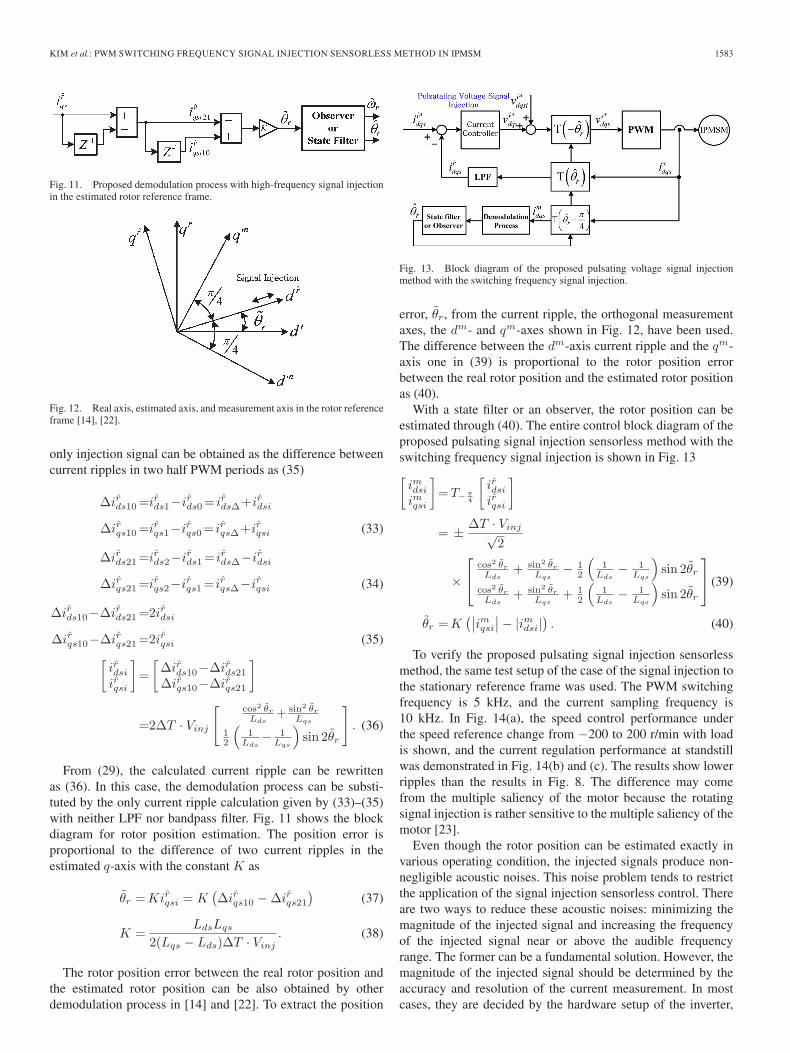
Fig. 11. Proposed demodulation process with high-frequency signal injectionin the estimated rotor reference frame.
Fig. 12. Real axis, estimated axis, and measurement axis in the rotor referenceframe [14], [22].
only injection signal can be obtained as the difference betweencurrent ripples in two half PWM periods as (35)
Δir̂ds10=ir̂ds1−ir̂ds0= ir̂dsΔ+ir̂dsi
Δir̂qs10=ir̂qs1−ir̂qs0= ir̂qsΔ+ir̂qsi (33)
Δir̂ds21=ir̂ds2−ir̂ds1= ir̂dsΔ−ir̂dsi
Δir̂qs21=ir̂qs2−ir̂qs1= ir̂qsΔ−ir̂qsi (34)
Δir̂ds10−Δir̂ds21=2ir̂dsi
Δir̂qs10−Δir̂qs21=2ir̂qsi (35)[ir̂dsiir̂qsi
]=
[Δir̂ds10−Δir̂ds21Δir̂qs10−Δir̂qs21
]
=2ΔT · Vinj
[cos2 θ̃rLds
+ sin2 θ̃rLqs
12
(1
Lds− 1
Lqs
)sin 2θ̃r
]. (36)
From (29), the calculated current ripple can be rewrittenas (36). In this case, the demodulation process can be substi-tuted by the only current ripple calculation given by (33)–(35)with neither LPF nor bandpass filter. Fig. 11 shows the blockdiagram for rotor position estimation. The position error isproportional to the difference of two current ripples in theestimated q-axis with the constant K as
θ̃r =Kir̂qsi = K(Δir̂qs10 −Δir̂qs21
)(37)
K =LdsLqs
2(Lqs − Lds)ΔT · Vinj. (38)
The rotor position error between the real rotor position andthe estimated rotor position can be also obtained by otherdemodulation process in [14] and [22]. To extract the position
Fig. 13. Block diagram of the proposed pulsating voltage signal injectionmethod with the switching frequency signal injection.
error, θ̃r, from the current ripple, the orthogonal measurementaxes, the dm- and qm-axes shown in Fig. 12, have been used.The difference between the dm-axis current ripple and the qm-axis one in (39) is proportional to the rotor position errorbetween the real rotor position and the estimated rotor positionas (40).
With a state filter or an observer, the rotor position can beestimated through (40). The entire control block diagram of theproposed pulsating signal injection sensorless method with theswitching frequency signal injection is shown in Fig. 13[imdsiimqsi
]=T−π
4
[ir̂dsiir̂qsi
]
= ± ΔT · Vinj√2
×
⎡⎣ cos2 θ̃r
Lds+ sin2 θ̃r
Lqs− 1
2
(1
Lds− 1
Lqs
)sin 2θ̃r
cos2 θ̃rLds
+ sin2 θ̃rLqs
+ 12
(1
Lds− 1
Lqs
)sin 2θ̃r
⎤⎦ (39)
θ̃r =K(∣∣imqsi∣∣− |imdsi|
). (40)
To verify the proposed pulsating signal injection sensorlessmethod, the same test setup of the case of the signal injection tothe stationary reference frame was used. The PWM switchingfrequency is 5 kHz, and the current sampling frequency is10 kHz. In Fig. 14(a), the speed control performance underthe speed reference change from −200 to 200 r/min with loadis shown, and the current regulation performance at standstillwas demonstrated in Fig. 14(b) and (c). The results show lowerripples than the results in Fig. 8. The difference may comefrom the multiple saliency of the motor because the rotatingsignal injection is rather sensitive to the multiple saliency of themotor [23].
Even though the rotor position can be estimated exactly invarious operating condition, the injected signals produce non-negligible acoustic noises. This noise problem tends to restrictthe application of the signal injection sensorless control. Thereare two ways to reduce these acoustic noises: minimizing themagnitude of the injected signal and increasing the frequencyof the injected signal near or above the audible frequencyrange. The former can be a fundamental solution. However, themagnitude of the injected signal should be determined by theaccuracy and resolution of the current measurement. In mostcases, they are decided by the hardware setup of the inverter,
1584 IEEE TRANSACTIONS ON INDUSTRY APPLICATIONS, VOL. 48, NO. 5, SEPTEMBER/OCTOBER 2012
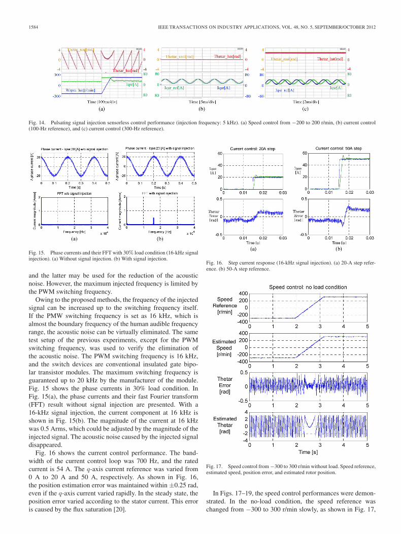
Fig. 14. Pulsating signal injection sensorless control performance (injection frequency: 5 kHz). (a) Speed control from −200 to 200 r/min, (b) current control(100-Hz reference), and (c) current control (300-Hz reference).
Fig. 15. Phase currents and their FFT with 30% load condition (16-kHz signalinjection). (a) Without signal injection. (b) With signal injection.
and the latter may be used for the reduction of the acousticnoise. However, the maximum injected frequency is limited bythe PWM switching frequency.
Owing to the proposed methods, the frequency of the injectedsignal can be increased up to the switching frequency itself.If the PMW switching frequency is set as 16 kHz, which isalmost the boundary frequency of the human audible frequencyrange, the acoustic noise can be virtually eliminated. The sametest setup of the previous experiments, except for the PWMswitching frequency, was used to verify the elimination ofthe acoustic noise. The PWM switching frequency is 16 kHz,and the switch devices are conventional insulated gate bipo-lar transistor modules. The maximum switching frequency isguaranteed up to 20 kHz by the manufacturer of the module.Fig. 15 shows the phase currents in 30% load condition. InFig. 15(a), the phase currents and their fast Fourier transform(FFT) result without signal injection are presented. With a16-kHz signal injection, the current component at 16 kHz isshown in Fig. 15(b). The magnitude of the current at 16 kHzwas 0.5 Arms, which could be adjusted by the magnitude of theinjected signal. The acoustic noise caused by the injected signaldisappeared.
Fig. 16 shows the current control performance. The band-width of the current control loop was 700 Hz, and the ratedcurrent is 54 A. The q-axis current reference was varied from0 A to 20 A and 50 A, respectively. As shown in Fig. 16,the position estimation error was maintained within ±0.25 rad,even if the q-axis current varied rapidly. In the steady state, theposition error varied according to the stator current. This erroris caused by the flux saturation [20].
Fig. 16. Step current response (16-kHz signal injection). (a) 20-A step refer-ence. (b) 50-A step reference.
Fig. 17. Speed control from −300 to 300 r/min without load. Speed reference,estimated speed, position error, and estimated rotor position.
In Figs. 17–19, the speed control performances were demon-strated. In the no-load condition, the speed reference waschanged from −300 to 300 r/min slowly, as shown in Fig. 17,
KIM et al.: PWM SWITCHING FREQUENCY SIGNAL INJECTION SENSORLESS METHOD IN IPMSM 1585
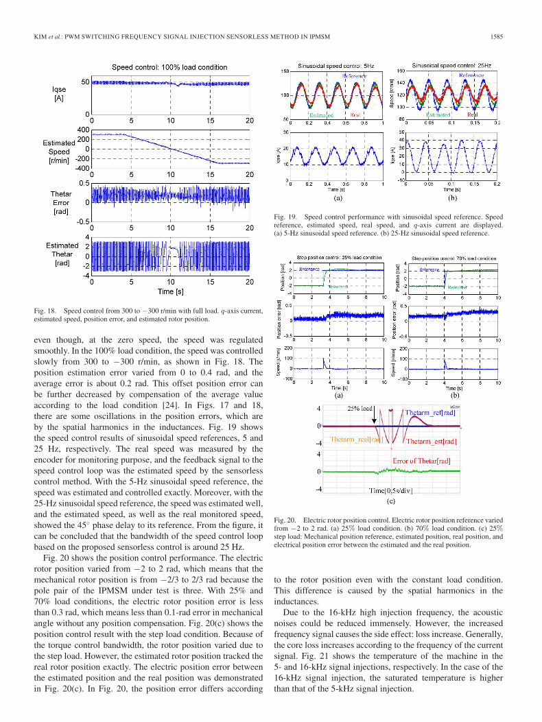
Fig. 18. Speed control from 300 to −300 r/min with full load. q-axis current,estimated speed, position error, and estimated rotor position.
even though, at the zero speed, the speed was regulatedsmoothly. In the 100% load condition, the speed was controlledslowly from 300 to −300 r/min, as shown in Fig. 18. Theposition estimation error varied from 0 to 0.4 rad, and theaverage error is about 0.2 rad. This offset position error canbe further decreased by compensation of the average valueaccording to the load condition [24]. In Figs. 17 and 18,there are some oscillations in the position errors, which areby the spatial harmonics in the inductances. Fig. 19 showsthe speed control results of sinusoidal speed references, 5 and25 Hz, respectively. The real speed was measured by theencoder for monitoring purpose, and the feedback signal to thespeed control loop was the estimated speed by the sensorlesscontrol method. With the 5-Hz sinusoidal speed reference, thespeed was estimated and controlled exactly. Moreover, with the25-Hz sinusoidal speed reference, the speed was estimated well,and the estimated speed, as well as the real monitored speed,showed the 45◦ phase delay to its reference. From the figure, itcan be concluded that the bandwidth of the speed control loopbased on the proposed sensorless control is around 25 Hz.
Fig. 20 shows the position control performance. The electricrotor position varied from −2 to 2 rad, which means that themechanical rotor position is from −2/3 to 2/3 rad because thepole pair of the IPMSM under test is three. With 25% and70% load conditions, the electric rotor position error is lessthan 0.3 rad, which means less than 0.1-rad error in mechanicalangle without any position compensation. Fig. 20(c) shows theposition control result with the step load condition. Because ofthe torque control bandwidth, the rotor position varied due tothe step load. However, the estimated rotor position tracked thereal rotor position exactly. The electric position error betweenthe estimated position and the real position was demonstratedin Fig. 20(c). In Fig. 20, the position error differs according
Fig. 19. Speed control performance with sinusoidal speed reference. Speedreference, estimated speed, real speed, and q-axis current are displayed.(a) 5-Hz sinusoidal speed reference. (b) 25-Hz sinusoidal speed reference.
Fig. 20. Electric rotor position control. Electric rotor position reference variedfrom −2 to 2 rad. (a) 25% load condition. (b) 70% load condition. (c) 25%step load: Mechanical position reference, estimated position, real position, andelectrical position error between the estimated and the real position.
to the rotor position even with the constant load condition.This difference is caused by the spatial harmonics in theinductances.
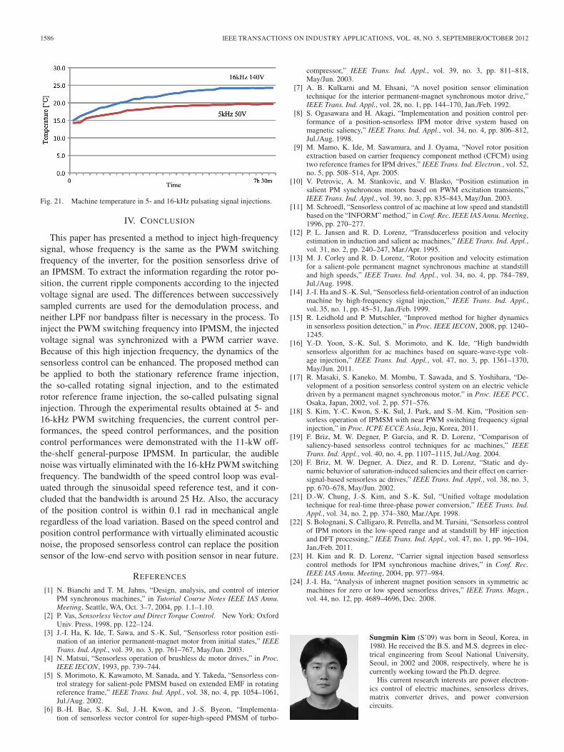
Due to the 16-kHz high injection frequency, the acousticnoises could be reduced immensely. However, the increasedfrequency signal causes the side effect: loss increase. Generally,the core loss increases according to the frequency of the currentsignal. Fig. 21 shows the temperature of the machine in the5- and 16-kHz signal injections, respectively. In the case of the16-kHz signal injection, the saturated temperature is higherthan that of the 5-kHz signal injection.
1586 IEEE TRANSACTIONS ON INDUSTRY APPLICATIONS, VOL. 48, NO. 5, SEPTEMBER/OCTOBER 2012
Fig. 21. Machine temperature in 5- and 16-kHz pulsating signal injections.
IV. CONCLUSION
This paper has presented a method to inject high-frequencysignal, whose frequency is the same as the PWM switchingfrequency of the inverter, for the position sensorless drive ofan IPMSM. To extract the information regarding the rotor po-sition, the current ripple components according to the injectedvoltage signal are used. The differences between successivelysampled currents are used for the demodulation process, andneither LPF nor bandpass filter is necessary in the process. Toinject the PWM switching frequency into IPMSM, the injectedvoltage signal was synchronized with a PWM carrier wave.Because of this high injection frequency, the dynamics of thesensorless control can be enhanced. The proposed method canbe applied to both the stationary reference frame injection,the so-called rotating signal injection, and to the estimatedrotor reference frame injection, the so-called pulsating signalinjection. Through the experimental results obtained at 5- and16-kHz PWM switching frequencies, the current control per-formances, the speed control performances, and the positioncontrol performances were demonstrated with the 11-kW off-the-shelf general-purpose IPMSM. In particular, the audiblenoise was virtually eliminated with the 16-kHz PWM switchingfrequency. The bandwidth of the speed control loop was eval-uated through the sinusoidal speed reference test, and it con-cluded that the bandwidth is around 25 Hz. Also, the accuracyof the position control is within 0.1 rad in mechanical angleregardless of the load variation. Based on the speed control andposition control performance with virtually eliminated acousticnoise, the proposed sensorless control can replace the positionsensor of the low-end servo with position sensor in near future.
REFERENCES
[1] N. Bianchi and T. M. Jahns, “Design, analysis, and control of interiorPM synchronous machines,” in Tutorial Course Notes IEEE IAS Annu.Meeting, Seattle, WA, Oct. 3–7, 2004, pp. 1.1–1.10.
[2] P. Vas, Sensorless Vector and Direct Torque Control. New York: OxfordUniv. Press, 1998, pp. 122–124.
[3] J.-I. Ha, K. Ide, T. Sawa, and S.-K. Sul, “Sensorless rotor position esti-mation of an interior permanent-magnet motor from initial states,” IEEETrans. Ind. Appl., vol. 39, no. 3, pp. 761–767, May/Jun. 2003.
[4] N. Matsui, “Sensorless operation of brushless dc motor drives,” in Proc.IEEE IECON, 1993, pp. 739–744.
[5] S. Morimoto, K. Kawamoto, M. Sanada, and Y. Takeda, “Sensorless con-trol strategy for salient-pole PMSM based on extended EMF in rotatingreference frame,” IEEE Trans. Ind. Appl., vol. 38, no. 4, pp. 1054–1061,Jul./Aug. 2002.
[6] B.-H. Bae, S.-K. Sul, J.-H. Kwon, and J.-S. Byeon, “Implementa-tion of sensorless vector control for super-high-speed PMSM of turbo-
compressor,” IEEE Trans. Ind. Appl., vol. 39, no. 3, pp. 811–818,May/Jun. 2003.
[7] A. B. Kulkarni and M. Ehsani, “A novel position sensor eliminationtechnique for the interior permanent-magnet synchronous motor drive,”IEEE Trans. Ind. Appl., vol. 28, no. 1, pp. 144–170, Jan./Feb. 1992.
[8] S. Ogasawara and H. Akagi, “Implementation and position control per-formance of a position-sensorless IPM motor drive system based onmagnetic saliency,” IEEE Trans. Ind. Appl., vol. 34, no. 4, pp. 806–812,Jul./Aug. 1998.
[9] M. Mamo, K. Ide, M. Sawamura, and J. Oyama, “Novel rotor positionextraction based on carrier frequency component method (CFCM) usingtwo reference frames for IPM drives,” IEEE Trans. Ind. Electron., vol. 52,no. 5, pp. 508–514, Apr. 2005.
[10] V. Petrovic, A. M. Stankovic, and V. Blasko, “Position estimation insalient PM synchronous motors based on PWM excitation transients,”IEEE Trans. Ind. Appl., vol. 39, no. 3, pp. 835–843, May/Jun. 2003.
[11] M. Schroedl, “Sensorless control of ac machine at low speed and standstillbased on the “INFORM” method,” in Conf. Rec. IEEE IAS Annu. Meeting,1996, pp. 270–277.
[12] P. L. Jansen and R. D. Lorenz, “Transducerless position and velocityestimation in induction and salient ac machines,” IEEE Trans. Ind. Appl.,vol. 31, no. 2, pp. 240–247, Mar./Apr. 1995.
[13] M. J. Corley and R. D. Lorenz, “Rotor position and velocity estimationfor a salient-pole permanent magnet synchronous machine at standstilland high speeds,” IEEE Trans. Ind. Appl., vol. 34, no. 4, pp. 784–789,Jul./Aug. 1998.
[14] J.-I. Ha and S.-K. Sul, “Sensorless field-orientation control of an inductionmachine by high-frequency signal injection,” IEEE Trans. Ind. Appl.,vol. 35, no. 1, pp. 45–51, Jan./Feb. 1999.
[15] R. Leidhold and P. Mutschler, “Improved method for higher dynamicsin sensorless position detection,” in Proc. IEEE IECON, 2008, pp. 1240–1245.
[16] Y.-D. Yoon, S.-K. Sul, S. Morimoto, and K. Ide, “High bandwidthsensorless algorithm for ac machines based on square-wave-type volt-age injection,” IEEE Trans. Ind. Appl., vol. 47, no. 3, pp. 1361–1370,May/Jun. 2011.
[17] R. Masaki, S. Kaneko, M. Mombu, T. Sawada, and S. Yoshihara, “De-velopment of a position sensorless control system on an electric vehicledriven by a permanent magnet synchronous motor,” in Proc. IEEE PCC,Osaka, Japan, 2002, vol. 2, pp. 571–576.
[18] S. Kim, Y.-C. Kwon, S.-K. Sul, J. Park, and S.-M. Kim, “Position sen-sorless operation of IPMSM with near PWM switching frequency signalinjection,” in Proc. ICPE ECCE Asia, Jeju, Korea, 2011.
[19] F. Briz, M. W. Degner, P. Garcia, and R. D. Lorenz, “Comparison ofsaliency-based sensorless control techniques for ac machines,” IEEETrans. Ind. Appl., vol. 40, no. 4, pp. 1107–1115, Jul./Aug. 2004.
[20] F. Briz, M. W. Degner, A. Diez, and R. D. Lorenz, “Static and dy-namic behavior of saturation-induced saliencies and their effect on carrier-signal-based sensorless ac drives,” IEEE Trans. Ind. Appl., vol. 38, no. 3,pp. 670–678, May/Jun. 2002.
[21] D.-W. Chung, J.-S. Kim, and S.-K. Sul, “Unified voltage modulationtechnique for real-time three-phase power conversion,” IEEE Trans. Ind.Appl., vol. 34, no. 2, pp. 374–380, Mar./Apr. 1998.
[22] S. Bolognani, S. Calligaro, R. Petrella, and M. Tursini, “Sensorless controlof IPM motors in the low-speed range and at standstill by HF injectionand DFT processing,” IEEE Trans. Ind. Appl., vol. 47, no. 1, pp. 96–104,Jan./Feb. 2011.
[23] H. Kim and R. D. Lorenz, “Carrier signal injection based sensorlesscontrol methods for IPM synchronous machine drives,” in Conf. Rec.IEEE IAS Annu. Meeting, 2004, pp. 977–984.
[24] J.-I. Ha, “Analysis of inherent magnet position sensors in symmetric acmachines for zero or low speed sensorless drives,” IEEE Trans. Magn.,vol. 44, no. 12, pp. 4689–4696, Dec. 2008.
Sungmin Kim (S’09) was born in Seoul, Korea, in1980. He received the B.S. and M.S. degrees in elec-trical engineering from Seoul National University,Seoul, in 2002 and 2008, respectively, where he iscurrently working toward the Ph.D. degree.
His current research interests are power electron-ics control of electric machines, sensorless drives,matrix converter drives, and power conversioncircuits.

KIM et al.: PWM SWITCHING FREQUENCY SIGNAL INJECTION SENSORLESS METHOD IN IPMSM 1587
Jung-Ik Ha (S’97–M’01) was born in Korea in1971. He received the B.S., M.S., and Ph.D. de-grees in electrical engineering from Seoul NationalUniversity, Seoul, Korea, in 1995, 1997, and 2001,respectively.
From 2001 to 2002, he was a Researcher withYASKAWA Electric Corporation, Japan. From 2003to 2008, he worked for SAMSUNG ElectronicsCompany, Korea, as a Senior and Principal Engineer.From 2009 to 2010, he was Chief Technology Officerwith LS Mecapion Company, Korea. Since 2010,
he has been an Assistant Professor in the School of Electrical Engineering,Seoul National University. His research interests include circuits and control inhigh-efficiency and integrated electric energy conversions for various industrialfields.
Seung-Ki Sul (S’78–M’80–SM’98–F’00) was bornin Korea in 1958. He received the B.S., M.S., andPh.D. degrees in electrical engineering from SeoulNational University, Seoul, Korea, in 1980, 1983,and 1986, respectively.
From 1986 to 1988, he was an AssociateResearcher in the Department of Electrical andComputer Engineering, University of Wisconsin,Madison. From 1988 to 1990, he was a Principal Re-search Engineer with Gold-Star Industrial SystemsCompany. Since 1991, he has been a member of the
faculty of the School of Electrical Engineering, Seoul National University,where he is currently a Professor. From 2005 to 2007, he was the Vice-Deanof the College of Engineering, Seoul National University. From 2008 to 2011,he was the President of the Korea Electrical Engineering and Science ResearchInstitute, Seoul. His current research interests are power-electronic control ofelectric machines, electric/hybrid vehicle drives, and power-converter circuits.

本文献由“学霸图书馆-文献云下载”收集自网络,仅供学习交流使用。
学霸图书馆(www.xuebalib.com)是一个“整合众多图书馆数据库资源,
提供一站式文献检索和下载服务”的24 小时在线不限IP
图书馆。
图书馆致力于便利、促进学习与科研,提供最强文献下载服务。
图书馆导航:
图书馆首页 文献云下载 图书馆入口 外文数据库大全 疑难文献辅助工具