protecting precision machinery using guideway sliding isolator with gap spring and dampers
TRANSCRIPT
4th International Conference on Earthquake Engineering Taipei, Taiwan
October 12-13, 2006
Paper No. 221
PROTECTING PRECISION MACHINERY USING GUIDEWAY SLIDING ISOLATOR WITH GAP SPRING AND DAMPERS
George C. Yao 1 Wen-Chun Huang 2 Fan-Ru Lin 3
ABSTRACT
Guideway sliding isolator can be one of the most efficient ways to protect precision machinery from damage in an earthquake. However, it brings large displacement between the machine and the floor. In order to improve the performance, viscous dampers, as the energy absorber to reduce the displacements, and gap springs, providing the resilient force to eliminate the relative and residual displacements, are both added to the sliding system. The special feature of a gap spring is that a spring is initially kept away from the machinery with a gap so that the isolation system does not have a constant nature frequency therefore reducing the resonant vibration. In this paper, a numerical model to simulate the machinery and a full scale shaking table test of a 22-tons-weight specimen were both performed to study the behavior of guideway sliding isolator with gap spring. Testing results showed that absolute acceleration transmitted to the specimen can be very low if the frictional coefficient of the guideway isolator is under 0.05, and the gap springs are effective to control the relative displacements of the system. Numerical model is shown to be satisfying since the test results are well correlated to the analyzed one.
Keywords: Isolator, Guideway, Precision Machinery Protection, Equipment Protection, Viscous Damper, Shaking Table Test
INTRODUCTION
The hi-tech industry in Taiwan incurred a great loss due to the equipment and precision machinery damage during the Chi-Chi Earthquake and the following 331 Earthquake though the factorial building structures were well maintained. People become aware of that not only the seismic capacity of the structure of the factorial buildings should be well treated, but also the protecting strategy for the nonstructural components, especially the precision machinery, should be seriously considered. However, because of the specific environmental features in the hi-tech factories, difference between the precision machinery and common equipments exists. There are some limitations of the aseismic design on the precision machinery: 1. The floor height of a hi-tech factory is mostly taller than usual, and the pipelines above and below
floors are numerous and complicated due to the production function of the machinery, thus it is difficult to fasten the machinery to the factory structure.
2. For the strict environmental demand of the clean room, the materials with volatility, such as rubbers, which may produce dusts polluting environments, would be prohibited. Therefore the lead-rubber-bearing isolator lost the applicability in protection equipment in some clean rooms.
3. The precision machinery are sensitive to vibration, hence isolating the vibration at the precision
1 Professor, Dept. of Architecture, NCKU, Tainan, Taiwan, [email protected] 2 Ph.D. student, Dept. of Architecture, NCKU, Tainan, Taiwan, [email protected] 3 Research Assistant, National Center for Research on Earthquake Engineering, Taipei, Taiwan, [email protected]
machinery is better than fixing the machinery to the structure, i.e., the protection strategy should be devoted to lower the transmissibility ratio of the vibration from environment to the machinery.
4. Besides reducing the transmissibility of vibration, the allowable relative displacements between the machines and the floor needs to be considered to prevent the machinery interfering with the pipeline or bumping into each other.
According to the points mentioned above, providing isolation system under the foundation of the precision machinery is one of the best strategies for protecting the precision machinery [1]. The studies and applications of isolation system applied in protecting buildings are numerous and mature in many countries around the world [2~4]. Considering the environmental demand, the isolation system with the same mechanism such as FPS may be the better choice. Many researches revealed that the sliding isolation system with restoring force could performed well in protecting equipments if the optimal parameters such as system periods and friction coefficient were well designed [1,5~7]. In this study, the seismic performance of guideway sliding isolation system with gapped spring and viscous dampers would be evaluated by numerical model built in SAP2000N and full scale shaking table test are performed to prove the accuracy of the analytical model.
GUIDEWAY SLIDING ISOLATOR SYSTEM
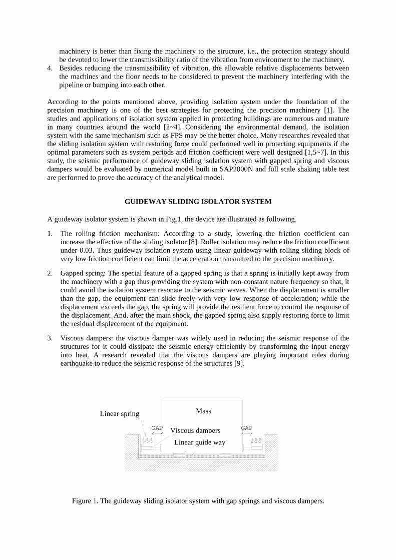
A guideway isolator system is shown in Fig.1, the device are illustrated as following.
1. The rolling friction mechanism: According to a study, lowering the friction coefficient can increase the effective of the sliding isolator [8]. Roller isolation may reduce the friction coefficient under 0.03. Thus guideway isolation system using linear guideway with rolling sliding block of very low friction coefficient can limit the acceleration transmitted to the precision machinery.
2. Gapped spring: The special feature of a gapped spring is that a spring is initially kept away from the machinery with a gap thus providing the system with non-constant nature frequency so that, it could avoid the isolation system resonate to the seismic waves. When the displacement is smaller than the gap, the equipment can slide freely with very low response of acceleration; while the displacement exceeds the gap, the spring will provide the resilient force to control the response of the displacement. And, after the main shock, the gapped spring also supply restoring force to limit the residual displacement of the equipment.
3. Viscous dampers: the viscous damper was widely used in reducing the seismic response of the structures for it could dissipate the seismic energy efficiently by transforming the input energy into heat. A research revealed that the viscous dampers are playing important roles during earthquake to reduce the seismic response of the structures [9].
GAP
線性彈簧
黏性阻尼器
滾動摩擦機制
GAP
機台
Figure 1. The guideway sliding isolator system with gap springs and viscous dampers.
Mass
Viscous dampersLinear guide way
Linear spring
THE NUMERICAL MODEL IN SAP2000N
To simulate the guideway sliding isolation system, three nonlinear elements in SAP2000N are used: 1. Friction-Pendulum Isolator: this is used to simulate the sliding surface of the system, i.e., it can
imitate the linear guideway by setting appropriate friction coefficient and rigidity and make the curvature of the sliding surface almost close to zero.
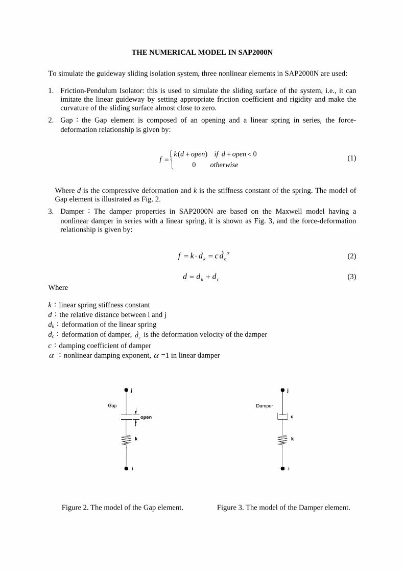
2. Gap: the Gap element is composed of an opening and a linear spring in series, the force-deformation relationship is given by:
⎩⎨⎧ <++
=otherwise
opendifopendkf
00)( (1)
Where d is the compressive deformation and k is the stiffness constant of the spring. The model of Gap element is illustrated as Fig. 2.
3. Damper:The damper properties in SAP2000N are based on the Maxwell model having a nonlinear damper in series with a linear spring, it is shown as Fig. 3, and the force-deformation relationship is given by:
α
ck dcdkf &=⋅= (2)
ck ddd += (3) Where k:linear spring stiffness constant d:the relative distance between i and j dk:deformation of the linear spring dc:deformation of damper, cd& is the deformation velocity of the damper c:damping coefficient of damper α :nonlinear damping exponent, α =1 in linear damper
Figure 2. The model of the Gap element. Figure 3. The model of the Damper element.
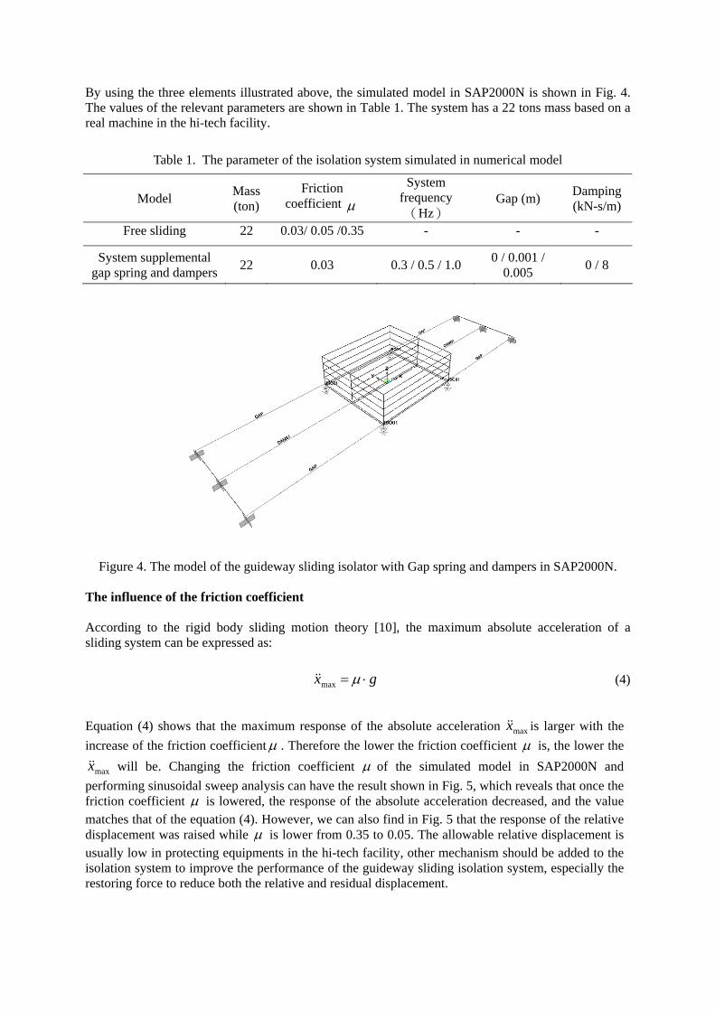
By using the three elements illustrated above, the simulated model in SAP2000N is shown in Fig. 4. The values of the relevant parameters are shown in Table 1. The system has a 22 tons mass based on a real machine in the hi-tech facility.
Table 1. The parameter of the isolation system simulated in numerical model
Model Mass(ton)
Friction coefficient μ
System frequency(Hz)
Gap (m) Damping (kN-s/m)
Free sliding 22 0.03/ 0.05 /0.35 - - -
System supplemental gap spring and dampers 22 0.03 0.3 / 0.5 / 1.0 0 / 0.001 /
0.005 0 / 8
Figure 4. The model of the guideway sliding isolator with Gap spring and dampers in SAP2000N.
The influence of the friction coefficient According to the rigid body sliding motion theory [10], the maximum absolute acceleration of a sliding system can be expressed as:
gx ⋅= μmax&& (4)
Equation (4) shows that the maximum response of the absolute acceleration maxx&& is larger with the increase of the friction coefficientμ . Therefore the lower the friction coefficient μ is, the lower the
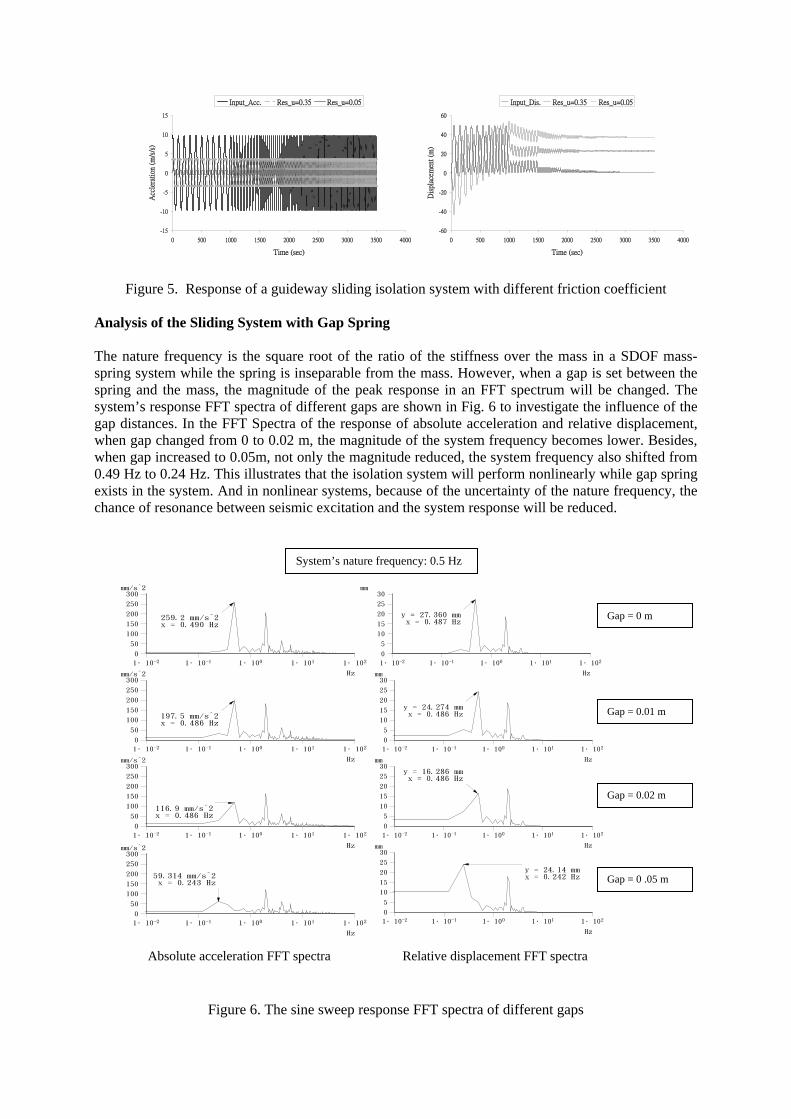
maxx&& will be. Changing the friction coefficient μ of the simulated model in SAP2000N and performing sinusoidal sweep analysis can have the result shown in Fig. 5, which reveals that once the friction coefficient μ is lowered, the response of the absolute acceleration decreased, and the value matches that of the equation (4). However, we can also find in Fig. 5 that the response of the relative displacement was raised while μ is lower from 0.35 to 0.05. The allowable relative displacement is usually low in protecting equipments in the hi-tech facility, other mechanism should be added to the isolation system to improve the performance of the guideway sliding isolation system, especially the restoring force to reduce both the relative and residual displacement.
-15
-10
-5
0
5
10
15
0 500 1000 1500 2000 2500 3000 3500 4000
Time (sec)
Acc
lera
tion
(m
/s/s
)
Input_Acc. Res_u=0.35 Res_u=0.05
-60
-40
-20
0
20
40
60
0 500 1000 1500 2000 2500 3000 3500 4000
Time (sec)
Dis
plac
emen
t (m
)
Input_Dis. Res_u=0.35 Res_u=0.05
Figure 5. Response of a guideway sliding isolation system with different friction coefficient Analysis of the Sliding System with Gap Spring The nature frequency is the square root of the ratio of the stiffness over the mass in a SDOF mass-spring system while the spring is inseparable from the mass. However, when a gap is set between the spring and the mass, the magnitude of the peak response in an FFT spectrum will be changed. The system’s response FFT spectra of different gaps are shown in Fig. 6 to investigate the influence of the gap distances. In the FFT Spectra of the response of absolute acceleration and relative displacement, when gap changed from 0 to 0.02 m, the magnitude of the system frequency becomes lower. Besides, when gap increased to 0.05m, not only the magnitude reduced, the system frequency also shifted from 0.49 Hz to 0.24 Hz. This illustrates that the isolation system will perform nonlinearly while gap spring exists in the system. And in nonlinear systems, because of the uncertainty of the nature frequency, the chance of resonance between seismic excitation and the system response will be reduced.
Figure 6. The sine sweep response FFT spectra of different gaps
0
5
10
15
20
25
30mm
y = 27.360 mmx = 0.487 Hz
-21∙10 -11∙10 01∙10 11∙10 21∙10
Hz
0
5
10
15
20
25
30mm
y = 24.274 mmx = 0.486 Hz
-21∙10 -11∙10 01∙10 11∙10 21∙10
Hz
0
5
10
15
20
25
30mm
y = 16.286 mmx = 0.486 Hz
-21∙10 -11∙10 01∙10 11∙10 21∙10
Hz
0
5
10
15
20
25
30mm
y = 24.14 mmx = 0.242 Hz
-21∙10 -11∙10 01∙10 11∙10 21∙10
Hz
Relative displacement FFT spectra
0
50
100
150
200
250
300mm/s^2
259.2 mm/s^2x = 0.490 Hz
-21∙10 -11∙10 01∙10 11∙10 21∙10
Hz
0
50
100
150
200
250
300mm/s^2
197.5 mm/s^2x = 0.486 Hz
-21∙10 -11∙10 01∙10 11∙10 21∙10
Hz
0
50
100
150
200
250
300mm/s^2
116.9 mm/s^2x = 0.486 Hz
-21∙10 -11∙10 01∙10 11∙10 21∙10
Hz
0
50
100
150
200
250
300mm/s^2
59.314 mm/s^2x = 0.243 Hz
-21∙10 -11∙10 01∙10 11∙10 21∙10
Hz
Absolute acceleration FFT spectra
Gap = 0 m
Gap = 0.01 m
Gap = 0.02 m
Gap = 0 .05 m
System’s nature frequency: 0.5 Hz
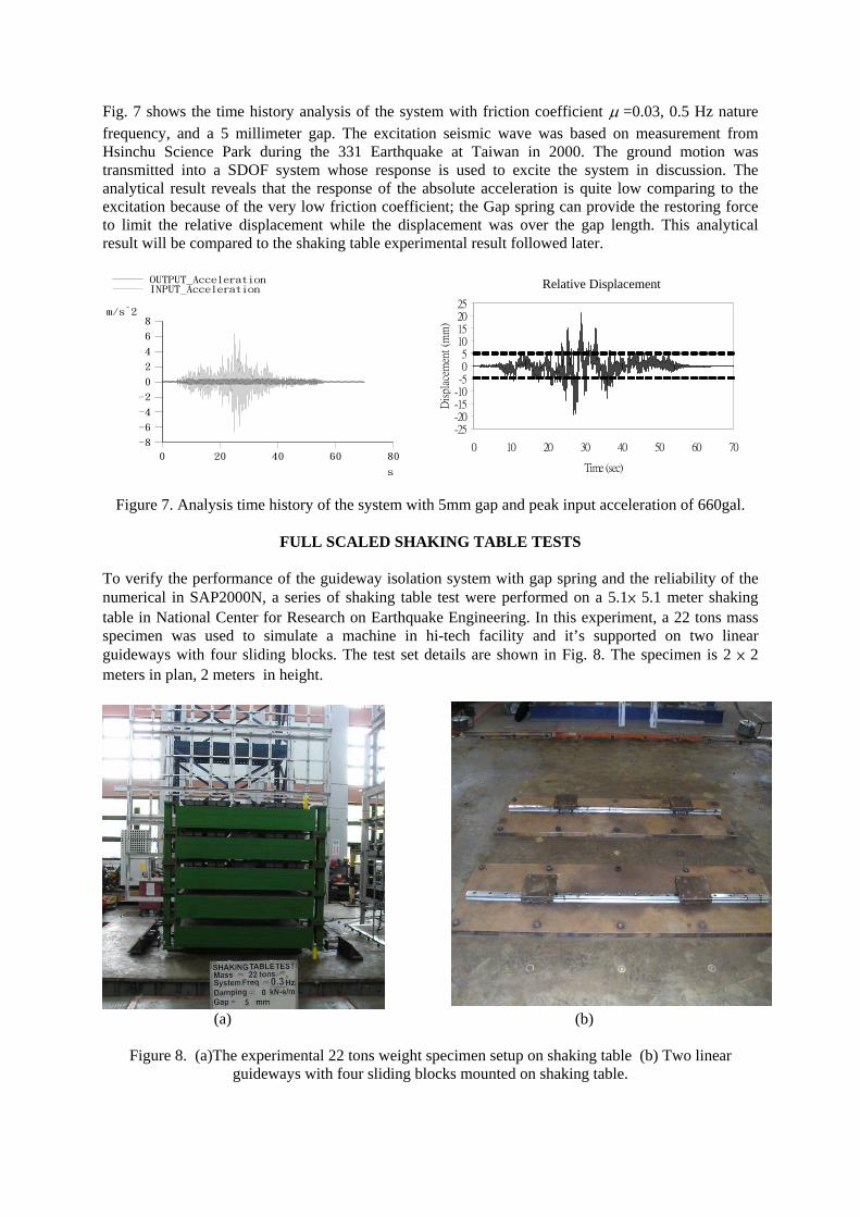
Fig. 7 shows the time history analysis of the system with friction coefficient μ =0.03, 0.5 Hz nature frequency, and a 5 millimeter gap. The excitation seismic wave was based on measurement from Hsinchu Science Park during the 331 Earthquake at Taiwan in 2000. The ground motion was transmitted into a SDOF system whose response is used to excite the system in discussion. The analytical result reveals that the response of the absolute acceleration is quite low comparing to the excitation because of the very low friction coefficient; the Gap spring can provide the restoring force to limit the relative displacement while the displacement was over the gap length. This analytical result will be compared to the shaking table experimental result followed later.
OUTPUT_AccelerationINPUT_Acceleration
-8
-6
-4
-2
0
2
4
6
8m/s^2
0 20 40 60 80
s
-25-20-15-10-505
10152025
0 10 20 30 40 50 60 70
Time (sec)
Dis
plac
emen
t (m
m)
Figure 7. Analysis time history of the system with 5mm gap and peak input acceleration of 660gal.
FULL SCALED SHAKING TABLE TESTS To verify the performance of the guideway isolation system with gap spring and the reliability of the numerical in SAP2000N, a series of shaking table test were performed on a 5.1× 5.1 meter shaking table in National Center for Research on Earthquake Engineering. In this experiment, a 22 tons mass specimen was used to simulate a machine in hi-tech facility and it’s supported on two linear guideways with four sliding blocks. The test set details are shown in Fig. 8. The specimen is 2 × 2 meters in plan, 2 meters in height.
(a) (b)
Figure 8. (a)The experimental 22 tons weight specimen setup on shaking table (b) Two linear
guideways with four sliding blocks mounted on shaking table.
Relative Displacement
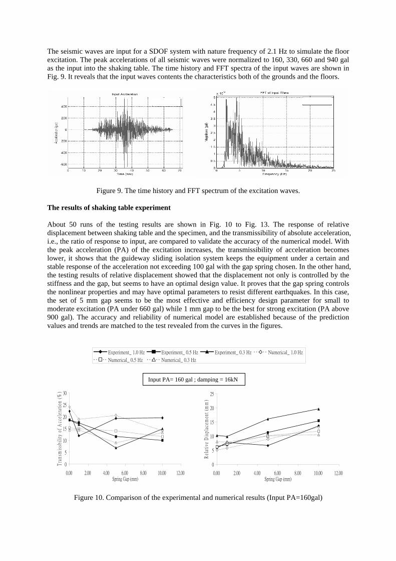
The seismic waves are input for a SDOF system with nature frequency of 2.1 Hz to simulate the floor excitation. The peak accelerations of all seismic waves were normalized to 160, 330, 660 and 940 gal as the input into the shaking table. The time history and FFT spectra of the input waves are shown in Fig. 9. It reveals that the input waves contents the characteristics both of the grounds and the floors.
Figure 9. The time history and FFT spectrum of the excitation waves.
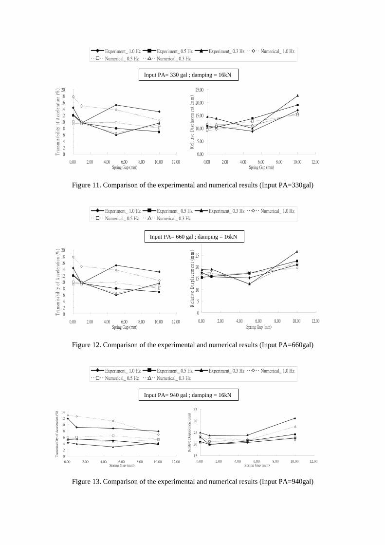
The results of shaking table experiment About 50 runs of the testing results are shown in Fig. 10 to Fig. 13. The response of relative displacement between shaking table and the specimen, and the transmissibility of absolute acceleration, i.e., the ratio of response to input, are compared to validate the accuracy of the numerical model. With the peak acceleration (PA) of the excitation increases, the transmissibility of acceleration becomes lower, it shows that the guideway sliding isolation system keeps the equipment under a certain and stable response of the acceleration not exceeding 100 gal with the gap spring chosen. In the other hand, the testing results of relative displacement showed that the displacement not only is controlled by the stiffness and the gap, but seems to have an optimal design value. It proves that the gap spring controls the nonlinear properties and may have optimal parameters to resist different earthquakes. In this case, the set of 5 mm gap seems to be the most effective and efficiency design parameter for small to moderate excitation (PA under 660 gal) while 1 mm gap to be the best for strong excitation (PA above 900 gal). The accuracy and reliability of numerical model are established because of the prediction values and trends are matched to the test revealed from the curves in the figures.
Experiment_ 1.0 Hz Experiment_ 0.5 Hz Experiment_ 0.3 Hz Numerical_ 1.0 Hz
Numerical_ 0.5 Hz Numerical_ 0.3 Hz
0
5
10
15
20
25
30
0.00 2.00 4.00 6.00 8.00 10.00 12.00Spring Gap (mm)
Tra
nsm
issb
ilit
y of
Acc
eler
atio
n (%
)
0
5
10
15
20
25
0.00 2.00 4.00 6.00 8.00 10.00 12.00Spring Gap (mm)
Rel
ativ
e D
ispl
acem
ent
(mm
)
Numerical_ 0.5 Hz Numerical_ 0.3 Hz
Figure 10. Comparison of the experimental and numerical results (Input PA=160gal)
Input PA= 160 gal ; damping = 16kN
Experiment_ 1.0 Hz Experiment_ 0.5 Hz Experiment_ 0.3 Hz Numerical_ 1.0 Hz
Numerical_ 0.5 Hz Numerical_ 0.3 Hz
0.00
2.00
4.00
6.00
8.00
10.00
12.00
14.00
16.00
18.00
20.00
0.00 2.00 4.00 6.00 8.00 10.00 12.00Spring Gap (mm)
Tra
nsm
issb
ilit
y of
Acc
eler
atio
n (%
)
0.00
5.00
10.00
15.00
20.00
25.00
0.00 2.00 4.00 6.00 8.00 10.00 12.00Spring Gap (mm)
Rel
ativ
e D
ispl
acem
ent
(mm
)
Figure 11. Comparison of the experimental and numerical results (Input PA=330gal)
Experiment_ 1.0 Hz Experiment_ 0.5 Hz Experiment_ 0.3 Hz Numerical_ 1.0 Hz
Numerical_ 0.5 Hz Numerical_ 0.3 Hz
0.00
2.00
4.00
6.00
8.00
10.00
12.00
14.00
16.00
18.00
20.00
0.00 2.00 4.00 6.00 8.00 10.00 12.00Spring Gap (mm)
Tra
nsm
issb
ilit
y of
Acc
eler
atio
n (%
)
0
5
10
15
20
25
0.00 2.00 4.00 6.00 8.00 10.00 12.00Spring Gap (mm)
Rel
ativ
e D
ispl
acem
ent
(mm
)
Figure 12. Comparison of the experimental and numerical results (Input PA=660gal)
Experiment_ 1.0 Hz Experiment_ 0.5 Hz Experiment_ 0.3 Hz Numerical_ 1.0 Hz
Numerical_ 0.5 Hz Numerical_ 0.3 Hz
0
2
4
6
8
10
12
14
0.00 2.00 4.00 6.00 8.00 10.00 12.00Spring Gap (mm)
Tra
nsm
issb
ility
of A
ccel
erat
ion
(%)
15
20
25
30
35
0.00 2.00 4.00 6.00 8.00 10.00 12.00Spring Gap (mm)
Rel
ativ
e D
ispl
acem
ent (m
m)
Figure 13. Comparison of the experimental and numerical results (Input PA=940gal)
Input PA= 330 gal ; damping = 16kN
Input PA= 660 gal ; damping = 16kN
Input PA= 940 gal ; damping = 16kN
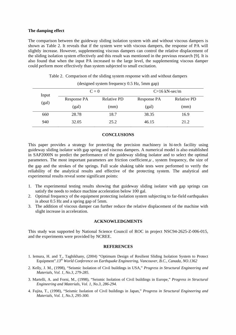
The damping effect The comparison between the guideway sliding isolation system with and without viscous dampers is shown as Table 2. It reveals that if the system were with viscous dampers, the response of PA will slightly increase. However, supplementing viscous dampers can control the relative displacement of the sliding isolation system effectively and this result was mentioned in the previous research [9]. It is also found that when the input PA increased to the large level, the supplementing viscous damper could perform more effectively than system subjected to small excitation.
Table 2. Comparison of the sliding system response with and without dampers
(designed system frequency 0.5 Hz, 5mm gap) C = 0 C=16 kN-sec/m
Input
(gal) Response PA
(gal)
Relative PD
(mm)
Response PA
(gal)
Relative PD
(mm)
660 28.78 18.7 38.35 16.9
940 32.05 25.2 46.15 21.2
CONCLUSIONS
This paper provides a strategy for protecting the precision machinery in hi-tech facility using guideway sliding isolator with gap spring and viscous dampers. A numerical model is also established in SAP2000N to predict the performance of the guideway sliding isolator and to select the optimal parameters. The most important parameters are friction coefficientμ , system frequency, the size of the gap and the strokes of the springs. Full scale shaking table tests were performed to verify the reliability of the analytical results and effective of the protecting system. The analytical and experimental results reveal some significant points: 1. The experimental testing results showing that guideway sliding isolator with gap springs can
satisfy the needs to reduce machine acceleration below 100 gal. 2. Optimal frequency of the equipment protecting isolation system subjecting to far-field earthquakes
is about 0.5 Hz and a spring gap of 5mm. 3. The addition of viscous damper can further reduce the relative displacement of the machine with
slight increase in acceleration.
ACKNOWLEDGMENTS This study was supported by National Science Council of ROC in project NSC94-2625-Z-006-015, and the experiments were provided by NCREE.
REFERENCES 1. Iemura, H. and T., Taghikhany, (2004) “Optimum Design of Resilient Sliding Isolation System to Protect
Equipment”.13th World Conference on Earthquake Engineering, Vancouver, B.C., Canada, NO.1362
2. Kelly, J. M., (1998), “Seismic Isolation of Civil buildings in USA,” Progress in Structural Engineering and Materials, Vol. 1, No.3, 279-285.
3. Martelli, A. and Forni, M., (1998), “Seismic Isolation of Civil buildings in Europe,” Progress in Structural Engineering and Materials, Vol. 1, No.3, 286-294.
4. Fujita, T., (1998), “Seismic Isolation of Civil buildings in Japan,” Progress in Structural Engineering and Materials, Vol. 1, No.3, 295-300.
5. Morikawa, Y. and Fujita, S.,(1992), “Development of Seismic Isolation System for Light Equipment using Friction Pendulum Bearing,” Proceeding of Tenth World Conference on Earthquake Engineering, Madrid, Spain, pp. 2287-2290.
6. Lei, KM. and Hemried, AG.,(1992), “Seismic Response of Equipment in Resilient-Friction Base Isolated Structures,” Proceeding of Tenth World Conference on Earthquake Engineering, Madrid, Spain, pp. 2013-2018.
7. Saadeghvaziri, AM. and Feng, MQ.,(2000~2001), “Experimental and Analytical Study of Base-Isolation for Electric Power Equipment,” Report on Research Progress and Accomplishments: 2000-2001, MCEER Publication, State University of New York, Buffalo.
8. Hamaguchi, H., and Higashino, M., (2000), “Development of low-friction factor sliding isolation device,” Proceeding of 12th WECEE, 2135/6/A
9. Kelly, J. M., (1999),”The role of damping in seismic isolation.” Earthquake Engineering and Structural Dynamics, Vol. 28, pp.3~20
10. Wang, W. C., (1999), “Dynamic Behavior of Frictional Base Isolation Structures,” Ph. D thesis, NCKU, Tainan, Taiwan, pp 23.