performance characterization of fluid viscous dampers
TRANSCRIPT

PERFORMANCE CHARACTERIZATION OF FLUID VISCOUS DAMPERS
G. Mosqueda1, A. S. Whittaker2, G. L. Fenves3, and D. Mellon4
ABSTRACT
An experimental study on the use of viscous dampers in seismically isolated bridges has been completed at the University of California, Berkeley. This paper discusses the performance characterization of two fluid viscous dampers used in the earthquake simulator tests of an isolated bridge model. Prior to earthquake testing, the two dampers were subjected to uniaxial compression-tension cycles consisting of sinusoidal tests, constant velocity tests and low-velocity friction tests. Thermocouples were used to monitor the temperature of the damper casing. From these cyclic tests, it was found that the dampers exhibited linear viscous behavior at moderate to high velocities and nonlinear behavior at low velocities due to friction in the damper seals. The damping constant did not change for the range of temperatures developed in the dampers but the seal friction force increased considerably with increasing temperature. Based on these uniaxial tests and the subsequent earthquake simulator tests of the damped isolated bridge model, recommendations regarding prototype testing and acceptance criteria for fluid viscous dampers are presented.
Introduction
The use of seismic isolation will reduce accelerations in a bridge superstructure and the force transmitted to a bridge substructures, but will increase the relative displacement response of the superstructure. This (substantial) increase in relative displacement may place onerous demands on expansion joints that generally have limited displacement capacity. To reduce the superstructure displacements to levels that can be tolerated by expansion joints, bridge engineers have turned to supplemental energy dissipation in seismic isolation systems that can either be integrated directly into a seismic isolator (e.g., as a lead core in a lead-rubber bearing) or added externally in the form of discrete damping devices. To date, the fluid viscous damper is the only supplemental damping device that has been used in seismically isolated bridges in California. Fluid viscous dampers have been shown to be effective in reducing both superstructure displacements and forces transmitted to bridge substructures (Constantinou et al. 1993). To extend this knowledge and to address other issues related to the analysis and design of seismically isolated bridges, the California Department of Transportation (Caltrans) funded the PROSYS research project at the University of California, Berkeley. Two damper-related objectives of the PROSYS project were: (1) to investigate the effectiveness of supplemental damping in isolated bridges subjected to bi-directional excitation, and (2) study the effect of
1 Graduate Research Assistant, Dept. of Civil Engineering, University of California, Berkeley, CA 94720 2 Associate Professor, Dept. of Civil Engineering, State University of New York, Buffalo, NY 14260 3 Professor, Dept. of Civil Engineering, University of California, Berkeley, CA 94720 4 Associate Bridge Engineer, California Department of Transportation, Sacramento, CA

different damper configurations on bridge response. These objectives were achieved through coordinated analytical and experimental studies of a small-scale bridge model subjected to multiple components of earthquake excitation. In the experimental studies, two fluid viscous dampers were installed in symmetric and asymmetric configurations on the bridge model. Prior to the installation of these dampers in the model, each damper was carefully characterized using displacement-controlled testing in a uniaxial damper test machine. The results of these damper characterization studies, related information from the earthquake simulator testing of the model, and implications for practice are the focus of this paper. The reader is referred to Mahin et al. (2001) for a more detailed description of the scope and results of the overall research program.
Experimental Testing Program
The research program described in this paper made use of two 10-kip fluid viscous dampers fabricated by Taylor Devices of North Tonawanda, New York, to specifications developed by the authors. A cross-section through a double-ended damper similar to that used for this research program is presented in Fig. 1. The total stroke of the dampers used in the research program was 12 in. and the pin-to-pin length at mid-stroke was 50 in. Substantial internal pressures are introduced into Taylor seismic dampers under static conditions to facilitate seal function. Forces are developed in the damper by differential pressure on the two sides of the piston head. Fluid flows from one side of the piston head to the other around the perimeter of the piston head and through orifices in the piston head. Different velocity exponents can be achieved by selecting different orifice geometries and piston head-casing clearances.
Figure 1. Cross-section through a double-ended fluid viscous damper (from Taylor Devices).
Damper Test Machine
The two viscous dampers (Damper 1 and Damper 2) were characterized by uniaxial testing in a Damper Test Machine in the laboratories of the Earthquake Engineering Research Center at the University of California, Berkeley. The Damper Test Machine, shown in Fig. 2a, was originally designed to characterize uniaxial damping devices of the type proposed for the retrofit of the Golden Gate Bridge (Aiken and Kelly 1996). For the study reported in this paper, a damper was installed in the Machine with thermocouples at the bottom of the damper casing. Thermocouples were also used between tests to monitor the temperature of the damper casing near the mid-stroke position of the damper. These thermocouples were removed during the cyclic tests because their installed location interfered with the damper sleeve. A calibrated load

cell installed in-line and beneath the damper measured the axial force history in the damper.
photograph
(a) Damper Test Machine (b) isolated rigid block model with dampers
Figure 2. Damper Test Machine and rigid block model
The fluid viscous damper testing program included three types of signals, labeled as A, B, and C. Test type A was a low-velocity (<0.2 in./s) sinusoidal test that was used to measure the friction between the seals and the piston rod. Test type B was a constant velocity (sawtooth) test, which served to establish the force-velocity relationship for the damper. Test type C was a sinusoidal test that was used to study the energy dissipation characteristics of the damper and to verify the force-velocity relationship obtained from test type B.
Earthquake Simulations
For earthquake testing, the fluid viscous dampers were installed in a small-scale isolated bridge on the Berkeley earthquake simulator. The superstructure of the model was effectively rigid for all intents and purposes. In one configuration, the model was supported by four Friction Pendulum bearings (Zayas et al. 1987) with a concrete and lead weights installed on the superstructure for a total isolated weight of approximately 65 kips. The sliding isolated period of the model was 1.75 s. One five-component load cell was attached to the end of each damper and under each bearing to monitor the axial load, shear, and moment response. A photograph of the isolated small-scale model with two dampers attached to the model is shown in Fig. 2b.
Five configurations of the two dampers were considered to study the effect of adding discrete dampers to isolated bridges. Symmetric unidirectional, asymmetric unidirectional, symmetric bi-directional, and asymmetric bi-directional configurations were studied using combinations of unidirectional horizontal, bi-directional horizontal, and tridirectional earthquake shaking. The earthquake histories used for the study were obtained from the FEMA/SAC database (SAC 1997). These histories are listed in Table 1 below. The histories from the database were scaled in both time (length) and amplitude to meet the limitations of the Berkeley earthquake simulator.

Table I. List of records selected for earthquake history testing
Peak acceleration (g) Record ID Record Scale1
X-direction Y-direction LA13/14 1994 Northridge, Newhall 2 0.619 0.541
LA17c/18c 1994 Northridge, Sylmar 5 0.332 0.425
NF01/02 1978 Tabas 5 0.796 0.630
1. Length scale factor; a length scale factor of 5 corresponds to a time scale factor of 2.32
Results and Analysis of Characterization Tests
Force-Velocity Relationship
The results of the uniaxial characterization tests showed that the dampers exhibit essentially linear viscous behavior over the expected velocity range, namely, d dF C uα= (1) where dF is the axial force in the damper, dC is the damping constant, u is the relative velocity between the two ends of the damper, and α is the velocity exponent that is equal to 1.0 for a linear damper. Table II lists the calibrated damping constant, dC , from selected tests obtained by a least squares fit on the force-velocity data. The temperature of the damper casing at the start of the tests is also reported in the table as supplemental information. The values for the calibrated damping constant are not constant for all tests, which indicates that the velocity exponent is not equal to unity across the entire velocity range. This result was expected because a combination of orifices (for values of α both less than and greater than 1) was used in the construction of the damper (Taylor, 2001). Some of the calibrated values of the damping coefficient for Damper 2 are plotted in Fig. 3 as a function of the maximum measured velocity. At velocities above 5 in./s, the damping constant increases with increasing velocity and increasing displacement amplitude, with the velocity dependence being more pronounced. The damping constant dC is much higher for the low velocity test as a result of the friction force that develops between the damper seals and the piston rod. For small velocities, the friction force dominates the total resisting force of the damper. Evidence of the friction force can also be seen in Fig. 4a.

Table II. List of tests for damper characterization and calibration of the damping constant dC .
Damper 1 Damper 2 Test no. Type
Vel.1
(in./s)
Amp.2
(in.) Cycles
dC 3 Temp4 dC Temp
1 A 0.08 2 3 NA 60.4 NA 64.8
3 B 2 1 3 0.905 60.8 0.889 65.1
5 B 10 1 3 0.705 61.2 0.686 65.5
7 B 20 1 3 0.735 63.7 0.710 67.2
8 B 25 1 3 0.746 65.1 0.721 68.3
15 B 25 3 3 0.815 80.2 0.791 82.7
16 B 1 4.75 3 1.534 78.5 1.177 88.9
17 B 2 4.75 3 1.020 78.7 0.857 91.7
19 B 10 4.75 3 0.720 81.3 0.696 93.0
21 B 20 4.75 3 0.805 91.8 0.774 101.0
22 B 25 4.75 3 0.842 100.2 0.816 106.5
23 A 0.08 2 3 NA 106.0 NA 113.7
24 C 3.1 1 5 0.879 102.7 0.788 110.1
26 C 12.6 1 5 0.715 102.0 0.691 110.1
27 C 25.1 1 5 0.754 103.0 0.731 110.6
31 C 20 4.75 5 0.806 121.2 0.764 126.1
32 C 25 4.75 5 0.814 129.9 0.794 133.1
33 A 0.08 2 3 - 135.6 - 138.4
1. Target peak velocity
2. Target peak displacement
3. Computed damping constant per equation (1)
4. Maximum temperature (°F) of casing at the start of the test
A sample of the constant velocity tests for Damper 2 is presented in Fig. 4 for displacement amplitude of 1 in. and target velocities of 2 and 20 in./s. From Fig. 4, it is apparent that the low velocity test demonstrates non-linear behavior attributed to friction in the seals. Say something else here.

0 5 10 15 20 25 300.6
0.7
0.8
0.9
1
Damping constant (kip-s/in.)
Maximum velocity (in./s)
Displacement = 1 in. Displacement = 3 in. Displacement = 4.75 in.
Figure 3. Variation of damping constant with maximum velocity and displacement amplitude
-2 -1 0 1 2-2
-1
0
1
2
Force (kips)
Velocity (in./s)
-20 -10 0 10 20
-20
-10
0
10
20
Force (kips)
Velocity (in./s) (a) Test 3 (b) Test 8
Figure 4. Force-velocity relationship for Damper 2 subjected to constant velocity testing
Temperature Rise
Energy dissipation by fluid viscous dampers is based on forcing fluid through an orifice. The mechanical work done on the fluid results in heating of the damper’s fluid and casing which is then conducted into the surrounding environment. An important, but controllable effect of heating is that the viscosity of the fluid is dependent on the fluid’s temperature. Fortunately, the

behavior of fluid damper is governed primarily by the speed of the fluid through orifice and changes in fluid viscosity result in only secondary effects (Symans and Constantinou 1998). However, Symans and Constantinou (1998) also report a 25 percent decrease in damping constant for a small damper (3 kip) as the testing temperatures increases from 75 OF to 122 OF. The dampers tested as part of the current study are less dependent on temperature. A comparison of Tests 15, 22 and 32 all conducted at peak velocities of 25 in./s show less than a 4 percent change in the damping constant with temperatures ranging from 80 OF to 130 OF for both dampers. Fig. 5 presents the temperature history of a thermocouple located on the bottom side of the casing during Test 22 and data from the same channel acquired after the cyclic test. The experimental results show that the temperature increased from 105.5 OF to 115 OF, with the maximum temperature occurring over 200 seconds after the cyclic test had been completed. Data collected from a thermocouple installed near the center of the mid-stroke after the cyclic test is also shown in Fig. 5 and provides readings up to 4 OF higher. The temperature rise was most probably similar for this test because the damper was stroked from end-cap to end-cap. It is important to note that the thermocouples measured the temperature of the damper casing. Experimental studies on the heating of fluid viscous dampers have shown that the temperature in the vicinity of the piston head increases at a much faster rate and attains higher values when compared to the temperature on the outer casing (Black and Makris 2000).
0 100 200 300 400 500106
108
110
112
114
116
118
120
Temperature (
oF)
Time (s)
Casing - bottom Casing - near mid-stroke
End of cyclic test
Figure 5. Temperature rise in 10-kip damper during and after Test 22.
Each test resulted in a small increase in temperature that did not alter the behavior of the damper. However, over the course of the testing program, the temperature of the damper increased substantially as can be seen by the temperatures listed in Table 2. The overall increase in temperature was limited by allowing sufficient cooling time between tests. No damper test was permitted to start until the temperature of the damper casing stabilized below 140 oF.
Friction in Seals
Three tests, labeled as type A in Table 2, were performed at very slow velocities to evaluate the frictional resistance of the damper with negligible viscous force. The friction force

as a source of non-linearity, particularly for low velocities test, is evident in Fig. 4a. Fig. 6a shows the force-displacement relationship for Test 1 (65 oF) and Test 33 (138 oF) on Damper 2. The friction force in the latter test is two times greater than in the first. One key difference between these two tests is that the temperature of the damper casing at the start of Test 33 was much higher than the temperature at the start of Test 1. Fig. 6b summarizes the resulting friction force for both dampers as a function of testing temperature. Each data point represents once cycle of a friction test. In general, the magnitude of the friction force increases with temperature, with the relation being close to linear for Damper 1. The likely explanation is that as the viscous fluid heats, the internal pressure in the damper increases and provides a greater pressure on the Teflon seals against the piston rod. This effect might not be characteristic for other designs of fluid viscous dampers.
-2 -1 0 1 2-2
-1
0
1
2
Displacement (in.)
Friction force (kips)
65 oF 138 oF
50 100 1500
0.5
1
1.5
2
Temperature (oF)
Friction Force (kips)
Damper 1Damper 2
(a) Force-Displacement from test type A (b) Variation of friction with temperature
FIGURE 6. Friction forces in 10-kip Taylor damper.
Energy Dissipation from Uni-axial Tests
The purpose of the sinusoidal tests type C was to evaluate the energy dissipation characteristics of the dampers. For one cycle of harmonic loading, the damping constant can be calculated as (Chopra, 1995)
2dW
C dd πω
= (2)
where dW is the area enclosed by the hysteresis loop, d is the displacement amplitude and ω is the angular frequency of the sinusoidal history. The damping constant was evaluated for the sinusoidal tests using Eq. 2 and compared to the previously calculated values of dC in Table 2 using the least-squares method. A comparison of the two methods gave similar values for dC that are within 9 percent of each other.
Energy Dissipation from Earthquake Tests
The amount of energy dissipated by the dampers was computed for each test and
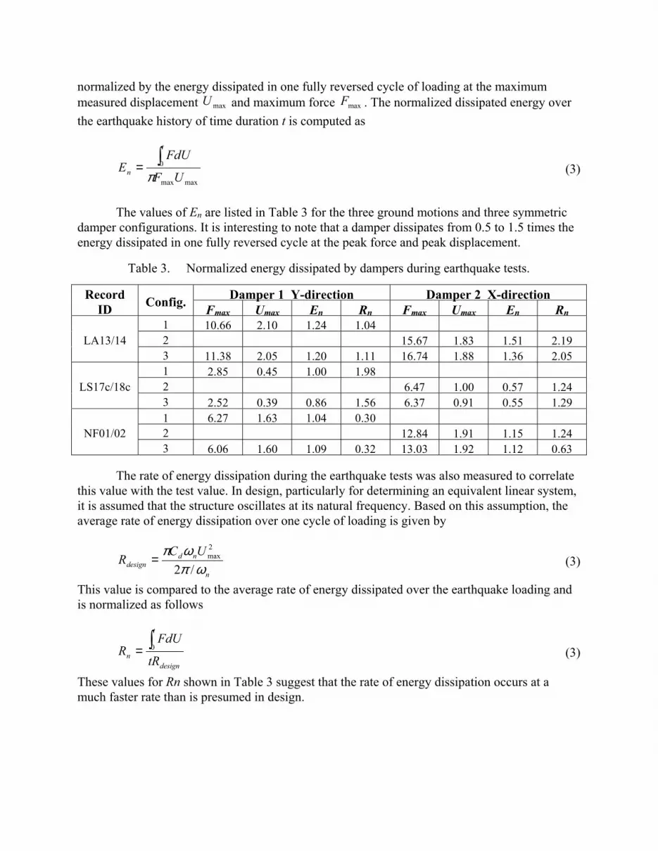
normalized by the energy dissipated in one fully reversed cycle of loading at the maximum measured displacement maxU and maximum force maxF . The normalized dissipated energy over the earthquake history of time duration t is computed as
maxmax
0
UF
FdUE
t
n π∫= (3)
The values of En are listed in Table 3 for the three ground motions and three symmetric damper configurations. It is interesting to note that a damper dissipates from 0.5 to 1.5 times the energy dissipated in one fully reversed cycle at the peak force and peak displacement.
Table 3. Normalized energy dissipated by dampers during earthquake tests.
Damper 1 Y-direction Damper 2 X-direction Record ID Config. Fmax Umax En Rn Fmax Umax En Rn
1 10.66 2.10 1.24 1.04 2 15.67 1.83 1.51 2.19 LA13/14 3 11.38 2.05 1.20 1.11 16.74 1.88 1.36 2.05 1 2.85 0.45 1.00 1.98 2 6.47 1.00 0.57 1.24 LS17c/18c 3 2.52 0.39 0.86 1.56 6.37 0.91 0.55 1.29 1 6.27 1.63 1.04 0.30 2 12.84 1.91 1.15 1.24 NF01/02 3 6.06 1.60 1.09 0.32 13.03 1.92 1.12 0.63
The rate of energy dissipation during the earthquake tests was also measured to correlate this value with the test value. In design, particularly for determining an equivalent linear system, it is assumed that the structure oscillates at its natural frequency. Based on this assumption, the average rate of energy dissipation over one cycle of loading is given by
n
nddesign
UCR
ωπωπ
/2
2max= (3)
This value is compared to the average rate of energy dissipated over the earthquake loading and is normalized as follows
design
t
n tR
FdUR ∫= 0 (3)
These values for Rn shown in Table 3 suggest that the rate of energy dissipation occurs at a much faster rate than is presumed in design.

Prototype Testing and Acceptance Criteria
Conclusions
Each paper is expected to concisely state the conclusions of the work. The Conclusions section should discuss the significance and applicability of the work, and not merely restate the abstract. Great care should be exercised to make explicit the limitations or conditions under which the results can be applied.
Acknowledgments
This project is supported by the California Department of Transportation under Contract 59A169. Professor Stephen A. Mahin..... EERC Laboratory Manager Don Clyde provided extensive support of the experimental program. Doug Taylor supplied the dampers.
References
Aiken, I. D. and Kelly, J. M. (1996). Cylic Dynamic Testing of Fluid Viscous Dampers. Proceedings, Caltrans’ Fourth Seismic Research Workshop, California Department of Transportation, Sacramento, CA.
Black, C. J. and Makris, N. (2000). Viscous Heating of Fluid Dampers: Experimental Studies. Proceedings of the SPIE's 7th International Symposium on Smart Structures and Materials. Newport Beach, CA.
Constantinou et al. (1993). Reference on bridge isolation with dampers SAC (1997). Suites of Earthquake Ground Motions for Analysis of Steel Moment Frame Structure. Report
SAC/BD-97/03, Woodward-Clyde Federal Services, SAC Steel Project. Symans, M. D. and Constantinou, M. C. (1998). Passive Fluid Viscous Damping Systems for Seismic
Energy Dissipation. ISET Journal of Earthquake Technology, 35(4), 185-206.