proposed international standard for emr spectroscopic data
TRANSCRIPT
613
Pure Appl. Chem., Vol. 78, No. 3, pp. 613–631, 2006.doi:10.1351/pac200678030613© 2006 IUPAC
INTERNATIONAL UNION OF PURE AND APPLIED CHEMISTRY
COMMITTEE ON PRINTED AND ELECTRONIC PUBLICATIONS*SUBCOMMITTEE ON ELECTRONIC DATA STANDARDS (JCAMP-DX)
JCAMP-DX FOR ELECTRON MAGNETICRESONANCE (EMR)
(IUPAC Recommendations 2006)
Prepared for publication byRICHARD CAMMACK1, YANG FANN2, ROBERT J. LANCASHIRE3,‡, JOHN P. MAHER4,
PETER S. MCINTYRE5, AND REEF MORSE6
1Pharmaceutical Sciences Research Division, King’s College, Franklin-Wilkins Building,150 Stamford St, London SE1 9NH, UK; 2Intramural IT Program, NINDS/NIH, 10 Center Drive,MSC 1430, Bethesda, MD 20892-1430, USA; 3Department of Chemistry, University of the West
Indies, Mona, Kingston 7, JMAAW15, Jamaica; 4School of Chemistry, University of Bristol,Bristol BS8 1TS, UK; 5School of Applied Sciences, University of Glamorgan, Pontypridd,
Mid-Glamorgan, CF37 1DL, UK; 6Department of Chemistry, Illinois State University,Normal, IL 61790-4160, USA
*Membership of the Committee on Printed and Electronic Publications during the final preparation of this report(2005) was as follows:
President: L. Glasser (Australia); Secretary: A. Davies (Germany); Members: J. R. Bull (South Africa), S. Heller(USA), D. Martinsen (USA), S. E. Stein (USA), B. Valter (Czech Republic), B. Vickery (UK).
‡Corresponding author: E-mail: [email protected]
Republication or reproduction of this report or its storage and/or dissemination by electronic means is permitted without theneed for formal IUPAC permission on condition that an acknowledgment, with full reference to the source, along with use of thecopyright symbol ©, the name IUPAC, and the year of publication, are prominently visible. Publication of a translation intoanother language is subject to the additional condition of prior approval from the relevant IUPAC National AdheringOrganization.
JCAMP-DX for electron magnetic resonance(EMR)
(IUPAC Recommendations 2006)
Abstract: In this document, we define a data exchange format initially formulatedfrom discussions of an International Union of Pure and Applied Chemistry(IUPAC) limited-term task group at the 35th Royal Society of Chemistry-ESR con-ference in Aberdeen 2002. The definition of this format is based on the IUPACJoint Committee on Atomic and Molecular Physical Data Exchange (JCAMP-DX) protocols, which were developed for the exchange of infrared spectra and ex-tended to chemical structures, nuclear magnetic resonance data, mass spectra, andion mobility spectra. This standard of the JCAMP-DX was further extended tocover year 2000 compatible date strings and good laboratory practice, and the nextrelease will cover the information needed for storing n-dimensional data sets. Theaim of this paper is to adapt JCAMP-DX to the special requirements for electronmagnetic resonance (EMR).
Keywords: recommendations; JCAMP-DX; data standard; spectroscopy; EMR;EPR; ESR; IUPAC Committee on Printed and Electronic Publications.
1. INTRODUCTION
The Joint Committee on Atomic and Molecular Physical Data Exchange (JCAMP-DX) is an evolving,open-ended, machine-independent, self-documenting file format for exchanging and archiving datafrom computerized laboratory instruments like spectrometers, diffractometers, and others, whose out-put is commonly represented as spectral (profile) plots, contours, or peak tables. The first JCAMP-DXprotocol was designed to meet the need for exchanging infrared spectra between similar instruments ofdifferent manufacturers. The present document is the result of ongoing efforts by users and manufac-turers to extend JCAMP-DX to other types of instrumental data.
A major objective of JCAMP-DX is to enable routine capture of data at the source to make itavailable for exchange, archiving, and entry into databases. All data are represented as labelled fieldsof variable length using printable ASCII characters. A JCAMP-DX file is a text file which can beviewed, corrected, and annotated with ASCII text editors.
The JCAMP-DX protocol is nonproprietary. These specifications are copyrighted by theInternational Union of Pure and Applied Chemistry (IUPAC) solely for the purpose of linking themwith the name JCAMP-DX. The right to copy these specifications for scientific purposes is herebygranted.
Use of the name JCAMP-DX to describe data files implies that they conform to the format andstyle described in the relevant protocols and the information content defined for a particularDATATYPE.
Use of the name JCAMP-DX in the description of software capability implies the ability to gen-erate and read JCAMP-DX files as defined in the relevant published protocols for a particularDATATYPE (Section 4).
R. CAMMACK et al.
© 2006 IUPAC, Pure and Applied Chemistry 78, 613–631
614
2. SIGNIFICANCE AND USE
This version of JCAMP-DX provides for a description of the file structure to be used to accommodatea very wide range of electron magnetic resonance (EMR) applications.
Inasmuch as it is very desirable for instrument data systems to be able to read and write files in astandard format directly, instrument vendors are encouraged to develop JCAMP-DX software for theinstruments they currently support. It is feasible for vendors to do so for a tightly defined CORE of in-formation.
3. BASIC STRUCTURE OF JCAMP-DX FILES
JCAMP-DX is a FILE specification. The basic element of JCAMP-DX files is the LABELLED-DATA-RECORD (LDR). LDRs are combined into BLOCKS. A FILE may contain more than one BLOCK.
A simple FILE would look like
Data Block ##TITLE=HeadersData
##END=
The BLOCK structure was first described for IR COMPOUND files in Section 11 of ref. [1].
Link Block ##TITLE=Define total number of BLOCKS
Data Block 1 ##TITLE=
##END=Data Block 2 ##TITLE=
##END=Data Block 3 ##TITLE=
##END=File End ##END=
The NTUPLE structure was first described for NMR COMPLEX DATA STORAGE files in Section 7of ref. [3].
NTUPLE File Start ##TITLE=Headers
##NTUPLES=##PAGE=
Data##PAGE=
Data##END NTUPLES=
File End ##END=
This is what we will normally mean by the word FILE.
© 2006 IUPAC, Pure and Applied Chemistry 78, 613–631
JCAMP-DX for EMR 615
The logical division of a JCAMP-DX file into CORE and NOTES subsets is a measure to sepa-rate the protocol for representing tabular data (CORE) which must be parsed by computer from thatwhich is mainly for reference by humans.
4. CORE
The CORE portion of a JCAMP-DX BLOCK or FILE is the irreducible minimum JCAMP-DX file. TheCORE provides a focus for instrument and software vendors to convert between in-memory forms andJCAMP-DX. The CORE contains one or more data arrays, corresponding attributes for defining units,scale factors, sizes, etc., of arrays for the data, plus key application dependent attributes and identifica-tion. The main objective of the CORE is to focus on the information which must be transferred to a for-eign system in order for it to process and/or plot and label the data as if it had been generated internally.
The CORE is divided into two subsets: CORE HEADER and CORE DATA.
4.1 Core header
The CORE HEADER provides for overall identification of a JCAMP-DX file. Each record is prefixedwith a ## sign and represented as ##HEADER= in the BLOCK or FILE. For example, ##TITLE= MyFirst EMR Spectrum
All the core headers are required elements. The CORE HEADER consists of:
TITLE JCAMP-DX DATATYPE DATA CLASSORIGINOWNER
In general, information in the Header is either TEXT (free format) or STRING (reserved or pre-defined keywords) and information in the Data is either AFFN (ASCII FREE FORMAT NUMERIC)or ASDF (ASCII SQUEEZED DIFFERENCE FORM).
4.1.1 ##TITLE= (TEXT)A description of the data file.
4.1.2 JCAMP-DX= (STRING) $$ for example, JCAMP-DX _writer.exe version 0.99The VERSION NUMBER of JCAMP-DX, followed by a comment on the version of the software writ-ing the file. (Required)
4.1.3 ##DATA TYPE= (STRING)EMR spectroscopy now includes a wide variety of techniques, all of which involve measurementswhich exploit the magnetic properties or ascertain the environment of the unpaired electron. The de-scription of many of these as either electron spin resonance (ESR) or as electron paramagnetic reso-nance (EPR) is commonplace in the literature. However, the great diversity of techniques now appliedto the measurement of paramagnetism, usually (but not always) in the presence of an external magneticfield, needs a generic descriptive term. In particular, the emergence of imaging technology, of tech-niques such as electron–nuclear double resonance (ENDOR) which sits between NMR and EPR/ESR,and of newer optical detection techniques, leads us to suggest an overall classification as “EMR”. Theuse of the historical terms ESR or EPR thus falls under this overall classification, a situation which wedo not wish to change. (The existing IUPAC recommendation is to use the term EPR rather than ESR)
R. CAMMACK et al.
© 2006 IUPAC, Pure and Applied Chemistry 78, 613–631
616
[9]. The task group has therefore decided to adopt the generic title for the DATA TYPE as EMR, andto define all the METHODs in terms of either a MEASUREMENT or a SIMULATION.
e.g., ##DATA TYPE= EMR MEASUREMENTe.g., ##DATA TYPE= EMR SIMULATION(Required)
4.1.4 ##DATA CLASS= (STRING) This LDR contains the name of the type of tabular data, i.e., XYDATA, XYPOINTS, PEAK TABLE,PEAK ASSIGNMENTS, BLOCKS, or NTUPLES. Coates [10] first pointed out that the data for a num-ber of different applications (IR and Raman spectra, GC retention times, and NMR chemical shift) areso similar that JCAMP-DX files for all these types can be plotted or processed (smoothed, peak-picked,deconvoluted, etc.) by existing software for one of the techniques. This can clearly be extended to manyother types to XY data which are represented in the XYDATA form, and probably also as XYPOINTS.
##DATA CLASS= is intended to provide an early indication to software for the purpose of deter-mining whether or not it can process a given file. This seems important because it allows crossover ofdata processing routines between different techniques. (Required)
4.1.5 ##ORIGIN= (TEXT)Origin of the data, i.e., the name of the organization. (Required)
4.1.6 ##OWNER= (TEXT)Owner or author of the data. This can be “public domain” or the name of the person or organization andmay include a copyright note. (Required)
4.2 Core variable header information
The JCAMP-DX standard is easy to understand and expand. Many LDRs are already defined in previ-ous JCAMP-DX protocols, and they should be used for EMR. However, in the case of the equipmentparameters, the particular requirements of this technique call for some special LDRs. In the followingpart, definitions are given for LDRs that will allow a precise description of the equipment parametersfor all EMR experiments (note the syntax of ##.LABEL=).
4.2.1 ##.DETECTION MODE= CW or PULSE(Required)
4.2.1.1 CWContinuous wave (CW), the frequency (or field) dependence of the sample is measured in response toa periodic perturbation of microwave radiation to the sample.
4.2.1.2 PULSEOne or more pulses of (e.g., microwave and/or radio frequency, RF) radiation are used to perturb thesample, and the recovery from this perturbation is measured as a function of a swept variable.
CW and pulse measurements are related via the Fourier Transform [11–13]. (Required)
4.2.2 ##.METHOD= (STRING)There are a wide variety of experimental methods used in EMR. The acronyms used are those describedin the references used for the DETECTION MODE. The protocol description in this document concernsthe following:
Abbreviations associated with other forms of EMR measurements not mentioned above, andwhich may need inclusion in the METHOD LDR in the future are as follows. Some of these will re-
© 2006 IUPAC, Pure and Applied Chemistry 78, 613–631
JCAMP-DX for EMR 617
quire extra EMR-specific LDRs, but some may use the present set. Since many of these use pulse ex-citation, they will require methods to define pulse sequences.
ADMR absorption-detected magnetic resonanceCIDEP chemically induced dynamic electron polarizationCOSY 2D correlation spectroscopyCYCLOPS cyclically ordered phase sequenceDECENT decoupled ESEEM correlated to nuclear transition frequenciesDEER double electron–electron resonanceDEFENCE deadtime free ESEEM by nuclear coherence-transfer echoesDONUT double nuclear coherence transferELDOR electron–electron double resonanceEPR electron paramagnetic resonance (encompassed by SPECTRUM)ESR electron spin resonance (encompassed by SPECTRUM)ESR–STM ESR scanning tunnelling microscopyESE electron spin envelope field sweep spectroscopyESEEM electron spin echo envelope modulationEXSCY (EXSY) 2D exchange spectroscopyFDMR fluorescence-detected magnetic resonanceFMR very high-field EPRFORTE forbidden-transition-labelled EPRHETEROCOSY n-dimensional correlation spectroscopyHFEPR high-field EPRHYEND hyperfine correlated ENDORHYSCORE hyperfine sublevel correlation spectroscopyLEFE linear electric field effectLODESR longitudinal-detected ESRLOD–PEPR longitudinal-detected pulsed EPRLOD–ESEEM longitudinal-detected ESEEMLOMENDOR longitudinally modulated ENDORMARY magnetic field dependence of (effect on) reaction yieldMAS–EPR magic-angle spinning EPRMODR microwave optical double resonanceMQ–EPR multiple-quantum EPRMQ–ELDOR multiple-quantum ELDORMQ–ENDOR multiple-quantum ENDORNZ–ESEEM nuclear-Zeeman-resolved ESEEMPCDMR photoconductive detected magnetic resonancePEANUT phase-inverted echo-amplitude detected nutationPEDRI proton-electron double resonance imagingPYESR product yield detected ESRRAS–EPR right-angle spinning EPRRYDMR reaction yield detected magnetic resonanceSECSY spin echo correlated spectroscopySEDOR spin echo double resonanceSEESR simultaneous electrochemistry ESRSIFTER single-frequency technique for refocusingSMART single-pulse matched resonance transferTREPR time-resolved EPRTRFDMR time-resolved fluorescence-detected magnetic resonance
R. CAMMACK et al.
© 2006 IUPAC, Pure and Applied Chemistry 78, 613–631
618
The list is intended to be as complete as possible to allow researchers to classify their particularform of spectrum. However, a number of the abbreviations are already encompassed by the currentMETHODs.
One possible route for defining these abbreviations might be by using a JCAMP-DX private LDR.Users can devise their own private labels to cover items they wish to include in the data file for com-pleteness, e.g., ##$RYDMR. Note, however, that many software packages do not parse private labelsand they may not be rewritten if saved from within an application.
If used, the abbreviations need to have references.
4.2.2.1 DYNAMICAny of a number of EMR experiments in which a non-Boltzmann spin state distribution is produced bya combination of radical pairs or directly from the triplet state.
4.2.2.2 ELDORElectron–electron double resonance (ELDOR) is a technique in which one frequency is used to pumpan electronic transition at one frequency while observing at another frequency. It is often used to de-termine distances between centers containing unpaired electrons in different environments.
4.2.2.3 ENDORENDOR has been described as EMR-detected NMR and makes use of electron-nuclear hyperfine cou-plings between unpaired electrons and neighboring nuclei.
4.2.2.4 ESEEMElectron spin echo envelope modulation (ESEEM) is a pulsed technique used for observing solid-phasesamples [14].
4.2.2.5 ODMRAny EMR experiment in which spin transitions are detected by optical means.
4.2.2.6 GONIOMETERAny EMR experiment in which the sample angle, relative to the main magnetic field, is one of the axes.
4.2.2.7 HYSCOREThe hyperfine sublevel correlation spectroscopy (HYSCORE) sequence was introduced in 1986 as a 2Dfour-pulse experiment [15].
4.2.2.8 KINETICAny EMR experiment in which time is one of the axes.
4.2.2.9 SATURATIONAny EMR experiment in which microwave power is one of the axes.
4.2.2.10 SPECTRUMAny EMR experiment in which the magnetic field is one of the axes.
4.2.2.11 FIDAny EMR experiment in which the free induction decay (FID) is detected.
4.2.2.12 TRIPLEAny EMR experiment, which involves the use two RF fields for modulating nuclear spins.
© 2006 IUPAC, Pure and Applied Chemistry 78, 613–631
JCAMP-DX for EMR 619
4.2.2.13 IMAGINGAny EMR experiment in which distance is one or more of the experimental axes.
4.2.2.14 SPECTRAL SPATIALAny EMR experiment in which distance and magnetic field are the experimental axes. (METHOD isRequired)
4.2.3 ##.DETECTION METHOD= (TEXT)Used where a resonator is not involved in the measurement and can name, e.g., fluorescence, phospho-rescence, photoconductivity, reaction yield. An alternative where appropriate is to give a wavelength forthe detector; this may be applicable for HFEPR. (Required)
4.2.4 ##.MICROWAVE FREQUENCY1= (AFFN)Unit: hertz, Hz
Typical EMR experiments were conducted at a fixed microwave frequency that ranged from fewMHz to hundreds of GHz. To accommodate EMR experiments that utilized more than one source ofmicrowave radiation, the numbers 1 and 2 are appended to the LDRs. (Required)
4.2.5 ##.MICROWAVE POWER1= (AFFN)Unit: watt, W
Power of the microwave source. (Required)
4.2.6 ##.MICROWAVE PHASE1= (AFFN)Unit: degree
Phase of the microwave source. (Required)
4.2.7 ##.MICROWAVE FREQUENCY2= (AFFN)Unit: hertz, Hz
Frequency for the second microwave source. (Required for ELDOR)
4.2.8 ##.MICROWAVE POWER2= (AFFN)Unit: watt, W
Power for the second microwave source. (Required for ELDOR)
4.2.9 ##.MICROWAVE PHASE2= (AFFN)Unit: degree
Phase for the second microwave source. (Required for ELDOR)
4.2.10 ##.RECEIVER GAIN= (AFFN)Scalar factor (gain) that is applied to the detection signal. (Required)
4.2.11 ##.MODULATION UNIT= (TEXT)In a typical CW EMR experiment, the signal can be modulated by either field or frequency to achievethe enhancement of the signal resolution. The source of the modulation must be specified. (Required forCW)
4.2.12 ##.MODULATION AMPLITUDE= (AFFN)Amplitude of the corresponding modulation unit. For example, the amplitude of field modulation is keptsmall compared to the linewidth in order to avoid oversaturation of the signal. (Required for CW)
R. CAMMACK et al.
© 2006 IUPAC, Pure and Applied Chemistry 78, 613–631
620
4.2.13 ##.MODULATION FREQUENCY= (AFFN)Unit: hertz, Hz
Frequency of modulation unit. The typical modulation frequency in an EMR experiment is100 kHz. (Required for CW)
4.2.14 ##.RECEIVER HARMONIC= (AFFN)The typical CW experiment is recorded in 1st harmonic (i.e., ##. RECEIVER HARMONIC= 1).However, it can also be recorded as 2nd or 3rd harmonics. (Required for CW)
4.2.15 ##.DETECTION PHASE= (AFFN)Phase-sensitive detection is the common technique for EMR experiments and is often calibrated to 0°relative to the reference arm. Therefore, the phase of the detector must be reported, especially when thespectrum is not recorded in phase. (Required for CW)
4.2.16 ##.SCAN TIME= (AFFN)Unit: second, s
Time required to complete one scan of the spectrum. (Required)
4.2.17 ##.NUMBER OF SCANS= (AFFN)Total number of scans for a spectrum. (1 if a single scan) (Required)
4.2.18 ##.GONIOMETER ANGLE= (AFFN)Unit: degree
Assumes a single circle goniometer. The crystal orientation will also need to be recorded as willthe crystal structure properties of the host lattice, and assuming the measurements are on a magneticallydilute sample chemical details of the host will be needed. (Required if .METHOD= GONIOMETER)
4.2.19 ##.STATIC FIELD= (AFFN)Unit: tesla, T
Static magnetic field. This is commonly used when carrying out double resonance or spin echoexperiments. (Required for ENDOR)
4.2.20 ##.SCANNED RF POWER= (AFFN)Unit: watt, W
In a double resonance experiment, say ENDOR, a constant power of RF source that was used toscan for nuclear transitions. (Required for ENDOR)
4.2.21 ##.PUMPED RF FREQUENCY 1= (AFFN)Unit: hertz, Hz
In a double resonance experiment, say ENDOR, frequency of the RF source used to scan for nu-clear transitions. (Required for TRIPLE)
4.2.22 ##.PUMPED RF POWER 1= (AFFNUnit: watt, W
In a double resonance experiment, say ENDOR, power of the RF source used to scan for nucleartransitions. (Required for TRIPLE)
© 2006 IUPAC, Pure and Applied Chemistry 78, 613–631
JCAMP-DX for EMR 621
4.2.23 ##.GRADIENT THETA= (AFFN)Unit: tesla, T
For EMR imaging experiments, intensity of the gradient magnetic field along the theta angle(using spherical coordinates). (Required for IMAGING)
4.2.24 ##.GRADIENT PHI= (AFFN)Unit: tesla, T
For EMR imaging experiments, intensity of the gradient magnetic field along the phi angle (usingspherical coordinates). (Required for IMAGING)
4.2.25 ##.GRADIENT STRENGTH IN THETA/PHI DIRECTION= (AFFN)Unit: tesla, T
For EMR imaging experiments, intensity of the total angular gradient magnetic field (using spher-ical coordinates) (Required for IMAGING)
4.2.26 ##.GRADIENT STRENGTH X= (AFFN)Unit: tesla, T
For EMR imaging experiments, intensity of the gradient magnetic field along the X axis.(Required for IMAGING)
4.2.27 ##.GRADIENT STRENGTH Y= (AFFN)Unit: tesla, T
For EMR imaging experiments, this is the intensity of the gradient magnetic field along the Y axis.(Required for IMAGING)
4.2.28 ##.GRADIENT STRENGTH Z= (AFFN)Unit: tesla, T
For EMR imaging experiments, intensity of the gradient magnetic field along the Z axis.(Required for IMAGING)
4.2.29 ##.SIMULATION SOURCE= (TEXT)Sources or tools used to simulate the spectrum (e.g., QPOW, Bruker, WinEPR, etc.). (Required for EMRSIMULATION)
4.2.30 ##.SIMULATION PARAMETERS= (TEXT)Detailed descriptions of the EMR parameters that are needed to reproduce the simulated spectra suchas microwave frequency, hyperfine coupling constants, rotation angles, static magnetic fields, scanrange, linewidth, etc. (Required for EMR SIMULATION)
4.3 Core data
4.3.1 ##XUNITS= (STRING) and ##YUNITS= (STRING)Here, the units of the axes can be given as one of the following keywords:
For ##XUNITS=: DEGREE, HERTZ, KELVIN, SECOND, TESLA, WATT.For ##YUNITS=: POWER, INTENSITY, and ARBITRARY UNITS.(Required)
R. CAMMACK et al.
© 2006 IUPAC, Pure and Applied Chemistry 78, 613–631
622
4.3.2 ##FIRSTX= (AFFN) and ##LASTX= (AFFN)First and last actual abscissa values of ##XYDATA=. First tabulated abscissa times ##XFACTOR=should equal ##FIRSTX=.
(Required for ##DATA CLASS=XYDATA)
4.3.3 ##FIRSTY= (AFFN)Here, the actual ordinate value corresponding to ##FIRSTX= is meant. ##FIRSTY= should be equal##YFACTOR= times the first Y-value in ##XYDATA=.
(Required for ##DATA CLASS=XYDATA)
4.3.4 ##XFACTOR= (AFFN) and ##YFACTOR= (AFFN) The values of a spectrum may be converted to integer to save space and allow the DIFDUP format (seeSection 5 in ref. [1]). It is important to select a convenient scaling to keep the file within reasonable lim-its, but to store all significant digits. In such a case, the ##XFACTOR= and ##YFACTOR= LDR con-tain a floating-point number to be multiplied by the values in ##XYDATA= to arrive at the original datapoint value.
In most cases, ±32767 is sufficient; therefore, this is the recommended ordinate scaling. If largerscaling is necessary, it is required to give the actual unscaled maximum and minimum of the ordinatesin the records ##MAXY= and ##MINY=.
For example, if a Y-value with 9 significant figures (e.g., 0.002457194) needs to be converted toan integer value for ASDF coding then
a) divide by the maximum of the absolute Y-value (say, 0.346299765),b) multiply by the largest integer value (MAXINT) necessary to place all significant figures left of
the decimal point, andc) convert to integers.
(Required for ASDF data types. Should be set to 1.0 for AFFN.)
4.3.5 ##NPOINTS= (AFFN)Number of points in the data table is required for all data classes: XYDATA, XYPOINTS, PEAKTABLE, and PEAK ASSIGNMENTS.
(Required, handled by VAR_DIM in NTUPLE files)
4.4 Core data table
Data must be stored in one of the following data formats (Sections 4.4.1–4.4.4). Only one of these for-mats is allowed per DATA block, and the selected data table is given in the header, e.g., ##DATACLASS=XYDATA.
4.4.1 ##XYDATA= (AFFN or ASDF).This LDR contains a table of spectral data with abscissa values at equal intervals specified by para-meters defined in Section 4.3. The label is followed by a variable list, (X++(Y..Y)) where “..” indicatesindefinite repeat of Y-values until the end of line and ++ indicates that X is incremented by(LASTX-FIRSTX)/(NPOINTS-1) between two Y-values. For discrete points, the AFFN form is al-lowed where each Y value is written out in full. This form creates large files, but is easily human-read-able. The ASDF forms defined in JCAMP-DX 4.24 produce much smaller files but at the cost of re-duced human readability. In modern computer systems, file size is no longer the restriction it used tobe, and the task group felt that users may be more comfortable with AFFN, which would also allow thestorage of numbers in scientific notation.
© 2006 IUPAC, Pure and Applied Chemistry 78, 613–631
JCAMP-DX for EMR 623
4.4.2 ##XYPOINTS= (AFFN)This LDR contains a table of spectral data with unequal abscissa increments. The label is followed bya variable list, (XY..XY). X and Y are separated by commas, data pairs are separated by semicolons orblanks. This LDR should not be used for peak tables. For example, X1, Y1; X2,Y2, …, Xi, Yi.
4.4.3 ##PEAK TABLE= (AFFN)It is recommended to store peak information using ##PEAK ASSIGNMENTS=, however, for backwardcompatibility this definition is included. This data table contains a table of peaks where the peak datastarts on the following line. The label is followed by the variable list (XY) or (XYW) for peak position,intensity, and width, where known, on the same line. The function used to calculate the peak widthshould be defined by a $$ comment in the line below the label. The peak groups are separated by a semi-colon or space, components of a group are separated by commas.
4.4.4 ##PEAK ASSIGNMENTS= (STRING)Variable list: (XA), (XYA), or (XYWA)
After this LDR, a list of peaks and their assignments for each component is given in the follow-ing form:
(X1, [Y1, [W1]], <A1>). . . (Xi, [Yi, [Wi]], <Ai>)X and Y indicate the location and height of each peak in units given by ##XUNITS= and
##YUNITS=. W stands for width in ##XUNITS=, and A represents a string describing the assignmentenclosed in angle brackets.
The parentheses provide a start and end flag of each assignment. Square brackets indicate optionalinformation. It is important for the technical readability to have the same format for the whole peak as-signment table and describe it after the ##PEAK ASSIGNMENTS= LDR with (XA), (XYA), or(XYWA). This LDR should be followed by a comment, which gives the method of finding the peak.
5. NOTES
The notes portion of a JCAMP-DX file or block complements the core. Notes describe an experimentin greater detail than does ##TITLE=, including descriptions of equipment, method of observation, anddata processing, as appropriate. Notes may contain information, which is not found in the native file inwhich data is originally collected by an instrument. Notes are placed before the core data section to per-mit them to be viewed without listing the whole file. The content of the notes depends on the user aswell as the technique or application. Notes will vary for different samples, sites, data systems, and ap-plications employed in the experiment.
5.1 Global notes
These have been already defined in JCAMP-DX and are common to all spectroscopy types. The fileheaders, spectral and sample parameters are often the same for different analytical techniques. This al-lows us to implement many of the standard LDRs from the existing JCAMP-DX protocols. The listgiven below is only a selection from those allowed. A complete list can be found in refs. [1–6].
At least one of the optional LDRs described in Sections 5.1.3–5.1.8 should be included in eachJCAMP-DX file. This is important for later archiving, as these fields will yield more detailed informa-tion on the content of the data stored than a simple ##TITLE= field.
R. CAMMACK et al.
© 2006 IUPAC, Pure and Applied Chemistry 78, 613–631
624
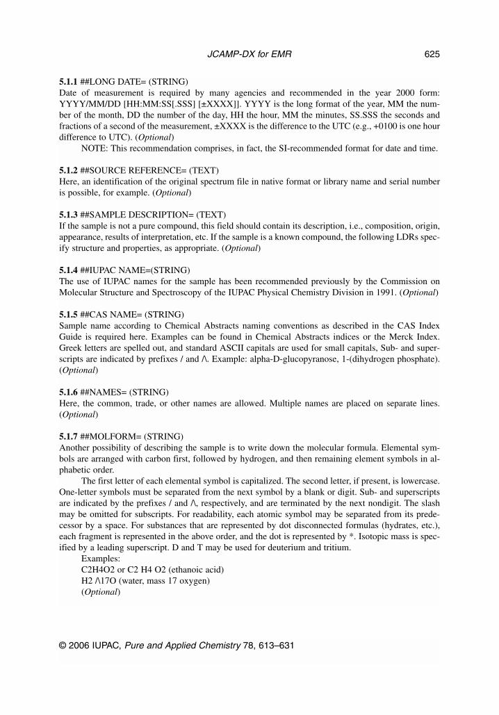
5.1.1 ##LONG DATE= (STRING)Date of measurement is required by many agencies and recommended in the year 2000 form:YYYY/MM/DD [HH:MM:SS[.SSS] [±XXXX]]. YYYY is the long format of the year, MM the num-ber of the month, DD the number of the day, HH the hour, MM the minutes, SS.SSS the seconds andfractions of a second of the measurement, ±XXXX is the difference to the UTC (e.g., +0100 is one hourdifference to UTC). (Optional)
NOTE: This recommendation comprises, in fact, the SI-recommended format for date and time.
5.1.2 ##SOURCE REFERENCE= (TEXT)Here, an identification of the original spectrum file in native format or library name and serial numberis possible, for example. (Optional)
5.1.3 ##SAMPLE DESCRIPTION= (TEXT)If the sample is not a pure compound, this field should contain its description, i.e., composition, origin,appearance, results of interpretation, etc. If the sample is a known compound, the following LDRs spec-ify structure and properties, as appropriate. (Optional)
5.1.4 ##IUPAC NAME=(STRING)The use of IUPAC names for the sample has been recommended previously by the Commission onMolecular Structure and Spectroscopy of the IUPAC Physical Chemistry Division in 1991. (Optional)
5.1.5 ##CAS NAME= (STRING)Sample name according to Chemical Abstracts naming conventions as described in the CAS IndexGuide is required here. Examples can be found in Chemical Abstracts indices or the Merck Index.Greek letters are spelled out, and standard ASCII capitals are used for small capitals, Sub- and super-scripts are indicated by prefixes / and /\. Example: alpha-D-glucopyranose, 1-(dihydrogen phosphate).(Optional)
5.1.6 ##NAMES= (STRING)Here, the common, trade, or other names are allowed. Multiple names are placed on separate lines.(Optional)
5.1.7 ##MOLFORM= (STRING)Another possibility of describing the sample is to write down the molecular formula. Elemental sym-bols are arranged with carbon first, followed by hydrogen, and then remaining element symbols in al-phabetic order.
The first letter of each elemental symbol is capitalized. The second letter, if present, is lowercase.One-letter symbols must be separated from the next symbol by a blank or digit. Sub- and superscriptsare indicated by the prefixes / and /\, respectively, and are terminated by the next nondigit. The slashmay be omitted for subscripts. For readability, each atomic symbol may be separated from its prede-cessor by a space. For substances that are represented by dot disconnected formulas (hydrates, etc.),each fragment is represented in the above order, and the dot is represented by *. Isotopic mass is spec-ified by a leading superscript. D and T may be used for deuterium and tritium.
Examples:C2H4O2 or C2 H4 O2 (ethanoic acid)H2 /\17O (water, mass 17 oxygen) (Optional)
© 2006 IUPAC, Pure and Applied Chemistry 78, 613–631
JCAMP-DX for EMR 625
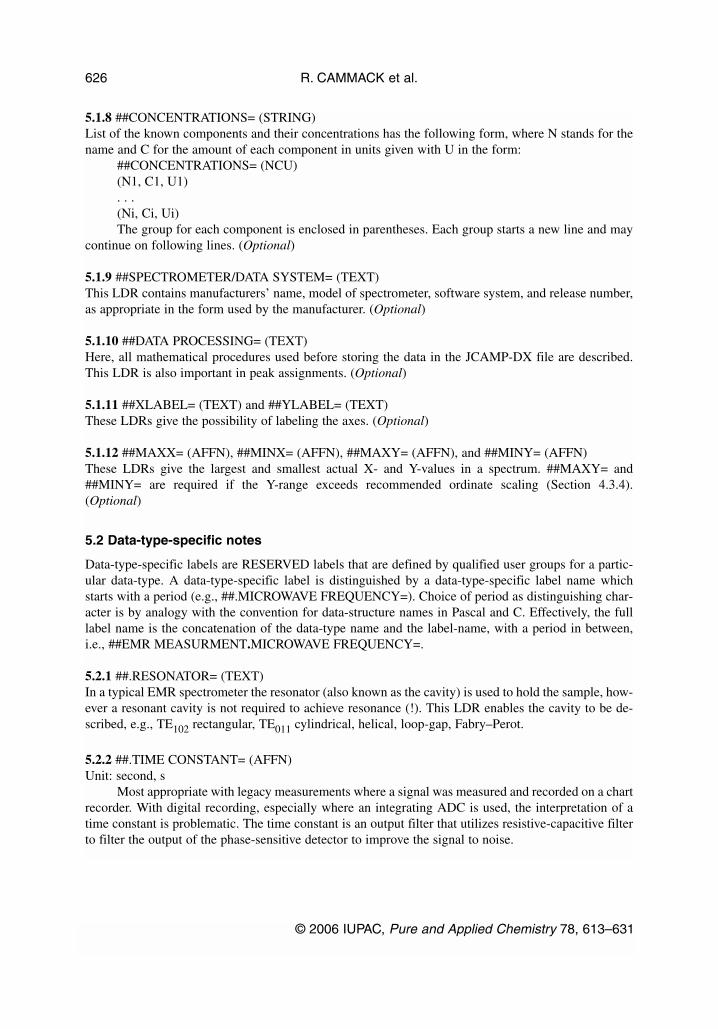
5.1.8 ##CONCENTRATIONS= (STRING)List of the known components and their concentrations has the following form, where N stands for thename and C for the amount of each component in units given with U in the form:
##CONCENTRATIONS= (NCU)(N1, C1, U1). . .(Ni, Ci, Ui)The group for each component is enclosed in parentheses. Each group starts a new line and may
continue on following lines. (Optional)
5.1.9 ##SPECTROMETER/DATA SYSTEM= (TEXT)This LDR contains manufacturers’ name, model of spectrometer, software system, and release number,as appropriate in the form used by the manufacturer. (Optional)
5.1.10 ##DATA PROCESSING= (TEXT)Here, all mathematical procedures used before storing the data in the JCAMP-DX file are described.This LDR is also important in peak assignments. (Optional)
5.1.11 ##XLABEL= (TEXT) and ##YLABEL= (TEXT)These LDRs give the possibility of labeling the axes. (Optional)
5.1.12 ##MAXX= (AFFN), ##MINX= (AFFN), ##MAXY= (AFFN), and ##MINY= (AFFN)These LDRs give the largest and smallest actual X- and Y-values in a spectrum. ##MAXY= and##MINY= are required if the Y-range exceeds recommended ordinate scaling (Section 4.3.4).(Optional)
5.2 Data-type-specific notes
Data-type-specific labels are RESERVED labels that are defined by qualified user groups for a partic-ular data-type. A data-type-specific label is distinguished by a data-type-specific label name whichstarts with a period (e.g., ##.MICROWAVE FREQUENCY=). Choice of period as distinguishing char-acter is by analogy with the convention for data-structure names in Pascal and C. Effectively, the fulllabel name is the concatenation of the data-type name and the label-name, with a period in between,i.e., ##EMR MEASURMENT.MICROWAVE FREQUENCY=.
5.2.1 ##.RESONATOR= (TEXT)In a typical EMR spectrometer the resonator (also known as the cavity) is used to hold the sample, how-ever a resonant cavity is not required to achieve resonance (!). This LDR enables the cavity to be de-scribed, e.g., TE102 rectangular, TE011 cylindrical, helical, loop-gap, Fabry–Perot.
5.2.2 ##.TIME CONSTANT= (AFFN)Unit: second, s
Most appropriate with legacy measurements where a signal was measured and recorded on a chartrecorder. With digital recording, especially where an integrating ADC is used, the interpretation of atime constant is problematic. The time constant is an output filter that utilizes resistive-capacitive filterto filter the output of the phase-sensitive detector to improve the signal to noise.
R. CAMMACK et al.
© 2006 IUPAC, Pure and Applied Chemistry 78, 613–631
626
5.2.3 ##.PUMPED RF FREQUENCY 2= (AFFN)Unit: hertz, Hz
In a triple resonance experiment, frequency of the RF source used for the third source.
5.2.4 ##.PUMPED RF POWER 2= (AFFN)Unit: watt, W
In a triple resonance experiment, power of the RF source used for the third source.
5.2.5 ##DATA PROCESSING= (TEXT)Descriptions of methods or algorithms used to process the data (e.g., FT).
5.2.6 ##.CALIBRATION STANDARD= (TEXT)The chemical standard used internally or externally to calibrate the g value of an EMR signal. (e.g.,DPPH or MgO).
5.2.7 ##.X_OFFSET= (AFFN)Numerical offset of the global X axis.
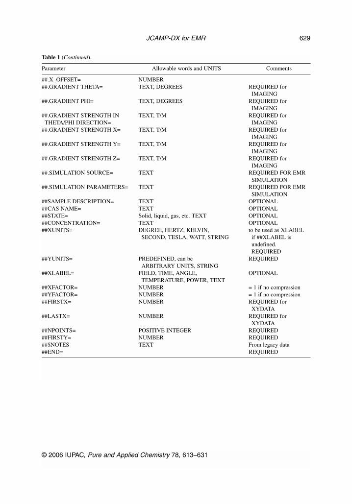
6. SUMMARY
Table 1 lists the LDRs discussed with their basic parameters shown.
© 2006 IUPAC, Pure and Applied Chemistry 78, 613–631
JCAMP-DX for EMR 627
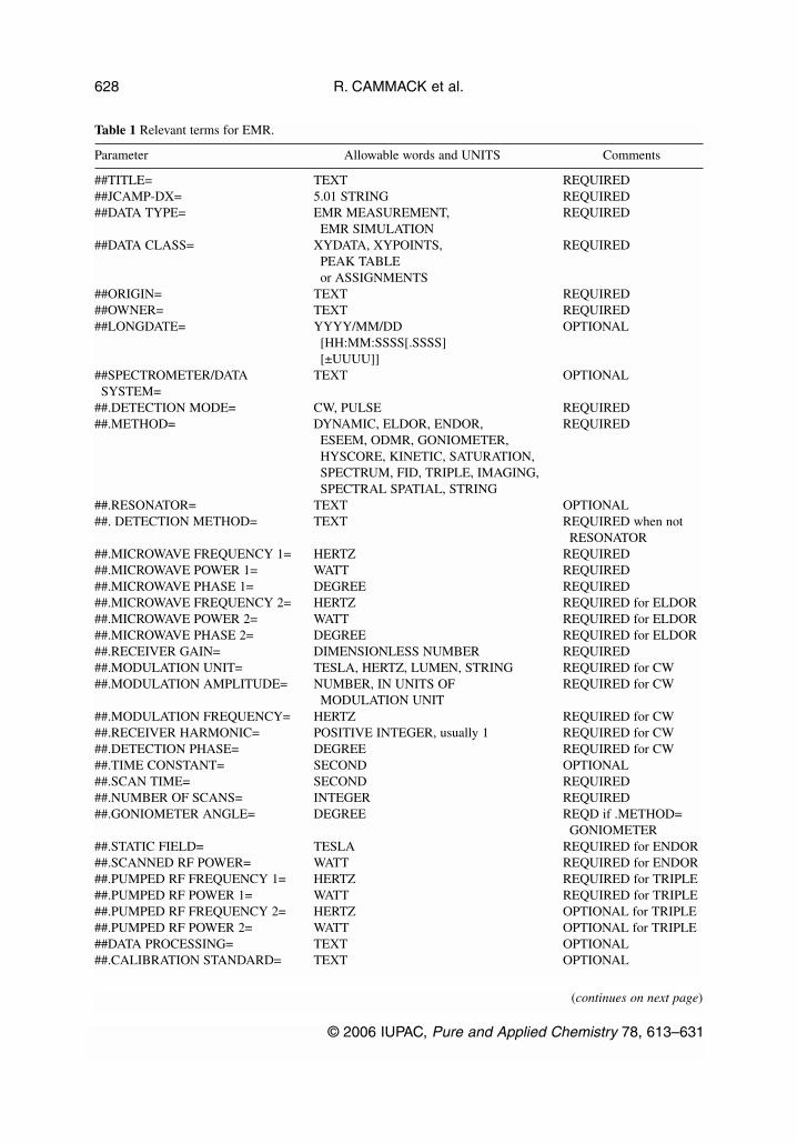
Table 1 Relevant terms for EMR.
Parameter Allowable words and UNITS Comments
##TITLE= TEXT REQUIRED##JCAMP-DX= 5.01 STRING REQUIRED##DATA TYPE= EMR MEASUREMENT, REQUIRED
EMR SIMULATION##DATA CLASS= XYDATA, XYPOINTS, REQUIRED
PEAK TABLEor ASSIGNMENTS
##ORIGIN= TEXT REQUIRED##OWNER= TEXT REQUIRED##LONGDATE= YYYY/MM/DD OPTIONAL
[HH:MM:SSSS[.SSSS][±UUUU]]
##SPECTROMETER/DATA TEXT OPTIONALSYSTEM=
##.DETECTION MODE= CW, PULSE REQUIRED##.METHOD= DYNAMIC, ELDOR, ENDOR, REQUIRED
ESEEM, ODMR, GONIOMETER,HYSCORE, KINETIC, SATURATION,SPECTRUM, FID, TRIPLE, IMAGING,SPECTRAL SPATIAL, STRING
##.RESONATOR= TEXT OPTIONAL##. DETECTION METHOD= TEXT REQUIRED when not
RESONATOR##.MICROWAVE FREQUENCY 1= HERTZ REQUIRED##.MICROWAVE POWER 1= WATT REQUIRED##.MICROWAVE PHASE 1= DEGREE REQUIRED##.MICROWAVE FREQUENCY 2= HERTZ REQUIRED for ELDOR##.MICROWAVE POWER 2= WATT REQUIRED for ELDOR##.MICROWAVE PHASE 2= DEGREE REQUIRED for ELDOR##.RECEIVER GAIN= DIMENSIONLESS NUMBER REQUIRED##.MODULATION UNIT= TESLA, HERTZ, LUMEN, STRING REQUIRED for CW##.MODULATION AMPLITUDE= NUMBER, IN UNITS OF REQUIRED for CW
MODULATION UNIT##.MODULATION FREQUENCY= HERTZ REQUIRED for CW##.RECEIVER HARMONIC= POSITIVE INTEGER, usually 1 REQUIRED for CW##.DETECTION PHASE= DEGREE REQUIRED for CW##.TIME CONSTANT= SECOND OPTIONAL##.SCAN TIME= SECOND REQUIRED##.NUMBER OF SCANS= INTEGER REQUIRED##.GONIOMETER ANGLE= DEGREE REQD if .METHOD=
GONIOMETER##.STATIC FIELD= TESLA REQUIRED for ENDOR##.SCANNED RF POWER= WATT REQUIRED for ENDOR##.PUMPED RF FREQUENCY 1= HERTZ REQUIRED for TRIPLE##.PUMPED RF POWER 1= WATT REQUIRED for TRIPLE##.PUMPED RF FREQUENCY 2= HERTZ OPTIONAL for TRIPLE##.PUMPED RF POWER 2= WATT OPTIONAL for TRIPLE##DATA PROCESSING= TEXT OPTIONAL##.CALIBRATION STANDARD= TEXT OPTIONAL
R. CAMMACK et al.
© 2006 IUPAC, Pure and Applied Chemistry 78, 613–631
628
(continues on next page)
##.X_OFFSET= NUMBER##.GRADIENT THETA= TEXT, DEGREES REQUIRED for
IMAGING##.GRADIENT PHI= TEXT, DEGREES REQUIRED for
IMAGING##.GRADIENT STRENGTH IN TEXT, T/M REQUIRED forTHETA/PHI DIRECTION= IMAGING
##.GRADIENT STRENGTH X= TEXT, T/M REQUIRED forIMAGING
##.GRADIENT STRENGTH Y= TEXT, T/M REQUIRED forIMAGING
##.GRADIENT STRENGTH Z= TEXT, T/M REQUIRED forIMAGING
##.SIMULATION SOURCE= TEXT REQUIRED FOR EMRSIMULATION
##.SIMULATION PARAMETERS= TEXT REQUIRED FOR EMRSIMULATION
##SAMPLE DESCRIPTION= TEXT OPTIONAL##CAS NAME= TEXT OPTIONAL##STATE= Solid, liquid, gas, etc. TEXT OPTIONAL##CONCENTRATION= TEXT OPTIONAL##XUNITS= DEGREE, HERTZ, KELVIN, to be used as XLABEL
SECOND, TESLA, WATT, STRING if ##XLABEL isundefined.REQUIRED
##YUNITS= PREDEFINED, can be REQUIREDARBITRARY UNITS, STRING
##XLABEL= FIELD, TIME, ANGLE, OPTIONALTEMPERATURE, POWER, TEXT
##XFACTOR= NUMBER = 1 if no compression##YFACTOR= NUMBER = 1 if no compression##FIRSTX= NUMBER REQUIRED for
XYDATA##LASTX= NUMBER REQUIRED for
XYDATA##NPOINTS= POSITIVE INTEGER REQUIRED##FIRSTY= NUMBER REQUIRED##$NOTES TEXT From legacy data##END= REQUIRED
© 2006 IUPAC, Pure and Applied Chemistry 78, 613–631
JCAMP-DX for EMR 629
Table 1 (Continued).
Parameter Allowable words and UNITS Comments
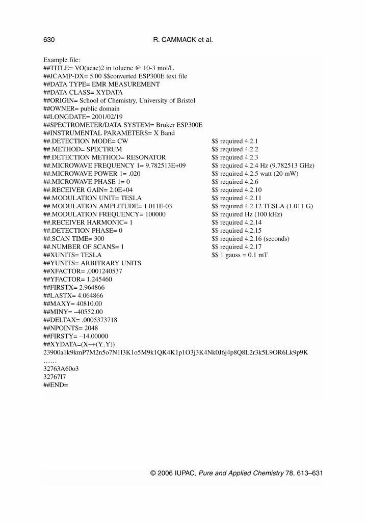
Example file:##TITLE= VO(acac)2 in toluene @ 10-3 mol/L##JCAMP-DX= 5.00 $$converted ESP300E text file##DATA TYPE= EMR MEASUREMENT##DATA CLASS= XYDATA##ORIGIN= School of Chemistry, University of Bristol##OWNER= public domain##LONGDATE= 2001/02/19##SPECTROMETER/DATA SYSTEM= Bruker ESP300E##INSTRUMENTAL PARAMETERS= X Band##.DETECTION MODE= CW $$ required 4.2.1##.METHOD= SPECTRUM $$ required 4.2.2##.DETECTION METHOD= RESONATOR $$ required 4.2.3##.MICROWAVE FREQUENCY 1= 9.782513E+09 $$ required 4.2.4 Hz (9.782513 GHz)##.MICROWAVE POWER 1= .020 $$ required 4.2.5 watt (20 mW)##.MICROWAVE PHASE 1= 0 $$ required 4.2.6##.RECEIVER GAIN= 2.0E+04 $$ required 4.2.10##.MODULATION UNIT= TESLA $$ required 4.2.11##.MODULATION AMPLITUDE= 1.011E-03 $$ required 4.2.12 TESLA (1.011 G)##.MODULATION FREQUENCY= 100000 $$ required Hz (100 kHz)##.RECEIVER HARMONIC= 1 $$ required 4.2.14##.DETECTION PHASE= 0 $$ required 4.2.15##.SCAN TIME= 300 $$ required 4.2.16 (seconds)##.NUMBER OF SCANS= 1 $$ required 4.2.17##XUNITS= TESLA $$ 1 gauss = 0.1 mT##YUNITS= ARBITRARY UNITS##XFACTOR= .0001240537##YFACTOR= 1.245460##FIRSTX= 2.964866##LASTX= 4.064866##MAXY= 40810.00##MINY= –40552.00##DELTAX= .0005373718##NPOINTS= 2048##FIRSTY= –14.00000##XYDATA=(X++(Y..Y))23900a1k9kmP7M2n5o7N1l3K1o5M9k1QK4K1p1O3j3K4Nk0J6j4p8Q8L2r3k5L9OR6Lk9p9K……32763A60o332767I7##END=
R. CAMMACK et al.
© 2006 IUPAC, Pure and Applied Chemistry 78, 613–631
630
7. ACKNOWLEDGMENTS
The task group wishes to acknowledge financial support from IUPAC and to acknowledge technicalcontributions and feedback from instrument vendors and users.
8. REFERENCES
1. (a) R. S. McDonald, P. A. Wilks Jr. Appl. Spectrosc. 42, 151 (1988); (b) R. S. McDonald, P. A.Wilks Jr. Pure Appl. Chem. 63, 1781 (1991).
2. J. Gasteiger, B. M. P. Hendriks, P. Hoever, C. Jochum, H. Somberg. Appl. Spectrosc. 45, 4 (1991).3. A. N. Davies, P. Lampen. Appl. Spectrosc. 47, 1093 (1993).4. A. N. Davies, J. Lambert, R. J. Lancashire, P. Lampen, W. Conover, M. Frey, M. Grzonka, E.
Williams, D. Meinhart. Pure Appl. Chem. 73, 1749 (2001).5. P. Lampen, H. Hillig, A. N. Davies, M. Linscheid. Appl. Spectrosc. 48, 1545 (1994).6. J. I. Baumbach, P. Lampen, A. N. Davies. Pure Appl. Chem. 73, 1765 (2001).7. P. Lampen, J. Lambert, R. J. Lancashire, R. S. McDonald, P. S. McIntyre, D. N. Rutledge, T.
Fröhlich, A. N. Davies. Pure Appl. Chem. 71, 1549 (1999).8. For a draft, see <http://www.jcamp.org>.9. H. Kon. Pure Appl. Chem. 61, 2195 (1989).
10. J. P. Coates. Spectroscopy 2, 14, 120 (1987).11. J. A. Weil, J. R. Bolton, J. E. Wertz. Electron Paramagnetic Resonance, Wiley-Interscience, New
York (1994). 12. A. Schweiger, G. Jeschke. Principles of Pulse Electron Paramagnetic Resonance, Oxford
University Press, Oxford (2001).13. L. Kevan, M. Bowman (Eds.) Modern Pulsed and Continuous-Wave Electron Spin Resonance,
John Wiley, New York (1990).14. L. G. Rowan, E. L. Hahn, W. B. Mims. Phys. Rev. A 137, 61 (1965).15. P. Hoefer, A. Grupp, H. Nebenfuehr, M. Mehring. Chem. Phys. Lett. 132, 279 (1986).
© 2006 IUPAC, Pure and Applied Chemistry 78, 613–631
JCAMP-DX for EMR 631