propane heat pump with low refrigerant charge: design and laboratory tests
TRANSCRIPT
Propane heat pump with low refrigerant charge:
design and laboratory tests
Primal Fernando*, Bjorn Palm, Per Lundqvist, Eric Granryd
Division of Applied Thermodynamics and Refrigeration, Department of Energy Technology,
Royal Institute of Technology (KTH), SE-100 44 Stockholm, Sweden
Received 12 January 2004; received in revised form 28 June 2004; accepted 30 June 2004
Abstract
Independently of the choice of refrigerant, environmental and or safety issues can be minimised by reducing the amount of
refrigerant charge per heat pump or refrigeration system. In the investigation reported here, a laboratory test rig was built,
simulating a water-to-water heat pump with a heating capacity of 5 kW. The system was designed to minimize the charge of
refrigerant mainly by use of mini-channel aluminium heat exchangers. It was shown that the system could be run with 200 g of
propane at typical Swedish operating conditions without reduction of the COP compared to a traditional design. Additional
charge reduction is possible by selecting proper compressor lubrication oils or by using a compressor with less lubrication oil.
q 2004 Elsevier Ltd and IIR. All rights reserved.
Keywords: Heat pump; Water-water; Refrigerant charge; Propane; Design; Experiment
Pompe a chaleur a propane et a faible charge:
conception et essais en laboratoire
Mots cles: Pompe a chaleur; Eau-eau; Charge en frigorigene; Propane; Conception; Experimentation
1. Introduction
Sweden has several relatively big (for European
standards) production units of heat pumps. The Swedish
heat pump market is also traditionally larger than other
European markets. The number of installed and sold heat
0140-7007/$35.00 q 2004 Elsevier Ltd and IIR. All rights reserved.
doi:10.1016/j.ijrefrig.2004.06.012
* Corresponding author. Tel.: C46-8-790-8941; fax: C46-8-20-
30-07.
E-mail addresses: [email protected] (P. Fernando), bpalm
@energy.kth.se (B. Palm), [email protected] (P. Lundqvist),
[email protected] (E. Granryd).
pumps annually in Sweden is at the same level as for the rest
of Europe. The main reason for this large interest is the cold
climate in combination with low price of electricity at the
consumer level, being, per kWh, comparable to the price of
oil. Several countries, however, foresee a strong increase in
sales of heat pumps within coming years. Swedish heat
pumps generally have good reputation for high quality.
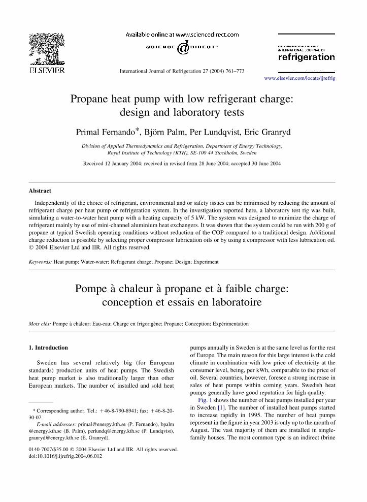
Fig. 1 shows the number of heat pumps installed per year
in Sweden [1]. The number of installed heat pumps started
to increase rapidly in 1995. The number of heat pumps
represent in the figure in year 2003 is only up to the month of
August. The vast majority of them are installed in single-
family houses. The most common type is an indirect (brine
International Journal of Refrigeration 27 (2004) 761–773
www.elsevier.com/locate/ijrefrig
Nomenclature
A heat transfer area (m2)
A-BH-25 average temperature of the borehole, 25 m deep
(8C)
A-BH-50 average temperature of the borehole, 50 m deep
(8C)
A-ut average outside temperature (8C)
COP coefficient of performance, heating
cp specific heat capacity (J kgK1 KK1)
C-170 charge 170 g
C-201 charge 201 g
C-240 charge 240 g
C-265 charge 265 g
GWP green house warming potential
h refrigerant enthalpy (J kgK1)
LMTD log mean temperature difference (K)
m mass flow rate (kg sK1)
M-BH-25 minimum temperature of the borehole, 25 m
deep (8C)
M-BH-50 minimum temperature of the borehole, 50 m
deep (8C)
M-ut minimum outside temperature (8C)
M-Br-in minimum brine inlet temperature (8C)
ODP ozone depletion potential
Q heat capacity (W)
SH super heat (K)
SC sub cool (K)
t temperature (8C)
U overall heat transfer coefficient (W mK2 KK1)
Subscripts
ave average
c condenser
c,in condenser inlet
c,out condenser outlet
c,dsh,r condenser de-superheat region
c,sc,r condenser sub-cool region
c,tp,r condenser two-phase region
c,sl condenser, saturated liquid
c,sg condenser, saturated gas
c,sc condenser, sub-cooled liquid
e evaporator
e,in evaporator inlet
e,out evaporator outlet
e,sh,r evaporator superheat region
e,tp,r evaporator two phase region
e,sg at evaporator saturated gas
e,sh at evaporator super heat
g glycol
g,out glycol outlet
g,in glycol inlet
g,sg glycol at refrigerant saturated gas
min minimum
r refrigerant
r,sh refrigerant, superheated gas
r,sg refrigerant, saturated gas
r,in,e refrigerant inlet in evaporator
r,in,c refrigerant, condenser inlet
r,sl refrigerant, saturated liquid
w water
w,out water outlet
w,in water inlet
w,sg water at condenser saturated gas
w,sl water at saturated liquid
P. Fernando et al. / International Journal of Refrigeration 27 (2004) 761–773762
loop) ground or rock-coupled heat pump, connected to the
water circulating heating system of the house. Usually, the
heat pump is chosen to cover more than 90% of the annual
heating need of a house and 50–60% of the heating demand
of the coldest day. The total heating demand covered by heat
pumps in Sweden is estimated to be about 15 TWh/year,
thus reducing the total energy demands by about 10 TWh/
year. Environmentally adopted and energy effective heat
pumps can play an important role as replacement of the
presently dominant energy technology, in Sweden, the
direct electric heating.
The ozone depletion potential (ODP) and green house
warming potential (GWP) of some commonly used
refrigerants have led to increased research efforts for
developing other refrigerants, which are environmentally
friendly. Propane is a refrigerant, which has no ODP and
extremely low (!20) GWP [2], compared to many
currently used refrigerants. Also thermodynamic and
transport properties are the same as or better than the most
popular refrigerants used in refrigeration systems. Propane
is not corrosive in combination with many materials such as
aluminium, brass, bronze, copper, stainless steel, silver, etc.
Therefore it is fully compatible with existing components
such as heat exchangers, expansion valves, compressors,
lubricants and copper tubing, which are commonly used in
current refrigeration systems [3]. Its major drawback,
however, is the flammability.
Independently of the chosen refrigerant it is of interest to
decrease the total charge of the system, if this can be done
without negative influence on the COP of the system. For
HFC and HCFC systems, reduced charge means less
environmental impact in case of leakage. For systems with
flammable refrigerants lower charge is important for safety
reasons. An ongoing project at The Royal Institute of
Technology (KTH), Stockholm, aims to increase the
existing knowledge about heat pumps and refrigeration
systems designed for the lowest possible refrigerant charge,
with the goal of designing a heat pump system with a charge
of less than 150 g (with propane) having a heating capacity
of the order of 5 kW or more. This should be reached
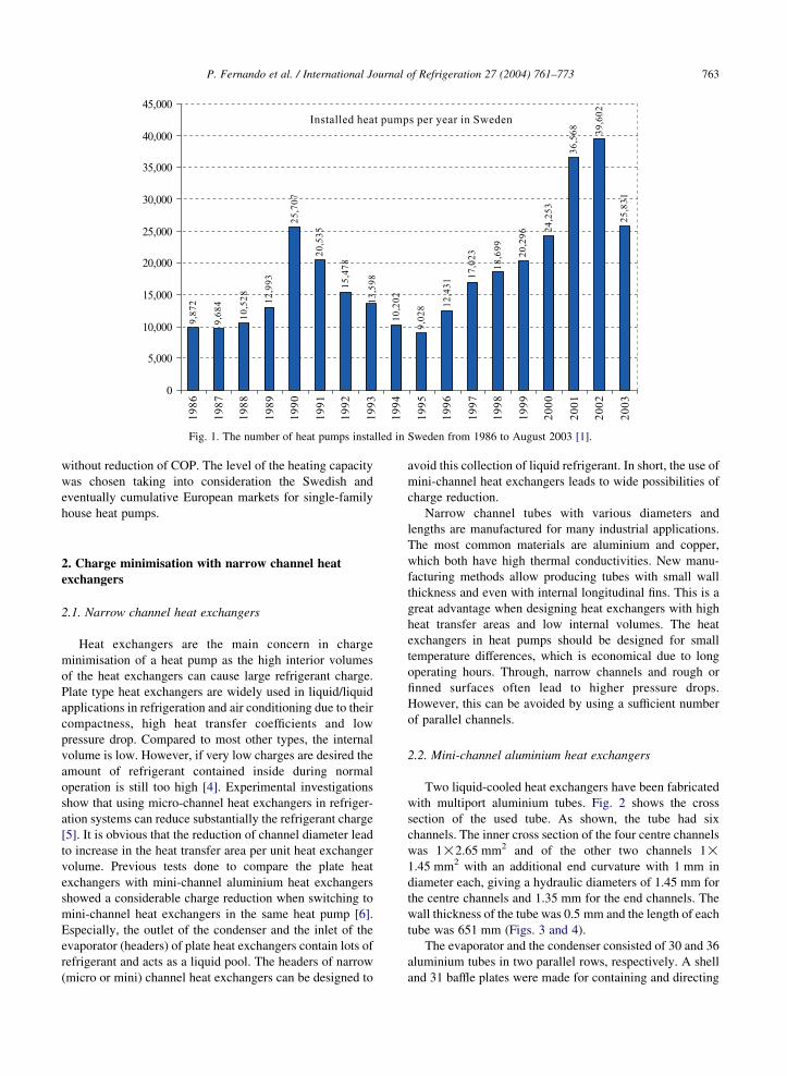
Fig. 1. The number of heat pumps installed in Sweden from 1986 to August 2003 [1].
P. Fernando et al. / International Journal of Refrigeration 27 (2004) 761–773 763
without reduction of COP. The level of the heating capacity
was chosen taking into consideration the Swedish and
eventually cumulative European markets for single-family
house heat pumps.
2. Charge minimisation with narrow channel heat
exchangers
2.1. Narrow channel heat exchangers
Heat exchangers are the main concern in charge
minimisation of a heat pump as the high interior volumes
of the heat exchangers can cause large refrigerant charge.
Plate type heat exchangers are widely used in liquid/liquid
applications in refrigeration and air conditioning due to their
compactness, high heat transfer coefficients and low
pressure drop. Compared to most other types, the internal
volume is low. However, if very low charges are desired the
amount of refrigerant contained inside during normal
operation is still too high [4]. Experimental investigations
show that using micro-channel heat exchangers in refriger-
ation systems can reduce substantially the refrigerant charge
[5]. It is obvious that the reduction of channel diameter lead
to increase in the heat transfer area per unit heat exchanger
volume. Previous tests done to compare the plate heat
exchangers with mini-channel aluminium heat exchangers
showed a considerable charge reduction when switching to
mini-channel heat exchangers in the same heat pump [6].
Especially, the outlet of the condenser and the inlet of the
evaporator (headers) of plate heat exchangers contain lots of
refrigerant and acts as a liquid pool. The headers of narrow
(micro or mini) channel heat exchangers can be designed to
avoid this collection of liquid refrigerant. In short, the use of
mini-channel heat exchangers leads to wide possibilities of
charge reduction.
Narrow channel tubes with various diameters and
lengths are manufactured for many industrial applications.
The most common materials are aluminium and copper,
which both have high thermal conductivities. New manu-
facturing methods allow producing tubes with small wall
thickness and even with internal longitudinal fins. This is a
great advantage when designing heat exchangers with high
heat transfer areas and low internal volumes. The heat
exchangers in heat pumps should be designed for small
temperature differences, which is economical due to long
operating hours. Through, narrow channels and rough or
finned surfaces often lead to higher pressure drops.
However, this can be avoided by using a sufficient number
of parallel channels.
2.2. Mini-channel aluminium heat exchangers
Two liquid-cooled heat exchangers have been fabricated
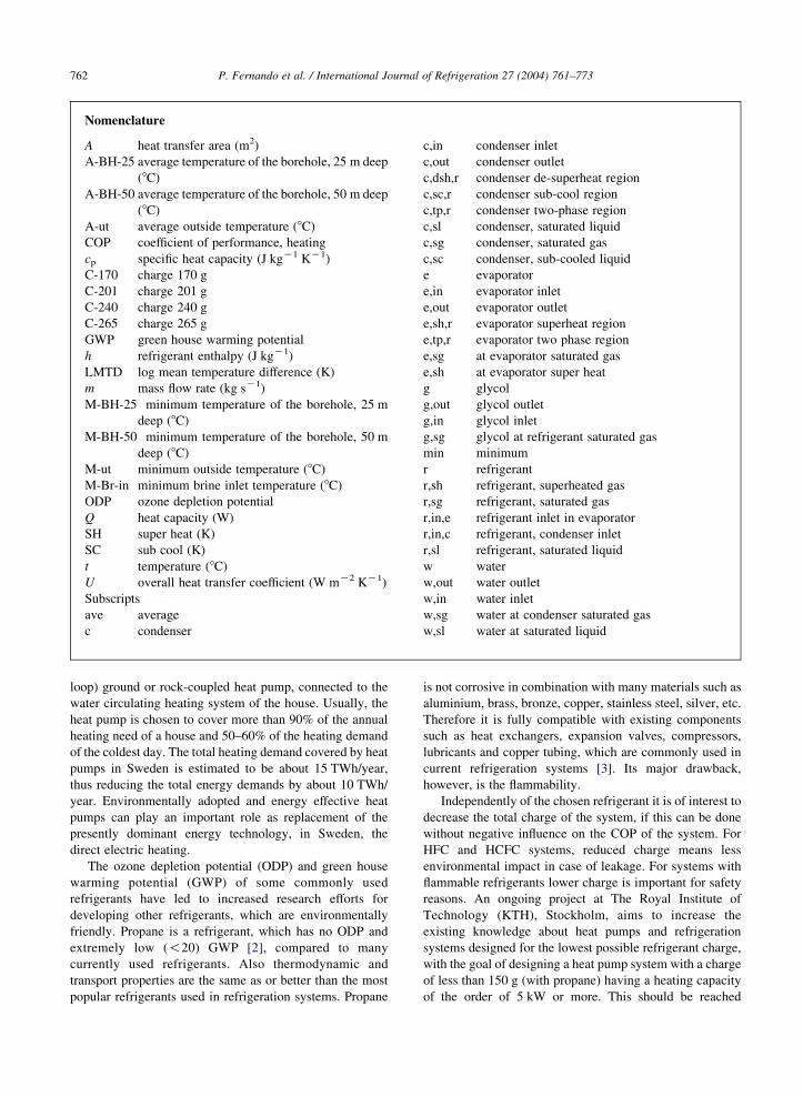
with multiport aluminium tubes. Fig. 2 shows the cross
section of the used tube. As shown, the tube had six
channels. The inner cross section of the four centre channels
was 1!2.65 mm2 and of the other two channels 1!1.45 mm2 with an additional end curvature with 1 mm in
diameter each, giving a hydraulic diameters of 1.45 mm for
the centre channels and 1.35 mm for the end channels. The
wall thickness of the tube was 0.5 mm and the length of each
tube was 651 mm (Figs. 3 and 4).
The evaporator and the condenser consisted of 30 and 36
aluminium tubes in two parallel rows, respectively. A shell
and 31 baffle plates were made for containing and directing
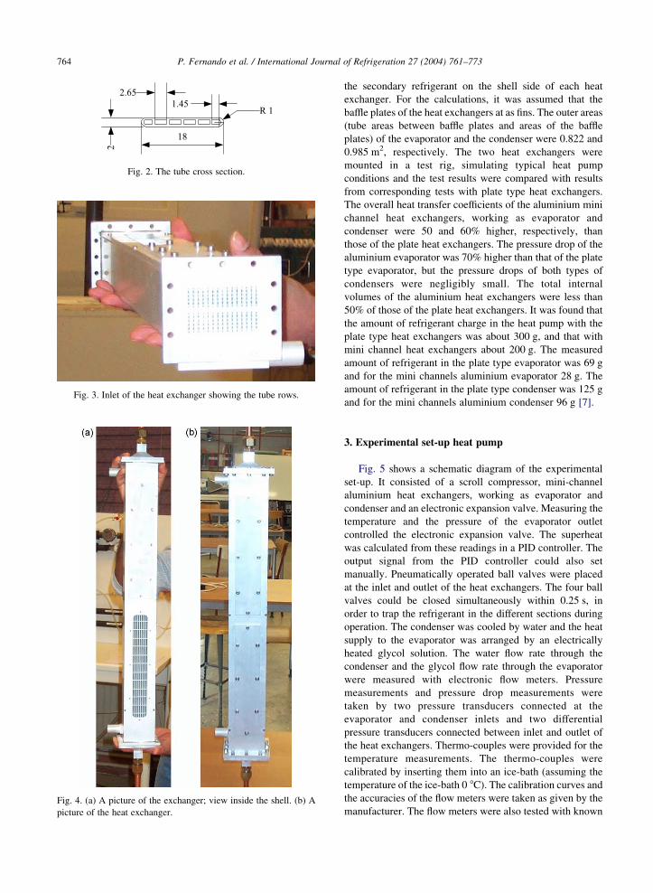
Fig. 2. The tube cross section.
Fig. 3. Inlet of the heat exchanger showing the tube rows.
Fig. 4. (a) A picture of the exchanger; view inside the shell. (b) A
picture of the heat exchanger.
P. Fernando et al. / International Journal of Refrigeration 27 (2004) 761–773764
the secondary refrigerant on the shell side of each heat
exchanger. For the calculations, it was assumed that the
baffle plates of the heat exchangers at as fins. The outer areas
(tube areas between baffle plates and areas of the baffle
plates) of the evaporator and the condenser were 0.822 and
0.985 m2, respectively. The two heat exchangers were
mounted in a test rig, simulating typical heat pump
conditions and the test results were compared with results
from corresponding tests with plate type heat exchangers.
The overall heat transfer coefficients of the aluminium mini
channel heat exchangers, working as evaporator and
condenser were 50 and 60% higher, respectively, than
those of the plate heat exchangers. The pressure drop of the
aluminium evaporator was 70% higher than that of the plate
type evaporator, but the pressure drops of both types of
condensers were negligibly small. The total internal
volumes of the aluminium heat exchangers were less than
50% of those of the plate heat exchangers. It was found that
the amount of refrigerant charge in the heat pump with the
plate type heat exchangers was about 300 g, and that with
mini channel heat exchangers about 200 g. The measured
amount of refrigerant in the plate type evaporator was 69 g
and for the mini channels aluminium evaporator 28 g. The
amount of refrigerant in the plate type condenser was 125 g
and for the mini channels aluminium condenser 96 g [7].
3. Experimental set-up heat pump
Fig. 5 shows a schematic diagram of the experimental
set-up. It consisted of a scroll compressor, mini-channel
aluminium heat exchangers, working as evaporator and
condenser and an electronic expansion valve. Measuring the
temperature and the pressure of the evaporator outlet
controlled the electronic expansion valve. The superheat
was calculated from these readings in a PID controller. The
output signal from the PID controller could also set
manually. Pneumatically operated ball valves were placed
at the inlet and outlet of the heat exchangers. The four ball
valves could be closed simultaneously within 0.25 s, in
order to trap the refrigerant in the different sections during
operation. The condenser was cooled by water and the heat
supply to the evaporator was arranged by an electrically
heated glycol solution. The water flow rate through the
condenser and the glycol flow rate through the evaporator
were measured with electronic flow meters. Pressure
measurements and pressure drop measurements were
taken by two pressure transducers connected at the
evaporator and condenser inlets and two differential
pressure transducers connected between inlet and outlet of
the heat exchangers. Thermo-couples were provided for the
temperature measurements. The thermo-couples were
calibrated by inserting them into an ice-bath (assuming the
temperature of the ice-bath 0 8C). The calibration curves and
the accuracies of the flow meters were taken as given by the
manufacturer. The flow meters were also tested with known
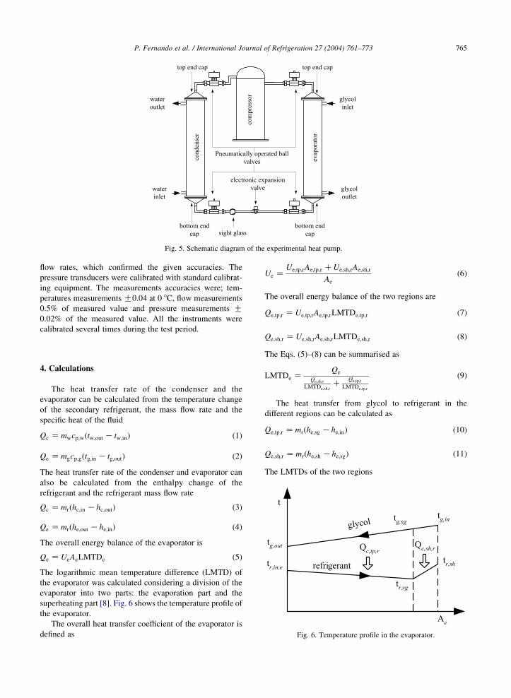
Fig. 5. Schematic diagram of the experimental heat pump.
P. Fernando et al. / International Journal of Refrigeration 27 (2004) 761–773 765
flow rates, which confirmed the given accuracies. The
pressure transducers were calibrated with standard calibrat-
ing equipment. The measurements accuracies were; tem-
peratures measurements G0.04 at 0 8C, flow measurements
0.5% of measured value and pressure measurements G0.02% of the measured value. All the instruments were
calibrated several times during the test period.
Fig. 6. Temperature profile in the evaporator.
4. Calculations
The heat transfer rate of the condenser and the
evaporator can be calculated from the temperature change
of the secondary refrigerant, the mass flow rate and the
specific heat of the fluid
Qc Zmwcp;wðtw;out K tw;inÞ (1)
Qe Zmgcp;gðtg;in K tg;outÞ (2)
The heat transfer rate of the condenser and evaporator can
also be calculated from the enthalpy change of the
refrigerant and the refrigerant mass flow rate
Qc Zmrðhc;in Khc;outÞ (3)
Qe Zmrðhe;out Khe;inÞ (4)
The overall energy balance of the evaporator is
Qe ZUeAeLMTDe (5)
The logarithmic mean temperature difference (LMTD) of
the evaporator was calculated considering a division of the
evaporator into two parts: the evaporation part and the
superheating part [8]. Fig. 6 shows the temperature profile of
the evaporator.
The overall heat transfer coefficient of the evaporator is
defined as
Ue ZUe;tp;rAe;tp;r CUe;sh;rAe;sh;r
Ae
(6)
The overall energy balance of the two regions are
Qe;tp;r ZUe;tp;rAe;tp;rLMTDe;tp;r (7)
Qe;sh;r ZUe;sh;rAe;sh;rLMTDe;sh;r (8)
The Eqs. (5)–(8) can be summarised as
LMTDe ZQe
Qe;sh;r
LMTDe;sh;rC
Qe;tp;r
LMTDe;tp;r
(9)
The heat transfer from glycol to refrigerant in the
different regions can be calculated as
Qe;tp;r Zmrðhe;sg Khe;inÞ (10)
Qe;sh;r Zmrðhe;sh Khe;sgÞ (11)
The LMTDs of the two regions
P. Fernando et al. / International Journal of Refrigeration 27 (2004) 761–773766
LMTDe;sh;r Zðtg;in K tr;shÞK ðtg;sg K tr;sgÞ
lntg;inKtr;sh
tg;sgKtr;sg
� � (12)
LMTDe;tp;r Zðtg;sg K tr;sgÞK ðtg;out K tr;in;eÞ
lntg;sgKtr;sg
tg;outKtr;in;e
� � (13)
The overall energy balance of the condenser is
Qc ZUcAcLMTDc (14)
The LMTD of the condenser was calculated considering
division of the condenser into three parts [9]: de-super-
heating region, condensing region and sub-cooling region.
Fig. 7 shows the temperature profile of the condenser.
Fig. 7. Temperature profile in the condenser.
The overall heat transfer coefficient of the condenser is
defined as
Uc ZUc;sc;rAc;sc;r CUc;tp;rAc;tp;r CUc;dsh;rAc;dsh;r
Ac
(15)
The overall energy balance of the three regions
Qc;sc;r ZUc;sc;rAc;sc;rLMTDc;sc;r (16)
Qc;tp;r ZUc;tp;rAc;tp;rLMTDc;tp;r (17)
Qc;dsh;r ZUc;dsh;rAc;dsh;rLMTDc;dsh;r (18)
The Eqs. (14)–(18) can be summarised as,
LMTDc ZQc
Qc;dsh;r
LMTDc;dsh;rC
Qc;tp;r
LMTDc;tp;rC
Qc;sc;r
LMTDc;sc;r
(19)
The heat transfer from refrigerant to water in the different
regions of the condenser can be calculated as
Qc;sc;r Zmrðhc;sl Khc;scÞ (20)
Qc;tp;r Zmrðhc;sg Khc;slÞ (21)
Qc;dsh;r Zmrðhc;in Khc;sgÞ (22)
The LMTDs of different regions can be described as
LMTDc;dsh;r Zðtr;in;c K tw;outÞK ðtr;sg K tw;sgÞ
lntr;in;cKtw;out
tr;sgKtw;sg
� � (23)
LMTDc;tp;r Zðtr;sg K tw;sgÞK ðtr;sl K tw;slÞ
lntr;sgKtw;sg
tr;slKtw;sl
� � (24)
LMTDc;sc;r Zðtr;sl K tw;slÞK ðtc;sc K tw;inÞ
lntr;slKtw;sl
tc;scKtw;in
� � (25)
The pressure drop of the evaporator was considered in
calculations of the refrigerant side temperatures, but was not
considered in the condenser, since the pressure drop of the
condenser was negligibly small.
5. The performance of the heat pump with mini-channel
aluminium heat exchangers
5.1. Optimum charge tests
The heat pump was tested with selected heat source
temperatures and with a constant heat sink temperature. The
selected heat source temperatures were K10, K2, 6 and
12 8C, and the heat sink temperature was 40 8C. The cooling
water inlet temperature was kept at 33 8C, to obtain a 7 K
temperature increase of the water. The temperature change
of the glycol was kept at about 3 K for the heat source
temperatures of K10 and K2 8C and at about 3.75 and
4.4 K for the heat source temperatures of 6 and 12 8C,
respectively.
The refrigerant quantity (propane) in the system was
varied for each heat source and heat sink temperature
combination and the coefficient of performance (COP) of
the system was determined. The superheat at the evaporator
outlet was slightly increased with decreasing evaporation
temperature for lower charges in order to avoid gas bubbles
in the expansion valve inlet. This was done in order to
simulate the performance of a correctly sized thermostatic
expansion valve. The minimum (desired) superheat was
maintained around 5 K. The sub-cooling at the condenser
outlet was allowed to increase for higher charges. The heat
pump was tested over 1000 h for all heat source/sink
combinations.
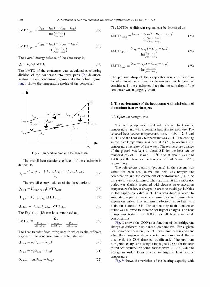
Fig. 8 shows the COP as a function of the refrigerant
charge at different heat source temperatures. For a given
heat source temperature, the COP was more or less constant
when the charge was above a certain minimum level. Below
this level, the COP dropped significantly. The optimum
refrigerant charges resulting in the highest COP, for the four
tested heat source/sink combinations were170, 200, 240 and
265 g, in order from lowest to highest heat source
temperature.
Fig. 9 shows the variation of the heating capacity with
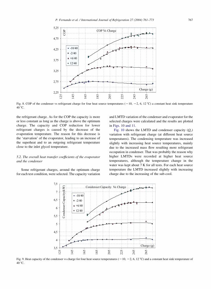
Fig. 8. COP of the condenser vs refrigerant charge for four heat source temperatures (K10, K2, 6, 12 8C) a constant heat sink temperature
40 8C.
P. Fernando et al. / International Journal of Refrigeration 27 (2004) 761–773 767
the refrigerant charge. As for the COP the capacity is more
or less constant as long as the charge is above the optimum
charge. The capacity and COP reduction for lower
refrigerant charges is caused by the decrease of the
evaporation temperature. The reason for this decrease is
the ‘starvation’ of the evaporator, leading to an increase of
the superheat and to an outgoing refrigerant temperature
close to the inlet glycol temperature.
5.2. The overall heat transfer coefficients of the evaporator
and the condenser
Some refrigerant charges, around the optimum charge
for each test condition, were selected. The capacity variation
Fig. 9. Heat capacity of the condenser vs charge for four heat source tempe
40 8C.
and LMTD variation of the condenser and evaporator for the
selected charges were calculated and the results are plotted
in Figs. 10 and 11.
Fig. 10 shows the LMTD and condenser capacity (Qc)
variation with refrigerant charge (at different heat source
temperatures). The condensing temperature was increased
slightly with increasing heat source temperatures, mainly
due to the increased mass flow resulting more refrigerant
occupation in condenser. That was probably the reason why
higher LMTDs were recorded at higher heat source
temperatures, although the temperature change in the
water was kept about 7 K for all tests. For each heat source
temperature the LMTD increased slightly with increasing
charge due to the increasing of the sub-cool.
ratures (K10, K2, 6, 12 8C) and a constant heat sink temperature of
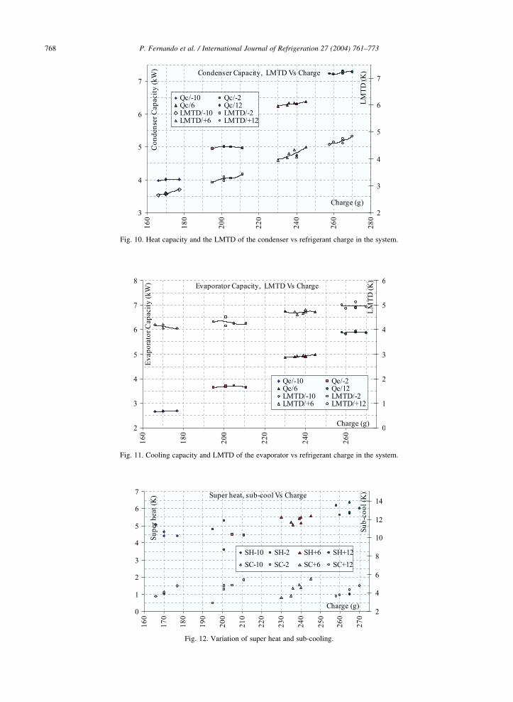
Fig. 10. Heat capacity and the LMTD of the condenser vs refrigerant charge in the system.
Fig. 11. Cooling capacity and LMTD of the evaporator vs refrigerant charge in the system.
Fig. 12. Variation of super heat and sub-cooling.
P. Fernando et al. / International Journal of Refrigeration 27 (2004) 761–773768
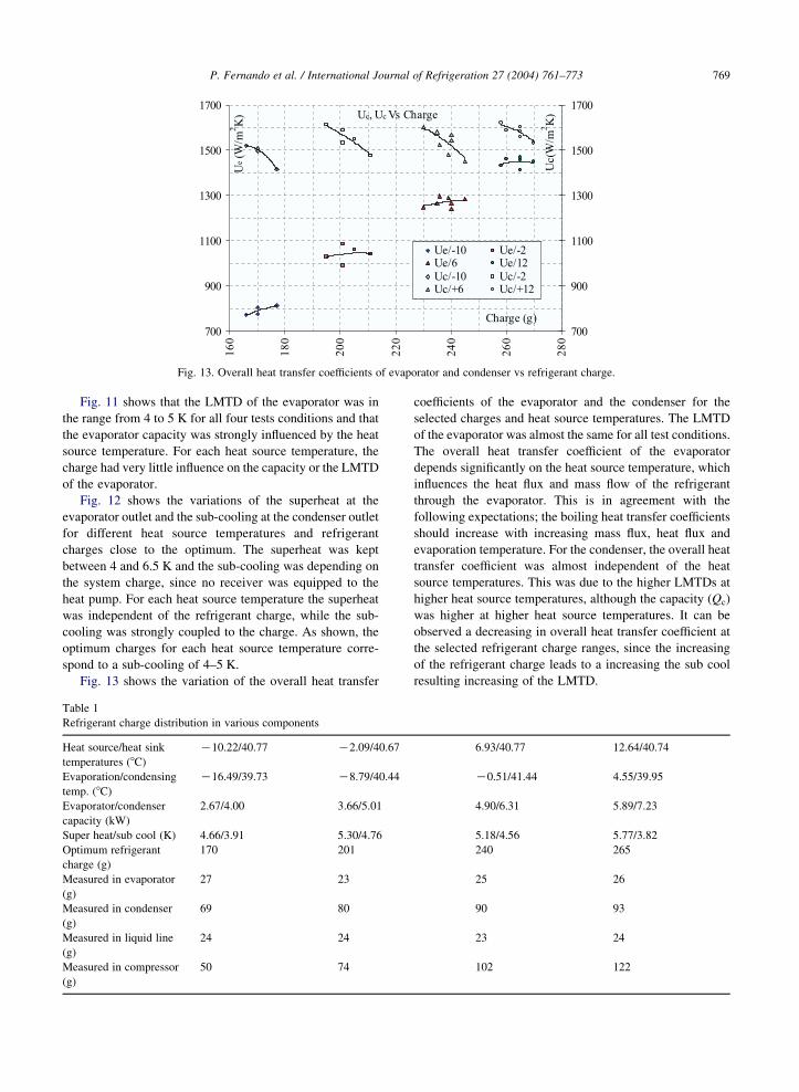
Fig. 13. Overall heat transfer coefficients of evaporator and condenser vs refrigerant charge.
P. Fernando et al. / International Journal of Refrigeration 27 (2004) 761–773 769
Fig. 11 shows that the LMTD of the evaporator was in
the range from 4 to 5 K for all four tests conditions and that
the evaporator capacity was strongly influenced by the heat
source temperature. For each heat source temperature, the
charge had very little influence on the capacity or the LMTD
of the evaporator.
Fig. 12 shows the variations of the superheat at the
evaporator outlet and the sub-cooling at the condenser outlet
for different heat source temperatures and refrigerant
charges close to the optimum. The superheat was kept
between 4 and 6.5 K and the sub-cooling was depending on
the system charge, since no receiver was equipped to the
heat pump. For each heat source temperature the superheat
was independent of the refrigerant charge, while the sub-
cooling was strongly coupled to the charge. As shown, the
optimum charges for each heat source temperature corre-
spond to a sub-cooling of 4–5 K.
Fig. 13 shows the variation of the overall heat transfer
Table 1
Refrigerant charge distribution in various components
Heat source/heat sink
temperatures (8C)
K10.22/40.77 K2.09/40.67
Evaporation/condensing
temp. (8C)
K16.49/39.73 K8.79/40.44
Evaporator/condenser
capacity (kW)
2.67/4.00 3.66/5.01
Super heat/sub cool (K) 4.66/3.91 5.30/4.76
Optimum refrigerant
charge (g)
170 201
Measured in evaporator
(g)
27 23
Measured in condenser
(g)
69 80
Measured in liquid line
(g)
24 24
Measured in compressor
(g)
50 74
coefficients of the evaporator and the condenser for the
selected charges and heat source temperatures. The LMTD
of the evaporator was almost the same for all test conditions.
The overall heat transfer coefficient of the evaporator
depends significantly on the heat source temperature, which
influences the heat flux and mass flow of the refrigerant
through the evaporator. This is in agreement with the
following expectations; the boiling heat transfer coefficients
should increase with increasing mass flux, heat flux and
evaporation temperature. For the condenser, the overall heat
transfer coefficient was almost independent of the heat
source temperatures. This was due to the higher LMTDs at
higher heat source temperatures, although the capacity (Qc)
was higher at higher heat source temperatures. It can be
observed a decreasing in overall heat transfer coefficient at
the selected refrigerant charge ranges, since the increasing
of the refrigerant charge leads to a increasing the sub cool
resulting increasing of the LMTD.
6.93/40.77 12.64/40.74
K0.51/41.44 4.55/39.95
4.90/6.31 5.89/7.23
5.18/4.56 5.77/3.82
240 265
25 26
90 93
23 24
102 122

P. Fernando et al. / International Journal of Refrigeration 27 (2004) 761–773770
5.3. Charge distribution tests
The purpose of these tests was to determine the
distribution of the refrigerant charge in the different parts
of the system. For each heat source temperature tested, the
system was charged with the optimum refrigerant charge.
Measurements were taken at stable conditions for a given
heat source/sink temperature combinations and the four ball
valves of the heat pump were closed simultaneously while
the system was in operation. A small cylinder (one litre
capacity) was connected to the isolated sections by a flexible
hose and the cylinder was immersed in a larger container,
which was filled with liquid air. The cooling of the cylinder
caused a low pressure inside and thereby all the refrigerant
in different sections was drained to the cylinder. The
differences between original refrigerant charge and the total
refrigerant drained were less than 5 g in all tests. The
drained refrigerant was weighed. The accuracy of the
measurements was G1 g.
Table 1 shows the refrigerant charge distribution in the
heat pump for the four tested heat source temperatures for
the optimum charge. The amount of refrigerant in the
evaporator was almost same for all four tests, even though
the evaporation temperature varied from K16.5 to C4.5 8C.
Also, the amount of refrigerant in the liquid line was the
same in all four experiments. The amount of refrigerant in
the condenser varied from 69 to 93 g, showing an increase of
24 g in spite of the fact that the condensing temperature was
almost constant. The refrigerant amount in the compressor
was increased from 50 to 122 g, showing an increase of
72 g. The results of the charge distribution tests indicate that
a considerable amount of the refrigerant is located in the
compressor. It increases rapidly with increasing evaporation
temperature. This is a problem if, preferably, the system
should be able to run with the same charge at different
conditions. The lubrication oil type used in the compressor
was ester type oil (polyol ester). In parallel experiments, the
solubility of propane in different lubrication oils was tested.
In these experiments, the solubility of propane with two
polyol ester (POE) type oils and with one polyalkylene
glycol (PAG) type oil was tested. The solubility was tested
at different saturation temperatures and found that increased
at higher temperatures and pressures. The solubility of
propane in ester oil was higher than PAG oil [10].
Solubility of refrigerant in lubrication oil is positive
outside of the compressor as it aids the oil return to the
compressor and also keeps the heat transfer surfaces free of
oil. Within the compressor high solubility causes a decrease
in lubricant viscosity, which may be harmful for the proper
lubrication [11]. The solubility of refrigerant in lubricants
also depends on the viscosity of the lubricant. A lubricant
with higher viscosity has low solubility in a refrigerant
compared with the same lubricant type with lower viscosity
[12]. The selection of less soluble lubricant oil with propane
or lubricant oil with higher viscosity than that used for these
experiments, will allow further reduction of refrigerant
charge.
The pneumatically operated ball valves were placed
close to the heat exchangers (Fig. 5). The refrigerant
amounts measured in the heat exchangers were; the total
amounts in the heat transfer tubes, two end caps (headers)
and the tube lengths between ball valves and heat
exchangers. The total inside volume between the ball valves
surrounding the evaporator is 376 cm3; of this, the top end
cap with the tube length between the ball valve and the heat
exchanger has a volume of 52 cm3, the bottom end cap with
the tube length between the ball valve and the heat
exchanger has a volume 42 cm3 and heat transfer tube
volume is 279 cm3. The total inside volume between the
valves surrounding the condenser is 437 cm3; of which the
top end cap with the tube length between the ball valve and
the heat exchanger represents a volume of 53 cm3, the
bottom end cap with the tube length between the ball valve
and the heat exchanger has the volume of 49 cm3 and the
heat transfer tube volume is 335 cm3. The end caps and the
extra tube lengths occupy 25% of the total volume. Half of
this 25% volume is in the bottom side of the evaporator and
condenser where the refrigerant is at least partly in liquid
phase. Since both, the evaporator and the condenser were
placed vertically; a considerable amount of refrigerant was
in the evaporator bottom side end cap and condenser bottom
side end cap. A redesign of these parts should result in lower
liquid hold-up. The line between the two ball valves at the
condenser outlet and the evaporator inlet was considered as
the liquid line. The liquid line consisted of: a sight glass,
the expansion valve and some extra tubing to facilitate the
fitting of the ball valves. The refrigerant amounts in the
liquid line were consistent for all tests with a total mass of
about 24 g. The introduction of smaller ends caps and
exclusion of extended tube lengths for the ball valves may
further reduce the optimum charge at least by 20 g.
5.4. Performance of the heat pump for a given refrigerant
charge
In a separate test series, the system was charged with the
optimum refrigerant charges determined for the heat source
temperatures K10, K2, 6 and 12 8C. For each charge the
heat source temperature was varied from K10 to C12 8C,
while keeping the heat sink temperature constant at 40 8C.
Fig. 14 shows the influence of the heat source
temperature on the COP. The minimum sub-cooling of the
condenser was about 2 K and was increased for lower heat
source temperatures due to backup of refrigerant into the
condenser. The minimum super heat was kept at 4–6 K but
was allowed to increase at higher heat source temperatures
by closing the electronic expansion valve, thereby also
lowering the evaporation temperature. This was done in
order to prevent uncondensed gas to reach the expansion
valve inlet.
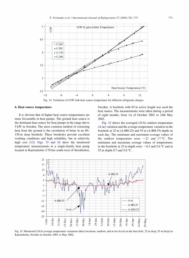
Fig. 14. Variations of COP with heat source temperature for different refrigerant charges.
P. Fernando et al. / International Journal of Refrigeration 27 (2004) 761–773 771
6. Heat source temperature
It is obvious that of higher heat source temperatures are
more favourable in heat pumps. The ground heat source is
the dominant heat source for heat pumps in the range above
5 kW in Sweden. The most common method of extracting
heat from the ground is the circulation of brine in an 80–
150 m deep borehole. These boreholes provide excellent
working conditions and high reliability, but at relatively
high cost [13]. Figs. 15 and 16 show the monitored
temperature measurements in a single-family heat pump
located in Katrineholm (170 km south-west of Stockholm),
Fig. 15. Monitored (24 h) average temperature variations (three locations; o
Katrineholm, Sweden in October 2001 to May 2002.
Sweden. A borehole with 83 m active length was used the
heat source. The measurements were taken during a period
of eight months, from 1st of October 2001 to 24th May
2002.
Fig. 15 shows the averaged (24 h) outdoor temperature
(A-ut) variation and the average temperature variation in the
borehole at 25 m (A-BH-25) and 55 m (A-BH-55) depth on
each day. The minimum and maximum average values of
the outdoor temperature were K21 and 17 8C. The
minimum and maximum average values of temperatures
in the borehole at 25 m depth were K0.2 and 5.6 8C and at
55 m depth 0.7 and 5.6 8C.
utdoor, and at two levels in the bore hole, 25 m deep, 55 m deep) in
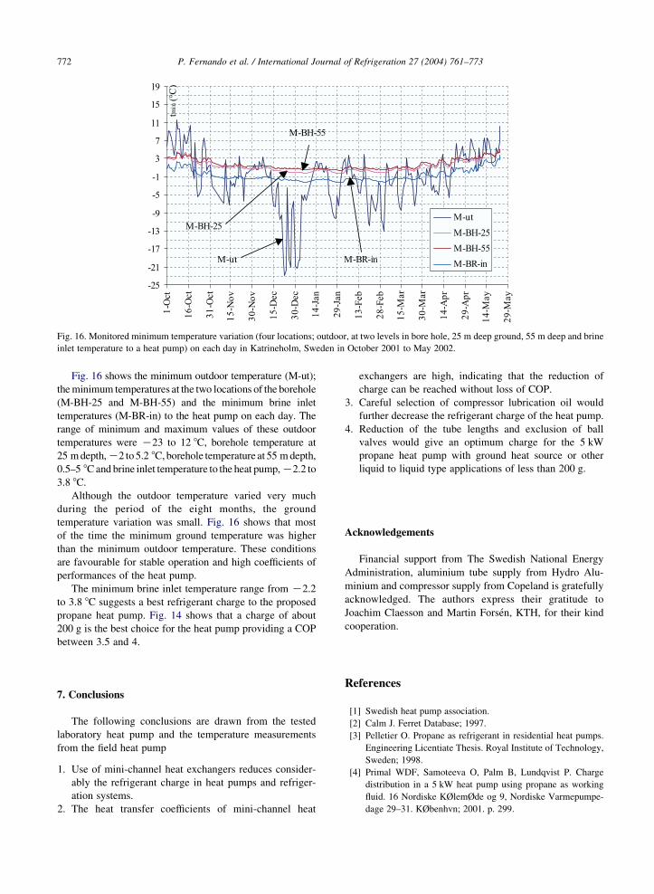
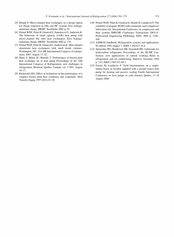
Fig. 16. Monitored minimum temperature variation (four locations; outdoor, at two levels in bore hole, 25 m deep ground, 55 m deep and brine
inlet temperature to a heat pump) on each day in Katrineholm, Sweden in October 2001 to May 2002.
P. Fernando et al. / International Journal of Refrigeration 27 (2004) 761–773772
Fig. 16 shows the minimum outdoor temperature (M-ut);
the minimum temperatures at the two locations of the borehole
(M-BH-25 and M-BH-55) and the minimum brine inlet
temperatures (M-BR-in) to the heat pump on each day. The
range of minimum and maximum values of these outdoor
temperatures were K23 to 12 8C, borehole temperature at
25 m depth,K2 to 5.2 8C, borehole temperature at 55 m depth,
0.5–5 8C and brine inlet temperature to the heat pump,K2.2 to
3.8 8C.
Although the outdoor temperature varied very much
during the period of the eight months, the ground
temperature variation was small. Fig. 16 shows that most
of the time the minimum ground temperature was higher
than the minimum outdoor temperature. These conditions
are favourable for stable operation and high coefficients of
performances of the heat pump.
The minimum brine inlet temperature range from K2.2
to 3.8 8C suggests a best refrigerant charge to the proposed
propane heat pump. Fig. 14 shows that a charge of about
200 g is the best choice for the heat pump providing a COP
between 3.5 and 4.
7. Conclusions
The following conclusions are drawn from the tested
laboratory heat pump and the temperature measurements
from the field heat pump
1.
Use of mini-channel heat exchangers reduces consider-ably the refrigerant charge in heat pumps and refriger-
ation systems.
2.
The heat transfer coefficients of mini-channel heatexchangers are high, indicating that the reduction of
charge can be reached without loss of COP.
3.
Careful selection of compressor lubrication oil wouldfurther decrease the refrigerant charge of the heat pump.
4.
Reduction of the tube lengths and exclusion of ballvalves would give an optimum charge for the 5 kW
propane heat pump with ground heat source or other
liquid to liquid type applications of less than 200 g.
Acknowledgements
Financial support from The Swedish National Energy
Administration, aluminium tube supply from Hydro Alu-
minium and compressor supply from Copeland is gratefully
acknowledged. The authors express their gratitude to
Joachim Claesson and Martin Forsen, KTH, for their kind
cooperation.
References
[1] Swedish heat pump association.
[2] Calm J. Ferret Database; 1997.
[3] Pelletier O. Propane as refrigerant in residential heat pumps.
Engineering Licentiate Thesis. Royal Institute of Technology,
Sweden; 1998.
[4] Primal WDF, Samoteeva O, Palm B, Lundqvist P. Charge
distribution in a 5 kW heat pump using propane as working
fluid. 16 Nordiske KØlemØde og 9, Nordiske Varmepumpe-
dage 29–31. KØbenhvn; 2001. p. 299.
P. Fernando et al. / International Journal of Refrigeration 27 (2004) 761–773 773
[5] Hrnjak P. Micro-channel heat exchangers as a design option
for charge reduction in NH3 and HC systems Zero leakage-
minimum charge, IIR/IIF, Stockholm 2002 p. 91.
[6] Primal WDF, Palm B, Granryd E, Samoteeva O, Anderson K.
The behaviour of small capacity (5 kW) heat pump with
micro-channel flat tube heat exchangers Zero leakage-
minimum charge, IIR/IIF, Stockholm 2002 p. 179.
[7] Primal WDF, Palm B, Granryd E, Andersson K. Mini-channel
aluminium heat exchangers with small inside volumes.
Washington, DC: 21st IIR International Congress of refriger-
ation; 2003. August 17–22.
[8] Dutto T, Blaise JC, Benedic T. Performance of brazed plate
heat exchanger set in heat pump Proceedings of the 18th
International Congress of Refrigeration, new challenges in
refrigeration, Montreal, Quebec, Canada, vol. 3 1991. August
10–17.
[9] Kedzierski MA. Effect of inclination on the performance of a
compact brazed plate heat condenser and evaporator. Heat
Transfer Engng 1997;18(3):25–38.
[10] Primal WDF, Palm B, Granryd E, Houde H, Lundqvist P. The
solubility of propane (R290) with commonly used compressor
lubrication oils. International Conference on compressors and
their systems IMECHE Conference Transactions 2003–4.:
Professional Engineering Publishing, ISSN; 2004 p. 1356–
448.
[11] ASHRAE handbook. Refrigeration systems and applications,
SI edition 1994 chapter 7; ISBN 1 883413 16 8.
[12] Spauschus HO, Henderson DR, Grasshoff HD. Lubricants for
hydrocarbon refrigerants Proceedings of the IIF-IIR Con-
ference, new applications of natural working fluids in
refrigeration and air conditioning, Hanover, Germany 1994
p. 153; ISBN 2 903 633 68 1.
[13] Forsen M, Lundqvist P. Field measurements on a single-
family house in Sweden supplied with a ground source heat
pump for heating and passive cooling Fourth International
Conference on heat pumps in cold climates Quebec 17–18
August 2000.