projectile catcher accesory - conatex.com
TRANSCRIPT
012-05091E04/00
© 1993 PASCO scientific $10.00
Instruction Manual and
Experiments Guide for
PASCO scientific
Model ME-6815
PROJECTILE CATCHER
ACCESSORY
ME-6815
PROJECTILE CATCHER
ACCESSORY
Instruction Manual andExperiment Guide forthe PASCO scientificModel ME-6815
PROJECTILE CATCHERACCESSORY
IncludesTeacher's Notes
andTypical
Experiment Results

The exclamation point within an equilateral triangle isintended to alter the user of the presence of importantoperating and maintenance (servicing) instructions inthe literature accompanying the appratus.
Projectile Catcher Accessory 012-05091E
ii
Table of Contents
Section Page
Copyright, Warranty, and Equipment Return .................................................... iii
Introduction ........................................................................................................ 1
Equipment .......................................................................................................... 1
Projectile Launcher Setup .................................................................................. 2
Ball Catcher Setup ............................................................................................. 3
Experiments
Experiment 1: Ballistic Pendulum ........................................................ 5
Experiment 2: Conservation of Momentumin an Inelastic Collision ............................................... 11
Demonstration: Inelastic/Elastic Collisions Demonstration ................. 15
Teacher's Guide ............................................................................................... 19
Technical Support ................................................................... Inside Back Cover
012-05091E Projectile Catcher Accessory
iii
Copyright Notice
The PASCO scientific ME-6815 Projectile CatcherAccessory manual is copyrighted and all rightsreserved. However, permission is granted to non-profit educational institutions for reproduction of anypart of the manual providing the reproductions areused only for their laboratories and are not sold forprofit. Reproduction under any other circumstances,without the written consent of PASCO scientific, isprohibited.
Limited Warranty
PASCO scientific warrants the product to be free fromdefects in materials and workmanship for a period of oneyear from the date of shipment to the customer. PASCOwill repair or replace at its option any part of the productwhich is deemed to be defective in material or workman-ship. The warranty does not cover damage to the productcaused by abuse or improper use. Determination ofwhether a product failure is the result of a manufacturingdefect or improper use by the customer shall be madesolely by PASCO scientific. Responsibility for the returnof equipment for warranty repair belongs to the customer.Equipment must be properly packed to prevent damageand shipped postage or freight prepaid. (Damage causedby improper packing of the equipment for return shipmentwill not be covered by the warranty.) Shipping costs forreturning the equipment after repair will be paid byPASCO scientific.
Copyright, Warranty, and Equipment Return
Please—Feel free to duplicate this manualsubject to the copyright restrictions below.
Equipment Return
Should the product have to be returned to PASCOscientific for any reason, notify PASCO scientific byletter, phone, or fax BEFORE returning the product. Uponnotification, the return authorization and shipping instruc-tions will be promptly issued.
➤ ➤ ➤ ➤ ➤ NOTE: NO EQUIPMENT WILL BEACCEPTED FOR RETURN WITHOUT ANAUTHORIZATION FROM PASCO.
When returning equipment for repair, the units must bepacked properly. Carriers will not accept responsibility fordamage caused by improper packing. To be certain theunit will not be damaged in shipment, observe the follow-ing rules:
➀ The packing carton must be strong enough for the itemshipped.
➁ Make certain there are at least two inches of packingmaterial between any point on the apparatus and theinside walls of the carton.
➂ Make certain that the packing material cannot shift inthe box or become compressed, allowing theinstrument come in contact with the packing carton.
Address: PASCO scientific
10101 Foothills Blvd.
Roseville, CA 95747-7100
Phone: 1-800-772-8700 (toll-free within U.S.)or
(916) 786-3800
FAX: (916) 786-3292
email: [email protected]
web: www.pasco.com
012-05091E Projectile Catcher Accessory
1
Introduction
Equipment
ME-6815
PROJECTILE CATCHER
ACCESSORY
steel balls(2)
support plate
slots forphotogate
timing
ball catcher
rod clamp
support rod(not included)
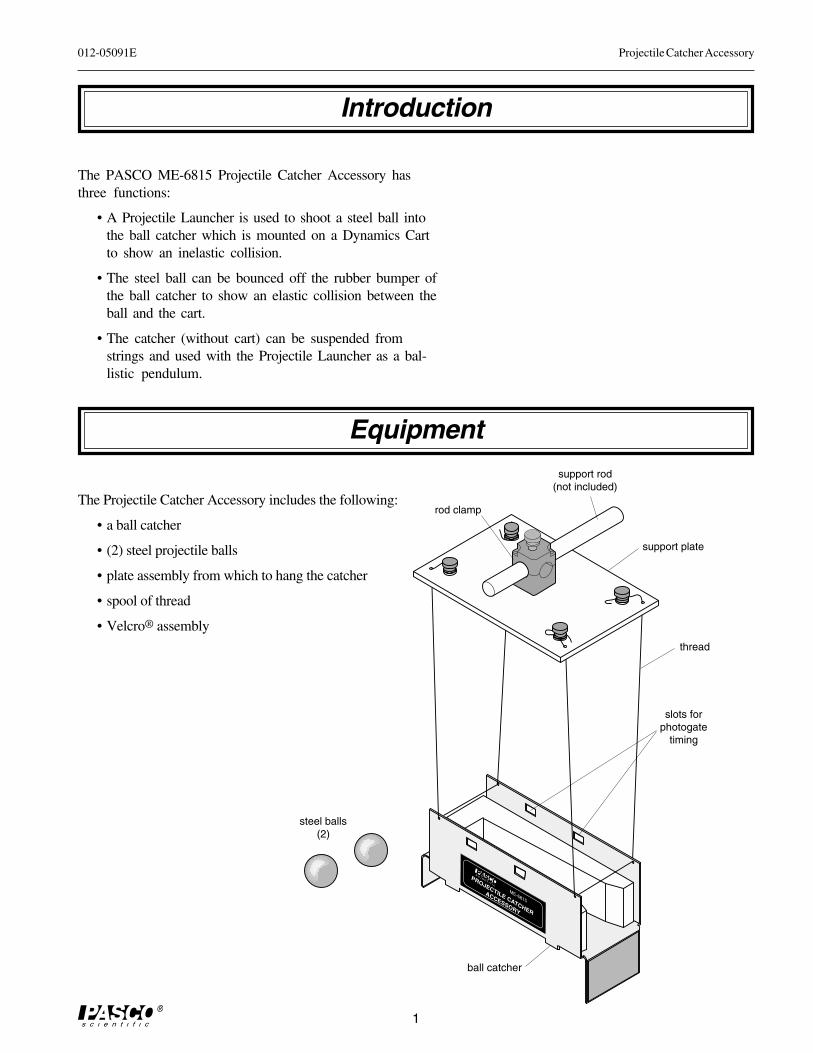
The PASCO ME-6815 Projectile Catcher Accessory hasthree functions:
• A Projectile Launcher is used to shoot a steel ball intothe ball catcher which is mounted on a Dynamics Cartto show an inelastic collision.
• The steel ball can be bounced off the rubber bumper ofthe ball catcher to show an elastic collision between theball and the cart.
• The catcher (without cart) can be suspended fromstrings and used with the Projectile Launcher as a bal-listic pendulum.
The Projectile Catcher Accessory includes the following:
• a ball catcher
• (2) steel projectile balls
• plate assembly from which to hang the catcher
• spool of thread
• Velcro® assemblythread
Projectile Catcher Accessory 012-05091E
2
Projectile Launcher Setup
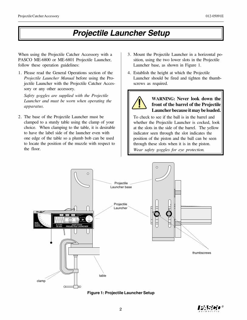
When using the Projectile Catcher Accessory with aPASCO ME-6800 or ME-6801 Projectile Launcher,follow these operation guidelines:
1. Please read the General Operations section of theProjectile Launcher Manual before using the Pro-jectile Launcher with the Projectile Catcher Acces-sory or any other accessory.
Safety goggles are supplied with the ProjectileLauncher and must be worn when operating theapparatus.
2. The base of the Projectile Launcher must beclamped to a sturdy table using the clamp of yourchoice. When clamping to the table, it is desirableto have the label side of the launcher even withone edge of the table so a plumb bob can be usedto locate the position of the muzzle with respect tothe floor.
����������������� ��������
����������������� ��������
��������
��������
� ����
�������
���������
���������
� ��������
��������������
������
������������� �������� ������ !!
"#���$���%�� ��%�$��%����#����&#'
����
��
��
��
��
��
� � �
���(�)��"*��((�( +�����(�'
��#,-..
/�� �� ���"�
ProjectileLauncher base
ProjectileLauncher
thumbscrews
clamp
table
3. Mount the Projectile Launcher in a horizontal po-sition, using the two lower slots in the ProjectileLauncher base, as shown in Figure 1.
4. Establish the height at which the ProjectileLauncher should be fired and tighten the thumb-screws as required.
WARNING: Never look down thefront of the barrel of the ProjectileLauncher because it may be loaded.
To check to see if the ball is in the barrel andwhether the Projectile Launcher is cocked, lookat the slots in the side of the barrel. The yellowindicator seen through the slot indicates theposition of the piston and the ball can be seenthrough these slots when it is in the piston.Wear safety goggles for eye protection.
Figure 1: Projectile Launcher Setup
012-05091E Projectile Catcher Accessory
3
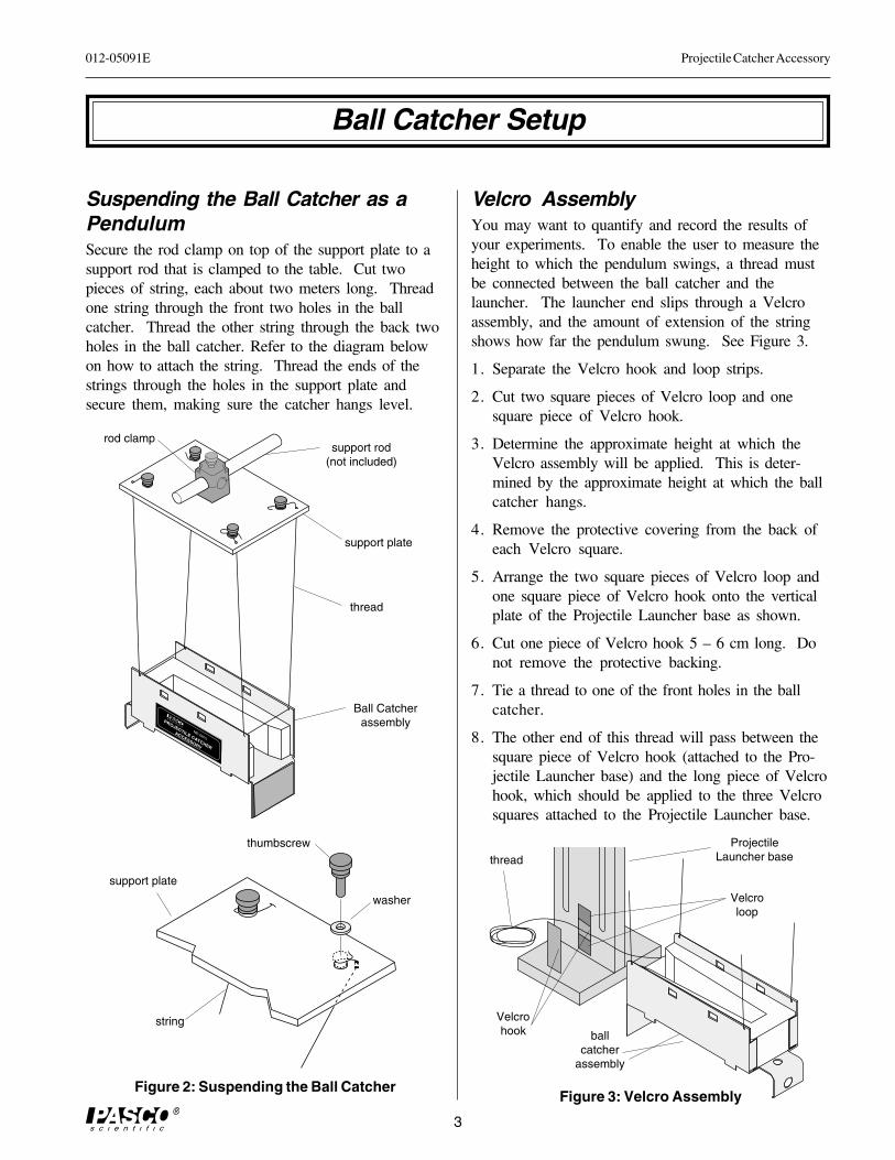
Suspending the Ball Catcher as aPendulumSecure the rod clamp on top of the support plate to asupport rod that is clamped to the table. Cut twopieces of string, each about two meters long. Threadone string through the front two holes in the ballcatcher. Thread the other string through the back twoholes in the ball catcher. Refer to the diagram belowon how to attach the string. Thread the ends of thestrings through the holes in the support plate andsecure them, making sure the catcher hangs level.
Velcro AssemblyYou may want to quantify and record the results ofyour experiments. To enable the user to measure theheight to which the pendulum swings, a thread mustbe connected between the ball catcher and thelauncher. The launcher end slips through a Velcroassembly, and the amount of extension of the stringshows how far the pendulum swung. See Figure 3.
1. Separate the Velcro hook and loop strips.
2. Cut two square pieces of Velcro loop and onesquare piece of Velcro hook.
3. Determine the approximate height at which theVelcro assembly will be applied. This is deter-mined by the approximate height at which the ballcatcher hangs.
4. Remove the protective covering from the back ofeach Velcro square.
5. Arrange the two square pieces of Velcro loop andone square piece of Velcro hook onto the verticalplate of the Projectile Launcher base as shown.
6. Cut one piece of Velcro hook 5 – 6 cm long. Donot remove the protective backing.
7. Tie a thread to one of the front holes in the ballcatcher.
8. The other end of this thread will pass between thesquare piece of Velcro hook (attached to the Pro-jectile Launcher base) and the long piece of Velcrohook, which should be applied to the three Velcrosquares attached to the Projectile Launcher base.
Ball Catcher Setup
Figure 2: Suspending the Ball Catcher
Velcrohook
thread
ProjectileLauncher base
Velcroloop
ballcatcher
assembly
washer
thumbscrew
string
support plate
Ball Catcherassembly
thread
ME-6815
PROJECTILE CATCHER
ACCESSORY
support plate
support rod(not included)
rod clamp
Figure 3: Velcro Assembly
Projectile Catcher Accessory 012-05091E
4
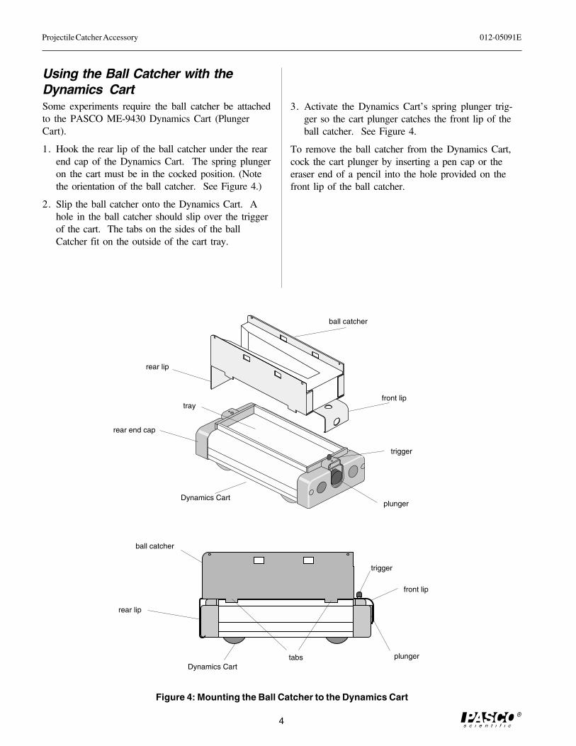
Using the Ball Catcher with theDynamics CartSome experiments require the ball catcher be attachedto the PASCO ME-9430 Dynamics Cart (PlungerCart).
1. Hook the rear lip of the ball catcher under the rearend cap of the Dynamics Cart. The spring plungeron the cart must be in the cocked position. (Notethe orientation of the ball catcher. See Figure 4.)
2. Slip the ball catcher onto the Dynamics Cart. Ahole in the ball catcher should slip over the triggerof the cart. The tabs on the sides of the ballCatcher fit on the outside of the cart tray.
rear lip
ball catcher
plunger
trigger
front lip
Dynamics Carttabs
3. Activate the Dynamics Cart’s spring plunger trig-ger so the cart plunger catches the front lip of theball catcher. See Figure 4.
To remove the ball catcher from the Dynamics Cart,cock the cart plunger by inserting a pen cap or theeraser end of a pencil into the hole provided on thefront lip of the ball catcher.
rear end cap
front lip
ball catcher
rear lip
Dynamics Cartplunger
trigger
tray
Figure 4: Mounting the Ball Catcher to the Dynamics Cart
012-05091E Projectile Catcher Accessory
5
Exp 1: Ballistic Pendulum
EQUIPMENT NEEDED– Projectile Launcher (ME-6800) -meter stick– Projectile Catcher Accessory (ME-6815) -white paper
[Velcro must be assembled (See Figure 3)] -carbon paper– Base and Support Rod (ME-9355) -mass balance– table clamp
Optional: Photogates and Photogate Bracket
Purpose
The muzzle velocity of the Projectile Launcher can be determined by shooting the ball intoa ballistic pendulum and then measuring the height reached by the pendulum.
Theory
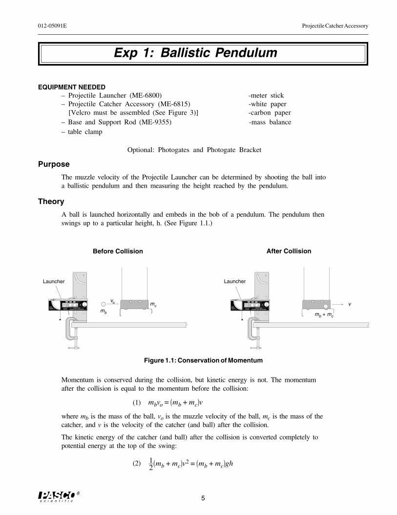
A ball is launched horizontally and embeds in the bob of a pendulum. The pendulum thenswings up to a particular height, h. (See Figure 1.1.)
Momentum is conserved during the collision, but kinetic energy is not. The momentumafter the collision is equal to the momentum before the collision:
(1) mbvo = mb + mc v
where mb is the mass of the ball, vo is the muzzle velocity of the ball, mc is the mass of thecatcher, and v is the velocity of the catcher (and ball) after the collision.
The kinetic energy of the catcher (and ball) after the collision is converted completely topotential energy at the top of the swing:
(2) 12
mb + mc v2 = mb + mc gh
����������������� ��������
����������������� ��������
��������
��������
� ����
�������
���������
���������
� ��������
��������������
������
������������� �������� ������ !!
"#���$���%�� ��%�$��%����#����&#'
����
��
��
��
��
��
� � �
���(�)��"*��((�( +�����(�'
��#,-..
/�� �� ���"�v
mb + mc
Launcher
����������������� ��������
����������������� ��������
��������
��������
� ����
�������
���������
���������
� ��������
��������������
������
������������� �������� ������ !!
"#���$���%�� ��%�$��%����#����&#'
����
��
��
��
��
��
� � �
���(�)��"*��((�( +�����(�'
��#,-..
/�� �� ���"�
vo
mb
mc
Launcher
Before Collision After Collision
Figure 1.1: Conservation of Momentum
Projectile Catcher Accessory 012-05091E
6
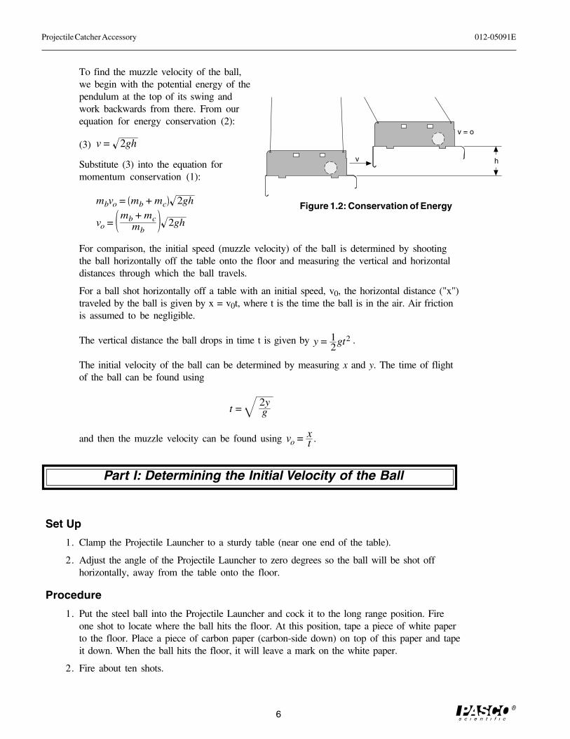
To find the muzzle velocity of the ball,we begin with the potential energy of thependulum at the top of its swing andwork backwards from there. From ourequation for energy conservation (2):
(3) v = 2gh
Substitute (3) into the equation formomentum conservation (1):
mbvo = mb + mc 2gh
vo =mb + mc
mb2gh
For comparison, the initial speed (muzzle velocity) of the ball is determined by shootingthe ball horizontally off the table onto the floor and measuring the vertical and horizontaldistances through which the ball travels.
For a ball shot horizontally off a table with an initial speed, v0, the horizontal distance ("x")traveled by the ball is given by x = v0t, where t is the time the ball is in the air. Air frictionis assumed to be negligible.
The vertical distance the ball drops in time t is given by y = 12
gt2 .
The initial velocity of the ball can be determined by measuring x and y. The time of flightof the ball can be found using
t =2yg
and then the muzzle velocity can be found using vo = xt .
Part I: Determining the Initial Velocity of the Ball
Set Up
1. Clamp the Projectile Launcher to a sturdy table (near one end of the table).
2. Adjust the angle of the Projectile Launcher to zero degrees so the ball will be shot offhorizontally, away from the table onto the floor.
Procedure
1. Put the steel ball into the Projectile Launcher and cock it to the long range position. Fireone shot to locate where the ball hits the floor. At this position, tape a piece of white paperto the floor. Place a piece of carbon paper (carbon-side down) on top of this paper and tapeit down. When the ball hits the floor, it will leave a mark on the white paper.
2. Fire about ten shots.
Figure 1.2: Conservation of Energy
v h
v = o
012-05091E Projectile Catcher Accessory
7
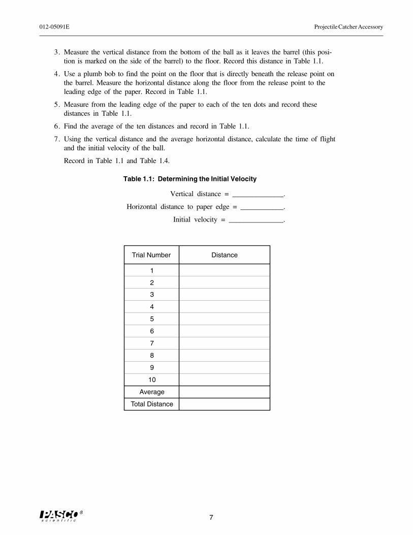
3. Measure the vertical distance from the bottom of the ball as it leaves the barrel (this posi-tion is marked on the side of the barrel) to the floor. Record this distance in Table 1.1.
4. Use a plumb bob to find the point on the floor that is directly beneath the release point onthe barrel. Measure the horizontal distance along the floor from the release point to theleading edge of the paper. Record in Table 1.1.
5. Measure from the leading edge of the paper to each of the ten dots and record thesedistances in Table 1.1.
6. Find the average of the ten distances and record in Table 1.1.
7. Using the vertical distance and the average horizontal distance, calculate the time of flightand the initial velocity of the ball.
Record in Table 1.1 and Table 1.4.
Table 1.1: Determining the Initial Velocity
Vertical distance = ______________.
Horizontal distance to paper edge = ____________.
Initial velocity = _______________.
1
Distance
2
3
4
5
6
7
Trial Number
8
9
10
Average
Total Distance
Projectile Catcher Accessory 012-05091E
8
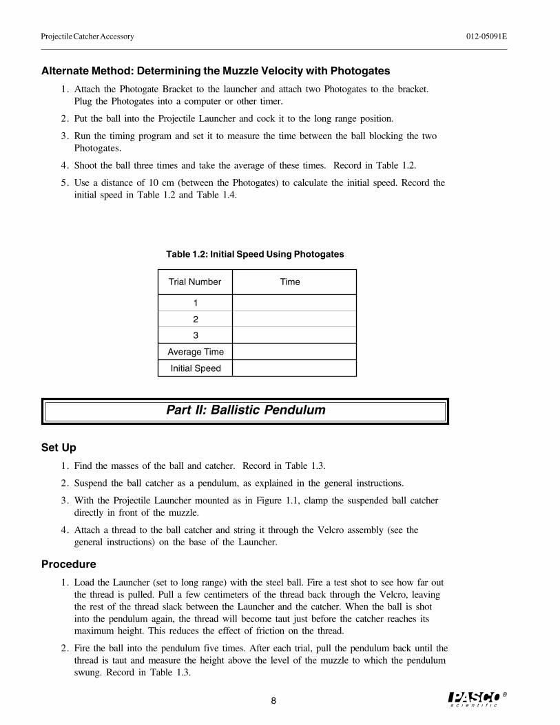
Alternate Method: Determining the Muzzle Velocity with Photogates
1. Attach the Photogate Bracket to the launcher and attach two Photogates to the bracket.Plug the Photogates into a computer or other timer.
2. Put the ball into the Projectile Launcher and cock it to the long range position.
3. Run the timing program and set it to measure the time between the ball blocking the twoPhotogates.
4. Shoot the ball three times and take the average of these times. Record in Table 1.2.
5. Use a distance of 10 cm (between the Photogates) to calculate the initial speed. Record theinitial speed in Table 1.2 and Table 1.4.
1
Time
2
3
Trial Number
Average Time
Initial Speed
Table 1.2: Initial Speed Using Photogates
Part II: Ballistic Pendulum
Set Up
1. Find the masses of the ball and catcher. Record in Table 1.3.
2. Suspend the ball catcher as a pendulum, as explained in the general instructions.
3. With the Projectile Launcher mounted as in Figure 1.1, clamp the suspended ball catcherdirectly in front of the muzzle.
4. Attach a thread to the ball catcher and string it through the Velcro assembly (see thegeneral instructions) on the base of the Launcher.
Procedure
1. Load the Launcher (set to long range) with the steel ball. Fire a test shot to see how far outthe thread is pulled. Pull a few centimeters of the thread back through the Velcro, leavingthe rest of the thread slack between the Launcher and the catcher. When the ball is shotinto the pendulum again, the thread will become taut just before the catcher reaches itsmaximum height. This reduces the effect of friction on the thread.
2. Fire the ball into the pendulum five times. After each trial, pull the pendulum back until thethread is taut and measure the height above the level of the muzzle to which the pendulumswung. Record in Table 1.3.
012-05091E Projectile Catcher Accessory
9
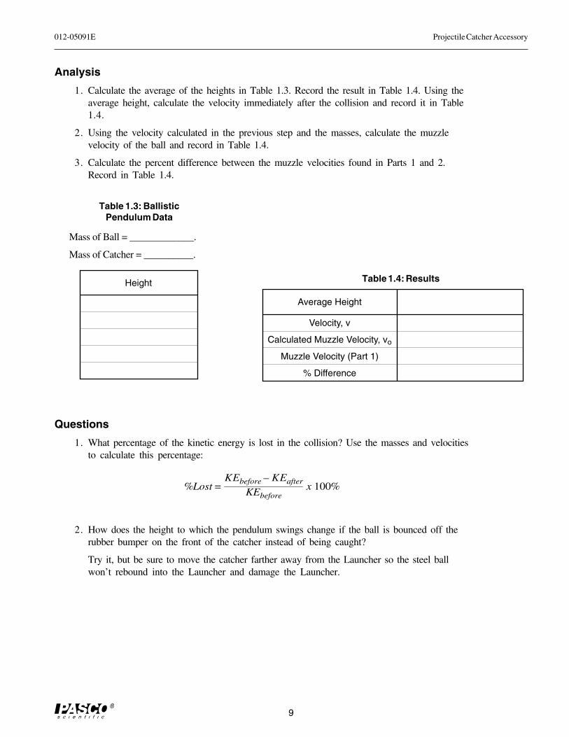
Analysis
1. Calculate the average of the heights in Table 1.3. Record the result in Table 1.4. Using theaverage height, calculate the velocity immediately after the collision and record it in Table1.4.
2. Using the velocity calculated in the previous step and the masses, calculate the muzzlevelocity of the ball and record in Table 1.4.
3. Calculate the percent difference between the muzzle velocities found in Parts 1 and 2.Record in Table 1.4.
Table 1.3: BallisticPendulum Data
Mass of Ball = _____________.
Mass of Catcher = __________.
Height
Average Height
Velocity, v
Calculated Muzzle Velocity, vo
Muzzle Velocity (Part 1)
% Difference
Table 1.4: Results
Questions
1. What percentage of the kinetic energy is lost in the collision? Use the masses and velocitiesto calculate this percentage:
%Lost =KEbefore – KEafter
KEbeforex 100%
2. How does the height to which the pendulum swings change if the ball is bounced off therubber bumper on the front of the catcher instead of being caught?
Try it, but be sure to move the catcher farther away from the Launcher so the steel ballwon’t rebound into the Launcher and damage the Launcher.

Projectile Catcher Accessory 012-05091E
10
012-05091E Projectile Catcher Accessory
11
Exp. 2: Conservation of Momentum in an Inelastic Collision
EQUIPMENT NEEDED
– Projectile Launcher (ME-6800)– Projectile Catcher Accessory (ME-6815)– computer photogate timing system (such as Series 6500, or Science Workshop™)– timing program*– (3) Photogates (ME-9498)– Photogate Bracket for Launcher (ME-6821)– Dynamics Track (ME-9435A)– Dynamics Cart (ME-9430)– Photogate Bracket for Dynamics Track
➤ NOTE: For timing systems with only two photogate capacity, use the PASCO Four-to-One Adaptor (CI-6820) to accommodate 3 photogates, and use the "MotionTimer" data collection choice.*Precision Timer, IDS Timer, Smart Pulley Timer, DataStudioTM or ScienceWorkshop®.
Purpose
The purpose of this experiment is to show that during an inelastic collision, momen-tum is conserved and energy is not conserved.
Theory
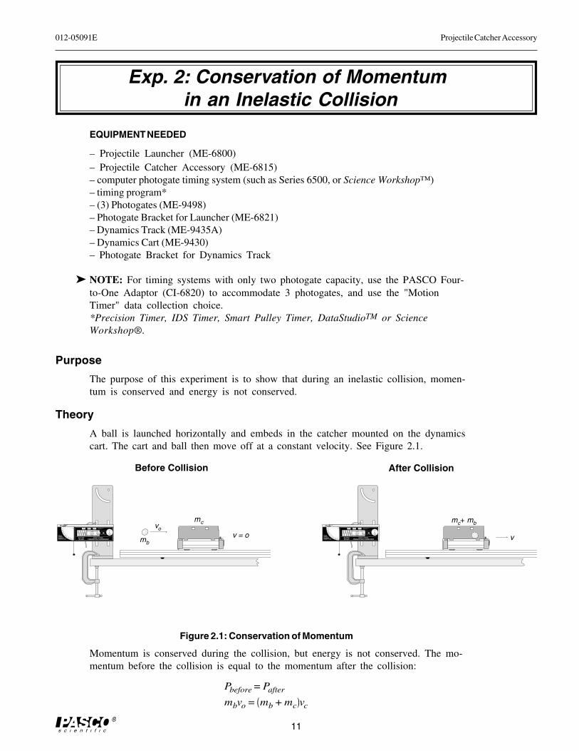
A ball is launched horizontally and embeds in the catcher mounted on the dynamicscart. The cart and ball then move off at a constant velocity. See Figure 2.1.
����������������� ��������
����������������� ��������
��������
��������
� ����
�������
���������
���������
� ��������
��������������
������
������������� �������� ������ !!
"#���$���%�� ��%�$��%����#����&#'
����
��
��
��
��
��
� � �
���(�)��"*��((�( +�����(�'
��#,-..
/�� �� ���"�
����������������� ��������
����������������� ��������
��������
��������
� ����
�������
���������
���������
� ��������
��������������
������
������������� �������� ������ !!
"#���$���%�� ��%�$��%����#����&#'
����
��
��
��
��
��
� � �
���(�)��"*��((�( +�����(�'
��#,-..
/�� �� ���"�
Before Collision
mb
vo
mc
v = o
mc+ mb
v
After Collision
Figure 2.1: Conservation of Momentum
Momentum is conserved during the collision, but energy is not conserved. The mo-mentum before the collision is equal to the momentum after the collision:
Pbefore = Pafter
mbvo = mb + mc vc
Projectile Catcher Accessory 012-05091E
12
where mb is the mass of the ball, vo is the muzzle velocity of the ball, mc is the mass ofthe catcher and cart, and v is the velocity of the cart and ball immediately after thecollision.
The initial speed (muzzle velocity) of the ball is determined using two photogatesmounted on the Launcher, and the final speed of the cart is found using a photogatemounted on the track.
Setup
1. Clamp the Projectile Launcher to a sturdy table (near one end of the table with the muzzleend facing inward toward the table).
2. Attach the photogate bracket to the Launcher, and attach two photogates to the bracket.Plug the photogates into the computer photogate timing system (or the Four-to-OneAdapter). The photogate nearest the muzzle has to be plugged into port number one sincethe ball will go through it first.
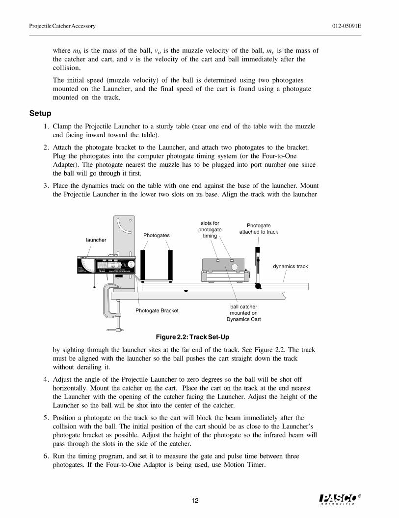
3. Place the dynamics track on the table with one end against the base of the launcher. Mountthe Projectile Launcher in the lower two slots on its base. Align the track with the launcher
by sighting through the launcher sites at the far end of the track. See Figure 2.2. The trackmust be aligned with the launcher so the ball pushes the cart straight down the trackwithout derailing it.
4. Adjust the angle of the Projectile Launcher to zero degrees so the ball will be shot offhorizontally. Mount the catcher on the cart. Place the cart on the track at the end nearestthe Launcher with the opening of the catcher facing the Launcher. Adjust the height of theLauncher so the ball will be shot into the center of the catcher.
5. Position a photogate on the track so the cart will block the beam immediately after thecollision with the ball. The initial position of the cart should be as close to the Launcher’sphotogate bracket as possible. Adjust the height of the photogate so the infrared beam willpass through the slots in the side of the catcher.
6. Run the timing program, and set it to measure the gate and pulse time between threephotogates. If the Four-to-One Adaptor is being used, use Motion Timer.
����������������� ��������
����������������� ��������
��������
��������
� ����
�������
���������
���������
� ��������
��������������
������
������������� �������� ������ !!
"#���$���%�� ��%�$��%����#����&#'
����
��
��
��
��
��
� � �
���(�)��"*��((�( +�����(�'
��#,-..
/�� �� ���"�
Figure 2.2: Track Set-Up
launcher
dynamics track
Photogates
Photogateattached to track
ball catchermounted on
Dynamics Cart
slots forphotogate
timing
Photogate Bracket
012-05091E Projectile Catcher Accessory
13
Procedure
1. Find the mass of the steel ball and the mass of the cart with catcher. Record in Table 2.3.
2. Put the ball into the Projectile Launcher and cock it to the long range position. Put the carton the track directly in front of and as close as possible to the photogate bracket on theLauncher.
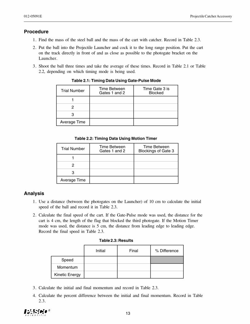
3. Shoot the ball three times and take the average of these times. Record in Table 2.1 or Table2.2, depending on which timing mode is being used.
Analysis
1. Use a distance (between the photogates on the Launcher) of 10 cm to calculate the initialspeed of the ball and record it in Table 2.3.
2. Calculate the final speed of the cart. If the Gate-Pulse mode was used, the distance for thecart is 4 cm, the length of the flag that blocked the third photogate. If the Motion Timermode was used, the distance is 5 cm, the distance from leading edge to leading edge.Record the final speed in Table 2.3.
3. Calculate the initial and final momentum and record in Table 2.3.
4. Calculate the percent difference between the initial and final momentum. Record in Table2.3.
Trial Number
1
2
3
Average Time
Time Between Gates 1 and 2
Time Gate 3 is Blocked
Table 2.1: Timing Data Using Gate-Pulse Mode
Table 2.3: Results
Trial Number
1
2
3
Average Time
Time Between Gates 1 and 2
Time Between Blockings of Gate 3
Table 2.2: Timing Data Using Motion Timer
Initial
Speed
Momentum
Kinetic Energy
Final % Difference
Projectile Catcher Accessory 012-05091E
14
5. Calculate the initial and final kinetic energy. Record in Table 2.3.
6. Calculate the percentage of the initial kinetic energy that is lost during the collision. Recordin Table 2.3.
Questions
1. Was momentum conserved in the inelastic collision?
2. Was kinetic energy conserved in the inelastic collision?
012-05091E Projectile Catcher Accessory
15
����������������� ��������
����������������� ��������
��������
��������
� ����
�������
���������
���������
� ��������
��������������
������
������������� �������� ������ !!
"#���$���%�� ��%�$��%����#����&#'
����
��
��
��
��
��
� � �
���(�)��"*��((�( +�����(�'
��#,-..
/�� �� ���"�
DEMONSTRATION: Inelastic/Elastic Collisions
mc + mb
EQUIPMENT NEEDED
– Projectile Launcher (ME-6800)– Projectile Catcher Accessory (ME-6815)– Dynamics Track (ME-9435A)– Dynamics Cart (ME-9430)
Purpose
The purpose of this demonstration is to show that the final cart speed during an elasticcollision between the steel ball and the cart is twice the final cart speed of that duringan inelastic collision between the steel ball and the cart.
Theory
Inelastic Collision
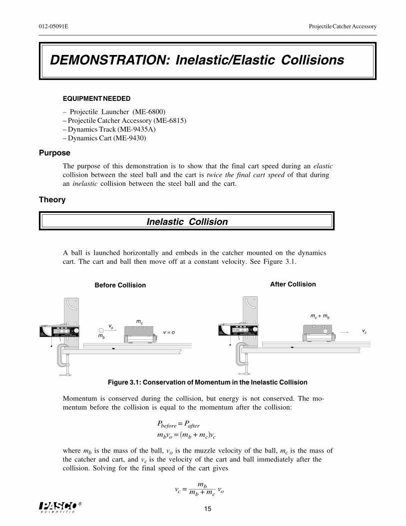
A ball is launched horizontally and embeds in the catcher mounted on the dynamicscart. The cart and ball then move off at a constant velocity. See Figure 3.1.
����������������� ��������
����������������� ��������
��������
��������
� ����
�������
���������
���������
� ��������
��������������
������
������������� �������� ������ !!
"#���$���%�� ��%�$��%����#����&#'
����
��
��
��
��
��
� � �
���(�)��"*��((�( +�����(�'
��#,-..
/�� �� ���"�
Before Collision
Figure 3.1: Conservation of Momentum in the Inelastic Collision
mb
vo
mc
v = o vc
After Collision
Momentum is conserved during the collision, but energy is not conserved. The mo-mentum before the collision is equal to the momentum after the collision:
Pbefore = Pafter
mbvo = mb + mc vc
where mb is the mass of the ball, vo is the muzzle velocity of the ball, mc is the mass ofthe catcher and cart, and vc is the velocity of the cart and ball immediately after thecollision. Solving for the final speed of the cart gives
vc =mb
mb + mcvo
Projectile Catcher Accessory 012-05091E
16
Elastic Collision
����������������� ��������
����������������� ��������
��������
��������
� ����
�������
���������
���������
� ��������
��������������
������
������������� �������� ������ !!
"#���$���%�� ��%�$��%����#����&#'
����
��
��
��
��
��
� � �
���(�)��"*��((�( +�����(�'
��#,-..
/�� �� ���"�
����������������� ��������
����������������� ��������
��������
��������
� ����
�������
���������
���������
� ��������
��������������
������
������������� �������� ������ !!
"#���$���%�� ��%�$��%����#����&#'
����
��
��
��
��
��
� � �
���(�)��"*��((�( +�����(�'
��#,-..
/�� �� ���"�
Before Collision
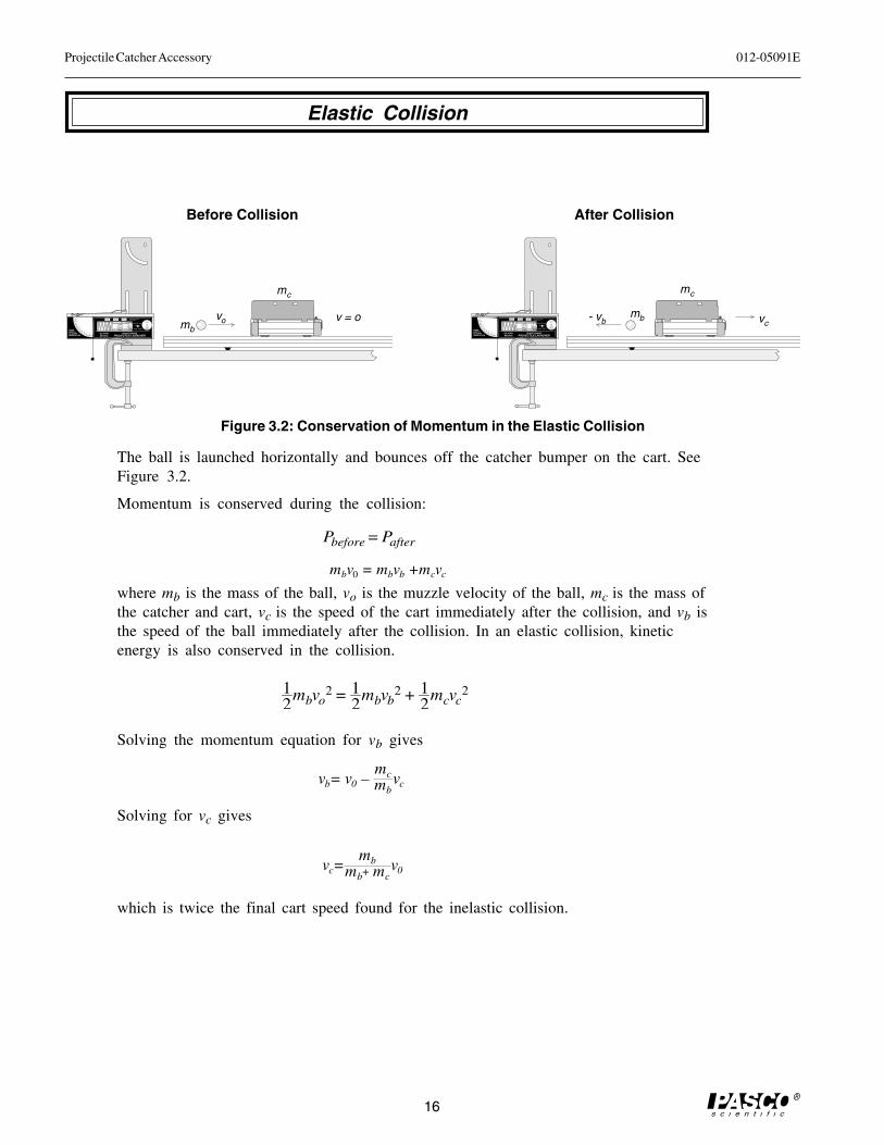
Figure 3.2: Conservation of Momentum in the Elastic Collision
v = o
After Collision
mc
mb
vo vc- vb
mb
mc
The ball is launched horizontally and bounces off the catcher bumper on the cart. SeeFigure 3.2.
Momentum is conserved during the collision:
Pbefore = Pafter
where mb is the mass of the ball, vo is the muzzle velocity of the ball, mc is the mass ofthe catcher and cart, vc is the speed of the cart immediately after the collision, and vb isthe speed of the ball immediately after the collision. In an elastic collision, kineticenergy is also conserved in the collision.
12
mbvo2 = 1
2mbvb
2 + 12
mcvc2
Solving the momentum equation for vb gives
Solving for vc gives
which is twice the final cart speed found for the inelastic collision.
mbv0 = mbvb +mcvc
vc=mb
mb+ mcv0
vb= v0 –mcmb
vc
012-05091E Projectile Catcher Accessory
17
Setup
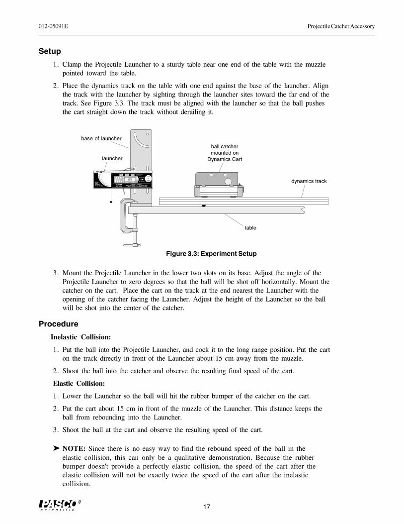
1. Clamp the Projectile Launcher to a sturdy table near one end of the table with the muzzlepointed toward the table.
2. Place the dynamics track on the table with one end against the base of the launcher. Alignthe track with the launcher by sighting through the launcher sites toward the far end of thetrack. See Figure 3.3. The track must be aligned with the launcher so that the ball pushesthe cart straight down the track without derailing it.
3. Mount the Projectile Launcher in the lower two slots on its base. Adjust the angle of theProjectile Launcher to zero degrees so that the ball will be shot off horizontally. Mount thecatcher on the cart. Place the cart on the track at the end nearest the Launcher with theopening of the catcher facing the Launcher. Adjust the height of the Launcher so the ballwill be shot into the center of the catcher.
Procedure
Inelastic Collision:
1. Put the ball into the Projectile Launcher, and cock it to the long range position. Put the carton the track directly in front of the Launcher about 15 cm away from the muzzle.
2. Shoot the ball into the catcher and observe the resulting final speed of the cart.
Elastic Collision:
1. Lower the Launcher so the ball will hit the rubber bumper of the catcher on the cart.
2. Put the cart about 15 cm in front of the muzzle of the Launcher. This distance keeps theball from rebounding into the Launcher.
3. Shoot the ball at the cart and observe the resulting speed of the cart.
➤ NOTE: Since there is no easy way to find the rebound speed of the ball in theelastic collision, this can only be a qualitative demonstration. Because the rubberbumper doesn't provide a perfectly elastic collision, the speed of the cart after theelastic collision will not be exactly twice the speed of the cart after the inelasticcollision.
����������������� ��������
����������������� ��������
��������
��������
� ����
�������
���������
���������
� ��������
��������������
������
������������� �������� ������ !!
"#���$���%�� ��%�$��%����#����&#'
����
��
��
��
��
��
� � �
���(�)��"*��((�( +�����(�'
��#,-..
/�� �� ���"�
launcher
ball catchermounted on
Dynamics Cart
Figure 3.3: Experiment Setup
dynamics track
table
base of launcher

Projectile Catcher Accessory 012-05091E
18
012-05091E Projectile Catcher Accessory
19
Teacher's Guide
Experiment 1: Ballistic Pendulum
Part I
Generally, determining the velocity of the ballby the “horizontal-shot” method is moreaccurate than using the photogate method, butthe photogate method is quicker and easier.
If you use the photogate method, make surethat the photogates are parallel.
If you use the horizontal-shot method, makesure that the gun is perfectly horizontal. Use aspirit level for best results.
Part II
Setup: Ensure that the string is very loose inthe Velcro assembly. There should be justenough friction so that that weight of thestring does not pull the string through.
Procedure: It is helpful to anchor the string inplace with a piece of tape (close to the velcro,on the opposite side from the pendulum) afterfiring but before measuring the height reachedby the pendulum.
Notes on Analysis:
The difference between all measured veloci-ties (by horizontal-shot, photogate, or ballisticpendulum measurement) should be less than 5%.
Answers to Questions:
1. The theoretical loss is:
For our trials, the theoretical loss was 74.25%.The actual loss measured was 76.25%. Theexcess loss is most likely due to energy lost byrotational motion of the pendulum. (The motionof the pendulum is not entirely in the plane of thependulum. There is some twisting, whichrequires energy.)
2. If the collision is perfectly elastic instead ofperfectly inelastic, the height of the pendulum
increases by a factor of 2. It is difficult toexperimentally verify this because the colli-sion is not perfectly elastic.
Experiment 2: Conservation of Momentum in an Inelastic Collision
Notes on Setup:
1. If you are using the 6500 and gate-pulse mode,position the Photogate so that it is blocked by theentire length of the catcher, rather than shiningthrough the slots.
Notes on Procedure:
2. Make sure that the cart is far enough from the thirdphotogate that the ball comes to rest relative to the cartbefore the cart begins to interrupt the photogate. (5cm at least.)
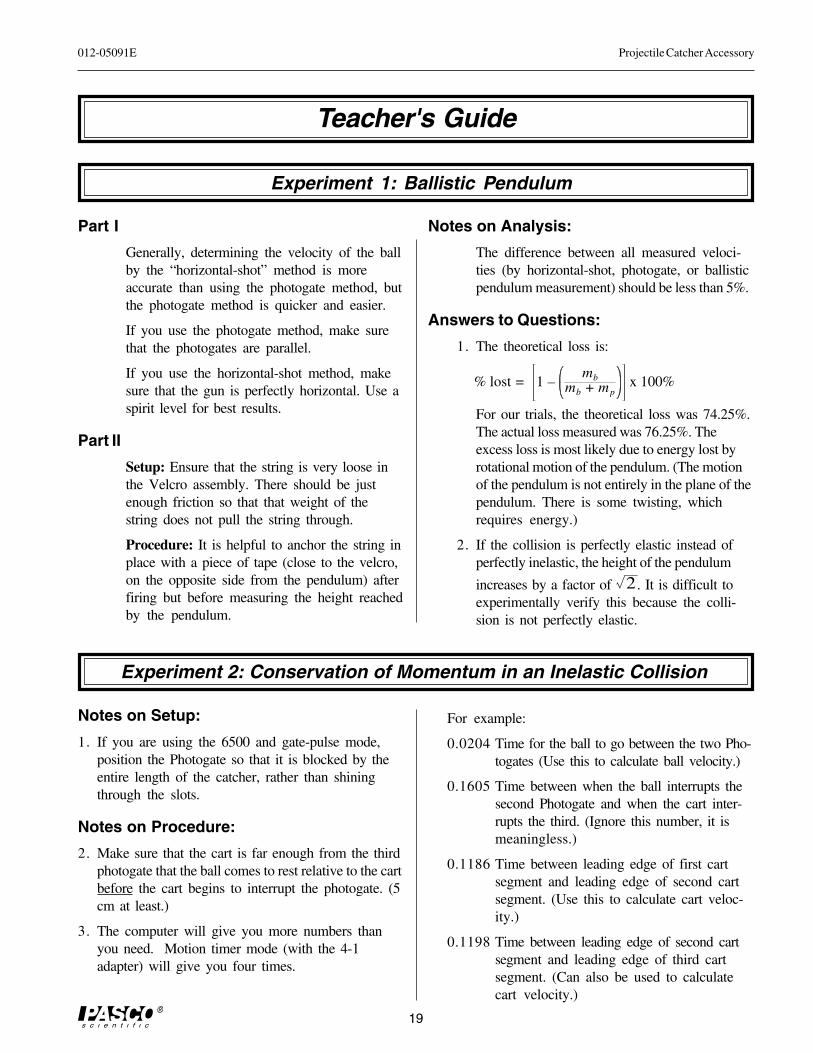
3. The computer will give you more numbers thanyou need. Motion timer mode (with the 4-1adapter) will give you four times.
For example:
0.0204 Time for the ball to go between the two Pho-togates (Use this to calculate ball velocity.)
0.1605 Time between when the ball interrupts thesecond Photogate and when the cart inter-rupts the third. (Ignore this number, it ismeaningless.)
0.1186 Time between leading edge of first cartsegment and leading edge of second cartsegment. (Use this to calculate cart veloc-ity.)
0.1198 Time between leading edge of second cartsegment and leading edge of third cartsegment. (Can also be used to calculatecart velocity.)
% lost = 1 –mb
mb + mpx 100%
Projectile Catcher Accessory 012-05091E
20
In Gate-Pulse mode, the computer will show fivenumbers. They are:
time 1 Duration of first Photogate’s blockage bythe ball
time 2 Time between unblocking first Photogateand blocking second
time 3 Duration of second Photogate’s blockageby the ball
time 4 Time between unblocking secondPhotogate and blocking third with cart
time 5 Duration of third Photogate’s blockage bythe cart.
Add the first two times to find the total time it tookthe ball to travel the 10 cm between Photogates,and use this time to calculate the ball velocity. Ig-nore the third and fourth times given. Use the fifthtime to calculate the cart velocity.
Analysis
2. If you are using the gate-pulse mode rather thanmotion timer, be sure to use the actual length ofwhatever blocked the third Photogate the first timeto calculate cart velocity. In other words, if thephotogate is aligned with the catcher slots, thelength would be 4 cm; but if the photogate is notaligned with these slots, then use the entire lengthof the catcher.
4,8. The initial and final momentum should be within10% of each other. They will not be exact be-cause of inaccuracy in measuring velocity andbecause of frictional losses to the cart track.
5,6. The theoretical loss of kinetic energy is
Actual loss will be slightly greater than this, due tofriction between the cart and track.
Answers to Questions
1. Momentum is conserved, within the limits of mea-surement for this experiment.
2. Kinetic energy is not conserved.
% lost = 1 –mb
mb + mpx 100%
012-05091E Projectile Catcher Accessory
21
Technical Support
Contacting Technical Support
Before you call the PASCO Technical Support staff, itwould be helpful to prepare the following informa-tion:
• If your problem is computer/software related, note:
Title and Revision Date of software
Type of Computer (Make, Model, Speed)
Type of external Cables/Peripherals
• If your problem is with the PASCO apparatus, note:
Title and Model number (usually listed on the label)
Approximate age of apparatus
A detailed description of the problem/sequence ofevents. (In case you can't call PASCO right away,you won't lose valuable data.)
If possible, have the apparatus within reach whencalling. This makes descriptions of individual partsmuch easier.
• If your problem relates to the instruction manual,note:
Part number and Revision (listed by month and yearon the front cover)
Have the manual at hand to discuss your questions.
Feed-Back
If you have any comments about this product or thismanual, please let us know. If you have any sugges-tions on alternate experiments or find a problem in themanual, please tell us. PASCO appreciates anycustomer feed-back. Your input helps us evaluate andimprove our product.
To Reach PASCO
For Technical Support, call us at 1-800-772-8700(toll-free within the U.S.) or (916) 786-3800.
email: [email protected]
Tech support fax: (916) 786-3292
Web: http://www.pasco.com