project manualfor: - columbus metropolitan library
TRANSCRIPT
PROJECT MANUAL for:
Prepared by:
Date: October 30, 2020
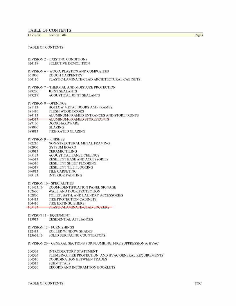
TABLE OF CONTENTS Division Section Title Pages
TABLE OF CONTENTS TOC
TABLE OF CONTENTS DIVISION 2 – EXISTING CONDITIONS 024119 SELECTIVE DEMOLITION DIVISION 6 – WOOD, PLASTICS AND COMPOSITES 061000 ROUGH CARPENTRY 064116 PLASTIC-LAMINATE-CLAD ARCHITECTURAL CABINETS DIVISION 7 – THERMAL AND MOISTURE PROTECTION 079200 JOINT SEALANTS 079219 ACOUSTICAL JOINT SEALANTS DIVISION 8 – OPENINGS 081113 HOLLOW METAL DOORS AND FRAMES 081416 FLUSH WOOD DOORS 084113 ALUMINUM-FRAMED ENTRANCES AND STOREFRONTS 084313 ALUMINUM-FRAMED STOREFRONTS 087100 DOOR HARDWARE 088000 GLAZING 088813 FIRE-RATED GLAZING DIVISION 9 – FINISHES 092216 NON-STRUCTURAL METAL FRAMING 092900 GYPSUM BOARD 093013 CERAMIC TILING 095123 ACOUSTICAL PANEL CEILINGS 096513 RESILIENT BASE AND ACCESSORIES 096516 RESILIENT SHEET FLOORING 096519 RESILIENT TILE FLOORING 096813 TILE CARPETING 099123 INTERIOR PAINTING DIVISION 10 – SPECIALITIES 101423.16 ROOM-IDENTIFICATION PANEL SIGNAGE 102600 WALL AND DOOR PROTECTION 102800 TOLIET, BATH, AND LAUNDRY ACCESSORIES 104413 FIRE PROTECTION CABINETS 104416 FIRE EXTINGUISHERS 105123 PLASTIC-LAMINATE-CLAD LOCKERS DIVISON 11 – EQUIPMENT 113013 RESIDENTIAL APPLIANCES DIVISION 12 – FURNISHINGS 122413 ROLLER WINDOW SHADES 123661.16 SOLID SURFACING COUNTERTOPS DIVISION 20 – GENERAL SECTIONS FOR PLUMBING, FIRE SUPPRESSION & HVAC 200501 INTRODUCTORY STATEMENT 200505 PLUMBING, FIRE PROTECTION, AND HVAC GENERAL REQUIREMENTS 200510 COORDINATION BETWEEN TRADES 200515 SUBMITTALS 200520 RECORD AND INFORAMTION BOOKLETS
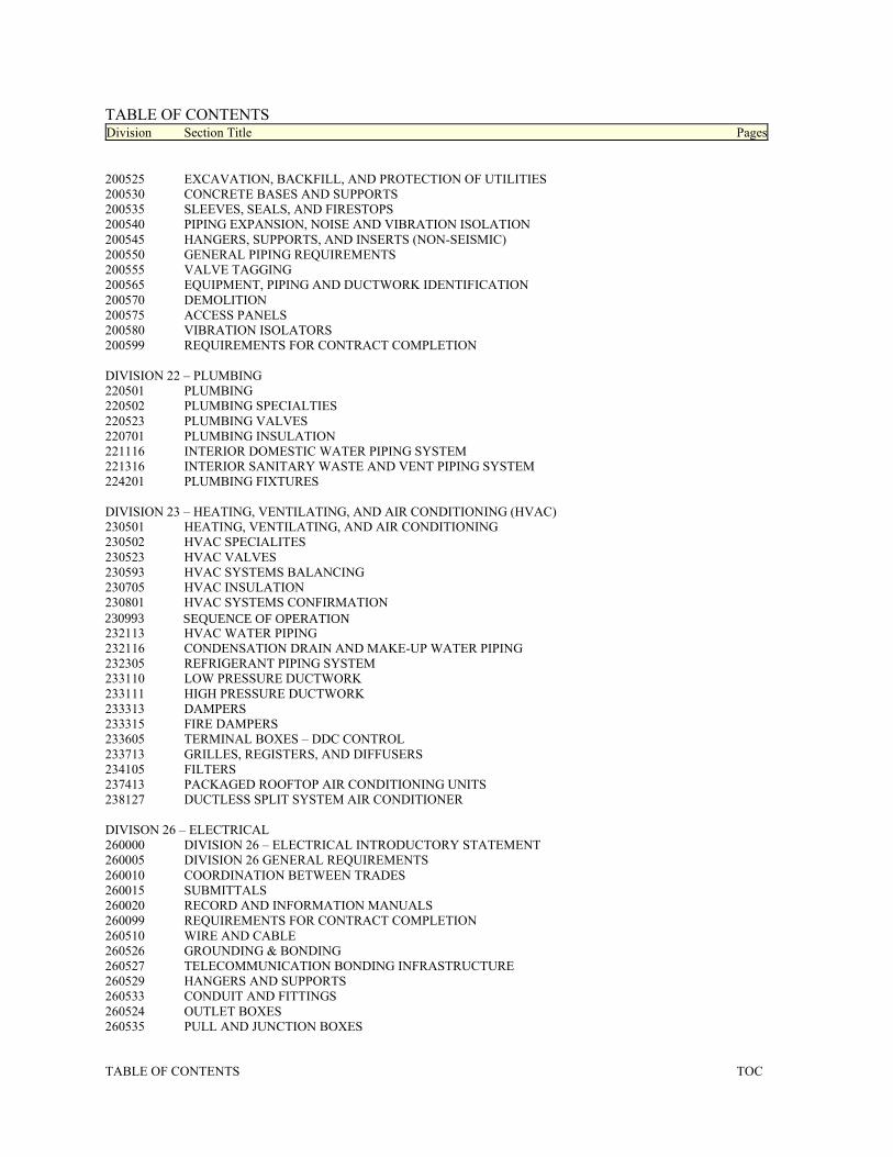
TABLE OF CONTENTS Division Section Title Pages
TABLE OF CONTENTS TOC
200525 EXCAVATION, BACKFILL, AND PROTECTION OF UTILITIES 200530 CONCRETE BASES AND SUPPORTS 200535 SLEEVES, SEALS, AND FIRESTOPS 200540 PIPING EXPANSION, NOISE AND VIBRATION ISOLATION 200545 HANGERS, SUPPORTS, AND INSERTS (NON-SEISMIC) 200550 GENERAL PIPING REQUIREMENTS 200555 VALVE TAGGING 200565 EQUIPMENT, PIPING AND DUCTWORK IDENTIFICATION 200570 DEMOLITION 200575 ACCESS PANELS 200580 VIBRATION ISOLATORS 200599 REQUIREMENTS FOR CONTRACT COMPLETION DIVISION 22 – PLUMBING 220501 PLUMBING 220502 PLUMBING SPECIALTIES 220523 PLUMBING VALVES 220701 PLUMBING INSULATION 221116 INTERIOR DOMESTIC WATER PIPING SYSTEM 221316 INTERIOR SANITARY WASTE AND VENT PIPING SYSTEM 224201 PLUMBING FIXTURES DIVISION 23 – HEATING, VENTILATING, AND AIR CONDITIONING (HVAC) 230501 HEATING, VENTILATING, AND AIR CONDITIONING 230502 HVAC SPECIALITES 230523 HVAC VALVES 230593 HVAC SYSTEMS BALANCING 230705 HVAC INSULATION 230801 HVAC SYSTEMS CONFIRMATION 232113 HVAC WATER PIPING 232116 CONDENSATION DRAIN AND MAKE-UP WATER PIPING 232305 REFRIGERANT PIPING SYSTEM 233110 LOW PRESSURE DUCTWORK 233111 HIGH PRESSURE DUCTWORK 233313 DAMPERS 233315 FIRE DAMPERS 233605 TERMINAL BOXES – DDC CONTROL 233713 GRILLES, REGISTERS, AND DIFFUSERS 234105 FILTERS 237413 PACKAGED ROOFTOP AIR CONDITIONING UNITS 238127 DUCTLESS SPLIT SYSTEM AIR CONDITIONER DIVISON 26 – ELECTRICAL 260000 DIVISION 26 – ELECTRICAL INTRODUCTORY STATEMENT 260005 DIVISION 26 GENERAL REQUIREMENTS 260010 COORDINATION BETWEEN TRADES 260015 SUBMITTALS 260020 RECORD AND INFORMATION MANUALS 260099 REQUIREMENTS FOR CONTRACT COMPLETION 260510 WIRE AND CABLE 260526 GROUNDING & BONDING 260527 TELECOMMUNICATION BONDING INFRASTRUCTURE 260529 HANGERS AND SUPPORTS 260533 CONDUIT AND FITTINGS 260524 OUTLET BOXES 260535 PULL AND JUNCTION BOXES
232113 HVAC WATER PIPING 232116 CONDENSATION DRAIN AND MAKE-UP WATER PIPING 232305 REFRIGERANT PIPING SYSTEM 233110 LOW PRESSURE DUCTWORK 233111 HIGH PRESSURE DUCTWORK 233313 DAMPERS 233315 FIRE DAMPERS 233605 TERMINAL BOXES – DDC CONTROL 233713 GRILLES, REGISTERS, AND DIFFUSERS 234105 FILTERS 237413 PACKAGED ROOFTOP AIR CONDITIONING UNITS 238127 DUCTLESS SPLIT SYSTEM AIR CONDITIONER DIVISON 26 – ELECTRICAL 260000 DIVISION 26 – ELECTRICAL INTRODUCTORY STATEMENT 260005 DIVISION 26 GENERAL REQUIREMENTS 260010 COORDINATION BETWEEN TRADES 260015 SUBMITTALS 260020 RECORD AND INFORMATION MANUALS 260099 REQUIREMENTS FOR CONTRACT COMPLETION 260510 WIRE AND CABLE 260526 GROUNDING & BONDING 260527 TELECOMMUNICATION BONDING INFRASTRUCTURE 260529 HANGERS AND SUPPORTS 260533 CONDUIT AND FITTINGS 260524 OUTLET BOXES 260535 PULL AND JUNCTION BOXES
230993 SEQUENCE OF OPERATION
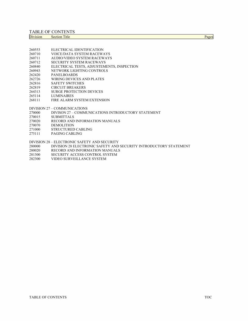
TABLE OF CONTENTS Division Section Title Pages
TABLE OF CONTENTS TOC
260553 ELECTRICAL IDENTIFICATION 260710 VOICE/DATA SYSTEM RACEWAYS 260711 AUDIO/VIDEO SYSTEM RACEWAYS 260712 SECURITY SYSTEM RACEWAYS 260840 ELECTRICAL TESTS, ADJUSTEMENTS, INSPECTION 260943 NETWORK LIGHTING CONTROLS 262420 PANELBOARDS 262726 WIRING DEVICES AND PLATES 262816 SAFETY SWITCHES 262819 CIRCUIT BREAKERS 264313 SURGE PROTECTION DEVICES 265114 LUMINAIRES 268111 FIRE ALARM SYSTEM EXTENSION DIVISION 27 – COMMUNICATIONS 270000 DIVISON 27 – COMMUNICATIONS INTRODUCTORY STATEMENT 270015 SUBMITTALS 270020 RECORD AND INFORMATION MANUALS 270070 DEMOLITION 271000 STRUCTURED CABLING 275111 PAGING CABLING DIVISION 28 – ELECTRONIC SAFETY AND SECURITY 280000 DIVISION 28 ELECTRONIC SAFETY AND SECURITY INTRODUCTORY STATEMENT 280020 RECORD AND INFORMATION MANUALS 281300 SECURITY ACCESS CONTROL SYSTEM 282300 VIDEO SURVEILLANCE SYSTEM
Copyright 2014 AIA MasterSpec Full Length 06/14
SELECTIVE DEMOLITION 024119 - 1
SECTION 024119 - SELECTIVE DEMOLITION
PART 1 - GENERAL
1.1 RELATED DOCUMENTS
A. Drawings and general provisions of the Contract, including General and Supplementary Conditions and Division 01 Specification Sections, apply to this Section.
1.2 SUMMARY
A. Section Includes:
1. Demolition and removal of selected portions of building or structure. 2. Salvage of existing items to be reused or recycled.
B. Related Requirements:
1. Section 011000 "Summary" for restrictions on use of the premises, Owner-occupancy requirements, and phasing requirements.
2. Section 017300 "Execution" for cutting and patching procedures. 3. Section 013516 "Alteration Project Procedures" for general protection and work
procedures for alteration projects.
1.3 DEFINITIONS
A. Remove: Detach items from existing construction and dispose of them off-site unless indicated to be salvaged or reinstalled.
B. Remove and Salvage: Detach items from existing construction, in a manner to prevent damage, and deliver to Owner ready for reuse.
C. Remove and Reinstall: Detach items from existing construction, in a manner to prevent damage, prepare for reuse, and reinstall where indicated.
D. Existing to Remain: Leave existing items that are not to be removed and that are not otherwise indicated to be salvaged or reinstalled.
E. Dismantle: To remove by disassembling or detaching an item from a surface, using gentle methods and equipment to prevent damage to the item and surfaces; disposing of items unless indicated to be salvaged or reinstalled.
1.4 MATERIALS OWNERSHIP
A. Unless otherwise indicated, demolition waste becomes property of Contractor.
Copyright 2014 AIA MasterSpec Full Length 06/14
SELECTIVE DEMOLITION 024119 - 2
B. Historic items, relics, antiques, and similar objects including, but not limited to, cornerstones and their contents, commemorative plaques and tablets, and other items of interest or value to Owner that may be uncovered during demolition remain the property of Owner.
1. Carefully salvage in a manner to prevent damage and promptly return to Owner.
1.5 INFORMATIONAL SUBMITTALS
A. Qualification Data: For refrigerant recovery technician.
B. Engineering Survey: Submit engineering survey of condition of building.
C. Proposed Protection Measures: Submit report, including Drawings, that indicates the measures proposed for protecting individuals and property, for environmental protection, for dust control and , for noise control. Indicate proposed locations and construction of barriers.
D. Schedule of Selective Demolition Activities: Indicate the following:
1. Detailed sequence of selective demolition and removal work, with starting and ending dates for each activity. Ensure Owner's building manager's and other tenants' on-site operations are uninterrupted.
2. Interruption of utility services. Indicate how long utility services will be interrupted. 3. Coordination for shutoff, capping, and continuation of utility services. 4. Use of elevator and stairs. 5. Coordination of Owner's continuing occupancy of portions of existing building and of
Owner's partial occupancy of completed Work.
E. Predemolition Photographs or Video: Show existing conditions of adjoining construction, including finish surfaces, that might be misconstrued as damage caused by demolition operations. Comply with Section 013233 "Photographic Documentation." Submit before Work begins.
F. Statement of Refrigerant Recovery: Signed by refrigerant recovery technician responsible for recovering refrigerant, stating that all refrigerant that was present was recovered and that recovery was performed according to EPA regulations. Include name and address of technician and date refrigerant was recovered.
G. Warranties: Documentation indicating that existing warranties are still in effect after completion of selective demolition.
1.6 CLOSEOUT SUBMITTALS
A. Inventory: Submit a list of items that have been removed and salvaged.
1.7 QUALITY ASSURANCE
A. Refrigerant Recovery Technician Qualifications: Certified by an EPA-approved certification program.
Copyright 2014 AIA MasterSpec Full Length 06/14
SELECTIVE DEMOLITION 024119 - 3
1.8 FIELD CONDITIONS
A. Owner will occupy portions of building immediately adjacent to selective demolition area. Conduct selective demolition so Owner's operations will not be disrupted.
B. Conditions existing at time of inspection for bidding purpose will be maintained by Owner as far as practical.
C. Notify Architect of discrepancies between existing conditions and Drawings before proceeding with selective demolition.
D. Hazardous Materials: It is not expected that hazardous materials will be encountered in the Work.
1. Hazardous materials will be removed by Owner before start of the Work. 2. If suspected hazardous materials are encountered, do not disturb; immediately notify
Architect and Owner. Hazardous materials will be removed by Owner under a separate contract.
E. .
F. Storage or sale of removed items or materials on-site is not permitted.
G. Utility Service: Maintain existing utilities indicated to remain in service and protect them against damage during selective demolition operations.
1. Maintain fire-protection facilities in service during selective demolition operations.
1.9 WARRANTY
A. Existing Warranties: Remove, replace, patch, and repair materials and surfaces cut or damaged during selective demolition, by methods and with materials and using approved contractors so as not to void existing warranties. Notify warrantor before proceeding.
B. Notify warrantor on completion of selective demolition, and obtain documentation verifying that existing system has been inspected and warranty remains in effect. Submit documentation at Project closeout.
1.10 COORDINATION
A. Arrange selective demolition schedule so as not to interfere with Owner's operations.
Copyright 2014 AIA MasterSpec Full Length 06/14
SELECTIVE DEMOLITION 024119 - 4
PART 2 - PRODUCTS
2.1 PERFORMANCE REQUIREMENTS
A. Regulatory Requirements: Comply with governing EPA notification regulations before beginning selective demolition. Comply with hauling and disposal regulations of authorities having jurisdiction.
B. Standards: Comply with ASSE A10.6 and NFPA 241.
PART 3 - EXECUTION
3.1 EXAMINATION
A. Verify that utilities have been disconnected and capped before starting selective demolition operations.
B. Review Project Record Documents of existing construction or other existing condition and hazardous material information provided by Owner. Owner does not guarantee that existing conditions are same as those indicated in Project Record Documents.
C. Perform an engineering survey of condition of building to determine whether removing any element might result in structural deficiency or unplanned collapse of any portion of structure or adjacent structures during selective building demolition operations.
1. Perform surveys as the Work progresses to detect hazards resulting from selective demolition activities.
D. Survey of Existing Conditions: Record existing conditions by use of preconstruction photographs.
1. Comply with requirements specified in Section 013233 "Photographic Documentation." 2. Inventory and record the condition of items to be removed and salvaged. Provide
photographs or video of conditions that might be misconstrued as damage caused by salvage operations.
3.2 PREPARATION
A. Refrigerant: Before starting demolition, remove refrigerant from mechanical equipment according to 40 CFR 82 and regulations of authorities having jurisdiction.
3.3 UTILITY SERVICES AND MECHANICAL/ELECTRICAL SYSTEMS
A. Existing Services/Systems to Remain: Maintain services/systems indicated to remain and protect them against damage.
Copyright 2014 AIA MasterSpec Full Length 06/14
SELECTIVE DEMOLITION 024119 - 5
B. Existing Services/Systems to Be Removed, Relocated, or Abandoned: Locate, identify, disconnect, and seal or cap off utility services and mechanical/electrical systems serving areas to be selectively demolished. 1. Arrange to shut off utilities with utility companies. 2. If services/systems are required to be removed, relocated, or abandoned, provide
temporary services/systems that bypass area of selective demolition and that maintain continuity of services/systems to other parts of building.
3. Disconnect, demolish, and remove fire-suppression systems, plumbing, and HVAC systems, equipment, and components indicated on Drawings to be removed.
a. Piping to Be Removed: Remove portion of piping indicated to be removed and cap or plug remaining piping with same or compatible piping material.
b. Piping to Be Abandoned in Place: Drain piping and cap or plug piping with same or compatible piping material and leave in place.
c. Equipment to Be Removed: Disconnect and cap services and remove equipment. d. Equipment to Be Removed and Reinstalled: Disconnect and cap services and
remove, clean, and store equipment; when appropriate, reinstall, reconnect, and make equipment operational.
e. Equipment to Be Removed and Salvaged: Disconnect and cap services and remove equipment and deliver to Owner.
f. Ducts to Be Removed: Remove portion of ducts indicated to be removed and plug remaining ducts with same or compatible ductwork material.
g. Ducts to Be Abandoned in Place: Cap or plug ducts with same or compatible ductwork material and leave in place.
3.4 PROTECTION
A. Temporary Protection: Provide temporary barricades and other protection required to prevent injury to people and damage to adjacent buildings and facilities to remain.
1. Provide protection to ensure safe passage of people around selective demolition area and to and from occupied portions of building.
2. Provide temporary weather protection, during interval between selective demolition of existing construction on exterior surfaces and new construction, to prevent water leakage and damage to structure and interior areas.
3. Protect walls, ceilings, floors, and other existing finish work that are to remain or that are exposed during selective demolition operations.
4. Cover and protect furniture, furnishings, and equipment that have not been removed. 5. Comply with requirements for temporary enclosures, dust control, heating, and cooling
specified in Section 015000 "Temporary Facilities and Controls."
B. Temporary Shoring: Design, provide, and maintain shoring, bracing, and structural supports as required to preserve stability and prevent movement, settlement, or collapse of construction and finishes to remain, and to prevent unexpected or uncontrolled movement or collapse of construction being demolished.
1. Strengthen or add new supports when required during progress of selective demolition.
C. Remove temporary barricades and protections where hazards no longer exist.
Copyright 2014 AIA MasterSpec Full Length 06/14
SELECTIVE DEMOLITION 024119 - 6
3.5 SELECTIVE DEMOLITION, GENERAL
A. General: Demolish and remove existing construction only to the extent required by new construction and as indicated. Use methods required to complete the Work within limitations of governing regulations and as follows:
1. Proceed with selective demolition systematically, from higher to lower level. Complete selective demolition operations above each floor or tier before disturbing supporting members on the next lower level.
2. Neatly cut openings and holes plumb, square, and true to dimensions required. Use cutting methods least likely to damage construction to remain or adjoining construction. Use hand tools or small power tools designed for sawing or grinding, not hammering and chopping. Temporarily cover openings to remain.
3. Cut or drill from the exposed or finished side into concealed surfaces to avoid marring existing finished surfaces.
4. Do not use cutting torches until work area is cleared of flammable materials. At concealed spaces, such as duct and pipe interiors, verify condition and contents of hidden space before starting flame-cutting operations. Maintain portable fire-suppression devices during flame-cutting operations.
5. Maintain fire watch during and for at least 24 hours after flame-cutting operations. 6. Maintain adequate ventilation when using cutting torches. 7. Remove decayed, vermin-infested, or otherwise dangerous or unsuitable materials and
promptly dispose of off-site. 8. Remove structural framing members and lower to ground by method suitable to avoid
free fall and to prevent ground impact or dust generation. 9. Locate selective demolition equipment and remove debris and materials so as not to
impose excessive loads on supporting walls, floors, or framing. 10. Dispose of demolished items and materials promptly.
B. Site Access and Temporary Controls: Conduct selective demolition and debris-removal operations to ensure minimum interference with roads, streets, walks, walkways, and other adjacent occupied and used facilities.
C. Removed and Salvaged Items:
1. Clean salvaged items. 2. Pack or crate items after cleaning. Identify contents of containers. 3. Store items in a secure area until delivery to Owner. 4. Transport items to Owner's storage area designated by Owner. 5. Protect items from damage during transport and storage.
D. Removed and Reinstalled Items:
1. Clean and repair items to functional condition adequate for intended reuse. 2. Pack or crate items after cleaning and repairing. Identify contents of containers. 3. Protect items from damage during transport and storage. 4. Reinstall items in locations indicated. Comply with installation requirements for new
materials and equipment. Provide connections, supports, and miscellaneous materials necessary to make item functional for use indicated.
Copyright 2014 AIA MasterSpec Full Length 06/14
SELECTIVE DEMOLITION 024119 - 7
E. Existing Items to Remain: Protect construction indicated to remain against damage and soiling during selective demolition.
3.6 DISPOSAL OF DEMOLISHED MATERIALS
A. Remove demolition waste materials from Project site and dispose of them in an EPA-approved construction and demolition waste landfill acceptable to authorities having jurisdiction.
1. Do not allow demolished materials to accumulate on-site. 2. Remove and transport debris in a manner that will prevent spillage on adjacent surfaces
and areas. 3. Remove debris from elevated portions of building by chute, hoist, or other device that
will convey debris to grade level in a controlled descent.
B. Burning: Do not burn demolished materials.
3.7 CLEANING
A. Clean adjacent structures and improvements of dust, dirt, and debris caused by selective demolition operations. Return adjacent areas to condition existing before selective demolition operations began.
END OF SECTION 024119
Copyright 2018 AIA MasterSpec Full Length 09/18
ROUGH CARPENTRY 061000 - 1 Copyright © 2019 by the American Institute of Architects. Warning: This AIA MasterSpec based document is protected by U.S. Copyright Law and International Treaties. A valid, current MasterSpec license is required for editing or use of this document.
SECTION 061000 - ROUGH CARPENTRY
PART 1 - GENERAL
1.1 RELATED DOCUMENTS
A. Drawings and general provisions of the Contract, including General and Supplementary Conditions and Division 01 Specification Sections, apply to this Section.
1.2 SUMMARY
A. Section Includes:
1. Framing with dimension lumber for millwork desk framing. 2. Wood blocking and nailers. 3. Plywood backing panels.
1.3 DEFINITIONS
A. Boards or Strips: Lumber of less than 2 inches nominal (38 mm actual) size in least dimension.
B. Dimension Lumber: Lumber of 2 inches nominal (38 mm actual) size or greater but less than 5 inches nominal (114 mm actual) size in least dimension.
C. Exposed Framing: Framing not concealed by other construction.
D. OSB: Oriented strand board.
E. Timber: Lumber of 5 inches nominal (114 mm actual) size or greater in least dimension.
1.4 ACTION SUBMITTALS
A. Product Data: For each type of process and factory-fabricated product. Indicate component materials and dimensions and include construction and application details.
1. Include data for wood-preservative treatment from chemical treatment manufacturer and certification by treating plant that treated materials comply with requirements. Indicate type of preservative used and net amount of preservative retained.
2. Include data for fire-retardant treatment from chemical treatment manufacturer and certification by treating plant that treated materials comply with requirements. Include physical properties of treated materials based on testing by a qualified independent testing agency.
3. For fire-retardant treatments, include physical properties of treated lumber both before and after exposure to elevated temperatures, based on testing by a qualified independent testing agency according to ASTM D5664.
Copyright 2018 AIA MasterSpec Full Length 09/18
ROUGH CARPENTRY 061000 - 2 Copyright © 2019 by the American Institute of Architects. Warning: This AIA MasterSpec based document is protected by U.S. Copyright Law and International Treaties. A valid, current MasterSpec license is required for editing or use of this document.
4. For products receiving a waterborne treatment, include statement that moisture content of treated materials was reduced to levels specified before shipment to Project site.
1.5 INFORMATIONAL SUBMITTALS
A. Material Certificates: For dimension lumber specified to comply with minimum allowable unit stresses. Indicate species and grade selected for each use and design values approved by the ALSC Board of Review.
B. Evaluation Reports: For the following, from ICC-ES: 1. Fire-retardant-treated wood.
1.6 QUALITY ASSURANCE
A. Testing Agency Qualifications: For testing agency providing classification marking for fire-retardant treated material, an inspection agency acceptable to authorities having jurisdiction that periodically performs inspections to verify that the material bearing the classification marking is representative of the material tested.
1.7 DELIVERY, STORAGE, AND HANDLING
A. Stack wood products flat with spacers beneath and between each bundle to provide air circulation. Protect wood products from weather by covering with waterproof sheeting, securely anchored. Provide for air circulation around stacks and under coverings.
PART 2 - PRODUCTS
2.1 WOOD PRODUCTS, GENERAL
A. Lumber: DOC PS 20 and applicable rules of grading agencies indicated. If no grading agency is indicated, comply with the applicable rules of any rules-writing agency certified by the ALSC Board of Review. Grade lumber by an agency certified by the ALSC Board of Review to inspect and grade lumber under the rules indicated.
1. Factory mark each piece of lumber with grade stamp of grading agency. 2. For exposed lumber indicated to receive a stained or natural finish, mark grade stamp
on end or back of each piece. 3. Dress lumber, S4S, unless otherwise indicated.
B. Maximum Moisture Content of Lumber: 19 percent unless otherwise indicated.
2.2 FIRE-RETARDANT-TREATED MATERIALS
A. General: Where fire-retardant-treated materials are indicated, materials shall comply with requirements in this article, that are acceptable to authorities having jurisdiction, and with fire-
Copyright 2018 AIA MasterSpec Full Length 09/18
ROUGH CARPENTRY 061000 - 3 Copyright © 2019 by the American Institute of Architects. Warning: This AIA MasterSpec based document is protected by U.S. Copyright Law and International Treaties. A valid, current MasterSpec license is required for editing or use of this document.
test-response characteristics specified as determined by testing identical products per test method indicated by a qualified testing agency.
B. Fire-Retardant-Treated Lumber and Plywood by Pressure Process: Products with a flame-spread index of 25 or less when tested according to ASTM E84, and with no evidence of significant progressive combustion when the test is extended an additional 20 minutes, and with the flame front not extending more than 10.5 feet (3.2 m) beyond the centerline of the burners at any time during the test.
1. Treatment shall not promote corrosion of metal fasteners. 2. Exterior Type: Treated materials shall comply with requirements specified above for fire-
retardant-treated lumber and plywood by pressure process after being subjected to accelerated weathering according to ASTM D2898. Use for exterior locations and where indicated.
3. Interior Type A: Treated materials shall have a moisture content of 28 percent or less when tested according to ASTM D3201 at 92 percent relative humidity. Use where exterior type is not indicated.
C. Identify fire-retardant-treated wood with appropriate classification marking of qualified testing agency.
1. For exposed lumber indicated to receive a stained or natural finish, mark end or back of each piece.
2.3 DIMENSION LUMBER FRAMING
A. Non-Load-Bearing Interior Partitions: Construction or No. 2 grade.
1. Application: Millwork desk framing..
2.4 MISCELLANEOUS LUMBER
A. General: Provide miscellaneous lumber indicated and lumber for support or attachment of other construction, including the following:
1. Blocking. 2. Nailers. 3. Furring.
B. Dimension Lumber Items: Construction or No. 2 grade lumber of any species.
C. Concealed Boards: 15 percent maximum moisture content and [any of ]the following species and grades:
1. Mixed southern pine or southern pine; No. 2 grade; SPIB. 2. Hem-fir or hem-fir (north); Construction or No. 2 Common grade; NLGA, WCLIB, or
WWPA. 3. Spruce-pine-fir (south) or spruce-pine-fir; Construction or No. 2 Common grade;
NeLMA, NLGA, WCLIB, or WWPA.
Copyright 2018 AIA MasterSpec Full Length 09/18
ROUGH CARPENTRY 061000 - 4 Copyright © 2019 by the American Institute of Architects. Warning: This AIA MasterSpec based document is protected by U.S. Copyright Law and International Treaties. A valid, current MasterSpec license is required for editing or use of this document.
D. For blocking not used for attachment of other construction, Utility, Stud, or No. 3 grade lumber of any species may be used provided that it is cut and selected to eliminate defects that will interfere with its attachment and purpose.
E. For blocking and nailers used for attachment of other construction, select and cut lumber to eliminate knots and other defects that will interfere with attachment of other work.
F. For furring strips for installing plywood or hardboard paneling, select boards with no knots capable of producing bent-over nails and damage to paneling.
2.5 PLYWOOD BACKING PANELS
A. Equipment Backing Panels: Plywood, DOC PS 1, Exterior, A-C, fire-retardant treated, in thickness indicated or, if not indicated, not less than 3/4-inch (19-mm) nominal thickness.
2.6 FASTENERS
A. General: Fasteners shall be of size and type indicated and shall comply with requirements specified in this article for material and manufacture.
1. Where rough carpentry is exposed to weather, in ground contact, pressure-preservative treated, or in area of high relative humidity, provide fasteners with hot-dip zinc coating complying with ASTM A153/A153M.
B. Nails, Brads, and Staples: ASTM F1667.
C. Power-Driven Fasteners: Fastener systems with an evaluation report acceptable to authorities having jurisdiction, based on ICC-ES AC70.
D. Post-Installed Anchors: Fastener systems with an evaluation report acceptable to authorities having jurisdiction, based on [ICC-ES AC01] [ICC-ES AC58] [ICC-ES AC193] [or] [ICC-ES AC308] as appropriate for the substrate. 1. Material: Stainless steel with bolts and nuts complying with ASTM F593 and
ASTM F594, Alloy Group 1 or 2 (ASTM F738M and ASTM F836M, Grade A1 or A4).
2.7 METAL FRAMING ANCHORS
A. Manufacturers: Subject to compliance with requirements, provide products by one of the following:
1. Cleveland Steel Specialty Co. 2. MiTek Industries, Inc. 3. Phoenix Metal Products, Inc. 4. Simpson Strong-Tie Co., Inc. 5. Tamlyn.
B. Allowable design loads, as published by manufacturer, shall meet or exceed those of products of manufacturers listed. Manufacturer's published values shall be determined from empirical data or by rational engineering analysis and demonstrated by comprehensive testing performed
Copyright 2018 AIA MasterSpec Full Length 09/18
ROUGH CARPENTRY 061000 - 5 Copyright © 2019 by the American Institute of Architects. Warning: This AIA MasterSpec based document is protected by U.S. Copyright Law and International Treaties. A valid, current MasterSpec license is required for editing or use of this document.
by a qualified independent testing agency. Framing anchors shall be punched for fasteners adequate to withstand same loads as framing anchors.
C. Galvanized-Steel Sheet: Hot-dip, zinc-coated steel sheet complying with ASTM A653/A653M, G60 (Z180) coating designation.
1. Use for interior locations unless otherwise indicated.
D. Stainless Steel Sheet: ASTM A240/A240M or ASTM A666, Type 304.
1. Use for exterior locations and where indicated.
2.8 MISCELLANEOUS MATERIALS
A. Sill-Sealer Gaskets: Closed-cell neoprene foam, 1/4 inch (6.4 mm) thick, selected from manufacturer's standard widths to suit width of sill members indicated.
B. Adhesives for Gluing Furring and Sleepers to Concrete or Masonry: Formulation complying with ASTM D3498 that is approved for use indicated by adhesive manufacturer.
PART 3 - EXECUTION
3.1 INSTALLATION, GENERAL
A. Framing Standard: Comply with AF&PA's WCD 1, "Details for Conventional Wood Frame Construction," unless otherwise indicated.
B. Framing with Engineered Wood Products: Install engineered wood products to comply with manufacturer's written instructions.
C. Set rough carpentry to required levels and lines, with members plumb, true to line, cut, and fitted. Fit rough carpentry accurately to other construction. Locate furring, nailers, blocking, grounds, and similar supports to comply with requirements for attaching other construction.
D. Install plywood backing panels by fastening to studs; coordinate locations with utilities requiring backing panels. Install fire-retardant-treated plywood backing panels with classification marking of testing agency exposed to view.
E. Install shear wall panels to comply with manufacturer's written instructions.
F. Install metal framing anchors to comply with manufacturer's written instructions. Install fasteners through each fastener hole.
G. Install sill sealer gasket to form continuous seal between sill plates and foundation walls.
H. Do not splice structural members between supports unless otherwise indicated.
I. Provide blocking and framing as indicated and as required to support facing materials, fixtures, specialty items, and trim.
Copyright 2018 AIA MasterSpec Full Length 09/18
ROUGH CARPENTRY 061000 - 6 Copyright © 2019 by the American Institute of Architects. Warning: This AIA MasterSpec based document is protected by U.S. Copyright Law and International Treaties. A valid, current MasterSpec license is required for editing or use of this document.
1. Provide metal clips for fastening gypsum board or lath at corners and intersections where framing or blocking does not provide a surface for fastening edges of panels. Space clips not more than 16 inches (406 mm) o.c.
J. Provide fire blocking in furred spaces, stud spaces, and other concealed cavities as indicated and as follows:
1. Fire block furred spaces of walls, at each floor level, at ceiling, and at not more than 96 inches (2438 mm) o.c. with solid wood blocking or noncombustible materials accurately fitted to close furred spaces.
2. Fire block concealed spaces of wood-framed walls and partitions at each floor level, at ceiling line of top story, and at not more than 96 inches (2438 mm) o.c. Where fire blocking is not inherent in framing system used, provide closely fitted solid wood blocks of same width as framing members and 2-inch nominal (38-mm actual) thickness.
3. Fire block concealed spaces between floor sleepers with same material as sleepers to limit concealed spaces to not more than 100 sq. ft. (9.3 sq. m) and to solidly fill space below partitions.
K. Sort and select lumber so that natural characteristics do not interfere with installation or with fastening other materials to lumber. Do not use materials with defects that interfere with function of member or pieces that are too small to use with minimum number of joints or optimum joint arrangement.
L. Comply with AWPA M4 for applying field treatment to cut surfaces of preservative-treated lumber.
1. Use inorganic boron for items that are continuously protected from liquid water. 2. Use copper naphthenate for items not continuously protected from liquid water.
M. Where wood-preservative-treated lumber is installed adjacent to metal decking, install continuous flexible flashing separator between wood and metal decking.
N. Securely attach rough carpentry work to substrate by anchoring and fastening as indicated, complying with the following:
1. Table 2304.9.1, "Fastening Schedule," in 2017 Ohio Building Code. 2. ICC-ES evaluation report for fastener.
O. Use steel common nails unless otherwise indicated. Select fasteners of size that will not fully penetrate members where opposite side will be exposed to view or will receive finish materials. Make tight connections between members. Install fasteners without splitting wood. Drive nails snug but do not countersink nail heads unless otherwise indicated.
3.2 INSTALLATION OF WOOD BLOCKING AND NAILERS
A. Install where indicated and where required for screeding or attaching other work. Form to shapes indicated and cut as required for true line and level of attached work. Coordinate locations with other work involved.
Copyright 2018 AIA MasterSpec Full Length 09/18
ROUGH CARPENTRY 061000 - 7 Copyright © 2019 by the American Institute of Architects. Warning: This AIA MasterSpec based document is protected by U.S. Copyright Law and International Treaties. A valid, current MasterSpec license is required for editing or use of this document.
B. Attach items to substrates to support applied loading. Recess bolts and nuts flush with surfaces unless otherwise indicated.
3.3 INSTALLATION OF WOOD FURRING
A. Install level and plumb with closure strips at edges and openings. Shim with wood as required for tolerance of finish work.
B. Furring to Receive Plywood or Hardboard Paneling: Install 1-by-3-inch nominal- (19-by-63-mm actual-) size furring horizontally and vertically at [24 inches (610 mm)] [600 mm] o.c.
C. Furring to Receive Gypsum Board: Install 1-by-2-inch nominal- (19-by-38-mm actual-) size furring vertically at 16 inches (406 mm) o.c.
3.4 INSTALLATION OF WALL AND PARTITION FRAMING
A. General: Provide single bottom plate and double top plates using members of 2-inch nominal (38-mm actual) thickness whose widths equal that of studs, except single top plate may be used for non-load-bearing partitions. Fasten plates to supporting construction unless otherwise indicated. 1. For interior partitions and walls, provide 2-by-4-inch nominal- (38-by-89-mm actual-)
size wood studs spaced 16 inches (406 mm) o.c. unless otherwise indicated. 2. Provide continuous horizontal blocking at midheight of partitions more than 96 inches
(2438 mm) high, using members of 2-inch nominal (38-mm actual) thickness and of same width as wall or partitions.
B. Construct corners and intersections with three or more studs, except that two studs may be used for interior non-load-bearing partitions.
C. Frame openings with multiple studs and headers. Provide nailed header members of thickness equal to width of studs. Support headers on jamb studs.
1. For non-load-bearing partitions, provide double-jamb studs and headers not less than 4-inch nominal (89-mm actual) depth for openings 48 inches (1200 mm) and less in width, 6-inch nominal (140-mm actual) depth for openings 48 to 72 inches (1200 to 1800 mm) in width, 8-inch nominal (184-mm actual) depth for openings 72 to 120 inches (1800 to 3000 mm) in width, and not less than 10-inch nominal (235-mm actual) depth for openings 10 to 12 feet (3 to 3.6 m) in width.
END OF SECTION 061000
Copyright 2014 AIA MasterSpec Full Length 06/14
JOINT SEALANTS 079200 - 1 Copyright © 2019 by the American Institute of Architects. Warning: This AIA MasterSpec based document is protected by U.S. Copyright Law and International Treaties. A valid, current MasterSpec license is required for editing or use of this document.
SECTION 079200 - JOINT SEALANTS
1.1 RELATED DOCUMENTS
A. Drawings and general provisions of the Contract, including General and Supplementary Conditions and Division 01 Specification Sections, apply to this Section.
1.2 SUMMARY
A. Section Includes: 1. Nonstaining silicone joint sealants. 2. Mildew-resistant joint sealants. 3. Latex joint sealants.
B. Related Requirements: 1. Section 079219 "Acoustical Joint Sealants" for sealing joints in sound-rated construction.
1.3 ACTION SUBMITTALS
A. Product Data: For each joint-sealant product.
B. Samples for Initial Selection: Manufacturer's color charts consisting of strips of cured sealants showing the full range of colors available for each product exposed to view.
C. Joint-Sealant Schedule: Include the following information:
1. Joint-sealant application, joint location, and designation. 2. Joint-sealant manufacturer and product name. 3. Joint-sealant formulation. 4. Joint-sealant color.
1.4 INFORMATIONAL SUBMITTALS
A. Sample Warranties: For special warranties.
1.5 QUALITY ASSURANCE
A. Installer Qualifications: An authorized representative who is trained and approved by manufacturer.
1.6 FIELD CONDITIONS
A. Do not proceed with installation of joint sealants under the following conditions:
Copyright 2014 AIA MasterSpec Full Length 06/14
JOINT SEALANTS 079200 - 2 Copyright © 2019 by the American Institute of Architects. Warning: This AIA MasterSpec based document is protected by U.S. Copyright Law and International Treaties. A valid, current MasterSpec license is required for editing or use of this document.
1. When ambient and substrate temperature conditions are outside limits permitted by joint-sealant manufacturer or are below 40 deg F (5 deg C).
2. When joint substrates are wet. 3. Where joint widths are less than those allowed by joint-sealant manufacturer for
applications indicated. 4. Where contaminants capable of interfering with adhesion have not yet been removed
from joint substrates.
1.7 WARRANTY
A. Special Installer's Warranty: Installer agrees to repair or replace joint sealants that do not comply with performance and other requirements specified in this Section within specified warranty period.
1. Warranty Period: Two years from date of Substantial Completion.
B. Special Manufacturer's Warranty: Manufacturer agrees to furnish joint sealants to repair or replace those joint sealants that do not comply with performance and other requirements specified in this Section within specified warranty period.
1. Warranty Period: Five years from date of Substantial Completion.
C. Special warranties specified in this article exclude deterioration or failure of joint sealants from the following:
1. Movement of the structure caused by stresses on the sealant exceeding sealant manufacturer's written specifications for sealant elongation and compression.
2. Disintegration of joint substrates from causes exceeding design specifications. 3. Mechanical damage caused by individuals, tools, or other outside agents. 4. Changes in sealant appearance caused by accumulation of dirt or other atmospheric
contaminants.
PART 2 - PRODUCTS
2.1 JOINT SEALANTS, GENERAL
A. Compatibility: Provide joint sealants, backings, and other related materials that are compatible with one another and with joint substrates under conditions of service and application, as demonstrated by joint-sealant manufacturer, based on testing and field experience.
B. Colors of Exposed Joint Sealants: As selected by Architect from manufacturer's full range.
2.2 NONSTAINING SILICONE JOINT SEALANTS
A. Nonstaining Joint Sealants: No staining of substrates when tested according to ASTM C1248.
Copyright 2014 AIA MasterSpec Full Length 06/14
JOINT SEALANTS 079200 - 3 Copyright © 2019 by the American Institute of Architects. Warning: This AIA MasterSpec based document is protected by U.S. Copyright Law and International Treaties. A valid, current MasterSpec license is required for editing or use of this document.
B. Silicone, Nonstaining, S, NS, 100/50, NT: Nonstaining, single-component, nonsag, plus 100 percent and minus 50 percent movement capability, nontraffic-use, neutral-curing silicone joint sealant; ASTM C920, Type S, Grade NS, Class 100/50, Use NT.
1. Manufacturers: Subject to compliance with requirements, provide products by one of the following:
a. Dow Corning Corporation. b. GE Construction Sealants; Momentive Performance Materials Inc. c. Sika Corporation, Construction Products Division. d. Tremco Incorporated.
2.3 MILDEW-RESISTANT JOINT SEALANTS
A. Mildew-Resistant Joint Sealants: Formulated for prolonged exposure to humidity with fungicide to prevent mold and mildew growth.
B. Silicone, Mildew Resistant, Acid Curing, S, NS, 25, NT: Mildew-resistant, single-component, nonsag, plus 25 percent and minus 25 percent movement capability, nontraffic-use, acid-curing silicone joint sealant; ASTM C920, Type S, Grade NS, Class 25, Use NT.
2.4 LATEX JOINT SEALANTS
A. Acrylic Latex: Acrylic latex or siliconized acrylic latex, ASTM C834, Type OP, Grade NF.
1. Manufacturers: Subject to compliance with requirements, provide products by one of the following:
a. BASF Building Systems. b. Bostik, Inc. c. Tremco Incorporated.
2.5 JOINT-SEALANT BACKING
A. Sealant Backing Material, General: Nonstaining; compatible with joint substrates, sealants, primers, and other joint fillers; and approved for applications indicated by sealant manufacturer based on field experience and laboratory testing.
B. Cylindrical Sealant Backings: ASTM C1330, Type C (closed-cell material with a surface skin), Type O (open-cell material), Type B (bicellular material with a surface skin), or any of the preceding types, as approved in writing by joint-sealant manufacturer for joint application indicated, and of size and density to control sealant depth and otherwise contribute to producing optimum sealant performance.
C. Bond-Breaker Tape: Polyethylene tape or other plastic tape recommended by sealant manufacturer for preventing sealant from adhering to rigid, inflexible joint-filler materials or joint surfaces at back of joint. Provide self-adhesive tape where applicable.
Copyright 2014 AIA MasterSpec Full Length 06/14
JOINT SEALANTS 079200 - 4 Copyright © 2019 by the American Institute of Architects. Warning: This AIA MasterSpec based document is protected by U.S. Copyright Law and International Treaties. A valid, current MasterSpec license is required for editing or use of this document.
2.6 MISCELLANEOUS MATERIALS
A. Primer: Material recommended by joint-sealant manufacturer where required for adhesion of sealant to joint substrates indicated, as determined from preconstruction joint-sealant-substrate tests and field tests.
B. Cleaners for Nonporous Surfaces: Chemical cleaners acceptable to manufacturers of sealants and sealant backing materials, free of oily residues or other substances capable of staining or harming joint substrates and adjacent nonporous surfaces in any way, and formulated to promote optimum adhesion of sealants to joint substrates.
C. Masking Tape: Nonstaining, nonabsorbent material compatible with joint sealants and surfaces adjacent to joints.
PART 3 - EXECUTION
3.1 EXAMINATION
A. Examine joints indicated to receive joint sealants, with Installer present, for compliance with requirements for joint configuration, installation tolerances, and other conditions affecting performance of the Work.
B. Proceed with installation only after unsatisfactory conditions have been corrected.
3.2 PREPARATION
A. Surface Cleaning of Joints: Clean out joints immediately before installing joint sealants to comply with joint-sealant manufacturer's written instructions and the following requirements:
1. Remove all foreign material from joint substrates that could interfere with adhesion of joint sealant, including dust, paints (except for permanent, protective coatings tested and approved for sealant adhesion and compatibility by sealant manufacturer), old joint sealants, oil, grease, waterproofing, water repellents, water, surface dirt, and frost.
2. Clean porous joint substrate surfaces by brushing, grinding, mechanical abrading, or a combination of these methods to produce a clean, sound substrate capable of developing optimum bond with joint sealants. Remove loose particles remaining after cleaning operations above by vacuuming or blowing out joints with oil-free compressed air. Porous joint substrates include the following:
a. Concrete. b. Masonry. c. Unglazed surfaces of ceramic tile.
3. Remove laitance and form-release agents from concrete. 4. Clean nonporous joint substrate surfaces with chemical cleaners or other means that do
not stain, harm substrates, or leave residues capable of interfering with adhesion of joint sealants. Nonporous joint substrates include the following:
a. Metal.

Copyright 2014 AIA MasterSpec Full Length 06/14
JOINT SEALANTS 079200 - 5 Copyright © 2019 by the American Institute of Architects. Warning: This AIA MasterSpec based document is protected by U.S. Copyright Law and International Treaties. A valid, current MasterSpec license is required for editing or use of this document.
b. Glass. c. Glazed surfaces of ceramic tile.
B. Joint Priming: Prime joint substrates where recommended by joint-sealant manufacturer or as indicated by preconstruction joint-sealant-substrate tests or prior experience. Apply primer to comply with joint-sealant manufacturer's written instructions. Confine primers to areas of joint-sealant bond; do not allow spillage or migration onto adjoining surfaces.
C. Masking Tape: Use masking tape where required to prevent contact of sealant or primer with adjoining surfaces that otherwise would be permanently stained or damaged by such contact or by cleaning methods required to remove sealant smears. Remove tape immediately after tooling without disturbing joint seal.
3.3 INSTALLATION OF JOINT SEALANTS
A. General: Comply with joint-sealant manufacturer's written installation instructions for products and applications indicated, unless more stringent requirements apply.
B. Sealant Installation Standard: Comply with recommendations in ASTM C1193 for use of joint sealants as applicable to materials, applications, and conditions indicated.
C. Install sealant backings of kind indicated to support sealants during application and at position required to produce cross-sectional shapes and depths of installed sealants relative to joint widths that allow optimum sealant movement capability.
1. Do not leave gaps between ends of sealant backings. 2. Do not stretch, twist, puncture, or tear sealant backings. 3. Remove absorbent sealant backings that have become wet before sealant application, and
replace them with dry materials.
D. Install bond-breaker tape behind sealants where sealant backings are not used between sealants and backs of joints.
E. Install sealants using proven techniques that comply with the following and at the same time backings are installed:
1. Place sealants so they directly contact and fully wet joint substrates. 2. Completely fill recesses in each joint configuration. 3. Produce uniform, cross-sectional shapes and depths relative to joint widths that allow
optimum sealant movement capability.
F. Tooling of Nonsag Sealants: Immediately after sealant application and before skinning or curing begins, tool sealants according to requirements specified in subparagraphs below to form smooth, uniform beads of configuration indicated; to eliminate air pockets; and to ensure contact and adhesion of sealant with sides of joint.
1. Remove excess sealant from surfaces adjacent to joints. 2. Use tooling agents that are approved in writing by sealant manufacturer and that do not
discolor sealants or adjacent surfaces. 3. Provide concave joint profile per Figure 8A in ASTM C1193 unless otherwise indicated.
Copyright 2014 AIA MasterSpec Full Length 06/14
JOINT SEALANTS 079200 - 6 Copyright © 2019 by the American Institute of Architects. Warning: This AIA MasterSpec based document is protected by U.S. Copyright Law and International Treaties. A valid, current MasterSpec license is required for editing or use of this document.
4. Provide flush joint profile according to Figure 8B in ASTM C1193. 5. Provide recessed joint configuration of recess depth and according to Figure 8C in
ASTM C1193.
a. Use masking tape to protect surfaces adjacent to recessed tooled joints.
3.4 CLEANING
A. Clean off excess sealant or sealant smears adjacent to joints as the Work progresses by methods and with cleaning materials approved in writing by manufacturers of joint sealants and of products in which joints occur.
3.5 PROTECTION
A. Protect joint sealants during and after curing period from contact with contaminating substances and from damage resulting from construction operations or other causes so sealants are without deterioration or damage at time of Substantial Completion. If, despite such protection, damage or deterioration occurs, cut out, remove, and repair damaged or deteriorated joint sealants immediately so installations with repaired areas are indistinguishable from original work.
3.6 JOINT-SEALANT SCHEDULE
1. \
B. Joint-Sealant Application: Interior joints in vertical surfaces and horizontal nontraffic surfaces not subject to significant movement.
1. Joint Locations:
a. Control joints on exposed interior surfaces of exterior walls. b. Perimeter joints between interior wall surfaces and frames of interior doors and
windows. c. All interior joints not indicated elsewhere. d. Other joints as indicated on Drawings.
2. Joint Sealant: Acrylic latex. 3. Joint-Sealant Color: As selected by Architect from manufacturer's full range of
colors.
C. Joint-Sealant Application: Mildew-resistant interior joints in vertical surfaces and horizontal nontraffic surfaces.
1. Joint Locations:
a. Joints between plumbing fixtures and adjoining walls, floors, and counters. b. Tile control and expansion joints where indicated. c. Joints between backsplash, endsplash, and countertops.
2. Joint Sealant: Silicone, mildew resistant, acid curing, S, NS, 25, NT.
Copyright 2014 AIA MasterSpec Full Length 06/14
JOINT SEALANTS 079200 - 7 Copyright © 2019 by the American Institute of Architects. Warning: This AIA MasterSpec based document is protected by U.S. Copyright Law and International Treaties. A valid, current MasterSpec license is required for editing or use of this document.
3. Joint-Sealant Color: As selected by Architect from manufacturer's full range of colors.
END OF SECTION 079200
Copyright 2014 AIA MasterSpec Full Length 06/14
ACOUSTICAL JOINT SEALANTS 079219 - 1 Copyright © 2019 by the American Institute of Architects. Warning: This AIA MasterSpec based document is protected by U.S. Copyright Law and International Treaties. A valid, current MasterSpec license is required for editing or use of this document.
SECTION 079219 - ACOUSTICAL JOINT SEALANTS
PART 1 - GENERAL
1.1 RELATED DOCUMENTS
A. Drawings and general provisions of the Contract, including General and Supplementary Conditions and Division 01 Specification Sections, apply to this Section.
1.2 SUMMARY
A. Section includes acoustical joint sealants.
B. Related Requirements:
1. Section 079200 "Joint Sealants" for elastomeric, latex, and butyl-rubber-based joint sealants for nonacoustical applications.
1.3 ACTION SUBMITTALS
A. Product Data: For each acoustical joint sealant.
B. Samples for Initial Selection: Manufacturer's color charts consisting of strips of cured sealants showing the full range of colors available for each product exposed to view.
C. Acoustical-Joint-Sealant Schedule: Include the following information:
1. Joint-sealant application, joint location, and designation. 2. Joint-sealant manufacturer and product name. 3. Joint-sealant formulation. 4. Joint-sealant color.
1.4 INFORMATIONAL SUBMITTALS
A. Product Test Reports: For each kind of acoustical joint sealant, for tests performed by a qualified testing agency.
B. Sample Warranties: For special warranties.
1.5 WARRANTY
A. Special Installer's Warranty: Installer agrees to repair or replace acoustical joint sealants that do not comply with performance and other requirements specified in this Section within specified warranty period.
Copyright 2014 AIA MasterSpec Full Length 06/14
ACOUSTICAL JOINT SEALANTS 079219 - 2 Copyright © 2019 by the American Institute of Architects. Warning: This AIA MasterSpec based document is protected by U.S. Copyright Law and International Treaties. A valid, current MasterSpec license is required for editing or use of this document.
1. Warranty Period: Two years from date of Substantial Completion.
B. Special Manufacturer's Warranty: Manufacturer agrees to furnish acoustical joint sealants to repair or replace those joint sealants that do not comply with performance and other requirements specified in this Section within specified warranty period.
1. Warranty Period: Two years from date of Substantial Completion.
PART 2 - PRODUCTS
2.1 PERFORMANCE REQUIREMENTS
A. Provide acoustical joint-sealant products that effectively reduce airborne sound transmission through perimeter joints and openings in building construction, as demonstrated by testing representative assemblies according to ASTM E90.
2.2 ACOUSTICAL JOINT SEALANTS
A. Acoustical Sealant for Exposed and Concealed Joints: Manufacturer's standard nonsag, paintable, nonstaining latex acoustical sealant complying with ASTM C834. 1. Colors of Exposed Acoustical Joint Sealants: As selected by Architect from
manufacturer's full range of colors.
2.3 MISCELLANEOUS MATERIALS
A. Primer: Material recommended by acoustical-joint-sealant manufacturer where required for adhesion of sealant to joint substrates.
B. Cleaners for Nonporous Surfaces: Chemical cleaners acceptable to manufacturers of sealants and sealant backing materials, free of oily residues or other substances capable of staining or harming joint substrates and adjacent nonporous surfaces in any way, and formulated to promote optimum adhesion of sealants to joint substrates.
C. Masking Tape: Nonstaining, nonabsorbent material compatible with joint sealants and surfaces adjacent to joints.
PART 3 - EXECUTION
3.1 EXAMINATION
A. Examine joints indicated to receive acoustical joint sealants, with Installer present, for compliance with requirements for joint configuration, installation tolerances, and other conditions affecting performance of the Work.
B. Proceed with installation only after unsatisfactory conditions have been corrected.
Copyright 2014 AIA MasterSpec Full Length 06/14
ACOUSTICAL JOINT SEALANTS 079219 - 3 Copyright © 2019 by the American Institute of Architects. Warning: This AIA MasterSpec based document is protected by U.S. Copyright Law and International Treaties. A valid, current MasterSpec license is required for editing or use of this document.
3.2 PREPARATION
A. Surface Cleaning of Joints: Clean out joints immediately before installing acoustical joint sealants to comply with joint-sealant manufacturer's written instructions.
B. Joint Priming: Prime joint substrates where recommended by acoustical-joint-sealant manufacturer. Apply primer to comply with joint-sealant manufacturer's written instructions. Confine primers to areas of joint-sealant bond; do not allow spillage or migration onto adjoining surfaces.
C. Masking Tape: Use masking tape where required to prevent contact of sealant or primer with adjoining surfaces that otherwise would be permanently stained or damaged by such contact or by cleaning methods required to remove sealant smears. Remove tape immediately after tooling without disturbing joint seal.
3.3 INSTALLATION OF ACOUSTICAL JOINT SEALANTS
A. Comply with acoustical joint-sealant manufacturer's written installation instructions unless more stringent requirements apply.
B. STC-Rated Assemblies: Seal construction at perimeters, behind control joints, and at openings and penetrations with a continuous bead of acoustical joint sealant. Install acoustical joint sealants at both faces of partitions, at perimeters, and through penetrations. Comply with ASTM C919, ASTM C1193, and manufacturer's written recommendations for closing off sound-flanking paths around or through assemblies, including sealing partitions to underside of floor slabs above acoustical ceilings.
C. Acoustical Ceiling Areas: Apply acoustical joint sealant at perimeter edge moldings of acoustical ceiling areas in a continuous ribbon concealed on back of vertical legs of moldings before they are installed.
3.4 CLEANING
A. Clean off excess sealant or sealant smears adjacent to joints as the Work progresses by methods and with cleaning materials approved in writing by manufacturers of acoustical joint sealants and of products in which joints occur.
3.5 PROTECTION
A. Protect acoustical joint sealants during and after curing period from contact with contaminating substances and from damage resulting from construction operations or other causes so sealants are without deterioration or damage at time of Substantial Completion. If, despite such protection, damage or deterioration occurs, cut out, remove, and repair damaged or deteriorated acoustical joint sealants immediately so installations with repaired areas are indistinguishable from original work.
END OF SECTION 079219
HOLLOW METAL DOORS AND FRAMES 081113 - 1
SECTION 081113 - HOLLOW METAL DOORS AND FRAMES
PART 1 - GENERAL
1.1 RELATED DOCUMENTS
A. Drawings and general provisions of the Contract, including General and Supplementary Conditions and Division 01 Specification Sections, apply to this Section.
1.2 SUMMARY
A. Section includes:
1. Interior standard steel doors and frames.
B. Related Requirements: 1. Section 081416 “Flush Wood Doors” 2. Section 087100 "Door Hardware" for door hardware for hollow-metal doors.
1.3 DEFINITIONS
A. Minimum Thickness: Minimum thickness of base metal without coatings according to NAAMM-HMMA 803 or ANSI/SDI A250.8.
1.4 COORDINATION
A. Coordinate anchorage installation for hollow-metal frames. Furnish setting drawings, templates, and directions for installing anchorages, including sleeves, concrete inserts, anchor bolts, and items with integral anchors. Deliver such items to Project site in time for installation.
B. Coordinate requirements for installation of door hardware, electrified door hardware, and access control and security systems.
1.5 ACTION SUBMITTALS
A. Product Data: For each type of product.
1. Include construction details, material descriptions, core descriptions, and finishes.
B. Shop Drawings: Include the following:
1. Elevations of each door type. 2. Details of doors, including vertical- and horizontal-edge details and metal thicknesses. 3. Frame details for each frame type, including dimensioned profiles and metal thicknesses. 4. Locations of reinforcement and preparations for hardware.
HOLLOW METAL DOORS AND FRAMES 081113 - 2
5. Details of each different wall opening condition. 6. Details of electrical raceway and preparation for electrified hardware, access control
systems, and security systems. 7. Details of anchorages, joints, field splices, and connections. 8. Details of accessories. 9. Details of moldings, removable stops, and glazing.
C. Samples for Initial Selection: For hollow-metal doors and frames with factory-applied color finishes.
D. Product Schedule: For hollow-metal doors and frames, prepared by or under the supervision of supplier, using same reference numbers for details and openings as those on Drawings. Coordinate with final door hardware schedule.
1.6 INFORMATIONAL SUBMITTALS
A. Product Test Reports: For each type of hollow-metal door and frame assembly for tests performed by a qualified testing agency indicating compliance with performance requirements.
1.7 DELIVERY, STORAGE, AND HANDLING
A. Deliver hollow-metal doors and frames palletized, packaged, or crated to provide protection during transit and Project-site storage. Do not use nonvented plastic.
1. Provide additional protection to prevent damage to factory-finished units.
B. Deliver welded frames with two removable spreader bars across bottom of frames, tack welded to jambs and mullions.
C. Store hollow-metal doors and frames vertically under cover at Project site with head up. Place on minimum 4-inch- (102-mm-) high wood blocking. Provide minimum 1/4-inch (6-mm) space between each stacked door to permit air circulation.
PART 2 - PRODUCTS
2.1 INTERIOR STANDARD STEEL DOORS AND FRAMES
A. Construct hollow-metal doors and frames to comply with standards indicated for materials, fabrication, hardware locations, hardware reinforcement, tolerances, and clearances, and as specified.
B. Standard-Duty Doors and Frames: ANSI/SDI A250.8, Level 1; ANSI/SDI A250.4, Level C. At locations indicated in the Door and Frame Schedule .
1. Doors:
a. Type: As indicated in the Door and Frame Schedule. b. Thickness: 1-3/4 inches (44.5 mm).
HOLLOW METAL DOORS AND FRAMES 081113 - 3
c. Face: Uncoated steel sheet, minimum thickness of 0.032 inch (0.8 mm). d. Edge Construction: Model 1, Full Flush. e. Edge Bevel: Bevel lock and hinge edges 1/8 inch in 2 inches (3.2 mm in 51 mm) f. Core: Manufacturer's standard.
2. Frames:
a. Materials: Uncoated steel sheet, minimum thickness of 0.042 inch (1.0 mm). b. Construction: Full profile welded.
3. Exposed Finish: Prime.
2.2 FRAME ANCHORS
A. Jamb Anchors:
1. Type: Anchors of minimum size and type required by applicable door and frame standard, and suitable for performance level indicated.
2. Quantity: Minimum of three anchors per jamb, with one additional anchor for frames with no floor anchor. Provide one additional anchor for each 24 inches (610 mm) of frame height above 7 feet (2.1 m).
3. Postinstalled Expansion Anchor: Minimum 3/8-inch- (9.5-mm-) diameter bolts with expansion shields or inserts, with manufacturer's standard pipe spacer.
B. Floor Anchors: Provide floor anchors for each jamb and mullion that extends to floor.
C. Floor Anchors for Concrete Slabs with Underlayment: Adjustable-type anchors with extension clips, allowing not less than 2-inch (51-mm) height adjustment. Terminate bottom of frames at top of underlayment.
D. Material: ASTM A879/A879M, Commercial Steel (CS), 04Z (12G) coating designation; mill phosphatized.
1. For anchors built into exterior walls, steel sheet complying with ASTM A1008/A1008M or ASTM A1011/A1011M; hot-dip galvanized according to ASTM A153/A153M, Class B.
2.3 MATERIALS
A. Recycled Content of Steel Products: Postconsumer recycled content plus one-half of preconsumer recycled content not less than 25 percent.
B. Cold-Rolled Steel Sheet: ASTM A1008/A1008M, Commercial Steel (CS), Type B; suitable for exposed applications.
C. Metallic-Coated Steel Sheet: ASTM A653/A653M, Commercial Steel (CS), Type B.
D. Inserts, Bolts, and Fasteners: Hot-dip galvanized according to ASTM A153/A153M.
HOLLOW METAL DOORS AND FRAMES 081113 - 4
E. Power-Actuated Fasteners in Concrete: Fastener system of type suitable for application indicated, fabricated from corrosion-resistant materials, with clips or other accessory devices for attaching hollow-metal frames of type indicated.
F. Mineral-Fiber Insulation: ASTM C665, Type I (blankets without membrane facing); consisting of fibers manufactured from slag or rock wool; with maximum flame-spread and smoke-developed indexes of 25 and 50, respectively; passing ASTM E136 for combustion characteristics.
G. Glazing: Comply with requirements in Section 088000 "Glazing."
2.4 FABRICATION
A. Door Astragals: Provide overlapping astragal on one leaf of pairs of doors where required by NFPA 80 for fire-performance rating or where indicated. Extend minimum 3/4 inch (19 mm) beyond edge of door on which astragal is mounted or as required to comply with published listing of qualified testing agency.
B. Hollow-Metal Frames: Fabricate in one piece except where handling and shipping limitations require multiple sections. Where frames are fabricated in sections, provide alignment plates or angles at each joint, fabricated of metal of same or greater thickness as frames.
1. Frames: Provide closed tubular members with no visible face seams or joints, fabricated from same material as door frame. Fasten members at crossings and to jambs by welding.
2. Provide countersunk, flat- or oval-head exposed screws and bolts for exposed fasteners unless otherwise indicated.
3. Door Silencers: Except on weather-stripped frames, drill stops to receive door silencers as follows. Keep holes clear during construction.
a. Single-Door Frames: Drill stop in strike jamb to receive three door silencers. b. Double-Door Frames: Drill stop in head jamb to receive two door silencers.
C. Hardware Preparation: Factory prepare hollow-metal doors and frames to receive templated mortised hardware, and electrical wiring; include cutouts, reinforcement, mortising, drilling, and tapping according to ANSI/SDI A250.6, the Door Hardware Schedule, and templates.
1. Reinforce doors and frames to receive nontemplated, mortised, and surface-mounted door hardware.
2. Comply with BHMA A156.115 for preparing hollow-metal doors and frames for hardware.
2.5 STEEL FINISHES
A. Prime Finish: Clean, pretreat, and apply manufacturer's standard primer.
1. Shop Primer: Manufacturer's standard, fast-curing, lead- and chromate-free primer complying with ANSI/SDI A250.10; recommended by primer manufacturer for substrate; compatible with substrate and field-applied coatings despite prolonged exposure.
HOLLOW METAL DOORS AND FRAMES 081113 - 5
PART 3 - EXECUTION
3.1 PREPARATION
A. Remove welded-in shipping spreaders installed at factory. Restore exposed finish by grinding, filling, and dressing, as required to make repaired area smooth, flush, and invisible on exposed faces. Touch up factory-applied finishes where spreaders are removed.
B. Drill and tap doors and frames to receive nontemplated, mortised, and surface-mounted door hardware.
3.2 INSTALLATION
A. Install hollow-metal doors and frames plumb, rigid, properly aligned, and securely fastened in place. Comply with approved Shop Drawings and with manufacturer's written instructions.
B. Hollow-Metal Frames: Comply with ANSI/SDI A250.11 or NAAMM-HMMA 840.
1. Set frames accurately in position; plumbed, aligned, and braced securely until permanent anchors are set. After wall construction is complete, remove temporary braces without damage to completed Work.
a. Where frames are fabricated in sections, field splice at approved locations by welding face joint continuously; grind, fill, dress, and make splice smooth, flush, and invisible on exposed faces. Touch-up finishes.
b. Install frames with removable stops located on secure side of opening. 2. Floor Anchors: Secure with postinstalled expansion anchors.
3. Solidly pack mineral-fiber insulation inside frames. 4. Masonry Walls: Coordinate installation of frames to allow for solidly filling space
between frames and masonry with grout or mortar. 5. In-Place Concrete or Masonry Construction: Secure frames in place with post installed
expansion anchors. Countersink anchors, and fill and make smooth, flush, and invisible on exposed faces.
6. Installation Tolerances: Adjust hollow-metal frames to the following tolerances:
a. Squareness: Plus or minus 1/16 inch (1.6 mm), measured at door rabbet on a line 90 degrees from jamb perpendicular to frame head.
b. Alignment: Plus or minus 1/16 inch (1.6 mm), measured at jambs on a horizontal line parallel to plane of wall.
c. Twist: Plus or minus 1/16 inch (1.6 mm), measured at opposite face corners of jambs on parallel lines, and perpendicular to plane of wall.
d. Plumbness: Plus or minus 1/16 inch (1.6 mm), measured at jambs at floor.
C. Hollow-Metal Doors: Fit and adjust hollow-metal doors accurately in frames, within clearances specified below.
D. Glazing: Comply with installation requirements in Section 088000 "Glazing" and with hollow-metal manufacturer's written instructions.

HOLLOW METAL DOORS AND FRAMES 081113 - 6
3.3 REPAIR
A. Prime-Coat Touchup: Immediately after erection, sand smooth rusted or damaged areas of prime coat and apply touchup of compatible air-drying, rust-inhibitive primer.
B. Metallic-Coated Surface Touchup: Clean abraded areas and repair with galvanizing repair paint according to manufacturer's written instructions.
C. Factory-Finish Touchup: Clean abraded areas and repair with same material used for factory finish according to manufacturer's written instructions.
D. Touchup Painting: Cleaning and touchup painting of abraded areas of paint are specified in painting Sections.
END OF SECTION 081113
Copyright 2018 AIA MasterSpec Full Length 06/18
FLUSH WOOD DOORS 081416 - 1
SECTION 081416 - FLUSH WOOD DOORS
PART 1 - GENERAL
1.1 RELATED DOCUMENTS
A. Drawings and general provisions of the Contract, including General and Supplementary Conditions and Division 01 Specification Sections, apply to this Section.
1.2 SUMMARY
A. Section Includes:
1. Solid-core five-ply flush wood veneer-faced doors for transparent finish. 2. Factory finishing flush wood doors. 3. Factory fitting flush wood doors to frames and factory machining for hardware.
B. Related Requirements: 1. Section 081113 “Hollow Metal Doors and Frames” for door frames. 2. Section 087100 "Door Hardware" for hardware for wood doors.
1.3 ACTION SUBMITTALS
A. Product Data: For each type of door. Include details of core and edge construction and trim for openings. Include factory-finishing specifications.
B. Shop Drawings: Indicate location, size, and hand of each door; elevation of each type of door; construction details not covered in Product Data; and the following:
1. Door schedule indicating door location, type, size, fire protection rating, and swing. 2. Door elevations, dimension and locations of hardware, lite and louver cutouts, and
glazing thicknesses. 3. Details of electrical raceway and preparation for electrified hardware, access control
systems, and security systems. 4. Dimensions and locations of blocking for hardware attachment. 5. Dimensions and locations of mortises and holes for hardware. 6. Clearances and undercuts. 7. Requirements for veneer matching. 8. Doors to be factory finished and application requirements. 9. Fire-protection ratings for fire-rated doors.
C. Samples for Initial Selection: For factory-finished doors.
1.4 INFORMATIONAL SUBMITTALS
A. Sample Warranty: For special warranty.
Copyright 2018 AIA MasterSpec Full Length 06/18
FLUSH WOOD DOORS 081416 - 2
1.5 CLOSEOUT SUBMITTALS
A. Special warranties.
B. Record Documents: For fire-rated doors, list of door numbers and applicable room name and number to which door accesses.
1.6 DELIVERY, STORAGE, AND HANDLING
A. Comply with requirements of referenced standard and manufacturer's written instructions.
B. Package doors individually in plastic bags or cardboard cartons.
C. Mark each door on top and bottom rail with opening number used on Shop Drawings.
1.7 FIELD CONDITIONS
A. Environmental Limitations: Do not deliver or install doors until spaces are enclosed and weathertight, wet-work in spaces is complete and dry, and HVAC system is operating and maintaining temperature and relative humidity at levels designed for building occupants for the remainder of construction period.
1.8 WARRANTY
A. Special Warranty: Manufacturer agrees to repair or replace doors that fail in materials or workmanship within specified warranty period.
1. Failures include, but are not limited to, the following:
a. Delamination of veneer. b. Warping (bow, cup, or twist) more than 1/4 inch (6.4 mm) in a 42-by-84-inch
(1067-by-2134-mm) section. c. Telegraphing of core construction in face veneers exceeding 0.01 inch in a 3-inch
(0.25 mm in a 76.2-mm) span.
2. Warranty shall also include installation and finishing that may be required due to repair or replacement of defective doors.
3. Warranty Period for Solid-Core Interior Doors: Life of installation.
PART 2 - PRODUCTS
2.1 MANUFACTURERS
A. Source Limitations: Obtain flush wood doors from single manufacturer.
Copyright 2018 AIA MasterSpec Full Length 06/18
FLUSH WOOD DOORS 081416 - 3
2.2 PERFORMANCE REQUIREMENTS
A. Fire-Rated Wood Door Assemblies: Assemblies complying with NFPA 80 that are listed and labeled by a qualified testing agency acceptable to authorities having jurisdiction, for fire-protection ratings indicated on Drawings, based on testing at positive pressure in accordance with UL 10C or NFPA 252.
B. Smoke- and Draft-Control Door Assemblies: Listed and labeled for smoke and draft control by a qualified testing agency acceptable to authorities having jurisdiction, based on testing in accordance with UL 1784 and installed in compliance with NFPA 105.
2.3 FLUSH WOOD DOORS, GENERAL
A. Quality Standard: In addition to requirements specified, comply with ANSI/WDMA I.S. 1A, “Architectural Wood Flush Doors.”
2.4 SOLID-CORE FIVE-PLY FLUSH WOOD VENEER-FACED DOORSFOR TRANSPARENT FINISH
A. Interior Doors : 1. Performance Grade: ANSI/WDMA I.S. 1A Extra Heavy Duty. 2. Performance Grade:
a. ANSI/WDMA I.S. 1A Extra Heavy Duty unless indicated on Drawings.
3. Architectural Woodwork Standards ANSI/WDMA I.S. 1A Grade: Premium. 4. Faces: Single-ply wood veneer not less than 1/50 inch (0.508 mm) thick.
a. Species: As selected by Owner and Architect from Manufacturer’s full range. b. Cut: As selected by Owner and Architect from Manufacturer’s standard options. c. Match between Veneer Leaves: Book match. d. Assembly of Veneer Leaves on Door Faces: Running match. e. Pair and Set Match: Provide for doors hung in same opening. f. Room Match: Match door faces within each separate room or area of building.
Corridor-door faces do not need to match where they are separated by 20 feet (6 m).
g. Room Match: Provide door faces of compatible color and grain within each separate room or area of building.
5. Exposed Vertical and Top Edges: Same species as faces or a compatible species - Architectural Woodwork Standards edge Type A.
a. Fire-Rated Single Doors: Provide edge construction with intumescent seals concealed by outer stile. Comply with specified requirements for exposed vertical edges.
b. Mineral-Core Doors: At hinge stiles, provide laminated-edge construction with improved screw-holding capability and split resistance. Comply with specified requirements for exposed edges.
Copyright 2018 AIA MasterSpec Full Length 06/18
FLUSH WOOD DOORS 081416 - 4
1) Screw-Holding Capability: 400 lbf (1780 N) in accordance with WDMA T.M. 10.
6. Core for Non-Fire-Rated Doors:
a. ANSI A208.1, Grade LD-2 particleboard.
1) Blocking: Provide wood blocking in particleboard-core doors as to eliminate through-bolting hardware.
a) 5-inch (125-mm) top-rail blocking, in doors indicated to have closers. b) 5-inch (125-mm) bottom-rail blocking, in exterior doors and doors
indicated to have kick, mop, or armor plates. c) 5-inch (125-mm) midrail blocking, in doors indicated to have exit
devices.
2) Provide doors with glued-wood-stave or WDMA I.S. 10 structural-composite-lumber cores instead of particleboard cores for doors scheduled to receive exit devices in Section 087100 "Door Hardware.".
3) Screw Withdrawal, Door Face: 400 lbf (1780 N).
b. Either glued wood stave or WDMA I.S. 10 structural composite lumber.
7. Core for Fire-Rated Doors: As required to achieve fire-protection rating indicated on Drawings.
a. Blocking for Mineral-Core Doors: Provide composite blocking with improved screw-holding capability approved for use in doors of fire-protection ratings indicated on Drawings as follows:
1) 5-inch (125-mm) top-rail blocking. 2) 5-inch (125-mm) bottom-rail blocking, in doors indicated to have protection
plates. 3) 5-inch (125-mm) midrail blocking, in doors indicated to have armor plates. 4) 4-1/2-by-10-inch (114-by-250-mm) lock blocks, 5-inch (125-mm) midrail
blocking, in doors indicated to have exit devices.
8. Construction: Five plies, hot-pressed bonded (vertical and horizontal edging is bonded to core), with entire unit abrasive planed before veneering.
2.5 LIGHT FRAMES AND LOUVERS
A. Wood Beads for Light Openings in Wood Doors: Provide manufacturer's standard wood beads unless otherwise indicated.
1. Wood Species: Same species as door faces. 2. Profile: Flush rectangular beads.
Copyright 2018 AIA MasterSpec Full Length 06/18
FLUSH WOOD DOORS 081416 - 5
3. At wood-core doors with 20-minute fire-protection ratings, provide wood beads and metal glazing clips approved for such use.
B. Wood-Veneered Beads for Light Openings in Fire-Rated Doors: Manufacturer's standard wood-veneered noncombustible beads matching veneer species of door faces and approved for use in doors of fire-protection rating indicated on Drawings. Include concealed metal glazing clips where required for opening size and fire-protection rating indicated.
C. Wood Louvers: Door manufacturer's standard solid-wood louvers unless otherwise indicated.
1. Wood Species: Same species as door faces 2. Profile: Flat. 3.
D. Louvers for Fire-Rated Doors: Metal louvers with fusible link and closing device, listed and labeled for use in doors with fire-protection rating of 1-1/2 hours and less.
1. 2. Metal and Finish: Hot-dip galvanized steel, 0.040 inch (1.0 mm) thick, factory primed
for paint. finish.
2.6 FABRICATION
A. Factory fit doors to suit frame-opening sizes indicated.
1. Comply with clearance requirements of referenced quality standard for fitting unless otherwise indicated.
2. Comply with NFPA 80 requirements for fire-rated doors.
B. Factory machine doors for hardware that is not surface applied.
1. Locate hardware to comply with DHI-WDHS-3. 2. Comply with final hardware schedules, door frame Shop Drawings, ANSI/BHMA-
156.115-W, and hardware templates. 3. Coordinate with hardware mortises in metal frames, to verify dimensions and alignment
before factory machining. 4. For doors scheduled to receive electrified locksets, provide factory-installed raceway and
wiring to accommodate specified hardware.
C. Openings: Factory cut and trim openings through doors.
1. Light Openings: Trim openings with moldings of material and profile indicated. 2. Glazing: Factory install glazing in doors indicated to be factory finished. Comply with
applicable requirements in Section 088000 "Glazing." 3. Louvers: Factory install louvers in prepared openings.
2.7 FACTORY FINISHING
A. Comply with referenced quality standard for factory finishing.
Copyright 2018 AIA MasterSpec Full Length 06/18
FLUSH WOOD DOORS 081416 - 6
1. Complete fabrication, including fitting doors for openings and machining for hardware that is not surface applied, before finishing.
2. Finish faces, all four edges, edges of cutouts, and mortises. 3. Stains and fillers may be omitted on top and bottom edges, edges of cutouts, and
mortises.
B. Factory finish doors.
C. Transparent Finish:
1. Architectural Woodwork Standards or ANSI/WDMA I.S. 1A Grade: Premium. 2. Finish: Architectural Woodwork Standards System-5, Varnish, Conversion. 3. Finish: ANSI/WDMA I.S. 1A TR-4 Conversion Varnish. 4. Staining: As selected by Architect from manufacturer's full range. 5. Effect: Semifilled finish, produced by applying an additional finish coat to partially
fill the wood pores. 6. Sheen: Satin.
PART 3 - EXECUTION
3.1 EXAMINATION
A. Examine doors and installed door frames, with Installer present, before hanging doors.
1. Verify that installed frames comply with indicated requirements for type, size, location, and swing characteristics and have been installed with level heads and plumb jambs.
2. Reject doors with defects.
B. Proceed with installation only after unsatisfactory conditions have been corrected.
3.2 INSTALLATION
A. Hardware: For installation, see Section 087100 "Door Hardware."
B. Install doors to comply with manufacturer's written instructions and referenced quality standard, and as indicated.
C. Install frames level, plumb, true, and straight.
1. Shim as required with concealed shims. Install level and plumb to a tolerance of 1/8 inch in 96 inches (3.2 mm in 2400 mm).
2. Anchor frames to anchors or blocking built in or directly attached to substrates.
a. Secure with countersunk, concealed fasteners and blind nailing. b. Use fine finishing nails or finishing screws for exposed fastening, countersunk
and filled flush with woodwork.
Copyright 2018 AIA MasterSpec Full Length 06/18
FLUSH WOOD DOORS 081416 - 7
1) For factory-finished items, use filler matching finish of items being installed.
3. Install fire-rated doors and frames in accordance with NFPA 80. 4. Install smoke- and draft-control doors in accordance with NFPA 105.
D. Job-Fitted Doors:
1. Align and fit doors in frames with uniform clearances and bevels as indicated below.
a. Do not trim stiles and rails in excess of limits set by manufacturer or permitted for fire-rated doors.
2. Machine doors for hardware. 3. Seal edges of doors, edges of cutouts, and mortises after fitting and machining. 4. Clearances:
a. Provide 1/8 inch (3.2 mm) at heads, jambs, and between pairs of doors. b. Provide 1/8 inch (3.2 mm) from bottom of door to top of decorative floor finish or
covering unless otherwise indicated on Drawings. c. Where threshold is shown or scheduled, provide1/4 inch (6.4 mm) from bottom of
door to top of threshold unless otherwise indicated. d. Comply with NFPA 80 for fire-rated doors.
5. Bevel non-fire-rated doors 1/8 inch in 2 inches (3-1/2 degrees) at lock and hinge edges. 6. Bevel fire-rated doors 1/8 inch in 2 inches (3-1/2 degrees) at lock edge; trim stiles and
rails only to extent permitted by labeling agency.
E. Factory-Fitted Doors: Align in frames for uniform clearance at each edge.
F. Factory-Finished Doors: Restore finish before installation if fitting or machining is required at Project site.
3.3 ADJUSTING
A. Operation: Rehang or replace doors that do not swing or operate freely.
B. Finished Doors: Replace doors that are damaged or that do not comply with requirements. Doors may be repaired or refinished if Work complies with requirements and shows no evidence of repair or refinishing.
END OF SECTION 081416
ALUMINUM-FRAMED ENTRANCES AND STOREFRONTS 084113 - 1
SECTION 084113 – ALUMINUM-FRAMED ENTRANCES AND STOREFRONTS
PART 1 - GENERAL
1.1 RELATED DOCUMENTS
A. Drawings and general provisions of the Contract, including General and Supplementary Conditions and Division 01 Specification Sections, apply to this Section.
1.2 SUMMARY
A. Section Includes:
1. Aluminum-framed storefront systems. 2. Aluminum-framed entrance door systems.
B. Related Requirements: 1. Section 087100 “Door Hardware” for door hardware of aluminum-framed entrance door
systems. 2. Section 088000 “Glazing” for glazing of non-fire-rated aluminum-framed storefront
systems. 3. Section 088813 “Fire-Rated Glazing” for glazing of fire-rated aluminum-framed
entrances and storefronts.
1.3 ACTION SUBMITTALS
A. Product Data: For each type of product.
1. Include construction details, material descriptions, dimensions of individual components and profiles, and finishes.
B. Shop Drawings: For aluminum-framed entrances and storefronts. Include plans, elevations, sections, full-size details, and attachments to other work.
1. Include details of provisions for assembly expansion and contraction and for draining moisture occurring within the assembly to the exterior.
2. Include full-size isometric details of each type of vertical-to-horizontal intersection of aluminum-framed entrances and storefronts, showing the following:
a. Joinery, including concealed welds. b. Anchorage. c. Expansion provisions. d. Glazing. e. Flashing and drainage.
ALUMINUM-FRAMED ENTRANCES AND STOREFRONTS 084113 - 2
3. Show connection to and continuity with adjacent thermal, weather, air, and vapor barriers.
4. Include point-to-point wiring diagrams showing the following:
a. Power requirements for each electrically operated door hardware. b. Location and types of switches, signal device, conduit sizes, and number and size
of wires.
C. Samples for Initial Selection: For units with factory-applied color finishes.
D. Samples for Verification: For each type of exposed finish required, in manufacturer's standard sizes.
E. Entrance Door Hardware Schedule: Prepared by or under supervision of supplier, detailing fabrication and assembly of entrance door hardware, as well as procedures and diagrams. Coordinate final entrance door hardware schedule with doors, frames, and related work to ensure proper size, thickness, hand, function, and finish of entrance door hardware.
1.4 INFORMATIONAL SUBMITTALS
A. Product Test Reports: For aluminum-framed entrances and storefronts, for tests performed by manufacturer and witnessed by a qualified testing agency.
B. Sample Warranties: For special warranties.
1.5 CLOSEOUT SUBMITTALS
A. Maintenance Data: For aluminum-framed entrances and storefronts to include in maintenance manuals.
1.6 QUALITY ASSURANCE
A. Installer Qualifications: An entity that employs installers and supervisors who are trained and approved by manufacturer.
B. Product Options: Information on Drawings and in Specifications establishes requirements for aesthetic effects and performance characteristics of assemblies. Aesthetic effects are indicated by dimensions, arrangements, alignment, and profiles of components and assemblies as they relate to sightlines, to one another, and to adjoining construction.
1. Do not change intended aesthetic effects, as judged solely by Architect, except with Architect's approval. If changes are proposed, submit comprehensive explanatory data to Architect for review.
ALUMINUM-FRAMED ENTRANCES AND STOREFRONTS 084113 - 3
1.7 WARRANTY
A. Special Warranty: Manufacturer agrees to repair or replace components of aluminum-framed entrances and storefronts that do not comply with requirements or that fail in materials or workmanship within specified warranty period.
1. Failures include, but are not limited to, the following:
a. Structural failures, including, but not limited to, excessive deflection. b. Noise or vibration created by wind and thermal and structural movements. c. Deterioration of metals, metal finishes, and other materials beyond normal
weathering. d. Water penetration through fixed glazing and framing areas. e. Failure of operating components.
2. Warranty Period: 10 years from date of Substantial Completion.
B. Special Finish Warranty, Anodized Finishes: Standard form in which manufacturer agrees to repair finishes or replace aluminum that shows evidence of deterioration of anodized finishes within specified warranty period.
1. Deterioration includes, but is not limited to, the following:
a. Color fading more than 5 Delta E units when tested according to ASTM D 2244. b. Chalking in excess of a No. 8 rating when tested according to ASTM D 4214. c. Cracking, peeling, or chipping.
2. Warranty Period: 10 years from date of Substantial Completion.
PART 2 - PRODUCTS
2.1 MANUFACTURERS
A. Source Limitations: Obtain all components of aluminum-framed entrance and storefront system, including framing and accessories, from single manufacturer.
2.2 PERFORMANCE REQUIREMENTS
A. General Performance: Comply with performance requirements specified, as determined by testing of aluminum-framed entrances and storefronts representing those indicated for this Project without failure due to defective manufacture, fabrication, installation, or other defects in construction.
1. Aluminum-framed entrances and storefronts shall withstand movements of supporting structure, including, but not limited to, twist, column shortening, long-term creep, and deflection from uniformly distributed and concentrated live loads.
2. Failure also includes the following:
a. Thermal stresses transferring to building structure.
ALUMINUM-FRAMED ENTRANCES AND STOREFRONTS 084113 - 4
b. Glass breakage. c. Noise or vibration created by wind and thermal and structural movements. d. Loosening or weakening of fasteners, attachments, and other components. e. Failure of operating units.
B. Deflection of Framing Members: At design wind pressure, as follows:
1. Deflection Normal to Wall Plane: Limited to edge of glass in a direction perpendicular to glass plane not exceeding 1/175 of the glass edge length for each individual glazing lite or an amount that restricts edge deflection of individual glazing lites to 3/4 inch (19.1 mm), whichever is less.
2. Deflection Parallel to Glazing Plane: Limited to 1/360 of clear span or 1/8 inch (3.2 mm), whichever is smaller).
a. Operable Units: Provide a minimum 1/16-inch (1.6-mm) clearance between framing members and operable units.
3. Cantilever Deflection: Where framing members overhang an anchor point, as follows:
a. Perpendicular to Plane of Wall: No greater than 1/240 of clear span plus 1/4 inch (6.35 mm) for spans greater than 11 feet 8-1/4 inches (3.6 m) or 1/175 times span, for spans of less than 11 feet 8-1/4 inches (3.6 m).
C. Noise Reduction: Test according to ASTM E90, with ratings determined by ASTM E1332, as follows.
1. Outdoor-Indoor Transmission Class: Minimum 30. a.
2.3 STOREFRONT SYSTEMS
A. Basis-of-Design Manufacturers and/or Product: 1. Storefront System at Door 100: Fireframes® Designer Series by Technical Glass
Products or comparable product subject to compliance with requirements and passing UL 263 / ASTM E119 for a 90 minute system within a 2-hour rated fire partition as indicated on the drawings.
2. Non-fire-rated storefront system manufacturers: a. EFCO Corporation b. Kawneer North America c. Oldcastle Building Envelope d. Truelite Glass & Aluminum e. Tubelite Inc.
B. Framing Members: Manufacturer's extruded- or formed-aluminum framing members of thickness required and reinforced as required to support imposed loads. 1. Interior Vestibule Framing Construction: Nonthermal. 2. Glazing System: Retained mechanically with gaskets on four sides. 3. Glazing Plane: Front. 4. Finish: Clear anodic finish.
ALUMINUM-FRAMED ENTRANCES AND STOREFRONTS 084113 - 5
5. Fabrication Method: Field-fabricated stick system. 6. Aluminum: Alloy and temper recommended by manufacturer for type of use and finish
indicated. 7. Steel Reinforcement: As required by manufacturer.
C. Backer Plates: Manufacturer's standard, continuous backer plates for framing members, if not integral, where framing abuts adjacent construction.
D. Brackets and Reinforcements: Manufacturer's standard high-strength aluminum with nonstaining, nonferrous shims for aligning system components.
2.4 ENTRANCE DOOR SYSTEMS
A. Basis-of-Design Manufacturers and/or Product: 1. Storefront System at Door 100: Fireframes® Designer Series by Technical Glass
Products or comparable product subject to compliance with requirements and passing UL 263 / ASTM E119 for a 90 minute system within a 2-hour rated fire partition as indicated on the drawings.
B. Entrance Doors: Manufacturer's standard glazed entrance doors for manual-swing or automatic operation.
1. Door Construction: 1-3/4-inch (44.5-mm) overall thickness, with minimum 0.125-inch- (3.2-mm-) thick, extruded-aluminum tubular rail and stile members. Mechanically fasten corners with reinforcing brackets that are deeply penetrated and fillet welded or that incorporate concealed tie rods.
2. Door Design: As indicated on drawings.
3. Glazing Stops and Gaskets: Beveled, snap-on, extruded-aluminum stops and preformed gaskets.
a. Provide nonremovable glazing stops on outside of door.
4. Finish: Match adjacent storefront framing finish.
2.5 ENTRANCE DOOR HARDWARE
A. Entrance Door Hardware: Hardware not specified in this Section is specified in Section 087100 "Door Hardware."
2.6 GLAZING
A. Glazing: Comply with Section 088000 "Glazing" and Section 088813 “Fire Rated Glazing.”
B. Glazing Gaskets: Manufacturer's standard sealed-corner pressure-glazing system of black, resilient elastomeric glazing gaskets, setting blocks, and shims or spacers.
C. Glazing Sealants: As recommended by manufacturer.
ALUMINUM-FRAMED ENTRANCES AND STOREFRONTS 084113 - 6
2.7 MATERIALS
A. Sheet and Plate: ASTM B209 (ASTM B209M).
B. Extruded Bars, Rods, Profiles, and Tubes: ASTM B221 (ASTM B221M).
C. Extruded Structural Pipe and Tubes: ASTM B429/B429M.
D. Structural Profiles: ASTM B308/B308M.
E. Steel Reinforcement:
1. Structural Shapes, Plates, and Bars: ASTM A36/A36M. 2. Cold-Rolled Sheet and Strip: ASTM A1008/A1008M.
F. Steel Reinforcement Primer: Manufacturer's standard zinc-rich, corrosion-resistant primer complying with SSPC-PS Guide No. 12.00; applied immediately after surface preparation and pretreatment. Select surface preparation methods according to recommendations in SSPC-SP COM, and prepare surfaces according to applicable SSPC standard.
2.8 ACCESSORIES
A. Automatic Door Operators: Section 087100 "Door Hardware."
B. Fasteners and Accessories: Manufacturer's standard corrosion-resistant, nonstaining, nonbleeding fasteners and accessories compatible with adjacent materials.
1. Use self-locking devices where fasteners are subject to loosening or turning out from thermal and structural movements, wind loads, or vibration.
2. Reinforce members as required to receive fastener threads. 3. Use exposed fasteners with countersunk Phillips screw heads, finished to match
framing system.
C. Anchors: Three-way adjustable anchors with minimum adjustment of 1 inch (25.4 mm) that accommodate fabrication and installation tolerances in material and finish compatible with adjoining materials and recommended by manufacturer.
1. Concrete and Masonry Inserts: Hot-dip galvanized cast-iron, malleable-iron, or steel inserts complying with ASTM A123/A123M or ASTM A153/A153M requirements.
D. Bituminous Paint: Cold-applied asphalt-mastic paint containing no asbestos, formulated for 30-mil (0.762-mm) thickness per coat.
E. Rigid PVC Filler.
2.9 FABRICATION
A. Form or extrude aluminum shapes before finishing.
ALUMINUM-FRAMED ENTRANCES AND STOREFRONTS 084113 - 7
B. Weld in concealed locations to greatest extent possible to minimize distortion or discoloration of finish. Remove weld spatter and welding oxides from exposed surfaces by descaling or grinding.
C. Fabricate components that, when assembled, have the following characteristics:
1. Profiles that are sharp, straight, and free of defects or deformations. 2. Accurately fitted joints with ends coped or mitered. 3. Physical and thermal isolation of glazing from framing members. 4. Accommodations for thermal and mechanical movements of glazing and framing to
maintain required glazing edge clearances. 5. Provisions for field replacement of glazing from exterior. 6. Fasteners, anchors, and connection devices that are concealed from view to greatest
extent possible.
D. Mechanically Glazed Framing Members: Fabricate for flush glazing without projecting stops.
E. Storefront Framing: Fabricate components for assembly using shear-block system .
F. Entrance Door Frames: Reinforce as required to support loads imposed by door operation and for installing entrance door hardware.
1. At interior and exterior doors, provide compression weather stripping at fixed stops.
G. Entrance Doors: Reinforce doors as required for installing entrance door hardware.
H. Entrance Door Hardware Installation: Factory install entrance door hardware to the greatest extent possible. Cut, drill, and tap for factory-installed entrance door hardware before applying finishes.
I. After fabrication, clearly mark components to identify their locations in Project according to Shop Drawings.
2.10 ALUMINUM FINISHES
A. Clear Anodic Finish: AAMA 611, AA-M12C22A41, Class I, 0.018 mm or thicker.
PART 3 - EXECUTION
3.1 EXAMINATION
A. Examine areas, with Installer present, for compliance with requirements for installation tolerances and other conditions affecting performance of the Work.
B. Proceed with installation only after unsatisfactory conditions have been corrected.
ALUMINUM-FRAMED ENTRANCES AND STOREFRONTS 084113 - 8
3.2 INSTALLATION, GENERAL
A. Comply with manufacturer's written instructions.
B. Do not install damaged components.
C. Fit joints to produce hairline joints free of burrs and distortion.
D. Rigidly secure nonmovement joints.
E. Install anchors with separators and isolators to prevent metal corrosion and electrolytic deterioration and to prevent impeding movement of moving joints.
F. Seal perimeter and other joints watertight unless otherwise indicated.
G. Metal Protection:
1. Where aluminum is in contact with dissimilar metals, protect against galvanic action by painting contact surfaces with materials recommended by manufacturer for this purpose or by installing nonconductive spacers.
2. Where aluminum is in contact with concrete or masonry, protect against corrosion by painting contact surfaces with bituminous paint.
H. Set continuous sill members and flashing in full sealant bed, as specified in Section 079200 "Joint Sealants," to produce weathertight installation.
I. Install joint filler behind sealant as recommended by sealant manufacturer.
J. Install components plumb and true in alignment with established lines and grades.
3.3 INSTALLATION OF OPERABLE UNITS
A. Install operable units level and plumb, securely anchored, and without distortion. Adjust weather-stripping contact and hardware movement to produce proper operation.
3.4 INSTALLATION OF GLAZING
A. Install glazing as specified in Section 088000 "Glazing" and Section 088813 Fire-Rated Glazing.”
3.5 INSTALLATION OF ALUMINUM-FRAMED ENTRANCE DOORS
A. Install entrance doors to produce smooth operation and tight fit at contact points.
1. Exterior Doors: Install to produce weathertight enclosure and tight fit at weather stripping.
2. Field-Installed Entrance Door Hardware: Install surface-mounted entrance door hardware according to entrance door hardware manufacturers' written instructions using concealed fasteners to greatest extent possible.
ALUMINUM-FRAMED ENTRANCES AND STOREFRONTS 084113 - 9
3.6 ERECTION TOLERANCES
A. Install aluminum-framed entrances and storefronts to comply with the following maximum tolerances:
1. Plumb: 1/8 inch in 10 feet (3.2 mm in 3 m); 1/4 inch in 40 feet (6.35 mm in 12.2 m). 2. Level: 1/8 inch in 20 feet (3.2 mm in 6 m); 1/4 inch in 40 feet (6.35 mm in 12.2 m). 3. Alignment:
a. Where surfaces abut in line or are separated by reveal or protruding element up to 1/2 inch (12.7 mm) wide, limit offset from true alignment to 1/16 inch (1.6 mm).
b. Where surfaces are separated by reveal or protruding element from 1/2 to 1 inch (12.7 to 25.4 mm) wide, limit offset from true alignment to 1/8 inch (3.2 mm).
c. Where surfaces are separated by reveal or protruding element of 1 inch (25.4 mm) wide or more, limit offset from true alignment to 1/4 inch (6 mm).
4. Location: Limit variation from plane to 1/8 inch in 12 feet (3.2 mm in 3.6 m); 1/2 inch (12.7 mm) over total length.
END OF SECTION 084113
GLAZING 088000 - 1
SECTION 088000 - GLAZING
PART 1 - GENERAL
1.1 RELATED DOCUMENTS
A. Drawings and general provisions of the Contract, including General and Supplementary Conditions and Division 01 Specification Sections, apply to this Section.
1.2 SUMMARY
A. Section includes:
1. Glass for doors, interior borrowed lites, and storefront framing 2. Glazing sealants and accessories.
B. Related Requirements: 1. Section 088813 "Fire-Resistant Glazing."
1.3 DEFINITIONS
A. Glass Manufacturers: Firms that produce primary glass, fabricated glass, or both, as defined in referenced glazing publications.
B. Glass Thicknesses: Indicated by thickness designations in millimeters according to ASTM C1036.
C. IBC: International Building Code.
1.4 COORDINATION
A. Coordinate glazing channel dimensions to provide necessary bite on glass, minimum edge and face clearances, and adequate sealant thicknesses, with reasonable tolerances.
1.5 ACTION SUBMITTALS
A. Product Data: For each type of product.
B. Glazing Schedule: List glass types and thicknesses for each size opening and location. Use same designations indicated on Drawings.
DOOR HARDWARE 08 71 00 - 1
SECTION 08 71 00 – DOOR HARDWARE
GENERAL
1.01 RELATED DOCUMENTS
A. Drawings and general provisions of the Contract, including General and Supplementary Conditions and Division 01 Specification Sections, apply to this Section.
1.02 SUMMARY
A. Section includes:
1. Mechanical and electrified door hardware for:
a. Swinging doors. b. Sliding doors. c. Gates.
2. Electronic access control system components, including:
a. Biometric access control reader. b. Electronic access control devices.
3. Field verification, preparation and modification of existing doors and frames to receive new door hardware.
4. Lead-lining door hardware items required for radiation protection at door openings. 5. The intent of the hardware specification is to specify the hardware for interior and exterior
doors, and to establish a type, continuity, and standard of quality. However, it is the door hardware supplier’s responsibility to thoroughly review existing conditions, schedules, specifications, drawings, and other Contract Documents to verify the suitability of the hardware specified.
B. Exclusions: Unless specifically listed in hardware sets, hardware is not specified in this section for:
1. Windows 2. Cabinets (casework), including locks in cabinets 3. Signage 4. Toilet accessories 5. Overhead doors
C. Related Sections:
1. Division 01 Section “Alternates” for alternates affecting this section. 2. Division 07 Section “Joint Sealants” for sealant requirements applicable to threshold
installation specified in this section. 3. Division 09 sections for touchup, finishing or refinishing of existing openings modified by
this section.
DOOR HARDWARE 08 71 00 - 2
4. Division 13 Section “Radiation Protection” for requirements for lead-lining for door hardware at openings indicated to receive radiation protection.
5. Division 26 sections for connections to electrical power system and for low-voltage wiring. 6. Division 28 sections for coordination with other components of electronic access control
system.
1.03 REFERENCES
A. UL - Underwriters Laboratories
1. UL 10B - Fire Test of Door Assemblies 2. UL 10C - Positive Pressure Test of Fire Door Assemblies 3. UL 1784 - Air Leakage Tests of Door Assemblies 4. UL 305 - Panic Hardware
B. DHI - Door and Hardware Institute
1. Sequence and Format for the Hardware Schedule 2. Recommended Locations for Builders Hardware 3. Key Systems and Nomenclature
C. ANSI - American National Standards Institute
1. ANSI/BHMA A156.1 - A156.29, and ANSI/BHMA A156.31 - Standards for Hardware and Specialties
1.04 SUBMITTALS
A. General:
1. Submit in accordance with Conditions of Contract and Division 01 requirements. 2. Highlight, encircle, or otherwise specifically identify on submittals deviations from
Contract Documents, issues of incompatibility or other issues which may detrimentally affect the Work.
3. Prior to forwarding submittal, comply with procedures for verifying existing door and frame compatibility for new hardware, as specified in PART 3, “EXAMINATION” article, herein.
B. Action Submittals:
1. Product Data: Technical product data for each item of door hardware, installation instructions, maintenance of operating parts and finish, and other information necessary to show compliance with requirements.
2. Riser and Wiring Diagrams: After final approval of hardware schedule, submit details of electrified door hardware, indicating:
a. Wiring Diagrams: For power, signal, and control wiring and including: 1) Details of interface of electrified door hardware and building safety and security
systems. 2) Schematic diagram of systems that interface with electrified door hardware. 3) Point-to-point wiring. 4) Risers.
DOOR HARDWARE 08 71 00 - 3
3. Samples for Verification: If requested by Architect, submit production sample of requested door hardware unit in finish indicated, and tagged with full description for coordination with schedule.
a. Samples will be returned to supplier. Units that are acceptable to Architect may, after final check of operations, be incorporated into Work, within limitations of key coordination requirements.
4. Door Hardware Schedule: Submit schedule with hardware sets in vertical format as illustrated by Sequence of Format for the Hardware Schedule as published by the Door and Hardware Institute. Indicate complete designations of each item required for each door or opening, include:
a. Door Index; include door number, heading number, and Architects hardware set number.
b. Opening Lock Function Spreadsheet: List locking device and function for each opening.
c. Quantity, type, style, function, size, and finish of each hardware item. d. Name and manufacturer of each item. e. Fastenings and other pertinent information. f. Location of each hardware set cross-referenced to indications on Drawings. g. Explanation of all abbreviations, symbols, and codes contained in schedule. h. Mounting locations for hardware. i. Door and frame sizes and materials. j. Name and phone number for local manufacturer's representative for each product. k. Operational Description of openings with any electrified hardware (locks, exits,
electromagnetic locks, electric strikes, automatic operators, door position switches, magnetic holders or closer/holder units, and access control components). Operational description should include operational descriptions for: egress, ingress (access), and fire/smoke alarm connections. 1) Submittal Sequence: Submit door hardware schedule concurrent with
submissions of Product Data, Samples, and Shop Drawings. Coordinate submission of door hardware schedule with scheduling requirements of other work to facilitate fabrication of other work that is critical in Project construction schedule.
5. Key Schedule:
a. After Keying Conference, provide keying schedule listing levels of keying as well as explanation of key system's function, key symbols used and door numbers controlled.
b. Use ANSI/BHMA A156.28 “Recommended Practices for Keying Systems” as guideline for nomenclature, definitions, and approach for selecting optimal keying system.
c. Provide 3 copies of keying schedule for review prepared and detailed in accordance with referenced DHI publication. Include schematic keying diagram and index each key to unique door designations.
d. Index keying schedule by door number, keyset, hardware heading number, cross keying instructions, and special key stamping instructions.
e. Provide one complete bitting list of key cuts and one key system schematic illustrating system usage and expansion. 1) Forward bitting list, key cuts and key system schematic directly to Owner, by
means as directed by Owner.
f. Prepare key schedule by or under supervision of supplier, detailing Owner’s final keying instructions for locks.
DOOR HARDWARE 08 71 00 - 4
6. Templates: After final approval of hardware schedule, provide templates for doors, frames and other work specified to be factory or shop prepared for door hardware installation.
C. Informational Submittals:
1. Qualification Data: For Supplier, Installer and Architectural Hardware Consultant. 2. Product data for electrified door hardware:
a. Certify that door hardware approved for use on types and sizes of labeled fire-rated doors complies with listed fire-rated door assemblies.
3. Warranty: Special warranty specified in this Section.
D. Closeout Submittals:
1. Operations and Maintenance Data: Provide in accordance with Division 01 and include:
a. Complete information on care, maintenance, and adjustment; data on repair and replacement parts, and information on preservation of finishes.
b. Catalog pages for each product. c. Factory order acknowledgement numbers (for warranty and service) d. Name, address, and phone number of local representative for each manufacturer. e. Parts list for each product. f. Final approved hardware schedule, edited to reflect conditions as-installed. g. Final keying schedule h. Copies of floor plans with keying nomenclature i. As-installed wiring diagrams for each opening connected to power, both low voltage
and 110 volts. j. Copy of warranties including appropriate reference numbers for manufacturers to
identify project.
1.05 QUALITY ASSURANCE
A. Supplier Qualifications and Responsibilities: Recognized architectural hardware supplier with record of successful in-service performance for supplying door hardware similar in quantity, type, and quality to that indicated for this Project and that provides certified Architectural Hardware Consultant (AHC) or Door Hardware Consultant (DHC) available to Owner, Architect, and Contractor, at reasonable times during the Work for consultation.
1. Warehousing Facilities: In Project's vicinity. 2. Scheduling Responsibility: Preparation of door hardware and keying schedules. 3. Engineering Responsibility: Preparation of data for electrified door hardware, including
Shop Drawings, based on testing and engineering analysis of manufacturer's standard units in assemblies similar to those indicated for this Project.
4. Coordination Responsibility: Assist in coordinating installation of electronic security hardware with Architect and electrical engineers and provide installation and technical data to Architect and other related subcontractors.
a. Upon completion of electronic security hardware installation, inspect and verify that all components are working properly.
B. Architectural Hardware Consultant Qualifications: Person who is experienced in providing consulting services for door hardware installations that are comparable in material, design, and extent to that indicated for this Project and meets these requirements:
DOOR HARDWARE 08 71 00 - 5
1. For door hardware, DHI-certified, Architectural Hardware Consultant (AHC) or Door Hardware Consultant (DHC).
2. Can provide installation and technical data to Architect and other related subcontractors. 3. Can inspect and verify components are in working order upon completion of installation. 4. Capable of producing wiring diagrams. 5. Capable of coordinating installation of electrified hardware with Architect and electrical
engineers.
C. Single Source Responsibility: Obtain each type of door hardware from single manufacturer.
D. Fire-Rated Door Openings: Provide door hardware for fire-rated openings that complies with NFPA 80 and requirements of authorities having jurisdiction. Provide only items of door hardware that are listed products tested by Underwriters Laboratories, Intertek Testing Services, or other testing and inspecting organizations acceptable to authorities having jurisdiction for use on types and sizes of doors indicated, based on testing at positive pressure and according to NFPA 252 or UL 10C and in compliance with requirements of fire-rated door and door frame labels.
E. Electrified Door Hardware: Listed and labeled as defined in NFPA 70, Article 100, by testing agency acceptable to authorities having jurisdiction.
F. Accessibility Requirements: For door hardware on doors in an accessible route, comply with governing accessibility regulations cited in “REFERENCES” article, herein.
G. Keying Conference
1. Incorporate keying conference decisions into final keying schedule after reviewing door hardware keying system including:
a. Function of building, flow of traffic, purpose of each area, degree of security required, and plans for future expansion.
b. Preliminary key system schematic diagram. c. Requirements for key control system. d. Requirements for access control. e. Address for delivery of keys.
H. Pre-installation Conference
1. Review and finalize construction schedule and verify availability of materials, Installer's personnel, equipment, and facilities needed to make progress and avoid delays.
2. Inspect and discuss preparatory work performed by other trades. 3. Inspect and discuss electrical roughing-in for electrified door hardware. 4. Review sequence of operation for each type of electrified door hardware. 5. Review required testing, inspecting, and certifying procedures.
I. Coordination Conferences:
1. Installation Coordination Conference: Prior to hardware installation, schedule and hold meeting to review questions or concerns related to proper installation and adjustment of door hardware.
2. Electrified Hardware Coordination Conference: Prior to ordering electrified hardware, schedule and hold meeting to coordinate door hardware with security, electrical, doors and frames, and other related suppliers.
DOOR HARDWARE 08 71 00 - 6
1.06 DELIVERY, STORAGE, AND HANDLING
A. Inventory door hardware on receipt and provide secure lock-up for hardware delivered to Project site.
B. Tag each item or package separately with identification coordinated with final door hardware schedule, and include installation instructions, templates, and necessary fasteners with each item or package.
1. Deliver each article of hardware in manufacturer’s original packaging.
C. Project Conditions:
1. Maintain manufacturer-recommended environmental conditions throughout storage and installation periods.
2. Provide secure lock-up for door hardware delivered to Project. Control handling and installation of hardware items so that completion of Work will not be delayed by hardware losses both before and after installation.
D. Protection and Damage:
1. Promptly replace products damaged during shipping. 2. Handle hardware in manner to avoid damage, marring, or scratching. Correct, replace or
repair products damaged during Work. 3. Protect products against malfunction due to paint, solvent, cleanser, or any chemical
agent.
E. Deliver keys to manufacturer of key control system for subsequent delivery to Owner.
F. Deliver keys and permanent cores to Owner by registered mail or overnight package service.
1.07 COORDINATION
A. Coordinate layout and installation of floor-recessed door hardware with floor construction. Cast anchoring inserts into concrete.
B. Installation Templates: Distribute for doors, frames, and other work specified to be factory or shop prepared. Check Shop Drawings of other work to confirm that adequate provisions are made for locating and installing door hardware to comply with indicated requirements.
C. Security: Coordinate installation of door hardware, keying, and access control with Owner's security consultant.
D. Electrical System Roughing-In: Coordinate layout and installation of electrified door hardware with connections to power supplies and building safety and security systems.
E. Existing Openings: Where existing doors, frames and/or hardware are to remain, field verify existing functions, conditions and preparations and coordinate to suit opening conditions and to provide proper door operation.
DOOR HARDWARE 08 71 00 - 7
1.08 WARRANTY
A. Warranty: Manufacturer's standard form in which manufacturer agrees to repair or replace components of door hardware that fail in materials or workmanship within specified warranty period.
1. Warranty Period: Beginning from date of Substantial Completion, for durations indicated.
a. Closers: 1) Mechanical: 30 years.
b. Automatic Operators: 2 years. c. Exit Devices:
1) Mechanical: 3 years. 2) Electrified: 1 year.
d. Locksets: 1) Mechanical: Schlage L Series, 3 years; Schlage ND series, 10 years. 2) Electrified: 1 year.
e. Continuous Hinges: Lifetime warranty. f. Key Blanks: Lifetime
2. Warranty does not cover damage or faulty operation due to improper installation, improper use or abuse.
1.09 MAINTENANCE
A. Maintenance Tools: Furnish complete set of special tools required for maintenance and adjustment of hardware, including changing of cylinders.
PRODUCTS
2.01 MANUFACTURERS
A. The Owner requires use of certain products for their unique characteristics and project suitability to insure continuity of existing and future performance and maintenance standards. After investigating available product offerings, the Awarding Authority has elected to prepare proprietary specifications. These products are specified with the notation: “No Substitute.”
1. Where “No Substitute” is noted, submittals and substitution requests for other products will not be considered.
B. Approval of manufacturers and/or products other than those listed as “Scheduled Manufacturer” or “Acceptable Manufacturers” in the individual article for the product category shall be in accordance with QUALITY ASSURANCE article, herein.
C. Approval of products from manufacturers indicated in “Acceptable Manufacturers” is contingent upon those products providing all functions and features and meeting all requirements of scheduled manufacturer’s product.
DOOR HARDWARE 08 71 00 - 8
D. Where specified hardware is not adaptable to finished shape or size of members requiring hardware, furnish suitable types having same operation and quality as type specified, subject to Architect's approval.
2.02 MATERIALS
A. Fasteners
1. Provide hardware manufactured to conform to published templates, generally prepared for machine screw installation.
2. Furnish screws for installation with each hardware item. Finish exposed (exposed under any condition) screws to match hardware finish, or, if exposed in surfaces of other work, to match finish of this other work including prepared for paint surfaces to receive painted finish.
3. Provide concealed fasteners for hardware units exposed when door is closed except when no standard units of type specified are available with concealed fasteners. Do not use thru-bolts for installation where bolt head or nut on opposite face is exposed in other work unless thru-bolts are required to fasten hardware securely. Review door specification and advise Architect if thru-bolts are required.
4. Install hardware with fasteners provided by hardware manufacturer.
B. Modification and Preparation of Existing Doors: Where existing door hardware is indicated to be removed and reinstalled.
1. Provide necessary fillers, Dutchmen, reinforcements, and fasteners, compatible with existing materials, as required for mounting new opening hardware and to cover existing door and frame preparations.
2. Use materials which match materials of adjacent modified areas. 3. When modifying existing fire-rated openings, provide materials permitted by NFPA 80 as
required to maintain fire-rating.
C. Provide screws, bolts, expansion shields, drop plates and other devices necessary for hardware installation.
1. Where fasteners are exposed to view: Finish to match adjacent door hardware material.
2.03 HINGES
A. Manufacturers and Products:
1. Scheduled Manufacturer and Product: Ives 5BB series. 2. Acceptable Manufacturers and Products: McKinney TA/T4A series, Stanley FBB Series.
B. Requirements:
1. Provide hinges conforming to ANSI/BHMA A156.1. 2. 1-3/4 inch (44 mm) thick doors, up to and including 36 inches (914 mm) wide:
a. Exterior: Standard weight, bronze or stainless steel, 4-1/2 inches (114 mm) high b. Interior: Standard weight, steel, 4-1/2 inches (114 mm) high
3. 1-3/4 inch (44 mm) thick doors over 36 inches (914 mm) wide:
a. Exterior: Heavy weight, bronze/stainless steel, 5 inches (127 mm) high
DOOR HARDWARE 08 71 00 - 9
b. Interior: Heavy weight, steel, 5 inches (127 mm) high
4. 2 inches or thicker doors:
a. Exterior: Heavy weight, bronze or stainless steel, 5 inches (127 mm) high b. Interior: Heavy weight, steel, 5 inches (127 mm) high
5. Provide three hinges per door leaf for doors 90 inches (2286 mm) or less in height, and one additional hinge for each 30 inches (762 mm) of additional door height.
6. Where new hinges are specified for existing doors or existing frames, provide new hinges of identical size to hinge preparation present in existing door or existing frame.
7. Hinge Pins: Except as otherwise indicated, provide hinge pins as follows:
a. Steel Hinges: Steel pins b. Non-Ferrous Hinges: Stainless steel pins c. Out-Swinging Exterior Doors: Non-removable pins d. Out-Swinging Interior Lockable Doors: Non-removable pins e. Interior Non-lockable Doors: Non-rising pins
8. Width of hinges: 4-1/2 inches (114 mm) at 1-3/4 inch (44 mm) thick doors, and 5 inches (127 mm) at 2 inches (51 mm) or thicker doors. Adjust hinge width as required for door, frame, and wall conditions to allow proper degree of opening.
9. Provide hinges with electrified options as scheduled in the hardware sets. Provide with sufficient number and wire gage to accommodate electric function of specified hardware. Locate electric hinge at second hinge from bottom or nearest to electrified locking component.
10. Provide mortar guard for each electrified hinge specified. 11. Provide spring hinges where specified. Provide two spring hinges and one bearing hinge
per door leaf for doors 90 inches (2286 mm) or less in height. Provide one additional bearing hinge for each 30 inches (762 mm) of additional door height.
2.04 CONTINUOUS HINGES
A. Aluminum Geared
1. Manufacturers:
a. Scheduled Manufacturer: Ives. b. Acceptable Manufacturers: Select, Stanley.
2. Requirements:
a. Provide aluminum geared continuous hinges conforming to ANSI/BHMA A156.26, Grade 1.
b. Provide aluminum geared continuous hinges, where specified in the hardware sets, fabricated from 6063-T6 aluminum.
c. Provide split nylon bearings at each hinge knuckle for quiet, smooth, self-lubricating operation.
d. Provide hinges capable of supporting door weights up to 450 pounds, and successfully tested for 1,500,000 cycles.
e. On fire-rated doors, provide aluminum geared continuous hinges that are classified for use on rated doors by testing agency acceptable to authority having jurisdiction.
f. Provide aluminum geared continuous hinges with electrified option scheduled in the hardware sets. Provide with sufficient number and wire gage to accommodate electric function of specified hardware.
g. Install hinges with fasteners supplied by manufacturer.
DOOR HARDWARE 08 71 00 - 10
h. Provide hinges 1 inch (25 mm) shorter in length than nominal height of door, unless otherwise noted or door details require shorter length and with symmetrical hole pattern.
2.05 FLUSH BOLTS
A. Manufacturers:
1. Scheduled Manufacturer: Ives. 2. Acceptable Manufacturers: Burns, Rockwood.
B. Requirements:
1. Provide automatic, constant latching, and manual flush bolts with forged bronze or stainless-steel face plates, extruded brass levers, and with wrought brass guides and strikes. Provide 12 inch (305 mm) steel or brass rods at doors up to 90 inches (2286 mm) in height. For doors over 90 inches (2286 mm) in height increase top rods by 6 inches (152 mm) for each additional 6 inches (152 mm) of door height. Provide dust-proof strikes at each bottom flush bolt.
2.06 MORTISE LOCKS
A. Manufacturers and Products:
1. Scheduled Manufacturer and Product: Schlage L9000 series. 2. Acceptable Manufacturers and Products: No substitutions.
B. Requirements:
1. Provide mortise locks conforming to ANSI/BHMA A156.13 Series 1000, Grade 1, and UL Listed for 3 hour fire doors.
2. Indicators: Where specified, provide indicator window measuring a minimum 2 inch x 1/2 inch with 180 degree visibility. Provide messages color-coded with full text and/or symbols, as scheduled, for easy visibility.
a. Outside Occupancy Indicator: Provide indicator above cylinder or emergency release for visibility while operating the lock that identifies an occupied/unoccupied status of the lock or latch.
3. Provide locks manufactured from heavy gauge steel, containing components of steel with a zinc dichromate plating for corrosion resistance.
4. Provide lock case that is multi-function and field reversible for handing without opening case. Cylinders: Refer to “KEYING” article, herein.
5. Provide locks with standard 2-3/4 inches (70 mm) backset with full 3/4 inch (19 mm) throw stainless steel mechanical anti-friction latchbolt. Provide deadbolt with full 1 inch (25 mm) throw, constructed of stainless steel.
6. Provide standard ASA strikes unless extended lip strikes are necessary to protect trim. 7. Provide electrified options as scheduled in the hardware sets. Where scheduled, provide
switches and sensors integrated into the locks and latches. 8. Lever Trim: Solid brass, bronze, or stainless steel, cast or forged in design specified, with
wrought roses and external lever spring cages. Provide thru-bolted levers with 2-piece spindles.
a. Lever Design: Schlage 6A.
DOOR HARDWARE 08 71 00 - 11
2.07 CYLINDRICAL LOCKS – GRADE 1
A. Manufacturers and Products:
1. Scheduled Manufacturer and Product: Schlage ND series. 2. Acceptable Manufacturers and Products: No substitutions.
B. Requirements:
1. Provide cylindrical locks conforming to ANSI/BHMA A156.2 Series 4000, Grade 1, and UL Listed for 3 hour fire doors.
2. Cylinders: Refer to “KEYING” article, herein. 3. Provide locks with standard 2-3/4 inches (70 mm) backset, unless noted otherwise, with
1/2 inch latch throw. Provide proper latch throw for UL listing at pairs. 4. Provide locksets with separate anti-rotation thru-bolts, and no exposed screws. 5. Provide independently operating levers with two external return spring cassettes mounted
under roses to prevent lever sag. 6. Provide standard ASA strikes unless extended lip strikes are necessary to protect trim. 7. Provide electrified options as scheduled in the hardware sets. 8. Lever Trim: Solid cast levers without plastic inserts and wrought roses on both sides.
a. Lever Design: Schlage Rhodes.
2.08 EXIT DEVICES
A. Manufacturers and Products:
1. Scheduled Manufacturer and Product: Von Duprin 99/33A series. 2. Acceptable Manufacturers and Products: No substitutions.
B. Requirements:
1. Provide exit devices tested to ANSI/BHMA A156.3 Grade 1 and UL listed for Panic Exit or Fire Exit Hardware.
2. Cylinders: Refer to “KEYING” article, herein. 3. Provide touchpad type exit devices, fabricated of brass, bronze, stainless steel, or
aluminum, plated to standard architectural finishes to match balance of door hardware. 4. Touchpad must extend a minimum of one half of door width. No plastic inserts are
allowed in touchpads. 5. Provide exit devices with deadlatching feature for security and for future addition of alarm
kits and/or other electrified requirements. 6. Provide flush end caps for exit devices. 7. Provide exit devices with manufacturer’s approved strikes. 8. Provide exit devices cut to door width and height. Install exit devices at height
recommended by exit device manufacturer, allowable by governing building codes, and approved by Architect.
9. Mount mechanism case flush on face of doors, or provide spacers to fill gaps behind devices. Where glass trim or molding projects off face of door, provide glass bead kits.
10. Provide cylinder or hex-key dogging as specified at non fire-rated openings. 11. Removable Mullions: 2 inches (51 mm) x 3 inches (76 mm) steel tube. Where scheduled
as keyed removable mullion, provide type that can be removed by use of a keyed cylinder, which is self-locking when re-installed.
12. Provide factory drilled weep holes for exit devices used in full exterior application, highly corrosive areas, and where noted in hardware sets.
13. Provide electrified options as scheduled.
DOOR HARDWARE 08 71 00 - 12
14. Top latch mounting: double or single tab mount for steel doors, face mount for aluminum doors eliminating requirement of tabs, and double tab mount for wood doors.
15. Provide exit devices with optional trim designs to match other lever and pull designs used on the project.
2.09 POWER SUPPLIES
A. Manufacturers and Products:
1. Scheduled Manufacturer and Product: Schlage/Von Duprin PS900 series. 2. Acceptable Manufacturers and Products: No substitutions.
B. Requirements:
1. Provide power supplies approved by manufacturer of supplied electrified hardware. 2. Provide appropriate quantity of power supplies necessary for proper operation of
electrified locking components as recommended by manufacturer of electrified locking components with consideration for each electrified component using power supply, location of power supply, and approved wiring diagrams. Locate power supplies as directed by Architect.
3. Provide regulated and filtered 24 VDC power supply, and UL class 2 listed. 4. Provide power supplies with the following features:
a. 12/24 VDC Output, field selectable. b. Class 2 Rated power limited output. c. Universal 120-240 VAC input. d. Low voltage DC, regulated and filtered. e. Polarized connector for distribution boards. f. Fused primary input. g. AC input and DC output monitoring circuit w/LED indicators. h. Cover mounted AC Input indication. i. Tested and certified to meet UL294. j. NEMA 1 enclosure. k. Hinged cover w/lock down screws. l. High voltage protective cover.
2.10 CYLINDERS
A. Manufacturers and Products:
1. Scheduled Manufacturer and Product: Medeco 2. Acceptable Manufacturers and Products: No substitutions.
B. Requirements:
1. Provide cylinders/cores, from the same manufacturer of locksets, compliant with ANSI/BHMA A156.5; latest revision; cylinder face finished to match lockset, manufacturer’s series as indicated. Refer to “KEYING” article, herein.
2. Nickel silver bottom pins.
C. Construction Keying:
1. Temporary Construction Cylinder Keying.
DOOR HARDWARE 08 71 00 - 13
a. Provide construction cores that permit voiding construction keys without cylinder removal, furnished in accordance with the following requirements. 1) Split Key or Lost Ball Construction Keying System. 2) 3 construction control keys, and extractor tools or keys as required to void
construction keying. 3) 12 construction change (day) keys.
2.11 KEYING
A. Provide a factory registered keying system, complying with guidelines in ANSI/BHMA A156.28, incorporating decisions made at keying conference.
B. Comply with guidelines in ANSI/BHMA A156.28, incorporating decisions made at keying conference.
C. Requirements:
1. Provide permanent cylinders/cores keyed by the manufacturer according to the following key system.
a. Master Keying system as directed by the Owner.
2. Forward bitting list and keys separately from cylinders, by means as directed by Owner. Failure to comply with forwarding requirements will be cause for replacement of cylinders/cores involved at no additional cost to Owner.
3. Provide keys with the following features:
a. Material: Nickel silver; minimum thickness of .107-inch (2.3mm) b. Patent Protection: Keys and blanks protected by one or more utility patent(s) until the
year, 2029.
4. Identification:
a. Mark permanent cylinders/cores and keys with applicable blind code per DHI publication “Keying Systems and Nomenclature” for identification. Do not provide blind code marks with actual key cuts.
b. Identification stamping provisions must be approved by the Architect and Owner. c. Stamp cylinders/cores and keys with Owner’s unique key system facility code as
established by the manufacturer; key symbol and embossed or stamped with “DO NOT DUPLICATE” along with the “PATENTED” or patent number to enforce the patent protection.
d. Failure to comply with stamping requirements will be cause for replacement of keys involved at no additional cost to Owner.
e. Forward permanent cylinders/cores to Owner, separately from keys, by means as directed by Owner.
5. Quantity: Furnish in the following quantities.
a. Change (Day) Keys: 3 per cylinder/core. b. Permanent Control Keys: 3. c. Master Keys: 6.
DOOR HARDWARE 08 71 00 - 14
2.12 DOOR CLOSERS
A. Manufacturers and Products:
1. Scheduled Manufacturer and Product: LCN 4040XP series. 2. Acceptable Manufacturers and Products: No substitutions.
B. Requirements:
1. Provide door closers conforming to ANSI/BHMA A156.4 Grade 1 requirements by BHMA certified independent testing laboratory. ISO 9000 certify closers. Stamp units with date of manufacture code.
2. Provide door closers with fully hydraulic, full rack and pinion action with high strength cast iron cylinder, and full complement bearings at shaft.
3. Cylinder Body: 1-1/2 inch (38 mm) diameter with 5/8 inch (16 mm) diameter double heat-treated pinion journal.
4. Hydraulic Fluid: Fireproof, passing requirements of UL10C, and requiring no seasonal closer adjustment for temperatures ranging from 120 degrees F to -30 degrees F.
5. Spring Power: Continuously adjustable over full range of closer sizes, and providing reduced opening force as required by accessibility codes and standards.
6. Hydraulic Regulation: By tamper-proof, non-critical valves, with separate adjustment for latch speed, general speed, and backcheck.
7. Provide closers with solid forged steel main arms and factory assembled heavy-duty forged forearms for parallel arm closers.
8. Pressure Relief Valve (PRV) Technology: Not permitted. 9. Finish for Closer Cylinders, Arms, Adapter Plates, and Metal Covers: Powder coating
finish which has been certified to exceed 100 hours salt spray testing as described in ANSI Standard A156.4 and ASTM B117, or has special rust inhibitor (SRI).
10. Provide special templates, drop plates, mounting brackets, or adapters for arms as required for details, overhead stops, and other door hardware items interfering with closer mounting.
2.13 ELECTRO-HYDRAULIC AUTOMATIC OPERATORS
A. Manufacturers and Products:
1. Scheduled Manufacturer and Product: LCN 4600 series. 2. Acceptable Manufacturers and Products: No substitutions.
B. Requirements:
1. Provide low energy automatic operator units with hydraulic closer complying with ANSI/BHMA A156.19.
2. Hydraulic Fluid: Fireproof, passing requirements of UL10C, and requiring no seasonal closer adjustment for temperatures ranging from 120 degrees F to -30 degrees F.
3. Provide units with conventional door closer opening and closing forces unless power operator motor is activated. Provide door closer assembly with adjustable spring size, back-check, and opening and closing speed adjustment valves to control door
4. Provide units with on/off switch for manual operation, motor start up delay, vestibule interface delay, electric lock delay, and door hold open delay.
5. Provide units with conventional door closer opening and closing forces unless power operator motor is activated. Provide door closer assembly with adjustable spring size, back-check valve, sweep valve, latch valve to control door.
6. Provide drop plates, brackets, or adapters for arms as required for details. 7. Provide hard-wired actuator switches for operation as specified.
DOOR HARDWARE 08 71 00 - 15
8. Provide weather-resistant actuators at exterior applications. 9. Provide key switches with LED’s, recommended and approved by manufacturer of
automatic operator as required for function described in operation description of hardware group below. Cylinders: Refer to “KEYING” article, herein.
10. Provide complete assemblies of controls, switches, power supplies, relays, and parts/material recommended and approved by manufacturer of automatic operator for each individual leaf. Actuators control both doors simultaneously at pairs. Sequence operation of exterior and vestibule doors with automatic operators to allow ingress or egress through both sets of openings as directed by Architect. Locate actuators, key switches, and other controls as directed by Architect.
11. Provide units with vestibule inputs that allow sequencing operation of two units, and SPDT relay for interfacing with latching or locking devices.
2.14 DOOR TRIM
A. Manufacturers:
1. Scheduled Manufacturer: Ives. 2. Acceptable Manufacturers: Burns, Rockwood.
B. Requirements:
1. Provide push plates 4 inches (102 mm) wide by 16 inches (406 mm) high by 0.050 inch (1 mm) thick and beveled 4 edges. Where width of door stile prevents use of 4 inches (102 mm) wide plate, adjust width to fit.
2. Provide push bars of solid bar stock, diameter and length as scheduled. Provide push bars of sufficient length to span from center to center of each stile. Where required, mount back to back with pull.
3. Provide offset pulls of solid bar stock, diameter and length as scheduled. Where required, mount back to back with push bar.
4. Provide flush pulls as scheduled. Where required, provide back-to-back mounted model. 5. Provide pulls of solid bar stock, diameter and length as scheduled. Where required,
mount back to back with push bar. 6. Provide pull plates 4 inches (102 mm) wide by 16 inches (406 mm) high by 0.050 inch (1
mm) thick, beveled 4 edges, and prepped for pull. Where width of door stile prevents use of 4 inches (102 mm) wide plate, adjust width to fit.
7. Provide wire pulls of solid bar stock, diameter and length as scheduled. 8. Provide decorative pulls as scheduled. Where required, mount back to back with pull.
2.15 PROTECTION PLATES
A. Manufacturers:
1. Scheduled Manufacturer: Ives. 2. Acceptable Manufacturers: Burns, Rockwood.
B. Requirements:
1. Provide kick plates, mop plates, and armor plates minimum of 0.050 inch (1 mm) thick, beveled four edges as scheduled. Furnish with sheet metal or wood screws, finished to match plates.
2. Sizes of plates:
DOOR HARDWARE 08 71 00 - 16
a. Kick Plates: 10 inches (254 mm) high by 2 inches (51 mm) less width of door on single doors, 1 inch (25 mm) less width of door on pairs
b. Mop Plates: 4 inches (102 mm) high by 2 inches (51 mm) less width of door on single doors, 1 inch (25 mm) less width of door on pairs
c. Armor Plates: 36 inches (914 mm) high by 2 inches (51 mm) less width of door on single doors, 1 inch (25 mm) less width of door on pairs
2.16 OVERHEAD STOPS AND OVERHEAD STOP/HOLDERS
A. Manufacturers:
1. Scheduled Manufacturers: Glynn-Johnson. 2. Acceptable Manufacturers: Rixson, Sargent.
B. Requirements:
1. Provide heavy duty concealed mounted overhead stop or holder as specified for exterior and interior vestibule single acting doors.
2. Provide heavy duty concealed mounted overhead stop or holder as specified for double acting doors.
3. Provide heavy or medium duty and concealed or surface mounted overhead stop or holder for interior doors as specified. Provide medium duty surface mounted overhead stop for interior doors and at any door that swings more than 140 degrees before striking wall, open against equipment, casework, sidelights, and where conditions do not allow wall stop or floor stop presents tripping hazard.
4. Where overhead holders are specified provide friction type at doors without closer and positive type at doors with closer.
2.17 DOOR STOPS AND HOLDERS
A. Manufacturers:
1. Scheduled Manufacturer: Ives. 2. Acceptable Manufacturers: Burns, Rockwood.
B. Provide door stops at each door leaf:
1. Provide wall stops wherever possible. Provide convex type where mortise type locks are used and concave type where cylindrical type locks are used.
2. Where a wall stop cannot be used, provide universal floor stops for low or high rise options.
3. Where wall or floor stop cannot be used, provide medium duty surface mounted overhead stop.
2.18 THRESHOLDS, SEALS, DOOR SWEEPS, AUTOMATIC DOOR BOTTOMS, AND GASKETING
A. Manufacturers:
1. Scheduled Manufacturer: Zero International. 2. Acceptable Manufacturers: National Guard, Reese.
B. Requirements:
DOOR HARDWARE 08 71 00 - 17
1. Provide thresholds, weather-stripping (including door sweeps, seals, and astragals) and gasketing systems (including smoke, sound, and light) as specified and per architectural details. Match finish of other items.
2. Smoke- and Draft-Control Door Assemblies: Where smoke- and draft-control door assemblies are required, provide door hardware that meets requirements of assemblies tested according to UL 1784 and installed in compliance with NFPA 105.
3. Size of thresholds:
a. Saddle Thresholds: 1/2 inch (13 mm) high by jamb width by door width b. Bumper Seal Thresholds: 1/2 inch (13 mm) high by 5 inches (127 mm) wide by door
width
4. Provide door sweeps, seals, astragals, and auto door bottoms only of type where resilient or flexible seal strip is easily replaceable and readily available.
2.19 SILENCERS
A. Manufacturers:
1. Scheduled Manufacturer: Ives. 2. Acceptable Manufacturers: Burns, Rockwood.
B. Requirements:
1. Provide "push-in" type silencers for hollow metal or wood frames. 2. Provide one silencer per 30 inches (762 mm) of height on each single frame, and two for
each pair frame. 3. Omit where gasketing is specified.
2.20 FINISHES
A. Finish: BHMA 626/652 (US26D); except:
1. Hinges at Exterior Doors: BHMA 630 (US32D) 2. Continuous Hinges: BHMA 630 (US32D) 3. Continuous Hinges: BHMA 628 (US28) 4. Push Plates, Pulls, and Push Bars: BHMA 630 (US32D) 5. Protection Plates: BHMA 630 (US32D) 6. Overhead Stops and Holders: BHMA 630 (US32D) 7. Door Closers: Powder Coat to Match 8. Wall Stops: BHMA 630 (US32D) 9. Latch Protectors: BHMA 630 (US32D) 10. Weatherstripping: Clear Anodized Aluminum 11. Thresholds: Mill Finish Aluminum
EXECUTION
3.01 EXAMINATION
A. Prior to installation of hardware, examine doors and frames, with Installer present, for compliance with requirements for installation tolerances, labeled fire-rated door assembly construction, wall and floor construction, and other conditions affecting performance.
DOOR HARDWARE 08 71 00 - 18
B. Field verify existing doors and frames receiving new hardware and existing conditions receiving new openings. Verify that new hardware is compatible with existing door and frame preparation and existing conditions.
C. Examine roughing-in for electrical power systems to verify actual locations of wiring connections before electrified door hardware installation.
D. Proceed with installation only after unsatisfactory conditions have been corrected.
3.02 INSTALLATION
A. Mount door hardware units at heights to comply with the following, unless otherwise indicated or required to comply with governing regulations.
1. Standard Steel Doors and Frames: ANSI/SDI A250.8. 2. Custom Steel Doors and Frames: HMMA 831. 3. Wood Doors: DHI WDHS.3, "Recommended Locations for Architectural Hardware for
Wood Flush Doors."
B. Install each hardware item in compliance with manufacturer’s instructions and recommendations, using only fasteners provided by manufacturer.
C. Do not install surface mounted items until finishes have been completed on substrate. Protect all installed hardware during painting.
D. Set units level, plumb and true to line and location. Adjust and reinforce attachment substrate as necessary for proper installation and operation.
E. Drill and countersink units that are not factory prepared for anchorage fasteners. Space fasteners and anchors according to industry standards.
F. Install operating parts so they move freely and smoothly without binding, sticking, or excessive clearance.
G. Hinges: Install types and in quantities indicated in door hardware schedule but not fewer than quantity recommended by manufacturer for application indicated or one hinge for every 30 inches (750 mm) of door height, whichever is more stringent, unless other equivalent means of support for door, such as spring hinges or pivots, are provided.
H. Intermediate Offset Pivots: Where offset pivots are indicated, provide intermediate offset pivots in quantities indicated in door hardware schedule but not fewer than one intermediate offset pivot per door and one additional intermediate offset pivot for every 30 inches (750 mm) of door height greater than 90 inches (2286 mm).
I. Lock Cylinders: Install construction cores to secure building and areas during construction period.
1. Replace construction cores with permanent cores as indicated in keying section.
J. Lead Protection: Lead wrap hardware penetrating lead-lined doors. Levers and roses to be lead lined. Apply kick and armor plates on lead-lined doors with adhesive as recommended by manufacturer.
K. Wiring: Coordinate with Division 26, ELECTRICAL sections for:
DOOR HARDWARE 08 71 00 - 19
1. Conduit, junction boxes and wire pulls. 2. Connections to and from power supplies to electrified hardware. 3. Connections to fire/smoke alarm system and smoke evacuation system. 4. Connection of wire to door position switches and wire runs to central room or area, as
directed by Architect. 5. Testing and labeling wires with Architect’s opening number.
L. Key Control System: Tag keys and place them on markers and hooks in key control system cabinet, as determined by final keying schedule.
M. Door Closers: Mount closers on room side of corridor doors, inside of exterior doors, and stair side of stairway doors from corridors. Mount closers so they are not visible in corridors, lobbies and other public spaces unless approved by Architect.
N. Closer/Holders: Mount closer/holders on room side of corridor doors, inside of exterior doors, and stair side of stairway doors.
O. Power Supplies: Locate power supplies as indicated or, if not indicated, above accessible ceilings or in equipment room, or alternate location as directed by Architect.
P. Thresholds: Set thresholds in full bed of sealant complying with requirements specified in Division 07 Section "Joint Sealants."
Q. Stops: Provide floor stops for doors unless wall or other type stops are indicated in door hardware schedule. Do not mount floor stops where they may impede traffic or present tripping hazard.
R. Perimeter Gasketing: Apply to head and jamb, forming seal between door and frame.
S. Meeting Stile Gasketing: Fasten to meeting stiles, forming seal when doors are closed.
T. Door Bottoms: Apply to bottom of door, forming seal with threshold when door is closed.
3.03 FIELD QUALITY CONTROL
A. Engage qualified manufacturer trained representative to perform inspections and to prepare inspection reports.
1. Representative will inspect door hardware and state in each report whether installed work complies with or deviates from requirements, including whether door hardware is properly installed and adjusted.
3.04 ADJUSTING
A. Initial Adjustment: Adjust and check each operating item of door hardware and each door to ensure proper operation or function of every unit. Replace units that cannot be adjusted to operate as intended. Adjust door control devices to compensate for final operation of heating and ventilating equipment and to comply with referenced accessibility requirements.
1. Door Closers: Adjust sweep period to comply with accessibility requirements and requirements of authorities having jurisdiction.
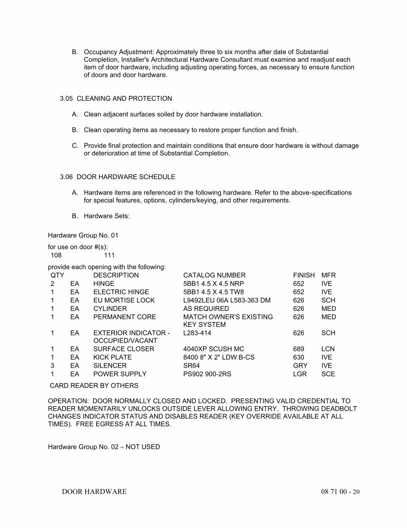
DOOR HARDWARE 08 71 00 - 20
B. Occupancy Adjustment: Approximately three to six months after date of Substantial Completion, Installer's Architectural Hardware Consultant must examine and readjust each item of door hardware, including adjusting operating forces, as necessary to ensure function of doors and door hardware.
3.05 CLEANING AND PROTECTION
A. Clean adjacent surfaces soiled by door hardware installation.
B. Clean operating items as necessary to restore proper function and finish.
C. Provide final protection and maintain conditions that ensure door hardware is without damage or deterioration at time of Substantial Completion.
3.06 DOOR HARDWARE SCHEDULE
A. Hardware items are referenced in the following hardware. Refer to the above-specifications for special features, options, cylinders/keying, and other requirements.
B. Hardware Sets:
Hardware Group No. 01
for use on door #(s): 108 111
provide each opening with the following: QTY DESCRIPTION CATALOG NUMBER FINISH MFR 2 EA HINGE 5BB1 4.5 X 4.5 NRP 652 IVE 1 EA ELECTRIC HINGE 5BB1 4.5 X 4.5 TW8 652 IVE 1 EA EU MORTISE LOCK L9492LEU 06A L583-363 DM 626 SCH 1 EA CYLINDER AS REQUIRED 626 MED 1 EA PERMANENT CORE MATCH OWNER'S EXISTING
KEY SYSTEM 626 MED
1 EA EXTERIOR INDICATOR - OCCUPIED/VACANT
L283-414 626 SCH
1 EA SURFACE CLOSER 4040XP SCUSH MC 689 LCN 1 EA KICK PLATE 8400 8" X 2" LDW B-CS 630 IVE 3 EA SILENCER SR64 GRY IVE 1 EA POWER SUPPLY PS902 900-2RS LGR SCE
CARD READER BY OTHERS OPERATION: DOOR NORMALLY CLOSED AND LOCKED. PRESENTING VALID CREDENTIAL TO READER MOMENTARILY UNLOCKS OUTSIDE LEVER ALLOWING ENTRY. THROWING DEADBOLT CHANGES INDICATOR STATUS AND DISABLES READER (KEY OVERRIDE AVAILABLE AT ALL TIMES). FREE EGRESS AT ALL TIMES.
Hardware Group No. 02 – NOT USED
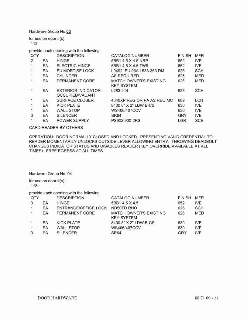
DOOR HARDWARE 08 71 00 - 21
Hardware Group No.03
for use on door #(s): 113
provide each opening with the following: QTY DESCRIPTION CATALOG NUMBER FINISH MFR 2 EA HINGE 5BB1 4.5 X 4.5 NRP 652 IVE 1 EA ELECTRIC HINGE 5BB1 4.5 X 4.5 TW8 652 IVE 1 EA EU MORTISE LOCK L9492LEU 06A L583-363 DM 626 SCH 1 EA CYLINDER AS REQUIRED 626 MED 1 EA PERMANENT CORE MATCH OWNER'S EXISTING
KEY SYSTEM 626 MED
1 EA EXTERIOR INDICATOR - OCCUPIED/VACANT
L283-414 626 SCH
1 EA SURFACE CLOSER 4040XP REG OR PA AS REQ MC 689 LCN 1 EA KICK PLATE 8400 8" X 2" LDW B-CS 630 IVE 1 EA WALL STOP WS406/407CCV 630 IVE 3 EA SILENCER SR64 GRY IVE 1 EA POWER SUPPLY PS902 900-2RS LGR SCE
CARD READER BY OTHERS OPERATION: DOOR NORMALLY CLOSED AND LOCKED. PRESENTING VALID CREDENTIAL TO READER MOMENTARILY UNLOCKS OUTSIDE LEVER ALLOWING ENTRY. THROWING DEADBOLT CHANGES INDICATOR STATUS AND DISABLES READER (KEY OVERRIDE AVAILABLE AT ALL TIMES). FREE EGRESS AT ALL TIMES.
Hardware Group No. 04
for use on door #(s): 118
provide each opening with the following: QTY DESCRIPTION CATALOG NUMBER FINISH MFR 3 EA HINGE 5BB1 4.5 X 4.5 652 IVE 1 EA ENTRANCE/OFFICE LOCK ND50TD RHO 626 SCH 1 EA PERMANENT CORE MATCH OWNER'S EXISTING
KEY SYSTEM 626 MED
1 EA KICK PLATE 8400 8" X 2" LDW B-CS 630 IVE 1 EA WALL STOP WS406/407CCV 630 IVE 3 EA SILENCER SR64 GRY IVE
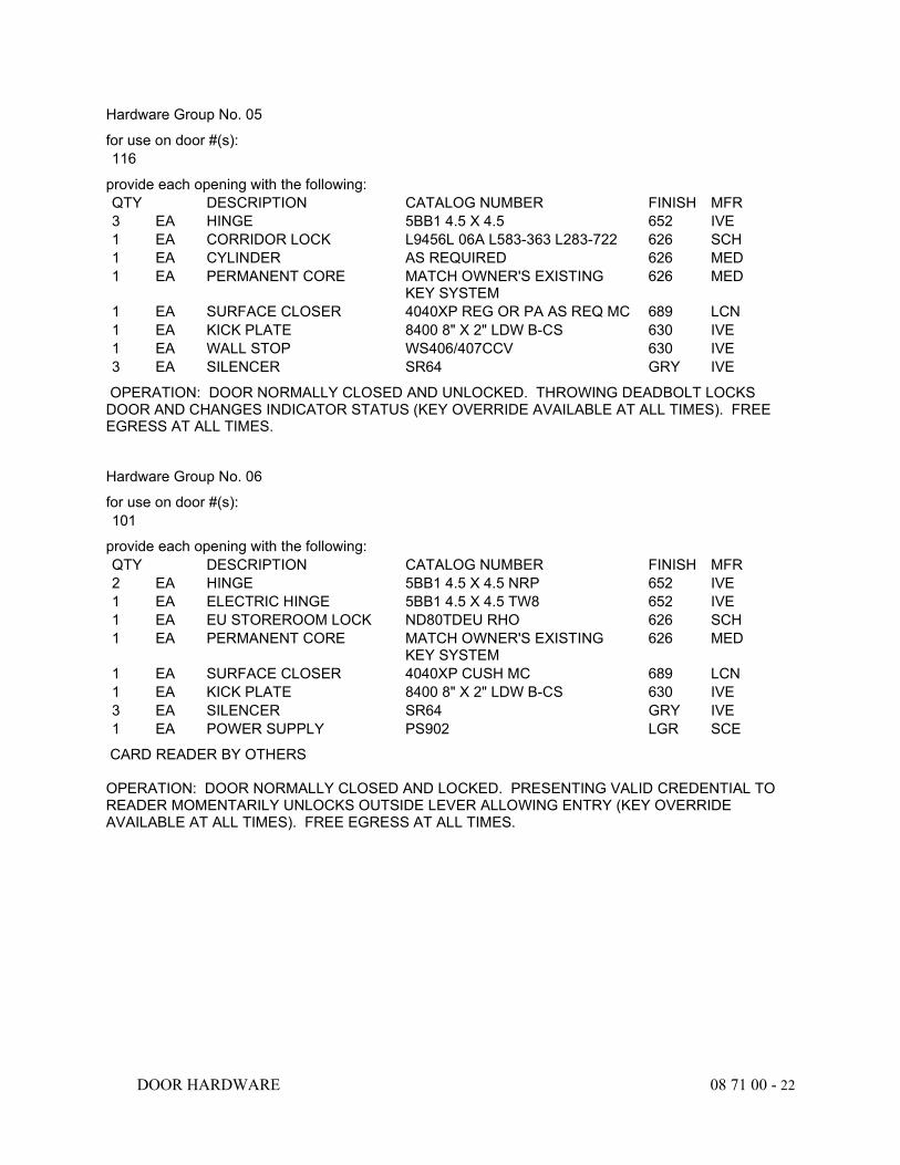
DOOR HARDWARE 08 71 00 - 22
Hardware Group No. 05
for use on door #(s): 116
provide each opening with the following: QTY DESCRIPTION CATALOG NUMBER FINISH MFR 3 EA HINGE 5BB1 4.5 X 4.5 652 IVE 1 EA CORRIDOR LOCK L9456L 06A L583-363 L283-722 626 SCH 1 EA CYLINDER AS REQUIRED 626 MED 1 EA PERMANENT CORE MATCH OWNER'S EXISTING
KEY SYSTEM 626 MED
1 EA SURFACE CLOSER 4040XP REG OR PA AS REQ MC 689 LCN 1 EA KICK PLATE 8400 8" X 2" LDW B-CS 630 IVE 1 EA WALL STOP WS406/407CCV 630 IVE 3 EA SILENCER SR64 GRY IVE
OPERATION: DOOR NORMALLY CLOSED AND UNLOCKED. THROWING DEADBOLT LOCKS DOOR AND CHANGES INDICATOR STATUS (KEY OVERRIDE AVAILABLE AT ALL TIMES). FREE EGRESS AT ALL TIMES.
Hardware Group No. 06
for use on door #(s): 101
provide each opening with the following: QTY DESCRIPTION CATALOG NUMBER FINISH MFR 2 EA HINGE 5BB1 4.5 X 4.5 NRP 652 IVE 1 EA ELECTRIC HINGE 5BB1 4.5 X 4.5 TW8 652 IVE 1 EA EU STOREROOM LOCK ND80TDEU RHO 626 SCH 1 EA PERMANENT CORE MATCH OWNER'S EXISTING
KEY SYSTEM 626 MED
1 EA SURFACE CLOSER 4040XP CUSH MC 689 LCN 1 EA KICK PLATE 8400 8" X 2" LDW B-CS 630 IVE 3 EA SILENCER SR64 GRY IVE 1 EA POWER SUPPLY PS902 LGR SCE
CARD READER BY OTHERS OPERATION: DOOR NORMALLY CLOSED AND LOCKED. PRESENTING VALID CREDENTIAL TO READER MOMENTARILY UNLOCKS OUTSIDE LEVER ALLOWING ENTRY (KEY OVERRIDE AVAILABLE AT ALL TIMES). FREE EGRESS AT ALL TIMES.
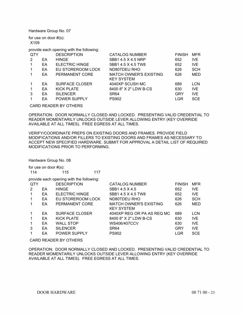
DOOR HARDWARE 08 71 00 - 23
Hardware Group No. 07
for use on door #(s): X109
provide each opening with the following: QTY DESCRIPTION CATALOG NUMBER FINISH MFR 2 EA HINGE 5BB1 4.5 X 4.5 NRP 652 IVE 1 EA ELECTRIC HINGE 5BB1 4.5 X 4.5 TW8 652 IVE 1 EA EU STOREROOM LOCK ND80TDEU RHO 626 SCH 1 EA PERMANENT CORE MATCH OWNER'S EXISTING
KEY SYSTEM 626 MED
1 EA SURFACE CLOSER 4040XP SCUSH MC 689 LCN 1 EA KICK PLATE 8400 8" X 2" LDW B-CS 630 IVE 3 EA SILENCER SR64 GRY IVE 1 EA POWER SUPPLY PS902 LGR SCE
CARD READER BY OTHERS OPERATION: DOOR NORMALLY CLOSED AND LOCKED. PRESENTING VALID CREDENTIAL TO READER MOMENTARILY UNLOCKS OUTSIDE LEVER ALLOWING ENTRY (KEY OVERRIDE AVAILABLE AT ALL TIMES). FREE EGRESS AT ALL TIMES. VERIFY/COORDINATE PREPS ON EXISTING DOORS AND FRAMES. PROVIDE FIELD MODIFICATIONS AND/OR FILLERS TO EXISTING DOORS AND FRAMES AS NECESSARY TO ACCEPT NEW SPECIFIED HARDWARE. SUBMIT FOR APPROVAL A DETAIL LIST OF REQUIRED MODIFICATIONS PRIOR TO PERFORMING.
Hardware Group No. 08
for use on door #(s): 114 115 117
provide each opening with the following: QTY DESCRIPTION CATALOG NUMBER FINISH MFR 2 EA HINGE 5BB1 4.5 X 4.5 652 IVE 1 EA ELECTRIC HINGE 5BB1 4.5 X 4.5 TW8 652 IVE 1 EA EU STOREROOM LOCK ND80TDEU RHO 626 SCH 1 EA PERMANENT CORE MATCH OWNER'S EXISTING
KEY SYSTEM 626 MED
1 EA SURFACE CLOSER 4040XP REG OR PA AS REQ MC 689 LCN 1 EA KICK PLATE 8400 8" X 2" LDW B-CS 630 IVE 1 EA WALL STOP WS406/407CCV 630 IVE 3 EA SILENCER SR64 GRY IVE 1 EA POWER SUPPLY PS902 LGR SCE
CARD READER BY OTHERS OPERATION: DOOR NORMALLY CLOSED AND LOCKED. PRESENTING VALID CREDENTIAL TO READER MOMENTARILY UNLOCKS OUTSIDE LEVER ALLOWING ENTRY (KEY OVERRIDE AVAILABLE AT ALL TIMES). FREE EGRESS AT ALL TIMES.
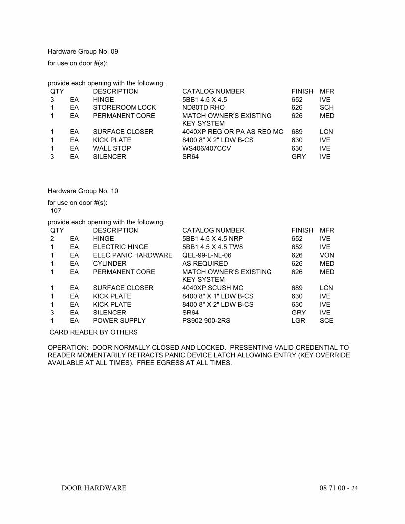
DOOR HARDWARE 08 71 00 - 24
Hardware Group No. 09
for use on door #(s):
provide each opening with the following: QTY DESCRIPTION CATALOG NUMBER FINISH MFR 3 EA HINGE 5BB1 4.5 X 4.5 652 IVE 1 EA STOREROOM LOCK ND80TD RHO 626 SCH 1 EA PERMANENT CORE MATCH OWNER'S EXISTING
KEY SYSTEM 626 MED
1 EA SURFACE CLOSER 4040XP REG OR PA AS REQ MC 689 LCN 1 EA KICK PLATE 8400 8" X 2" LDW B-CS 630 IVE 1 EA WALL STOP WS406/407CCV 630 IVE 3 EA SILENCER SR64 GRY IVE
Hardware Group No. 10
for use on door #(s): 107
provide each opening with the following: QTY DESCRIPTION CATALOG NUMBER FINISH MFR 2 EA HINGE 5BB1 4.5 X 4.5 NRP 652 IVE 1 EA ELECTRIC HINGE 5BB1 4.5 X 4.5 TW8 652 IVE 1 EA ELEC PANIC HARDWARE QEL-99-L-NL-06 626 VON 1 EA CYLINDER AS REQUIRED 626 MED 1 EA PERMANENT CORE MATCH OWNER'S EXISTING
KEY SYSTEM 626 MED
1 EA SURFACE CLOSER 4040XP SCUSH MC 689 LCN 1 EA KICK PLATE 8400 8" X 1" LDW B-CS 630 IVE 1 EA KICK PLATE 8400 8" X 2" LDW B-CS 630 IVE 3 EA SILENCER SR64 GRY IVE 1 EA POWER SUPPLY PS902 900-2RS LGR SCE
CARD READER BY OTHERS OPERATION: DOOR NORMALLY CLOSED AND LOCKED. PRESENTING VALID CREDENTIAL TO READER MOMENTARILY RETRACTS PANIC DEVICE LATCH ALLOWING ENTRY (KEY OVERRIDE AVAILABLE AT ALL TIMES). FREE EGRESS AT ALL TIMES.
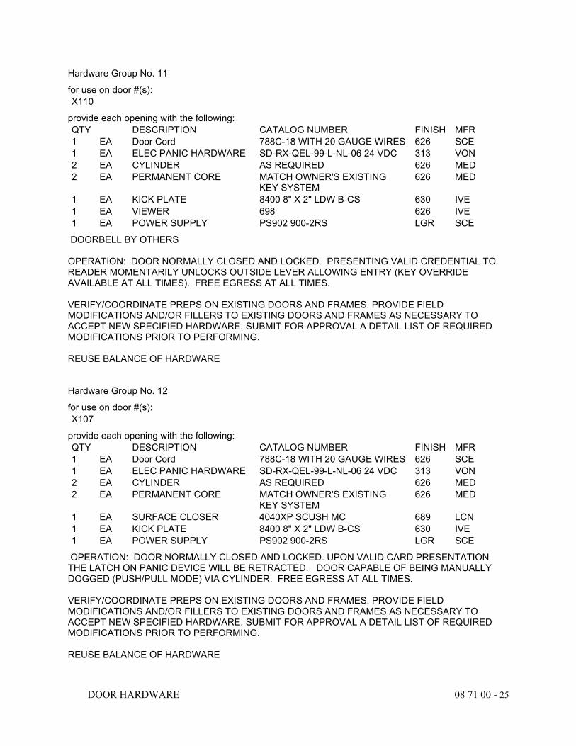
DOOR HARDWARE 08 71 00 - 25
Hardware Group No. 11
for use on door #(s): X110
provide each opening with the following: QTY DESCRIPTION CATALOG NUMBER FINISH MFR 1 EA Door Cord 788C-18 WITH 20 GAUGE WIRES 626 SCE 1 EA ELEC PANIC HARDWARE SD-RX-QEL-99-L-NL-06 24 VDC 313 VON 2 EA CYLINDER AS REQUIRED 626 MED 2 EA PERMANENT CORE MATCH OWNER'S EXISTING
KEY SYSTEM 626 MED
1 EA KICK PLATE 8400 8" X 2" LDW B-CS 630 IVE 1 EA VIEWER 698 626 IVE 1 EA POWER SUPPLY PS902 900-2RS LGR SCE
DOORBELL BY OTHERS OPERATION: DOOR NORMALLY CLOSED AND LOCKED. PRESENTING VALID CREDENTIAL TO READER MOMENTARILY UNLOCKS OUTSIDE LEVER ALLOWING ENTRY (KEY OVERRIDE AVAILABLE AT ALL TIMES). FREE EGRESS AT ALL TIMES. VERIFY/COORDINATE PREPS ON EXISTING DOORS AND FRAMES. PROVIDE FIELD MODIFICATIONS AND/OR FILLERS TO EXISTING DOORS AND FRAMES AS NECESSARY TO ACCEPT NEW SPECIFIED HARDWARE. SUBMIT FOR APPROVAL A DETAIL LIST OF REQUIRED MODIFICATIONS PRIOR TO PERFORMING. REUSE BALANCE OF HARDWARE
Hardware Group No. 12
for use on door #(s): X107
provide each opening with the following: QTY DESCRIPTION CATALOG NUMBER FINISH MFR 1 EA Door Cord 788C-18 WITH 20 GAUGE WIRES 626 SCE 1 EA ELEC PANIC HARDWARE SD-RX-QEL-99-L-NL-06 24 VDC 313 VON 2 EA CYLINDER AS REQUIRED 626 MED 2 EA PERMANENT CORE MATCH OWNER'S EXISTING
KEY SYSTEM 626 MED
1 EA SURFACE CLOSER 4040XP SCUSH MC 689 LCN 1 EA KICK PLATE 8400 8" X 2" LDW B-CS 630 IVE 1 EA POWER SUPPLY PS902 900-2RS LGR SCE
OPERATION: DOOR NORMALLY CLOSED AND LOCKED. UPON VALID CARD PRESENTATION THE LATCH ON PANIC DEVICE WILL BE RETRACTED. DOOR CAPABLE OF BEING MANUALLY DOGGED (PUSH/PULL MODE) VIA CYLINDER. FREE EGRESS AT ALL TIMES. VERIFY/COORDINATE PREPS ON EXISTING DOORS AND FRAMES. PROVIDE FIELD MODIFICATIONS AND/OR FILLERS TO EXISTING DOORS AND FRAMES AS NECESSARY TO ACCEPT NEW SPECIFIED HARDWARE. SUBMIT FOR APPROVAL A DETAIL LIST OF REQUIRED MODIFICATIONS PRIOR TO PERFORMING. REUSE BALANCE OF HARDWARE
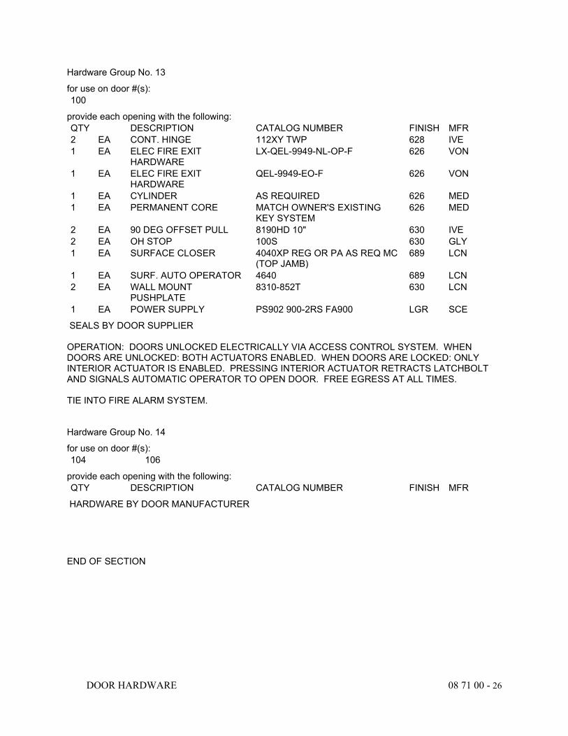
DOOR HARDWARE 08 71 00 - 26
Hardware Group No. 13
for use on door #(s): 100
provide each opening with the following: QTY DESCRIPTION CATALOG NUMBER FINISH MFR 2 EA CONT. HINGE 112XY TWP 628 IVE 1 EA ELEC FIRE EXIT
HARDWARE LX-QEL-9949-NL-OP-F 626 VON
1 EA ELEC FIRE EXIT HARDWARE
QEL-9949-EO-F 626 VON
1 EA CYLINDER AS REQUIRED 626 MED 1 EA PERMANENT CORE MATCH OWNER'S EXISTING
KEY SYSTEM 626 MED
2 EA 90 DEG OFFSET PULL 8190HD 10" 630 IVE 2 EA OH STOP 100S 630 GLY 1 EA SURFACE CLOSER 4040XP REG OR PA AS REQ MC
(TOP JAMB) 689 LCN
1 EA SURF. AUTO OPERATOR 4640 689 LCN 2 EA WALL MOUNT
PUSHPLATE 8310-852T 630 LCN
1 EA POWER SUPPLY PS902 900-2RS FA900 LGR SCE
SEALS BY DOOR SUPPLIER OPERATION: DOORS UNLOCKED ELECTRICALLY VIA ACCESS CONTROL SYSTEM. WHEN DOORS ARE UNLOCKED: BOTH ACTUATORS ENABLED. WHEN DOORS ARE LOCKED: ONLY INTERIOR ACTUATOR IS ENABLED. PRESSING INTERIOR ACTUATOR RETRACTS LATCHBOLT AND SIGNALS AUTOMATIC OPERATOR TO OPEN DOOR. FREE EGRESS AT ALL TIMES. TIE INTO FIRE ALARM SYSTEM.
Hardware Group No. 14
for use on door #(s): 104 106
provide each opening with the following: QTY DESCRIPTION CATALOG NUMBER FINISH MFR
HARDWARE BY DOOR MANUFACTURER
END OF SECTION
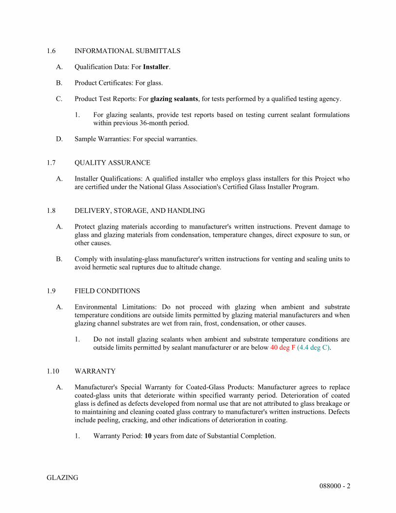
GLAZING 088000 - 2
1.6 INFORMATIONAL SUBMITTALS
A. Qualification Data: For Installer.
B. Product Certificates: For glass.
C. Product Test Reports: For glazing sealants, for tests performed by a qualified testing agency.
1. For glazing sealants, provide test reports based on testing current sealant formulations within previous 36-month period.
D. Sample Warranties: For special warranties.
1.7 QUALITY ASSURANCE
A. Installer Qualifications: A qualified installer who employs glass installers for this Project who are certified under the National Glass Association's Certified Glass Installer Program.
1.8 DELIVERY, STORAGE, AND HANDLING
A. Protect glazing materials according to manufacturer's written instructions. Prevent damage to glass and glazing materials from condensation, temperature changes, direct exposure to sun, or other causes.
B. Comply with insulating-glass manufacturer's written instructions for venting and sealing units to avoid hermetic seal ruptures due to altitude change.
1.9 FIELD CONDITIONS
A. Environmental Limitations: Do not proceed with glazing when ambient and substrate temperature conditions are outside limits permitted by glazing material manufacturers and when glazing channel substrates are wet from rain, frost, condensation, or other causes.
1. Do not install glazing sealants when ambient and substrate temperature conditions are outside limits permitted by sealant manufacturer or are below 40 deg F (4.4 deg C).
1.10 WARRANTY
A. Manufacturer's Special Warranty for Coated-Glass Products: Manufacturer agrees to replace coated-glass units that deteriorate within specified warranty period. Deterioration of coated glass is defined as defects developed from normal use that are not attributed to glass breakage or to maintaining and cleaning coated glass contrary to manufacturer's written instructions. Defects include peeling, cracking, and other indications of deterioration in coating.
1. Warranty Period: 10 years from date of Substantial Completion.
GLAZING 088000 - 3
PART 2 - PRODUCTS
2.1 MANUFACTURERS
A. <Double click here to find, evaluate, and insert list of manufacturers and products.>
B. Manufacturers: Subject to compliance with requirements, available manufacturers offering products that may be incorporated into the Work include, but are not limited to, the following: 1. Guardian Glass; SunGuard. 2. Oldcastle BuildingEnvelope (OBE); CRH Americas. 3. Pilkington North America. 4. Trulite Glass & Aluminum Solutions, LLC. 5. Viracon, Inc.
C. Source Limitations for Glass: Obtain from single source from single manufacturer for each glass type.
D. Source Limitations for Glazing Accessories: Obtain from single source from single manufacturer for each product and installation method.
2.2 PERFORMANCE REQUIREMENTS
A. General: Installed glazing systems shall withstand normal thermal movement and wind and impact loads (where applicable) without failure, including loss or glass breakage attributable to the following: defective manufacture, fabrication, or installation; failure of sealants or gaskets to remain watertight and airtight; deterioration of glazing materials; or other defects in construction.
B. Safety Glazing: Where safety glazing is indicated, provide glazing that complies with 16 CFR 1201, Category II.
2.3 GLASS PRODUCTS, GENERAL
A. Glazing Publications: Comply with published recommendations of glass product manufacturers and organizations below unless more stringent requirements are indicated. See these publications for glazing terms not otherwise defined in this Section or in referenced standards.
1. GANA Publications: "Laminated Glazing Reference Manual" and "Glazing Manual."
B. Safety Glazing Labeling: Where safety glazing is indicated, permanently mark glazing with certification label of the SGCC or another certification agency acceptable to authorities having jurisdiction or manufacturer. Label shall indicate manufacturer's name, type of glass, thickness, and safety glazing standard with which glass complies.
C. Thickness: Where glass thickness is indicated, it is a minimum. Provide glass that complies with performance requirements and is not less than the thickness indicated.
GLAZING 088000 - 4
2.4 GLASS PRODUCTS
A. Fully Tempered Float Glass: ASTM C1048, Kind FT (fully tempered), Condition A (uncoated) unless otherwise indicated, Type I, Class 1 (clear) or Class 2 (tinted) as indicated, Quality-Q3.
1. Fabrication Process: By horizontal (roller-hearth) process with roll-wave distortion parallel to bottom edge of glass as installed unless otherwise indicated.
2.5 GLAZING SEALANTS
A. General:
1. Compatibility: Compatible with one another and with other materials they contact, including glass products, seals of insulating-glass units, and glazing channel substrates, under conditions of service and application, as demonstrated by sealant manufacturer based on testing and field experience.
2. Suitability: Comply with sealant and glass manufacturers' written instructions for selecting glazing sealants suitable for applications indicated and for conditions existing at time of installation.
3. Colors of Exposed Glazing Sealants: As selected by Architect from manufacturer's full range.
B. Glazing Sealant: Neutral-curing silicone glazing sealant complying with ASTM C920, Type S, Grade NS, Class 100/50, Use NT.
2.6 GLAZING TAPES
A. Back-Bedding Mastic Glazing Tapes: Preformed, butyl-based, 100 percent solids elastomeric tape; nonstaining and nonmigrating in contact with nonporous surfaces; with or without spacer rod as recommended in writing by tape and glass manufacturers for application indicated; and complying with ASTM C1281 and AAMA 800 for products indicated below:
1. AAMA 804.3 tape, where indicated. 2. AAMA 806.3 tape, for glazing applications in which tape is subject to continuous
pressure. 3. AAMA 807.3 tape, for glazing applications in which tape is not subject to continuous
pressure.
B. Expanded Cellular Glazing Tapes: Closed-cell, PVC foam tapes; factory coated with adhesive on both surfaces; and complying with AAMA 800 for the following types:
1. AAMA 810.1, Type 1, for glazing applications in which tape acts as the primary sealant. 2. AAMA 810.1, Type 2, for glazing applications in which tape is used in combination with
a full bead of liquid sealant.
GLAZING 088000 - 5
2.7 MISCELLANEOUS GLAZING MATERIALS
A. General: Provide products of material, size, and shape complying with referenced glazing standard, with requirements of manufacturers of glass and other glazing materials for application indicated, and with a proven record of compatibility with surfaces contacted in installation.
B. Cleaners, Primers, and Sealers: Types recommended by sealant or gasket manufacturer.
C. Setting Blocks:
1. Neoprene with a Shore A durometer hardness of 85, plus or minus 5. 2. Type recommended by sealant or glass manufacturer.
D. Spacers:
1. Neoprene blocks or continuous extrusions of hardness required by glass manufacturer to maintain glass lites in place for installation indicated.
2. Type recommended by sealant or glass manufacturer.
E. Edge Blocks:
1. Neoprene with a Shore A durometer hardness per manufacturer's written instructions. 2. Type recommended by sealant or glass manufacturer.
F. Cylindrical Glazing Sealant Backing: ASTM C1330, Type O (open-cell material), of size and density to control glazing sealant depth and otherwise produce optimum glazing sealant performance.
2.8 FABRICATION OF GLAZING UNITS
A. Fabricate glazing units in sizes required to fit openings indicated for Project, with edge and face clearances, edge and surface conditions, and bite complying with written instructions of product manufacturer and referenced glazing publications, to comply with system performance requirements.
1. Allow for thermal movements from ambient and surface temperature changes acting on glass framing members and glazing components.
a. Temperature Change: 120 deg F (67 deg C), ambient; 180 deg F (100 deg C), material surfaces.
B. Clean-cut or flat-grind vertical edges of butt-glazed monolithic lites to produce square edges with slight chamfers at junctions of edges and faces.
C. Grind smooth and polish exposed glass edges and corners.
GLAZING 088000 - 6
PART 3 - EXECUTION
3.1 EXAMINATION
A. Examine framing, glazing channels, and stops, with Installer present, for compliance with the following:
1. Manufacturing and installation tolerances, including those for size, squareness, and offsets at corners.
2. Presence and functioning of weep systems. 3. Minimum required face and edge clearances. 4. Effective sealing between joints of glass-framing members.
B. Proceed with installation only after unsatisfactory conditions have been corrected.
3.2 PREPARATION
A. Clean glazing channels and other framing members receiving glass immediately before glazing. Remove coatings not firmly bonded to substrates.
B. Examine glazing units to locate exterior and interior surfaces. Label or mark units as needed so that exterior and interior surfaces are readily identifiable. Do not use materials that leave visible marks in the completed Work.
3.3 GLAZING, GENERAL
A. Comply with combined written instructions of manufacturers of glass, sealants, gaskets, and other glazing materials, unless more stringent requirements are indicated, including those in referenced glazing publications.
B. Protect glass edges from damage during handling and installation. Remove damaged glass from Project site and legally dispose of off Project site. Damaged glass includes glass with edge damage or other imperfections that, when installed, could weaken glass, impair performance, or impair appearance.
C. Apply primers to joint surfaces where required for adhesion of sealants, as determined by preconstruction testing.
D. Install setting blocks in sill rabbets, sized and located to comply with referenced glazing publications, unless otherwise required by glass manufacturer. Set blocks in thin course of compatible sealant suitable for heel bead.
E. Do not exceed edge pressures stipulated by glass manufacturers for installing glass lites.
F. Provide spacers for glass lites where length plus width is larger than 50 inches (1270 mm).
1. Locate spacers directly opposite each other on both inside and outside faces of glass. Install correct size and spacing to preserve required face clearances, unless gaskets and
GLAZING 088000 - 7
glazing tapes are used that have demonstrated ability to maintain required face clearances and to comply with system performance requirements.
2. Provide 1/8-inch (3-mm) minimum bite of spacers on glass and use thickness equal to sealant width. With glazing tape, use thickness slightly less than final compressed thickness of tape.
G. Provide edge blocking where indicated or needed to prevent glass lites from moving sideways in glazing channel, as recommended in writing by glass manufacturer and according to requirements in referenced glazing publications.
H. Set glass lites in each series with uniform pattern, draw, bow, and similar characteristics.
I. Set glass lites with proper orientation so that coatings face exterior or interior as specified.
J. Where wedge-shaped gaskets are driven into one side of channel to pressurize sealant or gasket on opposite side, provide adequate anchorage so gasket cannot walk out when installation is subjected to movement.
K. Square cut wedge-shaped gaskets at corners and install gaskets in a manner recommended by gasket manufacturer to prevent corners from pulling away; seal corner joints and butt joints with sealant recommended by gasket manufacturer.
3.4 TAPE GLAZING
A. Position tapes on fixed stops so that, when compressed by glass, their exposed edges are flush with or protrude slightly above sightline of stops.
B. Install tapes continuously, but not necessarily in one continuous length. Do not stretch tapes to make them fit opening.
C. Cover vertical framing joints by applying tapes to heads and sills first, then to jambs. Cover horizontal framing joints by applying tapes to jambs, then to heads and sills.
D. Place joints in tapes at corners of opening with adjoining lengths butted together, not lapped. Seal joints in tapes with compatible sealant approved by tape manufacturer.
E. Do not remove release paper from tape until right before each glazing unit is installed.
F. Apply heel bead of elastomeric sealant.
G. Center glass lites in openings on setting blocks, and press firmly against tape by inserting dense compression gaskets formed and installed to lock in place against faces of removable stops. Start gasket applications at corners and work toward centers of openings.
H. Apply cap bead of elastomeric sealant over exposed edge of tape.
3.5 GASKET GLAZING (DRY)
A. Cut compression gaskets to lengths recommended by gasket manufacturer to fit openings exactly, with allowance for stretch during installation.
GLAZING 088000 - 8
B. Insert soft compression gasket between glass and frame or fixed stop so it is securely in place with joints miter cut and bonded together at corners.
C. Installation with Drive-in Wedge Gaskets: Center glass lites in openings on setting blocks, and press firmly against soft compression gasket by inserting dense compression gaskets formed and installed to lock in place against faces of removable stops. Start gasket applications at corners and work toward centers of openings. Compress gaskets to produce a weathertight seal without developing bending stresses in glass. Seal gasket joints with sealant recommended by gasket manufacturer.
D. Installation with Pressure-Glazing Stops: Center glass lites in openings on setting blocks, and press firmly against soft compression gasket. Install dense compression gaskets and pressure-glazing stops, applying pressure uniformly to compression gaskets. Compress gaskets to produce a weathertight seal without developing bending stresses in glass. Seal gasket joints with sealant recommended by gasket manufacturer.
E. Install gaskets so they protrude past face of glazing stops.
3.6 SEALANT GLAZING (WET)
A. Install continuous spacers, or spacers combined with cylindrical sealant backing, between glass lites and glazing stops to maintain glass face clearances and to prevent sealant from extruding into glass channel and blocking weep systems until sealants cure. Secure spacers or spacers and backings in place and in position to control depth of installed sealant relative to edge clearance for optimum sealant performance.
B. Force sealants into glazing channels to eliminate voids and to ensure complete wetting or bond of sealant to glass and channel surfaces.
C. Tool exposed surfaces of sealants to provide a substantial wash away from glass.
3.7 CLEANING AND PROTECTION
A. Immediately after installation remove nonpermanent labels and clean surfaces.
B. Protect glass from contact with contaminating substances resulting from construction operations. Examine glass surfaces adjacent to or below exterior concrete and other masonry surfaces at frequent intervals during construction, but not less than once a month, for buildup of dirt, scum, alkaline deposits, or stains.
1. If, despite such protection, contaminating substances do come into contact with glass, remove substances immediately as recommended in writing by glass manufacturer. Remove and replace glass that cannot be cleaned without damage to coatings.
C. Remove and replace glass that is damaged during construction period.
D. Wash glass on both exposed surfaces not more than four days before date scheduled for inspections that establish date of Substantial Completion. Wash glass as recommended in writing by glass manufacturer.
GLAZING 088000 - 9
3.8 MONOLITHIC GLASS SCHEDULE
A. Glass Type [GL-1]: Clear fully tempered float glass.
1. Minimum Thickness: ¼” . 2. Safety glazing required.
END OF SECTION 088000
FIRE-RATED GLAZING 088813 - 1
SECTION 088813 - FIRE-RATED GLAZING
PART 1 - GENERAL
1.1 RELATED DOCUMENTS
A. Drawings and general provisions of the Contract, including General and Supplementary Conditions and Division 01 Specification Sections, apply to this Section.
1.2 SUMMARY
A. Section Includes: 1. Fire-resistance-rated glazing.
1.3 DEFINITIONS
A. Fire-Resistance-Rated Glazing: Glazing that prevents spread of fire and smoke and radiant heat; used in rated wall and door applications 60 minutes and above without size limitations.
B. Glass Manufacturers: Firms that produce primary glass, fabricated glass, or both, as defined in referenced glazing publications.
C. Glass Thicknesses: Indicated by thickness designations in millimeters in accordance with ASTM C1036.
1.4 COORDINATION
A. Coordinate glazing channel dimensions to provide necessary bite on glass, minimum edge and face clearances, and adequate sealant thicknesses, with reasonable tolerances.
1.5 ACTION SUBMITTALS
A. Product Data: For each type of product.
B. Glass Samples: For each type of glass product; 12 inches (300 mm) square.
C. Glazing Schedule: List glass types and thicknesses for each size opening and location. Use same designations indicated on Drawings.
1.6 INFORMATIONAL SUBMITTALS
A. Qualification Data: For Installer and glass testing agency.
B. Product Certificates: For each type of glass and glazing product.
FIRE-RATED GLAZING 088813 - 2
C. Sample Warranties: For special warranties.
1.7 QUALITY ASSURANCE
A. Installer Qualifications: A qualified installer who employs glass installers for this Project who are certified under the NGA's Certified Glass Installer Program.
1.8 DELIVERY, STORAGE, AND HANDLING
A. Protect glazing materials in accordance with manufacturer's written instructions. Prevent damage to glass and glazing materials from condensation, temperature changes, direct exposure to sun, or other causes.
1.9 FIELD CONDITIONS
A. Environmental Limitations: Do not deliver or install fire-resistant glazing until spaces are enclosed and weathertight and temporary HVAC system is operating and maintaining ambient temperature conditions at occupancy levels during remainder of construction period.
1.10 WARRANTY
A. Manufacturer's Special Warranty for Tempered Glazing Units with Clear Intumescent Interlayer: Manufacturer agrees to replace units that deteriorate within specified warranty period. Deterioration of tempered glazing units with clear intumenscent interlayer is defined as failure of hermetic seal under normal use that is not attributed to glass breakage or to maintaining and cleaning glass contrary to manufacturer's written instructions. Evidence of failure is air bubbles within units, or obstruction of vision by contamination or deterioration of intumescent interlayer.
1. Warranty Period: 10 years from date of Substantial Completion.
PART 2 - PRODUCTS
2.1 MANUFACTURERS
A. Source Limitations for Glass: For each glass type, obtain from single source from single manufacturer.
B. Source Limitations for Glazing Accessories: For each product and installation method, obtain from single source from single manufacturer.
2.2 PERFORMANCE REQUIREMENTS
A. General: Installed glazing systems shall withstand normal thermal movement and impact loads (where applicable) without failure, including loss or glass breakage attributable to defective
FIRE-RATED GLAZING 088813 - 3
manufacture, fabrication, or installation; deterioration of glazing materials; or other defects in construction.
2.3 GLASS PRODUCTS, GENERAL
A. Glazing Publications: Comply with published recommendations of glass product manufacturers and organization below unless more stringent requirements are indicated. See these publications for glazing terms not otherwise defined in this Section or in referenced standards.
1. NGA Publications: "Laminated Glazing Reference Manual" and "Glazing Manual."
B. Safety Glazing Labeling: Where safety glazing is indicated, permanently mark glazing with certification label of the SGCC or another certification agency acceptable to authorities having jurisdiction or manufacturer. Label shall indicate manufacturer's name, type of glass, glass thickness, and safety glazing standard with which glass complies.
2.4 GLASS PRODUCTS
A. Tempered Float Glass: ASTM C1048, Kind FT (fully tempered), Condition A (uncoated) unless otherwise indicated, Type I, Class I (clear) unless otherwise indicated, Quality-Q3.
1. Fabrication Process: By horizontal (roller-hearth) process with roll-wave distortion parallel to bottom edge of glass as installed unless otherwise indicated.
2.5 FIRE-RESISTANCE-RATED GLAZING
A. Fire-Resistance-Rated Glazing: Listed and labeled by a testing agency acceptable to authorities having jurisdiction, for fire-resistance ratings indicated, based on testing in accordance with ASTM E119 or UL 263.
B. Fire-Resistance-Rated Glazing Labeling: Permanently mark fire-resistance-rated glazing with certification label of a testing agency acceptable to authorities having jurisdiction. Label shall indicate manufacturer's name, test standard, that glazing is approved for use in walls, and fire-resistance rating in minutes.
C. Fire-Resistance-Rated Framing and Doors: Fire-resistance-rated glazing with 60-, 90-, and 120-minute ratings requires framing and doors from glass supplier, tested as an assembly complying with ASTM E119 or UL 263.
D. Fire-Resistance-Rated Tempered Glazing Units with Clear Intumescent Interlayer: Glazing units made from two or more lites of uncoated, fully tempered, ultraclear float glass; with a perimeter edge seal enclosing a cavity filled with optically clear, intumescent polymer; complying with 16 CFR 1201, Category II.
2.6 GLAZING ACCESSORIES
A. Provide glazing gaskets, glazing sealants, glazing tapes, setting blocks, spacers, edge blocks, and other glazing accessories that are compatible with glazing products and each other and are
FIRE-RATED GLAZING 088813 - 4
approved by testing agencies that listed and labeled fire-resistant glazing products with which products are used for applications and fire-protection ratings indicated.
B. Glazing Sealants for Fire-Rated Glazing Products: Neutral-curing silicone glazing sealant complying with ASTM C920, Type S, Grade NS, Class 50, Use NT. Comply with sealant and glass manufacturers' written instructions for selecting glazing sealants suitable for applications indicated. 1. Colors of Exposed Glazing Sealants: As selected by Architect from manufacturer's
full range of industry colors.
C. Back-Bedding Mastic Glazing Tapes: Preformed, butyl-based, 100 percent solids elastomeric tape; nonstaining and nonmigrating in contact with nonporous surfaces; with or without spacer rod as recommended in writing by tape and glass manufacturers for application indicated; and complying with ASTM C1281 and AAMA 800 for products indicated below:
1. AAMA 804.3 tape, where indicated. 2. AAMA 806.3 tape, for glazing applications in which tape is subject to continuous
pressure. 3. AAMA 807.3 tape, for glazing applications in which tape is not subject to continuous
pressure.
D. Expanded Cellular Glazing Tapes: Closed-cell, PVC foam tapes; factory coated with adhesive on both surfaces; and complying with AAMA 800 for the following types:
1. AAMA 810.1, Type 1, for glazing applications in which tape acts as primary sealant. 2. AAMA 810.1, Type 2, for glazing applications in which tape is used in combination with
a full bead of liquid sealant.
2.7 MISCELLANEOUS GLAZING MATERIALS
A. General: Provide products of material, size, and shape complying with referenced glazing standard, recommended in writing by manufacturers of glass and other glazing materials for application indicated, and with a proven record of compatibility with surfaces contacted in installation.
B. Cylindrical Glazing Sealant Backing: ASTM C1330, Type O (open-cell material), of size and density to control glazing sealant depth and otherwise produce optimum glazing sealant performance.
C. Perimeter Insulation for Fire-Resistance-Rated Glazing: Product that is approved by testing agency that listed and labeled fire-resistant glazing product with which it is used for application and fire-protection rating indicated.
2.8 FABRICATION OF GLAZING UNITS
A. Fabricate glazing units in sizes required to fit openings indicated for Project, with edge and face clearances, edge and surface conditions, and bite complying with written instructions of product manufacturer and referenced glazing publications, to comply with system performance requirements.
FIRE-RATED GLAZING 088813 - 5
PART 3 - EXECUTION
3.1 EXAMINATION
A. Examine framing, glazing channels, and stops, with Installer present, for compliance with manufacturing and installation tolerances, including those for size, squareness, and offsets at corners, and for compliance with minimum required face and edge clearances.
B. Proceed with installation only after unsatisfactory conditions have been corrected.
3.2 PREPARATION
A. Clean glazing channels and other framing members receiving glass immediately before glazing. Remove coatings not firmly bonded to substrates.
B. Examine glazing units to locate fire side and protected side. Label or mark units as needed so that fire side and protected side are readily identifiable. Do not use materials that leave visible marks in the completed Work.
3.3 GLAZING, GENERAL
A. Use methods approved by testing agencies that listed and labeled fire-resistant glazing products.
B. Comply with combined written instructions of manufacturers of glass, sealants, gaskets, and other glazing materials unless more stringent requirements are indicated, including those in referenced glazing publications.
C. Protect glass edges from damage during handling and installation. Remove damaged glass from Project site and legally dispose of off Project site. Damaged glass is glass with edge damage or other imperfections that, when installed, could weaken glass and impair performance and appearance.
D. Apply primers to joint surfaces where required for adhesion of sealants, as determined by preconstruction testing.
E. Install setting blocks in sill rabbets, sized and located to comply with referenced glazing publications unless otherwise required by glass manufacturer. Set blocks in thin course of compatible sealant suitable for heel bead.
F. Do not exceed edge pressures stipulated by glass manufacturers for installing glass lites.
G. Provide spacers for glass lites where length plus width is larger than 50 inches (1270 mm).
1. Locate spacers directly opposite each other on both inside and outside faces of glass. Install correct size and spacing to preserve required face clearances unless gaskets and glazing tapes are used that have demonstrated ability to maintain required face clearances and to comply with system performance requirements.
FIRE-RATED GLAZING 088813 - 6
2. Provide 1/8-inch- (3-mm-) minimum bite of spacers on glass and use thickness equal to sealant width. With glazing tape, use thickness slightly less than final compressed thickness of tape.
H. Provide edge blocking where indicated or needed to prevent glass lites from moving sideways in glazing channel, as recommended in writing by glass manufacturer and in accordance with requirements in referenced glazing publications.
I. Set glass lites with proper orientation so that coatings face fire side or protected side as specified.
J. Where wedge-shaped gaskets are driven into one side of channel to pressurize sealant or gasket on opposite side, provide adequate anchorage so gasket cannot walk out when installation is subjected to movement.
K. Square cut wedge-shaped gaskets at corners and install gaskets in a manner recommended by gasket manufacturer to prevent corners from pulling away; seal corner joints and butt joints with sealant recommended in writing by gasket manufacturer.
3.4 TAPE GLAZING
A. Position tapes on fixed stops so that, when compressed by glass, their exposed edges are flush with or protrude slightly above sightline of stops.
B. Install tapes continuously, but not necessarily in one continuous length. Do not stretch tapes to make them fit opening.
C. Cover vertical framing joints by applying tapes to heads and sills first and then to jambs. Cover horizontal framing joints by applying tapes to jambs and then to heads and sills.
D. Place joints in tapes at corners of opening with adjoining lengths butted together, not lapped. Seal joints in tapes with compatible sealant approved by tape manufacturer.
E. Do not remove release paper from tape until right before each glazing unit is installed.
F. Apply heel bead of elastomeric sealant, where required.
G. Center glass lites in openings on setting blocks and press firmly against tape by inserting dense compression gaskets formed and installed to lock in place against faces of removable stops. Start gasket applications at corners and work toward centers of openings.
H. Apply cap bead of elastomeric sealant over exposed edge of tape.
3.5 GASKET GLAZING (DRY)
A. Cut compression gaskets to lengths recommended by gasket manufacturer to fit openings exactly, with allowance for stretch during installation.
B. Insert soft compression gasket between glass and frame or fixed stop, so it is securely in place with joints miter cut and bonded together at corners.
FIRE-RATED GLAZING 088813 - 7
C. Installation with Drive-in Wedge Gaskets: Center glass lites in openings on setting blocks and press firmly against soft compression gasket by inserting dense compression gaskets formed and installed to lock in place against faces of removable stops. Start gasket applications at corners and work toward centers of openings.
D. Install gaskets so they protrude past face of glazing stops.
3.6 SEALANT GLAZING (WET)
A. Install continuous spacers, or spacers combined with cylindrical sealant backing, between glass lites and glazing stops to maintain glass face clearances. Secure spacers or spacers and backings in place and in position to control depth of installed sealant relative to edge clearance for optimum sealant performance.
B. Force sealants into glazing channels to eliminate voids and to ensure complete wetting or bond of sealant to glass and channel surfaces.
C. Tool exposed surfaces of sealants to provide a substantial washaway from glass.
3.7 CLEANING AND PROTECTION
A. Immediately after installation, remove nonpermanent labels and clean surfaces.
B. Protect glass from contact with contaminating substances resulting from construction operations. Examine glass surfaces adjacent to or below exterior concrete and other masonry surfaces at frequent intervals during construction, but not less than once a month, for buildup of dirt, scum, alkaline deposits, or stains.
1. If, despite such protection, contaminating substances do contact with glass, remove substances immediately as recommended in writing by glass manufacturer.
C. Remove and replace glass that is damaged during construction period.
D. Wash glass on both exposed surfaces not more than four days before date scheduled for inspections that establish date of Substantial Completion. Wash glass as recommended in writing by glass manufacturer.
3.8 FIRE-RESISTANCE-RATED GLAZING SCHEDULE
A. Glass Type FRGL-1: 90-minute fire-resistance-rated glazing complying with ASTM E119 or UL 263 in a tested assembly of glass and framing with 450 deg F (250 deg C) temperature-rise limitation; fire-resistance-rated tempered glazing units with clear intumescent interlayer.
END OF SECTION 088813
NON-STRUCTURAL METAL FRAMING 092216 - 1
SECTION 092216 - NON-STRUCTURAL METAL FRAMING
PART 1 - GENERAL
1.1 RELATED DOCUMENTS
A. Drawings and general provisions of the Contract, including General and Supplementary Conditions and Division 01 Specification Sections, apply to this Section.
1.2 SUMMARY
A. Section Includes:
1. Non-load-bearing steel framing systems for interior partitions. 2. Suspension systems for interior ceilings and soffits.
1.3 ACTION SUBMITTALS
A. Product Data: For each type of product.
1.4 INFORMATIONAL SUBMITTALS
A. Product Certificates: For each type of code-compliance certification for studs and tracks.
1.5 QUALITY ASSURANCE
A. Code-Compliance Certification of Studs and Tracks: Provide documentation that framing members are certified according to the product-certification program of the Certified Steel Stud Association, the Steel Framing Industry Association, or the Steel Stud Manufacturers Association.
PART 2 - PRODUCTS
2.1 PERFORMANCE REQUIREMENTS
A. Fire-Test-Response Characteristics: For fire-resistance-rated assemblies that incorporate non-load-bearing steel framing, provide materials and construction identical to those tested in assembly indicated, according to ASTM E119 by an independent testing agency.
B. STC-Rated Assemblies: For STC-rated assemblies, provide materials and construction identical to those tested in assembly indicated on Drawings, according to ASTM E90 and classified according to ASTM E413 by an independent testing agency.
NON-STRUCTURAL METAL FRAMING 092216 - 2
C. Horizontal Deflection: For wall assemblies, limited to 1/240 of the wall height based on horizontal loading of 10 lbf/sq. ft. (480 Pa).
2.2 FRAMING SYSTEMS
A. Framing Members, General: Comply with ASTM C754 for conditions indicated.
1. Steel Sheet Components: Comply with ASTM C645 requirements for steel unless otherwise indicated.
2. Protective Coating: ASTM A653/A653M, G40 (Z120), hot-dip galvanized unless otherwise indicated.
B. Studs and Tracks: ASTM C645.
1. Steel Studs and Tracks:
a. Manufacturer: Subject to compliance with specified requirements, the following manufacturers are acceptable: 1) Clark Dietrich 2) MarinoWARE 3) CEMCO 4) MBA Building Supplies 5) MRI Steel Framing, LLC. 6) SCAFCO Steel Stud Company 7) Steel Construction Systems 8) Telling Industries 9) The Steel Network, Inc.
b. Minimum Base-Steel Thickness: 0.0329 inch (0.836 mm). c. Depth: As indicated on Drawings.
2. Embossed, High Strength Steel Studs and Tracks: Roll-formed and embossed with surface deformations to stiffen the framing members so that they are structurally comparable to conventional ASTM C645 steel studs and tracks. a. Minimum Base-Steel Thickness: As required by horizontal deflection
performance requirements. b. Depth: As indicated on Drawings.
C. Slip-Type Head Joints: Where indicated, provide one of the following:
1. Clip System: Clips designed for use in head-of-wall deflection conditions that provide a positive attachment of studs to tracks while allowing 2-inch (51-mm) minimum vertical movement.
2. Double-Track System: ASTM C645 top outer tracks, inside track with 2-inch- (51-mm-) deep flanges in thickness not less than indicated for studs and fastened to studs, and outer track sized to friction-fit over inner track.
3.
D. Flat Strap and Backing Plate: Steel sheet for blocking and bracing in length and width indicated. 1. Minimum Base-Steel Thickness: 0.0329 inch (0.836 mm).
NON-STRUCTURAL METAL FRAMING 092216 - 3
2.3 \SUSPENSION SYSTEMS
A. Tie Wire: ASTM A641/A641M, Class 1 zinc coating, soft temper, 0.062-inch- (1.59-mm-) diameter wire, or double strand of 0.048-inch- (1.21-mm-) diameter wire.
a. Material for Interior Locations: Carbon-steel components zinc-plated to comply with ASTM B633 or ASTM F1941 (ASTM F1941M), Class Fe/Zn 5, unless otherwise indicated.
2. Power-Actuated Anchors: Fastener systems with an evaluation report acceptable to authorities having jurisdiction, based on ICC-ES AC70.
B. Wire Hangers: ASTM A641/A641M, Class 1 zinc coating, soft temper, 0.16 inch (4.12 mm) in diameter.
C. Carrying Channels (Main Runners): Cold-rolled, commercial-steel sheet with a base-steel thickness of 0.0538 inch (1.367 mm) and minimum 1/2-inch- (13-mm-) wide flanges.
1. Depth: 2-1/2 inches (64 mm).
D. Grid Suspension System for Gypsum Board Ceilings: ASTM C645, direct-hung system composed of main beams and cross-furring members that interlock.
2.4 AUXILIARY MATERIALS
A. General: Provide auxiliary materials that comply with referenced installation standards.
1. Fasteners for Steel Framing: Of type, material, size, corrosion resistance, holding power, and other properties required to fasten steel members to substrates.
B. Isolation Strip at Exterior Walls: Provide[ one of] the following:
1. Asphalt-Saturated Organic Felt: ASTM D226/D226M, Type I (No. 15 asphalt felt), nonperforated.
2. Foam Gasket: Adhesive-backed, closed-cell vinyl foam strips that allow fastener penetration without foam displacement, 1/8 inch (3.2 mm) thick, in width to suit steel stud size.
PART 3 - EXECUTION
3.1 EXAMINATION
A. Examine areas and substrates, with Installer present, and including welded hollow-metal frames, cast-in anchors, and structural framing, for compliance with requirements and other conditions affecting performance of the Work.
B. Proceed with installation only after unsatisfactory conditions have been corrected.
NON-STRUCTURAL METAL FRAMING 092216 - 4
3.2 PREPARATION
A. Suspended Assemblies: Coordinate installation of suspension systems with installation of overhead structure to ensure that inserts and other provisions for anchorages to building structure have been installed to receive hangers at spacing required to support the Work and that hangers will develop their full strength.
1. Furnish concrete inserts and other devices indicated to other trades for installation in advance of time needed for coordination and construction.
3.3 INSTALLATION, GENERAL
A. Installation Standard: ASTM C754. 1. Gypsum Board Assemblies: Also comply with requirements in ASTM C840 that apply to
framing installation.
B. Install framing and accessories plumb, square, and true to line, with connections securely fastened.
C. Install supplementary framing, and blocking to support fixtures, equipment services, heavy trim, grab bars, toilet accessories, furnishings, or similar construction.
D. Install bracing at terminations in assemblies.
E. Do not bridge building control and expansion joints with non-load-bearing steel framing members. Frame both sides of joints independently.
3.4 INSTALLING FRAMED ASSEMBLIES
A. Install framing system components according to spacings indicated, but not greater than spacings required by referenced installation standards for assembly types.
1. Single-Layer Application: 16 inches (406 mm) o.c. unless otherwise indicated. 2. Tile Backing Panels: 16 inches (406 mm) o.c. unless otherwise indicated.
B. Where studs are installed directly against exterior masonry walls or dissimilar metals at exterior walls, install isolation strip between studs and exterior wall.
C. Install studs so flanges within framing system point in same direction.
D. Install tracks at floors and overhead supports. Extend framing full height to structural supports or substrates above suspended ceilings except where partitions are indicated to terminate at suspended ceilings. Continue framing around ducts that penetrate partitions above ceiling.
1. Slip-Type Head Joints: Where framing extends to overhead structural supports, install to produce joints at tops of framing systems that prevent axial loading of finished assemblies.
2. Door Openings: Screw vertical studs at jambs to jamb anchor clips on door frames; install track section (for cripple studs) at head and secure to jamb studs.
NON-STRUCTURAL METAL FRAMING 092216 - 5
a. Install two studs at each jamb unless otherwise indicated. b. Install cripple studs at head adjacent to each jamb stud, with a minimum 1/2-inch
(13-mm) clearance from jamb stud to allow for installation of control joint in finished assembly.
c. Extend jamb studs through suspended ceilings and attach to underside of overhead structure.
3. Other Framed Openings: Frame openings other than door openings the same as required for door openings unless otherwise indicated. Install framing below sills of openings to match framing required above door heads.
4. Sound-Rated Partitions: Install framing to comply with sound-rated assembly indicated.
E. Installation Tolerance: Install each framing member so fastening surfaces vary not more than 1/8 inch (3 mm) from the plane formed by faces of adjacent framing.
3.5 INSTALLING CEILING SUSPENSION SYSTEMS
A. Install suspension system components according to spacings indicated, but not greater than spacings required by referenced installation standards for assembly types.
1. Hangers: 48 inches (1219 mm) o.c. 2. Carrying Channels (Main Runners): 48 inches (1219 mm) o.c. 3. Furring Channels (Furring Members): 24 inches (610 mm) o.c.
B. Isolate suspension systems from building structure where they abut or are penetrated by building structure to prevent transfer of loading imposed by structural movement.
C. Suspend hangers from building structure as follows:
1. Install hangers plumb and free from contact with insulation or other objects within ceiling plenum that are not part of supporting structural or suspension system.
a. Splay hangers only where required to miss obstructions and offset resulting horizontal forces by bracing, countersplaying, or other equally effective means.
2. Where width of ducts and other construction within ceiling plenum produces hanger spacings that interfere with locations of hangers required to support standard suspension system members, install supplemental suspension members and hangers in the form of trapezes or equivalent devices.
a. Size supplemental suspension members and hangers to support ceiling loads within performance limits established by referenced installation standards.
3. Wire Hangers: Secure by looping and wire tying, either directly to structures or to inserts, eye screws, or other devices and fasteners that are secure and appropriate for substrate, and in a manner that will not cause hangers to deteriorate or otherwise fail.
4. Flat Hangers: Secure to structure, including intermediate framing members, by attaching to inserts, eye screws, or other devices and fasteners that are secure and appropriate for
NON-STRUCTURAL METAL FRAMING 092216 - 6
structure and hanger, and in a manner that will not cause hangers to deteriorate or otherwise fail.
5. Do not attach hangers to steel roof deck. 6. Do not attach hangers to permanent metal forms. Furnish cast-in-place hanger inserts that
extend through forms. 7. Do not attach hangers to rolled-in hanger tabs of composite steel floor deck. 8. Do not connect or suspend steel framing from ducts, pipes, or conduit.
D. Installation Tolerances: Install suspension systems that are level to within 1/8 inch in 12 feet (3 mm in 3.6 m) measured lengthwise on each member that will receive finishes and transversely between parallel members that will receive finishes.
END OF SECTION 092216
GYPSUM BOARD 092900 - 1
SECTION 092900 - GYPSUM BOARD
PART 1 - GENERAL
1.1 RELATED DOCUMENTS
A. Drawings and general provisions of the Contract, including General and Supplementary Conditions and Division 01 Specification Sections, apply to this Section.
1.2 SUMMARY
A. Section Includes:
1. Interior gypsum board. 2. Tile backing panels.
B. Related Requirements: 1. Section 092216 "Non-Structural Metal Framing" for non-structural steel framing and
suspension systems that support gypsum board panels. 2. Section 093013 "Ceramic Tiling" for cementitious backer units installed as substrates for
ceramic tile.
1.3 ACTION SUBMITTALS
A. Product Data: For each type of product.
B. Samples: For the following products:
1. Trim Accessories: Full-size Sample in 12-inch- (300-mm-) long length for each trim accessory indicated.
1.4 DELIVERY, STORAGE AND HANDLING
A. Store materials inside under cover and keep them dry and protected against weather, condensation, direct sunlight, construction traffic, and other potential causes of damage. Stack panels flat and supported on risers on a flat platform to prevent sagging.
1.5 FIELD CONDITIONS
A. Environmental Limitations: Comply with ASTM C840 requirements or gypsum board manufacturer's written instructions, whichever are more stringent.
B. Do not install paper-faced gypsum panels until installation areas are enclosed and conditioned.
C. Do not install panels that are wet, moisture damaged, and mold damaged.
GYPSUM BOARD 092900 - 2
1. Indications that panels are wet or moisture damaged include, but are not limited to, discoloration, sagging, or irregular shape.
2. Indications that panels are mold damaged include, but are not limited to, fuzzy or splotchy surface contamination and discoloration.
PART 2 - PRODUCTS
2.1 PERFORMANCE REQUIREMENTS
A. Fire-Resistance-Rated Assemblies: For fire-resistance-rated assemblies, provide materials and construction identical to those tested in assembly indicated according to ASTM E119 by an independent testing agency.
B. STC-Rated Assemblies: For STC-rated assemblies, provide materials and construction identical to those tested in assembly indicated according to ASTM E90 and classified according to ASTM E413 by an independent testing agency.
2.2 GYPSUM BOARD, GENERAL
A. Size: Provide maximum lengths and widths available that will minimize joints in each area and that correspond with support system indicated.
2.3 INTERIOR GYPSUM BOARD
A. Gypsum Wallboard: ASTM C1396/C1396M.
1. Gypsum Wallboard Manufacturer: Subject to compliance with specified requirements, the following manufacturers are acceptable: a. CertainTeed Gypsum. b. American Gypsum. c. Continental Building Products, LLC. d. Georgia-Pacific Gypsum LLC. e. National Gypsum Company. f. PABCO Gypsum. g. USG Corporation.
B. Gypsum Board, Type X: ASTM C1396/C1396M. 1. Thickness: 5/8 inch (15.9 mm). 2. Long Edges: Tapered.
C. Gypsum Ceiling Board: ASTM C1396/C1396M. 1. Thickness: 5/8 inch (12.7 mm). 2. Long Edges: Tapered.
GYPSUM BOARD 092900 - 3
2.4 TILE BACKING PANELS
A. Manufacturer: Subject to compliance with specified requirements, the following manufacturers are acceptable: 1. CertainTeed Gypsum. 2. America Gypsum. 3. Continental Building Projects, LLC. 4. Georgia-Pacific Gypsum, LLC> 5. National Gypsum Company. 6. PABCO Gypsum. 7. USG Corporation.
B. Glass-Mat, Water-Resistant Backing Board: ASTM C1178/C1178M, with manufacturer's standard edges. 1. Core: [ 5/8 inch (15.9 mm), Type X. 2. Mold Resistance: ASTM D3273, score of 10 as rated according to ASTM D3274.
2.5 TRIM ACCESSORIES
A. Interior Trim: ASTM C1047.
1. Material: Galvanized or aluminum-coated steel sheet or rolled zinc. 2. Shapes:
a. Cornerbead. b. LC-Bead: J-shaped; exposed long flange receives joint compound. c. L-Bead: L-shaped; exposed long flange receives joint compound. d. U-Bead: J-shaped; exposed short flange does not receive joint compound.
2.6 JOINT TREATMENT MATERIALS
A. General: Comply with ASTM C475/C475M.
B. Joint Tape:
1. Interior Gypsum Board: Paper.
2. Tile Backing Panels: As recommended by panel manufacturer.
C. Joint Compound for Interior Gypsum Board: For each coat, use formulation that is compatible with other compounds applied on previous or for successive coats.
1. Prefilling: At open joints and damaged surface areas, use setting-type taping compound. 2. Embedding and First Coat: For embedding tape and first coat on joints, fasteners, and
trim flanges, use setting-type taping compound.
GYPSUM BOARD 092900 - 4
a. Use setting-type compound for installing paper-faced metal trim accessories.
3. Fill Coat: For second coat, use drying-type, all-purpose compound. 4. Finish Coat: For third coat, use drying-type, all-purpose compound. 5. Skim Coat: For final coat of Level 5 finish, use drying-type, all-purpose compound.
2.7 AUXILIARY MATERIALS
A. General: Provide auxiliary materials that comply with referenced installation standards and manufacturer's written instructions.
B. Steel Drill Screws: ASTM C1002 unless otherwise indicated.
1. Use screws complying with ASTM C954 for fastening panels to steel members from 0.033 to 0.112 inch (0.84 to 2.84 mm) thick.
2. For fastening cementitious backer units, use screws of type and size recommended by panel manufacturer.
C. Sound-Attenuation Blankets: ASTM C665, Type I (blankets without membrane facing) produced by combining thermosetting resins with mineral fibers manufactured from glass, slag wool, or rock wool.
D. Acoustical Sealant: Manufacturer's standard nonsag, paintable, nonstaining latex sealant complying with ASTM C834. Product effectively reduces airborne sound transmission through perimeter joints and openings in building construction as demonstrated by testing representative assemblies according to ASTM E90.
PART 3 - EXECUTION
3.1 EXAMINATION
A. Examine areas and substrates including welded hollow-metal frames and support framing, with Installer present, for compliance with requirements and other conditions affecting performance of the Work.
B. Examine panels before installation. Reject panels that are wet, moisture damaged, and mold damaged.
C. Proceed with installation only after unsatisfactory conditions have been corrected.
3.2 APPLYING AND FINISHING PANELS, GENERAL
A. Comply with ASTM C840.
GYPSUM BOARD 092900 - 5
B. Install ceiling panels across framing to minimize the number of abutting end joints and to avoid abutting end joints in central area of each ceiling. Stagger abutting end joints of adjacent panels not less than one framing member.
C. Install panels with face side out. Butt panels together for a light contact at edges and ends with not more than 1/16 inch (1.5 mm) of open space between panels. Do not force into place.
D. Locate edge and end joints over supports, except in ceiling applications where intermediate supports or gypsum board back-blocking is provided behind end joints. Do not place tapered edges against cut edges or ends. Stagger vertical joints on opposite sides of partitions. Do not make joints other than control joints at corners of framed openings.
E. Form control and expansion joints with space between edges of adjoining gypsum panels.
F. Cover both faces of support framing with gypsum panels in concealed spaces (above ceilings, etc.), except in chases braced internally.
1. Unless concealed application is indicated or required for sound, fire, air, or smoke ratings, coverage may be accomplished with scraps of not less than 8 sq. ft. (0.7 sq. m) in area.
2. Fit gypsum panels around ducts, pipes, and conduits. 3. Where partitions intersect structural members projecting below underside of floor/roof
slabs and decks, cut gypsum panels to fit profile formed by structural members; allow 1/4- to 3/8-inch- (6.4- to 9.5-mm-) wide joints to install sealant.
G. Isolate perimeter of gypsum board applied to non-load-bearing partitions at structural abutments. Provide 1/4- to 1/2-inch- (6.4- to 12.7-mm-) wide spaces at these locations and trim edges with edge trim where edges of panels are exposed. Seal joints between edges and abutting structural surfaces with acoustical sealant.
H. Attachment to Steel Framing: Attach panels so leading edge or end of each panel is attached to open (unsupported) edges of stud flanges first.
I. STC-Rated Assemblies: Seal construction at perimeters, behind control joints, and at openings and penetrations with a continuous bead of acoustical sealant. Install acoustical sealant at both faces of partitions at perimeters and through penetrations. Comply with ASTM C919 and with manufacturer's written instructions for locating edge trim and closing off sound-flanking paths around or through assemblies, including sealing partitions above acoustical ceilings.
J. Install sound attenuation blankets before installing gypsum panels unless blankets are readily installed after panels have been installed on one side.
3.3 APPLYING INTERIOR GYPSUM BOARD
A. Install interior gypsum board in the following locations: 1. Type X: As indicated on Drawings . 2. Ceiling Type: As indicated on Drawings
B. Single-Layer Application:
GYPSUM BOARD 092900 - 6
1. On ceilings, apply gypsum panels before wall/partition board application to greatest extent possible and at right angles to framing unless otherwise indicated.
2. On partitions/walls, apply gypsum panels horizontally (perpendicular to framing) unless otherwise indicated or required by fire-resistance-rated assembly, and minimize end joints.
a. Stagger abutting end joints not less than one framing member in alternate courses of panels.
b. At stairwells and other high walls, install panels horizontally unless otherwise indicated or required by fire-resistance-rated assembly.
3. On Z-shaped furring members, apply gypsum panels vertically (parallel to framing) with no end joints. Locate edge joints over furring members.
4. Fastening Methods: Apply gypsum panels to supports with steel drill screws.
C. Multilayer Application:
1. On ceilings, apply gypsum board indicated for base layers before applying base layers on walls/partitions; apply face layers in same sequence. Apply base layers at right angles to framing members and offset face-layer joints one framing member, 16 inches (400 mm) minimum, from parallel base-layer joints, unless otherwise indicated or required by fire-resistance-rated assembly.
2. On partitions/walls, apply gypsum board indicated for base layers and face layers vertically (parallel to framing) with joints of base layers located over stud or furring member and face-layer joints offset at least one stud or furring member with base-layer joints unless otherwise indicated or required by fire-resistance-rated assembly. Stagger joints on opposite sides of partitions.
3. On Z-shaped furring members, apply base layer vertically (parallel to framing) and face layer either vertically (parallel to framing) or horizontally (perpendicular to framing) with vertical joints offset at least one furring member. Locate edge joints of base layer over furring members.
4. Fastening Methods: Fasten base layers and face layers separately to supports with screws.
3.4 APPLYING TILE BACKING PANELS
A. Glass-Mat, Water-Resistant Backing Panels: Comply with manufacturer's written installation instructions and install at locations indicated to receive tile. Install with 1/4-inch (6.4-mm) gap where panels abut other construction or penetrations.
B. Cementitious Backer Units: ANSI A108.11, at locations indicated to receive tile.
C. Where tile backing panels abut other types of panels in same plane, shim surfaces to produce a uniform plane across panel surfaces.
GYPSUM BOARD 092900 - 7
3.5 INSTALLING TRIM ACCESSORIES
A. General: For trim with back flanges intended for fasteners, attach to framing with same fasteners used for panels. Otherwise, attach trim according to manufacturer's written instructions.
B. Control Joints: Install control joints at 30’ – 0” maximum and according to ASTM C840 and in specific locations approved by Architect for visual effect.
C. Interior Trim: Install in the following locations:
1. Cornerbead: Use at outside corners.
2. LC-Bead: Use at exposed panel edges. 3. L-Bead: Use where indicated. 4. U-Bead: Use where indicated.
3.6 FINISHING GYPSUM BOARD
A. General: Treat gypsum board joints, interior angles, edge trim, control joints, penetrations, fastener heads, surface defects, and elsewhere as required to prepare gypsum board surfaces for decoration. Promptly remove residual joint compound from adjacent surfaces.
B. Prefill open joints and damaged surface areas.
C. Apply joint tape over gypsum board joints, except for trim products specifically indicated as not intended to receive tape.
D. Gypsum Board Finish Levels: Finish panels to levels indicated below and according to ASTM C840: 1. Level 4: At panel surfaces that will be exposed to view unless otherwise indicated.
a. Primer and its application to surfaces are specified in Section 099123 "Interior Painting."
3.7 PROTECTION
A. Protect adjacent surfaces from drywall compound and promptly remove from floors and other non-drywall surfaces. Repair surfaces stained, marred, or otherwise damaged during drywall application.
B. Protect installed products from damage from weather, condensation, direct sunlight, construction, and other causes during remainder of the construction period.
C. Remove and replace panels that are wet, moisture damaged, and mold damaged.
1. Indications that panels are wet or moisture damaged include, but are not limited to, discoloration, sagging, or irregular shape.
2. Indications that panels are mold damaged include, but are not limited to, fuzzy or splotchy surface contamination and discoloration.

GYPSUM BOARD 092900 - 8
END OF SECTION 092900
CERAMIC TILING 093013 - 1
SECTION 093013 - CERAMIC TILING
PART 1 - GENERAL
1.1 RELATED DOCUMENTS
A. Drawings and general provisions of the Contract, including General and Supplementary Conditions and Division 01 Specification Sections, apply to this Section.
1.2 SUMMARY
A. Section Includes: 1. Glazed wall tile.
B. Related Requirements: 1. Section 079200 "Joint Sealants" for sealing of expansion, contraction, control, and
isolation joints in tile surfaces. 2. 3. Section 092900 "Gypsum Board" for cementitious backer units and glass-mat, water-
resistant backer board.
1.3 DEFINITIONS
A. General: Definitions in the ANSI A108 series of tile installation standards and in ANSI A137.1 apply to Work of this Section unless otherwise specified.
B. Face Size: Actual tile size, excluding spacer lugs.
C. Module Size: Actual tile size plus joint width indicated.
1.4 ACTION SUBMITTALS
A. Product Data: For each type of product.
B. Shop Drawings: Show locations of each type of tile and tile pattern. Show widths, details, and locations of expansion, contraction, control, and isolation joints in tile substrates and finished tile surfaces.
C. Samples for Initial Selection: For tile, grout, and accessories involving color selection.
D. Samples for Verification:
1. Full-size units of each type and composition of tile and for each color and finish required. 2. Full-size units of each type of trim and accessory.
CERAMIC TILING 093013 - 2
1.5 INFORMATIONAL SUBMITTALS
A. Qualification Data: For Installer.
1.6 MAINTENANCE MATERIAL SUBMITTALS
A. Furnish extra materials that match and are from same production runs as products installed and that are packaged with protective covering for storage and identified with labels describing contents.
1. Tile and Trim Units: Furnish quantity of full-size units equal to 3 percent of amount installed for each type, composition, color, pattern, and size indicated.
2. Grout: Furnish quantity of grout equal to 3 percent of amount installed for each type, composition, and color indicated.
1.7 DELIVERY, STORAGE, AND HANDLING
A. Deliver and store packaged materials in original containers with seals unbroken and labels intact until time of use. Comply with requirements in ANSI A137.1 for labeling tile packages.
B. Store tile and cementitious materials on elevated platforms, under cover, and in a dry location.
C. Store liquid materials in unopened containers and protected from freezing.
1.8 FIELD CONDITIONS
A. Environmental Limitations: Do not install tile until construction in spaces is complete and ambient temperature and humidity conditions are maintained at the levels indicated in referenced standards and manufacturer's written instructions.
PART 2 - PRODUCTS
2.1 MANUFACTURERS
A. Source Limitations for Tile: Obtain tile from single source or producer.
1. Obtain tile of each type and color or finish from same production run and of consistent quality in appearance and physical properties for each contiguous area.
B. Source Limitations for Setting and Grouting Materials: Obtain ingredients of a uniform quality for each mortar, adhesive, and grout component from single manufacturer and each aggregate from single source or producer.
CERAMIC TILING 093013 - 3
2.2 PRODUCTS, GENERAL
A. ANSI Ceramic Tile Standard: Provide tile that complies with ANSI A137.1 for types, compositions, and other characteristics indicated.
1. Provide tile complying with Standard grade requirements.
B. ANSI Standards for Tile Installation Materials: Provide materials complying with ANSI A108.02, ANSI standards referenced in other Part 2 articles, ANSI standards referenced by TCNA installation methods specified in tile installation schedules, and other requirements specified.
C. Factory Blending: For tile exhibiting color variations within ranges, blend tile in factory and package so tile units taken from one package show same range in colors as those taken from other packages and match approved Samples.
D. Mounting: For factory-mounted tile, provide back- or edge-mounted tile assemblies as standard with manufacturer unless otherwise indicated.
2.3 TILE PRODUCTS
A. Ceramic Tile Type CT1: Glazed wall tile.
1. Basis-of-Design Product: Subject to compliance with requirements, provide Daltile. 2. Module Size: 4 ¼” by 12 ¾” inches (108 by 324 mm) 3. Face Size Variation: Rectified. 4. Thickness: 5/16 inch (8 mm). 5. Tile Color and Pattern: As indicated on Finish Legend. 6. Grout Color: As selected by Architect and Owner from manufacturer's full range. 7. Mounting: Factory, back mounted.
2.4 SETTING MATERIALS
A. Portland Cement Mortar (Thickset) Installation Materials: ANSI A108.02.
1. Cleavage Membrane: Asphalt felt, ASTM D226/D226M, Type I (No. 15); or polyethylene sheeting, ASTM D4397, 4.0 mils (0.1 mm) thick.
B. Standard Dry-Set Mortar (Thinset): ANSI A118.1. 1. For wall applications, provide mortar that complies with requirements for nonsagging
mortar in addition to the other requirements in ANSI A118.1.
2.5 GROUT MATERIALS
A. Sand-Portland Cement Grout: ANSI A108.10, consisting of white or gray cement and white or colored aggregate as required to produce color indicated.
B. Standard Cement Grout: ANSI A118.6.
CERAMIC TILING 093013 - 4
2.6 MISCELLANEOUS MATERIALS
A. Trowelable Underlayments and Patching Compounds: Latex-modified, portland cement-based formulation provided or approved by manufacturer of tile-setting materials for installations indicated.
B. Tile Cleaner: A neutral cleaner capable of removing soil and residue without harming tile and grout surfaces, specifically approved for materials and installations indicated by tile and grout manufacturers.
2.7 MIXING MORTARS AND GROUT
A. Mix mortars and grouts to comply with referenced standards and mortar and grout manufacturers' written instructions.
B. Add materials, water, and additives in accurate proportions.
C. Obtain and use type of mixing equipment, mixer speeds, mixing containers, mixing time, and other procedures to produce mortars and grouts of uniform quality with optimum performance characteristics for installations indicated.
PART 3 - EXECUTION
3.1 EXAMINATION
A. Examine substrates, areas, and conditions where tile will be installed, with Installer present, for compliance with requirements for installation tolerances and other conditions affecting performance of the Work.
1. Verify that substrates for setting tile are firm; dry; clean; free of coatings that are incompatible with tile-setting materials, including curing compounds and other substances that contain soap, wax, oil, or silicone; and comply with flatness tolerances required by ANSI A108.01 for installations indicated.
2. Verify that installation of grounds, anchors, recessed frames, electrical and mechanical units of work, and similar items located in or behind tile has been completed.
3. Verify that joints and cracks in tile substrates are coordinated with tile joint locations; if not coordinated, adjust joint locations in consultation with Architect.
B. Proceed with installation only after unsatisfactory conditions have been corrected.
3.2 PREPARATION
A. Blending: For tile exhibiting color variations, verify that tile has been factory blended and packaged so tile units taken from one package show same range of colors as those taken from other packages and match approved Samples. If not factory blended, either return to manufacturer or blend tiles at Project site before installing.
CERAMIC TILING 093013 - 5
3.3 INSTALLATION OF CERAMIC TILE
A. Comply with TCNA's "Handbook for Ceramic, Glass, and Stone Tile Installation" for TCNA installation methods specified in tile installation schedules. Comply with parts of the ANSI A108 series "Specifications for Installation of Ceramic Tile" that are referenced in TCNA installation methods, specified in tile installation schedules, and apply to types of setting and grouting materials used.
B. Extend tile work into recesses and under or behind equipment and fixtures to form complete covering without interruptions unless otherwise indicated. Terminate work neatly at obstructions, edges, and corners without disrupting pattern or joint alignments.
C. Accurately form intersections and returns. Perform cutting and drilling of tile without marring visible surfaces. Carefully grind cut edges of tile abutting trim, finish, or built-in items for straight aligned joints. Fit tile closely to electrical outlets, piping, fixtures, and other penetrations so plates, collars, or covers overlap tile.
D. Provide manufacturer's standard trim shapes where necessary to eliminate exposed tile edges.
E. Where accent tile differs in thickness from field tile, vary setting-bed thickness so that tiles are flush.
F. Jointing Pattern: Lay tile in grid pattern unless otherwise indicated. Lay out tile work and center tile fields in both directions in each space or on each wall area. Lay out tile work to minimize the use of pieces that are less than half of a tile. Provide uniform joint widths unless otherwise indicated. 1. Where adjoining tiles on base, walls, or trim are specified or indicated to be same size,
align joints. 2. Where tiles are specified or indicated to be whole integer multiples of adjoining tiles on
base, walls, or trim, align joints unless otherwise indicated.
G. Joint Widths: Unless otherwise indicated, install tile with the following joint widths: 1. Glazed Wall Tile: 1/16 inch (1.6 mm).
H. Lay out tile wainscots to dimensions indicated or to next full tile beyond dimensions indicated.
3.4 ADJUSTING AND CLEANING
A. Remove and replace tile that is damaged or that does not match adjoining tile. Provide new matching units, installed as specified and in a manner to eliminate evidence of replacement.
B. Cleaning: On completion of placement and grouting, clean all ceramic tile surfaces so they are free of foreign matter.
1. Remove grout residue from tile as soon as possible. 2. Clean grout smears and haze from tile according to tile and grout manufacturer's written
instructions but no sooner than 10 days after installation. Use only cleaners recommended by tile and grout manufacturers and only after determining that cleaners are safe to use by testing on samples of tile and other surfaces to be cleaned. Protect metal surfaces and
CERAMIC TILING 093013 - 6
plumbing fixtures from effects of cleaning. Flush surfaces with clean water before and after cleaning.
3.5 PROTECTION
A. Protect installed tile work with kraft paper or other heavy covering during construction period to prevent staining, damage, and wear. If recommended by tile manufacturer, apply coat of neutral protective cleaner to completed tile walls and floors.
B. Before final inspection, remove protective coverings and rinse neutral protective cleaner from tile surfaces.
3.6 INTERIOR CERAMIC TILE INSTALLATION SCHEDULE
A. Interior Wall Installations, Wood or Metal Studs or Furring:
1. Ceramic Tile Installation: TCNA W223; organic adhesive on solid backing.
a. Ceramic Tile Type: Glazed Wall Tile. b. Grout: Standard sanded cement grout.
END OF SECTION 093013
ACOUSTICAL PANEL CEILINGS 095113 - 1
SECTION 095113 - ACOUSTICAL PANEL CEILINGS
PART 1 - GENERAL
1.1 RELATED DOCUMENTS
A. Drawings and general provisions of the Contract, including General and Supplementary Conditions and Division 01 Specification Sections, apply to this Section.
1.2 SUMMARY
A. Section includes acoustical panels and exposed suspension systems for interior ceilings.
B. Products furnished, but not installed under this Section, include anchors, clips, and other ceiling attachment devices to be cast in concrete.
1.3 ACTION SUBMITTALS
A. Product Data: For each type of product.
B. Samples: For each exposed product and for each color and texture specified, 6 inches (150 mm) in size.
C. Samples for Initial Selection: For components with factory-applied finishes.
D. Samples for Verification: For each component indicated and for each exposed finish required, prepared on Samples of sizes indicated below:
1. Acoustical Panels: Set of 6-inch- (150-mm-) square Samples of each type, color, pattern, and texture.
2. Exposed Suspension-System Members, Moldings, and Trim: Set of 6-inch- (150-mm-) long Samples of each type, finish, and color.
1.4 CLOSEOUT SUBMITTALS
A. Maintenance Data: For finishes to include in maintenance manuals.
1.5 MAINTENANCE MATERIAL SUBMITTALS
A. Furnish extra materials, from the same product run, that match products installed and that are packaged with protective covering for storage and identified with labels describing contents.
1. Acoustical Ceiling Units: Full-size panels equal to 1 percent of quantity installed. Not less than one full box.
ACOUSTICAL PANEL CEILINGS 095113 - 2
2. Suspension-System Components: Quantity of each exposed component equal to 1 percent of quantity installed.
1.6 DELIVERY, STORAGE, AND HANDLING
A. Deliver acoustical panels, suspension-system components, and accessories to Project site and store them in a fully enclosed, conditioned space where they will be protected against damage from moisture, humidity, temperature extremes, direct sunlight, surface contamination, and other causes.
B. Before installing acoustical panels, permit them to reach room temperature and a stabilized moisture content.
1.7 FIELD CONDITIONS
A. Environmental Limitations: Do not install acoustical panel ceilings until spaces are enclosed and weathertight, wet-work in spaces is complete and dry, work above ceilings is complete, and ambient temperature and humidity conditions are maintained at the levels indicated for Project when occupied for its intended use.
1. Pressurized Plenums: Operate ventilation system for not less than 48 hours before beginning acoustical panel ceiling installation.
PART 2 - PRODUCTS
2.1 MANUFACTURERS
A. Source Limitations: Obtain each type of acoustical ceiling panel and its supporting suspension system from single source from single manufacturer.
2.2 PERFORMANCE REQUIREMENTS
A. Surface-Burning Characteristics: Comply with ASTM E84; testing by a qualified testing agency. Identify products with appropriate markings of applicable testing agency.
1. Flame-Spread Index: Class A according to ASTM E1264. 2. Smoke-Developed Index: 50 or less.
B. Fire-Resistance Ratings: Comply with ASTM E119; testing by a qualified testing agency. Identify products with appropriate markings of applicable testing agency.
1. Indicate design designations from UL or from the listings of another qualified testing agency.
ACOUSTICAL PANEL CEILINGS 095113 - 3
2.3 ACOUSTICAL PANELS (APC)
A. Basis of Design Product: Subject to compliance with requirements, provide Armstrong Ceiling and Wall Solutions Optima 2’ x 4’ Lay In Tile or a comparable product by one of the following: 1. CertainTeed Corporation. 2. USG Corporation.
B. Acoustical Panel Standard: Provide manufacturer's standard panels according to ASTM E1264 and designated by type, form, pattern, acoustical rating, and light reflectance unless otherwise indicated.
C. Color: White.
D. Light Reflectance (LR): Not less than 0.80.
E. Ceiling Attenuation Class (CAC): Not less than 35.
F. Noise Reduction Coefficient (NRC): Not less than 0.55 .
G. Edge/Joint Detail: As indicated by manufacturer's designation.
H. Thickness: 3/4 inch (19 mm) .
I. Modular Size: 24 by 48 inches (610 by 1220 mm) .
J. Antimicrobial Treatment: Manufacturer's standard broad spectrum, antimicrobial formulation that inhibits fungus, mold, mildew, and gram-positive and gram-negative bacteria and showing no mold, mildew, or bacterial growth when tested according to ASTM D3273, ASTM D3274, or ASTM G21 and evaluated according to ASTM D3274 or ASTM G21.
2.4 METAL SUSPENSION SYSTEM
A. Basis of Design Product: Subject to compliance with requirements, provide Armstrong Ceiling and Wall Solutions Prelude 15/16” Grid or a comparable product by one of the following: 1. CertainTeed Corporation. 2. USG Corporation.
B. Metal Suspension-System Standard: Provide manufacturer's standard, direct-hung, metal suspension system and accessories according to ASTM C635/C635M and designated by type, structural classification, and finish indicated.
2.5 ACCESSORIES
A. Attachment Devices: Size for five times the design load indicated in ASTM C635/C635M, Table 1, "Direct Hung," unless otherwise indicated. Comply with seismic design requirements.
1. Anchors in Concrete: Anchors of type and material indicated below, with holes or loops for attaching hangers of type indicated and with capability to sustain, without failure, a load equal to five times that imposed by ceiling construction, as determined by testing
ACOUSTICAL PANEL CEILINGS 095113 - 4
according to ASTM E488/E488M or ASTM E1512 as applicable, conducted by a qualified testing and inspecting agency.
a. Type: Postinstalled expansion anchors.
B. Wire Hangers, Braces, and Ties: Provide wires as follows: 1. Nickel-Copper-Alloy Wire: ASTM B164, nickel-copper-alloy UNS No. N04400. 2. Size: Wire diameter sufficient for its stress at three times hanger design load
(ASTM C635/C635M, Table 1, "Direct Hung") will be less than yield stress of wire, but not less than 0.106-inch- (2.69-mm-) diameter wire.
2.6 METAL EDGE MOLDINGS AND TRIM
A. Basis of Design Product: Subject to compliance with requirements, provide Armstrong Ceiling and Wall Solutions or a comparable product by one of the following: 1. CertainTeed Corporation. 2. USG Corporation.
B. Extruded-Aluminum Edge Moldings and Trim: Where indicated, provide manufacturer's extruded-aluminum edge moldings and trim of profile indicated or referenced by manufacturer's designations, including splice plates, corner pieces, and attachment and other clips, complying with seismic design requirements.
1. Clear Anodic Finish: AAMA 611, AA-M12C22A31, Class II, 0.010 mm or thicker. 2. Baked-Enamel or Powder-Coat Finish: Minimum dry film thickness of 1.5 mils (0.04
mm). Comply with ASTM C635/C635M and coating manufacturer's written instructions for cleaning, conversion coating, and applying and baking finish.
2.7 ACOUSTICAL SEALANT
A. Acoustical Sealant: As specified in Section 079219 "Acoustical Joint Sealants."
PART 3 - EXECUTION
3.1 EXAMINATION
A. Examine substrates, areas, and conditions, including structural framing to which acoustical panel ceilings attach or abut, with Installer present, for compliance with requirements specified in this and other Sections that affect ceiling installation and anchorage and with requirements for installation tolerances and other conditions affecting performance of acoustical panel ceilings.
B. Examine acoustical panels before installation. Reject acoustical panels that are wet, moisture damaged, or mold damaged.
C. Proceed with installation only after unsatisfactory conditions have been corrected.
ACOUSTICAL PANEL CEILINGS 095113 - 5
3.2 PREPARATION
A. Measure each ceiling area and establish layout of acoustical panels to balance border widths at opposite edges of each ceiling. Avoid using less-than-half-width panels at borders unless otherwise indicated, and comply with layout shown on reflected ceiling plans.
B. Layout openings for penetrations centered on the penetrating items.
3.3 INSTALLATION
A. Install acoustical panel ceilings according to ASTM C636/C636Mand manufacturer's written instructions.
B. Suspend ceiling hangers from building's structural members and as follows:
1. Install hangers plumb and free from contact with insulation or other objects within ceiling plenum that are not part of supporting structure or of ceiling suspension system.
2. Where width of ducts and other construction within ceiling plenum produces hanger spacings that interfere with location of hangers at spacings required to support standard suspension-system members, install supplemental suspension members and hangers in form of trapezes or equivalent devices.
3. Secure wire hangers to ceiling-suspension members and to supports above with a minimum of three tight turns. Connect hangers directly to structure or to inserts, eye screws, or other devices that are secure and appropriate for substrate and that will not deteriorate or otherwise fail due to age, corrosion, or elevated temperatures.
4. Do not support ceilings directly from permanent metal forms or floor deck. Fasten hangers to cast-in-place hanger inserts, postinstalled mechanical or adhesive anchors, or power-actuated fasteners that extend through forms into concrete.
5. When steel framing does not permit installation of hanger wires at spacing required, install carrying channels or other supplemental support for attachment of hanger wires.
6. Do not attach hangers to steel deck tabs. 7. Do not attach hangers to steel roof deck. Attach hangers to structural members. 8. Space hangers not more than 48 inches (1200 mm) o.c. along each member supported
directly from hangers unless otherwise indicated; provide hangers not more than 8 inches (200 mm) from ends of each member.
9. Size supplemental suspension members and hangers to support ceiling loads within performance limits established by referenced standards.
C. Secure bracing wires to ceiling suspension members and to supports with a minimum of four tight turns. Suspend bracing from building's structural members as required for hangers, without attaching to permanent metal forms, steel deck, or steel deck tabs. Fasten bracing wires into concrete with cast-in-place or postinstalled anchors.
D. Install edge moldings and trim of type indicated at perimeter of acoustical ceiling area and where necessary to conceal edges of acoustical panels.
1. Apply acoustical sealant in a continuous ribbon concealed on back of vertical legs of moldings before they are installed.
ACOUSTICAL PANEL CEILINGS 095113 - 6
2. Screw attach moldings to substrate at intervals not more than 16 inches (400 mm) o.c. and not more than 3 inches (75 mm) from ends. Miter corners accurately and connect securely.
3. Do not use exposed fasteners, including pop rivets, on moldings and trim.
E. Install suspension-system runners so they are square and securely interlocked with one another. Remove and replace dented, bent, or kinked members.
F. Install acoustical panels with undamaged edges and fit accurately into suspension-system runners and edge moldings. Scribe and cut panels at borders and penetrations to provide precise fit.
1. For square-edged panels, install panels with edges fully hidden from view by flanges of suspension-system runners and moldings.
2. For reveal-edged panels on suspension-system runners, install panels with bottom of reveal in firm contact with top surface of runner flanges.
3. For reveal-edged panels on suspension-system members with box-shaped flanges, install panels with reveal surfaces in firm contact with suspension-system surfaces and panel faces flush with bottom face of runners.
4. Paint cut edges of panel remaining exposed after installation; match color of exposed panel surfaces using coating recommended in writing for this purpose by acoustical panel manufacturer.
3.4 ERECTION TOLERANCES
A. Suspended Ceilings: Install main and cross runners level to a tolerance of 1/8 inch in 12 feet (3 mm in 3.6 m), non-cumulative.
B. Moldings and Trim: Install moldings and trim to substrate and level with ceiling suspension system to a tolerance of 1/8 inch in 12 feet (3 mm in 3.6 m), non-cumulative.
3.5 CLEANING
A. Clean exposed surfaces of acoustical panel ceilings, including trim, edge moldings, and suspension-system members. Comply with manufacturer's written instructions for cleaning and touchup of minor finish damage.
B. Remove and replace ceiling components that cannot be successfully cleaned and repaired to permanently eliminate evidence of damage.
END OF SECTION 095113
RESILIENT BASE AND ACCESSORIES 096513 - 1
SECTION 096513 - RESILIENT BASE AND ACCESSORIES
PART 1 - GENERAL
1.1 RELATED DOCUMENTS
A. Drawings and general provisions of the Contract, including General and Supplementary Conditions and Division 01 Specification Sections, apply to this Section.
1.2 SUMMARY
A. Section Includes: 1. Vinyl base. 2. Rubber molding accessories.
1.3 ACTION SUBMITTALS
A. Product Data: For each type of product.
B. Samples: For each exposed product and for each color and texture specified, not less than 12 inches (300 mm) long.
C. Samples for Initial Selection: For each type of product indicated.
1.4 MAINTENANCE MATERIAL SUBMITTALS
A. Furnish extra materials, from the same product run, that match products installed and that are packaged with protective covering for storage and identified with labels describing contents.
1. Furnish not less than 10 linear feet (3 linear m) for every 500 linear feet (150 linear m) or fraction thereof, of each type, color, pattern, and size of resilient product installed.
1.5 DELIVERY, STORAGE, AND HANDLING
A. Store resilient products and installation materials in dry spaces protected from the weather, with ambient temperatures maintained within range recommended by manufacturer, but not less than 50 deg F (10 deg C) or more than 90 deg F (32 deg C).
1.6 FIELD CONDITIONS
A. Maintain ambient temperatures within range recommended by manufacturer, but not less than 70 deg F (21 deg C) or more than 95 deg F (35 deg C), in spaces to receive resilient products during the following periods:
RESILIENT BASE AND ACCESSORIES 096513 - 2
1. 48 hours before installation. 2. During installation. 3. 48 hours after installation.
B. After installation and until Substantial Completion, maintain ambient temperatures within range recommended by manufacturer, but not less than 55 deg F (13 deg C) or more than 95 deg F (35 deg C).
C. Install resilient products after other finishing operations, including painting, have been completed.
PART 2 - PRODUCTS
2.1 VINYL BASE (WB1):
A. Basis of Design Manufacturer: As indicated by Finish Legend.
B. Product Standard: ASTM F1861, Type TV (vinyl, thermoplastic).
1. Group: I (solid, homogeneous). 2. Style and Location:
a. Style A, Straight: Provide in areas with carpet. b. Style B, Cove: Provide in areas with resilient floor coverings.
C. Minimum Thickness: 0.125 inch (3.2 mm).
D. Height: 4 inches (102 mm).
E. Lengths: Coils in manufacturer's standard length.
F. Outside Corners: Preformed.
G. Inside Corners: Preformed.
H. Colors and Patterns: As indicated in Finish Legend in Contract Documents.
2.2 RUBBER STAIR ACCESSORIES <Insert drawing designation>
A. Fire-Test-Response Characteristics: As determined by testing identical products according to ASTM E648 or NFPA 253 by a qualified testing agency.
1. Critical Radiant Flux Classification: Class I, not less than 0.45 W/sq. cm.
B. <Double click here to find, evaluate, and insert list of manufacturers and products.>
C. Stair Treads: ASTM F2169.
1. Type: [TS (rubber, vulcanized thermoset)] [or] [TP (rubber, thermoplastic)].
RESILIENT BASE AND ACCESSORIES 096513 - 3
2. Class: [1 (smooth, flat)] [2 (pattern; embossed, grooved, or ribbed)]. 3. Group: [1 (embedded abrasive strips)] [2 (with contrasting color for the visually
impaired)]. 4. Nosing Style: [Square, adjustable to cover angles between 60 and 90 degrees]
[Square] [Round]. 5. Nosing Height: [1-1/2 inches (38 mm)] [2 inches (51 mm)] [2-3/16 inches (56 mm)]
<Insert dimension>. 6. Thickness: [1/4 inch (6 mm) and tapered to back edge] <Insert thickness>. 7. Size: Lengths and depths to fit each stair tread in [one piece] [one piece or, for treads
exceeding maximum lengths manufactured, in equal-length units]. 8. Integral Risers: Smooth, flat; in height that fully covers substrate.
D. Separate Risers: Smooth, flat; in height that fully covers substrate; produced by same manufacturer as treads and recommended by manufacturer for installation with treads.
1. Style: [Coved toe, 7 inches (178 mm) high by length matching treads] [Toeless, by length matching treads].
2. Thickness: [0.125 inch (3.2 mm)] [Manufacturer's standard] <Insert thickness>.
E. Stringers: Height and length after cutting to fit risers and treads and to cover stair stringers, produced by same manufacturer as treads, and recommended by manufacturer for installation with treads.
1. Thickness: [0.125 inch (3.2 mm)] [0.080 inch (2.0 mm)] [Manufacturer's standard] <Insert thickness>.
F. Landing Tile: [Matching treads; produced by same manufacturer as treads and recommended by manufacturer for installation with treads] <Insert requirements>.
G. Locations: [Provide rubber stair accessories in areas indicated] <Insert requirements>.
H. Colors and Patterns: [As indicated by manufacturer's designations] [Match Architect's sample] <Insert colors and patterns>.
2.3 VINYL STAIR ACCESSORIES <Insert drawing designation>
A. Fire-Test-Response Characteristics: As determined by testing identical products according to ASTM E648 or NFPA 253 by a qualified testing agency.
1. Critical Radiant Flux Classification: Class I, not less than 0.45 W/sq. cm.
B. <Double click here to find, evaluate, and insert list of manufacturers and products.>
C. Stair Treads: ASTM F2169, Type TV (vinyl, thermoplastic).
1. Class: [1 (smooth, flat)] [2 (pattern; embossed, grooved, or ribbed)]. 2. Group: [1 (embedded abrasive strips)] [2 (with contrasting color for the visually
impaired)]. 3. Nosing Style: [Square, adjustable to cover angles between 60 and 90 degrees]
[Square] [Round].

RESILIENT BASE AND ACCESSORIES 096513 - 4
4. Nosing Height: [1-1/2 inches (38 mm)] [2 inches (51 mm)] [2-3/16 inches (56 mm)] <Insert dimension>.
5. Thickness: [1/4 inch (6 mm) and tapered to back edge] <Insert thickness>. 6. Size: Lengths and depths to fit each stair tread in [one piece] [one piece or, for treads
exceeding maximum lengths manufactured, in equal-length units]. 7. Integral Risers: Smooth, flat; in height that fully covers substrate.
D. Separate Risers: Smooth, flat; in height that fully covers substrate; produced by same manufacturer as treads and recommended by manufacturer for installation with treads.
1. Style: [Coved toe, 7 inches (178 mm) high by length matching treads] [Toeless, by length matching treads].
2. Thickness: [0.125 inch (3.2 mm)] [0.080 inch (2.0 mm)] [Manufacturer's standard] <Insert thickness>.
E. Stringers: Height and length after cutting to fit risers and treads and to cover stair stringers, produced by same manufacturer as treads, and recommended by manufacturer for installation with treads.
1. Thickness: [0.125 inch (3.2 mm)] [0.080 inch (2.0 mm)] [Manufacturer's standard] <Insert thickness>.
F. Landing Tile: [Matching treads; produced by same manufacturer as treads and recommended by manufacturer for installation with treads] <Insert requirements>.
G. Locations: [Provide vinyl stair accessories in areas indicated] <Insert requirements>.
H. Colors and Patterns: [As indicated by manufacturer's designations] [Match Architect's sample] <Insert colors and patterns>.
2.4 RUBBER MOLDING ACCESSORY
A. Description: Rubber transition strips.
B. Profile and Dimensions: As indicated <Insert profile and dimensions>.
C. Locations: Provide rubber molding accessories in areas indicated <Insert requirements>.
2.5 Colors and Patterns: As indicated by manufacturer's designations. Architect to select color from manufacturer’s full color line. >.INSTALLATION MATERIALS
A. Trowelable Leveling and Patching Compounds: Latex-modified, portland-cement-based or blended hydraulic-cement-based formulation provided or approved by resilient-product manufacturer for applications indicated.
B. Adhesives: Water-resistant type recommended by resilient-product manufacturer for resilient products and substrate conditions indicated.
RESILIENT BASE AND ACCESSORIES 096513 - 5
PART 3 - EXECUTION
3.1 EXAMINATION
A. Examine substrates, with Installer present, for compliance with requirements for maximum moisture content and other conditions affecting performance of the Work.
1. Verify that finishes of substrates comply with tolerances and other requirements specified in other Sections and that substrates are free of cracks, ridges, depressions, scale, and foreign deposits that might interfere with adhesion of resilient products.
B. Proceed with installation only after unsatisfactory conditions have been corrected.
1. Installation of resilient products indicates acceptance of surfaces and conditions.
3.2 PREPARATION
A. Prepare substrates according to manufacturer's written instructions to ensure adhesion of resilient products.
B. Fill cracks, holes, and depressions in substrates with trowelable leveling and patching compound; remove bumps and ridges to produce a uniform and smooth substrate.
C. Do not install resilient products until materials are the same temperature as space where they are to be installed.
1. At least 48 hours in advance of installation, move resilient products and installation materials into spaces where they will be installed.
D. Immediately before installation, sweep and vacuum clean substrates to be covered by resilient products.
3.3 RESILIENT BASE INSTALLATION
A. Comply with manufacturer's written instructions for installing resilient base.
B. Apply resilient base to walls, columns, pilasters, casework and cabinets in toe spaces, and other permanent fixtures in rooms and areas where base is required.
C. Install resilient base in lengths as long as practical without gaps at seams and with tops of adjacent pieces aligned.
D. Tightly adhere resilient base to substrate throughout length of each piece, with base in continuous contact with horizontal and vertical substrates.
E. Do not stretch resilient base during installation.
F. On masonry surfaces or other similar irregular substrates, fill voids along top edge of resilient base with manufacturer's recommended adhesive filler material.
RESILIENT BASE AND ACCESSORIES 096513 - 6
G. Preformed Corners: Install preformed corners before installing straight pieces.
3.4 RESILIENT ACCESSORY INSTALLATION
A. Comply with manufacturer's written instructions for installing resilient accessories.
B. Resilient Molding Accessories: Butt to adjacent materials and tightly adhere to substrates throughout length of each piece. Install reducer strips at edges of floor covering that would otherwise be exposed.
3.5 CLEANING AND PROTECTION
A. Comply with manufacturer's written instructions for cleaning and protecting resilient products.
B. Perform the following operations immediately after completing resilient-product installation:
1. Remove adhesive and other blemishes from surfaces. 2. Sweep and vacuum horizontal surfaces thoroughly. 3. Damp-mop horizontal surfaces to remove marks and soil.
C. Protect resilient products from mars, marks, indentations, and other damage from construction operations and placement of equipment and fixtures during remainder of construction period.
END OF SECTION 096513
RESILIENT SHEET FLOORING 096516 - 1
SECTION 096516 - RESILIENT SHEET FLOORING
PART 1 - GENERAL
1.1 RELATED DOCUMENTS
A. Drawings and general provisions of the Contract, including General and Supplementary Conditions and Division 01 Specification Sections, apply to this Section.
1.2 SUMMARY
A. Section Includes:
1. Unbacked vinyl sheet flooring.
1.3 ACTION SUBMITTALS
A. Product Data: For each type of product.
B. Shop Drawings: For each type of resilient sheet flooring.
1. Include sheet flooring layouts, locations of seams, edges, columns, doorways, enclosing partitions, built-in furniture, cabinets, and cutouts.
2. Show details of special patterns.
C. Samples: For each exposed product and for each color, texture, and pattern specified, in manufacturer's standard size, but not less than 6-by-9-inch (150-by-230-mm) sections.
1. For heat-welding bead, manufacturer's standard-size Samples, but not less than 9 inches (230 mm) long, of each color required.
D. Samples for Initial Selection: For each type of resilient sheet flooring indicated.
E. Welded-Seam Samples: For seamless-installation technique indicated and for each resilient sheet flooring product, color, and pattern required; with seam running lengthwise and in center of 6-by-9-inch (150-by-230-mm) Sample applied to a rigid backing and prepared by Installer for this Project.
F. Product Schedule: For resilient sheet flooring. Use same designations indicated on Drawings.
1.4 INFORMATIONAL SUBMITTALS
A. Qualification Data: For Installer.
RESILIENT SHEET FLOORING 096516 - 2
1.5 CLOSEOUT SUBMITTALS
A. Maintenance Data: For each type of resilient sheet flooring to include in maintenance manuals.
1.6 MAINTENANCE MATERIAL SUBMITTALS
A. Furnish extra materials, from the same product run, that match products installed and that are packaged with protective covering for storage and identified with labels describing contents.
1. Resilient Sheet Flooring: Furnish not less than 10 linear feet (3 linear m) for every 500 linear feet (150 linear m) or fraction thereof, in roll form and in full roll width for each type, color, and pattern of flooring installed.
1.7 QUALITY ASSURANCE
A. Installer Qualifications: An entity that employs installers and supervisors who are competent in techniques required by manufacturer for resilient sheet flooring installation and seaming method indicated.
1. Engage an installer who employs workers for this Project who are trained or certified by resilient sheet flooring manufacturer for installation techniques required.
1.8 DELIVERY, STORAGE, AND HANDLING
A. Store resilient sheet flooring and installation materials in dry spaces protected from the weather, with ambient temperatures maintained within range recommended by manufacturer, but not less than 50 deg F (10 deg C) or more than 90 deg F (32 deg C). Store rolls upright.
1.9 FIELD CONDITIONS
A. Maintain ambient temperatures within range recommended by manufacturer, but not less than 70 deg F (21 deg C) or more than 85 deg F (29 deg C), in spaces to receive resilient sheet flooring during the following periods:
1. 48 hours before installation. 2. During installation. 3. 48 hours after installation.
B. After installation and until Substantial Completion, maintain ambient temperatures within range recommended by manufacturer, but not less than 55 deg F (13 deg C) or more than 95 deg F (35 deg C).
C. Close spaces to traffic during resilient sheet flooring installation.
D. Close spaces to traffic for 48 hours after resilient sheet flooring installation.
E. Install resilient sheet flooring after other finishing operations, including painting, have been completed.
RESILIENT SHEET FLOORING 096516 - 3
PART 2 - PRODUCTS
2.1 PERFORMANCE REQUIREMENTS
A. Fire-Test-Response Characteristics: For resilient sheet flooring, as determined by testing identical products according to ASTM E648 or NFPA 253 by a qualified testing agency.
1. Critical Radiant Flux Classification: Class I, not less than 0.45 W/sq. cm.
2.2 UNBACKED VINYL SHEET FLOORING (VYL):
A. Basis-of-Design Product: As indicated on Finish Legend.
B. Product Standard: ASTM F1913.
C. Thickness: As standard with manufacturer..
D. Wearing Surface: Smooth.
E. Sheet Width: As standard with manufacturer.
F. Seamless-Installation Method: Heat welded.
G. Colors and Patterns: As selected by Owner and Architect from Manufacturer’s Full Range.
2.3 INSTALLATION MATERIALS
A. Trowelable Leveling and Patching Compounds: Latex-modified, portland-cement-based or blended hydraulic-cement-based formulation provided or approved by resilient sheet flooring manufacturer for applications indicated.
B. Adhesives: Water-resistant type recommended by flooring and adhesive manufacturers to suit resilient sheet flooring and substrate conditions indicated.
C. Seamless-Installation Accessories:
1. Heat-Welding Bead: Manufacturer's solid-strand product for heat welding seams.
a. Colors: Match flooring.
D. Integral-Flash-Cove-Base Accessories (WB3)
1. Cove Strip: 1-inch (25-mm) radius provided or approved by resilient sheet flooring manufacturer.
2. Cap Strip: Square metal, vinyl, or rubber cap provided or approved by resilient sheet flooring manufacturer.
RESILIENT SHEET FLOORING 096516 - 4
3. Corners: Metal inside and outside corners and end stops provided or approved by resilient sheet flooring manufacturer.
PART 3 - EXECUTION
3.1 EXAMINATION
A. Examine substrates, with Installer present, for compliance with requirements for maximum moisture content and other conditions affecting performance of the Work.
1. Verify that finishes of substrates comply with tolerances and other requirements specified in other Sections and that substrates are free of cracks, ridges, depressions, scale, and foreign deposits that might interfere with adhesion of resilient sheet flooring.
B. Proceed with installation only after unsatisfactory conditions have been corrected.
3.2 PREPARATION
A. Prepare substrates according to resilient sheet flooring manufacturer's written instructions to ensure adhesion of resilient sheet flooring.
B. Concrete Substrates: Prepare according to ASTM F710.
1. Verify that substrates are dry and free of curing compounds, sealers, and hardeners. 2. Remove substrate coatings and other substances that are incompatible with adhesives and
that contain soap, wax, oil, or silicone, using mechanical methods recommended by resilient sheet flooring manufacturer. Do not use solvents.
3. Alkalinity and Adhesion Testing: Perform tests recommended by resilient sheet flooring manufacturer. Proceed with installation only after substrate alkalinity falls within range on pH scale recommended by manufacturer in writing, but not less than 5 or more than 9 pH.
4. Moisture Testing: Perform tests so that each test area does not exceed 200 sq. ft. (18.6 sq. m), and perform no fewer than three tests in each installation area and with test areas evenly spaced in installation areas.
a. Anhydrous Calcium Chloride Test: ASTM F1869. Proceed with installation only after substrates have maximum moisture-vapor-emission rate of 3 lb of water/1000 sq. ft. (1.36 kg of water/92.9 sq. m) in 24 hours.
b. Relative Humidity Test: Using in-situ probes, ASTM F2170. Proceed with installation only after substrates have a maximum 75 percent relative humidity level measurement.
C. Fill cracks, holes, and depressions in substrates with trowelable leveling and patching compound; remove bumps and ridges to produce a uniform and smooth substrate.
D. Do not install resilient sheet flooring until materials are the same temperature as space where they are to be installed.
RESILIENT SHEET FLOORING 096516 - 5
1. At least 48 hours in advance of installation, move flooring and installation materials into spaces where they will be installed.
E. Immediately before installation, sweep and vacuum clean substrates to be covered by resilient sheet flooring.
3.3 RESILIENT SHEET FLOORING INSTALLATION
A. Comply with manufacturer's written instructions for installing resilient sheet flooring.
B. Unroll resilient sheet flooring and allow it to stabilize before cutting and fitting.
C. Lay out resilient sheet flooring as follows:
1. Maintain uniformity of flooring direction. 2. Minimize number of seams; place seams in inconspicuous and low-traffic areas, at least 6
inches (152 mm) away from parallel joints in flooring substrates. 3. Match edges of flooring for color shading at seams. 4. Avoid cross seams.
D. Scribe and cut resilient sheet flooring to butt neatly and tightly to vertical surfaces and permanent fixtures including built-in furniture, cabinets, pipes, outlets, and door frames.
E. Extend resilient sheet flooring into toe spaces, door reveals, closets, and similar openings.
F. Maintain reference markers, holes, and openings that are in place or marked for future cutting by repeating on resilient sheet flooring as marked on substrates. Use chalk or other nonpermanent marking device.
G. Install resilient sheet flooring on covers for telephone and electrical ducts and similar items in installation areas. Maintain overall continuity of color and pattern between pieces of flooring installed on covers and adjoining flooring. Tightly adhere flooring edges to substrates that abut covers and to cover perimeters.
H. Adhere resilient sheet flooring to substrates using a full spread of adhesive applied to substrate to produce a completed installation without open cracks, voids, raising and puckering at joints, telegraphing of adhesive spreader marks, and other surface imperfections.
I. Seamless Installation:
1. Heat-Welded Seams: Comply with ASTM F1516. Rout joints and heat weld with welding bead to fuse sections permanently into a seamless flooring installation. Prepare, weld, and finish seams to produce surfaces flush with adjoining flooring surfaces.
2. Chemically Bonded Seams: Bond seams with chemical-bonding compound to fuse sections permanently into a seamless flooring installation. Prepare seams and apply compound to produce tightly fitted seams without gaps, overlays, or excess bonding compound on flooring surfaces.
RESILIENT SHEET FLOORING 096516 - 6
J. Integral-Flash-Cove Base: Cove resilient sheet flooring 6 inches (152 mm) up vertical surfaces. Support flooring at horizontal and vertical junction with cove strip. Butt at top against cap strip.
1. Install metal corners at inside and outside corners.
3.4 CLEANING AND PROTECTION
A. Comply with manufacturer's written instructions for cleaning and protecting resilient sheet flooring.
B. Perform the following operations immediately after completing resilient sheet flooring installation:
1. Remove adhesive and other blemishes from surfaces. 2. Sweep and vacuum surfaces thoroughly. 3. Damp-mop surfaces to remove marks and soil.
C. Protect resilient sheet flooring from mars, marks, indentations, and other damage from construction operations and placement of equipment and fixtures during remainder of construction period.
D. Cover resilient sheet flooring until Substantial Completion.
END OF SECTION 096516
RESILIENT TILE FLOORING 096519 - 1
SECTION 096519 - RESILIENT TILE FLOORING
PART 1 - GENERAL
1.1 RELATED DOCUMENTS
A. Drawings and general provisions of the Contract, including General and Supplementary Conditions and Division 01 Specification Sections, apply to this Section.
1.2 SUMMARY
A. Section Includes:
1. Solid vinyl floor tile.
1.3 ACTION SUBMITTALS
A. Product Data: For each type of product.
B. Shop Drawings: For each type of resilient floor tile.
1. Include floor tile layouts, edges, columns, doorways, enclosing partitions, built-in furniture, cabinets, and cutouts.
2. Show details of special patterns.
C. Samples for Verification: Full-size units of each color and pattern of floor tile required.
D. Product Schedule: For floor tile. Use same designations indicated on Drawings.
1.4 INFORMATIONAL SUBMITTALS
A. Qualification Data: For Installer.
1.5 CLOSEOUT SUBMITTALS
A. Maintenance Data: For each type of floor tile to include in maintenance manuals.
1.6 MAINTENANCE MATERIAL SUBMITTALS
A. Furnish extra materials, from the same product run, that match products installed and that are packaged with protective covering for storage and identified with labels describing contents.
1. Floor Tile: Furnish 2-percent of installed quantity, of each type, color, and pattern of floor tile installed, but not less than one full box
RESILIENT TILE FLOORING 096519 - 2
1.7 QUALITY ASSURANCE
A. Installer Qualifications: An entity that employs installers and supervisors who are competent in techniques required by manufacturer for floor tile installation and seaming method indicated.
1. Engage an installer who employs workers for this Project who are trained or certified by floor tile manufacturer for installation techniques required.
1.8 DELIVERY, STORAGE, AND HANDLING
A. Store floor tile and installation materials in dry spaces protected from the weather, with ambient temperatures maintained within range recommended by manufacturer, but not less than 50 deg F (10 deg C) or more than 90 deg F (32 deg C). Store floor tiles on flat surfaces.
1.9 FIELD CONDITIONS
A. Maintain ambient temperatures within range recommended by manufacturer, but not less than 70 deg F (21 deg C) or more than 95 deg F (35 deg C), in spaces to receive floor tile during the following periods:
1. 48 hours before installation. 2. During installation. 3. 48 hours after installation.
B. After installation and until Substantial Completion, maintain ambient temperatures within range recommended by manufacturer, but not less than 55 deg F (13 deg C) or more than 95 deg F (35 deg C).
C. Close spaces to traffic during floor tile installation.
D. Close spaces to traffic for 48 hours after floor tile installation.
E. Install floor tile after other finishing operations, including painting, have been completed.
PART 2 - PRODUCTS
2.1 PERFORMANCE REQUIREMENTS
A. Fire-Test-Response Characteristics: For resilient floor tile, as determined by testing identical products according to ASTM E648 or NFPA 253 by a qualified testing agency.
1. Critical Radiant Flux Classification: Class I, not less than 0.45 W/sq. cm.
2.2 SOLID VINYL FLOOR TILE (LVT)
A. Basis-of-Design Product: As indicated on Finish Legend.
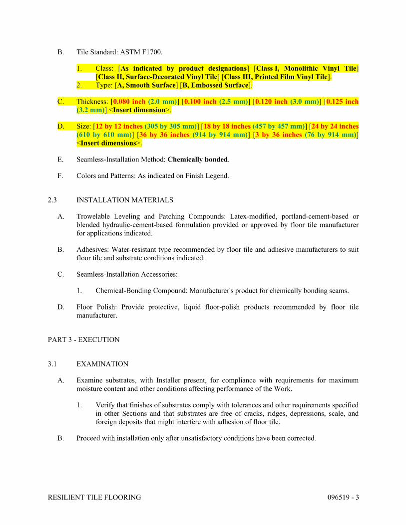
RESILIENT TILE FLOORING 096519 - 3
B. Tile Standard: ASTM F1700.
1. Class: [As indicated by product designations] [Class I, Monolithic Vinyl Tile] [Class II, Surface-Decorated Vinyl Tile] [Class III, Printed Film Vinyl Tile].
2. Type: [A, Smooth Surface] [B, Embossed Surface].
C. Thickness: [0.080 inch (2.0 mm)] [0.100 inch (2.5 mm)] [0.120 inch (3.0 mm)] [0.125 inch (3.2 mm)] <Insert dimension>.
D. Size: [12 by 12 inches (305 by 305 mm)] [18 by 18 inches (457 by 457 mm)] [24 by 24 inches (610 by 610 mm)] [36 by 36 inches (914 by 914 mm)] [3 by 36 inches (76 by 914 mm)] <Insert dimensions>.
E. Seamless-Installation Method: Chemically bonded.
F. Colors and Patterns: As indicated on Finish Legend.
2.3 INSTALLATION MATERIALS
A. Trowelable Leveling and Patching Compounds: Latex-modified, portland-cement-based or blended hydraulic-cement-based formulation provided or approved by floor tile manufacturer for applications indicated.
B. Adhesives: Water-resistant type recommended by floor tile and adhesive manufacturers to suit floor tile and substrate conditions indicated.
C. Seamless-Installation Accessories:
1. Chemical-Bonding Compound: Manufacturer's product for chemically bonding seams.
D. Floor Polish: Provide protective, liquid floor-polish products recommended by floor tile manufacturer.
PART 3 - EXECUTION
3.1 EXAMINATION
A. Examine substrates, with Installer present, for compliance with requirements for maximum moisture content and other conditions affecting performance of the Work.
1. Verify that finishes of substrates comply with tolerances and other requirements specified in other Sections and that substrates are free of cracks, ridges, depressions, scale, and foreign deposits that might interfere with adhesion of floor tile.
B. Proceed with installation only after unsatisfactory conditions have been corrected.
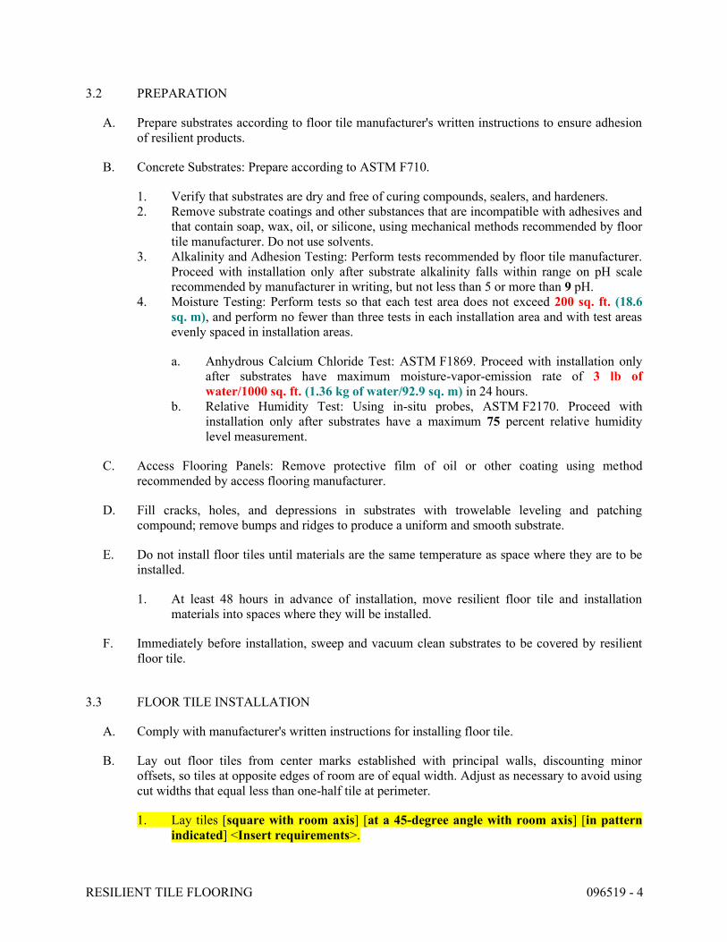
RESILIENT TILE FLOORING 096519 - 4
3.2 PREPARATION
A. Prepare substrates according to floor tile manufacturer's written instructions to ensure adhesion of resilient products.
B. Concrete Substrates: Prepare according to ASTM F710.
1. Verify that substrates are dry and free of curing compounds, sealers, and hardeners. 2. Remove substrate coatings and other substances that are incompatible with adhesives and
that contain soap, wax, oil, or silicone, using mechanical methods recommended by floor tile manufacturer. Do not use solvents.
3. Alkalinity and Adhesion Testing: Perform tests recommended by floor tile manufacturer. Proceed with installation only after substrate alkalinity falls within range on pH scale recommended by manufacturer in writing, but not less than 5 or more than 9 pH.
4. Moisture Testing: Perform tests so that each test area does not exceed 200 sq. ft. (18.6 sq. m), and perform no fewer than three tests in each installation area and with test areas evenly spaced in installation areas.
a. Anhydrous Calcium Chloride Test: ASTM F1869. Proceed with installation only after substrates have maximum moisture-vapor-emission rate of 3 lb of water/1000 sq. ft. (1.36 kg of water/92.9 sq. m) in 24 hours.
b. Relative Humidity Test: Using in-situ probes, ASTM F2170. Proceed with installation only after substrates have a maximum 75 percent relative humidity level measurement.
C. Access Flooring Panels: Remove protective film of oil or other coating using method recommended by access flooring manufacturer.
D. Fill cracks, holes, and depressions in substrates with trowelable leveling and patching compound; remove bumps and ridges to produce a uniform and smooth substrate.
E. Do not install floor tiles until materials are the same temperature as space where they are to be installed.
1. At least 48 hours in advance of installation, move resilient floor tile and installation materials into spaces where they will be installed.
F. Immediately before installation, sweep and vacuum clean substrates to be covered by resilient floor tile.
3.3 FLOOR TILE INSTALLATION
A. Comply with manufacturer's written instructions for installing floor tile.
B. Lay out floor tiles from center marks established with principal walls, discounting minor offsets, so tiles at opposite edges of room are of equal width. Adjust as necessary to avoid using cut widths that equal less than one-half tile at perimeter.
1. Lay tiles [square with room axis] [at a 45-degree angle with room axis] [in pattern indicated] <Insert requirements>.
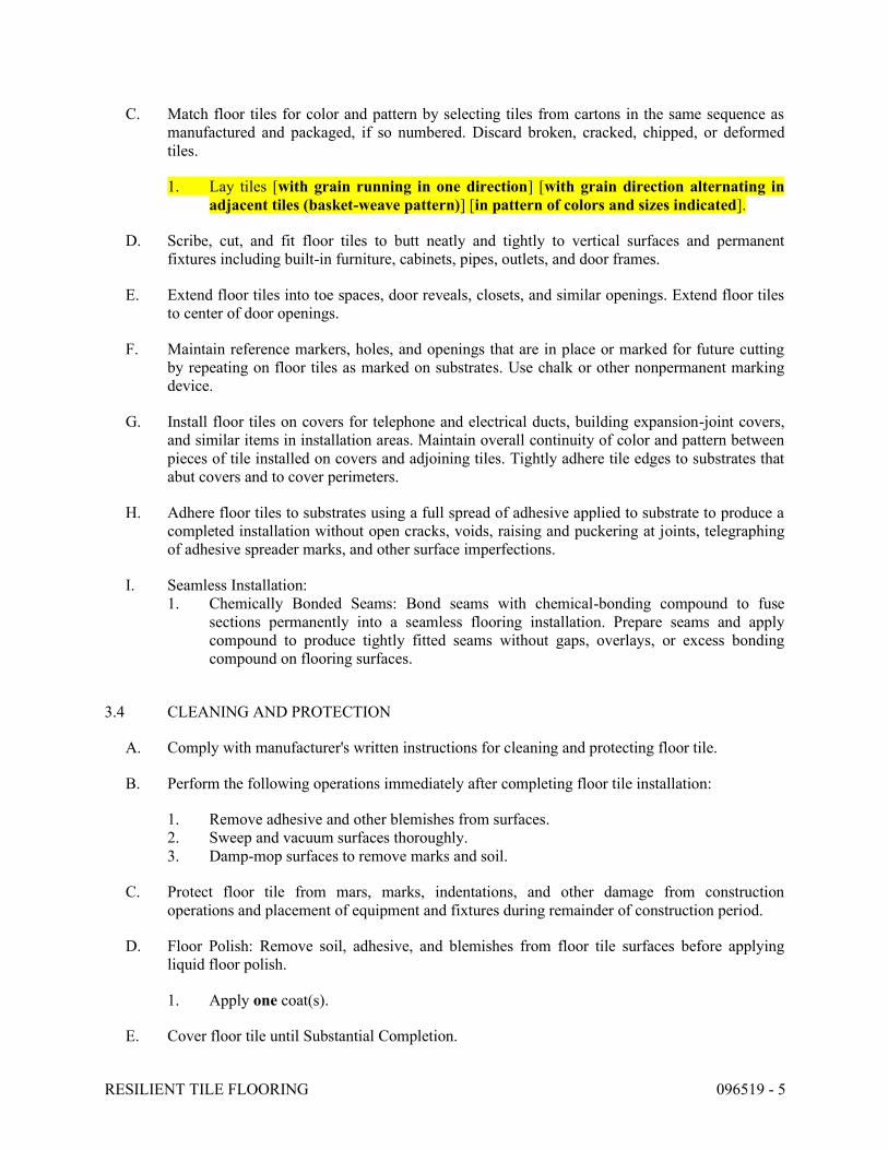
RESILIENT TILE FLOORING 096519 - 5
C. Match floor tiles for color and pattern by selecting tiles from cartons in the same sequence as manufactured and packaged, if so numbered. Discard broken, cracked, chipped, or deformed tiles.
1. Lay tiles [with grain running in one direction] [with grain direction alternating in adjacent tiles (basket-weave pattern)] [in pattern of colors and sizes indicated].
D. Scribe, cut, and fit floor tiles to butt neatly and tightly to vertical surfaces and permanent fixtures including built-in furniture, cabinets, pipes, outlets, and door frames.
E. Extend floor tiles into toe spaces, door reveals, closets, and similar openings. Extend floor tiles to center of door openings.
F. Maintain reference markers, holes, and openings that are in place or marked for future cutting by repeating on floor tiles as marked on substrates. Use chalk or other nonpermanent marking device.
G. Install floor tiles on covers for telephone and electrical ducts, building expansion-joint covers, and similar items in installation areas. Maintain overall continuity of color and pattern between pieces of tile installed on covers and adjoining tiles. Tightly adhere tile edges to substrates that abut covers and to cover perimeters.
H. Adhere floor tiles to substrates using a full spread of adhesive applied to substrate to produce a completed installation without open cracks, voids, raising and puckering at joints, telegraphing of adhesive spreader marks, and other surface imperfections.
I. Seamless Installation: 1. Chemically Bonded Seams: Bond seams with chemical-bonding compound to fuse
sections permanently into a seamless flooring installation. Prepare seams and apply compound to produce tightly fitted seams without gaps, overlays, or excess bonding compound on flooring surfaces.
3.4 CLEANING AND PROTECTION
A. Comply with manufacturer's written instructions for cleaning and protecting floor tile.
B. Perform the following operations immediately after completing floor tile installation:
1. Remove adhesive and other blemishes from surfaces. 2. Sweep and vacuum surfaces thoroughly. 3. Damp-mop surfaces to remove marks and soil.
C. Protect floor tile from mars, marks, indentations, and other damage from construction operations and placement of equipment and fixtures during remainder of construction period.
D. Floor Polish: Remove soil, adhesive, and blemishes from floor tile surfaces before applying liquid floor polish.
1. Apply one coat(s).
E. Cover floor tile until Substantial Completion.

RESILIENT TILE FLOORING 096519 - 6
END OF SECTION 096519
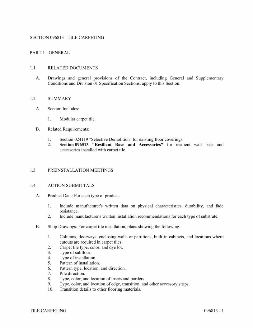
TILE CARPETING 096813 - 1
SECTION 096813 - TILE CARPETING
PART 1 - GENERAL
1.1 RELATED DOCUMENTS
A. Drawings and general provisions of the Contract, including General and Supplementary Conditions and Division 01 Specification Sections, apply to this Section.
1.2 SUMMARY
A. Section Includes:
1. Modular carpet tile.
B. Related Requirements:
1. Section 024119 "Selective Demolition" for existing floor coverings. 2. Section 096513 "Resilient Base and Accessories" for resilient wall base and
accessories installed with carpet tile.
1.3 PREINSTALLATION MEETINGS
1.4 ACTION SUBMITTALS
A. Product Data: For each type of product.
1. Include manufacturer's written data on physical characteristics, durability, and fade resistance.
2. Include manufacturer's written installation recommendations for each type of substrate.
B. Shop Drawings: For carpet tile installation, plans showing the following:
1. Columns, doorways, enclosing walls or partitions, built-in cabinets, and locations where cutouts are required in carpet tiles.
2. Carpet tile type, color, and dye lot. 3. Type of subfloor. 4. Type of installation. 5. Pattern of installation. 6. Pattern type, location, and direction. 7. Pile direction. 8. Type, color, and location of insets and borders. 9. Type, color, and location of edge, transition, and other accessory strips. 10. Transition details to other flooring materials.
TILE CARPETING 096813 - 2
C. Samples: For each of the following products and for each color and texture required. Label each Sample with manufacturer's name, material description, color, pattern, and designation indicated on Drawings and in schedules.
1. Carpet Tile: Full-size Sample. 2. Exposed Edge, Transition, and Other Accessory Stripping: 12-inch- (300-mm-) long
Samples.
D. Product Schedule: For carpet tile. Use same designations indicated on Drawings.
1.5 INFORMATIONAL SUBMITTALS
A. Qualification Data: For Installer.
B. Product Test Reports: For carpet tile, for tests performed by a qualified testing agency.
C. Sample Warranty: For special warranty.
1.6 CLOSEOUT SUBMITTALS
A. Maintenance Data: For carpet tiles to include in maintenance manuals. Include the following:
1. Methods for maintaining carpet tile, including cleaning and stain-removal products and procedures and manufacturer's recommended maintenance schedule.
2. Precautions for cleaning materials and methods that could be detrimental to carpet tile.
1.7 MAINTENANCE MATERIAL SUBMITTALS
A. Furnish extra materials, from the same product run, that match products installed and that are packaged with protective covering for storage and identified with labels describing contents.
1. Carpet Tile: Full-size units equal to 3 percent of amount installed for each type indicated, but not less than 10 sq. yd. (8.3 sq. m).
1.8 QUALITY ASSURANCE
A. Installer Qualifications: An experienced installer who is certified by the International Certified Floorcovering Installers Association at the Commercial II certification level.
1.9 DELIVERY, STORAGE, AND HANDLING
A. Comply with the Carpet and Rug Institute's CRI 104.
TILE CARPETING 096813 - 3
1.10 FIELD CONDITIONS
A. Comply with the Carpet and Rug Institute's CRI 104 for temperature, humidity, and ventilation limitations.
B. Environmental Limitations: Do not deliver or install carpet tiles until spaces are enclosed and weathertight, wet-work in spaces is complete and dry, and ambient temperature and humidity conditions are maintained at levels planned for building occupants during the remainder of the construction period.
C. Do not install carpet tiles over concrete slabs until slabs have cured and are sufficiently dry to bond with adhesive and concrete slabs have pH range recommended by carpet tile manufacturer.
D. Where demountable partitions or other items are indicated for installation on top of carpet tiles, install carpet tiles before installing these items.
1.11 WARRANTY
A. Special Warranty for Carpet Tiles: Manufacturer agrees to repair or replace components of carpet tile installation that fail in materials or workmanship within specified warranty period.
1. Warranty does not include deterioration or failure of carpet tile due to unusual traffic, failure of substrate, vandalism, or abuse.
2. Failures include, but are not limited to, the following:
a. More than 10 percent edge raveling, snags, and runs. b. Dimensional instability. c. Excess static discharge. d. Loss of tuft-bind strength. e. Loss of face fiber. f. Delamination.
3. Warranty Period: 10 years from date of Substantial Completion.
PART 2 - PRODUCTS
2.1 CARPET TILE - CPT
A. Basis-of-Design Product: As indicated on Finish Legend.
B. Color: As indicated on Finish Legend.
C. Pattern: As indicated on Finish Legend.
D. Fiber Content: 100 percent nylon.
E. Pile Characteristic: Tufted Pattern Loop.
TILE CARPETING 096813 - 4
F. Density: 7,776 oz./cu. yd. (g/cu. cm).
G. Pile Thickness: 0.125 inches (mm).
H. Stitches: 13 per inch (mm).
I. Gage: 1 end per 10 inch (mm).
J. Tufted Yarn Weight: 27 oz./sq. yd.2 (g/sq. m2)> for finished carpet tile.
K. Primary Backing/Backcoating: Manufacturer's standard materials .
L. Secondary Backing: Manufacturer's standard material.
M. Size: 9.845 in x 39.38 in.
N. Applied Treatments:
1. Soil-Resistance Treatment: Manufacturer's standard treatment. 2. Antimicrobial Treatment: Manufacturer's standard treatment that protects carpet tiles
as follows:
a. Antimicrobial Activity: Not less than 2-mm halo of inhibition for gram-positive bacteria, not less than 1-mm halo of inhibition for gram-negative bacteria, and no fungal growth, according to AATCC 174.
2.2 INSTALLATION ACCESSORIES
A. Trowelable Leveling and Patching Compounds: Latex-modified, hydraulic-cement-based formulation provided or recommended by carpet tile manufacturer.
B. Adhesives: Water-resistant, mildew-resistant, nonstaining, pressure-sensitive type to suit products and subfloor conditions indicated, that comply with flammability requirements for installed carpet tile, and are recommended by carpet tile manufacturer for releasable installation.
C. Metal Edge/Transition Strips: Extruded aluminum with mill finish of profile and width shown, of height required to protect exposed edge of carpet, and of maximum lengths to minimize running joints.
PART 3 - EXECUTION
3.1 EXAMINATION
A. Examine substrates, areas, and conditions, with Installer present, for compliance with requirements for maximum moisture content, alkalinity range, installation tolerances, and other conditions affecting carpet tile performance.
B. Examine carpet tile for type, color, pattern, and potential defects.
TILE CARPETING 096813 - 5
C. Concrete Slabs: Verify that finishes comply with requirements specified in Section 033000 "Cast-in-Place Concrete" and that surfaces are free of cracks, ridges, depressions, scale, and foreign deposits.
1. Moisture Testing: Perform tests so that each test area does not exceed 200 sq. ft. (18.6 sq. m), and perform no fewer than three tests in each installation area and with test areas evenly spaced in installation areas.
a. Anhydrous Calcium Chloride Test: ASTM F1869. Proceed with installation only after substrates have maximum moisture-vapor-emission rate of 3 lb of water/1000 sq. ft. (1.36 kg of water/92.9 sq. m) in 24 hours.
b. Relative Humidity Test: Using in situ probes, ASTM F2170. Proceed with installation only after substrates have a maximum 75 percent relative humidity level measurement.
c. Perform additional moisture tests recommended in writing by adhesive and carpet tile manufacturers. Proceed with installation only after substrates pass testing.
D. Proceed with installation only after unsatisfactory conditions have been corrected.
3.2 PREPARATION
A. General: Comply with the Carpet and Rug Institute's CRI 104 and with carpet tile manufacturer's written installation instructions for preparing substrates indicated to receive carpet tile.
B. Use trowelable leveling and patching compounds, according to manufacturer's written instructions, to fill cracks, holes, depressions, and protrusions in substrates. Fill or level cracks, holes and depressions 1/8 inch (3 mm) wide or wider, and protrusions more than 1/32 inch (0.8 mm) unless more stringent requirements are required by manufacturer's written instructions.
C. Concrete Substrates: Remove coatings, including curing compounds, and other substances that are incompatible with adhesives and that contain soap, wax, oil, or silicone, without using solvents. Use mechanical methods recommended in writing by adhesive and carpet tile manufacturers.
D. Metal Substrates: Clean grease, oil, soil and rust, and prime if recommended in writing by adhesive manufacturer. Rough sand painted metal surfaces and remove loose paint. Sand aluminum surfaces, to remove metal oxides, immediately before applying adhesive.
E. Broom and vacuum clean substrates to be covered immediately before installing carpet tile.
3.3 INSTALLATION
A. General: Comply with the Carpet and Rug Institute's CRI 104, Section 10, "Carpet Tile," and with carpet tile manufacturer's written installation instructions.
B. Installation Method: As recommended in writing by carpet tile manufacturer.
C. Maintain dye-lot integrity. Do not mix dye lots in same area.
TILE CARPETING 096813 - 6
D. Maintain pile-direction patterns recommended in writing by carpet tile manufacturer.
E. Cut and fit carpet tile to butt tightly to vertical surfaces, permanent fixtures, and built-in furniture including cabinets, pipes, outlets, edgings, thresholds, and nosings. Bind or seal cut edges as recommended by carpet tile manufacturer.
F. Extend carpet tile into toe spaces, door reveals, closets, open-bottomed obstructions, removable flanges, alcoves, and similar openings.
G. Maintain reference markers, holes, and openings that are in place or marked for future cutting by repeating on carpet tile as marked on subfloor. Use nonpermanent, nonstaining marking device.
H. Install pattern parallel to walls and borders.
I. Access Flooring: Stagger joints of carpet tiles so carpet tile grid is offset from access flooring panel grid. Do not fill seams of access flooring panels with carpet adhesive; keep seams free of adhesive.
3.4 CLEANING AND PROTECTION
A. Perform the following operations immediately after installing carpet tile:
1. Remove excess adhesive and other surface blemishes using cleaner recommended by carpet tile manufacturer.
2. Remove yarns that protrude from carpet tile surface. 3. Vacuum carpet tile using commercial machine with face-beater element.
B. Protect installed carpet tile to comply with the Carpet and Rug Institute's CRI 104, Section 13.7.
C. Protect carpet tile against damage from construction operations and placement of equipment and fixtures during the remainder of construction period. Use protection methods indicated or recommended in writing by carpet tile manufacturer.
END OF SECTION 096813
INTERIOR PAINTING 099123 - 1
SECTION 099123 - INTERIOR PAINTING
PART 1 - GENERAL
1.1 RELATED DOCUMENTS
A. Drawings and general provisions of the Contract, including General and Supplementary Conditions and Division 01 Specification Sections, apply to this Section.
1.2 SUMMARY
A. Section includes surface preparation and the application of paint systems on the following interior substrates: 1. Steel and iron. 2. Gypsum board.
1.3 DEFINITIONS
A. MPI Gloss Level 1: Not more than five units at 60 degrees and 10 units at 85 degrees, according to ASTM D523.
B. MPI Gloss Level 2: Not more than 10 units at 60 degrees and 10 to 35 units at 85 degrees, according to ASTM D523.
C. MPI Gloss Level 3: 10 to 25 units at 60 degrees and 10 to 35 units at 85 degrees, according to ASTM D523.
D. MPI Gloss Level 4: 20 to 35 units at 60 degrees and not less than 35 units at 85 degrees, according to ASTM D523.
E. MPI Gloss Level 5: 35 to 70 units at 60 degrees, according to ASTM D523.
F. MPI Gloss Level 6: 70 to 85 units at 60 degrees, according to ASTM D523.
G. MPI Gloss Level 7: More than 85 units at 60 degrees, according to ASTM D523.
1.4 ACTION SUBMITTALS
A. Product Data: For each type of product. Include preparation requirements and application instructions.
1. Include Printout of current "MPI Approved Products List" for each product category specified, with the proposed product highlighted.
2. Indicate VOC content.
B. Samples for Initial Selection: For each type of topcoat product.
INTERIOR PAINTING 099123 - 2
C. Product List: Cross-reference to paint system and locations of application areas. Use same designations indicated on Drawings and in schedules. Include color designations.
1.5 MAINTENANCE MATERIAL SUBMITTALS
A. Furnish extra materials, from the same product run, that match products installed and that are packaged with protective covering for storage and identified with labels describing contents.
1. Paint: 5 percent, but not less than 1 gal. (3.8 L) of each material and color applied.
1.6 DELIVERY, STORAGE, AND HANDLING
A. Store materials not in use in tightly covered containers in well-ventilated areas with ambient temperatures continuously maintained at not less than 45 deg F (7 deg C).
1. Maintain containers in clean condition, free of foreign materials and residue. 2. Remove rags and waste from storage areas daily.
1.7 FIELD CONDITIONS
A. Apply paints only when temperature of surfaces to be painted and ambient air temperatures are between 50 and 95 deg F (10 and 35 deg C).
B. Do not apply paints when relative humidity exceeds 85 percent; at temperatures less than 5 deg F (3 deg C) above the dew point; or to damp or wet surfaces.
PART 2 - PRODUCTS
2.1 MANUFACTURERS
A. Products: Subject to compliance with requirements, provide the product listed in the Finish Legend for the paint category indicated.
2.2 PAINT, GENERAL
A. MPI Standards: Products shall comply with MPI standards indicated and shall be listed in its "MPI Approved Products Lists."
B. Material Compatibility:
1. Materials for use within each paint system shall be compatible with one another and substrates indicated, under conditions of service and application as demonstrated by manufacturer, based on testing and field experience.
2. For each coat in a paint system, products shall be recommended in writing by topcoat manufacturers for use in paint system and on substrate indicated.
INTERIOR PAINTING 099123 - 3
C. VOC Content: Products shall comply with VOC limits of authorities having jurisdiction and, for interior paints and coatings applied at Project Site, the following VOC limits, exclusive of colorants added to a tint base, when calculated according to 40 CFR 59, Subpart D (EPA Method 24). 1. Flat Paints and Coatings: 50 g/L. 2. Nonflat Paints and Coatings: 150 g/L. 3. Dry-Fog Coatings: 400 g/L. 4. Primers, Sealers, and Undercoaters: 200 g/L. 5. Anticorrosive and Antirust Paints Applied to Ferrous Metals: 250 g/L. 6. Zinc-Rich Industrial Maintenance Primers: 340 g/L.
D. Colors: As indicated by the Finish Legend.
2.3 SOURCE QUALITY CONTROL
A. Testing of Paint Materials: Owner reserves the right to invoke the following procedure:
1. Owner will engage the services of a qualified testing agency to sample paint materials. Contractor will be notified in advance and may be present when samples are taken. If paint materials have already been delivered to Project site, samples may be taken at Project site. Samples will be identified, sealed, and certified by testing agency.
2. Testing agency will perform tests for compliance with product requirements. 3. Owner may direct Contractor to stop applying paints if test results show materials being
used do not comply with product requirements. Contractor shall remove noncomplying paint materials from Project site, pay for testing, and repaint surfaces painted with rejected materials. Contractor will be required to remove rejected materials from previously painted surfaces if, on repainting with complying materials, the two paints are incompatible.
PART 3 - EXECUTION
3.1 EXAMINATION
A. Examine substrates and conditions, with Applicator present, for compliance with requirements for maximum moisture content and other conditions affecting performance of the Work.
B. Maximum Moisture Content of Substrates: When measured with an electronic moisture meter as follows: 1. Gypsum Board: 12 percent.
C. Gypsum Board Substrates: Verify that finishing compound is sanded smooth.
D. Verify suitability of substrates, including surface conditions and compatibility, with existing finishes and primers.
E. Proceed with coating application only after unsatisfactory conditions have been corrected.
1. Application of coating indicates acceptance of surfaces and conditions.
INTERIOR PAINTING 099123 - 4
3.2 PREPARATION
A. Comply with manufacturer's written instructions and recommendations in "MPI Architectural Painting Specification Manual" applicable to substrates and paint systems indicated.
B. Remove hardware, covers, plates, and similar items already in place that are removable and are not to be painted. If removal is impractical or impossible because of size or weight of item, provide surface-applied protection before surface preparation and painting.
1. After completing painting operations, use workers skilled in the trades involved to reinstall items that were removed. Remove surface-applied protection if any.
C. Clean substrates of substances that could impair bond of paints, including dust, dirt, oil, grease, and incompatible paints and encapsulants.
1. Remove incompatible primers and reprime substrate with compatible primers or apply tie coat as required to produce paint systems indicated.
3.3 APPLICATION
A. Apply paints according to manufacturer's written instructions and to recommendations in "MPI Manual."
1. Use applicators and techniques suited for paint and substrate indicated. 2. Paint surfaces behind movable equipment and furniture same as similar exposed surfaces.
Before final installation, paint surfaces behind permanently fixed equipment or furniture with prime coat only.
3. Paint front and backsides of access panels, removable or hinged covers, and similar hinged items to match exposed surfaces.
4. Do not paint over labels of independent testing agencies or equipment name, identification, performance rating, or nomenclature plates.
5. Primers specified in painting schedules may be omitted on items that are factory primed or factory finished if acceptable to topcoat manufacturers.
B. Tint each undercoat a lighter shade to facilitate identification of each coat if multiple coats of same material are to be applied. Tint undercoats to match color of topcoat, but provide sufficient difference in shade of undercoats to distinguish each separate coat.
C. If undercoats or other conditions show through topcoat, apply additional coats until cured film has a uniform paint finish, color, and appearance.
D. Apply paints to produce surface films without cloudiness, spotting, holidays, laps, brush marks, roller tracking, runs, sags, ropiness, or other surface imperfections. Cut in sharp lines and color breaks.
3.4 FIELD QUALITY CONTROL
A. Dry Film Thickness Testing: Owner may engage the services of a qualified testing and inspecting agency to inspect and test paint for dry film thickness.
INTERIOR PAINTING 099123 - 5
1. Contractor shall touch up and restore painted surfaces damaged by testing. 2. If test results show that dry film thickness of applied paint does not comply with paint
manufacturer's written recommendations, Contractor shall pay for testing and apply additional coats as needed to provide dry film thickness that complies with paint manufacturer's written recommendations.
3.5 CLEANING AND PROTECTION
A. At end of each workday, remove rubbish, empty cans, rags, and other discarded materials from Project site.
B. After completing paint application, clean spattered surfaces. Remove spattered paints by washing, scraping, or other methods. Do not scratch or damage adjacent finished surfaces.
C. Protect work of other trades against damage from paint application. Correct damage to work of other trades by cleaning, repairing, replacing, and refinishing, as approved by Architect, and leave in an undamaged condition.
D. At completion of construction activities of other trades, touch up and restore damaged or defaced painted surfaces.
3.6 INTERIOR PAINTING SCHEDULE
A. Gypsum Board Substrates: 1. Institutional Low-Odor/VOC Latex System MPI INT 9.2M:
a. Prime Coat: Primer sealer, interior, institutional low odor/VOC, MPI #149.
b. Intermediate Coat: Latex, interior, institutional low odor/VOC, matching topcoat.
c. Topcoat: Latex, interior, institutional low odor/VOC (MPI Gloss Level 4), MPI #146.
END OF SECTION 099123
ROOM-IDENTIFICATION PANEL SIGNAGE 101423.16 - 1
SECTION 101423.16 - ROOM-IDENTIFICATION PANEL SIGNAGE
PART 1 - GENERAL
1.1 RELATED DOCUMENTS
A. Drawings and general provisions of the Contract, including General and Supplementary Conditions and Division 01 Specification Sections, apply to this Section.
1.2 SUMMARY
A. Section includes room-identification signs that are directly attached to the building.
1.3 DEFINITIONS
A. Accessible: In accordance with the accessibility standard.
1.4 ACTION SUBMITTALS
A. Product Data: For each type of product.
B. Shop Drawings: For room-identification signs.
1. Include fabrication and installation details and attachments to other work. 2. Show sign mounting heights, locations of supplementary supports to be provided by other
installers, and accessories. 3. Show message list, typestyles, graphic elements, including raised characters and
Braille, and layout for each sign at least half size.
C. Samples for Initial Selection: For each type of sign assembly, exposed component, and exposed finish.
1. Include representative Samples of available typestyles and graphic symbols.
D. Product Schedule: For room-identification signs. Use same designations indicated on Drawings or specified.
1.5 INFORMATIONAL SUBMITTALS
A. Qualification Data: For Installer and manufacturer.
B. Sample Warranty: For special warranty.
ROOM-IDENTIFICATION PANEL SIGNAGE 101423.16 - 2
1.6 CLOSEOUT SUBMITTALS
A. Maintenance Data: For signs to include in maintenance manuals.
1.7 MAINTENANCE MATERIAL SUBMITTALS
A. Furnish extra materials, from the same product run, that match products installed and that are packaged with protective covering for storage and identified with labels describing contents.
1. Variable Component Materials: 12 replaceable text inserts and interchangeable characters (letters, numbers, and graphic elements) of each type.
2. Tools: Two set(s) of specialty tools for assembling signs and replacing variable sign components.
1.8 QUALITY ASSURANCE
A. Installer Qualifications: An entity that employs installers and supervisors who are trained and approved by manufacturer.
1.9 FIELD CONDITIONS
A. Field Measurements: Verify locations of [anchorage devices] [and] [electrical service] embedded in permanent construction by other installers by field measurements before fabrication, and indicate measurements on Shop Drawings.
1.10 WARRANTY
A. Special Warranty: Manufacturer agrees to repair or replace components of signs that fail in materials or workmanship within specified warranty period.
1. Failures include, but are not limited to, the following:
a. Deterioration of finishes beyond normal weathering. b. Deterioration of embedded graphic image. c. Separation or delamination of sheet materials and components.
2. Warranty Period: Five years from date of Substantial Completion.
PART 2 - PRODUCTS
2.1 PERFORMANCE REQUIREMENTS
A. Accessibility Standard: Comply with applicable provisions in the ABA standards of the Federal agency having jurisdiction and ICC A117.1.
ROOM-IDENTIFICATION PANEL SIGNAGE 101423.16 - 3
2.2 ROOM-IDENTIFICATION SIGNS
A. Room-Identification Sign : Sign with smooth, uniform surfaces; with message and characters having uniform faces, sharp corners, and precisely formed lines and profiles; and as follows: 1. Laminated-Sheet Sign: Photopolymer face sheet with raised graphics laminated to
acrylic backing sheet to produce composite sheet.
a. Composite-Sheet Thickness: 0.125 inch (3.18 mm). b. Color(s): As selected by Architect from manufacturer's full range.
2. Sign-Panel Perimeter: Finish edges smooth.
a. Edge Condition: As indicated on Drawings . b. Corner Condition in Elevation: Rounded to radius indicated.
3. Mounting: Manufacturer's standard method for substrates indicated. 4. Text and Typeface: Accessible raised characters and Braille typeface as selected by
Architect from manufacturer's full range and variable content as scheduled. Finish raised characters to contrast with background color, and finish Braille to match background color.
2.3 SIGN MATERIALS
A. Acrylic Sheet: ASTM D4802, category as standard with manufacturer for each sign, Type UVF (UV filtering).
B. Vinyl Film: UV-resistant vinyl film with pressure-sensitive, permanent adhesive; die cut to form characters or images as indicated on Drawings.
C. Paints and Coatings for Sheet Materials: Inks, dyes, and paints that are recommended by manufacturer for optimum adherence to surface and are UV and water resistant for colors and exposure indicated.
2.4 ACCESSORIES
A. Adhesive: As recommended by sign manufacturer.
B. Two-Face Tape: Manufacturer's standard high-bond, foam-core tape, 0.045 inch (1.14 mm) thick, with adhesive on both sides.
2.5 FABRICATION
A. General: Provide manufacturer's standard sign assemblies according to requirements indicated.
1. Preassemble signs and assemblies in the shop to greatest extent possible. Disassemble signs and assemblies only as necessary for shipping and handling limitations. Clearly mark units for reassembly and installation; apply markings in locations concealed from view after final assembly.
ROOM-IDENTIFICATION PANEL SIGNAGE 101423.16 - 4
2. Mill joints to a tight, hairline fit. Form assemblies and joints exposed to weather to resist water penetration and retention.
3. Conceal connections if possible; otherwise, locate connections where they are inconspicuous.
4. Provide rabbets, lugs, and tabs necessary to assemble components and to attach to existing work. Drill and tap for required fasteners. Use concealed fasteners where possible; use exposed fasteners that match sign finish.
B. Signs with Changeable Message Capability: Fabricate signs to allow insertion of changeable messages as follows: 1. For slide-in changeable inserts, fabricate slot without burrs or constrictions that inhibit
function. Furnish initial changeable insert. Furnish two blank inserts for each sign for Owner's use.
2.6 GENERAL FINISH REQUIREMENTS
A. Protect mechanical finishes on exposed surfaces from damage by applying a strippable, temporary protective covering before shipping.
B. Appearance of Finished Work: Noticeable variations in same piece are not acceptable. Variations in appearance of adjoining components are acceptable if they are within the range of approved Samples and are assembled or installed to minimize contrast.
PART 3 - EXECUTION
3.1 INSTALLATION
A. General: Install signs using mounting methods indicated and according to manufacturer's written instructions.
1. Install signs level, plumb, true to line, and at locations and heights indicated, with sign surfaces free of distortion and other defects in appearance.
2. Install signs so they do not protrude or obstruct according to the accessibility standard. 3. Before installation, verify that sign surfaces are clean and free of materials or debris that
would impair installation.
B. Accessibility: Install signs in locations on walls as indicated on Drawings and according to the accessibility standard .
C. Mounting Methods: 1. Two-Face Tape: Clean bond-breaking materials from substrate surface and remove loose
debris. Apply tape strips symmetrically to back of sign and of suitable quantity to support weight of sign without slippage. Keep strips away from edges to prevent visibility at sign edges. Place sign in position, and push to engage tape adhesive.
ROOM-IDENTIFICATION PANEL SIGNAGE 101423.16 - 5
3.2 ADJUSTING AND CLEANING
A. Remove and replace damaged or deformed signs and signs that do not comply with specified requirements. Replace signs with damaged or deteriorated finishes or components that cannot be successfully repaired by finish touchup or similar minor repair procedures.
B. Remove temporary protective coverings and strippable films as signs are installed.
C. On completion of installation, clean exposed surfaces of signs according to manufacturer's written instructions, and touch up minor nicks and abrasions in finish. Maintain signs in a clean condition during construction and protect from damage until acceptance by Owner.
END OF SECTION 101423.16
WALL AND DOOR PROTECTION 102600 - 1
SECTION 102600 - WALL AND DOOR PROTECTION
PART 1 - GENERAL
1.1 RELATED DOCUMENTS
A. Drawings and general provisions of the Contract, including General and Supplementary Conditions and Division 01 Specification Sections, apply to this Section.
1.2 SUMMARY
A. Section Includes:
1. Corner guards. 2. Abuse-resistant wall coverings.
1.3 ACTION SUBMITTALS
A. Product Data: For each type of product.
1. Include construction details, material descriptions, impact strength, dimensions of individual components and profiles, and finishes.
2. Include fire ratings of units recessed in fire-rated walls and listings for door-protection items attached to fire-rated doors.
B. Shop Drawings: For each type of wall and door protection showing locations and extent.
1. Include plans, elevations, sections, and attachment details.
C. Samples for Initial Selection: For each type of impact-resistant wall-protection unit indicated, in each color and texture specified.
1. Include Samples of accent strips and accessories to verify color selection.
D. Samples for Verification: For each type of exposed finish on the following products, prepared on Samples of size indicated below:
1. Corner Guards: 12 inches (300 mm) long. 2. Abuse-Resistant Wall Covering: 6 by 6 inches (150 by 150 mm) square.
1.4 INFORMATIONAL SUBMITTALS
A. Material Certificates: For each type of exposed plastic material.
B. Sample Warranty: For special warranty.
WALL AND DOOR PROTECTION 102600 - 2
1.5 CLOSEOUT SUBMITTALS
A. Maintenance Data: For each type of wall and door protection product to include in maintenance manuals.
1. Include recommended methods and frequency of maintenance for maintaining best condition of plastic covers under anticipated traffic and use conditions. Include precautions against using cleaning materials and methods that may be detrimental to finishes and performance.
1.6 MAINTENANCE MATERIAL SUBMITTALS
A. Furnish extra materials, from the same product run, that match products installed and that are packaged with protective covering for storage and identified with labels describing contents. 1. Corner-Guard Covers: Full-size plastic covers of maximum length equal to 2 percent of
each type, color, and texture of cover installed, but no fewer than two, 48-inch- (1200-mm-) long units.
2. Mounting and Accessory Components: Amounts proportional to the quantities of extra materials. Package mounting and accessory components with each extra material.
3. Wall Covering: One roll of each color used.
1.7 DELIVERY, STORAGE, AND HANDLING
A. Store wall and door protection in original undamaged packages and containers inside well-ventilated area protected from weather, moisture, soiling, extreme temperatures, and humidity.
1. Maintain room temperature within storage area at not less than 70 deg F (21 deg C) during the period plastic materials are stored.
2. Keep plastic materials out of direct sunlight. 3. Store plastic wall- and door-protection components for a minimum of 72 hours, or until
plastic material attains a minimum room temperature of 70 deg F (21 deg C).
a. Store corner-guard covers in a vertical position. b. Store wall-protection covers in a horizontal position.
1.8 WARRANTY
A. Special Warranty: Manufacturer agrees to repair or replace components of wall- and door-protection units that fail in materials or workmanship within specified warranty period.
1. Failures include, but are not limited to, the following:
a. Structural failures including detachment of components from each other or from the substrates, delamination, and permanent deformation beyond normal use.
b. Deterioration of metals, metal finishes, plastics, and other materials beyond normal use.
2. Warranty Period: Five years from date of Substantial Completion.
WALL AND DOOR PROTECTION 102600 - 3
PART 2 - PRODUCTS
2.1 MANUFACTURERS
A. Source Limitations: Obtain wall- and door-protection products of each type from single source from single manufacturer.
2.2 PERFORMANCE REQUIREMENTS
A. Surface Burning Characteristics: Comply with ASTM E84 or UL 723; testing by a qualified testing agency. Identify products with appropriate markings of applicable testing agency.
1. Flame-Spread Index: 25 or less. 2. Smoke-Developed Index: 450 or less.
B. Regulatory Requirements: Comply with applicable provisions in the U.S. Architectural & Transportation Barriers Compliance Board's ADA-ABA Accessibility Guidelines for Buildings and Facilities and ICC A117.1.
2.3 CORNER GUARDS
A. Surface-Mounted, Metal Corner Guards (CG): Fabricated as one piece from formed or extruded metal with formed edges; with 90- or 135-degree turn to match wall condition.
1. Basis-of-Design Manufacturer: CS Construction Specialties. 2. Material: Stainless-steel sheet, Type 304.
a. Thickness: Minimum 0.0500 inch (1.3 mm). b. Finish: As selected by Architect and Owner from Manufacturer’s Full Range.
3. Material: Extruded aluminum, minimum 0.0625 inch (1.6 mm) thick, with clear anodic finish.
4. Wing Size: Nominal 1-1/2 by 1-1/2 inches (38 by 38 mm) . 5. Corner Radius: 1/8 inch (3 mm). 6. Mounting: Flat-head, countersunk screws through factory-drilled mounting holes.
2.4 ABUSE-RESISTANT WALL COVERINGS
A. Abuse-Resistant Sheet Wall Covering (PWP1 & PWP2)>: Fabricated from semirigid, plastic sheet wall-covering material.
1. Basis-of-Design Manufactuer: Acrovyn. 2. Size: As indicated on Finish Legend. 3. Sheet Thickness: 0.040 inch (1.0 mm). 4. Color and Texture: As indicated on Finish Legend. 5. Height: Wainscot. 6. Trim and Joint Moldings: Extruded rigid plastic that matches wall-covering color. 7. Mounting: Adhesive.
WALL AND DOOR PROTECTION 102600 - 4
2.5 MATERIALS
A. Plastic Materials: Chemical- and stain-resistant, high-impact-resistant plastic with integral color throughout; extruded and sheet material as required, thickness as indicated.
B. Polycarbonate Plastic Sheet: ASTM D6098, S-PC01, Class 1 or Class 2, abrasion resistant; with a minimum impact-resistance rating of 15 ft.-lbf/in. (800 J/m) of notch when tested according to ASTM D256, Test Method A.
C. Fasteners: Aluminum, nonmagnetic stainless-steel, or other noncorrosive metal screws, bolts, and other fasteners compatible with items being fastened. Use security-type fasteners where exposed to view.
D. Adhesive: As recommended by protection product manufacturer.
2.6 FABRICATION
A. Fabricate wall and door protection according to requirements indicated for design, performance, dimensions, and member sizes, including thicknesses of components.
B. Factory Assembly: Assemble components in factory to greatest extent possible to minimize field assembly. Disassemble only as necessary for shipping and handling.
C. Quality: Fabricate components with uniformly tight seams and joints and with exposed edges rolled. Provide surfaces free of wrinkles, chips, dents, uneven coloration, and other imperfections. Fabricate members and fittings to produce flush, smooth, and rigid hairline joints.
2.7 FINISHES
A. Protect finishes on exposed surfaces from damage by applying a strippable, temporary protective covering before shipping.
B. Appearance of Finished Work: Noticeable variations in same piece are not acceptable. Variations in appearance of adjoining components are acceptable if they are within the range of approved Samples and are assembled or installed to minimize contrast.
PART 3 - EXECUTION
3.1 EXAMINATION
A. Examine substrates and wall areas, with Installer present, for compliance with requirements for installation tolerances and other conditions affecting performance of the Work.
B. Examine walls to which wall and door protection will be attached for blocking, grounds, and other solid backing that have been installed in the locations required for secure attachment of support fasteners.
WALL AND DOOR PROTECTION 102600 - 5
C. Proceed with installation only after unsatisfactory conditions have been corrected.
3.2 PREPARATION
A. Complete finishing operations, including painting, before installing wall and door protection.
B. Before installation, clean substrate to remove dust, debris, and loose particles.
3.3 INSTALLATION
A. Installation Quality: Install wall and door protection according to manufacturer's written instructions, level, plumb, and true to line without distortions. Do not use materials with chips, cracks, voids, stains, or other defects that might be visible in the finished Work.
B. Accessories: Provide splices, mounting hardware, anchors, trim, joint moldings, and other accessories required for a complete installation.
1. Provide anchoring devices and suitable locations to withstand imposed loads. 2. Where splices occur in horizontal runs of more than 20 feet (6.1 m), splice aluminum
retainers and plastic covers at different locations along the run, but no closer than 12 inches (305 mm) apart.
3. Adjust end and top caps as required to ensure tight seams.
C. Abuse-Resistant Wall Covering: Install top and edge moldings, corners, and divider bars as required for a complete installation.
3.4 CLEANING
A. Immediately after completion of installation, clean plastic covers and accessories using a standard ammonia-based household cleaning agent.
B. Remove excess adhesive using methods and materials recommended in writing by manufacturer.
END OF SECTION 102600
TOILET, BATH, AND LAUNDRY ACCESSORIES 102800 - 1
SECTION 102800 - TOILET, BATH, AND LAUNDRY ACCESSORIES
PART 1 - GENERAL
1.1 RELATED DOCUMENTS
A. Drawings and general provisions of the Contract, including General and Supplementary Conditions and Division 01 Specification Sections, apply to this Section.
1.2 SUMMARY
A. Section Includes:
1. Public-use washroom accessories. 2. Warm-air dryers. 3. Childcare accessories. 4. Custodial accessories.
B. Related Requirements: 1. Section 093013 "Ceramic Tiling" for ceramic tile in restrooms..
1.3 COORDINATION
A. Coordinate accessory locations with other work to prevent interference with clearances required for access by people with disabilities, and for proper installation, adjustment, operation, cleaning, and servicing of accessories.
B. Deliver inserts and anchoring devices set into concrete or masonry as required to prevent delaying the Work.
1.4 ACTION SUBMITTALS
A. Product Data: For each type of product.
1. Include construction details, material descriptions, dimensions of individual components and profiles, and finishes.
2. Include anchoring and mounting requirements, including requirements for cutouts in other work and substrate preparation.
3. Include electrical characteristics.
B. Product Schedule: Indicating types, quantities, sizes, and installation locations by room of each accessory required.
1. Identify locations using room designations indicated. 2. Identify accessories using designations indicated.
TOILET, BATH, AND LAUNDRY ACCESSORIES 102800 - 2
1.5 INFORMATIONAL SUBMITTALS
A. Sample Warranty: For manufacturer's special warranty.
1.6 CLOSEOUT SUBMITTALS
A. Maintenance Data: For accessories to include in maintenance manuals.
1.7 WARRANTY
A. Manufacturer's Special Warranty for Mirrors: Manufacturer agrees to repair or replace mirrors that fail in materials or workmanship within specified warranty period.
1. Failures include, but are not limited to, visible silver spoilage defects. 2. Warranty Period: 15 years from date of Substantial Completion.
PART 2 - PRODUCTS
2.1 PERFORMANCE REQUIREMENTS
A. Electrical Components, Devices, and Accessories: Listed and labeled as defined in NFPA 70, by a qualified testing agency, and marked for intended location and application.
2.2 PUBLIC-USE WASHROOM ACCESSORIES
A. Source Limitations: Obtain public-use washroom accessories from single source from single manufacturer. 1. Basis-of-Design Manufacturer: Bobrick Washroom Equipment.
B. Accessories: Refer to Toilet Accessory Schedule in Contract Drawings: 1. Surface Mounted Paper Towel (Folded) Dispenser: T-1 2. Surface Mounted Liquid-Soap Dispenser: T-2. 3. Surface Mounted Sanitary-Napkin Disposal Unit: T-3. 4. Surface Mounted Seat-Cover Dispenser: T-4. 5. Surface Mounted Framed Mirror Unit, 24’ x 36’: T-5. 6. Surface Mounted Standard Coat Hook: T-6.
2.3 WARM-AIR DRYERS
A. Source Limitations: Obtain warm-air dryers from single source from single manufacturer. 1. Basis-of-Design Manufacturer: Dyson.
B. Accessories: Refer to Toilet Accessory Schedule in Contract Drawings: 1. Surface Mounted Warm-Air Hand Dryer: T-7.
TOILET, BATH, AND LAUNDRY ACCESSORIES 102800 - 3
2.4 CHILDCARE ACCESSORIES
A. Source Limitations: Obtain childcare accessories from single source from single manufacturer. 1. Basis of Design Manufacturer: Bradley Corporation.
B. Accessories: Refer to Toilet Accessory Schedule. 1. Surface-Mounted Diaper-Changing Station: T-8a. 2. Recessed Diaper-Changing Station: T-8.
2.5 CUSTODIAL ACCESSORIES
A. Source Limitations: Obtain custodial accessories from single source from single manufacturer. 1. Basis of Design Manufacturer: Bobrick Washroom Equipment.
B. Accessories: Refer to Toilet Accessory Schedule. 1. Utility Shelf: T-9
a. Description: With exposed edges turned down not less than 1/2 inch (13 mm) and supported by two triangular brackets welded to shelf underside.
b. Size: 16 inches (406 mm) long by 6 inches (152 mm) deep. c. Material and Finish: Not less than nominal 0.05-inch- (1.3-mm-) thick stainless
steel, No. 4 finish (satin). 2. Surface Mounted Mop and Broom Holder: T-10.
a. Length: 36 inches (914 mm). b. Hooks: Four.
2.6 MATERIALS
A. Stainless Steel: ASTM A666, Type 304, 0.031-inch (0.8-mm) minimum nominal thickness unless otherwise indicated.
B. Brass: ASTM B19, flat products; ASTM B16/B16M, rods, shapes, forgings, and flat products with finished edges; or ASTM B30, castings.
C. Steel Sheet: ASTM A1008/A1008M, Designation CS (cold rolled, commercial steel), 0.036-inch (0.9-mm) minimum nominal thickness.
D. Galvanized-Steel Sheet: ASTM A653/A653M, with G60 (Z180) hot-dip zinc coating.
E. Galvanized-Steel Mounting Devices: ASTM A153/A153M, hot-dip galvanized after fabrication.
F. Fasteners: Screws, bolts, and other devices of same material as accessory unit and tamper-and-theft resistant where exposed, and of galvanized steel where concealed.
G. Chrome Plating: ASTM B456, Service Condition Number SC 2 (moderate service).
H. Mirrors: ASTM C1503, Mirror Glazing Quality, clear-glass mirrors, nominal 6.0 mm thick.
TOILET, BATH, AND LAUNDRY ACCESSORIES 102800 - 4
2.7 FABRICATION
A. General: Fabricate units with tight seams and joints, and exposed edges rolled. Hang doors and access panels with full-length, continuous hinges. Equip units for concealed anchorage and with corrosion-resistant backing plates.
B. Keys: Provide universal keys for internal access to accessories for servicing and resupplying. Provide minimum of six keys to Owner's representative.
PART 3 - EXECUTION
3.1 INSTALLATION
A. Install accessories according to manufacturers' written instructions, using fasteners appropriate to substrate indicated and recommended by unit manufacturer. Install units level, plumb, and firmly anchored in locations and at heights indicated.
B. Grab Bars: Install to withstand a downward load of at least 250 lbf (1112 N), when tested according to ASTM F446.
3.2 ADJUSTING AND CLEANING
A. Adjust accessories for unencumbered, smooth operation. Replace damaged or defective items.
B. Remove temporary labels and protective coatings.
C. Clean and polish exposed surfaces according to manufacturer's written instructions.
END OF SECTION 102800
FIRE PROTECTION CABINETS 104413 - 1
SECTION 104413 - FIRE PROTECTION CABINETS
PART 1 - GENERAL
1.1 RELATED DOCUMENTS
A. Drawings and general provisions of the Contract, including General and Supplementary Conditions and Division 01 Specification Sections, apply to this Section.
1.2 SUMMARY
A. Section Includes:
1. Fire-protection cabinets for the following:
a. Portable fire extinguisher.
B. Related Requirements:
1. Section 104416 "Fire Extinguishers" for portable, hand-carried fire extinguishers accommodated by fire-protection cabinets
1.3 ACTION SUBMITTALS
A. Product Data: For each type of product.
1. Show door hardware, cabinet type, trim style, and panel style. Include roughing-in dimensions and details showing recessed-, method and relationships of box and trim to surrounding construction.
2. Show location of knockouts for hose valves.
B. Shop Drawings: For fire-protection cabinets.
1. Include plans, elevations, sections, details, and attachments to other work.
C. Samples: For each type of exposed finish required.
D. Samples for Initial Selection: For each type of exposed finish required.
E. .
F. Product Schedule: For fire-protection cabinets. Indicate whether recessed, semirecessed, or surface mounted. Coordinate final fire-protection cabinet schedule with fire-extinguisher schedule to ensure proper fit and function.
FIRE PROTECTION CABINETS 104413 - 2
1.4 CLOSEOUT SUBMITTALS
A. Maintenance Data: For fire-protection cabinets to include in maintenance manuals.
1.5 COORDINATION
A. Coordinate size of fire-protection cabinets to ensure that type and capacity of fire extinguishers indicated are accommodated.
B. Coordinate sizes and locations of fire-protection cabinets with wall depths.
PART 2 - PRODUCTS
2.1 MANUFACTURERS
A. Source Limitations: Obtain fire-protection cabinets, accessories, and fire extinguishers from single source from single manufacturer.
2.2 PERFORMANCE REQUIREMENTS
A. Electrical Components, Devices, and Accessories: Listed and labeled as defined in NFPA 70, by a qualified testing agency, and marked for intended location and application.
2.3 FIRE-PROTECTION CABINET (FEC)
A. Cabinet Type: Suitable for fire extinguisher.
B. Cabinet Construction: Nonrated.
C. Cabinet Material: Cold-rolled steel sheet.
1. Shelf: Same metal and finish as cabinet.
D. Recessed Cabinet: 1. Exposed Flat Trim: One-piece combination trim and perimeter door frame overlapping
surrounding wall surface, with exposed trim face and wall return at outer edge (backbend).
E. Cabinet Trim Material: Steel sheet.
F. Door Material: Steel sheet.
G. Door Style: Vertical duo panel with frame.
H. Door Glazing: Tempered float glass (clear).
FIRE PROTECTION CABINETS 104413 - 3
I. Door Hardware: Manufacturer's standard door-operating hardware of proper type for cabinet type, trim style, and door material and style indicated.
J. Accessories:
1. Mounting Bracket: Manufacturer's standard steel, designed to secure fire extinguisher to fire-protection cabinet, of sizes required for types and capacities of fire extinguishers indicated, with plated or baked-enamel finish.
2. Lettered Door Handle: One-piece, cast-iron door handle with the word "FIRE" embossed into face.
3. Identification: Lettering complying with authorities having jurisdiction for letter style, size, spacing, and location. Locate as indicated.
a. Identify fire extinguisher in fire-protection cabinet with the words "FIRE EXTINGUISHER"
1) Location: Applied to cabinet door. 2) Application Process: Silk-screened. 3) Lettering Color: Red. 4) Orientation: Vertical.
K. Materials:
1. Cold-Rolled Steel: ASTM A1008/A1008M, Commercial Steel (CS), Type B.
a. Finish: Baked enamel, TGIC polyester powder coat, HAA polyester powder coat, epoxy powder coat, or polyester/epoxy hybrid powder coat, complying with AAMA 2603.
b. Prepare, pretreat, and apply coating to exposed metal surfaces to comply with coating and resin manufacturers' written instructions.
c. Color: White . 2. Tempered Float Glass: ASTM C1048, Kind FT, Condition A, Type I, Quality q3, 3 mm
thick, Class 1 (clear)
2.4 FABRICATION
A. Fire-Protection Cabinets: Provide manufacturer's standard box (tub) with trim, frame, door, and hardware to suit cabinet type, trim style, and door style indicated.
1. Weld joints and grind smooth. 2. Miter corners and grind smooth. 3. Provide factory-drilled mounting holes. 4. Prepare doors and frames to receive locks. 5. Install door locks at factory.
B. Cabinet Doors: Fabricate doors according to manufacturer's standards, from materials indicated and coordinated with cabinet types and trim styles.
1. Fabricate door frames with tubular stiles and rails and hollow-metal design, minimum 1/2 inch (13 mm) thick.
FIRE PROTECTION CABINETS 104413 - 4
2. Fabricate door frames of one-piece construction with edges flanged. 3. Miter and weld perimeter door frames and grind smooth.
C. Cabinet Trim: Fabricate cabinet trim in one piece with corners mitered, welded, and ground smooth.
2.5 GENERAL FINISH REQUIREMENTS
A. Comply with NAAMM's AMP 500, "Metal Finishes Manual for Architectural and Metal Products," for recommendations for applying and designating finishes.
B. Protect mechanical finishes on exposed surfaces of fire-protection cabinets from damage by applying a strippable, temporary protective covering before shipping.
C. Finish fire-protection cabinets after assembly.
D. Appearance of Finished Work: Noticeable variations in same piece are unacceptable. Variations in appearance of adjoining components are acceptable if they are within the range of approved Samples and are assembled or installed to minimize contrast.
PART 3 - EXECUTION
3.1 EXAMINATION
A. Examine roughing-in for hose and cabinets to verify actual locations of piping connections before cabinet installation.
B. Examine walls and partitions for suitable framing depth and blocking where recessed cabinets will be installed.
C. Proceed with installation only after unsatisfactory conditions have been corrected.
3.2 PREPARATION
A. Prepare recesses for recessed fire-protection cabinets as required by type and size of cabinet and trim style.
3.3 INSTALLATION
A. General: Install fire-protection cabinets in locations and at mounting heights indicated or, if not indicated, at height indicated below:
1. Fire-Protection Cabinets: 42 inches (1067 mm) above finished floor to top of fire extinguisher.
B. Fire-Protection Cabinets: Fasten cabinets to structure, square and plumb.
FIRE PROTECTION CABINETS 104413 - 5
1. Unless otherwise indicated, provide recessed fire-protection cabinets. If wall thickness is inadequate for recessed cabinets, provide semirecessed fire-protection cabinets.
2. Provide inside latch and lock for break-glass panels. 3. Fasten mounting brackets to inside surface of fire-protection cabinets, square and plumb.
C. Identification:
1. Apply [decals] [vinyl lettering] at locations indicated.
3.4 ADJUSTING AND CLEANING
A. Remove temporary protective coverings and strippable films, if any, as fire-protection cabinets are installed unless otherwise indicated in manufacturer's written installation instructions.
B. Adjust fire-protection cabinet doors to operate easily without binding. Verify that integral locking devices operate properly.
C. On completion of fire-protection cabinet installation, clean interior and exterior surfaces as recommended by manufacturer.
D. Touch up marred finishes, or replace fire-protection cabinets that cannot be restored to factory-finished appearance. Use only materials and procedures recommended or furnished by fire-protection cabinet and mounting bracket manufacturers.
E. Replace fire-protection cabinets that have been damaged or have deteriorated beyond successful repair by finish touchup or similar minor repair procedures.
END OF SECTION 104413
FIRE EXTINGUISHERS 104416 - 1
SECTION 104416 - FIRE EXTINGUISHERS
PART 1 - GENERAL
1.1 RELATED DOCUMENTS
A. Drawings and general provisions of the Contract, including General and Supplementary Conditions and Division 01 Specification Sections, apply to this Section.
1.2 SUMMARY
A. Section includes portable, fire extinguishers and mounting brackets for fire extinguishers.
B. Related Requirements:
1. Section 104413 "Fire Protection Cabinets."
1.3 ACTION SUBMITTALS
A. Product Data: For each type of product. Include rating and classification, material descriptions, dimensions of individual components and profiles, and finishes for fire extinguisher and mounting brackets.
B. Product Schedule: For fire extinguishers. Coordinate final fire-extinguisher schedule with fire-protection cabinet schedule to ensure proper fit and function.
1.4 INFORMATIONAL SUBMITTALS
A. Warranty: Sample of special warranty.
1.5 CLOSEOUT SUBMITTALS
A. Operation and Maintenance Data: For fire extinguishers to include in maintenance manuals.
1.6 COORDINATION
A. Coordinate type and capacity of fire extinguishers with fire-protection cabinets to ensure fit and function.
FIRE EXTINGUISHERS 104416 - 2
1.7 WARRANTY
A. Special Warranty: Manufacturer's standard form in which manufacturer agrees to repair or replace fire extinguishers that fail in materials or workmanship within specified warranty period.
1. Failures include, but are not limited to, the following:
a. Failure of hydrostatic test according to NFPA 10 when testing interval required by NFPA 10 is within the warranty period.
b. Faulty operation of valves or release levers.
2. Warranty Period: Six years from date of Substantial Completion.
PART 2 - PRODUCTS
2.1 PERFORMANCE REQUIREMENTS
A. NFPA Compliance: Fabricate and label fire extinguishers to comply with NFPA 10, "Portable Fire Extinguishers."
B. Fire Extinguishers: Listed and labeled for type, rating, and classification by an independent testing agency acceptable to authorities having jurisdiction.
1. Provide fire extinguishers approved, listed, and labeled by FM Global.
2.2 PORTABLE, HAND-CARRIED FIRE EXTINGUISHERS
A. Fire Extinguishers: Type, size, and capacity for each fire-protection cabinet indicated. 1. Source Limitations: Obtain fire extinguishers, fire-protection cabinets, and accessories,
from single source from single manufacturer. 2. Valves: Manufacturer's standard. 3. Handles and Levers: Manufacturer's standard. 4. Instruction Labels: Include pictorial marking system complying with NFPA 10,
Appendix B, and bar coding for documenting fire-extinguisher location, inspections, maintenance, and recharging.
B. Stored-Pressure Water Type: UL-rated 2-A, 2.5-gal. (9.5-L) nominal capacity, with water in stainless-steel container; with pressure-indicating gage.
C. Regular Dry-Chemical Type in Steel Container: UL-rated 40-B:C, 6-lb (2.7-kg) nominal capacity, with sodium bicarbonate-based dry chemical in enameled-steel container.
2.3 MOUNTING BRACKETS
A. Mounting Brackets: Manufacturer's standard galvanized steel, designed to secure fire extinguisher to wall or structure, of sizes required for types and capacities of fire extinguishers indicated, with plated or black baked-enamel finish.
FIRE EXTINGUISHERS 104416 - 3
1. Source Limitations: Obtain mounting brackets and fire extinguishers from single source from single manufacturer.
B. Identification: Lettering complying with authorities having jurisdiction for letter style, size, spacing, and location. Locate as indicated by Architect.
1. Identify bracket-mounted fire extinguishers with the words "FIRE EXTINGUISHER" in red letter decals applied to mounting surface.
a. Orientation: Vertical.
PART 3 - EXECUTION
3.1 EXAMINATION
A. Examine fire extinguishers for proper charging and tagging.
1. Remove and replace damaged, defective, or undercharged fire extinguishers.
B. Proceed with installation only after unsatisfactory conditions have been corrected.
3.2 INSTALLATION
A. General: Install fire extinguishers and mounting brackets in locations indicated and in compliance with requirements of authorities having jurisdiction.
1. Mounting Brackets: Top of fire extinguisher to be at 42 inches (1067 mm) above finished floor.
B. Mounting Brackets: Fasten mounting brackets to surfaces, square and plumb, at locations indicated.
END OF SECTION 104416
RESIDENTIAL APPLIANCES 113013 - 1
SECTION 113013 - RESIDENTIAL APPLIANCES
PART 1 - GENERAL
1.1 RELATED DOCUMENTS
A. Drawings and general provisions of the Contract, including General and Supplementary Conditions and Division 01 Specification Sections, apply to this Section.
1.2 SUMMARY
A. Section Includes:
1. Cooking appliances. 2. Refrigeration appliances.
B. Related Requirements: 1. Section 224100 "Residential Plumbing Fixtures" for kitchen sinks, dishwasher air-gap
fittings, waste (garbage) disposers, and instant hot-water dispensers.
1.3 ACTION SUBMITTALS
A. Product Data: For each type of product.
1. Include installation details, material descriptions, dimensions of individual components, and finishes for each appliance.
2. Include rated capacities, operating characteristics, electrical characteristics, and furnished accessories.
1.4 INFORMATIONAL SUBMITTALS
A. Qualification Data: For manufacturer.
B. Product Certificates: For each type of appliance.
C. Sample Warranties: For manufacturers' special warranties.
1.5 CLOSEOUT SUBMITTALS
A. Operation and Maintenance Data: For each residential appliance to include in operation and maintenance manuals.
RESIDENTIAL APPLIANCES 113013 - 2
1.6 WARRANTY
A. Special Warranties: Manufacturer agrees to repair or replace residential appliances or components that fail in materials or workmanship within specified warranty period.
1. Warranty Period: Two years from date of Substantial Completion.
B. Microwave Oven: Full warranty, including parts and labor, for on-site service .
1. Warranty Period: Two years from date of Substantial Completion.
C. Refrigerator/Freezer, Sealed System: Full warranty, including parts and labor, for on-site service on the product.
1. Warranty Period for Sealed Refrigeration System]: Two years from date of Substantial Completion.
2. Warranty Period for Other Components: Two years from date of Substantial Completion.
PART 2 - PRODUCTS
2.1 MANUFACTURERS
A. Source Limitations: Obtain each type of residential appliance from single manufacturer.
2.2 PERFORMANCE REQUIREMENTS
A. Electrical Appliances: Listed and labeled as defined in NFPA 70, by a qualified testing agency, and marked for intended location and application.
B. Gas-Fueled Appliances: Certified by a qualified testing agency for each type of gas-fueled appliance according to ANSI Z21 Series standards.
C. Accessibility: Where residential appliances are indicated to comply with accessibility requirements, comply with applicable provisions in the DOJ's 2010 ADA Standards for Accessible Design, and ICC A117.1.
2.3 MICROWAVE OVENS
A. Microwave Oven E-3: 1. Mounting: Undercabinet. 2. Type: Conventional. 3. Dimensions:
a. Width: 30 inches (762 mm b. Depth: 19-1/2 inches (495 mm) c. Height:18 inches (457 mm).
RESIDENTIAL APPLIANCES 113013 - 3
4. Capacity: 1.5 cu. ft. (0.04 cu. m)]. 5. Oven Door: Door with observation window and pull handle . 6. Exhaust Fan: [Variable] [Two] [Four]-speed fan, [vented to outside] [nonvented,
recirculating type with charcoal filter] and with [manufacturer's standard] [300-cfm (140-L/s)] <Insert value> capacity.
7. Microwave Power Rating: Manufacturer's standard
a. Convection Element Power Rating: [Manufacturer's standard] [1450 W] <Insert power rating>.
8. Electric Power Supply: [120 V, 60 Hz, 1 phase, 15 A] [As indicated on Drawings] <Insert requirement>.
9. Controls: Digital panel controls and timer display. 10. Other Features: Turntable . 11. Material: Stainless steel .
2.4 REFRIGERATOR/FREEZERS
A. Refrigerator/Freezer E-2: Two-door, side-by-side refrigerator/freezerand complying with AHAM HRF-1. 1. Type: Freestanding. 2. Dimensions:
a. Width: [16 inches (406 mm)] [24 inches (610 mm)] [27 inches (686 mm)] [30 inches (762 mm)] [36 inches (914 mm)] [42 inches (1067 mm)] [48 inches (1219 mm)] [As indicated on Drawings] <Insert dimension>.
b. Depth: [24 inches (610 mm)] [27 inches (686 mm)] [33-1/4 inches (845 mm)] [As indicated on Drawings] <Insert dimension>.
c. Height: [34-1/2 inches (876 mm)] [70 inches (1778 mm)] [73 inches (1854 mm)] [84 inches (2134 mm)] [As indicated on Drawings] <Insert dimension>.
3. Storage Capacity:
a. Refrigeration Compartment Volume: 15.6 cu. ft. (0.44 cu. m). b. Freezer Volume: 5.13 cu. ft. (0.15 cu. m). c. Shelf Area: Three adjustable [wire] [glass] shelves, [26 sq. ft. (2.42 sq. m)]
<Insert area>. d. <Insert storage requirement>.
4. General Features:
a. Door Configuration: [Framed] [Overlay]. b. Dispenser in door for ice and cold water with dispenser lock. c. Built-in water-filtration system. d. Dual refrigeration systems. e. Separate temperature controls for each compartment.
5. Refrigerator Features:
a. Interior light in refrigeration compartment.
RESIDENTIAL APPLIANCES 113013 - 4
b. Compartment Storage: Vegetable crisper. c. Door Storage: [Glazed door without storage] .
6. Freezer Features: One freezer compartment(s) with door
a. Automatic defrost. b. Interior light in freezer compartment. c. Automatic icemaker and storage bin.
7. ENERGY STAR: Provide appliances that qualify for the EPA/DOE ENERGY STAR product-labeling program.
8. Front Panel(s): Stainless steel .
9. Appliance Color/Finish: Stainless steel .
2.5 GENERAL FINISH REQUIREMENTS
A. Protect mechanical finishes on exposed surfaces from damage by applying a strippable, temporary protective covering before shipping.
B. Appearance of Finished Work: Noticeable variations in same piece are not acceptable. Variations in appearance of adjoining components are acceptable if they are within the range of approved Samples and are assembled or installed to minimize contrast.
PART 3 - EXECUTION
3.1 EXAMINATION
A. Examine substrates, areas, and conditions, with Installer present, for compliance with requirements for installation tolerances, power connections, and other conditions affecting installation and performance of residential appliances.
B. Examine roughing-in for piping systems to verify actual locations of piping connections before appliance installation.
C. Examine walls, ceilings, and roofs for suitable conditions where microwave ovens with vented exhaust fans will be installed.
D. Prepare written report, endorsed by Installer, listing conditions detrimental to performance of the Work.
E. Proceed with installation only after unsatisfactory conditions have been corrected.
3.2 INSTALLATION
A. Install appliances according to manufacturer's written instructions.
RESIDENTIAL APPLIANCES 113013 - 5
B. Built-in Equipment: Securely anchor units to supporting cabinets or countertops with concealed fasteners. Verify that clearances are adequate for proper functioning and that rough openings are completely concealed.
C. Freestanding Equipment: Place units in final locations after finishes have been completed in each area. Verify that clearances are adequate to properly operate equipment.
3.3 DEMONSTRATION
A. Engage a factory-authorized service representative to train Owner's maintenance personnel to adjust, operate, and maintain residential appliances.
END OF SECTION 113013
ROLLER WINDOW SHADES 122413 - 1
SECTION 122413 - ROLLER WINDOW SHADES
PART 1 - GENERAL
1.1 RELATED DOCUMENTS
A. Drawings and general provisions of the Contract, including General and Supplementary Conditions and Division 01 Specification Sections, apply to this Section.
1.2 SUMMARY
A. Section Includes:
1. Manually operated roller shades with single rollers. 2. Motor-operated roller shades with single rollers.
B. Related Requirements:
1. Section 061000 "Rough Carpentry" for wood blocking and grounds for mounting roller shades and accessories.
2. Section 079200 "Joint Sealants" for sealing the perimeters of installation accessories for light-blocking shades with a sealant.
1.3 ACTION SUBMITTALS
A. Product Data: For each type of product.
1. Include construction details, material descriptions, dimensions of individual components and profiles, features, finishes, and operating instructions for roller shades.
B. Shop Drawings: Show fabrication and installation details for roller shades, including shadeband materials, their orientation to rollers, and their seam and batten locations.
1. Motor-Operated Shades: Include details of installation and diagrams for power, signal, and control wiring.
C. Samples: For each exposed product and for each color and texture specified, 10 inches (250 mm) long.
D. Samples for Initial Selection: For each type and color of shadeband material.
1. Include Samples of accessories involving color selection.
E. Product Schedule: For roller shades.
ROLLER WINDOW SHADES 122413 - 2
1.4 INFORMATIONAL SUBMITTALS
A. Qualification Data: For Installer.
1.5 CLOSEOUT SUBMITTALS
A. Operation and Maintenance Data: For roller shades to include in maintenance manuals.
1.6 MAINTENANCE MATERIAL SUBMITTALS
A. Furnish extra materials that match products installed and that are packaged with protective covering for storage and identified with labels describing contents.
1. Roller Shades: Full-size units equal to 5 percent of quantity installed for each size, color, and shadeband material indicated, but no fewer than two units.
1.7 QUALITY ASSURANCE
A. Installer Qualifications: Fabricator of products.
1.8 DELIVERY, STORAGE, AND HANDLING
A. Deliver roller shades in factory packages, marked with manufacturer, product name, and location of installation using same designations indicated on Drawings.
1.9 FIELD CONDITIONS
A. Environmental Limitations: Do not install roller shades until construction and finish work in spaces, including painting, is complete and dry and ambient temperature and humidity conditions are maintained at the levels indicated for Project when occupied for its intended use.
B. Field Measurements: Where roller shades are indicated to fit to other construction, verify dimensions of other construction by field measurements before fabrication and indicate measurements on Shop Drawings. Allow clearances for operating hardware of operable glazed units through entire operating range. Notify Architect of installation conditions that vary from Drawings. Coordinate fabrication schedule with construction progress to avoid delaying the Work.
PART 2 - PRODUCTS
2.1 MANUFACTURERS
A. Source Limitations: Obtain roller shades from single source from single manufacturer.
ROLLER WINDOW SHADES 122413 - 3
2.2 MANUALLY OPERATED SHADES WITH SINGLE ROLLERS
A. Basis-of-Design Product: Mechoshade System Euroveil Basket Weave 5300 Series.
B. Chain-and-Clutch Operating Mechanisms: With continuous-loop bead chain and clutch that stops shade movement when bead chain is released; permanently adjusted and lubricated.
1. Bead Chains: Manufacturer's standard .
a. Loop Length: Full length of roller shade b. Limit Stops: Provide upper and lower ball stops. c. Chain-Retainer Type: Clip, jamb mount .
2. Spring Lift-Assist Mechanisms: Manufacturer's standard for balancing roller shade weight and for lifting heavy roller shades.
a. Provide for shadebands that weigh more than 10 lb (4.5 kg) or for shades as recommended by manufacturer, whichever criterion is more stringent.
C. Rollers: Corrosion-resistant steel or extruded-aluminum tubes of diameters and wall thicknesses required to accommodate operating mechanisms and weights and widths of shadebands indicated without deflection. Provide with permanently lubricated drive-end assemblies and idle-end assemblies designed to facilitate removal of shadebands for service.
1. Roller Drive-End Location: Right side of interior face of shade . 2. Direction of Shadeband Roll: Regular, from back (exterior face) of roller 3. Shadeband-to-Roller Attachment: Manufacturer's standard method .
D. Mounting Hardware: Brackets or endcaps, corrosion resistant and compatible with roller assembly, operating mechanism, installation accessories, and mounting location and conditions indicated.
E. Roller-Coupling Assemblies: Coordinated with operating mechanism and designed to join up to three inline rollers into a multiband shade that is operated by one roller drive-end assembly.
F. Shadebands:
1. Shadeband Material: Light-filtering fabric . 2. Shadeband Bottom (Hem) Bar: Steel or extruded aluminum.
a. Type: Enclosed in sealed pocket of shadeband material . b. Color and Finish: 5309 Dove Grey.
G. Installation Accessories:
1. Front Fascia: Aluminum extrusion that conceals front and underside of roller and operating mechanism and attaches to roller endcaps without exposed fasteners.
a. Shape: L-shaped. b. Height: Manufacturer's standard height required to conceal roller and shadeband
assembly when shade is fully open, but not less than 4 inches (102 mm).
ROLLER WINDOW SHADES 122413 - 4
2. Exposed Headbox: Rectangular, extruded-aluminum enclosure including front fascia, top and back covers, endcaps, and removable bottom closure.
a. Height: Manufacturer's standard height required to enclose roller and shadeband assembly when shade is fully open, but not less than 4 inches (102 mm).
3. Endcap Covers: To cover exposed endcaps. 4. Installation Accessories Color and Finish: As selected from manufacturer's full range .
2.3 MOTOR-OPERATED, SINGLE-ROLLER SHADES
A. Basis-of-Design Product: Mechoshade System Euroveil Basket Weave 5300 Series.
B. Motorized Operating System: Provide factory-assembled, shade-operator system of size and capacity and with features, characteristics, and accessories suitable for conditions indicated, complete with electric motor and factory-prewired motor controls, power disconnect switch, enclosures protecting controls and operating parts, and accessories required for reliable operation without malfunction. Include wiring from motor controls to motors. Coordinate operator wiring requirements and electrical characteristics with building electrical system.
1. Electrical Components: Listed and labeled as defined in NFPA 70, by a qualified testing agency, and marked for intended location and application.
2. Electric Motor: Manufacturer's standard tubular, enclosed in roller.
a. Electrical Characteristics: 110-V ac . b. Maximum Total Shade Width: As required to operate roller shades indicated. c. Maximum Shade Drop: As required to operate roller shades indicated. d. Maximum Weight Capacity: As required to operate roller shades indicated
3. Remote Control: Electric controls with NEMA ICS 6, Type 1 enclosure for surface mounting. Provide the following for remote-control activation of shades: a. Individual/Group Control Station: Maintained-contact, three-position, rocker-
style, wall-switch-operated control station with open, close, and center off functions for individual and group control.
b. Timer Control: Clock timer, 24-hour seven-day programmable for regular events. c. Microprocessor Control: Electronic programmable means for setting, changing,
and adjusting control features; isolated from voltage spikes and surges. d. Color: As selected by Architect from manufacturer's full range
4. Crank-Operator Override: Crank and gearbox operate shades in event of power outage or motor failure.
5. Limit Switches: Adjustable switches interlocked with motor controls and set to stop shades automatically at fully raised and fully lowered positions.
6. Operating Features:
a. Group switching with integrated switch control; single faceplate for multiple switch cutouts.
b. Capable of interface with audiovisual multiroom control system. c. Capable of accepting input from building automation control system.
ROLLER WINDOW SHADES 122413 - 5
d. Override switch.
7. Accessories:
C. Rollers: Corrosion-resistant steel or extruded-aluminum tubes of diameters and wall thicknesses required to accommodate operating mechanisms and weights and widths of shadebands indicated without deflection. Provide with permanently lubricated drive-end assemblies and idle-end assemblies designed to facilitate removal of shadebands for service.
1. Roller Drive-End Location: Right side of interior face of shade . 2. Direction of Shadeband Roll: Regular, from back (exterior face) of roller. 3. Shadeband-to-Roller Attachment: Manufacturer's standard method.
D. Mounting Hardware: Brackets or endcaps, corrosion resistant and compatible with roller assembly, operating mechanism, installation accessories, and mounting location and conditions indicated.
E. Roller-Coupling Assemblies: Coordinated with operating mechanism and designed to join up to three inline rollers that are operated by one roller drive-end assembly.
F. Shadebands:
1. Shadeband Material: Light-filtering fabric 2. Shadeband Bottom (Hem) Bar: Steel or extruded aluminum.
a. Type: Enclosed in sealed pocket of shadeband material . b. Color and Finish: 5309 Dove Grey.
G. Installation Accessories:
1. Front Fascia: Aluminum extrusion that conceals front and underside of roller and operating mechanism and attaches to roller endcaps without exposed fasteners.
a. Shape: L-shaped. b. Height: Manufacturer's standard height required to conceal roller and shadeband
assembly when shade is fully open, but not less than 4 inches (102 mm) .
2. Exposed Headbox: Rectangular, extruded-aluminum enclosure including front fascia, top and back covers, endcaps, and removable bottom closure.
a. Height: Manufacturer's standard in height required to enclose roller and shadeband assembly when shade is fully open, but not less than 4 inches (102 mm).
3. Endcap Covers: To cover exposed endcaps. 4. Installation Accessories Color and Finish: As selected from manufacturer's full range.
2.4 SHADEBAND MATERIALS
A. Shadeband Material Flame-Resistance Rating: Comply with NFPA 701. Testing by a qualified testing agency. Identify products with appropriate markings of applicable testing agency.

ROLLER WINDOW SHADES 122413 - 6
B. Light-Filtering Fabric: Woven fabric, stain and fade resistant.
1. Source: Roller shade manufacturer. 2. Type: MechoShades Euroveil 5300 Series 3. Weave: Manufacturer’s Standard. 4. Thickness: Manufacturer’s standard. 5. Weight: Manufacturer’s standard. 6. Roll Width: Match existing window opening widths. 7. Orientation on Shadeband: Up the bolt . 8. Openness Factor: 5 percent. 9. Color: 5309 Dove Grey.
2.5 ROLLER SHADE FABRICATION
A. Product Safety Standard: Fabricate roller shades to comply with WCMA A 100.1, including requirements for flexible, chain-loop devices; lead content of components; and warning labels.
B. Unit Sizes: Fabricate units in sizes to fill window and other openings as follows, measured at 74 deg F (23 deg C):
1. Between (Inside) Jamb Installation: Width equal to jamb-to-jamb dimension of opening in which shade is installed less 1/4 inch (6 mm) per side or 1/2-inch (13-mm) total, plus or minus 1/8 inch (3.1 mm). Length equal to head-to-sill or -floor dimension of opening in which shade is installed less 1/4 inch (6 mm), plus or minus 1/8 inch (3.1 mm).
2. Outside of Jamb Installation: Width and length as indicated, with terminations between shades of end-to-end installations at centerlines of mullion or other defined vertical separations between openings.
C. Shadeband Fabrication: Fabricate shadebands without battens or seams to extent possible, except as follows:
1. Vertical Shades: Where width-to-length ratio of shadeband is equal to or greater than 1:4, provide battens and seams at uniform spacings along shadeband length to ensure shadeband tracking and alignment through its full range of movement without distortion of the material.
2. Skylight Shades: Provide battens and seams at uniform spacings along shadeband as required to ensure shadeband tracking and alignment through its full range of movement without distortion or sag of material.
3. Railroaded Materials: Railroad material where material roll width is less than the required width of shadeband and where indicated. Provide battens and seams as required by railroaded material to produce shadebands with full roll-width panel(s) plus, if required, one partial roll-width panel located at top of shadeband.
ROLLER WINDOW SHADES 122413 - 7
PART 3 - EXECUTION
3.1 EXAMINATION
A. Examine substrates, areas, and conditions, with Installer present, for compliance with requirements for installation tolerances, operational clearances, locations of connections to building electrical system, and other conditions affecting performance of the Work.
B. Proceed with installation only after unsatisfactory conditions have been corrected.
3.2 ROLLER SHADE INSTALLATION
A. Install roller shades level, plumb, and aligned with adjacent units according to manufacturer's written instructions.
B. Electrical Connections: Connect motor-operated roller shades to building electrical system.
C. Roller Shade Locations: As indicated on Drawings.
3.3 ADJUSTING
A. Adjust and balance roller shades to operate smoothly, easily, safely, and free from binding or malfunction throughout entire operational range.
3.4 CLEANING AND PROTECTION
A. Clean roller shade surfaces, after installation, according to manufacturer's written instructions.
B. Provide final protection and maintain conditions, in a manner acceptable to manufacturer and Installer, that ensure that roller shades are without damage or deterioration at time of Substantial Completion.
C. Replace damaged roller shades that cannot be repaired, in a manner approved by Architect, before time of Substantial Completion.
3.5 DEMONSTRATION
A. Engage a factory-authorized service representative to train Owner's maintenance personnel to adjust, operate, and maintain motor-operated roller shades.
END OF SECTION 122413
SOLID SURFACING COUNTERTOPS 123661.16 - 1
SECTION 123661.16 - SOLID SURFACING COUNTERTOPS
PART 1 - GENERAL
1.1 RELATED DOCUMENTS
A. Drawings and general provisions of the Contract, including General and Supplementary Conditions and Division 01 Specification Sections, apply to this Section.
1.2 SUMMARY
A. Section Includes:
1. Solid surface material countertops. 2. Solid surface material backsplashes.
B. Related Requirements:
1. Section 224100 "Residential Plumbing Fixtures" for sinks.
1.3 ACTION SUBMITTALS
A. Product Data: For countertop materials.
B. Shop Drawings: For countertops. Show materials, finishes, edge and backsplash profiles, methods of joining, and cutouts for plumbing fixtures.
1. Show locations and details of joints. 2. Show direction of directional pattern, if any.
C. Samples for Initial Selection: For each type of material exposed to view.
1.4 INFORMATIONAL SUBMITTALS
A. Qualification Data: For fabricator.
1.5 CLOSEOUT SUBMITTALS
A. Maintenance Data: For solid surface material countertops to include in maintenance manuals. Include Product Data for care products used or recommended by Installer and names, addresses, and telephone numbers of local sources for products.
SOLID SURFACING COUNTERTOPS 123661.16 - 2
1.6 QUALITY ASSURANCE
A. Fabricator Qualifications: Shop that employs skilled workers who custom-fabricate countertops similar to that required for this Project, and whose products have a record of successful in-service performance.
B. Installer Qualifications: Fabricator of countertops.
1.7 FIELD CONDITIONS
A. Field Measurements: Verify dimensions of countertops by field measurements before countertop fabrication is complete.
1.8 COORDINATION
A. Coordinate locations of utilities that will penetrate countertops or backsplashes.
PART 2 - PRODUCTS
2.1 SOLID SURFACE COUNTERTOP MATERIALS
A. Solid Surface Material: Homogeneous-filled plastic resin complying with ICPA SS-1.
1. Basis of Design Manufacturer: Corian by DuPont, comparable products from manufacturers listed herein subject to meet specification and drawing requirements. a. Samsung Chemical USA. b. Wilsonart Contract.
2. Type: Provide Standard type unless Special Purpose type is indicated. 3. Integral Sink Bowls: Comply with CSA B45.5/IAPMO Z124. 4. Colors and Patterns: As indicated on Finish Legend.
B. Particleboard: ANSI A208.1, Grade M-2.
C. Plywood: Exterior softwood plywood complying with DOC PS 1, Grade C-C Plugged, touch sanded.
2.2 COUNTERTOP FABRICATION
A. Fabricate countertops according to solid surface material manufacturer's written instructions and to the AWI/AWMAC/WI's "Architectural Woodwork Standards."
1. Grade: Custom.
B. Configuration:
1. Front: Straight, slightly eased at top 1-1/2-inch (38-mm) laminated front edge. 2. Backsplash: Straight, slightly eased at corner.

SOLID SURFACING COUNTERTOPS 123661.16 - 3
3. End Splash: None.
C. Countertops: 1/2-inch- (12.7-mm-) thick, solid surface material with front edge built up with same material.
D. Backsplashes: 3/4-inch- (19-mm-) thick, solid surface material.
E. Fabricate tops with shop-applied edges and backsplashes unless otherwise indicated. Comply with solid surface material manufacturer's written instructions for adhesives, sealers, fabrication, and finishing.
1. Fabricate with loose backsplashes for field assembly. 2.
F. Joints: Fabricate countertops in sections for joining in field.
1. Joint Locations: Not within 18 inches (450 mm) of a sink or cooktop and not where a countertop section less than 36 inches (900 mm) long would result, unless unavoidable.
G. Cutouts and Holes:
1. Undercounter Plumbing Fixtures: Make cutouts for fixtures in shop using template or pattern furnished by fixture manufacturer. Form cutouts to smooth, even curves.
a. Provide vertical edges, slightly eased at juncture of cutout edges with top and bottom surfaces of countertop and projecting 3/16 inch (5 mm) into fixture opening.
b. Provide vertical edges, rounded to 3/8-inch (10-mm) radius at juncture of cutout edges with top surface of countertop, slightly eased at bottom, and projecting 3/16 inch (5 mm) into fixture opening.
c. Provide 3/4-inch (20-mm) full bullnose edges projecting 3/8 inch (10 mm) into fixture opening.
2.3 INSTALLATION MATERIALS
A. Adhesive: Product recommended by solid surface material manufacturer.
B. Sealant for Countertops: Comply with applicable requirements in Section 079200 "Joint Sealants."
PART 3 - EXECUTION
3.1 EXAMINATION
A. Examine substrates to receive solid surface material countertops and conditions under which countertops will be installed, with Installer present, for compliance with requirements for installation tolerances and other conditions affecting performance of countertops.
B. Proceed with installation only after unsatisfactory conditions have been corrected.
SOLID SURFACING COUNTERTOPS 123661.16 - 4
3.2 INSTALLATION
A. Install countertops level to a tolerance of 1/8 inch in 8 feet (3 mm in 2.4 m), 1/4 inch (6 mm) maximum. Do not exceed 1/64-inch (0.4-mm) difference between planes of adjacent units.
B. Fasten countertops by screwing through corner blocks of base units into underside of countertop. Predrill holes for screws as recommended by manufacturer. Align adjacent surfaces and, using adhesive in color to match countertop, form seams to comply with manufacturer's written instructions. Carefully dress joints smooth, remove surface scratches, and clean entire surface.
C. Fasten subtops to cabinets by screwing through subtops into cornerblocks of base cabinets. Shim as needed to align subtops in a level plane.
D. Secure countertops to subtops with adhesive according to solid surface material manufacturer's written instructions. Align adjacent surfaces and, using adhesive in color to match countertop, form seams to comply with manufacturer's written instructions. Carefully dress joints smooth, remove surface scratches, and clean entire surface.
E. Bond joints with adhesive and draw tight as countertops are set. Mask areas of countertops adjacent to joints to prevent adhesive smears. 1. Clamp units to temporary bracing, supports, or each other to ensure that countertops are
properly aligned and joints are of specified width.
F. Install backsplashes and end splashes by adhering to wall and countertops with adhesive. Mask areas of countertops and splashes adjacent to joints to prevent adhesive smears.
G. Install aprons to backing and countertops with adhesive. Mask areas of countertops and splashes adjacent to joints to prevent adhesive smears. Fasten by screwing through backing. Predrill holes for screws as recommended by manufacturer.
H. Complete cutouts not finished in shop. Mask areas of countertops adjacent to cutouts to prevent damage while cutting. Make cutouts to accurately fit items to be installed, and at right angles to finished surfaces unless beveling is required for clearance. Ease edges slightly to prevent snipping.
1. Seal edges of cutouts in particleboard subtops by saturating with varnish.
I. Apply sealant to gaps at walls; comply with Section 079200 "Joint Sealants."
END OF SECTION 123661.16
SECTION 20 05 01
INTRODUCTORY STATEMENT
INTRODUCTORY STATEMENT 20 05 01 – 1
PART 1 GENERAL
1.01 GENERAL REQUIREMENTS
A. The requirements of Instructions to Bidders, General Conditions, and Division 1 apply to all
work herein.
B. In addition to conforming to the documents listed in Paragraph A above, the work performed
by the Plumbing, Fire Protection, and Heating, Ventilating and Air Conditioning (HVAC)
Contractors shall conform to all provisions of Sections 20 00 00 through 20 99 99 as included
in this Specification. The Plumbing and Heating, Ventilating and Air Conditioning
Contractors are each to consider the word "Contractor" when used in these Sections to mean
themselves.
C. All Plumbing and Heating, Ventilating and Air Conditioning Contractors must read the entire
Specification and all divisions therein because they will be responsible for Work described
in other Sections where reference is made to "Mechanical Contractor" or other commonly
used terminology that implies the Plumbing Contractor, Fire Protection Contractor, or
Heating, Ventilating and Air Conditioning Contractor.
D. Plumbing Contractor shall provide temporary water, unless otherwise assigned in Division 1.
Heating, Ventilating and Air Conditioning Contractor shall provide temporary heat, unless
otherwise assigned in Division 1.
E. All work included under this heading is subject to the Bidding Requirements, General
Conditions, and Division 1 General Requirements written for this entire Specification,
whether attached to this Part or not, and the Contractor is notified to refer thereto as an
integral part of the work.
1.02 APPLICABLE SECTIONS
A. Contractors shall perform work described in the preceding paragraphs, the General
Conditions, Division 1 and in the following Sections (as included):
1. Plumbing: Sections 20 00 00 through 20 99 99
Sections 22 00 00 through 22 99 99
2. HVAC: Sections 20 00 00 through 20 99 99
Sections 23 00 00 through 23 99 99
B. Contractors are required to coordinate their work with that described in other Sections, and
therefore, must familiarize themselves with the entire set of Specifications.
1.03 RESPONSIBILITY
A. The Engineer's efforts under this contract are aimed at designing a project that will be safe
after full completion. The Engineer has no expertise in, and assumes no responsibility for,
construction means and methods, nor job site safety during construction. These are
exclusively the Contractor's responsibility. The Engineer may process or approve Contractor
submitted means or methods that may contain information related to construction methods
or safety issues. The Engineer may also participate in meetings where such issues might be

INTRODUCTORY STATEMENT 20 05 01 – 2
discussed. Such processing or participation shall not be construed as voluntary assumption
by the Engineer of any responsibility for safety procedures.
END OF SECTION
SECTION 20 05 05
PLUMBING AND HVAC GENERAL REQUIREMENTS
PLUMBING AND HVAC GENERAL REQUIREMENTS 20 05 05 – 1
PART 1 GENERAL
1.01 DESCRIPTION
A. Furnish all materials, labor, tools, and equipment to complete and leave ready for operation
all Plumbing and Heating, Ventilating and Air Conditioning (HVAC) systems.
B. By submitting a Bid, the Contractor certifies that:
1. The Contractor has visited the site and is satisfied that he/she understands all site
conditions that may affect his/her Bid price, with the sole exception of those items which
he/she specifically is taking exception to in writing in his/her Bid.
2. The Contractor fully understands the make-up, construction, and operation of all systems
and equipment he/she is bidding on and has included in his/her price all materials,
supplies, accessories, and services necessary to make these systems complete and
operational, whether such materials, supplies, and services are explicitly shown on the
Drawings or included in these Specifications or only implied by the clear intent of these
Documents that the Contractor provide a complete and fully operational system as part
of the scope of work undertaken by this Contractor.
C. These General Requirements are in addition to the other requirements referenced elsewhere
within these Specifications.
1.02 ENVIRONMENTAL GUIDELINES
A. Comply with all Project Requirements in Division 01 for Construction Waste Management.
B. Minimize the use of virgin materials and minimize waste during construction.
C. Use low-VOC mastics and sealants.
1.03 STANDARDS OF QUALITY
A. Provide quality work conforming to the best accepted practice and standards of the trade.
Further definition of quality is given by reference to various laws, codes, standards, and
regulations.
B. All laws and codes having jurisdiction over this project are deemed to be included in their
entirety as a part of these Specifications. Also, any other laws, codes, standards, or
regulations referenced herein are deemed to be included in their entirety.
C. If a conflict occurs between the Drawings, the Specifications, and the applicable codes,
immediately call the conflict to the attention of the Architect before bids are submitted. The
Architect will determine which interpretation shall take precedence. Conflicts not brought
to the Architect's attention before bids are due shall be priced by the Contractor to include
the most expensive, highest quality alternative.
D. Material and equipment installed under this Contract shall be new, undeteriorated, and of a
quality not less than the minimum specified. All equipment shall be certified, listed, and
labeled by UL. If UL does not certify an associated piece of equipment, then certification by
PLUMBING AND HVAC GENERAL REQUIREMENTS 20 05 05 – 2
another nationally recognized testing laboratory such as CTL shall be permissible. If
equipment is of a type that no testing lab lists nor labels, then a safety evaluation must be
performed at the supplier's expense by the inspecting authority or another federal, state, or
municipal agency.
E. The following codes apply to this work (as approved and amended by the Authority Having
Jurisdiction including all applicable sections of interim agreements in effect at the time of
permit issuance):
1. Local
a. Building Code
b. Fire Code
2. State of Ohio
a. Ohio Building Code
b. Energy Conservation Code
c. Mechanical Code
d. Plumbing Code
e. Boiler Code including ASME Boiler and Pressure Vessel Code Section I, "Power
Boilers," and Section IV, "Heating Boilers"
f. Pressure Piping Code
g. Fire Code
3. National
a. National Fire Protection Association (NFPA) Codes as listed in subsequent Sections
and Article 101
b. Power Piping ASME B31.1
c. Refrigeration Piping ASME B31.1
d. International Fuel Gas Code (IFGC)
e. All applicable OSHA Requirements
f. All applicable EPA Requirements
g. Industrial Risk Insurers (IRI)
F. Work must be performed by licensed Contractors as required by Local and State Codes.
G. Methods and materials must be certified where noted in the individual Specification Sections.
H. All equipment and appliances must bear a tag or label of an Approved Testing Agency.
Review Local Code requirements.
I. Work must comply with City of Canal Winchester, Ohio; Ohio Building, Mechanical,
Plumbing, and Fire Codes. Unless otherwise noted, the latest enforced code edition shall
apply to this work.
J. If the hardware or software installed under this Contract interacts with any existing systems
that do not already have this feature, this Contractor is to notify the Owner, in writing and in
a timely manner, of the specific changes that the Owner must make to the existing systems
to bring the combined system into compliance with this requirement.
1.04 CONTRACT DRAWINGS
A. Drawings are schematic and show approximate locations and extent of work. Exact locations
and extents must be coordinated with other Contractors and verified in the field.
Coordination of the final fabrication drawings and final coordination of the installation in the
PLUMBING AND HVAC GENERAL REQUIREMENTS 20 05 05 – 3
field is the Contractor's responsibility. The Contractor is to take the design to the next level
of detail, knowing exactly what equipment and materials he/she is going to provide, and build
the project on the basis of that equipment and other approved Shop Drawings.
B. The Drawings indicate required size and points of termination of pipes and ducts and suggests
proper routes to conform to structure, avoid obstructions, and preserve clearances. However,
it is not intended that Drawings indicate all necessary offsets, and the Contractor shall,
without further instructions or additional cost to the Owner, make the installation in such a
manner as to conform to structure, avoid obstructions, preserve headroom, and keep openings
and passageways clear.
C. When the work as indicated on the Contract Drawings exceeds the minimum required by any
code, standard, requirement, rule, or regulation, the Contract Drawings shall govern the
design and installation of the work.
D. Significant deviations from Drawings must be approved by the Architect.
E. Up to the time of roughing in, the Architect reserves the right to make minor changes in
location that do not require additional labor or material. No cost shall be added to the
Contract for a minor change. The Architect shall determine what is a "significant" and what
is a "minor" change.
1.05 ABBREVIATIONS AND SYMBOLS
A. Listed below are titles and abbreviations used in the Specification. All may not necessarily
apply to this work.
1. AABC Associated Air Balance Council
2. ADA Americans with Disabilities Act
3. ADC Air Diffusion Council
4. AGA American Gas Association
5. AMCA Air Movement and Control Association
6. ANSI American National Standards Institute
7. ARI Air Conditioning and Refrigeration Institute
8. ASA Acoustical Society of America
9. ASHRAE American Society of Heating, Refrigerating, and Air Conditioning
Engineers
10. ASME American Society of Mechanical Engineers
11. ASSE American Society of Sanitary Engineers
12. ASTM American Society for Testing and Materials
13. AWWA American Water Works Association
14. BAS Building Automation System
15. CGA Compressed Gas Association
16. CISPI Cast Iron Soil Pipe Institute
17. EJMA Expansion Joint Manufacturers Association, Inc.
18. EPA Environmental Protection Agency
19. FM Factory Mutual
20. HVAC Heating, Ventilating, and Air Conditioning
21. MSS Manufacturers Standardization Society of the Valve and Fittings
Industry, Inc.
22. NEBB National Environmental Balancing Bureau
23. NEC National Electrical Code
PLUMBING AND HVAC GENERAL REQUIREMENTS 20 05 05 – 4
24. NEMA National Electrical Manufacturers Association
25. NFPA National Fire Protection Association
26. NSF National Sanitary Foundation
27. OAC Ohio Administrative Code
28. OBC Ohio Building Code
29. ODH Ohio Department of Health
30. ODMH Ohio Department of Mental Health
31. ODOE Ohio Department of Energy
32. ODOT Ohio Department of Transportation
33. OSHA Occupational Safety and Health Administration
34. PDI Plumbing and Drainage Institute
35. SMACNA Sheet Metal and Air Conditioning Contractors National Association
36. TAB Testing, Adjusting, and Balancing
37. UL Underwriters' Laboratories
B. The abbreviations are shown on Drawings. For further abbreviations, Contractor shall refer
to the symbols list shown in the latest ASHRAE Fundamentals Handbook.
1.06 DEFINITIONS
A. Applicable definitions as listed by Ohio Building Codes apply to this work.
B. "The Authority Having Jurisdiction" shall refer to any duly authorized governmental body
or public utility and/or their agents having jurisdiction over the work as provided under this
Contract.
C. "Concealed": Embedded in or installed behind walls, within partitions, above suspended
ceilings, in trenches, in tunnels, below floor slabs, and within crawl spaces. Items within
mechanical rooms are not considered "concealed."
D. "Contractor": Means the Contractor whose scope of work is described within Divisions 20,
21, 22, or 23.
E. "Ductwork": Duct and fittings, dampers, vanes, controls, hangers, bracing, insulation and
other items required or necessary.
F. "Exposed": Not installed underground or "concealed," as defined previously. In full view,
all items within a mechanical room are considered "exposed."
G. "Furnish": To purchase and deliver products to the project site and make ready for
installation.
H. "Install": To take furnished products, assemble, erect, secure, connect, and place into
operation.
I. "Piping": Pipe, fitting, flanges, valves, controls, specialties, hangers, concrete inserts,
bracing, insulation, and other items required or necessary.
J. "Products": Includes materials, systems, and equipment.
PLUMBING AND HVAC GENERAL REQUIREMENTS 20 05 05 – 5
K. "Provide": To furnish, erect, install, and connect to make completely ready for regular
operation.
L. "Work": The providing of products for entire Contract.
1.07 PERMITS, FEES, AND NOTICES
A. Secure and pay for all permits and governmental fees, bonds, licenses, and inspections
necessary for the proper execution and completion of the work. Refer also to specific permit
requirements in other Sections of Divisions 20, 21, and 22 (as included) and in Division 1.
B. Give notice and comply with all laws, ordinances, rules, regulations, and lawful orders of
any public authority bearing on the performance of the work.
C. The Plumbing and HVAC Contractors shall arrange for inspection of the work by the Code
Authority having jurisdiction.
D. If the Contractor performs any work knowing that work to be contrary to such Laws,
Ordinances, Rules and Regulations, and without notice to the Architect, the Contractor shall
assume full responsibility for and shall bear all costs associated with such work.
1.08 EXAMINATION OF SITE
A. Certain existing conditions affect the manner or sequence of the work performance. Review
existing services, structures, and operating schedules to facilitate installation of the Work.
Coordinate scheduling of the work with existing operations.
B. Visit the site of the proposed project and familiarize with all conditions which might affect
the work. After the Contract is signed, no allowance will be made for lack of knowledge of
project conditions.
C. Prior to bidding the project, verify and reconcile work required by the Contract Documents
with conditions at the Site.
D. Should any discrepancies be noted during the Bidding Period, notify the Architect
immediately, in writing, to permit the issuance of an addendum to prevent misunderstandings
at a later date.
1.09 UTILITIES
A. Prior to construction, locate any existing utilities within the project limits. Make minor
relocations to permit installation of work. Advise the Architect immediately of major
conflicts on a site plan layout to permit modifications of the Contract Documents, and submit
to the Architect for review prior to any excavation. Where existing utilities conflict with new
work, mark and identify proposed modifications on the site plan layout.
B. Record locations of all concealed utilities on the Record Drawings.
C. Coordinate any utility service shutdown or outages with the Architect and the Owner.
Shutdowns shall conform to all utility company requirements. Avoid inconveniencing the
Owner, and provide temporary service during the curtailment, as required by the Architect
PLUMBING AND HVAC GENERAL REQUIREMENTS 20 05 05 – 6
or Owner. Provide five (5) working days (minimum) advanced notice to the Owner for any
required utility outages.
D. At least two (2) working days prior to construction in an area in which underground utility
facilities may be located, notify the Project Engineer, the registered utility protection service,
and the Owner of each underground utility facility listed here:
1. Utilities Protection Service
Phone: 1-800-362-2764
2. Columbia Gas of Ohio
New Business Team
1600 Dublin Road, First Floor
920 West Goodale
Columbus, Ohio 43215
Phone: 614-280-7500
3. City of Columbus Water Department
Mr. Burly Dunn, Line Location
910 Dublin Road
Columbus, Ohio 43215
Phone: 614-645-7788
4. City of Columbus Storm/Sanitary
Division of Sewage & Drainage
90 West Broad Street
Columbus, Ohio 43215
Phone: 614-645-8156
5. Division of Construction
910 Dublin Road
Columbus, Ohio 43215
Phone: 614-645-6441
1.10 CONTRACTOR DESIGN/DETAILING
A. The Contractor is required to include the design of component parts, subsystems, and
installation details as required by the Specifications, as indicated on the Drawings, and as
required for a complete and operating installation. This design work shall be done after all
equipment manufacturers and material types have been selected from those allowed by the
Specifications. If required by the Specifications, submit design calculations for review.
Obtain the services of qualified personnel to perform this design and detailing. The
Contractor's design and detailing does not relieve the Contractor from complying with the
Contract Documents.
1.11 RECORD DRAWINGS
A. Maintain at the job site one (1) copy of Drawings, which shall be used exclusively for
recording the location of all installed work.
B. Record deviations in locations of concealed piping, valves, all buried or concealed utility
services (water, gas, fire, manholes, etc.), dimensioned from a fixed control point, including
depth of bury at start of gas line, at each change of direction as required for further reference.
Minor piping variations need not be recorded. Record Addendum and Change Order Items.
PLUMBING AND HVAC GENERAL REQUIREMENTS 20 05 05 – 7
C. Record deviations necessary to incorporate equipment different from the Design Base
equipment.
D. At completion of the project, deliver Record Drawings and Coordination Drawings to the
Architect.
E. For large, complex electrical equipment, supply and post at, on, or near the equipment, all
electrical power and control drawings. Provide framed glass or plastic protection for the
Drawings.
F. Diagrams and Operating Instructions: Post complete diagrams and operating instructions for
all control systems near the related equipment. Provide framed glass or plastic protection for
the Drawings and operating instructions. When multiple equipment rooms exist in a
building, these diagrams shall be required at each piece of equipment. Additionally, post or
make available in the main equipment room a complete set of diagrams.
G. Refer to Division 1, Section 01 74 01, "Execution Requirements," for additional
requirements.
1.12 GUARANTEE
A. Guarantee equipment, workmanship, and materials for one (1) year from date of Contract
Completion. If defects develop within this guarantee period, and upon receiving written
notice from the Architect or Owner, remedy the defects and reimburse the Owner for all
damage to other work caused either by the defects or during the work of correcting the
defects.
B. Refer also to Division 1 and any individual Sections that define the starting date of the
guarantee period or discuss either additional warranty requirements or extended warranties
beyond the standard period.
1.13 COORDINATION
A. Coordinate work carefully with the work of all other Contractors.
B. Consult all contract documents that may affect the locations of any piping, and make minor
adjustments in location to secure coordination.
C. Before proceeding, coordinate drilling, welding, etc., and method of attachment to columns,
joists, beams, girders, etc., with Structural Engineer and General Trades Contractor.
1.14 TEMPORARY UTILITIES
A. Refer to Division 1, General Requirements.
PART 2 PRODUCTS
2.01 DESIGN-BASE MANUFACTURERS
A. The Drawings and Specifications are based on the requirements and layouts of the equipment
of the Design-Base Manufacturers. Design of equipment has been coordinated with the
PLUMBING AND HVAC GENERAL REQUIREMENTS 20 05 05 – 8
building and other Trades for these specific models and manufacturers of equipment. Where
several manufacturers are listed, the first named is the Design-Base Manufacturer, unless
specifically noted otherwise. Submit for final approval products of the listed manufacturers
that are of performance and quality comparable to the Design-Base Manufacturer's products.
B. Where necessary, prepare new layouts to be used for other equipment listed. Adjust and
coordinate the layouts with the equipment and service requirements and with Code-required
working clearances that may have different dimensions or service requirements from the
Design-Base Manufacturer's equipment. Verify that this equipment will fit and function in
the indicated application and will coordinate with adjacent equipment for fit and clearances.
Submit all new layouts as part of the shop drawing review.
C. Whenever the Contractor furnishes equipment or material other than that of the Design-Base
Manufacturer, he/she is responsible for the cost and coordination of all modifications
required not only for his/her work, but also for the work of all other Trades affected. Where
changes to other Trades' work are required, the Contractor furnishing the equipment or
material must include the additional costs of all such changes in his/her Bid, arrange with
these other Trades for the changes, and compensate them accordingly.
2.02 APPROVED EQUALS
A. Equal (equivalent) components (articles, materials, forms of construction, equipment,
fixtures, etc.) by manufacturers not listed but meeting the Specifications may be submitted
to the Architect for approval and subsequent inclusion into the bidding documents. Submittal
must be received no later than ten (10) working days before bid date. If approved, such
manufacturers will be listed in an addendum.
B. Submittals must include all of the following:
1. Cover Letter: Company letterhead addressed to Architect. Indicate the following:
a. Project name, project building name, project number, and phase or bid package if
applicable
b. Specification Section by number and title
c. Specified Product
d. Proposed Product
e. Deviations, if any, from Specified Product
f. List of attachments
2. Product Data: Manufacturer's literature, fully describing proposed product with exact
item highlighted or clearly indicated.
3. Specifications: Manufacturer's Specifications with all modifications noted as required
to show compliance with Bidding Documents.
4. Test Data: Where performance requirements are specified, submit laboratory tests to
indicate compliance.
5. Samples: When required by Architect, submit appropriate samples of proposed product
showing color, texture, construction and other attributes necessary for evaluation.
C. If the Contractor fails to comply with all of the preceding requirements and fails to provide
all of the requested information, the submittal will not be reviewed.
PLUMBING AND HVAC GENERAL REQUIREMENTS 20 05 05 – 9
2.03 SUBSTITUTIONS
A. Contractor may submit equipment and material substitutions of his/her choice, without prior
approval, on the "Substitution Sheet" included in the Bid Schedule. Such substitutions will
not form the basis of the award and may be considered only after selection of the lowest
bidder furnishing "Standards" as specified.
2.04 MANUFACTURER'S DECLARATION
A. Submit a list of the suppliers to be used on this project within thirty (30) days of award of
contract. Type this list on company letterhead and include the project title. Include all
equipment listed in Section 20 05 15, "Submittals." Adjacent to each Specification Section
number and product description, list the manufacturer and catalog number/type.
2.05 QUANTITIES
A. Equipment may be referred to either in these Specifications or on the Drawings, as singular
or plural; Contractor is responsible for verifying the exact number of items required to
complete his/her work.
2.06 OWNER-FURNISHED EQUIPMENT
A. The Owner will furnish certain items of equipment to the Contractor. The Contractor shall
take delivery of such items and unload them from the truck at the job site.
B. The Contractor shall protect and store such items as part of this Contract.
C. The Contractor shall install these items in conformance with the requirements of the
Specifications and Drawings and the supplier's recommended installation instructions.
PART 3 EXECUTION
3.01 CUTTING AND PATCHING
A. Unless otherwise required in the General Conditions and other Specification Sections, the
Contractor shall include in his/her Bid the cost of all cutting and patching required for his/her
work. Work must be accomplished in a neat and workmanlike manner that is acceptable to
the Architect.
B. If necessary to cut into the work of other Trades, the other Trades shall do the cutting in at
this Contractor's expense. Patching shall be done in the same fashion.
C. Cutting of structural support beams, joists, plates, precast, or other structural members is
strictly prohibited without the specific written consent of the Architect and Structural
Engineer. Use rotary drills where cutting holes through concrete, brick, plaster, or tile is
necessary. Obtain approval of the Architect before proceeding with work.
D. All cutting and patching shall be done promptly and all repairs shall be made as necessary to
leave the entire work in good condition, including all cutting, fitting, and drilling of masonry,
concrete, metal, wood, plaster, and other materials as specified or required for proper
assembly, fabrication, installation, and completion of all work of the Contract.
PLUMBING AND HVAC GENERAL REQUIREMENTS 20 05 05 – 10
E. Patching shall match adjacent materials and shall be accomplished only by tradesmen skilled
in the respective craft required. Materials and equipment used in the patching work shall
comply with requirements of those Sections of the Specifications relating to material to be
used in new construction. Contractor is not necessarily obliged to employ the General Trades
Contractor to do patching. The HVAC and Plumbing Contractors shall incur all cost for
cutting and patching necessary for their installation of their respective work.
F. Patch to match adjacent surface construction. Exception: Portions of the existing floor slab
shall be cut and removed by Contractor and replaced by the other Contractors is appropriate
for the underfloor plumbing piping. Plumbing Contractor shall excavate and backfill for
his/her own work.
G. Refer to Division 1 and Division 2 for additional requirements.
3.02 PAINTING AND RELATED WORK
A. Finish painting in areas of new construction and remodeled areas is the responsibility of the
General Trades Contractor and is specified in Division 9.
B. Any other painting required by Sections of Division 20, 21, 22, or 23 is the responsibility of
the respective HVAC or Plumbing Contractors. Such painting shall be done by a qualified
tradesman skilled in the craft and shall meet the requirements of Division 9. Each Contractor
is responsible for repainting of finished areas disturbed by his/her own cutting and patching.
Finishes shall match existing conditions.
C. If factory-finished equipment has rusted or has been damaged, clean the equipment, spot
prime it with zinc chromate, and finish it to the original quality and color.
D. Clean HVAC and Plumbing support steel and bare ferrous metal, remove all rust, apply
primer, and paint in accordance with Division 9 Specifications.
E. Prime and finish all plywood mounting boards in accordance with Division 9 Specifications.
3.03 CLEANING
A. Upon completion of work, thoroughly clean of dirt, stickers, grease, rust, oil and other foreign
matter, all material, fixtures and equipment furnished in this Contract. Prepare for finish
painting, where painting is specified.
B. Clean galvanized piping and ductwork in exposed areas with diluted acetic acid.
C. Clean copper piping in exposed areas with fine emery cloth and solvent.
D. Clean all gauges, thermometers, traps, dirt legs, strainers and fittings.
E. Clean all insulation coverings.
F. Keep all areas as clean as possible during construction. Refer to Division 1 for additional
requirements.
PLUMBING AND HVAC GENERAL REQUIREMENTS 20 05 05 – 11
3.04 SCAFFOLDING, RIGGING, HOISTS, AND TRANSPORTATION
A. The Contractor shall provide scaffolding, staging, cribbing, tackle, hoists, and rigging
necessary for placing of his/her materials and equipment in their proper places in the Project.
B. The Contractor shall pay costs for transportation of materials and equipment to the job site
and shall include such costs in his/her proposal. The Contractor shall pay costs for storage
of materials and equipment if space is not available at the site and shall include such costs in
his/her proposal.
C. Scaffolding and hoisting equipment shall comply with requirements of applicable Federal,
State, and Local Laws and Codes.
3.05 TESTS
A. The Contract Documents, laws, ordinances, rules, regulations, or orders of any public
authority having jurisdiction may require portions of the work to be inspected, tested, or
approved. These services shall be performed by approved agencies.
B. The Architect must receive notification of all scheduled tests and adjustments at least
72 hours before they are scheduled so he/she may witness the tests and adjustments. If the
Contractor performs any test or adjustment without the Architect present or without proper
notification, the Contractor may be required to perform the test or adjustment a second time
at the Contractor's expense. To minimize inconvenience, all test schedules shall be
coordinated with the Owner.
C. Secure required certifications of inspection, testing, or approval and include those in the
Service Manuals. See Section 20 05 20, "Record and Information Booklets."
D. Test and secure approval after the piping installation has been completed, but before the
piping has been concealed and before the pipe covering has been applied. Each system shall
be tested as required by other Sections of this Specification. The piping shall be free of leaks
at the test pressure. If a leak appears, repair the line and any damage resulting from the leak
at no additional cost to the Owner. The test shall be repeated until the system is proven to
be free of leaks and properly anchored.
E. Should any of the work be covered up or enclosed before all required inspections are
completed and approvals obtained, uncover the work as required and, after the work has been
completely inspected and approved, make all repairs and replacements, with such materials
and workmanship as are necessary for the approval of the Architect. Do so at no additional
cost to the Owner.
3.06 TESTING PROCEDURES
A. Provide all tools, instruments, personnel, and equipment required to perform tests. Make all
required temporary connections. Properly repair defects that develop under tests and repeat
the tests. Do not caulk threaded joints, cracks, or holes. Repair leaks by tightening threaded
joints or by replacing pipe, fittings, or equipment with new materials. Minor leaks in welded
joints may be chipped out and rewelded.
PLUMBING AND HVAC GENERAL REQUIREMENTS 20 05 05 – 12
B. Perform hydrostatic and air tests before piping is concealed or covered. Completely drain
all systems after hydrostatic tests are performed.
C. Testing of service lines shall follow recommended practices. Remove all air from lines when
testing with water pressure, to avoid false pressure readings.
3.07 INSPECTION
A. Check each piece of equipment in the system for defects. Verify that all parts are properly
furnished and installed, that all items function properly, and that all adjustments have been
made.
3.08 PROTECTION
A. Do not deliver equipment and material to the site until the work is ready to receive it, unless
it can be protectively stored in a manner acceptable to the Architect.
B. During construction, protect all equipment and materials during construction from damage
by weather, water, dirt, paint droppings, welding and cutting spatters, and other construction
activities.
C. Elevate and protectively cover all materials or equipment stored outside.
D. Store inside all materials and equipment sensitive to weather or construction conditions.
Where necessary, store sensitive equipment in a heated area.
E. During construction, cover all non-operating motors, bearings, and controls that are stored
or installed in place.
F. Refer also to individual Specification Sections for specialized protection.
G. Immediately repair or replace damaged equipment or materials to the satisfaction of the
Architect and at no additional cost to the Owner.
H. Protect the building and other Contractor's material and equipment from damage caused by
your work. Protect floors from cutting oil and chips.
I. Use all means necessary to protect materials before, during, and after installation.
3.09 NOTIFICATION OF START-UP
A. Notify the Architect of the start-up schedule for all equipment. The Architect shall then
notify the Owner.
3.10 TEMPORARY FIELD OFFICE AND MATERIALS STORAGE
A. Refer to Division 1, General Requirements.
3.11 USE OF EXISTING FACILITIES
A. Refer to Division 1, General Requirements.

PLUMBING AND HVAC GENERAL REQUIREMENTS 20 05 05 – 13
3.12 DEMOLITION AND REMOVAL
A. Refer to Division 1, General Requirements.
END OF SECTION
SECTION 20 05 10
COORDINATION BETWEEN TRADES
COORDINATION BETWEEN TRADES 20 05 10 – 1
PART 1 GENERAL
1.01 DESCRIPTION
A. Plumbing, HVAC, and Electrical Contractors shall coordinate their rough-in, service, and
control wiring requirements with each other. Electrical Contractor shall review all control
Drawings to coordinate exact number of temperature control panels, as well as to provide
proper starters (including necessary time delays, auxiliary contacts, etc.).
B. Equipment drawing 1,000 watts or more, before power factor correction, must have a power
factor of 85% or greater at rated load conditions. Equipment with an operating power factor
of less than 85% shall be corrected to at least 90% under rated load-operating conditions.
The Contractor furnishing the equipment shall be responsible for power factor correction
devices.
C. The Electrical Contractor shall install all wiring required to power Plumbing or HVAC
equipment, including 120 volt to control panels as shown. The Contractor furnishing the
control device is responsible for all control and interlock wiring, regardless of voltage, except
if the control device actuates or is actuated by the fire alarm control panel. The Electrical
Contractor shall be responsible for this wiring from the fire alarm control panel to the control
device. The Contractor providing a control panel shall extend control power for temperature
control panels required, but not shown on the Drawings from the nearest available breaker to
the control panel.
D. Each Contractor furnishing motors is responsible for advising Electrical Contractor of the
exact function of the systems to assure proper type of starter (including necessary time
delays, etc.) with correct number of auxiliary contacts required for proper system operation.
If motors that require larger starters, safety switches, circuit breakers, fuses, or branch circuit
conductors than indicated are furnished, the Contractor furnishing the motors shall reimburse
the Electrical Contractor for any cost differential.
E. All electrical devices furnished as part of Plumbing and HVAC equipment, and the
installation requirements for all electrical work included in the project, shall conform to all
other applicable Sections of these Specifications.
F. The Plumbing and HVAC Contractors shall be responsible for start-up, commissioning, and
final operation of equipment provided under their respective contracts and shall demonstrate
the operation of all systems to the Owner. Provide the appropriate personnel for the checkout
of the building life safety systems and for the life safety system demonstration to the
Authorities having jurisdiction.
1.02 COORDINATION
A. The Plumbing, HVAC, and Electrical items are listed in the Coordination Schedule, with key
letters and numbers to identify the responsibility of each Contractor. The following two (2)
paragraphs describe the key numbers and letters.
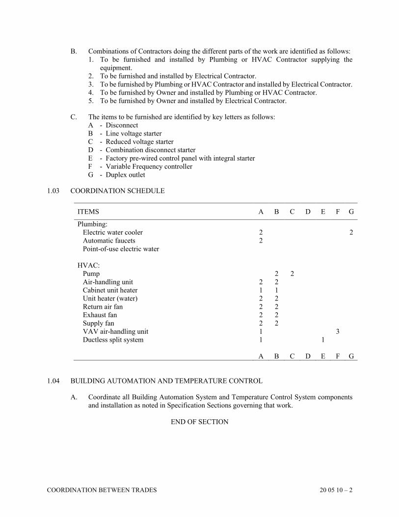
COORDINATION BETWEEN TRADES 20 05 10 – 2
B. Combinations of Contractors doing the different parts of the work are identified as follows:
1. To be furnished and installed by Plumbing or HVAC Contractor supplying the
equipment.
2. To be furnished and installed by Electrical Contractor.
3. To be furnished by Plumbing or HVAC Contractor and installed by Electrical Contractor.
4. To be furnished by Owner and installed by Plumbing or HVAC Contractor.
5. To be furnished by Owner and installed by Electrical Contractor.
C. The items to be furnished are identified by key letters as follows:
A - Disconnect
B - Line voltage starter
C - Reduced voltage starter
D - Combination disconnect starter
E - Factory pre-wired control panel with integral starter
F - Variable Frequency controller
G - Duplex outlet
1.03 COORDINATION SCHEDULE
ITEMS A B C D E F G
Plumbing:
Electric water cooler 2 2
Automatic faucets 2
Point-of-use electric water
HVAC:
Pump 2 2
Air-handling unit 2 2
Cabinet unit heater 1 1
Unit heater (water) 2 2
Return air fan 2 2
Exhaust fan 2 2
Supply fan 2 2
VAV air-handling unit 1 3
Ductless split system 1 1
A B C D E F G
1.04 BUILDING AUTOMATION AND TEMPERATURE CONTROL
A. Coordinate all Building Automation System and Temperature Control System components
and installation as noted in Specification Sections governing that work.
END OF SECTION
SECTION 20 05 15
SUBMITTALS
SUBMITTALS 20 05 15 – 1
PART 1 GENERAL
1.01 DESCRIPTION
A. For general requirements, refer to the GENERAL CONDITIONS and Division 1.
B. Materials and equipment installed in this work shall meet all the requirements of the Contract
Documents and no materials or equipment shall be ordered until submittals are reviewed and
approved by the Contractor, Architect, and Engineer.
C. Contractors assume all responsibility for changes required as a result of work performed, or
equipment ordered, by the Contractor prior to submittal approval.
D. Submit complete copies of the catalog data or Drawings for each manufactured item of
equipment and each component to be used in the work as required in the table below. Catalog
data shall include specific performance data, utility requirements, service area required,
material description, rating, capacity, working pressure, dimensional data, material gauge or
thickness, wiring diagrams, brand name, catalog number, and general type.
E. Submittals reviewed by the Engineer shall not take precedence over the Contract Documents,
and the Engineer's review shall not relieve the Contractor from the responsibility for
complying with the Drawings or Specifications, nor from the responsibility for providing
proper clearance and coordination with other Trades.
F. When submitted for review, all shop Drawings shall bear the Contractor's certification that
he/she has reviewed, checked, and approved the shop drawings, that they have been
coordinated with the requirements of the project and the provisions of the Contract
Documents, and that he/she has verified all field measurements and construction criteria,
materials, catalog numbers, and similar data. Submittals without a Contractor's approval will
not be reviewed and will be returned.
G. Submittals shall include the complete package of equipment materials, piping, and insulation
pertaining to that piece of equipment. A package of equipment requiring long lead times
may be submitted earlier.
H. The Engineer's review and approval does not extend to means, methods, manners,
techniques, sequences, procedure of construction or to safety precautions or programs
incident thereto. This is solely the Contractor's responsibility.
I. Shop Drawings that are submitted, but are not required by the table below, will not be
reviewed, and they will not be returned.
J. Shop Drawings that are indicated to be provided for Record Purposes only will not be
reviewed, and they will not be returned.
1.02 CONTRACTOR'S RESPONSIBILITIES
A. Completely review and approve shop Drawings, product data, and samples prior to submittal.
SUBMITTALS 20 05 15 – 2
B. Determine and verify:
1. Field measurements
2. Field construction criteria
3. Catalog numbers and similar data
4. Conformance with Specifications
5. Quantities
C. Coordinate each submittal with requirements of the work and the Contract Documents and
other Trades.
D. Notify the Architect in writing, at the time of submittal, of any deviations in the submittals
from the requirements of the Contract Documents. The Contractor must boldly note all
deviations on the submittal.
E. Make submittals promptly in accordance with the approved schedule and in such sequence
as to cause no delay in the work of the Contractor or any other Contractor.
F. Correct or change and then resubmit rejected submittals as required until approved. The
Contractor must clearly note all revisions on resubmitted submittals. Resubmittals without
the revisions noted may be returned without review.
G. Do not begin fabrication or work that requires submittals until approved submittals are
returned.
1.03 CERTIFICATIONS
A. Provide:
1. Test Agency results verifying capacities, operating conditions and power requirements
at design conditions. Test Agencies are to be hired by the Contractor at the Contractor's
expense.
2. Manufacturer's Statement of Compliance with Standards discussed in individual
Specification Sections.
3. Equipment labels indicating Certification requirements.
4. Quality standard designations on each unit piece, for example, each pipe length, pressure
vessel, or valve.
5. Typed verification that noted mixes, chemical compositions, and testing procedures were
complied with.
6. Other Certifications listed in other Sections of the Specifications.
1.04 REQUIRED SUBMITTAL INFORMATION (ALSO REFER TO DIVISION 1)
A. Submittal Transmittal
1. Provide the following information on the Transmittal Form for each submittal:
a. Project name
b. Specification number for each submittal item required in table below
c. Item description, as listed for each submittal item required in table below. Where
equipment is identified by number or tag on the documents, use the same
identification on the submittal.
d. Specification number and item description (b and c, preceding) for each submittal if
more than one (1) submittal is sent under one (1) transmittal form.
e. Name, address, and telephone number of Contractor.
SUBMITTALS 20 05 15 – 3
f. Bid package number.
2. Submittal transmittal forms not properly identified with the preceding information will
be returned (without review) to the Contractor.
B. Shop Drawing Requirements
1. Shop Drawings – Provide catalog cuts, Drawings, warranties, motor efficiencies and
power factor information (where applicable), wiring diagrams (where applicable),
performance curves and characteristics. Shop drawings shall be submitted electronically
in PDF file format and as described in Division 1. The submittals will be returned to the
Contractor, who will make and distribute as many copies as needed. Only submittals
with the approved stamp printed on them shall be permitted on the site.
2. Color Samples of the following items are to be provided:
a. Cabinet Unit Heaters
b. Finned Tube Radiation
c. Louvers
d. Convectors
e. Panel Radiators
f. Electric Finned Radiation
C. Submit ductwork layout shop Drawings for record purposes only after coordination between
all Contractors has occurred. Drawings shall be at 1/4 inch equals 1 foot scale and shall
include duct, top and bottom elevations with enlarged sections and elevation plans as
necessary. Coordinate size and location of ductwork with structure, piping, lighting,
equipment, conduit, bus ducts, ceiling construction, clear height above, and other items that
may present a potential conflict. These Drawings will not be reviewed or returned.
D. Submit HVAC piping layout shop Drawings for record purposes only after coordination
between all Contractors has occurred. Drawings to be a 1/4 inch equals 1 foot scale with
enlarged sections and elevation plans as necessary. Identify all valve locations, as well as all
piping and support elevations. Coordinate size and location of ductwork with structure,
ductwork, lighting, equipment, conduit, bus ducts, ceiling construction, and Owner's desired
clear headroom. These Drawings will not be reviewed or returned.
E. Each Contractor shall submit information on the equipment items as listed in the following
table. Identify each item with Specification numbers.
Section #
Item
Provide for
Approval
Provide for
Record
Purposes Only General Items for Plumbing and HVAC 20 05 05 Suppliers and manufacturers list X
20 05 20 Record and information booklets X
20 05 35 Fire stops through floors and walls X
20 05 40 Piping expansion, noise and vibration isolation X
20 05 45 Hangers, supports, and inserts (Seismic) X
Plumbing Contract Items 22 05 02 Plumbing Specialties X
22 05 23 Plumbing Valves X
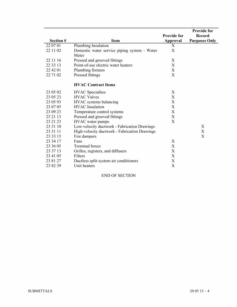
SUBMITTALS 20 05 15 – 4
Section #
Item
Provide for
Approval
Provide for
Record
Purposes Only
22 07 01 Plumbing Insulation X
22 11 02 Domestic water service piping system - Water
Meter
X
22 11 16 Pressed and grooved fittings X
22 33 13 Point-of-use electric water heaters X
22 42 01 Plumbing fixtures X
22 71 02 Pressed fittings X
HVAC Contract Items 23 05 02 HVAC Specialties X
23 05 23 HVAC Valves X
23 05 93 HVAC systems balancing X
23 07 05 HVAC Insulation X
23 09 23 Temperature control systems X
23 21 13 Pressed and grooved fittings X
23 21 23 HVAC water pumps X
23 31 10 Low-velocity ductwork - Fabrication Drawings X
23 31 11 High-velocity ductwork - Fabrication Drawings X
23 33 15 Fire dampers X
23 34 17 Fans X
23 36 05 Terminal boxes X
23 37 13 Grilles, registers, and diffusers X
23 41 05 Filters X
23 81 27 Ductless split-system air conditioners X
23 82 39 Unit heaters X
END OF SECTION
SECTION 20 05 20
RECORD AND INFORMATION BOOKLETS
RECORD AND INFORMATION BOOKLETS 20 05 20 – 1
PART 1 GENERAL
1.01 DESCRIPTION
A. See Division 1 for general requirements.
B. Submit draft manual to the Architect for review and approval thirty (30) days before final
inspection is due.
C. After approval, submit two (2) copies of approved booklets to the Owner and obtain receipt.
(See Section 20 05 99, "Requirements for Contract Completion.")
PART 2 PRODUCTS
2.01 MANUALS
A. Manuals shall be loose leaf, three-ring, hardcover binders. Material shall be typewritten or
printed (in English) and fully legible. Each section shall be divided by labeled tabs and
organized by Specification number.
B. The following items, together with any other necessary pertinent data, shall be included in
each Record and Information Booklet:
1. Each manual to be labeled on front cover with Project name, Contract, Contractor's name,
Architect's name, Engineer's name, and date of Project Completion.
2. Manufacturers' names, nearest factory representative (including postal and e-mail
address, telephone and fax number), and model and serial numbers of components of
systems.
3. Name, postal and e-mail address, telephone and fax number of contact persons handling
warranty work and issues.
4. Operating instructions, including start-up and shut-down procedures.
5. Maintenance and lubrication instructions, including routine and emergency service
information and instructions.
6. Parts list with numbers of replaceable items (such as couplings and packings). Include
sources of supply, with postal and e-mail address, telephone and fax number.
7. One (1) approved copy of each shop Drawing submitted.
8. Temperature control diagrams.
9. Valve charts.
10. Written warranties.
11. Belt sizes, types, and lengths.
12. Wiring diagrams, as actually wired.
13. Testing and balancing reports.
14. Copy of Owner's statement concerning completion of instruction period (see
Section 20 05 99, "Requirements for Contract Completion").
15. Routine and 24-hour emergency service and repair information:
a. Name, post and e-mail address and telephone and fax number of servicing agencies
- routine and emergency.
b. Names of personnel to be contacted for service arrangements - routine and
emergency.
RECORD AND INFORMATION BOOKLETS 20 05 20 – 2
2.02 CONTROL DIAGRAM AND VALVE CHART
A. In the main Mechanical Room or location designated by Owner's Representative, mount
approved copy in a neat frame with backing under glass or within a plastic jacket.
END OF SECTION
SECTION 20 05 25
EXCAVATION, BACKFILL, AND PROTECTION OF UTILITIES
EXCAVATION, BACKFILL, AND PROTECTION OF UTILITIES 20 05 25 – 1
PART 1 GENERAL
1.01 DESCRIPTION
A. Provide all protection, removal, and relocation of existing utilities and all excavation and
backfilling (including concrete) associated with the work of this Division. Protect above
grade and below grade utilities that are to remain.
B. Locate all existing utilities and equipment, in all areas of work, and record the actual
locations. Take extreme care during excavations to avoid interruption of utilities. Protect
above grade and below grade utilities that are to remain.
C. Disconnect all utilities designated for removal or relocation, in conformance with the
requirements of the utility company and the Owner.
D. Cooperate with other Contractors and the utility company to protect existing utilities and
avoid disruption of service. Repair damaged utilities.
E. Restore or repair to their existing condition all lawns, planting areas, curbs, paving, streets,
and walks damaged by the work of this Division.
F. Coordinate the timing of excavation and backfilling with the work of other Contractors.
G. Protect plant life, lawns, and other features remaining as a portion of final landscaping.
Coordinate with General Trades Contractor.
H. Protect benchmarks, existing structures, sidewalks, paving, and curbs from excavation
equipment and vehicular traffic.
I. In general, conform to the requirements of Division 2, except as specifically modified in this
Section.
1.02 EXCAVATION SAFETY
A. The Contractor has the responsibility to comply with all governing Codes and Ordinances
regarding safety of open excavations. This responsibility includes the use of all sheet piling,
bracing, shoring, sheathing, warning lights, barricades, etc., that may be required. Such
material will remain the Contractor's property upon completion of the work.
PART 2 PRODUCTS
2.01 FILL MATERIALS
A. Granular Material: Material shall consist of natural or synthetic mineral aggregate such as
broken or crushed rock, gravel, or sand; graded in accordance with ANSI/ASTM C136 within
the following limits:
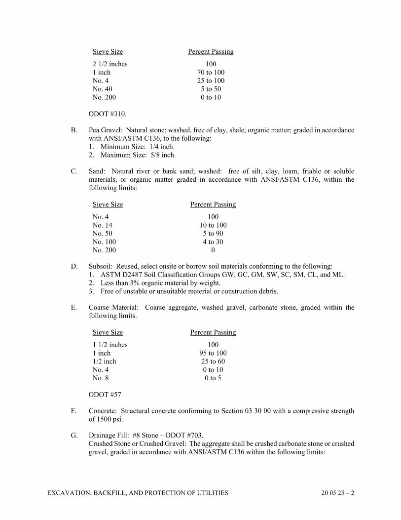
EXCAVATION, BACKFILL, AND PROTECTION OF UTILITIES 20 05 25 – 2
Sieve Size Percent Passing 2 1/2 inches 100
1 inch 70 to 100
No. 4 25 to 100
No. 40 5 to 50
No. 200 0 to 10
ODOT #310.
B. Pea Gravel: Natural stone; washed, free of clay, shale, organic matter; graded in accordance
with ANSI/ASTM C136, to the following:
1. Minimum Size: 1/4 inch.
2. Maximum Size: 5/8 inch.
C. Sand: Natural river or bank sand; washed: free of silt, clay, loam, friable or soluble
materials, or organic matter graded in accordance with ANSI/ASTM C136, within the
following limits:
Sieve Size Percent Passing No. 4 100
No. 14 10 to 100
No. 50 5 to 90
No. 100 4 to 30
No. 200 0
D. Subsoil: Reused, select onsite or borrow soil materials conforming to the following:
1. ASTM D2487 Soil Classification Groups GW, GC, GM, SW, SC, SM, CL, and ML.
2. Less than 3% organic material by weight.
3. Free of unstable or unsuitable material or construction debris.
E. Coarse Material: Coarse aggregate, washed gravel, carbonate stone, graded within the
following limits.
Sieve Size Percent Passing 1 1/2 inches 100
1 inch 95 to 100
1/2 inch 25 to 60
No. 4 0 to 10
No. 8 0 to 5
ODOT #57
F. Concrete: Structural concrete conforming to Section 03 30 00 with a compressive strength
of 1500 psi.
G. Drainage Fill: #8 Stone – ODOT #703.
Crushed Stone or Crushed Gravel: The aggregate shall be crushed carbonate stone or crushed
gravel, graded in accordance with ANSI/ASTM C136 within the following limits:
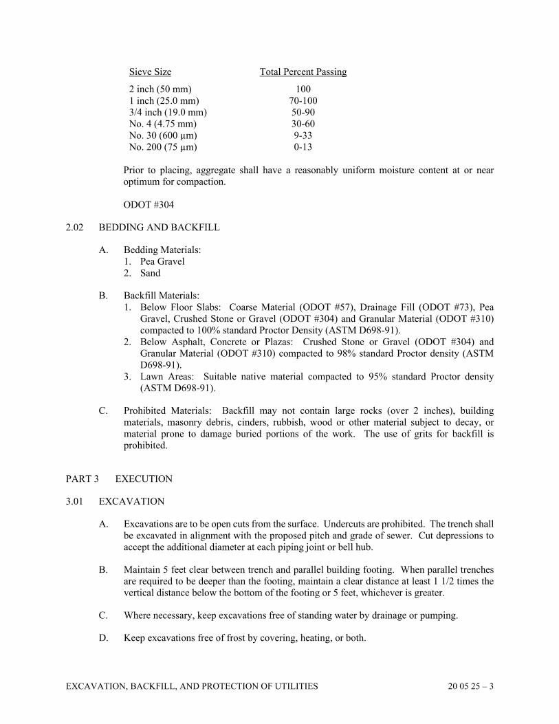
EXCAVATION, BACKFILL, AND PROTECTION OF UTILITIES 20 05 25 – 3
Sieve Size Total Percent Passing 2 inch (50 mm) 100
1 inch (25.0 mm) 70-100
3/4 inch (19.0 mm) 50-90
No. 4 (4.75 mm) 30-60
No. 30 (600 µm) 9-33
No. 200 (75 µm) 0-13
Prior to placing, aggregate shall have a reasonably uniform moisture content at or near
optimum for compaction.
ODOT #304
2.02 BEDDING AND BACKFILL
A. Bedding Materials:
1. Pea Gravel
2. Sand
B. Backfill Materials:
1. Below Floor Slabs: Coarse Material (ODOT #57), Drainage Fill (ODOT #73), Pea
Gravel, Crushed Stone or Gravel (ODOT #304) and Granular Material (ODOT #310)
compacted to 100% standard Proctor Density (ASTM D698-91).
2. Below Asphalt, Concrete or Plazas: Crushed Stone or Gravel (ODOT #304) and
Granular Material (ODOT #310) compacted to 98% standard Proctor density (ASTM
D698-91).
3. Lawn Areas: Suitable native material compacted to 95% standard Proctor density
(ASTM D698-91).
C. Prohibited Materials: Backfill may not contain large rocks (over 2 inches), building
materials, masonry debris, cinders, rubbish, wood or other material subject to decay, or
material prone to damage buried portions of the work. The use of grits for backfill is
prohibited.
PART 3 EXECUTION
3.01 EXCAVATION
A. Excavations are to be open cuts from the surface. Undercuts are prohibited. The trench shall
be excavated in alignment with the proposed pitch and grade of sewer. Cut depressions to
accept the additional diameter at each piping joint or bell hub.
B. Maintain 5 feet clear between trench and parallel building footing. When parallel trenches
are required to be deeper than the footing, maintain a clear distance at least 1 1/2 times the
vertical distance below the bottom of the footing or 5 feet, whichever is greater.
C. Where necessary, keep excavations free of standing water by drainage or pumping.
D. Keep excavations free of frost by covering, heating, or both.
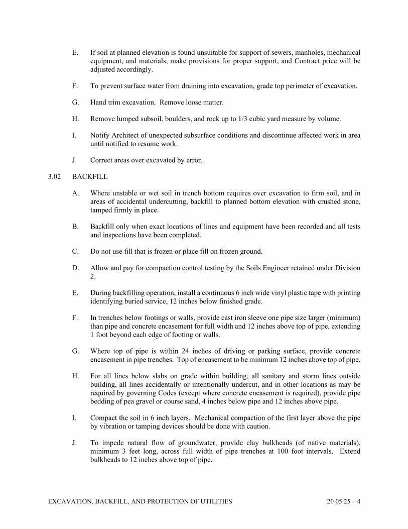
EXCAVATION, BACKFILL, AND PROTECTION OF UTILITIES 20 05 25 – 4
E. If soil at planned elevation is found unsuitable for support of sewers, manholes, mechanical
equipment, and materials, make provisions for proper support, and Contract price will be
adjusted accordingly.
F. To prevent surface water from draining into excavation, grade top perimeter of excavation.
G. Hand trim excavation. Remove loose matter.
H. Remove lumped subsoil, boulders, and rock up to 1/3 cubic yard measure by volume.
I. Notify Architect of unexpected subsurface conditions and discontinue affected work in area
until notified to resume work.
J. Correct areas over excavated by error.
3.02 BACKFILL
A. Where unstable or wet soil in trench bottom requires over excavation to firm soil, and in
areas of accidental undercutting, backfill to planned bottom elevation with crushed stone,
tamped firmly in place.
B. Backfill only when exact locations of lines and equipment have been recorded and all tests
and inspections have been completed.
C. Do not use fill that is frozen or place fill on frozen ground.
D. Allow and pay for compaction control testing by the Soils Engineer retained under Division
2.
E. During backfilling operation, install a continuous 6 inch wide vinyl plastic tape with printing
identifying buried service, 12 inches below finished grade.
F. In trenches below footings or walls, provide cast iron sleeve one pipe size larger (minimum)
than pipe and concrete encasement for full width and 12 inches above top of pipe, extending
1 foot beyond each edge of footing or walls.
G. Where top of pipe is within 24 inches of driving or parking surface, provide concrete
encasement in pipe trenches. Top of encasement to be minimum 12 inches above top of pipe.
H. For all lines below slabs on grade within building, all sanitary and storm lines outside
building, all lines accidentally or intentionally undercut, and in other locations as may be
required by governing Codes (except where concrete encasement is required), provide pipe
bedding of pea gravel or course sand, 4 inches below pipe and 12 inches above pipe.
I. Compact the soil in 6 inch layers. Mechanical compaction of the first layer above the pipe
by vibration or tamping devices should be done with caution.
J. To impede natural flow of groundwater, provide clay bulkheads (of native materials),
minimum 3 feet long, across full width of pipe trenches at 100 foot intervals. Extend
bulkheads to 12 inches above top of pipe.
EXCAVATION, BACKFILL, AND PROTECTION OF UTILITIES 20 05 25 – 5
K. Provide washed gravel backfill in trenches containing concrete encased underground ducts.
Top of gravel 6 inches minimum above top of duct.
L. Provide manufacturer recommended backfill around underground sumps, interceptors, meter
pits, catch basins, and tanks.
END OF SECTION

SECTION 20 05 30
CONCRETE BASES AND SUPPORTS
CONCRETE BASES AND SUPPORTS 20 05 30 – 1
PART 1 GENERAL
1.01 CONCRETE WORK
A. Provide all concrete bases required for equipment supplied under this Division. Coordinate
all pertinent dimensions, details, and cast-in-place items with the equipment being supplied.
B. All other concrete work incidental to the work of this Division is the responsibility of this
Division's Contractor. Conform to the quality standards in Division 3. Such concrete
includes but is not limited to:
1. Backfill in trenches, where required to be concrete
2. Pipe or duct encasement, thrust blocks, and similar concealed work
3. Manholes, interceptors, catch basins, or other underground structures
C. Do not mount equipment on concrete supports until concrete has had sufficient setting time
(seven (7) days minimum).
1.02 SUPPORT STEEL
A. In general, all hangers, concrete anchor bolts, brackets, and other steel supports incidental to
the work of this Division are to be provided by this Division's Contractor. Conform to the
quality standards in Division 5. Only major support framing shown on the structural
Drawings is to be provided by the others. For the proper execution of this work, provide all
pertinent dimensions, details, and weights to those others.
PART 2 PRODUCTS
2.01 PREFABRICATED ROOF CURBS
A. Construction: Minimum 18 gauge galvanized steel, continuous welded seams, mitered
corners, pressure treated wood nailer strip, 12 inches minimum height above finished roof
elevation, and counterflashing with lag screws. Where curb is used for equipment support,
provide integral base plates and internal reinforcing as required to support equipment load.
Where curb is around a roof penetration, provide 1 1/2 inch thick, 3 lb. density rigid fiberglass
insulation. Provide pitched roof curb as required to keep equipment level.
B. Manufacturers: Pate Company, Louvers & Dampers, Inc., Vent Products Company,
Swarthwout, Inc., Shipman Industries, or Thy-Curb.
PART 3 EXECUTION
3.01 INSTALLATION
A. Other Contractors, as appropriate, shall provide roof openings and installation of roof curbs.
B. The HVAC Contractor shall coordinate the size and location of all roof curbs, to avoid
trapping water from ponding.

CONCRETE BASES AND SUPPORTS 20 05 30 – 2
C. Provide weathertight curb caps if equipment cannot be set immediately.
D. Install thrust blocks at least 72 hours before testing the water lines.
END OF SECTION
SECTION 20 05 35
SLEEVES, SEALS AND FIRESTOPS
SLEEVES, SEALS AND FIRESTOPS 20 05 35 – 1
PART 1 GENERAL
1.01 DESCRIPTION
A. Furnish sleeves for pipe and duct penetrations through precast concrete, masonry, and
concrete construction or where piping or ductwork passes through walls, through smoke-
rated or fire-rated separations, and equipment room walls and floors.
B. Provide watertight, corrosive service, oil-resistant service, and fire rated seals and firestops
as specified herein.
C. Use sleeving with absolutely watertight seal for piping passing through all foundation walls,
floor slabs on grade, and other below grade penetrations into building.
D. Provide dimensions and locations of openings for sleeves, piping, ducts, louvers, grilles, and
similar items to the Contractor requiring the information.
E. Carefully coordinate and check locations of sleeves immediately before and after each
concrete pour and masonry installation.
F. Provide approved firestop materials around all penetrations through fire-rated construction
walls and floors per ASTM E814 and ASTM E119, including but not limited to pipes, ducts,
drains, closet flanges, conduits, and raceways.
G. At no additional cost to the Owner, correct unacceptable seals and firestops, and provide
additional inspection as necessary to verify compliance with this Specification.
1.02 QUALITY ASSURANCE
A. Firestop materials shall be classified by UL as "fill, void, or cavity materials" and "through
penetration firestop systems."
B. Firestop materials shall conform to both Flame (F) and Temperature (T) ratings as tested by
nationally accepted test agencies per ASTM E814 or UL 1479 Fire Tests of Through-
Penetration Firestops.
1. The F rating shall be a minimum of one (1) hour but not less than the fire-resistance
rating of the assembly being penetrated.
2. Conduct the fire test with a minimum positive pressure differential of 0.01 inches of
water column.
C. Firestop materials and equipment used shall be in accordance with the manufacturer's written
installation instructions. Installer shall be experienced, certified, licensed, or otherwise
qualified by the firestopping manufacturer as having been provided the necessary training to
install manufacturer's products per specified requirements. Note that a manufacturer's
willingness to sell its firestopping products to the Contractor or to an Installer engaged by
the Contractor does not in itself confer qualification on the buyer.
D. Firestop materials shall be expanded to fill cavities or provide adhesion to substrates that will
maintain seal under normal expected movements of substrates.
SLEEVES, SEALS AND FIRESTOPS 20 05 35 – 2
E. For those firestop applications that exist for which no UL-tested system is available through
a manufacturer, a manufacturer's engineering judgment derived from similar UL system
designs or other tests will be submitted to local authorities having jurisdiction for their review
and approval prior to installation. Engineering judgment Drawings must follow requirements
set forth by the International Firestop Council.
1.03 SUBMITTALS
A. Submit the following in accordance with Section 20 05 15, "Submittals":
1. Manufacturer's product data sheets indicating product characteristics, performance, and
limiting criteria.
2. Manufacturer's installation instruction for each type of seal or firestop required by the
project.
3. Written certification that firestop systems meet firestop requirements specified herein.
B. To be included in Record and Information Booklets:
1. One (1) copy of each approved submittal.
1.04 MANUFACTURERS
A. Seals:
1. "Link-Seal" by Thunderline Corporation
2. CSD Sealing Systems
3. Calpico
4. Wayne
5. Michigan
6. Metraflex
B. Firestop materials:
1. Hilti
2. 3M
3. CSD Sealing Systems
4. Johns-Manville
5. Tremco
6. Rectorseal
7. Proset Systems
8. Nelson
9. Firestop "Flame Safe"
10. STI
PART 2 PRODUCTS
2.01 SLEEVE MATERIAL
A. For sleeves less than 8 inches in diameter, use machine cut, standard weight, black steel pipe.
Fabricate sleeves 8 inches in diameter and larger from 12 gauge galvanized steel sheet.
B. Use copper sleeves for bare copper piping.
SLEEVES, SEALS AND FIRESTOPS 20 05 35 – 3
C. Sleeves to be large enough for insulation to be continuous or for seals to be installed, but
clearance all around to be less than 1/4 inch for both insulated and uninsulated pipes that
penetrate walls and slabs.
D. Proset system prefabricated fire-rated sleeves may be installed as an option for poured-in-
place concrete or through cored holes in floors or masonry walls.
E. Provide with waterstop anchor flange at midpoint where penetrating below grade floor slab
or exterior structure at or below grade. Sleeves shall have a full-length welded intermediate
flange and be imbedded in masonry. The Contractor may provide steel wall sleeves by Link-
Seal or Proset Systems Prefabricated Sleeve System.
2.02 SEALS
A. Modular Mechanical Type:
1. Seals shall consist of interlocking synthetic rubber links shaped to continuously fill the
annular space between conduit and sleeve.
2. Seal assembly shall have steel bolts and nuts and rubber sealing element for service and
environment under which assembly will be used. Seal shall have a pressure resistance
rating of 20 psig.
B. Sealing Plug Type:
1. Seals shall consist of two (2) identical piece plugs made of synthetic rubber with one
edge flanged, serrated profile on the outside, and on the inside a series of ridges that
compress and assure a tight seal. Seal shall have a pressure resistance of 15 psig at the
plug base and 30 psig at the flange. Rubber grade shall be suitable for the service and
environment under which sealing plug will be used.
2.03 WATERTIGHT SEALS
A. Modular, mechanical-type watertight seals shall have zinc galvanized bolts and nuts with
EPDM rubber sealing element. Seals shall be Link-Seal, Type C.
B. Sealing-plug-type watertight seals shall be made of EPDM rubber. Seals shall be by CSD
Sealing Systems. OPTION: Proset System Elastomeric Seals.
2.04 FIRE-RATED SEALS
A. Sealing-plug-type fire-rated seals shall be made of fire resistance rated rubber for three (3)
hour fire resistance rating. OPTION: Proset System Elastomeric Seals.
2.05 OIL RESISTANT SERVICE SEALS
A. Modular, mechanical-type, oil-resistant-service seals shall have zinc galvanized bolts and
nuts with Nitrile rubber sealing element. Seals shall be Link-Seal, Type O.
B. Sealing-plug-type oil resistant seals shall be made of Nitrile rubber. Seals shall be by CSD
Sealing Systems. OPTION: Proset System Elastomeric Seals.
SLEEVES, SEALS AND FIRESTOPS 20 05 35 – 4
2.06 CORROSIVE-SERVICE SEALS
A. Modular, mechanical-type corrosive-service seals have stainless steel bolts and nuts with
rubber sealing element that is highly resistant to most organic compounds, acids, alkalis, and
related chemicals. Seals shall be Link-Seal, Type S.
B. Sealing-plug-type corrosive-service seals shall be made by Viton rubber. Seals shall be by
CSD Sealing Systems.
2.07 FIRESTOPPING MATERIALS
A. Penetration sealants:
1. 3M Brand "Fire Barrier" caulk, putty or penetrating sealing systems
2. CSD Sealing Systems CSD-FW and CSD-F caulk and putty
3. Johns-Manville "Cerafiber"
4. Rectorseal "Metacaulk"
5. Tremco
6. Hilti
7. Firestop "Flame Safe"
8. Spec Seal
B. Provide firestopping composed of components that are compatible with each other, the
substrates forming openings, and the items, if any, penetrating the firestopping under
conditions of service and application, as demonstrated by the firestopping manufacturer
based on testing and field experience. Provide components for each firestopping system that
are needed to install fill material. Use only components specified by the firestopping
manufacturer and approved by the qualified testing agency for the designated fire resistance-
rated systems. Contractor shall be responsible for using the correct method and type of fire
sealant and fire-rated seals in each type of installation.
C. All firestop installations shall be UL rated.
PART 3 EXECUTION
3.01 CUTTING
A. Cut sleeves through walls flush with each surface. Unused sleeves shall extend beyond wall
surface and be capped on each end.
B. Cut sleeves 3/4 inch above finished floors or concrete curbs and 4 inches above floors in
equipment rooms, rooms with floor drains, and shafts. Sleeves through waterproof floors
shall project a minimum of 4 inches above the floor. Cut bottom of sleeve flush with bottom
of floor.
C. Core drill holes for sleeves in existing construction.
D. Patching shall be by others at this Contractor's expense.
SLEEVES, SEALS AND FIRESTOPS 20 05 35 – 5
3.02 INSTALLATION OF SLEEVES
A. Carefully coordinate and check locations of sleeves immediately before and after each
concrete pour and masonry installation. Install cast-in-place sleeves subject to the following
limitations:
1. Do not embed aluminum without prior approval of coating material.
2. Do not displace reinforcing steel.
3. Maintain a center-to-center spacing of at least 3 diameters of sleeve.
4. Do not install sleeves in any concrete beam, unless specifically shown on the structural
Drawings.
B. Give other Contractors as appropriate locations and sizes of all openings required for sleeve
installation before construction of masonry or concrete walls and floors is started. If it is
necessary to cut into the new work of other Trades due to the failure of this Contractor to
provide proper notification, the other Trades shall do the cutting in at this Contractor's
expense. Patching shall be done in the same fashion.
C. Core drill hole for sleeves in existing construction after locations have been approved by the
Structural Engineer and General Contractor.
D. Size sleeves with 1/4 inch minimum and 1 inch maximum clearance all around pipe or pipe
insulation.
E. Piping is not to bear on sleeves. Install sleeves plumb with respect to wall.
F. Minimize gaps between sleeve and ducts and pipes passing through walls and floors. Seal
space up to a 1/2 inch gap with sealant or caulking. Close off space greater than 1/2 inch gap
with sheet metal and seal airtight. To maintain fire rating of structure, pack all fire-rated
separation sleeves with fire retardant or other noncombustible material. To fill space around
all sleeves leading into exposed areas, use material compatible with adjacent construction
and finish.
G. Plug, pack, and finish unused sleeves to match adjacent surface and be compatible with their
ratings.
H. Use sleeves where round or oval duct openings are required through exposed walls, smoke
or fire partitions, or equipment room walls. Close off all spaces around rectangular ducts
through these walls.
I. Provide chrome plated wall or floor escutcheons, sized to cover opening and seal, for all
exposed installations.
3.03 INSTALLATION OF SEALS AND FIRESTOPS
A. Clean surfaces and substrates of dirt, oil, loose materials, and other foreign materials that
may affect the proper bond or installation of seals and firestopping.
B. Do not apply seals and firestopping to surfaces previously painted or treated with a sealer
curing compound or similar product. Remove coatings as required in compliance with
manufacturer's instructions. Provide primers, as required, that conform to manufacturer's
recommendations for various substrates and conditions.
SLEEVES, SEALS AND FIRESTOPS 20 05 35 – 6
C. Follow manufacturer's written instructions for installation of seals and firestopping.
D. To ensure an effective smoke seal and to maintain the assembly's fire-resistance rating, install
firestops with sufficient pressure to fill seal holes, voids, and openings.
E. Tool or trowel exposed surfaces. Remove excess firestop material promptly as work
progresses and upon completion.
F. Fill and surround unused sleeves with firestop material. Sleeve ends. Contractor may use
blind sealing plugs.
G. Install watertight seals for all below grade penetrations of piping into the building.
H. To maintain the fire-rating of the structure, pack all openings in fire-rated walls and floors
and between sleeves and pipes with noncombustible material. Pipe insulation shall not be
continued through a rated partition, unless sealant assembly is listed for use with continuous
insulation. Maintain vapor barriers at all penetrations.
I. Install oil-resistant-service seals in environment where oils, fuels, solvents, and other
petroleum-base products are used.
J. Install corrosive-service seals in environments where organic materials, acids, alkalis, and
related chemicals are used.
3.04 INSPECTION
A. Examine seals and firestops to ensure proper installation and full compliance with this
Specification. Work shall be accessible until inspection and approval by the applicable Code
authorities.
B. At no additional cost to the Owner, correct unacceptable seals and firestops, and provide
additional inspection to verify compliance with this Specification.
C. Maintain a current, legible copy of the manufacturer's written instructions for installation of
seals and firestopping at the project site, for all products being used on the Project. Make
installation instructions available on request for all Inspecting Authorities, the Architect, and
the Engineer.
END OF SECTION
SECTION 20 05 40
PIPING EXPANSION, NOISE AND VIBRATION ISOLATION
PIPING EXPANSION, NOISE AND VIBRATION ISOLATION 20 05 40 – 1
PART 1 GENERAL
1.01 DESCRIPTION
A. Provide thermal expansion control for all piping.
B. Isolate all piping for both noise and vibration transmission.
C. To prevent damage to building, equipment, joists, hangers, and piping, provide expansion
loops, expansion joints, guides, anchors, and offsets in piping systems as necessary to
accurately control pipe movement resulting from equipment operation or thermal gradients.
D. Provide pump connectors for each pump 1 hp and larger.
E. Provide expansion joints and accompanying anchors and guides where shown, or where
expansion cannot be provided for with loops and offsets.
1.02 MANUFACTURERS
A. Metraflex Company, Flexible Metal Hose, Wheatley, Proco, Mason Industries, or General
Rubber.
PART 2 PRODUCTS
2.01 PUMP CONNECTORS (HYDRONIC SYSTEMS)
A. 1 1/2 Inch and Smaller: Metraflex SST, 250 degrees F, 400 psig, Type 321 stainless steel
corrugated inner tubing and outer wire braid shield, threaded ends.
B. 2 Inches and Larger: Metraflex "Metraflex Style R" or "Cablesphere", 150 psig rating at
concurrent 200 degrees F, EDPM and nylon molded globe, bias-ply tire cord reinforcing,
cadmium-plated 150 ASA steel companion flanges. Provide restraining cables or rods to
limit axial growth.
2.02 EXPANSION JOINTS
A. Stainless steel bellows and elements, cast iron equalizing rings, tie-rods and pipe connections
as required, 300 psig working pressure. Use packless, internally guided type for lines 2
inches and smaller. Metraflex Model MC.
2.03 FLEXIBLE CONNECTORS
A. Flexible rubber connector, 22 degrees F, 150 psig, 150 lb. ASA flanges, steel retaining ring.
2.04 PIPE ALIGNMENT GUIDES
A. All heating hot water lines shall be guided by a painted steel cylinder guide assembly with
welded mounting brackets and two piece pipe clamp "Spider" assembly.
PIPING EXPANSION, NOISE AND VIBRATION ISOLATION 20 05 40 – 2
B. Provide galvanized steel U bolts (PHD Fig. 91 or equivalent) nutted firmly in place for
alignment, with insulation guard and shield on heating hot water, installed on stands or racks.
PART 3 EXECUTION
3.01 INSTALLATION
A. Line Expansion:
1. U Bends: In all piping subject to expansion and contraction, install U Bends or loops in
piping, in accordance with ASHRAE Equipment Handbook.
2. Expansion Joints: Where space is insufficient to provide U Bends, or where specifically
shown or specified, provide expansion joints. Install according to the manufacturer's
instructions.
B. Branch Connections:
1. Make branch connections to mains with a minimum of two (2) 90 degree elbows, and
incorporate at least one (1) change of direction in the horizontal plane and one (1) change
of direction in the vertical plane before connecting to equipment or fixtures, or dropping
into or rising in a wall.
2. Bullhead connections in any piping services are expressly prohibited.
C. Guides: To preserve alignment and pitch, supplement all loops and expansion joints with
adequate guides as close to loops and joints as possible and additionally at recommended
intervals from joints. Rigidly secure guides to the structure and ensure that only axial
movement is permitted. Provide auxiliary support metal as required to secure guides to
structure. Follow the recommendations and guidelines of the Expansion Joint Manufacturer's
Association, Inc.
D. Pump Connectors: Install pump connectors according to the manufacturer's
recommendations and instructions. Do not use pump connectors to align pump connections
with piping. Install connectors with as little initial misalignment or deflection as possible.
END OF SECTION

SECTION 20 05 45
HANGERS, SUPPORTS AND INSERTS
HANGERS, SUPPORTS AND INSERTS 20 05 45 – 1
PART 1 GENERAL
1.01 DESCRIPTION
A. Provide hangers, supports, concrete inserts, threaded rods, framing steel, and hardware
required for piping, ductwork, and equipment installed under this Division.
B. Install all necessary inserts, expansion shields, beam clamps, floor supports, and auxiliary
steel.
C. For new concrete installations, furnish and install concrete inserts (when used or required)
for the work. Coordinate with other Contractors as appropriate.
D. So as not to delay construction, the Plumbing and HVAC Contractors are responsible for
correct locations, size, type, and installation of the concrete inserts for their work. Coordinate
work with other Contractors as appropriate.
E. Install wall brackets where required. Provide pipe guides and anchors as required to properly
control pipe movement. Method to suit job conditions. Refer to Section 20 05 40, "Piping
Expansion, Noise and Vibration Isolation."
F. Support piping at pumps and equipment from floor, structure or walls, so that piping weight
is not supported by pumps or by equipment. Install hangers with vibration isolator on all
piping, ductwork, and equipment support in the room's housing mechanical equipment. See
Section 20 05 80, "Vibration Isolators."
1.02 QUALITY ASSURANCE
A. All piping supports and parts shall conform to the latest requirements of the Code for Power
Piping (ANSI B31.1) and MSS Standard Practice SP-58 and SP-69, except as supplemented
or modified by the requirements of this Specification.
B. Components shall be selected and matched to the load imposed on them.
C. For ductwork supports, refer to SMACNA's "HVAC Duct Construction Standards Metal and
Flexible" (latest edition).
1.03 MANUFACTURERS
A. Pipe Hangers: PHD, PHP, Michigan Hanger (Erico), Hilti, Kinetics, B-Line, Anvil, or
Modern.
PART 2 PRODUCTS
2.01 HANGERS
A. Uninsulated Piping:
1. Steel or Plastic:
a. 1/2 Inch to 6 Inches: PHD Fig. 151, adjustable swivel ring, steel band, adjusting nut
or Fig. 450 adjustable clevis, carbon steel yoke, U-strap, bolt and hex nuts.
HANGERS, SUPPORTS AND INSERTS 20 05 45 – 2
2. Copper:
a. Use copper-plated hangers as specified previously for sizes up to 6 inches.
B. Insulated Piping:
1. Cast Iron (Storm), Steel, Plastic or Copper:
a. All piping except hot water piping, all sizes: PHD Fig. 450, adjustable clevis, carbon
steel yoke, U-strap, bolt, and hex nuts. Provide thermal protector.
b. Hot Water Piping:
1) 1/2 Inch to 1 1/2 Inches: PHD Fig. 450, adjustable clevis, carbon steel yoke,
U-strap, bolt, and hex nuts. Provide thermal protector.
2) 2 Inches to 16 Inches: PHD Fig. 475, adjustable roller, carbon steel yoke, cast
iron roll, rod and hex nuts.
c. Hanger size must be sufficient to accommodate pipe and insulation without
compressing insulation.
2. Thermal Protector:
a. Insulated saddle system consisting of a factory-assembled glass-reinforced
polypropylene saddle and steel pipe spacer. Assembly conductivity must be less
than 0.77 btuh-in./sf-hr°F, and shall be rated for at least 40 degrees F to 200 degrees
F service. Anvil Figure 260 ISS, or equal by approved manufacturer.
b. 6 inch long segments of 20 pcf molded fiberglass blocks Hamfab "H-block" or
hardwood (oak) blocks supported by PHD Fig. 170, galvanized steel protection
shield. Outdoor installations to be hardwood inserts, paraffin-coated. No softwood
(pine) wood blocks or wooden dowels will be permitted. Provide a vapor barrier
cover over inserts so that the insulation vapor barrier will not be broken.
C. Sanitary and Vent Piping:
1. Cast Iron: PHD Fig. 450, adjustable clevis, carbon steel yoke, U-strap, bolt, and hex
nuts.
2. Plastic: PHD Fig. 440, lightweight, adjustable clevis, carbon steel yoke, U-strap and
bolt.
D. Vertical Piping:
1. Cast Iron, Plastic, or Steel Piping:
a. 1/2 Inch to 10 Inches: Friction clamp with two point bearing, PHD Fig. 550 series
at each floor level.
b. 12 Inches to 14 Inches: Friction clamp with two point bearing, PHD Fig. 550 series
at each floor level and Fig. 855 wall bracket at mid span of the floor height.
c. 16 inches and above are to be support at base of riser by pipe stanchions from the
floor below the riser or stack. Structural reinforcement of building structure is
required at stanchion attachment point.
2. Copper Piping: Copper-plated friction clamp with two point bearing for sizes up to
6 inches, PHD Fig. 552.
2.02 SPRING HANGERS
A. Refer to Section 20 05 80, "Vibration Isolators."
2.03 TRAPEZE HANGERS
A. Pre-engineered strut or angle iron of sufficient length to support pipes and insulation on
individual hangers, roller supports, or saddles with insulation protectors as specified for
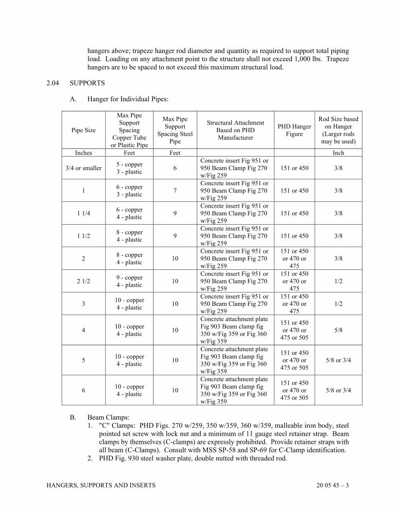
HANGERS, SUPPORTS AND INSERTS 20 05 45 – 3
hangers above; trapeze hanger rod diameter and quantity as required to support total piping
load. Loading on any attachment point to the structure shall not exceed 1,000 lbs. Trapeze
hangers are to be spaced to not exceed this maximum structural load.
2.04 SUPPORTS
A. Hanger for Individual Pipes:
Pipe Size
Max Pipe
Support
Spacing
Copper Tube
or Plastic Pipe
Max Pipe
Support
Spacing Steel
Pipe
Structural Attachment
Based on PHD
Manufacturer
PHD Hanger
Figure
Rod Size based
on Hanger
(Larger rods
may be used)
Inches Feet Feet Inch
3/4 or smaller 5 - copper
3 - plastic 6
Concrete insert Fig 951 or
950 Beam Clamp Fig 270
w/Fig 259
151 or 450 3/8
1 6 - copper
3 - plastic 7
Concrete insert Fig 951 or
950 Beam Clamp Fig 270
w/Fig 259
151 or 450 3/8
1 1/4 6 - copper
4 - plastic 9
Concrete insert Fig 951 or
950 Beam Clamp Fig 270
w/Fig 259
151 or 450 3/8
1 1/2 8 - copper
4 - plastic 9
Concrete insert Fig 951 or
950 Beam Clamp Fig 270
w/Fig 259
151 or 450 3/8
2 8 - copper
4 - plastic 10
Concrete insert Fig 951 or
950 Beam Clamp Fig 270
w/Fig 259
151 or 450
or 470 or
475
3/8
2 1/2 9 - copper
4 - plastic 10
Concrete insert Fig 951 or
950 Beam Clamp Fig 270
w/Fig 259
151 or 450
or 470 or
475
1/2
3 10 - copper
4 - plastic 10
Concrete insert Fig 951 or
950 Beam Clamp Fig 270
w/Fig 259
151 or 450
or 470 or
475
1/2
4 10 - copper
4 - plastic 10
Concrete attachment plate
Fig 903 Beam clamp fig
350 w/Fig 359 or Fig 360
w/Fig 359
151 or 450
or 470 or
475 or 505
5/8
5 10 - copper
4 - plastic 10
Concrete attachment plate
Fig 903 Beam clamp fig
350 w/Fig 359 or Fig 360
w/Fig 359
151 or 450
or 470 or
475 or 505
5/8 or 3/4
6 10 - copper
4 - plastic 10
Concrete attachment plate
Fig 903 Beam clamp fig
350 w/Fig 359 or Fig 360
w/Fig 359
151 or 450
or 470 or
475 or 505
5/8 or 3/4
B. Beam Clamps:
1. "C" Clamps: PHD Figs. 270 w/259, 350 w/359, 360 w/359, malleable iron body, steel
pointed set screw with lock nut and a minimum of 11 gauge steel retainer strap. Beam
clamps by themselves (C-clamps) are expressly prohibited. Provide retainer straps with
all beam (C-Clamps). Consult with MSS SP-58 and SP-69 for C-Clamp identification.
2. PHD Fig. 930 steel washer plate, double nutted with threaded rod.
HANGERS, SUPPORTS AND INSERTS 20 05 45 – 4
C. Wall Brackets: PHD Fig. 850 (lightweight 750 lbs. load) or Fig. 855 (medium weight 1,500
lb. load), carbon steel, back plates and bolts. Wall brackets for horizontal piping runs are
limited to 10 inch pipe size and smaller.
D. Attachment to Concrete Structures: PHD, Fig. 903 concrete rod attachment plate.
E. Welded Beam Attachment: PHD, Fig. 900 concrete rod attachment plate.
2.05 INSERTS
A. In Concrete: PHD, Fig. 950 wedge type insert, low carbon steel, for up to 600 lb. load.
B. In precast or already poured concrete: Hilti "Kwik Bolt TZ" concrete fasteners, or approved
equal by ITW/Redhead. "Drop-in" type fasteners are not acceptable without written evidence
of third-party testing indicating there is no measurable loss of an insert's tensile capacity
when concrete cracking occurs where the insert is installed.
2.06 FINISH
A. Unless otherwise noted, all hangers and supports to be standard black, except that hangers
and supports for exposed exterior applications and applications subject to high humidity shall
be hot-dipped galvanized.
PART 3 EXECUTION
3.01 PIPING INSTALLATION
A. Install necessary pipe hangers and supports to properly support all piping and to maintain
piping uniformly level or vertical (3/4 inch maximum deflection). Hangers to be double-
nutted.
B. Maximum spacing of piping supports shall be per Hanger Table included in this
Specification. Provide additional hangers as follows:
1. On both sides of steel or brass, or cast metal valves for pipe sizes 6 inches and larger.
2. Horizontal DWV Plastic Piping: At branch connections and at each change of direction.
3. Vertical DWV Piping: At branch connections, at each change of direction, at each floor,
and mid-story, for no more than a 10 foot vertical spacing. Provide additional supports
as necessary to maintain piping alignment at the base.
4. Cast Iron Piping: Horizontal at intervals not in excess of the standard lengths of pipe
used; vertical 15 foot maximum intervals, at base, and at each floor.
5. At each drop at a pump boiler, chiller or other major equipment item.
3.02 DUCTWORK HANGER INSTALLATION
A. Install necessary hanger rods and angle iron support brackets to properly support ductwork,
insulation, reinforcing, and external loads. Friction clamps are excluded as upper attachment
devices.
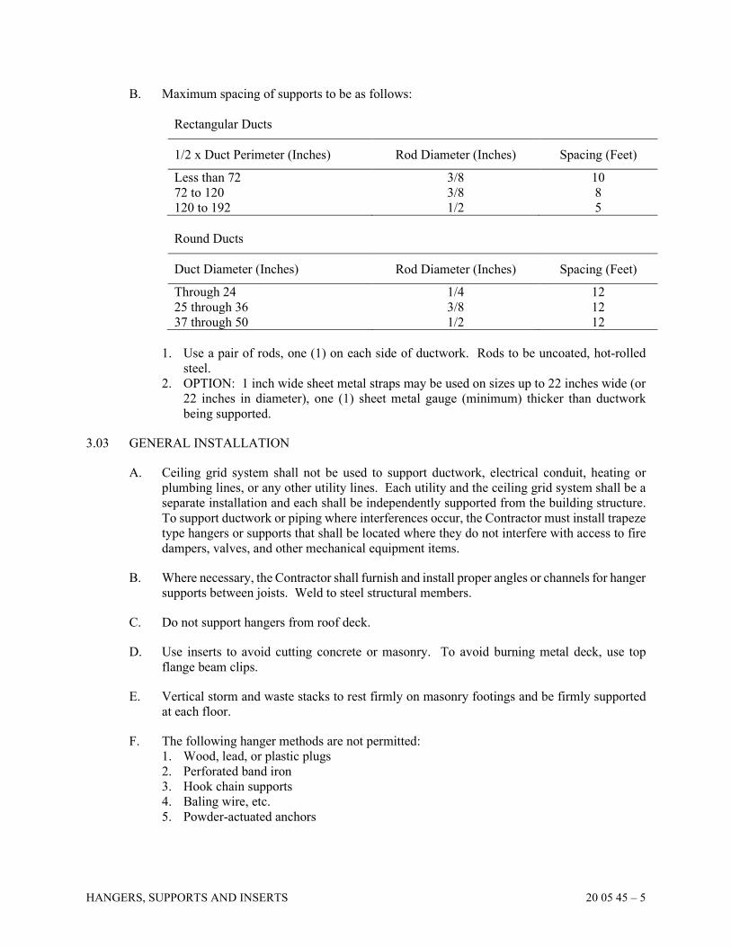
HANGERS, SUPPORTS AND INSERTS 20 05 45 – 5
B. Maximum spacing of supports to be as follows:
Rectangular Ducts
1/2 x Duct Perimeter (Inches) Rod Diameter (Inches) Spacing (Feet)
Less than 72 3/8 10
72 to 120 3/8 8
120 to 192 1/2 5
Round Ducts
Duct Diameter (Inches) Rod Diameter (Inches) Spacing (Feet)
Through 24 1/4 12
25 through 36 3/8 12
37 through 50 1/2 12
1. Use a pair of rods, one (1) on each side of ductwork. Rods to be uncoated, hot-rolled
steel.
2. OPTION: 1 inch wide sheet metal straps may be used on sizes up to 22 inches wide (or
22 inches in diameter), one (1) sheet metal gauge (minimum) thicker than ductwork
being supported.
3.03 GENERAL INSTALLATION
A. Ceiling grid system shall not be used to support ductwork, electrical conduit, heating or
plumbing lines, or any other utility lines. Each utility and the ceiling grid system shall be a
separate installation and each shall be independently supported from the building structure.
To support ductwork or piping where interferences occur, the Contractor must install trapeze
type hangers or supports that shall be located where they do not interfere with access to fire
dampers, valves, and other mechanical equipment items.
B. Where necessary, the Contractor shall furnish and install proper angles or channels for hanger
supports between joists. Weld to steel structural members.
C. Do not support hangers from roof deck.
D. Use inserts to avoid cutting concrete or masonry. To avoid burning metal deck, use top
flange beam clips.
E. Vertical storm and waste stacks to rest firmly on masonry footings and be firmly supported
at each floor.
F. The following hanger methods are not permitted:
1. Wood, lead, or plastic plugs
2. Perforated band iron
3. Hook chain supports
4. Baling wire, etc.
5. Powder-actuated anchors
HANGERS, SUPPORTS AND INSERTS 20 05 45 – 6
G. Whenever possible, use supports, clamps, hangers, etc., designed especially for the
equipment to be installed.
H. Where necessary, furnish and install proper angles or channels or support steel to reinforce
the building structure or to spread out the load on the building structure. Weld to steel
structural members or attach to concrete structures using inserts or concrete fasteners.
3.04 COORDINATION
A. Coordinate drilling, welding, etc., and method of attachment to columns, joists, beams, girts,
etc., with Structural Engineer and other Contractors as appropriate before proceeding.
END OF SECTION
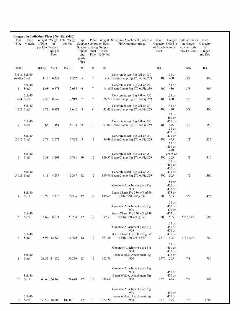
HANGERS, SUPPORTS AND INSERTS 20 05 45 – 7
Hangers for Individual Pipes ( Not SEISMIC ) Pipe
Size
Pipe
Material
Weight
of Pipe
per Foot
Weight
of
Water in Pipe per
Foot
Total Weight
per Foot
Pipe
Support
Spacing Copper
and
plastic Pipe
Pipe
Support
Spacing Steel
Pipe
Weight
on Each
Support (Max
1500 lbs)
Structural Attachment Based on
PHD Manufacturing.
Load
Capacity
of Attach ment
Hanger
PHD Fig
Number
Rod Size based
on Hanger
(Larger rods may be used)
Load
Capacity
of Hanger
and Rod
inches lbs/LF lbs/LF lbs/LF ft ft lbs lbs inch lbs
3/4 or
smaller
Sch 40
Steel 1.13 0.232 1.362 5 7 9.53
Concrete insert Fig 951 or 950
Beam Clamp Fig 270 w/Fig 259 400
151 or
450 3/8 300
1
Sch 40
Steel 1.68 0.375 2.055 6 7 14.39
Concrete insert Fig 951 or 950
Beam Clamp Fig 270 w/Fig 259 400
151 or
450 3/8 300
1-1/4
Sch 40
Steel 2.27 0.649 2.919 7 9 26.27
Concrete insert Fig 951 or 950
Beam Clamp Fig 270 w/Fig 259 400
151 or
450 3/8 300
1-1/2
Sch 40
Steel 2.72 0.882 3.602 8 9 32.42
Concrete insert Fig 951 or 950
Beam Clamp Fig 270 w/Fig 259 400
151 or
450 3/8 300
2
Sch 40
Steel 3.65 1.454 5.104 8 10 51.04
Concrete insert Fig 951 or 950
Beam Clamp Fig 270 w/Fig 259 400
151 or
450 or 470 or
475 3/8 150
2-1/2
Sch 40
Steel 5.79 2.073 7.863 9 11 86.49
Concrete insert Fig 951 or 950
Beam Clamp Fig 270 w/Fig 259 400
151 or 450 or
470 or
475 1/2 225
3
Sch 40
Steel 7.58 3.201 10.781 10 12 129.37
Concrete insert Fig 951 or 950
Beam Clamp Fig 270 w/Fig 259 400
151 or
450 or
470 or475 or
505 1/2 310
3-1/2
Sch 40
Steel 9.11 4.287 13.397 12 12 160.76
Concrete insert Fig 951 or 950
Beam Clamp Fig 270 w/Fig 259 400
151 or 450 or
470 or 475 or
505 1/2 390
4
Sch 40
Steel 10.79 5.516 16.306 12 12 195.67
Concrete Attachment plate Fig
903 Beam Clamp Fig 350 w/Fig359
or Ffig 360 w/Fig 359 600
151 or 450 or
470 or 475 or
505 5/8 475
5
Sch 40
Steel 14.62 8.674 23.294 12 12 279.53
Concrete Attachment plate Fig
903 Beam Clamp Fig 350 w/Fig359
or Ffig 360 w/Fig 359 800
151 or 450 or
470 or 475 or
505 5/8 or 3/4 685
6
Sch 40
Steel 18.97 12.520 31.490 12 12 377.88
Concrete Attachment plate Fig
903 Beam Clamp Fig 350 w/Fig359
or Ffig 360 w/Fig 359 2710
151 or 450 or
470 or 475 or
505 5/8 or 3/4 780
8
Sch 40
Steel 28.55 21.680 50.230 12 12 602.76
Concrete Attachment plate Fig
903 Beam Welded Attachment Fig
900 3770
151 or 450 or
470 or 475 or
505 7/8 780
10
Sch 40
Steel 40.48 34.160 74.640 12 12 895.68
Concrete Attachment plate Fig
903 Beam Welded Attachment Fig
900 3770
450 or 470 or
475 7/8 965
12
Sch 40
Steel 53.52 48.500 102.02 12 10 1020.20
Concrete Attachment plate Fig
903 Beam Welded Attachment Fig
900 3770
450 or 470 or
475 7/8 1200
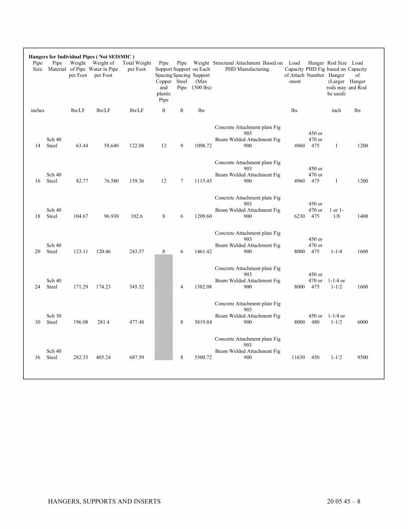
HANGERS, SUPPORTS AND INSERTS 20 05 45 – 8
Hangers for Individual Pipes ( Not SEISMIC )
Pipe
Size
Pipe
Material
Weight
of Pipe per Foot
Weight of
Water in Pipe per Foot
Total Weight
per Foot
Pipe
Support Spacing
Copper
and plastic
Pipe
Pipe
Support Spacing
Steel
Pipe
Weight
on Each Support
(Max
1500 lbs)
Structural Attachment Based on
PHD Manufacturing.
Load
Capacity of Attach
-ment
Hanger
PHD Fig Number
Rod Size
based on Hanger
(Larger
rods may be used)
Load
Capacity of
Hanger
and Rod
inches lbs/LF lbs/LF lbs/LF ft ft lbs lbs inch lbs
14
Sch 40
Steel 63.44 58.640 122.08 12 9 1098.72
Concrete Attachment plate Fig 903
Beam Welded Attachment Fig
900 4960
450 or
470 or
475 1 1200
16
Sch 40
Steel 82.77 76.580 159.36 12 7 1115.45
Concrete Attachment plate Fig 903
Beam Welded Attachment Fig
900 4960
450 or
470 or
475 1 1200
18
Sch 40
Steel 104.67 96.930 102.6 8 6 1209.60
Concrete Attachment plate Fig 903
Beam Welded Attachment Fig
900 6230
450 or
470 or
475
1 or 1-
1/8 1400
20
Sch 40
Steel 123.11 120.46 243.57 8 6 1461.42
Concrete Attachment plate Fig 903
Beam Welded Attachment Fig
900 8000
450 or
470 or
475 1-1/4 1600
24
Sch 40
Steel 171.29 174.23 345.52 4 1382.08
Concrete Attachment plate Fig 903
Beam Welded Attachment Fig
900 8000
450 or
470 or
475
1-1/4 or
1-1/2 1600
30
Sch 30
Steel 196.08 281.4 477.48 8 3819.84
Concrete Attachment plate Fig 903
Beam Welded Attachment Fig
900 8000
450 or
480
1-1/4 or
1-1/2 6000
36
Sch 40
Steel 282.35 405.24 687.59 8 5500.72
Concrete Attachment plate Fig 903
Beam Welded Attachment Fig
900 11630 450 1-1/2 9500
SECTION 20 05 50
GENERAL PIPING REQUIREMENTS
GENERAL PIPING REQUIREMENTS 20 05 50 – 1
PART 1 GENERAL
1.01 PIPING SYSTEMS - GENERAL
A. The following instructions apply to all piping systems, except where otherwise noted:
1. Provide unions or flanges / Provide unions, flanges, or grooved ends at each final
connection and at each piece of equipment. Arrange piping and locate unions and flanges
/ unions, flanges, and grooved ends to permit easy removal of parts and equipment for
inspection and cleaning. Welded connections to equipment are prohibited.
2. Make connections to equipment as detailed on the Drawings and according to the
manufacturer's installation instructions.
3. Where connection size is smaller than piping make reduction at final connection only
(do not reduce size of pipe drop).
4. Provide valves and specialties as required to complete installation of each piece of
equipment for proper operation.
5. Install all piping parallel to building lines, level and plumb unless required to slope.
B. Cleanout and flush water piping systems.
C. If other means of draining are not provided, install drain valves at all low points to permit
complete draining of each of the following:
1. All water systems
2. Compressed air systems
3. Fire sprinkler systems (according to NFPA)
D. Contractor to provide information on chases, sleeves, and openings required for his/her work
to other Contractors. This Contractor to assume cost and responsibility for all cutting and
patching resulting from improper coordination of the work.
E. Certified Pipe Welding Bureau. Welds to be stamped at each joint or fitting.
F. Install dielectric unions at all connections of dissimilar metals.
PART 2 PRODUCTS
2.01 UNIONS
A. Unions in Copper Pipe: Bronze 150 lb. ground joint, cast body, solder end (do not use
wrought copper unions). Mueller, Chase, Crane, or Northern Indiana Brass Company.
B. Unions in Steel Pipe: Black malleable iron, bronze ground ball joint. Mueller, Chase, Crane,
or Northern Indiana Brass Company.
C. Dielectric unions when connecting steel to copper pipe: 250 lb. W.P., insulating gasket, and
dielectric insulators. Epco, Dart, Capital, or Watts.
D. Dielectric fittings on flanges when connecting flanges on piping of dissimilar metals:
175 psig W.P., insulating gaskets, dielectric insulators including bolt isolators.
GENERAL PIPING REQUIREMENTS 20 05 50 – 2
2.02 JOINTS
A. Flanges:
1. Through 2 1/2 Inches: Cast iron screwed, 125 lb. or higher as required.
2. 3 Inches and Larger: Steel welding neck, 150 lb. or higher as required.
B. Gaskets: Asbestos-free, suitable for the intended service. Use dielectric gaskets where
joining dissimilar piping material.
C. Bolts for steel, cast iron, brass, and bronze, for 250 lb. SWP and 450 degrees F or below to
be carbon steel, with American Standard, regular, square heads and American Standard,
heavy, hexagon grade or better semi-finished nuts.
D. ASTM A307, Grade B, Tee head, high-tensile steel bolts and nuts may be used in mechanical
joint pipelines. (Mechanical joints are not to be used with tubing of copper or aluminum
alloys.)
E. Screwed Piping: Use NPT tapered threads.
2.03 GROOVED PIPING
A. Where grooved piping systems are allowed by reference in other Sections within this
Specification, the installing Contractor must have installed at least five (5) grooved
mechanical piping systems.
B. Install grooved couplings on 2 inch – 24 inch roll-grooved, standard weight Schedule 40 pipe
in accordance with the coupling manufacturer's installation instructions. Cut-grooved piping
systems will be unacceptable.
C. Install flexible couplings with the bolt pads metal to metal; rigid (slant bolt pad) couplings
shall be installed within the bolt pads metal to metal with equal offset. Installing Contractor
shall verify that bolt pad gaps do not exist.
D. The grooved mechanical coupling manufacturer shall perform on-site installation
demonstrations for the Installing Contractor before grooved coupling installation begins.
2.04 COPPER PRESS JOINT JOINING SYSTEM
A. Where such copper press joint piping systems are allowed by reference in other Sections
within this Specification, and if permitted by local authorities, the installing Contractor must
have installed at least five of such mechanical piping systems.
1. Copper and copper alloy press connections shall be made in accordance with the
manufacturer's installation instructions. The tubing shall be fully inserted into the fitting
and the tubing marked at the shoulder of the fitting. The fitting alignment shall be
checked against the mark on the tubing to assure the tubing is fully engaged (inserted) in
the fitting. The joints shall be pressed using the tool(s) approved by the manufacturer.
2. All piping shall be Type "L" copper. Fittings 1/2 inch to 4 inches shall be crimped on
both sides of an integral bead containing an EPDM seal. Fittings 2 1/2 inches through 4
inches shall be double crimped, and be fitted with a stainless steel grip ring.
3. The Contractor shall be trained on the installation of the product by the manufacturer and
shall follow the manufacturer's installation instructions.

GENERAL PIPING REQUIREMENTS 20 05 50 – 3
4. The copper tubing system shall be water tested for joint tightness. The piping system
shall be filled with water. The system shall be pressurized to the maximum pressure and
length of time required by the code or standard. The system shall have no leaks at the
rated pressure.
PART 3 EXECUTION
3.01 INSTALLATION
A. Install each union or flange to permit removal of parts, valves, and equipment and in a
position permitting the device or equipment to be removed without disconnecting piping.
Use flanged equipment connections exclusively on all steam and condensate systems.
B. Make reductions in piping lines with reducing coupling or weld fitting reducer. No bushings
will be permitted.
C. Install piping to provide clearance for personnel passage, headroom, operation of doors or
windows, equipment, lighting outlets, and for the Owner's apparatus and equipment.
Coordinate pipe runs and elevations with other Contractors before installation. Where
interferences develop in the field, pipes may need to be offset or rerouted, at no additional
cost to the Owner, as required to resolve interferences.
D. In pipe spaces to be entered for servicing, offset piping so that all lateral runs are located
either near the floor or at least 6 feet above the floor, and all vertical piping is held close to
the wall through that height. Keep all piping to the side of the chase wherever possible.
Offset vents immediately above the connection to the waste line.
E. Piping shall not be installed over electrical equipment, motor control centers, or transformers
and shall not be installed within elevator shafts or elevator equipment rooms.
F. Install pipes, valves, fittings, etc. with a minimum of 1/2 inch clearance between the finished
covering and other work and between the finished covering of parallel, adjacent pipes.
G. Use fittings to make changes in pipeline direction. Do not bend or spring piping.
H. Offset lines around columns, beams, and other obstructions as required. Where special
conditions are encountered in the field, arrangement and alignment of piping shall be decided
by the Architect and Engineer.
I. At time of assembly, clean piping components of loose material. After assembly and before
putting in service, blow or flush lines free of loose materials. Clean strainer screens and
sediment pockets prior to putting the lines in service.
J. Install valves at service connections to equipment and branch lines from main lines. Install
all valves and unions so that they are accessible through ceiling or wall access panel.
K. Use dielectric unions, shims, gaskets, or coatings to insulate direct contact between pipe,
fittings, and hangers of dissimilar metal
L. Install thermometers and gauges to permit them to be read from floor level.
GENERAL PIPING REQUIREMENTS 20 05 50 – 4
M. Securely support all piping from structure with approved hangers, rods, brackets, and
accessories.
N. Where piping is installed in new masonry block walls, coordinate other Contractors as
appropriate so that piping extends out through a masonry joint where possible.
O. Bullhead connections are not allowed.
P. Where exposed pipes pass through walls, floors, or ceilings of finished rooms, provide
chrome-plated escutcheons. Prime-coated black iron escutcheons may be used in unfinished
rooms. Protect escutcheons from tool marks.
Q. Keep pipe level except where a slope is required. Use eccentric reducers to keep bottom of
pipe level.
R. Avoid trapping of piping.
S. Install ball valves at pressure gauges and air vents at high points of piping.
T. Provide a union or bolted flange fitting downstream and within approximately 12 inches of
each valve and adjacent to both inlet and outlet of pumps and other equipment.
U. When copper lines are supplied, install dielectric unions or flanges on water line connections
to water heaters and equipment with steel pipe connections.
V. Provide unions or flanged connections where required for construction or assembling
purposes.
3.02 WELDED CONNECTIONS
A. Welded joints to be fabricated and stamped by welders qualified and certified for the
positions, materials, methods, and equipment being used and as required by enforcing bodies.
B. Buttweld joints shall have substantially full penetration and recommended bead
reinforcement.
C. Slip-on, socket, and fillet welds to have geometry indicated in the "Code for Power Piping"
(ANSI B31.1).
D. Remove weld scale from joints as work proceeds and at completion.
3.03 SOLDERED AND BRAZED CONNECTIONS
A. Joints to have pipe or tubing end reamed to full I.D. after cutting.
B. Exterior of joint shall be smooth.
C. Clean with steel wool.
D. Apply flux to prevent oxidation.
GENERAL PIPING REQUIREMENTS 20 05 50 – 5
E. Apply solder or brazing filler material and thoroughly heat to completely melt material and
cause it to migrate completely over the mating surfaces.
F. Solder and brazing work shall comply with ANSI Standard B31.1.
3.04 THREADED CONNECTIONS
A. Ream pipe ends of threads to full cross sectional area after cutting. Threads shall conform
to ANSI Standard B2.1.
B. Joints shall be made with TFE tape, applied to male threads only. Option: Use Permatex
pipe dope.
3.05 FLANGED CONNECTIONS
A. Face flanged joints square and true. Install gaskets suitable for the operating temperature
and pressure of the fluid or gaseous medium being piped.
3.06 PIPE CLEANING
A. Before systems are placed in operation, flush out all water piping systems to remove dirt and
grease from pipes and equipment. Clean strainers after each flushing until they remain clean.
B. For heating and cooling water piping systems, after system has been flushed thoroughly and
drained, perform the following steps:
1. Completely fill and circulate through system for four (4) hours at design temperature
with a solution of Burman "Pre-Clean."
2. Completely drain and refill system with fresh clean water.
3. Check pH and continue cleaning as recommended by Burman.
C. Fire protection mains to be flushed at flows required by NFPA-13 and NFPA-24.
D. For steam piping systems, after system is placed in operation, dump condensate for 24 hours
before returning condensate to boiler.
3.07 PIPING PROHIBITIONS
A. Do not run piping over electrical equipment, across windows, door openings, access panels
or lighting fixtures or within 36 inches in front of electrical panels that operate at a voltage
of 150 volts or less, or within 42 inches of electrical panels that operate at a voltage of 151
to 600 volts. Obtain instructions from the Architect if a conflict occurs. Coordinate with the
Electrical Contractor.
B. On any given system, the Contractor will not be permitted to mix and join different types of
pipe material. For example, if a storm or sanitary system uses plastic, copper, and cast iron,
the Contractor may change from one to the other only once. The line may not be changed
back to the first material further downstream.
C. Storm, vent and sanitary lines shall be continuously sloped; trapping is expressly prohibited.
GENERAL PIPING REQUIREMENTS 20 05 50 – 6
3.08 EMBEDDED PIPING LIMITATIONS
A. Install embedded pipes and sleeves subject to the following limitations:
1. Do not embed aluminum without prior approval of coating material.
2. Do not displace reinforcing steel.
3. In slabs and walls, limit outside dimension of pipes to 1/3 member thickness. Minimize
crossing embedded piping, and where crossing cannot be avoided, maintain same
minimum concrete cover as required for reinforcing bars. For slabs over metal decks,
slab thickness is measured from the top of the metal deck.
4. In columns, limit total area of pipes to 4% of column area.
5. Maintain a center-to-center spacing of at least three diameters of pipe or sleeve.
6. Do not install sleeves or piping in any concrete beam, unless specifically shown on the
structural Drawings.
END OF SECTION
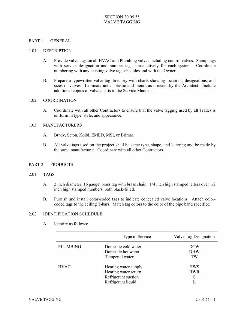
SECTION 20 05 55
VALVE TAGGING
VALVE TAGGING 20 05 55 – 1
PART 1 GENERAL
1.01 DESCRIPTION
A. Provide valve tags on all HVAC and Plumbing valves including control valves. Stamp tags
with service designation and number tags consecutively for each system. Coordinate
numbering with any existing valve tag schedules and with the Owner.
B. Prepare a typewritten valve tag directory with charts showing locations, designations, and
sizes of valves. Laminate under plastic and mount as directed by the Architect. Include
additional copies of valve charts in the Service Manuals.
1.02 COORDINATION
A. Coordinate with all other Contractors to ensure that the valve tagging used by all Trades is
uniform in type, style, and appearance.
1.03 MANUFACTURERS
A. Brady, Seton, Kolbi, EMED, MSI, or Brimar.
B. All valve tags used on the project shall be same type, shape, and lettering and be made by
the same manufacturer. Coordinate with all other Contractors.
PART 2 PRODUCTS
2.01 TAGS
A. 2 inch diameter, 16 gauge, brass tag with brass chain. 1/4 inch high stamped letters over 1/2
inch high stamped numbers, both black-filled.
B. Furnish and install color-coded tags to indicate concealed valve locations. Attach color-
coded tags to the ceiling T-bars. Match tag colors to the color of the pipe band specified.
2.02 IDENTIFICATION SCHEDULE
A. Identify as follows:
Type of Service Valve Tag Designation
PLUMBING Domestic cold water DCW
Domestic hot water DHW
Tempered water TW
HVAC Heating water supply HWS
Heating water return HWR
Refrigerant suction S
Refrigerant liquid L
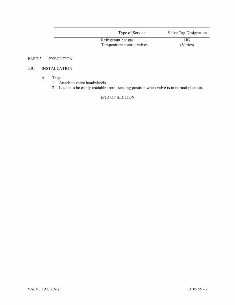
VALVE TAGGING 20 05 55 – 2
Type of Service Valve Tag Designation
Refrigerant hot gas HG
Temperature control valves (Varies)
PART 3 EXECUTION
3.01 INSTALLATION
A. Tags:
1. Attach to valve handwheels.
2. Locate to be easily readable from standing position when valve is in normal position.
END OF SECTION
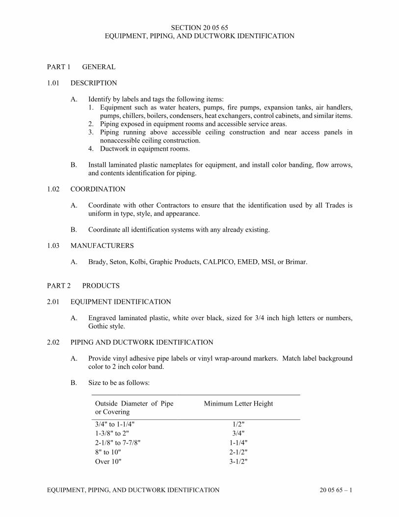
SECTION 20 05 65
EQUIPMENT, PIPING, AND DUCTWORK IDENTIFICATION
EQUIPMENT, PIPING, AND DUCTWORK IDENTIFICATION 20 05 65 – 1
PART 1 GENERAL
1.01 DESCRIPTION
A. Identify by labels and tags the following items:
1. Equipment such as water heaters, pumps, fire pumps, expansion tanks, air handlers,
pumps, chillers, boilers, condensers, heat exchangers, control cabinets, and similar items.
2. Piping exposed in equipment rooms and accessible service areas.
3. Piping running above accessible ceiling construction and near access panels in
nonaccessible ceiling construction.
4. Ductwork in equipment rooms.
B. Install laminated plastic nameplates for equipment, and install color banding, flow arrows,
and contents identification for piping.
1.02 COORDINATION
A. Coordinate with other Contractors to ensure that the identification used by all Trades is
uniform in type, style, and appearance.
B. Coordinate all identification systems with any already existing.
1.03 MANUFACTURERS
A. Brady, Seton, Kolbi, Graphic Products, CALPICO, EMED, MSI, or Brimar.
PART 2 PRODUCTS
2.01 EQUIPMENT IDENTIFICATION
A. Engraved laminated plastic, white over black, sized for 3/4 inch high letters or numbers,
Gothic style.
2.02 PIPING AND DUCTWORK IDENTIFICATION
A. Provide vinyl adhesive pipe labels or vinyl wrap-around markers. Match label background
color to 2 inch color band.
B. Size to be as follows:
Outside Diameter of Pipe
or Covering
Minimum Letter Height
3/4" to 1-1/4" 1/2"
1-3/8" to 2" 3/4"
2-1/8" to 7-7/8" 1-1/4"
8" to 10" 2-1/2"
Over 10" 3-1/2"
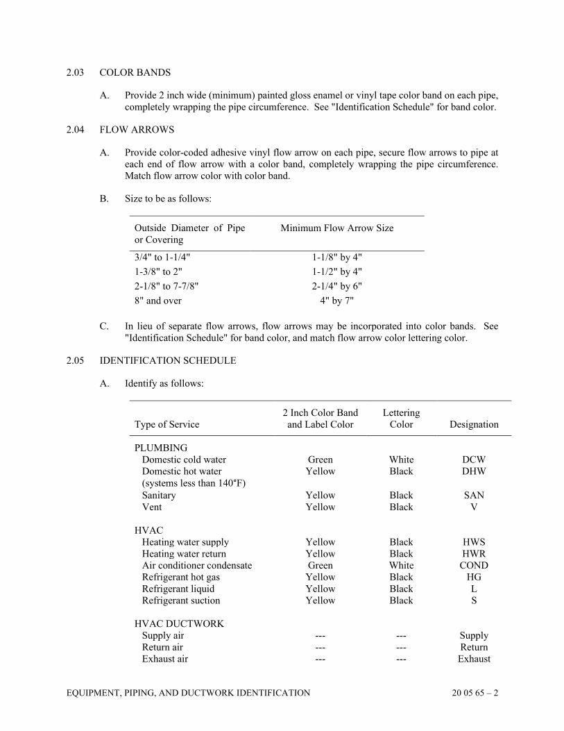
EQUIPMENT, PIPING, AND DUCTWORK IDENTIFICATION 20 05 65 – 2
2.03 COLOR BANDS
A. Provide 2 inch wide (minimum) painted gloss enamel or vinyl tape color band on each pipe,
completely wrapping the pipe circumference. See "Identification Schedule" for band color.
2.04 FLOW ARROWS
A. Provide color-coded adhesive vinyl flow arrow on each pipe, secure flow arrows to pipe at
each end of flow arrow with a color band, completely wrapping the pipe circumference.
Match flow arrow color with color band.
B. Size to be as follows:
Outside Diameter of Pipe
or Covering
Minimum Flow Arrow Size
3/4" to 1-1/4" 1-1/8" by 4"
1-3/8" to 2" 1-1/2" by 4"
2-1/8" to 7-7/8" 2-1/4" by 6"
8" and over 4" by 7"
C. In lieu of separate flow arrows, flow arrows may be incorporated into color bands. See
"Identification Schedule" for band color, and match flow arrow color lettering color.
2.05 IDENTIFICATION SCHEDULE
A. Identify as follows:
Type of Service
2 Inch Color Band
and Label Color
Lettering
Color
Designation
PLUMBING
Domestic cold water Green White DCW
Domestic hot water
(systems less than 140°F)
Yellow Black DHW
Sanitary Yellow Black SAN
Vent Yellow Black V
HVAC
Heating water supply Yellow Black HWS
Heating water return Yellow Black HWR
Air conditioner condensate Green White COND
Refrigerant hot gas Yellow Black HG
Refrigerant liquid Yellow Black L
Refrigerant suction Yellow Black S
HVAC DUCTWORK
Supply air --- --- Supply
Return air --- --- Return
Exhaust air --- --- Exhaust
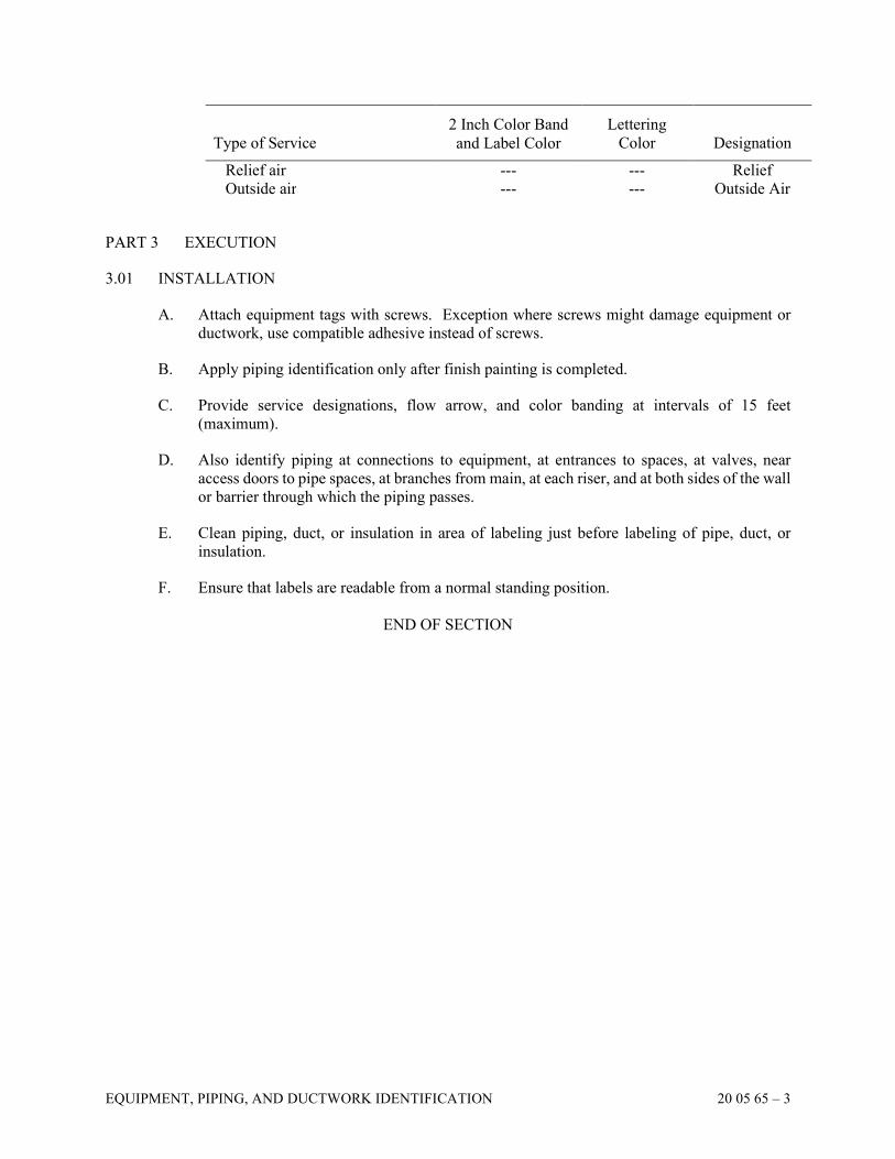
EQUIPMENT, PIPING, AND DUCTWORK IDENTIFICATION 20 05 65 – 3
Type of Service
2 Inch Color Band
and Label Color
Lettering
Color
Designation
Relief air --- --- Relief
Outside air --- --- Outside Air
PART 3 EXECUTION
3.01 INSTALLATION
A. Attach equipment tags with screws. Exception where screws might damage equipment or
ductwork, use compatible adhesive instead of screws.
B. Apply piping identification only after finish painting is completed.
C. Provide service designations, flow arrow, and color banding at intervals of 15 feet
(maximum).
D. Also identify piping at connections to equipment, at entrances to spaces, at valves, near
access doors to pipe spaces, at branches from main, at each riser, and at both sides of the wall
or barrier through which the piping passes.
E. Clean piping, duct, or insulation in area of labeling just before labeling of pipe, duct, or
insulation.
F. Ensure that labels are readable from a normal standing position.
END OF SECTION
SECTION 20 05 70
DEMOLITION
DEMOLITION 20 05 70 – 1
PART 1 GENERAL
1.01 DESCRIPTION
A. Carefully inspect the entire project and verify with the Architect all items designated to be
removed or to remain. Refer also to Division 1 for additional requirements.
B. Perform demolition work of all Plumbing and HVAC items as shown or described on the
Drawings. Remove from the site all items designated as scrap.
C. Locate all existing utilities requiring removal and determine all requirements for
disconnecting and capping.
D. Locate all existing active utilities designated to remain and determine the requirements for
their protection.
E. Take care not to damage adjacent construction designated to remain.
F. Unless otherwise noted, carefully remove existing ceiling tiles and supporting structure as
required to install or remove existing material and replace after work is completed. Any
damaged ceiling tiles and supporting tiles shall be replaced by each Contractor at no
additional cost to the Owner.
G. All demolished Plumbing and HVAC items in good condition are to remain the property of
the Owner. Verify with the Owner's representative which demolished items are considered
scrap and are to be removed from site.
PART 2 PRODUCTS (NOT APPLICABLE)
PART 3 EXECUTION
3.01 PREPARATION
A. Notify the Architect at least two (2) full working days prior to commencing work in a
particular area.
B. Coordinate and schedule all work in a careful manner with all necessary consideration for
the Owner, neighbors, and the public. Avoid interference with the use of, and passage to and
from, adjacent areas and facilities designated to remain in use during demolition. Coordinate
work with the other Contractors and Owner.
C. Before starting site operations, disconnect or arrange for the disconnection of all utilities or
equipment designated to be removed. Perform all such work in accordance with the
requirements of the utility company and the Owner.
D. Maintain in operating condition all active utilities designated to remain.
DEMOLITION 20 05 70 – 2
3.02 DEMOLITION
A. Demolish and remove equipment foundations and supports, piping, ductwork, abandoned
utility lines, and all other existing items designated for removal as indicated on the Drawings
and in these Specifications.
B. Do not use equipment or methods that will cause damage to adjacent construction designated
to remain.
C. Plug or cap piping that Drawings or Specifications indicate will remain.
D. Plug or cap wall and floor sleeves not being reused. Refer to Section 20 05 35, "Sleeves,
Seals, and Firestops."
E. Cap removed branch ducts close to mains with 24 gauge galvanized sheet metal.
3.03 RELOCATION
A. Remove and store until the construction is ready for their installation, all items designated to
be relocated.
B. Clean all Plumbing and HVAC fixtures and equipment designated to be relocated after
relocation is complete.
3.04 SALVAGE AND SCRAP
A. Maintain salvaged materials in good condition. Salvaged materials shall remain the property
of the Owner. Salvaged materials not acceptable to the Owner shall be considered scrap and
removed by the Contractor from the job site.
B. Tag and identify salvaged materials.
C. Coordinate with Owner's representative all Plumbing and HVAC items to be salvaged and
stored on site as directed. Storage of salvaged items will be permitted only at specified areas.
Provide weather covering of stockpiled salvage materials. The Owner shall remove salvaged
and stored items from the site.
D. Remove all scrap items from the building and arrange for disposal in accordance with State
and local regulations.
3.05 EXISTING EQUIPMENT TO REMAIN
A. Clean all Plumbing and HVAC fixtures and equipment designated to remain in the areas of
construction.
3.06 HAZARDOUS MATERIALS
A. Contractors are cautioned to check premises for existence of hazardous materials such as
paint with lead and asbestos in the form of pipe insulation or plaster. If materials that may
present a health hazard to workers, occupants, or the public are encountered during the work,
the Contractor shall do the following:
1. Take immediate action to limit the exposure or hazardous condition.
DEMOLITION 20 05 70 – 3
2. Cease work in the area until suspected hazardous material can be identified. Laboratory
testings, if required, will be paid for by the Owner.
3. Follow procedures and requirements of the governing authority (including, but not
limited to, EPA and OSHA) regarding monitoring, removal and disposal of the hazardous
material. Provide special equipment as required.
4. Costs relating to special work or procedures used or required for performance of the work
required to monitor, remove and dispose of hazardous materials will be borne by the
Owner.
END OF SECTION
SECTION 20 05 75
ACCESS PANELS
ACCESS PANELS 20 05 75 – 1
PART 1 GENERAL
1.01 DESCRIPTION
A. Furnish access panels necessary for access to mechanical equipment, valves, or other devices
requiring service, adjustment, or maintenance as follows:
1. Ceiling
2. Wall
3. Ductwork
B. All access panels shall be 24 inches by 24 inches unless otherwise noted.
1.02 WORK NOT INCLUDED
A. Access panels are to be turned over to other Contractors as appropriate for installation.
1.03 COORDINATION
A. This Contractor is responsible for providing the dimension and locations of all ceiling, wall,
and floor openings for the access panels to other Contractors requiring that information.
B. Coordinate with other Contractors with respect to panel locations and group valves, traps,
etc., so that they are accessible from a single panel.
1.04 MANUFACTURERS
A. Milcor, Bilco, Zurn, Larsen's, Acudor, JL, Inland Ryerson, MIFAB, Nystrom, Mitco, or
Karp.
PART 2 PRODUCTS
2.01 CEILING ACCESS PANELS
A. Drywall Ceilings: Milcor Style DW, 16 gauge steel frame with 14 gauge door panel, double-
acting concealed spring hinges, flush, cylinder lock, prime-painted for finish painting with
ceiling.
B. Fire-Rated Ceiling: Milcor fire-rated access door, UL approved, 16 gauge steel frame with
18 gauge recessed door panel, 20 gauge panel sides and 26 gauge panel hat channel,
continuous hinge, self-latching, cylinder lock, prime painted for finish painting.
C. Provide access panels with "Best Master" cylinder locks.
2.02 WALL ACCESS PANELS
A. Drywall: Milcor Style DW, 16 gauge steel frame with 14 gauge door panel, double-acting
concealed spring hinge, flush, cylinder lock, prime painted for finish painting.
ACCESS PANELS 20 05 75 – 2
B. Masonry and Tile: Milcor Style M Standard, 14 gauge steel frame and door panel, concealed
spring hinges, flush, cylinder lock, prime painted for finished painting.
C. Fire-Rated: Milcor fire-rated access door, UL approved, 1 1/2 hour, Class B rating, 16 gauge
steel frame, 20 gauge insulated door panel continuous hinge, automatic door closer cylinder
lock, interior release mechanism, prime painted for finish painting.
D. Provide access panels with "Best Master" cylinder locks.
PART 3 EXECUTION
3.01 COORDINATION OF INSTALLATION
A. Coordinate size, location, and installation of panels required to permit convenient access to
valves, dampers, bearings, motors, filters, controls, and other equipment requiring
adjustment, service, or maintenance. Mark locations of access panels on Record Drawings.
END OF SECTION
SECTION 20 05 80
VIBRATION ISOLATORS
VIBRATION ISOLATORS 20 05 80 – 1
PART 1 GENERAL
1.01 DESCRIPTION
A. Provide a complete vibration isolation system to isolate motorized equipment, piping,
ductwork, and appurtenances from the building structure and ceiling construction. Include
concrete for equipment pads.
B. Provide vibration isolation devices with motion limiters, sway struts, limits stops, shock
absorbing devices, and/or snubbers to control the horizontal and vertical movement of
equipment during seismic events. These devices shall be supplied based on the seismic
design data included in the other sections of this specification or listed on the drawings. This
data includes Site Class, Seismic Design Category, and Design Spectral Response
Acceleration for short period.
1.02 QUALITY ASSURANCE
A. Expected noise levels in various parts of the building shall conform to noise criteria
recommendations as set forth in the current edition of ASHRAE Guide and Fundamentals.
The midpoint of the range of noise criteria curves shall apply and become part of these
Specifications.
B. Sound and vibration control design criteria for mechanical systems for this building shall
conform to the chapter in Sound and Vibration Control in the current edition of ASHRAE
Guide, HVAC Systems and Applications.
C. Vibration isolation devices, including auxiliary steel bases and pouring forms, shall be
designed and furnished by a single manufacturer or supplier.
1.03 MANUFACTURERS
A. Kinetics, Korfund Dynamics Corporation, Vibration Eliminator Company, Inc., Vibration
Mountings and Controls, Inc., or Mason Industries, Inc.
PART 2 PRODUCTS
2.01 VIBRATION ISOLATORS
A. Type 1 - Pad Mounts: Precompressed molded fiberglass isolation pads, neoprene jacketed
and stabilized during manufacturing. Pads shall be sized for loading from 40 to 60 psi.
1. Kinetics Model KIP
B. Type 2 - Hanger Mounts: Vibration isolators with maximum static deflection requirements
under the operating load conditions not exceeding 0.40 inch shall be hangers consisting of
an elastomer-in-shear insert encased in a welded steel bracket and provided with a stamped
load transfer cap. The elastomer insert shall be neoprene, molded from oil resistant
compounds, and shall be color coded to indicate load capacity and selected to operate within
its published load range. The hanger bracket shall be designed to carry a 500% overload
VIBRATION ISOLATORS 20 05 80 – 2
without failure and to allow a support rod misalignment through a 30 degree arc without
metal-to-metal contact or other short circuit.
1. Kinetics Model RH
C. Type 3a - Spring Hanger Mounts: Vibration isolators shall be hangers consisting of a
freestanding, laterally stable steel spring and elastomeric washer in series, assembled in a
stamped or welded steel bracket. Springs shall have a lateral stiffness greater than 0.8 times
the rated vertical stiffness and shall be designed to provide up to 50% overload capacity.
Springs shall be selected to provide operating static deflections shown on the Vibration
Isolation Schedule or as indicated on the project documents. Springs shall be color coded or
otherwise identified to indicate load capacity.
1. Kinetics Noise Control Type SH
D. Type 3b - Spring Hanger Mounts: Vibration isolators where both high and low frequency
vibrations are to be isolated, shall be hangers consisting of a laterally stable steel spring in
series with a pre-compressed molded fiberglass insert, complete with load transfer plates and
assembled in a stamped or welded steel bracket. Vibration isolators shall be pre-compressed
molded fiberglass pads individually coated with a flexible, moisture impervious elastomeric
membrane. Vibration isolation pads shall be molded from glass fibers with fiber diameters
not exceeding 0.00027 inches and with a modulus of elasticity of 10.5 million PSI. Natural
frequency of fiberglass vibration isolators shall be essentially constant for the operating load
range of the supported equipment. Vibration isolators shall be color coded or otherwise
identified to indicate the load capacity. Springs shall have a lateral stiffness greater than 0.8
times the rated vertical stiffness and shall be designed to provide up to 50% overload
capacity. Springs shall be selected to provide operating static deflections shown on the
Vibration Isolation Schedule or as indicated on the project documents. Springs shall be color
coded or otherwise identified to indicate load capacity.
1. Kinetics Noise Control Type SFH
E. Type 3 - Spring Floor Mounts: Vibration isolators shall be freestanding, unhoused, laterally
stable springs wound from high strength spring steel. Springs shall have a lateral stiffness
greater than 0.8 times the rated vertical stiffness and shall be designed to provide up to 50%
overload capacity. Springs shall be selected to provide operating static deflections shown on
the Vibration Isolation Schedule or as indicated on the project documents. Springs shall be
color coded or otherwise identified to indicate load capacity. In capacities up to 5,000 lbs.,
springs shall be replaceable. In capacities over 5,000 lbs., springs shall be welded to the top
and bottom load plate assemblies. Springs shall be assembled between a top and bottom steel
load plate. The upper load plate shall be provided with a steel leveling bolt lock nut and
washer for attachment to the supported equipment. The lower load plate shall have a non-
skid noise isolation pad bonded to the bottom and have provisions for bolting the isolator to
the supporting structure.
1. Kinetics Noise Control Type FDS
F. Type 4 - Spring Limit Floor Mounts: Similar to Type 3 Spring Floor Mounts, but include
neoprene and steel vertical limit stops to assure a constant spring mount. Vibration isolators
shall consist of large diameter laterally stable steel springs assembled into formed or welded
steel housing assemblies designed to limit vertical movement of the supported equipment.
Housing assembly shall be formed or fabricated steel members and shall consist of a top-
load plate complete with adjusting and leveling bolts, vertical restraints, isolation washers
and a bottom plate with non-skid noise stop pads and holes provided for anchoring to
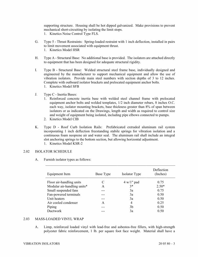
VIBRATION ISOLATORS 20 05 80 – 3
supporting structure. Housing shall be hot dipped galvanized. Make provisions to prevent
mechanical short-circuiting by isolating the limit stops.
1. Kinetics Noise Control Type FLS.
G. Type 5 - Thrust Restraints: Spring-loaded restraint with 1 inch deflection, installed in pairs
to limit movement associated with equipment thrust.
1. Kinetics Model HSR
H. Type A - Structural Base: No additional base is provided. The isolators are attached directly
to equipment that has been designed for adequate structural rigidity.
I. Type B - Structural Base: Welded structural steel frame base, individually designed and
engineered by the manufacturer to support mechanical equipment and allow the use of
vibration isolators. Provide main steel numbers with section depths of 3 to 12 inches.
Complete with outboard isolator brackets and prelocated equipment anchor bolts.
1. Kinetics Model SFB
J. Type C - Inertia Bases:
1. Reinforced concrete inertia base with welded steel channel frame with prelocated
equipment anchor bolts and welded templates, 1/2 inch diameter rebars, 8 inches O.C.
each way, isolator mounting brackets, base thickness greater than 8% of span between
isolators or as indicated on the Drawings, length and width as required to control size
and weight of equipment being isolated, including pipe elbows connected to pumps.
2. Kinetics Model CIB
K. Type D - Roof Curb Isolation Rails: Prefabricated extruded aluminum rail system
incorporating 1 inch deflection freestanding stabile springs for vibration isolation and a
continuous foam neoprene air and water seal. The aluminum rail shall include an integral
slot anchoring springs to the bottom section, but allowing horizontal adjustment.
1. Kinetics Model KSR-2
2.02 ISOLATOR SCHEDULE
A. Furnish isolator types as follows:
Equipment Item
Base Type
Isolator Type
Deflection
(Inches)
Floor air-handling units C 4 w/1" pad 0.75
Modular air-handling units* A 3* 2.50*
Small suspended fans --- 3a 0.75
Fan-powered terminals --- 3a 0.50
Unit heaters --- 3a 0.50
Air cooled condenser A 4 0.25
Piping --- 3b 0.50
Ductwork --- 3a 0.50
2.03 MASS-LOADED VINYL WRAP
A. Limp, reinforced loaded vinyl with lead-free and asbestos-free fillers, with high-strength
polyester fabric reinforcement, 1 lb. per square foot face weight. Material shall have a
VIBRATION ISOLATORS 20 05 80 – 4
continuous operating range of -40 degrees F to +180 degrees F, and shall be resistant to water,
oil, weak acids, alkalies, mold, and fungi. Material shall not rot, shrink or cause metal
corrosion. Provide Class A fire-rating where required.
B. Type KNM-100 by Kinetics, or equal by other listed manufacturers.
PART 3 EXECUTION
3.01 PREPARATION
A. Use steel components that are phosphated and painted. Use only nuts, bolts, and washers
that are zinc-electroplated.
B. Thoroughly clean structural steel bases of welding slag and prime them with zinc-chromate
or metal etching primer.
C. All isolators exposed to the weather, located outdoors, or within manholes or tunnels shall
have all steel parts either PVC-coated or hot-dip galvanized.
D. Use aluminum components that are etched and painted.
3.02 INSTALLATION
A. Equipment: All motorized heating and air-conditioning equipment, including pumps, fans
and other equipment, shall be mounted on, or suspended with, vibration isolators.
B. Piping and Ductwork:
1. All piping over 1 inch outside diameter located in mechanical equipment rooms shall be
isolated from the building structure by means of noise and vibration isolation hangers.
The only exclusions are roof and floor drain piping, and all sprinkler piping.
2. All piping located less than 50 feet (or 100 pipe diameters - whichever is greater) from
any connection to vibration isolated mechanical or electrical equipment, shall be isolated
from the building structure by means of noise and vibration isolation hangers. All piping
in the building, which is connected to vibration-isolated equipment, shall be isolated at
these connections to the building structure.
3. All ductwork located in mechanical equipment rooms, and for a minimum of 50 feet
from any connection to vibration-isolated air moving equipment shall be isolated from
the building structure by means of noise and vibration isolation guides and supports.
4. Isolate all ductwork vertical risers from the building structure by means of noise and
vibration isolation guides and supports.
5. Use vibration and noise isolating expansion hangers to isolate vertical pipe risers from
the structure. The hangers shall have a minimum rated deflection of four times the
anticipated pipe expansion and shall be enclosed in a housing for fail-safe operation.
6. All piping and ductwork to be isolated according to this Section of the Specifications
shall freely pass through walls and floors without rigid connections. Penetration points
shall be sleeved or otherwise formed to allow passage of piping or ductwork, and
maintain a minimum of 3/4 inch and maximum of 1 1/4 inches clearance around the
outside surfaces. This clearance space shall be tightly packed with 1.58 PCF glass fiber
and shall be caulked airtight after installation of the piping or ductwork, to form an
acoustic seal.

VIBRATION ISOLATORS 20 05 80 – 5
C. The installed vibration isolation system for each floor or for ceiling supported equipment
shall have a maximum lateral motion under equipment start-up or shutdown conditions of
1/4 inch. Motions in excess shall be restrained by approved spring-type thrust restraints as
specified or approved by submittal Drawing.
END OF SECTION
SECTION 20 05 99
REQUIREMENTS FOR CONTRACT COMPLETION
REQUIREMENTS FOR CONTRACT COMPLETION 20 05 99 – 1
PART 1 GENERAL
1.01 DESCRIPTION
A. Following is a partial list of items that must be submitted as required before Contract
Completion.
1. All Plumbing and HVAC Contractors:
a. Receipt for Operating Instructions and Service Manual
b. Certificate of Equipment Demonstration
c. Valve tags and charts
d. Receipt for keys
e. Warranties
f. All required test reports as specified in other Sections
g. All As-Built Drawings per Specifications
2. Plumbing Contractor only:
a. Certificate of Plumbing Inspection
b. Certificate of Sterilization
c. Certification that the solder or brazing used for entire new domestic water piping
system is lead-free.
d. Certificate from local fire department, Ohio EPA, or both that fuel storage tanks and
equipment installation is acceptable.
e. Medical Gas Certifications
3. HVAC Contractor only:
a. Certificate of Inspection
b. Air and water balance reports
c. Contractor's Certificate of Operation of fire and smoke dampers
B. In addition to the written submittals, the following material shall also be submitted prior to
Contract Completion. Submit a signed copy of the Certificate of Materials Receipt.
(ATTACHED TO THE END OF THIS SECTION)
1. Loose or spare parts as specified in other Sections.
2. Spare parts as specified in this Section.
C. Refer to Division 1 for additional requirements.
PART 2 PRODUCTS
2.01 SPARE PARTS
A. Furnish one complete set of the following spare parts:
1. Gaskets for each pump
2. Pump packing/mechanical seal for each pump
3. Gaskets for manholes and handholes
4. Glass for each water gauge
5. All air filters (does not include air filters used during construction)
6. Special keys, wrenches, and similar required or special tools
REQUIREMENTS FOR CONTRACT COMPLETION 20 05 99 – 2
PART 3 EXECUTION
3.01 OPERATIONAL TEST
A. At completion, operate the systems at least five (5) days, not necessarily consecutive, to
demonstrate fulfillment of the requirements of the Contract. During this time, make
adjustments so that equipment will perform as the manufacturer intended and systems will
function as designed. Complete balancing before operating test is started.
B. Operate each system in every mode of operation and check the position of valves, dampers,
and other devices for proper closure and switching.
C. Following completion of the testing described previously, sign and submit the Certificate of
System Completion. (ATTACHED TO THE END OF THIS SECTION)
3.02 PERSONNEL INSTRUCTION
A. After all system operational tests have been completed, schedule an instruction period with
the Owner. Instruct the Owner-designated personnel in the operation and maintenance of all
systems and equipment. Use manuals to familiarize the Owner-designated personnel with
equipment and procedures. Allow time as necessary for this instruction. Schedule time
convenient for the Owner and the Architect.
B. The instruction is to include the following:
1. Location of items of equipment and explanation of their use
2. Reference to service manual for record and clarity
3. Coordination of written and verbal instructions so that each is understood by personnel
4. Explanation of control system
5. Complete review of items in the manuals
6. Maintenance procedures to be followed by the Owner
C. At the completion of instruction, have all attendees sign the Certificate of System
Completion. (ATTACHED TO THE END OF THIS SECTION)
END OF SECTION
REQUIREMENTS FOR CONTRACT COMPLETION 20 05 99 – 3
CERTIFICATE OF MATERIAL RECEIPT
Project Name:
Date:
Contractor:
Contractor's Representative:
On the date listed previously, the following pieces of equipment, as required by the Project Specifications,
were delivered to the Owner's representative:
Equipment Quantity
1.
2.
3.
4.
5.
6.
7.
8.
9.
10.
(Attach a separate page for additional items)
Owner's Representative: (PRINT)
(SIGN)
REQUIREMENTS FOR CONTRACT COMPLETION 20 05 99 – 4
CERTIFICATE OF SYSTEM COMPLETION
Project Name:
Contractor:
System:
Specification Section Number:
A. Manufacturer's Inspection and Approval (if required by specification section)
The previously identified system has been inspected and approved as meeting the manufacturer's
written instructions for installation and operation.
Manufacturer's Representative: Date:
B. Testing
The previously identified system has passed all testing required by the Project Specifications and
has met the terms of the contract. Written test results are attached.
Contractor's Representative: Date:
C. Equipment Demonstration
The previously identified system has been demonstrated to the following Owner's representatives:
Name Title Date Signature
1.
2.
3.
4.
5.
6.
7.
8.
9.
10.
(ATTACH A SEPARATE PAGE FOR ADDITIONAL NAMES)
SECTION 22 05 01
PLUMBING
PLUMBING 22 05 01 – 1
PART 1 GENERAL
1.01 DESCRIPTION
A. Furnish material, labor, tools, accessories and equipment to complete and leave ready for
operation all plumbing systems of this project as described in these Specifications and as
shown on the Drawings.
B. Refer to Sections 20 00 00 through 20 99 99 (as included) for items of a general nature which
apply to this portion of the work. Sections 22 00 00 through 22 99 99 (as included) also
describe Plumbing work.
C. It is the intent that the Plumbing Work be complete in every respect.
D. Use sufficient journeymen plumbers and competent supervisors in execution of this portion
of the work to ensure proper and adequate installation throughout. In the acceptance or
rejection of installed plumbing, no allowance will be made for lack of skill on the part of
workmen.
E. Coordinate location of all work with other Contractors and equipment.
F. Plumbing Rough-in and Final Connections
1. Provide service rough-ins and make final connections to equipment furnished by the
Equipment Contractor or the Owner.
2. Install plumbing equipment furnished by the Owner, unless otherwise noted.
3. Provide piping, valves and specialties as required and as specified under other Sections
of these Specifications.
G. Equipment Connections
1. Make final connections to equipment. Coordinate rough-in locations with other
Contractors and the Owner.
2. Refer to approved equipment Drawings for exact rough-in sizes and locations.
3. Provide stops on supplies to equipment not otherwise furnished with integral stops.
1.02 LICENSES
A. The installation of this plumbing work shall be made by a Contractor and craftsmen licensed
by the City, County, or State.
B. Obtain from the State Department of Health, a Certificate of inspection and approval.
Certificate of approval is to be inserted in the record and information booklets turned over to
the Owner.
C. Pay for all permits, tapping fees, inspection fees, meter cost, and other charges related to
Plumbing work listed.
END OF SECTION
SECTION 22 05 02
PLUMBING SPECIALTIES
PLUMBING SPECIALTIES 22 05 02 – 1
PART 1 GENERAL
1.01 DESCRIPTION
A. Provide plumbing piping specialties or accessories as listed herein or specified or indicated
on Drawings.
1.02 QUALITY ASSURANCE
A. Standards: Plumbing and Drainage Institute (PDI), American Society of Sanitary
Engineering (ASSE), American National Standards Institute (ANSI), American Society of
Mechanical Engineers (ASME), National Sanitation Foundation (NSF), American Society
for Testing and Materials (ASTM), and the Manufacturers' Standardization Society of the
Valve and Fittings Industry (MSS).
B. All cast brass or bronze products shall be certified to be lead-free and meet EPA Standards
when installed in the waterway used for drinking.
PART 2 PRODUCTS
2.01 PRESSURE GAUGES
A. 4 1/2 inch diameter dial, glass face with standard stainless steel bourdon tube spring, black
die cast aluminum case, 0 to 160 psig range, ±0.5% of span accuracy, provided with ball
valve.
1. Weiss Model 4PGA-1, Trerice, Ashcroft, Miljoco, Marsh, or Marshalltown.
2.02 THERMOMETERS
A. Industrial thermometer, heavy-duty casing, 9 inch scale, mercury-free, non-toxic, organic
spirit-filled, front double strength window, adjustable angle, 30 to 240 degree F range with
required insertion length to sense fluid temperature (1.5 inches minimum), brass or stainless
steel separable sockets of required length with insulation extension and heat transfer paste,
recalibration feature.
1. Weiss Model, Miljoco, Trerice, Ashcroft, Marsh, or Marshalltown.
2.03 BACKFLOW PREVENTERS
A. Coffee, ice, vending, and carbonated beverage machine backflow preventer: ASSE 1022
approved, continuous pressure type, chrome brass body, stainless steel springs and parts,
double-check valve assembly, strainer, FDA approved.
B. Manufacturers and their models shall be approved by the EPA.
2.04 VACUUM BREAKERS
A. 125 lb. SWP (ANSI 112.1.1, ASSE 1001) bronze body construction, chrome plated, full line
size with body trim, disc float, full size orifice. (For use without continuous backpressure.)
1. Watts No. 288C, Conbraco, Lawler, Wilkins, or Clayton.
PLUMBING SPECIALTIES 22 05 02 – 2
B. 150 lb. SWP (ASSE-1056) bronze construction, 3/8 inch and 1/2 inch size, body trim, disc
float, anti-siphon, spill-proof. (For use with continuous back pressure.)
1. Watts No. 008QT, Conbraco, Wilkins, Hersey or Clayton.
2.05 WATER PRESSURE REDUCING VALVES
A. 1 1/2 Inches and Smaller: All bronze body, lead free, stainless steel renewable seats,
reinforced Buna-N diaphragm and valve disc (ASSE 1003) and a separate inlet strainer with
stainless steel screen. Provide with low pressure range (10-35 psig) or higher pressure range
(1/2 inch to 1 1/4 inch 50-145 psig; 1 1/2 inch 50-95 psig). Refer to Drawings for pressure
ranges.
B. 2 Inches to 24 Inches: Flanged ductile iron body, Class 125 rated at 175 psig, pressure
reducing balanced control valve with V-port throttling, stainless steel seat, stainless steel
tubing and large control filter.
C. Provide strainer upstream of pressure reducing valves.
D. Acceptable Manufacturers: Watts, Apollo, Bermad, Cla-Val, Cash-Acme, or Zurn.
2.06 WATER PRESSURE RELIEF VALVE
A. Bronze body, diaphragm-activated, phosphor-bronze diaphragm and renewable seat disc,
adjustable pressure settings. Refer to Drawings for pressure setting.
B. Acceptable Manufacturers: Watts, Apollo, Zurn, or Cash-Acme.
2.07 SHOCK ABSORBERS
A. Shock absorbers shall conform to ASSE Standard 1010, PDI WH-201 and ANSI
A112.26.1M-1984, stainless steel / copper housing. Furnish shock absorbers as shown on
the Drawings. Shock absorbers shall be selected by weight in fixture units as indicated on
the Drawings.
1. Zurn No. 1700, sizes 100 to 600, Wade No. W Series, Josam No. 75000 Series, Watts
"SS" Stainless Steel series, or Jay R. Smith No. 5000 Series.
2.08 TRAP SEAL PROTECTION DEVICES
A. Mechanical Trap Primers: Provide fully automatic, all brass trap primers activated by a drop
of only 5 psig in building water pressure. Trap primers shall be able to be disassembled and
repaired in field, provided with replaceable filter and so indicated on Shop Drawings. Trap
primers shall conform to ASSE Standard 1018. Furnish trap primers as shown on the
Drawings. Trap primers shall be sized as indicated on the Drawings. Provide distribution
units when required. Provide 3/4 inch underfloor slab gravity drain from trap primer to inlet
of trap.
1. MIFAB, Precision Plumbing Products, Wade, or Sioux Chief.
B. Electronic Trap Primers: Provide fully automatic, UL-listed, all brass trap primers activated
by a pre-set 24-hour timer and a manual override switch. Provide atmospheric vacuum
breaker conforming to ASSE 1001, a single point power connection and a 3/4 inch water
connection in a flush-mount 16 gauge steel cabinet. The entire trap primer assembly shall
PLUMBING SPECIALTIES 22 05 02 – 3
conform to ASSE Standard 1044. Furnish trap primers as shown on the Drawings. Trap
primers shall be sized as indicated on the Drawings. Provide distribution units when
required. Provide 3/4 inch underfloor slab gravity drain from trap primer to inlet of trap.
1. MIFAB, Precision Plumbing Products, Wade, or Sioux Chief.
C. Barrier Type Trap Seal Protection Devices: Provide compression-fit inline floor drain
barrier-type trap seals with UV-resistant pliable material that allows liquids to pass, but will
also create a vapor seal to minimize evaporation rate of the trap water seal. Trap seal devices
shall conform to ASSE Standard 1072.
1. MIFAB, Precision Plumbing Products, RectorSeal, Wade, or JR Smith.
2.09 WATER HEATER EXPANSION TANKS
A. Welded ASME 125 psig steel tank with air charge valve, hot water connection, flexible heavy
duty butyl diaphragm, rigid polypropylene liner, air precharge, FDA approved or certified
for use in potable water service. Provide certification with Shop Drawing.
1. Amtrol, State, Taco, Bell & Gossett, Watts, Zurn, Wessels Expansion Tanks, or Niles
Steel Tank.
B. Non-ASME rated steel tank with air charge valve, hot water connection, flexible butyl
diaphragm, air precharge, FDA approved or certified for use in potable water service.
Provide certification with Shop Drawing.
1. Amtrol, Watts, State, Bell & Gossett, Zurn, or Wessels Expansion Tanks.
2.10 STRAINERS
A. 1/2 Inch to 4 Inches: Watts No. 777S, "Y" strainer, 125 SWP, bronze body with 20 mesh
stainless steel screen, threaded ends. Provide drain valve on strainer with 3/4 inch garden
hose threaded outlet and capped.
B. 6 Inches to 12 Inches: Watts No. 77-D-FDA, "Y" strainer, 125 SWP, cast iron body,
interior/exterior epoxy coated, FDA approved, stainless steel screen, flanged ends. Provide
drain valve on strainer with 3/4 inch garden hose threaded outlet and capped.
1. Keckley, Watts, Conbraco, Nibco, Branukman, Zurn, or Armstrong.
2.11 TEMPERATURE REGULATOR (MASTER MIXING VALVE)
A. A combined high/low flow thermostatic mixing system. The master-mixing valve shall be
of the thermostatic type with liquid filled thermal motor. It shall have bronze body
construction with replaceable corrosion resistant components. Valve construction shall
employ a sliding piston control mechanism. Sliding piston and liner shall be made of
stainless steel material. Valve shall come equipped with union end stop and check inlets with
removable stainless steel strainers. Valve shall control temperature from a minimum flow 1-
gpm to a maximum flow rate as indicated on the Drawings. Valve shall provide protection
against hot or cold water supply line failure and thermostat failure. The system shall include
pressure gauges (on each of the inlet and outlet lines) and a color-coded dial thermometer on
the tempered water outlet. The assembly shall be piped as per manufacturer's instructions,
installed below the height of the domestic water heater hot water outlet and a piping diagram
shall be furnished as part of the Contractor's submittals. Capacities as indicated on the
Drawings.
1. Leonard, Symmons, Bradley, Lawler, or Powers
PLUMBING SPECIALTIES 22 05 02 – 4
B. High/low stage thermostatic water mixing valve system (which will provide stand-by service
should one mixing valve be isolated for service), furnished with large and small thermostatic
water mixing valves, each including a solid bi-metal thermostatic element which cannot
puncture or fatigue, color-coded dial and is covered by a seven (7) year warranty by the
manufacturer. Both mixing valves shall be furnished with integral check stops; and unions
and ball valves on the inlets and outlets. The system shall include a pressure regulating valve,
pressure gauges (on each of the inlet and outlet lines) and color-coded dial thermometer on
a tempered water outlet. The assembly shall be piped as per manufacturer's instructions,
installed below the height of the domestic water heater hot water outlet and a piping diagram
shall be furnished as part of the Contractor's submittals. Capacities as indicated on the
Drawings.
1. Leonard, Symmons, Bradley, Lawler, or Powers
2.12 TEMPERATURE REGULATOR (POINT-OF-USE)
A. Lead free, bronze body, thermostatic, point-of-use thermostatic mixing valve shall conform
to ASSE Standards 1070. Provide mixing valve with vandal resistant temperature adjustment
cap, stainless steel springs, Buna-N o-rings, and integral check valves on hot and cold inlets.
1. Leonard, Chicago Faucet, Lawler, Acorn, Watts, or Powers.
2.13 RECESSED WATER CONNECTION BOX
A. WB1 (DCW only): White powder coated / Galvanized steel box, lead-free quarter turn ball
valve.
1. Guy Gray, Oatey, Neptune, Water-Tite, or Sioux Chief.
B. WB2 (DCW and drain): White powder coated / Galvanized steel box, lead-free quarter turn
ball valve, 2” drain connection. Provide standpipe and trap.
1. Guy Gray, Oatey, Neptune, Water-Tite, or Sioux Chief.
2.14 WATER METER
A. 3 Inch Size and Larger: Turbine type with all bronze case, flanged ends, polypropylene rotor,
ceramic magnets, stainless steel shaft and bolts, 150 psig W.P., register readout per utility
company requirements. Provide remote readout register.
1. Hersey Model MHR, Badger, Rockwell or approved equal.
B. 5/8 Inch Size to 2 Inch Size: Disc type, with all-bronze split case, three (3) piece measuring
chamber, oil-enclosed gear chain, unrestricted waterways, rubber gasket with metal
reinforcing, stainless steel strainer and 150 psig maximum operating pressure at 32 to
100 degrees F, threaded ends. Provide remote readout register.
1. Hersey, Badger, Rockwell or approved equal.
C. Furnish meter and remote readout register with construction and readout approved by Utility
Company.
D. Remote Readout Register: Hersey Gen-a-reader II with register readout per utility company
requirements.
1. Hersey, Badger or approved equal.
E. Coordinate requirements with utility company.
PLUMBING SPECIALTIES 22 05 02 – 5
2.15 WATER HEATER DRAIN PAN
A. Provide water heater drain pan and support for water heater. Drain pan shall be a minimum
of 2 inches larger all around water heater, 21 inches / 24 inches / 26 inches / 27 inches /
30 inches diameter high density polyethylene with 1" diameter drain outlet.
1. Benjamin Manufacturing Company, Oatey or equal.
PART 3 EXECUTION
3.01 INSTALLATION
A. Install all plumbing specialties per manufacturer's instructions.
B. Locate shock absorbers according to PDI Standard WH-201 and where shown on Drawings.
Sizes shown on Drawings. Tag all shock absorbers with size designations for field
inspection.
C. Install backflow preventers and vacuum breakers as shown on the Drawings. Air gap type
drain fittings are to be provided on reduced pressure backflow preventers and pipe to nearest
drain.
D. After installation of backflow preventer, flush water supply to remove debris. Clean out
backflow preventer after flushing. Test backflow preventers at time of installation. A person
or firm certified by the Ohio Department of Health shall perform the test and provide the
testing equipment. Submit proper test report to Architect.
E. Provide Y-type strainer with capped drain valve on upstream line to each backflow preventer.
F. Install thermometers on inlet and outlet piping to the water heaters and on domestic hot water
recirculating pumps and where shown on Drawings.
G. Install pressure gauges at the water service entrances and on the inlet and outlet piping of all
pumps.
H. Install wall hydrants flush and plumb with building wall and 24 inches above finished grade.
Confirm exact height and locations with Architect.
I. After installation of mixing valve assembly, flush water supply line to remove debris. Clean
out shower mixing valve assembly and inlet strainers after flushing. Install strainers on
upstream lines to inlets on mixing valve.
J. Install continuous back pressure vacuum breaker on all lines to hose bibs if not furnished
with integral vacuum breaker.
K. Provide pressure reducing valve (set for 20 psig), pressure gauge, and a shock absorber on
water line to dishwasher/booster heater unit, if not supplied with unit. Coordinate size and
capacity with equipment supplied.
L. Provide support for water meter and backflow preventer when required.
M. Install water meter remote reader plumb with outside wall.
PLUMBING SPECIALTIES 22 05 02 – 6
N. Installation of water meter shall be approved by and meet Utility Company standards.
O. Provide and install approved water meter.
P. Water meter and remote reader furnished by Utility Company, installed by Plumbing
Contractor.
Q. Plumbing Contractor shall purchase water meter and remote reader from the Utility Company
and install.
R. Install water meter with three (3) valve bypass.
S. Install backflow preventer on water supply line where shown.
T. All products of the same type shall be by the same manufacturer.
U. Install strainer on inlet side of each pressure reducing valve.
V. Extend drain from water pressure relief valve to 2 inches above floor drain.
3.02 COORDINATION
A. Coordinate installation height and location of hose bibbs, faucets, interior and exterior wall
hydrants with the Architect.
B. Coordinate water make-up locations with HVAC Contractor.
C. Coordinate location and requirements of recessed water connection box with Architect,
equipment and the Electrical Contractor.
D. Coordinate location of water meter remote reader with the Architect.
3.03 WIRING
A. Provide all wiring for water meter remote reader.
END OF SECTION
SECTION 22 05 23
PLUMBING VALVES
PLUMBING VALVES 22 05 23 – 1
PART 1 GENERAL
1.01 DESCRIPTION
A. Provide valves to facilitate maintenance and isolation of piping systems.
B. All valves shall be line size. All valves shall be constructed so that all wetted surfaces contain
a weighted average of 0.25 percent lead or less.
C. Provide valve chart. Refer to Section 20 05 20, "Record and Information Booklets."
D. Shut-off valves shall be provided on all branches of main water lines and ahead of dielectric
unions.
E. All valves on domestic water system shall have threaded or flanged ends.
F. Valves shall be suitable for use with potable water up for pressures up to 125 psig and
temperatures up to 180˚F.
1.02 QUALITY ASSURANCE
A. Standards: American National Standards Institute (ANSI), American Society of Mechanical
Engineers (ASME), National Sanitation Foundation (NSF), American Society for Testing
and Materials (ASTM), and the Manufacturers' Standardization Society of the Valve and
Fittings Industry (MSS).
B. All cast brass or bronze valves shall be third-party certified to be lead-free per NSF/ANSI-
61-8 (Commercial Hot 180°F) and NSF/ANSI-372 when installed in the waterway used for
delivering potable water. Submit certification with valve shop drawings.
C. All valves of the same type used on the project shall be by the same manufacturer, except as
noted.
D. Brass valves shall be constructed using alloys proven to prevent dezincification when used
in the specific plumbing system where they are being installed.
PART 2 PRODUCTS
2.01 BALL VALVES
A. 3 Inches and Smaller: 2-piece, 600 lb. WOG, lead free, cast bronze body, RTPFE seat,
hexagonal threaded packing gland, PTFE packing, full port, blow-out proof stainless steel
stem, adjustable packing gland, extension shaft for insulation clearance, stainless steel or
chrome plated solid bronze ball, threaded ends.
B. Acceptable Manufacturers: Milwaukee Valve, Apollo, Hammond, Powell, Watts, Nibco, or
Crane.
PLUMBING VALVES 22 05 23 – 2
2.02 BUTTERFLY VALVES
A. 2 Inches to 12 Inches: 200 lb. WOG, full lug type, ductile iron body, extended neck, EPDM
seal, aluminum-bronze disc, stainless steel stem, 6 inches - lever operated, 8 inches and
larger - gear operated. Provide lever with lever operated valve.
B. Acceptable Manufacturers: Milwaukee Valve, Apollo, Hammond, Powell, Watts, Nibco,
Keystone, Crane, or Mueller.
2.03 GATE VALVES
A. 3 Inches and Smaller: 300 lb. WOG, lead free, solid cast bronze body and wedge, rising or
non-rising stem, threaded bonnet, threaded ends, and malleable or ductile iron handwheel.
B. 4 Inches and Larger: Class 125, 200 lb. WOG, lead free, cast iron body and wedge, cast
bronze seat ring, bolted bonnet, O.S.&Y. stem, handwheel operator, flanged ends.
C. Acceptable Manufacturers: Milwaukee Valve, Hammond, Powell, Watts, Nibco, or Crane.
2.04 GLOBE VALVES
A. 2 Inches and Smaller: 300 lb. WOG, lead free, cast bronze body and disc, brass seat ring,
threaded bonnet, non-rising stem, threaded ends, handwheel operator.
B. Acceptable Manufacturers: Milwaukee Valve, Apollo, Hammond, Powell, Watts, Nibco, or
Crane.
2.05 CHECK VALVES
A. 2 Inches and Smaller: 200 lb. WOG, lead free, cast bronze body, brass disc, threaded bonnet,
and threaded ends.
B. 2 1/2 Inches and Larger: Class 125, 200 lb. WOG, lead free, cast iron body, disc, and seat
ring, bolted bonnet, flanged ends.
C. Acceptable Manufacturers: Milwaukee Valve, Hammond, Powell, Watts, Nibco, or Crane.
2.06 BALANCING VALVES
A. Manual calibrated balancing valves, 2 Inches and Smaller: 200 PSIG, lead free brass body,
threaded or solder joint ends, stainless steel ball, glass and carbon filled PTFE seat rings.
Valves shall have differential pressure read-out ports across valve seat area. Read-out ports
shall be fitted with internal EPT inserts/check valves. Valve bodies shall have 1/4 inch NPT
tapped drain/purge port. Valves shall have memory stop feature to allow valve to be closed
for service and then reopened to set point without disturbing balance position. Valves shall
have calibrated nameplates to assure specific valve settings. Valves shall be designed for
positive shut-off.
B. Automatic Balancing Valves: Lead free brass body with threaded connections. Factory set
to maintain constant flow rate with ±10% accuracy over system pressure fluctuations;
operating range to be 2-80 PSID. Each valve shall have an identification label or tag attached
by chain, and be factory marked with manufacturer identification, valve series, and flow rate.
PLUMBING VALVES 22 05 23 – 3
Optional readout kit including differential pressure gauge, probes, and carrying case must be
made available for purchase from the manufacturer. Operating Pressure: 600 psig,
temperature range: 32°F-225°F. Cartridge internal control mechanism shall be of a quiet,
clog resistant design, and consist of one or more high temperature elastomeric diaphragm
and polyphenylsulfone orifice plate. Manufacturer shall offer optional valve body style that
allows for flow-control cartridge change-out. Lifetime warranty on elastomeric diaphragms
and polyphenylsulfone orifice plates.
C. Valves shall be suitable for use on domestic hot water systems.
D. Acceptable Manufacturers: Bell & Gossett, Apollo, Watts, Nibco, Taco, Armstrong, Nexus,
or Hays Fluid Controls.
2.07 DRAIN VALVES
A. Rough bronze body, angle pattern, screwed, boiler drain valves with packing nuts, garden
hose thread outlet with bronze cap and chain as manufactured by any of the above listed
Manufacturers.
B. 3/4 inch ball valve with garden hose threaded outlet, bronze gasketed cap, and chain by any
of the above listed Manufacturers may be used at Contractor's option.
PART 3 EXECUTION
3.01 INSTALLATION
A. Install valves and specialties where indicated on the Drawings or where required for
maintenance and service. Install valves with stems horizontal wherever possible, or within
15 degrees of vertical. Install valves with stems in the vertical in piping near the floor.
B. Install 3/4 inch drain valves with hose end and capped in piping at low points to provide
complete drainage of all systems.
C. Install valves on hot and cold water branches serving more than one fixture, in supply lines
to any equipment not provided with stops and in lines to wall hydrants.
D. Install all valves in accessible locations. Coordinate with ceilings, structure, mechanical and
electrical equipment.
E. Provide space to allow adjustment of balancing valve.
F. Install union between each valve and piece of equipment.
G. Install access panels for all valves above inaccessible ceilings and locate in walls or chases.
Coordinate panel locations with the General Contractor and Owner's Representative.
H. Install valves on branches to isolate areas of the building.
PLUMBING VALVES 22 05 23 – 4
3.02 PROHIBITIONS
A. Do not install any valves where the fluid operating pressure exceeds 80% of its pressure
rating.
3.03 TESTS
A. Test all valves for tightness.
B. Test operate all valves at least once from closed-to-open-to-closed positions while valve is
under pressure. Replace or repair leaking valve.
END OF SECTION
SECTION 22 07 01
PLUMBING INSULATION
PLUMBING INSULATION 22 07 01 – 1
PART 1 GENERAL
1.01 DESCRIPTION
A. Insulate all domestic cold water supply, hot and tempered water supply, hot water return and
make-up water piping, regardless of length or location, and also insulate the following:
1. Water supply and waste pipe under all fixtures accessible to the handicapped.
2. Electric water cooler and drinking fountain waste traps and piping to wall.
3. All above-floor slab trap primer drain lines to trap inlet.
4. All above-floor slab main water supply lines from building entrance to tee for domestic
water connection.
B. If insulation is damaged while in storage or during installation, replace insulation at no
additional cost to the Owner.
1.02 FACTORY-INSULATED EQUIPMENT
A. Water heaters and hot water storage tanks shall be factory-insulated to comply with the State
Energy Code and shall comply with Federal Standards HHI-530A.
1.03 QUALITY ASSURANCE
A. Reference standards: National Fire Protection Association (NFPA) and Underwriters'
Laboratories (UL).
B. Insulation shall be in accordance with the State Energy Code and provide a maximum
allowable heat loss as follows:
1. Piping: 25 BTUH psf of pipe surface area.
C. Insulation to be installed according to "Commercial and Industrial Insulation Standards," as
published by the Midwest Insulation Contractor's Association, latest edition.
1.04 FIRE AND SMOKE HAZARD RATINGS
A. Indoor pipe insulation shall have a flame-spread rating not exceeding 25, a smoke-developed
rating not exceeding 50, and a fuel-contributed rating not exceeding 50. All insulation
accessories shall have similar ratings. Rates are as tested by procedures ASTM E-84,
NFPA 255, and UL 723.
1.05 DELIVERY, STORAGE AND HANDLING
A. Protection: Leave insulation boxed and stored until time for use. Elevate and cover material
to avoid moisture condensation and physical abuse and to protect from weather.
1.06 MANUFACTURERS
A. Pipe Insulation
1. Fiberglass: Owens-Corning, Manson, Knauf, or Johns-Manville.
2. Closed Cell Insulation: Armacell "Armaflex," K-Flex, Aeroflex or Nomaco.
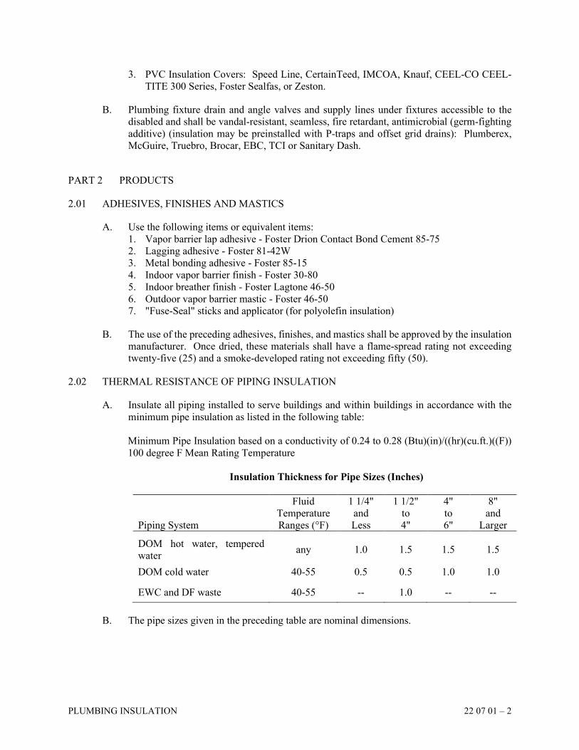
PLUMBING INSULATION 22 07 01 – 2
3. PVC Insulation Covers: Speed Line, CertainTeed, IMCOA, Knauf, CEEL-CO CEEL-
TITE 300 Series, Foster Sealfas, or Zeston.
B. Plumbing fixture drain and angle valves and supply lines under fixtures accessible to the
disabled and shall be vandal-resistant, seamless, fire retardant, antimicrobial (germ-fighting
additive) (insulation may be preinstalled with P-traps and offset grid drains): Plumberex,
McGuire, Truebro, Brocar, EBC, TCI or Sanitary Dash.
PART 2 PRODUCTS
2.01 ADHESIVES, FINISHES AND MASTICS
A. Use the following items or equivalent items:
1. Vapor barrier lap adhesive - Foster Drion Contact Bond Cement 85-75
2. Lagging adhesive - Foster 81-42W
3. Metal bonding adhesive - Foster 85-15
4. Indoor vapor barrier finish - Foster 30-80
5. Indoor breather finish - Foster Lagtone 46-50
6. Outdoor vapor barrier mastic - Foster 46-50
7. "Fuse-Seal" sticks and applicator (for polyolefin insulation)
B. The use of the preceding adhesives, finishes, and mastics shall be approved by the insulation
manufacturer. Once dried, these materials shall have a flame-spread rating not exceeding
twenty-five (25) and a smoke-developed rating not exceeding fifty (50).
2.02 THERMAL RESISTANCE OF PIPING INSULATION
A. Insulate all piping installed to serve buildings and within buildings in accordance with the
minimum pipe insulation as listed in the following table:
Minimum Pipe Insulation based on a conductivity of 0.24 to 0.28 (Btu)(in)/((hr)(cu.ft.)((F))
100 degree F Mean Rating Temperature
Insulation Thickness for Pipe Sizes (Inches)
Piping System
Fluid
Temperature
Ranges (°F)
1 1/4"
and
Less
1 1/2"
to
4"
4"
to
6"
8"
and
Larger DOM hot water, tempered
water any 1.0 1.5 1.5 1.5
DOM cold water 40-55 0.5 0.5 1.0 1.0
EWC and DF waste 40-55 -- 1.0 -- --
B. The pipe sizes given in the preceding table are nominal dimensions.
PLUMBING INSULATION 22 07 01 – 3
2.03 INDOOR PIPING
A. Fiberglass heavy-density insulation with all service vapor membrane jacket and pressure
sealing lap adhesive on longitudinal and butt strips, K=0.23 at 75 degrees F, Owens-Corning
25 ASJ/SSL II. Staple and seal with pressure sealing lap adhesive on longitudinal and butt
strips. Jacket vapor membrane shall have an installed vapor permeance of not more than
0.09 perms.
B. Polyolefin foam insulation (for service temperature up to 210 degrees F), K=0.24 at
75 degrees F, IMCO "IMCOLOCK" or "IMCOSHIELD." No vapor barrier is necessary with
0.0 perm/inch permeability.
C. Option: A flexible, closed-cell elastomeric insulation with pressure sealing longitudinal
joints or applied adhesive meeting ASTM E84's ratings of 25 flame-spread and 50 smoke-
developed. Adhesive shall be approved by Insulation Manufacturer.
2.04 EXPOSED INDOOR PIPING DROPS UP TO 10 FEET ABOVE NEAREST WALKING
SURFACE
A. Insulation same as for indoor piping. Cover with ultraviolet-resistant PVC jacket. Jacket to
be self-extinguishing and have zero fuel contribution. PVC jacket shall have a flame-spread
rating not exceeding twenty-five (25) and a smoke developed rating not exceeding fifty (50).
All piping visible inside and outside mechanical rooms is considered exposed.
2.05 FITTINGS AND VALVES
A. Premolded PVC covers over molded insulation. Insulation same thickness as on adjoining
pipe. Insulation shall have a flame-spread rating not exceeding twenty-five (25) and a
smoke-developed rating not exceeding fifty (50). For polyolefin insulation, use insulation of
same type and thickness as on adjoining pipe.
2.06 PIPE INSULATING SUPPORT
A. Refer to Section 20 05 45, "Hangers, Supports and Inserts." The use of thermal protectors
as pipe insulation supports are noted elsewhere in this specification. Where inserts are used,
maintain insulation vapor barrier integrity.
PART 3 EXECUTION
3.01 GENERAL INSTALLATION NOTES
A. Installation shall be in accordance with the manufacturer's recommendations.
B. Use no damaged or water-soaked insulation.
C. Insulate all water piping as described above, including piping concealed in walls.
D. Insulation to be continuous through sleeves and hangers.
PLUMBING INSULATION 22 07 01 – 4
E. When piping is installed through fire-rated walls and floors, the insulation shall be
continuous and fire-rated calking shall be installed between pipe insulation and wall sleeve
without any interruption to the vapor barrier.
F. Leave no "raw" ends on fiberglass insulation. Bevel fiberglass insulation terminations seal
with insulating cement and cover ends with glass cloth or similar to pipe insulation covering.
G. Ensure that exposed insulation has a neat and finished appearance. Provide sizing for
insulation if required and leave ready for painting.
H. Overlap jacket joints and seal with a suitable adhesive. The use of staples is acceptable on
domestic hot water systems only, but only as an installation aid and not as a substitute for
adhesive.
I. Brush coat all staples with a white vapor-barrier mastic and seal to provide an uninterrupted
vapor membrane. Mastic shall be approved for use by the insulation manufacturer.
J. Install all insulation with a continuous, unbroken, and unpunctured factory-applied vapor
membrane.
END OF SECTION

SECTION 22 11 16
INTERIOR DOMESTIC WATER PIPING SYSTEM
INTERIOR DOMESTIC WATER PIPING SYSTEM 22 11 16 – 1
PART 1 GENERAL
1.01 DESCRIPTION
A. Connect into the existing domestic water piping system where shown on the Drawings.
B. Provide a complete system of hot, tempered, hot or tempered return, and cold water to
fixtures and equipment.
C. Test and sanitize the complete new domestic water system, isolating any existing water
system as much as possible.
1.02 QUALITY ASSURANCE
A. Standards: American Society of Plumbing Engineers (ASPE), American National Standards
Institute (ANSI), American Society for Testing and Materials (ASTM), American Water
Works Association (AWWA), National Sanitation Foundation (NSF) and Plumbing and
Drainage Institute (PDI), Columbus, Ohio Division of Water.
B. Provide only fittings, piping, valves, and solder certified to be lead-free in accordance with
EPA and NSF requirements. Submit written certification that all of the installed components
meet these requirements.
PART 2 PRODUCTS
2.01 PIPING
A. 4 Inches and Smaller:
1. Type "L" hard drawn copper tubing (ASTM B88).
B. The use of PEX piping is prohibited.
2.02 JOINTS AND FITTINGS
A. Copper: Wrought copper socket solder (ANSI B16.22) or brazed (ANSI B31.1) joints.
B. Copper Press Fitting Joining System
1. If permitted by local authorities, copper pipe may be mechanically joined by copper or
bronze compression fittings. Fittings shall carry a 50-year manufacturer's warranty.
a. Use shall be limited to systems with maximum operating pressure of 200 psi, and
maximum operating temperature of 210 degrees.
b. Fittings 1/2 inch to 3 inches shall be crimped on both sides of an integral bead
containing an EPDM seal. Fittings 2 1/2 inches through 3 inches shall be double
crimped and be fitted with a stainless steel grip ring.
c. Piping shall be Type "L" copper.
d. The Contractor shall be trained on the installation of the product by the manufacturer
and shall follow the manufacturer's installation instructions.
e. All valves and specialties must conform to all other requirements of these
Specifications.
INTERIOR DOMESTIC WATER PIPING SYSTEM 22 11 16 – 2
2. Material:
a. Copper and copper alloy press fittings shall conform to material requirements of
ASME B16.18 or ASME B16.22 and performance criteria of IAPMO PS 117.
Sealing elements for press fittings shall be EPDM. Sealing elements shall be factory
installed or an alternative supplied by fitting manufacturer. Fittings shall have a
feature which allows the installer to quickly and easily identify connections which
have not been pressed prior to putting the system into operation.
3. Acceptable Manufacturers:
a. Rigid-Viega, Nibco, Apollo, or Anvil
C. Grooved Mechanical Piping System (Stainless Steel Only) / (Stainless Steel and Copper)
1. Any Contractor who has installed at least five (5) grooved mechanical piping systems
may use mechanical grooved couplings and fittings on 2 inches-24 inches roll grooved
standard weight Schedule 40 pipe.
2. Grooved mechanical piping systems shall be installed according to manufacturer's
instructions. The manufacturer shall perform on-site installation demonstrations to the
installing contractor before grooved coupling installation begins. Installing contractor
shall verify that couplings are tightened to manufacturer’s instructions.
3. Grooved isolation valves, check valves, balance valves, strainers, and specialties are
accepted when grooved method is utilized. Isolation valves, check valves, balance
valves, strainers, and specialties shall meet the requirements of sections 23 05 02 “HVAC
Specialties” and 23 05 23 “HVAC Valves.”
4. Victaulic Manufacturing Co. or Anvil Gruvlok.
2.03 SOLDER AND BRAZING ALLOYS
A. Solder: 95/5 tin-antimony (ASTM B32), (above grade use only), less than 0.2% lead.
1. "Silvabrite 100" as manufactured by Englelhard or equal.
2. "Bridgit" as manufactured by J.W. Harris Company or equal.
3. "Sterling" as manufactured by Tarament or equal.
B. Copper Brazing Alloys: AWS A5.8 Class BCUP-5 alloys having a melting point greater
than 1350 degrees F. (ANSI B31.1), less than 0.2% lead.
1. Sil-Fos filler as manufactured by Handy and Harmon or equal.
2. Aircosil 15 filler as manufactured by Airco Welding Products or equal.
3. "Stay-Silv "15" as manufactured by J.W. Harris.
C. No alloys containing 0.2% or more lead shall be used for joints within any portion of the
potable water system. No fluxes containing 0.2% or more of lead shall be used in the
fabrication of soldered joints.
PART 3 EXECUTION
3.01 INSTALLATION
A. Install all valves in accessible locations and coordinated with access panel locations.
B. Make all joints in strict accordance with the manufacturer's written installation instructions
and best practices of the profession.
INTERIOR DOMESTIC WATER PIPING SYSTEM 22 11 16 – 3
C. Install water lines located in exterior walls closest to the "heated" side of the wall. Cover the
piping with continuous insulation. Pack the space between the insulated pipe and the
"unheated" side of the wall with a continuous layer of building insulation.
D. Locate shock absorbers according to PDI Standard WH-201 and where shown on Drawings.
Sizes shown on Drawings. Tag all shock absorbers with size designations for field
inspection.
E. Provide an approved dielectric break between piping of dissimilar metals; fittings, flanges,
transition materials, etc.
F. Install unions or flanges between valves and final connections to all equipment.
G. Use only nipples of the same or similar material as the pipe being connected.
H. Install valves on all branch line, fixture group areas, wall hydrant drops at the wall and at all
equipment connection, whether specifically shown on the Drawings or not.
I. Securely anchor all supply piping to fixtures, faucets, hydrants and flush valves to prevent
movement.
J. Provide all low points within the potable water systems with drain valves to facilitate
drainage. Install system to permit complete drainage of the system.
K. Where piping is installed above ceilings, below ceiling insulation, the Plumbing Contractor
shall confirm that ceiling insulation has no insulation voids above piping.
L. Install piping entering the building below grade with a minimum of 5 feet of cover from
finished grade.
3.02 COORDINATION
A. Coordinate piping with beams, joints, wall, HVAC piping, ductwork, equipment and
electrical equipment and conduit.
B. Coordinate locations of cold water make-up with HVAC Contractor.
1. Install the backflow preventer in a serviceable location; no greater than 48 inches AFF.
2. Terminate the piping serving the HVAC equipments within five feet of the backflow
preventer, unless noted otherwise on the Drawings.
3. Additional valves, strainer, piping and final connections to equipment downstream of
backflow preventer shall be by the HVAC Contractor.
C. Coordinate flushing of new site water line and building domestic water lines after
sterilization of new domestic water lines with Owner.
D. Coordinate location of main building water supply line within building, above floor slab with
Site Utility Contractor.
E. Coordinate any shutdown time for water line connection(s) with the Owner and General
Trades Contractor.

INTERIOR DOMESTIC WATER PIPING SYSTEM 22 11 16 – 4
F. Coordinate location of site water service line entrance into building and water meter with
equipment and doors.
G. Coordinate location and size of new water service connection with Fire Protection
Contractor.
H. Coordinate location of rough-ins, outlets, and final equipment connections with all other
Contractors and Owner's equipment.
3.03 TESTS
A. Perform tests as required by the Local Code Authority and as specified below:
1. Take precautions to remove all air before performing hydrostatic tests.
2. Test piping at 1 1/2 times actual working pressure or 125 psig, whichever is greater, for
six (6) hours with no pressure drop. All tests shall be made before piping is concealed.
3. If a leak occurs, defective piece or joint shall be replaced. Caulking is prohibited. Repeat
tests until no leaks are detected.
4. Perform all testing after completion of roughing-in, before setting of fixtures.
B. Submit test reports to the Owner.
3.04 STERILIZATION OF WATER LINES
A. The entire domestic water system must be sterilized no more than 20 days prior to whole or
any partial occupancy of the building. After the water system is complete and fixtures have
been installed, and before whole or partial occupancy of the building, flush piping clean and
sterilize all new hot and cold-water piping, including water service line and water heaters.
This requirement also includes any existing piping systems that had significant modification
as part of the project and any portion of the existing system that had been out of service for
more than 20 days. Any delay in occupancy beyond this timeframe shall require additional
disinfection and flushing by the Contractor at no cost to the Owner. Sterilize lines under the
immediate on-the-job supervision of a Water Testing Laboratory regularly engaged in the
service. This Contractor shall pay all fees for testing and use of testing equipment. A written
chlorination report shall be submitted to the Owner for his records.
B. With all outlets closed, fill system to working pressure and close valve on supply main.
C. Open all fixtures slightly and pump a sterilization solution into test tap to achieve a minimum
of 50 parts per million chlorine solution made from a sanitation grade of hyperchlorite, 70%
available chlorine. Hyperchlorites may be Pittchlor, H.T.H. or Perclorn.
D. Test every outlet, hot or cold, during fill to prove the presence of chlorine at that outlet.
Chlorine shall be present at all outlets. Measure chlorine level at a minimum of 30%
Engineer to review this percentage for each project of the outlet locations distributed
throughout the system, but no less than 20 outlets all if less than 20 outlets on the project,
including the most remote outlets and on every level of the building to insure total system
chlorination.
E. Water piping system shall remain filled for a period of 24 hours. As an alternative, the system
may be filled with a 200-parts per million solution of chlorine and allowed to stand for three
(3) hours.
INTERIOR DOMESTIC WATER PIPING SYSTEM 22 11 16 – 5
F. After sterilizing, all outlets shall be opened wide and the main supply valves opened, flushing
system free of chlorine with clean water. Outlets shall be again checked and flushed until
free of chlorine. Flush entire system. Coordinate this action with Owner if building is
occupied.
G. After final flushing, all electric water cooler strainers, faucet aerators and mixing valve
strainers shall be removed, cleaned and reinstalled.
H. Chlorination of the system may be performed at the same time the pressure test is conducted,
if it is conducted within the 20-day timeline.
I. After sterilization of system is complete, notify the local Health Department having
jurisdiction to obtain water samples and complete biological examination.
J. Obtain Certification of Acceptance from the Health Department and forward to the Owner /
the using agency / the Architect.
K. When connecting to an existing system, isolate all existing piping to the extent possible
during testing.
3.05 BALANCING OF DOMESTIC HOT WATER RECIRCULATION SYSTEM
A. After final flushing and sterilization, balance the domestic hot water recirculation system.
B. Unless noted otherwise on Drawings, balance each leg of the domestic hot water recirculation
system for equal flows.
C. Record all flow measurements and balance valve settings and submit report as part of close-
out documentation.
END OF SECTION
SECTION 22 13 16
INTERIOR SANITARY WASTE AND VENT PIPING SYSTEM
INTERIOR SANITARY WASTE AND VENT PIPING SYSTEM 22 13 16 – 1
PART 1 GENERAL
1.01 DESCRIPTION
A. Connect to existing / new renovated area building sanitary drain and vent system where
shown on Drawings.
B. Refer to Drawings for size of connections to fixtures.
C. Test complete new system.
1.02 QUALITY ASSURANCE
A. Standards: American Society for Testing and Materials (ASTM) and the Cast Iron Soil Pipe
Institute (CISPI), American Water Works Association (AWWA), American Society of
Mechanical Engineers (ASME), and American National Standard Institute (ANSI).
B. All pipe and fittings shall conform to the requirements of Commercial Standard CS188.
1.03 MANUFACTURERS
A. Piping:
1. Cast Iron: Charlotte Pipe & Foundry or Tyler Pipe, American Brass and Iron (AB&I)
2. Copper: American Brass Company, Revere, Chase Brass Company or Nibco.
B. Drains and Cleanouts: Zurn, Wade, Jay R. Smith, MIFAB, Watts or Josam.
PART 2 PRODUCTS
2.01 PIPING
A. Piping and fittings in earth under slab:
1. Service weight cast iron soil pipe and fittings (ASTM A74), factory enamel coated.
2. Copper/DWV (ASTM B306) pipe.
3. Hubless cast iron (CISPI-301), factory enamel coated.
B. Interior Piping and Fittings Above Slab:
1. Hubless cast iron (CISPI-301), factory enamel coated.
2. Service weight cast iron (ASTM A74), factory enamel coated.
3. Copper/DWV (ASTM B306).
C. Vent Piping and Fittings:
1. Hubless cast iron (CISPI-301).
2. Service weight cast iron (ASTM A74).
3. Copper/DWV (ASTM B306).
D. Note: Entire / Certain ceiling area(s) is / are used as a return air plenum, and plastic piping
is prohibited. Refer to Architectural and HVAC Drawings for areas that apply to this
requirement.
INTERIOR SANITARY WASTE AND VENT PIPING SYSTEM 22 13 16 – 2
E. All cast iron piping and fittings shall have factory-applied coatings and be E.P.A. acceptable.
F. All fittings shall be drainage type and be same manufacturer as piping and be compatible
with piping for size, material, and joint type.
G. Sump Pump / Sewage Ejector Discharge Piping:
1. 4 Inches and Smaller: Standard weight, galvanized steel (ASTM 120, Type "F") with
galvanized cast iron screwed drainage fittings, shall be used to the point of connection
to a gravity line.
2. For Piping 5 Inches and Larger: Schedule 40 galvanized carbon steel piping (ASTM
A53) with galvanized cast iron Class 125 lb. flanged drainage fittings (ANSI B16.1) shall
be used to the point of connection to a gravity line. Option, Copper, Type "L" (ASTM
B306), with solder joint.
2.02 JOINTS
A. Cast Iron Piping:
1. Compression type plastic or rubber gaskets (ASTM C564) by Dual-Tight or Ty Seal with
lubricant equal to "Lubrifast."
2. "No-Hub" coupling with ASTM C-564 neoprene sealing sleeve, minimum of 28 gauge
(0.016 inch) thick heavy duty slotted or corrugated Type 304 stainless steel shield with
a minimum of two (2) stainless steel bands on pipe sizes 1 1/2 inch to 4 inches, minimum
of four (4) bands on pipe sizes 5 inches to 10 inches. Joints in hubless cast iron pipe
sizes 1 1/2 inch to 2 inches where exposure to head pressure cannot exceed 10 foot head
shall be approved by CISPI Standard 310-85. Pipe sizes 2 1/2 inches to 10 inches shall
be Clamp-All Model #80. Approved manufacturers: Anaco "Husky," Mission or
Charlotte Heavy Duty.
3. No-Hub couplings shall be Factory Mutual approved to FM-1680, Class 1 and so marked
on each coupling, ASTM C-564 neoprene sealing sleeve, minimum of 28 gauge
(0.016 inch) thick heavy duty slotted or corrugated Type 304 stainless steel shield with
a minimum of two (2) stainless steel bands on pipe sizes 1 1/2 inch to 4 inches - Clamp-
All Model #80, minimum of four (4) stainless steel bands on pipe sizes 5 inches to
10 inches - Clamp-All Model #125, 15 psig rating. Anaco "Husky," Mission, Tyler and
Charlotte Heavy Duty are approved as long as they meet all of the specified requirements.
a. The no-hub manufacturer shall provide the following guarantee: The no-hub
coupling manufacturer shall make a full replacement for the number of couplings
acknowledged by mutually agreeable independent third party analysis to have failed.
No-hub coupling manufacturer will help subrogate the portion of any direct or
consequential damage, deemed by mutually agreeable independent third party
analysis, to have been caused by coupling failure for the life of the piping system.
b. The no-hub-coupling manufacturer shall submit with the shop drawings that they are
Factory mutual approved to FM 1680 Class 1 standard, and that they are providing
the above guarantee.
4. Provide external restraints on all piping over 4 inches in size at all changes in direction
and all changes in pipe size of two sizes or more. Restraints shall be rated for 500 feet
of head pressure.
B. Copper DWV Piping:
1. Cast brass solder type (ASTM B-584). No soldering or brazing alloys containing lead
shall be used.
INTERIOR SANITARY WASTE AND VENT PIPING SYSTEM 22 13 16 – 3
2.03 FLOOR DRAINS
A. General Construction: Drains to be adjustable, coated cast iron double drainage pattern,
bottom outlet, inside caulk with flashing clamp, strainers, sediment buckets and trap primer
inlets where required and other accessories and features indicated on the Schedule on the
Drawings.
B. Each floor drain, other than a light duty rating, shall have an ANSI load rating and be so
indicated on the Shop Drawings. If rating is not indicated on Shop Drawings, they will be
rejected.
C. Provide membrane clamps on all floor drains in floors having waterproof membrane.
D. Slot in grates shall be free of flashing (clean cut), and tops shall not have sharp edges which
may be injurious to bare feet when used in shower or swimming pool areas.
E. Refer to Schedule on the Drawings for specific types and accessories.
2.04 CLEANOUTS
A. General Construction: Floor cleanouts shall be adjustable, inside caulk with flashing clamp
and other accessories and features indicated on the Schedule on the Drawings.
B. General: All cleanouts to be line size up to and including 4 inches and installed in accessible
locations.
C. Each floor cleanout other than a light duty rating, shall have an ANSI load rating and be so
indicated on the Shop Drawings. If rating is not indicated on Shop Drawings, they will be
rejected.
D. Provide membrane clamps on all cleanouts in floors having waterproofing membranes.
E. Refer to Schedule on the Drawings for specific types and accessories.
2.05 TRAPS
A. Same material as piping.
B. Refer to Section 22 42 01, "Plumbing Fixtures" for fixture traps, exception, floor mounted
fixtures.
2.06 SOLDER AND BRAZING ALLOYS
A. Solder: 95/5 tin-antimony (ASTM B32).
B. Copper Brazing Alloys: Silver/phosphorous or silver/zinc alloys having a melting point
greater than 1,000 degrees F.
1. Sil-Fos filler as manufactured by Handy Harmon.
2.07 VENT FLASHING
A. 8 ounce copper (ASTM B152) flashing or per roof manufacturer's requirements.
INTERIOR SANITARY WASTE AND VENT PIPING SYSTEM 22 13 16 – 4
B. Ultra-violet light and ozone resistant, flexible weather resistant E.D.P.M pipe flashing with
ribbed aluminum base.
1. Pate, Vent Products, Swarthwout, Shipman or Thy-Curb.
2.08 VANDALPROOF VENT CAPS
A. Zurn Model Z-193, cast iron with vandal-resistant fastening device.
1. Stoneman, Wade, Jay R. Smith, Watts or Josam.
2.09 TRENCH DRAINS
A. Large Trucks or Buses:
1. Pre-slope fiberglass or polymer concrete trench drain system, 6 inch or 12 inch wide,
interlocking joints with screwed connections. Heavy-duty frame assembly with bracket
support or anchor bars for concrete installation. Section will have end caps, no-hub end
outlets, no-hub bottom outlet or 12 x 24 or 24 x 24 inch catch basins with dome strainer
for bottom outlet or 18 gauge stainless steel sediment baskets for catch basins. Grate
will be slotted cast iron or ductile iron and secured to the trench with screws to the frame
or locking device and meeting "AASHTO" HS-20 loading standards.
2. Refer to the drawings for length, sizes, (widths) connections, etc.
3. Manufacturers: Zurn, Neenah, Quazite (Polycast), ABT, Inc. (Polydrain), or approved
equal.
2.10 BACKWATER VALVES
A. Zurn Z-1090, cast iron body, no-hub inlet and outlet, gasketed bolted cover, automatic ABS
valve seat and flapper.
1. Wade, Jay R. Smith, Watts or Josam.
PART 3 EXECUTION
3.01 GENERAL INSTALLATION
A. Install all underfloor sanitary piping per manufacturer’s recommendations and those of
ASTM F1668. Trench width shall be the pipe diameter plus 16 inches or 1.25 times pipe
diameter plus 12 additional inches, whichever is greater. Provide a minimum of 4 inches of
firm, compacted pipe bedding in the bottom of the trench. Pipe shall be laid on bottom of
trench with proper pitch to provide proper drainage. Blocking or propping up pipe with
wood, rock, or other materials is prohibited. Installed pipe shall be surrounded with
aggregate material along both sides of pipe to trench wall. Additional back filling over buried
pipe shall be accomplished in 6 inch layers compacting each layer prior to adding additional
backfill material. Trench shall be completely filled to the aggregate sub base. Do not drive
over buried piping and trench with construction equipment.
B. Pitch soil and waste piping no less than 1/8 inch per foot, for pipes 2 inches and smaller,
pitch at 1/4 inch per foot. Pitch kitchen piping at 1/4 inch per foot from the grease interceptor
to sanitary inlet piping.
C. Minimum size is 2 inches for underground waste and vent piping.
INTERIOR SANITARY WASTE AND VENT PIPING SYSTEM 22 13 16 – 5
D. Install P-trap below floor for floor drains, floor sinks, janitor receptors, showers, standpipes,
bathtubs, and hub drains.
E. All changes of directions shall be made with TY or Y fittings and 1/8 bends as required.
F. All pipe joints shall be compatible with piping for size, material and joint types.
G. Provide all necessary adapters, fittings, and pipe required to make connections to site utility
piping and to new and existing building sewer and drains.
H. All sanitary waste and vent piping in return air plenums required to be insulated, shall be
insulated with pipe insulation meeting the requirements for return air plenums.
I. Plastic piping shall not be allowed in return air plenums and other areas prohibited by Code.
J. All piping shall be concealed, unless indicated on Drawings.
K. Any horizontal sanitary piping located in elevator equipment rooms shall be covered and
enclosed by a painted metal enclosure to prevent water dripping onto equipment.
L. Vertical stacks shall be supported by riser clamps at each floor and concealed when passing
through finished areas, unless noted otherwise.
M. Install bathtub traps to be accessible. Coordinate locations with General Trades Contractor.
3.02 VENTS
A. Install vents through roof as follows:
1. 3 inches minimum size.
2. Locate at least 8 feet away from outside wall of building and 15 feet away from outside
air intakes or operable windows.
3. Offset vent piping below roof to allow for thermal expansion and contraction, minimum
4 foot offset.
4. Vents to extend 12 inches above roof, except where specifically required to be higher or
lower by code.
5. Plumbing Contractor cuts hole(s) in roof. Install vent through roof vent boot or sleeve
in membrane or metal roof. Roof vent boots furnished and installed by General Trades
Contractor. General Trades Contractor to flash vents into roof construction and make
watertight. For standing seam metal roof or membrane roof.
6. Coordinate vent locations through roofs with General Trades Contractor, HVAC
Contractor and Architect.
B. Connect to existing vents where shown on Drawings.
C. Pitch vents for proper drainage.
3.03 FLOOR DRAINS AND CLEANOUTS
A. This Contractor is responsible for installing top of floor drains and cleanouts flush and level
with wall or finished floor. If not shown on Architectural Drawings, confirm elevation and
proper floor pitch to floor drains and floor cleanouts with Architect before roughing in. All
INTERIOR SANITARY WASTE AND VENT PIPING SYSTEM 22 13 16 – 6
items not installed flush and level will be removed and replaced by this Contractor at no cost
to the Owner.
B. Use graphite on all cleanout plug threads.
C. Install duct tape over floor drains and cleanout covers to provide protection from scratching
and collection of dirt and debris during construction. Remove tape just prior to final
inspection.
D. Install wall cleanouts at the base of all stacks at 18 inches above finished floor.
E. Install coverplates for all cleanouts in finished areas.
F. Provide exposed cleanout plugs without coverplate in unfinished areas or in above ceiling
installations.
G. Exterior: Install in center of 24 inch square concrete slab, 6 inches thick flush with grade or
pavement. Concrete shall be installed by General Trades / Plumbing Contractor.
H. All floor drain interiors shall be clean just prior to final inspection.
I. Install floor drains and cleanouts in accessible locations.
J. Install square cleanouts and floor drains in quarry tile floors and carefully align edges parallel
to room walls.
K. Install tops of hub drains flush with finished floor.
3.04 COORDINATION
A. Coordinate piping with beams, joists, foundation piers and walls and footings, HVAC piping
and ductwork, equipment, electrical equipment, wiring, and installation with conduit, crane
and crane rails.
B. Coordinate vents through roof, floor and hub drain and cleanout locations and elevations and
installation with walls, equipment and housekeeping pads with the General Trades
Contractor and other Contractors.
C. Coordinate location and elevation of existing / new site sanitary sewer.
D. Coordinate location, size and elevation of existing building sanitary lines.
E. Coordinate pit locations for bathtubs on slab with General Trades Contractor.
3.05 TESTS
A. Test entire new sanitary system as required by the Local Code Authority.
B. For a minimum test, plug piping and fill with water to highest vent on roof to provide a
minimum of 10 foot of head of water on all parts of the system. Maintain for one hour with
no leakage. Repair any deficiencies. Final test to be conducted with smoke or peppermint
INTERIOR SANITARY WASTE AND VENT PIPING SYSTEM 22 13 16 – 7
at 1 inch W.C. for fifteen (15) minutes. Install gaskets or reset fixtures with new gaskets as
required.
C. All tests to be performed before any piping is covered or concealed and a written record of
the test shall be submitted to the Architect's Representative as a part of the Owner's Record
and Information Booklets.
D. Should leaks occur, the defective section(s) of pipe and/or defective fitting(s) shall be
removed and replaced with new materials at no cost to Owner.
E. Tests shall be repeated until no leaks occur.
F. Isolate existing system as much as possible during test.
END OF SECTION
SECTION 22 42 01
PLUMBING FIXTURES
PLUMBING FIXTURES 22 42 01 – 1
PART 1 GENERAL
1.01 DESCRIPTION
A. Provide new plumbing fixtures installed in place, complete with carrier supports, supply and
waste trim as indicated on the Drawings.
B. Provide trim, fittings, carriers, stops, chrome water supply piping and all accessories required
for a complete installation.
C. Fixture connection sizes are shown on Drawings.
1.02 QUALITY ASSURANCE
A. Standards: American National Standards Institute (ANSI A112.19 and Z124), American
Society of Sanitary Engineering (ASSE), National Sanitation Foundation (NSF), Plumbing
and Drainage Institute (PDI), city and state plumbing and energy codes.
B. Unless otherwise noted, all fixtures of the same type shall be by the same manufacturer.
C. Exposed metal parts shall be chrome-plated unless otherwise noted. Fixtures and trim shall
be free of defects. Provide white vitreous china or enamel fixtures, unless otherwise noted.
D. Electric water cooler components that come in contact with the potable water system shall
be lead-free per the Safe Drinking Water Act Amendments of 1986, and have CFC-free
refrigerant.
E. All faucets shall meet or exceed NSF 61, Section 9 drinking water standard and be so
indicated on shop drawings or they will be rejected.
F. All shower mixing valves shall have a minimum of 45 degrees of handle rotation between
outlet temperature range of 90 degrees F to 105 degrees F when served by 120 degrees F of
hot water and 45 degrees F of cold water. The mixing valve performance shall be indicated
on shop drawings in the form of certified laboratory reports.
1.03 SUBMITTALS
A. Submit manufacturer's product data for all products specified in this section and shown on
Drawings.
B. Shop Drawings: Each submittal shall be clearly marked with fixture designation number,
model number, and indicate all required fittings, construction, color and rough-in
requirements. Submit color charts when required.
C. The approved fixture's shop drawings shall be a part of the Owner's Manual.
PLUMBING FIXTURES 22 42 01 – 2
1.04 DELIVERY, STORAGE AND HANDLING
A. Protection: Fixtures and trim shall remain crated and stored until installation to prevent
moisture and dirt contamination and physical damage. Adequately protect installed fixtures
from damage.
PART 2 PRODUCTS
2.01 PLUMBING FIXTURES AND ACCESSORIES
A. Refer to the Specifications and Drawings for specific catalog numbers and required fittings.
B. Fixture Manufacturers:
1. Vitreous China Fixtures: American Standard, Sloan, Kohler, ToTo, or Zurn.
2. Stainless Steel Sinks: Elkay, Just Mfg. Co., Moen, American Standard, or Kohler.
3. Electric Water Coolers and Drinking Fountains: Oasis, Haws, Elkay, Sunroc, or Halsey-
Taylor.
4. Kitchenette Disposer: In-Sink-Erator, KitchenAid, Waste King, or Whirlaway.
C. Fittings Manufacturers:
1. Flush Valves: Sloan, American Standard, Chicago, Zurn, Kohler, Delany, or ToTo.
2. Water Closet Seats: Bemis, Olsonite, Beneke, or Church.
3. Faucets: Chicago, Zurn, T&S Brass, Watersaver, American Standard, Symmons, Eljer,
Speakman, Moen, or Kohler.
4. Automatic Flush Valves: Sloan, Chicago, Zurn, American Standard, Kohler, Hydrotek,
Josam-Stern, Delany, or ToTo with vandal-resistant stop cap cover.
5. Automatic Faucets: Chicago, Zurn, Bradley, Sloan, Speakman, T&S, ToTo, or
American Standard.
6. Supplies and Stops: McGuire Mfg. Co., Central Brass, EBC, Dearborn, Bridgeport,
Speedflex, T & S Brass, Chicago Faucet, Consolidated, Frost, Waterway, Sanitary Dash,
Speedway, or Brass Craft.
7. Fixture Traps: McGuire Mfg. Co., EBC, or Central Brass.
D. All trim and exposed piping to be chrome-plated unless noted otherwise.
E. All flush valves shall be provided with vandal-resistant supply stop cap covers, solder
adapters, chrome supply tube covers, chrome escutcheon flange, and seat bumpers.
F. Faucets to have ceramic disc cartridges or shall be supplied with renewable seats.
G. Wall faucets to include vacuum breaker, pail spout and wall brace.
H. All germ-fighting water closet seats shall be factory embossed or stamped that the water
closet seat is germ-fighting (anti-microbial) by indication of model logo on the seat in a non-
conspicuous location. This factory stamp shall indicate that the water closet seat is germ
fighting (anti-microbial) and shall also be indicated on the water closet seat Shop Drawings.
I. All plumbing fixtures and accessories of the same generic type shall be the products of the
same manufacturer unless specified otherwise.
PLUMBING FIXTURES 22 42 01 – 3
J. All electric water coolers and/or drinking fountains shall be lead-free, and consumption shall
not pass through, around or near lead of any form or sort.
K. Supplies to lavatory and sink fittings shall be flexible tube risers with solid (no plastic) handle
stops (unless otherwise noted), all chrome plated brass or copper.
2.02 CARRIERS
A. Provide heavy duty, rectangular vertical support, floor supported, commercial type fixture
carrier for all new wall mounted plumbing fixtures, unless noted otherwise. Provide carrier-
bearing plates for electric water coolers and urinals as part of the fixture carrier. Provide
flush valve supply support as part of the urinal fixture carrier.
B. Water Closets: Floor supported, with buttress foot and foot anchor, rear foot support, flush
valve supply support, finishing frame, cast iron, commercial type, neoprene gaskets. The
studs and nipple on the carrier shall be adjustable without cutting or defacing the wall and
still maintain a tight joint. Coordinate location of carrier closely with Architect.
C. All carriers shall be specifically chosen to accommodate the particular brand and style of
fixture actually installed, the particular type of floor and wall actually present at each fixture
location and the piping arrangement at each fixture. Furnish plastic or metal positioning
frames to isolate carrier bolts from wall construction. Anchor carriers firmly to the floor with
maximum sized bolts that feet will accommodate.
D. Provide neoprene carrier gaskets.
E. Zurn, J.R. Smith, Wade, MIFAB, Josam, or Watts.
2.03 ELECTRONICALLY CONTROLLED FIXTURES
A. Water Closet and Lavatory Combination Fixture:
1. The fixture shall be electrically operated with 24 volt soft close, industrial type solenoid
valves and sensors. The electrical hook-up of sensor and solenoid valves shall be with
modular plug type connectors. Furnish a 110 volt primary and 24 volt secondary
transformer, a B-1090-CR controller and hand controller.
2. Connections from the transformer to the controller are made using 20/2 AWG
(minimum) to 16/2 AWG (maximum) wire. All connections from pushbutton/switches
to controller and from controller to solenoid actuators are accomplished using the Bauer
patented plug. This plug is attached to the wire prior to shipping. Wire is #24 AWG,
four conductor, color coded (black, red, green, yellow) flat telephone cable.
3. Lavatory Control Sequence: Upon activation of hot water pushbutton, the water will run
for twenty (20) seconds and then turn off. Upon activation of the cold water pushbutton,
the water will run for ten (10) seconds and then turn off. Immediate repeat operation is
possible. A Non-Hold Open feature which senses any button being depressed for longer
than five (5) seconds will automatically disrupt the flow of water until the button is
released and normal function is restored.
4. Toilet Control Sequence: After the button is pushed, there is a two (2) minute delay
before onset of flush cycle. If the fixture is flushed twice within a five (5) minute period,
the system will automatically lock out and the toilet will not flush again for one (1) hour.
After this delay, the toilet will resume normal operation.
PLUMBING FIXTURES 22 42 01 – 4
B. Electronic Fixtures:
1. Provide vandal-resistant electronic fixtures as scheduled on Drawings with proximity
operation. Fixtures shall be complete with microprocessor controls and shall be low-
voltage powered, without the use of batteries.
2. Provide all transformers and wiring as necessary for low voltage power supply.
Transformers shall have an adapter plate to mount directly on a 2-gang electrical junction
box.
PART 3 EXECUTION
3.01 COORDINATION
A. See Architectural Drawings for the exact location of plumbing fixtures.
B. Review approved millwork shop drawings from the General Trades Contractor. Coordinate
location and size of countertop fixtures, casework and openings before ordering or
proceeding with rough-in work.
C. Countertop lavatory and sink openings and cabinet base backs for drains and water supply
stop valves shall be cut by the General Trades Contractor. Furnish templates and locate.
Coordinate with General Trades Contractor and Architect.
D. Coordinate location and rough-in requirements with equipment requiring plumbing with
General Trades Contractor, other Contractors, and Owner.
3.02 INSTALLATION
A. Install fixtures according to the manufacturer's written installation instruction.
B. Fixtures to be mounted at the following heights or according to the manufacturer's
recommendations, unless noted or directed otherwise.
1. Regular Mounting Heights:
Wall Hung Water Closet (not including seat) 15 inches to top
Wall Hung Lavatory 31 inches to rim
Wall Hung Urinal 24 inches to lip
Electric Water Cooler 40 inches to spout outlet
2. Handicapped (Disabled) Mounting Heights:
Wall Hung Water Closet (including seat) 17 to 19 inches to top of seat
Wall Hung Lavatory 29 inches to bottom of apron,
maximum height to rim 34 inches
Wall Hung Urinal 17 inches to top of lip
Electric Water Cooler 36 inches to spout outlet, 27 inches
clearance from floor
C. At new floor and wall-mounted plumbing fixtures, caulk between fixture, floor and wall with
silicone caulking compatible with the wall paint. Refer to Division 7 of Specifications for
specific requirements. Exception: Electric watercoolers - caulk top and side of basin only.
PLUMBING FIXTURES 22 42 01 – 5
D. Install fixture carriers and drainage fittings on wall hung fixtures such as water closets,
lavatories, urinals, sink, electric water coolers, etc. Securely anchor all carriers to the floor.
E. Install chrome plated brass escutcheons on waste and supply piping at walls, including piping
in cabinets.
F. Install stops on all cold and hot water supplies to fixtures.
G. Thoroughly clean all fixtures of paper and dirt before final acceptance.
H. Plug-in unit and adjust electric water coolers flow for correct operation and temperature of
55 degrees F outlet.
I. Provide all required seals, gaskets, nuts, bolts and washers.
J. Fixtures shall be carefully assembled and connected to the required plumbing inlets and
outlets, and tested so fixtures will be functioning correctly when the Work is completed.
K. After the installation of the plumbing fixtures is completed, all connecting water pipes shall
be flushed out through the fixtures to eliminate scale. Clean faucet and electric water cooler
strainers and aerators. Refer to Specification Sections referring to Domestic Water Piping
System, for sterilization of water lines.
L. Adjust self-sustaining water closet seats to self-sustain in any position.
M. Provide anchors and supports behind walls and chases for flush valve supply piping.
N. Do not permit the use of installed plumbing fixtures by construction personnel without prior
written consent by the Owner. Any of the installed fixtures or trim found damaged prior to
final acceptance shall be removed and replaced by the Contractor at no additional cost to the
Owner.
O. Adjust faucets with temperature limit stops for a maximum leaving temperature of 120
degrees F.
P. Adjust all flush valves and/or flush tanks for proper operation.
Q. Adjust all sensor type automatic water coolers, faucets and flush valves for proper operation,
per manufacturer's written installation instructions.
3.03 SPECIAL INSTALLATION INSTRUCTIONS
A. Install handicapped water closet flush valves so the control lever is on the wide side of water
closet and no more than 44 inches A.F.F. Install handicapped urinal flush valve control
levers at no more than 44 inches A.F.F. Coordinate locations with any grab bars.
B. Insulate all water and drain piping that could come in contact with wheelchair occupants.
Refer to Section 22 07 01, "Plumbing Insulation" and Drawings.
C. Coordinate exact location of shower and bathtub controls used by the handicapped with the
Architect.
PLUMBING FIXTURES 22 42 01 – 6
3.04 ELECTRICAL WIRING INSTALLATION AND COORDINATION
A. Electronic Fixtures:
1. Branch circuit power wiring for power supplies for all electronic faucets, flush valves
and showers shall be provided by the Electrical Contractor. The Electrical Contractor's
work terminates at a junction box.
2. Install transformer(s) for electronic fixture power supplies and make final electrical
connections.
3. Provide all wiring from transformers to electronic faucets, flush valves, and showers.
4. All wiring must conform to the NEC. In addition, install all wiring exposed in finished
spaces in conduit. In mechanical rooms, chases, and janitor's closets, install wiring
located within 96 inches of the floor in conduit.
B. Power wiring for electric water coolers shall be provided by the Electrical Contractor.
C. Power wiring for garbage disposer shall be provided by the Electrical Contractor.
END OF SECTION
SECTION 23 05 01
HEATING, VENTILATING, AND AIR CONDITIONING
HEATING, VENTILATING, AND AIR CONDITIONING 23 05 01 – 1
PART 1 GENERAL
1.01 DESCRIPTION
A. Furnish material, labor, tools, accessories, and equipment to complete test, adjust, start up,
balance, and successfully run all HVAC systems of this Project as described in these
Specifications and as shown on the Drawings.
B. Refer to Sections 20 00 00 through 20 99 99 (as included) for items of a general nature which
apply to this portion of the Work. Sections 23 00 00 through 23 99 99 (as included) describe
the HVAC work.
C. It is the intent that the HVAC Work be complete in every respect.
1.02 LICENSES
A. The installation of this HVAC work shall be made by a Contractor and craftsmen licensed
by the Governing Authorities.
B. Obtain all permits and licenses required by Local Code Authorities having jurisdiction.
1.03 FEES
A. Unless otherwise noted, this Contractor shall pay for all permits, inspection fees, and other
charges related to the installation and inspection of the HVAC work.
1.04 CODES, REGULATIONS, AND STANDARDS
A. Unless otherwise noted, the latest enforced Edition shall apply to this work.
1.05 HVAC ROUGH-INS
A. Provide service rough-ins and make final connections to equipment furnished by the
Equipment Contractor or the Owner.
B. Provide piping, valves, ductwork, and specialties as required, and as specified under other
Sections of these Specifications.
1.06 EQUIPMENT CONNECTIONS
A. Make final connections to equipment. Coordinate rough-in locations with other Contractors.
B. Refer to approved equipment drawings for exact rough-in sizes and locations.
END OF SECTION
SECTION 23 05 02
HVAC SPECIALTIES
HVAC SPECIALTIES 23 05 02 – 1
PART 1 GENERAL
1.01 DESCRIPTION
A. Provide all HVAC specialties required to complete the installation of all HVAC systems.
B. Manufacturers: Refer to individual product item.
PART 2 PRODUCTS
2.01 PRESSURE/TEMPERATURE TEST PLUGS (PETE'S PLUG)
A. 1/4 inch NPT fittings to receive either a temperature or pressure probe, 1/8 inch O.D. Fitting,
and caps shall be brass with valve core of Nordel, rated at 400 psig, 45 degrees F to 275
degrees F.
B. Manufacturers: Peterson Equipment Company, Flow Design or Sisco.
2.02 GAUGES AND THERMOMETERS
A. Pressure gauges shall have a 4 1/2 inch dial glass face with psig calibrations, ±0.5% of span
accuracy, and provided with ball valve. Select pressure gauges with a full scale pressure
range of approximately twice the normal operating pressure. The maximum operating
pressure should not exceed 75% of the full scale range.
B. Compound gauges shall have 4 1/2 inch dial glass face with psig and inches of mercury
calibrations, ±0.5% of span accuracy and provided with ball valve.
C. Thermometers shall be industrial type, 9 inch scale, heavy-duty casing, mercury-free, non-
toxic organic spirit-filled, double-strength window, adjustable angle, insertion bulb,
separable socket with insulated extension and degrees Fahrenheit calibration. Provide 0-
120 degrees F range for chilled water and condenser water systems; 30-240 degrees F for
heating hot water systems.
D. Provide throttling devices when a pressure gauge is measuring pressure immediately on the
discharge of any pump, and in all other places where gauges may be subject to rapid pressure
fluctuations. Use throttle screws, pulsation dampeners, gauge savers, pressure snubbers,
instrument valves, or steel needle valves appropriate for the specific application.
E. Provide pigtail siphons for steam pressure gauges up to 500 psig and 400 degrees F.
F. Provide ball valves for all pressure gauges.
G. Manufacturers: Ashcroft, Miljoco, Trerice, Marsh, Marshalltown, Weksler, or Weiss.
HVAC SPECIALTIES 23 05 02 – 2
2.03 HYDRONIC SPECIALTIES AND PIPING AUXILIARIES
A. Water Pressure Reducing Valves
1. For fill pressure up to 25 psig, install low pressure reducing valve with inlet pressure
check valve and removable strainer. (B&G No. B7-12)
2. For fill pressure up to 60 psig install high pressure reducing valve with low-pressure
check valve, removable strainer, and extra large diaphragm. (B&G No. 7)
3. Manufacturers: Bell & Gossett, Taco, Amtrol, or Armstrong.
B. ASME Safety Relief Valves
1. Install bronze body ASME safety relief valves on make-up water line to protect make up
water line against overpressure conditions. Relief settings shall be no greater than the
boiler pressure rating. (B&G No. 790)
2. Manufacturers: Bell & Gossett, Taco, Amtrol, or Armstrong.
C. High Capacity Air Vents
1. Install high capacity air vents at the highest point of the water main and at the top of the
main risers.
2. Vents shall be designed for 125 psig and 250 degrees F. (B&G No. 107A)
3. Manufacturers: Bell & Gossett, Taco, Amtrol, or Armstrong.
D. Automatic Air Vents
1. Install automatic air vents at high points of branch pipes and risers, coils, and heating
elements.
2. Vent shall be designed for 125 psig and 240 degrees F. (B&G No. 87)
3. Manufacturers: Bell & Gossett, Taco, Amtrol, Bermad, or Armstrong.
E. "Coin Operated" Air Vents
1. Install air vents at high points of branch pipes and risers, coils, and heating elements.
2. Air vent shall be designed for 125 psig and 250 degrees F.
3. Manufacturers: Bell & Gossett, Taco, Amtrol, or Armstrong.
F. Factory Assembled Valve Hookups-2 inches and smaller
1. All components shall be rated for 125 psig working pressure and shall be full-port (full-
bore) design.
2. The component order and arrangement shall comply with the piping diagrams shown on
Drawings.
3. The individual components of the assembly shall meet the specification requirements for
components of a field-assembled system.
4. Manufacturers: Bell & Gossett, Flow Design, Griswold, Hayes, and HCi.
G. Wafer-type Orifices
1. Install flow meter orifices for measuring system of flow by determining differential
pressures. (B&G No. OP 2 1/2 A through OP12A)
2. Acceptable Manufacturers: Bell & Gossett or Taco.
H. Vacuum Breakers
1. Install vacuum breakers to protect pressure vessels and piping systems against collapse
when vacuum is induced. (B&G NO. 2.6)
2. Acceptable Manufacturers: Bell & Gossett, Taco, Amtrol, Bermad, or Armstrong.
HVAC SPECIALTIES 23 05 02 – 3
I. Triple Duty Valves (In lieu of Combination Balancing/shutoff Valve and Check Valve on
Pump Discharge):
1. 175 psig working pressure at a maximum temperature of 240 degrees F, cast iron body,
non-slam check valve with spring loaded disc and a calibrated adjustment for regulating
flow and shutoff. Valve shall be re-packable under pressure.
2. Manufacturers: Bell & Gossett, Flow Design, Tour and Anderson, Griswold, Taco, or
Armstrong.
J. Dielectric Unions
1. Union shall be ground joint, bronze to bronze when connecting steel to copper pipe.
2. Install Dielectric Unions at all pipe connections of dissimilar metal.
3. Manufacturer: Epic or Capitol Manufacturing Company.
K. Strainers
1. Install strainers before all pumps, coils, flow meters, and control valves.
2. Y-type strainers, cast bronze body with screwed ends for sizes up through 2 inches, and
cast iron body with flanged ends on sizes 2 1/2 inches and larger, rated for 125 psig, with
perforated stainless steel screen. Screen opening sizes: Up to 2 inches - 0.033 inch,
2 1/2 inches through 4 inches - 0.062 inch, 5 inches and up-1/8 inches. Provide
blowdown valve with hose end fitting.
3. Basket strainers, clamped cover, 125 lb. cast iron body with flanged connections and
perforated stainless steel screen. Screen opening sizes: Up to 2 inches - 0.033 inch,
2 1/2 inches through 4 inches - 0.062 inch, 5 inches and up-1/8 inch.
4. Manufacturers: Armstrong, Wheatley, Keckley, Meuller, FabroTech, or Islip.
L. Make-up Water Solenoid Valves
1. Normally closed solenoid valve.
2. Manufacturers: ASCO or Magnetrol.
PART 3 EXECUTION
3.01 INSTALLATION
A. Contractor shall install specialties at locations and in an arrangement required to facilitate
the maintenance, operation, and servicing of all HVAC piping systems.
B. Clean all strainers before system start-up and balancing.
END OF SECTION
SECTION 23 05 23
HVAC VALVES
HVAC VALVES 23 05 23 – 1
PART 1 GENERAL
1.01 DESCRIPTION
A. Provide ball valves, gate valves, and butterfly valves to facilitate maintenance and isolation
of all piping systems, provide globe valves to regulate flow, and provide check valves to
prevent back flow.
B. Provide valve chart. Refer to Section 20 05 20, "Record and Information Booklets."
1.02 QUALITY ASSURANCE
A. Standards: American National Standards Institute (ANSI), American Society of Mechanical
Engineers, (ASME), American Society for Testing and Materials (ASTM), and the
Manufacturer's Standardization Society of the Valve and Fittings Industry (MSS). B. Valves shall be rated at least 20% over the maximum system working pressure. C. All valves of the same type used on the project shall be by the same manufacturer, except as
noted.
PART 2 PRODUCTS 2.01 HVAC SYSTEMS WITH OPERATING TEMPERATURES UP TO 200 DEGREES F. FOR
HEATING HOT WATER AND MAKE-UP WATER:
A. Ball Valves 2 Inches and Smaller: 2-piece, 150 lb. SWP, 600 lb. WOG, cast bronze body,
reinforced PTFE seals, full port, stainless ball and stem, extension shaft for insulation
clearance, threaded ends.
1. Acceptable Manufacturers: Milwaukee Valve, Apollo, Hammond, Powell, Watts,
Nibco, or Crane.
B. Butterfly Valves 2 1/2 Inches and Larger: 150 lb. SWP, 200 lb. WOG, full lug type, cast
iron or ductile iron body, extended neck, EPDM seal, aluminum bronze or epoxy coated
ductile disc, stainless steel shaft, sizes up 6 inches - lever operated with memory stop,
8 inches and larger - gear operated. Valves and seats shall be rated 150 psig shutoff during
dead end service without downstream piping or flange. Provide lever with lever operated
valve.
1. Acceptable Manufacturers: Milwaukee Valve, Apollo, Hammond, Watts, Nibco,
Keystone, Crane, or Mueller. C. Globe Valves 2 Inches and Smaller: 125 lb. SWP, 200 lb. WOG, cast bronze body, solid cast
bronze disc, threaded bonnet, non-rising stem, handwheel operator, threaded ends.
1. Acceptable Manufacturers: Milwaukee Valve, Apollo, Hammond, Powell, Watts,
Nibco, or Crane.
D. Globe Valves 2 1/2 Inches and Larger: 125 lb. SWP, 200 lb. WOG, cast iron body, solid cast
bronze disc and seat ring conforming to ASTM B-62, bolted bonnet, rising stem, handwheel
operator, flanged ends.
1. Acceptable Manufacturers: Milwaukee Valve, Apollo, Hammond, Powell, Watts,
Nibco, or Crane.
HVAC VALVES 23 05 23 – 2
E. Swing Type Check Valves 2 Inches and Smaller: 125 lb. SWP, 200 lb. WOG, cast bronze
body, brass disc, threaded bonnet, threaded ends.
1. Acceptable Manufacturers: Milwaukee Valve, Hammond, Powell, Watts, Nibco, or
Crane.
F. Swing Type Check Valves 2 1/2 Inches and Larger: 125 lb. SWP, 200 lb. WOG, cast iron
or ductile iron body, cast iron or stainless steel disc, bronze seat ring, bolted bonnet, flanged
ends.
1. Acceptable Manufacturers: Milwaukee Valve, Hammond, Powell, Watts, Nibco, or
Crane.
G. Globe Body Silent Check Valve 2 1/2 Inches and Larger: 125 lb. SWP, 200 lb. WOG, cast
iron or ductile iron body, bronze or stainless steel disc, bronze or welded nickel seat, stainless
steel spring, flanged ends.
1. Acceptable Manufacturers: Milwaukee Valve, Hammond, Watts, Nibco, Mueller,
DeZurik, or Crane
H. Manual Balancing Valves
1. Install balancing valves with separate shut-off or service valves, where shown on the
Drawings. Valves shall be designed for use as a balancing valve and flow measurement
device, to facilitate adjustment of system flow rates to meet project design requirements.
Provide means for connecting to a portable differential pressure meter for readout.
2. Valves shall be equipped with flanged or union connections, read out ports with integral
check valves, and a variable orifice or a fixed venturi for differential pressure readings.
3. Valves shall be designed for 125 psig and 250 degrees F.
4 Acceptable Manufacturers: ITT Bell & Gossett, "Circuit Setter," Flow Design, Tour and
Anderson, Griswold, Taco, Hayes, or Armstrong.
I. Manual Combination Balancing and Shutoff Valves
1. Install combination balancing valves with integral service shut-off valves, where shown
on the Drawings. Valves shall be designed for use as a balancing valve, a flow
measurement device, and an isolation valve to facilitate adjustment of system flow rates
to meet project design requirements, and for positive service shutoff. Provide means for
connecting to a portable differential pressure meter for readout.
2. 2 Inches and Smaller: 125 psig working pressure at a maximum temperature of
250 degrees F. Provide brass or bronze body full port stainless steel ball valves with
fixed venturi or variable-orifice design. Provide integral calibrated dial on valves using
a variable orifice, and a memory stop on variable orifice devices.
a. Acceptable Manufacturers: Armstrong Series CBV, Bell & Gossett "Circuit Setter
Plus," Tour and Anderson, Griswold "Quick Set," Taco, Flow Design "Accusetters,"
Hayes, or HCi.
3. 2 1/2 Inches and Larger: 125 psig WOG, cast iron body with brass trim valve including
upstream and downstream taps, with fixed venturi or variable-orifice design. Provide
integral calibrated dial on valves using a variable orifice, and a memory stop on variable
orifice devices.
a. Acceptable Manufacturers: Armstrong Series CBV, Bell & Gossett "Circuit Setter
Plus," Tour and Anderson, Griswold "Quick Set," Flow Design "Accusetters," Taco,
Hayes, or HCi.
HVAC VALVES 23 05 23 – 3
PART 3 EXECUTION
3.01 INSTALLATION OF VALVES
A. Valves shall be installed as called for in the Specifications, at locations shown on the
Drawings, and as required to facilitate the maintenance, operation and servicing of all HVAC
piping systems.
B. All valves shall be line size unless noted otherwise on the Drawings.
C. Valves shall be installed at service connections to equipment, at branch take-off lines, at
mains at low points for draining, and at high points for venting.
D. Valves shall be installed with the hand wheel at or above the centerline of the pipe.
E. Valves installed in copper lines shall be provided with screwed or flanged adapters with a
union installed downstream and within 12 inches of the valve.
F. Valves shall be installed in accessible locations. Coordinate with ceilings, structure,
mechanical and electrical equipment.
G. Provide chain wheel and chain for all valves located with the lowest portion of its handwheel
or lever at 10 feet or more above the finished floor.
H. Install shutoff and gate drain valves in branches and risers.
I. Install 3/4 inch drain valves with hose end and capped in piping at low points to provide
complete drainage of all systems.
J. Install access panels for all valves above inaccessible ceilings and located in walls or chases.
Coordinate panel locations with the General Contractor and Owner's Representative.
3.02 PROHIBITIONS
A. Do not install any valves where the fluid operating pressure exceeds 80% of its pressure
rating.
B. Brass valves are prohibited in all HVAC water systems.
3.03 TESTS
A. Test all valves for tightness.
B. Test operate all valves at least once from closed-to-open-to-closed positions while valve is
under pressure. Replace or repair leaking valve.
END OF SECTION
SECTION 23 05 93
HVAC SYSTEMS BALANCING
HVAC SYSTEMS BALANCING 23 05 93 – 1
PART 1 GENERAL
1.01 DESCRIPTION
A. Provide all labor, materials, and tools for completely testing, balancing and adjusting the air
systems.
B. The HVAC Contractor shall retain the services of an Independent Testing, Adjusting, and
Balancing (TAB) Agency that specializes in, and whose business is limited to, the testing
and balancing of HVAC systems.
1.02 SUBMITTALS
A. Strategies and Procedure Plan: Submit a step by step, test and balance procedures plan. The
plan shall include equipment and systems to be tested, strategies and step by step procedures
for balancing, instruments to be used and sample forms.
B. Provide a summary report of the examination review, if any issues are discovered that may
preclude the proper testing and balancing of the system.
C. Certified Report: Within 14 days of completion of the balancing work, submit a certified test
and balance report.
1.03 QUALITY ASSURANCE
A. Agency shall be fully certified by AABC or NEBB.
B. Standards: AABC National Standards for Total System Balance or NEBB Procedural
Standards for Testing, Adjusting and Balancing of Environmental Systems.
C. Instruments used for testing and balancing shall have been calibrated within a period of six
months and checked for accuracy prior to start of work on this project.
D. The agency shall also comply with the American Society of Heating, Refrigerating, and
Air-Conditioning Engineers (ASHRAE) recommendations pertaining to measurements,
instruments and testing, adjusting and balancing.
PART 2 PRODUCTS (NOT APPLICABLE)
PART 3 EXECUTION
3.01 EXAMINATION
A. Examine the Contract Documents to become familiar with Project requirements and to
discover conditions in systems' designs that may preclude proper T&B of systems and
equipment. Examine systems for installed balancing devices, such as test ports, gage cocks,
thermometer wells, flow-control devices, balancing valves and fittings, and manual volume
HVAC SYSTEMS BALANCING 23 05 93 – 2
dampers. Note the locations of devices that are not accessible for testing and balancing.
Examine the approved submittals for HVAC systems and equipment.
B. Examine HVAC equipment and verify that bearings are greased, belts are aligned and tight,
clean permanent filters are installed and controls are ready for operation. Examine terminal
units and verify that they are accessible and controls are connected, configured and
functioning. Examine strainers to verify that mechanical contractor has replaced start up
screens with permanent screens and that all strainers have been cleaned. Examine two-way
and three-way valves for proper installation and function. Examine heat transfer coils for
correct piping connections and for clean and straight fins. Examine air vents to verify that
mechanical contractor has removed all air from the hydronic system.
3.02 GENERAL PROCEDURES
A. Air Systems: Prepare test reports for both fans and outlets. Obtain approved submittals and
any manufacturer-recommended testing procedures. Crosscheck the summation of required
outlet volumes with required fan volumes. Prepare a single-line schematic diagram of
systems for the purpose of identifying HVAC components. For variable-air-volume systems,
develop a plan to simulate diversity. Determine the best locations in main and branch ducts
for accurate duct-airflow measurements. Locate start-stop and disconnect switches, electrical
interlocks, and motor starters. Verify that motor starters are equipped with properly sized
thermal protection. Check condensate drains for proper connections and functioning. Check
for proper sealing of air-handling-unit components.
3.03 AIR SYSTEMS
A. After all equipment and duct installation, the air systems shall be balanced for proper
distribution. For systems with diversity, determine the diversity factor and simulate the
system diversity by closing the required number of control dampers. Repeat this procedure
through the system. Do not make fan speed adjustments that result in motor overload.
Operate the system in all modes to assure the fan motors will not overload. Verify final
operation of the equipment and fan. Provide a complete profile of static pressures throughout
the air handling unit components.
B. In measuring velocities in ducts or at outlets, traverse the duct or outlet so that one reading
is taken for each 80 square inches maximum of flow area, but a minimum of six readings
shall be taken for each duct or outlet regardless of size.
C. Determine by field measurements the installed K-factor of each terminal box. Set correct
value in the BAS and record the value in the final report.
3.04 TOLERANCES
A. Flow rates shall be balanced within plus or minus 5% of design conditions. Any
discrepancies exceeding this range or items not in accordance with contract documents,
which may affect the total system or systems balance shall be reported to the HVAC
Contractor for corrections. Balance procedures shall be repeated following corrections to
confirm that corrections were made.
HVAC SYSTEMS BALANCING 23 05 93 – 3
B. Assist the Mechanical Contractor in the selection of additional fixed sheaves as required to
achieve the proper final balance of belt drive units. Sheaves and belts shall be furnished and
installed by the Mechanical Contractor.
C. Verifications shall continue, at no cost to the Owner, until the system is in compliance with
the Contract Documents.
3.05 FINAL TEST AND BALANCING REPORT
A. The report shall be a complete record of the HVAC system performance, including conditions
of operation, items outstanding, and any deviations found during the T&B process. The final
report also provides a reference of actual operating conditions for the owner and/or operations
personnel. All measurements and test results that appear in the reports must be made on site
and dated by the technicians or test and balance engineers. As a minimum, the report shall
include the following:
1. Title Page
2. Table of Contents
3. Performance Guarantee
4. Report Summary including a list of items that do not meet tolerances with information
that may be considered in resolving the deficiencies.
5. Test and Balance Data
B. Provide final copies, in accordance with the submittal requirements, of the final test and
balance report to the Engineer.
END OF SECTION
SECTION 23 07 05
HVAC INSULATION
HVAC INSULATION 23 07 05 – 1
PART 1 GENERAL
1.01 DESCRIPTION
A. Insulate the following:
1. Piping:
a. Heating water
b. Condensation drain
c. Refrigerant lines
2. Ductwork:
a. Supply
b. Outside air and ducted combustion air
c. Plenums
3. Equipment:
a. Terminal box hydronic heating coil return bends and casings
b. Coil sections of all terminal boxes that are not factory insulated
B. Items not requiring insulation include:
1. Unions and valves in heating hot water lines
C. Refer to Section 23 31 10, "Low Velocity Ductwork" for duct liner.
1.02 QUALITY ASSURANCE
A. Indoor pipe and duct insulation shall have a flame-spread rating not exceeding 25, a smoke-
developed rating not exceeding 50, and a fuel-contributed rating not exceeding 50. All
insulation accessories shall have similar ratings. All rating procedures shall meet the
standards set in ASTM E-84, NFPA 255, and UL 723.
B. Install insulation to according to "Commercial and Industrial Insulation Standards," as
published by the Midwest Insulation Contractor's Association, latest edition.
C. Insulation values shall be in accordance with the State Energy Codes.
1.03 DELIVERY, STORAGE, AND HANDLING
A. Protection: Leave insulation boxed and stored until time for use. Elevate and cover material
to avoid moisture condensation and physical abuse.
1.04 MANUFACTURERS
A. Fiberglass-based insulation: Owens-Corning, Manson, Knauf, or Johns-Manville.
B. Closed-cell elastomeric insulations: Armacell, Rubatex, or IMCOA.
C. Calcium silicate insulation: Pabco Super Caltemp Gold 1500, or approved equal by Kaylo.
D. Polyisocyanurate insulation: Dow Chemical Company
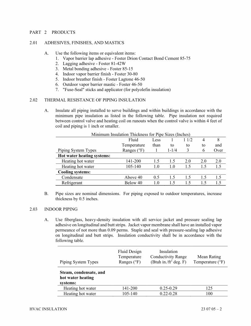
HVAC INSULATION 23 07 05 – 2
PART 2 PRODUCTS
2.01 ADHESIVES, FINISHES, AND MASTICS
A. Use the following items or equivalent items:
1. Vapor barrier lap adhesive - Foster Drion Contact Bond Cement 85-75
2. Lagging adhesive - Foster 81-42W
3. Metal bonding adhesive - Foster 85-15
4. Indoor vapor barrier finish - Foster 30-80
5. Indoor breather finish - Foster Lagtone 46-50
6. Outdoor vapor barrier mastic - Foster 46-50
7. "Fuse-Seal" sticks and applicator (for polyolefin insulation)
2.02 THERMAL RESISTANCE OF PIPING INSULATION
A. Insulate all piping installed to serve buildings and within buildings in accordance with the
minimum pipe insulation as listed in the following table. Pipe insulation not required
between control valve and heating coil on runouts when the control valve is within 4 feet of
coil and piping is 1 inch or smaller.
Minimum Insulation Thickness for Pipe Sizes (Inches)
Piping System Types
Fluid
Temperature
Ranges (°F)
Less
than
1
1
to
1-1/4
1 1/2
to
3
4
to
6
8
and
Over
Hot water heating systems:
Heating hot water 141-200 1.5 1.5 2.0 2.0 2.0
Heating hot water 105-140 1.0 1.0 1.5 1.5 1.5
Cooling systems:
Condensate Above 40 0.5 1.5 1.5 1.5 1.5
Refrigerant Below 40 1.0 1.5 1.5 1.5 1.5
B. Pipe sizes are nominal dimensions. For piping exposed to outdoor temperatures, increase
thickness by 0.5 inches.
2.03 INDOOR PIPING
A. Use fiberglass, heavy-density insulation with all service jacket and pressure sealing lap
adhesive on longitudinal and butt strips. Jacket vapor membrane shall have an installed vapor
permeance of not more than 0.09 perms. Staple and seal with pressure-sealing lap adhesive
on longitudinal and butt strips. Insulation conductivity shall be in accordance with the
following table.
Piping System Types
Fluid Design
Temperature
Ranges (°F)
Insulation
Conductivity Range
(Btuh in./ft3 deg. F)
Mean Rating
Temperature (°F)
Steam, condensate, and
hot water heating
systems:
Heating hot water 141-200 0.25-0.29 125
Heating hot water 105-140 0.22-0.28 100
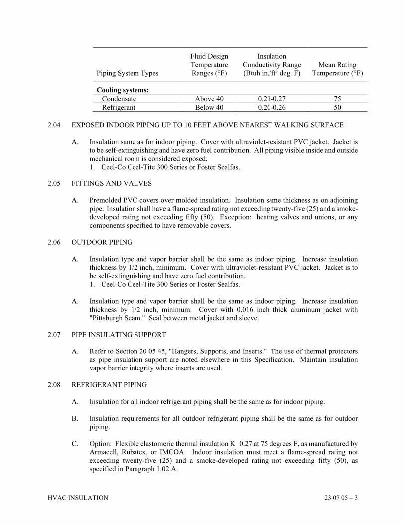
HVAC INSULATION 23 07 05 – 3
Piping System Types
Fluid Design
Temperature
Ranges (°F)
Insulation
Conductivity Range
(Btuh in./ft3 deg. F)
Mean Rating
Temperature (°F)
Cooling systems:
Condensate Above 40 0.21-0.27 75
Refrigerant Below 40 0.20-0.26 50
2.04 EXPOSED INDOOR PIPING UP TO 10 FEET ABOVE NEAREST WALKING SURFACE
A. Insulation same as for indoor piping. Cover with ultraviolet-resistant PVC jacket. Jacket is
to be self-extinguishing and have zero fuel contribution. All piping visible inside and outside
mechanical room is considered exposed.
1. Ceel-Co Ceel-Tite 300 Series or Foster Sealfas.
2.05 FITTINGS AND VALVES
A. Premolded PVC covers over molded insulation. Insulation same thickness as on adjoining
pipe. Insulation shall have a flame-spread rating not exceeding twenty-five (25) and a smoke-
developed rating not exceeding fifty (50). Exception: heating valves and unions, or any
components specified to have removable covers.
2.06 OUTDOOR PIPING
A. Insulation type and vapor barrier shall be the same as indoor piping. Increase insulation
thickness by 1/2 inch, minimum. Cover with ultraviolet-resistant PVC jacket. Jacket is to
be self-extinguishing and have zero fuel contribution.
1. Ceel-Co Ceel-Tite 300 Series or Foster Sealfas.
A. Insulation type and vapor barrier shall be the same as indoor piping. Increase insulation
thickness by 1/2 inch, minimum. Cover with 0.016 inch thick aluminum jacket with
"Pittsburgh Seam." Seal between metal jacket and sleeve.
2.07 PIPE INSULATING SUPPORT
A. Refer to Section 20 05 45, "Hangers, Supports, and Inserts." The use of thermal protectors
as pipe insulation support are noted elsewhere in this Specification. Maintain insulation
vapor barrier integrity where inserts are used.
2.08 REFRIGERANT PIPING
A. Insulation for all indoor refrigerant piping shall be the same as for indoor piping.
B. Insulation requirements for all outdoor refrigerant piping shall be the same as for outdoor
piping.
C. Option: Flexible elastomeric thermal insulation K=0.27 at 75 degrees F, as manufactured by
Armacell, Rubatex, or IMCOA. Indoor insulation must meet a flame-spread rating not
exceeding twenty-five (25) and a smoke-developed rating not exceeding fifty (50), as
specified in Paragraph 1.02.A.
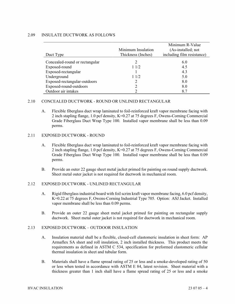
HVAC INSULATION 23 07 05 – 4
2.09 INSULATE DUCTWORK AS FOLLOWS
Duct Type
Minimum Insulation
Thickness (Inches)
Minimum R-Value
(As-installed; not
including film resistance) Concealed-round or rectangular 2 6.0
Exposed-round 1 1/2 4.5
Exposed-rectangular 1 4.3
Underground 1 1/2 5.0
Exposed-rectangular-outdoors 2 8.0
Exposed-round-outdoors 2 8.0
Outdoor air intakes 2 8.7
2.10 CONCEALED DUCTWORK - ROUND OR UNLINED RECTANGULAR
A. Flexible fiberglass duct wrap laminated to foil-reinforced kraft vapor membrane facing with
2 inch stapling flange, 1.0 pcf density, K=0.27 at 75 degrees F, Owens-Corning Commercial
Grade Fiberglass Duct Wrap Type 100. Installed vapor membrane shall be less than 0.09
perms.
2.11 EXPOSED DUCTWORK - ROUND
A. Flexible fiberglass duct wrap laminated to foil-reinforced kraft vapor membrane facing with
2 inch stapling flange, 1.0 pcf density, K=0.27 at 75 degrees F, Owens-Corning Commercial
Grade Fiberglass Duct Wrap Type 100. Installed vapor membrane shall be less than 0.09
perms.
B. Provide an outer 22 gauge sheet metal jacket primed for painting on round supply ductwork.
Sheet metal outer jacket is not required for ductwork in mechanical room.
2.12 EXPOSED DUCTWORK - UNLINED RECTANGULAR
A. Rigid fiberglass industrial board with foil scrim kraft vapor membrane facing, 6.0 pcf density,
K=0.22 at 75 degrees F, Owens-Corning Industrial Type 705. Option: ASJ Jacket. Installed
vapor membrane shall be less than 0.09 perms.
B. Provide an outer 22 gauge sheet metal jacket primed for painting on rectangular supply
ductwork. Sheet metal outer jacket is not required for ductwork in mechanical room.
2.13 EXPOSED DUCTWORK – OUTDOOR INSULATION
A. Insulation material shall be a flexible, closed-cell elastomeric insulation in sheet form: AP
Armaflex SA sheet and roll insulation, 2 inch installed thickness. This product meets the
requirements as defined in ASTM C 534, specification for preformed elastomeric cellular
thermal insulation in sheet and tubular form.
B. Materials shall have a flame spread rating of 25 or less and a smoke-developed rating of 50
or less when tested in accordance with ASTM E 84, latest revision. Sheet material with a
thickness greater than 1 inch shall have a flame spread rating of 25 or less and a smoke
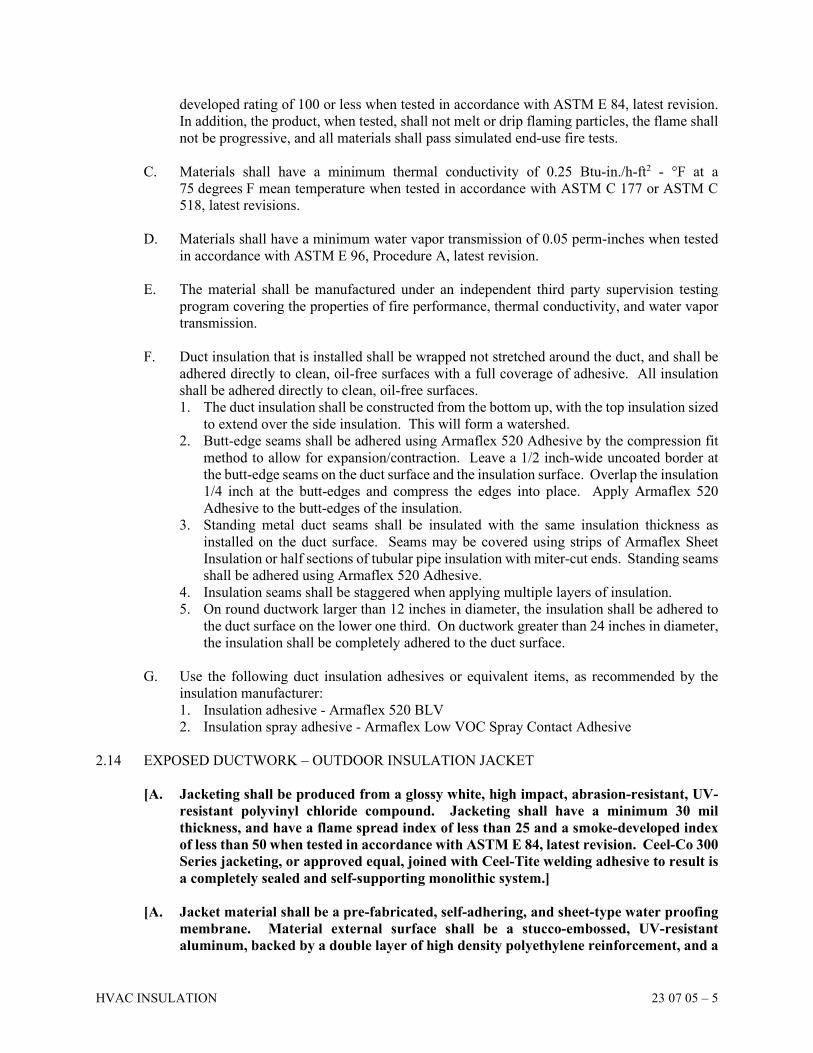
HVAC INSULATION 23 07 05 – 5
developed rating of 100 or less when tested in accordance with ASTM E 84, latest revision.
In addition, the product, when tested, shall not melt or drip flaming particles, the flame shall
not be progressive, and all materials shall pass simulated end-use fire tests.
C. Materials shall have a minimum thermal conductivity of 0.25 Btu-in./h-ft2 - °F at a
75 degrees F mean temperature when tested in accordance with ASTM C 177 or ASTM C
518, latest revisions.
D. Materials shall have a minimum water vapor transmission of 0.05 perm-inches when tested
in accordance with ASTM E 96, Procedure A, latest revision.
E. The material shall be manufactured under an independent third party supervision testing
program covering the properties of fire performance, thermal conductivity, and water vapor
transmission.
F. Duct insulation that is installed shall be wrapped not stretched around the duct, and shall be
adhered directly to clean, oil-free surfaces with a full coverage of adhesive. All insulation
shall be adhered directly to clean, oil-free surfaces.
1. The duct insulation shall be constructed from the bottom up, with the top insulation sized
to extend over the side insulation. This will form a watershed.
2. Butt-edge seams shall be adhered using Armaflex 520 Adhesive by the compression fit
method to allow for expansion/contraction. Leave a 1/2 inch-wide uncoated border at
the butt-edge seams on the duct surface and the insulation surface. Overlap the insulation
1/4 inch at the butt-edges and compress the edges into place. Apply Armaflex 520
Adhesive to the butt-edges of the insulation.
3. Standing metal duct seams shall be insulated with the same insulation thickness as
installed on the duct surface. Seams may be covered using strips of Armaflex Sheet
Insulation or half sections of tubular pipe insulation with miter-cut ends. Standing seams
shall be adhered using Armaflex 520 Adhesive.
4. Insulation seams shall be staggered when applying multiple layers of insulation.
5. On round ductwork larger than 12 inches in diameter, the insulation shall be adhered to
the duct surface on the lower one third. On ductwork greater than 24 inches in diameter,
the insulation shall be completely adhered to the duct surface.
G. Use the following duct insulation adhesives or equivalent items, as recommended by the
insulation manufacturer:
1. Insulation adhesive - Armaflex 520 BLV
2. Insulation spray adhesive - Armaflex Low VOC Spray Contact Adhesive
2.14 EXPOSED DUCTWORK – OUTDOOR INSULATION JACKET
[A. Jacketing shall be produced from a glossy white, high impact, abrasion-resistant, UV-
resistant polyvinyl chloride compound. Jacketing shall have a minimum 30 mil
thickness, and have a flame spread index of less than 25 and a smoke-developed index
of less than 50 when tested in accordance with ASTM E 84, latest revision. Ceel-Co 300
Series jacketing, or approved equal, joined with Ceel-Tite welding adhesive to result is
a completely sealed and self-supporting monolithic system.]
[A. Jacket material shall be a pre-fabricated, self-adhering, and sheet-type water proofing
membrane. Material external surface shall be a stucco-embossed, UV-resistant
aluminum, backed by a double layer of high density polyethylene reinforcement, and a
HVAC INSULATION 23 07 05 – 6
rubberized asphalt adhesive. Material shall be MFM "Flex-Clad 400" or approved
equal and shall be installed with heat-sealed joints and in accordance with
manufacturer’s instructions.]
PART 3 EXECUTION
3.01 INSTALLATION NOTES
A. Use no damaged or water-soaked insulation.
B. Insulate piping where concealed in walls.
C. Make insulation continuous through sleeves and hangers, except through fire-rated walls.
D. Leave no "raw" ends on insulation. Bevel insulation terminations, seal with insulating
cement, and cover ends with glass cloth or similar to pipe insulation covering.
E. Ensure that exposed insulation has a neat and finished appearance. Size insulation if required
and leave ready for painting.
F. Ensure that jacket has overlapping joints and is sealed with suitable adhesive. The use of
staples is acceptable on heating hot water systems only, but only as an installation aid and
not as a substitute for adhesive.
G. Brush coat all staples used with a white vapor barrier mastic.
H. Use adhesive and welded pins with washers for attaching liner and rigid board insulation to
ductwork. Seal joints with a 2 inch wide application of adhesive.
I. Provide sheet metal lips on leading and leaving air edges at liner transitions.
J. All duct sizes shown are clear inside dimensions.
K. Tape and seal all joints.
L. Wrap all outside air ductwork.
M. Duct insulation that is installed shall be wrapped not stretched around the duct. On ductwork
larger than 12 inches in diameter, the insulation shall be adhered to the duct surface on the
lower one third. On ductwork greater than 24 inches in diameter, the insulation shall be
completely adhered to the duct surface. Butt-edge seams shall be adhered using adhesive by
the compression fit method to allow for expansion/contraction. Overlap the insulation at the
butt-edges and compress the edges into place. Apply adhesive to the butt-edges of the
insulation.
END OF SECTION
SECTION 23 08 01
HVAC SYSTEM CONFIRMATION
HVAC SYSTEM CONFIRMATION 23 08 01 – 1
PART 1 GENERAL
1.01 DESCRIPTION
A. Provide HVAC System Confirmation to ensure the proper operation of all HVAC systems as
complete systems, including all items of equipment, piping and controls. Perform the
confirmation in four separate steps:
1. 120 Hour Test
2. Initial Confirmation Period
3. Summer Confirmation Period
4. Winter Confirmation Period
Steps 1 and 2 must be completed prior to Final Completion; Steps 3 and 4 may be completed
after Final Completion as Special Warranty Work.
B. 120 Hour Test: After the completion of all operational checks of the equipment, and after all
control system function checks and all software debugging is complete, the Contractor shall
demonstrate the automatic operation of the system by having the systems operate under the
automatic controls without any intervention from the Contractor or the Owner's operators for
a period of 120 continuous hours. The test will be considered successful if all systems operate
properly without intervention, and if no alarm conditions occur and all set points are
continuously maintained as indicated in the documents, or if in the Engineer's judgment, the
reasons for all failures are trivial and beyond the control of the Contractor.
C. Initial Confirmation Period: During an eight (8) week period immediately after the
successful completion of the 120 Hour Test and after the final punch list items have been
completed, the Initial HVAC System Confirmation shall commence and shall include:
1. Documentation of proper operation of all control devices.
2. Documentation of all sensor operation and calibration.
3. Confirmation of all Modes of Operation: Operate the system in every mode of operation,
all combinations of chillers and pumps or heat exchangers, fans and air handling units,
indicated in the sequence of operation for a period of time not less than three (3) hours
each with the Owner's operating personnel present to verify the operation.
4. Computer Trend Logs: During the Initial Confirmation Period, monitor the HVAC
control system operation and provide computer trend logs to the Owner on each Monday
for the duration of the confirmation period. The logs shall record on a hourly basis, all
temperatures and static pressures measured for control or monitoring purposes within all
air handling units, all air handler damper and valve command signals, all space
temperatures, all heating hot water temperatures and pressures, all chilled water
temperatures and pressures, all cooling tower water temperatures, all outside air
conditions, all variable frequency drive command signals, and a listing of what
equipment is in operation and all alarm conditions. Submit a weekly report on the data
from the trend logs to the Owner, including an explanation of all alarms, set points that
were not maintained and the corrective action taken. If the system is not operating as
designed, i.e. the trend logs of more than two (2) weeks have instances of alarms or set
points not being maintained, the confirmation period will be extended until there are no
more alarms for four (4) additional weeks.
D. Summer Confirmation Period: For four (4) weeks in the July following the Initial
Confirmation Period (or during the next four (4) weeks following the Initial Confirmation
HVAC SYSTEM CONFIRMATION 23 08 01 – 2
Period if it ends in July), monitor the HVAC control system operation and provide computer
trend logs to the Owner on each Monday. The logs shall record on a hourly basis, all
temperatures and static pressures measured for control or monitoring purposes within all air
handling units, all air handler damper and valve command signals, all space temperatures, all
heating hot water temperatures and pressures, all chilled water temperatures and pressures,
all cooling tower water temperatures, all outside air conditions, all variable frequency drive
command signals, and a listing of what equipment is in operation and all alarm conditions.
Submit a weekly report on the data from the trend logs to the Owner, including an explanation
of all alarms, set points that were not maintained and the corrective action taken.
E. Winter Confirmation Period: For four (4) weeks in the January following the Initial
Confirmation Period (or during the next four (4) weeks following the Initial Confirmation
Period if it ends in January), monitor the HVAC control system operation and provide
computer trend logs to the Owner on each Monday. The logs shall record on a hourly basis,
all temperatures and static pressures measured for control or monitoring purposes within all
air handling units, all air handler damper and valve command signals, all space temperatures,
all heating hot water temperatures and pressures, all chilled water temperatures and pressures,
all cooling tower water temperatures, all outside air conditions, all variable frequency drive
command signals, and a listing of what equipment is in operation and all alarm conditions.
Submit a weekly report on the data from the trend logs to the Owner, including an explanation
of all alarms, set points that were not maintained and the corrective action taken.
1.02 GENERAL
A. Provide all necessary products, equipment and manpower to operate the HVAC system for
the 120 Hour Test.
B. Provide all necessary products, equipment and manpower to complete all four steps of the
HVAC System Confirmation.
PART 2 PRODUCTS - NOT APPLICABLE
PART 3 EXECUTION
3.01 GENERAL
A. The HVAC system shall be operated successfully for a period of 120 hours as described
above before any HVAC system will be confirmed.
B. The HVAC Contractor shall have one (1) licensed electrician, two (2) functionally-proficient
HVAC mechanics, and two (2) functionally-proficient employees of the Temperature
Control Contractor or BAS Contractor available on a twenty-four (24) hour, seven (7) day-
a-week basis with a guaranteed two (2) hour response time to the site for the duration of the
Initial Confirmation Period. The above stated manpower shall have each worked on the
HVAC system installation for a minimum of 120 hours of which forty (40) hours is to be
during the operational check of the plant. If the response time exceeds two hours, the Owner
has the option of providing the necessary manpower to correct the problem, at the expense
of the HVAC Contractor.
HVAC SYSTEM CONFIRMATION 23 08 01 – 3
C. The HVAC Contractor is responsible for any equipment that is damaged in any way during
the 120-Hour Test, or the initial confirmation of the HVAC system. The HVAC Contractor
shall be responsible for all costs associated with the restoration of the equipment to its
original condition and for any temporary equipment needed to keep the system in operation.
D. If, for any reason, the HVAC system operation during the confirmation period generates a
condition that does not meet the Sequences of Operation, the condition shall be corrected at
the Contractor's expense. Provide to the Owner a written report explaining why the failure
occurred and how it was corrected.
END OF SECTION
SECTION 23 09 93
SEQUENCES OF OPERATION
SEQUENCES OF OPERATION 23 09 93 – 1
PART 1 GENERAL
1.01 CONTROL DIAGRAMS AND SCHEDULE
A. Provide a system of controls as required to accomplish the Sequences as hereinafter specified.
Refer to the Drawings for information indicating the components and intended control
functions and devices. Note that the Building Automation System for this building is being
designed by the project team for the City of Canal Winchester, and the Columbus
Metropolitan Library is a tenant in this building.
B. Building Automation System (BAS) Contractor for the building’s BAS shall be responsible
for all control wiring connections, auxiliary devices and control wiring diagrams to complete
the control system and attain the described sequence of operation. All work associated with
the Columbus Metropolitan Library portion of the building must be coordinated with this
BAS Contractor.
C. All set-points of thermostats, controllers and the like, that are not factory preset, shall be
preset by the Temperature Control Contractor before system startup.
D. The control system shall be easily expandable as the future equipment is installed with no
control component replacements. All main system control panels shall have all inputs and
outputs necessary for the future equipment.
E. All temperature and pressure control set-points and time limits shall be adjustable at the BAS
OWS.
F. Through stable operation and control and sensor accuracy, the following control points shall
be held within the following ranges:
1. General occupied spaces (offices, conferences) cooling setpoint + 1 degree
heating setpoint -1 degree
2. RTU discharge +/- 1.0 degrees
3. Ducted Air ±1ºF
4. Outside Air ±2ºF
5. Dewpoint ±2ºF
6. Relative Humidity ±2% RH
7. Water Flow ±2% of full scale
8. Airflow (terminal) ±10% of full scale
9. Airflow (measuring stations) ±5% of full scale
10. Air Pressure (ducts) ±0.1" W.G.
11. Air Pressure (space) ±0.01" W.G.
12. Electrical (A, V, W, Power factor) ±1% of reading
13. Carbon Dioxide (CO2) ±50 ppm (accuracy)
G. All temperature sensors in air handling units shall be averaging type sensors to average the
reading across the cross-sectional area of the unit. Point type sensors are not acceptable.
H. There are many interrelated control loops that will require tuning and adjustment to prevent
"hunting" and excessive modulation. Allow time in the bid proposal for tuning and
adjustment based on the actual construction and operation.
SEQUENCES OF OPERATION 23 09 93 – 2
1.02 SAFETY INTERLOCKS - GENERAL
A. All safety interlocks shall be hard wired and independent of control system programming
software, and electronic controllers. These safety interlocks include the shutdown of
equipment items due to low temperatures, shutdown due to lack of combustion air supply
and/or proper flue draft for fuel fired equipment, and shutdown due to smoke detection.
B. The Division 26 fire alarm panel shall contain one (1) set of contacts for each air handling
unit that the Temperature Control Contractor shall be responsible for wiring through in order
to shut down the air handling unit, associated return fans, and associated exhaust fans when
smoke is detected by smoke detectors that report through the fire alarm panel. This safety
interlock is in addition to smoke detectors located at the air handling unit that are locally hard
wired by the Temperature Control Contractor for air system shut down of the air handling
unit, associated return fans, and associated exhaust fans.
C. Smoke Dampers: Smoke dampers and combination fire and smoke dampers shall be motor
driven open, motor held open, and spring closed. Each smoke damper shall be operated by
a duct mounted spot type smoke detector provided by the Division 26 Contractor located in
the duct adjacent to the damper. The Temperature Controls Contractor shall be responsible
for wiring between the smoke detector contacts and the damper motor and for the power
wiring to the motor regardless of voltage.
PART 2 PRODUCTS
A. Dampers (Multiple Blade Dampers)
1. Automatic dampers shall be single or multiple blade. All dampers are to be sized to the
application by the BAS Contractor using methods similar to control valve sizing.
2. Frames shall be 16 gauge galvanized steel structural channel and shall have flanges for
duct mounting as appropriate.
3. Blades shall be 14 gauge galvanized steel, roll-formed air foil type not exceeding 8 inches
wide.
4. Damper bearings shall be permanently lubricated, stainless steel type. Dampers hung
with blades mounted vertically shall be provided with thrust bearings.
5. Each blade and top and bottom of frame shall have replaceable butyl rubber seals suitable
for -80 to 300 degrees F. Seals shall be mechanically locked into blade slots.
6. Jamb seals shall be flexible metal compression type.
7. Maximum damper leakage shall be 8.0 cfm/sf at 4 inch static pressure
8. Damper sections shall not exceed 16 sq. ft. and shall have minimum of one operator per
damper section.
9. All dampers in modulating applications shall have opposed blades. Dampers in two
position services shall have parallel blades.
10. Submittals shall include damper sizes and leakage characteristics.
11. Return air dampers shall be smoke rated dampers.
B. Electronic Actuators
1. General
a. Actuators shall be sized sufficiently to operate the controlled device throughout its
range of movement and provide adequate power to closed the controlled device
against system differential pressures. Actuator shall be sized for 150% of required
SEQUENCES OF OPERATION 23 09 93 – 3
duty. Actuators may be mechanically and electrically paralleled on the same shaft
to multiply the available torque.
b. Actuators shall accept 24 VAC or VDC power supply and be UL listed, direct
coupled type capable of being direct mounted over the shaft of the controlled device.
The control signal shall be 2-10 VDC or 4-20 mA, and the actuator shall provide a
clamp position feedback signal of 2-10 VDC. The feedback signal shall be
independent of the input signal and may be used to parallel other actuators and
provide true position indication. The feedback signal of each actuator shall be wired
back to a terminal strip in the control panel.
c. Power consumption shall not exceed 8 watts or 15 VA of transformer sizing capacity
per high torque actuator nor 2 watts or 4 VA for VAV actuators. Sound level shall
not exceed 45 dB for high torque nor 35 dB for VAV actuators.
d. Electronic overload protection shall protect actuator from damage. If device jams,
the actuator shall not burn out. Internal end switch type actuators are not acceptable.
e. A reversing switch shall be provided to change action from direct to reverse in
relation to control signal as operation requires. Actuator shall also have manual
override, field selectable rotational/spring return direction, field adjustable zero and
span. Actuator (except for Generator intake/exhaust) shall cycle in ninety (90)
seconds maximum end to end full stroke, fifteen (15) seconds maximum return to
normal for spring return.
2. Electronic Damper Actuators
a. Damper sections shall be sized and coordinated based on actuator and dampers
manufacturer's recommendations based on face velocity, differential pressure and
damper type.
b. All damper actuators (except terminal units) shall be furnished with mechanical
spring return unless otherwise specified in the sequences of operations. Actuators
for terminal units shall fail to last known value.
c. Damper actuators shall have external adjustable stops to limit the travel in either
direction, and a gear release to allow manual positioning.
d. Provide auxiliary adjustable end switches on damper shaft or blade switch to prove
damper position as required by the sequence of operations.
3. Electronic Valve Actuators
a. All actuators shall fail in the last position unless specified otherwise (as normally
open/closed) in the sequence of operations. The spring return feature shall permit
normally open or normally closed positions of the valves.
b. All direct shaft mount rotational actuators shall have adjustable stops to limit the
travel in either direction.
c. Isolation valves as specified in the sequence of operations shall be furnished with
adjustable end switches to indicate open/closed position.
C. Temperature Sensors, Nodes and Transmitters
1. General Requirements
a. Provide sensors, nodes, and transmitters as required by the sequence of operation.
b. Temperature transmitters shall be equipped with non-interactive, individual zero and
span adjustments for calibration without iterative operations.
c. Each temperature sensor shall match the requirements of the associated temperature
controller. Each sensor shall be designed for the appropriate application (i.e., duct,
immersion, etc.) and be provided with all necessary installation accessories. Ranges
shall be selected to the middle of the control range. The BAS shall be equipped with
a self-calibrating feature for temperature sensors.
SEQUENCES OF OPERATION 23 09 93 – 4
d. Temperature transmitters shall be sized and constructed to be compatible with the
medium monitored. Transmitters shall be equipped with a linearization circuit to
compensate for non-linearities of the sensor and bridge and provide a true linear
output signal.
e. Temperature sensors shall be resistance type and shall be three-wire 100 ohm
platinum RTD, or two-wire 1,000 ohm platinum RTD, wound nickel or thermistor
type.
f. Thermistors shall have a minimum of 100 ohm/degrees F resistance change versus
temperature. Thermistors shall be certified to be stable + 0.24 degrees F over five
(5) years and + 0.36 degrees F accurate and free from drift for five (5) years.
Thermistors are acceptable provided BAS can compensate for the mathematical
variation of the fitting constraints and that accuracy can be obtained.
g. The following accuracies are required and include errors associated with the sensor,
lead wire and A to D conversion.
Point Type Accuracy Temperature 1.00°F
Duct Temperature 1.00°F
Water Temperature 1.00°F
2. Room Sensors and Nodes
a. Room temperature sensors are to be provided with a screw cover.
b. Terminal unit temperature sensors shall be RTD 1,000 Ohm Platinum, 2 wire,
accurate to + 0.5 degrees F at room temperature with 12 Bit A to D resolution.
Provide sensor with / without room temperature indicator and with / without setpoint
adjustment. Adjustment shall be +/- 3 degrees from setpoint in the BAS.
c. Sensor shall be supplied with a vertical base for mounting on a standard single gang
junction box.
3. Outside Air Sensors
a. Outside air sensors shall be designed to withstand the environmental conditions to
which they will be exposed. They shall also be provided with a solar shield.
b. Sensors exposed to wind velocity pressures shall be shielded by a perforated plate
surrounding the sensor element.
c. Temperature transmitters shall be of NEMA 3R construction and rated for ambient
temperatures.
4. Duct Type Sensors
a. Duct mount sensors shall mount in a hand box through a hole in the duct and be
positioned so as to be easily accessible for repair or replacement. A neoprene
grommet (Sealtite fitting and mounting plate) shall be used on the sensor assembly
to prevent air leaks.
b. Duct sensors shall be insertion type and constructed as a complete assembly
including lock nut and mounting plate. Duct sensor probe shall be constructed of
304 stainless steel.
c. Where a device is used for sensing of mixed air temperature and the duct or air
handler cross-sectional area is in excess of 14 square feet, the instrument will
incorporate an averaging element with a minimum length of 96 inches or a suitable
array of duct sensors wired as a single input. Provide capillary supports at the sides
of the duct unit to support the sensing string.
d. For outdoor air duct applications, use a weatherproof mounting box with
weatherproof cover and gasket.
SEQUENCES OF OPERATION 23 09 93 – 5
D. Relative Humidity Sensors/Transmitter
1. The relative humidity sensor shall be solid state, resistance type sensor of the Bulk
Polymer Design, Class 2. The sensor element shall be washable and shall resist surface
contaminations.
2. Transmitter shall be equipped with non-interactive span and zero adjustments, a 2 wire
isolated loop powered, 0-10vDC, 4-20ma, linear proportional output.
3. The humidity transmitter shall be accurate to ±2% RH, including lead loss and A to D
conversion. Range shall be 20% to 80%.
4. Acceptable Manufacturers: HyCal, General Eastern or Mamac.
E. Humidistats shall have SPST switching which makes on a fall in relative humidity. The
sensing element shall be moisture sensitive nylon ribbon wound around three bobbins to give
four element control. Provide removable setting knob to prevent tampering.
F. High Limit Humidity Controller: Duct mounted air sampling tube with nylon element for
sampling humidity within the duct. Setpoint range 65% to 95% RH in 5% increments.
Operable up to 125 degrees F.
G. Pressure Sensing Devices
1. General Requirements:
a. Sensing elements shall be corrosion resistant, bourdon tubes, bellows, or diaphragm
type.
b. Units shall have tamper-proof adjustable range and pressure settings and shall
provide an output signal of 0 to 10V dc, or 4 to 20 mA.
c. The sensing range and mounting of the device shall be as appropriate for the
application and system design.
d. Pressure devices shall be constructed to withstand a minimum of 100% over pressure
without damage and to hold accuracy during a momentary 40% over-range input.
e. Mount the sensing element within 20 feet of the pickup point. Locate transmitters in
accessible location and in control panels wherever possible.
f. Devices shall be furnished by the BAS contractor and mounted in the duct or pipe
by the HVAC Contractor.
g. Provide a minimum of a NEMA 1 construction for the transmitter.
h. Acceptable Manufacturers: Mercoid, Dwyer, or McDonnell Miller.
2. Differential Pressure Switches
a. Switch contacts shall be snap action micro-switch type Form C contact.
b. Assembly shall operate automatically and reset automatically when conditions return
to normal. Complete sensor assembly shall be protected against vibration and
movement.
c. High pressure switches shall be manual reset devices.
d. Switches shall be vented to withstand a 50% over-pressure without loss of
calibration.
3. Differential Pressure Transmitters used for flow measurement shall be sized to the flow
sensing device and shall be supplied with shutoff and bleed valves in the high and low
sensing pick-up lines (3 valve manifolds).
H. Electronic Room Thermostats: A modulating solid state controller with built-in detector, P
or PI controller, as required, with continuous voltage or current output. Each unit shall have
individual setpoint, proportional band, start-point, and span adjustments. Input voltage shall
be 24 VAC or less. Provide each unit with night setback, summer/winter switch over, or
remote reset capabilities, as required.
SEQUENCES OF OPERATION 23 09 93 – 6
I. Programmable Electronic Thermostats: A modulating solid state controller with built-in
detector, P or PI controller, as required, with continuous voltage or current output. Each unit
shall have individual setpoint, proportional band, start point, and span adjustments. Input
voltage shall be 24 VAC or less. Provide each unit with night setback, summer/winter
switchover, or remote reset capabilities, as required. Thermostat shall have a seven (7) day
four (4) time sequence programmable schedule.
J. Electric Room Thermostats: Heavy duty snap action type with key operators rated at 6 FLA
at 120 VAC contacts suitable for the intended service. Provide manual selector switches as
required in the sequence of operation.
K. Low Limit Detection Thermostats: Low limit detection thermostats shall be of the vapor
tension capillary type having a sensing element a minimum of 20 feet in length. These
thermostats shall be manual reset type. The elements shall be complete with necessary
fittings to permit installation in the duct or AHU to sense the correct discharge
temperatures. One (1) low limit detection thermostat will be installed for every 20 square
feet of protected area and arranged to sequence unit as described when sensed temperature
falls below 38 degrees F.
PART 3 EXECUTION
3.01 GENERAL
A. Alarms: The system shall have multiple levels of action with each alarm. The BAS
contractor shall review each alarm point with the Owner's representative to determine the
range of alarms (if not already specified) and the appropriate action of each alarm within the
system. The actions include changing colors on the graphic at the OWS, notification on the
BAS, mobile device, email, etc.
B. Setpoints: All setpoints in the BAS shall be adjustable within the BAS at the OWS.
C. Air Handling Unit Damper Control: Each damper operator within an air handling unit shall
be modulated from its own individual control signal from the BAS. Linkage control or
modulation of multiple dampers from a single signal is not acceptable.
D. Air Handling Unit Temperature Sensors: All temperature sensors within air handling units
shall incorporate an averaging element with a minimum length of 96 inches or the length
needs to provide adequate coverage of the cross-section of the unit. The intent is to provide
an average temperature throughout the unit. Provide capillary supports at the sides of the
duct unit to support the sensing element.
E. Tuning: Each control loop shall be tuned to eliminate unnecessary rapid changes, hunting
and adverse impacts on other control loops.
F. Motor Status: The status of all constant speed motors shall be determined by current sensing
devices on the motor leads. The status of all motors with variable frequency drives (VFD)
shall be via the fault status alarm on the VFD.
SEQUENCES OF OPERATION 23 09 93 – 7
G. Schedule: In consultation with the Owner’s Representative, create an operating schedule for
all major equipment and systems, and for certain building areas. Some systems, equipment
items, or areas will operate continuously, but operating schedule functionality shall be
provided for all equipment/systems for future flexibility.
3.02 ROOFTOP UNIT, VARIABLE VOLUME, MULTIZONE
A. System Components
1. Powered Exhaust
2. Mixing chamber with return, relief and outside air dampers
3. Pre-Filter bank
4. Gas Heating
5. Cooling coil – Dx
6. Supply Fan with VFD
B. Schedule: The unit shall operate continuously. The unoccupied, cool down, and warm-up
modes are to be provided for future use. / The unit shall operate continuously in accordance
with the Owner’s schedule.
C. System Off State
1. When the unit is off for any reason, the outside air, relief and any associated smoke
dampers shall be closed. The return air damper shall be fully open. The unit: return fan,
the supply fan, heating and cooling system shall be off.
D. Start-up
1. Optimized Start - The unit will be indexed to this state by the BAS, based on an optimal
start algorithm that considers outside air temperature and space temperature to estimate
the amount of time necessary to bring the space to occupied temperatures at the
scheduled occupied time.
2. Start-up – All associated smoke dampers shall open. The outside, relief and return
dampers shall remain in their “off” position. The packaged unit controls shall start the
return fan and supply fan. The fans shall slowly ramp to maintain their normal setpoint
control operation as indicated by the BAS. Fans shall run continuously when the
schedule is in occupied mode. Fan status shall be monitored by the BAS through the
unit controller output / via current sensors on the motor leads provided by the BAS
contractor.
3. Warm-up – If the return air temperature is below 68 degrees F / If more than three (3)
sensors indicate space temperature is more than 5 degrees F below setpoint, the unit shall
be released to control to the full heating mode. The unit discharge air temperature shall
be set to maximum value. As the return air temperature / space temperature reaches
setpoint, the unit shall be slowly released to occupied control.
4. Cool Down – If the return air temperature is above 78 degrees F / If more than three (3)
sensors indicate space temperature is more than 3 degrees F above setpoint, the unit shall
be released to control in the full cooling mode. The unit discharge air temperature shall
be set to minimum value. As the return air temperature / space temperature reaches
setpoint and after a minimum 3-minute run time, the unit shall be slowly released to
occupied control.
SEQUENCES OF OPERATION 23 09 93 – 8
E. Occupied Operation
1. Minimum Outside Air Damper Control – The outside air, return air and relief air dampers
shall each be actuated by the unit’s controller. Once released to normal control, the
outside air and return air dampers shall slowly modulate to the minimum outside air
position. Then, the dampers shall be released to control to their setpoint as required by
economizer or ventilation control loops. Minimum outside air is achieved by a single
outside air damper, set by the balancer in response to an air flow measuring station in the
air intake section.
2. Discharge Air Temperature Setpoint
a. The discharge air temperature setpoint shall be linearly reset from a minimum of 54
degrees F at 75 degrees F outside air temperature to a maximum of 65 degrees F at
30 degrees F outside air temperature.
b. After the supply duct static pressure has been reset to its minimum setting, all of the
spaces associated with the rooftop unit are operating at their setpoint, and the
terminal heating coils are operational, then the unit setpoint temperature shall be
raised by 1.0°F. If the unit discharge air temperature has been reset and any space is
more than 2°F above setpoint, then the discharge air temperature shall be reduced by
1.0°F. If the return air humidity is above 55%, then the discharge air temperature
shall be reduced by 2°F. A 10 minute delay shall be utilized between each
increase/decrease in the discharge air temperature before making additional changes.
The minimum and maximum discharge air temperature setpoint shall be 52 to 64
degrees F.
3. Discharge Air Temperature Control: The unit’s controller with a discharge air
temperature sensor in the discharge plenum / duct of the unit shall maintain discharge air
temperature through economizer damper modulation, compressor control, and heating
control modulation. Simultaneous heating and cooling operation shall not be permitted.
a. Outside Air Temperature Above 67 Degree F / Outside Enthalpy Greater than Return
Air Enthalpy: The outside air damper, and the return damper, and relief air damper
shall be controlled by the ventilation control loop to bring in the minimum outside
air required. The discharge air controller shall modulate the Dx system to maintain
the discharge air temperature setpoint.
b. Outside Air Temperature below 67 Degrees F / Outside Air Enthalpy less than
Return Air Enthalpy: The BAS shall control the economizer dampers to the full
outdoor air positions. Discharge air temperature shall be controlled by Dx
modulation until the cooling system is off. Then, the discharge air temperature shall
be controlled by the modulation of the economizer dampers by the mixed air
controller. When the outside air damper reaches its minimum ventilation position as
indicated by the ventilation control loop, the dampers shall then be controlled to the
ventilation control signal and the discharge air temperature shall be controlled by the
modulation of heating system.
4. Supply Fan Control
a. A remote duct static pressure sensor and controller shall measure duct pressure and
modulate the fan speed to maintain the static pressure setpoint. Fan speed control
shall by way of VFD modulation. The sensor shall be located at two-third (2/3) the
system distance from the AHU. The initial setpoint shall be 1.0 inch, but this
requirement shall be optimized by the balancing contractor. The VFD shall be
controlled by speed signal from the BAS.
SEQUENCES OF OPERATION 23 09 93 – 9
b. Pressure Reset: The BAS shall monitor all terminal box damper positions associated
with the AHU. The static setpoint shall be reset based on VAV box position. If all
boxes are below 80% of full open, reset the static setpoint downward 0.05" w.g.
every 10 minutes until at least one VAV box is at least 80% open. If any box is more
than 90% open, reverse the sequence. The setpoint low limit shall be 0.5" w.g. below
initial setpoint and the high control unit setpoint shall be 0.5" w.g. above the initial
setpoint.
c. Supply air flow shall be indicated by the summation of the air flows at all associated
terminal boxes.
5. Return Fan Control
a. The return fan speed shall modulate to maintain an offset airflow CFM / speed from
the supply fan air flow / speed. Fan speed control shall be by way of VFD
modulation. The amount of the offset shall be determined during balancing by
setting the supply and return fan to full design air flow operation with the unit in
100% outside air economizer. The difference in the fan speeds / CFM at that point
shall be the offset value. / The offset shall be based on the air volumes monitored by
AFMS in the return fan inlet and the supply fan volume as determined by the sum of
the terminal box air flows.
6. Dehumidification
a. Based on Return Air: A humidity sensor in the return air ductwork shall monitor
return air humidity. If the sensed humidity is greater than 59%, the discharge air
temperature shall be decreased by one degree below the reset temperature. The
relative humidity shall be monitored at 20 minute increments. If the humidity
remains above setpoint, the discharge air temperature shall be decreased in one
degree increments to a minimum value of the design leaving air temperature. If the
humidity is below 55%, the discharge air temperature shall be increased in one
degree increments until the reset temperature is reached.
7. Filter Differential Pressure
a. Differential pressure measuring sensors, provided by the BAS contractor, which
provide a differential pressure readout located across each filter bank total of two (2)
shall report to the BAS. Each filter shall alarm when pressures exceed three (3) times
the initial pressure drop, 0.90 inch. System shall alarm if the pressure drop is below
the design initial pressure. The use of switches that only trigger alarm at a setpoint
are not acceptable.
b. Differential pressure switches, provided by the BAS contractor, located across each
filter bank total of two (2) shall report to the BAS. Each filter shall alarm when
pressures exceed three (3) times the initial pressure drop, 0.90 inch.
8. Outside Air Flow Air Flow Measurement Station (AFMS): An outside air flow
measuring station (AFMS) shall be monitored by the unit controller and output to the
BAS. The unit controller shall control the minimum outside air quantity by modulating
the outside air damper, return air damper and relief air damper to provide the specified
minimum ventilation. The air balance shall establish initial damper positions so that the
return damper is as much open as possible. Relief dampers shall control as specified
previously. The AFMS shall be mounted in the outside air intake, furnished by the air
handler manufacturer.
F. Unoccupied Operation
1. When the unit is scheduled to unoccupied, the system shall be in the off state described
previously.
SEQUENCES OF OPERATION 23 09 93 – 10
2. Heating: Whenever two spaces served by the unit are below a space temperature of 63
degrees F, the unit shall be indexed to run in warm-up mode. The unit dampers shall
remain in the "off" configuration. The system shall run until all spaces are above 65
degrees F, then it shall return to unoccupied mode.
3. Cooling: Whenever two spaces served by the unit are above a space temperature of 82
degrees F, the unit shall be indexed to run in cool down mode. The unit dampers shall
remain in the "off" configuration. The system shall run until all spaces are below 80
degrees F, then it shall return to unoccupied mode.
G. Safeties
1. Smoke Detector: The BAS shall, upon receiving a signal from the smoke detector in the
supply and/or the return air stream, or the building fire alarm system, shall disable the
air handling system and index the system to the “off” state. The system shall not be
allowed to operate until the fire alarm is cleared and the system is manually reset.
2. Freezestat: A low temperature cutout shall, upon sensing a temperature below 38 degrees
F at any point, open the preheat coil control valve, close both outside air dampers and
the relief damper, open the return air dampers and shut off the fans.
3. High Supply Static Pressure: A high limit static pressure sensor located at the air handler
discharge duct or plenum, set at 0.5 inch below the supply duct design static pressure
shall override the speed of the supply fan system to prevent higher pressure and shall
alarm the BAS. Alarm shall automatically reset when pressure decreases 0.25” below
setpoint. If pressure reaches the supply duct design static pressure, the supply fan system
shall be stopped and the BAS alarmed. Manual reset shall be required to restart the AHU
system.
4. High Negative Return Static Pressure: A high negative limit static pressure sensor
located at the air handler return duct or plenum, set at 0.5 inch above the return duct
design static pressure shall override the speed of the return fan system to prevent higher
negative pressure and shall alarm the BAS. Alarm shall automatically reset when
pressure decreases 0.25” below setpoint. If pressure reaches the return duct design static
pressure, the return fan system shall be stopped and the BAS alarmed. Manual reset shall
be required to restart the AHU system.
5. Smoke Damper Alarm and Shutdown: The BAS shall, upon receiving a signal from the
smoke detector controlling smoke dampers at the shaft branched, or the building fire
alarm system, shall disable the air handling system and index the system to the “off”
state. The system shall not be allowed to operate until the fire alarm is cleared and the
system is manually reset.
H. Alarms: In addition to those indicated above, alarms to the BAS shall include, but not be
limited to the following. Unless noted otherwise, these shall automatically reset if the alarm
condition clears.
1. General trouble alarm from the RTU.
2. Fan Status: The status of each fan shall be monitored by current sensing relays.
Whenever the fan status does not match the command point for a period of 15 seconds.
3. Mixed air temperature below 40 degrees F.
4. High Discharge Air Temperature: 5 degrees F above setpoint.
5. Low Discharge Air Temperature: 5 degrees F below setpoint.
6. Supply fan static pressure out of limits (too high and too low)
7. Return fan static pressure out of limits (too high and too low)
8. Fire alarm Shutdown
9. Low limit thermostat Shutdown
10. High Filter Static Pressure.
SEQUENCES OF OPERATION 23 09 93 – 11
11. High return air humidity (above 60%)
I. Graphic Interface: The graphic at the BAS User Interface shall include a system diagram
complete with, but not limited to, the following information:
1. Outside Air Temperature
2. Outside air, minimum outside air, return air, relief air damper position via unit controller
interface
3. Building differential pressure
4. Outside air flow (AFMS)
5. Mixed air plenum temperature
6. Cooling coil leaving air temperature
7. Heating system status
8. Supply fan status
9. Supply fan VFD data as indicated herein.
10. Supply plenum static pressure
11. Supply duct pressure (both actual and setpoint)
12. Supply fan air flow via sum of terminal boxes
13. Final static pressure drop
14. Unit discharge air temperature (both actual and setpoint)
15. Return air temperature
16. Return air humidity
17. Powered exhaust fan status
18. Alarm status as indicated above.
3.03 EXHAUST FANS
A. General: The existing restroom fans shall via wall switch.
3.04 TERMINAL BOXES
A. VARIABLE VOLUME, ELECTRIC HEATING COIL: When the associated air handler is
in occupied mode, the box controller shall control the damper and electric heating element
to maintain space temperature setpoint. There shall be a minimum of 2 degree offset between
the heating and cooling setpoint. While space temperature is within the offset, the box
damper shall be at minimum air flow and the heating element shall not be energized. When
the space temperature rises above the offset, the controller shall modulate the damper from
its minimum position to its maximum position to maintain the space temperature. When the
space temperature falls below the range, the controller shall energize the heating element.
When the associated air handler is in the unoccupied mode, the box shall operate to maintain
a space temperature 5 degrees below heating setpoint and 5 degrees above the cooling
setpoint. The box controller shall report both the measured air flow and the discharge air
temperature to the BAS.
3.05 DEMAND CONTROL VENTILATION
A. During occupied mode, the BAS shall monitor space CO2 with wall mounted sensors as
located on the drawings. The Demand Ventilation Controls shall first increase zone
minimum airflow to satisfy ventilation requirements, and then increase the outdoor air rate
at the air handler as described in the following sequence.
SEQUENCES OF OPERATION 23 09 93 – 12
1. At the Zone: Upon a rise in zone CO2 concentration above 850 ppm, the airflow to the
space shall be increased through modulation of the zone VAV terminal up towards a
ventilation override maximum value. This value is adjustable, but initially shall be the
maximum flow value for the terminal box as indicated on the drawings. The air flow
shall be increased linearly from the minimum at 850 ppm to the override value air flow
at 950 ppm.
2. At the Air Handler: If the space carbon dioxide levels are increase to over 1000 ppm for
15 minutes after the box reaches maximum air flow setpoint, the outside air volume of
the air handling unit serving that space shall be slowly increased from the absolute
minimum to the design minimum scheduled on the drawings. If all of the sensors in
spaces served by the air handling unit detect a concentration below 950 ppm the outside
air damper position will be decreased to the scheduled absolute minimum. The outside
air damper will maintain its increased opening for a minimum of 5 minutes in order to
avoid short cycling.
3.06 TERMINAL EQUIPMENT
A. Air conditioning units (ductless split systems or packaged): Upon a call for cooling as sensed
by the unit-mounted temperature sensor, the factory-supplied control panel shall cycle the
compressor and evaporator fan to maintain the room temperature set points. Provide all field
control wiring for unit control system for indoor and outdoor components. Provide a
temperature sensor to monitor space and to report to the BAS. The BAS shall be alarmed if
the temperature exceeds 80 degrees F.
B. Emergency Power Operation: Units shall operate as they do under normal power.
C. All control wiring is provided by the BAS Contractor.
3.07 MISCELLANEOUS
A. Domestic Hot Water Mixing Valve Station: Provide a temperature sensor in the domestic hot
B. Lighting Control: The lighting controller furnished by the electrical contractor shall include
a communication port and protocol compatible with the BAS. The BAS contractor shall
connect to and wire the lighting controller port to the BAS and integrate the lighting
controller to be fully accessible through the BAS.
C. All sensing points of the miscellaneous systems shall be programmed for monitoring and
alarms shall report to the OWS.
D. Monitor space temperature of all spaces with self-contained controls (i.e. Data center,
elevator equipment rooms, electrical rooms, vestibules, exterior water meter pit, etc.) at the
BAS.
E. Building/Tenant Metering: Provide metering equipment, wiring, software, and interfaces for
real-time instantaneous and totalized consumption measurement of the electrical power,
natural gas, chilled water BTU, heating hot water BTU, and domestic water.

SEQUENCES OF OPERATION 23 09 93 – 13
3.08 TREND REPORTS
A. It shall be possible to trend all BAS data without having to program points or set-up. Trended
points and times shall be set in conjunction with the Owner's requirements and the
Commissioning Agent. Data storage processes shall be set to maintain this data for time
constraints coordinated with the Owner. As a minimum, the following points shall be
recorded and stored every thirty minutes:
END OF SECTION
SECTION 23 21 13
HVAC WATER PIPING
HVAC WATER PIPING 23 21 13 – 1
PART 1 GENERAL
1.01 DESCRIPTION
A. Provide complete piping systems for the following:
1. Heating Hot Water
PART 2 PRODUCTS
2.01 PIPING
A. 2 Inches and Smaller: Type "L" hard copper (ASTM B88).
B. 2 1/2 Inches through 4 Inches: Schedule 40 black steel (ASTM A53, Type F) or Type "L"
hard copper (ASTM B88).
2.02 JOINTS AND FITTINGS
A. 2 Inches and Smaller: Wrought copper socket solder (ANSI B16.22) or brazed (ANSI B31.1)
joints.
B. Larger than 2 inches: Forged steel butt welding (ASTM A234) or brazed wrought copper
(ASTM B88).
[C. Grooved Mechanical Piping System (Up to 225˚F, 2” and larger) 1. Any Contractor who has installed at least five (5) grooved mechanical piping
systems may use mechanical grooved couplings and fittings on 2 inches-24 inches roll grooved standard weight Schedule 40 pipe.
2. Grooved mechanical piping systems shall be installed according to manufacturer's instructions. The manufacturer shall perform on-site installation demonstrations to the installing contractor before grooved coupling installation begins. Installing
contractor shall verify that couplings are tightened to manufacturer’s instructions. 3. Grooved isolation valves, check valves, balance valves, strainers, and specialties are
accepted when grooved method is utilized. Isolation valves, check valves, balance valves, strainers, and specialties shall meet the requirements of sections 23 05 02 “HVAC Specialties” and 23 05 23 “HVAC Valves.”
4. Victaulic Manufacturing Co. or Anvil Gruvlok.]
D. Copper Press Fitting Joining System
1. If permitted by local authorities, copper pipe may be mechanically joined by copper or
bronze compression fittings. Fittings shall carry a 50-year manufacturer's warranty.
a. Use shall be limited to systems with maximum operating pressure of 200 psi, and
maximum operating temperature of 210 degrees.
b. Fittings 1/2 inch to 3 inches shall be crimped on both sides of an integral bead
containing an EPDM seal. Fittings 2 1/2 inches through 3 inches shall be double
crimped, and be fitted with a stainless steel grip ring.
c. Piping shall be Type "L" copper.
HVAC WATER PIPING 23 21 13 – 2
d. The Contractor shall be trained on the installation of the product by the manufacturer
and shall follow the manufacturer's installation instructions.
e. All valves and specialties must conform to all other requirements of these
Specifications.
2. Material:
a. Copper and copper alloy press fittings shall conform to material requirements of
ASME B16.18 or ASME B16.22 and performance criteria of IAPMO PS 117.
Sealing elements for press fittings shall be EPDM. Sealing elements shall be factory
installed or an alternative supplied by fitting manufacturer. Fittings shall have a
feature which allows the installer to quickly and easily identify connections which
have not been pressed prior to putting the system into operation.
3. Acceptable Manufacturers:
a. Rigid-Viega, Nibco, Apollo, or Anvil
2.03 GASKETS
A. 1/8 inch thick SBR rubber material with cloth finish on systems operating up to 150 psig and
200 degrees F (Garlock 91 or equivalent).
B. 1/16 inch thick synthetic material with SBR binder on systems over 200 degrees F, or over
150 psig, but not concurrently (Garlock "Blue-Gard" or equivalent).
2.04 SOLDER AND BRAZING ALLOYS
A. Size 2 inches and less shall be lead-free, 95/5 Tin-Antimony (ASTM B32).
B. Joints in copper pipe larger than 2 inches shall be made with an alloy filler material with a
melting point of not less than 1,000 degrees F, conforming to AWS A5.8, Class BCuP-5.
1. J. W. Harris, or Harmon & Handy.
2.05 WELDING
A. Joint surfaces shall be properly cleaned and welded with an approved filler material (ANSI
B31.1, B31.9), per one of the following methods:
1. Shielded Metal Arc (SMAW)
2. Submerged Arc (SAW)
3. Flux Cored Arc (FCAW)
PART 3 EXECUTION
3.01 GENERAL INSTALLATION
A. Do not run piping over or within 3 feet of electrical switchgear, panels, or similar equipment.
B. Install mains without pitch. Use eccentric reducing couplings where pipe size changes, but
keep top of all pipes at same elevation on liquid services.
C. Install air vents at high points of branch lines to equipment.
D. Install swing joints at all branch lines to equipment.
HVAC WATER PIPING 23 21 13 – 3
E. Pitch branch piping not less than 1 inch per 10 feet of run.
F. Installation of copper piping systems requires the use of approved bronze body valves and
specialties or dielectric isolation of all ferrous components.
3.02 TESTING
A. Flush all piping to clear dirt and debris.
B. Fill with water and test at 125 psig for six (6) hours with no drop in pressure.
C. Visually check for leaks. Repair and retest to establish leak-free system.
END OF SECTION
SECTION 23 21 16
CONDENSATION DRAIN AND MAKE-UP WATER PIPING
CONDENSATION DRAIN AND MAKE-UP WATER PIPING 23 21 16 – 1
PART 1 GENERAL
1.01 DESCRIPTION
A. Provide a complete piping system for the following:
1. Condensation drain
2. Make-up water
PART 2 PRODUCTS
2.01 PIPING
A. Underground condensation drain piping below slab: Polyvinyl chloride plastic pipe (PVC)
Schedule 40 (ASTM D1785).
B. Interior piping: Type "L" hard copper tubing (ASTM B88).
2.02 JOINTS AND FITTINGS
A. Interior Piping Copper: Wrought copper socket solder (ANSI B16.22) joints.
[B. Copper Press Fitting Joining System
1. At Contractor's option, and if permitted by local authorities, copper pipe may be
mechanically joined by copper or bronze compression fittings. Fittings shall carry
a 50-year manufacturer's warranty.
a. Use shall be limited to systems with maximum operating pressure of 200 psi,
and maximum operating temperature of 210 degrees.
b. Fittings 1/2 inch to 3 inches shall be crimped on both sides of an integral bead
containing an EPDM seal. Fittings 2 1/2 inches through 3 inches shall be double
crimped, and be fitted with a stainless steel grip ring.
c. Piping shall be Type "L" copper.
d. The Contractor shall be trained on the installation of the product by the
manufacturer and shall follow the manufacturer's installation instructions.
e. All valves and specialties must conform to all other requirements of these
Specifications.
2. Material:
a. Copper and copper alloy press fittings shall conform to material requirements
of ASME B16.18 or ASME B16.22 and performance criteria of IAPMO PS 117.
Sealing elements for press fittings shall be EPDM. Sealing elements shall be
factory installed or an alternative supplied by fitting manufacturer. Fittings
shall have a feature which allows the installer to quickly and easily identify
connections which have not been pressed prior to putting the system into
operation.
3. Acceptable Manufacturers:
a. Rigid-Viega, Nibco, Apollo, or Anvil]
CONDENSATION DRAIN AND MAKE-UP WATER PIPING 23 21 16 – 2
2.03 SOLDER
A. 95/5 Tin-Antimony (ASTM B32).
PART 3 EXECUTION
3.01 INSTALLATION OF CONDENSATION DRAIN PIPING
A. Provide trapped condensation drain piping from outlets of drain pans of all cooling coils.
B. Install insect screen at outdoor terminations.
C. Provide drain piping from drain valves and overflows.
D. Pitch all condensation lines down a minimum of 1 inch in 8 feet in the direction of flow.
E. Provide full size interior piping cleanouts consisting of plugged tees at all changes of
direction and where shown on the Drawings.
F. Contractor shall install top of underground piping cleanouts flush and level with floor. All
items not installed flush and level will be removed and replaced by this Contractor at no cost
to the Owner.
G. Where cleanouts occur below carpet, provide vandalproof stainless steel carpet marker.
3.02 INSTALLATION OF MAKE-UP WATER PIPING
A. Coordinate final connection with the Plumbing Contractor.
B. Run piping level.
C. Test at 125 psig for six (6) hours with no drop in pressure.
END OF SECTION
SECTION 23 23 05
REFRIGERANT PIPING SYSTEM
REFRIGERANT PIPING SYSTEM 23 23 05 – 1
PART 1 GENERAL
1.01 DESCRIPTION
A. Provide refrigerant piping between the indoor units and outdoor condensing units. Install oil
and refrigerant charge, and test system.
PART 2 PRODUCTS
2.01 REFRIGERANT PIPING
A. Hard drawn, Type "L" copper tubing (ASTM B88), cleaned and capped.
2.02 FITTINGS
A. Wrought copper or wrought bronze fittings (ANSI B16.22) with brazed joints.
2.03 BRAZING ALLOYS
A. 45% Silver/phosphorous, or silver/zinc alloys with a melting point greater than
1,000 degrees F.
1. Handy and Harmon or Airco Welding Products.
2.04 SERVICE VALVES
A. Henry Type 203 or approved equal.
2.05 FLEXIBLE CONNECTORS
A. Corrugated stainless inner tube with braided outer shield, 200 lb. minimum working pressure,
sweat connections.
B. Metraflex, Flexonics, Flexicraft, or Hyspan Precision Products.
PART 3 EXECUTION
3.01 INSTALLATION
A. Clean ends immediately before brazing joints. Plug ends to exclude dirt and foreign matter
during construction.
B. Adequately support tubing with consideration for expansion, contraction, and vibration.
C. Provide adequate lift traps for hot gas riser.
D. Maintain a continual flow of inert gas (nitrogen) through the tubing while brazing joints.
REFRIGERANT PIPING SYSTEM 23 23 05 – 2
3.02 LEAK TESTING
A. After refrigerant piping system is completed, but before insulation is applied, the system shall
be thoroughly tested for leaks. Nitrogen at 300 psig may be used for initial test; loss of initial
pressure must be zero psig after a duration of four (4) hours.
B. After system is tight, all inert gas shall be evacuated. Full refrigerant charge for proper
operation shall be furnished and placed in the system by this Contractor. System shall be
leak tested with halide leak detector after installation of refrigerant. All defective materials
shall be replaced. Leaking joints shall be completely re-done, and the entire testing
procedure performed again.
C. Upon completion of testing, but before insulation is applied, piping shall be inspected by a
representative of the governing authority.
END OF SECTION
SECTION 23 31 10
LOW PRESSURE DUCTWORK
LOW PRESSURE DUCTWORK 23 31 10 – 1
PART 1 GENERAL
1.01 DESCRIPTION
A. This section specifies the construction of ductwork for the listed systems when the duct static
pressure is 2 inches W.C. or less (positive or negative). Each duct system shall have a single
pressure classification, which shall exceed the fan's external static rating listed in the
equipment schedules. In cases where an external fan static is not given in the equipment
schedules, the pressure classification of the duct system shall exceed the fan's total static
rating.
B. Provide ductwork and/or plenums for the following low pressure air systems:
1. Outside air
2. Supply air
3. Supply air downstream of terminal boxes
4. Relief air
5. Exhaust air other than fume hood exhausts
6. Return air
C. Include all turning vanes, extractors, volume dampers, duct access doors, walls and ceiling
access panels, flexible connections, flexible duct, duct sealing systems, hangers and supports
necessary to complete the indicated and specified system and achieve the desired system
operation.
D. The following rectangular ductwork shall be lined:
1. All supply air ductwork downstream of terminal boxes
2. All return air ductwork
1.02 QUALITY ASSURANCE
A. The listed standards are referenced for the contractor to follow for the construction of
ductwork items not specifically addressed in this specification section. This specification
takes precedence over the referenced standards.
B. Standards:
1. American Society of Heating, Refrigerating and Air Conditioning Engineers (ASHRAE),
Sheet Metal and Air Conditioning Contractors National Association (SMACNA),
National Fire Protection Association (NFPA), and Underwriters' Laboratories (UL).
2. SMACNA "HVAC Duct Construction Standards Metal and Flexible" – 2006 ANSI
edition. Construct ductwork to meet all functional criteria defined in the SMACNA
standards except where superseded by this Specification. Note: Duct constructions
compliant with SMACNA standards that do not meet the minimum duct thickness listed
in this Specification are not acceptable.
3. SMACNA "HVAC Air Duct Leakage Test Manual" latest edition.
C. All ductwork and fittings must have a computer generated label affixed to each section
detailing all applicable information including the duct dimensions, gage, reinforcement
type/class, and connector type of systems manufacturer. In addition, galvanizing thickness
and country of origin must be clearly stenciled on each duct section.
LOW PRESSURE DUCTWORK 23 31 10 – 2
D. The Engineer reserves the right to randomly check sheet metal gauges and reinforcing to
verify all duct construction is in compliance. Non-conforming material will be replaced by
the Contractor at no cost to the Owner.
1.03 SUBMITTALS
A. Submit ductwork fabrication and layout shop drawings in accordance with Section 20 05 15,
"Submittals." Coordinate the detailed fabrication drawings with all trades. Coordinate size
and location of ductwork with structure, piping, lighting, equipment, conduit, bus ducts,
ceiling construction and clear height above ceilings and other items which may present a
potential conflict. B. Layout Drawings shall be at 1/4 inch = 1 foot scale on reproducible media with enlarged
sections, elevations, plan drawings, and mechanical room drawings as necessary to ensure a
coordinated installation. C. Provide a written program outlining protection of ductwork from contamination with dirt and
procedures for cleaning contaminated ductwork. D. Submit documentation that the minimum two weeks building 100% outside air flush-out was
completed, including dates when the flush-out was begun and completed and what steps were
taken to guarantee 100% outside air usage. E. Submit documentation for the filtration media used during the flush-out period, including
filtration media manufacturer's name, model number, and MERV value.
F. Submit documentation that all filtration was replaced immediately, prior to occupancy
including filtration media manufacturer's name, model number, and MERV value.
G. Low Emitting Materials Documentation:
1. Provide a cut sheet and a Material Safety Data Sheet for each adhesive used in the
building highlighting compliance with Specification requirements.
2. Provide a cut sheet and a Material Safety Data Sheet for each sealant used in the building
highlighting compliance with Specification requirements.
1.04 DUCT DIMENSIONS
A. The dimensions indicated on the drawings are the net inside clear dimensions available for
airflow.
B. Contractor shall allow for shop-lined or exterior insulation thickness as required and indicate
this on the ductwork layout shop drawings.
PART 2 PRODUCTS
2.01 STEEL DUCTWORK
A. MATERIAL
1. Unless noted otherwise, all ducts shall be constructed with G-90 or better galvanized
steel conforming to ASTM A653/A653M and A924/A924M Standards, Lock-Forming
Quality (LFQ). G-60 galvanized steel is not acceptable.
LOW PRESSURE DUCTWORK 23 31 10 – 3
2. Pre-engineered low pressure duct systems with factory fabricated fittings utilizing
gasketed joints are acceptable. "Spiro-safe" by Lindab, "Uni-gasket" by McGill Airflow
Corporation, or "Velocity" by Semco.
3. Stainless steel ductwork shall be Type 304 stainless steel with a No. 2D finish in
concealed locations, and a No. 4 finish for exposed locations, conforming to ASTM A-
167 and A-480.
2.02 RECTANGULAR DUCT
A. Minimum gauges and duct reinforcement shall comply with the ANSI 2006 edition of the
SMACNA Standards, as well as the requirements listed below.
1. No ductwork, regardless of size, shall be less than 24 gauge.
2. There shall be no cross internal reinforcement; all internal reinforcement shall be in the
direction of one axis only. If more reinforcement is needed, increase the duct gauge or
provide external reinforcement.
3. All ductwork with a side 16 inches or greater and 20 gauge or less thickness with more
than 10 square feet of panel area shall be cross-broken or beaded.
4. Bead, crossbreak and reinforce flat surfaces of all fittings the same as straight duct
sections.
5. Transverse joints shall not be considered as duct reinforcement unless specifically stated
and listed in the SMACNA standard.
6. Rectangular elbows shall be centerline radius, 1.5 times duct width. Short radius (1D)
elbows or square throat mitered elbows are only to be used where shown on the drawings.
The drawings shall indicate the style of elbow to be provided. Square throat 90 degree
elbows shall include turning vanes. Square throat elbows that are less than 90 degrees
shall not contain vanes.
7. The following fittings are strictly prohibited: square throat with radius heel elbows,
gored elbows, and drop cheek elbows.
8. All rectangular duct fittings shall conform to the gauge and reinforcement requirements
indicated for the largest connected straight duct section.
9. Provide opposed multiblade volume dampers in rectangular ducts.
10. Turning vanes shall be double wall with every sixth vane welded to the runner. Provide
standard vane spacing of 3.25” with a radius of 4.5”. Different radius or spacing must
be submitted for approval.
a. Turning vanes shall be Harper double wall turning vanes fabricated from the same
material as the duct.
b. Turning vane front and back panels shall be securely locked together with adequate
crimping to prevent twisting of vane. Vane shall be capable of withstanding 250
pounds of tensile load when secured according to the manufacturer's instructions.
c. Rails for mounting turning vanes shall have self-locking, friction fit tabs designed to
facilitate proper alignment of vanes.
2.03 ROUND DUCT
A. Minimum gauges and duct reinforcement shall comply with the ANSI 2006 edition of the
SMACNA Standards, as well as the requirements listed below.
1. Seam construction shall be spiral seam, lap and rivet or tack weld on 6 inch interval, spot
weld on 2 inch interval, continuous butt weld, or lapped and seam welded.
2. Round elbows shall be radius type, with a centerline radius of 1.5 times the duct diameter,
of stamped, pleated, or three-piece segmented construction. Mitered elbows are
prohibited unless specifically shown on the drawings.
LOW PRESSURE DUCTWORK 23 31 10 – 4
3. Provide round volume dampers with wing nuts, hand quadrants, bearings and stiffened
blades.
4. No ductwork, regardless of size, shall be less than 24 gauge.
2.04 FLAT OVAL DUCT
A. Minimum gauges and duct reinforcement shall comply with the ANSI 2006 edition of the
SMACNA Standards. All fittings are to be continuously welded construction, or spot
welded and bonded.
1. Seam construction shall be spiral seam, lap and rivet or tack weld on 6 inch interval, spot
weld on 2 inch interval, continuous butt weld, or lapped and seam welded.
2. Round elbows shall be radius type, with a centerline radius of 1.5 times the duct diameter,
of stamped, pleated, or three-piece segmented construction. Mitered elbows are
prohibited unless specifically shown on the drawings.
3. Provide round volume dampers with wing nuts, hand quadrants, bearings and stiffened
blades.
4. No ductwork, regardless of size, shall be less than 24 gauge.
2.05 EXPOSED DUCTWORK
A. All ductwork exposed in conditioned spaces shall be provided with a paint-grip galvanized
finish or similar mill surface etch treatment for painting. Prime appropriately.
B. Provide tapered wedge (ramp) joint or gasketed fittings on round ducts.
C. Minimize the use of duct sealants. Apply sealants at joints only in a neat and workman-like
manner.
2.06 ALUMINUM DUCTWORK
A. General aluminum ductwork material and construction:
1. Type 3003-H14 alloy, conforming to ASTM B-209.
2 Duct longitudinal joints (corner seams) shall have a "double corner seam", "Pittsburgh
lock", or all-soldered construction.
3. All straight run and fittings shall meet the thickness requirements described below.
4. Provide only fasteners, hangers, turning vanes, access doors, taps, fittings, dampers,
insulation, liners, supports, reinforcing, and accessories that are fully compatible with
aluminum. Galvanized reinforcing is not acceptable.
B. Aluminum ductwork material thickness shall be based on SMACNA construction standards
for steel rectangular ducts, with the table below used to determine the required corresponding
aluminum duct thicknesses:
Galvanized Steel Gauge Required 24 22 20 18 16
Minimum Al Equiv. (Inch) 0.034 0.043 0.052 0.067 0.083
Commercial Al Thickness (Inch) 0.040 0.050 0.063 0.071 0.090
C. Aluminum ductwork reinforcement shall meet the equivalency outlined in the latest
SMACNA tables and any aluminum shape used must have a moment of inertia at least three
times the steel shape mandated by the rectangular duct construction tables.
LOW PRESSURE DUCTWORK 23 31 10 – 5
2.07 SPLITTER DAMPERS
A. 20 gauge galvanized steel blades welded to square cold-rolled steel operating rod, air tight
end bearings with rubber gasket, adjustable locking mechanism.
2.08 DUCT SEALS
A. Seal all duct transverse joints and longitudinal seams to meet SMACNA Seal Class A for
2 inches of static pressure (positive or negative) as a minimum, and so that leakage rates do
not exceed those stated in other sections of this specification.
B. Duct Sealant: Liquid seal for joints and seams. Surfaces are to be clean and free from oil,
dust, dirt, rust, moisture, or any substance which would interfere with bonding of sealant.
Where metal clearances exceed 1/16 inch, several applications are required.
1. McGill AirSeal Corporation, "United Duct Sealer – Water Based"
2. Hardcast "Duct-Seal 321"
3. Ductmate "Proseal"
4. Products with documented VOC-emission rates meeting LEED guidelines by Dow
Corning, Miracle Adhesives, Ductmate Industries, or Surebond, Inc.
2.09 FIELD ERECTED CASING, PLENUMS AND MIXING BOXES
A. Construct all casings and plenums to the pressure class equal to the fan's total static pressure
as indicated on the drawings, but for no less than 2 inches static pressure. The casings shall
be capable of handling both positive and negative pressures.
B. Seal all pipe penetrations airtight.
C. Panel construction shall be galvanized steel.
D. Drain pans shall be welded stainless steel and shall extend beyond the coil to catch all
condensed water (extend a minimum of 6 inches beyond coil). For coils over 30 inches tall
provide intermediate drain pans.
E. Provide casing access doors with a minimum of two hinges and two latches. Provide access
doors such that filters, dampers, motors, coils and control devices are accessible for service
or removal.
1. Ventlock, Ruskin, or McGill AirPressure Corporation.
F. Seal all joints, seams, duct wall penetrations, and connections in accordance with SMACNA
Seal Class A for 2 inches of static pressure (positive or negative) as a minimum. Provide
gasketing on all doors and access panels.
G. Insulate all casings, plenums and mixing boxes.
H. Outside air intake plenums behind louvers: panel construction shall be galvanized steel
except for the bottom. The bottom of the plenum shall be aluminum or stainless steel and
shall be sloped towards the louver to allow for water drainage. Caulk all seams to prevent
water leakage. If the plenum is large enough for personnel access, provide external
reinforcement for walking support.
LOW PRESSURE DUCTWORK 23 31 10 – 6
2.10 INSULATED FLEXIBLE DUCTWORK
A. Five feet is the maximum allowable length for final connection to supply diffusers in
suspended ceilings. Flexible ductwork shall not be used to connect return or exhaust air
devices unless specifically indicated on Drawings.
B. All flexible ducts shall be UL-listed for use as flexible air ducts, and rated for 10 inches W.C.
positive pressure and 2 inches negative pressure for sizes through 16 inches diameter, from -
20 degrees F to +250 degrees F. Flexible ductwork shall be composed of an aluminum and
fiberglass or heavy duty polyester and fiberglass core with a steel wire helix, a fiberglass
insulating blanket (R6.0), and metalized outer vapor barrier. The flame spread rating shall
not exceed 25 and the smoke developed rating shall not exceed 50. Average attenuation
across octave bands one through seven, based on 650 FPM velocity through 9 feet of 8 inch
duct, shall be 23 dB.
C. Each flexible duct section shall be supported by a minimum of two duct supports and shall
not sag more than 1/2 inch per linear feet of duct.
D. Manufacturers: Flexmaster USA Type 5M or Thermaflex M-KC.
2.11 FLEXIBLE CONNECTIONS
A. Flexible duct connector shall be used where ductwork connects to fans of apparatus, or
apparatus casing to fans to isolate vibration transfer. Connectors shall be attached in such a
manner as to provide an airtight and waterproof seal. Connectors will comply with NFPA
90A, "Installation of Air Conditioning & Ventilation Systems" and NFPA 90B, "Installation
of Warm Air Heating & Air Conditioning Systems."
B. Indoor installations shall be of a UL 214 listed, fire retardant Vinyl coated woven nylon or
Neoprene coated woven fiberglass fabric. Minimum density of Vinyl is 20 ounces per square
yard and rated to 200 degree F. Minimum density of Neoprene is 30 ounces per square yard
and rated to 200 degrees F.
C. Outdoor installations shall be of a UL 214 listed UV-resistant Hypalon coated woven-
fiberglass fabric. Minimum density 24 ounces per square yard and rated to 250 degrees F.
2.12 DUCT LINER
A. Semi-rigid fiberglass duct liner with flame spread rating not to exceed 25 and a smoke
developed rating not to exceed 50 and K=0.23 at 75 degrees F, 1 inch thick.
B. All edges of liner facing in the direction of airflow shall be coated with adhesive or shall
have a metal nosing.
C. Mechanical fasteners shall be used to install the liner in addition to the adhesive. Fasteners
shall be welded pin and washer or clinching type impact fasteners - galvanized.
D. Remove and replace all liner that is exposed to water during construction.
LOW PRESSURE DUCTWORK 23 31 10 – 7
2.13 BLANK-OFF PANELS
A. Provide 16 gauge, steel or aluminum, double skinned, insulating blank-off panels behind
louvers as indicated on the drawings. Sheet metal material shall match louver material. Panel
finish and color to match louver. Seal panel joints airtight. Provide panels with a minimum
R-value of 6.
2.14 ROUND TAKEOFF FITTINGS
A. Bellmouth galvanized (24 gauge minimum) fitting with neoprene gasket and locking
quadrant volume damper with square shaft and shaft extension. Provide insulation guard
when used with internally lined ductwork.
1. Elgen "Bellmouth" fitting or approved equal by Flexmaster USA or Buckley.
B. Conical galvanized (24 gauge minimum) fitting locking quadrant volume damper with square
shaft and shaft extension. Provide insulation guard when used with internally lined
ductwork.
1. Elgen "Conical" fitting or approved equal by Flexmaster USA or Buckley.
PART 3 EXECUTION
3.01 INSTALLATION
A. All duct installations and duct construction shall comply with all requirements of this
specification and meet or exceed SMACNA standards and recommendations for construction
and installation.
B. Provide sweep elbows at all changes of direction in supply, exhaust, and return ductwork. If
mitered elbows must be used due to coordination, provide turning vanes in 90 degree elbows
only.
C. Seal all duct seams, joints, connections, and duct wall penetrations. Seal all branch ductwork
connecting to plenums.
D. Provide a minimum 6 inch flexible connection where ductwork connects to motor-driven
equipment. Do not bulge or install on a bind.
E. Provide duct access doors at all fire dampers, smoke dampers, combination fire/smoke
dampers, and motor-operated control dampers. Provide ceiling access panel in dry wall or
other inaccessible ceiling systems such that fire dampers are serviceable.
F. Keep ductwork tight to underside of structure. Maintain at least 7 inches clear between duct
and suspended ceiling construction.
G. Install all dampers and provide blank-off plates to seal frames airtight.
H. Provide volume dampers at all low velocity duct connections. This includes, but is not
limited to, duct connections at shafts, takeoffs to submains (serving two or more branch
mains), takeoffs to branch mains (serving two or more terminals or outlets), and branches to
single terminals or outlets. The fact that some, but not necessarily all, volume dampers are
LOW PRESSURE DUCTWORK 23 31 10 – 8
shown on the contract drawings does not relieve the contractor from these requirements.
Locate volume dampers in accessible locations.
I. All duct liners shall be secured in place with mechanical fasteners and adhesive spread over
the entire contact surface. Pin spacing shall meet or exceed SMACNA requirements.
J. Install flexible ducting only for termination in 5 feet maximum lengths and with only one
90 degree bend at a radius of one duct diameters.
K. Metallic flexible duct shall be attached with at least three (3) #8 sheet metal screws equally
spaced around duct circumference, and five (5) #8 screws for ducts over 12 inches in
diameter. Locate screws at least 1/2 inch from duct end.
L. Non-Metallic flexible ducts shall be secured with a draw band. On ducts over 12 inches in
diameter, position draw band behind a bead in the metal collar.
M. Secure all insulation and vapor barriers on factory-fabricated flexible ducts with a separate
draw band, independent of any used for the connection of the flexible duct to the duct collar.
N. Provide duct access doors at all duct smoke detector locations. Coordinate locations with the
Electrical Contractor.
O. Galvanizing Repairs – Repair galvanizing damaged by welding, scratches, etc., using cold
galvanizing compound.
P. Branch taps off of elbows are prohibited.
3.02 TESTING
A. Test Requirements:
1. Installed ductwork shall be tested prior to installation of access doors, take-offs, etc.
2. The Contractor shall give the Architect, Engineer, and Owner 72 hours notice prior to
testing.
3. Any testing conducted without prior notification shall be considered invalid and will be
redone at the Contractor's expense.
4. Leak-test all ductwork. Air leakage in any tested section of ductwork shall not exceed
that of SMACNA Leakage Class 12 for rectangular duct and Leakage Class 6 for round
duct.
B. Recommended Test Procedure: Perform testing in accordance with SMACNA HVAC Air
Duct Leakage Test Manual and as follows below. Note that this reference establishes
procedures only; and the allowable leakage rates are found in these Specifications.
1. Use a certified orifice tube and its corresponding logarithmic chart for measuring the
leakage. Supply fan must have a CFM capacity greater than the allowable leakage in
CFM for the section being tested.
2. Define section of system to be tested and blank off.
3. Determine the percentage of the system being tested, on a square foot of surface area
basis.
4. Using the percentage determined in Step "3" and the maximum allowable leakage of 2%
of the total system volume, determine the allowable leakage (cfm) for the section being
tested.
LOW PRESSURE DUCTWORK 23 31 10 – 9
5. Pressurize to 100% of the duct pressure class design pressure and repair any significant
or audible leaks.
6. Pressurize again and measure leakage.
7. Repeat Steps "5" and "6" until the leakage measured is less than the allowable defined in
Step "4."
C. Document all duct testing and submit testing results as part of "As-Built" documents. Furnish
copies of all completed duct testing documentation upon request of the Architect, Engineer,
or Owner.
3.03 DUCT CLEAN OUT
A. Clean and blow out complete duct system before any connections to equipment are made.
Inspect ductwork for debris before starting any fans.
B. Interior surfaces shall be free of dust and debris prior to initial start up. Protect equipment
which may be harmed by excessive dirt with filters, or bypass during cleaning.
C. When internally cleaning duct work prior to installation or shipment to the jobsite, cover all
duct ends and openings with a dual polyethylene protective film. Securely affix the film to
protect against dirt and debris. Film must be translucent to facilitate inspection of interior
surfaces without removing film. Film must have a minimum elongation of 600%, contain no
VOC and leave no residue on duct after removal. Ductmate Industries "ProGuard" or
approved equal.
D. The working area for duct installation shall be clean and dry. Protective coverings shall only
be removed immediately before installation.
E. Clean external surfaces of foreign substances that might cause corrosion, deterioration of the
metal, or where ductwork is to be painted.
3.04 LEED / CLEANLINESS REQUIREMENTS
A. Construction Indoor Air Quality:
1. Follow control measures of SMACNA IAQ Guidelines for Occupied Buildings Under
Construction, Chapter 3, latest edition and as described below.
2. Protect stored on-site or installed absorptive materials from moisture damage.
3. After fabrication in the shop, wipe down interior of each piece of supply air and return
air ductwork with a lint-free rag, using a solution of 30% isopropyl alcohol and 70%
water.
4. Cap/seal supply, return, and exhaust air duct openings immediately after fabrication or
cleaning. Schedule deliveries to the job site to match installation to avoid excessive
storage at the job site. Store ductwork at the job site in closed trailers or in the immediate
area in which it will be installed. Any ducts at the site that have any opening seals
perforated are to be re-cleaned per shop cleaning requirements and re-sealed until needed
for installation. Maintain caps/seals on all openings of installed ducts. If openings of
installed ducts have their seals perforated, re-clean contaminated duct sections per shop
cleaning requirements.
5. Demonstrate the cleanliness quality control to the Construction Manager.
END OF SECTION
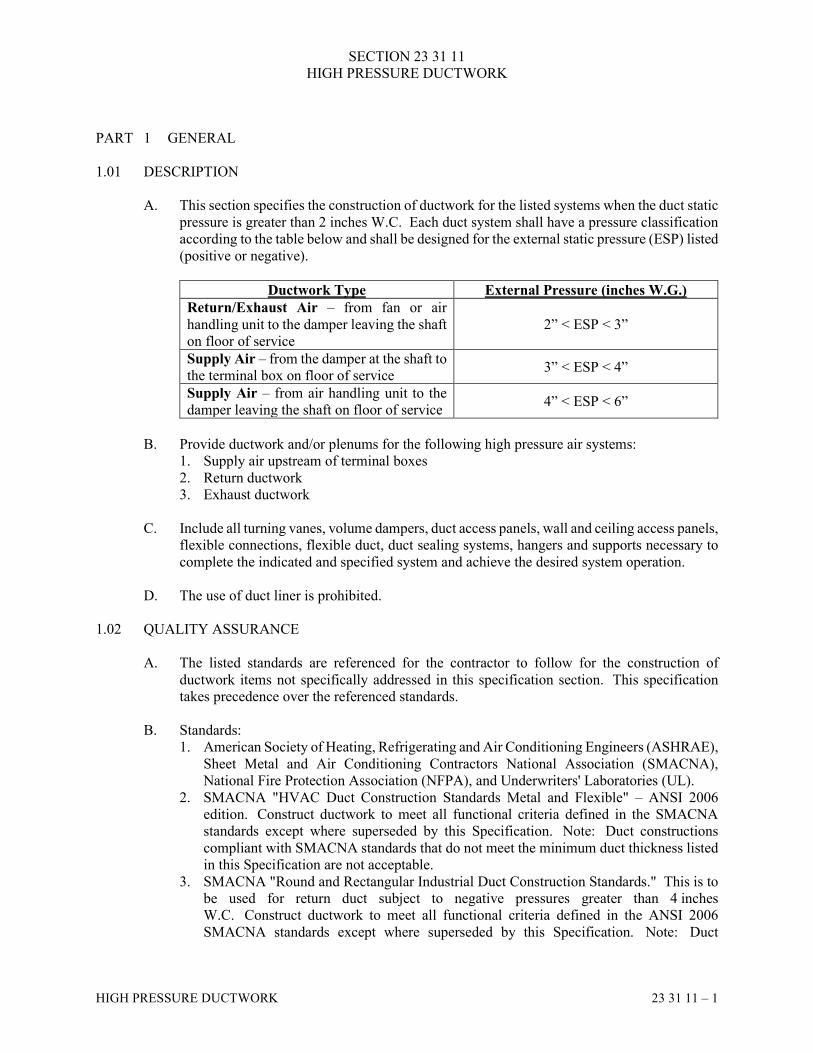
SECTION 23 31 11
HIGH PRESSURE DUCTWORK
HIGH PRESSURE DUCTWORK 23 31 11 – 1
PART 1 GENERAL
1.01 DESCRIPTION
A. This section specifies the construction of ductwork for the listed systems when the duct static
pressure is greater than 2 inches W.C. Each duct system shall have a pressure classification
according to the table below and shall be designed for the external static pressure (ESP) listed
(positive or negative).
Ductwork Type External Pressure (inches W.G.)
Return/Exhaust Air – from fan or air
handling unit to the damper leaving the shaft
on floor of service
2” < ESP < 3”
Supply Air – from the damper at the shaft to
the terminal box on floor of service 3” < ESP < 4”
Supply Air – from air handling unit to the
damper leaving the shaft on floor of service 4” < ESP < 6”
B. Provide ductwork and/or plenums for the following high pressure air systems:
1. Supply air upstream of terminal boxes
2. Return ductwork
3. Exhaust ductwork
C. Include all turning vanes, volume dampers, duct access panels, wall and ceiling access panels,
flexible connections, flexible duct, duct sealing systems, hangers and supports necessary to
complete the indicated and specified system and achieve the desired system operation.
D. The use of duct liner is prohibited.
1.02 QUALITY ASSURANCE
A. The listed standards are referenced for the contractor to follow for the construction of
ductwork items not specifically addressed in this specification section. This specification
takes precedence over the referenced standards.
B. Standards:
1. American Society of Heating, Refrigerating and Air Conditioning Engineers (ASHRAE),
Sheet Metal and Air Conditioning Contractors National Association (SMACNA),
National Fire Protection Association (NFPA), and Underwriters' Laboratories (UL).
2. SMACNA "HVAC Duct Construction Standards Metal and Flexible" – ANSI 2006
edition. Construct ductwork to meet all functional criteria defined in the SMACNA
standards except where superseded by this Specification. Note: Duct constructions
compliant with SMACNA standards that do not meet the minimum duct thickness listed
in this Specification are not acceptable.
3. SMACNA "Round and Rectangular Industrial Duct Construction Standards." This is to
be used for return duct subject to negative pressures greater than 4 inches
W.C. Construct ductwork to meet all functional criteria defined in the ANSI 2006
SMACNA standards except where superseded by this Specification. Note: Duct
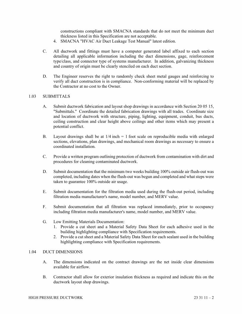
HIGH PRESSURE DUCTWORK 23 31 11 – 2
constructions compliant with SMACNA standards that do not meet the minimum duct
thickness listed in this Specification are not acceptable.
4. SMACNA "HVAC Air Duct Leakage Test Manual" latest edition.
C. All ductwork and fittings must have a computer generated label affixed to each section
detailing all applicable information including the duct dimensions, gage, reinforcement
type/class, and connector type of systems manufacturer. In addition, galvanizing thickness
and country of origin must be clearly stenciled on each duct section.
D. The Engineer reserves the right to randomly check sheet metal gauges and reinforcing to
verify all duct construction is in compliance. Non-conforming material will be replaced by
the Contractor at no cost to the Owner.
1.03 SUBMITTALS
A. Submit ductwork fabrication and layout shop drawings in accordance with Section 20 05 15,
"Submittals." Coordinate the detailed fabrication drawings with all trades. Coordinate size
and location of ductwork with structure, piping, lighting, equipment, conduit, bus ducts,
ceiling construction and clear height above ceilings and other items which may present a
potential conflict.
B. Layout drawings shall be at 1/4 inch = 1 foot scale on reproducible media with enlarged
sections, elevations, plan drawings, and mechanical room drawings as necessary to ensure a
coordinated installation.
C. Provide a written program outlining protection of ductwork from contamination with dirt and
procedures for cleaning contaminated ductwork.
D. Submit documentation that the minimum two weeks building 100% outside air flush-out was
completed, including dates when the flush-out was begun and completed and what steps were
taken to guarantee 100% outside air usage.
E. Submit documentation for the filtration media used during the flush-out period, including
filtration media manufacturer's name, model number, and MERV value.
F. Submit documentation that all filtration was replaced immediately, prior to occupancy
including filtration media manufacturer's name, model number, and MERV value.
G. Low Emitting Materials Documentation:
1. Provide a cut sheet and a Material Safety Data Sheet for each adhesive used in the
building highlighting compliance with Specification requirements.
2. Provide a cut sheet and a Material Safety Data Sheet for each sealant used in the building
highlighting compliance with Specification requirements.
1.04 DUCT DIMENSIONS
A. The dimensions indicated on the contract drawings are the net inside clear dimensions
available for airflow.
B. Contractor shall allow for exterior insulation thickness as required and indicate this on the
ductwork layout shop drawings.
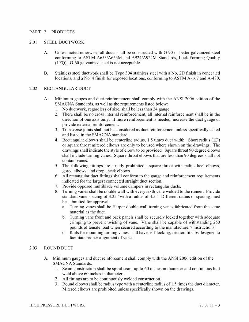
HIGH PRESSURE DUCTWORK 23 31 11 – 3
PART 2 PRODUCTS
2.01 STEEL DUCTWORK
A. Unless noted otherwise, all ducts shall be constructed with G-90 or better galvanized steel
conforming to ASTM A653/A653M and A924/A924M Standards, Lock-Forming Quality
(LFQ). G-60 galvanized steel is not acceptable.
B. Stainless steel ductwork shall be Type 304 stainless steel with a No. 2D finish in concealed
locations, and a No. 4 finish for exposed locations, conforming to ASTM A-167 and A-480.
2.02 RECTANGULAR DUCT
A. Minimum gauges and duct reinforcement shall comply with the ANSI 2006 edition of the
SMACNA Standards, as well as the requirements listed below:
1. No ductwork, regardless of size, shall be less than 24 gauge.
2. There shall be no cross internal reinforcement; all internal reinforcement shall be in the
direction of one axis only. If more reinforcement is needed, increase the duct gauge or
provide external reinforcement.
3. Transverse joints shall not be considered as duct reinforcement unless specifically stated
and listed in the SMACNA standard.
4. Rectangular elbows shall be centerline radius, 1.5 times duct width. Short radius (1D)
or square throat mitered elbows are only to be used where shown on the drawings. The
drawings shall indicate the style of elbow to be provided. Square throat 90 degree elbows
shall include turning vanes. Square throat elbows that are less than 90 degrees shall not
contain vanes.
5. The following fittings are strictly prohibited: square throat with radius heel elbows,
gored elbows, and drop cheek elbows.
6. All rectangular duct fittings shall conform to the gauge and reinforcement requirements
indicated for the largest connected straight duct section.
7. Provide opposed multiblade volume dampers in rectangular ducts.
8. Turning vanes shall be double wall with every sixth vane welded to the runner. Provide
standard vane spacing of 3.25” with a radius of 4.5”. Different radius or spacing must
be submitted for approval.
a. Turning vanes shall be Harper double wall turning vanes fabricated from the same
material as the duct.
b. Turning vane front and back panels shall be securely locked together with adequate
crimping to prevent twisting of vane. Vane shall be capable of withstanding 250
pounds of tensile load when secured according to the manufacturer's instructions.
c. Rails for mounting turning vanes shall have self-locking, friction fit tabs designed to
facilitate proper alignment of vanes.
2.03 ROUND DUCT
A. Minimum gauges and duct reinforcement shall comply with the ANSI 2006 edition of the
SMACNA Standards.
1. Seam construction shall be spiral seam up to 60 inches in diameter and continuous butt
weld above 60 inches in diameter.
2. All fittings are to be continuously welded construction.
3. Round elbows shall be radius type with a centerline radius of 1.5 times the duct diameter.
Mitered elbows are prohibited unless specifically shown on the drawings.
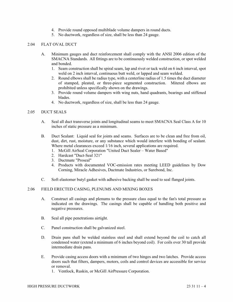
HIGH PRESSURE DUCTWORK 23 31 11 – 4
4. Provide round opposed multiblade volume dampers in round ducts.
5. No ductwork, regardless of size, shall be less than 24 gauge.
2.04 FLAT OVAL DUCT
A. Minimum gauges and duct reinforcement shall comply with the ANSI 2006 edition of the
SMACNA Standards. All fittings are to be continuously welded construction, or spot welded
and bonded.
1. Seam construction shall be spiral seam, lap and rivet or tack weld on 6 inch interval, spot
weld on 2 inch interval, continuous butt weld, or lapped and seam welded.
2. Round elbows shall be radius type, with a centerline radius of 1.5 times the duct diameter
of stamped, pleated, or three-piece segmented construction. Mitered elbows are
prohibited unless specifically shown on the drawings.
3. Provide round volume dampers with wing nuts, hand quadrants, bearings and stiffened
blades.
4. No ductwork, regardless of size, shall be less than 24 gauge.
2.05 DUCT SEALS
A. Seal all duct transverse joints and longitudinal seams to meet SMACNA Seal Class A for 10
inches of static pressure as a minimum.
B. Duct Sealant: Liquid seal for joints and seams. Surfaces are to be clean and free from oil,
dust, dirt, rust, moisture, or any substance which would interfere with bonding of sealant.
Where metal clearances exceed 1/16 inch, several applications are required.
1. McGill AirSeal Corporation "United Duct Sealer – Water Based"
2. Hardcast "Duct-Seal 321"
3. Ductmate "Proseal"
4. Products with documented VOC-emission rates meeting LEED guidelines by Dow
Corning, Miracle Adhesives, Ductmate Industries, or Surebond, Inc.
C. Soft elastomer butyl gasket with adhesive backing shall be used to seal flanged joints.
2.06 FIELD ERECTED CASING, PLENUMS AND MIXING BOXES
A. Construct all casings and plenums to the pressure class equal to the fan's total pressure as
indicated on the drawings. The casings shall be capable of handling both positive and
negative pressures.
B. Seal all pipe penetrations airtight.
C. Panel construction shall be galvanized steel.
D. Drain pans shall be welded stainless steel and shall extend beyond the coil to catch all
condensed water (extend a minimum of 6 inches beyond coil). For coils over 30 tall provide
intermediate drain pans.
E. Provide casing access doors with a minimum of two hinges and two latches. Provide access
doors such that filters, dampers, motors, coils and control devices are accessible for service
or removal.
1. Ventlock, Ruskin, or McGill AirPressure Corporation.
HIGH PRESSURE DUCTWORK 23 31 11 – 5
F. Seal all joints, seams, duct wall penetrations, and in accordance with SMACNA Seal Class
A for 10 inches of static pressure as a minimum. Provide gasketing on all doors and access
panels.
G. Insulate all casings, plenums, and mixing boxes.
2.07 FLEXIBLE DUCTWORK
A. 5 feet is the maximum allowable length for connection to supply terminal boxes and
laboratory air control supply terminals.
B. All flexible duct shall be UL-listed for use as flexible air ducts and rated for 10 inches W.C.
positive pressure and 2 inches negative pressure for sizes through 16 inches diameter, from -
20 degrees F to +250 degrees F. The flame spread rating shall not exceed 25 and the smoke
developed rating shall not exceed 50.
C. Concealed and Unconditioned Spaces: Flexible ductwork shall be composed of an aluminum
and fiberglass or heavy duty polyester and fiberglass core with a steel wire helix, a fiberglass
insulating blanket (R6.0), and metalized outer vapor barrier. Flexmaster 5M or Thermaflex
M-KC.
D. Exposed Spaces: Flexible ductwork shall be composed of an uninsulated heavy fiberglass
cloth fabric with a steel wire helix. Flexmaster 4NI or Thermaflex S-TL.
E. Each flexible duct section shall be supported by a minimum of two (2) duct supports and
shall not sag more than 1/2 inch per linear foot of duct.
2.08 FLEXIBLE CONNECTIONS
A. Flexible duct connector shall be used where ductwork connects to fans of apparatus, or
apparatus casing to fans to isolate vibration transfer. Connectors shall be attached in such a
manner as to provide an airtight and waterproof seal. Connectors will comply with NFPA
90A, "Installation of Air Conditioning & Ventilation Systems" and NFPA 90B, "Installation
of Warm Air Heating & Air Conditioning Systems."
B. Indoor installations shall be of a UL 214 listed, fire retardant Vinyl coated woven nylon or
Neoprene coated woven fiberglass fabric. Minimum density of Vinyl is 20 ounces per square
yard and rated to 200 degrees F. Minimum density of Neoprene is 30 ounces per square yard
and rated to 200 degrees F.
C. Outdoor installations shall be of a UL 214 listed UV-resistant Hypalon coated woven-
fiberglass fabric. Minimum density is 24 ounces per square yard and rated to 250 degrees F.
2.09 BLANK-OFF PANELS
A. Provide 16 gauge, steel or aluminum, double skinned insulating blank-off panels behind
louvers as indicated on the drawings. Material shall match louver material. Panel finish and
color to match louver. Seal panel joints airtight. Provide panels with a minimum R-value of
6.
HIGH PRESSURE DUCTWORK 23 31 11 – 6
2.10 EXPOSED DUCTWORK
A. All ductwork exposed in conditioned spaces shall be provided with a paint-grip galvanized
finish or similar mill surface etch treatment for painting. Prime with Glidden #5229.
B. Provide tapered wedge (ramp) joint or gasketed fittings on round ducts.
C. Take special care in applying duct sealants. Apply sealants at joints only in a neat and
workman-like manner.
PART 3 EXECUTION
3.01 INSTALLATION
A. All duct installations and duct construction shall comply with all requirements of this
specification and meet or exceed SMACNA standards and recommendations for construction
and installation.
B. Provide sweep elbows at all changes of direction in supply and return ductwork. If mitered
elbows must be used due to coordination, provide turning vanes in 90 degree elbows only.
C. Seal all duct seams, joints, connections, and duct wall penetrations.
D. Provide a minimum 6 inch flexible connection where ductwork connects to motor drive
equipment. Do not bulge or install on a bind.
E. Provide duct access doors at all fire dampers, smoke dampers, combination fire/smoke
dampers, and motor-operated control dampers. Provide ceiling access panel in drywall or
other inaccessible ceiling systems such that all such dampers are serviceable.
F. Keep ductwork tight to underside of structure. Maintain at least 7 inches clear between duct
and ceiling construction.
G. Install all dampers and provide blank-off plate to seal frames airtight.
H. Provide volume dampers as needed to balance system to airflow indicated on the drawings.
Provide volume dampers at all high velocity duct connections to shafts. Locate dampers in
accessible locations.
I. Metallic flexible duct shall be attached with at least three (3) #8 sheet metal screws equally
spaced around duct circumference, and five (5) #8 screws for ducts over 12 inches in
diameter. Locate screws at least 1/2 inch from duct end.
J. Non-Metallic flexible ducts shall be secured with a draw band. On ducts over 12 inches in
diameter, position draw band behind a bead in the metal collar.
K. Secure all insulation and vapor barriers on factory-fabricated flexible ducts with a separate
draw band, independent of any used for the connection of the flexible duct to the duct collar.
HIGH PRESSURE DUCTWORK 23 31 11 – 7
L. Provide duct access doors at all duct smoke detector locations. Coordinate locations with the
Electrical Contractor.
M. Galvanizing Repairs – Repair galvanizing damaged by welding, scratches, etc., using cold
galvanizing compound.
N. Branch taps off of elbows are prohibited.
3.02 TESTING
A. Test Requirements:
1. Installed ductwork shall be tested prior to installation of access doors, take-offs, etc.
2. The Contractor shall give the Architect, Engineer, and Owner 72 hours notice prior to
testing.
3. Any testing conducted without prior notification shall be considered invalid and will be
redone at the Contractor's expense.
4. Leak-test all ductwork. Air leakage in any tested section of ductwork shall not exceed
that of SMACNA Leakage Class 6 for rectangular duct and Leakage Class 3 for round
duct.
B. Recommended Test Procedure: Perform testing in accordance with SMACNA HVAC Air
Duct Leakage Test Manual and as follows below. Note that this reference establishes
procedures only; and the allowable leakage rates are found in these Specifications.
1. Use a certified orifice tube and its corresponding logarithmic chart for measuring the
leakage. Supply fan must have a CFM capacity greater than the allowable leakage in
CFM for the section being tested.
2. Define section of system to be tested and blank off.
3. Determine the percentage of the system being tested, on a square foot of surface area
basis.
4. Using the percentage determined in Step "3" and the maximum allowable leakage of 2%
of the total system volume, determine the allowable leakage (cfm) for the section being
tested.
5. Pressurize to 100% of the duct pressure class design pressure and repair any significant
or audible leaks.
6. Pressurize again and measure leakage.
7. Repeat Steps "5" and "6" until the leakage measured is less than the allowable defined in
Step "4."
C. Document all duct testing and submit testing results as part of "As-Built" documents. Furnish
copies of all completed duct testing documentation upon request of the Architect, Engineer,
or Owner.
3.03 DUCT CLEAN OUT
A. Clean and blow out complete duct system before any connections to equipment are
made. Inspect ductwork for debris before starting any fans.
B. Interior surfaces shall be free of dust and debris prior to initial start up. Protect equipment
which may be harmed by excessive dirt with filters, or bypass during cleaning.
HIGH PRESSURE DUCTWORK 23 31 11 – 8
C. When internally cleaning duct work prior to installation or shipment to the jobsite, cover all
duct ends and openings with a dual polyethylene protective film. Securely affix the film to
protect against dirt and debris. Film must be translucent to facilitate inspection of interior
surfaces without removing film. Film must have a minimum elongation of 600%, contain no
VOC and leave no residue on duct after removal. Ductmate Industries "ProGuard" or
approved equal.
D. The working area for duct installation shall be clean and dry. Protective coverings shall only
be removed immediately before installation.
E. Clean external surfaces of foreign substances that might cause corrosion, deterioration of the
metal, or where ductwork is to be painted.
3.04 LEED / CLEANLINESS REQUIREMENTS
A. Construction Indoor Air Quality:
1. Follow control measures of SMACNA IAQ Guidelines for Occupied Buildings Under
Construction, Chapter 3, latest edition and as described below.
2. Protect stored on-site or installed absorptive materials from moisture damage.
3. After fabrication in the shop, wipe down interior of each piece of supply air and return
air ductwork with a lint-free rag, using a solution of 30% isopropyl alcohol and 70%
water.
4. Cap/seal supply, return, and exhaust air duct openings immediately after fabrication or
cleaning. Schedule deliveries to the job site to match installation to avoid excessive
storage at the job site. Store ductwork at the job site in closed trailers or in the immediate
area in which it will be installed. Any ducts at the site that have any opening seals
perforated are to be re-cleaned per shop cleaning requirements and re-sealed until needed
for installation. Maintain caps/seals on all openings of installed ducts. If openings of
installed ducts have their seals perforated, re-clean contaminated duct sections per shop
cleaning requirements.
5. Demonstrate the cleanliness quality control to the Construction Manager.
END OF SECTION
SECTION 23 33 13
DAMPERS
DAMPERS 23 33 13 – 1
PART 1 GENERAL
1.01 DESCRIPTION
A. Provide all dampers for adjusting and modulating airflow. See floor plans, schedules and
details for required equipment for all specific situations.
B. Scope of work includes the installation of all motor-operated control dampers, including
those that may be furnished by the Temperature Control Contractor.
1.02 QUALITY ASSURANCE
A. Standards: AMCA Standard 500 Certified Performance.
1.03 MANUFACTURERS
A. Ruskin, Greenheck, Louvers and Dampers, Arrow/United, Vent Products, or American
Warming and Ventilating.
PART 2 PRODUCTS
2.01 COUNTERBALANCED BACKDRAFT DAMPERS
A. Steel frame, extruded aluminum blades with vinyl edge seal, 1/2 inch axle, dustproof ball
bearings, adjustable counter-balance weights, weather-resistant construction.
2.02 CONTROL DAMPERS
A. Rectangular Balancing Dampers:
1. Galvanized steel blades, 6 inches wide, 6 inches O.C., 16 gauge, 1/2 inch hex. steel axles,
extended 1/2 inch O.D. control shaft. Opposed blade operation, concealed linkage,
TFE-filled bearings.
B. Round Balancing Dampers:
1. Galvanized steel blades, 18 inches and less - 12 gauge; above 18 inches - 10 gauge, with
neoprene blade seal. Plated steel axle, extended control shaft.
C. Manual balancing dampers for rectangular ducts 12 inches and smaller:
1. Galvanized steel blades, 5 inches wide, 16 gauge. 3/8 inch square control shaft, opposed
blade damper operation, concealed linkage, TFE-filled bearings.
2.03 PRESSURE RELIEF DAMPERS
A. Steel frame, counter-balanced, 16 gauge aluminum blades, ball bearings, 1/2 inch O.D. steel
axles 9 inches O.C., interconnecting linkage, adjustable weights, factory set relief pressure,
horizontal or vertical mounting.
1. American Warming Type DAA-P-494.
DAMPERS 23 33 13 – 2
2.04 HIGH VELOCITY CONTROL DAMPERS
A. Round, low leakage, butterfly, 18 gauge steel frame, two layer single steel blade, neoprene
seal, 1/2 inch O.D. axle, stainless steel sleeve bearings, extended control shaft, rolled stiffener
beads to seal with round spiral ductwork.
1. Ruskin Type CDRS-25.
2.05 INLET VANE DAMPER
A. Round, 10 gauge steel frames, radial 16 gauge steel blades, open hub, 1/2 inch O.D. steel
axle, stainless steel sleeve bearings, mounting frame. Vane shall be internally mounted.
1. Ruskin Type IVD.
PART 3 EXECUTION
3.01 INSTALLATION
A. Install all dampers in ductwork and provide access to adjustments as required.
B. Coordinate the selection and installation of all motor-operated control dampers, including
those that may be furnished by the Temperature Control Contractor.
3.02 CONTROLS
A. See Section 23 09 23, "Temperature Control" for control requirements.
B. Provide motor-operated dampers as required to execute the provisions described in Section
23 09 93, "Sequences of Operation."
END OF SECTION
SECTION 23 33 15
FIRE DAMPERS
FIRE DAMPERS 23 33 15 – 1
PART 1 GENERAL
1.01 DESCRIPTION
A. Provide fire dampers at all duct penetrations through fire rated walls.
1.02 QUALITY ASSURANCE
A. Standards:
1. SMACNA Publication "Fire Damper Guide."
2. UL Standard 555 - Standard for Fire Dampers.
3. UL Standard 555C - Standard for Ceiling Dampers.
4. NFPA 90A
5. SMACNA Publication "HVAC Duct Construction Standards."
1.03 MANUFACTURERS
A. Ruskin, Vent Products, American Warming and Ventilating, Pottorff, or Prefco.
PART 2 PRODUCTS
2.01 CURTAIN TYPE FIRE DAMPERS
A. Construction: Curtain type, positive spring closure, with blades out of air stream, galvanized
steel channel frame, interlocking galvanized steel blades, factory-furnished steel sleeve, UL
listed 212 degrees F fusible link, 1 1/2 hour fire protection rating, vertical or horizontal
mounting, factory-furnished retaining angles, and mounting hardware. Steel sleeve shall be
equal to or thicker than the ductwork it is connecting to, and at least the manufacturer's
recommended thickness, but in no case less than 18 gauges. All fire dampers shall be UL
classified and labeled for assured closure.
B. Provide flexible metal jamb seals for lowest leakage.
[C. Provide fire dampers specifically labeled for use in dynamic applications when shown in the
following systems:
1. Air Handler AH1
2. Air Handler AH2]
2.02 CEILING FIRE DAMPERS
A. Ceiling Diffuser: 16 gauge galvanized steel frame, 22 gauge galvanized steel blades with 1/2
inch UL classified insulation and volume adjustment and diffuser radiation shield.
B. Ceiling Register: 16 gauge galvanized steel frame, 22 gauge galvanized steel blades with 1/2
inch UL classified insulation and volume adjustment. Damper to be full neck and size.
FIRE DAMPERS 23 33 15 – 2
PART 3 EXECUTION
3.01 INSTALLATION
A. HVAC Contractor shall coordinate the selection of damper with the fire resistance rating of
the structure being penetrated.
B. Install fire dampers in locations where they can be readily inspected, serviced, adjusted and
maintained.
C. Install transitions where required to match duct size to damper dimensions.
D. Coordinate installation of access panels. Install access doors in ductwork at each fire damper.
Locate access doors to provide access to damper actuator/fusible link. Provide multiple doors
if required. Label locations of all access doors.
E. Install mounting angles and duct sleeves. Bolt, screw or tack weld fire damper enclosure to
sleeve.
F. Label locations of access door and ceilings per building code.
G. Firestop all wall penetrations at all fire dampers per damper manufacturer's written
instructions. Use only firestop materials that are compatible with damper construction and
operation.
H. Maintain a current, legible copy of the damper manufacturer's installation instructions at the
Project site for all fire dampers being used on the Project. Make installation instructions
available on request for all inspecting authorities.
3.02 INSPECTION
A. At final acceptance inspection, approximately 10% of all fire dampers, as randomly selected
by the Owner or Engineer, must be demonstrated by the Contractor to be accessible, in proper
position, and in operational order. Failure of any one of the demonstrated dampers shall
require the Contractor to check and demonstrate operation and accessibility to all dampers,
and take corrective measures at no cost.
3.03 CERTIFICATION
A. Certify in writing that all fire dampers were checked by operation at installation and that all
are in proper position and functional order.
END OF SECTION
SECTION 23 36 05
TERMINAL BOXES - DDC CONTROL
TERMINAL BOXES - DDC CONTROL 23 36 05 – 1
PART 1 GENERAL
1.01 DESCRIPTION
A. Provide high velocity terminal boxes and fan powered terminal boxes, complete with direct
digitally controlled velocity controller, electric actuator, and velocity pressure pickup device.
Provide reheat coils and fans as scheduled on Drawings and specified herein.
B. Terminal boxes and fan power boxes shall be pressure independent, and suitable for either
constant volume or variable volume service as indicated on the Drawings.
C. All terminal box controls, whether factory or field installed, shall be fully compatible with
and communicate seamlessly with the building's temperature control or building automation
system described in Section 23 09 23, "Temperature Control."
1.02 QUALITY ASSURANCE
A. Standards: American Refrigeration Institute (ARI), National Fire Protection Association
(NFPA), and Underwriters' Laboratories (UL).
B. AH RI-880: Performance rating.
1.03 RATINGS AND CAPACITIES
A. Refer to the Drawings for CFM, noise criteria and other design requirements.
1.04 MANUFACTURERS
A. Titus, Anemostat, Trane, Price, Krueger, Tuttle and Bailey.
PART 2 PRODUCTS
2.01 TERMINAL BOXES
A. General Construction:
1. Galvanized steel, 22 gauge minimum, plenum box with 3/8 inch thick, 1.5 lb. density,
fiber-free acoustical thermal lining in accordance with UL 181 and NFPA 90A.
Fiberglass lining is not acceptable. Casing leakage shall be less than 9 CFM at 1 inch
W.G.
2. Components such as inlet dampers, reheat coils, and velocity pickups, shall be furnished
and factory-mounted by the terminal box manufacturer. The BAS contractor shall
furnish the controller and actuator for factory mounting by the terminal box
manufacturer. The thermostat shall be provided by the BAS contractor.
B. Inlet Dampers: Self-seating against a closed cell foam gasket, pivoted on self-lubricating
Delrin bearings, mounted directly to the inlet port, and positively connected to an electric
operator. Damper leakage not to exceed 8 CFM at 6 inches W.G. in fully closed position.
TERMINAL BOXES - DDC CONTROL 23 36 05 – 2
C. Controls:
1. Each VAV terminal shall include application specific controls with integral
microelectronic flow sensors mounted within a NEMA 1 enclosure. The controllers shall
have been connected by suitable tubing to an inlet velocity sensor mounted in the inlet
to the terminal.
2. Each VAV terminal shall be powered by 24Vac power that is provided to the terminal
box by the BAS contractor.
3. Each controller shall control zone temperature by varying the airflow into the space using
a PI control loop with programmable proportional and integral coefficients. Applications
requiring supplemental heat shall utilize a separate PI algorithm, with programmable
proportional and integral coefficients to maintain heating temperature setpoint.
4. The controllers shall modulate the damper motors to maintain CFM from each terminal
in accordance with the cooling/heating requirements calculated by comparing the sensed
space temperature with the setpoint and time of day schedule. Zone temperature shall be
controlled to +1 degree F. Airflow shall be controlled down to 250 fpm, and shall be
read in 25 fpm increments at velocities greater than 500 fpm.
5. Each controller shall have an internal software clock to implement setpoint changes and
changes of control state, in accordance with the resident occupancy. The clocks will be
synchronized hourly and automatically following power failures, by a battery backed
real-time clock located in the system interface.
D. Damper Operator: Supply suitable bi-directional, 24 volt, synchronous electric damper
actuators. The motors shall have heavy duty gears and shall contain a magnetic clutch that
releases when the damper is driven to either extreme. Stall type actuators or DC actuators
without current limiting are not acceptable. The operator shall be sized to accurately and
smoothly operate the damper through the expected CFM range of the terminal, against a duct
static pressure ranging up to the largest external static pressure scheduled on the Drawings.
E. Sound Attenuator Section: 22 gauge, galvanized steel with insulation lining to match the
terminal box lining, 3 foot length minimum (unless noted otherwise on Drawings).
F. Velocity Pickup: Ring or cross-shaped, multi-point center averaging type velocity pressure
pickup shall be provided by Box Manufacturer. Velocity pickup shall amplify the duct
velocity pressure, and maintain control accuracy with inlet ducts in any configuration. Single
point or a single inline multiple point velocity pickups will not be accepted.
G. Hot Water Coil:
1. Galvanized steel casing, flanged duct connection at unit discharge, 1/2 inch diameter
copper tubes, aluminum fins, solder connections, one or two row serpentine coil (refer
to scheduled data on Drawings for performance requirements and required number of
rows). All coils shall be factory installed.
2. Insulate the entire exposed perimeter of hot water coil.
3. The hot water control valve and operator, compatible with terminal box controls shall be
provided by the BAS contractor
PART 3 EXECUTION
3.01 INSTALLATION
A. Support boxes independent of ceiling system. Coordinate with General Trades Contractor.
TERMINAL BOXES - DDC CONTROL 23 36 05 – 3
B. Provide access as required for maintenance and repair. All boxes located above the ceiling
shall be end discharge unless otherwise noted. All boxes shall deliver the air quantities
shown on the Drawings at acceptable sound levels.
C. Make flexible duct and flexible connections at box duct connections. Provide a transition
from the full size of each terminal outlet to the discharge ductwork shown on Drawings.
Transition shall be tapered with a 60 degree maximum included angle.
D. Coordinate installation of controls.
E. Install hot water piping, valves and specialties.
END OF SECTION
SECTION 23 37 13
GRILLES, REGISTERS, AND DIFFUSERS
GRILLES, REGISTERS, AND DIFFUSERS 23 37 13 – 1
PART 1 GENERAL
1.01 DESCRIPTION
A. Provide grilles, registers, and diffusers as indicated on the Drawings.
1.02 QUALITY ASSURANCE
A. Standards: Air Diffusion Council (ADC).
1.03 RATINGS AND CAPACITIES
A. Refer to Drawings for air device construction, CFM, Noise Criteria, throw, pattern, finish,
and accessories.
1.04 MANUFACTURERS
A. Anemostat, Titus, Tuttle & Bailey, Krueger, and Price.
1.05 SUBMITTALS
A. Provide noise criteria to meet that shown on the Drawing Schedules.
PART 2 PRODUCTS
2.01 GRILLES, REGISTERS, AND DIFFUSERS
A. General Construction:
1. Steel or aluminum, factory-fabricated to evenly distribute design CFM throughout the
space without causing noticeable drafts.
2. Provide all diffusers and registers with a volume controller device complete with an
accessible operator unless otherwise indicated.
3. Diffusers shall be round, linear, or square with adjustable air discharge pattern unless
otherwise indicated.
4. Square ceiling diffusers (for variable volume systems) shall have internal Coanda
pockets with a 360 degree isovel pattern enabling them to maintain a nonsmudging
horizontal pattern at various air volumes with or without a ceiling.
5. Grilles shall be same construction as registers without volume-control damper.
6. All diffusers, registers, grilles, and mounting frames shall be furnished with factory finish
as scheduled.
7. Provide concealed fastener mounting on all surface mount registers.
8. Unless noted otherwise, provide a mounting frame for all air devices mounted in a
drywall or plaster ceiling, Mounting frame shall be factory-fabricated by the same
manufacturer as the air device being mounted, and shall match air device in material of
construction, color, and finish. Permanently secure mounting frame in ceiling
construction, and install "lay-in" type air device within mounting frame with flexible
ductwork to permit future access above ceiling assembly.
GRILLES, REGISTERS, AND DIFFUSERS 23 37 13 – 2
2.02 SECURITY GRILLES, REGISTERS, AND DIFFUSERS
A. When security grilles, registers, and diffusers are specified, products specifically designed
for use in prison and jail facilities are to be provided.
B. Products are to be of welded construction, cold rolled steel exposed parts, with 10 gauge x
1/4 mesh screen welded to frame behind the face.
C. When volume adjustment is specified, the damper and adjustment mechanism are to be
inaccessible to the room occupant.
D. Manufacturers: Titus, Anemostat, Krueger, Kees, Custom Industries, R&L, or Van Packer.
2.03 VANDAL RESISTANT GRILLES, REGISTERS, AND DIFFUSERS
A. When vandal resistant grilles, registers and diffusers are specified, the standard grilles,
registers, and diffusers called for on the Drawings are to be provided with vandal-proof
fasteners.
2.04 EQUALIZING DEFLECTORS
A. Steel bladed assembly, flat black finish.
2.05 COMBINATION VOLUME CONTROLLER/EQUALIZING DEFLECTOR
A. Steel butterfly damper and steel bladed equalizing deflector assembly, flat black finish.
2.06 VOLUME CONTROLLER
A. Steel radial blades with flat black finish for round neck square diffusers.
B. Steel opposed blades with flat black finish for registers and square neck diffusers.
2.07 INTEGRAL EXTRACTORS AND BALANCING DAMPERS
A. Steel frame and parallel diverting blades, angle bracket, pivot bearing assembly, worm gear
operator and control shaft.
1. Anemostat, Tuttle and Bailey or Titus.
2.08 LIGHT TROFFER DIFFUSERS
A. Zinc coated steel, single, or double-sided with crossover duct, 1/2 inch thick internal
insulation, round or flat oval inlets, built-in volume, and pattern controllers with concealed
operator.
B. Diffusers must be physically compatible with light fixtures installed on this project.
2.09 LINEAR DEVICES
A. Heavy gauge extruded aluminum, satin finish, concealed fasteners, removable cores, built-in
volume, and pattern controllers, concealed alignment pins.
GRILLES, REGISTERS, AND DIFFUSERS 23 37 13 – 3
B. Provide factory-fabricated and factory-insulated steel plenums for all active sections of linear
supply diffusers that are 5 feet long or less. Use multiple sections of factory-fabricated and
insulated supply plenums for longer active sections.
C. Provide factory-fabricated steel plenums for all active sections of linear return air devices 5
feet long or less.
D. Provide factory-fabricated end caps for all lay-in linear devices and factory-fabricated end
border pieces for all surface mount linear devices.
E. Provide factory-fabricated mitered corners sections as required.
F. Provide non-specular flat black steel blank-offs behind all unused portions of linear air
devices.
PART 3 EXECUTION
3.01 INSTALLATION
A. Square diffusers supplied by flexible ducts shall be installed with volume damper and
equalizing grid in the diffuser neck.
B. Surface mounted registers shall be provided with sponge-rubber gasket between flanges and
wall or ceiling.
C. Wall supply registers shall be installed at least 6 inches below the ceiling, unless otherwise
indicated.
D. Provide additional support hangers for diffusers, grilles, or registers mounted in lay-in ceiling
tiles.
E. Insure airtight seal at all connections.
F. Paint inside portions of all ductwork or plenums that are visible behind registers or grilles,
with non-specular flat black enamel.
3.02 LINEAR DIFFUSER PATTERN ADJUSTMENTS
A. Adjust slots in linear diffusers for proper airflow without objectionable drafts.
B. Adjust slots in linear supply diffusers located adjacent to exterior glazing to direct half of air
down along window and other half toward interior.
C. Adjust slots in linear supply diffusers not located near windows for horizontal airflow.
D. Adjust slots in corridors for vertical projection.
END OF SECTION
SECTION 23 41 05
FILTERS
FILTERS 23 41 05 – 1
PART 1 GENERAL
1.01 DESCRIPTION
A. Provide filters as shown on the Drawings. Refer to Schedules for type, size, efficiency, and
other design requirements.
B. Filters shall have a minimum efficiency MERV-A value when evaluated under the guidelines
of ASHRAE Standard 52.2, including Appendix J of the same Standard.
1.02 QUALITY ASSURANCE
A. Standards:
1. ASHRAE 52.2
2. MIL-STD-282
3. UL 900
PART 2 PRODUCTS
2.01 MANUFACTURERS
A. Camfil or American Air Filter.
2.02 DISPOSABLE RIGID FILTERS – PLEATED PANEL
A. Filter shall be high-efficiency, high lofted supported glass fiber media in enclosing frame.
Filter media shall have reinforced backing, welded wire support grid for tapered radial pleats.
Media shall be bonded to frame to prevent air bypass.
B. MERV 8A: Filter shall be 4 or 2 inches deep, UL Class 2 and have MERV-A rating of 8A
and a 30-35% average dust spot efficiency when tested to ASHRAE Standards. Initial
resistance shall be rated at 0.27 inches W.C at 500 FPM face velocity for a 4 inch deep filter
and 0.31” for a 2 inch filter.
1. Camfil 30/30.
C. MERV 9A: Filter shall be 4 or 2 inches deep, UL Class 2 and have MERV-A rating of 9A
and a 40-45% average dust spot efficiency when tested to ASHRAE Standards. Initial
resistance shall be rated at 0.27 inches W.C at 500 FPM face velocity for a 4 inch deep filter
and 0.30” for a 2 inch filter.
1. Camfil 30/30 Dual 9.
D. MERV 9A: Filter shall be 12 inches deep, UL Class 2 and have MERV-A rating of 9A and
a 40-45% average dust spot efficiency when tested to ASHRAE Standards. Initial resistance
shall be rated at 0.20 inches W.C at 500 FPM face velocity.
1. Camfil Farr Riga-Flo XL.
E. MERV 11A, 13A or 14A: Filter shall be 4 inches deep, UL Class 2, box style filters
consisting of mini-pleated wet laid fine fiber media. Filter media shall be of one continuous
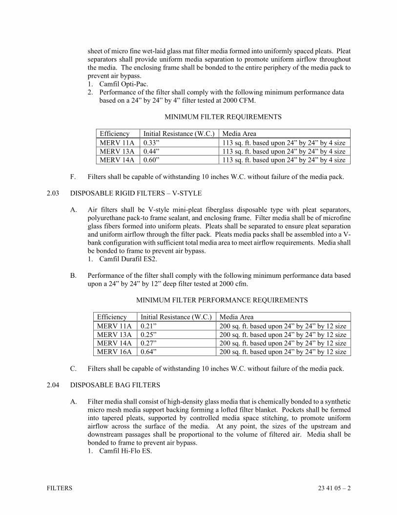
FILTERS 23 41 05 – 2
sheet of micro fine wet-laid glass mat filter media formed into uniformly spaced pleats. Pleat
separators shall provide uniform media separation to promote uniform airflow throughout
the media. The enclosing frame shall be bonded to the entire periphery of the media pack to
prevent air bypass.
1. Camfil Opti-Pac.
2. Performance of the filter shall comply with the following minimum performance data
based on a 24” by 24” by 4” filter tested at 2000 CFM.
MINIMUM FILTER REQUIREMENTS
Efficiency Initial Resistance (W.C.) Media Area
MERV 11A 0.33” 113 sq. ft. based upon 24” by 24” by 4 size
MERV 13A 0.44” 113 sq. ft. based upon 24” by 24” by 4 size
MERV 14A 0.60” 113 sq. ft. based upon 24” by 24” by 4 size
F. Filters shall be capable of withstanding 10 inches W.C. without failure of the media pack.
2.03 DISPOSABLE RIGID FILTERS – V-STYLE
A. Air filters shall be V-style mini-pleat fiberglass disposable type with pleat separators,
polyurethane pack-to frame sealant, and enclosing frame. Filter media shall be of microfine
glass fibers formed into uniform pleats. Pleats shall be separated to ensure pleat separation
and uniform airflow through the filter pack. Pleats media packs shall be assembled into a V-
bank configuration with sufficient total media area to meet airflow requirements. Media shall
be bonded to frame to prevent air bypass.
1. Camfil Durafil ES2.
B. Performance of the filter shall comply with the following minimum performance data based
upon a 24” by 24” by 12” deep filter tested at 2000 cfm.
MINIMUM FILTER PERFORMANCE REQUIREMENTS
Efficiency Initial Resistance (W.C.) Media Area
MERV 11A 0.21” 200 sq. ft. based upon 24” by 24” by 12 size
MERV 13A 0.25” 200 sq. ft. based upon 24” by 24” by 12 size
MERV 14A 0.27” 200 sq. ft. based upon 24” by 24” by 12 size
MERV 16A 0.64” 200 sq. ft. based upon 24” by 24” by 12 size
C. Filters shall be capable of withstanding 10 inches W.C. without failure of the media pack.
2.04 DISPOSABLE BAG FILTERS
A. Filter media shall consist of high-density glass media that is chemically bonded to a synthetic
micro mesh media support backing forming a lofted filter blanket. Pockets shall be formed
into tapered pleats, supported by controlled media space stitching, to promote uniform
airflow across the surface of the media. At any point, the sizes of the upstream and
downstream passages shall be proportional to the volume of filtered air. Media shall be
bonded to frame to prevent air bypass.
1. Camfil Hi-Flo ES.
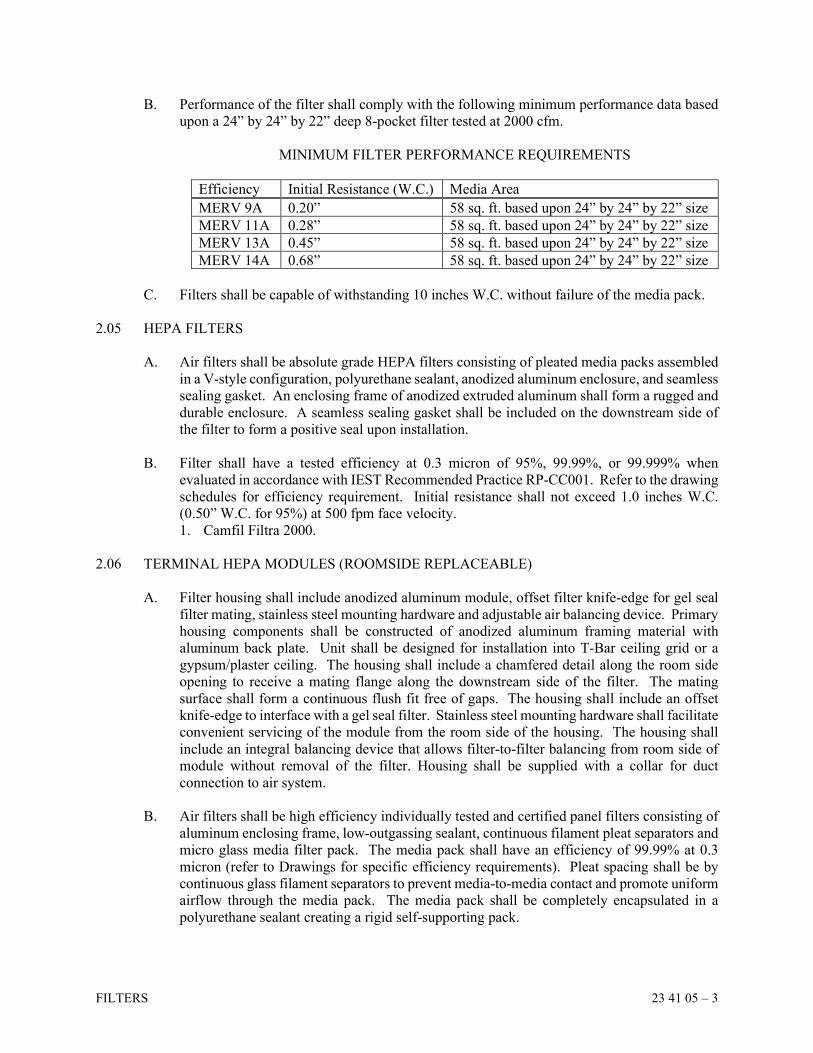
FILTERS 23 41 05 – 3
B. Performance of the filter shall comply with the following minimum performance data based
upon a 24” by 24” by 22” deep 8-pocket filter tested at 2000 cfm.
MINIMUM FILTER PERFORMANCE REQUIREMENTS
Efficiency Initial Resistance (W.C.) Media Area
MERV 9A 0.20” 58 sq. ft. based upon 24” by 24” by 22” size
MERV 11A 0.28” 58 sq. ft. based upon 24” by 24” by 22” size
MERV 13A 0.45” 58 sq. ft. based upon 24” by 24” by 22” size
MERV 14A 0.68” 58 sq. ft. based upon 24” by 24” by 22” size
C. Filters shall be capable of withstanding 10 inches W.C. without failure of the media pack.
2.05 HEPA FILTERS
A. Air filters shall be absolute grade HEPA filters consisting of pleated media packs assembled
in a V-style configuration, polyurethane sealant, anodized aluminum enclosure, and seamless
sealing gasket. An enclosing frame of anodized extruded aluminum shall form a rugged and
durable enclosure. A seamless sealing gasket shall be included on the downstream side of
the filter to form a positive seal upon installation.
B. Filter shall have a tested efficiency at 0.3 micron of 95%, 99.99%, or 99.999% when
evaluated in accordance with IEST Recommended Practice RP-CC001. Refer to the drawing
schedules for efficiency requirement. Initial resistance shall not exceed 1.0 inches W.C.
(0.50” W.C. for 95%) at 500 fpm face velocity.
1. Camfil Filtra 2000.
2.06 TERMINAL HEPA MODULES (ROOMSIDE REPLACEABLE)
A. Filter housing shall include anodized aluminum module, offset filter knife-edge for gel seal
filter mating, stainless steel mounting hardware and adjustable air balancing device. Primary
housing components shall be constructed of anodized aluminum framing material with
aluminum back plate. Unit shall be designed for installation into T-Bar ceiling grid or a
gypsum/plaster ceiling. The housing shall include a chamfered detail along the room side
opening to receive a mating flange along the downstream side of the filter. The mating
surface shall form a continuous flush fit free of gaps. The housing shall include an offset
knife-edge to interface with a gel seal filter. Stainless steel mounting hardware shall facilitate
convenient servicing of the module from the room side of the housing. The housing shall
include an integral balancing device that allows filter-to-filter balancing from room side of
module without removal of the filter. Housing shall be supplied with a collar for duct
connection to air system.
B. Air filters shall be high efficiency individually tested and certified panel filters consisting of
aluminum enclosing frame, low-outgassing sealant, continuous filament pleat separators and
micro glass media filter pack. The media pack shall have an efficiency of 99.99% at 0.3
micron (refer to Drawings for specific efficiency requirements). Pleat spacing shall be by
continuous glass filament separators to prevent media-to-media contact and promote uniform
airflow through the media pack. The media pack shall be completely encapsulated in a
polyurethane sealant creating a rigid self-supporting pack.
FILTERS 23 41 05 – 4
C. Acceptable Manufacturers: Camfil Slimline RSR and Camfil Megalam filter, or Price LFDC.
2.07 FAN POWERED TERMINAL HEPA MODULES (ROOMSIDE REPLACEABLE)
A. Provide a self-contained fan powered HEPA filter module that provides vertical laminar air
flow. The unit is to be factory sealed and tested to assure leakage is consistent with the filter.
Provide an aluminum filter plenum with integral blower housing, threaded nuts in each corner
to seismic hanger loops, and a HEPA filter, factory sealed in an extruded aluminum frame
for leak-free operation, furnished with a neoprene gasket. The filter face guard shall be
removable, perforated anodized aluminum screen. The filter construction shall be room side
replaceable, which allows filter removal and installation without disturbing the unit or
adjacent ceiling components.
B. Motor/Blower Assembly: Direct drive continuous duty motor with inherent overload
protection. The centrifugal type fan shall be supplied with rubber mounts to isolate the
motor/blower assembly from the diffuser plenum. Provide a single point power connection.
Transformers shall be included where required for motor and unit operation. Provide integral
disconnect switch. Fan motor shall be supplied with a motor speed controller:
1. PSC solid-state speed controller: The PSC speed controller shall provide variable
speed control of the PSC motor. Provide an integral heat sink/mounting plate.
1. ECM standard speed controller: The ECM speed controller shall operate on 24
VAC supply voltage. It shall have dual outputs to control up to two motors
simultaneously. The ECM speed controller shall be supplied with a BAS interface
to accept 2-10 VDC signal for variable speed remote control, as well as be able to
remotely shut off via BAS signal. The ECM speed controller shall be supplied as a
wall mounted kit, shipped loose for field installation.
C. Air filters shall be high efficiency individually tested and certified panel filters consisting of
aluminum enclosing frame, low-outgassing sealant, continuous filament pleat separators and
micro glass media filter pack. The media pack shall have an efficiency of 95%, 99.99%, or
99.9995% at 0.3 micron (refer to Drawings for specific efficiency requirements). Pleat
spacing shall be by continuous glass filament separators to prevent media-to-media contact
and promote uniform airflow through the media pack. The media pack shall be completely
encapsulated in a polyurethane sealant creating a rigid self-supporting pack.
D. Additional features:
1. Filter status indicator: The filter status shall be communicated by a BAS signal. The
filter BAS signal shall close a dry contact to generate a BAS signal when the static
pressure is greater than the specified limit. Unit shall be field wired to the terminal block
according to manufacturer’s instructions.
2. Motor status indicator: Motor status shall be communicated by a BAS signal. The
factory- calibrated motor BAS signal shall close a dry contact to generate a BAS signal
when the motor is not operating. Unit shall be field wired to the terminal block according
to manufacturer’s instructions.
3. BACnet Flow Controller: The BACnet Flow Controller shall be supplied to facilitate
adjustment or monitoring of the following parameters through the building networks:
airflow rate, motor rpm, filter pressure drop, filter hours, and filter reset.
4. Aerosol test system: A room-side accessible aerosol test system shall be provided for
injecting aerosol challenge into the diffuser to allow the filter to be scanned for leaks
during commissioning or after filter replacement.

FILTERS 23 41 05 – 5
E. Acceptable Manufacturers: Camfil or Price.
2.08 GRILLE FILTERS
A. For air grilles provided with a filter frame, provide 1 inch deep MERV 8A filters similar to
the Camfil 30/30. Filter media shall have reinforced backing, welded wire support grid. See
plans for specific sizes.
2.09 DIRTY FILTER GAUGE
A. Provide a differential pressure gauge across the following filter banks:
1. All air handler prefilter/main filter banks
2. All air handler final filter banks
3. All radioisotope hood filter banks
4. All HEPA filter banks
B. On air handler prefilter/main filter banks, provide valving and piping to allow reading to be
taken across prefilter bank and main filter bank, both individually and collectively.
C. Filter gauges shall be 4 inch diameter, 0 to 2 inch W.C. range, and an adjustable signal flag.
D. Dwyer Series 2000 "Magnehelic," or approved equal.
2.10 BAG-IN / BAG-OUT HOUSING
A. System housing shall be 304 stainless steel sheet metal, able to withstand up to 10" W.C.
B. The housing shall be side-servicing for filter installation and change-out. The housing shall
accommodate standard size filters that do not require any special attachments or devices to
function properly. For outdoor installation, provide a sloped stainless steel or aluminum
weather cover to prevent water accumulation. Providing lifting lugs and
upstream/downstream ductwork connections with outward-turned flanges. For round inlet
and outlet ductwork, provide bubble-tight dampers in the connection flanges.
C. The filter access door shall be fastened to housing using quick connect fasteners and all
fasteners shall be an integral part of the door. Fasteners and other hardware shall be
300 series stainless steel. The filter access door shall have a viewport that allows the visual
indication of the installation of the change-out bag and HEPA filter.
D. The housing shall have a bagging ring flange around each filter access port. One PVC
change-out bag shall be furnished with each filter access port. Bag shall include three (3)
glove ports built into the bag to assist in filter change-out. All change-out operations shall
be within the bag so there is a barrier between the worker and the filter at all times. Multi-
wide housing shall be equipped with a filter removal rod to pull the filters to the change-out
position. The removal rod shall operate from the inside of the filter change out bag.
E. Camfil FB-Series.
FILTERS 23 41 05 – 6
2.11 DUCT-MOUNTED FILTER HOUSING
A. Provide a duct-mounted filter housing consisting of 16-gauge [galvanized steel]
[aluminum] [stainless steel] enclosure with standing flanges to facilitate attachment to other
HVAC system components. The housing shall be weatherproof and suitable for
rooftop/outdoor installation without modification. Multi-filter adaptable extruded aluminum
filter mounting track, dual-access doors, two static pressure taps, door and filter gaskets and
seals. In-line housing depth shall not exceed 25”. Leakage at rated airflow, upstream to
downstream of filter and slide mechanism shall not exceed 1% 3.0” w.g.
B. The housing shall incorporate the capability of multiple stages of filtration without
modification to the housing. A filter track of extruded aluminum construction shall be an
integral component of housing construction. The track shall accommodate, at minimum, 2”
or 4” deep prefilter, and a 6” or 12” deep rigid or pocket final filter.
C. The housing shall include three (3) pneumatic fittings to allow the installation of static
pressure gauge(s) to evaluate pressure drop across the prefilter, the secondary filter, the final
filter, or any combination of the installed filters.
D. Dual access swing-open doors shall include a neoprene gasket to facilitate a door-to-filter
seal against all individual stages of filtration. Each door shall be equipped with adjustable
and replaceable positive sealing knobs and replaceable door hinges.
E. Camfil GlidePack MultiTrack 25 or AAF SureSeal.
PART 3 EXECUTION
3.01 GENERAL INSTALLATION
A. Install filters and holding frame at locations indicated on the Drawings.
B. Level filter assembly and provide service access.
C. Tighten filters and achieve a 50% gasket crush to prevent air bypass.
D. Install filter gauge across each filter bank, one (1) for each pre-filter and one (1) for each
final filter.
E. When operating fans during construction, filters are to be in place and replaced when pressure
drop reaches 1 inch W.C. more than the initial resistance. Do not operate fans without filters.
F. At the time of occupancy, install new media throughout for each piece of equipment requiring
filters. Provide one (1) complete replacement set of filters for each piece of equipment upon
completion of the project.
END OF SECTION
SECTION 23 74 13
PACKAGED ROOFTOP AIR CONDITIONING UNITS
PACKAGED ROOFTOP AIR CONDITIONING UNITS 23 74 13 – 1
PART 1 GENERAL
1.01 DESCRIPTION
A. Provide packaged, DX cooling, gas heating, complete with prewired controls. This unit will
be mounted on grade.
1.02 QUALITY ASSURANCE
A. Standards: Air-Conditioning, Heating and Refrigeration Institute (AHRI), American Society
of Heating, Refrigerating and Air-Conditioning Engineers (ASHRAE), and Underwriters'
Laboratories (UL).
B. AHRI 210, 270, 340 and 360. ASHRAE 90.1
1.03 RATINGS AND CAPACITIES
A. Refer to Drawings for dimensions, CFM, cooling MBH, HP, voltage, and other electrical
requirements.
1.04 EXTENDED WARRANTY
A. Compressors to have a five (5) year warranty.
PART 2 PRODUCTS
2.01 ROOFTOP UNIT
A. Cabinet Construction: Weatherproof, heavy gauge galvanized steel, foam or fiberglass
insulated panels, factory painted finish condenser coil hail guards. All service access doors
and panels shall have air and water tight seals.
B. DX Cooling Section
1. Coils
Single circuit coils with aluminum fins mechanically bonded to copper tubes. All coils
shall be leak tested at the factory. The evaporator coil shall be pressure tested to 450 psig,
and the condenser coil shall be pressure tested to 650 psig.
2. Condenser Fan
The outdoor fan shall be direct-driven, statically and dynamically balanced, resiliently
mounted, draw through, propeller type in the vertical discharge position. The fan motors
shall be permanently lubricated with thermal overload protection. Provide rain shield on
motor.
3. Compressors
Fully hermetic scroll compressors with refrigerant gas cooled motor. Compressors shall
have a crankcase heater, vibration isolators, and thermal overload protection.
PACKAGED ROOFTOP AIR CONDITIONING UNITS 23 74 13 – 2
4. Refrigerant Circuit
Unit efficiency shall meet the requirements of ASHRAE 90.1. Each refrigerant circuit
shall have a thermal expansion valve, service pressure ports, a refrigerant line filter drier,
low pressure control, and high pressure control.
C. Gas Heating Section
1. Indirect fired, modulating, stainless steel heat exchanger, pilotless ignition system.
2. Direct-driven, single inlet, forward-curved, centrifugal induced draft blower made from
steel with a corrosion resistant finish. The blower shall be statically and dynamically
balanced.
3. All gas piping shall enter the unit cabinet in a single location.
D. Supply Fan Section
1. Statically and dynamically balanced, centrifugal fan.
2. Fan assembly shall be mounted on spring vibration isolators.
3. Fan shaft bearings shall be self-aligning, pillow-block, grease lubricated ball or roller
type rated to provide a minimum L-50 life of 200,000 hours at design operating
conditions.
4. Premium efficiency, open drip-proof motor with grease lubricated ball bearings, and
thermal overload protection. Fan speed shall be modulated by a factory mounted VFD.
The motor shall be provided with shaft grounding rings.
E. Outside Air/Economizer Section
1. Outside air intake rain hood or louvers.
2. Factory mounted, fully modulating (0-100%), low leak dampers with minimum position
setting.
3. Differential enthalpy economizer control.
4. Factory mounted airflow measuring station in the outside air opening.
F. Relief/Exhaust Fan Section
1. Power exhaust with building pressure control. The horizontal duct connections for this
unit will require the power exhaust accessory to be field installed in the return air
ductwork by the HVAC Contractor, with power and control coming from the rooftop
unit. The HVAC Contractor is responsible for properly supporting the power exhaust fan
accessory in the return air ductwork as well as the wiring between the rooftop unit and
power exhaust fan accessory.
2. Statically and dynamically balanced, centrifugal fans.
3. Independently modulated low leak dampers.
G. Filters Section
1. 2” rack with hinged access door.
2. See Schedule and Section 23 41 05 for filter requirements.
H. Controls
1. Unit shall have a factory wired microprocessor DDC system with operator interface that
is programmable to perform the functions listed below and in the sequence of operation.
See Section 23 09 93 for sequence of operation.
a. Sequence economizer, cooling, and heating to maintain discharge air temperature.
b. Sequence heating for building warm-up cycles.
c. Modulate supply fan speed to maintain duct static pressure.
d. Sequence power exhaust during economizer operation.
PACKAGED ROOFTOP AIR CONDITIONING UNITS 23 74 13 – 3
2. The factory DDC system shall control/monitor the following variables:
a. Time and date schedules
b. Occupancy Schedule
c. Set points (cooling and heating discharge air temperature, duct static pressure,
economizer, heat/cool changeover temperature, etc.)
d. Supply, return, outdoor, and space temperature
e. Supply fan status
f. Economizer position
3. Unit shall be provided with a BACnet interface to communicate to an independent
building management system (BMS). The BMS shall have access to the following
variables:
a. Controller inputs and outputs (read only)
b. Controller set points and parameters (read & write)
c. Alarms (read & clear)
d. Cooling and heating discharge air temperature set point (read & write)
e. Duct static pressure set point (read & write)
f. Heat/Cool changeover temperature (read & write)
4. Unit shall have demand controlled ventilation. Provide space-mounted CO2 sensors as
required by the sequence of operation and shown on the floor plans.
5. Unit shall have a factory mounted and wired return air smoke detector.
I. Electrical Requirements
1. Power assemblies shall provide a single point power connection.
2. All unit power wiring shall enter unit cabinet at a single location.
3. All VFD’s shall be housed in vented enclosures within the unit.
J. Acceptable Manufacturers: Trane, Daikin, or JCI.
PART 3 EXECUTION
3.01 INSTALLATION
A. Install unit on grade. See Section 20 05 80 for vibration isolation requirements. Unit shall
be installed to resist the wind pressures determined in accordance with the building code.
B. Ductwork shall be attached to unit with flexible duct connections.
C. Coordinate cutting of duct openings and flashing with the General Contractor.
D. Install trapped drain line from drain pan.
E. Contractor shall install tube from factory mounted building static pressure sensor.
F. Check and tighten bearings after forty-eight (48) hours operation.
G. Provide selection of fixed sheaves and belts, as required, to Balancing Contractor for proper
final balancing.
H. Filters shall be installed prior to operating the unit fans.

PACKAGED ROOFTOP AIR CONDITIONING UNITS 23 74 13 – 4
I. At final completion, replace all filters with clean, new filters, and turn one complete set of
replacement filters over to the Owner.
END OF SECTION
SECTION 23 81 27
DUCTLESS SPLIT SYSTEM AIR CONDITIONER
DUCTLESS SPLIT SYSTEM AIR CONDITIONER 23 81 27 – 1
PART 1 GENERAL
1.01 DESCRIPTION
A. Provide packaged ductless split system air conditioner complete with fan, filters, electronic
controls, factory-furnished condensate pump, and DX coil.
B. Provide matching air-cooled condensing unit complete with fan, coil, and compressor.
1.02 QUALITY ASSURANCE
A. Standards: American Refrigeration Institute (ARI) and Underwriters' Laboratories (UL).
B. The units shall be listed by Electrical Laboratories (ETL) and bear the ETL label.
C. All wiring shall be in accordance with the National Electrical Code (N.E.C.).
1.03 RATINGS AND CAPACITIES
A. See Drawings for capacity requirements.
1.04 MANUFACTURERS
A. Daikin, Friedrich, Mitsubishi/Trane, or Sanyo.
1.05 WARRANTY
A. Provide a one year parts and labor warranty on the entire unit commencing at Project
Completion. Provide a five-year warranty parts and labor warranty for compressors,
commencing at Project Completion. Warranties commencing from the date of shipment or
start-up are not sufficient.
PART 2 PRODUCTS
2.01 GENERAL DESCRIPTION
A. The air conditioning evaporator shall be a self-contained factory assembled unit. The system
shall be designed for draw through air arrangement to insure even air distribution to the entire
face area of the coil.
2.02 STANDARD FEATURES
A. Evaporator Fan Section: The evaporator unit shall be factory assembled, wired and run
tested. Contained within the unit shall be all factory wiring, piping, control circuit board and
fan motor. The unit shall have a self-diagnostic function, 3-minute time delay mechanism,
an auto restart function, an emergency operation function and a test run switch. Evaporator
unit and refrigerant pipes will be charged with dry air before shipment from the factory. The
evaporator fan shall be an assembly with a turbo fan direct driven by a single motor. The fan
DUCTLESS SPLIT SYSTEM AIR CONDITIONER 23 81 27 – 2
shall be statically and dynamically balanced and run on a motor with permanently lubricated
bearings. The evaporator coil shall be of nonferrous construction with smooth plate fins on
copper tubing. The tubing shall have inner grooves for high efficiency heat exchange. All
tube joints shall be brazed with phoscopper or silver alloy. The coils shall be pressure tested
at the factory. A condensate pan and drain shall be provided under the coil. The condensate
pump shall be able to raise drain water 33 inches above the condensate pan.
B. Condensing Unit: The compressor shall be a high efficiency scroll design and shall operate
with R410a. A crankcase heater shall be factory mounted on the outside of the compressor.
The condensing unit shall have an accumulator. The compressor will be equipped with an
internal thermal overload. The condensing unit shall have high pressure and low pressure
safety switches. The condensing unit must have the ability to operate with a maximum height
difference of 50 feet and have refrigerant tubing length of 75 feet between evaporator and
condensing units without the need for line size changes, traps, or additional oil. The
compressor shall be mounted to avoid the transmission of vibration. The condensing unit
shall be capable of operating at 0 degree F outdoor ambient temperature.
C. Control: This unit shall have a wired controller to perform input functions necessary to
operate the system. The control system shall consist of two microprocessors interconnected
by a single non-polar two wire cable. Wiring shall run direct from the indoor unit to the
controller with no splices. Manufacturer shall provide 2 conductor 18 gauge stranded wire
for connection to remote controller. The microprocessor located in the evaporator unit shall
have the capability of sensing return air temperature and indoor coil temperature, receiving
and processing commands from the wired controller, providing emergency operation and
controlling the outdoor unit.
D. Condensate Pump: Provide unit mounted condensate pump, wired to, and powered from the
indoor unit. If condensate pump is required to be mounted outside indoor unit, provide all
power wiring for the condensate pump at no additional cost to the Owner.
PART 3 EXECUTION
3.01 INSTALLATION
A. Install unit and piping as per manufacturer's written recommendations.
B. Make wiring connections between remote control panel and unit mounted control devices
and panel. Also make any other field wiring connection required for remote or duct mounted
sensors.
C. Make all refrigerant-piping connections, fully charge unit and complete installation in
accordance with the manufacturer's written installation instructions.
END OF SECTION
SECTION 26 00 00
DIVISION 26 - ELECTRICAL INTRODUCTORY STATEMENT
DIVISION 26 - ELECTRICAL INTRODUCTORY STATEMENT 26 00 00 – 1
PART 1 GENERAL
1.01 RELATED REQUIREMENTS
A. The requirements of Instructions to Bidders, General Conditions, and Division 1 apply to
all work herein.
B. In addition to conforming to the documents listed in Paragraph 1.01 A. above, the Work
performed by the Division 26 Contractor shall conform to all provisions of Sections
26 00 00 through 26 99 99 as included in this Specification. The Division 26 Contractor is
to consider the word "Contractor" when used in these Sections to mean himself/herself.
C. The Division 26 Contractor must read the Specifications of all divisions therein because
they will be responsible for Work described in other Sections where reference is made to
"Electrical Contractor."
D. All work included under this heading is subject to the Bidding Requirements, General
Conditions and Division 1 General Requirements written for this entire Specification,
whether attached to this Part or not, and the Contractor is notified to refer thereto as an
integral part of the Work.
1.02 APPLICABLE SECTIONS
A. Contractor shall perform Work described in the preceding paragraphs, the General
Conditions, Division 1 and in the following Sections (as included):
Electrical: Sections 26 00 00 through 26 99 99
B. Contractor is required to coordinate his/her work with that described in other Sections, and
therefore, must familiarize themselves with the entire set of Specifications.
1.03 RESPONSIBILITY
A. The Engineer's efforts under this Contract are aimed at designing a project which will be
safe after full completion. The Engineer has no expertise in, and takes no responsibility
for, construction means and methods or job site safety during construction, which are
exclusively the Contractor's responsibility. Processing and/or approving submittals made
by the Contractor which may contain information related to construction methods or safety
issues, or participation in meetings where such issues might be discussed must not be
construed as voluntary assumption by the Engineer of any responsibility for safety
procedures.
END OF SECTION
SECTION 26 00 05
DIVISION 26 GENERAL REQUIREMENTS
DIVISION 26 GENERAL REQUIREMENTS 26 00 05 – 1
PART 1 GENERAL
1.01 DESCRIPTION
A. Furnish all materials, labor, tools and equipment to complete and leave ready for operation
all electrical systems as called for in these Specifications or shown on the Drawings and
any and all details essential to complete the work.
B. By submitting a bid, the Contractor certifies that:
1. He/she has visited the site and is satisfied that he/she understands all site conditions
that may have an effect on his/her bid price.
2. He/she fully understands the makeup, construction, and operation of all systems and
equipment he/she is bidding on, and that he/she has included in his/her price all
materials, supplies, accessories, and services necessary to make these systems complete
and operational.
1.02 REFERENCE
A. These General Requirements are in addition to the other requirements referenced in Section
26 00 00, "Introductory Division 26 Statement." They are not meant to replace them. In
case of conflict, ask the Architect for interpretation.
B. The Contractor is responsible for becoming thoroughly familiar with all Drawings and
Specifications prior to bidding so that all conditions of work are clear with regard to
electrical requirements of equipment, mounting conditions, etc. Contractor shall study
reflected ceiling plans, elevations, and details, etc.
C. The Division 26 Contractor is responsible for all electrical work shown, whether noted by
his/her division or not, on all Drawings and Specifications in the entire construction
documents package. In case of conflict, Contractor shall include greatest quantity of
equipment, extent of work, and expense in his/her bid. If there is any question about scope,
the bidder must bring his concerns to the attention of the Owner's representative during
bidding.
1.03 STANDARDS OF QUALITY
A. Provide quality work conforming to the best accepted practices and standards of the trade.
Further definition of quality is given by reference to various laws, codes, standards, and
regulations. Refer also to the publications of NECA (National Electrical Contractors
Association).
B. All laws and codes having jurisdiction over this project are deemed to be included in their
entirety as a part of these Specifications. Also, any other laws, codes, standards, or
regulations referenced herein are deemed to be included in their entirety.
C. If a conflict occurs between the Drawings and the Specifications, immediately call the
conflict to the attention of the Architect at least ten (10) days before bids are submitted, so
an addendum clarification may be issued. Conflicts not brought to the Architect's attention
DIVISION 26 GENERAL REQUIREMENTS 26 00 05 – 2
before bids are due, shall be priced by the Contractor to include the most expensive, highest
quality and quantity of the conflicting items in question.
D. Material and equipment installed under this Contract shall be new, undeteriorated, and of a
quality not less than the minimum specified. All equipment and conductors shall be
certified, listed and labeled by UL. If UL does not certify an associated piece of
equipment, then certification by another nationally recognized testing laboratory such as
ETL shall be permissible. If equipment or conductors are of a type that no testing lab lists
or labels, then a safety evaluation must be performed at the supplier's expense by the
inspecting authority or another Federal, State or municipal agency.
E. The latest adopted editions of the following also apply to this work:
1. National Electrical Code, NEC
2. National Fire Protection Association Publications, NFPA
3. State Building Code
1.04 CONTRACT DRAWINGS
A. Drawings are schematic and show approximate locations and the extent of work. Exact
locations and extent must be coordinated with other Contractors and verified in the field.
Coordination of the final fabrication drawings and final coordination of the installation in
the field is the Contractor's responsibility. Contractor is to take the design to the next level
of detail knowing exactly what equipment and materials he/she is going to provide and
build the project based on that equipment and other approved shop drawings.
B. Significant deviations from Drawings must be approved by the Architect.
C. The Architect reserves the right to make minor changes in location which do not require
additional labor or material up to the time of roughing-in without additional cost. No cost
shall be added to the Contract for a minor change. The Architect shall determine what is
"SIGNIFICANT" and what is a "MINOR" change.
1.05 DEFINITIONS
A. "Provide": To furnish and install.
B. "Concealed": Embedded in or installed behind walls, within partitions, above suspended
ceilings, below grade, in trenches, in tunnels and in crawl spaces.
C. "Exposed": Not installed underground or "concealed" as defined above.
D. "Contractor": Means the Division 26 Contractor.
E. "Furnish": To purchase and deliver products to the project site and make ready for
installation.
F. "Install": To take furnished products, assemble, erect, secure, connect, and place into
operation.
G. "Products": Includes materials, systems and equipment.

DIVISION 26 GENERAL REQUIREMENTS 26 00 05 – 3
H. "Work": The providing of products for entire Contract.
1.06 PERMITS, FEES AND NOTICES
A. Unless otherwise excluded in the Contract Documents, secure and pay for all permits and
governmental fees, licenses, and inspections necessary for the proper execution and
completion of work.
B. Give notice and comply with all laws, ordinances, rules, regulations and lawful orders of
any public authority having jurisdiction on the performance of the work.
1.07 EXAMINATION OF SITE
A. Certain existing conditions may affect the manner or sequence of the performance of work.
Review existing services and structures prior to bidding the work. Review operating
schedules for existing systems and services. Coordinate the scheduling of the work with
existing operations.
B. The Contractor is required to visit the site of the proposed project. After the Contract is
signed, no allowance will be made for lack of knowledge of the project conditions.
C. Verify and reconcile work required by the Contract Documents with conditions at the site.
1.08 UTILITIES
A. Locate any existing utilities prior to construction. Advise the Architect immediately of
major conflicts to permit modification of the Contract Documents.
B. Contractor shall record exact locations of all existing overhead and underground site
utilities within the project limits on a site layout plan and submit to Architect for review
prior to any excavation. Where existing utilities conflict with new work, proposed
modifications shall also be marked and identified on the site layout plan.
C. Record locations of all concealed utilities on the Record Drawings.
D. Coordinate any utility service shutdowns or outages with the Architect and the Owner.
Shutdowns shall conform to all utility company requirements. Avoid inconveniencing the
Owner and provide temporary service during the curtailment, as required by the Architect
or the Owner. Provide ten working days advance notice for any required utility outages.
E. At least ten (10) working days prior to construction in an area which may involve
underground utility facilities, the Contractor shall notify the Project Engineer, the registered
utility protection service and each underground utility company:
1. Utilities Protection Service
Phone .................. 1-800-362-2764
1.09 ABBREVIATIONS
A. Abbreviations used in these specifications:
ADA - Americans with Disabilities Act
DIVISION 26 GENERAL REQUIREMENTS 26 00 05 – 4
ANSI - American National Standards Institute
CBM - Certified Ballast Manufacturers
EIA - Electronic Industries Association
ETL - Electrical Testing Laboratories
FCC - Federal Communications Commission
ICEA - Insulated Cable Engineers Association
IEC - International Electro Technical Commission
IES - Illuminating Engineering Society
ITL - Independent Testing Laboratories
NEC - National Electrical Code
NECA - National Electrical Contractors Association
NEMA - National Electrical Manufacturers Association
NESC - National Electrical Safety Code
UL - Underwriters Laboratories
PART 2 PRODUCTS
2.01 DESIGN BASE MANUFACTURERS ("STANDARDS")
A. The Contract Documents are based on the requirements and layout of the equipment of the
Design Base Manufacturer. Coordination of equipment with the building and with other
trades has been made for these specific models and manufacturers of equipment. Where
several manufacturers are listed, the first named is the Design Base Manufacturer, unless
specifically noted otherwise. Products of the other listed manufacturers which are of
comparable performance and quality to the Design Base Manufacturers may be submitted
for review and approval per Section 26 00 15, "Submittals." Refer to 26 00 05, "Division
26 General Requirements," Paragraph 2.02, "Approved Equals" for products of
manufacturers not listed.
B. Prepare new layouts for all non-Design Base Manufacturers equipment and adjust and
coordinate these layouts with equipment dimensions or service requirements which may be
different from those of the Design Base Manufacturer. Verify that this equipment will fit
and function in the indicated application. Submit these layouts as part of the submittal
review.
C. Whenever the Contractor furnishes equipment or material other than the Design Base
Manufacturer specified, the Contractor is responsible for the cost and coordination of all
modifications required not only for his/her work, but also for the work of all other Trades
affected. Where changes to other Trades' work are required, this Contractor must include
the additional costs of all such work in his/her bid and ultimately make arrangements with
these other Trades for such changes and compensate them accordingly. Where changes to
design are required, the Contractor shall submit such changes to the Architect for approval.
The Contractor shall investigate potential conflicts such as the following:
1. Physical dimensions and weights
2. Code required working clearances
3. Connecting pipe sizes
4. Additional control and interlock wiring
5. Lug size and quantity
6. Increased wire size, fuse size, and motor control equipment size
7. Increased ventilation requirements
DIVISION 26 GENERAL REQUIREMENTS 26 00 05 – 5
8. Battery capacity
9. Sound levels of audible devices
10. Increased withstand and interrupting ratings of downstream equipment due to
differences in overcurrent protective device characteristics
2.02 APPROVED EQUALS
A. Equal (equivalent) components (articles, devices, materials, forms of construction, fixtures,
etc.) by manufacturers not listed but meeting the specifications may be submitted to the
Architect for approval and subsequent inclusion into the bidding documents. Submission
must be received no later than ten (10) working days before bid date. If approved, such
manufacturers will be listed in an addendum.
B. Submittals must include all of the following:
1. Cover Letter: Company letterhead; addressed to Architect. Indicate the following:
a. Project name, project number, and phase or bid package if applicable
b. Specification Section by number and title
c. Specified Product
d. Proposed Product
e. Deviations, if any, from Specified Product
f. List of attachments
2. Product Data: Manufacturer's literature, fully describing proposed product with exact
item clearly indicated.
3. Specifications: Manufacturer's specifications with all modifications noted as required
to show compliance with Bidding Documents.
4. Test Data: Where performance requirements are specified, submit laboratory tests to
indicate compliance.
5. Samples: Submit appropriate samples of proposed product when required by Architect,
showing color, texture, construction and other attributes necessary for evaluation.
C. Failure to comply with and provide all of the above requirements will result in the
submission not being reviewed.
2.03 QUANTITIES
A. Equipment may be referred to either in these Specifications or on the Drawings, as singular
or plural; Contractor is responsible for verifying the exact number of items required to
complete his/her work.
2.04 OWNER FURNISHED (CONTRACTOR INSTALLED) EQUIPMENT
A. Certain items of equipment may be furnished by the Owner to the Contractor. The
Contractor shall take delivery of such items and unload them from the truck at the job site.
B. The Contractor shall protect and store such items as part of this Contract.
C. The Contractor shall install these items in conformance with the requirements of the
Specifications and Drawings and the supplier's recommended installation instructions.
DIVISION 26 GENERAL REQUIREMENTS 26 00 05 – 6
2.05 ACCESS DOORS
A. Install junction boxes, remote ballasts, etc. in locations where they will be accessible.
Where not possible, Division 26 Contractor shall pay General Contractor to install access
doors for electrical equipment. Coordinate all access door types and locations with the
Architect.
2.06 RECORD (AS-BUILT) DRAWINGS
A. Contractor shall maintain at the job site, one (1) copy of Drawings which shall be used
exclusively for recording the location of all installed work not extraneous information such
as field notes. Neatly record all information with red pen.
B. Record deviations in locations of concealed conduit, equipment, lighting, outlets, manholes,
etc., dimensioned from a fixed control point, including depth of bury, at each change of
direction, at each change of slope and as required for further reference. Minor variations
need not be recorded. Addendums, Change Orders, Field Work Orders, Supplemental
Instructions and other pertinent changes of record shall be recorded. These changes shall
be reviewed monthly for conformance.
C. Record deviations made necessary to incorporate equipment different from the Design Base
equipment.
D. Record deviations as noted above.
E. At completion of the project, Contractor shall deliver "As-Built" Drawings and
Coordination Drawings to the Architect for review and approval with regard to
completeness. This submission shall consist of the job site "As-Built" Drawings in
electronic format and as PDF files. Following approval, provide a full-plotted set as well as
the electronic version and original.
F. Refer to Division 1 for additional requirements.
PART 3 EXECUTION
3.01 PAINTING AND RELATED WORK
A. Finish painting in areas of new construction is the responsibility of the General Trades
Contractor and is specified in Division 9.
B. Any other painting, required by Sections in Division 26, is the responsibility of the
respective Division 26 Contractor. It shall be done by a qualified tradesman skilled in the
craft, and shall meet the requirements of Division 9. Each Contractor is responsible for
repainting of finished areas disturbed by his/her own cutting and patching.
C. Factory-finished equipment which has rusted or has been damaged shall be cleaned, spot
primed with zinc chromate, and finished to the original quality and color by the Contractor.
D. Support steel shall be cleaned, rust removed, primed, and painted.
DIVISION 26 GENERAL REQUIREMENTS 26 00 05 – 7
3.02 CUTTING AND PATCHING
A. Unless otherwise required in General or Special Conditions, Contractor shall perform all
cutting and patching required for his/her own work. Work must be accomplished in a neat
and workmanlike manner, acceptable to the Architect.
B. If necessary to cut into work of other Trades, it shall be done by other Trades at this
Contractor's expense. Patching shall be similarly executed.
C. Cutting of structural support beams, joists, plates, or other structural members is strictly
prohibited without the specific written consent of the Architect. Use rotary drills where
cutting holes through concrete, brick, plaster, or tile is necessary. Obtain approval of the
Architect before proceeding with work.
D. All cutting and patching shall be done promptly and all repairs shall be made as necessary
to leave the entire work in good condition, including all cutting, fitting, and drilling of
masonry, concrete, metal, wood, plaster, and other materials as specified or required for
proper assembly, fabrication, installation, and completion of all work of the Contract.
E. Patching shall match adjacent materials and shall be accomplished only by tradesmen
skilled in the respective craft required. Materials and equipment used in the patching work
shall comply with requirements of those Sections of the Specifications relating to material
to be used in new construction.
3.03 SCAFFOLDING, RIGGING, HOISTS AND TRANSPORTATION
A. The Contractor shall provide scaffolding, staging, cribbing, tackle, hoists, and rigging
necessary for placing of his/her materials and equipment in their proper places in the
project.
B. The Contractor shall pay costs for transportation of materials and equipment to the jobsite
and shall include such costs in his/her proposal.
C. Scaffolding and hoisting equipment shall comply with requirements of applicable Federal,
State, and Local Laws and Codes.
3.04 CLEANING
A. Upon completion of work, all material and equipment furnished in this Contract shall be
thoroughly cleaned of labels, dirt, grease, rust, oil and other foreign matter. Prepare for
finish painting, where painting is specified.
3.05 TESTS
A. The Contract Documents, laws, ordinances, rules, regulations, or orders of any public
authority having jurisdiction may require portions of the work to be inspected, tested, or
approved. These services shall be performed by approved agencies.
B. The Architect (and Owner's representative) must be notified of all scheduled tests and
adjustments at least 72 hours before they are scheduled so that he/she may witness same.
Obtain confirmation of attendance or absence for each test. If the Contractor performs any
DIVISION 26 GENERAL REQUIREMENTS 26 00 05 – 8
test or adjustment without the Architect present, or without proper notification, the
Contractor may be required to perform the test or adjustment a second time. All test
schedules are to be coordinated with the Owner to minimize inconvenience.
C. The Contractor shall bear all costs of such inspections, tests, or approvals.
D. Required certifications of inspection, testing, or approval shall be secured by the Contractor
and included in the Record and Information Manuals. See Section 26 00 20, "Record and
Information Manuals."
3.06 WARRANTY OF WORK
A. The Contractor shall warrant all work for a period of one (1) year from date of Contract
Completion against defects in materials, equipment, and workmanship. All manufacturer
warranties shall begin on date of Contract Completion also.
B. The Contractor will be required to make all repairs or changes which, in the opinion of the
Owner, are necessary as the result of defective materials, equipment, or workmanship.
C. The Contractor shall, promptly upon receipt of notice from the Owner, and without expense
to the Owner, replace all defective work with suitable materials and equipment.
D. Failure by the Contractor to promptly respond to warranty service calls can be sufficient
reason for the Owner to have the defects corrected at the expense of the Contractor.
E. Refer to Division 1 for additional guarantee requirements.
F. Refer to other Specification Sections for extended warranty requirements.
3.07 TEMPORARY POWER
A. Provide temporary electrical power to be used for construction purposes by all Contractors
in accordance with Division 1. Provide all fixtures, wiring, and equipment, and make all
connections required for temporary electrical service during the construction period;
coordinate all power and lighting requirements with the various trades. Provide power to
contractor job trailers, and power and lighting on the construction site. Contractor to pay
for energy consumption, and any utility company charges to establish service.
1. Temporary Service Panels: Provide a minimum of one (1) 100 Ampere rated service
panel in a location or locations within 200 feet of all building work areas; include as
many such panels as required to meet 200 foot maximum distance. Provide all wiring
and raceways required for service connection and branch circuit wiring connecting each
panel to the serving utility and to the following electrical loads; obtain all permits
required.
2. Lighting: Provide minimum of 5 footcandles of illumination in all building work areas
where construction work is being accomplished; increase illumination to 50 footcandles
for painting, plastering and other interior fine finish work.
3. Outlets: Provide duplex receptacle outlets on 100 foot centers maximum; arrange and
locate so that no work area of the building is more than 100 feet from a 120 volt outlet;
allow no more than five (5) outlets on any 20 Ampere circuit.

DIVISION 26 GENERAL REQUIREMENTS 26 00 05 – 9
4. Power Circuit Breaker: Provide one 100 Ampere, 208 volt, 3 phase or 240 volt, 1
phase circuit breaker in each panel for power equipment.
END OF SECTION
SECTION 26 00 10
COORDINATION BETWEEN TRADES
COORDINATION BETWEEN TRADES 26 00 10 – 1
PART 1 GENERAL
1.01 DESCRIPTION
A. The Division 21, 22, 23, 26, 27 and 28 Contractors shall coordinate their rough-in, service,
and control requirements with each other. Division 26 Contractor shall review all control
Drawings to coordinate exact number and locations of temperature control panels as well as
to provide proper starters (including necessary time delays, auxiliary contacts, etc.).
B. Division 26 Contractor shall coordinate all of his/her work with the General Trades
Contractor for location of all devices, luminaires and equipment prior to rough-in.
C. All wiring required to power Division 21, 22, 23, 27 and 28 equipment shall be installed by
the Division 26 Contractor, including 120 volt to temperature control panels. All control
and interlock wiring, regardless of voltage, is by the Contractor furnishing the control
device. The Division 26 Contractor shall be responsible for all wiring from the fire alarm
control panel.
D. If motors and/or equipment are furnished by Division 21, 22 or 23, which require larger
starters, safety switches, circuit breakers, fuses, and/or branch circuit conductors than
indicated, due to a larger size than specified, the Contractor furnishing the motors shall
reimburse the Division 26 Contractor for any cost differential.
E. All electrical devices furnished as a part of Division 21, 22, 23, 27 and 28 equipment, and
installation requirements of all electrical work done by Division 21, 22, 23, 27 and 28
Contractors shall conform to the applicable sections of Division 26.
F. Division 26 Contractor shall coordinate with other Contractors prior to installation of
switchboards and panelboards to insure requirements of NEC Article 110 and 408 are met.
The Contractor violating this requirement shall be responsible for the cost of all
modifications required to comply to the satisfaction of the inspection agency for failure to
meet the above code requirements.
G. Final operation of equipment provided under Division 21, 22, 23, 27 and 28 shall be the
responsibility of the respective Division 21, 22 or 23 Contractor.
H. Division 26 Contractor shall coordinate in particular with Divisions 8, 11, 13, and 14
Contractors for specific requirements for door hardware, kitchen equipment, elevators,
pool, and theatrical equipment.
I. Division 26 Contractor shall provide a safety switch for every mechanical piece of
equipment that he/she is providing power for.
J. Division 26 Contractor is responsible for all electrical work shown on all documents within
the bid set.
END OF SECTION
SECTION 26 00 15
SUBMITTALS
SUBMITTALS 26 00 15 – 1
PART 1 GENERAL
1.01 DESCRIPTION
A. Refer to the GENERAL CONDITIONS and Division 1 for general requirements.
B. Materials and equipment installed in this work shall meet all the requirements of the
Contract Documents and no materials or equipment shall be ordered until submittals are
reviewed and approved by the Architect and Engineer.
C. Submit complete catalog data or shop drawings for each manufactured item of equipment
and all components to be used in the work, including specific performance data, material
description, rating, capacity, working pressure, dimensional data, material gauge or
thickness, wiring diagrams, brand name, catalog number, and general type.
D. Catalog data for equipment reviewed by the Engineer shall not take precedence over the
requirements of the Contract Documents. The review of the Engineer shall not relieve the
Contractor from the responsibility for deviations from Drawings or Specifications, nor from
the responsibility for providing proper clearance and coordination with other Trades.
E. When submitted for review, all shop drawings shall bear the Contractor's signed
certification that he/she has reviewed, checked, and approved the shop drawings, that they
have been coordinated with the requirements of the project and with the provisions of the
Contract Documents, and that he/she has verified all field measurements and construction
criteria, materials, catalog numbers, and similar data. Annotations shall be in red ink.
F. Each required Specification Section submittal shall be complete with all required
information included in one PDF file. External web links are not permitted. Include a
transmittal cover page indicating Specification Section name and number.
G. Submittals shall be sent to [email protected].
1.02 CONTRACTOR'S RESPONSIBILITIES
A. Complete review of shop drawings, product data, and samples prior to submission.
B. Determine and verify:
1. Field Measurements
2. Field Construction Criteria
3. Catalog Numbers and Similar Data
4. Conformance with Specifications
C. Coordinate each submittal with requirements of the work and the Contract Documents.
D. Include a letter in the front of the submittal of any deviations in the submittals from the
requirements of the Contract Documents.
SUBMITTALS 26 00 15 – 2
E. Make submittals and resubmittals, if necessary, promptly in accordance with the approved
schedule and in such sequence as to cause no delay in the work or in the work of any other
Contractor, or the project as a whole.
F. Make any corrections or changes in rejected submittals as required by the Architect and
resubmit until approved.
G. Begin no fabrication or work which requires submittals until approved submittals are
returned.
1.03 INCORPORATION OF SUBMITTALS INTO RECORD AND INFORMATION MANUALS
A. Refer to Section 26 00 20, "Record and Information Manuals."
1.04 CERTIFICATIONS
A. Provide:
1. Test Agency results verifying capacities, operating conditions and power requirements
at design conditions
2. Manufacturer's Statement of Compliance with Standards discussed in individual
Specification Sections
3. Equipment labels indicating Certification requirements
4. Quality standard designations on each unit piece
5. Typed verification that noted mixes, chemical compositions, and testing procedures
were complied with
6. Other Certifications listed in other Sections of the Specifications
1.05 REQUIRED SUBMITTAL INFORMATION
A. Submittal Transmittal
1. Provide the following information on the Transmittal Form for each submittal:
a. Project name and address.
b. Specification number, as listed for each submittal item required in Paragraph 1.05C
below.
c. Item description, as listed for each submittal item required in Paragraph 1.05C
below. Where equipment is identified by number or tag on the documents, same
shall be indicated on the submittal.
d. Specification number and item description (b and c, above) for each submittal if
more than one submittal is sent under one transmittal form.
e. Name, address and telephone number of Contractor.
f. Bid package number (if applicable).
2. Submittal Transmittal Forms not properly identified with the above information will be
returned (without review) to the Contractor.
B. Refer to the following letter key:
KEY FOR REQUIRED SUBMITTALS:
A. Shop Drawings and/or Layout Drawings
B. Product Data Sheets
C. Color Samples
SUBMITTALS 26 00 15 – 3
D. Product Samples
E. Typed Statement
F. Typed Verification of Compliance with Certification Requirements
G. Motor Efficiencies and Power Factor
H. Wiring Diagrams
I. Installation, Operation, and Maintenance Instructions
J. Reports or Test results
C. Submit information on equipment items as listed below.
SECTION #
CONTRACT ITEM
SUBMITTALS
REQUIRED 26 00 20 RECORD AND INFORMATION MANUALS A, B, E, F, H, I
26 00 55 SLEEVES, SEALS AND FIRESTOPS B
26 05 37 FLOOR OUTLETS B
26 05 38 RECESSED CONCRETE FLOOR BOXES B
26 08 40 ELECTRICAL TESTS, ADJUSTMENTS, INSPECTIONS J
26 09 43 NETWORK LIGHTING CONTROLS A, B, E, H
26 24 20 PANELBOARDS B, I
26 27 26 WIRING DEVICES AND PLATES B
26 28 16 SAFETY SWITCHES B, I
26 28 19 CIRCUIT BREAKERS B, I
26 43 13 TRANSIENT VOLTAGE SURGE SUPPRESSION B, I
26 51 14 LUMINAIRES B
26 81 10 FIRE ALARM SYSTEM A, B, H, I
D. After approval, one (1) copy shall be returned to the Contractor. Contractor shall make
prints of the approved transparencies and reproductions of all other shop drawing
information as necessary for his/her use and for inclusion in the Record and Information
Manuals.
END OF SECTION
SECTION 26 00 20
RECORD AND INFORMATION MANUALS
RECORD AND INFORMATION MANUALS 26 00 20 – 1
PART 1 GENERAL
1.01 REFERENCE
A. Refer to Division 1 for general requirements and for specific information regarding Record
(As-Built) Drawings and quantity required.
1.02 SUBMITTALS
A. Submit one (1) copy of draft manual to the Architect for review and approval thirty (30)
days before final inspection is due.
B. After approval, submit three (3) approved manuals to the Owner and obtain receipt. (See
Section 26 00 99, "Requirements for Contract Completion.")
PART 2 PRODUCTS
2.01 MANUALS
A. Manuals shall be loose leaf, three-ring, hard-cover binders. Material shall be typewritten or
printed and be fully legible. Each section shall be divided by labeled tabs.
B. The following items, together with any other necessary pertinent data, shall be included in
each Manual:
1. Each manual shall be labeled on front cover with project name, Contract, Contractor's
name, Architect, Engineer, and date of project completion.
2. Manufacturers' names, nearest Factory Representative, and model and serial numbers
of components of systems
3. Operating instructions, start-up and shutdown procedures
4. Maintenance instructions
5a. Routine and 24 hour emergency service/repair information:
a. Name, address and telephone number of servicing agency
b. Names of personnel to be contacted for service arrangements
5. Parts list with numbers of replaceable items, including sources of supply
6. Manufacturers' literature describing each piece of equipment
7. One (1) approved copy of each submittal
8. Written warranties
9. Certificate of Material Receipt and Certificate of System Completion
10. One (1) typewritten directory for each panelboard as installed
11. Record (As-Built) Drawings
12. Certificate of Final Inspection signed by Building Authority having jurisdiction
13. Test results
14. Coordination analysis (see Section 26 05 73, "Power System Coordination Analysis")
15. Video recordings of all equipment demonstrations and training sessions
END OF SECTION
SECTION 26 00 99
REQUIREMENTS FOR CONTRACT COMPLETION
REQUIREMENTS FOR CONTRACT COMPLETION 26 00 99 – 1
PART 1 GENERAL
1.01 DESCRIPTION
A. The following material must be submitted prior to Contract Completion:
1. Spare parts
2. Record and Information Manuals
3. Accessories and miscellaneous equipment
4. Keys for equipment
B. Contractor shall use only the attached forms for Material Receipt and System Completion.
1.02 SUBMITTALS
A. To be included in Record and Information Manuals:
1. Certificate of Material Receipt for all required spare parts
2. Certificate of System Completion for each system when required by individual
Division 26 Specifications
PART 2 PRODUCTS
2.01 SPARE PARTS
A. Furnish spare parts and devices as required by Division 26 Specifications.
PART 3 EXECUTION
3.01 SPARE PARTS AND KEYS
A. Deliver spare parts and keys to Owner's Representative. Obtain a signed copy of the
Certificate of Material Receipt (ATTACHED TO THE END OF THIS SPECIFICATION
SECTION).
3.02 MANUFACTURER'S INSPECTION
A. Arrange for inspection and approval by Equipment Manufacturer where required by
Division 26 Specifications. Provide Manufacturer Representative's signature on the
Certificate of System Completion (ATTACHED TO THE END OF THIS
SPECIFICATION SECTION).
3.03 OPERATIONAL TEST
A. At completion, Contractor shall operate the systems for a period of at least seven (7) days,
to demonstrate fulfillment of the requirements of the Contract. During this time, adjust
equipment so that it will perform as the Manufacturer intended, and so that systems will
function as designed. Contractor shall sign the Certificate of System Completion
(ATTACHED TO THE END OF THIS SECTION).

REQUIREMENTS FOR CONTRACT COMPLETION 26 00 99 – 2
3.04 EQUIPMENT DEMONSTRATION
A. After all system operational tests have been completed, schedule an instruction period with
the Owner. Instruct designated personnel in the operation and maintenance of all systems
and equipment. Use manuals to familiarize Owner with equipment and procedures. Allow
time as necessary for this instruction. Schedule a time convenient for the Owner and the
Architect. All training sessions shall be videotaped for the Owners use in instructing future
employees.
Instruction shall include:
1. Location of all components of the system and explanation of their function
2. Programming procedures for computer-based equipment
3. Maintenance and repair procedures
4. Review of documents in Record and Information Manuals
At the completion of instruction, have all attendees sign the Certificate of System
Completion.
END OF SECTION
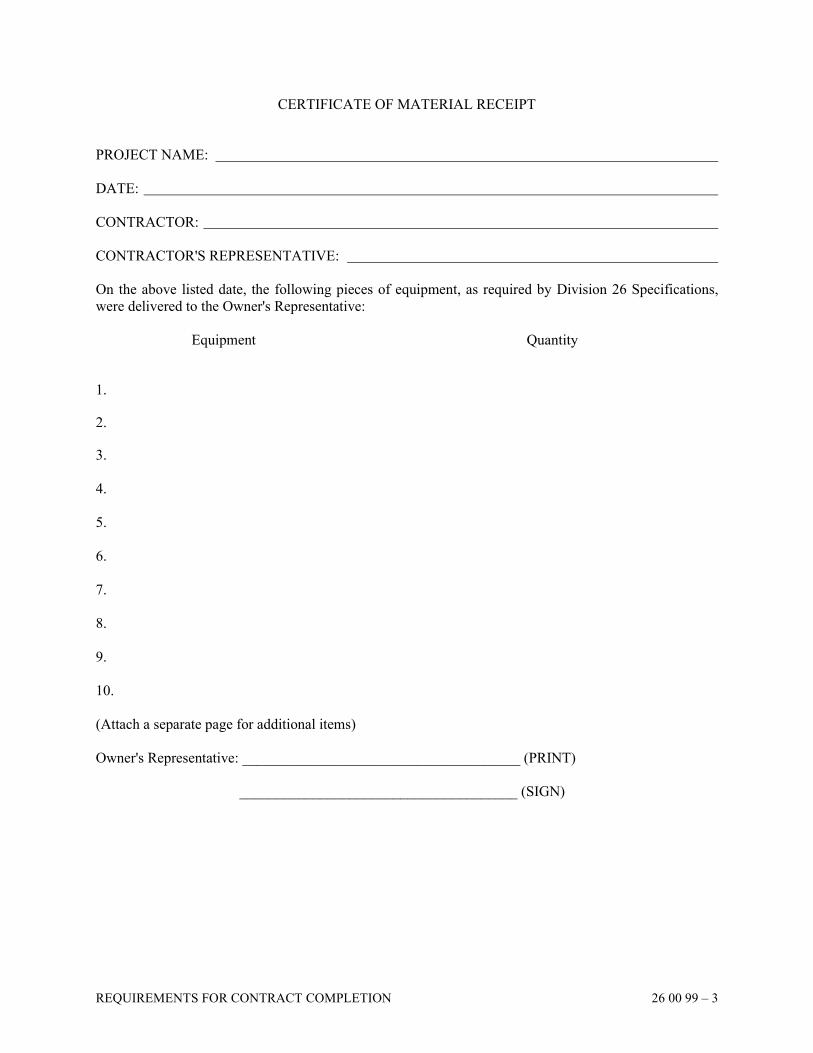
REQUIREMENTS FOR CONTRACT COMPLETION 26 00 99 – 3
CERTIFICATE OF MATERIAL RECEIPT
PROJECT NAME:
DATE:
CONTRACTOR:
CONTRACTOR'S REPRESENTATIVE:
On the above listed date, the following pieces of equipment, as required by Division 26 Specifications,
were delivered to the Owner's Representative:
Equipment Quantity
1.
2.
3.
4.
5.
6.
7.
8.
9.
10.
(Attach a separate page for additional items)
Owner's Representative: ______________________________________ (PRINT)
______________________________________ (SIGN)

REQUIREMENTS FOR CONTRACT COMPLETION 26 00 99 – 4
CERTIFICATE OF SYSTEM COMPLETION
PROJECT NAME:
CONTRACTOR:
SYSTEM:
SPECIFICATION SECTION NUMBER:
A. MANUFACTURER'S INSPECTION AND APPROVAL (If required by Specification Section)
The above listed system has been inspected and approved as meeting the Manufacturer's written
instructions for installation and operation.
Manufacturer's Representative: ______________________ Date: _____________________
B. TESTING
The above listed system has passed all testing required by Division 26 Specifications and has met
the terms of the Contract. Written test results are attached.
Contractor's Representative: ________________________ Date:______________________
C. EQUIPMENT DEMONSTRATION
The above listed system has been demonstrated to the following Owner's Representatives:
NAME TITLE DATE SIGNATURE
1.
2.
3.
4.
5.
6.
7.
8.
9.
10.
(ATTACH A SEPARATE PAGE FOR ADDITIONAL NAMES)
SECTION 26 05 10
WIRE AND CABLE
WIRE AND CABLE 26 05 10 – 1
PART 1 GENERAL
1.01 DESCRIPTION
A. Furnish and install all electrical conductors for service entrance, feeder and branch circuit
wiring and control wiring.
B. Refer to other Division 26 Specification Sections for additional wiring requirements.
C. Insulation shall be low smoke producing, zero halogen type.
1.02 QUALITY ASSURANCE
A. Wire and cable furnished shall be in accordance with the following standards where
applicable:
1. UL Standard 44 for rubber insulated wires and cables
2. UL Standard 83 for thermoplastic insulated wires and cables
3. UL Standard 817 for flexible cords and cables
B. Wire and cable shall be in accordance with applicable NEC Articles.
C. Wire and cable shall be identified by surface markings indicating manufacturer, size, metal
type, voltage rating, UL listing and cable type.
PART 2 PRODUCTS
2.01 TYPE "THHN/THWN" WIRING
A. Wire shall be single conductor annealed uncoated copper with PVC insulation and nylon
jacket. Insulation shall be heat and moisture resistant with light stabilized jacket. Wire
shall be rated 600 volt, 90 degree C in dry locations, 75 degree C in wet locations.
B. Conductors No. 10 AWG and smaller may be solid; No. 8 AWG and larger shall be
stranded. Where stranded conductors of sizes 12 and 10 are used, appropriate crimp
terminations shall be provided on the ends of each conductor for making connections to
wiring devices, switches, etc.
2.02 TYPE "XHHW" WIRING
A. Wire shall be single conductor annealed uncoated copper with heat and moisture resistant
thermosetting cross-linked polyethylene insulation. Wire shall be rated 600 volt, 90 degree
C in dry locations, 75 degree C in wet locations.
2.03 SPLICES
A. Splices in No. 10 AWG and smaller wire shall be made with insulated connectors with
metallic coil springs and contoured wings such as 3M "Scotchlok," Ideal Company "Wing
Nut," Thomas & Betts Company "Piggy" connectors, or with mechanically-crimped sleeves
WIRE AND CABLE 26 05 10 – 2
as manufactured by T & B or Ideal Company, which shall be insulated with pressure
sensitive vinyl plastic electrical tape equal to Scotch No. "33" or No. "88."
B. All taps, terminations or splices, size No. 8 and larger shall be made with bolted-type
pressure or compression connectors. Connectors shall be compatible with the conductor
material. Insulate connectors with electrical tape to 150% of the insulating value of the
conductor insulation. The tape shall have insulating properties equivalent to the conductor.
C. All splices located in exterior junction boxes shall be made with waterproof splice kits.
2.04 TYPE "XHHW-2" WIRING
A. Wire shall be single conductor, uncoated aluminum with XLPE insulation and compressed
compacted stranded conductor. Aluminum shall be Alcan Stabiloy AA-8030 alloy, or
equal by Southwire.
PART 3 EXECUTION
3.01 APPLICATION
A. Service entrance conductors for underground installations in raceways shall be Type
"XHHW."
B. All branch circuits, feeders and control wiring shall be Type "THHN/THWN."
C. Unless otherwise noted, minimum wire size for power branch circuits shall be No. 12
AWG and for control and auxiliary systems No. 14 AWG. Wire size for branch circuit
homeruns shall be as indicated in the panelboard schedules. Remainder of branch circuit
shall be No. 12 AWG, unless noted otherwise.
D. Where shown on the Drawings, conductors may be aluminum XHHW-2 wiring.
Terminations on both ends shall be made with aluminum alloy, long barrel, one or two
holes, high compression crimp lug connectors on cleaned ends protected with anti-
corrosion joint compound. Cable ampacity and conduit size shall be in accordance with
National Electrical Code tables. All panelboards, safety switches, etc. shall come factory
prepared with appropriate bus terminators to accept high compression crimp lug
connectors. Equipment shall have sufficient wire bending space.
3.02 INSTALLATION
A. Install electrical cables, wires and connectors as indicated, in compliance with
Manufacturer's written instructions, applicable requirements of NEC and NECA'S
"Standard Installation," and in accordance with recognized industry practices.
B. Coordinate cable and wire installation work with electrical raceway and equipment
installation work, as necessary for proper interface.
C. No wire may be pulled until masonry and concrete is in place. Free ends and loops at
boxes and enclosures are to be pushed back in box and protected by blank covers or other
means until the interior painting and decorating work is completed.
WIRE AND CABLE 26 05 10 – 3
D. Leave at least 6 inches of free conductor at all outlets except where conductors are intended
to loop without joints through outlets for luminaires or wiring devices hookups.
E. Wire color and code shall be used as follows:
120/208 Volt 277/480 Volt Phase A Black Brown
Phase B Red Orange
Phase C Blue Yellow
Neutral White Gray
Ground Green Green
F. All circuits shall have separate neutral conductors run for each phase conductor.
G. Number of branch circuit conductors in a conduit including switch legs and neutral
conductors shall not exceed nine (9) conductors. Conductors shall be derated in accordance
with NEC Article 310 when more than three (3) current carrying conductors are installed in
a raceway.
H. Branch circuits shall be connected as numbered on the Drawings. Test and permanently tag
by circuit number each circuit wire, except neutrals in panelboard gutter before connecting
to panelboard. Numbered adhesive tapes may be used at Contractor's option.
I. Where a feeder or branch circuit exceeds the terminating lug size, the Contractor shall use
an appropriate adapter fitting to reduce cable size. Cutting of conductor strands is not
permitted.
J. Use pulling means, including fish tape, cable or rope and lubricant which will not damage
raceway or deteriorate insulation.
K. Branch circuit conductor splices shall be kept to a minimum. Feeder conductors shall have
no splices.
L. Any equipment having multiple power connections shall have a warning label attached to
each source where it connects to the equipment.
M. Subsequent to wire and cable hookups, energize circuitry and demonstrate functioning in
accordance with requirements.
N. Division 26 Contractor shall provide cords and plugs for equipment furnished by General
Trades Contractor which is intended or shown for connection to a receptacle but not
furnished with the equipment.
3.03 CONDUCTOR SIZING
A. Branch circuit conduit routing is not shown on the plans and is left to the discretion of the
Contractor. Wire size shall be as follows, unless specifically noted on the Drawings:
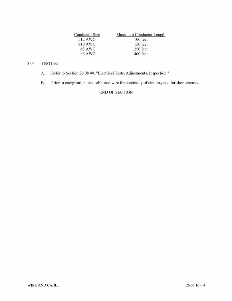
WIRE AND CABLE 26 05 10 – 4
Conductor Size Maximum Conductor Length
#12 AWG 100 feet
#10 AWG 150 feet
#8 AWG 250 feet
#6 AWG 400 feet
3.04 TESTING
A. Refer to Section 26 08 40, "Electrical Tests, Adjustments, Inspection."
B. Prior to energization, test cable and wire for continuity of circuitry and for short circuits.
END OF SECTION
SECTION 26 05 26
GROUNDING AND BONDING
GROUNDING AND BONDING 26 05 26 – 1
PART 1 GENERAL
1.01 DESCRIPTION
A. Furnish and install a complete grounding system as shown on the Drawings and specified
herein. Provide all accessories as necessary for a complete system.
B. All components of the electrical system shall be grounded and bonded including:
raceways, enclosures, receptacles, motors, controllers, panelboards, contactors, luminaires,
emergency generators, transfer switches, telephone systems, and all other electrical
components and subsystems.
1.02 REQUIREMENTS
A. The Division 26 Contractor shall work with the Division 27 Contractor. The Division 26
Contractor shall be responsible for the grounding system and include the
telecommunications grounding listed in 26 05 27, Section 1.02.B.1. All applicable
requirements listed in 26 05 27 shall be provided.
1.03 QUALITY ASSURANCE
A. All equipment shall be UL listed and labeled and in accordance with applicable NEMA and
ANSI Standards and NEC Article 250.
1.04 SUBMITTALS
A. For Review:
1. Product data sheets of all components
2. Ground resistance testing results (refer to Section 26 08 40, "Electrical Tests,
Adjustments, Inspection")
B. To be included in Record and Information Manuals:
1. One (1) copy of each approved submittal
1.05 MANUFACTURERS
A. Exothermic Weld
1. Cadweld by ERICO Products, Inc.
2. Ultraweld by Harger
B. Low Resistivity Backfill
1. TerraFill by ALLTEC Corporation
2. GEM by ERICO Products, Inc.
3. Power Fill by LORESCO International, Inc.
4. Ultrafill by Harger
GROUNDING AND BONDING 26 05 26 – 2
PART 2 PRODUCTS
2.01 DRIVEN GROUND ROD
A. Ground rod shall be copper-clad steel, 3/4 inch minimum diameter, 10 foot length.
2.02 CONDUCTORS, CLAMPS AND CONNECTORS
A. Refer to Section 26 05 10, "Wire and Cable."
2.03 EXOTHERMIC WELD
A. Exothermic welds shall be powdered copper oxide and aluminum to form a molded
homogeneous copper joint connection between the copper conductor and the material being
bonded to.
2.04 SINGLE POINT GROUND BUS BAR
A. Bus bar shall be minimum size 1/4" x 2" x 24" flat copper, wall mounted on standoff
insulators.
PART 3 EXECUTION
3.01 INSTALLATION
A. System Grounding Connections
1. The service entrance conductors shall be grounded in accordance with NEC Article
250.24. The grounding electrode conductor shall be connected to the grounded service
conductors at the terminal or bus at the main service disconnecting means. A
grounding connection shall not be made to any grounded circuit conductor on the load
side of the service disconnecting means.
2. A separately derived alternating current system, such as a 480 volt delta to a 208/120
volt wye transformer, or any emergency generator, shall be grounded and bonded as
required in NEC Article 250.30.
B. Enclosure and Equipment Grounding
1. Metal enclosures or raceways for conductors or equipment shall be grounded.
2. Exposed noncurrent-carrying metal parts of fixed equipment likely to become
energized shall be grounded.
3. Exposed noncurrent-carrying metal parts of switchboard frames and structures, motor
frames, enclosures for motor controllers, and luminaires shall be grounded.
C. Method of Grounding
1. Equipment grounding connections at service equipment shall be made by bonding the
equipment grounding conductor to the grounded service conductor and the grounding
electrode conductor.
2. The grounding electrode conductor shall connect the equipment grounding conductors,
the grounded service conductors and the service entrance enclosures to the grounding
electrode.
GROUNDING AND BONDING 26 05 26 – 3
3. A main bonding jumper shall connect the equipment grounding conductors and the
service equipment enclosure to the grounded conductor within the service equipment.
4. Provide separate green insulated equipment grounding conductors for all feeders and
branch circuits.
5. Circuits shown with isolated ground devices shall have a completely separate isolated
grounding conductor run in addition to equipment grounding conductor of the same
size.
D. Bonding
1. Bonding shall be provided and conform to all requirements of NEC Article 250 V and
VII.
2. Bond panelboards in hospitals in accordance with NEC 517.14.
E. Grounding electrode system shall consist of all of the following components exothermically
bonded together:
1. The main domestic water service pipe ahead of any meter, and within 5 feet of entry
into building.
2. Ufer Ground – 20 foot minimum length of re-bar, or Bare No. 4/0 cable embedded
within concrete footer, with No. 4/0 cable extended to single point grounding buss bar.
3. The Steel Frame of the Building - At a column nearest to the service entrance
equipment and at a point accessible to view.
4. Driven Ground Rods - Two ground rods, installed vertically into earth near the service
entrance point and spaced 20 feet apart, with top 8 feet encased with low resistivity
backfill.
5. Counterpoise Ground Ring - Bare No. 4/0 AWG stranded copper conductor installed at
30 inches below grade surrounding the entire building and encased with minimum of 4
inches low resistivity backfill. Bond from ring to nearest steel column every 100 feet
around building.
6. Single Point Ground Bus Bar - Bus bar installed adjacent to the service entrance switch
gear with each grounding electrode system component listed above bonded to it.
F. Exterior luminaires and poles shall be grounded by the use of a manufacturer supplied
ground lug or pigtail or by the use of ground clips fastened in bare metal that is free of
paint. Poles shall be grounded to an equipment grounding conductor. Poles shall also have
a driven ground rod installed at the bottom of their base excavation and bonded to pole.
G. Separately derived systems such as transformers and emergency generators shall be
grounded to the nearest building steel column. If building steel is not available, then
ground to the nearest domestic cold water pipe. In addition, run a grounding electrode
conductor back to the main service entrance ground point. Grounding electrode conductor
shall be bonded to conduit at each end.
H. Motor terminal boxes shall be grounded by the use of a manufacturer supplied ground lug
or by drilling and tapping a hole for a ground screw. Remove paint prior to making the
connection.
I. Isolated grounding conductors shall be run from designated receptacles shown on the
Drawings with the branch circuit phase conductors and terminated in separate isolated
ground bus bars in panelboards and switchgear. A grounding electrode conductor shall be
run from the isolated ground bus bar to the service or separately derived system grounding
GROUNDING AND BONDING 26 05 26 – 4
electrode connection point and shall be the same size as the equipment grounding
conductor.
J. Metal roofing and metal veneer siding shall be bonded to building steel or nearest
grounding system connection with No. 6 AWG conductor every 100 feet.
K. A No. 4/0 AWG ground jumper shall be installed around water meters. A No. 2 AWG
ground jumper shall be installed around water heaters.
L. Metal piping systems such as compressed air, natural gas, lab gases, vacuum, hot water,
heating and chilled water HVAC systems, shall all be bonded to the grounding electrode
system with No. 2 AWG conductors.
M. Lightning Protection System shall be bonded to the grounding electrode system
underground exterior to the building.
3.02 GROUNDING SYSTEM TESTING
A. Soil Resistivity
1. Measure soil resistivity and record
B. Grounding System Resistance
1. Ground system resistance measurements shall be taken and submitted to the Architect
for approval before energizing equipment. Measurements shall be taken in dry
weather, not less than 48 hours after rainfall.
2. The test method used shall be the fall-of-potential method described in IEEE Standard
142. If it is not possible to use the fall-of-potential method, then the slope method of
Dr. George Tag shall be used.
3. Documentation shall include the following information:
a. Sketch of site showing building, ground connection and test locations
b. Location in feet of all test spikes
c. Graphs showing all recorded data plotted
d. A minimum of ten (10) data points shall be recorded
C. Grounding System in Patient Care Areas
1. The effectiveness of the grounding system in patient care areas shall be determined by
voltage and impedance measurements and shall be evaluated before acceptance.
2. Voltage and impedance measurements shall be made in accordance with the testing
requirements of NFPA 99, Paragraph 4.3.3 Performance Criteria and Testing.
3. The criteria for acceptability shall be a voltage limit of 20 mV and an impedance limit
of 0.1 ohms.
4. A record of the test results shall be maintained per NFPA 99, Paragraph 4.3.4.2.
3.03 GROUNDING SYSTEM ADJUSTMENT
A. Where grounding system resistance test results are above 25 ohms, install additional driven
ground rods spaced 20 feet apart until such a reading is achieved.
END OF SECTION
SECTION 26 05 27
TELECOMMUNICATIONS BONDING INFRASTRUCTURE
TELECOMMUNICATIONS BONDING INFRASTRUCTURE 26 05 27 – 1
PART 1 GENERAL
1.01 REQUIREMENTS
A. The Division 27 Contractor shall work with the Division 26 Contractor who shall be
responsible for the grounding system and shall follow Section 26 05 26, "Grounding &
Bonding" requirements and include the telecommunications grounding listed in Section
1.02.B.1, below. The Division 27 Contractor shall be responsible for grounding work
identified in Section 1.02.B.2 below.
B. The Contractor shall supply a grounding system as shown on the Drawings, specified
herein and per ANSI/TIA-607-B Generic Telecommunications Grounding (Earthing) and
Bonding for Customer Premises.
1.02 SCOPE
A. The aim of this document is to install a proper grounding system to achieve the following
needs:
1. Safety from electrical hazards.
2. Reliable signal reference within the network.
3. Satisfactory and/or enhanced electromagnetic performance of the network.
B. The "Grounding System" shall be a shared responsibility between the Division 26
(Electrical) Contractor and Division 27 (Low Voltage) Contractor. See attached schematic
diagram. The Division 27 Contractor shall be responsible for coordinating his/her work
with the Division 26 Contractor and the General Contractor.
1. The Division 26 Contractor shall supply and install the grounding system as specified
in Section 26 05 26, "Grounding & Bonding" and is also to include the following:
a. Provide the TMGB (Telecommunication Main Grounding Busbar) in the MTR
(Main Technology Room/demarc. room).
b. The TMGB shall be connected to an earth ground (ground loop surrounding the
building, if available) and the building steel.
c. Provide a TGB (Telecommunication Grounding Busbar) in each TR located
throughout the facility.
d. Each TGB shall be connected to building steel and the equipment ground terminal
of the nearest AC electrical panelboard serving the telecommunications equipment
in the TR.
e. Provide and connect the TBB (Telecommunications Bonding Backbone) from the
TMGB to all TGBs.
2. The Division 27 Contractor shall:
a. Connect via compression connectors all equipment, ladder rack, basket rack,
telecom racks, cabinets and other equipment, in each TR and/or MTR, green
insulated, stranded copper ground conductor to the TGB and/or TMGB located in
each TR and/or MTR. These bonding conductors shall minimum conductor size #6
AWG, and sized at 2 kcmil per linear foot up to a maximum size of 750 kcmil per
the table below.
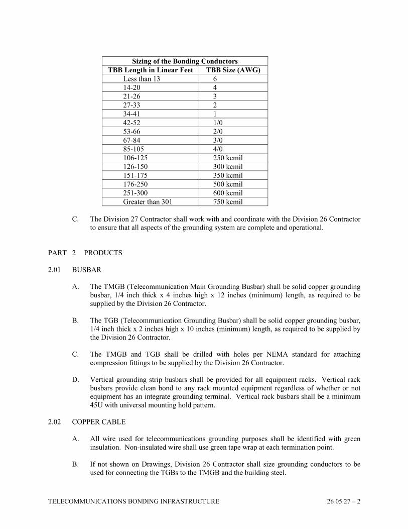
TELECOMMUNICATIONS BONDING INFRASTRUCTURE 26 05 27 – 2
Sizing of the Bonding Conductors
TBB Length in Linear Feet TBB Size (AWG)
Less than 13 6
14-20 4
21-26 3
27-33 2
34-41 1
42-52 1/0
53-66 2/0
67-84 3/0
85-105 4/0
106-125 250 kcmil
126-150 300 kcmil
151-175 350 kcmil
176-250 500 kcmil
251-300 600 kcmil
Greater than 301 750 kcmil
C. The Division 27 Contractor shall work with and coordinate with the Division 26 Contractor
to ensure that all aspects of the grounding system are complete and operational.
PART 2 PRODUCTS
2.01 BUSBAR
A. The TMGB (Telecommunication Main Grounding Busbar) shall be solid copper grounding
busbar, 1/4 inch thick x 4 inches high x 12 inches (minimum) length, as required to be
supplied by the Division 26 Contractor.
B. The TGB (Telecommunication Grounding Busbar) shall be solid copper grounding busbar,
1/4 inch thick x 2 inches high x 10 inches (minimum) length, as required to be supplied by
the Division 26 Contractor.
C. The TMGB and TGB shall be drilled with holes per NEMA standard for attaching
compression fittings to be supplied by the Division 26 Contractor.
D. Vertical grounding strip busbars shall be provided for all equipment racks. Vertical rack
busbars provide clean bond to any rack mounted equipment regardless of whether or not
equipment has an integrate grounding terminal. Vertical rack busbars shall be a minimum
45U with universal mounting hold pattern.
2.02 COPPER CABLE
A. All wire used for telecommunications grounding purposes shall be identified with green
insulation. Non-insulated wire shall use green tape wrap at each termination point.
B. If not shown on Drawings, Division 26 Contractor shall size grounding conductors to be
used for connecting the TGBs to the TMGB and the building steel.
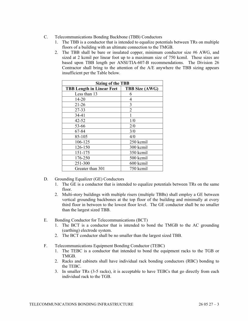
TELECOMMUNICATIONS BONDING INFRASTRUCTURE 26 05 27 – 3
C. Telecommunications Bonding Backbone (TBB) Conductors
1. The TBB is a conductor that is intended to equalize potentials between TRs on multiple
floors of a building with an ultimate connection to the TMGB.
2. The TBB shall be bare or insulated copper, minimum conductor size #6 AWG, and
sized at 2 kcmil per linear foot up to a maximum size of 750 kcmil. These sizes are
based upon TBB length per ANSI/TIA-607-B recommendations. The Division 26
Contractor shall bring to the attention of the A/E anywhere the TBB sizing appears
insufficient per the Table below.
Sizing of the TBB
TBB Length in Linear Feet TBB Size (AWG)
Less than 13 6
14-20 4
21-26 3
27-33 2
34-41 1
42-52 1/0
53-66 2/0
67-84 3/0
85-105 4/0
106-125 250 kcmil
126-150 300 kcmil
151-175 350 kcmil
176-250 500 kcmil
251-300 600 kcmil
Greater than 301 750 kcmil
D. Grounding Equalizer (GE) Conductors
1. The GE is a conductor that is intended to equalize potentials between TRs on the same
floor.
2. Multi-story buildings with multiple risers (multiple TBBs) shall employ a GE between
vertical grounding backbones at the top floor of the building and minimally at every
third floor in between to the lowest floor level. The GE conductor shall be no smaller
than the largest sized TBB.
E. Bonding Conductor for Telecommunications (BCT)
1. The BCT is a conductor that is intended to bond the TMGB to the AC grounding
(earthing) electrode system.
2. The BCT conductor shall be no smaller than the largest sized TBB.
F. Telecommunications Equipment Bonding Conductor (TEBC)
1. The TEBC is a conductor that intended to bond the equipment racks to the TGB or
TMGB.
2. Racks and cabinets shall have individual rack bonding conductors (RBC) bonding to
the TEBC.
3. In smaller TRs (3-5 racks), it is acceptable to have TEBCs that go directly from each
individual rack to the TGB.
TELECOMMUNICATIONS BONDING INFRASTRUCTURE 26 05 27 – 4
G. Alternating Current Equipment Ground (ACEG)
1. The ACEG is a conductor that intended to bond the nearest AC electrical panelboard
serving the telecommunications equipment in the TR to the TGB or TMGB.
PART 3 EXECUTION
3.01 WORK TO BE DONE
A. The Division 26 Contractor shall provide the TMGB and the TGB in each room requiring
grounding.
B. The Division 26 Contractor shall provide all grounding cabling required connecting the
TMGB to earth and building steel and all cabling required connecting the TGBs to building
steel and to the TMGB.
C. The Division 26 Contractor shall provide all GE conductors where required.
D. The Division 27 Contractor shall provide and connect all grounding cables required in the
MTR and TR to properly ground all equipment to the TMGB and TGB.
E. The completed installation (from TGB to TMGB to ground) shall be tested by the Division
26 Contractor and a record of test supplied to the Division 27 Contractor and the Engineer.
The Division 27 Contractor shall include these test results in the "Record and Information
Manual."
END OF SECTION
SECTION 26 05 29
HANGERS AND SUPPORTS
HANGERS AND SUPPORTS 26 05 29 – 1
PART 1 GENERAL
1.01 DESCRIPTION
A. Furnish and install complete hangers, supports and concrete inserts as required for the
installation of conduits, cabinets, transformers and equipment installed under Division 26.
B. Provide all beam clamps, expansion anchors, threaded rod, framing steel and hardware as
required.
1.02 QUALITY ASSURANCE
A. All equipment shall be UL listed and labeled and in accordance with applicable NEMA and
ANSI Standards.
1.03 MANUFACTURERS
A. Hangers, Supports and Inserts
1. GTE/Unistrut International Inc.
2. Superstrut
3. Kindorf/Midland Ross Corporation
4. Grinnell
5. Tufstrut - Pilgrim Technical Inc.
PART 2 PRODUCTS
2.01 MATERIALS
A. Conduits or raceways shall be securely supported and anchored with proper devices, using
lead shields in walls or sides of beams, expansion shields or other approved type device for
direct down-pull loads. Minerallac type hanger shall be limited to above ceilings. Holes
made in walls or ceilings for use with anchoring devices shall be covered by large steel
washers. Include special hangers, as required. Minerallac type fittings shall not be
permitted within 8 feet of the floor surface where exposed raceways are installed.
B. Hangers shall be individual ring or clevis type, one hole straps or multiple trapeze hangers.
2.02 STRUCTURAL ATTACHMENTS
A. Concrete: Use Grinnell Fig. 285, or equal, Light Weight concrete insert for loads up to 400
lbs., or Grinnell Fig. 282, or equal, Universal Concrete insert for loads up to 1430 lbs.
B. Steel Beams: Where pipe size is 2 inches or less, use Grinnell Figure 87 or equal,
Malleable iron C-Clamp and Retaining Clip. Where pipe size is over 2 inches, use Grinnell
Figure 229, or equal.
HANGERS AND SUPPORTS 26 05 29 – 2
C. Intermediate Attachments: Continuous threaded rod shall be used wherever possible. No
chain, wire or perforated strap shall be used. Up to 2 inches trade size pipe use 3/8 inch
(minimum) rod, 2 1/2 inches and larger use 1/2 inch (minimum) rod.
D. Pipe Attachments: For steel pipe use Grinnell Figure 115 Ring and Turnbuckle Adjuster,
or Figure 260 Clevis.
PART 3 EXECUTION
3.01 INSTALLATION
A. Conduits shall be supported to meet the conditions as required using proper type and size
straps, clamps, and hangers.
B. Exposed conduits shall be installed parallel with or at right angles to building structure,
fastened at least every 8 feet and at both sides of each outlet, except at one side only of
conduit terminating outlets. Conduits shall be installed tight to structure and beams/joists.
Coordinate exposed conduit routing with Architect prior installation.
C. Conduit risers shall be supported with friction clamps with two point bearing anchored to
building construction and at every floor.
D. The following hanger methods are not permitted:
1. Wood plugs
2. Perforated band iron
3. Hook chain supports
4. Bailing wire, etc.
5. Minerallacs where previously mentioned
6. Friction type clamps, such as hammer on clips
E. Whenever possible, use supports, clamps, hangers, etc., designed especially for the
equipment to be installed.
F. The maximum permitted load on hanger rod, plain or all-thread, shall be as follows:
1. 1/4 inch size - 750 pounds
2. 3/8 inch size - 1000 pounds
3. 1/2 inch size - 2000 pounds
4. 5/8 inch size - 3000 pounds
5. The minimum size hanger rod permitted is 1/4 inch size.
G. Any supports exposed to weather, shall be cleaned, primed and painted.
END OF SECTION
SECTION 26 05 33
CONDUIT AND FITTINGS
CONDUIT AND FITTINGS 26 05 33 – 1
PART 1 GENERAL
1.01 DESCRIPTION
A. Provide complete grounded conduit systems for all electrical conductors.
B. All conduits shown on the Drawings shall meet NEC fill requirements for the conductors
enclosed.
C. Conduit raceway systems shall be made mechanically tight and electrically continuous
throughout. All metal raceway systems shall be grounded.
D. Refer to Section 26 05 43, "Underground Raceways" for all conduits located within or
below slab-on-grade floors, and exterior to the building foundation.
1.02 QUALITY ASSURANCE
A. All equipment shall be UL listed and labeled and in accordance with applicable NEMA and
ANSI Standards.
B. Conduit shall be in accordance with applicable NEC Articles.
PART 2 PRODUCTS
2.01 RIGID (RMC) AND INTERMEDIATE METAL CONDUIT (IMC)
A. Conduit shall be steel, hot dipped zinc galvanized (minimum 0.0008 inch thick) inside and
out, with circular cross section, uniform wall thickness, continuously welded seams and
chamfered threaded ends. Conduit shall be furnished in 10 foot standard lengths.
2.02 ELECTRICAL METALLIC TUBING (EMT)
A. EMT shall be zinc galvanized (minimum 0.0008 inch thick) inside and out, with circular
cross section, uniform wall thickness and continuously welded seams. EMT shall be
furnished in 10 foot standard lengths.
2.03 FLEXIBLE METAL CONDUIT (FMC)
A. Conduit shall be steel or aluminum, hot dipped zinc galvanized inside and out and made
from one continuous length of high grade strip of uniform weight and thickness shaped into
interlocking convolutions with smooth interior and exterior surfaces. Conduit shall be
provided in standard coil lengths.
2.04 LIQUID-TIGHT FLEXIBLE METAL CONDUIT (LFMC)
A. Conduit shall be hot dipped zinc galvanized inside and out and made from one continuous
length of high grade steel strip of uniform weight and thickness shaped into interlocking
CONDUIT AND FITTINGS 26 05 33 – 2
convolutions with smooth interior and exterior surfaces. Conduit shall be provided in
standard coil lengths.
B. Conduit shall have a continuous PVC jacket enclosing it.
2.05 CONDUIT FITTINGS
A. All RMC, IMC, and EMT fittings shall be galvanized steel. Connectors and couplings shall
be threaded, set screw or compression type, concrete-tight.
B. Conduit bodies shall be threaded steel type. Provide neoprene cover gaskets for conduit
body covers exposed to the weather.
C. Expansion fittings, shall be O-Z/Gedney Type "AX" for RMC and Type "TX" for EMT.
For IMC applications, a 15 inch minimum length of RMC shall be used with a Type "AX"
expansion fitting. Provide O-Z/Gedney Type "BJ" bonding jumpers at all expansion
fittings.
D. Sealing fittings shall be Crouse Hinds Type EYD or Appleton Type EYD, with drain.
E. RMC and IMC conduit bushings shall be of the insulated type with phenolic thermosetting
insulation molded to a hot dipped galvanized steel body of the threaded type.
F. EMT fittings shall be of the insulated throat type. Fittings larger than 2 1/2 inches shall
have threaded bushings installed as described in Paragraph E above.
G. Conduits larger than 1 inch shall have grounding type bushings.
2.06 ROOF PENETRATIONS
A. Use prefabricated pipe flashing of ultra-violet resistant EDPM rubber with ribbed
aluminum base.
B. Pate, Shipman, or Thy-Curb.
2.07 ROOF SUPPORTS
A. Rooftop conduit supports shall be UL listed for glue down installation.
PART 3 EXECUTION
3.01 APPLICATION
A. All conduit shall be rigid metal conduit, unless noted otherwise below, minimum 3/4 inch
trade size.
B. EMT may only be used in these locations:
1. Within interior partitions and exterior walls
2. Above suspended ceilings inside building
CONDUIT AND FITTINGS 26 05 33 – 3
3. Exposed above 9 feet A.F.F. inside building (except in wet, hazardous, or corrosive
locations)
4. Exposed above electrical equipment above 7 feet in electrical and mechanical rooms.
C. Intermediate metal conduit may be used at the Contractor's option in lieu of rigid steel
conduit within the building interior.
D. Flexible metal conduit up to 6 feet in length shall be used for connections to lighting
fixtures. A green grounding conductor shall be installed in each flexible conduit as
specified in Section 26 05 26, "Grounding." All runs shall be terminated in insulated
flexible conduit fittings in accordance with NEC. Minimum size to be 1/2 inch.
E. Liquid tight flexible metal conduit (up to 3 feet in length) and appropriate fittings shall be
used for connections to motors, engine/generators, and vibrating equipment. A green
grounding conductor shall be installed in each flexible conduit as specified in Section
26 05 26, "Grounding." All runs shall be terminated in insulated flexible conduit fittings in
accordance with NEC. Minimum size to be 1/2 inch.
F. EMT shall not be installed on the underside of metal roof decking.
G. RMC conduit shall be used on roofs with appropriate expansion fittings.
3.02 INSTALLATION
A. Generally, all conduits shall be concealed with runs installed parallel and perpendicular to
walls and floor. Exposed conduits below 9 feet will be permitted only in electrical and
mechanical rooms. Anywhere else at the discretion of the Architect or where specifically
noted on the Drawings. In these cases, install conduit escutcheon plates around conduit
penetration, sized to cover the conduit sleeve. Submit proposed routing of exposed
conduits in finished spaces with Architect prior to installation.
B. Branch circuit conduits shall not be run within concrete floors except for short runs to floor
boxes.
C. Conduit shall be securely and rigidly fastened in place with approved pipe straps, wall
brackets, conduit clamps, conduit hangers, threaded C-clamps, or ceiling trapeze. C-
clamps and beam clamps shall have strap or rod-type retainers.
D. Conduit support fastenings shall be by:
1. Wood screws to wood
2. Toggle bolts in hollow concrete masonry units
3. Expansion bolts in concrete or brick
4. Machine screws, welded threaded studs on steel work
5. Nail-type nylon anchors or threaded studs driven by a powder charge and provided
with lock washers and nuts for concrete, brick or steel work
6. Conduit shall not be supported using wire or nylon ties.
E. In areas without ceilings, conduits shall be run as high as possible attached to the structure
of the roof, or of the floor deck above. Do not attach directly to the metal deck. Conduits
shall be run next to walls as inconspicuously as possible. In finished areas exposed to
public view without ceilings, all work shall be installed in an aesthetically acceptable
CONDUIT AND FITTINGS 26 05 33 – 4
manner. The Architect reserves the right to require the Contractor to make changes as
necessary to equipment installation that is unsuitable for public view due to poor
workmanship.
F. Install conduit sleeves for all conduit penetrations through floors, masonry walls, and fire
rated walls. Refer to Section 03 30 00, "Concrete" for spacing requirements. Sleeves shall
be spaced a sufficient distance apart to maintain fire ratings as required by the UL Fire
Resistance Construction Manual.
G. Conduit shall be independently supported from elements of the building and shall not rest
on, nor be supported from suspended ceilings. Boxes shall be fastened to structure
independently from conduit system. Conduits shall not be attached to metal decking
forming the roof or floor slab above.
H. Lay out conduit system to avoid crossing building expansion joints. Where crossings are
necessary, use expansion fittings.
I. All conduits shall be continuous from outlet to outlet or junction box, and installed
complete before pulling conductors. Swab conduits free of dirt, grease and moisture before
pulling conductors.
J. Install bushings on all RMC and IMC conduit ends. Install insulated throat fittings on all
EMT conduit ends. Fasten conduit to boxes and cabinets using locknuts. Provide two (2)
locknuts where required by the NEC, where insulating bushings are used and where
bushings cannot be brought into firm contact with the box.
K. Do not install conduits beneath nor above equipment generating heat such as boilers, heat
exchangers or water heaters.
L. Provide a high strength pull cord in all empty conduits, and cap ends.
M. Maintain minimum clearances of 6 inches from parallel hot water piping and 4 inches from
crossovers.
N. Provide conduit sleeves, seals and firestops in accordance with Section 26 00 55, "Sleeves,
Seals and Firestops."
O. Provide expansion joints in conduits run on roofs and exterior to building above grade.
Provide proper roof flashing and sealing when penetrating roofs.
P. Do not exceed four (4) 90 degree bends in any conduit run without a pulling point. Provide
pullboxes as required. Locate pullboxes in accessible areas. Coordinate locations with all
other building Trades.
Q. Roof support steel shall be galvanized.
END OF SECTION
SECTION 26 05 34
OUTLET BOXES
OUTLET BOXES 26 05 34 – 1
PART 1 GENERAL
1.01 DESCRIPTION
A. Outlets shall be provided for devices, luminaires, motors, and equipment connections,
systems equipment connections, special outlets, and as otherwise required.
B. Outlet boxes shall be of sufficient size to provide free space for all conductors enclosed in
the box. Boxes shall be not less than the minimum size required by NEC Article 314 for
the number and size of conductors contained within.
1.02 QUALITY ASSURANCE
A. All equipment shall be UL listed and labeled and in accordance with applicable NEMA and
ANSI Standards.
PART 2 PRODUCTS
2.01 OUTLET BOXES
A. Interior Outlet Boxes: Provide galvanized flat rolled sheet steel interior outlet wiring
boxes, of types, shapes and sizes, including box depths, to suit each respective location and
installation; construct with stamped knockouts in back and sides, and with threaded screw
holes with corrosion-resistant screws for securing box covers and wiring devices. Through-
wall boxes shall not be used.
B. Interior Outlet Box Accessories: Provide outlet box accessories as required for each
installation, including mounting brackets, wallboard hangers, extension rings, fixture studs,
cable clamps and metal straps for supporting outlet boxes, which are compatible with outlet
boxes being used and fulfilling requirements of individual wiring situations. Choice of
accessories is Installer's option.
C. Weatherproof Outlet Boxes: Provide corrosion-resistant cast aluminum, weatherproof
outlet wiring boxes, of types, shapes and sizes, including depth of boxes, with threaded
conduit ends, cast-metal face plates with spring-hinged waterproof caps suitably configured
for each application, including face plate gaskets and corrosion-resistant fasteners.
D. Luminaire outlet boxes shall be standard 4 inch octagonal, minimum 1 1/2 inches deep.
E. Flush device boxes in masonry walls to be masonry boxes designed for the purpose, or 4
inch square boxes with raised covers designed for masonry.
F. Wiring device boxes for surface conduit work and located in potentially damp areas shall
be FS series cast aluminum boxes.
G. Where outlet boxes are to be cast in concrete slabs, they shall be boxes designed for
concrete installation.
OUTLET BOXES 26 05 34 – 2
H. Flush device boxes shall be 4 inch square, 2 1/8 inch deep boxes with plaster covers or
gangable 2 1/2 inch deep boxes. Shallow 1 1/2 inch deep gangable boxes may be used only
in demountable partitions and in other walls too thin for standard depth boxes.
I. Flush boxes for low voltage cabling shall be 4 11/16 inches square x 2 1/8 inches deep for
3/4 inch and 1 inch conduits. Boxes shall be 5 inches square x 2 7/8 inches deep for 1 1/4
inch conduits.
J. Flush boxes for low voltage cabling for 1 1/2 inch conduits shall be 6 inches x 6 inches x
3 inches deep with flush NEMA 1 screw cover. Provide grommitted hole in cover.
K. Flush boxes for low voltage cabling for 2 inch conduits shall be 6 inches x 6 inches x
4 inches deep with flush NEMA 1 screw cover. Provide grommitted hole in cover.
(Coordinate wall depth with General Contractor.)
J. All television and monitor locations shall use a recessed TV box for both power and low-
voltage. Basis of design is Legrand TV2MW with equivalents by Leviton, Hubbell, and
FSR.
PART 3 EXECUTION
3.01 INSTALLATION
A. All outlet boxes upon which luminaires are to be installed, shall be equipped with 3/8 inch
fixture studs. All outlet boxes shall be installed vertically plumb within 3 degrees.
B. All boxes shall be rigidly supported from building structure independent of the conduit
system. Boxes cast into masonry or concrete are considered to be rigidly supported.
Framing members of suspended ceiling systems shall not be permitted as a support.
C. Flush boxes shall finish within 1/4 inch of surface of non-combustible materials. Boxes
shall not project beyond finished surfaces.
D. Flush luminaires in lay-in ceilings shall have branch circuit conduit terminated in a junction
box above ceiling, but accessible through ceiling opening and located at least one foot away
from the luminaire.
E. Locations of all outlets are approximate. Final location shall be verified with the Architect
in the field prior to installation.
F. Install knockout closures for unused openings.
G. Outlet boxes installed on opposite sides of a fire rated wall shall have a minimum of 24
inch spacing between adjacent boxes.
H. All outlet boxes shall use stud to stud box brackets with far side supports.
I. "Through-wall" type boxes shall not be used.

OUTLET BOXES 26 05 34 – 3
J. Boxes shall not be installed in a "back-to-back" manner. Boxes shall be spaced at least 10
inches apart where in opposite walls within the same stud cavity, unless a sound absorptive
barrier is placed between boxes.
END OF SECTION
SECTION 26 05 35
PULL AND JUNCTION BOXES
PULL AND JUNCTION BOXES 26 05 35 – 1
PART 1 GENERAL
1.01 DESCRIPTION
A. Pull or junction boxes shall be provided in all raceway systems where required to avoid an
excessive number of bends, to facilitate wire pulling, or to afford required access to the
raceway system. Maximum distance between boxes in raceway systems shall not exceed
100 feet.
B. Pull and junction boxes shall provide adequate space and dimensions for the installation of
conductors in accordance with NEC Article 314.
1.02 QUALITY ASSURANCE
A. All equipment shall be UL listed and labeled and in accordance with applicable NEMA and
ANSI Standards.
PART 2 PRODUCTS
2.01 PULL AND JUNCTION BOXES
A. Pull and Junction Boxes: Provide galvanized code-gauge sheet steel junction and pull
boxes, with screw-on covers, of types, shapes and sizes, to suit each respective location and
installation. Minimum size shall be 4 inch square, 2 1/8 inch deep box.
B. Concealed pull or junction boxes shall be flush in finished walls, located near the floor and
provided with flush type covers; blank device plates in case of outlet type boxes and flat
plates prime painted and secured with flat head screws in the case of larger boxes. Surface
junction boxes in utility areas shall be without knockouts, shall have close fitting screw
covers and shall be finished in medium gray enamel.
C. Boxes exposed to the weather shall be weatherproof type as required by NEC.
D. Bushings, Knockout Closures and Locknuts: Provide corrosion-resistant punched-steel box
knockout closures, conduit locknuts and malleable iron conduit bushings, offset connectors,
of types and sizes to suit respective uses and installation.
PART 3 EXECUTION
3.01 INSTALLATION
A. Install pull and junction boxes, complying with Manufacturer's written instructions,
applicable requirements of NEC and NECA's "Standard of Installation," and in compliance
with recognized industry practices.
B. Coordinate installation of electrical boxes and fittings with wire/cable and raceway
installation work.
PULL AND JUNCTION BOXES 26 05 35 – 2
C. Pull and junction boxes shall be located in utility areas or above accessible ceiling systems
wherever possible. Boxes located in exposed areas shall be brought to the attention of the
Architect prior to installation.
D. Pull and junction boxes shall be sized in accordance with the NEC for both contained
conductors and conduit entrances and exits.
E. Fasten boxes rigidly to structural surfaces, or solidly imbed electrical boxes in concrete or
masonry.
F. Boxes not otherwise accessible in ceilings and walls shall be made accessible by an access
panel.
G. Provide watertight boxes, slip expansions or bonding jumpers where dictated by
construction conditions.
END OF SECTION
SECTION 26 05 53
ELECTRICAL IDENTIFICATION
ELECTRICAL IDENTIFICATION 26 05 53 – 1
PART 1 GENERAL
1.01 NAME PLATES
A. Furnish and install equipment identification nameplates on all pieces of electrical
equipment including, but not limited to:
1. Safety Switches
2. Motor Starters
3. Panelboards
4. Transformers
5. Lighting Contactors
6. Relays
7. Each Switch, Circuit Breaker, Spare, and Space in Switchboards
Identify and label all existing circuits and equipment that are located within the
contract construction area.
B. Nameplates shall state the equipment name and number or letter as shown on the Drawings;
voltage and phase; HP, ampacity or KW size; and source of power. Identification shall be
as shown in the following examples:
1. Main Switchboard "MSB"
480/277 Volt, 3 Phase
2000 Ampere
Powered from Utility Company Transformer
2. Exhaust Fan "EF1"
208 Volt, 3 Phase
2 HP
Powered from Panel P1
3. Panel "P1"
208/120 Volt, 3 Phase
225 Ampere
Powered from Transformer T1
4. Electric Water Heater "EWH-1"
208 Volt, 3 Phase
4 KW
Powered from Panel P1
C. Refer to Section 26 05 10, "Wire and Cable" for color code identification of wire and cable.
D. Refer to Section 26 24 20, "Panelboards" for branch circuit identification.
1.02 JUNCTION BOX IDENTIFICATION
A. Junction boxes in conduit runs shall be color coded and labeled as to the system that they
have within. Each system shall have a different color or labeling scheme used. Do not
color code in finished areas without ceilings.

ELECTRICAL IDENTIFICATION 26 05 53 – 2
B. Electrical power and lighting branch circuit junction boxes shall be painted, but labeled
with the circuit numbers contained within. Labeling may be done with paint stencils or
permanent black felt-tip markers.
C. Special systems shall have junction boxes painted as follows:
1. Fire Alarm - Red
2. Paging/Sound - Blue
3. Card Access/Security - Yellow
4. Voice/Data/Video - White
5. Normal – Silver
6. Life Safety System – Green
7. Lighting – Black
PART 2 PRODUCTS
2.01 NAMEPLATES
A. Nameplates shall be laminated plastic with letter type a minimum of 1/4 inch high.
B. Color of nameplates shall be white with black letters for normal power systems and red
with white letters for emergency power systems.
PART 3 EXECUTION
3.01 INSTALLATION
A. Install nameplates on equipment using cadmium plated, steel, self-tapping screws or rivets.
B. Nameplates shall be installed on the front cover or trim of each piece of equipment. Where
not possible, install on wall next to equipment using hollow-wall anchors.
C. Horsepower, ampacity, or kilowatt values shall be taken from the equipment as delivered in
the field, not from the Drawings.
END OF SECTION
SECTION 26 07 10
VOICE/DATA SYSTEMS RACEWAYS
VOICE/DATA SYSTEMS RACEWAYS 26 07 10 – 1
PART 1 GENERAL
1.01 DESCRIPTION
A. Division 26 Contractor shall furnish and install outlet boxes, conduits, raceways, risers,
service lateral conduits and backboards for voice/data systems raceways.
B. Conduit stub-ups shall be provided in rooms with lay-in acoustic tile ceilings. In all other
rooms, provide continuous conduit runs to nearest lay-in ceiling in corridors or directly to
telecom rooms.
PART 2 PRODUCTS
2.01 OUTLET BOXES AND PLATES
A. Outlet boxes shall be 4 11/16 inches square by 2 1/8 inches deep with one (1) gang plaster
ring installed. Outlet boxes shall accommodate 1 inch conduit as required. Outlet boxes
shall be 5 inches square by 2 1/8 inches deep where 1 1/4 inch conduits are required.
B. Coverplates shall be blank.
2.02 CONDUITS
A. Conduits from voice/data outlet boxes shall be 1 inch.
B. Conduits and conduit sleeves run between voice/data terminal closets shall be 3 inches.
C. Conduits run underground as service lateral raceway shall be 4 inches.
D. Refer to Section 26 05 43, "Underground Raceways" and Section 26 05 33, "Conduit and
Fittings."
2.03 JUNCTION/PULL BOXES
A. Junction boxes shall be of the following minimum dimensions for conduit sizes as shown:
1. 1 inch conduit – 6" W x 6" L x 3" D
2. 1 1/4 inch conduit – 12" W x 12" L x 4" D
3. 3 inch conduit – 24" W x 24" L x 5" D
B. Pull boxes shall be of the following minimum dimensions for conduit sizes as shown:
1. 1 inch conduit – 6" W x 12" L x 3" D
2. 1 1/4 inch conduit – 12" W x 12" L x 4" D
3. 3 and 4 inch conduit – 12" W x 48" L x 6" D
C. Pull boxes shall be galvanized or baked enamel steel with screw covers.
VOICE/DATA SYSTEMS RACEWAYS 26 07 10 – 2
2.04 VOICE/DATA WALL FIELD BOARDS
A. Service lateral conduits and riser conduits and sleeves shall terminate onto plywood
voice/data wall field boards. Boards shall be of 4 feet by 8 feet by 3/4 inch fire retardant
plywood mounted vertically in room from floor to 8 feet above floor.
PART 3 EXECUTION
3.01 INSTALLATION
A. Provide a minimum of two 4 inch conduits as service lateral raceways underground from
telephone point to main voice/data telecom room in building.
B. Provide a minimum of two 3 inch conduits or conduit sleeves between voice/data telecom
rooms.
C. Provide a minimum of two 3 inch conduits from each voice/data telecom room to above
ceiling of main corridor or to cable tray system.
D. Provide conduit stub-ups from each outlet location to above accessible ceiling space.
Provide continuous conduits across exposed areas or areas of inaccessible ceilings. Provide
conduits between isolated areas of accessible ceilings to provide a continuous pathway for
wiring from main equipment location to each device. Floor outlets in slab on grade shall
have conduits run up nearest column or wall to above accessible ceiling. Poke through type
outlets shall have conduits run to above ceiling of main corridor on the floor below.
E. All conduit elbows shall have the following minimum bend radius:
1 inch conduit - 9 inches
1 1/4 inch conduit - 12 inches
3 inch conduit - 36 inches
4 inch conduit - 48 inches
F. Conduits for outlets shown exterior to the building shall be continuous from the outlet box
back to the telecommunications room for the use of exterior rated cable.
G. All conduits shall have a pull wire installed. Restore all fire ratings of walls, floors, and
ceilings penetrated by conduits.
H. Provide a pull box in each conduit run that exceeds 100 feet in length. All pull boxes shall
have straight through conduit entrance and exit. Pull boxes shall be installed in accessible
locations.
I. Conduit runs shall have a maximum of two 90 degree bends.
J. Provide a 3/4 inch conduit with a No. 2 AWG copper ground wire from a splice bar on each
voice/data wall field board to the main building grounding electrode system. Bond each
end of conduit to the ground wire.
K. Provide a blank coverplate on all outlet boxes.
VOICE/DATA SYSTEMS RACEWAYS 26 07 10 – 3
L. Each conduit stub-up shall have a grounding bushing installed and No. 12 AWG copper
ground wire run to nearest building steel.
M. Telecom rooms have been located such that all outlets shall have a maximum of 90 meters
of cable length. Install outlet conduits in the shortest manner possible to avoid exceeding
this cable length.
END OF SECTION
SECTION 26 07 11
AUDIO/VIDEO SYSTEMS RACEWAYS
AUDIO/VIDEO SYSTEMS RACEWAYS 26 07 11 – 1
PART 1 GENERAL
1.01 DESCRIPTION
A. Division 26 Contractor shall furnish and install outlet boxes, conduits, and raceways for
audio/video systems.
PART 2 PRODUCTS
2.01 OUTLET BOXES AND PLATES
A. Outlet boxes shall be 5 inches square by 2 7/8 inches deep with one (1) gang plaster ring
cover installed. Coverplates shall be blank stainless steel. Outlet boxes shall have
knockouts for 1 1/4 inch conduits.
B. Outlet boxes for 2 inch conduits shall be 6" x 6" x 4" with flush screw cover with
grommited hole.
C. Refer to Section 26 05 34, "Outlet Boxes."
2.02 CONDUITS
A. Conduits from outlet boxes shall be 1 1/4 inch.
B. Conduits for ceiling video projector control shall be 2 inches.
C. Refer to Section 26 05 33, "Conduit and Fittings."
2.03 PULL BOXES
A. Pull boxes shall be of the following minimum dimensions for conduit sizes as shown:
1. 1 1/4 inch conduit - 4" W x 12" L x 3" D
B. Pull boxes shall be of baked enamel steel with screw covers.
PART 3 EXECUTION
3.01 INSTALLATION
A. Division 26 Contractor shall provide conduit stub out from each outlet to above accessible
ceiling in corridor, or to cable tray. Floor outlets in slab on grade shall have conduits run
up nearest column or wall to above accessible ceiling. Poke-through type outlets shall have
conduits run to above ceiling of main corridor on the floor below. Provide conduit to
between isolated areas of accessible ceilings to provide a continuous pathway for wiring
from main equipment location to each device.
AUDIO/VIDEO SYSTEMS RACEWAYS 26 07 11 – 2
B. All conduit elbows shall have the following minimum bend radius:
1 1/4 inch conduit - 12 inches
C. All conduits shall have a pull wire installed.
D. Restore all fire ratings of walls, floors, and ceilings penetrated by conduits.
E. Provide a pull box in each conduit run that exceeds 100 feet in length. All pull boxes shall
have straight through conduit entrance and exit. Pull boxes shall be installed in accessible
locations.
END OF SECTION
SECTION 26 07 12
SECURITY SYSTEM RACEWAYS
SECURITY SYSTEM RACEWAYS 26 07 12 – 1
PART 1 GENERAL
1.01 DESCRIPTION
A. Division 26 Contractor shall furnish and install outlet boxes, conduits, and raceways for
security systems.
PART 2 PRODUCTS
2.01 OUTLET BOXES AND PLATES
A. Outlet boxes shall be 4 11/16 inches square by 2 1/8 inches deep with one (1) gang plaster
ring cover installed. Coverplates shall be blank stainless steel. Outlet boxes shall
accommodate 3/4 inch conduits as required.
2.02 CONDUITS
A. Conduits from outlet boxes shall be 3/4 inch.
B. Refer to Section 26 05 33, "Conduit and Fittings."
2.03 PULL BOXES
A. Pull boxes shall be of the following minimum dimensions for conduit sizes as shown:
1. 3/4 inch conduit - 4" W x 12" L x 3" D
B. Pull boxes shall be of baked enamel steel with screw covers.
PART 3 EXECUTION
3.01 INSTALLATION
A. Division 26 Contractor shall provide conduit stub out from each outlet to above accessible
ceiling in corridor, or to cable tray. Floor outlets in slab on grade shall have conduits run
up nearest column or wall to above accessible ceiling. Poke-through type outlets shall have
conduits run to above ceiling of main corridor on the floor below. Provide conduit to
between isolated areas of accessible ceilings to provide a continuous pathway for wiring
from main equipment location to each device.
B. All conduit elbows shall have the following minimum bend radius:
3/4 inch conduit - 5 inches
C. All conduits shall have a pull wire installed.
D. Restore all fire ratings of walls, floors, and ceilings penetrated by conduits.

SECURITY SYSTEM RACEWAYS 26 07 12 – 2
E. Provide a pull box in each conduit run that exceeds 100 feet in length. All pull boxes shall
have straight through conduit entrance and exit. Pull boxes shall be installed in accessible
locations.
F. Conduit runs shall have a maximum of three 90 degree bends.
END OF SECTION

SECTION 26 08 40
ELECTRICAL TESTS, ADJUSTMENTS, INSPECTION
ELECTRICAL TESTS, ADJUSTMENTS, INSPECTION 26 08 40 – 1
PART 1 GENERAL
1.01 DESCRIPTION
A. Furnish equipment and perform as necessary all testing as required herein and called for in
other Division 26 Specification Sections. Perform adjustments of equipment as required.
Arrange for inspections by the authority having jurisdiction.
1.02 QUALITY ASSURANCE
A. Testing equipment shall be UL listed and specially manufactured and appropriate for the
intended type of testing to be performed.
B. All testing shall be witnessed by Owner's Representatives. Provide five days advance
notice.
1.03 SUBMITTALS
A. For Review:
1. Test results form (attached to the end of this Section) with all recorded data sheets and
graphs
B. To be included in Record and Information Manuals:
1. One (1) copy of each approved submittal
2. Final Certificate of Inspection
PART 2 PRODUCTS (NOT APPLICABLE)
PART 3 EXECUTION
3.01 TESTING
A. Amperage Phase Balance
1. Test and record amperage of each phase at main switchboard, each branch distribution
panel, and all lighting and appliance panels.
B. Continuity of Conduit System
1. Test each run of metallic conduit for continuity of ground return path.
C. Conductor Insulation Leakage
1. Test each run of 600 volt cable for insulation leakage. Use the short-time method with
readings taken at 30 and 60 seconds. Record results for conductors used for
switchboard and panelboard feeders.
D. Grounding System Resistance
1. Test and record grounding system resistance. Refer to Section 26 05 26, "Grounding"
for test procedure.
ELECTRICAL TESTS, ADJUSTMENTS, INSPECTION 26 08 40 – 2
E. Operating Voltage
1. Measure and record operating voltage at main switchgear and all panelboards with all
systems in building operating normally.
3.02 ADJUSTMENTS
A. Amperage Phase Balance
1. Where Contractor has deviated from panelboard circuit arrangement as shown on the
Drawings, perform a phase balancing within the panelboard by rearranging the position
of selected circuit breakers. Record the changed circuits on the "As-Built" Drawings.
B. Continuity of Conduit System
1. Where the resistance of a conduit run is greater than two (2) ohms, disassemble all
connections, clean, and reassemble to obtain an acceptable reading.
C. Conductor Insulation Leakage and Impedance
1. Where insulation leakage is above Manufacturer's stated values, replace conductor.
D. Grounding System Resistance
1. Refer to Section 26 05 26, "Grounding" for procedure for grounding system resistance
adjustment.
E. Other Adjustments
1. Refer to Division 26 Specification Sections for additional adjustments.
3.03 INSPECTION
A. Inspection shall be performed by:
1. Local authorized inspection agency, or
2. State division of Inspection
B. Contractor shall arrange for periodic and final inspections in a timely manner and with due
regard for the work of other Contractors and the Construction Schedule.
C. Include final Certificate of Inspection in the Record and Information Manuals.
END OF SECTION
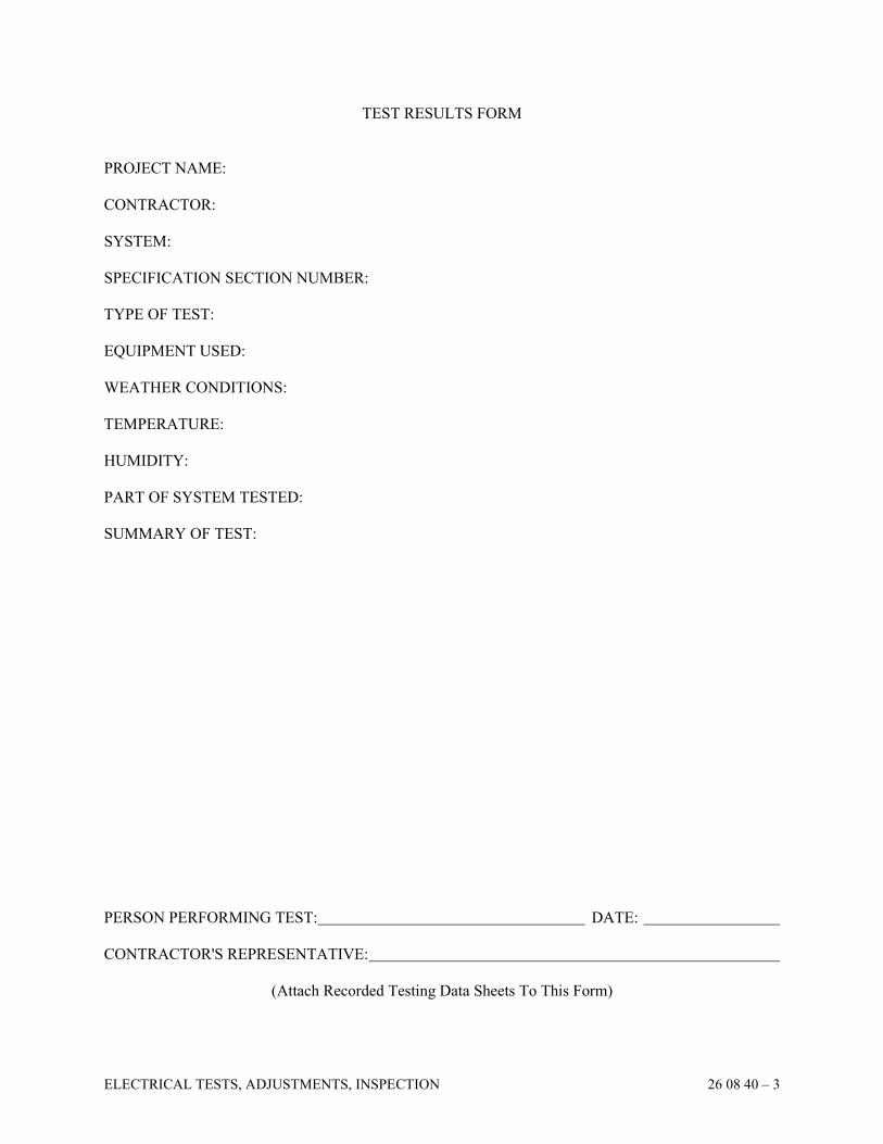
ELECTRICAL TESTS, ADJUSTMENTS, INSPECTION 26 08 40 – 3
TEST RESULTS FORM
PROJECT NAME:
CONTRACTOR:
SYSTEM:
SPECIFICATION SECTION NUMBER:
TYPE OF TEST:
EQUIPMENT USED:
WEATHER CONDITIONS:
TEMPERATURE:
HUMIDITY:
PART OF SYSTEM TESTED:
SUMMARY OF TEST:
PERSON PERFORMING TEST: DATE:
CONTRACTOR'S REPRESENTATIVE:
(Attach Recorded Testing Data Sheets To This Form)

ELECTRICAL TESTS, ADJUSTMENTS, INSPECTION 26 08 40 – 4
CERTIFICATE OF SYSTEM APPROVAL
PROJECT NAME:
CONTRACTOR:
SYSTEMS COMPONENT:
SPECIFICATION SECTION NUMBER:
A. APPROVAL (If required by specification section)
The above listed system has been inspected and approved as meeting the specified instructions for
installation.
Owner's Representative: Date:
B. EQUIPMENT DEMONSTRATION
The above listed system has been demonstrated to the following Owner's Representatives:
NAME TITLE DATE SIGNATURE
1.
2.
3.
4.
5.
6.
7.
8.
9.
10.
(ATTACH A SEPARATE PAGE FOR ADDITIONAL NAMES)
SECTION 26 09 43
NETWORK LIGHTING CONTROLS
NETWORK LIGHTING CONTROLS 26 09 43 – 1
PART 1 GENERAL
1.01 GENERAL
A. Lighting control panels, daylight harvesting/dimming panels, programmable switches,
photocontrols, and head end controls shall be by the Automated Logic-BAS system
provided by Division 23. All wiring and conduct to lighting fixtures and control
components by Division 26.
B. The BAS system shall control on/off time-of-day scheduling; remote override; dimming
panel, daylight harvesting setpoints, etc. for a complete lighting control system.
1.02 ADMINISTRATIVE REQUIREMENTS
A. Coordination:
1. Coordinate the placement of sensors and wall controls with millwork, furniture,
equipment, etc. installed under other sections or by others.
2. Coordinate the placement of wall controls with actual installed door swings.
3. Coordinate the placement of daylight sensors with windows, skylights, and luminaires
to achieve optimum operation. Coordinate placement with ductwork, piping,
equipment, or other potential obstructions to light level measurement installed under
other sections or by others.
B. Pre-Installation Meeting: Conduct on-site meeting with lighting control system
manufacturer prior to commencing work as part of manufacturer's standard startup services.
Manufacturer to review with installer:
1. Low voltage wiring requirements
2. Separation of power and low voltage/data wiring
3. Wire labeling
4. Lighting management hub locations and installation
5. Control locations
6. Load circuit wiring
7. Network wiring requirements
8. Connections to other equipment
9. Installer responsibilities
10. Power panel locations
C. Sequencing:
1. Do not install sensors and wall controls until final surface finishes are complete.
1.03 SUBMITTALS
A. See Section 01 3000 - Administrative Requirements for submittal procedures.
B. Product Data: Include ratings, configurations, standard wiring diagrams, dimensions,
colors, service condition requirements, and installed features.

NETWORK LIGHTING CONTROLS 26 09 43 – 2
C. Shop Drawings:
1. Provide schematic system riser diagram indicating component interconnections.
Include requirements for interface with other systems.
2. Provide detailed sequence of operations describing system functions.
D. Manufacturer's Installation Instructions: Include application conditions and limitations of
use stipulated by product testing agency. Include instructions for storage, handling,
protection, examination, preparation, and installation of product.
E. Project Record Documents: Record actual installed locations and settings for lighting
control system components.
F. Operation and Maintenance Data: Include detailed information on lighting control system
operation, equipment programming and setup, replacement parts, and recommended
maintenance procedures and intervals.
G. Warranty: Submit sample of manufacturer's Warranty or Enhanced Warranty as specified in
Part 1 under "WARRANTY". Submit documentation of final execution completed in
Owner's name and registered with manufacturer.
1.04 QUALITY ASSURANCE
A. Conform to requirements of NFPA 70.
B. Maintain at the project site a copy of each referenced document that prescribes execution
requirements.
C. Manufacturer Qualifications:
1. Company with not less than ten years of experience manufacturing lighting control
systems of similar complexity to specified system.
2. Registered to ISO 9001, including in-house engineering for product design activities.
3. Qualified to supply specified products and to honor claims against product presented in
accordance with warranty.
D. Maintenance Contractor Qualifications: Manufacturer's authorized service representative.
1.05 DELIVERY, STORAGE, AND HANDLING
A. Store products in a clean, dry space in original manufacturer's packaging in accordance
with manufacturer's written instructions until ready for installation.
1.06 FIELD CONDITIONS
A. Maintain field conditions within manufacturer's required service conditions during and after
installation.
1. System Requirements Unless Otherwise Indicated:
a. Ambient Temperature:
1) Lighting Control System Components, Except Those Listed Below: Between
32 and 104 degrees F.
2) Lighting Management System Computer: Between 50 and 90 degrees F.
b. Relative Humidity: Less than 90 percent, non-condensing.
NETWORK LIGHTING CONTROLS 26 09 43 – 3
PART 2 PRODUCTS
2.01 MANUFACTURERS
A. Blue Ridge Technology Components
B. Automated Logic System
2.02 GENERAL REQUIREMENTS
A. Provide products listed, classified, and labeled by Underwriter's Laboratories Inc. (UL) as
suitable for the purpose indicated.
B. Unless specifically indicated to be excluded, provide all required equipment, conduit,
boxes, wiring, connectors, hardware, supports, accessories, etc. as necessary for a complete
system that provides the control intent indicated.
C. Design lighting control equipment for 10 year operational life while operating continually
at any temperature in an ambient temperature range of 32 degrees F (0 degrees C) to 104
degrees F (40 degrees C) and 90 percent non-condensing relative humidity.
D. Electrostatic Discharge Tolerance: Design and test equipment to withstand electrostatic
discharges without impairment when tested according to IEC 61000-4-2.
E. Dimming and Switching (Relay) Equipment:
1. Designed so that electrolytic capacitors operate at least 36 degrees F (20 degrees C)
below the capacitor's maximum temperature rating when the device is under fully
loaded conditions at maximum rated temperature.
2. Inrush Tolerance:
a. Utilize load-handling thyristors (SCRs and triacs), field effect transistors (FETs)
and isolated gate bipolar transistors (IGBTs) with maximum current rating at least
two times the rated operating current of the dimmer/relay.
b. Capable of withstanding repetitive inrush current of 50 times the operating current
without impacting lifetime of the dimmer/relay.
3. Surge Tolerance:
a. Panels: Designed and tested to withstand surges of 6,000 V, 3,000 amps according
to IEEE C62.41.2 and IEC 61000-4-5 without impairment to performance.
b. Other Power Handling Devices: Designed and tested to withstand surges of 6,000
V, 200 amps according to IEEE C62.41.2 without impairment to performance.
4. Power Failure Recovery: When power is interrupted and subsequently restored, within
3 seconds lights to automatically return to same levels (dimmed setting, full on, or full
off) as prior to power interruption.
5. Dimming Requirements:
a. Line Noise Tolerance: Provide real-time cycle-by-cycle compensation for incoming
line voltage variations including changes in RMS voltage (plus or minus 2 percent
change in RMS voltage per cycle), frequency shifts (plus or minus 2 Hz change in
frequency per second), dynamic harmonics, and line noise.
1) Systems not providing integral cycle-by-cycle compensation to include
external power conditioning equipment as part of dimming system.
b. Incorporate electronic "soft-start" default at initial turn-on that smoothly ramps
lights up to the appropriate levels within 0.5 seconds.
NETWORK LIGHTING CONTROLS 26 09 43 – 4
c. Utilize air gap off to disconnect the load from line supply.
d. Control all light sources in smooth and continuous manner. Dimmers with visible
steps are not acceptable.
e. Load Types:
1) Assign a load type to each dimmer that will provide a proper dimming curve
for the specific light source to be controlled.
2) Provide capability of being field-configured to have load types assigned per
circuit.
f. Low Voltage Dimming Modules:
1) Coordination Between Low Voltage Dimming Module and Line Voltage
Relay: Capable of being electronically linked to a single zone.
2) Single low voltage dimming module; capable of controlling the following light
sources:
a) 0-10V analog voltage signal.
i. Provide Class 2 isolated 0-10V output signal conforming to IEC
60929.
ii. Sink current according to IEC 60929.
iii. Source current.
b) 10-0V reverse analog voltage signal.
6. Switching Requirements:
a. Rated Life of Relays: Typical of 1,000,000 cycles at fully rated 16 A for all
lighting loads.
b. Switch load in a manner that prevents arcing at mechanical contacts when power is
applied to and removed from load circuits.
c. Provide output fully rated for continuous duty for inductive, capacitive, and
resistive loads.
F. Device Finishes:
1. Wall Controls: Match finishes specified for wiring devices.
2. Standard Colors: Comply with NEMA WD1 where applicable.
3. Visible Parts: Exhibit ultraviolet color stability when tested with multiple actinic light
sources as defined in ASTM D4674. Provide proof of testing upon request.
G. Interface with building automation system BACnet protocol.
PART 3 EXECUTION
3.01 EXAMINATION
A. Verify that field measurements are as shown on the drawings.
B. Verify that ratings and configurations of system components are consistent with the
indicated requirements.
C. Verify that mounting surfaces are ready to receive system components.
D. Verify that conditions are satisfactory for installation prior to starting work.
NETWORK LIGHTING CONTROLS 26 09 43 – 5
3.02 INSTALLATION
A. Perform work in a neat and workmanlike manner in accordance with NECA 1 and, where
applicable, NECA 130.
B. Install products in accordance with manufacturer's instructions.
C. Define each dimmer/relay load type, assign each load to a zone, and set control functions.
D. Mount exterior daylight sensors to point due north with constant view of daylight.
E. Ensure that daylight sensor placement minimizes sensor view of electric light sources.
Locate ceiling-mounted and luminaire-mounted daylight sensors to avoid direct view of
luminaires.
3.03 EQUIPMENT DEMONSTRATION
A. After all system operational tests have been completed, schedule an instruction period with
the Owner. Instruction to be provided by manufacturer’s authorized field technician.
B. The instruction is to include the following:
1. Location of all components of the system and explanation of their function
2. Demonstration of equipment
3. Maintenance and repair procedures
4. Programming procedures
5. Review of documents in Record and Information Manuals
C. All participants shall sign the Certificate of System Completion from Section 26 00 99,
″Requirements for Contract Completion.″.
END OF SECTION
SECTION 26 24 20
PANELBOARDS
PANELBOARDS 26 24 20 – 1
PART 1 GENERAL
1.01 DESCRIPTION
A. Furnish and install circuit breaker panelboards as indicated in the panelboard schedules and
as shown on the Drawings. B. Provide all circuit breaker devices and accessories as noted on the Drawings, herein
specified, and as required. C. Short circuit ratings shall be as shown on the Drawings. D. Provide lug sizes as necessary for cable sizes as shown on the Drawings.
1.02 QUALITY ASSURANCE
A. All equipment shall be UL listed and labeled and in accordance with applicable NEMA and
ANSI Standards. B. Branch circuit breakers shall be UL listed as SWD (switching duty) for single pole 15 and
20 Ampere circuits. C. Branch circuit breakers feeding HVAC equipment shall be "HACR" rated.
1.03 SUBMITTALS
A. For Review:
1. Product data sheets of panelboards and devices
2. Schedules showing quantities, sizes, and arrangement of devices
B. To be included in Record and Information Manuals:
1. One (1) copy of each approved submittal
2. Accurate panelboard directories based on the schedules on the Drawings, but updated
per as-built changes
1.04 MANUFACTURERS
A. Panelboards
1. Square D Company
2. Cutler-Hammer/Eaton Corporation
3. Siemens Energy & Automation, Inc.
4. General Electric Company
PART 2 PRODUCTS
2.01 CIRCUIT BREAKER PANELBOARDS
A. Types
1. Panelboards shall be molded case circuit breaker type with dead front construction.
PANELBOARDS 26 24 20 – 2
2. Panelboards for 208Y/120 volt, 3 phase, 4 wire service shall be Square D Type NQOD
with Type "QOB" bolt on thermal magnetic molded case circuit breakers, (maximum
depth of 5 3/4 inches). 22,000 AIC minimum.
B. Boxes
1. Boxes shall be constructed of commercial, galvanized, code gauge sheet steel, surface
or flush mounted as scheduled on the Drawings.
2. Boxes for panelboards shall be sized to provide code gutters but to have minimum
width of 20 inches and a maximum depth of 5 3/4 inches.
3. Boxes for double tub panels shall be same size in height.
4. Boxes shall have sufficient wire bending space to accommodate conductor sizes as
shown on the Drawings.
5. Panelboard enclosures shall not have any openings that would compromise Arc-Flash
safety levels.
C. Bussing
1. Bus bars shall be copper and arranged and drilled for sequence phasing.
2. Equipment ground bus shall be provided in each panelboard in addition to any neutral
bus requirements. Bus to have same number, size, and type of anti-turn solderless lugs
neutral assembly has. Ground bus to be factory bonded to panelboard tub.
3. Provide full size neutral bus with suitable lugs for each outgoing feeder requiring a
neutral connection.
4. Provide through-feed lugs for all panelboards for future use.
D. Mains
1. Provide main breakers for panelboards of the type and class indicated on the Drawings.
Panelboards without main breakers are to be provided with solderless type incoming
lugs suitable for either copper or aluminum conductors sized to accommodate wiring as
shown on the Drawings.
E. Arrangement
1. Panelboards shall have respective main and branch breakers including spares,
provisions for future breakers and spaces arranged in accordance with panelboard
schedule to facilitate field wiring and be in agreement with branch circuiting shown on
the Drawings.
2. Panelboards equipped with multiple pole circuit breakers shall have circuit numbers
based on single pole position. Multiple pole breakers and spaces shall be identified by
top single pole position number of that breaker.
F. Branch Circuit Breakers
1. Thermal magnetic molded case circuit breakers with bolted bus connections.
2. Breakers shall have an over center, trip-free, toggle-type operating mechanism with
quick-make, quick-break action and positive handle indication.
3. Ground fault circuit interrupter (GFCI) type circuit breakers shall be rated for 5 or 30
milliamp trip setting, up to 60 Amperes/2 pole configuration at 22,000 AIC. Five
milliamp setting circuit breakers shall be used for personnel protection interior and
exterior. Thirty milliamp setting circuit breakers shall be used for equipment
protection only, exterior to the building (snow/ice melting equipment or pool/pond
pumping and lighting equipment).
4. Branch circuits shall be connected for sequenced phasing, i.e., circuits No. 1 and 2
connected to Phase A; circuits No. 3 and 4 connected to Phase B; etc. to conform with
PANELBOARDS 26 24 20 – 3
the branch circuit numbering system on the Drawings. "Polarity" or "Block" phasing
will not be acceptable.
5. Scheduled lock-on devices for certain branch circuits are to be furnished and installed
which prevent manual operation of breaker handle but not impede trip-free capability
of breaker.
G. Trims
1. Door and trim finish shall be Manufacturer's standard lacquer or enamel.
2. All trim shall be made for surface or flush mounted panelboards as scheduled on the
Drawings and hinged to back box for "door in door" design. Doors shall be equipped
with totally concealed hinges and trim clamps and flush chrome-plated combination
locks and catches, all keyed alike. Fronts shall not be removable with door in the
locked position.
3. Furnish two (2) keys for each panelboard installed and one (1) pint of touch-up enamel
paint.
PART 3 EXECUTION
3.01 INSTALLATION
A. Coordinate location of panelboards with the work of other Contractors. Installation shall
meet the requirements of NEC Article 110.26.
B. Securely install panelboards to building walls.
C. Install panelboard cabinets (box) at a height such that highest circuit breaker does not
exceed 6'-6" above floor.
D. Panelboards mounted on perimeter outside walls shall be shimmed 1/2 inch from wall with
washers to permit back ventilation.
E. Furnish directory frames inside the door of each panel which shall contain a correct
typewritten directory card, properly filled out to correspond to the circuit numbers on the
Drawings and the room numbers of loads served. If room numbers assigned by the Owner
do not match the room numbers on the Drawings, both sets of room numbers must be cross-
referenced and identified in the panel directory.
F. All flush panelboards shall have a 3/4 inch spare conduit rising and turning out of the wall
above the ceiling line for every three (3) spares and spaces in the panelboard.
G. Clean interior and exterior of equipment. Touch-up all scratched finishes. Vacuum out all
debris in enclosure before energizing.
H. Provide nameplates in accordance with Section 26 05 53, "Electrical Identification."
I. Deliver keys and touch-up enamel to Owner's Representative. Refer to Section 26 00 99,
"Requirements for Contract Completion."
END OF SECTION
SECTION 26 27 26
WIRING DEVICES AND PLATES
WIRING DEVICES AND PLATES 26 27 26 – 1
PART 1 GENERAL
1.01 DESCRIPTION
A. Furnish and install wiring devices and plates as specified herein and as shown on the
Drawings.
B. Specialty switches and outlets required for auxiliary systems shall be specified under those
Sections or as shown on the Drawings.
C. All devices shall be ganged together where shown grouped on the Drawings.
D. All normal power devices shall be the same color.
1.02 QUALITY ASSURANCE
A. All equipment shall be UL listed and labeled and in accordance with applicable NEMA and
ANSI Standards.
B. All wiring devices and plates shall be furnished by one of the Manufacturers listed. No
mixing of Manufacturer's products shall be permitted unless otherwise noted herein or on
the Drawings.
1.03 SUBMITTALS
A. For Review:
1. Product data sheets for wiring devices and plates
B. To be included in Record and Information Manuals:
1. One (1) copy of each approved submittal
1.04 MANUFACTURERS
A. Wiring Devices (except dimmers) and Plates
1. Cooper
2. Pass and Seymour
3. Hubbell
4. Leviton
B. Dimmers and Plates
1. Lutron
2. Leviton
C. Cover Assemblies
1. TayMac Corporation
2. Intermatic Inc.
3. Carlon Electrical Products
WIRING DEVICES AND PLATES 26 27 26 – 2
D. Occupancy Sensors
1. Watt Stopper Inc.
2. Leviton
3. Sensorswitch
4. Lutron
PART 2 PRODUCTS
2.01 SWITCHES
A. Switches shall conform to NEMA Heavy Duty Standards and shall be Specification Grade,
general use AC quiet type, 20 Ampere, 120-277 volt, back and side wired with white
handles, unless noted otherwise.
B. Lock type switches shall be 20 Ampere, 120-277 volt, back and side wired Corbin lock
type, with stainless steel flush plate. Furnish two (2) keys with each lock type switch. All
locks shall be keyed alike.
C. Pilot light switches shall be Specification Grade, general use AC quiet type, 20 Ampere,
120-277 volt, back and side wired with clear handle.
D. Momentary contact switches shall be SPDT 2 circuit, 3 position, center "off," 20 Ampere,
120-277 volt, side wired with white handles.
E. Door jam switch shall be flush mounted, push button type switch. Arrow Hart 4029.
2.02 DIMMERS
A. LED Dimmers
1. Dimmers for LED luminaires shall be listed and tested for use on LED luminaires.
Local manual dimmers for LED loads shall be solid state, thin profile, slide type with
square law dimming, power failure memory, gangable with side sections intact. Color
shall be white. There shall be no visible screws or fins from the front. Wattage rating
shall be 2000 watt, unless otherwise shown on the Drawings. Dimmers shall not be
derated. Dimmers shall be single location or two location (using standard 3 way
wiring) as noted on the Drawings.
2.03 RECEPTACLES
A. All convenience and power receptacles shall conform to NEMA Heavy Duty Standards and
shall be Specification Grade, grounding type.
B. Convenience duplex receptacles shall be 20 Ampere, 125 volt, back and side wired, 3 wire
grounding, UL listed as complying with the requirements of NEC Article 250.146, NEMA
5-20R configuration.
C. Ground-fault circuit-interrupting (GFCI) duplex receptacles shall be 20 Ampere, 125 volt
"feed-through" type, NEMA 5-20R configuration.
WIRING DEVICES AND PLATES 26 27 26 – 3
D. Tamper resistant duplex receptacles shall be 20 Ampere, 125 volt, 3 wire grounding, UL
listed in accordance with NEC 406.11 and 210.52, NEMA 5-20R configuration.
E. Weatherproof Duplex Receptacles shall be 20 Ampere, 125 volt or 250 volt, UL listed as
weather resistant type per NEC 406.
F. All receptacles shall be white, unless on emergency power, in which case receptacles shall
be red.
G. USB receptacles shall be combination USB charger and 120 volt outlet (5 volt 3.8 Amp
DC).
H. Refer to the Drawings for specification of specialty receptacles.
2.04 PLATES
A. Plates for flush devices in interior partitions finished with glass, stone, wood paneling,
and/or p-lam shall be stainless steel. White thermoplastic plates shall be used at painted
walls.
B. Plates for flush devices on concrete block walls shall match others but be "Jumbo" plates.
C. Plates for voice/data communication boxes shall match wiring device plates in material.
D. Plates for devices in surface fittings shall be cadmium plated steel surface covers. Covers
shall fit without overlap and have round corners.
E. Plates for specialty receptacles required for auxiliary systems shall be satin stainless steel,
furnished and specified with the device.
F. Plates for future system outlets shall be blank plates matching device plates in quality and
finish.
G. Plates for devices on emergency circuit shall be red.
2.05 COVER ASSEMBLIES
A. Wiring devices in wet locations shall have hinged, gasketed cast aluminum coverplates of a
color matching adjacent wall finish.
B. Wiring devices subject to wet locations while in use shall be provided with NEMA 3R
cover assemblies UL listed for wet locations while in use. Cover assemblies shall use a
vertically-lifting "canopy" to protect the wiring device(s). Cover assemblies shall be
standard size, one (1) or two (2) gang as required with gaskets between the hinged cover
and mounting plate/base to assure proper seal.
2.06 OCCUPANCY SENSORS
A. Ceiling mounted low voltage dual technology occupancy sensors shall contain both PIR
and ultrasonic technologies, adjustable 15 second to 15 minute time delay, integrated
adjustable light level sensor, adjustable sensitivities, LED indicator for both technologies,
WIRING DEVICES AND PLATES 26 27 26 – 4
isolated relay, 24 VDC operable, 120 volt power pack, 1200 square feet - wide angle
coverage. Watt Stopper DT-200L, white color. Provide minimum one (1) power pack for
every room.
B. Wall mounted line voltage passive infrared occupancy sensor shall have adjustable 30
second to 30 minute time delay, manual off switches for bilevel lighting control, integrated
adjustable light level sensor, adjustable sensitivity, LED indicator, 900 square feet - 180
degree coverage. Color shall be white.
2.07 OCCUPANCY SENSOR / DIMMER SWITCH
A. Wall mounted device shall match 2.06B and have 0-10 volt dimming capability using
“sink” configuration for powered drivers in LED lighting fixtures.
2.08 PHOTOSENSORS
A. Ceiling mounted photosensor shall be compatible with Daylight Harvesting Relay based
lighting control panel furnished with the Automated Logic BAS System.
PART 3 EXECUTION
3.01 APPLICATION
A. Provide outlets as noted on the Drawings and herein described.
B. Provide GFCI type outlets in all bathrooms, anywhere within 6 feet of sinks, lavatories,
mop basins, and in all exterior locations.
C. Provide GFCI type outlets for all 120 volt devices located in kitchens and other food
preparation rooms.
D. Provide tamper resistant devices in all spaces for children under 8 years of age.
3.02 INSTALLATION
A. Install wiring devices as indicated, in compliance with the Manufacturer's written
instructions, applicable requirements of NEC and NECA's "Standard of Installation," and in
accordance with recognized industry practices to fulfill project requirements.
B. Coordinate installation of wiring devices with other work, including painting, electrical box
and wiring work, as necessary.
C. Install wiring devices only in electrical boxes, which are clean, free from excess building
materials, dirt and debris.
D. All devices shall be connected to conductors using the side wiring terminal screw
connections. Devices with voltages higher than 120 volt shall have two (2) layers of
electrical tape applied over the exposed side terminals. Provide electrically continuous,
tight grounding connections for wiring devices, as required by NEC Article 250.

WIRING DEVICES AND PLATES 26 27 26 – 5
E. Delay installation of wiring devices and wall plates until after painting work is completed.
Wiring devices may be installed prior to painting where protective plastic covers are used.
All wiring devices and covers shall be clean and free of paint upon completion of work.
F. Upon installation of wall plates and receptacles, advise other Contractors regarding proper
and cautious use of convenience outlets. At time of Contract Completion, replace those
items which have been damaged, including those burned and scored by faulty plugs.
G. Install matching device plates on all devices. Devices shown grouped on the Drawings
shall be ganged together with one plate.
H. Ceiling mounted occupancy sensors shall not be installed within 3 feet of an HVAC
diffuser. Provide lens shields as required to prevent nuisance operation of occupancy
sensors. Locate or aim sensors so they sense all areas of the room, but not out the doorway.
I. Install engraved flush switch plates at all locations indicating function of switches for
special applications and at every location where more than two switches are ganged
together. Engraved switch plates shall have 1/8 inch black filled letters.
J. Provide permanently installed barriers between switches ganged in outlet boxes where the
voltage between adjacent switches exceeds 300 volts.
K. Run neutral conductor to all dimmers.
L. Receptacle plates shall be labeled with permanent marker on the back with panelboard and
circuit number.
M. All unused outlet boxes shall have blank coverplates installed.
N. Wiring from ground-fault circuit-interrupters shall not occupy the same raceways with
wiring from non-ground-fault interrupting type devices.
O. Occupancy sensors to be initially set at 75% maximum sensitivity and 5 minute time delay.
Locate all occupancy sensor power packs and slave packs above lay-in ceiling at room
entry location.
P. Tamper resistant duplex receptacles shall have their coverplates attached with tamper proof
screws.
Q. Wiring devices shall be installed with grounding pin on top.
3.03 OCCUPANCY SENSOR OPERATION VERIFICATION
A. Contractor shall verify proper operation of every occupancy sensor in building at
completion of project. Provide appropriate masking on sensor where line-of-site extends
out of room and causes nuisance operation when room is vacant.
3.04 SPARE PARTS
A. Furnish spare occupancy sensors in a quantity of 5% of total (of each type) used in building
(minimum of two (2) of each type).
WIRING DEVICES AND PLATES 26 27 26 – 6
B. Division 26 Contractor shall include in his/her bid an allowance for furnishing and
installing five (5) additional occupancy sensors of each type (with average length of
conduit and wire) at completion of the project as directed by the Architect. If all are not
used, remaining value shall be credited to the Owner or turned over to the Owner as
additional spares per Owner's discretion.
C. Two screwdrivers for any specialty fasteners used.
3.05 TESTING
A. Prior to energizing circuitry, test wiring devices for electrical continuity, short circuits, and
proper polarity connections.
B. Verify that occupancy sensors are turning off lighting when spaces are unoccupied. Each
sensor shall be tested for proper operation with HVAC system operational.
END OF SECTION
SECTION 26 28 16
SAFETY SWITCHES
SAFETY SWITCHES 26 28 16 – 1
PART 1 GENERAL
1.01 DESCRIPTION
A. Furnish and install safety switches where shown on the Drawings, and where required
including all accessories and mounting hardware.
1.02 QUALITY ASSURANCE
A. All equipment shall be UL listed and labeled and in accordance with applicable NEMA and
ANSI Standards.
1.03 SUBMITTALS
A. For Review:
1. Product data sheets of safety switches
B. To be included in Record and Information Manuals:
1. One (1) copy of each approved submittal
1.04 MANUFACTURERS
A. Safety Switches
1. Square D Company
2. Cutler-Hammer Electric Corporation
3. Siemens Energy & Automation, Inc.
4. General Electric Company
B. Equipment shall be furnished by the Manufacturer supplying major components of the
electrical distribution system.
PART 2 PRODUCTS
2.01 SAFETY SWITCHES - NON-FUSIBLE
A. Safety switches shall have heavy-duty, single-throw, quick-make, quick-break, visible knife
blade operators mounted in hinged cover steel enclosure. Lugs shall be listed for 75
degrees C ampacity aluminum or copper wire.
B. Switches shall be clearly labeled for "ON" and "OFF" handle positions. Cover shall have
defeatable safety interlock with handle to prevent inadvertent opening when in the "ON"
position. Handle shall be pad lockable in the "OFF" position.
C. Safety switches to be horsepower rated 600 volt AC.
D. Switches shall have ground lug kit and neutral when required.
SAFETY SWITCHES 26 28 16 – 2
2.02 SAFETY SWITCHES - FUSIBLE
A. Fusible safety switches shall be as specified in Paragraph 2.01 and with the following
additional features:
1. Safety switches rated 600 Amperes and less shall have spring reinforced, plated fuse
clips with rejection feature for Class R fuses.
2. Safety switches rated larger than 600 Amperes shall have provisions for Class L fuses.
3. Short circuit-interrupting rating shall be 200,000 Amperes RMS symmetrical.
4. Safety switches to be horsepower rated 240 volt AC for 208 or 240 volt usage, and 600
volt AC for 480 volt usage.
2.03 AC MANUAL TOGGLE DISCONNECT SWITCHES
A. Toggle disconnect switch shall be snap switch with copper mechanism, silver alloy
contacts, 10,000 Ampere withstand rating, in a NEMA 1 enclosure. 1, 2, or 3 pole with
amperages of 30 to 60 Amperes, as required for load connected.
PART 3 EXECUTION
3.01 APPLICATION
A. Provide the following NEMA rated enclosure types in these locations:
1. Interior - 1
2. Exterior - 3R
B. Provide AC manual toggle disconnect switch in NEMA 1 enclosure for disconnecting
means located at instantaneous electric water heaters.
3.02 INSTALLATION
A. Use flexible conduit to and from safety switches where vibration isolation is required.
B. Install safety switches securely to building structure. Install safety switches on freestanding
metal framing system support where mounting to building structure is not feasible or where
shown on the Drawings. Framing system shall be galvanized steel.
C. Safety switches located downstream of variable frequency drives shall have auxiliary
control power interlock switch on handle. Run wiring to variable frequency drives.
D. Provide fuses sized in accordance with Equipment Manufacturer's data plate.
E. Provide nameplates in accordance with Section 26 05 53, "Electrical Identification."
F. Touch-up all scratches on enclosure after installation.
END OF SECTION
SECTION 26 28 19
CIRCUIT BREAKERS
CIRCUIT BREAKERS 26 28 19 – 1
PART 1 GENERAL
1.01 DESCRIPTION
A. Furnish and install circuit breakers in switchboards, distribution panelboards, and separate
enclosures for overcurrent protection for panelboards, transformers and equipment, as
shown on the Drawings and specified herein. Provide all accessories as necessary.
B. Short circuit ratings shall be as shown on the Drawings.
C. Refer to Section 26 24 20, "Panelboards-Lighting and Appliance" for circuit breakers in
panelboards.
D. Provide frame size of circuit breaker with lug size as required to accommodate feeder size
as shown on the Drawings.
E. Provide frame size, plug size, and trip units as necessary to meet short circuit ratings, and to
provide selective coordination (down to 0.01 seconds) on emergency power distribution
systems.
F. All circuit breakers shall be fully rated for short circuit levels indicated. Series ratings are
not permitted.
1.02 QUALITY ASSURANCE
A. All equipment shall be UL listed and labeled and in accordance with applicable NEMA and
ANSI Standards.
1.03 SUBMITTALS
A. For Review:
1. Product data sheets for all circuit breakers and components
2. Wiring diagrams
B. To be included in Record and Information Manuals:
1. One (1) copy of each approved submittal
2. Test results
3. Manufacturer Representative's signed Certificate of Inspection and Approval
1.04 MANUFACTURERS
A. Circuit Breakers
1. Siemens Energy & Automation, Inc.
2. Cutler-Hammer/Eaton Corporation
3. Square D Company
4. General Electric Company
CIRCUIT BREAKERS 26 28 19 – 2
PART 2 PRODUCTS
2.01 MOLDED CASE CIRCUIT BREAKERS WITH THERMOMAGNETIC TRIP
A. Molded case circuit breakers shall be bolt-on type operated by a toggle type handle and
shall have quick-make/quick-break over-center switching mechanism that is mechanically
trip free from the handle so that the contacts cannot be held closed against short circuits and
abnormal currents. Tripping due to overload or short circuit shall be clearly indicated by
the handle automatically assuming a position midway between the manual ON and OFF
positions.
B. Breakers must be completely enclosed in a molded case. Non-interchangeable trip breakers
shall have their covers sealed; interchangeable trip breakers shall have the trip unit sealed
to prevent tampering. Ampere ratings shall be clearly visible. Arc extinction must be
accomplished by means of arc chutes.
C. Molded case breakers shall be of the thermal magnetic standard type that provides inverse
time delay overload and instantaneous short circuit protection by means of a thermal
magnetic element.
D. Single phase circuit breakers shall be balanced among the three (3) phases.
E. All circuit breakers shall have an integral lock-out/tag-out means.
F. High magnetic withstand circuit breaker type shall utilize higher trip levels of 18 to 20
times the breaker handle rating.
2.02 MOLDED CASE CIRCUIT BREAKERS WITH SOLID STATE TRIP
A. Circuit protective devices shall be molded case type circuit breakers UL Listed for 80%
continuous current with full function trip system. Frame/Sensor ampere ratings shall be as
shown on the Drawings. The ampere rating shall be clearly marked on the front of the
circuit breaker. Circuit breakers shall be of fixed construction.
B. Circuit breakers shall be constructed using glass-reinforced insulating material providing
high dielectric strength. Current carrying components shall be completely isolated from the
trip unit and accessory mounting area. Breakers shall have common tripping of all poles
and shall be trip free. The breakers shall have quick-make/quick-break contacts with an
over center toggle operating mechanism. All circuit breakers shall be equipped with
electrical accessories as noted on the Drawings.
C. The integral electronic trip system shall be independent of any external power source and
shall contain electronic components to measure and time the output from internal current
sensors and initiate automatic tripping action. The continuous ampere rating of the circuit
breaker shall be determined by the combination of the ampere rating switch position, and
the frame/sensor size of the circuit breaker. The resulting ampere rating shall be clearly
marked on the face of the circuit breaker. Provide a means to seal the trip unit adjustments
to discourage unauthorized tampering to meet the requirements of NEC Article 240.6.
CIRCUIT BREAKERS 26 28 19 – 3
D. Provide the following time/current curve shaping adjustment to maximize system selective
coordination. Each adjustment shall have discrete settings and shall be independent from
all other adjustments:
1. Adjustable Long Time Ampere Rating and Delay
2. Adjustable Short Time Pickup and Delay (delay includes I2t in and I2t out)
3. Fixed Instantaneous Trip
4. Ground fault trip (where shown on one line diagram)
E. Provide local visual trip indication for overload, short circuit occurrences. The trip system
shall include a memory circuit to detect intermittent overcurrent conditions. Each circuit
breaker trip system shall be equipped with an externally accessible test port for use with a
Universal Test Set. No disassembly of the circuit breaker is required for testing. Test set
shall be capable of verifying the operation of all trip functions with or without tripping the
circuit breaker.
F. All circuit breakers shall have an integral lock-out/tag-out means.
2.03 INSULATED CASE CIRCUIT BREAKERS WITH SOLID STATE TRIP
A. Circuit protective devices shall be insulated case type circuit breakers UL lists for 100%
continuous current with full function trip system. Frame/Sensor ampere ratings shall be
shown on the Drawings. Circuit breakers shall be of drawout construction.
B. Provide selective override circuit on circuit breakers with defeatable instantaneous
adjustment to allow the breaker (1) to remain closed for up to thirty (30) cycles during
overcurrents below 50 kA RMS symmetrical, and (2) to trip instantaneously when current
levels exceed thirty (30) cycle withstand rating. All circuit breakers shall be constructed in
accordance with UL 489 and NEMA AB1-1986. Circuit breakers shall be constructed
using glass-reinforced insulating material providing high dielectric strength. Current
carrying components shall be completely isolated from the trip unit and accessory
mounting area. Breakers shall have common tripping of all poles and shall be trip free.
The circuit breaker shall be UL listed for reverse connection without requiring special
construction.
C. Provide true two step stored energy mechanism for five (5) cycle closing. Energy required
to close breaker shall be stored pending release to close action. All circuit breakers shall
have multiple CHARGE/CLOSE provisions allowing the following sequence: CHARGE,
CLOSE, RECHARGE, OPEN/CLOSE/OPEN. Visual indication of mechanism
CHARGED and DISCHARGED position on the face of the breaker. Visual indicator shall
show the face of the breaker. Visual indicator shall show CHARGED only when closing
springs are completely charged.
D. Provide interlocking capabilities for lockout of local manual closing buttons and
padlocking main contacts in OPEN position.
E. The integral trip system shall be independent of any external power source and shall
contain electronic components to measure and time the output from internal current sensors
and initiate automatic tripping action. The trip unit shall be factory installed and capable of
being field interchangeable while retaining UL listing.
CIRCUIT BREAKERS 26 28 19 – 4
F. The continuous ampere rating of the circuit breaker shall be determined by the combination
of an interchangeable rating plug and the sensor size of the circuit breaker. The ampere
rating resulting from the rating plug/sensor combination shall be clearly marked on the
front of the circuit breaker. Provide a means to seal the rating plug and trip unit
adjustments to discourage unauthorized tampering to meet the requirements of NEC Article
240.6.
G. Provide the following time/current curve shaping adjustments to maximize system selective
coordination. Each adjustment shall have discrete settings and each function is independent
from all other adjustments:
1. Adjustable Long Time Ampere Rating and Delay
2. Adjustable Short Time Pickup and Delay (delay includes I2t in and I2t out)
3. Adjustable Defeatable Instantaneous Pickup
4. Adjustable Ground-Fault Pickup and Delay (delay includes I2t in and I2t out)
5. Fixed Selective Override
H. Provide local visual trip indication for overload, short circuit and ground-fault trip
occurrences. Provide a long time pickup light to indicate when loading approaches or
exceeds the continuous current carrying capacity of the circuit breaker. The trip system
shall include a memory circuit to detect intermittent overcurrent conditions. Each circuit
breaker trip system shall be equipped with an externally accessible test port for use with a
Universal Test Set. No disassembly of the circuit breaker is required for testing. Test set
shall be capable of verifying the operation of all trip functions with or without tripping the
circuit breaker.
I. Circuit breakers shall be provided with integral ground-fault protection. The circuit breaker
shall be applicable on 3 phase, 3 wire circuits where the neutral is grounded, but not carried
through the system or 3 phase, 4 wire systems. The ground-fault system shall be Zero
Sequence. The ground-fault sensing system shall meet the on-site testing requirements of
NEC Article 230.95(c). Provide a separate neutral current transformer for 3 phase, 4 wire
systems.
J. Circuit breakers provided with emergency power system shall have ground-fault indication
only.
2.04 ENCLOSURES
A. Enclosures shall have padlocking provisions for locking circuit breakers in the "OFF"
positions.
B. Enclosure types shall be as follows:
1. NEMA 1 - Gray baked enamel on galvanized steel
2. NEMA 3R - Gray baked enamel on galvanized steel with drain holes, lockable door,
securable in the open position
3. NEMA 4X - Stainless steel with gasketed cover
C. Enclosures shall be flush mounted in gypsum board walls and surface mounted on concrete
walls.
CIRCUIT BREAKERS 26 28 19 – 5
PART 3 EXECUTION
3.01 APPLICATION
A. 15 Ampere through 250 Ampere circuit breakers shall be molded case with
thermomagnetic trip sensor and mechanism.
B. 300 Ampere and above through 1600 Ampere circuit breakers shall be molded case with
solid state trip sensor and mechanism.
C. Circuit breakers above 1600 Ampere shall be insulated case with solid state trip sensor and
mechanism.
D. Service entrance main circuit breakers shall have single phase protection and shall open
when the voltage on any one phase leg drops below 70%.
E. Provide the following NEMA rated enclosure types for single circuit breakers in these
locations:
1. Interior - 1
2. Exterior - 3R
3. Kitchens - 4X
F. Provide electronic trip circuit breakers for switchboards where two levels of ground-fault
protection are used.
G. Provide auxiliary contacts on circuit breakers used to feed elevator equipment.
3.02 INSTALLATION
A. Install circuit breakers in switchboards, distribution panelboards or enclosures as shown on
the Drawings and in accordance with Manufacturer's written instructions.
B. Provide nameplates in accordance with Section 26 05 53, "Electrical Identification."
3.03 TESTING
A. Perform a complete functional test of all features of circuit breakers in accordance with
Manufacturer's recommendations. Submit written documentation in Record and
Information Manuals.
END OF SECTION
SECTION 26 43 13
SURGE PROTECTION DEVICES
SURGE PROTECTION DEVICES 26 43 13 – 1
PART 1 GENERAL
1.01 DESCRIPTION
A. Furnish and install Transient Voltage Surge Suppression (TVSS) units as shown on the
Drawings and herein specified.
1.02 QUALITY ASSURANCE
A. Surge suppressors shall be UL Listed and labeled under UL 1449.
B. Surge suppressors shall be tested to ANSI C62.41 and C62.45 Standards.
1.03 SUBMITTALS
A. For Review:
1. Product data sheets of all components
2. All operating parameters including UL 1449 voltage category
3. Test results
B. To be Included in Record and Information Manuals:
1. One (1) copy of each approved submittal
1.04 MANUFACTURERS
A. Transient Voltage Surge Suppression
1. Cutler-Hammer (Clipper)
2. Siemens Sentron TPS
3. Square D Company
4. General Electric Company
PART 2 PRODUCTS
2.01 TRANSIENT VOLTAGE SURGE SUPPRESSION
A. Transient Voltage Surge Suppression (TVSS) units where shown within switchgear shall be
integral mounted in an enclosed compartment, separate from the internal busbars with a
hinged lockable door and provided with disconnect means. Diagnostic lights shall be
mounted in front door.
B. Units shall be self-contained, wall mountable, solid-state devices in an NEMA 12,
enameled steel enclosure with hinged door and locking handle.
C. Units shall consist of an engineered system to achieve suppression using one (1) or more of
the following components:
1. Doped selenium plates
2. Metal Oxide Varisters (MOV) in enclosed replaceable modules
3. Sillicon Avalanche Diodes (SAD) in enclosed replaceable modules

SURGE PROTECTION DEVICES 26 43 13 – 2
D. SPD unit components shall be arranged to operate bi-directionally, in parallel with the line,
have sinewave tracking characteristics, and have seven (7) modes of protection as follows:
1. Each Phase: Line to Neutral
2. Each Phase: Line to Ground
3. Neutral - Ground
E. SPD units shall be classified by UL with the following ratings:
Maximum Clamping
Voltage L-N
Maximum Clamping
Voltage N-G
208/120 volt, 3 phase "WYE" units - 400 volt 400 volt
480/277 volt, 3 phase "WYE" units - 800 volt 800 volt
F. SPD units shall be capable of surviving the following surge current on a single impulse
basis without performance degradation of more than 10%:
1. Located at Service Entrance switchgear 150,000 Amperes per mode
(300,000 Amperes per phase)
2. Located at downstream panelboards 50,000 Amperes per mode
(100,000 Amperes per phase)
G. Units shall have Form C summary output contacts for remote monitoring capability.
H. Units shall have integral noise filtering of the following minimum attenuation level:
100 KHz – 55dB.
I. Units shall have integral diagnostic indicating lights and individual MOV fusing.
PART 3 EXECUTION
3.01 INSTALLATION
A. Install transient voltage surge suppression where shown on the Drawings, and in
accordance with Manufacturer's written instructions.
B. Units shall be installed as close as possible to the equipment being protected (preferably
closed nippled). Conductors and conduit shall be run horizontally directly from electrical
equipment to surge suppressor enclosure.
3.02 EQUIPMENT DEMONSTRATION
A. After all system tests have been completed, schedule an instruction period with the Owner.
Instruction to be provided by Manufacturer's authorized field technician.
B. Instruction shall include:
1. Location of all components of the system and explanation of their function
2. Demonstration of equipment

SURGE PROTECTION DEVICES 26 43 13 – 3
3. Maintenance and repair procedures
4. Programming procedures
5. Review of documents in Record and Information Manuals
C. Contractor shall have all participants sign the Certificate of System Completion in Section
26 00 99, "Requirements for Contract Completion."
3.03 EXTENDED WARRANTY/SPARE PARTS
A. Provide a five (5) year Extended Warranty or a complete spare parts package in accordance
with Manufacturer's standard arrangement.
END OF SECTION
SECTION 26 51 14
LUMINAIRES
LUMINAIRES 26 51 14 – 1
PART 1 GENERAL
1.01 DESCRIPTION
A. Furnish and install luminaires, lamps, ballasts and in-line fuses as herein specified and
shown on the Drawings.
B. Luminaire Manufacturer and model numbers shall be as scheduled on the Drawings.
Luminaires not bearing a letter symbol shall match adjacent luminaire in space.
C. All lamps and ballasts for a given luminaire type shall be by the same Manufacturer.
1.02 QUALITY ASSURANCE
A. All equipment shall be UL listed and labeled and in accordance with applicable NEMA and
ANSI Standards.
B. Ballasts shall be certified by ETL and CBM. Ballasts shall match lamps with appropriate
ANSI code.
1.03 SUBMITTALS
A. For Review:
1. Luminaires
a. Product data sheets for each fixture.
b. Lamp product data sheets for each fixture.
c. Ballast, LED driver, or power supply product data sheets for each fixture.
2. Construction Drawings for custom luminaires
B. To be included in Record and Information Manuals:
1. One (1) copy each of approved submittal
2. Spare lamp inventory list
3. Certificate of Material Receipt
1.04 MANUFACTURERS
A. Luminaires
1. Refer to Luminaire Schedule on the Drawings.
B. Fuses
1. Refer to Section 26 28 13, "Fuses."
C. Surge Arrestors
1. Delta Lightning Arrestors Inc.
LUMINAIRES 26 51 14 – 2
PART 2 PRODUCTS
2.01 LUMINAIRES
A. Luminaires shall be as scheduled on the Drawings.
2.02 LUMINAIRE ACCESSORIES
A. Luminaires located in mechanical and electrical rooms shall have appropriate guards
provided with each luminaire.
B. Luminaires located in gypsum board (drywall) or plaster ceilings shall have appropriate
plaster rings provided with each luminaire.
C. Luminaires provided by the Manufacturer with cords attached shall be coordinated by the
Division 26 Contractor so that cord lengths are of appropriate lengths for each luminaire
installation.
D. Luminaires shall be provided with all required mounting hardware for a complete
installation.
E. Exterior luminaires shall be installed on concrete bases.
F. Lightning arrestors shall be rated for a 100,000 Ampere discharge current.
G. Exterior aluminum poles longer than 19 feet shall have internal vibration dampeners.
PART 3 EXECUTION
3.01 INSTALLATION
A. Luminaires shall be securely mounted to elements of the building structure such that they
will be square, plumb, and rigid, and will not fall or sag. Flush luminaires shall be
furnished with installation provisions compatible with the suspended acoustical system
furnished by the General Trades Contractor. This Contractor shall verify the actual
suspension system to be used and make all adjustments in luminaire installation provisions.
B. All luminaires mounted in suspended acoustical tile ceilings shall be securely attached to
the ceiling grid system by removable grid clips or fasteners. Recessed "can" type
luminaires shall have bar hangers attached to the ceiling grid system.
C. All luminaires mounted on suspended acoustical tile ceilings shall be mounted to junction
boxes with bar hangers attached to the ceiling grid system. In addition, luminaires heavier
than ten (10) pounds shall have hangers attached to the ceiling grid system.
D. All luminaires that are wall mounted or surface mounted to other than suspended acoustical
tile ceilings shall be attached to outlet boxes that are securely supported to the building
structure and UL listed for luminaire support.
LUMINAIRES 26 51 14 – 3
E. All surface mounted and recessed luminaires installed in suspended acoustical tile ceilings,
shall have a supplemental support means attached to the building structure consisting of
chain or cable, installed with 6 inches of slack. This support means shall be attached from
the structure to the luminaire at each end and shall be capable of suspending the luminaire
in the event the ceiling grid at the luminaire is removed.
F. Clean both inside and outside surfaces of luminaires after installation. No luminaires shall
be installed until the painting work of the General Trades Contractor is completed.
Damaged, deformed or defective luminaires are to be replaced.
G. Prewired flush luminaire shall have minimum 90 Degree C wiring. Junction box capacity
shall be sufficient for the circuit wiring requirements.
H. Furnish all required installation accessories for the luminaires as required for specific
location whether or not included in the Manufacturer's catalog number. Such accessories
include plaster frames, rings, flanges, canopies, stem hangers, and suspension straps.
REFER TO ARCHITECTURAL ROOM TREATMENT SCHEDULE.
I. Designated night light, emergency egress, and exit signage luminaires shall be connected
ahead of any switching.
J. Luminaires provided by the Manufacturer with cords attached shall be coordinated by the
Division 26 Contractor to assure adequate cord length for each individual luminaire
installation.
K. Luminaire supports used in fire rated ceiling assemblies shall be in conformance with that
assembly's UL listing requirements.
L. Install in-line fuse and fuse holders in all exterior pole luminaires on the line side of the
ballasts. Install two (2) fuse holders or a double pole fuse holder for ballasts on 208, 240,
or 480 volt single phase circuits. Fuse holders shall be installed at a location convenient for
changing fuses. Install lighting surge arrestors in base.
M. Coordinate exact wiring requirements to luminaire ballasts with Manufacturer.
N. Flexible conduit or cord run down to suspended luminaires shall be installed along side of
the suspension chain and neatly attached along its entire length.
O. Fixture whips shall be of a minimum size as specified in Section 26 05 10, "Wire and
Cable" and Section 26 05 33, "Conduit and Fittings".
3.02 SPARE PARTS
A. Division 26 Contractor shall include in his/her bid an allowance for furnishing and
installing five (5) additional exit sign luminaires (with average length of conduit and wire)
at completion of project as directed by the Architect. If not all used, remaining value shall
be credited to Owner or turned over to Owner as additional spares per Owner's discretion.
B. Division 26 Contractor shall provide one spare lighting fixture for each type used.
END OF SECTION
SECTION 26 81 11
FIRE ALARM SYSTEM EXTENSION
FIRE ALARM SYSTEM EXTENSION 26 81 11 – 1
PART 1 GENERAL
1.01 DESCRIPTION
A. Division 26 Contractor shall furnish and install all equipment and accessories for an
extension of the existing fire alarm system.
1.02 QUALITY ASSURANCE
A. Fire alarm installation shall conform to the requirements of the NFPA 101, Life Safety Code,
the Ohio Building Code, and Local Code and Building Authority requirements.
B. All equipment shall be UL listed and labeled, and in accordance with applicable NEMA and
ANSI Standards and Codes:
1. American Society of Heating, Refrigerating and Air Conditioning Engineers (ASHRAE)
ANSI/ASHRAE Standard 135-1995 BACnet
2. UL 916 Underwriters Laboratories Standard for Energy Management Equipment.
Canada and the U.S.
3. National Electrical Code (NFPA 70)
4. FCC Part 15, Subpart J
5. EMC Directive 89/336/EEC
6. NFPA 72
C. All devices and installation shall be in accordance with the Americans with Disabilities Act.
1.03 SUBMITTALS
A. For Review:
1. Product data sheets of all components.
2. Riser/wiring diagrams and plans of entire system showing all devices, quantity and size
of wires, conduit sizes, zone schedule, sound levels, types of audible devices.
3. Power supply, amplifier and battery calculations indicating operating time and spare
capacity for additional devices.
4. Voltage drop calculations for strobe circuits.
B. To be included in Record and Information Manuals:
1. One (1) copy of each approval submittal
2. Certificate of Material Receipt
3. Certificate of System Completion
C. Submit shop drawings to the appropriate Building Authority's office for review after approval
by the Associate. These drawings shall include the following statement:
Korda/Nemeth Engineering, Inc., 1650 Watermark Drive, Columbus, Ohio 43215 as
shown on the Construction Documents and as required by the OBC, designed the fire
protective signaling system for this project. The [Insert Company Name] project
drawings are provided with manufacturer's installation and wiring recommendations to
assist in the installation. Korda/Nemeth Engineering, Inc., Job # _____________.
FIRE ALARM SYSTEM EXTENSION 26 81 11 – 2
[Insert Designer Name]
[Insert Company]
[Insert City, State]
NICET Level ________
Fire Protection System Designer
[Insert, Name]
[Certification # ________, valid through ________]
1.04 MANUFACTURERS
A. Fire alarm system components shall be as manufactured and/or certified by manufacturer to
work as a complete and functional system and shall be the same or compatible with the
existing system.
1.05 SYSTEM OPERATION
A. Operation of any manual pull station or the actuation of any automatic device shall cause
immediate and continuous operation of fire alarm signal and alarm indication at the control
panel, remote annunciators until the actuated device is restored to normal and the control
panel is manually reset.
B. Sprinkler waterflow and tamper switches shall be supervised for alarm and trouble
conditions. Tamper switches and flow switches are located schematically. Coordinate exact
location with Division 21 Contractor in field.
C. All air handling units and return air fans shall shut down when smoke is detected by return
air duct mounted smoke detectors at the unit, unless unit is an integral part of a smoke control
system. Shutdown shall be achieved by relay closure signaled by the fire alarm panel. Exact
location of smoke detectors shall be coordinated with Division 23 Contractor.
D. Fire alarm system shall have an auxiliary relay module for each air handling unit (AHU).
This relay shall close upon smoke detection by any smoke detector associated with that air
handler in ductwork or at fan powered VAV terminal boxes. Division 23 shall wire to
temperature control system.
E. Each fan powered VAV HVAC terminal box or fan coil unit shall have a duct mounted smoke
detector installed in the return air duct, with auxiliary relay base. Shutdown wiring is by
Division 23.
F. Area type spot smoke detectors shall be installed within the HVAC ductwork for each smoke
damper and combination fire/smoke damper. Smoke detector shall have auxiliary relay base
and remote alarm light. Wiring to smoke damper shall be by Division 23 Contractor.
G. Smoke detectors located in elevator lobbies, elevator machine rooms and hoistways shall be
connected to the elevator control panel through fire alarm system relay modules. Activation
of any of these devices shall send a signal to the elevator controller for seizure purposes.
Elevator to be recalled to grade level access floor, unless the fire is on that floor, in which
case the elevator shall be recalled to an alternate floor as designated by the local fire marshal.
FIRE ALARM SYSTEM EXTENSION 26 81 11 – 3
H. Heat detectors and water flow switches located in elevator hoistways and machine rooms
shall signal power feeder circuit breakers to elevator machines to shunt trip, through fire
alarm system relay modules.
I. The fireman's helmet in the elevator shall illuminate upon activation of associated elevator
lobby smoke detectors and shall flash intermittently upon activation of the associated
elevator room or hoistway smoke detectors.
J. Kitchen exhaust hood fire suppression system shall be monitored by the fire alarm system
for alarm and trouble supervision. Gas and electrical appliances located under exhaust hoods
in kitchens shall be disconnected from their supply by a signal from the kitchen hood fire
suppression panel.
PART 2 PRODUCTS
2.01 SMOKE DETECTORS
A. Area smoke detectors shall be analog addressable smoke sensor type photoelectric devices
that communicate smoke density values to the fire alarm control panel. Sensors shall have
integral insect screens and RFI shielded electronics in a white plastic head and base. Detector
base shall be addressable. Bases shall have LED status indicating light and locking tamper
resistant screw. Detectors performing auxiliary control function such as elevator lobby,
hoistway, and machine room detectors shall be associated with a Programmable Relay
Module.
B. Duct mounted smoke detectors shall be similar to area smoke detectors but with sampling
tube as required to span HVAC duct width, and remote LED indicator station. Addressable
relay control module shall be provided for equipment shutdown. Housing shall be NEMA 4
gasketed and weatherproofed with internal heating means for applications where detector is
located in an unheated space or on roofs. Tamper switch on cover. UL listed for 100-4000
fpm air velocity.
C. Duct smoke detector and area smoke detectors installed within return air HVAC ductwork
shall have a test port installed upstream for aerosol smoke injection. Test port shall consist
of pipe and elbow within ductwork upstream of detector, flexible hose with cap below
ductwork at an accessible location. Product available from: Lifesafetytest.com.
2.02 HEAT DETECTORS
A. Heat detectors shall be analog addressable combination rate-of-rise and fixed temperature
(135 degree F) sensing with RFI shielded electronics. Base shall have an LED status
indicating light and locking tamper resistant screw.
2.03 MANUAL PULL STATIONS
A. Manual pull stations shall be red lexan semi-flush mounted push type double action with pull
handle. Unit shall lock in the pulled position requiring a key to reset. Unit shall be
individually addressable on the system.
FIRE ALARM SYSTEM EXTENSION 26 81 11 – 4
B. Manual pull stations shall have clear lexan tamper resistant cover over top, with integral
battery and horn.
C. Manual pull stations in gymnasiums shall have wireguard.
2.04 AUDIBLE/VISUAL DEVICES
A. Visual devices (strobes) shall be multi-candela, 24 VDC, xenon flash unit, white semi-flush
base assembly stating "FIRE," clear tamper resistant lexan lens. Candela settings shall be set
per Part 3, Execution. Contractor shall verify with the AHJ that white is an acceptable color
in their jurisdiction.
B. Combination audible/visual devices (horn/strobes) shall have multi candela 24 VDC xenon
flash unit, clear tamper resistant lexan lens, 24 VDC, white semi-flush base assembly stating
"FIRE," minimum 95 dB (at 10 feet) electronic horn. Contractor shall verify with the AHJ
that white is an acceptable color in their jurisdiction.
C. Combination audible/visual devices (speaker strobes) shall have multi candela 24 VDC
xenon flash unit, clear tamper resistant lexan lens, white semi-flush base assembly stating
"FIRE," minimum 85 dBA (at 10 feet at 2 watts) speaker with water sealed compression
driver and taps at 1/8, 1/4, 1/2, 1, 2, and 4 watts. Contractor shall verify with the AHJ that
white is an acceptable color in their jurisdiction.
D. Patient room smoke detectors shall annunciate through the nurse call corridor light.
E. Audible/visual devices installed on the exterior of building or in high humidity areas shall be
weatherproof and moisture proof.
F. Provide synchronizing flash rate modules as needed to sync all strobes in the facility.
G. Audible/visual devices in gymnasiums shall have wireguard over face.
2.05 MONITOR AND CONTROL DEVICES
A. Dual Contact Relay IAM (Individual Addressable Module) control module shall provide
relays with isolated contacts for controlling equipment.
B. Communicating Device IAM (Individual Addressable Module) shall provide supervised
Class B monitoring of normally open, dry contacts
2.06 MAGNETIC DOOR HOLDERS
A. Magnetic door holders shall be 24 VDC electromagnetic, flush wall or floor mounted single
door devices. Provide Programmable Relay Module for each set of doors to remove power
to doors during alarm condition.
2.07 REMOTE NOTIFICATION APPLIANCE CIRCUIT (NAC) POWER EXTENDER PANELS
A. Remote Notification Appliance Circuit (NAC) power extender panels shall be wall
mountable, with locking hinged door cabinet. The panels shall contain batteries, charging
circuit, and power supply.
FIRE ALARM SYSTEM EXTENSION 26 81 11 – 5
B. The Notification Appliance Circuit panel shall be addressable or controlled by programmable
relay modules. Strobe sync circuitry shall be built into each panel.
C. Each Notification Appliance Circuit panel shall have a minimum of 6 Amperes of
notification circuit power and shall have a minimum of four (4) zones.
PART 3 EXECUTION
3.01 APPLICATION
A. Smoke detectors shown on the Drawings are located schematically. Maximum spacing
between multiple smoke detectors in an area shall be 30 feet. No walls shall be more than
15 feet from a smoke detector. Smoke detectors shall not be installed within 3 feet of a
HVAC diffuser. Wall mounted smoke detectors shall be installed at 12 inches from ceiling.
B. Programming shall be done by the Manufacturer's authorized representative. Division 28
Contractor shall include in the bid sufficient funds to cover three (3) visits of eight (8) hours
duration each for programming changes to include re-burning of electronic hardware
components, to be done at the completion of the project after the life safety test.
C. Visual device types shall be located as follows:
Candela Level Corridors 15/75
Rooms < 400 SF 15/75
All other spaces 110
D. Visual device types shall be located within 15 feet of end of corridor and within 15 feet of
corridor doors.
3.02 INSTALLATION
A. Follow Manufacturer's written instructions regarding mounting, wiring, and testing the fire
alarm system. Installers shall be certified for fire alarm work by State Agencies.
B. Conductors shall be UL listed to work with manufacturer’s equipment. Installation shall be
in accordance with the Manufacturer's wiring diagrams, recommendations, and in
compliance with practices set forth by local, State and National fire codes. Color code and
tag all wires at all junction points. Do not exceed 40% conduit fill capacity. All cables shall
be UL listed for Fire Alarm Application. Fire alarm wiring shall be red. Conductors shall be
Type FPLP and FPLR, inner and outer insulation: LS PVC-Low Smoke Polyvinyl Chloride,
75 degrees C, NFPA 262.
C. Duct mounted smoke detectors and duct mounted area detectors shall be installed in return
ducts as directed by the mechanical equipment supplier under the supervision of the Division
23 Contractor, in a location that is accessible. Provide wiring to mechanical control
equipment as necessary to achieve equipment control upon smoke detection. Install remote
test stations at 60 inches above finished floor on adjacent wall in utility spaces, or in ceiling
below duct detectors. Install label on each station identifying application.
FIRE ALARM SYSTEM EXTENSION 26 81 11 – 6
D. Elevator Interface:
1. Provide a smoke detector on each elevator landing centered in front of elevator cars.
Provide fire alarm system control relay in elevator machine room. Wire from control
relay to elevator controller to permit capture and control of all elevators during a fire.
Provide connection to elevator control panel to activate visual (fireman's helmet) signal
system, which shall alert passengers that the elevator recall has been activated and is
returning nonstop to the designated level.
2. Provide a smoke detector in the elevator machine room and at the top of the hoistway.
Provide fire alarm system control relay in elevator machine room. Wire from control
room to elevator controller to permit capture and control of all elevators during a fire.
Provide connection to elevator control panel to activate the visual signal (fireman's
helmet) to flash to alert firemen.
3. Heat detectors shown on plans are located schematically. Provide heat detectors, within
2 feet of each sprinkler head, in each hoistway, pit, and elevator machine room. Provide
wiring from fire alarm system control relay, upon activation of the device, to activate the
associated shunt trip circuit breaker. Provide the shunt trip breaker with auxiliary
contacts to disable battery-lowering device.
4. Provide power disconnect switch in machine room with auxiliary contacts to disable
battery-lowering device.
5. Connect water flow switches and tamper switches in sprinkler piping at each hoistway
and machine room to fire alarm panel.
E. Provide heat detectors in elevator hoistways, pits, and machine rooms within 2 feet of each
sprinkler head and connect to shunt trip power feeder to elevator. Coordinate quantity with
fire suppression contractor.
F. All wiring shall be installed in conduit and independent of all other systems. Paint all
junction boxes with red paint and label "Fire Alarm." Wiring configuration shall be “Class
B”.
G. Smoke detectors located on either side of smoke doors and smoke shutters shall be installed
between 1 foot and 5 feet of the door and connected to release magnetic door holders.
Motorized smoke shutters with electric release shall have control power run from shutter
operator through relay module to electric release mechanism.
H. Exterior cover of all fire alarm wiring shall be red.
I. The system shall be programmed by the Manufacturer to operate as described in Paragraph
1.05 - System Operation. In addition, the following sensitivity shall be programmed for
smoke detectors in the following areas:
General Areas 2.5%
Duct Mounted Smoke Detectors 1.0%
Mechanical/Electrical/Telephone Rooms 1.0%
Elevator Lobbies 3.7%
Computer Areas 1.0%
J. Signaling device circuits shall be loaded to no more than 75% of capacity.
FIRE ALARM SYSTEM EXTENSION 26 81 11 – 7
K. Provide wiring from fire alarm panel for alarm monitoring and supervision of kitchen exhaust
hood fire suppression systems. Provide any required programmable modules for interfacing
with hood system.
L. Gas and electric appliances located in kitchens under exhaust hoods protected by fire
suppression systems shall be electrically disconnected from their power sources by the
suppression system alarm panel. Division 26 Contractor shall provide 120 volt control power
to gas appliance solenoid valves through normally closed relay contacts in panel. Division
26 Contractor shall provide 120 volt control signal to shunt trip operators on branch circuit
breakers feeding electrical appliances through normally open relay contacts in panel to cause
operators to disconnect power to the electrical appliances.
M. Provide relay modules and wiring connection from the fire alarm system to all security
system controllers to cause stairway door locks, exterior doors, and other egress doors to be
released. Coordinate location with security contractor.
N. Provide wiring from fire alarm panel to emergency responder radio repeater system for
monitoring of supervision of system.
O. Provide relays as required to connect fire alarm system to auxiliary systems as specified in
other Sections and noted on Drawings.
P. Provide conduit, wire, and addressable relay control module connection to dimming system
panels for override to full lighting level.
Q. Fire alarm system shall monitor emergency generator and report failure as a trouble
condition.
R. Smoke detector bases shall be labeled with programmed address visible from floor when
head is removed.
S. Provide an area type smoke detector within HVAC ductwork for each HVAC smoke damper
shown on the HVAC Drawings. Detector shall be located within 5 feet of damper at access
door location, in center of duct. Provide two (2) smoke detectors for ducts between 36 inches
and 72 inches wide. Provide three (3) smoke detectors for ducts greater than 72 inches wide.
Provide a system relay adjacent to smoke damper to signal damper to close.
T. Area smoke detectors on ceilings shall be located at a minimum of 36 inches away from
HVAC air supply or return diffusers.
U. Fire alarm system shall monitor emergency generator and report failure as a trouble
condition.
V. Smoke and heat detector bases shall have an adhesive tape label with the programmed
address visible from floor when head is removed.
3.03 TESTING
A. Each zone in the fire alarm control panel and remote annunciator and each device shall be
individually tested as installed in the building under the supervision of an authorized
FIRE ALARM SYSTEM EXTENSION 26 81 11 – 8
Manufacturer's Representative. Division 26 Contractor shall include in his/her bid, time for
testing after normal work hours.
B. The complete fire alarm system shall be tested by the Division 26 Contractor as required by
the Fire Marshal inspecting authority in the presence of the Owner's representative. Division
26 Contractor shall make all modifications as required by the Fire Marshal. Division 26
Contractor shall include in bid a second fire alarm system test of modifications made.
C. Operate system for a minimum of seven (7) consecutive days with no trouble conditions
before claiming contract completion.
D. Complete and submit the required NFPA 72 test and inspection forms.
3.04 SPARE PARTS
A. Provide spare parts as follows:
1. Smoke Detectors 1
2. Audio Visual Devices 2
3. Heat Detectors 1
B. Obtain a signed copy of the Certificate of Material Receipt from Section 26 00 99,
"Requirements for Contract Completion."
3.05 EQUIPMENT DEMONSTRATION
A. After all system operational tests have been completed, schedule an instruction period with
the Owner. Instruction to be provided by Manufacturer's authorized field technician. Include
four sessions of four hours.
B. The instruction is to include the following:
1. Location of all components of the system and explanation of their function
2. Demonstration of equipment
3. Maintenance and repair procedures
4. Programming procedures
5. Review of documents in Record and Information Manuals
C. All participants shall sign the Certificate of System Completion from Section 26 00 99,
"Requirements for Contract Completion."
D. Training sessions shall be videotaped, and two copies provided to owner on DVD in MPEG
3 format.
3.06 SMOKE DETECTOR SENSITIVITY TEST
A. All area and duct mounted smoke detectors shall have a sensitivity test conducted at the time
of completion and during the eleventh month after date of Contract Completion. Sensitivity
test shall be conducted by the Manufacturer's Representative. Clean all detectors that are out
of their listed sensitivity range. Provide written documentation of test results.

FIRE ALARM SYSTEM EXTENSION 26 81 11 – 9
3.07 WARRANTY OF WORK
A. The Division 26 Contractor shall warrant all materials, equipment and workmanship for a
period of one (1) year from date of completion.
END OF SECTION
SECTION 27 00 00 DIVISION 27 - COMMUNICATIONS INTRODUCTORY STATEMENT
DIVISION 27 - COMMUNICATIONS INTRODUCTORY STATEMENT 27 00 00 - 1
PART 1 GENERAL
1.01 REQUIREMENTS
A. All work included under this heading is subject to the Bidding Requirements, the Instructions to Bidders, the General Conditions, and/or the Division 1 General Requirements written for this entire Specification and shall apply to all work herein.
B. In addition to conforming to the documents listed in Paragraph 1.01A above, the Work performed by the Division 27 Contractor shall conform to all provisions of Sections 27 00 00 through 27 99 99 as included and made part of this Specification. The Division 27 Contractor is to consider the word "Contractor" when used in these Sections to mean himself/herself.
C. The Division 27 Contractor must read the entire Specifications of all divisions because he/she will be responsible for any and all Work described in other Sections where reference is made to Division 27 and/or Communications Contractor.
1.02 APPLICABLE SECTIONS
A. Division 27 Contractor shall perform work described in the preceding paragraphs, and as it relates to Division 27 work in the following Sections (as included):
03 30 00 Cast-in Place Concrete 26 00 10 Coordination Between Trades 26 00 11 Coordination with Utility Companies 26 00 55 Sleeves, Seals and Firestops 26 05 10 Wire and Cable 26 05 26 Grounding & Bonding 26 05 27 Telecommunications Bonding Infrastructure 26 05 29 Hangers and Supports (Seismic Loads) 26 05 33 Conduit and Fittings 26 05 34 Outlet Boxes 26 05 35 Low Voltage Outlet Boxes 26 05 36 Pull and Junction Boxes 26 05 43 Underground Raceways
B. Where reference is made to the Division 26 Contractor in the above applicable Division 26 Specification Sections, it shall be construed to mean Division 27 Contractor.
C. Refer to 26 05 27 Telecommunications Bonding Infrastructure for Division 27 grounding and bonding requirements.
1.03 RESPONSIBILITY
A. The Engineer's efforts under this Contract are aimed at designing a project that will be safe during construction and after full completion of the project. The Engineer has no expertise in, and takes no responsibility for, construction means and methods or job site safety during construction, which are exclusively the Contractor's responsibility. Processing and/or
DIVISION 27 - COMMUNICATIONS INTRODUCTORY STATEMENT 27 00 00 - 2
approving submittals made by the Contractor which may contain information related to construction methods or safety issues, or participation in meetings where such issues might be discussed must not be construed as voluntary assumption by the Engineer of any responsibility for safety procedures.
B. If a conflict occurs between the Drawings and/or the Specifications, immediately call the conflict to the attention of the Architect at least ten (10) days before bids are submitted, so an addendum clarification may be issued. Conflicts not brought to the Architect's attention before bids are due, shall be priced by the Contractor to include the most expensive, highest quality and quantity of the conflicting items in question.
1.04 CONTRACTOR QUALIFICATIONS
A. The Division 27 Contractor approved for this project shall meet the following qualifications and provide information as listed. 1. Must be a member of Building Industry Consulting Service International (BICSI) or have
at least five (5) years’ experience in Telecommunications Industry. 2. A list of a minimum of five (5) projects over $100,000 that the firm has completed along
with contact names and phone numbers of the Owner's Representatives for those projects. At least three (3) of the completed facilities shall have been occupied and in full operation for at least one (1) year.
3. Manufacturers shall have, within 150 miles, a service department of a duly authorized distributor who stocks standard parts on the premises.
4. Refer to individual specification sections for additional qualifications.
END OF SECTION
SECTION 27 00 15
SUBMITTALS
SUBMITTALS 27 00 15 - 1
PART 1 GENERAL
1.01 DESCRIPTION
A. Refer to the GENERAL CONDITIONS and Division 1 for general requirements.
B. Materials and equipment installed in this work shall meet all the requirements of the Contract
Documents and no materials or equipment shall be ordered until submittals are reviewed and
approved by the Architect and Engineer.
C. Submit complete catalog data or shop drawings for each manufactured item of equipment
and all components to be used in the work, including specific performance data, material
description, rating, capacity, working pressure, dimensional data, material gauge or
thickness, wiring diagrams, brand name, catalog number, and general type.
D. Catalog data for equipment reviewed by the Engineer shall not take precedence over the
requirements of the Contract Documents. The review of the Engineer shall not relieve the
Contractor from the responsibility for deviations from Drawings or Specifications, nor from
the responsibility for providing proper clearance and coordination with other Trades.
E. When submitted for review, all shop drawings shall bear the Contractor's signed certification
that he/she has reviewed, checked, and approved the shop drawings, that they have been
coordinated with the requirements of the project and with the provisions of the Contract
Documents, and that he/she has verified all field measurements and construction criteria,
materials, catalog numbers, and similar data. Annotations shall be in red ink.
F. Each required Specification Section submittal shall be complete with all required information
included in one PDF file. External web links are not permitted. Include a transmittal cover
page indicating Specification Section name and number.
G. Submittals shall be sent to [email protected].
1.02 CONTRACTOR'S RESPONSIBILITIES
A. Complete review of shop drawings, product data, and samples prior to submission.
B. Determine and verify:
1. Field Measurements
2. Field Construction Criteria
3. Catalog Numbers and Similar Data
4. Conformance with Specifications
C. Coordinate each submittal with requirements of the work and the Contract Documents.
D. Include a letter in the front of the submittal of any deviations in the submittals from the
requirements of the Contract Documents.
E. Make submittals and resubmittals, if necessary, promptly in accordance with the approved
schedule and in such sequence as to cause no delay in the work or in the work of any other
Contractor, or the project as a whole.
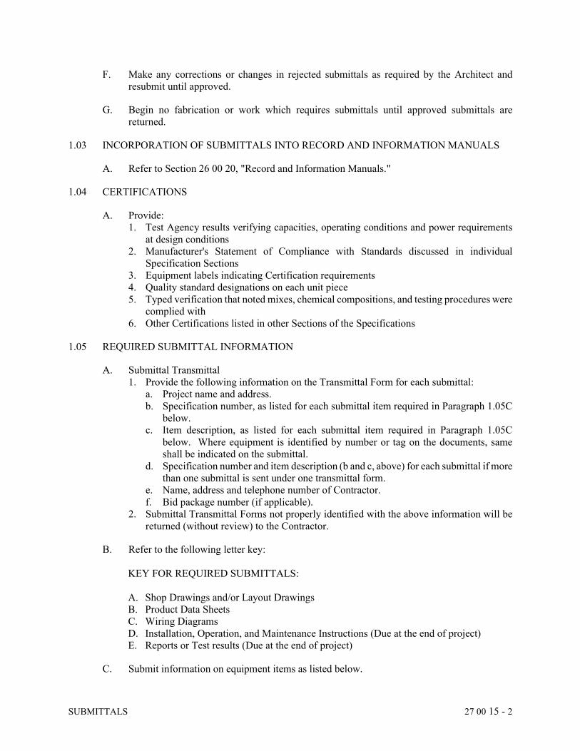
SUBMITTALS 27 00 15 - 2
F. Make any corrections or changes in rejected submittals as required by the Architect and
resubmit until approved.
G. Begin no fabrication or work which requires submittals until approved submittals are
returned.
1.03 INCORPORATION OF SUBMITTALS INTO RECORD AND INFORMATION MANUALS
A. Refer to Section 26 00 20, "Record and Information Manuals."
1.04 CERTIFICATIONS
A. Provide:
1. Test Agency results verifying capacities, operating conditions and power requirements
at design conditions
2. Manufacturer's Statement of Compliance with Standards discussed in individual
Specification Sections
3. Equipment labels indicating Certification requirements
4. Quality standard designations on each unit piece
5. Typed verification that noted mixes, chemical compositions, and testing procedures were
complied with
6. Other Certifications listed in other Sections of the Specifications
1.05 REQUIRED SUBMITTAL INFORMATION
A. Submittal Transmittal
1. Provide the following information on the Transmittal Form for each submittal:
a. Project name and address.
b. Specification number, as listed for each submittal item required in Paragraph 1.05C
below.
c. Item description, as listed for each submittal item required in Paragraph 1.05C
below. Where equipment is identified by number or tag on the documents, same
shall be indicated on the submittal.
d. Specification number and item description (b and c, above) for each submittal if more
than one submittal is sent under one transmittal form.
e. Name, address and telephone number of Contractor.
f. Bid package number (if applicable).
2. Submittal Transmittal Forms not properly identified with the above information will be
returned (without review) to the Contractor.
B. Refer to the following letter key:
KEY FOR REQUIRED SUBMITTALS:
A. Shop Drawings and/or Layout Drawings
B. Product Data Sheets
C. Wiring Diagrams
D. Installation, Operation, and Maintenance Instructions (Due at the end of project)
E. Reports or Test results (Due at the end of project)
C. Submit information on equipment items as listed below.
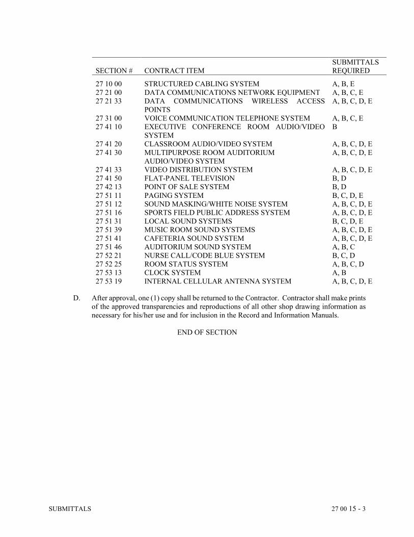
SUBMITTALS 27 00 15 - 3
SECTION #
CONTRACT ITEM
SUBMITTALS
REQUIRED 27 10 00 STRUCTURED CABLING SYSTEM A, B, E
27 21 00 DATA COMMUNICATIONS NETWORK EQUIPMENT A, B, C, E
27 21 33 DATA COMMUNICATIONS WIRELESS ACCESS
POINTS
A, B, C, D, E
27 31 00 VOICE COMMUNICATION TELEPHONE SYSTEM A, B, C, E
27 41 10 EXECUTIVE CONFERENCE ROOM AUDIO/VIDEO
SYSTEM
B
27 41 20 CLASSROOM AUDIO/VIDEO SYSTEM A, B, C, D, E
27 41 30 MULTIPURPOSE ROOM AUDITORIUM
AUDIO/VIDEO SYSTEM
A, B, C, D, E
27 41 33 VIDEO DISTRIBUTION SYSTEM A, B, C, D, E
27 41 50 FLAT-PANEL TELEVISION B, D
27 42 13 POINT OF SALE SYSTEM B, D
27 51 11 PAGING SYSTEM B, C, D, E
27 51 12 SOUND MASKING/WHITE NOISE SYSTEM A, B, C, D, E
27 51 16 SPORTS FIELD PUBLIC ADDRESS SYSTEM A, B, C, D, E
27 51 31 LOCAL SOUND SYSTEMS B, C, D, E
27 51 39 MUSIC ROOM SOUND SYSTEMS A, B, C, D, E
27 51 41 CAFETERIA SOUND SYSTEM A, B, C, D, E
27 51 46 AUDITORIUM SOUND SYSTEM A, B, C
27 52 21 NURSE CALL/CODE BLUE SYSTEM B, C, D
27 52 25 ROOM STATUS SYSTEM A, B, C, D
27 53 13 CLOCK SYSTEM A, B
27 53 19 INTERNAL CELLULAR ANTENNA SYSTEM A, B, C, D, E
D. After approval, one (1) copy shall be returned to the Contractor. Contractor shall make prints
of the approved transparencies and reproductions of all other shop drawing information as
necessary for his/her use and for inclusion in the Record and Information Manuals.
END OF SECTION
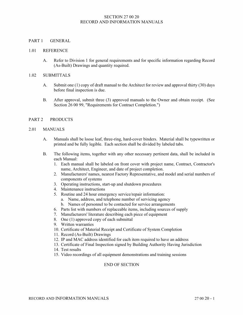
SECTION 27 00 20
RECORD AND INFORMATION MANUALS
RECORD AND INFORMATION MANUALS 27 00 20 - 1
PART 1 GENERAL
1.01 REFERENCE
A. Refer to Division 1 for general requirements and for specific information regarding Record
(As-Built) Drawings and quantity required.
1.02 SUBMITTALS
A. Submit one (1) copy of draft manual to the Architect for review and approval thirty (30) days
before final inspection is due.
B. After approval, submit three (3) approved manuals to the Owner and obtain receipt. (See
Section 26 00 99, "Requirements for Contract Completion.")
PART 2 PRODUCTS
2.01 MANUALS
A. Manuals shall be loose leaf, three-ring, hard-cover binders. Material shall be typewritten or
printed and be fully legible. Each section shall be divided by labeled tabs.
B. The following items, together with any other necessary pertinent data, shall be included in
each Manual:
1. Each manual shall be labeled on front cover with project name, Contract, Contractor's
name, Architect, Engineer, and date of project completion.
2. Manufacturers' names, nearest Factory Representative, and model and serial numbers of
components of systems
3. Operating instructions, start-up and shutdown procedures
4. Maintenance instructions
5. Routine and 24 hour emergency service/repair information:
a. Name, address, and telephone number of servicing agency
b. Names of personnel to be contacted for service arrangements
6. Parts list with numbers of replaceable items, including sources of supply
7. Manufacturers' literature describing each piece of equipment
8. One (1) approved copy of each submittal
9. Written warranties
10. Certificate of Material Receipt and Certificate of System Completion
11. Record (As-Built) Drawings
12. IP and MAC address identified for each item required to have an address
13. Certificate of Final Inspection signed by Building Authority Having Jurisdiction
14. Test results
15. Video recordings of all equipment demonstrations and training sessions
END OF SECTION

SECTION 27 00 70
DEMOLITION
DEMOLITION 27 00 70 - 1
PART 1 GENERAL
1.01 DESCRIPTION
A. Perform demolition work of all telecommunications items as shown and/or described on the
Drawings. Remove all items from site designated as scrap.
B. Provide care so as not to damage adjacent construction designated to remain.
C. All telecommunications items in good condition are to remain the property of the Owner.
Verify with the Owner's Representative which items are considered scrap and are to be
disposed of.
PART 2 PRODUCTS - (NOT APPLICABLE)
PART 3 EXECUTION
3.01 DEMOLITION
A. Coordinate and schedule all work in a careful manner with all necessary consideration for
the Owner, neighbors, and the public, avoiding interference with the use of, and passage to
and from adjacent areas and facilities designated to remain in use during demolition.
Coordinate work with other trades.
B. Disconnect and remove all items as shown and described on the Drawings completely back
to source, including:
1. Telecommunications, audio/visual, and security devices, boxes and plates
2. Low-voltage cabling
C. Maintain all existing cabling to items that are to remain in use.
D. For existing outlets which are to be removed and have conduits rising from the floor slab, re-
cable as required to provide service to remaining outlets. Division 26 Contractor shall
remove outlets and conduit and shall patch floor as required.
E. For all other existing devices to be removed mid-span (e.g., consolidation points, speakers,
CATV, etc.), re-cable as required to maintain service to the remaining devices.
F. Abandoned outlet boxes in walls to remain shall be closed with blank coverplates. If
equipped with devices, the devices and cabling shall be removed as required.
G. Disconnect and remove telecommunications connections to equipment designated to be
removed by other Trades.
H. Abandoned low voltage cables, if not being labeled for future use, shall be removed.
Coordinate with building Owner regarding tagging for future use. Any cable that shall
remain for future use shall be tagged at the cut end with the label “For Future Use”, including
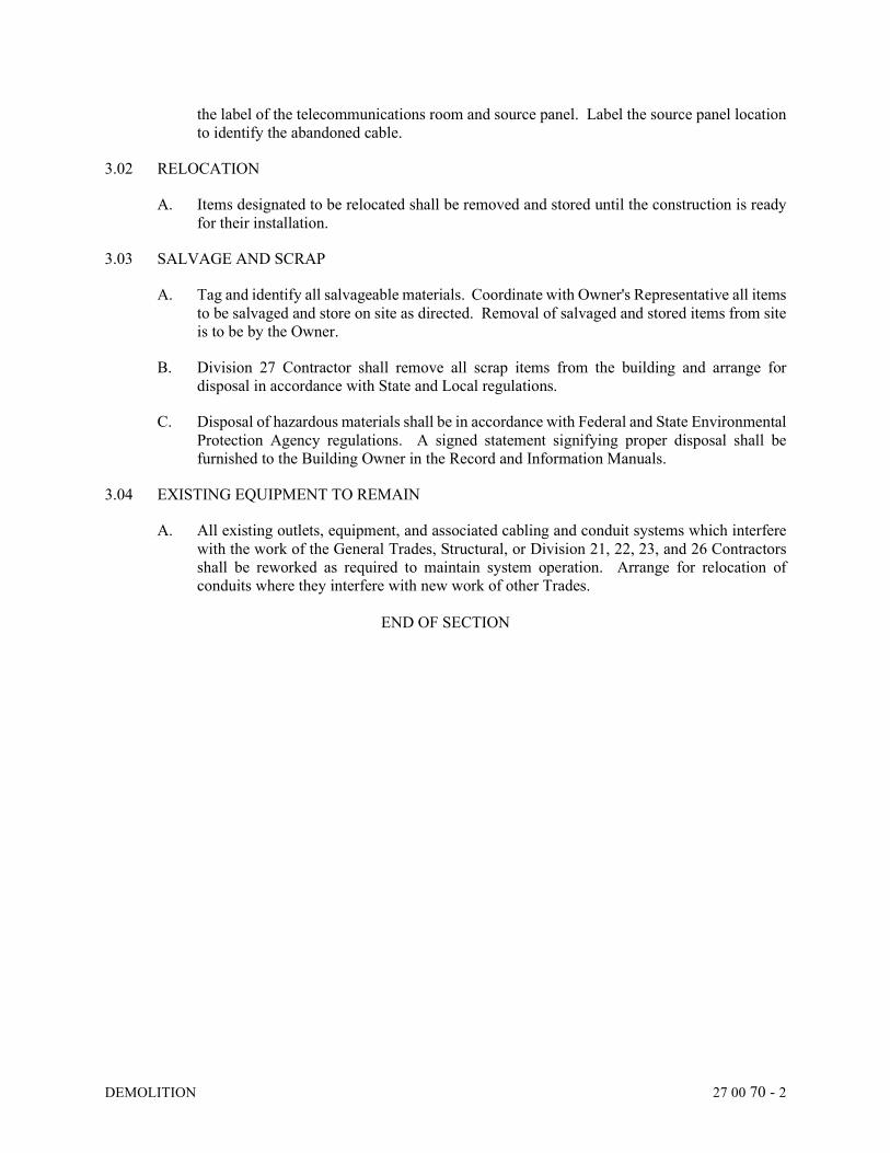
DEMOLITION 27 00 70 - 2
the label of the telecommunications room and source panel. Label the source panel location
to identify the abandoned cable.
3.02 RELOCATION
A. Items designated to be relocated shall be removed and stored until the construction is ready
for their installation.
3.03 SALVAGE AND SCRAP
A. Tag and identify all salvageable materials. Coordinate with Owner's Representative all items
to be salvaged and store on site as directed. Removal of salvaged and stored items from site
is to be by the Owner.
B. Division 27 Contractor shall remove all scrap items from the building and arrange for
disposal in accordance with State and Local regulations.
C. Disposal of hazardous materials shall be in accordance with Federal and State Environmental
Protection Agency regulations. A signed statement signifying proper disposal shall be
furnished to the Building Owner in the Record and Information Manuals.
3.04 EXISTING EQUIPMENT TO REMAIN
A. All existing outlets, equipment, and associated cabling and conduit systems which interfere
with the work of the General Trades, Structural, or Division 21, 22, 23, and 26 Contractors
shall be reworked as required to maintain system operation. Arrange for relocation of
conduits where they interfere with new work of other Trades.
END OF SECTION
SECTION 27 10 00 STRUCTURED CABLING
STRUCTURED CABLING 27 10 00 - 1
PART 1 GENERAL
1.01 DESCRIPTION
A. This document describes the product and execution requirements related to furnishing and installing the Structured Cabling System as shown on the Drawings and specified herein.
1.02 SCOPE OF WORK
A. The Structured Cabling Contractor (SCC) shall provide a complete Structured Cabling System (SCS) as defined in this section.
B. As described elsewhere in these Documents the system consists of fiber optic and copper cabling, and related hardware. In addition to the basic cable plant requirements, the testing and identification requirements are also defined. Finally, racks, enclosures and other related hardware are indicated herein.
C. The installation shall be of an "Open System," using standard media and layout, standard connections and interfaces. The Contractor shall adhere to this Specification, local and national codes and provide quality workmanship.
D. This section includes: 1. Main Telecommunications Room (MTR) 2. Telecommunications Room (TR) 3. Racks, Enclosures and Cable management 4. Ladder Rack 5. Rack mounted surge suppressor 6. Lightning Protector 7. Backbone cabling 8. Horizontal cabling 9. Consolidation Points 10. MTR and TR connections
a. Patch Panels b. Fiber enclosures
11. Work Area outlets a. Faceplates b. Connectors (jacks)
12. Work Area Extensions to Device 13. Hangers and Supports
E. The components used on this project for voice, data, and CATV shall be as identified in Part 2 of this Section.
F. Unless noted otherwise on the Drawings, for all 4 pair Category cable, this project shall use T568B termination for eight (8) position jack pair assignments as specified per the ANSI/TIA 568-C wiring standard. For fiber, follow ANSI/TIA 568-C.3, Optical Fiber Cabling Components Standard, and its published addenda.
STRUCTURED CABLING 27 10 00 - 2
G. All continuous pathways (i.e., conduit, cable tray, raceway, etc.) required to support the cabling shall be provided by the Electrical Contractor under Division 26 unless indicated otherwise in the Contract Documents. 1. All non-continuous or non-rigid pathways (i.e., J-hooks, inner-duct, etc.) required to
support the cabling shall be provided by the SCC under the Structured Cabling System, unless indicated otherwise in the Contract Documents.
2. All ladder rack, cable tray, and related pathway hardware built into Telecommunications Spaces shall be provided by the SCC.
H. The SCC shall be responsible for providing the racks and enclosures as required and specified herein.
I. The SCC shall test and label the entire installation as specified and required by the codes and standards.
J. The SCC shall be responsible for providing the hangers and support system specified herein and shown on the Drawings.
K. Final sizing and location of J-hooks, hangers, and supports shall be the responsibility of the Contractor. However, NO increases to the bid price and/or the schedule extension shall be allowed due to equipment alterations.
L. For new installations, J-hooks fill capacity shall not exceed 70% of its rated cable fill capacity (i.e., if J-bracket is rated for 100 cables, no more than 70 shall be installed).
M. J-hooks are intended for voice, data, video, audio, and security cables only. They are intended for cable routing in areas of less than 100 Category 6 cables. All other low voltage cabling systems, such as building controls, shall have cabling run-ins separate raceway system.
N. All hangers and support material shall be galvanized or stainless steel, rust free material.
O. The Telecommunications Contractor shall ensure that the General Contractor and Painting Contractor acknowledge that the painting or over spray of any single or group of 4 pair horizontal telecommunications Category cable is not allowed. Any painted or over sprayed cable(s) shall be completely removed and replaced at the Painting Contractor’s expense. No in-line connectors, splices, taps or other repairs will be permitted. Painted cable will not be covered as part of an extended warranty. Painted cable obscures the print legend and can alter the cable’s mechanical properties and fire rating. Painted cable compromises its integrity and/or performance. It may act as an accelerant or create an additional smoke hazard in the event of a fire and as such this is considered a life safety issue. Paint contamination and/or removing paint from the cable with a solvent can affect the cable’s durability and its electrical characteristics.
1.03 QUALIFICATIONS
A. The SCC must meet the following requirements to be approved for this project. He/she shall meet the following qualifications and provide the information, as listed, in the submittal package:
STRUCTURED CABLING 27 10 00 - 3
1. Must be a member of Building Industry Consulting Service International (BICSI) or Engineer approved, other Telecommunications Organization, and shall have at least five (5) years' experience installing Telecommunications Cabling and Equipment.
2. Supply a list of a minimum of five (5) projects over $100,000 that the firm has completed along with contact names and phone numbers of the Owners' Representatives for those projects. At least three (3) of the completed facilities shall have been occupied and in full operation for at least one (1) year.
3. The SCC shall be a certified installer for the connectivity and cabling solution specified for this project and maintain that status with the warranting manufacturer, including all training requirements, for the duration of the cable infrastructure project.
4. The SCC shall have, as a direct employee, a minimum of one (1) RCDD on staff. The RCDD must be a full-time employee of the company and must be listed with the company on the BICSI Credential Holder website. This individual shall review all submittals, RFIs, change order proposals, as-built documents, and shall provide system engineering support and oversight of all field work to ensure system installation is fully compliant with all requirements of ANSI/TIA-568-C, ANSI/TIA-569-D, and all associated TSBs, ANSI/TIA-606-B, labeling, and ANSI/TIA-607, bonding and grounding, including all addenda.
5. The SCC's RCDD shall stamp all test results included in the Record and Information Manual and the final (field marked) As-Built Drawings, as being correct and accurate, that are included in the Record and Information Manual.
6. It is the intent of this contract for the Contractor to provide sole responsibility for material, labor, and service for the communication cabling system. The Contractor shall, at a minimum, staff the project with BICSI certified installers for project foremen and crew leader positions.
7. The SCC must own or have a current lease agreement for equipment to test up to Category 6a and fiber optic cable. He/she shall supply proof as required above in the submittal package, including latest calibration date.
B. At the time of bid form submission, the SCC shall submit the following information: 1. The SCC's manufacturer certifications for:
a. Twisted pair cabling b. Fiber optic cabling c. Connectivity
2. The RCDD's BICSI certification. Refer to SCC's Qualifications below. 3. A listing of the like projects within the last three (3) years. Refer to SCC's Qualifications
below.
C. During the bid review, the SCC may be asked to provide any/or all of the following: 1. A listing of the probable team members 2. BICSI and manufacturer certifications for the installation of the Structured Cable Plant. 3. Certifications for the installation for any firestopping required under the scope of the
Structured Cable Plant installation.
D. Any/all items listed in paragraph 1.03 subparagraph B.1 or B.2, can and will be checked for authenticity and accuracy. The Owner reserves the right to reject any unauthorized or inaccurate submissions.
E. Should the SCC either fail or refuse to provide any of the items listed and/or requested in paragraph 1.03 subparagraph B.1 or B.2, the Owner reserves the right to determine the SCC as being not fully responsive and as such discard the bid in its entirety.
STRUCTURED CABLING 27 10 00 - 4
1.04 SUBMITTALS
A. Product Data Sheets 1. All products 2. Copies of all certifications
B. Shop Drawings 1. The SCC shall submit the following shop drawings:
a. A detailed riser diagram demonstrating the SCC's understanding of the backbone cabling.
b. Drawings of any floor boxes with details of the various internal faceplates and their respective contents.
c. Drawings of any through floor fittings with details of their contents. d. Layout drawings for cable tray and cable runway (1/16" scale minimum) based on
trade coordination efforts indicating anticipated routings based on the coordination among the various trades.
PART 2 PRODUCTS
2.01 MAIN TELECOMMUNICATIONS ROOM/DEMARC (MTR)
A. The SCC shall provide plywood backboard as shown on the Drawings. If the Drawings do not indicate where or how much plywood is to be installed, Contractor shall provide, as a minimum, two (2) walls covered by 3/4 inch x 4 feet x 8 feet fire retardant plywood, painted industrial gray with two (2) coats of fire retardant paint. Plywood shall be AC grade or better and void-free with Grade A surface exposed. To reduce warping, plywood shall be kiln-dried to a maximum moisture content of 15%. 1. Fire retardant plywood shall be securely fastened to wall such that it can and will support
equipment to be mounted. Additionally, it shall be mounted such that the 8 feet is vertical. Unless otherwise noted, bottom of plywood shall be mounted 8 inches AFF.
2. Contractor shall cover with masking tape the "Fire Retardant" stamp on the plywood, before painting, and remove tape after painting, so that the inspector can still see the original "Fire Retardant" stamp on the plywood.
3. Cut out plywood around all wiring devices.
B. The SCC shall provide all equipment required and/or shown on the Drawings to make MTR a safe and usable room for the Structured Cabling System.
C. For fiber optic cable entering from outside or from another TR coil, provide 30 feet of slack on re-closeable storage ring before routing cable to rack for termination in rack mounted fiber panel using LC connectors (unless otherwise noted).
D. Terminate copper station cable coming from TRs or work areas in a standard 19 inch data rack, rack mounted patch panel with 110 type punch down terminations located close to incoming protector unit.
E. Terminate incoming coaxial cable on backboard. Terminate coax station cable coming from TRs or work area on same backboards with "F" connectors.
STRUCTURED CABLING 27 10 00 - 5
F. Install racks, cable management, enclosures, patch panels, ladder racks, cables, and other equipment required in MTR as shown on Drawings. If no equipment location is indicated, coordinate rack and equipment location with Owner before installing equipment.
G. Provide MTR with ladder racking or wire mesh cable tray as shown on Drawings. Fasten ladder racking or cable tray to data racks.
H. Provide grounding and bonding as specified in Section 26 05 27, "Telecommunications Bonding Infrastructure."
I. Provide "D" rings for cable routing support on backboards, for feeding cables up or down from ladder rack and/or floor.
2.02 TELECOMMUNICATIONS ROOM (TR)
A. The SCC shall provide plywood backboard as shown on the Drawings. If the Drawings do not indicate where or how much plywood is to be installed, Contractor shall provide, as a minimum, each TR with at least two (2) walls covered by 3/4 inch x 4 feet x 8 feet fire retardant plywood, painted industrial gray with two (2) coats of fire retardant paint. Plywood shall be AC grade or better and void-free with Grade A surface exposed. To reduce warping, plywood shall be kiln-dried to a maximum moisture content of 15%. 1. Fire retardant plywood shall be securely fastened to wall such that it can and will support
equipment to be mounted. Additionally, it shall be mounted such that the 8 feet is vertical. Unless otherwise noted, bottom of plywood shall be mounted 8 inches AFF.
2. Contractor shall cover with masking tape the "Fire Retardant" stamp on the plywood, before painting, and remove tape after painting so that the Inspector can still see the original "Fire Retardant" stamp on the plywood.
3. Cut out plywood around all wiring devices.
B. The SCC shall provide all equipment shown on the Drawings or as required to make TRs safe and usable for the structured cabling system.
C. For fiber optic cable entering from another TR coil, provide 30 feet of slack on re-closeable storage ring before routing cable to rack for termination in rack mounted fiber panel using LC connectors.
D. For copper station cable, terminate in a rack mounted patch panel with 110 type punch down termination.
E. For coaxial station cable, terminate on "F" connectors in designated backboard area.
F. For audio/video cable, terminate in the audio/video rack as required by the equipment using the proper connectors.
G. Install racks, cable management, enclosures, patch panels, ladder racks, cables, and other equipment required in TR as shown on Drawings. If no location is indicated, coordinate with Owner before installing equipment.
H. Provide TR ladder racking or wire mesh cable tray as shown on Drawings. Fasten to data racks.
STRUCTURED CABLING 27 10 00 - 6
I. Provide grounding and bonding as specified in Section 26 05 27, "Telecommunications Bonding Infrastructure."
J. Provide "D" rings for cable routing support on backboards, for feeding cables up or down from ladder rack and/or floor.
2.03 RACKS, ENCLOSURES, AND CABLE MANAGEMENT
A. Two post network equipment racks nominal 19 inches 1. Manufactured from extruded aluminum. Finish shall be flat black, post dimensions to
be 84" tall x 20" wide x 3" deep with anchor plates at the top and bottom. 2. Free standing data rack, 45RMU 3. Floor anchored with minimum of four (4) floor anchors, anchor top of rack to either
ladder racking / cable tray above rack or to backboard using angle iron or unistrut 4. Minimum load rating for rack shall be 1,000 lbs. weight capacity 5. EIA/ECA-310-E compliant, double sided universal mounting holes #12-24, supply
minimum of twenty-four (24) #12-24 mounting screws 6. Approved manufacturer Chatsworth #48353-703
a. Equivalents by Belden, B-line, Hoffman, Great Lakes, Ortronics, and Panduit
B. Four post network equipment racks nominal 19 inches, adjustable depth 1. Manufactured from extruded aluminum. Finish shall be flat black, post dimensions to
be 84" tall x 20" wide with anchor plates at the top and bottom. 2. Free standing data rack, 45RMU 3. Floor anchored with minimum of four (4) floor anchors, anchor top of rack to either
ladder racking above rack or to backboard using angle iron or unistrut 4. Minimum load rating for rack shall be 1,000 lbs. weight capacity 5. EIA/ECA-310-E compliant, double sided universal mounting holes #12-24, supply
minimum of twenty-four (24) #12-24 mounting screws 6. Approved manufacturer Chatsworth #1521X-703
a. Equivalents by Belden, B-line, Hoffman, Great Lakes, Ortronics, and Panduit
C. Wall Mount Enclosure nominal 19 inches 1. Manufactured from 14-gauge steel. Finish shall be flat black powder coat, post
dimensions to be 24" tall x 21.5" wide x 24.5" deep. 2. Wall mounted data rack, 12RMU 3. Lockable solid steel front door. 4. Dust resistance kit. 5. Vented sides for airflow. 6. Reversible cabinet for left and right-hand swing-out. 7. EIA/ECA-310-E compliant, double sided universal mounting holes #12-24, supply
minimum of twenty-four (24) #12-24 mounting screws 8. Approved manufacturer Great Lakes GL24WMS
a. Equivalents by Belden, Chatsworth, Hoffman, Ortronics, and Panduit
D. Vertical Cable Management 1. The vertical cable manager nominal height shall match the height of the rack(s)/frame(s). 2. The vertical cable manager shall bolt to the side of racks/frames with included hardware. 3. The cable manager shall be sized to match cabling requirements. Maximum cable fill
shall be calculated by dividing 50% of the usable area within the cable manager by the area of a single cable.
STRUCTURED CABLING 27 10 00 - 7
4. A single vertical cable manager may be used in between bayed racks/frames if it is sized to match cable requirements for both racks/frames.
5. The double-sided vertical cable manager shall be a double-sided H-shaped trough with a front door and a rear door. The double-sided trough shall provide independent front and rear cable pathways. The front and rear sides of the cable manager shall have T-shaped cable guides separated by openings that align with each U space on the rack. The middle of the managers shall be mostly open to allow easy cable pass-through. Three movable mid-sections shall allow attachment of cable management accessories inside the cable manager. a. Double-Sided Vertical Cable Manager, 80.5" High (minimum) x 4" Wide x 16.4"
Deep (minimum), black. b. Double-Sided Vertical Cable Manager, 80.5" High (minimum) x 6" Wide x 16.6"
Deep (minimum), black. c. Double-Sided Vertical Cable Manager, 80.5" High (minimum) x 10" Wide x 17.5"
Deep (minimum), black. d. Double-Sided Vertical Cable Manager, 80.5" High (minimum) x 12" Wide x 17.8"
Deep (minimum), black. 6. Approved manufacturers:
a. Belden b. Chatsworth c. Great Lakes d. Ortronics e. Panduit
7. Basis of Design - 4 inches wide vertical cable manager: Chatsworth Velocity #13911-703
8. Basis of Design - 6 inches wide vertical cable manager: Chatsworth Velocity #13912-703
9. Basis of Design - 10 inches wide vertical cable manager: Chatsworth Velocity #13914-703
10. Basis of Design - 12 inches wide vertical cable manager: Chatsworth Velocity #13915-703
E. Horizontal Cable Management 1. Units shall be 1U to 3U construction. 2. Units shall be single sided. 3. Units shall have covers that have a dual hinge technology. 4. Access into and out of the top and bottom of the Management shall be finger type
construction. 5. Approved manufacturers:
a. Belden b. Chatsworth c. Great Lakes d. Ortronics e. Panduit
6. Basis of Design – 1U horizontal vertical cable manager: Chatsworth #30139-719 7. Basis of Design – 2U horizontal vertical cable manager: Chatsworth #30130-719 8. Basis of Design – 3U horizontal vertical cable manager: Chatsworth #30131-719

STRUCTURED CABLING 27 10 00 - 8
2.04 LADDER RACK
A. Ladder rack shall be manufactured from tubular steel. Stringers (side rails) shall be 1.5 inches deep. Maximum fill is equivalent to TIA recommended maximum fill of 6 inches deep. Provide accessory cable retaining posts if cable fill height exceeds 2 inches. Where cable retaining posts are used, they shall be 8 inches high and shall attach to the side stringer of the ladder rack with included hardware. The top of the cable retaining posts shall be fitted with a rubberized end cap to protect cables.
B. Unless otherwise noted on the Drawings, ladder rack width shall be 18 inches with cross member (rung) spacing on 9 inch centers.
C. All cross members shall be welded into position for maximum strength and electrical continuity of elements. No cross members shall protrude below side members that would interfere with supporting structures.
D. All straight sections shall be provided in standard 10 foot nominal sections.
E. Provide a method of splicing ladder rack sections and fabricated turns together end-to-end or side-to-end to form a continuous pathway.
F. Vertical-to-horizontal and horizontal-to-vertical 90-degree turns shall be provided as required
G. Ladder rack supports shall be of the trapeze type. Supports shall be sized to match the width of the ladder rack that is supported. Support design shall allow the support to be placed under the ladder rack at any point mid-span, but not under a ladder rack splice.
H. All ladder rack elbows, tees, and cross fittings shall be furnished in a radius of 12, 24, or 36 inches in 30, 45, 60, or 90 degrees of arc as necessary to meet the National Electrical Code and BICSI bending radius limitations of cables to be installed in the trays. Using straight runs with radius corner brackets is also acceptable.
I. Dropouts shall be aluminum sheets with round radius attached to either side stringer or cross member to permit cable exit out of bottom of cable tray. Where cable exits or enters the side of overhead ladder rack to access a rack, frame, cabinet or wall-mounted rack, cabinet or termination field, a radius drop shall be used to guide the cable.
J. End caps shall be provided to cover the ends of the ladder rack. End caps shall be manufactured from a black fire-retardant rubberized material.
K. Cable straps used for attaching cable bundles to the ladder rack cross members must be reusable with a hook and loop-style closure, at least 3/4 inch wide, and sized for cable bundles that are 2 inches, 3 inches, or 4 inches in diameter.
L. Unless otherwise noted, finish on all metal components shall be black epoxy-polyester hybrid powder coat.
M. Separate different cable media types within the ladder rack pathway. Treat each type of cable media separately when determining cable fill limits.
STRUCTURED CABLING 27 10 00 - 9
N. Provide touch-up paint color-matched to the finish on the component and correct any minor cosmetic damage (chips, small scratches, etc.) resulting from normal handling during the installation process prior to delivery to the Owner. If a component is cosmetically damaged to the extent that correction in the field is obvious against the factory finish, replaced with a new component finished from the factory. If a component is physically damaged due to mishandling or modification during the installation process, it shall not be used as part of the ladder rack system.
O. Approved manufacturer: Chatsworth Universal Cable Runway 1. Equivalents by Belden Runway Products, Great Lakes, Middle Atlantic, Panduit, and
Snake Tray.
2.05 RACK MOUNTED SURGE SUPPRESSOR
A. For all wall-mounted enclosures less than 4 feet in height, provide horizontal rack mounted power strip with surge protection and six NEMA 5-20R outlets. Basis of design is CPI 12816-707 with equivalents by APC, Belden, Geist, Panduit, or Tripp-Lite.
B. For all other equipment racks and enclosures, provide two (2) vertical rack mounted power strip with surge protection and 14 NEMA 5-20R outlets. Basis of design is CPI 12850-706 with equivalents by APC, Belden, Geist, Panduit, or Tripp-Lite.
2.06 LIGHTNING PROTECTOR
A. Provide one Telecom Building Entrance Terminal, sized for the number of pairs entering the building, at the demark to cover incoming and outgoing connections. 1. Units shall utilize 110 blocks for both input and output. 2. Units shall comply with UL 497. 3. Units shall be powder epoxy coated. 4. Units shall utilize a five pin socket for devices.
B. Acceptable Manufacturer and Model 1. Circa 1880ECA1 series (25, 50, 100), with C3B1S solid state protector modules. 2. Equivalent by Siemon, Panduit or Porta Systems.
2.07 BACKBONE CABLING
A. The SCC shall provide all backbone cabling system as shown on the Drawings and as required to make a complete installation (both copper and fiber).
B. Outside Plant, Copper Cable 1. Approved cable manufacturers for PE 89 type, 50/100/300 multi-pair cable:
a. Superior Essex b. General c. Omni Cable
2. Approved cable manufacturers for Category 5e, UTP, 25 pair: a. Belden b. Mohawk c. Superior Essex
STRUCTURED CABLING 27 10 00 - 10
C. Outside Plant, Fiber Optical Cable shall be indoor/outdoor or outside plant "tight buffer" type cable. All fiber not installed in conduit must be armored or installed in inner duct. 1. Strand count shall be as shown on the Drawings. 2. Cable shall be single-mode and/or minimum OM3 50/125-micron multimode cable
unless otherwise shown on the Drawings. 3. Fiber must be protected from moisture with a moisture resistant jacket and a filling of
water blocking material. 4. Approved cable manufacturers:
a. Belden b. BerkTek c. CommScope d. Corning e. Mohawk f. Panduit g. Superior Essex h. TCS
D. Outside Plant, coaxial cable shall be hard line cable/coax size as shown on the Drawings. 1. Approved cable manufacturers:
a. CommScope
E. Inside Plant, Copper Cable 1. Approved cable manufacturers for 25/50/100 multi-pair Category 3 copper plenum
cable: a. Belden b. BerkTek c. CommScope d. Mohawk e. Superior Essex
2. Approved cable manufacturers for 25 PR Category 5e, UTP plenum cable: a. Belden b. BerkTek c. CommScope d. Mohawk e. Superior Essex
F. Inside Plant, fiber optical cable shall be tight buffer type plenum rated armored cable. 1. Strand count shall be as shown on the Drawings. 2. Cable shall be single-mode and/or OM3 50/125-micron multimode cable as shown on
the Drawings. 3. Approved cable manufacturers:
a. Belden b. BerkTek c. CommScope d. Corning e. Mohawk f. Panduit g. Superior Essex h. TCS
G. Inside Plant, coaxial cable shall be RG11 or 0.5" hardline, size as shown on the Drawings.
STRUCTURED CABLING 27 10 00 - 11
1. Approved cable manufacturers: a. Belden b. CommScope c. West Penn
2.08 HORIZONTAL CABLING
A. Copper Station Cabling from the TR to the work area jack shall be: 1. Category 6, UTP, 4 pair, plenum rated approved manufacturers:
a. Belden 3613 b. BerkTek LANmark 1000 c. Mohawk AdvanceNet d. Panduit PUP6004 e. Superior Essex DataGain Cat 6+
2. Category 6a, UTP, 4 pair, plenum rated approved manufacturers: a. Belden 10GXS13 b. BerkTek LANmark 10G2 c. Mohawk GigaLAN 10 Reduced Diameter d. Panduit PUP6AV04 e. Superior Essex 10GainXP
3. Category 6, UTP, 4 pair, OSP rated approved manufacturers a. Belden OSP6U 0101000 b. BerkTek LANmark 6 OSP UTP c. Mohawk LAN-Trak 6 OSP M57622 d. Panduit PUO6C04 e. Superior Essex CMR/CMX Cat 6
4. Coaxial cable, RG11 or RG6, plenum rated approved cable manufacturers: a. Belden b. CommScope c. West Penn
B. Fiber optical station cabling from the TR shall be terminated on LC connectors mounted in fiber duplex jack modules.
C. Cabling for wireless access point shall be two Category 6a cables with a 25 foot figure 8 service loop for each AP (unless otherwise noted).
D. Cabling for CCTV indoor Cameras shall be one Category 6 cable with a 10 foot figure 8 service loop for each camera (unless otherwise noted). Contractor may use a direct connect plug for the cameras, but the contractor must use a “modified single connector permanent link” test to test the cable run. The manufacturer must supply a warranty for the direct connect link. Examples: Belden REVConnect RJ45 Plug, Legrand High Performance Cat 6 RJ45 Modular Plug, Leviton Atlas X1 plus patch cord, and Panduit mini-com direct attachment plug FP6X88MTG.
E. Paging speaker cable shall be 18 AWG UTP single pair cable as shown on Drawings. 1. Approved cable manufacturers:
a. Belden b. CommScope c. West Penn d. General
STRUCTURED CABLING 27 10 00 - 12
F. Program speaker cable shall be 14 AWG UTP single pair cable as shown on Drawings. 1. Approved cable manufacturers:
a. Belden b. CommScope c. West Penn d. General
2.09 MTR AND TR CONNECTIONS
A. Patch panels for Category 6 cables shall be: 1. Belden Category 6 KeyConnect 6+ 2. Leviton eXtreme 6+ 3. Ortronics Category 6 4. Panduit Cat 6 PanNet
B. Patch panel for Category 6a cables shall be: 1. Belden Category 6A KeyConnect 10GX 2. Leviton eXtreme 6a 3. Ortronics Category 6a 4. Panduit Cat 6 PanNet
C. Patch panel shall be standard or modular type punchdown patch panels.
D. Fiber Patch Panels shall be LC connectors mounted in fiber duplex jack modules. 1. Belden Fiber - FX UHD 2. Leviton Opt-X Ultra 3. Ortronics 1U Fiber Patch/Splice 4. Panduit OptiCom 5. TCS 1U Fiber Patch/Splice
2.10 CONSOLIDATION POINTS
A. Wiring blocks for consolidation points shall be 110-style by Belden, Leviton, Ortronics, or Panduit.
B. Passive, plenum-rated 2' x 2' telecommunications enclosures for consolidation points shall be Leviton Z1000-PC2 or equivalents by Belden, Ortronics, or Panduit.
2.11 WORK AREA OUTLETS
A. Work area faceplates for flush devices in interior partitions shall be stainless steel.
B. Work area faceplates for flush devices on concrete block walls shall match others but be "Jumbo" plates.
C. Work area jacks for Category 6 cables shall be: 1. Belden Category 6+ KeyConnect 6+ 2. Leviton eXtreme 6+ 3. Ortronics Category 6 4. Panduit CJ688TGxx

STRUCTURED CABLING 27 10 00 - 13
D. Work area jacks for Category 6a cables shall be: 1. Belden Category 6a KeyConnect 10GX 2. Leviton eXtreme 6a 3. Ortronics Category 6a 4. Panduit CJ688TGxx
E. Wall Phone Plate, stainless steel, single gang, one-port shall be: 1. Belden AX104230 2. Leviton eXtreme 6+ 3. Ortronics Category 6 4. Panduit KWP6PY
F. Wireless 2-port surface mount box for connection shall be Leviton 41089-2WP or equivalents by Belden, Ortronics, or Panduit.
2.12 WORK AREA EXTENSIONS TO DEVICE
A. Patch Cords shall be manufactured and supplied by the manufacturer of the connectivity and shall be rated for the same performance specifications as the cabling and connectivity being utilized. These cords shall be small diameter type patch cords, 24 to 28 AWG stranded conductors.
B. Unless otherwise indicated on the Drawings, the Contractor shall provide two cables for each work area outlet data jack (one for work area outlet and one for TR) and one cable for each wall phone jack (for TR only). Of the cables provided, the Contractor shall supply 50% of the cables as 3 feet (1 meter) and 50% as 10 feet (3 meters). Refer to the Technology Drawings for any specific quantities and lengths that may override these criteria. Category 6a patch cords shall be used for category 6a connectivity.
C. Unless otherwise noted, mounting and installing of work area equipment such as computers, phones printers, etc. are not part of the SCC's scope of work under this Specification.
2.13 HANGERS AND SUPPORTS
A. J-Hooks 1. J-hooks shall be at least 1 inch hook size, minimum. 2. J-hooks shall not be over 4 inch hook size (for locations requiring 100 4-PR Category 6
cables or more, use basket tray). 3. J-hooks shall be manufactured from Spring Steel. Securable to wall, beam, threaded rod,
unistrut, or pipe. 4. May utilize multi-tier configuration. 5. J-hooks shall have no sharp edges. 6. Approved J-Hook Manufacturers:
a. Cooper B-Line J-hook b. ERICO, type Cable Cat 21 and 32 c. Mag Daddy d. Panduit J-Pro Series e. Or Engineer approved equivalent
B. Threaded Rods
STRUCTURED CABLING 27 10 00 - 14
1. Threaded rod is to be attached to building steel in a permanent manner. Minimum size of threaded rod shall be 3/8.
2. Threaded rods are to be used for J-hook support where required. 3. When used for wire basket or cable tray support, use threaded rods with a hanger trapeze
kit or unistrut to form a trapeze type support for the wire basket or cable tray.
PART 3 EXECUTION
3.01 DOCUMENTS
A. Prepare and supply documents required. See "TESTING" below.
3.02 BACKBONE CABLING INSTALLATION
A. The SCC shall provide labor, supervision, and materials as required for a complete installation of the backbone cabling system which includes, but is not limited to, the cabling to and from the MTR and to the TR, pulling, supporting, terminating, labeling and testing.
B. Vertical cable runs shall be supported by split cable grip every 20 vertical feet.
3.03 MTR INSTALLATION
A. The SCC shall provide labor, supervision, and materials as required for a complete installation of the MTR and cabling.
B. The SCC shall route incoming cables to proper location by means of ladder racking, cable tray, and/or backboard. Cable shall be routed neatly (vertical/horizontal) with some slack before termination at the proper location.
3.04 TR INSTALLATION
A. The SCC shall provide labor, supervision, and materials as required for a complete installation of the TR cabling and cabling going to and from the TR.
B. The SCC shall route incoming cables to proper location by means of ladder racking, cable tray, and/or backboard. Cable shall be routed neatly (vertical/horizontal) with some slack before termination at the proper location.
3.05 HORIZONTAL CABLING INSTALLATION
A. The SCC shall provide labor, supervision, and materials as required for a complete installation of the horizontal cabling system that includes, but is not limited to, cabling from the TR to the work area, pulling, supporting, terminating, labeling, and testing.
B. Cables shall be installed in continuous lengths from origin to destination (no splices) except for transition points, or consolidation points.
C. Where transition points or consolidation points are allowed, they shall be located in accessible locations and housed in an enclosure intended and suitable for the purpose.
STRUCTURED CABLING 27 10 00 - 15
D. Each consolidation point (CP) shall serve a maximum of 12 work areas and shall be installed with a minimum of 25% spare terminations. No more than one CP shall be placed in each permanent link. CPs shall be located in fully accessible and permanent locations, a minimum of 50 feet from the TR or MTR.
E. When CPs are installed in a suspended ceiling or access floor space, the ceiling or floor tile locations should be clearly and permanently marked and identified as containing a CP.
F. Exception to ANSI/TIA 568-C distance limitations for horizontal category 6 cables. Extending Ethernet and POE Ethernet cabling distances beyond the 100 meter limit is permitted using Ethernet extenders for devices such as CCTV cameras, wireless access points, and IP blue light telephones. The cable must be tested to the extender manufacturer's specifications. Only use this exception where noted on the drawings.
3.06 WORK AREA INSTALLATION
A. The SCC shall provide labor, supervision, and materials as required for a complete installation of work area that includes, but is not limited to, terminating cable, placing the jacks and modules, faceplates, labeling and testing.
B. Upon completion of the project, the SCC shall clean work area and leave ready for move-in. He/she shall remove all marks, fingerprints, trash, and other debris from area.
3.07 HANGERS AND SUPPORTS INSTALLATION
A. Hangers and supports for ladder rack and cable tray shall be supported every 5 feet or less in accordance with ANSI/TIA-569-D. Ladder rack and cable tray shall be supported within 2 feet of every splice and within 2 feet on both/all sides of every intersection. Support ladder rack and cable tray within 2 feet on both sides of every change in elevation. Support ladder rack every 2 feet when attached vertically to a wall.
B. Threaded rod for support of hooks and/or trays shall be permanently fastened to structural steel.
C. J-hooks shall be securely fastened to wall, steel, or pipe and shall not be spaced more than 4 feet on center.
D. Contractor should install cable to be independently supported by approved cable tray or hanger and support products specified in this section. Avoid draping cable to be in contact and supported by other trades’ products such as ductwork, sprinkler piping, plumbing, ceiling tile, etc.
3.08 WORK
A. The SCC shall furnish all materials, labor, and supervision required to install and put into service the structured cabling system specified and shown on the Drawings.
B. The SCC shall be aware that they must coordinate their work with other trades and lack of access to the job site does not relieve them of the responsibility to complete the work as scheduled.
STRUCTURED CABLING 27 10 00 - 16
C. The SCC shall furnish sufficient manpower and resources to finish the project when scheduled for completion. If required, the SCC will work their crew overtime to meet the completion schedule with no additional compensation.
D. All work shall be done in a professional manner; equipment installed vertical and horizontal; cables pulled neat and aligned, but allowing slack; cables bundled, but no tie wraps shall be used; use hook and loop straps loosely, do not tighten cable bundle.
E. All conduits pull boxes, junction boxes, AP enclosures, cables, jacks, modules and other devices shall be labeled.
3.09 CABLE ROUTING
A. The SCC shall avoid electromagnetic interference (EMI) by routing all structured cabling a minimum of: 1. 4 feet from 480 volt motors and transformers 2. 12 inches from electrical power distribution cables 3. 6 inches from fluorescent lighting
B. Horizontal cable shall not exceed 90 meters.
C. Conduits shall have no more than an equivalent of two (2) 90 degree bends allowed in any single run between junction boxes.
3.10 TESTING
A. The SCC shall provide a copy of the unaltered certification test reports to the Engineer in both hardcopy and electronic format. The Contractor shall also provide a copy of the associated Cable Tester's Database Management Software with unedited soft copy.
B. Upon completion of the balanced twisted-pair cable installation, the SCC shall perform copper cable certification tests on the complete channel for every cable, included but not limited to: 1. Wire map 2. Length 3. Attenuation 4. Near End Cross Talk (NEXT) 5. Attenuation to Crosstalk Ratio (ACR-F) 6. Propagation Delay and Delay Skew 7. Return Loss 8. Power Sum Near End Cross Talk (PSNEXT) 9. Power Sum Equal Level Far End Cross Talk (PSELFEXT) 10. Insertion Loss
C. Test shall be performed to published standards, including but not limited to, the latest revisions of ANSI/TIA 568-C, ISO/IEC 11802 and other applicable standards at the time of installation.
D. All UTP/ScTP field testers shall be factory calibrated each calendar year by the field test equipment manufacturer as stipulated by the manuals provided with the field test unit. The calibration certificate shall be provided to the Engineer for review prior to the start of testing.
STRUCTURED CABLING 27 10 00 - 17
E. All Category 6 permanent links are qualified for linear transmission performance up to 250 MHz and all Category 6a permanent links are qualified for linear transmission performance up to 500 MHz to ensure that high frequency voltage phase and magnitude contributions do not prove cumulative or adversely affect channel performance.
F. Upon completion of the coaxial cable installation, the SCC shall perform cable certification tests on every cable including, but not limited to: 1. Direct current loop resistance 2. Impedance 3. Length 4. TDR 5. Noise
G. Upon completion of the fiber optic cable installation, the SCC shall perform optical time domain reflectometer (OTDR) testing and optical loss testing with a light source power meter on every cable.
H. In addition to any specific tests mentioned here, the SCC shall perform all required testing and documentation to obtain a fully certified installation from the manufacturer.
I. As may be required for extended applications warranties by the manufacturer, the manufacturer shall provide site inspection services of the installation in completed and/or in progress. The SCC shall make all necessary arrangements for such site visits.
J. Upon completion of all installation, termination and testing, the SCC shall review the entire installation with the Engineer and, at the discretion of the Owner, the Owner's authorized representative. At the time of this review, the Contractor shall present the hard copies of all unadulterated test results. The Engineer and Owner will review these test results, assess the installation, and return a written letter of acceptance to the Contractor for the Structured Cabling System.
3.11 WARRANTY
A. The SCC shall provide a minimum twenty (20) year extended Product and Applications Warranty on parts and labor from the Connectivity Manufacturers (certified Contractor Program).
END OF SECTION
SECTION 27 51 11
PAGING SYSTEM
PAGING SYSTEM 27 51 11 - 1
PART 1 GENERAL
1.01 REQUIREMENTS
A. The Contractor shall comply with Section 27 00 00, "Division 27 - Communications
Introductory Statement" of Division 27 Specifications.
1.02 SCOPE OF WORK
A. Division 27 Contractor shall furnish and install a complete Paging System as shown on the
Drawings and specified herein. Provide all accessories and equipment as necessary for a
complete system.
1.03 QUALITY ASSURANCE
A. Electrical systems shall be UL listed and labeled.
1.04 SUBMITTALS
A. For Review:
1. Product data sheets of all components
2. Wiring Diagrams
B. To be included in Record and Information Manuals:
1. One (1) copy of each approved submittal
2. Certificate of System Completion
3. Certificate of Equipment Receipt
1.05 SYSTEM OPERATION
A. The zone paging system shall be designed with a minimum of six zones with the capability
of expanding to 99 zones and be a fully integrated zone paging and signaling system. The
system will be integrated with a digital audio processor with MIC/line inputs and line level
outputs.
B. The unit shall include flanges with keyhole slots for wall-mounted installation. Operation
shall require a 12-volt (1.5 Amperes) DC power supply. A suitable power supply shall be
provided.
C. The system shall consist of the appropriate modules as specified and shall be registered under
Part 68 of FCC rules.
1.06 MANUFACTURERS
A. The equipment specified herein and shown on the Drawings is based upon a Bogen PCM
2000. The intent is to establish a standard of quality, function, and features. It is the
responsibility of the bidder to insure that the proposed product meets or exceeds all standards
set forth in these Specifications. Products of other manufacturers as listed below will be
considered, providing their products equal or exceed the quality specified; and they can
provide products of the type, function, size, arrangement, and configuration required.
PAGING SYSTEM 27 51 11 - 2
B. Rauland
PART 2 PRODUCTS
2.01 ZONE PAGING SYSTEM MODULES
A. The zone paging system shall be the Bogen PCMSYS3 Zone Paging System and shall allow
total system amplifier power of up to 250 watts.
B. The unit shall include flanges with keyhole slots for wall-mounted installation. Operation
shall require a 12-volt (1.5 Amperes) DC power supply. A suitable power supply shall be
provided (PCMPS2 power supply).
C. The system shall consist of the appropriate modules as specified and shall be registered under
Part 68 of FCC rules.
D. All modules shall be designed for wall or rack mounted installation. All modules shall be
equipped with a ribbon cable and connector and power cable with connector to permit them
to be interconnected to each other. The faceplates of each module shall be finished in black,
with each control connector clearly labeled in white. Each faceplate shall have knockouts to
facilitate cable and wire dressing. All connections shall be made using a small regular
screwdriver or common jacks (RJ11 or RCA).
E. Telephone Interface Module. The module shall provide for telephone interface selection via
built-in DIP switches. It shall include a volume control for tone and BGM source, and RJ11
jacks for night ringer, telephone line, and override. A connector block, using screw terminal
connections, shall be provided for BGM source, and two (2) C-form relay contact sets. A
power-on LED indicator shall be provided to indicate power-applied status.
F. Central Processing Module. One P module shall be provided for the first nine (9) zones in
the system. The module shall provide for satellite system identification via built-in DIP
switches. It shall include a locking program/run selector switch (with program LED),
satellite data link RCA jack, and 12-volt DC power source jack. A connector block, using
screw terminal connections, shall be provided for paging amplification connection, low-
power and high-power BGM connections, emergency/shift change signal activation, AUX
contact closure, and 12 volt DC power source connection. A power-on LED indicator shall
be provided to indicate power-applied status.
G. The Zone Paging System shall supply the following features and functions:
1. Simultaneous high-power and low-power paging. Total system high- power audio
capacity of 250 watts.
2. A minimum of three paging zones and maximum zone capacity of ninety-nine (99)
paging zones. The system shall be expandable in groups of three zones.
3. Up to 32 field-programmable paging zone groups, each consisting of 1 to 99 zones.
4. Field programmable Night Ringer Zone Group, consisting of from 1 to 99 zones. This
feature shall be activated by high-voltage ring signal or contact closure.
5. Field programmable Emergency/Shift change Zone Group, consisting of from 1 to 99
zones. This feature shall require activation by a customer-supplied contact closure, and
sound a user-selected tone. The user shall have the choice of no tone (allowing use of
PAGING SYSTEM 27 51 11 - 3
outside tone source), tone burst (One to seven second duration, user-selected), single
chime, or quad beep.
6. Emergency All-Facility Page Override. This feature shall be activated through a loop
start trunk or through contact closure and dry audio input. It shall override the normal
paging features of the system, sound a user-defeatable alert tone in all zones, and open
an audio channel for a voice page.
7. Background music assigned per zone and local background music sourcing capability.
8. Field programmable Code Call Zone Group, consisting of from 1 to 99 zones. The user
shall have the choice of pattern or echo code calls, and repeat functions.
9. Two (2) C-form relay contact sets for activating external equipment. The contacts shall
change state when the unit is activated.
10. Capability of providing uninterrupted background music to all zones not being paged.
11. Non-volatile RAM shall be included to allow for retention of programming information
during power interruptions.
12. Screwdriver-adjustable volume control of confirmation, pre-announce, error, and shift
change/emergency-call tones.
H. Basis for system design: Bogen PCMSYS3 with PCMZPM module.
2.02 SOUND EQUIPMENT RACK
A. The sound equipment rack will follow the specifications Section 27 10 00 2.02 for two post
equipment rack.
2.03 SPEAKERS
A. Central Sound Speakers
1. The ceiling mounted speaker shall be a NEAR Orbit Model OCS1(W), or approved
equivalent by JBL and OWI, consisting of one 6-1/2 inch (nominal) low frequency
transducer, one 20 mm (3/4 inch) (nominal) high frequency transducer with a filter
network for dividing frequencies between the transducers.
2. The front baffle shall be injection-molded, ABS material containing fire inhibitors with
a 94VO rating, and the back can (enclosure) shall be steel. All components shall be
mounted inside the enclosure.
3. The baffle shall be supplied in off-white or black with a mild texture finish to promote
paint adhesion if desired. A perforated speaker grille shall be made of steel, color
matched to the baffle.
4. The low-frequency driver shall utilize a metal-alloy cone with hard-anodized surface
treatment for rigidity and corrosion resistance. The cone shall provide a heat transfer
element for the voice coil under high-power input. A compounded rubber cone surround
shall be formulated to withstand environmental conditions with high or low heat, high or
low humidity, and ultra-violet light. The voice coil shall be protected via a high gauss
low viscosity magnetic liquid, to prevent corrosion from occurring in the magnet gap.
The fluid will also serve as a thermal path to further reduce heat build-up in the voice
coil. The driver will utilize the ferrofluid to provide a centering force for the voice coil
in the magnet gap.
5. The high-frequency driver shall utilize a diaphragm consisting of black polycarbonate.
Ferrofluid shall dampen the voice coil and facilitate the transfer of heat from the coil to
the magnet structure.
6. Integral swing-out clamps shall provide a secure installation in the ceiling surface. A
safety cable attachment point shall be included in the removable terminal cover
PAGING SYSTEM 27 51 11 - 4
enclosure. An optional 10-foot long cable kit shall be available to serve as a back-up
support cable (Model CK10). An optional tile bridge support ring installation bracket
shall provide additional support when mounting the loudspeaker into suspended ceilings
(Model TBCR). The bracket shall also serve as a pre-installation guide for new
construction installations, providing attachment to either 16 inch OC or 24 inch OC
mounting.
7. The input connector shall be a 4-screw snap-lock input connector, providing "loop-
through" for additional speakers.
8. Power input selection shall be via a front-mounted rotary switch, located under the
removable grille. 70-volt (high-impedance) tap selections shall be 1, 2, 4, 8, 16, and 32
watts; 100-volt (high-impedance) tap selections shall be 2, 4, 8, 16, and 32 watts. A low-
impedance 16-ohm selection shall also be provided. Usable coverage area shall be 140°.
9. Dimensions of the speaker shall not exceed 12-3/8 inch diameter x 12 inch diameter.
Product weight shall be 10 lbs.
B. Central Sound Pendant Speakers
1. The Pendant style speaker shall be a NEAR Orbit Model OPS1W or approved equivalent
by JBL and OWI, consisting of one 6-1/2 inch (nominal) low frequency transducer, one
20 mm (3/4 inch) (nominal) high frequency transducer with a filter network for dividing
frequencies between the transducers.
2. All components shall be mounted inside the enclosure. An injection-molded, ABS
material containing fire inhibitors with a 94VO rating, shall house all components.
3. The baffle shall be supplied in off-white or black with a mild texture finish to promote
paint adhesion if desired. A perforated speaker grille shall be made of steel, color
matched to the baffle.
4. The low-frequency driver shall utilize a metal-alloy cone with hard-anodized surface
treatment for rigidity and corrosion resistance. The cone shall provide a heat transfer
element for the voice coil under high-power input. A compounded rubber cone surround
shall be formulated to withstand environmental conditions with high or low heat, high or
low humidity, and ultra-violet light. The voice coil shall be protected via a high gauss
low viscosity magnetic liquid, to prevent corrosion from occurring in the magnet gap.
The fluid will also serve as a thermal path to further reduce heat build-up in the voice
coil. The driver will utilize the ferrofluid to provide a centering force for the voice coil
in the magnet gap.
5. The high-frequency driver shall utilize a diaphragm consisting of black polycarbonate.
Ferrofluid shall dampen the voice coil and facilitate the transfer of heat from the coil to
the magnet structure.
6. Integral hanging cables shall be designed with forged eyebolts captured on one end to
attach directly to the enclosure. The other end of the cables shall have a secured loop
that will attach to a quick connect clip. An integral safety cable attachment point shall
be included in the enclosure. An optional 10-foot cable kit (CK10) shall be available to
serve as a back-up safety cable or main suspension drop cable. An internal safety strap
ensures that the drivers are secured to the upper suspension.
7. The input connector shall be a 4-screw snap-lock input connector, providing "loop-
through" for additional speakers.
8. Power input selection shall be via a front-mounted rotary switch, located under the
removable grille. 70-volt (high-impedance) tap selections shall be 1, 2, 4, 8, 16, and 32
watts; 100-volt (high-impedance) tap selections shall be 2, 4, 8, 16, and 32 watts. A low-
impedance 16-ohm selection shall also be provided. Usable coverage area shall be 140°.
9. Dimensions of the speaker shall not exceed 12-3/8 inch diameter x 12 inch diameter.
Product weight shall be 10 lbs.
PAGING SYSTEM 27 51 11 - 5
2.04 MISCELLANEOUS
A. Speaker cable shall be 2 conductor, 18 gauge, copper with plenum rated jacket. Verify
minimum wire size per manufacturer specifications and voltage drop.
PART 3 EXECUTION
3.01 INSTALLATION
A. Division 27 Contractor shall install Paging System as shown on the Drawings in accordance
with Manufacturer's written instructions.
B. Wiring shall be installed in conduits where exposed with no ceilings.
C. Wiring shall be run along building lines and supported by bridle rings every five (5) feet
where within ceiling plenums.
D. Provide 120 volt power to sound equipment rack.
3.02 TESTING
A. Provide a complete functional test of all components in accordance with Manufacturer's
recommendation.
B. Operate system for a minimum of seven (7) consecutive days with no problem before
claiming completion.
C. Refer to Section 26 08 40, "Electrical Tests, Adjustments, Inspection."
3.03 EQUIPMENT DEMONSTRATION
A. After all system tests have been completed, schedule an instruction period with the Owner.
Instruction to be provided by Manufacturer's authorized field technician.
B. Instruction shall include:
1. Location of all components of the system and explanation of their function
2. Demonstration of equipment
3. Maintenance and repair procedures
4. Programming procedures
5. Review of documents in Record and Information Manuals
3.04 SPARE PARTS
A. Provide five (5) spare speakers for each type used.
B. Obtain a signed copy of the Certificate of Material Receipt from Section 26 00 99,
"Requirements for Contract Completion."
END OF SECTION

SECTION 28 00 00
DIVISION 28-ELECTRONIC SAFETY AND SECURITY INTRODUCTORY STATEMENT
DIVISION 28-ELECTRONIC SAFETY AND SECURITY INTRODUCTORY STATEMENT 28 00 00 - 1
PART 1 GENERAL
1.01 REQUIREMENTS
A. All work included under this heading is subject to the Bidding Requirements, the Instructions
to Bidders, the General Conditions, and/or the Division 1 General Requirements written for
this entire Specification and shall apply to all work herein.
B. In addition to conforming to the documents listed in Paragraph 1.01 A. above, the work
performed by the Division 28 Contractor shall conform to all provisions of Sections 28 00 00
through 28 99 99 as included and made part of this Specification. The Division 28 Contractor
is to consider the word "Contractor" when used in these Sections to mean himself/herself.
C. The Division 28 Contractor must read the Specifications of all divisions, because they will
be responsible for any and all work described in other Sections where reference is made to
Division 28 and/or Electronic Safety and Security Contractor.
1.02 APPLICABLE SECTIONS
A. Division 28 Contractor shall perform work described in the preceding paragraphs, and as it
relates to Division 28 work in the following Sections (as included):
26 05 27 Telecommunications Bonding Infrastructure
27 00 00 Communications Introductory Statement
26 06 10 Cable Tray for Communication Systems
26 07 12 Security System Raceways
27 10 00 Structured Cabling
27 52 21 Nurse Call / Code Blue System
27 53 13 Clock System
B. Where reference is made to the Division 27 Contractor in the above applicable Division 27
Specification Sections, it shall be construed to mean Division 28 Contractor.
1.03 RESPONSIBILITY
A. The Engineer's efforts under this Contract are aimed at designing a project that will be safe
during construction and after full completion of the project. The Engineer has no expertise
in, and takes no responsibility for, construction means and methods or job site safety during
construction, which are exclusively the Contractor's responsibility. Processing and/or
approving submittals made by the Contractor which may contain information related to
construction methods or safety issues, or participation in meetings where such issues might
be discussed must not be construed as voluntary assumption by the Engineer of any
responsibility for safety procedures.
B. If a conflict occurs between the Drawings and/or the Specifications, immediately call the
conflict to the attention of the Architect at least ten (10) days before bids are submitted, so
an addendum clarification may be issued. Conflicts not brought to the Architect's attention
before bids are due, shall be priced by the Contractor to include the most expensive, highest
quality and quantity of the conflicting items in question.
END OF SECTION
SECTION 28 00 20
RECORD AND INFORMATION MANUALS
RECORD AND INFORMATION MANUALS 28 00 20 - 1
PART 1 GENERAL
1.01 REFERENCE
A. Refer to Division 1 for general requirements and for specific information regarding Record
(As-Built) Drawings and quantity required.
1.02 SUBMITTALS
A. Submit one (1) copy of draft manual to the Architect for review and approval thirty (30) days
before final inspection is due.
B. After approval, submit three (3) approved manuals to the Owner and obtain receipt. (See
Section 26 00 99, "Requirements for Contract Completion.")
PART 2 PRODUCTS
2.01 MANUALS
A. Manuals shall be loose leaf, three-ring, hard-cover binders. Material shall be typewritten or
printed and be fully legible. Each section shall be divided by labeled tabs.
B. The following items, together with any other necessary pertinent data, shall be included in
each Manual:
1. Each manual shall be labeled on front cover with project name, Contract, Contractor's
name, Architect, Engineer, and date of project completion.
2. Manufacturers' names, nearest Factory Representative, and model and serial numbers of
components of systems
3. Operating instructions, start-up and shutdown procedures
4. Maintenance instructions
5. Routine and 24 hour emergency service/repair information:
a. Name, address, and telephone number of servicing agency
b. Names of personnel to be contacted for service arrangements
6. Parts list with numbers of replaceable items, including sources of supply
7. Manufacturers' literature describing each piece of equipment
8. One (1) approved copy of each submittal
9. Written warranties
10. Certificate of Material Receipt and Certificate of System Completion
11. Record (As-Built) Drawings
12. IP and MAC address identified for each item required to have an address
13. Certificate of Final Inspection signed by Building Authority Having Jurisdiction
14. Test results
15. Video recordings of all equipment demonstrations and training sessions
END OF SECTION
SECTION 28 13 00
SECURITY AND ACCESS CONTROL SYSTEM
SECURITY AND ACCESS CONTROL SYSTEM 28 13 00 - 1
PART 1 GENERAL
1.01 DESCRIPTION
A. Division 28 Contractor shall furnish and install a complete Security and Access Control
System as shown on the Drawings and as specified herein. Provide all accessories and
equipment as necessary for a complete system.
B. System shall be complete with control panels, door contacts, motion detectors, keypads,
power supplies, batteries, phone line dialer, audible devices, supervised wiring, and all other
items required for a complete fully functioning system. The connection to the intrusion
devices shall be fully supervised and support normally open, normally closed, supervised and
non-supervised circuits.
C. The system shall connect to all reader and alarming devices to support the following:
1. The system shall support Standard Cards, Biometric technologies as well as Government
cards with the following specifications:
a. Proximity (125 KHz),
b. MIFARE®, MIFARE DESFire®, MIFARE DESFire® EV1 (13.56 MHz),
c. Biometric Identification & Authentication (1:1 and 1:N multi-factor),
d. HID® iCLASS®,
e. NFC,
f. Magnetic Swipe,
g. Barcode (1D linear, 2D datamatix, US & International formats),
h. PIV, PIV-II, TWIC, CAC (Transition, Endpoint) HSPD-12 FIPS 201 Compliant
D. Electric strikes/latches and power supplies are provided by the door hardware supplier. This
Contractor is required to coordinate with door hardware supplier and Division 26 Contractor,
and is responsible for final connections to access control system including integration with
automatic handicap door operators.
E. The security system shall provide monitor and control interface to the CCTV System
(28 23 00). The input interface shall monitor selected video motion alarm contact closures
from the CCTV System, causing an alarm when un-authorized motion is detected by the
CCTV System. The output interface shall provide contact closures to the CCTV System to
start video recording at full speed for selected cameras when an alarm occurs.
F. The Security System shall be designed and installed to not interfere with egress requirements
for life safety nor interfere with intrusion or fire alarm systems.
1.02 QUALITY ASSURANCE
A. The system shall be UL listed and approved for the application intended and shall be
compliant with all standards and regulations that may apply. These listing and approvals
shall include, but not be limited to, FCC, CE, UL 1950, UL 294, and UL 1076. The latter
UL 1076 will be applied only to the overall system, including the host when available.
SECURITY AND ACCESS CONTROL SYSTEM 28 13 00 - 2
1.03 SUBMITTALS
A. For Review:
1. Product data sheets of all components
2. Wiring Diagrams
3. Full Size Layout Drawings
B. To be included in Record and Information Manuals:
1. One (1) copy of each approved submittal
2. Test results
3. Certificate of System Completion
4. Certificate of Material Receipt
1.04 MANUFACTURERS
A. Security and Access Control System
1. S2
2. Kantech
3. AMAG
4. Isonas
5. Lenel
B. Proximity Card Reader
1. HID – iCLASS
C. Power Supplies
1. Altronix
2. LifeSafety Power
3. ASSA ABLOY
PART 2 PRODUCTS
2.01 CONTROL UNIT
A. Control unit shall contain all necessary components to provide complete control, testing and
indicating facilities for the entire security alarm and access control system. The unit shall
have battery back-up providing four hours of continuous operation during power outages.
1. The unit shall have processing capabilities to remain completely operational in an offline
mode should the communications link become non-functional,
2. The unit shall have as a part of their standard package the ability to communicate with
servers and other local controllers via an Ethernet based TCP/IP protocol.
3. The unit shall have the capability to interface standard Wiegand devices, as well as
provide I/O to various serial protocols, including but not limited to RS-485, RS-422, and
RS-232,
4. The unit shall have as a part of their standard package the ability to communicate with
servers and other local controllers via an Ethernet based TCP/IP protocol,
5. The unit shall have peripheral I/O panels that provide additional digital I/O both logic
level and form-C contacts.
SECURITY AND ACCESS CONTROL SYSTEM 28 13 00 - 3
B. The Contractor shall provide sufficient cabinets, card, and related hardware to control all
doors, door contacts and other related devices indicated on the drawings, plus spare capacity
of 25% per Telecommunications Room (TR). This spare capacity shall be distributed
throughout the system control panels on a TR by TR basis, i.e. each TR shall contain the
available spare capacity as defined above.
C. To ensure continued, one-call support, the system shall be constructed of sensing components
provided directly by the system manufacturer, such as power supplies, motion detectors, door
and window position switches, glass break detectors, or other sensing devices that the
manufacturer offers.
D. The Contractor shall include all power supplies, batteries and other peripheral devices
required to provide a fully functional system as described herein, and indicated on the
Drawings.
E. The system shall support user interaction by way of a keypad, web browser, system software,
key switch, or radio frequency wireless control, using integrated or auxiliary devices
provided by the system manufacturer.
2.02 CREDENTIAL READERS AND CREDENTIALS
A. The credential reader shall be a read only Multi-technology contactless smart card reader and
be designed to securely read, interpret, and authenticate access control data from 13.56 MHz
contactless smart card credentials and 125 kHz proximity cards.
1. Customized security protection through support of the device-independent Secure
Identity Object™ (SIO) portable credential methodology to provide enhanced security
and performance features.
2. Backwards compatibility with legacy 13.56 MHz contactless smart card and 125 kHz
proximity access control formats (E.g. 26-bit, 32, 35-bit, 37-bit, 56-bit, and HID
Corporate 1000 formats). Compatibility across the product line shall be assured without
the need of special programming.
3. The multi-technology contactless smart card reader shall be configurable to provide
multiple hierarchical degrees of key compatibility for accessing the smart card access
control data.
4. The multi-technology contactless smart card reader shall provide simultaneous support
for 125 kHz proximity FSK (HID Proximity, AWID). PSK (Indala), and ASK (EM4102)
125 kHz technology to increase credential technology migration options.
B. The Credential shall be a 13.56MHz based proximity card.
1. The card shall be 2.125" x 3.370" x 0,030" ±0.003" nominal.
2. The card shall be constructed of polyvinyl chloride (PVC) laminate.
3. The card shall have an operating temperature of -50º to 160º F. and weigh 6.8g.
4. The card shall be RF programmable at 13.56MHz with customer specified ID numbers.
5. The card shall use passive technology allowing an infinite number of reads.
6. The card shall be capable of accepting either direct image or thermal printing.
7. The card shall be laser engraved with an external identification number.
C. Provide battery backup with batteries and battery charger as required to provide one-hour
operation of the security system in the event of a power failure.

SECURITY AND ACCESS CONTROL SYSTEM 28 13 00 - 4
D. Proximity Card Readers shall read cards up to 4" away, fit in a standard 1-gang wall box, be
black in color, and have bi-color LED indicator. Provide 100 proximity cards with the
system. Programming of cards shall be included and coordinated with Owner.
2.03 ACCESS CONTROL SOFTWARE FUNCTIONS
A. General
1. The Web based CCAS shall operate on a dedicated server system or host computer. This
dedicated server shall run network and Internet services for industry standard web
browsers to use in order to administer personnel records. For reporting purposes, a
browser-accessible reporting package shall be used. Dynamic on-line help shall be
available within the software with step-by-step instructions available for common
administration tasks.
2. A copy of all personnel records from the individual LCP's shall be stored in the CCAS
and shall be available to all authorized operators. All hardware components/modules
shall be commercial off-the-shelf products offered by recognized industry
manufacturers. Systems utilizing proprietary hardware shall not be acceptable.
3. The client Web browser PC shall be 100% IBM compatible PC running Microsoft IE
and network enabled. No proprietary or advanced computer hardware, i.e. high end
video graphics cards, etc. shall not be necessary in order to retrieve and/or edit personnel
records.
B. Minimum Server/Host Specifications
1. The CCAS CPU shall be a 100% compatible running the Microsoft Windows 7 for
workstation based software, or Microsoft Windows Server 2008 for server based
software and IIS. The PC shall meet the CAS manufacturer's requirements or
recommendations for optimal configuration, as well as having at a minimum of the
following configuration as follows whichever is greater:
a. Intel Quad Core 3.10 GHz minimum
b. 8Gb RAM minimum
c. 500GB 7.2K RPM SATA 3Gbps minimum
d. 1GbE Single Port NIC
e. Recordable DVD drive
f. Display Adapter
C. Software requirements
1. In addition to the required hardware specified elsewhere, the following software
components shall be used in the CCAS.
a. MS Windows Server 2008 with Service Pack 2, or greater
b. Microsoft Internet Information Server (IIS v4 or greater)
c. Microsoft Internet Explorer 5.5 or greater
d. MS TCP/IP networking protocol
2.04 MISCELLANEOUS EQUIPMENT
A. Provide all cabling required for installation of complete system.
B. Provide I/O points for 8 inputs and 8 relay outputs for interface into the CCTV System
(28 23 00).
C. Provide Duress Alarm as noted on drawings.
SECURITY AND ACCESS CONTROL SYSTEM 28 13 00 - 5
1. The unit consists of a housing that contains the electrical circuitry and magnetic reed
contacts, a cover plate to protect the internal electronics and an actuating lever with an
Alnico V magnet installed in a cradle in the lever. When the lever is fully closed, the
magnet, in proximity to the reed, triggers the circuit.
2. The alarm occurs when the actuating lever is moved 20° to 45° past the fully closed
position (approximately 1" from the fully closed position).
3. On the latching models, an LED on the unit flashes and latches when the lever is opened.
4. The unit shall be made of ABS fire-retardant plastic
5. Basis For design: Sentrol 3040
6. Equivalent manufactures, Amesco, Bosch and Honeywell
PART 3 EXECUTION
3.01 INSTALLATION
A. Division 28 Contractor shall install Security System as shown on the Drawings in accordance
with Manufacturer's written instructions.
B. All wiring shall be installed in conduit.
C. All delayed egress equipped doors will be monitored by the Security System for device power
supply status, fire alarm relay status, device arm/disarm status, device alarm status, and door
position.
3.02 TESTING
A. Division 28 Contractor shall provide a complete functional test of all components in
accordance with Manufacturer's recommendations.
B. Operate system for a minimum of seven (7) consecutive days with no problems before
claiming Contract Completion.
C. Refer to Section 26 08 40, "Electrical Tests, Adjustments, Inspection."
3.03 SPARE PARTS
A. Division 28 Contractor shall furnish one (1) spare device for each type used, including
keypad, passive infrared detector, and door contacts.
B. Obtain a signed copy of the Certificate of Material Receipt from Section 26 00 99,
"Requirements for Contract Completion."
C. Coordinate the I/O interface, programming and wiring with CCTV System supplier
(28 23 00) for control and monitor of the CCTV System.
3.04 EQUIPMENT DEMONSTRATION
A. After all system tests have been completed, schedule an instruction period with the Owner.
Instruction to be provided by Manufacturer's authorized field technician. Provide four
separate sessions of four hours. Record sessions on DVD and furnish two copies to Owner.

SECURITY AND ACCESS CONTROL SYSTEM 28 13 00 - 6
B. Instruction shall include:
1. Location of all components of the system and explanation of their function
2. Demonstration of equipment
3. Maintenance and repair procedures
4. Programming procedures
5. Review of documents in Record and Information Manuals
C. Division 28 Contractor shall have all participants sign the Certificate of System Completion
in Section 26 00 99, "Requirements for Contract Completion."
3.05 WARRANTY OF WORK
A. The Division 28 Contractor shall warrant all materials, equipment, and workmanship for a
period of one (1) year from date of completion. Refer to Section 28 00 00.
END OF SECTION
SECTION 28 23 00
VIDEO SURVEILLANCE SYSTEM
VIDEO SURVEILLANCE SYSTEM 28 23 00 - 1
PART 1 GENERAL
1.01 DESCRIPTION
A. Furnish and install a complete IP Video Surveillance System as shown on the Drawings and
as specified herein. Provide all accessories and equipment as necessary for a complete
system.
B. The Surveillance System shall utilize IP-based cameras to monitor the internal and external
areas of the facility. The activity shall be recorded onto a network video recorder (NVR)
that will be connected to the Owner's network. Viewing and/or control shall occur by means
of a software client loaded onto assigned PC's. Viewing only shall be capable by means of
a web-based interface, and/or by means of smartphones and tablets utilizing both Apple iOS
and/or Android operating systems.
1.02 QUALITY ASSURANCE
A. All equipment shall be UL listed and labeled and in accordance with applicable NEMA and
ANSI Standards.
1.03 SUBMITTALS
A. For Review:
1. Product data sheets of all components
2. Wiring Diagrams
3. Schematic Block diagrams
4. Network bandwidth calculation
5. Digital video storage calculation
6. Copies of all certifications
B. To be included in Record and Information Manuals:
1. One (1) copy of each approved submittal
2. Test results
3. Certificate of System Completion
1.04 MANUFACTURERS
A. As listed within. Basis of design listed is intended to meet the minimum requirements. Other
acceptable manufacturers are as noted.
PART 2 PRODUCTS
2.01 IP CAMERA SYSTEM
A. The system shall be a complete IP based video surveillance system that shall utilize the
Owner's network as the method of transport to a video surveillance server that shall record
and retain the video and provide an export capability to transfer files that the Owner wishes
to record to their choice of media.
VIDEO SURVEILLANCE SYSTEM 28 23 00 - 2
B. Cameras
1. All Cameras shall utilize Internet Protocol as the transport for the video signaling.
2. The Indoor Camera shall meet or exceed the following performance requirements and
criteria:
a. Image Sensor: 1/ 3" 1.3M PS CMOS
b. Lens: 3 ~ 8.5mm (2.8x) motorized varifocal
c. Horizontal Angle of View: 93.3˚(Wide) ~ 33.2˚(Tele)
d. Vertical Angle of View: 73.7˚(Wide) ~ 26.6˚(Tele)
e. Compression: H.264 (MPEG-4 part 10/AVC), MJPEG
f. Resolution: 1920x1080 2MP
g. Day Night: Yes (Auto)
h. Network: 10BASE-T / 100BASE-TX (RJ-45)
i. PoE: IEEE802.3af compliant
j. Vandal Resistant: Yes, IK10
3. The Outdoor Camera for standard viewing shall meet or exceed the following
performance requirements and criteria:
a. Image Sensor: 1/ 2.8" PS Exmor 3.2M CMOS
b. Lens: 3 ~ 8.5mm (2.8x) motorized varifocal
c. Horizontal Angle of View: 100.12°(Wide) ~ 35.38°(Tele)
d. Vertical Angle of View: 73.7˚(Wide) ~ 26.6˚(Tele)
e. Compression: H.264(MPEG-4 part 10/AVC), MJPEG
f. Resolution: 1280x1024 /1280x720 / 1024x768 /
800x600/ 640x480 / 320x240
g. Day Night Yes (Auto) Built-in IR illuminators
h. Network: 10BASE-T / 100BASE-TX (RJ-45)
i. PoE: IEEE802.3af compliant
j. Outdoor IP66 rated for outdoor use
k. Vandal Resistant: Yes, IK10
4. The Indoor/Outdoor 360 Fisheye type cameras shall meet or exceed the following
performance requirements and criteria:
a. Image Sensor: 1/1.8" 6M PS CMOS(IMX178)
b. Lens: 1.14mm fixed
c. Total Pixels 6 megapixel / 5.2M (2560 x 2048) (horizontal
x vertical)
d. Angular Field of View H: 187° / V: 187° / D: 187°
e. Resolution: 2560 x 2048, 1920 x 1080, 1600 x 1200, 1280
x 1024, 1280 x 960, 1280 x 720, 1024 x 768,
800 x 600, 720 x 480, 640 x 480, 320 x 240
f. Day Night Yes (true Day/Night)
g. Digital Zoom 16x, Digital PTZ (Preset, Group)
h. Network: 10BASE-T / 100BASE-TX (RJ-45)
i. PoE: IEEE802.3af compliant
j. Outdoor IP66 rated for outdoor use
5. The Indoor/Outdoor 360 Multi-sensor type cameras shall meet or exceed the following
performance requirements and criteria:
a. Image Sensor: 1/2.8" 2.38M CMOS x 4
b. Lens: 2.8 ~ 12mm (4.3x) motorized varifocal
c. Total Pixels 8 megapixel 1,945(H) x 1,109(V) 2.16M x 4
/ 1,945(H) x 1,097(V) 2.13M x 4
VIDEO SURVEILLANCE SYSTEM 28 23 00 - 3
d. Resolution: 1920 x 1080, 1280 x 1024, 1280 x 960, 1280
x 720, 1024 x 768, 800 x 600, 800 x 450, 720
x 576, 640 x 480, 640 x 360, 320 x 240
e. Day Night Auto (ICR) / Color / B/W / External /
Schedule
f. Network: 10BASE-T / 100BASE-TX (RJ-45)
g. PoE: IEEE802.3af compliant
h. Outdoor IP66 rated for outdoor use
6. Acceptable Manufacturers and Models shall be:
a. Indoor Camera basis of design: Hanwha Techwin SND-L6083R
b. Outdoor Camera basis of design: Hanwha Techwin SNV-7084R
c. Indoor/Outdoor 360 Fisheye camera basis of design: Hanwha Techwin SNF-
8010VM
d. Indoor/Outdoor 360 Multi-sensor camera basis of design: Hanwha Techwin PNM-
9020VQ
e. Equivalents by Axis, Avigilon and Bosch / Sony
7. Provide enclosures and appropriate mounting bracket for each camera provided based on
the location and environment of the installation location. Refer to drawings for camera
mounting details and schedule. All exterior wall mount cameras shall be installed with
an exterior wall mount kit such that the camera is horizontally mounted (not vertically
mounted on the wall). For exterior ceiling mount camera locations where installed on a
gable or sloped ceiling, ensure that camera view will be level to the ground by either (a)
rotating the camera lens or (b) providing an appropriate pitched mount bracket to
compensate for the slope.
C. Network Video Recording Software (VMS)
1. The VMS shall manage video and event data received from cameras connected to
multiple recording servers, as well as from physical security, content analytic,
environmental detection, transaction and other enterprise systems.
2. The VMS shall allow the integration of a host of add-on components via integration tools
including data link integration events, API commands, contact closure and more.
3. The VMS shall run on off-the-shelf PC hardware and support all leading manufacturers'
cameras and devices (over 1500 models), as well as all industry standard compression
formats (MPEG4, MJPEG, H.263, H.264 and H.265)
4. The VMS system resources shall be optimized through per camera configuration for
compression level/format, image resolution, bandwidth, frame rate, conditional
recording, retention time, archiving frequency, archiving location and more.
5. The VMS shall operate so all recording servers and client users are managed by the base,
which coordinates all event and alert handling, manages users' rights to specific cameras
and functions system wide (Active Directory supported), and distributes all shared assets
6. The VMS shall function so storage, based on either size or retention period, is allocated
per camera or camera group, with prioritization of important cameras. Video can be
stored on local or network drives, using a database structure that eliminates the
distinction between 'live recording' and 'archived' video.
7. The VMS shall have a system-wide repository for shared assets management, including
maps for easy navigation to cameras, icons and events tagging/classification tables.
8. The VMS shall provide free client software capable of operating on Windows, Linux, or
Mac and have the following additional features:
a. Event Management
b. Event Prioritization
c. Composite Events (linking events or alerts)
VIDEO SURVEILLANCE SYSTEM 28 23 00 - 4
d. Push video alerting
e. Management of Users, User Groups and Authorizations
9. The VMS shall be capable of providing the following Actions on an event:
a. Send email notification to one or more recipients
b. Move PTZ camera to preset
c. Send HTTP GET/POST request
d. Send TCP/UDP package
e. Send event camera(s) to remote Video wall
10. The VMS shall support the recording, viewing, archiving, and configuring of at least the
camera manufacturer that is chosen.
11. The VMS shall support access for mobile devises (Smartphone, touch pads etc.) with
proper authentication.
12. The Base server shall have the following requirements:
a. CPU: Intel Core i3 or better
b. RAM: 4 GB (8 GB if using 64-bit OS)
c. Hard Drive: minimum 250 GB; dependent of recording/archiving needs
d. Operating System: Microsoft® Windows® 7 Professional, Ultimate, or Enterprise
(32 & 64 Bit), Windows 8, Server 2003/2008/2012 (32 or 64-bit).
e. Software: Microsoft .NET 4.0 Framework; IIS 6.0 or newer
13. The Administrative Client shall have the following requirements:
a. CPU: Intel Core i3 or better
b. RAM: Minimum 4 GB (8 GB is using 64-bit OS)
c. Operating System: Windows 7 Professional or Ultimate (32 or 64-bit), Windows 8
d. Graphics Adapter: Adapter: PCI-Express, 128 MB RAM, Direct 3D supported
e. 24" Monitor with full HD Resolution (1920x 1080) in 16:9 format.
f. Acceptable Manufacturer shall be camera manufacturer’s acceptable unit or Dell,
IBM or HP.
14. Acceptable Manufacturer and Product shall be:
a. Exacq
b. Genetec
c. Milestone
d. OnSSI
e. Salient
f. Engineer-approved equivalent
D. Network Video Recorder Hardware (NVR)
1. The NVR shall be a rack mounted unit capable of being installed in an EIA standard 19"
rack without the use of custom mounting hardware with the exception of commercial,
off the shelf, rack mount hardware from the NVR server manufacturer. Each NVR shall
have Scalable Architecture with unlimited number of cameras, connected to multiple
recording servers (up to 64 cameras per server) at multiple sites; support for MJPEG,
MPEG4, H.263 and H.264 compression formats, at image resolutions up to 5MP (and
higher) and frame rates of 30 fps or more; support for analog cameras via a wide range
of IP video encoders.
2. Each NVR shall be configured via an administration utility for setup and configuration
of cameras and I/O devices, camera event settings, archive settings, scheduling, and soft
buttons for manually triggered events.
3. Each NVR shall automatically discover and detect cameras and other devices based on
user preferences and have the following other features
a. Batch Device Configuration
b. Export/import of configuration data
VIDEO SURVEILLANCE SYSTEM 28 23 00 - 5
c. Set automatic system restore points
d. Recording and Archiving
e. Maintenance-Free, Transparent Archiving
f. Multi/dual-stream support
g. Support for DNS and NAT (Network Address Translation.)
h. PTZ Preset Settings
i. PTZ Patrols
j. Two way audio
k. Networking: Support for Multi-Network operation
l. Detailed logging
m. Advanced Motion Detection with three resolution levels of motion detection.
4. Each NVR shall have no limit on the number of concurrent client users, and no
incremental cost for additional Clients.
5. Each NVR shall support up to eight connected displays.
6. The NVR shall be configured with RAID-5 storage consisting of a 4U chassis and eight
hot swappable hard drives. The RAID-5 storage shall be internal to the server and shall
provide notification of a drive failure to the administrator.
7. In addition to the previously declared requirements of the NVR, it must meet all
specifications set by the manufacturer.
8. Acceptable Manufacturer shall be Dell, IBM, HP or VMS/Camera Manufacturer Product
E. Keyboard/Video/Mouse (KVM)
1. The unit shall be 1U high and mount in a standard EIA 19" rack mount enclosure or rack.
2. The unit shall be compatible with all current versions of the Microsoft Windows
operating system.
3. The unit shall provide inputs compatible with the computers specified for the NVR
servers.
4. The unit monitor shall be:
a. Size: 19" diagonal
b. Video Input: Digital
5. Basis for Design: Tripp Lite KVM Rack Console w/ 19" LCD in 1URM Steel Drawer
with Cable Kit. Equivalents by StarTech, Belkin and Middle Atlantic
F. Ethernet Extender
1. Ethernet Extenders lengthens the distance beyond the 328 feet limitation and under 700
feet. Extends both Ethernet and PoE.
a. Requires two units. One on the transmit end and another at the camera.
1) Eight port Transmit chassis basis of design: Vigitron Vi2308
2) Single port Receiver basis of design: Vigitron Vi2301
2. Equivalents by: ComNet or Veracity.
G. Poe Ethernet Switch
1. Ethernet Switch shall support the transmission of 10/100/1000 Mbps with 30 watts PoE
over unshielded twisted pair. The switch shall be capable of supporting IEEE 802.3at
30Watt PoE at every port simultaneously with a fully internal power supply.
a. The switch shall feature 24 UTP POE switch ports.
b. The switch shall come with 2-Port Gigabit Uplink Ports
c. The switch shall require no in-field electrical or optical adjustments or in-line
attenuators to ease installation.
2. Acceptable Manufacturers: ComNet, GeoVision, or Vigitron.
VIDEO SURVEILLANCE SYSTEM 28 23 00 - 6
H. Uninterruptible Power Supply
1. All units whether enclosed in a single housing or utilizing a master slave configuration
shall utilize a standard EIA 19" rack mount width and mounting hardware.
2. All units shall be designed for operation on a nominal 120VAC system, with an input
range of ±20%.
3. All units shall contain a sealed maintenance free, lead acid battery.
4. All units shall provide both local LED status display, and accessibility via an RJ-45
connector for remote monitoring and shutdown of the unit. Units shall also contain an
audible alarm to be annunciated for all alarm conditions.
5. All units shall be compliant with all applicable UL, cUL and IEC ratings and listings.
6. All units shall have fully on-line double conversion operation.
7. Unless otherwise noted on the Drawings, all units shall be sized for a 90 minute run time
based on the assigned load with a 20% growth factor. Output capacity has been
calculated based on the apparent connected load. The Contractor shall verify the actual
load prior to bidding based on the switches being provided and increase any explicit
sizing called for on the drawings based on actual installation conditions at no additional
cost to the Owner.
8. All units shall provide an SNMP module and Ethernet interface for remote monitoring
and orderly shutdown.
9. Acceptable Manufacturers APC, Trip Lite or Liebert
PART 3 EXECUTION
3.01 APPLICATION
A. Provide IP cameras with lenses appropriate for the areas to be covered.
3.02 INSTALLATION
A. Install Video Surveillance System as shown on the Drawings in accordance with
manufacturer's written instructions.
B. Provide 120 volt power to all equipment from nearest emergency circuit.
C. Provide grounding of all equipment in accordance with ANSI/EIA/TIA-607.
D. Coordinate Camera height with owner before securing.
E. Install all components in cabinets and racks.
F. Coordinate complete system installation with Owner's representative.
G. Install Ethernet Switches and validate connectivity throughout. Configure all VLANs, IP
Routing, and IP Subnets.
H. Install and configure UPS systems.
I. Provide all required Integration Services to setup and program the Network (IP addresses,
VLAN's, Routing, Wireless Surveys, etc.).
VIDEO SURVEILLANCE SYSTEM 28 23 00 - 7
J. Contractor shall supply the "latest" software updates as part of the system configuration for
two (2) years after system acceptance.
3.03 TESTING
A. Provide a complete functional test of all components in accordance with manufacturer's
recommendations.
B. Operate system for a minimum of seven (7) consecutive days with no problems before
claiming contract completion.
C. Refer to Section 26 08 40, "Electrical Tests, Adjustments, Inspection."
3.04 EQUIPMENT DEMONSTRATION
A. After all system tests have been completed, schedule an instruction period with the Owner.
Instruction to be provided by manufacturer's authorized field technician. Include four (4)
sessions of four (4) hours each on different days.
B. Instruction shall include:
1. Location of all components of the system and explanation of their function
2. Demonstration of equipment
3. Maintenance and repair procedures
4. Programming procedures
5. Review of documents in Record and Information Manuals
C. Contractor shall have all participants sign the Certificate of System Completion in Section
26 00 99, "Requirements for Contract Completion."
3.05 WARRANTY OF WORK
A. Contractor shall warrant all materials, equipment, and workmanship for a period of one (1)
year from date of completion.
END OF SECTION