project manual - md anderson cancer center
TRANSCRIPT
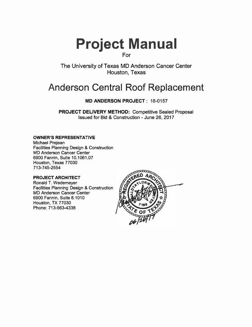
Project Manual For
The University of Texas MD Anderson Cancer Center Houston, Texas
Anderson Central Roof Replacement
MD ANDERSON PROJECT: 16-0157
PROJECT DELIVERY METHOD: Competitive Sealed Proposal Issued for Bid & Construction - June 26, 2017
OWNER'S REPRESENTATIVE
Michael Prejean Facilities Planning Design & Construction MD Anderson Cancer Center 6900 Fannin, Suite 10.1061.07 Houston, Texas 77030 713-745-2554
PROJECT ARCHITECT
Ronald T. Wedemeyer Facilities Planning Design & Construction MD Anderson Cancer Center 6900 Fannin, Suite 8.1010 Houston, TX 77030 Phone: 713-563-4338
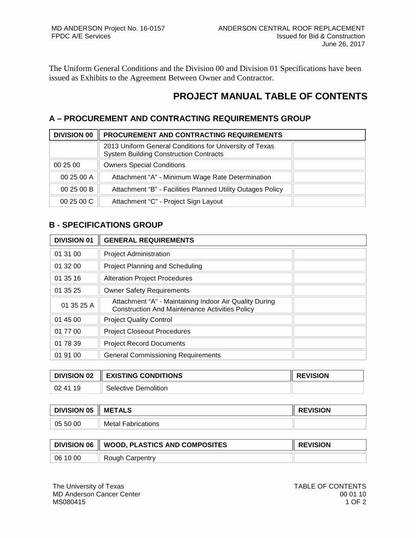
MD ANDERSON Project No. 16-0157 ANDERSON CENTRAL ROOF REPLACEMENT FPDC A/E Services Issued for Bid & Construction
June 26, 2017
The University of Texas TABLE OF CONTENTS MD Anderson Cancer Center 00 01 10 MS080415 1 OF 2
The Uniform General Conditions and the Division 00 and Division 01 Specifications have been issued as Exhibits to the Agreement Between Owner and Contractor.
PROJECT MANUAL TABLE OF CONTENTS
A – PROCUREMENT AND CONTRACTING REQUIREMENTS GROUP
DIVISION 00 PROCUREMENT AND CONTRACTING REQUIREMENTS 2013 Uniform General Conditions for University of Texas System Building Construction Contracts
00 25 00 Owners Special Conditions
00 25 00 A Attachment “A” - Minimum Wage Rate Determination
00 25 00 B Attachment “B” - Facilities Planned Utility Outages Policy
00 25 00 C Attachment “C” - Project Sign Layout
B - SPECIFICATIONS GROUP
DIVISION 01 GENERAL REQUIREMENTS
01 31 00 Project Administration
01 32 00 Project Planning and Scheduling
01 35 16 Alteration Project Procedures
01 35 25 Owner Safety Requirements
01 35 25 A Attachment “A” - Maintaining Indoor Air Quality During Construction And Maintenance Activities Policy
01 45 00 Project Quality Control
01 77 00 Project Closeout Procedures
01 78 39 Project Record Documents
01 91 00 General Commissioning Requirements
DIVISION 02 EXISTING CONDITIONS REVISION
02 41 19 Selective Demolition
DIVISION 05 METALS REVISION
05 50 00 Metal Fabrications
DIVISION 06 WOOD, PLASTICS AND COMPOSITES REVISION
06 10 00 Rough Carpentry
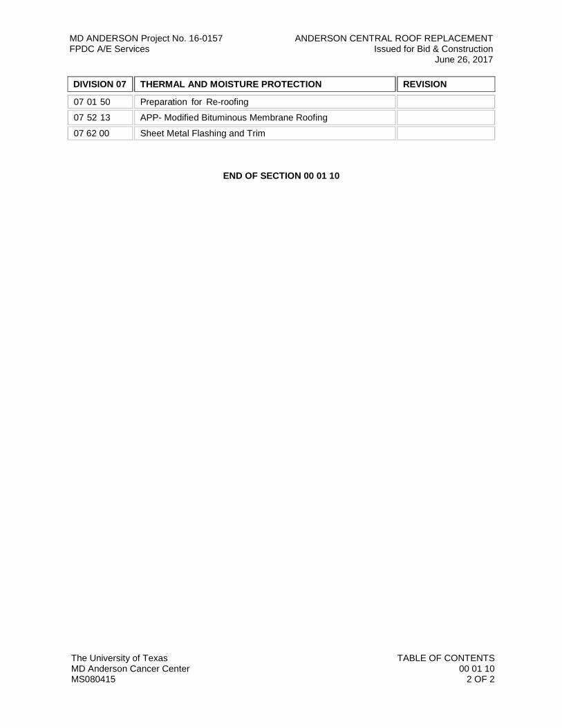
MD ANDERSON Project No. 16-0157 ANDERSON CENTRAL ROOF REPLACEMENT FPDC A/E Services Issued for Bid & Construction
June 26, 2017
The University of Texas TABLE OF CONTENTS MD Anderson Cancer Center 00 01 10 MS080415 2 OF 2
DIVISION 07 THERMAL AND MOISTURE PROTECTION REVISION
07 01 50 Preparation for Re-roofing
07 52 13 APP- Modified Bituminous Membrane Roofing
07 62 00 Sheet Metal Flashing and Trim
END OF SECTION 00 01 10
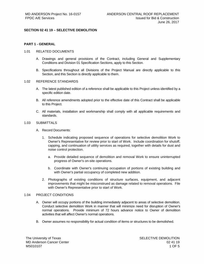
MD ANDERSON Project No. 16-0157 ANDERSON CENTRAL ROOF REPLACEMENT FPDC A/E Services Issued for Bid & Construction June 26, 2017
The University of Texas SELECTIVE DEMOLITION MD Anderson Cancer Center 02 41 19 MS010107 1 OF 5
SECTION 02 41 19 – SELECTIVE DEMOLITION
PART 1 - GENERAL
1.01 RELATED DOCUMENTS
A. Drawings and general provisions of the Contract, including General and Supplementary Conditions and Division 01 Specification Sections, apply to this Section.
B. Specifications throughout all Divisions of the Project Manual are directly applicable to this Section, and this Section is directly applicable to them.
1.02 REFERENCE STANDARDS
A. The latest published edition of a reference shall be applicable to this Project unless identified by a specific edition date.
B. All reference amendments adopted prior to the effective date of this Contract shall be applicable to this Project.
C. All materials, installation and workmanship shall comply with all applicable requirements and standards.
1.03 SUBMITTALS
A. Record Documents:
1. Schedule indicating proposed sequence of operations for selective demolition Work to Owner's Representative for review prior to start of Work. Include coordination for shutoff, capping, and continuation of utility services as required, together with details for dust and noise control protection.
a. Provide detailed sequence of demolition and removal Work to ensure uninterrupted progress of Owner's on-site operations.
b. Coordinate with Owner's continuing occupation of portions of existing building and with Owner's partial occupancy of completed new addition.
2. Photographs of existing conditions of structure surfaces, equipment, and adjacent improvements that might be misconstrued as damage related to removal operations. File with Owner's Representative prior to start of Work.
1.04 PROJECT CONDITIONS
A. Owner will occupy portions of the building immediately adjacent to areas of selective demolition. Conduct selective demolition Work in manner that will minimize need for disruption of Owner's normal operations. Provide minimum of 72 hours advance notice to Owner of demolition activities that will affect Owner's normal operations.
B. Owner assumes no responsibility for actual condition of items or structures to be demolished.
MD ANDERSON Project No. 16-0157 ANDERSON CENTRAL ROOF REPLACEMENT FPDC A/E Services Issued for Bid & Construction June 26, 2017
The University of Texas SELECTIVE DEMOLITION MD Anderson Cancer Center 02 41 19 MS010107 2 OF 5
1. Conditions existing at time of inspection for bidding purposes will be maintained by Owner insofar as practicable. However, minor variations within structure may occur by Owner's removal and salvage operations prior to start of selective demolition Work.
C. Promptly repair damages caused to adjacent facilities by demolition Work.
D. Conduct selective demolition operations and debris removal to ensure minimum interference with roads, streets, walks, and other adjacent occupied or used facilities.
1. Do not close, block, or otherwise obstruct streets, walks, or other occupied or used facilities without written permission from authorities having jurisdiction. Provide alternate routes around closed or obstructed traffic ways if required by governing regulations.
E. Do not use cutting torches for removal until Work area is cleared of flammable materials. At concealed spaces, such as interior of ducts and pipe spaces, verify condition of hidden space before starting flame cutting operations. Maintain portable fire suppression devices during flame cutting operations.
F. Maintain existing utilities indicated to remain in service and protect them against damage during demolition operations.
1. Do not interrupt utilities serving occupied or used facilities, except when authorized in writing by authorities having jurisdiction. Provide temporary services during interruptions to existing utilities, as acceptable to governing authorities.
2. Maintain fire protection services during selective demolition operations.
G. Use water sprinkling, temporary enclosures, and other methods to limit dust and dirt migration. Comply with governing regulations pertaining to environmental protection.
1. Do not use water when it may create hazardous or objectionable conditions such as ice, flooding, and pollution.
PART 2 - PRODUCTS
2.01 GENERAL
A. All materials shall meet or exceed all applicable referenced standards, federal, state and local requirements, and conform to codes and ordinances of authorities having jurisdiction.
2.02 MATERIAL OWNERSHIP
A. Except for items or materials indicated to be reused, salvaged, or otherwise indicated to remain the Owner's property, demolished materials shall be become the Contractor's property and shall be removed from the Site with further disposition of the Construction's option.
B. Historical items, relics, and similar objects including, but not limited to, cornerstones and their contents, commemorative plaques and tablets, antiques, and other items of interest or value to the Owner, which may be encountered during demolition, remain the Owner's property. Carefully remove and salvage each item or object in a manner to prevent damage and deliver promptly to the Owner.
MD ANDERSON Project No. 16-0157 ANDERSON CENTRAL ROOF REPLACEMENT FPDC A/E Services Issued for Bid & Construction June 26, 2017
The University of Texas SELECTIVE DEMOLITION MD Anderson Cancer Center 02 41 19 MS010107 3 OF 5
PART 3 - EXECUTION
3.01 PREPARATION
A. Provide interior and exterior shoring, bracing, or support to prevent movement, settlement, or collapse of areas to be demolished and adjacent facilities to remain.
1. Cease operations and notify Owner's Representative immediately if safety of structure appears to be endangered. Take precautions to support structure until determination is made for continuing operations.
2. Locate, identify, stub off, and disconnect utility services that are not indicated to remain.
a. Provide bypass connections as necessary to maintain continuity of service to occupied areas of building. Provide minimum of 72 hours advance notice to Owner if shutdown of service is necessary during changeover.
3.02 INSTALLATION
A. Installation shall meet or exceed all applicable federal, state and local requirements, referenced standards and conform to codes and ordinances of authorities having jurisdiction.
B. All installation shall be in accordance with manufacturer’s published recommendations.
3.03 DEMOLITION
A. Perform selective demolition Work in a systematic manner. Use such methods as required to complete Work indicated on Drawings in accordance with demolition schedule and governing regulations.
1. Demolish concrete and masonry in small sections. Cut concrete and masonry at junctures with construction to remain using power driven masonry saw or hand tools; do not use power driven impact tools.
2. Locate demolition equipment throughout structure and promptly remove debris to avoid imposing excessive loads on supporting walls, floors, or framing.
3. Provide services for effective air and water pollution controls as required by local authorities having jurisdiction.
4. Demolish foundation walls to a depth of not less than 12 inches below existing ground surface. Demolish and remove below grade wood or metal construction. Break up below grade concrete slabs.
5. For interior slabs on grade, use removal methods that will not crack or structurally disturb adjacent slabs or partitions. Use power saw where possible.
6. Completely fill below grade areas and voids resulting from demolition Work. Provide fill consisting of approved earth, gravel, or sand, free of trash and debris, stones over 6 inches in diameter, roots, or other organic matter.
MD ANDERSON Project No. 16-0157 ANDERSON CENTRAL ROOF REPLACEMENT FPDC A/E Services Issued for Bid & Construction June 26, 2017
The University of Texas SELECTIVE DEMOLITION MD Anderson Cancer Center 02 41 19 MS010107 4 OF 5
B. Remove culvert or sewer pipe for reuse by careful excavation of all material on the top and sides so that the pipe will not be damaged. Removal of sewer appurtenances shall be included for removal with the pipe. Remove pipe which are unsatisfactory for reuse, and dispose of, off the Project Site.
C. Concrete parts of structures below the permanent ground-line shall be neatly squared off with reinforcement cut off close to the concrete.
D. Dismantle steel structures or steel portions of structures in sections determined by the Owner's Representative.
1. The sections shall be of such weight and dimensions which permit convenient handling, hauling and storing.
2. Rivet and bolts connecting steel rail members, steel beams or girder spans and steel stringers of truss spans will be removed by cutting the heads with a cold cut then punching or drilling by a method that will not injure the member for reuse.
3. The removal of rivets and bolts from connections will not be required unless specifically indicated.
4. Unless otherwise specified, the Contractor shall have the option of dismantling these members by flame cutting immediately adjacent to the connection.
5. Flame-cutting will not be permitted when Drawings call for the structural unit to be salvaged in such a manner as to permit re-erection. In such cases, all members shall be carefully dismantled without damage, match marked with paint, and all rivets and bolts removed from the connections.
E. Remove brick and stone structures by sledging the masonry into removal sizes. Portions of such structures below the permanent ground-line, which will not in any manner interfere with the proposed construction, may be left in place, but removal shall be carried at least two feet below the permanent ground-line and neatly squared off.
F. If unanticipated mechanical, electrical, or structural elements that conflict with intended function or design are encountered, investigate and measure both nature and extent of the conflict. Submit report to Owner's Representative in written, accurate detail. Pending receipt of directive from Owner's Representative, rearrange selective demolition schedule as necessary to continue overall job progress without undue delay.
3.04 EXCAVATION AND BACKFILL
A. Back-fill to the level of the original ground-line, all excavation made in, and all openings below, the natural ground-line caused by the removal of old structures or portions thereof.
B. That portion of the back-fill which will support any portion of the roadbed or paving shall be placed in layers of the same thickness as those required subgrade preparation.
1. Material in each layer shall be wetted uniformly, if required, and shall be compacted to the density required in the adjoining embankment. In places inaccessible to blading and rolling equipment, mechanical or handtampers shall be used to obtain the required compaction.
MD ANDERSON Project No. 16-0157 ANDERSON CENTRAL ROOF REPLACEMENT FPDC A/E Services Issued for Bid & Construction June 26, 2017
The University of Texas SELECTIVE DEMOLITION MD Anderson Cancer Center 02 41 19 MS010107 5 OF 5
C. Place that portion of the back-fill which will not support any portion of the roadbed or paving in such a manner, and compact, to preclude settling.
3.05 DISPOSAL OF DEMOLISHED MATERIALS
A. Remove from building Site debris, rubbish, and other materials resulting from demolition operations. Transport and legally dispose off Site.
1. If hazardous materials are encountered during demolition operations, comply with applicable regulations, laws, and ordinances concerning removal, handling, and protection against exposure or environmental pollution.
2. Burning of removed materials is not permitted on the Project Site.
3.06 CLEANUP AND REPAIR
A. Upon completion of demolition Work, remove tools, equipment, and demolished materials from the Project Site. Remove protections and leave interior areas broom clean.
1. Repair demolition performed in excess of that required. Return elements of construction and surfaces to remain to condition existing prior to start operations. Repair adjacent construction or surfaces soiled or damaged by selective demolition Work.
END OF SECTION 02 41 19

The University of Texas MD Anderson Cancer Center MS100710
METAL FABRICATIONS 05 50 00
1 OF 3
MD ANDERSON Project No. 16-0157 ANDERSON CENTRAL ROOF REPLACEMENT FPDC A/E Services Issued for Bid & Construction
June 26, 2017
SECTION 05 50 00 METAL FABRICATIONS
PART 1 GENERAL
1.1 SUMMARY
A. Section Includes:1. Miscellaneous steel framing and supports for mechanical and electrical equipment,
where indicated.
B. Related Sections:1. Section 07 01 50 - Preparation for Re-Roofing2. Section 07 52 13 - APP-Modified Bituminous Membrane Roofing
1.2 ACTION SUBMITTALS
A. Shop Drawings: Show fabrication and installation details for metal fabrications.1. Include plans, elevations, sections, and details of metal fabrications and
their connections. Show anchorage, components and accessory items.
PART 2 PRODUCTS
2.1 METALS, GENERAL
A. Metal Surfaces, General: Provide materials with smooth, flat surfaces without blemishes.
2.2 FERROUS METALS
A. Steel Plates, Shapes, and Bars: ASTM A 36/A 36M.
B. Steel Tubing: ASTM A 500, cold-formed steel tubing.
C. Steel Pipe: ASTM A 53/A 53M, standard weight (Schedule 40) unless otherwise indicated.
D. Slotted Channel Framing: Cold-formed metal box channels (struts) complying with MFMA-4.1. Size of Channels: As indicated or required.
E. Material: Galvanized steel, ASTM A 653/A 653M, structural steel, Grade 33, withG90 coating; 0.079-inch nominal thickness or 0.45 ounces per square feet of surface area.
2.3 FASTENERS
A. Anchor Bolts: ASTM F 1554, Grade 36, of dimensions indicated; with nuts, ASTM A563; and, where indicated, flat washers.1. Hot-dip galvanized or provide mechanically deposited, zinc coating where item
being fastened is indicated to be galvanized.
The University of Texas MD Anderson Cancer Center MS100710
METAL FABRICATIONS 05 50 00
2 OF 3
MD ANDERSON Project No. 16-0157 ANDERSON CENTRAL ROOF REPLACEMENT FPDC A/E Services Issued for Bid & Construction
June 26, 2017
2.4 MISCELLANEOUS MATERIALS
A. Galvanizing Repair Compound: High-zinc-dust-content paint complying with SSPC-Paint 20 and compatible with paints specified to be used over it.
B. Bituminous Paint: Cold-applied asphalt emulsion complying with ASTM D 1187.
C. Nonshrink, N o n m e t a l l i c Grout: Factory-packaged, nonstaining, noncorrosive,nongaseous grout complying with ASTM C 1107. Provide g r o u t s p e c i f i c a l l yrecommended by manufacturer for interior and exterior applications.
2.5 FABRICATION, GENERAL
A. Shop Assembly: Preassemble items in the shop to greatest extent possible. Useconnections that maintain structural value of joined pieces.
B. Cut, drill, and punch metals cleanly and accurately. Remove burrs and ease edges.Remove sharp or rough areas on exposed surfaces.
C. Weld corners and seams continuously to comply with the following:1. Use materials and methods that minimize distortion and develop strength and
corrosion resistance of base metals.2. Obtain fusion without undercut or overlap.3. Remove welding flux immediately.4. At exposed connections, finish exposed welds and surfaces smooth and blended.
D. Form exposed connections with hairline joints, flush and smooth, using concealedfasteners or welds where possible. Locate joints where least conspicuous.
E. Fabricate seams and other connections that will be exposed to weather in a manner toexclude water. Provide weep holes where water may accumulate.
2.6 MISCELLANEOUS FRAMING AND SUPPORTS
A. General: Provide steel framing and supports not specified in other Sections asneeded to complete the Work.
B. Fabricate units from steel shapes, plates, and bars of welded construction unlessotherwise indicated. Fabricate to sizes, shapes, and profiles indicated and asnecessary to receive adjacent construction.
C. Fabricate steel pipe columns from steel pipe with steel baseplates and top plates asindicated.Drill or punch baseplates and top plates for anchor and connection bolts and weld topipe with fillet welds all around. Make welds the same size as pipe wall thicknessunless otherwise indicated.1. Unless otherwise indicated, fabricate from Schedule 40 steel pipe.2. Unless otherwise indicated, provide 1/2-inch (12.7-mm) baseplates with four
5/8-inch (16-mm) anchor bolts and 1/4-inch (6.4-mm) top plates.
D. Galvanize miscellaneous framing and supports where indicated.
The University of Texas MD Anderson Cancer Center MS100710
METAL FABRICATIONS 05 50 00
3 OF 3
MD ANDERSON Project No. 16-0157 ANDERSON CENTRAL ROOF REPLACEMENT FPDC A/E Services Issued for Bid & Construction
June 26, 2017
2.7 STEEL AND IRON FINISHES
A. Galvanizing: Hot-dip galvanize items as indicated to comply with ASTM A 153/A 153Mfor steel and iron hardware and with ASTM A 123/A 123M for other steel and iron products.
PART 3 EXECUTION
3.1 INSTALLATION, GENERAL
A. Cutting, Fitting, and Placement: Perform cutting, drilling, and fitting required forinstalling metal fabrications. Set metal fabrications accurately in location, alignment, andelevation; with edges and surfaces level, plumb, true, and free of rack; and measuredfrom established lines and levels.
B. Fit exposed connections accurately together to form hairline joints. Weld connections thatare not to be left as exposed joints but cannot be shop welded because of shipping sizelimitations. Do not weld, cut, or abrade surfaces of exterior units that have been hot-dipgalvanized after fabrication and are for bolted or screwed field connections.
C. Field Welding: Comply with the following requirements:1. Use materials and methods that minimize distortion and develop strength and
corrosion resistance of base metals.2. Obtain fusion without undercut or overlap.3. Remove welding flux immediately.4. At exposed connections, finish exposed welds and surfaces smooth and blended.
D. Fastening to In-Place Construction: Provide anchorage devices and fasteners where metalfabrications are required to be fastened to in-place construction.
E. Provide temporary bracing or anchors in formwork for items that are to be built intoconcrete, masonry, or similar construction.
3.2 INSTALLING MISCELLANEOUS FRAMING AND SUPPORTS
A. General: Install framing and supports to comply with requirements of items beingsupported, including manufacturers’ written instructions and requirements indicated onShop Drawings.
3.3 ADJUSTING AND CLEANING
A. Touchup Painting: Immediately after erection, clean field welds, bolted connections, andabraded areas. Paint uncoated and abraded areas with the same material as usedfor shop painting to comply with SSPC-PA 1 for touching up shop-painted surfaces.
B. Galvanized Surfaces: Clean field welds, bolted connections, and abraded areas and repairgalvanizing to comply with ASTM A 780.
END OF SECTION 05 50 00
The University of Texas MD Anderson Cancer Center MS100710
ROUGH CARPENTRY 06 10 00
1 OF 4
MD ANDERSON Project No. 16-0157 ANDERSON CENTRAL ROOF REPLACEMENT FPDC A/E Services Issued for Bid & Construction
June 26, 2017
SECTION 06 10 00 ROUGH CARPENTRY
PART 1 GENERAL
1.1 SUMMARY
A. This Section includes the following:1. Miscellaneous wood blocking, cants and nailers.2. Fasteners.
B. Related Sections include the following:1. Section 07 52 13 - APP-Modified Bituminous Membrane Roofing2. Section 07 62 00 - Sheet Metal Flashing and Trim
1.2 DEFINITIONS
A. Rough Carpentry: Carpentry work not specified in other Sections and not exposed, unlessotherwise indicated.
B. Lumber grading agencies, and the abbreviations used to reference them, include the following:1. NELMA - Northeastern Lumber Manufacturers Association2. NLGA - National Lumber Grades Authority3. SPIB - Southern Pine Inspection Bureau4. WCLIB - West Coat Lumber Inspection Bureau.5. WWPA - Western Wood Products Association.
1.3 SUBMITTALS
A. Product Data: For each type of process and factory-fabricated product. Indicate componentmaterials and dimensions and include construction and application details.
1. Include date for wood-preservative treatment from chemical treatment manufacturerand certification by treating plant that treated materials comply with requirements.Indicate type of preservative used, net amount of preservative retained, andchemical treatment manufacturer’s written instructions for handling, storing, installing,and finishing treated material. Also include manufacturer’s written requirement forcorrosion protection of fasteners and connectors to be in contact with treatedmaterials.
2. For products receiving waterborne treatment, include statement that moisture contentor treated materials was reduced to levels specified before shipment to Project site.
3. Include copies of warranties from chemical treatment manufacturers for eachtype of treatment
1.4 DELIVERY, STORAGE, AND HANDLING
A. Stack lumber, plywood, and other panels. Protect from water and weather. Place spacers betweenbundles to provide air circulation. Provide for air circulation around stacks and under coverings.
The University of Texas MD Anderson Cancer Center MS100710
ROUGH CARPENTRY 06 10 00
2 OF 4
MD ANDERSON Project No. 16-0157 ANDERSON CENTRAL ROOF REPLACEMENT FPDC A/E Services Issued for Bid & Construction
June 26, 2017
PART 2 PRODUCTS
2.1 WOOD PRODUCTS, GENERAL
A. Lumber: DOC PS 20 and applicable rules of lumber grading agencies certified by theAmerican Lumber Standards Committee Board of Review.1. Factory mark each piece of lumber with grade stamp of grading agency.2. Where nominal sizes are indicated, provide actual sizes required by DOC PS 20
for moisture content specified. Where actual sizes are indicated, they are minimumdressed sized for dry lumber.
3. Provide lumber, S4S, unless otherwise indicated.4. Provide dry lumber with 19 percent maximum moisture content at time of dressing for
2- inch nominal thickness or less, unless otherwise indicated.
2.2 WOOD-PRESERVATIVE-TREATED M A T E R I A L S
A. Preservative Treatment by Pressure Process: Per AWPA Standard U1 and AWPAStandard T1. Lumber that is not in contact with the ground and is continuouslyprotected from liquid water may be treated for Use Category UC2. All other woodindicated in this Section or the Drawings to be treated for Use Category UC4A.1. Preservative Chemicals: Water-borne preservatives or Oxine Copper
(copper-8- quinolinolate) acceptable to authorities having jurisdiction.
B. Kiln-dry material after treatment to a maximum moisture content of 19 percent for lumberand15 percent for plywood. Do not use material that is warped or does not complywith requirements for untreated material.
C. Treat all rough carpentry unless otherwise indicated.
D. Field-Applied Preservative Treatment: AWPA M4-02, minimum 2% solids Copper-Napthenate solution.
2.3 MISCELLANEOUS LUMBER AND PLYWOOD
A. General: Provide lumber for support or attachment of other construction, including thefollowing:1. Rooftop equipment bases and support curbs, unless details depict prefabricated
metal units.2. Blocking: Provide minimum of six inch nominal width.3. Cants: Provide minimum of four inch face.4. Nailers: Provide minimum six inch nominal width.5. Plywood: Provide minimum of 3/4 inch thickness on horizontal plane and 5/8
inch thickness on vertical plane.
B. For concealed boards and dimension lumber size, provide No. 2 or better lumber with19 percent maximum moisture content and of the following species and grades:1. Mixed southern pine, No. 2; SPIB.2. Spruce-pine-fur; NELMA, NLGA, WCLIB, or WWPA.
C. Plywood: Provide marine grade plywood of thicknesses indicated.
The University of Texas MD Anderson Cancer Center MS100710
ROUGH CARPENTRY 06 10 00
3 OF 4
MD ANDERSON Project No. 16-0157 ANDERSON CENTRAL ROOF REPLACEMENT FPDC A/E Services Issued for Bid & Construction
June 26, 2017
2.4 FASTENERS
A. Wood nailers to metal deck: #10 x 2-1/2" stainless steel screws with 5/8" stainlesssteel washers.
B. Wood nailers to concrete: X-CR-L 72 P8 S23 stainless steel powder actuated fastener byHilti North America.
C. Upper wood nailers to lower wood nailers: #10x3" stainless steel screws.
D. Miscellaneous Common Nails: Provide Type 304 stainless steel common nails.1. 16d Common Nail: 0.162” diameter x 3-1/2” length2. 10d Common Nail: 0.148” diameter x 3” length3. 8d Common Nail: 0.131” diameter x 2-1/2” length
PART 3 EXECUTION
3.1 INSTALLATION, GENERAL
A. Set rough carpentry to required levels and lines, with members plumb, true to line, cutand fitted. Fit rough carpentry to other construction; scribe and cope as needed foraccurate fit. Locate, nailers, blocking and similar supports to comply with requirement forattaching other construction.
B. Do not use materials with defects that impair quality of rough carpentry or pieces that aretoo small to use with minimum number of joints or optimum joint arrangement.
C. Apply field treatment complying with AWPA M4 to cut surfaces of preservative-treated lumber and plywood. Apply minimum two coats per manufacturer’srecommendations. Wipe off excess treatment.
D. Securely attach rough carpentry work to substrate by anchoring and fastening asindicated in the Drawings, complying with the following:1. CABO NER-272 for power-driven fasteners
E. Select fasteners of size that will not fully penetrate members where opposite side willbe exposed to view or will receive finish materials. Make tight connections betweenmembers. Install fasteners without splitting wood.
F. For hardware, anchors, and connectors, use fasteners in all holes per manufacturer’srecommendations unless indicated otherwise.
G. Lag bolts and lag screws: Pre-drill for lag bolts and lag screws to diameter at base ofthreads and length equal to embedment.
The University of Texas MD Anderson Cancer Center MS100710
ROUGH CARPENTRY 06 10 00
4 OF 4
MD ANDERSON Project No. 16-0157 ANDERSON CENTRAL ROOF REPLACEMENT FPDC A/E Services Issued for Bid & Construction
June 26, 2017
H. Bolting: Drill holes 1/16-inch larger in diameter than bolts used. Drill straight and truefrom one side only. Use washers under head and nut where both bear on wood. Usewashers under all nuts.
3.2 WOOD BLOCKING AND NAILER INSTALLATION
A. Install where indicated and where required for attaching other work. Form to shapesindicated and cut as required for true line and level of attached work. Coordinatelocations with other work involved.
B. Attach wood blocking to new or existing wood blocking lumber utilizing screws staggered12 inches on center.
C. All connections of new wood blocking shall be as indicated in the details on theDrawings. Fasteners shall be of compatible material when used in conjunction with newblocking and metal items.1. When securing wood blocking for flashing details, predrill holes for anchors to
be installed.2. Mechanically attach wood blocking in accordance with FM LPDS 1-29 and 1-49
guidelines. Blocking thickness: Equal to final insulation thickness, plus or minus 1/8inch. Width shall be nominal six inches, unless otherwise indicated.
3. Install fasteners in two rows staggered. Spacing in any one row shall not exceed24 inches. Minimum two (2) fasteners per blocking. Within eight feet of outsidecorners, spacing shall not exceed 12 inches in any one row.
4. Offset additional blocking layers 12 inches and weave corners. Additional layers ofblocking may be secured to bottom layer with screws staggered 12 inches on center.
D. Attach items to substrates to support applied loading. Recess bolts and nuts flush withsurfaces, unless otherwise indicated.
3.3 CLEANUP
A. Remove from the job site and legally dispose of all trash and debris. Remove allsurplus materials, tools and equipment from the job site.
B. Carefully inspect all completed work and correct all defects.
END OF SECTION
The University of Texas MD Anderson Cancer Center MS100710
PREPARATION FOR RE-ROOFING 07 01 50
1 OF 4
MD ANDERSON Project No. 16-0157 ANDERSON CENTRAL ROOF REPLACEMENT FPDC A/E Services Issued for Bid & Construction
June 26, 2017
SECTION 07 01 50 PREPARATION FOR RE-ROOFING
PART 1 GENERAL
1.1 SUMMARY
A. Section includes:1. Roof tear-off2. Removal of base flashing and sheet metal flashing and trim intended for
temporary removal or replacement.3. Recycling of existing isocyanurate insulation.
B. Related Sections:1. Section 07 52 13 - APP-Modified Bituminous Membrane Roofing2. Section 07 62 00 - Roofing Sheet Metal and Flashing
1.2 MATERIALS OWNERSHIP
A. Except for items or materials indicated to be reused, reinstalled, recycled or otherwiseindicated to remain Owner’s property, demolished materials shall become Contractor’sproperty and shall be removed from Project site.
B. Isocyanurate insulation shall be recycled using an approved recycling vendor.
1.3 DEFINITIONS
A. Roofing Terminology: Refer to ASTM D 1079 and glossary in NRCA’s “The NRCA Roofingand Waterproofing Manual” for definition of terms related to roofing work in this Section.
B. Existing Membrane Roofing System: EPDM roofing membrane, roof insulation, surfacing,and components and accessories between deck and roofing membrane.
C. Roof Tear-Off: Removal of existing membrane roofing system from deck.
D. Remove: Detach items from existing construction and legally dispose of them off-siteunless indicated to be removed and reinstalled.
E. Existing to Remain: Existing items of construction that are not indicated to be removed.
F. End of Work Day: Time when work is stopped for any reason; either completion ofplanned hours or early termination of work due to weather or other causes.
1.4 SUBMITTALS
A. Product Data: For each type of product indicated.
B. Submit written description of the intended method of ensuring that the area affected byremovals, including all penetrations and perimeters is complete and weather tight at theend of the work day. This is an “informational submittal” and not subject to the Architect’sapproval.
C. Landfill Records: Indicate receipt and acceptance of hazardous wastes, such as asbestos-containing material, by a landfill facility licensed to accept hazardous wastes.
The University of Texas MD Anderson Cancer Center MS100710
PREPARATION FOR RE-ROOFING 07 01 50
2 OF 4
MD ANDERSON Project No. 16-0157 ANDERSON CENTRAL ROOF REPLACEMENT FPDC A/E Services Issued for Bid & Construction
June 26, 2017
D. Recycling documentation: Provide sample certificate from company performing recycling.
1.5 QUALITY ASSURANCE
A. Regulatory Requirements: Comply with hauling and disposal regulations of authoritieshaving jurisdiction.
1.6 PROJECT CONDITIONS
A. Owner will occupy portions of building immediately below reroofing area. Conductreroofing so Owner’s operations will not be disrupted. Provide Owner with not less than10 day notice of activities that may affect Owner’s operations.1. Coordinate work activities daily with Owner so Owner can place protective dust or
waterleakage covers over sensitive equipment or furnishings, shut down HVAC and fire-alarm or -detection equipment if needed, and evacuate occupants from below the workarea.
2. Schedule a shutdown with a 10 day notice before working over structurallyimpairedareas of deck, notify Owner to evacuate occupants from below the affected area.Verify that occupants below the work area have been evacuated before proceedingwith work over the impaired deck area.
B. Protect building to be reroofed, adjacent buildings, walkways, site improvements, exteriorplantings, and landscaping from damage or soiling from reroofing operations.
C. Maintain access to existing walkways, corridors, and other adjacent occupied or usedfacilities.
D. Uniformly distributed construction loads across the roof surface.
E. Weather Limitations: Proceed with reroofing preparation only when existing andforecasted weather conditions permit Work to proceed without water entering existingroofing system or building.
PART 2 PRODUCTS
2.1 AUXILIARY REROOFING MATERIALS
A. General: Auxiliary reroofing preparation materials recommended by roofing systemmanufacturer for intended use and compatible with components of new membraneroofing system.
B. Corrosion Inhibiting Coating:
1. Use: Coating bottom edge of cut penthouse wall panels in preparation for newroofing base flashing.
2. Acceptable product: “Ospho” by The Skybryte Company, Cleveland, Ohio.
PART 3 EXECUTION
The University of Texas MD Anderson Cancer Center MS100710
PREPARATION FOR RE-ROOFING 07 01 50
3 OF 4
MD ANDERSON Project No. 16-0157 ANDERSON CENTRAL ROOF REPLACEMENT FPDC A/E Services Issued for Bid & Construction
June 26, 2017
3.1 PREPARATION
A. Coordinate with Owner to shut down air-intake equipment, if possible, in the vicinity ofthe Work. Cover air-intake louvers with filtration material before proceeding with reroofingwork that could affect indoor air quality or activate smoke detectors in the ductwork.
B. During removal operations, have sufficient and suitable materials on-site to facilitaterapid installation of temporary protection in the event of unexpected rain.
C. Maintain roof drains in functioning condition to ensure roof drainage at end of eachworkday.Prevent debris from entering or blocking roof drains and conductors. Use roof-drainplugs specifically designed for this purpose. Remove roof-drain plugs at end of eachworkday, when no work is taking place, or when rain is forecast.1. If roof drains are temporarily blocked or unserviceable due to roofing system removal
or partial installation of new membrane roofing system, provide alternative drainagemethod to remove water and eliminate ponding. Do not permit water to enter into orunder existing membrane roofing system components.
D. Verify that rooftop utilities and service piping have been shut off before beginning the Work.
3.2 ROOF TEAR-OFF
A. General: Notify Owner each day of extent of roof tear-off proposed for that day andobtain authorization to proceed.
B. Roof Tear-Off: Remove existing roofing membrane and other roofing system componentsdown to the structural concrete deck.1. Remove residual adhesives from concrete roof deck as required to comply with
manufacturer’s requirements for the new roofing system specified in Section 07 5213 - APP-Modified Bituminous Membrane Roofing.
2. In cutting the existing roofing, ensure that cutting tools do not penetrate thesubstrate intended to remain.
3. If cutting machines are used in the performance of the work, set the blade cuttingdepth high enough to prevent penetration into the substrate intended to remain.
4. Patch cuts made into the substrate intended to remain according to the directions ofthe Architect.
C. Control dust, noise and debris to the satisfaction of the Owner.
3.3 DECK PREPARATION
A. Inspect deck after tear-off of membrane roofing system.
B. Verify that concrete substrate is visibly dry and free of moisture. Test for capillarymoisture by plastic sheet method according to ASTM D 4263. Do not proceed withroofing work if moisture condenses under the plastic sheet.
C. If deck surface is not suitable for receiving new membrane sheet or if structural integrityof deck is suspect, immediately notify Architect. Do not proceed with installation untildirected by Architect.
The University of Texas MD Anderson Cancer Center MS100710
PREPARATION FOR RE-ROOFING 07 01 50
4 OF 4
MD ANDERSON Project No. 16-0157 ANDERSON CENTRAL ROOF REPLACEMENT FPDC A/E Services Issued for Bid & Construction
June 26, 2017
D. Prior to drilling or penetrating the concrete roof deck, in any manner, contractor shall testor scan intended location for embedded electrical conduit. If suspected electrical conduitis found, notify Architect prior to drilling.
3.4 EXISTING BASE FLASHINGS
A. Remove existing base flashings around parapets, curbs, walls, and penetrations.1. Clean substrates of contaminants such as adhesive, sheet materials, dirt, and debris.
B. Do not damage metal counter flashings that are to remain. Replace metal counterflashings damaged during removal with counter flashings of same metal, weight orthickness, and finish.
3.5 DISPOSAL
A. Collect demolished materials and place in containers. Promptly recycle or dispose ofdemolished materials. Do not allow demolished materials to accumulate on-site.1. Storage or sale of demolished items or materials on-site is not permitted.
B. Transport and legally dispose of demolished materials off Owner’s property.
C. Provide certificate of recycle indicating volume of insulation recycled with project andOwner name printed on certificate.
END OF SECTION
The University of Texas MD Anderson Cancer Center MS100710
APP-MODIFIED BITUMINOUS MEMBRANE ROOFING 07 52 13 1 OF 21
MD ANDERSON Project No. 16-0157 ANDERSON CENTRAL ROOF REPLACEMENT FPDC A/E Services Issued for Bid & Construction
June 26, 2017
SECTION 07 52 13 APP-MODIFIED BITUMINOUS MEMBRANE ROOFING
PART 1 GENERAL
1.1 SUMMARY
A. Section Includes:1. Surface preparation and installation of a cold adhesive-applied granule-surfaced,
APP- modified bituminous membrane roofing system.2. Installation of a torch-applied modified bituminous vapor retarder membraneover the concrete roof deck.
3. Installation of roof and deck insulation, cover boards, and liquid membrane flashing.4. Replacement drains for overflow roof drains.
B. Related Sections:1. Section 07 01 50 - Preparation for Re-Roofing2. Section 07 62 00 - Sheet Metal Flashing and Trim3. Section 07 92 00 - Joint Sealants
1.2 REFERENCES
A. The latest published edition of a reference shall be applicable to this Project unlessidentified by a specific edition date.
B. All reference amendments adopted prior to the effective date of this Contract shallbe applicable to this Project.
C. All materials, installation and workmanship shall comply with the applicable requirementsand standards addressed within this Section.
D. American National Standards Institute (ANSI)/ Single Ply Roofing Industry (SPRI):1. ANSI/SPRI ES-1 2003 Wind Design Standard for Edge Systems Used with Low-
Slope Roofing Systems.
E. ASTM International:1. C 1177: Standard Specification for Glass Mat Gypsum Substrate for Use as Sheathing.2. C 1289 - Standard Specification for Faced Rigid Cellular Polyisocyanurate
Thermal Insulation Board.3. D 41 - Standard Specification for Asphalt Primer Used in Roofing, Dampproofing
and Waterproofing.4. D 1079: Standard Terminology Relating to Roofing and Waterproofing5. D 4263: Standard Test Method for Indicating Moisture in Concrete by the Plastic
Sheet Method.6. D 4586 - Standard Specification for Asphalt Roof Cement, Asbestos-Free.7. D 5147 - Standard Test Method for Sampling and Testing Modified Bituminous
Sheet Materials8. D 6223: Standard specifications for APP modified bitumen sheet materials using a
combination of polyester and fiberglass reinforcements.9. D 6509 - Standard Specification for Atactic Polypropylene (APP) Modified Bituminous
Base Sheet Materials Using Glass Fiber Reinforcements.10. E 108: Standard Test Methods for Fire Tests of Roof Coverings.
The University of Texas MD Anderson Cancer Center MS100710
APP-MODIFIED BITUMINOUS MEMBRANE ROOFING 07 52 13 2 OF 21
MD ANDERSON Project No. 16-0157 ANDERSON CENTRAL ROOF REPLACEMENT FPDC A/E Services Issued for Bid & Construction
June 26, 2017
F. Factory Mutual (FM Global)1. Class Number 4450 – Approval Standard for Class 1 Insulated Steel Deck Roofs.2. Class Number 4470 – Approval Standard for Class 1 Roof Covers.3. FM Global Loss Prevention Data Sheet 1-28, Wind Design.4. FM Global Loss Prevention Data Sheet 1-29, Roof Deck Securement and Above-
Deck Roof Components.5. Approval Guide.
G. National Roofing Contractors Association (NRCA)1. The NRCA Roofing Manual: Membrane Roof Systems.2. Quality Control Guidelines for Application of Polymer Modified Bitumen Roofing.
H. Structural Engineering Institute (SEI)/American Society of Civil Engineers (ASCE):1. SEI/ASCE 7 – Minimum Design Loads for Buildings and Other Structures.
1.3 DEFINITIONS
A. Roofing Terminology: Refer to ASTM D 1079 and glossary of The NRCA RoofingManual for definition of terms related to roofing work in this Section.
1.4 SYSTEM DESCRIPTION
A. Design and Performance Requirements1. General Performance: Installed membrane roofing and base flashings shall withstand
specified uplift pressures, thermally induced movement, and exposure to weatherwithout failure due to defective manufacture, fabrication, installation, or otherdefects in construction. Membrane roofing system and base flashings shall remainwatertight.
2. Material Compatibility: Provide roofing materials that are compatible with oneanother under conditions of service and application required, as demonstrated bymembrane roofing manufacturer based on testing and field experience.
3. Roofing System Design: Provide membrane roofing system that is identical tosystems that have been successfully tested by a qualified testing and inspectingagency to resist uplift pressure calculated according to ASCE/SEI 7.a. Corner Uplift Pressure: -225 psfb. Perimeter Uplift Pressure: -165 psfc. Field-of-Roof Uplift Pressure: -105 psf
4. FM Approvals Listing: Provide membrane roofing, base flashings, and componentmaterials that comply with requirements in FM Approvals 4450 and FM Approvals4470 as part of a membrane roofing system, and that are listed in FM Approvals’“Roof Nav” for Class 1 or noncombustible construction, as applicable. Identifymaterials with FM Approvals markings.a. Fire/Windstorm Classification: Class 1A-255.b. Hail Resistance Rating: SH.
5. Asbestos Containing Materials: Install only asbestos free materials. Asbestoscontaining materials inadvertently installed to be immediately removed in accordancewith all applicable regulations.
6. Energy Performance: Provide roofing system with initial solar reflectance not lessthan0.70 and thermal emittance not less than 0.75 when tested according to one of thetest methods listed below.a. Solar Reflectance Test Methods: ASTM C1549, ASTM E903, ASTM E1175, or
ASTM E1918.
The University of Texas MD Anderson Cancer Center MS100710
APP-MODIFIED BITUMINOUS MEMBRANE ROOFING 07 52 13 3 OF 21
MD ANDERSON Project No. 16-0157 ANDERSON CENTRAL ROOF REPLACEMENT FPDC A/E Services Issued for Bid & Construction
June 26, 2017
b. Thermal Emittance Test Methods: ASTM C835, ASTM C1371, or ASTM E408.7. Underwriters Laboratory Classification: Materials and components of the roofing
system shall meet UL Class A requirements.
1.5 SUBMITTALS
A. Product Data: Roofing-system manufacturer’s literature, including written instructions forevaluating, preparing, and treating substrate; technical data including tested physical andperformance properties; and application instructions.1. Provide f o r m e m b r a n e a n d b a s e f l a s h i n g m a t e r i a l s , a n d
r o o f i n g c e m e n t , primer, adhesives, mastic sealant, and fasteners.2. Include temperature ranges for storage and application of materials, and special
weather application requirements or limitations.
B. Shop Drawings: Include plans, elevations, sections, details, and attachments to other work;for details and fabrications not shown on Project Drawings. Submit only project specificdetails that have been reviewed and approved by the membrane manufacturer. Draw shopdrawings to scale. Manufacturer’s standard installation details are not sufficient to be shopdrawings. Duplication of Architect’s details does not suffice for shop drawings. Shopdrawings may include, but are not limited to the following list:1. Base flashings and membrane terminations.2. Penetrations, roof drains, supports, davits, expansion joints.3. Tapered insulation, including slopes.4. Crickets, saddles, and tapered edge strips, including slopes.5. Insulation fastening patterns for corner, perimeter, and field-of-roof locations.6. Membrane and walkway pads layout showing orientation of membrane ply sheets.
C. Samples for Verification: For the following products:1. Sheet roofing materials, including temporary roof membrane, base sheet, membrane
cap sheet, flashing base sheet, and flashing cap sheet, of color specified. Provide 3-inch by 4- inch samples, including color specified.
2. Elastomeric c o a t i n g a p p l i e d t o s u i t a b l e m a t e r i a l . Provide 3 -inch-by-4-inchs a m p l e s , including color specified.
3. Roof insulation.4. Walkway pads or rolls.5. Termination bar.6. Termination bar fasteners.7. Liquid flashing material applied to suitable material. Provide 3-inch-by-4-inch
samples, including color specified.
D. Installer’s Certificate:
1. Signed by roofing-system manufacturer, certifying that Roofing Installer is trainedand licensed or approved by the manufacturer to install specified, warranted, roofingsystem.
2. Submit evidence that Installer’s existing company has minimum of 5 yearscontinuous experience in application of specified materials. Submit list of at leastfive completed projects of similar scope and size, including:a. Project name.b. Owner’s name.c. Owner’s Representative name, address, and telephone number.d. Description of work.e. APP-modified-bitumen materials used.
The University of Texas MD Anderson Cancer Center MS100710
APP-MODIFIED BITUMINOUS MEMBRANE ROOFING 07 52 13 4 OF 21
MD ANDERSON Project No. 16-0157 ANDERSON CENTRAL ROOF REPLACEMENT FPDC A/E Services Issued for Bid & Construction
June 26, 2017
f. Project supervisor.g. Total cost of roofing work and total cost of project.h. Completion date.
E. Manufacturer Certificate: Signed by roofing-system manufacturer , cer t i f ying thatroof ing system complies with specified requirements.1. Written approval by membrane manufacturer for use and performance of membrane
over specified board insulation, including that materials supplied for project complywith requirements of cited ASTM standards and Project Documents. Approval shouldalso indicate materials are suitable for ASTM E 108, Class 1A roof and meetspecified wind uplift requirements.
2. Submit evidence of meeting performance requirements including method and spacingof fasteners or adhesive for roof system attachment to the substrate.
3. Certify that materials are free of asbestos.4. Written c e r t i f i c a t i o n s i g n e d by t h e manufacturer t h a t the specified
materials are acceptable for this application and is eligible for the specified warranty.
F. Sample Warranty: Copy of roofing-system manufacturer’s w a r r a n t y , s t a t i n gob l ig a t i ons , remedies, limitations, and exclusions. Submitted with bid.
G. Following completion of Work, submit roofing-system manufacturer’s inspection reports,including final inspection, of completed roofing installation and completed warranty;submit Installer’s completed warranty.
H. Maintenance data for roofing system.
I. LEED Submittals:1. Product Test Reports for Credit SS 7.2: For roof materials, indicating that roof
materials comply with Solar Reflectance Index requirement.2. Product Data for Credit IEQ 4.1: For adhesives and sealants used inside the
weatherproofing system, documentation including printed statement of VOC content.
1.6 QUALITY ASSURANCE
A. General: In general, roofing materials to be obtained from one (1) manufacturer. The useof other materials must be acknowledged and approved by both the primarymanufacturer and the supplier of incidental materials, each accepting the other.
1. Portions of these specifications may exceed the minimum requirements ofmaterial manufacturer(s). Installer to comply, first with these Specifications, andsecondly, with the manufacturer’s recommendations and instructions. In no eventwill less quality, less weight or a lesser number of plies or any other lesserrequirements be acceptable than at least the minimum of such required by thisSection and those of the manufacturer(s).a. The current published product and installation literature of these materials
manufacturers will be considered part of this specification. Any revisions tothe published literature, prior to the date of installation of the project willalso be considered part of this specification.
b. Maintain one copy of contract documents and submittals on site at all timesduring work activities.
B. Manufacturer Qualifications: A qualified manufacturer with a minimum of ten (10) yearsdocumented experience that has UL listing and FMG approval for roofing system identical
The University of Texas MD Anderson Cancer Center MS100710
APP-MODIFIED BITUMINOUS MEMBRANE ROOFING 07 52 13 5 OF 21
MD ANDERSON Project No. 16-0157 ANDERSON CENTRAL ROOF REPLACEMENT FPDC A/E Services Issued for Bid & Construction
June 26, 2017
to that used for this Project.
C. Installer Qualifications: Qualified firm that is approved, authorized, or licensed byroofing- system manufacturer to install roofing-system products and that is eligible toreceive roofing- system warranty. Must have installations of specified materials in localarea in use for minimum of 5 years.1. Employ foreman with minimum of 5-years’ experience as foreman on similar
projects, who is fluent in English, to be on site at all times during Work.
D. Preinstallation Roofing Conference:1. Conduct meeting at Project site.2. Contractor’s site foreman, roofing-system manufacturer’s technical
representative, roofing Installer, Owner’s Representative, and Architect/Engineer shallattend.
3. Review requirements for roofing system, including:a. Construction schedule and availability of materials, Installer’s personnel,
equipment, and facilities needed to make progress and avoid delays.b. Site use, access, staging, and set-up location limitations.c. Methods and procedures related to roofing installation, including
manufacturer’s written instructions.d. Surface preparation and roof-deck condition and pretreatment.e. Modification or replacement of existing roof drains and installation of new roof
drains. Method of roof drainage during each stage of reroofing and roof drainplugging and plug removal requirements.
f. Installation procedures.g. Required submittals, both completed and yet to be completed.h. Shop drawings for base flashings, special roofing details, roof drainage, roof
penetrations, equipment curbs, and condition of other construction that willaffect roofing system.
i. Deviations o r d i f f e r e n c e s be t wee n Con t rac t D ocum en ts a n d them a n u f a c t u r e r ’ s specifications.
j. Required inspection, testing, certifying, and material usage accounting procedures.k. Temporary protection and repair of roofing system.l. Structural loading limitations of roof deck.m. Governing regulations and requirements for insurance and certificates if applicable.
4. Tour representative areas of Work.
1.7 DELIVERY, STORAGE, AND HANDLING
A. Deliver roofing materials to Project site in original containers with seals unbroken andlabeled with manufacturer’s name, product brand name and type, date of manufacture,lot numbers, approval or listing agency markings, and directions for storing andmixing with other components.
B. Keep materials dry and do not allow materials to be exposed to moisture duringtransportation, storage, handling, or installation. Reject and remove from Project sitenew materials which exhibit evidence of moisture during application or which have beenexposed to moisture. Conspicuously mark wet or damaged materials and promptly removefrom site.
C. Store liquid materials in their original undamaged containers in a clean, dry, protectedlocation and within the temperature range required by roofing system manufacturer.Protect stored liquid material from direct sunlight. Discard and legally dispose of liquid
The University of Texas MD Anderson Cancer Center MS100710
APP-MODIFIED BITUMINOUS MEMBRANE ROOFING 07 52 13 6 OF 21
MD ANDERSON Project No. 16-0157 ANDERSON CENTRAL ROOF REPLACEMENT FPDC A/E Services Issued for Bid & Construction
June 26, 2017
material that cannot be applied within its stated shelf life.
D. Store rolled materials on ends only, unless otherwise required by roofing-systemmanufacturer’s written instructions. Discard rolls that have been flattened, creased, orotherwise damaged.
E. Do not store materials at locations where new roofing materials have been installed.
F. Protect roof insulation materials from physical damage and from deterioration bysunlight, moisture, soiling, and other sources. Store in a dry location. Comply withinsulation manufacturer’s written instructions for handling, storing, and protecting duringinstallation.1. Manufacturer’s standard packaging is not sufficient protection from weather. Provideprotective coverings that are breathable. Canvas is preferred. Store on raised platforms.
G. Limit stored materials on structures to safe loading of structure at time materials arestored. Handle and store roofing materials and place equipment in a manner to avoidsignificant or permanent damage to deck or structural supporting members.
H. Remove and replace materials that cannot be applied within stated shelf life.
1.8 PROJECT CONDITIONS
A. Verify existing dimensions and details prior to installation of materials. NotifyArchitect/Engineer of conditions found to be different than those indicated in Contrac tDocuments. Architect/Engineer will review situation and inform Contractor and Installerof changes.
B. Comply with Owner’s limitations and restrictions for site use and accessibility.
C. Environmental Limitations: Install roofing when existing and forecast weather condit ionspermit roofing system to be installed according to roofing-system manufacturer’s writteninstructions and warranty requirements.1. Observe cold-weather precautions a n d g u i d e l i n e s r e c o m m e n d e d by
r o o f i n g -system manufacturer when applying membrane materials below 40degrees F.
2. Do not proceed with installation during inclement weather except for temporarywork necessary to protect building interior and installed materials. Removetemporary work and Work that becomes moisture damaged.
D. Daily seal: Ensure that moisture does not penetrate beneath any completed sections ofthe roof by sealing temporary roof terminations at the end of each work day and priorto the arrival of inclement weather. Inspect existing components for moisture intrusionalong the temporary terminations at temporary cut-offs, tie-ins, and night seals afteropening the seal on the next workday. Remove any wet, damp or moisture-damagedmaterials
E. Install materials in strict accordance with safety requirements required by roofingmanufacturer, Material Safety Data Sheets, and local, state, and federal rules andregulations.
F. Maintain adequate ventilation during preparation and application of roofing materials.
The University of Texas MD Anderson Cancer Center MS100710
APP-MODIFIED BITUMINOUS MEMBRANE ROOFING 07 52 13 7 OF 21
MD ANDERSON Project No. 16-0157 ANDERSON CENTRAL ROOF REPLACEMENT FPDC A/E Services Issued for Bid & Construction
June 26, 2017
G. Torch Safety: Crew members handling torches shall be trained by an AuthorizedCertified Roofing Torch Applicator (CERTA) Trainer, be certified according to CERTAtorch safety guidelines as published by the National Roofing Contractors Association(NRCA), and follow torch safety practices as required by the contractor's insurancecarrier. Designate one person on each crew to perform a daily fire watch. The designatedcrew member shall watch for fires or smoldering materials on all areas during roofconstruction activity, and for the minimum period required by CERTA guidelines afterroofing material application has been suspended for the day.
1.9 SEQUENCING AND SCHEDULING
A. Coordinate work with other trades to avoid or minimize work on, or in immediate vicinity of,installation in progress and completed new roofing. Provide temporary protection ofnew roofing as necessary to prevent damage to the roofing during construction.Repair any damage that may result from sequencing activities.
B. Phasing of the roof plies will not be allowed unless approved by the Owner in writing priorto the start of the project. However, the roof system must remain watertight at all timesduring construction. Provide t em p o r a r y protect ion o f new roof ing base p l y f romcons t r uc t i on damage during phased installation. Base ply shall not remain exposedover 30 days. Base ply shall be inspected by manufacturer and general contractor andall repairs performed as directed by the manufacturer prior to the installation of the capsheet.
1.10 WARRANTY
A. Manufacturer’s System Warranty1. Written System Warranty, non-prorated and without monetary limitation, signed by
roofing-system manufacturer, including:a. Repair or replace components of roofing system that do not comply with
requirements; that do not remain watertight; that fail in adhesion, cohesion, orgeneral durability; or that deteriorate in manner not clearly specified bysubmitted roofing-system manufacturer’s data as inherent quality of materialfor application indicated.
b. Manufacturer’s System Warranty includes roofing membrane, base flashings,vapor retarder membrane, accessories, roof insulation, fasteners, coverboards, substrate boards, walkway products and other components installedas part of the roofing system.
c. Failure includes roof leaks and defects that do not result in roof leaks suchas blisters, wrinkles, and excessive granule loss
d. Labor and materials to perform warranty work.2. Manufacturer’s System Warranty Period: Twenty (20) years from date of completion
of roofing system.
B. Roofing Installer’s Warranty1. Completed warranty form at end of Section, signed by Roofing Installer.
a. Repair or replace components of roofing system that do not comply withrequirements; that do not remain watertight; that fail in adhesion, cohesion, orgeneral durability; or that deteriorate in manner not clearly specified bysubmitted roofing-system manufacturer’s data as inherent quality of materialfor application indicated. Warranty includes defects such as blisters, ridging,and excessive surfacing loss.
The University of Texas MD Anderson Cancer Center MS100710
APP-MODIFIED BITUMINOUS MEMBRANE ROOFING 07 52 13 8 OF 21
MD ANDERSON Project No. 16-0157 ANDERSON CENTRAL ROOF REPLACEMENT FPDC A/E Services Issued for Bid & Construction
June 26, 2017
b. Removal and replacement of base sheets, insulation, cover boards,walkway products, and other components of roofing system. Warrantyincludes replacing materials as necessary.
c. Labor and materials to perform warranty work.2. Warranty Period: Minimum two (2) years from date of completion of roofing system.
PART 2 PRODUCTS
2.1 MANUFACTURERS
A. APP-Modified Bituminous Membrane Roofing System:1. Subject to compliance with performance requirements, provide products and related
components manufactured or approved for use as part of the roofing system by thefollowing:a. Derbigum Americas, Inc., 4800 Blue Parkway, Kansas City, Missouri.
B. Roof Cover Board:1. USG Corporation
C. Rigid Insulation Board:1. Derbigum Americas, Inc., 4800 Blue Parkway, Kansas City, Missouri.
D. Vapor Retarder Membrane:1. Derbigum Americas, Inc., 4800 Blue Parkway, Kansas City, Missouri.
E. Roof Coating:1. Isothermal Protective Coatings, Inc.
F. Replacement Roof Drains1. Zurn Light Commercial Plumbing Products, Falconer, New York.
2.2 MATERIALS
A. APP-Modified Bituminous Membrane Roof Assemblies1. Derbigum Americas, Inc.
a. Bottom Ply: Derbigum GP-FR Smoothb. Cap Sheet: Derbicolor GP FR
2. Cap Sheet to be coated with granules. Granule color: Grey.
B. Base Flashing Systems1. Derbigum Americas, Inc.
a. Bottom ply: Derbigum GP-FR Smoothb. Cap Sheet: Derbicolor GP FR
2. Flashing sheet to be coated with granules. Granule color to match color of roofingmembrane granules.
3. Glass-Fiber Fabric: ASTM D 1668, Type I, woven glass-fiber cloth treated with asphalt.
C. Cover Boards:1. Type: gypsum-fiber, high-density gypsum board substrate meeting ASTM C 1278.2. Thickness: 0.5 inches
The University of Texas MD Anderson Cancer Center MS100710
APP-MODIFIED BITUMINOUS MEMBRANE ROOFING 07 52 13 9 OF 21
MD ANDERSON Project No. 16-0157 ANDERSON CENTRAL ROOF REPLACEMENT FPDC A/E Services Issued for Bid & Construction
June 26, 2017
3. Acceptable product: “Securock Gypsum-Fiber Roof Board” as manufactured byUnited States Gypsum Company, Chicago, IL.
D. Roof Insulation1. General: Provide preformed insulation boards that comply with requirements and
referenced standards, selected from insulation manufacturer’s standard sizes and ofthicknesses indicated on Drawings.
2. Polyisocyanurate Boards: Material shall comply with the requirements of ASTMD1621 for a minimum compressive strength of 20 psi, and meet flame spreadrequirements of ASTM E84. ASTM C 1289, Type II, felt or glass-fiber mat facer onboth major surfaces.a. Acceptable products and manufacturers shall be as recommended by the
roofing membrane manufacturer for a system warranty and as approved byArchitect.
3. Tapered I n s u l a t i o n : Drainage c r i c k e t s a n d s a d d l e s s h a l l h a v e am a x i m u m s t a r t i n g thickness of 1/2-inch and a minimum slope of 1/2-inch perfoot to achieve a minimum resultant slope of 1/4-inch per foot. Tapered and Flatpolyisocyanurate boards shall be surfaced with either fiber reinforced or fiberglassfacer sheets. Provide preformed saddles, crickets, tapered edge strips, and otherinsulation shapes where indicated for sloping to drain. Fabricate to slopes indicated.a. Acceptable products and manufacturers shall be as recommended by the roofingmembrane manufacturer for a system warranty and as approved by Architect.
4. Insulation Accessories:a. General: Insulation accessories recommended by insulation manufacturer
for intended use and compatible with membrane roofing.b. Adhesive: Adhesive formulated to adhere roof insulation to concrete substrate
or roofing membrane, and subsequent layers of insulation and cover board to eachother.1) Acceptable Product: Olybond 500 A d h e s i v e Fastener by O M G
Roofing Products Company.
c. Provide preformed saddles, crickets, tapered edge strips, and other insulationshapes at upslope side of curbs two feet wide or greater and where indicated forsloping to drain. Fabricate to slopes indicated.
d. Tapered Edge Strips: ASTM D 1621, polyisocyanurate insulation board withslope equal to 1.5 inches per foot.1) Use: Primary roof drain sumps.2) Acceptable product: Gemini Tapered Edge Str ip as manufactured by
Atlas Roofing Corporation.
E. Vapor Retarder Membrane1. Derbigum Americas, Inc.
a. Fiberglass reinforced APP-modified bituminous membrane designed for use as abase sheet meeting ASTM D 6509.
b. Acceptable product: Derbibase Ultra as Manufactured by Derbigum Americas, Inc.
F. Auxiliary Roofing Membrane Materials1. General: Auxiliary materials recommended by roofing-system manufacturer for
intended use and compatible with roofing membrane.2. Flashing Cement: ASTM D 4586, asbestos free, of consistency required by
roofing-system manufacturer for application.a. Use: Adhering modified bitumen membranes to vertical surfaces and flashing
modified bituminous membranes to metal components.
The University of Texas MD Anderson Cancer Center MS100710
APP-MODIFIED BITUMINOUS MEMBRANE ROOFING 07 52 13
10 OF 21
MD ANDERSON Project No. 16-0157 ANDERSON CENTRAL ROOF REPLACEMENT FPDC A/E Services Issued for Bid & Construction
June 26, 2017
3. Mastic Sealant: Polyisobutylene, plain or modified bitumen, non-hardening, non-migrating, non-skinning, and non-drying.
4. Termination Bars: Roofing-system manufacturer’s standard; Type-304-stainless-steelor aluminum bars, approximately 1-inch wide by 1/8-inch thick; with predrilled holes 4inches on center.
5. Fasteners, General: Factory-coated steel fasteners and metal or plastic plates meetingcorrosion-resistance provisions in FM GLOBAL 4470 and acceptable to roofing-system manufacturer.a. Designed for fastening roofing membrane components to substrate and tested
by roofing-system manufacturer for required pullout strength.6. Fasteners for Base Flashings
a. Wood and Plywood Substrates: Coated and threaded wood screw of sufficientlength to provide 1-inch-minimum embedment or pass through bottom side ofwood or plywood.
b. Masonry and Concrete Substrate: Stainless steel with hex washer head.1) 410 Stainless Steel Tapcon, manufactured by ITW Buildex.2) Type 304 Stainless Steel Tapper, 1/4-inch diameter with hex washer
head, manufactured by Rawl.3) 1-3/4-inch-minimum length, or as noted on details.
c. Metal substrate: No. 12 x 1 1/2 inch, 410 stainless steel, self-drilling screws with1- inch, stainless steel washers.
7. Adhesive: Manufacturer’s standard adhesive formulated to adhere roofing membraneto coverboard and subsequent layers of roofing membrane.
8. Roofing Granules: Ceramic-coated roofing granules provided by roofing-system manufacturer, color to match roofing membrane.
9. Miscellaneous Accessories: Provide miscellaneous accessories recommended byroofing- system manufacturer.
10. Penetration and Roof Drain Flashing Components:a. Type: Cold fluid-applied polymerized methyl-methacrylate resin
(PMMA) reinforced membrane flashing system.b. Accessories:
1) PMMA Primer: Two-component, quick-dry reactive cure methylmethacrylate resin for use in improving adhesion of membrane towood, metal, and cementitious substrate surfaces, as provided by themanufacturer of the fluid- applied flashing system.
2) Aggregate Finish Coating Resin: Two-component methyl methacrylate-based coating suitable for use to both bond and seal aggregate, asprovided by the manufacturer of the fluid-applied flashing system.
3) Reinforcement: 360 degree needle punched non-woven 165 g/m2 polyesterreinforcing fleece, as provided by the manufacturer of the fluid-appliedflashing system.
4) Cleaner: Methyl Ethyl Ketone (MEK) or acetone, or as recommended bythe flashing manufacturer for the intended substrate.
c. Acceptable product: Derbigum SD Flashing System as Manufactured byDerbigum Americas, Inc.
11. Walkways:a. Cap Sheet Strips: As approved by roofing-system manufacturer.
G. Elastomeric Roof Coating:1. Roof Coating: Acrylic elastomer emulsion coating, formulated for use on bituminous
roof surfaces and complying with ASTM D 6083.a. Color: White.b. Acceptable product: “Acrylink G” by Isothermal Protective Coatings, Pearland, TX.
The University of Texas MD Anderson Cancer Center MS100710
APP-MODIFIED BITUMINOUS MEMBRANE ROOFING 07 52 13
11 OF 21
MD ANDERSON Project No. 16-0157 ANDERSON CENTRAL ROOF REPLACEMENT FPDC A/E Services Issued for Bid & Construction
June 26, 2017
H. Replacement Roof Drains:1. Replacement roof drain designed for renovation roof applications where existing
roof drain bodies cannot be utilized.a. Acceptable product: RD2150 Replacement Roof Drain by Zurn Light
CommercialPlumbing Products, Falconer, NY.
PART 3 EXECUTION
3.1 EXAMINATION
A. Examine substrates, areas, and conditions, with Installer and manufacturer’s technicalrepresentative present, for compliance with the following requirements and otherconditions affecting performance of roofing system:1. Verify that roof openings and penetrations are in place and curbs are set and braced
and that roof drain bodies are securely clamped in place.2. Verify that wood cants, blocking, curbs, and nailers are securely anchored to roof
deck at penetrations and terminations and that nailers match thicknesses of insulation.3. Verify that concrete substrate is visibly dry and free of moisture. Test for capillary
moisture by plastic sheet method according to ASTM D 4263.B. Notify Architect/Engineer in writing of conditions which may adversely affect roofing-system
installation or performance. Do not proceed with roof ing-system ins ta l la t ion un t i lthese conditions have been corrected and reviewed by Architect/Engineer.
C. Proceed with installation only after unsatisfactory conditions have been corrected.
3.2 COORDINATION
A. Coordinate Work to ensure that new insulation and roofing materials and building interiorare kept continuously dry and that continuous, watertight, new roofing system is provided.Coordinate:1. With Owner’s Representative.2. With other trades to avoid or minimize work on, or in immediate vicinity of,
installation in progress and completed new roofing.3. To avoid or minimize adverse effects on completed new roofing.
B. Ensure that drains are operational at end of each workday or if precipitation is forecast.
3.3 PREPARATION
A. Clean and prepare concrete substrate according to roofing-system manufacturer’s writteninstructions. Provide clean, dust-free, and dry substrate.1. Verify that substrate is sound and is visibly dry and free of moisture.2. Verify that concrete curbs and transitions from one surface plane to another (inside
and outside corners) are cleanly formed and free of broken edges and excessconcrete.
3. Remove concrete fins and projections, concrete splatter, and other irregularitieswhich would prevent monolithic, continuous application of roofing.
4. Properly patch substrate defects (such as voids, form tie holes, honeycombing, andcracks) with latex-modified concrete or another material acceptable to roofing-systemmanufacturer and Architect/Engineer.
The University of Texas MD Anderson Cancer Center MS100710
APP-MODIFIED BITUMINOUS MEMBRANE ROOFING 07 52 13
12 OF 21
MD ANDERSON Project No. 16-0157 ANDERSON CENTRAL ROOF REPLACEMENT FPDC A/E Services Issued for Bid & Construction
June 26, 2017
5. Remove grease, oil, asphalt solids, form-release agents, paints, curingcompounds, and other penetrating contaminants or film-forming coatings fromconcrete.
6. Thoroughly sweep substrate and clean with oil-free compressed air.
B. Mask adjoining surfaces not receiving roofing system to prevent spillage or migrationaffecting other construction.
C. Close off roof drains and other penetrations to prevent materials from entering andclogging drains and conductors, and from spilling or migrating onto adjacent surfaces.Remove roof- drain plugs when no work is taking place or when rain is forecast.
D. Proceed with installation only after unsatisfactory conditions have beencorrected. Commencing installation constitutes acceptance of work surfaces andconditions.
3.4 ROOFING-SYSTEM INSTALLATION, GENERAL
A. Install roofing membrane and base flashings according to roofing-system manufacturer’swritten instructions and applicable recommendations of NRCA/ARMA Quality ControlGuidelines for Application of Polymer Modified Bitumen Roofing.
B. Install materials in strict accordance with safety requirements required by roofing-systemmanufacturer, Material Safety Data Sheets, and local, state, and federal rules andregulations.1. Follow safety procedures of OSHA, City of Houston, and other applicable
governing agencies, including Owner requirements. Assume responsibility for Workarea safety at all times.
2. Provide fully-charged fire extinguishers, appropriately sized and rated, minimum 10lb. ABC, and water within 50 feet of open flame.
3. Torch Safety for areas where torches are approved for use by Owner’ Representativeand Architect/Engineer.a. Do not use wood-fiber cant strips or insulation.b. Install continuous, glass-fiber, base sheet over combustible substrates.c. Install metal flashings at penetrations, or protect with tight-fitting felt collar
before torching.d. Torches to have safety lever (pilot only or self-igniting). Do not use ful l-time
torches.e. Maintain fully-charged fire extinguishers, appropriately sized and rated,
minimum 10 lb. ABC, within 50 feet of torch work locations.f. Walk job every day at least 1 hour after torches are out for fire watch.
C. Maintain adequate ventilation during installation of roofing materials. Notify Owner’sRepresentative at least 1 week in advance of Work with materials with noxious vapors.Review application schedule and venting precautions with Owner’s Representative priorto beginning application.
D. Substrate-Joint Penetrations: Prevent roofing asphalt and adhesives from penetratingsubstrate joints, entering building, or damaging roofing system components or adjacentbuilding construction.
E. Coordinate installing roofing system components so insulation and other moisture-sensitive components of the roofing system are not exposed to precipitation, or leftuncovered at the end of the workday or when rain is forecast.
The University of Texas MD Anderson Cancer Center MS100710
APP-MODIFIED BITUMINOUS MEMBRANE ROOFING 07 52 13
13 OF 21
MD ANDERSON Project No. 16-0157 ANDERSON CENTRAL ROOF REPLACEMENT FPDC A/E Services Issued for Bid & Construction
June 26, 2017
1. Provide tie-offs at end of each day’s work to cover exposed roofing membrane sheetsand insulation with course of coated felt set in roofing cement with joints and edgessealed.
2. Complete terminations and base flashings and provide temporary seals to preventwater from entering completed sections of roofing system.
3. Remove and discard temporary seals before beginning work on adjoining roofing.
F. Prohibit foot traffic and equipment movement over roofing system until adhesive hascured. Minimize foot traffic and equipment movement over base ply prior toinstallation of membrane top ply/cap sheet.
G. Cooperate with Architect/Engineer in performing inspections and testing of roofing system.
H. Do not store materials at areas of completed roofing.
3.5 VAPOR RETARDER INSTALLATION
A. Concrete Substrate: Prime surface to receive roofing with asphalt primer at rate of 3/4gallon per square, or rate required by manufacturer of membrane, and allow primer todry. Primed surface to be covered same day or re-priming is required.
B. Install modified bituminous roofing membrane sheet according to roofing manufacturer’swritten instructions, starting at low point of roofing system. Extend membrane sheetsvertically up perimeter walls, as indicated, installing as follows:1. Unroll roofing membrane sheets and allow them to relax for minimum time
period required by manufacturer.2. Torch-apply to substrate following torch safety practices of NRCA and CERTA.
Provide approved two-layer flashing backer in accordance with NRCA/CERTA oruse indirect torching methods such as torch-and-flop method to adhere membrane atlocations of combustible substrates.
3. Mechanically fasten upper edge of vapor retarder securely at terminations andperimeter of roofing using termination bars and fasteners spaced 8 inches on centerand within 2 inches of end termination.
C. Laps: Accurately align roofing membrane sheets, without stretching, and maintainuniform side and end laps. Stagger end laps. Completely bond and seal laps, leaving novoids.1. Repair tears and voids in laps and lapped seams not completely sealed.
D. Install membrane sheets such that side laps shed water.
E. Completely seal vapor retarder at terminations, obstructions, and penetrations to preventair movement into membrane roofing system.
3.6 INSULATION AND COVERBOARD INSTALLATION
A. Insulation Installation:1. Comply with roofing system manufacturer’s written instructions for installing roof
insulation.2. Coordinate installation so insulation is not exposed to precipitation or left exposed at
end of workday.3. Install insulation with long joints of insulation in a continuous straight line with end
joints staggered 24 inches between rows, abutting edges and ends between boards.
The University of Texas MD Anderson Cancer Center MS100710
APP-MODIFIED BITUMINOUS MEMBRANE ROOFING 07 52 13
14 OF 21
MD ANDERSON Project No. 16-0157 ANDERSON CENTRAL ROOF REPLACEMENT FPDC A/E Services Issued for Bid & Construction
June 26, 2017
a. Cut and fit insulation within 1/4 inch of nailers, projections, and penetrations.b. Fill gaps exceeding 1/4 inch with insulation.
4. Where overall insulation thickness is two (2) inches or greater, install two or morelayers with joints of each succeeding layer staggered from joints of previous layer atleast of 24 inches in each direction. Apply succeeding layers using same procedure asfor first layer.
5. Trim surface of insulation where necessary at roof drains so completed surface isflush and does not restrict flow of water. Provide drainage sumps with taperedinsulation boards at all primary roof drains and scuppers.
6. Install tapered edge strips at perimeter edges of roof that do not terminate atvertical surfaces.
7. Set each layer of insulation in adhesive using manufacturers approved sprayer, roller,or notched squeegee. Apply adhesive at specified rate or spacing as required tomeet wind uplift performance requirements, as submitted and reviewed by theArchitect/Engineer. Firmly press and maintain insulation in place.
B. Drainage Crickets and Saddles1. Construct drainage crickets and saddles on top of the main insulation layer.2. Crickets and saddles shall be constructed in sufficient width to achieve a minimum
valley slope of 1/8-inch per foot.3. Adhere each successive layer of crickets and saddles using approved insulation
adhesive.
C. Cover Board Installation:1. Install cover boards over insulation with long joints in continuous straight lines with
end joints staggered between rows.2. Offset joints a minimum of 24 inches in each direction from joints of insulation below.3. Loosely butt cover boards together.4. Set in approved adhesive and in accordance with adhesive manufacturer’s
requirements.5. Provide continuous transition boards underneath the cover board where cover board
extends across cricket and saddle edges resulting in an unsupported section of thecover board.
3.7 APP-MODIFIED BITUMINOUS MEMBRANE INSTALLATION
A. General: Install modified bituminous roofing membrane base ply and cap sheet instrict accordance with roofing manufacturer’s written instructions. Install sheets as follows:1. Prior to application, unroll roofing membrane sheets and allow them to relax for
minimum time period required by manufacturer.2. Factory splices in top ply shall be cut out of membrane. Alternately, splice shall
be covered with a full-width section of top-ply membrane that extends at least 6inches beyond sides of splice.
3. Embed each ply and adhere to substrate in a continuous coating of cold adhesivewithout breaks or voids.
4. Accurately align sheets without stretching and maintain uniform side and end lapsof minimum dimensions required by roofing system manufacturer for selvage and non-selvage laps.a. Start at low point of roof deck and shingle side laps with slope of deck where
possible.b. Stagger end laps at least three (3) feet.c. Extend sheets over and terminate a minimum of one (1) inch above top of cants.
B. Cold Process Membrane Application:
The University of Texas MD Anderson Cancer Center MS100710
APP-MODIFIED BITUMINOUS MEMBRANE ROOFING 07 52 13
15 OF 21
MD ANDERSON Project No. 16-0157 ANDERSON CENTRAL ROOF REPLACEMENT FPDC A/E Services Issued for Bid & Construction
June 26, 2017
1. Plan Work and foot traffic so adhesive is not tracked across the top of the finishedbase ply membrane.
2. Starting at the low point of the roof area, the membrane sheet shall be unrolledinto position with laps as specified.
3. Fold membrane back to allow for adhesive application, as recommended by themanufacturer, maintaining alignment of the individual sheets and uniformity of theside laps.
4. Apply adhesive uniformly over the previously marked area using manufacturer’sspecified squeegee at the minimum rate of 1.5 to 2 gallons per 100 square feet,keeping the adhesive from the side and end lap areas.
5. Roll sheet into adhesive, maintaining alignment of the roll and uniformity of theside laps.
6. Broom the membrane as necessary to ensure continuous embedment of themembrane into the adhesive, free of wrinkles, creases, fishmouths, or air pockets.
7. Cut out wrinkles and fishmouths, and repair.8. Side and end laps must be left clean and free of adhesive.
C. Side and End Laps:1. Prepare and prime non-selvage laps as recommended by roofing system manufacturer.2. Heat-weld side and end laps of the modified bituminous membrane using hot air
welding equipment, leaving no voids.3. Roll with a 20 pound steel roller while the bitumen is still warm. The edge of the
lap must be left untooled, with a continuous bead of bitumen visible at the seam.4. Repair wrinkles and voids in lapped seams.5. Embed loose granules in adhesive bleed out at side and end laps which exceeds 1/4
inch in width and at minor asphalt, primer, or adhesive spillage on finishedmembrane surfaces.
D. At locations where asphalt, primer, or adhesive spillage on finished membrane surfacesexceeds 1 square foot, install additional top ply of membrane.
3.8 FLASHING AND STRIPPING INSTALLATION
A. General: Install base flashing over cant strips and other sloped and vertical surfaces, atroof edges, and at penetrations through roof; secure to substrates with manufacturer’sflashing cement according to roofing system manufacturer’s written instructions and asfollows:1. Prime substrates with asphalt primer if required by roofing system manufacturer.
Allow primer to dry before installing new flashings.2. Accurately align base flashing sheets without stretching, and maintain uniform side
and end laps required by roofing system manufacturer for selvage and non-selvagelaps.a. Start wall and curb base flashing at low point of roof deck and shingle with slope
of deck.b. Extend base flashing plies to top of curbs and a maximum of 12 inches on walls
or within one (1) inch of counterflashing reglets or receivers, and at least 8inches above finished surface of roofing system.
c. Heat-weld all laps, leaving no voids. Repair wrinkles and voids in laps andlapped seams. Non-selvage laps to be heated and granules embedded with atrowel, as recommended by roofing system manufacturer.
3. Install at least one ply of base flashing membrane same day that roofingmembrane is installed to provide temporary watertight seal.
The University of Texas MD Anderson Cancer Center MS100710
APP-MODIFIED BITUMINOUS MEMBRANE ROOFING 07 52 13
16 OF 21
MD ANDERSON Project No. 16-0157 ANDERSON CENTRAL ROOF REPLACEMENT FPDC A/E Services Issued for Bid & Construction
June 26, 2017
B. Flashing Sheet Application: Torch-apply to substrate following torch safety practices o fNRCA and CERTA. Provide approved two-layer flashing backer in accordance withNRCA/CERTA or use indirect torching methods such as torch-and-flop method to adheremembrane at locations of combustible substrates. Press sheet firmly into place to ensurecontinuous adhesion to substrate with no voids, wrinkles, or unadhered base flashing.1. Cut sheets off end of roll and install vertically, working to selvage edge.2. For sheets without selvage edges or where selvage edge cannot be provided, limit
length of sheets to 5 feet maximum. Prepare and prime non-selvage edges asrecommended by roofing-system manufacturer. Provide side laps of 4 inchesminimum.
3. Stagger end lap seams in top ply at least 12 inches from lap seams in bottom plies.4. Extend the smooth and granulated wall flashing membrane past the leading edge of
the cant strip 6 inches and 12 inches respectively onto the field membranes5. Mechanically fasten upper edge of base flashing securely at terminations and
perimeter of roofing using termination bars and fasteners spaced 8 inches oncenter and within 2 inches of end termination in base flashing.a. Install three course application of flashing cement and glass fiber fabric over
termination bar at the upper edge of all wall and curb flashings.
C. Install sheet metal flashing or counterflashing at top termination of base flashing,per Section 07 62 00.
D. Install roofing membrane cap-sheet stripping where metal flanges and edgings areset on membrane roofing according to roofing system manufacturer’s written instructions.
E. Equipment Penetrations. Flash per Drawing details or per roof ing systemmanufacturer’s recommendations.1. Prime flange of sheet-metal flashing, allow to dry, and set in modified-bitumen mastic.2. Apply sealant at base flashing termination on sheet metal flashing.
3.9 COLD FLUID-APPLIED MEMBRANE FLASHING
A. General:1. Install flashing system in accordance with the requirements/recommendations of the
roofing system manufacturer and as depicted on standard drawings and details.2. All flashings shall be installed concurrently with the roofing membrane as the
job progresses. Temporary flashings are not allowed without prior written approvalfrom the roofing system manufacturer and Architect/Engineer. Should any waterpenetrate the new roofing system because of incomplete flashings, the affected areashall be removed and replaced at the contractor’s expense.
3. Fleece shall overlap two (2) inches minimum for all joints. Fleece shall be cut neatlyto fit all flashing conditions without a buildup of multiple fleece layers. Work wetmembrane with a brush or roller to eliminate blisters, openings, or lifting atcorners, junctions, and transitions.
4. All flashing shall be terminated as required by the roofing system manufacturer.
B. Pipes, Conduits and Unusually Shaped Penetrations or Membrane Terminations:1. Flashing shall be constructed as a two part assembly consisting of a vertical wrap
and a horizontal target patch. A minimum two (2) inch overlap must be providedbetween vertical and horizontal flashing components.
2. Reinforce all transition locations and other potential wear areas with a four (4) inchwide polyester fleece bottom layer evenly positioned over the transition prior toinstalling the exposed flashing layer.
The University of Texas MD Anderson Cancer Center MS100710
APP-MODIFIED BITUMINOUS MEMBRANE ROOFING 07 52 13
17 OF 21
MD ANDERSON Project No. 16-0157 ANDERSON CENTRAL ROOF REPLACEMENT FPDC A/E Services Issued for Bid & Construction
June 26, 2017
3. Reinforce all inside and outside corners with a four (4) inch diameter conical pieceof fleece prior to installing the exposed flashing layer.
4. Extend flashing a minimum of four (4) inches onto the field substrate surface, oras shown in the drawings.
3.10 ROOF DRAINS
A. Install replacement roof drains at all existing overflow roof drains. Install drain inaccordance with drain manufacturer’s written instructions.
B. At all primary roof drains, sump insulation approximately of 36 inches in each directionas measured from the center of the drain. Provide tapered insulation with slope equalto 1.5 inches per foot. Provide additional flat stock insulation underneath tapered boardsto match height of adjacent insulation.
C. Install membrane bottom plies. Extend one inch beyond inside edge of drain bowl flange.
D. Install membrane cap sheet over base flashing. Extend one inch beyond inside edge ofdrain bowl flange.1. Trim flashing as necessary to one inch from inside edge of drain bowl flange.
E. Flash drains and scuppers using cold f lu id-applied re inforced unsaturated polyesterwaterproofing. Apply in accordance with roofing system manufacturer’s written instructions.1. Flashing material shall extend four inches minimum onto drain or scupper.
F. Install clamping ring and drain strainer.1. Install clamping ring same day that base flashing installed to prevent water back-up
under membrane.2. Remove and reinstall clamping ring when membrane top-ply installed, if installed at
later time.3. Securely fasten clamping ring to provide continuous compression of drain flashings.4. Install strainer dome.
G. Water test drain flashings when complete. Plug drain pipe and fill drain sump withwater. Allow to sit for 24 hours.
H. Ensure that drains flow freely at the end of project.
3.11 COATING INSTALLATION
A. Apply coating to roofing membrane and base flashings according to manufacturer’swritten instructions, by spray, roller, or other suitable application method. Apply toachieve dry film thickness of not less than manufacturer’s specified thickness.
3.12 WALKWAY INSTALLATION
A. Install walkways on roof membrane at doors; on 3 sides of hatches; below equipmentand supports; at base and top of roof access ladders; at base of HVAC accessladders; below prefabricated, service-line supports; below duct supports, service lines,and condensate lines; and at other locations indicated.
The University of Texas MD Anderson Cancer Center MS100710
APP-MODIFIED BITUMINOUS MEMBRANE ROOFING 07 52 13
18 OF 21
MD ANDERSON Project No. 16-0157 ANDERSON CENTRAL ROOF REPLACEMENT FPDC A/E Services Issued for Bid & Construction
June 26, 2017
B. Use only full-size units, except partial units at corners if necessary to provide neat,finished appearance.
C. Provide 2 inches minimum between adjacent units. Extend walkway 6 inches minimumbeyond edges of equipment or supports.
D. Sweep loose surfacing material from walkway locations.
E. Cap Sheet Strips: Set strips, in lengths not exceeding 10 feet, in heavy application ofasphalt mastic or same bitumen used to install roofing system, in accordance withrecommendations of walkway and roofing-system manufacturers.
3.13 FIELD QUALITY CONTROL
A. Architect/Engineer will inspect roofing system at various stages of construction a n d a tcompletion.
B. If indicated by inspections, test cuts may be made to evaluate observed problems withroofing system.1. Approximate quantit ies of components within roofing membrane will be
determined according to ASTM D 3617.2. Test specimens will be examined for interply voids according to ASTM D 3617 and
to comply with criteria established in Appendix 3 of NRCA/ARMA QualityControl Guidelines for Application of Polymer Modified Bitumen Roofing.
C. Final Roof Inspection: Arrange for roofing-system manufacturer’s technical personnel toinspect roofing installation on completion and submit report to Architect/Engineer. NotifyArchitect/Engineer and Owner’s Representative 48 hours in advance of date and time ofinspection.
D. Repair or remove and replace components of roofing system where test results orinspections indicate that they do not comply with specified requirements.
E. Roofing system will be considered defective if it does not pass tests and inspections.1. Additional t e s t i n g a n d i n s p e c t i n g , a t C o n t r a c t o r ’ s e x p e n s e , will
b e performed t o determine compliance of replaced or additional work with specifiedrequirements.
F. Manufacturer’s technical representative will inspect roofing at various stages ofconstruction and at completion. The representative will provide written field reportssubmitted to the Architect/Engineer within five (5) days of site visit.
G. Wind uplift testing in accordance with ASTM E 907-96, Standard Test Method forField Testing Uplift Resistance of Adhered Membrane Roofing Systems, will be performedby the Owner’s consultant. Testing will be performed six months a f t e r f i n a lc o m p l e t i o n a n d acceptance of the roofing assembly. Failures will need to be cut outand removed for investigation and will need to be repaired by the Contractor.
3.14 PROTECTING AND CLEANING
A. Protect roofing system from damage and wear during remainder of construction period.When remaining construction will not affect or endanger roofing, inspect roofing fordeterioration and damage, describing its nature and extent in a written report, with copies
The University of Texas MD Anderson Cancer Center MS100710
APP-MODIFIED BITUMINOUS MEMBRANE ROOFING 07 52 13
19 OF 21
MD ANDERSON Project No. 16-0157 ANDERSON CENTRAL ROOF REPLACEMENT FPDC A/E Services Issued for Bid & Construction
June 26, 2017
to Architect and Owner.
B. Installer to keep foot traffic and equipment movement over newly installed roofmembrane plies to the absolute minimum during application of the roof membrane.
C. Correct deficiencies in or remove roofing system that does not comply withrequirements, repair substrates, and repair or reinstall roofing system to a conditionfree of damage and deterioration at time of Substantial Completion and according towarranty requirements.
D. Clean overspray and spillage from adjacent construction using cleaning agents andprocedures recommended by manufacturer of affected construction.
3.15 ROOFING INSTALLER’S WARRANTY FORM
WHEREAS <Insert name> of <Insert address>, herein called the “Roofing Installer,” has performed roofing and associated work (“work”) on the following project:
Owner: <Insert name of Owner>. Address: <Insert address>. Building Name/Type: <Insert information>. Address: <Insert address>. Area of Work: <Insert information>. Acceptance Date: <Insert date>. Warranty Period: <Insert time>. Expiration Date: <Insert date>.
AND WHEREAS Roofing Installer has contracted (either directly with Owner or indirectly as a subcontractor) to warrant said work against leaks and faulty or defective materials and workmanship for designated Warranty Period,
NOW THEREFORE Roofing Installer hereby warrants, subject to terms and conditions herein set forth, that during Warranty Period it will, at its own cost and expense, make or cause to be made such repairs to or replacement of said Work as necessary to correct faulty and defective work and as are necessary to maintain said Work in watertight condition and warrants against following:
1. Components of roofing system that do not comply with requirements; that do notremain watertight; that fail in adhesion, cohesion, or general durability; or that deteriorate inmanner not clearly specified by submitted roofing-system manufacturer’s data as inherentquality of material for application indicated, regardless of whether Work was previouslyaccepted by Owner. Warranty includes defects such as blisters, ridging, and excessivesurfacing loss.
2. Damage by exposure to foreseeable weather; damage from leaks in roof system orrelated components; and damage by intrusion of foreseeable wind-borne moisture. Damage isunderstood to include accumulation of subsurface roof system moisture (i.e. wet insulationboard); even if no other visible interior damage or moisture exists.
Warranty is made subject to following terms and conditions:
1. Specifically excluded from Warranty are damages to Work and other parts of building, andto building contents, caused by:a. lightning;b. peak gust wind speed exceeding <Insert wind speed> miles per
hour;c. fire;
The University of Texas MD Anderson Cancer Center MS100710
APP-MODIFIED BITUMINOUS MEMBRANE ROOFING 07 52 13
20 OF 21
MD ANDERSON Project No. 16-0157 ANDERSON CENTRAL ROOF REPLACEMENT FPDC A/E Services Issued for Bid & Construction
June 26, 2017
d. failure of roof structure;e. faulty construction of parapet walls, copings, chimneys, skylights, vents, equipment
supports, and other edge conditions and penetrations of Work;f. activity on roofing by others, including construction contractors and maintenance
personnel, whether authorized or unauthorized by Owner.2. When Work has been damaged by any of foregoing causes, Warranty shall be null and void
until such damage has been repaired by Roofing Installer and until cost and expense thereofhave been paid by Owner or by another responsible party so designated.
3. Roofing Installer is responsible for damage to Work covered by Warranty and forconsequential damages to building or building contents resulting from leaks or faults ordefects of Work.
4. During Warranty Period, if Owner allows alteration of Work by anyone other than RoofingInstaller, including cutting, patching, and maintenance in connection with penetrations,attachment of other work, and positioning of anything on roof, Warranty will become nulland void on date of said alterations, but only to extent said alterations affect Work covered byWarranty. If Owner engages Roofing Installer to perform said alterations, Warranty shallnot become null and void unless Roofing Installer, before starting said work, shall havenotified Owner in writing, showing reasonable cause for claim, that said alterations wouldlikely damage or deteriorate Work, thereby reasonably justifying limitation or termination ofWarranty.
5. During Warranty Period, if original use of roof is changed and it becomes used for, but wasnot originally specified for, promenade, work deck, spray-cooled surface, flooded basin, orother use or service more severe than originally specified, Warranty will become null andvoid on date of said change, but only to extent said change affects Work covered byWarranty.
6. Owner will promptly notify Roofing Installer of observed, known, or suspected leaks, defects,or deterioration and will afford reasonable opportunity for Roofing Installer to inspect Workand to examine evidence of such leaks, defects, or deterioration. Roofing Installer shallinspect leak, defect, or deterioration within 24 hours of notification.
7. If permanent repair or replacement of warranted condition cannot be made immediately,due to weather conditions, availability of appropriate labor or materials, building occupancy,etc., Roofing Installer must make, or cause to be made, immediate temporary repairs toprevent any further damage, deterioration, or unsafe conditions. Permanent repair orreplacement of warranted condition shall be scheduled as soon thereafter as practical, andwith Owner's consent and approval.
8. If Owner notifies Roofing Installer of warranted condition that requires immediate attentionto prevent potential injury or damage, and Roofing Installer cannot or does not promptlyinspect and repair same, either permanently or temporarily, then Owner may make, or causeto be made, such temporary repairs as may be essential and Roofing Installer will reimburseOwner for cost of such repairs. Such action will not relieve Roofing Installer of its obligationto perform any necessary permanent repairs, and Warranty shall remain in full force andeffect for remaining portion of its original term.
9. Roofing Installer shall provide equipment, labor, and material required to remedywarranted conditions, including repair or replacement of damage to other work resultingtherefrom, and removal and replacement of other work required to access warrantedcondition. Additional required work will be at Roofing Installer’s sole expense for full termof Warranty. Warranty includes removal and replacement of roof-deck boards, base sheets,temporary roof/vapor retarder, insulation, cover boards, walkway products, roof membranecoating and work that conceals defect, for all components of roofing system.
The University of Texas MD Anderson Cancer Center MS100710
APP-MODIFIED BITUMINOUS MEMBRANE ROOFING 07 52 13
21 OF 21
MD ANDERSON Project No. 16-0157 ANDERSON CENTRAL ROOF REPLACEMENT FPDC A/E Services Issued for Bid & Construction
June 26, 2017
10. Roofing Installer shall perform a thorough inspection of roof system and other Work, within30 day period preceding first and second anniversaries of start of Warranty period, inpresence of roofing-system manufacturer's representative and Owner's Representative.Roofing Installer shall make, or cause to be made, necessary repairs or replacement toremedy conditions noted during inspections, under the terms of this Warranty. Repairs to bemade within 30 days of inspection date or as otherwise agreed by Owner, even if such timeextends beyond Warranty period.
11. Warranty is recognized to be only Warranty of Roofing Installer on said Work and shallnot operate to restrict or cut off Owner from other remedies and resources lawfully availableto Owner in cases of roofing failure. Specifically, Warranty shall not operate to relieveRoofing Installer of responsibility for performance of original Work according to requirementsof Contract Documents, regardless of whether Contract was directly with Owner or withOwner’s General Contractor.
IN WITNESS THEREOF, and intending to be legally bound hereby, Roofing Installer has caused this document to be executed by undersigned, duly-authorized officer.
Corporate Seal: (Roofing Installer)
By: (Signature)
(Name)
(Date)
Subscribed and sworn to before me this day of , 20
Notary Public My commission expires
END OF SECTION 07 52 13
The University of Texas MD Anderson Cancer Center MS100710
SHEET METAL FLASHING AND TRIM 07 62 00 1 OF 10
MD ANDERSON Project No. 16-0157 ANDERSON CENTRAL ROOF REPLACEMENT FPDC A/E Services Issued for Bid & Construction
June 26, 2017
SECTION 07 62 00 SHEET METAL FLASHING AND TRIM
PART 1 GENERAL
1.1 SUMMARY
A. Section Includes:1. Roof and wall flashings, counterflashings, copings, and through-wall scuppers.2. Sealants for use with sheet metal flashing and trim.
B. Related Sections:1. Section 07 01 50 - Preparation for Re-Roofing2. Section 07 52 13 - APP-Modified Bituminous Membrane Roofing
1.2 REFERENCES
A. Reference Standards: Latest edition as of Specification date.1. American Architectural Manufacturers Association (AAMA):
a. 611 - Voluntary Specification for Anodized Architectural Aluminum.b. 2604 - Voluntary Specification, Performance Requirements and Test Procedures
for High Performance Organic Coatings on Aluminum Extrusions and Panels.2. American National Standards Institute (ANSI)/ Single Ply Roofing Industry (SPRI):
a. ANSI/SPRI ES-1 Wind Design Standard for Edge Systems Used with Low-Slope Roofing Systems.
3. ASTM International:a. A240/A240M: Standard Specification for Chromium and Chromium-Nickel
Stainless Steel Plate, Sheet, and Strip for Pressure Vessels and for GeneralApplications.
b. A653/A653M: Standard Specification for Steel Sheet, Zinc-Coated (Galvanized)or Zinc-Iron Alloy-Coated (Galvannealed) by the Hot-Dip Process.
c. A755/A755M: Standard Specification for Steel Sheet, Metallic Coated by theHot- Dip Process and Prepainted by the Coil-Coating Process for ExteriorExposed Building Products.
d. A792/A792M: Standard Specification for Steel Sheet, 55% Aluminum-ZincAlloy- Coated by the Hot-Dip Process.
e. B32: Standard Specification for Solder Metal.f. B209: Standard Specification for Aluminum and Aluminum-Alloy Sheet and Plate.g. B370: Standard Specification for Copper Sheet and Strip for Building Construction.h. B601: Classification for Temper Designation for C o p p e r a n d C o p p e r
A l l o y s - Wrought and Cast.i. B749: Standard Specification for Lead and Lead Alloy Strip, Sheet, and Plate
Products.j. C920: Standard Specification for Elastomeric Joint Sealants.k. C1311: Standard Specification for Solvent Release Sealants.
The University of Texas MD Anderson Cancer Center MS100710
SHEET METAL FLASHING AND TRIM 07 62 00 2 OF 10
MD ANDERSON Project No. 16-0157 ANDERSON CENTRAL ROOF REPLACEMENT FPDC A/E Services Issued for Bid & Construction
June 26, 2017
l. D226: Standard Specification for Asphalt-Saturated Organic Felt Used inRoofing and Waterproofing.
m. D4637: Standard Specification for EPDM Sheet Used in Single-PlyRoofMembrane.
4. National Roofing Contractors Association (NRCA)a. The NRCA Roofing Manual: Architectural Metal Flashing, Condensation
Control and Reroofing.5. SSPC: The Society for Protective Coatings:
a. Painting Manual, Volume 2 - Systems and Specifications.6. Sheet Metal and Air Conditioning Contractors’ National Association (SMACNA).
a. Architectural Sheet Metal Manual.
1.3 PERFORMANCE REQUIREMENTS
A. Design and Performance Requirements1. General Performance: Install sheet metal flashing and trim to withstand wind loads,
structural movement, thermally induced movement, and exposure to weather withoutfailing, rattling, and leaking and fastener disengagement.
2. Provide and install shop-fabricated sheet metal coping and edge flashing inaccordance with ANSI/SPRI ES-1, as required by local building code.
3. Thermal Movements: Provide sheet metal flashing and trim that allow for thermalmovements resulting from the following maximum change (range) in ambient andsurface temperatures by preventing buckling, opening of joints, hole elongation,overstressing of components, failure of joint sealants, failure of connections, andother detrimental effects. Provide clips that resist rotation and avoid shear stress asa result of sheet metal and trim thermal movements. Base engineering calculationon surface temperatures of materials due to both solar heat gain and nighttime-skyheat loss.a. Temperature Change (Range): 120 deg F, ambient; 180 deg F material surfaces.
1.4 ADMINISTRATIVE REQUIREMENTS
A. Coordinate Work to ensure that adjacent areas are not adversely affected. Coordinate:1. With Owner’s Representative.2. With other trades to ensure that Work done by other trades is complete and
ready to receive sheet metal flashing and trim.3. With other trades to avoid or minimize work on, or in immediate vicinity of,
installation Work in progress and completed new or existing roofing.4. With interfacing and adjoining construction to prov ide leakproof , secure , and
non- corrosive installation. Coordinate:a. Installation of roof drainage system with installation of roof perimeter flashing.b. Counterflashing installation with base flashing installation.c. Installation of wall flashing with installation of wall-opening components such
as windows, doors, and louvers.5. Contractor’s site superintendent, roofing manufacturer’s technical representative,
roofing Installer, sheet metal fabricator, sheet metal Installer, cladding InstallerOwner’s Representative, and Architect shall participate in coordination.
The University of Texas MD Anderson Cancer Center MS100710
SHEET METAL FLASHING AND TRIM 07 62 00 3 OF 10
MD ANDERSON Project No. 16-0157 ANDERSON CENTRAL ROOF REPLACEMENT FPDC A/E Services Issued for Bid & Construction
June 26, 2017
1.5 SUBMITTALS
A. Product Data: For each product specified.
B. Shop Drawings:1. Show layouts, profiles, shapes, seams, dimensions, and details for fastening, joining,
supporting, and anchoring sheet metal flashing and trim. For all shop-fabricatedsheet metal coping and edge flashing, submit detailed profile drawings ofANSI/SPRI ES-1 tested assembly and corresponding tested wind resistance load.
C. Samples: For each type of sheet metal flashing and trim. Provide sample joinery for allfield soldered or welded seams.
D. Installer Qualifications: Submit evidence that Installer’s existing company has minimumof 5-years continuous experience in application of specified materials. Submit list of atleast five completed projects of similar scope and size, including:1. Project name.2. Owner’s name.3. Owner’s Representative name, address, and telephone number.4. Description of work.5. Sheet metal members installed.6. Project supervisor.7. Total cost of sheet metal work and total cost of project.8. Completion date.
1.6 QUALITY ASSURANCE
A. Installer Qualifications: Must have installations of specified materials in local area in usefor minimum of five years.1. Employ foreman with minimum of 5-years’ experience as foreman on similar
projects, who is fluent in English, to be on site at all times during Work.
B. Mockups: Build mockups to demonstrate aesthetic effects and set quality standards forfabrication and installation.1. Build mockup of typical flashing and trim, at least 48 inches long, including
supporting construction cleats, seams, attachments, underlayment, and accessories.2. Approved mockups may become part of completed Work if undisturbed at time
of Substantial Completion.
C. Pre-installation Meeting:1. Conduct meeting at Project site.2. Review requirements for sheet metal Work, including:
a. Construction schedule and availability of materials, Installer’s personnel,equipment, and facilities needed to make progress and avoid delays.
b. Surface preparation and substrate condition and pretreatment.c. Installation procedures.d. Special details.
The University of Texas MD Anderson Cancer Center MS100710
SHEET METAL FLASHING AND TRIM 07 62 00 4 OF 10
MD ANDERSON Project No. 16-0157 ANDERSON CENTRAL ROOF REPLACEMENT FPDC A/E Services Issued for Bid & Construction
June 26, 2017
1.7 DELIVERY, STORAGE, AND HANDLING
A. Sheet Metal Members: Deliver, store, and handle to avoid damage.
B. Sealants, Coatings, and Miscellaneous Materials:1. Deliver materials to Project site in original packages with seals unbroken, labeled
with manufacturer’s name, product brand name and type, date of manufacture, lotnumber, and directions for storing.
2. Store materials in original, undamaged containers in clean, dry, protected locationon raised platforms with weather-protective coverings, within temperature rangerequired by manufacturer. Protect stored materials from direct sunlight.Waterproofing manufacturer’s standard packaging and covering is not consideredadequate weather protection.
3. Handle materials to avoid damage.4. Conspicuously mark damaged or opened containers or containers with contaminated
materials, and remove from site as soon as possible.5. Remove and replace materials that cannot be applied within stated shelf life.
C. Limit stored materials on structures to safe loading of structure at time materials arestored, and to avoid permanent deck deflection.
1.8 PROJECT CONDITIONS
A. Verify existing dimensions and details prior to installation of materials. Notify Architectof conditions found to be different than those indicated in Contract Documents.Architect will review situation and inform Contractor and Installer of changes.
B. Comply with Owner’s limitations and restrictions for site use and accessibility.
C. Environmental Limitations: Apply sheet metal members when existing and forecastweather conditions permit sealants, coatings, and miscellaneous materials to be installedaccording to sealant, coating, or miscellaneous material manufacturer’s writteninstructions and warranty requirements.
D. Handle and install materials in strict accordance with safety requirements required bywaterproofing manufacturer, Material Safety Data Sheets, and local, state, and federalrules and regulations.
1.9 CHANGES IN WORK
A. During rehabilitation work, existing conditions may be encountered which are not knownor are at variance with drawings and specifications. Such conditions may interfere withWork and may consist of damage or deterioration of substrate or surrounding materialsor components that could jeopardize integrity or performance of new sheet metalinstallation.
B. Notify Architect of conditions that may interfere with proper execution of Work orjeopardize integrity of new sheet metal installation prior to proceeding with Work.
The University of Texas MD Anderson Cancer Center MS100710
SHEET METAL FLASHING AND TRIM 07 62 00 5 OF 10
MD ANDERSON Project No. 16-0157 ANDERSON CENTRAL ROOF REPLACEMENT FPDC A/E Services Issued for Bid & Construction
June 26, 2017
1.10 WARRANTY
A. Contractor’s Warranty:1. Written warranty, signed by Contractor, including
a. Replace sheet metal work that does not comply with requirements; that hascorroded surface, coating that fails cohesively or adhesively, or other surfacedefects or imperfections; or that deteriorates in manner not c lear ly specif iedby material supplier’s data as inherent quality of material for applicationindicated.
b. Remove and replace sealant that has failed cohesively or adhesively; or thatdeteriorates in manner not clearly specified by sealant manufacturer’s data asinherent quality of material for application indicated.
c. Repair or replacement, to satisfaction of Owner, of other work or items whichmay have been displaced or damaged as consequence of defective work.
d. Warranty does not include deterioration or damage from changes in sheet metalenvironment from that reasonably anticipated at Substantial Completion, orphysical damage from adjacent activities.
2. Warranty Period: Minimum two (2) years after Substantial Completion date.
B. Manufacturer’s Warranty:1. Written warranty, signed by sheet-metal manufacturer, including
a. Replace sheet metal work that does not comply with requirements; that hascorroded surface, coating that fails cohesively or adhesively, or other surfacedefects or imperfections; or that deteriorates in manner not c lear ly specif iedby material supplier’s data as inherent quality of material for applicationindicated.
b. Warranty does not include deterioration or damage from changes in sheet metalenvironment from that reasonably anticipated at Substantial Completion, orphysical damage from adjacent activities.
2. Written warranty, signed by manufacturer against defects to the metal panelsincluding color, fade, chalking, and film integrity.
3. Warranty Period: Twenty (20) years after Substantial Completion date.
PART 2 PRODUCTS
2.1 SHEET METAL
A. For parapet copings and scupper conductor heads:1. Aluminum Sheet: ASTM B209, Alloy 3003, 3004, 3105, or 5005; temper suitable for
forming and structural performance required, but not less than H14.a. Thickness: as designated on drawings, or 0.050 inches.b. High-performance-organic Finish: AAMA 2604, three-coat, thermocured system
containing not less than 70 percent polyvinylidene fluoride resin by weight; coloras selected by Architect from manufacturer’s full range.
2. Continuous Cleat: Mill finish, standard one-side bright; one gage or thicknessheavier than exposed sheet metal being secured to cleat.
The University of Texas MD Anderson Cancer Center MS100710
SHEET METAL FLASHING AND TRIM 07 62 00 6 OF 10
MD ANDERSON Project No. 16-0157 ANDERSON CENTRAL ROOF REPLACEMENT FPDC A/E Services Issued for Bid & Construction
June 26, 2017
B. For receivers and counterflashings:1. Zinc-Coated (Galvanized), Steel Sheet: ASTM A653/A653M, G90 coating
designation; structural quality; mill phosphatized for field painting.a. Thickness: as designated on drawings, or 18 gage. 20 gage for counterflashing
cover plate.
C. For through-wall scuppers:1. Stainless-Steel Sheet: ASTM A240/A240M, Type 316; No. 2B finish; 24 gage.
2.2 AUXILIARY MATERIALS
A. Underlayment Materials1. Self-Adhering Sheets: Rubberized-asphalt, self-adhering waterproofing sheets.
a. Acceptable Product: Grace Ultra by Grace Construction Products, Cambridge, MA.
B. Miscellaneous Materials1. General: Provide materials and types of fasteners, solder, welding rods, protective
coatings, separators, sealants, and other miscellaneous items required for installation.2. Fasteners: Wood screws, annular-threaded nails, self-tapping screws, self-locking
rivets and bolts, and other suitable fasteners designed to withstand design loads.Size fasteners to provide penetration into substrate of at least 1 1/4 inches for nailsand 3/4 inches for wood screws.a. Use stainless-steel fasteners, except that aluminum fasteners may be used with
aluminum sheet metal, and copper or hardware bronze fasteners may be usedwith copper sheet metal.
b. Exposed Fasteners: Heads match color of sheet metal by means of plasticcaps or factory-applied coating.
c. Fasteners for Flashing and Trim: Blind fasteners or self-drilling screws,gasketed, with hex washer head.1) Blind Fasteners: High-strength aluminum or stainless-steel rivets.
3. Sealing Tape: Pressure-sensitive, 100-percent solids, polyisobutylene-compoundsealing tape with release-paper backing. Provide permanently elastic, nonsag,nontoxic, non- staining tape.
4. Polyurethane Elastomeric Sealant: ASTM C920, elastomeric polyurethane sealant; oftype, grade, class, and use classifications required for specified applications.a. Uses: Sealing perimeter edges of sheet metal flashing and trim intended to
remain watertight.b. Acceptable Products: “Sonolastic NP1” manufactured by B A S F
Construction Chemicals or Sikaflex-1a by Sika Corporation.5. Silicone Elastomeric Sealant: ASTM C920, elastomeric silicone sealant.
a. Type: Class 50; neutral-curing, single-component silicone sealant.b. Uses: to seal joints in sheet metal flashing that abut existing silicone sealants,
or as indicated on the drawings, intended to remain watertight.c. Acceptable Products: “795” by Dow Corning Corporation.
6. Butyl Sealant: single-component, non-skinning, non-hardening, butyl rubber-basedsealant.a. Uses: Sealing joints or laps in sheet metal flashing and trim; bedding flashing
over substrate.b. Acceptable Products: “SikaLastomer-511” manufactured by Sika Corporation
and “Pecora BA-98” manufactured by Pecora Corporation.
The University of Texas MD Anderson Cancer Center MS100710
SHEET METAL FLASHING AND TRIM 07 62 00 7 OF 10
MD ANDERSON Project No. 16-0157 ANDERSON CENTRAL ROOF REPLACEMENT FPDC A/E Services Issued for Bid & Construction
June 26, 2017
7. Bituminous Coating: SSPC Paint Specification No. 12 (Discontinued 2005), Cold-applied asphalt mastic; compounded for 15-mil-dry-film thickness per coat.
8. Solder: As recommended by manufacturer as appropriate for sheet metal materials.a. For stainless steel: ASTM B32; 60% tin/40% lead.
9. Flux for soldering:a. Acceptable Product: “Stay-Clean Liquid Flux” by Harris Products Group.
10. Galvanizing Repair Paint: Galvanic zinc-rich coating containing 95% metallic zincby weight in the dried film; recognized under the Component Program ofUnderwriter’s Laboratories, Inc. as an equivalent to hot-dip galvanizing.a. Type: Brush or spray-applied galvanizing repair compound meeting ASTM
A780 and SSPC-Paint 20.b. Uses: For all new fabrications where sheet metal is welded or cut; bottom of
existing sheet metal panels that are cut for new flashing installation.
2.3 FABRICATION
A. Custom fabricate to comply with recommendations in SMACNA’s Architectural SheetMetal Manual, that apply to design, dimensions, metal, and other characteristics of itemindicated. Conform to dimensions and profiles shown in SMACNA’s Architectural SheetMetal Manual, unless requirements that are more stringent are indicated.1. Obtain field measurements for accurate fit before fabrication.2. Shop fabricate items where practicable.
B. Fabricate without excessive oil canning, buckling, or tool marks, and true to line andlevels indicated, with exposed edges folded back to form hems.1. Fabricate nonmoving seams wi th f lat-lock seams. Form seams and seal wi th
butyl sealant. Rivet joints for additional strength.
C. Sealed Joints: Form non-expansion but movable joints in metal to accommodateelastomeric sealant and in compliance with recommendations in SMACNA’sArchitectural Sheet Metal Manual.
D. Expansion Provisions: Provide expansion provisions in all sheet metal applications. Forcoping expansion joints, use 1/2-inch butt-joint with cover plate expansion assembly orstanding seam expansion joint, as required to match typical coping joint profile. Forcounterflashing, use 1/2-inch butt-joint with cover plate expansion assembly.
E. Conceal fasteners and expansion provisions, where possible, on exposed-to-view sheetmetal flashing and trim, unless otherwise indicated.
F. Fabricate cleats and attachment devices from same material as accessory beinganchored or from compatible, non-corrosive metal, and in thickness one gage heavierthan that of metal being secured.
G. Roof Drainage Fabrications:1. Parapet Scuppers: Fabricate scuppers of dimensions required with closure flange
trim to exterior, 4-inch-wide wall flanges to interior, and base extending 4 inchesbeyond cant or tapered strip into field of roof. Provide soldered seam at top of side ofscupper.
2. Conductor Heads: Fabricate conductor heads with flanged back and stiffened topedge and of dimensions and shape indicated, complete with built-in overflows.
The University of Texas MD Anderson Cancer Center MS100710
SHEET METAL FLASHING AND TRIM 07 62 00 8 OF 10
MD ANDERSON Project No. 16-0157 ANDERSON CENTRAL ROOF REPLACEMENT FPDC A/E Services Issued for Bid & Construction
June 26, 2017
H. Roof Flashing Fabrications:1. Copings: Fabricate in minimum 8-foot-long, but not exceeding 10-foot-long, sections.
a. Fabricate coping with sheet metal having minimum thicknesses indicated, or asrequired by the SMACNA Coping Design guidelines for field verified copingwidths.
b. Where indicated in drawings, provide standing seam joints unless standing seamwill affect water runoff. Apply sealant between faying surfaces at each end ofstanding seam to seal coping.
c. At narrow parapet wall of penthouse roofs, provide minimum 8 inch coverplate with back-up plate. Provide slight stiffener break along sides of cover plate.
d. Furnish with continuous cleats to support edge of external leg and drillelongated holes for fasteners on interior leg.
e. Provide mitered, standing seam corners with sealant at ends of standing seam.Shop fabricate with 24-inch long legs (shortest dimension).
2. Counterflashing: Fabricate in minimum 8-foot-long, but not exceeding 10-foot-long,sections.a. Prefabricate corners with 24-inch long legs (shortest dimension). Weld corner
seam watertight.b. Fabricate minimum 6-inch wide, top-mounted cover plate from 20 gage
galvanized sheet metal. Provide slight stiffener break along sides of cover plateand allow for top and bottom of cover plate to be crimped over counterflashingwithout fastening.
PART 3 EXECUTION
3.1 EXAMINATION
A. Examine substrates and conditions for compliance with requirements and other conditionsaffecting performance of sheet metal flashings and trim.1. Ensure that Work done by other trades is complete and ready to receive sheet
metal flashings and trim.2. Verify that areas and conditions under which Work is to be performed permit proper
and timely completion of Work.3. Notify Architect in writing of conditions which may adversely affect installationor performance of sheet metal flashings and trim. Do not proceed with installation ofsheet metal flashings and trim until these conditions have been corrected and reviewedby Architect.
3.2 INSTALLATION
A. Sheet Metal Coping Underlayment:1. Provide additional wood blocking, plywood or tapered edge board to achieve 1/2-inch
per foot slope toward roof side of wall.2. At all coping locations remove existing underlayment to allow for additional
blocking and install self-adhering sheet, as specified.
B. Install sheet metal flashings and trim according to recommendations in SMACNA’sArchitectural Sheet Metal Manual or NRCA’s Architectural Metal Flashing Manual andas indicated.
The University of Texas MD Anderson Cancer Center MS100710
SHEET METAL FLASHING AND TRIM 07 62 00 9 OF 10
MD ANDERSON Project No. 16-0157 ANDERSON CENTRAL ROOF REPLACEMENT FPDC A/E Services Issued for Bid & Construction
June 26, 2017
C. Install sheet metal flashing and trim to fit substrates and to result in watertight performance.1. Install true to line and levels indicated.2. Where exposed, install without excessive oil canning, buckling, or tool marks.3. Provide uniform, neat seams with minimum exposure of solder, welds, or sealant.4. Do not torch cut sheet metal.
D. Provide for thermal expansion of exposed flashing and trim.1. Space expansion joints no more than 40 feet apart, with no joint within 24 inches
of corner or intersection.2. Form expansion joints in accordance with SMACNA’s Architectural Sheet Metal
Manual or NRCA’s Architectural Metal Flashing Manual. Coping expansion jointsshall match the profile of the typical coping joint. Standing seam coping shall utilize astanding seam type expansion joint with cover cap and 1/2-inch space between copingends.
E. Metal Protection: Where dissimilar metals will contact each other or corrosive substrates,protect against galvanic action by painting contact surfaces with bituminous coating orby other permanent separation as recommended by fabricator or manufacturers ofdissimilar metals.
F. Anchor sheet metal flashing and trim and other components of Work securely in place,with provisions for thermal and structural movement. Use fasteners, solder, weldingrods, protective coatings, separators, sealants, and other miscellaneous items as required.1. Provide continuous cleats with lengths not to exceed 12 feet. Allow 1/2-inch gap
between pieces. Joints in cleats shall not coincide with joints in flashing and trim.Fasten at 6- inches on center with approved corrosion resistant fasteners into wood,blocking, or steel studs.
G. Seal joints with butyl sealant as required for watertight construction.
H. Soldered Joints: Clean surfaces to be soldered, removing oils and foreign matter. Pre-tinedges of sheets to be soldered to width of 1 1/2 inches.1. Do not solder aluminum, prepainted, metallic-coated steel, or galvanized steel sheets.
I. Welded Joints: Clean surfaces to be welded, removing oils and foreign matter. Weld allcorners of galvanized steel flashing. Apply cold galvanizing to weld area to restorecorrosion resistance of hot-dip galvanized steel.
J. Roof Flashing Installation:1. General:
a. Set units true to line and level asindicated.
b. Provide concealed fasteners wherepossible.
c. Install Work with laps, joints, and seams that will be permanentlywatertight.
2. Parapet Scuppers: Install scuppers where indicated, through parapet.a. Set to correct elevation, continuously support scupper, and seal flanges to
interior wall face, over cants or tapered edge strips and under roofing membrane.3. Conductor Heads: Anchor securely to
wall with elevation of conductor headrim 1 inch below scupper d ischarge.
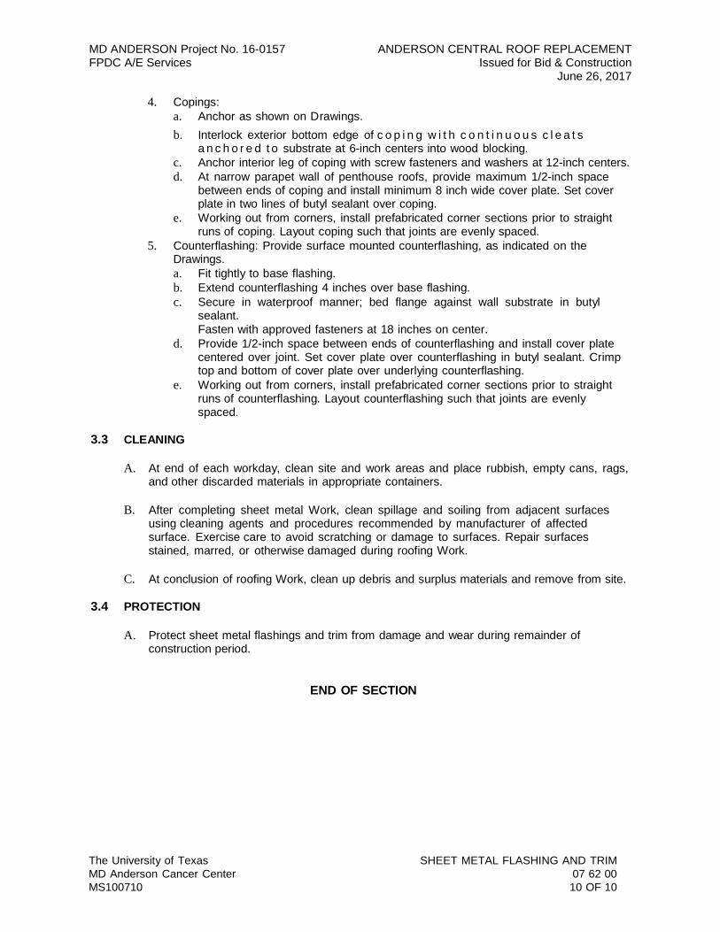
The University of Texas MD Anderson Cancer Center MS100710
SHEET METAL FLASHING AND TRIM 07 62 00 10 OF 10
MD ANDERSON Project No. 16-0157 ANDERSON CENTRAL ROOF REPLACEMENT FPDC A/E Services Issued for Bid & Construction
June 26, 2017
4. Copings:a. Anchor as shown on Drawings.b. Interlock exterior bottom edge of c o p i n g w i t h c o n t i n u o u s c l e a t s
a n c h o r e d t o substrate at 6-inch centers into wood blocking.c. Anchor interior leg of coping with screw fasteners and washers at 12-inch centers.d. At narrow parapet wall of penthouse roofs, provide maximum 1/2-inch space
between ends of coping and install minimum 8 inch wide cover plate. Set coverplate in two lines of butyl sealant over coping.
e. Working out from corners, install prefabricated corner sections prior to straightruns of coping. Layout coping such that joints are evenly spaced.
5. Counterflashing: Provide surface mounted counterflashing, as indicated on theDrawings.a. Fit tightly to base flashing.b. Extend counterflashing 4 inches over base flashing.c. Secure in waterproof manner; bed flange against wall substrate in butyl
sealant.Fasten with approved fasteners at 18 inches on center.
d. Provide 1/2-inch space between ends of counterflashing and install cover platecentered over joint. Set cover plate over counterflashing in butyl sealant. Crimptop and bottom of cover plate over underlying counterflashing.
e. Working out from corners, install prefabricated corner sections prior to straightruns of counterflashing. Layout counterflashing such that joints are evenlyspaced.
3.3 CLEANING
A. At end of each workday, clean site and work areas and place rubbish, empty cans, rags,and other discarded materials in appropriate containers.
B. After completing sheet metal Work, clean spillage and soiling from adjacent surfacesusing cleaning agents and procedures recommended by manufacturer of affectedsurface. Exercise care to avoid scratching or damage to surfaces. Repair surfacesstained, marred, or otherwise damaged during roofing Work.
C. At conclusion of roofing Work, clean up debris and surplus materials and remove from site.
3.4 PROTECTION
A. Protect sheet metal flashings and trim from damage and wear during remainder ofconstruction period.
END OF SECTION