product data quality and collaborative engineering
TRANSCRIPT
Product development is a key activity forenterprise survival and competitiveness.
This process must be agile and efficient to provideenough flexibility to adapt to achanging market. Most new prod-uct development methods focus onthe design and shorten the devel-opment cycle. Digital tools like com-puter-aided design, engineering,and manufacturing (CAX) andproduct data management (PDM)systems are key elements in thisstrategy. They let product develop-ers experiment with many alterna-tive solutions, providing betterquality in less time and at a lowercost. These are just some of theadvantages of employing digitalmock-ups and simulating the man-ufacturing process in a virtual envi-ronment.
A complete digital representation of the product andits manufacturing process lets product designer teamsperform simulations, avoiding the construction of phys-ical prototypes and providing early detection of bottle-necks in the manufacturing process. However, thisapproach can be problematic because designers andengineers must transfer product data between differentsoftware applications. This causes a data exchange prob-lem because data can be lost or degenerated duringexchanges. In this context, product data quality is essen-tial to guaranteeing a true integration among partici-pants defining the product development process.
In this article, we give an overview of how productdata quality (PDQ) affects collaborative engineering inthe extended enterprise framework. We also propose alinguistic approach to PDQ, which emphasizes the roleof modeling techniques to achieve high-quality models.
Collaborative engineeringWe must broaden the scope of concurrent engineer-
ing—noted in the sidebar “Defining Concurrent Engi-
neering”—to include the new models of extended, vir-tual, and concurrent enterprises that have become com-monplace during the last decade. The concept ofcollaborative engineering encompasses both supplierintegration and advanced communications tools to copewith the product development process. With the inten-tion of widening the scope of concurrent engineering, deGraaf proposed the following definition for collabora-tive engineering:
Collaborative engineering is a systematic ap-proach to control life-cycle cost, product qualityand time to market during product development,by concurrently developing products and theirrelated processes with response to customerexpectations, where decision making ensuresinput and evaluation by all life-cycle disciplines,including suppliers, and information technologyis applied to support information exchange wherenecessary.1
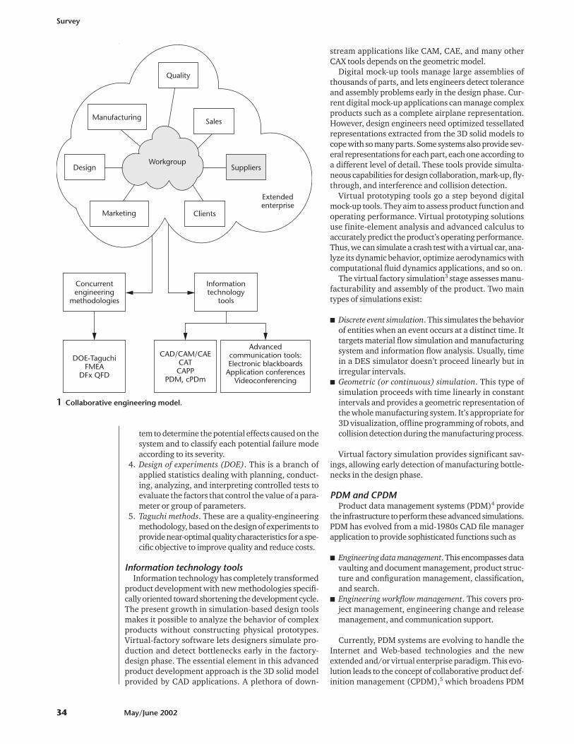
Figure 1 (on p. 34) shows a schematic vision of ourcollaborative engineering model, which we based on deGraaf’s definition. The central element is the work-group, usually geographically dispersed, working in thecontext of the extended and/or virtual enterprise. Con-current engineering methodologies and informationtechnologies tools support the product and processesdevelopment. As in de Graaf’s definition, product lifecycle, customer input, and supplier involvement under-lie our model.
Concurrent engineering methodologiesVirtual workgroups employ several concurrent engi-
neering methodologies,2 including
1. Quality function deployment. This is a structuredmethod in which customer requirements are trans-lated by product developers into appropriate tech-nical requirements for each stage of productdevelopment and production.
2. Design for X rules. These capture, in a standard pro-
0272-1716/02/$17.00 © 2002 IEEE
Survey
32 May/June 2002
We survey the impact of
product data quality within
an extended enterprise
framework and present a
linguistic model, which
focuses on three levels:
morphological, syntactic,
and semantic.
Manuel ConteroPolytechnic University of Valencia, Spain
Pedro Company, Carlos Vila, and Nuria AleixosJaume I University, Spain
Product DataQuality andCollaborativeEngineering
cedure, all the important factors in a particulardesign activity, such as
� Design for manufacturability rules. These canease manufacturing during early conceptualdevelopment.
� Design for assembly rules. These can ease assem-bly during early conceptual development.
� Design for environment (DfE) rules. These helpdevelopers achieve a design that uses mini-mum material and energy at all stages of itslife cycle providing maximum reuse and recy-cling of products.
3. Failure model and effects analysis (FMEA). This pro-cedure analyzes each potential failure mode in a sys-
IEEE Computer Graphics and Applications 33
Defining Concurrent EngineeringProduct development has suffered an enormous
evolution the last two decades. The appearance ofconcurrent engineering was a milestone in simultaneouslylowering product costs, increasing product quality, andreducing time to market. Concurrent engineering began asan initiative of the US Department of Defense. In 1982, theDefense Advanced Research Projects Agency (DARPA)began a program with the objective of improving productdevelopment. As a result of this program, Winner et al. firstdefined the term concurrent engineering as
… a systematic approach to the integrated, concurrentdesign of products and their related processes,including manufacturing and support. This approachis intended to cause the developers, from the outset, toconsider all elements of the product life cycle fromconception to disposal, including quality cost,schedule, and user requirements.1
After this project, DARPA started a five-year program—theDARPA Initiative in Concurrent Engineering (DICE), aimedto incorporate this methodology in the US military. As partof this initiative, the Concurrent Engineering ResearchCenter (CERC) was founded at West Virginia University inthe US. As a result of this work, Cleetus proposed anotherdefinition for concurrent engineering:
Concurrent Engineering is a systematic approach tothe integrated and concurrent development of aproduct and its related processes, that emphasizesresponse to customer expectations and embodies teamvalues of cooperation, trust, and sharing in such amanner that decision making proceeds with largeintervals of parallel working by all life-cycleperspectives, synchronized by comparatively briefexchanges to produce consensus.2
At the end of the 1990s, the quest for reducing costs ledto the progressive outsourcing of design tasks to suppliers.This movement brought suppliers into greater involvementin design and product technology responsibility.3 The mostadvanced industries—like automotive, aeronautics, andaerospace—soon adopted this trend. Chrysler pioneeredthe development and use of the extended enterpriseconcept. This means working closely with the supply basein a teamwork atmosphere of cooperation based in trust,communication, and partnership, where the workgroup isusually geographically dispersed and advanced toolssupport communications.
Recently, new enterprise models have exploited modernhigh-performance computer networks. In this context, the
concept of virtual enterprise4 with its sharing of data, costs,skills, and technology lets companies introduce products inthe market that they couldn’t previously deliver individually.The European Society of Concurrent Engineering defines avirtual enterprise as a
distributed, temporary alliance of independent, co-operating companies in the design and manufacturingof products and services. Such a complex organizationmakes use of systematic approaches, methods andadvanced technologies for increasing efficiency, and isenacted by the means offered by recent information andcommunication technologies [see http://www.esoce.net/Glossary.htm].
Integrating the virtual enterprise paradigm andconcurrent engineering methods results in a new concept—concurrent enterprise. Thoben and Weber proposed thefollowing definition:
The Concurrent Enterprise is a distributed, temporaryalliance of independent, co-operating manufacturers,customers and suppliers using systematic approaches,methods and advanced technologies for increasingefficiency in the design and manufacturing of products(and services) by means of parallelism, integration,team work, etc. for achieving common goals on globalmarkets.5
As product development continues to evolve, so shall theconcepts behind concurrent engineering.
References1. R.J. Winner et al., The Role of Concurrent Engineering in Weapons
System Acquisition, IDA R-338, Inst. for Defense Analyses, Alexan-dria, Va., 1988.
2. K.J. Cleetus, Definition of Concurrent Engineering (CERC TechnicalReport Series), CERC-TR-RN-92-003, Concurrent Eng. ResearchCenter, West Virginia Univ., Morgantown, W. Va., 1992.
3. H. Bates and D. Twigg, “Outsourcing of Automotive ComponentDesign,” Proc. 30th Int’l Symp. Automotive Technology and Automa-tion (ISATA 97), ISATA, Florence, 1997.
4. M. Hardwick and R. Bolton, “The Industrial Virtual Enterprise,”Comm. ACM, vol. 40, no. 9, Sept. 1997, pp. 59-60.
5. K.D. Thoben and F. Weber, “Information and CommunicationStructures for Product Development in the Concurrent Enterprise:Requirements and Concepts,” Proc. Ann. Conf. Intelligent Controland Integrated Manufacturing Systems Network of Excellence ICIMS-NOE (Advanced Summer Institute [ASI] 97), ICIMS-NOE, Budapest,1997, pp. 460-467.
tem to determine the potential effects caused on thesystem and to classify each potential failure modeaccording to its severity.
4. Design of experiments (DOE). This is a branch ofapplied statistics dealing with planning, conduct-ing, analyzing, and interpreting controlled tests toevaluate the factors that control the value of a para-meter or group of parameters.
5. Taguchi methods. These are a quality-engineeringmethodology, based on the design of experiments toprovide near-optimal quality characteristics for a spe-cific objective to improve quality and reduce costs.
Information technology toolsInformation technology has completely transformed
product development with new methodologies specifi-cally oriented toward shortening the development cycle.The present growth in simulation-based design toolsmakes it possible to analyze the behavior of complexproducts without constructing physical prototypes.Virtual-factory software lets designers simulate pro-duction and detect bottlenecks early in the factory-design phase. The essential element in this advancedproduct development approach is the 3D solid modelprovided by CAD applications. A plethora of down-
stream applications like CAM, CAE, and many otherCAX tools depends on the geometric model.
Digital mock-up tools manage large assemblies ofthousands of parts, and lets engineers detect toleranceand assembly problems early in the design phase. Cur-rent digital mock-up applications can manage complexproducts such as a complete airplane representation.However, design engineers need optimized tessellatedrepresentations extracted from the 3D solid models tocope with so many parts. Some systems also provide sev-eral representations for each part, each one according toa different level of detail. These tools provide simulta-neous capabilities for design collaboration, mark-up, fly-through, and interference and collision detection.
Virtual prototyping tools go a step beyond digitalmock-up tools. They aim to assess product function andoperating performance. Virtual prototyping solutionsuse finite-element analysis and advanced calculus toaccurately predict the product’s operating performance.Thus, we can simulate a crash test with a virtual car, ana-lyze its dynamic behavior, optimize aerodynamics withcomputational fluid dynamics applications, and so on.
The virtual factory simulation3 stage assesses manu-facturability and assembly of the product. Two maintypes of simulations exist:
� Discrete event simulation. This simulates the behaviorof entities when an event occurs at a distinct time. Ittargets material flow simulation and manufacturingsystem and information flow analysis. Usually, timein a DES simulator doesn’t proceed linearly but inirregular intervals.
� Geometric (or continuous) simulation. This type ofsimulation proceeds with time linearly in constantintervals and provides a geometric representation ofthe whole manufacturing system. It’s appropriate for3D visualization, offline programming of robots, andcollision detection during the manufacturing process.
Virtual factory simulation provides significant sav-ings, allowing early detection of manufacturing bottle-necks in the design phase.
PDM and CPDMProduct data management systems (PDM)4 provide
the infrastructure to perform these advanced simulations.PDM has evolved from a mid-1980s CAD file managerapplication to provide sophisticated functions such as
� Engineering data management. This encompasses datavaulting and document management, product struc-ture and configuration management, classification,and search.
� Engineering workflow management. This covers pro-ject management, engineering change and releasemanagement, and communication support.
Currently, PDM systems are evolving to handle theInternet and Web-based technologies and the newextended and/or virtual enterprise paradigm. This evo-lution leads to the concept of collaborative product def-inition management (CPDM),5 which broadens PDM
Survey
34 May/June 2002
Concurrentengineering
methodologies
DOE-TaguchiFMEA
DFx QFD
Informationtechnology
tools
CAD/CAM/CAECATCAPP
PDM, cPDm
Advancedcommunication tools:Electronic blackboards
Application conferencesVideoconferencing
Quality
Sales
SuppliersDesign
Clients
Manufacturing
Marketing
Workgroup
Extendedenterprise
1 Collaborative engineering model.
capabilities to support the management of product def-inition and associated processes in the extended enter-prise framework by Internet and Web technologies.Systems such as these are particularly interesting forglobal companies with facilities located around the worldand also for enabling true integration among originalequipment manufacturers (OEMs), clients, and suppli-ers in the product-development process.
Web-based CAD and communication toolsThe heterogeneous enterprise architectures present-
ed previously encouraged the development of new Web-based design tools, which combine CAD, PDM, and Webaccess in a unified environment. These tools help reducecosts between OEMs and suppliers sharing a commondesign platform, and usually have a three-tier architec-ture using the Internet as the communication infra-structure. Thus, we have a first tier where a thin client,usually through a Web browser, provides the front-endto the system. In a second tier, an application serverhosts the software application. Finally, the databaseserver that stores and manages design data provides thethird tier. Users pay for this technology as a subscrip-tion-based service. This approach lets companies reduceinformation technology expenses by avoiding the needto buy and maintain expensive software and hardware.
Finally, communication tools are evolving in con-junction with the Internet and are fundamental to pro-viding collaboration for a geographically dispersed workteam. Such tools involve synchronous and asynchro-nous collaboration depending on whether the collabo-rative partners are working simultaneously. Examplesof asynchronous collaboration include email and news-groups. On the other hand, to arrange a virtual meetingbetween partners requires synchronous communicationtools such as whiteboards, videoconferencing, and
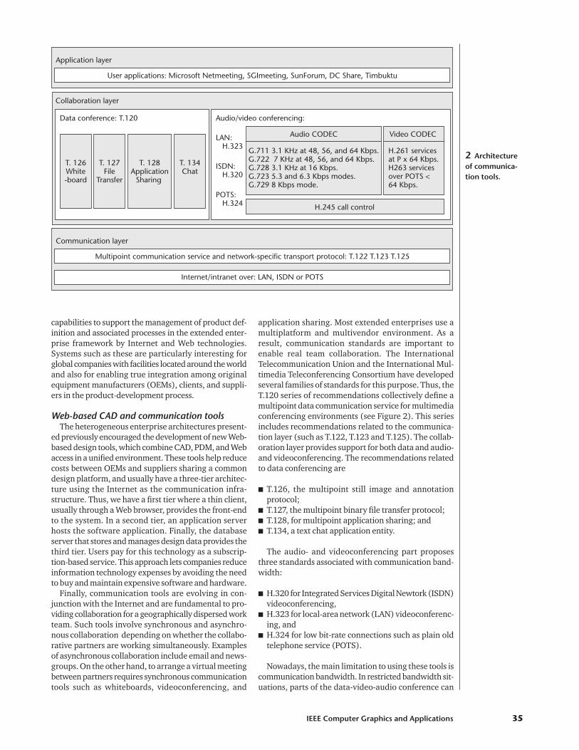
application sharing. Most extended enterprises use amultiplatform and multivendor environment. As aresult, communication standards are important toenable real team collaboration. The InternationalTelecommunication Union and the International Mul-timedia Teleconferencing Consortium have developedseveral families of standards for this purpose. Thus, theT.120 series of recommendations collectively define amultipoint data communication service for multimediaconferencing environments (see Figure 2). This seriesincludes recommendations related to the communica-tion layer (such as T.122, T.123 and T.125). The collab-oration layer provides support for both data and audio-and videoconferencing. The recommendations relatedto data conferencing are
� T.126, the multipoint still image and annotationprotocol;
� T.127, the multipoint binary file transfer protocol;� T.128, for multipoint application sharing; and� T.134, a text chat application entity.
The audio- and videoconferencing part proposesthree standards associated with communication band-width:
� H.320 for Integrated Services Digital Newtork (ISDN)videoconferencing,
� H.323 for local-area network (LAN) videoconferenc-ing, and
� H.324 for low bit-rate connections such as plain oldtelephone service (POTS).
Nowadays, the main limitation to using these tools iscommunication bandwidth. In restricted bandwidth sit-uations, parts of the data-video-audio conference can
IEEE Computer Graphics and Applications 35
T. 126White-board
T. 127File
Transfer
T. 128Application
Sharing
T. 134Chat
Data conference: T.120
Application layer
Collaboration layer
Audio/video conferencing:
LAN: H.323
G.711 3.1 KHz at 48, 56, and 64 Kbps.G.722 7 KHz at 48, 56, and 64 Kbps.G.728 3.1 KHz at 16 Kbps.G.723 5.3 and 6.3 Kbps modes.G.729 8 Kbps mode.
H.261 servicesat P x 64 Kbps.H263 servicesover POTS <64 Kbps.
ISDN: H.320
POTS: H.324
Audio CODEC
H.245 call control
User applications: Microsoft Netmeeting, SGImeeting, SunForum, DC Share, Timbuktu
Communication layer
Multipoint communication service and network-specific transport protocol: T.122 T.123 T.125
Internet/intranet over: LAN, ISDN or POTS
Video CODEC
2 Architectureof communica-tion tools.
be redirected to other communication channels—forinstance, moving audio conferencing to normal tele-phone calls and selectively using video.
One of the most interesting facts about communica-tions tools is that many of them are free or have areduced cost. For example, setting up a newsgroup serv-er can be an inexpensive way to provide a discussionforum where work-team members can ask for help orreceive general notifications about the product-devel-opment process.
Product data modelProduct data management systems4 supply an infra-
structure oriented to providing everybody’s need forinformation in a concurrent engineering environment.These systems also cover external partners’ access andcompany security and release procedures. Two types ofdata comprise PDM systems:
� Product (and tooling) data: geometry, digital mock-up, analysis and simulation results, materials, reports,and so on.
� Process data: advanced manufacturing engineeringdata (relations between parts, tools, and processes),sequence planning and machining data, work-celldefinition and plant layout, and so on.
Both types of data closely relate to the geometricmodel provided by CAD applications. As we’ll see later,the quality of these CAD models are important forsmoothly integrating the participants of the productdevelopment process.
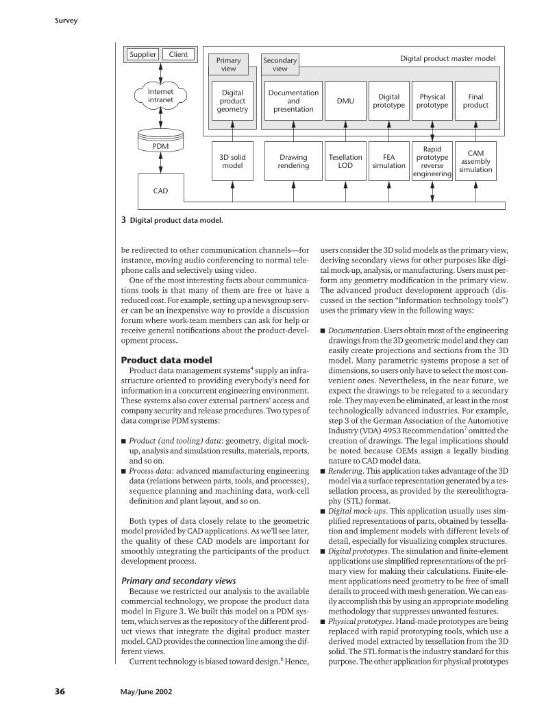
Primary and secondary viewsBecause we restricted our analysis to the available
commercial technology, we propose the product datamodel in Figure 3. We built this model on a PDM sys-tem, which serves as the repository of the different prod-uct views that integrate the digital product mastermodel. CAD provides the connection line among the dif-ferent views.
Current technology is biased toward design.6 Hence,
users consider the 3D solid models as the primary view,deriving secondary views for other purposes like digi-tal mock-up, analysis, or manufacturing. Users must per-form any geometry modification in the primary view.The advanced product development approach (dis-cussed in the section “Information technology tools”)uses the primary view in the following ways:
� Documentation. Users obtain most of the engineeringdrawings from the 3D geometric model and they caneasily create projections and sections from the 3Dmodel. Many parametric systems propose a set ofdimensions, so users only have to select the most con-venient ones. Nevertheless, in the near future, weexpect the drawings to be relegated to a secondaryrole. They may even be eliminated, at least in the mosttechnologically advanced industries. For example,step 3 of the German Association of the AutomotiveIndustry (VDA) 4953 Recommendation7 omitted thecreation of drawings. The legal implications shouldbe noted because OEMs assign a legally bindingnature to CAD model data.
� Rendering. This application takes advantage of the 3Dmodel via a surface representation generated by a tes-sellation process, as provided by the stereolithogra-phy (STL) format.
� Digital mock-ups. This application usually uses sim-plified representations of parts, obtained by tessella-tion and implement models with different levels ofdetail, especially for visualizing complex structures.
� Digital prototypes. The simulation and finite-elementapplications use simplified representations of the pri-mary view for making their calculations. Finite-ele-ment applications need geometry to be free of smalldetails to proceed with mesh generation. We can eas-ily accomplish this by using an appropriate modelingmethodology that suppresses unwanted features.
� Physical prototypes. Hand-made prototypes are beingreplaced with rapid prototyping tools, which use aderived model extracted by tessellation from the 3Dsolid. The STL format is the industry standard for thispurpose. The other application for physical prototypes
Survey
36 May/June 2002
Internetintranet
Supplier Client
PDM
CAD
TesellationLOD
DMU
FEAsimulation
Digitalprototype
Rapidprototype
reverseengineering
Physicalprototype
CAMassemblysimulation
Finalproduct
Drawingrendering
Documentationand
presentation
3D solidmodel
Digitalproduct
geometry
Secondaryview
Primaryview
Digital product master model
3 Digital product data model.
is CAD data input in styling applications, where 3Dlaser scanning devices provide clouds of points thatlater must be transformed to surfaces and importedinto the CAD application.
� Final products. CAM and assembly simulation use theprimary view intensively. Besides, engineers some-times need to make modifications in the originalgeometry. For example, in mold making, sometimes-nominal part geometry must be modified to avoidwarpage. This requirement introduces additional dif-ficulties, because reusing the primary CAD model forthis purpose depends on the modeling methodologypreviously used.
Finally, the associativity concept is important becauseit lets changes made on the primary view be automati-cally transferred to the secondary ones, avoiding manymistakes caused by the continuous variations sufferedby the product model during the development process.The quest for associativity is also one of the reasons thatjustify the adoption of a unique integrated CAD systemby major OEMs.
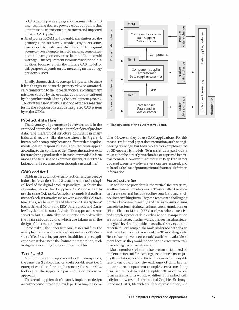
Product data flowThe diversity of partners and software tools in the
extended enterprise leads to a complex flow of productdata. The hierarchical structure dominant in manyindustrial sectors, like the one shown in Figure 4,increases the complexity because different data require-ments, design responsibilities, and CAX tools appearaccording to the considered tier. Three alternatives existfor transferring product data in computer-readable formamong the tiers: use of a common system, direct trans-lation, or indirect translation through a neutral file.8
OEMs and tier 1OEMs in the automotive, aeronautical, and aerospace
industries force tiers 1 and 2 to achieve the technologi-cal level of the digital product paradigm. To obtain theclose integration of tier 1 suppliers, OEMs force them touse the same CAD tools. A classical example is the align-ment of each automotive maker with a specific CAD sys-tem. Thus, we have Ford and Electronic Data Systems’Ideas, General Motors and EDS’ Unigraphics, and Daim-lerChrysler and Dassault’s Catia. This approach is con-servative but is justified by the important role played bythe main subcontractors, which are taking over thedesign of their components.
Some tasks in the upper tiers can use neutral files. Forexample, the current practice is to maintain a STEP ver-sion of files for storing purposes. In addition, some appli-cations that don’t need the feature representation, suchas digital mock-ups, can support neutral files.
Tiers 1 and 2A different situation appears at tier 2. In many cases,
the same tier 2 subcontractor works for different tier 1enterprises. Therefore, implementing the same CAXtools as all the upper tier partners is an expensiveapproach.
These end-suppliers don’t usually implement designactivity because they only provide parts or simple assem-
blies. However, they do use CAM applications. For thisreason, traditional paper documentation, such as engi-neering drawings, has been replaced or complementedby 3D geometric models. To transfer data easily, datamust either be directly translatable or captured in neu-tral formats. However, it’s difficult to keep translatorsupdated when new software versions are released, andto handle the loss of parametric and features’ definitioninformation.
Infrastructure tierIn addition to providers in the vertical tier structure,
another class of providers exists. They’re called the infra-structure tier and include tooling providers and engi-neering consulting firms. They can represent a challengingproblem because engineering and design consulting firmscan help perform studies, like kinematical simulations or(Finite Element Method) FEM analysis, where intensiveand complex product data exchange and manipulationare normal issues. In other words, this tier has a high tech-nological level and provides specialized services to theother tiers. For example, the mold makers do both designand manufacturing activities and use 3D modeling tools.Hence, having a geometric model available is valuable tothem because they avoid the boring and error-prone taskof modeling parts from drawings.
Most members of the infrastructure tier need toimplement neutral file exchange. Economic reasons jus-tify this solution, because these firms work for many dif-ferent customers and the exchange of data has animportant cost impact. For example, a FEM consultingfirm usually needs to build a simplified 3D model to per-form its analysis. Its workload differs if furnished witha digital drawing, an International Graphics ExchangeStandard (IGES) file with a surface representation, or a
IEEE Computer Graphics and Applications 37
OEM
Component customerData supplier
Data customer
Prod
uct
data
exc
hang
ePr
oduc
t da
ta e
xcha
nge
Prod
uct
data
exc
hang
e
Tier 1
Component supplierPart customer
Data supplier/customer Prod
uct
data
exc
hang
e
Tier 2
Part supplierData supplier
Data customer Prod
uct
data
exc
hang
e
Tool
ing
and
cons
ultin
gD
ata
sup
plie
r/cu
stom
er
Infr
astr
uctu
re
Components
Parts
4 Tier structure of the automotive sector.
3D model with feature information. In the latter case,for instance, sometimes an easy feature suppressionoperation provides the simplified model. This exampleshows that the preprocessing part of FEM analysis canbe less time consuming if CAD operators use the prop-er representation in the input of design information.Therefore, it’s important to have a rich neutral formatsupporting features, constraints, and parametric geom-etry (see the sidebar “Standards Status.”)
Product data qualityA 1999 survey performed by the National Institute of
Standards and Technology (NIST) Strategic Planningand Economic Assessment Office, estimates that the eco-nomic cost of bad interoperability in the US automotiveindustry is $1 billion per year.9 A similar study in theGerman automotive industry calculates the economicimpact of the data exchange problem to be about a halfbillion dollars per year.10
To provide answers to this problem, we must distin-guish between intrinsic and extrinsic problems relatedto the data exchange process. Intrinsic problems arethose related to the CAD model’s structure before anytranslation process begins, while extrinsic problems
relate to those issues appearing during translation. Inthis article, we focus on the intrinsic aspect of the prod-uct data exchange problem. Here’s where the concept ofproduct data quality is fundamental to understandingthe origin of many problems that impede collaborativeengineering. In this article, we don’t consider the extrin-sic problems, which have been extensively studied in theliterature (see, for example, Vergeest and Horváth11).
Data quality definitionsHow is product data defined? Phelps12 proposes a sim-
ple definition: “Product data quality is a measure of theaccuracy and appropriateness of product data combinedwith the timeliness with which those data are providedto all the people who need it.” This definition resemblesthe concept of data quality coming from the softwareengineering domain, where a list of desirable qualitydimensions is defined. For example, Ballou and Pazer13
identify four dimensions of data quality: accuracy, com-pleteness, consistency, and timeliness.
Other approaches give a wider vision integrating con-textual aspects of data quality. Thus, Shanks14 propos-es a semiotic data quality framework based on fourlevels: the syntactic (structure of data), semantic
Survey
38 May/June 2002
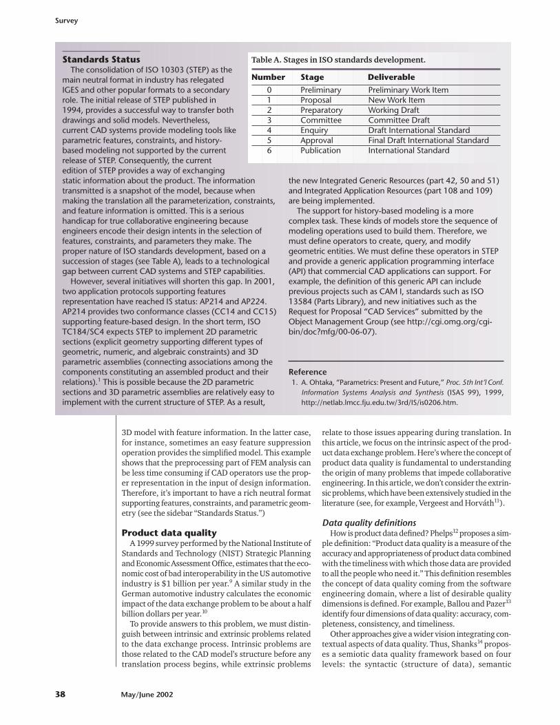
Standards StatusThe consolidation of ISO 10303 (STEP) as the
main neutral format in industry has relegatedIGES and other popular formats to a secondaryrole. The initial release of STEP published in1994, provides a successful way to transfer bothdrawings and solid models. Nevertheless,current CAD systems provide modeling tools likeparametric features, constraints, and history-based modeling not supported by the currentrelease of STEP. Consequently, the currentedition of STEP provides a way of exchangingstatic information about the product. The informationtransmitted is a snapshot of the model, because whenmaking the translation all the parameterization, constraints,and feature information is omitted. This is a serioushandicap for true collaborative engineering becauseengineers encode their design intents in the selection offeatures, constraints, and parameters they make. Theproper nature of ISO standards development, based on asuccession of stages (see Table A), leads to a technologicalgap between current CAD systems and STEP capabilities.
However, several initiatives will shorten this gap. In 2001,two application protocols supporting featuresrepresentation have reached IS status: AP214 and AP224.AP214 provides two conformance classes (CC14 and CC15)supporting feature-based design. In the short term, ISOTC184/SC4 expects STEP to implement 2D parametricsections (explicit geometry supporting different types ofgeometric, numeric, and algebraic constraints) and 3Dparametric assemblies (connecting associations among thecomponents constituting an assembled product and theirrelations).1 This is possible because the 2D parametricsections and 3D parametric assemblies are relatively easy toimplement with the current structure of STEP. As a result,
the new Integrated Generic Resources (part 42, 50 and 51)and Integrated Application Resources (part 108 and 109)are being implemented.
The support for history-based modeling is a morecomplex task. These kinds of models store the sequence ofmodeling operations used to build them. Therefore, wemust define operators to create, query, and modifygeometric entities. We must define these operators in STEPand provide a generic application programming interface(API) that commercial CAD applications can support. Forexample, the definition of this generic API can includeprevious projects such as CAM I, standards such as ISO13584 (Parts Library), and new initiatives such as theRequest for Proposal “CAD Services” submitted by theObject Management Group (see http://cgi.omg.org/cgi-bin/doc?mfg/00-06-07).
Reference1. A. Ohtaka, “Parametrics: Present and Future,” Proc. 5th Int’l Conf.
Information Systems Analysis and Synthesis (ISAS 99), 1999,http://netlab.lmcc.fju.edu.tw/3rd/IS/is0206.htm.
Table A. Stages in ISO standards development.
Number Stage Deliverable
0 Preliminary Preliminary Work Item1 Proposal New Work Item2 Preparatory Working Draft3 Committee Committee Draft4 Enquiry Draft International Standard5 Approval Final Draft International Standard6 Publication International Standard
(meaning of data), pragmatic (usage of data), andsocial levels that concern the shared understanding ofthe meaning of symbols.
Another important idea from Wand and Wang15 is thatthe notion of data quality depends on the actual use ofdata. They agree with many other authors who definedata quality as “fitness for use,” showing that the conceptof data quality is relative. Finally, they also note that it’simportant to know how data quality will be measured.
Product data quality standardsCurrently, the most extended product data quality stan-
dard is VDA 495516 and its equivalent ODG11CQ9504Odette CAD/CAM Quality Assurance Method standard.Although it originated in the automotive sector, it hasbeen adopted in many other industries. VDA 4955 pro-vides quality criteria for both geometrical and organiza-tional aspects of CAD/CAM data. We can implementthese criteria in software applications, known as qualitycheckers, to automate quality auditing.
The geometric criteria analyze the polynomial degreeof curves and surfaces to avoid undesired oscillatingcurves and rippling surfaces. Criteria exist for checkingthe orientation and parameterization of curve elementsand surfaces. Detecting surface and curve defects (over-laps, steps and gaps) and the analysis of their continu-ity is important for downstream applications such asNumerical Control (NC) processing and coordinates-measuring machines. The organizational criteria of VDA4955 propose some recommendations related to modelnaming and structuring, drawing generation, and mod-eling methodology.
Other organizations in the automotive industry havedeveloped similar standards. Thus, the French associa-tion, Amelioration of Liaisons in the Automobile Indus-try Group (Groupement pour l’Amélioration des Liaisonsdans l’Industrie Automobile, or Galia), has developedthe standards CAO.3 and CAO.4 with similar content toVDA 4955. The Japan Automotive Manufacturers Asso-ciation (JAMA) recently developed a standard related toproduct data quality. In the US, the Automotive Indus-try Action Group (AIAG) established its Vehicle ProductData Quality work group after the organization identi-fied product data quality as the highest priority issueaffecting product development in supply chains.
With the objective of unifying the emergent nationalrecommendations related to product data quality, theStrategic Automotive Product Data Standards IndustryGroup (SASIG), established in 1995, is working on aninternational recommendation (SASIG-PDQ) for prod-uct data quality in the automotive industry. This groupcomprises AIAG, VDA, Galia, JAMA, Odette Sweden,Australia’s Federal Chamber of Automotive Industries,and the Japan Automobile Parts Industry. The first ver-sion of SASIG-PDQ was released in September 2001.
For other interesting references to PDQ standards,visit OEM Web sites dedicated to suppliers, such as
� BMW: http://www.zulieferer.bmw.de/en/� General Motors: http://www.gmsupplypower.com� Volkswagen: http://www.vw-zulieferer.de (in
German)
� DaimlerChrysler: http://supplier.daimlerchrysler.com
� Ford: https://fsn.ford.com
A linguistic model of product data qualityAfter analyzing precedent standards on product data
quality, we noticed that various levels of quality mimicthe different levels and approaches that natural-languageanalysis uses, such as phonology (phonetics and sounds),morphology (forming words from more basic meaningunits), syntax (forming sentences out of words), seman-tics (sentence meanings obtained from words) and prag-matic (understanding how sentences are used).
Therefore, we can distinguish among three levels ofquality:
� Morphological—relates to the geometrical and topo-logical correctness of the CAD model.
� Syntactic—evaluates the use of the proper modelingconventions.
� Semantic/pragmatic—considers the CAD model capa-bility for reusing and modification.
These quality levels closely relate to the proposedproduct data model, where we’ve defined both primaryand secondary views of a product model. A high-qualityprimary view avoids many of the problems that appearduring the product data exchange process. Here the “fit-ness for use” concept applies because the secondaryviews of the model need data of different quality accord-ing to the data’s application. Thus, some secondary viewsonly require a primary view of good morphological qual-ity. They’re simplified geometric representations of theprimary view, where the usability depends on the geo-metric and topological correctness. This is the case ofdigital mock-up and presentation views.
In other situations, where sharing product data isimportant, we need something more than correct geom-etry. Additional organizational information must beunderstood, such as naming conventions, layer struc-ture, parameters, and more attributes related to the syn-tactical model’s quality. These situations cover the needto access the model without modifying it. The docu-mentation view is one instance where it’s important tofollow some modeling conventions.
Finally, users need an additional level of quality toaccess a model for modification. Many CAD users havesuffered from a regeneration error, due to a modificationof a simple dimension in a complex solid model with hun-dreds of features. This is the level associated with seman-tic/pragmatic quality, where the modeling methodologyis the key element to success in reusing models.
The recommendations presented in previous sec-tions, as in VDA 4955, provide criteria for the morpho-logical and syntactic levels. Researchers have studiedthese two levels in detail in recent years. Nowadays,there are a few commercial applications dedicated toautomating the verification of the quality criteria inCAD. The syntactic level depends on in-house modelingconventions. In industrial sectors where few OEMs con-trol the market, such as automotive and aeronautics,the syntactic quality criteria play an important role in
IEEE Computer Graphics and Applications 39
ensuring smooth communication within a work teaminside the extended enterprise framework. Informationrelated to the semantic quality level is hard to findbecause the modeling methodologies that provide thecriteria for semantic/pragmatic quality belong to theenterprise’s know-how.
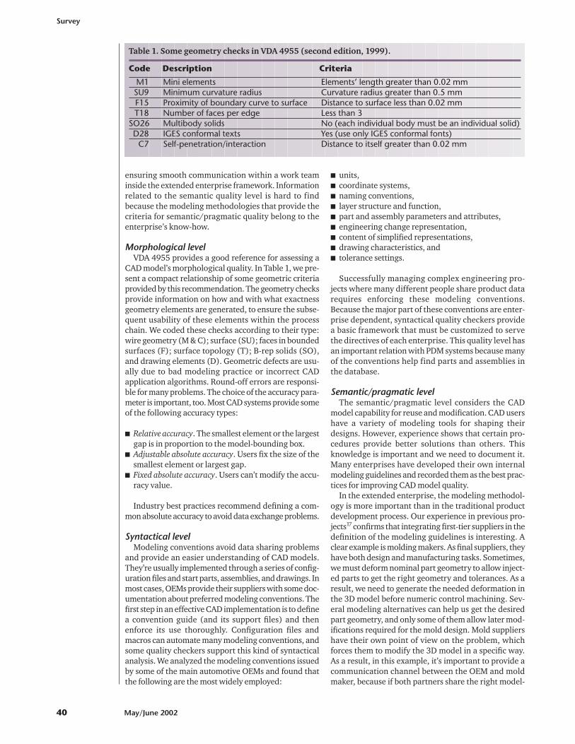
Morphological levelVDA 4955 provides a good reference for assessing a
CAD model’s morphological quality. In Table 1, we pre-sent a compact relationship of some geometric criteriaprovided by this recommendation. The geometry checksprovide information on how and with what exactnessgeometry elements are generated, to ensure the subse-quent usability of these elements within the processchain. We coded these checks according to their type:wire geometry (M & C); surface (SU); faces in boundedsurfaces (F); surface topology (T); B-rep solids (SO),and drawing elements (D). Geometric defects are usu-ally due to bad modeling practice or incorrect CADapplication algorithms. Round-off errors are responsi-ble for many problems. The choice of the accuracy para-meter is important, too. Most CAD systems provide someof the following accuracy types:
� Relative accuracy. The smallest element or the largestgap is in proportion to the model-bounding box.
� Adjustable absolute accuracy. Users fix the size of thesmallest element or largest gap.
� Fixed absolute accuracy. Users can’t modify the accu-racy value.
Industry best practices recommend defining a com-mon absolute accuracy to avoid data exchange problems.
Syntactical levelModeling conventions avoid data sharing problems
and provide an easier understanding of CAD models.They’re usually implemented through a series of config-uration files and start parts, assemblies, and drawings. Inmost cases, OEMs provide their suppliers with some doc-umentation about preferred modeling conventions. Thefirst step in an effective CAD implementation is to definea convention guide (and its support files) and thenenforce its use thoroughly. Configuration files andmacros can automate many modeling conventions, andsome quality checkers support this kind of syntacticalanalysis. We analyzed the modeling conventions issuedby some of the main automotive OEMs and found thatthe following are the most widely employed:
� units,� coordinate systems,� naming conventions,� layer structure and function,� part and assembly parameters and attributes,� engineering change representation,� content of simplified representations,� drawing characteristics, and� tolerance settings.
Successfully managing complex engineering pro-jects where many different people share product datarequires enforcing these modeling conventions.Because the major part of these conventions are enter-prise dependent, syntactical quality checkers providea basic framework that must be customized to servethe directives of each enterprise. This quality level hasan important relation with PDM systems because manyof the conventions help find parts and assemblies inthe database.
Semantic/pragmatic levelThe semantic/pragmatic level considers the CAD
model capability for reuse and modification. CAD usershave a variety of modeling tools for shaping theirdesigns. However, experience shows that certain pro-cedures provide better solutions than others. Thisknowledge is important and we need to document it.Many enterprises have developed their own internalmodeling guidelines and recorded them as the best prac-tices for improving CAD model quality.
In the extended enterprise, the modeling methodol-ogy is more important than in the traditional productdevelopment process. Our experience in previous pro-jects17 confirms that integrating first-tier suppliers in thedefinition of the modeling guidelines is interesting. Aclear example is molding makers. As final suppliers, theyhave both design and manufacturing tasks. Sometimes,we must deform nominal part geometry to allow inject-ed parts to get the right geometry and tolerances. As aresult, we need to generate the needed deformation inthe 3D model before numeric control machining. Sev-eral modeling alternatives can help us get the desiredpart geometry, and only some of them allow later mod-ifications required for the mold design. Mold suppliershave their own point of view on the problem, whichforces them to modify the 3D model in a specific way.As a result, in this example, it’s important to provide acommunication channel between the OEM and moldmaker, because if both partners share the right model-
Survey
40 May/June 2002
Table 1. Some geometry checks in VDA 4955 (second edition, 1999).
Code Description Criteria
M1 Mini elements Elements’ length greater than 0.02 mm SU9 Minimum curvature radius Curvature radius greater than 0.5 mmF15 Proximity of boundary curve to surface Distance to surface less than 0.02 mm T18 Number of faces per edge Less than 3
SO26 Multibody solids No (each individual body must be an individual solid)D28 IGES conformal texts Yes (use only IGES conformal fonts)
C7 Self-penetration/interaction Distance to itself greater than 0.02 mm
ing technique, we can dramatically reduce the time andcost to develop molds.
The previous analysis serves to introduce a new con-cept that we call extended modeling.17 We define thisapproach as a modeling methodology that integratesdifferent perspectives from the product developmentprocess in the framework of extended enterprise col-laboration. Using a common modeling strategy betweenpartners permits engineers to reuse generated modelsand improve the effectiveness of applications withinthird-tier suppliers. Including suppliers in the develop-ment of the modeling guidelines lets them concentrateon added-value tasks instead of wasting time reintro-ducing or adapting the geometric information theyreceive. We can establish an analogy with the design forX methodologies, with a modeling for X, where X meansmolding, manufacturing, analysis, and so on.
In the previous section, the choice of those featuresappropriate to facilitate downstream operations has beena key element. However, another important aspect ofsemantic quality is the CAD model’s structure. Complexparts with more than 100 features become difficult tomodify because of the multiple interrelations among fea-tures. Without a careful working procedure, undesireddependencies can appear. Anderl and Mendgen18 repre-sent parent–child feature relations in a matrix form andtry to reorganize the model to approximate this matrix toits diagonal form. Thus, related features are grouped andmany unwanted dependencies are avoided. Current CADsystems provide limited support for analyzing featuresdependencies. Usually a tree representation displays themodeling history, but it’s difficult to achieve a wholevision of the dependencies in the model.
ImplementationTo implement a strategy on PDQ, we must adhere to
some PDQ standard, such as VDA 4955, which providesa good reference for analyzing morphological qualityand develop modeling conventions and modeling guide-lines adapted to the product development process.
Commercial, Web-based quality checkers are invalu-able for enforcing morphological and syntactical checks.Usually, many modeling conventions are implementedby a set of configuration files and start parts, assemblies,and drawings. These elements, combined with a quali-ty checker, ensure the desired syntactical quality level.
The quality evaluation process must be done beforeexchanging models with other CAD systems or submit-ting them to the PDM server. Commercial tools supportboth interactive and batch processes to automate thechecking process. The growing number of applicationsdedicated to this task clearly shows an industry need forimproving the quality of models. The most widely usedcheckers are
� Parametric Technology’s ModelCheck,� International TechneGroup’s CAD/IQ,� Prescient Technologies’ DesignQA,� Software Factory’s PE Check, and� Rand TransCAT’s Q-check.
Web technology is also a good communication chan-
nel to circulate modeling conventions and guidelines.They can be made available through the enterprise Website, where selected suppliers have authorization toenter the restricted-access areas where these documentsare stored.
ConclusionThe expansion of concepts like extended enterpris-
ing and collaborative engineering is forcing an expo-nential growth of data flow inside the productdevelopment team. Ensuring product data qualityavoids data exchange problems and simplifies down-stream applications’ integration in the design chain.
The proposed linguistic approach to PDQ tries toclarify concepts present in the current product dataquality literature and emphasizes the role of modelingmethodology to achieve high-quality models. Eventhough the morphological and syntactical levels arequite developed, the evaluation of semantic qualityremains an open issue in quality-checker applications.It’s a complex task, where new research activity mustprovide tools to objectively evaluate the models’semantic quality.
Modeling methodology is an important but poorlydocumented topic. Best practices documents are diffi-cult to find because much of the enterprise expertise isembedded in the modeling strategy. Therefore, seman-tic or pragmatic quality procedures become strategicknowledge that industry preserves and doesn’t publi-cize. The extended modeling approach transfers thisknowledge inside the extended and/or virtual enter-prise, providing overall lower cost and a shorteneddevelopment time.
Finally, we must note the importance of training toreach a high-quality level in PDQ. The best CAD sys-tem in the world used by a badly trained operatorwithout a good modeling methodology produces badCAD models that impede the effectiveness of down-stream applications. Therefore, it’s as important toinvest in training as it is to have good data exchangestandards and detailed modeling methodologies andconventions. Training has a direct impact in increasingoverall productivity and decreasing developmenttime. Our experience shows that developing model-ing guidelines is also important for training purpos-es. New users can develop good modeling skills andbecome productive in less time than by previous train-ing methods.
For future research, we’re going to focus on thedevelopment of tools that evaluate the semanticquality of models and document the best modelingpractices. �
AcknowledgmentsThe Spanish Government national R&D Feder pro-
gram partially sponsored this work as project number1FD97 0784 “Implementing Design and Manufactur-ing Advanced Technologies in a Concurrent Engineer-ing Environment. Application to an AutomotiveComponents Manufacturing Company.” We also thankRadiadores Ordoñez, who helped us check the effec-tiveness of our approach.
IEEE Computer Graphics and Applications 41
References1. R. de Graaf, Assessing Product Development, Visualizing
Process and Technology Performance with RACE 2, PhD the-sis, Faculty of Technology Management, Eindhoven Univ.of Technology, The Netherlands, 1996.
2. B. Prasad, Concurrent Engineering Fundamentals: Inte-grated Product Development, vols. 1 and 2, Prentice Hall,Upper Saddle River, N.J., 1996.
3. P. Klingstam and P. Gullander, “Overview of SimulationTools for Computer-Aided Production Engineering,” Proc.Advanced Summer Inst. (ASI 97), Advanced Summer Inst.,Paris, 1997.
4. T. Bilgiç and D. Rock, “Product Data Management Systems:State-of-the-Art and the Future,” Proc. ASME Design Engi-neering Technical Conf. (DETC 97), Am. Soc. MechanicalEng., New York 1997.
5. E. Miller, “Managing Product Data Throughout the LifeCycle,” Computer-Aided Engineering, March 2000,http://www.plmsolutions-eds.com/publications/articles/cae_pdm/.
6. C.M. Hoffmann and R.J. Arinyo, “Distributed Maintenanceof Multiple Products Views,” Computer-Aided Design, vol.32, no. 7, June 2000, pp. 421-431.
7. VDA Recommendation 4953, Part 1: Simplified CAD Draw-ing, German Assoc. Automotive Industry (VDA), Frankfurt,Germany, 1999.
8. M.S. Bloor and J. Owen, Product Data Exchange, UCL Press,London, UK, 1995.
9. Nat’l Inst. of Standards and Technology, InteroperatibilityCost Analysis of the US Automotive Supply Chain, PlanningReport #99-1, NIST Strategic Planning and EconomicAssessment Office, Gaithersburg, Md., 1999, http://www.nist.gov/director/prog-ofc/report99-1.pdf.
10. D. Trippner and M. Endres, “STEP—The Significance forthe Designer,” Product Data J., no. 2, 1998, pp. 13-15.
11. J.S.M. Vergeest and I. Horváth, “Where InteroperatibilityEnds,” Proc. 2001 Computers and Information in Eng. Conf.(DETC 01), Am. Soc. Mechanical Engineers, New York, 2001,http://dutoa36.io.tudelft.nl/docs/cie21233.pdf.
12. T. Phelps, “Extending Quality Concepts to Product Data,”AIAG Actionline, vol. 19, no. 7, Aug. 1999, pp. 38-42.
13. D.P. Ballou and H.L. Pazer, “Modeling Data and ProcessQuality in Multi-input, Multi-output Information Systems,”Management Science, vol. 31, no. 2, 1985, pp. 150-162.
14. G. Shanks and B. Corbitt, “Understanding Data Quality:Social and Cultural Aspects,” Proc. 10th Australasian Conf.Information Systems, 1999, pp. 785-797, http://www.vuw.ac.nz/acis99/Papers/PaperShanks-095.pdf.
15. Y. Wand and R.Y. Wang, “Anchoring Data Quality Dimen-sions in Ontological Foundations,” Comm. ACM, vol. 39,no. 11, 1996, pp. 86-95.
16. VDA Recommendation 4955/2: Scope and Quality ofCAD/CAM Data, German Assoc. Automotive Industry(VDA), Frankfurt, Germany, 1999.
17. C. Vila, M. Contero, and P. Company, “Extended Model-ling, A Tool for Cooperative Design,” Proc. 6th Int’l Conf.Concurrent Enterprising (ICE 2000), Center for ConcurrentEnterprising, Univ. of Nottingham, Nottingham, UK, 2000,pp. 171-179.
18. R. Anderl and R. Mendgen, “Analyzing and OptimizingConstraint-Structures in Complex Parametric CAD Mod-els,” Geometric Constraint Solving and Applications,Springer-Verlag, Berlin, 1998.
Manuel Contero is an associateprofessor of engineering graphics atthe Polytechnic University of Valen-cia, Spain. His research interestsinclude calligraphic interfaces andmodeling methodologies for CADapplications, concurrent engineer-
ing, and product data quality models. He received an MSand PhD in electrical engineering from Polytechnic Uni-versity of Valencia, Spain.
Pedro Company is a full professorof engineering graphics and the headof the Technology Department atJaume I University of Castellón,Spain. His research interests includetechnical drawings, computer-aideddesign, computer graphics, geomet-
rical reconstruction, and calligraphic interfaces. Hereceived an MS and PhD in mechanical engineering fromPolytechnic University of Valencia, Spain.
Carlos Vila is an associate profes-sor of manufacturing technology atJaume I University of Castellón,Spain. His research interests includeconcurrent engineering, computer-integrated manufacturing, andproduct data management. He
received an MS in mechanical engineering from Polytech-nic University of Valencia and a PhD in mechanical engi-neering from Jaume I University of Castellón.
Nuria Aleixos is an associate pro-fessor of engineering graphics at theJaume I University of Castellón,Spain. Her research interests includemodeling methodologies for CADapplications and image processing.She received an MS and PhD in com-
puter science from Polytechnic University of Valencia, Spain.
Readers may contact Manuel Contero at Departamen-to de Expresión Gráfica en la Ingeniería. Escuela TécnicaSuperior de Ingenieros Industriales (DEGI–ETSII), Poly-technic University of Valencia, Camino de Vera s/n,E46022 Valencia, Spain, email [email protected].
For further information on this or any other computingtopic, please visit our Digital Library at http://computer.org/publications/dlib.
Survey
42 May/June 2002